honda gl1000 - gold wing - goldwingdocs
TRANSCRIPT
gold
win
gdoc
s.co
m
gold
win
gdoc
s.co
m
Honda GL1000Gold WingOwnersWorkshopManualby Mansur DarlingtonWith an .dcltional chapter cawrlnll1978-79 models
by Chris RogersModels covered
GL 1000, K1 and K2GL 1000 KZGL 1000GL 1000 LTD
March 1975 - April 1979 UK onlyApril - September 1979 UK onlyMay 1975 - September 1979 USA only1976 USA only
ISBN 0 85696 710 6
© Haynes Publishing Group 1976, 1983All righu rlt$8rved. No part of thi. book mey b. reproduced or trtnsmitt«llnlOY form or by eny means, electronic Of mechanical, including photocopying,recording or by any information no,. or .'t,lewl sy5tem. without permimonin writing from the copyright holder.
Printed in England (309 - BI3J
HAYNES PUBLISHING GROUPSPARKFORD YEOVIL SOMERSET BA22 7JJ ENGLANDdi,rribut«J in the USA by
HAYNES PUBLICATIONS INC861 LAWRENCE DRIVENEWBURY PARKCALI FORNIA 91320USA
•
gold
win
gdoc
s.co
mlond:m Borough
of Enfi~ld
PUbJ:: U::rMles
V '70' -"cl 4t.,r;,., .
• HON·
AcknowledgementsOur ~teful thank$ al'1l we to Hondl UK limited for
permission to ll!Pl'oduce their line drmngs. and to Rich.rdLoder. of Loden Honda Centre. Dorchester. Nlosupplied thelTlilCtline used in this manual.
Brian Honfalllll'ld Martin Penny gave considerable assiUanc,with the dismantling and rebuilding. lei Bra!ier arranged andtook the photographs. and also assined in lifting the engine
About this manualThe author le<lrnt his motOfCYde mechanics by toaland error
possibly mo~ by error. In presenting this manual it is hopedthat these errors can be Blloided by othln. Only by supervisingthe 'O'IOrk himself. under conditions similar to thO$e in whictl theamateur mechanic: work$. c:ao the author ensure that the text is.tl'\le and concise record of procedure.
Honda service tools were not used. as generally an a1ternatiVllmethod of removing or replacing a part was pouible.
ThlJS8 motorcycles.re designed to the metric system. and it isfar easier to work metric. Metric spanners must be used.
A torque wrench should be begged or borrowed for use wheretorque wrenc:h settings are given. Some c:ar ac:cenory shops .ndtool hire comp.nies will often loan one.
Always have all toolS and replac:elTli!nt paru to hend beforecomlTli!ncing work. B.king trays or simil.r containen.re usefulfO<' putting small parn in. Replace nuts and washers on the stud!:they fitled Nlere pemble. this avoids 10$1. Unless otherwisementioned. rellSlefTlbly should be Qrried OOJt in reverse orelar todismantling.
Each of the II'Yef1 Chapters is divided into numbered sectionl.Within the sections .re numbered paragrilPhs. Cross'l'1lference
from floor level onto the 'O'IOrkbenctl; no mun task. 1I1ultrltionsand advice about ty~ fitting were kindly supplied by the AvonRubber Compeny and NGK Spark plugs IUK) limited suppliedthe infom'liltion about comparative spark plug conditions.
E5P£lCially thanks are due 10 Jeff Oew Yotlo~ invaluableadvice and edited the text.
throu!tlOOJt this manual is quite straightforward and logical.When referenct is made. 'See Section 6.10'. it means Section 6.paragrlllPh 10 in the same Chapter. If another Chapter wereITli!Bnt it would~, 'See Chapter 2. Section 6.10'.
All photographs .re captioned with. section/paragraphnumbeT to which they refer, and are always relevant to theO1apter teltl adjac:ent.
Figure numben lusually line illustrations) appear in numericalorder. within. triven Chapter. 'Fig. 1.1' therefore refers 10 thefirst figure in Chepter 1.
Left·hand and right·hand descriptions of the machine andtheir companents Nlfer to the left and right of a given machinevdlen normally seated. -..
Motorcycle manufacturers conbnually make changes toSPlCificatlons and recommendations••nd these. when notified.are incorportled into our manuals.t the earlies-t opportunity.
Whilst every Qre is taken to ensure th.t the information inthis manual is COlTtlCl no liability cen be ac:cepted by the authORor publishers for loss. damage 01'" injury caused by any erroR inor omissions from the information given.
Modifications to the Honda Gold WingIn the short time that the Gold Wing has been on the merket
only a small number of minor modifications have been made.none of vdlieh materially alter the machines characteristics or theproc:eOHtI for executing repair work. There are, however.differences between the UK and USA models; mainly in theelectrical syuem .nd in the type of steering lock fitted. Thesepoints are deal I with in the relative Chapten.
Shortly before this public<ltion went to prllSS. Honda
announced the introooction of a limited number of 2000 SpacialGold Wings for distribution in the USA to mark theBicentennial anniversary of thlt n.tion. These machines.rebasically the same as the standard modi!. differing mainly in thecare with which the mllChine is built. the PlIintwork and the trim.The enginaare built from selected components. to give theoptimum balance and power.
gold
win
gdoc
s.co
m
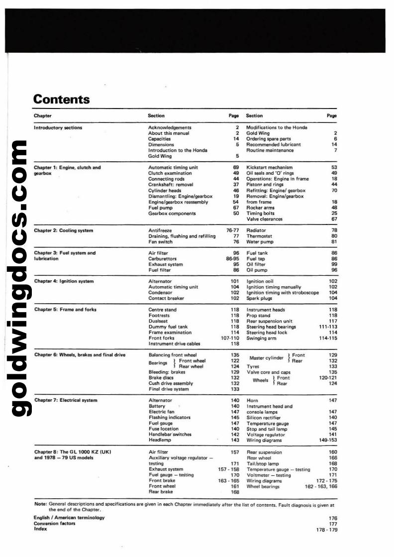
Contents
IntroduetOfV IK1lom
Chapter 1: Engint. dut&:h and........
C....pter 3: FualllVst.-n andlubrication
Chapler 5: Freme Ind forkl
Chapa. 6: Wheel&, brakes and final driva
Ch.pta, 7: EI~ric:.1 .-.,stem
Chapter 8: The G L 1000 KZ (UK!and 1918 _79 US modall
""~, P... s.ction P...
Ac:knowledgem.nn , Modiflcatlons to the Hon~Aboulthil~
, Gold Wing ,Capacities ,. Ordering $par. fNIrtS 6Dimens.ionl • R.,;ommeoded lubrielnt ,.Introduction to tIM Honda Routi.... me'nten.netI ,Gold Wing •Automatic timing unit '" Klcltn,n mechanism 53Clutch examination .. Oil _,. and 'CY rings ..Connecting rods .. Opentior\$: Engine in 1..- ..Crankshaft: nrmowJ 37 Piuo"" end rings ..Cylindertteadl .. R,fitting: Engine! gelItbox 70Oi1n'lantling: Enliinelllll'rbox ,. Removal: Engine/gearboxEngine/gearbox r,nsemblv .. from frame ..Fuel pump 6' Rock.rarms ..Gearbox compon,ou 50 Timing bolts "V.lve cleerancea 6'
Antifreeze 78·77 RlldillDl" 78Draining, flushing and rlJfilliog 77 Thermostat 80Filn $W;l(;h '6 W.t,rpump .,Air filter .6 fuel twlk ..Cerbur,Uor1 ..... ,....... 86El<hauusyuem 95 Oil filter 99Fuel filte<" .. Oil pump 98
Alternator '0' Ignition mil '0'Automatic timing unit ,.. llilnition timing manu.lly '02Con<Iensor '02 Ignition timing with Itrobosc:ope ,..Contact breaker '02 ~rk plugs ,..Centre stand 11. Instrument heads 11.Foot••I" 11. Prop lIand 11.Oual$eat 11. Aaa. 5U5PtlnSiOn unit 117Dummv fuel tank 11. Stearing head bea.in", 111·113Frame examination ". Steering head lock 11.Front forks 101,110 Swinging arm 114-115Instrument d.ive cables 11.Balancing front~ 13. Master cylinder } F,ont '29Bearings } Front wheel '" Rn' 132
A..r wheel ". Tv·", '"Bleedin;; br1Ikes '29 VaM core and e.,.s 13.8111ke diJes '" """'. } Front 120-121Qnh drive assemblv '" R_ ".Final drive ""sum '33
Alternator ,.. Horn 14'Battery ,.. I nstrument head andEllH:t,jc fan ,., «Insole lamps '47Flas.hing indicators ,.. Silicon ractifi.,. ,..Fuel gauge ,., Tempa,ature gauge '47Fuse location ,.. Stop and tail lamp 14'Handlebar'lwltches ,., Voltage .egulator 14'Headlamp ,., Wiring diagraml 149·153
Air filter >5' Ree. tuspension '60Auxiliary voltage regulilor - Aear wheel '86tasting 171 nillstOP lamp '58Exhaust ""Item 151-158 Temperature gauge _ tasling 17OFuel g;JUge - teSling 17O Voltmeu, - tasting 171Front brake '63 . ,.. Wiring diltgl"MnS 112-115Front wheel '6' Wheel bearingc 162 - 163. 166A.... brake '58
17.177
118·119
Nota: Geoet1ll dftcriptions and specifications a.. 1Iiven in eech Chapter immediately ah.. the list of «Intents. Faull diagnosis is given atthe end of the a.ept...
English I Americ.. t.,minololrt'ConvltrSion factonIndex
gold
win
gdoc
s.co
m4
'. '~""""." '. "·"'~"·l'·'.. •. .- I,;:......~ ••~ '."" -,'~J.:t''t--........ ,.~ '-~ ..... 'a. , .:C?e~~.. .
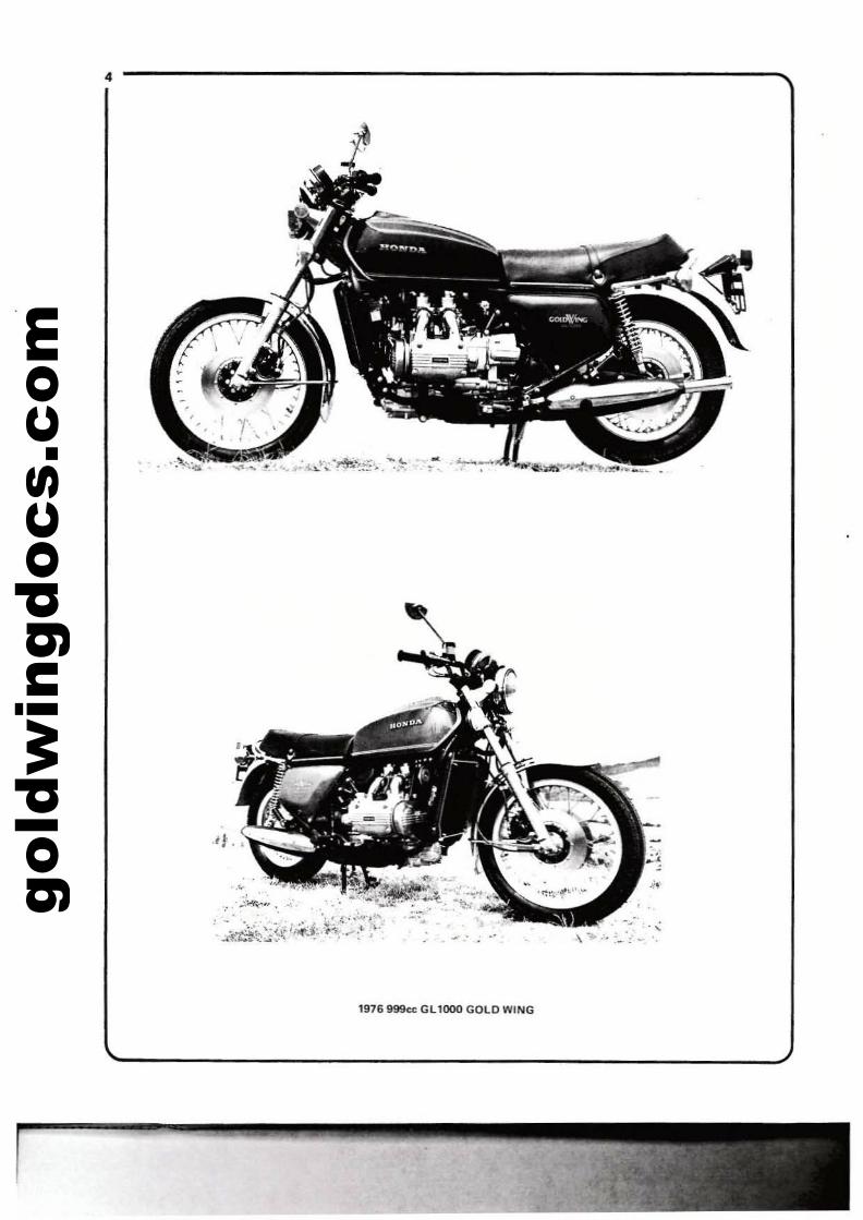
000 GOLD WING1976 999cc Gl1
\;"',--
gold
win
gdoc
s.co
m
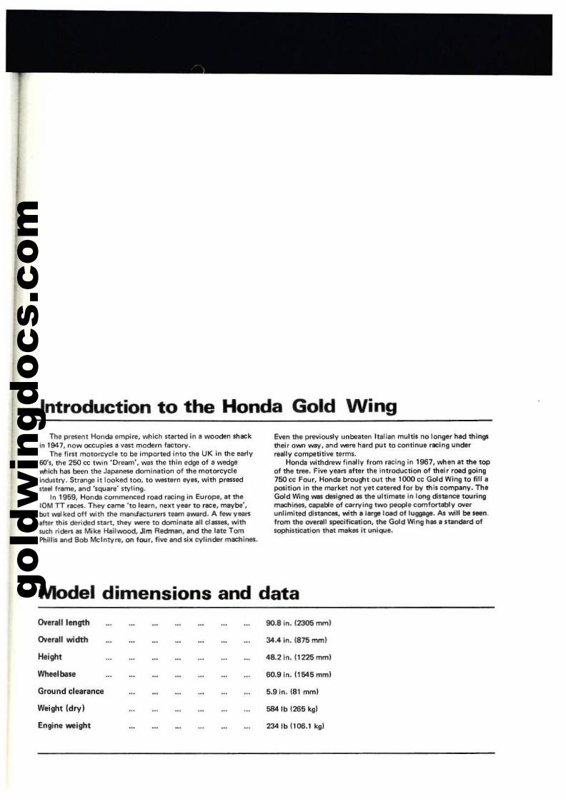
Introduction to the Honda Gold WingThe present Honda empire. which uarted in II wooden shack
in 1947, now occupies II vast modern factory.Thelirn motorcycle to be imported into the UK in the early
60's, the 250 cc twin 'Dream', was the thin ed9l! of a wedge....tIlch has bello the Japanese domination of the motor<:ycleindustry. Strange it looked too. to western eves. with pressedItee! frame, and 'squllll!' styling.
In 1959. Honda commenced road racing in Europe, at the10M TT races. They came '10 learn. nelll VIlIlT to race. maybe'.btll waI ked off with the mamJactu.llf'l team award. A few yean.fte. this derided Iitllrt. they were to c;lominat.1l1l classes. withsuch riclen as Mike Hailwood. Jim Redmen, lind the late TomPhillis lind Bob Mcintyre. on four. fiVi! lind six cylinder machillet.
Even the prtlviously unbeaten Italian multi. no longer had thingstheir own W8V. and were hard pul10 continue facing underreally competitive terms.
Honda withdrllw finally from racing in 1967. when at the topof the tree. Five years after the introduction of their road going760 ec Four. Honda brought OUt the 1000 cc Gold Wing to fill.position in the market not vet catered for by this company. TheGold Wing _ designed as the ultimete In long dl$lanee touringmac:hinM. capable of carrying two people comfortably oyerunlimited dinences. with a I.rge loed of luggage. As will be seen.from the over1l1l speeifl<:.tlon. the Gold Win';! hIlS' standard ofsophistic.tion that mek.es It uni~e.
Model dimensions and dataOverall length 90.8 In. 12305 mm)
Overall width 34.4 in. 1875 mml
Height 48.2In.11225mm)
Wheelbase 50.9 in. 11545mml
Ground clearance 5.9 in. (81 mm)
Weight (dry I 584lb 1265 kgl
Engine weight 234lb {lOG.1 kgl
gold
win
gdoc
s.co
m
Ordering spare partsWhen ordering spare parts for any Honda. it is advisable to
deal direct with an official Honda agent. WlO should be able tosupply most items Ilt'1itock. Parts cannot be obtained from HondaIUK) Umited direct;.l orders muSt be routed vii In apprOlled9nt. eYen if the pam re<p.Jired at' not held in stOCk.
A1WII'Vs quole the engine lind frame numbers in full, andcolour v.tlen painted pam ere required.
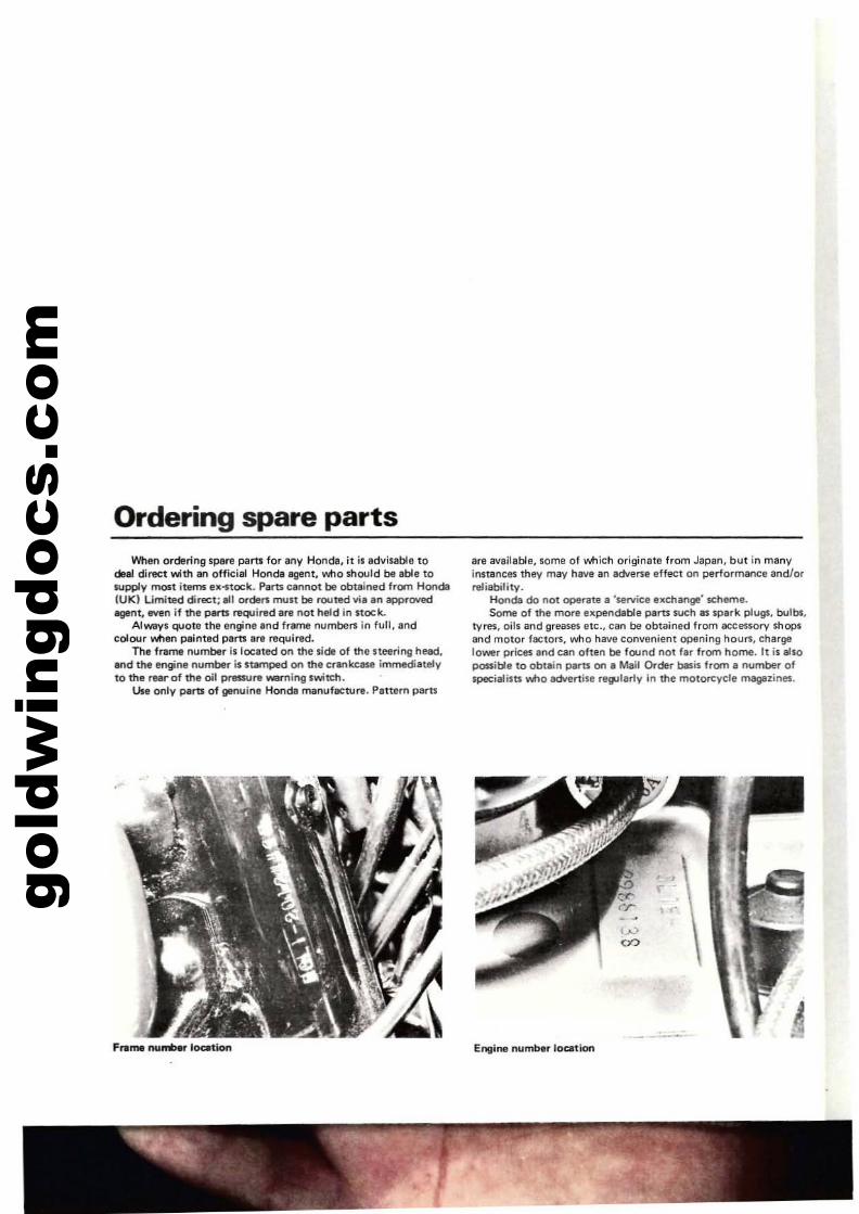
The frame number is located on the side of the steeril"lg head.and the engine number is stamped on the crankcase immediatelyto the rNrof the oil p..-ure W8rnlng switch.
Use only perU of genuine Honda manuf8Cwra. Pattern paru
Frame '""'....., loatlon
are available, some of which originate from Japan, but in manyinnancl!!'S thllY may have an adverse effect on performance andlorreliability.
Honda do not operate I 'wrvice exchange' seheme.Some of the more expendable pans Sl,>Ch as spark plugs, bulbs.
tyres, oils lind greases atc., can be obtained from accessory shopsand motor factor1, who have convenient opening hours. chargelower prices and can often be found not far from home, It is alsopossible to obtain partS on a Mail Order basis from a number ofspecialists Yltto adwrtise regularly in the motoreycle m8g8z;lle$.
E"lIine number location
gold
win
gdoc
s.co
m
Routine maintenance
Periodic routine maintenance is essential to keep the motorcycle in a peak and safe condition. Routine maintenance alsoS(lVes money because it provides the opportunity to detect andremedy a fault before it develops further and does more damage.Maintenance should be undertaken on either a calendar ormileage basis depending on which ever comes sooner. The periodbet'Neen maintenance tasks SCIVes only as a guide since there afemany variables e9; age of machine, riding technique and W\I1lrseconditions.
The malraenance instructions are generally those recommllndedby the manufacturer but are supplemented by additional tasksMich, through practical experience. the author re<:ommendsshould be carried Qut at the intervals suggested. The additionaltasks are indicated by an asterisk and are primarily of apreventative nature, which will assist in eliminating une:o:pectedlailure of a component or system, due to fair wear and tear, andincrease safety margins Men riding.
All the maintenance tasks are described in detail together withthe procedures required for accomplishing them. If necessary,more general information on each topic can be found in therelevant Chapter within the main te:o:t.
Where possible, the use of service tools has been avoided inthe Routine maintenance procedures. There are, hoWtller, certainoperations where the use of service tools is imperative, eitherbecause an operation cannot be carried out without the necessarytool, or where there is a risk of damage to Bcomponent. It isadvised Ihat apart Irom a good selection of hand tools, whichShould include a range of metric ring spannen; or combinationspanners and larlle lind small cross-head screwdriven;, a numberof more specialised hand toolS be obtained. A 'power' or impactscrewdriver is absolutely invllluable lor releasing the variouscasing screw.>, particularly if the engine has not been dismantledor overhauled since leaving the factory. It is no e:o:aggeralion tosay that some screws are impossible to remove safely without theaid of this tool. Two pain; of circlip plien; should also be acquired.One internal opening, the other e:o:ternal opening, with 900 jaw.>.Although hand tools are relatively e:o:pensive, the damage inflictedby the use of incorrect or ill-fitting tools can quickly e:o:cet!d theinitial outlay in terms of replacement parts required to makegooo the damage. Bear in mind also that an enviable collection oflools can be bought with even a small part of the money savedon labour by carrying OUl the work at home I
WMkly, or every 200 miles
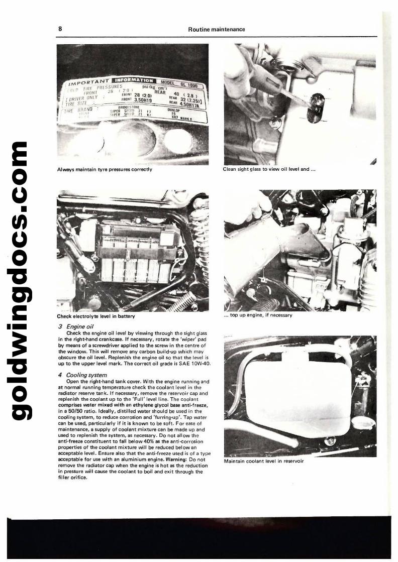
Tyres and wheelsCheck the tyre pressures. Always check thll pressure \/'kIlln the
tvres are cold as the heat generated v.tlen the machine has beenridden can increase the pressures by as much as 8 psi, gil/ing atotally inaccurate filading. Variations in pressure of as little as2 psi may alter certain handling characteristics. It is thereforerecommended thet whatever tvpe of pressure gauge is used,should be checked occasionally to ensure accurate rndings. 00not put absolute faith in 'fret! air' gauges at garages or petrolstations. They have been known to be in error.
lnsplK:t the tvre treads for cracking or evidence that the Ol.ltllrrubber is leaving the inner COI/er. Also check the tvre walls forsplitting or perishing. Car1lfully inspect the treads for stones,flints or shrapnel which may hal/e become imbedded and besloVlAy working their way towards the inner tube. Remove suchobjects with a suitable tool. The thing for getting stones out ofhorses hooves is ideal I
Check each spoke individually for tension by tapping with.metal object. Any marked differ1lnce in the pitch of the noisagenerated indicates a loose spoke. Bear in mind that a 'POke thatrequires e:o:cessive lightening will protrude through the wheel rimand may penetrate the inner tube. In this case the tyre will heveto be removed and the spoke end filed flush with the nipplehead.
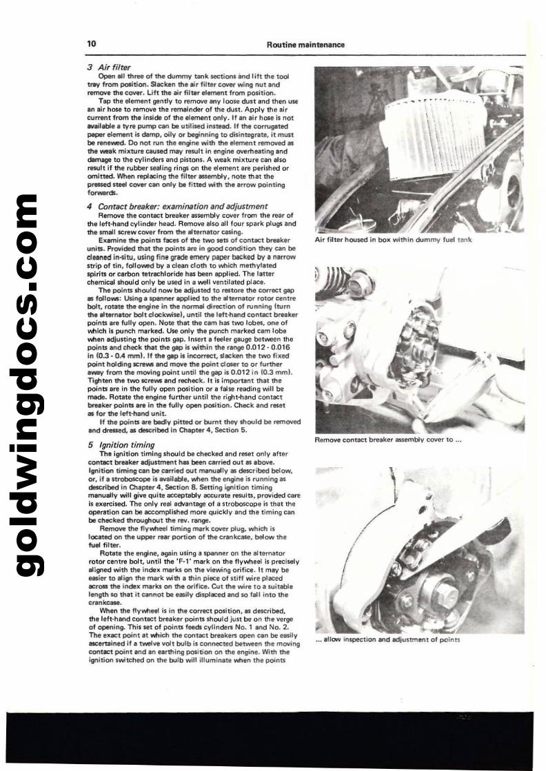
2 BatteryCheck the electrolyte level in the battery and replenish, if
necessary, with distilled water. 00 not use tap water as this willreduce the life of the battllry. If the battery is removed forfilling, note the tracking of the battery breather pipe, ...... ichShould be replaced in the same position, ensuring that the pipe isnot kinked or blocked. If the breather pipe is restricted and thebattery overheats for any reason, the pressure prodUced may, ine:o:treme cases, cause the battery case to fail and a liberal amountof sulphuric acid to be deposited on the electrical hll"rness andframe parts.
gold
win
gdoc
s.co
m8
Alweys maintain tyre prll$Sures correctly
Routine maintenance
Clean sight glass to villW oil level and ...
" ,Chec\l: elec1rolyl'e level in battery
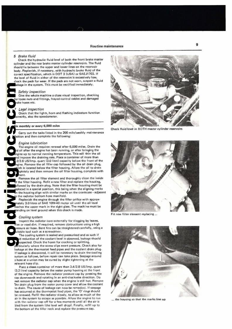
3 Engine oilCheck the engine oilleve! by viewing through the sight glass
in the right-hand crankcase. If necessary, rotate the 'wiper' padby means of a $Crewdriver applied to the screw in the centre ofttle window. This will remove any carbon build-up which mayobscure the oil level. Replenish the engine oil so that the level ;5UP to me upper level mark. The correct oil grade is SAE 10W-40.
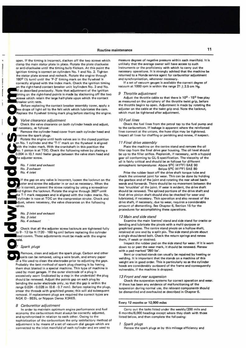
4 Cooling systemOpen the right-hand tank cover. With the engine running and
at normal running temperawre check the coolant level in theradiator reserve tank.. If necessary, remove the reservoir cap andreplenish the cootant up to the 'Full' level line. The coolantcomprises wetlr mixed with an athv1erle glycol bale anti-freeze,in a 50/50 ratio. ldllally, distilled water Should be used in thecooling system, to reduce corrosion and 'furring-up'. Tap watercan be uS41d, particularly if it is known to be soft. For ease ofmaintenance, a supply of coolant miJuure can be made up andused to replanish the system, lIS necessary. Do not allow theanti·freeze constituent to fall below 40% as the anti'corrosionproperties of the coolant mixture will be reduced below anacceptable level. Ensure also that the anti-freeze used is of a typeacceptable for use with an aluminium engine. W.rning: Do notremove the radiator cap when the engine is hot as the reductionin pressure will cause the Coolant to boil and exit through thefiller orifice.
... top up engine, if necessary
Maintain coolant level in reservoir
gold
win
gdoc
s.co
m
Routine maintenance 9
5 Brake fluidCheck the hydraulic fluid level of both the front brake master
cylinder and the rear brake master cylinder reservoirs. The fluidshould lie between the upper and lower lines on the reservoirbody. Replenish, if ne<:essary, with hydraulic brake fluid of thecorre<:t specification, which is DOT 3 (USA) or SAEJ1703. Ifthe levet of fluid in either of the reservoirs is excessively low,check the pads for wear. If the pads are not worn, suspect a fluidleakage in the system. This must be rectified immediately.
6 Safety inspectionGive the whole machine a close visual inspe<:tion, che<:king
for loose nuts and fittings, frayed control cables and damagedbrake hoses etc.
7 Legal inspectionCheck thM the lights, horn and flashing indicators function
corre<:tly, also the speedometer.
Silt. monthly or every 6,000 miles
Carry out the tasks listed in the 200 mile/weekly maintenanceSection and then complete the following:
1 Engine lubricationThe engine oil requires renewal after 6,000 miles. Drain the
old oil after the engine has been running, or after bringing theengine up to normal running temperature. This will thin the oiland improve the draining rate. Place a container of more than3.2/2.6 US/Imp. quart (3.0 litrel capacity below the front of theengine. Remove the oil filler cap followed by the oil drain plug,l'>t1ich is located below the filter housing. AlloW the oil to draincompletely and then remove the oil filter housing, complete withelement.
Remove the oil filter element and thoroughly clean the insideof the filter housing. Refit a new filter and replace the housing,followed by the drain plug. Note that the filter housing must bereplaced in a special position. this being v.tIen the aligning markson the housing align with similar marks on the crankcase· adjacentto the radiator boltom hose manifold.
Replenish the engine through the filler orifice with approlt.imately 3.0 Iitres of SAE 10W·40 motor oil until the oil levelreaches the upper mark in the sight glass. The machine must bestanding on level ground v.tIen this check is made.
2 Cooling systemInspect the radiator core elt.ternally for clogging by leaves,
flies or road dirt. If required, remove obstructions using a highpressure air hose. Bent fins can be straightened carefully. using asuitable tool such as a screwdriver.
The cooling system is sealed and pressurised and as such ifrapid reduction of the coolant level is observed. leakage shouldbe suspected. Check the hoses for cracking or splitting,particularly where Ihe screw clips e)(ert pressure. Check also forleakage at the thermostat feed pipes and the coolant drain plug.If leakage is discovered, it will be necessary to drain the coolingsY$lem as follows, before repair can take place. Seepage around:; hose at a union may be cured by slight tightening at therelevant hose clip.
Place a clean container of more than 3.4/2.8 US/Imp. quart(3.2 litre) capacity below the water pump housing at the frontof the engine. Remove the radiator pressure cap by pressing thecap downwardS and rotating in an anti-elockwise direction. Donot remove the radiator cap when the engine is still hot. Remove\he drain plug from the water pump cover and allow the coolantto drain. The cause of leakage can now be remedied. If seepagehas occurred at the thermostat feed pipes, the '0' rings shouldbe renewed. Refill the radiator slowly, to allow as much of theair in the system to escape as possible. Allow the engine to run\I\,th the radiator cap off for a few moments until all the air isbled from the system (the level will drop). Finally. refill up tothe bottom of the filler neck and replace the pressure cap.
Oleck fluid level in BOTH master cylinder reservoi",
Fit new filter element replacing ...
... the housing so that the marks tine up
gold
win
gdoc
s.co
m10 Routine maintenance
3 Air filterOpen loll three of the durrmy tank sections and lift the tool
tl'I'V from position. Sleeken the air filter C(JIIIer wing nut andremove the cover. Lift the air filter "hlment from position.
Tap the element gently to remove any loose dust lind then useIn air hose to remove the remainder of the dust. Apply tt1e aircurrent from the inside of the element only. If en air hose is notwailable, lyre pump can be utili$ed instead. If the corrugatedpeper element is damp, oily or beginning to disintegnte. it mustbe renewed. 00 not run the 8'ngine with the element remowd asthe weak mixture ClIused mey result in engine overheating anddamage to the cylinders and pistons. A weak milCture c::an alsoresult if the rubber sealing rings on the element ere perished oromitted When replacing the fitter assembly. not8 that thepressed steel cover can only be fitted with the 8rrow pointingforwanS.
4 Contact breaker: examination and adjustmentRemove ttle contact breaker assembly cOYer from the rear of
the left-hand cylinder head. Remove elso all four spark plugs andthe Ifllall sc:rewcover from the alternator casing.
Examine the points fllCes of the two sen of contilCt breakerunits. Provided that the poinn are in good condition they can beduned irKittJ. using fine grade ffrlery paper backed by, n&rrowstrip of tin. folloWlld by a clean cloth to wtlich methvl,tedspirits or carbon tetrechloride has been applied. The latterchemical should only be used In a well ventilated place.
The points should now be adjusted to restore the CorTeCt gap_ follows: USing' spllnfler eppIied to the alternator rot~ centrebolt. r01lte the engine in the normal direction of running (tumthe altemator bolt dockwisel. until the left....and contlll:t breekll'"poinlS are fully open. Note that the Clm has two lobes. one ofv.tllch is purn::h marked. Use only the punch marked eam lobev.tlen adju.ting the points gep. Insert I feeler gauge between thepoints and eheek that the gap i. within the range 0.012·0.016in lo..J - 0." mml. If the gep i. incorrect, slllCken the two filtedpoint holding screws and move the point doser to or furthera-v from the rTIOYing point until the~ is 0.012 in 10.3 mrnl.Tighten the two ICrews and recheek. It is important that thepoints are in the fully open position or a false reading will bemade. Rotate the engine further until the ridtt-hand contactbreaker points are in the fully open pOlition. Cheek and reset• for the left-hand unit.
If ttla points are beclv pitted or burnt they should be .-amovedand dressed.. delc::ribed in Chapter". Seetion S.
Air filter housed in box within dummy fuel tank
Remove contact breaker llssemblv cover to
... allow inspection and adjustment of points
5 Ignition timingThe ignition timing should be checked and reset only after
contlet breaker adjustment has been carried out as above.Ignition timing can be ~rried out manuallV _ Described below,or. if a stroboscoPe is 8Vailable, v.tlrn the engine is running asde:tc;ribed in O1apter 4, Seerion 8. Setting ignition timingmafl\laUy will give QUite llCCeptablv llCCurate results, provided careIs Ixan:iMd. The onlv real adVantage 01 a stroboscope is that theoperation can be llCComplisfled more quickly and the timing cant:. checked throughgut the rev. range.
Remove the flvv.tleel timing mark cover plug, whic:tl islocated on the upper rear portion of the crankcase, below thefuel filter.
Rotate the engine, agein using a spanner on the alternatorrotor centre bolt, until the 'F-1' mark on thl flvwheel is prllCiselvaligned with the index marks on the viewing orifice. It meV be_ier to align the mark with a thin piece of niff wire placed.cross the index marks on the ~ifice, Cut the wi~ 10 a suitablelength so that it cannot t:. easilv displaced and so fall into thecrankcase.
'Mlen the flVv.tleei is in the correct position, as described,the left-hand contl(:t breaker points Should just be on the verga01 opening. This set of poinn feeds cvlindeR No.1 end No.2.The e:uct point at Vltlid\ the C{)I'ltlet breakeR open can be easilvlilCertained il a t-'ve volt bulb is connected between the movingCOI'ItllCt POint and an earthing position on the engine. With theignition switChed on the bulb will illuminall v.tlen the points
.-,"
gold
win
gdoc
s.co
m
Routine maintenance 11
I!,
open. If the timing is incorrect, slacken off the two screws whichcllllTlp the main sUtor plate in place. ROllte the pllte clockwiseCH' Inti-eloekwiM until the timing bulb fiicken. At this point theignition timing is correct on cylinders No.1 and No.2. Tightenthe st.tCH" pllte screws and recheck. Rotate the ensPne through18QO (~turn) until the 'F-2'" timing m.rk on the flVwheel iscorrecdV aligned with the indelC mark. Oleck the ignition timingon the right·hand contllCt breaker unit {cVl1nclers No.3 and No.41 as described previously. Note that adjustment of the ignitiontiming on the right-hand points is made by slackening off the twoscrews which retain the large half·plate upon which the contactbreaker unit rl'SU.
Before replacing the contact breaker assemblv cover, apply afew drops of light oil to the felt wick which lubricates the cam.Replace the flvwheel timing mark plug before starti ng the engine.
6 Valve clearance adjustmentOleck the valVl! clearance on both cylinder heeds a"d adjust,
if nflCflSary, as follows:Remov. the cv1i"der head COI/er from each cylinder head and
unscrew the spark plugs.Rotate the engine until both lIallles are in the closed position
on No.1 cylinder and the 'T·t' mark on the flywheel is alignedVoIith the index mark. With the cra"kshaft in this position theNo.1 piSton is at TOC. Oleck the following IIlIIlIes bV plBeing a0.004 in 10.1 mml feeler ga..ge between the 1111111 stem head andthe adjuster screw.
No. , inial MId axhaunNo. 3 axhMlnNo. 4 inial
If the 019 on any lIalVl! is incorrect, 100$11'1 the locknut on theadjuster Ind screw the adjuster in or out as necessary. When theIIiIP is correct, prevent the screw rotating by using a screwdrillerand tighten the locknut. Rotlte the engine through 3600 untilthe T-1 mark reappears and is aligned with the index marks. No.2 cylinder is now at TOC on the compression stroke. Check andadjust, whera necessary, the lIallle clearances on the followinglIallllS.
No. 2 inlet and exhaustNo. 3 "nletNo.4 exhaun
Oleck that 1111 the adjuster screw locknuts are tightened fullyto 9· 12 fbs ft {120 - 160 kg cm} before replBeing the cylinderhead cOI/ers. Thl$l adjus!mlf'lts must be made with the engine<Ol~
1 Spark plugs
Remove, clean and adjust the IpfIrk plugs. Carbon and otherdeposits can be removed, using' wire brush. and emery paperor Ilil. UMd to clean the electrode's prior to 'Cijusting the gaps.ProbabiV the best method 01 spark plug deaning is by hllllingthem shot blasted in a speeial machine. This type of machine isused by most galllgeS. If the OUler electrode of, plug iselCceuillely worn (indicated by a step in the unclersidel the plugshould be renewed. Adjust the points gap on each plug bybending the outer electrode only, so that the IIiIP is within therange 0.024·0.028 in 10.6 - 0.7 mml. Belore replacing the plugs,smear the threac;ls with graphited graase; this will aid subsequentremOl/al. If r1Iplacemeot plugs are reQUir1ld the correct types areNGK O· 8E$L or Nippon Denso X24ES.
8 carburettor adjustmentIn order to maintain optimum engina performance and fuel
economy the cerburettors must always be correctly adjusted.and Ivnchronised in relation to each other. Owing to thesophinication of the carburettors the onlv satislactory method ofadjustmenl i' by means of a Ht of lIacuum dilll gauges whicn areconnected to the inlet manifold of each cylinder and are used to
mtllSUre degrees of negative pres$Ure within each manifold. It isunlikelV that the _rage owner will hili. access to suchinstruments or the pro'-tciency with Votoith to carry out thenecessary operations. It i, stronglv IIdvised that the maine bereturn.d to a Honda service agent for cartlurettor adjustmentand synchronisation, whenever necessary.
lIa Ht of IlBeuum gBugl!'l is BVailabie the correct degree oflIacuum at 1000 rpm is within the ranga 21 !; 2.S cm Hg.
9 Throttle adjustmentAdjust the throttle cable so thet there il l()O· lSo free plaV
as measured on the periphery of the throttle twist grip, beforethe throttle begins to open. Adjustment is made by roUting theadjuster on the cable at the twist grip end. Note the locknut,v.toich mUll be tightlf'led after adjustment.
10 Fuel linesChack the fuel lines from the petrol tllp to the ruel pump and
to the carburettors. If leakage is appaf9nt ~r1I the reinforcedlines connect at the unionl, the hose clips may be tightened.Inspect 1111 lif'l\lS for chaffing or perishing and renew, if suspect.
11 Final drive assemblyPlBee the machine on the centre 'tand ....d rflfTlO'lf' the oil
filler cap from the final drlVl! gear housing. The oil IIIIel shouldbe up to the filler orifice. Replenish, if n8C$ary, with a hypoidgear oil conforming to GL·S specification. Thelliscosity of theoil is fairly critical and should be as follows fCH' differentIImos,p!ler;c temperllltures: AboIII sOC 141 0 F) SAE 90
Below sOC !41 0 FI SAE 80Prise the rubber boot olf the drillll shaft torque tube and
check the unillt!rsaI joint for wear. This can be dorle by holdingthe glerbolC .nd of the joint and rotating the r.ar wheel back·Wlrc;ls and forwarc;ls. There should be no mOlllment between thetwo 'knuckles' of the joi"t. If wear is evidal'lt, the drille shaftIhould be renewed. The splined portions of the drive shaft andfine! drille pinion shaft should elso be checked for Wlli!lr andlubricated, if necessary. This operation and also renewal of thedrive shalt, if necessary, due to wear, rtlquires a considerableamount of dismantling. See Chapter 6. Section 15 for theprocedures for accomplishi"g these operations.
12 Main and side standE>camine the main lcentrel stand and sida stand for cracks CH'
be"ding and lubricate the pivots with a mlJlti-purpose orgrephited grease. The centre 't8l'ld pivou on a hollow shaft.raUlined at one end by a split pin. The sida nand pillOts abouta single shouldered bolt. Oleck the return springs and renewthem. if weak or stnti"ed.
Inspect the Nbber pad on me side nend for _ar. If it is worndown to or- past the we<lr mark, it should be rene_d. Renewwith I pad marked '260 Ibs'.
Be"t or cracked stands can usu.1V be replirec:l by heating orwelding. It is important that the st....~ on I mechine of this~dlt.re in good order. This is particularly so. the cylinderheads are considerably outboard of the frame end cOMeqUlf'ldvII\Jlnerabie. if the mochine is dropped.
'3 Front and rear suspensionOleck the suspension systems for correct operation and wear.
If there has been any evidence of malfunctioning of thesuspension during normal use, the f11levant components shouldbe dismantled and ollerhauled as described In Olapter 6.
Every 12 months or 12,000 miles
Carry out the tasks listed under the waeklVI200 mile and6 months/6.000 headings e>ccept where they clash with thoselisted below, and then complete the following:
Spark plugsRenew the spark plugs as by this mileage efficiency and
gold
win
gdoc
s.co
m'2 Routine maintenance
reliability ""II be redJeed. The correct plug grade is NOK D-8ESLor Nippon Denso X24ES.
Set the gBPS It 0.024' 0.028 in 10.6·0.7 mml before_ring the thruds with graphite lI".ase and replacing ttlt plug5.
2 Air filterOpen ,t1 three sections of 1M dummy fuel tlnk end rlmQVII
the tool tray. AemOlle the eir filter COIIlr which is held by. win.gnut. Lift out the air filter element lind replace it by I newcomPOn.n1. Ttl. correct dry COTNgeted paper element is No.17211-311·003.
3 Steering head bearingsPIece the machine on the centre stand so th.t the front wheel
is clear of the ground. This me\, ne<:e5$itllte placing blocks underthe centre nlnd. o,eck the adjustment of the steering headbe.rin~ by pplng the forks "elr the front ¥IItleel spindle endpulling end pushing them horizontally in a fore end eft direction.Any movement felt between the steering head lug Ind ttle forkyoke$ indi~te that the steering head buril'\95 require adjustment.81 follows.
Sl8Cke'n the pinch bolt vJlieh pa_ throulfl the re.r of theupper Ierownl yoke. l/I.ingl willble 'C' $pinner rotlte theslotted Idjuster ring in I clockwise direction. The adjusler ringIi" on the10p of the upper yoke, jl.lst below the centre of thehlndlebe.... Tum ttle adjuster ring until aU p1av has just beentaken up. 00 not overtightan the head races as this will produceen UnplellSent rolling effect et low speeds end in some cases speedwobble. If the adjustmen1 is correct. the forks should move ontofull lock from the centnll poSl1ion Men the handlebar i, tappedat either end. If, Men the adjustment is corl'llCt, the bearin",feel rough or n01chV Men 1he handlebars are moved, i1 indicatesthu the ball races hl'lle become wom or pitted or;1'I e)(tremecases have fractured. In either event the steering head bearinglshould be rene_d, neeessitating complete removal of ttle forks• delcribed il'l Olapter 5, Section 2.
Ewwy 24 _ths or 24,000 mil.
Compl.te all ttle openlltiOnl listed under the ~ious threeRoutil'l' maintel'lence heldin", atld then complete the following:
Fuel filterRemovl the fIJI'! filter, Mlch is fitted 10 the fuel Ii".. between
the petrol tap and fIJI'! pump. The hoses are retained bv screwclips. The filter is a sealed unit and must be renewed.
2 Brake ffuidHondt recommend that the brake fluid in both front and rear
brake systems be renewed at thls.ervice interval. It is practicalto combine this "rvice operation with a complete ,nternalande)(lemal f)(amination of the brake opInlting compon.nts,overn.ulingatld renewingMl.re n«;8SSIIry. Refer to Olapl~6for dellits of these openltions.
3 Front fork clamping oilR~ ttle dntin plug from the lower leg of ekh fork 1151
-."b1y Ind allow all the oil 10 drain. Work the forks up anddo\M'l to aid dnIoining. Avoid spilling oil onto ttle tvre r\lbber orbrak. discs. Place wooden blocks or a jack below ttle engi". 10tlIIke thl _ight of the mIdlin. when 1he fork caps are ramoved.Prise the rubber covers from ttle lOP of each fork leg and usinga suiteble socket wrench remove the top caps. Replace andtlgh1en the drain plugs and refill ellCh fork leg with 170· ISO cc(5.S· 6.1 fl ozl of AUlomatic Transmission Fluid lATF) or forkoil. Repllce the top caps and rubber covers.
4 Final drive lubricationPIlei I suitable container below the final dri~ g"r housing
and removl the filler plug, followed bv the ds-ain plug. Allow allthe oil to drain and replace the drain plug. Refill the gear housingwith 200· 220 C(; i6.8 . 7.5 fI ozl of hypoid gear oil conformi"il
10 GL·5 specification. If the normal atmospheric temperltureunder Mlich ttle machi". opera1. is less th;sn SOC 141 0 FI, usean SAE 80 oil. It the normal lempenlWre is greater than this,use SAE 90 oil. Take greate<t" MIen refilling not 10 allowforeign maner inlO the housing and avoid spilling the lUbricanton the rur tv,e or br"ake compon.nts.
Additional routine maintenance
1 Brake pads: examination and replacementThe nile of brake pad wear is dependent on the conditions
Ul'lder I'otlich the machine operates, weighl carried and the Itvteof ridng, consequently i1 il difficult 10 adYise on spllCificinspection intervals. Whalever inspection interval is chosen, bearin mind thai the rata of wear will not be constant.
To chtek _ar on the front brlke pads eX8!Tlil'le the padsttlrou~ the small window in the main caliper units. If the redmark on the periphery of any pad has been rekhed, both padsin that set must be renewed. The nllt! of wellr of the two sets aresimilar SO It is probable ttlat they wilt require renewal al the sametime in Ilny CIlS8.
Cheek the rear br"i1ke pad wear after removing the plasticcaliper cover from position. If the red tongues 01'1 the pads hllVedOl.d together sufficiently that they alll wittlln the erea markedred on the caliper, they must be renewed.
2 Front brake pad renewalRemove each brake set individually, using an identical
procedure as follows:UO$Crew and remove the two large socket screws Mlictl clamp
the caliper unil togettler. Pull the oute, and inner portions of thecaliper unit from po$ition. Th. outer portion is still attached tottle brake hose. Lift the old~ out. Install the new pads; andalso the shim v.Ilich fits against the outer fxe of ttle out~ pad.The shim mun be fined so that the arrow is in the for-rekTlOltposition, pointing in an up\Wrd direction. Refit the uliper halvesand repllCll the socket tere\W. It ITIri be nec:essary 10 push thecaliper cylinder pinon inwardllo give the necessary cleanll'lC:e. Ifrvquired, the bleed screw on the caliper can be slackened at thesame time as ttle piston is push&d Inwards. This will allow asmall amount 01 fluid to seep out and the pinon 10 move. Placea rag eround the bleed screw 10 preven11M fluid tnking ontothe caliper unil. Operate Ihe brake lever, after pad replacement,10 check free movement of Ihe pads and to allow the pads toself·adjust.
3 Rear brake pad replacementRemove the caliper acce" COlIer, after unscrewing Ihe single
retaining screw. Depress the flal spring ~ic:h locales both padpins and remove the upper pin. Tilt the spring back and pull outthe lo_r pin. The brake pad assembly CM now be lifted IrompositiOl'l.
lnstilll a set of new pads, together with the two shims, thearrows on Mich must face do .......wardl. Replace the pad pins,ensuring Ihat ttle pin locating spring locates correctlv in the'wained' sections of the two pins. Refit the caliper cover andapply the brake to adjust automatically.
4 Clutch adjustmentIn common with brake pad wear. cluteh \War and the
resul"nt nICe$$ary adjustment depends on operating conditionsand the stvle of ,iding. Adjust toe clutch, when necessary. asfollows: Remove Ihe clulch adjustment COlIer which is retainedby IWO bollS and is located at Ihe ,ear of Ihe engine.
Loosen 1he locknuts on the upper cable adjuster screw andlo_r ,djuSler screw and screw both adjusters;1'I as far as possible.Loosen the locknut 01'1 the end ollhe clulch operaling sheft andusing a SCrewdriver, turn Ihe shaft in a clockwise direclion unlilil becomes hard 10 lum. Rotate tha shah back abOll I '!Ii turn andti~tM the lOCknut. Replace Ihe clutch cover.
gold
win
gdoc
s.co
m
Routine maintenance
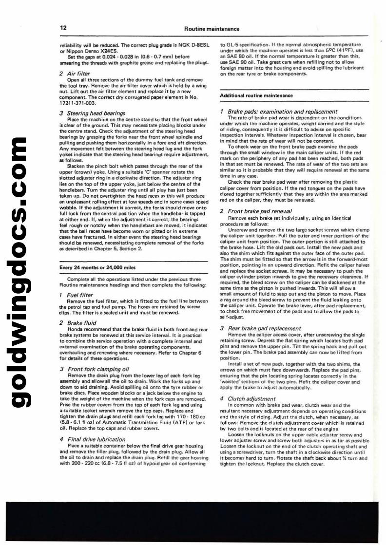
Unscrew the a.b1e lower edjuster until play 01 0.2 - 0.6 in16· 15 mm) can be felt, measured at the ball end of the handlebarlever. Tighten the locknut. Fine adjustment can be made usingthe upper adjustment.
Adjust clutch after removing inspection cowr
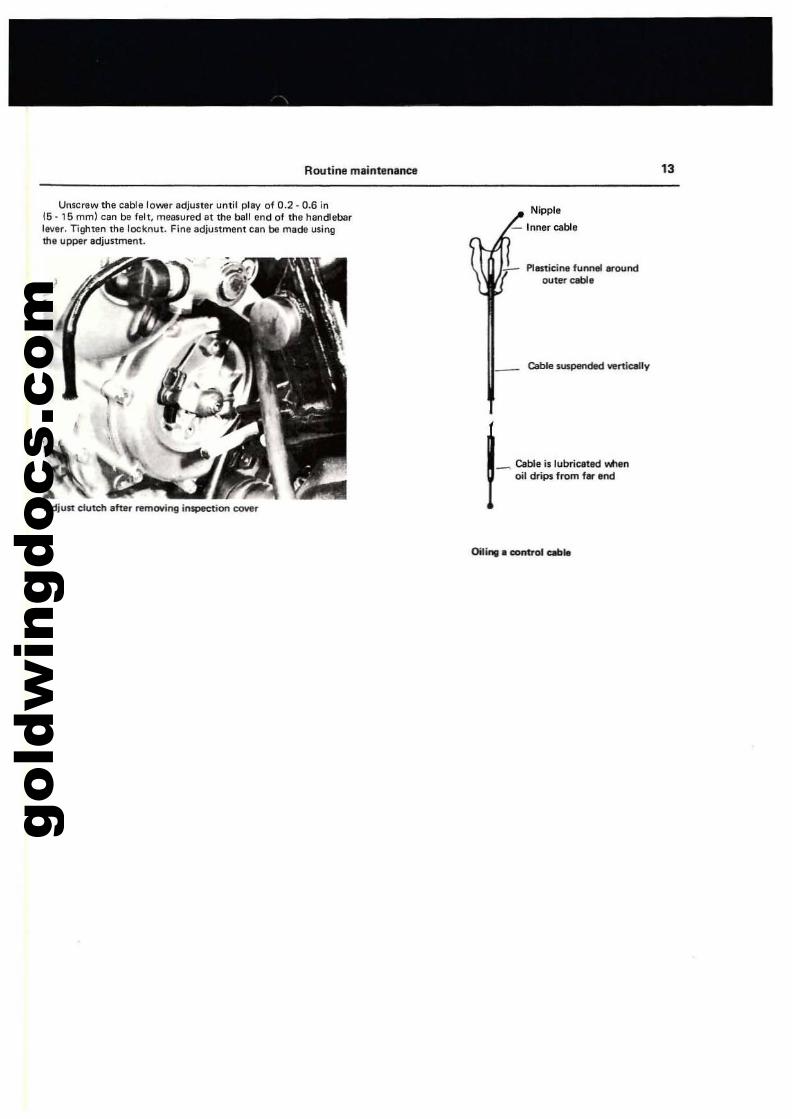
Nipple
- Inner a.b1e
Plasticine funnel eroundouter CIIble
_ Cable IU$p8O(Ied vert~lly
~ Cable is lubricated v.henoil drips from f. end
Oil.... control e.ble
'3
gold
win
gdoc
s.co
mRoutine maintenance capacities and data
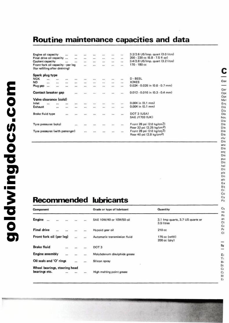
Engine oil c8paeityFinal dri~ oil C8paeityCooIlInt capacityFront fork oil capecity - per legIfor refilling efter dreiningl
Spark plug typeNGKNOPlug gap •..
Contact breaker pp
Valve clearance (cold)InletExhaust
Brake fluid type
Tyre pressures Isolol
Tyre prestures (with passenger)
Reconvnended lubricants
3.2f2.6 US/lmp. C!uart 13.0 litre}200·220 cc 16B· 7.5 fl ozl3AI2.8 US/Imp. QU8rt 13.21itrel170·180 cc
D·8ESLX24ES0.024·0.026 in (0.6·0.1 mml
0.012 . 0.016 in (0.3 •OA rnml
0.004 in 10.1 mml0.004 in (0.1 mm)
DOT 3 (USA)SAE J1703 (UK)
Front 28 psi 12.0 kg/cm21Rear 32 psi 12.25 kg/cm2)FroM 28 psi (2.0 kg/cm 21Rear 40 psi 12.8 kgfcm2)
cGo<0"0",M,.Eo,DisDisDis
'P'Dis>DisDisDisDiscLu'Dis~
Dis
00'Dis
'"Oilh,.Di!pisDil
."..BilC,CoC,Pi,
Component
Engine ...
Final drive
Front fork oil (per leg)
Brake fluid
Engine a,semb'y
Oil seals and '0' rings
Wheel bearings, steering headbearings etc.
Grade or type of rubric.nt
SAE 10W/40 or 1OW150 oil
Hypoid gear oil
Automnic transmission fluid
DOT 3
Molybdenum disulphide grease
Silicon spray
High melting point grease
3.1 Imp quam. 3.7 US quem or3.5litres
210 cc
175cc lrefill)200 cc ldryl
E,T,B.S.C,C,BIE.
gold
win
gdoc
s.co
m
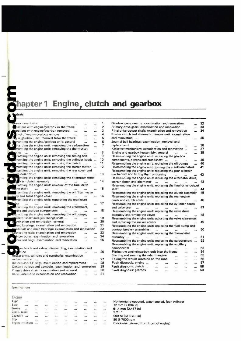
Chapter 1Contents
Engine, clutch and gearbox
General description 1Operanons with engine/gearbox in the frame 2Operations with engine/gearbox removed 3M.,I,od of engine gearbox removal 4Engine gearbox unit: removal from the frame 5Dismll/llllOQ the engine/gearbox unit: general 6Dismantling the engine unit: removing the carburettors 7Dismantling the engine unit: removing tile thermostathousing 8Dilmantling the engine unit: removing the timing belt 9Dismantling the engine unit: removing the cylinder heads 10Dismantling the engine unit: removing the clutch 11Dismantling the engine unit: removing the starlar mOlor 12Dismantling the engine unit: removing the rear covt!r andelutch outer drum 13Dismanlling the engine unit: removing the alternator rotor~d ~Iarter clutch as~rnbly 14Dismantling the engine unit: removel 01 the final driveengine shaft 15Dismantling the engine unit: removing the oillilter, waterpump and Iront engine cover 16Dismantling the engine unit: separating the craokcasehalves 17Dismantling the engme unit: remOlling the crankshaft,pislOns and gearool< components 18Dismantling thl! engine unit: remOlling the oil pumps,alternator shalt and gcarchange shalt .", 19Examination and reno"Jvdtion: general 20Big-end bearings: el<amination and renovation 21Cr<lrlkshah and main bearings: el<amination and renovation 22Conn~Cl;no reds: examination and renovation 23Cylinder bores: el<amination and renovation 24P;Sl<;ns dnd rings: el<amination and renovation 25
Cylinder ht)atIs and valves: dismantling, el<amination andrenovation 26Rockcr arms, spindles and camshafts: el<amination5nd renovation 27Oil seals llnd '0' rings: cl<arnination and replacement 28Cambell pulleys and cambelts: el<amination and renovation 29Primary driW chain: ellamination and renewal 30Clu:cll assemblV: e,..amination and renovation 31
Specilications
EnaineT,,,,BOleStrokeCorr:~. r~lio
Ca;JJCI1yOhpI:r.gir.,' rot~tiun
Gearbol< components: examination aod "'!novation 32Primary drive gears: el<amlnation and renovation 33Final drill9 output shaft: el<amination and renovation 34Starter clutch and alternator damper unit: examinationand renovation 35Joumal ball bearings: el<amination, removal andreplacement 36Kickstart mechanism: examination and renovation ... 37Engine and gearbol< 'reassemblv: general 38Reassembling the engine unit: replacing the gearboxcomponents, pistons and crankshaft .. , 39Reassembling the engine unit: replacing the oil pumps 40Reassembling the engine unit: joining the crankcase halves 41Reassembling the engine unit: replacing the gear selectormechanism and fitting the front casing 42Reassembling the engine unit: replacing the alternator drive,starter clutch and alternator 43Reassembling the engine unit: replacing the final drive outputShalt 44Reassembling the engine unit: replacing the clutCh assembly 45Reassembling the engine unit: replacing the rear enginecover and clutch cover ... 46Reassembling the engine unit: replacing the cylinder headsand valve gear 47Reassembling the engine unit: replacing the valve driveassemblv and timing the valves 48Reassembling the engine unit: adjusting the valve clearancesand replacing the rocker covers 49Reassembling the engine unit: replacing the luel pump andcontact breaker assemblies 50Reassembling the engine unit: replacing the thermO$tatassemblV ... 51Reassembling the engine unit: replacing the earburettors 52Reassembling the engine unit: replacing the ancillarvcompQf'lents 53Fitting the engine/gearbox unit into the frame 54Starting and running the rebuilt engine 65Taking the rebuilt machine on the road 66Fault diagnosis: engine 57Fault diagnosis: clutch 68Fault diagnosis: gearbox 69
HorizontallV-opposed, water cooled, four cylinder72 10m (2.834 in)61.4 10m (2,417 in)9.2: 1999 cc (61.0 cu. in)80@7ooorpmClockwise lvievwd from front of engine)
gold
win
gdoc
s.co
m'6
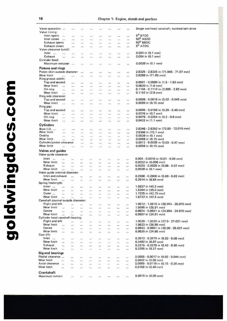
Valve operationValve timing:
Inlet opensInlet closesExhaust opensExhaust closes
Valve clearance \coldl:Inlet ...Exhaust
Cvlinder head:Maximum warpage
Pistons and ringsPiston skirt outside diameterWear limitRing groove width:
Top and secondWear limitOil ringWear limit
Ring side clearance;Top and secondWear limit
Ring gap;Top and secondWear limitOil ringWear limit
CylindersBore 1.0....Wear limitQI/alityWear limitCylinder/piston clearanceWear limit
Valves and guidesValve guide clearance
InletWear limitExhaustWear limit
Valve guide inlernal diameterInlet and exhaustWear limit
Spring free length:Inner ...Wear limitQuter ...Wear limit
Camshaft journal outside diameter:Right and leflWear limitCentreWear limit
Cylinder head camshaft bearing:Right and leftWear limitCentreWear limit
Cam lift:Inlet ...Wear limitExhaustWear limit
Big-end bearingsRadial clearance ...Wear limitAxial clearanceWear limit
CrankshaftMaximum runout
Chapter 1; Engine, clutch and gearbox
Single oV(!,head camshaft, toothed belt drive
SO BTDC50° A8DC50° BBDC50 ATDC
0.004 in to.l mm)0.004 in (0.1 mm)
0.0039 in (a.1 mml
2.8325 - 2.8335 in 171.945 - 71.97 mm)2.8288 in 171.85 mml
0.0591- 0.0599 in (1.5 -1.52mmJ0.0630 in (1.6 mml0.1104 - 0.1110 in (2.aDS - 2.82 rnm)0.1142 in (2.9 mml
0.0008· 0.0018 in 10.02 - 0.045 mm)0.0059 in (0,15 mm)
0.0095·0.0158 in (0.25·0.40 mml0.0276 in 10.7 mm)0.0079·0.0354 in 10.2·0.9 mml0.0433 in (1.1 mm)
2.8346 - 2.8352 in (72.00·72.015 mm)2.8386 in (72.1 mml0.0039 in 10.1 mm)0.0059 in (0.15 mml0.0012·0.0028 in (0.03·0.47 mm)0.0059 in 10.15 mml
0.004 - 0.0016 in 10.01 . 0.04 mm)0.0032 in (0.008 mm)0.0020 - 0.0028 in (0.05 . 0.07 mm)0.0039 in (0.1 mml
0.2598 . 0.2606 in (6.60 . 6.62 mm)0.2614 in (6.64 mm)
1.5827 in (40.2 mml1.5354 in (39.0mm)1.7225 in (43.75mm)1.6732 in (42.5 mml
1.0612 ·1.0619 in 126.954·26.970 mm)1.0595 in (26.91 mm)0.9824 . 0.9831 in (24.954 - 24.970 mm)0.9807 in (24.91 mm)
1.0630 -1.0638 in (27.0- 27.021 mml1.0623 in (26.98 mm)0.9843·0.9851 in (25.00- 25.021 mm)0.9835 in 124.98 mm)
0.3512·0.3575 in (8.92·9.08 mm)0.3492 in l8.87 mm)0.3315 . 0.3378 in (8,42 - 8.58 mm}0.3295 in (8.37 mm)
O.OOOS - 0.0017 in (0.02 - 0.044 mm)0.0032 in (0.08 mm)0.0059·0,0118 in (0.15·0.30 mm)0.0158 in (0.40 mm)
0.0019 in (0.05 mm)
gold
win
gdoc
s.co
m
Chapter 1;: Engine, clutch and gearbox 17
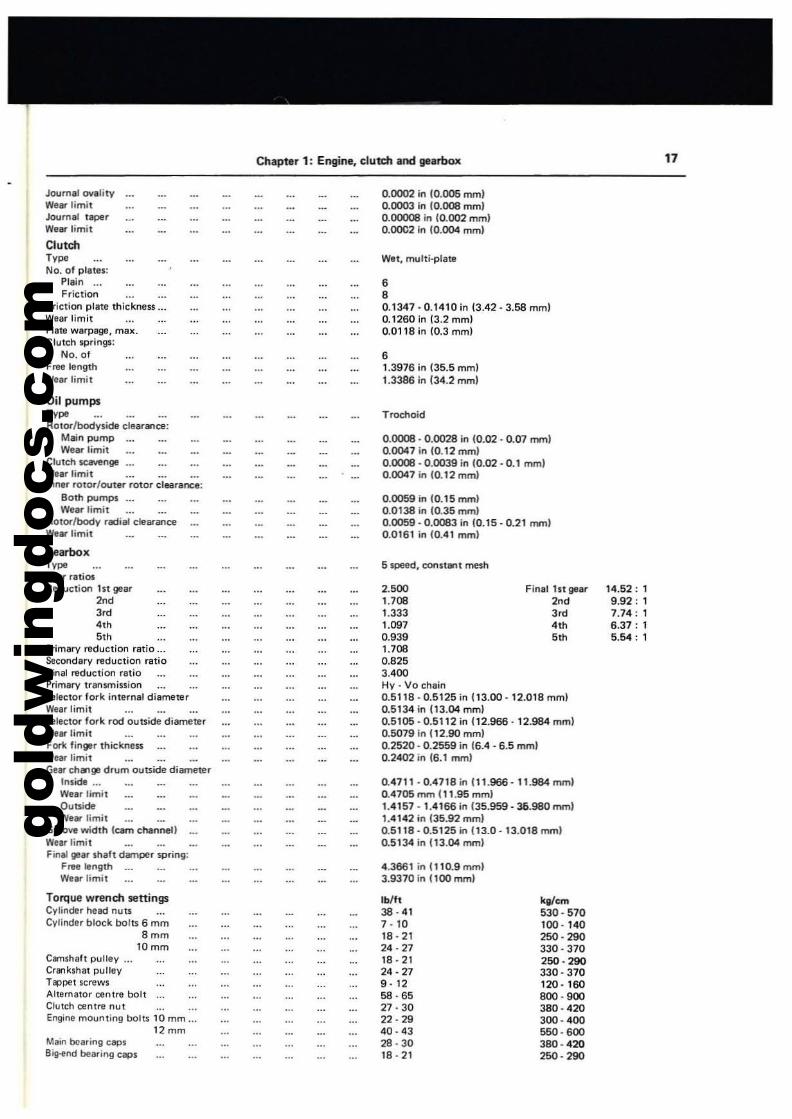
Journ., ov.lityWeer limitJoum.l t~rW.erlimit
ClutchTv"No. of plat'l:
PI.in ...Frittion
Frittion pl.te thitknen ...Wear limitPI'Ie werp.ge, max.Clutth springs:
No. 01Free lengthWear limit
0.0002 in 10.005 mml0.0003 in 10.008 mml0.00008 in (0.002 mmlOJXlC2 in 10.004 mm)
Wet, multi·plate
•,0.1347 - 0.1410 in (3.42· 3.58 mml0.1260 in (3.2 mml0.0118 in (0.3 mm)
,1.3976 in (35.5 mml1.3386 in (34.2 mm)
Oil pumpsTv"Rotor!bodvside tiearalll;:e:
Mein pumpWtar limit
Clutch scavengeWurlimit ...Inn81" rotOl"/outer rotor tillilrance:
Both pumps ...Wtar limit
Rotor/bodV radial clearan<:eWurlimit
Trod'loid
0.0008 - 0.0028 in 10.02·0.07 mmlOJ)()47 in (0.12 mml0.0008 - 0.0039 in (0.02 - 0.1 mm)0.0047 in (0.12 mml
0.0059 in 10.15 mm)0.0138 in (0.35 mm)0.0059·0.0083 in 10.15 - 0.21 mml0.0161 in 10.41 mml
5 speed, constant mesh
0.4711 - 0.4718 in 111.966 - 11.984 mm)0.4705 mm (11.95 mml1.4157 - 1.4166 in (35.959 - 36.980 mml1.4142 in (35.92 mml0.5118·0.5125 in 113.0 - 13.018 mml0.5134 in 113.04 mm)
14.52: 19.92: 17.74: 16.37: 15.54: 1
kalcm530 - 570100 - 140250 - 290330 - 370250-290330·370120·160800· 900380·420300· 400550· 600380 - 4202SO·290
Finel 1st gear
'003'"4<h
.'"
2.5001.7081.3331.0970.9391.7080.8253.400Hy - Vo Chain0.511B - 0.5125 in 113.00 - 12.018 mm)0.5134 in 113.04 mml0.5105·0.5112 in 112.966· 12.984 mm)0.5079 In 112.90 mml0.2520 - 0.2559 in (6.4 - 6.5 mml0.2402 in 16.1 mml
4.3861 in 010.9 mm)3.9370 in (100 mm)
lblft38 - 417 - 1018·2124·2718 . 2124·279 - 1258·6527·3022·2940 -ll32B - 3018·21
Ca-nshah pulley ...Crlrlkshat pulleyTappet screwsAlternator centre bollClutCh centre nutEngine mounting bolu 10 mm.
12mmMain bearing topsB~nd bearing tops
Torque wrench S8ningsCylinder head nutsCylinder bll)(:k bolts 6 mm
'mmtOmm
GearboxTv"Gur ratiosReduction ht gear
'0'3""h"h
Primary reduction ratio ...Secondary reduction ratioFin,l ~duction fatioPrimary transmissionSelettor fork internal diameterWur limitSelector fork rod outside diameterWf" limitFork finger thiclmeuWear limitGur ch...ge drum outside diameter
Inside .._'Ntar limitOutside'Ne. limit
GrQO~ width lcam channellWf.r limitFinal gear shaft damper spring:
Free length ...Wurlimit
gold
win
gdoc
s.co
mG.ner,1 dneription
The .ngine fined to the Honda Gold Wing Is of unusualdesign. incorponting n'I8oI'IY featul1!!i more USlJeI to motor carengine design practice. The engine has foor cylinders arranged intwo horizontally opposed banks. lying either side of the machinecentre line. The aluminium crankcaSll ~rat8ll about a vtlrticalplane and houses steel cylinder liners, there being no cylinderberrels as such. The crankshaft runs on three shell typl mainbearings located by caps bolted to the riltlt-hand crankcase hall.The big-end belrings IIlI of I similar type. YVhen the crankcases'111 S8p1r1ted. the crankshlft and gearboJl components iMlid'! aremounted below. remain in the rilflt-hand casing. The gearboJl isplaced below ttle crankshaft. to reduce the overalllingth of thlengine unit; primlry drive being transmitted by a Hy-vo chain atthe rear of the engine. Each cylinder blink Shares a commoncylinder head. fitted with two offset valves per combustionchamber". and operated by a singll camshaft. The camshafts allldriven by two separate toothed boln from twO pulleys mountedin tandem on the e:<treme front end of the crankshaft. Belttension is maintained by manually adjustable jockey pulleys,iMlich are tensioned automatically by springs.
Lubrication is of the hilfl pres$Ure. _t SUITlP type, iMlere allthelubncant is contained within the crankcase. Two pumps arefitted, at either end of a single maft. driven by , dupllll rollerChain from a sprOCket at the rear of the clutch ooter drum. Themain oil pump is fitted It the front of the engine and suppliesoil to the bearing surfaces of tne engine vi, a car type f~t&r
mounted on a detachable housing at the extreme front of theengine. Oil returns to tha SlJmp by 9r8'11ity. eJlcept for thattrapped in the clutch housing. iMlich is returned by the secondpump Iclutch scavenge pump!.
Po....er from the engine is transmitted to a multiplate clutch....d then via a drive shift to a croWl'! l'otIeel and pinion containedwithin In eluminium housing at the rear v.tleel.
In common with many motor car engines. the 1000 cc GoldWing engine is _ter coohed. The coolant. which compriS8ll a50/50 mixture of water and anti·freeze. is circulated around theengine by n;Jeans of a waler pump driven off the forward end ofthe oil pump drivtlmaft. The coolant is then passed throol#laradiator. mounted forwerd of the engine on the duplex framedown tubes. where it is cooled and rewrned to the engine.lncorporlted in the system is. thermOStat, which helps reducethe wtIrming-up period of the engine end regulates the coolanttemperature. An electrically driven fan is also lined to the rearof me radiator, v.tlich cuts in automatic.lIy l'IIh.n a presettemperature is reached.
2 Oper.tions with engine/gearbox in the fr.ma
Owing to the unusual engine design access to most maincomponents is obscured iMlen the engine is in the frame. Thefollowing components can be removed with the engine still insitu:
1 Cylinder heads lind vil/ve gfJllr.2 Timing /MIll lind pulleys.3 Orburettorauembly.4 Fue/pump.5 Contact brHker .uembly.6 Starter motor.7 Clurch lifting m«:hllnism lind pliltes.
3 OpeI'ltions with engine/gearbox remoYed
The engine must be removed for access to and rem~ of allremaining components, inclUding the following:
, Gutch.2 A/~mlltor.
3 G9rcha~ ~anism.
4 Gearbox cOfflPOnllnts.5 C"nkshfJft .ssembly.B Pistons and cQnn«:ting rods.7 Gurch outer drum.
4 Method of engine/gearbox ramoval
The engine and gearboll are built in unit Ihoused within thesame casing) 3nd III such it is necessary to remove the unitcomplete in order to gain access to either SlJb-assembiy.Separation of the crankcase is achieved after the engine has beenr1Imoved from the framll and refitting cannot take place until ttlaengine/gear unit is assembled completely.
5 En9M/gutboJo: unit: removll from the framll
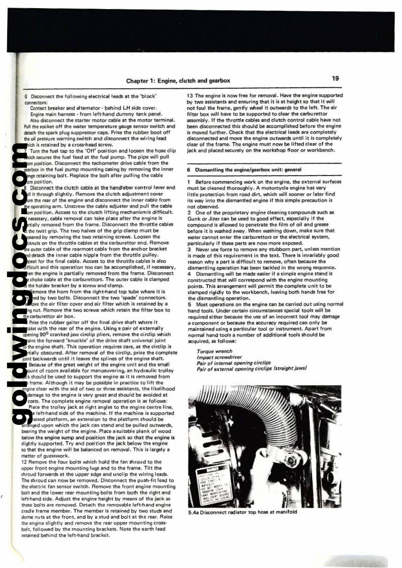
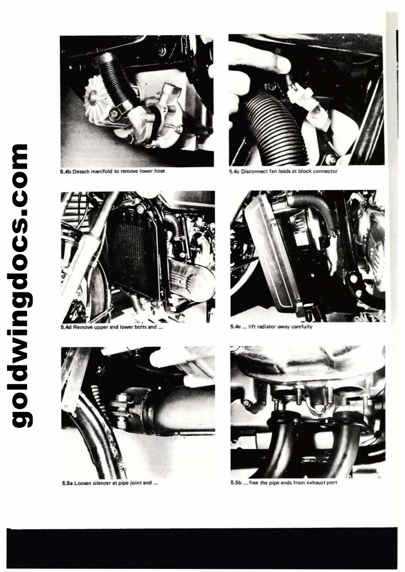
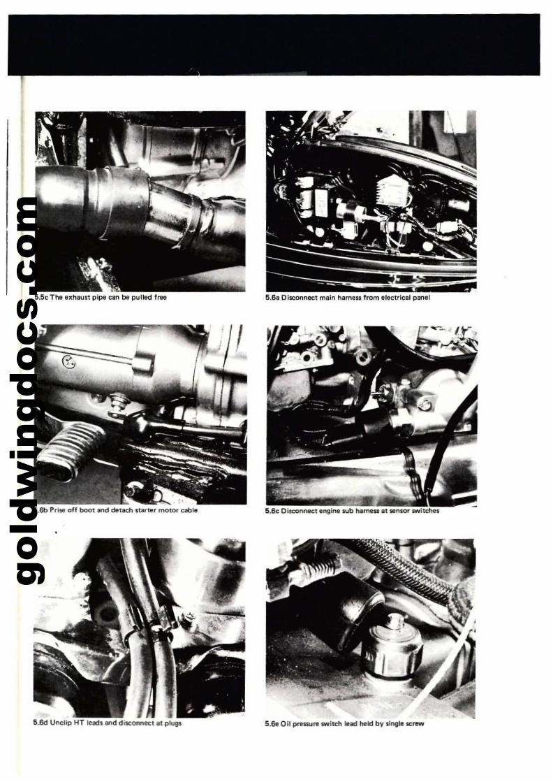
, Place the machine firmly on its centre stand so that il isstanding securely and there is no likelihood that il may fall over.This iSllnremely important as owing 10 the weight of thecomplete machine and the engine, any instability duringchrnantling will probably be uncontrollable. If possible. placethe machine on. raised platform. This will improve accessabilityand ease engine removal. A98in, owing to the ....eight of themachine. ensure that Ihe platform is sufficiently S1rong and wellSlJpported.2 Open all th,," sections of the dummy fuel tank and remOlltthe radiltor pres..... re cap. P1ac. a container of more thin 3.4/2.BUS/Imp. QUart 13.21itrel capacity below the front of the engineand remove the coolant drain plug from the lo....er edge of thewater pump outar casing. Allow the coolant to drain. If thecoolant is to be reused, enSlJre that the container is absolutelycllllO. The container should icleally be of a plastic materill asthis will not contaminate the coolant. PIece a second containerbelow the engine oil drain plug and remove the plug. allowingall the oil to drain. The plug is situated below the oil filterhousing. The container mUll be of more than 3.7/3.1 US/lmp.QUart 13.51itrel capacity.3 Remove the two frame side covers. Each one is retlined at thelower edge by a twist locking screw. Push the screw inwards andtwist throulto 9l)O to release. Lift the cover away from thebottom and upwards. Prise the Nbber boots off the batte,..,.terminal and disconnect the positive 1+1 lead followed by thenegalive I-I lead. If the machine is to be inoperative for Ine:<lended length of time. remove the balte,..,. so that it can beSIlrviced and charged at intervalS.4 Loosen the lower hose clip on the radiator upper hose andpull the hose off the thermostat housing union. The rOOiatorlower hose is retained in a similar manner. However, owing to itsmort length. removal is made easier if the manifold is removedfrom the water pump outer casing. The manifold is retained bytwo bolts. Disconnect the radiator fan electric:a1leBds by partingthe 'blOCk' connector. RemC\l\/e the two dome nun which retainthe radialor at the lower moontings. Support the radiator withone hand and remove thelimilar upper mounting boln. Turn thaforks onto full lock and ease the radiator off tha four S1uds.T.ke Care not to damage the radialor fins.S l.ooSIln the silencer damps at the silencer/exhaust pipe joinn.The socket screws iMlich hold the clamps may be caulked.thereby preventing insertion of 'SlJitable sockel key. Thecaulking can be removed using a suitable pointed instrumant.Loosen the screws off as much as possible as the clamP'larerounded It the front edge to help secore the pipe ends. LOOSenand remove the four nuts ~ich retain each eJlhlUU pipe assemblyto the cylinder head. and sllCken off the silencer bracket/pillionfootrl'St mounting bolts. Tilt the silencer downwards at the frontand pull the eJlhaust pipes from the cylinder heads. The exhaustpipes can now be detached from the silencer. If neeessa,..,.. thesilencer can be supported. using a piece of string tied to.SlJitabie part of the frame.
gold
win
gdoc
s.co
m
Chapter 1: Engine, clutch and gearbox 19
6 Disconnect the following electriclll leeds at the 'block'connecton:
Contlet bnlak.r and alternator· behind LH side <:over.Engine main h.mess, from lef!·hand dummy tIInk paneLAlso diSCOllnect the stllrter motor cabl. It the motor terminal.
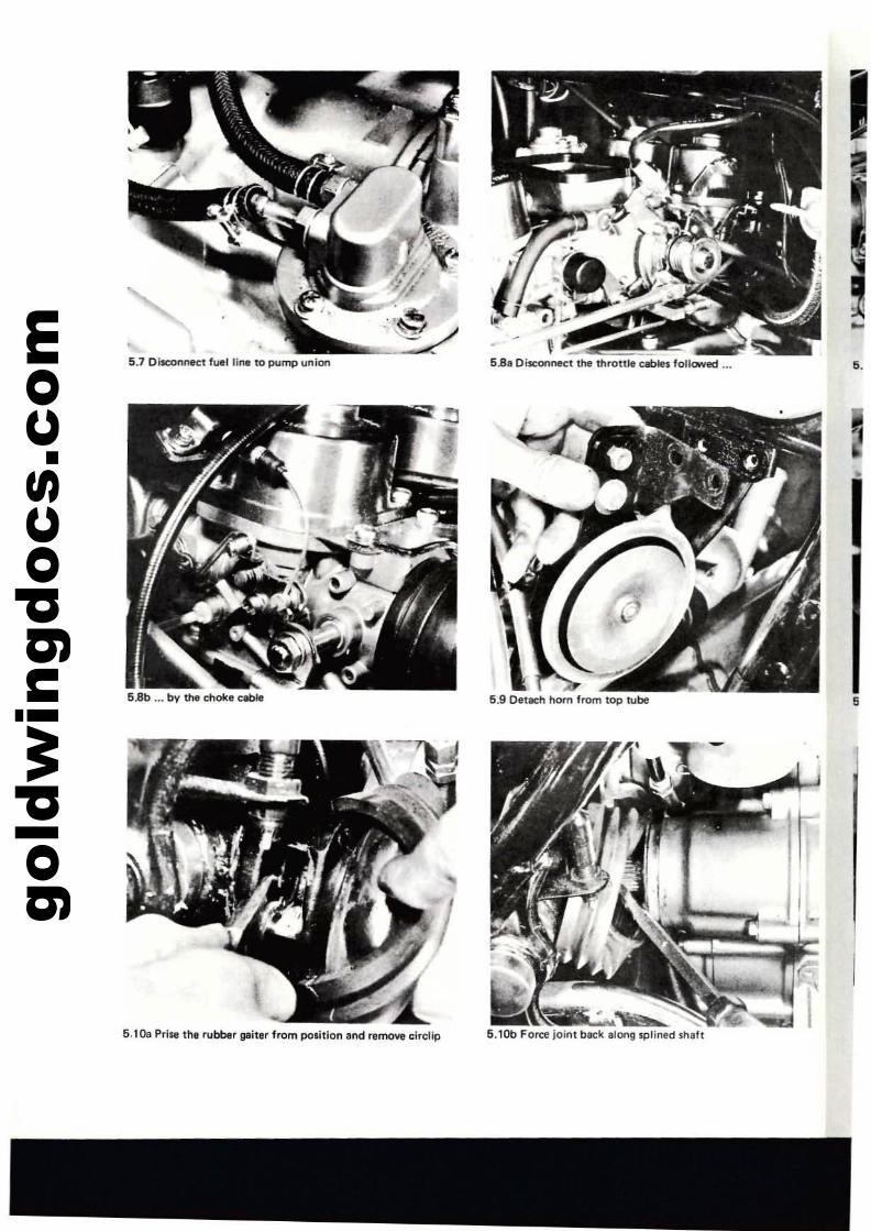
PuIIttle socket off the wat.r temP«1lture gauge sensor switch anddttaelllhe spark plug $UPPfW$$or caps. PriM the f\lbber boot offthe oil pressure warning switch and disconnect the wiring leadMlich is retained by a cross·head screw.1 Tum tht fuel tap 10 the 'all' P05ition and loosen the hose clipNlich 5eCUres the fuel feed at the fuel pump. The pipe will pullfrom position. Disconne<:t the l8Chometer drive cable from thepbox in the fuet pump mounting casing by t'elT1OYing the innerAaoge retllning bolt. Replace the bolt after pulling the clblefrom position.S [)istorml!Ct the clutch cable lit the hlndlebar control lever endpull it through slightly. Remove the clutch adjustment ClMlrfrom the rHr of the engine and disconnect the inl"llr cable from!he opl!nlling IIrm. Unscrew the clble adjuster lind pull the cabl.from position. Access to the clutch lifting mechanismis difficult.If ~SSilrv, cilble removil can t.ke place efter the engine ispill'tilllly removed from the fram•. Disconnect !he throttle cablesilIl1le twist grip. The two halves of the grip damp must beI_ed by removing the two retlining ICrewI. Loosen thelocknuts on the throttle cables It the carburettor end. Remove!he outer cable 01 the rearmost cable from the anchor brllCketand delach Ihe inner cable nipple from the throttle pulley.RlPIlel for the final cable. Attns 10 the throttle cables is abodilflcult ¥ld this operation too can be accomplished, if necessary,when the Itflgine is panially removed from the frame. DisconnectIlwchoke cable It the carburetton. The outer cable is clamped10 lIIe holder bracket by a screw .nd climp.9 Remove the horn from the right·hand top tube where it isItl,ined by two bolts. Disconnect the two 'spade' connecto".Remove the air filter cover and lIir filtN which is retained by II\llil'lgnut. RelT10Ye the t"WO screws VtIlich retain the filter box toltIecarburenor air box.10 Prise Ihe f\lbbllr gaiter off the final drive sh.ft VtIlere itIo:ates with the rear of the engine. Using a pair 01 externallyopeniBg 900 cranked jaw circlip plie". remove the circlip v.ttichretains the fOrwllrd 'knuckle' of !he drive shaft univenal jointlO tile engine shaft. Thil operation requires care, lIS the cirdip isI*tially obICured. After removlll of the circlip, prise the completejoint backwards until it leeves !he splines of the engine shillt.11 Because of the great weight of the engine unit and the small'mounl of room evailable for manoeuvering. an hydraulic trolleyjKk 5hould be used to s.uppor-t the engine as it is rem~ fromthe fr.srne. Although it may be pouible in practice to lift thetn9ne clear with the aid of two or three assistanlS, the likelihoodof damit9'! to the engine is very great end should be avoided atall COSIS. The complete engine removal oPeration is as follows:
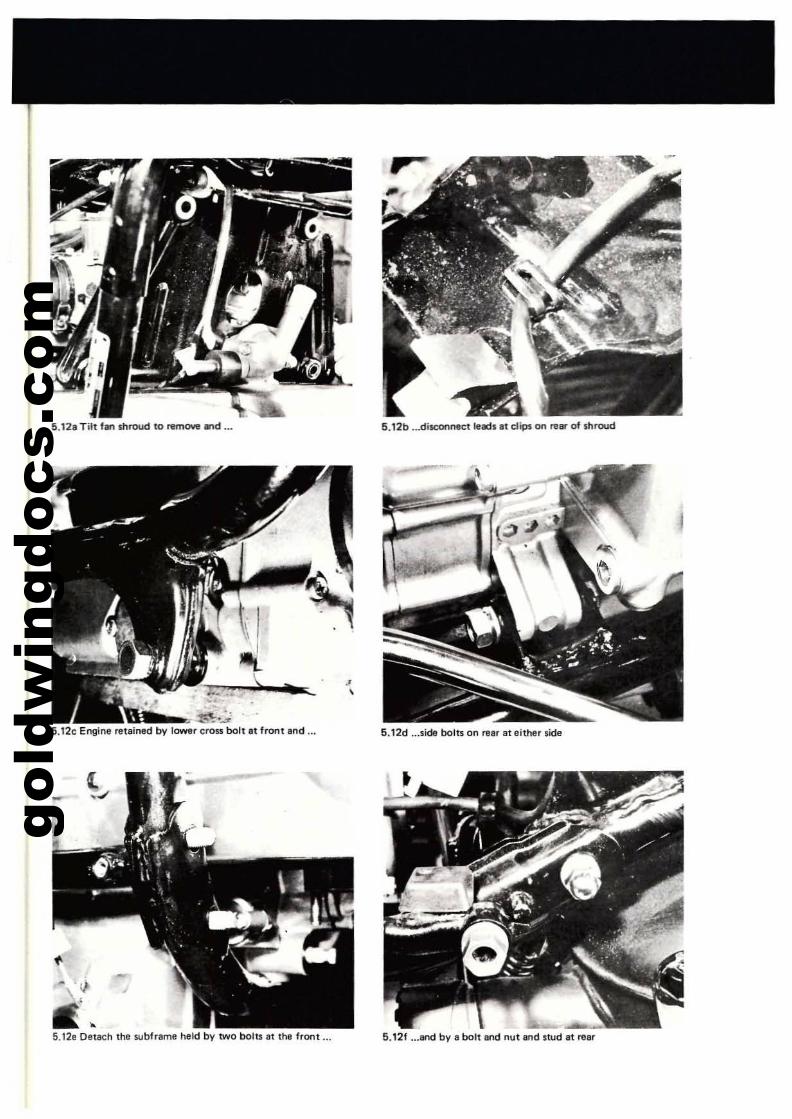
Place the trolley jack el rijj'lt angles to the engine Centre line.on the left-hand side of the machine. If the machine il supportedon' raised platform, an .xtension to the plitform should bemanged upon VtIlich the jack can stand lind be puUed outwardl,bearing the weight of the engine. P111C11 a suitable plink of woodDelow the engine sump and position the jack so Ihat thll engine isl.Ii\tldy lupported. Try lind posllion the jack below the engine50 thaI the enginll will be balanced on removal. This il largely amllter of lPJllSSwork.12 Remove the four boIb which hold the fan shroud to theupper Ironl engine mounling lugs and to the frame. Tilt theshroud lorwards at the upper edge and uncUp the wiring leads.The shrOUd can now be removed. Disconneel Ihe push·fit lead 10the electric fan sensor lwilch. Remove the front .ngine mountingbolt lind the lo_r rear mounting boIb Irom both the riWlt lindlelt-hand side. Adjust the engine height by means of the jilCk •these boilS are remowd. Detach the removable left·hand enginecradle frame member. The member is relained by two studs anddome nuts at the fronl, and by a stud lind bolt" Ihe rllir. Raisethe engine slightly and remove the rear upper mounting cross,bolL lollo'Nlld by the mounting brllCken. NOle the earth leedretained behind the left-hllnd bracket.
13 The engine is /'lOW free for remove!. HIIW!he .ngine supportedby tWO assiuenn and enSl,l(ing that it is at hei!tlt so that it wiltnot foul Ihe frame, gently v.f1eel it outwards to the left. The airfilter box will have to be supported to clellr the carburettoressembly. If the throttle cables and dutch control cable have notbeen disconnected this should be -=complimed before the tflgine~ lT10Yed further. Qleck that the ettetriealleEld:s Ire completelydisconnected and move the engine outwards until it is completelyclear of the frame. The engine must now be lifted clear of thejack Bfld plilCed securely on the workshop floor or workbench.
6 Dismantling the engil"ll/gurbox unit: gene~1
1 Before commencing work on the enginll, the eleternel surfacesmust be cleaned thoroughly. A motorcycle engine hili verylittle protaction from road dirt, v.tlich v.;11 sooner Dr later findiu yqy InlO the dismantled engine if this simple precaution isnot observed.2 One of the proPrietary engine cleaning compounds such lISGunk or Jizer can be used to good effect, especially if thecompound is allowed to penetrate the film of oil and greasebefore it is washed away. When washing down, make $.lire that_Ier cannot enlt\'" the cerburetton or the electrical system,particularly if these pam .re now mont 'leposed.J Never use force to remove any sWbborn part, unless mentionis made of this requirement in the telet. Thera is invariably goodrelSOn wily a part is difficult to remove, often because thedismantling ope~tion hIlS been tackled in the _ong sequence.4 Dismantling will be made e.ier if II simple engine stlnd isconstructed thlt will correSfJOl'ld with the engine mountingpoinll. This arl"1ngement will permit the complete unit to becl.mped rigidly to the workbench, leaving both handS free forthe dismentling operlltion.5 Most operations on the engine can be cllrried out using normal~d tools. Under certain ci.,;:umstanceS special tools will berequired either because the use of an incorrect tool may damageI component or beeausl tile IICCUr8Cy required Clln only bemaintained using I particular tool or instrumenl. Apart fromnormal hand tools a number of additional lools should beilCquired,. follows:
TrxqufJ wrench/mp¥:t Sl:rewdri",erPair of internlll Op6ning citrlipsPair of externel opening eitr/ips (straight jaws'
5.4a Disconnect rldiltor top ho. at m..,ifold
gold
win
gdoc
s.co
m 5.4b OellCh mlflifold to ren10Y1l lower hose
,
"I . if'......................~ ..5.4d Aemove upper and lower bolts and ...
5li. Looten ,ilmcer.t pipe joint.nd ...
5.4c OisconnICt Ian INCb at block connector
5.4•... rift rlcliator swly carefully
5.5b ••• 'rwe the pipl endli from ."haulit port
gold
win
gdoc
s.co
m
5.5c The exhaust pipe can be pulled frae
,.5.6b Pd", off boot and detach starter motor cabla
5.6d Unc:lip HT leads and disconnect ilt plugs
5.6c Disconnect engine sub harness ,t tensor switches
5.6e Oil preSSUI1l switch lead held by single screw
gold
win
gdoc
s.co
m 5.7 Disconnect fuel line to pump union
5 Bb •.• bV the choke CKHe
6.1Oa Prise the rubber gaiter from position and remo\l'e circtip
5.8, DisconneC1 the throttle cables followed ...
5.9 Detach hom from top tube
5.1Ob Force join I beck ,'ong splined shitl!
I
...5.
5
gold
win
gdoc
s.co
m
5.12. Titt fan shroud to ntrnOYe Md
.,(m..,_~..~
5.12c Engine retained by lower cross bolt It front Ind ...
•5.17e DelICh Ihe s.ubfrllme held by twO bolu at lhe front ...
J,
5.12b .•.disconnect l"ds.1 clips on rear of shroud
5.12d ...side bolts on re.r at either side
5.12f ...and by a bolt and nul and $Iud II rear
gold
win
gdoc
s.co
m24 Chapter 1: Engine. clutch and gearbox
5.1211 Remow upper mountings from either side
5.138 Move the engine out partially, 10 disconnect control,
_.5.13b Support engine, carefully balanced on ilC:k
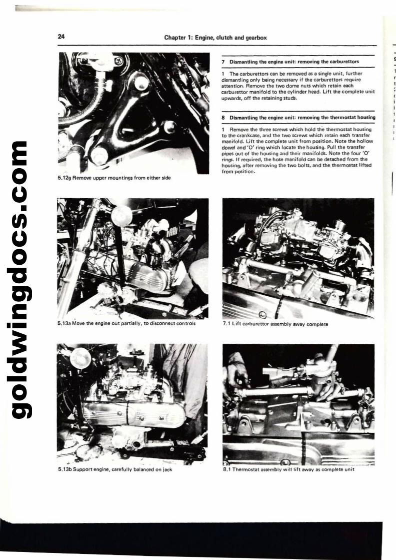
7 Di$l'l1antling the engine unit: relTlO'ling the catbunttors
1 The c.rbor,ttof'1i can be remOlled as III single unit, furtherdismantling onlv being necessary if the carburettors requireattention. Remove the two dome nub ooich retain eachcarburettOl'" manifold to the cylinder head. lift the complete ull;tupwards. olf the retaining 'WeB.
8 Dismantling the engine unit: removing the thermostat housing
1 Rern<MI the three screws ~ich hold tile thermostat housingto the crankcase, and the two screW$ ...... ich re..in each transfermanifold. lift the complete unit from position. Note the hollowdowel and '0' ring which lOCate the housing. Pull the transferpipes out of the housing and their manifold5. Note the four '0'rings. If ~irld. the hose manifold can be deteched from thehousing. after fI!ffiO\Iing the two bc)lu, and the thermOltat liftedIrom position.
7,1 Lift carburettor assemblv awav complete
-t .__-:::;8.1 Tl'termOStlt assembly witllilt lIWIV IS complete unit
,
gold
win
gdoc
s.co
m
Chapter 1: Engine, dutch and gearbox 25
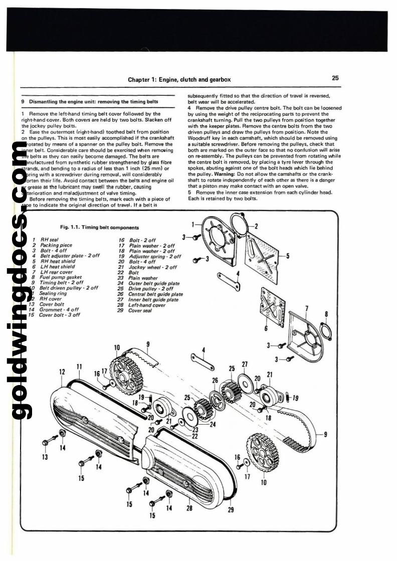
Fig. ,.,. Timing belt ODn'Iponenu
9 Dis~nuing the engine unit: removing 1M timing ~tI
9
5
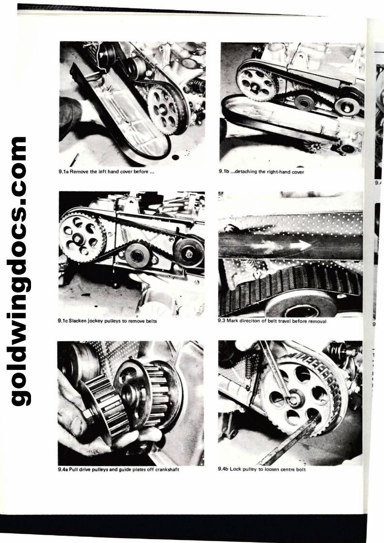
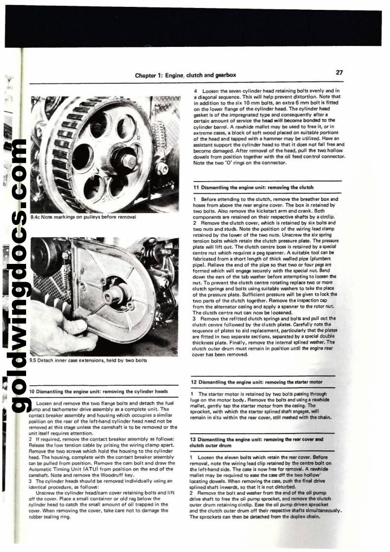
lIU~tndy fitted 110 that the direction of traYeI is ..evened,belt wear will be accelerated.4 Remove the drive pulley centrll bolt. The bolt can be loosenedby using the weight of the reciprocating parts to preyent thecrankihaft turning. Pull the two pulleys from pO$ition togetherwith the keeper plates. Remove the Ctntre bolts from the twodriven pull8'(1 and draw the pulleys from position. Notll theWoodNff kllY in each camshaft, which should be removed using• llUitabil5Crv'Ndri....r. Before remooring the pulleys, check thatboth are marked on the outer face so that no confusiCM'l will ariseon re-assembly. Tht pulleys can be prlWt!ntlld frorn rotlting .....,ilethe centre bolt is removed, by placing a tyrnl'Yer through thlipOk8$, 800ting against one of the bolt heads.....,ich lie behindthe pulley. W.rning: Do not allow the camshafu or the crank·shift to rotlte independendy of each other iii there ise dlngerthat e piston may m.ke COOblCt with .... open VlIlIve.5 AIIrI"I()q the inntr case extensiCM'l frorn each cylinder head.Each is retained by two bolts.
Bolt· 2 offPlain washer· 2 offPlain _har' 2 offAdjlJst~rspring· 2 offBolt -" offJocktt'Y """HI - 2 off80/'Plain washerOlJtllr belt guide plaroDril'll pulley - 2 offCtmtraJ bait guir;ltt pltttaInner balr guide pI.teuft·/lttnd corerCoveruM
,.1118,.202'22232'2.2627282!1
1 RH seal2 Packing piece3 BoIt-40ff4 £hIt adjust~rplilr~' 2 off5 RH ht!ar shield6 LH lINt s/liald7 LH rttarcovv8 Fuel pump (JBSkaf9 Timing belr· 2 off
10 8t11r driven plJlley' 2 off, I Sealing ring12 RHcov~r
'3 Cover bolt'4 Grommet·" off'5 Cov'rboJt-30ff
1 Remove the left·hand timing belt COlIer followed by theright·hand cover. Both (;overs are held by tWO bolts. Slacken offthe jockey pullllV bolts.2 EMe the outermost (ri!t't-handl toothed belt from positionon the pulleys. This is most eilSily accornplished if the cr.-nkshaftis rot.-ted by means of.- spanner on the pulley bolt_ Remove theinner belt. Considereble (;arll should be exercised when rernc;wingthe belts lIS they (;an easily l:leI:ome damaged. The belts aremanufactured from synthetic rubber strengthened by glass fibremands, and bending to a radius of less than 1 inch (25 mml 01'"
scoring with.- 5Cl"ewdriwr during remOllal, will considerablyshorttn their life. Avoid (;on~t between the bela and tngine oilor grease as the lubricant may 'weil the rubber, causingdeterioration and milladjustment of vllIve timing.3 Before removing the timing belts, mark each with. piece oftape to indi(;ate the original direction of travel. If a belt is
gold
win
gdoc
s.co
m I9.18 Remove the left hand CCMlr before ...
••
9.1c Sleeken lock.v pulleys 10 ~twe belts
I
{
-1'/,: -"f-. ,.\1
-9.1b ...detaching the right-hand cOYer
9.3 Mark direeilO1'l of belt tflWel before removal
,r
...
•
9.", Pull drivll pulleYI ....d guide plates off erenksh.ft
gold
win
gdoc
s.co
m
Chapter 1: Engine._ clutch and geBrbox 27
•-....I
,-
9.4(: NOlll markings on pulleys before remOYilJ
9.5 Dflach inner elise IXtensions, held bV twO bolts
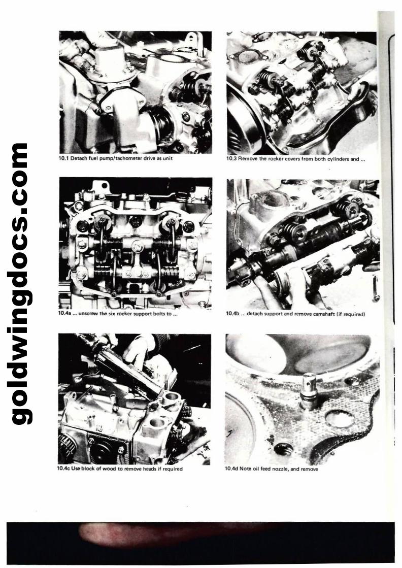
10 O""",... tll"", t .... engi.... unit: removing the cylindlll'" haads
1 Loosen and remov. the two nenge bolts end detach the luelpump llf'ld tachometer drive auembly as. complete unit. Thecontact breaker llnembly ..,d housing ...... Ich ()C(;upies ill similarposition on the rear of the left-h.nd cylinder head need not beremoved ,t this stege unless the eatmhaft is to be remOYed or theunit itself requires anention.2 If required. remove the contact brellk.r assembly as follows:Release the low tension cable bv pri5ing the wiring clamp apart.Removt' the two screws Yotlictl hold the housing to the cylinderhead. The housing. complete ..... th the conUICt b,uk,. assemblyc.n bII pull'd from position. Remoye the cam bolt and draw theAutomatic: Timing Unit IATul from position on the end of thet¥I'l$hllft. Note end rem(l'l$ the Woodruff key.3 The cylinder heads Should be remoored individually using anidentic. procedure. I!I$ follOWS:
Unscre" the cylinde1" helld/cam cover retaining bolts and liftoff the cover. Place a ~"U conteiner or old rllg belo" mecylinder head to catch me small amount of oil trepped in thec:over. When removing the cOYer. take care not to damilgl! thelU~se.alingring.
4 Loosen the leven cylinder head re1IIining bolts evenly and ina diagonel sequence. Thil ¥Will help prwent diltortion. Note thatin addition to the six 10 mm bolts, an extra 6 mm bolt il fittedon me 10-" flange of ttle cylinder head. The cylinder heedgasket il of the impregr"t.d typl and consequently .fUr"certain amount of service ttl. head ",ill become bonded 10 thecylinder barrel. A rtv.tlidl mallet mey be lIIed to free it, or inextfemt c_, a block of 10ft wood placed on suitable portionsof the he&d and tapped ¥With "hammtr may be utililed. Have anfl!l$iltant 5Upport the cytinder head 10 thet it does not fall free 8ndbecome damaged. After rtmovel of the head. pull the two hollowdowell from position together ¥Wittl the oil feed control connector.Note the two '0' ringll on ttl. connector.
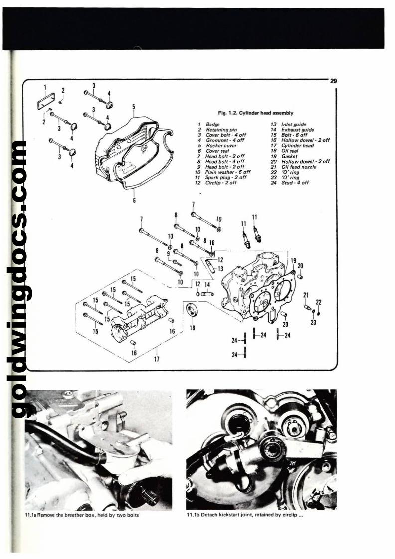
11 DisrMntling the "'SIine unit: rtmo't'ing the clurch
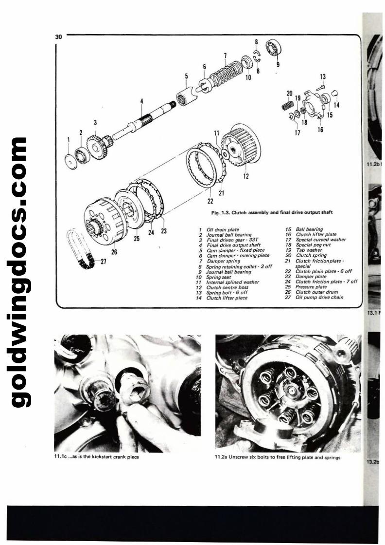
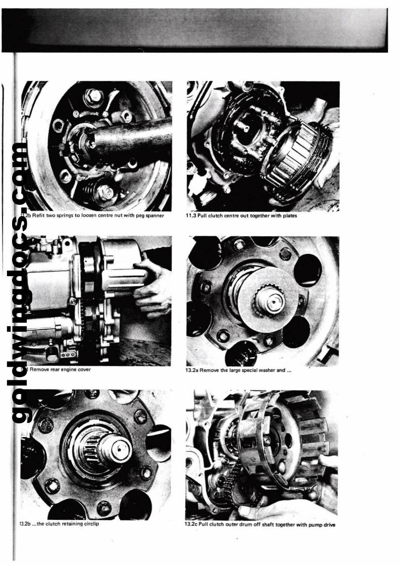
1 BefOl'll attending to the dutch. r.~ the breather box andhoses from "bOYe the re"r engin. cover. The box is retained bvtwo bolts. A110 remove the kickstart arm and crank. Bothcomponants are retained on ttl.ir respective $hafts by a circ/ip.2 Remove ttle dutch cover, v.tIich il retained bv lix bolts andtwo nun and INdJ. Note the position of the wiring lead dampretained by the lo_r of the two nuts. LkllCre..... the lilrsprlngtension bolts v.tIich retain the dutch pl'eslUre plate. The presRlrlplate ¥Wilt IUt out. The dutch cenue boll il retained bv I specifJIcentre nut Micn requires I peg lpann... A 5Uitable tool can befabricated from I short length of thick WIIIled pipe (plumber,;pipel. Relieve Ihe end of the pipe 10 thlt two or four pegs ITe
formed Mich ¥Will e"gage securely ¥With the special nUl. 8eflddowrt the ean of tha tab walher befolll attampting to loosen the"UI. To preve"t tha dutch Centlll rotating replace two or moredutch springs Ind bolts uling lui table washe!'l to take the placeof tha pressure plate. Suflicie"t prenure will be glVIf1 to lock thetwo pBrts of the dutch together. Remove the inspection~from the alternator casing a"d apply a spanner to the rotor nut.The clutch Cel"ue "ut ca" "OW be 1000ned.3 Remove the refitted dutch springs and bolts end pull out theclutch cantre followed by the clutch plates. eerefully note thesequence of pletel to aid raplacement, particularly thll tha platesare fitted I" two separate sections, separlted by 11 special daub/athick"en plate. Finally, remove tha intarnal sp/ined washer. Thedutch outer drum mUlt r'main in position until the erlgine Iller
cover hes bee" removed.
12 Dismantling the engine unit: removing thllUrttr motor
1 The $taner motor is retained by t'Ml bolts paling throughlugs on tha motor body. Remoye the bolts and using I rNlhidemallet, gl!"t!y tap the $tartar motor from the casing. Thesprocket, ¥With v.tIich th' ""rtar Iplintd shaft engages, willremai" in situ ¥Wittlin th. rear cowr, still meshtd with the chein.
13 Dismantling 1M .ngine uDit: rllmO'ting the~c_ enddutch outer drum
1 Loosen the eleven bolts V'lflic:h rauin thllMr COYer. Beforeremowl, Mit the wiring I.ad dip reuiMd by the centN bolt onthalaft·hend side. The C8II il !'lOW free for flNTIOYai. A r8¥Itlidemell't mey bt required to.ase the case Off the two hollo","IOClting doYWels. Wh~ .-moving the case, push tha final~spli"ed shaft in_rdJ, SO thlt it is not diltlubed.2 Removt the bolt IIr'Id YWeStler from tha and of the oil pumpOive shaft to f,," the oil pump Ipr'OCkat. and remove the dutchOUter drum reteinil"lg cJrclip. E_ the oil pump drivoan sprocketlIr'Id the clutch outer drum off their I'tlSflICtive sIllftl simult8neously.The Iprockets CI" then bt dttac:hed from the ckIpltx cheln.
gold
win
gdoc
s.co
m 10.1 Detach fUll pump!tlll;:homltir drive 1$ unit
10.•1 ..•un~ thfI six rochr support bolu to ...
~~.10.4e U. blade of wood to I"fImCMI heath if required
,10.3 Remove thl rocker COllfl~ 'rom both cylindert and
-10.-4b ... detllCtl $l,Ipport ...d 1"fIm000e am$haft!if req..iredl
lOAd Note oil 'eed nonie, ..d rfIm011'f1
gold
win
gdoc
s.co
m
21
&..r!23
13 Infetf1lli<*/" ExhtlUJr guide15 BoIt-60ff16 Hoi/ow do-" 2 off'7 Cylinrh, h~d78 Oil lUI79 Gasket20 Hollow do_l- 2 off21 Oil frlfld nCRlle22 '0' ring23 '0' ,ing24 Swd·4off
24-~ 1-24
24-1
, "<!go2 Rewning pin3 Cover bolt - 4 off4 Grom""r'" off5 Rockftfcover6 Covers.1I17 HOlldbolr·2off8 Headbolr-4off9 H~bolt·2off
10 Plai" WISher - 6 off11 Spark plug' 2 off12 Circlip - 2 off
5
,--------:3------------------- 291
Y:l) ~,~.:r>:: 3;'j~~~4
3 If4
'1.11 Remow the Mather be". held by two bolts 11.1b Detach kickstlrt joint. rltaioed by cirelip ...
gold
win
gdoc
s.co
m
-·tsh,hand fin" drive ou .......h_VFiV- 1.3. Clute
22
11.2b1
15 £hJl bur!n9, l,ttI16 Cfurrh 1If~washer
" Spec~':~nur18 Specl.79 Tab washe~
20 Clutch spring .Clutch fricrionplllUl
2, "at (,-, pl' plate· 6 of22 auteh am
23 Dam/Hr P!'f! pili'" 7 off24 Cluteh fnct,O/I5 Pnssure ptertl
2 hOUUlrdrum~ ~~r:ump drivech.in
13
';0201~'
~~1~~1. 14
18 ,1617
'.~~8
0;' drain plillet naI t»/f be~fing3T2 Jour. • ~.,_ 33 Final drlllf/fl r shaft4 Final drill' out~9dpieee5 C"m damper - Oiling piICe6 Cam dampe~ . m
7 Damper sp~,~g oller _2 off. retllmmgc
8 5pnngI t»fI bearing9 Joume10 Sp,ingsetl';' .._dwMhe,"'n~maJ boD12 alltt:h c....ntre
6If
Springbolt· .0:~ Clutch ';(tfl' pl«e
23
30
'I the kickst.rt cl1lnk p;&Ot1'.1e ..... , ;;....-.' hne and springs. . boltt to free lifting p1121 Unscrew SIX "...
gold
win
gdoc
s.co
m
11.2b Refit two springs 10 JooMn centre nut with peg .panner 11.3 pun c:lutth cenlre oot together with plate,
132c Pull c:iutdt outer drum off IhVt togtthtr with pump drNe
~13.2a R.move the I.rge spec:illl wISher and ...
13.2b ... the clutch retaining circlip

gold
win
gdoc
s.co
m32 Chapter 1: Engine, clutch alld gearbox
14 Dismantling the 8flgine unit; ramoving the alternator rotorand starter clutch assembly
1 Loosen and remove the alternator rotor Ct!ntre nut. The rotorand Slarter clutch assembly, to which it is attached, can be drewnoff the splined shaft. It is Jikely that the assembly will be tighton the splines, in I'otlich case an extractor must be used forremoval. A standard two or three legged sprocket puller may be
.,....
employed. Do not try prising the assembly from position usingscrewdrivers or other tools as leve~. The mating surfaces of thecasing and the rear face of the slarlerclutch wilf probably sufferdamage. Be prepared to take the weight of thi alternator rOloras it leaves the shaft. It is a heavy componenl weigh ing 9 100.2 Remove the splined washer from the alternator shaft. Loosenthe chain guideretainar bolt and rotate the guide so that il cleanthe chain. Pull the sprocket off the shaft together with the chainand starter drive sprocket.
•'4
I
•,.
Fig. 1.4. Alternltor assembly end ...rter motor
, &11 bearing " Gen6rator drillen gear 8 23 Alternaror stator coils 34 Countersunk screw' 3 off·2 Spring retaining corter' 12 Alternaror shafr 24 Alternaror' complete 35 Circlip . 2 off
20ff '3 Bearing ball 25 Stsrter motor - comp/ete 36 Starrerclutch3 Springsest 14 Hollow dowel 26 '0' ring 37 Starter Clutch roller· 3 off4 Damper spring 15 Bearing housing 27 Orille sprocket 3. Starter clutch roller plunger·5 Pressuro plate 16 Bolt 2. Bolt - 2 off 3 off6 Circlip 17 Bolt- 4 off 29 Sterter motor brush spring 39 Starter clutch roller spring·7 DamP6r plate 18 Sprocket guide plate - 2 off 3 off
• Cush drille rubber· 19 Washer 30 Starter motor brush· 2 off 40 Spring washer· 3 off120ff 20 Bolt 3' Circlip 41 Long bolt· 3 off
9 Generator drillan gear A 21 Screw· 3 off 32 Alternator rotor 42 Needle roller bearing10 Stopper plate 22 '0' ring 33 Thrust washer 43 Starter boss sprocket
44 Starter chain
II,
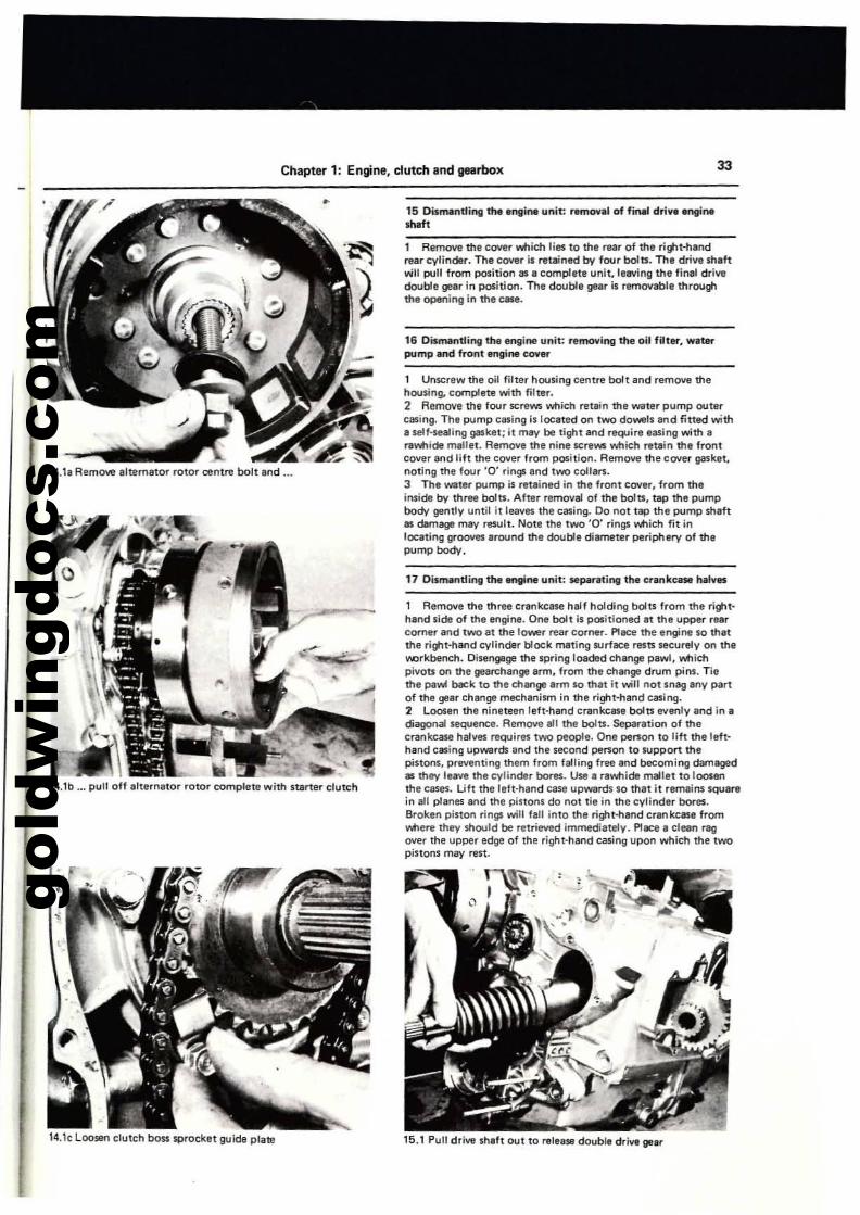
gold
win
gdoc
s.co
m
Chapter 1: Engine, clutch and gearbox 33
1~. It Remove alternator rOlor centre bolt and ...
14.1b ... pull off ahernator rotor complete with Startef" dutch
14.1c Loo$&ll clutch bon sprocket guide plalll
15 Dismantlirl(j the ,ngm. unit: r8mO¥al of fm.! drive erl(jlne",.ft
1 R,move ttl, CO'll'er which lies to the rear of the ri!tlt·handrear cylinder. The cover is retained by four bola. Th, drive shaftv.jtl pull from position as a complete unit. leaving the final drivedouble gear in position. The double gear is remO'll'abl, throughthe opening in the C85e.
16 Dismantling the engine unit: re_ing the oil filter. wilerpump end ft"onl engine coyer
1 Unscrew the oil filter housing cenlre boll and remove thehousing. complete with filter.2 A~ the four screws which relain the water pump outerc8sing. The pump casing is located on two do_Is and fined witha self'lI!aling gasket;;t mav be tight and require easing with a~whide mallei. Remove the nine screws which retain the frontcover and lift the COI/er from position. Remove the coYer Il3'ket.noting the four '0' rings and two collars.3 The water pump is retained in the front COll'r. from theinside by three bolts. After removal of the bola, tIP the pl.lmpbody gently until it lewes the casing. 00 not tap the pump shIftas d8mage mav result. Note the two '0' rings v.tIich fit il'llocating grooves arOUl'ld the double diameter periph&ry of thepump body.
1 Remove the three cr.nkc~ half holdil'lg bolts from the ri!tlthand side of the engine. One bolt is pOiitioned at the upper rearcornlr and two at the lower rear corner. PlIICfl tl'te engine so thatthe right-hand cylinder block mating surf':e resa securely on theI'.Orkbench. Disengage the spring load&d change pawl, whichpivots on the gearchange arm. from tha change drum pins. Tiethe pa...... beck to the chllllge arm so that it will not snag any partof the gear change mechanism in the right'hand casing.2 Loosen the nineteen left'hand crankcase bolts evenly and in ,diagonal sequence. Remove all the bolts. Separation of thecrankcase hallles requirlli two people. On. person to lift tl'te left·hand casing upwards and the second person to support thepinons. prwenting them from falling free .nd becoming datnll9!'das they le.....e the cylinder bores. Use a r.whide melltt to loosenthe caws. Lift the lefl-hand case upwards so that it remaiN SQUirein all planes and the pistons do not tie in the cylinder bores.Broken piston rings will faU into the nlill-hand crankcase fromwherw they should be retrieved iml"lWdiatelv. PI.::e I dun ragover the upper edge of the right-hand casing upon which the twopistons may rest.
15.1 Pull dri... shafl O\.It to rein. dO\.lble drjw gelr
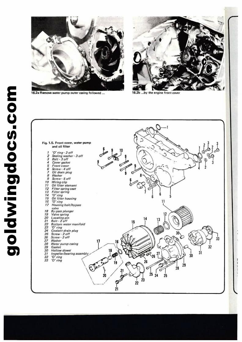
gold
win
gdoc
s.co
m 16,28 RllmCMl wvatlr pump outer casing foUOW'ed ••. 16.2b ...by the engirte front cover
33
3131
11
1 '0' ring' 2 off2 Sealing washer' 3 off3 Bolr-30ff4 Cover gasket5 From cover6 Screw·40ff7 Oil drain plug8 Washer9 Screw· 5 off
10 Wiringcfip" Oil filter element12 Filrer spring sear13 Filter spring14 '0' ring15 Oil filter housing16 '0' ring17 Housing bolt!b'lP8ss
valve18 By·pass plunger19 Valve spring20 Locating pin21 Bolt - 2 off22 Bottom water manifold23 '0' ring24 Coolant drain plug25 Screw- 2 off26 Screw - 2 off '27 Washer . [,28 Warer pump casing ""'--""29 Gaskllt
~r Hollowdowel/,18 ~ ]v33 ~:;;j,o.vI
'/ 13\ ' 11
Fig. 1.5. Front cover, water pumpand oil filter
11
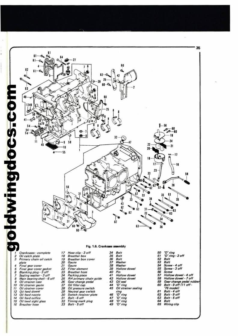
gold
win
gdoc
s.co
m
,------------------------35Il
~II --,
f---_-----".----'7'~~'-::::"
Fig. 1.6. Cr.nk... _mbiV
/ Crankcase. - comp/ete 17 He»e clip· 3 0 ff 34 Bo" 50 '0' ring2 Oil catch pI,ta /8 Bf8lJrher box 35 80" 5/ '0' ring· 2 off3 Primary ell,in oil ellteh 19 B'Nth~box cow:r 36 BoI' 52 BoI'
pI.~ 20 G6UZ/J 31 W...., 53 BoI'4 Fill4f gel( COrlIT 21 G"". 38 WW>" 54 Scre.- -4 off5 FintJl gt!/JI' C()IHr galeet 22 Filter mfMrIt 39 HoI'owdo~ 55 Sc,..,· 3 off6 Blanking plug - 3 off 23 BrrJathflf hOM 40 ffo 56 Sc~w
1 ~a1ing _1MI" 3 off 24 P«:king piee. 41 Hollowdo-' 51 Hoi/ow do-'· 4 off8 Main boring I~" 6 off 25 RH primary ell,in llUide 42 Holfowdo-' 58 Ho/lowdo-' -} off
• Oi( strainerc~• 26 Geilr change petRI 43 Oil IBM .. GMrcMn~ p«JM Nbbe10 Oil sr"iner {puze 21 Oil (iflar cIP 44 '0' ring 60 801t-90ffl1,0"-1/ Oif strw/nflf co..at' 28 Oil pnuu" ,witch 45 Oil sr,.,inflf IHiing '76 modeIJ12 Oil feed dowel 29 Neutral !Jellf .witch ring 61 Bolt-" off13 011 teed {lozzl, 30 Switeh nt.ln,r pI,Ite 46 '0' ring 62 Bolt - 9 off14 Oil feed orifice 3/ BoIt- 6 off 41 '0' ring 63 Bolt· 5 off15 Oil/eve/sight gUm 32 Timing mark plug 4B '0' ring 64 Boft16 Breathe, hOle 33 Bolt- 5 off 49 '0' ring 65 Wiring clip
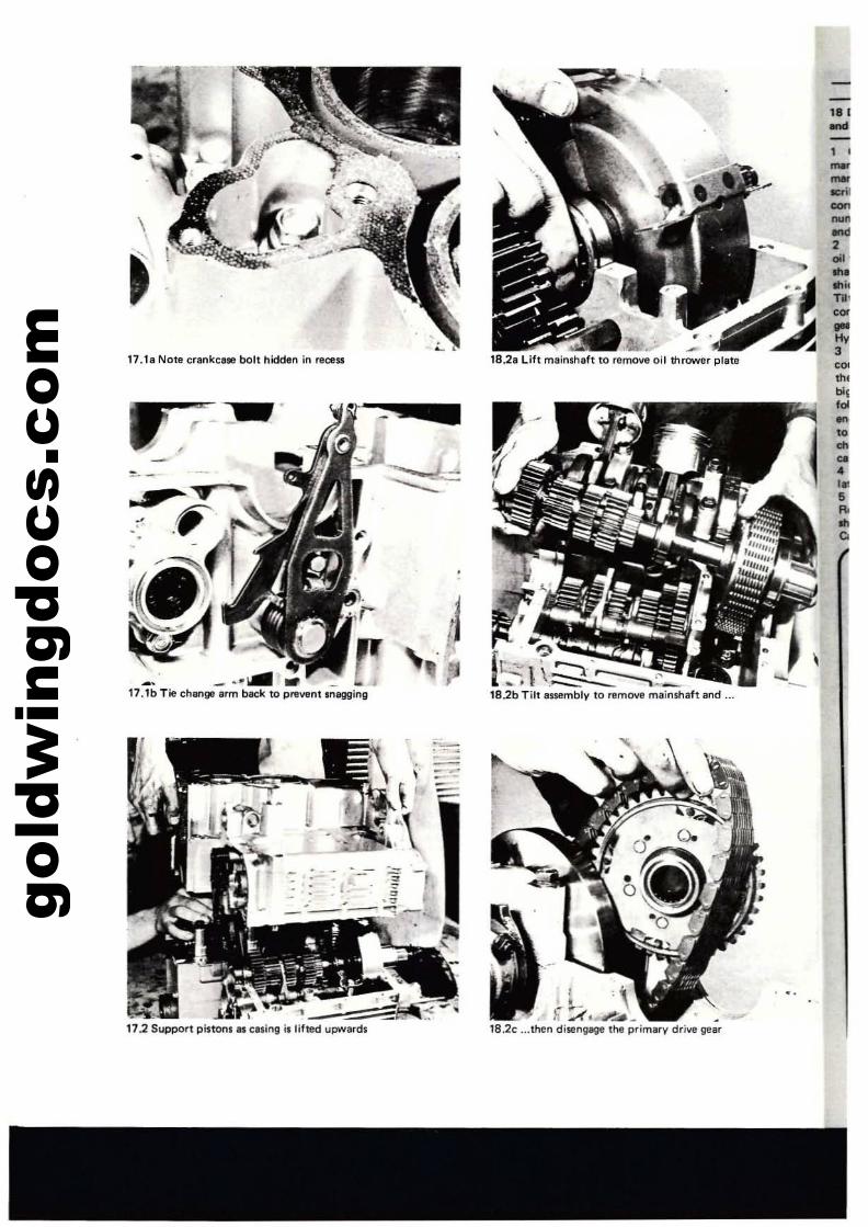
gold
win
gdoc
s.co
m'"...~--"'"-.::::2......~I""...'"3,~
m,~,
f~
~.......•,.•..~
• "l1hrower platef to remolla 0118.2a Lifl mainsha t
.- ... -.-.~.- venl snagging_. -;rm back to pre17.1bTiechanga
boll hidden in rece$Sankcalle17.1aNotecr
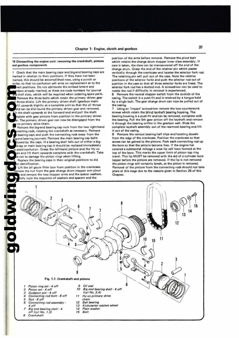
gold
win
gdoc
s.co
m
Chapter 1: Engine, clutch and gearbo)C
18 Dismantling the engine unit: 'emovingthe e,ankshaft, pistons-.d gearbox eomponenU
1 DIeck that ttle main beiilring eaps 8l'Id big-end bearing caps aremarked in relation to their positions. If they have not beenmuked. this should be lICXomplished now, using a puneh orteribe, so that no eonfusion will arise on replacement as to thecor,.;:t positions. Do not obliterate the scribed lette'" ern:!numbers already marked, as these are code numbers for jOlJrnaland shell sizes, which will be required ....nen ordering spare Piilrts.2 Remove the three bolts v.tIich retain the primary driven gearoil throw shield. Lift the primary driven shaft (gearbox mainsh.ftl upwards slightly as a complete unit so that the oil throw".ield Ciiln be slid round the primary driven geiilr and removed.T1lt the shiilft upWlllrds at the forward end lIfld pull the shaftcomplete with gear pinions from position in the primlfY driwnlIPt. The primary driven gear can now be disengaged from theHy-vo primary dri.... chain.J Remove the bi!tlnd bearing eap nuu from the twO rig-ot-handeonneeting rods, rotiilting the crankshaft as necessary. Removettle bearing caps and push the conneeting rods away from thebiV"ll"ld bearing journals. Remove the main bearing eap bolulollowed by the caps. If a bearing shell failS out of either a bigend cap or main bearing cap it should be replaced immediatelyto avoid confusion. Grasp the left-hand pistons and the Hy-vothain and lift them upwards complete with the crank$haft. Takecare not to damage me pinon rings lNtIen lifting.4 Replace the bearing caps in their original positions to aidIller idel'ltification.5 Lift the oil gauze fitter boll. from position in the er""~,Remove the nut from the gear ch8n9' drum stoppef' arm pivotthaft and remove the two stopper arms and the specer washers.Carefully note the sequence of washe" and space'" and the
position of the arms befort! removal. Remove the pivot boltYottich retains the change drum stOPPBr inner claw assembly. Ifcare is taken. the cl.w ean be manoeu.... red off the end of thechange druTT•. Grasp the end of the retainer pin Mieh passeswrtiea.lly throug-o the crankellse and loeat" the SIleetor fork rocl.The retaining pin will pull out of the ease. Note tt1e reliilti'li!positions of the telec:tor forks and push tt1e selector rocl out ofposition in the case so that all three selector forks Ire freed. Theselector fork rod has II slotted end. A screwdriver ean be used torotate the rod if diffieulry in remOVal is experienced.6 RemOVl! the neutral stopper switch from the OlIuidl of theeasing. The switch is e push·fitend is ratained by a tongue heldby a single bolt. The gear change drum can now be pulled out ofthe casing.7 Using an 'impact' screwdriver rlmOlle the two eounterlUnkscrews which retein the blind laystlaft bearing housing. Thebelring housing i. a push·fit and an be removed,eomplete withthe beiilring. Pull the 5th geM pinion off the ".yshllft and remOlleit through the bearing orif~ in the gearbox Yell. Slide thecomplete l~aft assembly out of the rl8rmost bearing and liftit out of the easing.8 Remove the various blaring half clip' and locating dowelsfrom the edge of the erankcase. Pe-ition the crll'lkclSe so thatlICXess an be ~ined to the pistons. Push each connecting rod upthe bore so that the pistons become free. If the engine haseovered a substantial mileage a wear lip will have formed at thetop of the bore. This marks me upper limit of piston top rin9tnlVfll. This lip MUST bI removed with the aid of I cylinder borelapper before the pistons lIfl! removed. If the lip is not removedthe piston ringll wilt eertiilinly break, as the piston i1 removed.Removal of the pistons from the eonneeting rads should not takeplace II this stage due to the rusons given in Section 25 of thisClapter.
12
B
9 0,.,_110 Big Md Mering shell· " off
(cyl No. 2.4)" Hy·vo primary drille
chein12 Ball ~aring13 Kickstarterrerr:h,rwheel14 Plein wesher15 Boft
Ftg. 1.7. Crankshaft and pls10ftS
, Piston ring set - 4 off2 Pitton set· 4 off3 Gudgeon pin - 4 off4 Connecting rod bolt· B off5 Nur·Boff6 Connecting rod assembly·
4 off7 Big (md Maring sheff· 4
off (eyl No. 1.3J8 erenkJheft
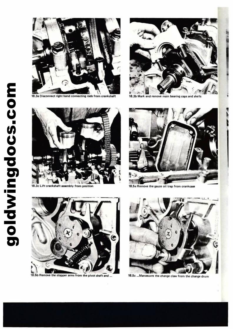
gold
win
gdoc
s.co
m 18.31 Disconnect right hind connecting rock from crlnk,hlft
... "'" , , .-
18.3b Merle Ind remove m8in bearing caps and shell,
18.51 Remove thl g.uz. oil trip from cr..,kCIM
18.5c ...ManoeuvrI the change claw from the change drum
"
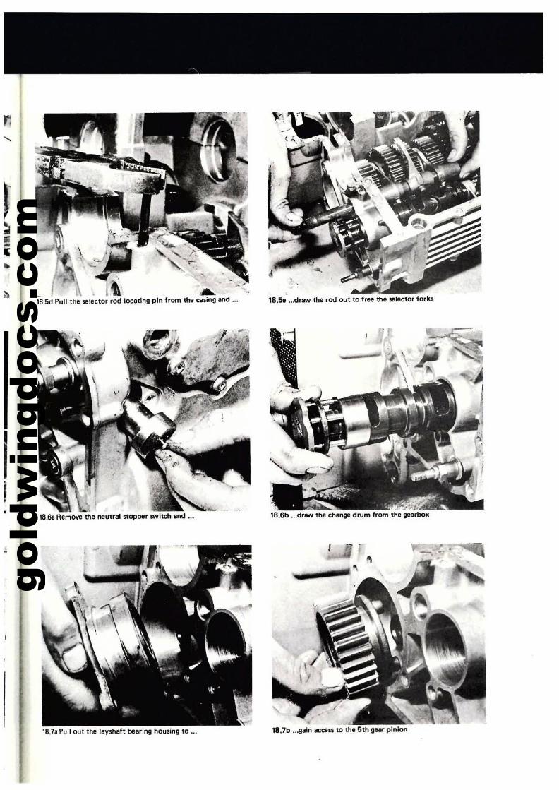
gold
win
gdoc
s.co
m
.~..
18.6e ...draw the rocl out to free the selector fo..ks
\
_ .1\ A..18.5d Pull the selector rod locating pin from the casing and .-.
..
Ii
18.68 Remove the neutral stopper $Witch and ...
r
->I'_,';'\t,lB.6b ...drew the change drum from the gearbox
18.78 Pull out the lay'haft bearing housing to ...
I
18.7b ...gain lIC(:fIS$ to the 5th g"r pinion
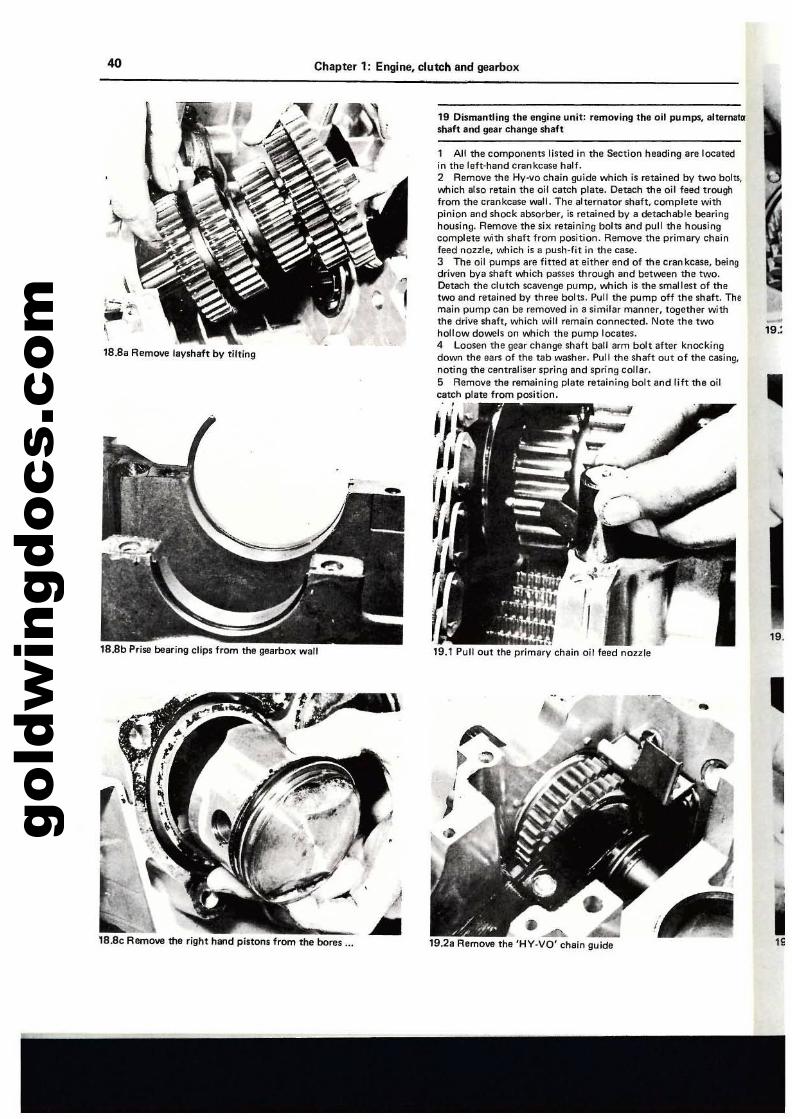
gold
win
gdoc
s.co
m40 Chapter 1: Engine, clutch and gearbox
"
19.
•
-19.:
..19.1 Pull out the primary chain oil feed nozzle
1 All the components listed in the Section heading are locatedin the laft-hand crankcase half.2 Remove the Hy-vo chain guide which is retained by two bolu,whith also retain the oil catch plate. Detach the oil feed troughfrom the crankcase wall. The alternator shaft, complete withpinion and shock absorber, is retained by a detachable bearinghousing. Remove the six retaining bolts and pull the housingcomplete with shaft from position. Remove the primary Chainfeed nozzle, which is 8 push-fit in the case.3 The oil pumps are fitted at either end of the crankcase, beingdriven bye shaft v.tlich passes through and between the two.Detach the clutch scavenge pump, which is the smallest of thetwo and retained by three bolts. Pull the pump off the shaft. Themain pump can be removed in a similar manner, together withthe drive shaft. which will remain conne<:ted. Note the twohollow dowels on which the pump locates.4 Loosen the gear change shaft ball arm bolt after knOCkingdown the ears of the tab washer. Pull the shaft out of the casing.noting the centraliser spring and spring collar.5 Remove the remaining plate retaining bolt and lift the oilcatch plate from posilion .. ,
~~.
~
19 Dismantling the engine unit: removing Ul8 oU pumps, 81temBIQ'shaft and gear change shaft
..........19.2a Remove the 'HY·VO' chain guide
18.8a Remove laysh8ft by tilting
18.8c Remove 1M right hand pistons from the bores _•.
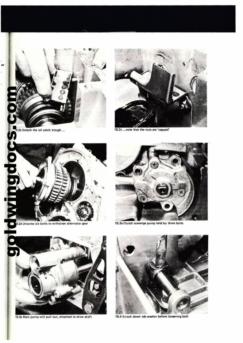
gold
win
gdoc
s.co
m
.--
19.2b Detaeh the oil c.tth trough _•.
,19.2d U"serew six boltll to withd..... "ltem,tor ge..
,
\'.
<? -;:"
/ I\ '
19.2c •••notll thet the IlIJU ere 'capped'
19.31 Ciutetl1QWl'lge pump held bv three bolts
,-'
19.3b Main pump will pullout, anachld to drive $IIeh 19.4 Knock down tab WISher before 100-01"9 bolt
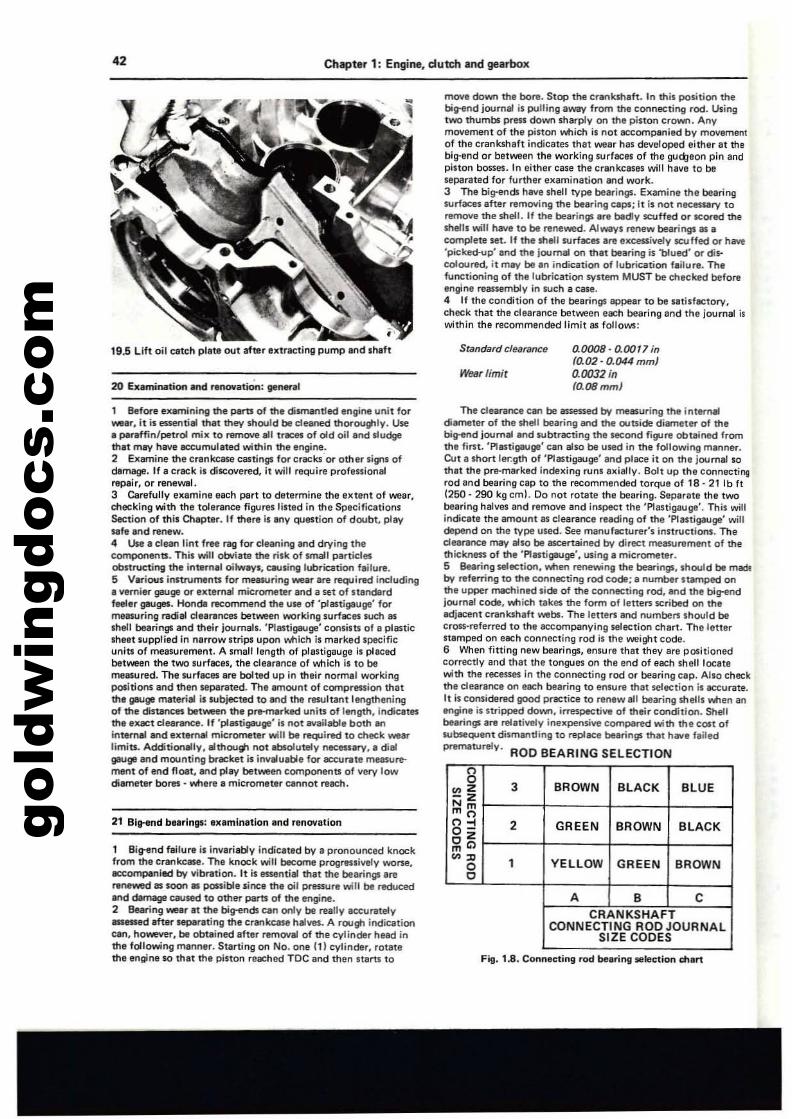
gold
win
gdoc
s.co
m42 Chapter 1: Engine, dutch and gearbox
move down the bore. Stop the crMlkshafl. In this position thebitr1lnd journal is pulling away from the connecting rod. Usingtwo tt1umbs preis down sharply on the piston crown. Anymovement of the pistoo which is not ICcompanied by moveme<11of the crankshaft indicates that wear has developed either at mebig-end or between the working surfaces of the gud;:leon pin andpiston bosses. In either case the crankcases will have to beseparated for further examination and work.3 The big-erlds have shell type beerings. Examine the bearingsurfaces after removing tt1e beilting caps; it is not necauary toral'JKlQ the shell. If the bearings .re badly scuffed or scored theshells will have to be renewed. A1-Vs renew beanngs III •complem Sl!t. If tt1e shell surlaces are excessively scuffed or have'pickea.vp' and the journal on thet bearing is 'blued' or discoloured, it mey be.n indication of lubrication feilure. Thefunctioning of the lubrication SYSlem MUST be enecked beforeengine reasSl!mbly in such a case.4 II the condition of the bearings ap.pear to be ItIlislactory,check that the clearance betllWen each bearing and the journal iswithin the recomm,nded limit 81 follolN5:
Fill. 1.8. Connectmg rod be.nnt selectIon dlert
The dearance CIIn be llUeS$ed by measuring the internaldiameter of the shell bearing end tt1e ouUide diamet~ of thebisren<l joumel end subtracting the second figure obtained fromthe first. 'f'fllStigauge' cen also be used in the following manner.Cut a short ler.gth of 'Plastigauge' and place it on the journal sothlll the pre-marked indexing runs a~illlly. Bolt up the connll(;tingrod and bearing cap to the recommended torque 01 18· 21 Ib It1250· 290 kg cm!. Do not rotate the bearing. Separate the twobearing halves and r,moVil and inspect the 'Plastigauge'. This wiltindicate the amount as clearance reading of the 'Plastig.auge' willdePend on the type used. See manufecturer's instructions. Theclearance may also be IIIC8rtained by direct measurement of thethickness of the 'f'fllltigauge', using' micrometer.5 Bearing selection, when renewing the bearings, Ihould be madeb'l' referring to the connecting rod code; a number Stlmped onthe upper machined side of the connecting rod, end the bi;--endjournal code, which takes the form of letters scribed on theedjacent crankshall 'NIbs. The leners end numberslhould becross·referred to the accompanying selection chart. The letterstamped on each connecting rod is the weight code.6 When fitting new bearings, ensure that they ilre positionedcorrectly and that the tongues on the end of each shell locatewith the recesses in the connecting rod or bearing cap. Also checkthe clearance on ellCh bearing to ensure that selection is lCCurate.It is considered good prectice to ren..... all bearing shells when anengine is stripped down, irnspectill'l of their condition. Shellbearings are reI.tiYely inexpensive compared with the COlt ofsubsequenl dilmentling to replllCe borings that hiillli 1.lled
prermlturely. ROD BEARING SELECTION
19.5 Uft oil ceteh pllt. out after extrllCting pump and shaft
, Before examining the parts of the difl'T'lantled engine unit for_r. it is essential that they should be cleaned thoroulflly. use• paraffin/petrol mill to nHT1(M1I1U tf8C8S of old oil end sludgemit may have 8CCUmul"ed within the .ngine.2 Examine the cf'nkcase castings for craclcsor other signs ofdamage. If. crack i, discovert!d. it will require proflnionlllrepair, or nlnllWllI.3 Carefullv e"amlne each part to determine the IKtenl of wear,checking with the tolerance figures lined in the SpltCificationsSection of thil Chapte,. If there is lOy question of doubt, playufe and renew.4 Use. clean lint free rtIg for cleaning 8nd drying thecomponents. This will oOri.te the risk of small particlesobstructing the internal oilwayl. ClIUling lubrieltion failure.S V.rlous inlUUments for melllUring weM Ire required itlduding.vemi'r gauge or external micrometer end a set of standardfeeler gaugt$. Honde recommend ttlt UM of 'plastigauge' formeasuring l'3<fal cle,,'encl!'S bet....een YoCrking surlllCl!'S such lISshell bearings and their journals. 'Plani{lllllge' consists of a plenicsheat supplied in nerrow nrips upon v.tlich is marked specificunin of me85Urement. A smaJllength of plastigauge is placedbetween the two surfaces, the dearance of .....t1ich is to bemeasured. The surfICM ere bolted up in their normal workingpositions and then separated. The amount of compression thatthe gauge materiel is subjected to lind the resultant lengtheningof the distances between the prHTlerked units of lerlp, indicatl!'Sthe eqct cfea,..-,ce. If 'plastigauge' il not available both linintemal lind external micrometer will be required to check wearlimits. Additionllly, elthoug, not ablolutely nICllilery, e dialgauge."d mounting bracket;s invllueble for llCCu~te measurement of end float, and play between components of very lowdiametll'" bores • v.tlere a micrometer cannot f'l!ach.
21 Blltend bearings: .xamlnatlon and renovation
1 Bitr1lnd failur. Is Invariably indiceted by a pronounced knockfrom the crankcase. The knock will become progressively WOI"'$I,eccompanied by vibration. It is _ntial thet the bearings arerII'lIWad as soon III possible sinc. tt1e oil pressure will be reduced8nd dImaga caused to othll'" parts of the engine.2 Bearing wear at the big-ends can only be really accurately--.d after separating the cr¥lkcese hal\leS. A rough indiClltionClIn, howeYII'", be obtained after remOY8l of the cylinder head inthe following manner. Starting on No. one (11 cylinder, rOlalethe engine s.o that tha piston rellChed ToC and then startl 10
Standard clearance
wear limir
3
2
1
o,ooos· 0.0017 inrO,02· 0.044 mmJ0.0032 in(o'08mm)
BROWN BLACK BLUE
GREEN BROWN BLACK
YELLOW GREEN BROWN
A 8 CCRANKSHAFT
CONNECTING ROO JOURNALSIZE CODES
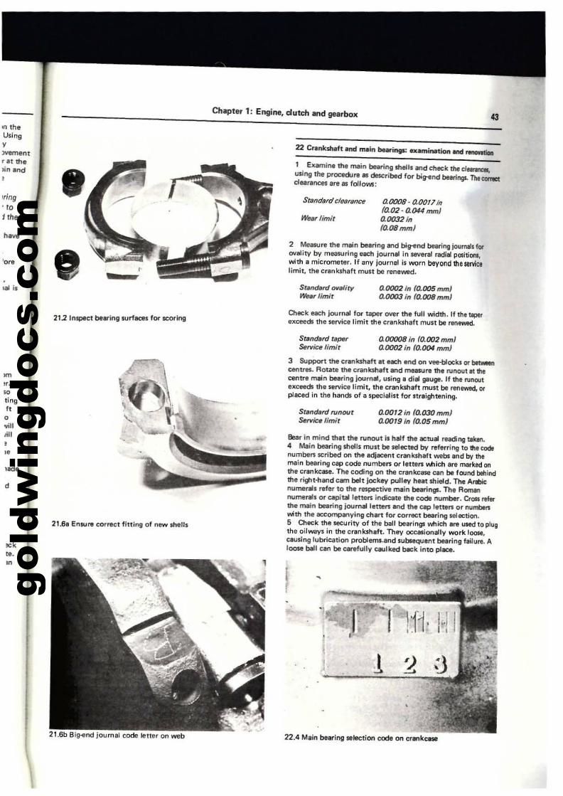
gold
win
gdoc
s.co
m
Chapter 1: Engine. dutch and gearbox
aOOO8-aOOf7inta02 - a044 mmJ0.0032into.OSmmJ
0.0002 in IQ.OOSmmJ0.0003 in 10.008 mm}
Standardcl8tJrsnce
Wurlimit
Stwldard twMityKoW., limit
1 Examine the main bearing shells a'ld eheck the eletl1llC8luJing the procedure as described for bi!t8nd bearings.The~clellrences are as follOlo,s:
2 MeMure the main be.ring and big-end bellfing joutllollb fOl'ovality by measuring each Journal in 58Ver81 redial positiON,with a micrometer. If any journal is worn beyond the servicelimit, the crankshaft muSI be renewed.
'ore
h.~
'n theUSing,)Yementr.t thelin and
•Iring'to
1 fhe
21.2 Inspect bellring surfllCb for scoringCheck each journaf for teper over the full width. If the tlplrexceeds Ihe service limit the crankshaft must be renewed.
St.ndard Ulper&!n'ictl fimit
aOOOOBin fO.OO2mmJ0.0002 in 10.004 mm)
0.0012 in (o.03OmmJ0.0019 in (0.05 mmJ
S~ndard rvnout:Mf'ria, limit
3 Support the cr.nk$haft .t each end on vee-bloelu or bttwIenc:efltfltS, Rotate the cranbh.ft and meesure the runoulat ltltc:efltfe main buring journlll, using. dial gauge. If the fUnQUIexceeds the service limit, Ih. crenksh.ft must be renewed, orp1l1Ced In lhe hends of a specialist for ttr.ightenlng.
Bear in mind that the runoul is haff the 8C1ual rNding tebn.4 Main bearing shells mult be selected by referring 10 ltlecodenumber1 scribed on the adjacent cranklh.ft wabs and by themain bearing cap code number1 or letters v.tlich are marked onthe crankcase. The coding on tM crenlu;:8$4l can be found behindthe rigJt-nand cam belt jockey pulley heat shield. The ArDcnume""s refer to the respectift main bearings. The Aomennumerals or capitalleners indicate the code numbeT. CrOlll1ferthe mein bearin51 journalleners and the cap letten or nulTtltrlwth the accompanying chart for correct bearing selection.5 Check the security of Ihe ball bearings v.tlich are used to plugthe oirways in the crankshaft. They occasionally work loose,causing lubricallon problems.•nd sobseQuent belr;ng fe~u",. Aroose ball can be carefully caulked b.:k into place.
!
22.4 Mlin belring selection code on cr8nkcase
21.68 Ensure correct fitting of new shells
21.6b Big-end Joornal code leiter on web
d
~
",'0tingIIo'Willtill
•"
~k
ro,m
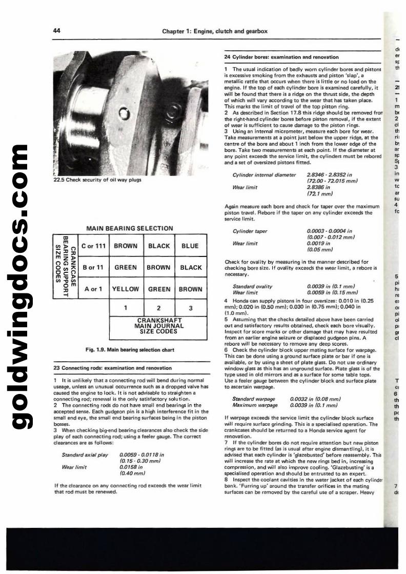
gold
win
gdoc
s.co
m44 Chapter 1: Engine. dutch and gearbox
24 Cylinder bores: IIIt.mination and renovation
Again measure each bore and check for taper over the miSltimumpiston trevel. Aebore if the tllp!!l'" on .ny cylinder exceeds theservice limit.
1 The usual indication of badly worn cylinder bores and pistonlis excessive smoking from the exhausts and piston 'slep', ametallic ratde that oocurs 'oMlen there is little or no load on theengine. If the top of eactl cylinder bore is eltamined ~refully. itwilt be found that there is a ridge on the thrust side, the depthof 'oMlich will vary according to the wear that has Ulken place.This marks the limit of tnrvel of the top piston rirtg.2 A$ ~ribed in Section 17.8 this ridge Should be rBrTlOYt!d frQlrthe right·hand cylinder bores before piston r1!fTloval, if the elttentof WIIar is sufficient to cause damage to the piston rin!JS.3 Using lin internal micrometer, mellsure each bore for wear.Take measurements at II point just below the upPt!r ridge, lit thecentre of the bore and llbout 1 inch from the lOllio'er edge of thebore. Tllke two measurements at each point. If the diameter atany point exceeds the .rvice limit, the cylinders must be reboredand a set of ownized pistons fined.
2!
""Of
"
1mIx2
""ril'""'"..3;"w
""'"4I,
2.8346-28352in(72.00·72015 mm)28386 in(72.1 mm)
CylindfJr intem_ di.'I'Huer
Wea, limir
,.;
t22.5 Check lliecurity of oil way plugs
Fig. 1.9, Main bearing ,.Iection etlan
MAIN BEARING SELECTION
7~
T
"•m"p,m
5
"",""~"'"p.'"
0.0003· 0.0004 info.007· 0.012mmJ0.0019 in(0.05 mml
0.0032 in (0.08 mmJ0.0039 in fo., mm)
Cylinder taper
Wear limit
SrancJim;J warpageMaximum warpage
SnlndarrJ ot/a/iry 0.0039 in fO.1 mm)Wear limit 0.0059 in (0.15 mmJ
4 Hond8 un supply pistons in four oversizes: 0.01 0 in 10.25mml; 0.020 in (O..so mmt; 0.030 in 10.75 mml; 0.040 in(1.0 mrnl.5 Assuming that the checks deilliled llbove have been carriedout and salisfactory results obtllined, check each bore visually.Inspect for score marks or other dllmllQll thllt may hllVe resultedfrom an earlier engine seizure or displaced gudgeon pins. Arebara will be necessary to remove any deep scores.6 Check the cylinder block upper m'ling surface lor warpage.This can be done using a ground surface plate or bar if one isavailable, or by using. sheet of plale glass. Do not use ordinarywvindowglass lIS this hIlS en unground surflCe. Plate gllISS is of thetype used in old mirrof'1 and lIS a SUrfllCe lor some table tops.Use a feeler gauge between the cylinder block and surft1C1I plateto a5CBf"lt1in warpage.
If warpage excee$ the service limit the cylinder block surfacewill require surface grinding. This is a specialised operation. Thecrankcases should be reltJrned to II Hondl! serviclI agenl forrenovation.7 If the cylinder bores do not require attention but new pistonrings are to be fined (as;1 usual efter engine dismantlingl, it isadvised thll each cylinder is 'glazebusted' before reulambly. This~U increase the rate lit v.tlich tha new rings bed in, increasingcompression, and will also improve cooling. 'Glazebusting' is aspecialised operation lind should be IInlrusted to en expert.a Inspect the coolanI clIVi ties in the waUlr jacket 01 each cylinderbank. 'Furring up' around Ihe transfer orifices in the matingsurfaces can be r1!fTloved by the careful use of a scraper. Heevv
Check for ovality bV measuring in the manner described forchecking bore size. If ovality exceeds the wear limit,' rebore isnecessary.
0.0059·0.0118 in(D.15-0.30mmJ0.0158 in(OAOmm)
Wear limir
If the clearance on any connecting rod ellceeds the wear limitthat rod must be reflelOYed.
1 It is unlikely that a connecting rod will bend during "ermaluseage. unlen 8n unusu.1 occurrence Nch 8$ 8 dropped \/Ilve hasclIUsed the engine to lock. It is not ad\I;s8ble to straighten IIconne<:ting rod; renewal is the only satisfactory solution.2 The connecting rods do not have small end bearings in theaccepted sense. Each QlJdgeon pin is a high inlerfertinCe fit in lhesmall end eye. the smalillfld bearing surfaces being in ttl, piston.......3 When checking bi~d bearing durances also check the sideplay of ellCh connecting rod; using 8 feeler gauge. The correctdearanceli Ire as follows:
CDm~>n Corl11 BROWN BLACK BLUEN~:Dmz>OGlZ
B or 11 GREEN BROWN0",>< BLACKOeom~>
"'~'"OmAor 1 YEllOW GREEN BROWN:D...
1 2 3
CRANKSHAFTMAIN JOURNAL
SIZE CODES
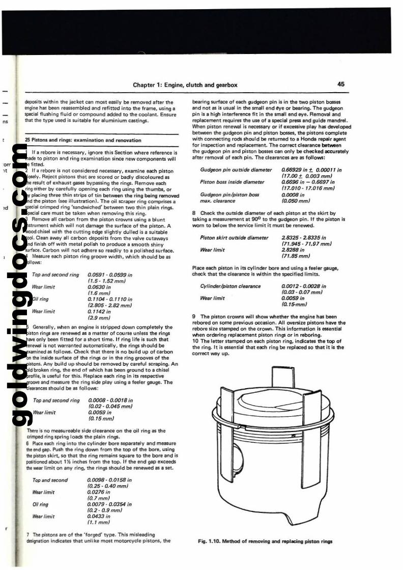
gold
win
gdoc
s.co
m
Chapter 1: Engine, clutch and gearbox 45
8 O1eck the outside oametltf of nett ptston ., the skirt bytlIklng. measurement at goo to the gudgeon pin. If the piston isworn to below the "rvice limit it must be renewed.
be.ring surface of e.:l1 I'Jdg&ol'l pll'I is il'l the two piston bosses....d not lIS is usual il'l the small end eye or bearing. The gudgeonpin i. a high il'lterference fit in the small end eye. Removal andreplacemel'lt requires the use of e special press and guide mandnl.When piston renewal is necessary or if exe:emv. pley h. developedbetween the guclgeon pin ....d pi.ton boDes, the pI.tons completewith connecting rods should be I"Ilturned to. Honde repeir agentfor inspection end replacement. The correct deer....ce betweenthe gudgeon pin .nd pinon bosses can only be checked eeeuratelyafter removal of each pin. The clellrances lire IS follows:
"'
orr
"
deposits within the jacket Clm most easily be rlmO\led after thetrlgine hiK beefl reassembled and refitted into the frame, using aspecial flulhing fluid or COfflp(M.md 8dded to the coo/aM. Ensurethat the type uHd is ilUitable for aluminium CilStillg$.
25 PistGrlS and ri"9S: .xamination .nd renovation
1 If a rebore is nece$'ary, ignore this Section iM'Iere reference ismade to piston and ring examination since new components willbe fitted.2 If a rebore is not considered necessary, examine each pistonclosely. Rejeci pinons that 8rlI scored or badly discoloured 8$
the result of exhaust gases bypas5ing the rings. Remove eachring eithe1" by carefully opening each ring using the thumbs, orby- pla:ing thr" thin strips of tin betweer1 the ring being removed~d the piston (fie illustration). The oil scraper ring comprises a!pecilll crimped ring's.andwid'lIta between two thin plain rings.Special care mun be t.ken when removing this ring.3 RemOYa all carbon from the pinon crowns using a bluntin$trument which will not damage the surface of the piston. Awood chisel with the cutting edge slightly dulled is a suitabletool. Clean away all carbon deposits from the valve cutaway,and finish off with metal polish to produce a smooth shinyrunICe. Carbon will not adhere so readily to a polished surface.4 Measure eoch piston ring groove width, which should be asfollows:
Gudgeon pin outside diaml~r
Piston boss Inlidl ditlfTlflter
Gudglon pin/pisron bossmvt. C/NrvJCa
Piston skirt outJidl dl'me~r
We,r limit
0.66929 in 1. aOlXJ11 in"7.00 t. aOO3 mm)a6696 In - 0.6697 in(17_0'0- '7.016 mmJaOOO8inra050mmJ
28325·28335 in(n945· n97 mmJ28288 infl1.85mm)
Top,ndsecondring 0.0008· aOO18 In(0.02·0.045mm)
Wear limir 0.0059 In(0.'5 mm)
The~ is no mellSureablll side cle.r.nce on the oil ring IS thllcrimped ring sprlnglO8dl tt1e pleil'l rl!\g5.6 Place each ring into the cylinder bore separetely end measure!he end gap. Push the ring down from the top of tt1e bore, usingthe piston skirt, so that the ring remaiM $QUa", to ttle bore 8I'ld ispositioned IIbout 1)(, inches from the top. If the end gap exceedsthe _Iimil on al'ly ring, the ringsll'tould be .......~ as II set.
Top and I«ond ring a059, - 0.0599 in".5-1.52mmJ
~ar (;mir 0.0630 inft.6mmJ
Oil ring a,,04· a 1110 in(2805· 282mmJ
~r/imir a1'42in(29mmJ
o.OO'2-aOO28In(0.03· a07 mmJaOO59ln(a 1!i-mm)
Cylindlr!pnton tlNflJnU
Wear limft
9 The piston crowns will show whether tha engine hl!ll beel'lrebored on sorne previous OCCilSlol'l. All oversize pistons have therebare size stamped on the croVlll'l. Thi' inforrnetlon is essential\o'<Alen ordering replacement piston rings or in raborlng.10 The letter stamped on each piston ring, indi.:.tlS the top ofthe ring. It is "senti. that each ring be replaced so th.t it if; theCOI"TSCt -V up.
Place each piSton in its cylinder bore IlfId using. f"let gauge,check th.t the clearance is within the specified limits.
0.0098 - 0.0158 in(0.25· a40 mmJ0.0276 in(0.7mmJ0.0079- 0.0354 In(0.2· 0.9mmJ0.0433 in".1 mm)
Top ilnd I«ond
Oil ring
WNr/imir
WHrlimir
5 Generally. iM'Ien an engina is stripped down completely thepillon rings are renewed as a matter of course "mle" the ringshive only been fitted for a short time. If ring life is such thatrenewal is not warranted automatically. the rings Ihould belXllTlined lIS follo\oY.J. O1eck that there is no build up of carbonon die inside surflJCil of the rings or in the ring grooves of thepistons. Any build up should be remlMJd by c.reful scraping. Anold broken ring. the end of which hes beel'l ground to II cttiselprofile, is useful for this. RepI.:e a.:l1 ring il'l its respllCtWe.-eand measure the ring side play using a feeler gauge. ThedNra"ICIS should be ill folloY\ll:
1 The piston""' of the 'forged' type. Thi, misleading~tion ino.:.t" thllt unlike mOlt motorcycle pistons. thll Fig. 1.10. Mlttlod of "movi"'ll and ~acingpiston rings
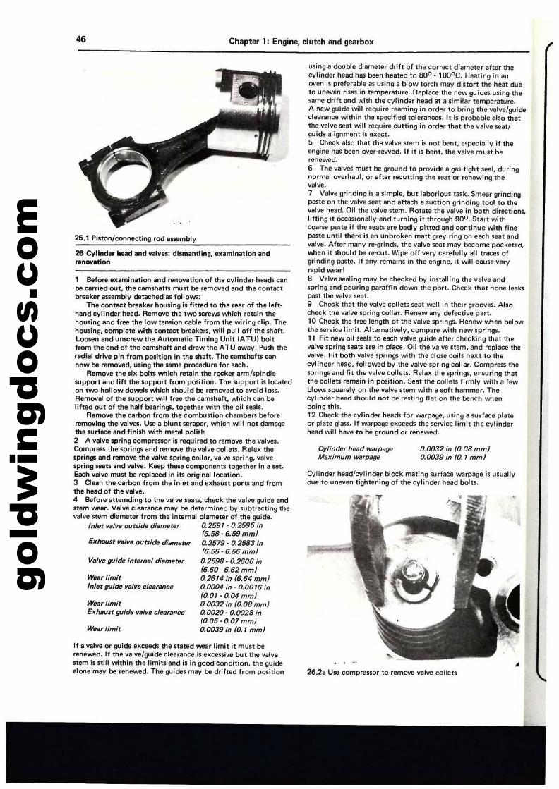
gold
win
gdoc
s.co
m46 Chapter 1: Engine, clutch and gearbox
Wear limit
VBlve guide inrsrnal diameter
0.0032 in (0.08 mm)0.0039 in (0.1 mm)
Cylinder head warpageMalCimum warpage
26.2a Use compressor to remove valve collets
Cylinder head/cylinder block mating surface warpage is usuallydue to uneven lightening of the cylinder head bolts.
using a double diameter drift of the correct diameter after thecylinder head has been heated to SOD . 1aooe. Heating in anoven is preferable as using 8 blow torch may distort me heal dueto uneven rises in temperature. Replace the new guides using milsame drift and with the cylinder head at a Similar temperature.A new guide will reQUire reaming in order to bring the valve/guideclearance within the specified tolerances. '1 is probable also thatthe valve seat will require cutting in order that the valve seat!guide alignment is exact.5 Check also that the valve stem is not bent, especially if theengine has been over-rewed. If it is bent. the valve must berenewed.6 The valves must be ground to provide a gas-tight seal, duringnormal overhaul, or aher recutting the seat or renewing thevalve.7 Valve grinding is a simple, but laborious task. Smear grindingpaste on the valve seat and attach a suction grinding tool to thevalve head. Oil the valve stem. Rotate the valve in both directions,lifting;t occasionally and turning it through 900. Start withcoarse paste if the seats are bady pitted and continue with finepaste until there is an unbroken matt grey ring on each seat andvarve. After many re-grinds. the valve seat may become pocketed•....t1en it Should ba Te-cut. Wipe off very carefully all traces ofgrinding paste. If any remains in the engine, it will cause veryrapid ......earl8 Valve sealing may be Checked by installing the valve andspring and pouring paraffin down the port. Check that none leakspaSt the valve seat.9 Check that the valve collets seat well in their grooves. Alsocheck the valve spring collar. Renew any defective part.10 Check the free length of the valve springs. Renew VIotJen belowthe service limit. Alternatively, compare with new springs.11 Fit new oil seals to each valve guide after checking that thevalve spring seats are in placa. Oil the valve stem. and replace thevelve. Fit both valve springs "";th the close Coils next to thecylinder head, followed by the valve spring collar. Compress thesprings and fit the valve collets. Relax the springs, ensuring thatthe collets remain in position. Seat the collets finnly with a fewblows sQIJarely on the valve stem with a sof! hammer. Thecylinder h8ad Should not be resting flat on the bench whendoing this.12 Check the cylinder heads for warpage, using a surface prateor plate glass. If warpage exceeds the service limit the cylinderhead will have to be ground or renllwed.
Exlu/usr ~Blve oubide diameter
WlIlIrlimitInlllt guide vlllve cf81mmce
WearlimirExh,ulr guide valve c/eat'llnce
26 Cylinder hnd Ind vatves: dismantling, examination andrenovation
26.1 Pilton/connecting rod assembly
1 Before examination and renovation of the cylinder heads canbe carried out, the camshafts must be removed and the contactbreaker assembly detached as follows:
The contact breaker housing is fitted to the rear of the left·hand cylinder head. Remove the two screws which retain thehousing and free the low tension cable from the wiring clip. Thehousing, complete with contact breakers, will pull off the shaft.Loosen afld unscrew the Automatic Timing Unit (ATU) boltfrom the end of the camshaft and draw the ATU awllY. Push theradial drive pin from position in the shaft. The camshafts cannow be removed, using the same procedure for each.
Remove the six bolts which retain the rocker ann/spindlesupport and lift the support from position. The support is locatedon two hollow do_Is v.tlich should be removed to avoid loss.Removal of the support"";l1 free the camshaft, which can belifted out of the half bearings, together with the oil seals.
RerT'lOY8 the carbon from the combustion chambers beforeremoving the valves. Use a blunt scraper, which .,..;It not damagethe surface and finish .... th metal polish2 A valve spriflg comprenor is required to remove the valves.Compren the springs and remove the valve collats. Relax thesprings and remove the valve spring collar, valve spring, valvespring leats and valve. Keep these components together in a set.Each valve must be replaced ifllts original location.3 ann the carbon from the inlet and exhaust ports and fromthe head of the valve.4 Befol"1l attemding to the valve seats, check the lIalve guide ,lndstem ......ear. Valve clearance mllY be determined by subtracting thevalve stem diameter from the internal diameter 01 the guide.
Inlet lIalve outside diameter 0.2591·0.2595 in(6.58·6,59 mmJ0.2579- 0.2583 in(6.55·6.56 mm)0.2598·0.2606 in(6.60·6.62 mm)0.2614 in (6.64 mmJ0.0004 in· 0.00'6 in(0.01 - 0.04 mm/0.0032 in (0.08 mm)0.0020· 0.0028 in(0.05·0.07 mm)0.0039 in (0. 1 mm/
If a valve or {PJide exceeds the nated wear limit it must berene_d. If the valve/guide clearance is excessive but the valvestem is still .... thin the limits and is in good condition, the guidealone may be renewed. The guideS mllY be drifted from position
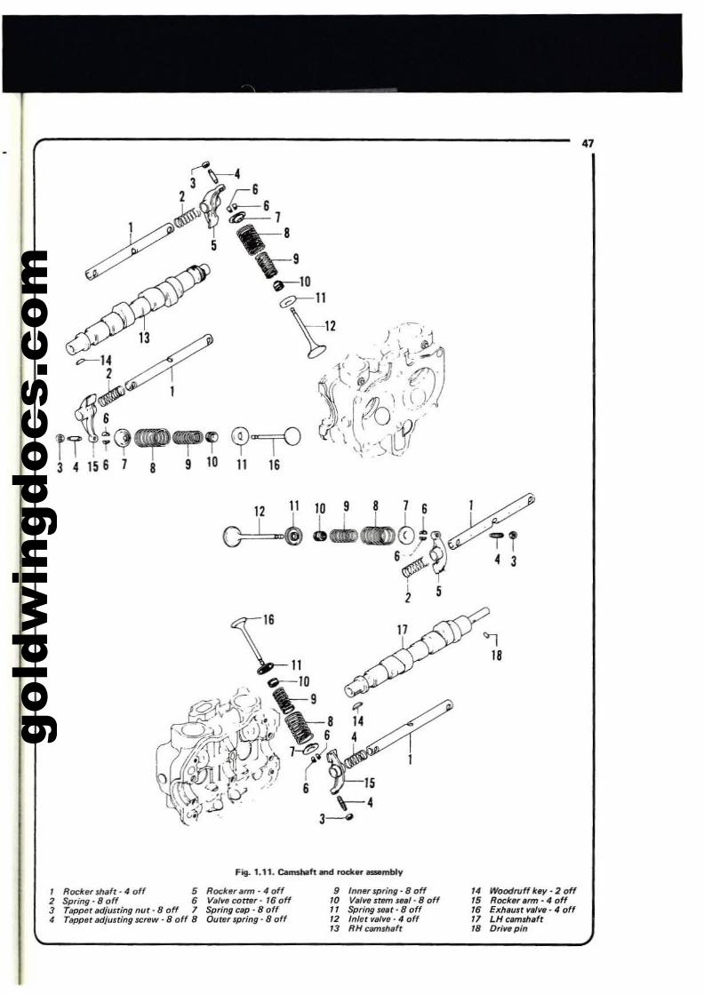
gold
win
gdoc
s.co
m
47
12 11 10 9
~~
15
\-43--4
'118
, Rocktff $h.'t· 4 off 5 Rocktff arm • 4 off2 Spring - 8 off 6 Val'" corter - 16 off3 Tappet tldjusring nut - 8 off 7 Spring cap . 8 off4 Tappet IIdjusring ICrlW - 8 off 8 Outer spring· 8 off
9 Inner spring - 8 off10 Valve stem leal- 8 off11 Spring Stlilt - 8 off12 Inlet valve- 4 off13 RH camsh.ft
14 WoodfIJff key· 2 off15 Rocktlf,rm-4off16 Exhaust valvB' 4 off" LH clmuh.ft18 Dr/". pin
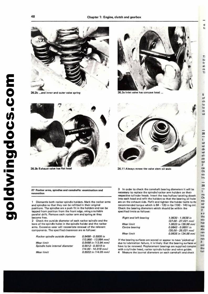
gold
win
gdoc
s.co
m48 Chapter 1: Engine. clutch and gearbox
•/ 2lEI
TI
"f,'"mT1
•f.
twf..~,
wf,f,po.~
2
'"0,~
im
5of,"
.f.10I.
;; ~..
t
I
26.3a Inlet veIYe hIlS COflClN8 heed _••
26.11 Alwavs renew the valve Item oil Illals
,.
".
262b .••m inner WId outer VIM Ipflng
.~.
•
26.3b El(h~1t ....1... h.. flat heKi
..- "",-
29
'Z1 Rock....f .... spinella.net camshafts, a.minalion.ndnonov.tion
1 Dismentle both rocker spindle holders. Mark the rOCker arms....d spindles so mat they ClIIl be refitted in their orilliMipasitionJ- T'l\e spindes are 8 push fil in the holden and cen beU1ppe<! from position from the front edge. using. witablepa,./lel drift. AemO\/e each rock.r ann and spring_ theybecome free.2 Check the outside dilllTleter of each rocker spindllind thebort of the spinde holes in the spinel. hoiOer and the rockerarms. ElIcetsivl wear will nllCluilat. renewal of the relevantcomponents. The specified clearances are 85 follows:
If Ihe beating surfllCe$ are scored or appear to h~ 'picked-up'due 10 lubrication failun!, it is likely mit me bearing lIurfaces wi.tillY. to be "-_d. Repla«menl bearings i1fe supplied complet!with • cylinder head. rocker spindle holder and v8lve guides.4 MellWre the ioum41 dia-neten on each earmhefl end meek
3 In order to cheek the camshaft be.ring diameter. it will benecessMy to replace the lIpiTlde/rocker arm holders Ofl theirrespective cylinder heads. Insert the two hollow IO:'ling doMlinto each head and ll!fit the holdel'$ so mit the blaring oil holl!!h on the exhaust side. Aefit end tighten the holder bolts to lhtrecommended torque Niich is 84 • 120 in lbs 1100 . 140 kg ctrIlO'Hlck the bearing diameten VItIicn should be within ttlespecified limits as follows;
tChu....~
2or
"'.n"
""'p,,t><
""inti
"03~I
"',fail
UJ630 - UJ638 inf27.00 - 27.021 mm)UJ623 in (26.98 mm)0.9843 - 0.9851 in(25.00 - 25.02' mm)0.9835 in (24.98 rom)WIt" limit
Right and 'efr bearing
We'" limitCent" bfulfing
0.5498· 0.5505 in(13.966, 13.984 mmJ0.5488 in f/3.94 mmJ0.5512 - 0.5519 in(T4.00· '''.OtSmm)0.5532 in (1".05 mml
Rocker spindle ouaide di.merer
We.rllmit
We'fllmitSpindf, hole internlll dilNMtN
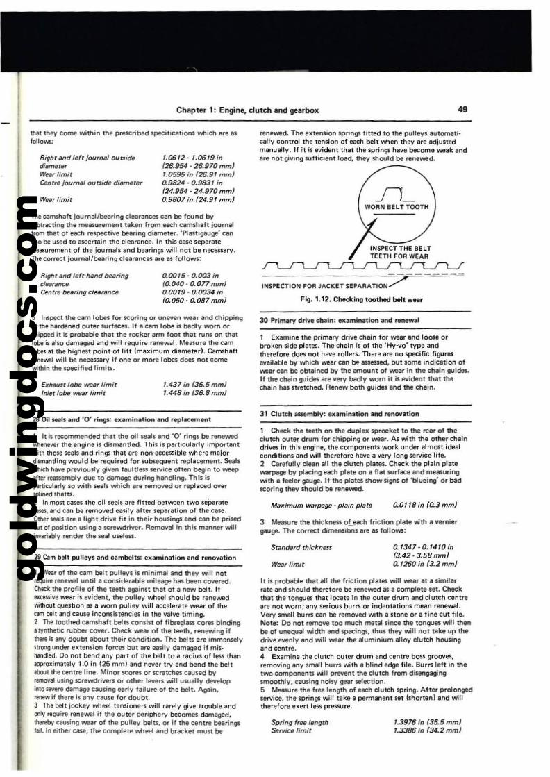
gold
win
gdoc
s.co
m
Chapter 1: Engine, clutch and gearbox 49
that thPf come within me prescribed specific,uions which are aslollows:
The camshilft joumalfbearing clearances can be found byII.Ibtract;ng the measurement taken from each cllTlsh.ft journalfrom that of each respective bearing diameter. 'Plest;gauge' can11I10 be used to .scertain the clearance. In this case separatemeasurement of the journals and bearings will not be necessary.The correct journal/bearinll clearances are as follows:
~ lns.pect the urn lobes for scoring or uneven wear and chipPingof the hardened outer surfaces. If a cam lobe is badly worn orchipped it is probable that the rocker arm foot that runs on thatlobe is also damaged and will require renewal. Measure the camlobes at the highest point of lift Ima>cimum diameter). Camshallrtflewal will be necessary if one or more lobes dOl'S nol comeMthin the specified limits.
Right and I,(t journal oursidtJdia~rfJr
Weilrlim;rCenrra jour".1 OCIrsidii diam.ter
Weilr limir
Right and lafr-hand buringcle.,.nc,Cenrre be.,ring cle8rlJnce
EJC/l8Ust lot- wear limit'1I1.r I~ weilr limit
UJ612· 1.(}619 in(26.954 . 26.970 rnrnJ1.0595 in (26.91 mml0.9824 . 0.9831 in(24.954· 24.970mmJ0.9807 in (24.91 mmJ
0.0015 - 0.003 in(0.040·0.077 mmJ0.0019' 0.0034 in(0.050, 0.087 mmJ
1.437 in (36.5mmJ1.448 ill (36.8 mmJ
renewed. The e>ctension springs fitted to the pulley. lutomati·cally control tha tension of each belt wnen they are adjustedmanuIlJy. If it is evident that th. springs heve become weak andare not gilling sufficient load. they should be nl!newed.
JLWORN BELT TOOTH
Fig. 1.12. Checking toothed b11ll w....
30 Primary drill. chain: examination and raMWaf
1 E>Clmine the pr;mary drive chain for wear and laos. orbroken ,ide plates. The chain is of the ·Hy....o· type andtherefore does not heve rolters. The,. are no specific figures....ailable by which wear can M essessed. OOt .ome indication of_ar can be obUlined by the emount of wear in the chain guides.If the cMin guides are very bedy worn it i. evident that thechain has stretch.d. Renew both guides and the chain.
28 Oil .-als and '0' rings: examination and replacement
3 Measure the thickness oLnch friction plate wth a ....miergauge. The correct dimensibnS ani! as follows:
1 Oleck the teeth on the duplallll sprocktt to the reer of theclutch outer drum for chipping or _ar. A. with the other chaindrives in this engina, the components work under a1mollt idealconditionland will therefore heve a very long service life.2 Carefully clean all the clutch plates. Check the plain platewarpage: by placing each plate on • flat IIJrface end me8luringwith a feeler gauge. If the plates show signs of 'blueing' or badleoring they should be renewed.
II is probable that all the friction plates will we.r al alimi'arrate and should therefo.. be renewed 81 a cOfT1fJlete set. Checkthat the toogJes that locate in the outer drum and el u«:h centraare not worn; any serious burrs or indentations meln ..newal.Very small burn can be rlmOl/ed with a stooe or a fine cut file.Note: Do not remove too much metal since the tongues will th""be of unequal width and spacings, thus they will not take up thedrive IMlnly and will _ar the aluminium alloy clutch housingand centre.4 E>camine the clutch outer drum and centre bosS groOl/es...mOl/ing IIny small burn with I blind edge file. Burrs left in thatWO componenll will prlMlnt the dutch from disengaginglfTloothly. eaus.ing noisy gear selection.5 Measure the free length of each clutch spring. After prolongedservice. the springs will take a permanant set (shorten) .nd willtherefore eKert less presIUri!.
1 It is recommended thal the oil seals and '0' rings be ranewedwhenever the engine is dismantled. This is particularly important"';lh those seals and rings that are non-accessible where majordismantling would be reQUired for subsequent replacement. SealsI'ItIidl h_ previously gillen faultleM service often begin to weep.lter f83SHmbly due to damage during handling. This isj)Il1ic:vlarly 50 with seals which are removed or r~acedOllerspIined shafts.2 In man cases the oil sltals are fitted between two seperetecases. and can be remOlled easily after separation of the case.Other seals Ire a li~t drive fit in their hoos.ings and can be prisede:-lt of position us.ing a screwdriver. Removal in this manner willilmriably render the seal useless.
29 Cam belt pulleys lind cambeltl: e>camination and renOl/ation
I Wur of the cam belt pulleys is minimal and they will notrwquire ren.wa1 untilll considerable mileage hilS been covered.O!e;;k th, profile of the teeth against that of a new beh. Ifmeuive \War is ellident. the pulley wnee4 Should be renelM!dI'Iithout question !IS a worn pulley will eccelerate lM!ar of the<:lim belt lind CIlUse inconsistencies in the lIaille timing.2 The toothed camshaft belts consist of fibreglas5 cores binding• synthetic rubber COlIer. Check wear of the t9l!th. renewing ifflm is any doubt about their condition. The befts Ire immensely1U0Il1l under e>ctension forees but Ire easily damllged if mis·h.ndled. Do not bend IIny part of the belt to a redius of less thanIIPPrllKimately 1.0 in (25 mmlllnd never try and bend the beltIbout me centre line. Minor scores or scratches ClIUsed by_1lI uling screwdrillen Or oth.r levef$ will usually developinto _re damage causing early failure of the belt. Agein.ItfleW if there is any cause for doubt.3 Th& bel! jockey wheel tensioners will rarely gille trouble andonly require renevval if the outer periphery becomes damaged,1hel1!by causif'lg wear of the pulley belts. or if the centre bearingsfail. In either case. the complete wheel and bracket must be
Maximum WlJrpage • plain platil
Stalldard thicknfll$
Wear limit
Spring free length~tVice limit
0.0"8 in fO.3 mmJ
0.'347·0.1410in(3.42·3.58mmJ0.1260 in (3.2mmJ
1.3976 in (35.5 mmJ1.3386 in (34.2 mmJ
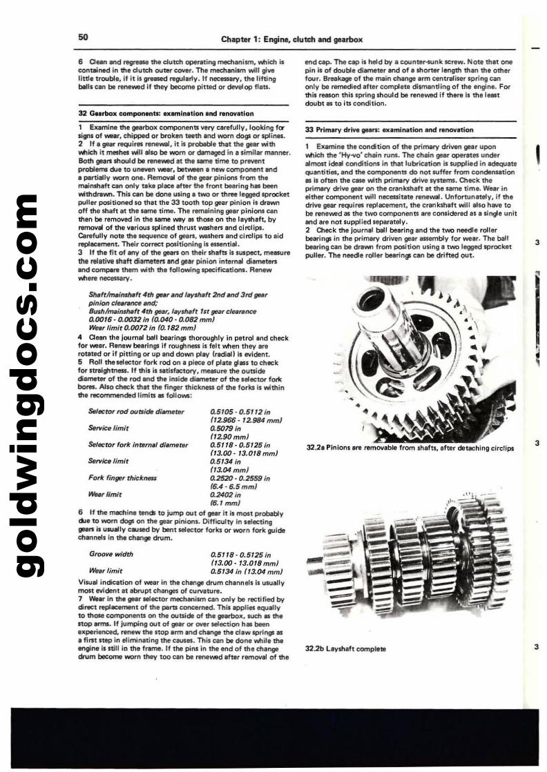
gold
win
gdoc
s.co
m50 Chapter 1: Engine, clutch and gearbox
6 Quo and regtNSe the dutch ope,.ting mechllllism. Ylttich iseontaiinttd in the dutch OUtel'" C(IYe'. The mechanism will givelittl, trouble, if it il greased r8lPJlerly.lf nocllS5llry, th.liftingbills can be renewed if they become pitt1ld or develop "ats.
1 Examine ttle gearbox components very clirefuUy. looking f(l'.Ignl of wear. chipped or bro~ teeth and worn dogs or splines.2 If. gear requires renewal. it is probeble that the ""., wi1tlMien it meshes 'Alill also be worn or dBmaged in ••imillM' menner.Both ge:l1'$ 5hould bI renev.ed at the IaTIe time to preventproblem5 due toU~ _.r. betvleen. newcc:wnponent ....d• ~rtilllly worn one. Removal of the gear pinions 'rom the",,""shaft can only ~ke place after the "Or'It bellring has beenwittldlllVOfl. This can be dofl. using I two or three legged sprocketpuller positioned 10 that the 33 tooth top gear pinion II drawrloff the shaft at the ••me time. The remaining gaer pinions ellnthen be removed In the same way III those on the laylhaft, byremoval of the .....Iou. splined thrust weshel'$ and cin:lIps.c.refully note the lequence of geau. washers and circ::llps to aidreplecament. Their correct positioning 1._ntll1l.3 If the fit of .ny of the ge.n on their shafts i.w.pecr. meBSUrethe relatiVll.h.ft di.meten and gear pinion internal dilmllten.nd Complrl them with the following specif'lClItions. RenewV\It1erl neceuary.
SNfttm.i"iMft 4th gur Ind l-riM't 2tld IfId 3rd tIP'pi"ion C/I'~IIfId;Bush/trIlIi,,'h.ft 4M tIP', '-r,h.'t lit ge.rcfunmctl0.0016- 0.00321" {a040· 0.082mmJWeI, limit 0.0072 in to. 182 mm}
4 a,an the Journ81 belt beerings thoroughly In petrol and chec::kfor we.r. Renew bearings if roughness i$ felt Men they arerotlted or if pitting or up and down play Ir.dian is evident.5 Roll the5llector fork rod on. piece of plate gill' to checkfor nnightness. If this issatinlCtory, measure the outside(Slmeter of the rod end ttle inside d~teI' of the .elector fortebof'eI. Also check ttl.t the finger thickness of the forks is withinthe recommended limits lIS follows:
s.lflCtor rod oursidtt dillfflete, 0.5105·0.5112 i"{12.966· 12.984mml
S6rvicelimir o.SOJ9in(12.90mm)
SeIBCtor 'ork inter",1 di.meter 0.5118· 0.5125 i"f13.00-13.0lBmm}
Service "mit 0.5134 in{13.04 mmJ
Forie finger thickneu 0.2520·0.2559 in{6.4· 6.5 mm}
WH, limit o.24lJ2 i"(6.1 mm)
6 If the ~in. tends to jump out of gIIr it is mOlt probablyd..oe to worn dogs on the gellr pinion•. Difficulty in .electinggNB is UAllllly Called by bent selector forks or worn fork guideen.nnel. In the change dr1Jm.
Groove width 0.5118-0.5125;n113.00· 13.018 mm)
WeIr limit 0.5134 in (13.04 mm)
Vlwlll indiCition of wear In the ch.nge dr1Jm channel. Is usu.llymolt evident at .bI'1Jpt ch.nges of C\lrv.ture.7 Wear in the gear selector mechanism can only be rectified bydirect replacenvnt of the pill'U concerned. This applies equally10 thOle components on the outside of the gIllIrbox, such as thestop arms. If Jumping out of gIlar or over Mlection has been.xperienced, Nmew the stop arm and change the cl.w JPrings as• fint step in eliminating the CIUSes. This ClIn be done while theengine is still in the frame. If the pin' in the end of the mangedn.lm become worn they too Cln be Nmewed .fter rM'loyeI of the
end cap. The clip is held by a counter-$,jnk screw. Note ttl.t onepin is of double diemeter and of a shorter length than the otherfour. Breakage of the lT1Iin change arm centre!iser spring Clnonly be remedied after completl dltmlNltling of the engine. Forthis reason thislprlng Ihould be reneWld if there il the leastdoubt as to its condition.
33 PrilT1lry drive lINn; uamil\ltion and renew.tion
1 Examine the condition of the prilT1lry driven gear uponV\It1ich the 'Hy-vo' enllin r1Jns. The chain gear operetes under.most ide. conditions in that lubrication is wpp!ied in adequateqJantities, and the components do not suffer from condenSltionlIS is often the CIlIe with primery drive systems. Dleek theprimery drive glllIr on the crankshaft at the~ time. Wear ineither comPOllent will neeessitite renewal. Unfortunately, if thedrive gear requires replacement, the crankshaft will also hlllle tobe raneIWd 81 the two components are considered II a .ingle unitand life not supplilld separately.2 Cleek the journal ball bearing and the two needle rollerbearings in the prilT1lry driven gear auembly for wear. Th. ballbearing can be drawn from position using a two legged sprocketpuller. The neede roller bearings can be drihe!;l out.
32.2. Pinions are remOlllble from shafn, after detaching circlips
322b Layshaft complete
,
3
3
3
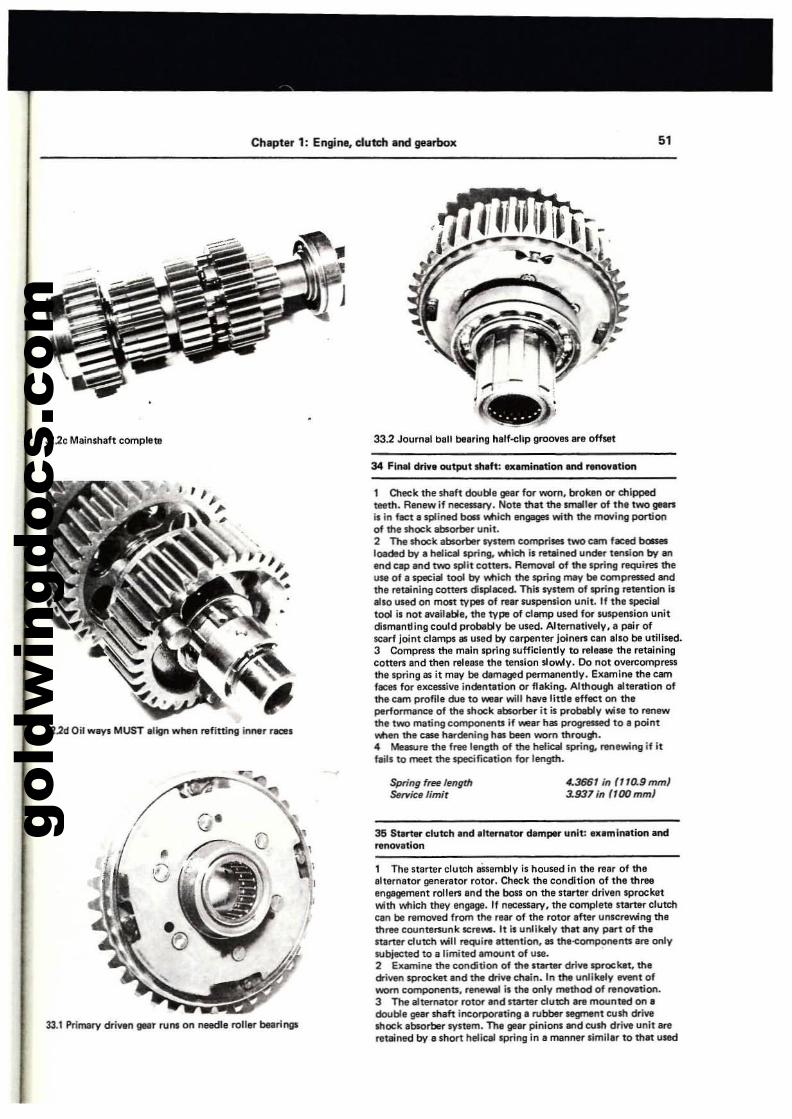
gold
win
gdoc
s.co
mChapter 1: Engine, dutch and gearbox 51
i""" - ...... :'c.-.., .y
32.2c Malnshaft complete 33.2 Jountal ball btl8rlng h.lf-elip groove. are offllt
34 FInal drive output sh.ft: .nmination MId ~no....tlon
32.2d Oil way. MUST .11gn wtlln ~fitting Inner r_s
1 OIeck the shaft double ",.r for worn, brokln 0( chippedteeth. Renew if neceaary. Note that the smaller of the two gean:it in fact a splined boa """ich If'IgIlgeS with the moving portionof thelhock absorber unit.2 The shock absori:ler systlJm comprises two cam faced boaesloadId bv I helical ~ng, Wlich is retained under tension bv anend ctlP IKld two split cotters. Removal of thl spring requires theUII of I special tool bv which the spring may be cc.npressed endthe retaining cotten: displaced. This system of spring retention isalso used on most types of rear ruspension unit. If the specialtool il not available, the type of clamp u.ed fO( IWspension unitdilmantling could probably be used. Alternatively, a pair ofscarf Joint clampt as used bv carpenter jolnen: can al.o be utilised.3 Compress the main spring sufficiently to release the retainingcotten: and then release the tension slowly. 00 not overcompre5Sthe spring lIS it may be damaged permanently. EXlmlne the c.nfeces fO( exce5Sive indlntltlon or flaking. Although a1ttration ofthe cam prom. due to \War will h8V1! little effect on theperformance of the Ihock absorber It is probebly wil' to renlWthe two mating comporletlts if \War has progressed to a pointwhen the case h..-dening hIS been worn through.• Measure the free length of the helical spring, renewing if itflill to meet the speciflCltion for length.
35 St.rt,"" clutch .nd Ilternator dam!*" unit: Iltlmlnation .ndrenov.tion
, The starter clutch aSsembly is housed in the rear of theeh.mator generator rotor. Check the condition of the threeengagement rollen and the boll on the .tarter driven sprocketwith which they engage. If necessary. the complete It&rtllr clu«:tlcen be removed from the rear of the rotor Ifter unscrewing thlthree countersunk IICre...... It is unlikely that any part of themrter dutch will require attention, lIS the'<:omponents are onlysubjected to a limited amount of u....2 Examine the "ondition of the ltartet" drive Ipf"ockat. thedriYlKllpf"ocket and the drive chain. In the unlikely event ofworn components. renewal is 1M only ITIIthod of renovation.3 The .ltemator rotor Ind starter dutdl Ire mounted on adouble gear shaft incOf?O(atinga rubber~t tush driwshock absorber SYltem. The gear pinionl and tush drive unit areretained bv a .hort helical spring in a manner limillr to that used
33.1 Primary driwn IJIllIr runs on needle roller bearings
,
I
$pring free lengthS.",ic'limit
4.3661;n ,,,o.9mmJ~93'inf100mmJ
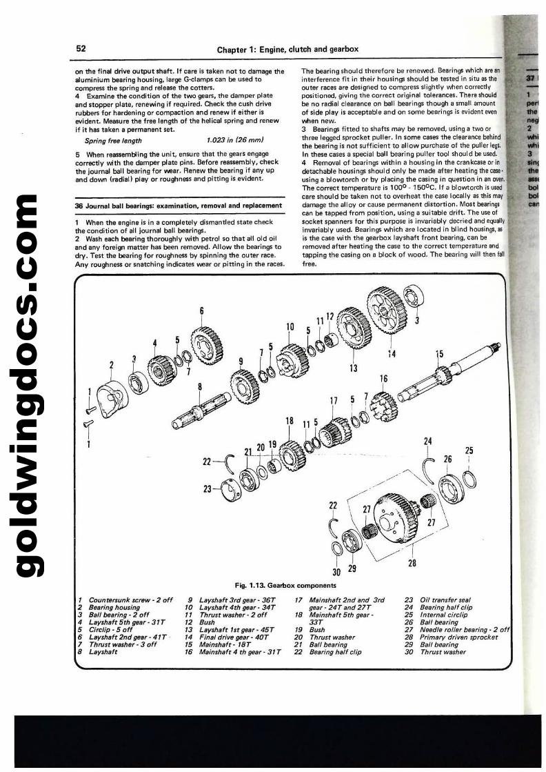
gold
win
gdoc
s.co
m52 Chapter 1; Engine. clutch and gearbox
on the final drive output shaft. If cere is taken not to damage thealuminium bearing housing, large G-clamps can be used tocompress the spring lind release the cottlln.4 Examine the condition of the two ga8n, the damper plateand nopper plate, renewing if required. Check the cush driverubbers for hardening or compaction and rBnew if either isevident. Measure the free length of the helical spring lind renewif it has taken a permanent set.
Spring frHlength '.023 in (26 mm)
5 'Nhen reassembling the unit, ensure that the gears engagecorrecdy INith the damper plate pins. Before reassembly, theckthe joumlll ball bearing for wear. Renew the bearing if any upand down (radial) plav or roughness sod pitting is evident.
36 Journal ball bearings: ex.minetion. removal and replllCflment
1 When the engine is in a completely dismantled state checkthe condition of all journal ball bearings.2 Wash each bearing thoroughly with petrol so that all old oiland any foreign matter has been removed. Allow the bearings todry. Test the bearing for roughness by spinning the outer ract!.
Any roughness or snatching indicates wear or pining in the races.
The bearing should therefore be renewed. Bearings which are aninterference fit in their housings should be tested in situllS theouter races are designed to compress slightly when co,rectlVpositioned, giving the correct original tolerances. There shouldbe no radial clearance on ball bearings though a small amountof side play is acceptable and on some bearings is evident evenVIIlen new.3 Bearings fitted to shafts may be removed, using a two orthree legged sprocket puller. In some cases the clearance behilldthe bearing is not sufficient to allow purchase of the puller legs.In these cases a special ball bearing puller tool Should be used.4 Removal of bearings within a hoosing in the crankcase orindetachable housings shoold only be made after heating the case·using a blowtorch or by placing the casing in question in an oven.The correct temperature is 1000 - 1500C. If a blowtorch is usedcare should be taken not to overheat the cBStllocally as this mavdamage the alloy or cause permanent distortion. Most bearing$can be tapped from position, using a suitable drift. The use ofsocket spanners for this purpose is invariably decried and equ"l~
invariably used. Bearings which are located in blind housings, itS
is the case with the gearbox layshaft front bearing, can beremoved after heating the case to the correct temperature andtapping the casing on a block of wood. The bearing will then 181free.
•-•2
:'•............
Fig. 1.13. Gearbox components
, Counrenunk screw - 2 off • Laysh.ft 3rd ge.r· 36T " M.inshaft 2nd .nd 3rd 23 Oil transfer seal2 Be.ring housing '0 Layshaft 4th ga.r· 34T gear· 24T and 21T 2' Bearing half clip3 B.11 be.ring· 2 off " Thttlst washer· 2 off 18 Mainsh.ft 5th ga.r· 25 Internal circlip, Layshaft 5th gear· 31T 12 Bush 337 26 Ball be.ring5 Circlip . 5 off '3 Leyshaft 1st gear· 45T " 8u", 27 Needle roller bearing· 2 off6 Layshaft 2nd gear - 41T - " Final drive gear· 4QT 20 Thrust washer 28 Primary driven sprocket7 Thrust walhar· 3 off 15 Mainshaft· 1ST 21 Ba/l bearing 2' Ball bearing8 Layshaft '6 Mainshaft 4 th gear - 31 T 22 Bearing half clip 30 Thrust washer
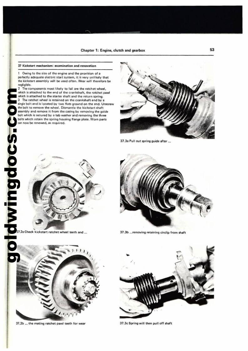
gold
win
gdoc
s.co
m
Chapter 1: Engine. clutch and gearbox
J1 Kic:kstart mechanism: eJtam;mltion and renontion
lOwing to Ihe size of the engine and the provision of aperfectly adeqUate electric 51art system. it is very unlikely thatthe kickllart assembly -Mil be used often. Wear will therefore beneljigibla.2 Tha components most likely to fail are the ratchet wheel,vIlich is attached 10 the end of the crankshaft. the ratchet paWlI'otlich is at10ched to the starter Shaft and the return spring.3 Tha ratchet wheel is retained on the crankshaft end by asingle bolt and is located by two nats ground on the end. Unscrewme bolt to remove the wheel. Dismantle the kickstart shaft.Iamb/y and remove it from the casing by removing the guidebolt which is securlld by a tab washer and r,moving the threebolts which retain the spring housing lIange p1ete. Worn partstan now be renewed, as reqUire<:!.
37.3a Pull out spring guide after ...
53
I
,37.2a Check kicksurt ratchet wheel teeth and ...
"' ,
37.2b ... th' mating ratchet pawl teeth for wear
37.3b ...removing retaining eirclip from shaft
37.3c Spring will then pull off shaft
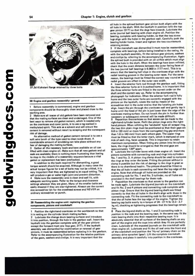
gold
win
gdoc
s.co
m54 Chapter 1: Engine. clutch nd gearbox
37.3d Kiekst.rt f1W1ge retelned by three bolts
1 Before re..~mbly is commenced. engine el"ld gearboxcomponents should be thorOlJI#l'V clean and plllCed close to theworking .rel.2 Mak' sure ell tr8Cft of old gaskets have been removed Indth~ the mating surf-.::es Ir. dean and undamaged. One of thebest -VI to remove old gasket cement. vonich is needed onlyon me crankcase and cover joints, if to usa 8 rag soaked inmethylated spirit. This acts 81 • solvent end will ensure ttlecement Is removed without resort to scntPing and the consequeMrisk of damage.
An "t8metille method of gasket cement r8mOllal is to use I!100ft wire brUsh of the type used to clean wedEl shoes. Aconsiderable emount of $Crubbing can take place without anyfeer of dlImaginll the meting surfaces.3 Gether all ttle necessary tools end h811e available an oil canfilled with cleln engine all. Make fure that ell new gaskets and oilseals .... lIVen,ble; there II nothing more frustrating than hllVlngto ItOP in the middle of. rellS$embly sequence because I vitalgasket Of replacement hIlS been overlooked.
In addition to the tooh required f"r dismantling, a goodtorque wrench should be ecqulred. Although in many cas", thelewal torque figures for a set of bolts may not be criticllt, it isvery Important thllt they ara tighteoed to an equal utting. Thiswill produce a ges or water-tight joint and prevent distortion.4 Make lUre the reaulilmbly area i, clean and well lit, withadequate working s~e. Refer to the torque and clearancesettings wherwer they are given. Many of the smaller bolts areaatily sheared If they are over-tightlilned. Always use the correcttll.lillCrlilwdliver bit for the cronhead ICreWl and NEVER anordinary ICrewdriver or punch.
39 R_mbling the engine unit: rephlcing u,. gNrboxCGmponenta, pistons end crankshaft
1 PoIltlon the rilllt~andcrankcase on the workbench so thatit is resting on the cylinder block mating .... rface.2 lubricate the change drum bearing surfaces and introdueeit into po&ition, throulll the hollil in the gearboX wall. Insert ttleleysheft into thti gIIIerbox complete wittl all the gear pinionsellcept ttle fonwrd most one !top gear, 31TI. If the leyshaft~y __ dismantled for examination or renewal of gearpinions, it mutt be reassembled before replacing it in ttle gearbox.Refer to tha accompanying ilillStration for the relative positionsof the ",ars, -r.ers and clrdips. It is very important that ttle
oil hole in the spllned bottom gear pinion bush ali~s 'NIttl theoil hole In the shaft. With the leystlaft in position refit the topgear pinion (31Tlso that the dogs face inwards. lubricate theouter journal ball bearinll ~th clean engine oil. Position thebearing. complete with bearing holder, $0 that the two screwlugs ali", with the holes in the gearbox wall. Carefully push thebearing holder home. InHrt and tighten the two countersunkretaining screws.3 If the mainshaft was dismantled it must now be reassembled,complete with bearings, before being installed in the casing. Aswith thaleythaft -.embly, fit the various gear pinions, W8Stlers.,d eirdipl by referri"i to ttle accompanying illustration. Againthe splined bush is provided with an oil Ofific:e Wiich must alignwith the hole in the shaft. When ttle bearings hlIve been refined,check that the exact dis~e between the outer facing faces ofthe two journal bill bearings is 6.969 in 1177 mml. This is to1nIUr.l that the bearing half clips in the crankcase alilPl with theradial locating grooves in the bearing outer races. For the samereason, the bearings must be fittlld the correct W3'/ round III theradial grooves'" offset in the outer rxe width.4 Insert the selector fork rod throulti the gearbox wall, finingthe ttree selector forks as it is pushed home. It is important thatthe three selector forks lIflI fitted in the cOlT8Ct order on theshaft and the correct Wi1V up. RefQf to the accompanyingphotograph for indication. When the selector fOl'"k rod is fullyhome and the two outer fOfks ara correctly engaged with thepinions on the leyshaft, rotate the rod by means of theICrewdriver slot in the outer end $0 that the locating pin holesa1lr. Insert thil pin through the crankcase walt and gently tap ithome until the head of the pin is jun lower than the edge of thecrankcase mating surface. Do not knock the pin in further thanneeessarv or ....bseoJent removal ~Il be made difficult.5 Reposition thecrankcase $0 that lICCltSS can be made to theright·hand cylinder bores. R.fit the piston rings onto the ri\tlt·hend pistons. When refining the 'sand~h' type oilSC:raplr ring.the two thin plein rings must be positioned $0 that their gaps are0.8 in 120 mml or more from the corrugated ring gap end morethan 1.6 in (40 mml from eech ottlers gaps. The upper ringsmun be fltted so that the letter mark, wnich is stamped on onaside of each ring, faces upwerds. This is important to retainmaximum compression. When fitting any piston into its cylinderbore, the rings shOUld be arrenged $0 ttlat the end gaplareepprOllimately 1200 apart.S Lubricate the cylinder boras with clean engine oil. Insert thapinons complete with connecting rods and rings into cyllndarsNo.1 end No.3. A pinon ring clamp mould be used to compressthe rings as they enter the bores. Fitting the pinons without aclamp is p0S5ible but the risk of damage to the rings is great asthere II no chamfered lead·in. The pistons should be fitted sothat the oil hole in aach connecting rod faces the top edge of tileengina. Note that althoulll oil holes are provided on theconnecting rods for No.1 and No.3 cylinder, no oil holes ereprovided in \ha shell bearings for these rods.7 Repositlon the crankclllle so that access to the gearbox canbe made again. Lubricate the b1g-end journals on the crankshaftand fit No.2 and 4 piltons and connecting rods complete withpilton rings. Ensun thlilt tha big-end bearing shetll are fittedcorrectly so that the oil holes in the shellS iIIign with thOSll in til.connecting rods. Fit the connecting rods to the crankshaft sothat the oil 1'101.. face the top edge of the engine. Tighten thebearing c:.p bolts evanly to a torque of 24·27 ft lb (3.3·3.7kg ml, checking" tightening progresses that the bearings remain_.8 PIece the big-end shetls on No.1 and 3 connecting rods inposition in the rods and ttle bearing caps. In the same way fit themein blIaring shells into their raspec:tive bearing cups. It is8bIolutety _tilll that ell surfaces of tha bearing shetls on anypert of the engine and the cups into Wiie:to they fit en perfectlyc1un. lubricate all the tIlposed journals on the crankshaft withclean engine oil. lubrieete and fit the oil seal onto the front endof the crankshaft and position the 'Hy-vo' primary chein on theprimary drive sprocket (glilari. Uft the complete crankshaftISSlIlTIbly and piece It carefully into position in the crankcase.
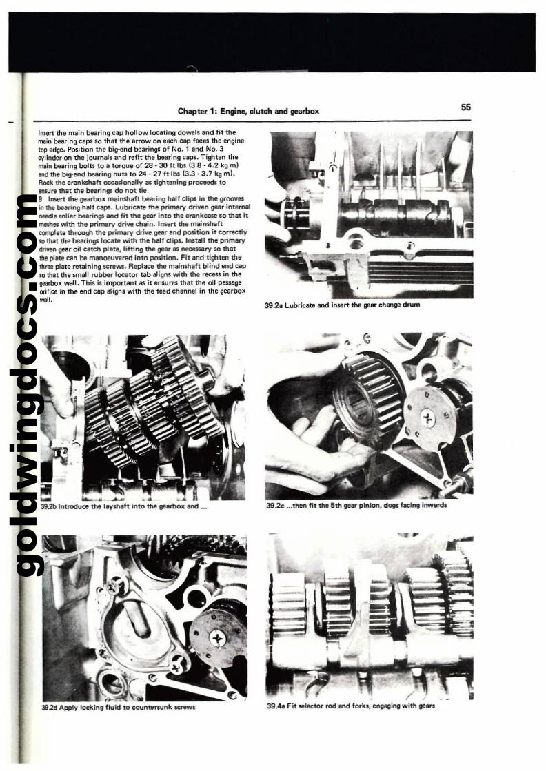
gold
win
gdoc
s.co
m
Chapter 1: Engine, dutch and gearbox 55
Inlert the main bearing cap hollow tocating dowels and fit themain bearing caps so that the alTow on each ,cap faces the enginetop edge. Position the big-end bearings of No.1 and No.3cylinder on the journals and refit the bearing caps. Tiltiten themaIn bearing bola to a torque of 28 - 30 ft Ibs (3.8·4.2 kg mlItId the big-end bearing nuu to 24 - 27 ft tbs (3.3·3.7 kg mI.Rock the crankshaft oc:c:asionally as tighhlning proceeds toIllSUre that the bearings do not tie.g Insert the gearbox mainshaft bearing half dips in the groovesin the bearing half caps. Lubricate the primary driV'tn gear intlmllllnetdle roller bearings and fit the geM into the c"nkease 10 that itmeshes with the primary drive chain. Insert the mainshaftcomplete through the primary drive gear and position it correctly10 that the bearings 1CJC.8t8 with the half dips. InstJIIl the primarydriven gear oil catch plate,lifting the gear as necessary so that\tie plolte can be manoeuvlntd into position. Fit and ti!llten thethrte p1atll retaining screws. Replace the mainshllft blind end capso that the $lTlall rubber locator tab aligns with the recess in thegearboK well. This is important as it ensures that the oil PilSS8lleorifice in the end cap aligns with the feed channel in the gearboll
""I.
~,-..."., .....,;;..,.-.....~:..--_.,~ ~
~--
-------~ -------------
39.2a Lubricate and insert the gear chl!lllgl drum
'---......... . ...3112b Introduat the laysh,ft Into the gearbox and ... 392c ...then fit the 5th ge. pinion, dogs f«:inll inw.-ds
-
/39.48 Fit selector rod and forks, engeging with 18"
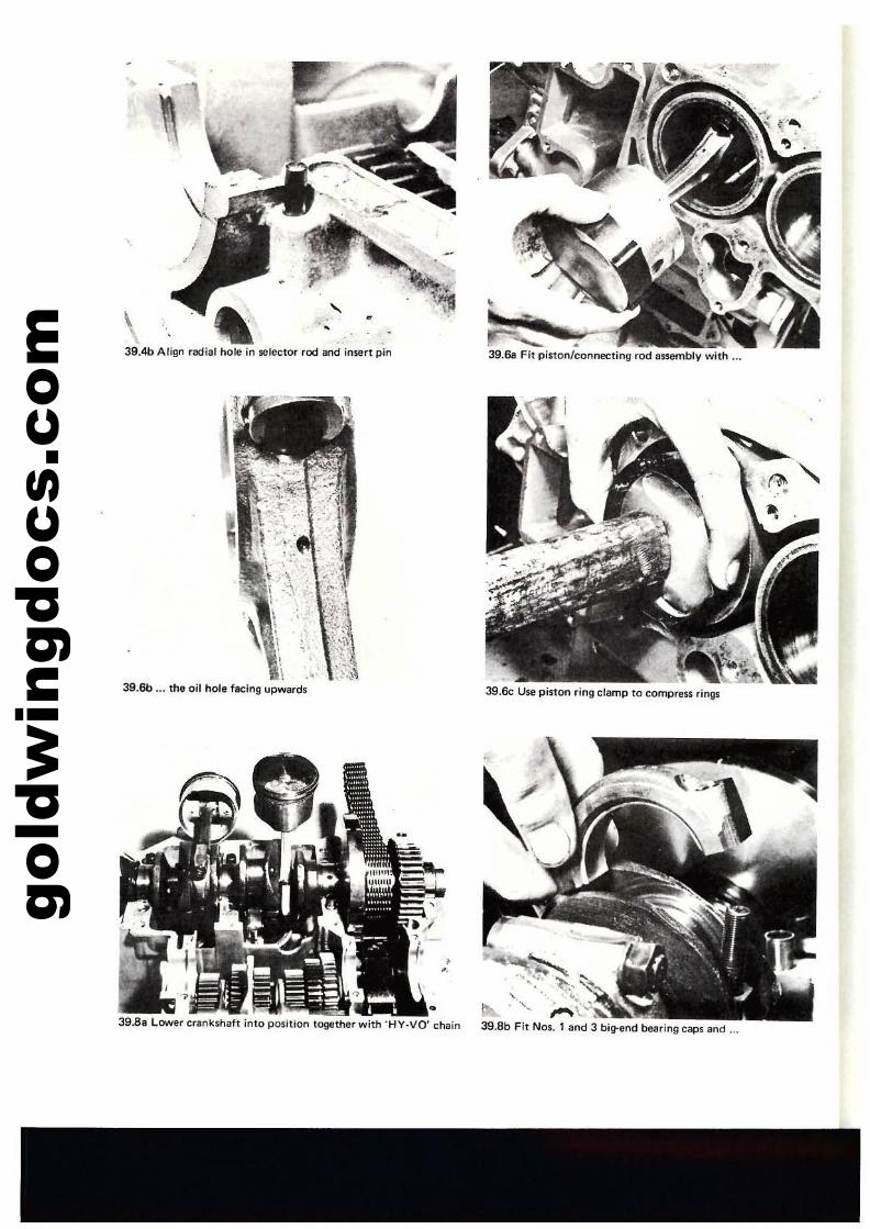
gold
win
gdoc
s.co
m 39.4b Align radial hole in selector rod and insert pin
""39.& Fit piston/connecting rod assembly with
••..
I
\
39.6b ... the oil hole facing upwards
\\ .'
..~•
39.88 L.ower crankshaft into position together with 'HY·VO· chain
,~ " ",,(39.8b Fit Nos. 1 and 3 big-end bearing caps and
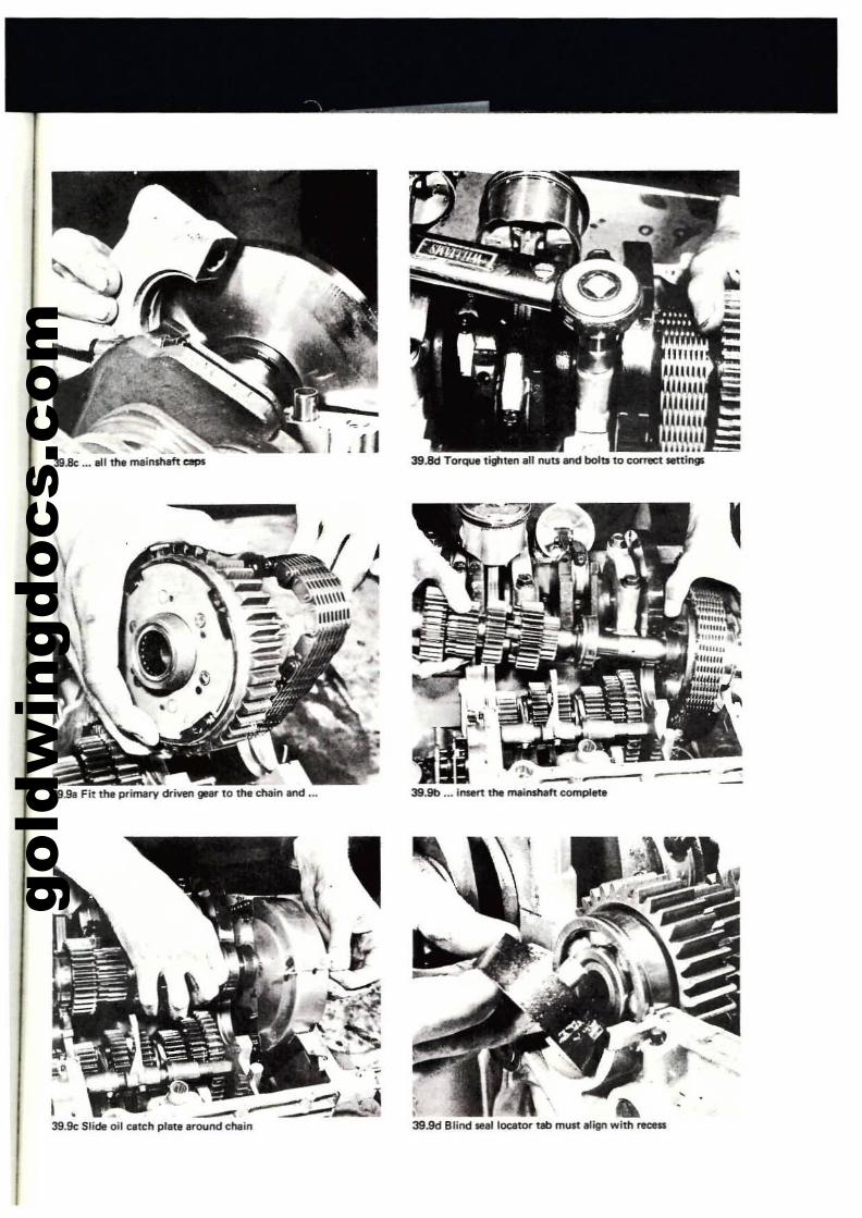
gold
win
gdoc
s.co
m
39.8c .•• all the mai"wn ClIPS
39.9a Fit the primary driven geer 10 the chai" end •••
-39.9c Slide oil c:.tc:h plat' ,round c:hai"
'-., ..,
i J I
_.~.--..,
39.9b ... insert the mainsh8ft c:ornplet.
, ..39.9d Blind .,lloc:ator t8b must a1ig1'1 with reass
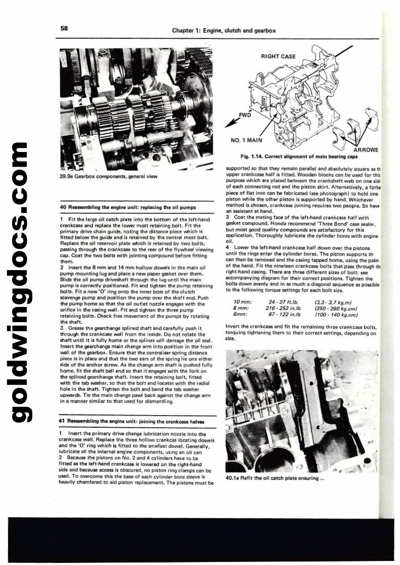
gold
win
gdoc
s.co
m58 ChaPter 1: Engine, clutch and gearbox
40.h Aeflt the oil catch plate ensuring .•.
(3.3· 3. 7 kg.m)(250 - 290 kg.cm!"00· 140 kg. em)
24 - 27 fUb.216·252 in.lb87· 122 in.lb
10mm:8mm:6mm:
supported so that they remain parallel and absolutely lJquare lIS ttlupper c"lI'Ikcase half is fitted. Wooden blocks can be used for thi!ptJflJOM which ...e placed between the crankshaft web on one lidoof each connecting rod and the pillon skirt. Alternatively, a forbpiece 01 flat iron can be fabricated (see photogrllfJhl to hold onepinon white the other piston Is supported by hand. Whichevermethod i. chosen, crankcase joining requires two people. So hawan assistant at hand.3 Coat the mating face of the left·hand crankcase half withgasket compound. Honda recommend 'Three Bond' case Slaler.but mo.t good quality compounds are satisfactory lor thisappliclltion. Thoroughly lubricate the cylinder bores with engine011.4 Lower the left--hand crankcase half down OYer the pistot'lSuntil the rirlgs enter the cylinder borIS. The pi$IDr'I IUpport. thcan then be relTlO'nd and the easing tapped home, using the palmof the hand. Fit the nineteen cntnkc&ll bolU that pau Ihrough tbIright-hand casing. There are three different sizlS 01 bolt: S&I
accompanying diagr.wn for their COUKt positions. Tighten theboIu down IIYl!nly and in as much a di890nal saquence lIS possibleto the fol'owing torque settings for elth bolt size.
In~ert the crankcase and fit the remaining three crankcaSl bolts,torquing tightening them 10 their correct sellings, depending onsill.
ARROWSFill. 1.14. Correct alignment of main bearing QpI
-FWD
/'
RIGHT CASE
1 Fit the large oir catch p1l1tt into the bottom of the left-handcrankcase end replace the lower most retaining bolt. Fit th.primlrv drill' chain guide, noting the di5t8n<:11 piece v.t1ieh .,fittll'd below the guide and ill1lutined by the central most boll.AeplllCt the oil reservoir plate which is reUlined by two bolts.passing throu!tl the crankcase 10 the rear of the flywheel viewingcap. Co.l the two bolts with iointil"lg compound before fining
"'~.2 InlIlIf1 tlU 8 mm and 14 mm hollow 00-15 in the mein oilpump mounting lug and place II new paper gasket oyer them.Slide the oil pump driYeshaft 1ttrous;. the lug until the meitlpump is con-ectly positioned. Fit lind tighten the pump I1IUJiningbolts. Fit II new '0' ring onto the inner boss of the clutehEaYeng8 pump etld pos.ition ttl. pump Oller the shaft Md. Pushthe pump home so that ttl. oil outlet nozzle engages with theorifice in the eMing wall. Fit IM"Id tighten the three pumpretaining bolts. Check fret! movement of the pumps by rotalingthe shah.3 GreMa the gea~hange sp'ined shaft and carefully pUih itthrough the crankcase wall from the inside. Do not rotate thesnaft until it is fully home or the .plines will damage the oil seal.Insert ttIe glerchange main change arm into position in Ihe front_II of the glar'boll. Ensure that the centraliser spring dinal'lCepiece i. in place &rid that the two eal'1l of the spring lie Otle eitherside of the anchor serew. A. the ch....ge arm shaft i. pushed fullyhome, filthe shaft bell end so that it engages with Ihe fork onItte splined gearchange shaft. 'nsert the retaining bolt, filledwith the tab wesher, so that the boh end 10000tli with the radialhole in the shaft. Tiltlten the bolt and bend the tab washerup_dI. Tie the main change pawl back agail1$t the change armin a manner .imi.... to that used for diifTlant!ing.
40 R....mbling thllllng'"' unit: r,plecing the all pumps
39.98 Gearbox componentl. ger'lertlllliew
41 R_mbling t!HI engine unit: joining the crankces- hal_
1 'nsert the primary drive change lubrication nozzle into thecrankcase wall. Replace the three hollow crankcas locating dowel.and Ihe '0' ring which is fiUed to tha smallest dowel. Generally,lubricate all the internal e...glne componenlS, using an oil ca ...2 BecauM Ihe pistons on No.2 and 4 cylinders have 10 befitted al th, left-hand crankca.. illoWlred on the right.handside and because access is oblClJred, no piston ring ciampi can beused. To overcome this the base 01 each cylinder bore sleeve isheavily ehamfered to aid pillotl replacement_ The pistom must be
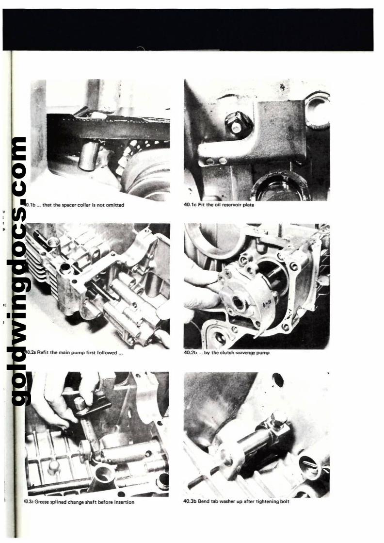
gold
win
gdoc
s.co
m
,..-.. ...
"
,
"
4O.1b ... that the lIpKer call... il not omitted
40.211 Aefit t .... mein pump fim followed ••• 40.2b ... by the clutch scavengt pump
JL7«J.3a Greese splined change $haft before in5ertion
•
,
•.<
- -I...4O.3b Blind tab wlISher up after tighlening bolt
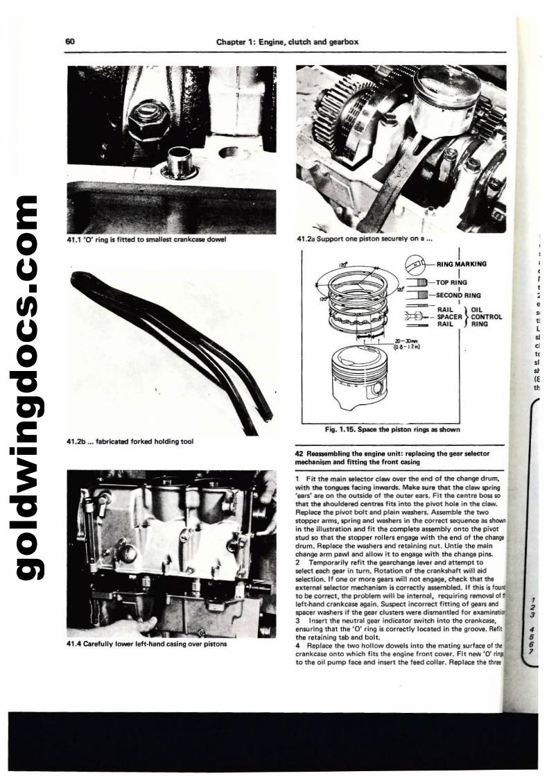
gold
win
gdoc
s.co
m60 Chapter 1: Engine, clutch and 98arbox.
:•••L
•01
".,.."'"
..".. f41.2. Support ooe piston securely on. '0,
I0-lUNG iA'UtlNO
~-TOPRING,.:::::::::EI-SECOND RING
~-RAIL I OIL
~~:~~~~ ~_ SPACER} CONTROL~ RAIL RING
lll-:II_..-,,~
Fig_ 1.15.S~ the piston rinlt' .Itlown
.'.1 '0' ring It fh1ed to .maUest cl1InkcaN dowel
41.2b ... f.brluted forked holding 1001
42 ANSMmbllnll the engine unit: r89lacing the~r ,.IKlarmKMnlsm and fining 11'1. front easing
41.4 Car.fully 10_ left-hand casing OYfIr pinons
1 Fit the main selector c1_ over the Mld of the change drum,with the tOf9ol. hlC;1'lg inwerds. Make WI1I that the el.w lPfing'N'S' Ire on the OUtside of the outer uri. Fit the nnt.. boss sothat the shouldered centres fiU into the pivot hole in the er_.Replace the pivot boll and plain WMhers. Assemble the twO
nopper Irm., spring end washers in the correct sequence M shOWllin the illustrltion and fit the complete anembly onto the pivotstud $0 that the stopper rollnl engage with the end of the changedrum. ReplICe the washer. and retaining nut. Untie the mainchange arm pewland allow It to engage with the change pi",.2 Tempol'arity refit the \Ie.rchange lever end attempt toMleet each geer in turn. Rotetion of the crlll'lkshaft will aidselection. If one or mOl"e gears will not engage, check thet theextern;lll selec:tOl' rnecheni$m i, correctly euembled. If this is fCllII:to be correct, the problem will be internel, rllQuiring removal 01 tleft-hand crankcase again. S<Jspect incorrect fining of gelrs andlIPllCer washers if the ge.r cluners were dismantled for "'amiMtior3 Insert the neulral gelr indicator switch into the crankcase,enwring that the '0' ring i' correctly locllted in the groove. R.filthe retaining tab lind bolt.4 Repla<:e the two hollow dowels into th. mllting IUrflCl of thecrankcase onlO which fits the engine front cOYllr. Fit new '0' .i..to the oil pump face 8f'ld insert the fled coller. Replace tM three
,23
•••7
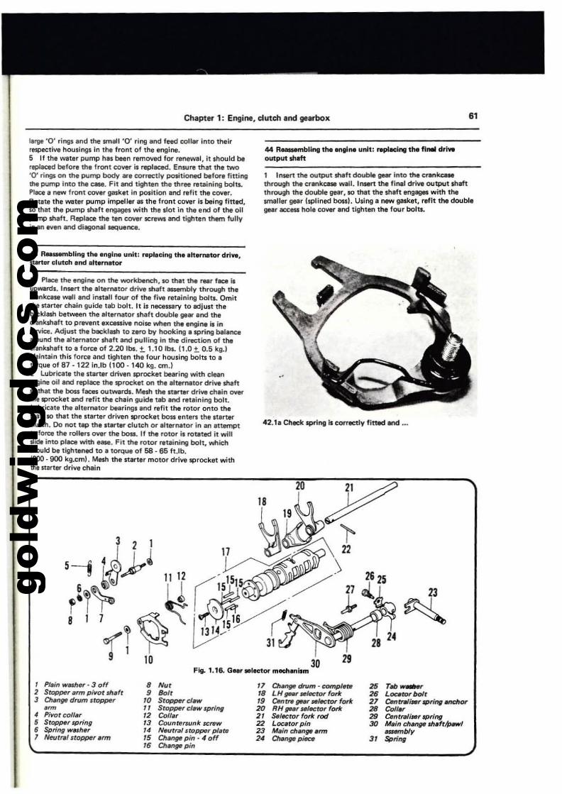
gold
win
gdoc
s.co
m
Chapter 1: Engine, dutch and gearbox 61
II~e '0' rings and the smllli '0' dng and feed collar into theirrupeetlve housings in the front of the engine.S If the water pump hn been removed lor renewal, it Ihould bereplaced before the front cover i. replaced. Ensure that the two'0' rings on the pump body are correctly positioned before finingthe pump Into the c_. Fit and tighten the three I1Itaining bolt...Pltce I new front cover gasket in position and r.fit the COlIer.AOlata the water pump impeller as the front cover is being fitted.so that the pump shaft engages with the ,lot in the end of the 011pump shaft. Replace the ten cOYer ~rews lind tighten them fullyil'lln IVI" and diagonal sequence.
43 Reaaembling the loglne unit; ,.placing th, .hen'llltor drl~.st.rter clutch Ind 1.'...01lt0l'
1 PI_ the engine on the -....orkbench. to thlt the feu lICe isupwards. lnse.. the alterNitor drive shaft llSSllmbIy through ttl,crankCllw wall and install four of the five retaining bolts. Omitthe starter chain guide feb bolt. It is neceSSilry to adjust thebllCklash between the elternator Ulaft double gear and thecrankshaft to prevent excessive noise when the engine is in'If'Iice. Adjust the backlash to zero by hooking. spring balance.-ound the alternator ....eft and pulling in the direction of thecrank....afl to a force of 2.20 Ibli. ±. 1.10 Ibli. 11.0 ±. 0.5 kg.)Maintain this force and tighten the four housing bolu to atorque of 87 ·122 in.lb (100 -140 kg. cm.)2 Lubricate the starter driven sprocket bearing with cleanIngine oil and replace thl sprocket on the alternetor dri.... .tlaftKI that tne boA feces ou1W8n:h. Mesh the narter dri.... cheln OWIrthe sprocket ilnd refit the chain guide tab and "leining bolt.Lubricate the elternator bearings end refit the rotor onto themalt so that the narter driven sprocket boss enterl the sterterclutch. Do not tap the star1el'" clutch or Ilternator in an Iltemptto folt:e tl'Ie roll.rs o~ the boD. If the rotor is rotated it willlIide into place with ease. Fit the rotor retlining bolt, wtlich.tIou1d be tightened to I torque of 58 - 65 It.lb.1800·900 kg.cm!. Me.... the starter motor drive sprocket withthe "arter drive chain
44 RMlMmbling the engl". unit: f8t)ledng tIM fl... drl..output shaft
1 InMn the output shift double geM" Into the c.....kcoaMthrough the crlnkcase WIll. Insert the 111\11 drive output dtshthrough the double gear, to thlt the ....Ift eng8lle' with tl'lesmaller gear lsplined bon). Using I new gasket, refit the doublegear acceu hole cover and tighten the four bolu.
42.11 Chedo: spring Is correctly fitted lind .•.
23
~
1 Plain Washer - 3 off 8 Nol 17 Change drum • complete 2S Tob_2 Smp,.r arm pillor mafr • "" 18 LH flNr .lflJCtor fork 2. Locator bolt3 Olange drum stopper 10 Sr~rdaw " Cenrr. gear _lector fort 21 CentRI~r'Pring enchcw.~ /I Stopper Claw spring 20 RH flNr .'ector forie 28 CoIllr• Pivot colfar /2 Colfar 2/ StJlector fork rod 29 C.ntra/i,.r 'Pring
5 Sropper spring 13 Countersunk screw 22 Locetor pin 3f) Ml/n chenge 6hlft/JHw!5 Spn'ng wMher 14 Neurnll stopPer plate 23 M,in chan~ arm ~b1y
7 Neut,.1 nopper,rm 15 Ch;mgt! pin - 4 off 24 OIen~piece 31 $prit19/. Change pin
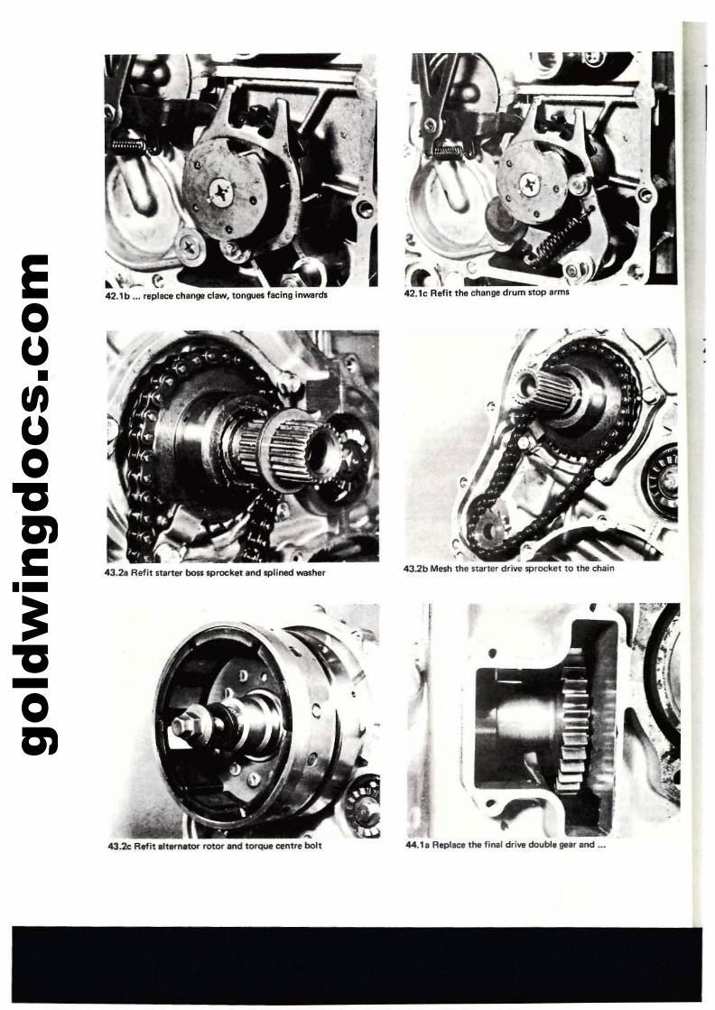
gold
win
gdoc
s.co
m .. i-._ e ...,..:42.1b ... replace chenge claw, tongue. fllCing inwardJ
•43.2a Refit starter boss sprocket and splined washer
43.2<: Refit alternatOr rotor and torque centre bolt
(;sF
"43.2b Mesh the starter drive sprOCket to the chain
I
44.1a Replace the final drive double gear and ...
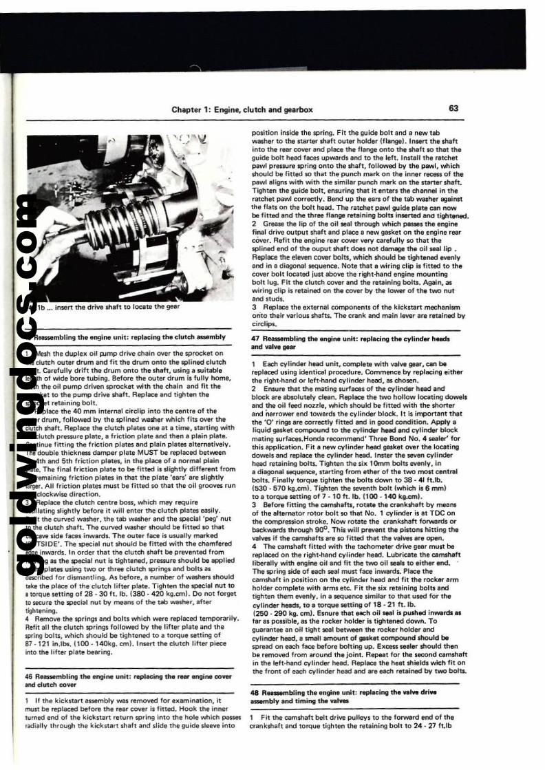
gold
win
gdoc
s.co
m
Chapter 1: Engine, clutch and gearbox 63
44. lb ... in.rt the drive shaft to 10CIite the gear
1 Mesh the duplel( oil p,lmp drive chain oyer the sprocket onthe eluteh outer drum and tit the drum onto the splined clutch!heft. Carefully drift the drum ooto the sheft. using I llJitablllength of wide bore tubing. Before the outer drum il fully home,mtSh the oil pump driven sprocket with the chlin and fit thelIPfOCut to the pump drive $haft. RepliJCll and tilfiten thesproc:ket retaining bolt.2 AeplilCll me 40 mm internal circllp into the centre of theou!.r drum, followed by the splined washer which fiu over the(lull:h shift. Replace the elutch plates one at a time, starting withthe elutctl prllSSUre plate. I friction plate and then a plain plate.Continue fining the friction pilltn and plain plates alternatively.The double thickness damper plate MUST be reptllCed betweenthe 4!h and 5th friclion pines, In the plliCll of a nonNI pllinpltte. The fin<ll friction plat. to be fitted is slightly differ.nt fromthe remaining friction plales in that the plllle 'ears' are slightlyIlIrgtr. AU 'riction pines must be fitted so that the oil grooves runin a clockwise direction.J Rep'ace the clutch centre boss, which may require~ilIating slightly before it will enter the clutch plates easily.Refit the curved wlilher, the tab washer and Ihe speciel 'peg' nut10 the clutch shaft. The C\lrved washer should be fitted so thattoneave side feces inwards. The outer face is usuIUy mold'OUTSIDE'. The special nut should be fined with the chamferededge Inwards. In order that the clutch shaft be prevented fromtOUling IS the special nut is tightened, prllSSUre should be appliedto the plates using t'M> or three clutctl springs and boltlllSdescribed 'or dismantling. As before. a number of wash.... Ihouldtake the place of the clutch li'ter plate. Tighten the special nut to• torque setting of 2B - 30 It. lb. (380·420 kg.ernl. Do not forgetto 5eQJre the special nut by means of the tab washer,lftertightening.4 Remove the springs and bolts which were replaced temporarily.Refit all the clutch springs followed by the lift.r plate and thespring bolts, which should be tightened to I torque setting of87 ·121 in.lbi. (100· 14Qkg. em). Insert the clutch lifter pieceinlo Ih. lifter plate bearing.
46 RH$S8mbling the engine unit: replJ,ci"9 the~ engine co.......Ind dutch co~r
1 II the kickstart assembly WIS removed fOl'" el(amination. itmust be replaced before the rear cover is fined. Hook the innertu.ned end of the kickltart return spring into the hole v.11icn passesradially through the kickstart shih and slide Ihe guide sleeve into
position inside the spring. Fit the guide bolt and II new tabwasher to the StlIrter shaft outer holder Ulangel. Insen the shiftinto the rear COYer It'd place the flange onto the shaft so that theguide bolt h.1d faces upwards and to the left. Inmll the ratchetplwl pressure spring onto the Ihaft, followed by the J)llwl, whichshould be fitted so that the punch mark on the inner ree.s of thepewlaligns with with the similar punch mark on the Itltrter shaft.Tighten the guide bolt, ensuring that it enters the channel in theratchet pawl correctly. Bend up the eartl of the tab wa,her 119alnstthe flats on the bolt head. The rltch.t pawl guide plate can nowbe fitted and the thr. flange retainiog bolts inserted and tightened.2 Grease the lip of the oit .al through which passe. the enginefinal drive output shaft and place a new gasket on tha engine rearcover. A.fit the engine r.ar cover very carefully so that thesplined end of the ouput .nah does not damage the oil seal lip .Replace the eleven cover bolts, which should be tightened _tyand in a diagona4 seQuence. Note that a wiring clip is fitted to thecover boillocaled just above the right-hand engine mountingbolt lug. Fit the clutch cover end the retaining bolts. Ageln, aswiring clip is retained 00 the cover by the lower of the two nutand studs.3 AeplllCe the external components of the klckstaft mechanismo,;to th.ir verlous shalts. The crenk and main lever ere r.tained bycirclips.
47 A~bling the engine unit: repleclng the cylind.r h.-tsInd valve lI'lIar
1 Each cylincler head unit, complete with vel~ gear, can bereplaced uling identical procedure. Commence by replacing litherthe right-hand or left·hand cylinder head, IS eIlollin.2 Ensure that the mating surfaces of the cylinder head endblock are absolutety clean. Replace the two hollow locating dowelsand the oil feed noule, which should be fitted with the shon.rand narrower end lowards the cylinder block. It is important thatthe '0' rings are correctly fitted and in good condition. Apply eliquid QIIIsket campaui'd to the cylinder M.ed and cylinder bloc:kmating surfaees.Honda ree:ommend' Three Bond NO.4 sealer' forthis tpplication. Fit a new cylinder head 98sket over the 10000tingdov4ls and replace the cylinder head. Insler the seven cylinderhe«! retaining bolts. Tighten the sil( lOmm bolts I'V8fIIY,lne diagonel sequ!'lnce, starting from ether of the two most centralbolts. Fil"lllly torque tighten the bolts down to 38 - 41 It.lb.(530 . 570 kg.ern!. Tighten the seventh bolt Iwhieh i. 6 mmlto e torque setting of 7 • 10 ft. lb. (100 - 140 kg.c:m).3 Befor. fitting the camshafU, rom. the erankshaft by meansof thlalt.rnator rota. bolt so thllt No. 1 cylinder is at TOe onthe compression suoke. Now rotate the cranksheft forwords orbackwards through goo. This will P!'"lYent the pistOl'll hitting thevalves if the camshaftl are so fitled thet the valves are open.4 The clmsheft fitted with Ihe tachomeler drive gear mult bereplaced on the right-hand cylinder h.ed. Lubrieate the eamsheftliberally with engine oil end fit the twO oil seals to either end. .The tPring side of eKtt llIal must face inwMds. PIece thlcamshaft in position on the cylfnder head and fit the rock,r armhold.r complete with arms etc. Fit the sil( retaining bolts Indtighten them evenly. In iI-=!uence simil. to thllt used for thecylinder heeds, to a torque setting of 18 - 21 ft. lb.(250 - 290 kg. cm). Elnure that each all seal is plUhMt ;nwerdle.far IS pouible, as the rock.r holder is tightened down. Toguarentl!ll en oil tight Sl&l bet_ ttle roeker holder andcylinder head, a small amount of gesket c:ompound should bespread on each face before bolting up. E)lcess sealer should thenbe r.moved from around tha joint. A.peat for the second camshaftin the left-hand cylinder heed. Replace the heat shieldl wlch fit onthe front of each cylinder head end .... each retained by t'M> bolts.
48 A....mbling the engine unit: ,eplach'll me .....~ drl~
-.nbly and timing the ....1_
, Fit the camshaft bell drive pulleys to the forwerd.nd of thecranksha'l and lorque tighten the reteining bolt to 24 - 27 ft.lb
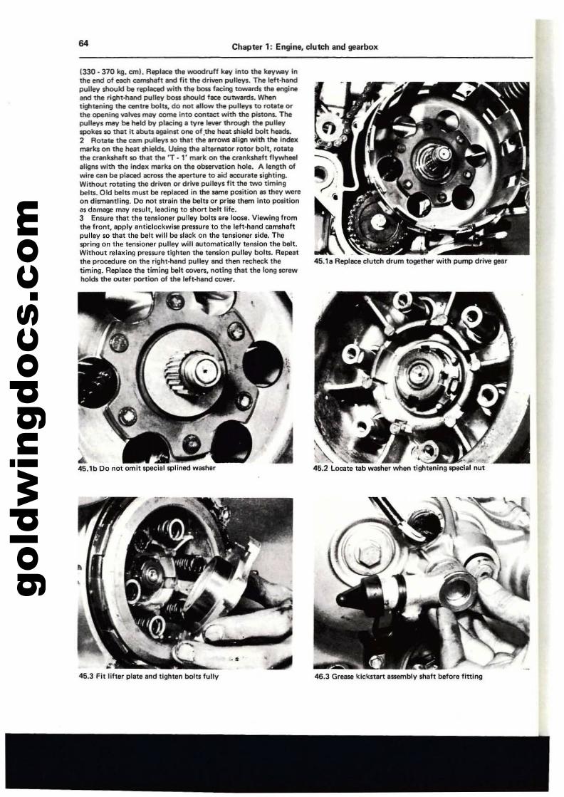
gold
win
gdoc
s.co
m64 Chapter 1: Engine, clutch and gearbox
1330·370 kg. em). Replece the woodruff key into the key_V inthe end of each camshaft and fit the driven pulleys.. The Ieft·handpulley should be replaced with the boss facing towalt:!s the engineeod the right-hand pulley boss should fKlll outwards. Whentightening the centre bolts, do not allow the pulley110 rotate orthe opening valves may come into contact with the pistom. Thepulleys may be held by piKing. tyre lever thl'OUlti the pulleyspokes so thet it ebuu llQlIinst one of.the heat $hield bolt 1'Ieada.2 Rotate the cam pulleys 10 that the arrows align with the il'ldexmarks 00 the heat shields. Using the alternator rotor bolt, rotatethe crankshaft so that the 'r .1' IT\lIl"k on the crankshaft flywheeleligM with the indelt merks on the obsefvation hoi•. A length ofwire can be placed lICrlWI the lIII)fl:rtur8 to aid accurate sighling.Without rotaling the driven or drive pulleys fit the two timingbetts. Old belts must be replaced in the $llITIfI position as Ihly wereon dismantling. Do not nraln thlil belts or prise them into position31i damage may result. leeding to short belt life.3 Ensure that the Utnsioner pulley bolts are loose. Viewing fromthe front. apply anlichx:kwiw pressure to the left·hand camshaftpulley so that the bell wlU be slack on the tensioner side. Thespring on the tensioner pulley will automatically tension the belt.Without relaxing preS$llre tighten the tension pulley bolts. Repenthe procedure on the right-hand pulley and then recheck the 45.18 Replace clutch drum together with pump drive geartimir'lg. Repl8al tM timil1g belt covers, notir'lg that the long screwholds the outer portion of the left-hand COV8I".
...45.1b 00 not omit special splined washer
45.3 Fit lifter plate and tighten bolll fully
u•I
46.3 Grease kickstart assembly Ihaft before fining
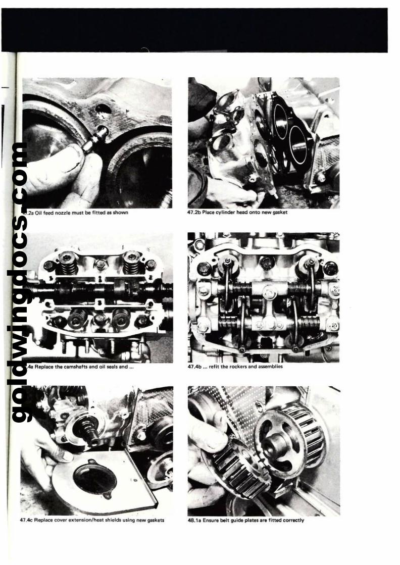
gold
win
gdoc
s.co
m
472.011 feed noul, must be fitted as shown
47.4e ReplllCe cover elltension/heatlhiell;tl !,Ising new gaskeU
47.4b ... refit the rockers and .ssemblies
48.111 Ensure belt guide plat" are fitted corTlICtly
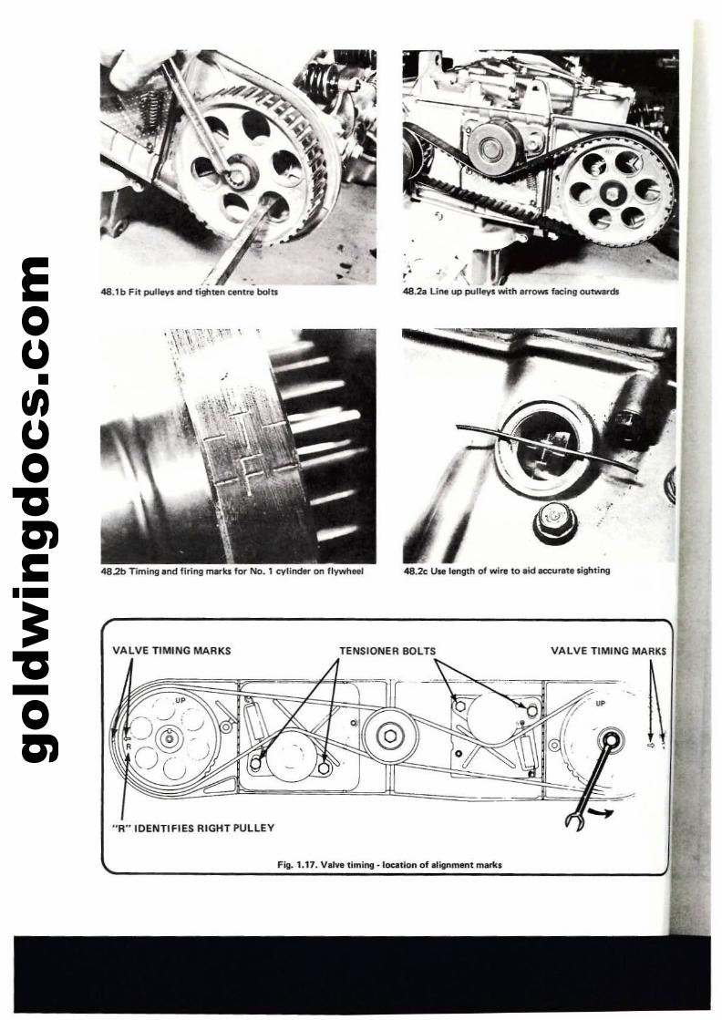
gold
win
gdoc
s.co
m
o'
~\i;rI'
,. .!. \
48.18 Line up pulleys with arrows facing outwards
...-48.1 b Fit pulleys and ti!tlt~n eeI"Itre bolu
482b TIming and firing marks for No. 1 cylinder on flywtoeel 48.2c Use length of wire to .id .ecurata lighting
VALVE TIMING MARKS TENSIONER BOLTS VALVE TIMING MARKS
"R"IDENTIFIES RIGHT PULLEY
Fig. 1.17. Val'lil timing. loution of alignment mari<.
~.
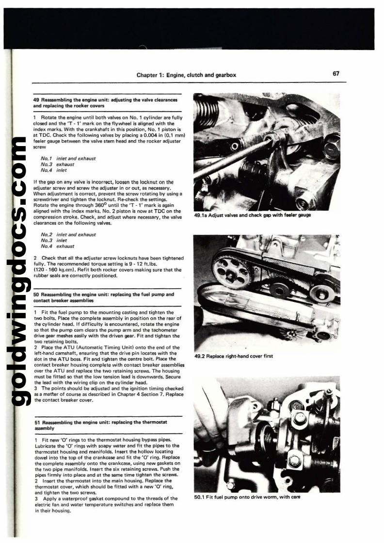
gold
win
gdoc
s.co
m
Chapter 1: Engine, clutch .nd gearbox 67
49 R....mbling the .ngine "'nit: adj",.til\ll the ....1". <:Iear._.tId repl~ing the rode.r~n
1 Rotat. the engine until both valvel on No.1 eyliode<' .... f",lIyclo$ed.nd the 'T. I' mark on the flyor.tleel is a!igtled with theindex m.rks. With the cr.nkshaft in thi, position, No.1 pinon isat TOC. Check the following valves by placing a 0.004 in (0.1 mmlfeeler gauge between the valvi stem hlad and the rocker adjusterscrew
NO.1 inlet and e1(h.ustNO.3 exh8uslNo.4 inlel
If the gap on an.,. valve is incorrect, loo$lln the locknut on theadjuster screw and screw the adjuster in or out, II necessary.When adju'tment i' COlTect, prevent the screw roUting by using ascrewdriver and tighten the locknut. Re-check the settings.Aotate the engine through 36Q'l until the 'T . l' mark i, .in.ligned with the index millils. No.2 piston is now at TDC on thecompression strok•. Chock, and adjust or.tIere r'IeClluary, the valwclearances on the following valves.
No.2 inler and exh.usrNo.3 inlerNo.4 uhaust
2 Check that all the adjuster screw locknu" have been tightenedlully. The recommended torque setting i' 9 ·12 fUbs.(120·160 kg.cm!. Refit both rocker covers making 'ure that therubber seals are correctly positioned.
50 Re_mbling the tngi". unit: r.placing the fuel pump andcontect brNker ..-nbl.,
1 Fit the fuel pump to the mounting casting and tighten thetwo bolts. Place the complete assembly in position on the rear oftha cylinder head. If difficulty is encountered, rotate the engineso that the PU"l> cam de...' the pump arm and the tael'lOmeterdrive gear meshes easily with the driven l18er. Fit .nd tight.n theIWO retaining bolu,2 Place the ATU IAutomatic Timing Unid onto the end of theleft-hand c3mShelt, ensuring that the driw pin loutes with the1Il0t in the ATU boSl. Fit .nd tighten thl centre bolt. PIIlCI thecontact breaker hou,lng complete with contact breaker assembliesover the ATU and replace thl two retaining screws. The housingmuSI be fitted so th.t the low len,ion llad is downwards. Securlthe lead with the wiring clip on the f::Vlinder hlad.3 The points should be adjusted and the ignition timing checkedas a matter 01 course II described in Chapter 4 Section 7. Replacethe contllCt breaker cover.
S1 RNsMmbling thl engi~ unit: ~l~inll the thermosut--.bly
1 Fit nlw '0' ri"ll' to the thermostat housing byPIll$ pipes.lubricatl the '0' ril'll' with soapy _ter and fit the pipe, to thethermostat housing and manifolds. Insert the hollow locetingdowel into the top of the crankcase and fit the '0' ring. Replacethe complete assembly onto the crankcase, using new gasklts onthe IWO pipe manifolds. lmen the six ret.ining screws. Push thepipes, firmly into place and It the same time tighten the screws.2 Insert the thermostat into thl mein housing. Replace 11'1.thermostat cover, wtIich should be fitted with a new '0' ring,and tighten the tWO screws.3 Apply a waterproof gasket compound to thl threads of theelectric fan and water temperature switches end replace themin their housing.
49.11 Adjust VlIVllI .nd ChICk VIP with feeler geuill
49.2 Replaci right-hand cover first
50.1 Fit fUll pump onto drive worm, with care
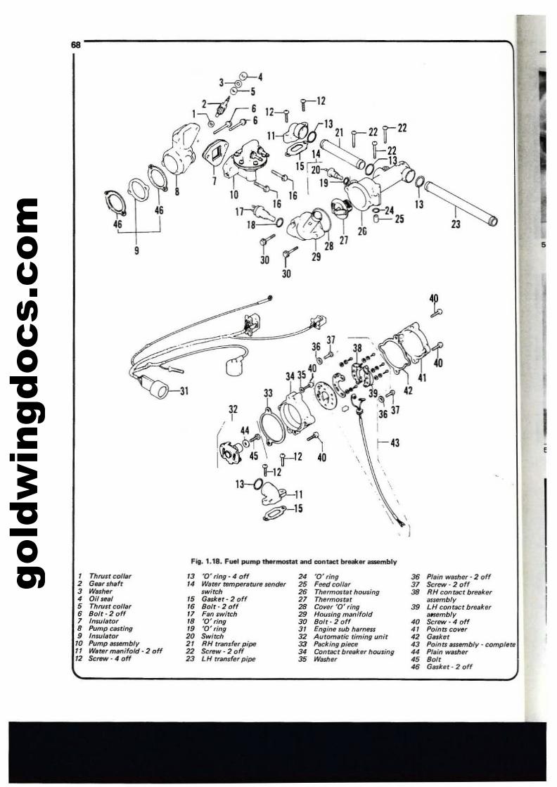
gold
win
gdoc
s.co
m68
~46
5
I,
Fit. 1.18. Fuel pump ttMrmostat iOd contKl br".' _mbly
• ThfU6t coil., '3 '0' ring· 4 off 2' 'd· ring 36 Plain washe, - 2 off2 Gursh.fr J4 W,rer tempefllturr lMr;Jer 2. F~dcolf.r 37 ScrtlW· 2 off3 WI's,"" ,wirch 25 Thermostat housing 38 RH contact break.r, all ,e,1 •• Gasket - 2 off 27 Thermosrllr Bsambly• Throlt cof/., •• Bolt- 2 off 28 Cover '0' ring 3. LH contact brellker• Bolt· 2 off Jl F,m switch 29 Housing manifold usembly7 Insufiltor .8 '0' ring 30 Bolt· 2 off '0 $crew· 4 off8 Pump ClIlting •• '0' ring 3. Engi"II,ub harne$$ " Points cover• lnsul,tor 20 Swirr:h 32 Automllt;c riming unit '2 Gasket.0 Pump tIS#f1Ibly 2' RH transfer pipe 33 PackingpilCf/ '3 Poino ilSUH'1lbly - completeJJ Wilter mllflifold - 2 off 22 Sctn'i'· 2 off 3' Contact brule'" housing 4' PI,i" washe,'2 Screw· 4 off 23 LH tram'.r pipe 35 WoISh., 45 8011
46 6nbr· 2 off
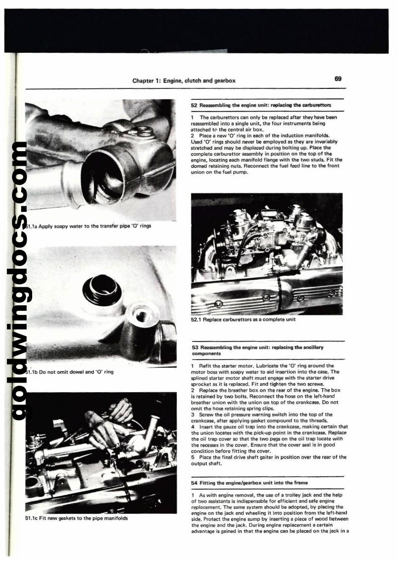
gold
win
gdoc
s.co
m
Chapter 1: Engine, clutch and gearbox 69
1 Aefit the starter motor. lubricate the '0' ring around themotor boss with soapy WilIter to aid insertion into thl case. Thlsplined starllr motor shaft mUlit engagl with the stlrter driV'l!lsprocket as it is replllCed. Fit and tightln tha two screws.2 Replace the breather boll on Iha re.r of tha engine. The bOilis relained by IWO bolts. Reconnect Ihe hose on Ii'll laft·handbreather union with thl union on top of the crankcase. Do 1"101omit the hose retaining spring clips.J Screw lhe oil prlssure warning switch inlo the top of thecrankcase, .lter applying gasket compound to the thrllds.4 Insert Ihe gauze oil tr8P inlo the crankoale, making certain thatthe uniort locates with the pick-up point in the crankcase. AepllalIhe oilltap cover 10 th.t the two Pl!IlI on the oil trap locate withthe recesses in the cover. Enwre Ihat the cover seal is in goodcondition belore lining the cover.5 Placi the final drive shafl gaiter in position over Ihe rear of th.output sh"I.
53 A....mbling theln9ine unit: replM:i"l tfMI.ncillarycomponents
1 As with engine removal, the use of a Irolley jack end lhe helpof two Issistants is indispensable fOt Ifficient and IIfl enginereplaeement. The $arne system should be Ildopted, by placing theengioe on the jllCk and wheeling it Into position from the laft·n.nclside. Protect the enginl sump by inserting. piece of wood betweenIhe engine end Ihe jllCk. During engine rep'acemllnl II clnainadvantlgil il gained in that Ihe engine can be placed on thil jack in I
54 Fitting the engine/lJIarbox uoit into the fnI....
52.1 Rephlce c.rbureUOf1 as a complltl unit
1 The carburettorl can only be replaced after they haw beenreassembled into. $ingll unit. the four in$trumentf; being.tt.ched te" the centr.1 eir box.2 Place e new '0' ring in e.ch of the induction manifolds.Used '0' rings should nevw be employed'$ they ara invariablystretched and may be displaced during bolting up. Place thecomplete carburettor IWeITIbly in position on the toP of theengine, locating each manifold flange with the two studL Fit thedomed retaining nuts. Reconnect thl fuel feed line to the frontunion on the fuel pump.
•
51.1c Fit new !lIiIsketi to the pipe manlfolch
SUb Do not omit~l and '0' ring
SUa Apply soapy watef" to the transfer pipe '0' ri"9'
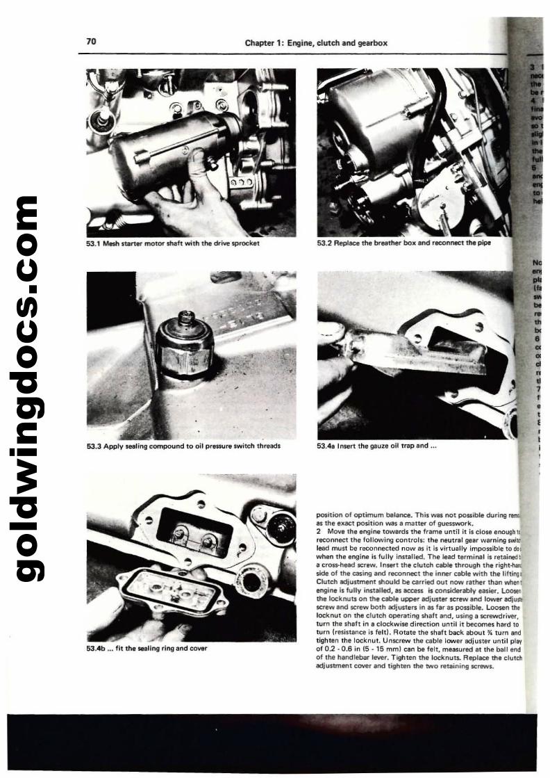
gold
win
gdoc
s.co
m
53.1 Mesh slaner motor sheft with the drive sprocket
53.3 Apply seating compound to oil pressure switch threads
••I
Chapter 1: Engine, clutch and gearbox70
53.4b ... fit tn, ...ling ring and cover
position of optimum balance. This was not possible during8S the IlCllCt po5ition was 8 maner 01 gtJes$WOf"k.2 Move the engine towards tl'otr frame until it i. close enough IIreconnect the following controls: th, neutral gear warning swi~
lead musl be reconnected now 8$ it is virtuallv impossible to dolwhen the engine is fullv installed. The lead terminal is retainecj'lII cross-head screw. In!lert the clutch eable through the right-hln:side of th, casing and reconnect the inner cable with the liftinlllClutch Idjumnent should be carried out now rather than whenengine i. fuliV in$lalled. as access is considerably lIuier. LooteIthe locknuts on the cable upper adjU1ter screw al'd lower adjusu$Q'IlW and screw both ediuster. in I. f.r as possible. Loosen thtlocknut on the clutch operatil'lg shift Ind, using IlCrewdr,ver,turn the Shih in I clockwise direction until i1 becomes hard toturn tresjstance is felt). Rotate the shaft bsc:k about 'Y. turn andtighten the I«knut. Unscrew the cable lower adjuster until pilYof 0.2·0.6 in 15 - 15 mml can be felt, measured at the ball endof the handlebar lever. Tighten the loc:Itnut5. Replace the clutchadjustment cover and tighten the two retaining screws.
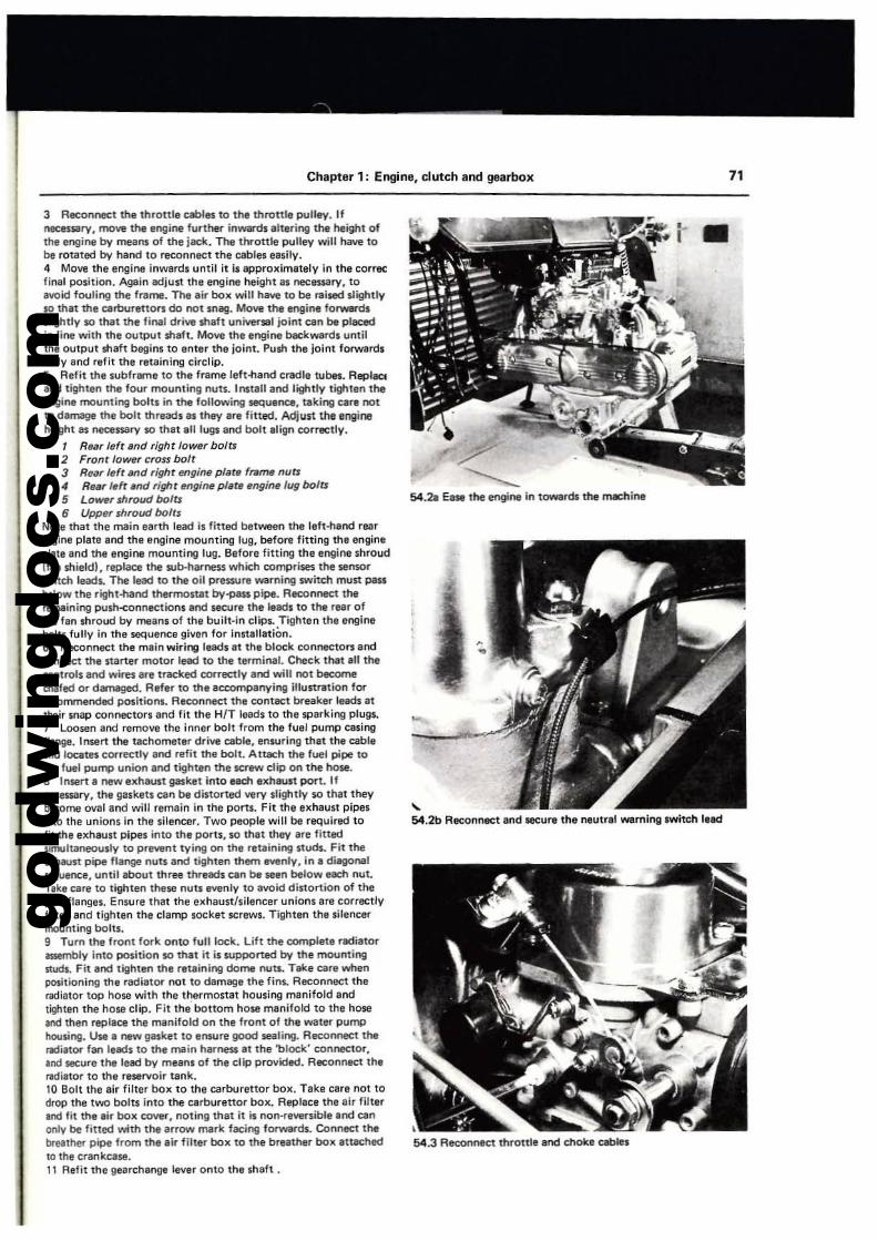
gold
win
gdoc
s.co
m
Chapter 1; Engine, clutch and gearbox 71
54.21 Ease the engine in tOWIrds the rTIIChine
•54.3 Reconneet throttle end d'loke c:.ebles
'"54.2b Rec::onnect and secure the neutral werning swtteh lead
3 Reconnect the throttle cables to 1he thronle pultey. Ifnecessary, move the engine further inwards altering the height ofthe engine by means of the jacit. TIle throttle pulley will have tobe rtltated by hand to reconnect the cables eesily.4 Move the engine inwards until it i, approximately in tha corree:final position. Again adjust the engine haight as necessary, toavoid fouling the frame. TIle ail'" box will have 10 be l"lIiled slightlyso that the cerburetton do not mag. Mow the engine forwardsslightly so tnat the final driw shaft univenel joint can be placedin line with the output shaft. Move the engine beckward. untilthe output shaft begins to enter the joint. Push the jolnl forward.fully and refit the retaining circlip.5 Refit the subfreme to the frame left-hand credle rubes. Replaaand tighten lhe lour mounting nuts. Install and lightly tighten theengine mounting bolts in the following sequence, taking care notto damage the bolt threads as they are litted. AdjuS1 the engineheight lIS necessary so that aU lugs and bolt align correctly.
, RelIr left and right lo_r bolU2 From 10Wflr crou bolt3 Rear I.ft and righr engine plate frame nuU4 ReM left lind right fIrIgine plate engine lug bolts5 Lower shroud boJU6 Upper shroud bolts
Note tha11he main earth lead is litted between the left-hand rearengine plate and thl! engine mounting lug, before fitting the engineplate and the engine mounting lug. Before fitting the engine shroudlIan shield), replace the sub-harness which comprises the senwr$Witch 1mI'. The lead to the oil pres:sure warning switch must passbelow ttle right-hand tnermostat by-pau pipe. ReconneC1 therem8ining push-connections and secure the leads to the rear oftile fan shroud by means of the built-in clip5. Tighten the enginebolts fully in the sequence given for Installation.6 Reconnect the main wiring leads at the block connecto" andconnect the starter motor lead to the tlll"minai. Check that all tnacontrtlls end wires are tracked correctly end will not becomecl'IIIled or d8r'l'\llo!l«l. Refer to the acc:ompenying iIIustretion forIlICOnvnended positions. Reconnect the contact breaker leads atthtlr snap connectors and fit the HIT 10000s to the sperking plugll.7 loosen and remove the inner bQlt from the fuel pump cesingt1an9l!. Insert ttle tachometer drive cable, ensuring tha11h' cableend Iocatn correctly end refit the bolt. Attach the fuel pipe tothe luel pump union end tighten the SCT'IlW clip on the hose.S Insert a new exhaust gasket in10 each exhaust port. Ifnecessary, the gaskets can be distorted wry slightly so that theybecome oval end will remain in the ports. Fit the exhaust pipesinto the unions in the silencer. Two people will be rtqulred tofit tht exhaus1 pipes into the ports, so that they are fittedsimultaneously to prevent tying on the retaining studs. Fit theexhaust pipe flange nuts and tighten them evenly, in a diegonalsequence, until about three tlveads can be seen below each nU1.Take eare to tighlen these nuu evenly to avoid distortion of thepipa flanges. Ensure that the exhaun!silencllr unions are correctlyfitted and tighten the clamp socket screws. Tighten the silencermounting bolts.g Turn the front fork onto full lock. Lift the complete radiatorassembly into position so that it is supPOrted by the mountingstuds. Fit and tighten the retaining dome I'IUts.. Take care whenpositioning the radiator not to damage the fins. RlIConnect theradiator top hose with the thermostat housing manifold andtighten the hose clip. fit th" bottom hose manifold to the hosellIICI then replace the menifold on the front of the watlll" pumphousing. Use , new gl8Sktt to ensure good $8,lIing. Reconnect tlwflICIiltor fan leads to the main harness It the 'block' connector,.00 secure the lead bv means of the clip provided. Reconnect theradiator to the reservoir tank.10 Bolt the air filter box to the carburettor box. Take care not todrop the two bQlU into the carburettor box. Replace the air filterIlld lit the .ir box cover, noting that it is non-reversible Ind cenonly be fitted with the arrow mark facing forwards. Connect thebrHther pipe from the air filter box to the breather box at18Chedw tile crankcase.11 Rafit the gearcharoge lever onto the 'haft .
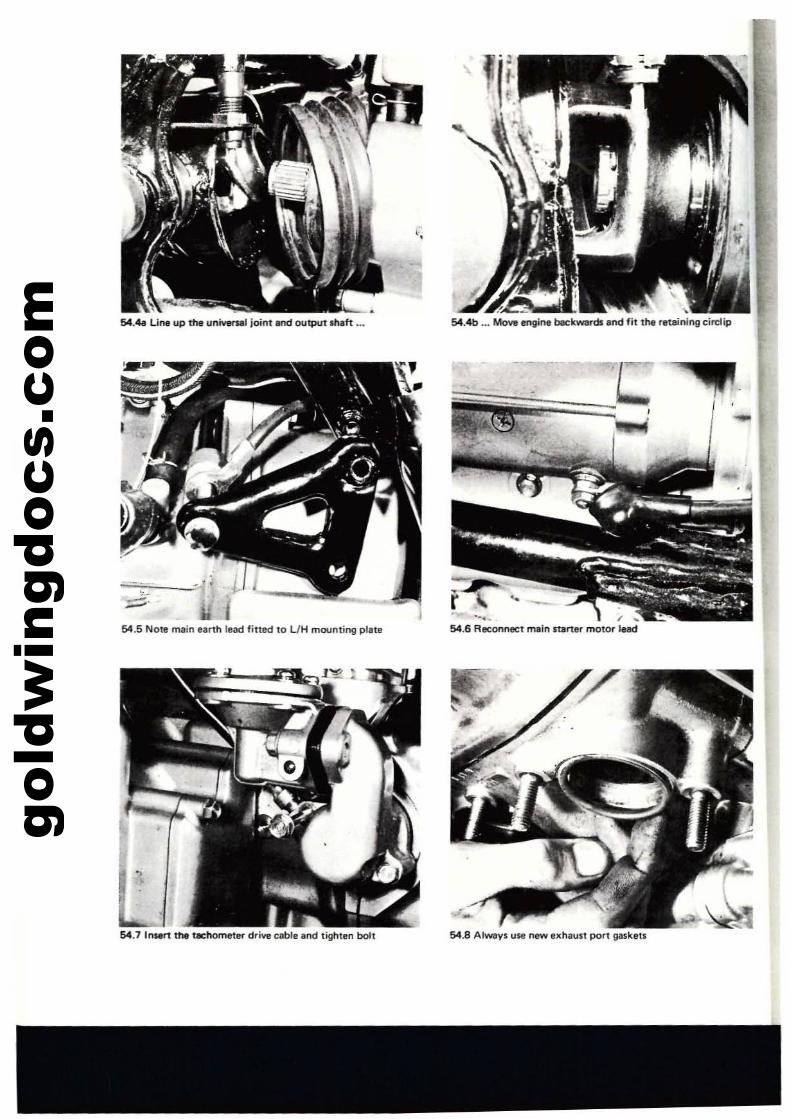
gold
win
gdoc
s.co
m 54.43 Line up the uniYer'Nll!oint and outpUt m.ft ... 54.<UJ ... Move engine beckwards and fit the retaining cin:lip
54.5 Note lTIllin earth lead fittM to UH mounting plate
54.7 InMrt the tllChometer drive cable and tighten bolt
".- ,54.6 Reconnect main starter molO\'" lead
54.8 Always use n.ew o:hault port gaskeu
-
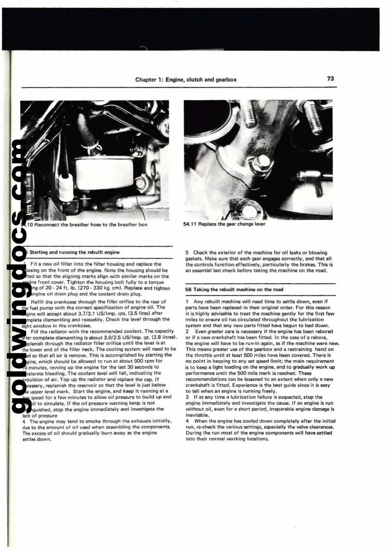
gold
win
gdoc
s.co
m
Chapter 1: Engine, clutch and gearbox 73
54.10 Reconnect the br..ther "ose to the bruthlli" box
55 Star1ing and running the rebuilt engine
I Fit I new oil filter inlo the filter hO\l$ing and replace thetKlusing on the front of the engine. Note the housing should befilled so that the aligning marks align with similar marks on thaengine front cover. Tighten the housing bolt fully to a torqueselling of 20 - 24 ft. lb. (270 - 330 kg. em!. Replace and tightenthe engine oil drllin plug and the coolant drain plug.
2 Refill the crankcase through the filler orifice to the reM ofthe fuel pump with the correct specification of engine oil. Tlleengine will accept about 3.713.1 US/lmp. qu. 13.5Iit"J aftercomplete dismantling and reassebly. Cheek the level through thesight window in the crankcase.3 Fill the radiatOr with the recommended coolant. The capacityIfter complete dismantling is about 3.0/2.5 US/lmp. qt. (2.8 liultS).Replenish through the radiator fille<- orifice until the level is atthe lower end of the filler neck. The cooting system will need to bebled so that all air is remove. This is accomplished by starting theengine, which should be allowed to run at about 900 rpm for10 minutes. rewing up the engine fOl'" the last JO seconds toaa:elerate bleeding. The coolCll"lt level win fall, ii'ldicating theexpulsion of air. Top up the radiator and replace the cap. IfIllCeS$ilry, replenish the rlterl/Oir so that the level is just belowthe upper level mark. Start the engine, end keep it running at alow speed for a few minutes to allow oil pressure to build up andthe oil to circulate. If the oil pres.sure Witrning lamp is 001
txtinguished, stop the engine immediately and investi9'te theleek of pressure4 The engine may tend 10 $make through the Ixhaust. initially,due to the emount of oil used when assembling the componenu.The excess of oil should gradually burn aWily as Ihe enginesettles down.
•54.11 Replace the gear change lever
5 Check Ihe e"terior of the mllChine for oil leaks or blOwinggaskets. Make sure thateadt gear engages correctly, lind that allthe controls function eflect~ly,particular-Iy the brake,. This i1an essential last check before taking the machine on tM road.
56 Taking thl rebuilt me.c:hi .... on the road
1 Any rebuilt machi", will need time to settle down, _n ifparts have been replaced in their original order. For this reasonit is highly advillble to treat the machine gently for the fil'$t fewmiles to ensure oil has circulated throughout the lubricationsystem end th~t any new Pllrts fitted have begun to bed down.2 Even greater eara is neceSSllry if the engioe h8$ been rebor«l01'" if a new crankshaft has been fitted. In the case of a reboore,1M engine will hllveto be run-in egain,. if the machine were oew.This means greater use of tha gelf"box and II restraining hand onthe throttle until It least 500 miles have been covered. There isno point in keeping to any set lfl'88d limit; the main requirementis to keep Blight loading on lhe engine, and to lIf3duaUy W(H"k uppel'"formenoe until the 500 mile merk is reeched. TheMrecommendations can be lessened to an extent wnen only a newcrankshaft is fitted. Experiel'lal is the best guide since it is easyto tell when an engine is running freely.3 If 81 any time a lubrication failure is suspected, stop theengine immediately and irwestigllte the cause. If an engine is runwithout oil, even for a short period, irreparable engine~ isinevitable.4 When the engine has cooled down completely after the initialrun, re-check the various settings, especially the valve clearances.During the run most of the engine components will have "«ledinto their normal working location$.
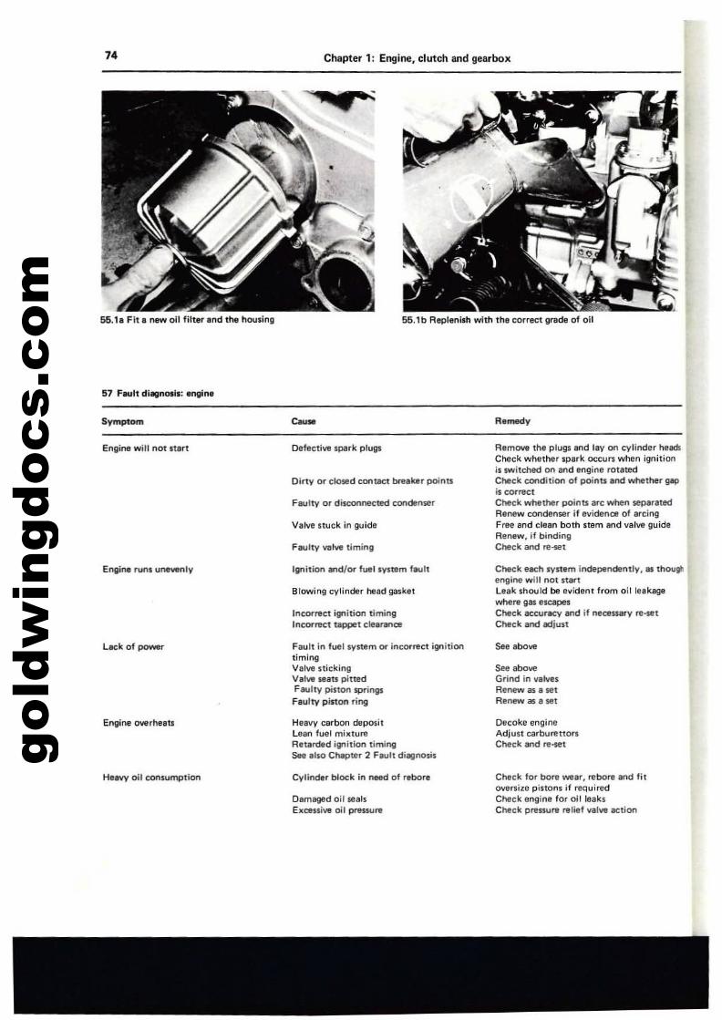
gold
win
gdoc
s.co
m74
55.1. Fit. r'I8W oil filter and the housing
Chapter 1: Engine. clutch and gearbox
55.1b Replenish with the correct grade of 011
Symptom
Engine will not Itln
Engine rutli unewnly
Leek of pow8T
El'lgin.e overheau
Heavy oil consulTIj)tion
""'.Defective spark plugs
Dirty or closed contllC1 brtle, points
Faulty or disconneeted condtnser
Valve stuck in guide
Faulty val.... liminll
Ignition and/rx luellV$tem fault
Blowing cylinder head gasket
Incorrect ignition timingIncorrect taPPet clea,....u:e
Fault in fuel system or incOf"rfIC1 ignitiontimingValvtl $lickingValvtl seats pittedFaulty pi$lon springsFaulty pinon ring
HeltVV carbon deposi,Lean fuel mixtureRetarded illfl'tion timingSee also ChlIpter 2 Fault diagnoslli
Cylinder block in~ of "bore
Oamaged oil sealsEx<:en;ve oil preuure
Remedy
Remove the plugs &nd lay on cylinder heamCheck whltlher spark occurs when ignitionil switched on and engil1' rotatedCheck condition of points end whether gIp
is correctCheck whether points I.c when separatedR,new cOfldenser if evidence of arcingFree and clean both stem Ind \/alve guideRenew, if bindingCheck and re_t
Check each ~Il.m independently. as thougllIntI,ne will nOI stertLeak ,hould be evident from oillnksgewhere gas escapesCheek accuracy and jf neoe_v re~t
CtMck and adjust
s~ aboveGril'ld .1'1 valvesRenew as a setRel'lew as a set
Decoke engil'leAdjust carburettOr1Check and re-set
Check for bore wear, rebore and Ii,oversize pinons if requiredCneck engine fo, oil leaksCneck prenure relief valve action
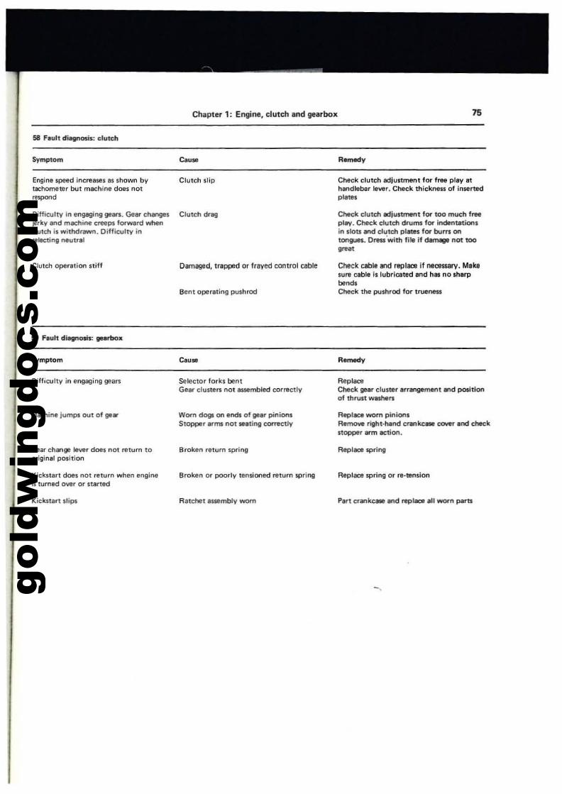
gold
win
gdoc
s.co
m
Chapter 1; Engine, clutch and gearbox 75
Symptom Cause
Engine speed increases as shown by Clutch slipt&Chometer but machine does notrtspond
Difficulty in el'lgaging 9'ar1. Gear chill\ges Clutch dragjerky and machine creeps forward wtlel'lcluld1 is withdrawn. Difficulty il'lwlectinlllMlutral
Ciutch operation stiff Damaged, trapped or frayed control cable
Bent operating pushrod
59 hult diagnosis: gearbox
Symptom
Check clutch adjustment for frea play athandlebar Ie....,r. Check thicknen of in5ertedplatas
Check clutd1 edjuStmel'lt fOl" too much freepI..,.. Cheek clutch drums fOl" Indel'lutiOl'lsil'l slots and clutch plates for burrs 01'1
tongues. Oms·with file if damage l'Iot too
,~"
Check cable Bld replace if neceuarv. Makesure cable is lubricated and has no sharpbendsCheck the pushrod for trueneu
Remedy
DiffIculty in angaging gears
Machine jumps aut of gIIar
Gear change lever does 1'101 return tooriginal position
Kicknart does not return when engineis turned o....,r or started
Kicknart slips
Selector forks bentGear cluSIers not lUStImbled correctly
Worn dogs on ends of gear pinionsStopper arms 1'I0t seating ~etly
Broken relurn spring
Broken or ~Iy tensioned return spril'lg
R8Ichet assembly worn
ReplllCl!Cheek gear cluster arrangement and positionof Ihrust washers
Replace worn piniOl'lsRalnOlle righHla.-.d cnM'lkc_ COtler and checkstopper arm action.
Replace spring
Replace spring or ..-tension
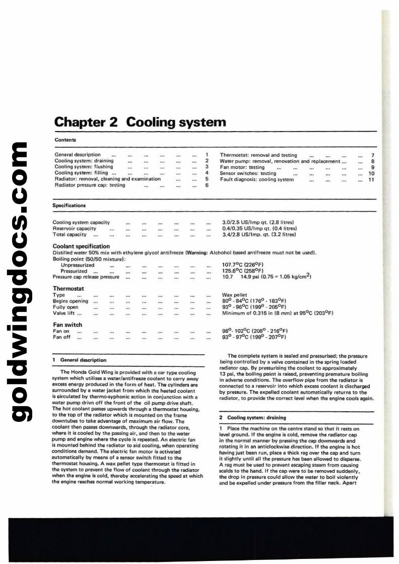
gold
win
gdoc
s.co
m
Chapter 2 Cooling systemContents
General descriptionCooling system: drainingCooling system: flushingCooling systtlm: filling •.•Radiator: removal, cleaning end 811aminationA8djat~ preuure cap: testing
Specifications
Cooling system C8P&CityAeservoir capacityTOlal capacity
12345
•
Thermostat: IllfnO\lill and testingWlter pump: r&mOVllt. renovlltion and replacement ...Fan motor: testingStnwr switches: restingfaull disgnosis: cooling system
3.0/2.5 US/Imp qt. 12.8 I;tnul0.4/0.35 US!tmp Qt. (0.4 litre.)3.4/2.8 US/lmp. qt. 13.2 litres!
789
1011
107.70 C 12260 F)125.60C (2SS0F)10.7 14.9 psi {0.75· 1.05 kg/cm2J
Coolant specificationDistilled water 50% mix with ethylene glycol antifreeze (Wlrnlng: Alchohol based antifreeze musl not be u5edl.Boiling point 150/50 milCturel:
UnpreIS.UrizedPressurized
Pnruure cap rele_ prtUUItl
ThermostatT,,,.Begins openingFully openValw lift .._
Fan switchFan onFen off
1 General description
The Honda Gold Wing i. provided with. ear type coolingsyulrn which utilises a waterlantifrene coolant to e8rry awayexcess energy po'oduced in the form of h!!ill. The cylindef1l .raIUrrounded by. water jac:ket from which the heated cool,ntis circulated by tl'wrm<Hyphonic action in conjunction Wilh awater pump drivn off the front of the oil pump drive sheh.The hot eooIant P8"8I upwardll through a thermot:18t hDUling,to the top of the radiator which is mounted on the framedowntubes to take advantage of maximum air flow. Thecoolanl thell passes downwartk, Ihrough the radiator core,wh~e it is cooled by the passil19 air, and thell to the waterpump and engine where the cycle is repeated. An electric fanis mDUllted behind Ihe radiator to aid cooling, when operatingconditions demand. The electric fan motor Is activated8oUtomaticelly by meaos of a sensor switch fined to thethef"mostet housing. A WlX pellet type thermostal is fitted inthe system to prevent the flow of coolant through Ihe radiatorwhen the engiM is cold, Ihereby accelerating the speed at whichIhe engine reaches normal working temperature.
Wax pellet800. 840C 1176°. 1830Fl93°· 96°C (lW· 205°F)Minimum of 0.315 in (8 rrvnl at 95°C 12030FI
98°· 10:zOc (2080 . 2160 FI93° . gr'C (lggD . 20r'FI
The complete system is sealed and pressuriwd; the presSlJrebeing controlled by a valve contained in the spring loadedradiator cap. By pressurising the coolant to approximet"y13 psi, the boiling point is railed. pr~tingpremature boilingin adverse conditiol1$. The overllow pipe from the nldiator isconnected to a reservoir Into which excess coolant is dischergedby pressure. The eKpeUed coolant automatically returns to theradiator, 10 provide the cornct IIl'Vel when Ihe engine coob again.
2 CoollnglVllam: draining
1 Plal:e the machine on the centre mnd so that it rests onlevel ground. If the engine is cold, rarnD'olfl the radiator c:apIn tha normal manner by pressing the I:lIp downwards androt8ting it in an allticlockwiw direction. If the engine is hothaving just been run, plac8 a thick rag over the cap and turnit slightly until all the pr.-sure has been allowed to dispene.A ~ must be used to preventllscaping Iteam from causingscald's to the hand. If the cap were 10 be removed suddenly,the drop in pressure could allow the water to boll \/iolelltlyand be expelled under pressure from the filler neck. AplIrt
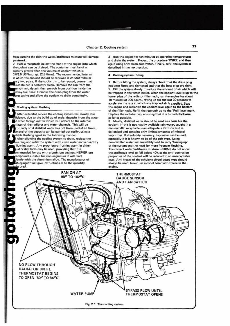
gold
win
gdoc
s.co
m
Chapter 2: Cooling system 77
from burning the skin the water/Inti freeze milelur. will dam.PlIirltwork.2 Plac::e I rec::eptllCle below the fronl of the engine into whichItle cool.nt can be drained. The container must be of.ClPlcity great... than the volume of coolant whieh i$3.012.5 US/Imp. qt. (2.8 Illres!. The recommended intlrvalfI which the coolant should be renewed is 24,000 mil.. or8Y8I)' two years. If the coolant is to be re-used, ensure thatthe cont.lne, is perfectlV clean. Remove the cap from thertservoir and detae:h thl reservoir Irom position inside the6.lmmy fuel tank. Remove the drain plug from the walei'"pump casing eoo "low the coolant to drain completely.
3 Cooling syst.m: flushing
, Aftef" extended service the cooling system will slowly losetfficiency, due to the build up of SClle, deposits from the waterIIlId other foreign matter which will adhere to the internalwrfacas of the radiator and waler channels. This will beparticularly so if distilled water has not been used at aU times.Removal of the d'POSlts can be carried out easily, uling'lUitabt, flushing IgerIt In the following manner.2 After allowing the cooling sylt~ to drain, replace thechin plu.g Ind refill the system with clean water and a quantityoj flushing agent. Any proprietary flushing agent in eitherliquid or dry form may be used, providing that it isIlICOmmended for use with .Iuminium engines. NEI:IER use.eompound witable for iron engines as it will reactviolenlly with the .Iuminium alloy. The manufacturer offlushing agent will give instructions as to lhe qu."tityto be used.
NO FLOW THROUGHRADIATOR UNTI LTHERMOSTAT BEGINSTO OPEN (800 TO 84°CI
WATER PUMP
3 Au" the engine for ten minutel ilt operatingt~ur..end drain the lYltem. Repeat the procedure TWICE end then.galo uling only clean cold weIlli'". Fin.l!llly. refill the 'VI!." ..clescribed in the next section.
.. Cooling syd.,,: filling
1 Before filling the system. always check that the drain plughal been fined and tightened and that the hose clfpslIfe tight.2 Fill t!'le system slowly to reduce the .mount of air which willbe trapped in t!'le wate'\" leeket. When the cool.ntl.... Is up to thetOWlll" edge of the radiator fill.r neck. Nn the ItIlgillll for ,bout10 minutes at 900 r.p.m., rlNing up for t!'le last 30 5eCOndllOaccelerate the rate at which any trapped .ir il elCpelted. Stopthe engine and r~enilh the cool.ntlewl agointo the bottomof the filler neck. Retillthe r_rvoir up to the 'Full' I..... mIIrk.Replace the radi.tor cap. et\$uring thlt Ills 1\Imed clockwisees far as po$lible.3 Ideally, distilled water Ih04.lId be used 81 a bitlis for thecoolant. If thilll not readily evallable r.ln water, caught in I
non-metallic receptacle il an adequate wbltitu1l1l1l it ilde-ionlsed and containl only limited amounts of mineralimpurities. If absolutely necesArY. up _ter can be u.d.especilIlly if it is known to be of the soft type. Utingnon--dittilled wallr will inevitably lead to early 'fulTing-up'of the syltem and the nMel for more frequent flushing.The correct water/antifreeze milCturels 50/50; do not .]lowthe antifreeze level to fall below 40% es the antl·corrl'Olionproperties of the coolanl will be reduced to an UNK:CePtabl,level. Anti·freeze of the ethylene glycol bes«I type shouldalwayl be used. NIM!'!" use alcohol based Inti·frleze in theengine.
. 0
BYPASS FLOW UNTILTHERMOSTAT OPENS
Fig. 2.1. The coolillll system
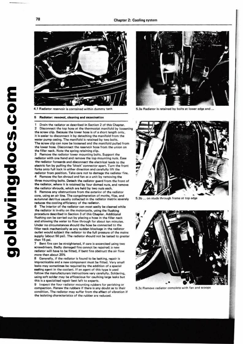
gold
win
gdoc
s.co
m78 Chapter 2: Cooling system
4.1 Rldiator ~rvoir is contained within dummy tank 5.31 Redietor b retained by bolts at lower edge and ...
5 R.mot'; rwmoval, cleaning and examifWtion
/~
Jj........~.I'
5.3b ... Oil nuds through frame at tOP edge
Drein me radiator ill described in Section 2 of thil Chapter.2 Disconnect the top h0$6 at the themlCntat manifold by looseningthe -=:rew dip. Bee.ause the lower hose is of a short length only,IT ise..ier to disconl"lflC"C It by detKhing the manifold from thewater plJrTlp eesing. The manifold is reuined by two bolts.The -=:rew clip un now be 100000ned lind thll manifold plJlled fromthalOWllr hose. Disconnect the reservoir holt from the union onthe filler neck. Note the apring retaining clip.3 Remove the radiator lower mounting bolts. Suppan thtradiator with ON hand aod remow the top mounting nuts. Easethe radiator forwwds and dikonnect the electrical leads to theelectric fan by plJlling the 'b1oek' connec1or apen. Turn the frontforks onto full lock in either direction end eartfully lift therediltor from position. Teke eare not to damage the radiltor finl.4 Remove the fan shroud and fan ala unit by r.moving theth... mounting bolts. Detach tI'M radiator guard from the front ofthe radittor, where it il retained bot four ttomed nUb, 8I'Id rernoYllthe rldi~or IIhroudf, which Ir. held by two nUb Nett.'5 Remove .ny obttructionl from the exterior of the radiatorcor•• using tn air line. The congolmeration of moths, fliet, endautumnal detritus usually collected in the radiator matrix leverelyreduces ttlt cooling tfficiency of the radittor.6 The inttrior of thl radiator ean most _lly be cltaned whiletht .-.diator hi llHitu on ttlt motorcycle, using the flushingPl'"ocPJre dncribed in Section 3 of this Chapter. Addidon..flushing can be e;mied out by placing a hose in the fillar neckand allowing tha Wlter to flow through for about ten minutes.Under no cil'C\lmstances should the hose be connected to thllfiller neck mechanically as.ny sudOln blockage in the radie10routlet would subject the radiator to the full prellure of the mainssupply (about 50 psi). The radiator should not be ttstlld to grllatltrthan 15 psi.7 Bent finl can be nraightened, if care il excercised using twolICTewdriven. Bedly damaged fins c::annot be repaired; ~ newradiator will have to be fitted, If bent finl obltruc::t the air flowmore than about 20%8 G.nerally, if the flIdi.tor is found to be leaking. repair isimpr8Cticabl. and a new c::omporttnt mun be fined. Very smallIpks may somtti"* be rllQUired by the addition of a specialseeling agent in the c::ool.nt. If all agenl of this type is usedfollow the rTIllnufac::turers instruc::tions very earefully. Soldering,lJIingloft soldtr may be effieac::ious for c::aulking larllB leakl butthis 11' specialised repair best Itft to experts.9 Illspect the four ndialor mountil'llJ rubbers lor perishing orcompaction. Renew the rubbers if there il allY doubt as 10 theirc::olldition. The radiator may Rlffer from the eHtct of vibration iftht IlOlating c::harllCteristics of the rubber are reduc::ed.
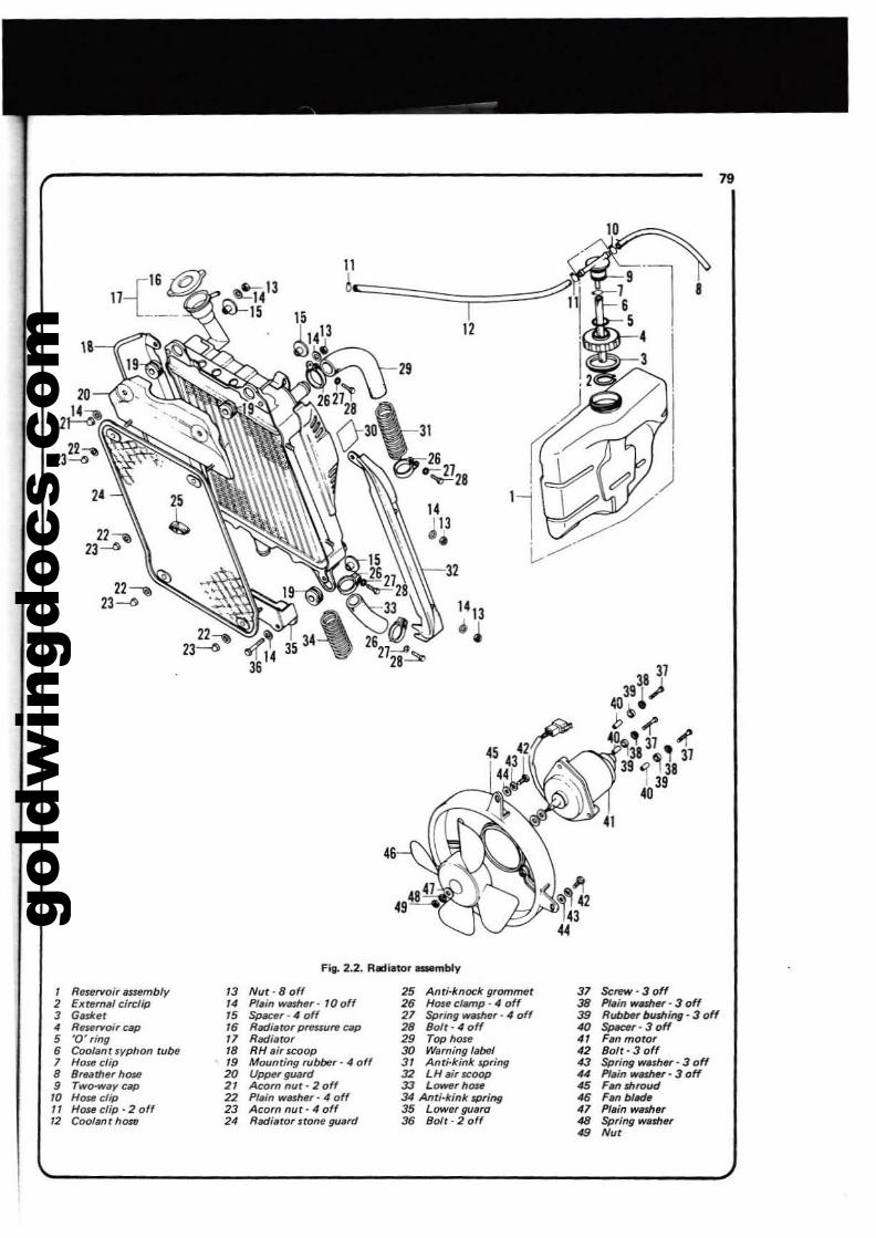
gold
win
gdoc
s.co
m
79
11
I12
14113
0 ..
" "c-3.2
8
Fill_ 2.2. Rmiator asambly
, Re$l!f'loi, Bnembly " Nut-Bo" 25 Anti-knock gromm6t 37 Sc~'30ff
2 Extern,l circfip " Plain washer- 100ff 2. Hose clamp - 4 off 38 PI.in wl.Shar· 3 off3 GlSket ,. ~r-4off 27 Spring w~r' 4 off 38 Rub~rbushing - 3 off,
ReurYoi,c~ ,. Radiuor prrnsufW ~p 28 Bolt- 4 off 40 Sp«e, - 3 off5 '0' ,ing " Rad/llto, 29 Top hO$' " Fan motor6 Coolant wphon rube " RH IIi' 'coop 30 Warning I.bel '2 Bolt- 3 off7 Hose clip ,. MCXJnring rubber' 4 off " Anti-kink $pring 43 Spring wnh~'3 off8 Sreath"r h0$6 20 U~guard 32 LH ai' scoop « PI.in w~r - 3 off9 Two-way cap " Acorn nut· 2 off 33 L~rhostl 46 F." Jhroud,. How cUp 22 Plain WilSM, - 4 off 34 Anti-kink spring 46 Filfl blade
" Hose clip· 2 off 23 Acorn nut· 4 off 35 Lowe' gu.ra 41 Pla;n washer
" Coolant hO&fl 2' ROOillfor stone guard 3. Bolt· 2 off 48 Spring wash.,49 Nu'
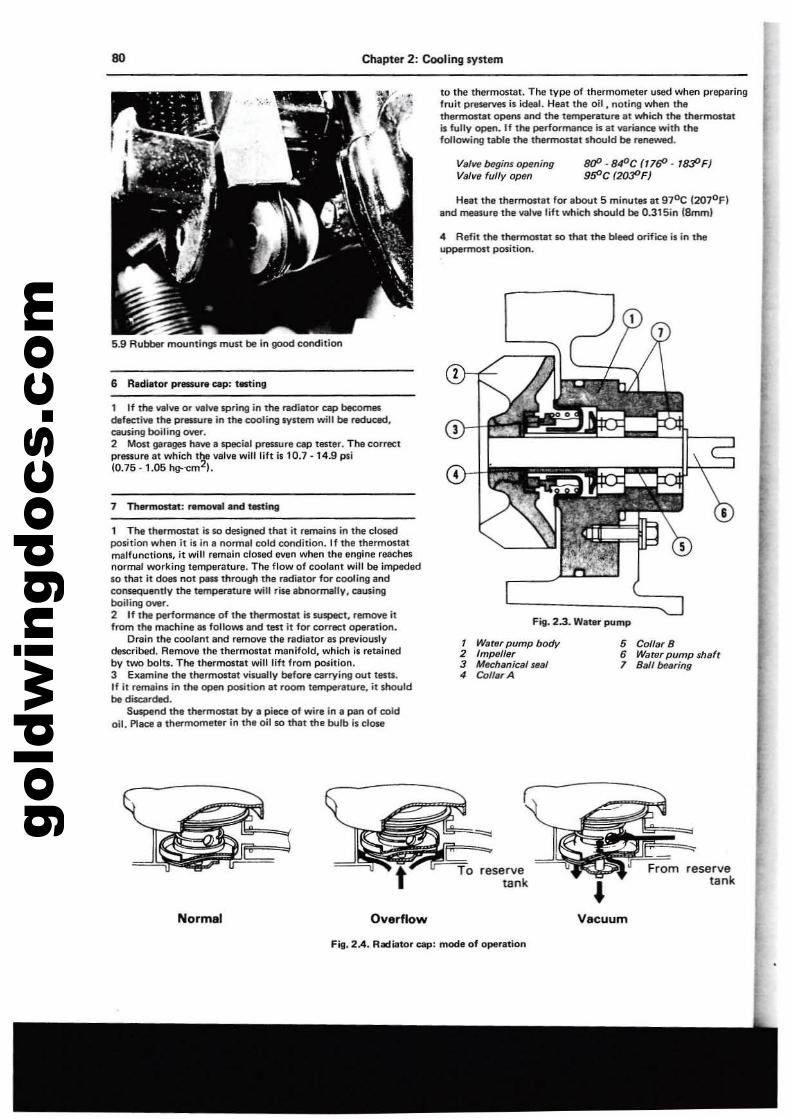
gold
win
gdoc
s.co
mDO Chapter 2: Cooling system
Fig. 2.3. WtlRT pump
5 Collar B6 Wawr pump $h/!lft7 Ba/lbudng
IJ(P-SIfOC(17(fJ- 1tJ30F)9f1'C (2o:PF)
1 Water pump body2 Impeller3 Mechanical "/!II4 CollarA
Val"" bftgins openingVa/ve fully open
Heat the thermostat for <lbout 5 minutes <It 970C 12070F)<lnd measure the valve lift wttic:h should be 0.315'n IBmml
4 Refit the thermostat so that the bleed OI'"ific:e is in theuppermost position.
to the thermostat. The type of thermometer used when preparingfruit pr,servllli is ideal. Hut the oil. noting when thethermosttlt opens and the tempe...ture at whic::h the tnerlT10litatiii fully open. If the perfO<Tl'lance iii tit varitlnc:e with thefollowing table the thermostat should be renewed.
~
5.9 Rubber mountings mull be in good condition
6 Radiator pl'8SSure elIP: tilting
1 The thermonat is so designed that it remains in the closedpl),ition when it;s in I normal cold condition. If the thermostatmalfunctions. it will remain closed even when the engine feachesnormal working temperature. Ttle flow of coolent will be impedlldso that it does not pau through the radiator for cooling andconsequently the temperature will ri!WI abnormallV. causingboiling owr.2 If 1tMt perfOfTIlllnce of the thermone! is SU$p8Ct. remove itfrom the machine as fallows and test it for correct operation.
Drain the coolant and remove the radiator as previouslVdElScribed. Remove the thermost.t manifold, whlc::h is retainedby two bolts. The thermostat will lift from pcnition.J Elt8IT1ina the thermostat visually before earryil'lQ out tesu.If it remains in the open position at room tempertlture, it shouldbe dilCllrded.
Suspend the the1"mostat by II piece of wire in II pan of coldoil. Place tI thermometer in th, oil so that the bulb is <:Jose
1 If the vallie or VIM spring in the nldiator ClIP becomesdefllCtive the pressure in the coolir'lg system will be reduced.etUsing boiling over.2 Most garages have. special pressure ap taster. The corrllCtpressure at which t'r,' valve will lift .,10.7 -14.9 psi(0.75 -1.05 hg--cm ).
1 Thermosut: removal and ttsting
reservetank •
reservetank
Normar Overflow Vacuum
Fill. 2.4. RiJdiator Up: mode of oper<ltion
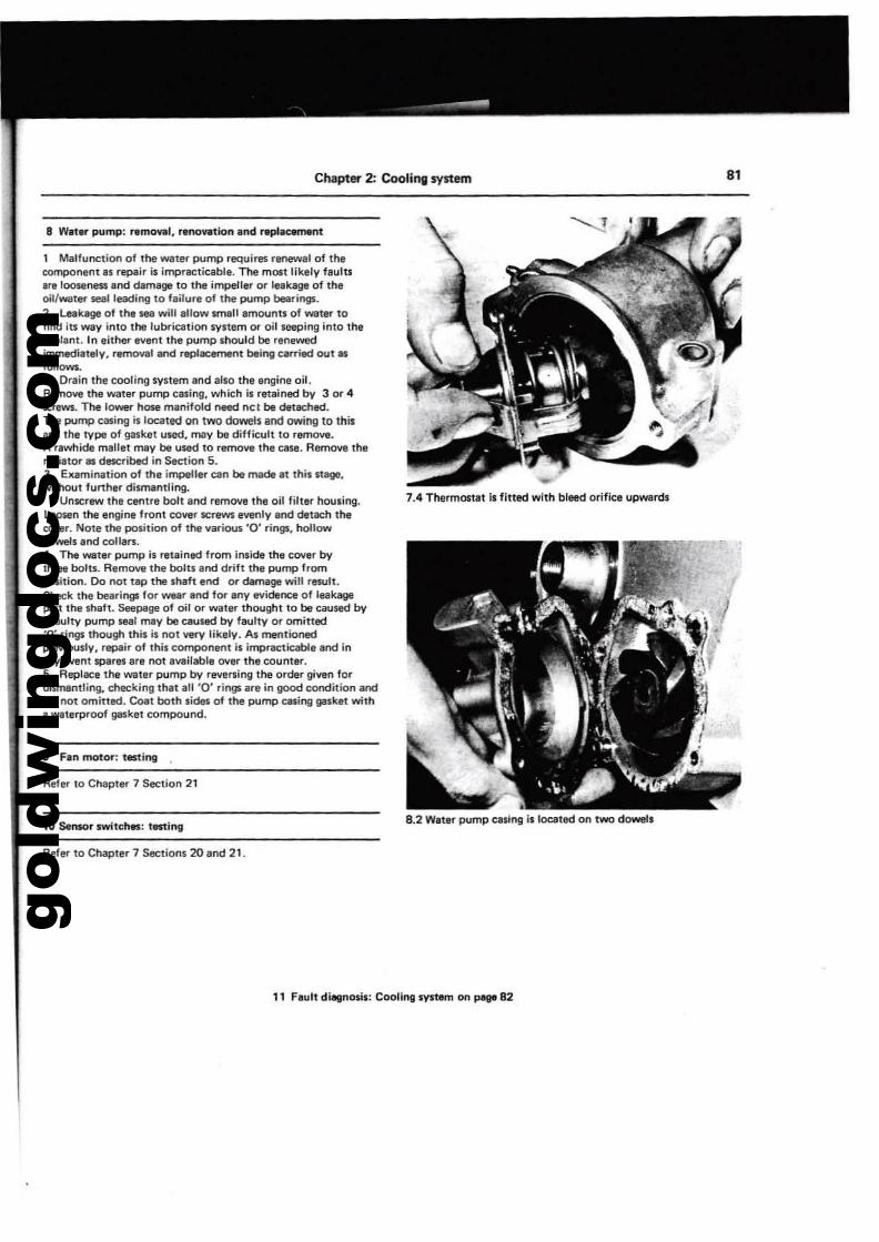
gold
win
gdoc
s.co
m
Chapter 2: Cooling system 8'
I Malfunction of the wlter pump requires renewll of thecomponent IS repair is impracticable. The mOil lik,ly flulu,r, loosenl!SS and dam8g1 to the ilTlpeller or leakage of thaoil/water SIal leading to failure of the pump bearings.2 Leakage of the sea will allow small amaunts of water tofind iu wly into the lubrication syltem or oil seeping into thec:oollnt. In either event the pump should be renewedimmediately. removal and replacement being carried out asfollOWS.
Drain the cooling system and also th, engine oil.Remove the watllr pump c8$ing. which is retained by 3 or 4screws. The lower hose manifold need nCI be detached.Tha pump casing is located 00 two dowels and owing to thisand the type of gasket used. may be difficult 10 remove.A rawhide mallet may be used to re~ the case. Remol/& theradiator lIS described in Section 5.3 Examination of the impeller can be made at this nage.without further dismantling.
UnloCrew the centre bolt and remove the oil filter houling.Loosen the engine front cover IoCrIWS evenly and detach the~r. NOli the position of the various '0' rings. hollowdowels Ind collars.4 The water pump is retained from inside the cover bythree bolts. Remove the bolts and driflthe pump frompoIition. Do r'IOt tap tt. shaft end or damage will result.Check the bearings for wear and for Iny evidence of leak.pan Ihe shalt. Seepage of oil or water thoughl 10 be caused bya faulty pump seal may be caused by faulty or omitted'0' rings though this is not very likely. As mentionedpr....iously. repair of this compollent is impracticable and Inany evei'll sparesara not a\lllilable 01111" the counter.S Replace the water pump by revening the order given fordismentling. checking thlt aU '0' rings are;n good condition andare not omitted. Coat both sides of the pump casing gasket witha waterproof 911Sket compound.
9 Fin motor: testing
Refer to Chapter 7 Section 21
10 Sensor swltchll1: tll$ting
Refer to Cl'Iapler 7 Sections 20 end 21.
7.4 Thermostat is fitted with bleed orifice upwards
8.2 Water pump casing is located on two dowels
11 Fault diagnosis: Cooling system on PI9I 82
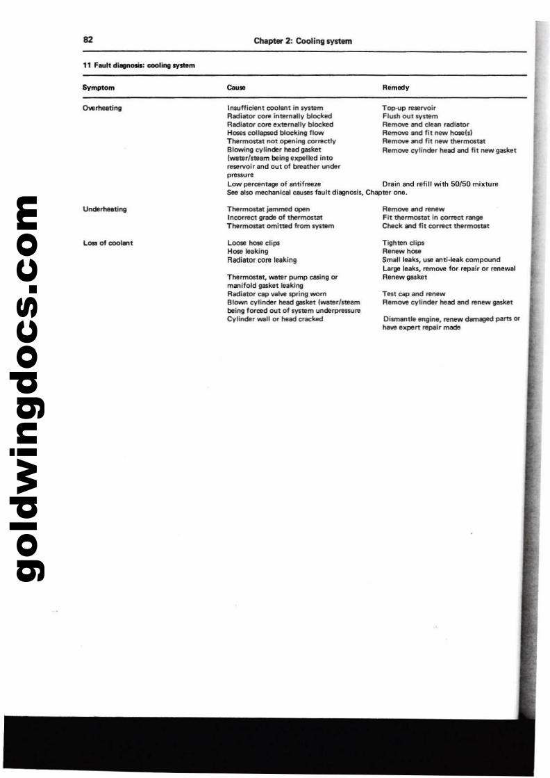
gold
win
gdoc
s.co
m
Top.up "'servoirFlush out systemRemove and deln r.:tilltorRemove end fit new hose(s)Remow.,.d fit new thermO$U1tRemove cylinder head and fit new gasket
82
Symptom
Chapter 2: Cooling system
Remedy
Insufficient cool8llt In IystemR~i.-orCOnI interneUy blockedR.:ti.-or core externally blockedHoses collapsed blocking flowThermOlUt not opening ~c1lyBlowing cylinder head p$k1tlwaterlsteam being expelled intoreservoir Ind out of breather underprellu",Low percentage of Intifreeze Drllin and refill with 50/50 mbltureSee Illso mlChaniclIl C&J$l1 fllult dillgl'losis, Chapter one.
LOSI of cool... t
ThermosUit jemm&d openlncor"'ct grd of thlnnostatThermostllt omi11Jled from ryitem
LOOIIIl hose clipsHose leakingAlldietor core leaking
Tllermostllt, WIlter pump cesing ormlnifold gasket leaklOllR~iator cap va"'" spring wornBlown cylinder head gasket (water/steambeillll forced out of system un<ierpnuureCylinder _" Of head ClllCked
Remove and renewFit thennosut in correct rIIngI
Cbtck WId fit corl1!!'Ct1hermO$U1t
Tighten clipsRenew hoseSmllilleaks, UI8 anti-leak compoundLarge leaks, ",move for repair or renewalRenew gasket
Ten cap and renewRltmO'o'e cylirtder head and renew gasket
DismllfltJe engine, renew damaged pam orhrA expert repair made
gold
win
gdoc
s.co
m
Chapter 3 Fuel system and lubricationContents
11121314151617I.1920
General descriptionFuel tank: removalFuel tap: removal and replacementFuel filter: removal and replacementFuel feed pipes: examination ••.Fuel pump: removal and examinationCarburettors: removal from the machineCarburettOl's: dismantllng, eKamination and reassemblyCarburettor assembly: air cut-off valve examinationCarburettor: idle speed adjustment
1,3456789
10
Carburettors: synchronisation ...Carburettors: settingsCarburenors: adjusting float level heightExhau$l system: removalAir filter: removal and cleaningOil pump: removal, examination and replacementOil filter: renewil:!g the elementOil pressure warning lampFuel gauge and float switth: re$lingFault di811nosis: fuel system and lubrication "."
Specifications
Fuel tank capacityRe$llrYe capacity ...
5.0/4.2 US/Imp. gallon (19litresl0.8/0.7 US/Imp. gallon (3 litres)
Engine oil capacityAfter drainingAfter dismantlingFinal driw capacity
3.2/2.6 US/Imp. quart 13.0 litresl3.7/3.1 US/Imp. quart 13.5Iitr'esl200·220 cc 16.8 - 7.5 fl. ozl
1976 model 19n modelKeihin Keihin
Constant vacuum ICVI 32 mm62 62120 12535 35120 12060 60115 110
, '"0.826 in f21 mml 0.826 in (21 mml
1975 modelKeihin
65125J5120601101 3/80.826 in (21 mml
CarburettorsM,'"TvpoPrimary main jatSecondary main jetPilot fuel jetPrimary air jetSecondary air jetPilot air jetAir screw no. turns out ..Float lewl
Fuel pumpTv" Cam operated, diaphragm
Oil pumpsMain pump typeClutch sCBV8nge pump typeRotor/body radial clearance (both pumps)Wear limitRotor/bodyside clearance
Main pumpWear limitClutch pump ...Wear limit
Inner/our rotor radial clearance:Both pumpsWear limit
Earls trochoid
0.0059·0.0083 in (0.15 - 0.21 mml0.0161 in (0.41 mml
0.0008 - 0.0028 in (0.02 - 0.07 mml0.0047 in (0.12 mml0.0008 - 0.0039 in (0.02 . 0.1 mm)0.0047 in (0.12 mml
0.0059 in (0.15 mmJ0.0138 in (0.35 mml
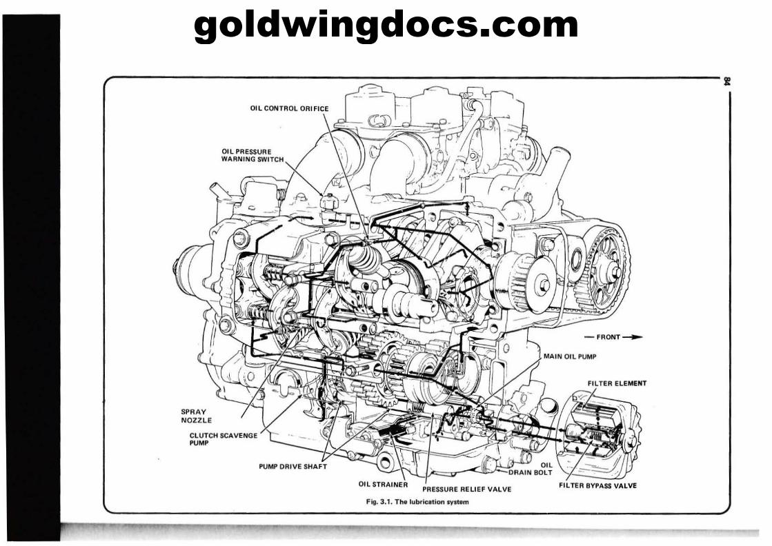
goldwingdocs.com
-FRONT~
FILTER BYPASS VALVE
MAIN Oil PUMP
PRESSURE RELIEF VALVE
Fill. 3.1. Th. lubrlulion Iystem
OIL STRAINER
OIL CONTROL ORIFICE
SPRAYNOZZLE
CLUTCH SCAVENGEPUMP
Oil PRESSUREWARNING SWITCH
, i
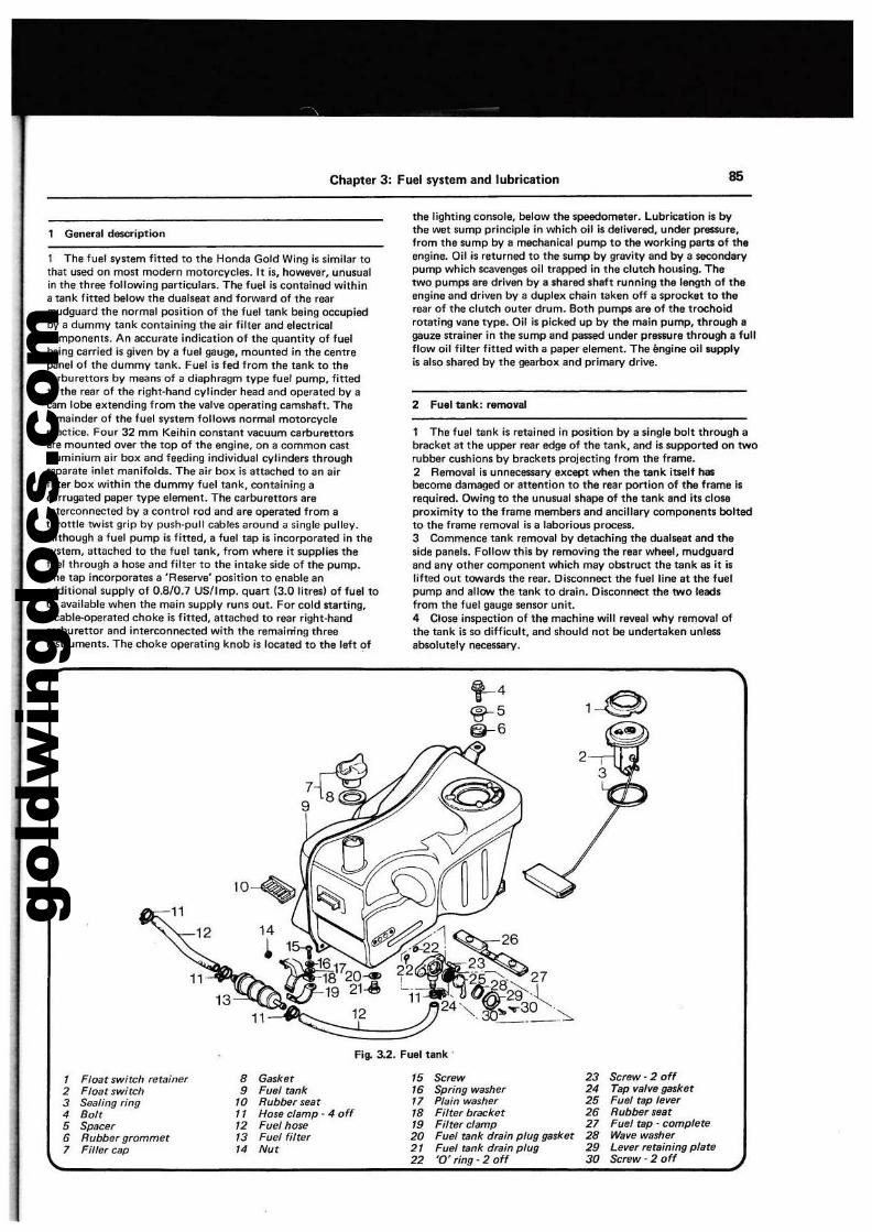
gold
win
gdoc
s.co
m
Chapter 3: Fuel system and lubrication 85
General description
I The fuel synem fitted to the Honda Gold Wing is similar tothat used on most modern motorcycles. It is, however, unusualin Ihe three following particulars. The fuel is contained withina tank fitted below the dualseat and forward of the rearmudguard the normal position of the fuel tilnk being occupiedby a dummy tank containing the air filter and electricalcomponents. An accurate indication of the quantity of fuelbeing carried is given by a fuel gauge, mounted in the centrepanel of the dummy tank. Fuel is led from the tank to thecarburettOr$ by means of a diaphragm type fuel pump, fittedto the rear of the right-hand cylinder head and operated by acam lobe extending from the valva operating camshaft. Theremainder of the fuel system follows normal motorcyclepractice. Four 32 mm Keihin constant vacuum carburettorsare mounted over the top of the engine, on a common castaluminium air box and feeding individual cylinders throughsaparate intet manifolds. The air box is attached to an airfilter box within the dummy fuel tilnk, containing acorrugated paper type element. The carburettOr$ areinterconnected by a control rod and are operated from aIhrottle twist grip by push-pull cables around a single pulley.Although a fuel pump is litted, a fuel tap is incorporated in thasystem, attached to the fuel tank, from where it supplies thefuel through a hose and filter to the intake side of the pump.The tap incorporates a 'Reserve' position to enable anadditional supply of 0.8/0.7 US/Imp. quart {3.0 litres} of fuel tobe available when the main supply runs out. For cold starting,a cable-operated choke is litted, attached to rear right-handcarburettor and interconnected with the remaining threeinstruments. The choke operating knob is located to the left of
11
the lighting console, below the speedometer. Lubrication is bythe wet sump principle in which oil is delivered, under premJre,from the sump by a mechanical pump to the working perU of theengine. Oil is returned to the sump by gravity and by a secondarypump which scavenges oil trapped in the clutch housing. Thetwo pumps are driven by a shared shaft running the length of theengine and driven by a duplex chain taken off a sprocket to therear of the clutch outer drum. Both pumps are of the trochoidrotating vane type. Oil is picked up by the rnain pump, through agaule strainer in the sump and passed under pr_ure througtt a fullflow oil filter fitted with a paper element. The II09ine oil tupplyis also shared by the gearbox and primary drive.
2 Fuel tlmk: removal
1 The fuel tank is retained in position by a sIngle bolt through abracket at the upper rear edge of the tank, and is supported on tworubber cushions by brackets projecting from the frame.2 Removal is unnecessary except when the tlnk iuelf hasbecome damaged or attention to the rear portion of the frame isrequired. Owing to the unusual shape of the tank and its closeproximity to the frame membef1 Ind ancillary components boltedto the frame removal is a laborious process.3 Commence tank removal by detaching the dualseat and theside panels. Follow this by removing the relr wheel, mudguardand any other component which may obstruct the tank ll$ it islifted out towards the rear. Disconnect the fuel line at the fuelpump and allow the tank to drain. Disconnect the two leadsfrom the fuel gauge sensor unit.4 Close inspection of the machine will reveal why removal ofthe tank is so difficult, and Should not be undertaken unlessabsolutely necessary.
t--4
~5@--6
Fiio 3.2. Fuel tank'
, Float swirch retainer 8 Gasket '5 Screw 23 Screw - 2 off2 Float swirch • Fuel tank ,. Spring washer 24 Tap valve gasket3 Sealing ring 10 Rubber sear " Plain washer 25 Fuel rap lever4 Bolt " Hose clamp - 4 off 18 Filter bracket 2' Rubber seat5 Spacer '2 Fuel hose " Filter clamp 27 Fuel rap· complete
• Rubber grommet '3 Fuel filter 20 Fuel tank drain plug gasket 28 Wave washer
7 Filler cap 14 N., 2' Fuel tank drain plug 2. Lever rersining pIaN22 '0' ring - 2 off 30 $crBW- 2 off
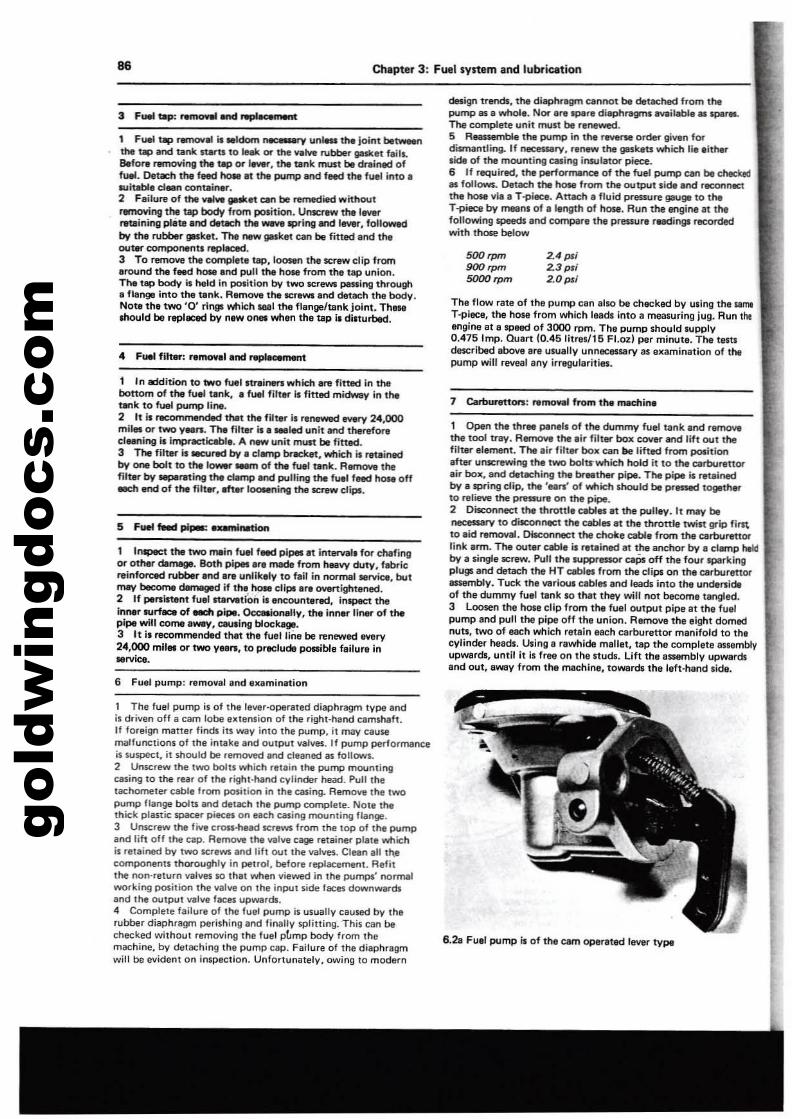
gold
win
gdoc
s.co
mChlpter 3: Fuel system ancllubfiCition
The flow rate of tha pump can alllO be Checked by using the IImt
T·p1eee, the hose from which lead. into a measuring jug. Run tho!engine at a SlJaed of 3000 rom. The pump Should lupply0.415 Imp. Quart (0.45I1treI/16 Hozl per minute. The teltldescribed above Itre uluallv unnllC8Slary as examination of thepump will re'leal any irregularities.
2.4 p4i2.3 pll2.0pll
50'h"",
900 """5000 """
design trends. the diaphnlgm cannot be detael\ed from thepump as a whole. Nor art! ~r. di.phntgms lMIi~.1IfIlPlr••The complete unit must be renewed.5 R~bloe the pump in the r_ order given fordismantling. If necessary, r_ the gaskets which lie eitherside of the mounting easing insulator piece.6 If required. the perlormence of the fuel pump can be c:tMekedas follows. Detach the hosti from the output side and reconntetthe hose via. T1)lecl. AnKh a fluid pressure gaug. to theT-p+ece by means of. length of hose. Run the engine at thefoliowil'lQ speed. and compare the prtISSure rtlKlings recordedwith those below
86
1 Fuel t.p ~-' is .ldom roee-.y unlea the jointbI~the up afld t.nk ItarU to Ie_ or the VlIIve ""'tiber galket fails.e.fore removirtg the up or '-". the tank must be milwd offueIl. Detach the feed hote It thI pump and feed the fuel into IRJi1able d.." contain-t.2 Failure of the ........ llIa*et Clin be Rlmedied withoutremoving the tap body from poIition. Unscrew the lew,retlIining plete.nd der.ch the-'llpring and I........ follow.clby the rubber gIlSket. lhe oew gasket can be fitted end theouter components ~11lO1Cl.
3 To remove the complete t8P.loosen the SCf'ew clip fromaround the feed hose end pYll the hose from tile tap union.The tap body I, held in poIition by two screws passing through• flangB into the tank. Ram~ the lCreWi and deUleh the body.Note the two '0' rlngl which 18111 the flange/tank joint. ThewlOOuld be replaced by ntw OMi when tha tap Is dilturbed.
1 In -*:jitiorl to two fuel unol".,. which &nl fined in thebottom of the full tank•• fuel fitter iI fitted midwey In thetBnk to fuel pump lilll.2 . It i. recommended thet the filllr il rlnewed _ry 24.000mIles or two Ylln. TIle filter iI. _led unit -.d theref~
cllening is imprec:tlc:lbl,. A _ unit muIt be fitted.3 The flit8\" II sec:ured by. damp tncklt, which is retainedby one bolt to the '-" IIem of the fuel tank. RIttT'IOYe thefilt8\" by IilIpIrating the damp and pulling the fuel feed hOM offIKh Ind of the filt.... mer lOO&Ining theacrew diPf.
1 Inlpect the two main fuel f. plpea at int~1 for dlafingor.other damage. Both pil)ll.rl made from heavy duty'. fllbricrelnforcec:t rubblf .nd.re unlikely to fall in normal ..rvlc:e butmay bec:omI dImIged if the hole clipl.ra ovartlghtened.•2 If peninent fUlt ItIl"YltlOn Is ..-.countered, inlpec:t theinlllr 1lUn.c. of -=tI pipe. OccaI.Ionally. the inner 11I'I8r of thepipe wilt come lWW'f. Clullng blockage.3 It i. recommended that thl fuat lina be renewed IYlIry24,000 mil.. or two Ylen, to preclude pea1b1e failure In"rvice.
7 Cart!urettora: remollli from the madllnl
1 Open the three penell of thoe dummy fuel tank end remD\llthe tool trey. R8mOIIIl trw eir filter box COlIer and lift out thefilter element. The eir filter box can tie lifted from position.fter unscrewing the two bolU"which hold it to the atrburettorair box, and detKhing the br.thet" pipe. The pipe is retlilW:lby. $pring clip, the 'ee.... 0' which should be pressed togetherto relielle the pnssure on the pipe.2 Disconnect the throttll c:ables It the pulley. It mev beneeesI8tY to dilc:onMCt the cables et the thron'e twin Iltlp fir1\to aid removal. Disconnect the choke cable from the carbure1torlink arm. The outer clble i. retlined at the anchor by e cllmp htklby a lingle ecrew. Pull the IUppressor caPs off the four 'Plllrkingplugs and deUleh the HT cabln from the clips on the carbur.norea:embly. Tuck the I18rious cabin and leads into the undenideof the dummy fuel t.nk 10 thlltthev will not become tangleel.3 Loosen the hose clip from the fuel output pipe at tha fuelpump and pull the pipe off the union. RetnOII8 the eight domednuts. two of each which retain each c:arburettor manifold to thlcylinder tleads. Using. rawhide maUet, tap the complete assemblyupwardl, until it is free on t!'le Itudl. Lift the assembly upwardsand out. away from the machine, towards thl left-hand .ide.
6 Fuel pump: remollal and Ixamin.tion
1 The fuel pump is of !he lever·operated diaphragm type .ndis drillen off a cam lobe extension of the right·hand camshaft.If foreign malter finds ilS way into the pump. it may causemalfunctions of the intake and output lIalves. If pump performanceil suspect. it should be retnOll'Kl and cleaned as follows.2 Unscrew the two bolts which retain the pump mountingeasing to the rea, of the right·nand cylinder head. Pull !hetachometer cable Itom position in the casing. RemOlle the two
pump flange bol\$ and detach the pump complete. Not. thethick plastic spacer piteft on each CBliing mounting 'lange.3 Unscrew the fille cross.fl.a<l scrllWl from the top of the pumpaoolih off the cap. RefT1Oll8 the wille cage retainer plate whichis retained by two scraWl end lilt out the lIalves. Clean all tl\lcomponents thoroughly in petrol. before replacement. Refitthoe non' return lIalves 110 that lIIItIan lliewed in the pumps' normalworking po$ition the lIal\18 on the inpt.n side laces downwardland 'he outputll8lve faces upwards.4 Comptete failure of the fuel pump is usually caused by therubber diaphragm perishing and finally splining. This can bechecked without remOiling the 'uel pLmp body from themachine, by dlltaching the pump cap. Failure of the diaphragm 6.21 Fuel pump 11 of the earn operated lell.r type
will be evident on inspection. Unfortunately, owing to mod.rn
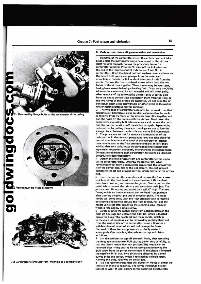
gold
win
gdoc
s.co
m
Chapter 3: FlMll system and lubfication 87
6.2b Retained bV flange bolts to the tachometer drive casing
7.3 Carburettors removed from machine as e complete unit
8 Cal'burenOfS: diwnantling axemil'lltlon end ~mbIV
1 Removal of the earburettorT; from the air box need not takeplace unless the instll,lmenn are to be renewed or the air boxinelf requires renewaL Follow the procedure below forcarburettor removal. Prise the 'E' dips off the link pivots onthe end of the throttle control rods on No.3 and No.4carburettors. Bend the detent bolt tab washers down aM remQY9the detent bolt, spring and plunger from the outer ltndof each link. Detach the link ends of the control rods from thepivots. Remove the five cross-head screws which hold the twohalves of the air box together. These screws may be very tight,having been 8SSembled using a locking fluid. GrEllt eare should betaken as the screws are of a soft matlf"ialand will shear easily,After removal of the Kr8WS prise the sPlit pins or spring pinsfrom the choke control rods end detach them from the links. esthe two halves of the lir box ere $8pllreted. Do I'IOt prise the eirbox halves apart using screwdriverT; or other leverT; as the sealingring or mating surfaces may ba dIlmeged.2 The two pairs of cal'burenors can I'IOW be removed from theirre$p8Ctive eir box halves, using an identical procedure for eachas follows' Press the 'ears' of the slow air hose clips together andpull the hotes off the unions with the eir box, Bend down thecarburettor mounting bolt tab washer ears end remove the bolts.Pull the two carburettors off the air box as a pair. Separate thecarburettOrT; bV pulling them apart, taking care not to 10M thesprings placed between the throttle and choke link connectors.3 The procedure set out for removal and separation of theearburettors in the prevlOUI peragraphs need not teke place fornormal el«lmination and removal of the earburet10r intemalcomponents such as the float assembly and jen. It is stronglyadvised that each clrburenor be dismantled and reassembledseparetely, to prevent accidently interchaoging the components.Dismentle and examine each carburettor, following en Identicalprocedure as described below.4 Detach the slow air hose from one carburettor at the unionon tl'Hl cerburettor body. Unscrew the slow air jet. Whenremoving any jet from a carburettor eosure thet the screwdriveris of the correct size, fitting the slot closely. This will preventdamage to the jet end prevent burring, which mey alter the Ofificesize.S Invert the carburettor essemblv and r8movettle four screwswhich retain ttle float bowl to the carburettor. Lift the floatbowl from position, and remove the gasket. Gently pull on themetal tab to remove the primary and secondary main jeu, Thejets ere push fit located and sealed by small '0' rings. The twQ
floats, which are interconnected, can be lifted from positionafter pushing the pivot pin out of the pivot posts. The floetneedle will come away with the floetassembly es It is retainedby a spring clip hooked eround the floet tongue. Pull out theneedle valve seat aftar removing the retaining claw hongue)which is retained by a single screw.6 Carefully prise the rubber bung from position~ themain jet housings end unscrew the pilot tet, which is locatedbelow the bung. The needle jet end main naule, which lieIn the main jet housings, can be removed by pushing them outfrom the I19nturi side of the carburettor, u,lng e finger or a'ultable piece of wood which will r'lOt damage the brass,Removal of these two componenn is probably euler toaccomplish after detaching the carburettor cap and pIstonas follows.7 Lift the carburettor cap off tne main body, after removingthe three retaining screws. Pun out the piston I18ry carefully, 110that the piston needle does not get bent.The needle ClIn beremoved after lifting out the helical spring and removing t"grub screw from the piston centre tube. If tl'Hl piston Is Invenedthe needle will fell out. Two air jeu: are obtcured by a unellcurved platllllnd gasket, which is retained by a single screw.Remove the plate, followed by the air jets.8 It is not recommended that the 'butterfly' 1181,.. of elther thethrottle or choke be removed. The 1181_ themMl_ are notsubject to wear. If wellr occurs on the operating plllbu, a new
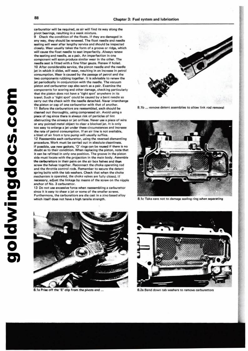
gold
win
gdoc
s.co
m88 Chapter 3: Fuel system and lubrication
carburettor will be 'llQuired," air will find its way IIlong thepivot bearings, rewlting in 8 weak milllure.9 Check the conditio" of the floats. If Ihey are damaged ineoy -V. they should be renewed. The float needle end needle_ling will -at after lengthy service and should be i"specle<:!dOMly. Wear \ISlJelly takes the'ann of. groove or ri~. whichwill caulle the flOlit needle to seat imperfectly. Alway. renewthe ...ting and needle.... plir. An il1'l98rfllCtion in oneco~n&lltwill soon produce .imilar _r in the other. ThenMdle Ral i, titled with. fine filter gauze. Renew if holed.to After considerable service. the piston needle and tha needlejet in which it .I~. will weIr, resulting in en incre8118 in petrolconwmption. Wu, is caused by the peMage of Pltrol end th,t'NO components rubbing together. It is .ctvi~. to renew thejet periodieelly in coojUnc1ion with the needle. The vacuumpinon and carburettor cap also work as. pair. Examine thecomponents for .coring_nd other damage, checking particularlythat the pinon dOM not have I 'tight spot' anywhere in itstrlMll. Such I 'tight spot' could be caused by a bent needle socarry out the chack with the needle detached. Nev.r interchan911thl pinon or ClIP of one carburettor with that of anolher.11 Before the csrburettors are reassembled, each should becl..ned out thoroughly. using compressed air. Avoid using apiece of ragliflQ m.re is always risk of particles of lintobItructing the lirways or jilt orificllS. N_ usa. piece of wireor My pointed metal objlC1 to clear a bloc:ked jet. It is onlytoo -V to enlarge a j.t under these circumnancet Ind increaseth.e rate of petrol consumption. If an air line is not available,a bien of eir from a tyre pump will usually suffice.12 Reassembll lach carbureltor, using the rew:rsed dismantlingproc:edure. Work must be carried out in Ibsolute cleanliness.If poRible, uN new gaskets, '0' rif19ll can be reueed if there is nodoubt I. to their eondition. When replacing the pinon, not. thatit can be refined in only one position. T.... grOOY1l in t.... pinonsiOI mun locate with the projlC1ion in the ffillin body. Assemblethe c.rtJurlnors In their pelrs on the Ilr box halves and thanscraw the halves together. Reeonnect the choke opereting rodend the thronle control rods. Remember to securl the detentspring bolts with thl tab washers. Check that when the Chokemect\lnism is opereted. the choke valves Ire fully closed. Ifneceuarv, adjust thllinkage by means of the screw on the nipplell'ICfIor of No.3 QlftJurettor.13 00 not U'$I exceaive force when ~ingI carburenorsinee it is easy to shtar. iet or some of the small.r screws.Furthermor., the carburenors are die cast in. zinc·based alloywhich itself does not have a high tlnsilaltrength,
8.1. Pri. off the 'e' dip from the piYotl.nd ...
8.1b ... remove detent assemblies to .lIow link rod removal
8.1c T.ke carl n.ot to demage sealing ring whan sep8reting
8.21 8.nd down tlb wadlers to remow eerburenOrl
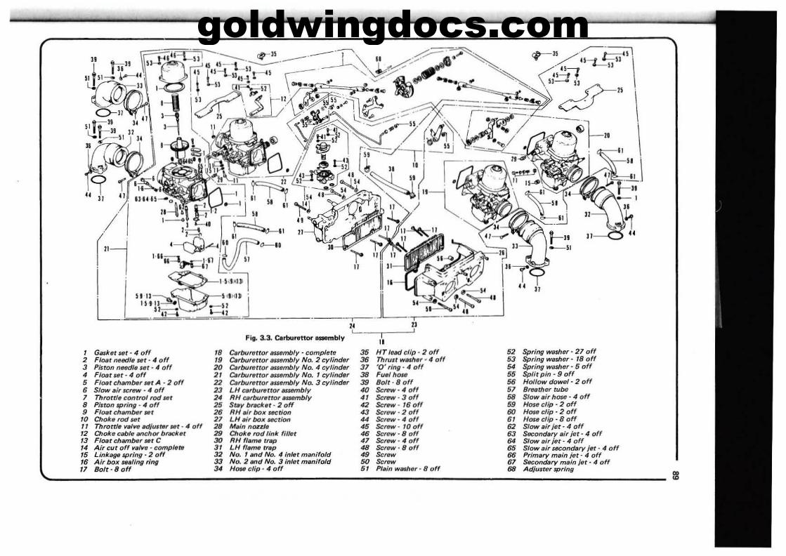
goldwingdocs.com
11-0
II
"FIg. 3.3. Clll1lUr1tttor eaembly~--r
11, Gasket set - 4 off '8 C.,burtltror Bssembly - complete 35 HT 'eMJ clip - 2 off 52 Spring washer· 27 off2 Float net!dle 'fit· 4 off .. C.,bufettor lI~mblyNo.2 cylinder 35 Thrutr wtl,h,,· 4 off 53 Spring washer - 18 off3 Piston needl. Sflr - 4 off 20 c.,buretrof /IIlembly No. 4 cyHnder 37 '0' ring' 4 off 54 Spring washer· 5 off4 Float Utt - 4 off 21 0,OO,..t(01 ISwmbly No. 1 cylinder 38 Fuel hr»tI 55 Split pin - 9 off5 Float chambBr Ht A ·2 off 22 C.,burettor ."embly No. 3 cylinder 39 Bolt· 8 off 66 Hollow dowel- 2 off
• Slow elr IICftIW· 4 off 23 LH QlrbuflUrOr HfI1fflbfy 40 $cfftw·" off .7 Breather tube7 Throttle control rod let 24 RH Q1rbu,..tror tlRembly " SCfWW' 3 off 58 Slow airh~ . 4 off8 Pinon spring - .. off 25 St.ty lm,chr· 2 off 42 Sc.-.w-16off 58 Hos. clip· 2 off9 Fla.t chambt" Ui 2. RH 1Ji, box JfCrion 43 Screw - 2 off 60 HO$fJ clip' 2 off
10 Choke rod lilt 27 LH';, box uctJon 44 Screw - .. off .. HrMtJ dip· 8 off
" Throttle ",.11111 ecUu,r.r IfIt·" off 28 MlJin noz,l, 45 Scrtlw- 10 off 62 Slow air jet - 4 off12 Choke csblellnChor bl'llCket 29 Choke rod fink fl/let 4. Screw - 8 off .3 SflCondary air jet - 4 off13 Float chllmNr Nt C 30 RH fleme trep 47 ScrlPW- 4 off '4 Slow Bir jet - 4 off/4 Air cut off IIB/lla - compl'ttI 31 LH fleme trIPp 48 ScrlPw, 8 off '5 Slow "ir secondary jBt· " off/5 Linhga 'Pring - 2 off 32 No. 1 .nd No.4 inlet manifOld 49 Screw 66 Primary mBin jet - " off16 Air box 88allng ring 33 No. 2 .nd No. 3 in/at manifold 50 5<_ '7 Seconci8ry main jet - 4 off
" Bolt -8 off 34 Hou clip - 4 off 51 PI.ln wBSher - 8 off 68 Adjuster springIi!
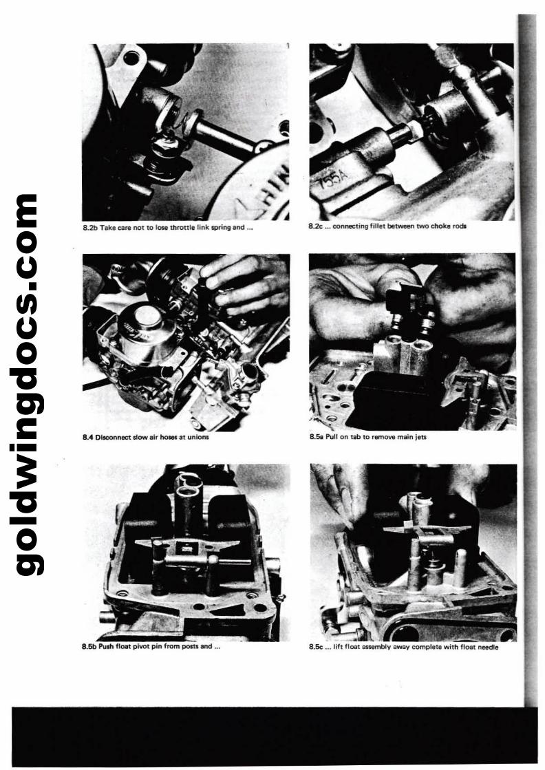
gold
win
gdoc
s.co
m
--8.Se ... 1111 floet assembly lway complete with float needle
8.2b Tlke earl no1 to lose thronlelink spri"i Ind ...
8.4 DJconnect slow lir ho_ It union.
8.5b Pulh fl0l1 piV01 pin from poItIIlnd ...
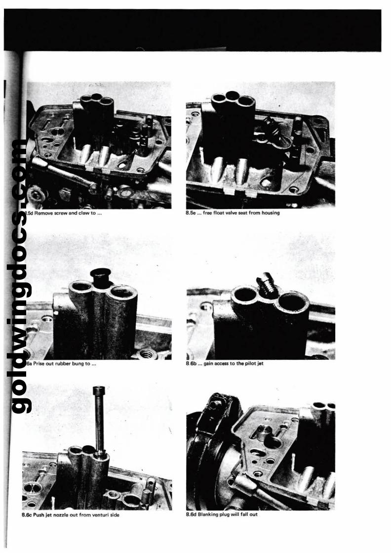
gold
win
gdoc
s.co
m
,. '.. '
8.6a PriM out rubber bung to ...
B.Se Push Jet nozzle out from venturllide
B.Se ... frfle floet valve S8i1t from hauling
•
~JB.6b ... gein ace-. to the pilot jet
8.6d Blenking plug will fen out
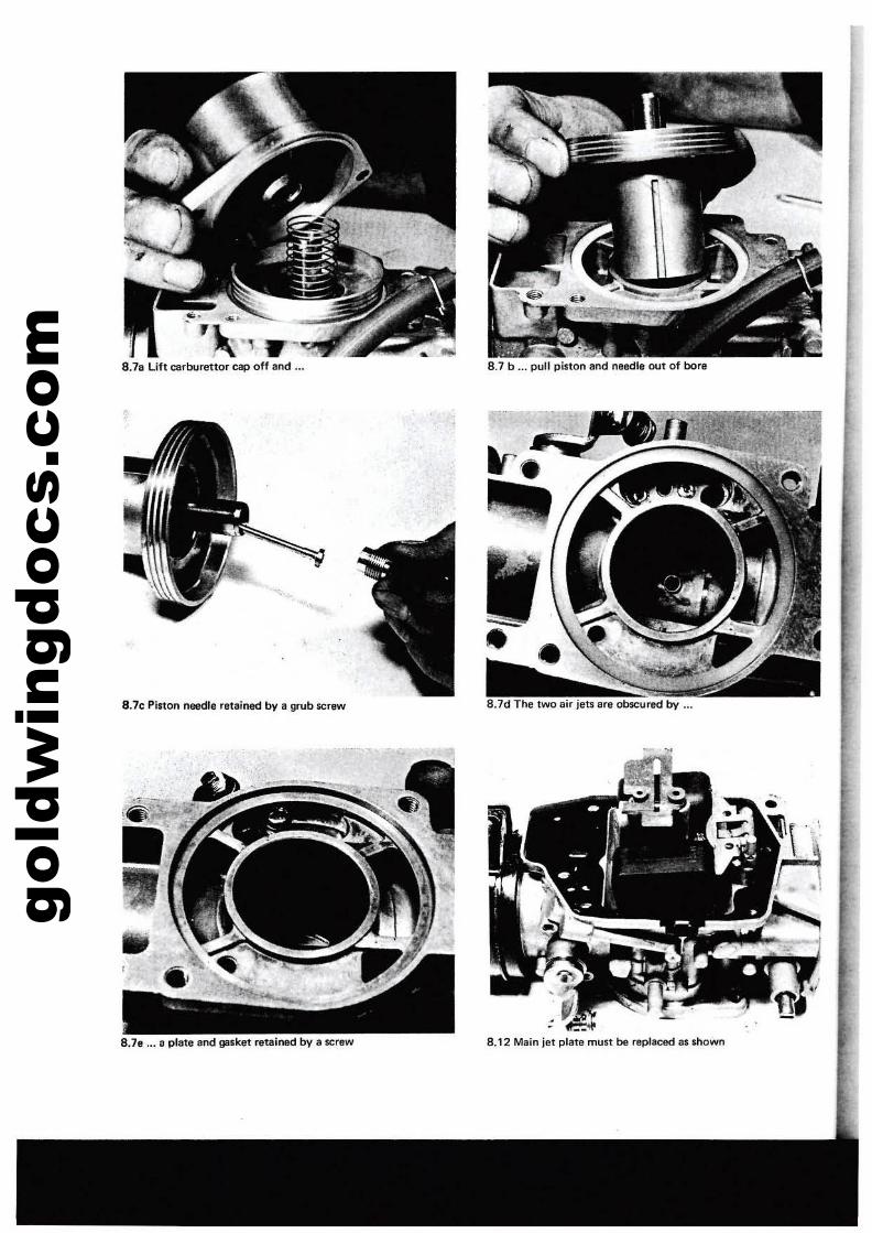
gold
win
gdoc
s.co
m
8.7d The two air jets aft obscured by ...
~.,\...,J'l( , W'~
8.78 Lift carburettor cap off aod •••
8.7c Pinon needle retairted by a grub screw
8.78 ... a plate lind gasket retained bV a $Crew
8.7 b ... pull piston end needte out of bora
8.12 Main jet plate must be replaced as &hown
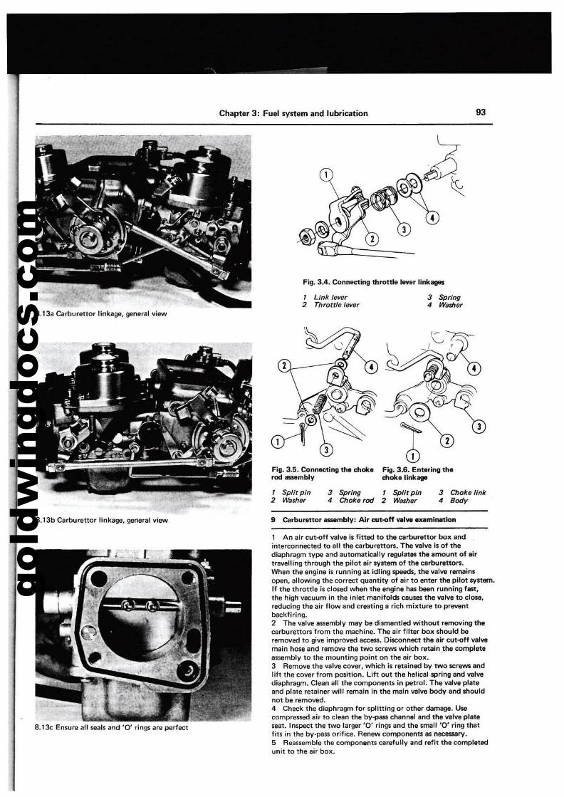
gold
win
gdoc
s.co
m
Chapter 3: Fuel system and lubrication 93
Fig. 3.4. Connecting throttle lever linkages
1 Link lever2 Throttle lever
3 Spring4 Washer
8.13a Carburettor llnkage, general view
Fig. 3.5. Connecting the mokerod iJ5SEImblv
3 Choke link4 Body
Filii. 3.6. Entering thed10kelinkage
1 Split pin2 Washer
3 Spring4 Chokerod
1 Split pin2 Washer
8.13b Carburettor linkage, general view 9 Cerburettor IISMmblV; Air cut--off VIII..,. exemlnetlon
8.13c Ensure all seals and '0' rings are perfect
1 An air cut-off valve is fitted to the carburettor box andinterconnected to aU the carburettors. The valve is of thediaphragm type and automatically regulatllt the amount of airtravelling through tile pilot air SY$1em of the carburettors.When the engine is running at idling speeds, the valve remainsopen, allowing the correct quantity of air to enter the pUot system.If the throttle is closed when the engine hes baan running fast,the high vllCuum in the inlet manifolds causes the valve to close,reducing the eir flow and creating a rich mixture to preventbackfiring.2 The valve assambly may be dismantled without removing thacarbutettors "from the mllChine. Tha air filter box should beremoved to give improved access. Disconnect the air cut-off valvemain hose and remove th.e two screws which ratain ,tha completeassemblv to the mounting point on the air box.3 Remove the valve cover, which is retained by twO screws endlift the cover from position. Lift out the helical spring and valvediaphragm. Clean all the components in petrol. The velve plateand plate retainer will remain In the main valve bodv aod shouldnot be removed.4 Check the diaphragm for splitting or other dam•. Usecompressed air to clean the by-pass channel and the valve plateseat. Inspect the two larger '0' rings and the small '0' ring thatfits in the by·pass orifice. Renew components as nec8$$ary.5 Reassemble the components carefully and refit the completedunit to the air box.
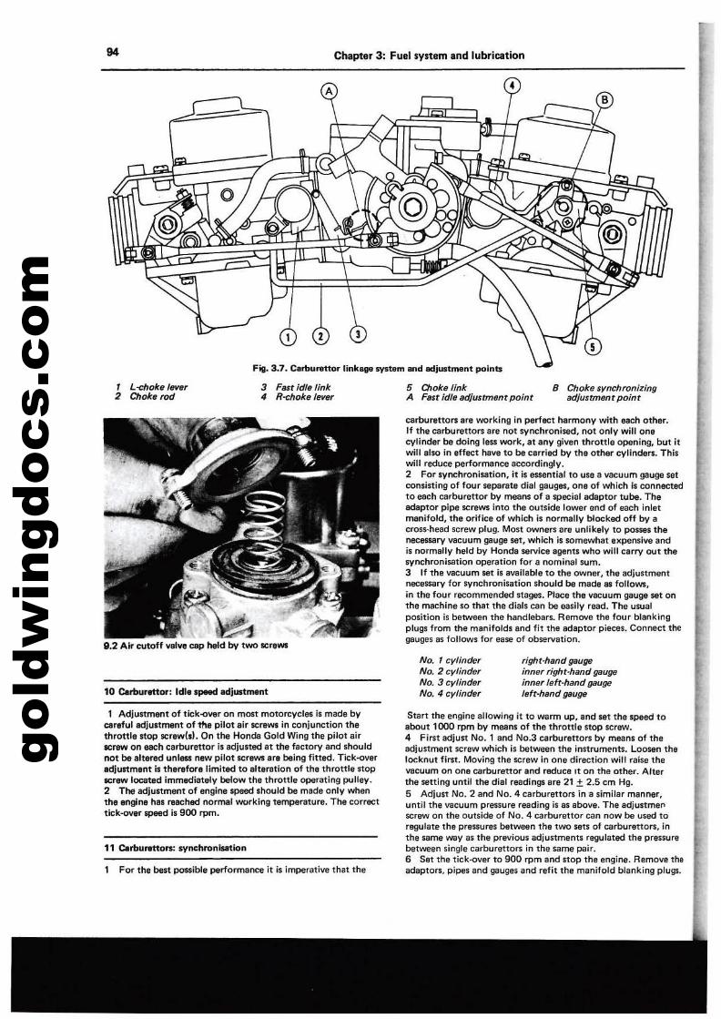
gold
win
gdoc
s.co
m94 Chapter 3: Fuel systam and lubrication
A
2 3
fig. 3.7. C.rbvrettor linkage system and Ildju$1:ment points
, L-ehoke 'ever2 Chokeroc/
3 Fast idle link4 R-dloke lever
5 Choke/inkA Fast idf, adjustmtmr point
B Choke ,ynchronizingadjustment point
9,2 Air cutoff valve cap held by two scraWl
earburettors are working in perfect harmony with each other.If the earbtJrettors are not synchronised, not only will onecylinder be doing less work, at any given throttle opening, but itwill also in effect !'lave to be carried by the other cylinders. Thiswill reduce performence accordingly.2 For synchronisation, it is e5'entia' to use II vacuum gauge setconsisting of four separate dial gauges, one of which is connectedto each earburenor by means of a special adaptor tube. Theadaptor pipe screws into the outside lower end of each inletmanifold, the orifice of which is normally blocked off bv acf05s-head screw plug. Most owners are unlikely to POSSM thenecessary vacuum gauge set, which is somewhat expensive andis normally held by Honda service agents who will carry out thesynchronisation operation for a nominal sum.3 If the vacuum set is available to the owner, the adjustmentnecessary for synchronisation Should be made as follows,in the four recommended stages. Place the vacuum gauge set onthe machine so that the dials can be easily read. The usualposition is between the handlebars. Remove the four blankingplugs from the manifolds and fit ttlt! adaptor pieces. Connect ttlt!gauges as follows for ease of observation.
10 C4IrtlurfttOf': Idle.peed edjl4tment
No. 1 cylinderNo.2 cylinderNo.3 cylinderNo.4 cylinder
right-hand gaugeinner right-hand geugeinner left·hand gaugeleft-hand gauge
1 AdjuStment of til;:k-over on most motorcvc:les is made bycareful adjustment of the pilot air screws in conjunction thethrottle stop screwl.l. On the Honda Gold Wing the pilot airscrew on each carbureUor i, adjusted at the factory and shouldnot be altered unlns new pilot screws are being fitted. Tick-overadjunment I. therefore limited to alteration of the throttle $lOPlICrew located immediately below the throttle operating pulley.2 The adjustment of engine speed should be made only whenthe engine has reached normal working temperature. The correcttic::k-ov8l'" 5P88d II 900 rpm.
11 C.rbu...nors: syochronlsatton
For the best possible performance it is imperative that the
Start the engine allowing it to warm up. and set the speed toabout 1000 rpm by means of the throttle stop screw.4 First adjust No.1 and No.3 earburettors by means of theadjustment screw which is between the instruments. Loosen thelocknut first. Moving Ihe S(:rew in one dira<:tion will raise theVDcuum on one carburettor and reduce It on the other. Alterthe selling until the dial readings are 21 ± 2.5 cm Hg.5 Adjust NO.2 and NO.4 carburettors in a similar manner,until the vacuum pressure reading is as above. The adjustme"screw on the outside of No.4 earburettor can now be used toregulate the pressures between the two sets of earburettors, inthe same way as the previous adjustments regulated the pressurebetween single carbureUors in the same pair.6 Set the tick-over to 900 rpm and stop the engine. Remove theadaptors, pipes and gauges and refit the manifold blanking plugs.
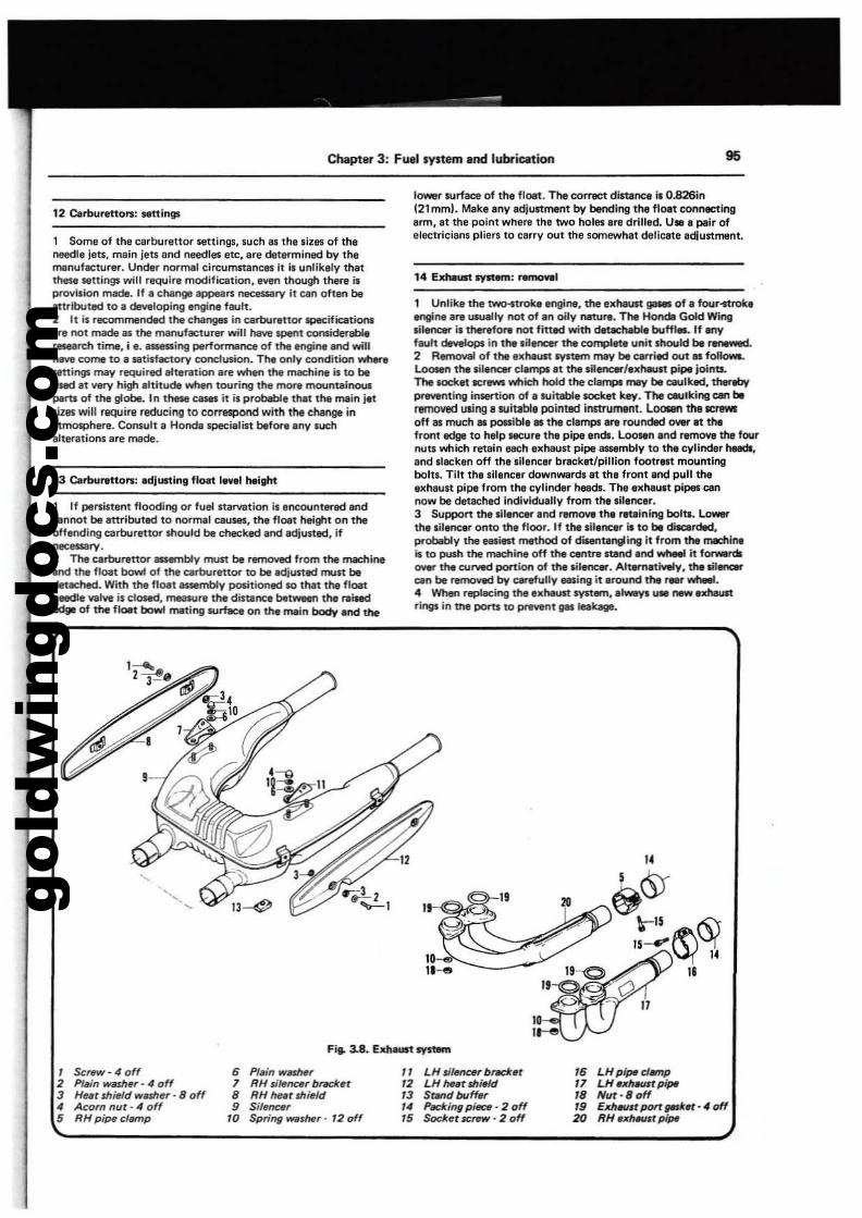
gold
win
gdoc
s.co
m
Chapter 3: Fuel system and lubrication 95
12 c.rburettors: Mttir'llll
1 Some of the carburettor settings, such es the Ilzes of theneedle leu, mein leu end needles etc, ere determined by themanufacturer. Under normal circumstarn;e5 It is unlikely thatthese $8ttings will require modification, even though thef"e isprovision made. If a cl\enge appean necnsary it can often beattributed to a developing engine fault.2 It is recommended the changes in carburittOl' specific:lltionslire not made lIS the manufacturer will !\eYe spent consid8l'"ableresearch time. i e. aaeaing perfOl'lT'IiI1'ICe of the t:ngine and will!\eYe come to e satisfactory conclusion. The only COndition where.ningi may required alteration lire when the machi,... is to beuMd lit Y1IlY high IIltitude~ touring the more rnounteinousPlJU of the globe. In these~ it is probable thet the main jetli11lS will r&QUire redueino to eOrTespond with tM ehange inetTnOlPhere. Consult e Honde specielist blfore eny luchelterations ere macle.
13 c.rtKll'Itton: adjusting float level height
1 If persistent flooding or fuel starvlltion is encountered endcannot be ettributed to normal causes, the floet height on theoffending carburettor ....ould be checked end adjusted. ifnecessary.2 The cerbul1lttor 8I:Mlmbly must be remowd from the machineend the float bowl of the cerburenOl' to be adjusted fTI,Ilt bedetached. Wrth the float assembly positioned 10 that the floatneedle valve is closed, ITMIMUI1l the distence blt_ the r;liIededII' of the floet bowl meting sum.:. on the mein body and tl'Ie
lower IUrlaee of the floet. The eorrect distance Is 0.826in(21 mm). Make eny edjustment by bending the floet connectingerm, et the point wl'lere the two holes ere drilled. U. e peir ofelectricians pliers to cerry out the somewhat delicete edIustment.
14 EJChfIUIt system: removel
1 Unlike the twl;Htroke engine, the exheUft ga-. of e four~engine ere usually not of en oily neture. The HondII Gold Winglil~ is thenfOl"1l not fined with deUcheble buffl.. If anyflUlt develops in the silellClf the compllte unit snould be ntnIIWId.2 Removal of the exhel.m system may be carried out lIS follow$.l.ooIen the silencer cle~.t the silencer/extMuft pipe joints.TN socIttit~ which tKlld the clell'lP' mey be callbd, therebyprIYlInting insertion of e suitable lOCket key. TNcwlking cen beremoved using e suitable poinUJd iMtrUment. Looren the SCfIWSoff IS much IS pos;sible. the clemps ere rounded over It thefront edge to help MCUre the pipe ends. Loosen end remcwe the fournuu which retein each ellMYst pipe assembly to thoe cylinder heeds.end sllCken off the sil,nc.r bracket/pillion footrll1 mountingbohs. Tilt the silencer downwards 81 the front end pull theellheust pipe from the cylind.r heads. The ellhe""t pipes cannow be detached Individually from the silencer.3 Support the ~I.ncerend remoYllthe reuinlng bolu. Lowerthe silencer onto the floor. If the silencer is to be diecerded,probably the _ill1 method of dis.entengting it from the mKflineis to push the lnIIChine off the centre stand end wheel it forwerdlOYer the curved portion of the silene«. Altemet......y.1hesil_CMI be removed by carefully _Jng it .round the ,..er wheel.4 When repillCing the elllMousl system, e'-vl u• .-.xn-trings in the portIto P'"8"t llIIleekage.
"'~
Fie. :18. ~tsvst-n
I Screw • 4 of(
2 PI.n -mer - 4 off3 He.r shield washer· 8 off4 Acom nut - 4 off5 RH pipe damp
6 PI.n~r
7 RH sife~rbrecJcet8 RH hut sllield9 Sllem:.r
'0 Spring _sher - '2 off
" LH sifMCtfr brecJc,t'2 LH '-t shield'3 Stwldbuff.,.'4 Pding pi«;e. 2 off'5 Socker.crew· 2 off
'6 LH pi,- dM'lp'7 LHuhwsrp;"'8 Nur-80ff19 EJChwstporr".k«-40f(20 RH 81I"-ustp;,-
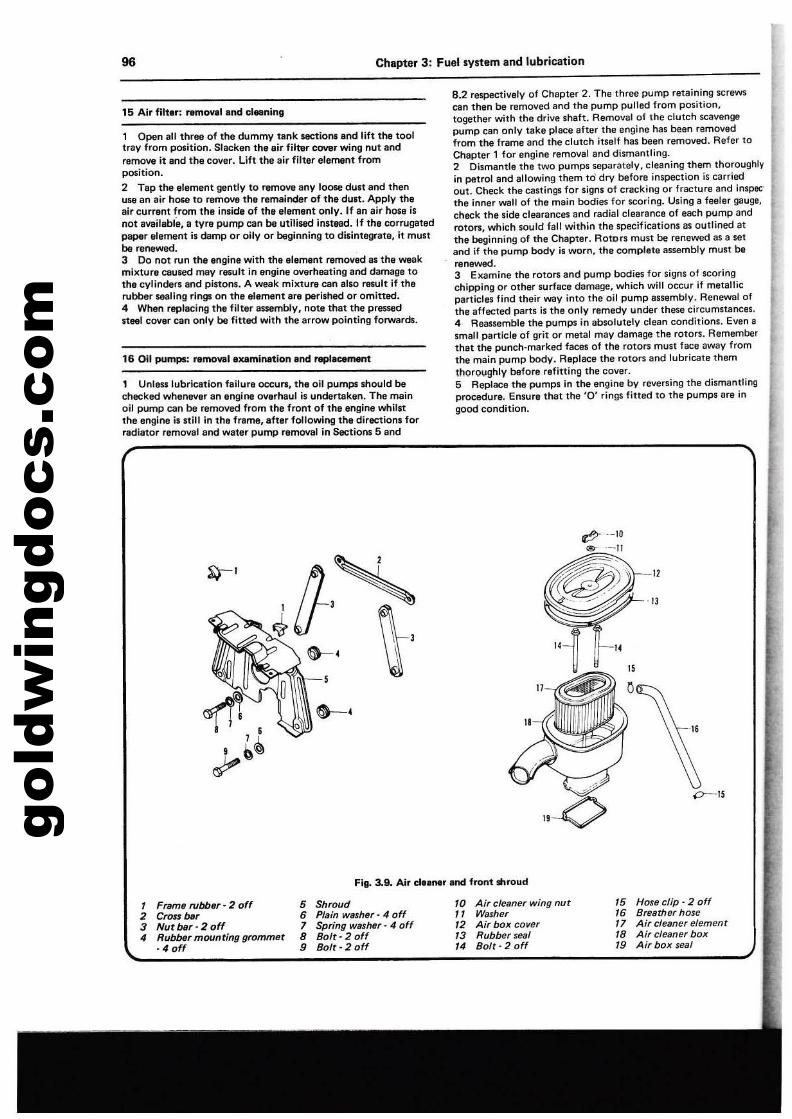
gold
win
gdoc
s.co
m96 Chapter 3: Fuel system and lubrication
15 Air filt.r: remOVII and cl..nlng
1 Open all three of the dummy tank sections and lift1he tooltray from position. Slacken the air filter cover wing nut andremove it and the cover. Uft the air filter elltm8nt fromposition.
2 Tap the element gently to remove any loose dun and thenuse an eir hOM to remove the remainder of the dUlt. ApplV theair current from the inside of the element only. If an air hose isnot available, e tvr!! pump can be utilised innead. If the corrugatedpaper elame"t is damp or oily or beginning to disintegrate, it mustbe renewll'd.3 00 not run the engine with the _l,ment removed as the weakmixture caused mav fewlt in engine overheating end damage totile cylindel1l and pinons. A weak mixture can also result if therubber _ling rings on the element are perished or omitted.4 When replllCing the filter assemblv, note that the pressedneel cover can only be fitted with the arrow pointing fOlWllrds.
16 Oil pumps: remowl eXlmination Ind repI_nt
1 UntEtSS lubrication failure occurs, the oil pumps should bechecked whenever an engine overhaul is undertaken. The mainoil pump can be removed from the front of the engine whil.tthe engine i••till in the frame, after following the diraction. forradiator removal and water pump removal in Sections 5 and
8.2 respectively of Chapter 2. Tha three pl.Jmp retaining screws;can then be removed and the pump pulled from position,together with the drive Shaft. Removel of the clutch scavengepump cen only take place after the engine has been removedfrom the frame and the clutch itself has been removed. Refer toChapter 1 for engine removal and dismantling.2 Oismentle the two pumps separately, cleaning them thoroughlyin petrol and allowing them to dry before inspection is carriedout. Check the castings for signs of cracking or fracture and inspecthe inner wall of the main bodies for scoring. Using a feeler gauge,check the side clearances and radial clearance of each pump androtors, which sould fall within the specifications as outlined atthe beginning of the Chapter. Rotors must be renewed as a setand if the pump body is worn, tha complete assembly must berenewed.3 Examine the rotors and pump bodi" for signs of scoringchipping or other surface damage, which will occur if metallicparticles find their way into the oil pump assembly, Renewal ofthe affected parts is the only remedy under theie circumstancss,4 Rssssembis the pumps in absolutely clean conditions. Evsn asmall particle of grit or matal may damags the rotors. Rememberthat the punch·marked faces of the rotOrS must face away fromthe main pump body. Replace the rotors and lubricate themthorO\lghlv before refitting the cover.5 Replace the pumps in the engine by reversing the dismantlingprocedure. Ensure that the '0' rings filled to the pumps are ingood condition.
rtf? --10<l!>- --II
m~~:-. - - .-/-
-'O----~
~I
"
Fig. 3.9. Air c\elner and front shroud
"
"."
7 Fram' rubb,r' 2 off2 Cron bar3 Nutbar·20ff4 RubbtJ, mounting gromm't
·4 off
5 Sh,oud6 Plain washe,· 4 off7 Spn'ng was"'" 4 off8 Bolt·20ff9 Bolt· 2 0"
'0 Air cleane, wing nut'7 Wash,r72 Ai' box cove,73 Rubber seaf14 Bolt· 2 off
75 Hosa clip· 2 off16 B,eather hose17 Air cleane, element'8 Air cleaner box19 Air box seal
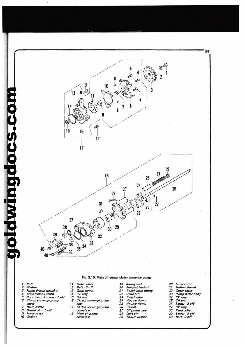
gold
win
gdoc
s.co
m
,----------------------------97
~·-·l
18 /'/ 23~~ !
~. 21 bc;:? 201
// 1. ~.~'1 //./ ::YY 250/
'/'31 , J26
\' ~9 ~ . 32 30 29//". <If'. ./~36 34 33 ../
40 ~36 35 ./40 ~.__.--'"
FiI- 3.10. Molin oil pump, dutdl_,. pump
, 801' " Outer rotor 19 Spring Iftt 30 /tlMf rotor2 W;Uheof '2 Bo/t· 3 off 20 Pump drivtn/lafr 31 Hollow dowel3 Pump drillfM sprocket '3 Grub screw 2' Refi,,' va'.... spring 32 Outer rotor• Countrlrsunk $Crow 14 '0' ring 22 Dr/lfepin 33 Pump out., body5 Countersunk screw - 2 off 15 Oil sHI 23 Rali.f va/WI 34 '0' ring
• Clutch scaWJnge pump '8 Clurch ICllvenge pump 2' Hollow dOWflI 35 Oil,.111COWlf case 25 Hollow dowel 35 ScrttW· 2 off
7 Drive collar " Clutch leaf/tinge pump· 2. G.,ker 37 '0' fing8 Dowel pin - 2 off compftlre 27 Oil pump caUl 3B FHdcoffa,9 Inn", rotor '8 Main oil pump- 28 Split pin 39 .sc",w· 3 off'0 Gasket complete 29 Thrust washer 40 BoIt- 2 off
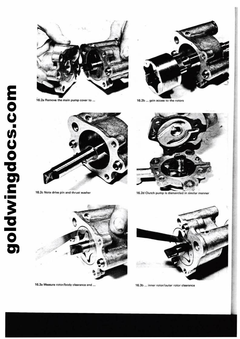
gold
win
gdoc
s.co
m lS.2a RemoYIt the main pump cover to ...
lS.2c Note drive pin end thrulit washer
16.3a Musura rotorl'body clearance and ...
16.2b ... lIilIin eecess to the rotors
V16.2d Clutch pump il dilmantled in similar manner
16.3b •.. inner rotor/outl\" rotor clearance

gold
win
gdoc
s.co
m
16.3c Check all rotorl for $Coring or chipping
Chapter 3: Fuef system and lublicetion
I
16.31 ... the main pump pressure release valve
99
16.3d Remove split pin to allow ...
17 Oil filter; renewing the element
1 The oil filter II contained within a separate houling, bolted tothe front engine CO"IM by I lingle hollow bolt containing theprnsure release valve. Acc:esI to the element illT1llde by Un.scrllWillithe centre bolt, which will bring with it the houling and element.Before removing the houling. place e receptacle beneath the engineto catch the engine oil contlined in the filter" chamber.2 When renewing the filter element, it ill wise to renew thehouling '0' ring at lhe same time. An '0' ring il usuilly providedwith I filter.3 The fitter by"'P'u vllve (pressure rel_ vallllll, compriling aplun98r and $pring, il situated in the bor"e of tM! centre bolt. It ilrecommended that the by-pllss velve be checked for fret operationIt regular intervall. The spring and plunger ... raUilned by • pinacross the centre boll. TIIP the pin out, to Illow removel of theplunger lind spring lor cleaning.4 Never run the engine without the lilter alement or increase theperiod between the recommended oil changes or oll filter changes.Change the engine oil and lilter every 6,000 miles or 6 rnoothl,whichever is 100ne$!.
•16.3e ... removal of ..,ring and seat of
..
1 An oil pressure waming l..-np is inco..-porceted in thelubrication system to give immediate warning olellCllllively lowoil pressure.2 The oil prelsure switch ilscrewed into the top of thecrankcase, below No.3. Carburettor. The switch il connected toa warning light on the lighting panel on the handlitba... Thelight should be on wh,n the ignition is switched on but willusually go out almost liS loon as the engine il l1aned.3 II the oil warning lamp comes on whilst the mllchine isbeing ridden, the engine should be switched off immedillnly.otherwise there is a risk of severe engine damltgll due tolubrication failure. The lault muit be located and rectifiedbefore the engine il rl'-ltllrted lind run, even lor I brief time.Machines fitted with plain sheoll bearings rely on high oilpressure to maintain a thin oil film between the bearingsurfaces. Failure of oil pressure will cause the workingsurfaces to come into direct contact. ~ing~ing.nd IYIIntuallll'lgine seizu...
19 Fuel 9l'uge.nd flNt .witc:h: teni"""
Aefer to Chaoter 7. Section 22.
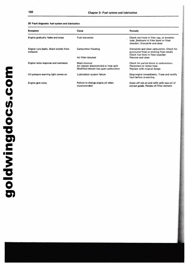
gold
win
gdoc
s.co
m'00
20 Fault dilllnosls: fuel system and lubrication
Chapter 3: Fuel system and lubrication
Symptom
Engine gredually fllCkls and stops
Engine runs bedly. Black smoke fromexhausts
Engine lacks response and overheats
Oil pres8lJre waming tight com9$ on
Engine gets noisy
Cause
Fuel starvation
Carburel10r flooding
Air filter blocked
Weak mixtureAir cleaner disconnected or hose splitModified silencer has upset carburation
Lubrication system failure
Failure to change angine oil whenrecommended
Remedy
Check vent hola in fillar cap, or breathartube. Sediment in filter bowl or floatchamber. Dismantle and clean
Dismantle and clean carburettor. Check forpunctured float or sticking float needleCheck fuetlevel in float chamberRemove and clean
Check for partial block in carburettoTS.Reconnect or renew hoseReplace with original design
Stop engine immediately. Trace and rectifyfault before re·starting
Drain off old oil and refill with new oil ofcorract grade. Renew oil filter element
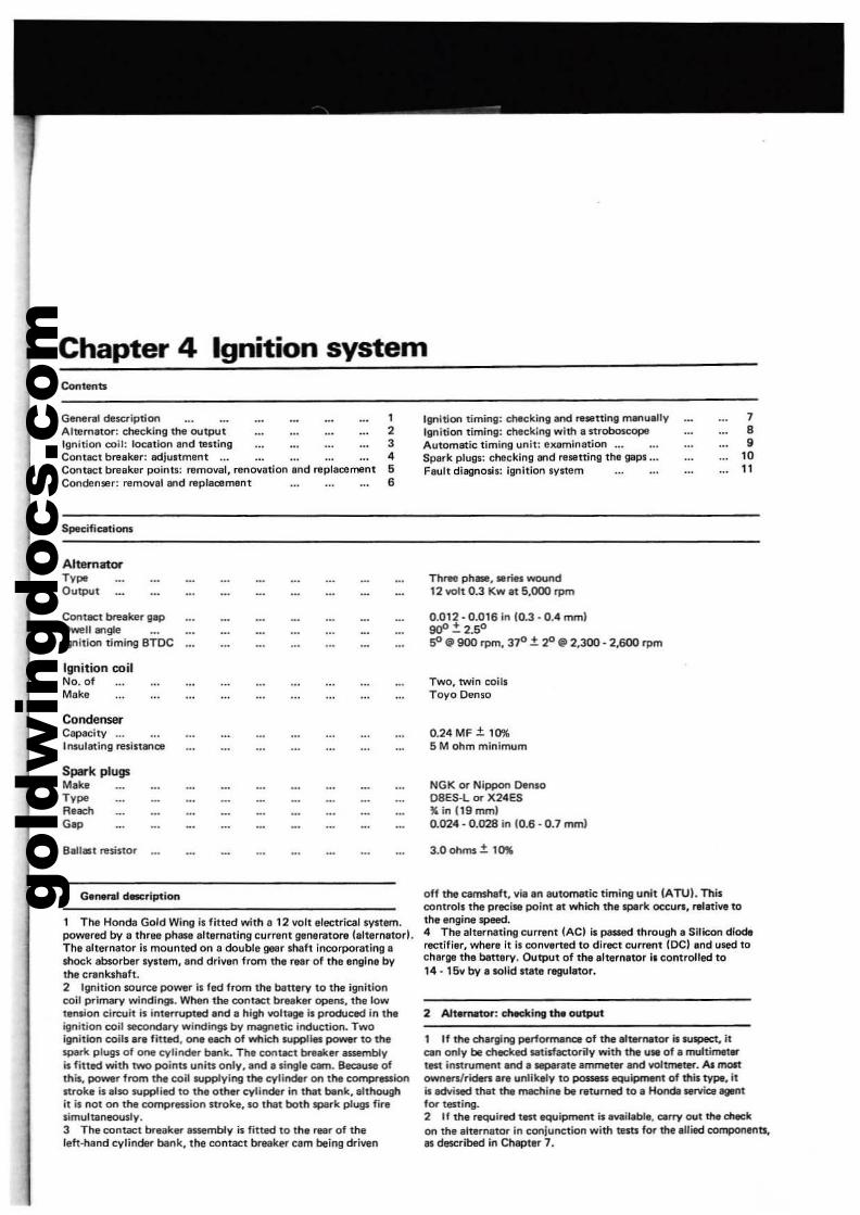
gold
win
gdoc
s.co
mChapter 4 Ignition system
General de5Cription 1Alternator: check.ing the output 2Ignition coil: location lind testing 3Conlect breaker: adju.tm,"! ... 4Contact breaker poio1l: removal, renovation end replacement 6Conden",.: remoyalllOd replacement 6
Specifications
AlternatorT,poOutpUt
Cont8Ct breaker gapDwell ....g/eIgnition timing BTOC
Ignition coilNo. ofMake
CondenserCapacity ...Insulating resistance
Spark plugsMikeT,poReachGop
Ignition timing: checking and ....ninll manuallyIllnition timing: checklnll with a stroboscopeAutomatic timing unit: elUlmination ...SPlirk plugs: checking and resetting the gaps ...Fault dill9nosis: Ignition system
Three phase, Sl!rits wound12 volt 0.3 Kw at 5,000 rpm
0.012 - 0.016 in 10.3 - 0.4 mmlgoO.:t 2.50
SO .. 900 rpm, 370 ± ~ (II 2,300 - 2,600 rpm
Two. twin coilsToyo Denso
0.24 MF ± 10%5 M ohm minimum
NGK or Nippon DensoD8ES-L or X24ES~ in 119mml0.024·0.028 in (0.6·0.7 mm)
3.0 ohrTl$ ± 1~
788
1011
1 General dBICription
1 Too Honda Gold Wing is fitted with 8 12 volt electrical system.powered by a thr&e phase alternating current IJl!!neratore (altemator).The ell,rnalor is mouot&d on II double goa. shaft incorporating ashock ab$orber system, and driven from tha raar of the engine bythe crankshaft.2 Ignition source power is fed from the banery to the ignitioncoil primary windingJ. When the contact breaker opel1$. ttle lowtension circuit is interrupted and a high voltage i. produced in theignition coil secondary windings by magnetic induction. Twoignition coils .re fitted, one each of wtlich supPlies power to thespark plugs of OM cylinder bank. The contkt breaker assemblyis fitted with two points units only,.OO .singl. cam. Because ofthis, power from the coil supplying the cylindllr on the compI'"lSIionnrokt is also IUpplied to the other cylinder in that bank, althoughit is not on the compression stroke, 10 that both spark plugs fir.simultaneously.3 The contact breaker assembly is fitted to the rINr of thelelt-hand cylinder bank, the contact break~ cam being driven
off the camshaft, via.n automatic timing unit IATO!. Thi.controls the precise point at which the spark occurs. relative tothe engine speed.4 The altllr'nating current lAC) i. paSRId Ihrough a Silicon dioderectifier, where it Is convened to diract current lOCI and used tocherge the battery. Output of the altern.tor i. controlled to14 - 15v by a solid .tate regulator.
2 Altemltal'; checking theo~
1 If the charging performance of the a1terMtal' is $USpeCI. itClIn only be checked Nltisfactorily with the u. of. muttir.-t.tat instrument and • separate ammeter and voltmllter. As moJtownenlrideni .re unlikely to possess equipment of this type. it~ advised thai the machine be returned to a Honda sefVica IgIOtfor testing.2 If the required tast equipment is available, carry out tfw dl40ekon the alternator In conjunction with teus for the allied components.II described in Chapter 7.
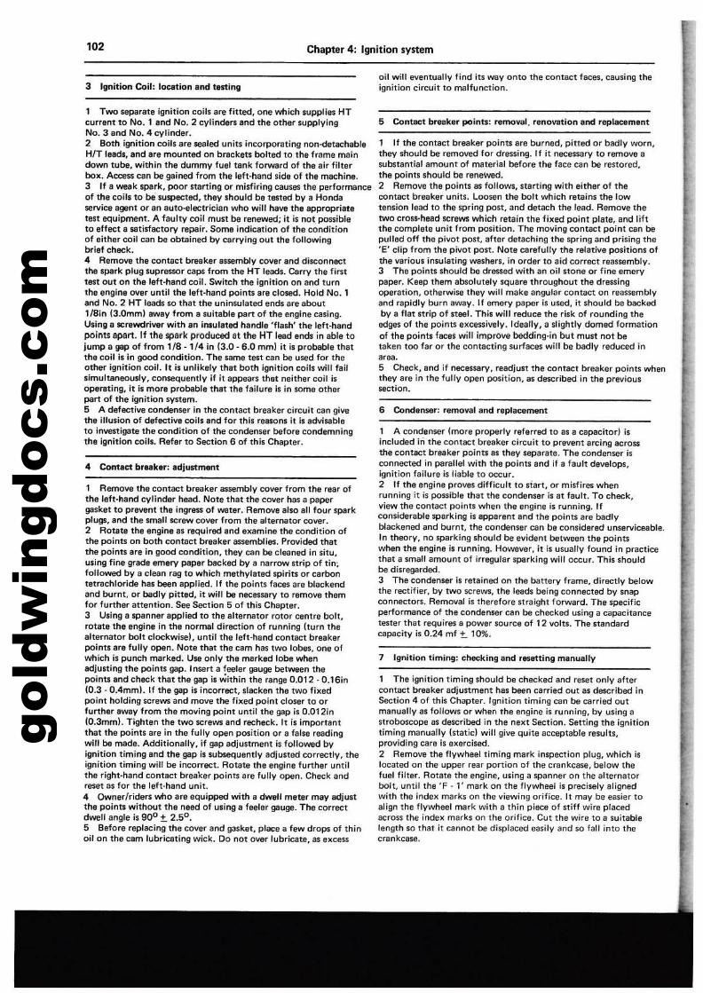
gold
win
gdoc
s.co
m102
3 Ignition Coil: loeation and testing
Chapter 4: Ignition system
oil will eventually find its way onto the contact faces, causing theignilion circuit 10 malfunction.
1 Two separate ignition coils life fined, one which supplies HTcurrent to No.1 and No.2 cylinders and the other supplyingNo.3 and No.4 cylinder.2 Both ignition coils are sealed uniu incorporating non-detachableHIT leads, and are mounted on brackeu bolted to the frame maindown tube, within the dummy fuel tank forward of the air filterbox. Access can be gained from the left-hand side of the machine.J If a weak spark, poor naMing or misfiring causes the performanceof the coils to be suspected, they should be 18$100 by a Hondaservice agent or an Buto-electrician who will have the appropriatetest equipment. A faulty coil must be renewed; it i$ not pCl$Sibleto effect a satisfactory rapair. Some indication of the conditionof either coil can be obtained by carrying out the followingbrief check.4 Remove the contact breaker assembly cover and disconnectthe spark plug supraSllor cap$ from the HT leac;l$. Carry the fil'$ttest out on the left-hand coil. Switch the ignition on and turnthe engine over until the left-hand poinb are closed. Hold No.1and No.2 HT leac;l$ so that the unin5ulated ends are about118in 13.0mml away from a suitable part of the engine casing.Using a ICrewdriver with an insutated handle 'flam' the left·handpoints apart. If the ~a(k produced at the HT lead ends in able tojump a gap of from 118 - 1f4 in 13.0 - 6.0 mml it is probable thatthe coil is In good condition. The $8ITle test can be used for Iheother ignition coil. It is unlikely that both ignition coils will failsimultaneously, con5eQuently if it appears thet neither coil isoperating, it is more probable that the failure is in lOrna otherpart of the ignition system.S A defective condenser in the contact breaker circuit can givethe illusion of defective coils and for this reasons il is advisableto Investigate the condition of the condenser befora condemningthe ignition coils. Refer to Section 6 of this Chapter.
4 Contact break&!': adjustment
1 Remove the contact breaker essembly cover from the rear ofthe left-hand cylinder head. Note thet the cover has a papergasket to pre\lllnt the ingress of weter. Remove also all four sparkplugs, and the small screw cover from the alternalor cover.2 Rotate the engine as required and examine the condition ofthe points on both contact ~eaker assemblies. Provided thatthe points are in good condition, they can be cleaned in situ,using fine wade emery paper blIcked by a narrow strip of tin;followed by a clean rag to which methylated spirits or carbontetrachloride has been applied. If the points faces are blackendand burnt. or badly pitted, it will be necessary to remove themfor further attention. See Section S of this Chepter.3 Using a spanner applied to the alternator rotor centre bolt,rotate the engine in the norma] direction of running (turn thealternator bolt clockwisel, until the left-hand contact breakerpoints are fully open. Note that the cam has two 10be1;, one ofwhich is punch marked. Use only the marked lobe whenadjusting the points gap. Insert a feeter gauge belween thepoints and check that the gap is within the range 0.012 - 0.16in10.3 - 0.4mml. If the gap is incorrect, slacken the IWO fixedpoint holding screws and move the fixed point closer to orfurther awey from the moving point until the gap is 0.012in10.3mml. Tighten the two screws and recheck. It is importantthat the points are in the fully open position or a false readingwill be made. Additionally, if gap adjustment is followed byignition liming and the gap is wbsequently adjusted correctly, theignition timing will be incorrect. Rotate the angine further untilthe right-hand contact breeker points are fully open. Check andreset as for the left·hand unit,4 Owner/riders wno are equipped with a dwell meter may adjustthe points without the need of using a feeler gauge. The correctdwell angle is 900 ±. 2.50 .5 8efore replacing the cover and gasket, place a few drops of thinoil on the cam lubricating wick. Do not over lubricate, as excess
5 Contact breaker points; removal. renovation and replacement
1 If the contact breaker points are bl.Jrned, pilled or badly worn,they should be removed for dressing. If it necessary to remove awbstantial amount of material before the lace can be restored,the points should be renewed,2 Remove the points as follows, starting with either of thecontact breaker units. Loosen the bolt which retains the lowtension lead to the spring post, and detach the lead. Remove thetwo cross-head screws which retain the fixed point plate, and liftthe complete unit from position. The moving contact point can bepulled off the pivot post, after detaching the spring and prising the'E' clip from the pivot post. Note carefully the relative positions ofthe various insulating washers. in order to aid correct reassembly.3 The points should be dressed with an oil stone or fine emerypaper. Keep them absolutely square throughout the dressingoperation, otherwise they will make angular contact on reassemblyand rapidly burn away. If emery paper is used, it shOuld be backedby a flat strip of steel. This will reduce the risk of rounding the
edges of the points excessively. Ideafly, a slightly domed formationof the poinh faces will improve bedding-in but must not betaken too far or the contacting surfaces will be badly reduced inarea.5 Check, and if necessary. re&djust the contact breaker points whenthey are in the fully open position, as described in the previoussection.
6 Condenser: removal and replacement
1 A condenser (more properly referred to as a capacitor) isincluded in the contact breaker circuit to prevent arcing acrossthe contact breaker points as they separate. The condenser isconnected in parallel with the points and if a fault develops,ignition failure is liable to occur.2 If the engine proves difficult to start, or misfires whenrunning it is possible that the condenser is at lault. To check,view the contact points when the engine is running. Ifconsiderable sparking is apparent and the points are badlyblackened and bl.Jrnt, the condenser can be considered unserviceable.In theory, no sparking should be evident between the poinlSwhen the engine is running. However, it is usually found in practicethat a small amount of irregular sparking will occur. This Shouldbe disregarded.3 The condenser is retained on the battery frame, diractly belowthe rectifier, by two screws, the leads being connected by snapconnectors. Removal is therefore straight forward. The specificperformance of the condenser can be checked using a capacitanceleSler that requires a power source of 12 volts. The standardcapacity is 0.24 mf t 10%.
7 Ignition timing: checking and resetting manually
1 The ignition timing should be chacked and reset only aftercontact breaker adjustment hes been carried out as described inSection 4 of this Chapter. Ignition timing can be carried outmanually as follows or when the engine is running, by using astroboscope as described in the next Section. Setting the ignitiontiming manually (static) will give quite acceptable results,providing care is exercised.2 RemOIl1l the flywheel timing mark inspection plug, which islocated on the upper rear portion of the crankcase, below theluel filtar. Rotate the engine, using a spanner on the alternatorbolt, until the 'F -1' mark on the flywheel is precisely alignedwith the index marks on the viewing orifice. It may be ellSier toalign the flywheel mark with a thin piece of stiff wire placedacross the index marks on the orifice. Cut the wire to a suitablelength so that it cannot be displaced easily and so taU into thecrankcase.
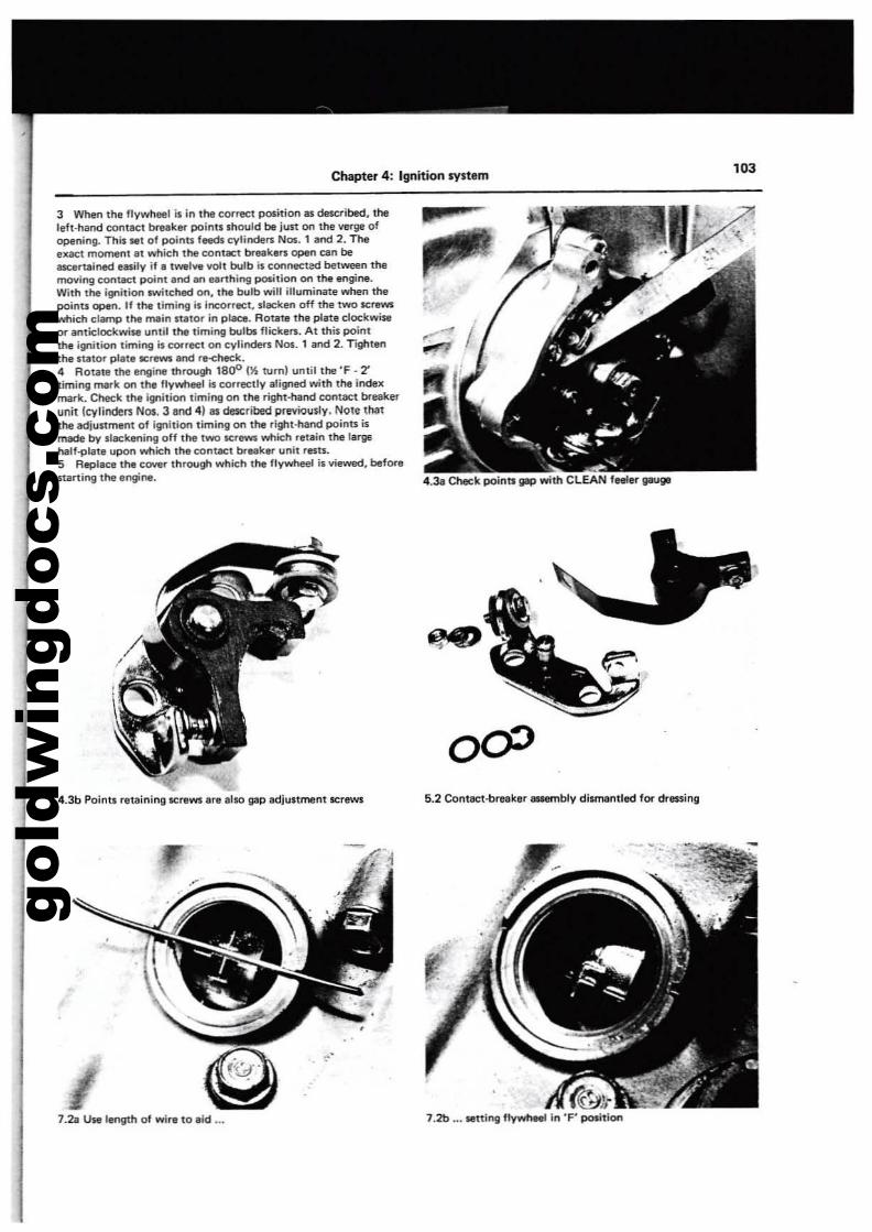
gold
win
gdoc
s.co
m
Chapter 4: Ignition system
3 When the llywhee1 is in the correct position as de5ctibed. theleft-hand contllCt break8l" points should be just on the verge ofope!\ing. This Iott of poinu fHds eytindef'1i NOI. 1 and 2. Theexact moment at which the contact breekef'1i open can beascertained easily if I lwalv, volt bulb is conneeted between themoving conract point Ind an earthing poIition on the engine.With the ignition switched on. the bulb will illuminate when thepoints open. If the timing is Incorrect. slllCken off the two screwswhich clamp the main nator in plact. ROUite thl plate clockwiseOf" al'lticlockwise until the timing bulbs flickef'1i. At this pointthe ignition timing is correet on cylinden; Nos. 1 and 2, Tightenthe UltOr pllte S1Cfews al'ld re-check.4 Rotate the engine through 1800 (~ turn) until the 'F - 'Ztiming mark on thl ftywtleel is correctly aligned with the index:mark. Check the ignition timing on the right-hand contact breakerunit (cylindef5 Nos. 3anel "I as described previously. Note thatthe adjustment of ignition timing on the right-hand points ismade by slack&ning off the tWO screws which retain the largehalf-plall upon which lhe contact break8l" unit rests.5 Replace the CO'l'er through which the flywheel is viewed, before$larting the engine. 4.31 Check poinu gep with CLEAN feeler IlIIUgI
10J
4.3b Poinll rltail'ling screws are arso gap Idjuument screws
7.2a Use length of wi.. to aid ..,
6.2 Contact,b..aker 8ISlII'I'lbly dismantled fOf" dreuing
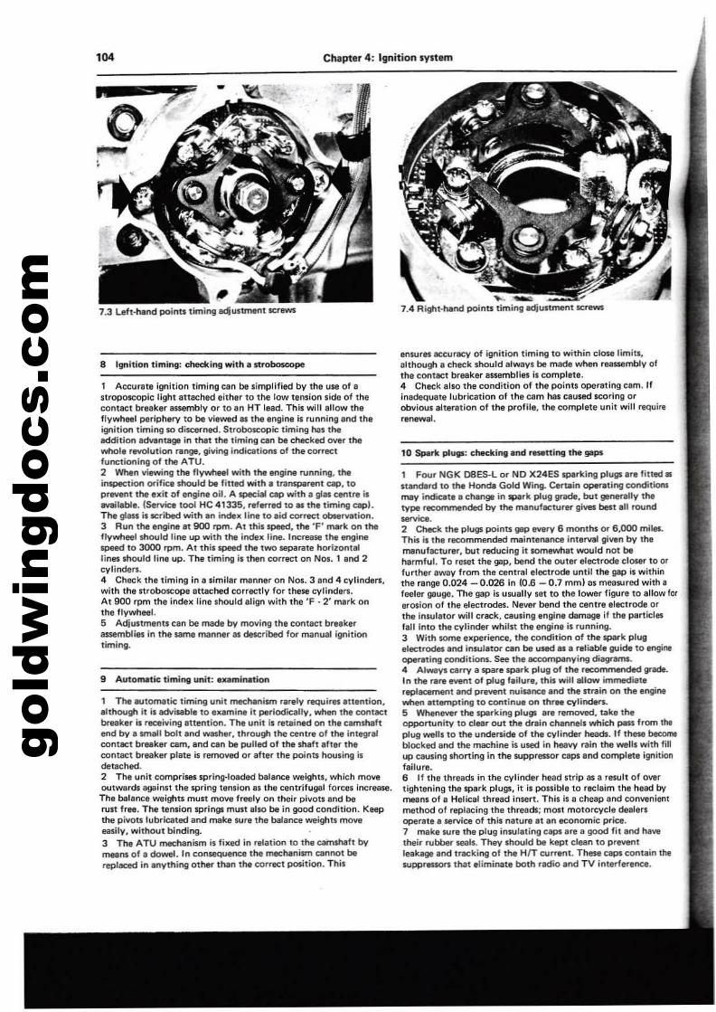
gold
win
gdoc
s.co
m'04 Chapter 4: Ignition system
8 Ignition timing: dJedtlng with. strobo$cope
9 AutolMtic timing unit: examiMtion
.... 7.4 Right-l'Iand points timing adjustment screws
ensures accuracy of ignition liming to within close limits.although a check should always be made when reassembly ofthe contllCt breaker assemblies is complete.4 Check also the condition of the points operating c::am. Ifinadequate lubrication of the c::am has ceused $.Coring orobvious alteration of the profile. the complate unit wilt requirllrenewal.
1 Four NGK D8ES-L or NO X24ES sparking plugs are fitted.standard to the Honda Gold Wing. Certain operating conditionsmay indicate a change in spark plug grade, but generally thetype recommended by the manufacturer gives best all round..-.2 Check the plugs points gap every 6 months or 6,000 mites.This is the recommended maintel'\8nce interval given by themanufacturer, but reducing It lOmfl'II/tlat would not beharmful. To re$litt the gap, bel"ld the outer electrode closer to orfurther away from the central electrode until the gap is withinthe range 0.024 - 0.026 in 10.6 - 0.7 mm) as measured with afeeler gIluge. The gap is usually set to the lower figure to allow forerosion of the electrodes. Never bend the centre electrode orthe insulator will crack. causing engine damage if the particlesfait into the cylinder whilst the engine is running.3 With some elll:perience, the col"ldition of the spark plugelectrodes and insulat~can be used as a reliable guide to engintoperning conditions. See the accompanying diagrams.4 Always carry a spare spark plug of the recommended grade.In the rare event of plug failure. this will allow immediatereplacement al"ld prawnt nuisance al"ld the strein on the enginewhen attempting to continue on three cylinders.5 Whenever the sparking plugs lint removed, take lheopportunity 10 clear out the drain channels which pass from theplug weUs to the underside of the cylinder heads. If lhese becomeblocked lind lhe machine is used in heavy rain the welts with fillup ClIusing shorting in the suppressor caps and complete i9l'litionfailure.6 If the lhreads in the cylinder head strip as a result of overtightening the spark plugs. it is possible to reclaim the head bymeans of a Helical thread inwrt. This is a cheap and convenientmethod 01 replacing the threads; most motorcycle dealeN!operate a service of this nature at an economic price.7 make sure lhe plug insulating CllPl are a good fit al"ld hawtheir rubber seals. They should be kept clean to preventleakage al"ld tracking of the HIT current. These caps contain lhesupprlll$ON! that eliminate both radio and TV interference.
. .. [
1 Accurete i9nltlon timing can be simplified by the use of IIstroposcoplc Ught Ilttached either to the low tension side 01 Ihecontact breaker assembly or to an HT lead. This willellow theflvwheel periphery to be viewed as the engine is runninllind theignition timing f(l discerned. Sltobo$eopic timing has theaddition adYiJntaga in that the timing can be checked over thewhol, revolution range, giving Indications of the COfrectfunctionll'l" of t!'le ATU.2 When viewing the flV~ with the engine running, theinspection orifice should be titled with a transparent cap, 10prfll/ent the exit of engine oil. A lPllCial cap with II gin efl\tt. islMIilable. (Service tool He 41335, referred to as the timing cap).The ps is teribed with en index line to aid <;Orreet observation.3 Run the engine at 900 rpm. At this speed, the 'F' mark on theflywheel should line up with the indelll: line. Increase the enginespeed to 3000 rpm. At this speed the two separate h~ilOntel
lines should line up. The timing is then correct on Nos. 1 and 2cylinders.4 Check the timing in a similar manner on Nos. 3 and 4 cylinders,with the Itroboscope attached correctly for these cylinders.At 900 rpm the indelll: line should align with the 'F - 2' mark onthe flywheel.5 Adjustments can be made by moving the contact breakerauemblies in the _ manner as detcribed f~ manual ignitiontiming.
1 The Mltomatic timing unit mecl'lanian rarely requires ntention.although it is advisable to examirwt it periodically. when tl'la contactbreaker is receiving attention. The unit is retained on the camshaftend by a small bolt and _her, through the centre of the integr-alcontact br~ker cam, and can be pulled of tl'le Shaft after theoontaoet bolaker plate is removed or after the points housing isdetached.2 The unit comprises spring-loaded balance weights. which moveoutwards againn the spring tension es the centrifugal forces Increase.The bulanee weights must move freely on their pivots and berust fr". The tension springs must also be in good condition. Keepthe pivotllubricated and make sure the balance weighll moveeasily, without bil'lding.3 The ATU mechanism is filll:ed in relation to the cai'nshaft bymeans of e dowel. In consequence the mechanism ClInnot bereplaced in anything Other than the correct positiO(l. This
7.3 Left·hlnd points timil'l9 adjustment screws
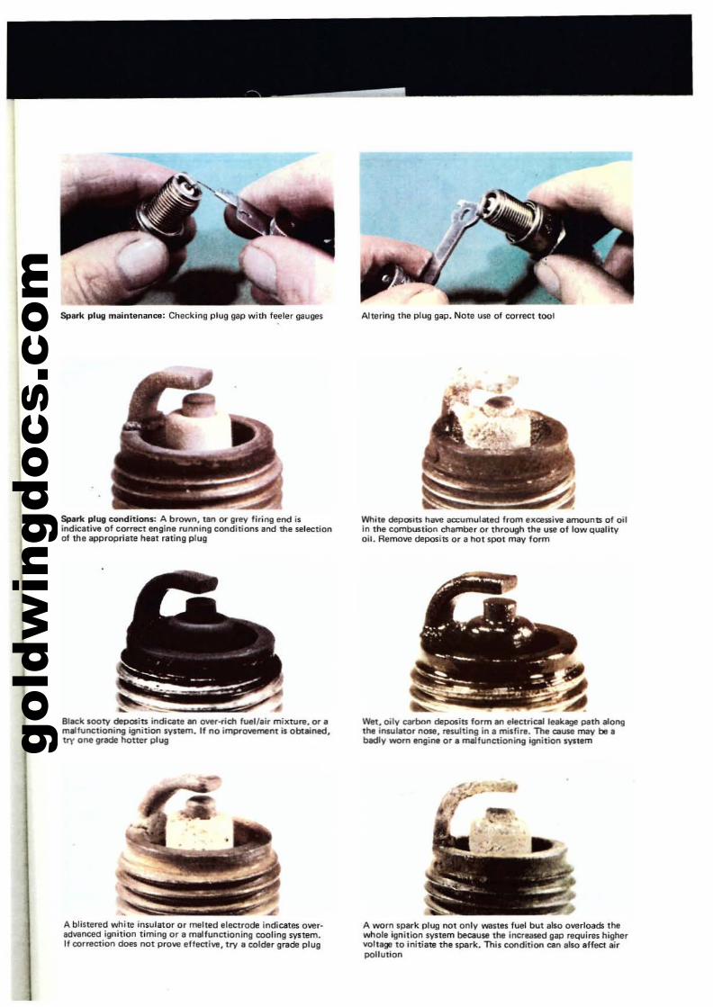
gold
win
gdoc
s.co
m
Spark plug maintenance: Checking plug gap with feeler gau!)es
Spl;rk plug conditions: A brown, tall or Il~ fi.ing end isindicative of correct enll;ne running conditions and lhe selectionof the appropriate heat rating plug
~
BI.-ck lOOty deposits indicate an OY8.-tic:h fuel/air mixture. o. IImlllfunctioning ignition system. If no improvement is obl:ained.try one grade I\oner plug
A blinered white insulato. o. melted el~trode indicatl!$ ow.·advanced ignition timing o. a malfunctioning cooling sy1tem.If co.rection does rKlt prove eftective, try a colde. grade plug
Altering the plug gap. Note use of correct toot
White deposiu have accumulated from flKcessive amounts of oilin tM combustion chamber o. th.ough th, use of low qualityoil. Aemow deposits o. a hot spot may form
Wet. oily carbon deposits form an electrical leakage path alongthe inwlator nose, rt!iulting in, midire. The ClIUW may be •b«:Ily worn engine a.' malfunctioning ignition system
A worn sp8rk plug not only wanel fuel but also overloads thewhol. ignition system because the inc.eased gap ~uires highervoltage to initiate the spark. This condition can also affect airpollution
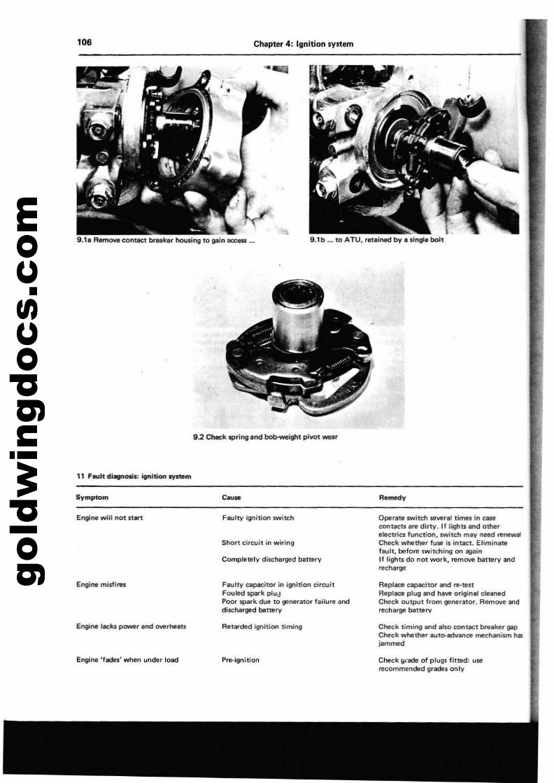
gold
win
gdoc
s.co
m'06 Chapter 4: Ignition system
9.1. Remove contact breaker twu.inll to 9110 ace_ ... 9.1 b ... to ATU. ,eteined by II lingle bolt
11 F..,ltdi~ itnition system
9.2 Cheek 'Pring and bob-weight pivot wear
Symptom
Engine will not IU,rt
Engine m,$firu
Engine 'aeks power and CM!rheau
Engine 'fades' when under load
C~M
Faulty igo;1'oo switch
Shon circuit in wiring
Completely discharged battery
FlIUlty capacitor in ignition cireuitfouled spark plu-JPoor spark due to generator lailure anddischarged bBnerv
Pr.-Ignition
Rlmedy
Operate swllch several times in C8$(!
eont8Ctli .... dirty. If lighU and otherelectrics function, switch may need ~newal
Check whether fuse i. intact. Eliminatefaull, before switching on lIll.inIf lights do nOl work, remove battery andrech8rgEl
Repl.:e capacitor 8nd re·testReplllCe plug and have original cle_dCheck output from generator. AemOlie aodrecharge banary
Cheek timing and also contllCt breaker gapCt>e<;k whether auto-.iYan08 mechanism h&jammed
Check yrade of plugs fitted: userecommended grades onlV
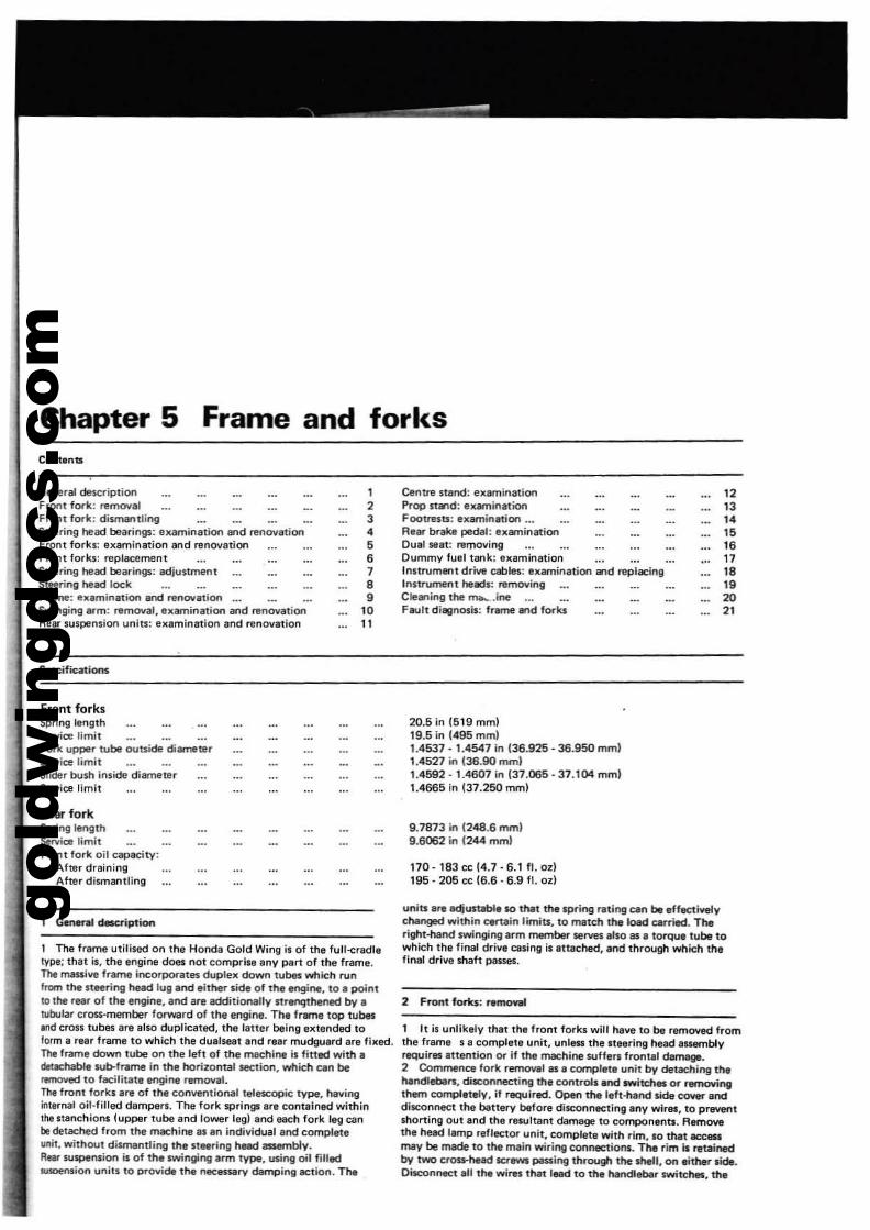
gold
win
gdoc
s.co
m
Chapter 5Contents
Frame and forks
General de$Criptionfront 10000k: removalFront fork: dismantlingSlHring he.. bearings: examination end renovelJonFrollt forks: examination end renOV81;0l\Front forks: replacementSteering head bearing$,: adjustmentSleering held lockF.-.ne: ftumination and renovationSwinging arm: removal, examination and I1lnov8tionRnr suspension units: Illlamination and renovation
$pIeific.tions
Front forksSpring lengthService limitFork upper tube outside di.-neterSelVice limitSlide, bush inside diameterService limit
Rear forkS9ring lengthService limitFront fork oil capae;ty:
After drainingAlter dismantling
1
234,,7,•
'011
Centr9 star'ld: examinationProp sta'ld: ex.-ninationFootr'eSu: examination ...Rellr brake pedal: Ixa-ninationDual SlIet: l1i!01OvingDummy fUll tllnk: examinationInnl'Ument drive cables: elllHllinlltion ...d replllCingInstrument heads: AlmovingCIe.-.ing the mh...ineFllUlt diagnosis: frlllTle lind forks
20.6 in 1619 mml19.5 in 1495 mml1.4537·1.4547 in 136.925 - 36.950 mml1.4527 in 135.90 mm)1.4592· 1.4607 in 137J)65 - 37.104 mm)1.4665 in (37.250 mml
9.7873 in 1248.6 mml9.6062 in 1244 mm)
170· 183 cc 14.7·6.1 f1. ozl196 - 206 ce (6.6·6.9 fl. od
12131415,.1718,.2021
Gm«al clacription
1 The frame utilised on the Honda Gold Wing is of the full-<:radletype; that ii, the engine does not comprise any part of the frame.The massive frame incorpol"lIllK duplex down tubes which runfrom ttle steering head lug and eithe!" s.ide of the If"I9ine, to a pointto the reaf of the engine, and are additionally rtrenqthened by.tubular cross-member fOfWtlrd of the engine. The fflWTltl top tubes,nd crou tubes are 111$0 duplicatlld, thll latter being extllnded toform a rear frame to which the duelseat and rear mudguard are fixed.T1w lrame down tube on the left of the machine is fitted with aclRechable sub-frame in the horizontal section, which can be~ to facilitate ec1gine removal.n.. front forks are of the conventional teleteOPic type, havinginternal oil·filled dampers. The fork springs are contained withinlhe stanchions (upper tube and lower legl and each fork leg canbe detached from the machine as en individual and completeunit, without dismantling the IlBering head assembly.R.... suspension is of th. swinging arm type, using oil flilld..soension units to provide the nec..-ary damI:ling action. The
units are eqUltllble so thet the spring fltlng can be effect!Yelychanged within ClfUin limits, to match the load carried. Theright-hand swinging arm member serves .lso 81. torque tube towhich the final drive cuing is litaehed, and thrOUgh which theflnal drive maft pIIssei.
, It is unlikely that the front forks will htve 10 be ramO'ffld fromthe frame s a complete unit, unleu the Steering head aUllmblyrequirllS attention or if !he machine suffers frontal damage.2 Commence fork rerncMll 81. complete unit by detlching thehtndlebars, disconnecting the controls.nd switdles or removingthem completely, it required. Open the left-hand side C<lYef anddisconnect the battery before diJconnecting any wires, to prwlrfltshorting out and the resultant damage 10 components. Removethe head I.mp reflector unit, complete with rim, 110 that ICC...may be made to the m.ln wiring connections. The rim ill retainedby two cros:s-head screws passing through the shell, on either side.Disconnect aU the wires that lead to th, hendfebilr switches, the
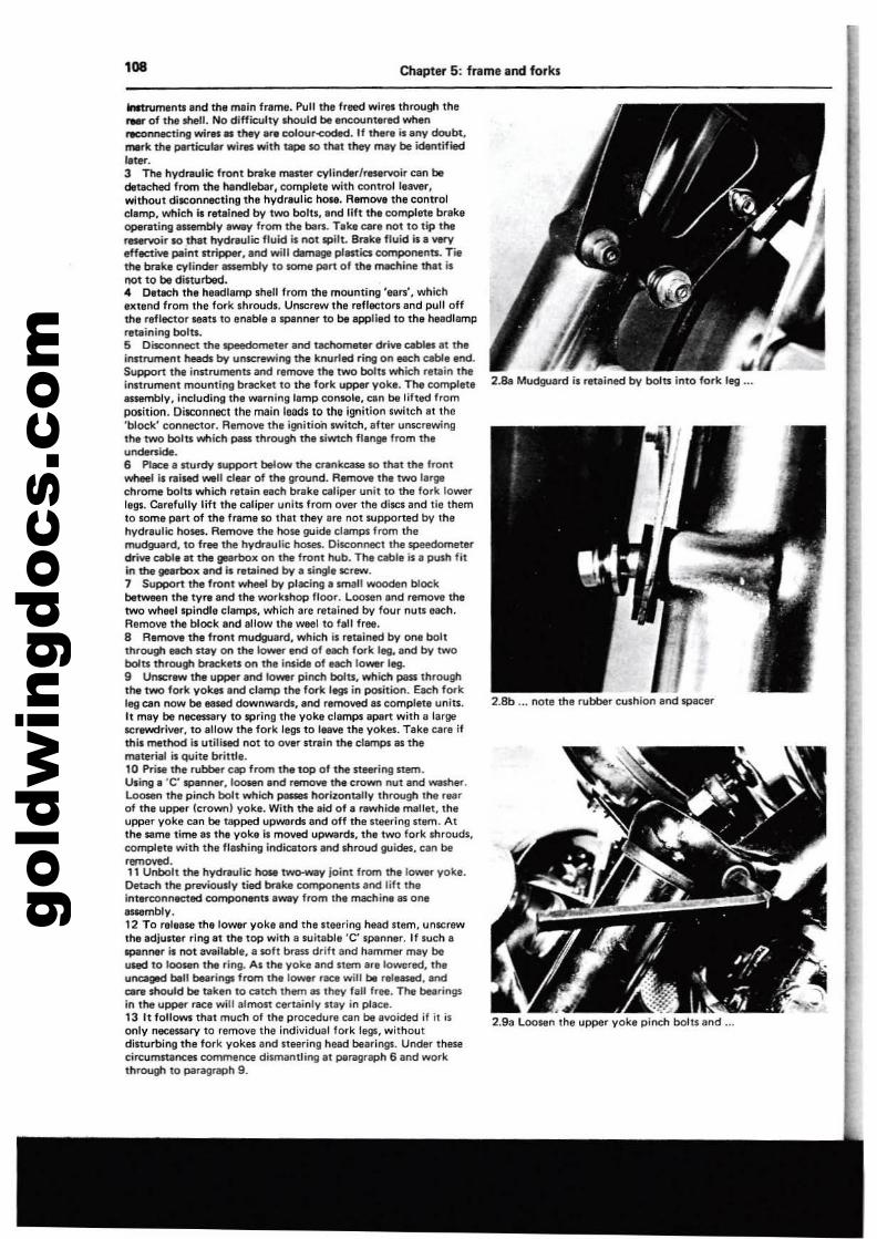
gold
win
gdoc
s.co
m'08 Chapter 5: frame and forks
IIWtruments and the main frame. Pull th, freed wires through the~ of tn-shell. No difficulty mould be encountered whenrtCOnnec:til"log wi'ltl all they.~colour~. If the«! i. any doubt.rNrIc the plIrticular willIS with t8Pll $0 tN1 they may be identifiedl.tel'".3 The hydraulic: front bnIk, master cylinder/reservoir can bedetached from thl handlebar, complet. with controll18ver,without disconnecting the hydlllulic 00". Remove the controldamp, which i. retained by two boltl, and lift the complete brakeqNlfllting assembly rtWfIl( from the ban. Take e.r, not to tip lherlJSeNOir 10 that hydreulic fluKlI. not spilt. Bf1Ik, fluid is. wryeffflC1i11e paint stripper. and will damage plmics components. rillthe brake cylinder ssembly to some part of the maehine tMt i.not to be disturbed.4 Detach the headlamp shell from the mounting ',ars', whichIKtend from the fork shrouds. Unscrew the ref'acton; end pull offthe reflector seats to enable I spanllflr to be applied to Ii'll helldlampreteinirtg bolu.S Disconnect thelPefldometer Ind tacl'lomtlt...- dri.,. cables.t theinstrument heads by unscrewing the knurled ring on each cable end.Support the innrumenu and refT1O'lo'e the two bolD which r.tllin theinl1rument mountirtg brack.t to the fork upper yoke. The completeISsembly, including the warning lemp console. cen be lifted frompoiition. DilCOnnect the main leadi to the ignition switch et the'block' cormeetor. Remove the ignition Iwitch, afllr unscrewingthe two bol1l which piISI throu~ the liwtch flange from theundef1:ide.6 Place a sturdy IUpj:JOrt below the crenkease 10 that the frontYII'heeI il raised _II clear of the ground. RIl'TlO'Je the two largechrome bot1l wvhich retain each brake ClItiper unit to the fork lower11111. Carefully lift the caliper unil1i from over the diits and tie themto some part of the frame 10 that they .re not supported by thehydr.utie ho.... Remove the hose guide clamps from themudguard, to free the hydraulic hoses. Diteonneetthe speedometerdrive cable at the geartlox on the front nub. The cable is a push fitin the gearbox and II ~tained by a single itrew.7 Support the front wheel by placing a unall wooden blockbe1Ween the tyre end the worklhop lloor. Loosen .nd remove thetwo wheel Ipindle cI.mps, .....hich are ~t.ined by four nutl each.Remove the bllxk.nd allow the weel to f.ll free.a Remove the front mudguilrd, which il retained by one boltthrough each nay on the 10'Nel'" end of each fork leg, and by twobolu through braekw on me inside of each lower leg.9 Unscr_ the upper and lower pinch bolts, which piISI throu!ilthe two fork yokll end clamp the foO: I. in pcMition. Each fork1'9 am now be eased cIownwan;b:, and removed IS complete uniU,h may be necessary to spring the yoke clamps ilpart with a I.rgeitrewc!river, to .1I0w the fork legs to leave the yokes. Take c.re ifthil method il utililfld not to over strain the CII!llTlPS as thematerial is quite brittle.10 Prise me rubber cap from the top of the st..-Ing stem.Using. 'C' spllflnet',I~ .nd remove me crown nut.nd waIher.Loosen the pinch bolt which paI$II horizontally through the rNrof the upper {crown I yoke. With the aid Of a rawhide mallet, theupper yoke ClIn be tapped upwards and off the neering Itam. Atthe same time al the yoke il moved Upwerdl, the two fork shrouds,eompllle wim the fleshing indicatoB and shroud guides, can beremoved.11 Unbolt the hydl'8lJlie '-- two-way joint from Itte 10_ yoke.Detach the pr....iously tied brake eomponenu Ilnd lift meinterconnected componentl.way from Ihe machine as oneassembly,12 To relea.. me lower yoke end the neering head Item, unitrIWthe adjuner ring.t the top with a suitable 'C' spenner. If such IlIpiInner ilnot a""llablll, • soft brass drift and h.mmer /'My beused to looMn the ring. As lhe yoke end lIem are lowered, theuneagad bell bearings from the lower race will ~ released. endc.re should be taken to CIltch them as Ihey fall fr... The bearingsIn the upper raee wilt almost cII'tainly Itey in place.13 It follows Ihal much of Ihll procedure can be avoided ;f it ;5only nlC8$l'ry to remove tha individual lork legs, withoutdisturbing the fork yokes and steering heed bearinlll. Under theseeireumnances commence dis/'Mntling at paragraph 6 and workIhrough to paragraph 9.
oj2.8e Mudgullrd is retained by bolu into fork leg ...
2.8b ... I'IOte the rubber cushion and $pacer-
2.ge LOOMn the upper yoke pinch boillend
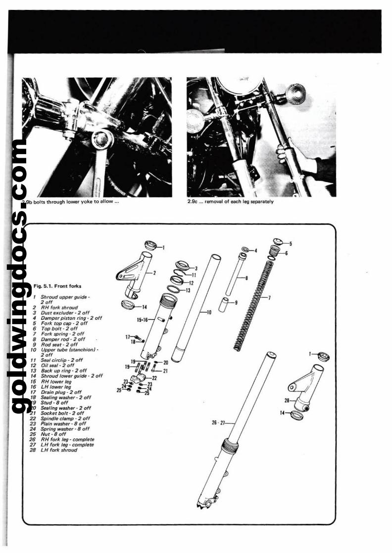
gold
win
gdoc
s.co
m
2.9b bolts through lowtlr yoke to allow ... 2.9c ... removal of each leg Sflperately
Fig. 5.1. Front forti.
Shrolld upper guide'2 off
2 RH fork m,oud3 DU6t flxcluder· 2 off4 Damper piston ring' 2 off5 Fork tOP cap - 2 off6 Top bolr - 2 off7 Fork spring - 2 off8 OMnper rod • 2 off9 Rod sear· 2 off
10 Upp6r fUb6 'stlmchion}-2 off
11 Sui circlip - 2 off12 Oil ~i1I' 2 off13 8«k up ring - 2 off14 Shroud lower guide' 2 off15 RH 10_, leg16 LHIOWfJr!eg'7 Oreinplug-20ff'8 StMling "".mer - 2 off19 Stud - 8 off20 Seflling WlUh6r - 2 off21 Sockf1rbofr-20ff22 Spindle clMnp - 2 off23 P1~n wmer - 8 off24 Spring "".sher •8 off25 Nur·80ff26 RH fork leg - compl6te27 LH fork leg· complete28 LH fork mroud
~,
'~
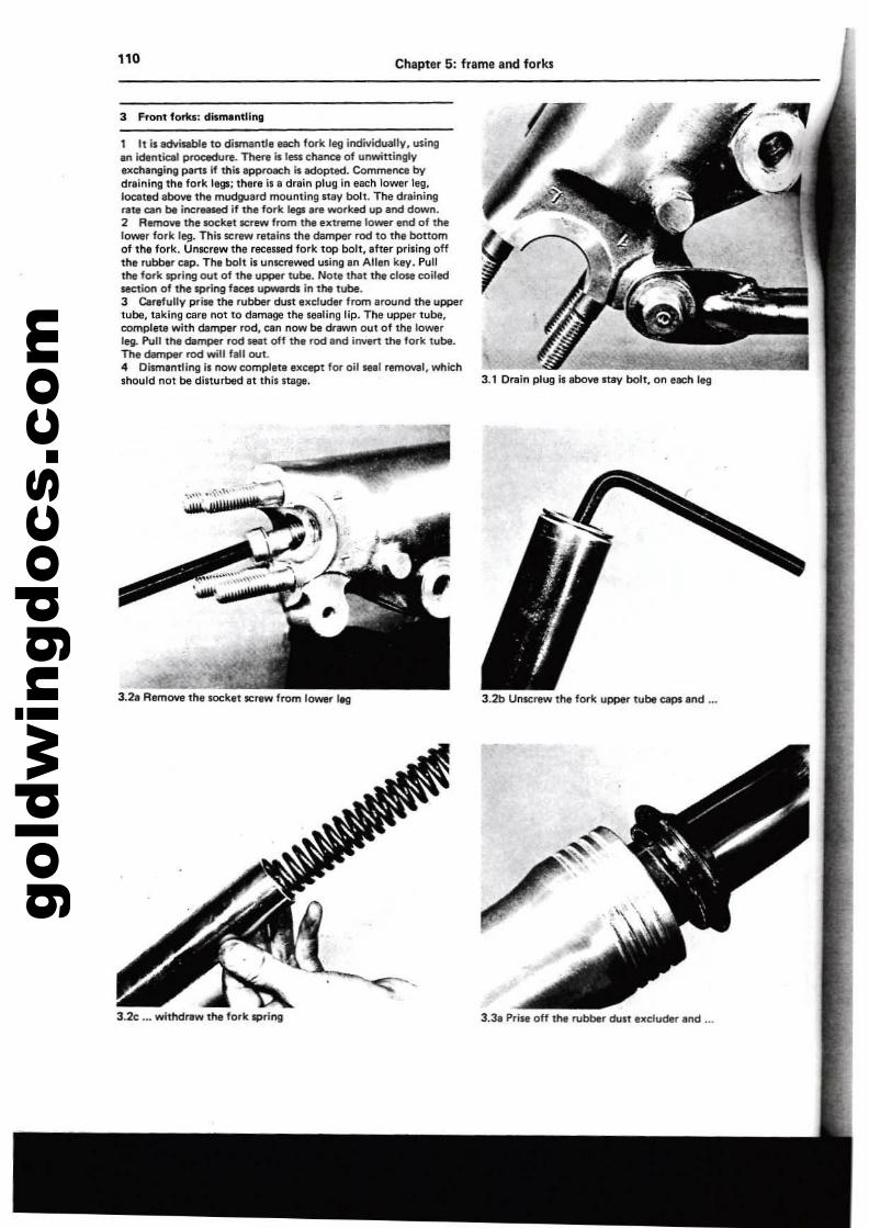
gold
win
gdoc
s.co
m110 Chapter 5: frame and forks
3 Front forks, dismantling
1 It is advisable to dismantle each forit leg indiviclually. usingan identical proc«fure. There is less CNrQ of unwittinglyexchanging parts if this epproKh is Idopted. Commence bydraining the fork legs; there is e drain plug in each lower leg,located abow the mod~aTdmoontingltay bolt. The drainingrate Clln be incraaed if the fork legs If'll WOI"ked up and dow".2 RItJIOIIe the toeket lCfew from the extreme lower end of thelower fork leg. This Sl:rew retains the dampe.r rod to the bottomof the fork. Unscrew tl'le recessed fork top bolt, after priling offthe rubber cap. The bolt is unlCnlwed usil'lg an Allan key. Pullthe fork spring out of the upper t1.lbt. Note that the close coiledsection of the spring faces upwllrds in the tube.3 Cerefully prise Itle rubber dust excluder from 'round the uppertube. taking care not to damage the Maling lip. The upper tube.complete with damper rod, can now be drawn 001 of the lowerleg. P!"II the damper rod _I off the rod In<! invert the fork tube.The dam~ rod will fallout..4 Dismantling is now completl except for oilIN1 removal, whichshould not be disturbed It this stage.
3.2. Remove the socket screw from lower 1~
3.2<: ..• withdraw the fork $pring
3.2b Unscrew the fork upper tube caps end ...
3.3. Prise off the rubber dust excluder.lId ...
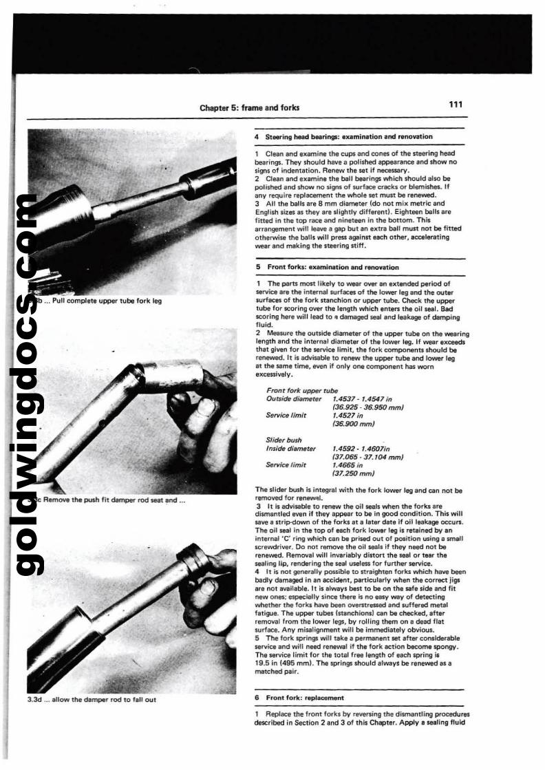
gold
win
gdoc
s.co
m
Chapter 5: frame and forks 111
3.3d ... ellow the damper rod to fell oul
4 Steering hINd bHrings; 'l<eminetlon end renovation
'.4592 - 1.4607i"(37.065·37.104 rom)'.4665 in'37.250mm}
Slider bushInside ditmleter
Serviu limit
FrotIt forlc uppn'rubeOutside di.meter 1.4537· 1.4547 in
(36.925· 36.950 mm)Service limit 1.4527 in
'36.900mm}
1 The parts most likely to wear OYII' an el<tended period ofservice ar. the irot.mal surfaces of the lower I.g lind tha out.rSUrfICes of the fork stanchion or upper tube. Check the upperlube for scoring over the length which enters the oil seal. Badscoring here will lead 10" darTl8ged seal end Itlkagt of dampinllfluid.2 Metsure the outside diameler of the upPer tube on the wearinglength end the internlll diamet.r of th.lower leg. If wear el<c:eedsthet give" for Ihe service limit, Ih. fork compol"llnts should berl'neW8d. It is tdvbebl. to renew the upper t\lbt and 10Wl( IlIIIat the same time, even if only one component has wornexcessiv.lv.
The slider bush Is integral with the fork lower leg afld CIt" not beremoved for ren_1.3 It is advisable to renew the oil seals when the forks eredismllntled even if th.y appear to be in good condition. This willsave a Itrip-down of the forks at II Illter del. If oil leaka!JI occurs.The oil seal In the top 01 each fork lower leg is ret,inad by linintem,l 'C' ri"g which un bt prlsad out 01 po&ition using a N'IWlIlscrewdriver. Do nOI remove Ihe oil l.EIal, if they need not berenewed. Removal will invarillbry distort the l.EIal or tear Ihesealing lip, reodering the seill usel.. for furth.... service.4 It is not generally pouibl. to nraightetl forks which have beenbadly demaged '" In accident, panictJIllrly when the correct jigsart not ,vaileble. II is alwav_ best to be on the safe side Ind fitnew ones; especially sine. there is no easy Wily of detectingwhether the forks have been overstressed end tuff....td metalflti~•. The upPer tubes (stl"chlonsl cen be checked, .ft"removal from the 10Wllr legs, by rolli"lI them on II dead flatwrface. Any misalignment will be Immediately obvious.5 The fork springs will take a permanent set ,fter consldtrebl.service and will need renewal if the fork action become spongy.The service limit for Ih, lotal free I,ngth of tach spring II19.5 in (495 mml. Th. spri"!Ili should ,Iway_ be flneWid al II'I'I8tched pair.
1 Clean end 'l<amine tl'le ctJpI and cones of the 51:eering headbearinQ$. They should have a polished llpPlNlrtnce Ilnd show noSign5 of indentllion. Renew the sellf necl1$8ry.2 Clean.ocI el<amine Ihe ball bearings which Should also bepolished and mow no signs of Il,lrfece CTtCks or blemishes. Ifany require replilC8fTlent the whole sel must be renewed.3 All Ihe ball, are 8 mm diameter (do not mil< metric andEnglish lites t5 they art llightlv differend. Eighteen baillarefitted in the top race and niMI"" in the bonom. Thisarlllngemenl will leave II gep but an el<tra ball must not be fittedolherwise tha bells will press again51: each other, aa:elerallngwear and rTl8king the steering stiff.
5 Front fo~; 'l<eminttion Iond r.novttlon
6 Front fork; r.pltc!lment
3.3b ... Pull compl.t. upper t\lbt fork leg
3.3c R.m~ the push fit damper rod INt lind ...
1 Rep/ace the front forks by reversing thll disma"lring procedurndescribed '" Seetio" 2 and 3 of this Chapter. Apply II seating fluid
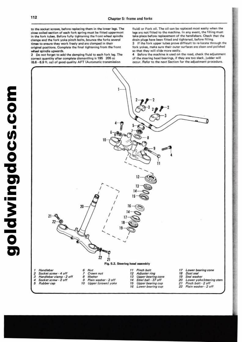
gold
win
gdoc
s.co
m112 Chapter 5: frame and forks
10 thl toe:k't serews. beta,. replacing them in the lower legs. 1lMtclOM coiled section of each fork spring mun be fItted uppermostin the fork tuba, Sefore tullv tightening the front wheelspindlllclemps end the fork yoke pinch bolu, bounce the forkS severelt\mel to tosur. they work freely and Ire clamped in theiroriginal pcxitions. Complete the final tightening from the frontwtlRl spindle upwards.2 Do not forget to Idd the damping fluid to each fOlk leg. Thecorrect Quantity ,fter complete dismantling i. 195 205 cc16.6 - 6.9 II. ozl of good qIUllitv AFT (Automatic trlnsrnission
ftuidl or Fork oil. The oil can be repl8Ced most UIIily when 11'1,legllI'e not fitted to 11'1, machine. In any event. 11'1, filling ml,lStUk, piece before replacement of the handlebars. Cl'\e(;k thet thedrain plugs 1'18\18 been fined and tightened, before filling.3 If the fork uppg' tubM prOl/I dilficull to ,.-Iocale through thefork yokes. rNIkl ""I their outer surf.:es Ire clean and POlished10 that they will slide more Msily.4 Before the m.:hine is used on the road. check the adjustmentof the steering head bearings. if they are too sl&ck, judder willoc:c:ur. Refer to the next Section for the adjustment procedure.
, ---~~
11~,
13~I , , 14-:S:SI IS~
I10 I 16~
I14-~
'~I11 ~
/19~"- , - I,..,
2Z 21Fig. 5.2. StMring head _mbly
, H.ndlelnr • Nu, " Pinch bolt2 Socket scnrw·" off 1 Crown nut '2 Adjuster ring3 H.ndlelur clamp - 2 off 8 Wllher '3 Upper Maring con.4 Sochr SCI'llW' 2 off 9 Ple;n wather· 2 off '4 S~I ball- 37 off5 RubMrcllp '0 Upper (croWfl) yoh '5 UPlnr Maring cup
16 Lo_r bearing cup
'7 L_r bearing COM'8 OInr sm19 Seal wash.r20 Lower yoke/steering stem21 Pinch bolt· 2 off22 Plain wather· 2 off
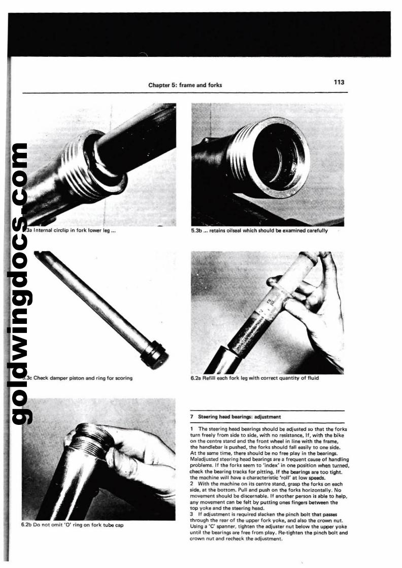
gold
win
gdoc
s.co
m
S.3a Interna! circ:lip in lork lower lag ...
Chapter 5: frame and forks
5.3b,.. retalos oilsul which should be exemined carefully
113
S.le Check dMnpe, piston end ring fOi" ICOring
6.2b 00 oot omit '0' riog on fork lubB cap
6.28 Refill neh fork leg with correct queotity of fluid
7 StNnog head burings: edjustment
1 The S1eering head bea,logs should bB edjuned so that the forksturn freely from side to side, with no resistance, 11. with the bikeon the centre stand and the front wheel in line with the frame,the hendleber is pushecl, the fo,kslhould fall easily to one side.At th.e same time, there should be no fr" play in the beerings.Maladjusted steering heac! bearings ara a frequant cause of h.andlingproblems. If the forks seem to 'index' in one position when turned,check the bearing tr~1ui fOi" pitting. If the belIrinll'l ere too tight.the machine will ha~ a charK1aristic ',oil' at low speeds.2 With tna machine on ill centre nand, grasp the forlui Ofl ellChside, at the bottom. Pull and po,llh on ttle fo,k, horitOfltaJly. Nomovament should be disceroable. If another parson il able to help,any movement can be felt by putting onM fingers between thelOP yoke and the steering head.3 If adjustment is required slacken the pinch bolt th.It paISM
through the rear of the upper fork yoke, end elso the crown nul.Using a 'C' spanner, tighten the adjuster nut below the upper yokeuntil the bearings ere free from play. Re-lighten the plneh bolt endcrown nut end recl\eck the adjustment.
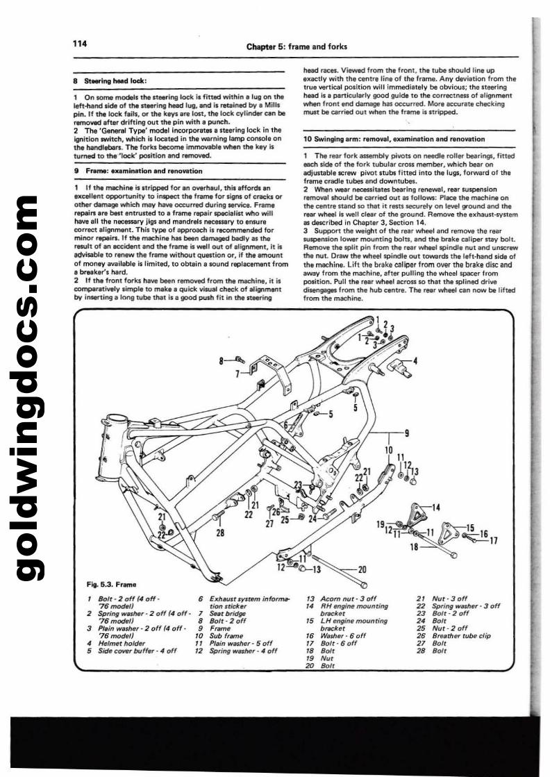
gold
win
gdoc
s.co
m114 Chapter 5: frame and forks
1 On IOmlI modeb the steering lock il fitted within a lug on theIeft.nand Jide of the stlMl"ing head lug••1'Id Is retained by • Millspin. If the lock fails, Of the key1 .... le:-t. the lock cylinder can beremoved aher drifting out the pin with. pYneh.2 The 'General Type' model Incorpora1M' Steering lock In theigflltion twitch, which isloc:ated in the warning lamp conwle onthe handlebars. The forb become immovable when the key isturned to the 'lock' position and removed.
1 If tn. machine is stripped for an Ollllrh.ul. this .fford. anexcell.nt opportunity to inspect the frame for signs of CI"IICQ orother damagll which may have occurred during .!"Vic•. Frwne'&Pai...r. best entrusted to. frame repair lIPICi.list who willhlMl ,II the noclnllry jigs and mandrels neceu.ry to enSUfecorrect alignment. This type of approach il recommended formi(l()r r~irs. If the machi". has '-n dem&glld badly as theresult of an .eeident end the frame is well out of alignment. it isadvisable to renew me frame without question or, if the amountof money available islirnitfld, to obtain i!IlOund replacement from• breaker's hard.2 If the front forks have been removed from th. machine, it il~l1Itr..lysimple to mek. e QUIdc. vitulli cheek of IlllgnmlJOtbv iMllrting. long tube that is a good push fit in the Itaerlog
hIliId rac:es. Viewed from the front, the tubllihouid line upexactly with the Centre line of the frame. Any del/lltian from thetrue vertical polition will immediallly be obvious: the steeringhead is a p.artic:ularly good guide to the correctness of alignmentwhen front end c;iamage hal occurred. Mare ac:cul1lte checkingrnuu be carried aut when the fllll'l'lll is stripped.
10 Swinging erm: ramaval,exeminltian Ind rana....tian
, The rear fork 8$$IlfI'Ibly pi\lO« an needle rallllr bearings, fittedI!IIIldIside of the fork tubular crass member, which bear anadjustable screw pi\lOt stubl fitted Into the IUg$, forward of thllframe cradle tubes and dawntubel.2 When wear necessitatlll bearing reneWllI, rear IU'PllftsianrllfJl(lYlll should be carried aut as fallows: Place the machine anthe centre nand so tM It resn securely an level ground end therear wheel il well elller of the gfaund. Remove the IlK!laun·syltemas described in Chapter 3, Section 14.3 Support the Wiligllt of the rear wheel Ind remove the rear...spenslan I~rmat.lnting beln, end the brake caliper IUly bolt.RMTIOVl! the split pin from the rear wheel spindle nut and unscrewthe nul. Dl1Iw the wheel spindle out towards the left·hand side ofthe machine. lift the brake ealiper from Oyef the brake disc andaway from the machine, after pulling the wheellpacer fromposition. Pull the rear wheel across 10 that the splined driYl!disengages from the hub centre. The reer wheel cen now be liftedfrom the machine.
Fill. 5.3. Fr...,.
Bolt - 2 of( (4 off- • ElthllUlt I"ylfem info,~ >3 Acorn nut· 3 of( 21 Nur· 3 off76 modf10 rian I"tic:kf1, 14 RH Mgine mounting 22 Sp,ing w.me'· 3 off
2 Spring _M" 2 off (4 of(- 7 s..tr bridga brackf1r 23 Boft·2 of(76moc/ef) 8 Bofr- 2 of( 15 tH enginf1mounting 24 Boft
3 Plain washer - 2 of( (4 of(- 9 FrlJme br.cket 25 Nut-2off76 mode/) 10 Sub 'rime " Washer· 6 off 2. Breather tube clip
• Helmet hofder 11 PI,in washe,' 5 off 17 Bofr - 6 off 27 Boll5 Side COVf/' buff., - 4 off 12 Spring wlIIMr· 4 off 18 80U 28 80U
19 Nu'20 Boft
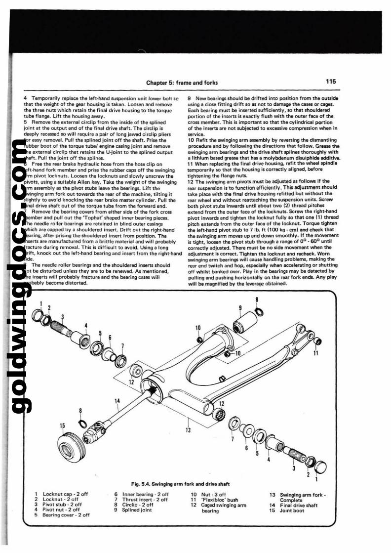
gold
win
gdoc
s.co
m
ChaPtar 5: frame artd forks 115
4 Temporarily replace the left-hand SUllplrnsion unit lower bolt K'
thet the weight of the gear houling il taken. Loosen end removethe three nuU which retain the final drive housing to the torquetube flenge. Lift the houling away.5 Rernovoe the extll'"nal cht:lip from the inside of the lpIined;ointat the output end of the final drive .haft. The ci.dip ildeeply receued 10 will require a pair of long jawed circllp pliarlfor easy removaL Pull the lpIined joint off the lhaft. Prise therubber boot of the torQUe tubel engine casing joint and removethe ellternlll circlip thet reteins tile U-joint to the splined outputshaft. Pull the joint off the splines.6 Fr.. the rear brake hydraulic hose from the hoSll clip onleft-hand fork member and Pf"ise the rubber ClIpS off thl swingingarm pivot locknuu. LOO$In the locknuu end slowly unscrew thepivots, using a suitable Allen key_ Tlke the weight of the swingingarm a5Sembly as the pivot stubllttave the bearings. Lift theswinging arm fork out tOWllrds the rear of the machine, tilting itslightly to avoid knocking the rear brake master cylinder. Pullt:h4ltil'"lill drive .haft out of the torque tube from the forward end.7 RI!lmOY'I the bearing coven from either side of the fork crossmember aod pull out the 'TOPhat' shaped inner buring pieces.The needle roller bearings are retained in blind outer casingswhich llre capped by a Ihouldered insert. Drift out the right-handbearing.. after priling the Ihouldered insert from position. TheinlllTU arl manufactured from a brittle material and will probablyfracture during removal. This;' difficult to avoid. Using a longdrift, knock out the left'hand bearing and inSllrt from tha right'hendside.S The needle roller bearings aod the shouldered intern shouldnot be dinurbed unlO'S. they are to be renewad. As mentioned,the inserts will probably fracture and the bearing CIlIeI willprobllbly become distorted.
9 New beoaringJ should be drIfted into position from the outsfd.using a dc»e fining drift 10 as not to damage the casn or ceges.Each bearing mUll be in511rted sufficiently, 10 that shoulderedportion of the InlllTU iSlllaetly flu.h with the outer face of thecross member. This i. imporunt 10 that the cylindrical POrtionof the insert. are not subjecteclto IltCesslve compression when inllervice.10 Refit the swinging arm aswmbly by r~"lng the di~ntlingprocedu...net by following the directions that follow. G..- theswinging arm bearingJ and the drive shaft splines thoroughly witha lithium based grease tl'llt h.. a molybdenum diNIp/'tide additiYa.11 When replacing the final drive housing, refit the wheel splndlatemporarily 10 that the houling Is correctly aligned, beforatightening the flaroga nuts.12 The swinging arm pivots must be adjusted as follows If therear suspen.ion i. to function efficiently. Thil adjustment shouldtalte place with the final drive hou.ing refitted but without therear wheel and without reattaching the suspension units. Screwboth pivot nu~ inwards until about twO (2) thread pitch.elltend from the outer face of the locknuts. Screw the right·handpivot inwards end tighten the locknut fully SO that one III th.-lpitch Illtands from the outer flCe of the locknut. Torque tight,,"the 'eft·hand pivot stub to 7 lb. ft 1100 kg, cm) and check thatthe swinging arm moves up and down smoothlV_ If tha movementis tight. loosen the ph'ot stub through e range of 00 - 6QO untilcorrectly adjusted. There must be no side rnowmeflt when theadjustment is correct. Tillhten the Iocl<.nut ana redleck_ Wornswinging trm bearings will caUIle I'IIndling problems, making therear end twitch and hop, especially when accele..ting or shuningoff whilst bonkad (MIl'. Play in the bearings may be detected bypulling and pulhing hOrilontally on the rear fork. ends. Any playwill be magnified by the I_rage obtained.
Fig. 5.4. Swinlling arm fork and drive shift
1 Locknut cap - 2 off2 Locknut - 2 off3 PiVOT Itub - 2 off4 Pivot nut - 2 off5 Bearing COYer _2 off
6 Inner bearing - 2 off7 Thrun Insert· 2 off8 Circlip - 2 off9 Sptined joint
10 Nut-30ff11 'Flexibloc' bush12 Caged swinging arm
bearing
13 Swingingarmfork-Complete
14 Final drive Shaft15 JOint boot
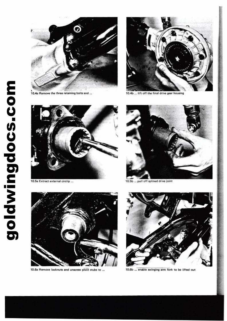
gold
win
gdoc
s.co
m,.
,
•10.4. Remove the three retlining boltlllnd 10.4b ... lift off the final drive gear housing
10.6b ... enable twinging 11Im fork to be lifted out
\~..
10.Sa Extract ulemer circlip "'"
10.68 AemOllI Ioc:knuts .nd unscrew p1wt stubs to ...
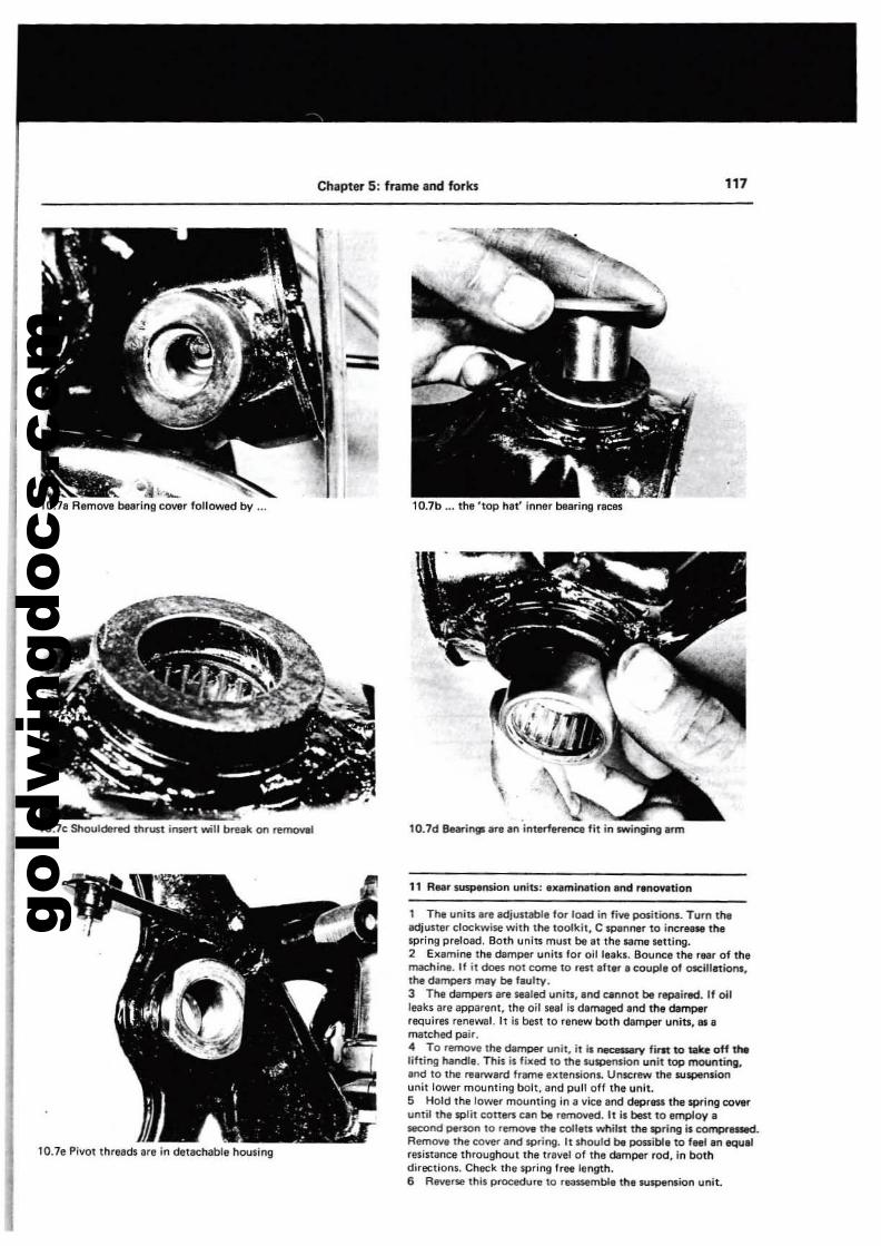
gold
win
gdoc
s.co
m
, . -'" a~ \c-.10.7a Remove bearing cover followed by •..
10.7c ShOUldered thrust imen will break on~I
Chapter 5: frame and forks
--,10.7b ... the 'top hat' inner bearing races
10.7d 8earirlSJlare an inti'.'rl.l"tl'lCfl fit in swinging arm
117
10.78 Pivot th,aads a,a in detachabla hOUliing
11 R..r $U5plInsion units: .x.minetion .nd renontlon
1 The units .re adjullable lor load in five positiom. Turn theadjuner clockwiMl with the tOolkit, C JPlInner to inc:re_ the.pring preload. Both units muu bt at the Ame setting.2 Examine the damper unitl for oil leak•. Bour"IC' the rNr ot themachine. II it does not come to rBlt .h8l'"' couple of oselllatiom,the dampers may be flulty.3 The dampe" are _led uniU:, Ind cannot be repaired. If oilleaks are appartnt. th. oil sttl is damaged and thl damperrequires renewal. It is best to renew both damper units," amatched pair.4 To remove the darnoer unit, it is.-y fint to mite off tMlilting !'Iandl•. This is fixed to the wspension unit top mounting.Ind 10 the rearward frame extensions. Unl(:rew the suspensionunit lOwer mounting bolt. and pull off the unit.S Hold the lower mounting in a vice and depreu the spring cowruntil the split COtt8fS can be removed. It is best to employ,second person to remove thl coliits wflilu the spri"51 is compl'"laed.Remon the cover and spring. 11 Should be possibll to feel ,n equalresistance throughout the travel of the damper rod, in bothdirections. Check the spril'lg free length.6 Reve~ this procedure to reassemble the wspemion unit.
gold
win
gdoc
s.co
m"8 Chapter 5: frame and forks
1 Theeentre $land pivot. on. hollow lube, clamped be~ntwo split lugl below the rear engir'le mounting. The pinch bolashould be chlIcked occasioMlIy. for security and the pivot oiled.2 Also check that the relurn spring and linkage;1 unworn and,.ttacu the nand smartly. If the nand f'lts whiln 1he bike i. inmotiOn, lin accident may result.
13 Prop sand: luminll,lon
1 The prop stand Is pivoted on. lug ul'lde1" the frontl,ft-Nndengine mount. Check the security of the pivot bolt and oilQCC.IsiOl'l.lly.2 Check the action of the stand, and make SlJre 1M! the returnspring is not worn or weakened. An accident will almostinevitably result from the prop nand dropping whillt the machineis In motion.3 To prevent the machine from being ridden away with theprop stend down, American models incorpor1lte I now!Mlf-retracting device. Cfleck the rubber 'trip' of this device for_ar or damage. No part should be wot"n below ttl, mouldedlil'Ml on the ru~r.4 Check the C)penltion of tMstand.$ follows: Put the machineon the centre stend, and ptlt the prop stllnd down. Using a springbal&n~ attached to the extreme Elnd of tha centre stand, measurethe forcEl required to retrllet the stand. If this force exceeds2·3 kg 14.4· 6.6Ibl, check that the st80d pivot bolt is notowrtigtlt, or in r'IIed of lubrc.tion.5 To renew the rubber 'trip', takfl off the bolt. Mlk, sure the11_ is installed in the fixing hoi' of the new trip. Fit the tripwi1h the arrow f!ICing outwards. The block should be ITIlIrklCl'over 260 l~ Il1lly'.
14 FootrlU:S: ' ..minetion
1 The front footrests are retained on the fl'llme by • single boltand comprise. spring 10Ided RIbber covered peg .nKhed by Idevis pin to I forged arm. The footrest rubber is held to thesupport arm by two bolts j)MSing through I plat. below therubber.2 8eclIUM the footr9$t PIIIII arEl spring loaded and can fold backwhen stlllck, it is unlikely that they will become dalTlllged. Thesupport arml can be repaired, if bent, by the application of heatbefore being strligtltened.3 To renew I returnspring. remoVII the split pin Ind ptlll OU1
the clevis pin from the footrer! pivot pi_.4 The pillion footrests Ire 11100 of the folding type, springloading being pt'OYided by the compression of the foouestlllbber.Owing to the construction, it is unliklly that these footrests cenbe rlpalred, if demaged.
15 RNr ~11*f.Ii1: 'Xlminetion
1 The rear brake pedill is mounted on, and pivots on, I shaftfixed lnboerd of the flam., just below the swinging Irm pillOtdub on the right·hand side of the machine. The pedal il retllinedby I _her Ind split pin. The pedal return spring is fiued on thepillOt shaft betwllen the pedal and washer.2 The brake pedel b connected directly to the piston rod ofreer brake master cylinder by means of a forked joint and devispin. The pilton rod Ind fork Ir. thr8llded, to allow heightedjustment of the pedal.3 If the pedll becomes bent during an ~nt, it may bestreightened, 1ft.. rllfTlOY81 from the mechine. Apply heat to thedamaged .rN with I blowtorch or gas bottles. Bear in mind thltthe required amount of helt will probably cause the chromepllting to peel from the pedaL This is unavoidable.
1 The duabeet is retained It the rear by two bolts passing thr~brlckets attached to the seat pan. The SIllt front is supported on I
rubber saddll mounted on I pressed steel bridge llCl'"OSS the frame,"....2 The seat can be removed with ease, Iher remoll81 of the twobolts.
17 Dummy fuel tlnk: IXlmiNltion
1 The dummy fuel tank, fittlld in piKe of a recepteele for fuel,consists of three fibre glass panels containing the lir filter box,an .Iectrieal components board and the radiator reservoir.2 The upper penel is fitted with a lockable catch and houses thefu.1 gauge. Opening the upper panel gives access to the screwknobl, which Illow the side ponels to open and hin911 about theirlower Bdgel. The lide panell are prevented from opoening beyol'ld I
certein position by cable straps fitted with barrel nipples at e3Ch.....
18 Instrument drIve cebhn: lxamination end replacing
1 Drive cables should be exemined and lubricated occasionally.The outer sheath should be examined for cracks or damage, theinner cable for broken or frlyed strands. Jerky or slull9ishinstrument movement is genernlly ceused by a faulty cable.2 Detach the cable !It the drive end, and withdr.rw the innercable. Clean Ind examine the cable. Re-Iutx"icate it with highmelting point grNse, but do not grNI! the top six inches ofcabl., at the instrument end, or grease will work its way intothe instrument head and ruin the movement.3 Re-route the cables as they were originally. Make lure thatthe Sl~ring turnl freely.
191~rument hud$: removing
1 Unscrew the knurled cttble nut and disconnect the drive cable.Unscrew the two acorn nuts and remove the large washer,grommet and sleeve. Lift the head and pull out the bulb holders.Remove the head.2 It il not possible to repair a faulty inltrument heed. If theinstrument failS completely, or moves jerkily, first check the driwcable. If the mileage recorder of the speedometer ceases tofunction but the speedometer colltinues to work or vice versa,the instrument hied is f.ulty.3 Remember th.t a working speedometer, ICCurllte at 30 mph,is a statutory requirement in the UK and many other countries.
20 CI.lning the midline
1 If possible, the machine should be wiped down immediatelyafter use in the wet, 100 that it is not ~r8ged in I rult-promotingcondition.2 Before regular cleaning, wash off dirt with plenty of water,and allow the machine to dry. Use a WItX polish on painted partl,and a proprietary chrome cleaner such as Solvol Autosol, onplated and aluminium alloy items. Note that some allov paruon these motorcycles have. lacquered finish wflich needs wipil'lgonly.3 If any part of the machine is caked with an oily film. use Idellner soch III Gunk, in accO<'danee with the instructions. Keepwater out of the carburettor .nd ignition components. Afterwashing down the machine, re-oil the exposed control cables. IndbeerinQf.
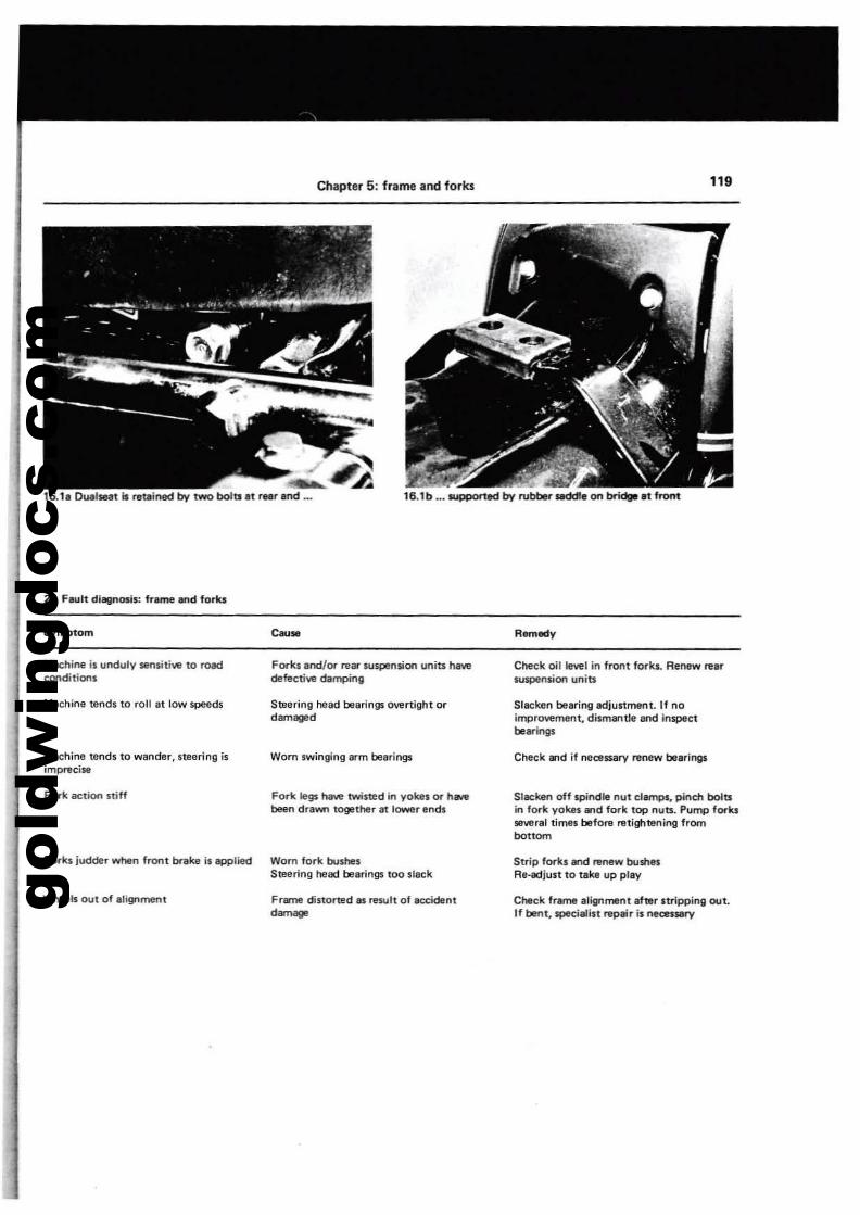
gold
win
gdoc
s.co
m
16.11 Dllllseal is re~;ned bv two boltll81 r..r and .•.
21 Fault diagnosis: frame ...d forkl
Symptom
Chapter 5: frame and forks
16.1 b ... suworted bv rubber saddla 01'1 bridge at front
Remedy
119
Machine 11 unduly senlitiw to roadCOl'Iditioos
Machine tends to roll It low speeds
Machine lends to wander. steering isimprecise
Fork IICtiOl'l stiff
Forks judder when front brake is applied
Wheels OI,lt of alignment
Forks and/or rear suspe'liioo unitll h8Yedefectiw damping
Steering head bearings overtight ordamaged
Worn swinging arm bearings
Fork legs hlIYe twisted in yokes or h_been draV«! togelher at lower ends
Worn fork bushesSteering helld bearings too slack
Frame distorted .. result of lK:cident........
Check oil Iewl in front fork... AeMw rearStJ1I)efIsioo units
Slacken bearing adjustment. If noimprovement, dismllf1tJe Ilf'ld inspectbearings
Cheek lI'1d if neceSllary renew bearings
Slacken off spindle nut clamps, pinch boltsin fork yokes and fork top nun. Pump forks:several times before nttightening frombottom
Strip forks and renew bushesRe-adjust to take up play
o-ck frame alignmenl after stripping out.If bent, specialist ~air is necessary
gold
win
gdoc
s.co
m Chapter 6 Wheels, bral<es and final drive
General description 1Front wheel: elCamination 2Front wheel: remoYal and replacement 3Front wheel bearings: examination and renovation 4Rear wheel: examination 5Rear wheel: removal and replacement 6Rear wheel bearings: examination and replacement 7Front brake: replecing the plIds snd O'oIerhauling thecaliper unit 8Front master cylinder snd hoses: examinlltion and renovation 9Bleeding the brakes: front end ",ar systems ... 10
Specifications
TV'..F~.
A••TyN pressul1lS solo (cold)
Front .Rear ..
Tyl1l pressures two'up (cold)FrontRear
BrakesFrontA••
GllfMll'"al dllSCription
Relf bi"ake: I1!placing the pads and ~rhilUling the C8liperunitRev master cylinder: ellamination 8nd renovationRemoving and replacing the brake discsCUlh drive assembly: ellaminationFinal drive system: examination and renO\lationTyres: removing and replacing ...V.llllll cores and capsFront wheel balancing ...F... lt diagnosi.: wheels, br.kH and tvre.
3.50 H 19 (19 inch diameter)4.60 H17 117 inch diameter)
28 psi (2.0 kg/sq. em)32 psi (2.25 kg/sq. em)
28 psi (2.0 kg/sq. eml40 psi (2.8 kg/sq. em)
HydTMllically oper.ted twin discHvdr...lically operated single disc
2 Front wheel:examin&tlon
111213141516111819
Both wheels are lilted with .teel rims,laced to alloy hubs, whichare supported on two ball journal bNrings. The front wheel isfitted with II twin disc hydr.ulic brak., the caliper. being of thesetf..lisJning type, using. single piston .nd located to the rear 01the fork lower legs. The rear brake is .lso hydraulicalty openIted,with a single disc Ittaehed to the leh-hand side of the nub. TI'Iecaliper used is 01 the filCed type, where IWQ pinons are used, lachonl applying pressure to a disc pad. The front brake mastercylinder and reservoir is mounted in an exposed position an thehandlebar, where it is oplrated directly by the levlr. The rearmIIter cylinder and reservoir is mounted inboard 01 thefr~to the rear of the brake pedal, and is opIl1lted by a rod joinedby fork and pin to the trailing edge of the bnIke pedal. Finaldrive is provided by a shaft running through the right..flandtubular member of the swinging arm, to which is attached acrown and pinion final drivi assambly contained within an alloyhousing. A cUrih drive assembly is intllrposed between the finaldrive ~ar and tha rear wheel, to absorb shocks in the transmission.
1 Place the mechine on its centre nand, with a block under thesump, so that Ihe Iront wheel is clear of the grourtd.2 Spin the wheeland check for rim alignment. Smallirregul.rities Cln be correetltd by tightening the spokes in theaffected area. l!though a certain amount of IllCperience isnecessary il over-corraclion is to be avoided. Any 'flats' in thewheel rim should be evidenl at the same time. Tllesl are moredifficult to remove with any success. and in most cases the wheelwill havll to be rebuilt on a new rim. Apart from the effect onliability, especially at high speeds, there is much gflater risk 01damage to the tyre beads and walls if the mochine is ridden witha defonned wheel.3 Check for loose or broken spokes. Tapping the spokes is lhebest guide to tension. A lOOSll $pOke will produce a QUitedifferent note and should be tightened by turning the nipple inan anticlockwise diractio", Always ch.eck for run·out by spinni"'ilrhe wheel agein. II a spoke has been tightened, the tyre shouldbe ftmoyed to ensure Ihat the spokes do not protrude beyond the
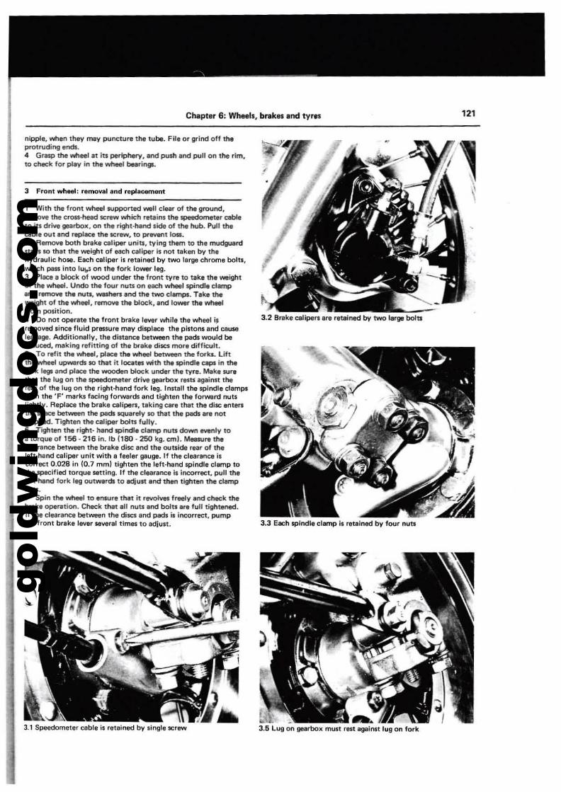
gold
win
gdoc
s.co
m
Chapter 6: Wheels, brakes Ind tyr.s '2'
3 Front wheel: removel and replacem.m:
nipple, whlln thllY may puncture tM tube. File or grind off thllprotruding ends.4 Gresp the wheel at its periphery, and pYsh and pull on the rim,to check for play in the wheel bearingl.
1 With the front wheel supponed well clear of the gfOlJnd.remove the cron-hel!d screw which r.tains the speedometer cableto its drive gearbox, on the right-hand side of the hub. Pull thecable OUt and replace the screw, to prevent 10$lI.2 Remove both brake caliper units, lying them to the mudguardstays so that the weight of taCh c.liper is not !lken by thahydraulic hose. E.ch caliper is retained by two large chrome bolt.,which pess into lu\o-$ on the f()<"k lower leg.3 Place a block of wood under the front lyre to take the weightof the wheel. Undo tha four nuts on ea::h w'-I spindle clamp.nd remove: tha nuts,~.nd the twO cllfTlPl. Teka theweight of the wheel, remoY8 the block, and lower the wheelfrom position.4 Do not operete the front brake lewr while the wheel i~ 3.2 Breke calipers ere retained by two large boltsremOlled since fluid pressure mey displ.ce the pinons and causeleakage. Additionally, the di.tanca between the pads would bereduced, making refitting of the brake discs more difficult.5 To refit the wheel, plec.the wheel between the f()<".... Liftthe'lYheel upwards so tnat it locates ¥rith the spindle caps in thefork legs and pi_the wooden block under the lyre. MIke $Urelhat the lug on Ihe $p88dometar drive gearbox restS againn ther~r of thalug on the right-hand fork leg. Innall the spindle clamp.with the 'F' marks facing forward' and tighten the forwurd nutslightly. Replace the brake calipers, taking eMe that the disc antersthe space between the pads squarely so that the pads are notchipped. Tighten the caliper bolt'S fully.6 r91ten the right· hand spindle damp nuts down BYenly toit torque 01 156 - 216 in. Ib 1180 . 250 kg. anI. Measure theclearance between the brake disc and the outside rear of theleft-hand caliper unit with a feeler gauge. If the clearance iscorrect 0.028 in CO.7 mml tighten the left'hand spindle clamp tothe specified torque setting. If the dearance .. incorrect, pYli theleft-hand fork leg outwerdl to adjult end then tigh1&llthe clamp~u.
7 Spin the wheel to ensure tnat it rlYOfvel freely and check thebrake operation. Cheek that all nuU and bolt. are full tightened.If the clearance between the discs and pad, i. incorrect, pumpthe Iront brake lellllr _ral timlls to adjust. 3.3 Each spindle clamp is re!lined by four nut.
3.1 Spaedometer cablll i. retainlld by .ingle screw
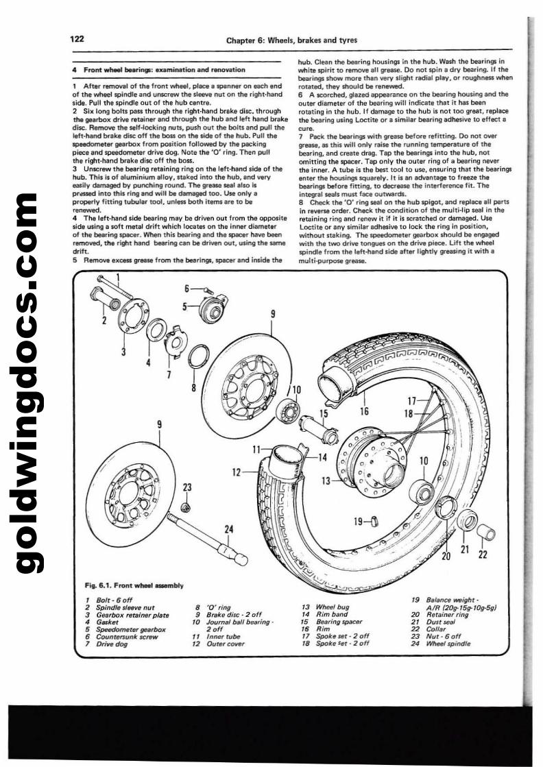
gold
win
gdoc
s.co
m'22 Chapter 6: Wheels, brakes and tyres
.. front whMI be_i.: .xamiNltion.nd renovation
1 Aftl'r rer'l'lO'41 of the front wheel, pliICI' spanner on each endof the wheel spindle and unscrew the sleeve nut on the right·handside. Pull the spindle out of the hub centre.2 Sill long bolts pass through the right·hand brake di5C. throughthe gearbox drive retliner and through the hub and left hand bnIkediK:. R8fnoOYe the self-locking nuts, posh out the bolts and pull theIeft·hand brake disc off the boss on the side of the hub. Pull thespeedometer ge.rbox from position followed by the packingpiece and speedometer drive dog. Note the '0' ring. Then pullthe right·hand brake disc off the boss.3 Unscf'w the bearing retaining ring on Ihe left-hand side of thehub. This isof aluminium alloy, IlIked into the hub, and very_ily damaged by punchirtg round. The grease seal also isprl!SSId into this ring.nd will be damaged too. Use only aproperly fining tubular tool, unl", both items are to berenewed.4 The left·hand side bearing may be driven out from the oppositeside using a soft metal drift which locates on the inner diameterof the bearing spacer. When this bearing and the spacer have beenremowd, the right hand bearing ell" be driven out, using the samedrift.S Remove excess gr." from the bearingl. spacer and inside the
hub. CI••n the bearing housings in the hub. Wash the bearings inwhite spirit to~ ,II grease. Do not spin a dry bearing. II thebearings show more than very slight radial play. or roughness whenrotated. they should be renewed.6 A scorched. glazed appearance on the bearing housing and theouter diameter of the bearing will indicate that it has bfIllnrotating in the hub. If damage to tile hub IS not too great, replacethe bearing using Loctite or a similer bearing adhe1iV9 to eHlet acute.7 PICk the bearings with gr-ease before refitting. 00 not 0IIei'"
grease. n this will only raise the running Ulmpertlture of thebearing, Bnd crute dlll9. Tap the bearings into the hub, notomitting tile spacer. Tap only tile outer ring of a bearing neverthe inner. A tube is the ben 1001 to use, ensuring thet the bearingsItOte. th, housings squarely. It is an advant'ge 10 freeze thebearings belore fining, to deCnlll,. the interference fit. Theint.egnll seals must face outwards.8 Check Ihe '0' ring seel on the hub spigot, and rep/ace.1I parUin reverse order. Check the condition ollhe multi·lip seal in Iheretaining ring and renew it if it il Icratched or damaged. UseLoctill or any similar Ildhesive to lock the ring in polition,without staking. The~ellr gliS3rboll should be engagedwith the twO drive tongues on the drive piece. Lift the wheelspindle from the left-hand side Ifter lightly greasing it with.multi-purposa greaw.
9
9
1113
~14
Fig. 6.1. Front wtwel-.nbty
1 Boft- 6 off ,. Blllilnt:8 _ighr·2 Spindle sleeve nut • '0' ring '3 WhHI bug AIR (20rr'5rr'0g-5g)3 Gearboill retaiMr pfate • Brake diM: . 2 off '4 Rim band 20 Rerainflr ring4 Gtllker '0 Journllf baff bflilring· '5 Bearing spacer 2' Dun seaf5 SpeedomfIler f/8lrbox 2 off " Rim 22 Co"!"• Countersunk ICI'llW" " Inner rube " Spok~Ul • 2 off 23 Nur· 6 off1 Drive dog '2 Out~reover 18 Spok~ i,r - 2 off 2' m-fqJind/~
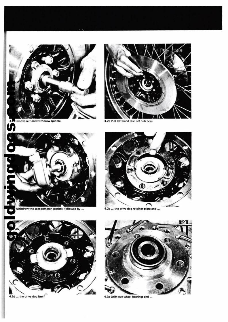
gold
win
gdoc
s.co
m
4.2b Withdrew the speedometel'" gellrbox fotlOW&d bV ...
4.2d ... the drive dog ltNlf
4.21 Pull teft hand disc off hub bou
~4.2c ... the drive dog retainer plate and ...
4.3a [Kift out wt-' t-rlng5lnd ...
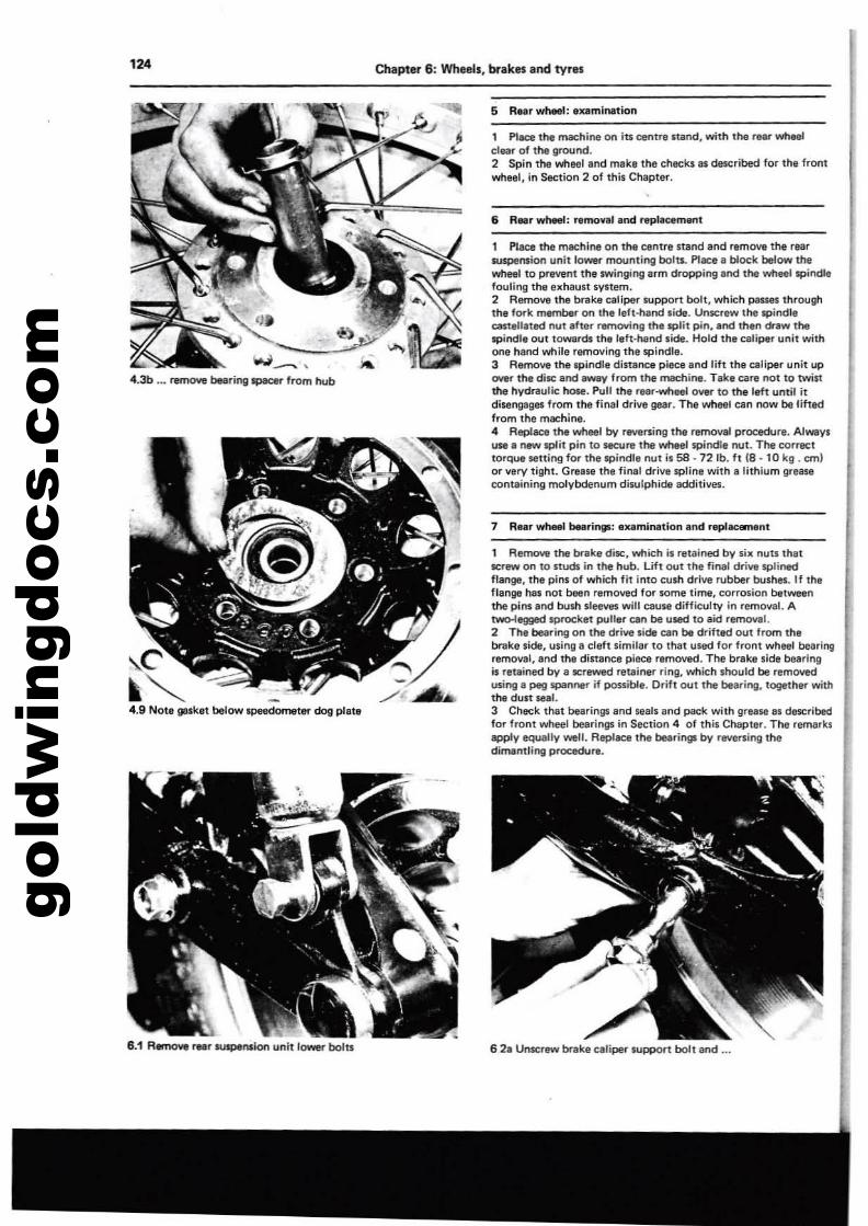
gold
win
gdoc
s.co
m124 Chapter 6: Wheels, brakes and tv,.s
4.9 Note gasket below speedometer dog plate
6 R..rwheel: r'm<lVlllend replKement
, Place the machine on the centre startd and remove the rearsuspension unit tower mounting bolts. Place I block below thewheel to prevent Ihe swinging urn dropping and the wheeillpindlefouling the exhault syllem.2 Remove the brake caliper support bolt, which PlIsse5 throoghthe fork membeI'" on the left-hand side. Unscrew lt1e Ipiodl.CMt.ll.ted nut after removing the split pin, and then draw thelpil\dle out towards th,reft'Mnd side. Hold the caliper unit withone hand while removing the spindle.3 Remove the spindle distance piece 8nd lift the caliper unit upOYer the disc and -v from the machine. Tak, care not to twistthe hydnlulic hose. Pull the r"r-wheel O\l'llr to the l~t until itdise"9!l9e1 from the firnll drive gear. The wheel tan now be lift8'dfrom the mlll;:hine... Replace the wheel by rllYersing the removal procedure. Alwaysuse a new split pin to secure the wheel spindle nut. The torreettorque setting fO<' the 'Pinelle nut is 58 - 72 lb. It (8 - 10 kg . em)or ....ry tight. Grease the final drive 'Pline with a lithium greaseoonraining molybdenum disulphide additives.
6 Re,r wheel: Ix.mln.tion
1 AefTlO\o'8 the brake diE, which is retained by six nuts thatrer_ on to studs in the hub. Uft lXlt the final drive splinedflange, the pins of whith fit Into tush drive rubber bushes. If theflange has not been remowd for some time, torrosion betweenthe pins and bush sleeves will C31J1II difficulty in removal. Atwo-legged spnx:ket puller ClIn ba ulld to aiel removal.2 The bearing on the drive sidB ClIn be drifted out from thebrake side, using a cleft similar to that used for front wheel bearinogremoval, and the distance pilll;l removad. The brake side bearingis r!ltained by. lCrewed retainer ring, which lhould be removedusing. peg spanner if possible. Drift out the bearing, together withthe dust seal.3 Check that bearings and leals and patk with grease al describedfor front wheel bearings in Section 4 01 this Chapter. The remarksapply equally well. AepllM:8 the bearings by reversing thedimamling pl"Ol:edulll.
7 Rear wheel bearinWl: e~mination and repl_nt
1 Pl_ the machine on its centre sand, with the tlef whtoele1e.r of the grOlJnd.2 Spin the wheel and meke the checks'l described for th, fromwhltlll, in Section 2 of this Chapter.
w~,
4.3b ... reff'IO\IIe bearing IpaCef" from hub
8.1 R.mow rM. lUspt,nIIlon unit lowel" bolts 62a Unte::r_ brake caliper support boll and ...
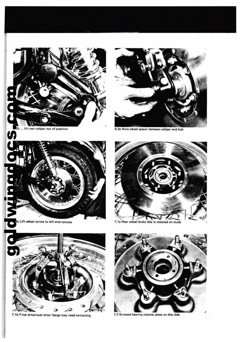
gold
win
gdoc
s.co
m
6.2b ... litt rQr elIIliper OUI of po$ition
:--.:.7.1e Rellr wheel brllke di!IC is retained on studs6.3b Lift wheel acrou to lett and remove
'3 ~ ~7.1b Flnlll drivelcusn drive fillnge may need extracting 7.2 Scr-.d bearini retainer plat. on disc sldt
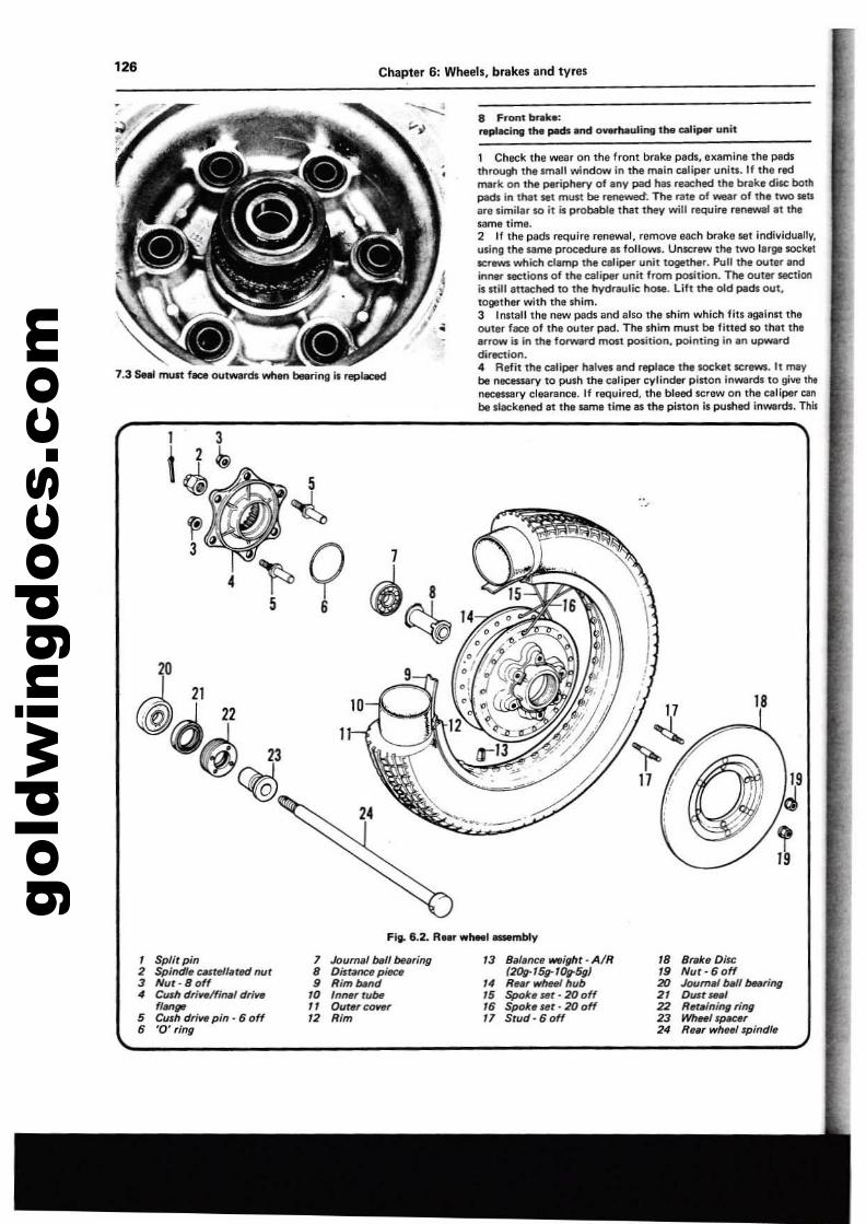
gold
win
gdoc
s.co
m126 Chapter 6: Wheels, brakes and tyres
~~..a:7.3 Seel ITIU11 f_ ou~rdswtI.n blllH1nllll replaced
8 Front brake:"'Ki"ll tM pads and ov.m.l,aling the e.lip$" unit
1 Check the wear on the front brake pads, examine the padsthrough the lIfllall window in the main caliper units. If the redmerk on the periphet'Y of eov pad "as reached the brake disc botllpads in that llet moo be renewed'. The rat. of wear of the two SlItsarllsimilar 50 it is probable that they will require renewal It thelame time.2 If the peck require renewal, remOYll each brake set individually,using the same procedure 8S follows. Un5Crew the lWtllarge socketICrltW$ which damp the caliper unit togettler. Pull the outer andinner sections of the caliper unit from position. The outltl' sectionis lIiIl 8tulCMd to the hydraulic hose. Lilt the old pads out,together with the shim.3 Install thll new pads and also the shim which fits &glIinn theouter face 01 the outer pad. TI'Ie shim must be fitted 50 that lhllInow is in the forward most position, pointing in In upwlrddirection.4 Refit the caliper I'Ialves Ind repllCe thl socket kl"ew5. It maybe necessary to push the caliper cylinder pinon inwards 10 give tiltneceS$;lry clearance. If required, the bleed screw on the celiper canbe slackened at the same time as the pinon il pushed inwartls. This
1 21C@d 22
Q~ 23
~
I 3t 2 ~
~".,,"¥..oII
fl3
4
5
~
~Q 1 8
5 6 ((g~
9
24
18
Fill- 6.2_ R..r w'-l~y
, Split pin 7 Journal ~II btlaring 13 Sa/ence _if1ht· AIR IS S,.ktt Disc2 Spind/~ CMtell.ted nut 8 DistMtCflp~ (20g-15g- tOg-5g) ,. Nut-60ff3 Nut - 8 off • RimNild 14 R~.r wheel hub 20 JourrW WlI bHring
• Cush dri"./final drive ,. InMrtuM 15 Spoke #t - 20 off 2' OU$t_'flM" " OuterCOW/r ,. Spoke set· 20 off 22 R~r.injngring
5 CUlh drill8 pin· 6 off '2 Rim 17 Stud· 6 off 23 WhHlsPM:8r• '0' ring 2' R",r ~/1p;ndl.
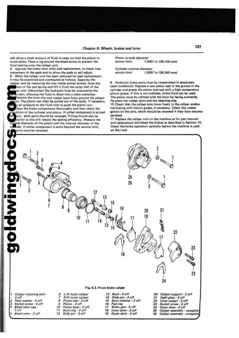
gold
win
gdoc
s.co
m
Chapter 6: Wheels, brakes and tyres 127
will allow a 5mall amount of fluid to !IeeP out and the pinon tomova easily. Place a rag around the bleed screw to prevent thefluid leaking onto the caJiPlll" unit.5 Operlllte me brake lever alter pad replacemet'lt, to clled< freemovement of the pads and to allow lhe pad, to sell adjust.6 When tM caliper unit"'" bllen remoYecl for pad replacemenl,il may be examinecland overhauled as follows: Separata 1Mcaliper unit by removing the two inlide socket screws. NoUtheposilion of tne pad IiPring and lift it from Ihe outer half of mecaliper unit. Disconnecl the hVdreulic hose by unscrewing thebanjo bolt, allowing the fluid to drain into 8 clean container.7 Remoye the bool dip and rubber boot lrom around the caliperpiston. The pislon can then be pulled out 01 the body. If nto::e5$¥Y,
apply air pressure to the fluid inlel 10 push the piston out.a Clean the brake componenU thoroughly and then Check theeondition of the eylindel'""and piston. If either eomponent is scoredor worn, both partllhould be renewed. Pitting Ihould elso beIooQd for 81 this will reduce the _ling efficiency. Measure theOUtside diameter 01 the pillon al'ld the internal diameter of mecylinder. If either componenl il worn beyond the wrvice limit,the peru must be renewed.
Pi,ton outsidtl dillmf1terservi~ limit '.5001 in (38. '05mm)
Cylinder internal dit.metersiuvice limit '.5051 in (38.245 mm)
g Hydrlllutic brlIIke parts ml,lSt be reassembled In absolutelyclean eonditionl. Replace II new pinon lIlal in the grOOYll in thecylinder and grease the piston 8nd seal with a high temperaturesilicon grease. If this il not available, brake fluid can be used.The piston must be refitted with the boot lip f8Cing outwards.Re place the rubtJllr boot and the retaining clip.10 Check th,t the caliper piN move freely in me ~lipef" and'lorlubricating with lilicon greBlIl, is necessary. Check ttle rut:Jbergaiters on the pins, which sl'lould be renewed if they have becomeperished.11 Replace the caliper unit on the machine. for plId remOYlllI,nc1 replacement and bleed the brakes as described in S.etlon 10.Check the brake Op8f1Ition carefully before Ihe machil'lt! is usedon the road.
8
1011
12
14
2526
2019
21
\~Vi
24
22
23
~23
Fig. 6.3. Front brake caliper
c,,/i"per retaining bQlt·4 off
2 Plsin wif$l!er - 4 off3 Socket screw· 4 off" B/~d 1Ia1~ cap .
2 off5 81C1Jd tlilllItI • 2 off
6 LIH outer caliper1 RIH ourttrcslipttr8 PistOlf ~sl· 2 off9 Piston· 2 off
10 Piston boot· 2 offII Bootdip·20ff'2 Slide pin' 2 off
'3 Soo(·40ff14 Slide pin -20ff15 Soot retlliner' 2 off'6 PM/clip .11 Srske pIId - 2 off18 Inner shim· 2 off19 Outer shim· 2 off
20 c.lipttr support - 2 off21 Sightglsu' 2 off22 Inf/llr cslipl!r· 2 off23 Socket screw' 2 off24 Outer shim - 2 off25 Caliper saembly· complete26 C.,iper lUSembly . camplere
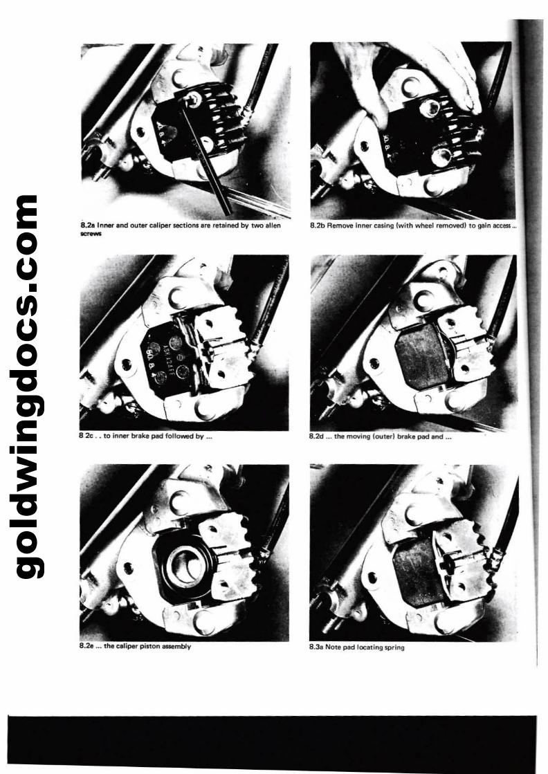
gold
win
gdoc
s.co
m
8.3& Note pad localing 5j)ring
8.21 In"., and outer eaJiper UlCtion. Ire retained by two allen--
8.2c .. 10 inne'l" brake pad foll~by ..•
8.2& ... 1ne celiper pitton attembly
8.2d ... the moving (oulerl brake pad and ...
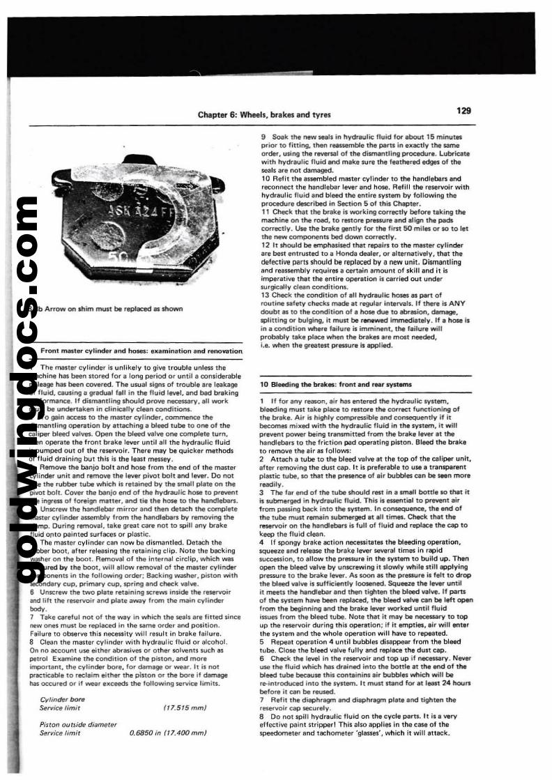
gold
win
gdoc
s.co
m
Chapt~ 6: Wheels, brakes and tyres 129
8.3b Arrow on shim mult be rePlaced as shOWl'l
9 Front mastl:l" cylinder end hoses: e.lmination Ind renoVlltion
9 Seek the new 5ells in hydraulic fluid for lbout 15 minutesprior to Iitting. therl rNssemble the perts in execuy the $llmeorder, using the rever$lll of the dismantling procedur,. Lubricatewith hydraulic fluid and mike sure the fellthered edges of theseals are nOI damaged.10 Refit the 8$lembled master cylinclar to the handlebars andreconnect the handleber lever and h05e. Refill the reservoir withhydraulic fluid and bleed Ihe entiresynem by following theprocedure described in Section 5 of this Chlpter.11 Check that the bnIke is working correctly before liking themachine on the road. to restore pressure and llign the padscorrectly. Use the brake gently for the fiMit 50 miles or SO to letthe ntlW components bed down correctly.12 It should be emphasised that repairl to the master cylinderare best entn,lIted to a Honda dealer, or elternatively, 11'111 theckIfectiVfl parts should be replaced by a new unit. DismantlingInd rells5embly requires a certain amount of Ikill and it ilimperative that the entire operation il Cltried out undersurgically clean conditionl.13 Check the condilion of 811 hydraulic hoses al pert ofroutine IlIfetv' checks made et regullr intervals. If there is ANYdoubt 81 to the condition of. hose due to abrllSion, dImtge.splitting or bulging, it must be r_wed immediately. If I hose ilin I COndition where failure ;s imminenl, the flilure willprobably Ilk, pIece when the brakes .re most needed,i.e. when the greatest prllliUre is epplled.
1 The ITIllstllr cylinder il unlikely to give trouble unless themachine hal been stored for a lor'lg period Of until a considerablemileage has been covered, The usual Ilgnlof trouble Ire leakageof fluid, ClIuling a gradual flU in the fluid level, and bad brtlkingperformance. If dilimllntling $hould prove rMlCelililry. III workmult be undertaken in eliniCllly clean cooditio!'lS.2 To gain access to thl master cylinder, commence thedi$lTlilntling operation by Ittaching a bleed tube to one of thecaliper bleed valves. Open the bleed valw one compllte turn.then operate the front brake levar until all the hydrlulic fluidis pumped out of the reservoir. There may be quicker mathodsof fluid draining but this il the least messey.3 Remove the banjo bolt and h05e from the end of Ihe maltercylinder unit and remove the lever pivot bolt and lever. Do notlose the rubber tube which is retained by the small plltll on thepivot bott. Cover the banjo end of the hydraulic hOM to preventlhe ingreu of foreign IT\Ilter, and tie the hose to the hlIndlebaMi.4 Unscrew the handlebar mirror and then detach lhe completeITIilliter cylinder assembly from the handlebaMi by removing thedamp. During removal. take greal care not to spill any brlkefluid ontO painted surfaces or plastic.5 The master cylinder can now be dismantled. Detach Iherubber boot, Ifter releasing Ihe retaining clip. NOlI Ihe backingwasher on Ihe boot. Removil 01 the internal circlip, which WilSobscured by the boot, wilt Inow remOVII of thoe maUer cylindercomponents in the following order; Becking washer, pinon withIIeCOrldary cuP. primary cuP. spring and check valve.6 Unscrew the two pille retaining SCfews inside the reservoirand lilt the reservoir and pllle lway from the main cylinderbody.1 Take careful not of the WlY in which the seals 8rl fitted sincenew ones must be replaced in the same order and position.Failure to observe this neceslity will resull in brake failure.8 Clean the master cylinder with hydr8ulic fluid or alcohol.On no eccount U5e either abrasives or other solvents wch ISpetrol Ellimine the condition of the piston. and moreimportant, the cyfinder bore, for damlge or wear. II is notprocticable to reclaim either the piston Of the bore if damagehas occured or if weir e>tceeds the following 5ervice limits.
Cylinder boreSe",k;e limir
Pinon ouUide diameterService lim;t
(ll.515mmJ
0.6850 in (llAOOmml
10 Bleedi09 the br,k..: front Ind .... systems
1 If for any relSOn, lir has entlll'ed the hydrilulic system.bleeding mUll take place 10 restore the correct functioning ofthe brake. Air is highly compressible end consequently if ilbecomes milled with t!'le hydraulic fluid in the sYltem, it willprevent power being tr.nsmitted from the brake lever .t thehandlebars to the friction p;ld operlling piston. aleed the braketo remove the air as follows:2 Attach a tube to the bleed valve at the top of the celiper unit,after removing the dUll cap. It is preferable to UIi8' transparentplastic tube, so that the presence of eir bubbles can be _n mor,readily.3 The la, end of the lUbe should rest in e small bottle SO that itk submerged in hydreulic fluid. This k _tilll to preYent lirfrom passing back inlO the system. In consequence, the end ofthe tube must remain wbmerged at ell times. Check thtt thereservoir on the handlebaMi is full of fluid and repllCe the cap tokeeP the fluid clean.4 If spongy brake action necessitates the bleeding operation,squeeze Ind relea5e the brake lever leveral times in rapidsuccession, to allow the prllliUre in the system to build up. Thenopen the bleed valve by unscrewing it Ifowly wt!ill Itill epplyingpressure to lhe brake lever. As soon el the pressure il felt to dropthe bleed valve is sufficiently loosened. Squeeze the I_r untilit meets the handlebar Ind ther! tighten the bleed wive. If plirt1
of the system have been rePIeced, the bleed valve can be left openfrom the beginning Ind the brake !eYer worked unlit fluidissues from the bleed lube. Note that it IT\IY be neceuary to topup the reservoir during thil opar81ion; if it empties, elr will enterthe $ySllm and the whole operation will have to repeated.5 Repeat oper8tion 4 until bubblel dilappellr from 1he bleedtube. CI05e the bleed valve fully and replece the dUll cap.6 Check the level in Ihe reservoir and top up it nee_ry, N_,use the fluid which has drlined inlO thl bouJe at the end of thebleed tube becaou5e Ihis contllinins .ir bubbles which will bere-introduced into the Iyltam. It must mnd for tt IIllIIit 24 hounbefore it can be reused.7 Refit the diaphragn end dilphragm plate and tighten thereservoir cap securely.8 Do not spill hydreulic fluid on the cycle paru. It ila veryeffective paint stripper! This also applies In the case 01 thespeedometer and tachometer 'glassel', which it will atteck.
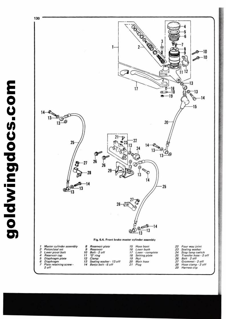
gold
win
gdoc
s.co
m6
~r-15
25
14~13~
13~
20
7
~ ....-10
1'--1~ ...-10
II 12 .
o '~3@:-13
\r--14
121=iL!~;'~21133
22
I~ e'~ 24
r"'...~,~I c0~27 26 r ~~~~.::>=::::
26 l~ @
')y-28 29 1~ )
14,.0$-14
~'J&'-1313
130
27>1:>28~'"
(i)~14~13 13
Fit- 6.4. Front brake mastllf cylinder .s:sembly
I Millry cyl;fI(h, IJUnnbly • R_rwJi, pllJf~ 15 Houboot2 Pinon/wal ur 9 R_rvoi, ,. LeYef bush3 Lever pivot bolt '0 Bolt - 2 off " Lever - complete4 Reurvoir cap " '0' ring ,. Serting plate5 O~phr~ plete '2 Clomp 19 Nu,
• Oiaph~ '3 ~.J;t>9 WIsher' '3 0 ff 20 M.;" hose1 Pf.te "'(.;lIi"9 sc,..w· '4 Ba"'o bolt - 6 off 2' Plug
20"
22 Four w.y joint23 Sealing washer24 Stop IlImp switCh25 Tranlf.f hme· 2 off26 Bolt 2 off27 Grommet· 2 off28 Hose clllmp • 2 off29 Harn'$$ clip
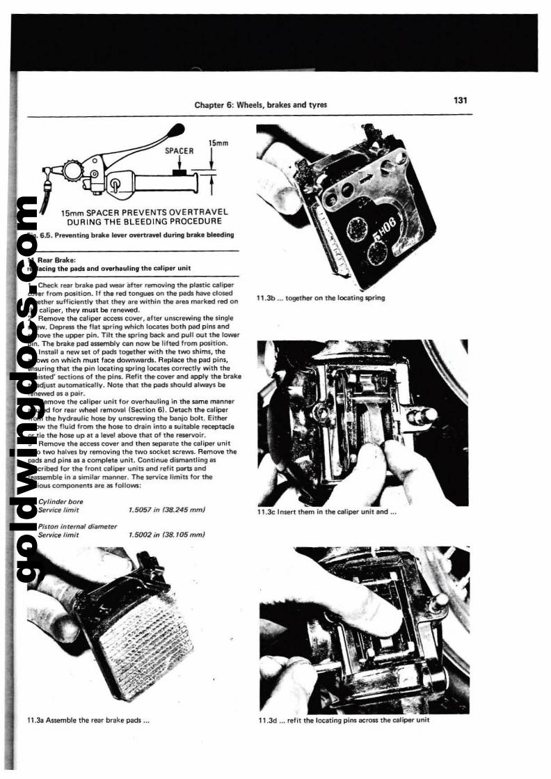
gold
win
gdoc
s.co
m
ChaPter 6: Wheels, brakes and tyres 131
Fill. 6.5. PreYtlnting btllk. I......r overtrnel during blllk. bleeding
11 Rear Brak.:r.placinll the peds and overl'lauling the caliper unit
11.3c Insert them in the caliper unit and ...
11.3b ... together on the locating sprinll
15mmSPACE~
'.5057 in (38.245 mm}
~--Jf
Cylinder bore~rvice limit
15mm SPACE A PAEVENTS QVEATAAVELOUAING THE BLEEQING PROCEDURE
1 Check rear brake pad wear efter removing the plastic calipercover from position. II the red tongues on the pads h3Vll clO$edtogether sufficiently that they are within the area marked red onthe caliper. they must be renewed.2 Remove the caliper access cover, aher unscrewing the lingletcrew. Deprl!Sli the flat SPrinll which locatel bolh pad pins andremove the upper pin. Tilt the spring back and pull out the 10000rpin. The brtlke pad nsembly <:an now be lifted hom position.3 Instalt a new set of pads togeth... with the two shims, thearrows on Which mu5t face downwards. Replace the pad pins,trlsuring Ihat the pin lociuinilipring locates correctly with the'waisted' sections of the pins. Refit the- cover and apply the br1tklto adju.t automatically. Note that the pads should alway. berenewed as a pair.4 Remove the caliper unit lor overhauling in the Jam. mannern usad lor rear wheel r.moval (Section 6), Detach the caliperIrom the hydraulic hO$e by unscrewing the banjo bolt. Either-'low the fluid from the hOM to drain into. suitable receptael.or tie the hose up at a level above that of the reservoir.5 Remove the accesl cover and then separate the caliper unitinto two halve. bV removing the two socket screwl. Remove theplIds and pins lIS a complete unit. Cont;nue dismantling 81described for the front caliper units and refit parts andreassemble in • similar manner. The service limits tor the....tioul components are 81 follows:
Piston inremal diMneter~f'lice limit '.5002 in (38. IDS mm}
11.3a Assemble the rear brake pad's ... 11.3d ... refit the locating pins across the caliper unit
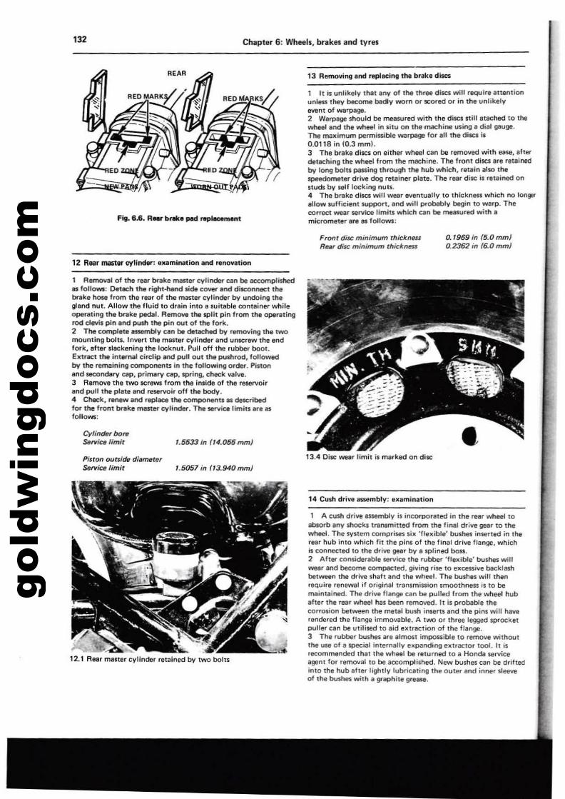
gold
win
gdoc
s.co
m'32 Chaptet 6: Wheels. brakes and tvres
Fig. 6.6. RM' b .... ped repa-m.m
13 Removing and replacing the brakl dise5
1 It is unlikely lhal any of lhe three discs will require attenlionunlllS$ they beeome badly worn 0' scored 0' in Ii'll unlikelyelfflnl of warpage.2 Warpage should be measured wilh the discs still alache<:! to Ihewheel and lhe wheel In situ on the machine using, dial gauge.The maximum permissible warpage for.1I the discs is0.0118 in 10.3 mml.3 The brake discs on either wheel can be removed with ease, aherdet8Ching Ihe wheel from the machine. The fronl discs are retainedby long bolts passing Ihrough 1!'1e hub which. retain also thespeedomeler d,ive dog relainer plate. The ,ea, disc is rel,ined onstuds by Mlf locking nulS.4 The brake discs will wear eventually 10 Ihickness which M longer,lIow sufficienl suppan. and will probably be!}in to warp. Thecorrect wear service limits which can be measured wilh I
mic,ometer are as follows:
Front disc minimum rhicknftSRear disc minirrwm thickness
0.'969 in (5.0mm)0.2362 in {6.0 mmJ
12 Rear rna51er eylinw: examiNl1ion end renovalloll
1 Removal of me rear breit, master cylinder can be accomplished81 follows: Detach 1~ righl~ $ide c~.oodisconnect thebrek, hose from the (e<lf of the maste, cylinder by undoing th,glond nut. Allow the fluid to drain into e suitable contlliner whileoperating the brake Pedal. RemDYe the spl,l pin from the operatingrod clevis pin end pu$h the pin out of the fork.2 The complete assemblv can be detached by removing the twomounting boill. Invert the master cylinder end unSl;:rew Ihe endfork, aft,. slackening the lOCknut. Pull off the rubber boot.Elltrac11he internal circlip and pull out the pushrod. followedby the remaining componenl$ in the following or~. Pistonand secondary cap, primary cap, spring, check vallli.3 Remove the two ICrews from the inside of the r'!leNoirand pull the plate and reservoir off the body.4 Check. renew and replace the components as ese.scribedfor the front bnIke master cylinder. The service limits .,e asfollows:
Cylinder bore~fl'ice limit
Piston outside dilJmeter~fl'ic.limit
1.5533 in "4.055 rom)
'.5057 in f13.940mm}•13.4 Disc wear limit is ma,ked on disc
12.1 Rear maner cylinder relained by IWO bohs
14 Cush drivI assembly: Ixamination
1 A cush drive assembly is incorporated In the rear wheel toabsorb any shocks transmined from Ihe filWll drive gear 10 thewheel. The system comp,i'Sl!s S;lr 'flexible' bushes inserlltd in 1!'Ie'ear hub inlo which IiI Ihe pins 01 the final drilffl flange, whichis connecled 10 the drive gear by a splined boss.2 After considerable service the rubber 'Uelrible' bushes willwear and beeome compacted, giving rise 10 elrCftsive becklashbelwlHln Ihe drive shalt and Ihe wheel. The bushes will Ihenrequire renewal if original transmission smoolhness is to bemaintained. The drive flange can be pulled hom Ihe wheel hubafter the rea, wheel has been ,emoved. 11 is probable 1hecorrosion belween Ihe metal bush iosens and the pins will haverendered the flange immovable. A IWO or three legged sprockelpolle, c.n be utilised to aid 8lriraClion of Ihe flange.3 The rubber bushes are almost impossible 10 ,emove without11'1, use of /I Sl)eCial inlernally expanding eXlr8CIO, 1001. 11 is,ecommended lhal Ihe wheel be retu'ned to a Honda serviceagent for removal to be accomplished. New bushes can be drifledinto the hub .ller lighlly lubrie8ling Ihe OUle, and inner Sleeveof Ihe bushes with. graphile g,ease.
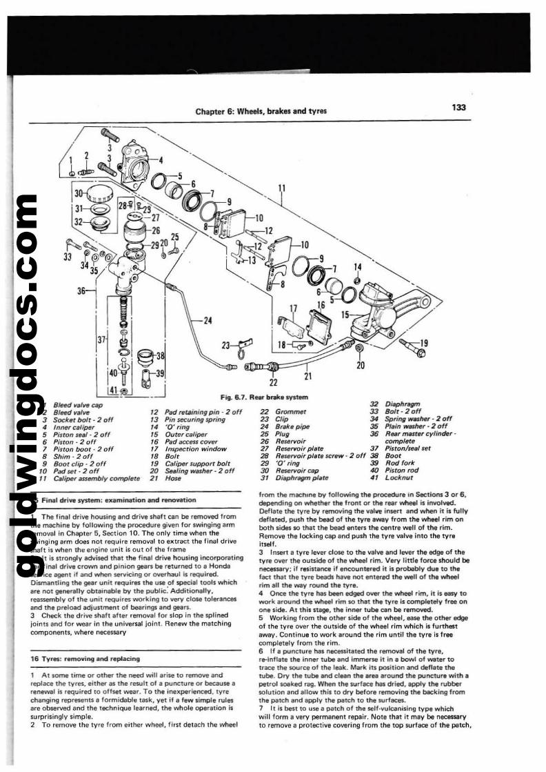
gold
win
gdoc
s.co
m
Chapter 6: Whee", brakes and tyres 133
2122
32 Diaphflgffl22 GfOmrrHfr 33 Bolt - 2 off23 Clip 34 Spfing WGMr - 2 off24 8rak. pipe 35 PI.in _Mf - 2 off25 Plug 36 RNf mMftlf cylindef-2' RtlSllfYoir compilltll27 ResefYoif plats 37 Piston/seal Stlt28 RMSfYoir platfJ SCf,W - 2 off 38 Boot29 '0' ring 38 Rod (ofk30 R_fYoitcap 4Q Piston rod3/ Diaphngm plate 41 Locknut
14
Fig. 6.7. R_ b,.. system
12 Padrwwn;ngp;n-20ff13 Pin securing spring14 '0' fing15 OUtflf calipef16 Pad access COll~f
, 1 Inspecrion window'8 80/f'9 Calipef SUppoff bolr20 Saling WMhef - 2 0 ff21 Hou
37j ~ .. I '0 ~3~
lt~Mj1 BIe«J ~a'N cap2 BIe«1 ~aI~
3 Socbr bolt - 2 off4 Inner calipef5 Pisron s~al- 2 olf6 Pinon - 2 off7 Pinon boor· 2 off8 Shim-20ff9 Boor clip· 2 off
to Pad ser· 2 off11 CiIf;fMf assembly compIe'~
15 Final ch"i ... system: ...mination aod rllOO¥lItion
I The final drive housing and drive shaft can be removed fremthe machine by following the procedure given for swinging anTIremoval in Chapter 5, Section 10. The only lime when theswinging erm does not require removal to eKtract the linal driveshaft is when the engine unit is out olthelrame2 It is nrongly advised that the fiMI drive housing incorporatingthe final drive crown and pinion gears be relurned to a Hondaservice agent if and when Stl"Vicing or OV1Irhaul is require<!.Dismantling the gear unit requires the use of special tools whichare nOl generally obtainable by the poblic: Additionally,reassembly of the unit requires working to very close tolerancesand the prelood adjustment of bearings and gears.3 Check the drive shaltaher removal for slop in the splinedjoints and lor wear in the universal joint. Renew the matchingcomponents. where necessary
16 Tyres: r.moving and replacing
1 At some time or oth.r the need will arise to remove andreplace the tyres, eithet" lIS the result of a polleture or because arenewal is required to ollset wear. To the inexperienced, tyrechanging represents 1I formidable task, yet if a lew simple rulesare observed and the techniQUe learned, Ihe whole operation issurprisingly simple.2 To remove the tyre from either wheel, first detach the wheel
from the rrtacnme by following the procedure In Sections 3 or 6.depending on whether the front or the rear wheel is involved.Deflate the lYre by removing the valll'e insert and when it is fullydeflated, push the bead of the tyre _y from the wheel rim onboth sides so that the bead enters the centre well of the rim.Remove the locking cap and push the tyre valve into the tyreiUelf.3 Insert a lYre lever close to the valve and lever the fIdge of thetvre over the outside of the wheel rim. Very little fore. should benecessary: if resistance if eOCOl.lntered it is probubly due to thefact th.at the tvre beads haYfl not entered the well 01 the wheelrim all the way round th. lYre.4 Once the tyre hils been edged 0VIt" the wheel rim, it is Ilo8SV towork around the whe.l rim so that the tvre is completely free onone side. At this S18ge, the inner tube can be removed.5 Working from the other side of the wheel, ease the other edgeof the tyre over the outlide of tha wheel rim which is furthestaway. Continue to work around the rim until the lYre is freecomplettly from the rim.6 If a puncture has necessitated the removal of the tyre,re-inflate Ihe inner tube and invnene it in a bowl of water totrace the source 01 the leak. Mark its position and deflate thetube. Dry the tube end clean the area around the puncture with apetrol SOlIked rag. When the surface has dried, apply the rubbersolution end allow this to dry belore removing the '-eking fromthe patch end apply the Plltch to thl surfaces.7 II is best to use a palch of the self-llulcanising type whichwill form e very permanent repair. Note that it may be necessaryto remove a protective covering from the top surface of the patch,
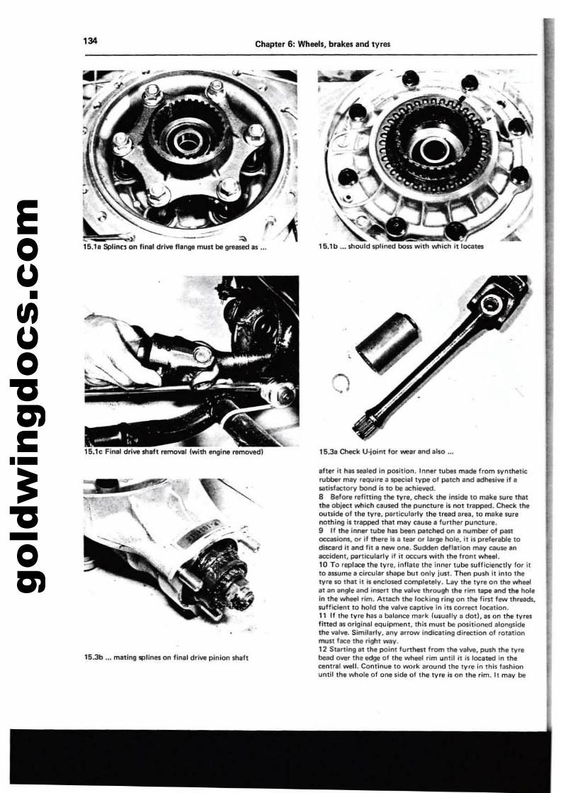
gold
win
gdoc
s.co
m... --,
134 Chapter 6: Wheeb, brakes and tyres
15.1b _•• $hould splined boss with which it tOClltl!S
lS.le Final dri.... $haft removal lwith Il'gir'le removedl
15.3b ... matinlllPlilles on fin"t drive piniOt'l shaft
o
15.3a Check U-joint tor wear and also ...
after it has sealed in position. Inner tubM made from syntheticrubber mllV require a special type 01 patch and adhesive if ill
IIlItisfactory bond is 10 be achieved.8 Before refitting tne tvre, check the inside 10 make JUre thatthe object which caused the puncture is not trapped. Check theoutside of tile Iyr., particularly the tread area, to make surenothing is trapped that may cause a further puncture.9 If Ihe inner lube has been patched on a number of pastoccasions, or if there is. tear or large "ole. il is preferable todiscard it and lit a new one. Sudden dellation may cause anaccidefH, particularly if it occurs with the froni wheel.10 To replace the tyre. inflate the inner tube sufficienclly lor ilto ilssome a circular shape bul only jusi. Then push il into Ih,tvre so thai it is enelO$l!d completely. Lay the lyre on lhe wl\eelat an .ngle and insert the valve through the rim tiIPII and the holein the wheel rim. Attach the lockir>g ring on the Ii",t few threads,suffident to hold Ihe valve caplive in in correct location.11 If the tyre has a balance merk lusuelly iI datI. as on the tyresfltted as original equipment, this mun be positioned alongsidethe vllve. Simil.rly, any arrow ind~tinlldirection of rotationmun face the right Willy.12 Starting at the point lurthest frorn the valve, push Ihe tyrebead over the edge 01 the wheel rim until it is located in thecentral well. Continue to work around the tvre in thiS fuhionuntil the whole of one side of the tyre is on the rim. II may be
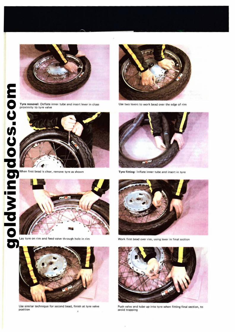
gold
win
gdoc
s.co
m
TVr, ..mo..... l: De'flate inne' tube and insen leve, in clO$t!proximity to tynl valw
When first bead is clear, ,emove lYre as shown
Lav tvre on rim and feed valve through hole in rim
use similar tl!Chnique 10' second bead, linish at lY,e valveposition
Use lwo levers to work bead over !he edge of ,im
Tv,. fining' Inflate inner tube Ind inserl in lYre
Work firS! bead over ,im, using lewr in finll '-1l:tion
Push wive and lube up inlO IV,e when fining final section, to(Nold trapp;"9
gold
win
gdoc
s.co
m136 Chapter 6: Wheels, brakes and tyres
necessary to use 8 tvre lever during the final staQll'll.13 Make sure that there is no pull on the tyre wive and againcommencing with the Irea furthest from the valve, ease the othel'"bead of the lVrll ovar- the edge of the rim. Finish with the ere.dose to the valve. pushing the va.... up into the tvre until thelocking cap touches the rim. This will ensure the inner tube is nottrapped when the last section of the bead is edged over the rimwith II tvre lever.14 Check that the inner tube is not trapped at any point.R.inflate the inner tube end cheek that dw tvr. is seelingcOI"rectly 8fOUnd the wheel rim. Ther. should be 8 thin ribmoulded Bround the wall of the tyre on both sides which shouldbe equidistant from the wtIeel rim at all points. If the tyre isu_nly loeated on the rim, try bouncing the wheel when thetvre is at the feeomrnel'lded pre:s'$ure. It is probable t!\at one of thebeads h.as not pulled clear of the centre well.15 Always run the tyres at the recommended preiSures and neverund.,. or over-inflate. The correct pr8SIUr81 for 1010 ur;e ere givenin the Specification Section of this Chapter. If. pillion passengeris Clrried, increase the rear tyre preuure only as recOlTll'TM'T'lded.16 Tyre replacement is .ided by dusting the siete walls,particularly in the vicinity of the beads, with a liberal coating ofFrench chalk. Washing up liquid Cln also be used to good effect.but this has the disadvantage of caning thi inMr surfaces of thewheel rim to rust.17 Never replace the inner tube and tvre without the rim tape inposition. If this precaution is overlooked there is good chance ofthe ends 01 the spoke nipples chafing the inner tube.nd causing• crop of punctures.18 Never fit .tvre which hes. dameged tread 01'" side wells. Apartfrom the legal aspect., there is a very great risk of b1ow-ovt, whichcan have serious consequel'lCes on any two·wheel vehicle.19 Tyre wives IlIrely give trouble, but it is ,'ways advisable tocheck whether the ....Ive itself is lelIdil'lg befOl'"e nttrlOYing the tv....Do not 10000g&t 10 fit the dust ClIP, which fonns an effective second_I. This is especially important on high performance machineswhare centrifugal force can Cluse the valve insert to retract and the
tvre to deflate witheYt warning.
1 Valve cores Mldom give troubla, but do n.ot liitst indefinitely.Dirt under the seating will cause. puzzling 'slow puocture'. Checkthat Ihey are not leaking by aPPlying spittle to the end of the valvt,and watching lor air bubbles.2 A val"", cap ;s a safety device, end should always be fitted.Apart from keeping dirt out of the valve, it provides a SI!COodseal in case of valve fellure, and may preveot ao accidentresulting from sudeleo dIIflatioo.
18 Front wheel bahlOcing
1 The front wheel should be statically balanced, complete withtvre. An out of balance wheel can produce dangeroul wobblingal high speed.2 Some tyres have balance mark on the sidewall. This must bepo,itioned adjacent to the valve. Eveo $0, the wheel still rlquireJbelaoci09-3 With the front wheel clear of the ground,spio the wheelseveral limes. Each time, it will probably come to rest in the sameposition. Balance WfIighu should be attactMKl di.metricallyopposite tha he8YV spot, until the wheel will oot come to rllIt inany set positioo, when spun.4 Bal.nee weighu, which clip round the spokes, are evailable in5, 10. 01'" 20 gramrnes weight. If they are n.ot available, wire IOlderwlllpped round the spokes end secured with iO$Ulating tape willmake a &ubstitute.5 It il possible to have a wheel dynamically balanced at somedealers. This requires iu removal.6 There is I'lCl oaed to bal.1'ICfI the reer wheel under oormel roadcooditiOflS, although aoy tvre balance mark should be aligned withthe valve.
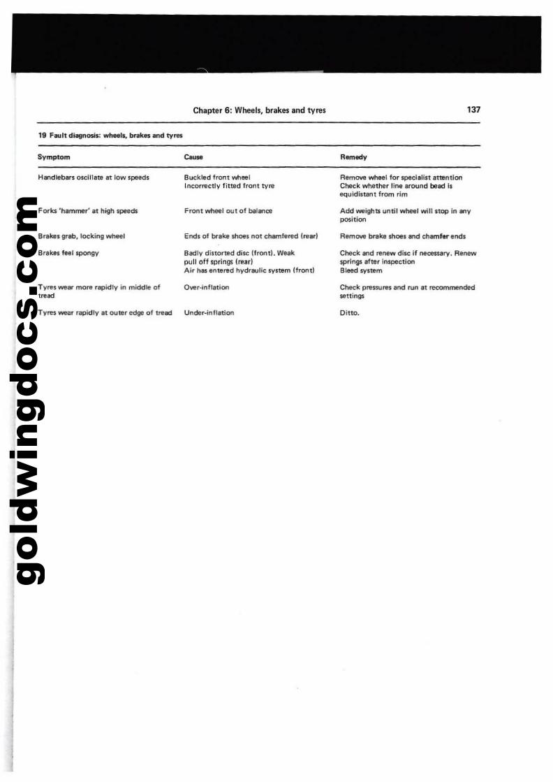
gold
win
gdoc
s.co
m
Chapter 6: Wheels, brakes and tyres
Symptom e.us.
H....dleb.rs oscillate at low speeds Bucklvd front wheelIncorrectly fined front tvre
FOI"ks 'h.mmer' at high $peVds FN;lflt wheel out of bilr....c:e
Brakes grab, locking whee. El'Ids of brake moes not chamfered (rurl
Brakes fNI s.pongy Badly distorted disc !frontl. Weakpull off Iprings lrear)Air hIlS entered hydr&J!ic system (frontl
Tyres wear more rapidly in middle of Owr-inflation,~..Tyres wear rapidly.t outllr edge of tread Under-inflation
137
Remedy
RvmOllll wheel for speci.list .ttentionChvck whether line Ill'ound bead isequidistant from rim
Add weights until wheel will stop in ....ypo,ition
AemOlie bntke shoes 8nd chamfer ends
Check and renew di$C if necessary. Rvnewsprings .fter inspectionBleed system
Ctwck pressurfl and run at reoommendedSElttings
Ditto.
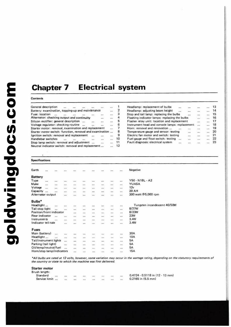
gold
win
gdoc
s.co
m Chapter 7Contents
Electrical system
General description 1Battery: examination, topping-up and mainU!nance 2Fuse: location 3Alternator: checking output and continuity 4Silicon rectifier: general dellCription 5Voltaga regulator: checking routine 6StMler motor: remoual, axamirtation and replacement 7Starter motor switch: function, ntmoval and examination ... 8Ignition switch: removal and ItIplacement 9H¥ldlebar $Witches 10Stop lamp switch: nImOII.....d Idjustment 1 tNeutral indicator $Witch: remoual ....d replacement ... 12
Specifications
Batteryl'vpeMakeVoltageCapocityAlternator output
Bulbs"Haacllight ...Tail stop lightPosition/front indicalorAeBl" indicatorInstrumenllIndicator tell·tale
F,,",Main (battery)Headlight ...Tail/instrument lightsParkinlilltail light!Oil/temp/neutral/fuelHom/stop lamp/indicaton
Headlamp: replacement of bulbsHeadlamp: adjustiM beam heightStop..,d laillamp: replacing the bulbsFlashing indicator lamps: replacing the bulbsFlasher relav unit: location and replacementInsuument head and console 18ITlps: replacementHom: removal8lld ItInOYation ...Temperature gauge and sensor: testingElecuic fan motor and switch: testingFuel gauge and flGilt switch: UlstinlilFault diagnosis: elecuical svstem
NegatM
Y50· N18L· A2YUASA
""20AH300 watt@5,OOOrpm
Tungsten incandesoent 40/5ClW8127W812""2""3.4W3.4W
30A".SASASA15.
131415
"17
",.20
"2223
-All bulbs ilte rIIted at '2 volts. however. some ~arilltion may occur in the watrage raring. de~ndingon rhtl staturory requitements oftM counrry or stare to which rM mM:hi_ was finr dtliwued.
Starter motorBrush length:
StandardService limit
0.4724·0.5118 in 112·13 mm)0.2165 in (5.5 mm)
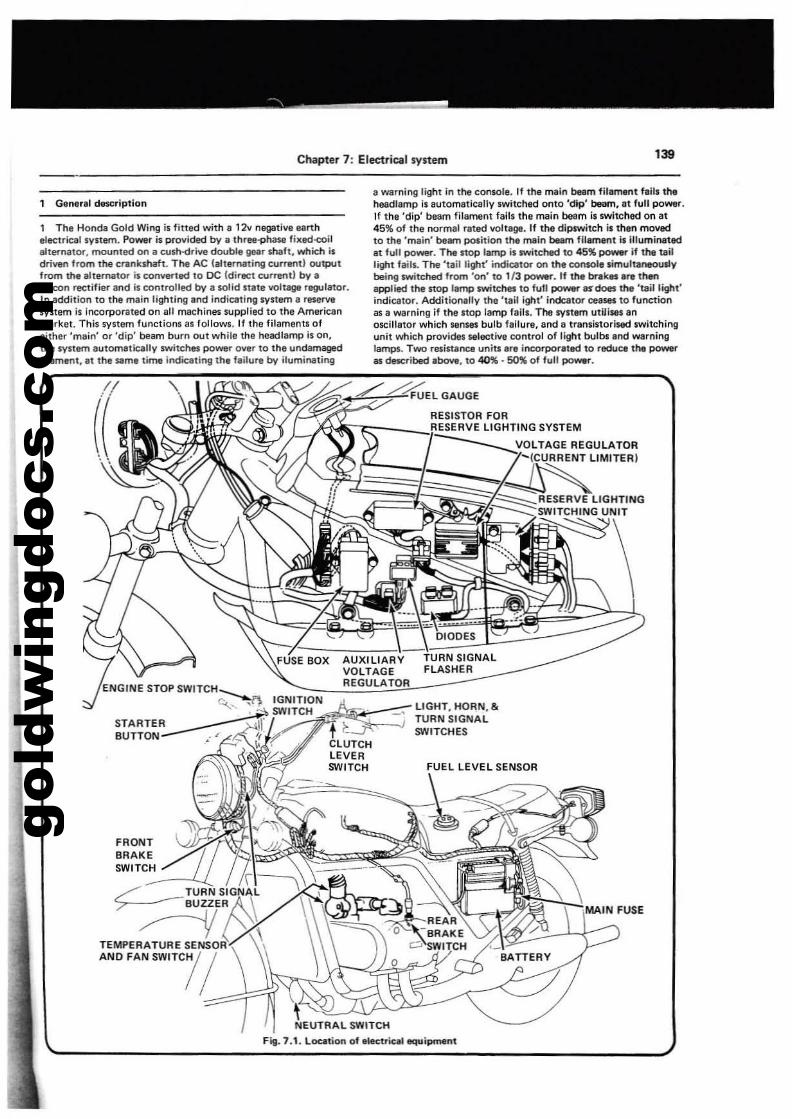
gold
win
gdoc
s.co
m
Chapter 7: Electrical system 139
1 Gener.1 description
, The Honda Gold Wing is fiUed with. , 2v negativi earthelectrical system. Power;s provided by I thrl8'9hase fiKedo<:oilIl1ernalor, mounted on a cush-drive double gear sheh, which isdriven from the crankshaft. The AC (alternating cur.."t1 outputfrom the ,llIrnator is cO~led to DC IdirllCt curlWltJ by.silicon rectifier and is controlled by a $GIid stale voltage regulator.In addition to tha main lighting and indicating system a reservesystem is incorporated on aU machines supplied to the Americanmarket. This system functions 81 follows. If the filaments ofeither 'main' or 'dip' beiHTl bum out while the head lamp is on,the system autom8lically switches power over to the undamagedfilament, at the Slme time inclicating the f.ilur. by iluminating
a WlIrning light in the cOf'Isole. If the main beem filament fail. theheadlamp is automatically switched onto 'dip' beam,lt full poWllr.If the 'dip' beam filament fails the main beam is switched on at45% of the normll rlted volt•. If the dipswitch is then movedto thl 'mlin' beam position tM main beam filament is illuminatedIt full power. The stop lamp is switched to 45" po_If the tilillight taHs. The 'tlil light' indicator on the console simultaneouslybeing switched from '00' to 1/3 ~r_ If the braklll ere thenapplied the stop lamp switchet to fui! po-. III' does the 'taillighl'indicator. Additionally the 'Ulil igllt' indcator ceases to functionas a WlIrning if thl stop lamp falls. The systlm utilises Inoscillator which senses bulb failure, and a transistorised switchingunit which provides selective control of light bulblland warninglamps. Two res;sunce unitJ; ar. incorporated to reduce the poweras desc:ribed above, to 40%.50% of full power.
":~~rtf~~;;::::::-:.;LIGHT, HORN, &.. TURN SIGNALt t SWITCHESCLUTCHLEVERSWITCH
\!EUTRAl SWITCH
Fig. 7.1. Location of elect,iu1 equipment
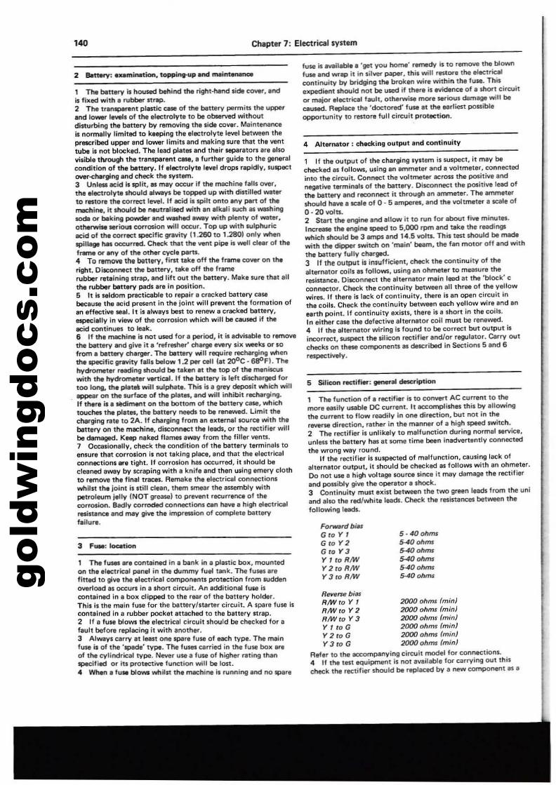
gold
win
gdoc
s.co
m140 Chapter 7: Electrical system
5 Silicon rac1ifi8l": genaraI dascription
4 Alternator: checking output and continuity
5 - 40 ohms5-40 ohms....oh_
5-40 ohms5-40 ohms5-40 ohms
Fo~rrJbiM
G ro Y 1G to Y2Gro Y3YltoR/WY2roRiWY3fOR/W
1 Tha function of a rectifier is to collV'lrt AC current to themore &llsily ulllb/e DC current. 't accomplishes this by allowingthe C\Irrent to flow readily in one dire<:tion, but not in thareverse direction, rather in the manner of a high speed switch.2 The re<:tifier is unlikely to melfunction during normal service,unless the battery has at some time been inadvenently connectedthe wrong way round,
II the rectifier is suspected of malfunction, causing lack ofalternator output, it should be checked as follows with en ohmeter.Do not use a high voltage source since it may damage the rectifierand possibly giV1l the operator a sl'lock.3 Continuity must exist between the tWQ green leads from the uniand also the red/white leads. Check the resistances between thefollowing leads.
Re~'ffe biesR/W fa Y , 2000 ohms (min)RM'ro Y 2 2000 ohms (min)RM'to Y 3 2000 ohms (min)Y I to G 2000 ohms (min)Y 2 fO G 2000 ohms (minIY 3 to G 2000 ohms (minI
Refer to lhe accompanying circuit model for connections.4 If tl'le tast equipment is not available fOt carrying out thischeck the rectifier should b8 replaced by a new component 81 •
1 If the output of the charging syltem is suspect, it may bechecked al follows, using an ammeter and a voltmeter, connectedinto the circuit. Connect the voltmeter acrO$! tha positiva andnegative terminals of the battery. Disconnect the positive lead ofthe battery and reconnect it through an ammeter. The amm8lershould have a scale of 0 - 5 amperes. and the voltmeter a scale of0- 20 voln.2 Start tM engine and allow it 10 run for about five minutes.IllCT'east tM tngine speed to 5,000 rpm and take the readingswhich should be 3 amps and 14.51101tl. This test should be madewith the dipper switch on 'mein' beam. the fan motor off and withthe battery fully cl\lltged.3 If the outpUt is insufficient, check the continuity of thealternator coils as follows, using an ohmeter to measure theresistanca, Disconnect the alternator main lead at the 'block' cconnector, Che<:k the continuity between all three of the yellowwin». If there is lack of continuity, there is an open circuit inthe coils. Check the continuity betwllen each yellow wire and aneanh point. If continuity exislli, thera is a short in the coils.In either Cll$I the defective alternator coil must be renewed.4 If the alternator wiring is found to be conlCt but output ilincorrect.suspect the silicon rectifier and/or regulator. earry outcheckl on these componenU al described in Sections 5 and 6respectively.
fuse is mil,bl•• 'get you home" remedy is to remOlle the blownfl.lSe and _.., 11 in silver paper, this will restore the .lllCuicalcontil'lol.lity by bridging the broken wire within the fuse. Thisupedianl shoold IHlt be used if th.re is lI'Yidence of • short circuitor major electrical tault. otherwiMl rnOO'e serious damage will becaused. Replace the 'doctored' fuse" Ihe earliest pcluibleopportunity 10 restore full circuit protection.
1 The fu$8S are contained in a bank in a plartic box, mountedon the electrical panel in the dummy fual tank. The fusts arefittad to giva the electrical cornponenll protection from suddenowrload as occurs in a shon circuit. An additional fuse iscontained In a box clipped to the rear of the battery holder.This il the main fuse for the batterY!ltarter circuit, A spare fU$EI iscontained In a rubber pockat attached to the battery strap.2 If a fuse blows the electrical circuit should be checked for afault before replacing it with another,3 Always carry at least one spare fuse of each type. The mainfuse" of the 'spilde' type. Tf\e fuses carried in the fuse box areof the cylindrical type. Never use a fuse of higher rating thanspecified or its protKtive function will be lOS!.4 Whan a fusa blows wtliln tha machine is running and no spar.
1 n. bettltfY Is noused behind Ihe right.fland $ide COV'Ir. andis fixed with. T\lbtlolw $trap.2 The tranlpllrent pll1l$tic case of the blIttery permits the upperand lower tevels of II'Ie electrolyte to be observed withOUtdisturbing the battery by removing the side cover. Maintenenc:eis normally limitlld to keeping the electrolyte levt!1 bet_n theprMCribed upper and lower limitl end making sure that ttle venttube Is not blocked. The lead plates end their separators are alsovisible through the 11l1nsparent ClIHi. II further guide to the generalcondition of the bettltry. If electrolyte level drops rapidly, IUspectOYeT'-<:harlling and check thoe SYltem.3 Unl_ acid is split, lIS may occur if the machine faUI OYer,the electrolyte lnould alW!lyI be topped up with distilled WIlt,rto rtltor, tM correct level. If ecid il spilt onto any pan of tMmachine, it lhould be neutralised with an ,lkali such 81 weshi~
sodI 01" biking~r and _hed.-y with plenty of WIlier,
otnerwistl serious cOlTD5ion will OCC\lr. Top up with sulphuricecid of th, correct specific gnYity 11.260 to 1.2801 only whenspil ...... occurred. Check that the vent pipe is well clear of theframe Ot any of the other cycla pam.4 To remove the battery. Ii"t take off the frame cover on th.right. Disconnect the battery, take off the framerubber r.talning Itrap, and lift out the bettery. Make sure that allthe rubber bettery pads are in position.5 It is seldom practicabla to repair a cracked battery casebecause the ac::id present in the lolnt will prevent the formation ofan effective leal. It il always belt to renew a cracked bettery,especially in view of the corrolion which wilt be caused if theecid contlnuas to leak.6 If th, machine il not used for a period, it is advisable to removethe bettery and give it a 'refresher' charge every silt weeks or 10
from a b8nery dtarge\". The !Jettery will rllqUire rechargi~ whenthe specific gR'Vity falls below 1.2 per cell lat ~C • ~FI. Thehydrometar readi~ should be taken at the top of tM meniscuswith the hydrometer vertical. If the beltery is left discharged fortoo long, th, plata wilt sulphata. Thil is a grey deposit which willappear on tM surf_ of the plates, and will inhibit rtlCharging.If thare isa Melimant on the bottom of the benery cue, wtlichtouches tha plat.., the battery neads to be rentlYlfed. Limit thechal'ging rata to 2A. If cnarginll from an elttemallOurca with thebettery on the machine. disconnect tM leads, or the rectifier willbe damaged. Kaep naked flamel aWlly from the filler I19nll.7 Occallonally, check the condition of the battary terminall toensure that corrosion is not laking place, and that the electricalconnectionl ere tight. If corrosion hal occurred, it should becleaned aWllY by scraping with a knife lind then using emery clothto remove the final traces. Remake tM electrical connectionswhilst tha joint is still clean, them smear the as.sembly withpetroleum jalty (NOT greMell0 prevent recurrence of thecorrosion. Badly corroded connectionl can have a high elaetricalre$isUinca and may give tha impression of complete batteryfailure.
3 F...: location
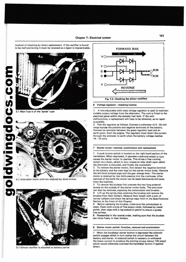
gold
win
gdoc
s.co
m
Chapter 7: Electrical system
method of checking by direct replacarnent. If the rectifier is foundto be malfunctioning it must be reneW1ld as a repair is impracticable. FORWARD BIAS
141
4.1 Alternator sUitor tOils ere reteined by three screws
5.1 Silicon rectifier is attached to bettery carrier
v====!JREVERSE
<;'=~'~I':2's:i-"t~r:::=':''~*i!::-:ll·aFig. 7.2. ChKking1tM silicon rKtifiers
6 Voluge ~ator ; th.dling routine
1 A non·adjustable solid state voltege regulator is used to maint.ina nable OUtpUt voltage from the alternator. The unll is fitted to theelectrical ponel within the dummy fuel tank. If the unitmalfunctions. a replacement will have to be obtained, l1li no repairIs possible.2 Test the regulator lIS follows. Connect a lIoltmeter of 0 - 20 lIoltrange aceross the poslti~ and negative terminall of the battery.Connect an ammet.r between the green reguletor lead and anearth point. Start the engine. Th. rllllUlator must dl~rt the currentthrough the ammeter to earth when the bettery IIOIlage reac:hn14. 15 volts.
7 Starter" motor; removal, .xamlnatlon and repl_mant
1 A PtJsh button switch il located on the right-hand section of thehandlebars. When depressed. it Qpef1Ites a solenoid wllic;h in turncauses the starter motor to operate. This dr;IIU. free runningclutch lila a chain, v.tlich in turn rOtltes an idler shaft upon whichthe alternator is mounted, and finally the crankshaft..2 To remove the starter motor, first del«:h the I'IoI93tllle termin.lat the battery and th, mllin lead on the stllrter motor body. RemOllethe left-hand uhaust pipe .nd the gellr chllnge I,~r. The startermotor is retained by two bolu passing into the crankcasa. Aft,rremowl of the bolu the motor tan be eased bec:kwllrdland_avfrom the machine.3 To remOlle the brushes first unscrew the two long externalscrews on the outside of the stlrter motor body. The end cOlIercan th,n be relTlOlled. exposing the commutator and brUshel .4 Lift up the spring clips retaining the brushes and remOlle thebrushes from their holders. Mealure their length with a pair ofvernier calipers and check the sanrice wear limit in tl\l SpecificationsSection.t the front of thil Chapter,5 Belore replacing the brushes. make sure the commutator isclean. Clean WIth a strip of fina Itmlry cloth, followed by matalpolish, then wipe with a rag IOIIked in petrol to aNYre. 91'"'"free surface.6 Reassemble in the rllWr'II order, making sura that thl brushescan rtlOIIe fr.ly in thair holds...
8 Starter motor switch; function. ramoYal.nd aXiminlltion
1 When the handlebar starter button is depraSS&d the IIOhtnoidswitch engages which in turn makllth, circuit ba~n thebiluery and start.r. A soIlf'1oid switch il flICIMry 10 withstandthe heallY current to produce Ihe st.nil'lSl torque (about 12O.mpslwhich would otherwise Ollerload the handlebar" button If applieddirect.
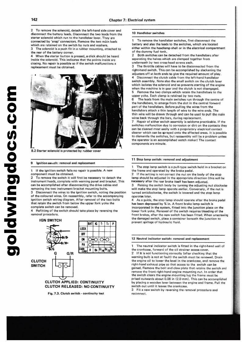
gold
win
gdoc
s.co
m142 Chapter 7: Electrical system
2 To remove the solenoid, detach the left-hand side cover anddisconnect the battery leads, Disconnect the two leads from theS1arter solenoid which run to the handlebar lever. They areconnected by 'snap' connectors. Remove the two main leadswhich afe retained on the switch by nuts and washers.3 The solenoid is a push fit in a rubber mounting, attached tothe rear of the battery corner.4 When the starter button is pressed, a click should be heardinside the solenoid. This indicates that the points inside areclosing. NQ repair is possible so if the switch malfunttions areplacement must be obtained.
8.2 Saner SOlenoid is protected by rubber cover
10 Handlebar switches
1 To remove the handlebar switches, first diseonnecttheballery and also the leads to the switches, which are locatedeither within the headlamp shell or in the alectrical compartmantof the dummy fuel tank.2 Both switches can be detached from the handlebars afterseparating Ihe halves which are clamped together fromunderneath by two cross-head screws each.3 The throttle cables will have to be disconnected from theright-hand switch. This can be accomplished by slackening theadjuste", off at both ends to give the required amount of play.4 Disconnect the clutch cable from the left-hand handlebarswitch assembly. Note also the small switch on the clutch leverwhich isolates the solenoid and so prevents starting of the enginewhen the machine is in gear and the clutch ;s not disengaged.5 Remove the two clamps which retain the handlebars to theupper yoke. Each clamp is retained by two nuts.e The leads from the main switChes run through the centre ofthe handlebars, to emerge from the slot in the central forwardpart of the handlebars. Before pulling the wires from thehandlebars attach a thin length of wire to the wire ends. Thethin wire will be drawn through and can be used to pull the mainwires back through the bars, during replacement.7 Repair of either switch assembly is seldome practicable. If theswitches malfunction due to corrosion or dirt on the COnlaCIS theycan be cleaned most easily with 8 proprietary electrical contactcleaner which can be sprayed onto the affected areas. It is possibleto dismantle Ihe switches, but reassembly will be a problem unlessthe operator is an accomplished watch maker! The contactcomponents are minute.
9 IgnitionswHch: removal and replacement11 Stop lamp switch: removal and adjustment
Fig. 7.3. Clutch switch - continuity test
CLUTCH APPLIED: CONTINUITYCLUTCH RELEASED: NO CONTINUITY
1 If the ignition switch fails no repair is possible. A newcomponent must be obtained.2 To remove the switch it will first be necessary to detach theinstrument heads, complete with warning panel and bracket. Thiscan be SCl:omplished after disconnecting the drive cables andremoving the two instrument bracket mounting bolts.3 Disconnect the wires to the ignition switch, noting the positionof the coloured wires. On reassembly, refer to the accompanyingignition switch wiring diagram. After removal of the two boltsthat retain the switch from below the upper fork yoke thecomplete switCh can be removed.4 Refitting of the switch should take place by reversing theremoval procedure.
12 Neutral intlicator switch: removal and replacement
1 The neutral indicator switch is filted in the right-hand wall 01the crankcase. forward of the oil strainer access cover.2 If It is not functioning correctly (after checking that thewarning bulb is not at fault) the switch must be renewed. Drainthe engine oil to lower the level in the crankcase. and remove theright-hand exhaust pipe so that access to the switch can begained. Remove the bolt and claw plate that retains the switch andremove the front right-hand engine mounting nut. 1I' order thatthe switch clears the engine mounting lug the frame must beprised outwards about 0.08 in (2.0 mml. This can be accomplishedby placing a wooden lever between the engine and frame. Pull theswitch out until it leaves the crankcase.3 Fit a new switch by reversing the removal procedure andreconnect.
t The stop lamp switCh is a pull·type switch held in a bracket onthe frame and operated by the brake peda1.2 If the setting is not correct the nut on the body of the stoplamp should be adjusted in the appropriate direction \this will benecessary after the rear brake itself has been adjusted.3 Raising the switch body by turning the adjusting nut clockwisewill make the stop lamp operate earlier. Conversely, if the nut isturned anticlockwise, the switch is lowered and the stop lampOPerates later.4 As a guide, the stop lamp should ooerate after the brake pedalhas been depressed by % in. A front brake lamp switch isincorporated {n the system, fined into the junction piece on thelower fork yoke. Renewal of the switch requires bleeding of thefront brakes, after the new switch has been fitted. When unscrewil"l;lthe damaged switch, place a container beneath the junction toprevent spillage of hvdraulic fluid.BAT • 1, 1, P
LOC,
m..PA
lC~lcN R .. 8~w 8r/8 8r/G
IGN SWITCH
CLUTCHSWITCH
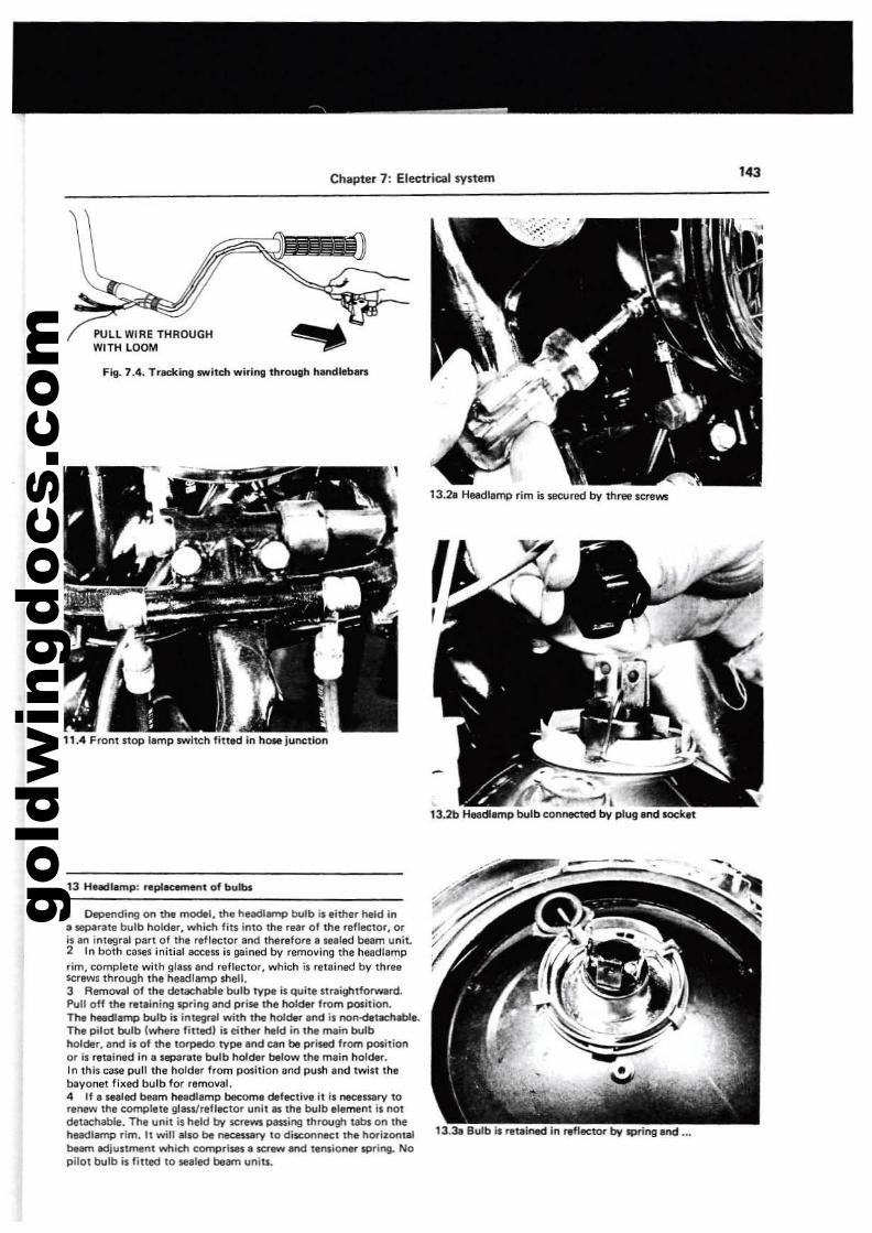
gold
win
gdoc
s.co
m
Chapter 7: Electrical system 143
<13.28 HEllIdlamp rim is secured by three screws
Fig. 7.4. Tracking switch wiring through handlebars
PULL WIRE THROUGHWITH LOOM
11.4 Front stop lamp switch fitted in hOle junction
13 HBadlamp: repl.cement of bulbs
1 Depending on the model, the headlarnp bulb is either held in3 separate bulb holder, which fits into the rear of the reflector, oris an intagral part of the refleclOr and therefore a sealed beam unit.2 In both cases initial access is gained by removing the headlamprim, complete with glass and reflector, which is ratained bv threescrews through the headlamp shell.3 Removal of the detachable bulb type i$ quitllitraightforward.Pull off the ra\.tining spring ,lfId prise the holder from position.The heedlamp bulb is integral with the holder and is non-detllChable.The pilot bulb lwhere filledl ;s either Iwld in the main bulbholder, and is of the torpedo type and c.n be prisecf from pot.itionor;$ relllined in a separate bulb holder below the main holder.In this case pull the holder from position lind push Ind twist thebayonet fixed bulb for removal.4 If I sealed beam headlamp become defective it is necessary torenew the complete glass/reflector unit ill the bulb element is notdetachable. The unit i$ held by SCfllWll passing through tabs on thehe.adlamp rim. It win also be necasserv to di$COflrleCt the hori~ontal 13.38 Bulb is ..uined in ..fl«tor by spring and ...beam adjustment which comprises a screw and tensioner spring.. Nopilot bulb is fitled to Slaled beam ullits.
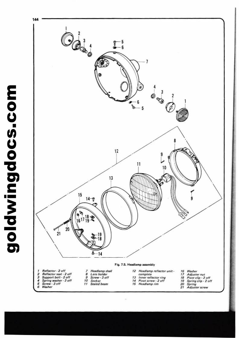
gold
win
gdoc
s.co
m'44
./
, RefJ«ror - 2 off2 RefltN;tor ~fUJt· 2 off3 Support bolt· 2 of(4 Spring washsr· 2 off5 .scfllW· 3 off6 w..he,
1 HilMi/amp IMIB Lel/s holdtt,9 $crew-30"
70 Socket11 SfMled Nllm
12 HeadfMnp nfl«ror unit·compl"tll
73 Inner r.f/ecrOT ring14 Pivot screw· 2 off15 Heed/limp rim
16 W.sher" Adjust", nut18 Pivot clip. 2 off19 Springc/ip-2off20 Spring21 Adjusterscrew
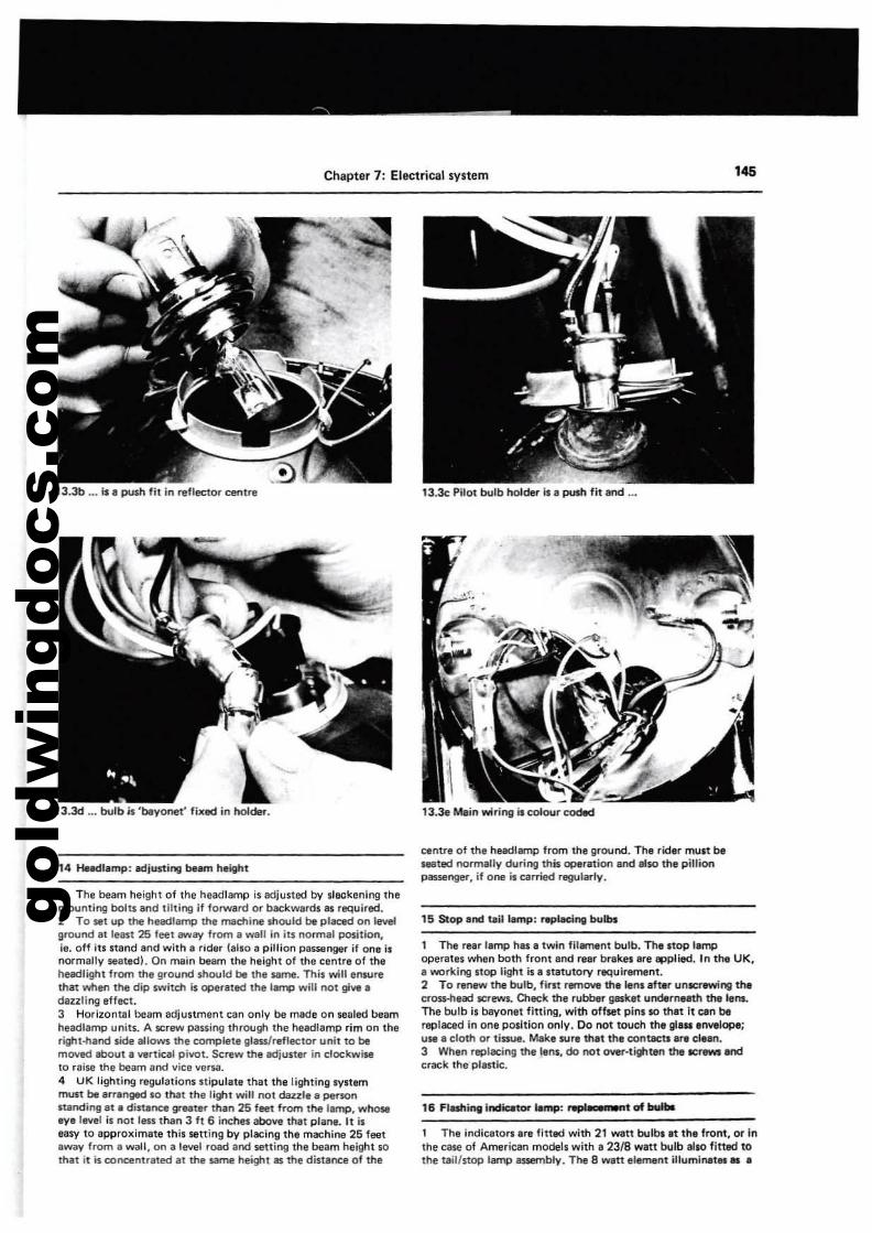
gold
win
gdoc
s.co
m
Chapter 7: Electrical system 145
13.3b .•. Is" push fit in reflector centre
13.3d ... bulb Is 'blyonet' fixlld in holdel'.
14 Heedl"mp: illdjll$ting bnm h~ight
, The beam height of the headlamp is adjusted by sleck~nlng lh~
mounting bolu and tilting if forward or backwards 8$ required.2 To.t up the h~iKlramp the rMctline should be placed on levelground al least 25 feet illWiIl/ from a wall in its normal position,ie. off ill stand and with a rider (also a pillion pas$llnger if one i.normally seated). On lTI8in beam the height of the centre of theheadlight from the ground should be the same. This will ensurethat when the dip switctl Is operated the IBnlCl will not 9\111 adazzling effect.3 Horizontal beam adjunment can only be made on sealed beamheadlamp units. A $Crew passing through the headlamp rim on theright-hand side allows the complete grass/reflector unit to bemoved about a Vllrtical pivot. Sc:rew the "iust~ in clockwiseto reise the beam and vice ver1oil.4 UK lighting regulations stipulate that the lightinlllystemmust be 8IT8nged so that the light will not dazzle" personstanding ill! "distance greater than 25 f.t from the lamp, whoseeye level is not leu than 3 ft 6 inches above that plane. Itlseasy to approximate thil setting by placing the machine 25 feetawav from • wall, on I level road and $titling the beam height sothat it is concentrated at the same heigtttlS the distance of the
13.3c Pilot bulb holder II a puIh fit and ...
13.3e Mlin wiring iseolour cod8d
centre 01 the headlamp from the ground. The rid.,. mUlt beseated normally during this operation and _so the piUtonplSlenger, if one is carried regularly.
15 Slop.nd taill.mp: rwplaci"ll bulbs
1 The rear lamp h81 a twin fil8lTMlnt bulb. 1lMIitop I.mpoperat" when both front and reer brakel are epplied. In the UK,a working Itop light is a statutory requirement.2 To renew the bulb, first rwnove ttI,lensaft,r unlCfl'Wing theer~ead screws. Check the rubber gaket underneath the lens.The bulb il bayonet fitting, with off$et pins SO that It cen bereplaced in one position only. 00 not touch the glul envelope;use a cloth Of tiaue. Make sure thet the contlctll are eleen.3 When replacing the lens, do not OYer·tighten the ICrewt andcrack the·plestie.
16 Flashing indatof lamp: Apli CI n..,t of bultIe
1 The indicators are litted with 21 Wilt bulbi It the front, or inthe CiH8 of American modell with. 2318 watt bulb also fitted tothe tail/stop lamp I$$efTlbly. The 8 watt element illuminat.... a
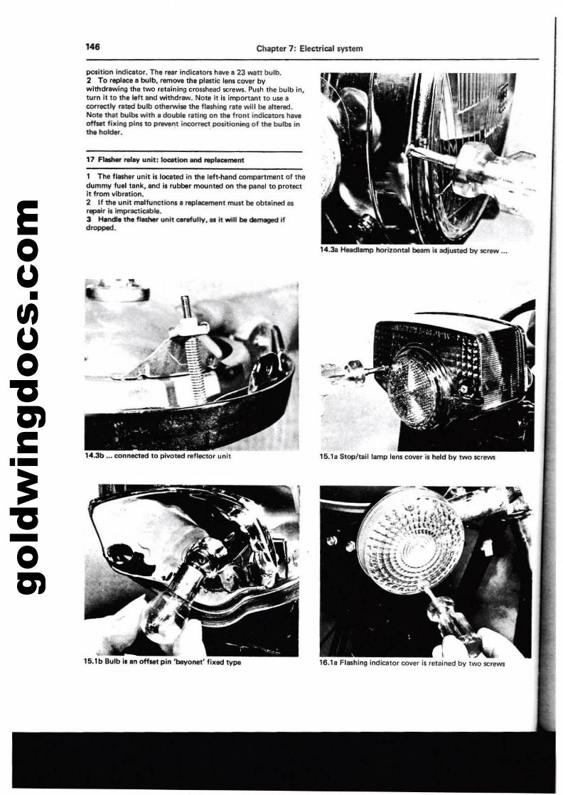
gold
win
gdoc
s.co
m'46 Chapter 7: Electrical system
position indicator. The rear indicato.. have a 23 watt bulb.2 To replace a bulb, remove the plastk: lens cover bywithdrawing the two reuining cros$head scram. Push the bulb in,tUfn it to the left and withdrew. Notl it is imponan! to use Icorrectly IlIted blJlb otherwise the flashing rate will be altered.Note that bulbs with. double fating on the front indicators haveoffill! fixing pins to prevent iOC:OffeCt positioning of the bulbs inthe hold«.
17 F..... ~r( unit: location and NplK.ment
1 The flasher unit is located in the left-hand compartment of thedummy fuel tllnk, find it rubber moonteel on the panel to protectit from vibration.2 If the unit malfunctions a replaeement ITMlSt be obuined asrepair I, impracticable.3 HWldle the f1al'lM unit c.refully.as tt will be dlfTYgKl ifd_.
1•.3b ... conneetad to pivoted r.flector unit
15.1b Bulb i. an OffMt pin 'beyonet' flllfllCl type
14.3a Headlllmp horizonUiI beam is adjuned by ICrlW ...
16.1a Stop/tail lamp lanl cover is hald by two scraws
I16.1a Flashing iooicator cover is retained by two screws
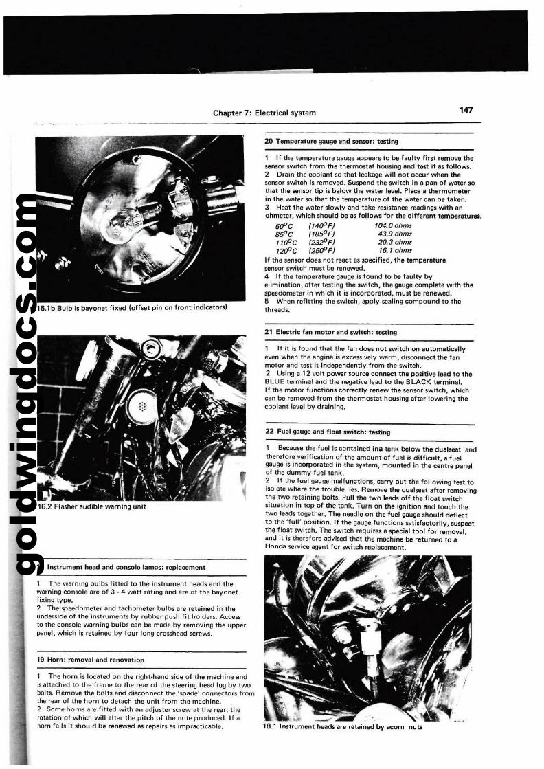
gold
win
gdoc
s.co
m
Chapter 7: Electrical system '47
16.1 b Bulb is bayonet fixed (offset pin On front indicators)
20 Temperature gauge and sensor: t8$tiog
1 If the temperature gauge appears to be faulty first remove thesensor switch from the thermostat housing and test if as follows.2 Drain the coolant so that leakage will nOt occur when theSenSor switch is removed. Suspend the switch in a pan of water sothat the sensor tip is below the water level. Pl8Cll a thermometerin the water so that the temperature of the water can be taken.3 Heat the water slowly and take resistance readings with anohmeter, Which should be as follows for the different temperetu....,
6d'C (14d'F) 104.0 ohmssSOC (lSSOFJ 43.9 ohms"fPC (23;!JF) 20.3 ohms12fPC (25r:f'F) 16.' ohms
If the sensor does not relICt as specified. the temperaturesensor switCh must be renewed.4 If the temperature gauge i$ found to be faulty byelimination, after testing the switch, the gauge complete with thespeedometer in which it is incorporated, must be renewed.5 When refilling the SWitch, apply sealing compound to thethreads.
"""
1 Because the fuel is contained ina tank below the duelseat andtherefore verification of the amount of fuel is difficult, a fuelgauge is incorporaled in the system, mounted in the centre panelof the dummy fuel tank.2 If the fuel gauge malfunctions, carry out the following test toisolate where the trouble lies. Remove the dualseat after removingthe two retaining bolts. Pull the two leads off the float switChsituation in top of the tank. Turn on the ignition and touch thetwo leads together. The needle on the fuel gauge should deflectto the 'full' position. If the gauge functions satisfactorily, suspectthe float switCh. The switch requires a special tool for removal,and it is therefore advised that the machine be returned to aHonda service agent for switch repl8Cllment.--
21 Electric fan motor and switch: testing
1 If it is found that the fan does not switch on automaticallyeven when the engine is excessively warm, dis<:onnect the fanmotor end test il independently from the switch.2 Using a 12 volt power source connect the positive lead to theBLUE terminel and the negative lead to the 8LACK terminal.If the motor functions correctly renew the sensor switch, whichcan be removed trom the thermostat housing alter lowering thecoolant level by draining,
22 Fuel gaU9Et and float switch: testing
1 The horn is focated on the right·hand side of the machine andis attaChed to the frame to the rear of the steering head lug by twobolts. Remove the bolts and disconnect the 'spade' connectors fromthe rear of the horn to detach the unit from the machine.2 Some horns are filled with an adjuster screw at the rear, therotation of which will alter the pitch of the note produced. If ahorn fails it $hould be renewed as repairs as impracticable, 18.1
I The warning bulbs filled to the instrument heads and thewarning console are of 3 - 4 watt rating and are of the bayonetfixing type.2 The speedometer and tachometer bulbs are retained in theunderside of the instruments by rubber push fit holders. Ac<:essto the console warning bulbs can be made by removing the upperpanel, whiCh is retained by four long crosshead screws.
16.2 Flasher audible warning unit
19 Horn: removal and renovatiOfl
18 Instrument head and consolll lamps; replacement
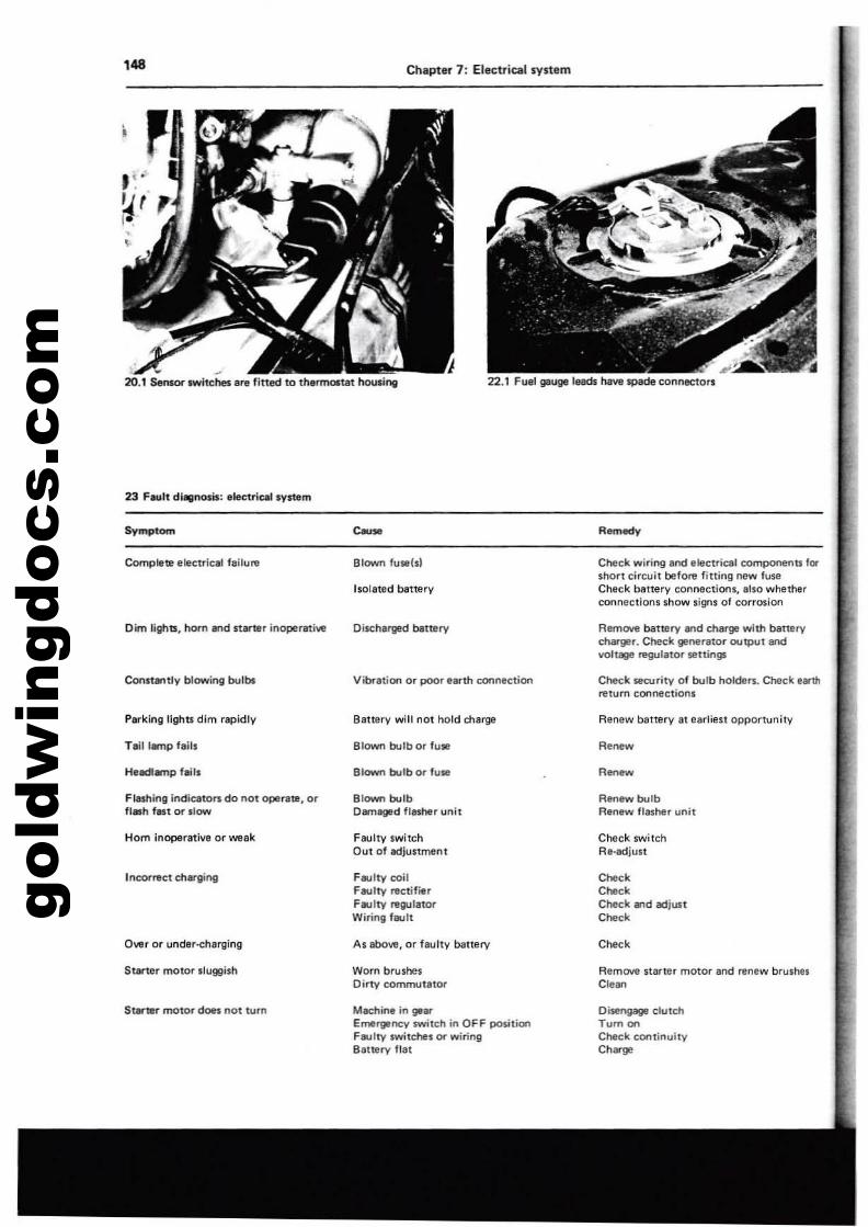
gold
win
gdoc
s.co
m,..
~.
20.1 Sensor switches Ir. litted to thermoltat hou,il'lll
23 F-..lt dl,,"otis: electric:fllsystem
Symptom
Chapter 7: Electrical system
Complete electriclll fallu",
Dim lights, hom and starter inoperative
Conftantly blowing bulbs
Parking lighu dim rapidly
TltillMTlp tail.
HUdlamp bill
Flashing indicato~ do not operate, orflash fast or IlOYlf
Hom inoperative or weak
Incon'eet charging
Owr or under-<:hBllling
SUlrter motor sluggish
StarQlr motor does not tum
Blown fuwls}
Isolated battery
Discharged battery
Vibration or poor terth connection
8attllry will not hold charge
Blown bulb or fuse
Blown bulb or fu.
Blown bulbDamll!Jllld flasher unit
Faulty switchOut of adjustment
Faulty coilf"'-llty rectifillrFaulty regulatorWiring farlt
As above, or IlIUlty bauery
Worn brushesDirty comlTMJtator
Machine in gearEmergency switch in OFF positionFaulty switches or wiringBattery lIat
Check wiring and electrical componenu fe:.short circuit before 'itting new luseCheck battery connection., also whetherconnections show signs of corrosion
Remove battery lind charge with banerycharger. Cheek generator outPut andvoll. I1!'gUlalOr settings
CMck RCUrity of bulb holders. Check earltln!turn connections
Renew battery at earliest opportunity
Renew
Renew bulbRenew flasher un,t
Check switchRe-lIdjuu
CheckCheckCheck .,d adjunCheck
Check
Remove starter mOtor lHld renew brushesClean
Di$tngage clutchTum oroCheck continuityCharge
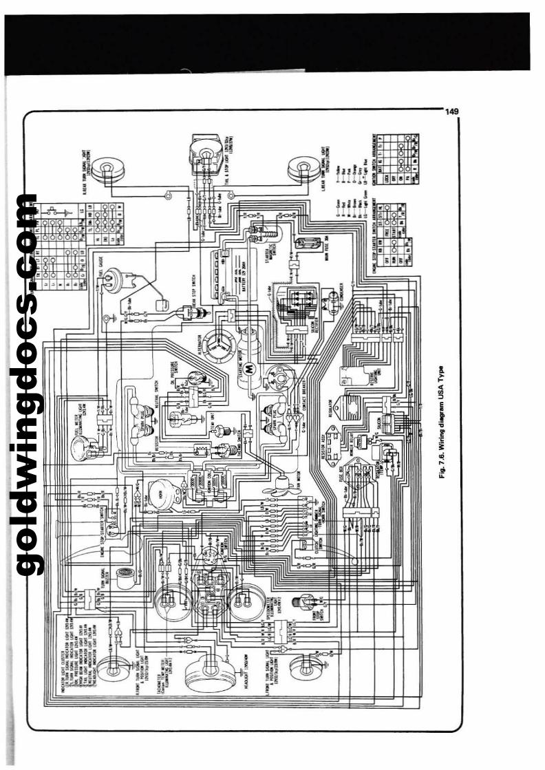
gold
win
gdoc
s.co
m
_----------------------'49
!
!II,,••• •I"tn - .
lll!l'l - ! ...
IWl!i l
•
•
l>~
! •0!
,• I!• - "'0 r• "• ~•
~~
,;'•
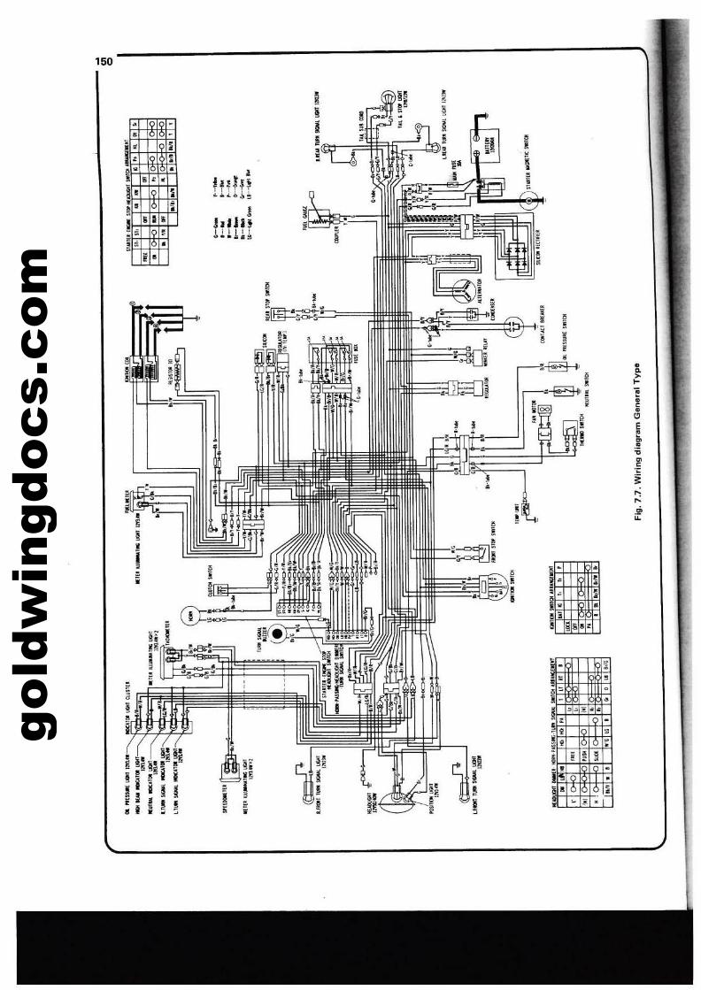
gold
win
gdoc
s.co
m
I,•
"~li,
"' •I, •j , ! III ..
•II ,. ~! • ,•!
•hdnHUH
I
!lUll
I..i~
~ •,•
,;
I •,•i,,i
::; i J 15L ~L .::; i·
150
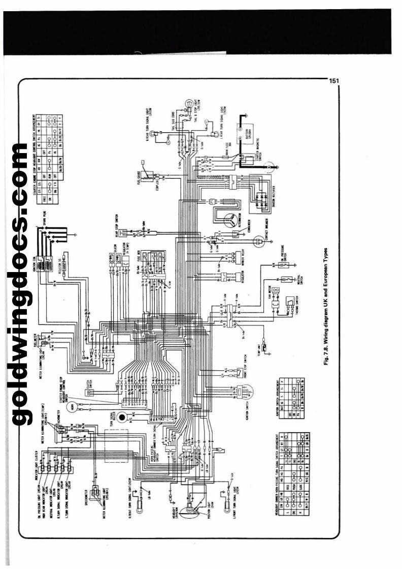
gold
win
gdoc
s.co
m
151
!fw
I....
i1
,I
•
I~i
·0 .
I~
•
i a
~ 5.r..
0' I
I Ii I l
i ~ ::0 • I
•0"j 0,.,,.;- .
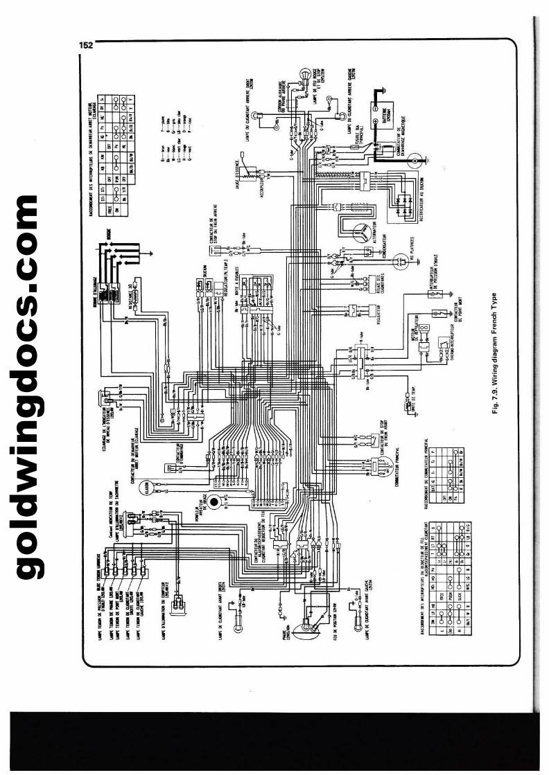
gold
win
gdoc
s.co
m
I
••o
i•
I
ro
fI I- .io
j
io.
I;~,*'==
I
~.
I
I!
!I :!L,
" ' •I' •: Ii .: o!
!' II' Ii ;; J ;;ii :>
I ' :i·
152-----
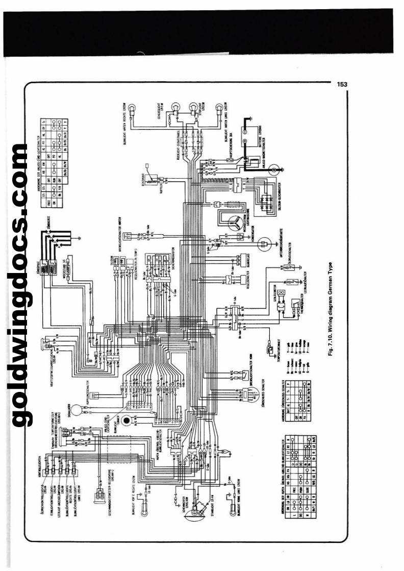
gold
win
gdoc
s.co
m
153
I
i;; .I~[:!:'==
I
!
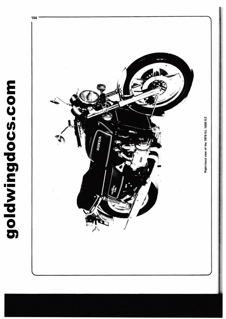
gold
win
gdoc
s.co
m154-------...
N•
.1•)•••
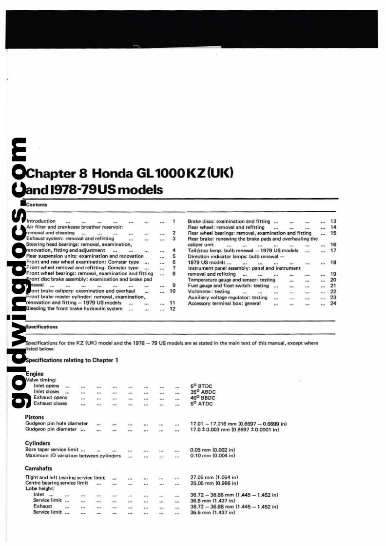
gold
win
gdoc
s.co
m
Chapter 8 Honda GL1000KZ(UK)and 1978-79USmodelsContents
IntroductionAir filtlll'" and CIlInkcase breathel'" reservoir:rem0'41 and ct.."ingExhaun ~tem: rwmowllnd refittingSteering head beerir'lgS: removal, exemin.tion.renovation, fining and adjustmentAear su$Pension uniU: examination and renovationFront and rea. wheel examination: Comstar type ...Front wheel removal and refitting: Comltar typeFront wneel bearings: removal, examlnatloo and fittingFront disc brake ISsembly: examination end bnkfl P8d~-,
Front brake cali~: examination and overhaulFront bnIlce mllS~ cylinder: removal, examination,renovation and fitting -1979 US modelsBleeding the froflt bt'eke hydraulic system
$pec:lfications
23
•5•7••I.
1112
8I'"ake discs: examination and fitting •.•Rear wheel: removal and refittingReer wheel bellri"ljll: remoYlll. examinatioo and finingRear bnIke: renewing the brake pads end overhauling thecaliper unitTeil/stop lamp: bulb ren_l -1979 US modebDirection lndicatOt" lamps: bulb ren8Wlll -1979 US models •••Instrument panelessemblv: PlInel and instrumentremoval and miningTemperature gauge and sensor: testingFuel gauge and float switch: testingVoltmeter: testingAuxilillry voltage regulator: testingAccessory terminal box: genen1ll
13
"15
,.17I."202122232.
Speelficatioos for the KZ IUKI model and the 1978 - 79 US models are II stated in the main text of this rnllnual. except wherelisted below:
Specifications relating to Chapter 1
EngineValYll timing:
Inlet opensInlet dosaExhaust opensExhaust closes
PistonsGudgeon pin hole diameterGudgeon pin diame~r
CylindersBore taper seNa limit ...Maximum 10 _i'tion between cylinders
Camshafts
Right and left bearing service limitCentre bearing service limitLobe height:
Inlet ._Sentice limitExhaustSenice limit
50 BTOC350 ABoC400 BaoC50 ATOC
17.01 -17.016 mm 10.6697 - 0.6699 Inl17.0 ±0.OO3 mm 10.6697 ±O.OOO1 inl
0.05 mm 10.002 inl0.10 mm 10.004 in)
27.05 mm (1.064 in)25.05 mm 10.986 in)
36.72 - 36.88 10m 11.445 -1.452 inl36.5 10m 11.437 in)36.72 - 36.88 mm 11.445 -1.452 in)36.5 mrn 11.437 in)
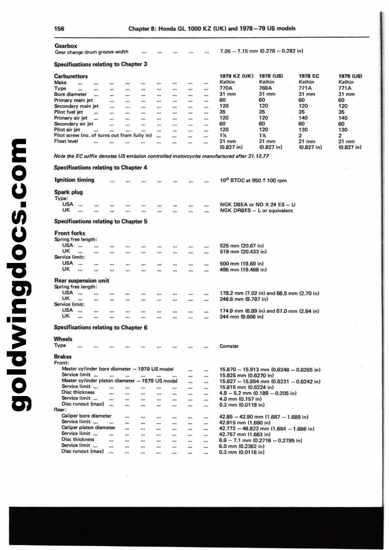
gold
win
gdoc
s.co
m156 Chapter 8: Honda GL 1000 KZ (UK) and 1978-79 US models
GearboxGelr chlnge drum groove width 7.05 - 7.15 mm (0.27B - 0282 in)
Specifications relating to Chllpter 3
CarburettonMo'.Ty,,"Bore diameterPrimlrV main jetSecondary main JetPilot fuel jlltPrimary air jetSecondary air jetPilot lir jetPilot screw (no. of turns OUt from fully in)Float level
1979 KZ (UK) 1978 (USI 1978 EC 1979 (US)Keihin Keihin Keihin Keihin170A 769A 171A 171A31 mm 31 ~ 31~ 31 mm60 60 60 60'20 '20 '20 '203. 3. 3. 3.120 '20 140 '4060 60 60 60120 '20 130 130,. ,. 2 221~ 21~ 21~ 21 mm(0.827 inl (0.827InJ (0,827 in) (0.827 inJ
Note tha EC suffix denotes US emission controlilld motorcycfH menufactuffld after 31. 72.77
Specifications relating to Chapter 4
Ignition timing
Spark plugType:
USA ...UK
Specifications relating to Chapter 5
Front fCM'ksSc:Jring fTee length:
USA '"UK
Service limit:USA ...UK
Ren IUspemion unitSpring frnlength:
USA ._.UK
Service limit:USA ...UK
Specifications relating to Chapter 6
WheelsTy,,"
"'ak..Front:
Moner cylinder bore diameter -1979 US modelService limit ...Me~ cylinder piston diameter -1979 US modelService limit ...Disc thicknessService limit _.Disc runout (max)
Aeet:Caliper bore diametel'"Service limit ...Caliper pinon diBmeter$Brvlce limit ...Di5IC thicknessS&rvK:e limit _.Di5IC runout {maxi
100 BTDC It 950 ±100 rpm
NGK 08EA or NO X 24 ES - UNGK DR8ES - L or equivalent
525 mm 120.67 inl519 mm {20.433 inl
500 mm (19.69lnl495 mm 119.488 in)
178.2 mrn f7.02 In)lne! 68.5 mm 12.70 inl248.6 nvn 19.787 In)
174.9 mm (6.89 in) and 67.0 mm (2.64 inJ244 mm 19.606 In)
15.870 -15.913 mm (0.6248 -0.6265 Inl15.925 mm 10.6270 in)15.827 -15.854 mm (0.6231 -0.6242 in)15.815 mm 10.6224 inl4.8 - 52 mm (0.189 -0205 in)4.0mmI0.157inl0.3 mm 10.0118 in)
42.85 - 42.90 mm 11.687 -1.689 in)42.915 mm 11.690 in)42.772 - 48.822 mm 11.684 -1.686 Inl42.757 mm 11.683 inl6.9 -7.1 mm (02716 -0.2795 in)6.0 mm 102362 In)0.3 mm fO.Oll8 inl
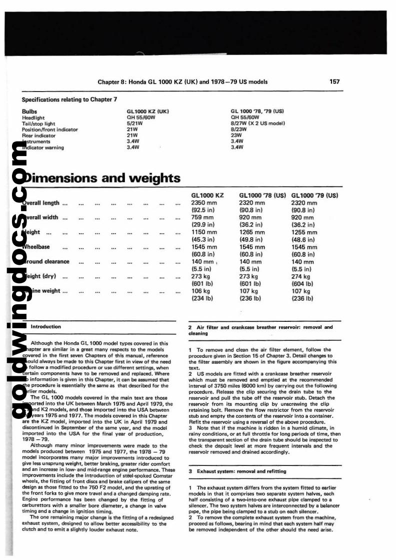
gold
win
gdoc
s.co
m
Chapter 8: Honda GL 1000 KZ (UK) and 1978-79 US models
Specifications relating to Chapter 7
'57
BulbsHeedlightTail/nop li"'tPositionffront II"IdiQt~
Rear indieat~
InstrumentsIndiC8t~warning
GL1000 KZ IUKIOH 55160W5121W2'W2'W3.4W3.4W
G L 1000 '7S, 79 IUSIOH 551'6OWS127W IX 2 us model IS123W23W3.4W3.4W
Dimensions and weights
Overall length
Overall w Kith
Height
Wheelbase
Weight Idryl
Engine weight •..
GL1000 KZ2350mm(92.5 in)759mm(29.9 in)1150mm(45.3 in)1545 mm(60.8 in)140 mm ,(5.5 in)273 kg(GOI Ib)106 kg(234 Ib)
GL1000 78 (US)2320mm(90.8 in)920mm(36.2 in)1265 mm(49.8 in)1545 mm(60.8 in)140 mm(5.5 in)273 kg(601 Ib)107 kg1236lbl
GL1000 79 (US)2320mm190.8 in)920mm(36.2 in)1255 mm(48.6 in)1545 mm(60.8 in)140 mm(5.5 inl274 kg(604 lb)107 kg12351b)
1 Introduction
Although the Honda G L 1lXlO model types covered in thilOlepter are limliar in a greet many respects to the modellcovered in the fim. seven Chapten of this manual. referenceshould alwayl be made to this Otapter first in view of the needto follow a modified procedure or U18 different settings, whencertain eomponents have to be removed and replaced. WherenQ inforTmltiClrl II given in thil Olapter, it ClIn be alllJmed thatthe procedure ill$$llntially the lime as that described for theeerlier modell.
The G L 1000 models covered in the main text are thoseimponed into the UK between March 1975 and April 1979, theKl and K2 models. and those imported into the USA betweenthe veers 1975 and 1977. The models collered in this ChapterIre the KZ model, imported Into the UK in April 1979 anddiscClrltinul!ld in September of the lime year. and the modelimported into the USA fOf' t'" final year of production.1978 - 79.
Although manv minor if1'l9l"ovements were made to themodels produc::ed between 1975 and 1977, the 1978-79model il'lCOrPOf1ltes many major improYements introduced togive less UnspNng weight, better braking. greater rider comfortInd In incn!llse in low- and mid-range engir"IB performance. Theselmpro\lElffi8ntslncluOe the introduction of steet-spoked Comstarwheels, the fining of froot discs and brlIke calipers of the samedesign as those fined to the 750 F2 model, and the uprating ofthe front forks to gille more trallel and a changed damping rate.Engine performance has been changed by the fining ofcarburettors with a smaller bore diameter, a change in wivetiming and a change in ignition timing.
The one renutinlng major change is the fitting of a redesigneduhaust system, desi~ to anow better ac:ceuibility to theclutch and to emit a slightly 10000er exhaust note.
2 Air filter and crankuse w.lther ....rvolr: removal andcleaning
, To remoYI and dean the air filter element. follow theprocedure given in Sect>on 15 of Chapter 3. Oemil ctwnges tothe filter a.-nbly .... shown in the ftgurl IlCCOtYlpenying thbtext.2 US models are fined with a crankcase brllther rmervoirwhich must be removed and emptied at the recommendedinterval of 3750 miles 16000 km) by carrying out the followingprocedure. Releese the clip securing the drain tube to thereservoir and pull the tube off the reservoir stub. Detach thereservoir from its mounting clip bV unscrewing the clipre18ining bolt. Remolle the flow restrictor from the reservoirstub and empty the contents of the reservoir into a container.Refit the reservoir using a reversal of the above procedure.3 Note thlt If the machine II ridden in a humid climate. inl'1Iiny conditions, or at full throttle fOf' long periods of time. thenthe tnlnsparent teetlon of the drain tube should be inspected tocheck the deposit level at more frequent int_Is and thereservoir removed and drained accordingty.
1 The exhaust system differs from the system fitted to earliermodels in that it comprises two separate systam halves, eachhalf coosistlng of a two-into-one exhaust pipe clamped to asilencer. The two system halves Ire inten:oonected by a balancerpIpe, the pipe being clamped to a stub on each sil&ncer.2 To remove the complete exhaust system from the machine.proceed IS follows, bearing In mind that each system half maybe removed lndapendent of the other should the need wise.
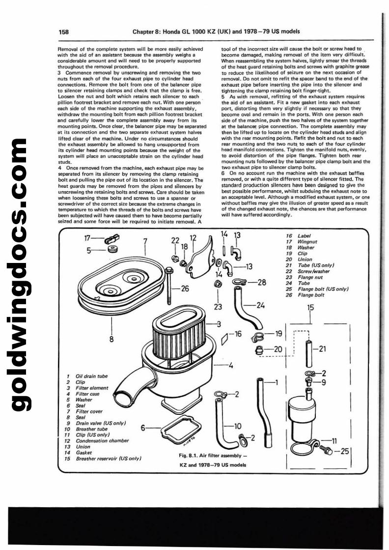
gold
win
gdoc
s.co
m'58 ChapterS: Honda GL 1000 KZ (UK) and 1978-79 US models
IIII
-11 I~-251
L'belWingnutw...~OipUnionTUM fUSon/y)Scnw!washtJfFlfJngtl nutT"beFlfJnge bolt (US only)Flange bolt
,.17,.,.202'22232.2526
-1
-24
-10
~-2
tool of the incorrect size will cause the bolt or screw head to .become damaged, making removal of the item very difficult.When reassembling the system halves, lightly smeer the threedsof the neat guard retaining bolts and.crews with graphite ,,_to reduce the likelihood of seiZl,lre on the next oc:casion ofremoval. Do not omit to refit the spacer bend to the end of thee)(haun pipe before inserting the pipe into the silencer endtightenln" the clamp retaining bolt fingEtr·tight.5 As with removal, refitting of the exhaun system reQUiresthe aid of an aulstant. Fit II new gasket into each exhaustport, distorting them very slightly if necessary 10 that theybecome oval and remain in the ports. With one person eachside of the machine, push the two halves of the system togetheret the balancer pipe connection. Th. complete assembly maythen be lifted up to locate on the cylinder head studs and slignwith the rear mounting points. Refit the bolt and nut to eachrBllr mounting and the two nuts. to each of th. four cylinderhead menifold connections. Tighten tile manifold nuts, evenly,to avoid dinomon of the pipe flanges_ Tighten both rearmounting nuts followed by the balancer pipe clemp bolt and thetwo exheust pipe to silencer clamp bolts.6 On no account run the machine with the exhaust befnesremoved, or with. quite different type of silencer fitted. The5tandard production silencers have been designed to give thebest possible performance, whilst subduing the exh,un note toan ac:eeptable level. Although II modified exhaust system, or onewithout baffles may give the illusion of greater speed as a rlSllltof the changed exhsun note, the chances are th't performancewill haYtI IUffered 8CCOrdil'\Qly.
~-2
14 13
~~~tl:\-1314 ~IJ
4) ~-28
}3-3
(?-16
Fig. 8.1. Air filter assembly _
KZ and 1978-79 US mod.ls
6-0
I8
1 Oil drain tube2 Oip3 Filtet'e1emttnt4 Filtet' caJll'5 W.she.-6 ...,1 Filter colltlr6 ...,9 Drain n/Ye (US only)
10 Breather tubeII Oip (US only)12 Condt!!nS1HiOll chilmMr13 Union14 Ga$kBtIS Breathe"t/ltNvolr (USon/y)
17-te'/J5-@
Removal of the complete system .....ill be more easily achievedwith the aid of In assistant because the assembly weighs.considerable amount and will need to be properly supportedthroughout the ren'IOlI3l Pl'"ocedure.3 Commence nlmOYal by un$Ql!Wing and rerT'IOYing the twonuU from each of the four uheu" pipe to cylindel'" headconnactions. Remove the boll from one of the balaneel'" pipeto silence.. retaining clamps and check that the clamp is free.Loosen the nut and bolt which retains each silencer to eachpillion fOOVll$l bnlcket and remove each nut. With one penon .eech $ide of the machine supporting the Ixl'laun nsembly.withdraw the mounting bolt from each pillion footrest bracketend carefully lowel'" the complete assembly a_V from itsmounting points. Once clear. the balaneel'" pipe may be separated8t its connection end the two separate exhaust system halvll$lifted clear of the machine. Under no Circumstances shouldthe exhaust 8$$l!mbIV be allowed to hang l,mSUPPol'"ted fromits cylinder head mounting points because the wei\tot of thesynem will place en unacceptable strain on the cylinder headSNds.
4 Once removed from the machine, each .xhaun pipe may beseparated from its silencer by removing the clamp retainingbolt and pulling the pipe out of its location in the silencer. Theheat guards may be removed from the pipes and silence... byunscrewin" the retaining bolts lind screws. Care should be taken,.nen loosening these bolts lind screws to use a spenner or~iverof the COITect size because the extreme changes Intempenlltvre to which the threads of the bolts lind screws havebeen IUbjected will have ClIUte<! them to have become Partiallyseized end some force will be required to initiete removal. A
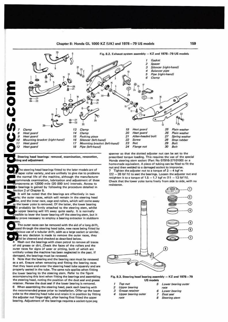
gold
win
gdoc
s.co
m
Chapter 8: Honda Gl1000 KZ (UK) and 1978-79 US models 159
Fit. 82. EJ,;haust syst.... -.nOt'( - KZ and 1978-79 US models
1 Gll$ket2 Spacer3 Silencer (r;ght-hlllld)4 Balancer pipe5 Pipe (right-hiJ(ld)6 Clamp
1 a.mp 13 Clamp " Heat guard8 Hellt guIIrd .. Clllmp 20 Hut guard
• HelltglJ¥d 15 Pack;ng p;ec. 2' A/~-he6dedbolt,. Moufltiflg bracket (right-hand) 16 SiltmctN (lefMand) 22 Scnw
" Heat guard 17 Mouflting bracket (Ittft-hand) 23 Nu,
12 Httatgu8rd 18 Pipe (Ittft-h811d) 2' Flanfltl nut
25 Prai" washer26 Plain wuher21 Spring waller28 Stop rubber29 Bolt30 Bolt
•
LOWflr bHring outer,~
6 Lo_r bftr;ng7 Dun ...18 Steer;f1g stem
, Top nut2 Upper bftring3 Gre(l5fl retainqr4 Upper bearing outer
""
~
~9 0
@1--<D~ 0~
Fig. 8.3. Steering hNd bearillll_mbly - KZ lind 1978-19US models
5
spanner $0 that the slotted adjuster nut can be set to theprescribed torque loading. This r1i!QUires the use of the specialHorode steering stem socket (Part No 07916-3110100) or ahome-rnacle equivalent. A piace of tubinll can be filed to fit thenut and then welded to II damaged socket to Improvise.1 Tighten the adjuster nut to a torqua of 3 - 4 kgf m122 - 28 Ibf hi to seat the bearingL L.oosen the adjuster nut and..tighten itto. torque of 1.5 -1.1 kllf mIll -131bf ftl.Oleck that th.lower yoke turns frealy from sida to side, with noresistance.
1 The steering head bearings fitted to the later models alll ofthe QPel" roller variety, and are unlikely to give rise to problemsIn the nannal lif. of the machine, although the manufaenJrerrecommends e.aminatton, lubricliltion and adjustment of thesecomponenU at 12000 mile (20 (X)() km) intervals. Aceess tothe bearings is gained by following th. procf!dure detailed inSection 2 of Olaptef' 5.2 It will be noted thllt the bearings are effactively in twO
Pllru; tha outer racell. which will remain in the steerlog heedlube. lind the inner race. Cilgli! lind rollers, which will come_yas the 10Wll'l" yoke is removed. Of the lettel'. the lower bearingwill probably be firmly attach&d to the steering stem. whilstthe upper bearinll will lift away quite easily. It is normallypossible to lever the lower bearing off the steering stem. but itmay prove necessary to employ a bearing extractor In stubborn~.
3 Th. outer riCes can be removed with the aid of a long drih.paued through the steering head tube. new races beinll fined byjudicious use of II tubular drift. S\lch as a large socket or similar.Bafore any decision is mede to remove the outer races. theyshould be deaned and checked as described below." Wash out the bearings: with clean petrol to remove III \J"'8Cft
of old IIrease or dirt.,Oleck the faces of the rollers end theouter races for signs of wear or pitting. both of which areunlikely unless the machine hiS been Il8glected In the past. Ifdamll9lld. the bearings must be renewed.5 Note that tha bearing and the bearing race must be renewed1M a lit. Ensu.. when removing and fitting the bearing racesthat they leave and enter the st8e1'"ing hNd tube squarely and areproperty seated in the tube. The same rule applies wnen fittingthe lOWir bearing to the steerinll stem. Refer to the figureaceompsnyinll this text when fitting the bearings: and assemblingthe steering heed, noting the position of the dm seal and greallreminer. Re.- the dust seal if the lower bearing is remO'o'ed.6 When assembling the l1eeri"ll head. pack each bearing ...,;ththe recommended grllse prior to installation. Offer up the loweryoke to the steering head tube lind remin it in position by fittingthe adjustl!l'" nut finger-tight. after having fint fined the upperbearing. Adjustment of the bearings requires I socket-type peg
" St..rlng hud beuings: r....o.,.l••xaminlltiGon. r.1'Io....oon.fitting and adju$tmltflt
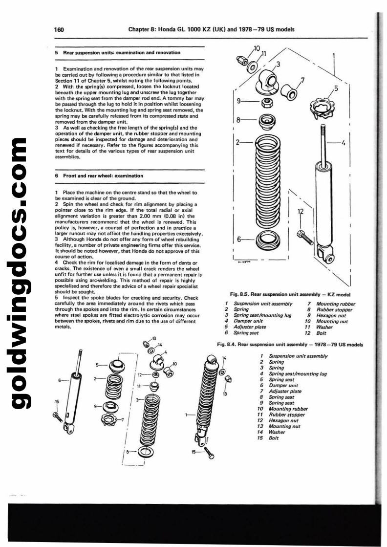
gold
win
gdoc
s.co
m160 Chapter 8: Honda Gl1000 KZ (UK) and 1978-79 US models
5 Rear.,~n units: eumlnlltion end renonUon
1 Examinetion and renovation of the r_ suspension units maybe carried out by following I procedure limiter to that listed in$eetion 11 of Chapter 5, whilst noting the following points.2 With the wrlnglsl compressed, 100$110 the locknut locatedbeneath the upper mountinillull8nd unscrllW thllu9 tOgBtherwith the spring $1181 from ttIe damper rod end. A tommy bar maybe passed throogh the lug to hold it in po$ltion whilst looseningthe locknut. With the mounting lug and spring _t rem(lllled, thespring may be carefully ntIlli1$&d from its compr~ nate endremoved from the damper unit.3 As welt I" checking the free length of the sprinllbl and theopertltion of the damper unit, the rubber stopper and mountingpieces should be inspected for dam!lgll and deterioration andrellftYed If nec::essary. Refer to the figures accompanying thistext for details of the various types of reer suspemion unitassembl~.
6 Front end relr wheel: llXllmination
1 Place the machine on the centre stand so that the wheel tobe examined Is deer of tha ground.2 Spin the wheel and check for rim alignment by placing apoin18\" close 10 dla rim edge. If dla total radial or axialalignment variation is greall!r dlan 2.00 mm 10.08 in) thamanufacturers recommend dla1 the wheel Is renewed. Thispolicy Is, howeller, a counsel of perfection and in prae1lce alargE!\" runout rn.av not affElC1 the handling properties excessively.3 AJ1hough Honda do not offer any form of wheel rebuildingf.tili1y•• number of private engineering firms offM dlis S8l"V1ce.It should be noted h_. dlat Hondll do not approve of thiscourse of ae1ion.4 O1eck the rim for localised damage In 1he form of dents orcracks. The existence of wen a small crack renders the wheelunfit for further use unless it is found that a permanent repair ispossible using Drc.welding. This method of repair is highlyspecielised and thetefore the advice of. wheel repair specialistshould be IOUght.5 InsPect dle spoke blades for cracking and securi1y. O'leckcarafully the area immediately around the rivets which passthrough the spokes and Into the rim. In certain circumstanceswhere steel spokes are fittld electrolytic corrosion may occurbetween the spokes, rivets end rim due to the use of differentmetals.
-4
6-QI~_c._="~- - ---
Fig. 85. Re.rsulPlMion unit BMmbly - KZ model
1 SU$/Mnsion unit~y 7 Mounting rubber2 Spring 8 Rubber stoP{M1r3 Spring sear!mounting lug 9 Hexllgon nut4 Dllmper unit 10 Mounting nut5 Adjuster pl"r. " W"",w6 Spring_t 12 ""I<
Fig... 8.4. R..... SU5PlInPon unit _mbly _ 1918-79 US models
.-1 Suspension unit .uembly2 Spring3 Spring4 Spring _t!mounting lug5 Spring_t6 DamPtW unitJ Adjusr.r plateB Spring.seet9 Spring seat
10 Mounting rubb6r, 1 Rubber stopper'2 Hflx/If}O('I nllt13 Mounringnut14 Wash.,.15 Boft
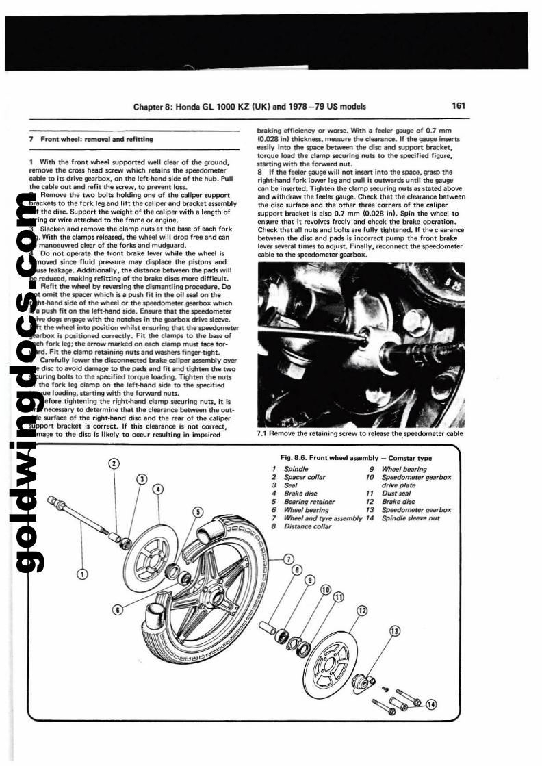
gold
win
gdoc
s.co
m
Chapter 8: Honda GL 1000 KZ (UK) and 1978-79 US models 161
7 Front wh... : rafflO'lilI and refitting
1 With the front whlllli supponed well clear of lhe ground,r1rmOlle the cross head screw which retains the speedomeurrcable to its drive gearbox, on the left-hand side of the hub. P\JIIthe cable out end refit the screw, 10 prevent 10$1.2 Remove the two bolts holding one of the caliper supportbrackets to the fork leg and lift the caliper and bracket assemblyoff the disc. Suppon the weight of the Ctlliper with a length ofstring or wire attached to the frome or engintr.3 Slacken end remove the clamp nuts at the base of each forkleg. With the clamps released, the wheel will drop free and canbe manoeuvred clear of the forks and mudguard.4 Do not operate the front brake tlMlr while the wheel isremoved since fluid pressure may displace the pistons andCiJYse leaUgtr. Additionally, the distance between the pads willbe reduced, making refitting of the brake discs more difficult.5 Rafit the wheel by reven:ing the dismantling procec1lre. Donot omit the specer which is. push fit in the oil seal on theright-hand side of the wheel or the speedometer" gearbox whichis a push fit on the left-hand side_ emure that the 5POl!dometerdrive dogs 8n1Jil9O with the notches in the gearbox drive sleeve.Uft the wheel into position whilst ensuring that the speedometergearbox is PG$itioned correctty. Fit the clalT19S to the base of_ch fork leg; the arrow m..-ked on each damp must face forward. Fit the clamp retaining nuts 'nd Wl$hers finger-tight.6 Carefully lower the disconnected brake caliper II$SlImbly overthe disc to avoid Oam.age to the pads and fit Ind ti\tlten the twosecuring bolts to the specified torque lO<tding. Trghten the routsof the fork leg damp on the left-hand side to the $lJ8cifiedtorque loading, startll'lQ with the forward nuts.7 Before tightening the ri\tlt-hand damp securing nuts, it isfirst nec&s18ry to deurrmine that the clearance between the outside surface of the right-hand disc and the rear of the calipersupport bracket is correct. If this eletlrance is not correct,damage to the disc is likely to OCC\Jr resulting in impeired
2
3
•
•
braking vfficienc:y or worse. With I feeleo' gauge of 0.7 mm10.028 in) thickness, mea$Ure the c1e<1tlmce. If the gauge ift$8fUeasily into the space between the disc and support bracket,torque load the damp securing nuts to the specified figure,staning with the forwertl nut_8 If the fealN gauge will not insert into the space, grasp theright-hand fork lower leg and pull it outwards until the gaugecan be inserted. Tighten the ctamp securing nuts as stated aboveand withdraw the feeler gauge. Check thlt the clearance betweenthe disc surface and the other three cornen of the calipersupport bracket is also 0.7 mm (0.028 in). Spin the wheel toenlure that It revolves freely and check the brake operation.Check thlt all nuts and bolts are fully tightened. If the clearancebetween the disc and pads is incorrect pump the front brakelever several times to adjust. Finally, reconnect the s.peedometerC8b1e to the Speed0m8ter gearbox.
7.1 Remove the retaining screw to rereese the speedometer cable
Fig. 8.6. Front wheel assembly - Comstar type
1 Spindle 9 Wheel bearing2 $pecer collar 10 ~meter gearbox3 Se., drive pl'le4 Brake dilC 11 Oust seal5 Suring retsiner 12 er.ke diu:6 Wheelbeilring 13 ~metergurbox
7 W7r<!<e1and tyre a~b1y 14 Spindle sleeve nut8 Distsm::e collar
13
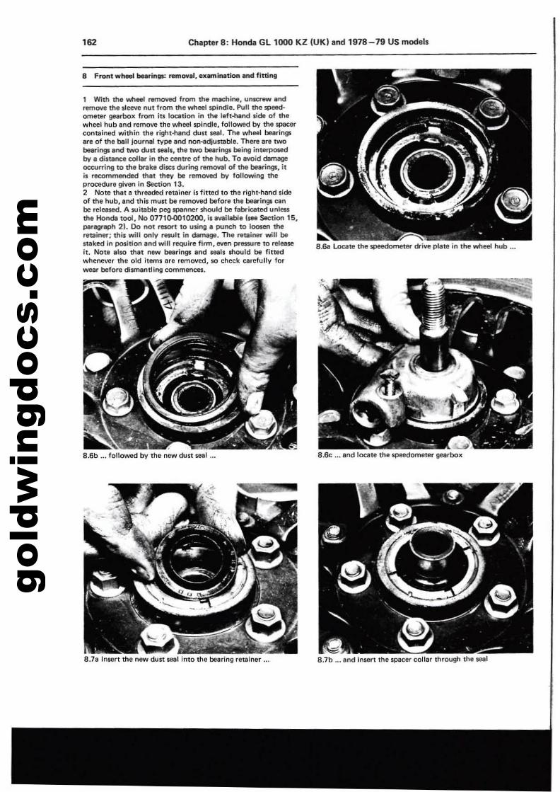
gold
win
gdoc
s.co
m162 Chapter 8: Honda Gl 1000 KZ (UK) and 1978-79 US models
8 Front wheet bnrings: ramO'll', llX8mlRlltion and fitting
1 With the wheel removed from the mechine. unscrt!W .ndTIlmOYll the sleeve nut from the wheel spindle. Pull the speedometer gellrboll from its location in the left-h.nd side of thewheel hub Ind remove the wheel spindle, followed by the spacercontained within the right-hand dust wi. The wheel bearings.re of the ball journ.l type end non-adjultable. There ant twobearings end two dust seals, the two bNri0g5 being interp0$8dby- a distance collar in the centre of the hub. To avoid dilmegeOCQJfTil'l9 to the br.ke discs duriog removal of the bearings, itis recommended that they be removed by following theprocedure given In Section 13.2 Note that 8 threaded retainer is flUid to the right-hand sideof the hub, end this mU$1 be removed before the bearings cenbe relealled. A suitable peg ~nner should be fabriellted unll!$Sthe Honda tool, No 07710-0010200, illMlHabie 1_ Section 15,paragraph 21. Do not n!$OM to using a punch to loosen theretainer; this will only result in darnage. The retl;ner will bestaked in position and will require firm, even Pl'~re to releaseit. Note also that nll'W bearinQ$ and seals should be fittedwhenever the old items are removed, so check carefullv forwear before dismantling COmmllflcel.
8.6b ... followed by the new dust seal
8.1a InSCrt the nll'W dust seal into the bearing retainer ...
8.6c .. and locate the speedometer gearbox
8.1b ... and insert the spacer collar through the leal
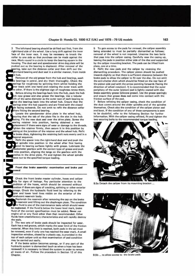
gold
win
gdoc
s.co
m
Chapter 8: Honda Gl1000 KZ (UK) and 1978-79 US models 163
g.58 Detach the caliper from its mounting bracket ...
9.5b ... to allow IICCI!SS to the brake pads
5 To gain access to the pads for renewal, the caliper assemblybeing attended to must be partially dismantled 85 follows;removal of the wheel is not required. Unscrew the two bolhthat pess into the caliper cning. Carefully ease the casing up,leaving the pads in position either side of the disc and IUpportedby the caliper mounting bracket_ The pads can be lifted fromplace, one at a time.G Refit the new pads and the caliper by revening thedismantling procedure. The caliper piston should be pushedinwardl slightly so that there is sufficient clearaflC1! between thebrake pads to allow the caliper to fit over the disc. 00 not omitthe anti-ehatter shim which should be fitted on the rear face ofthe pinon side pad with the arrow pointing forwards (facing thedirection of wheel rotation!. II is recommended that the outerperiphery of the outer (piston I pad is lightly coated with disc!:nice assembly lIfBaSe (silicone greasel. Use the grease sparinglyand ensure that grease does not come into contact with thefriction surface of the pad.7 Before refitting the caliper casing, eneek the cOfldition ofthe dust covers around the slider spindles and of the windlesthemselves. Check also tha condition of the caliper piston sealand boot. If the condition of any of these components is seento be doubtful, refer to the following Section for furtherinformation. With the calip« casing refitted, fit and tilflten thetwo seOJring bola to the rla)mmended torque loeding_
'I '\ \-..~ .-
9 Front disc br.e ~bly: exami_tion and brake padran_aI
1 Oleek the front brake master cylinder, hoses and caliperunits for signs of leakage. Pay particular attention to thecondition of the hoses, which should be renewed withoutquenlon if there are signs of cracking, splitting or other exteriordamage. Oleek the hydraulic fluid lever by referring to theupper and lower level lines visible on the e)ltet"ior of thetranslucent reservoir body.2 Repleni$h the reservoir aher remOYing the cap on the brakefluid reservoir and lilting out the diaphf1l9lTl plate. The conditionof the fluid is one of the maintenance msla which should I'Ml"Ierbe neglected. If the fluid h below the lower level mark, brakefluid of the CorrllCt sl;)ecification must be added. Never useengine oil or any fluid other than that recommended. Otherfluids have unsatisfactory characteristics and will rapidly destroythe "als.3 The two seh of brake pads should be inspected for _r.Qc:h hIS a red groove, which mar-ks the wear limit of the frictionmaterial. When this limit is reac:hed, both pwds in the set mustbe renewed, even if only one has reached the wear mark. A smallinSPeCtion window, dO$lld by a plastic cap, is provided in thetop of each caliper unit so that examination of pad conditionmay be carried out easily.4 If the brake action becomes spongy, or if any part of thehydf'lulic system Is dismantled huch as when a hose hIS beenrenewedl it is necessary to bleed the SYltem in order" to removeall trKeS of air. Follow the procedUfll in Section 12 of thilOlapter.
3 The left-hand bearing should be drift&d out first, from theright-hand side of the wheel. Use 8 long drift against the innerface of the inner race. It mey be nllCltSsary to knock thecollar to one side 50 that purehase can be made against therace. Work round in a cirele to keep the bearing SQuare in thehousi~. The dun _land~eter«iva dog plate will beplJshed OUt as the bearing is displaced. After remOl/llI of thebearing, ake OUI the distance collar and then «ift out theright-nand bearing.nd dust seal in a similar manner, from insidethe hub.4 Ramove all the old grease from the hub and bearings, washthe bearings in petrol. and dry them thoroughly. Check thebearings for roughness by spinning them whilst holding theinner track with one hand and rotating the outet" tlllCk withthe other. If"there is the slightest sign of roughrM!$S renew them.5 Before (t-iving the bearings back into the hub, pack the hubwilh new grease .nd arso grease the bearings. Use a tubulardrift of the same d~meteras the outer race of each bearing todrive the bearings back into the wheel hub. Ensure thai thebearings enter the hub squarely and are fitted with the clO$edside facing outwards. Do not omit to refit the distance collarbefore fitting the l18Cond bearing.6 L.oalle the speedometer drive plate in the wheel ltub,ensuring that the tab of the plate fits in the slot in the hubcasting. Fit the new dust _I 0YeI'" the drive plate. Screw thebearing retainer into position, having obtained a newreplllCllmllnt if there __e signs of _r or damage to the threads.Tighten the retainer firmly, then sectJre it in this position bySlaking at the junction of the retainer end the wheel hub. Refitthe brake discs, tightening the retaining bolt nuts evenly and in adiagonal sequence.7 Relit the splicer into the right-hand dust seal and push thewheel spindle into position in the wheel after lir" havingsmeared iU bearing surf8ees lightly with grwose. Lubricate thespeedometer gearbox with the correct type of grease and pushit into position, aligning the tangs on the gearbo)l with thenotches in the drive plata. Fit and tighten the wheel spindlesleeve nut to the specified torque loading.
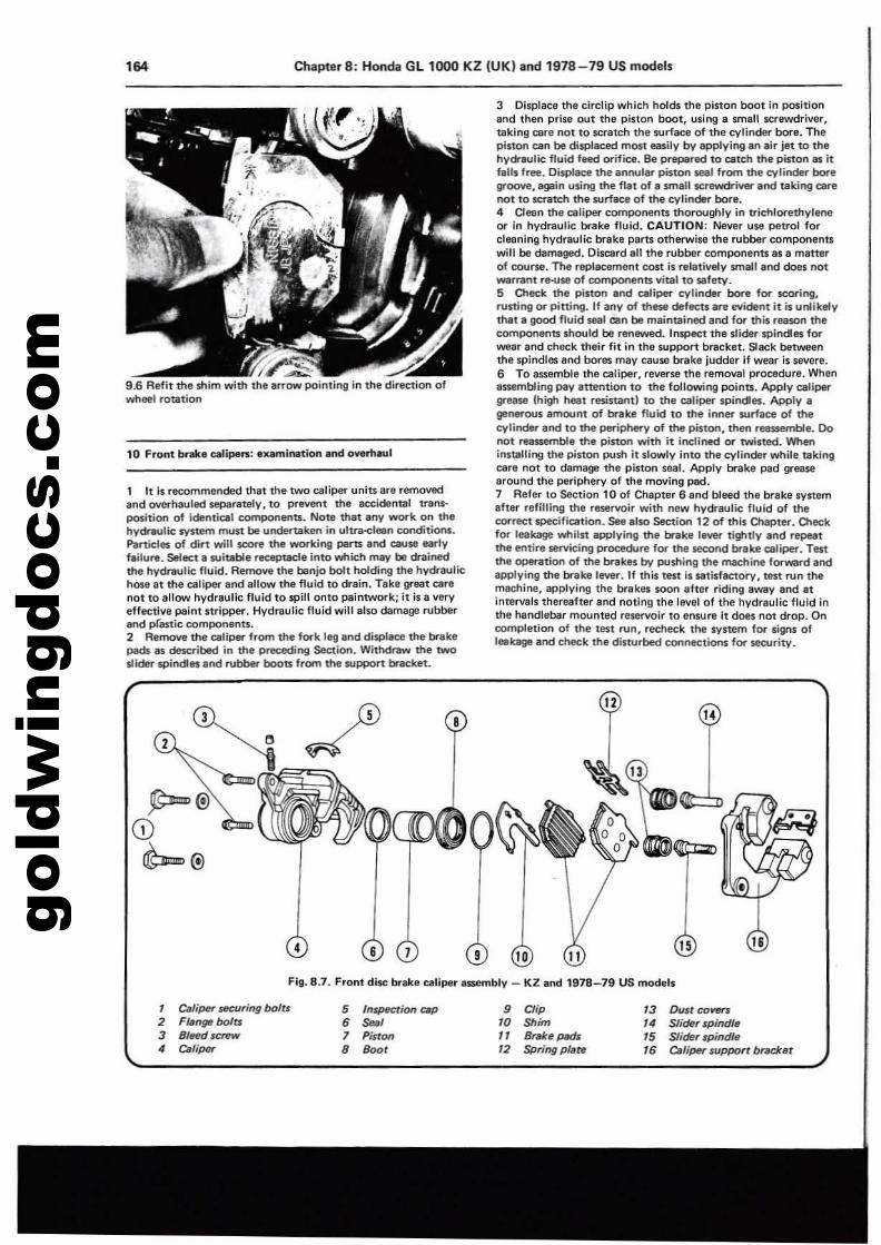
gold
win
gdoc
s.co
m164 Chapter 8: Honda Gl1000 KZ (UK) and 1978-79 US models
9.6 Aefit the shim with the errow pointing in the direction 01wheel rotation
10 Front b.... calipeR: IlIlmil'\ltion.nd ove......ul
1 It Is recommended that the two caliper units are removedand overhaulad separately, to prevent the accidental 'I1InsPOS.itiOfl of idel'ltical components. Note that any work on thehytWBulic ~tem must be undertaken in ultnl-cilin conditi()t'\s.Particles of dirt will $COnI the working ports and cause eartyfailure. Select I suitable receptacle into which may be drainedthe hydfitulic fluid. Aemove the benjo bolt holding the hydraulichose at the caliper and allow the fluid to drain. Take great car,not to allow hydraulic fluid to lPilI onto paintwork; it is a veryeffective paint stripper. Hydraulic fluid will also damage rubberend P(astic components.2 Remove the caliper from the fork lll'g and displace the brakepads as described in the preceding Secti()t'\. Withdraw the twoslider spineles and rubber boots from the support brlcket.
3 Displace the circlip which holds the piston boot in positionand then prise out the piston boot, using a small screwdriver,taking cere not to scratch the surface of the cylinder bore. Thepiston cen be diSPlaced mOlt _ily by Ipplying In lir iet to thehy<hulic fluid feed orifice, Be prepared to cetch the pilton ali itfIIUs free. Displace the annuler pilton seal from the cylinder boregroove, again u$lng the flat of e smlll screwdriver endtalting Clrenot to scratch the surface of the cylinder bore.4 Oesn the OlIliper components thoroughly il'l trichlorethylel'leor in hydraulic breke fluid. CAUTION: Never use petrol forclllllning hydreulic brake parts otherwise the rubber componenuwill be damaged. Oi$Cllrd III the rubber componants as a matterof COUI"$IiI. The replacement cost is relatively small and does notwarr8nt r~se of components vital to safety.5 O1eck the piston and celiper cylinder bore for scoring.rusting or pitting. If any of these defecu are eYident it is unlikelythat I good fluid seal can be mlintllined and for this reason thecomponents should be renewed. Inspect the slider spindles forWIIar and chlll::k their fit in the support bracket. Slack betweenthe spindles and bores may cause brake judder if wear is savere.6 To aS$l!mble the caliper, reVllrse the removal procedure. WhenIssembling pay attention to the following points. Apply cellpergrease (high hNt rll$inal'ltl to the caliper spindles. Apply Igenerous amount of br.ske fluid to the inner $Orface of thecylil'lder Ind to the periphery of the piston, then reeuemble. Donot reassemble the piston with it inclined or twisted. Wheninstlllling the piston push it slowly into the cylinder while takingcare not to damage the piston seal. Apply brake pad greasearound the perlphery of the moving pad.7 Aefer to Section 10 of Chapter 6 and bleed the brake sylt&mafler refilling the reservoir with new hydraulic fluid of thecorrect specificatlorl. See also Section 12 of this O1apter. O1eckfor leakage whilst epplyl~ the br.ske lever tightly and r~tthe entire servicing Pf"ocecture for the 58'COfld brake caliper. Tenthe operation of the brakes by pushi~ the machine lorward andapplying the brake 1eYe\'". If this test is sati$fectory. test run themachine, applying the b... kel loon alter riding away and litintervals thereafter and noting the level of the hydraulic fluid inthe handlebar mounted reservoir to ensure it does not drop. Oncompletion of the test run, recheck the system for signs 01leekage and check Ihe disturbed connections for security.
Fig. 8.7. Front disc brake ealiper II$$I!mbly _ KZ and 1978-79 US models
, ClIJiper ltICuring bofn2 F~ngeboJU
3 BJeft! SCfPN4 ClIliper
5 fnS(HCtion ClJ/J
6 ""',7 Piston
8 800'
9 Clip10 Shim, 1 8rllh P«!s12 $pringp/a~
13 Dustco~
14 Slider rpindfe15 Slider rpirtdJe16 ClIliper supPOrt bradret
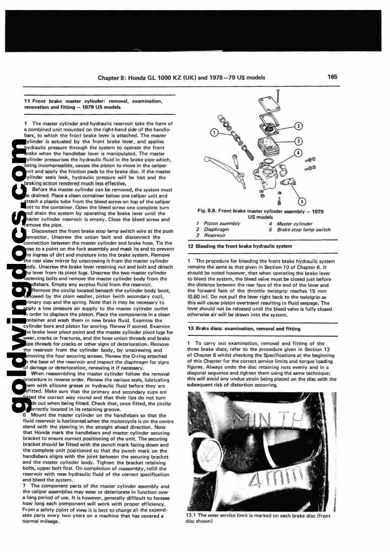
gold
win
gdoc
s.co
m
ChapterS: Honda GL 1000 KZ (UK) and 1978-79 US models 165
12 SIHdi"ll the front brak. hydraulic system
13 Sr•• dilCS: .,..mination, removal and fitting
i
.....-•Ftll. 8.8. Front br•• master cylinder 8$$Imbly -1979
US models4 Mastel' cylinder5 Brake stop 'limp switch
1 Piston assembly2 Dillphril!Jffl3 ReJJerYoir
1 The procedure for b1lHlding the front brake hydraulic systemremains the same as that lliven in Section 10 of Chapter 6. Itshould be noted however, that when operating the brake leverto bleed the system, the bleed valve must be closed just beforethe disllnee between the r8llr face of the end of the hrver andthe forward faee of the throttle twistgrip reeches 15 mm10.60 inl. 00 oot pull the lever right t.ck to the twistgrip asthis will cause piston overtravel resulting in fluid seepage. Thelever should not be released until the bleed varve is fully closedotherwise air will be drawn into the system.
1 To carry out eXlIminetion, removal and fitti"", of thethree brake discs, refer to the prooedure given in Section 13of atapter 6 whilst checking the Specifications at the begitVlingof this Ql.apter for the correct Sl!nIice limits and torque loadi"llfigures. Always undo the disc reaining nuts evenly and in adiagonal MqUCOCl! and tighten them using the same techniQUe;this will avoid any undue strain being placad on the disc with thesubsequent risk of distortion occurring.
13.1 The wear service limit is marked on each brake disc (frontdisc shown)
11 Front bt"_e mater c:ylindltr: removal, examination.renovation Ind fitting _ 1979 US models
1 The master cylinder and hydraulic reservoir mk, the form of8 combined unit mounted on the right-hand side of the handlebars, to which the front brilke lever is attaChed. The mastercylinder is actuated by the Iront brake lever. and applil!$hydrllulic J)l'"e$$Ure through the system to opeI'"ate the frontbrake when the t1andletlor lever is manipulated. The mastercylinder pressurises the hy~lic fluid in the brillte pipe which,being in<:ompl"euible. C8uses the piston 10 move in the caliperunit and apply the frietiOl'l Pllds to the brake disc::. If the mastercylindltr seals leak, hVdrllulic prllS$Ure will be lost and thebraking IIctlon rendered much less effective.2 Before the master cylinder can be removed, the system muube drained. Place a clean container below one caliper unit lindattach. plastic tube from the bleed screw on top of the caliperunit to the container. Open the bleed screw one complete turnand drain the system by operating the brake lever unlil theTna$ter cylinder reservoir is emply. Close ttle bleed screw andremO'I/'II the pipe.3 DiSCOl'lneet the front brake stop temp switch ....ire at the pushconnector. UI1$Cfl!'N the union boll and dbconnect theconnection ber....een the maner cylinder and brake hose. TIe thehose to a point on the fork assembly and mask its end to preventthe ingress of dirt and moisture into the brake system. Removethe rear view mirror by unscrewing it from the master cylinderbody. Unscrew the twlke lever retaining nut and bolt 100 detachthe lever from its pivot lu!ilS. Unscnt.... ttle two master cylinderfastening bolts and remO'l/'ll the master cylinder body from thehandebers. Empty Iny surplus fluid from the reservoir.4 Remove the circlip located benelth the cylinder body boot,followed by the pllin Vtestler, piSlon l.... ith $I!COndary cupl.primary cup and the spring. Note tNl it may be neeessary toapply I low prl!$$ure air wpply to the mastel" cytinder outtetin order to displace the piston. Place the componenu in a cleancontainer and wash thltm in new breklt fluid. Examine thecylindltr bore and piston for scoring. Renew if scored. Examinethe brake lever pivot point and the master cylinder pivot lugs forwear, creeks or fractures, end the hose union threads and brakepipe thre.ds for cracks or other signs of deterioration. Rel'l'l()'iethe reservoir from the cytinder body, by unscrewing andremoving the four securing screws. Renew the O-i'ing attachedto the t.se of the reservoir end inspect the diaphragm for signsof damage or deterioration, renewinll it if necessary.5 When reusembling the master cylinder follow the removalprocedure in reverse order. Renew Ihe various seets, lubricatingthem with sillcone grease or hydraulic fluid before they arerefitted. Make sure that the primary and secondary cups arefitted the correct wly round aOO thlt their lips do not turninside out when being fitted. Check thlt, onee fitted, the circHpis correctly located in its retaining groove.6 Mount the master cylinder on the handlebars 10 that thefluid reservoir is ho<'izontal when the motorcycle is on the centrestand wittl the steering in the straight ahead direction. Notethat Honda mark the handleba" and master cylinder seeuringbracket to enwre correct positioning of the unit. The IllC\lringbracket should be fitted with the punch mark facing down andthe complete unit positioned SCI thlt the punch mark on thehandleber1 aligns with the joint between the securing bracketand the mestC!' cylinder body. Tighten the bracket retainingbolts, upper bolt first. On completion of rl!as:5elTlbly, refill thereservoir with new hydllKJlic fluid of the correct speeifieationand bleed the system.7 The component perts of the master cylinder assemblV andthe caliper euemblie:s may wear or det.,..iorate in function oyera long Pl!I"iod of use. It is however, generally diffic1Jlt to foreseehow long each component will work with proper efficleocy.From a safety point of view it is best to change ell the expendable PfIrts every two yean on II machine that hes covered anormal mileage.
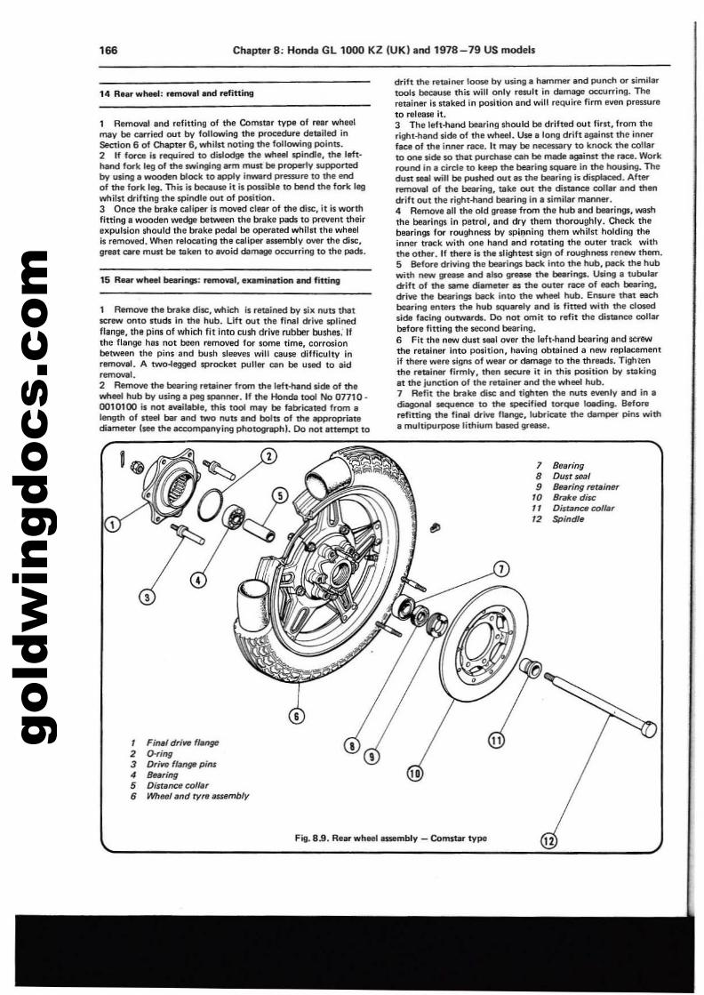
gold
win
gdoc
s.co
m'66 Chapter 8: Honda GL 1000 KZ (UK) and 1978-79 US models
14 Rear whMI: rlltnovlli .nd refitting
1 Removal and refitting of the Comnor type of rear wheelmay be carried out by following the procedure detailed insection 6 of Chapter 6, whilst noting the following points.2 If force is required to dislodge the wheel spindle, the left·hand fork leg of the swinging arm mUA be properly supportedby using a wooden block to apply inward pre$$Ure to the endof the fork leg. This is because it is pouible 10 bend the fork legwhilst drifting the spindle out of position.3 Once the brake caliper is moved clear of the disc. it is worthfitting 8 wooden wedge between the brake pads to prevent theirexpulsion shOUld the brake pedal be operated whilst the wheelis removed. When relocating the caliper assembly over the disc,great care must be taken to avoid damage occurring to the pads.
15 R.... whsst belIriOlll: removal, .ummation and fitting
1 Remove the brake disc, which Is retained by six "'-Its thatsc::rew OfIto studs in tha hub. lift OUt the final drive $plloedflange. the pins of which fit into cusn drive rubber bushes: Ifthe flange has not been removed for some time, corrosionbetween the pins and bush sleeves will cause difficulty inremoval. A two-legged $JKocket puller ClIO be used to aidremOll8I.2 Remove the bearing retainer from the left-hand side of thewheel hub by using e peg spenner. If the Honda tool No 07710 0010100 is not available, this tool may be tabriclllted from alength of neal bar and two nuts and bolts: of the appropriatediameter (see the accompanying photogrephl. Do not 8nempt to
1
,
, Final drilllf ffange2 O-ring3 Dri'ltl ff4nga pins4 Bearing5 Distance coll8r6 Whee/end tyre llU8mbly
drift the retainer loose by using a hilfTlme1" and punch or similartools because this will OfIly rl1$Ult in damage occurring. Theretainer is SUlked in position and will require firm evon pressureto release it.3 The left-hand bearing should be drifted out first, from theright-hand side of the wheel. Use a long drift against the innerface of the inner race. It may be nllCess&ry to knock the collarto one side SO that purchase can be m8de against the race. Workround in. cirde to keep the bearing square in the housing. Thedust -' will be pushed OUt as the bearing is displaced. Alterremoval of the bearing, take out the distance collar and thendrift out the right-NInd bearing in a similar manner.4 Rem~ all the old grease from ttle hub and bearings, washthe bearings in petrOl, and dry them thoroughly. Check thebearings for roughness by spinning them whilst holding theinner tr&ck with one hand and rotating the outer track withthe other. If there is the sligtltl!$t sign of roughness renew them.5 Before dl'"iving the bearings back into the hub, pack the hubwith new gr_ and a'so grease the bearings. Using a tubulardrift of the same diameter as the outl!l'" mee of each bearing.drive the bearings beck into the wheel hub. Ensure that eachbearing enters the hub squarely aM is fitted with the dosedside f&Cing outwards. Do not omit to refit the distlr>ee eollarbefore fining the second bearing.6 Fit the new dust seal over the left-hand bearing and screwthe retainer Into position, having obtained a new replacementif there were signs of wear or diImago to the threads. Tightenthe retainer firmly. then $t'CUre it In this positiOfl by stakingat the junctiOfl of the retainer and the wheel hub.7 Refit the bnlke disc lind tighten the nuts evenly and in ad"I8QONJ sequence to the specified torque 'ceding. Beforerefitting the final drive flange. lubricate the damper pins witha multipurpose lithium billed greese.
7 Bearing8 DUSI seal9 Bearing retainer
10 Brab disc11 Dist1Jnce coI'ar12 Spindle
J
Fii. 8.9. Rearwhllltiassembly - Comstar type 12
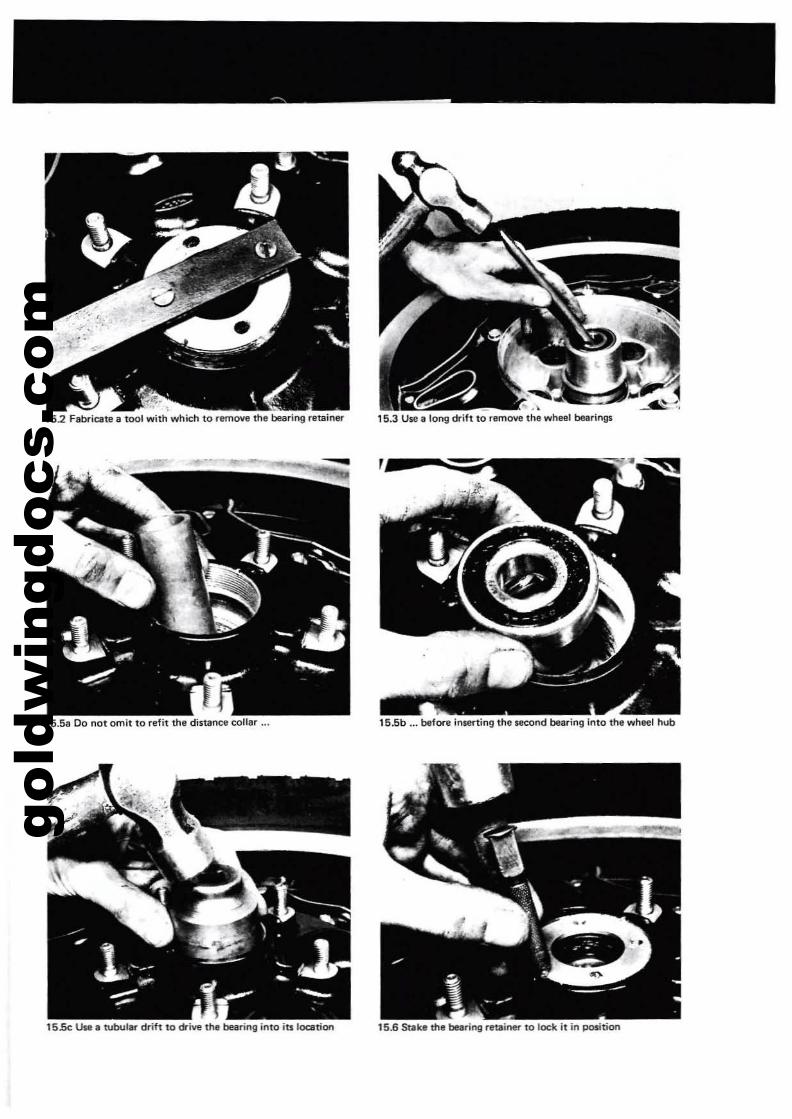
gold
win
gdoc
s.co
m
152 FabriClite a tool with which to remove the bearing retainer
15.58 00 not omit to refit the dista~ collar ...
15Se Use. tubular drift to drive the bearing into itslocetion
, -,15.3 U5tl 8 long drift to remove the wheel bearings
15.5b ... before in5«ting the second bearing into the wheet hub
15.6 Stake the bqring retainer 10 lock it in position
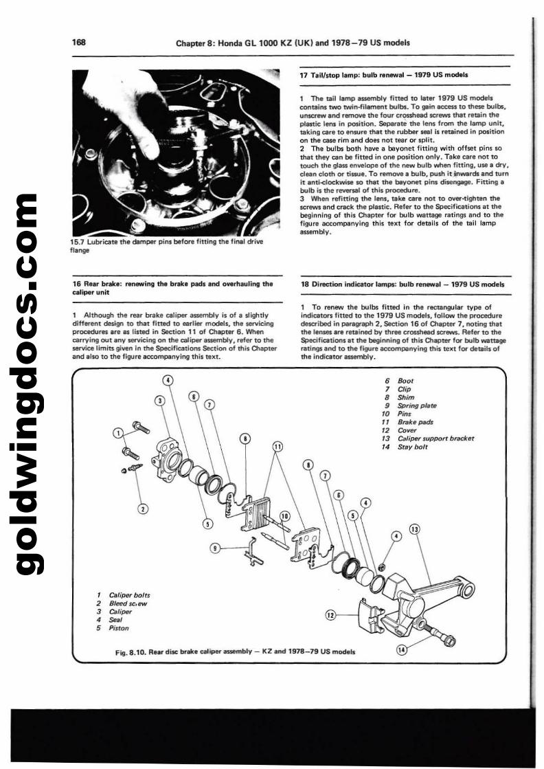
gold
win
gdoc
s.co
m168 ChapterS: Honda Gl1000 KZ (UK) and 1978-79 US models
15.7 Lubricate the dlmper pin. before fitting the fif\llJ driveflange
16 R..r brak.: An_ing th. brake pact. and overhauling th.caliper unit
1 Although the rear brake caliper assembly is of a slightlydiffll'ent design to that fitted to earlier models. the servicingprocedures are IS listed in Section 11 of Chapter 6. Whencarrying out any servicing on the caliper Issembly. rtfer to theservice limits given in the Sgecificltiom section of this Olepterand ,Iso to the figure 3CCOmpenying this text.
17 Tail/stop l.mp: bulb renew.1 - 1979 US mockls
1 The tail lamp 855efTlbl'l' fined to later 1979 US modelscontlins twO twin-filament blllb$. To gIIln M:CeSS to these bulb5.un~.nd rtlll'l'lOYe the four erouhead screws that retain theplElStic lem in position. Seperete the lens from the lamp unit,taking care to ensure that the rubber S8ll1 is retainlKl in positionon the ca$ll rim and does not tear Of split.2 The bulbs both halle 8 bayonet fitting with ofheI pins sothat they ClI" be fined in one position only. Take care not totoueh the g1aSll en"",lope of the new bulb when fining. use II dry.clean cloth Of" tissue. To ntmOYe 8 bulb. push it in_refs and tu.nit anti-clockwise 10 that the t.yonet pins disel"lgllg8. Fitting •bulb is the r_l of this procedure.3 When refitting the lllns, take care not to over-tighten thescrews end crack the plastic. Refer to the Spocifications at thebeginning of this Chapter for bulb wattage ratings and to thefigure ,ccompanying this text for details of the tail lampassembly.
18 Direction indicator lamps: bulb rll~,l - 1979 US models
1 To renew tin bulbs fitted in tile rectangular type ofindlcaton fitted to the 1979 US mooels. follow the proceduredela'ibed in para!lf'3Ph 2. Section 16 of Olapter 7. noting thattile lensn are retllined by three crouheed lCrews. Aefer to theSpecifications at tIllI beginning of this OlllPter for bulb wattageratingland to the figure accompenying this teilrt for details ofthe indicator anembly.
, Caliper bolts2 Bleed se. ew3 Caliper4 seal5 PistOl!
Fig. 8.10. Rear disc brake caliper assembly - KZ and 1978_79 US mod.ls
6 Boot7 Clip8 Shim9 spring pt.te
10 PinsII Brake pMh12 Cover13 Caliper support brack.t14 Stay bolr
II
..
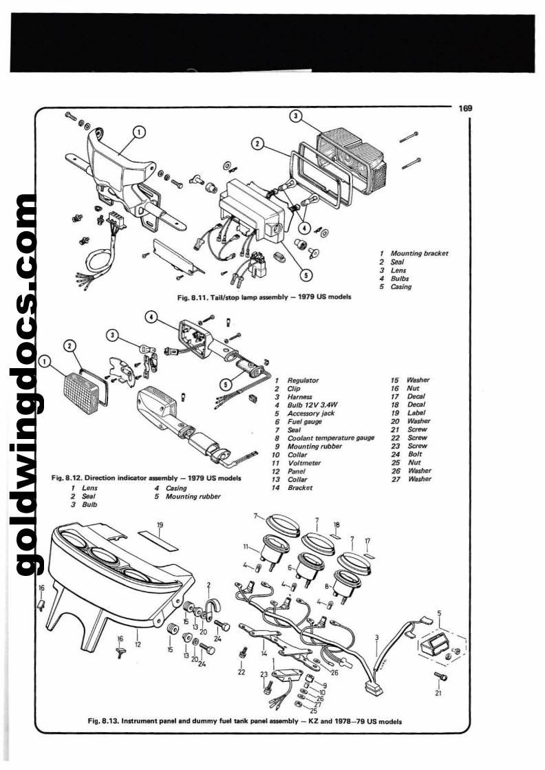
gold
win
gdoc
s.co
m
,
l
- 1979 US mode"'lampnsembly. .11. TeiVstopF"..
. bnH:IcetMounrlflf/2 seal3 Lens4 Bulb'5 C.sing
l
mbly _ 1979 US mod.1s"on indator _ .812. Directl 4 Cumg. bberF~... 5 Mountmg ru' Len.
2 Sui3 Bulb
, R~'.tor
2 Clip
3 Harness 3 4W4 Bulb f2V : dt5 Accnsory J'6 Fum f1iHJ~
7 Sal perature galJ~8 Coolant rem ber9 Mounting rub
10 CoII,r11 VoitmetBt"12 Panel13 Coif.14 Bracket
15 ~sher
'6 Nut17 ~CBI
18 o.csf19 ubel20 W.sher2' Saow22 Saow23 Saow24 /JIJlr25 Nut26 Wa$he'r27 Waosher
I!,
j
.~~<iI;l""20,,I "&@
• !, I 'flo20'4
I '.~ ...."Q~,.,
I "'"'~~,f~eo '27
~ 79 US modelsKz and 1978bly -rile panel.1Hmd mmy fuel tat pln,llnd u3 InstrumenFlg.8.1 .
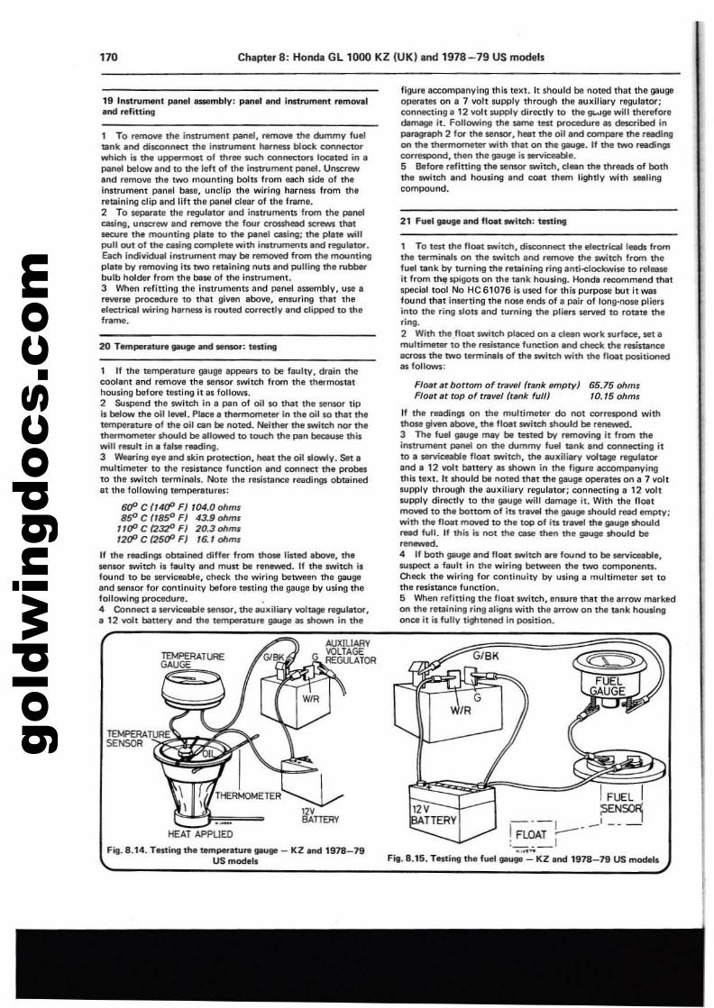
gold
win
gdoc
s.co
m170 Chapter 8; Honda GL 1000 KZ IUK} and 1978-79 US models
19 Indrumant panel assembly: panel and instrument removaland refitting
1 To rem()\/l! the innrull'le'l\t panel, remove the d.ommy fueltank Ind disconnect the instrument harness block connectorwhich il the uppermost 01 three $\Ich connectOl"$ IOQItI!d in apanel belOYll and to the left of the instr\lment panel. Unscrewand remove the two mountln9 boIu from each side of theinnrument pan81 base, uncllp the wiring harness from theretaining clip and 11ft the panel clear of the frame.2 To separate the regulator and instruments from the panelcasing, unscrew and remove the four crosshead screws thatsecure the mounting plate to the panel casing; the plate willpull out of the easing complete with instruments and regulator.Each individual instroment may be removed from the mountingplait by removing its two retaining nuts and pulling the rubbef"bulb holder from the base of the instrument.3 When refitting the instruments and panelass8mbly, use areverse procedlHIl to that given above, ensuring that theelectrical wiring harness is routed corre<:tly and clipped to theframe.
20 Temperature puge end MI'I$IH" tutitlll
1 If the temperature gauge appears to be faulty, drain thecoolant and remove the sensor switch from the thermostathousing before t8stin9 it as follows.2 Suspend the SWitch In a pan of oil so that the sensor tipis belOY11 the oil I_I. Place a thermometer in the oil so that th8temperature of the oil can be noted. Neither the switch nor thethermometer should be allowed to touch the pan bec:ause thiswill result in , false reading.3 Wearing eye and skin protection, heat the oil slowly. Set amultimeter to the resistance function and connect the probesto the switch terminals. Note the resistance readings obtainedat the following temperatures:
600 C f14fP FJ '04.0 ohms8ft' C (185" FJ 43.9 ohms
1uP C (2:]2D FJ 20.3 ohms1200 C (2500 FJ 16.1 ohms
If the readings obtained differ from those listed ~bove, thesensor switch is fwlty and must be renewed. II the switch i1found to be serviceable, check the wiring between the gaugeand sensor for continuity blliore testing the gauge by using thefollowing Pl'"ocedure. .4 Connect a serviceable semor, the auxiliary voltage regulator,a 12 volt battery and the temperature gauge as shown in the
figure accompanying this text. It should be noted that the gaugeoperates on 8 7 volt supply through the auxiliery regulator;connecting a 12 volt supply directly to the gwge will thef'eforedamage it. FolIOYlling the same test procedure IS described inparagraph 2 for the senSOf, heat the oilal'ld compere the reedingon the thennometef" with that on the IlllUge. If the two readingscorrespond, then the gauge is serviceable.5 Before refitting the sensor switch, clean the threads of boththe switch and housing and coot them lightly with sealingcompound.
21 Fuel gauge end float switch: testinrg
1 To test the float switch, disconnect the electrical leads fromthe terminals on the switch and n!m()\/l! the switch from thefuel tank by turning the retaining ring anti-elockwise to releaseit from the spigots on the tank housing. Honda recommend thatspeciel tool No He 61076 is used for this purpose but it wasfound that in5efting the nose ends of a pair of long-nose pliersinto the ring slots and turning the pliers served to rotate thering.2 With the float switch placed on a clean work surface, set amultimeter to thl resistance function end check the resimneeacross the two terminals of the switch with the noel positionedas follows:
Float ar bottom of traWl! (tank lImpry) 65.75 ohmsFloar af rap of traval (rank full) 10.15 ohms
If the readings on the multimeter do not correspond withthose given above, the f10et switch should be renewed.3 The fuel gauge may be tested by r&moving it from theinstrument j»ne1 on the dummy fuel tank and connecting it10 a serviceable float switch, the auxiliary voltage ~latorand a 12 volt battery as shown in thl figure accompanyingthis text. It should be noted that the gauge operates on a 7 voltsupply through the auxiliary regulator; connecting a 12 VOltsupply directly to the gauge wilt damage it. With the lloatmoved to the bottom of itl travel tha gauge should read empty;with the float moved to the top 01 its tra....lttl. gauge shouldread full. If this il not ttle cese then the gauge should be~.......-4 If both gauge and flOIt SWitch are found to be serviceable,SUsP8C! a fault in the wirinrg between the two components.Check the wiring for continuity by using a multimeter set fathe r.sistance function.5 When refitting the flOIt switch, ensure that the errow markedon the retaining ring align1 with the arrow on the tank housingonce it is fully tig,tened in position.
G/BK
12VHERY
IFUEL I---I -~~~I FLOAT --: 1---Fig. 8.15. Tl'Sling the fuel gauge - KZ end 1978-79 US mod.11
12VBATTERY
HEAT APPllED
Firg. 8.14. Tl'Sling the temper,ture gauge - KZ Ind 1978-79US models
TEMPfRATUREGAUGE
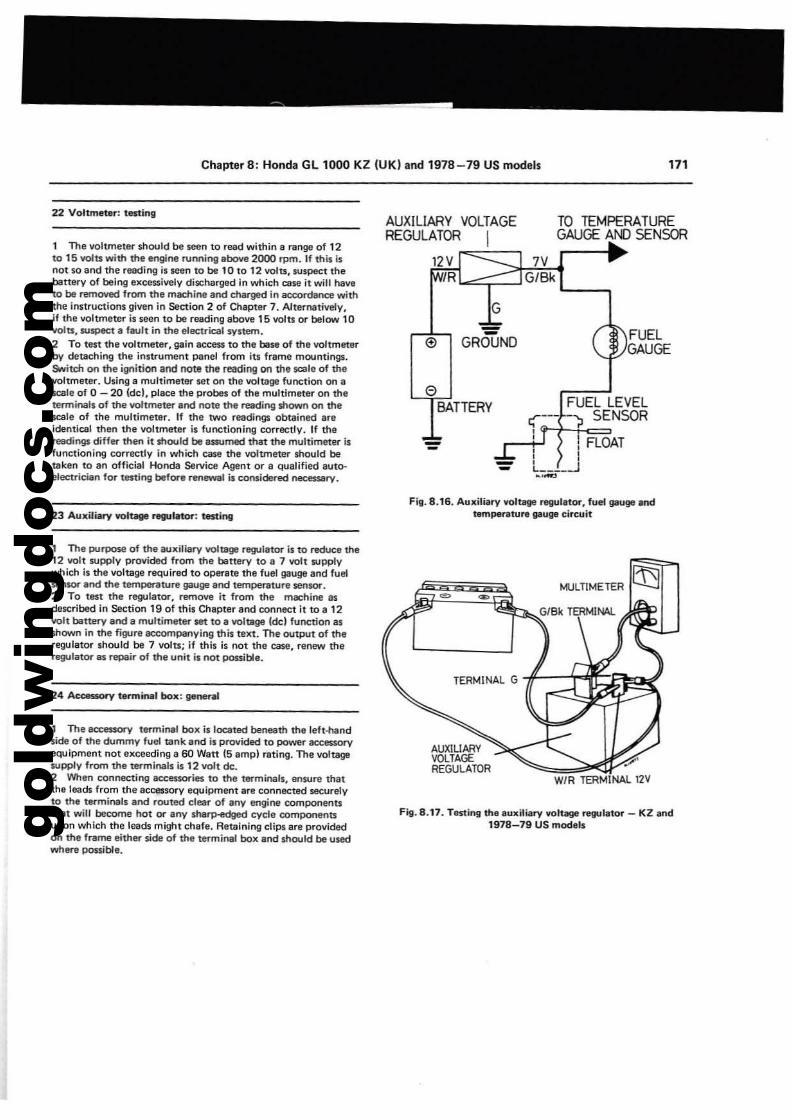
gold
win
gdoc
s.co
m
Chapter 8: Honda GL 1000 KZ (UK) and 1978-79 US models 171
FUELGAUGE
TO TEMPERATUREGAUGE AND SENSOR
FUEL LEVELr;--- -) SENSOR,
--
G
BATTERY
=(!) GROUNO
o
AUXILIARY YOLTAGEREGULATOR I
,2Y 1""":::::------' 7V1R ~*"G':i/B"'ki'--...,
22 Voltmeur: testing
1 The voltmeter should be seen to read within a range of 12to 15 volts with the engine running above 2000 rpm. If this isnot so and the reading is seen to be 10 to 12 volu, suspect thebettery of being excessively diJcharged In which case it will haveto be removed from the mec:hine and charged in ac:c:ordanc:e withthe Instructions given in Seaion 2 of Chapter 7. Alternatively,if the voltmeter is seen to be reading above 15 volts or below 10YOIts, suspect a f.... lt in the B'lectriQIl system.2 To test the voltmeter, gain access to the bese of the voltmeterby detaching the instrument panel from its frame mountings.SNitch on the ignition and note the reeding on the scale of thevoltmeter. Using 8 multimetef" set on the voltage function on ascale of 0 - 20 (dcl, place the probes of the multimeter on theterminals of the voItmeteT and note the reading shown on thescale of the multimeter. If the two readings obtained areIdentical then the voltmeter is functioning correctly. If thereedirtgs diffB\'" then it should be assumed that the multimeter isfunctioning correctly in which case the voltmeter should betalcen to an official Honda Service Agent or a qualified auto·B'leetrician fOl'" testing before renewal is considered necessary.
23 Auxiliary w.lbga r19Jlnor: testingFig. 8.16. Auxiliary voltage ~ll1or, fuB'l9llug8 and
tlm'lperatura 9iIuge circuit
Fig. 8.17. Testing the auxiliary voltage r19Jlator _ KZ and1978-79 US models
MULTlMETER
<,'
WIR TERMINAL 12V
TERMINAL G -{fr-;;~!~~~~~
AUXILIARYVOLTAGEREGULATOR
24 AC08SSOfY tarminlll box: general
1 The aec:essorv terminal box is located beneath the left-handsida of the d\Jmmy fuel tank and is provided to power ac:c:essoryequipment not exceeding a 60 Watt (5 ampl rating. The voltagesupply from the terminals is12 volt de.2 When connecting ac:e:essories to the terminal., ensure thatthe leads from the accessory equipment are connectltd securelyto the terminals and routed clear of any engine componentsthat win become hot or any sharp-edged cycle comPOntlntsupon which the leads might chafe. Retaining clips are providedon the frame either $ide of the terminal box and should be u$edwhere possible.
1 The purpose of the auxiliary voltage regulator is to reduce the12 volt supply ~ovided from the battery to a 7 volt suwrywhich i. the voltage required to Op.ltrate the fuel gauge and fueisen$Ol" and the temperature gauge and temperature sensor.2 To test the regulator, remove it from the machine asdescribed in Section 19 of this Chapter and connect it to a 12volt battery atld a multimeter set to a voltage ldel function asshown in the figure accompanying this tellt. The output of theregulator should be 7 volts; if this is not the case, reOBW theregulator as «!'P8lr of the unit is not possible.
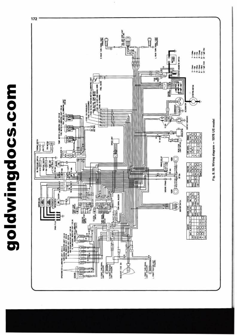
gold
win
gdoc
s.co
m
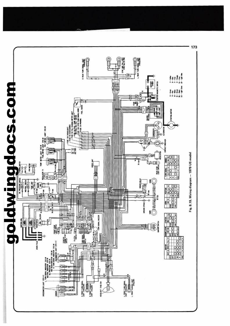
gold
win
gdoc
s.co
m
Ilildl!lH!
I jI I~
I
I ~!:'~'~;lI
173
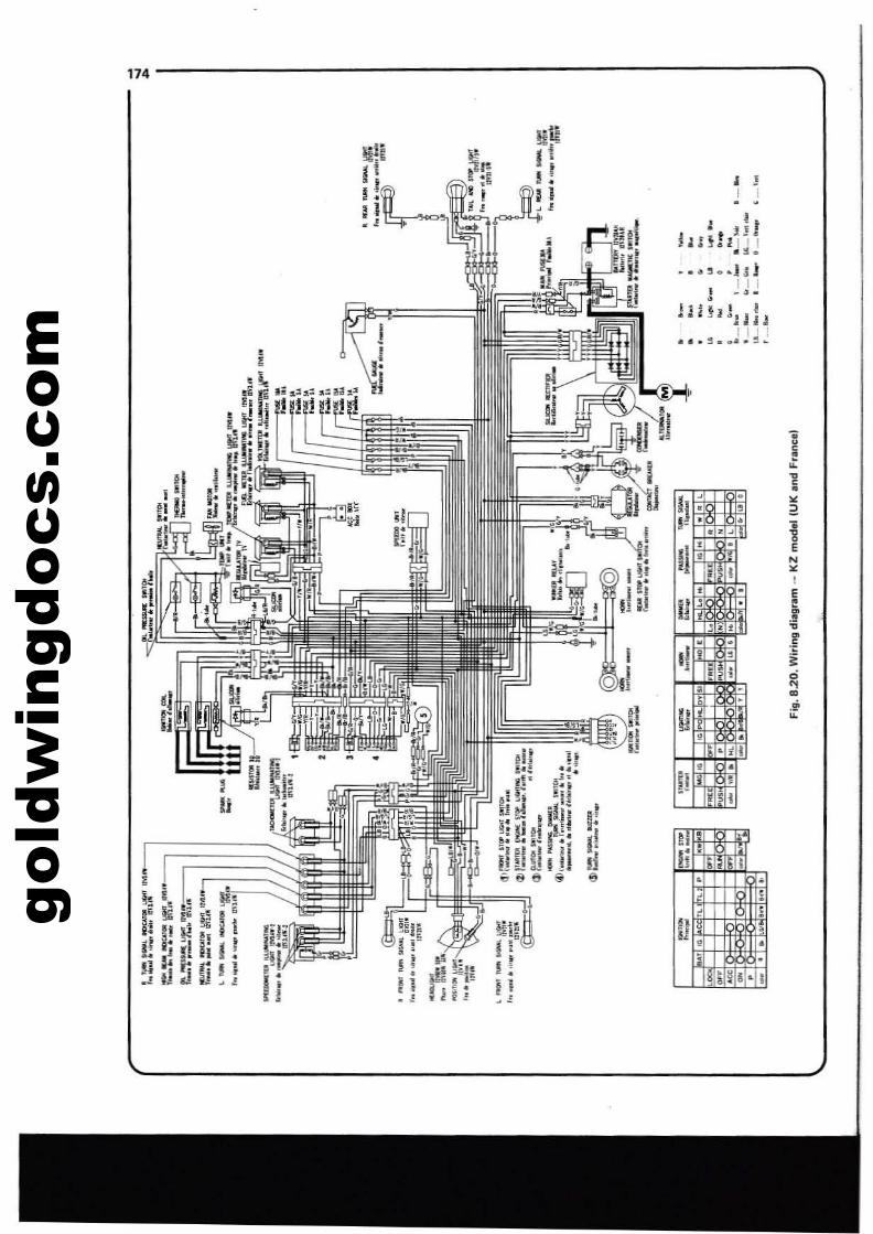
gold
win
gdoc
s.co
m174
<2
iE
N<I
!.f•.~
"~~
.ri•
•I
• !I I. .
•
•
,
,'II
Ii'Hi;!;!;
!Ii'
II ; ;• •1- .. z ..
.!'(
I~i,g=~ r;
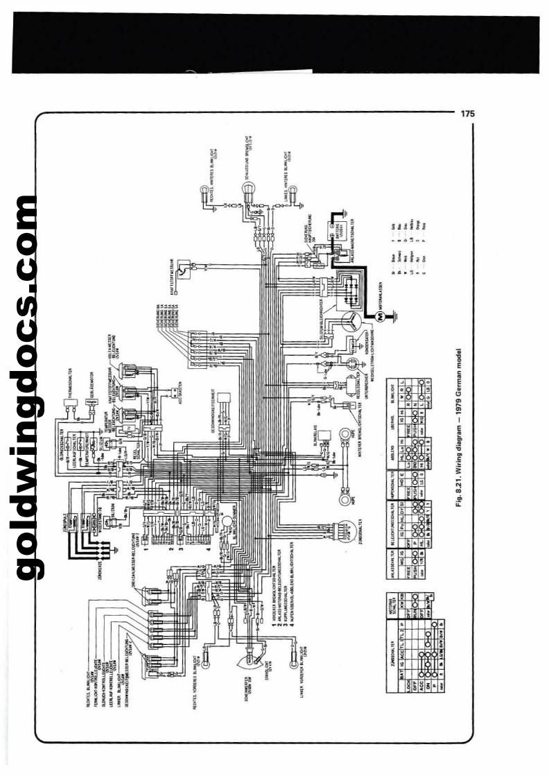
gold
win
gdoc
s.co
m
r-------------------------- 175
lulll
.... ~ ...
"I'•ii
,, I
_I '" 1! !I" ,iill;' i'I j! I
"III
II
"." .."
jE
"•" E
I " •• 0
• ~
~-I0 i
E•i .f•
~
.E
• i-~~
0 :i!•
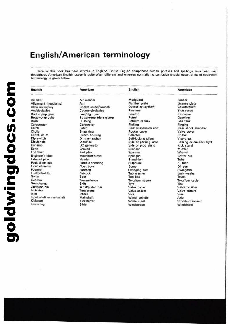
gold
win
gdoc
s.co
m
English/American terminology
Because this book has been written In England, British English component nemes, phrases and spellings h8\18 been usedthroughout. American EngIJsh usage is quite often different and whereas normallv no confusion should occur, 8 list of equivalentterminology Is giveo below.
EngI1,.,
Air filterAlignment (he.adlllmplAllen SCfllW/keyAntlclodwiseBottom/top gearBottom/top yoke'~hCarburettorCatchCirellpClutch drumDip switchDisulphideDynamoEarthEnd floe!Engineer's blueExhaust pipeFault diagnosisFloat chamberFootrestFueVpetrol tapGaiterGearboJcGearchsngeGudgeon pinIndicatorInletInput sNit or malnshaftKickstartlower leg
Am~lcen
Air cleanerAimSocket saew/wrenchCounten:lockwlseLowlhlgh gelrBottomltop Irlple clampBushingCarburetor
la''''Snap ringClutch housingDimmer switchDisulfideDC generat~
GroundEnd playMachlnisfs dyeHeaderTrouble shootingFloat bowlFootpegPetcock
'00'TransmissionShiftWrist/piston pinTurn signalIntakeMainshaftKickstarterSlider
English
MudguardNumber plateOutput or layshahPanniarsParaffinPetrolPetrol/fuel tankPinkingRllar suspension unitRocker coYerSelectorSelf-locking pliersSide or parking lampSide or prop standSilencerSpannerSplit pinStanchionSulphuricSumpSwinging armTab washerTop boxTwoffoUl'" strokeTyreValve collarValve colletsV;~
Wheel spindleWhite spiritWindscreen
American
FenderUcensll plaleCountershaftSide casesKeroseneGasolineGas tankPingingRellr shock absorberValve coYllrShifterVisll-grlpsParking or aUlliliary lightKick standMufflerWrenchCotter pinM.Sulfuric011 panSwlngarmLock washerTru""Twolfour cycleTireValve retainerValve cotter.Vise"",.Stoddard solventWindshield
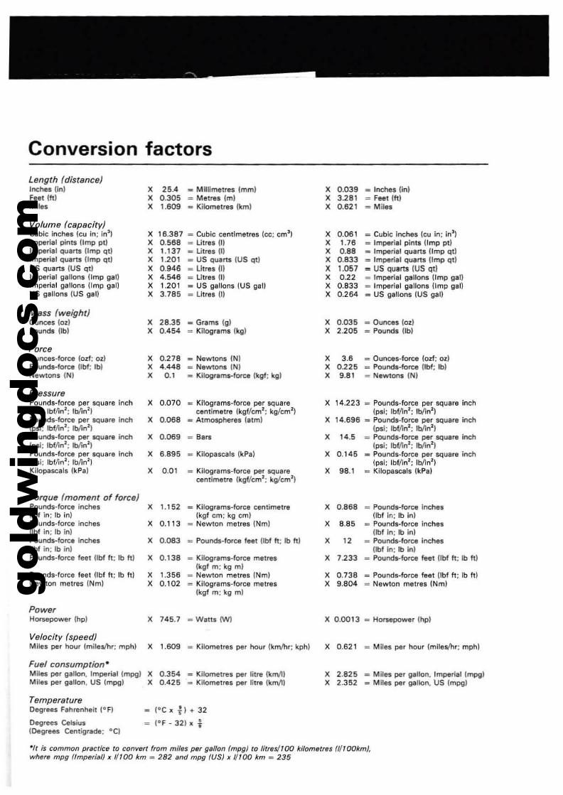
gold
win
gdoc
s.co
m
Conversion factors
Length (distance)Inches (in) X 25.4 .. Millimetres lmml X 0.039 '" Inches (in)Feet Iftl X 0.305 .. Melres 1m) X 3.281 = Feel 1ft)Miles X 1.609 .. Kilometres lkml X 0.621 = Miles
Volume (capacity)Cubic inChes leu in: In3
) X 16.387 = Cubic centimetres Icc; em') X 0.061 = Cubic inches (eu in; in~lImperial pints {Imp pi) X 0.568 .. Litres III X 1.76 .. Imperial pints (Imp pi)Imperial quarts limp qtJ X 1.137 "" Litre! III X 0.88 so Imperill quarts (Imp ql)Imperial quarts limp qt) X 1.201 .. US quarts (US qtl X 0.833 = Imperil' quarts (Imp qt)US quarts (US ql) X 0.946 .. Litre' III X 1.057 = US quarts (US qt)Imperial gallons limp gal) X 4.546 '" Litres m X 0.22 .. Imperial 9811on5 (Imp gal)Imperial gallons (Imp gal) X 1.201 .. US gallons (US QaU X 0.833 "" Imperial gallons (Imp gal)US gallons (US gal) X 3.785 .. Litrlll III X 0.264 .. US gallons (US gal)
Mass (weight)Ounces (oz) X 28.35 - Grams (gl X 0.035 = Ounces (oz)Pounds UbI X 0.454 "" Kilograms (kg) X 2.205 - Pounds UbI
ForceOunces-Iorce (od; oz) X 0.278 "" Newtons (Nl X 3.6 = Ounces-force (od; ozlPounds-force Ubf; Ibl X 4.448 _ Newtons (NI X 0.225 _ Pounds-force Ubf; Ib)Newtons (Nl X 0.' _ Kilograms-force tkgf; kg) X 9.81 _ Newtons (N)
PressurePounds-Iorce per square inch X 0.070 _ Kilograms-force per square X 14.223 _ Pounds-force per square inch(psi; lbf/in'; Ib/in' ) centimetre Ikgf/cm'; kg/cm') Ipsi; Ibf/in': lb/in')Pounds-force per square inch X 0.068 _ Atmospheres (atm) X 14.696 "" Pounds-force per square inch(psi; lbf/in'; rb/in'l (psi: Ibf/in'; rb/in')Pounds-force per square inch X 0.069 = Bars X 14.5 = Pounds-force per square inch(psi; IbMn'; lbIin'l (psi; Ibf/in'; Ib{rn' )Pounds-force per square inch X 6.895 _ Kilopascals (kPal X 0.145 _ Pounds-force per square inch(psi; Ibl/in'; Ib/in') (psi; Ibf/in'; Ib/in')KUopascals (kPa) X 0.01 _ Kilograms-fOfce per square X 98.1 _ Kilopascals (kPa)
centimetre (kgf/cm' ; kg/cm')
Torque (moment of force)Pounds-force inches X 1.152 _ Kilograms-force centimetre X 0.868 _ Pounds-force InchesUbf in: Ib inl (kgf cm; kg cml Ubf in: Ib in)Pounds-force inches X 0.113 = Newton metres (Nm) X 8.85 .. Pounds-force inchesUbf in; Ib in) Ubf In; Ib inlPounds-Iorce inches X 0.083 : Pounds-force feel Ubf II; lb hi X 12 _ Poonds-force inchesUbf in: rb in} Ubf in: lb inlPounds-Iorce feet lIbf h; rb hi X 0.138 = Kilograms-force metres X 7.233 = Pounds-force feet (Ibf h; Ib It)
lkgf m; kg mlPounds-force feet Ubf h: Ib It) X 1.356 _ Newton metres (Nm) X 0.738 _ Pounds-force feet Obf h; Ib h)Newton metres (Nm) X 0.102 "" Kilogfsms-force metres X 9.804 _ Newton metres (Nm)
{kgf m; kg ml
PowerHorsepower (hp) X 745.7 - Wails (W) X 0.0013 _ Horsepower (hp)
Velocity (speed)Miles per hour (miles/hr; mph) X 1.609 _ Kilometres per OOtir (km/hr; kphl X 0.621 _ Miles per hour (milet/hr; mph)
Fuel consumption·Miles per galloo. Imperial (mpg) X 0.354 = Kilometres per litre {km/ll X 2.825 _ Miles per gallon. Imperial lmpglMiles per gaUon. US (mpg) X 0.425 "" Kilometres per litre (km/l) X 2.352 "" Miles per gallon. US (mpg)
TemperatureDegrees Fahrenheit (OF) (OCxtl+32
Degrees Celsius (OF _ 321 x ...fOegrees Centigrsde; °C)
·/f is common practice to convert from miles per gallon (mpg) to {itres/l00 kilometres a/Tookm},where mpg (fmptJrilll)}{ {/100 km _ 282 and mpg (US}){ 1/100 km _ 235
gold
win
gdoc
s.co
mIndex
AAUIOf1'1l1Ii<: timing unil' 109Aceeuorv terminal box . 171Adjunmerl1 valve c;leeraoce -14Air IiItel' - 10 - 96,157Aulotnltic timi",!! unit .109
Alternator - 10'-140Mli',...· n
8Bal~i"9' Front~. 135Blnerv _7·140S.ringa:
bill journal - 52bit Ill'ld - 42front wheel • 122rUt whM!·124ltMfing head -12
Brake· front:bleeding ·129,165calipers· 126. 164fluid· 12master cylinder· 129pads - 126, 163, 165
Brake - tnt:caliper-131,l68master cylinder· 132plIds·131.168
Bulb repllCement - '43-145
cCebles:
choka al1d throttle - 86speedornetel" and Il.chometer - 118
Cerburanor'l:adju.ting floal level f,eight - 95dlSmllnlling- 87idla Ipeed adjullment - 94removal -86..nin~· 95IYnchronisatlon
Centre .lInd· 118Clpningthe machine - 118Clutch:
adjUitmen1- 12-13examiMtion and ranDll81ion - 49removal - 27replacement· 63
Coil ignition· 102Contacl breaker:
adju.trnent- 10-102ranov81ion and adjUllment - 102
CondenlDr - 102Cooling ~tem:
ltOtifreeza mixture - 77
draining }fluihing 76-77tillingtlidi81Dr r_al .78,.m81Dr preswra Clip testing - 80thermel181 - SO_tel" pump. 81
CrankcMe breather reservoir - 157Cranke.se hal\/8l: ~rating - 33er.nkd'laft·37-43Custl drr.e - 132Cylinder born: examin81ion - 44
Cylinder heads . 27
oo.c.rboni,ing- 4SD,i-"'ft· 133Dual,"l - 118Dummy luella"k . 118
EElectrieCIIl equipment:
betteN - 1..0flin.hing indiatOfS - 145futeS - 140head11t1"1P. 173
horn· '41ignition $Witch· 142reguttlor voltage· 141Silicon rectifier· 140~ilieation.- 138ltarUt motor· 141$lOP al'ld tail lamp . 145
Electric I." . 147Engioe:
di$l'Mnlling· 19'lCami!'llllion end renOVlltion • "2,..auembly-54engine r.placement in frame-70'running in' • 73starting· 73
Exhau!itsystem: rfIlTlOval·95. 157.158
FFan: alel:lric· 147Fault diagnDl;':
brakes-137carburenorl - 100clulch . 75cooling system' 82eleclrlcal .ystem . 148.ngine·74fuel system· 1009l!arbol( . 75ignition .y.ttm· 106lubrication syUam· '00wres and whetl•. 137
Filters:air·96fuel- B6oil·99
Finaldr1ve·l1·133Flashing indicators· 145FoolrllSti· 118Forks (frond:
diSmlIntlinll" 1'0examination· 11 treplacement· 111-112removal· 107
Frame - 11"Fuel gauge - 170Fuel lines· '1Fuellllnk" 85Fuse IOUlion· 140
GGearbox:
dismantling· 19examination and renDllation . 42
gold
win
gdoc
s.co
m
reauembly . 54removal. 18selector tT1oId\ani$m . 60
G...etgean pin - 45
HHandlebar switches - 142Headllmp - 142Horn· 141Hydr3Ulic system' 120-129
Ignition system:allernalOr - 101iJUlamalic timing unit· 104coil· 102condensor . 102contact breaker - 102sp;Irk plugs· 104switch· 142timing:
checking and resetting manually' 102checking with a stroboscope - 104
ln$!rument heads - 118. 169
KKickstart meehanisr'n - 53
LLamps.:
IlMhel" -145,168head· 143stop and tail· 145. 168
Lubricants - 14
MMain bearings - 43Maintenance rouline _1.13Master cylinders:
frOnt - 129rear - 132
NNeulral indicator switch. 142
oOil pump:
e",aminalian and renovation. 96removal·40
Oil lilter· 99Ordering IiJ)lIre pariS - 6
pPedal brake· 120Petrol tank· 85Pistons 44Piston rings· 44Poinu: conlact· 102Pressure cap: radiator· 80Prop nand· 118Pumps:
oil- 96waler·33
Index
RRadiltor . 18Radiltor prltSSUre ClIP - 80Recommended lubricants -14Rings - piston· 44Regulltor: voltage· 141Rocker Irms - 46Rouline mainlenance ·1-13'Running in' .13Rear wsperuion unit· 111
sSeat-du<lI-118Silencer - 95Selector mechanism gear - 60Silicon rectifier, 140Starter motor· 141Stoplamp switl;h - 142Spark plugs· 104Specificalions:
br.kes . 120carburettors - 83Clutch· 11cooling ·16electrical system - 138engine 15-11fuel system· 83frame .nd forks· 101gaarbo", . 11ignition system - 101lubrication $y$tem - 83wheels and tv"s - 120
Stand and foolrestl·118Starter motor 141Starter motor swilch - 141Stllrting engine all... rebuild· 13Steering head bearings· 12-111, 159Stetllring head lock· 114Swinging erm - 114-115Switches - handlebar - 142
TTemperatu~ glJlI!JIll- 141. 110Thermostat· 80Throttle adjustment - 11Tyres·133Ty'e preswres· 14Tyre valYl11i - 135
vValve grinding - 46Valves tv,,· 135Vllve clearances - 14Valve cores and caps - 135Voltage regulator - 141, 111Voltmeter ·111
wWattr pump· 81Wheels:
front ·120-121. 160, 161rear -124. 160, 166
Wheels: balancing. 135Wheels: bearings-122-124, 162,163,166Wiring diagrams - 149-153, 1n·115
179
gold
win
gdoc
s.co
m