hds gen2 touch - installation manual - tradeinn
TRANSCRIPT
ENGLISH
HDS Gen2 TouchInstallation Manual
lowrance.com


| 1
PrefaceAs Navico is continuously improving this product, we retain the right to make changes to the product at any time which may not be reflected in this version of the manual. Please contact your nearest distributor if you require any further assistance.
It is the owner’s sole responsibility to install and use the instrument and transducers in a manner that will not cause accidents, personal injury or property damage. The user of this product is solely responsible for observing safe boating practices.
NAVICO HOLDING AS AND ITS SUBSIDIARIES, BRANCHES AND AFFILIATES DISCLAIM ALL LIABILITY FOR ANY USE OF THIS PRODUCT IN A WAY THAT MAY CAUSE ACCIDENTS, DAMAGE OR THAT MAY VIOLATE THE LAW.
Governing Language: This statement, any instruction manuals, user guides and other information relating to the product (Documentation) may be translated to, or has been translated from, another language (Translation). In the event of any conflict between any Translation of the Documentation, the English language version of the Documentation will be the official version of the Documentation. This manual represents the product as at the time of printing. Navico Holding AS and its subsidiaries, branches and affiliates reserve the right to make changes to specifications without notice.
CopyrightCopyright © 2012 Navico Holding AS.
WarrantyThe warranty card is supplied as a separate document.
In case of any queries, refer to the brand web site of your display or system:
www.lowrance.com
Declarations and conformanceThis equipment is intended for use in international waters as well as inland waters and coastal sea areas administered by countries of the USA, E.U. and E.E.A.

2 |
Compliance StatementsLowrance HDS-7, HDS-9, and HDS-12 Gen2 Touch:
• meet the technical standards in accordance with Part 15.103 of the FCC rules
• comply with CE under RTTE directive 1999/5/EC
• comply with the requirements of level 2 devices of the Radiocommunications (Electromagnetic Compatibility) standard 2008
For more information please refer to our website:
www.lowrance.com
WarningThe user is cautioned that any changes or modifications not expressly approved by the party responsible for compliance could void the user’s authority to operate the equipment.
This equipment has been tested and found to comply with the limits for a Class B digital device, pursuant to Part 15 of the FCC rules. These limits are designed to provide reasonable protection against harmful interference in a residential installation. This equipment generates, uses and can radiate radio frequency energy and, if not installed and used in accordance with the instructions, may cause harmful interference to radio communications. However, there is no guarantee that the interference will not occur in a particular installation. If this equipment does cause harmful interference to radio or television reception, which can be determined by turning the equipment off and on, the user is encouraged to try to correct the interference by one or more of the following measures:
• Reorient or relocate the receiving antenna
• Increase the separation between the equipment and receiver
• Connect the equipment into an outlet on a circuit different from that of the receiver
• Consult the dealer or an experienced technician for help
| 3
About this manualThis manual is a reference guide for installing the Lowrance HDS-7, HDS-9, and HDS-12 Gen2 Touch system.
The manual does not cover basic background information about how equipment such as radars, echo sounders and AIS work. Such information is available from our web site:
http://www.lowrance.com/Support/Library/
Important text that requires special attention from the reader is emphasized as follows:
¼ Note: Used to draw the reader’s attention to a comment or some important information.
! Warning: Used when it is necessary to warn personnel that they should proceed carefully to prevent risk of injury and/or damage to equipment/personnel.
Trademarks• ‘NMEA 2000’ is a registered trademark of the National Marine
Electronics Association
• ‘Navionics’ is a registered trademark of Navionics SpA
• ‘Simrad’ is a trademark of Kongsberg Maritime AS Company registered in the US and other countries and is being used under license.
• ‘HDS’, ‘StructureScan’, ‘Navico’, ‘Lowrance’, ‘SonicHub’, ‘SimNet’ and ‘Skimmer’ are trademarks of Navico, registered in the US and other countries. ‘InsightHD’, ‘Broadband Radar’ and ‘Broadband Sonar’ are trademarks of Navico.

4 |
Contents
6 HDS Gen2 Touch overview7 Front - controls8 Rear - connectors9 SD card slot
10 Check the contents
11 Display Installation11 Mounting location12 Bracket mounting13 Flush mounting14 Research14 Select a transducer location15 Attaching the transducer16 Adjusting the transducer
17 Wiring17 Guidelines18 Power connection20 Transducer connection21 Ethernet device connection22 NMEA 2000 device connection24 NMEA 0183 device connection25 Video In25 Connecting video sources
26 Software setup26 Sonar installation settings28 Touch Screen Calibration28 Software upgrades
29 Dimensional drawings29 HDS 7 Gen2 Touch29 HDS 9 Gen2 Touch29 HDS 12 Gen2 Touch
| 5
30 Accessories30 NMEA 200030 Transducers31 Ethernet cables31 Display parts
33 Supported data 33 NMEA 200034 NMEA 0183
35 Specifications

6 | HDS Gen2 Touch overview | HDS Gen2 Touch Installation Manual
HDS Gen2 Touch overviewThe HDS-7, HDS-9, and HDS-12 Gen2 Touch multifunction displays are available with or without inbuilt sonar and structure scan. The ability to network over NMEA 2000 and ethernet allows access to data as well as control of numerous optional devices that can provide sonar, radar, audio entertainment, weather and even digital switching.
All displays are charting ready, with built-in GPS receiver and Insight cartography (region dependent) and with optional Navionics support via an SD card slot.
The displays may be mounted on to the vessel with the supplied surface mount bracket, or flush mounted in to the dash.
Power should be supplied at around 12V, but due to the variable nature of boat power systems, the displays are designed to operate on 10.8 V - 17 V.
1

| 7HDS Gen2 Touch overview | HDS Gen2 Touch Installation Manual
Front - controls
2
1 3
4
5
6
1 Touchscreen
2 Card reader door
3 Pages key
4 Zoom in / Zoom out key
5 Mark / Waypoint key
6 Power key

8 | HDS Gen2 Touch overview | HDS Gen2 Touch Installation Manual
Rear - connectors
2 34 5 12 3 4 4 51
A B
A HDS-9 & 12 connector arrangement
B HDS-7 connector arrangement
1 Sonar
2 StructureScan - connects to LSS-2 HD Transducer
3 Power - also video for HDS-9 & 12, with optional adaptor
4 Ethernet - two ports on HDS-9 & 12, one on 7
5 NMEA 2000

| 9HDS Gen2 Touch overview | HDS Gen2 Touch Installation Manual
SD card slotUsed for optional Navionics or InsightHD chart data, software updates, transfer of user data and system backup.
The card reader door is opened by lightly pressing and sliding the door to the left, then pulling forward from the left side.
The card reader door should always be shut immediately after inserting or removing a card, in order to prevent possible water ingress.
¼ Note: The HDS-9 and 12 Displays have two card readers, the HDS-7 has one.

10 | Check the contents | HDS Gen2 Touch Installation Manual
Check the contentsDisplay Bracket knobs (x2)
Front Bezel (attached to unit) Power cable
Sun cover Fasteners - #6 x 1.5” (4x)
Mounting bracket
Parts Included, dependent on model
83/200 KHz transducer LSS-2 HD transducer
50/200 KHz transducer DVD - manuals
2
| 11Display Installation | HDS Gen2 Touch Installation Manual
Display Installation
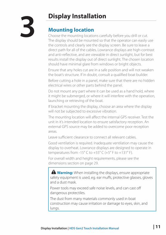
Mounting locationChoose the mounting locations carefully before you drill or cut. The display should be mounted so that the operator can easily use the controls and clearly see the display screen. Be sure to leave a direct path for all of the cables. Lowrance displays are high-contrast and anti-reflective, and are viewable in direct sunlight, but for best results install the display out of direct sunlight. The chosen location should have minimal glare from windows or bright objects.
Ensure that any holes cut are in a safe position and will not weaken the boat’s structure. If in doubt, consult a qualified boat builder.
Before cutting a hole in a panel, make sure that there are no hidden electrical wires or other parts behind the panel.
Do not mount any part where it can be used as a hand hold, where it might be submerged, or where it will interfere with the operation, launching or retrieving of the boat.
If bracket mounting the display, choose an area where the display will not be subjected to excessive vibration.
The mounting location will affect the internal GPS receiver. Test the unit in it’s intended location to ensure satisfactory reception. An external GPS source may be added to overcome poor reception areas.
Leave sufficient clearance to connect all relevant cables.
Good ventilation is required. Inadequate ventilation may cause the display to overheat. Lowrance displays are designed to operate in temperatures from -15° C to +55° C (+5° F to +131° F).
For overall width and height requirements, please see the dimensions section on page 29.
! Warning: When installing the displays, ensure appropriate safety equipment is used, eg. ear muffs, protective glasses, gloves and a dust mask.
Power tools may exceed safe noise levels, and can cast off dangerous protectiles.
The dust from many materials commonly used in boat construction may cause irritation or damage to eyes, skin, and lungs.
3

12 | Display Installation | HDS Gen2 Touch Installation Manual
Bracket mountingPlace the bracket in the desired mounting location, and use a pencil or permanent marker to mark drilling locations.
¼ Note: ensure that the chosen location has enough height to accomodate the display fitted in the bracket, and allows tilting of the display. Also adequate space is required on both sides to allow tightening and loosening of the knobs.
Use fasteners suited to the mounting surface material. If the material is too thin for self tappers, reinforce it, or mount bracket with machine screws and large washers. Use only 304 or 316 stainless steel fasteners. Mark the screw locations using bracket as template, and drill pilot holes.
Screw down the bracket.
Mount the display to the bracket using the knobs. Hand tighten only. The ratchet teeth in the bracket and display case ensure a positive grip and prevent the unit changing from the desired angle.

| 13Display Installation | HDS Gen2 Touch Installation Manual
Flush mountingCheck the template for scaling accuracy, using a tape measure or ruler against the ruler printed on the template.
MOUNTING SCREW SIZE IS #6 TAPPING SCREW LC
LC
Check dimensions before cutting12"
SUN COVER
PRODUCT OUTLINE
199.0 mm (7.83")
190.5 mm (7.50")
220.4 mm (8.68")
95.3 mm (7.50")
99.5 mm (3.92")95.3 mm (7.50")
110.2 mm (3.75")
Cut away excess paper, and tape down the template. Check it is correctly aligned to a vertical or horizontal reference. Do not use a bubble level as vessel may be listing! Adjust where required.
Drill all marked pilot holes, then using an appropriate saw, cut through the template and mounting surface, along the dotted line bordering the shaded center of the template.
Remove the bezel from the display, using a fingernail or small flat screwdriver, starting at the edges that are closest to the card reader door.
Check the fit of the display, and use a file to remove any remaining obstructions. If water-tightness is required, apply a thin, continuous bead of sealant to the back of the display prior to final installation. Sealant should be of a ‘neutral cure’ type to prevent damage to the plastics. Secure the display with the supplied screws. Once screws are fully tightened, ensure there is complete contact with the mounting surface. Lastly, fit the bezel with the card reader door open; insert the outermost tabs on the bezel in to the slots on the display, then gently press down the bezel above and below the card reader door till it clicks in to place.

14 | Display Installation | HDS Gen2 Touch Installation Manual
Mounting the transducerTransducer location selection and installation are two of the most critical steps in sonar installation. To function properly the transducer must be in the water at all times, and in a location that has a smooth flow of water when the boat is moving.
ResearchBefore starting the installation of the transducer, it’s advised to check the following;
• Find out if the boat builder has a recommended installation location
• Establish direction of rotation of the propeller(s)
• Watch actual water flow when boat is travelling at cruising speed to determine the area of transom with cleanest flow (least bubbles)
Select a transducer locationThe primary aim is to stay clear of propeller and hull generated turbulence, while mounting the transducer as close to the center of the vessel as possible.
1 2 3 54
1 Avoid mounting within 1m (3.3’) to port of propeller
2 Conventional clockwise propeller rotation
3 Avoid mounting within 7.5cm (3“) to starboard of propeller
4 Best mounting location - undisturbed water flow
5 Planing strake - avoid mounting behind here
¼ Note: Reverse the distance guides (1 & 3) from propeller where engine is of counterclockwise configuration.
4

| 15Display Installation | HDS Gen2 Touch Installation Manual
¼ Note: Boats with strakes or ribs on the hull can create large amounts of turbulence at higher speeds. A good transducer location on these types of boats is between the ribs closest to the engine.
¼ Note: If the transducer is not placed in a smooth flow of water, interference caused by bubbles and turbulence may show on-screen in the form of random lines or dots. The unit could also lose bottom signal when the boat is on plane.
¼ Note: Trim tabs will vary in the amount of turbulence they create as they are adjusted, stay clear of these.
Attaching the transducerThe transducer should be installed parallel with the transom’s waterline, not the bottom of the boat (deadrise).
¼ Note: Ensure the entire bottom surface of the transducer hangs at least couple of millimetres (1/16ths of an inch) lower than the bottom of the hull.
Hold the transducer with bracket up to the transom of the boat and trace the slotted screw hole locations (two on the 83/200 KHz transducer, and four on the 50/200 KHz transducer). Mark drilling points in the middle of each outline, to allow for transducer height adjustment. Drill pilot holes to suit fasteners.
¼ Note: Check that there is nothing on the other side of the mounting surface that may be damaged by drilling.
Attach transducer to transom, using supplied stainless steel fasteners. Drill a 25mm (1”) hole above the waterline, large enough to pass the plug through.

16 | Display Installation | HDS Gen2 Touch Installation Manual
Secure the cable to the hull at regular intervals using cable P clips or saddles and ensure that moving parts such as an outboard motor or boarding ladder can’t snag the cable.
Adjusting the transducerIf the sounder image shows interference lines on the screen when moving, which worsen with speed, it may be possible to eliminate these by adjusting the transducer’s angle.
¼ Note: A transducer that is tilted too far in either direction will not perform well, missing targets, and/or losing the bottom at speed.
If performance does not improve with tilting, try adjusting the height of the transducer relative to the transom of the boat. If the transducer is too high it may be seeing cavitation caused by the trailing edge of the transom.

| 17Wiring | HDS Gen2 Touch Installation Manual
Wiring
GuidelinesDon’t do this Do this
Don’t make sharp bends in the cables
Do make drip and service loops
Don’t run cables in a way that allows water to flow down into the connectors
Do cable tie all cables to keep them secure
Don’t route the data cables in areas adjacent to radar, transmitter, or large current carrying cables
Do solder/crimp and insulate all wiring connections, if extending or shortening power or NMEA 0183 cablesDo leave room at the back to install and remove cables
! Warning: Before starting the installation, be sure to turn electrical power off. If power is left on or turned on during the installation, fire, electrical shock, or other serious injury may occur. Be sure that the voltage of the power supply is compatible with the HDS Gen2 Touch display
! Warning: The HDS Gen2 Touch has a voltage rating of 12 V DC, it is not suited for use with 24V DC systems.
! Warning: The positive supply wire (red) should always be connected to (+) DC with the supplied fuse or a circuit breaker (closest available to fuse rating).
5

18 | Wiring | HDS Gen2 Touch Installation Manual
Power connectionHDS Gen2 Touch displays are designed to be powered by a 12 V DC system. They are protected against reverse polarity, under voltage and over voltage.
The plug of the supplied power cable has two discrete cables exiting from it. The thickest cable provides the following:
• power into the system (Red and Black wires)
• remote turn-on for certain Navico expansion modules (Yellow wire)
+_
2
3
4
65
1
1 HDS display rear (9 & 12 connector arrangement shown)
2 Power cable
3 12 V negative wire (black)
4 12 V positive wire (red) shown with fuse holder fitted
5 Accessory Wake Up wire (yellow)
6 Vessel’s 12 V DC supply
Connect red to (+) DC using a 5 A fuse. Connect Black to (-) DC.
Accessory wake upThe yellow colored accessory wake up line may be used to control the power state of Navico modules such as SonicHub, StructureScan, and Broadband radar. This means that the modules are turned on the moment the display is powered up.
¼ Note: Broadband radar will be put in standby, when triggered by the accessory wake up line. For connection, simply combine all yellow wires on a common bus or to a single termination point.
| 19Wiring | HDS Gen2 Touch Installation Manual
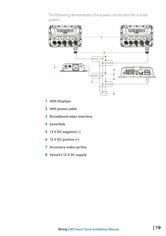
The following demonstrates the power connections for a small system.
+ _
6
3
2
7
8
5
4
1
1 HDS Displays
2 HDS power cable
3 Broadband radar interface
4 SonicHub
5 12 V DC negative (-)
6 12 V DC postive (+)
7 Accessory wake up line
8 Vessel’s 12 V DC supply

20 | Wiring | HDS Gen2 Touch Installation Manual
Transducer connectionAll Combo HDS Gen2 Touch displays have internal Broadband and StructureScan sonar (chart only units require an external module for sonar). Navico transducers fitted with the 7 pin blue connector can be plugged directly into the corresponding blue socket labeled ‘Sonar’. The 9 pin black structure scan connector can be plugged in to the socket labelled ‘Structure’ . Refer to the Overview section of this manual, or embossed labeling on the unit for connector location.
Connector attached to cable is keyed and can only be inserted in one orientation. Once inserted, turn locking collar to secure.
¼ Note: Connectors are not in same location on the HDS-7 display as they are on the HDS-9 and 12 displays (shown above). The ‘Structure’ connector is located to the right of the ‘Sonar’ connector on all units.
¼ Note: Sonar data can also be supplied by an external sonar source such as the BSM-2 or another sonar capable Navico display connected via ethernet.
¼ Note: While made for LSS-2 HD transducer, the displays are also compatible with earlier LSS-1 transducers through use of an adaptor cable - see page 30.

| 21Wiring | HDS Gen2 Touch Installation Manual
Ethernet device connectionEthernet is used to interconnect high bandwidth devices such as radar, sonar, and other displays. The HDS-7 display has one ethernet port, whereas the HDS-9 and 12 displays have two. Navico ethernet cables have a locking collar, for maintaining a reliable, waterproof connection.
Connecting directly to a single device The ethernet port is auto sensing, meaning that the unit can connect to one network device directly, without the use of a cross-over cable or switch.
Connecting to multiple devicesIf connecting more than one ethernet device to a HDS-7 display, or two devices to a HDS-9 or HDS-12 display, use the optional network expansion Port (NEP-2).
If the number of ethernet devices exceeds the number of available ports on the NEP-2, it is possible to link two or more NEP-2 modules together to provide the required ports. The NEP-2 modules are fitted with 5 ethernet ports. See page 31 for cable options.
¼ Note: When designing a system, take in to account the ports ‘lost’ when used for linking multiple NEP-2 modules together.

22 | Wiring | HDS Gen2 Touch Installation Manual
NMEA 2000 device connectionAll HDS Gen2 Touch models are equiped with a NMEA 2000 port, which allows the receiving and sharing of a multitude of data from various sources.
Essential network information • A NMEA 2000 network consists of a linear “backbone” from which
“drop cables” connect to NMEA 2000 devices
• NMEA 2000 is a powered network.
• NMEA 2000 cables used for Lowrance products are of the ‘micro-c’ style, which is a cable/connector specification approved for use in NMEA 2000 certified networks.
• A single drop cable has a maximum length of 6 m (20 ft). The total length of all drop cables combined should not exceed 78m (256 ft)
• The backbone has a maximum cable length of 100m (328ft). The maximum cable length between any two devices on the network is also 100 m (328 ft) - this is taking in to account device drop cable length.
• A NMEA 2000 network needs to have a terminator at each end of the backbone.
Planning and installing a network backboneThe NMEA 2000 backbone needs to run between the locations of all products you want to install, typically in a bow to stern layout. Route the backbone so that drop cables to devices do not exceed 6m length. Choose from the following components to make up your NMEA 2000 backbone:
• Micro-C cables: 2’ (0.61m), 6’ (1.82m), 15’ (4.55m), 25’ (7.58m)
• T-connector. Use at locations where you want to connect a device by drop cable
• Micro-C male and Micro-C female to SimNet adaptor cables for connecting to SimNet bus, or adding devices fitted with a SimNet connector to a Micro-C network.
¼ Note: If using a wind sensor, plan to connect this to one end of the backbone with the termination resistor at the mast head.
Power the networkA NMEA 2000 network requires its own 12 V DC power supply. The Lowrance NMEA 2000 power cable is pre fitted with an inline fuse holder and 3 amp fuse.

| 23Wiring | HDS Gen2 Touch Installation Manual
In smaller NMEA 2000 systems, the power connection may be made anywhere in the system,
For larger systems introduce power at a central point in the backbone to ‘balance’ the voltage drop of the network. Use a power cable without termination.
¼ Note: When joining a NMEA 2000 network with a Simrad SimNet network, it is important that you do not introduce power to both.
¼ Note: Do not connect the power cable to the same terminals as the autopilot computer, pulse radar, bow thruster or other high current devices - the network may be affected by voltage drop when these devices are operated. Avoid connection to the engine starting batteries where possible.The following diagram demonstrates a typical small NMEA 2000 network:
+_12 V DC TT
98
5
7
6
4321
9
1 GPS antenna
2 HDS Display
3 Broadband radar interface
4 SonicHub
5 ‘Drop’ cables (should not exceed 6m (20’) each)
6 Power cable
7 Micro-C T junctions
8 Backbone
9 Micro-C terminator (one male, one female)

24 | Wiring | HDS Gen2 Touch Installation Manual
NMEA 0183 device connectionThe HDS has a NMEA 0183 serial port, providing both an input and output for NMEA 0183 data.
The port can be set to different baud rates, up to 115,200 baud. The NMEA0183 sentences output can be individually turned on or off.
Refer to the section Supported Data / NMEA 0183 for a complete list of sentences.
1
2
34
1 Data cable (combined in same plug as power cable)
2 Transmit: A (yellow), B (blue)
3 Receive: A (orange), B (green)
4 ground (shield)
¼ Note: The majority of NMEA 0183 devices communicate at 4,800 baud. AIS is a common exception, and normally transmits at 38,400 baud.
| 25Wiring | HDS Gen2 Touch Installation Manual
Talkers and ListenersDo not connect multiple devices outputing data (Talkers) on to the input (Rx) of the unit. The RS422 protocol is not intended for this type of connection, and data will be corrupted if more than one device transmits simultaneously. The output however may drive multiple receivers (Listeners). The number of receivers is finite, and depends on the receiving hardware. Typically three devices is possible.
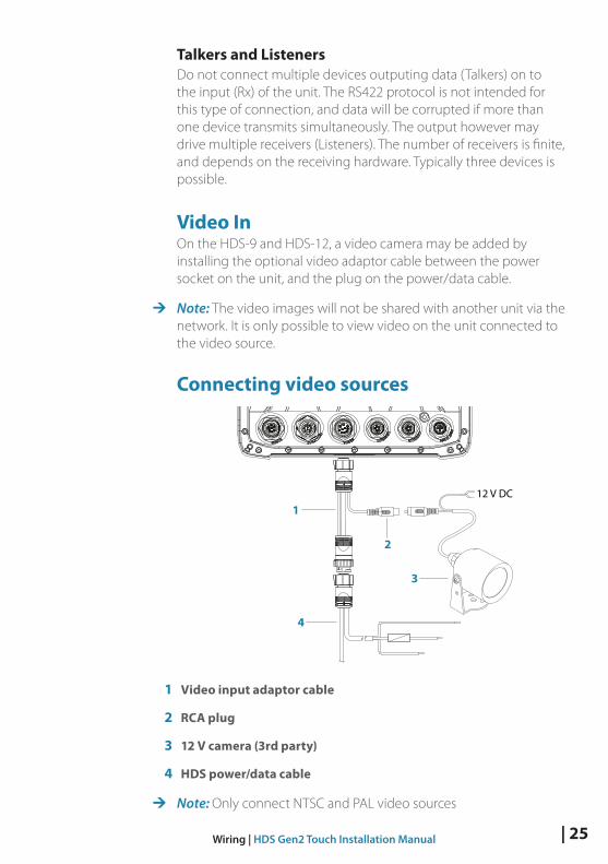
Video InOn the HDS-9 and HDS-12, a video camera may be added by installing the optional video adaptor cable between the power socket on the unit, and the plug on the power/data cable.
¼ Note: The video images will not be shared with another unit via the network. It is only possible to view video on the unit connected to the video source.
Connecting video sources
12 V DC1
4
3
2
1 Video input adaptor cable
2 RCA plug
3 12 V camera (3rd party)
4 HDS power/data cable
¼ Note: Only connect NTSC and PAL video sources
26 | Software setup | HDS Gen2 Touch Installation Manual
Software setup
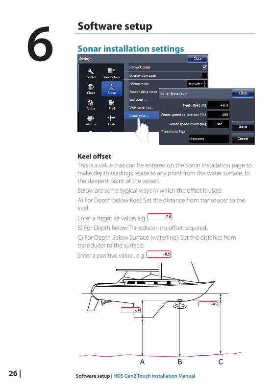
Sonar installation settings
Keel offsetThis is a value that can be entered on the Sonar Installation page to make depth readings relate to any point from the water surface, to the deepest point of the vessel.
Below are some typical ways in which the offset is used:
A) For Depth below Keel: Set the distance from transducer to the keel.
Enter a negative value, e.g.
B) For Depth Below Transducer: no offset required.
C) For Depth Below Surface (waterline): Set the distance from transducer to the surface:
Enter a positive value., e.g.
A B C
6

| 27Software setup | HDS Gen2 Touch Installation Manual
Water speed calibration Water speed calibration is used to adjust the speed value from the paddle wheel to match the actual boat speed through the water. Actual speed can be determined from GPS speed over ground (SOG) or by timing the boat over a known distance. Water speed calibration should be performed in calm conditions, with minimal wind and current movement.
Water speed averagingAverages water speed by measuring your speed at a selected interval of time. Water speed intervals range from one to thirty seconds, e.g. If you select five seconds, your displayed water speed will be based on averaging over 5 seconds of sampling.
Water temperature calibrationTemperature calibration is used to adjust the water temperature value from the sonar transducer to match the data from another temperature sensor. It may be required to correct for localized influences to the measured temperature.
¼ Note: Water temperature calibration only appears if the transducer is temperature capable. Check transducer type selection if this option should be available.
Transducer typeTransducer type is used for selecting the transducer model that came with your unit. In some transducers with built-in temperature sensors, the temperature reading may be inaccurate if the wrong transducer is selected from the transducer type menu.

28 | Software setup | HDS Gen2 Touch Installation Manual
Touch Screen CalibrationIn some cases it may be required to re-calibrate the touch screen due to electrical influences on the device from it’s installation environment. The following steps should be completed to apply calibration:
1. Turn the unit off
2. Press and hold the Waypoint key, then turn the unit on
3. Hold the Waypoint key during power on, until the calibration utility screen comes up
4. Touch crosshair shown on screen to perform nine points calibration
5. After successful calibration the unit will return to normal application screen
Software upgradesThe latest software for this unit will be available for download from the Lowrance web site;
www.lowrance.com
An SD card and SD reader/writer are required for this.
Detailed instructions for how to install the software are provided on the update web page.

| 29Dimensional drawings | HDS Gen2 Touch Installation Manual
Dimensional drawings
HDS 7 Gen2 Touch
146
mm
(5.
76")
215 mm (8.48")
240 mm (9.45")95 mm (3.72")
166
mm
(6.
52")
82 mm (3.23")
30 mm (1.18")
7"
HDS 9 Gen2 Touch
287 mm (11.30")
265 mm (10.43")
9"
169
mm
(6.
65")
178
mm
(7.
01")
30 mm (1.18")54 mm (2.13")
60.5 mm (2.38")
HDS 12 Gen2 Touch
7
12.1"
351.0 mm (13.82")
60.9 mm (2.4")
62 mm (2.44")
82.8 mm (3.26")
224.
7 m
m (
8.85
")
233.
6 m
m (
9.20
")
328.1 mm (12.92")30.3 mm (1.19")
30 | Accessories | HDS Gen2 Touch Installation Manual
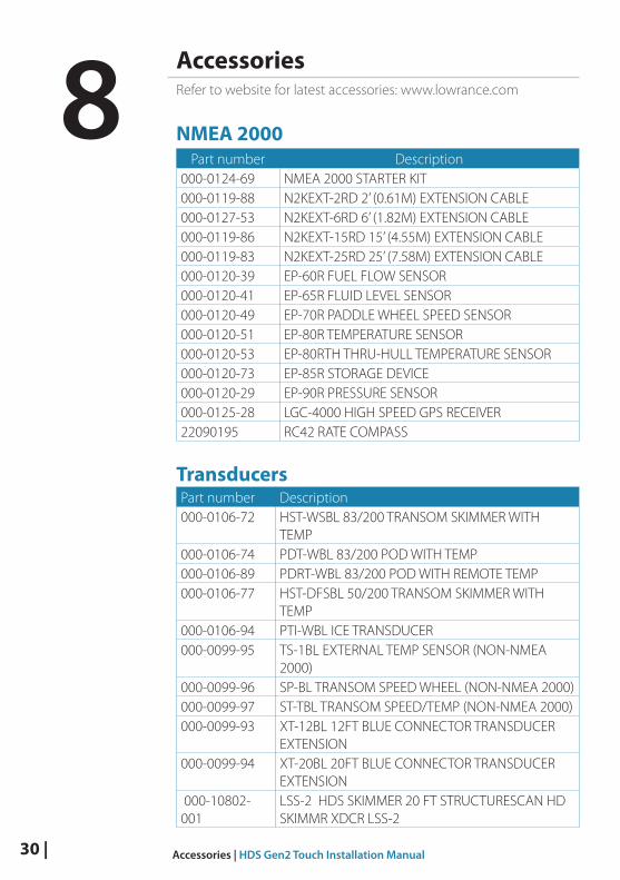
AccessoriesRefer to website for latest accessories: www.lowrance.com
NMEA 2000Part number Description
000-0124-69 NMEA 2000 STARTER KIT000-0119-88 N2KEXT-2RD 2’ (0.61M) EXTENSION CABLE000-0127-53 N2KEXT-6RD 6’ (1.82M) EXTENSION CABLE000-0119-86 N2KEXT-15RD 15’ (4.55M) EXTENSION CABLE000-0119-83 N2KEXT-25RD 25’ (7.58M) EXTENSION CABLE000-0120-39 EP-60R FUEL FLOW SENSOR000-0120-41 EP-65R FLUID LEVEL SENSOR000-0120-49 EP-70R PADDLE WHEEL SPEED SENSOR000-0120-51 EP-80R TEMPERATURE SENSOR000-0120-53 EP-80RTH THRU-HULL TEMPERATURE SENSOR000-0120-73 EP-85R STORAGE DEVICE000-0120-29 EP-90R PRESSURE SENSOR000-0125-28 LGC-4000 HIGH SPEED GPS RECEIVER22090195 RC42 RATE COMPASS
TransducersPart number Description000-0106-72 HST-WSBL 83/200 TRANSOM SKIMMER WITH
TEMP000-0106-74 PDT-WBL 83/200 POD WITH TEMP000-0106-89 PDRT-WBL 83/200 POD WITH REMOTE TEMP000-0106-77 HST-DFSBL 50/200 TRANSOM SKIMMER WITH
TEMP000-0106-94 PTI-WBL ICE TRANSDUCER000-0099-95 TS-1BL EXTERNAL TEMP SENSOR (NON-NMEA
2000) 000-0099-96 SP-BL TRANSOM SPEED WHEEL (NON-NMEA 2000)000-0099-97 ST-TBL TRANSOM SPEED/TEMP (NON-NMEA 2000)000-0099-93 XT-12BL 12FT BLUE CONNECTOR TRANSDUCER
EXTENSION000-0099-94 XT-20BL 20FT BLUE CONNECTOR TRANSDUCER
EXTENSION 000-10802-001
LSS-2 HDS SKIMMER 20 FT STRUCTURESCAN HD SKIMMR XDCR LSS-2
8

| 31Accessories | HDS Gen2 Touch Installation Manual
Part number Description000-0136-02 P319 50/200 LOW PROFILE THRU-HULL W/TEMP000-0136-03 P79 50/200 IN-HULL000-10116-001 TM260 50/200 TRANSOM MOUNT W/TEMP000-00021-001 B60 50/200 BRONZE THRU-HULL W/TEMP000-0136-05 B744V 50/200 BRONZE THRU-HULL W/TEMP AND
SPEED
000-10247-001 B164 50/200 BRONZE THRU-HULL W/TEMP 1KW000-0136-00 B258 50/200 BRONZE THRU-HULL W/TEMP000-0106-82 B260 50/200 BRONZE THRU-HULL W/TEMP000-0106-91 M260 50/200 TANK MOUNTED IN-HULL22098479 DST-800 235 NMEA 2000 SMART SENSOR W/
TEMP AND SPEED (DIGITAL DISPLAY ONLY, NO SONAR IMAGE)
000-11040-001 LSS-1 XDCR TO LSS-2 MODULE ADAPTOR
Ethernet cablesPart Number Description000-0127-56 ADAPTER CABLE: ETHERNET YELLOW MALE TO
RJ-45 FEMALE 2M (6.5FT)000-0127-51 ETHERNET CABLE YELLOW 5 PIN 2M (6.5FT)000-0127-29 ETHERNET CABLE YELLOW 5 PIN 4.5M (15FT)000-0127-30 ETHERNET CABLE YELLOW 5 PIN 7.7M (25FT)000-0127-37 ETHERNET CABLE YELLOW 5 PIN 15.2M (50FT)
Display partsPart Number Description000-11010-001 HDS GEN2 VIDEO ADAPTER CABLE000-11033-001 HDS-7 GEN2 TOUCH BEZEL AND CARD DOOR000-11034-001 HDS-9 GEN2 TOUCH BEZEL AND CARD DOOR000-11035-001 HDS-12 GEN2 TOUCH BEZEL AND CARD DOOR000-11030-001 HDS-7 GEN2 TOUCH SUNCOVER000-11031-001 HDS-9 GEN2 TOUCH SUNCOVER000-11032-001 HDS-12 GEN2 TOUCH SUNCOVER000-11019-001 HDS-7 GEN2 TOUCH GIMBAL BRACKET000-11020-001 HDS-9 GEN2 TOUCH GIMBAL BRACKET000-11021-001 HDS-12 GEN2 TOUCH GIMBAL BRACKET000-11050-001 HDS GEN2 TOUCH FLUSH MOUNT KIT000-10467-001 BRACKET KNOBS PAIR – NSS/GEN2T

32 | Accessories | HDS Gen2 Touch Installation Manual
Part Number Description000-0127-49 HDS POWER CABLE 000-0124-70 HDS CONNECTOR CAPS000-0127-50 HDS FUSE & FUSE HOLDER

| 33Supported data | HDS Gen2 Touch Installation Manual
Supported data
NMEA 2000PGN Description Rx Tx59392 ISO Acknowledgement 1 160928 Address Claim 1 1126208 NMEA Group Function 1 1126992 System Time 1 1126996 Product Info 1 1127237 Heading/Track Control 1 1127245 Rudder 1127250 Vessel Heading 1 1127251 Rate of Turn 1127257 Attitude 1127258 Magnetic Variation 1 1127488 Engine Parameters Rapid Update 1127489 Engine Parameters Dynamic 1127493 Transmission Parameters Dynamic 1127503 AC Input Status 1127505 Fluid Level 1127506 DC Detailed Status 1127508 Battery Status 1128259 Speed Water Referenced 1 1128267 Water Depth 1 1129808 DSC Call Information 1129025 Position Rapid Update 1 1129026 COG & SOG, Rapid Update 1 1129029 GNSS Position Data 1 1129033 Time and Date 1129038 AIS Class A Position Report 1129039 AIS Class B Position Report 1129040 AIS Class B Extended Position Report 1129283 Cross Track Error 1 1129284 Navigation Data 1 1129285 Route/WP Information 1129539 GNSS DOPs 1 1129540 GNSS Sats In View 1 1129794 AIS Class A Static and Voyage Related Data 1129801 AIS Addressed Safety Related Message 1129802 AIS Safety Related Broadcast Message 1129808 DSC Call Information 1
9

34 | Supported data | HDS Gen2 Touch Installation Manual
PGN Description Rx Tx130074 Waypoint Name and Position 1 1130306 Wind Data 1130310 Environmental Parameters 1 1130311 Environmental Parameters 1 1130312 Temperature 1 1130313 Humidity 1130314 Actual Pressure 1130576 Small Craft Status 1130577 Direction Data 1 1
NMEA 0183TX / RX Category / SentenceGPSReceive GGA GLL GSA GSV VTG ZDATransmit GGA GLL GSA GSV VTG ZDANavigationReceive RMCTransmit AAM APB BOD BWC BWR RMC RMB XTEEchoReceive DBT DPT MTW VLW VHWTransmit DBT DPT MTW VLW VHWCompassReceive HDG HDT HDMTransmit HDGWindReceive MWV MWDTransmit MWV
AIS / DSCReceive DSC DSE VDM MARPATransmit TLL TTM
¼ Note: AIS sentences are not bridged to or from SimNet.

| 35Specifications | HDS Gen2 Touch Installation Manual
SpecificationsRefer to website for updates to specifications: www.lowrance.com
Mul
ti Fu
nctio
n D
ispla
yH
DS-
7H
DS-
9H
DS-
12
Disp
lay
Disp
lay
reso
lutio
n80
0x48
012
80x8
00
Disp
lay
type
7 in
ch W
VGA
colo
r TFT
LCD
9 in
ch W
VGA
colo
r TFT
LCD
12.1
inch
WXG
A TF
T LC
D
Disp
lay
brig
htne
ss12
50 n
its14
00 n
its12
50 n
its
Touc
h sc
reen
S-CA
P
Pow
er
Pow
er su
pply
12 V
DC
(10.
8 - 1
7.0
V D
C m
in -
max
) 12
V D
C (1
0.8
- 17.
0 V
DC
min
- m
ax)
12 V
DC
(10.
8 - 1
7.0
V D
C m
in -
max
)
Pow
er c
onsu
mpt
ion
12 W
(0.
9 A
@ 1
3 V
DC)
15.6
W (
1.2
A @
13
V D
C)26
W (
2.0
A @
13
V D
C)
Tech
nica
l / E
nviro
nmen
tal
Hou
sing
Plas
tic
Tem
pera
ture
-15°
C to
+ 5
5° C
(+5°
F to
+13
1° F
)
Wat
erpr
oof s
tand
ard
IPx7
Dec
lara
tion
of c
onfo
rmity
Part
15.
103
FCC
rule
s & C
E RT
TE d
irect
ive
1999
/5/E
C
Inte
rface
Ethe
rnet
1 Po
rt2
Port
2 Po
rts
NM
EA20
00M
icro
-C (1
)
Vide
o in
put
No
Com
posit
e vi
deo
RCA
- sin
gle
chan
nel
Dat
a ca
rd sl
otSD
(ful
l siz
e)2x
SD
(ful
l siz
e)2x
SD
(ful
l siz
e)
Oth
er
Wei
ght (
disp
lay
only
)1.
6 kg
(3.5
lb)
2.1
kg (4
.6 lb
)3.
78 k
g (8
.3 lb
)
Pack
dim
ensio
ns (L
x W
x H
)30
.5 x
27.
9 x
27.9
cm
(12"
x 1
1" x
11"
)40
.6 x
27.
9 x
25.4
cm
(16"
x 1
1" x
10"
)
Pack
wei
ght
2.54
kg
(5.6
lb)
2.9
kg (6
.5 lb
)
Echo
soun
der
Sona
r fre
quen
cy(5
0/20
0 or
83/
200
kHz)
+ 4
55/8
00 k
Hz
(50/
200
or 8
3/20
0 kH
z) +
455
/800
kH
z(5
0/20
0 or
83/
200
kHz)
+ 4
55/8
00 k
Hz
Sona
r out
put p
ower
Max
pow
er 5
00W
RM
SM
ax p
ower
500
W R
MS
Max
pow
er 5
00W
RM
S
10


*988
-103
17-0
02*
N2584

lowrance.com
ENGLISH
Link-8 VHFUser Guide

Copyright © 2013 Navico
All rights reserved.
Lowrance® is a registered trademark of Navico
No part of this manual may be copied, reproduced, republished, transmitted or distributed for any purpose, without prior written consent of Lowrance Electronics.
Any unauthorized commercial distribution of this manual is strictly prohibited.
Lowrance Electronics may find it necessary to change or end our policies, regulations, and special offers at any time. We reserve the right to do so without
notice. All features and specifications subject to change without notice. All screens in this manual are simulated.
For free owner’s manuals and the most current information on this product, its operation and accessories, visit our website: www.lowrance.com
Important safety information Please read carefully before installation and use.
DANGERThis is the safety alert symbol. It is used to alert you to potential personal injury hazards, Obey all safety messages that follow this symbol to avoid possible injury or death.
WARNING WARNING indicates a potentially hazardous situation which, if not avoided, could result in death or serious injury
CAUTION CAUTION indicates a potentially hazardous situation which, if not avoided, could result in minor or moderate injury.
CAUTIONCAUTION used without the safety alert symbol indicates a potentially hazardous situation which, if not avoided, may result in property damage.

Lowrance - Link-8 Operation Instructions 3
Section 1 - General information .......................................................................71-1 Features ................................................................................................................................................71-2 Customizing your Lowrance VHF radio ......................................................................................81-3 How to display and navigate menus .........................................................................................81-4 How to enter alphanumeric data .................................................................................................81-5 LCD symbols and meanings ..........................................................................................................81-3 Beep tones & call alerts ................................................................................................................. 10
Section 2 - Basic operation and key functions ...............................................11
Section 3 - Radio MENU SELECT options .........................................................173-1 Manage your waypoints list (WAYPOINT) .............................................................................. 18
3-1-1 Add a new waypoint ...................................................................................................................................183-1-2 Edit or delete a waypoint .........................................................................................................................183-1-3 Go to a new waypoint ...............................................................................................................................193-1-4 Go to nearest waypoint (NEAREST WP) ...........................................................................................193-1-5 Go to temporary waypoint .....................................................................................................................203-1-6 Edit or delete a temporary waypoint ................................................................................................203-1-7 Send waypoint data to a chartplotter ..............................................................................................21
3-2 Set the backlighting level (BACKLIGHT) ............................................................................... 213-3 Maintain your buddy list (BUDDY LIST) .................................................................................. 22
3-3-1 Add an entry ...................................................................................................................................................223-3-2 Edit or delete an entry ..............................................................................................................................23
3-4 Local or distance sensitivity (LOCAL/DIST) ........................................................................... 233-4-1 Set distance sensitivity ...............................................................................................................................233-4-2 Set local sensitivity .......................................................................................................................................24
3-5 Set the contrast level (CONTRAST) .......................................................................................... 243-6 GPS data and time (GPS/DATA) ................................................................................................. 24
3-6-1 Manually enter position and UTC time (MANUAL) ................................................................253-6-2 Local time (TIME OFFSET) ........................................................................................................................253-6-3 Time format options (TIME FORMAT) ..............................................................................................263-6-4 Time display options (TIME DISPLY) .................................................................................................263-6-5 Position display options (LL DISPLY) ................................................................................................273-6-6 Course & speed display options (COG/SOG) ..............................................................................273-6-7 GPS alert (GPS ALERT) ...............................................................................................................................28
3-7 GPS simulator (GPS SIM) .............................................................................................................. 283-8 Reset to factory defaults (RESET) ............................................................................................. 28
Section 4 - Radio setup menu (RADIO SETUP) ................................................294-1 Channel (UIC) ................................................................................................................................... 29

Lowrance - Link-8 Operation Instructions4
4-2 Channel names (CH NAME) ........................................................................................................ 294-3 Ring volume (RING VOLUME) ..................................................................................................... 304-4 Key beep volume (KEY BEEP) ..................................................................................................... 304-5 Select units (UNITS) ........................................................................................................................ 314-6 Internal speaker connections (INT SPEAKER) ........................................................................ 314-7 Set the priority channel (WATCH MODE) ................................................................................ 314-8 Weather alerts (WX ALERT).......................................................................................................... 32
4-8-1 TONE ALERT ......................................................................................................................................................324-8-2 SAME ALERT......................................................................................................................................................324-8-3 Receiving a SAME ALERT ..........................................................................................................................334-8-4 Receiving SAME TEST messages ..........................................................................................................334-8-5 Enter a SAME CODE (County ID) ..........................................................................................................334-8-6 Select a working SAME code .................................................................................................................34
4-9 NMEA protocol (COM PORT) ..................................................................................................... 354-10 Select the GPS source (GPS SOURCE) .................................................................................... 354-11 Favourite channel setup - Wx key (FAV CH SETU) ............................................................. 35
Section 5 - DSC setup menu (DSC SETUP) ........................................................365-1 Enter or view your USER MMSI (USER MMSI) ........................................................................ 365-2 Maintain your groups ................................................................................................................... 37
5-2-1 Create a group (GROUP SETUP) ...........................................................................................................375-2-2 Edit or delete a group name or group MMSI (GROUP SETUP) ..........................................38
5-3 Enter or check your ATIS MMSI (ATIS MMSI) .......................................................................... 385-4 Enable ATIS functionality (ATIS SELECT) ................................................................................. 395-5 Response to individual calls (INDIV REPLY) ........................................................................... 405-6 Enable DSC functionality (DSC FUNC) ..................................................................................... 405-7 Response type to LL polling calls (LL REPLY) ........................................................................ 415-8 Automatic channel switching (AUTO SWITCH) .................................................................... 415-9 DSC Test Reply (TEST REPLY) ....................................................................................................... 425-10 Set the inactivity timer (TIMEOUT) ........................................................................................ 42
Section 6 - AIS setup menu (AIS SETUP) ...........................................................436-1 Enable AIS functionality (AIS FUNC) ......................................................................................... 436-2 AIS data display format (AIS DISPLAY) ..................................................................................... 436-3 AIS baud rate (BAUD RATE) .......................................................................................................... 436-4 GPS redirection (GPS REDIR) ....................................................................................................... 446-5 Closest point of approach alarm (CPA ALARM) .................................................................... 446-6 Closest point of approach settings (CPA) ............................................................................... 446-7 Time to closest point of approach (TCPA) .............................................................................. 44

Lowrance - Link-8 Operation Instructions 5
Section 7 - Sending and receiving DSC Calls ..................................................457-1 What is DSC? .................................................................................................................................... 457-2 Sending DSC Calls ........................................................................................................................... 457-3 Send an individual call (INDIVIDUAL) ...................................................................................... 46
Call to a Buddy .............................................................................................................................................................46Call to others .................................................................................................................................................................46
7-4 Acknowledgement of an individual incoming call (INDIV) ............................................. 477-5 Reply to the Last Call (LAST CALL) ............................................................................................ 477-6 Send a group call (GROUP) ......................................................................................................... 487-7 Send an all ships call (ALL SHIPS) .............................................................................................. 487-8 Send using the call log (CALL LOG) .......................................................................................... 497-9 Send using the distress log (DIST LOG) ................................................................................... 507-10 View sent call log (SENT CALL) ................................................................................................. 517-11 Request the LL position of a Buddy (LL REQUEST) ........................................................... 517-12 Track your Buddy (TRACK BUDDY) ......................................................................................... 52
7-12-1 Start or stop tracking a Buddy (START TRACK) .........................................................................527-12-2 Select a Buddy to Track (SET BUDDY) ............................................................................................527-12-3 Add or delete a Buddy on your track list (TRACKLIST) ........................................................537-12-4 Set the track your Buddy update interval (INTERVAL) ........................................................53
7-13 Make a DSC test call (DSC TEST) .............................................................................................. 537-13-1 Send a DSC TEST call ................................................................................................................................537-13-2 Receiving an incoming DSC TEST call reply (DSC TEST ACK) ..........................................547-13-3 Acknowledging an incoming DSC TEST call .............................................................................54
7-14 View user MMSI and GPS information ................................................................................... 557-15 Receiving DSC calls ...................................................................................................................... 557-16 Receiving an all ships call (ALL SHIPS) .................................................................................. 557-17 Receiving an individual call (INDIV) ....................................................................................... 567-18 Receiving a group call (GROUP) .............................................................................................. 567-19 Receiving a geographic area call (GEOGRAPH) ................................................................. 577-20 Receiving a polled position call (POSITION) ....................................................................... 57
Section 8 - DISTRESS calls ................................................................................588-1 Sending a Distress Call ................................................................................................................. 588-2 Receiving a distress call (DISTRESS!) ......................................................................................... 598-3 Distress acknowledgement (DISTRESS ACK) or distress relay all ships (DISTRESS REL) .............................................................................................................................................................. 608-4 Distress relay individual (INDIV DISTR RELAY) ...................................................................... 60

Lowrance - Link-8 Operation Instructions6
Section 9 - AIS functionality ............................................................................619-1 About AIS ........................................................................................................................................... 619-2 AIS - Static and dynamic information ...................................................................................... 619-3 Using the AIS receiver.................................................................................................................... 629-4 AIS Information and display ........................................................................................................ 63
9-4-1 T/CPA approach screen .............................................................................................................................649-4-2 Plotter symbols and meanings .............................................................................................................64
Section 10 - General functionality...................................................................6510-2 Using the Fog Horn ...................................................................................................................... 6510-1 Using the PA (Public Address) Hailer ..................................................................................... 66
Appendix A - Technical specifications ............................................................67LOWRANCE Link-8 .....................................................................................................................................................67Link-8 NMEA 2000 PGNS ......................................................................................................................................69
Appendix B - Troubleshooting ........................................................................70
Appendix C - US & ROW VHF Marine Channel Charts .....................................71C-1 International channel chart ........................................................................................................ 71
Special notes on international channel usage.........................................................................................72
C-2 USA channel chart .......................................................................................................................... 73Special notes on USA channel usage ............................................................................................................74
C-3 CANADA channel chart ................................................................................................................ 75Special notes on Canada channel usage ....................................................................................................76
C-4 US & Canada WEATHER channels .............................................................................................. 77C-5 EAS (Emergency Alert Systems) Alerts .................................................................................... 78
Appendix D - EU VHF marine channel charts .................................................80D-1 EU international channel chart ................................................................................................. 80
Special notes on EU international channel usage .................................................................................81
D-2 Inland waterways country specific table - ATIS ON ........................................................... 82D-3 Special channels ............................................................................................................................. 85
Appendix E - MMSI and license information ...................................................86Countries of intended use in the EU: .................................................................. 86

Section 1 - General information 1-1 Features
Congratulations on your purchase of this Lowrance Link-8 marine band VHF radio. Your Link-8 provides you with the following useful features: • Access to all currently available Marine VHF Channel Banks (USA, Canada, International)
including weather channels where available (model dependant)• DSC (Digital Select Calling) capability that meets Class D standards
• Separate CH70 DSC receiver built in• ATIS facility for inland waterways (EU models)• 10 weather channels (where available)• NOAA and SAME weather alert capability (US models)
• Dual channel AIS receiver built in - receive AIS transmissions (receive only)• Choice of High or Low (25 W or 1 W) transmission power • Special CH16 or CH16/9 key for quick access to the priority (International Distress)
channel• DISTRESS call button to automatically transmit the MMSI and position until an
acknowledgement is received• Special 3CH key for quick selection of your three favorite channels• Memory channel scan and All channel priority scan• Dual/Tri Watch capability • Call log for the 20 most recent incoming DSC calls
• Distress call log for the 20 most recent distress calls• Easy access to a buddy list of up to 20 favorite people• MMSI storage for 20 favorite groups• GROUP CALL and ALL SHIPS CALL facility
• LL position polling and Track Your Buddy feature• Automatic position and time update when connected to a GPS receiver• Adjustable keypad backlighting for easy night-time use
• Adjustable contrast settings for the LCD• Waterproof and submersible to comply with JIS-7• Rotary channel selector knob with Push To Select function • Speaker microphone with large PTT key and 6 keys for easy channel and mode selection• 30 W Hailer with listen back capability• Foghorn (manual and automatic)• Great Circle GPS navigation calculations to a waypoint (stores up to 200 waypoints)• NMEA 2000 & NMEA 0183 connectivity• Local/Distance sensitivity to eliminate noise in high traffic urban areas.
Lowrance - Link-8 Operation Instructions 7
1-2 Customizing your Lowrance VHF radio
You can customize the radio to suit your individual preferences. Some preferences can be set directly through the keys as explained in this section.
Other preferences are set up through the built-in menus and these are explained in the other sections.
1-3 How to display and navigate menus 1. Press MENU (or CALL) key.
2. Some line items may show an ▲ or ▼ indicator. This means there is more information available to show. Scroll (rotate the Rotary knob, or use + / - keys on the handset mic) to scroll up and down the menu until the cursor is positioned at the desired option. Press ENT (press the Push To Select) to display that option.
3. Make any entries or changes as explained in the following section.
4. Press ENT to confirm changes. Otherwise, press EXIT to keep the original entry.
5. Press EXIT to backup one screen (this key is equivalent to an ESC function on a PC).
1-4 How to enter alphanumeric data
If your radio does not have the optional alphanumeric microphone, you can rotate the rotary knob, or use +/- keys on the handset mic to enter alphanumeric data.
• Press - to count through numbers, or hold down to scroll rapidly to the desired number
• Press + to step through the alphabet, or hold down to scroll rapidly to the desired character
• If you make an error, press - until < is displayed, then press ENT to backup and correct the entry.
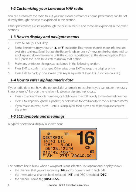
1-5 LCD symbols and meanings
A typical operational display is shown here:
The bottom line is blank when a waypoint is not selected. This operational display shows:• the channel that you are receiving (16) and Tx power is set to high (Hi)• the International channel bank selected (INT) and DSC is enabled (DSC)• the channel name tag (DISTRESS)
Lowrance - Link-8 Operation Instructions8
• your current course (128°) and speed (5.0Kt)• your latitude (55°33.122N) and longitude (012°42.408E) and UTC time displayed in 24
hour format (14:43 - 2:43pm)• the name of the destination waypoint (FISH), its bearing (275°), your distance in nautical
miles, mile, or kilometres (depending on your choice of units) - in this case, 800nm, and the cross track error (XTE - 0.00) are shown.
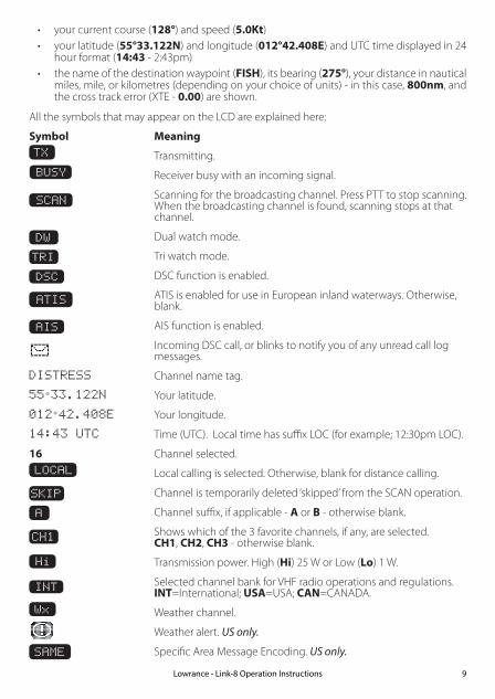
All the symbols that may appear on the LCD are explained here:
Symbol Meaning TX Transmitting.
Receiver busy with an incoming signal.
SCAN Scanning for the broadcasting channel. Press PTT to stop scanning. When the broadcasting channel is found, scanning stops at that channel.
DW Dual watch mode.
TRI Tri watch mode.
DSC DSC function is enabled.
ATIS ATIS is enabled for use in European inland waterways. Otherwise, blank.
AIS AIS function is enabled.
Incoming DSC call, or blinks to notify you of any unread call log messages.
DISTRESS Channel name tag.
55 33.122N Your latitude.
012 42.408E Your longitude.
14:43 UTC Time (UTC). Local time has suffix LOC (for example; 12:30pm LOC).
16 Channel selected.
LOCAL Local calling is selected. Otherwise, blank for distance calling.
SKIP Channel is temporarily deleted ‘skipped’ from the SCAN operation.
A Channel suffix, if applicable - A or B - otherwise blank.
CH1 Shows which of the 3 favorite channels, if any, are selected. CH1, CH2, CH3 - otherwise blank.
Hi Transmission power. High (Hi) 25 W or Low (Lo) 1 W.
INT Selected channel bank for VHF radio operations and regulations. INT=International; USA=USA; CAN=CANADA.
Wx Weather channel.
Weather alert. US only.
SAME Specific Area Message Encoding. US only.
BUSY
Lowrance - Link-8 Operation Instructions 9
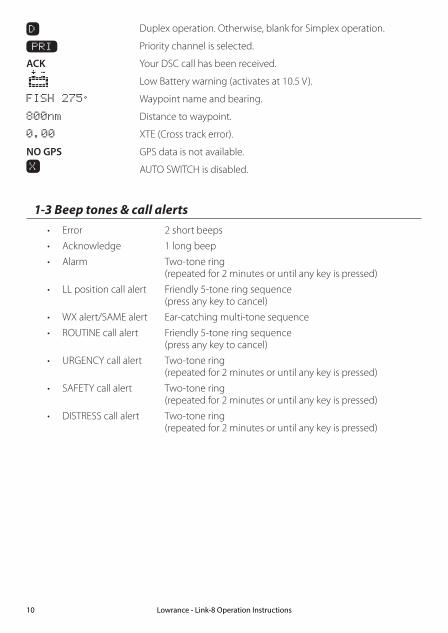
D Duplex operation. Otherwise, blank for Simplex operation.
PRI Priority channel is selected.
ACK Your DSC call has been received.
Low Battery warning (activates at 10.5 V).
FISH 275 Waypoint name and bearing.
800nm Distance to waypoint.
0.00 XTE (Cross track error).
NO GPS GPS data is not available.X AUTO SWITCH is disabled.
1-3 Beep tones & call alerts• Error 2 short beeps
• Acknowledge 1 long beep
• Alarm Two-tone ring (repeated for 2 minutes or until any key is pressed)
• LL position call alert Friendly 5-tone ring sequence (press any key to cancel)
• WX alert/SAME alert Ear-catching multi-tone sequence
• ROUTINE call alert Friendly 5-tone ring sequence (press any key to cancel)
• URGENCY call alert Two-tone ring (repeated for 2 minutes or until any key is pressed)
• SAFETY call alert Two-tone ring (repeated for 2 minutes or until any key is pressed)
• DISTRESS call alert Two-tone ring (repeated for 2 minutes or until any key is pressed)
Lowrance - Link-8 Operation Instructions10

Section 2 - Basic operation and key functions All possible keys and their functions are listed here. Note that some of the keys may not be available, depending on your Lowrance VHF radio model.
Key: Function:
VOL / Volume and Power Turn clockwise to power on. Continue to turn until a comfortable volume is reached. VOL / will also adjust the settings of an external speaker, if connected.
SQL Squelch or Threshold Level Sets the threshold level for the minimum receiver signal. Turn fully counterclockwise until random noise is heard, then turn slowly clockwise until the random noise disappears. Make another 1/4 turn clockwise for best reception in open sea conditions. In areas of high noise (eg. close to large cities) reception may improve if sensitivity is reduced. Either turn SQL slowly clockwise or use the LOCAL setting. See section 3-4.
16 / 9 Priority channel Also on the handset mic. Press to cancel all other modes and to tune into the priority channel. Press again to return to your original channel. The default Priority Channel is CH16.
For US models: To make Channel 09 the priority channel, hold down 16/9 until a beep sounds and 09 is displayed.
DISTRESS Send a DSC Distress Call DSC must be active and an MMSI must be programmed. See Section 7. Lift the red cover door then press and release DISTRESS to show the DISTRESS menu. Select the category you want to transmit. Hold down DISTRESS for about 3 seconds to transmit. The DISTRESS key can also be held down continuously to transmit an “undefined” category Distress call.
See Section 8 for more information about distress calls.
6 Key handset mic Link-8 base station radio
Lowrance - Link-8 Operation Instructions 11

PTT Press To Talk (Located on the handset mic). Press PTT to transmit at any time on an allowable channel. This automatically exits you from menu mode and stops scanning. You must release PTT to receive a signal.
If PTT sticks, a built-in timer will automatically shut down a transmission after five minutes and sound a short error beep.
PUSH TO SELECT Enter (ENT) When you are in MENU mode, push the center of the Channel Select knob to enter your choice or setting. This is referred to throughout the manual as “press ENT”.
Rotary knob Channel select Turn to select a channel. The current channel is shown on the LCD in BIG digits and an A or B designator suffix (if applicable) in small letters below the channel number. See Appendix C for a complete listing of channel charts.
Push to activate the ENT function.
Alphanumeric entry You can also use the rotary knob for alphanumeric entry. Turn to step through alphanumeric characters one at a time, then push to confirm each selection. If you make an error, select the < character then push to backup.
+ / - Channel select (Located on the handset mic). The current channel is shown on the screen in BIG digits with an appropriate designator suffix A or B in small letters below the channel number.
Press + or - to step through the available channels one at a time, or hold down to scroll rapidly through all the available channels. See Appendix C for a complete listing of channel charts.
Alphanumeric entry This key can be used for both menu selection and for alphanumeric entry. Press + or - to scroll the cursor up or down to menu options when navigating menus. When editing an item containing only numbers, press - to count through the numbers or hold down to scroll rapidly. To enter a character, press + to step through the alphabet or hold down to scroll rapidly.
EXIT Escape (ESC) Use EXIT when navigating menus, to clear incorrect entries, to exit from a menu without saving changes, and to back up to the previous screen.
CALL/MENU DSC CALL menu Quick press to enter the DSC CALL menu and make DSC calls. See Section 5.
Lowrance - Link-8 Operation Instructions12

Radio and DSC setup MENU mode Hold down for about 1 second to show the radio MENU so that you can customize your radio. See section 4.
WX/NAV Weather channel For US models: In USA and Canadian waters, press to hear the most recently selected weather station. The WX symbol Wx is displayed on the LCD. Rotate the dial or + / - on the handset mic to change to a different weather channel. Press WX again to return to the most recent channel. If the weather alert mode (ALT) is ON and an alert tone of 1050 Hz is broadcast from the weather station, it is picked up automatically and the alarm sounds. Press any key to hear the weather alert voice message. Note: If SAME is activated and the 6 digit County IDs you want to monitor are entered, the radio will sound the weather alarm when it detects a weather alert or weather hazard alert on the selected weather channel.
For all other models: The Wx key can be programmed to a weather channel of your choice. See section 4-11 to program your favourite channel.
NAV (Show waypoint) Hold down for about 1 second to enter the Navigation mode. If a waypoint is already selected, the bearing and distance to the waypoint and the cross track error are shown on the bottom line of the LCD.
If you are in Navigation mode and want to scan all the VHF channels while staying in Navigation mode, just hold down SCAN. Press SCAN to quit scanning.
3CH Three favourite channels Also on the handset mic. Press to toggle between your favourite channels. The CH1, CH2, or CH3 symbol appears on the LCD to show which favourite channel is selected.
To scan only one of your favourite channels, press 3CH then immediately press and release SCAN. If you want to scan all three favourite channels, press 3CH then immediately press and hold SCAN.
To add a favourite channel for the first time, select that channel then hold 3CH to store it in the CH1 location. Repeat the procedure to store two more favourite channels in the CH2 and CH3 locations respectively.
If you try and add another favourite channel it will overwrite the existing CH3. CH1 and CH2 remain unless you delete them.
To delete a favourite channel, select that channel then hold down 3CH until the CH1, CH2 or CH3 symbol disappears off the LCD.
Lowrance - Link-8 Operation Instructions 13

SCAN Scan (ALL SCAN & 3CH SCAN) There are two SCAN modes you can use to find the broadcast channel: • ALLSCANmodescansALLchannelsinsequence,andcheckstheprioritychannel every 2 seconds. • 3CHSCANmodescansthefavoritechannelsandCH16.
When a signal is received, scanning stops at that channel and BUSY appears on the LCD. If the signal ceases for more than 5 seconds, the scan restarts. Press SCAN or PTT to stop at the current channel. If you are in NAVIGATION mode and want to scan the DSC channels while staying in that mode, just hold down SCAN.
Note: SCAN functionality is limited in some European countries and, if ATIS mode is enabled, the 3CH SCAN mode will be disabled and an error beep will sound.
Note: The weather channel is also scanned if TONE ALERT or SAME is ON (US only).
ALL SCAN mode: Hold down SCAN for about 3 seconds to start an ALL SCAN. ALL SCAN appears on the LCD. Press ENT to temporarily skip over (lock out) an “always busy” channel when in ALL SCAN mode. SKIP is shown on the top line of the LCD to designate a skipped channel. SKIP will disappear when the radio is powered OFF/ON. With scanning OFF and the SKIP channel selected, press ENT to cancel the skipped channel.
Note: It is not possible to skip over the priority channel.
Press SCAN to stop at the current channel. Press EXIT to cancel scan mode and return to normal operation.
3CH SCAN mode With any of your three favorite channels selected (by pressing the 3CH key) hold down SCAN to start all 3CH scanning. Press SCAN again to stop at the broadcast channel, or press EXIT to quit 3CH SCAN and return automatically to the previous broadcast channel.
AIS / IC AIS (Automatic Identification System) Quick press to enter the AIS menu. See section 6 for AIS setup or Section 9 for AIS functionality.
Lowrance - Link-8 Operation Instructions14

IC (FOG HORN mode) Hold down for about 1 second to enter HAILER mode. Select FOG HORN. The FOG HORN will sound certain international standard fog horn tones through the hailer speaker depending on the mode selected. See section 10 for HAILER functionality.
IC (PA HAILER mode) Hold down for about 1 second to enter HAILER mode. Select PA (Public Address). The PA allows you to make an announcement at high volume to people or vessels using the Link-8 hand mic. See section 10 for HAILER functionality.
GO / MOB GO (Reset the Cross Track Error) Note: A valid GPS signal must be received to see this selection. Press GO if you are navigating to a waypoint and want to reset the cross track error. This is a very useful single keystroke feature to use if you wander a little off-course but want to continue to your active waypoint.
The bearing and distance to the waypoint and any cross track error are shown on the bottom line of the LCD.
MOB (Man Over Board) Hold down MOB until the radio automatically enters Navigation mode, saves your cur-rent latitude and longitude as the MOB waypoint and immediately sets this position as the destination waypoint.
You will see the following sequence of LCDs:
HOLD 3 SECFOR MOBRELEASE TOSAVE
HOLD 2 SECFOR MOBRELEASE TOSAVE
HOLD 1 SECFOR MOBRELEASE TOSAVE
MOB
B 010D 0.01X 0.00
The bearing and distance to the Man Overboard position, and any cross track error (XTE), are shown on the bottom line of the LCD.
To cancel MOB, select another waypoint.
Lowrance - Link-8 Operation Instructions 15

MOB (Temporary waypoint)
To mark your current position as a temporary waypoint, hold down MOB and release the key before the 3 second countdown ends.
You will see the following sequence of LCDs:
HOLD 3 SECFOR MOBRELEASE TOSAVE
HOLD 2 SECFOR MOBRELEASE TOSAVE
HOLD 1 SECFOR MOBRELEASE TOSAVE
The new temporary waypoint is shown in your waypoints list. Hold down MENU, press ENT, then press ENT again to display the waypoints list (TEMP1, WP001, WP002).
You cannot store more than three temporary waypoints. If you store another tempo-rary waypoint, TEMP1 is overwritten with the new information.
H/L Transmission power (Located on the handset mic). High (HI) 25 W or Low (LO) 1 W. Press to toggle between high or low transmission power for the entire channel bank. The HI or LO selection is shown on the LCD.
Some channels allow only low power transmissions. Error beeps will sound if the power transmission setting is incorrect.
Some channels allow only low power transmissions initially, but can be changed to high power by holding down H/L and PTT at the same time. See Appendix C for a complete listing of channel charts.
Softkeys: This radio uses virtual softkeys during certain functions. A softkey is defined by a name that appears at the bottom of the LCD that positioned immediately above an actual key on the radio. A softkey provides you with the additional function or choice when the softkey appears during certain functions:
ACK Able key (WX/NAV key) Press to ACK (acknowledge) a DSC call.
ACCEPT Accept key (AIS/IC key) Press to ACCEPT a channel request. The radio will immediately change to the requested channel.
NEW-CH New channel request key (AIS/IC key) Press to request a new channel.
PAUSE PAUSE key (WX/NAV key) Press to pause a call when in repeat mode.
RESEND Resend key (AIS/IC key) Press to resend the DSC call.
SILENC Silence key (AIS/IC key) Provided as an option to silence an audible alarm.
Lowrance - Link-8 Operation Instructions16

Section 3 - Radio MENU SELECT optionsHold down CALL MENU for about 1 second to access any of the following radio MENU SELECT options.
Menu options shown inside the gray boxes are explained in this section.
Lowrance - Link-8 Operation Instructions 17
WAYPOINT Section 3-1BACKLIGHT Section 3-2BUDDY LIST Section 3-3LOCAL/DIST Section 3-4CONTRAST Section 3-5GPS/DATA MANUAL Section 3-6-1
SETTING TIME OFFSET Section 3-6-2TIME FORMAT Section 3-6-3TIME DISPLY Section 3-6-4LL DISPLY Section 3-6-5COG/SOG Section 3-6-6GPS ALERT Section 3-6-7
RADIO SETUP UIC (US and AUS only) Section 4-1CH NAME Section 4-2RING VOLUME Section 4-3KEY BEEP Section 4-4UNITS Section 4-5INT SPEAKER Section 4-6WATCH MODE (US only) Section 4-7WX ALERT (US only) TONE ALERT Section 4-8-1
SAME ALERT Section 4-8-2SAME CODE Section 4-8-5
COM PORT Section 4-9GPS SOURCE Section 4-10FAV CH SETU (EU and AUS only) Section 4-11
DSC SETUP USER MMSI Section 5-1GROUP SETUP Section 5-2ATIS MMSI (EU only) Section 5-3ATIS SELECT (EU only) Section 5-4INDIV REPLY Section 5-5DSC FUNC Section 5-6LL REPLY Section 5-7AUTO SWITC Section 5-8TEST REPLY Section 5-9TIMEOUT Section 5-10
AIS SETUP AIS FUNC Section 6-1AIS DISPLAY Section 6-2BAUD RATE Section 6-3GPS REDIR Section 6-4CPA ALARM Section 6-5CPA Section 6-6TCPA Section 6-7
GPS SIM Section 3-7RESET Section 3-8

3-1 Manage your waypoints list (WAYPOINT)• You can store a maximum of 200 waypoints with their LL positions. When your waypoint
list is full, you cannot make a new entry until you have deleted an existing entry
• Each waypoint name can have a maximum of 6 alphanumeric characters
• Waypoints are stored in order of entry, with the most recent entry shown first
• The waypoints are displayed in columns of 6 with a box. Rotate the Channel Select knob to scroll through the columns to easily locate your desired waypoint. Then press ENT and use the Channel Select knob to select a waypoint within the column.
3-1-1 Add a new waypoint
MENU SELECT►WAYPOINT BACKLIGHT BUDDY LIST LOCAL/DIST▼
WAYPOINT►WP LIST NEAREST WP TEMP
WP LISTNEW WP R14W05R01W02 R14W04R01W01 R14W03
ENTER WP
. N
. W
ENTER WPR01W03
17 32.233 N
160 45.651 E
SAVE
►YES NO
WP LISTNEW WP R01W01R01W03 R14W05R01W02 R14W04
1. Select WAYPOINT then WP LIST.
2. Your waypoint list is displayed. Press ENT.
3. NEW WP starts to flash. Press ENT to add a new waypoint.
4. Enter a waypoint name (maximum 6 characters), then the latitude, then the longitude.
5. Press ENT when all the information is correct then select YES.
The new waypoint is saved and your waypoint list is displayed again.
3-1-2 Edit or delete a waypoint
MENU SELECT►WAYPOINT BACKLIGHT BUDDY LIST LOCAL/DIST▼
WAYPOINT►WP LIST NEAREST WP TEMP
WP LISTNEW WP R14W05R01W02 R14W04R01W01 R14W03
R14W05►WP EDIT DELETE GO TX WPT DATA
WP EDITR14END
17 32.233 N
160 45.651 E
SAVER14END►YES NO
WP LISTNEW WP R01W01R01W03 R14ENDR01W02 R14W04
1. Select WAYPOINT then WP LIST. Lowrance - Link-8 Operation Instructions18

Note: A valid GPS signal must be received to see parts of this selection.
2. Your waypoint list is displayed. Press ENT.
3. NEW WP starts to flash. Scroll down to the incorrect entry. The selected waypoint flashes. Press ENT again.
4. To delete the waypoint, select DELETE then YES. The waypoint is deleted immediately and the waypoint list is refreshed and displayed again.
5. To edit the waypoint, select WP EDIT. The cursor is at the first character of the name. Edit the waypoint name or to edit only the latitude or longitude, press ENT repeatedly until the cursor moves to the required line.
6. When you are finished, press ENT (repeatedly if necessary) until an updated page appears.
7. Press ENT to store the changes. The waypoint list is displayed again. If more changes are required, repeat steps 2 through 6. Otherwise, press EXIT to cancel any edits.
3-1-3 Go to a new waypoint
MENU SELECT►WAYPOINT BACKLIGHT BUDDY LIST LOCAL/DIST▼
WAYPOINT►WP LIST NEAREST WP TEMP
WP LISTNEW WP R14W05R01W02 R14W04R01W01 R14W03
R01W01 WP EDIT DELETE►GO TX WPT DATA
1. Select WAYPOINT then WP LIST.
2. Your waypoint list is displayed. Press ENT.
3. NEW WP starts to flash. Scroll down to the waypoint you want to go to. The selected waypoint flashes. Press ENT again.
4. Select GO.
5. Select Yes. The waypoint is set immediately as the destination waypoint.
Tip: If you are in the NAV big number screen, just turn the Channel Select knob to immediately access the Waypoint List. Select the new waypoint and press ENT.
3-1-4 Go to nearest waypoint (NEAREST WP)
Note: A valid GPS signal must be received to see this selection.
MENU SELECT►WAYPOINT BACKLIGHT BUDDY LIST LOCAL/DIST▼
WAYPOINT►WP LIST NEAREST WP TEMP
NEAREST WP►R01W04 001 98 R01W01 003 136
1. Select WAYPOINT then NEAREST WP.
2. Press ENT to display the nearest waypoint with distance and bearing from your current position.
Other waypoints are listed in increasing distance from your current position.
Lowrance - Link-8 Operation Instructions 19

3. Press ENT to set the nearest waypoint as the active waypoint OR move the cursor to another waypoint and then press ENT.
The chosen waypoint is shown on the bottom line of the LCD.
3-1-5 Go to temporary waypoint
MENU SELECT►WAYPOINT BACKLIGHT BUDDY LIST LOCAL/DIST▼
WAYPOINT WP LIST NEAREST WP►TEMP
TEMP►TEMP1 TEMP2
TEMP1►GO TEMP EDIT DELETE
1. Select WAYPOINT then TEMP.
2. Your temporary waypoint list is displayed. There are 3 choices for quick access.
3. Select the temporary waypoint to go to. Press ENT.
4. Press ENT to set the temporary waypoint as the destination waypoint. It is immediately shown on the bottom line of the LCD.
Tip: Hold down MOB and release before the 3 second countdown completes. Your current LL position is stored in TEMP1 to TEMP3 in the waypoint list.
If the list is full, a message appears. See following section to delete a TEMP WP.
TEMP IS FULL
3-1-6 Edit or delete a temporary waypoint
MENU SELECT►WAYPOINT BACKLIGHT BUDDY LIST LOCAL/DIST▼
WAYPOINT WP LIST NEAREST WP►TEMP
TEMP2 GO TEMP EDIT►DELETE
DELETE►YES NO
WAYPOINT WP LIST NEAREST WP►TEMP
TEMP TEMP1►TEMP2
1. Select WAYPOINT then TEMP. Your temporary waypoint list is displayed.
2. Select the temporary waypoint to edit then select TEMP EDIT.
Note: To delete the temporary waypoint, select DELETE then YES. The temporary waypoint is deleted immediately and the temporary waypoint list is displayed again.
Lowrance - Link-8 Operation Instructions20

3. The waypoint details are displayed. The cursor is at the first character of the name.
4. Edit the temporary waypoint name or to edit only the latitude or longitude, press ENT repeatedly until the cursor moves to the required line.
5. When you are finished, press ENT (repeatedly if necessary) until a new LCD appears.
6. Press ENT to store the changes. The waypoint list is displayed again. If more changes are required, repeat steps 2 through 6. Otherwise, press EXIT.
3-1-7 Send waypoint data to a chartplotter
You can send waypoint data over NMEA 2000 to a compatible chartplotter.
MENU SELECT►WAYPOINT BACKLIGHT BUDDY LIST LOCAL/DIST▼
WAYPOINT►WP LIST NEAREST WP TEMP
TEMP2 WP EDIT DELETE GO►TX WP DATA
WP LISTNEW WP TEMP2MOB TEMP1
1. Select WAYPOINT then WP LIST. Your waypoint list is displayed. Press ENT. NEW WP starts to flash.
2. Scroll down to the waypoint whose data you want to send to the chartplotter then press ENT. In the example scroll to TEMP2 then press ENT.
3. Scroll down and select TX WPT DATA and press ENT to send the data.
3-2 Set the backlighting level (BACKLIGHT)
There are 8 levels of backlight. Level 8 is the brightest, Level 0 is OFF. The backlight function
affects the base station (LCD and Keypad) and the microphone keypad backlight.
MENU SELECT WAYPOINT►BACKLIGHT BUDDY LIST LOCAL/DIST▼
BACKLIGHT LO HIPRESS ENT
1. Select BACKLIGHT.
2. Select a comfortable level using the Channel Select knob or + or – on the microphone to change the setting.
3. Press ENT to enable the setting and return to the menu.
Note: The DISTRESS key backlight cannot be switched off.
Note: If the backlight setting is set to level 0 (OFF), the backlight will automatically turn ON at level 1 if the radio detects any DSC activity, or any buttons are pressed. The backlight will return to level 0 (OFF) after 10 seconds of inactivity.
Lowrance - Link-8 Operation Instructions 21

3-3 Maintain your buddy list (BUDDY LIST)
Use the buddy list to store the names and associated MMSIs of 20 favorite people. Names are stored in the order of entry, with the most recent entry shown first.
The following sections show how to add, edit and delete entries on your BUDDY LIST.
Section 7-3 explains how to call a buddy.
3-3-1 Add an entry
You can enter a maximum of 20 buddy names. When your BUDDY LIST is full, you cannot make a new entry until you have deleted an existing entry.
Each buddy name can have a maximum of 11 alphanumeric characters.
MENU SELECT WAYPOINT BACKLIGHT►BUDDY LIST LOCAL/DIST▼
BUDDY LIST►MANUAL NEW SEA ROSE MERMAID IV
ENTER NAME
ENTER MMSI
ENTER NAMESTARFISHENTER MMSI
ENTER NAMESTARFISHENTER MMSI123456789
STARFISH2123456789►STORE CANCEL
BUDDY LIST►MANUAL NEW STARFISH SEA ROSE MERMAID IV
1. Select BUDDY LIST. The cursor is at MANUAL NEW. Press ENT.
2. Enter the buddy name, one character at a time (this may be alphanumeric) then press ENT repeatedly until the cursor moves to the MMSI entry line.
3. Enter the MMSI associated with that buddy name (this must be numeric) then press ENT.
4. The new buddy name and MMSI are displayed. Press ENT to store the new entry, which is displayed at the top of your buddy list.
Note: When the BUDDY LIST is full (20 entries), you can make a new entry and the buddy at the end of the list is automatically erased.
Lowrance - Link-8 Operation Instructions22

3-3-2 Edit or delete an entry
MENU SELECT WAYPOINT BACKLIGHT►BUDDY LIST LOCAL/DIST▼
BUDDY LIST►MANUAL NEW SEA ROSE MERMAID IV
BUDDY LIST MANUAL NEW►SEA ROSE MERMAID IV
SEA ROSE►EDIT DELETE
EDIT NAMESEA ROSEEDIT MMSI123456789
EDIT NAMESEA ROSE 2EDIT MMSI122256798
SEA ROSE 2122256798►STORE CANCEL
1. Select BUDDY LIST. The cursor is at MANUAL NEW.
2. Scroll down to the incorrect entry and press ENT.
3. To delete the buddy, select DELETE then YES. The buddy is deleted immediately and the buddy list is displayed again.
4. To edit the buddy, select EDIT. The cursor is at the first character of the name. Edit the buddy name or to edit only the MMSI, press ENT repeatedly until the cursor moves to the MMSI line.
5. When you are finished, press ENT (repeatedly if necessary) until an updated screen appears.
6. Press ENT to store the changes. The buddy list is displayed again. If more changes are required, repeat steps 2 through 6. Otherwise, press EXIT to ESC.
3-4 Local or distance sensitivity (LOCAL/DIST)
Use LOCAL/DIST to improve the sensitivity of the receiver either locally (LOCAL) or over distances (DIST). LOCAL is not recommended for use in open sea conditions. It is designed for use in areas of high radio noise; for example, close to cities.
See also SQL (Squelch Control) in section 2.
3-4-1 Set distance sensitivity
MENU SELECT BACKLIGHT ▲ BUDDY LIST►LOCAL/DIST CONTRAST ▼
SENSITIVITY►DISTANT LOCAL
1. Select LOCAL/DIST then select DISTANT.
2. Press ENT to activate the DIST setting. This disables local sensitivity and the menu is displayed again.
Lowrance - Link-8 Operation Instructions 23

3-4-2 Set local sensitivity
MENU SELECT BACKLIGHT ▲ BUDDY LIST►LOCAL/DIST CONTRAST ▼
SENSITIVITY DISTANT►LOCAL
1. Select LOCAL/DIST then scroll to LOCAL.
2. Press ENT to activate the LOCAL setting. This disables distance sensitivity and the menu is displayed again.
LOCAL is displayed on the LCD as a reminder that sensitivity is reduced.
3-5 Set the contrast level (CONTRAST)
There are 8 levels of contrast.
MENU SELECT BUDDY LIST▲ LOCAL/DIST►CONTRAST GPS/DATA ▼
CONTRAST LO HIPRESS ENT
1. Select CONTRAST.
2. Select a comfortable contrast level using the Channel Select knob or + or – on the microphone to change the setting.
3. Press ENT to enable the setting and return to the menu.
3-6 GPS data and time (GPS/DATA)
If the boat has an operational GPS navigation receiver and is connected by NMEA port, the VHF radio automatically detects and updates the vessel position and the local time.
However, if the GPS navigation receiver is disconnected or absent, you can specify the vessel position and the local time manually, using the GPS/DATA option.
This information is important because it will be used if a DSC distress call is transmitted.
• If GPS data is NOT available for some reason, the NO GPS alert will sound for 5 seconds (or until you press any key) and the radio requests you to enter the position data manually.
• This request is repeated every 4 hours if you do not enter the position data manually. After you have entered the position data manually, you must update it within 23.5 hours otherwise the NO GPS alert sequence repeats.
• The NO GPS warning will be shown whenever GPS data is not available from an operational GPS navigation receiver.
Lowrance - Link-8 Operation Instructions24

3-6-1 Manually enter position and UTC time (MANUAL)
Note: this function is available only if an operational GPS receiver is not connected.
MENU SELECT LOCAL/DIST CONTRAST►GPS/DATA RADIO SETU
GPS/DATA►MANUAL SETTING
MANUAL LL
. N
. WMAN --:--UTC
14:38 UTC
M17 32.233 S
160 45.651 E
1. Select GPS/DATA then MANUAL.
2. Enter the latitude, then the longitude, then the UTC.
3. Press ENT when all the information is correct.
The vessel’s latitude and longitude are shown on the screen, with the UTC time. The prefix M indicates a manual entry. The manual entries are cancelled if a real GPS position is received.
Note: a warning will be displayed after 4 hours to remind you that the current position information is manually entered.
3-6-2 Local time (TIME OFFSET)
If your position and time data are being updated through a GPS navigation receiver, you can enter the time difference between UTC and local time and display your local time on the LCD.
MENU SELECT LOCAL/DIST▲ CONTRAST►GPS/DATA RADIO SETU▼
GPS/DATA MANUAL►SETTING
SETTING►TIME OFFSET TIME FORMAT TIME DISPLY LL DISPLY ▼
TIME OFFSET +00.00
04:43 UTC
TIME OFFSET +03.00
07:43 LOC
07:50AM LOC
17 36.233 N
161 05.651 E
1. Work out the time difference between UTC and your local time (from the following graphic).
2. Select GPS/DATA then SETTING.
3. Select TIME OFFSET to enter the difference between UTC and local time. Use the Channel Select knob or + or – to change the time. Half hour increments can be used with a maximum offset of ±13 hours.
4. Press ENT when the local time is correct.
LOC is displayed after the time on the LCD as a reminder that local time is selected.
Lowrance - Link-8 Operation Instructions 25
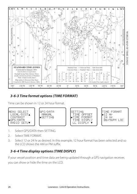
Z A B C D F G H INOPQRSTUW E
STANDARD TIME ZONESCorrected to January 2011
Zone boundaries are approximate
Daylight Saving Time (Summer Time),usually one hour in advance of Standard
Time, is kept in some places
Map outline © Mountain High MapsCompiled by HM Nautical Almanac Office
VX K L
PQ
Q
R
V
U T
S
RQ
P*
T
S
A
AZ
B
C
Z
A B
B
B
C
S
S
S
R
H I*K
K
M
M
H
H
H
I K
FG
ED*
*E*
*C
CD
GH
EF
H
IG
CE
K L
Z
ZP
N
0° 30°E 60°E 90°E 120°E 150°E30°W60°W90°W120°W150°W180° 180°
L
Z
N
O
O
Z
Z
Z
C
D
D
E
F
E*
F*
KL*
*
L
L MM
Q
O
Q
A
SU
W
V*
A
YML M Y
P
K
H
M
X X
W
W
X
M*
WM* M*
M M
L
M
M†
K
ID
F
G I
I
I
KL
L
Z
International Date L
ine
International Date L
ine
WO
RL
D M
AP O
F TIM
E Z
ON
ES
R
C
B
B
A
P
R
I
C
R
Q*
TU
Q
§
§
W
M
E†
M
K
C
G
GHII*KK*
– 7– 8– 9– 9 30–10–10 30
LL*MMM*M†
–11–11 30–12–12 45–13–14
VV*WXY
+ 9+ 9 30+10+11+12
h h h mmmmZABCC*D
0– 1– 2– 3– 3 30– 4
h m
EE*E†FF*
– 5 30– 5 45– 6 – 6 30
D* – 4 30– 5
NOPP*Q
+ 1+ 2+ 3+ 3 30+ 4
Q*RSTU
+ 4 30+ 5+ 6+ 7+ 8
Standard Time = Universal Time – value from table
h
No Standard Time legally adopted
Universal Time = Standard Time + value from table
h hm m
§
3-6-3 Time format options (TIME FORMAT)
Time can be shown in 12 or 24 hour format.
MENU SELECT LOCAL/DIST▲ CONTRAST►GPS/DATA RADIO SETU▼
GPS/DATA MANUAL►SETTING
SETTING TIME OFFSET►TIME FORMAT TIME DISPLY LL DISPLY ▼
TIME FORMAT►12 Hr 24 Hr 06:56PM LOC
1. Select GPS/DATA then SETTING.
2. Select TIME FORMAT.
3. Select 12 or 24 hr as desired. In this example, 12 hour format has been selected and so the LCD shows the AM or PM suffix.
3-6-4 Time display options (TIME DISPLY)
If your vessel position and time data are being updated through a GPS navigation receiver,
you can show or hide the time on the LCD.
Lowrance - Link-8 Operation Instructions26
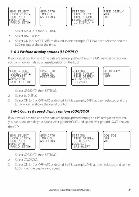
MENU SELECT LOCAL/DIST▲ CONTRAST►GPS/DATA RADIO SETU▼
GPS/DATA MANUAL►SETTING
SETTING TIME OFFSET TIME FORMAT►TIME DISPLY LL DISPLY ▼
TIME DISPLY►ON OFF
1. Select GPS/DATA then SETTING.
2. Select TIME DISPLY.
3. Select ON (on) or OFF (off ) as desired. In this example, OFF has been selected and the LCD no longer shows the time.
3-6-5 Position display options (LL DISPLY)
If your vessel position and time data are being updated through a GPS navigation receiver, you can show or hide your vessel position on the LCD.
MENU SELECT LOCAL/DIST▲ CONTRAST►GPS/DATA RADIO SETU▼
GPS/DATA MANUAL►SETTING
SETTING TIME FORMAT TIME DISPLY►LL DISPLY COG/SOG
LL DISPLY►ON OFF
1. Select GPS/DATA then SETTING.
2. Select LL DISPLY.
3. Select ON (on) or OFF (off ) as desired. In this example, OFF has been selected and the LCD no longer shows the vessel position.
3-6-6 Course & speed display options (COG/SOG)
If your vessel position and time data are being updated through a GPS navigation receiver, you can show or hide your course over ground (COG) and speed over ground (SOG) data on
the LCD.
MENU SELECT LOCAL/DIST▲ CONTRAST►GPS/DATA RADIO SETU▼
GPS/DATA MANUAL►SETTING
SETTING TIME DISPL▲ LL DISPLY►COG/SOG GPS ALERT
COG/SOG ON►OFF
1. Select GPS/DATA then SETTING.
2. Select COG/SOG.
3. Select ON (on) or OFF (off ) as desired. In this example, ON has been selected and so the LCD shows the bearing and speed.
Lowrance - Link-8 Operation Instructions 27

3-6-7 GPS alert (GPS ALERT)
If the GPS Alert is ON and the GPS navigation receiver is disconnected, the alarm sounds.
Note: The default setting is ON for the Link-8 EU and OFF for the Link-8 US.
MENU SELECT LOCAL/DIST▲ CONTRAST►GPS/DATA RADIO SETU▼
GPS/DATA MANUAL►SETTING
SETTING TIME DISPL▲ LL DISPLY COG/SOG►GPS ALERT
GPS ALERT►ON OFF
1. Select GPS/DATA then SETTING.
2. Select GPS ALERT.
3. Select ON (on) or OFF (off ) as desired.
3-7 GPS simulator (GPS SIM)
The GPS simulator is set to OFF whenever the radio is turned ON or whenever real GPS data is available through the COM port. (The GPS simulator will not operate if a GPS signal is received).
However, if you want to test it, turn it ON. Note that DSC transmissions will be blocked while
the GPS simulator is ON.
MENU SELECT RADIO SETU▲ DSC SETUP AIS SETUP►GPS SIM ▼
GPS SIM ON►OFF
1. Select GPS SIM.
2. Select ON (on) or OFF (off ) as desired.
3-8 Reset to factory defaults (RESET)
Use this to return every setting to the factory defaults except all MMSI settings and the entries in your buddy list.
MENU SELECT DSC SETUP ▲ AIS SETUP GPS SIM►RESET
RESET RADIOARE YOU SURE YES►NO
1. Select RESET. The radio asks for confirmation.
2. Select YES then press ENT to confirm and reset the radio. The menu is displayed again.
Lowrance - Link-8 Operation Instructions28

Section 4 - Radio setup menu (RADIO SETUP)Hold down CALL/MENU key for about 1 second to access the following RADIO SETUP options. The following menu options are explained in this section.
RADIO SETUP UIC * Section 4-1CH NAME Section 4-2RING VOLUME Section 4-3KEY BEEP Section 4-4UNITS Section 4-5INT SPEAKER Section 4-6WATCH MODE * Section 4-7WX ALERT * TONE ALERT Section 4-8-1
SAME ALERT Section 4-8-2SAME CODE Section 4-8-5
COM PORT Section 4-9GPS SOURCE Section 4-10FAV CH SETUP * Section 4-11
* Model dependant
See sections 1-3 and 1-4 if you want to know how to move around the menu and enter, save
and change data.
4-1 Channel (UIC)
US and AUS models only.
Toggle between USA, International, or Canadian channel banks. The selected channel bank is displayed on the LCD along with the last used channel. All the channel charts are shown in
Appendix C.
RADIO SETUP►UIC CH NAME RING VOLUME KEY BEEP ▼
UIC►USA INT L CANADA
1. Select RADIO SETUP then UIC.
2. Select the desired channel bank then press ENT.
4-2 Channel names (CH NAME)
The channel charts are listed in Appendix C with their default name tags. CH NAME gives you the option to edit or delete the channel name tags displayed on the LCD.
In this example, the channel name tag PHONE-PORTOP associated with channel 87 is being
changed to CALL PORT OP.Lowrance - Link-8 Operation Instructions 29

RADIO SETUP UIC►CH NAME RING VOLUME KEY BEEP ▼
CH NAMEPHONE-PORTOP
PHONE-PORTOP►EDIT DELETE
EDIT CH NAMEPHONE-PORTOP
SAVE CH NAMECALL PORTOP►YES NO
63
1. Select RADIO SETUP then CH NAME. Use the Channel Select knob or + or - to step through the channel name tags until you see the one you want to change then press ENT.
2. To delete the channel name, select DELETE and press ENT.
3. To edit the channel name, select EDIT to edit the existing name tag.
4. Input the new name over the existing name. It can be a maximum of 12 characters.
5. Press ENT (repeatedly is necessary) to display the YES/NO confirmation.
6. Press ENT to confirm the new channel name tag (or the deletion).
7. Press EXIT to return to the CH NAME screen.
4-3 Ring volume (RING VOLUME)
The radio sounds the friendly two-tone alert when it detects an incoming DSC call. You can
change the volume level.
RADIO SETUP UIC CH NAME►RING VOLUME KEY BEEP ▼
RING VOLUME►HIGH LOW
1. Select RADIO SETUP then RING VOLUME.
2. Select HIGH (loud) or LOW (soft) then press ENT.
4-4 Key beep volume (KEY BEEP)
You can change the key beep volume or turn the key beeps off completely.
RADIO SETUP CH NAME ▲ RING VOLUME►KEY BEEP UNITS ▼
KEY BEEP HIGH►LOW OFF
Lowrance - Link-8 Operation Instructions30
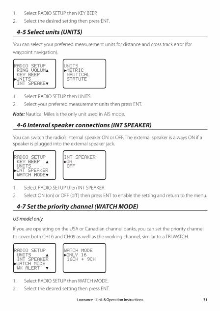
Lowrance - Link-8 Operation Instructions 31
1. Select RADIO SETUP then KEY BEEP.
2. Select the desired setting then press ENT.
4-5 Select units (UNITS)
You can select your preferred measurement units for distance and cross track error (for
waypoint navigation).
RADIO SETUP RING VOLUM▲ KEY BEEP►UNITS INT SPEAKE▼
UNITS►METRIC NAUTICAL STATUTE
1. Select RADIO SETUP then UNITS.
2. Select your preferred measurement units then press ENT.
Note: Nautical Miles is the only unit used in AIS mode.
4-6 Internal speaker connections (INT SPEAKER)
You can switch the radio’s internal speaker ON or OFF. The external speaker is always ON if a speaker is plugged into the external speaker jack.
RADIO SETUP KEY BEEP ▲ UNITS►INT SPEAKER WATCH MODE▼
INT SPEAKER►ON OFF
1. Select RADIO SETUP then INT SPEAKER.
2. Select ON (on) or OFF (off ) then press ENT to enable the setting and return to the menu.
4-7 Set the priority channel (WATCH MODE)
US model only.
If you are operating on the USA or Canadian channel banks, you can set the priority channel
to cover both CH16 and CH09 as well as the working channel, similar to a TRI WATCH.
RADIO SETUP UNITS ▲ INT SPEAKER►WATCH MODE WX ALERT ▼
WATCH MODE►ONLY 16 16CH + 9CH
1. Select RADIO SETUP then WATCH MODE.
2. Select the desired setting then press ENT.

Lowrance - Link-8 Operation Instructions32
4-8 Weather alerts (WX ALERT)
US model only.
Use WX ALERT to set your preferences for weather alert information.
The NOAA provides several weather forecast channels on USA and Canadian channel banks. If severe weather such as storms or hurricanes are forecast, the NOAA broadcasts a weather alert on 1050 Hz.
The NOAA All Hazards Weather Radio Service (NWR) works in conjunction with the Emergency Alert System (EAS) to issue weather alerts for specific geographic areas or specific weather conditions. It uses a digital encoding system known as SAME (Specific Area Message Encoding) to broadcast these alerts.
Each transmitter in the NOAA All Hazards Weather Radio Service (NWR) network is identified with a unique 6-digit SAME code. Each transmitter operates on one of 7 frequencies.
Note: To activate a SAME alert, a SAME CODE (county ID) must be selected and turned ON (see section 4-8-2).
4-8-1 TONE ALERT
If TONE ALERT is ON and an alert tone of 1050 Hz is broadcast from the NOAA weather station, the weather alert is picked up automatically and the alarm sounds. Press any key to
cancel the alarm and to hear the weather alert message.
RADIO SETUP INT SPEAKE▲ WATCH MODE►WX ALERT COM PORT ▼
►TONE ALERT SAME ALERT SAME CODE
TONE ALERT►ON OFF
1. Select RADIO SETUP then WX ALERT.
2. Select TONE ALERT.
3. Select ON to hear any weather alerts on 1050 Hz - the TONE ALERT symbol will be displayed on the LCD or, to ignore these weather alerts, select OFF.
4-8-2 SAME ALERT
Note: SAME ALERT works only after you have entered and selected a SAME code for your geographic area (see Section 4-8-5 and 4-8-6).
Note: SCAN mode will operate up to 50% more slowly when SAME ALERT is ON to allow time to decode the special warning code transmissions.

Lowrance - Link-8 Operation Instructions 33
RADIO SETUP INT SPEAKE▲ WATCH MODE►WX ALERT COM PORT ▼
TONE ALERT►SAME ALERT SAME CODE
SAME ALERT ON►OFF
1. Select RADIO SETUP then WX ALERT.
2. Select SAME ALERT.
3. Select ON to receive any local NWR or EAS alerts - the SAME ALERT symbol SAME will be displayed on the LCD or, to ignore these weather alerts, select OFF.
4-8-3 Receiving a SAME ALERT
If SAME ALERT alert is ON and an NWR or EAS alert for your geographic area is broadcast by the NOAA NWR transmitters, the alert is picked up automatically and the alarm sounds. Press any key to cancel the alarm.
If the alert is being sent by NOAA NWR, the radio automatically tunes to the designated frequency so that you can listen to the alert.
If the alert is being sent by the EAS, the nature of the alert is shown on the LCD as WARNING, WATCH, ADVISORY, or TEST. Press any key to show the nature of the alert. (The list of alerts is shown in Appendix C.)
4-8-4 Receiving SAME TEST messages
In addition to the WARNING, WATCH and ADVISORY alerts, the EAS also send out TEST mes-sages so that you can check your WX ALERT setup is working correctly. The TEST message is usually transmitted between 1000 and 1200 (10.00AM and noon) every Wednesday.
Note: If there is a threat of severe weather, the test is postponed until the next good weather day.
If your WX ALERT setup is working correctly, the alert sounds and TEST is displayed on the LCD, followed by a broadcast message from the National Weather Service.
4-8-5 Enter a SAME CODE (County ID)
If you want to receive SAME weather alerts, you must enter and then Select a SAME code for your geographic area into your radio. You can enter a maximum of 4 SAME codes (4 counties) in your geographic area.
Telephone 1-888-NWR-SAME (1-888-697-7263) or visit www.nws.noaa.gov/nwr/indexnw.htm to find the SAME codes for your geographic area (you must be within the United States of America, Puerto Rico, the U.S. Virgin Islands and U.S. Pacific Territories).
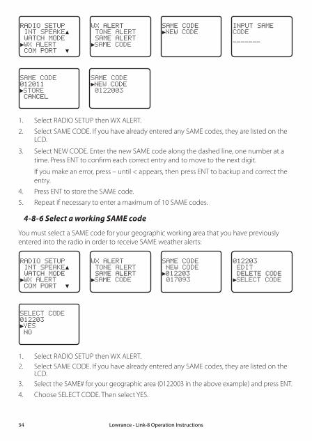
Lowrance - Link-8 Operation Instructions34
RADIO SETUP INT SPEAKE▲ WATCH MODE►WX ALERT COM PORT ▼
WX ALERT TONE ALERT SAME ALERT►SAME CODE
SAME CODE►NEW CODE
INPUT SAMECODE
SAME CODE012011►STORE CANCEL
SAME CODE►NEW CODE 0122003
1. Select RADIO SETUP then WX ALERT.
2. Select SAME CODE. If you have already entered any SAME codes, they are listed on the LCD.
3. Select NEW CODE. Enter the new SAME code along the dashed line, one number at a time. Press ENT to confirm each correct entry and to move to the next digit.
If you make an error, press – until < appears, then press ENT to backup and correct the entry.
4. Press ENT to store the SAME code.
5. Repeat if necessary to enter a maximum of 10 SAME codes.
4-8-6 Select a working SAME code
You must select a SAME code for your geographic working area that you have previously entered into the radio in order to receive SAME weather alerts:
RADIO SETUP INT SPEAKE▲ WATCH MODE►WX ALERT COM PORT ▼
WX ALERT TONE ALERT SAME ALERT►SAME CODE
SAME CODE NEW CODE►012203 017093
012203 EDIT DELETE CODE►SELECT CODE
SELECT CODE012203►YES NO
1. Select RADIO SETUP then WX ALERT. 2. Select SAME CODE. If you have already entered any SAME codes, they are listed on the
LCD.3. Select the SAME# for your geographic area (0122003 in the above example) and press ENT.
4. Choose SELECT CODE. Then select YES.

Lowrance - Link-8 Operation Instructions 35
4-9 NMEA protocol (COM PORT)
The COM PORT must be configured correctly before use. The radio can be added to a group
of instruments using NMEA protocol.
RADIO SETUP WATCH MODE▲ WX ALERT►COM PORT GPS SOURCE▼
NMEACHECK SUM►ON OFF
1. Select RADIO SETUP then COM PORT.
2. Select the desired setting then press ENT.
CHECK SUM ON (on) is the usual setting.
The COM PORT uses 4800 baud rate and can receive the following GPS data sentences: RMC, GGA, GLL, GNS. Additionally, the radio will output the following NMEA DSC data: DSC (for DSC call), DSE (for enhanced position).
4-10 Select the GPS source (GPS SOURCE)
This radio can use either NMEA 0183 or NMEA 2000 protocol to receive GPS data from a compatible GPS unit.
Note: NMEA 2000 SOURCE options will appear (up to 4 sources showing the actual source name) only if an NMEA 2000 network is connected to the radio and is operational.
RADIO SETUP WX ALERT ▲ COM PORT►GPS SOURCE FAV CH SETU
GPS SOURCE►NMEA0183 LGC3000 LCX113CHD
1. Select RADIO SETUP then GPS SOURCE. (If there is only one NMEA protocol available on your vessel, only that will be shown).
2. Select the desired NMEA source then press ENT.
4-11 Favourite channel setup - Wx key (FAV CH SETU)
EU and AUS models only.
The Wx key can be programmed to a weather channel of your choice so that you have quick access to that channel.
1. Select RADIO SETUP then FAV CH SETU.
2. Rotate the CH knob or press UP/DOWN key to select a channel that you want to save it as the WX favorite channel, then press ENT to save with WX icon lighting to indicate.

Section 5 - DSC setup menu (DSC SETUP)
WARNING
A valid USER MMSI must be entered into the radio before these DSC functions can be used. See Section 5-1 for instructions on entering your USER MMSI.
Hold down CALL/MENU key for about 1 second to access the following DSC SETUP options. The following menu options are explained in this section.
DSC SETUP USER MMSI Section 5-1GROUP SETUP Section 5-2ATIS MMSI (EU only) Section 5-3ATIS SELECT (EU only) Section 5-4INDIV REPLY Section 5-5DSC FUNC Section 5-6LL REPLY Section 5-7AUTO SWITC Section 5-8TEST REPLY Section 5-9TIMEOUT Section 5-10
See sections 1-3 and 1-4 if you want to know how to move around the menu and enter, save and change data.
5-1 Enter or view your USER MMSI (USER MMSI)
This is a once-only operation. You must enter your user MMSI before you can access the DSC functions.
You can display and read your user MMSI at any time, but you get only one opportunity to enter your user MMSI.
The user MMSI (Marine Mobile Service Identity) is a unique 9 digit number, similar to a personal telephone number. It is used on marine transceivers that are capable of using DSC (Digital Select Calling).
Contact the appropriate authorities in your country to obtain your user MMSI. If you are unsure who to contact, consult your Lowrance dealer.
DSC SETUP►USER MMSI GROUP SETUP ATIS MMSI ATIS SELEC▼
INPUT USERMMSI
USER MMSI876543210►STORE CANCEL
USER MMSIINPUT AGAIN
Lowrance - Link-8 Operation Instructions36

USER MMSI876543210►STORE CANCEL
DSC SETUP►USER MMSI GROUP SETUP ATIS MMSI ATIS SELEC▼
VIEW MMSI
876543210
1. Select DSC SETUP, then USER MMSI.
If you have already entered your MMSI, it is shown on the LCD.
2. If this is the first time that you are entering your MMSI, a dashed line appears.
Enter your MMSI along the dashed line, one number at a time. Press ENT to confirm each correct entry and to move to the next digit.
If you make an error, press – until < appears, then press ENT to backup and correct the entry.
3. Press ENT to store your user MMSI.
4. Enter your user MMSI again as a password check, then press ENT to permanently store the user MMSI and return to the menu.
5. You can view your stored user MMSI at anytime by selecting USER MMSI in the main menu.
5-2 Maintain your groups
Use GROUP SETUP to create, edit, or delete 1, 2, or up to 20 groups of frequently called people stored in alphanumeric order. A group MMSI always starts with 0.
5-2-1 Create a group (GROUP SETUP)
DSC SETUP USER MMSI►GROUP SETUP ATIS MMSI ATIS SELEC▼
GROUP SETUPMANUAL NEW
GROUP NAME
GROUP MMSI
0
FISHING 1012345678►STORE CANCEL
1. Select DSC SETUP then GROUP SETUP.
2. Select MANUAL NEW.
3. If this is the first time that you are entering a group name, a dashed line appears
4. Enter the group name along the dashed line. It can be a maximum of 12 alphanumeric characters. Press ENT to confirm each correct entry and to move to the next position.
If you make an error, press – until < appears, then press ENT to backup and correct the entry.
5. Enter the group MMSI. (Note that the first number is always a 0.) Press ENT.
6. The group name and group MMSI are shown in a confirmation screen. Press ENT to store the details and return to the GROUP SETUP screen.
Lowrance - Link-8 Operation Instructions 37

5-2-2 Edit or delete a group name or group MMSI (GROUP SETUP)
You can edit a group name or group MMSI at any time.
DSC SETUP USER MMSI►GROUP SETUP ATIS MMSI ATIS SELEC▼
GROUP SETUP MANUAL NEW►FISHING 1 SAILING
FISHING 1012345678►EDIT DELETE
EDIT NAMEFISHING 1ENTER MMSI012345678
FISHING 1012345678►STORE CANCEL
1. Select DSC SETUP then GROUP SETUP. The existing group names are displayed.
2. Select the group you want to edit. Press ENT.
3. To delete the group, select DELETE then YES. The group is deleted immediately and the group list is displayed again.
4. To edit the group, select EDIT.
5. Edit the group name OR to edit only the MMSI, press ENT repeatedly until the cursor moves to the MMSI line.
6. When you are finished, press ENT (repeatedly if necessary) until a new LCD appears.
7. Press ENT to store the changes and return to the GROUP SETUP screen.
5-3 Enter or check your ATIS MMSI (ATIS MMSI)
EU models only.
You must enter your ATIS MMSI to access ATIS functionality if you are navigating inland waterways within Europe.
• ATIS sends a digital message any time that you release the PTT key. Inland waterways rules require 1 W Tx power on Channels 06, 08, 10, 11, 12, 13, 14, 15, 17, 71, 72, 74, and 77.
• An ATIS MMSI always starts with the number 9
• This is a once-only operation. You must enter your ATIS MMSI before you can access the ATIS functions
• You can display and read your ATIS MMSI at any time, but you get only one opportunity to enter your ATIS MMSI.
1. Select DSC SETUP then ATIS MMSI.
If you have already entered your ATIS MMSI, it is shown on the LCD.
Lowrance - Link-8 Operation Instructions38

DSC SETUP USER MMSI GROUP SETUP►ATIS MMSI ATIS SELEC▼
INPUT ATISMMSI
9
ATIS MMSI9987654321►STORE CANCEL
ATIS MMSIINPUT AGAIN
9
ATIS MMSI9987654321►STORE CANCEL
2. If this is the first time that you are entering your ATIS MMSI, a dashed line appears. Enter your ATIS MMSI along the dashed line. The first number is always 9. Press ENT to confirm each correct entry and to move to the next digit.
If you make an error, press – until < appears then press ENT to backup and correct the entry.
3. Press ENT to store the ATIS MMS.
4. Enter your ATIS MMSI again as a password check, then press ENT to permanently store the ATIS MMSI and return to the menu.
5. You can view your stored ATIS MMSI at any time by selecting ATIS MMSI in the main
menu.
5-4 Enable ATIS functionality (ATIS SELECT)
EU models only.
ATIS functionality will operate only after the ATIS MMSI has been entered (see previous section).
When ATIS functionality is enabled, the ATIS symbol ATIS is shown on the LCD.
DSC SETUP GROUP SETUP ATIS MMSI►ATIS SELECT INDIV REPL▼
ATIS SELECT►ON OFF
1. Select DSC SETUP then ATIS SELECT.
2. Select OFF to disable ATIS functionality or select ON to enable the ATIS functionality - DSC must be turned off first.
3. Press ENT to confirm.
Note: It is not possible to have both ATIS ON (on) and DSC ON (on) simultaneously. If you want to activate ATIS, you must first switch DSC off. A warning will remind you if DSC is already ON.
Lowrance - Link-8 Operation Instructions 39

5-5 Response to individual calls (INDIV REPLY)
You can respond to incoming individual calls with an automatic response or with a manual response.
An automatic response sends an acknowledgement and then sets the request link channel, ready for a conversation.
A manual response asks if you want to acknowledge the call, and then asks if you want to converse with the caller.
1. Select DSC SETUP, then INDIV REPLY.
2. Select AUTO for an automatic response, or MANUAL for a manual response.
3. Press ENT to confirm your choice and return to the menu.
DSC SETUP GROUP SETU▲ ATIS MMSI ATIS SELECT►INDIV REPL▼
INDIV REPLY MANUAL►AUTO
5-6 Enable DSC functionality (DSC FUNC)
DSC functionality will operate only after a valid USER MMSI has been entered - see 5-1.
When DSC functionality is selected, the DSC symbol DSC is shown on the LCD.
DSC SETUP ATIS MMSI ▲ ATIS SELECT INDIV REPLY►DSC FUNC ▼
DSC FUNC►ON OFF
1. Select DSC SETUP then DSC FUNC.
2. Select OFF to disable DSC functionality or select ON to enable the DSC functionality - ATIS (if applicable) must be turned off first.
Note: Disabling DSC functionality is not recommended.
3. Press ENT to confirm.
Note: It is not possible to have both ATIS ON (on) and DSC ON (on) simultaneously. If you want to activate DSC, you must first switch ATIS off. A warning will remind you if ATIS is already ON.
Lowrance - Link-8 Operation Instructions40

5-7 Response type to LL polling calls (LL REPLY)
You can set up the radio to respond to an LL polling request in one of three ways:
• MANUAL reply manually to any incoming LL polling requests from your buddies.
• AUTO automatically replies to any incoming LL polling requests from any of your buddies.
• OFF ignores all incoming buddy LL polling requests.
DSC SETUP INDIV REPL▲ DSC FUNC►LL REPLY AUTO SWITC▼
LL REPLY►MANUAL AUTO OFF
1. Select DSC SETUP then LL REPLY.
2. Select your response and press ENT to confirm and return to the menu.
5-8 Automatic channel switching (AUTO SWITCH)
When a DSC call is received, it may include a request to change to a specific channel for subsequent communications. If a channel switch request is included, your options are:
• allow the radio to switch to the requested channel immediately by pressing the ENT button, or
• do nothing to allow the radio to automatically switch to the requested channel after a delay of 10 seconds, or
• cancel the automatic switch and remain on the current channel by pressing the EXIT button.
However, automatic switching to a subsequent communications channel on receipt of a DSC call might in some cases disrupt important ongoing communications if the working channel changes without the operator knowing. You can prevent the radio from automatically switching from the current working channel by setting the AUTO SWITCH feature to OFF.
If the AUTO SWITCH feature is set to OFF, an X will be displayed on the LCD to remind you that this feature is set to off. Additionally, the text “AUTO SW OFF” will be included in an All Ships or Group call replacing the text “AUTO CHxx”
DSC SETUP DSC FUNC ▲ LL REPLY►AUTO SWITC TEST REPLY▼
AUTO SWITCH►ON OFF
1. Select DSC SETUP, then AUTO SWITCH.
2. Select ON (on) to enable automatic channel switching.
3. Select OFF (off) to disable automatic channel switching.
Lowrance - Link-8 Operation Instructions 41

5-9 DSC Test Reply (TEST REPLY)
You can respond to incoming DSC TEST calls with an automatic response or with a manual response.
• MANUAL manual response is required, press ENT to confirm or press EXIT to cancel.
• AUTO automatically replies after a 10 second delay with an ACK to any incoming DSC TEST call.
DSC SETUP LL REPLY ▲ AUTO SWITC►TEST REPLY TIMEOUT
TEST REPLY►AUTO MANUAL
5-10 Set the inactivity timer (TIMEOUT)
You can set the inactivity timer with the following options:
• AUTOMATED you can set the inactivity timer to automatically timeout after a period of inactivity for the following two categories: NON-DISTRESS or DISTRESS. Timeout options are: DISTRESS: NO TIMEOUT; 5 MINS; 10 MINS (default is NO TIMEOUT) NON-DISTR: NO TIMEOUT; 10 MINS; 15 MINS (default is 15 MINS)
• NON AUTO you can set the inactivity timer to exit any non-automated procedure activity. Timeout options are: NO TIMEOUT; 10 MINS; 15 MINS (default is 10 MINS)
Note: If NO TIMEOUT is selected, then you must press the EXIT key to exit the procedure.
Example: to set a 10 minute TIMEOUT for non-automated functions:
1. Select TIMEOUT, then select NON AUTO
2. Select desired timeout period: NO TIMEOUT, 10 MINS or 15 MINS
NON AUTO NO TIMEOUT►10 MINS 15 MINS
TIMEOUT►AUTOMATED NON AUTO
DSC SETUP LL REPLY ▲ AUTO SWITC TEST REPLY►TIMEOUT
In this example, 10 MINS has been selected, meaning the radio will exit any non-automated procedure after a period of 10 minutes of non-activity.
Lowrance - Link-8 Operation Instructions42
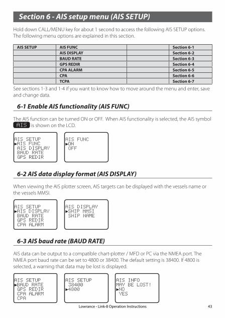
Section 6 - AIS setup menu (AIS SETUP)Hold down CALL/MENU key for about 1 second to access the following AIS SETUP options. The following menu options are explained in this section.
AIS SETUP AIS FUNC Section 6-1AIS DISPLAY Section 6-2BAUD RATE Section 6-3GPS REDIR Section 6-4CPA ALARM Section 6-5CPA Section 6-6TCPA Section 6-7
Lowrance - Link-8 Operation Instructions 43
See sections 1-3 and 1-4 if you want to know how to move around the menu and enter, save and change data.
6-1 Enable AIS functionality (AIS FUNC)
The AIS function can be turned ON or OFF. When AIS functionality is selected, the AIS symbol AIS is shown on the LCD.
AIS SETUP►AIS FUNC AIS DISPLAY BAUD RATE GPS REDIR
AIS FUNC►ON OFF
6-2 AIS data display format (AIS DISPLAY)
When viewing the AIS plotter screen, AIS targets can be displayed with the vessels name or the vessels MMSI.
AIS SETUP►AIS DISPLAY BAUD RATE GPS REDIR CPA ALARM
AIS DISPLAY►SHIP MMSI SHIP NAME
6-3 AIS baud rate (BAUD RATE)
AIS data can be output to a compatible chart-plotter / MFD or PC via the NMEA port. The NMEA port baud rate can be set to 4800 or 38400. The default setting is 38400. If 4800 is selected, a warning that data may be lost is displayed.
AIS SETUP►BAUD RATE GPS REDIR CPA ALARM CPA
AIS SETUP 38400►4800
AIS INFOMAY BE LOST!►NO YES

6-4 GPS redirection (GPS REDIR)
GPS redirection option set to output the GPS information to the chartplotter eliminating the need for an additional multiplexer. If “yes” is selected, the string $RMC will be redirected to the chartplotter once it is received.
Note: The REDIR function will only redirect RMC and GLL messages from NMEA 0183 input port to the AIS output port.
AIS SETUP►GPS REDIR CPA ALARM CPA TCPA
GPS REDIR►NO YES
6-5 Closest point of approach alarm (CPA ALARM)
Enables the CPA alarm. If set to OFF, there will be no T/CPA alarms regardless of the settings.
AIS SETUP GPS REDIR►CPA ALARM CPA TCPA
CPA ALARM►ON OFF
6-6 Closest point of approach settings (CPA)
CPA is the minimum distance between you and a target vessel based on the current speed and course. You can set the minimum distance for CPA alarm to sound (1 NM to 30 NM). Rotate the dial to set the CPA distance in 1 NM increments. Press ENT when done.
AIS SETUP GPS REDIR CPA ALARM►CPA TCPA
CPA►01NM
6-7 Time to closest point of approach (TCPA)
TCPA is the minimum time of intercept between you and a target vessel based on the current speed and course. Set the minimum time for the TCPA alarm to sound (5 Min to 30 Min). Rotate the dial to set the TCPA time in 30 sec increments. Press ENT when done.
AIS SETUP GPS REDIR CPA ALARM CPA►TCPA
TCPA►05:00Min
Lowrance - Link-8 Operation Instructions44

Section 7 - Sending and receiving DSC Calls
WARNING
A valid USER MMSI must be entered into this radio before these DSC functions can be used. See section 5-1.
7-1 What is DSC?
DSC (Digital Selective Calling) is a semi-automated method of establishing VHF, MF, and HF radio calls. It has been designated as an international standard by the IMO (International Maritime Organization) and is part of the GMDSS (Global Maritime Distress and Safety System).
Currently, you are required to monitor Distress Channel 16, but DSC will eventually replace listening watches on distress frequencies and will be used to broadcast routine and urgent maritime safety information.
DSC enables you to send and receive calls from any vessel or coast station that is equipped with DSC functionality and within geographic range. Calls can be categorized as distress, urgency, safety, or routine, and DSC selects a working channel automatically.
7-2 Sending DSC Calls
You can call any other person that has another DSC equipped radio.
• Quick press the CALL / MENU key to access the following DSC CALL menu options – select LAST CALL to quickly call back the person who called you.
• Note that only four DSC CALL menu options can be shown on the LCD at any one time.
• Press + or – on the microphone or turn the Channel Select knob on the base station to scroll up or down through the menu until the cursor is positioned at the desired option. Press ENT (the center of the Channel Select knob) to display that option.
The following options are available:
DSC CALL INDIVIDUAL Make a DSC Call Section 7-3LAST CALL Repeat the last DSC Call Section 7-5GROUP Make a Group DSC Call Section 7-6ALL SHIPS Make an All Ships DSC Call Section 7-7CALL LOG View DSC Call Log Section 7-8DISTR LOG View DSC Distress Log Section 7-9SENT CALL View DSC Sent Call Log Section 7-10LL REQUEST Request a position report Section 7-11TRACK BUDDY Automatically track Buddy’s Section 7-12DSC TEST Make a DSC Test Call Section 7-13MMSI/GPS View MMSI and GPS information Section 7-14
Lowrance - Link-8 Operation Instructions 45
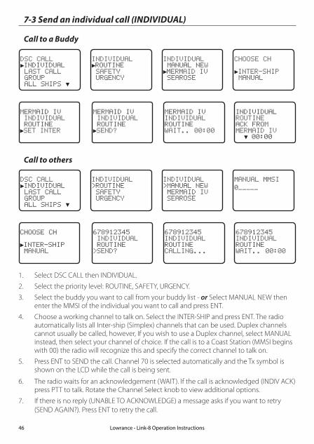
7-3 Send an individual call (INDIVIDUAL)
Call to a Buddy
DSC CALL►INDIVIDUAL LAST CALL GROUP ALL SHIPS ▼
INDIVIDUAL►ROUTINE SAFETY URGENCY
INDIVIDUAL MANUAL NEW►MERMAID IV SEAROSE
CHOOSE CH
►INTER-SHIP MANUAL
MERMAID IV INDIVIDUAL ROUTINE►SET INTER
MERMAID IV INDIVIDUAL ROUTINE►SEND?
MERMAID IV INDIVIDUALROUTINEWAIT.. 00:00
INDIVIDUALROUTINEACK FROMMERMAID IV ▼ 00:00
Call to others
DSC CALL►INDIVIDUAL LAST CALL GROUP ALL SHIPS ▼
INDIVIDUALROUTINE SAFETY URGENCY
INDIVIDUALMANUAL NEW MERMAID IV SEAROSE
MANUAL MMSI
0
CHOOSE CH
►INTER-SHIP MANUAL
678912345 INDIVIDUAL ROUTINESEND?
678912345INDIVIDUAL ROUTINECALLING...
678912345INDIVIDUALROUTINEWAIT.. 00:00
1. Select DSC CALL then INDIVIDUAL.
2. Select the priority level: ROUTINE, SAFETY, URGENCY.
3. Select the buddy you want to call from your buddy list - or Select MANUAL NEW then enter the MMSI of the individual you want to call and press ENT.
4. Choose a working channel to talk on. Select the INTER-SHIP and press ENT. The radio automatically lists all Inter-ship (Simplex) channels that can be used. Duplex channels cannot usually be called, however, If you wish to use a Duplex channel, select MANUAL instead, then select your channel of choice. If the call is to a Coast Station (MMSI begins with 00) the radio will recognize this and specify the correct channel to talk on.
5. Press ENT to SEND the call. Channel 70 is selected automatically and the Tx symbol is shown on the LCD while the call is being sent.
6. The radio waits for an acknowledgement (WAIT). If the call is acknowledged (INDIV ACK) press PTT to talk. Rotate the Channel Select knob to view additional options.
7. If there is no reply (UNABLE TO ACKNOWLEDGE) a message asks if you want to retry (SEND AGAIN?). Press ENT to retry the call.
Lowrance - Link-8 Operation Instructions46

7-4 Acknowledgement of an individual incoming call (INDIV)
When an incoming call is received, the alarm sounds for 2 minutes and INDIVIDUAL is displayed.
123456789NO AUTO SWCH12 REQUEST12:45 UTC ▲ 00:03
ROUTINE FROM123456789NO AUTO SWCH12 REQUEST ▲▼ 00:02
INDIVIDUALROUTINE FROM123456789NO AUTO SW ▼ 00:01
1. Press SILENC softkey (AIS/IC key) to silence the alert.
2. Press +/- button or rotate the CH knob to scroll any further information about the call.
3. Press NEW-CH softkey (AIS/IC key) to request a different working channel, or press ABLE softkey (WX/NAV key) to acknowledge the call.
4. Or press EXIT to return to standby.
7-5 Reply to the Last Call (LAST CALL)
This facility is useful and used frequently.
DSC CALL INDIVIDUAL►LAST CALL GROUP ALL SHIPS ▼
SEAROSEINDIVIDUALROUTINE10:22AM LOC
CHOOSE CH
►INTER-SHIP MANUAL
SEAROSEINDIVIDUALROUTINE►SEND?
1. Select DSC CALL then LAST CALL.
2. The contact details of the most recent incoming call are displayed. Press ENT.
3. Choose a working channel to talk on. Select the INTER-SHIP and press ENT. The radio automatically lists all Inter-ship (Simplex) channels that can be used. Duplex channels cannot usually be called, however, If you wish to use a Duplex channel, select MANUAL instead, then select your channel of choice. If the call is to a Coast Station (MMSI begins with 00) the radio will recognize this and specify the correct channel to talk on.
4. The call details are shown. Press ENT to send the call. The Tx symbol is displayed on the LCD while the call is being sent.
5. If the call is acknowledged (INDIV ACK) press PTT to talk. If there is no reply a message asks if you want to retry (SEND AGAIN?). Press ENT to retry the call.
Lowrance - Link-8 Operation Instructions 47

7-6 Send a group call (GROUP) You must already have stored a GROUP MMSI before making the call - see Section 5-2. Group
calls are always sent with ROUTINE priority.
DSC CALL INDIVIDUAL►LAST CALL GROUP ALL SHIPS ▼
GROUP►DIVE 1 DIVE 2
CHOOSE CH
►INTER-SHIP MANUAL
DIVE 1GROUP CALL
►SEND?
1. Select DSC CALL then GROUP.
The radio displays the names of your pre-programed groups.
2. Select the group that you want to call (the GROUP MMSI must be set before making the call).
3. Choose a working channel to talk on. Select the INTER-SHIP and press ENT. The radio automatically lists all Inter-ship (Simplex) channels that can be used. Duplex channels cannot usually be called, however, If you wish to use a Duplex channel, select MANUAL instead, then select your channel of choice.
4. The call details are shown. Press ENT to send the call. The Tx symbol is displayed on the LCD while the call is being sent.
7-7 Send an all ships call (ALL SHIPS)
DSC CALL LAST CALL ▲ GROUP►ALL SHIPS CALL LOG ▼
ALL SHIPS►SAFETY URGENCY
CHOOSE CH
►INTER-SHIP MANUAL
ALL SHIPSSAFETY►SEND?
1. Select DSC CALL then ALL SHIPS.
2. Select one of the following call priorities:
• SAFETY To send safety information to all other vessels in range.
• URGENCY For use when a serious situation or problem arises that could lead to a distress situation.
3. Choose a working channel to talk on. Select the INTER-SHIP and press ENT. The radio automatically lists all Inter-ship (Simplex) channels that can be used. Duplex channels cannot usually be called, however, If you wish to use a Duplex channel, select MANUAL instead, then select your channel of choice.
4. The call details are shown. Press ENT to send the call. The Tx symbol is displayed on the LCD while the call is being sent.
Lowrance - Link-8 Operation Instructions48

When the call log is full, the oldest entry is overwritten.
7-8 Send using the call log (CALL LOG)
The Call Log contains the contact details for the 20 most recent incoming calls, so that you can call any of them again quickly.
DSC CALL GROUP ▲ ALL SHIPS►CALL LOG DISTR LOG ▼
11 12345678INDIVIDUALROUTINE09:45 UTC
11 12345678►CALL BACK DELETE SAVE MMSI
CHOOSE CH
►INTER-SHIP MANUAL
12345678INDIVIDUALROUTINE►SEND?
1. Select DSC CALL then CALL LOG.
2. The radio displays the contact details for the most recent incoming call as the first entry (01) in the call log. In the example, the contact details for the 11th most recent call are displayed. Press ENT to move to the next screen.
3. Press ENT again to confirm the call back.
4. Choose a working channel to talk on. Select the INTER-SHIP and press ENT. The radio automatically lists all Inter-ship (Simplex) channels that can be used. Duplex channels cannot usually be called, however, If you wish to use a Duplex channel, select MANUAL instead, then select your channel of choice. If the call is to a Coast Station (MMSI begins with 00) the radio will recognize this and specify the correct channel to talk on.
5. The call details are shown. Press ENT to send the call. The Tx symbol is displayed on the LCD while the call is being sent.
Lowrance - Link-8 Operation Instructions 49
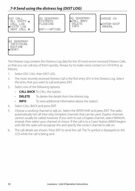
7-9 Send using the distress log (DIST LOG)
DSC CALL ALL SHIPS ▲ CALL LOG►DISTR LOG SENT CALL ▼
02 SEASPRAYDISTRESSFLOODING
ENT-- OPTION
CHOOSE CH
►INTER-SHIP MANUAL
02 SEASPRAY►CALL BACK DELETE INFO
02 SEASPRAY INDIVIDUAL ROUTINE►SEND?
The Distress Log contains the Distress Log data for the 20 most recent received Distress Calls, so that you can call any of them quickly. Always try to make voice contact on CH16 first, as follows:
1. Select DSC CALL then DIST LOG.
2. The most recently received Distress Call is the first entry (01) in the Distress Log. Select the entry that you want to call and press ENT.
3. Select one of the following options:
• CALL BACK To CALL the station.
• DELETE To delete the details from the distress log.
• INFO To view additional information about the station.
4. Select CALL BACK and press ENT.
5. Choose a working channel to talk on. Select the INTER-SHIP and press ENT. The radio automatically lists all Inter-ship (Simplex) channels that can be used. Duplex channels cannot usually be called, however, If you wish to use a Duplex channel, select MANUAL instead, then select your channel of choice. If the call is to a Coast Station (MMSI begins with 00) the radio will recognize this and specify the correct channel to talk on.
6. The call details are shown. Press ENT to send the call. The Tx symbol is displayed on the LCD while the call is being sent.
Lowrance - Link-8 Operation Instructions50
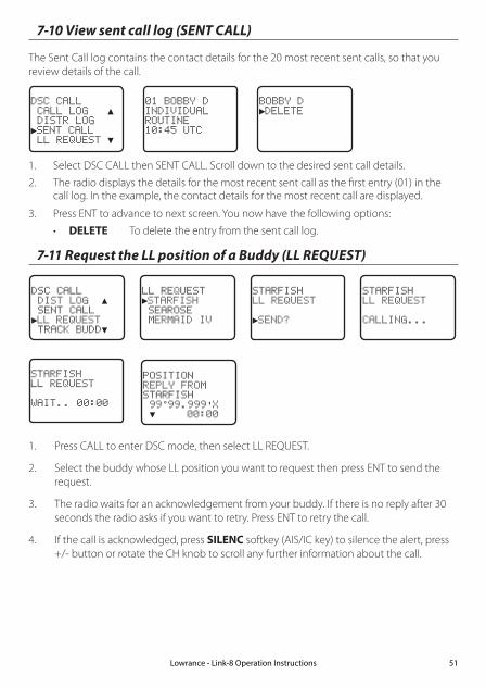
7-10 View sent call log (SENT CALL)
The Sent Call log contains the contact details for the 20 most recent sent calls, so that you review details of the call.
BOBBY D►DELETE
01 BOBBY DINDIVIDUALROUTINE10:45 UTC
DSC CALL CALL LOG ▲ DISTR LOG►SENT CALL LL REQUEST ▼
1. Select DSC CALL then SENT CALL. Scroll down to the desired sent call details.
2. The radio displays the details for the most recent sent call as the first entry (01) in the call log. In the example, the contact details for the most recent call are displayed.
3. Press ENT to advance to next screen. You now have the following options:
• DELETE To delete the entry from the sent call log.
7-11 Request the LL position of a Buddy (LL REQUEST)
DSC CALL DIST LOG ▲ SENT CALL►LL REQUEST TRACK BUDD▼
LL REQUEST►STARFISH SEAROSE MERMAID IV
STARFISHLL REQUEST
►SEND?
STARFISH LL REQUEST
CALLING...
STARFISHLL REQUEST
WAIT.. 00:00
1. Press CALL to enter DSC mode, then select LL REQUEST.
2. Select the buddy whose LL position you want to request then press ENT to send the request.
3. The radio waits for an acknowledgement from your buddy. If there is no reply after 30 seconds the radio asks if you want to retry. Press ENT to retry the call.
4. If the call is acknowledged, press SILENC softkey (AIS/IC key) to silence the alert, press +/- button or rotate the CH knob to scroll any further information about the call.
POSITIONREPLY FROMSTARFISH 99°99.999'X ▼ 00:00
Lowrance - Link-8 Operation Instructions 51
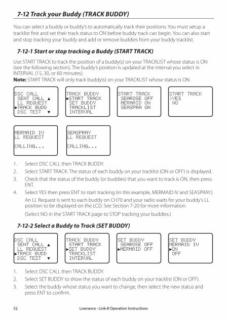
7-12 Track your Buddy (TRACK BUDDY)
You can select a buddy or buddy’s to automatically track their positions. You must setup a tracklist first and set their track status to ON before buddy track can begin. You can also start and stop tracking your buddy and add or remove buddies from your buddy tracklist.
7-12-1 Start or stop tracking a Buddy (START TRACK)
Use START TRACK to track the position of a buddy(s) on your TRACKLIST whose status is ON (see the following section). The buddy’s position is updated at the interval you select in INTERVAL (15, 30, or 60 minutes). Note: START TRACK will only track buddy(s) on your TRACKLIST whose status is ON.
DSC CALL SENT CALL ▲ LL REQUEST►TRACK BUDD DSC TEST ▼
TRACK BUDDY►START TRACK SET BUDDY TRACKLIST INTERVAL
START TRACK SEAROSE OFF MERMAID ON SEASPRA ON
START TRACKYES NO
MERMAID IVLL REQUEST
CALLING...
SEASPRAYLL REQUEST
CALLING...
1. Select DSC CALL then TRACK BUDDY.
2. Select START TRACK. The status of each buddy on your tracklist (ON or OFF) is displayed.
3. Check that the status of the buddy (or buddies) that you want to track is ON, then press ENT.
4. Select YES then press ENT to start tracking (in this example, MERMAID IV and SEASPRAY.)
An LL Request is sent to each buddy on CH70 and your radio waits for your buddy’s LL position to be displayed on the LCD. See Section 7-20 for more information.
(Select NO in the START TRACK page to STOP tracking your buddies.)
7-12-2 Select a Buddy to Track (SET BUDDY)
DSC CALL SENT CALL ▲ LL REQUEST►TRACK BUDD DSC TEST ▼
TRACK BUDDY START TRACK►SET BUDDY TRACKLIST INTERVAL
SET BUDDY SEAROSE OFF►MERMAID OFF
SET BUDDYMERMAID IV►ON OFF
1. Select DSC CALL then TRACK BUDDY.
2. Select SET BUDDY to show the status of each buddy on your tracklist (ON or OFF).
3. Select the buddy whose status you want to change, then select the new status and press ENT to confirm.
Lowrance - Link-8 Operation Instructions52

7-12-3 Add or delete a Buddy on your track list (TRACKLIST)
DSC CALL SENT CALL ▲ LL REQUEST►TRACK BUDD DSC TEST ▼
TRACK BUDDY START TRACK SET BUDDY ►TRACKLIST INTERVAL
TRACKLIST►ADD NEW SEAROSE
ADD NEW►MERMAID IV SEASPRAY
1. Select DSC CALL then TRACK BUDDY.
2. Select TRACKLIST. Any buddies already on the tracklist will be listed. Note: To delete a buddy from the tracklist, select that buddy then press ENT. Select YES then press ENT again to delete.
3. Select ADD NEW to show your buddy list. Buddy’s must be already setup in your Buddy list - see section 3-3.
4. Select a buddy then press ENT to add that buddy to the tracklist.
7-12-4 Set the track your Buddy update interval (INTERVAL)
Set the interval rate at which the position of your buddy is updated - options are 15, 30 or 60 minutes.
DSC CALL SENT CALL ▲ LL REQUEST►TRACK BUDD DSC TEST ▼
TRACK BUDDY START TRACK SET BUDDY TRACKLIST►INTERVAL
TRACKLIST►15 MINUTES 30 MINUTES 1 HOUR
7-13 Make a DSC test call (DSC TEST)
You can test your radio’s DSC operation by sending a DSC TEST CALL to a Buddy or other station equipped with a DSC radio.
Note: You should not use a routine DSC call to test your radio and you should minimize the use of the safety channel for test purposes.
7-13-1 Send a DSC TEST call
1. Select DSC CALL then DSC TEST.
2. Select the buddy you want to call from your buddy list, or Select MANUAL NEW then enter the MMSI of the individual you want to call.
3. Press ENT to accept the selection.
4. Press ENT again to SEND the call. Channel 70 is selected automatically and the TX symbol is shown on the LCD while the call is being sent.
5. The radio waits for an acknowledgement (WAIT). If the call is acknowledged a notification is displayed.
Lowrance - Link-8 Operation Instructions 53

TOMDSC TEST
►SEND?
DSC TEST MANUAL NEW SAM►TOM
DSC CALL LL REQUEST▲ TRACK BUDDY►DSC TEST MMSI/GPS
TOMDSC TEST
WAIT.. 00:17
6. If there is no reply after 30 seconds, the radio asks you if you want to retry.
7-13-2 Receiving an incoming DSC TEST call reply (DSC TEST ACK)1. When you receive notification of a DSC TEST reply, press SILENC softkey (AIS/IC key) to
silence the alert.
2. If the radio recognizes the user MMSI as one of your buddies, the buddy’s name is displayed in place of the user MMSI.
7-13-3 Acknowledging an incoming DSC TEST call
The radio sounds a friendly two-tone alert when it detects an incoming DSC TEST call.
Note: If TEST REPLY is set to AUTO, no sound will be emitted.
1. If the radio recognizes the MMSI as one of your buddies, your buddy’s name is displayed in place of the MMSI.
2. Press SILENC softkey (AIS/IC key) to silence the alert.
3. The radio will automatically acknowledge the call if TEST REPLY is set to AUTO (See sec-tion 5-9) and after a TIMEOUT period set for AUTO REPLY (See section 5-10).
CALL FROMTOMAUTO ACKIN 10S ▲▼ 00:02
TESTCALL FROMTOMAUTO ACK ▼ 00:01
4. Alternatively, if TEST REPLY is set to MANUAL, a manual response is required, press ACK (AIS/IC key) to acknowledge the DSC Test Call.
CALL FROMTOMAUTO ACKIS OFF ▲▼ 00:02
TESTCALL FROMTOMAUTO ACK ▼ 00:01
5. Press +/- button or rotate the CH knob to scroll any further information (if available), or press EXIT to cancel.
Lowrance - Link-8 Operation Instructions54
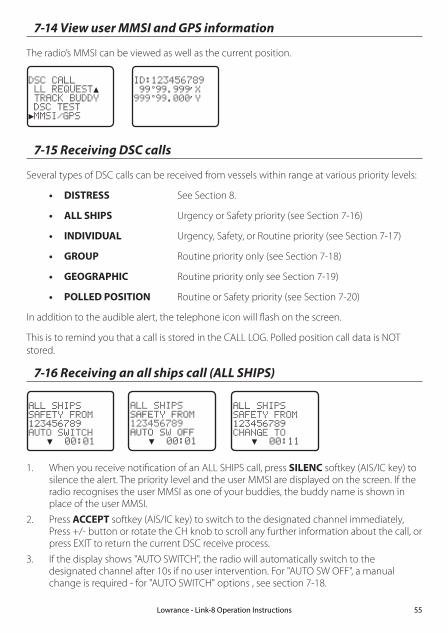
7-14 View user MMSI and GPS information
The radio’s MMSI can be viewed as well as the current position.
ID:123456789 99°99.999’X999°99.000’Y
DSC CALL LL REQUEST▲ TRACK BUDDY DSC TEST►MMSI/GPS
7-15 Receiving DSC calls
Several types of DSC calls can be received from vessels within range at various priority levels:
• DISTRESS See Section 8.
• ALL SHIPS Urgency or Safety priority (see Section 7-16)
• INDIVIDUAL Urgency, Safety, or Routine priority (see Section 7-17)
• GROUP Routine priority only (see Section 7-18)
• GEOGRAPHIC Routine priority only see Section 7-19)
• POLLED POSITION Routine or Safety priority (see Section 7-20)
In addition to the audible alert, the telephone icon will flash on the screen.
This is to remind you that a call is stored in the CALL LOG. Polled position call data is NOT stored.
7-16 Receiving an all ships call (ALL SHIPS)
ALL SHIPSSAFETY FROM123456789AUTO SWITCH ▼ 00:01
ALL SHIPSSAFETY FROM123456789AUTO SW OFF ▼ 00:01
ALL SHIPSSAFETY FROM123456789CHANGE TO ▼ 00:11
1. When you receive notification of an ALL SHIPS call, press SILENC softkey (AIS/IC key) to silence the alert. The priority level and the user MMSI are displayed on the screen. If the radio recognises the user MMSI as one of your buddies, the buddy name is shown in place of the user MMSI.
2. Press ACCEPT softkey (AIS/IC key) to switch to the designated channel immediately, Press +/- button or rotate the CH knob to scroll any further information about the call, or press EXIT to return the current DSC receive process.
3. If the display shows "AUTO SWITCH", the radio will automatically switch to the designated channel after 10s if no user intervention. For "AUTO SW OFF", a manual change is required - for "AUTO SWITCH" options , see section 7-18.
Lowrance - Link-8 Operation Instructions 55

4. Press PTT to initiate voice contact on current display channel.
The call data is stored in your Call Log (see Section 7-8).
7-17 Receiving an individual call (INDIV)
INDIVIDUALROUTINE FROM123456789AUTO SWITCH ▼ 00:01
INDIVIDUALROUTINE FROM123456789AUTO SW OFF ▼ 00:01
1. When you receive notification of an INDIV call, press SILENC softkey (AIS/IC key) to silence the alert. INDIV calls are almost always routine priority. If the radio recognises the user MMSI as one of your buddies, the buddy’s name is displayed in place of the user MMSI.
2. Press +/- button or rotate the CH knob to scroll any further information about the call, or press EXIT to return the current DSC receive process.
3. You have the following options to respond the call:
• ABLE softkey (WX/NAV key) respond to the call with requested channel
• NEW-CH softkey (AIS/IC key) respond to the call with but request a different channel
• UNABLE softkey (GO/MOB key) respond to the call with unable to use the requested channel ( Note: this option is not available with ROUTINE calls)
4. If the display shows "AUTO SWITCH", the radio will automatically respond to the call after 10s if no user intervention. For "AUTO SW OFF", a manual responce is required - for "INDIV REPLY" options , see section 5-5.
5. The caller should respond to your acknowledgement by making voice contact designated channel. If this does not happen, you can press PTT to initiate voice contact instead.
The call data is stored in your Call Log (see Section 7-8).
7-18 Receiving a group call (GROUP)
GP: SAMCALL FROM123456789AUTO SWITCH ▼ 00:01
GP: SAMCALL FROM123456789AUTO SW OFF ▼ 00:01
GP: SAMCALL FROM012345678CHANGE TO ▼ 00:11
1. When you receive notification of a GROUP call, press SILENC softkey (AIS/IC key) to silence the alert. Press +/- button or rotate the CH knob to scroll any further information about the call.
The priority level is always routine, and the group is identified on the screen. The group will be one of the 20 groups of frequently called people that you set up earlier (see Section 5-2).
2. Press ACCEPT softkey (AIS/IC key) to switch to the designated channel immediately, or
Lowrance - Link-8 Operation Instructions56
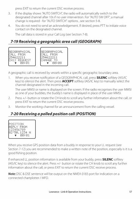
press EXIT to return the current DSC receive process.
3. If the display shows "AUTO SWITCH", the radio will automatically switch to the designated channel after 10s if no user intervention. For "AUTO SW OFF", a manual change is required - for "AUTO SWITCH" options , see section 5-8.
4. You do not need to send an acknowledgement. If desired, press PTT to initiate voice contact on the designated channel.
The call data is stored in your Call Log (see Section 7-8).
7-19 Receiving a geographic area call (GEOGRAPH)
GEOGRAPHICALCALL FROM254622211CH12 REQUEST ▼ 00:01
GEOGRAPHICALCALL FROM254622211CHANGE TO ▼ 00:08
A geographic call is received by vessels within a specific geographic boundary area.
1. When you receive notification of a GEOGRAPHICAL call, press SILENC softkey (AIS/IC key) to silence the alert. Then press ACCEPT softkey (AIS/IC key) to manually select the channel designated in the incoming call.
The user MMSI or name is displayed on the screen. If the radio recognises the user MMSI as one of your buddies, the buddy’s name is displayed in place of the user MMSI.
2. Press +/- button or rotate the CH knob to scroll any further information about the call, or press EXIT to return the current DSC receive process.
3. Monitor the working channel for an announcement from the calling vessel.
7-20 Receiving a polled position call (POSITION)
POSITIONREPLY FROM12345678982°50.1234 N ▼ 00:01
When you receive GPS position data from a buddy in response to your LL request (see Section 7-12) you are recommended to make a written note of the position, especially is it is a good fishing position.
If enhanced LL position information is available from your buddy, press SILENC softkey (AIS/IC key) to silence the alert. Press +/- button or rotate the CH knob to scroll any further information about the call, or press EXIT to return the current DSC receive process.
Note: DSC & DSE sentence will be output on the NMEA 0183 port for indication on a connected chartplotter / MFD.
Lowrance - Link-8 Operation Instructions 57

Section 8 - DISTRESS calls
WARNING
A valid USER MMSI must be entered into this radio before these DSC functions can be used. See section 5-1.
8-1 Sending a Distress Call
DISTRES CALL►UNDEFINED FIRE FLOODING COLLISION
DISTRES CALL ►UNDEFINED HOLD DISTRES 3 SECONDS..
DISTRES CALLUNDEFINED11:23 UTC 22°12.023’N ▼TX IN 00:01
1. Open the red cover labelled DISTRESS.
If time is available to specify the nature of the distress, go to step 2. Otherwise, go directly to step 3.
2. Press and release the DISTRESS key to display the following categories. Press +/- button or rotate the CH knob to select the category that describes your situation then press ENT.
• UNDEFINED (Undefined)
• FIRE (Fire)
• FLOODING (Flooding)
• COLLISION (Collision)
• GROUNDING (Grounding)
• LISTING (Listing)
• SINKING (Sinking)
• ADRIFT (Adrift)
• ABANDONING (Abandoning)
• PIRACY (Piracy)
• OVER BOARD (Overboard)
3. Press and hold down the DISTRESS key for about 3 seconds, until you see the distress call sending message (DISTRESS CALL SENDING) on the screen. The whole display starts to flash and beep loudly.
4. After the Distress Call is sent, the radio waits for an acknowledgment.
•The Distress call is automatically transmitted every 3.5 to 4.5 minutes, until an acknowledgement is received ("Call repeat" mode).
•Press ▼ / ▲ to display the transmitted Distress call information.
Lowrance - Link-8 Operation Instructions58

5. You now have the following options: RESEND, PAUSE, CANCEL:
6. To RESEND the call, press RESEND softkey (AIS/IC key) to enter "HOLD DISTRESS 3 SECONDS TO SEND" screen. Hold down DISTRESS key for 3s to resend the call or press EXIT softkey (AIS/IC key) to return to waiting for an acknowledgement call.
7. To PAUSE the call, press PAUSE softkey (WX/NAV key) to pause the "Call repeat" mode, press EXIT softkey (AIS/IC key) to resume the same call.
8. To CANCEL the call, press CANCEL softkey (GO/MOB key) to enter "DISTRESS CALL SEND CANCEL" screen.
•Press NO softkey (WX/NAV key) to return to waiting for an acknowledgement call.
•Press YES softkey (AIS/IC key) to send the DISTRESS CANCEL call. Then press PTT to report your situation using the handset mic, after the report, press EXIT to return to the normal operating mode.
9. After receiving the acknowledgment, press SILENC softkey (AIS/IC key) then reply using the microphone, or press EXIT key to quit the current distress acknowledgment.
Note: Prior to receiving an acknowledgement, the distress alert call cannot immediately be terminated by you, it can only be cancelled by completing the distress call cancel process as described above (step 8).
8-2 Receiving a distress call (DISTRESS!)
DISTRESSUNDEFINED123456789 82°50.123'N ▼ 00:01
An alert sounds when a distress call (DISTRESS!) is received.
1. Press SILENC softkey (AIS/IC key) to silence the alert. You do not need to send an acknowledgement.
2. The radio automatically selects CH16 after 10 seconds if no user intervention, or press ACCEPT softkey (AIS/IC key) to change to CH16 immediately.
3. Press +/- button or rotate the CH knob to view details of the distress call. Details include the user MMSI and nature of the emergency (if specified), also the time and the location (if specified). If the location and time are not specified, these are replaced with sequences of 9s and 8s respectively.
•The radio is capable of receiving enhanced LL position data if the vessel transmitting the distress call is sending this. This provides the position of the distressed vessel to within 20 m (60 ft).
4. Press PTT to establish voice contact or press EXIT key to quit the DISTRESS RECEIVE call.
Note: The call data is stored in the Distress Log and location data (DSC & DSE) sentence will be output on the NMEA 0183 port for indication on a connected chartplotter / MFD.
Lowrance - Link-8 Operation Instructions 59

8-3 Distress acknowledgement (DISTRESS ACK) or distress relay all ships (DISTRESS REL)
1. An alert sounds when a Distress ACK or Distress Relay all ship call is received. Press SILENC softkey (AIS/IC key) to silence the alert.
2. The radio automatically selects CH16 after 10 seconds if no user intervention, or press ACCEPT softkey(AIS/IC key) to change to CH16 immediately.
3. Press +/- button or rotate the CH knob to view details of the distress call. Details include the user MMSI and nature of the emergency (if specified), also the time and the location (if specified). If the location and time are not specified, these are replaced with sequences of 9s and 8s respectively.
4. Press PTT to make voice contact with the calling vessel. Maintain a listening watch on CH16 and standby to lend assistance
• For a Distress Acknowledgement (DISTRESS ACK) sent from the Search and Rescue (SAR) authorities of your country, your radio automatically cancels Distress Mode transmissions and CH16 appears. Press PTT to establish voice contact with the Search and Rescue (SAR) authority.
• The Search and Rescue (SAR) authorities of your country are the only instance allowed to send a Distress Acknowledgement (DISTRESS ACK).
5. Press EXIT key to quit the current DSC receive process.
Note: The call data is stored in the Distress Log and location data (DSC & DSE) sentence is sent on the NMEA 0183 port for indication on a connected chartplotter / MFD.
DISTRESSACK FROM567890123 FIRE ▼ 00:01
8-4 Distress relay individual (INDIV DISTR RELAY)
When an incoming Individual Distress Relay call is received, the alarm sounds and INDIV DISTR RELAY is displayed.
1. Press SILENC softkey (AIS/IC key) to silence the alarm.
2. Press +/- button or rotate the CH knob to view details of the distress call. Details include the user MMSI and nature of the emergency (if specified), also the time and the location (if specified). If the location and time are not specified, these are replaced with sequences of 9s and 8s respectively.
3. ALL MODELS: Press ACCEPT softkey (AIS/IC key) to immediately accept the channel change before the 10s timer expires
4. US MODELS: Press ACK softkey (AIS/IC key) to ACK the call after the 10s delay - for "INDIV REPLY" options, see section 5-15.
5. Press EXIT key to quit current receive DSC process..
Note: The call data is stored in the Distress Log and location data (DSC & DSE) sentence is sent on the NMEA 0183 port for indication on a connected chartplotter / MFD.
87654321ALL DISTRRELAY123456789 ▼ 00:01
Lowrance - Link-8 Operation Instructions60

Section 9 - AIS functionality
WARNING
A valid USER MMSI must be entered into this radio before these AIS functions can be used. See section 5-1.
9-1 About AIS
The marine Automatic Identification System (AIS) is a location and vessel information reporting system. It allows vessels equipped with AIS to automatically and dynamically share and regularly update their position, speed, course and other information such as vessel identity with similarly equipped vessels. Position is derived from the Global Positioning System (GPS) and communication between vessels is by Very High Frequency (VHF) digital transmissions.
There are a number of types of AIS device as follows:
• Class A transceivers. These are similar to class B transceivers, but they are designed to be fitted on large vessels such as cargo ships and large passenger vessels. Class A transceivers transmit at a higher VHF signal power than class B transceivers and therefore can be received by more distant vessels, and also transmit more frequently. Class A transceivers are mandatory on all vessels over 300 gross tonnes on international voyages and certain types of passenger vessels under the SOLAS regulations.
• Class B transceivers. Similar to class A transceivers in many ways, but are normally lower cost due to the less stringent performance requirements. Class B transceivers transmit at a lower power and at a lower reporting rate than class A transceivers.
• AIS base stations. AIS base stations are used by Vessel Traffic Systems to monitor and control the transmissions of AIS transceivers.
• Aids to Navigation (AtoN) transceivers. AtoNs are transceivers mounted on buoys or other hazards to shipping which transmit details of their location to the surrounding vessels.
• AIS receivers. AIS receivers will generally receive transmissions from class A transceivers, class B transceivers, AtoNs and AIS base stations but do not transmit any information about the vessel on which they are installed.
This radio contains an AIS receiver only function.
9-2 AIS - Static and dynamic information
Defined transmit rates for Class A vessels shown below are provided for reference purposes only. The frequency of messages received will vary due to a number of factors including but not limited to such factors as antenna height, gain and signal interference.
• Static information is either broadcast every 6 minutes, when data has been amended, or upon request.
Lowrance - Link-8 Operation Instructions 61

• Dynamic information is broadcast depending on speed and course alteration based on the following tables:
Ships dynamic conditions Normal reporting interval
At anchor or moored 3 Minutes
0-14 knots 10 Seconds
0-14 knots and changing course 3 1/3 Seconds
14-23 knots 6 Seconds
14-23 knots and changing course 2 Seconds
Ship faster than 23 knots 2 Seconds
Ship faster than 23 knots and changing course 2 Seconds
Platforms condition Normal reporting interval
Class B Shipborne mobile equipment not moving faster than 2 Knots
3 Minutes
Class B Shipbome mobile equipment moving 2-14 Knots
30 Seconds
Class B Shipbome mobile equipment moving 14-23 Knots
15 Seconds
Class B Shipbome mobile equipment moving faster than 23 Knots
5 Seconds
Search and Rescue aircraft (airborne mobile equipment)
10 Seconds
Aids to Navigation 3 Minutes
AIS base station 10 Seconds
Source of information for above tables 1-1, 1-2: (ITU recommendations technical document: ITU-R M.1371-1)
9-3 Using the AIS receiver
Providing that other vessels with AIS transceivers installed are within radio range of your vessel, you should see their details appear on the AIS plotter screen. These details are also repeated on the NMEA ports for display on a compatible chartplotter / MFD.
Specific details of how to configure your chartplotter to make use of the AIS receiver features will be given in your chartplotter manual. If you are using charting software running on a PC, please refer to the instructions provided with your chartplotting software for details of how to configure it to display AIS information.
Lowrance - Link-8 Operation Instructions62

9-4 AIS Information and display
CAUTION
Not all vessels transmit AIS information and therefore not all vessels will be displayed or listed in the following AIS screens.
AIS vessel information can be displayed on the radios LCD screen:
1. Press the AIS/IC button to display the AIS plotter screen Note: You must have LAT/LON position information for targets to be displayed on the plotter PPI.
2. AIS target details will be displayed on the left of the screen. Either the vessels name or MMSI will be displayed (if the information is available) depending on the setting you selected in Section "6-2 AIS data display format (AIS DISPLAY)". Also the targets bearing and distance to you are displayed. Note: it could take some time before AIS targets are displayed.
3. A simple plotter PPI on the right hand side of the LCD shows the geographical location of the AIS targets with respect to your position which is in the center of the plotter PPI.
4. Press the Zoom In (3CH +/-) or Zoom Out (Scan) keys to change the scale of the plotter. The scale available is 1nm / 2 nm / 4 nm / 8 nm / 16 nm / 32 nm.
5. Press the AIS/IC key again to change the display to T/CPA Approach screen.
6. Rotate the knob to highlight any AIS target shown on the plotter screen. The selected target will have the target symbol filled in.
NAME:OCEANIC.DISCOVERERMMSI:503492000 IMO: 9292747CALL SIGN:VMQ8808DIST: 1.62nM BEAR: 285°TCPA: ----- HEADING: 195.0°CPA: 1.62nM ROT: 0.0 /minWIDTH: 0.0m SOG: 9.9KTSLENGTH: 60.0m COG: 219.0°RECEIVED: 1M19S LAT: 36°45.785’SDRAUGHT:----- LON:174°49.157’ETYPE: PASSENGER SHIP - ALL SHIPS OF THIS TYPE STATUS:UNDERWAY USING ENGINE
Lowrance - Link-8 Operation Instructions 63
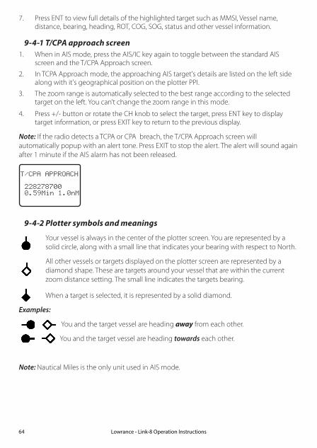
7. Press ENT to view full details of the highlighted target such as MMSI, Vessel name, distance, bearing, heading, ROT, COG, SOG, status and other vessel information.
9-4-1 T/CPA approach screen1. When in AIS mode, press the AIS/IC key again to toggle between the standard AIS
screen and the T/CPA Approach screen.
2. In TCPA Approach mode, the approaching AIS target's details are listed on the left side along with it's geographical position on the plotter PPI.
3. The zoom range is automatically selected to the best range according to the selected target on the left. You can’t change the zoom range in this mode.
4. Press +/- button or rotate the CH knob to select the target, press ENT key to display target information, or press EXIT key to return to the previous display.
Note: If the radio detects a TCPA or CPA breach, the T/CPA Approach screen will automatically popup with an alert tone. Press EXIT to stop the alert. The alert will sound again after 1 minute if the AIS alarm has not been released.
T/CPA APPROACH
228278700 0.59Min 1.0nM
9-4-2 Plotter symbols and meanings
Your vessel is always in the center of the plotter screen. You are represented by a solid circle, along with a small line that indicates your bearing with respect to North.
All other vessels or targets displayed on the plotter screen are represented by a diamond shape. These are targets around your vessel that are within the current zoom distance setting. The small line indicates the targets bearing.
When a target is selected, it is represented by a solid diamond.
Examples:
You and the target vessel are heading away from each other.
You and the target vessel are heading towards each other.
Note: Nautical Miles is the only unit used in AIS mode.
Lowrance - Link-8 Operation Instructions64

Section 10 - General functionality
10-2 Using the Fog Horn
An appropriate PA speaker must be connected to the Hailer wiring before the FOG HORN function can be used. The FOG HORN will sound certain international standard fog horn tones through the hailer speaker depending on the mode selected.
1. Press and hold the AIS/IC button for about 1 second to enter HAILER mode. Select FOG HORN and press ENT.
2. There are 8 choices of internationally recognized fog horn sounds and timing:
• HORN (Horn) Manual operation
• UNDERWAY (Underway) One long tone
• STOP (Stop) Two long tone
• SAIL (Sail) One long, two short
• ANCHOR (Anchor) One long warble
• TOW (Tow) One long, three short
• AGROUND (Aground) Warble sequence
• SIREN (Siren) Manual operation
3. Scroll through the menu to select a fog horn type, then press ENT to start the selected fog horn sounding. All except HORN and SIREN will sound automatically.
4. The fog horn will sound automatically approximately every two minutes until you press EXIT to cancel it. When the fog horn is not sounding, it is in LISTEN mode.
5. To change the volume, turn the Channel Select knob, or press + or – when the fog horn is sounding.
6. To operate HORN or SIREN, once selected, press and hold ENT button. This will sound as long as the ENT button is pressed. You can then also operate PTT to talk through the Hailer.
Lowrance - Link-8 Operation Instructions 65

HAILER
PA►FOG HORN
FOG HORN►HORN UNDERWAY STOP SAIL ▼
FOG HORN UNDERWAY ▲ STOP►SAIL ANCHOR ▼
SAILOUTPUTVOL LO HI
Note: you cannot change the volume of the HORN or SIREN.
10-1 Using the PA (Public Address) Hailer
An appropriate Hailer speaker must be connected to the Hailer wiring before the PA function can be used. The PA allows you to make an announcement at high volume to people or vessels using the Link-8 hand mic. The PA function also features a listen-back mode where the speaker is used as a microphone to listen for a response.
1. Press and hold the AIS/IC button for about 1 second to enter HAILER mode. Select PA and press ENT.
2. Press PTT to talk through the hailer. Turn the Channel Select knob, or press + or – to change the volume. Volume can only be changed while the PTT is pressed.
3. Release PTT to LISTEN for a response.
HAILER
►PA FOG HORN
PAOUTPUTVOL LO HI
PA
LISTEN
4. Press EXIT to return to operational mode.
Lowrance - Link-8 Operation Instructions66
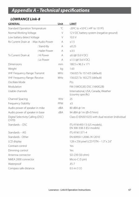
Appendix A - Technical specifications
LOWRANCE Link-8GENERAL Unit LIMIT
Standard Operation Temperature °C -20ºC to +55ºC (-4ºF to 131ºF)
Normal Working Voltage V 12 V DC battery system (negative ground)
Low battery detect Voltage V 10.5 V
Rx Current Drain at : Max Audio Power A ≤1.5
: Stand-By A ≤0.25
: Hailer Power A ≤3.5
Tx Current Drain at : Hi Power A ≤6 (@13.6 V DC)
: Lo Power A ≤1.5 (@13.6 V DC)
Dimensions mm 180.5 x 96.3 x 171
Weight kg 1.63
VHF Frequency Range: Transmit MHz 156.025 To 157.425 (default)
VHF Frequency Range: Receive MHz 156.025 To 163.275 (default)
Oscillate Mode PLL
Modulation FM (16KOG3E) DSC (16K0G2B)
Usable channels International, USA, Canada, Weather (country specific)
Channel Spacing KHz 25
Frequency Stability PPM ±5
Audio power of speaker in mike dBA 80 dBA @ 1m
Audio power of speaker in base dBA 94 dBA @ 1m (Ø=57mm)
Digital Selectivity Calling (DSC) Class-D (EN301025) with dual receiver (individual CH70)
Standards – DSC ITU-R M.493-13 (US models), EN 300-338-3 (EU models)
Standards – AIS ITU-R M.1371-4
Standards - Other EN 60950-1:2006 /A1:2010
LCD display 128 x 256 pixel LCD FSTN – 1.3” x 2.6”
Contrast control Yes
Dimming control Yes
Antenna connector SO-239 (50 ohm)
NMEA 2000 connector Micro-C (5 pin)
Waterproof JIS-7
Compass safe distance: 0.5 m (1.5’)
Lowrance - Link-8 Operation Instructions 67

RECEIVER: Unit LIMIT
Intermediate Frequency : 1st MHz 21.4
: 2nd KHz 450
Sensitivity : 12dB SINAD dBuV ≤-6
Squelch Sensitivity : at tight dBuV ≤6
Spurious Response Rejection Ratio dB ≥70
Adjacent Channel Selectivity dB ≥70
Intermodulation Response dB ≥68
S/N at 3KHz Dev. dB ≥40
Audio Output Power At THD 10% W 5W (external speaker output)
Audio Distortion % ≤5
Audio Response dB +1 to -3 dB of 6 dB/octave from 300 Hz to 3 kHZ
TRANSMITTER:
Frequency error PPM ±5
RF Power W Hi: 23 ± 2 / Lo: 0.8 ± 0.2
Maximum Deviation KHz ± 5
S/N at 3KHz Dev. dB 40
Modulation Distortion ±3KHz % ≤5
Audio Response at 1KHz Dev. dB +1 to -3 dB of 6 dB/octave from 300 Hz to 3 kHZ
Spurious/Harmonic Emissions : Hi/LO uW <0.25
Modulation Sensitivity mV ≤20
Transmitter Protection Open/short circuit of antenna
COMMUNICATIONS:Comm. port - NMEA 0183 NMEA 0183, 4800 baud
Comm. port - NMEA 2000 NMEA 2000
NMEA 0183 input (receive): RMC, GGA, GLL, GNS
NMEA 0183 output (transmit): DSC (for DSC call), DSE (for enhanced position). AIVDM (AIS)
HAILER:
Audio Power Out W 30W @ 4 Ohms
AIS:
AIS function Yes, dual receivers only
Receiver Frequency MHz 161.975, 162.025
CH87 - 161.975; CH88 - 162.025 (default channel)
Supported AIS Information: –Status/Destination/ETA
–Vessel Name –Type of vessel
–Call sign –MMSI number
–IMO number –Draft/Size of vessel
–Vessel position –SOG/COG/Rate of turn/Heading
Specifications are subject to change without notice.
Lowrance - Link-8 Operation Instructions68

Link-8 NMEA 2000 PGNS 127250 Vessel Heading
127258 Magnetic Variation
129025 Position, Rapid Update
129026 COG & SOG, Rapid Update
129029 GNSS Position Data
129033 Time & Date
129038 Class A position report (Rx,Tx)
129039 Class B position report (Rx,Tx)
129040 Class B extended position report (Rx, Tx)
129041 AIS Aids to Navigation (AtoN) Report
129283 Cross Track Error
129284 Navigation Data
129285 Navigation Route/WP Information
129792 DGNSS Broadcast binary message (Tx)
129793 UTC and date report (Tx)
129794 Class A static and voyage related data (rx, tx)
129795 Addressed binary message (tx)
129796 Acknowledge (tx)
129797 Binary broadcast message (tx)
129798 SAR Aircraft Position report (tx)
129799 Radio Frequency/Mode/Power
129800 UTC/Date enquiry (tx)
129801 Addressed safety msg (rx,tx)
129802 Broadcast safety msg (rx,tx)
129803 Interrogation (tx)
129804 Assignment Mode Command (tx)
129805 Data Link Management message (tx)
129807 AIS Group Assignment
129808 DSC Call Information
129809 AIS Class B “CS” Static Data Report, Part A
129810 AIS Class B “CS” Static Data Report, Part B
130074 Route and WP Service - WP List - WP Name & Position
130842 AIS and VHF Messages (Simrad Proprietary for AIS Class B ‘CS’)
Lowrance - Link-8 Operation Instructions 69

Appendix B - Troubleshooting 1. The transceiver will not power up.
A fuse may have blown or there is no voltage getting to the transceiver.
a) Check the power cable for cuts, breaks, or squashed sections.
b) After checking the wiring, replace the 7 Amp fuse.
c) Check the battery voltage. This must be greater than 10.5V.
2. The transceiver blows the fuse when the power is switched on.
The power wires may have been reversed.
a) Check that the red wire is connected to the positive battery terminal, and the black wire is connected to the negative battery terminal.
3. The speaker makes popping or whining noises when the engine is running.
Electrical noise may be interfering with the transceiver.
a) Re-route the power cables away from the engine.
b) Add a noise suppressor to the power cable.
c) Use resistive spark plug wires and/or use an alternator whine filter.
4. No sound from the external speaker. a) Check that the external speaker cable is physically connected.
b) Check the soldering of the external speaker cable.
5. Transmissions are always on low power, even when high (Hi) power is selected.
The antenna may be faulty.
a) Test the transceiver with a different antenna.
b) Have the antenna checked out.
6. Battery symbol is displayed.
The power supply is too low.
a) Check the battery voltage. This should be at least 10.5 V ± 0.5 V DC.
b) Check the alternator on the vessel.
7. GPS alarm sounds and LCD shows: Please check GPS link! The NO GPS symbol is shown.
GPS data has been lost. This sequence will repeat every 4 hours until GPS data from an opera-tional GPS receiver is available. The GPS cable may faulty or the GPS setting may be incorrect:
a) Manually enter your position and UTC time data (see Section 3.6.1)
b) Check that the GPS cable is physically connected.
c) Check the polarity of the GPS cable.
d) Check the baud rate setting of the GPS if applicable. The baud rate setting should be 4800. Parity should be set to NONE.
Lowrance - Link-8 Operation Instructions70

Appendix C - US & ROW VHF marine channel chartsThe following channel charts are provided for reference only and may not be correct for all regions. It is the operators responsibility to ensure correct channels and frequencies are used for local regulations.
C-1 International channel chartCH TX (MHz) RX (MHz) MODE TRAFFIC TYPE SHIP TO
SHIPSHIP TO SHORE
NAME TAG REMARK
01 156.050 160.650 D Public Correspondence No Yes TELEPHONE
02 156.100 160.700 D Public Correspondence No Yes TELEPHONE
03 156.150 160.750 D Public Correspondence No Yes TELEPHONE
04 156.200 160.800 D Port Operations No Yes PORT OPS
05 156.250 160.850 D Port Operations No Yes PORT OPS/VTS
06 156.300 156.300 S Inter-ship Safety Yes No SAFETY
07 156.350 160.950 D Port Operations No Yes PORT OPS
08 156.400 156.400 S Commercial (inter-ship only) Yes No COMMERCIAL
09 156.450 156.450 S Inter-ship Yes Yes CALLING
10 156.500 156.500 S Commercial Yes Yes COMMERCIAL
11 156.550 156.550 S Port Operations Yes Yes VTS
12 156.600 156.600 S Port Operations Yes Yes PORT OPS/VTS
13 156.650 156.650 S Inter-ship Navigation Safety (bridge-to bridge) Yes No BRIDGE COM
14 156.700 156.700 S Port Operations Yes Yes PORT OPS/VTS
15 156.750 156.750 S Port Operations Yes Yes PORT OPS 1 1W only
16 156.800 156.800 S International Distress, Safety, and Calling Yes Yes DISTRESS
17 156.850 156.850 S State Controlled Yes Yes SAR 1 1W only
18 156.900 161.500 D Port Operations No Yes PORT OPS
19 156.950 161.550 D Ship to Shore No Yes SHIP-SHORE
20 157.000 161.600 D Port Operations No Yes PORT OPS
21 157.050 161.650 D Port Operations No Yes PORT OPS
22 157.100 161.700 D Port Operations No Yes PORT OPS
23 157.150 161.750 D Public Correspondence No Yes TELEPHONE
24 157.200 161.800 D Public Correspondence No Yes TELEPHONE
25 157.250 161.850 D Public Correspondence No Yes TELEPHONE
26 157.300 161.900 D Public Correspondence No Yes TELEPHONE
27 157.350 161.950 D Public Correspondence No Yes TELEPHONE
28 157.400 162.000 D Public Correspondence No Yes TELEPHONE
60 156.025 160.625 D Public Correspondence No Yes TELEPHONE
61 156.075 160.675 D Port Operations No Yes PORT OPS
Lowrance - Link-8 Operation Instructions 71

62 156.125 160.725 D Port Operations No Yes PORT OPS
63 156.175 160.775 D Port Operations No Yes PORT OPS
64 156.225 160.825 D Public Correspondence No Yes TELEPHONE
65 156.275 160.875 D Port Operations No Yes PORT OPS
66 156.325 160.925 D Port Operations No Yes PORT OPS
67 156.375 156.375 S Commercial, bridge-to-bridge Yes No BRIDGE COM
68 156.425 156.425 S Inter-ship Yes No SHIP-SHIP
69 156.475 156.475 S Port Operations Yes Yes PORT OPS
70 156.525 156.525 - Digital Selective Calling - DSC ------ ------ DSC 2
71 156.575 156.575 S Port Operations Yes Yes PORT OPS
72 156.625 156.625 S Inter-ship Yes No SHIP-SHIP
73 156.675 156.675 S Port Operations Yes Yes PORT OPS
74 156.725 156.725 S Port Operations Yes Yes PORT OPS
77 156.875 156.875 S Ship to Shore Yes No SHIP-SHORE
78 156.925 161.525 D Ship to Shore No Yes SHIP-SHORE
79 156.975 161.575 D Port Operations No Yes PORT OPS
80 157.025 161.625 D Port Operations No Yes PORT OPS
81 157.075 161.675 D Public Correspondence No Yes TELEPHONE
82 157.125 161.725 D Public Correspondence No Yes TELEPHONE
83 157.175 161.775 D Public Correspondence No Yes TELEPHONE
84 157.225 161.825 D Public Correspondence No Yes TELEPHONE
85 157.275 161.875 D Public Correspondence No Yes TELEPHONE
86 157.325 161.925 D Public Correspondence No Yes TELEPHONE
87 157.375 161.975 D Public Correspondence No Yes TELEPHONE
88 157.425 162.025 D Public Correspondence No Yes TELEPHONE
Special notes on international channel usage1 . LOW POWER (1W) only.
2 . Channel 70 is designated for use exclusively for Digital Selective Calling (DSC), such as Distress, Safety, and Ship Calls. No voice communication is allowed on CH70. This channel is only available on DSC enabled radios.
Note:
• The INTERNATIONAL channel bank is not legal for use in U.S. or Canada waters.
• Select the INTERNATIONAL channel bank for use in Australia, New Zealand and other Asia Pacific regions, and all other regions where otherwise not specified.
KEY: S = Simplex operating channel; D = Duplex operating channel.
Lowrance - Link-8 Operation Instructions72

C-2 USA channel chartCH TX (MHz) RX (MHz) MODE TRAFFIC TYPE SHIP TO
SHIPSHIP TO SHORE
NAME TAG REMARK
01A 156.050 156.050 S Port Operations, Selected VTS Areas Yes Yes PORT OPS/VTS
03A 156.150 156.150 S US Government, Coast Guard Yes Yes UNAUTHORIZED 4
05A 156.250 156.250 S Port Operations, Selected VTS Areas Yes Yes PORT OPS/VTS
06 156.300 156.300 S Inter-ship Safety Yes No SAFETY
07A 156.350 156.350 S Commercial Yes Yes COMMERCIAL
08 156.400 156.400 S Commercial (inter-ship only) Yes No COMMERCIAL
09 156.450 156.450 S Recreational Calling Channel Yes Yes CALLING
10 156.500 156.500 S Commercial Yes Yes COMMERCIAL
11 156.550 156.550 S Commercial, VTS in Selected Areas Yes Yes VTS
12 156.600 156.600 S Port Operations, Selected VTS Areas Yes Yes PORT OPS/VTS
13 156.650 156.650 S Inter-ship Navigation Safety (bridge-to bridge), 1W with Power-up Yes No BRIDGE COM 3 1W
14 156.700 156.700 S Port Operations, Selected VTS Areas Yes Yes PORT OPS/VTS
15 --- 156.750 S Environmental ------ ------ ENVIRONMEN-TAL
2 RX only
16 156.800 156.800 S International Distress, Safety, and Calling Yes Yes DISTRESS
17 156.850 156.850 S State Controlled Yes Yes SAR 1 1W only
18A 156.900 156.900 S Commercial Yes Yes COMMERCIAL
19A 156.950 156.950 S Commercial Yes Yes COMMERCIAL
20 157.000 161.600 D Port Operations, Canadian Coast Guard No Yes PORT OPS
20A 157.000 157.000 S Port Operations Yes Yes PORT OPS
21A 157.050 157.050 S U.S. Government, Canadian Coast Guard Yes Yes UNAUTHORIZED 4
22A 157.100 157.100 S Coast Guard Liaison Yes Yes COAST GUARD
23A 157.150 157.150 S U.S. Government, Coast Guard Yes Yes UNAUTHORIZED 4
24 157.200 161.800 D Public Correspondence, Marine operator No Yes TELEPHONE
25 157.250 161.850 D Public Correspondence, Marine operator No Yes TELEPHONE
26 157.300 161.900 D Public Correspondence, Marine operator No Yes TELEPHONE
27 157.350 161.950 D Public Correspondence, Marine operator No Yes TELEPHONE
28 157.400 162.000 D Public Correspondence, Marine operator No Yes TELEPHONE
61A 156.075 156.075 S U.S. Government, Canadian Coast Guard Yes Yes UNAUTHORIZED 4
63A 156.175 156.175 S Port Operations, VTS in Selected Areas Yes Yes PORT OPS/VTS
64A 156.225 156.225 S U.S. Government, Canadian Commercial Fishing Yes Yes UNAUTHORIZED 4
65A 156.275 156.275 S Port Operations Yes Yes PORT OPS
66A 156.325 156.325 S Port Operations Yes Yes PORT OPS
67 156.375 156.375 S Commercial, bridge-to-bridge, 1W with Power-up Yes No BRIDGE COM 3 1W
Lowrance - Link-8 Operation Instructions 73

68 156.425 156.425 S Boat Operations, Recreational Yes No SHIP - SHIP
69 156.475 156.475 S Boat Operations, Recreational Yes Yes PLEASURE
70 156.525 156.525 Digital Selective Calling - DSC ------ ------ DSC 6
71 156.575 156.575 S Boat Operations, Recreational Yes Yes PLEASURE
72 156.625 156.625 S Boat Operations, Recreational Yes No SHIP - SHIP
73 156.675 156.675 S Port Operations Yes Yes PORT OPS
74 156.725 156.725 S Port Operations Yes Yes PORT OPS
77 156.875 156.875 S Port Operations Yes Yes PORT OPS 1 1W only
78A 156.925 156.925 S Boat Operations, Recreational Yes No SHIP - SHIP
79A 156.975 156.975 S Commercial Yes Yes COMMERCIAL
80A 157.025 157.025 S Commercial Yes Yes COMMERCIAL
81A 157.075 157.075 S U.S. Government, Environmental Protec-tion Agency Operations Yes Yes UNAUTHORIZED 4
82A 157.125 157.125 S U.S. Government, Canadian Coast Guard Yes Yes UNAUTHORIZED 4
83A 157.175 157.175 S U.S. Government, Canadian Coast Guard Yes Yes UNAUTHORIZED 4
84 157.225 161.825 D Public Correspondence, Marine Operator No Yes TELEPHONE
84A 157.225 157.225 S Public Correspondence, Marine Operator
85 157.275 161.875 D Public Correspondence, Marine Operator No Yes TELEPHONE
85A 157.275 157.275 S Public Correspondence, Marine Operator
86 157.325 161.925 D Public Correspondence, Marine Operator No Yes TELEPHONE
86A 157.325 157.325 S Public Correspondence, Marine Operator
87 157.375 161.975 D Public Correspondence, Marine Operator No Yes TELEPHONE
87A 157.375 157.375 S Public Correspondence, Marine Operator
88 157.425 162.025 D Public Correspondence, Marine Operator No Yes TELEPHONE
88A 157.425 157.425 S Commercial, Inter-ship Only Yes No COMMERCIAL
Special notes on USA channel usage1 . LOW POWER (1 W) only.2 . Receive Only.3 . LOW POWER (1 W) initially. Override to HIGH POWER by holding down H/L key before transmitting.
Used normally in bridge-to-bridge communications.4 . Lightly shaded simplex channels 03A, 21A, 23A, 61A, 64A, 81A, 82A, and 83A cannot be lawfully used
in U.S. waters unless special authorization is obtained from the U.S. Coast Guard. Not for use by the general public.
5 . The letter “A” illuminated by the channel number indicates the USA channel is simplex.
This same channel is always duplex when selecting International. There is no “A” reference for Interna-tional channels. The letter “B” is only used for some Canadian “Receive only” channels.
6 . Channel 70 is designated for use exclusively for Digital Selective Calling (DSC), such as Distress, Safety, and Ship Calls. No voice communication is allowed on CH70. This channel is only available on DSC enabled radios.
KEY: S = Simplex operating channel; D = Duplex operating channel.
Lowrance - Link-8 Operation Instructions74

C-3 CANADA channel chart
CH TX (MHz) RX (MHz) MODE TRAFFIC TYPE SHIP TO SHIP
SHIP TO SHORE
NAME TAG REMARK
01 156.050 160.650 D Public Correspondence No Yes TELEPHONE
02 156.100 160.700 D Public Correspondence No Yes TELEPHONE
03 156.150 160.750 D Public Correspondence No Yes TELEPHONE
04A 156.200 156.200 S Canadian Coast Guard, SAR Yes Yes CANADIAN CG
05A 156.250 156.250 S Port Operations, VTS in Selected Areas Yes Yes PORT OPS/VTS
06 156.300 156.300 S Inter-ship Safety Yes No SAFETY
07A 156.350 156.350 S Commercial Yes Yes COMMERCIAL
08 156.400 156.400 S Commercial (inter-ship only) Yes No COMMERCIAL
09 156.450 156.450 S Recreational Calling Channel Yes Yes CALLING
10 156.500 156.500 S Commercial Yes Yes COMMERCIAL
11 156.550 156.550 S Commercial, VTS in Selected Areas Yes Yes VTS
12 156.600 156.600 S Port Operations, VTS in Selected Areas Yes Yes PORT OPS/VTS
13 156.650 156.650 S Inter-ship Navigation Safety (bridge-to bridge) 1W with power-up Yes No BRIDGE COM 3 1W
14 156.700 156.700 S Port Operations, VTS in Selected Areas Yes Yes PORT OPS/VTS
15 156.750 156.750 S Commercial Yes Yes COMMERCIAL 1 1W only
16 156.800 156.800 S International Distress, Safety, and Calling Yes Yes DISTRESS
17 156.850 156.850 S State Controlled Yes Yes SAR 1 1W only
18A 156.900 156.900 S Commercial Yes Yes COMMERCIAL
19A 156.950 156.950 S Canadian Coast Guard Yes Yes CANADIAN CG
20 157.000 161.600 D Canadian Coast Guard No Yes CANADIAN CG 1 1W only
21 157.050 161.650 D Port Operations No Yes PORT OPS
21A 157.050 157.050 S U.S. Government, Canadian Coast Guard Yes Yes UNAUTHORIZED
21B --- 161.650 S Port Operations ------ ------ PORT OPS RX only
22A 157.100 157.100 S Canadian Coast Guard Liaison Yes Yes CANADIAN CG
23 157.150 161.750 D Public Correspondence No Yes TELEPHONE
24 157.200 161.800 D Public Correspondence No Yes TELEPHONE
25 157.250 161.850 D Public Correspondence No Yes TELEPHONE
25B --- 161.850 S Public Correspondence ------ ------ TELEPHONE RX only
26 157.300 161.900 D Public Correspondence No Yes TELEPHONE
27 157.350 161.950 D Public Correspondence No Yes TELEPHONE
28 157.400 162.000 D Public Correspondence No Yes TELEPHONE
28B --- 162.000 S Public Correspondence ------ ------ TELEPHONE RX only
60 156.025 160.625 D Public Correspondence No Yes TELEPHONE
61A 156.075 156.075 S U.S. Government, Canadian Coast Guard Yes Yes UNAUTHORIZED 4
Lowrance - Link-8 Operation Instructions 75

62A 156.125 156.125 S Canadian Coast Guard Yes Yes CANADIAN CG
64 156.225 160.825 D Public Correspondence, Duplex No Yes TELEPHONE
64A 156.225 156.225 S U.S. Government, Canadian Commercial Fishing Yes Yes UNAUTHORIZED 4
65A 156.275 156.275 S Port Operations Yes Yes PORT OPS
66A 156.325 156.325 S Port Operations Yes Yes PORT OPS 1 1W only
67 156.375 156.375 S Commercial, SAR Yes No COMMERCIAL
68 156.425 156.425 S Boat Operations, Recreational Yes No SHIP - SHIP
69 156.475 156.475 S Commercial Fishing Only Yes Yes COMMERCIAL
70 156.525 156.525 S Digital Selective Calling - DSC ------ ------ DSC 6
71 156.575 156.575 S Boat Operations, Recreational Yes Yes PLEASURE
72 156.625 156.625 S Inter-ship Yes No SHIP - SHIP
73 156.675 156.675 S Commercial Fishing Only Yes Yes COMMERCIAL
74 156.725 156.725 S Commercial Fishing Only Yes Yes COMMERCIAL
77 156.875 156.875 S Port Operations Yes Yes PORT OPS 1 1W only
78A 156.925 156.925 S Boat Operations, Recreational Yes No SHIP - SHIP
79A 156.975 156.975 S Commercial Yes Yes COMMERCIAL
80A 157.025 157.025 S Commercial Yes Yes COMMERCIAL
81A 157.075 157.075 S U.S. Government Operations Yes Yes UNAUTHORIZED 4
82A 157.125 157.125 S U.S. Government, Canadian Coast Guard Yes Yes UNAUTHORIZED 4
83 157.175 161.775 D Canadian Coast Guard Yes Yes CANADIAN CG
83A 157.175 157.175 S U.S. Government, Canadian Coast Guard Yes Yes UNAUTHORIZED 4
83B --- 161.775 S Canadian Coast Guard, RX Only ------ ------ CANADIAN CG
84 157.225 161.825 D Public Correspondence, Marine Operator No Yes TELEPHONE
85 157.275 161.875 D Public Correspondence, Marine Operator No Yes TELEPHONE
86 157.325 161.925 D Public Correspondence, Marine Operator No Yes TELEPHONE
87 157.375 161.975 D Public Correspondence, Marine Operator No Yes TELEPHONE
88 157.425 162.025 D Public Correspondence, Marine Operator No Yes TELEPHONE
Special notes on Canada channel usage1 . LOW POWER (1 W) only.
2 . Receive Only.
3 . LOW POWER (1 W) initially. Override to HIGH POWER by holding down H/L key before transmitting. Used normally in bridge-to-bridge communications.
4 . Lightly shaded simplex channels 21A, 23A, 61A, 64A, 81A, 82A, and 83A cannot be lawfully used in Canada waters unless special authorization is obtained from the Canadian Coast Guard. Not for use by the general public.
5 . The letter “A” illuminated by the channel number indicates the Canada channel is simplex. This same channel is always duplex when selecting International. There is no “A” reference for International channels. The letter “B” is only used for some Canadian
Lowrance - Link-8 Operation Instructions76
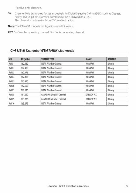
“Receive only” channels.
6 . Channel 70 is designated for use exclusively for Digital Selective Calling (DSC), such as Distress, Safety, and Ship Calls. No voice communication is allowed on CH70. This channel is only available on DSC enabled radios.
Note: The CANADA mode is not legal to use in U.S. waters.
KEY: S = Simplex operating channel; D = Duplex operating channel.
C-4 US & Canada WEATHER channels
CH RX (MHz) TRAFFIC TYPE NAME REMARK
WX01 162.550 NOAA Weather Channel NOAA WX RX only
WX02 162.400 NOAA Weather Channel NOAA WX RX only
WX03 162.475 NOAA Weather Channel NOAA WX RX only
WX04 162.425 NOAA Weather Channel NOAA WX RX only
WX05 162.450 NOAA Weather Channel NOAA WX RX only
WX06 162.500 NOAA Weather Channel NOAA WX RX only
WX07 162.525 NOAA Weather Channel NOAA WX RX only
WX08 161.650 CANADIAN Weather Channel CANADA WX RX only
WX09 161.775 CANADIAN Weather Channel CANADA WX RX only
WX10 163.275 NOAA Weather Channel NOAA WX RX only
Lowrance - Link-8 Operation Instructions 77

C-5 EAS (Emergency Alert Systems) alerts
National Codes Nature of Activation
Event Codes Message
Emergency Action Notification (National only) EAN WARNING
EAT ADVISORY
National Information Center NIC ADVISORY
National Periodic Test NPT TEST
Required Monthly Test RMT TEST
Required Weekly Test RWT TEST
State and Local Codes Nature of Activation
Event Codes Message
Avalanche Warning AVW WARNING
Avalanche Watch AVA WATCH
Blizzard Warning BZW WARNING
Child Abduction Emergency CAE WARNING
Civil Danger Warning CDW WARNING
Civil Emergency Message CEM WARNING
Coastal Flood Warning CFW WARNING
Coastal Flood Watch CFA WATCH
Dust Storm Warning DSW WARNING
Earthquake Warning EQW WARNING
Evacuation Immediate EVI WARNING
Fire Warning FRW WARNING
Flash Flood Warning FFW WARNING
Flash Flood Watch FFA WATCH
Flash Flood Statement FFS ADVISORY
Flood Warning FLW WARNING
Flood Watch FLA WATCH
Flood Statement FLS ADVISORY
Hazardous Materials Warning HMW WARNING
High Wind Warning HWW WARNING
High Wind Watch HWA WATCH
Lowrance - Link-8 Operation Instructions78

State and Local Codes Nature of Activation
Event Codes Message
Hurricane Warning HUW WARNING
Hurricane Watch HUA WATCH
Hurricane Statement HLS ADVISORY
Law Enforcement Warning LEW WARNING
Local Area Emergency LAE WARNING
911 Telephone Outage Emergency TOE WARNING
Nuclear Power Plant Warning NUW WARNING
Radiological Hazard Warning RHW WARNING
Severe Thunderstorm Warning SVR WARNING
Severe Thunderstorm Watch SVA WATCH
Severe Weather Statement SVS ADVISORY
Shelter in Place Warning SPW WARNING
Special Marine Warning SMW WARNING
Special Weather Statement SPS ADVISORY
Tornado Warning TOR WARNING
Tornado Watch TOA WATCH
Tropical Storm Warning TRW WARNING
Tropical Storm Watch TRA WATCH
Tsunami Warning TSW WARNING
Tsunami Watch TSA WATCH
Volcano Warning VOW WARNING
Winter Storm Warning WSW WARNING
Winter Storm Watch WSA WATCH
For more information about the Emergency Alert System and event codes, visit:
http://www.nws.noaa.gov/os/eas_codes.shtml
Lowrance - Link-8 Operation Instructions 79

D-1 EU international channel chartCH TX (MHz) RX (MHz) MODE TRAFFIC TYPE SHIP TO
SHIPSHIP TO SHORE
NAME TAG REMARK
01 156.050 160.650 D Public Correspondence, Port Op No Yes PHONE-PORTOP
02 156.100 160.700 D Public Correspondence, Port Op No Yes PHONE-PORTOP
03 156.150 160.750 D Public Correspondence, Port Op No Yes PHONE-PORTOP
04 156.200 160.800 D Public Correspondence, Port Op No Yes PHONE-PORTOP
05 156.250 160.850 D Public Correspondence, Port Op No Yes PHONE-PORTOP
06 156.300 156.300 S Inter-ship Safety Yes No SAFETY
07 156.350 160.950 D Public Correspondence, Port Op No Yes PHONE-PORTOP
08 156.400 156.400 S Commercial (inter-ship only) Yes No SHIP-SHIP
09 156.450 156.450 S Inter-ship Yes Yes SHIP-SHIP
10 156.500 156.500 S Inter-ship Yes Yes SHIP-SHIP
11 156.550 156.550 S Port Operations Yes Yes PORT OPS
12 156.600 156.600 S Port Operations Yes Yes PORT OPS
13 156.650 156.650 S Inter-ship Navigation Safety (bridge-to bridge) Yes No SAFETY COM
14 156.700 156.700 S Port Operations Yes Yes PORT OPS
15 156.750 156.750 S Inter-ship Yes Yes PORT OPS 1 1W only
16 156.800 156.800 S International Distress, Safety, and Calling Yes Yes DISTRESS
17 156.850 156.850 S Inter-ship Yes Yes PORT OPS 1 1W only
18 156.900 161.500 D Public Correspondence, Port Op No Yes PHONE-PORTOP
19 156.950 161.550 D Public Correspondence, Port Op No Yes PHONE-PORTOP
20 157.000 161.600 D Public Correspondence, Port Op No Yes PHONE-PORTOP
21 157.050 161.650 D Public Correspondence, Port Op No Yes PHONE-PORTOP
22 157.100 161.700 D Public Correspondence, Port Op No Yes PHONE-PORTOP
23 157.150 161.750 D Public Correspondence, Port Op No Yes PHONE-PORTOP
24 157.200 161.800 D Public Correspondence, Port Op No Yes PHONE-PORTOP
25 157.250 161.850 D Public Correspondence, Port Op No Yes PHONE-PORTOP
26 157.300 161.900 D Public Correspondence, Port Op No Yes PHONE-PORTOP
27 157.350 161.950 D Public Correspondence, Port Op No Yes PHONE-PORTOP
28 157.400 162.000 D Public Correspondence, Port Op No Yes PHONE-PORTOP
60 156.025 160.625 D Public Correspondence, Port Op No Yes PHONE-PORTOP
61 156.075 160.675 D Public Correspondence, Port Op No Yes PHONE-PORTOP
Appendix D - EU VHF marine channel chartsThe following channel charts are provided for reference only and may not be correct for all regions. It is the operators responsibility to ensure correct channels and frequencies are used for local regu-lations. For specific channel information for your country, please refer to local authorities.
Lowrance - Link-8 Operation Instructions80

62 156.125 160.725 D Public Correspondence, Port Op No Yes PHONE-PORTOP
63 156.175 160.775 D Public Correspondence, Port Op No Yes PHONE-PORTOP
64 156.225 160.825 D Public Correspondence, Port Op No Yes PHONE-PORTOP
65 156.275 160.875 D Public Correspondence, Port Op No Yes PHONE-PORTOP
66 156.325 160.925 D Public Correspondence, Port Op No Yes PHONE-PORTOP
67 156.375 156.375 S Commercial, bridge-to-bridge Yes No SHIP-SHIP
68 156.425 156.425 S Port Operations Yes No PORT OPS
69 156.475 156.475 S Inter-ship Yes Yes SHIP-SHIP
70 156.525 156.525 - Digital Selective Calling - DSC ------ ------ DSC 2
71 156.575 156.575 S Port Operations Yes Yes PORT OPS
72 156.625 156.625 S Inter-ship Yes No SHIP-SHIP
73 156.675 156.675 S Inter-ship Yes Yes SHIP-SHIP
74 156.725 156.725 S Port Operations Yes Yes PORT OPS
75 156.775 156.775 S Port Operations Yes Yes PORT OPS 1 1W only
76 156.825 156.825 S Port Operations Yes Yes PORT OPS 1 1W only
77 156.875 156.875 S Inter-ship Yes No SHIP-SHIP
78 156.925 161.525 D Public Correspondence, Port Op No Yes PHONE-PORTOP
79 156.975 161.575 D Public Correspondence, Port Op No Yes PHONE-PORTOP
80 157.025 161.625 D Public Correspondence, Port Op No Yes PHONE-PORTOP
81 157.075 161.675 D Public Correspondence, Port Op No Yes PHONE-PORTOP
82 157.125 161.725 D Public Correspondence, Port Op No Yes PHONE-PORTOP
83 157.175 161.775 D Public Correspondence, Port Op No Yes PHONE-PORTOP
84 157.225 161.825 D Public Correspondence, Port Op No Yes PHONE-PORTOP
85 157.275 161.875 D Public Correspondence, Port Op No Yes PHONE-PORTOP
86 157.325 161.925 D Public Correspondence, Port Op No Yes PHONE-PORTOP
87 157.375 157.375 S Port Operations No Yes PORT OPS 3
88 157.425 157.425 S Port Operations No Yes PORT OPS 3
Special notes on EU international channel usage1 . LOW POWER (1W) only.
2 . Channel 70 is designated for use exclusively for Digital Selective Calling (DSC), such as Distress, Safety, and Ship Calls. No voice communication is allowed on CH70. This channel is only available on DSC enabled radios.
3 . Maybe Duplex in some regions
KEY: S = Simplex operating channel; D = Duplex operating channel.
Lowrance - Link-8 Operation Instructions 81

D-2 Inland waterways country specific table - ATIS ON
For specific channel information for your country, please refer to local authorities.
CH SPECIFIC FOOT-NOTES
TRANSMITTING FREQUENCY (MHZ)
SHIP-TO-SHIP SHIP-TO PORT NAUTICAL INFORMATION
SHIP LAND
60 a) 156.025 160.625 x
01 a) 156.05 160.65 x
61 a) 156.075 160.675 x
02 a) 156.1 160.7 x
62 a) 156.125 160.725 x
03 a) 156.15 160.75 x
63 a) 156.175 160.775 x
04 a) 156.2 160.8 x
64 a) 156.225 160.825 x
05 a) 156.25 160.85 x
65 a) 156.275 160.875 x
06 a) b) 156.3 156.3 x
66 a) 156.325 160.925 x
07 a) 156.35 160.95 x
67 a) c) 156.375 156.375 x
08 a) q) 156.4 156.4 x
68 a) 156.425 156.425 x
09 a) b) c) 156.45 156.45 x
69 a) 156.475 156.475 x
10 e) 156.5 156.5 x
70 a) 156.525 156.525 Digital selective calling for distress, safety and calling
11 156.55 156.55 x
71 156.575 156.575 x
12 156.6 156.6 x
72 a) r) 156.625 156.625 x
13 f) 156.65 156.65 x
73 f) g) 156.675 156.675 x
14 q) 156.7 156.7 x
74 a) 156.725 156.725 x
15 h) 156.75 156.75 x
75 o) 156.775 156.775 x
16 i) 156.8 156.8 x
76 j) d) o) 156.825 156.825 x
17 h) 156.85 156.85 x
Lowrance - Link-8 Operation Instructions82

General remarks to Country Specific table:
1 The channels for service categories ship-to-ship and nautical information may also be used for vessel traffic -sys tems by traffic centres.
2 In some countries, frequencies certain channels are used for an other service category or other radio services. These countries are Austria, Bulgaria, Croatia, the Federal Republic of Yugosla via, Hun gary, Moldova, Romania, the Russian Federation, the Slovak Republic, the Czech Republic (with exemption of channels 08, 09, 72, 74 and 86), Ukraine and the Federal Republic of Yugosla via. The Administra tions concerned should make any possible attempt to make these fre quencies channels as soon as possible available for the radiotelephone service on Inland Waterways and/or the required service catego ry.
77 a) k) 156.875 156.875 x
18 156.9 161.5 x
78 156.925 161.525 x
19 156.95 161.55 x
79 a) 156.975 161.575 x
20 157 161.6 x
80 157.025 161.625 x
21 a) 157.05 161.65 x
81 a) 157.075 161.675 x
22 157.1 161.7 x
82 l) m) 157.125 161.725 x
23 m) 157.15 161.75 x
83 a) m) 157.175 161.775 x
24 m) 157.2 161.8 x
84 m) 157.225 161.825 x
25 m) 157.25 161.85 x
85 a) m) 157.275 161.875 x
26 m) 157.3 161.9 x
86 a) m) 157.325 161.925 x
27 m) 157.35 161.95 x
87 a) d) 157.375 157.375 x
28 m) 157.4 162 x
88 a) p) 157.425 157.425 x
AIS 1 a) n) 161.975 161.975
AIS 2 a) n) 162.025 162.025
Lowrance - Link-8 Operation Instructions 83

Explanation of specific footnotes in Country Specific table:
a. In the countries mentioned under remark 2, it is strictly prohibited to use this channel.
b. This channel is not allowed to be used between Rhine km 150 and km 350.
c. In the Netherlands, this channel is used by for its on-scene communi cations during safety operati ons on the North Sea, IJsselmeer, Wadden zee, Ooster- and Wester schelde.
d. This channel may also be used for piloting, mooring, tugging and for other nautical purposes.
e. This channel is the first ship-to-ship channel, unless the competent authority has designated an other channel. In the countries mentioned under remark 2, it is allowed that the output power is set to a value between 6 and 25 W until 1 January 2005.
f. In the countries mentioned under remark 2, this channel is used for service category ship-to-port authorities.
g. In the Netherlands, this channel is used by its national coastgu ard for communicati ons during oil pollution operations on the North Sea and for safety messages for the North Sea, Wadden zee, IJsselmeer, Ooster- and Westerschelde.
h. This channel may be used only for service category on-board communications.
i. This channel may be used only for communications between sea going vessels and participating land stations in case of distress and safety communica ti ons within the maritime sea-areas. In the countries mentioned under remark 2, this channel may be used only for distress, safety and calling.
j. The output power shall be reduced automatically to a value between 0.5 and 1 W.
k. This channel may be used for communications with a social charac ter.
l. In the Netherlands and Belgium, this channel may be used for trans mit ting mes sages concerning bunkering and victualling. The output power has to be reduced manually to a value between 0.5 and 1 W.
m. This channel may also be used for public correspondence.
n. This channel will be used for an automatic ship identifi cation and surveillance sys tem (AIS) capable of providing worldw ide operating on seas and Inland Waterways.
o. The availability of this channel is on a voluntary basis. All existing equipment shall be capable to of operating on this channel within a ten-year period after the entry into force of this Arrangement.
p. After permission of the competent authority, this channel may be used only for spe cial events on a temporary basis.
q. In the Czech Republic this channel is used for service category nautical information.
r. In the Czech Republic this channel is used for service category ship-to-port authorities.
Lowrance - Link-8 Operation Instructions84
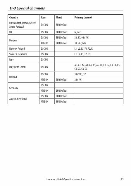
D-3 Special channels
Country Item Chart Primary channel
EU Standard, France, Greece, Spain, Portugal
DSC ON EUR Default
UK DSC ON EUR Default M, M2
BelgiumDSC ON EUR Default 31, 37, 96 (1W)
ATIS ON EUR Default 31, 96 (1W)
Norway, Finland DSC ON L1, L2, L3, F1, F2, F3
Sweden, Denmark DSC ON L1, L2, F1, F2, F3
Italy DSC ON
Italy (with Coast) DSC ON A0, A1, A2, A3, A4, A5, A6, C0, C1, C2, C3, C4, C5, C6, C7, C8, C9
HollandDSC ON 31 (1W), 37
ATIS ON EUR Default 31 (1W)
GermanyDSC ON
ATIS ON EUR Default
Austria, NewslandDSC ON EUR Default
ATIS ON EUR Default
Lowrance - Link-8 Operation Instructions 85

Appendix E - MMSI and license informationYou must obtain a user MMSI (Marine Mobile Service Identity) and enter it into your Link-8 in order to use the DSC functions. Contact the appropriate authorities in your country. If you are unsure who to contact, consult your Lowrance dealer.
The user MMSI is a unique nine digit number, similar to a personal telephone number. It is used on marine transceivers that are capable of using DSC (Digital Select Calling).
Depending upon your location, you may need a radio station license for the Link-8 . You may also need an individual operator’s license.
Lowrance recommends that you check the requirements of your national radio com-munications authorities before operating DSC functions.
AT - Austria
BE - Belgium
BG - Bulgaria
CY - Cyprus
CZ - Czech Republic
DK - Denmark
EE - Estonia
FI - Finland
FR - France
DE - Germany
GR - Greece
HU - Hungary
IS - Iceland
IE - Ireland
IT - Italy
LI - Liechtenstein
LV - Latvia
LT - Lithuania
LU - Luxembourg
MT - Malta
NL - Netherlands
NO - Norway
PL - Poland
PT - Portugal
RO - Romania
SK - Slovakia
SI - Slovenia
ES - Spain
SE - Sweden
CH - Switzerland
TR - Turkey
UK - United Kingdom
Countries of intended use in the EU:
CAUTION
Under extreme operating conditions, the temperature of the rear heat-sink on this radio may exceed normal surface temperatures. Caution is advised to prevent possible skin burns.
Lowrance - Link-8 Operation Instructions86


1177
*988
-102
54-0
01*