guns series. automatic weapons - collection of evidence for
TRANSCRIPT

UNCLASSIFIED
AD NUMBER
LIMITATION CHANGESTO:
FROM:
AUTHORITY
THIS PAGE IS UNCLASSIFIED
AD868578
Approved for public release; distribution isunlimited. Document partially illegible.
Distribution authorized to U.S. Gov't. agenciesand their contractors;Administrative/Operational Use; FEB 1970. Otherrequests shall be referred to Army MaterielCommand, Alexandria, VA. Document partiallyillegible.
USAMC ltr, 14 Jan 1972
'£*&& 4^4 H-aiiv «3
AMC PAMPHLET AMCP 706-260
ENGINEERING DESIGN HANDBOOK
GUNS SERIES
AUTOMATIC WEAPONS m o «70
HEADQUARTERS, U.S. ARMY MATERIEL COMMAND FEBRUARY 1970
Ipiiir 5 0510 00196754 3
AMC PAMPHLET No. 706-260
HEADQUARTERS UNITED STATES ARMY MATERIEL COMMAND
WASHINGTON. D. C. 20315
ENGINEERING DESIGN HANDBOOK
AUTOMATIC WEAPONS
5 February 1970
Paragraph
1-1 1-2 1-3 1-4
LIST OF ILLUSTRATIONS LISTOFTABLES LIST OF SYMBOLS PREFACE
CHAPTER 1. INTRODUCTION
SCOPE AND PURPOSE GENERAL DEFINITIONS DESIGN PRINCIPLES FOR AUTOMATIC WEAPONS
Page
\i viii
x xviii
1-1 1-1 1-1 1-1
CHAPTER 2. BLOWBACK WEAPONS
2-1 GENERAL 2-1 2-2 SIMPLE BLOWBACK 2-3 2-2.1 SPECIFIC REQUIREMENTS 2-3 2-2.2 TIMEOFCYCLE 2-4 2-2.2.1 Recoil Time 2-5 2—2.2.2 Counterrecoil Time 2-6 2-2.2.3 Total Cycle Time 2-7 2-2.3 EXAMPLE OF SIMPLE BLOWBACK GUN 2-8 2-2.3.1 Specifications 2-8 2—2.3.2 Computed Design Data 2-8 2—2.3.3 Case Travel During Propellant Gas Period 2-10 2-2.3.4 Sample Problem of Case Travel 2-10 2—2.3.5 Driving Spring Design 2—11 2-3 ADVANCED PRIMER IGNITION BLOWBACK 2-12 2-3.1 SPECIFIC REQUIREMENTS 2-12 2-3.2 SAMPLE CALCULATIONS OF ADVANCED
PRIMER IGNITION 2-13 2-3.2.1 Firing Rate 2-13 2—3.2.2 Driving Spring Design 2—15 2^1 DELAYEDBLOWBACK 2-17 2-4.1 SPECIFIC REQUIREMENTS 2-17 2-4.2 DYNAMICS OF DELAYED BLOWBACK 2-18 2-4.3 SAMPLE PROBLEM FOR DELAYED
BLOWBACK ACTION 2-24 2-4.3.1 Specifications 2-24 2-4.3.2 Design Data 2-24 2-4.4 COMPUTER ROUTINE FOR COUNTERRECOILING
BARREL DYNAMICS 2-33 2-4.5 SPRINGS 2-37 2-4.5.1 Driving Spring 2-37 2-4.5.2 Barrel Spring 2-39 2-4.5.3 Buffer Spring 2-39 2-5 RETARDEDBLOWBACK 2-40 2-5.1 SPECIFIC REQUIREMENTS 2-40
AMCP 706-260
TABLE OF CONTENTS (Con't.)
Paragraph Page
2-5.2 DYNAMICS OF RETARDED BLOWBACK 2-40 2—5.2.1 Kinematics of the Linkage 2—40
2-5.2.2 Equations of Dynamic Equilibrium 2—43 2—5.2.3 Digital Computer Program for
the Dynamic Analysis 2—44 2-6 RATING OF BLOWBACK WEAPONS 2-47
CHAPTER 3. RECOIL-OPERATED WEAPONS
3-1 GENERAL 3-1 3-2 LONG RECOIL DYNAMICS 3_i
3-3 SAMPLE PROBLEM _LONG RECOIL MACHINE GUN .. 3-1 3-3.1 SPECIFICATIONS 3_1 3-3.2 DESIGNDATA 3-1 3-4 SHORT RECOIL DYNAMICS 3_9 3-5 SAMPLE PROBLEM _SHORT RECOIL MACHINE GUN . . 3-9 3-5.1 SPECIFICATIONS 3_9 3-5.2 DESIGNDATA 3-9 3-6 ACCELERATORS 3_15
3-7 SAMPLE PROBLEM ACCELERATOR 3-17 3-7.1 SPECIFICATIONS 3-17 3-7.2 DESIGNDATA 3-17 3-8 RATING OF RECOIL-OPERATED GUNS 3-21
CHAPTER 4. GAS-OPERATED WEAPONS
4-1 GENERALREQUIREMENTS 4-1 4-2 TYPES OF GAS SYSTEMS 4-1 4-3 CUTOFF EXPANSION SYSTEM 4-1 4-3.1 MECHANICS OF THE SYSTEM 4_i 4—3.1.1 Gas Filling Period 4_g 4-3.1.2 Bolt Locking Cam 4_9 4—3.1.3 Cam Curve 4—15
4-3.2 SAMPLE PROBLEM FOR CUTOFF EXPANSION SYSTEM 4-17
4—3.2.1 Specifications 4—17 4—3.2.2 Design Data, Computed 4—17 4—3.2.3 Counterrecoil Computed Data 4—19 4-3.2.4 Counterrecoil Time 4_20
4-3.2.5 Recoil Time 4-23 4-3.2.5.1 Recoil Time, Decelerating 4—23 4-3.2.5.2 Recoil Time, Accelerating 4—24
4-3.3 DIGITAL COMPUTER ROUTINE FOR CUTOFF EXPANSION 4-28
4-3.3.1 Gas Dynamics Before Cutoff 4-28 4—3.3.2 Gas Dynamics After Cutoff 4—29
4-3.3.2.1 Bolt Unlocking During Helix Traverse 4-29 4-3.3.2.2 Bolt Unlocking During Parabola Traverse 4-29 4-3.3.2.3 Bolt Unlocked, Bolt Traveling With
Operating Rod 4—31
AMCP 706-260
TABLE OF CONTENTS (Con't.)
Paragraph Page
4—3.3.3 Dynamics After Gas Cylinder Operations 4-32 4-3.3.3.1 Recoil Dynamics 4-32 4-3.3.3.2 Counterrecoil Dynamics 4-35 4-3.3.3.3 Bolt Locking Dynamics 4-36 4-3.3.3.4 Firing Rate 4-37 4-3.4 SPRINGS 4-37 4-3.4.1 Driving Spring 4-37 4-3.4.2 Buffer Spring 4-37 4-4 THE TAPPET SYSTEM 4-38 4-4.1 SAMPLEPROBLEM 4-38 4-4.1.1 Specifications 4-38 4-4.1.2 Preliminary Design Data 4-38 4-4.1.3 Design Data. Computed 4-38 4-4.1.4 Spring Design Data 4-45
CHAPTER 5. REVOLVER-TYPE MACHINE GUNS
5-1 SINGLE BARREL TYPE 5-1 5-1.1 PRELIMINARY DYNAMICS OF FIRING CYCLE 5-2 5—1.1.1 Sample Problem of Preliminary Firing Rate Estimate . . . 5-7 5-1.1.2 Analysis of Cam Action 5-8 5-1.1.2.1 Sample Calculation of Cam Action 5-14 5-1.1.2.2 Driving Spring 5-18 5_1.2 FINAL ESTIMATE OF THE COMPLETE FIRING CYCLE 5-18 5—1.2.1 Control of Recoil Travel During Propellant Gas Period . . 5-20 5-1.2.2 Operating Cylinder Design 5-23 5—1.2.3 Dynamics of Simultaneous Adapter-operating
Cylinder Action 5-31 5 — 1.2.4 Sample Calculation for Complete Firing Cycle 5-32 5-1.2.4.1 Counterrecoil Time of Recoiling Parts 5-33 5-1.2.4.2 Digital Computer Analyses of Barreldrum Dynamics . . . 5-37 5-1.2.4.3 Firing Rate Computation 5-39 5-2 DOUBLE BARREL TYPE 5-46 5-2.1 FIRINGCYCLE 5-46 5-2.1.1 Cam Function 5-46 5-2.1.2 Loading and Ejecting 5-48 5-2.1.3 Ammunition Feed System 5—48 5-2.2 DYNAMICS OF FIRING CYCLE 5-49 5-2.2.1 Cam Analysis 5-50 5-2.2.2 Energy Concept 5-52 5-2.2.3 Digital Computer Program for Firing Cycle 5-52
CHAPTER 6. MULTIBARREL MACHINE GUN
6-1 GENERAL 6-1 6-2 BOLT OPERATING CAM DEVELOPMENT 6-1 6-2.1 CAMACTION 6-1 6—2.1.1 Cam Kinematics 6-3 6-2.1.2 Definition of Symbols 6-4 6—2.1.3 Cam Forces 6—5 6—2.1.4 Locking Angle 6-6
AMCP 706-260
TABLE OF CONTENTS (Con't.)
Paragraph Page
6-2.2 ROTOR KINEMATICS 6-7 6-2.3 ILLUSTRATIVE PROBLEM 6-9 6-2.3.1 Cam Analysis During Feed, Rotor at Constant Velocity .. 6-9 6-2.3.2 Cam Analysis During Ejection, Rotor at Constant
Velocity 6-11 6—2.3.3 Cam Analysis During Rotor Acceleration 6—12 6-2.3.4 Digital Computer Program for Gun Operating Power .... 6-13 6-3 RATING OF GAS-OPERATED AND EXTERNALLY
POWEREDGUNS 6-14
CHAPTER 7. COMPONENT DESIGN
7-1 GENERAL 7-1 7_2 FEED MECHANISM DESIGN 7-1
7-2.1 MAGAZINES 7-2 7—2.1.1 Box Magazines 7-2 7-2.1.2 Box Feed System 7-4 7-2.1.2.1 Flat Tape Spring 7-5 7-2.1.2.2 Rectangular Coil Spring 7-6 7—2.1.3 Example Problems 7-6 7-2.1.3.1 Flat Tape Spring 7-7 7-2.1.3.2 Rectangular Coil Spring 7-8
7-2.2 BOLT-OPERATED FEED SYSTEM ?-9 7_2.3 ROTATING FEED MECHANISM 7-10 7-2.3.1 Recoil-operated Feed Mechanism 7-10 7-2.3.2 Electrically Driven Feed Mechanism 7-12 7_2.4 LINKLESSFEED SYSTEM 7-14 7—2.4.1 Power Required 7-19 7-2.4.2 Example Problem for Power Required 7-21
7-3 EXTRACTORS, EJECTORS, AND BOLT LOCKS 1~24
7-3.1 EXTRACTORS 7~24
7_3.2 EJECTORS 7-27 7_3 2.1 Ejector Dynamics 7-27 7-3.2.2 Sample Problem of Ejector Dynamics 7-27 7-3.3 BOLTLOCKS 7-30
7_4 FIRING MECHANISM 7-32 7_4.1 COMPONENTS, TYPES, AND ACTION 7-32 7-4.1.1 Trigger Pull 7-37 7_4 12 Firing Pin Design 7-39 7_5 ' LINKS •. . . . 7-39 7_5 i TYPES OF LINK 7-40 7_s'.2 DESIGN REQUIREMENTS 7-40 7-6 MOUNTS 7-44
7_6.1 GEOMETRY AND RESOLUTION OF FORCES 7-44 7-6.2 SAMPLEPROBLEM 7-48
CHAPTER 8. LUBRICATION OF MACHINE GUNS
3-1 GENERALCONCEPT 3-1 3-2 EXAMPLES OF LUBRICANTS 8-1
8-3 CASELUBRICANT 8~2
IV
AMCP 706-260
TABLE OF CONTENTS (Con't.)
APPENDIXES
No. Title Page
A-1 Flow Chart for Delayed Blowback A-1 A—2 Listing for Delayed Blowback Program A—4 A-3 Flow Chart for Retarded Blowback A-6 A^l Listing for Retarded Blowback Program A—9 A—5 Flow Chart for Cutoff Expansion A—12 A-6 Listing for Cutoff Expansion Program A—15 A-7 Flow Chart for Operating Cylinder A-20 A-8 Listing for Operating Cylinder Program A—22 A—9 Flow Chart for Cam and Drum Dynamics During Recoil . . A—26 A—10 Listing for Cam and Drum Dynamics During Recoil A—30 A—1 1 Flow Chart for Cam and Drum Dynamics During
Counterrecoil A—35 A—12 Listing for Cam and Drum Dynamics During
Counterrecoil A—38 A—13 Flow Chart for Double Barrel Machine Gun A—43 A—14 Program Listing for Double Barrel Machine Gun A—46 A-15 Flow Chart for Multibarrel Power A-52 A—16 Program Listing for Multibarrel Power A—59 B Automatic Control of Rounds in a Burst for
Weapon Effectiveness B— 1 GLOSSARY G-l REFERENCES R-1
AMCP 706-260
LIST OF ILLUSTRATIONS
Fig. No. Title Page
2—1 Typical Pressure-time Curve 2—1 2—2 Schematic of Simple Blowback Mechanism 2—3 2—3 Allowable Case Travel 2—4 2—4 Pressure-time Curve of Cal .45(11.42 mm) Round 2—8
2—5 Schematic of Advanced Primer Ignition System 2—13 2—6 Locking System for Delayed Blowback 2—18 2—7 Pressure-time Curve of 20 mm Round 2—25 2—8 Schematic of Retarded Blowback Linkage 2—40 2—9 Kinematics of Retarded Blowback Linkage 2—41 2—10 Dynamics of Bolt and Linkage 2—42 3—1 Schematic of Long Recoil System 3—2 3—2 Schematic of Short Recoil System 3—2 3_3 Accelerator Geometry 3 — 16 4—1 Impingement System 4_i 4_2 Cutoff Expansion System 4_2
4-3 Rotating Bolt Lock and Activating Cam 4-11 4-4 Force System of Bolt Cam 4-12 4_5 Pressure-time Curve of 7.62 mm Round 4—18 4_6 Operating Distances of Moving Parts 4—19 4_7 Tappet System 4-38 4_8 Pressure-time Curve of 7.62 mm Carbine Round 4^10
5—1 Schematic of Single Barrel Revolver-type Machine Gun .... 5—1 5_2 Two Stage Ramming 5_2
5—3 Force Diagram of Recoiling Parts and Slide 5—3 5_4 Schematic of Cam Geometry 5—5 5_5 Cam-slide Force Diagrams 5—9
5—6 Single Barrel Drum Loading Diagram 5—10 5_7 Single Barrel Drum Dynamics 5—11
5-8 Interior Ballistics of 20 mm Revolver-type Gun 5-19 5_9 Extractor Assembly With Antidouble Feed Mechanism .... 5—35 5—10 Extractor Cam Assembly 5—36 5—11 Location of Basic Operations 5—47 5—12 Schematic of Double Barrel Drum-cam Arrangements 5—47 5—13 Schematic of Ammunition Feed System 5—48 5—14 Schematic of Ammunition Magazine 5—49
5—15 Double Barrel Cam Force Diagrams 5—50 5_16 Double Barrel Drum Loading Diagram 5—51 5—17 Double Barrel Drum Dynamics 5—51
5—18 Force-time Curve of 20 mm Revolver-type Gun 5—53 5—19 Geometry of Cam Actuating Lever 5—55 6—1 Cam Contour of Multibarrel Gun 6—2 6—2 Loading Diagram of Bolt and Cam During Acceleration . . . 6—2 6_3 Feed Portion of Cam 6—3 6—4 Loading Diagram of Bolt and Cam During Deceleration . . . 6—7 6—5 Bolt Position Diagram for Computer Analysis 6—13
AMCP 706-260
LIST OF ILLUSTRATIONS (Con't.)
Fig. No. Title Page
7-1 Initial Contact of Bolt and Cartridge Case Base 7_i 7-2 Chamber-projectile Contact 7-2 7-3 Box Magazine 7-2 7-4 Lip Guides 7_3 7-5 Lip-cartridge Case Orientation 7—4 7-6 Geometry of Double Row Stacking 7_4 7—7 Box Magazine Follower 7—4 7-8 Flat Tape Spring and Loading Analogy 7_5 7-9 Rectangular Coil Spring and Loading Characteristics 7_7 7-10 Schematic of Feed System. End View 7-10 7-11 Feed System Illustrating Mechanics of Operation 7-11 7-12 Recoil-operated Rotating Feed Mechanism 7-13 7-13 Feed Wheel and Operating Lever Units 7-14 7-14 Electrically Operated Rotating Feed Mechanism 7-15 7-15 Outer Drum 7-16 7-16 Inner Drum Helix 7-16 7—17 Conveyor Elements 7-17 7-18 Schematic of Linkless Feed System 7-18 7-19 Path of Rounds in Single End System 7-19 7-20 Extractors 7-25 7-21 Extractor Loading Diagrams 7-26 7-22 Ejectors 7-28 7—23 Ejector Loading Diagram 7-29 7-24 Sliding Breech Lock 7_31 7-25 Tipping Bolt Lock 7-32 7-26 Firing Mechanism for Recoil Machine Gun 7—33 7-27 Firing Mechanism for Gas-operated Machine Gun 7-34 7—28 Three-position Firing Mechanism 7-36 7-29 Triggering Mechanism Loading 7-38 7-30 Ammunition Link. Cal .50 Round 7_4l 7-31 Nose Fanning Flexibility. 7.62 mm Link 7—42 7—32 Base Fanning Flexibility. 7.62 mm Link 7—43 7-33 Geometry of Base Fanning 7—44 7-34 Helical Flexibility. 7.62 mm Link 7-45 7-35 Total Folding 7.62 mm Ammunition Belt 7-46 7-36 Partial Folding 7.62 mm Ammunition Belt 7-46 7-37 Loading Link With RADHAZ Shield 7_47 7—38 Loading Diagram of Mount 7-47 B—1 Hit Probabdity vs Number of Rounds in a Burst B—2
AMCP 706-260
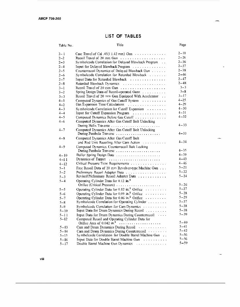
LIST OF TABLES
Table No. Title Page
2- 1 Case Travel of Cal .45(11.42 mm) Gun 2-11 2-2 Recoil Travel of 20 mm Gun 2-26 2-3 Symbolcode Correlation for Delayed Blowback Program .. 2-36 2-4 Input for Delayed Blowback Program 2-37 2-5 Counterrecoil Dynamics of Delayed Blowback Gun 2-38 2-6 Symbolcode Correlation for Retarded Blowback 2-46 2-7 Input Data for Retarded Blowback 2-47 2-8 Retarded Blowback Dynamics 2-48 3-1 Recoil Travel of 20 mm Gun 3-3 3-2 Spring Design Data of Recoil-operated Guns 3-8 3-3 Recoil Travel of 20 mm Gun Equipped With Accelerator .. 3-17 4-1 Computed Dynamics of Gas Cutoff System 4—25 4-2 Gas Expansion Time Calculations 4-29 4-3 Symbolcode Correlation for Cutoff Expansion 4—30 4-4 Input for Cutoff Expansion Program 4-31 4-5 Computed Dynamics Before Gas Cutoff 4-32 4-6 Computed Dynamics After Gas Cutoff Bolt Unlocking
During Helix Traverse 4-33 4-7 Computed Dynamics After Gas Cutoff Bolt Unlocking
During Parabola Traverse 4-33 4-8 Computed Dynamics After Gas Cutoff Bolt
and Rod Unit Recoiling After Cam Action 4-34 4-9 Computed Dynamics. Counterrecoil Bolt Locking
During Parabola Traverse 4-35 4-10 Buffer Spring Design Data 4-39 4_11 Dynamics of Tappet 4-43 4_12 Critical Pressure Time Requirements 4-46 5—1 Free Recoil Data of 20 mm Revolver-type Machine Gun ... 5—21 5-2 Preliminary Recoil Adapter Data 5-22 5_3 Revised Preliminary Recoil Adapter Data 5-24 5-4 Operating Cylinder Data for 0.12 in.2
Orifice (Critical Pressure) 5-26 5-5 Operating Cylinder Data for 0.12 in.2 Orifice 5-27 5-6 Operating Cylinder Data for 0.09 in.2 Orifice 5-28 5-7 Operating Cylinder Data for 0.06 in.2 Orifice 5-29 5_8 Symbolcode Correlation for Operating Cylinder 5-37 5-9 Symbolcode Correlation for Cam Dynamics 5-38 5_10 Input Data for Drum Dynamics During Recoil 5-38 5-11 Input Data for Drum Dynamics During Counterrecoil .... 5-39 5-12 Computed Recoil and Operating Cylinder Data for
Orifice Area of 0.042 in.2 5-40 5-13 Cam and Drum Dynamics During Recoil 5-41 5-14 Cam and Drum Dynamics During Counterrecoil 5-42 5_15 Symbolcode Correlation for Double Barrel Machine Gun .. 5-56 5-16 Input Data for Double Barrel Machine Gun 5-56 5-17 Double Barrel Machine Gun Dynamics 5—59
VII
AMCP 706-260
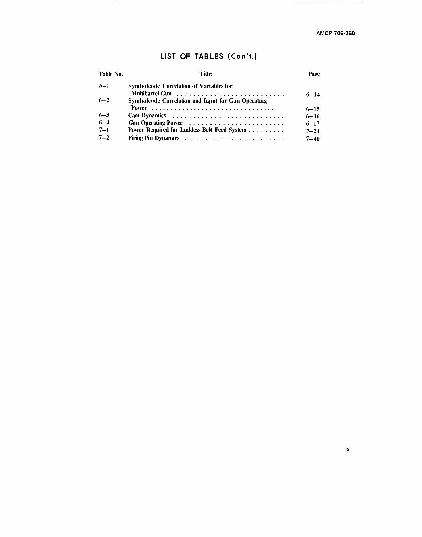
LIST OF TABLES (Con'f.)
Table No. Title Page
«5-1 Symbolcode Correlation of Variables for Multibarrel Gun 6-14
6-2 Symbolcode Correlation and Input for Gun Operating Power 6-15
6-3 Cam Dynamics 6-16 6-4 Gun Operating Power 6-17 7-1 Power Required for Linkless Belt Feed System 7-24 7-2 Firing Pin Dynamics 7-40
AMCP 706-260
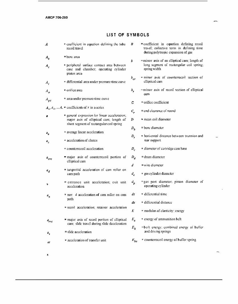
LIST OF SYMBOLS
A,
pt
= coefficient in equation defining the tube B recoil travel
= bore area
= peripheral surface contact area between case and chamber; operating cylinder piston area
»cr = differential area under pressure-time curve
= orifice area br
= area under pressure-time curve C
.A, = coefficients of x in a series Cr
= general expression for linear acceleration; major axis of elliptical cam; length of D short segment of rectangular coil spring
= average linear acceleration
= acceleration of chutes
= counterrecoil acceleration
D,
£>
= major axis of counterrecoil portion of Dd
elliptical cam d
- tangential acceleration of cam roller on cam path dc
= entrance unit acceleration; exit unit dp
acceleration
= nor: J1 acceleration of cam roller on cam path
= recoil acceleration; retainer acceleration
dt
dx
E
- major axis of recoil portion of elliptical Ea
cam; slide travel during slide deceleration
at
• slide acceleration
; acceleration of transfer unit
= coefficient in equation defining recoil travel; collective term in defining time during polytropic expansion of gas
=minor axis of an elliptical cam; length of long segment of rectangular coil spring; spring width
= minor axis of counterrecoil section of elliptical cam
=minor axis of recoil section of elliptical cam
= orifice coefficient
= end clearance of round
= mean coil diameter
= bore diameter
= horizontal distance between trunnion and rear support
= diameter of cartridge case base
= drum diameter
= wire diameter
= gas cylinder diameter
=gas port diameter; piston diameter of operating cylinder
= differential time
= differential distance
= modulus of elasticity; energy
= energy of ammunition belt
=bolt energy; combined energy of buffer and driving springs
Ebc = counterrecoil energy of buffer spring
AMCP 706-260
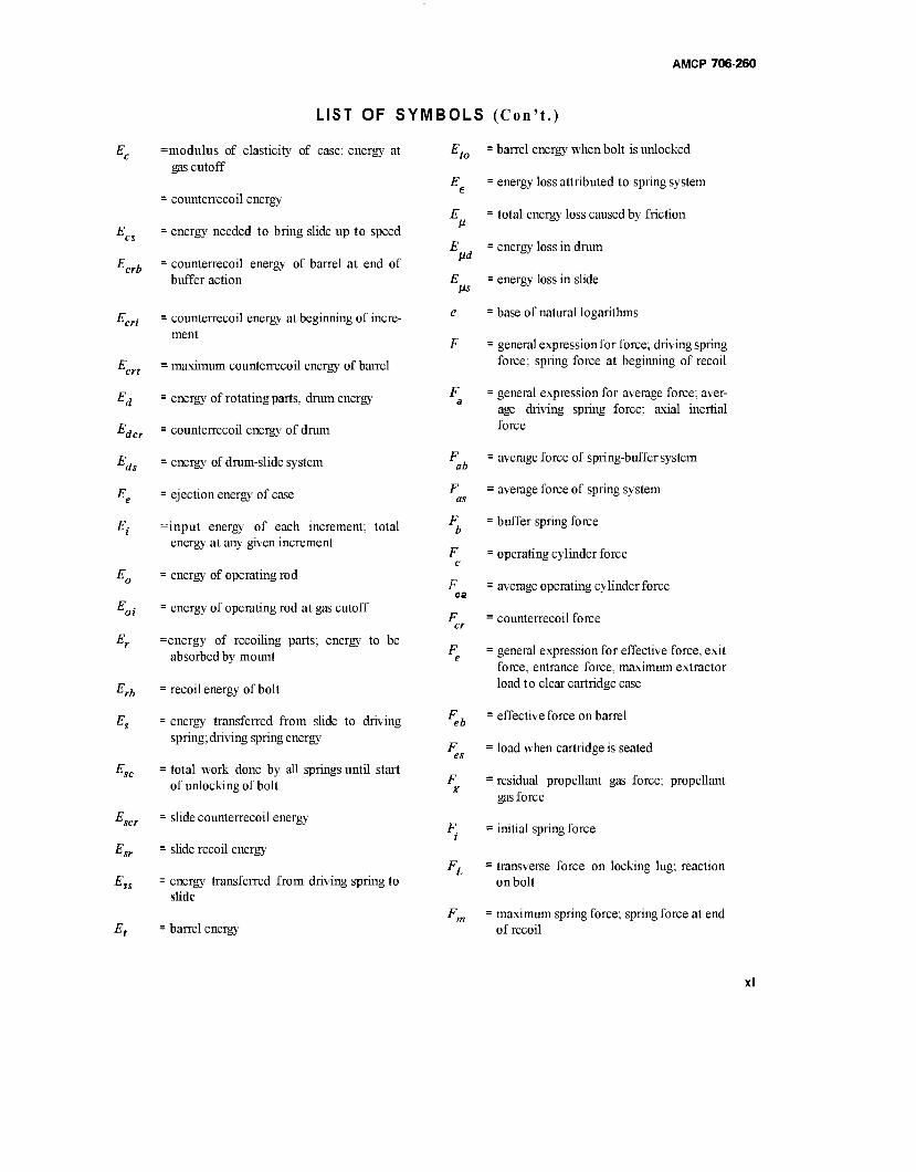
Jcrb
=modulus of elasticity of case; energy at gas cutoff
= counterrecoil energy
= energy needed to bring slide up to speed
= counterrecoil energy of barrel at end of buffer action
udcr
^ds
Et
E.
-rb
= counterrecoil energy at beginning of incre- ment
= maximum counterrecoil energy of barrel
= energy of rotating parts, drum energy
= counterrecoil energy of drum
= energy of drum-slide system
= ejection energy of case
=input energy of each increment; total energy at any given increment
= energy of operating rod
= energy of operating rod at gas cutoff
=energy of recoiling parts; energy to be absorbed by mount
= recoil energy of bolt
= energy transferred from slide to driving spring; driving spring energy
= total work done by all springs until start of unlocking of bolt
= slide counterrecoil energy
= slide recoil energy
= energy transferred from driving spring to slide
= barrel energy
Jto
LIST OF SYMBOLS (Con't.)
barrel energy when bolt is unlocked
E = energy loss attributed to spring system
E = total energy loss caused by friction
energy loss in drum
energy loss in slide
base of natural logarithms
ltd
iis
F a
ah
F
F b
F c
F
F cr
Feb
F g
- general expressionfor force; driving spring force; spring force at beginning of recoil
= general expression for average force; aver- age driving spring force; axial inertial force
= average force of spring-buffer system
= average force of spring system
= buffer spring force
= operating cylinder force
= average operating cylinder force
= counterrecoil force
= general expression for effective force, exit force, entrance force, maximum extractor load to clear cartridge case
= effective force on barrel
= load when cartridge is seated
= residual propellant gas force; propellant gas force
= initial spring force
= transverse force on locking lug; reaction on bolt
= maximum spring force; spring force at end of recoil
AMCP 706-260
mb
LIST OF SYMBOLS : maximum force of spring-buffer system g
ob
robs
sh
tb
Fdt, FAt
fr
f(TjT)
G
=maximum force of barrel and driving spring
= maximum force of barrel spring; of adapter
= minimum spring force; minimum operat- ing load
= initial buffer spring system force
= initial buffer spring force
= initial force of barrel spring; of adapter
= cam roller pin load
= average force during recoil
= sear spring force; centrifugal force of cartridge case or round
= horizontal component of safety spring force
= safety spring force
= force of barrel spring; of adapter; vertical reaction of trigger spring pin
= average adapter force for time intervals
= barrel spring force at end of propellant gas period
= resultant force of x-axis
= resultant force of^-axis
= frictional force
= general expressions for differential im- pulse
= rate of fire
= function of the ratio of compression time to surge time
= torsional modulus; shear modulus
H
HP
h
'de
J
K
K
Ks
Kt
K V
K
bs
(Con't.)
= acceleration due to gravity
= command height
= horsepower
= solid height of spring
= depth of magazine storage space
= distance between trunnion and pintle-leg intersection
= area moment of inertia; general term for mass moment of inertia
= mass moment of inertia of bolt
=mass moment of inertia of drum; mass moment of inertia of all rotating parts
= effective mass moment of inertia of drum
= area polar moment of inertia
= spring constant, general; driving spring constant
= coefficient in gas flow equation
= combined spring constant during buffing
= buffer spring constant
=combined constant of barrel and driving springs
= spring constant of barrel spring, of adapter
coefficient in the rate of gas flow equa- tion
= directional coefficient in/^ equation
directional coefficient in F equation
= ratio of specific heats; radius of gyration; bolt polar radius of gyration
= general expression for lengths; length of recoil; bolt travel; length of flat spring
AMCP 706-260
LIST OF SYMBOLS (Con't.)
bt
L r
Lt
M
M a
M a,
Mb
M c
M de
M
M_
M .
M
M
'■ length of buffer spring travel
: length of total bullet travel in barrel
: axial length of cam; length of slide travel; total peripheral length of cam
: decelerating distance prior to buffer con- tact; operating distance of operating rod spring; length of drum; driving spring travel
: extractor length
: length of front pintle leg
: location of gas port along barrel
= length of round; length of rear pintle leg
= tappet travel; barrel spring operating deflection
: mass, general; mass of accelerating parts; bending moment
= mass of round; mass of ammunition unit
= effective mass of ammunition
: mass of bolt
: mass of cartridge case
: mass of drum
: effective mass of drum and ammunition belt; effective mass of rotating drum
: effective mass, general; of extractor unit
: effective mass of extractor unit
: mass of ejector
1 mass of propellant gas
: momentum of recoiling or counterrecoil- ing parts
M o
M P
M r
M
M s
Mt
N
N.
N„
N.
N.
N„
Pb
Pc
Per
Pd
■ mass of operating rod; bending moment at first bend of flat tape spring
: mass of projectile
= mass of recoiling parts
: effective mass of recoiling parts
: mass of slide; mass of spring
: mass of barrel
: number of coils; normal reaction on cam curve; normal force on roller; number of rounds; number of active segments in flat spring
= axial component of normal force; number of links of ammunition
: number of chambers in drum
: number of retainer partitions
: transverse component of normal force
: cam tangential friction force
: general term for power
: power required to drive feed system
: trigger pull
: pressure, general; pressure in reservoir; general term for space between rounds (pitch)
: average pressure; average bore pressure
: bore pressure
: average gas cylinder pressure
=. critical pressure
: pitch of double helix drive
AMCP 706-260
Pi = interface pressure
Pm =propellant gas pressure as bullet leaves
muzzle
Pu = component of pressure that dilates cartridge case
P, = initial pressure
P2 = final pressure
R = radius of bolt outer surface
Ra = reaction of rear support; radius to CG of
round
R, = reaction of front support
R =cam radius
R ch
Ri
Rr
R
LIST OF SYMBOLS (Con't.)
= travel distance
= accelerating distance
= radius of chamber centers of drum
= distance from cam contact point to drum axis
= radius of locking lug pressure center
= roller radius; track reactions due to rota- tional forces
RT = specific impetus
R.
R
= track reactions due to tipping forces; trig- ger reaction on sear
= horizontal reaction on drum shaft
= mean radius of case
= distance from tipping point on rim to CG .of case
= cam radius to contact point on bolt
= extractor radius
= striker radius
= cam radius to contact point on barrel
s a
T T
= bore travel; distance of bolt retraction during recoil
= cutoff distance
= cam follower travel during counterrecoil
= dwell distance
= travel distance of operating unit at given time
= initial distance
=straight length of cam during counter- recoil
= straight length of cam during recoil; posi- tion where slide contacts gas operating unit
=cam follower travel during recoil; oper- ating rod travel before bolt pickup
= travel component due to change in veloci- ty
= travel component due to velocity
= surge time of spring; absolute tempera- ture; torque about gun axis; applied torque of trigger spring
= compression time of spring
= required drum torque
=torque due to friction on drum bearing and case
= locking lug torque
= required retainer torque
= applied torques

AMCP 706-260
'b
fbc
crb
°ct
fd
'rb
rt
Vb
Vch
Vco
K Vec
K
LIST OF SYMBOLS
= accelerating torque
= resisting torque
= applied torque
= time
= time to complete counterrecoil of slide
= buffer time
= buffer time during counterrecoil
= time of firing cycle
= counterrecoil time
= time of buffer counterrecoil
= counterrecod time of barrel after buffer action
= counterrecoil time of barrel
= decelerating time of bolt before buffer is contacted
= time of gas expansion
= duration of propellant gas period
=time interval of dwell between counter- recoil and recoil
= recoil time of bolt
= bolt decelerating time during recoil
= counterrecod time after buffer action
= recoil time of barrel during pressure decay after bolt unlocking
= thickness of spring
= counterrecoil time of slide
= barrel spring compression time
= accelerating time of rotor
"be
"crb
vdm
(Con't.)
: bore volume
: gas volume in operating cylinder
: chamber volume
= operating cylinder displacement
: equivalent gas volume
; equivalent bore volume
= chamber volume plus total bore volume
: initial volume of gas operating cylinder
: vertical component of spring load
: initial volume in gas equations
= final volume in gas equations
: velocity, general
: average velocity; axial velocity
= buffer velocity during recoil
: bolt velocity during counterrecoil
: linear velocity of cam follower along cam; velocity of chutes; linear ejected velocity of cartridge case
: counterrecoil velocity
= counterrecoil velocity of buffer
: peripheral velocity of drum
= maximum peripheral velocity of drum
: extractor velocity; maximum ejection velocity
: velocity of free recoil
: impact velocity
; muzzle velocity of projectile
xv
AMCP 706-260
LIST OF SYMBOLS (Con't.)
ot
W
Wa
K
Wc,
Wd
We
K
WP
w.
= initial velocity, general term
= initial velocity of barrel
= recoil velocity
= slide velocity
=velocity of recoiling parts at end of accelerating travel
= counterrecoil velocity of slide
= slide velocity before impact
= maximum slide velocity
= barrel velocity; tangential velocity of car- tridge case at ejection, velocity of transfer unit
= general term for weight; wall ratio; work
= weight of round
= bolt weight
= wall ratio of case; weight of gas in cylin- der; weight of propellant charge
= weight of cartridge case; weight of empty case
: weight of gas at critical pressure
: weight of drum
: equivalent weight of moving parts
= total weight of propellant or propellant gas
= weight of moving operating cylinder com- ponents
= combined weight of components and slide
= weight of projectile
= weight of recoiling parts
W.
W„.
w..
w_. srp
w.
w„
lbo
Td
V
to
= work needed to compress spring; slide weight; weight of spring
= equivalent weight of spring in motion
= weight of slide with 2 rounds
=weight of slide, 2 rounds, and gas oper- ating unit
= barrel weight
= rate of gas flow; width of magazine; width of flat spring
= width of cam
= recoil travel, general; case travel; distance inx-direction
= axial acceleration of bolt
= bolt travel
= bolt travel at end of propellant gas period
= axial length of parabola
= recoil distance during propellant gas period; recoil travel of drum and barrel assembly
= recoil travel during impulse period
= counterrecoiling travel during impulse period
= slide travel; relative axial travel between cam follower and drum
= travel of recoiling parts during cam dwell period
= barrel travel with respect to gun frame
= barrel travel during free recoil
= barrel travel during propellant gas period; after buffer engagement; recoil travel dur- ing cam dwell period
AMCP 706-260
LIST OF SYMBOLS (Con't.)
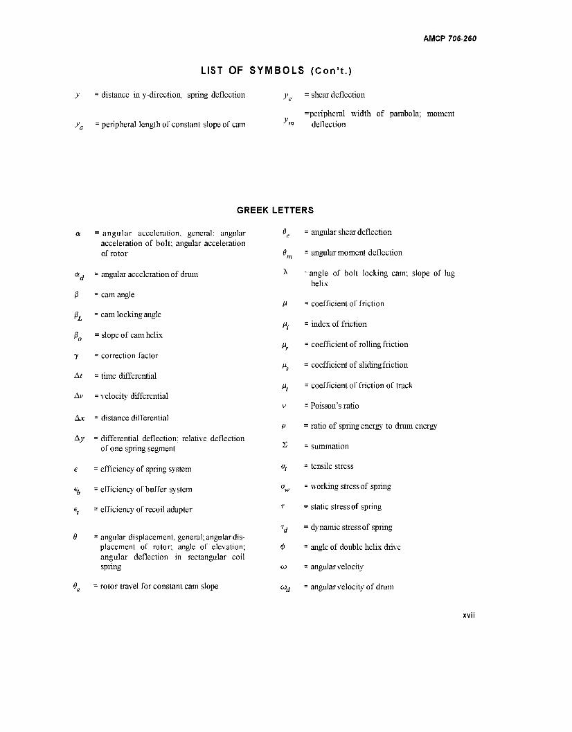
= distance in y-direction, spring deflection y
peripheral length of constant slope of cam y
shear deflection
peripheral width of parabola; moment m deflection
GREEK
a = angular acceleration, general; angular acceleration of bolt; angular acceleration of rotor
ad - angular acceleration of drum
jß = cam angle
ßL = cam locking angle
ß0 = slope of cam helix
y = correction factor
At = time differential
Av = velocity differential
Ax = distance differential
A3; = differential deflection; relative deflection of one spring segment
e = efficiency of spring system
eb = efficiency of buffer system
ef = efficiency of recoil adapter
0 = angular displacement, general; angular dis- placement of rotor; angle of elevation; angular deflection in rectangular coil spring
0 = rotor travel for constant cam slope
LETTERS
0 = angular shear deflection
8 = angular moment deflection
^ =angle of bolt locking cam; slope of lug helix
P
P
2
= coefficient of friction
= index of friction
= coefficient of rolling friction
= coefficient of slidingfriction
= coefficient of friction of track
= Poisson's ratio
= ratio of spring energy to drum energy
= summation
= tensile stress
= working stress of spring
= static stress of spring
= dynamic stress of spring
= angle of double helix drive
= angular velocity
= angular velocity of drum
AMCP 706-260
PREFACE
This handbook is one of a series on Guns. It is part of a group of handbooks covering the engineering principles and fundamental data needed in the development of Army materiel, which (as a, group) constitutes the Engineering Design Handbook Series. This handbook presents information on the fundamental operating principles and design of automatic weapons and applies specifically to automatic weapons of all types such as blowback, recoil-operated, gas-operated, and externally powered. These include single, double, multibarrel, and revolver-type machine guns and range from the simple blowback to the intricate M61A1 Vulcan and Navy 20 mm Aircraft Gun Mark II Mod 5 Machine Guns. Methods are advanced for preparing engineering design data on firing cycle, spring design, gas dynamics, magazines, loaders, firing pins, etc. All components are considered except tube design which appears in another handbook, AMCP 706-252, Gun Tubes.
This handbook was prepared by The Franklin Institute, Philadelphia, Pennsylvania, for the Engineering Handbook Office of Duke University, prime contractor to the U.S. Army, and was under the technical guidance and coordination of a special subcommittee with representation from Watervliet Arsenal, Rock Island Arsenal, and Springfield Armory.
The Handbooks are readily available to all elements of AMC including personnel and contractors having a need and/or requirement. The Army Materiel Command policy is to release these Engineering Design Handbooks to other DOD activities and their con- tractors, and other Government agencies in accordance with current Army Regulation 70-31, dated 9 September 1966. Procedures for acquiring these Handbooks follow:
a. Activities within AMC and other DOD agencies should direct their request on an official form to:
Commanding Officer Letterkenny Army Depot ATTN: AMXLE-ATD Publications Distribution Branch Chambersburg, Pennsylvania 17201
b. Contractors who have Department of Defense contracts should submit their request, through their contracting officer with proper justification, to the address indi- cated in par. a.
c. Government agencies other than DOD having need for the Handbooks may submit their request directly to the Letterkenny Army Depot, as indicated in par. a above, or to:
Commanding General U. S. Army Materiel Command ATTN: AMCAD-PP Washington, D. C. 20315
or
Director Defense Documentation Center ATTN: TCA Cameron Station Alexandria, Virginia 22314
AMCP 706-260
PREFACE (Con't.)
d. Industries not having a Government contract (this includes Universities) must for- ward their request to:
Commanding General U. S. Army Materiel Command ATTN: AMCRD-TV Washington, D. C. 20315
e. All foreign requests must be submitted through the Washington, D. C. Embassy to:
Office of the Assistant Chief of Staff for Intelligence ATTN: Foreign Liaison Office Department of the Army Washington, D. C. 20310
All requests, other than those originating within theDOD, must be accompanied by a validjustification.
Comments and suggestions on this handbook are welcome and should be addressed to Army Research Office-Durham, Box CM, Duke Station, Durham, N. C. 27706.
xix/xx
AMCP 706-260
CHAPTER 1
INTRODUCTION*
1-1 SCOPE AND PURPOSE
This handbook presents and discusses procedures normally practiced for the design of automatic weapons, and explores the problems stemming from the functions of each weapon and its components. It is intended to assist and guide the designer of automatic weapons of the gun type, and to contain pertinent design informa- tion and references.
1-2 GENERAL
The purpose of the handbook is (1) to acquaint new personnel with the many phases of automatic weapon design, and (2) to serve as a useful reference for the experienced engineer. It does not duplicate material available in other handbooks of the weapon series. Those topics which are presented in detail in other handbooks are discussed here only in a general sense; consequently, the reader must depend on the referenced handbook for the details. Unless repetitive, the text — for cyclic analyses, time-displacement (T-D) curves, chamber design, strength requirements, springs, cams, and drive systems — includes mathematical analyses embodying sketches, curves, and illustrative problems. Topics such as ammunition characteristics, lubrication, handling and operating features, and advantages and disadvantages are generally described more qualitatively than quantita- tively.
Appendix B is included to merely introduce the idea of the automatic control of a burst of rounds for weapon effectiveness in the point fire mode — a facet which the gun designer may wish to consider.
1-3 DEFINITIONS
An automatic weapon is a self-firing gun. To be fully automatic, the weapon must load, fire, extract, and eject continuously after the first round is loaded and fired - provided that the firing mechanism is held unlocked. Furthermore, the automatic weapon derives all its oper- ating energy from the propellant. Some weapons have external power units attached and, although not auto- matic in the strictest sense, are still classified as such.
There are three general classes of automatic weapons, all defined according to their system of operation, namely: blowback, gas-operated, and recoil- operated'**
a. Blowback is the system of operating the gun mechanism that uses propellant gas pressure to force the bolt to the rear; barrel and receiver remaining relatively fiied. The pressure force is transmitted directly by the cartridge case base to the bolt.
b. Gas-operated is the system that uses the propellant gases that have been vented from the bore to drive a piston linked to the bolt. The moving piston first unlocks the bolt, then drives it rearward.
c. Recoil-operated is the system that uses the energy of the recoiling parts to operate the gun.
Each system has variations that may borrow one or more operational features from the others. These variations, as well as the basic systems, are discussed thoroughly in later chapters.
\-l DESIGN PRINCIPLES FOR AUTOMATIC WEAPONS
The automatic weapon, in the process of firing a round of ammunition, is essentially the same as any other gun. Its basic difference is having the ability to continue firing many rounds rapidly and automatically. An outer stimulus is needed only to start or stop firing, unless the latter occurs when ammunition supply is exhausted. The automatic features require major effort in design and development. The design philosophy has been established, then the gun is to fire as fast as required without stressing any component to the extent where damage and therefore malfunction is imminent.
An extremely short firing cycle being basic, the designer must exploit to the fullest the inherent proper- ties of each type of automatic weapon. Generally, each type must meet certain requirements in addition to
*Prepared by Martin Regina, Franklin Institute Research Laboratories,Philadelphia,Pennsylvania.
'References are identified by a superscript number and are listed at the end of this handbook.
1-1
AMCP 706-260
being capable of operating automatically. These require- ments or design features are:
1. TJte part of the available energy of the propellant gases without materially affecting the ballistics.
2. Fire accurately at a sustained rate compatible with the required tactics.
3. TJte standard ammunition.
4. Be light for easy handling.
5. Have a mechanism that is:
a. simple to operate
b. safe
c. easy to maintain
d. economical with respect to manufacturing.
6. Have positive action for feeding, extracting, eject- ing.
7. Insure effective breech closure until the propellant gas pressure has dropped to safe limits.
All successful automatic weapons meet these require- ments but to a degree normally limited by type of weapon. Conflicting requirements are resolved by com- promise.
1-2
AMCP 706-260
CHAPTER 2
BLOWBACK WEAPONS
2-1 GENERAL
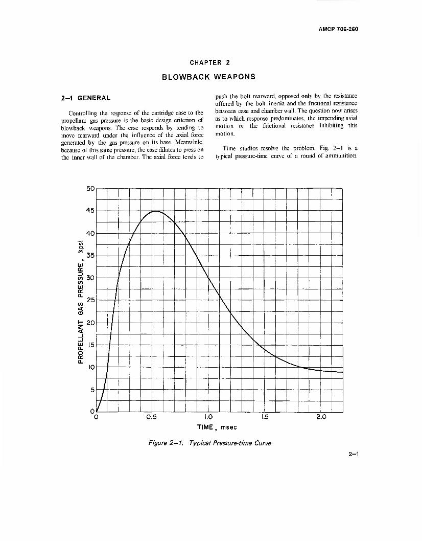
Controlling the response of the cartridge case to the propellant gas pressure is the basic design criterion of blowback weapons. The case responds by tending to move rearward under the influence of the axial force generated by the gas pressure on its base. Meanwhile, because of this same pressure, the case dilates to press on the inner wall of the chamber. The axial force tends to
push the bolt rearward, opposed only by the resistance offered by the bolt inertia and the frictional resistance between case and chamber wall. The question now arises as to which response predominates, the impending axial motion or the frictional resistance inhibiting this motion.
Time studies resolve the problem. Fig. 2-1 is a typical pressure-time curve of a round of ammunition.
3U
45
40
a.
CC
co 30 CO LJ DC
^25 CO < o £ 20 <
OP
ELL
a. 10
5 /
/
0 / 0.5 1.5 2.0
TIME, msec
Figure 2— 1. Typical Pressure-time Curve
2-1
AMCP 706-260
For simplicity, assume unity for bore area and bolt weight. According to Fig. 2—1, the maximum pressure of 45,000 psi develops in 0.0005 sec. Again for simplicity, assume that the pressure varies linearly from t = 0 to t = 0.0005 sec. The pressure/» at any time during the interval
'-(jra)'-"""''»*' (2-1)
The corresponding force F driving the cartridge case and bolt rearward is
F = Abp = 9xlO'! tA lb (2-2)
where A b = bore area in square inches
but,by assumption, Ab = 1.0 in? .therefore
F=9xl07?=Kt. (2-3)
From mechanics
F = Mba (2-4)
where a = bolt acceleration
Mb = mass of bolt.
According to an earlier assumption Mb = — = -1—
Solve for a in Eq. 2—4
but
a = £=Kgt
d2s v a -— = Kgt.
dr
(2-5)
(2-6)
Integration of Eq. 2—6 yields
J dt2 dt 2 (2-7)
when t = 0, 7 = 0, therefore C^ = 0.
Integration of Eq. 2—7 yields
(2-8)
when t = 0, s = 0, therefore, C2 = 0.
Assume that the limiting clearance between case and chamber is equal to the case dilation as it reaches the ultimate strength, and assume further that the cartridge case has a nominal outside diameter of 1.5 in., a wall thickness of 0.05 in., and an ultimate strength of 50,000 psi. Then, according to the thin-walled pressure vessel formula, the pressure at which failure impends and which presses the case firmly against the chamber wall is
Pu ott,
r
50,000x0.05
Ö~725 3440 psi (2-9)
where r = 0.725 in., mean radius of case
tc = 0.05 in., wall thickness
at = 50,000 lb/in.2, tensile stress
From Eq. 2—1, t is the time elapsed to reach this pressure.
Pu t =
9x 10⁷ 3.83 x 10"5 sec (2-10)
From Eq. 2—8, s is the distance that the case and bolt travel during this time, i.e., when only the inertia of the system is considered.
s=JKgt>
= ■£■ x 9 x 107 x 386 x 56 x 10"15 < 0.001 in. 6
This analysis indicates that when optimum conditions prevail, the cartridge case scarcely moves before frictional resistance begins to take effect. Motion will continue until Eq. 2—11 is satisfied.
AbP = ^cPi (2-11)
2-2
AMCP 706-260
where A, = bore area
■™' = peripheral surface contact area between case and chamber
p = propellant gas pressure
Pi = interface pressure of case and chamber
ß = coefficient of friction
With no initial clearance between the case and chamber, an approximate interface pressure pt may be determined by equating the inside deflection of the chamber, due to this pressure, to the outside deflection of the cartridge case, due to both interface and propellant gas pressure, when both case and chamber are considered cylindrical. Solve for the interface pressure.
2p
Pi
where
V2 -1) / \»l -1 /
(2-12)
E = modulus of elasticity of chamber
E, = modulus of elasticity of case
W = wall ratio of chamber
W. wall ratio of case
v = Poisson's ratio (assumed to be equal for both materials)
Spot checks indicate that those pressures which dilate unsupported cartridge cases to the limit of their strength
are reasonably close to the difference in propellant gas pressure and computed interface pressure. Thus
Pu * P-Pi (2-13)
Ample clearance between case and chamber is always provided but is never so large that barrel recovery exceeds case recovery after gas pressures subside; otherwise, interference develops, i.e., clamping the case to the chamber wall and rendering extraction difficult*.
2-2 SIMPLE BLOWBACK
Simple blowback is the system wherein all the operating energy is derived from blowback with the inertia of the bolt alone restraining the rearward movement of the cartridge case.
2-2.1 SPECIFIC REQUIREMENTS
Being restricted to low rates of fire because massive bolts are needed for their inertial properties, simple blowback systems are suitable only for low impulse, relatively low rate of fire weapons3.
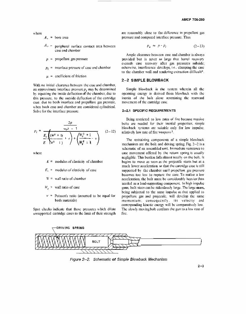
The restraining components of a simple blowback mechanism are the bolt and driving spring. Fig. 2—2 is a schematic of an assembled unit. Immediate resistance to case movement offered by the return spring is usually negligible. This burden falls almost totally on the bolt. It begins to move as soon as the projectile starts but at a much lower acceleration so that the cartridge case is still supported by the chamber until propellant gas pressure becomes too low to rupture the case. To realize a low acceleration, the bolt must be considerably heavier than needed as a load-supporting component. In high impulse guns, bolt sizes can be ridiculously large. The large mass, being subjected to the same impulse as that applied to propellant gas and projectile, will develop the same momentum; consequently, its velocity and corresponding kinetic energy will be comparatively low. The slowly movingbolt confines the gun to a low rate of fire.
-DRIVING SPRING
/ / / / / ///////
¥/y^f^f^f^
Figure 2—2. Schematic of Simple Blowback Mechanism
2-3
AMCP 706-260
ALLOWABLE TRAVEL
TC
BOLT
VfKKw; \
\
:\x, (A) STANDARD CASE
V
Figure 2—3. Allowable Case Travel
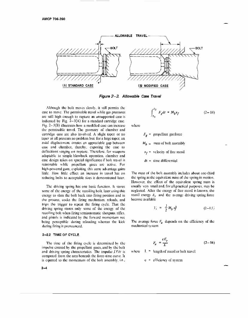
Although the bolt moves slowly, it still permits the case to move. The permissible travel while gas pressures are still high enough to rupture an unsupported case is indicated by Fig. 2-3(A) for a standard cartridge case. Fig. 2-3(B) illustrates how a modified case can increase the permissible travel. The geometry of chamber and cartridge case are also involved. A slight taper or no taper at all presents no problem but, for a large taper, an axial displacement creates an appreciable gap between case and chamber, thereby, exposing the case to deflections verging on rupture. Therefore, for weapons adaptable to simple blowback operation, chamber and case design takes on special significance if bolt travel is reasonable while propellant gases are active. For high-powered guns, exploiting this same advantage gains little. How little effect an increase in travel has on reducing bolts to acceptable sizes is demonstrated later.
The driving spring has one basic function. It stores some of the energy of the recoiling bolt, later using this energy to slam the bolt back into firing position and in the process, cocks the firing mechanism, reloads, and trips the trigger to repeat the firing cycle. That the driving spring stores only some of the energy of the recoiling bolt when firing semiautomatic shotguns, rifles, and pistols is indicated by the forward momentum not being perceptible during reloading whereas the kick during firing is pronounced.
t = Mbvf
where
(2- 14)
Fg = propellant gas force
Mb - mass of bolt assembly
Vr = velocity of free recoil
dt = time differential
The mass of the bolt assembly includes about one-third the spring as the equivalent mass of the spring in motion. However, the effect of the equivalent spring mass is usually very small and, for all practical purposes, may be neglected. After the energy of free recoil is known, the recoil energy Er and the average driving spring force become available
\Mbv} (2-15)
The average force Fa depends on the efficiency of the mechanical system
2-2.2 TIME OF CYCLE
The time of the firing cycle is determined by the impulse created by the propellant gases, and by the bolt and driving spring characteristics. The impulse fFdt is computed from the area beneath the force-time curve. It is equated to the momentum of the bolt assembly, i.e.,
eE, Fa (2-16)
where L - length of recoil or bolt travel
e = efficiency of system
2-4
AMCP 706-260
2-2.2.1 Recoil Time
The bolt travel must be sufficient to permit ready cartridge loading and case extraction. The initial spring force F, is based on experience and, when feasible, is selected as four times the weight of the recoiling mass. The maximum spring force Fm ,when the bolt is fully recoiled, is
2F - F a o (2-17)
The spring force at any time of recoil is
F = F0+Kx (2-18)
where K - spring constant
x = recoil distance at time t
At time t the energy remaining in the recoiling mass is
where E is the efficiency of the spring system. An inefficient system helps to resist recoil by absorbing energy.
(2-19)
D ♦ - dx But "r " dTr
.therefore
dx
~dtr = ^ \JMb 1
Solve for dt,.
\J2 "f l
7V- i
- — Kx2
2e (2-20)
dt.
— dx
Mb 2 1 -r- v2
f - - Fnx 1 ZrKx2
(2-2 1)
Set 7, = Vf, the initial velocity at time zero, and integrate.
Sin"1 F0 + Kx
yßl + eKMhv%
x=L
x = 0
(2-22)
2-5
AMCP 706-260
This computed time does not include the time while propellant gases are acting. The exclusion provides a simple solution without serious error. Since
MVQ = — (Fm + F0) and, by definition,
F - F K = -SLj-2- and jFl + eKMv% = Fm.
Therefore, the time elapsed during recoil t, from* - 0 tox = L is
eMh / it F0\ eMb F0
^ \i'S1"" t) - V^ Cos" t- (2-23» 2-2.2.2 Counterrecoil Time
The counterrecoil time is determined by the same procedure as that for recoil, except that the low efficiency of springs deters rapid counterrecoil. The energy of the counterrecoiling mass of the bolt assembly at any time tcr is
Ea = ± Mb v%. = i Mbvl + e(Fmx - I Kx*) (2-24)
where v0 = initial velocity
'cr
Since v„ = -r— a'cr
Integrating
2~ ^ dt, = ; (2-25)
\Mh e
— vl + eFmx ' 2 KX*
Kx - Fm -Fm Sin"1 , - Sin"1 - = \ (2-26)
K vS \ hl, + T-*VS e
When the initial velocity is zero, the time tcr to counterrecoil the total distance is
Mb . Fo - Cos-1— (2-27)
2-6
AMCP 706-260
2—2.2.3 Total Cycle Time
The mass of the bolt assembly and the bolt travel are the controlling elements of a simple blowback system. Large values will decrease firing rate whereas the converse is true for small values. The driving spring characteristics are determined after mass and travel are established. The total weapon weight limits, to a great extent, the weight and travel of the bolt.
Because of the efficiency of the spring system, counterrecoil of the bolt will always take longer than recoil. The time tc for the firing cycle is
t, = t,+ta +1{ (2-28)
where r,- is time elapsed at the end of counterrecod until
the bolt mechanism begins to move in recoil. Since the firing rate is specified, t, is
60 t, =
fr , sec/round (2-29)
where fr = firing rate in rounds/min.
Initial approximations of blowback parameters may be computed by relating average spring forces and acceleration to the recoil energy. The average spring force Fa needed to stop the recoiling mass is
Fa = eEr eM;
31 hU
(2-30)
where, according to Eq. 2-15, Er
Since Fa = eMbar
2 °f
a
eMh 2L (2-31)
From the general expression for computing distance in
terms of time and acceleration, L = — a, t\ , the recoil time becomes
(2-32)
During counterrecoil, the effectiveness of the spring force is reduced by the inefficiency of the system. This force is
eF„ = Mh a, (2-33)
where a„ is the counterrecoil acceleration. According to Eq. 2-30
eF„ e2M„v}
2L Mbacr- (2-34)
Proceed similarly as for recoil
2L 4L2
2 2 evf
2L
evf (2-35)
The approximate time of the firing cycle becomes
t> =tr + tcr=Vr (1+f )■ 2L
(2-36)
By knowing the required cycle time and the computed velocity of free recoil, the distance of bolt travel can be determined from Eq. 2-36. This computed distance will be less than the actual because the accelerations are not constant thereby having the effect of needing less time to negotiate the distance in Eq. 2-36. In order to compensate for the shorter time, the bolt travel is increased until the sum oft, and t,, from Eqs. 2-23 and 2-27 equals the cycle time.
t, =tr + f,
— ) Cos-' -Bo. (2-37)
Substitute 2Fa —Fm forFQ and rewrite Eq. 2-37
IF - F
Fa is computed from Eq. 2-30. Note that
is a constant for any given problem. Now by the judicious selection of L (using Eq. 2-36 for guidance) and K, the spring forces may be computed by iterative procedures so that (1) when substituted into Eq. 2-37 the specified time is matched, and (2) then into Eq. 2-17 to check whether Fa corresponds with the computed value obtained earlier from Eq. 2-30.
2-7
AMCP 706-260
The actual firing rate is determined from the final computed cycle time.
fr = ■— rounds/r (2-39)
2-2.3 EXAMPLE OF SIMPLE BLOWBACK GUN
2—2.3.1 Specifications
Gun: 11.42 mm (Cal .45) machine gun
Firing Rate: 400 rounds per minute
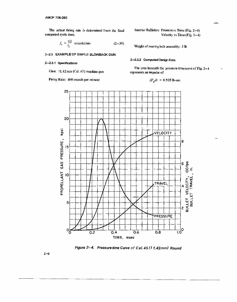
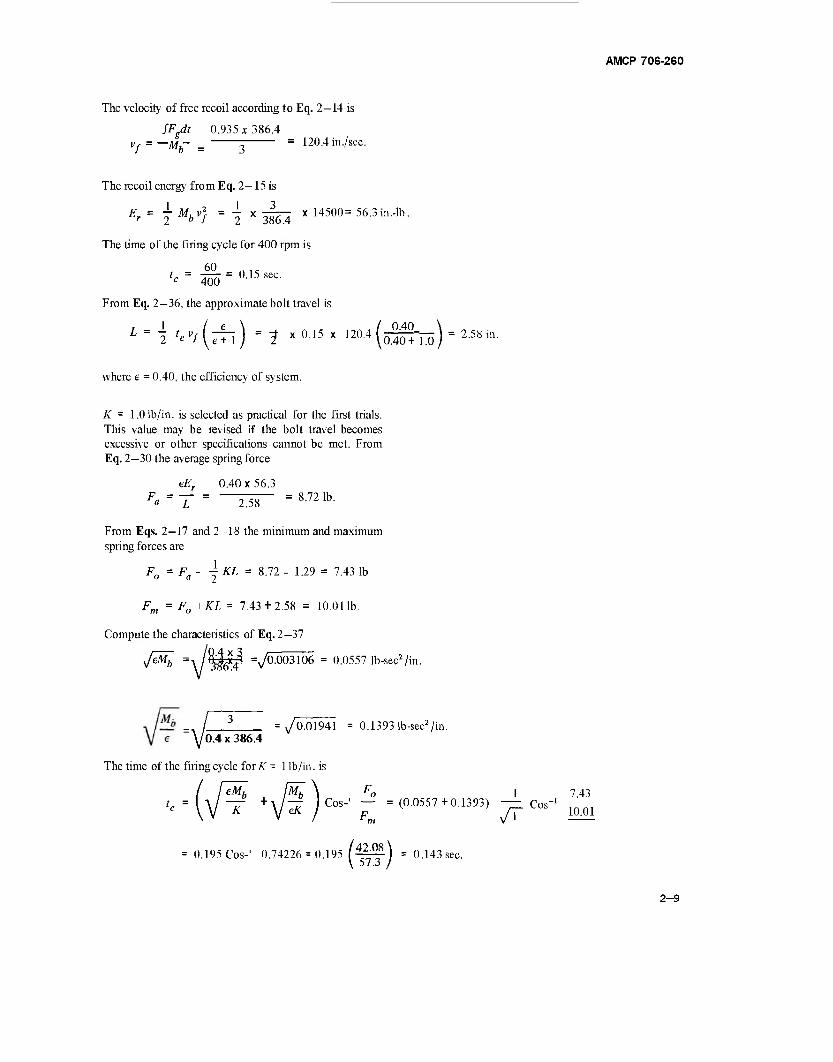
Interior Ballistics: Pressure vs Time (Fig. 2-4) Velocity vs Time (Fig. 2-4)
Weight of moving bolt assembly: 3 lb
2-2.3.2 Computed Design Data
The area beneath the pressure-timecurveof Fig. 2-4 represents an impulse of
JFgdt = 0.935 lb-sec.
25
20
a.
UJ or D <f) V) UJ or a en <
10
UJ a. o x a.
1 .VELOCITY
\
'
/ L
\
\ \ ,TRAVEL
"PRESSURE
0.2 0.4 0.6 TIME, msec
0.8
6 a.
O cf o —
>- UJ
UJ >
UJ _l
m 3 CD
1.0
Figure 2—4. Pressure-time Curve of Cal.45 (11.42mm) Round
2-8
AMCP 708-280
The velocity of free recoil according to Eq. 2—14 is
fFgdt 0.935x386.4 Vf = —Mb~ = 3 = 120-4 in-/sec.
The recoil energy from Eq. 2—15 is
1 w 2 1 3 Jr 2 b 7 2 386.4
The time of the firing cycle for 400 rpm is
fc= $0 = 0.15 sec.
From Eq. 2—36, the approximate bolt travel is
L = i ^(TTI) =f x015x 120-4(öSoTEö) = 2S8
where e = 0.40, the efficiency of system.
K = 1.0 lb/in. is selected as practical for the first trials. This value may be revised if the bolt travel becomes excessive or other specifications cannot be met. From Eq. 2—30 the average spring force
eEr 0.40x56.3 Fa=T = ~^W~ =8721b-
From Eqs. 2—17 and 2—18 the minimum and maximum spring forces are
Fo = Fa~ 2 KL = 8/72 " L29 = 743 lb
Fm = F0+KL = 7.43 + 2.58 = 10.011b.
Compute the characteristics of Eq. 2-37
yßh =A /%|jl3 V0003106 = °0557 lb-sec2/in.
m.
-^jm-^
10.4x386,4
The time of the firing cycle for K = 1 lb/in. is
= /0.01941 = 0.1393 lb-sec2 /in.
eMb Mb \ F0 i 7.43
T +V^ r°s"' ^ =(OO557 + 01393) 7^^- laoi
= 0.195 Cos-' 0.74226 = 0.195 R=f^ = 0.143 sec. (if) ■»' 2-9
AMCP 706-260
therefore, to have t„ = 0.15 sec, Cos-' — c f * n
rad and cos 0.76923 rad = 0.7185 so that
= 0.76923 At V Av Ax
F0+KL = 0.7185.
t = time, abscissa of pressure-time curve
At = tn - tn _ j, differential time
Since K = 1, -=—r ~ 0.7185 and Fn = 2.552L. F„+L ° Ai - differential area under pressure-time
curve
1 (F0 H. Fm)L Also, since "jFgL = — = Er = 56.3 in.-lb
2Fo+L=2Fa=W™^=^.
F At =AtyAj, differential impulse
A, = bore area
Av = F At/Mb , differential velocity
Mh = mass of bolt
Therefore
L2 = 7.379 in2
F0 = 6.94 lb
L = 2.72 in.
Fm =9.62 lb
The spring work Ws = -j(Fo + Fm)L = 22.52 in.-lb,
which matches the input. The time tc of the firing cycle for K =1
6.94 = (0.557 + 0.1393) Cos-' TTTT
y.oz
0.195 Cos-' 0.7214 = 0
0.15 sec.
/ 43.83 \ 195 IITT )
v = £Av velocity at end of each time incre- ment
1 va= 2^vn + vn - 0 averaSe velocity for each
time increment
Ax - vaAt, differential distance of case travel
x = SA«, case travel during propellant gas period
2—2.3.4 Sample Problem of Case Travel
The distance that the case is extracted as the pro- jectile leaves the bore is determined by numerically integrating the pressure-time curve of Fig. 2-4.
Ab=\Db=1^ xO.452 = 0.159 in? ,bore area
Av = F MMb = 32.2 x 12FgAt 3S6.4FgAt
2—2.3.3 Case Travel During Propellant Gas Period
Case travel while propellant gas pressures are active is found by numerically integrating the interior ballistics pressure-time curve and the velocity-time curve of the
128.8 FgAt
Ac = 0.053 in., the case travel distance when the projectile leaves the muzzle. This unsupported distance of the case is still within the allowable travel illustrated in Fig. 2—3.
2-10
AMCP 706-260
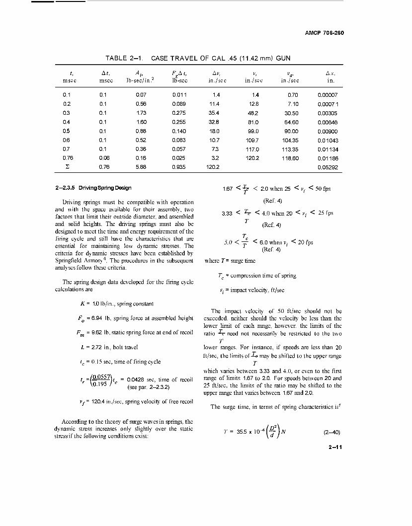
TABLE 2-1. CASE TRAVEL OF CAL .45 (11.42 mm) GUN
t, At, Av FgAt, Av, V, va< Ax, msec msec lb-sec/in.2 lb-sec in. /sec in./sec in. /sec in.
0.1 0.1 0.07 0.011 1.4 1.4 0.70 0.00007
0.2 0.1 0.56 0.089 11.4 12.8 7.10 0.0007 1
0.3 0.1 1.73 0.275 35.4 48.2 30.50 0.00305
0.4 0.1 1.60 0.255 32.8 81.0 64.60 0.00646
0.5 0.1 0.88 0.140 18.0 99.0 90.00 0.00900
0.6 0.1 0.52 0.083 10.7 109.7 104.35 0.01043
0.7 0.1 0.36 0.057 7.3 117.0 113.35 0.01134
0.76 0.06 0.16 0.025 3.2 120.2 118.60 0.01186 2 0.76 5.88 0.935 120.2 0.05292
2—2.3.5 Driving Spring Design
Driving springs must be compatible with operation and with the space available for their assembly, two factors that limit their outside diameter, and assembled and solid heights. The driving springs must also be designed to meet the time and energy requirement of the firing cycle and still have the characteristics that are essential for maintaining low dynamic stresses. The criteria for dynamic stresses have been established by Springfield Armory4. The procedures in the subsequent analyses follow these criteria.
The spring design data developed for the firing cycle calculations are
K = 1.0 lb/in., spring constant
FQ = 6.94 lb, spring force at assembled height
F = 9.62 lb, static spring force at end of recoil
L = 2.72 in., bolt travel
tc = 0.15 sec, time of firing cycle
t _/0.0557\ r \0.195 /
t - 0.0428 sec, time of recoil (see par. 2-2.3.2)
Vy= 120.4 in./sec, spring velocity of free recoil
According to the theory of surge waves in springs, the dynamic stress increases only slightly over the static stress if the following conditions exist:
1.67 < "^ < 2.0 when 25 < vi < 50 fps
(Ref. 4)
3.33 < ^rr < 4.0 when 20 < vt < 25 fps
T (Ref. 4)
Tc 5.0 < — < 6.0 when v, < 20 fps
(Ref. 4)
where T = surge time
T = compression time of spring
v2- = impact velocity, ft/sec
The impact velocity of 50 ft/sec should not be exceeded, neither should the velocity be less than the lower limit of each range, however, the limits of the ratio -TT need not necessarily be restricted to the two
T lower ranges. For instance, if speeds are less than 20
ft/sec, the limits of Xe may be shifted to the upper range T
which varies between 3.33 and 4.0, or even to the first range of limits 1.67 to 2.0. For speeds between 20 and 25 ft/sec, the limits of the ratio may be shifted to the upper range that varies between 1.67 and 2.0.
The surge time, in terms of spring characteristics is5
T = 35.5 x 10" '(f) N (2^0)
2-11
AMCP 706-260
where d = wire diameter
D = mean coil diameter
N = number of coils
Refer to the spring design data.
T = tr = 0.0428 sec, compression time of spring
According to Eq. 34 in Ref. 4, the dynamic torsional stress is
Td ■T(TJ['(£)
= 110,000(^)4 =
(2-44)
116,000 lb/in?
Select — =3.8, or T
Tc 0.0428 T = *# = —*#- = 0.01125 sec
G<T K = MdL. or N = -^— (Ref 6) (2-41)
SD3N SD3K
This stress is acceptable since the recommended maxi- mum stress for music wire is 150,000 lb/in? In Eq.
2-44,/(L<)rs the next largest even whole number
larger than the value of — if this ratio is not an even whole number. T
where G = torsional modulus (11.5 x 10⁶ lb/in? for steel)
K = spring constant
Substitute the exPression for N of Eq- 2~41 int0 Eq" 2-40, insert known values, and solve ford
d = 0.27 v^ DKT (2-42)
WhenZ) = 0.5 in., andÄ" = 1.0 (from spring data)
d = 0.27 V 0.5* 1.0x0.01126 = 0.048in.
From Eq. 2-41
„ Gd4 _ 11.5 xlO6 x530xlQ-g „ ., N = - = 61 coils
W3K 8*0.125* 1.0
Hs = Nd = 61x0.048 = 2.93 in., solid height.
The static torsional stress 7 is6
8fm£ nd3
8x9.62x 0.5
lllxlO^TT = 110,0001b/in?
(2-43)
2-3 ADVANCED PRIMER IGNITION BLOW- BACK
Timing the ignition so that the new round is firedjust before the bolt seats gives the first part of the impulse created by the propellant gas force opportunity to act as a buffer for the returning bolt. The rest of the impulse provides the effort for recoiling the bolt. The system that absorbs a portion of the impulse in this manner is called Advanced Primer Ignition Blowback. This system has its artillery counterpart in the out-of-battery firing system, i.e., the firing of the artillery weapon being initiated during counterrecoil but with the breechblock closed.
2-3.1 SPECIFIC REQUIREMENTS
By virtue of its ability to dispose of the early influence of propellant gas force on recoil, the advanced primer ignition system is much more adaptable to high rates of fire than the simple blowback system. Reducing the effectiveness of the impulse by fifty percent alone reduces the bolt weight by a factor of two with a sub- stantial increase in firing rate.
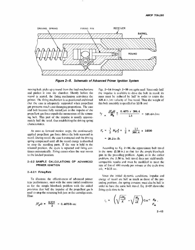
The restraining components may be considered as real and virtual; the real being the bolt and driving spring; the virtual, the momentum of the returning bolt. Fig. 2-5 is a schematic of the advanced primer ignition system. The firing cycle starts with the bolt latched open by a sear and the driving spring compressed. Releasing the sear, frees the bolt for the spring to drive it forward. The
2-12
AMCP 706-260
DRIVING, SPRING
BARREL
Figure 2—5. Schematic of Advanced Primer Ignition System
moving bolt picks up a round from the feed mechanisms and pushes it into the chamber. Shortly before the round is seated, the firing mechanism activitates the primer. The firing mechanism is so positioned and timed that the case is adequately supported when propellant gas pressures reach case-damaging proportions. The case and bolt become fully seatedjust as the impulse of the propellant gas force equals the momentum of the return- ing bolt. This part of the impulse is usually approxi- mately half the total, thus establishingthe driving spring characteristics.
As soon as forward motion stops, the continuously applied propellant gas force drives the bolt rearward in recoil. During recoil, the case is extracted and the driving spring compressed until all the recoil energy is absorbed to stop the recoiling parts. If the sear is held in the released position, the cycle is repeated and firing con- tinues automatically. Firing ceases when the sear moves to the latched position.
2-3.2 SAMPLE CALCULATIONS OF ADVANCED PRIMER IGNITION
2-3.2.1 Firing Rate
To illustrate the effectiveness of advanced primer type performance, start with the same initial conditions as for the simple blowback problem with the added provision that half the impulse of the propellant gas is used to stop the returning bolt just as the cartridge seats. Thus
/V 0.935
Eqs. 2—14 through 2—39 are again used. Since only half the impulse is available to drive the bolt in recoil, its mass must be reduced by half in order to retain the 120.4 in./sec velocity of free recoil. Thus the weight of this bolt assembly is specified as 15 lb and
sm Mb -
0.4675 x 386.4
1.5 120.4in./sec
= { M = 2 X 386.4 X 145°°
= 28.2in.-lb.
According to Eq. 2—36, the approximate bolt travel is the same (2.58 in.) as that for the simple blowback gun in the preceding problem. Again, as in the earlier problem, the 2.58 in. bolt travel does not yield totally compatible results and must be modified to meet the rate of fire of 400 rounds per minute or the cycle time oft, =0.15 sec.
Since the initial dynamic conditions, impulse and energy of recoil are half as much as those of the pre- ceding problem, the spring constant must also be half in order to have the same bolt travel. Eq. 2—37 shows the firing cycle time to be
= 0.4675 lb-sec -^ Cos"
2-13
AMCP 706-260
SinceK = 0.5 lb/in., E = 0.40, Mb = 1.5 lb-sec2
386.4 in. andtc = 0.15 sec,
hi - F0^-5L = l(«) 57.3°
fFgdt = 0.4675 lb-sec
F =7.49 lb, minimum spring load, simple blowback
F = 10.08 lb, maximum
K = *m - Fn 2.59 ,mL - = -h§- = 1.727 lb/in.
Solve for F„
Also
F = 1.2762L.
2eE, 2F0+ KL = 2F0 + 0.5L = 2Fa ■■
2x0.4x28.2
Substitute for FQ and collect terms
= 7.39 in? 2 _ 22.56 _a0f);„2 3.0524
L = 2.72 in
F0 = 3.47 lb
Fm = 4.83 lb
Recompute the time for the firing cycle
eM.
V- +
0.195 Cos -im)
Cos"1
0.195 x 0.769 = 0.15 sec
Another approach illustrates the advantage of increasing the firing rate by incorporating the advanced primer technique. The length of recoil in the preceding problems was selected to balance the dynamics of the problem and is not necessarily the ideal minimum dis- tance. Suppose that the ideal bolt travel is 1.5 in. and that the recoil force of the simple blowback gun is acceptable. The mass of the bolt is adjusted to suit the requirements.
e = 0.40, efficiency of spring system
The work Ws done to compress the springs is
W. = ^iFo + Fm)L = 8.785* 1.5 = 13.18 in.-lb.
The velocity vf of free recoil is 7
7 fFgdt glFgdt
Mh Wh
I 1 (wb\ The recoil energy Er = -w-Mbvj - 2\~ä~)vf
Substitute for v f
2
When the efficiency of the system is considered, the spring work is
Ws = 0.4£, or Er = 2.5 W,.
Substitute for E and solve for Wb, the weight of the bolt
2.5 ws = j(/v)2f:
32.95 = — x 0.2185 /386.4\
Wh 42.214
32.95 = 1.2811b.
The velocity of free recoil becomes
g-f-y _ 386.4 x 0.4675 Wh 1.281
141 in./sec
2-14
AMCP 706-260
The recoil energy Er = -j (MVI ) = -+(|^|j 19880 = 32.95 in.-lb.
The time of a firing cycle is
Mb Mb \ ~ [- K^' K \j eK I C0S = 0.0970x0.733 = 0.071 sec
where
eMb I 0.40 x 1.281
f^Üfel = \/°-000768 = 00277
M6 / 1.281
eK \ 0.40 x 1.727x386.4 7 0.00480 = 0.0693
F0 ( 7.49 \ cos-' — = Cos"1 TTTTT) = 42° = 0.733 rad
Fm \10.08/
The firing rate is
y 60 = _60_ = 845rounds/min. r f„ 0.071
2—3.2.2 DrivingSpring Design
The driving spring for the advanced primer ignition blowback gun has been assigned the following character- istics to comply with the requirements of the firing cycle for the simple blowback gun:
K = 0.5 lb/in., spring constant
FQ =3.48 lb, spring force at assembled height
Fm = 4.85 lb, spring force at end of recoil
L = 2.73 in., bolt travel
tr=Tc = 0.0428 sec, compression time of spring
Vf = Vj = 120.4 in./sec, velocity of free recoil, spring impact velocity
2-15
AMCP 706-260
Jc 0.0428 Select "TT = 3.8. Therefore, T = "7T— 0.1126 sec.
When D = 0.5 in., accordingto Eq. 2—42
d = 0.27 V DKT = 0.27 ^ 0.5 x 0.5 x 0.01125 = 0.038
From Eq. 2-41
N Gd* = 11.5 x 106 x208xlQ-8
SD3K 8x0.125x0.5 = 48 coils
H = Nd = 48x0.038 = 1.83 in., solid height.
The static torsional stress, Eq. 2—43, is
8FmD 8x4.85x0.5
TTCP 54.8 x IO^TT = 113,0001b/in2
Eq. 2—44 has the dynamic stress of
Td 1130001—14 = 119,000 lb/in?
The driving spring for the advanced primer ignition when the recoil force is equal to that of the simple blow- back gun has the following characteristics:
K = 1.7271b/in., spring constant
FQ = 7.49 lb, spring force at assembled height
Fm = 10.081b, springforce at end of recoil
L = 1.5 in., bolt travel
tr = T - 0.0203 sec, compression time of spring
vf ' vi = 141 in./sec, velocity of free recoil
2-16
AMCP 706-260
'c 0,0203 Select — = 3.8. Therefore, T = 3 8 = 0.00535 sec.
When D = 0.5, accordingto Eq. 2-42
d = 0.27 y DKT = 0.27 V 0.5 x 1.727x0.00535 = 0.045 in.
From Eq. 2-41
JV = <^4 = 11.5 x 106 x41 x IQ"7
SD3K 8x0.125 x 1.727 27.3 coils
Hs = Nd = 27.3x0.045 = 1.23 in., solid height.
The static torsional stress, Eq. 2—43, is
8FmD 8x 10.08x0.5
nd3 91.1 x 10"* n 141,000 lb/in2
The dynamic stress, Eq. 2—44, is
Td = r 7 141,000 I — U = 148,500 lb/in.2
2-4 DELAYED BLOWBACK
Delayed blowback is the system that keeps the bolt locked until the projectile leaves the muzzle. At this instant an unlocking mechanism, responding to some influence such as recoil or propellant gas pressure, releases the bolt thereby permitting blowback to take effect.
2-4.1 SPECIFIC REQUIREMENTS
Since the tremendous impulse developed by the propellant gases while the projectile is in the bore is not available for operating the bolt, the recoiling mass — including driving, buffing, and barrel springs — need not be nearly so heavy as the two types of blowback dis- cussed earlier.The smaller recoiling mass moves relatively faster and the rate of fire increases correspondingly.
Delayed blowback guns may borrow operating principles from other types of action, e.g., the piston action of the gas operating gun or the moving recoiling parts of the recoil operating gun. In either case, only unlocking activity is associated with these two types, the primary activity involvingbolt action still functions according to the blowback principle. Fig. 2-6 shows a simple locking system.
Like any other automatic gun, bolt action is con- gruous with timing particularly with respect to unlock- ing time. If recoil operated, distance also becomes an important factor. For this type gun, the barrel must recoil a short distance before the moving parts force open the bolt lock. Sufficient time should elapse to per- mit the propellant gas pressure to drop to levels below the bursting pressure of the cartridge case but retain enough intensity to blow back the bolt.
2-17
AMCP 706-260
BOUT FULLY RECOILEr UNLOCKING TRAVEL
Figure 2-6. Locking System for Delayed Blowback
The stiffness of the springs should not be so great as to interfere unduly with early recoil. Therefore, a system consisting of three springs is customarily used: (1) a barrel spring having an initial load slightly larger than the recoiling weight to insure almost free recoil and still have the capacity to hold the barrel in battery, (2) a buffer spring to stop the recoiling parts and return them, and (3) a bolt driving spring to control bolt activity. Before the bolt is unlocked, all moving parts recoil as one mass with only the barrel spring resisting recoil but this spring force is negligible compared to the propellant gas force and may be neglected during recoil. After the bolt becomes unlocked, the barrel spring combines with the buffer spring to arrest the recoiling barrel unit.
The unlocked bolt continues to be accelerated to the rear by the impetus of the decaying propellant gas pres- sure whose only resistance now is the force of the driv- ing spring, a negligible resistance until the propellant gas pressure becomes almost zero. Thereafter, the spring stops the bolt and later closes it. Normally the barrel unit has completed counterrecoil long before the bolt has fully recoiled to provide the time and relative dis- tance needed for extracting, ejecting, and loading. After the barrel unit is in battery, the bolt unit functions as a single spring unit.
2-4.2 DYNAMICS OF DELAYED BLOWBACK
While the complete unit is recoiling freely and later while all springs are operating effectively, the dynamics of the system are readily computed by an iterative process. Given the pressure-time curve, by knowing the
size of the masses in motion, the dynamics at any given time are determined by the summations of computed values for all preceding increments of time. The impulse during each increment is
Fto = AbAi (2-45)
where Ab = bore area
A( = area under A t of pressure-time curve
At = time increment
When the impulse is being determined during low pres- sure periods due consideration should be given to the resistance offered by the driving spring. F At should be adjusted after the driving spring and gas pressure forces become relatively significant. During each increment, the differential velocity is
Av Fj£t_
(2-46)
where Mr = mass of the recoilingpartsinfluenced by FAt.
The velocity of recoil at the end of each increment becomes
v =%_1) + ^v (2-47)
where "/„_,) = velocity at the preceding increment
2-18
AMCP 706-260
The distance traveled by the bolt with respect to the gun frame during the increment is
Ax = vflA« (v(«-.)+T Av) At (2-48)
where va = average velocity for the increment.
The total distance at the end of each increment is
x = 2Ax.
When the propellant gas pressures cease to be effective, the behavior of the barrel and bolt units depend entirely on springs. One such instance involving the buffer spring occurs when the bolt is unlocked. Although the gas pressure continues its effective action on the bolt, it can no longer influence the barrel unit except secondarily through the driving spring. Rewrite Eq. 2—19 for the isolated barrel unit and include the influence of the driving spring. Thus, the energy remaining in the recoiling mass is
(2^19)
iH)-i(v«) "obxt TM]4K) (2-50)
where F - drive spring force
Fob = initial buffer spring force
Kb = spring constant of combined buffer and barrel springs
Mt = mass of barrel unit
v t = initial velocity of barrel unit
v. = final velocity of barrel unit
x, = travel of barrel with respect to gun frame
e = efficiency of drive spring unit
eb = efficiency of buffer spring unit which in- cludes the barrel spring
The buffer spring performs in unison with the barrel spring. During counterrecoil, at the end of buffer spring
travel, the barrel spring continues to accelerate the barrel unit in its return to battery. During recoil, the propellant gas force is so much larger than the barrel spring force as to render the latter practically ineffective. Except for the last millisecond or two, the bolt driving spring also offers a negligible resistance to the propellant gas force. However, it does contribute a small force opposing the buffer spring and is represented in Eq. 2—50 by the
sion — ^*f)> expression — \rxt)> tne effective force of the driving
spring. The actual spring force F may be assumed to be the driving spring force at the time when the bolt is unlocked. Preliminary estimates should provide reasonable approximations at this stage of the design study.
An equation can be derived for the recoil time of the barrel unit by developing Eq. 2—50 by the same procedure used for Eq. 2—19. The recoil time for the barrel after bolt unlocking until pressure becomes zero is
2-19
AMCP 706-260
'rt Sin"1 Kb*,o + Fob - (T)F
- Sin-' 'oft e
J
Ob m F + e^tf^,
(2-5 1)
where x{0 = barrel travel from time of buffer engage- ment to end of propellant gas period
All values are known except xj0. Since tn is the time elapsed from bolt unlocking to pressure effectiveness reaching zero, this distance may be computed from Eq. 2-51. It represents the buffer spring deflection. The total barrel travel with respect to the frame is
+ x tf
where x tf = barrel travel during free recoil.
(2-52)
For the remainder of the buffer stroke and for the time that the barrel unit is counterrecoiling, the dynamics of the system may be computed by dividing the time into convenient intervals, and by use of the relationship existing between impulse and momentum, computing the dynamics for each corresponding increment of travel. Both recoil and counterrecoil of the barrel take place while the bolt is recoiling which changes the effective buffer spring forces for the two directions. The expression of the driving spring effective force does not change since the bolt travel direction does not change. The force of the driving spring at the end of each increment of travel is
The amount that the driving spring is compressed, while the barrel traverses xt, is the relative travel distance between barrel and bolt, thus
xh = x
In terms of differential values, the equation becomes
Ax6 = AX - Axt (2-53b)
On the assumption that the recoil velocity of the bolt has been computed at the time corresponding to xt0, the energy of the bolt can be computed and converted to the potential energy of the driving spring from which the spring forces may be determined. The average driving spring force over the remaining distance, Eq. 2-16, is
eEh (2-54)
F = F^l) + KAxb (2-55)
(2-53a) where
p = driving spring force at beginning of increment
K = driving spring constant
Axb = incremental driving spring deflection
The buffer spring force at the end of its increment of travel is
Fb ~ Fb(n - 1) + KbAxt (2-56)
where
Fb(n- 1) = Duffer spring force at beginning of increment
where Eb is calculated according to Eq. 2-15 and Lb - xb is the spring deflection remaining at the end of free recoil of the bolt.
Kb = buffer spring constant which includes the barrel spring
Ax, = incremental buffer spring deflection
2-20
The effective spring force on the bolt while it is recoiling is
AMCP 706-260
F F (n - l)
2E (2-57)
The effective spring force on the barrel while it is recoiling is
_ Fb + Fb(n-i) Feb~ 2e„ -F*
(2-58)
According to the relationship of impulse and momentum, Fdt = Mv, the general expression for differential velocity is
Av = FAt M '
(2-59)
Based on this expression, the bolt travel during each increment is derived in a sequence of algebraic expressions. Thus
Ax =v, (« 1)A?--(AvAr)=v(n_i)Ar FeAt2
2M, (2-60a)
Fin-O^2 KA? Ax ~v(n - x)At - ^M- - \ teMu l^b- Axh (2-60b)
But Axb = Ax - Axt (see Eq. 2-53b). Substituting this expression and collecting terms, the incremental travel of the bolt becomes
4eMh Ax
4eMb + KAt2
A Fjfi-i)*? KAt*\ v(«-')Af 7T— + 777" )Axt
2eMb \ 4eMb
(2-60c)
2-21
AMCP 706-260
The incremental travel for the barrel is a similar expression
Axt = vt(n - 1) At ~ ^(AvtAt) = vt(n - 1 At FebA^
>"' 2M, (2-61 a)
KAxh
At' Fh Ax =v, ,Lt ,1M"--^ t^ - V-') - ■ 3g (2-6 lb)
Again substituting Ax - Ax, for Ax^ and collecting
terms, the incremental travel of the barrel in recoil is
Ax, 4eebMt
^ee,^, + eKbAt2 + ebKAt2
'KAt2
vt(n _ „ Ar _ ^falfyAt2. + FtfsM^1- + IZXT/Ajc
4eM,
While the barrel is counterrecoiling, and the bolt recoiling, the effective spring force on the barrel is
(2-61c)
Feb = €bFb ' Fe = ebFb(n - i) ~ \^)KbAxt " ^T"2 -i) *A*6
2e (2-62)
The incremental travel of the barrel now becomes
Axt = vt(n-i)At + l( *v,Ar ) - wrtn-i)A' + 2M,
(2-63a)
A*f = v«n-i)At + 2M, \ 4M, AX' ' 2eM, ' \4eM, } Xf (2-63b)
Substitute Ax - Axt for Ae^,, collect terms and solve for Ax,
4eM, Axt =
4eMt + eebKbAt2 - KAt2
ebFb(n-i)At2
v*(»-»*t+ 2M,
F(n-0Af2 KAt2
2eMt \ 4eMt )Ax
(2-63c)
2-22
AMCP 706-260
While both bolt and barrel are counterrecoiling, the effective spring force on the bolt is
Fe = e(F + Fn . ,)/2 = eF(B _ 1} - eKAxbll.
Now, substitute for Fe and expand Eq. 2—60a so that
(2-64a)
Ax = v(„_0Af eF,
(« " I)
2M, ?k Yxb At2 (2-64b)
But, according to Eq. 2—53b, Axb = Ax - Axt, therefore
Ax = v(n_1}At - eF(n- i)
2MU At2 +
eK
4M! At2 Ax ik)At2Ax<- (2-64c)
Collect terms and solve for Ax
4M,. Ax =
4M6-e^A?2
eF(„_„Af2 / eKAt2 \
"(„ - i) A' I JA*, 2M, 4M,
(2-64d)
The effective force on the barrel during this period is
reb ebFb ~ Fe = eb
KbAxt
■b{n- 1)
KAxh
(n - 1) (2-65a)
The incremental barrel travel is, according to Eq. 2-63a
FebAt2
Axt= vt{n.nAt+^— (2-65b)
Substitute the expression for Feb of Eq. 2-65b, Ax - Axt for Axb, and collect terms. The incremental barrel travel now becomes
Ax, 4M,
AMt + (eK + ebKb) At2 vt(n - l) At
ebFb(n -l )
2M, At2
eF, (n- i)
2M,
eK At2 + TTT- At2Ax
4M, (2-65c)
2-23
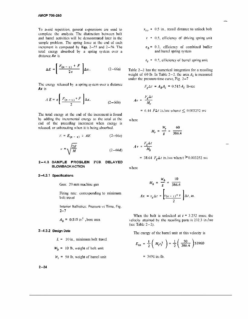
AMCP 706-2S0
To avoid repetition, general expressions are used to complete the analysis. The distinction between bolt and barrel activities will be demonstrated later in the sample problem. The spring force at the end of each increment is computed by Eqs. 2—55 and 2-56. The total energy absorbed by a spring system over a distance Ax is
AE 2e
Ax. (2-66a)
The energy released by a spring system over a distance Ax is
l^-F) AE= el f(n -l) Ax. (2-66b)
The total energy at the end of the increment is found by adding the incremental energy to the total at the end of the preceding increment when energy is released, or subtracting when it is being absorbed.
E = E(n- i) ± AE (2-66c)
(2-66d)
2-4.3 SAMPLE PROBLEM FOR DELAYED BLOWBACKACTION
xt0 = 0.5 in., recoil distance to unlock bolt
E = 0.5, efficiency of driving spring unit
eb= 0.3, efficiency of combined buffer and barrel spring system
et = 0.5, efficiency of barrel spring unit
Table 2—2 has the numerical integration for a recoiling weight of 60 lb. In Table 2—2, the area At is measured under the pressure-time curve, Fig. 2—7
FgAt = AbAt = 0.515^,- lb-sec
Av =
6A4 FAt in./sec when* < 0.003252 sec
where
W. Mr
60
386.4
Av = Mh
38.64 F.At in./sec when t >0.003252 sec
where
2—4.3.1 Specifications
Gun: 20 mm machine gun
Firing rate: corresponding to minimum bolt travel
Interior ballistics: Pressure vs Time, Fig. 2-7
Ab = 0.515 in? ,bore area
2-4.3.2 Design Data
L = 10 in., minimum bolt travel
Wb = 10 lb, weight of bolt unit
Wh 10 Mh
Ax = vaAt
g 386.4
V(„ - i)+v \At,in
When the bolt is unlocked at t = 3.252 msec, the velocity attained by the recoiling parts is 232.3 in./sec (see Table 2-2).
The energy of the barrel unit at this velocity is
*..=iKK(^)53960
w, 50 lb, weight of barrel unit = 3491 in.-lb.
2-24
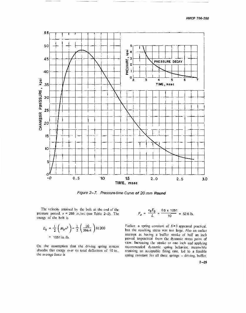
AMCP 706-260
55
50
45
40
Q. -* 35
w tr w 30 c/> w E * 25 cr w m < 20 I o
15
10
5
uT3 IX
CO c
CO UJ , tc 1 0.
0
^PRESSURE DECAY
> 3 4 5 6 7
1
/
/
/ 0.5 10 15
TIME, msec 2.0 2.5 3.0
Figure 2-7. Pressure-time Curve of 20 mm Round
The velocity attained by the bolt at the end of the pressure period, v = 285 in./sec (see Table 2-2). The energy of the bolt is
i (">'')■ 1051 in.-lb.
2 \ 386.4 / 81200
On the assumption that the driving spring system absorbs this energy over its total deflection of 10 in., the average force is
ebEb 0.5 x 1051
10 52.6 lb.
Earlier, a spring constant of K=3 appeared practical, but the resulting stress was too large. Also an earlier attempt at having a buffer stroke of half an inch proved impractical from the dynamic stress point of view. Increasing the stroke to one inch and applying recommended dynamic spring behavior, meanwhile retaining an acceptable firing rate, led to a feasible spring constant for all three springs - driving, buffer,
2-25
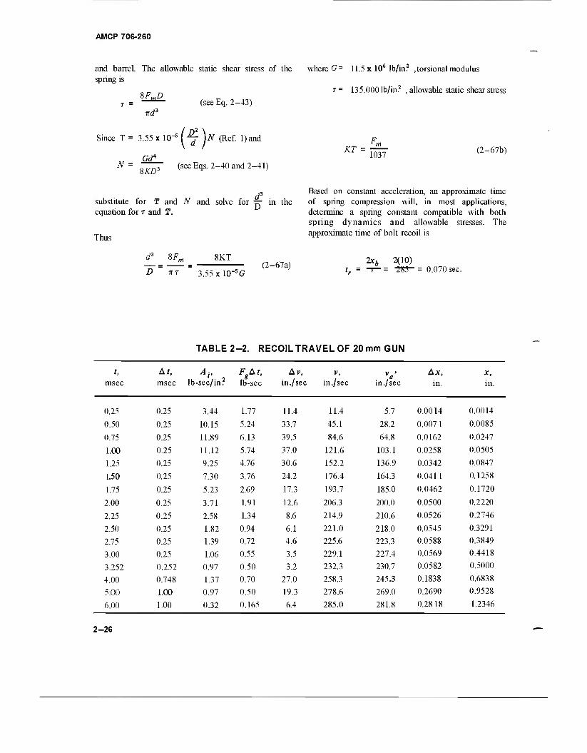
AMCP 706-260
and barrel. The allowable static shear stress of the where G= 11.5 x 10⁶ lb/in? ,torsional modulus spring is
*F„D_ T = 135,000 lb/in. , allowable static shear stress
nd3
Since T = 3.55 x 1(T5
GdA
(see Eq. 2-43)
N =
\~[)N (Ref l)and
8KD~ (seeEqs2-40and2-41)
KT = 1037 (2-67b)
3 Based on constant acceleration, an approximate time substitute for T and N and solve for — in the of spring compression will, in most applications, equation for r and T. determine a spring constant compatible with both
spring dynamics and allowable stresses. The approximate time of bolt recoil is
Thus
D ItT
8KT
3.55xl0"5G (2-67a)
2x6 2(10) -r—= -281-= 0.070 sec.
TABLE 2 -2. RECOILTRAVELOF20 mm GUN
t, At, Av , FgAt, Av, V, V Ax, x, msec msec lb-sec/inr lb-sec in. /sec in./sec in,/sec in. in.
0.25 0.25 3.44 1.77 11.4 11.4 5.7 0.0014 0.0014
0.50 0.25 10.15 5.24 33.7 45.1 28.2 0.007 1 0.0085
0.75 0.25 11.89 6.13 39.5 84.6 64.8 0.0162 0.0247
1.00 0.25 11.12 5.74 37.0 121.6 103.1 0.0258 0.0505
1.25 0.25 9.25 4.76 30.6 152.2 136.9 0.0342 0.0847
1.50 0.25 7.30 3.76 24.2 176.4 164.3 0.0411 0.1258
1.75 0.25 5.23 2.69 17.3 193.7 185.0 0.0462 0.1720
2.00 0.25 3.71 1.91 12.6 206.3 200.0 0.0500 0.2220
2.25 0.25 2.58 1.34 8.6 214.9 210.6 0.0526 0.2746
2.50 0.25 1.82 0.94 6.1 221.0 218.0 0.0545 0.3291
2.75 0.25 1.39 0.72 4.6 225.6 223.3 0.0588 0.3849
3.00 0.25 1.06 0.55 3.5 229.1 227.4 0.0569 0.4418
3.252 0.252 0.97 0.50 3.2 232.3 230.7 0.0582 0.5000
4.00 0.748 1.37 0.70 27.0 258.3 245.3 0.1838 0.6838
5.00 1.00 0.97 0.50 19.3 278.6 269.0 0.2690 0.9528
6.00 1.00 0.32 0.165 6.4 285.0 281.8 0.2818 1.2346
2-26
AMCP 706-260
Tc Since r < 25 ft/sec, (see par. 2—2.3.5), — = 3.8,
Tc = tr and Fm = Fa + — (KL ) (Eqs. 2-17 and
2-1B), Eq. 2-67b, after rc/3.8 is substituted for T, becomes
*r,
0.070/:=
Fa t 0.5KL
273
52.6+ 5K 273 '
Solve for K, thus
52.6 K
14.11
F
3.721b/in.
*+i(*L) 52.6 + 5x3.72 = 71.21b
2Lh 2x 1.0
= 232.3 0.0086sec
where Lb = buffer stroke
vb = recoil velocity of barrel when buffer is contacted
The average buffer force Fab is
rab f,, F., 0.3x 3491
HO 10471b.
Follow the same procedure for the buffer as for the driving spring
KbTc
Fab + 0.5KbLb
273
KL = 71.2- 37.2= 34.01b. 273 x 0.0086/^ = 1047+0.5*4.
Compute t from Eq. 2-23
-T Cos Tm
V0.5 x 10 , ^ 7?Y ^Rfi 4 Cos"1
3.72x386.4 C0S '
0.059 61.5
57.3
34.0
71.2
0.063sec.
Solve for Kb, thus
*4 = . R_ = 566 lb/in., buffer spring
constant
Fm6 = 1047 + 283 = 1330 lb, max buffer force
Fob - 1047 - 283 = 764 lb, min buffer force
Recomputing by inserting the newly calculated time t for Tc, the data converge to K = 4.4 lb/in. and t = 0.062 sec.
Compute tb from Eq. 2—23
The first set of detailed calculations (not shown) yielded a bolt recoil time of t = Tc = 51.5 msec. For this time, the computed spring constant of K = 5.8 lb/in. becomes the final value for computing the dynamics of Table 2—3.
The spring constant of the buffer system is found by assuming that the energy Eto=349\ in.-lb will be absorbed over the 1-inch buffer stroke. Later, adjustments will be made to compensate for the small discrepancies involving the spring forces. The time tb
of buffer action during recoil is
3* coS- A»
/ 0.3 x 50
566 x 386.44
mb
Cos" 764
1330 0.0079sec.
Recompute Kb by inserting the time 0.0079 sec for Tc. The new value of the spring constant Kb is 630 lb/in., but the new time remains tb = 0.0079sec.
2-27
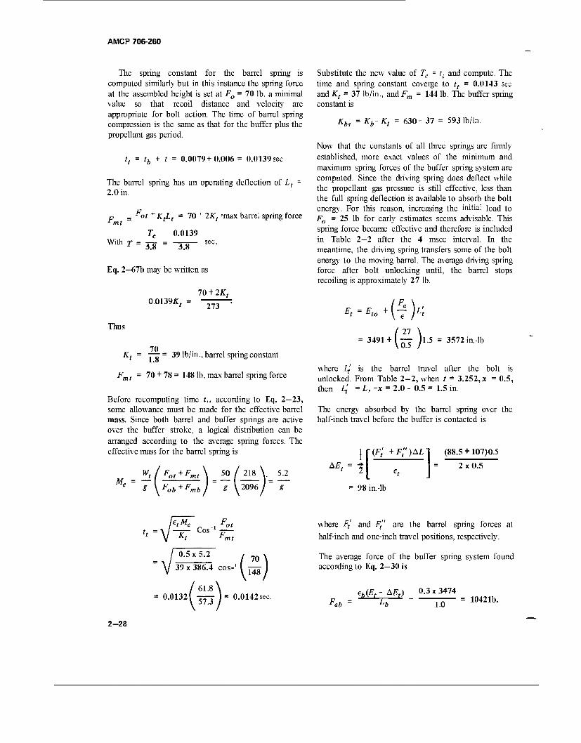
AMCP 706-260
The spring constant for the barrel spring is computed similarly but in this instance the spring force at the assembled height is set at F0 = 70 lb, a minimal value so that recoil distance and velocity are appropriate for bolt action. The time of barrel spring compression is the same as that for the buffer plus the propellant gas period.
tt = tb + t = 0.0079+0.006 = 0.0139 sec
The barrel spring has an operating deflection of Lt = 2.0 in.
p _ - ot *KfLt = 70 "*■ 2Kt 'max barrel spring force
0.0139 With T 3.8 " 3.8
Eq. 2—67b may be written as
70 + 2Kt
Thus
0.0139J:,
70
273
Kt = T7:= 39 lb/in., barrel spring constant
Fmt = 70 + 78 = 148 lb, max barrel spring force
Before recomputing time t,, according to Eq. 2-23, some allowance must be made for the effective barrel mass. Since both barrel and buffer springs are active over the buffer stroke, a logical distribution can be arranged according to the average spring forces. The effective mass for the barrel spring is
M. Wt/Fot+Fmt\ 50/2I8V 5.2
* yFob+F, mb g ^2096) g
Substitute the new value of Tc = tt and compute. The time and spring constant coverge to tt = 0.0143 sec and Kt = 37 lb/in., and Fm = 144 lb. The buffer spring constant is
Kbs = Kb- Kt = 630 - 37 = 593 lb/in.
Now that the constants of all three springs are firmly established, more exact values of the minimum and maximum spring forces of the buffer spring system are computed. Since the driving spring does deflect while the propellant gas pressure is still effective, less than the full spring deflection is available to absorb the bolt energy. For this reason, increasing the initial load to F0 = 25 lb for early estimates seems advisable. This spring force became effective and therefore is included in Table 2—2 after the 4 msec interval. In the meantime, the driving spring transfers some of the bolt energy to the moving barrel. The average driving spring force after bolt unlocking until, the barrel stops recoiling is approximately 27 lb.
Et0 +
3491 + (5) 1.5 = 3572 in.-lb
where Lf is the barrel travel after the bolt is unlocked. From Table 2—2, when / = 3.252, x = 0.5, then Zj' =L,-x = 2.0 - 0.5 = 1.5 in.
The energy absorbed by the barrel spring over the half-inch travel before the buffer is contacted is
A^ = ? (F' +F;')AL] (88.5 + 107)0.5
2x0.5
= 98 in.-lb
e,Me „ , Fot — Cos"1 — Kt bmt
°-5x5-2 / 70 39 x 386.4 cos-' (
0.0132 61.8
57.3
70 \
148 I
0.0142sec.
where Ft and Ft" are the barrel spring forces at
half-inch and one-inch travel positions, respectively.
The average force of the buffer spring system found according to Eq. 2—30 is
eh(Et-AEt) 0.3x3474 F„h = 'U — = 10421b. rab 1.0
2-28
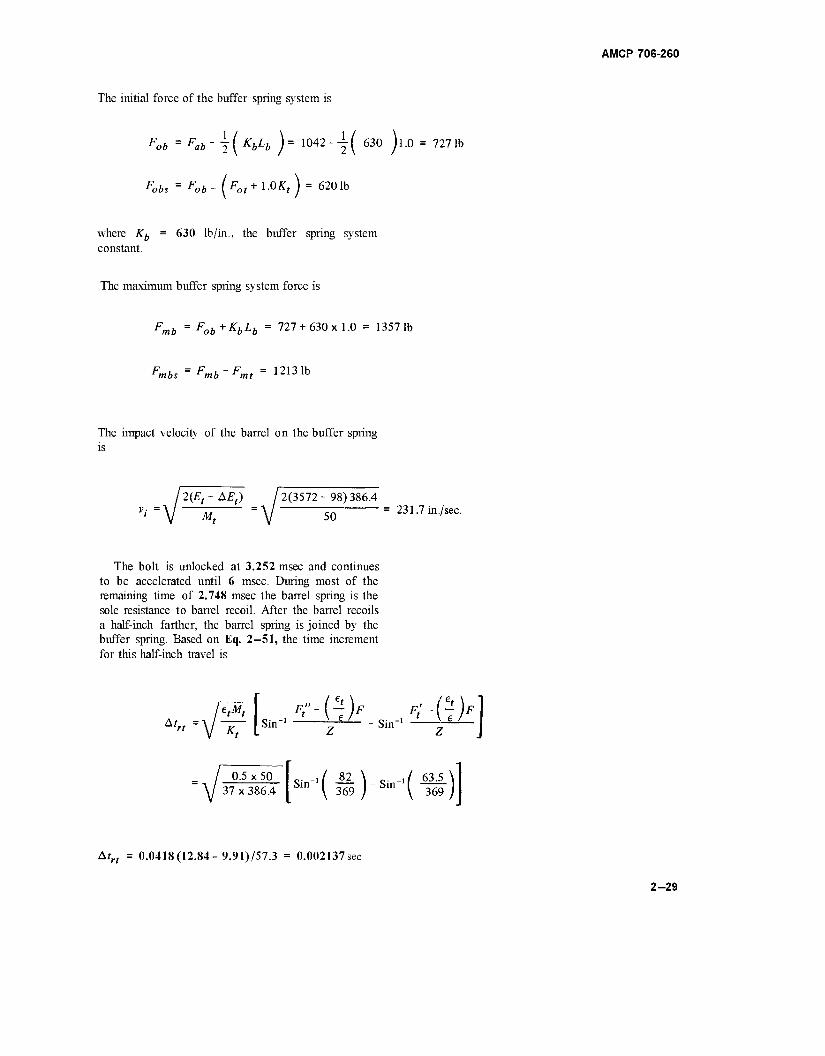
AMCP 706-260
The initial force of the buffer spring system is
Fob = Fab \(xbh )= 1042-|( 630 )i-o 7271b
6201b
where AT6 = 630 lb/in., the buffer spring system constant.
The maximum buffer spring system force is
Fmb = Fob+KbLb = 727 + 630x1.0 = 13571b
Fmbs = Fmb-Fmt = 12131b
The impact velocity of the barrel on the buffer spring is
M,
2(E, - AEt) / 2(3572 - 98) 386.4
50 231.7 in./sec.
The bolt is unlocked at 3.252 msec and continues to be accelerated until 6 msec. During most of the remaining time of 2.748 msec the barrel spring is the sole resistance to barrel recoil. After the barrel recoils a half-inch farther, the barrel spring is joined by the buffer spring. Based on Eq. 2-51, the time increment for this half-inch travel is
0.5 x 50 37 x 386.4
Atrt = 0.0418(12.84- 9.91)/57.3 = 0.002137sec
2-29
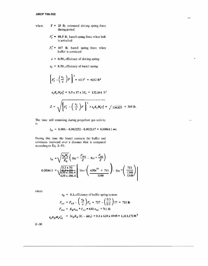
AMCP 706-260
where F = 25 lb, estimated driving spring force during period
Ft = 88.5 lb, barrel spring force when bolt is unlocked
Ff = 107 lb, barrel spring force when buffer is contacted
E = 0.50, efficiency of driving spring
et = 0.50, efficiency of barrel spring
MS)']'- 63.52 = 4032 lb2
etKtMtv) = 0.5 x 37 x IE, = 132,164 lb2
VM^> + etKtMrf = /l363Q1 = 3691b.
The time still remaining during propellant gas activity is
trt = 0.006-0.003252-0.002137= 0.000611 sec.
During this time the barrel contacts the buffer and continues rearward over a distance that is computed according to Eq. 2-51.
trt =1 Ä(-- F , * me Z
Sin-' f
-Sin —)
630*'° + 711 J - Sin-M 0.000611 = -, /0.3 x 50 711 \
\/6§ö3xX3?6.4 v 630x386.4
1348 / * 1348/ ^ 1348
where eb = 0.3, efficiency of buffer spring system
Fn. =Fnh-[- ]Fn = 727 - ( — /27 = 711 lb *oe = Fob ~ ( 7 )F0 = 727 - (H J27 = 7111 Fme= Kbxto^Foe = 63Qxto +71 lib
e K Mv2 = 2ebKb (E> ~ Mt) = °-3 x 630 x 6948 = 1,313,172lb2
2-30
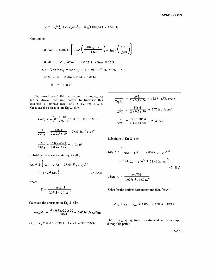
AMCP 706-260
z= y/Foe + ehKbMtvlt =v/l ,818,693 = 1348 lb.
Continuing
0.000611 = 0.00785 / 630xfo +711 \ / 711 \
Sm-'l 1348 y-^-'Visrj
0.0778 = Sin-' (0.4674xfo + 0.5274) - Sin-' 0.5274
Sin-' (0.4674x.„ + 0.5274) = 31" 50' +4° 28' = 36" 18'
0A61Axto = 0.5920- 0.5274 = 0.0646
xto = 0.138 in.
The barrel has 0.862 in. to go to complete its buffer stroke. The time needed to tranverse this distance is obtained from Eqs. 2-60c and 2-6 lc. Calculate the constants in Eq. 2-60c.
4eM, = 4(0.5) 10
386.4
386.4 leMZ = 2 x 0.5 x 10
0.0518 fb-sec2/in.
1
K = 5.8x386.4 4eMb 4x0.5x10
= 38.64 in./(lb-sec2)
112/sec2
Substitute these values into Eq. 2-60c.
Ax = B [v(„ _ 1} At - 38.64 F(n _ l} At'
+ 112A;2Ax •\
(2-68a)
where
B = 0.05 18
0.0518 + 5.8 Af2
Calculate the constants in Eq. 2-6lc.
A M 4 x 0.5 x 0.3 x 50 _ __„ „ ,, 4eebMt = ^-^ = 0.0776 lb-sec2/in.
eKb + ebK = 0.5x630+0.3x5.8 = 316.7 lb/in.
1 386.4
2ebMt 2x0.3x 50
1 386.4
2eMt = 2x0.5x50
K 5.8 x 386.4 4eMt 4 x 0.5 x 50
= 12.88 in ./(lb-sec2)
= 7.73 iti./(lb-sec2)
= 22.41/sec2
Substitute in Eq. 2-61 c.
, = A [ vt
+ 7.73F(„ - ,) Af2 + 22.41 Af2A.x]
Ax ,)At- I2.88^(„_0ArJ
(2-68b)
where A = 0.0776
0.0776 + 316.7 A;2
Solve for the various parameters and then for At.
A*, = Lb - xt0 = 1.00 - 0.138 = 0.862 in.
The driving spring force is estimated as the average during this period
2-31
AMCP 706-260
F(„ _ i) = 27 lb (assumed constant)
Fb(n _ ,} = Fob+Kbxto = 727 + 630 x 0.138 = 814 lb
AEt = 27"[ F°h +Fbi"~ ° K = 354in"lb
Et(/l _ 1} = Et - AEt - AE't = 3572 - 98 - 354 = 3120 in.-lb
Ax = 1.928 (assumed and then verified below)
vt(n - l)
V2Et(n _ ., / 6240x386.4 , H^- =V TO = v^^i = 219.6 in./sec
°-862 = (oo77604°37?6 7A^ )(2196At- 10484 Af2 + 209 Af2 + 43Af2)
0.862 +3518A?2 = 219.6A/- 10232 At2
At2 - 15.97x 10"3 At + 62.70 x 10"6 =0
At = 6.96 x 10"3
Since A^2 = 48.4 x 10"*, the fraction ^-^ =0.9946 0.0518+ 5.8A?2
Ax = 0 9946 1 0Af-38.64F(n_ t)Al2 +112Af2A;c,l \v(n
= 0.9946 J285 x 6.96 x 10~3 - (38.64 x 27 - 112 x 0.862) 48.4 x
Ax = 0.9946(1.984-0.046) = 1.928in.
The absolute distance traveled by the barrel at this time is 2.0 in., and xb the distance that the bolt traveled with respect to the barrel is
xb = £Ax-L, +Ax = 1.235-2.0+1.928= 1.163in.
The total time of buffer spring action during recoil is
tbr = trt + At = 0.00061 + 0.00696 = 0.00757 sec.
2-32
AMCP 706-260
The prevailing conditions at the end of the The energy remaining becomes propellant gas period are now computed. The barrel travel is
xt = 2Axf+x,0 = 1.0 + 0.138 = 1.138 in.
bufisa- 2A5:.f589 in9em.Tli®ibdlttilaarefelwhealriiting)BpHnlg deflection is
xbo = 2Ax-xt = 1.235- 1.138 = 0.097 in.
E = Eb-AE = 1051 - 58.6 = 992.4 in.-lb.
The bolt velocity at this time becomes
umm y 76693 = 276.9 in./sec.
where SAx = 1.235 in., absolute bolt travel at end of propellant gas period (Table 2—2). The average driving spring force for the remaining deflection is
eEK 0.5 x 1051 LTx bo 10.0-0.097
= 53.11b.
For Z = 5.8, the force at 0.10 in. deflection is
F'0= Fa-j K(L - xbo) = 53.1 - 28.7 = 24.4 lb.
The driving spring force when the bolt is fully retracted is
Fm = F'0 +K(L - xbo) = 24.4 + 57.4 = 81.8 lb.
The driving spring force at zero bolt travel is
F0 = Fm -KL = 81.8- 58 = 23.81b.
The bolt travel from the time that the propellant gas becomes ineffective until the barrel is fully recoiled is
x'b =xb-xb0 = 1.163-0.097 = 1.066 in.
The driving spring force F is
F=F'0+Kx'b = 24.4+ 5.8 * 1.066 = 30.61b.
The absorbed energy expressed as the differential energy AE is
AE (K * F)
2e ^=(y^7)L066=58-6in- lb.
The time t at full recoil of the barrel or when barrel begins to counterrecoil is
r = tg + At = 12.96 msec
where tg = 0.006 sec, duration of propellant gas period
At = 0.00696 sec, time for barrel to complete recoil after tg.
2-4.4 COMPUTER ROUTINE FOR COUNTER- RECOILING BARREL DYNAMICS
A digital computer routine is programmed in FORTRAN IV language for computing the dynamics of the barrel during counterrecoil. Since time and distance are the most pertinent parameters, the program is generated about these data. During a given differential time, Eqs. 2-60c and 2-64d give the differential travel 'distance of the bolt while Eqs. 2-63c and 2-65c give the differential travel distance of the barrel. Eq. 2—53a provides the relative travel which is equivalent to the driving spring compression. The differential relative travel between barrel and bolt is computed from Eq. 2-53b.
After substituting the various known constants, Eqs. 2-60c and 2—64d are rewritten as Eqs. 2—68a and 2—70a to define the action of the bolt during recoil and counterrecoil, respectively. The substitution of constants into Eq. 2-63c yields equations for the barrel travel while the bolt is recoiling; Eq. 2—69a when the buffer is active; and Eq. 2-69b when the barrel spring acts alone. Eq. 2-65c, after the substitution of numerical constants, becomes Eq. 2—70b which defines the differential barrel travel if the buffer is still active. When the buffer is inactive, Eq. 2—70c defines the differential barrel travel.
2-33
AMCP 706-260
Since the equation for solving Ax includes an expression that contains Ax„ and the equation for solving Axt includes an expression that contains Ax, the computer program contains an interative routine that approximates these two differential distances. The approximations for Ax and Ax, eventually approach the true values close enough to render any error negligible.
The computed values of the constants in Eq. 2—63c for the barrel counterrecoiling under the influence of the buffer while the bolt is still recoiling are
The constants in Eq. 2—63c now become
ee,Kt - /: = 0.5 x 0.5 x 37 . 5.8 = 3 45 lb/in
et 0.5 x 386.4 '2Mt 2 x 50
1.932 in./(lb-sec2).
Substitute the revised constants into Eq. 2-63c,
**t =AlvHn.1)At + [l.932Fft(„.0
4eMf 4 x 0.5 x 50
386.4 0.2588 lb-sec1/in.
7.73F(„_ ,) Ar2 - 22.41 At2Ax
eebKb - K = 0.5 x 0.3 x 630 - 5.8 = 88.7 lb/in.
eb 0.3 x 386.4 2Mt ' 2x50 = 1159in,/(lb-sec*)
(2-69b) where
0.2558
0.2558 + 3,45 A?2
386.4
2eM, 2 x 0.5 x 50 = 7.73 in./(lb-sec2)
K = 5.8 x 386.4 4eMt ~ 4 x 0.5 x 50
= 22.41 / sec2
Substitute these constants in Eq. 2—63c
Ax, = A[ v/(„_ L)^f+ (l.l59/^{„_ 0
- 7.73F(„ _ ,}) A/2 - 22.41 A?1 Ax] (2-69a)
The constants of Eq. 2-64d, when both bolt and barrel counterrecoil, are computed to be
4Mb = 0.1035 lb-sec1/in.; eK = 2.9 lb/in.
el2Mb = 9.66 in./(lb-sec1); eK/4Mb = 28/sec1
D _ 0.1035
0.1035 - 2.9At2
Eq. 2—64d now becomes
Ax = B\vin-l}At - 9£6FlH.n^
where
0.2558
0.2558+88.7 Af1
28 A/1 Ax,
The constants of Eq. 2-65c also change.
(2-70a)
At the end of buffer return, only barrel and driving springs remain effective. These design data for the barrel spring are
4Mt = 0.5181b-sec2/in. eKjAM, = 5.6/sec2
Kt = 37 lb/in., Fot = 1071b,
2-34
et = 0.5 e/2Mt = 1.932 in./(lb-sec2)
AMCP 706-260
If the buffer is still active, the computed constants are
eK+ebKb = 0.5x5.8 + 0.3x630 = 191.9 lb/in.
eb/2M( = 1.159 in./Ob-sec2); A 0.518
TT91.9Af2*
After substituting these constants into Eq. 2—65c, the differential barrel travel becomes
[■ Ax, =Alvnn-1)±t+\l.lS9Fb(n.1)
- 1 -932F(„ _ j} + 5.6A* \ At2 . (2-70b)
With the buffer no longer active, the constants become
eK+etKt = 0.5x5.8+0.5x37 = 21.4 lb/in.
0.518 et/2Mt = 1.932 in./(lb-sec2); A + 21.4Af2
After being assigned these constants, Eq. 2-65c becomes
Axt =A\ vr(„_1} At + [l.932F6(„_1,
- 1.932F(ff _ ,, + 5.6Ax ] At2 . (2_70c)
Although functions of the spring forces appear in
the equations for computing the dis" mce traveled by bolt and barrel, the spring forces must be computed for each increment of time since those values are projected into the next increment. At the end of each increment, the spring forces on bolt and barrel are computed, respectively, from Eqs. 2—55 and 2—56. The driving spring force is
F = F(„_1} +5.8A*Ä. (2-71a)
While the buffer is operating, the counterrecoil force on the barrel becomes
Fh = F, b(n- l) 630 Ax, (2-7 lb)
When the barrel spring operates alone, this force is
Fb =^(«-D " 37Axf (2-71Q
After the spring forces are computed, the respective energies and velocities of the bolt and barrel are computed from formulas based on Eqs. 2-66a, 2-66b, and 2—66d.
For convenience, the computer program is divided into four periods: (1) during buffer action, (2) during bolt recoil, (3) after buffer action, and (4) during bolt counterrecoil. Bolt action occurs simultaneously with barrel action (buffer action being a part of barrel action), but usually continues after the barrel is fully counterrecoiled. When the bolt is fully recoiled at t = 50.63 msec (Table 2-5), it immediately starts counterrecoiling with the barrel and these two now counterrecoil as one mass. The velocity at this instant is computed from the law of the conservation of momentum.
Mtvt = (Mt+Mb)vt{n _ 1} (2-7 Id)
Table 2—3 lists the variables and corresponding FORTRAN code in alphabetical order. Table 2-4 lists the input and Table 2-5 lists the output or results of the computer. The program is found in Appendix A—1 and its flow chart in Appendix A—2.
After the barrel has fully counterrecoiled, all remaining activity is confined to the bolt. It still has to negotiate its complete counterrecoil stroke. The time elasped for the bolt to complete the remaining counterrecoil stroke is computed from Eq. 2—26.
lcrb Sin" k VF
2 +U/AK
Sin"1 - t
(2-72)
tcrb = 00945
I
Sin-'( ) -sm-'(^r)]
= 0.0945 [Sin-' (-) 0.2693 - Sin-' (-) 0.92521
= 0.0945 (344.37 -292.3) /57.3 = 0.0859 sec
2-35
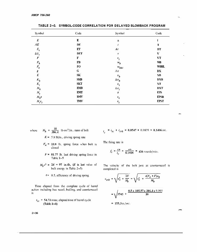
AMCP 706-260
TABLE 2-3. SYMBOL-CODE CORRELATION FOR DELAYED BLOWBACK PROGRAM
Symbol Code Symbol Code
E
AE
Et
g K
Kb Kt Mb Mt
Mbv
Mtvt
E
DE
ET
DET
F
FB
FO
G
SK
SKB
SKT
EMB
EMT
BMV
TMV
n
t
At
v
vt
w, Ax
bbl
Ax,
**t E
I
T
DT
V
VT
WB
WBBL
DX
XB
DXB
XT
DXT
EPS
EPSB
EPST
10 lb-secVin., mass of bolt where M" 386.4
K = 5.8 lb/in., driving spring rate
F0 = 23.8 lb, spring force when bolt is closed
F- 81.77 lb, last driving spring force in Table 2-5
t ~ ltc + hrb ~ °-0547 + 0.0859 = 0.1406 sec.
The firing rate is
CO 6Q lT ~ t ~ 0 1406 ~ 426 rounds/min.
Mbv7 = 2E = 97 in.-lb, (E is last value of The velocity of the bolt just as counterfoil
completed is bolt energy in Table 2—5)
E= 0.5, efficiency of driving spring vcrb Vi, +
2E e(F0+F)xb vX + Mh
Time elapsed from the complete cycle of barrel action including free recoil, buffing, and counterrecoil is
ttc = 54.73 msec, elapsed time of barrel cycle (Table 2-5)
0.5 x 105.57x386.4x9.995 3745 +
155.3 in./sec.
10
2-36
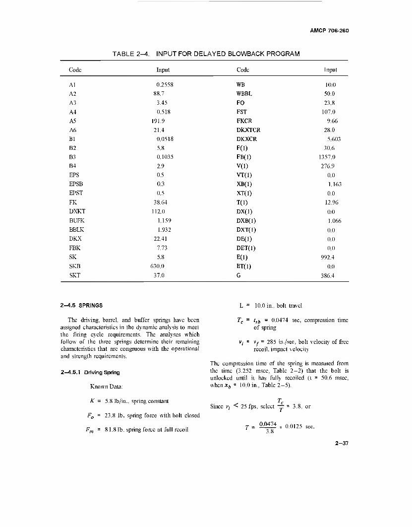
AMCP 706-260
TABLE 2-4. INPUT FOR DELAYED BLOWBACK PROGRAM
Code Input Code Input
AI
A2
A3
A4
A5
A6
Bl
B2
B3
B4
EPS
EPSB
EPST
FK
DXKT
BUFK
BBLK
DKX
FBK
SK
SKB
SKT
0.2558
88.7
3.45
0.518
191.9
21.4
0.0518
5.8
0.1035
2.9
0.5
0.3
0.5
38.64
112.0
1.159
1.932
22.41
7.73
5.8
630.0
37.0
WB
WBBL
FO
FST
FKCR
DKXTCR
DKXCR
F(l)
FB(1)
V(l) VT(1)
XB(1)
XT(1)
T(l)
DX(1)
DXB(l)
DXT(l)
DE(1)
DET(1)
E(l)
ET(1)
G
10.0
50.0
23.8
107.0
9.66
28.0
5.603
30.6
1357.0
276.9
0.0
1.163
0.0
12.96
0.0
1.066
0.0
0.0
0.0
992.4
0.0
386.4
2-4.5 SPRINGS
The driving, barrel, and buffer springs have been assigned characteristics in the dynamic analysis to meet the firing cycle requirements. The analyses which follow of the three springs determine their remaining characteristics that are congruous with the operational and strength requirements.
2—4.5.1 Driving Spring
Known Data:
K = 5.8 lb/in., spring constant
F0 = 23.8 lb, spring force with bolt closed
Fm - 81.8 lb, spring force at full recoil
L = 10.0 in., bolt travel
Tc = trb = 0.0474 sec, compression time of spring
Vj = Vr = 285 in./sec, bolt velocity of free recoil, impact velocity
The compression time of the spring is measured from the time (3.252 msec, Table 2—2) that the bolt is unlocked until it has fully recoiled (t = 50.6 msec, when x6 = 10.0 in., Table 2-5).
Since vt < 25 fps, select — = 3.8,
T = 0^174 = 00125 sec
3.8
2-37
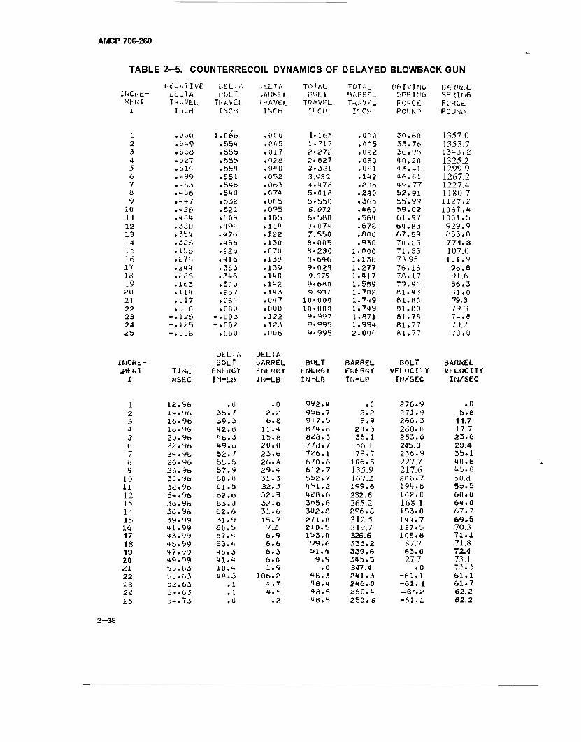
AMCP 706-260
TABLE 2-5. COUNTERRECOIL DYNAMICS OF DELAYED BLOWBACKGUN
KcXAl IVE UELIA - E L T A TO 1 AL TOTAL PR IV1Mb HArtRcL INCKt- ÜLLTA i?CLT ...ARf-EL BOLT rsAPRfL SPRIMO SPRING Mtl-il TkAVtU TRAVEL inAVEl.. TRAVEL TuAVFL FORCE FCMCc i IuCri Ir-iCri INCH I1 CH I-iCH POUNP PCUNL.)
1 .000 1.066 • oro 1.163 .000 30.60 1357.0 2 .5H9 .554 .0 05 1-717 .005 33.76 1353.7 3 1-. < O »JJÜ • 55b .017 2-27? .022 36.98 1343.2 4 .527 .555 .020 2.027 .050 40.20 1325.2 5 .1)14 .b54 .010 3.3U1 .091 43.41 1299.9 6 .499 .551 .052 3.932 .142 46.61 1267.2 7 .4M • 54b .063 4.478 .206 4Q.77 1227.4 8 .466 .540 .074 5-018 .280 52.91 1180.7 9 .447 .532 .0»-5 5-550 .365 55'. 99 1127.2
1Ü .420 .521 .095 6.072 .460 59.02 1067.4 11 .4Ü4 .b09 .105 6.560 .564 61.97 1001.5 12 .330 .494 .114 7.0 74 .670 64.83 929.9 13 ,3b4 . 4 7o .122 7.550 .800 67.59 853.0 14 .326 • 45b .130 8.005 .930 70.23 771.3 15 .lbb • 22b .070 8.230 1.000 71,53 107.0 16 .278 .416 .136* 8 • 646 1.138 73.95 101.9 17 .244 .3fc3 .139 9.02T 1.277 76.16 96.8 18 .206 .346 .140 9.375 1.417 78.17 91.6 19 .lo3 .3 Ob .142 9.680 1.559 79.94 86.3 20 .114 .257 .143 9.937 1.702 81.43 81.0 21 .ul7 .Of 4 .047 10.000 1.749 81.80 79.3 22 • coo .000 .000 10.000 1.749 81.80 79.3 23 -.125 -•UC'3 .122 9.997 1.871 81 .78 74.8 24 -.125 -.002 .123 9«995 1.994 PI. 77 70.2 2b -•0U6 .0 00
DELIA
.006
JELTA
9.995 2.000 81.77 70.0
iHCKL- BOLT BARREL BULT BARREL BOLT BARREL ^EHl TIME ENERGY ENERGY ENtRGY ENERGY VELOCITY VELOCITY
I to SEC IN-LH IN-LB IN-LB IN-LP IN/SEC IN/SEC
1 12.96 .U .0 992.4 ,C 276.9 .0 2 14.9b 3b. 7 2.2 9b6.7 2,2 271.9 b.ö 3 16.96 ^9.3 6.8 917.5 8.9 266.3 11.7 4 10.96 42.6 11 .4 8/4.6 20.3 260.0 17.7 3 20.96 46.3 is.a 8^6.3 36.1 253. ü 23.6 t> 22.96 49.6 20.0 7/6.7 56.1 245.3 29.4 7 24.96 b2. 7 23.6 7Ü6.1 79.7 236.9 35.1 6 26.96 bb.b 26. A 6'0.6 106.5 227.7 40.6 9 26.96 b7.9 29.4 612.7 135.9 217.6 45.8
10 30.96 6(1 . 0 31 .3 552.7 167.2 206.7 50.d u 32 . 96 61.b 32.5 491.2 199.6 194.6 5s.5
12 34.96 62.6 32.9 428.6 232.6 182.0 60.0 15 36.9b 63. 0 32.6 365.6 265.2 168.1 64.0 14 36.96 62.6 31.6 302. 8 296.8 153.0 67.7
15 39.99 31.9 15.7 2'1.0 312.5 144.7 69.5 16 41.99 60. b 7.2 210.5 319.7 127.5 70.3 17 43.99 b7.4 6.9 153.0 326.6 108.8 71.1 18 4 b. 99 53.4 6.6 99.6 333.2 87.7 71.8 19 <+7.99 46.3 6.3 51.4 339.6 63.0 72.4 20 49.99 41.4 6.0 9.9 345.5 27.7 73.1 21 5U. 63 1Ü.4 1.9 .0 347.4 .0 73.3
22 50.63 48.3 106.2 46.3 241.3 -61.1 61.1 23 52.63 .1 4.7 48.4 246.0 -61. 1 61.7 24 34.63 .1 4.5 48.5 250.4 -61.2 62.2
25 54.73 .U .2 48.5 250. 6 -61.2 62.2
2-38
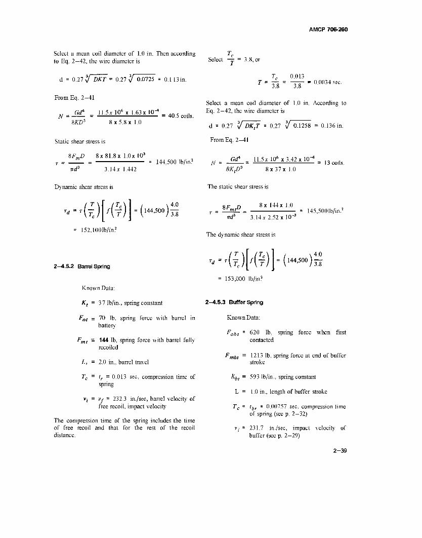
AMCP 706-260
Select a mean coil diameter of 1.0 in. Then according to Eq. 2—42, the wire diameter is
d = 0.27 % DKT = 0.27 % 0.0725 = 0.113i
From Eq. 2—41
N G<? _ 11.5A: 10* x 1.63x 10'
8£D3 8 x 5.8 x 1.0 40.5 coils.
Static shear stress is
%FmD 8x 81.8 x l.Ox 103
nd3 3.14* 1.442
Dynamic shear stress is
= 144,500 lb/in?
rd-r{~) /(f) =(H4,500)^
152,1001b/in2
2-4.5.2 Barrel Spring
Known Data:
Kt = 37 lb/in., spring constant
Fot = 70 lb, spring force with barrel in battery
Ffnt - 144 lb, spring force with barrel fully recoiled
L, = 2.0 in., barrel travel
Tc = tr =0.013 sec, compression time of spring
v;- = vr = 232.3 in./sec, barrel velocity of free recoil, impact velocity
The compression time of the spring includes the time of free recoil and that for the rest of the recoil distance.
Select — = 3.8, or
T = Tc 0.013
18 ~ 3.8 0.0034 sec.
Select a mean coil diameter of 1.0 in. According to Eq. 2—42, the wire diameter is
d = 0.27 y DKtT = 0.27 V 0.1258 = 0.136 i
FromEq. 2—41
N Gd* 11.5x 106 x 3.42x10'
13 coils. BKp* 8x37x1.0
The static shear stress is
%FmtD 8x 144x 1.0
nd3 3.14* 2.52 x 10"3
The dynamic shear stress is
145,500 lb/in.2
Td {{) f{i) -(l44'500)rs = 153,000 lb/in2
2-4.5.3 Buffer Spring
Known Data:
Fobs = 620 lb, spring force when first contacted
Fmbs = 1213 lb, spring force at end of buffer stroke
Kbs = 593 lb/in., spring constant
L = 1.0 in., length of buffer stroke
Tc = tbr = 0.00757 sec, compression time of spring (see p. 2—32)
v(- = 231.7 in./sec, impact velocity of buffer (see p. 2—29)
2-39
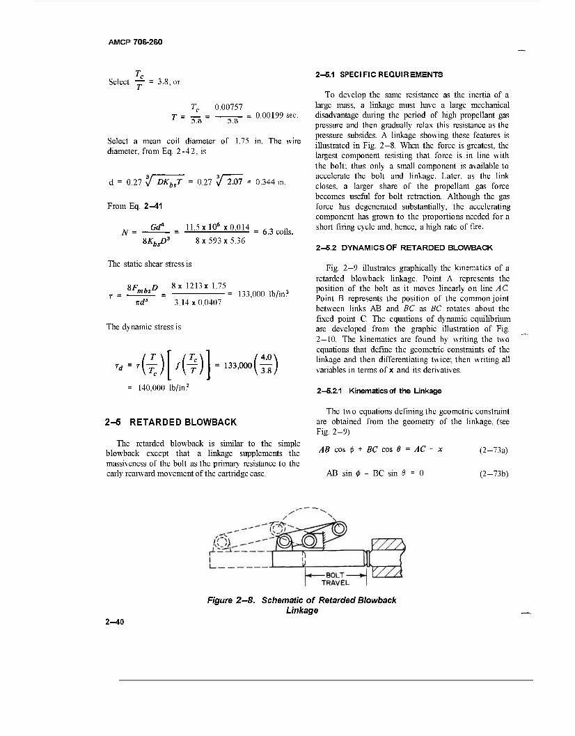
AMCP 706-260
Select — = 3.8, or
Tc 0.00757
3.8 3.8 = 0.00199 sec.
Select a mean coil diameter of 1.75 in. The wire diameter, from Eq. 2-42, is
d = 0.27 y DKbsT = 0.27 If 2.07 = 0.344 in.
From Eq. 2—41
„ GdA 11.5 xlO6 x 0.014 ,- ., N = = = 6.3 coils.
8KbsD3 8x593x5.36
The static shear stress is
8F u D 8x 1213 x 1.75 'mbi» = 133000 lb/in2
nd3 3.14x0.0407
The dynamic stress is
Td = T\ {TC) f{^) =133>000(IF)
140,000 lb/in?
2-6.1 SPECIFIC REQUIREMENTS
To develop the same resistance as the inertia of a large mass, a linkage must have a large mechanical disadvantage during the period of high propellant gas pressure and then gradually relax this resistance as the pressure subsides. A linkage showing these features is illustrated in Fig. 2—8. When the force is greatest, the largest component resisting that force is in line with the bolt; thus only a small component is available to accelerate the bolt and linkage. Later, as the link closes, a larger share of the propellant gas force becomes useful for bolt retraction. Although the gas force has degenerated substantially, the accelerating component has grown to the proportions needed for a short firing cycle and, hence, a high rate of fire.
2-5.2 DYNAMICS OF RETARDED BLOWBACK
Fig. 2-9 illustrates graphically the kinematics of a retarded blowback linkage. Point A represents the position of the bolt as it moves linearly on line AC. Point B represents the position of the common joint between links AB and BC as BC rotates about the fixed point C. The equations of dynamic equilibrium are developed from the graphic illustration of Fig. 2-10. The kinematics are found by writing the two equations that define the geometric constraints of the linkage and then differentiating twice; then writing all variables in terms of x and its derivatives.
2-5.2.1 Kinematics of the Linkage
2-6 RETARDED BLOWBACK
The retarded blowback is similar to the simple blowback except that a linkage supplements the massiveness of the bolt as the primary resistance to the early rearward movement of the cartridge case.
The two equations defining the geometric constraint are obtained from the geometry of the linkage, (see Fig. 2-9)
AB cos <(> + BC cos e = AC - x (2-73a)
AB sin 0 - BC sin 6 = 0 (2-73b)
Figure 2—8. Schematic of Retarded Blowback Linkage
2-40
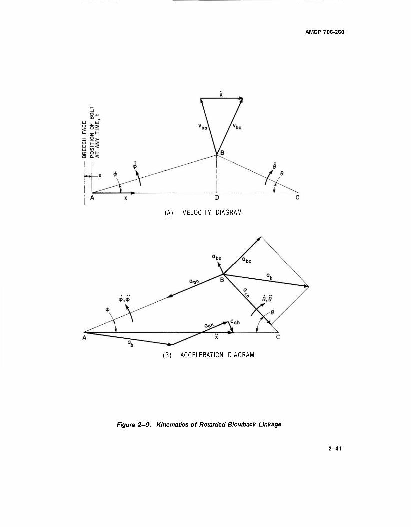
AMCP 706-260
(A) VELOCITY DIAGRAM
(B) ACCELERATION DIAGRAM
Figure 2-9. Kinematics of Retarded Blowback Linkage
2—41
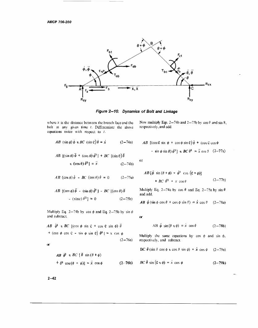
AMCP 706-260
Figure 2-10. Dynamics of Bolt and Linkage
where x is the distance between the breech face and the Now multiply Eqs. 2-74b and 2-75b by cos 0 and sin 8, bolt at any given time t. Differentiate the above respectively,and add. equations twice with respect to t.
AB (sin0)0 tBC (sine)ö = x (2-74a) AB [(cose sin 0 + cos0 sine)0 + (cose cos0
- sin 0 sin 0) 02] t BC 02 = x cos 0 (2-77a) /IB [(sin0)0 + (cos0)02] + BC [(sine)0
t (cos 0) 02 ] = x (2-74b)
/äß (cos 0)0 - ßC (cos 0)0 = 0 (2-75a)
/Iß [(cos 0) 0 - (sin 0) 02 ] - BC [(cos 0) 0
- (sine)0'2] = 0 (2-75b)
Multiply Eq. 2-74b by cos 0 and Eq. 2-75b by sin 0 and subtract.
AB 02 t BC [(cos 0 sin e + cos e sin 0) 0
+ (cos 0 cos e - sin 0 sin e) 02] = x cos 0
AB [0 sin (0+0) + 02 cos (e + 0)]
+ BC 0'2 = x cos 6 (2-77b)
Multiply Eq. 2-74a by cos 0 and Eq. 2-75aby sin0 and add.
AB 0 (sin 0 cos 0 + cos 0 sin 0) = x cos d (2—78a)
or
AB 0 sin (0 10) = x cos 0 (2-78b)
or
AB 02 t BC [ 8 sin (0 + 0)
+ 02 cos (0 + 0)] = X COS 0
Multiply the same equations by cos 0 and sin 0, (2-76a) respectively, and subtract.
BC 0 (sin 0 cos 0 t cos 0 sin 0) = x cos 0 (2-79a)
(2-76b) BC 9 sin (e t0) = x cos 0 (2-79b)
2^t2
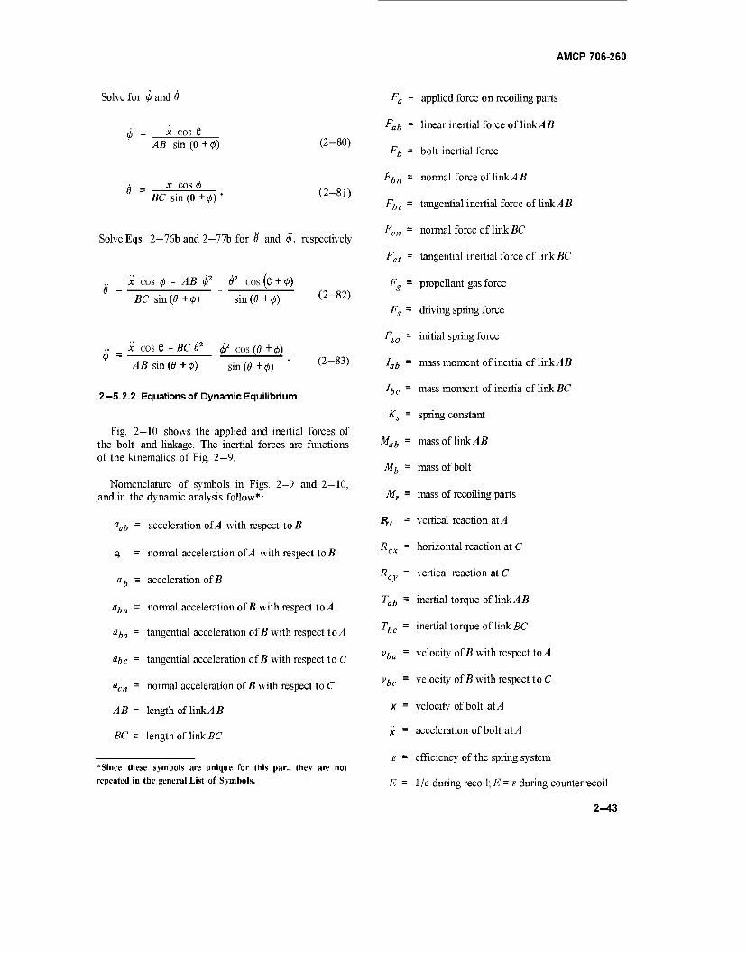
AMCP 706-260
Solve for 0 and 0
x cos e AB sin (0 + 0)
BC sin (0 + 0)
(2-80)
(2-81)
Solve Eqs. 2—76b and 2—77b for 0 and 0, respectively
x cos 0 - AB 02 02 cos (e + 0)
BC sin (0 + 0) sin (0 + 0) (2-82)
.. _ x cos e -BC62 02 cos (0 + 0)
.45 sin (0+0) sin (0+0)
2—5.2.2 Equations of Dynamic Equilibrium
(2-83)
Fig. 2—10 shows the applied and inertial forces of the bolt and linkage. The inertial forces are functions of the kinematics of Fig. 2—9.
Nomenclature of symbols in Figs. 2—9 and 2—10, ,and in the dynamic analysis follow*-
aab - acceleration of A with respect to B
a, = normal acceleration of A with respect to B
ab = acceleration of B
abn = normal acceleration of B with respect to A
aba = tangential acceleration of B with respect to/1
abc - tangential acceleration of £ with respect to C
acn = normal acceleration of B with respect to C
AB = length of link/1 B
BC = length of link BC
*Since these symbols are unique for this par., they are not repeated in the general List of Symbols.
Fa-- : applied force on recoiling parts
Fab - : linear inertial force of link/1 B
Fb - : bolt inertial force
Fbn - normal force of link/1 B
Fbt = tangential inertial force of link/15
F = ' en normal force of link BC
Fat = tangential inertial force of link BC
pg
= propellant gas force
Fs = driving spring force
F = 1 so initial spring force
lab = mass moment of inertia of link A B
he = mass moment of inertia of link BC
&s- spring constant
Mab = mass of link A B
Mb ~- mass of bolt
Mr = mass of recoiling parts
*,, = vertical reaction at/1
Rcx = horizontal reaction at C
RCy = vertical reaction at C
Tab* inertial torque of link A B
Tbc = inertial torque of link i?C
vba = velocity of B with respect to A
vbc = velocity of B with respect to C
X = velocity of bolt at A
X ~ acceleration of bolt at/1
E = efficiency of the spring system
E = 1 /e during recoil; E = E during counterrecoil
2-43
AMCP 706-260
6 = angle of BC with horizontal
0 = angular velocity of BC, shown positive
8 = angular acceleration of BC, shown positive
(j> = angle of AB with horizontal
0 = angular velocity of AB, shown positive
<t> = angular acceleration of AB, shown positive
To achieve equilibrium in the dynamic system, the applied forces and reactions of Fig. 2-10 are equated to the inertial forces. The reactions of the linkage ABC are computed by balancing the moments and forces of the complete system or of any individual link. The inertia forces and moments of each component are expressed in terms of the respective accelerations.
Fab = Kbx
Fb = Mbx
Fbn = Mab
Fbt = Mab
Fcn - Mbc
(4?)*
Fct = Mbc
Tab ~ 7ai<
Tbc = he*
(f)*
(2-84a)
(2-84b)
(2-84c)
(2-84d)
(2-84e)
(2-840
(2-84g)
(2-84h)
*C;K = \Tab - Tbc ~ Fab\—)^n(t> + (—)Fbt
- FenAB sin (6/0)
* Fct f AB cos (9 / 0) ■■ "Y 1 MC (2-85)
ÄCÄ, the horizontal reaction at C, is found by isolating link BC and equating the applied moment to the inertial moment.
„ (MB 1 RCXBC sinfl - R„ BC cos 6 = Tbc - ^«^"^
(2-86)
= cose + Tbc Fct _ 0 o7, " e^ 51/ie BCsinS 2 sine ^^ ;
The general equation for determining the dynamics of the system consists of the applied horizontal forces and reactions, and the horizontal components of the inertial forces. The inertial moments and vertical force components are not directly involved although they are needed to establish the general equation.
Fs - EFS - Rcx = Mrx- Fbn cos0 - Fht sin 0
* Fcn cos 8 + Fcn sine (2-88)
where
Fs = E(Fso + Ktf
R,,, the vertical reaction at C (Fig. 2—10) is found by computing the moments about A and dividing by length AC.
Mr = Mab + Mb
Eq. 2—88 may be solved by numerical integration after the variables 0, 8, 0, 0 are written in terms of x and x.
2-6.2.3 Digital Computer Program for the Dynamic Analysis
A digital computer program is compiled in FORTRAN IV language for the UNIVAC 1107 computer. The various parameters are solved for each one of many small increments of time into which the recoil and counterrecoil periods are divided. The
2^14
AMCP 706-260
solution follows the procedure of the Runge-Kutta-Gill Method of numerical integration. The program listing is in Appendix A-3; the corresponding Flow Chart in Appendix A—4.
Because Eq. 2—88 becomes extremely unwieldly when the appropriate expressions are substituted for <j>, Q ,4>,6, simple coefficients are introduced in sequence to represent the cumbersome expressions. The continued substitution eventually leads to an equation of simple terms. The list of coefficients that follow are determined from Eqs. 2-80 to 2-83.
C\ = cos <p/BC sin (0 + 0)
Cl = - ABjBC sin (6 t 0)
C3 = -cos (6+0)/sin (6 + 0)
C4 = cos0//45sin(6 + 0)
C5 = - BC/AB sin (6 t 0)
C6 = C2 • C42 + C3 • Cl2
C7 = CS-C12 + c3-C42
Rewrite Eqs. 2—80 to 2—83 by inserting the proper coefficient.
0 = C4x (2-89a)
e = Clx (2-89b)
e = Clx + C6x2 (2-89c)
0 = C4x + Clx2 (2-89d)
Rewrite Eq. 2-85
Rcv = E 3 (C4x + Clx2 ) - E4X cy
E5 • Cl2x2 + E6(Clx + C6x2) (2-90a)
where
E\ = Mab • AB 12
E2 = Mbc • BC/2
E3 = (Iob + E\ • ABj2)lAC
E4 = El sin MAC
E5 = E2 • AB sin (6 + 4>)IAC
E6 = \E2[ABCOS (6 + 0) + BC/2] - Ibc /AC
Collect terms and assign new coefficients
Rcy = CSx + C9x2
(2-90b)
where
C8 = E3- C4 - E4 + E6-C1
C9 = E3-C7 - E5 • Cl2 t E6 ■ C6
Rewrite Eq. 2—87
" \ sin 0 I \ sin 0 /
+ E7(Clx+ C6i2)/sin8
Rcx = C\0x+C\2x2
(2-91a)
(2-91b)
where
be E2 E1 = lc
CIO = (C8cos0+E7-Cl)/sin0
C12 = (C9 cos 6 + E7-C6)/sin0
Recall Eq. 2—88, solve for F and insert appropriate coefficients.
Fg = Mrx - El(C4x + Clx2) sin0
- E 1 • C42 x2 cos 0
+ E2(Clx+ C6x2)smS +E2-Clx2 cos0
+ ClOx' + C\2x2 - E(F0 - Ksx) (2-92)
2-45
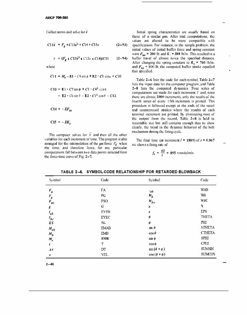
AMCP 706-260
Collect terms and solve for*
CU'x = Fg+Cl3x2 + C\4 + C\5x (2-93)
x = (Fgt Cl3x21 C\5x t C14)/C11 (2-94)
where
CU = Mr -El • C4sin0 + E2 ■ C\ sine + CIO
C13 = El • C7sin0 + C\ • C42 cos<£
- E2 • C6sintf - E2 • Cl2 cose - CT2
C14
C15
EF„,
EK.
The computer solves for x and then all the other variables for each increment of time. The program is also arranged for the interpolation of the gas force Fg when the time, and therefore force, for any particular computations fall between two data points selected from the force-time curve of Fig. 2-7.
Initial spring characteristics are usually based on those of a similar gun. After trial computations, the values are altered to be more compatible with specifications. For instance, in the sample problem, the initial values of initial buffer force and spring constant were Fso = 200 lb and K, = 388 lb/in. This resulted in a buffer travel of almost twice the specified distance. After changing the spring constant to Ks = 760 lb/in. and Fso = 800 lb, the computed buffer stroke equalled that specified.
Table 2-6 lists the code for each symbol, Table 2-7 lists the input data for the computer program, and Table 2-8 lists the computed dynamics. Four series of computations are made for each increment / and, since there are almost 2000 increments, only the results of the fourth series of every 15th increment is printed. This procedure is followed except at the ends of the recoil and counterrecoil strokes where the results of each terminal increment are printed. By eliminating most of the output from the record, Table 2-8 is held to reasonable size but still contains enough data to show clearly, the trend in the dynamic behavior of the bolt mechanism during the firing cycle.
The final time (at increment / = 1889) of t sec shows a firing rate of
60 t
0.067
/. = — = 895 rounds/min.
TABLE 2-6. SYMBOL-CODE RELATIONSHIP FOR RETARDED BLOWBACK
Symbol Code Symbol Code
*ab
he KS
M, ab Mb Mr
I
At
v
FA
FG
FSO
G
EYEB
EYEC
SK
EMAB
EMB
EMR
T
DT
VEL
'ab Wb Wbc X
e
6
<t> sinö
COS0
SÜ10
cos#
sin (0+0)
cos(0 +0)
WAB
WB
WBC
X
EPS
THETA
PHI
STHETA
CTHETA
SPHI
CPHI
SUMSIN
SUMCOS
2-46
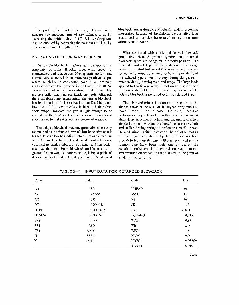
AMCP 706-260
The preferred method of increasing this rate is to increase the moment arm of the linkage, i. e., by decreasing the initial value of AC. A lower firing rate may be attained by decreasingthe moment arm, i. e., by increasing the initial length of AC.
2.6 RATING OF BLOWBACK WEAPONS
The simple blowback machine gun, because of its simplicity, outranks all other types with respect to maintenance and relative cost. Moving parts are few, and normal care exercised in manufacture produces a gun whose reliability is considered good, i. e., ordinary malfunctions can be corrected in the field within 30 sec. Take-down, cleaning, lubricating, and reassembly requires little time and practically no tools. Although these attributes are encouraging, the simple blowback has its limitations. It is restricted to small caliber guns, low rates of fire, low muzzle velocities, and, therefore, short range. However, the gun is light enough to be carried by the foot soldier and is accurate enough at short ranges to make it a good antipersonnel weapon.
The delayed blowback machine gun is almost as easily maintained as the simple blowback but its relative cost is higher. It has a low to medium rate of fire and a medium to high muzzle velocity. The delayed blowback is not confined to small calibers. It outranges and has better accuracy than the simple blowback and, because of its greater fire power, is more versatile, being capable of destroying both materiel and personnel. The delayed
blowback gun is durable and reliable, seldom becoming inoperative because of breakdown except after long usage, and can quickly be restored to operation after ordinary malfunction.
When compared with simple and delayed blowback guns, the advanced primer ignition and retarded blowback types are relegated to second position. The retarded blowback type, because it depends on a linkage system to control bolt recoil that is extremely sensitive to geometric proportions, does not have the reliability of the delayed type either in theory during design, or in practice during development and usage. The large loads applied to the linkage while in motion adversely affects the gun's durability. From these aspects alone the delayed blowback is preferred over the retarded type.
The advanced primer ignition gun is superior to the simple blowback because of its higher firing rate and lower recoil momentum. However, favorable performance depends on timing that must be precise. A slight delay in primer function, and the gun reverts to a simple blowback without the benefit of a massive bolt and stiffer driving spring to soften the recoil impact. Delayed primer ignition creates the hazard of extracting the cartridge case while subjected to pressures high enough to blow up the case. Although advanced primer ignition guns have been made, one by Becker, the exacting requirements in design and construction of gun and ammunition reduce this type almost to the point of academic interest only.
TABLE 2-7. INPUT DATA FOR RETARDED BLOWBACK
Code Data Code Data
AB
AZ
BC
DT
DTFG
DTNEW
EPS
FS1
FS2
G
N
7.0 NHEAD
12.9985 NPO
6.0 N9
0.000025 SKI
0.0000625 SK2
0.00026 TCHANG
0.50 WAB
63.0 WB
800.0 WBC
386.4 XLM
3000 XREC
XBATY
630
15
96
3.8
760.0
0.045
0.85
8.0
1.5
9.0
9.95859
0.010
2-47
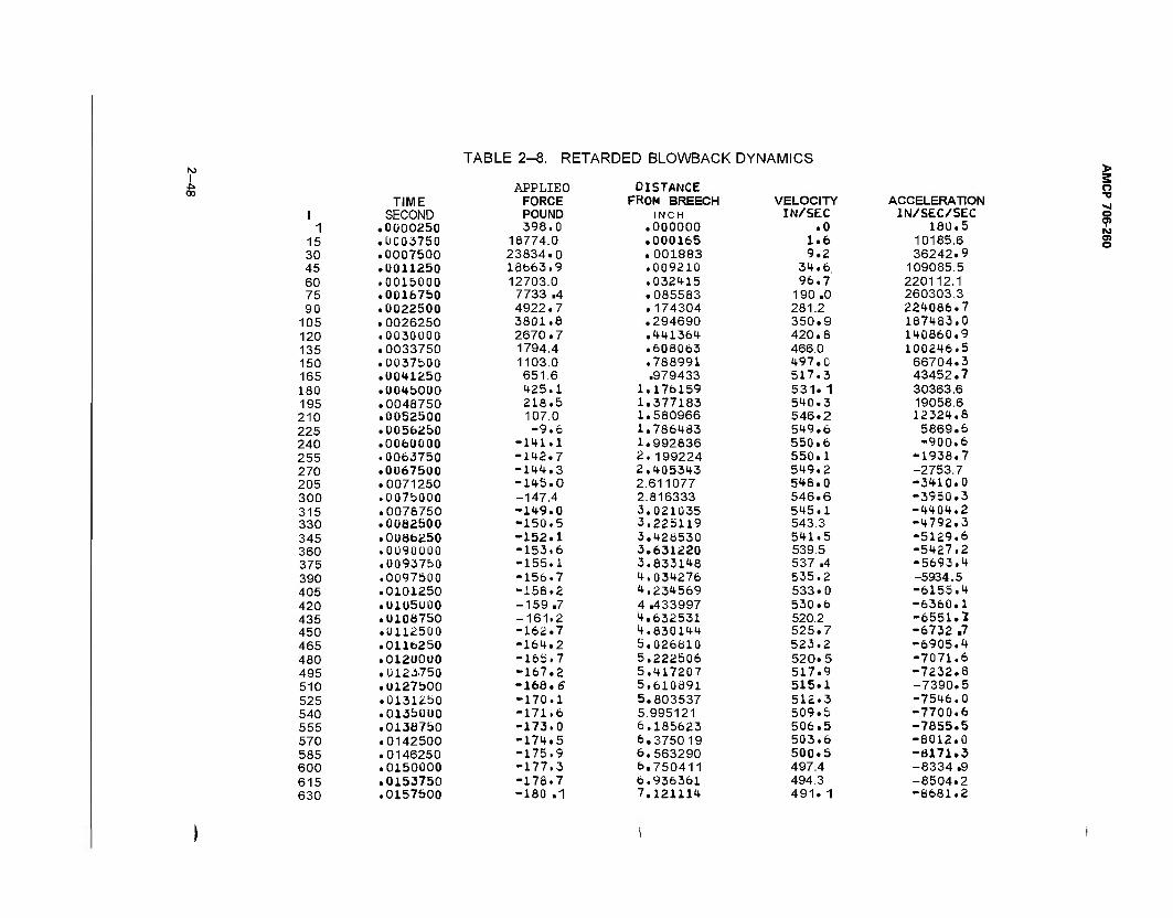
TABLE 2-8. RETARDED BLOWBACK DYNAMICS I
APPLIEO DISTANCE TIME FORCE FROM BREECH VELOCITY ACCELERATION
I SECOND POUND INCH IN/SEC IN/SEC/SEC 1 .0000250 398.0 .000000 .0 180.5
15 .0003750 18774.0 .000165 1.6 10185.6 30 .0007500 23834.0 .001883 9.2 36242.9 45 .0011250 18fa63.9 .009210 34.6 109085.5 60 .0015000 12703.0 .032415 96.7 220112.1 75 .0016750 7733 .4 .085583 190 .0 260303.3 90 .0022500 4922.7 .174304 281.2 224086.7
105 .0026250 3801.8 .294690 350.9 187483.0 120 .0030000 2670.7 .441364 420.8 140860.9 135 .0033750 1794.4 .608063 466.0 100246.5 150 .0037500 1103.0 .788991 497.0 66704.3 165 .0041250 651.6 .979433 517.3 43452.7 180 .0045000 425.1 1.176159 531.1 30363.6 195 .0048750 218.5 1.377183 540.3 19058.6 210 .0052500 107.0 1.580966 546.2 12324.8 225 .0056250 -9.6 1.786483 549.6 5869.6 240 .0060000 -141.1 1.992836 550.6 -900.6 255 .0063750 -142.7 2.199224 550.1 *1938.7 270 .0067500 -144.3 2.405343 549.2 -2753.7 205 .0071250 -145.0 2.611077 548.0 -3410.0 300 .0075000 -147.4 2.816333 546.6 -3950.3 315 .0078750 -149.0 3.021035 545.1 -4404.2 330 .0082500 -150.5 3.225119 543.3 -4792.3 345 .01)86250 -152.1 3.428530 541.5 -5129.6 360 .0090000 -153.6 3.631220 539.5 -5427.2 375 .0093750 -155.1 3,833148 537 .4 -5693.4 390 .0097500 -156.7 4.034276 535.2 -5934.5 405 .0101250 -158.2 4.234569 533.0 -6155.4 420 .0105000 -159 .7 4 .433997 530.6 -6360.1 435 .0106750 -161.2 4.632531 520.2 -6551.7. 450 .0112500 -162.7 4,830144 525.7 -6732 .7 465 .0116250 -164.2 5.026810 523.2 -6905.4 480 .0120000 -165.7 5.222506 520.5 -7071.6 495 .0123750 -167.2 5.417207 517.9 -7232.8 510 .0127500 -166.6 5.610891 515.1 -7390.5 525 .0131250 -170.1 5.803537 512.3 -7546.0 540 .0135000 -171.6 5.995121 509.5 -7700.6 555 .0136750 -173.0 6.185623 506.5 -7855.5 570 .0142500 -174.5 6.375019 503.6 -8012.0 585 .0146250 -175.9 6.563290 500.5 -8171.3 600 .0150000 -177.3 6.750411 497.4 -8334 .9 615 .0153750 -178.7 6,936361 494.3 -8504.2 630 .0157500 -180 .1 7,121114 491. 1 -8681.2
> 3 o -o »J o 0> to o> o
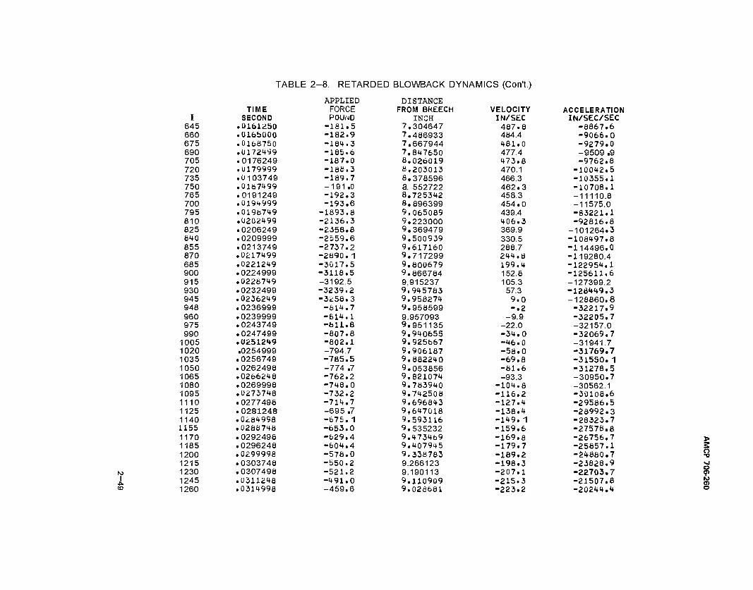
I CO
TABLE 2 -8. RETARDED BLOWBACK DYNAMICS (Con't.)
APPLIED DISTANCE TIME FORCE FROM BREECH VELOCITY ACCELERATION
I SECOND POUND INCH IN/SEC IN/SEC/SEC 645 .0161250 -181.5 7.304647 487.8 -8867.6 660 .0165000 -182.9 7.486933 484.4 -9066.0 675 .0168750 -184.3 7.667944 481.0 -9279.0 690 .0172499 -185.6 7,847650 477.4 -9509 .9 705 .0176249 -187.0 8.026019 473.8 -9762.8 720 .U179999 -188.3 8,203013 470.1 -10042.5 735 .0103749 -189.7 8.378596 466.3 -10355.1 750 .01871+99 -1 91 .0 a. 552722 462.3 -10708.1 765 .0191249 -192.3 8.725342 458.3 -11110.8 700 .0194999 -193.6 8.896399 454.0 -11575.0 795 .0198719 -1893.8 9.065089 439.4 -83221.1 810 .0202499 -2136.3 9.223000 406.3 -92816.8 825 .0206249 -2358.8 9.369479 369.9 -101264.3 840 .0209999 -2559.6 9.500939 330.5 -108497.8 855 .0213749 -2737.2 9.617160 288.7 -114496.0 870 .0217499 -2890. 1 9.717299 244.8 -119280.4 685 .0221249 -3017.5 9.800679 199,4 -122954.1 900 .0224999 -3118.5 9.866784 152.8 -125611.6 915 .0228749 -3192.5 9,915237 105.3 -127399.2 930 .0232499 -3239.2 9.945783 57.3 -12Ö449.3 945 .0236249 -3256.3 9.958274 9.0 -128860,8 948 .0236999 -614.7 9.958599 -.2 -32217.9 960 .0239999 -614.1 9.957093 -9.9 -32205.7 975 .0243749 -fall.8 9.951135 -22.0 -32157.0 990 .0247499 -807.8 9,940655 -34.0 -32069.7
1005 .0251249 -802.1 9.925867 -46.0 -31941.7 1020 .0254999 -794.7 9.906187 -58.0 -31769.7 1035 .0256749 -785.5 9.882240 -69.8 -31550. 1 1050 .0262498 -774 .7 9.053856 -81.6 -31278.5 1065 .0266248 -762.2 9.821074 -93.3 -30950.7 1080 .0269998 -748.0 9.783940 -104.8 -30562.1 1095 .0273748 -732.2 9.742508 -116,2 -30108.6 1110 .0277498 -714.7 9.696843 -127.4 -29586.5 1125 .0281248 -695 .7 9,647018 -138.4 -28992.3 1140 .0284998 -675. 1 9.593116 -149. 1 -28323.7 1155 .0286748 -653.0 9.535232 -159.6 -27578.8 1170 .0292498 -629.4 9,473469 -169.8 -26756.7 1185 .0296248 -604.4 9.407945 -179.7 -25857.1 1200 .0299998 -578.0 9.338783 -189.2 -24880.7 1215 .0303748 -550.2 9.266123 -198.3 -23828.9 1230 .0307498 -521.2 9.190113 -207.1 -22703.7 1245 .0311248 -491.0 9.110909 -215.3 -21507,8 1260 .0314998 -459.6 9.028681 -223.2 -20244.4
> 2 o -o >l o <p IO
©
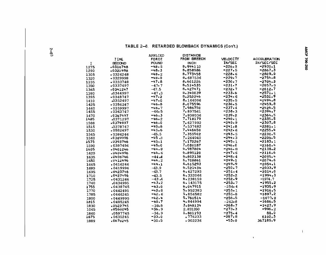
I o
TABLE 2- -8. RETAF
APPLIED 7IME FORCE
I SECOND POUND 1275 .0318748 -48.5 1290 .0322498 -48.3 1305 .0326248 -48.2 1320 .0329998 -48.0 1335 .0333748 -47.8 1350 .0337497 -47.7 1365 .0341247 -47.5 1380 .0344997 -47.3 1395 .0348747 -47.2 1410 .0352497 -47.0 1425 .0356247 -46.8 1440 .0359997 -46.7 1455 .0363747 -46.5 1470 .0367497 -46.3 1485 .0371297 -46.2 1500 .0374997 -46.0 1515 .0378747 -45.8 1530 .0582497 -45.6 1545 .0386246 -45.5 1560 .0389996 -45 .3 1575 .0393746 -45.1 1590 .0397496 -45.0 1605 .0401246 -44.8 1620 .0404996 -44.6 1635 .0408746 -44.4 1650 .0412496 -44.2 1665 .0416246 -44.1 1680 .0419996 -43.9 1695 .0423746 -43.7 1710 .0427496 -43.5 1725 .0431246 -43.4 1740 .0434995 -43.2 1755 .0438745 -43.0 1770 .0442495 -42.8 1785 .0446245 -42.6 1800 .0449995 -42.4 1815 .0485245 -40.7 1830 .0522745 -38.8 1045 .0560245 -36 e 9 1860 .0597745 -34,9 1675 .0635245 -33.0 1889 .067U245 -31.5
RETARDED BLOWBACK DYNAMICS (Con't.)
DISTANCE FROM BREECH
INCH 8,944110 8.856986 8.773458 8.687536 8.601226 8.514535 8.427471 Ö.340039 8.252246 8.164096 8.075596 7.986750 7.897561 7.808036 7.718179 7.627992 7.537482 7.446650 7.355502 7.264040 7.172267 7.080187 6.987804 6.895120 6.802138 6,708861 6.615293 6.521436 6.427293 6.332066 6.238159 6.143175 6.047915 5.952383 5.856582 5,760514 4.844994 3.848134 2.831350 1.801193 .776233 .002236
'ELOC] TY IN/SEC -226. 5 -227. 5 -228. 6 -229. 7 -230. 7 -231. 7 -232. 7 -233. 6 -234. 6 -235. 5 -236. 5 -237. 4 -238. 3 -239. 2 -240. 1 -240. 9 -241. 8 -242. 6 -243. 5 -244. 3 -245. 1 -246. 0 -246. 8 -247. 6 -248. 4 -249. 1 -249 9 -250. 7 -251 4 -252 .2 -252 .9 -253. .7 -254 .4 -255 .1 -255 6 -256 .5 -262 8 -268 7 -273. 3 -275. 4 -267. 8 -53. 0
ACCELERATION IN/SEC/SEC
-2930.1 -2867.3 -2809.0 -2754.8 -2704.3 -2657.0 -2612.7 -2571.1 -2531.9 -2494.8 -2459.8 -2426.5 -2394.7 -2364.5 -2335.5 -2307.8 -2281.1 -2255.4 -2230.5 -2206.5 -2183.1 -2160.4 -2138.2 -2116.6 -2095.4 -2074.6 -2054.1 -2033.9 -2014.0 -1994.3 -1974.7 -1955.2 -1935.9 -1916.5 -1897.2 -1877.8 -1686.5 -1427.9 -996.2
88.0 6102.3
367185.9
> S o •a
9 O) O
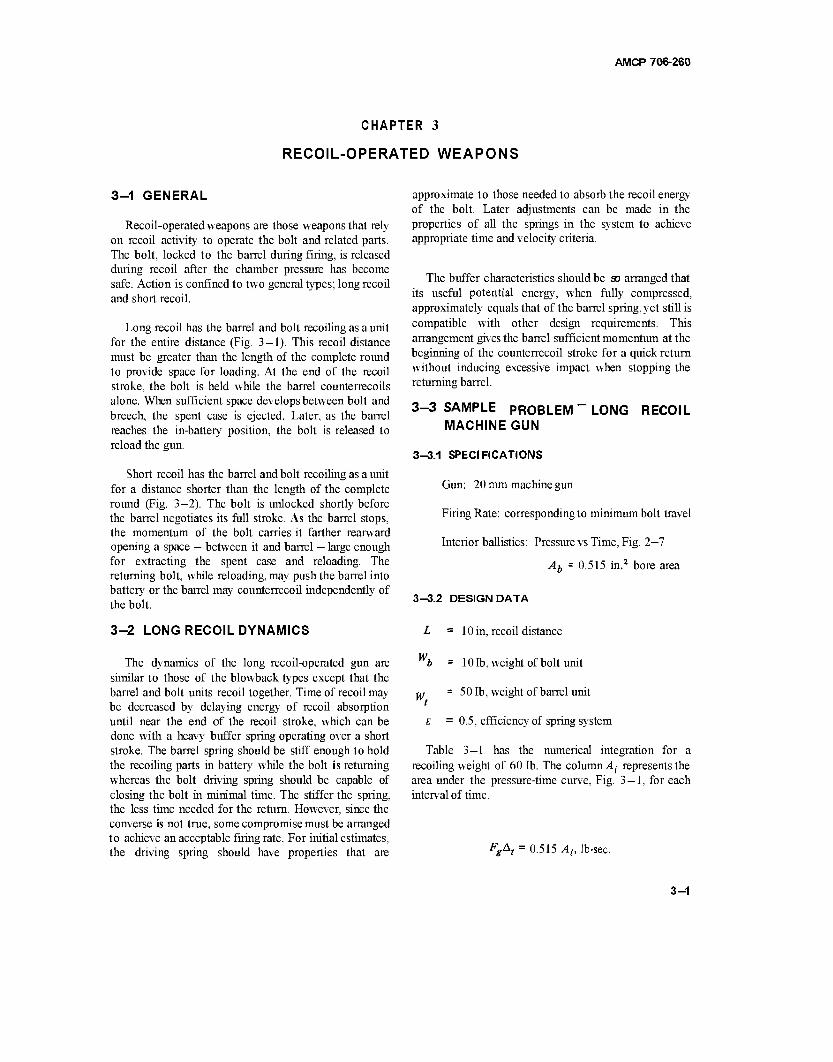
AMCP 706-260
CHAPTER 3
RECOIL-OPERATED WEAPONS
3-1 GENERAL
Recoil-operated weapons are those weapons that rely on recoil activity to operate the bolt and related parts. The bolt, locked to the barrel during firing, is released during recoil after the chamber pressure has become safe. Action is confined to two general types; long recoil and short recoil.
Long recoil has the barrel and bolt recoiling as a unit for the entire distance (Fig. 3-1). This recoil distance must be greater than the length of the complete round to provide space for loading. At the end of the recoil stroke, the bolt is held while the barrel counterrecoils alone. When sufficient space develops between bolt and breech, the spent case is ejected. Later, as the barrel reaches the in-battery position, the bolt is released to reload the gun.
Short recoil has the barrel and bolt recoiling as a unit for a distance shorter than the length of the complete round (Fig. 3—2). The bolt is unlocked shortly before the barrel negotiates its full stroke. As the barrel stops, the momentum of the bolt carries it farther rearward opening a space — between it and barrel — large enough for extracting the spent case and reloading. The returning bolt, while reloading, may push the barrel into battery or the barrel may counterrecoil independently of the bolt.
3-2 LONG RECOIL DYNAMICS
The dynamics of the long recoil-operated gun are similar to those of the blowback types except that the barrel and bolt units recoil together. Time of recoil may be decreased by delaying energy of recoil absorption until near the end of the recoil stroke, which can be done with a heavy buffer spring operating over a short stroke. The barrel spring should be stiff enough to hold the recoiling parts in battery while the bolt is returning whereas the bolt driving spring should be capable of closing the bolt in minimal time. The stiffer the spring, the less time needed for the return. However, since the converse is not true, some compromise must be arranged to achieve an acceptable firing rate. For initial estimates, the driving spring should have properties that are
approximate to those needed to absorb the recoil energy of the bolt. Later adjustments can be made in the properties of all the springs in the system to achieve appropriate time and velocity criteria.
The buffer characteristics should be S3 arranged that its useful potential energy, when fully compressed, approximately equals that of the barrel spring, yet still is compatible with other design requirements. This arrangement gives the barrel sufficient momentum at the beginning of the counterrecoil stroke for a quick return without inducing excessive impact when stopping the returning barrel.
3-3 SAMPLE PROBLEM MACHINE GUN
LONG RECOIL
3-3.1 SPECIFICATIONS
Gun: 20 mm machine gun
Firing Rate: corresponding to minimum bolt travel
Interior ballistics: Pressure vs Time, Fig. 2-7
Ab = 0.515 in.2 bore area
3-3.2 DESIGN DATA
L = 10 in, recoil distance
10 lb, weight of bolt unit
50 lb, weight of barrel unit
0.5, efficiency of spring system
Wi
w.
Table 3—1 has the numerical integration for a recoiling weight of 60 lb. The column A^ represents the area under the pressure-time curve, Fig. 3 — 1, for each interval of time.
FgAt = 0.515 At lb-sec.
3-1
AMCP 706-260
COUNTERRECOILING
WWW^
^T^4s <* I-/
i
FULLY RECOILED
§kdlHp^
IN BATTERY ~ ■ \WWWWWVW\WWWWW\WWV\|
■* -BOLT OVERTRAVEL
BOLT LOCK
fa eh ah ß> tu et eh
Aw \~v&\ ^^uuvu^Vsvws SAW^1
A]W V W W © © © © &
-BOLT LATCH N LOCK RELEASE
BARREL SPRING
Figure 3-1, Schematic of Long Recoil System
UNLOCKING CAM- -BOLT LOCK
/////////////^///A^
UNLATCHING CAMS
BARREL LATCH ACCELERATING r.AM
Figure 3-2. Schematic of Short Recoil System
3-2
AMCP 706-260
TABLE 3-1. RECOIL TRAVEL OF 20 mm GUN
t, At, Ai> FgAt, Av, V, va. Ax, msec msec Ib-sec/in.2 lb-sec in./sec in./sec in./sec in.
0.25 0.25 3.44 1.77 11.4 11.4 5.7 0.0014
0.50 0.25 10.15 5.24 33.7 45.1 28.2 0.007 1
0.75 0.25 11.89 6.13 39.5 84.6 64.8 0.0 162
1.00 0.25 11.12 5.74 37.0 121.6 103.1 0.0258
1.25 0.25 9.25 4.76 30.6 152.0 131.9 0.0330
1.50 0.25 7.10 3.76 24.2 176.4 159.3 0.0398
1.75 0.25 5.23 2.69 17.3 193.7 185.0 0.0462
2.00 0.25 3.71 1.91 12.6 206.3 200.0 0.0500
2.25 0.25 2.58 1.34 8.6 214.9 210.6 0.0526
2.50 0.25 1.82 0.94 6.1 221.0 218.0 0.0545
2.75 0.25 1.39 0.72 4.6 225.6 223.3 0.0558
3.00 0.25 1.06 0.55 3.5 229.1 227.4 0.0569
4.00 1.00 2.34 0.97 6.2 235.3 232.2 0.2322
5.00 1.00 1.04 0.40 2.6 237.9 236.6 0.2366
6.00 1.00 0.40 0.09 0.6 238.5 238.2 0.2382
Av = Fc (fHM^) FM
= 6.44 F At in./sec
where Wr - weight of recoiling parts
(v(n-i) + v ix = vaAt =y T )At, in.
The distance recoiled during the effective propellant gas pressure period
xr = 2AJC = 1.15 in.
The recoil velocity at this time is v = 238.5 in/sec (Table 3-1).
Three springs are in the system (Fig. 3—1). The bolt driving spring and barrel spring work in unison during recoil until the buffer spring is contacted; then all three work as a unit until the barrel and bolt come to a stop whereupon the bolt is latched, permitting the barrel
spring and buffer spring to force the barrel to counterrecoil. These two springs function as one until the buffer spring completes its short travel, thereafter the barrel spring alone continues to counterrecoil the barrel. Just as the barrel stops counterrecoiling, the bolt becomes unlatched and the driving spring closes it.
The energy of recoil is
1 / Wr \ 1 / 60 \
^=2(7Jv2=ll^6lJ56882
where
4416 in.-lb
g = 386.4 in./sec2
W = 60 lb, recoiling weight
v = 238.5 in./sec, velocity of recoil
Preliminary estimates of recoil time must be available to determine the spring characteristics. After an approximate recoil time has been established, some of
3-3
AMCP 706-260
the data used in early calculations may be altered for greater accuracy. A reasonable approach is achieved by absorbing 75% of the recoil energy before the buffer is reached thereby reducing the recoil velocity by 50% during the same period. Assigning more energy within limits to the buffer will increase the firing rate and conversely, less energy absorbed by the buffer will decrease the firing rate. The energy to be absorbed by the buffer is
Eb = 0.25 £, = 0.25x4416 = 1104 in.-lb
The recoil velocity as the buffer is contacted becomes
!2Eh
'* " V Mr V = 119.25 in./sec
7.20« x 386 4 2208 x 386.4
60 714220
The average force of the system which includes the driving, barrel, and buffer springs is
eEh 0.5 x 1104
0.5 11041b
where Lb = length of buffer stroke.
Fmb = Fas+025Kb = 1104+ 136 = 12401b
Fob = Fas-0.25Kb = 1104- 136 = 9681b.
The new compression time of the springs, Eq. 2—23, becomes
eMr . Fob Tc = \ /~P- Cos ~F~ = 0.0119x0.675 w Kb tmb
= 0.0080 sec.
By repeating the above process, Tc remains at 0.0080 sec and-Kft changes to 572 lb/in.
+ f(v<J Fmb ~ Fas + "£
Fob =Fas-\{KbLb) =
1104+ 143 = 12471b
1104- 143 = 9611b
Assume constant deceleration, then the recoil time from the end of the accelerating period to buffer contact will be
*r 2LA 16.7
v + vb 238.5+119.25 0.0467 sec
For constant acceleration, the buffing time and therefore the compression time of the springs is
2Lb 2 x 0.5 0.0084 sec. *c 'b Vb 119.25
The corresponding surge time is computed to be
T c T= 3$ =
0.0084
3.8 0.0022 sec.
From Eq. 2-67
KbT *•« + H'**)
1037
where £w = L- Lh-x = 10.0- 0.5 - 1.15 = 8.35 in.
v =238.5 in./sec, recoil velocity at end of acceleration
vb = 119.25 in./sec recoil velocity at start of buffing
The compression time of the springs includes the acceleratingtime and the buffing time.
Tc = ta + tr + tb = ft 006+ 0.0467 + 0.008
= 0.0607 sec.
1037 x 0.0022 Kfc = 1104 + 0.25 Kb The corresponding surge time is
K - -1104. = Afc ~ 3 fm - 543.6 lb/in., combined spring constant T. 0.0607
1 =3-8 -—- °-°160 S6C-
3-4
AMCP 706-260
The average combined force of the driving and barrel springs function as one spring. The combined minimum springs, based on 75%recoil energy absorption, becomes and maximum forces are
O.lSeE, 0,75x0.5x4416 F = F _ K I 1 L + \ —f^— = ZTl = 198.31b. os a s\ 2 d Tl
= 198.3- 16.7(4.175+1.15)= 198.3-88.9
= 109.41b
Fms = Fos+KsL = 109.4+ 16.7 x 10 = 276.41b
The combined spring forces at end of acceleration period and at the beginning of buffing are
Ks = Fos+K^r = 109.4+ 16.7 x 1.15 = 128.61b
F'ms = Fms - KsLb = 276.4 - 16.7 x 0.5 = 268 lb
Fa
3rdi rig to Eq. 2-67b,
8.35
Fm KJ = —— =
Fa + j(K^) 1037 1037
1037x0.016 K, = 198.3 + 4.175 A:
Ks = TrM = 16.0 lb/in. s 12.417
Fms~ ^a+4.175^ - 198.3+66.8 - 265.11b By setting the minimum driving spring force at F0 = 25 lb, the minimum barrel spring force becomes
Fos= Fa~ 4.175£j = 198.3-66.8= 131.51b p =F _F = 109.4-25.0 = 84.4 lb.
From Eq. 2"22 the time span between accelerating and Maintain the same ratio between sPnn§ constants » for
buffing is the initial forces. The driving and barrel spring constants become, respectively,
Ks \ Z m Z ) K =[-^- )K = \W9A 116.7= 3.8 lb/in.
= 0.0697 (Sin-' 0.8938 - Sin-' 0.4434) Fot \ / 84-4 . *' =
(F-K = IIÖ94 /167= 1291b/in-
= 0.0697x0.647 = 0.0451 sec \ os / \ )
where Z - \J Fos + eKsMrv0 - v 87948 - 296.6. The corresponding maximum forces are, respectively,
The new compression time becomes Fm = F0 + KL = 25 + 3.8x10 = 631b
Tc = ta +4 +tb = 0.006 + 0.0451+0.008 Fmt = p^ +K{L = 84.4+ 12.9x 10 = 213.41b.
= 0.0591 sec.
The spring constant of the buffer spring is Repeating the above Series of calculations has the time converging to tr = 0.044 sec, or Tc- 0.058 sec and K = 16.7 lb/in. Before buffing, the driving and barrel Kbs = Kb~ Ks = 572" 16-7 = 555.3 lb/in. s
3-5
AMCP 706-260
The buffer spring force at initial contact with recoiling parts is
Fob, = *ob-K» = 961 " 268 = 6931b.
At end of buffing, the maximum spring force is
Fmb,-Fmb- Fms= 1247~ 276.4 = 970.6 lb.
Table 3-2 lists design data and computed stresses for these three springs as well as for the springs of the three types of action employed in the short recoil gun. The calculations are based on the followingformulas.
d = 0.27 */ DKT, (Based onEq. 2-67a)
Cd^ N = , number of coils
8AD3
T = 2.55
Td ~ T,
FmD , static shear stress
Hs = dN, solid height
The available potential energy in the buffer spring for counterrecoil is
Ebc = ^(Fmbs +Fobs)Lb = T (970-6+693)0.5
= 208 in.-lb.
The available potential energy in the barrel spring for counterrecoil is
Et = \<Fmt + Fot)L = ^ (213.4 + 84.4)10
= 744.5 in.-lb.
The potential energy of the barrel spring that augments the buffer spring is
AEt = f(Fmt+F^t)Lb = Up (213.4 + 207)0.5
= 52.6 in.-lb.
where
F'mt = Fmt-KtLb = 213.4- 12.9x0.5 = 2071b.
The total energy of the counterrecoiling barrel at the end of buffer action becomes
Ecrb = Ebc + AEt = 260.6 in.-lb.
The corresponding velocity is
'2Ecrb /521.2X 386.4 v-»=v ^r = V—™— ■= s™* = 63.5in./sec.
The maximum energy of the counterrecoiling barrel is
Ecrt = Eb+Et = 208 + 744.5 = 952.5 in.-lb.
The maximum velocity attained by the bolt in counterrecoil is
, dynamic shear stress vcrt 2E. crt
M,
1905 x 386.4
50 = /14722
121.3 in ./sec.
The maximum energy of the counterrecoiling bolt is
Ecrd = | (Fm +Fo)L = ^ (63 + 25) 10
= 220 in.-lb.
The maximum velocity attained by the bolt in counter- recoil is
2E. crd Mb
130.4 in./sec
440 x 386.4
10 <yi7Ö02
The time elapsed from the propellant gas period until the buffer is reached, obtained from Eq. 2-51, will be
Vf(-% Sin T) tr = 0.0682(Sin-' 0.8904- Sin-' 0.4280)
= 0.0682(63.10-25.33)/57.3 = 0.045
3-6
AMCP 706-260
where
F^s = 128.6 lb ; F'ms = 268 lb
eMr
K.
0.5 x 60
16.7x 386.4 = 0.068 sec
Z = / (FÖsf + eKjarvl = 716538 t 73747
= 3011b
Ks = 16.7 lb/in.
E = 0.5
M,.»* = 2Er = 8832 in.-lb
The time elapsed during buffing, Eq. 2-23, becomes
'eMr
Kh
< F i_ COS- otr Fmb
/ 0.5x60 961
V 572x386.4 Cos"' 1247
= 7 0.0001357 Cos-' 0.7706 = 0.01 löf ^| j
= 0.008 sec.
The time elapsed for counterrecoil at the end of buffer activity is obtained from Eq. 2-27.
M,
crb -ye(Kbs+Kt) cos- Fobs + Fmi
Fmbs + Fmt
50 900 Cos"
0.5 x 568.2 x 386.4 11S4
= 0.0214 Cos-1 0.7601 = O.i
= 0.0151 sec.
>■«»" (ff)
Compute the time elapsed for the barrel to negotiate the remaining distance in counterrecoil according to Eq. 2-26.
'crt f3(
eKt\ Sin" - Sin"1
^)
0.1418 ISin-' (-0.3557)-Sin-' (-0.8723)1
= 0.1418 (339.17-299.27)/57.3 = 0.0987 sec
where [W ~ 1 5° VeKt Vo.5x 12.9x386.4
= 7 0.0201 = 0.1418 sec
Mv crb
= W207a + ( — J521.6 = v/56306 = 237.3 1b
The time elapsed for counterrecoil of the bolt, Eq. 2-27, is
lrr =\ "T" COS" ,cir
10
0.5x3.8x386.4
25
7 0.01362 Cos-' 0.3968
( 66.12 \ V 57.3 /
0.1167 0.1347 sec.
Time of cycle will be
tc = ta + tr + tb + tCrb + tcrt^[cr
= 0.006 t 0.045+ 0.008+ 0.0151 + 0.0987 10.1347
= 0.3075 sec
The rate of fire becomes
Jr * n 203« ' 195 rounds/min.
3-7
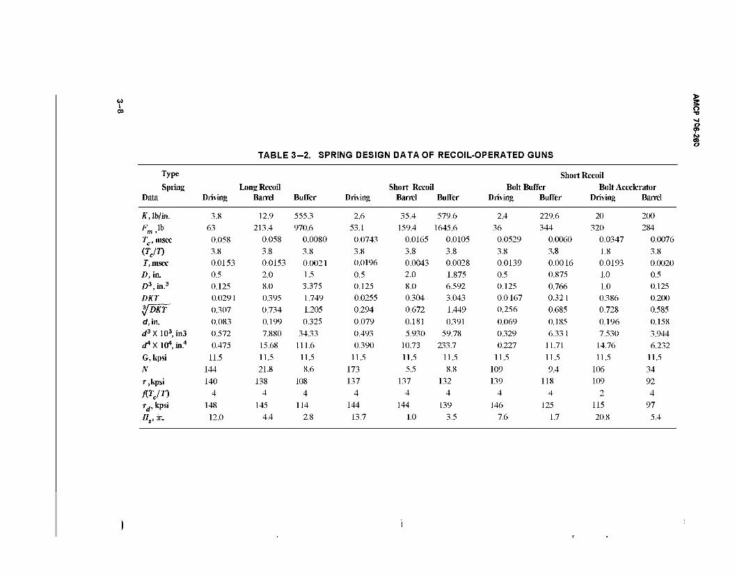
u I 00
TABLE 3-2. SPRING DESIGN DATA OF RECOIL-OPERATED GUNS
o ■a ■«j o 9> hi o> o
Type Short Recoil Spring Long Recoil Short Recoil Bolt Buffer Bolt Accelerator
Data Driving Barrel Buffer Driving Barrel Buffer Driving Buffer Driving Barrel
K, lb/in. 3.8 12.9 555.3 2.6 35.4 579.6 2.4 229.6 20 200
63 213.4 970.6 53.1 159.4 1645.6 36 344 320 284
Tc, msec 0.058 0.058 0.0080 0.0743 0.0165 0.0105 0.0529 0.0060 0.0347 0.0076
(TJT) 3.8 3.8 3.8 3.8 3.8 3.8 3.8 3.8 1.8 3.8
J,msec 0.0153 0.0153 0.0021 0.0196 0.0043 0.0028 0.0139 0.0016 0.0193 0.0020 D, in. 0.5 2.0 1.5 0.5 2.0 1.875 0.5 0.875 1.0 0.5 £>3,in.3 0.125 8.0 3.375 0.125 8.0 6.592 0.125 0.766 1.0 0.125
DKT 0.0291
0.307
0.395
0.734
1.749 1.205
0.0255
0.294
0.304
0.672
3.043
1.449
0.0 167 0.256
0.321
0.685 0.386 0.728
0.200
*JDKT 0.585
d, in. 0.083 0.199 0.325 0.079 0.181 0.391 0.069 0.185 0.196 0.158
</3X103,in3 0.572 7.880 34.33 0.493 5.930 59.78 0.329 6.331 7.530 3.944 ^XlO^in.4 0.475 15.68 111.6 0.390 10.73 233.7 0.227 11.71 14.76 6.232
G, kpsi 11.5 11.5 11.5 11.5 11.5 11.5 11.5 11.5 11.5 11.5
N 144 21.8 8.6 173 5.5 8.8 109 9.4 106 34
T,kpsi 140 138 108 137 137 132 139 118 109 92
fljjn 4 4 4 4 4 4 4 4 2 4
Td, kpsi 148 145 114 144 144 139 146 125 115 97
Hs,in. 12.0 4.4 2.8 13.7 1.0 3.5 7.6 1.7 20.8 5.4
AMCP 706-260
3-4 SHORT RECOIL DYNAMICS
The dynamics of the short recoil-operated gun approach those of the retarded blowback types more nearly than the long recoil. To eliminate all blowback tendencies, the bolt latch is not released until the propellant gas becomes ineffective. After unlatching, bolt and barrel continue recoiling, but as separate units. The barrel is arrested by the combined effort of the barrel spring and buffer. Having the same velocity of free recoil, but because it travels a much shorter distance than the bolt, the barrel will stop recoiling before the bolt. Both the bolt driving spring and buffer spring characteristics are determined from the recoil energy of the respective masses. The characteristics of the barrel spring are selected more arbitrarily but still must conform to the same initial load requirement as that for the long recoil barrel spring, i.e., sufficient to hold the barrel in battery.
To be compatible with allowable stresses, the spring characteristics must conform to computed data obtained from Eqs. 2—23 and 2—67b. When based on constant deceleration, the time required to stop the bolt in recoil
2iL ~ xr) 2x 8.85 vr ~ 238.5 =■ 0.0743sec.
Including the time of the effective gas period, the compression time of the driving spring is
Tc = t + ta = 0.0743+0.006= 0.0803sec.
The corresponding surge time will be
' = 0.0211sec. 3.8 Tr 0.0803
3.8
3-6 SAMPLE PROBLEM-SHORT RECOIL MACHINE GUN
3-5.1 SPECIFICATIONS: Identical to long recoil problem (see par. 3—3.1)
Apply Eq. 2—67b to compute the spring constant K.
KT Fm Fg+ 3"K(L-*,)
1037 1037
3-5.2 DESIGN DATA 21.881K = 41.6+4.425A
L = 10 in., minimum bolt travel distance
Wb = 10 lb, weight of bolt unit
Wt = 50 lb, weight of barrel unit
E = 0.5,efficiency of spring system
The numerical integration of Table 3—1 also applies to this problem, therefore, the distance recoiled during the effective pressure period of this propellant gas,jc,.= 1.15 in. and the corresponding recoil velocity v = 238.5 in./sec. The recoil energy of the bolt is
Erb =T(%V7 =T(3^4)56882= 736m"lb
The average force of the driving spring becomes
F = tE-rb a T _ «
L-x,
0.5 x 736
10.0-1.15 = 41.61b.
K = -^- - 2.41b/in. 17.456
Fm = Fa t 4.425Z = 41.6+ ID.6 = 52.21b
FÖ = Fa - 4.425K = 41.6- 10.6= 31.01b
The decelerating time, Eq. 2—23,is
31.0 eMb F^_ I 0.5 x 10
T C0S'
1~FZ
=\ 2.4X386.4
C0S"' ~2
0.0735X 0.935 = 0.0687sec.
The total compression time of the spring is
Tc = t + ta = 0.0687+0.006= 0.0747sec.
3-9
AMCP 706-260
Adjust the time and recompute Eqs. 2-67b and 2-23, the time and spring constant coverge to t =0.075 sec andK = 2.6 lb/in., respectively.
The time elapsed during bolt action may determine the firing rate, provided that the barrel returns to battery before the bolt recoils fully. The recoil energy of the barrel is
The maximum driving spring force Fm is
Fm = Fa + ^rK(L-xr) = 41.6+ 11.5 = 53.1 lb. *,, = T(^)=T(ä)56882
3680 in.-lb.
The driving spring force at x = 1.15 in. is
F'o = Fm~ K(L _ xr) = 531' 23° = 3(U lb-
The initial driving spring force is
F0 = Fm -KL = 53.1 - 26.0 = 27.1 lb.
The average buffing force, to be approximately the same as for the long recoil, should have a buffer travel of Z,6= 1.375 in.
According to Eq. 2-16 the average spring force during buffing is
According to Eq. 2-22 the time of bolt recoil is
tr=\l~T C0S ^~ Fm
0.5 x 10 30.1 cos-
2.6x386.4 53.1
. , / 55.47 \ yo.004976 Cos"1 0.5669 = 0.07061 -573- /
0.0683 sec.
eErt 0.5 x 3680 rflft 1.375
13381b.
Assume constant deceleration so that the time needed to stop the barrel during recoil becomes
2Lh 2.75 'rt 238.5
= 0.0115 sec.
This time is also the compression time Tc for the combined buffer and barrel springs. The surge time is
Tc 0.0115 T = -ZT = —TIT - 0.00302 sec.
3.8 3.:
According to Eq. 2-27, the time of bolt counterrecoil is Apply Eq. 2-67b to solve for the spring constant and correspondingforces.
^ Cos Tm
10 :V0' .5 x 2.6 x 386.4
Cos"1 27.1
53.1
/ / 59.3 \ y0.0199 Cos-' 0.5104 = 0.141l( -JJJ )
0.1459 sec.
= Fmb
F* +T lJ <b' L»)
KbT 1037 1037
3A32Kb = 1338 + 0.688 Kb
Kb = 1338 2.444 = 547 lb/in.
Fmb = 1338+ 0.688 Kb = 1338+376 = 17141b
Fob = 1338-0.688Kb = 1338- 376 = 9621b
3-10
AMCP 706-260
The decelerating time, Eq. 2-23, will be The barrel spring force at end of recoil is
Cos-1 Fob- Fmb
0.5 x 50 962 Cos"1
547x386.4 1714
Fmt=Fot +£,£, = 70 + 89.4= 159.41b.
The buffer spring constant is
Kbs = Kb - Kt = 615 - 35.4 = 579.6 lb/in.
= 0.0109 x 0.975 = 0.0106 sec.
By repeated computation, the time and spring constant quickly converge.
trt = 0.0105 sec
Kb = 615 lb/in.
Fob ~ Fab \{K»L») = 1338- 423 = 915 1b
Fmb = Fob+Kbh = 915+846 = 17611b
To realize an acceptable firing rate, the barrel spring force at firing is set as Fot = 70 lb, the initial barrel spring force.
The compression time includes the propellant gas period and becomes
Tc = f«+fa = 0.0105 t 0.006 = 0.0165 sec.
The surge time T = -r-%- = 0.00434 sec. 3.8
The appropriate spring constant is computed from Eq. 2-67b.
1037/C, T = Fm = Fot +K, L, = 70 + 2.525 Kt
where L, = Lb +xr = 1.375+ 1.15 = 2.525 in.
The barrel spring force at the end of the propellant gas period is
Ftb = Fot + Ktxr = 70 + 35.4x 1.15 = 110.71b.
The buffer spring force at the beginning of buffing is
^06* =Fob ~ Ftb = 915- 1107= 804.31b.
The maximum buffer spring force is
FmbS=Fmb-Fm, = 1761- 159.4= 1601.61b.
The time of barrel recoil from Eq. 2—22 becomes
K, 70
4.5 - 2.525 1.975
1 >eMt Fob r = A / Cos ' rt V
/
h Fmb
0,5 x50 915 =v 615 x 386.4 ■ COS-'
1761
70 35.4 lb/in.
y0.000105 Cos-' 0.5196 = 0.01025( JI^]
= 0.0105 sec.
The available energy released by the spring system at the end of buffer travel is
Ecrb = f (Fmb +Fob)h = " (1761+915) 1.375
= 920 in.-lb.
3-11
AMCP 706-260
The counterrecoil velocity at the end of buffer action becomes
"crb 2Ecrb / 1840x386.4
Mt 50 = y 14220
119.2 in ./sec.
The time consumed for counterrecoil by buffer action, Eq. 2-27, is
lcrb Mt x Fob
— Cos —— eK, rmb
50
0.5x615x386.4 Cos"1
915
1761
= y0.00042 Cos-' 0.5196 = 0.0205 (-^ j
The time of counterrecoil for the remaining barrel travel ofxr = 1.15 in. vial
0.0210 sec.
ot Sin-'
tb
0.0855 [Sin-1 (-0.1854) - Sin-' (-0.2934)]
0.0855 (349.32 - 342.93)/57.3 = 0.0095 sec
where Mt 50
eKt \l 0.5 x 35.4 x 386.4
= 0.0855 sec
y 0.00731
F*tb + T" Mvlrb
no.72 +2M 1840
= 377.5 lb
The time elapsed for the complete barrel cycle is
{ct = ra + lrt + tcrb + lcrt
= 0.0060 t 0.0105 10.0210 + 0.0095
= 0.0470 sec.
The time of the barrel cycle is considerably less than the recoil time of the bolt, tr = 0.0683 sec, and therefore has no influence on the firing cycle if its present operation remains undisturbed. The cyle time of the bolt is
= 0.0060+0.0683 + 0.1459 = 0.2202 sec.
The firing rate is
60 f = i£- /r t. 0.2202
272rounds/min.
This rate is faster than for long recoil (f = 195) but
slower than the recoil-operated delayed blowback gun (fr = 420). The rate of the short recoil gun can be improved by resorting to a softer driving spring and the addition of a bolt buffer. The time of bolt travel will then be less in both directions thereby increasing the rate of fire. For example, to initiate the computations, select a driving spring having these preliminary characteristics:
F0 = 12 lb (2 lb greater than the 10 lb bolt weight)
K = 1.0 lb/in., preliminary spring constant
Lb = 0.5 in., buffer travel
3-12
AMCP 706-260
The driving spring force when the buffer is reached becomes
Fdb = F0 +K(L~Lb) = 12+1 x9.5 = 21.5 lb.
The initial driving spring force at x = 1.15 in. is
F = F0 + Kxr = 12+ !.15 = 13.15 lb
The total time of driving spring compression will be
Tc = ta+td + tb = 0.0507 sec.
The spring surge time T =T7T = 0.0133 sec, 3.0
The required spring constant that supersedes the preliminaryK = l.Oiscomputed fromEq. 2—67b.
The energy absorbed during this period will be
1
F + KLj 13.2 + &.35K
Ed =te (F+Fdb)Ld =1
= 289 in. -lb
^j(34-65)835
where
Ld = L- Lb~ xr = 10.0 - 0.5 - 1.15 = 8.35 in.
The energy to be absorbed by the combined effort of buffer and driving springs is
Eb = Erb - Ed = 736- 289 = 447 in-lb
KT = 1037 1037 1037
K = 13.}9-28.35 = 2.4 Mm.
The spring forces at the limits of Ld are
Fd = FQ+Kxr = 12.0 +2.4 x 1.15 = 14.8 1b
Fdb = Fo +K(L ~ Lb) = 120+ 2A x 9-5 = 34-8 lb-
The time for this driving spring to compress from the propellant gas period to the buffer is obtained from Eq. 2-22.
The velocity of the bolt as it contacts the buffer is also the buffer velocity vb during recoil.
2Eh / 894 x 386.4
Mh 10 \/34544
= 7&5.9in./sec
The time during this decelerating period, based on constant deceleration, is
(
Sin"1- rfft-Sin-' —
= 0.0735 Sin-' 0.7807- Sin-' 0.3318
= 0.0735 (51.18- 19.28)1 57.3 = 0.0409 sec
where
2Ld 2x8.35
v + vb 238.5 t 185.9 0.0393 sec. K
0.5 x 10
2.4 x 386.4 = yj 0.00539 = 0.0735 sec
Buffing time, based on constant deceleration, is
2Lb 2 x 0.5 tb = ~v^ = 185.9
0.0054 sec
Z = N/' Fd +eKMbv2
= s/ 219 + 0.5 x 2.4 x 1472 = 44.6 lb
Mbv2 = 2Erb = 1472in.-lb.
3-13
AMCP 706-260
tj is somewhat higher than the initial Tc= 0.0507 sec. Repeating the computation establishes these values. To continue the analysis of the spring system, compute the energy to be absorbed by the buffer system
Eb ~ Erb Fd+Fdb
\LH = 736 - 414 = 3221b
where
Ld = 8.35 in.
E = 0.5
KbT : 1037
Fm Fas + i(L»K^)= Fas + 0.25Kb
1037 1037
1037x0.00158£6 = 322 +0.25 £$
**" S=2321b/to- Fob = 322 - 0.25 Kb = 264 lb
Fmb = 322+ 0.25 Kb = 3801b.
The average buffer spring system is
F = "s L
eEb 0.5 X322
0.5 322 lb.
The velocity at buffer contact is
vb = Mh
157.7 in ./sec.
644 x 386.4
10 724884
According to Eq. 2-23, the buffing time will be
Cos —— K mb
0.5 x 10 264
232 x 386.4 cos" 380
IQ"3,/55-78 Cos-' 0.6947 = 0.00747x0.803
For constant deceleration, the time of buffer action in recoil and also the compressiontime of the spring is
2Lb 2x0.5 Tc - lb ~ vu 157.7
0.0063 sec.
0.0060 sec
which verifies that tb = 0.0060 sec and fixes the spring constant at Kb = 232 lb/in. The spring constant of the buffer spring alone becomes
The surge time T = T-— = 0.0016 sec. 3.8
Kbs = Kb-K = 232- 2.4 = 229.6 lb/in.
Iterative computation has the spring characteristics converging rapidly. The computed buffer time, according to the procedure which follows, was 0.006 sec. Thus Tc = tb = 0.006 sec and T= 0.00158 sec.
Fobs = Fas- 0.25Kb-Fdb = 322- 58 - 34.
= 229.2 lb
The spring constant is computed from Eq. 2-67b. F„h,+Kh,Lh = 229.2+114.8 = 3441b. mbs ~ robs^^bs^b
3-14
AMCP 706-260
The recoil time of the bolt and, therefore, the Time of the complete cycle is compression time of the driving spring is
[rb L + ts + th 0.006C+ 0.0409+ 0.0060
= 0.0529 sec.
{c = fa + *d + h + tcrb + t„
= 0.0060+ 0.0409+ 0.0060+ 0.0120+ 0.0916
= 0.1565 sec.
The time of bolt return from buffing action, Eq. 2—27, is
The rate of fire is
b rob COS-' — -0.0149x0.803
tmb
0.012sec.
The energy of the moving bolt at the end of buffer return is
Ecrb = \<Fob + Fmb) h = "T (™ + 264) 0.5
= 80.5in.-lb.
The time elapsed for completing the bolt return, Eq. 2—26,becomes
10 / -12 - 34.8>
0.5x2.4x386.4 lSm 44.54 ~ Sl" 44.54 i
= 0.1468(344.37-308.62)/57.3 = 0.0916sec
where
*db +{f)Mv^b =W34.82+|TT)161 m = ^1984 - 44.541b.
- _ 60 _ _fiQ_ ■''' t, 0.1565
383rounds/min.
This rate is an increase of 28% over the rate of the gun which does not have a buffer for the bolt.
3-6 ACCELERATORS
Recoil-operated machine guns are relatively slow firing because of their slow response to the propellant gas forces. This slow response is due primarily to the large inertial resistance that must be overcome while accelerating the recoiling parts. The entire dynamics structure depends on the velocity of free recoil; the higher the velocity, the higher the rate of fire, but the velocity of free recoil can be influenced only by the mass of the recoiling parts which, for any given gun, is usually limited by structural requirements. High speeds, therefore, must be gained by other means. One of these, as demonstrated in the preceding problem, involves the arrangement of springs whereby somewhat faster action develops by delaying large energy absorption until the buffer is reached. This constitutes the extent of control over firing rates of long recoil guns. However, for short recoil guns, higher rates can be achieved by installing accelerators.
An accelerator, Fig. 3—3, is merely a rotating cam arranged to transfer, over a short distance, some momentum from the rest of the recoiling parts to the bolt, thus augmenting its velocity. At any given instant, the cam and the two masses represent a rotating system. From the law of conservation of angular momentum, the total remains unchanged after an exchange of momentums.
Mvlrb = 2Ecrb = 161 m,lb.
rtMtv + rbMbv = rtMtvt + rbMbvb
where g = acceleration of gravity
M = if , mass of bolt
(3-1)
3-15
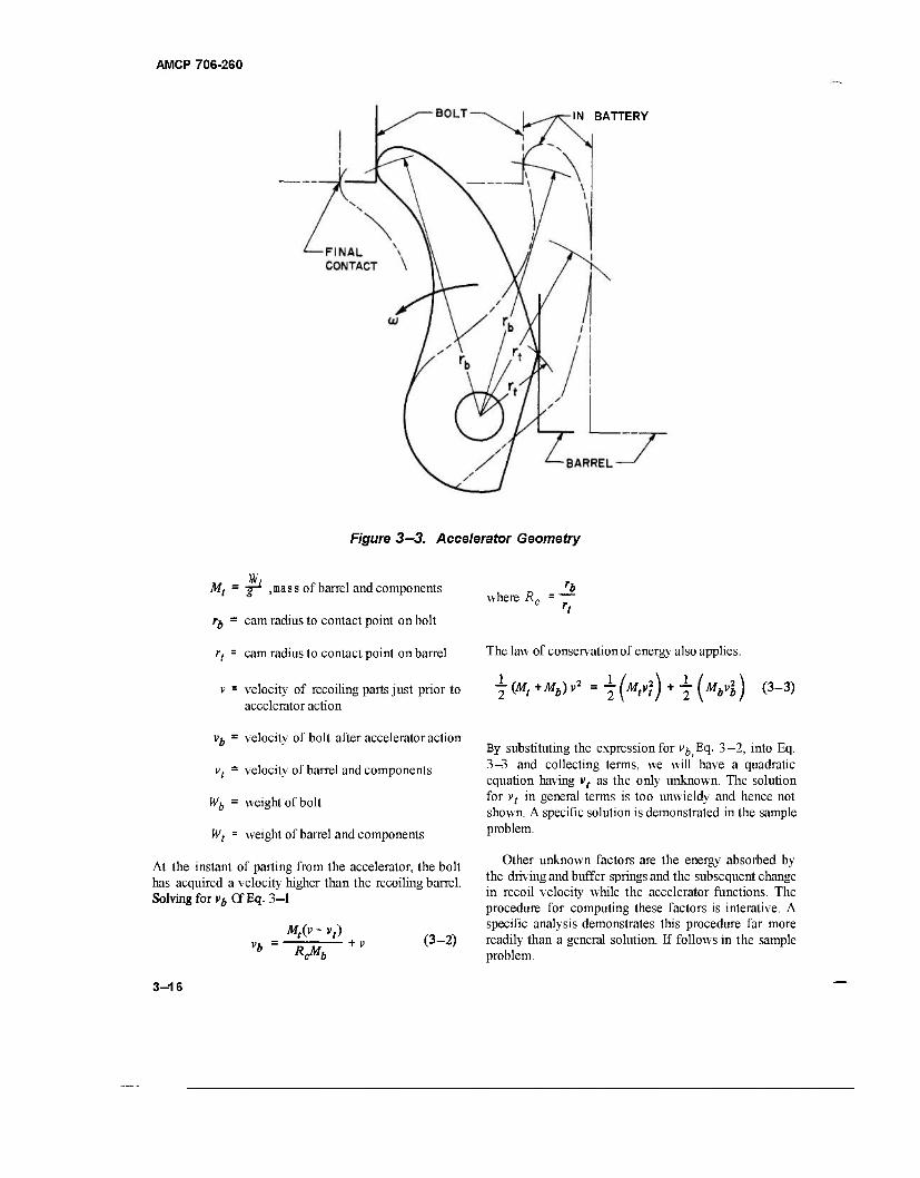
AMCP 706-260
IN BATTERY
Figure 3—3. Accelerator Geometry
Mt = jr1 ,mass of barrel and components
ff, = cam radius to contact point on bolt
rt = cam radius to contact point on barrel
v - velocity of recoiling parts just prior to accelerator action
vb = velocity of bolt after accelerator action
vt - velocity of barrel and components
Wfr = weight of bolt
Wt = weight of barrel and components
At the instant of parting from the accelerator, the bolt has acquired a velocity higher than the recoiling barrel. Solving for vb Of Eq. 3—1
where R^ rb
Mt(y - vt) (3-2)
The law of conservation of energy also applies.
\ (Mt +Mb) v2 = \ (W,v?) + 7 [MA ) 0-3)
By substituting the expression for v^Eq. 3—2, into Eq. 3—3 and collecting terms, we will have a quadratic equation having v( as the only unknown. The solution for vt in general terms is too unwieldy and hence not shown. A specific solution is demonstrated in the sample problem.
Other unknown factors are the energy absorbed by the driving and buffer springs and the subsequent change in recoil velocity while the accelerator functions. The procedure for computing these factors is interative. A specific analysis demonstrates this procedure far more readily than a general solution. If follows in the sample problem.
3-16
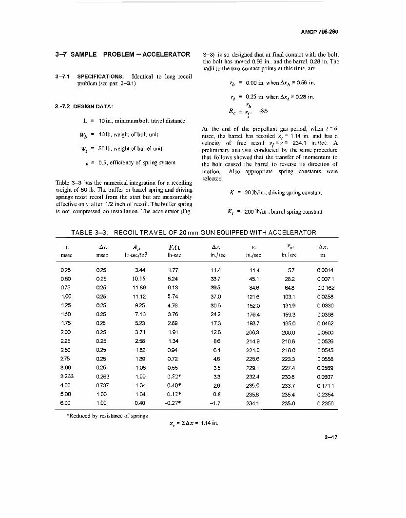
AMCP 706-260
3-7 SAMPLE PROBLEM-ACCELERATOR
3-7.1 SPECIFICATIONS: Identical to long recoil problem (see par. 3-3.1)
3-7.2 DESIGN DATA:
L = 10 in., minimum bolt travel distance
Wb = 101b, weight of bolt unit
Wt = 501b, weight of barrel unit
e = 0.5, efficiency of spring system
Table 3—3 has the numerical integration for a recoiling weight of 60 lb. The buffer or barrel spring and driving springs resist recoil from the start but are measureably effective only after 1/2 inch of recoil. The buffer spring is not compressed on installation. The accelerator (Fig.
3—3) is so designed that at final contact with the bolt, the bolt has moved 0.56 in, and the barrel, 0.28 in. The radii to the two contact points at this time, are
rb = 0.90 in. when Axb = 0.56 in.
rt = 0.25 in. when Axt = 0.28 in.
R, 3.6
At the end of the propellant gas period, when t = 6 msec, the barrel has recoiled xr= 1.14 in. and has a velocity of free recoil iy=i>= 234.1 in./sec. A preliminary analysis, conducted by the same procedure that follows showed that the transfer of momentum to the bolt caused the barrel to reverse its direction of motion. Also, appropriate spring constants were selected.
K = 20 lb/in., driving spring constant
Kt = 200 lb/in., barrel spring constant
TABLE 3-3. RECOILTRAVEL OF 20mm GUN EQUIPPED WITH ACCELERATOR
t, A?, AV FA% Av, V, V Ax,
msec msec lb-sec/in? lb-sec in./sec in./sec in./sec in.
0.25 0.25 3.44 1.77 11.4 11.4 5.7 0.0014
0.50 0.25 10.15 5.24 33.7 45.1 28.2 0.0071
0.75 0.25 11.89 6.13 39.5 84.6 64.8 0.0 162
1.00 0.25 11.12 5.74 37.0 121.6 103.1 0.0258
1.25 0.25 9.25 4.76 30.6 152.0 131.9 0.0330
1.50 0.25 7.10 3.76 24.2 176.4 159.3 0.0398
1.75 0.25 5.23 2.69 17.3 193.7 185.0 0.0462
2.00 0.25 3.71 1.91 12.6 206.3 200.0 0.0500
2.25 0.25 2.58 1.34 8.6 214.9 210.6 0.0526
2.50 0.25 1.82 0.94 6.1 221.0 218.0 0.0545
2.75 0.25 1.39 0.72 4.6 225.6 223.3 0.0558
3.00 0.25 1.06 0.55 3.5 229.1 227.4 0.0569
3.263 0.263 1.00 0.52* 3.3 232.4 230.8 0.0607
4.00 0.737 1.34 0.40* 2.6 235.0 233.7 0.1711 5.00 1.00 1.04 0.12* 0.8 235.8 235.4 0.2354
6.00 1.00 0.40 -0.27* -1.7 234.1 235.0 0.2350
*Reduced by resistance of springs x. = 2Ax= 1.14 in.
3-17
AMCP 706-260
The energy absorbed by the springs during the bolt acceleration period reduced the recoil velocity to 225.4 in./sec. This velocity was obtained by iterative computation. The energy absorbed by the barrel spring is
The driving spring force at assembly is
AE,
143 in.-lb
Axt =| 228 + 284
2x0.5 0.28
F0 = Fm- KLd = 320- 200 = 1201b.
The energy absorbed by the driving spring force during acceleration is
166 in.-lb
Ft = Ktxr = 200 x 1.14 = 228 lb, barrel spring force at beginning of accelerator action
Fm t= Kt{xr t Ax) = 200( 1.14 + 0.28) = 284 lb barrel spring force at end of barrel travel
E = 0.5, efficiency of spring system.
The two preceding sets of calculations had the energy absorbed by the driving spring equalling 3948 and 3923 in.-lb, respectively. With the average E= 3936 in.-lb, the average driving spring force over the remaining recoil distance becomes
eE 0.5 x 3936 „,, . F = = ~ = 237 b
udr 8.3
where
Ldr = Ld-xr- Axb = 10.0-1.14-0.56 = 8.3 in.
where F = F0 +Kx, = 120+20 x 1.14 = 1431b.
The total recoil energy is
*' = T\^86Th 60x54803
4255 in.-lb. 772.8
The energy remaining in the moving parts is
E = Er- AEt - AEb = 4255- 143- 166
= 3946in.-lb.
The corresponding velocity becomes
IE 7892 x 386.4 60
^y 50824
= 225.4 in./sec
Mt (v _ vt) 50 (225.4 - vt) - D 77 + v = —rz—— + 225.4 vb = RcMb 3.6 x 10
= 538.5- 1.39»,
The driving spring force at the end of acceleration is
Fe = Fa - Y(KLdr) = 237" 83 = 1541b-
The driving spring force at the end of recoil is
Fm = Fa + ^-( KLdr ) = 237+ 83 = 320lb.
3-18
v\ = 289982- 1497.0 V, + 1.932 v)
To solve for vr multiply all terms by g and equate the equivalent energies
386.4 x 3946 = 25 v] + 5 (289982- 1497 vt
+ 1.932 vf)
v) - 215.95 V,- 2158.8 = 0
9.57 in./sec.
The low negative velocity indicates a direction change near the end of the accelerating process.
vb = 538.5- 1.39v, = 538.5 t 13.3 = 551.8 in./sec.
Compute the energy of bolt and barrel
Eb = Y(Mbvb )= (^f?)304483 = 3940ia-Ib
^=T(^2)=(™)92 = 6in-n .-lb
AMCP 706-260
The time elapsed during recoil, which is the compression time of the barrel spring, is
hr = fab+ta = 0.0014 + 0.0060 = 0.0074 sec
where ta = 0.0060 sec, the propellant gas period.
The time elapsed during bolt recoil, which is the compression time of the driving spring, is
tr = tbr + trb = 0.0074 + 0.0271 = 0.0345 sec.
The time for the bolt to return as far as the latched barrel, Eq. 2-27, is
E = Eb tEt = 3946in.-lb
This energy compares favorably with the earlier computed energy of 3946 in.-lb thereby rendering the last computed data substantially correct.
The time of bolt acceleration period is
lcrb
Mh
Ä Cos-17r
10
0.5 x 20x386.4 cos-
148.4
320
Lb 2Ax, 2x0.56 1.12
:l v+vb 225.4+551.8 ~ 777.2
0.0014 sec.
= 7 0.002588 Cos"1 0.4638
= 0.0S08f ly3^ J = 0.0553 sec
The time of bolt decelerating period during recoil, Eq. 2-23, is
trb = K CoS Fm
0.5 x 10 154
20x386.4 C0S" 320
y 0.000647 Cos-' 0.4812 = 0.0254 y~j—
0.0271 sec.
where F = FQ + K(XAx + Ax,) = 120 + 20 x 1.42
= 148.4 lb, the driving spring force as the barrel latch is released.
The energy of the bolt at this time is
Eh = 6 F +F 1 m *
— J(L- SAx-Ax,)
0.5\ 320+148.4 78.58 = 1004.7 in.-lb.
3-19
AMCP 706-260
The bolt velocity at barrel pick-up is
"erb l2Eb 12009.4 x 386.4 ;
\h^=v—iö—i/™
278.6 in ./sec.
The velocity of all counterrecoiling parts after the barrel is engaged by the bolt, according to the conservation of momentum, is
Mbvcrb ( 278.6 v. cr Mr (*?)- 101 — 1= 46.4 in/sec.
With both springs acting as a unit, the combined spring constant is
Ks = K tKt = 201 200 = 220 lb/in.
The spring force at the time of impact is
Fs =F + Fmt = 148.4+284 = 432.41b.
The spring force at the end of counterrecoil, since the barrel spring force reduces to zero, is
F0 = 120 lb.
According to Eq. 2-26, the time elapsed for completing the recoiling parts return is
Mr I -fo ~Fs '"=\/lFlSiirl —'S™1 ~
I 60 / Q. „, ^120 -v / 0.5 x 220 x 386.4 I Sin 578
JO , ^U2J. 578 bm 578
0.0376( 348%-i1^)= 0.0239»
3-20
AMCP 706-260
where
-J her) F^
*"'*«(*) 2153
= yf 334070 = 578 lb.
The time consumed for the firing cycle is
lc ~ ldr + {crb + lcr
- 0.0345 +0.0553+0.0239 = 0.1137 sec.
The rate of fire
fr = bO
0.1137 "528 rounds/min.
Recapitulating, the firing rates of the various types of recoil-operated guns are shown in the table which follows. HD. guns are identical except for the type of automatic action.
Type
Blowback
Long Recoil
Short Recoil (without bolt buffer)
Short Recoil (without bolt buffer)
Short Recoil (with accelerator)
Rate of Fire, rounds/min
420
195
272
383
528
3-8 RATING OF RECOIL-OPERATED GUNS
The recoil-operated machine guns are idealy suited for large caliber weapons. Their inherent low rate of fire keeps them out of the small caliber field but, for large calibers, the firing rate is relatively high and therefore acceptable. Of the two types involved, the long recoil is superior to some extent although the short recoil has a higher firing rate. Both have the same range but the long recoil is more accurate because the high loading accelerations of the short recoil gun disturb the sighting. Also the higher accelerations require heavier feeders and correspondingly heavier associated parts. The large loads imposed to accelerate these components have a tendency to cause them to wear out faster, thus decreasing the reliability and durability of the weapon.
3-21/3-22
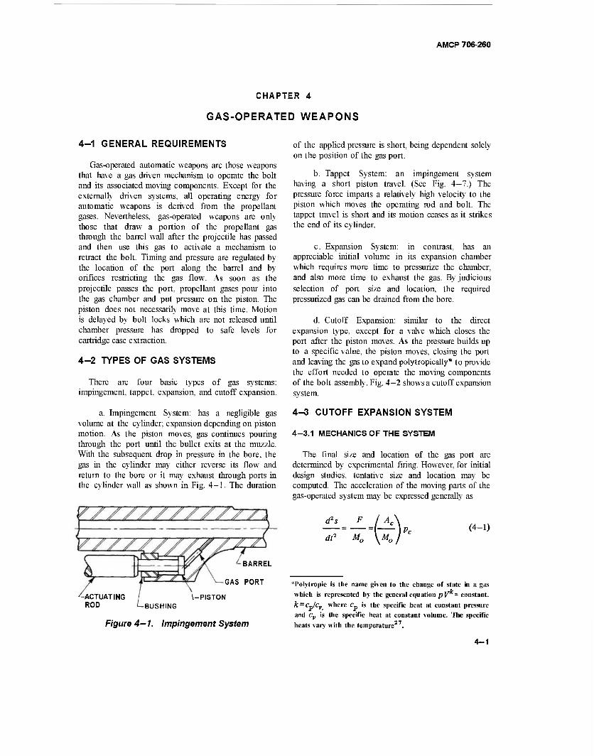
AMCP 706-260
CHAPTER 4
GAS-OPERATED WEAPONS
4-1 GENERAL REQUIREMENTS
Gas-operated automatic weapons are those weapons that have a gas driven mechanism to operate the bolt and its associated moving components. Except for the externally driven systems, all operating energy for automatic weapons is derived from the propellant gases. Nevertheless, gas-operated weapons are only those that draw a portion of the propellant gas through the barrel wall after the projectile has passed and then use this gas to activate a mechanism to retract the bolt. Timing and pressure are regulated by the location of the port along the barrel and by orifices restricting the gas flow. As soon as the projectile passes the port, propellant gases pour into the gas chamber and put pressure on the piston. The piston does not necessarily move at this time. Motion is delayed by bolt locks which are not released until chamber pressure has dropped to safe levels for cartridge case extraction.
4-2 TYPES OF GAS SYSTEMS
There are four basic types of gas systems: impingement, tappet, expansion, and cutoff expansion.
a. Impingement System: has a negligible gas volume at the cylinder; expansion depending on piston motion. As the piston moves, gas continues pouring through the port until the bullet exits at the muzzle. With the subsequent drop in pressure in the bore, the gas in the cylinder may either reverse its flow and return to the bore or it may exhaust through ports in the cylinder wall as shown in Fig. 4-1. The duration
BARREL
GAS PORT
-ACTUATING ROD
\-PISTON BUSHING
Figure 4— 1. Impingement System
of the applied pressure is short, being dependent solely on the position of the gas port.
b. Tappet System: an impingement system having a short piston travel. (See Fig. 4-7.) The pressure force imparts a relatively high velocity to the piston which moves the operating rod and bolt. The tappet travel is short and its motion ceases as it strikes the end of its cylinder.
c. Expansion System: in contrast, has an appreciable initial volume in its expansion chamber which requires more time to pressurize the chamber, and also more time to exhaust the gas. By judicious selection of port size and location, the required pressurized gas can be drained from the bore.
d. Cutoff Expansion: similar to the direct expansion type, except for a valve which closes the port after the piston moves. As the pressure builds up to a specific value, the piston moves, closing the port and leaving the gas to expand polytropically* to provide the effort needed to operate the moving components of the bolt assembly. Fig. 4-2 shows a cutoff expansion system.
4-3 CUTOFF EXPANSION SYSTEM
4-3.1 MECHANICS OF THE SYSTEM
The final size and location of the gas port are determined by experimental firing. However, for initial design studies, tentative size and location may be computed. The acceleration of the moving parts of the gas-operated system may be expressed generally as
d2s
di1 Mn Mn
(4-1)
*Polytropic is the name given to the change of state in a gas which is represented by the general equation pV - constant. k — cjcv where c„ is the specific heat at constant pressure and cv is the specific heat at constant volume. The specific heats vary with the temperature
4-1
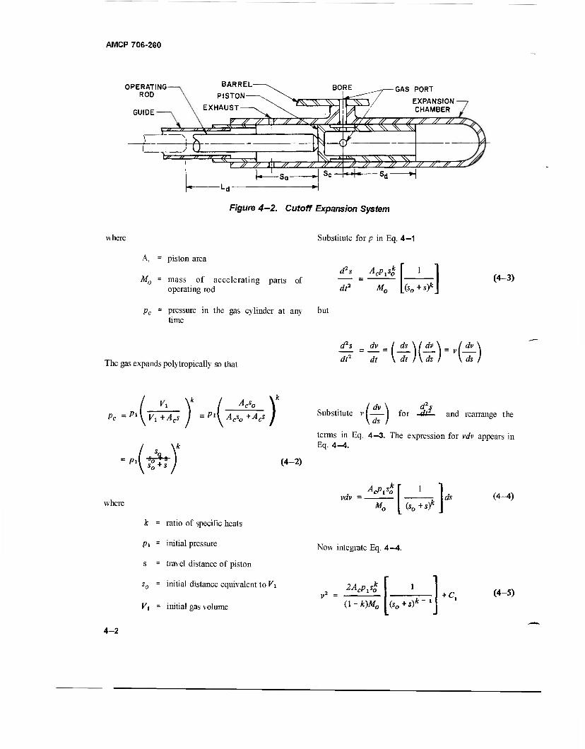
AMCP 706-260
OPERATING ROD
GUIDE
BARREL
PISTON
EXHAUST
BORE
" *» " \" "
±L-=rbL '1// tf u nv «i „ , |
Y ?? // Jl // // #
f4-¥
GAS PORT
EXPANSION CHAMBER
-Sa- Se fe^ » » » »
■sd—H > // // ^
F/gure 4-2. Cutoff Expansion System
where Substitute for p in Eq. 4—1
A, = piston area
d2s Acp^ M0 = mass of accelerating parts of
operating rod dt2 M„ (So**? (4-3)
pc = pressure in the gas cylinder at any but time
The gas expands polytropically so that dt2 dt \dt)\ck) V\d7j
Acso
Pc =Pl\ V,+Ac Pl\ Vo +Acs
p\rh
)' Substitute
\ds ) for and rearrange the
terms in Eq. 4—3. The expression for vdv appears in Eq. 4-4.
(4-2)
where vdv =
AcPjSo
(So+sT ds
k = ratio of specific heats
p\ = initial pressure Now integrate Eq. 4—4.
s = travel distance of piston
s0 = initial distance equivalent to Vt _ 2AcPA 1
Vi = initial gas volume (1 - k)M0 (*0+*)*-1 + c.
(4-4)
(4-5)
4-2
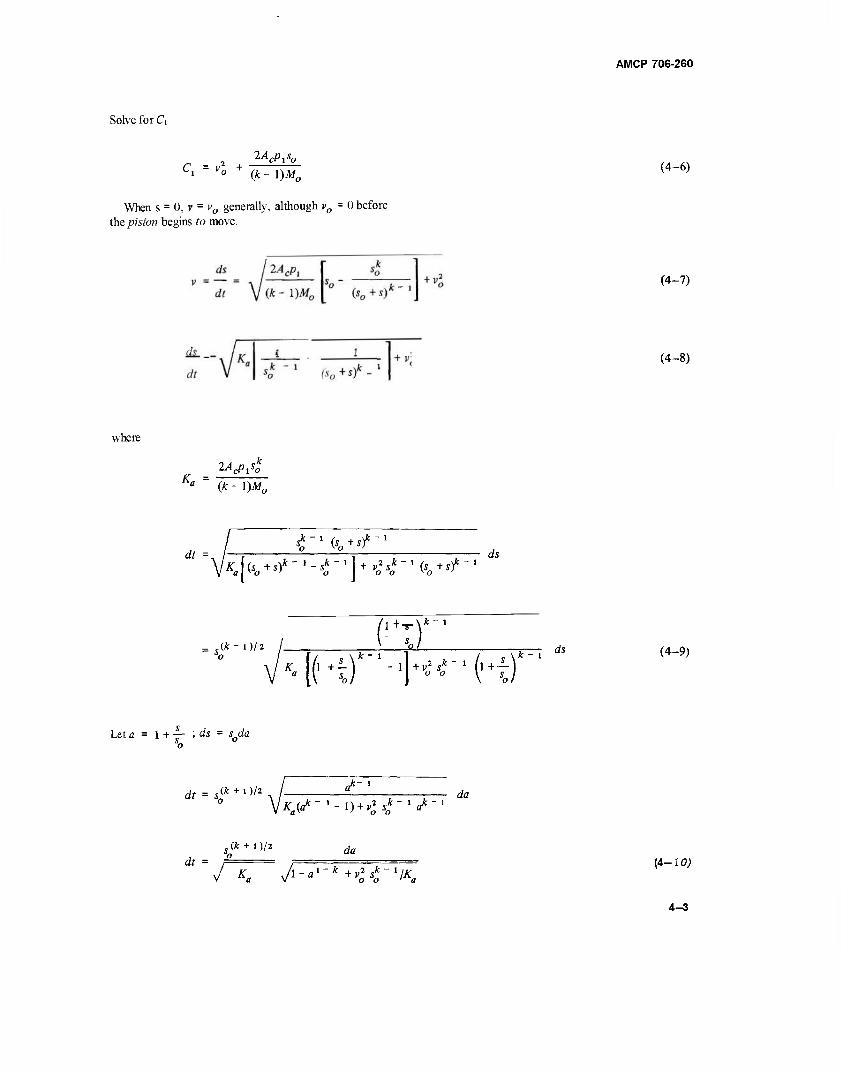
Solve for C\
AMCP 706-260
C, = vl + (4-6)
When s = 0, r = v0 generally, although vQ = 0 before the piston begins to move.
(4-7)
(4-8)
where
_ 2AcPlsZ K" ~ (k-\)M0
dt Z-x%+*f-x
IK Us +s)* - • - s*"J ] + v21*"»(s +sic~1 a\yo' o I o o K o '
ds
+ -!r\k~1
= j(*~ D/2 ri) MKf'-'h^'K)
it-1 ds (4-9)
Let a = 1 + — ; ds = s0<ia o
dr= (* + l)/2 a*"
^isrf«*-1-!)*^,*-'^-1 da
, (* + 1 )/2 rfa tff =
J Ka yi-«>-* +v»^~VA-B
(4-io;
4-3
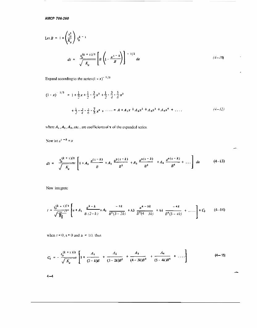
AMCP 706-260
^* = 1+ FK~'
Ak + i)/2
dt =
vT .1- fcl
5 1
1/2
da (4-11)
Expand according to the series (I - x) '
/, x" */* ,1 1 3 2 1 3 5 3
2 4 6 Bx + ,4 t^x + ,42x2 + y43x3 +A4x* + .. r^-72;
where Ai ,Ai ,A3, etc., are coefficients of x of the expanded series.
Now let a1 k=x
Ak + i )/2
df
/^
,(l-fc) „2(1"*) fl3(l-*) a4(l-fc)
1 +Ai *A* B B2
+ A3 +A4 ft3 ß4
da (4-13)
Now integrate
,(* + D/2 t = v-
/If ,2-A 2Jt
a+^. "+^2 ,4 - 3k .4*
+ A3 + A4 B(2-k) B2(l-2k) B\4- 3k) B\S - 4k)
+ C2 (4-14)
when f = 0, s = 0 and a = 1.0, thus
Ak + D/2
K
Ai AT. A3 An 1+ + + + + (4-15)
(2-k)B (3-2k)B2 (4-3fc)ß3 (5 - 4k)B*
4-4
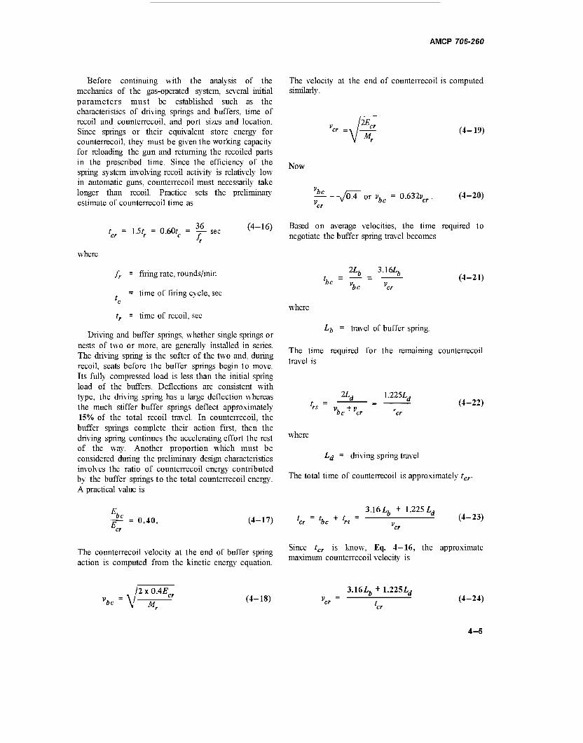
AMCP 706-260
Before continuing with the analysis of the mechanics of the gas-operated system, several initial parameters must be established such as the characteristics of driving springs and buffers, time of recoil and counterrecoil, and port sizes and location. Since springs or their equivalent store energy for counterrecoil, they must be given the working capacity for reloading the gun and returning the recoiled parts in the prescribed time. Since the efficiency of the spring system involving recoil activity is relatively low in automatic guns, counterrecoil must necessarily take longer than recoil. Practice sets the preliminary estimate of counterrecoil time as
The velocity at the end of counterrecoil is computed similarly.
Now
IE ci
M. (4-19)
t = 1.5t n<n, - 36 (4-16) 0.60f = — sec v ' c h
Based on average velocities, the time required to negotiate the buffer spring travel becomes
where
fr = firing rate, rounds/min
= time of firing cycle, sec c
tr = time of recoil, sec
Driving and buffer springs, whether single springs or nests of two or more, are generally installed in series. The driving spring is the softer of the two and, during recoil, seats before the buffer springs begin to move. Its fully compressed load is less than the initial spring load of the buffers. Deflections are consistent with type, the driving spring has a large deflection whereas the much suffer buffer springs deflect approximately 15% of the total recoil travel. In counterrecoil, the buffer springs complete their action first, then the driving spring continues the accelerating effort the rest of the way. Another proportion which must be considered during the preliminary design characteristics involves the ratio of counterrecoil energy contributed by the buffer springs to the total counterrecoil energy. A practical value is
2Lb 3.16Lb
be v, v be er (4-21)
where
Lb = travel of buffer spring.
The time required for the remaining counterrecoil travel is
2Lj 1.225L,
be er (4-22)
where
Ld = driving spring travel
The total time of counterrecoil is approximately tcr
be = 0.40.
3.16 L. + 1.2251. (4-17) tcr - tbc + trs - b- -d (4-23)
The counterrecoil velocity at the end of buffer spring action is computed from the kinetic energy equation.
Since tcr is know, Eq. 4-16, the approximate maximum counterrecoil velocity is
"be \
2 x 0.4£
M. (4-18)
3.16^ + 1.225Z,d (4-24)
4-5
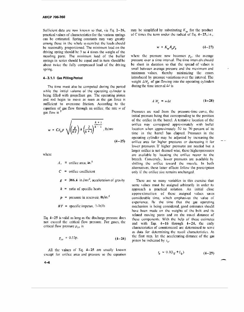
AMCP 706-260
Sufficient data are now known so that, via Eq. 2-26, practical values of characteristics for the various springs can be estimated. Spring constants may vary greatly among those in the whole system but the loads should be reasonably proportioned. The minimum load on the driving spring should be 3 to 4 times the weight of the recoiling parts. The minimum load of the buffer springs in series should be equal and in turn should be about twice the fully compressed load of the driving spring.
4-3.1.1 Gas Filling Period
The time must also be computed during the period while the initial volume of the operating cylinder is being filled with propellant gas. The operating piston and rod begin to move as soon as the gas force is sufficient to overcome friction. According to the equation of gas flow through an orifice, the rate w of gas flow is 7
CA0p /(*)*(£) k + i
k- i lb/sec
(4-25)
where
A, - orifice area, in.
C = orifice coefficient
g = 386.4 in./sec2, acceleration of gravity
k = ratio of specific heats
p = pressure in reservoir, lb/in.2
RT = specific impetus, ft-lb/lb
Eq. 4—25 is valid as long as the discharge pressure does not exceed the critical flow pressure. For gases, the critical flow pressure pcr is
may be simplified by substituting K for the product of C times the term under the radical of Eq. 4-25,i.e.,
w = w« (4-27)
where the pressure now becomes pa, the average pressure over a time interval. The time intervals should be short in duration so that the spread of values is small between average pressure and the maximum and minimum values, thereby minimizing the errors introduced by pressure variations over the interval. The weight A Wc of gas flowing into the operating cylinders during the time interval Ar is
AWC= wAt (4-28)
Pcr = 0.5 3p. (4-26)
Pressures are read from the pressure-time curve, the initial pressure being that corresponding to the position of the orifice in the barrel. A tentative location of the orifice may correspond approximately with bullet location when approximately SO to 70 percent of its time in the barrel has elapsed. Pressures in the operating cylinder may be adjusted by increasing the orifice area for higher pressures or decreasing it for lower pressures. If higher pressures are needed but a larger orifice is not deemed wise, these higherpressures are available by locating the orifice nearer to the breech. Conversely, lower pressures are available by shifting the orifice toward the muzzle. In both alternatives, these latter effects follow the prescription only if the orifice size remains unchanged.
There are so many variables in this exercise that some values must be assigned arbitrarily in order to approach a practical solution. An initial close approximation of these assigned values saves considerable time, which emphasizes the value of experience. By the time that the gas operating mechanism is being considered, good estimates should have been made on the weights of the bolt and its related moving parts and on the travel distance of these components. With the help of these estimates and with Eqs. 4-16 through 4-24, the early characteristics of counterrecoil are determined to serve as data for determining the recoil characteristics. As the first step, let the accelerating distance of the gas piston be indicated by sa.
All the values of Eq. 4-25 are usually known except for orifice area and pressure so the equation
sa = 03(Ld +Lb) (4-29)
4-6
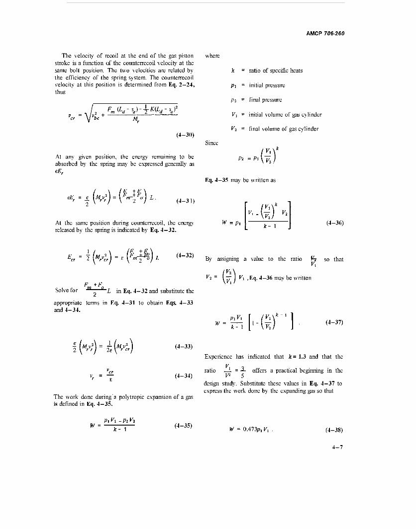
AMCP 706-260
The velocity of recoil at the end of the gas piston where stroke is a function of the counterrecoil velocity at the same bolt position. The two velocities are related by the efficiency of the spring system. The counterrecoil velocity at this position is determined from Eq. 2-24, thus
2 . ^(V^-T^V^ Vbc +
M.
(4-30)
At any given position, the energy remaining to be absorbed by the spring may be expressed generally as eEr
^=±(M^) = (^/O)L. (4-31)
At the same position during counterrecoil, the energy released by the spring is indicated by Eq. 4-32.
Since
k = ratio of specific heats
Pt = initial pressure
Pi = final pressure
Vi = initial volume of gas cylinder
V2 = final volume of gas cylinder
Pi =P ■(*)'
Eq. 4-35 may be written as
W =p, '-G)'
k- 1 (4-36)
(^)-,(i|^)l <4-32) By
Fm +Fn
Solve for m Q L in Eq. 4-32 and substitute the
appropriate terms in Eq. 4-31 to obtain Eqs. 4-33 and 4-34.
f(^)=iM cr E
(4-33)
(4-34)
The work done during a polytropic expansion of a gas is defined in Eq. 4—35.
assigning a value to the ratio V-i so that
®h Eq. 4-36 may be written
W = PiVi
k- 1 mi (4-37)
Experience has indicated that k= 1.3 and that the
V, , ratio — = J- offers a practical beginning in the
design study. Substitute these values in Eq. 4-37 to express the work done by the expanding gas so that
W Pi Vi - Pi v2
k~^~-\ (4-35)
W = 0A73Pl Vi (4-38)
4-7
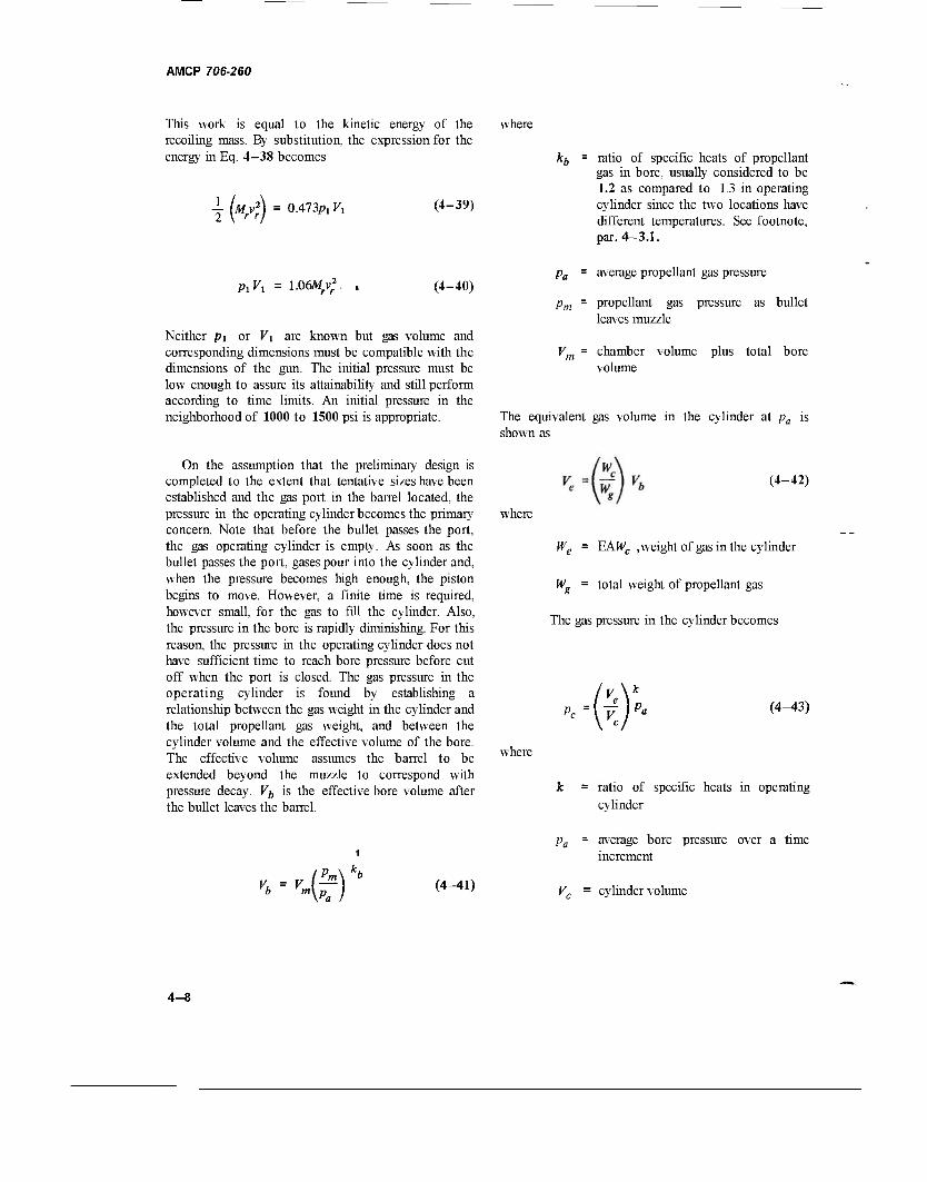
AMCP 706-260
This work is equal to the kinetic energy of the recoiling mass. By substitution, the expression for the energy in Eq. 4-38 becomes
iM = 0.473p, F, (4-39)
where
= ratio of specific heats of propellant gas in bore, usually considered to be 1.2 as compared to 1.3 in operating cylinder since the two locations have different temperatures. See footnote, par. 4—3.1.
PxVx 1.06Mrv; (4-40)
Neither pi or V\ are known but gas volume and corresponding dimensions must be compatible with the dimensions of the gun. The initial pressure must be low enough to assure its attainability and still perform according to time limits. An initial pressure in the neighborhood of 1000 to 1500 psi is appropriate.
pa = average propellant gas pressure
pm = propellant gas pressure as bullet leaves muzzle
Vm - chamber volume plus total bore volume
The equivalent gas volume in the cylinder at pa is shown as
On the assumption that the preliminary design is completed to the extent that tentative sizes have been established and the gas port in the barrel located, the pressure in the operating cylinder becomes the primary concern. Note that before the bullet passes the port, the gas operating cylinder is empty. As soon as the bullet passes the port, gases pour into the cylinder and, when the pressure becomes high enough, the piston begins to move. However, a finite time is required, however small, for the gas to fill the cylinder. Also, the pressure in the bore is rapidly diminishing. For this reason, the pressure in the operating cylinder does not have sufficient time to reach bore pressure before cut off when the port is closed. The gas pressure in the operating cylinder is found by establishing a relationship between the gas weight in the cylinder and the total propellant gas weight, and between the cylinder volume and the effective volume of the bore. The effective volume assumes the barrel to be extended beyond the muzzle to correspond with pressure decay. Vb is the effective bore volume after the bullet leaves the barrel.
where
(4-42)
We - ¥AWC , weight of gas in the cylinder
Wg = total weight of propellant gas
The gas pressure in the cylinder becomes
°c _u_r« (4-43)
where
k = ratio of specific heats in operating cylinder
#) (4-41)
pa = average bore pressure over a time increment
Vc = cylinder volume
4-8
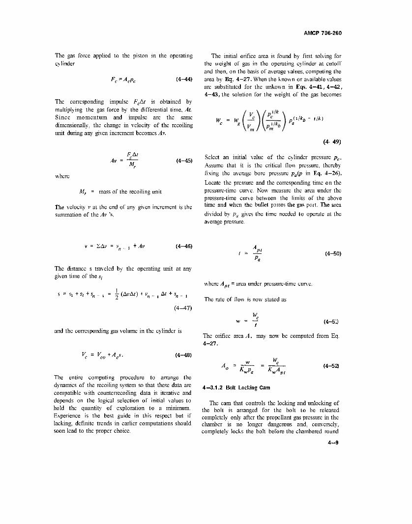
The gas force applied to the piston in the operating cy linder
Fc=AcPc (4-44)
The corresponding impulse FcAt is obtained by multiplying the gas force by the differential time, At. Since momentum and impulse are the same dimensionally, the change in velocity of the recoiling unit during any given increment becomes Av.
Av FAt c M
(4-45)
where
Mr = mass of the recoiling unit
The velocity v at the end of any given increment is the summation of the Av 's.
AMCP 706-260
The initial orifice area is found by first solving for the weight of gas in the operating cylinder at cutoff and then, on the basis of average values, computing the area by Eq. 4—27. When the known or available values are substituted for the unkown in Eqs. 4—41,4—42, 4—43, the solution for the weight of the gas becomes
W ,(i/*6 - ilk)
(4-49)
Select an initial value of the cylinder pressure pc.
Assume that it is the critical flow pressure, thereby fixing the average bore pressure pa(p in Eq. 4-26).
Locate the pressure and the corresponding time on the pressure-time curve. Now measure the area under the pressure-time curve between the limits of the above time and when the bullet passes the gas port. The area
divided by pa gives the time needed to operate at the average pressure.
v = 2Av = vn _ j + Av (4-46) pt
(4-50)
The distance s traveled by the operating unit at any given time of the s;-
s = s, + * + s„ - , = \ (AMO + vn _ x At + sn _ ,
(4-47)
and the corresponding gas volume in the cylinder is
K = V +A s. C CO c (4-48)
The entire computing procedure to arrange the dynamics of the recoiling system so that these data are compatible with countemecoiling data is iterative and depends on the logical selection of initial values to hold the quantity of exploration to a minimum. Experience is the best guide in this respect but if lacking, definite trends in earlier computations should soon lead to the proper choice.
where Apt = area under pressure-time curve.
The rate of flow is now stated as
(4-51)
The orifice area A, may now be computed from Eq. 4-27.
W A - w - c
o K p ~ K»APt
(4-52)
4-3.1.2 Bolt Locking Cam
The cam that controls the locking and unlocking of the bolt is arranged for the bolt to be released completely only after the propellant gas pressure in the chamber is no longer dangerous and, conversely, completely locks the bolt before the chambered round
4-9
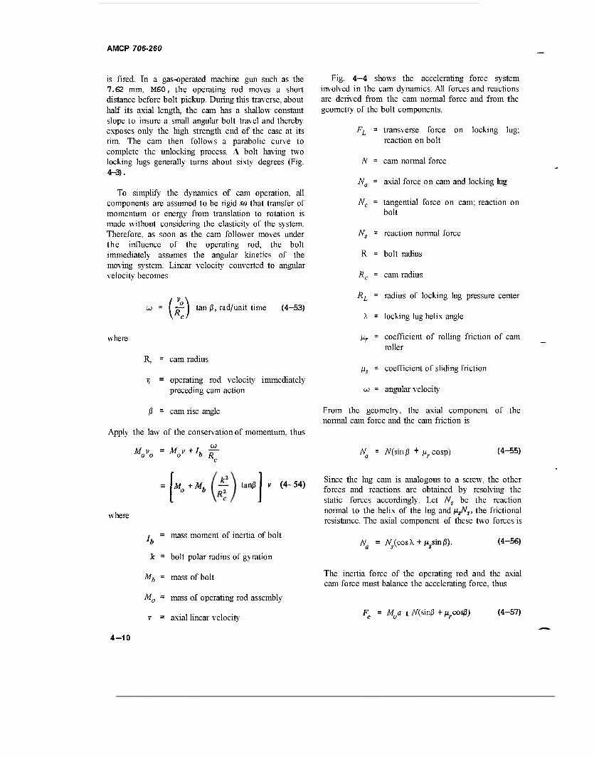
AMCP 706-260
is fired. In a gas-operated machine gun such as the 7.62 mm, M60, the operating rod moves a short distance before bolt pickup. During this traverse, about half its axial length, the cam has a shallow constant slope to insure a small angular bolt travel and thereby exposes only the high strength end of the case at its rim. The cam then follows a parabolic curve to complete the unlocking process. A bolt having two locking lugs generally turns about sixty degrees (Fig. 4-3).
To simplify the dynamics of cam operation, all components are assumed to be rigid so that transfer of momentum or energy from translation to rotation is made without considering the elasticity of the system. Therefore, as soon as the cam follower moves under the influence of the operating rod, the bolt immediately assumes the angular kinetics of the moving system. Linear velocity converted to angular velocity becomes
Fig. 4—4 shows the accelerating force system involved in the cam dynamics. All forces and reactions are derived from the cam normal force and from the geometry of the bolt components.
FL = transverse force on locking lug; reaction on bolt
N = cam normal force
Na = axial force on cam and locking lug
Nc = tangential force on cam; reaction on bolt
Ns = reaction normal force
R = bolt radius
Rc = cam radius
(*) tan (3, rad/unit time (4—53)
RL = radius of locking lug pressure center
X = locking lug helix angle
where
R. cam radius
7, = operating rod velocity immediately preceding cam action
ßr - coefficient of rolling friction of cam roller
jis = coefficient of sliding friction
oj = angular velocity
ß - cam rise angle
Apply the law of the conservation of momentum, thus
M v = Mv +Ih jr o o o b R
From the geometry, the axial component of the normal cam force and the cam friction is
N - A^sin ß + \xf cosp) (4-55)
where
o b tanj3 v (4-54)
r = mass moment of inertia of bolt 'b
k = bolt polar radius of gyration
Since the lug cam is analogous to a screw, the other forces and reactions are obtained by resolving the static forces accordingly. Let Ns be the reaction normal to the helix of the lug and M^j. the frictional resistance. The axial component of these two forces is
N = N (cosX + M5sin/3). (4-56)
M, mass of bolt
M0 = mass of operating rod assembly
v = axial linear velocity
The inertia force of the operating rod and the axial cam force must balance the accelerating force, thus
F = MQa t /V(sin|3 + Mrcos|3) (4-57)
4-10
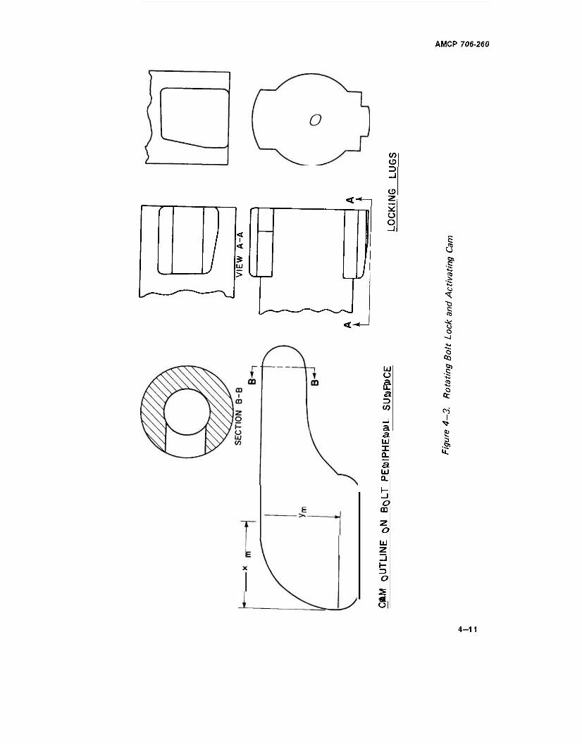
AMCP 706-260
7—
)
< l <
w >
•-
üi
co o Z>
z
o o
o
a CO
a a l±J X Q.
a ÜJ Q.
o CD
o UJ
ID
«I o
c
O
o
I
I
4-11
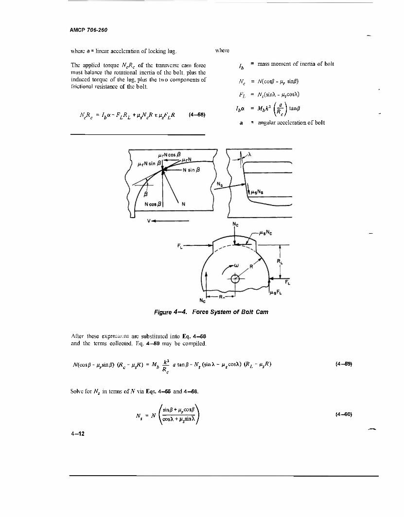
AMCP 706-260
where a = linear acceleration of locking lug.
The applied torque NCRC of the transverse cam force must balance the rotational inertia of the bolt, plus the induced torque of the lug, plus the two components of frictional resistance of the bolt.
where
N R, V-^L^A^^fi (4-58)
tf, =
mass moment of inertia of bolt
/V(cosj3 - ßr sinj3)
A^(sin\ - MjCosX)
Iha (*)
Mbk2 ( — ) tanjS
= angular acceleration of bolt
Figure 4-4. Force System of Bolt Cam
After these expressions are substituted into Eq. 4-58 and the terms collected, Eq. 4—59 may be compiled.
N(cosß- Mrsin/3) (R£ - j^Ä) = Mb J£ a tan/3 - Nf (sinX - MscosX) (RL - psR) Rc
(4-59)
Solve for A^ in terms of N via Eqs. 4-55 and 4—5S.
/ sinß + Mrcos|3'
s \ cosX + ß.sia\ (4-60)
4-12
Substitute for Ns in Eq. 4-59, collect terms and solve foriV.
AMCP 706-260
N = M.a k2 tan/3
b" R [(R - ixsR) (cos/3 - pr sin/3) + C\ (RL - ßsR) (sin/3 + M, cos/3)] (4-61)
where
C\ = sinX - Msc
os^
^ cosh + usinX
Now substitute forN in Eq. 4-57 so that
F = a M + IU k2 tan/3 Mo +Mb
R c (Rc- - u R) (cos/3 -u sin/?)
-V0 sin/3 + Mr cos/3 ' ^XVj,vi
(4-62)
For unlocking, F is the gas pressure force on the operating rod. It is the driving spring force during locking. The expression in the braces of Eq. 4-62 is equivalent to an effective massAfe. Eq. 4-62 may now be written as
Both pc and Fc may be found by assigning small increments to the operating rod travel s.
sn - l +As (4-65)
F = Ma (4-63) The average acceleration over the increment is
aa = 2 (°n - i + an> (4-66)
M. (4-64) The velocity at the end of each increment is obtained by first computing the energy E0 of the operating rod
During the unlocking period, the operating rod derives its accelerating force from the propellant gases which, after cutoff, expand polytropically. The pressure in the operating cylinder at a given position of the rod is computed according to Eq. 4-2 and the force according to Eq. 4-44.
E =E„. + AE =E, ,,+AE o oi o o(n - l) o
Eo(n- i) +
Fc(n - l)+Fc(n) As (4-67)
P' = P> (&) (from Eq. 4-2)
where Eoi = energy of operating rod at gas cutoff
(immEq. 444) then 2Io M„ (4-68)
4-13
AMCP 706-260
The incremental time may be computed from the expression
As = vn-i
Afe+i(flaA'e} (4-W)
Solving for At,, the incremental time of the gas expansion stroke becomes
A'< = -~yl~) % (4-70)
The time for the total gas expansion stroke is t,.
*e = 2A'e (4-71)
During the locking period, the applied force is derived from the driving spring. The spring accelerating forces at any position of the operating rod when efficiency is considered is
F = e(F.+Ks) = Fn _ , + eKAs (4-72)
where
M = initial driving spring force as bolt seats
f _ , = spring accelerating force of previous increment
K = spring constant
s = operating rod travel after bolt seats
As = incremental operating rod travel
E = efficiency of the spring system
The breech end of the locking lugs carries the axial reaction on the bolt, thereby relieving the helix end of all loads during cam action. Therefore, in Eq. 4—62, X = 0, and the effective mass becomes
M=M + M. e o b
k2 tan/3
Rc
URc-ßsR)(co0 -M, sin/3)
-*fiRL -"<*) I sin/3+/i cos/3
(4-73)
4-14
AMCP 706-260
Note that if the cam roller is not installed for either locking or unlocking, the Coefficient of rolling friction ßr changes to ßs the coefficient of sliding friction in Eqs. 4-62 and 4-73.
4—3.1.3 Cam Curve
The cam curves on the breech end of the bolt are helices, usually having identical slopes. The straight slope merges smoothly with the parabolic curve which may be expressed as
Bx„ A = (4-77)
y = Ax2 +Bx+C.
where
x, = axial length of the parabola (see Fig. 4-3)
ym = peripheral width of the parabola (see Fig. 4-3)
From Eq. 4-62, the equivalent mass for the unlocking system is a constant when the cam action involves the helix. The values assigned to the parameters in the equation are:
(4-74)
Locate the coordinate axes so that y = 0 when x = 0, thus C = 0 which reduces the equation to
k = 0.275 in., radius of gyration
R - 0.39 in., bolt radius
y = Ax2
The slope of the curve is defined as
when x
-f a x + dx
o;0„ =
■tan ß
(4-75)
(4-76)
tanß , and B = tanß
the slope of the helix and therefore the slope of the parabola where it joins the helix. When x andy reach their respective limits, dimensions that have been assigned and then substituted in Eq. 4—75 will yield the value of the coefficient A.
Rc = 0.32 in, cam radius
Py - 0.034 coefficient of rolling friction
jus = 0.30 coefficient of sliding friction
tanß0 = 0.007465, slope of cam helix
RL = 0.5 in., radius of locking lug
Wh = 0.75 lb, bolt weight
W = 2.5 lb, operating rod weight
cosj30 = 0.999972
sin0o = 0.0074648
X =3°, slope of lug helix
4-15
AMCP 706-260
JW„ 386.4 o b
fl
k2 tanß
(Rc-ßsR)(cosßo-ljLrünßo)
sinfl +u cosö + C\(RL-»SV
386.4 2.5 + 075 [o~
0.0756 x 0.007465
32 (0.203 x 24.12 - 0.244 x 0.383) J
where
coSiS„-Mrsin)3o 0.99997 - 0.00025 =
sinß + u cosß ~ 0.00746 + 0.0340
sinh - ßs cosh 0.05234 - 0.29959
"* cosh + /^ sinX 0.99863 + 0.01570 0.244
M = 2.5 + 0.75x1.18x10^ = g^Pi = Q 00647 ,b,ec,/in. 386.4 386.4
The effective mass adds less than one percent to the operating rod mass as the cam follower progresses along the constant cam slope hence it need not be considered in the calculations until the parabolic curvature is reached. Because the entire bolt mass without modification was entered in the analysis of the period before gas cutoff, this analysis may be considered conservative. The effective mass while the cam follower negotiates the parabolic curvature of the cam for the unlocking process becomes (Eqs. 4—63 and 4-62)
Me = 6.47 x 10 4.58 x 10~4 tanß
0.203 /^-0-034 sinß \ \ sinß + 0.034 cosp/
The effective mass for the locking process is obtained from Eq. 4—73.
M = 6.47 x 10"3 + e 4.58 x 10~4 tanß
0203 (cosf-0-034 sinß \_ \sinß+0.034 cosp/
4-16
AMCP 706-260
The straight slope of the cam is half the axial cam travel distance
1 x = — s =0.5 in. e 2 r
xm = s> ' s = 0-5 m> axial length of parabola
According to Eq. 4-76, B = tan ß0 = 0.007465. The bolt must turn through an angle of 60° to unlock. The peripheral width of the parabola (see Fig 4—3) is
(&-')>
The counterrecoil time t , Eq. 4—16 ,is
t = 0.60r„ = 0.036 sec. cr c
The recoil time
t, =t - t„ = 0.060- 0.036 = 0.024 sec.
Fig. 4-6 shows a sketch of the various distances involved in the operation of the moving mechanisms during the firing cycle. These initial distances are based on those of an earlier gun.
dc = 0.874 in, gas cylinder diameter
ym _ \T=~; _B )RC = 1.0397x0.32 = 0.3327 in.
From Eq. 4—77, the constant^ is
ym ' Bxm _ 0.3327 - 0.007465 x 0.5
m 0.25
1.316/in.
The slope of the curve, Eq. 4—76, is
tanß = ^ = 2.632x+0.007465. H dx
4-3.2 SAMPLE PROBLEM FOR CUTOFF EXPANSION SYSTEM
4—3.Z1 Specifications
Gun: 7.62 mm machine gun
Firing Rate: 1000 rounds/min
Interior Ballistics: Pressure vs Time, Fig. 4-5 Velocity vs Time, Fig. 4-5
4—3.2.2 Design Data, Computed
The time for the firing cycle, from Eq. 2—29, is
60 60 nn„ fc =Jr = IÖÖÖ = 0060sec'
d„ = 0.135 in, gas port diameter
= 1.00 in., buffer stroke
Lbi ~ 0-75 in., operating distance of primary buffer spring
Lb2 = 0.25 in., operating distance of secondary buffer spring
Lj =5.5 in., operating distance of operating rod spring
sa = 2.0 in, accelerating distance of gas piston
sb = 4.5 in., distance of bolt retraction during recoil.
sd
Wu
W„
Wr
= 0.20 in., cutoff distance
= 1.8 in., dwell distance
= 1.00 in., operating rod travel before bolt pickup
= 1.8 in.3, initial gas volume of operating cylinder
= 0.75 lb, weight of bolt
= 2.5 lb, weight of moving operating mechanism
= Wb + W0 - 3.25 lb, weight of recoiling parts
0.50, efficiency of spring system
4-17
AMCP 706-260
in a.
W CT
<o to a. Q.
CO <
< _J _l u 0- o 0L
70
65
60
55
50
45
40
35
30
25
20
10
5
0
0) Q.
IE 5
CO CO UJ
1 I PRESSURE \ DECAY
13 2.3 3.3 4.3 TIME , msec
PRESSURE / /VELOCITY
r
I
/
/ TRAVEL
1
/ 1
30
25
20
in a.
O E O
t < o o: o h- _i
> LJ
-j CO ID 00
10
0.5 TIME, msec
10
F/gure 4—5. Pressure-time Curve of 7.62 mm Round
4-18
AMCP 706-260
EXPANSION—i CHAMBER /
^M)m»4^ -b2
Figure 4-6. Operating Distances of Moving Parts
4—3.2.3 Counterrecoil Computed Data
From Eq. 4—24 the approximate maximum counterrecoil velocity is computed to be
_ 3.16^ + 1.228^ _ 316 + 675
"cr tcr 0.036
= 275 in./sec.
Lj = 5.5 in., operating distance of spring
5.5 F = r^5 a (\)(M) (75625 - 30276)
F„ = 69.3 1b
For the first trial a spring constant of 4 lb/in. was selected but proved to be too highly stressed. However, the first trial indicated a compression time of 16.6 msec. With an impact velocity above 25 ft/sec, the spring surge time is
From Eq,4-jr20 Ihe approximate counterrecoil velocity af the end of buffer spring action oecomes
T =- 0.0166
1.8 0.0092 msec,
vbc = 0.632 vcr = 174in./sec. According to Eq. 2-67b,
According to Eq. 2-24, by substituting Fa for
I Fm - — Kx I and Ld for x, the expression LdFa is F F° + T
KT = -J"= = M 1037 1037
da g 1M-1N] 0.0092A: = 69.3 +2.75£
1037
K = 10.2 lb/in.
where vbc is equivalent to vQ of Eq. 2—24.
Fa can now be determined.
M = — r g
g = 386.4 in./sec2 , acceleration of gravity
Fm = Fa + j(KLd) = 69.3 + 28.1 = 97.41b
Fo = Fm -KLd = 97.4- 56.1 = 41.3 lb.
4-19
AMCP 708-280
For the buffer springs in series, the spring constant Kb
is
K, = 60 lb/in.
Sin"1 KbL
b-F
mb\ F
mb
3TT
2
Lb = 1.0 in.
\{MAc)-\{pmbh)-\{^l) where v0 = 0, at the start of counterrecoil
lFmb=\ (M) 3°'276+i (60) 1°
Fmb = 2(127.3+ 15) = 284.6 lb, say, 285 lb
2 x 3.25
be J 386.4x60 „. _, / 1.0 x 60- 285 \ - 3»1
Lsm ( 2Ü—) l\
= 0.01675 [Sin-1 ( - 0.78947) - 4.71241
= 0.01675 (5.3733 - 4.7124) = 0.01 11 sec.
From Eq. 2—24, the buffer counterrecoil velocity is expressed in terms of spring energy.
F„h = Fm ~KhLh = 285- 60 = 2251b. ob m b b
Since the buffer springs in series should have the same terminal loads, spring constants will vary inversely as their deflections. Thus,
II2 =
FmhLb " 2 [^ K)
he Mr
= (285 x 1.0- 30 x 1.0)386.4
3.25
£i hi 025 K2
= Lbl ' 0.75 or K2 = 3Ki
2 _ 255 x 386.4 „,10 . 2. 2 vi. ~ T-^7 = 30318 in. /sec be 3.25
The spring constants of the primary and secondary springs of the buffer are
*i =
Fmh Fob 60
075 80 lb/in.
K2 = 3tf, = 240 lb/in.
v. = 174.1 in./sec, buffer counterrecoil velocity
which checks favorably with the first computed velocity of 174 in./sec
4_3.2.4 Counterrecoil Time The time consumed for counterrecoil during driving spring action also is divided into two periods, when the
The counterrecoil time is divided into two periods, total recoiling mass is considered, and after the bolt i.e., during buffer spring action and during driving stops when the moving mass consists only of the spring action. Both are computed according to Eq. moving parts of the operating rod unit. According to 2—26. For the buffer springs, v0 = 0 therefore Eq. 2—26, the first time component is
4-20
AMCP 706-260
Sin" Kh~Fr,
- Sin"' - F
vA™ + ^M/J l/F. + 2KMrvlc)
I 3.2f _. , 10.2x4.5-97.4 _. , -97.4 Sm-1 — — - Sin-
V386.4 x OJ x 10.2 | ^9487 +5202 y9487 + 5202
where
= 0.040611 Sin-1 (-0.4249)- Sin-' (-0.8036)
0.04061 (334.85 - 306.52)/57.3 = 0.04061 x 0.4944= 0.0201 sec
Fm = 97.41b
K = 10.2 lb/in
3.25 Mr 386.4
lb-sec /in.
sb = 4.5 in.
vie = 30,318 in.2/sec2
E = 0.50
According to Eq. 2-24, the expression for the counterrecoil velocity is
2e v2 = vi +- cr be
(Fmst *(".)]
M.
30318 + 97.4x4.5- 10.2x20.25/2
3.25 386.4
30318+39832 = 70150 in.2 /sec2
v = 264.9 in./sec = 22.08 ft/sec, maximum bolt velocity on return.
The terminal part of the counterrecoil stroke occurs after the bolt is in battery and the operating rod components are the remaining moving parts. From Eq. 2-26, the second time component is
'«■ = Sin" Wd-*J-Fm Sin-1
JK^M?O ~ V^+2ßVa 4-21
AMCP 706-260
2.5 {cr ,/386.4 x 0.5 x 10.2
Sin" 41.3
Sin-1 51.5
v/2652 + 9258 ^2652 + 9258
= 0.03562 Sin-' (-0.3784)-Sin-' (-0.4719)
0.03562 (337.77 - 331.85)/57.3 = 0.0037 sec
where
Fm = 51.5 1b
F0 = 41.3 1b
K = 10.2 lb/in.
Mn
sb
5.5 in.
386.4 lb-sec2/in.
4.5 in.
70147 in. /sec2
0.50
The total counterrecoil time is
fc, = ^+C+C =0.0349 sec.
This computed time compares favorably with the assigned time (0.036 sec) for counterrecoil thus supporting the characteristics of the selected spring.
At the end of counterrecoil the velocity of the operating rod moving parts, according to Eq. 2-24 is
/v2o + 2*[Fm<-Ld-tf--5K<-Ld->t?]lMo
/70147 + (51.5 x 1.0- 10.2 x 1.0/2)386.4/2.5
,/77318 = 278 in./sec = 23.08 ft/sec = 277 in./sec
which checks with the first computed velocity of 275 in./sec.
4-22
AMCP 706-260
4—3.2.5 Recoil Time
The dynamics of the operating rod and bolt while propellant gases are active in the gas cylinder do not include the resistance of the driving spring since the spring forces are negligible as compared to gas forces. With respect to the dynamics, two periods are involved, i. e., accelerating and decelerating. Initially, the time of each is proportioned according to their respective distance of operation. The decelerating time is computed to be
Ld+Lb
0.0166 sec
)I5.5 + 1.0- 2.0\ „ <r = y 5.5-M.0 ) °
.024
p = 41.3 +Ks= 41.3 +20.4 =61.7 lb ' sa
K = 10.2 lb/in., spring constant
Mr = 3.25/g, lb-sec2in.
sa = 2.0 in.
,. = 503.6 in./sec, initial velocity yo
E = 0.5, efficiency of spring system
The working distance of the drive spring during the decelerating period of recoil isi,.
L = L.-s = 5.5 - 2.0 = 3.5 in. r da
where tr = 0.024 sec (see par. 4-3.2.2) and Expand Eq. 2-22 to include the limits of x = 0 to
x =L„ thus the time to compress the drive spring is
UM. where sa = 2.0 in., the distance that the piston moves . ~...r
while being accelerated by the propellant tdr ~ J % ( Sin gas. \
F +KLr i sa r
JF2 + eKM v2
V sa r o
The counterrecoil velocity at this position is computed according to Eq. 2-24
\r = Ac + 24F»>(Lä -O-J K(Ld ~ *a?] >Mr
= v/30318 + (97.4 x 3.5 - 10.2 x 12.25/2)386.4/3.25
= 251.8 in./sec.
Sin"1
JFTeKMsl
=yo.0004123 /Sin-i m ---« 0.0081 sec.
From Eq. 4—34, the velocity of recoil at this position becomes
1 251.8 ~eVcr ~ TT = 503-6in-/sec.
The velocity of the recoiling parts as the buffer is contacted is
4—3.2.5.1 Recoil Time, Decelerating
As computed above, the recoil velocity at the end of the operating cylinder stroke is 503.6 in./sec which becomes the initial velocity of the spring system as deceleration begins. At this time the driving spring has been compressed to the extent of the two inches that the operating gas piston has traveled. The design data include
eM
253613 159.1x3.5x386.4
0.50x3.25
vb = ^253613 - 132410 = /l2120i = 348.1 in./sec. 4-23
AMCP 706-260
Since the buffer absorbs the remaining energy,
A3*+ew* =F« mb '
therefore, Eq. 2—23 becomes the expression for
recoil time during buffing,
eM.
h = Cos' .-ȣ*- /o-5 x 3.25 225 Cos -^ K ~"" F , \/60x 386.4
= 0.00837 Cos-' 0.78947 = 0.00837 (^y)
= 0.0055 sec.
The total recoil time during deceleration
V = 'dr + lb = 0.0081 + 0.0055 = 0.0136 sec.
4—3.2.5.2 Recoil Time, Accelerating
The time needed to accelerate the recoiling mass consists of two parts, i. e., time before cutoff and time after cutoff. First, the tentative size of the operating cylinder must be determined. According to Eq. 4-40, the work done by the expanding gas is
PiVi = l.06Mfv2
r
2261 in.-lb
1.06 / 3.2S \ \ 386.4 / 253613
Therefore, the average pressure in the barrel needed to provide it is, according to Eq. 4—26,
TT§3 2360 lb/in:
Other values are
k = 1.3, ratio of specific heats in operating cylinder
kb = 1.2, ratio of specific heats in bore
Pm = 9000 lb/in.2, muzzle pressure from Fig. 4-5
Vco = Vx - 18 in.3 , initial volume of operating cylinder
Vm = 1.74 in.3 , chamber volume plus bore volume
Wg = 0.00629 lb, weight of propellant
The weight of the gas in the operating cylinder at its maximum pressure, according to Eq. 4-49, is
w = w hr )pllkp(llkb-llk^p "kb c s\V I c " m
0.00629 / 1.8 \ ^241 x 1.66 \ V 1.74 / V 1970 /
0.00132 lb.
Select pi = 1250 lb/in.2
Pi FI 2261 Vx
P\ 1250 1.8 in.3
With the ratio Ü .3
To insure total access, the diameter of the orifice should not exceed the cutoff distance; thus the two orifices of 0.162 in. diameter.
V2 5
gas expansion stroke is V2
v2 = 3 vx
The measured area under the pressure-time curve between 0.0002 sec and 0.0032 sec is equivalent to
^ the volume at the end of the Apt =16.43 lb-sec/in.2 The first time (0.0002 sec) represents approximately 70% of the bullet travel and the second corresponds with the pressure, pa = 2360 psi. From Eq. 4-52, the first estimate of the orifice area is
■G) 1.8 = 3.0 in.3
W„ The selected cylinder pressure is pc=Pi - 1250 psi. Assume this pressure to be the critical flow pressure.
0.00132
KWAp, 0.00192 x 16.43
0.042 in.2
4-24
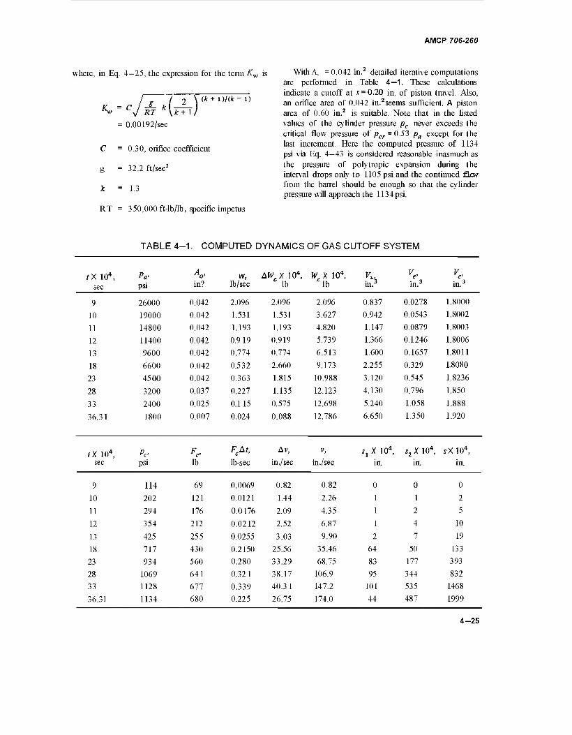
AMCP 706-260
where, in Eq. 4-25, the expression for the term Kw is With A, = 0.042 in.2 detailed iterative computations are performed in Table 4—1. These calculations
. ^ indicate a cutoff at s = 0.20 in. of piston travel. Also, „ r _S_ i ( 2 ) 1)/( l' an orifice area of 0.042 in.2seems sufficient. A piston
w V RT \k-H/ area of 0.60 in.2 is suitable. Note that in the listed = 0.00192/sec values of the cylinder pressure pc never exceeds the
critical flow pressure of pcr = 0.53 pa except for the last increment. Here the computed pressure of 1134 psi via Eq. 4-43 is considered reasonable inasmuch as
= 32 2 ft/sec2 *^e Pressure °f polytropic expansion during the interval drops only to 1105 psi and the continued flew
JL =13 fr°m the barrel should be enough so that the cylinder pressure will approach the 1134 psi.
RT = 350,000 ft-lb/lb, specific impetus
TABLE 4-1. COMPUTED DYNAMICS OF GAS CUTOFF SYSTEM
0.30, orifice coefficient
tx 104, sec
Pa' psi in?
w, lb/sec
AWX 104, C lb
WX 104, lb b in.3 in.3
9 26000 0.042 2.096 2.096 2.096 0.837 0.0278 1.8000
10 19000 0.042 1.531 1.531 3.627 0.942 0.0543 1.8002
11 14800 0.042 1.193 1.193 4.820 1.147 0.0879 1.8003
12 11400 0.042 0.919 0.919 5.739 1.366 0.1246 1.8006
13 9600 0.042 0.774 0.774 6.513 1.600 0.1657 1.8011
18 6600 0.042 0.532 2.660 9.173 2.255 0.329 1.8080
23 4500 0.042 0.363 1.815 10.988 3.120 0.545 1.8236
28 3200 0.037 0.227 1.135 12.123 4.130 0.796 1.850
33 2400 0.025 0.115 0.575 12.698 5.240 1.058 1.888
36.31 1800 0.007 0.024 0.088 12.786 6.650 1.350 1.920
tX 104, sec
Pe- psi
Fc> lb
FcAt,
lb-sec
Av,
in,/sec
V,
in ./sec s1 X 104,
in.
s2 X 104,
in.
sX 104,
in.
9 114 69 0.0069 0.82 0.82 0 0 0
10 202 121 0.0121 1.44 2.26 1 1 2
11 294 176 0.0176 2.09 4.35 1 2 5
12 354 212 0.0212 2.52 6.87 1 4 10
13 425 255 0.0255 3.03 9.90 2 7 19
18 717 430 0.2150 25.56 35.46 64 50 133
23 934 560 0.280 33.29 68.75 83 177 393
28 1069 641 0.321 38.17 106.9 95 344 832
33 1128 677 0.339 40.31 147.2 101 535 1468
36.31 1134 680 0.225 26.75 174.0 44 487 1999
4-25
AMCP 706-260
At cutoff, the velocity of the moving parts has reached 174 in./sec. This represents a kinetic energy of
Ec = 2\ ) 2 386.4/
30276 = 127.3 in.-lb.
The work done by poly tropic expansion, Eq. 4-35, is
PiVx-ihV2 _ 1134x1.92-635x3.0 W
k- 1
907.6 in.-lb
1.3- 1.0
where
= 1134x0.56 = 635 lb/in.
Vi = V +Aj = 1.8+0.6x0.2 = 1.92 in.3 1 CO c
At = 0.0005 sec and the corresponding average pressure are read from the pressure decay-time curve (see insert) of Fig. 4-5, pa = 3200 psi. Resorting to Eq. 4—57 to estimate the travel during the interval, observe that Av is unknown. However, in the preceding interval, the difference in Av
[Av for(t = 2.3 x 10"3)] - [Avforft = 1.8 x 10"3)]
< 8 in./sec. Add this increment to Av (t = 2.3 x 10~3).
Thus, Av = 33 + 7 = 40 in./sec.
The rate of flow by Eq. 4—27 is computed to be
w = KwAopa = 0.00192x0.037x3200
= 0.227 lb/sec.
The weight of the gas flowing through the orifice during the 0.0005 sec increment according to Eq. 4-28 is
AWC = wAt = 0.227 x 5 x 10" 1.135 xlO-4 lb.
The total work done by the operating cylinder is
E, = E, +W= 127.3 + 907.6 = 1034.9 in.-lb
The velocity of the system at the end of the accelerating period becomes
/2069.8 386.4 3.25
= 496.07 in./sec.
This velocity compares favorably with the required velocity of 503.6 in./sec (par. 4-3.2.5) and represents an error of only 1.5%. A slight increase in orifice area or location will match the two velocities, but the small error involved does not warrant further computation.
Although the weight of recoiling parts does not become 3.25 lb until the bolt is picked up after 1 inch of travel, the bolt weight is included to compenstate for whatever losses are experienced during the accelerating stroke.
The analysis which follows for the time, t = 2.8 x 10⁻³ sec, illustrates the mechanics for computing the results listed in Table 4—1. The increment of time
The total weight of the gas in the cylinder
We =2AH/c = We(n_x) +AWC
(10.988 + 1.135)10" 0.0012123 1b.
By first trial, the distance traveled by the operating unit (Eq. 4-47) is
s = -s- AvAf + v„ _ . At + s„ n - l — n - l
40 (0.0005) +68.75x0.0005+0.0393
= 0.0837 in.
From Eq. 4—48, the cylinder volume
V=V +Aj = 1.8 + 0.6x0.0837 = 1.850 in. C CO c
4-26
AMCP 706-260
According to Eq. 4—41,
1.74 /9000\ I 3200j
1/1.2
1.74x2.37 = 4.13 in.3
= 4 (AVA;) +v„_1^+J„_ ,
(38 17 I —r- + 68.75/ 0.0005 + 0.0393
= 0.0095 + 0.0344 + 0.0393 = 0.0832 in.
From Eq. 4—42, the equivalent gas volume in the _ _ , >■ j ... , From Eq. 4—48, the chamber volume is operating cylinder at the average bore pressure pa
M
becomes Vc = Vco+Acs = 1.8 + 0.6x0.0832 = 1.850 in.3
W„ '0.0012123 V =1 —' \V. = I - 1 413 = 0.796 in.3 This volume matches the earlier estimate thereby \Wg I \ J completing this series of calculations. Had the volumes
not checked, a new change in volume would be From Eq. 4—43, the gas pressure in the operating investigated and the series of calculations repeated, cylinder is
The time elapsed between firing and complete cutoff is the final figure (36.31) in the time column of
3200 Table 4-1. pc =\T P" H 0.334x3200 = 1069lb/in.;
t = 0.0036 sec. CO
The gas force applied to the operating rod, Eq. 4—44, is
Fr = ArPr = 0"6 X 1069 = 641 lb.
The impulse during the interval is
F At = 641 x 0.0005 = 0.321 lb-sec. c
The velocity at the end of the time interval, Eq. 4—46, is
^ F,At „0 ^ , 0.321 x 386.4 v = v + -c— = 68 75 +
K-i Mr 3.25
The time of the remaining accelerating period is determined by £qs 4—14 and 4-15. The known data
follow:
A, = 0.60 in.2 , area of operating piston
k = 1.3, ratio of specific heats
3 25 lb sec2
M = • —"- , mass of recoiling unit r 386.4 in.
p, = 1134lb/in.2, initial pressure
s = 1.8 in, total travel of piston
_ = 3.2 in., equivalent travel distance at
Pi
= 68.75+38.17 = 106.9 in./sec. v0 = 174 in ./sec, initial velocity
The distance traveled by the operating unit, Eq. 4—47, is
Substitute the expression for C2 , Eq. 4—15, in Eq. 4—14, and rewrite, for convenience, the time for the gas expansion stroke
4-27
AMCP 706-260
(*+ 0/2
y^ a + 2/L
1 + 2
zfl>\
zS>\
re = j^ (4.658-2.763) = 0.0046 sec
The total recoil time is
tr=tco+te+t'r
where
= 0.0036 + 0.0046 + 0.0136 = 0.0218 sec.
This is only 2.2 msec less that the specified 24 msec (par. 4-3.2.1) and, therefore, is acceptable. The time for the firing cycle is
tc = tcr+tr = 0.0349 + 0.0218 = 0.0567 sec.
a = 1+— = 1+ |4 = 1.562 s 3.2 o
K ^CPISQ 2X0.6X 1134X4.53X386.4
« ~ (k- 1)M, (1.3- 1)3.25
= 2,443,000 in.2 /sec2
The rate of fire is
fr = ~f— 1058 rounds/n
This rate is only 5.8%over the specified rate of 1000 (par. 4-3.2.1) and is acceptable. Firing tests will determine the accuracy of the theoretical rate and any undesirable discrepancies are to be corrected in compliance with the test data.
IK = 1,563 in./sec la
B= 1 + i *-» = !+ 30276 x 1.418 _ K_ So 2443000
,(* + i)/2 = 32i.is = 3^81
y = 1,2,3.
z = (y+\)-yk = 1.0- 0.3j>
4-3.3 DIGITAL COMPUTER ROUTINE FOR CUTOFF EXPANSION
This digital computer program is compiled in FORTRAN IV language for the UNIVAC 1107 Computer. The program considers the dynamics of the gas, the bolt operating cam, the bolt, and the operating rod. The specified and computed data are the same as those for the sample problem of par. 4-3.2. The program also follows the same sequence of computations except for the inclusions of the bolt unlocking and locking processes. Each set of computations is discussed in sequential order.
4—3.3.1 Gas Dynamics Before Cutoff
2A -2— = 3.0959 (summation of last column in
zBy Table 4-2)
2 = 1.763 (summation of next to last column in zßy Table 4-2)
The detailed calculations are tabulated for convenience in Table 4-2.
4-28
This analysis follows the same procedure as that for the preceding example of Table 4—1 except that the bolt is being turned by the helix portion of the cam. Bolt frictional and rotational inertia forces are considered by substituting the effective mass of Eq. 4-62 for the actual mass of the operating rod. At gas cutoff, the operating rod velocity is set for approximately 350 in./sec and to reach this velocity, the gas port is assigned an initial area of 0.40 in.2 If the computed velocity at gas cutoff exceeds ±10 in./sec, the port area is adjusted accordingly and the
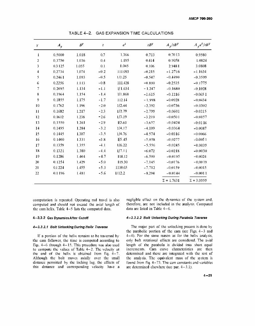
AMCP 706-260
TABLE 4-2. GAS EXPANSION TIME CALCULATIONS
Y Ay ßy z az zßy Ay/zßy Aya2/zßy
1 0.5000 1.018 0.7 1.366 0.713 0.7013 0.9580
2 0.3750 1.036 0.4 1.195 0.414 0.9058 1.0824
3 0.3 125 1.055 0.1 1.045 0.106 2.9481 3.0808
4 0.2734 1.074 -0.2 111.093 -0.215 -1.2716 -1.1634
5 0.2461 1.093 -0.5 1/1.25 -0.547 -0.4490 -0.3599
6 0.2256 1.113 -0.8 111.428 -0.890 -0.2535 -0.1775
7 0.2095 1.134 -1.1 1/1.634 -1.247 -0.1680 -0.1028
8 0.1964 1.154 -1.4 1/1.868 -1.615 -0.1216 -0.065 1
9 0.1855 1.175 -1.7 112.14 -1.998 -0.0928 -0.0434
10 0.1762 1.196 -2.0 1/2.44 -2.392 -0.0736 -0.0302
11 0.1682 1.217 -2.3 1/2.79 -2.799 -0.0601 -0.0215
12 0.1612 1.238 -2.6 1/3.19 -3.219 -0.0501 -0.0157
13 0.1550 1.261 -2.9 1/3.65 -3.657 -0.0424 -0.0116
14 0.1495 1.284 -3.2 1/4.17 -4.109 -0.0364 -0.0087
15 0.1445 1.307 -3.5 1/4.76 -4.574 -0.0316 -0.0066
16 0.1400 1.331 -3.8 1/5.45 -5.058 -0.0277 -0.005 1
17 0.1359 1.355 -4.1 1/6.22 -5.556 -0.0245 -0.0039
18 0.1321 1.380 -4.4 1/7.11 -6.072 -0.0218 -0.0030
19 0.1286 1.404 -4.7 118.12 -6.599 -0.0195 -0.0024
20 0.1254 1.429 -5.0 119.30 -7.145 -0.0176 -0.0019
21 0.1224 1.455 -5.3 1110.65 -7.712 -0.0159 -0.0015
22 0.1196 1.481 -5.6 1/12.2 -8.294 -0.0144 -0.0011
2= 1.7631 2 = 3.0959
computation is repeated. Operating rod travel is also computed and should not exceed the axial length of the cam helix. Table 4-5 lists the computed data.
4—3.3.2 Gas Dynamics After Cutoff
negligible effect on the dynamics of the system and, therefore, are not included in the analysis. Computed data are listed in Table 4-6.
4—3.3.2.2 Bolt Unlocking During Parabola Traverse
4-3.3.2.1 Bolt Unlocking During Helix Traverse
If a portion of the helix remains to be traversed by the cam follower, the time is computed according to Eqs. 4-6 through 4-15. This procedure was also used to compute the values of Table 4-2. The velocity at the end of the helix is obtained from Eq. 4-7. Although the bolt moves axially over the small distance permitted by the locking lug, the effects of this distance and corresponding velocity have a
The major part of the unlocking process is done by the parabolic portion of the cam (see Figs. 4-3 and 4—4). For the same reason as for the helix analysis, only bolt rotational effects are considered. The axial length of the parabola is divided into short equal increments. Cam curve characteristics are then determined and these are integrated with the rest of the analysis. The equivalent mass of the system is found from Eq. 4-73. The cam constants and variables are determined elsewhere (see par. 4-3.1).
4-29
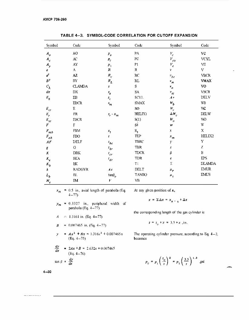
AMCP 706-260
TABLE 4-3. SYMBOL-CODE CORRELATION FOR CUTOFF EXPANSION
Symbol Code Symbol Code Symbol Code
Ao AO Pa PA Vc VC
Ac AC Pc PC Vco VCYL
Ay AY Pi PI Ve VE
a A R R V V
a2 AZ Rc RC vbc VBCR
ßy BY RL RL vm VMAX
CX CLAMDA s S vo VO
dx DX sa SA vsc VSCR
h EB sc SCYL Av DELV
EBCR sm SMAX Wb WB
Ecr E SO K W,
Er ER sr-xm HELIX] AWC DELW
Esc ESCR S(l) Wo WD
F F si w W
Fmb FBM S2 S2 X X
Fob FBO TEP m FffiLIX2
AF DELF he TBRC Y Y
g G hr TBR z Z
K DRK cr TDCR ß B
Ka SKA ldr TDR € EPS
Kb BK Tl X DLAMDA
k RADGYR At DELT Mr EMUR
h BL tan0o TANBO »S EMUS
Me FM V VB
xm = 0.5 in., axial length of parabola (Eq. 4-77)
ym = 0.3327 in., peripheral width of parabola (Eq. 4—77)
At any given position of x,
A
B
y
dy dx
tanj3 = -f. dx
1.3161 in. (Eq. 4-77)
0.007465 in. (Eq. 4-77)
Ax2 + Bx = 1.316*2 +0.007465* (Eq. 4-75)
2Ax+B = 2.632x + 0.007465 (Eq. 4-76)
dy
x = 2Ax = xn _ t + Ax
the corresponding length of the gas cylinder is
s = s„ + x = 3.5 +x ,in.
The operating cylinder pressure, according to Eq. 4—2, becomes
..(*)*->.(¥)'■' ,psi
4-30
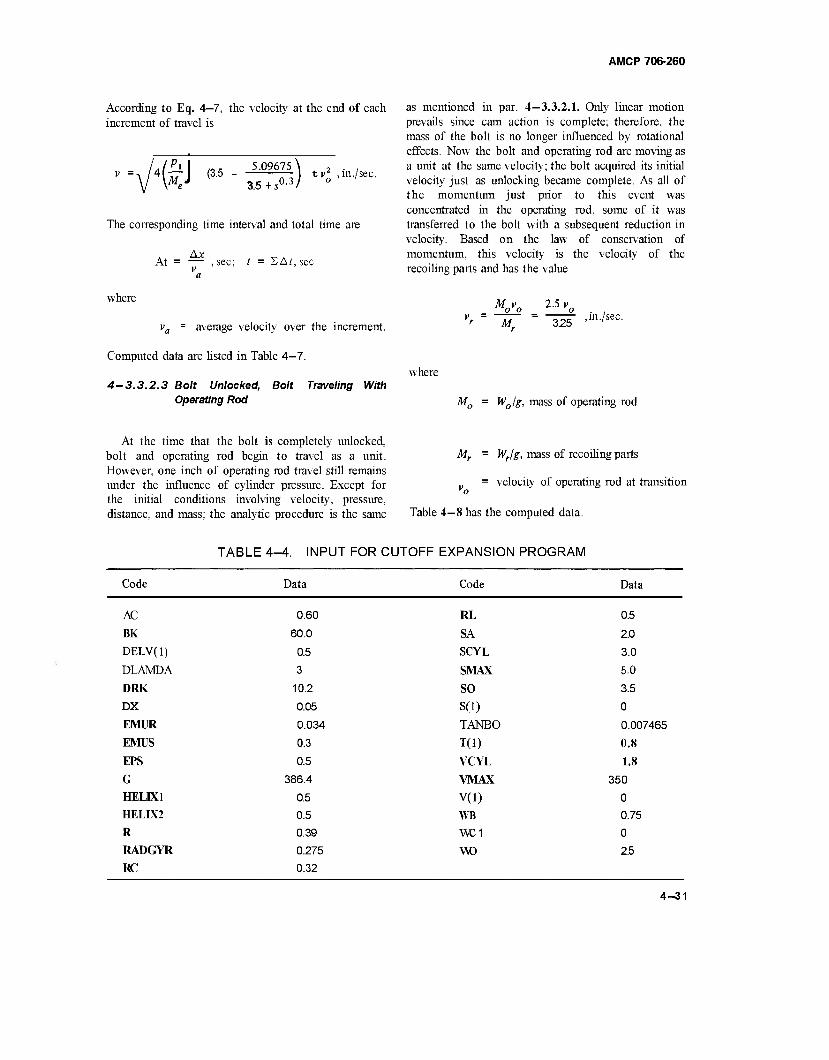
AMCP 706-260
According to Eq. 4—7, the velocity at the end of each increment of travel is
- /A(PI
I «K 5.09675 \ ^ 2 . , v =-\ /4 TT I (3.5 - tv' ,in./sec. V W 3.5+s0-3/ °
The corresponding time interval and total time are
Ax At = — , sec; t = £Af,sec
v a
where
va = average velocity over the increment.
Computed data are listed in Table 4—7.
4-3.3.2.3 Bolt Unlocked, Bolt Traveling With Operating Rod
as mentioned in par. 4—3.3.2.1. Only linear motion prevails since cam action is complete; therefore, the mass of the bolt is no longer influenced by rotational effects. Now the bolt and operating rod are moving as a unit at the same velocity; the bolt acquired its initial velocity just as unlocking became complete. As all of the momentum just prior to this event was concentrated in the operating rod, some of it was transferred to the bolt with a subsequent reduction in velocity. Based on the law of conservation of momentum, this velocity is the velocity of the recoiling parts and has the value
where
Movo M.
2-5vo 3.25
, in ./sec.
M0 = W0/g, mass of operating rod
At the time that the bolt is completely unlocked, bolt and operating rod begin to travel as a unit. However, one inch of operating rod travel still remains under the influence of cylinder pressure. Except for the initial conditions involving velocity, pressure, distance, and mass; the analytic procedure is the same Table 4-8 has the computed data.
Mr = Wr/g, mass of recoiling parts
= velocity of operating rod at transition
TABLE 4-4. INPUT FOR CUTOFF EXPANSION PROGRAM
Code Data Code Data
AC
BK
DELV(l)
DLAMDA
DRK
DX
EMUR
EMUS
EPS
G HELIX1
HELIX2
R
RADGYR
RC
0.60
60.0
0.5
3
10.2
0.05
0.034
0.3
0.5
386.4
0.5
0.5
0.39
0.275
0.32
RL
SA
SCYL
SMAX
SO
S(l)
TANBO
TO) VCYL
VMAX
V(l)
WB
VvC1
WO
0.5
2.0
3.0
5.0
3.5
0
0.007465
0.8
1.8
350
0
0.75
0
2.5
4-31
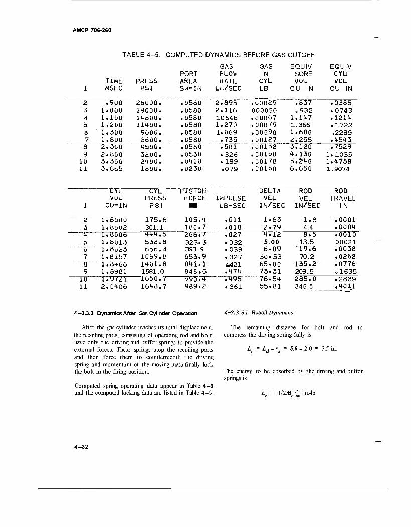
AMCP 706-260
TABLE 4-5. COMPUTED DYNAMICS BEFORE GAS CUTOFF
GAS GAS EQUIV EQUIV PORT FLOW 1 N SORE CYL
TlMfc PRESS AREA RATE CYL VOL VOL I MSLC PSI SU-IN Lo/SEC LB CU-IN CU-IN
2 .9u0 26000. ."0580 2 ."B9~5 TÖÖÖ29 .837 .0385 3 1.000 19000. .0580 2.116 000050 e932 .0743 4 1.100 14800. .0580 10648 .00067 1.147 .1214 b 1.2UÜ 11400. .0580 1.270 .00079 1.366 . 1722 6 1.300 9600. .0580 1.069 .00090 1.600 .2289 7 1.ÖÜÜ 6600. .0580 .735 .00127 2.255 .4543 8 2.300 4büü. . 058Ö" -T5 or" .00132 3.120 .7529 9 2.600 3200. .0530 .326 .001o8 4.130 1.1035
10 3.300 2400. .0410 . 189 .00178 5.240 1.4788 il 3»6o5 moo. .0230 .079 .00160 6.650 1.9074
CYL CYL PISTON DELTA ROD ROD VOL PRESS FORCE. IMPULSE VEL VEL TRAVEL
I CU-IN PSI ■ LB-SEC iN/SEd IN/SEÖ 1 N
2 l.aooo 175,6 105.4 .011 1.63 1.6 . WOT 3 1.8U02 301.1 160.7 .018 2.79 4.4 .0004 4 1.ÖÜÜ6 444.5 2~65T7~ .027 4.12 8.5 .0010 5 1.8013 538.6 323.3 • 032 5.00 13.5 00021 6 1.8Ü23 656.4 393.9 ,039 6.09 19.6 .0038 7 1.8157 1069,8 653.9 .327 50*53 70.2 .0262 8 i.6<+66 1401.8 641.1 e421 65.00 135.2 .0776 9 1.8981
i.y72i 1581.0 948.6 .474 73.31 208.5 ol635
10 1650./ 990.4 .495 76.54 285.0 .2869 11 2. 0<+Q6 1648,7 989.2 .361 55.81 340.8 .4011
4—3.3.3 Dynamics After Gas Cylinder Operation 4—3.3.3.1 Recoil Dynamics
After the gas cylinder reaches its total displacement, the recoiling parts, consisting of operating rod and bolt, have only the driving and buffer springs to provide the external forces. These springs stop the recoiling parts and then force them to counterrecoil; the driving spring and momentum of the moving mass finally lock the bolt in the firing position.
Computed spring operating data appear in Table 4—6 and the computed locking data are listed in Table 4-9.
The remaining distance for bolt and rod to compress the driving spring fully is
L. = LA 5.5 - 2.0 = 3.5 in.
The energy to be absorbed by the driving and buffer springs is
l/2Mv2 in.-lb r sa
4-32
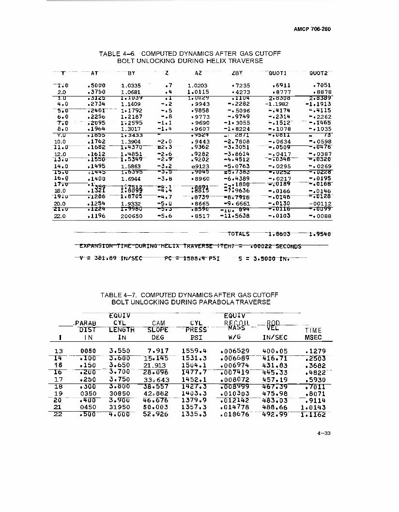
AMCP 706-260
TABLE 4-6. COMPUTED DYNAMICS AFTER GAS CUTOFF BOLT UNLOCKING DURING HELIX TRAVERSE
AT BY AZ ZBY XJUOTI QU0T2
r.o 2.0 3.U 4.0
6.0 T.tT 8.0
.5000
.3750 1.0335 1.0681
.7
.4 1.0203 1.0115
• 7235 .4273
.6911
.8777 .31üb .2734 .ZH6TT .225b .2T>95^ .19b4
l.iujy 1.1409 1.1792 1.2167 I.2595 1.3017
I7ÜU29 .9943 .9658 • 9773 .9690 .9607 .ybU4 . 9443
.9282
.9202 e9123 .9045 • 8960
:IÜ5 .^739™ • 8665
—.8590-
.11U4 -.2282 -.5096 -.9749
-1.3055 -1.8224 ~ 28/1 -2.7808 ■3.3051 -3.8614 -4.4512 " -5.0763 =5.7383" -6.4389 -TiT;8tnr" -f:9636
~srB'» 7916 -9.6661
•nr. 894-
2.8308 -1.1982 -.4174 -.2314 -.1512 -.1078 -.U811 -.0634 -.0509" -.0417
-^T0348" -.0295
.7051
.8878 2.83Uy
-1.1913 -.4115 -.2262 -.«65 -.1035
— rs~ -.0598
--ro47r -.0387 -.0320 -.0269
--.Ü228 -.0195
^T0T68- -.0146
^V0128 -00112
-■■•.0099 -.0088
Y.U 10.0 ii. r 12.0 I3TXT 14.0
.1 -.2 -.5 -.8
■1.1 -1.1
lb.U 16.0 17.u 18.0 19.u 20.0
.isoa
.1762
.1682—
.1612
. 1550^
.1495
1.3433 1.3904
-IV437Ü- 1.4851 1.5349 1.5863 1.6395 1.6944
-2.0 ^2^3" -2.6 -2^9" -3.2 -3.5 -3.8
21.u 22.0
.1400
a32T .1286- .1254 .1224 .1196
IHBif rlir87Ü5^ 1.9332 1.9980 200650
-4.4 -~**rr -5.Q -5.3 -5.6
-.UÜ52 -.0217
-=-.0189 -.0166
'-.1TC46 -.0130
--.0116- -.0103 •8517 -11.5638
^TOTStS- 1.8603 1.9540
EXPANSION TIME DURING HELIX TRAVERSE (TEH) -—.00022 SECONDS
-V- = 383r.^9 IN/SEC PC =~1588v4 PSl S = 3.5Ü0t)-rm
TABLE 4-7. COMPUTED DYNAMICS AFTER GAS CUTOFF BOLT UNLOCKING DURING PARABOLA TRAVERSE
EQUlV EQU1V -PARAB CYL CAM CYL RFC nil
-MA5S ■—see— OIST" T.EN6TH SLÜFE ~ "FRES~5 TIME I 1 N IN DtG PS I W/G IN/SEC MSEC
13 0050 3.550 7.917 1559.4 1531.3
.006529
.006689 400.05 .1279
14 .100 3.600 15.TJ5- 416.7T .2503 15 .150 3.650 21.913
28.096 1504.1 1477.7
.006974 7007419
431.83 445.33
.3682 16 ."20U 3.700 .4822 17 .250 3.750 33o643 1452.1 .008072 457.19 .5930 18 .300 3.ÜÜÖ ' 36.557 1427.3 .008999 467.39 .7011 19 0350 30850 42„882 1403.3 .010303 475.98 .8071 20 .400 3.900 46.676 1379.9 .TTCZWZ" 483.03 .9114 21 0450 31950 50.003 1357.3 .014778 488.66 1.0143 22 .500 4.000 52.926 T335.3 .018676 492.99 1.1162
4-33
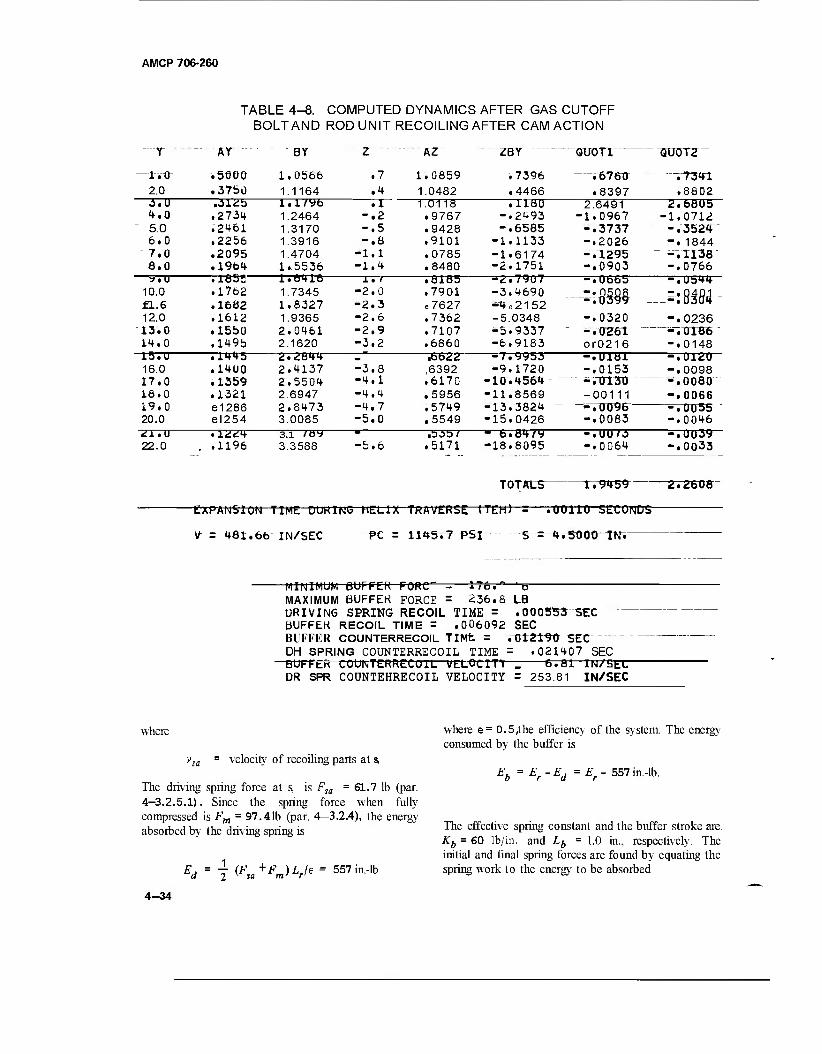
AMCP 706-260
t.t) 2.0 J.U 4.0 5.0 6.0 7.0 a.o
TABLE 4-8. COMPUTED DYNAMICS AFTER GAS CUTOFF BOLT AND ROD UNIT RECOILING AFTER CAM ACTION
AY
.5000
.3750
BY
1.0566 1.1164
.7
.4 .312b .2734 .2461 .2256 .2095 .19b4
~. 1855- .1762 . 1682 .1612 .15b0 .149b
-rr*f*-5- .1400 .1359 .1321 e1286 el254
l.i/yb 1.2464 1.3170 1.3916 1.4704 1.5536 1.6416- 1.7345 1.8327 1.9365 2.0461 2.1620
"2.2844 2.4137 2.5504 2.6947 2.8473 3.0085
-TT" -.2 -.5 -.6 •1.1 -1.4
AZ
1.0859 1.0482 1.0118 .9767 .9428 .9101 .0785 .8480
—.8185 .7901 e7627 .7362 .7107 .6860 —i6622~
,6392 .6170 .5956 .5749 .5549
ZBY
.7396
.4466 rrrair
-.2493 -.6585 -1.1133 -1.6174 -2.1751
~-2.7907 -3.4690 «4e2152 -5.0348 -5.9337 -6.9183 -7.9953" -9.1720
-10.4564 -11.8569 -13.3824 -15.0426 m b.84/v -18.8095
QUOTI QU0T2
• 6760 .8397
-.7341 .8602
2.6491 -1.0967 -.3737 -.2026 -.1295 -.0903 -.0665 -.0 -.XI
2.6805 -1.0712 -.3524 -.1844 -.1138 -.0766 -.Ub44 ■9.U
10.0 fl.6 12.0 13.0 14.0 15.U 16.0 17.0 18.0 19.0 20.0 21.U 22.0
1. /
-2.0 -2.3 -2.6 -2.9 -3.2
m —=tf*w -.0320 -.0261 or0216
-.0236 -~V0T86 -.0148 "-.0120 -.0098 -.0080 -.0066 -.0055 -.0046 "-.0039 -.0033
-3.8 -4.1 -4.4 ■4.7 -5.0
-•U1Ö1 -.0153 - ."013X1 -00111 -roow -.0083 -.UU/3 -.0064 .1196
3.i /8y 3.3588 -5.6 .5171
TOTALS r.9459
EXPANSION TIME DUK1N6 HELIX TRAVERSE (TEH) = .00110 SECONDS-
2.2608
V" =481.66 IN/SEC PC = 1145.7 PSI ~S = 4.500OTtT.
MINIMUM BUFFEK FORC—= 176." 'p MAXIMUM BUFFEK FORCE = 236.8 LB DRIVING SPRING RECOIL TIME = .000553 SEX BUFFEK RECOIL TIME = .006092 SEC BUFFER COUNTERRECOIL TIME = .0121^0 SEC DH SPRING COUNTERRECOIL TIME = .021407 SEC BUFFER COUNTERRECUIL VELOCITY . 6.81 IN/^i DR SPR C0UNTEHREC0IL VELOCITY = 253.81 IN/SEC
where
velocity of recoiling parts at ^
The driving spring force at s, is Fsa =61.7 lb (par. 4—3.2.5.1). Since the spring force when fully compressed is Fm = 97.41b (par. 4—3.2.4), the energy absorbed by the driving spring is
= T^+^JV6 557 in-lb
where e= 0.5,the efficiency of the system. The energy consumed by the buffer is
Eb=
Er 557 in.-lb.
The effective spring constant and the buffer stroke are. Kb = 60 lb/in. and Lb = 1.0 in., respectively. The initial and final spring forces are found by equating the spring work to the energy to be absorbed
4-34
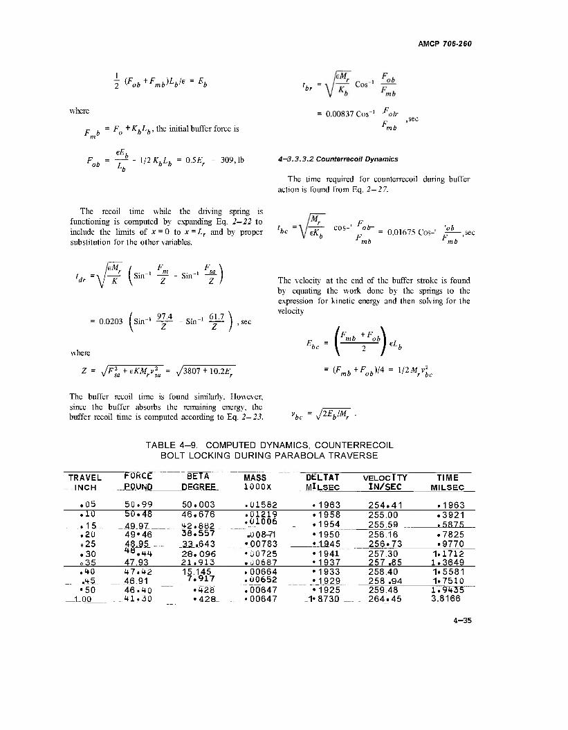
AMCP 706-260
2^ob^Fmb^bl
e = Eö
where
P . = FQ +KbLb, the initial buffer force is
lbr
0.00837 Cos"1 Fob-
mb ,sec
eE F . = -r^ - 1/2K,L. = 0.5£• - 309,1b ob £ b b r
b
4—3.3.3.2 Counterrecoil Dynamics
The time required for counterrecoil during buffer action is found from Eq. 2—27.
The recoil time while the driving spring is functioning is computed by expanding Eq. 2—22 to include the limits of x = 0 to x = Lr and by proper 'be substitution for the other variables.
tL = - COS-' ob- = 0 01675 Cos_, '£b_
° F , F u mb mb
ldr -V"^ I T in 2 '
0.0203 (sin"1 97.4 _t 61.' T" "Sin T 2)
where
Z= \/F2sa+eKMrvla = \/3807 + 10.2^
The velocity at the end of the buffer stroke is found by equating the work done by the springs to the expression for kinetic energy and then solving for the velocity
Jbc (^) eLl
(F ,+F ,)/4 = 1/2M v v mb ob" ' r , r be
The buffer recoil time is found similarly. However, since the buffer absorbs the remaining energy, the buffer recoil time is computed according to Eq. 2—23. vbe = PEblMr
TABLE 4-9. COMPUTED DYNAMICS, COUNTERRECOIL BOLT LOCKING DURING PARABOLA TRAVERSE
TRAVEL INCH
FORCE JBGUNO.
BETA- DEGREE
MASS 1000X
DELTAT MILSEC
VELOCITY IN/SEC
TIME MILSEC
.05 50.99 50.003 .01582 • 1963 254.41 .1963
.10
. 15 50.48
A9.9I 49M6 48.95
47.93
46.676
.. 42.882 38.557 33 .643 28.096 21.913
.01219
.01006
.0 0&71 •00783
.1958
.1954 255.00 255 59
.3921
.5875 .20 e25
'1950 L_1945
256.16 256.73 257.30 257 .85
.7825 • 9770
.30 e35
•Ü0725 .U0687
'1941 •1937
1.1712 1.3649
.to .45
47.42 46.91 46.40
^_41_..JQ
15.145 7.917
•428 • 428
.00664
.00652
.00647 •00647 1<
•1933 •1929 •1925 • 87 3D
258.40 258 .94
1.5581 1.7510
•50 _1.00
259.48 264.45
1.9435 3.8166
4-35
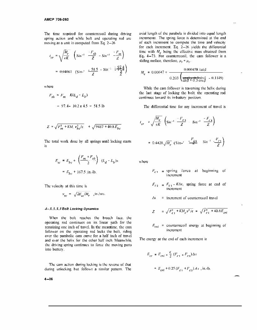
AMCP 706-260
The time required for counterrecoil during driving spring action and while bolt and operating rod are moving as a unit is computed from Eq. 2—26
'c=V^ (Sm_1 ^~Slir' m \
Z I
= 0.04061 (Sin-' ^P " Sin_1 "¥) where
Fsb =^-^d-V
= 97.4- 10.2x4.5 = 51.5 1b
axial length of the parabola is divided into equal length increments. The spring force is determined at the end of each increment to compute the time and velocity for each increment. Eq. 2—26 yields the differential time with Me being the effective mass obtained from Eq. 4-73. For counterrecoil, the cam follower is a sliding surface, therefore, pr = ns.
Af„ 0.00647 + 0.000458 tan/3
0.203 (SntfT ftjKinfl - 0.1149) smff + Ocosß
While the cam follower is traversing the helix during the last stage of locking the bolt, the operating rod continues toward its in-battery position.
The differential time for any increment of travel is
Z = y/F*m +KM, vjj~e + ^9487+40.8^ be
Sin"1 - Sin1
The total work done by all springs until locking starts is
0.4428sJMe (Sin- & Sin Z
E = E. + SC DC \ 2 / {Ld'Lb^
Ebc + 167.5 ,in.-lb.
The velocity at this time is
j2EsclMf , in./sec.
where
FCi = spring force at beginning of increment
Fc2 = Fcl-K/Ss, spring force at end of increment
As = increment of counterrecoil travel
4—3.3.3.3 Bolt Locking Dynamics
When the bolt reaches the breech face, the operating rod continues on its linear path for the remaining one inch of travel. In the meantime, the cam follower on the operating rod locks the bolt, riding over the parabolic cam curve for a half inch of travel and over the helix for the other half inch. Meanwhile, the driving spring continues to force the moving parts into battery.
The cam action during locking is the reverse of that during unlocking but follows a similar pattern. The
Z = y^, +KMeSle = 7^, +40.8£-c„.
Ecri = counterrecoil energy at beginning of increment
The energy at the end of each increment is
Ecr =Ecri + ^Fc^Fc2'>As
= Ecri+0.25 (Fci+Fc2> As,iKlb.
4-38
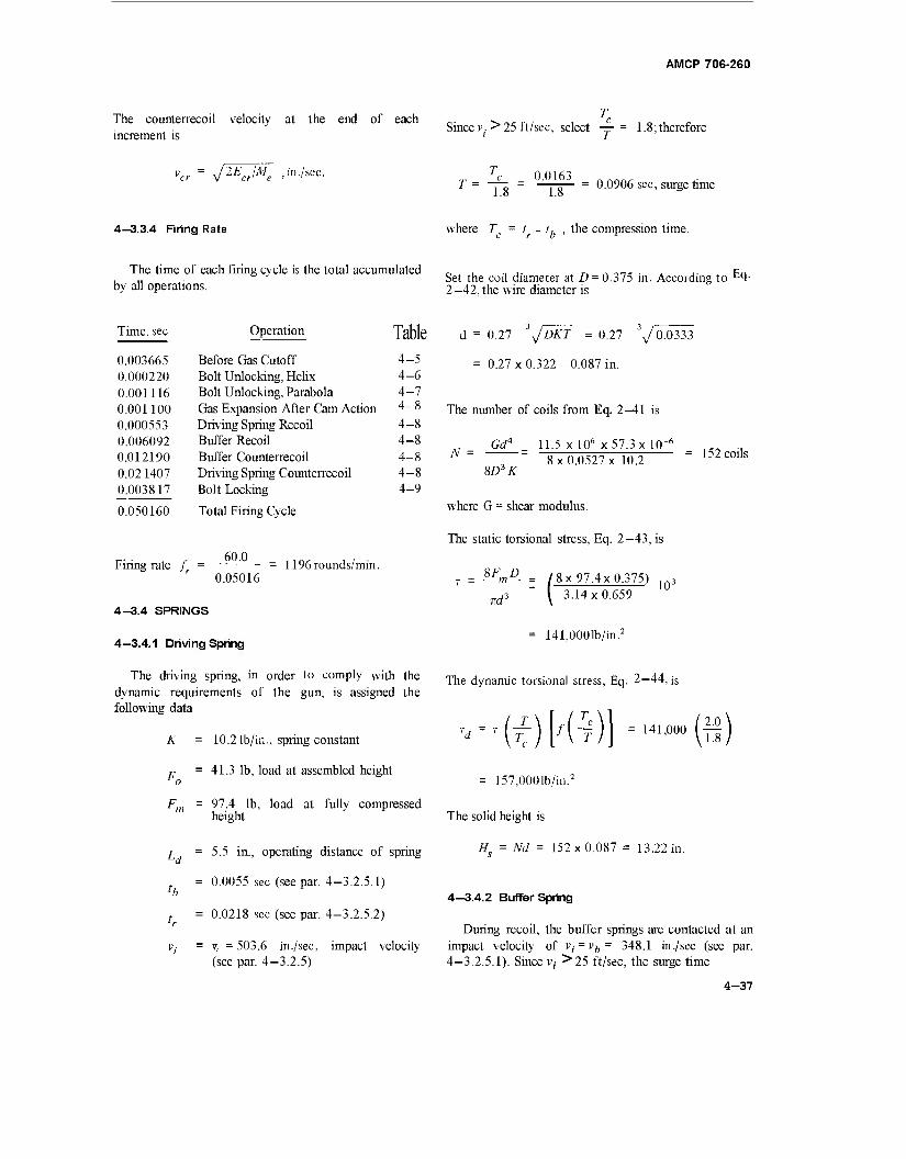
AMCP 706-260
The counterrecoil velocity at the end of each increment is
Since v; > 25 ft/sec, select — = 1.8; therefore
vcr = J2EJMe 'in-/s T =
0.0163 1.8
= 0.0906 sec, surge time
4—3.3.4 Firing Rate where T = t - t. , the compression time.
The time of each firing cycle is the total accumulated _, . .... ^ _ „ _„, . . ,. c,, , „ Set the coil diameter at D = 0.375 in. According to c4- by all operations. 2 -42, the wire diameter is
Time, sec Operation
0.003665 Before Gas Cutoff 0.000220 Bolt Unlocking, Helix 0.001116 Bolt Unlocking, Parabola 0.001100 Gas Expansion After Cam Action 0.000553 Driving Spring Recoil 0.006092 Buffer Recoil 0.012190 Buffer Counterrecoil 0.02 1407 Driving Spring Counterrecoil 0.003817 Bolt Locking
0.050160 Total Firing Cycle
Table d = 0.27 3JDKT = 0.27 3y 0.0333
4-5 4-6
= 0.27 x 0.322 - 0.087 in.
4-7 4 8
4-8 The number of coils from Eq. 2—41 is
4-8 4-8 4-8
Gd4 11.5 x 106 x57.3x 10"6
„ 8x 0.0527 x 10.2 SD3K
4-9
1196 rounds/min. „. . 60.0 Firing rate f =
0.05016
4-3.4 SPRINGS
4—3.4.1 Driving Spring
The driving spring, in order to comply with the dynamic requirements of the gun, is assigned the following data
K = 10.2 lb/in., spring constant
., = 41.3 lb, load at assembled height o
Fm = 97.4 lb, load at fully compressed height
^ = 5.5 in., operating distance of spring
= 0.0055 sec (see par. 4-3.2.5.1) lb
, = 0.0218 sec (see par. 4-3.2.5.2)
Vj = v, = 503.6 in./sec, impact velocity (see par. 4-3.2.5)
152 coils
where G = shear modulus.
The static torsional stress, Eq. 2-43, is
SF„D
ird3 \ 3.14x0.659
141,000 lb/in.2
10d
The dynamic torsional stress, Eq. 2—44, j
Td = T \T >m ■ '«*» in) = 157,0001b/in.2
The solid height is
Hs = Nd = 152x0.087 = 13.22 in.
4—3.4.2 Buffer Spring
During recoil, the buffer springs are contacted at an impact velocity of vi = vh= 348.1 in./sec (see par. 4-3.2.5.1). Since v,- •>25 ft/sec, the surge time
4-37
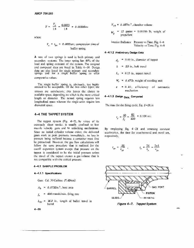
AMCP 706-260
0.0055 1.8
0.00306sec
where
Tc = tbr = 0.0055sec, compression time of
buffer spring.
A nest of two springs is used in both primary and secondary systems. The inner spring has 40% of the load and spring constant of the system. The assigned and computed data are listed in Table 4—10. Design data are also listed for single primary and secondary springs and for a single buffer spring to offer
comparative values.
The single buffer spring iSj obviously, too highly stressed to oe acceptable. Of the two other types, the
stresses are satisfactory; this leaves the choice to available space, depending on which is the more critical length or diameter. The nested spring requires less longitudinal space whereas the single units require less diametral space.
Vch = 0.057in.3 , chamber volume
w = 13 grains = 0.00186 lb, weight of g propellant
Interior Ballistics: Pressure vs Time, Fig. 4—8 Velocity vs Time, Fig. 4—8
4-4.1.2 Preliminary Design Data
d = 0.40 in., diameter of tappet
1 = 25 in., bolt travel
Lt = 0.15 in., tappet travel
Wr = 0.671b, weight of recoiling unit
i =0.40, efficiency of automatic mechanism
4-4.1.3 Design Data Computed
The time for the firing cycle, Eq. 2— 29, is
4-4 THE TAPPET SYSTEM
The tappet system (Fig. 4—7), by virtue of its extremely short stroke, is usually confined to low muzzle velocity guns and to unlocking mechanisms. Since no initial cylinder volume exists, the delivered gases work at peak pressures immediately, no loss in pressure being suffered because a container must first be pressurized. However, the gas flow calculations will follow the same procedure that is outlined for the cutoff expansion system except that pressure on the tappet is considered to be the initial pressure unless the travel of the tappet creates a gas volume that is not compatible with the critical pressure.
4-4.1 SAMPLE PROBLEM
4—4.1.1 Specifications
Gun: Cal .30 Carbine (7.62mm)
Ab = 0.0732in.2, bore area
f = 600 rounds/min, firing rate
Lbt = 1&.2 in., length of bullet travel in barrel
= 60 = J9_ = 0.100 sec. c f 600
By employing Eq. 4-21 and assuming constant acceleration, the time for counterrecoil and recoil are, respectively,
er v
2L 2L 2eL
iWWWVXX^rv-
GAS PORT
PISTON
SLIDE—/ "■—- BUSHING
Figure 4-7. Tappet System
4-38
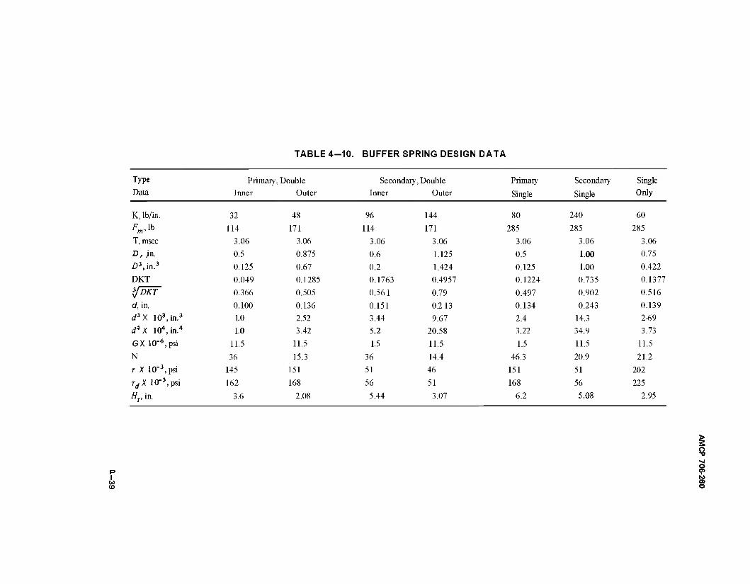
TABLE 4-10. BUFFER SPRING DESIGN DATA
Type Primary, Double Secondary, Double Primary Secondary Single Data Inner Outer Inner Outer Single Single Only
K, lb/in. 32 48 96 144 80 240 60
Fm>"> 114 171 114 171 285 285 285
T,msec 3.06 3.06 3.06 3.06 3.06 3.06 3.06
D, jn. 0.5 0.875 0.6 1.125 0.5 1.00 0.75
D3,in.3 0.125 0.67 0.2 1.424 0.125 1.00 0.422
DKT 0.049
0.366
0.1285
0.505
0.1763
0.561
0.4957
0.79
0.1224
0.497
0.735
0.902
0.1377
*/DKT 0.516
d, in. 0.100 0.136 0.151 0.213 0.134 0.243 0.139
d3X 103 ,in.3 1.0 2.52 3.44 9.67 2.4 14.3 2-69
rf4X 104; ,in.4 1.0 3.42 5.2 20.58 3.22 34.9 3.73
GX 10"6, psi 11.5 11.5 1.5 11.5 1.5 11.5 11.5
N 36 15.3 36 14.4 46.3 20.9 21.2
T X 10"3, psi 145 151 51 46 151 51 202
rrfX10-3 , psi 162 168 56 51 168 56 225
Ht,m 3.6 2.08 5.44 3.07 6.2 5.08 2.95
I w CO
o
o
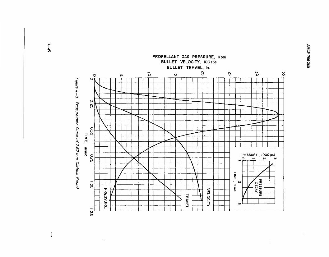
Po
a
-i
Sj
2 3
I 3" CD
30 O c
PROPELLANT GAS PRESSURE, kpsi BULLET VELOCITY, 100 fps
BULLET TRAVEL, in.
o •a vi o o> IS3
o
£0 VI 8 tt <ä (X
m
3 01 « o O
Ol
PRESSURE, 1000 psi O — M Ol
H Z PI " ro 3 U) CD O
CM
* a a
- ^x m 3 m CO i c 3)
< m r~ o o H
H 3)
m ■n r
AMCP 706-260
Solve both equation for v„ , equate and reduce to the simplest terms
t, = Et„ = 0.40 tcr
tr+tcr = 1.40tcr = 0.100 sec
tCF = 0.071 sec
t. = 0.029 sec
This is the time needed for the tappet to reach the velocity of 172 in./sec. The average pressure in the tappet cylinder is
p = J_ = -JZL = 13601b/in.2
' 7T, ~ 0.1257
where
A( = — d2( = 0.1257 in.2 ,tappet area
The counterrecoil velocity is
21 2 x 2.5 _„ . . . "cr'T =ÖTT =70.4.n./sec.
cr
The recoil velocity is
2L 2 x 2.5 t. 0.029
172 in. /sec.
d, = 0.40 in., tappet diameter
Assume that the pressure in the tappet cylinder is the critical pressure, then the corresponding pressure in the bore becomes, Eq. 4-26,
pc pb = 053= 25661b/in-
The area of the pressure-time corresponding to the impulse of the tappet, Eq. 4-50, is
The energy of the recoiling part, Eq. 2-15, is
*-■*(?)■;-* US)»«» = 25.65 in.-lb.
The average force on the tappet, Eq. 2-16, is
^ = m$ = 1711b. " L, 0.15
A = pbt = 2566x0.00175 = 4.5 lb-sec/in.
According to Eq. 4-49, when the bullet is still in the barrel, pm = Pf, and Vm = Vb, therefore, if kb = k = 1.3
-•■<m. 1/1.3
OMAWl-
= 0.614 (0.OOI86J 01°2
14
859 = 1.728 xlO"5 lb
The momentum of the recoiling parts Mvr is
\ 386.4/
where
Mv. 172 = 0.298 lb-sec.
Equate momentum and impulse, and solve for time t.
Mvr 0 298 t = -FL = ^TTT-lb = 0.00175 sec a 1/1
„ = 0.53pft, the pressure in the tappet cylinder, considered to be the critical pressure
Vc = A,Lt = 0.0189 in.3, volume of tappet displacement
y = Vch + AbLbt = 1.245 in.3, chamber plus bore volumes
4-41
AMCP 706-260
The estimated orifice area, Eq. 4—52, is
W„
KwA
Pt
1.728 x jo"5
.92 x l(T3 x4.5 = 0.002 in.2
where
K„ 0.00192/sec (see par. 4-3.2.5.2)
The orifice diameter d0 =0.0505 in.
If we proceed with the above computed parameters and with the assumed critical pressures, data similar to those in Table 4—11 were computed for the period of time starting at 0.53 msec and extending to the muzzle at 1.15 msec. The area under the pressure-time curve within these time limits equals the 4.5 area computed earlier. Although the required tappet velocity of 172 in./sec was obtained, the tappet travel of 0.072 in. was far short of the required 0.15 in. The required travel could be obtained by merely shifting the gas port toward the muzzle. However, the computed equivalent volumes Ve, Eq. 4—42, were always larger than the computed chamber volume Vc, Eq. 4—48. This created the illusion that the tappet cylinder pressure pc, Eq. 4-43, was much higher that the available bore pressure, a physical impossibility substantiated by the rate of pressure decline in the bore, so that pressure in the cylinder cannot be maintained higher than that in the bore.
Based on the first computed data, the gas port was moved farther toward the muzzle. Minimum limits on size precluding the use of a Port small enou^ t0
regulate the pressure to be compatible with velocity and distance had the original port location been kept. Tappet cylinder pressures were assumed to be bore pressure. The assumption is virtually correct since a much higher mass of gas can pass through the port than volume created to accommodate it on the other side by the accelerating tappet.
The pressure in the tappet cylinder now being the same as the bore pressure, the area under the pressure-time curve becomes
pt Pc1 1360x0.00175 = 2.38 lb-sec/in.2
beyond the muzzle must be considered to compensate for that lost by the relocation of the port. The first set of calculations is a good guide for locating the new port position. After the second set of calculations are completed, the exact velocity and tappet travel are determined by manipulating the areas under the pressure-time curve of the first and last increment. That amount subtracted from one must be added to the other to maintain the same area and hence velocity. If the travel distance is too short, the acceleration at the beginning is too high. Lowering the acceleration at the beginning grants the additional time needed at the end to cover the total required distance. A reduction of the area of the pressure-time curve at the start of the activity and its equal added to the end resolves this problem. If travel distance goes beyond that required, an increase in acceleration at the beginning is needed so that the terminal tappet velocity is realized at a shorter distance. A transfer of pressure-time area from the end to the beginning will serve the purpose. When both tappet travel distance and velocity comply with the required values, the gas port becomes located along the length of the barrel corresponding with the time when this activity started.
The data presented in Table 4—11 are the results of a series of computations arriving at a terminal tappet velocity of 172 in./sec on moving a distance of 0.15 in. the required value. The pressure is read from the pressure-time curve in Fig. 4—8 between the time limits 0.867 msec to 2.13 msec, which extends into the decay period after the bullet leaves the muzzle. While the bullet is still in the barrel, the pressures are
read at the time interval and are assumed to be constant over the interval. To illustrate the procedure, the sequence of calculations for t = 1.1 msec follows.
At t = 11.0 x \0'4,pa = 3100 lb/in.2 (Fig.4-8)
(The average pressure for 1.65 and 2.13 msec is obtained by dividing the differential area of the pressure-time curve by the corresponding time increment.)
The increment of time, At = 0.00005 sec.
The impulse on the tappet is
FAt = AfaAt = 0.0195 lb-sec
Now that the gas port has been moved closer to the muzzle, some of the area of the pressure time curve
where
^ = 0.1257 in.2, area of tappet
4-42
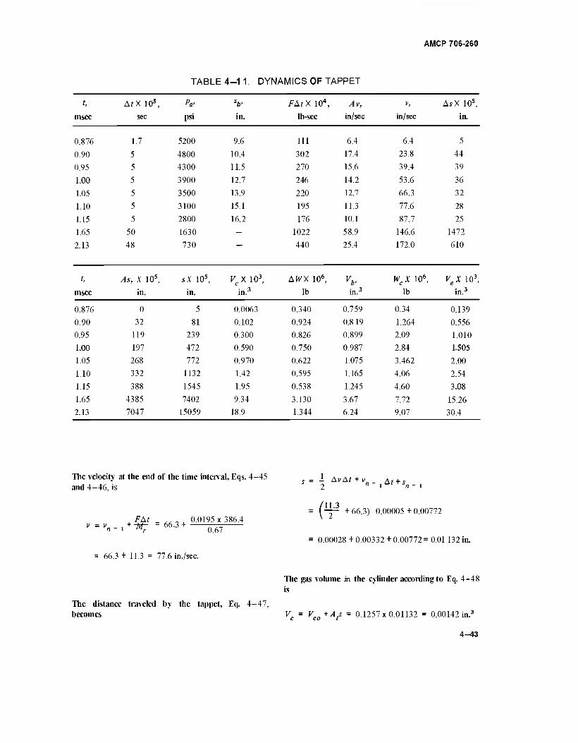
AMCP 706-260
TABLE 4-11. DYNAMICS OF TAPPET
t, AtX 10s, Pa' sb> FAtX 104, Av, V, AsX 10s,
msec sec psi in. lb-sec in/sec in/sec in.
0.876 1.7 5200 9.6 111 6.4 6.4 5
0.90 5 4800 10.4 302 17.4 23.8 44
0.95 5 4300 11.5 270 15.6 39.4 39
1.00 5 3900 12.7 246 14.2 53.6 36
1.05 5 3500 13.9 220 12.7 66.3 32
1.10 5 3100 15.1 195 11.3 77.6 28
1.15 5 2800 16.2 176 10.1 87.7 25
1.65 50 1630 - 1022 58.9 146.6 1472
2.13 48 730 — 440 25.4 172.0 610
t, As, X 10s, sX 10s, vcx 103, AWX 106, vb> wcx 106, vex 103, msec in. in. in.3 lb in.3 lb in.3
0.876 0 5 0.0063 0.340 0.759 0.34 0.139
0.90 32 81 0.102 0.924 0.819 1.264 0.556
0.95 119 239 0.300 0.826 0.899 2.09 1.010
1.00 197 472 0.590 0.750 0.987 2.84 1.505
1.05 268 772 0.970 0.622 1.075 3.462 2.00
1.10 332 1132 1.42 0.595 1.165 4.06 2.54
1.15 388 1545 1.95 0.538 1.245 4.60 3.08
1.65 4385 7402 9.34 3.130 3.67 7.72 15.26
2.13 7047 15059 18.9 1.344 6.24 9.07 30.4
The velocity at the end of the time interval, Eqs. 4-45 and 4-46, is
FAt _ ,, , 0.0195 x 386.4 v=\-1
+^7 "66-3+ Ö67
1 AMr + ViAt + Vi
(¥ + 66.3) 0.00005 +0.00772
0.00028 + 0.00332 + 0.00772 = 0.01 132 in.
= 66.3 + 11.3 = 77.6 in./sec.
The distance traveled by the tappet, Eq. 4-47, becomes
The gas volume in the cylinder according to Eq. 4-48 is
Vc = VCQ+Ats = 0.1257x0.01132 = 0.00142 in.3
4-43
AMCP 706-260
where the initial volume Vco = 0.
The rate of flow, Eq. 4—27, is
w = KwAQpa = 0.00129 x 0.002 x 3100
= 0.01 190 lb/sec.
The weight of the gas flowing through the port during the interval, Eq. 4—28, is
AW, = Atw = 0.00005x0.01190 = 5.95 x 10⁻⁷ lb.
The total weight of the gas in the tappet cylinder is Wc.
Wc = Wc(n - l) + AW, = (3.462 + 0.595) 10"6
= 4.057 x 10"6 lb.
The equivalent volume of this gas at 3100 psi pressure, according to Eq. 4—42 becomes
| V = 4.057 x 10"6 . .,, I Vb 1.8tix10-ä 1165
This pressure is absurd but it does indicate that more gas is capable of flowing through the port than the cylinder, as the receiver, can admit; therefore, the assumption that cylinder pressure is nearly equal to bore pressure is highly probable particularly since Ve >VC throughout the operation. Further assurance is available by computing the time needed during each interval to bring the pressure in the cylinder to the critical. In each increment, the gas flow is rapid enough to reach the critical before the moving tappet creates the corresponding volume. This approach is conservative since the differential pressures in the computations were based solely on critical pressures as limits although considerable time is available for additional gas flow into the cylinder, thus tending to approach the bore pressure. For example, continue with the same sequence of calculations for t= 1.1 msec. The critical pressure is
Per = 053Pa 0.53x3100 = 16401b/in.;
The pressure due to expansion of the gas in the cylinder during the interval provided that gas flow ceases is pe.
= 0.00254 in.'
where Vb is the gas volume of the barrel.
Pe = Per-,
1135 lb/in.'
1860
Vb = Vo+Absb = 0.057 + 0.0732 x 15.1 = 1.165 in.3
where where
y - 0.057 in.3, initial volume (chamber) o
A, = 0.0737 in.2, bore area
s = 15.1 in., bullet travel at t = 1.1 msec (Fig. 4-8)
According to Eq. 4—43
Per - l
Ve-*
1860 lb/in.2 , the critical pressure of the previous interval
0.00142 in.3, the gas volume in the tappet cylinder
0.00097 in.3, the gas volume of the previous interval
2.54 .1.42,
3100
The differential pressure between the expanded gas in the cylinder and the critical pressure provided by gas flow
2.13 x 3100 = 6600 lb/in.2 *Pr Pcr'Pe = 1640" 1135 = 5051b/'n-:
4-44
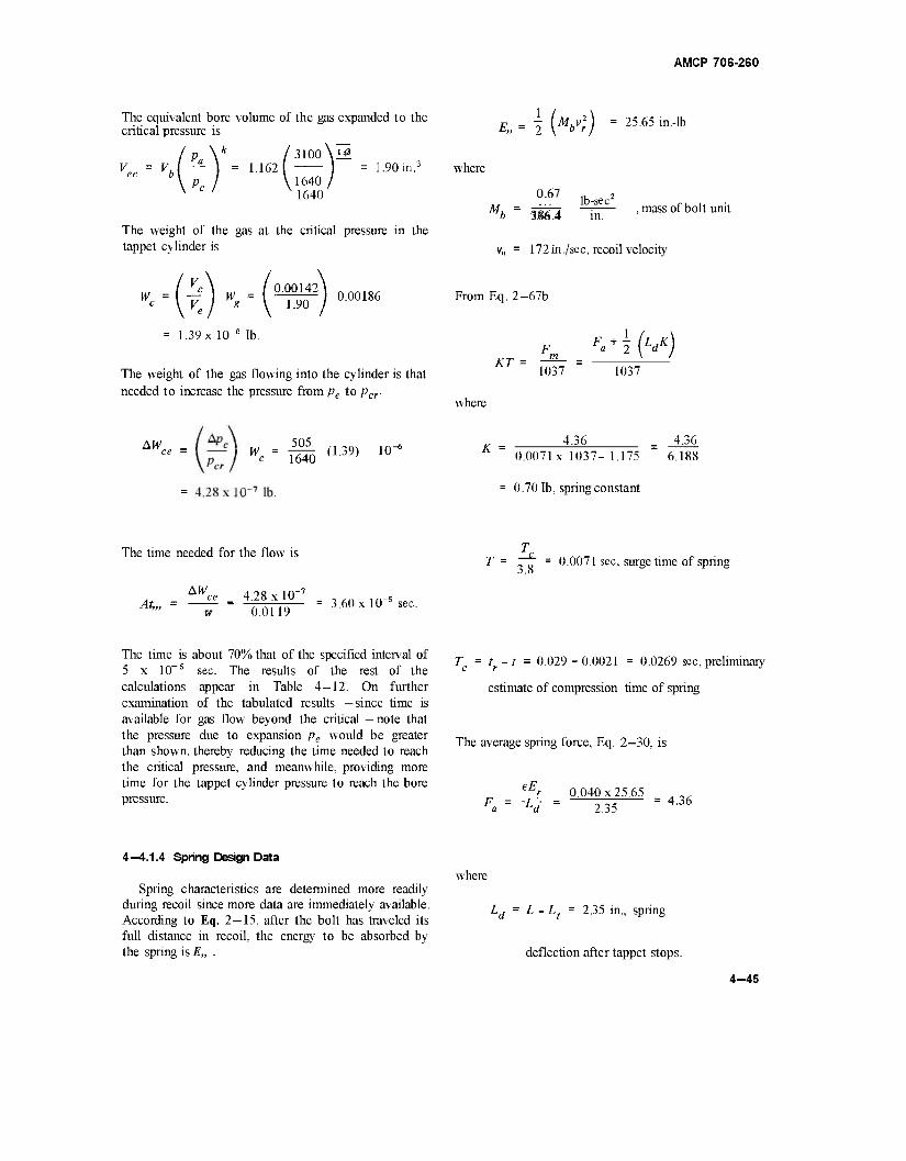
AMCP 706-260
The equivalent bore volume of the gas expanded to the critical pressure is
I p V /3100\H V«'v\t)-,A62W0) ■'■"""■' v c ' 1640
The weight of the gas at the critical pressure in the tappet cylinder is
Eu= \ (Mbvj) = 25.65 m,lb
where
0.67 Mu =
lb-sec b 3§fi.4 in.
v„ = 172 in./sec, recoil velocity
mass of bolt unit
wc'\y wg
= 1.39 x 10"6 lb.
0.00142 1.90 i
0.00186
The weight of the gas flowing into the cylinder is that needed to increase the pressure from pe to pcr-
AW w- - Wä(L39) 10~6
From Eq. 2—67b
F°+-2 KT =
M 1037 1037
where
K 4.36 = 4.36
0.0071x1037-1.175 6.188
0.70 lb, spring constant
The time needed for the flow is
AW At,,
4.28x10" 0.0119
= 3.60 xl0_s sec.
T = . 0 = 0.0071 sec, surge time of spring
The time is 5 x 10~5
calculations examination available for the pressure than shown, the critical time for the pressure.
about 70% that of the specified interval of sec. The results of the rest of the appear in Table 4—12. On further of the tabulated results —since time is gas flow beyond the critical — note that due to expansion pe would be greater
thereby reducing the time needed to reach pressure, and meanwhile, providing more tappet cylinder pressure to reach the bore
Tc = tf-t = 0.029 - 0.0021 = 0.0269 sec, preliminary
estimate of compression time of spring
The average spring force, Eq. 2-30, is
eE. -r 0.040x25.65 Fa= -Ld- = - _, - =4.36 2.35
4—4.1.4 Spring Design Data
Spring characteristics are determined more readily during recoil since more data are immediately available. According to Eq. 2—15, after the bolt has traveled its full distance in recoil, the energy to be absorbed by the spring is E„ .
where
Ld = L - Lt = 2.35 in., spring
deflection after tappet stops.
4-45
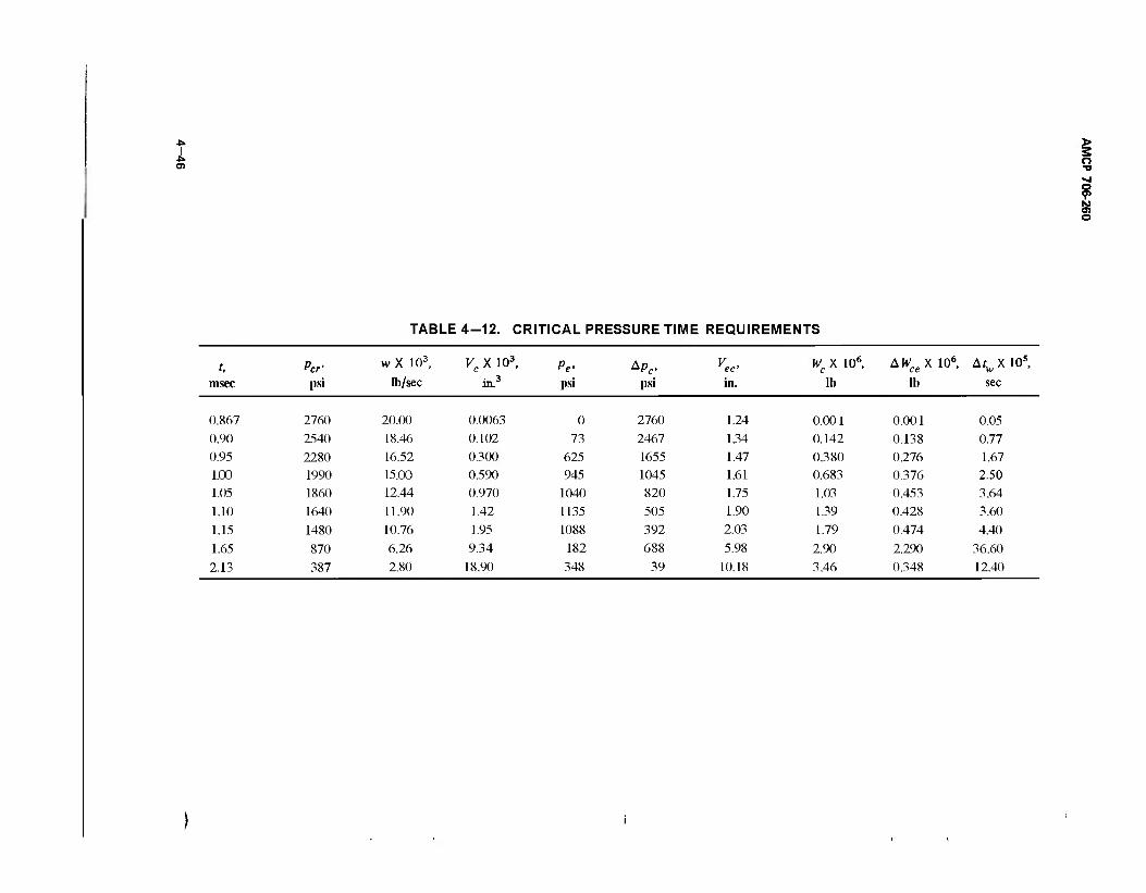
05
TABLE 4-12. CRITICAL PRESSURE TIME REQUIREMENTS
t, Per' w X 103, K,X10 3, P , *Pc- vec. W X 106, c AWceX 106, ArwX105,
msec psi lb/sec in.3 psi psi in. lb lb sec
0.867 2760 20.00 0.0063 0 2760 1.24 0.001 0.001 0.05 0.90 2540 18.46 0.102 73 2467 1.34 0.142 0.138 0.77 0.95 2280 16.52 0.300 625 1655 1.47 0.380 0.276 1.67 1.00 1990 15.00 0.590 945 1045 1.61 0.683 0.376 2.50 1.05 1860 12.44 0.970 1040 820 1.75 1.03 0.453 3.64
1.10 1640 11.90 1.42 1135 505 1.90 1.39 0.428 3.60
1.15 1480 10.76 1.95 1088 392 2.03 1.79 0.474 4.40
1.65 870 6.26 9.34 182 688 5.98 2.90 2.290 36.60
2.13 387 2.80 18.90 348 39 10.18 3.46 0.348 12.40
> 5 o "U
s o
AMCP 706-260
The driving spring force when the bolt is fully retracted The elapsed time for the firing cycle becomes is
Fm = Fa +1 (KLd) =4-36+i(2.3s) 0.70
= 5.18 1b.
The driving spring force when tappet contacts bolt is
Fn = Fm -KL, = 5.18-2.35x0.70 = 3.541b.
The time for the bolt to recoil, excluding the time of the initial 0.15 in. of tappet travel, is computed via Eq. 2-23.
t = t +t +t c a r cr 0.0021 +0.0258+0.0669
= 0.0948 sec.
The new firing rate of
'r ~ t - 633 rounds/min is acceptable since it is only
5.5%higher than the specified rate.
The revised surge time of the spring becomes
„ Tc la + tr 0.0021+0.0258 nn_. T = 3Ä = ~3Ä = 18 = 000734sec-
K c^ T
I 0.4 x 0.67 _! 154 0.70x386.4 5.18
= 0.0315x0.818 = 0.0258 sec
Having set the coil diameter at D = 0.25 in., we establish the spring constant at K = 0.70 lb/in., thus the wire diameter according to Eq. 2-42 becomes
d = 0.27 S/DKT = 0.27 ^0.001286
= 0.27x0.1088 = 0.0294 in.
Spring data and time are now computed for counterrecoil
F =F -KL = 5.18- 0.70x2.5 = 3.43 1b o m
where
2.5 in., total length of bolt travel including tappet travel.
The time of counterrecoil, Eq. 2—27,
Mh Fn —6 Cos"1 ■/■
0.67 _ , 3_43 '0.4x386.4x0.70 cos" 5.18
0.079 x 0.847 = 0.0669 sec.
The number of coils, Eq. 2-41, isN.
Gd4 11.5 x 106 x74.7 x 10"8
N gD3K 8x0.0156x0.66 = 104 coils
The static torsional shear stress becomes
SFmD 8x5.18x0.25
?rd3 3.14 x 25.4 x 10"6
The dynamic stress is
130,000 lb/in.2
(£) [f(£)] - .30,000 (||)
The time needed to accelerate the bolt during recoil is obtained from Table 4-11 where ta = t = 0.0021 sec, the last value (rounded to 4 places) in the time column.
= 137,0001b/in.:
The solid height is
Hs = Nd = 104 x 0.0294 = 3.06 in.
4-47/4-48
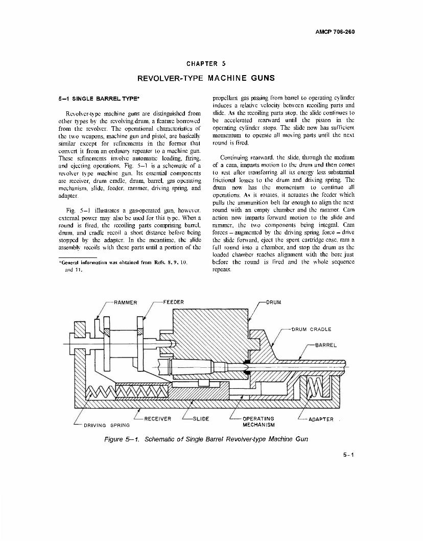
AMCP 706-260
CHAPTER 5
REVOLVER-TYPE MACHINE GUNS
5-1 SINGLE BARREL TYPE*
Revolver-type machine guns are distinguished from other types by the revolving drum, a feature borrowed from the revolver. The operational characteristics of the two weapons, machine gun and pistol, are basically similar except for refinements in the former that convert it from an ordinary repeater to a machine gun. These refinements involve automatic loading, firing, and ejecting operations. Fig. 5—1 is a schematic of a revolver type machine gun. Its essential components are receiver, drum cradle, drum, barrel, gas operating mechanism, slide, feeder, rammer, driving spring, and adapter.
Fig. 5—1 illustrates a gas-operated gun, however, external power may also be used for this type. When a round is fired, the recoiling parts comprising barrel, drum, and cradle recoil a short distance before being stopped by the adapter. In the meantime, the slide assembly recoils with these parts until a portion of the
*General information was obtained from Refs. 8, 9, 10, and 11.
propellant gas passing from barrel to operating cylinder induces a relative velocity between recoiling parts and slide. As the recoiling parts stop, the slide continues to be accelerated rearward until the piston in the operating cylinder stops. The slide now has sufficient momentum to operate all moving parts until the next round is fired.
Continuing rearward, the slide, through the medium of a cam, imparts motion to the drum and then comes to rest after transferring all its energy less substantial frictional losses to the drum and driving spring. The drum now has the momentum to continue all operations. As it rotates, it actuates the feeder which pulls the ammunition belt far enough to align the next round with an empty chamber and the rammer. Cam action now imparts forward motion to the slide and rammer, the two components being integral. Cam forces — augmented by the driving spring force — drive the slide forward, eject the spent cartridge case, ram a full round into a chamber, and stop the drum as the loaded chamber reaches alignment with the bore just before the round is fired and the whole sequence repeats.
-RAMMER -FEEDER DRUM
-DRUM CRADLE
OPERATING -DRIVING SPRING MECHANISM
Figure 5—1. Schematic of Single Barrel Revolver-type Machine Gun
-ADAPTER
5-1
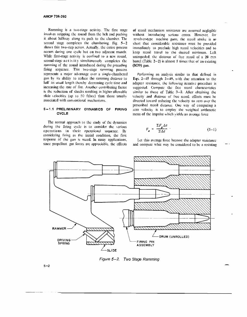
AMCP 706-260
Ramming is a two-stage activity. The first stage involves stripping the round from the belt and pushing it about halfway along its path to the chamber. The second stage completes the chambering. Fig. 5-2 shows this two-step action. Actually, the entire process occurs during one cycle but on two adjacent rounds. While first-stage activity is confined to a new round, second-stage activity simultaneously completes the ramming of the round introduced during the preceding firing sequence. This two-stage ramming process represents a major advantage over a single-chambered gun by its ability to reduce the ramming distance to half its usual length thereby decreasing cycle time and increasing the rate of fire. Another contributing factor is the reduction of shocks resulting in higher allowable slide velocities (up to SO ft/sec) than those usually associated with conventional mechanisms.
5-1.1 PRELIMINARY DYNAMICS OF FIRING CYCLE
of recoil mechanism resistance are assumed negligible without introducing serious errors. However, for revolver-type machine guns, the recoil stroke is so short that considerable resistance must be provided immediately to preclude high recoil velocities and to keep recoil travel to the desired minimum. Left unimpeded, the distance of free recoil of a 20 mm barrel (Table 2-2) is almost 5 times that of an existing (M39) gun.
Performing an analysis similar to that defined in Eqs. 2-45 through 2-49, with due attention to the adapter resistance, the following iterative procedure is suggested. Compute the free recoil characteristics similar to those of Table 3—2. After obtaining the velocity and distance of free recoil, efforts must be directed toward reducing the velocity to zero over the prescribed recoil distance. One way of computing a zero velocity is to employ the weighted arithmetic mean of the impulse which yields an average force
The normal approach to the study of the dynamics during the firing cycle is to consider the various operations in their operational sequence. By considering firing as the initial condition, the first response of the gun is recoil. In many applications, since propellant gas forces are appreciable, the effects
SAf (5-1)
Let this average force become the adapter resistance and compute what may be considered to be a resisting
RAMMER
DRIVING- SPRING IW\^\V\\S FIRING PIN
ASSEMBLY
^SLIDE
Figure 5-2. Two Stage Ramming
5-2
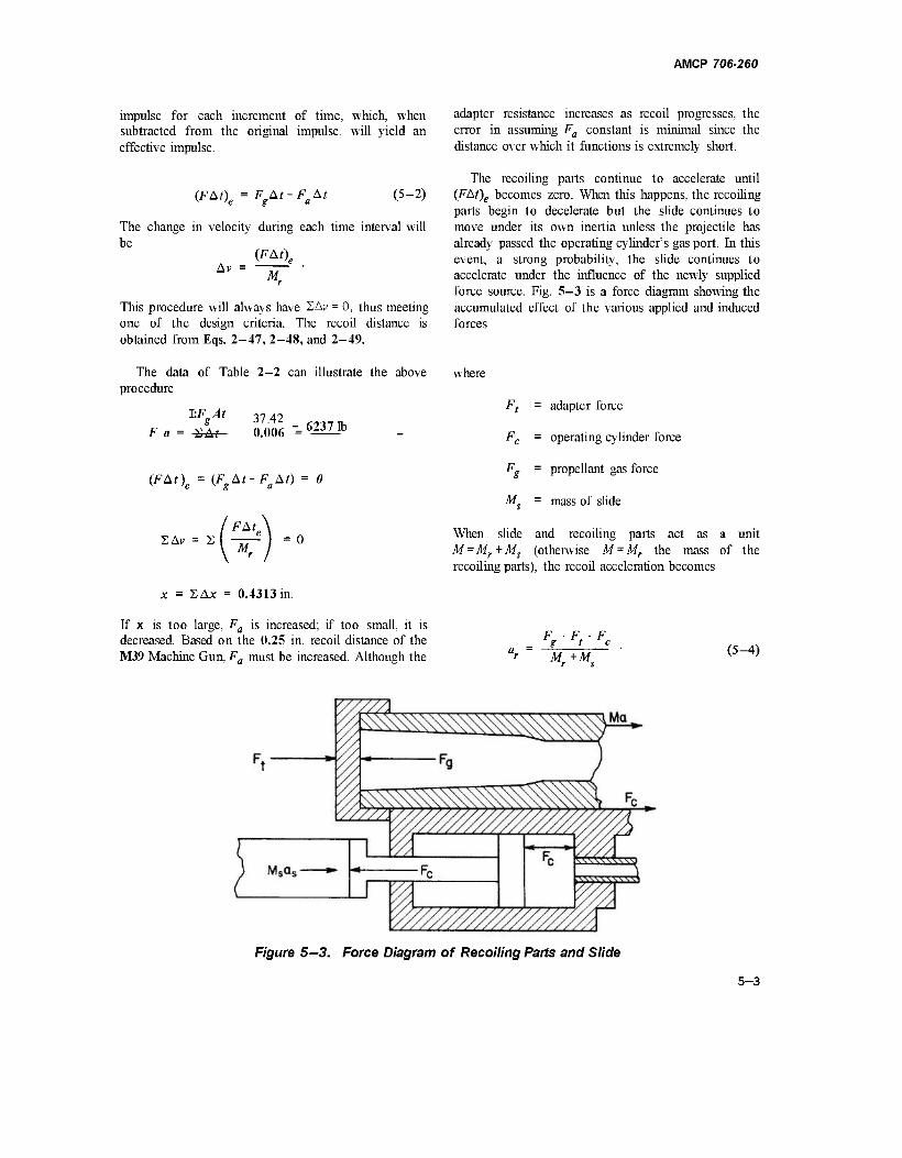
AMCP 706-260
impulse for each increment of time, which, when subtracted from the original impulse, will yield an effective impulse.
(FAt)e = F At-Fa At (5-2)
The change in velocity during each time interval will be
(FAt\
Mr
This procedure will always have 2Ay = 0, thus meeting one of the design criteria. The recoil distance is obtained from Eqs. 2-47, 2-48, and 2-49.
adapter resistance increases as recoil progresses, the error in assuming Fa constant is minimal since the distance over which it functions is extremely short.
The recoiling parts continue to accelerate until (FAt)e becomes zero. When this happens, the recoiling parts begin to decelerate but the slide continues to move under its own inertia unless the projectile has already passed the operating cylinder's gas port. In this event, a strong probability, the slide continues to accelerate under the influence of the newly supplied force source. Fig. 5—3 is a force diagram showing the accumulated effect of the various applied and induced forces
The data of Table 2-2 can illustrate the above procedure
I:V 37.42 F a = SAf 0.006
s -"— _ 6237ib
(FAt)e = (FgAt-FaAt) = 0
where
M_
adapter force
operating cylinder force
propellant gas force
mass of slide
2Av = 2 FAt^
M. When slide and recoiling parts act as a unit M = Mr + Ms (otherwise M = Mr the mass of the recoiling parts), the recoil acceleration becomes
x = 2 A* = 0.4313 in.
If x is too large, Fa is increased; if too small, it is decreased. Based on the 0.25 in. recoil distance of the M39 Machine Gun, Fa must be increased. Although the
W M+M,
(5-4)
Figure 5-3. Force Diagram of Recoiling Parts and Slide
5-3
AMCP 706-260
The slide acceleration becomes where
a + M„ (5-5)
The dynamics of the gas operating cylinder follow a procedure similar to that for the cutoff expansion system (see par. 4—3.1.1).
Before continuing with the gas system analysis, the required operating energy must be estimated which leads to the selection and analysis of the slide and drum dynamics. Transfer of energy of slide to drum and driving spring and then back to slide must be achieved with operative efficiency and tolerable forces. A system such as this is notorious for its high energy losses and large forces. These two characteristics are kept within bounds by an elliptical cam, although other curves may be used if they display similar properties with respect to cam action.
The physical dimensions of the drum are best suited to generate other design parameters. Drum length is dictated by round length. Its outer radius is based on the number of chambers and the strength of the outer wall. A minimum of 4 chambers is sufficient to meet the basic operating requirements of present revolver-type machine gun concepts but may prove awkward in actual practice because of large angular displacement for each firing cycle, thus reducing the firing rate and putting an added burden on the designer to provide more power and acceptable mechanisms such as rammers. A design study at Springfield Armory indicates an optimum number of 5 chambers when based on kinematics alone. When other factors were considered, 5 or 6 chambers showed little difference with 5 having a slightly lower firing rate but definitely lower forces and less weight, thus leaning toward 5 as the recommended number. With the number of chambers established, the linear dimensions are now available from which the mass of the drum can be estimated.
Present practice has the weight of the slide approximately 1/3 the weight of the drum. Another established criterion that provides acceptable design parameters of the cam is the relationship shown in Eq. 5-6a.
M: (#)-
.0
a = major axis of elliptical cam
b = minor axis of elliptical cam
Md = mass of drum
M. = mass of slide
WhenMd =3MS
a = 1.132 b. (5-6b)
Another design parameter, the index of friction,
"'*"("! +f) (Refl4> (5_7a)
Substitute the value for a in Eq. 5—6b into Eq. 5—7a
77(1.732 t 0.577) = 7.23. (5-7a)
This index may vary if other ratios of a and b become more attractive.
The slide travel relative to the receiver need be only slightly more than half the round length since ramming takes place in two stages. The addition to the half-length depends on the desired clearances between projectile nose and drum, and between rammer and cartridge case base. Straight portions of the cam provide a dwell period for the drum before and after firing; one over the first part of slide travel during recoil, the other over the last part of counterrecoil. These straight portions may be of different lengths as may be the width of the cam curves for recoil and counterrecoil. Because cam forces are inherently less severe during counterrecoil, a larger sweep of the curve for recoil has the tendency to equalize the forces of the two actions, thereby increasing the efficiency of the system. A separate study of the individual cases is recommended but the relative dimension of an existing system serves as a guide. Fig. 5—4 is a schematic of such an arrangement.
(5-6a)
a + s rec or
a + s ucrc ocr
(5-8)
5-4
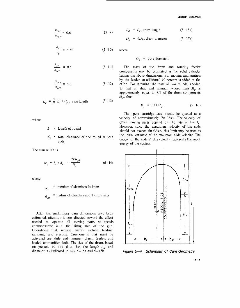
0.6 (5-9)
AMCP 706-260
h - Lr, dram length (5-15a)
Dd = 6Dh, dram diameter (5-15b)
0.75 (5-10) where
Du bore diameter.
= 0.5
1.5
Lc = -j L, +Cr , cam length
(5-1 1)
(5-12)
(5-13)
The mass of the dram and rotating feeder components may be estimated as the solid cylinder having the above dimensions. For moving ammunition by the feeder, an additional 10 percent is added to the effort. For ramming, the mass of two rounds is added to that of slide and rammer, whose mass M is approximately equal to 1/3 of the dram components M,. thus
Ms = 1/3 Md. (5-16)
where
L, = length of round
Cr = total clearance of the round at both ends
The cam width is
w = b. + b 2nR ch
c r er N (5-14)
where
Nn number of chambers in dram
D = radius of chamber about drum axis Rch
After the preliminary cam dimensions have been estimated, attention is now directed toward the effort needed to operate all moving parts at speeds commensurate with the firing rate of the gun. Operations that require energy include feeding, ramming, and ejecting. Components that must be activated are slide and rammer, drum, feeder, and loaded ammunition belt. The size of the dram, based on present 20 mm data, has the length Ld and diameter Dd indicated in Eqs. 5—15a and 5—15b.
The spent cartridge case should be ejected at a velocity of approximately 70 ft/sec. The velocity of other moving parts depend on the rate of fire fr. However, since the maximum velocity of the slide should not exceed 50 ft/sec, this limit may be used as the initial estimate of the maximum slide velocity. The energy of the slide at this velocity represents the input energy of the system.
i
a rec /
/ 9 (n
_l ■ o
ü
i> a:
CO
UN
TER
RE
CO
IL
SID
E
J
i
a crc
r
r
o _i to
-t
i
s ocr
s or
1 •r h » ur ■< Dcr »
Figure 5—4. Schematic of Cam Geometry
5-5
AMCP 706-260
By the time that all moving parts have returned to the firing position, where all motion ceases, considerable energy has been expended to friction, loading, and ejection. According to Ref. 14 when x = L, the loss of energy from slide to drum due to friction is
-fid (1.0-e~^)Ed (5-17)
where Ed is the total energy transferred from slide to drum if the system were frictionless and ju is the coefficient of friction. The energy of the drum alone (belt energy is of no help because it cannot push) just as the slide starts to counterrecoil is computed from Eq. 59, Ref. 9, and shown in Eq. 5-18
Ms
''der M de (5-18)
where
M d = mass of drum
M. = effective mass of drum and de ■ ■ , , ammumtion belt
According to Eq. 69, Ref. 9, when.x.= 0, the frictional energy loss in the slide when fully counterrecoiled is
Elu'(1.0-e~'li't)EH
The loss attributed to the driving spring is
E, =£(l-e2) (5-20)
where
Es = energy transferred from slide to driving spring
E = efficiency of spring system
The energy expended to eject the spent cartridge case at velocity ve is
i M (5-21)
where Mc = mass of cartridge case
5-6
The total expenditure of energy of the drum and its associated components during a firing cycle is expressed in Eq. 5-22.
Eß = E
ßd + EßS+Ee+Ee (5-22)
The energy of the slide derived from normal recoil and the gas operating cylinder is
("tin) (5-23)
where
vsm < 50 ft/sec, maximum slide velocity
Ms = mass of slide
A relatively stiff driving spring is recommended to hold the maximum velocity of drum and belt to a minimum (Ref. 9). If p is the ratio of spring energy E, to drum energy Ed,
(5-24)
Since the slide energy is converted to spring and drum energy, Esr = E, + Ed, the total energy transferred to the drum is shown to be
Eja+p). (5-25)
The preliminary firing rate is estimated from the times of recoil and counterrecoil when based on the relative velocity of the cam follower on the drum and the cam in the slide. The recoil time (Eq. 98, of Ref. 9) is
\v,m+vdmJ (5-26)
where
s = cam length for recoil
„ = maximum peripheral velocity of drum dm
7 = correction factor
AMCP 706-260
The counterrecoil time will be
t = 7 cr ' \vdm
+vScr'
(5-27)
br bcr b, = 175 = 2.15 (from Eq. 5-10)
= 3.77 - 2.15 = 1.62 in.
where = L, - a,„ = 1.67 in.
= cam length for counterrecoil
scr = counterrecoil velocity of slide
Based on operating guns, the empirical y = 0.935 (Ref.
socr = L> ~ "crc = 3.0 in.
sr =sor+2 J 2 " 1-67 + 4.40 = 6.07 in.,
The firing rate is
f, 60
frJcr ■,rounds/min. (5-28)
5—1.1.1 Sample Problem of Preliminary Firing Rate Estimate
Given data Wd = 30 lb, weight of drum
Ws = 10 lb, weight of slide
J^I =0.6 lb, weight of round
Wcc = 0.2 lb, weight of case
p = 3 in, radius of cam contact point d t A ■ to drum axis
5 in, distance of slide travel (same L, as cam length)
cam follower travel during recoil
a2 + b2
°cr = socr + i JJ^LTSL = 3-° + 2M = 5-86 m"
cam follower travel during counterrecoil
= 840 in./sec, maximum recommended ejection velocity of cartridge
= 600 in ./sec, maximum allowable slide velocity
10 x 360000 4
4658.4 in.-lb, maximum slide energy of recoil
Nc = 5 chambers
_ c = arec = —=- - 3.33 in. (from Eqs. 5-8
and 5-11)
acrc = 0.6 arec = 2.0 in. (from Eq. 5-9)
br + b„ 2itR
5
travel
d- = 3.11 in., peripheral cam
Select p = 0.25
„ _ Esr 4658.4 Ed ~ TTft OS"
= 3726.7 in.-lb, energy to be transferred
to drum
Et =ESr~Ed = 931-7in--'b,
energy to be transferred to driving spring
5-7

AMCP 706-260
At the end of slide recoil, the energy in the drum, Eq. 5—18. becomes
Jdcr 3L\ Mäe e
111801 68
hd 33
1644.1 in.-lb
where
Mde = 1.1M
Pf-
d ~ 33^
7.23x0.1 = 0.723
^dcr 2 M) = 2 ("**<**)
JMdvdm
where Ij = mass moment of inertia of drum
k = radius of gyration
iod = angular velocity of drum
'dm
4E der M,
4x 386.4 x 1644.1 30
= ^84704 = 291 in./sec, maximum
peripheral velocity of drum
The energy expended for ejection, Eq. 5-21, is
705600 , /,, i\ 0-2 x' Ee = i (KA) = -J7: 386.4
The energy in the slide at end of counterrecoil is
182.6 in.-lb.
Escr =Esd+E
ss~E' = 1211.8 ia-lb.
The velocity of the slide at end of counterrecoil when it bears the additional weight of two rounds is
IE.
scr = \ M + IM " s a
2x 1211.8x386.4 10t2x 0.6
= ^83614 = 289in./sec.
According to Eqs. 5—26 and 5—27, the firing cycle time becomes
c \v +v, v. +v I \ sm dm vdm scr I
= 187 (ML+ 5_M\ 187 I 891 + 580/
= 1.87 (0.0068 + 0.0101) = 0.0316 sec
where 7 = 0.935.
The firing rate, Eq. 5—28, is estimated to be
60 60 f = 77: 0.0316
= li rounds/min.
The energy transferred from drum to slide, from Eq. 5-19, is
- fjß _ 1644.1 _„„ . . ., ip - E,= —7-T-, 798.1 m-lb. Esd e 2-06
The energy transferred from driving spring to slide, assuming 80% efficiency, Eq. 5—20, is
£•„ = e2E = 0.64 A: 931.7 = 596.3 in.-lb. ss s
If the firing rate is too high, the initial velocity of the slide may be reduced proportionately. If too low, other avenues of design improvement must be explored since the upper limit of slide velocity has been incorporated. A stiffer driving spring, variations in moving masses, and efficiency improved by lowering frictional resistance represent three means of achieving a higher firing rate. All involve refinements ir design.
5-1.1.2 Analysis of Cam Action
The forces induced by cam action on the slide and drum roller are shown diagrammatically in Fig. 5—5
5-8
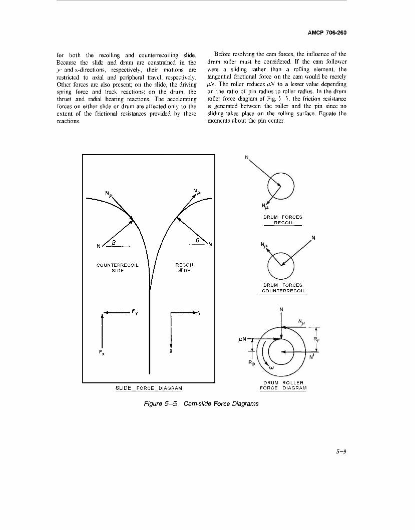
AMCP 706-260
for both the recoiling and counterrecoiling slide. Because the slide and drum are constrained in the y- and x-directions, respectively, their motions are restricted to axial and peripheral travel, respectively. Other forces are also present; on the slide, the driving spring force and track reactions; on the drum, the thrust and radial bearing reactions. The accelerating forces on either slide or drum are affected only to the extent of the frictional resistances provided by these reactions.
Before resolving the cam forces, the influence of the drum roller must be considered. If the cam follower were a sliding rather than a rolling element, the tangential frictional force on the cam would be merely liN. The roller reduces ßN to a lesser value depending on the ratio of pin radius to roller radius. In the drum roller force diagram of Fig. 5 -5, the friction resistance is generated between the roller and the pin since no sliding takes place on the rolling surface. Equate the moments about the pin center.
V >
/ß \ / *\ N \ / SN
COUNTERRECOIL 1 / RECOIL SIDE / SDE
tf Fv .
' ' ^x X
DRUM FORCES RECOIL
DRUM FORCES COUNTERRECOIL
MN-r
SLIDE FORCE DIAGRAM DRUM ROLLER
FORCE DIAGRAM
Figure 5—5. Cam-slide Force Diagrams
5-9
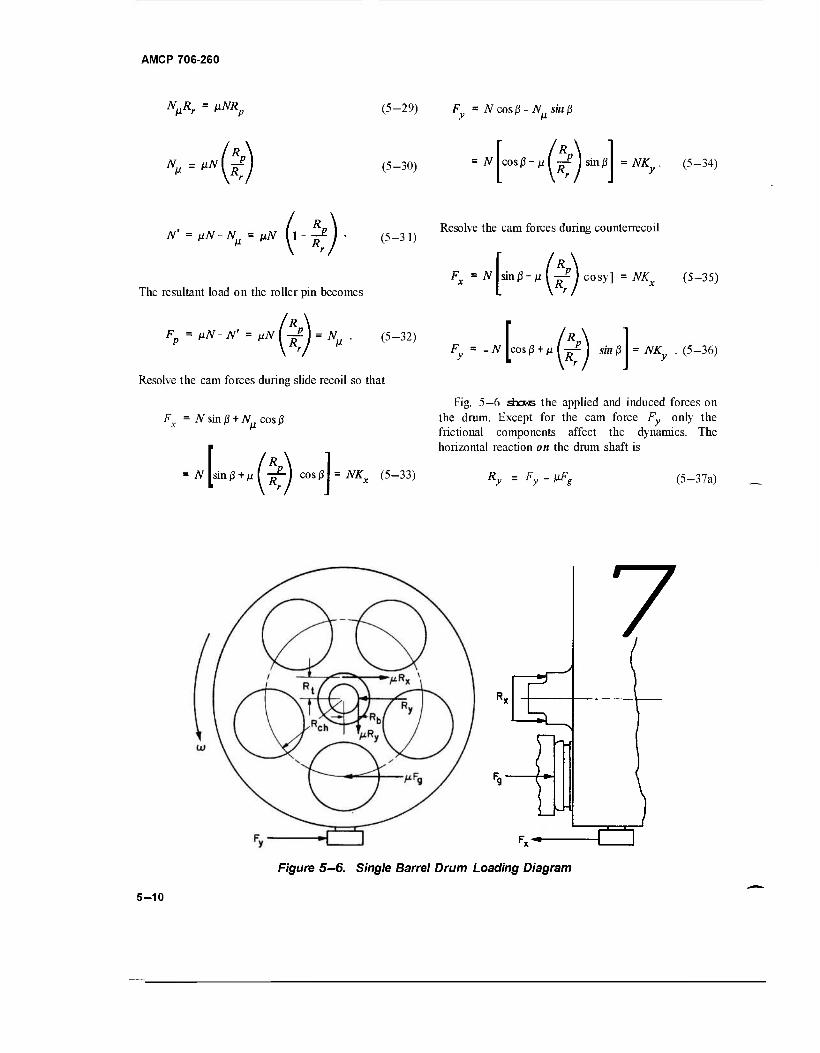
AMCP 706-260
NßRr = ßNRp (5-29) F = N cosß-N sinß
N, = ^(T (5-30) = N cos ß - y. I -ß? 1 sin ß = NK . (5-34)
N' = ßN-Nß = nN (l -^ j ■ (5-31)
The resultant load on the roller pin becomes
Fp = ßN- N' = ßN LA = Nß . (5-32)
Resolve the cam forces during slide recoil so that
Fr = TV sin ß + Nncosß
Resolve the cam forces during counterrecoil
F„ = N sin/3-Ml ^Icosy] = NKX (5-35)
Py = -N R\
cos ß + p I -jr£ I sin ß NKy . (5-36)
N sin/3 + Ml ~l cos
Fig. 5—6 shews the applied and induced forces on the drum. Except for the cam force Fy only the frictional components affect the dynamics. The horizontal reaction on the drum shaft is
NK (5-33) Ry =Fy- ßFg (5-37a)
Fg r-
7
Figure 5-6. Single Barrel Drum Loading Diagram
5-10
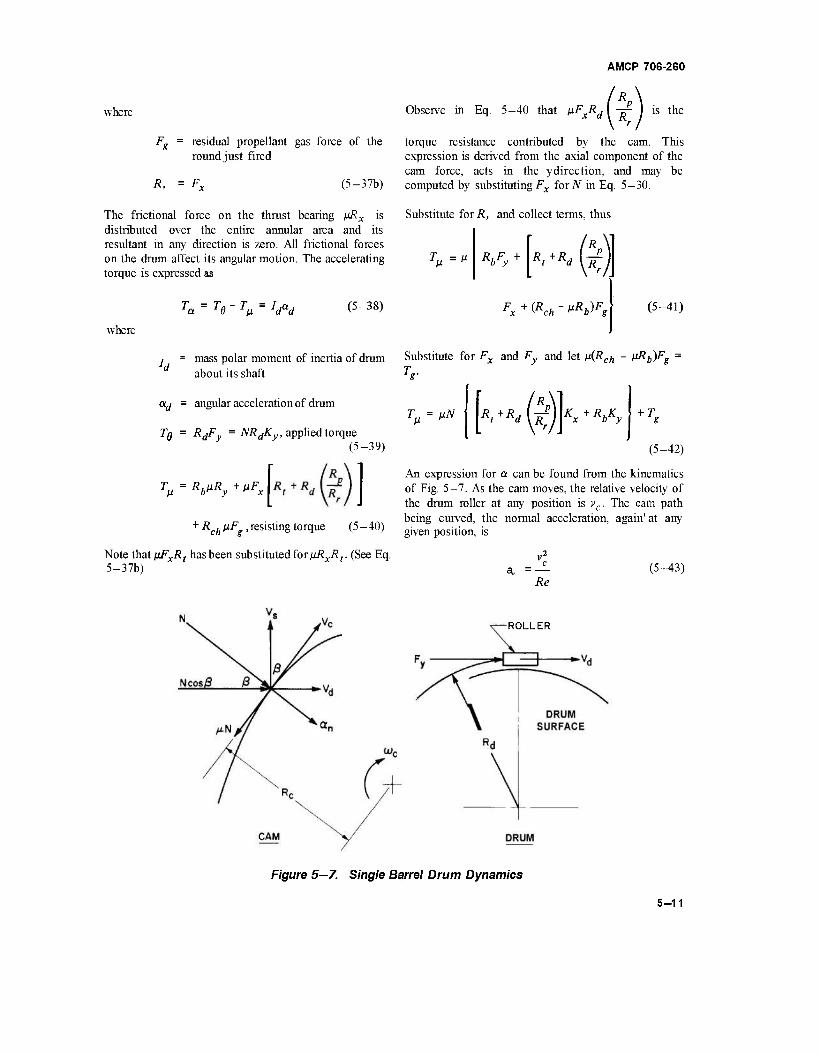
where
Fg = residual propellant gas force of the round just fired
R, (5-37b)
The frictional force on the thrust bearing nRx is distributed over the entire annular area and its resultant in any direction is zero. All frictional forces on the drum affect its angular motion. The accelerating torque is expressed as
AMCP 706-260
/*\ Observe in Eq. 5-40 that pFxRd I -jr ) is the
torque resistance contributed by the cam. This expression is derived from the axial component of the cam force, acts in the ydirection, and may be computed by substituting Fx for N in Eq. 5—30.
Substitute for R, and collect terms, thus
I'R. T,=»
R„Fy + R+R, ^
where
Tß = Vd (5-38) Fx+Vck-Wg (5-41)
j = mass polar moment of inertia of drum about its shaft
ad = angular acceleration of drum
TQ = RdFy = NRdKy, applied torque
Substitute for Fx and Fy and let ß(Rch - fR^g
(5-39)
Tß - RbßRy + ßFx
+ R£h ßF^,resisting torque (5-40)
Note that ßFxRt hasbeen substitutedfor/iRxÄr (See Eq. 5-37b)
T g
Tß = ßN \ Rt+Rd\R Kx+RöKy + T„
(5-42)
An expression for a can be found from the kinematics of Fig. 5-7. As the cam moves, the relative velocity of the drum roller at any position is vc. The cam path being curved, the normal acceleration, again' at any given position, is
c
Re (5-43)
ROLLER
Figure 5—7. Single Barrel Drum Dynamics
5-11
AMCP 706-260
However, the roller on the drum can physically travel only in the direction indicated by its tangential velocity vd, hence the tangential roller acceleration becomes
ad = an cos'3 ~ R~ cos/3 (5-44)
With vs = vc cos ß, the angular acceleration of the drum may be expressed in terms of the slide velocity.
d Rd RcRd cos$ (5-45)
Rewrite Eq. 5—38 with appropriate substitutions and solve forJV. Thus,
NRdK - nN Rt+Rä\T K
X+RbKy - T, S d \RcRd cos/3 (5-46)
N
Idv2 cosp
-RcRd~ +Ts
(Rd-»Rb*y-» R<+Rä\7T
K...
In the meantime, the slide is subjected to cam forces as well as the driving spring force F and also the frictional resistance pFy of the slide tracks.
The cam is the medium for transferring energy. The equation of an elliptical cam is
(5-47)
^ + z! = (5-48)
or
4 sR (5-49)
where
a = half of the major axis inxdirection
b = half of the minor axis in ^-direction
5-12
AMCP 706-260
The slope at any point is tan ß.
tan ß dy dx flU^7') (5-50)
d2y
d? ab
(a'-x2) 2v3/2 (5-51)
The radius of the curvature of the cam at any position is^„
*♦(£)'] 3/2
a2 - _ (a2 - b2) a2
3/2
cPy
dx2
ab
The cam dynamics involve an iterative integration procedure for which the law of conservation of energy becomes a convenient basis for computing the values of each increment. For any increment
E. = E +E. + AE + Eß i sr d T - \Msv }) +Id tan2/3
(5-52)
v] ^ Ea Ax+Eß (5-53)
where
AE = differential driving spring energy
Ed ~ drum energy at end of increment
t) = input energy of each increment
Esr - slide energy at end of increment
Ea = average driving spring force
Ax = incremental travel of slide
= frictional losses during increment
e = spring efficiency.
Note that for the next increment,
Ei = preceding Ei - E„ (5-54)
5-13
AMCP 706-260
The object now is to put E„ into terms of vs so that Eq. 5-53 may be solved. The resultant frictional force in the x-direction is composed of the frictional resistance of slide tracks and that of the cam in the xdirection
R. F.„ = pF+AiF I -^ = AiF 11.0 + ps y\R. (»♦*'
Write Fy in terms of N.
Fßs = ßNKy (1.0 +^ (5-56)
ft = 25° 52.2' = 0.4470 rad
sin (3, = 0.4364
cos ft = 0.8998
(5-55) *JL ab 3.33x2.15 ^3/2 &' (a2 - x2)
= 0.379 (from Eq. 5-51).
18.88
The energy loss in the slide is
EpS =1 (fßSi +VX- (5-57)
where subscripts 1 and 2 indicate values for adjacent increments.
The energy loss in the drum becomes
V= 2(r*" + V A0 (5-58)
According to Eq. 5—52
Äc, -
i
X2 1 3/2
k-7 «■*-''»] ab
I11,09" 1L09 01-09-4-62) 3/2
7.16
3.62 in.
The total frictional losses in drum and slide is the sum of the two components At this time the driving spring has been compressed by
*/i = V+£"*»- (5-59) Lx = sor tx = 1.67 + 2.0 = 3.67 in.
5-1.1.2.1 Sample Calculation of Cam Action
The energy absorbed by the spring at this position is The sample problem is the continuation of the one ■&
outlined in par. 5—1.1.1, at a time when the slide has traveled 2.0 inches on the cam. Thus, jci = 2.0. From Eq. 5-49.
E, = |y 931.7 = 684in.-lb
= 0.6456 x 2.6627 = 1.719 in.
The energy confined to the drum-slide system is
Eds = E,. - E; = 3974.4 in.-lb.
tan ft = -
0.4850 (from Eq. 5-50)
= 2T5 / 2.0 \ 3.33 \ 2.6627/
After losses have been deleted, the energy remaining in the system is
E' ds Edse (Ref. 14) (5-60)
5-14
AMCP 706-260
- 0.434 _ 3974.4 _ . £"' = 3974.4 e — = 2576 m.-lb 'ds 1.543
where - u-M — = - 7.23 x 0.1 x 2.0/3.33 = - 0.434 ' a
2 _ 2576 x 386.4 _ ,...., . 2/ 2 v; = . ~. . - „— = 143,425 in. /sec1
s 1.94 + 5.0
vs = 378.7 in./sec
where
j Jlf^tan'ß, = 1.94/y
| M, = 5.0/*
The above given and computed values are assumed to be the values of the parameters at x = 2.0 in. To illustrate the integration process, assume an incremental travel of Ax = 0.05 in.
x2 = Xj t Ax = 2.00 + 0.05 = 2.05 in.
y* = I [Ja2 x2) = W- /l 1.09- 4.203
= 0.6456 x 2.6243 = 1.694 in.
tan/32 2.15 x 2.05
3.33x2.6243
4.4075 8.7389
0.5044
*y = yx - y2 = 0.025
d2y
R„
A6 1 = ^ = 0 025 3.0
0.00833 rad
ab 3 .33x2.15
(a2 -x- !)3 18.07
1 K (a 2 -b2) '
All)
= flÄ
11.09- ( 4.203 \ 11.09/
6.47 3/2
0.396
7.16
Additional given data are now listed.
3.55 in.
Fg = 1000 lb, propellant gas force (residual)
Rj, =1.0 in., radius of radial bearing
Rcf, = 1.5 in., chamber center to drum axis
^ = 0.25 in, radius of roller pin
R = 0.5 in., roller radius
Rt = 1.25 in., thrust bearing pressure radius
ß = 0.10, coefficient of friction
In Eq. 5-42,
Tg = VL(Rch-»Rb)Fg = 0.10(1.5-0.10x1.0)1000
= 140 in.-lb
ld = Mdk* M. (-*} - _J°_ (l\ \ 2 / ~ 386.4 V 2 /
- 0.35 Ib-in.-sec', mass moment
of inertia of drum
ß2 = 26" 46' = 0.4672 rad
sin ß2 = 0.4504
cos/?2 = 0.8929
During slide recoil when the ammunition must also be accelerated, the effective mass moment of inertia Ide
changes from ld to
lde = (ll)[d = 0.385 lb-in.-sec2 .
5-15
AMCP 706-260
From Eq. 5—33
Kxi = sin,3i + JU(^") cos'3' = 0.4364 + 0.10x0.5x0.8998 = 0.4814
*■« = sin j32 + ft I ^ I cos 02 = 0.4505 + 0.10 x 0.5 x 0.8929 = 0.4950.
From Eq. 5—34
K Ä >i = cos/3, -I -^ I sin/3, = 0.8998-0.10x0.5x0.4364 = 0.8780
Ky2 = C0SP> •^lsin/32 = 0.8929-0.10x0.5x0.4504 = 0.8704.
Since the slide is recoiling, substitute vjcos ß for vc in Eq. 5-47, thus
V.i + T
JVi
RclRdcosßt g
{Rd-»Rb)K - ß Rt+Rd\R K„
0.385 x 143425 + 3.62x3.0x0.8998
140 5651+140 5791 (3.0-0.10x1.0)0.8780-0.10(1.25 + 3.0x0.5)0.4814 2.546-0.132 2.414
2399 lb
JV, =
de VS2 T
Rc2Rd cos/32 8
(Rd-ßRb)Ky2'ß[R^Rd(^)\Kx
0.385 vl, + 140 0.0405 V?, + 140
- 3 55 x TO y 0 8979 = il = 0.01696 v]+ 59. 2.9x0.8704-0.275x0.4950 2.524-0.136 s2
5-16
AMCP 706-260
The preliminary characteristics of the driving spring Insert the appropriate values in Eqs. 5—42 and 5-56 are based on an assumed efficiency of 80% and for Fm and compute the torsional and slide frictional » 2F0. The average spring force Fa over the full recoil resistance, distance is now computed.
eE, F
s 0.8x 931.7 " i„
1491b
Tßi =N1(0.27SKxl+0AKyi) + TK
= 2399 (0.1324+0.0878)+ 140= 668.31b-in.
F - F- F" = -2 °- = 149 Fa ~ 2 2 TßJ =N2(0.215Kx2 *0.1Kyt)+Tg
F = 398 = 99.3; F = 198.71b. (0.01696PS22 +59) (0.1361+0.0870)+ 140
= 0.00378i>2 + 153.21b-in. S2
The spring constant
K = Fm—Fo = 99A = 19.83b/in.
F = Q.\SKyiNi = 0.15x0.8780x2399
315.91b
F =F + 3.67K = 99.3+73.0= 172.31b X 1 o F,„, = 0.15*: „yV, = 0.15 x 0.8704U01696V2 + 59)
Fx2 = Fo + 3.72/v = 99.3+74.0= 173.31b. = 0.00221 v2 + 7.1b S2
Isolate the components of Eq. 5-53 to compute the combined energy of drum and slide
E. i
~ E'ds = 2576 m, -lb
E sr = 1 2 (M> *2) = ■ S 2 1
S2
2 x 386.4
Fd = 1
2 '*'
/tan2/32
)
v2 S2
0.01294 c2 S2
/ 0.385 x 0.2544 \ = \ 2^9 I V
.385x0.2544 , 2 = S2 S2
AE = — F Ax = \ --n s« \ 0.8 f^)o. 3x 2 /
05
According to Eqs. 5—57 and 5—58,the energy losses are
E = ± (315.9+7.7+0.00221 fj2)0.05
.1+ 5.525x 10"5v2
E d = -4- (668.3+ 153.2+0.00378 v2,,) 0.00833 2
3.4+ 1.574c 10"V„ S2
Insert computed values in Eq. 5—53 and solve for slide velocity vs and the energy Ej.
2576 = (1294+ 544+ 5.525+ 1.574)v22 x 10"s
= 10.8in.-lb. + 10.8+ 8.1+3.4
5-17
AMCP 706-260
1845.1 xlO-V„ = 2553.7 SI
Compute the number of coils from Eq. 2-41.
vs2 = 4138,412 = 372 in ./sec
£•„ = 11.5 + 7.099 x 10"s v2 = 11.5+9.9
= 21.4 in.-lb
Et=Et(_i)- AE-Eti = 2543.8 in.-lb
Gd4 11.5x10« X3.90X10"4 .„ , ., N = = s—r^—^ = 28.1 coils
&D'K 8x 1.0x20
The spring solid height is
H = Nd = 28.1 x 0.1406 = 4 in. s
Fo Fm
Since Fa = °2 m and Fo= Fm- Kar
5—1.1.2.2 Driving Spring
The average force on each of two driving springs over the decelerating period of the slide is computed from the known slide energy.
eE. F = a 2a„
0,8x931.7 2x3.33
111.91b.
where
arec ~ 3-33 in., slide travel during slide deceleration
jj = 931.7 in.-lb, slide energy
e = 0.80, system efficiency (assumed)
Investigation shows that K = 20 lb/in. is a practical spring constant. The compression time of the spring
F =F +i Karpr = 111.9 + 33.3 = 145.21b
The static torsional stress, Eq. 2—43, is
SFmD 8x145.2x1.0
Ttd3 jrx2.78x]0~3
The dynamic torsional stress, Eq. 2-44, is
= 133,200 lb/in.:
133,200 2 = 148,000 lb/in.2
T„ = t= 1.87x0.0068 = 0.0127 sec
(see par. 5—1.1.1).
The surge time T = 4%- - °-00706 sec (see par. 2-2.3.5).
Select a spring diameter of D = 1.0 in., then compute the wire diameter according to Eq. 2-42.
d = 0.27 l/DKT = 0.27 3J 0.1412 = 0.1406]
5-1.2 FINAL ESTIMATE OF THE COMPLETE FIRING CYCLE
This sample problem involves the procedures for computing all the data involved for making an accurate estimate of the firing rate for a drum-type machine gun by analyzing the firing cycle in detail. The interior ' ballistics of Fig. 5—8 are for a 20 mm gun firing a 2000-gram projectile with a 500-grain propellant charge. The pressure has been modified so that the impulse generated by the gas force is congruous with the momentum of projectile and gas from the expression obtained from Eq. 2-14
Fgdt = (Mp + 2 Mg)dv
5-18
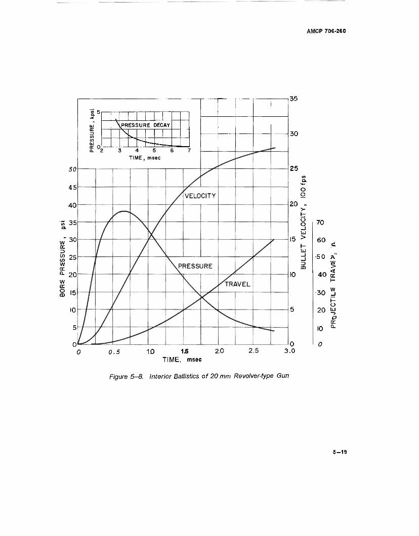
AMCP 706-260
w er 13 CO CO w cr a. w cr o GO
50
45
40
35
30
25
20
15
10
5
0
Ld CE
en CO
\ .PRESSURE DECAY
1
35
30
25
20
10
0.5 10 15 TIME, msec
Q
3.0
o g
^ > i- o o 70 _l ÜJ > 60 I- £ LJJ
_J •50 A ID m <r
40 tr h-
30 w _i (- o
20 LU
o cr
I0 a.
0
Figure 5-8. Interior Ballistics of 20 mm Revolver-type Gun
5-19
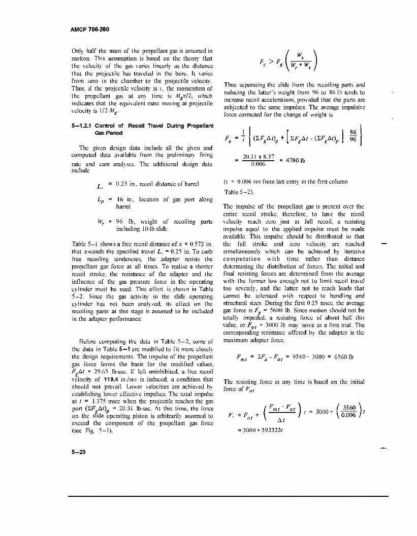
AMCP 706-260
Only half the mass of the propellant gas is assumed in motion. This assumption is based on the theory that the velocity of the gas varies linearly as the distance that the projectile has traveled in the bore. It varies from zero in the chamber to the projectile velocity. Thus, if the projectile velocity is Y, the momentum of the propellant gas at any time is Mgv/2, which indicates that the equivalent mass moving at projectile velocity is 1/2 Mg.
5—1.2.1 Control of Recoil Travel During Propellant Gas Period
The given design data include all the given and computed data available from the preliminary firing
rate and cam analyses. The additional design data include
W.
L, 0.25 in., recoil distance of barrel
Lp = 16 in., location of gas port along barrel
Wr = 96 lb, weight of recoiling parts including 10-lb slide
Table 5—1 shows a free recoil distance of x = 0.572 in. that exceeds the specified travel L, = 0.25 in. To curb free recoiling tendencies, the adapter resists the propellant gas force at all times. To realize a shorter recoil stroke, the resistance of the adapter and the influence of the gas pressure force in the operating cylinder must be used. This effort is shown in Table 5—2. Since the gas activity in the slide operating cylinder has not been analyzed, its effect on the recoiling parts at this stage is assumed to be included in the adapter performance.
Before computing the data in Table 5—2, some of the data in Table 5—1 are modified to fit more closely the design requirements. The impulse of the propellant gas force forms the basis for the modified values, FAt = 29.65 lb-sec. If left uninhibited, a free recoil velocity of 119.4 in ./sec is induced, a condition that should not prevail. Lower velocities are achieved by establishing lower effective impulses. The total impulse at t = 1.375 msec when the projectile reaches the gas port (SF At)p = .20.31 lb-sec. At this time, the force on the slide operating piston is arbitrarily assumed to exceed the component of the propellant gas force (see Fig. 5—1).
F > F wr + ws
Thus separating the slide from the recoiling parts and reducing the latter's weight from 96 to 86 lb tends to increase recoil accelerations, provided that the parts are subjected to the same impulses. The average impulsive force corrected for the change of weight is
i I r l 86 1 g 'P
20.31 t8.37 0.006
4780 lb
(t = 0.006 sec from last entry in the first column
TableS-2).
The impulse of the propellant gas is present over the entire recoil stroke, therefore, to have the recoil velocity reach zero just at full recoil, a resisting impulse equal to the applied impulse must be made available. This impulse should be distributed so that the full stroke and zero velocity are reached simultaneously which can be achieved by iterative computation with time rather than distance determining the distribution of forces. The initial and final resisting forces are determined from the average with the former low enough not to limit recoil travel too severely, and the latter not to reach loads that cannot be tolerated with respect to handling and structural sizes. During the first 0.25 msec, the average gas force is Fg - 5600 lb. Since motion should not be totally impeded, a resisting force of about half this value, or Fot = 3000 lb may serve as a first trial. The corresponding resistance offered by the adapter is the maximum adapter force.
2F -F„t a ot 9560- 3000 = 65601b
The resisting force at any time is based on the initial force of Fot
, ^),.3„„„t(S), ot \ At
F, =F
= 3000 + 593333/
5-20
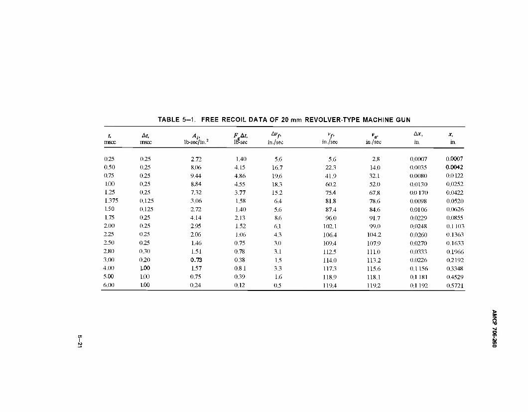
TABLE 5-1. FREE RECOIL DATA OF 20 mm REVOLVER-TYPE MACHINE GUN
t, H A" , FgAt, lb-sec
Aiy, vf, Va> Ax, x,
msec msec lb-sec/in. in./sec in./sec in./sec in. in.
0.25 0.25 2.72 1.40 5.6 5.6 2.8 0.0007 0.0007
0.50 0.25 8.06 4.15 16.7 22.3 14.0 0.0035 0.0042 0.75 0.25 9.44 4.86 19.6 41.9 32.1 0.0080 0.0122
1.00 0.25 8.84 4.55 18.3 60.2 52.0 0.0130 0.0252 1.25 0.25 7.32 3.77 15.2 75.4 67.8 0.0 170 0.0422 1.375 0.125 3.06 1.58 6.4 81.8 78.6 0.0098 0.0520 1.50 0.125 2.72 1.40 5.6 87.4 84.6 0.0106 0.0626 1.75 0.25 4.14 2.13 8.6 96.0 91.7 0.0229 0.0855 2.00 0.25 2.95 1.52 6.1 102.1 99.0 0.0248 0.1103 2.25 0.25 2.06 1.06 4.3 106.4 104.2 0.0260 0.1363 2.50 0.25 1.46 0.75 3.0 109.4 107.9 0.0270 0.1633 2.80 0.30 1.51 0.78 3.1 112.5 111.0 0.0333 0.1966 3.00 0.20 0.73 0.38 1.5 114.0 113.2 0.0226 0.2192 4.00 1.00 1.57 0.81 3.3 117.3 115.6 0.1156 0.3348 5.00 1.00 0.75 0.39 1.6 118.9 118.1 0.1181 0.4529 6.00 1.00 0.24 0.12 0.5 119.4 119.2 0.1192 0.5721
s o
I IS) 01 o
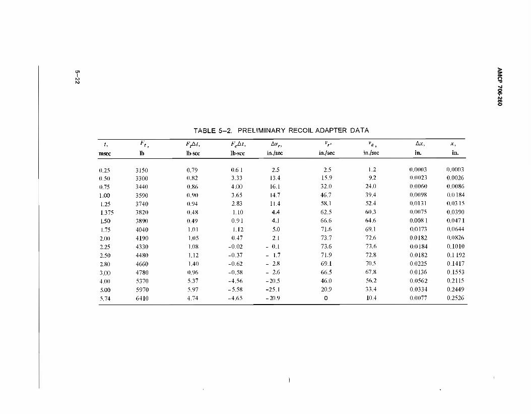
I o ■o >J o O) ISJ
§
TABLE 5-2. PRELIMINARY RECOIL ADAPTER DATA
t, F*. FfAt, Fekt, Av„ V v Ax, x,
msec lb lb-sec lb-sec in ./sec in./sec in./sec in. in.
0.25 3150 0.79 0.6 1 2.5 2.5 1.2 0.0003 0.0003
0.50 3300 0.82 3.33 13.4 15.9 9.2 0.0023 0.0026
0.75 3440 0.86 4.00 16.1 32.0 24.0 0.0060 0.0086
1.00 3590 0.90 3.65 14.7 46.7 39.4 0.0098 0.0184
1.25 3740 0.94 2.83 11.4 58.1 52.4 0.0131 0.0315
1.375 3820 0.48 1.10 4.4 62.5 60.3 0.0075 0.0390
1.50 3890 0.49 0.91 4.1 66.6 64.6 0.008 1 0.0471
1.75 4040 1.01 1.12 5.0 71.6 69.1 0.0173 0.0644
2.00 4190 1.05 0.47 2.1 73.7 72.6 0.0182 0.0826
2.25 4330 1.08 -0.02 - 0.1 73.6 73.6 0.0184 0.1010
2.50 4480 1.12 -0.37 - 1.7 71.9 72.8 0.0182 0.1192
2.80 4660 1.40 -0.62 - 2.8 69.1 70.5 0.0225 0.1417
3.00 4780 0.96 -0.58 - 2.6 66.5 67.8 0.0136 0.1553
4.00 5370 5.37 -4.56 -20.5 46.0 56.2 0.0562 0.2115
5.00 5970 5.97 -5.58 -25.1 20.9 33.4 0.0334 0.2449
5.74 6410 4.74 -4.65 -20.9 0 10.4 0.0077 0.2526
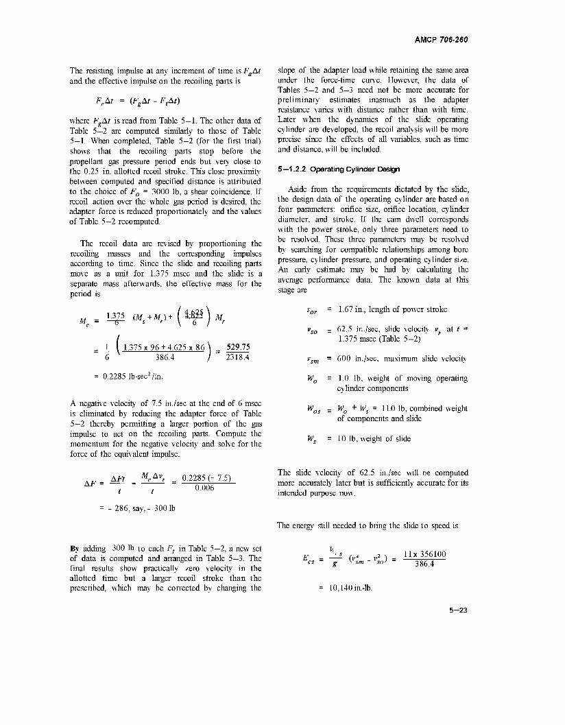
AMCP 706-260
The resisting impulse at any increment of time is FaAt and the effective impulse on the recoiling parts is
FeAt = (FgAt-FtAt)
where FgAt is read from Table 5—1. The other data of Table 5—2 are computed similarly to those of Table 5—1. When completed, Table 5—2 (for the first trial) shows that the recoiling parts stop before the propellant gas pressure period ends but very close to the 0.25 in. allotted recoil stroke. This close proximity between computed and specified distance is attributed to the choice of F0 = 3000 lb, a shear coincidence. If recoil action over the whole gas period is desired, the adapter force is reduced proportionately and the values of Table 5—2 recomputed.
The recoil data are revised by proportioning the recoiling masses and the corresponding impulses according to time. Since the slide and recoiling parts move as a unit for 1.375 msec and the slide is a separate mass afterwards, the effective mass for the period is
Af 1 325 (Ms+Mr)+ (iMI^j Mr
( 1.375 x 96 +4.625 x 86 \ = 529.75 ,.,, . I 231SA 386.4
= 0.2285 lb-sec2/in.
A negative velocity of 7.5 in./sec at the end of 6 msec is eliminated by reducing the adapter force of Table 5—2 thereby permitting a larger portion of the gas impulse to act on the recoiling parts. Compute the momentum for the negative velocity and solve for the force of the equivalent impulse.
slope of the adapter load while retaining the same area under the force-time curve. However, the data of Tables 5—2 and 5—3 need not be more accurate for preliminary estimates inasmuch as the adapter resistance varies with distance rather than with time. Later when the dynamics of the slide operating cylinder are developed, the recoil analysis will be more precise since the effects of all variables, such as time and distance, will be included.
5—1.2.2 Operating Cylinder Design
Aside from the requirements dictated by the slide, the design data of the operating cylinder are based on four parameters: orifice size, orifice location, cylinder diameter, and stroke. If the cam dwell corresponds with the power stroke, only three parameters need to be resolved. These three parameters may be resolved by searching for compatible relationships among bore pressure, cylinder pressure, and operating cylinder size. An early estimate may be had by calculating the average performance data. The known data at this stage are
sor = 1.67 in., length of power stroke
vso = 62.5 in./sec, slide velocity vf at t = 1.375 msec (Table 5-2)
vsm = 600 in./sec, maximum slide velocity
W0 = 1.0 lb, weight of moving operating cylinder components
Wos = Wo + Ws = 1L0 lb> combined weight of components and slide
Ws =10 lb, weight of slide
MA v. AF =
AFt _
t t
- 286, say,- 3001b
0.2285 (- 7.5) 0.006
The slide velocity of 62.5 in./sec will oe computed more accurately later but is sufficiently accurate for its intended purpose now.
The energy still needed to bring the slide to speed is
By adding -300 lb to each Ft in Table 5—2, a new set of data is computed and arranged in Table 5—3. The final results show practically zero velocity in the allotted time but a larger recoil stroke than the prescribed, which may be corrected by changing the
E - —s (V* v* ) - H« 356100 cs - g v sm - so) - 386 4
10,140 in.-lb.
5-23
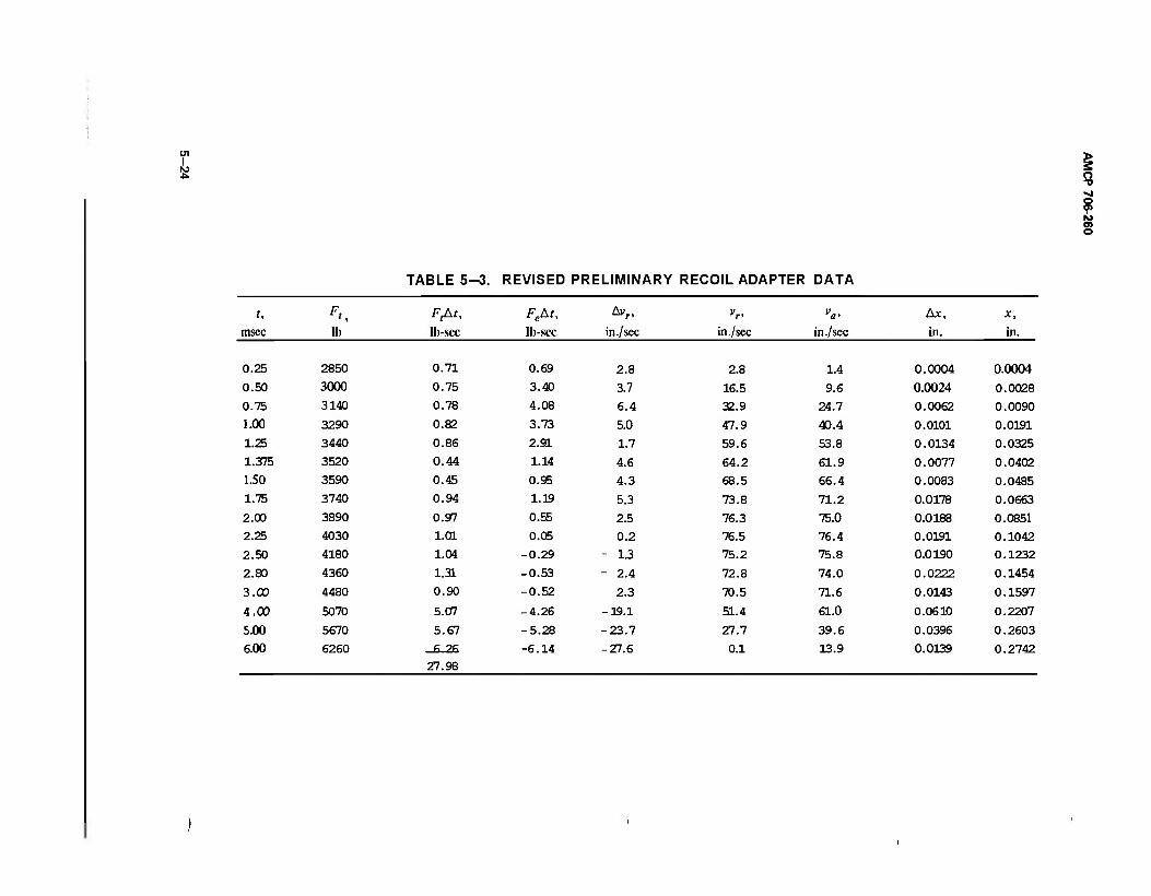
ro > 3 o
? to 01 o
TABLE 5-3. REVISED PRELIMINARY RECOIL ADAPTER DATA
t, Fi. FjAr, FeM, *»n vr> V A*, x, msec lb lb-sec lb-sec in ./sec in./sec in./sec in. in.
0.25 2850 0.71 0.69 2.8 2.8 1.4 0.0004 0.0004 0.50 3000 0.75 3.40 3.7 16.5 9.6 0.0024 0.0028 0.75 3140 0.78 4.08 6.4 32.9 24.7 0.0062 0.0090 1.00 3290 0.82 3.73 5.0 47.9 43.4 0.0101 0.0191 1.25 3440 0.86 2.91 1.7 59.6 53.8 0.0134 0.0325 1.375 3520 0.44 1.14 4.6 64.2 61.9 0.0077 0.0402 1.50 3590 0.45 0.95 4.3 68.5 66.4 0.0083 0.0485 1.75 3740 0.94 1.19 5.3 73.8 71.2 0.0178 0.0663 2.00 3890 0.97 0.55 2.5 76.3 75.0 0.0188 0.0851 2.25 4030 1.01 0.05 0.2 76.5 76.4 0.0191 0.1042 2.50 4180 1.04 -0.29 - 1.3 75.2 75.8 0.0190 0.1232
2.80 4360 1.31 -0.53 - 2.4 72.8 74.0 0.0222 0.1454
3.00 4480 0.90 -0.52 - 2.3 70.5 71.6 0.0143 0.1597
4.00 5070 5.07 -4.26 -19.1 51.4 61.0 0.0610 0.2207
5.00 5670 5.67 -5.28 -23.7 27.7 39.6 0.0396 0.2603
6.00 6260 27.98
-6.14 -27.6 0.1 13.9 0.0139 0.2742
AMCP 706-260
The average operating cylinder force is
10140
where
F = — ca s
or 1.67 6072 lb.
Assume that the gas pressure in the cylinder does not drop below 1000 psi, therefore, flow from bore to operating cylinder ceases at 3.85 msec. The area under the pressure time curve from 1.375 to 3.85 msec is
A, = 17 lb-sec/in.2
The average bore pressure for this interval is
i
It 17 17
Pa = "77 = 0.00385 - 0.001375 0.002475
6870 lb/in.2
Based on critical flow pressure, the average pressure in the operating cylinder during the same interval is
0.53p = 36401b/in.:
The required piston area is
A.. = 6072
cr pc - 3640 1.67 in.'
The corresponding piston diameter dp = 1.46 in. A nominal diameter of 1.5 in, has an area of
A, 1.161 in:
The operating cylinder displacement is
Vco = sorAc = 1.67 x 1.767 = 2.95 in.3
The initial orifice area is estimated by finding the quantity Wc of gas flowing into the operating clyinder. Eq. 4-49 serves the purpose by substituting pa for pm
since the muzzle pressure does not apply, hence
)(*)"
Ik = 0.00391b
k 1.3, ratio of specific heats
33.1 in.3, bore volume plus chamber volume
500 gr = 0.0714 lb, propellant gas weight
The rate of flow, Eq. 4—51, is
w 5L At
0.0039 1.58 lb/sec.
0.002475
The first estimate of orifice area, Eq. 4—52, is
w - L58 Ao' K^ - mm%am = °-120in-
The orifice diameter = 0.391 in.
Computed data of the operating cylinder are listed
in Tables 5—4 to 5—7. The analyses do not consider the influence' of recoil adapter or driving spring since they are an attempt to learn how the gas behaves when entering the operating cylinder. After the nature of gas activity becomes known, all contributing factors to the operating cylinder dynamics will be included in the digital computer program where the effects of their simultaneous activity can be computed in a reasonable time.
Computations in the four tables follow essentially the same procedure. Three values are read directly from Fig 5—8: t, the time; sb, the bore travel; and pa, the average bore pressure selected as the pressure falling half way between time intervals. The time of t x 103 = 4.00 in Table 5—7 illustrates the procedure. From Eq. 4—27
w = KwAopa = 0.00192* 0.06 x 1700 = 0.196 lb/sec
where
Kw = 0.00192/sec (see par. 4-3.2.S.2)
The amount of gas capable of passing through the orifice at 1700 psi during the interval of 0.001 sec is
AW = wAt = 0.196x0.001 = 1.96xl0"4lb.
5-25
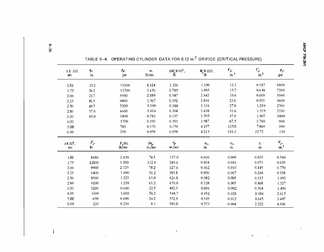
01 I
TABLE 5-4. OPERATING CYLINDER DATA FOR 0.12 in. ORIFICE (CRITICAL PRESSURE)
tX 103, sec in.
Pa- psi
w, lb/sec
AWX103, WX 103, lb in.3 in.3
Pe- psi
1.50 19.2 19200 4.424 1.106 1.106 12.1 0.187 4800
1.75 26.2 13700 3.156 0.789 1.895 15.7 0.416 7260
2.00 33.7 9500 2.189 0.547 2.442 19.6 0.669 5040
2.25 41.5 6800 1.567 0.392 2.834 23.6 0.935 3600
2.50 49.7 5200 1.198 0.300 3.134 27.8 1.219 2760
2.80 57.0 4400 1.014 0.304 3.438 31.6 1.519 2330
3.00 60.0 3400 0.783 0.157 3.595 37.9 1.907 1800
4.00 1700 0.392 0.393 3.987 67.5 3.769 900
5.00 740 0.170 0.170 4.157 135.0 7.860 390
6.00 250 0.058 0.058 4.215 334.3 19.73 130
rX103, sec lb
FM, lb/sec
Avs, in./sec in./sec
Sl,
in. Ü2,
in. s, in. in.3
1.50 8480 2.120 74.5 137.0 0.016 0.009 0.025 0.544
1.75 12800 3.200 112.4 249.4 0.034 0.014 0.073 0.629
2.00 8900 2.225 78.2 327.6 0.062 0.010 0.145 0.756
2.25 6400 1.600 56.2 383.8 0.096 0.007 0.248 0.938
2.50 4900 1.225 43.0 426.8 0.082 0.005 0.335 1.092 2.80 4100 1.230 43.2 470.0 0.128 0.005 0.468 1.327
3.00 3200 0.640 22.5 492.5 0.094 0.002 0.564 1.496 4.00 1600 1.600 56.2 548.7 0.492 0.028 1.084 2.415
5.00 690 0.690 24.2 572.9 0.549 0.012 1.645 3.407 6.00 230 0.230 8.1 581.0 0.573 0.004 2.222 4.926
> 2 o ■o
o
TABLE 5-5. OPERATING CYLINDER DATA FOR 0.12 in.2 ORIFICE
(X 103, sb- P«. w, AWC X 103, W, X 103, Vb> Ve- Pc, sec in. psi lb/sec lb lb in.3 to? psi
1.50 19.2 19200 4.424 1.106 1.106 12.1 0.187 4800 1.75 26.2 13700 3.156 0.789 1.895 15.7 0.416 7690 2.00 33.7 9500 2.189 0.547 2.442 19.6 0.669 7880 2.25 41.5 6800 1.567 0.392 2.834 23.6 0.935 6530 2.50 49.7 5200 1.198 0.300 3.134 27.8 1.219 5200
2.80 57.0 4400 1.014 0.304 3.438 31.6 1.519
3.00 60.0 3400 0.783 0.157 3.595 37.9 1.907 4.00 1700 0.392 0.392 3.987 67.5 3.769
5.00 740 0.170 0.170 4.157 135.0 7.860
6.00 250 0.058 0.058 4.215 334.3 19.73
tX 10\ Fa- FcAt, A»s, •V si, Sl, s, Ve- sec lb lb/sec in./sec in./sec in. in. in. in.3
1.50 8480 2.120 74.5 137.0 0.016 0.009 0.025 0.544
1.75 14060 3.515 123.5 260.5 0.034 0.015 0.074 0.631
2.00 13920 3.480 122.2 382.7 0.065 0.015 0.154 0.772
2.25 11540 2.885 101.3 484.0 0.096 0.013 0.263 0.965 2.50 9190 2.298 80.7 564.7 0.121 0.010 0.394 1.196
> o ■o ■>! O
I N) N) 9) --J O

TABLE 5-6. OPERATING CYLINDER DATA FOR 0.09 in/ ORIFICE
> S o -o
s 8
tX 103, sb< Pa- w, AWrX 103, WrX 103, Vb> V% Pc, sec ±i. psi lb/sec clb clb in. 3 in.3 psi
1.50 19.2 19200 3.318 0.830 0.830 12.1 0.141 3360
1.75 26.2 13700 2.367 0.592 1.422 15.7 0.312 5710
2.00 33.7 9500 1.642 0.410 1.832 19.6 0.503 5940
225 41.5 6800 1.175 0.294 2.126 23.6 0.702 5140
2.50 49.7 5200 0.898 0.224 2.350 27.8 0.915 4340
2.80 57.0 4400 0.760 0.228 2.578 31.6 1.140 3700
3.00 60.0 3400 0.588 0.118 2.696 37.9 1.430 3220
4.00 1700 0.294 0.294 2.990 67.5 2.826 1700
5.00 740 0.128 0.128 3.118 135.0 5.893
6.00 250 0.043 0.043 3.161 334.3 14.794
tX 103, F*> Fc&t, *,. vt> Sl, «2, s, re> sec lb lb-sec in./sec in./sec in. in. in. in.3
1.50 5940 1.485 52.2 114.7 0.016 0.007 0.023 0.541
1.75 10090 2.522 88.6 203.3 0.029 0.011 0.063 0.611
2.00 10500 2.625 92.2 295.5 0.051 0.012 0.126 0.723 2.25 9080 2.270 79.7 375.2 0.074 0.010 0.210 0.871 2.50 7670 1.917 67.3 442.5 0.094 0.008 0.312 1.051
2.80 6450 1.962 68.9 511.4 0.133 0.010 0.455 1.304
3.00 5690 1.138 40.0 551.4 0.102 0.004 0.561 1.491
4.00 3000 3.000 135.0 686.4 0.551 0.068 1.180 2.585
TABLE 5-7. OPERATING CYLINDER DATA FOR 0.06 in.2 ORIFICE
tX 103, sb' Pa, w, AWCX 103, Wc X 103, vb> Ve> Pc sec in. psi lb/sec lb lb in.3 in.3 psi
1.50 19.2 19200 2.212 0.553 0.553 12.1 0.094 2000
1.75 26.2 13700 1.578 0.395 0.948 15.7 0.208 3560
2.00 33.7 9500 1.094 0.274 1.222 19.6 0.335 3870
2.25 41.5 6800 0.783 0.196 1.418 23.6 0.468 3550
2.50 49.7 5200 0.599 0.150 1.568 27.8 0.598 3030
2.80 57.0 4400 0.507 0.152 1.720 31.6 0.761 2800
3.00 60.0 3400 0.392 0.078 1.798 37.9 0.954 2490
4.00 1700 0.196 0.196 1.994 67.5 1.884 1580
5.00 740 0.085 0.085 2.079 135.0 3.929 740
6.00 250 0.029 0.029 2.108 334.3 9.866 250
tX 103, Fc> FctSt, Av vs, Sl, s27 S, VC
sec lb lb-sec in./sec in./sec in. in. in. 3
1.50 3530 0.882 31.0 93.5 0.016 0.004 0.020 0.535
1.75 6290 1.572 55.2 148.7 0.023 0.007 0.050 0.588
2.00 6840 1.710 60.1 208.8 0.037 0.008 0.095 0.668
2.25 6270 1.568 55.1 263.9 0.052 0.007 0.154 0.772
2.50 5350 1.338 47.0 310.9 0.066 0.006 0.226 0.899
2.80 4950 1.485 52.2 363.1 0.093 0.008 0.327 1.078
3.00 4400 0.880 30.9 394.0 0.073 0.003 0.403 1.212
4.00 2790 2.790 98.0 492.0 0.394 0.049 0.846 1.991 > 5.00 1310 1.310 46.0 538.0 0.492 0.023 1.361 2.905 2
6.00 440 0.440 15.5 553.5 0.538 0.008 1.907 3.869 •sl
Ol 13.975 8 1
CO
to O) o
AMCP 706-260
The total weight of gas in the operating cylinder is
W _ W , tAW = (1.798+ 0.196) x 10"3 = 1.994 x 10'3 lb. c - c(n - 1) c v >
The equivalent volume of the bore, since the projectile has left the muzzle, according to Eq. 4—51 is
Vb = Vm &r = 67.5 in.3
where
pm = 4000 lb/in.2, muzzle pressure
Vm = 33.1 in.3, bore volume plus chamber volume
kb = 1.2, ratio of specific heats of bore gas
The equivalent gas volume Ve in the cylinder at pa - 1700psiis
1.994 x 10"3
0.0714 67.5 = 1.884 in.3
Since the cylinder volume Vc = 0.50 + A, s = 0.50 + 1.767 s is not known at this time, a trial and error procedure is adopted. First anticipate a change in slide velocity; that for the preceding interval is adequate. Then calculate, in turn, the differential travel, the total travel, the new cylinder gas volume, its pressure, piston force, corresponding impulse and change in slide velocity, and continue until the values converge to prescribed limits. Convergence for these calculations is rapid.
1st Trial
t= 4X10⁻³ seel fromTable5_7
At = 0.001 j n 1
A"s = Avs(n_ 0* 30.9
si = vn- tAt 0.394
s2 = \ (AVA/) 0.015
*Note that for the first trial Avj(n _ l( = 30.9 is obtained from Table 5-7 for t = 0.003 sec.
2nd Trial
2 101.8
0.394
0.051
3rd Trial
3 98.0
0.394
0.049
5-30
1st Trial
x = sn _ , +s, +s2 0.812
Vc = 0.50 + 1.767s 1.935
(VJVC)' -3 0.967
Pc = PaWel^c)1-3 1640
Fc = AcPc=\.161pc 2900
FcAt = 0.00 IF 2.90 F.At
M - -!< in F At c 101 8 s(n) M.
AMCP 706-260
2nd Trial 3rd Trial
0.848 0.846
1.998 1.995
0.927 0.928
1580 1580
2790 -
2.79
98.0 -
In the third trial, the cylinder pressure equals that of the second trial within three significant figures so that all values after pc = 1580 psi in the second trial are final and the slide velocity at the end of this interval is
+ A\ 394.0 + 98.0 = 492.0 in ./sec.
The data in Table 5—4 were computed to ascertain whether the critical flow pressures could be used as the operating cylinder pressure. Under this condition, the travel and corresponding gas volume indicated that the gas flow during the first two increments was sufficient to drive the piston over the rest of its stroke by normal polytropic expansion without the benefit of continued gas flow through the orifice. Since continued gas flow is provided, higher than critical flow pressures are certain. For this reason, the data of Tables 5-5, 5—6, and 5—7 were computed. These tables although similar, show how variations in orifice area lead to specified slide velocity and travel, and help establish acceptable limits in computer programming.
The last values of Table 5—5 indicate that the slide velocity of 50 fps will be reached within less than 30 percent of the stroke. If permitted to function with an orifice of this size, slide velocities would far exceed their limit. A smaller orifice area and hence less pressure would make velocity and travel more compatible. The data of Table 5—6 indicate this trend and those in Table 5—7 almost meet the requirements. A velocity of slightly less than 5 0 fps is acceptable but to be an accurate estimate, it must be achieved during the complete piston travel. A computed overtravel, a physical impossibility, is not acceptable. Under the
conditions enumerated in Table 5—7, the slide velocity lacks approximately 4.5 fps at a travel of 1.67 in. and is definitely acceptable at this stage even though the full 6 msec of effort are not used. The design analysis may now be organized to consider all variables simultaneously.
5—1.2.3 Dynamics of Simultaneous Adapter-Operating Cylinder Action
The resultant force on the recoiling parts (Fig. 5—3) is
where
F - F -F.-F = pAh-pA - F,-F g c t Fa b yc c t
(5-61)
Ab = bore area
A = piston area of slide operating cylinder
Ft = adapter force
F = driving spring force
Fc = operating cylinder force
Fg = propellant gas force
= average chamber pressure during each Pa
increment
pc = operating cylinder pressure
5-31
AMCP 706-260
During each time increment A t, the recoiling parts are subjected to the impulse F„At that induces a change in velocity defined by Eq 4—55.
Av„ PjM_
M. (5-62)
where Mr represents the mass of all the recoiling parts until the projectile passes the gas port where it loses the burden of the slide and moving operating cylinder components but picks up the operating cylinder force. During counterrecoil it regains the mass of the operating cylinder components. The velocity at the end of each increment is
The absolute slide travel is
^-.i+^-^jU'**') (5-68)
The slide travel with respect to recoil travel is the piston travel, thus
s-x. (5-69)
The corresponding gas volume in the operating cylinder becomes
V = F +Ax. C CO c s (5-70)
vr = SAv, = vr(n_ 1} + Av, (5-63)
The recoil travel is 5—1.2.4 Sample Calculation for Complete Firing Cycle
x =xn_ x+xx+x2
Vc-O+jU'AvJ ■ (5-64) - xn _ , + A?Av,
After the projectile passes the gas port and propellant gases begin to act on the slide operating mechanism, the kinematics of the recoiling parts are superimposed on the slide. If the slide unit is isolated, the dynamics of the system follow those expressed in Eqs. 4-51 to 4—58 but modified to fit the prevailing conditions. The resultant force on the piston of the operating cylinder is
The preliminary calculations summarized in Tables 5—3 and 5—7 provide the initial values for the complete firing cycle analysis. The functioning times of each are identical to the propellant gas period and, although the final results do not conform exactly to specifications, they are close enough to be acceptable; all fall within design specification acceptance limits. To present simultaneous activity, the effects of the adapter and slide forces during the gas period must be synchronized. In Table 5—3, SFfAf = 27.98 lb-sec; in Table 5-7, SFcAf =13.98 lb-sec. Based on time, the average adapter force
2F,Af. ^.«& = 23301b
Fc =AcPc-Fd (5-65)
The absolute differential velocity of the slide (absolute refers to the nonrecoiling parts as the fixed reference)
FcAt Av = ävr t Ai>, = Avr + —
cs (5-66)
The absolute slide velocity and travel are the same as for the recoiling parts until the projectile passes the gas port. The absolute velocity is
Maintain the proportions of Table 5—3 where Fa -
27.98/0.006 = 4660 lb, thus the minimum Fot and maximum Fmt adapter forces are
, = (2330\ ot \ 4660 ) 2850 = 1425 lb
where 2850 is first value in Ft column of Table 5—3, and
Fmr = (l|) 6260= 31301b
v = 2Av vn-y +Av (5-67) where 6260 is the last value inFf column of Table 5—3.
5-32
AMCP 706-260
Convert these limits to forces of a ring spring having a conical angle a = 15°, a coefficient of friction p = 0.10, and an efficiency of £ = 0.45 (Ref. 15),
F = F = 0.45 x 1425 = 6401b o ot
Fm = Fml = 0.45x3130 = 14101b
Distance now, as well as time, becomes a critical parameter in the analysis. For a recoil travel of 0.25 in., the equivalent spring constant of the ring spring is Kt.
Fm Fo 1410-640 ,nonlk/. Kt = -^ ^- = 30801b/in.
The average adapter force for any differential recoil travel Ac is
F -I " e h-.+{(M*)] - ds K -' + 1540H
The two driving springs offer a similar but milder effort. Their combined characteristics follow:
K =40 lb/in., spring constant
p = 85 lb, minimum operating load o
p = 285 lb, maximum operating load
e = 0.80, efficiency
The average driving spring load for any differential travel As of the operating slide is
F~l\Fi»-v + \{***)\ -ö5öK-n + 20H where As = Ax until the projectile passes the gas port. Observe that after propellant gases become active in the operating cylinder, F loses its identity by becoming a component of Fc which heretofore had been zero.
5—1.2.4.1 Counterrecoil Time of Recoiling Parts
By restricting the barrel-drum unit to linear travel only during countenecoil, the time required for the activity according to Eq. 2-27 is
Mr , ^o_ _ / 86 _! _640 '" \J etKt
Cos Fm ~\/0.45x 3080x386.4 1410
= 0.01303x Cos-' 0.4539 = 0.01303x 1.1 = 0.01433sec.
5-33
»MCP 706-ZbU
Earlier, the total time of recoil was estimated to be ?, = 0.0127 sec. Since 0.006 sec has been consumed for the 1.67 in. of recoil, the remaining time of 0.0067 sec indicates that the counterrecoil of barrel and slide will overlap and a component of the adapter force will be transmitted to the slide-rotating drum combination. Because of the simultaneous activity, the applied force on the slide will be modified according to the involved masses and the cam slope. The components of the adapter force allotted to recoiling parts, drum, and slide are found by a procedure based on the laws of conservation of momentum and energy. Equate the adapter impulse to the linear momentum of recoiling parts and slide so that
Ftdt Mrvcr +M/s Mrvcr+Msvc cos/3 (5-71)
where Ft is the average adapter force for the time interval dt and vc is the velocity of the cam follower along the cam. This form of showing the slide velocity is adopted to avoid the use of tan ß which eventually becomes infinite and cannot be used in the digital computer. The energy of the adapter distributed to the various moving element is
(5-72)
One great advantage inherent in the revolver-type machine gun is the independence of loading and ejecting. Both occur simultaneously with neither interfering with the other. Cam action is illustrated in Figs. 5—9 and 5—10 which show the mechanics of operation. The striker and extractor are fixed to and move with the operating slide whereas the extractor mechanism is fixed to the drum housing and moves with it. As the drum completes its angular travel, the spent cartridge case has moved into contact with the extractor and, in the meantime, lifting the antidouble feed safety switch to break the electric firing circuit so that inadvertent firing of the newly positioned round is precluded. During counterrecoil, the return cam has enough clearance to avoid contact with the extractor cam but, at a prescribed position, the striker hits the extractor cam with the impact needed to rotate the extractor, thereby extracting and ejecting the empty case. After the cam leaves, the antidouble feed safety switch drops into place to reclose the firing circuit. Extraction failure maintains an open circuit until the malfunction is corrected.
During slide recoil, the extractor return cam forces the extractor cam into its normal position. The torsion spring does not activate the extractor, being used primarily as a safety to hold the extractor firmly in position. The cams transmit all effort from slide to extractor. Relative dimensions must comply with required ejection velocity. Once the counterrecoil velocity of the slide is estimated, the ratio of extractor radius to striker radius, rjrs, can be arranged to fit the ejection velocity requirement. The required ratio
where
Mde = effective mass of the rotating drum. where
n **- (5-74)
The two simultaneous equations may be solved by obtaining the expression for vcr in Eq. 5-71 and substituting it into Eq. 5—72. This process merely involves algebraic gymnastics and, since the solution is unwieldly, the expressions for the two velocities are left in their present state. However, with the various constants known, the solutions reduce to a simple quadratic equation of the order
vscr = counterrecoil velocity of the slide
The ejection velocity is assumed immediately at impact of the striker on the ejector cam, resulting in a change of momentum of all involved moving parts. According to the conservation of momentum,
M/scr s scr ee e (5-75)
Avl +Bv-C = 0 (5-73) where
M„ effective mass of extractor unit
*Par. 5-1.1.2.2
5-34
slide velocity before impact.
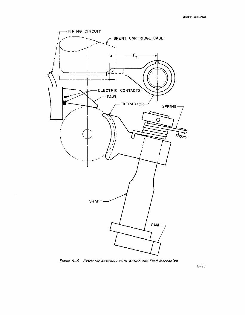
AMCP 706-260
■FIRING CIRCUIT
SPENT CARTRIDGE CASE
Figure 5—9. Extractor Assembly With Antidouble Feed Mechanism 5-35
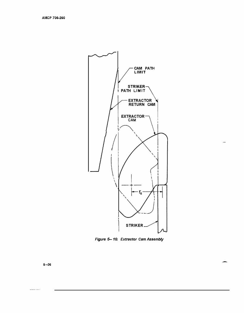
AMCP 706-260
CAM PATH LIMIT
Figure 5-10. Extractor Cam Assembly
5-36
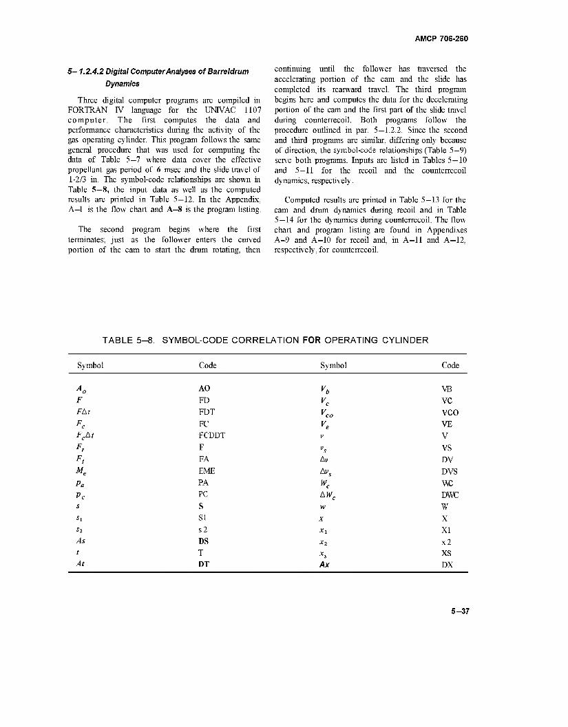
AMCP 706-260
5-1.2.4.2 Digital Computer Analyses of Barreldrum
Dynamics
Three digital computer programs are compiled in FORTRAN IV language for the UMVAC 1107 computer. The first computes the data and performance characteristics during the activity of the gas operating cylinder. This program follows the same general procedure that was used for computing the data of Table 5—7 where data cover the effective propellant gas period of 6 msec and the slide travel of 1-2/3 in. The symbol-code relationships are shown in Table 5—8, the input data as well as the computed results are printed in Table 5—12. In the Appendix, A—1 is the flow chart and A—8 is the program listing.
The second program begins where the first terminates; just as the follower enters the curved portion of the cam to start the drum rotating, then
continuing until the follower has traversed the accelerating portion of the cam and the slide has completed its rearward travel. The third program begins here and computes the data for the decelerating portion of the cam and the first part of the slide travel during counterrecoil. Both programs follow the procedure outlined in par. 5—1.2.2. Since the second and third programs are similar, differing only because of direction, the symbol-code relationships (Table 5—9) serve both programs. Inputs are listed in Tables 5—10 and 5—11 for the recoil and the counterrecoil dynamics, respectively.
Computed results are printed in Table 5—13 for the cam and drum dynamics during recoil and in Table 5—14 for the dynamics during counterrecoil. The flow chart and program listing are found in Appendixes A—9 and A-10 for recoil and, in A-ll and A-12, respectively, for counterrecoil.
TABLE 5-8. SYMBOL-CODE CORRELATION FOR OPERATING CYLINDER
Symbol Code Symbol Code
F Fat
Fc FcAt
Fr
Ft Me
Pa
Pc s
Si
S2
As
t
At
AO
FD
FDT
FC
FCDDT
F
FA
EME
PA
PC
S
SI
s2
DS
T
DT
v
vs Av
Wc
AWC
w
X
Xi
Xl
XS
Ax
VB
VC
vco VE
V
VS
DV
DVS
w: DWC
w X XI
x2 xs DX
5-37
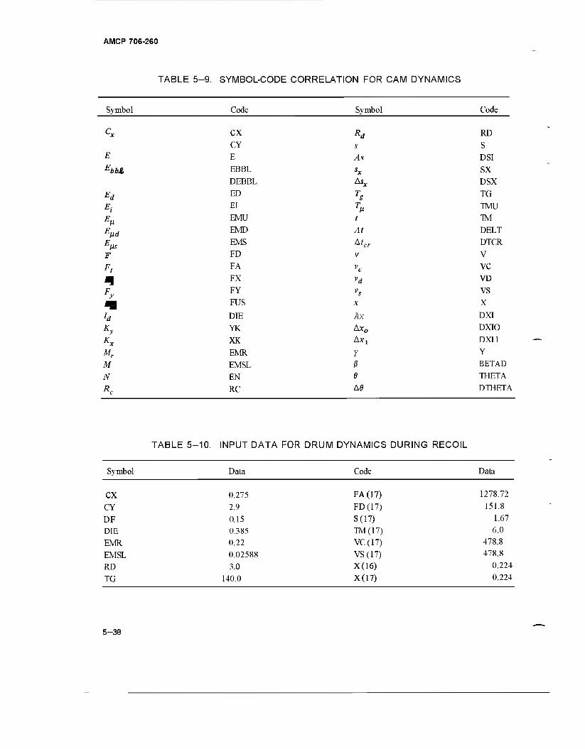
AMCP 706-260
TABLE 5-9. SYMBOL-CODE CORRELATION FOR CAM DYNAMICS
Symbol Code Symbol Code
-bbJg
-'fJs
' t
Ky
Kx
Mr
M N
CX
CY
E
EBBL
DEBBL
ED
El
EMU
EMD
EMS FD
FA
FX
FY
FUS
DIE
YK
XK
EMR
EMSL
EN
RC
Rd
s As sx Asx
T g T
t At
v vc vd
X
Ax Ax0
AXy
Y
ß e Ad
RD
S
DSI
SX
DSX
TG
TMU TM
DELT
DTCR
V
VC VD
vs X
DXI
DXIO
DXI1
Y
BETAD
THETA
DTHETA
TABLE 5-10. INPUT DATA FOR DRUM DYNAMICS DURING RECOIL
Symbol Data Code Data
CX
CY
DF DIE
EMR
EMSL RD
TG
0.275
2.9
0.15 0.385 0.22
0.02588 3.0
140.0
FA (17)
FD(17)
S(17) TM(17) VC (17)
VS (17) X(16)
X(17)
1278.72
151.8
1.67 6.0
478.8 478.8
0.224
0.224
5-38
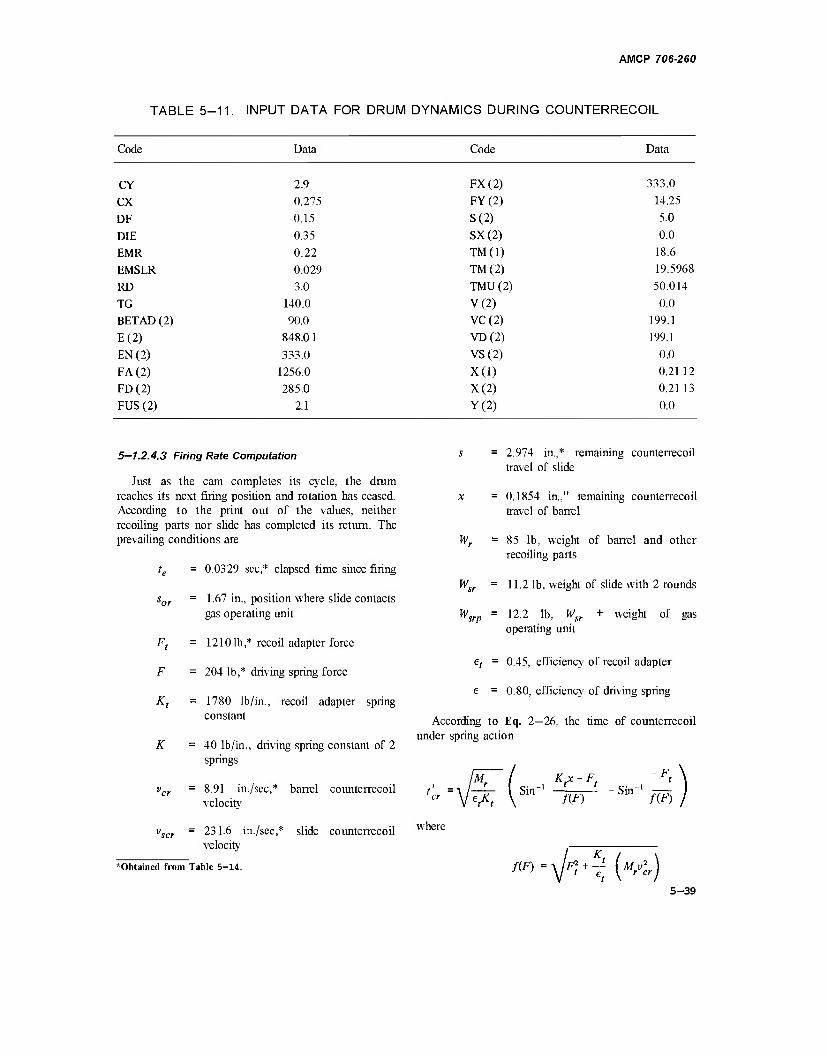
AMCP 706-260
TABLE 5-11. INPUT DATA FOR DRUM DYNAMICS DURING COUNTERRECOIL
Code Data Code Data
CY
CX
DF
DIE EMR
EMSLR
RD
TG BETAD (2)
E(2) EN (2)
FA (2) FD(2)
FUS (2)
2.9
0.275
0.15
0.35
0.22
0.029 3.0
140.0
90.0
848.0 1
333.0
1256.0
285.0
2.1
FX(2) FY(2)
S(2) SX(2)
TM(1)
TM(2)
TMU (2)
V(2) VC(2) VD(2)
VS(2)
X(l) X(2) Y(2)
333.0
14.25
5.0
0.0
18.6
19.5968
50.014
0.0
199.1
199.1
0.0
0.2112
0.2113
0.0
5—1.2.4.3 Firing Rate Computation
Just as the cam completes its cycle, the dram reaches its next firing position and rotation has ceased. According to the print out of the values, neither recoiling parts nor slide has completed its return. The prevailing conditions are
te = 0.0329 sec,* elapsed time since firing
sor = 1.67 in., position where slide contacts gas operating unit
Ft = 12101b * recoil adapter force
F = 204 lb,* driving spring force
Kt = 1780 lb/in., recoil adapter spring constant
K =40 lb/in., driving spring constant of 2 springs
vcr = 8.91 in./sec,* barrel counterrecoil velocity
vscr = 231.6 in./sec,* slide counterrecoil velocity
"Obtained from Table 5-14.
Wr
w„
= 2.974 in.,* remaining counterrecoil travel of slide
= 0.1854 in," remaining counterrecoil travel of barrel
= 85 lb, weight of barrel and other recoiling parts
= 11.2 lb, weight of slide with 2 rounds
= 12.2 lb, Wsr + weight of gas operating unit
et = 0.45, efficiency of recoil adapter
e = 0.80, efficiency of driving spring
According to Eq. 2—26, the time of counterrecoil under spring action
W. srp
M.
efKt Sin
, K,x-F< f(F)
SilT
-F
/CO
where
m=\lFt+Tt (MrVl)
5-39
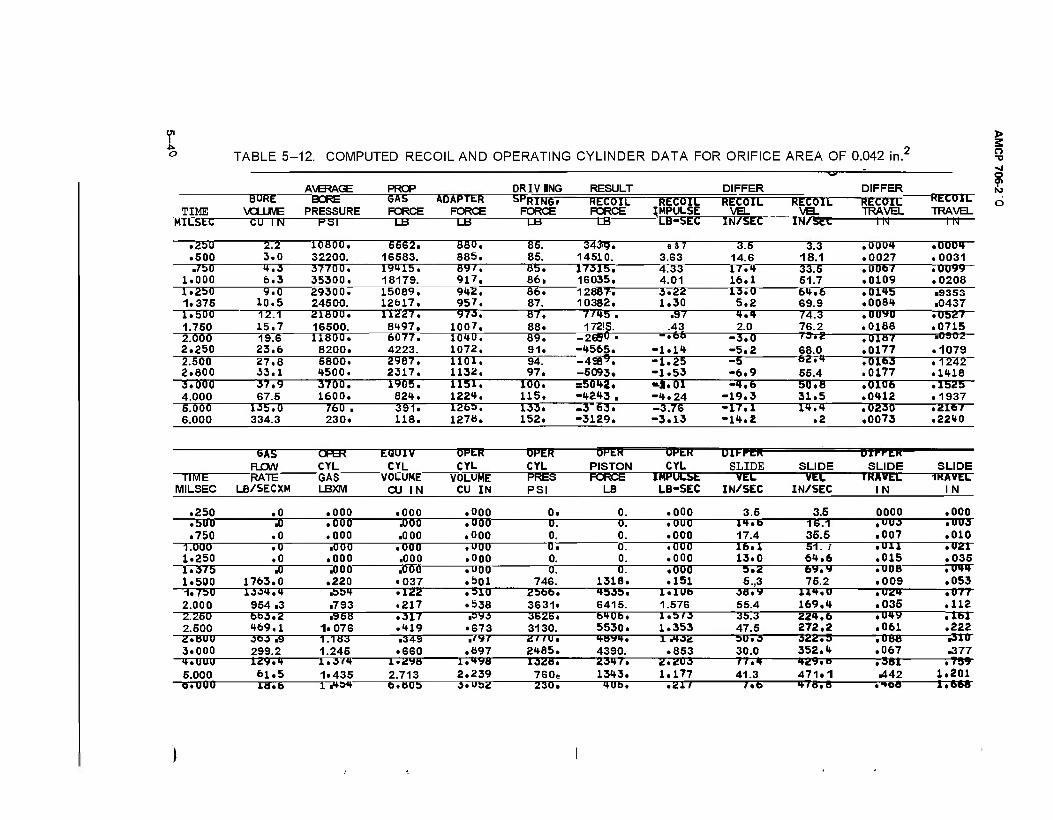
U1 1 o TABLE 5- -12. COMPUTED RECOIL AND OPERATING CYLINDER DATA FOR ORIFICE AREA OF 0.042 in.2
> S o •a
AVERAGE PROP DRIVING RESULT DIFFER DIFFER
O 01
TIME BORE
VOLUME BORE
PRESSURE GAS FORCE
ADAPTER FORCE
SPRING' FORCE
RECOIL FORCE
RECOIL IMPULSE
RECOIL VEL
RECOIL VEL
RECOIL TRAVEL
—REC0TL7 TRAVEL
O
MILStC CU IN PSI LB LB LB LB LB-StC IN/SEC 1NV5EC— m TO—
.250
.500 2.2 9.0
10800, 32200.
5562. 16583.
880. 885.
85. 85.
34ag. 14510.
e S 7 3.63
3.5 14.6
3.3 18.1
.0004
.0027 .0004 .0031
.750 1.000
4.3 6.3
37700. 35300.
19U15. 18179.
89/. 917.
85. 86.
17315. 16035.
4.33 4.01
17.4 16.1
33.5 51.7
.0067
.0109 .0099 .0208
1.250 1.375
9.0 10.5
29300. 24500.
15089. 12617.
942. 957.
86, 87.
1288T. 10382.
3,22 1.30
13.0 5.2
64.6 69.9
.0145
.0084 ■9353 .0437
1.500 1.750
12.1 15.7
21800. 16500.
11227. 8497.
973. 1007,
87. 88.
7 /45 . 172IS.
.97 .43
4.4 2.0
74.3 76.2
.00*0
.0188
.0187
.0177
.0163
.0177
.0527
.0715 .0902
.1079
.1242
.1418
2.000 2.250 2.500 2.600
19.6 23.6 27.8 33.1
11600. 8200. 5800. 1500.
6077. 4223. 2967, 2317.
1040. 1072. liOl. 1132.
89. 91. 94. 97.
-26S0 .
-4565. -49Ö9. -5093.
-»66
-1.14 -1.25 -1.53
-3.0 -5.2 -5 -6.9
73.2
68.0 62r*
55.4 9.000 4.000
37.9 67.5
37ÖÖ. 1600.
1905. 824.
1151, 1224,
1ÖÖ. 115.
s5042. -4243 ■
«J.01 -4.24
-4.6 -19.3
50.8 31.5
.0106
.0412 .1525 .1937
5.000 6.000
135.0 334.3
760 . 230.
391. 118.
1265. 1278.
133. 152,
.3 63. -3129.
-3.76 -3.13
-17.1 -14,2
14,4 .2
.0230
.0073 .2167 .2240
GAS FLOW
OPER CYL
EQU1V
CYL
OPt« CYL
0PER CYL
ÖHLH
PISTON
UMtK CYL
Uli-PER
SLIDE SLIDE —OTFPCT—
SLIDE SLIDE TIME
MILSEC RATE
LB/SECXM GAS LBXM
VOLUME CU IN
VOLUME CU IN
PRES PSI
FORCE LB
IMPULSE LB-SEC
VEL IN/SEC
VEL IN/SEC
IKAVLL IN
IKAVtL IN
.250 .0 .000 .000 .000 0. 0. .000 3.5 3.5 0000 .000
.500
.750 .0 .000 .000
J)00 .000
.000
.000 0. 0.
0. 0.
.000
.000 14,b 17.4
16.1 35.5
,UU3 .007
.UÜ3
.010 1.000 1.250
.0
.0 .000 .000
.000 .000
.U0Ü
.000 0, 0.
0. 0.
.000
.000 16.1 13.0
51. / 64.6
• Uli .015
• U21 .035
1.375 1.500
.0 1763.0
.000 .220
.000 • 037
.000
.501 0.
746. 0.
1318. .000 .151
5.2 5.,3
bv.y 75.2
.008
.009 .044 .053
-I.75U 2.000
1J34.4 954 .3
.554
.793 • 122 .217
.510
.538 2566. 3631»
4535. 6415.
l.lUb 1.576
38.y 55.4
114,U 169.4
.024
.035 .077 .112
2.250 2.500
6b3.2 469.1
.958 1.076
.317
.«♦19 ,sy3 .673
3626. 3130.
6406. 5530.
1.5/3 1.353
35.3 47.5
224.6 272.2
• U4V .061
.161
.222 2.BÜ0 9.000
363 .9 299.2
1.183 1.245
.349 .660
■ '*/ .097
2//U. 2485.
4BV4. 4390.
i .432 .853
50.3 30.0
322.5 352.4
.088
.067 ■310 .377
4.UUU 5.000
12V.4 61.5 IS.6
1.3*4 1*435 2.713
1,498 2.239
1328. 760e
2347. 1343.
2.203 1.177
77.4 41.3
429, o
471.1 .381 .442
.789 1.201
6.000 1 .4S4 b.bOb 3.U52 230. 4U6. .21/ /*b 478.8 .•»68 1.668
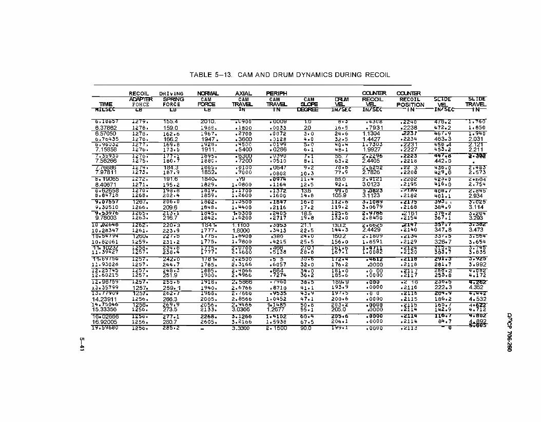
TABLE 5-13. CAM AND DRUM DYNAMICS DURING RECOIL
RECOIL DRIVING NORMAL AXIAL PERJPH COUNTER COUNTER
TIME ADAPTER
FOHCE SPRING FORCE
CAM FORCE
CAM TRAVEL
CAM TRAVEL
CAM SLOPE
DRUM VEL
RECOIL VEL
IN/SET
RECOIL POSITION TN
SLIDE VEL
TN'SEC
SLIDE TRAVEL
MILSEC LÖ LÜ LB IN IN DEGREE IN/SEC I N
b.lÖÖS/ 6.37862
i2/y. 1278.
1bb.4 159.0
2U1U. 1988.
.U9ÖÖ
.1800 .uuuy .0033
1.Ü 2.0
8.3 16.5
.43UB
.7931 .2240 .2238
4/6.2 472.2
1.7bö 1.850
6.57050 6.70435
1276. 1278.
162.6 166.2
1967. 1947.
.2700
.3600 .0072 .0126
3.0 4.0
24.6 32.5
1.1304 1.4427
.2237 .2234
467.9 463.3
1.940 2.031
b.96032 7.15858
1277. 127b.
169.8 173.5
1928. 1911.
.4500
.5400 .0199 .0286
5.0 6.1
40.4 48.1
1.73Ü3 1.9927
.2231
.2227 45Ö .4 453.2
2.121 2.211
7.3593U 7.56266
127b. 1275.
177.1 160.7
1895. I860.
.6300
.7200 .UJ90 .0510
7.1 8.1
55. 1 63.2
2.2296 2.4405
.2223
.2218 447.8 AA2.0 •
/ 76886 7.97811
1274. 1273.
184.3 187.9
1865. 1852.
.0100
.9000 .0647 .0602
9.2 10.3
/O.b 77.9
2.6252 2.7826
.22 3
.2206 436.0 429.6
2.4B3 2.573
8.19065 8.40671
1272. 1271.
191.6 195.2
1840. 1829.
.Y9 1.0800
.0974
.1164 11.4 12.5
85.0 92.1
2.9121 3.0123
.2202
.2195 42-3.0 416.0
2«b64 2.754
6.62Ö58 8.84718
1270. 1268.
198.8 202.4
Itti9. 1859.
1.17ÖÖ 1.2600
.1372
.1600 13.6 14.8
99.0 105.9
3 .ÜÖÜJ 3.1123 .2182
m)B, 7 401.1
2.Ö4S 2.934
9.0/bb/ 9.30510
126/. 1266.
206.U 209.6
1SÜ2. 1848.
1.3500 l.t400
.1847
.2116 16.0 17.2
112. 6 119.2
•J.ioay 3.0679
• 21fS .2168
3y301 36^.9
3.U25 3.114
9.53976 9.78003
126b. 1263.
213.1 216.7
1Ö45. 1642.
1.5300 1.6200
.2405
.2717 18.5 19.8
125.b 132.0
2.97Hb 2.8450
.2161 .2154
370.2 367.1
3.204 3.293
10 .02648 10.28347
I2b2~. 1261.
220.3 223.9
1841. 1777.
1.1100 1.8000 .3413
21.1 22.5
13LI.Z 144.3
2.bb20 2.4429
.Ü147 .2140
337.7 347.8
3.382 3.473
10.54/94 10.82061
126U. 1259.
22/.b 231.2
l//b. 1775.
l.öSJOO 1.9800
.380 .4215
24.0 25.5
15U.2 156.0
ü.iBuy 1.8591
.2104
.2129 3J' .D 326.7
3.564 3,654
11.1023/ 11.39427
l25'6. 1257.
234.8 238.4
1775. 1777.
2.U7ÖÖ 2.1600
.4fc>6
.5138 2/U1 28.8
161,6 167.1 l'rflii • 21.2»*
.2120 315,5 303.7
3.745 3.835
11.b97bb 11.93026
l2bV. 1257.
242. Ö 244.7
1/81. 1785.
2.2bÖÖ 2.3166
.5 5
.6057 JU.b 32.0
1/2.4 176.2
• 4bl2 .0000
.2110
.2118 281.7 3.992 12.25745 12.60215
1257. 1257.
248.3 251.9
1885. 1900.
2.4066 2.^966
.664
.7274 34.0 36.2
181.0 165.6
.0 00
.0000 .2117 .2117
268.2 253.8
4.082 4.172
12.967by A3.35799
1257. 1257.
255.b 259.1
1918. 1940.
2.5866 2.6766
. /"JbQ
.8710 38.5 41.1
189.9 193.9
.000
.0000 .2 16 .2116
238.b 222.3
4.262 4.352
13. 7 79.09 14.23911
1257. 1256.
262. 7 266.3
1968. 2005.
2. 7666 2.8566
.9535 1.0452
43.9 47.1
19/.b 200.6
.0 0
.0000 .2116 .2115
20"».y 186.2
4.442 4.532
14.75046 15.33356
1256. 1256.
269.9 273.5
2056. 2133.
2.9466 3.0366
1.1485 1.2677
50.8 55.1
203.2 205.0
.0000 .0000
.2115
.2114 16=. / 142.9
4*622 4.712
16.02666 16.92005
1256. 1256.
277.1 280.7
2268. 2605.
3.1266 3.2166
1.4102 1.5938
60.4 67.5
20b.6 204.1
.0000
.0000 .2114 .2114
116./ et.7
4.ÖU2
19.596ÜÜ 1256. 265.2 - 3.3300 2.1500 90.0 199.1 .00Ü0 .2113 - u
I
D 3 o
O) o
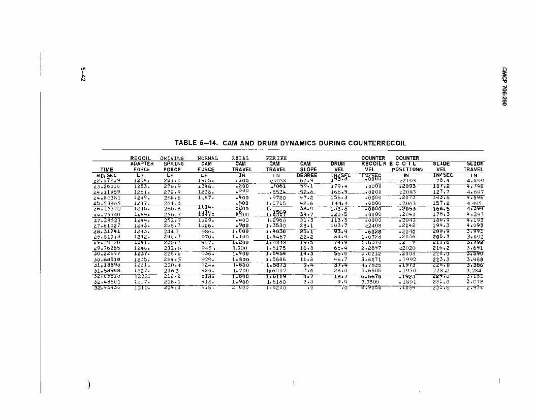
D S o ■o >j o o> ro ei o
TABLE 5-14. CAM AND DRUM DYNAMICS DURING COUNTERRECOIL
RECOIL DRIVING NORMAL AXIAL PERIPH COUNTER COUNTER
TIME ADAPTEH
FOKCt SPRING FORCE
CAM FORCE
CAM TRAVEL
CAM TRAVEL
CAM SLOPE
DRUM VEL
RECOILR VEL
E C O 1 L POSITIONN
SLIDE VEL
SLIDE TRAVEL
MILSEC <:2.17219
La 1254. 1253. 1251. 1249. 1247. 1245. 1244. 1244. 1243. 1243. 1242.
LB 261.0 276.9 272.9 268.6 264.6 260.6 256.7 252.7 248.7 244.7 240.7
LB 1405. 1346. 1238. 1167.
1114.
IN .100 .200 .300
.400
.500 SÜÖO
1 N e5058 .7061 .8534
DEGREE 67.9 i^_ 'i'oooo
.WÖO
..XLQ.0JJ
IN e2103
IN/SEC 78.4
1 N 4e899
23.26010 24.11989
59.1 . _52_.6
47.2 42.6 38.4 34.7
179.4 166.9 e2083
.20/3
.2063
.2053 ,2043
10/.2 127.7 143.8 157.2 16».5 178.3
4. 798 4.697
24.86381 2b.53465 26.15502
.9720 1.0715
155.3 144a 4
"133.8 '" " 123.5
.0000
.0000
.ooöö
.0000
4.596 4.495 4.~3W
26.75740 Mit 1029. 1006.
986e 970.
s^oo .600 .900
1.000 1.100
4e293 £7.28523 27.61027
1.2960 1.3530 1.4Ö30 1.4467
31.3 28.1
22.2
113.5 10 3.7
.0000 e2408
.2043
.2042 18b.9 19^.3
4,193 4.093
26.31741 26.81013
93.9 84.4 1.0728
.2040
.2036 206.7 3.892 29.29120 29.76265
1241. 1240.
23b. / 232.6
957. 945 .
1.2Ü0 1.300
1.4848 1.5175
19.5 16.8
/4.y 65.4
1.63/8 2.2897
.d Y e2020
211.8 216.2 3.691
30.22697 3Ü.ÖÖ518 J1.13Ö9Ü 31.56946
1237. 1235. 1231. 1227.
228.6 224.5 220 e 4 216.3
y36. 929. 924. 920.
1.400 1.500 1. 60 0 le700
1.54b4 1.5686 r.^bB/3 la6017
14.3 11.8 9.4 7.0
S6.U 46.7 3/.4 28.0
3.0212 3.8271 4,7035 5.6505
,2UÜ8 .1992 .iy/3 e 1950
220, u 223.3 225,0 228 .2
3.byu 3.488 3.36b 3.284
32.03613 32.46601
1222. 1217.
212.2 208.1
Yia. 918.
1.Ö0Ö 1.900
1.Ö119 1.6180
4.7 2.3
lö./ 9.4
fa.fa670 7.7509
• iy^3 e 1891
ÜÜ9.8 231.0
3.181 3.078
32e93430 1210. 204e0 9ia. 2.UQ0 1.62U0 .0 .0 a.voba .1054 231.8 2.974
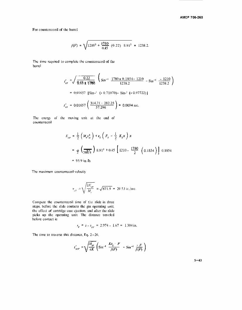
AMCP 706-260
For counterrecoil of the barrel
f(F) = \/l2102 + 1-^2. (0.22) 8.912 = 1238.2.
The time required to complete the counterrecoil of the barrel
, = / °-22 I Sin-i 1780x0.1854- 1210 _. , 'cr V @.4§ * Ittft 1238.2 " " Sm 1238
'c,
1210 \ 38.2 /
= 0.01657 [Sin-' (-0.71070)- Sin-' (-0.97722)]
= 0.01657 (3145
7;29f-25) = 0.0094 sec.
The energy of the moving unit at the end of counterrecoil
= f (3"^") 8.912 +0.45 [ 1210- ^p (o.l854)] 0.1854
= 95.9 in-lb.
The maximum counterrecoil velocity
2E r "= \/l/Z =\/871-9 = 29.53 in,/si
Compute the counterrecoil time of the slide in three steps, before the slide contacts the gas operating unit, the effect of cartridge case ejection, and after the slide picks up the operating unit. The distance traveled before contact is
sc = s-sor = 2.974- 1.67 = 1.304 in.
The time to traverse this distance, Eq. 2-26,
Msr / Ksc~ F _F
scr
5-43
AMCP 706-260
where
V^ mJmMmi - >000906 ■ °-0301
f(F) = F2 + - M„ v* = /2042 t ö1§ x 0.029x231.6' = 345.5.
Therefore
t'scr = 0.0301 (Sin-' 4° 345 g 2°4 " Sin-' ffj^f) = 0.0301 [ Sin-' (-0.43946)- Sin-' (-0.59045) 1
- nnw (333.93-323.81 ) _ = 0.0301 I ^y-r / = 0.0053 sec.
The slide energy at this position
Es = I (MsrVtcr ) + e (F ~ \ Ksc ) Sc = ( ^f"9 ) 23162 * °-8 I 2^ ' ( 1-304) ] 1-304
963.4 in.-lb
The corresponding velocity
VSCr =\ AT = VHÜM = \/66441 = 257.8 in./sec.
To avoid duplication of the above exercise, assume that cartridge case ejection and gas operating piston pick-up occur at the same time. When pick-up occurs, the slide gains one pound. From the conservation of momentum when the ejection velocity, ve = 840 in./sec,
f^),- .(3*), K., \ g I '" \ g I *" + ^g Ve
($&)257-8^)'~*(äS4)
2887 - 168 _ v = —TT^ = 222.9 in./sec scr 12.2
840
5-44
AMCP 706-260
where
yj = weight of slide with 2 rounds sr
Wsrp = weight of slide, 2 rounds, and gas operating unit
The time to complete slide counterrecoil is
'M I Ks - F p ip^Sin-1^^ -Sin"1 ~F
where
V^F -JuiMm =y^ö987= o.o3i4
F = 204- Ksc = 204- 52.16 = 151.841b.
f(F) =JF2 + | (MvpvlJ) =Wl51.842 + & (0.0316) 222.92 = 318.7.
Thus
t'^r = 0.0314 /sin'1 4° X L3i8 7151'84 _ Sin"' "5l87^ ) = °-0314 [Sin"' (" °-26683) " Sin_' (" °-47643)]
1344.52- 331.55 \ = 0.0314 [ 573 /= °-0071sec-
The total slide counterrecoil time after cam action is
t , = t' + t" = 0.0053+0.0071 = 0.0124sec. scr scr scr
The slide energy and velocity at the end of counterrecoil are
£s = iKpv-)+£(f-i^)v
/ ) 222.92 +0.8 f 151.84-^ (1.67) J 1.67 = 943.8 in.-lb.
I IE /Ü 'scr~\lMsrp "^o
1887.6 .0316 ^59734 = 244.4 in./sec.
5-45
AMCP 70S-260
The time of slide counterrecoil exceeds that for the barrel, therefore, the firing rate is based on the former. The total time to complete the firing cycle
t. " t +C = 0.0329 + 0.0124 e scr 0.0453 sec.
The rate of fire
/ = — =1324 rounds/min. c
Originally, the maximum recoil velocity of the slide was assumed to be 600 in./sec but, to satisfy some of the other design criteria, this velocity reduces to 478.8 in./sec. Rather than manipulate other variables to reach the 600 in./sec velocity, 478.8 in./sec was accepted to continue the analysis. When this reduced velocity was introduced in the earlier time estimates of par. 5—1.1.1, a revised rate of fire of 1590 rounds/min was computed. These two firing rates — one obtained by means of a digital computer, the other by a short cut estimate — are within 80% agreement of each other.
momentum of the recoiling parts is equivalent to the impulse generated by the propellant of this single shot. During the latter part of the recoil travel, the energy of translation of the recoiling parts is converted to rotational energy of the drum by cam action. The drum now acts as a flywheel, delivering energy needed to operate the feed system, meanwhile storing the remainder that eventually would be reconverted, by continued action, into the translational energy of counterrecoil. Just before reaching the in-battery position, both barrels are fired. Part of the total impulse of the two shots compensate for the momentum of counterrecoil to stop the moving parts in their forward motion. The remaining impulse induces the recoil that follows. This action continues until the end of the burst when a single shot is fired in the last-fire barrel, as opposed to the first-fire barrel that starts the burst. The impulse of this shot stops the counterrecoiling parts. Any residual impulse is absorbed by a buffer which also absorbs the full counterrecoil shock in the event of a misfire.
5-2 DOUBLE BARREL TYPE 5—2.1.1 Cam Function
The Navy MK 11 Gun is an excellent example of a double barrel revolver-type machine gun. This gun is recoil-operated and fires 4000 rounds/min at a muzzle velocity of 3300 ft/sec (Ref. 16). The high rate of fire is attributed to (1) the simultaneous loading, firing, and ejection of two belts of ammunition for each operation, (2) the use of advance primer ignition technique, and (3) the absence of conventional recoil and counterrecoil shock absorbing elements.
5-2.1 FIRING CYCLE
The firing cycle involves three basic operations: ramming, firing, and case ejection. All perform simultaneously at six chambers of the eight-chambered drum. Fig. 5—11 locates the relative positions of these operations. One belt of ammunition enters the rear drum area from each side of the gun and assumes the respective positions. The rounds in the top and bottom chambers, properly aligned with the barrels, are fired simultaneously. Propellant gases, bled from one barrel only, actuate the rammers and eject the empty cases, all other mechanical functions depend on recoil activity. Since firing must precede ramming and ejecting, an imperceptible lag occurs between firing and the two other functions.
At the start of each burst, only one shot is fired, always from the same first-fire barrel. Thus, the
The drum has eight elliptical cams cut into its outer surface in the arrangement shown in Fig. 5—12. Forward and rear cam followers, mounted on a pivoting arm, engage alternately forward and rear cams during successive rounds. Fig. 5-12(A) shows the gun in battery with the forward cam follower engaged in a forward cam. As the gun recoils, the follower moves along the straight portion of the cam. The relative motion between cam and follower is augmented by the rocker arm which pivots about its fixed center. As its lower end swings forward during recoil, it draws the cam followers forward thus increasing the relative motion between cam and follower. Fig. 5-12(B) shows the positions at full recoil. By this time the follower has traversed half the curved distance and rotated the drum 22-1/2 deg. All energy is now rotational energy with only the drum and associated parts in motion. As the drum continues to turn, it actuates the follower which induces counterrecoil thereby reversing all translational motion that occurred during recoil. Fig. 5-12(C) shows the positions of the various components after all rotation has reverted to translation. Fig. 5-12(D) shows the respective positions after the return to battery. The front follower has been lowered to disengage it from the cam while the rear follower has been raised to engage the next cam which reaches this position after the drum has completed the 45 deg of travel during the firing cycle.
5-46
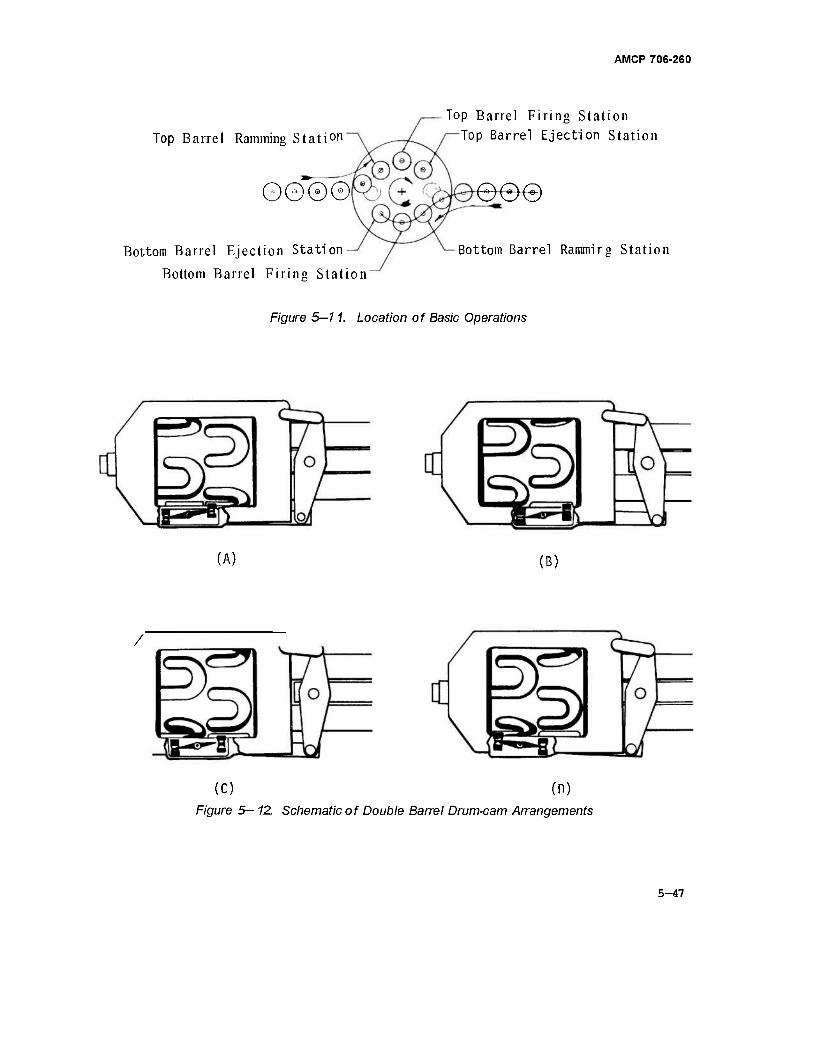
AMCP 706-260
Top Barrel Ramming Station
0000
Bottom Barrel Ejection Station
Bottom Barrel Firing Station
Top Barrel Firing Station Top Barrel Ejection Station
eee
Bottom Barrel Rammirg Station
Figure 5—11. Location of Basic Operations
(A) (B)
/
(c) (n) Figure 5— 12. Schematic of Double Barrel Drum-cam Arrangements
5-47
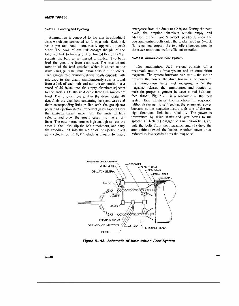
AMCP 706-260
5—2,1.2 Loading and Ejecting
Ammunition is conveyed to the gun in cylindrical links which are connected to form a belt. Each link has a pin and hook diametrically opposite to each other. The hook of one link engages the pin of the following link to form ajoint of limited flexibility that permits the belt to be twisted or folded. Two belts feed the gun, one from each side. The intermittent rotation of the feed sprocket, which is splined to the drum shaft, pulls the ammunition belts into the loader. Two gas-operated rammers, diametrically opposite with reference to the drum, simultaneously strip a round from a link of each belt and ram the ammunition at a speed of 50 ft/sec into the empty chambers adjacent to the barrels. On the next cycle these two rounds are fired. The following cycle, after the drum rotates 45 deg, finds the chambers containing the spent cases and their corresponding links in line with the gas ejector ports and ejection ducts. Propellant gases, tapped from the fiist-fire barrel, issue from the ports at high velocity and blow the empty cases into the empty links. The case momentum is high enough to seat the cases in the links, slip the belt attachment, and carry the case-link unit into the mouth of the ejection ducts at a velocity of 75 ft/sec which is enough to insure
emergence from the ducts at SO ft/sec. During the next cycle, the emptied chambers remain empty and advance to the 3 and 9 o'clock positions, where the two ammunition belts enter the loader (see Fig. 5-11). By remaining empty, the two idle chambers provide the space requirements for efficient operation.
5—2.1.3 Ammunition Feed System
The ammunition feed system consists of a pneumatic motor, a drive system, and an ammunition magazine. The system functions as a unit — the motor provides the power, the drive transmits the power to the ammunition belts and magazine, while the magazine releases the ammunition and rotates to maintain proper alignment between stored belt and feed throat. Fig. 5-13 is a schematic of the feed system that illustrates the functions in sequence. Although the gun is self-feeding, the pneumatic power boosters at the magazine insure high rate of fire and high functional link belt reliability. The power is transmitted by drive shafts and gear boxes to (he sprockets which (1) engage the ammunition belts, (2) pull the belts from the magazine, and (3) drive the ammunition toward the loader. Another power drive, reduced to low speeds, turns the magazine.
MAGAZINE DRIVE CRANK-
WORM GEAR
DECLUTCH LEVER-
SPROCKET FEED THROAT
RING GEAR
PINION GEAR
MAGAZINE
^OOQjDQObOOCXXpbQO'
PNEUMATIC MOTOR
SOLENOID-ACTUATEDVALVE-^// A|R UNE ik SPROCKET CRANK
Figure 5—13. Schematic of Ammunition Feed System
5-48
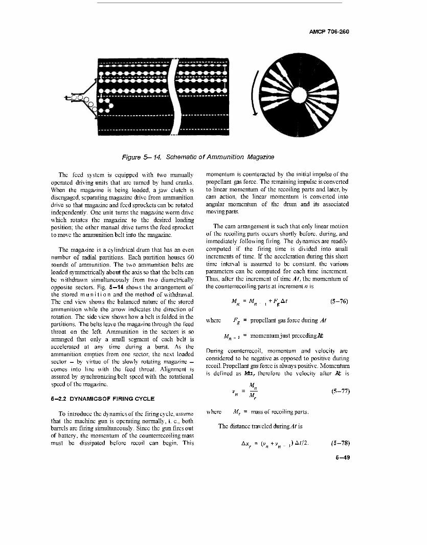
AMCP 706-260
Figure 5—14. Schematic of Ammunition Magazine
The feed system is equipped with two manually operated driving units that are turned by hand cranks. When the magazine is being loaded, a jaw clutch is disengaged, separating magazine drive from ammunition drive so that magazine and feed sprockets can be rotated independently. One unit turns the magazine worm drive which rotates the magazine to the desired loading position; the other manual drive turns the feed sprocket to move the ammunition belt into the magazine.
The magazine is a cylindrical drum that has an even number of radial partitions. Each partition houses 60 rounds of ammunition. The two ammunition belts are loaded symmetrically about the axis so that the belts can be withdrawn simultaneously from two diametrically opposite sectors. Fig. 5—14 shows the arrangement of the stored munition and the method of withdrawal. The end view shows the balanced nature of the stored ammunition while the arrow indicates the direction of rotation. The side view shows how a belt is folded in the partitions. The belts leave the magazine through the feed throat on the left. Ammunition in the sectors is so arranged that only a small segment of each belt is accelerated at any time during a burst. As the ammunition empties from one sector, the next loaded sector — by virtue of the slowly rotating magazine — comes into line with the feed throat. Alignment is assured by synchronizing belt speed with the rotational speed of the magazine.
5-2.2 DYNAMICSOF FIRING CYCLE
To introduce the dynamics of the firing cycle, assume that the machine gun is operating normally, i. e., both barrels are firing simultaneously. Since the gun fires out of battery, the momentum of the counterrecoiling mass must be dissipated before recoil can begin. This
momentum is counteracted by the initial impulse of the propellant gas force. The remaining impulse is converted to linear momentum of the recoiling parts and later, by cam action, the linear momentum is converted into angular momentum of the drum and its associated moving parts.
The cam arrangement is such that only linear motion of the recoiling parts occurs shortly before, during, and immediately following firing. The dynamics are readily computed if the firing time is divided into small increments of time. If the acceleration during this short time interval is assumed to be constant, the various parameters can be computed for each time increment. Thus, after the increment of time A t, the momentum of the counterrecoiling parts at increment n is
M M„ + F At i g
(5-76)
where
M„
propellant gas force during At
momentumjust preceding^:
During counterrecoil, momentum and velocity are considered to be negative as opposed to positive during recoil. Propellant gas force is always positive. Momentum is defined as Ma, therefore the velocity after Pt is
- ^ "" Mr
where Mr = mass of recoiling parts.
The distance traveled during/If is
(5-77)
Ax (v+vJA^. (5-78)
5-49
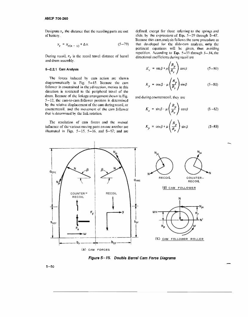
AMCP 706-260
Designate xr the distance that the recoiling parts are out of battery.
Xr(n- i) + Ax- (5-79)
During recoil, xr is the recoil travel distance of barrel and drum assembly.
defined, except for those referring to the springs and slide, by the expressions of Eqs. 5—29 through 5—47. Because this cam,analysis follows the same procedure as that developed for the slide-cam analysis, only the pertinent equations will be given, thus avoiding repetition. According to Eqs. 5—33 through 5-36, the directional coefficients during recoil are
5—2.2.1 Cam Analysis Kx = sinß+ß\-^ I cos/3 (5-80)
The forces induced by cam action are shown diagrammatically in Fig. 5-15. Because the cam follower is constrained in the ydirection, motion in this direction is restricted to the peripheral travel of the drum. Because of the linkage arrangement shown in Fig. 5—12, the cam-to-cam follower position is determined by the relative displacement of the cam during recoil, or counterrecoil, and the movement of the cam follower that is determined by the link rotation.
Ky = COSJ3-MI^- ) sin jß
and during counterrecoil, they are
Kx = sin(3-M(^-P ] cosj3
(5-81)
(5 -82)
The resolution of cam forces and the mutual influence of the various moving parts on one another are illustrated in Figs. 5—15, 5—16, and 5—17; and are
Ky = COS(3 + M I ^ I sinn (5-83)
(A) CAM FORCES
Qrec RECOIL COUNTER
RECOIL
(B) CAM FOLLOWER
MN
(C) CAM FOLLOWER ROLLER
Figure 5—15. Double Barrel Cam Force Diagrams
5-50
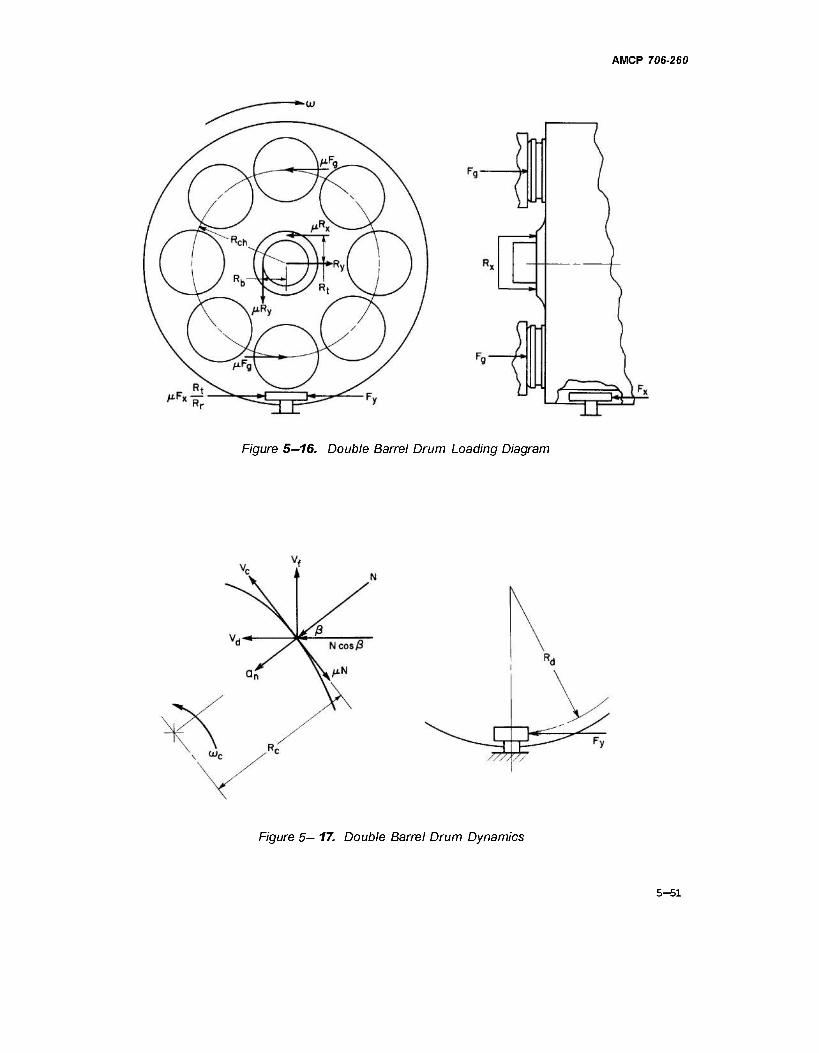
AMCP 706-260
Figure 5—16. Double Barrel Drum Loading Diagram
Figure 5— 17. Double Barrel Drum Dynamics
5-51
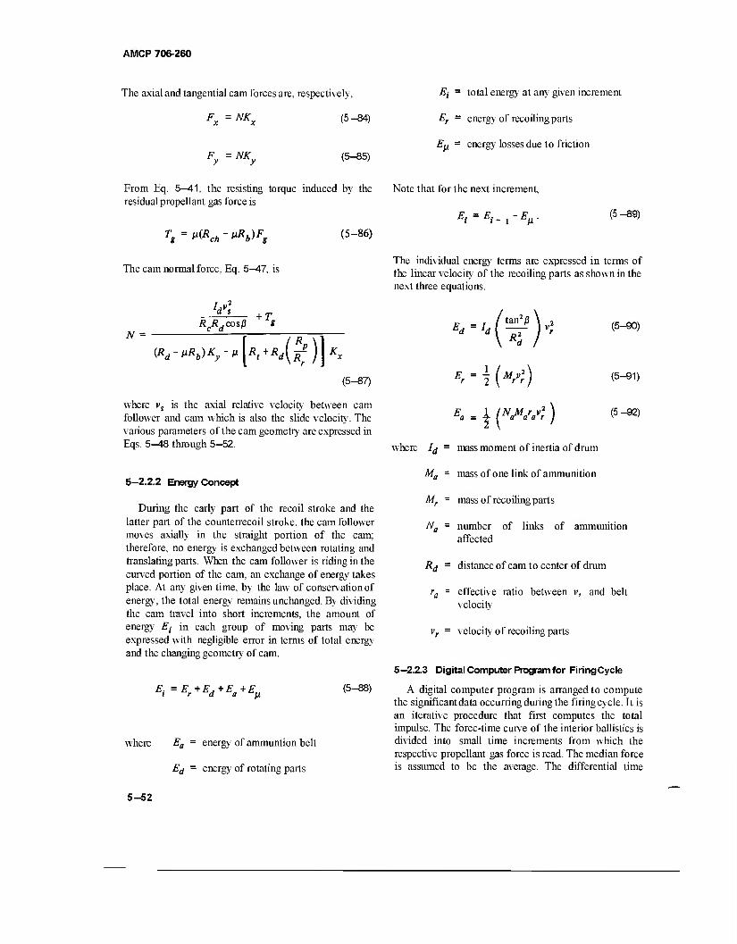
AMCP 706-260
The axial and tangential cam forces are, respectively,
(5-84) Fx = NKx
Fy=NKy (5-85)
From Eq. 5—41, the resisting torque induced by the residual propellant gas force is
Tg=n(Rch-ßRb)Fg
The cam normal force, Eq. 5—47, is
—Li +T RRd cos ß S
(5-86)
N =
(Rd-ßRb)Ky-»[Rt+Rd(^)]Kx
(5-87)
where vs is the axial relative velocity between cam follower and cam which is also the slide velocity. The various parameters of the cam geometry are expressed in Eqs. 5^18 through 5-52.
5—2.2.2 Energy Concept
During the early part of the recoil stroke and the latter part of the counterrecoil stroke, the cam follower moves axially in the straight portion of the cam; therefore, no energy is exchanged between rotating and translating parts. When the cam follower is riding in the curved portion of the cam, an exchange of energy takes place. At any given time, by the law of conservation of energy, the total energy remains unchanged. By dividing the cam travel into short increments, the amount of energy Ei in each group of moving parts may be expressed with negligible error in terms of total energy and the changing geometry of cam.
E{=Er+Ed+Ea+E^ (5-88)
where Ea = energy of ammuntion belt
Ed = energy of rotating parts
Ej = total energy at any given increment
Er = energy of recoiling parts
Ep = energy losses due to friction
Note that for the next increment,
Ei'Ei-rEß' (5-89)
The individual energy terms are expressed in terms of the linear velocity of the recoiling parts as shown in the next three equations.
Ed~h tan2 ß
1 (W)
\ (w«1*)
(5-90)
(5-91)
(5-92)
where ld = mass moment of inertia of drum
Ma = mass of one link of ammunition
Mr = mass of recoiling parts
Na = number of links of ammunition affected
Rd = distance of cam to center of drum
ra = effective ratio between v, and belt velocity
vr = velocity of recoiling parts
5—2.2.3 Digital Computer Program for FiringCycle
A digital computer program is arranged to compute the significant data occurring during the firing cycle. It is an iterative procedure that first computes the total impulse. The force-time curve of the interior ballistics is divided into small time increments from which the respective propellant gas force is read. The median force is assumed to be the average. The differential time
5-52

AMCP 706-260
between any two adjacent forces is small enough so that the corresponding portion of the curve approximates a straight line; therefore, the assumption is considered accurate. The computed area under the curve is the total impulse. The force-time curve is shown in Fig. 5—18.
The velocity of free recoil is found by equating the impulse to the momentum of the recoiling parts. The energy of free recoil may now be computed. However, this energy is a fictitious value since the gun is fired out of battery. Also, frictional losses in the system account for additional energy loss. To compensate for this loss during the first set of computations, only 70 percent of the energy of free recoil is entered toward computing the counterrecoil velocity plus the initial momentum of counterrecoil just as the first two chambered rounds are fired simultaneously. Each differential impulse is subtracted from the momentum until zero velocity is
achieved. Subsequently, the remaining impulse determines the new recoil velocity. The dynamics of the cam system are now computed and if the resulting counterrecoil velocity — after the cam is negotiated by the cam follower — does not match its original value, the initial counterrecoil is adjusted accordingly and the process continued.
The area under the force-time curve for a given time represents the cumulated impulse of the propellant gas force to that term. The area is computed by employing the trapezoid rule.
^4»i — ^4„ + FAt
FAt ■ft
g(n D+Fg(n) At.
(5-93)
(5-84)
40
35
2 30
^25
3 20
UJ S io a.
4
Ui"2
o a. 2
o
\ DECAY CURVE
3 4 5 6 TIME, msec
0.5 2.5 1.0 1.5 2.0
TIME, msec
Figure 5—18. Force-time Curve of 20 mm Revolver-type Gun
3.0
5-53
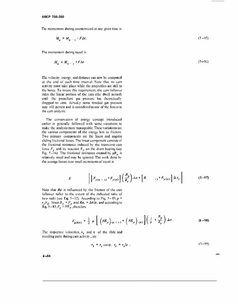
AMCP 706-260
The momentum during counterrecoil at any given time is
Mn =Mn-x~Fät- (5-95)
The momentum during recoil is
M = M „ , +FAt. n n - l (5-96)
The velocity, energy, and distance can now be computed at the end of each time interval. Note that no cam activity must take place while the projectiles are still in the bores. To insure this requirement, the cam follower rides the linear portion of the cam (the dwell period) until the propellant gas pressure has theoretically dropped to zero. Actually some residual gas pressure may still persist and is considered as one of the forces in the cam analysis.
The conservation of energy concept introduced earlier is generally followed with some variations to make the analysis more manageable. These variations are the various components of the energy lost to friction. Two primary components are the linear and angular slidingfrictional losses. The linear component consists of the frictional resistance induced by the transverse cam force Fy and its reaction Ry on the drum bearing (see Fig. 5—16). The frictional resistance created by ßRy is relatively small and may be ignored. The work done by the average forces over small increments of travel is
K-o+^))(^P)A*+[* i>+A,oo]A; (5-97)
Note that Ax is influenced by the friction of the cam follower roller to the extent of the indicated ratio of two radii (see Eq. 5—32). According to Fig. 5—19, p = rjrd. Since Ry - Fy and Ax, = Ax/p, and according to Vq.5-S5,Fy=NKy, therefore
w - \" [ (H)(*- »+ (NKy) («)] {j +i) Ax. (5-98)
The respective velocities, vs and v, of the slide and recoiling parts during cam activity , are
vs = vc cosp; vr = vjp . (5-99)
5-54
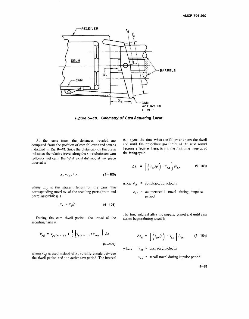
AMCP 706-260
-RECEIVER
BARRELS
CAM ACTUATING LEVER
Figure 5—19. Geometry of Cam Actuating Lever
At the same time, the distances traveled are computed from the position of cam follower and cam as indicated in Eq. 5—49. Since the distance* on the curve indicates the relative travel along the x-axisbetween cam follower and cam, the total axial distance at any given interval is
XS
= Sor+X (5-100)
At j spans the time when the follower enters the dwell and until the propellant gas forces of the next round become effective. Here, Ati is the first time interval of the fixing cycle.
^ = [('o> )-*«,]/>„■ <5"103>
where sor is the straight length of the cam. The corresponding travel x, of the recoiling parts (drum and barrel assemblies) is
where vcr = counterrecoil velocity
counterrecoil travel during impulse period
xr = xjp. (5-101)
During the cam dwell period, the travel of the recoiling parts is
Xrd Xrd(n -i). + T[Vn-.)+Vr.)] *' (5-102)
where xrd is used instead of xr to differentiate between the dwell period and the active cam period. The interval
The time interval after the impulse period and until cam action begins during recoil is
*'„= [('orlp)-Xm\l»n,
where vm = max recoilvelocity
(5-104)
recoil travel during impulse period
5-55
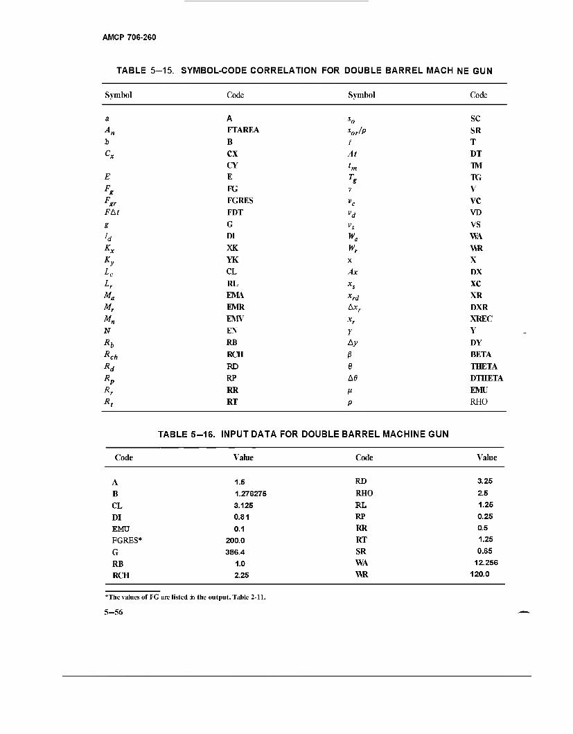
AMCP 706-260
TABLE 5-15. SYMBOL-CODE CORRELATION FOR DOUBLE BARREL MACH NE GUN
Symbol Code Symbol Code
a A„
g
F&t
S
Ky
Mr
M„ N
ch R
Rd Rp Rr
A
FTAREA
B
CX CY E
FG
FGRES
FDT
G DI
XK
YK
CL
RL EMA
EMR
EMV EN
RB
RCH
RD
RP
RR
RT
so sor/P I
At
tm T
v
vc vd vs
K
X
Ax xs xrd Axr
xr Y Ay
ß e A0
p
sc SR T
DT
TM TG V
VC VD
vs WA
WR X
DX
XC XR
DXR
XREC Y
DY
BETA
THETA
DTHETA
EMU
RHO
Code
TABLE 5-16. INPUT DATA FOR DOUBLE BARREL MACHINE GUN
Value Code Value
A B
CL
DI EMU FGRES*
G
RB RCH
1.5
1.27S275 3.125 0.81 0.1
200.0 386.4
1.0 2.25
RD
RHO
RL RP RR
RT
SR WA WR
3.25
2.5 1.25 0.25 0.5 1.25 0.65
12.256 120.0
*The values of FG are listed in the output, Table 2-11.
5-56
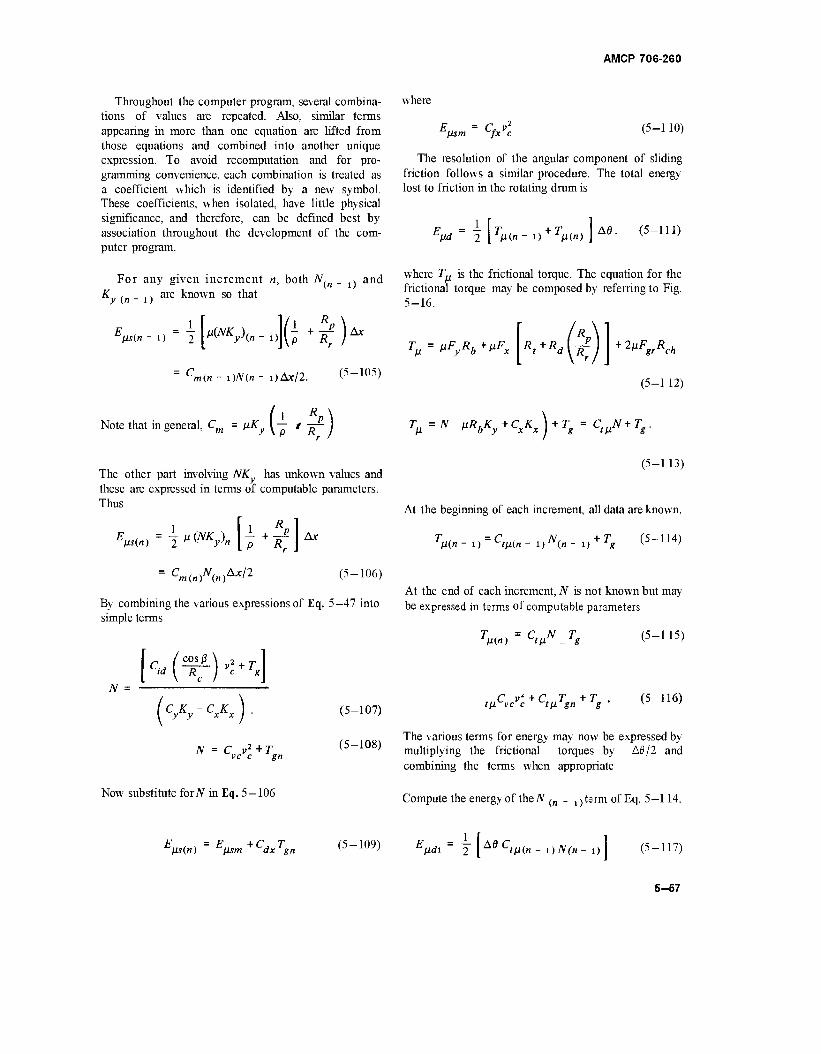
AMCP 706-260
Throughout the computer program, several combina- tions of values are repeated. Also, similar terms appearing in more than one equation are lifted from those equations and combined into another unique expression. To avoid recomputation and for pro- gramming convenience, each combination is treated as a coefficient which is identified by a new symbol. These coefficients, when isolated, have little physical significance, and therefore, can be defined best by association throughout the development of the com- puter program.
where
^ßsm = C, v2 fx c (5-110)
For any given increment n, both N, _ . and (n - i) are known so that
i(n - i)N(n - i)Ax/2. (5-105)
Note that in general, C = pK (*'*)
The resolution of the angular component of sliding friction follows a similar procedure. The total energy lost to friction in the rotating drum is
where T^ is the frictional torque. The equation for the frictional torque may be composed by referring to Fig. 5-16.
T = uF R.+uF ß * y b p x R*+RAK. + 2"VcA
(5-112)
Tß=
N VRöKy+CxKx) + Tg = C
tßN+T
g
The other part involving NK has unkown values and these are expressed in terms of computable parameters. Thus
V«) = -2^NK?n 7+lf^ CminJ<(n)**n (5-106)
By combining the various expressions of Eq. 5-47 into simple terms
N lc«ur2+r'j
(5- [cyKy-cxKxy -107)
N = CVA
+Tgn
(5- -108)
Now substitute forJV in Eq. 5-106
(5-113)
At the beginning of each increment, all data are known.
^-U-Wi,"«,-.,^ (5-114)
At the end of each increment, N is not known but may be expressed in terms of computable parameters
Tm»)~W.Tg (5-115)
rMC^ + V*» + V (5"116)
The various terms for energy may now be expressed by multiplying the frictional torques by A0/2 and combining the terms when appropriate
Compute the energy of the N ^ _ , j term of Eq. 5—114.
F = F + C T ßs(n) cfjLsm ^dx'gn (5-109) JHd\ 2 | A6CtH(n - i)N(n- i) (5-117)
5-57
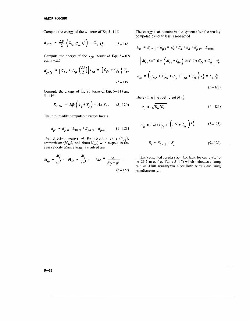
AMCP 706-260
Compute the energy of the 7, term of Eq. 5—116 The energy that remains in the system after the readily computable energy loss is subtracted
V.-3 [c<»cv/c) = ctqvl (5_118) Eie = */-,-*„, = Er+Ea+Ed+E
ßsn+Eßdn
Compute the energy of the Tgn terms of Eqs. 5-109 and 5-116 = AT sin2 ß + ( M +/, \ cos2 ß + C, + C, re ^ \ ae de I ^ fx tg
V, = ( Cäx + C,M (f )K = (C-x + ^ ) Tgn Eie = (Cmr+C
ma + Cid^Cfx+Ctg)vl = CeVi
(5-119)
v2
c
Compute the energy of the T, terms of Eqs. 5—114 and
~~ where C, is the coefficient of v2
Eßdtg = *f(Ts + Ts)-
Ä8Tg- (5-12°)
The total readily computable energy loss is
(5-123)
Em = V + V* + Evätg + Eßdt. (5-121)
vc = jEjCe (5-124)
Eß = ßu + cA + (er* + c,j)v* (5-125)
The effective masses of the recoiling parts (Mre), ammunition (Mae), and drum (Ide) with respect to the £". = £. _ , - £„ (5 — 126) cam velocity when energy is involved are
.._ r . M _ a i = ij The computed results show the time for one cycle to re ~ 2pil ' ae ~ 2pl e R2 + p2 De 26.2 msec (see Table 5—17) which indicates a firing
rate of 4580 rounds/min since both barrels are firing (5—122) simultaneously.
V
5-58
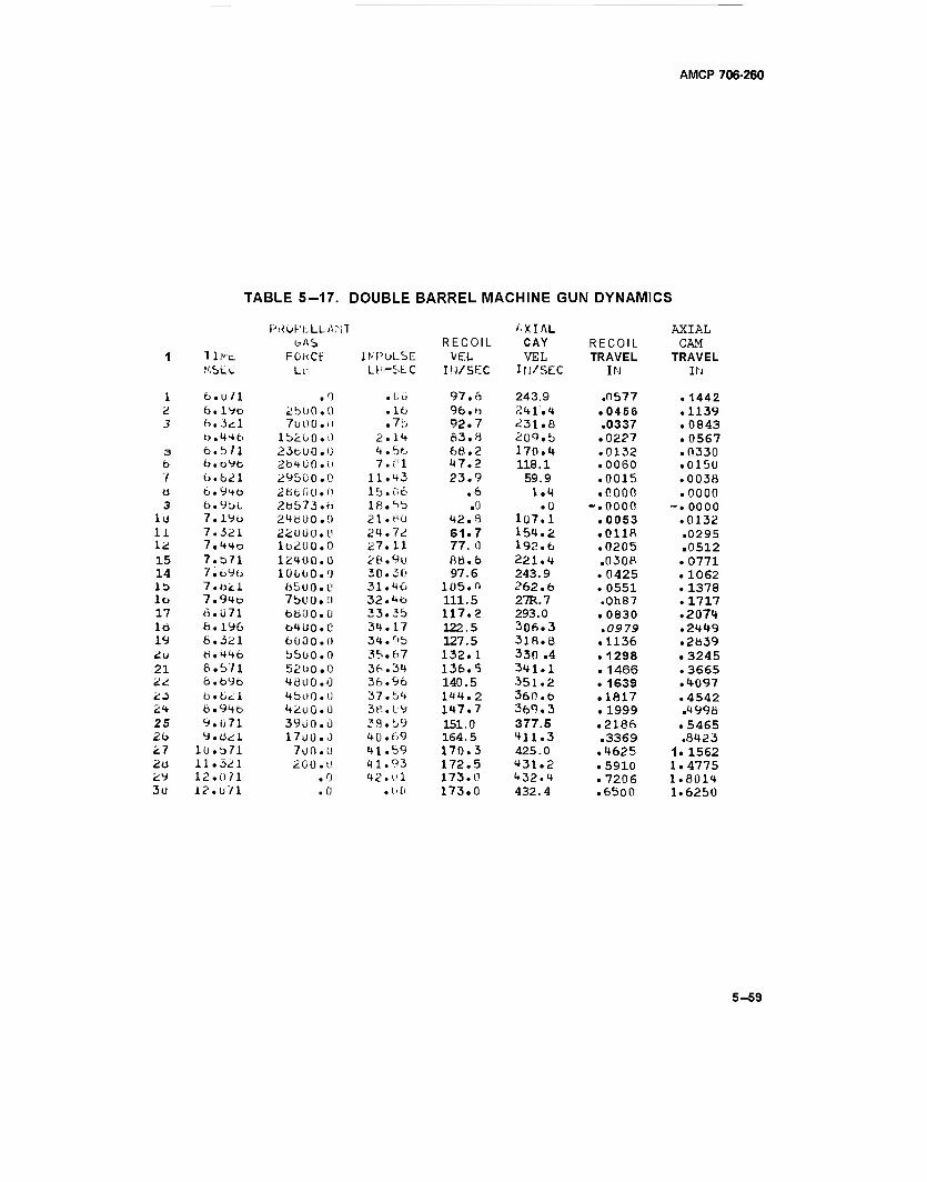
AMCP 706-260
TABLE 5-17. DOUBLE BARREL MACHINE GUN DYNAMICS
PHOPtLLANT AXIAL AXIAL bAS RECOIL CAY RECOIL CAM
1 111*11 FOKCt: INPULSE VEL VEL TRAVEL TRAVEL r'.St-v. Lt- LH-SLC IN/SEC Ifi/SEC IN IN
1 6.u 71 .0 .L;Ü 97.6 243.9 .0577 .1442 2 b.iyo 2bUO.O .16 96.b 241.4 .0456 .1139 3 ft. 3<il 7uUu.il .7b 92.7 231.0 .0337 .0843
b.44b 15200.0 2.14 63.5 2o9.b .0227 .0567 3 6.571 23bU0.0 4 . 5b 66.2 170.4 .0132 .0330 b b.oVb 264 0 0.0 7 .«; 1 47.2 118.1 .0060 .0150 1 b.621 295Ü0.0 11.43 23.9 59.9 .0015 .0036 a 6.94b 28600.0 15.06 .6 1.4 .0000 .0000 3 b.9b0 26573.6 18.5b .0 .0 -.0000 -.0000
lo 7.19b 24600.0 21. BU 42. 8 107.1 .0053 .0132 U 7.321 22000.0 24.72 61.7 154.2 .0118 .0295 12 7.44o lb2U0.0 27.11 77. 0 192.6 .0205 .0512 15 7.S71 12400.0 26.9u 8b.6 221.4 .030? .0771 14 7.b9b lüUUO.O 30.30 97.6 243.9 .0425 .1062 lb 7.021 650 0.0 31.46 105.0 262.6 .0551 .1378 lo 7.94e 7bOÜ.O 32.4b 111.5 27R.7 .Oh87 .1717 17 6. ü 71 660 0.0 33.3b 117.2 293.0 . 0830 .2074 lb e.istb b4 Ü 0 . C 34.17 122.5 306.3 .09 79 .2449 19 6.321 6000.0 34.r'5 127.5 318,6 .1136 .2839 2u 6.44b 5500.0 35.67 132.1 330 .4 .1298 .3245 21 6.b71 521)0.0 36.34 136.5 341.1 .1466 .3665 22 Ö.b9b 4ÜUO.0 36.96 140.5 351.2 . 1639 .4097 23 6.6<il 4500.0 37.54 144.2 360.6 .1817 .4542 an 6.94b 4200.0 3e.L'9 147.7 369.3 . 1999 .4996 25 9.071 3900.0 33.59 151.0 377.5 .2186 .5465 2b 9.621 17U0.0 40.69 164.5 411.3 .3369 .8423 27 lü.371 700.ü 41.59 170.3 425.0 .4625 1. 1562 2U 11.321 200.0 41.93 172.5 431.2 .5910 1.4775 29 12.0 71 .0 42.01 173.0 432.4 .7206 1.8014 3u 12.U/1 .0 .00 173.0 432.4 .6500 1.6250
5-59
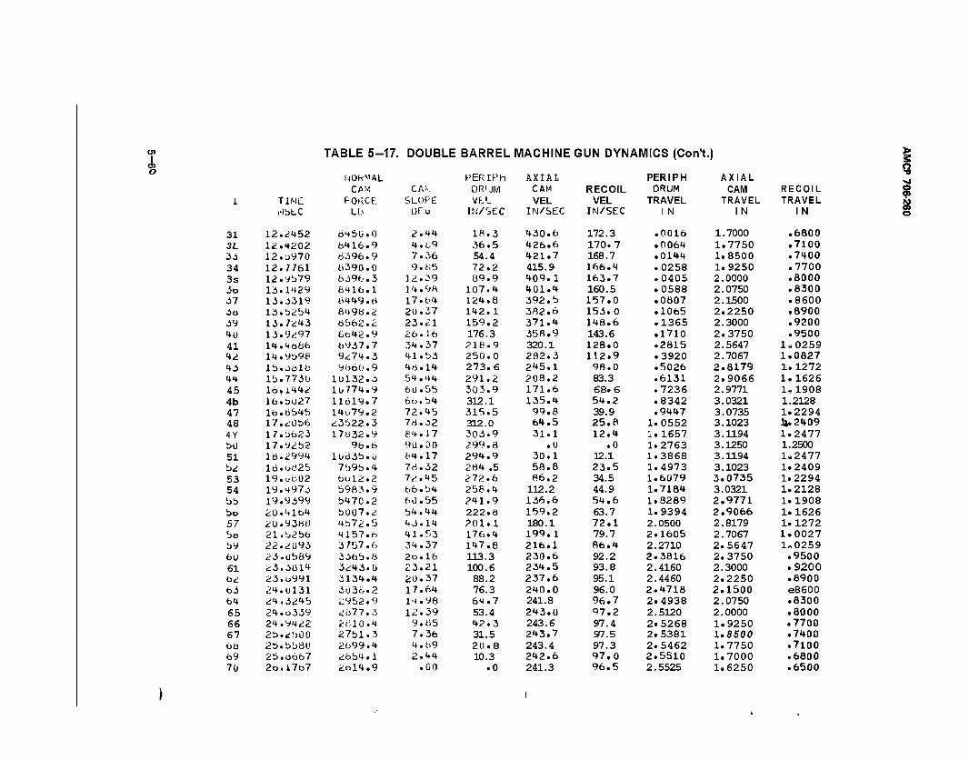
<J1 I o
TABLE 5-17. DOUBLE BARREL MACHINE GUN DYNAMICS (Con't.)
1-lOH^AL PER IPh AXIAL PERIPH AXIAL CAM CAIv DRUM CAM RECOIL DRUM CAM RECOIL
i TiME FORCE. SLOPE VEL VEL VEL TRAVEL TRAVEL TRAVEL i-lbtC Lb OEVJ IN/SEC IN/SEC IN/SEC 1 N 1 N 1 N
31 12.2452 Ö45U.0 2.44 18.3 430.6 172.3 .0016 1.7000 .6800 3L 12.4202 6416.9 4.69 36.5 426.6 170.7 .0064 1.7750 .7100 33 12.3970 6396.9 7.36 54.4 421.7 168.7 .0144 1.8500 .7400 34 12.7761 6390.0 9.65 72.2 415.9 166.4 .0258 1.9250 .7700 3s 12.9579 6396.3 12.39 89.9 409.1 163.7 .0405 2.0000 .8000 3o 13.1429 6416.1 14.98 107.4 401.4 160.5 .0588 2.0750 .8300 37 13.3319 6449.6 17.64 124.8 392.5 157.0 .0007 2.1500 .8600 36 13.b2b4 849Ö.2 2U.37 142. 1 382.6 153.0 .1065 2.2250 .8900 39 13.7*43 6562.2 23.21 159.2 371.4 148.6 .1365 2.3000 .9200 4U 13.9<;97 6o42.9 26.16 176.3 358.9 143.6 .1710 2.3750 .9500 41 14.4o66 6937.7 34.37 218.9 320.1 128.0 .2815 2.5647 le0259 42 14.9^98 9274.3 41. b3 250.0 282.3 112.9 .3920 2.7067 1.0827 43 lb.oolb 9660.9 46.14 273.6 245.1 98.0 .5026 2.8179 1.1272 44 lb.773U 1U132.3 54.44 291.2 208.2 83.3 .6131 2.9066 1.1626 45 16,1442 1U774.9 60.55 303.9 171.6 68.6 .7236 2.9771 lel908 4b 16.3U27 11619.7 66.b4 312.1 135.4 54.2 .8342 3.0321 1.2128 47 lb.6b45 14079.2 72.45 315.5 99.8 39.9 .9447 3.0735 1.2294 48 17.düb6 23b22.3 7d.32 312.0 64.5 25.8 1.0552 3.1023 U.2409 4Y 17.b623 17Ü32.9 84.17 303.9 31.1 12.4 1.1657 3.1194 1.2477 bo 17.92b2 96.6 90.00 299.8 .1) .0 1.2763 3.1250 1.2500 51 18.2994 lüö3b.O 64.17 294.9 30.1 12.1 1.3868 3.1194 U2477 52 ld.uü2b 7b9b.4 76.32 284 .5 58.8 23.5 1.4973 3.1023 1.2409 53 19.ubU2 6ol2.2 72.45 272.6 86.2 34.5 1.6079 3.0735 1.2294 54 19.4973 b983.9 66. b4 258.4 112.2 44.9 1.7184 3.0321 1.2128 bb 19.9499 b470.2 60.55 241.9 136.6 54.6 1.8289 2.9771 1.1908 bo 20.4164 5007.2 54.44 222.Ö 159.2 63.7 1.9394 2.9066 1.1626 57 2U.93MÖ 4b72.5 43.14 201.1 180.1 72.1 2.0500 2.8179 1.1272 bo 21.L.256 4157.6 41.53 176.4 199.1 79.7 2.1605 2.7067 1.0027 b9 22.2093 3757.6 34.37 147.8 216.1 86.4 2.2710 2.5647 1^0259 bU 23.ubö9 336b.8 2b.16 113.3 230.6 92.2 2.3816 2.3750 .9500 61 23.3614 3243.ü 23.21 100.6 234.5 93.8 2.4160 2.3000 .9200 b2 23.u991 3134.4 2Ü.37 88.2 237.6 95.1 2.4460 2.2250 .8900 6.5 24.U131 303Ö.2 17.64 76.3 240.0 96.0 2.4718 2.1500 086OO 64 24.324b 2952.9 14.98 64.7 241.8 96.7 2.4938 2.0750 .8300 65 24.o339 2677.3 12.39 53.4 243.0 97.2 2.5120 2.0000 .8000 66 24.9422 2B10.4 9.65 42.3 243.6 97.4 2.5268 1.9250 .7700 67 2b.^b00 27bl.3 7.36 31.5 243.7 97.5 2.5381 1.8500 .7400 bfc> 2b.bb80 2699.4 4.69 20.8 243.4 97.3 2.5462 1.7750 .7100 69 2b.oo67 26b4.1 2.44 10.3 242.6 97.0 2.5510 1.7000 .6800 7ü 2o.l767 2ol4.9 .00 .0 241.3 96.5 2.5525 1.6250 .6500
> s o -a
? o
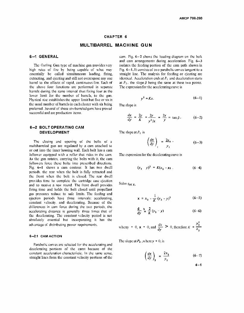
AMCP 706-260
CHAPTER 6
MULTIBARREL MACHINE GUN
6-1 GENERAL
The Gatling Gun type of machine gun provides very high rates of fire by being capable of what may essentially be called simultaneous loading, firing, extracting, and ejecting and still not overexpose any one barrel to the effects of rapid, continuous fire. Each of the above four functions are performed in separate barrels during the same interval thus fixing four as the lower limit for the number of barrels, to the gun. Physical size establishes the upper limit but five or six is the usual number of barrels in each cluster with six being preferred. Several of these six-barreled guns have proved successful and are production items.
6-2 BOLT OPERATING CAM DEVELOPMENT
The closing and opening of the bolts of a multibarreled gun are regulated by a cam attached to or cut into the inner housing wall. Each bolt has a cam follower equipped with a roller that rides in the cam. As the gun rotates, carrying the bolts with it, the cam followers force these bolts into prescribed directions. Fig. 6-1 shows a cam contour. It has two dwell periods, the rear when the bolt is fully retracted and the front when the bolt is closed. The rear dwell provides time to complete the cartridge case ejection and to receive a new round. The front dwell provides firing time and holds the bolt closed until propellant gas pressures reduce to safe limits. The feeding and ejection periods have three intervals: accelerating, constant velocity, and decelerating. Because of the differences in cam force during the two periods, the accelerating distance is generally three times that of the decelerating. The constant velocity period is not absolutely essential but incorporating it has the advantage of distributing power requirements.
6-2.1 CAM ACTION
Parabolic curves are selected for the accelerating and decelerating portions of the cams because of the constant acceleration characteristic. In the same sense, straight lines form the constant velocity portions of the
cam. Fig. 6-2 shows the loading diagram on the bolt and cam arrangements during acceleration. Fig. 6-3 isolates the feeding portion of the cam path shown in Fig. 6-1. It consists of two parabolic curves tangent to a straight line. The analysis for feeding or ejecting are identical. Acceleration ends at Pi and deceleration starts at Pi, the slope ß being the same at these two points. The expressionfor the accelerating curve is
■Kx.
The slope is
dx _ 2y _ 2y dy K y2/x
= ]* y
= tan/?
The slope at Pi is
(6-1)
(6-2)
(*).- 2x,
y\ (6-3)
The expressionfor the decelerating curve is
(y2-y? = K(x3 X) (6-4)
Solveforx.
1 x = x2-—(y2 -y)
K
—, = ~p O2_ y) d_ x_ _2 dy ~ K'
(6-5)
(6-6)
dx y\ wheny = 0, x = 0, and -— > 0, therefore K = -— dy x2
The slope at Pj , wherey = 0, is
UA = y. (6-7)
6-1
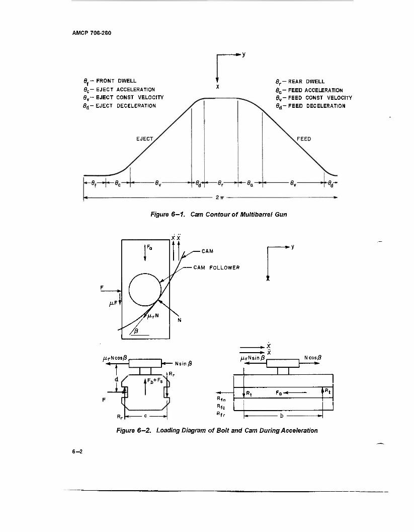
AMCP 706-260
6f- FRONT DWELL
0C- EJECT ACCELERATION ey- EJECT CONST VELOCITY
6d- EJECT DECELERATION
Br~ REAR DWELL
da- FEED ACCELERATION 0v-FEED CONST VELOCITY
6d-FEED DECELERATION
Figure 6-1. Cam Contour of Multibarrel Gun
F
P
/AFT
XX
■CAM
CAM FOLLOWER
iirN cos/3 . -*-j H—Nsinß
T^ i i Rr
■*■ X UrNsin ß NcosS _ n W J *
I I
' ft i ,Rt
Rfn Rfc
I u ■*
Rfr u _
Figure 6—2. Loading Diagram of Bolt and Cam During Acceleration
6-2
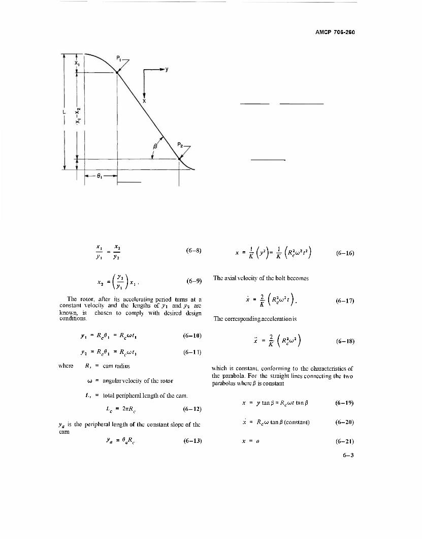
AMCP 706-260
x'■(£)*'■
(6-8)
(6-9)
The rotor, after its accelerating period turns at a constant velocity and the lengths of j>i and j^ are known, is chosen to comply with desired design conditions.
yt = Rc6l = Äcwf,
y-i = Rc6i = *cwri
(6-10)
(6-11)
where R, = cam radius
w = angularvelocity of the rotor
L, = total peripheral length of the cam.
(6-12) Lc = 2vRc
ya is the peripheral length of the constant slope of the cam
ya = «A (6-13)
X'H&T(W) (6"16)
The axial velocity of the bolt becomes
The corresponding acceleration is
x = I ( /?'aj2 ) (6"18)
which is constant, conforming to the characteristics of the parabola. For the straight lines connecting the two parabolas where ß is constant
x = y tan ß = Rcu>t tan (3
x = Äeco tan ß (constant)
(6-19)
(6-20)
(6-21)
6-3
AMCP 70S-2S0
The mechanics of the cam during feed deceleration are The curve for the ejection deceleration is defined as determined by developing Eq. 6-5. Substitute Rccot for
-\y*-y) =K\x2-x) (6-34)
x = x2 - f \y\ - 2y2Rut + R2u*tA (6-22) K v c c / whgny = o x = 0 ^ < 0
x = l(y2Rcu-R^t) (6-23) x = _ ^ + i_^ _2y2y+y^ (6-35)
*~-K(R>
2)- (6~24> f--£(-y**y) = f(y-yJ (6-36)
The ejection part of the cam behaves similarly but in the „2 opposite direction. The curve for ejection acceleration is when-*' = 0, -gy < 0, therefore > " and = ^
, Continue the mechanics and substitute RMt fory - y2 = Kx (6-2S) c
x = - x2 + -4- O2 - 2>>2Äcwf + Ä2wV)
f6-26; (6-3 7J
2 _=__^j (6-27)
2 wheny - y2, x = x2, and JT 0, A <•
^ ^5 6—2.1.2 Definition of Symbols therefore £ > 0 and Ä" = — .
Continue with the mechanics and substitute b = moment arm for tipping track reactions
c = moment arm for rotating track reactions
d - distance, CG of bolt to center of cam roller surface
Rcut fory.
x = - ^ (A2.«
2;
2) (6-28)
2/„,,\ F = driving force X=-JC\Rcut) (6-29)
Fa = axial inertial force of bolt and round x = _£(*»„*) (6. so) orofboltandcase
Fb = centrifugal force of bolt
While ejecting over the straight portion of the cam, the mechanics are Fba = tangential inertia force of bolt
x = -R wftanß (6-3\\ Fs = centrifugal force of round or of case
Fsa = tangential inertia force of round or of x=-£cwtanß (6-32) case
Fa = tangential inertia force of bolt and x = 0. (6-33) round or of bolt and case
6-4
AMCP 706-260
L
M
Mb
Mcc
N
Nt -
R =
R, =
R fa
R fc
R fr
Rr
R, =
a =
V-r
mass moment of inertia of all rotating parts
length of bolt travel
Mb +Ma = mass of bolt unit
mass of round
mass of bolt
mass of case
normal force on roller
axial component of the normal force of the roller
transverse component of the normal force of the roller
radius, gun axis to bolt
cam radius
frictional resistance due to tangential inertia forces
frictional resistance due to centrifugal forces
frictional resistance due to track reactions
track reactions due to rotational forces
track reactions due to tipping forces
torque about gun axis
axial acceleration of bolt
angular acceleration of rotor
angle of cam path (slope)
angular displacement of rotor
coefficient of rolling friction
coefficient of friction of case
coefficient of friction of track
angular velocity of rotor
6-2.1.3 Cam Forces
The axial inertia force of the bolt and round is
Fa = Wh +Ms» ■
The centrifugal force of the bolt is
Fb = MbRu2 •
The centrifugal force of the round is
Fs = MgR^ .
(6-40)
(6-41)
(6^2)
The frictional resistance due to centrifugal force is
Rf, = ± <P,Fh +^A)- fc v^t 0 *^s s' (6-43)
The tangential inertia force of bolt and round induced by angular acceleration is
Fa = Fba + Fsa = MbRa + MsRa • (6-44)
The frictional resistance due to the tangential inertia forces is
Rfa - ± Wta + VJ • t6-45)
The axial component of the normal force of the roller is
Na = Ncosß-ßrNsinß (6-46)
where firN is the resistance induced by rolling friction.
The transverse- component of the normal force is
N = N sin ß + nr N cos ß.
The driving force of the cam is
F = Nt = JV(sin|3 +ßr cosj3).
(6-47)
(6-48)
6-5
AMCP 706-260
The track reactions due to rotational forces are found by balancing moments in the plane perpendicular to the bolt axis.
Fig. 6- 4 shows the loading diagram on the bolt and cam arrangement during deceleration. All the developing equations are the same as for acceleration except
cR. = dF Na = N cosß + prNsmß (6-53)
*-(!)- (6-49) N( = N sin ß - ßfN cos ß (6-54)
The track reactions due to tipping forces are found by balancing moments in the vertical plane parallel to the bolt axis.
bR, = dNa
F = Nt = /V(sin ß - pr cosp). (6- 55)
Equate the sum of the forces along the x-axis to zero,
*.-(!)». (6-50)
The frictional resistance due to track reactions is
Rfr = ±2„t(Rr+Rt).
Rfa ,Rfc wadRfr have the same algebraic sign asx.
The normal force on the cam roller is found by balancing the axial forces thus ZFX = 0
Fa + HA + Rfc + Na + Rfr + Rfa = ° <6"56)
Substitute all values containing N for the terms in Eq. 6-56 and solve forN.
N = \(Fa+Rfc+RfJl[^t + 2J^t
- 2 j nt - 1.0) cosß - (ßr + ßt + 2- prpt
+ 2 - ßt) sin ß
The driving torque about the gun axis is
(6-57)
Fa +»tNt +Rfc ~ Na +Rfr +Rfa = 0 (6-51)
T = XFR+I,a c a (6-58)
Substitute all values containing N for the terms in Eq. 6-51 and then solve for JV. Note that N is always positive.
TV = (Fa-Rfc-RfJl[^r + ^-27^ H ri
2~b MrM,)sin/3 + (MrMf +2- ßrßt
+ 2^ n( - 1.0)cos/3| (6-52)
This force system also applies to the constant velocity portions of the cam, Fa being zero but all other force components acting in the same direction.
where "LF is the total drivingforce on all bolts.
6-2.1.4 Locking Angle
The cam becomes self-locking when the required driving force becomes infinite. Substitution of the expression for N of Eq. 6—52 into Eq. 6-48 indicates that F = °° when the denominator becomes zero. Equate the denominator to zero; divide by cos ß; and then solve for ßi ,the locking angle, defined by Eq. 6— 59.
ßL = Tan- ^r(l+2|)+2iif(|)-1.0
*M!H(?M-* (6-59)
6-6
AMCP 706-260
N sin/3
CAM
CAM FOLLOWER
X X
■, /J.rN cos/3
n~i -
-*-y
■M ̂ Nsmp , NCOS/ 3
_1 L
_ I . ,*t rQ 1
RfQ Rfc Rfr P. K ~" ~~
F/'gure 6^. Loading Diagram of Bolt and Cam During Deceleration
6-2.2 ROTOR KINEMATICS
The rotor is brought to speed under constant, varying, or a combination of both types angular acceleration during a prescribed period of time /. During the acceleration of the rotor, the acceleration of the round induced by the cam is modified by the components derived from the angular acceleration. If the acceleration is constant at a, the angular velocity is
a) = at
and the angular travel becomes
■ iM
(6-60)
(6-61)
While the rotor has constant acceleration when traversing the constant slope of the cam, the axial travel of the cam follower according to Eqs. 6-19 and 6-31 is
x = ± (RCB\ tan/3 = ± \ ^c«f2) tan ß. (6-62)
Positive indicates feed; negative, ejection. The linear velocity is
x = ± Rcat tan/3.
The linear acceleration becomes
x = ± Rex tan/J.
(6-63)
(6-64)
When traversing the feed and ejection acceleration portions of the cam, in this case a parabola, the axial travel, Eq. 6-16, while the rotor has constant acceleration is defined by
x = ± *£■ (<*2r3)
± 3 m»)
(6-65)
(6-66)
(6-67)
6-7
AMCP 706-260
Positive indicates feed acceleration whereas negative indicates ejection acceleration. During feed and ejection deceleration, Eq. 6-22, while the rotor has constant acceleration, Eq. 6—61, the mechanics alternate correspondingly.
1 x = ± x2 + j y\ -y,Rcca* +7(^«2'4)]
(6-68)
x = + K (R2coc2t3 - 2y,Rcat) (6-69)
x = + ^(^3Ryt2 - 2y2Rca) (6-70)
During dwell periods at constant rotor acceleration; the travel, velocity, and acceleration are all zero, i.e., x =0,JC =0,i'= 0.
When the rotor has a variable acceleration, a constantly decreasing one is generally preferred, thus
da d36 dt
Kn dt2
d2d a= —- =Kat +C,
dt2
(6-71)
(6-72)
(6-73)
e = -£ (Kat3 ) + \ (cS ) + C,l + C3 (6-74)
While traversing the constant slope of the cam for feed and ejection, Eqs. 6-19 and 6-31,when* =±RC8, tan ß, the mechanics are alternately
While traversing the increasing slope of the cam,
Eqs. 6-16 and 6-28, when x = + j (R2C8
2\ , the
mechanics for feed and ejection appear, respectively,
+ (C,C3 + C>) f2 + 2C2C3f+Cj f6-7s;
X = ± ^ /: *£.(*£),
- (^r!-^)f3 + ^«c3 + 3C^)'J
+ 2(C1C3 +<^)r + 2C2C3 (6-79)
+ (4KaC2 + 3C?)f2
+ 2{KaC3 + 3C,C,)f + 2(C,C3 + C^)
x = ± «.[JM'lM + C2r + C3
(6-80)
If F \Kat) represents the function in the brackets of Eq. 6—78, then the last three equations reduce to
x = ±Rcn(Ks) +c'f + CA
x = iRc(Kat +C1) tan/3.
tan (3
(6-75)
tan ß (6- 76)
(6-77)
x = ± -^ I F(K„f) a
x = ± # /'(V>]
i?2 r x = ± -f [F"(V)
r6-sy;
(6-S2)
(6-S3)
6-8
AMCP 706-260
The mechanics for deceleration during feed, Eq. 6-22, and ejection, Eq. 6-37, are alternately
X - ± X2 T-jj- I 2>2*, [(**.)■
(!'.) t1 + C2t +C3 | + Ä* F (Kat)
(6-84)
[*"(V>] (6-s5) ^
= ±^ 2y2Rc(Kat + C,)- R2C [F"(K^)J\
(6-86)
S-2.3 ILLUSTRATIVE PROBLEM
Compute the cam accelerating forces, the torque needed to develop these forces, and all associated data to operate a 20 mm, 6-barreled gun. The assigned data
b = 3.0 in., moment arm of tipping track reactions
c = 1.5 in., moment arm of rotational track reactions
d = 0.732 in., CG of bolt to center of cam roller surface
fr = 3000 rounds/min, firing rate (equivalent to angular velocity of 52.36 rad/sec)
Ij = 11.2 lb-in.-sec2 , moment of inertia of all rotating parts
L = 6.6 in., length of bolt travel
R = 2.643 in., radius, gun axis to bolt CG
Rr = 3.375 in., cam radius
ta = 0.35 sec, accelerating time of rotor
Wb = 1.15 lb,bolt weight
Wa = 0.57 lb, weight of total round
Wcc = 0.25 lb, weight of empty case
«m = 200 rad/sec2, maximum acceleration of rotor
ßr = 0.063, coefficient of rolling friction of cam roller
jus = 0.22, coefficient of friction of case
Ht = 0.125, coefficient of friction of track
Fig. 6-1 illustrates the developed cam. For an effective firing cycle, the bolt travel in terms of peripheral travel of the rotor
8, = 36°, dwell while bolt is fully retracted
8, = 42°, acceleration distance with total round
8, = 90°, distances at constant velocity in each direction
6d = 12°, decelerating distance in each direction
8f = 40°, dwell while firing
Qc = 38 , acceleration distance with empty case
The total peripheral length of the cam, Eq. 6-12
L = 2-nR = 6.75JT = 21.2058 in. c c
6—2.3.1 Cam Analysis During Feed, Rotor at Constant Velocity
The peripheral travel of the bolt while carrying the total round via Eq. 6-10
yt =Rc8a= 3.375 (^g) = 2.4740in.
y2 =Rc0d = 3.375 (i|) = 0.7069 m.
6-8
AMCP 706-260
The peripheral travel during constant velocity, Eq. 6—13
y" ~ 2 R = 5.3014 in.
From Eq. 6—15
4vi 1 2ya
+yi +Y2
6.6 x 2.474 13.7837
1.1846 in.
From Eq. 6—9 / y-i \ ( 0.7069 \
1846
= 0.3385 in.
FromEq. 6—2
ß = Tan-' 2*,
Tan ., 0,677
0.7069
Tan-' 0.9577 = 43°46'
sin/3 = 0.69172
cosß = 0.72216.
According to Eq. 6—2, for the accelerating curve
2v i _ 4 948 Kl = taTß " Ö9577" = 51665 in
For the decelerating curve, A^2 is found when >> = 0 in Eq. 6-6
. 2Vj 1.4138 ^2 " I—«" - n O7TI—="^4762 in. i tan p 0.9577
The firing rate of 3000 rounds/min is equivalent to 500 rpm since there are six barrels. The angular velocity is
_ 2 x 5007r „ .. ,, w - TT = 52.36 rad/sec.
The bolt acceleration with total round, Eq. 6 —18, is
..78 x 21M ,-l{KW)-m 1665
The inertia force of bolt and round, Eq. 6—40, is
Fa = {Mb +Ma)'x = 1.72 x 31.29 = 53.8 lb.
The centrifugal forces of bolt and round according to Eqs. 6—41 and 6—42 are
"(?) Rco2 = 1.15 x 18.8 = 21.6 lb
where
ROJ2 2.643 x 2742 = 18.8
g 386.4
F = MRu,2 = 0.57 x 18.8 = 10.7 1b. s s
The frictional resistance due to centrifugal force (Eq. 6-43,; > 0)
Rfc = Vfb +IJLsFs = 0125 x 2L6 +0-22 x 10.7
= 5 1b.
D = n (smce a ~ 0)
If we substitute the numerical equivalents for the general terms, Eq. 6—52 may be written
N 58.8
0.9234 COS0- 0.3062 sin (3
The locking angle, Eq. 6—59, is
m ßL = Tan-' o:3J62 = Tan-' 3.0157 = 71°39
The bolt deceleration with total round, Eq. 6—24, is
- 22.78 x 2742
ti)* 2 2
1.4762
12089 in./sec2 = 31.29 g
= - 42,313 in./see2 = - 109.5 g ,
The inertia force of bolt and round, Eq. 6—40, is
Fa = (Mb+Ma)x = 1.72 (-109.5) = - 188.3 1b.
6-10
AMCP 706-260
By proper substitution of numerical equivalents, Eq. 6-57 reads (x > 0)
N 183.3 1.0454 cos ß + 0.3138 sin/3
While the bolt moves along the constant slope of the cam, x = 0, and the normal force on the roller becomes
N = £ = = = 111b. 0.9234 cos ß - 0.3062 sin ß 0.6668 - 0.2118
6—2.3.2 Cam Analysis During Ejection, Rotor at Constant Vel ocity
The peripheral travel of the bolt carrying the empty case during acceleration is computed from Eq. 6—10
I 38TT \ \ 180 /
yt = RcBc = 3.375 l~1= 2.2384 in.
y? = 0.7069 in, ya = 5.3014 in., same as for total round.
FromEq. 6—15
Ly* 6.6 x 2.2384 2y +/, + y2 13.5481
1.0904 in.
From Eq. 6—9
FromEq. 6—2
= \ ) Xl = \ / 109°4 = °-3444in
i 2 1 SOS ß = Tan"1 -TT = Tan"1 ^£ = Tan-' 0.97426 = 44°15'
y\ 2.2384
sin (3 = 0.69779 cos|3 = 0.71630.
For the accelerating curve, Eq. 6-2,
2>i 4 4768 Kt = -—- = -^^1 = 4.5944 in. 1 tan ß 0.9743
For the decelerating curve, K2 is found when y = 0 in Eq. 6-6
K. 2^ 2 *— 2 £ TmW 1.4509 in.
tan ß 0.9743
6-11
AMCP 706-260
The bolt acceleration with empty case, Eq. 6-30, is
22.78 x 2742
" -fe) * 4.5944
= - 13595 in./sec2 = - 35.2 g.
The inertia force of bolt and empty case,Eq. 6-40, is
Fa = (Mb+Mcc)x = 1.40 (- 35.2) = -49.3 1b.
The forces during ejection have the same identification as those during feed since the same dynamic equations apply to both periods.
The centrifugal forceFs of the empty case, Eq. 6-42, is
F = M Äu2 = 0.25 x 18.8 = 4.7 lb. s cc
The frictional resistance due to centrifugal force (Eq. 6-43, x <0)
Rfc = "(MA^/P = - (0.125 x 21.6 + 0.22 x 4.7) = - 3.7 lb.
After numerical equivalents are substituted, Eq. 6—52 reads
N = 53.0
0.9234 COSJ3- 0.3062 sin ß
The bolt deceleration with empty case, Eq. 6-39, becomes
*--U)« 2 i 22.78 x 2742 cw ~ 1.4509
= 43,051 in./sec2 = 111.4 g.
FromEq. 6—40
Fa = (M&+Mec)* " L40x 1114 = 1561b-
The substitution of numerical equivalents makes Eq. 6-57 read (x < 0)
N 152.3
1.0454 cos/?+ 0.3138 sin/?
For the constant slope portion of the cam while * = 0,
R N ■fc 3.7
81b. 0.9234 cosf? - 0.3062 sin/3 0.4452
6—2.3.3 Cam Analysis During Rotor Acceleration
The rotor is brought to speed under a constant acceleration of 200 rad/sec2 for 0.1736 sec and then at a constantly reducing acceleration that is defined in Eqs. 6-71 and 6-72. When t = 0 and cv = 200, inEq. 6-72, Ci = 200; when a = 0, Kat = -200. Under constant acceleration, the rotor has achieved an angular velocity of 34.72 rad/sec; therefore, for the initial conditions of Eq. 6-73, when t = 0,w = 34.72 andC2 = 34.72,
* - (V) _ - -*■
dt 2 + 200t + 34.72 (6-87)
substitute -200 for Kat and 52.36 rad/sec for OJ (see par. 6-2.3.1), the upper limit of the angular velocity
52.36 = - 100r+200t + 34.72
17.64
K.
100
200
0.1764 sec
a 0.1764 1133.79.
Rewrite Eqs. 6—72 and 6—73 and include the time elapsed during constant acceleration
a= — =- 1133.79 (f-0.1736) +200 dt2
(6-88)
w = jL = - 566.895 (t- 0.1736)2
+ 200 (t - 0.1736) + 34.72 (6-89)
Substitute the proper values into Eq. 6—74 and integrate
e = - 188.965 t" + 100 t2 + 34.72 t + C3 (6-90)
when t = 0, 6 = 3.014, and C3 = 3.014. Modify the time by compensating for the constant acceleration period
e = - 188.965(f - 0.1736)3 + 100(f - 0.1736)2
+ 34.72 (t - 0.1736) + 3.014 (6-91)
when t = 0.35 sec
0 = -1.037+3.112 + 6.125+3.014 = 11.215 rad.
6-12
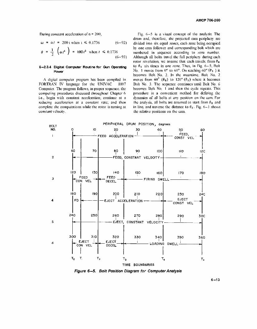
AMCP 708-280
During constant acceleration of a = 200,
co = at = 200 t when t < 0.1736 (6-92)
0 = 1 yati f = lOOf2 when? < 0.1736 (6-93)
6—2.3.4 Digital Computer Routine for Gun Operating Power
A digital computer program has been compiled in FORTRAN IV language for the UNIVAC 1107 Computer. The program follows, in proper sequence, the computing procedures discussed throughout Chapter 6 i.e., begin with constant acceleration; continue at a reducing acceleration at a constant rate; and then complete the computations while the rotor is turning at constant velocity.
Fig. 6-5 is a visual concept of the analysis. The drum and, therefore, the projected cam periphery are divided into six equal zones, each zone being occupied by one cam follower and corresponding bolt which are numbered in sequence according to zone number. Although all bolts travel the full periphery during each rotor revolution, we assume that each travels, fromÖ0
to 9S six times in one zone. Thus, in Fig. 6-5, Bolt No. 1 moves from 0" to 60". On reaching 60" (0S ) it becomes Bolt No. 2. In the meantime, Bolt No. 2 moves from 60° (0O) to 120" (0S) where it becomes Bolt No. 3. The sequence continues until Bolt No. 6 becomes Bolt No. 1 and then the cycle repeats. This procedure is a convenient method for defining the dynamics of all bolts at any position on the cam. For the analysis, all bolts are assumed to start from 60 and in line, and traverse the distance to 6S. Fig. 6-1 shows the relative positions on the cam.
BOLT NO.
PERIPHERAL DRUM POSITION,, degrees
10 20 30 40
FEED ACCELERATION I
60
120
70
130
FEED CON VEL
180
FD
240
300
190
250
310 ^ EJECT
CON VEL
80 90 100 I I
-FEED, CONSTANT VELOCITY
140 150 FEED i
DECEL
200 1
210
160 I
FIRING DWELL
5,0 FEED,
CONST VEL
110 i
60
120
170 180
220
EJECT ACCELERATION-
260 270 280 I
-EJECT, CONSTANT VELOCITY
230
EJECT CONST VEL"
290
240
300
320 EJECT_ DECEL
330 l
340 I
350 360
LOADING DWELL -
T0 T T5 T3 T4
TIME BOUNDARIES
Figure 6-5. Bolt Position Diagram for Computer Analysis
T«
6-13
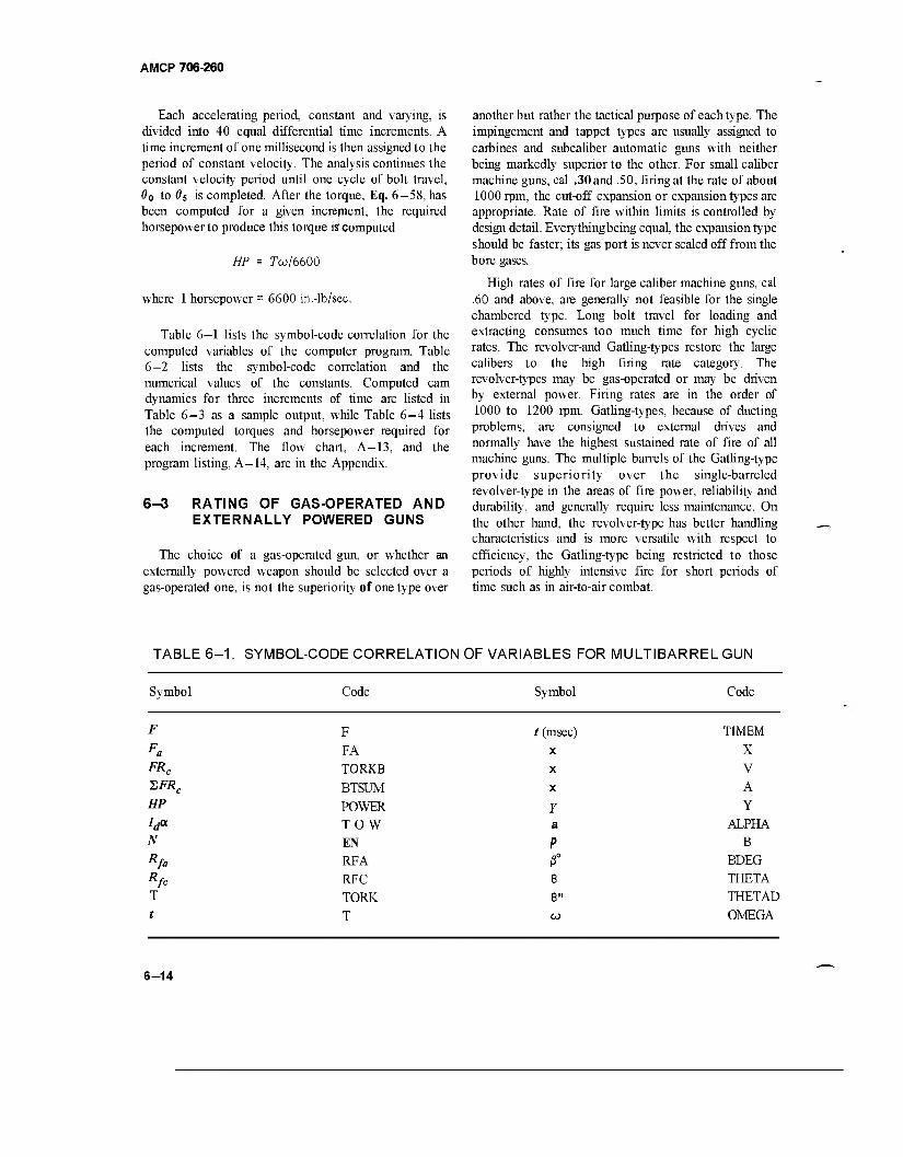
AMCP 706-260
Each accelerating period, constant and varying, is divided into 40 equal differential time increments. A time increment of one millisecond is then assigned to the period of constant velocity. The analysis continues the constant velocity period until one cycle of bolt travel, d0 to 05 is completed. After the torque, Eq. 6-58, has been computed for a given increment, the required horsepower to produce this torque is computed
HP = 7w/6600
where 1 horsepower = 6600 in.-lb/sec.
Table 6—1 lists the symbol-code correlation for the computed variables of the computer program. Table 6—2 lists the symbol-code correlation and the numerical values of the constants. Computed cam dynamics for three increments of time are listed in Table 6-3 as a sample output, while Table 6-4 lists the computed torques and horsepower required for each increment. The flow chart, A—13, and the program listing, A—14, are in the Appendix.
6-3 RATING OF GAS-OPERATED AND EXTERNALLY POWERED GUNS
The choice of a gas-operated gun, or whether an externally powered weapon should be selected over a gas-operated one, is not the superiority of one type over
another but rather the tactical purpose of each type. The impingement and tappet types are usually assigned to carbines and subcaliber automatic guns with neither being markedly superior to the other. For small caliber machine guns, cal .30 and .50, firing at the rate of about 1000 rpm, the cut-off expansion or expansion types are appropriate. Rate of fire within limits is controlled by design detail. Everythingbeing equal, the expansion type should be faster; its gas port is never sealed off from the bore gases.
High rates of fire for large caliber machine guns, cal .60 and above, are generally not feasible for the single chambered type. Long bolt travel for loading and extracting consumes too much time for high cyclic rates. The revolver-and Gatling-types restore the large calibers to the high firing rate category. The revolver-types may be gas-operated or may be driven by external power. Firing rates are in the order of 1000 to 1200 rpm. Gatling-types, because of ducting problems, are consigned to external drives and normally have the highest sustained rate of fire of all machine guns. The multiple barrels of the Gatling-type provide superiority over the single-barreled revolver-type in the areas of fire power, reliability and durability, and generally require less maintenance. On the other hand, the revolver-type has better handling characteristics and is more versatile with respect to efficiency, the Gatling-type being restricted to those periods of highly intensive fire for short periods of time such as in air-to-air combat.
TABLE 6-1. SYMBOL-CODE CORRELATION OF VARIABLES FOR MULTIBARREL GUN
Symbol Code Symbol Code
' a FRC
2FRe
HP
N
Rfi
T
t
F
FA
TORKB
BTSUM
POWER TOW EN RFA
RFC TORK
T
t (msec) x
x
x
Y a
P (3° 8
TIMEM
X
V A
Y
ALPHA B
BDEG THETA THETAD
OMEGA
6-14
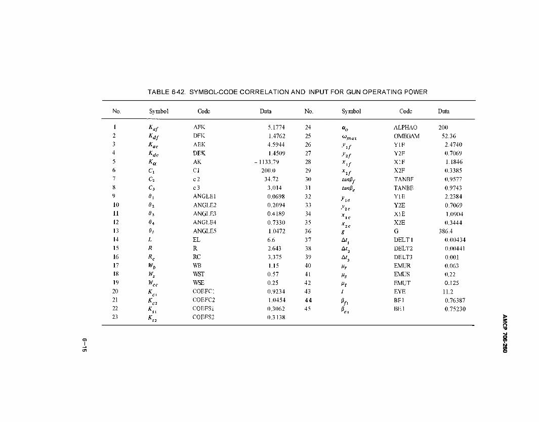
TABLE 6-42. SYMBOL-CODE CORRELATION AND INPUT FOR GUN OPERATING POWER
No. Symbol Code Data No. Symbol Code Data
1 Kaf AFK 5.1774 24 % ALPHAO 200 2 Kdf DFK 1.4762 25 umax OMEGAM 52.36 3 Kae AEK 4.5944 26 yif Y1F 2.4740 4 Kde DEK 1.4509 27 y2f Y2F 0.7069 5 Ka AK -1133.79 28 V X1F 1.1846 6 c, Cl 200.0 29 X2f X2F 0.3385 7 c2 c2 34.72 30 tanßf TANBF 0.9577 8 c3 c3 3.014 31 tanße TANBE 0.9743 9 0i ANGLE 1 0.0698 32 yie
Y1E 2.2384 10 0i ANGLE2 0.2094 33
-'2 C Y2E 0.7069
11 03 ANGLE3 0.4189 34 Xie XIE 1.0904
12 04 ANGLE4 0.7330 35 x2e X2E 0.3444
13 0f ANGLE5 1.0472 36 g G 386.4 14 Z, EL 6.6 37 Ati
DELT1 0.00434 15 fl R 2.643 38 At2
DELT2 0.00441 16 Äc RC 3.375 39 Af3 DELT3 0.001 17 »ft WB 1.15 40 ßr
EMUR 0.063 18 w* WST 0.57 41 Ms EMUS 0.22 19 Kc WSE 0.25 42 Mr EMUT 0.125 20 K
cl COEFC1 0.9234 43 l EYE 11.2
21 KC2 COEFC2 1.0454 44 ßfi
BF1 0.76387 22 K
Sl COEFS1 0.3062 45 hi BEI 0.75230
23 KS2 COEFS2 0.3138 >
3 o
s
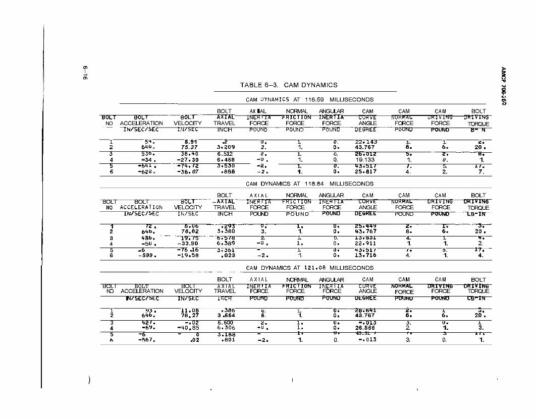
01
TABLE 6-3. CAM DYNAMICS
CAM UYNAMICS AT 116.59 MILLISECONDS
"BÜCT BÜLT NO ACCELERATION
TN/SEC/SEC-
BÜCT VELOCITY
IN/5EC
BOLT " AXIAL- TRAVEL
AXIAL NORMAL ANGULAR CAM
INCH
INER IT* FRICTION—rHERTTA CURVE FORCE FORCE FORCE ANGLE POUND POUND PÜUNÜ DEXJREET
CAM NORMAL FORCE POUND
CAM URlVlNb FORCE POUND
BOLT UElVINb TORQUE B- N
> 3 n ■o sj O 9
o
1 2
5.91 75.37
.2 3.209
u. 3.
L 1.
0. 0.
22.143 43.767
l. 8. 6.
2. 20 .
3 4
53t>. =34 .
36.10 -27.30
6.512 6.458
z. -u .
1. 1.
0. 0.
26.012 19.133
5. 1.
2. 0.
8. 1.
5 6
-6*U . -622 o
-7«f.72 -38.07
3.530 .888
-2. -2.
1. 1.
0. 0.
1*3.517 25.817 4.
5. 2.
17. 7.
CAM DYNAMICS AT 118.84 MILLISECONDS
BOLT BOLT NO ACCELERATION
TN7SEC/SEIT"
BÜLT VELOCITY
BOLT
TRAVEL
AXIAL
IN/SEC INCH
INERTIA FORCE POUND
NORMAL ANGULAR I-K1CI10N FORCE _ POUND
INERIIA FORCE POUND
CAM CURVE ANGLE
DEGREE-
CAM NURMAL FORCE
CAM UR1V1NÜ FORCE
POUND "POUND
BOLT -DRIVING TORQUE LB-IN
i 2
TZ . 6<+b.
8.06 76.82
.293 3.380
u. 3.
1. 1.
U. 0.
2b.<*i*y «13.767
2. 8.
1. 6. 3^—
20 . 3 4
486. -5U .
19.75 -33.90
b.b/B 6.389
2. -0 .
L 1.
0. 0.
13.831 22.911
4. 1.
L 1. 2.
5 6
-6 -599.
-76 .IE -19.58
3.361 .023 -2.
L 1.
u. 0.
ta.sir 13.716 4.
3. 1.
17T" 4.
CAM DYNAMICS AT 121 .08 MILLISECONDS
BOLT AXIAL NORMAL ANGULAR CAM CAM CAM BOLT BOLI
ND BOLT
ACCELERATION BOLI
VELOCITY AXIAL
TRAVEL INER HA
FORCE f-RICTION
FORCE INERIIA
FORCE CURVE ANGLE
NORMAL FORCE
UKlYlNy FORCE
DRIVING TORQUE
IN/SEC/btC IN/StC INCH POUND POUND rOUNU UttiKtt PÖUNU POUND LB-1N
1 2
93 . 646.
IT". 08 78.27
.386 3.554
u. 5.
l. 1.
XT. 0.
2U.btl 43.767
z, 8.
A 6. 20 .
3 4
12'. -6*.
-.02 -HO.85
6.600 6.306
1. 1.
0. 0.
-.1T13 26.555
3. 2
u. 1.
A 3.
5 6
-b -567.
0 .02
3. 188 .801 -2.
l •
1. 0. -.013 3. 0. 11.
1.
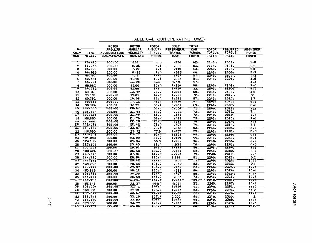
TABLE 6-4. GUN OPERATING POWER
I
40 160.938 "41—1.63.341" 42 165.745
"40—168.149" 44 173.S00
~4S177.237
ROTOR ROTOR ROTOR BOLT TOTAL
CRI- TIME ANGULAR
ACCELERATION ANGULAR VELOCITY
AN6ULAH TRAVEL
PERIPHERAL TRAVEL
CAM TORQUE
ROTOR TORQUE
REQUIRED TORQUE
REQUIRED HORSE-
MENT HILSEC RAD/SEC/SEC RAO/SEC- DEGREE INCH LB-IN LB-IN LB-IN POWER
1 2
26.420 31.255
200 .00 200 .00
5.28 6.25
4. U 5.6
.236 • 330
62. 63,
2240 . 2240.
2302. 2303.
1.8 2.2
3 4
36.090 40.925
200.00 200.00
T.T12 8.19
7,H 9.6
• 440 • 565
64. 66.
2240. 2240.
2304. 2306.
2.3 2.9
5 6
45.760 50.501
200.00 200.00
Y.13 10.10
12.U 14.6
.707
.861 bZ. 51.
2240. 2240.
22^0.
230/ . 2291.
2288.
0.2 3.5
/ 8
55.241 59.982
200.00 200.00
11.U5 12.00
17.3 20.6
1.03U 1.214
47, 48.
3.8 4.2
9 10
64.722 69.946
200.00 200.00
12.99 13,99
24,U 28.0
1.414 1.651
33. 60.
2240. 2240.
2293. 2300.
4.5 4.9
ii 12
75.169 80.392
2UU.U0 200.00
13.03 16.08
02.H 37.0
li^O / 2.181
/2. 87.
2240. 2240.
23i<; ■ 2327.
33 5.7
13 14
05.61b 93.974
2U0.00 200.00
1/.12 18.79
42. U 50.6
2.4/4 2.981
1U /, 69.
224U. 2240. 2309. 6.6
lä 16
1U2.303 105.688
200.00 200.00
2U.4/ 21.14
60.0 64.0
3.534 .236
71. 72.
2240. 2240.
2311. 2312.
/•Z 7.4
1/ 18
1U/.2V1 108.893
200.00 200.00
21.46 21.78
66.0 67.9
• 351 .468
72. 73.
2240. 2240.
2312. 2313.
/•a 7.6
20 410*46*50 112.098
200.00 200.00
22.10 22.42
70. U 72.0
• Mb .707
in. 74.
2240. 2240.
2014. 2314.
7.7 7.9
Ü1 22
114.344 116.590
200.00 200.00
22.8/ 23.32
74.9 77.9
.878 1.053
63. 55.
2240. 2240.
2303. 2295.
8.0 8.1
23 24
110.837 121.083
200.00 200.00
23. n 24.22
80.9 84.0
1.232 1.414
49. 44.
2240. 2240.
2289. 2284.
8.2 8.4
25 26
124.168 127.253
200.00 200.00
24,83 25.45
08.3 92.8
1.669 1.931
46. 50.
2240. 2240.
2286. 2290.
8.6 8.8
2/ 28
130 .339 133.424
ZOO.00 200 .00
26.U7 26.68
y/.o 102.0
2.199 2.474
54. 60.
2240 . 2240.
2294. 2300. 9.3
30 10V.0/2 144.720
200.00 200.00
2/.81 28.94
110.0 120.0
2.993 3.534
Z9. 81.
2240. 2240.
231Y. 2321.
V.Ö 10.2
a i 32
■14/. 112 148.280
£UU .uu 200.00
«»9,42 29.66
124.U 126.0
■23B • 352
U2 ■ 82.
224U. 2240.
2322. 2322.
10.3 10.4
33 34
149.44/ 150.615
200.00 200.00
29,89 30.12
128.0 130.0
• 4b"* .588
«50 ■ 84.
2240. 2240.
2323 ■ 2324.
1U.S 10.6
33 36
151.783 153.471
2U0.UU 200.00
3U .Ob 30.69
132.0 135.0
.707
.881 8b. 73.
2240. 2240.
2325 . 2313.
J.U./ 10.8
0/ 38
155.158 156.846
200.UU 200.00
0 i • U O 3.1.37
13/.» 141.0
1.056 1.234
64, 57.
2240. 2240.
2304. 2297.
1U.B 10.9
39 158.534 200.00 oi. r* 144,0 1.414 31 a 224u. 2291 ■ 11.U
200.00 "200.00 200.00 200.00 200.00 195.88
32.19 32.67- 33.15 00.60 34.72 35.44
148.4 152.9 157.4 182.0 172.7 180.0
1.673 1.93ft 2.203
-2.474- 3.103
53.
3.534
36 . 60. OS . 89.
-84T-
2240. -2240 . 2240. 2240. 2240.
-2T91R-
2293. -22961- 2300. 2305. 2329.
-22777-
11.2
11.6
12.3 12.2
O -D
a o
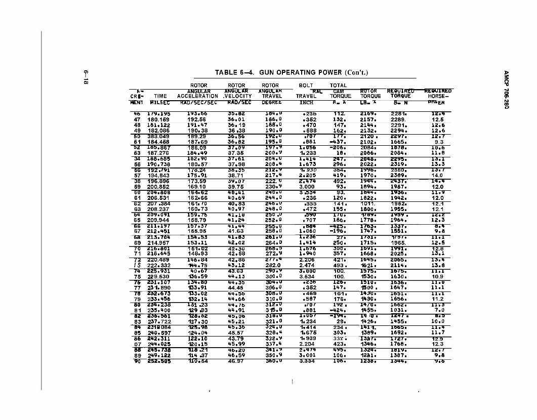
O) I TABLE 6-4. GUN OPERATING POWER (Con't.)
ROTOR
CRI- TIME "«EOT MILSEC
ANGULAR ACCELERATION
HAD/SEC/SEC
ROTOR ANGULAR .VELOCITY —RAO/SEC-
ROTOR ANGULAK
TRAVEL DEGREt
BOLT "RTC"
TRAVEL INCH
TOTAL —cm— TORQUE
HUIOH TORQUE
"LB-*-
KtUUlKEU TORQUE
—B=-R
-REQUIRED HORSE-
—wreER
46 47
179.195 180.159
193.b6 192.56
3b. 82 36.01
184. U 186.0
.23b
.352 112. 132.
2169. 2157.
2281. 2289.
12.4 12.5
48 49
181.122 182.086
191.47 190.38
36.19 36.38
188. U 190.0
.470
.588 147. 162.
2144. 2132.
2291. 2294.
12.6 12.6
SO 51
383.049 184.458
189.29 187.69
36.58 36,82
192. U 195.0
.707 .881
177, -437,
2120 ■ 2102.
2Z97. 1665.
12.7 9.3
b2 53
185.867 187.276
186.09 184.49
37.09 37.35
197. y 200. V
1.056 1.233
-206. 16.
2084. 2066.
1878. 2084.
10.6 11.8
34 55
188.685 190.738
182.90 180.57
37,61 37.98
204.u 208.4
1.414 1.673
247. 296.
2048. 2022.
2295. 2319.
13.1 13.3
S6 57
192.791 194.843
178.24 175.91
38,35 38.71
212. 9 217.4
1. 33(5 2.205
354. 419.
1996. 1970.
2350. 2389.
13. 1 14.0
38 59
196.896 200.852
173.59 169.10
39,07 39.75
222. u 230.9
2,474 3.000
492. 93.
1944. 1894.
2437. 1987.
14.4 12.0
60 61
204.808 206.531
164.62 162.66
40.41 40,69
240.U 244.0
3 £34 .236
93. 120.
1844. 1822.
1936. 1942.
11.9 12.0
62 63
207 .384 208.237
161. JO 160.73
40.83 40.97
246.0 248.0
■333 .472
141 ■ 155.
1011. 1800.
1952. 19bb.
12.1 12.1
64 65
209.091 209.944
159.76 158.79
41.IU 41,24
2bU ,U 252.0
AVO .707
1/0. 186.
i/«y. 1778.
19by . 1964,
12. Z 12.3
66 67
211.197 212.451
lb7.37 155.95
41,44 41.63
255.0 258.0
.884 1.060
-42b. -196.
1763. 1747.
1337. 1551.
8.4 9.8
6a 69
213.704 214.957
154.53 153.11
41.83 42,02
261. U 264.0
1.236 1.414
27. 250.
1/31. 1715.
1/b/. 1965.
11.1 12.5
70 71
216.801 218.645
151.02 148.93
42.30 42.58
268.3 272.9
1.676 1.940
300. 357.
1691. 1668.
1991. 2025.
12.8 13.1
72 IS
220.489 222.332
146.84 144.75
42.85 43.12
2//.4 282.0
2.206 2.474
421. 493.
164b. 1621.
2065. 2114.
13.4 13.8
74 75
225.931 229.530
40.67 136.59
43.63 44.13
290.9 300.0
5.000 3.534
100. 100.
lb/b. 1530.
lbrb. 1630.
11.1 10.9
16 77
231.107 231. 890
134.80 133.91
44.3» 44.45
304.u 306.0
• 236 .352
126. 147.
lblO. 1500 .
1636. 1647.
11.0 11.1
78 79
232.673 233.456
133.02 132.14
44. bb 44.66
308,0 310.0
• 469 .587
161. 176.
1430. 14 ao.
1631. 1656.
ll.l 11.2
00 81
234.238 235.400
131 .23 129 £3
44,76 44.91
312.0 315.0
.707 .881
192 , -424.
14/0. 1455.
Ibb2. 1031.
11.3 7.0
82 83
236.561 237.722
128.62 127.30
43, Ob 45.21
318.U 321.0
l.Ub/ 1.234
-iy4. 29.
14 tU • 1426.
144/ ■ 1455.
8.5 10.0
81» 85
2318 084 240.597
125. 98 124.04
49.30 45.57
324. U 328.4
1.414 1.675
234. 303.
1411. 1389.
Ibbb. 1692.
11.4 11.7
86 07
242.311 244.025
122.10 120.15
43.79 45.9,9
332.9 337.4
1.939 2.204
33Y . 423.
13a/. 1346.
1/2/. 1768.
12.9 12.3
88 89
245.73Ä 249.122
118 .21 114 .37
46.20 46,59
341.9 350.9
2.474 3.001
4yb. 106.
1.324. 1231.
1819. 1387.
12. f 9.8
90 252.505 110.54 46.97 360. U 3.334 106. 1238. 1344. 9.6
> 3 o ■o
? M o
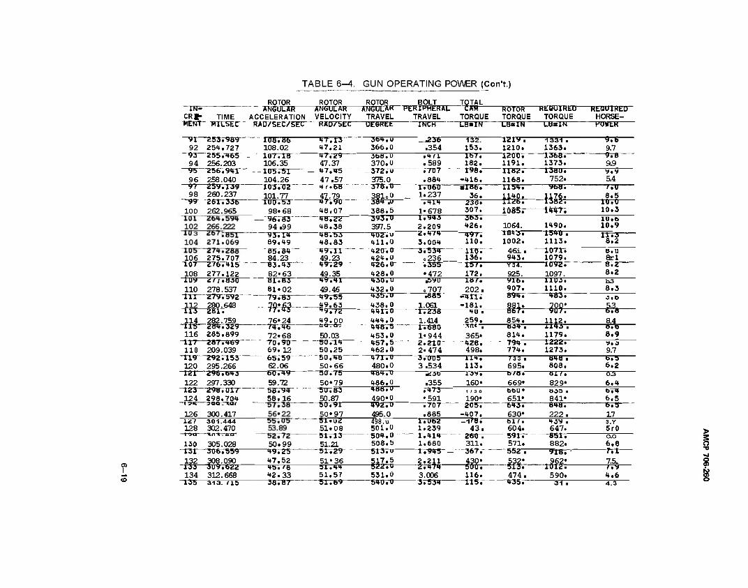
TABLE 6-4. GUN OPERATING POWER (CorTt.)
—TKF CRfr TIME RENT" TtttSEC
ROTOR ROTOR "" " ATH5ULAR ANGULAR ACCELERATION VELOCITY RAÜ/5EC/5EC HAD7SEIT
ROTOR BOLT TOTAL ANGULAR PERIPHERAL CÄW ROTOR REQUIRED REQUIRED TRAVEL TRAVEL TORQUE TORQUE TORQUE HORSE-
LBBIN LBSIN LBsIN POWER
I
;989"" 92 254.727
—93—2557465 94 256.203
—95~256794r" 96 258.040
~97—2597I39"~ 98 260.237
-"99-26X7336" 100 262.965
108.06 108.02 107.18
-T77T3-
47.21 ■47729-
106.35 47.37 I0575T — 47745- 104.26 47.57
tr.CB 47.79
90"~
"36470" 366.0 .354
•132. 153.
"T2T9-T 1210.
1331 . 1363.
106275.707 "io7 2767415—
108 277.122 "TÜ9 Z7T7B3Ö
110 278.537 TtT 279.592 112 280.648
XT3 ZBT7 114 282.759 115 ~2WiT3Z9~- 116 285.699
118 209.039 "119—2927153-
120 295.266
-"103702 101.77 Ttnj753—
98*68 - "96TB3" "
94.99 —93714"
89.49 85. W— 84.23
—83743 82» 63
^ITBT" 81.02
-79783"
48.07 "4B722"- 48.38
"48733 48.83 497 n " 49.23 49.29 "~ 49.35
3687 O 370.0
-3727TT 375.0 378.0 381 eU 384 .U 388.5
"39370" 397.5
49.41 49.46
"4027 u 411.0 420. O 424.0 426.0 428.0
.4fl
.589 —J7TT7-
.884 ITOBo" 1.237 .414
1*678 "17943- 2.209 2.474
lb7. 162.
~T9B7" -416. slB6.
36.
"1200 r 1191.
-1182. 1168.
-13687" 1373.
3, 13.
004 534 236 _
49.55
im—n-M
"121—296.b43 122 297.330
"123 298.017" 124 298.704 I gü 3QQ. lUf
126 300.417
76« 24 "74746"
72*68 70790" 69.12 65.-59 62.06
49.00
50.03 -507"I4" 50.25
430. U 432.0
""43570- 438.0
-44X70" 444.0
"448.5 453.0
"457,5" 462,0
7355 •472 B9TT
e707 i883"
1.061. "X723B"
1.414 17680
1*944
236. 307. 363. 426.
T»97. 110. no. 136. 15/. 172.
1154,
-HSfc-
1380. 752.
-5fc 10857" ^4477
1064. TOTTT 1002. 461. 943.
187. 202.
-411. -181.
Y34. 925.
-9T5. 907.
-8947
1490. •154U ■ 1113^_ 10717 1079.
"1092. 1097. UU3. 1110.
—*WJ3.
HO 259.
hi—-m-
365»
654.
-2v2nr 2*474
-6TTT49— 59.72 58794" 58.16
50.46 50.66
-50775- 50*79
"471.0 480.0
127 128
130
301.444 302.470
305.028 131 306.559 132 308.090
-T33- 134
-135-
3097622 312.668
50.99 "49725- 47,52
50.83 50.87 50.91" 50*97
"ST..U2 51*08 5X713" 51.21
-31729" 51*36
484. tl 486.0 488. U 490*0
"492.U 495.0 498. u 501.0
"50470- 508.5 513. u
-37005"" 3.534
-4287 498. 114. 113.
-B34T 814.
"794T 774. 733 . 695.
1112. -TT43T" 1179.
-1222. 1273.
84Ö . 808.
Ȇ.SO
.355 7473" •591
160* b/H*
669* air. 829*
rroT" .885
1/30
190*
313. fl5
45. fS 42.33 38.87
51.44 51.57
-5T769"
517.5 -5227tr 531.0 540.0
1.U62 1.239 "17414- 1.680 17945" 2.211
-27474- 3.006
"37534"
205. -407.
~Tl7B7" 43.
260 . 311.
"367r 430*
651» "6437 630«
Ö03 ■ 841» 848. 222.
"500. 116.
"H3."
5IT7 604. 591. 571.
-5S2T- 532«
43^ ■ 647. 851 ~ 882.
"313. 474.
-4357-
"9X87^
1012. 590.
9.7 -978^
9.9 "*.9 S4 I • u 8.5
10.0 10.3 IT! 75 10.9 IXTT 8.2
8rl -S72- 8.2 b3 8.3 J.O
"6TV 8.4
8.9 ft J 9.7 b.5 6.2 03 6.4 074 6.5 6.5 17 3.Y 5r0 0.0 6.8
-mr 7.5. ftt 4.6
31
> 2 o
s ä O
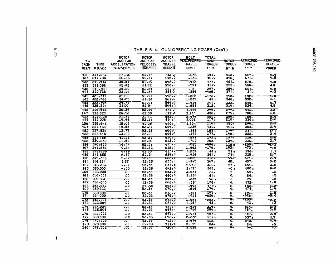
05
O
CRC- TIME
T/
ROTOR ANGULAR
ACCELERATION
\BI_E 6^. GUN OPERATING POWER (Con ■t.)
ROTOR ANGULAR VELOCITY
ROTOR ANGULAR
TRAVEL
BOLT TOTAL —CÄB1
TORQUE ROTOR— TORQUE
-PERIPHER*tr TRAVEL
-REQUIRED REQUIRED TORQUE HORSE-
HETTT MILSEC HAU/'StC/'bLC KAD/btL ULIsHtb. INCH c - It, B- N HOHER
136 137
317.06* 317.738
37 .34 36.58
bl.7b 51.77
544 .U 5*6.0
.236
.356 1*1. 162.
*1U. 410.
59V . 572.
*.* *.5
138 139
310,*1Z 319.086
.55.81 35.05
51.7y 51.82
5*8. U 550.0
• *73 .591
Ml. 192.
401. 393.
578. 58*.
*.s 4.6
140 141
319. teo 320.768
3*. 29 33.1*
51.8* 51.88
552.0 555.0
■ 0 .886
207, -*05.
38*. 371.
591, -34.
*.b -.3
•142 143
3Ü1.V77 322.786
32.00 30.85
51.91 51.94
558. U 561.0
1.062 1.239
-176. 45.
356. 346.
182. 390.
1.* 3.1
144 145
323.795 325.30*
29.71 28.00
51.9/ 52.01
bb*.U 568.5)
l.*l* 1.681
261. 312.
333. 31*.
59*. 625.
*.7 4.9
146 1*7
326.812 328.320
26.29 2*. 58
52.06 52.09
5/3 .U 577.5
1.946 2.211
368. 430.
2V*. 275.
662. 706.
3.2 5.6
148 149
329.029 332.038
22.87 19.*6
52.13 52.19
582. U 591.0
2.*7* 3.006
SOO. 117.
256. 218.
/5b. 335.
6.0 2.6
150 151
335.8*8 337.183
16.05 1*.53
52.26 52.27
600. u 60*.0
3.534 .236
lib. 142.
180. 163.
2*6. 304.
2.3 2.*
152 153
337.850 338.518
13.77 13.02
52.28 52.29
60b.u 608.0
.353
.473 163 . 177.
15*. 1*6.
31/. 323.
2.5 2.6
154 155
339.186 339.852
12.26 11.50
52 £v 52.30
blU.u 612.0
.byi
.707 192 . 208.
13/. 129.
33Ö. 336. 2.7
156 167
3*0.853 3*1.85*
10.37 9.2*
52.31 52.32
bis." 618.0
.885 1.062
-*06. -176.
116- 103. -73 .
-2.3 -.6
158 159
342.866 343.855
8.10 6.97
62.33 52.34
621.0 62*. 0
1.239 l.*l*
44 . 261.
91 ■ 78.
135. 339. 2.7
160 161
3*5.355 346.854 3.57
52.35 52.35
628.3 633.0
l.bBU 1.9*5
312. 367.
5y. 40.
3/1. 407.
2.9 3.2
162 163
348 .35* 350.000
1.87 -.00
52.36 52.36
63/. 3 6*2.5
2.210 2.474
430. 500.
21 ■ -0.
*51. 500.
3.b *.0
It* 165
333.000 356.001
J) .00
52.3b 52.36
baa.? 660.5
3.031 3.534
04. 64.
u 0.
Of ■ 64. .5
166 167
331.334 358.000
• uu .00
32 .3b 52.36
OOH.J 666.5
.23b .381
*6 ■ 132.
u. 0.
YO. 132.
• e 1.0
168 169
358.66/ 359.333
■00 .00
32 .36 52.36
bbti.a 670.5
• *y» .616
132. 17*.
u. 0.
152. 174. tit
170 171
360.000 361.000 .00
52.36 52.36
b/2.3 675.5
.f07 .911 -626.
0. 0. u. 0.
1V1. -626.
1.5 -5.0
172 173
362.001 363.001
.00 .00 52.36
678.5 681.5
1.ÜB7 1.264
-283. 43.
*^B3* 43. "":S
17* 175
364,001 365.501
.uu .00
52.3b 52.36
684.3 689.0
l.*l* 1.706
31*. 38* .
0. 0.
31*. 38*.
2.5 3.0
1/6 177
367.001 360.500
.00
.00 52.3b 52.36
693.3 698.0
1.971 2.236
*57 . 537.
0. 0.
*57. 537.
O.b 4.3
1/8 179
o/u.uuu 373.000
.0 .00
52. 3b 52.36
/02.5 711,5
2.*/* 3.031
<Si3. 64.
u. 0.
ft-15. 64.
f.V .5
ISO 376.001 .00 52.36 720.5 3.53* b* . u. Of. >9
> s o -o ■«J
? lid
o
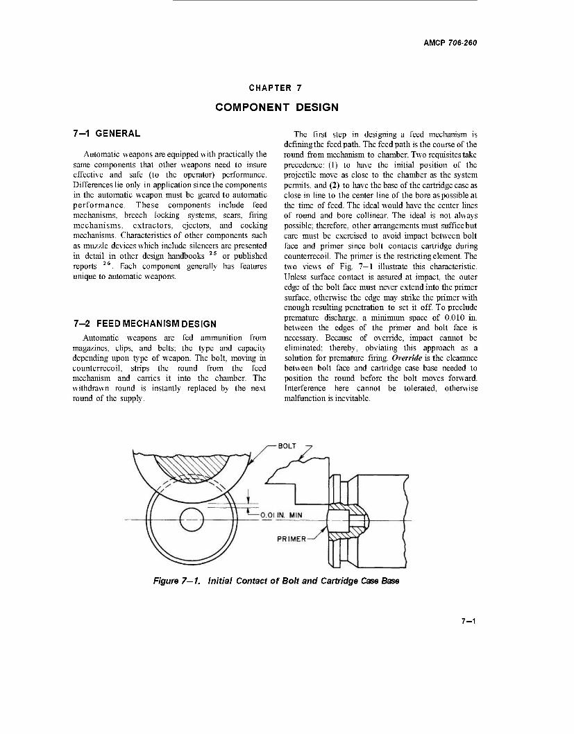
AMCP 706-260
CHAPTER 7
COMPONENT DESIGN
7-1 GENERAL
Automatic weapons are equipped with practically the same components that other weapons need to insure effective and safe (to the operator) performance. Differences lie only in application since the components in the automatic weapon must be geared to automatic performance. These components include feed mechanisms, breech locking systems, sears, firing mechanisms, extractors, ejectors, and cocking mechanisms. Characteristics of other components such as muzzle devices which include silencers are presented in detail in other design handbooks 2S or published reports 26. Each component generally has features unique to automatic weapons.
7-2 FEED MECHANISM DESIGN Automatic weapons are fed ammunition from
magazines, clips, and belts; the type and capacity depending upon type of weapon. The bolt, moving in counterrecoil, strips the round from the feed mechanism and carries it into the chamber. The withdrawn round is instantly replaced by the next round of the supply.
The first step in designing a feed mechanism is defining the feed path. The feed path is the course of the round from mechanism to chamber. Two requisites take precedence: (1) to have the initial position of the projectile move as close to the chamber as the system permits, and (2) to have the base of the cartridge case as close in line to the center line of the bore as possible at the time of feed. The ideal would have the center lines of round and bore collinear. The ideal is not always possible; therefore, other arrangements must sufficebut care must be exercised to avoid impact between bolt face and primer since bolt contacts cartridge during counterrecoil. The primer is the restricting element. The two views of Fig. 7—1 illustrate this characteristic. Unless surface contact is assured at impact, the outer edge of the bolt face must never extend into the primer surface, otherwise the edge may strike the primer with enough resulting penetration to set it off. To preclude premature discharge, a minimum space of 0.010 in. between the edges of the primer and bolt face is necessary. Because of override, impact cannot be eliminated; thereby, obviating this approach as a solution for premature firing. Override is the clearance between bolt face and cartridge case base needed to position the round before the bolt moves forward. Interference here cannot be tolerated, otherwise malfunction is inevitable.
BOLT
Figure 7—1. Initial Contact of Bolt and Cartridge Case Base
7-1
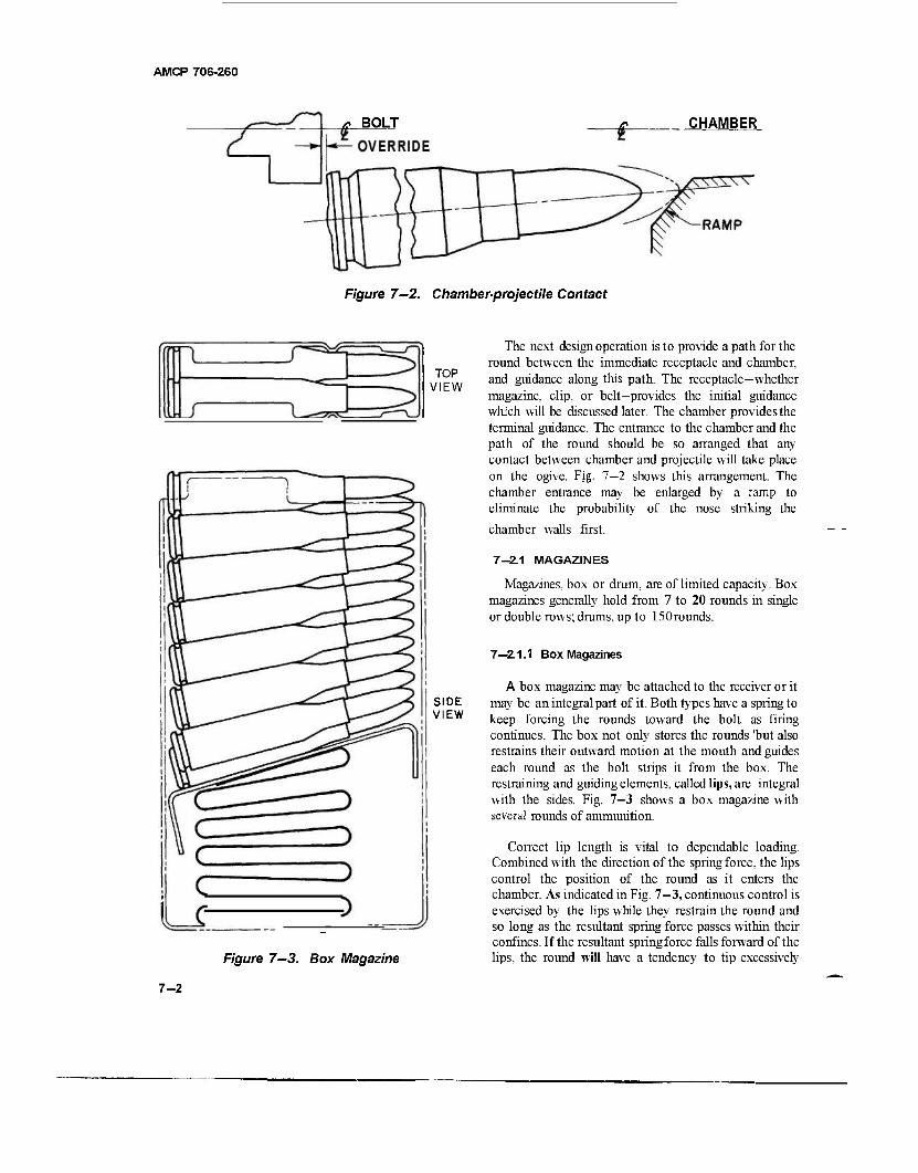
AMCP 706-260
* BOLT CHAMBER
Figure 7-2. Chamber-projectile Contact
TOP VIEW
SIDE VIEW
Figure 7—3. Box Magazine
The next design operation is to provide a path for the round between the immediate receptacle and chamber, and guidance along this path. The receptacle—whether magazine, clip, or belt—provides the initial guidance which will be discussed later. The chamber provides the terminal guidance. The entrance to the chamber and the path of the round should be so arranged that any contact between chamber and projectile will take place on the ogive. Fig. 7—2 shows this arrangement. The chamber entrance may be enlarged by a ramp to eliminate the probability of the nose striking the
chamber walls first.
7-2.1 MAGAZINES
Magazines, box or drum, are of limited capacity. Box magazines generally hold from 7 to 20 rounds in single or double rows; drums, up to 150rounds.
7—2.1.1 Box Magazines
A box magazine may be attached to the receiver or it may be an integral part of it. Both types have a spring to keep forcing the rounds toward the bolt as firing continues. The box not only stores the rounds 'but also restrains their outward motion at the mouth and guides each round as the bolt strips it from the box. The restraining and guiding elements, called lips, are integral with the sides. Fig. 7-3 shows a box magazine with several rounds of ammunition.
Correct lip length is vital to dependable loading. Combined with the direction of the spring force, the lips control the position of the round as it enters the chamber. As indicated in Fig. 7-3, continuous control is exercised by the lips while they restrain the round and so long as the resultant spring force passes within their confines. If the resultant springforce falls forward of the lips, the round will have a tendency to tip excessively
7-2
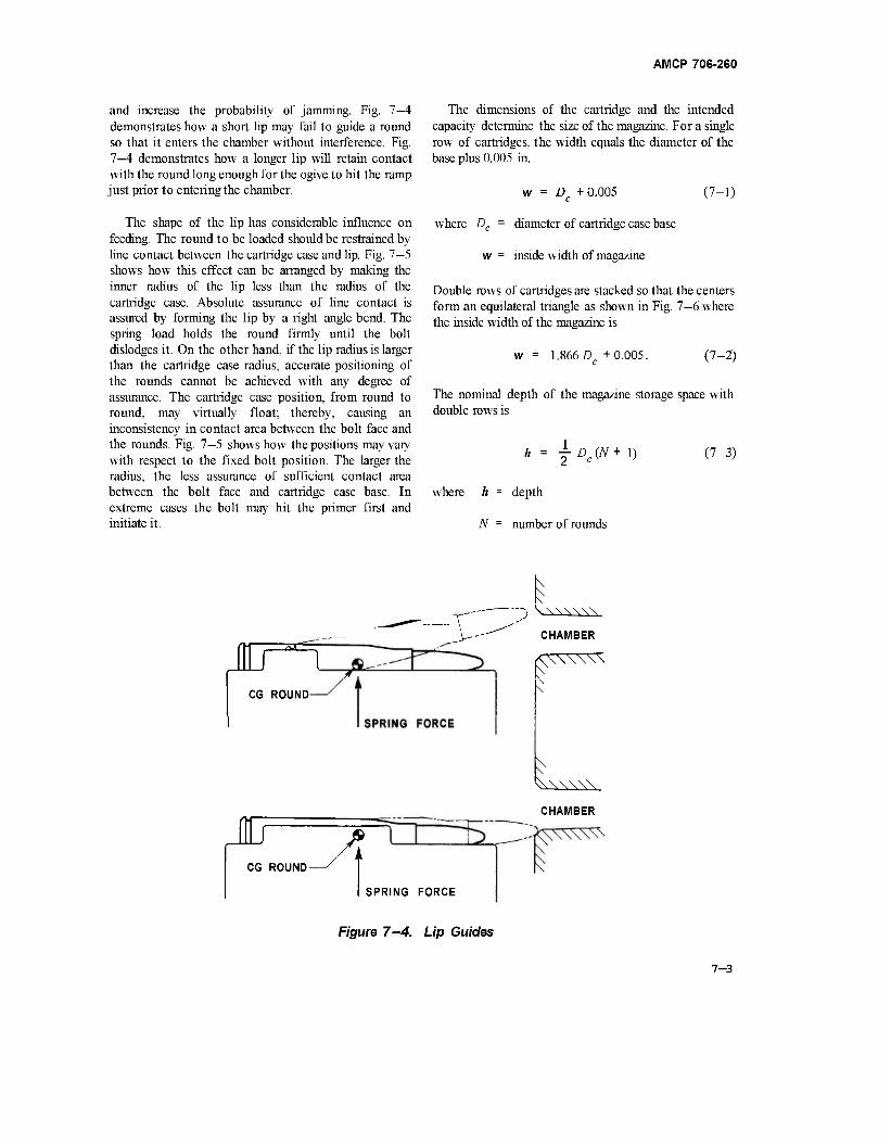
AMCP 706-260
and increase the probability of jamming. Fig. 7—4 demonstrates how a short lip may fail to guide a round so that it enters the chamber without interference. Fig. 7—4 demonstrates how a longer lip will retain contact with the round long enough for the ogive to hit the ramp just prior to entering the chamber.
The shape of the lip has considerable influence on feeding. The round to be loaded should be restrained by line contact between the cartridge case and lip. Fig. 7—5 shows how this effect can be arranged by making the inner radius of the lip less than the radius of the cartridge case. Absolute assurance of line contact is assured by forming the lip by a right angle bend. The spring load holds the round firmly until the bolt dislodges it. On the other hand, if the lip radius is larger than the cartridge case radius, accurate positioning of the rounds cannot be achieved with any degree of assurance. The cartridge case position, from round to round, may virtually float; thereby, causing an inconsistency in contact area between the bolt face and the rounds. Fig. 7—5 shows how the positions may vary with respect to the fixed bolt position. The larger the radius, the less assurance of sufficient contact area between the bolt face and cartridge case base. In extreme cases the bolt may hit the primer first and initiate it.
lUT^n CG ROUND
The dimensions of the cartridge and the intended capacity determine the size of the magazine. For a single row of cartridges, the width equals the diameter of the base plus 0.005 in.
w = D +0.005 c
(7-1)
where Dc = diameter of cartridge case base
w = inside width of magazine
Double rows of cartridges are stacked so that the centers form an equilateral triangle as shown in Fig. 7—6 where the inside width of the magazine is
1.866 D +0.005. c (7-2)
The nominal depth of the magazine storage space with double rows is
(7-3) h = JDC(N+1)
here h = depth
N - number of rounds
\ \ \
y- J \-\\\\\\
>-" CHAMBER
Kr CHAMBER
A CG ROUND-
SPRING FORCE
Figure 7-4. Lip Guides
7-3
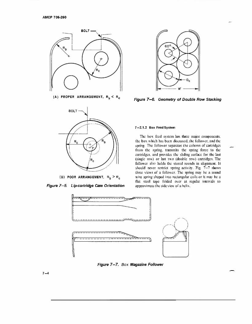
AMCP 706-260
BOLT-
(A) PROPER ARRANGEMENT, Rb < Rc Figure 7—6. Geometry of Double Row Stacking
BOLT
(B) POOR ARRANGEMENT, Rb > Rc
Figure 7—5. Lip-cartridge Case Orientation
7—2.1.2 Box Feed System
The box feed system has three major components, the box which has been discussed, the follower, and the spring. The follower separates the column of cartridges from the spring, transmits the spring force to the cartridges, and provides the sliding surface for the last (single row) or last two (double row) cartridges. The follower also holds the stored rounds in alignment. It should never restrict spring activity. Fig. 7—7 shows three views of a follower. The spring may be a round wire spring shaped into rectangular coils or it may be a flat steel tape folded over at regular intervals to approximate the side view of a helix.
Figure 7-7. Box Magazine Follower
7-4
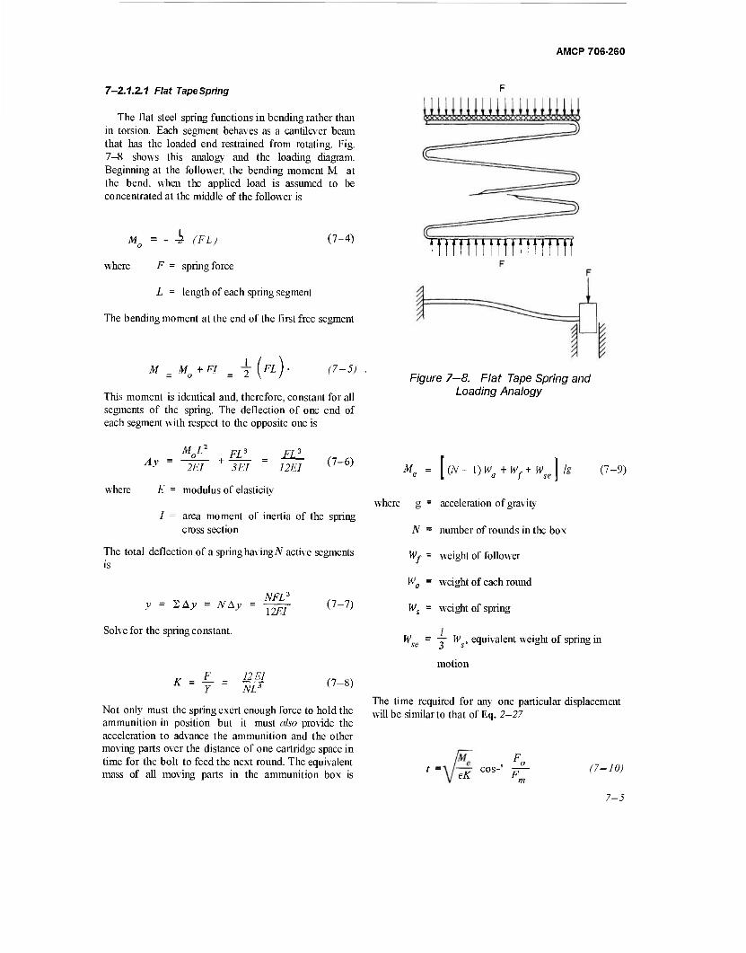
AMCP 706-260
7-2.1.2.1 Flat Tape Spring
The flat steel spring functions in bending rather than in torsion. Each segment behaves as a cantilever beam that has the loaded end restrained from rotating. Fig. 7-8 shows this analog}' and the loading diagram. Beginning at the follower, the bending moment M, at the bend, when the applied load is assumed to be concentrated at the middle of the follower is
Mo = - 4 (FL) (7-4)
where F = spring force
L = length of each spring segment
The bending moment at the end of the first free segment
M M + FT ~ = o = I H>4 (7-5)
This moment is identical and, therefore, constant for all segments of the spring. The deflection of one end of each segment with respect to the opposite one is
ttmmmttmtm
Figure 7—8. Flat Tape Spring and Loading Analogy
M L2
Ay FL3 FL3
2EI 3 EI 12EI
where E = modulus of elasticity
(7-6)
I = area moment of inertia of the spring cross section
The total deflection of a spring having N active segments is
y = I, Ay = NAy
Solve for the spring constant.
NFL3
12EI (7-7)
K F_ Y
12 El NLS (7-8)
Not only must the spring exert enough force to hold the ammunition in position but it must also provide the acceleration to advance the ammunition and the other moving parts over the distance of one cartridge space in time for the bolt to feed the next round. The equivalent mass of all moving parts in the ammunition box is
M„ [ (N ~ 1) Wa + Wf + Wse 1 k (7-9)
where g = acceleration of gravity
N = number of rounds in the box
Wf = weight of follower
Wa = weight of each round
Ws = weight of spring
W = — W , equivalent weight of spring in
motion
The time required for any one particular displacement will be similarto that of Eq. 2—27
t = „ COS- TT (7-10)
7-5
AMCP 706-260
where Fm = maximum spring force (preceding one The corresponding angular deflections are cartridge displacement)
F0 = minimum spring force (following one cartridge displacement)
K = (Eq.7-5)
Me = (Eq.7-6)
E = efficiency of system, generally assumed to be 0.5 for initial design analysis
For initial estimates, provide a spring load of Ft pounds for an empty box and one of iy for a full box.
The folded flat spring is less desirable than the rectangular coil spring because the latter can be compressed to its solid height whereas total compression of the flat spring is limited by the radius of the folds, thereby, requiring a longer box to house the spring and store the ammunition. Par. 7—2.1.2.2 discusses the rectangular coil spring.
7—2.1.2.2 Rectangular Coil Spring
The rectangular coil spring is a torsion element. Fig. 7-9 illustrates the mechanics of operation. Torsion in each straight segment rotates the adjacent segment. Although bending occurs along the span of each segment, the corners move with respect to each other only by torsional deflection. Bending deflections at the corners are neutralized by equal and opposite bending moments.
Rectangular coil spring characteristics are computed according to procedures similar to helical springs. The applied load is assumed to be concentrated on the axis. The torque T\ on the long segment is
and torque Ti on the short segment is
K")
(7-11)
(7-12)
where fl = length of short segment
b = length of long segment
F = spring force
bT,
IS"* JG
abF 2JG
T If 2JG
(7-14)
(7-15)
where G = torsionalmodulus
J = area polar moment of inertia of wire
The axial deflection of each segment of a coil varies directly with the sum of the products of the two segment lengths times the sine of the angular deflection of the adjacent segment (see Fig. 7-9). Stated in algebraic expressionsthe two deflections are
A^j = b sinöj
Ay2 = a sin(
(7-16)
(7-17)
But, according to Eqs. 7-14 and 7-15, 6t = 02, and if we let this angle be equal to 8, the deflection of two adjacent segments of a coil is
Ay = (Ajj + Ay2) = (a+b) sin« (7-18)
Since there are 4 segments to each coil, the total deflection of a spring having N active coils is
y = IN Ay. (7-19)
The spring constant, ify is based on a free spring, is
y (7-20)
(7-13)
The time required for any given displacement can be computed from Eq. 7-10.
7—2.1.3 Example Problems
Compute the spring characteristics for a double row box feed system that holds 20 rounds. Each round weighs 420 grains and has a cartridge case base diameter of 0.48 in. To function properly in the box, the spring should fit in a projected area of 1.75 x 0.75 in. The initial spring load should be approximately 4 pounds.
7-6
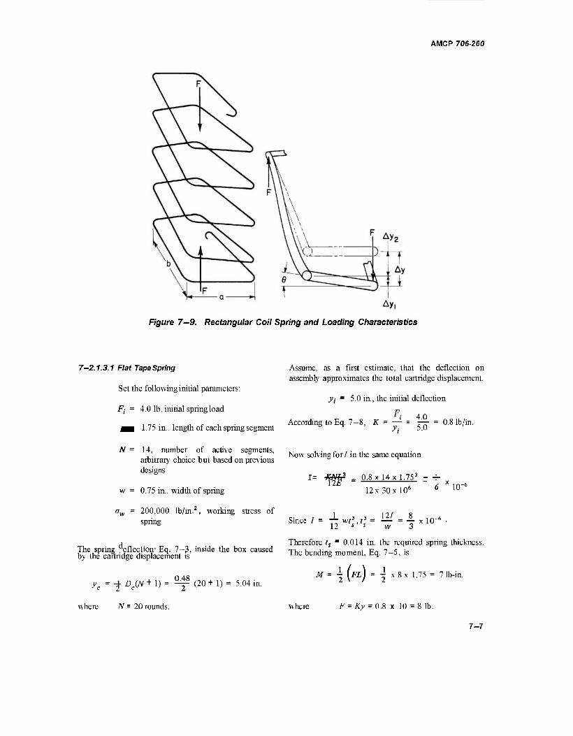
AMCP 706-260
Figure 7—9. Rectangular Coil Spring and Loading Characteristics
7-2.1.3.1 Flat Tape Spring
Set the following initial parameters:
Fj = 4.0 lb, initial spring load
^H 1.75 in., length of each spring segment
N = 14, number of active segments, arbitrary choice but based on previous designs
w = 0.75 in., width of spring
ow = 200,000 lb/m.2, working stress of spring
The spring eflection' Eq. 7—3, inside the box caused by the cartridge displacement is
yc = -£ De(N + 1) = ^ (20 + 1) = 5.04 in.
where N = 20 rounds.
Assume, as a first estimate, that the deflection on assembly approximates the total cartridge displacement.
}>j = 5.0 in., the initial deflection
According to Eq. 7-8, K = — = |^- = 0.8 lb/in.
Now solving for/ in the same equation
1= -KMß _ 0.8 x 14 x 1.753 - +
12x30xl06 b 1U
Since / lwf3f3=H/=Axl0-6 12
Therefore ts - 0.014 in. the required spring thickness. The bending moment, Eq. 7-5, is
M
where
- [FLJ = -| x8x 1.75 = 7 lb-ir
F- Ky = 0.8 x 10 = 8 lb.
7-7
AMCP 706-260
The bending stress is
Mc 7 x 0.007
0.1667 x 10" = 294,000 lb/in.
i F _ 'V 05702 C0S EB v/0.00323Cos ^
1.0 048
0.057 x 0.301 = 0.0172 sec
wherec = -r in.
This stress is too high. To lower it to acceptable levels, the initial and final loads were reduced to 1.0 and 2.0 pounds, respectively. Subsequent computation produced the following data:
K = 0.2 lb/in.
ts = 0.00874 in.
M = 1.751b-in.
a = 183,000lb/in.2
The bending stress is still uncomfortably high which almost rules out this type spring for the above application. However, a time analysis will give additional data. The time will be computed for spring action after the first and next to the last round are removed. If the spring weighs 0.063 lb and the follower 0.044 lb, the equivalent moving mass for 19 rounds, accordingto Eq. 7-9. is / \
Mg = I 19x0.06 + 0.044+ OmTJ/386.4 V 3
= 0.003 121b-sec2/in.
Substitute the appropriate values in Eq. 7—10 to compute the time for the'first round
eK Fi
/ 0.00312 , 1.952 0.5 x 0.2 C0S" 2.0
= 40.0312 Cos-' 0.976 = 0.1765x0.22
= 0.039 sec
where E = 0.5, the efficiency of the system.
For the last round
Me = ( 0.06+0.044+ °-y^-) /386.4
= 0.000323 lb-sec2/in.
7-8
The slower of the two is equivalent to 1500rounds/min which is more than adequate.
7-2.1.3.2 Rectangular Coil Spring
Set the following initial parameters:
a = 0.75 in., length of short segment
b = 1.75 in., length of long segment
F( = 4.0 lb, initial spring load
N = 7, number of coils, arbitrary choice but based on previous designs
yc = 5.04 in., cartridge displacement (see par. 7-2.1.3.1)
yt = 5.0 in., assembled deflection (see par. __ 7-2.1.3.1)
ri 4 0 K = — = ^ = 0.8 lb/in.
yi 5.0
The total deflection for a full box of cartridges is
y = yc +y. = 10.04 in.
The deflection for two adjacent segments of a coil from Eq. 7-19 is
Ay y 10.04 .....
= -4-: = —r-r- ~ 0.717 in. 27V 14
The angular displacement accordingto Eq. 7—18 is
t\y _ 0.717 sin 6 a + b 2.5
= 16° 40' = 0.291 rad
= 0.2868
Solve for/in Eq. 7-15.
-abE. 0.75 x 1.75x8.032 2G8 2x 12x 10e x 0.291
1.509 x 10-* in.4
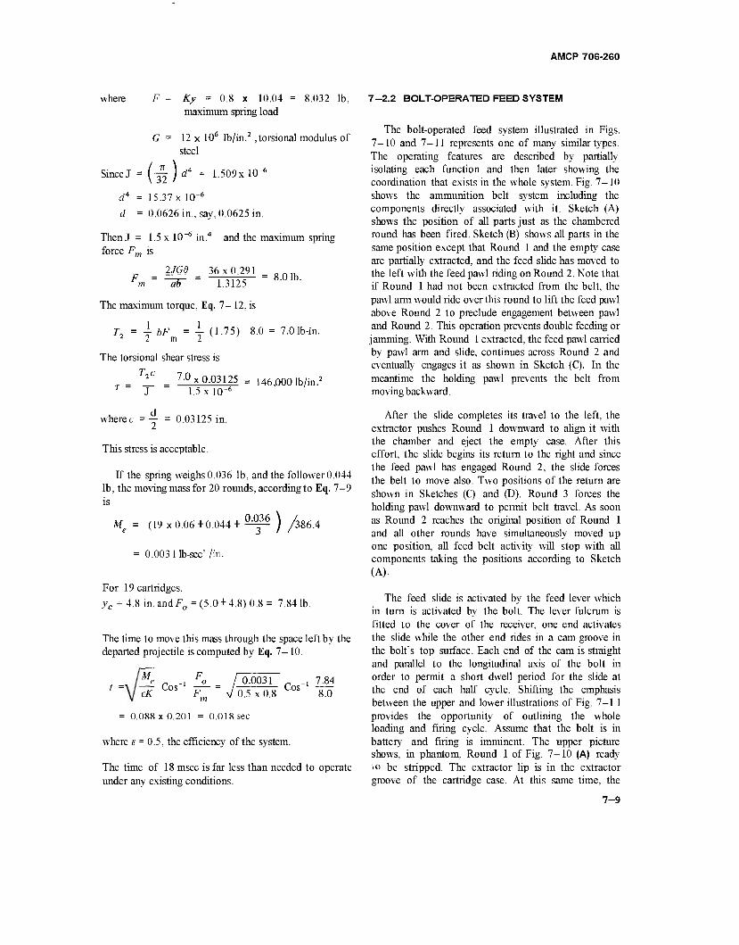
AMCP 70S-260
where F = Ky = 0.8 x 10.04 maximum spring load
8.032 lb,
G = 12 x 106 lb/in.2 ,torsional modulus of steel
Since J -te) d* = 1.509x 10"
d4 = 15.37 x 10"6
d = 0.0626 in., say, 0.0625 in.
Then J = 1.5 x 10 6 in.4 and the maximum spring force Fm is
2JG6 36x0.291 F = ^TT = i TTTi = 8-01b- m aö 1.3125
The maximum torque, Eq. 7-12, is
J, = i bF = 1 (1.75) 8.0 = 7.01b-in. 2 2 m 2
The torsional shear stress is
JL _ 7.0x0.03125 = 146!000 lb/in.2
T ~ J 1.5 xlO"6
7-2.2 BOLT-OPERATED FEED SYSTEM
The bolt-operated feed system illustrated in Figs. 7-10 and 7-11 represents one of many similar types. The operating features are described by partially isolating each function and then later showing the coordination that exists in the whole system. Fig. 7-10 shows the ammunition belt system including the components directly associated with it. Sketch (A) shows the position of all parts just as the chambered round has been fired. Sketch (B) shows all parts in the same position except that Round 1 and the empty case are partially extracted, and the feed slide has moved to the left with the feed pawl riding on Round 2. Note that if Round 1 had not been extracted from the belt, the pawl arm would ride over this round to lift the feed pawl above Round 2 to preclude engagement between pawl and Round 2. This operation prevents double feeding or jamming. With Round 1 extracted, the feed pawl carried by pawl arm and slide, continues across Round 2 and eventually engages it as shown in Sketch (C). In the meantime the holding pawl prevents the belt from moving backward.
where c = — = 0.03125 in.
This stress is acceptable.
If the spring weighs 0.036 lb, and the follower 0.044 lb, the moving mass for 20 rounds, according to Eq. 7-9 is
Me = (19 x 0.06 +0.044 + ^~ j
0.003 lib-sec' /in.
'386.4
For 19 cartridges,
yc = 4.8 in. and F0 = (5.0 + 4.8) 0.8 = 7.84 lb.
The time to move this mass through the space left by the departed projectile is computed by Eq. 7-10.
t = M F e c -1 ° eK CoS F~ m
IQ-0031 r ., m 0.5 x 0.8 8.0
= 0.088x0.201 = 0.018 sec
where E = 0.5, the efficiency of the system.
The time of 18 msec is far less than needed to operate under any existing conditions.
After the slide completes its travel to the left, the extractor pushes Round 1 downward to align it with the chamber and eject the empty case. After this effort, the slide begins its return to the right and since the feed pawl has engaged Round 2, the slide forces the belt to move also. Two positions of the return are shown in Sketches (C) and (D). Round 3 forces the holding pawl downward to permit belt travel. As soon as Round 2 reaches the original position of Round 1 and all other rounds have simultaneously moved up one position, all feed belt activity will stop with all components taking the positions according to Sketch (A).
The feed slide is activated by the feed lever which in turn is activated by the bolt. The lever fulcrum is fitted to the cover of the receiver, one end activates the slide while the other end rides in a cam groove in the bolt's top surface. Each end of the cam is straight and parallel to the longitudinal axis of the bolt in order to permit a short dwell period for the slide at the end of each half cycle. Shifting the emphasis between the upper and lower illustrations of Fig. 7-11 provides the opportunity of outlining the whole loading and firing cycle. Assume that the bolt is in battery and firing is imminent. The upper picture shows, in phantom, Round 1 of Fig. 7-10 (A) ready io be stripped. The extractor lip is in the extractor groove of the cartridge case. At this same time, the
7-9
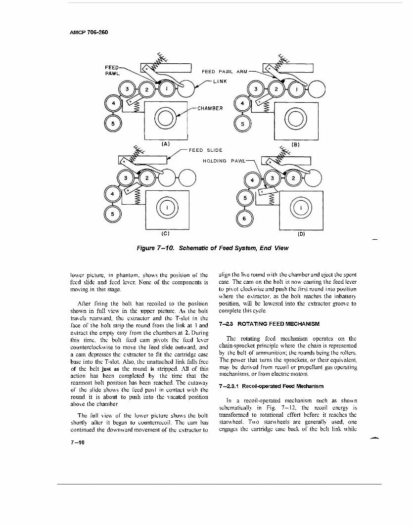
AMCP 706-260
FEED PAWL FEED PAWL ARM!
LINK
CHAMBER
FEED SLIDE
HOLDING PAWL
(C) (D)
Figure 7—10. Schematic of Feed System, End View
lower picture, in phantom, shows the position of the feed slide and feed lever. None of the components is moving in this stage.
After firing the bolt has recoiled to the position shown in full view in the upper picture. As the bolt travels rearward, the extractor and the T-slot in the face of the bolt strip the round from the link at 1 and extract the empty easy from the chambers at 2. During this time, the bolt feed cam pivots the feed lever counterclockwise to move the feed slide outward, and a cam depresses the extractor to fit the cartridge case base into the T-slot. Also, the unattached link falls free of the belt just as the round is stripped. All of this action has been completed by the time that the rearmost bolt position has been reached. The cutaway of the slide shows the feed pawl in contact with the round it is about to push into the vacated position above the chamber.
The full view of the lower picture shows the bolt shortly after it began to counterrecoil. The cam has continued the downward movement of the extractor to
align the live round with the chamber and eject the spent case. The cam on the bolt is now causing the feed lever to pivot clockwise and push the first round into position where the extractor, as the bolt reaches the inbattery position, will be lowered into the extractor groove to complete this cycle.
7-2.3 ROTATING FEED MECHANISM
The rotating feed mechanism operates on the chain-sprocket principle where the chain is represented by the belt of ammunition; the rounds being the rollers. The power that turns the sprockets, or their equivalent, may be derived from recoil or propellant gas operating mechanisms, or from electric motors.
7—2.3.1 Recoil-operated Feed Mechanism
In a recoil-operated mechanism such as shown schematically in Fig. 7—12, the recoil energy is transformed to rotational effort before it reaches the starwheel. Two starwheels are generally used, one engages the cartridge case back of the belt link while
7-10
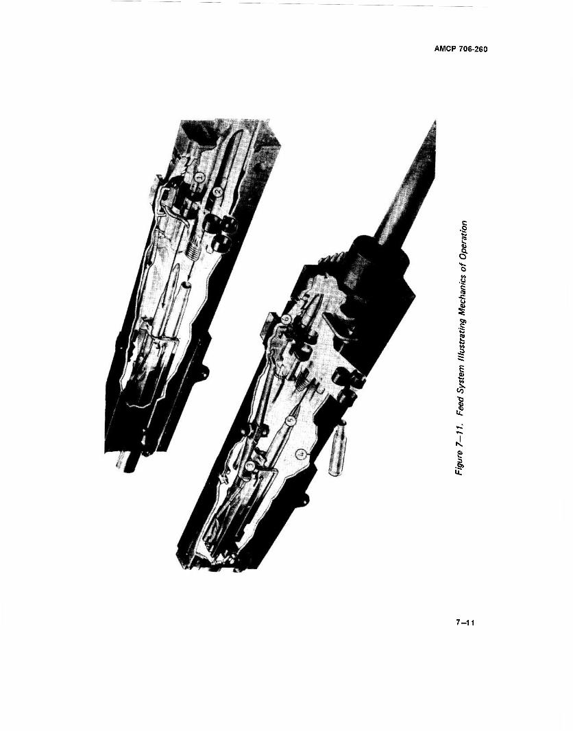
AMCP 706-260
.§
1 o
I f 3
| CO
I N, a? •I
7-11
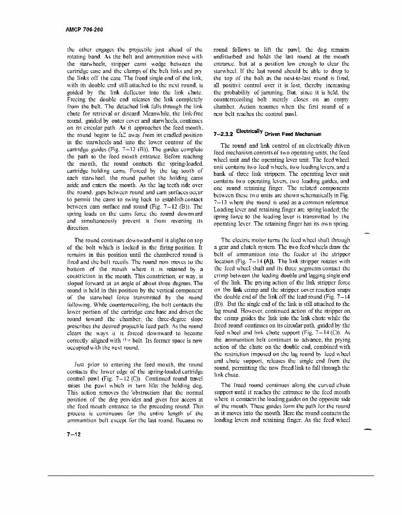
AMCP 706-260
the other engages the projectile just ahead of the rotating band. As the belt and ammunition move with the starwheels, stripper cams wedge between the cartridge case and the clamps of the belt links and pry the links off the case. The freed single end of the link, with its double end still attached to the next round, is guided by the link deflector into the link chute. Freeing the double end releases the link completely from the belt. The detached link falls through the link chute for retrieval or discard. Meanwhile, the link-free round, guided by outer cover and starwheels, continues on its circular path. As it approaches the feed mouth, the round begins to fall away from its cradled position in the starwheels and into the lower contour of the cartridge guides (Fig. 7-12 (B)). The guides complete the path to the feed mouth entrance. Before reaching the mouth, the round contacts the spring-loaded, cartridge holding cams. Forced by the lag tooth of each starwheel, the round pushes the holding cams aside and enters the mouth. As the lag teeth ride over the round, gaps between round and cam surfaces occur to permit the cams to swing back to establish contact between cam surface and round (Fig. 7—12 (B)). The spring loads on the cams force the round downward and simultaneously prevent it from reversing its direction.
The round continues downward until it alights on top of the bolt which is locked in the firing position. It remains in this position until the chambered round is fired and the bolt recoils. The round now moves to the bottom of the mouth where it is retained by a constriction in the mouth. This constriction, or way, is sloped forward at an angle of about three degrees. The round is held in this position by the vertical component of the starwheel force transmitted by the round following. While counterrecoiling, the bolt contacts the lower portion of the cartridge case base and drives the round toward the chamber; the three-degree slope prescribes the desired projectile feed path. As the round clears the ways it is forced downward to become correctly aligned with tl" bolt. Its former space is now occupied with the next round.
Just prior to entering the feed mouth, the round contacts the lower edge of the spring-loaded cartridge control pawl (Fig. 7—12 (C)). Continued round travel raises the pawl which in turn lifts the holding dog. This action removes the 'obstruction that the normal position of the dog provides and gives free access at the feed mouth entrance to the preceding round. This process is continuous for the entire length of the ammunition belt except for the last round. Because no
round follows to lift the pawl, the dog remains undisturbed and holds the last round at the mouth entrance, but at a position low enough to clear the starwheel. If the last round should be able to drop to the top of the bolt as the next-to-last round is fired, all positivi: control over it is lost, thereby increasing the probability of jamming. But, since it is held, the counterrecoiling bolt merely closes on an empty chamber. Action resumes when the first round of a new belt reaches the control pawl.
7-2.3.2 Electr,ca,|Y Driven Feed Mechanism
The round and link control of an electrically driven feed mechanism consists of two operating units, the feed wheel unit and the operating lever unit. The feed wheel unit contains two feed wheels, two loading levers, and a bank of three link strippers. The operating lever unit contains two operating levers, two loading guides, and one round retaining finger. The related components between these two units are shown schematically in Fig. 7—13 where the round is used as a common reference. Loading lever and retaining finger are spring loaded; the spring force to the loading lever is transmitted by the operating lever. The retaining finger has its own spring.
The electric motor turns the feed wheel shaft through a gear and clutch system. The two feed wheels draw the belt of ammunition into the feeder at the stripper location (Fig. 7—14 (A)). The link stripper rotates with the feed wheel shaft and its three segments contact the crimp between the leading double and lagging single end of the link. The prying action of the link stripper force on the link crimp and the stripper cover reaction snaps the double end of the link off the lead round (Fig. 7—14 (B)). But the single end of the link is still attached to the lag round. However, continued action of the stripper on, the crimp guides the link into the link chute while the freed round continues on its circular path, guided by the feed wheel and link chute support (Fig. 7 — 14 (C)). As the ammunition belt continues to advance, the prying action of the chute on the double end, combined with the restriction imposed on the lag round by feed wheel and chute support, releases the single end from the round, permitting the now freed link to fall through the link chute.
The freed round continues along the curved chute support until it reaches the entrance to the feed mouth where it contacts the loading guides on the opposite side of the mouth. These guides form the path for the round as it moves into the mouth. Here the round contacts the loading levers and retaining finger. As the feed wheel
7-12
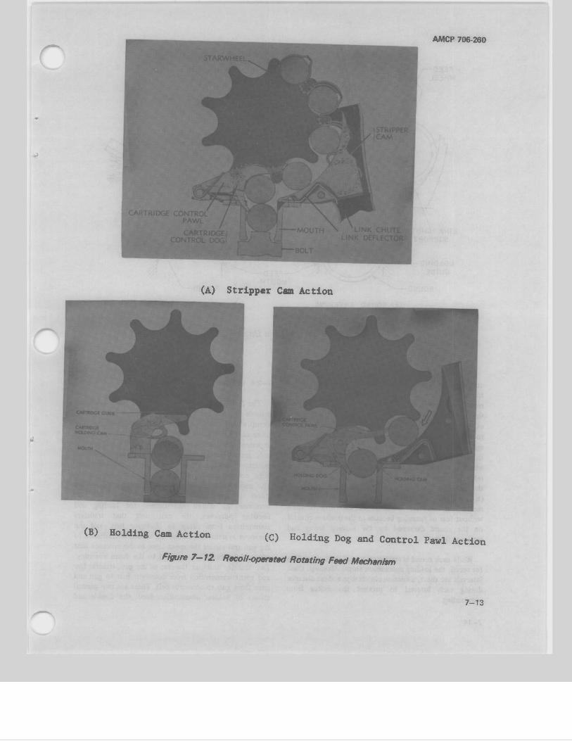
AMCP 706-260
(A) Stripper Cam Action
(B) Holding Cam Action (C) Holding Dog and Control Pawl Action
Figure 7—12. Recoil-operated Rotating Feed Mechanism
7-13
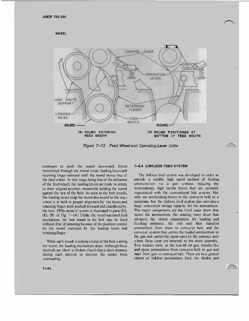
AMCP 706-260
WHEEL
LINK CHUTE SUPPORT
LOADING GUIDE
ROUND
(A) ROUND ENTERING FEED MOUTH
ROUND-
(B) ROUND POSITIONED AT BOTTOM OF FEED MOUTH
Figure 7—13. Feed Wheel and Operating Lever Units
continues to push the round downward, forces transmitted through the round rotate loading levers and retaining finger outward until the round moves free of the feed wheel. At this stage, being free of the influence of the feed wheel, the loading levers are ready to return to their original position, meanwhile holding the round against the top of the bolt. As soon as the bolt recoils, the loading levers snap the round downward to the ways where it is held in proper alignment by the levers and retaining finger until pushed forward and chambered by the bolt. (This series of events is illustrated in parts (D), (E), (F) of Fig. 7-14.) Unlike the recoil-operated feed mechanism, the last round in the belt may be fired without fear of jamming because of the position control on the round exercised by the loading levers and retaining finger.
While each round is resting on top of the bolt waiting for recoil, the loading mechanism stops. Although these intervals are short, a friction clutch slips a short distance during each interval to prevent the motor from overloading.
7-2.4 LINKLESS FEED SYSTEM
The linkless feed system was developed in order to provide a reliable high speed method of feeding ammunition to a gun without inducing the tremendously high inertia forces that are normally experienced with the conventional link systems. Not only are accelerating forces in the conveyor held to a minimum, but the linkless feed system also provides a large, convenient storage capacity for the ammunition. The major components are the fixed outer drum that stores the ammunition, the rotating inner drum that advances the stored ammunition for loading and feeding purposes, the exit unit that transfers ammunition from drum to conveyor belt, and the conveyor system that carries the loaded ammunition to the gun and carries the spent cases to the entrance unit where these cases are returned to the drum assembly. Two transfer units, at the rear of .ne gun, transfer live and spent ammunition from conveyor belt to gun and later from gun to conveyor belt. There are two general classes of linkless ammunition feed, the double and
7-14
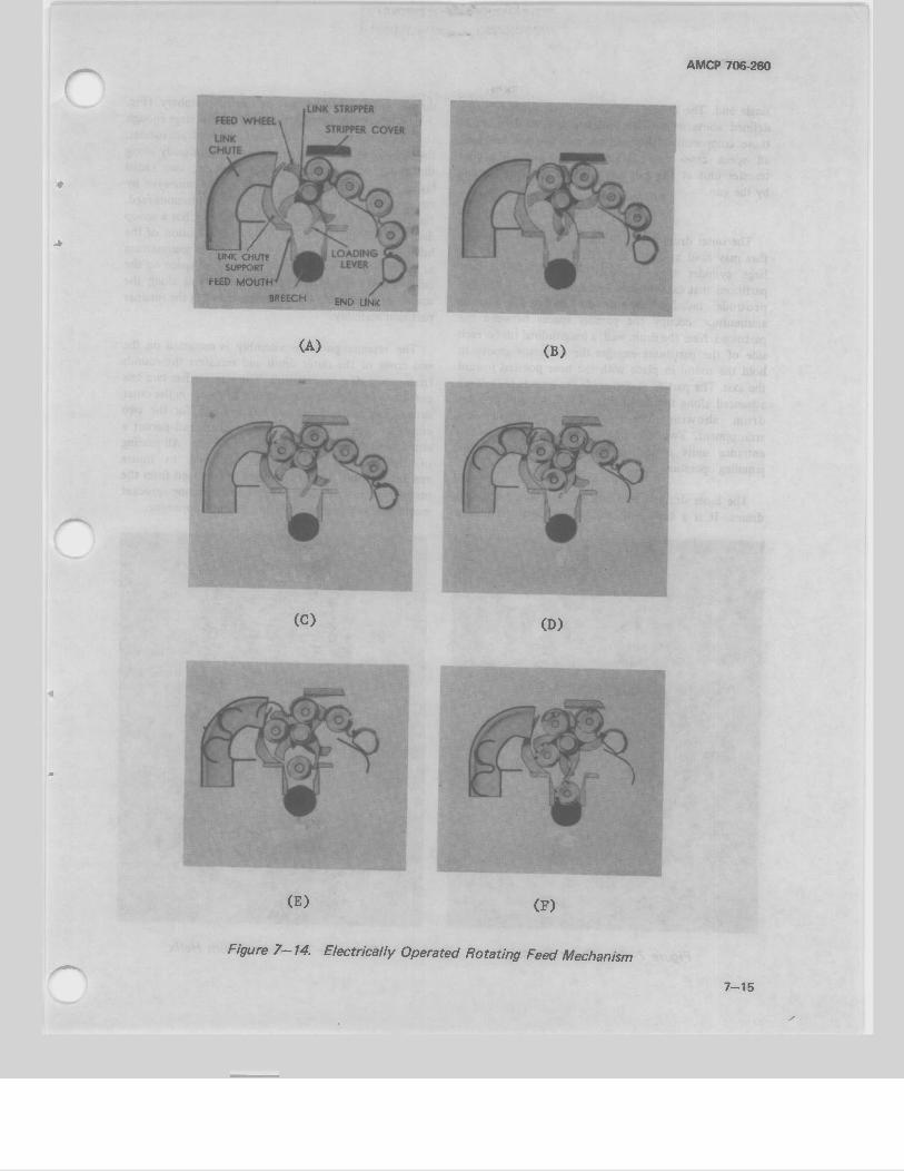
AMCP 706-260
/ UNK CHUTI
SUPPORT
FEED MOUTH'
BREECH END LINK
(A) (B)
r^
(C) (D)
(E) (F)
Figure 7-14. Electrically Operated Rotating Feed Mechanism
7-15
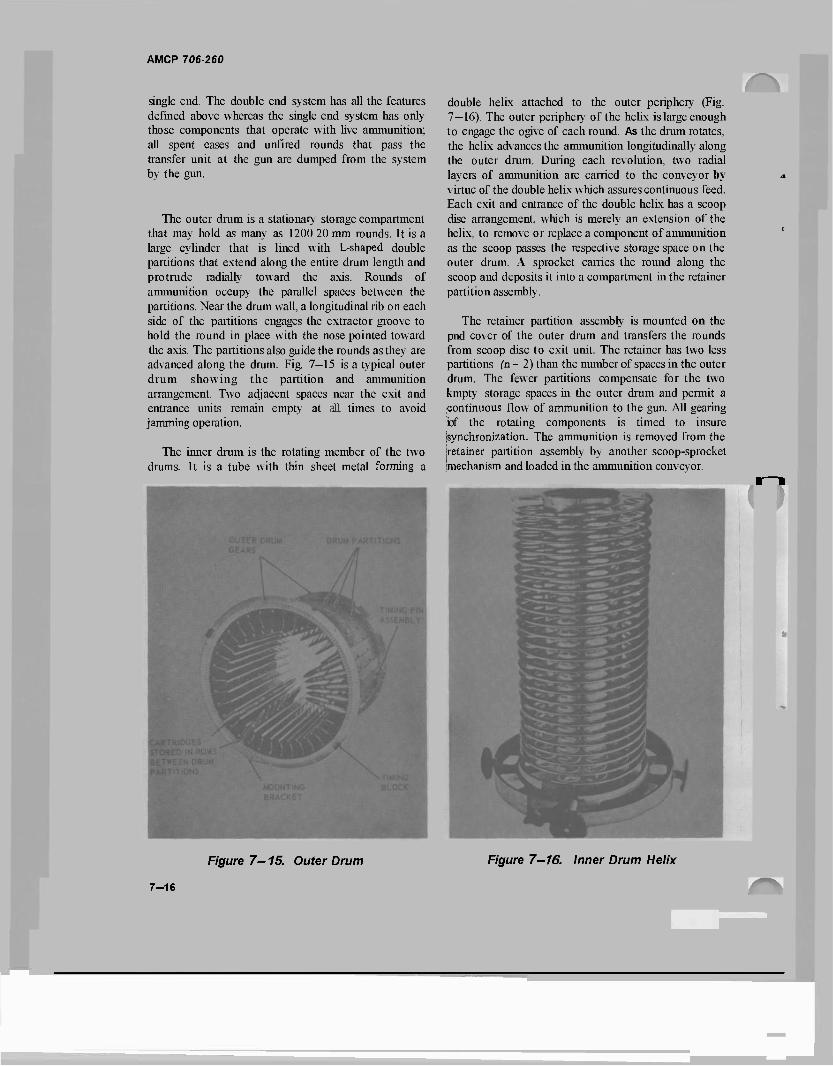
AMCP 706-260
single end. The double end system has all the features defined above whereas the single end system has only those components that operate with live ammunition; all spent cases and unfired rounds that pass the transfer unit at the gun are dumped from the system by the gun.
The outer drum is a stationary storage compartment that may hold as many as 1200 20 mm rounds. It is a large cylinder that is lined with L-shaped double partitions that extend along the entire drum length and protrude radially toward the axis. Rounds of ammunition occupy the parallel spaces between the partitions. Near the drum wall, a longitudinal rib on each side of the partitions engages the extractor groove to hold the round in place with the nose pointed toward the axis. The partitions also guide the rounds as they are advanced along the drum. Fig. 7—15 is a typical outer drum showing the partition and ammunition arrangement. Two adjacent spaces near the exit and entrance units remain empty at all times to avoid jamming operation.
The inner drum is the rotating member of the two drums. It is a tube with thin sheet metal forming a
double helix attached to the outer periphery (Fig. 7—16). The outer periphery of the helix is large enough to engage the ogive of each round. As the drum rotates, the helix advances the ammunition longitudinally along the outer drum. During each revolution, two radial layers of ammunition are carried to the conveyor by virtue of the double helix which assures continuous feed. Each exit and entrance of the double helix has a scoop disc arrangement, which is merely an extension of the helix, to remove or replace a component of ammunition as the scoop passes the respective storage space on the outer drum. A sprocket carries the round along the scoop and deposits it into a compartment in the retainer partition assembly.
The retainer partition assembly is mounted on the pnd cover of the outer drum and transfers the rounds from scoop disc to exit unit. The retainer has two less partitions (n - 2) than the number of spaces in the outer drum. The fewer partitions compensate for the two kmpty storage spaces in the outer drum and permit a continuous flow of ammunition to the gun. All gearing iof the rotating components is timed to insure jsynchronization. The ammunition is removed from the jretainer partition assembly by another scoop-sprocket (mechanism and loaded in the ammunition conveyor.
Figure 7-15. Outer Drum Figure 7—16. inner Drum Helix
7-16
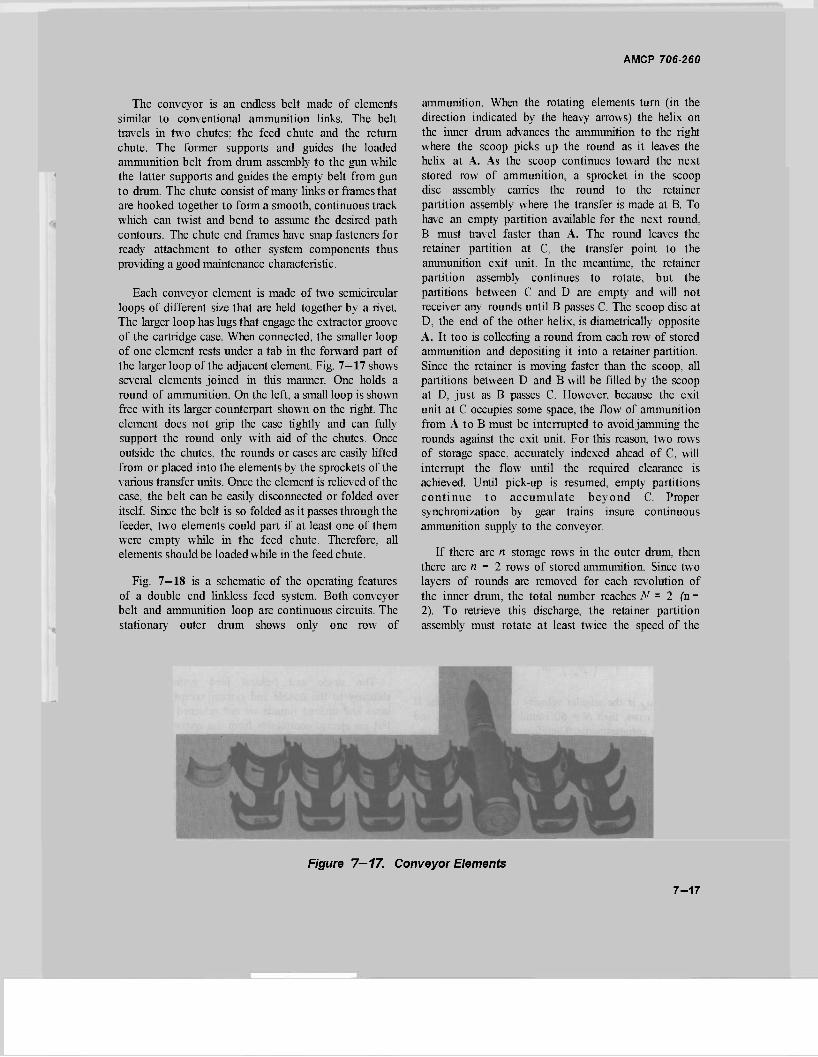
AMCP 706-260
The conveyor is an endless belt made of elements similar to conventional ammunition links. The belt travels in two chutes; the feed chute and the return chute. The former supports and guides the loaded ammunition belt from drum assembly to the gun while the latter supports and guides the empty belt from gun to drum. The chute consist of many links or frames that are hooked together to form a smooth, continuous track which can twist and bend to assume the desired path contours. The chute end frames have snap fasteners for ready attachment to other system components thus providing a good maintenance characteristic.
Each conveyor element is made of two semicircular loops of different size that are held together by a rivet. The larger loop has lugs that engage the extractor groove of the cartridge case. When connected, the smaller loop of one element rests under a tab in the forward part of the larger loop of the adjacent element. Fig. 7—17 shows several elements joined in this manner. One holds a round of ammunition. On the left, a small loop is shown free with its larger counterpart shown on the right. The element does not grip the case tightly and can fully support the round only with aid of the chutes. Once outside the chutes, the rounds or cases are easily lifted from or placed into the elements by the sprockets of the various transfer units. Once the element is relieved of the case, the belt can be easily disconnected or folded over itself. Since the belt is so folded as it passes through the feeder, two elements could part if at least one of them were empty while in the feed chute. Therefore, all elements should be loaded while in the feed chute.
Fig. 7—18 is a schematic of the operating features of a double end linkless feed system. Both conveyor belt and ammunition loop are continuous circuits. The stationary outer drum shows only one row of
ammunition. When the rotating elements turn (in the direction indicated by the heavy arrows) the helix on the inner drum advances the ammunition to the right where the scoop picks up the round as it leaves the helix at A. As the scoop continues toward the next stored row of ammunition, a sprocket in the scoop disc assembly carries the round to the retainer partition assembly where the transfer is made at B. To have an empty partition available for the next round, B must travel faster than A. The round leaves the retainer partition at C, the transfer point to the ammunition exit unit. In the meantime, the retainer partition assembly continues to rotate, but the partitions between C and D are empty and will not receiver any rounds until B passes C. The scoop disc at D, the end of the other helix, is diametrically opposite A. It too is collecting a round from each row of stored ammunition and depositing it into a retainer partition. Since the retainer is moving faster than the scoop, all partitions between D and B will be filled by the scoop at D, just as B passes C. However, because the exit unit at C occupies some space, the flow of ammunition from A to B must be interrupted to avoidjamming the rounds against the exit unit. For this reason, two rows of storage space, accurately indexed ahead of C, will interrupt the flow until the required clearance is achieved. Until pick-up is resumed, empty partitions continue to accumulate beyond C. Proper synchronization by gear trains insure continuous ammunition supply to the conveyor.
If there are n storage rows in the outer drum, then there are n - 2 rows of stored ammunition. Since two layers of rounds are removed for each revolution of the inner drum, the total number reaches N = 2 (n- 2). To retrieve this discharge, the retainer partition assembly must rotate at least twice the speed of the
Figure 7—17. Conveyor Elements
7-17
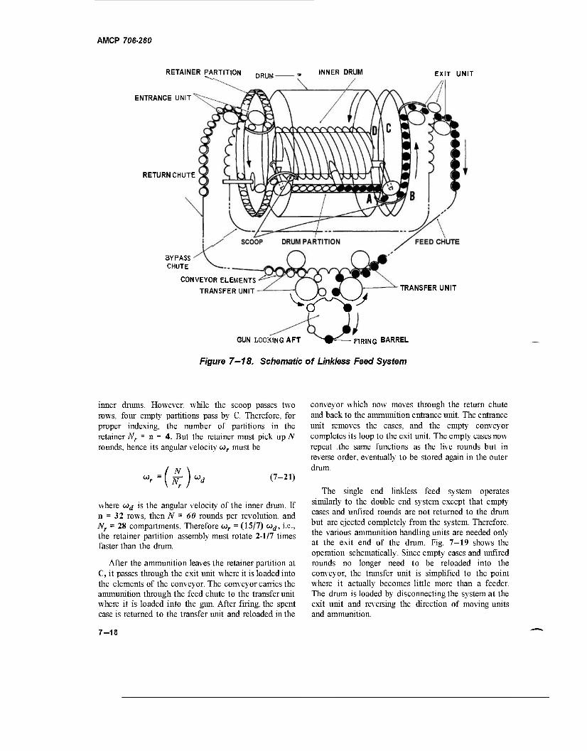
AMCP 706-260
RETAINER PARTITION DRUM INNER DRUM EXIT UNIT
ENTRANCE UNIT
RETURN CHUTE
BYPASS CHUTE
CONVEYOR ELEMENTS
TRANSFER UNIT TRANSFER UNIT
vv^x^yy
GUN LOOKING AFT ^9^— FIRING BARREL
Figure 7—18. Schematic of Linkless Feed System
inner drums. However, while the scoop passes two rows, four empty partitions pass by C. Therefore, for proper indexing, the number of partitions in the retainer Nr = n - A. But the retainer must pick up N rounds, hence its angular velocity cor must be
■(*)
(7-21)
where wd is the angular velocity of the inner drum. If n = 32 rows, then N = 60 rounds per revolution, and Nr = 28 compartments. Therefore cor = (15/7) wd, i.e., the retainer partition assembly must rotate 2-1/7 times faster than the drum.
After the ammunition leaves the retainer partition at C, it passes through the exit unit where it is loaded into the elements of the conveyor. The conveyor carries the ammunition through the feed chute to the transfer unit where it is loaded into the gun. After firing, the spent case is returned to the transfer unit and reloaded in the
conveyor which now moves through the return chute and back to the ammunition entrance unit. The entrance unit removes the cases, and the empty conveyor completes its loop to the exit unit. The empty cases now repeat .the same functions as the live rounds but in reverse order, eventually to be stored again in the outer drum.
The single end linkless feed system operates similarly to the double end system except that empty cases and unfired rounds are not returned to the drum but are ejected completely from the system. Therefore, the various ammunition handling units are needed only at the exit end of the drum. Fig. 7-19 shows the operation schematically. Since empty cases and unfired rounds no longer need to be reloaded into the conveyor, the transfer unit is simplified to the point where it actually becomes little more than a feeder. The drum is loaded by disconnecting the system at the exit unit and reversing the direction of moving units and ammunition.
7-18
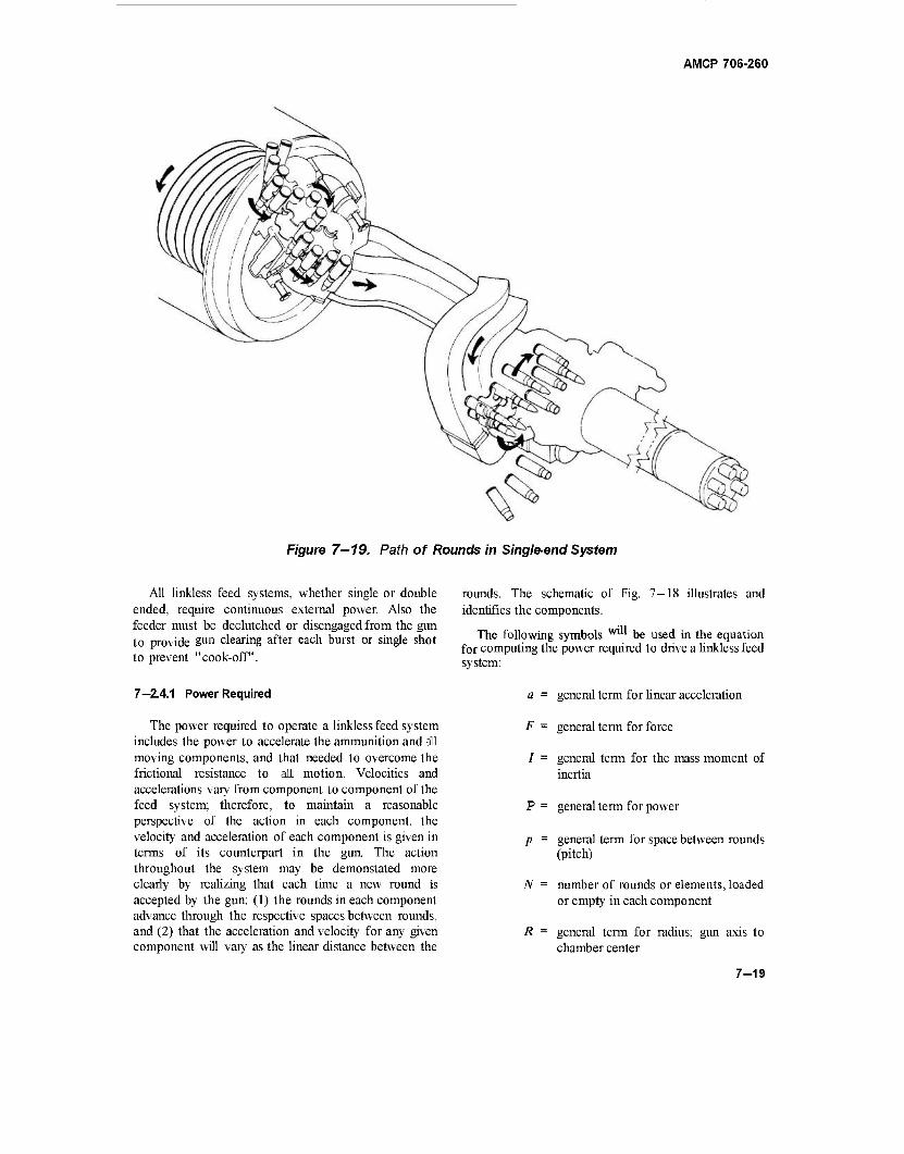
AMCP 706-260
Figure 7-19. Path of Rounds in Single-end System
All linkless feed systems, whether single or double ended, require continuous external power. Also the feeder must be declutched or disengaged from the gun to provide gun clearing after each burst or single shot to prevent "cook-off".
7—2.4.1 Power Required
The power required to operate a linkless feed system includes the power to accelerate the ammunition and all moving components, and that needed to overcome the frictional resistance to all motion. Velocities and accelerations vary from component to component of the feed system; therefore, to maintain a reasonable perspective of the action in each component, the velocity and acceleration of each component is given in terms of its counterpart in the gun. The action throughout the system may be demonstated more clearly by realizing that each time a new round is accepted by the gun: (1) the rounds in each component advance through the respective spaces between rounds, and (2) that the acceleration and velocity for any given component will vary as the linear distance between the
rounds. The schematic of Fig. 7-18 illustrates and identifies the components.
The following symbols W"* be used in the equation for computing the power required to drive a linkless feed system:
a = general term for linear acceleration
F = general term for force
/ = general term for the mass moment of inertia
P = general term for power
p = general term for space between rounds (pitch)
N = number of rounds or elements, loaded or empty in each component
R = general term for radius; gun axis to chamber center
7-19
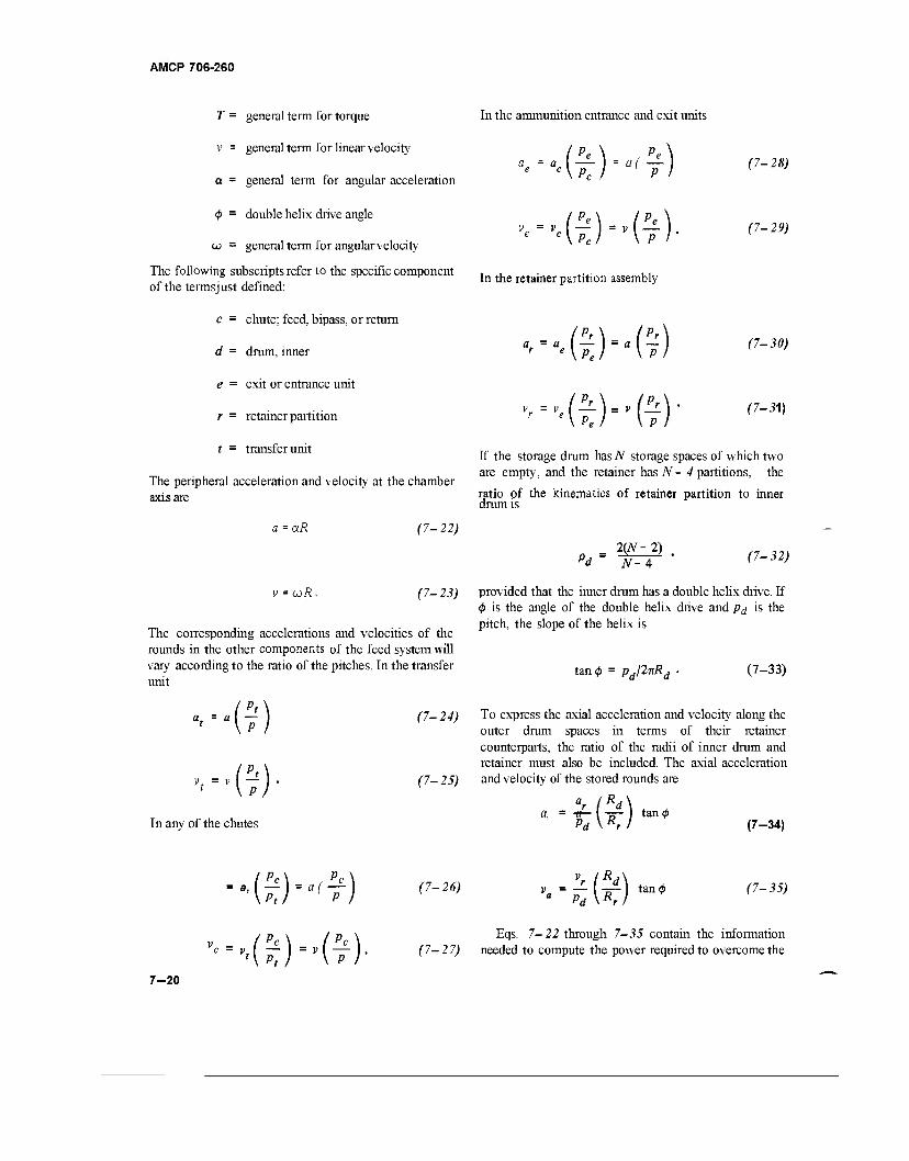
AMCP 706-260
T = general term for torque
v = general term for linear velocity
a = general term for angular acceleration
0 = double helix drive angle
w = general term for angularvelocity
The following subscripts refer to the specific component of the termsjust defined:
c = chute; feed, bipass, or return
d = drum, inner
e = exit or entrance unit
r = retainer partition
t = transfer unit
The peripheral acceleration and velocity at the chamber axis are
a=aR
v = coR*
(7-22)
(7-23)
In the ammunition entrance and exit units
(Pe\ Pe\ a = a I I = a( — I e C\PC I PI
(7-28)
■.(£)-(*)■ <>-> In the retainer partition assembly
"'-"<(£) "(7) <7-3»
G)-'G) (7-31)
If the storage drum has JV storage spaces of which two are empty, and the retainer has N- 4 partitions, the
ratio of the kinematics of retainer partition to inner drum is
2(JV-2) pd N- 4
(7-32)
The corresponding accelerations and velocities of the rounds in the other components of the feed system will vary according to the ratio of the pitches. In the transfer unit
provided that the inner drum has a double helix drive. If <$> is the angle of the double helix drive and p<j is the pitch, the slope of the helix is
tan 0 = Pdl2irRd (7-33)
(Pt\ a, = a I — I
' \ P I (7-24)
(7-25)
To express the axial acceleration and velocity along the outer drum spaces in terms of their retainer counterparts, the ratio of the radii of inner drum and retainer must also be included. The axial acceleration and velocity of the stored rounds are
In any of the chutes 1 (Ro\ Pd\Rrl
tan 0 (7-34)
[j;)-a(T) (7~26) -£(*)-♦ (7-35)
•«-.(£)-'(*)■ 7-20
Eqs. 7-22 through 7-35 contain the information (7-27) needed to compute the power required to overcome the
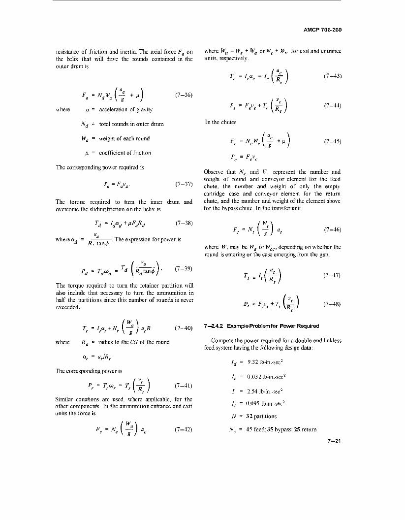
AMCP 706-260
resistance of friction and inertia. The axial force Fa on the helix that will drive the rounds contained in the outer drum is
a da G" (7-36)
where g = acceleration of gravity
Nd = total rounds in outer drum
Wa = weight of each round
ß - coefficient of friction
The corresponding power required is
P = F v 'a a a (7-37)
The torque required to turn the inner drum and overcome the sliding friction on the helix is
Td=Idad+*FaRd (7-38)
where a d R, tan0 . The expression for power is
T TdȊ = d \Rd\&n4>)- (7-39)
The torque required to turn the retainer partition will also include that necessary to turn the ammunition in half the partitions since this number of rounds is never exceeded.
«r+Nr(^)arR
where
Tf=I.
Ra = radius to the CG of the round
(7-40)
ar = ar/Rr
The corresponding power is
P = To: r r r •*m (7-41)
Similar equations are used, where applicable, for the other components. In the ammunition entrance and exit units the force is
N, &u (7-42)
where Wu = We + Wa or We + W„ for exit and entrance units, respectively.
T = la = / . „
p = F v +r e e e e m In the chutes
F = N W c c c
P = F v c c c
(**<■)
(7-43)
(7-44)
(7-45)
Observe that Nc and W, represent the number and weight of round and conveyor element for the feed chute, the number and weight of only the empty cartridge case and conveyor element for the return chute, and the number and weight of the element above for the bypass chute. In the transfer unit
7<=N<(j)a< (7-46)
where W, may be Wa or Wcc, depending on whether the round is entering or the case emerging from the gun.
'-'.(*)
*-',.".(*)
(7-47)
(7-48)
7—2.4.2 Example Problem for Power Required
Compute the power required for a double end linkless feed system having the following design data:
Id = 9.321b-in.-sec2
Ie = 0.032 lb-in. -sec2
/, = 2.54 lb-in.-sec2
It = 0.095 lb-in.-sec2
TV = 32 partitions
Nc = 45 feed; 35 bypass; 25 return
7-21
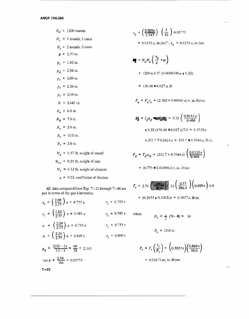
AMCP 706-260
"d = 1200 rounds
"e = 3 rounds; 3 cases
"t = 2 rounds; 2 cases
P = 2.77 in.
Pc = 1.62 in.
Pd = 2.54 in.
Pe = 2.09 in.
Pr = 2.24 in.
Pt = 2.09 in.
R = 2.643 in.
Ra = 6.0 in.
Rd = 7.0 in.
Re = 2.0 in.
Rr = 10.0 in.
Rt = 2.0 in.
wa = 0.57 lb, weight of round
Wcc = 0.25 lb, weight of case
We = 0.12 lb, weight of element
ß = 0.22, coefficient of friction
SI data computed from Eqs. 7-22 through 7-48 are put in terms of the gun kinematics.
a = 0.755 a
a = 0.585 a
/ 2.09 \ at ~ \2Til
■ (162\ ac - \27n)
*-(g?).-0.7«.
a, = (|^-)a = 0.809a
2(32-2) _ 60
vt = 0.755v
v = 0.585 v C
v = 0.755 v e
v = 0.809v
Pd
tan <
32-4
2.54 14ff
28 r 2143
0.05775
= 0.0153 a, in./sec*; v = 0.0153 v, in./sec
-»dWa(j+»)
= 1200x0.57 (0.0000396a 10.22)
150.48-i 0.027 a, lb
P =Fv = (2.302 + 0.00041 a) v, in.-lb/sec a a a v ' ' '
10.22 (150.48 ■■ 0.027a)7.0 = 0.3530a
1231.7 + 0.0416a = 231.7 -10.3946a, lb-in.
Pd = Td»d (231.7 +0.3946a) (^^)
= (8.775 ■■0.01494a>> in.-lb/sec
= (0.2055 t0.1002)a = 0.3057a, lb-in.
6.0
where N, \ = -f (N- 4) = 14
Rr = 10.0 in.
P, = ,,(^).(„,„5,«)(O-,)
- 0.02473 av, in.-lb/sec
7-22
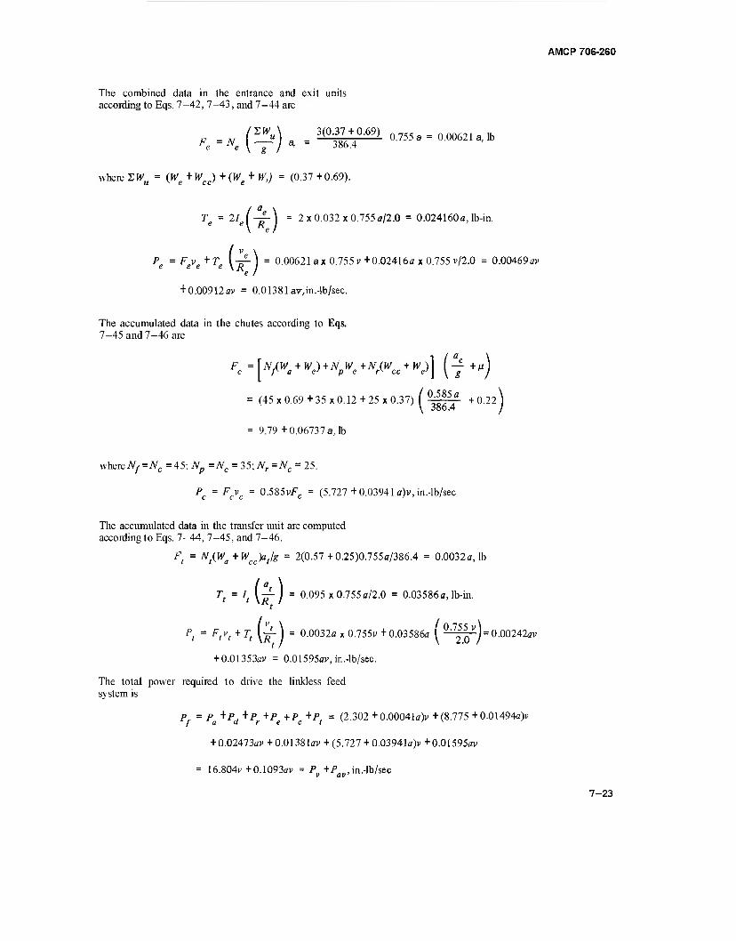
AMCP 706-260
The combined data in the entrance and exit units according to Eqs. 7-42, 7-43, and 7-44 are
("■) Fe = Ne \ ~^~ I a< = 386.4
where 2Wu = (We +Wcc) + (Wg + W,) = (0.37 +0.69).
3(0.37+0-69) o.755a = 0.00621 a, lb
Te = 11 e |-jf- I = 2x0.032x0.755 a/2.0 = 0.024160a, lb-in.
P =Fv +T \ -£- = 0.00621 ax 0.755 v+0.02416ax 0.755 v/2.0 = 0.00469av
+ 0.00912av = 0.0138 lav, in. -lb/sec.
The accumulated data in the chutes according to Eqs. 7-45 and 7-46 are
U/^ + Hy+TV^+TV/W^ + W)] (y +MJ
(45x0.69 +35x0.12+25x0.37) ( 0;^5/ +0.22 ) y 386.4 j
= 9.79 +0.06737 a, lb
whereAy=iVc=45;7Vp =NC = 35;Nr =NC = 25.
Pc = Fcvc = 0.585vFc = (5.727+ 0.03941 a)v, in.-lb/sec
The accumulated data in the transfer unit are computed according to Eqs. 7-44, 7-45, and 7-46.
Ft = Nt(Wa + wcc^t/g = 2(0.57+0.25)0.755a/386.4 = 0.0032a, lb
Tt = It y-^-J = 0.095 x0.755a/2.0 = 0.03586a, lb-in.
Pt = Ftv( + Tt \j- ) = 0.0032a x 0.755p + 0.03586a ( °'7^5vJ= 0.00242av
+ 0.01353av = 0.01595ai>, in.-lb/sec.
The total power required to drive the linkless feed system is
P = pa +pd +pr +pe +pc +pt = (2.302 +0.00041a)v +(8.775 +0.01494a>
+ 0.02473ai> + 0.01381av> + (5.727 + 0.03941a>+0.01595av
= 16.804v + 0.1093ai> = Pv +Pay, in.-lb/sec
7-23
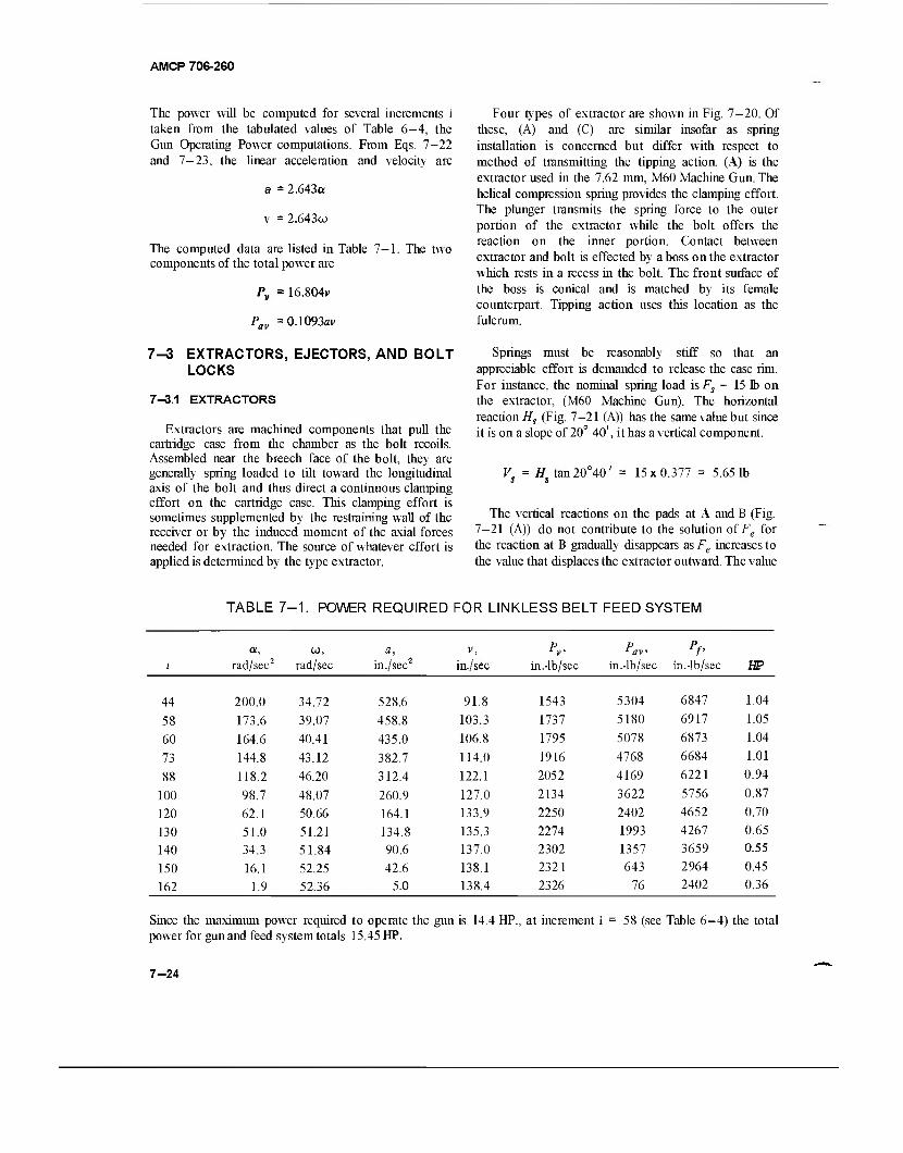
AMCP 706-260
The power will be computed for several increments i taken from the tabulated values of Table 6-4, the Gun Operating Power computations. From Eqs. 7-22 and 7-23, the linear acceleration and velocity are
a = 2.643a
v = 2.643w
The computed data are listed in Table 7—1. The two components of the total power are
Pv = 16.804v
Pav =0.1093av
Four types of extractor are shown in Fig. 7-20. Of these, (A) and (C) are similar insofar as spring installation is concerned but differ with respect to method of transmitting the tipping action. (A) is the extractor used in the 7.62 mm, M60 Machine Gun. The helical compression spring provides the clamping effort. The plunger transmits the spring force to the outer portion of the extractor while the bolt offers the reaction on the inner portion. Contact between extractor and bolt is effected by a boss on the extractor which rests in a recess in the bolt. The front surface of the boss is conical and is matched by its female counterpart. Tipping action uses this location as the fulcrum.
7-3 EXTRACTORS, EJECTORS, AND BOLT LOCKS
7-3.1 EXTRACTORS
Extractors are machined components that pull the cartridge case from the chamber as the bolt recoils. Assembled near the breech face of the bolt, they are generally spring loaded to tilt toward the longitudinal axis of the bolt and thus direct a continuous clamping effort on the cartridge case. This clamping effort is sometimes supplemented by the restraining wall of the receiver or by the induced moment of the axial forces needed for extraction. The source of whatever effort is applied is determined by the type extractor.
Springs must be reasonably stiff so that an appreciable effort is demanded to release the case rim. For instance, the nominal spring load is Fs - 15 lb on the extractor, (M60 Machine Gun). The horizontal reaction Hs (Fig. 7-21 (A)) has the same value but since it is on a slope of 20° 40', it has a vertical component.
Hs tan 20° 40' 15x0.377 = 5.65 1b
The vertical reactions on the pads at A and B (Fig. 7-21 (A)) do not contribute to the solution of Fe for the reaction at B gradually disappears as Fe increases to the value that displaces the extractor outward. The value
TABLE 7-1. POWER REQUIRED FOR LINKLESS BELT FEED SYSTEM
! rad/sec2 CJ,
rad/sec a,
in ./sec2 V,
in./sec in.-lb/sec Pav
in.4b/sec
PP in.4b/sec HP
44 200.0 34.72 528.6 91.8 1543 5304 6847 1.04
58 173.6 39.07 458.8 103.3 1737 5180 6917 1.05
60 164.6 40.41 435.0 106.8 1795 5078 6873 1.04
73 144.8 43.12 382.7 114.0 1916 4768 6684 1.01
88 118.2 46.20 312.4 122.1 2052 4169 6221 0.94
100 98.7 48.07 260.9 127.0 2134 3622 5756 0.87
120 62.1 50.66 164.1 133.9 2250 2402 4652 0.70
130 51.0 51.21 134.8 135.3 2274 1993 4267 0.65
140 34.3 51.84 90.6 137.0 2302 1357 3659 0.55
150 16.1 52.25 42.6 138.1 2321 643 2964 0.45
162 1.9 52.36 5.0 138.4 2326 76 2402 0.36
Since the maximum power required to operate the gun is 14.4 HP., at increment i power for gun and feed system totals 15.45 HP.
58 (see Table 6-4) the total
7-24
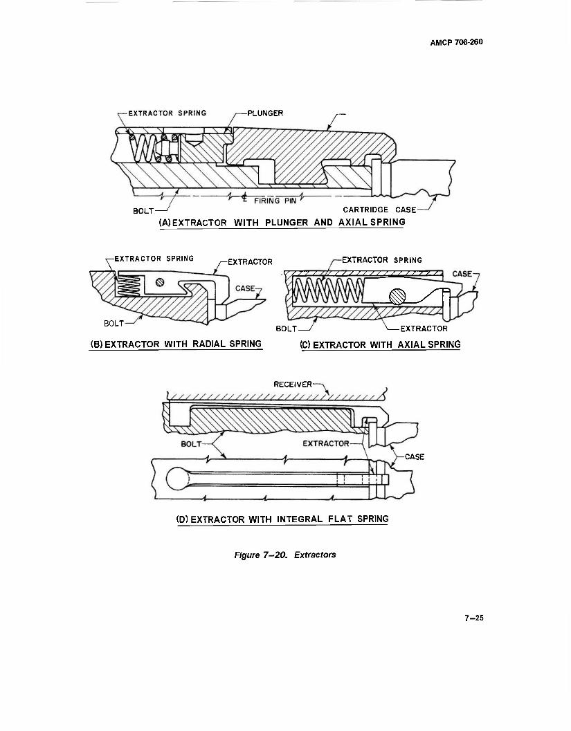
AMCP 706-260
-EXTRACTOR SPRING -PLUNGER
"* * FIRING PIN ^ BOLT / CARTRIDGE CASE-
(A) EXTRACTOR WITH PLUNGER AND AXIAL SPRING
^EXTRACTOR SPRING ^EXTRACTOR EXTRACTOR SPRING
J S S /ß / / S / / / / S S S S / / / 7
^-^D B0LT " BOLT—' N EXTRACTOR
(B) EXTRACTOR WITH RADIAL SPRING (C) EXTRACTOR WITH AXIAL SPRING
RECEIVER-
CASE
(D) EXTRACTOR WITH INTEGRAL FLAT SPRING
Figure 7-20. Extractors
7-25
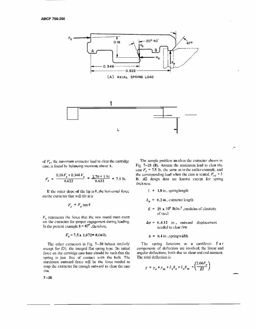
AMCP 706-260
(A) AXIAL SPRING LOAD
of Fe, the maximum extractor load to clear the cartridge case, is found by balancing moments about A.
0.18Fs + 0.346 Vs
0.622 2.70+ 1.96
0.622 = 7.5 lb.
The sample problem involves the extractor shown in Fig. 7-21 (B). Assume the maximum load to clear the case Fe = 7.5 lb, the same as in the earlier example, and the corresponding load when the case is seated, Fes = 5 lb. ÄÜ. design thickness.
data are known except for spring
If the outer slope of the lip is 8 ,the horizontal force on the extractor that will tilt it is
Fc =Fet<mt
Fc represents the force that the new round must exert on the extractor for proper engagement during loading. In the present example 8 = 47 .therefore,
L = 1.8 in., spring length
Le = 0.2 in., extractor length
E = 29 x 106 lb/in.2 .modulus of elasticity of steel
Ay = 0.032 in , outward displacement needed to clear rim
Fc = 7.5x 1.072= 8.041b.
The other extractors in Fig. 7-20 behave similarly except for (D), the integral flat spring type. Its initial force on the cartridge case base should be such that the spring is just free of contact with the bolt. The maximum outward force will be the force needed to snap the extractor far enough outward to clear the case rim.
b = 0.4 in .springwidth
The spring functions as a cantilever. Far components of deflection are involved, the linear and angular deflections, both due to shear and end moment. The total deflection is
ye+ym
+L e +L„ e e e -m
7-26
AMCP 706-260
where
FeL> 5.832F,
3EI 3EI
1.944F e EI
, shear deflection
L F L2 e e 0.2 x 3.24Fg
2EI 2EI
0324F e EI
V 3.24F e 1EI 3EI
1.62Fg angular shear defle EI
MeL 0.2xl.8fe
EI
0.36Fe
~EI
EI
.angular moment deflection
of their immediate associates, the extractors. Ejectors may be assembled either in the bolt or they may be attached to the receiver. Fig. 7—22 shows four types of ejectors, three are housed in the bolt, one in the chamber; Fig. 7-22 (A) is like that in the 7.62 mm, M60 Machine Gun. The spring force, via the ejector, is always applied to the edge of the cartridge case base. As soon as all radial restraint is removed diametrically opposite, the ejector will flip out the case. The off-center spring force accelerates the case angularly as well as linearly. However, the recoiling velocity at the time will compensate to some degree the forward velocity derived from the spring.
7—3.2.1 Ejector Dynamics
Because of its mass relative to the masses of ejector and cartridge case, the spring must be considered in the dynamics of the ejection mechanism. One-third of the spring mass—when included in the expressions for energy, velocity, and time—will yield approximate but sufficiently accurate results. The equivalent mass of the whole unit is
M jM^M. 4^) M (7-49)
The differential deflection fromFeJ to Fe
4v = y^yt = -jj- (Fe-FJ
29xl06/ C7-5 -5.0) = 0.032 in
7 = 7.16 x 10"6 in.'
But/ TT(".0 .therefore
t = 0.06 in., required spring thickness
7-3.2 EJECTORS
Ejectors are simple mechanisms that force the cartridge case from the .receiver. They usually are spring-operated but may derive their energy from other sources such as small quantities of the propellant gas. There are perhaps as many kinds of ejectors as there are
where Mcc = mass of the case
M. e] mass of the ejector
Ms = mass of the spring
k = radius of gyration of the case about its CG
r = distance from tipping point on rim to CG of case
The equivalent mass of the case involves its mass moment of inertia since it is rotating. Fig. 7—23 shows a diagram of the pertinent dimensions. The equivalent mass may now be used in the appropriate formulas to determine the dynamics, Eq. 2—27 for the time, and the conventional equations for energy and velocity.
7—3.Z2 Sample Problem of Ejector Dynamics
The sample problem illustrating the ejector dynamics involves a cal .30 cartridge case. The known data together with the diagram in Fig. 7—23 provide the needed information
7-27
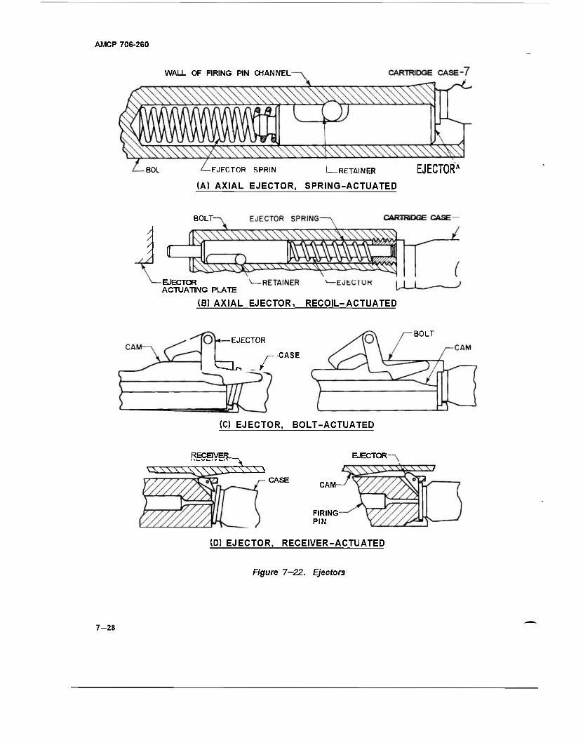
AMCP 706-260
WALL OF FIRING PIN CHANNEL
-BOL -EJECTOR SPRIN I—RETAINER EJECTOR'
(A) AXIAL EJECTOR, SPRING-ACTUATED
BOLT-
EJECTOR ACTUATING PLATE
(B) AXIAL EJECTOR, RECOIL-ACTUATED
EJECTOR
^L. _/"
BOLT
■CASE
(0 EJECTOR, BOLT-ACTUATED
RECEIVER^ EJECTOR
CASE CAM
FIRING PIN
(D) EJECTOR, RECEIVER-ACTUATED
Figure 7—22. Ejectors
7-28
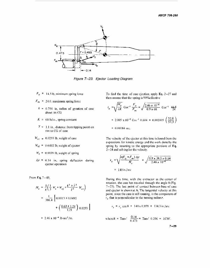
AMCP 706-260
0.473
t
\
r = 0 493
►'
?0 ♦V.
h-0.!4
Figure 7—23. Ejector Loading Diagram
F0 = 14.5 lb, minimum spring force
Fm = 24.0, maximum spring force
Ä = 0.794 in, radius of gyration of case about its CG
K = 68 lb/in., spring constant
f = 1.1 in., distance from tipping point on rim to CG of case
Wcc = 0.0293 lb, weight of case
Wej = 0.0492 lb, weight of ejector
Ws = 0.0039 lb, weight of spring
A/ = 0.14 in, spring deflection during ejector operation
From Eq. 7-49,
M = i/1 W +W . + k */ W )
0.0013 + 0.0492
^(^lill)0,293
1 386.4
2.46 x 10"4 lb-sec2/in.
To find the time of case ejection, apply Eq. 2—27 and then assume that the spring is 90%effective
/Af F L =\ \-T, Cos'1 /2.46x 10^
Cos ■14^ eK Fm V 0.9x68
= 2.005 x 10⁻³ Cos-1 0.604 = 0.002005 (fyf )
= 0.00184 sec.
The velocity of the ejector at this time is found from the expressions for kinetic energy and the work done by the spring by resorting to the appropriate portions of Eq. 2—24 and solving for the velocity.
<Fo+FnJ*y '0.9x38.5x0.14 Me
= 140in./sec
2.46 x 10"
During this time, with the extractor as the center of rotation, the case has traveled through the angle 8 (Fig. 7—23). The last point of contact between base of case and ejector is shown at A. The tangential velocity at this point, since the case is still rotating, is the component of ve that is perpendicular to the turning radius/-.
vt = vecos8 = 140x0.959 = 134.3 in./sec
where 8 = Tan- 0.14
0.473 Tan-' 0.296 = 16'30'.
7-29
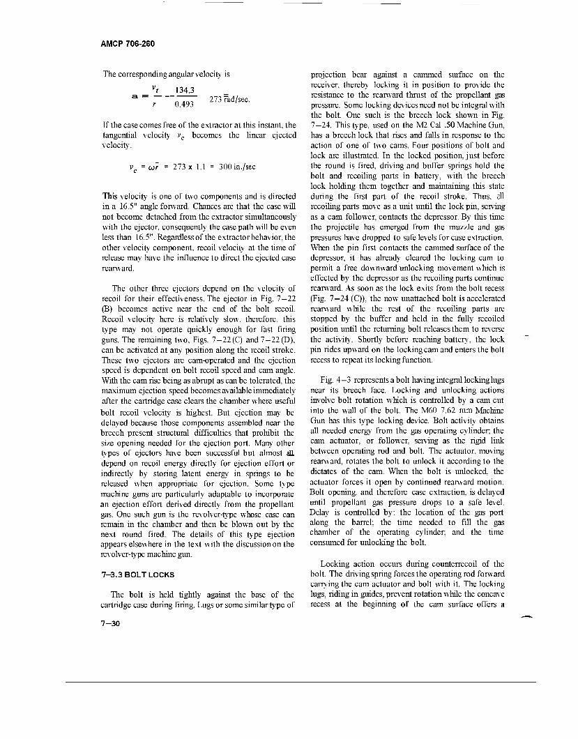
AMCP 706-260
The corresponding angular velocity is
134.3
0.493 273 rad/sec.
If the case comes free of the extractor at this instant, the tangential velocity vc becomes the linear ejected velocity.
vc = (jir = 273 x 1.1 = 300in./sec
This velocity is one of two components and is directed in a 16.5" angle forward. Chances are that the case will not become detached from the extractor simultaneously with the ejector, consequently the case path will be even less than 16.5". Regardless of the extractorbehavior, the other velocity component, recoil velocity at the time of release may have the influence to direct the ejected case rearward.
The other three ejectors depend on the velocity of recoil for their effectiveness. The ejector in Fig. 7—22 (B) becomes active near the end of the bolt recoil. Recoil velocity here is relatively slow, therefore, this type may not operate quickly enough for fast firing guns. The remaining two, Figs. 7—22(C) and 7—22(D), can be activated at any position along the recoil stroke. These two ejectors are cam-operated and the ejection speed is dependent on bolt recoil speed and cam angle. With the cam rise being as abrupt as can be tolerated, the maximum ejection speed becomes available immediately after the cartridge case clears the chamber where useful bolt recoil velocity is highest. But ejection may be delayed because those components assembled near the breech present structural difficulties that prohibit the size opening needed for the ejection port. Many other types of ejectors have been successful but almost all depend on recoil energy directly for ejection effort or indirectly by storing latent energy in springs to be released when appropriate for ejection. Some type machine guns are particularly adaptable to incorporate an ejection effort derived directly from the propellant gas. One such gun is the revolver-type whose case can remain in the chamber and then be blown out by the next round fired. The details of this type ejection appears elsewhere in the text with the discussion on the revolver-type machine gun.
7-3.3 BOLT LOCKS
The bolt is held tightly against the base of the cartridge case during firing. Lugs or some similar type of
projection bear against a cammed surface on the receiver, thereby locking it in position to provide the resistance to the rearward thrust of the propellant gas pressure. Some locking devices need not be integral with the bolt. One such is the breech lock shown in Fig. 7-24. This type, used on the M2 Cal .50 Machine Gun, has a breech lock that rises and falls in response to the action of one of two cams. Four positions of bolt and lock are illustrated. In the locked position, just before the round is fired, driving and buffer springs hold the bolt and recoiling parts in battery, with the breech lock holding them together and maintaining this state during the first part of the recoil stroke. Thus, all recoiling parts move as a unit until the lock pin, serving as a cam follower, contacts the depressor. By this time the projectile has emerged from the muzzle and gas pressures have dropped to safe levels for case extraction. When the pin first contacts the cammed surface of the depressor, it has already cleared the locking cam to permit a free downward unlocking movement which is effected by the depressor as the recoiling parts continue rearward. As soon as the lock exits from the bolt recess (Fig. 7—24 (C)), the now unattached bolt is accelerated rearward while the rest of the recoiling parts are stopped by the buffer and held in the fully recoiled position until the returning bolt releases them to reverse the activity. Shortly before reaching battery, the lock pin rides upward on the locking cam and enters the bolt recess to repeat its locking function.
Fig. 4-3 represents a bolt having integral locking lugs near its breech face. Locking and unlocking actions involve bolt rotation which is controlled by a cam cut into the wall of the bolt. The M60 7.62 mm Machine Gun has this type locking device. Bolt activity obtains all needed energy from the gas operating cylinder; the cam actuator, or follower, serving as the rigid link between operating rod and bolt. The actuator, moving rearward, rotates the bolt to unlock it according to the dictates of the cam. When the bolt is unlocked, the actuator forces it open by continued rearward motion. Bolt opening, and therefore case extraction, is delayed until propellant gas pressure drops to a safe level. Delay is controlled by: the location of the gas port along the barrel; the time needed to fill the gas chamber of the operating cylinder; and the time consumed for unlocking the bolt.
Locking action occurs during counterrecoil of the bolt. The driving spring forces the operating rod forward carrying the cam actuator and bolt with it. The locking lugs, riding in guides, prevent rotation while the concave recess at the beginning of the cam surface offers a
7-30
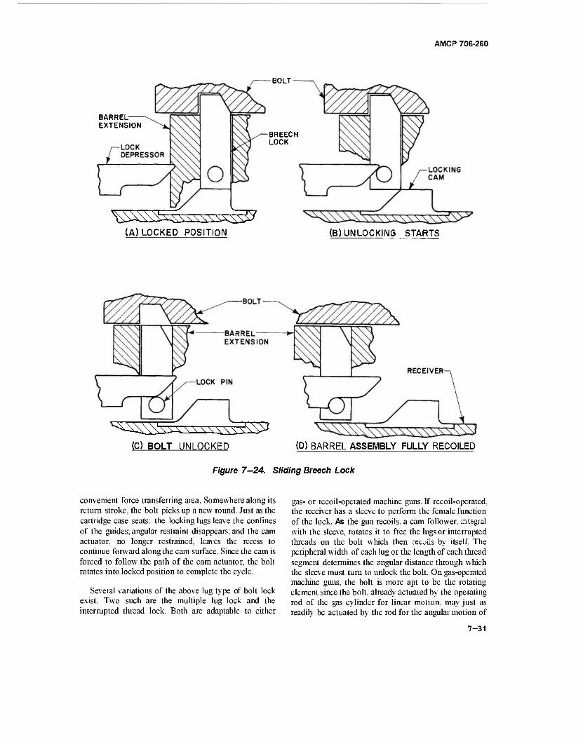
AMCP 706-260
BARREL EXTENSION
BOLT
BREECH LOCK
(A) LOCKED POSITION (B) UNLOCKING STARTS
(C) BOLT UNLOCKED (D) BARREL ASSEMBLY FULLY RECOILED
Figure 7—24. Sliding Breech Lock
convenient force transferring area. Somewhere along its return stroke, the bolt picks up a new round. Just as the cartridge case seats: the locking lugs leave the confines of the guides; angular restraint disappears; and the cam actuator, no longer restrained, leaves the recess to continue forward along the cam surface. Since the cam is forced to follow the path of the cam actuator, the bolt rotates into locked position to complete the cycle.
Several variations of the above lug type of bolt lock exist. Two such are the multiple lug lock and the interrupted thread lock. Both are adaptable to either
gas- or recoil-operated machine guns. If recoil-operated, the receiver has a sleeve to perform the female function of the lock. As the gun recoils, a cam follower, integral with the sleeve, rotates it to free the lugs or interrupted threads on the bolt which then recuils by itself. The peripheral width of each lug or the length of each thread segment determines the angular distance through which the sleeve must turn to unlock the bolt. On gas-operated machine guns, the bolt is more apt to be the rotating element since the bolt, already actuated by the operating rod of the gas cylinder for linear motion, may just as readily be actuated by the rod for the angular motion of
7-31
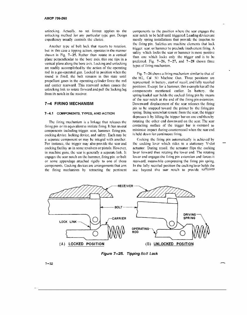
AMCP 706-260
unlocking. Actually, no set format applies to the unlocking method for any particular type gun. Design expediency usually controls the choice.
Another type of bolt lock that resorts to rotation, but in this case a tipping action, operates in the manner shown in Fig. 7-25. Rather than rotate in a vertical plane perpendicular to the bore axis, this one tips in a vertical plane along the bore axis. Locking and unlocking are readily accomplished by the action of the operating rod in a gas-operated gun. Locked in position when the round is fired, the bolt remains in this state until propellant gases in the operating cylinder force the rod and carrier rearward. This rearward action causes the unlocking link to rotate forward and pull the locking lug from its notch in the receiver.
7-4 FIRING MECHANISM
7-4.1 COMPONENTS, TYPES, AND ACTION
The firing mechanism is a linkage that releases the firing pin or its equivalent to initiate firing. It has several components including trigger, sear, hammer, firing pin, cocking device, locking device, and safety. Each may be a separate component or may be integral with another. For instance, the trigger may also provide the sear and cocking facility as in some revolvers or pistols. However, in machine guns, the sear is generally a separate link. It engages the sear notch on the hammer, firing pin, or bolt or some appendage attached rigidly to one of those components. Cocking devices are arrangements that arm the firing mechanism by retracting the pertinent
components to the position where the sear engages the sear notch to be held until triggered. Loading devices are mostly spring installations that provide the impetus to the firing pin. Safeties are machine elements that lock trigger, sear, or hammer to preclude inadvertent firing. A safety which locks the sear or hammer is more positive than one which locks only the trigger and is to be preferred. Fig. 7-26, 7-27, and 7-28 shown three types of firing mechanism.
Fig. 7-26 shows a firing mechanism similar to that of the M2, Cal .SO Machine Gun. Three positions are represented: in battery, start of recoil, and fully recoiled positions. Except for a hammer, this example has all the components mentioned earlier. In battery, the spring-loaded sear holds the cocked firing pin by means of the sear notch at the end of the firing pin extension. Downward displacement of the sear releases the firing pin to be snapped toward the primer by the firing pin spring. Being somewhat remote from the sear, the trigger depresses it by lifting the tripper bar on one end thereby rotating the other end downward on the sear. The sear contacting surface of the trigger bar is cammed to minimize impact during counterrecoil when the sear end is held down for continuous firing.
Cocking the firing pin automatically is achieved by the cocking lever which rides in a stationary V-slot actuator. During recoil, the actuator flips the cocking lever forward thus rotating the lower end. The rotating lower end engages the firing pin extension and forces it rearward, meanwhile compressing the firing pin spring. In the fully recoiled position the cocking lever holds the sear beyond the sear notch to provide sufficient
(A) LOCKED POSITION (B) UNLOCKED POSITION
Figure 7—25. Tipping Bolt Lock
7-32
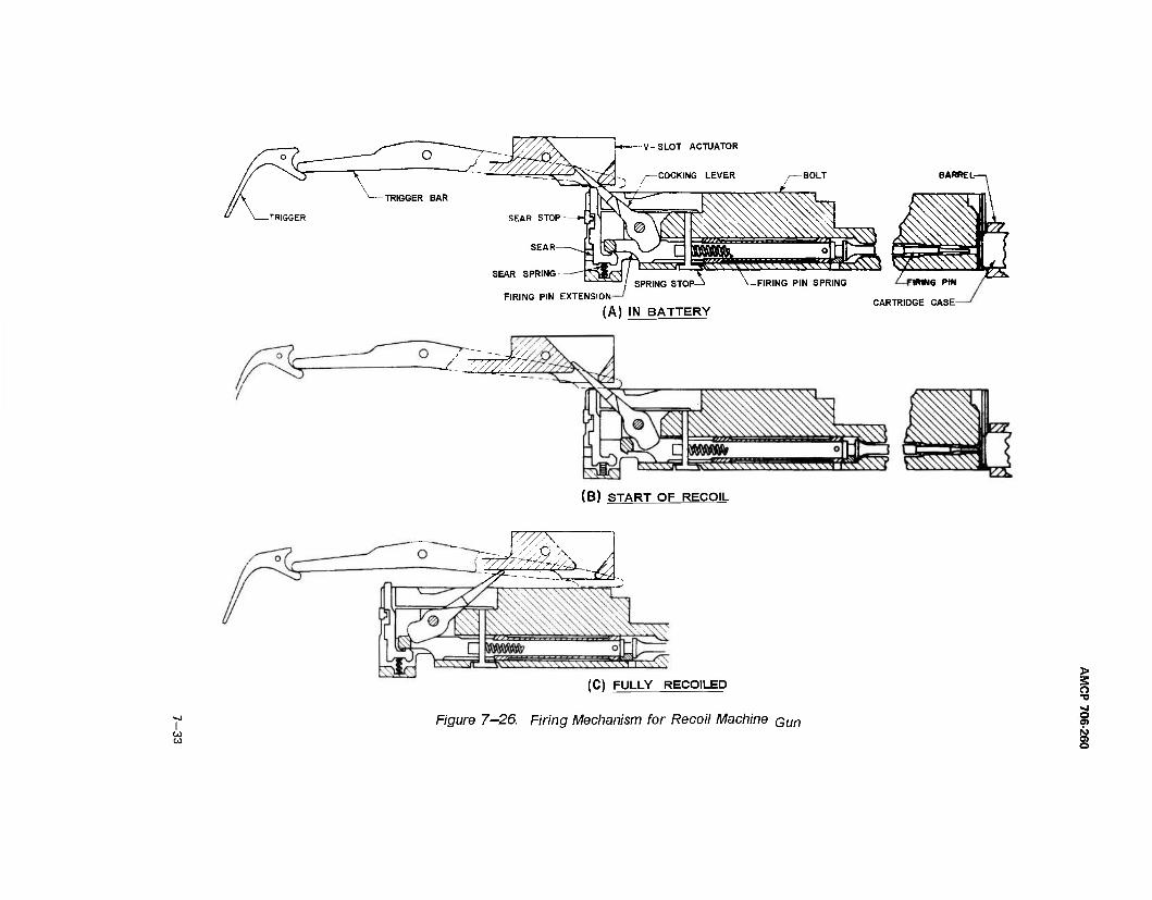
SPRING STOP-
FIRING PIN EXTENSION-
(A) IN BATTERY CARTRIDGE CASE-
(B) START OF RECOIL
CO CO
ww.
(C) FULLY RECOILED
Figure 7-26. Firing Mechanism for Recoil Machine Qun
o ■o
o 01 IS) o> o
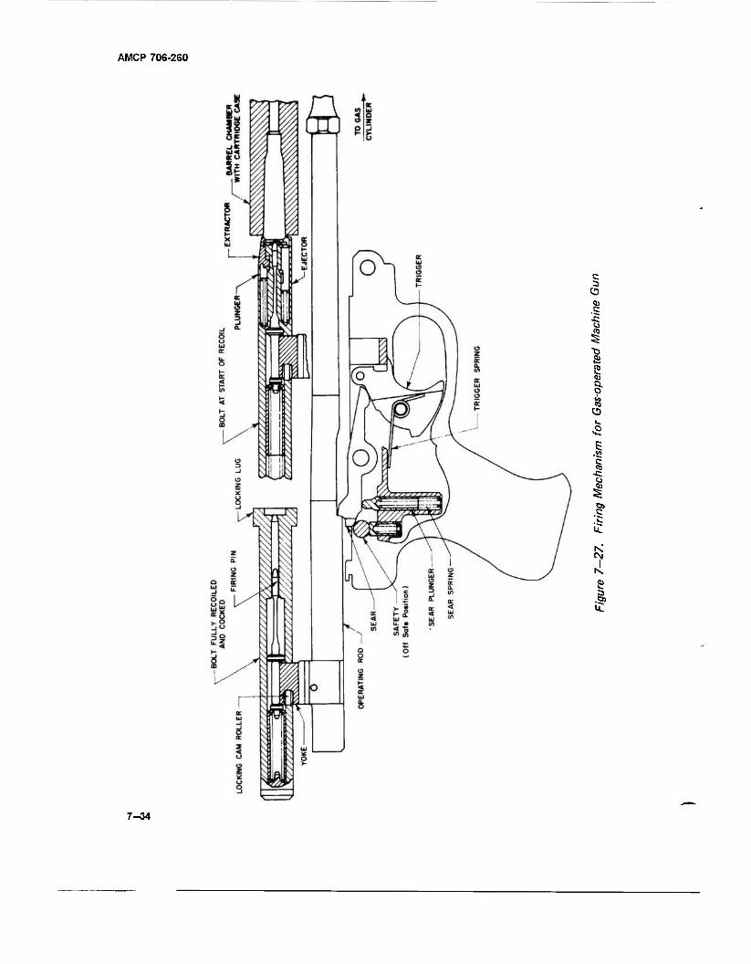
AMCP 706-260
c CO
<u
■s i
S §■ it
CO V.
5
£
CM
»I s 1
7-34
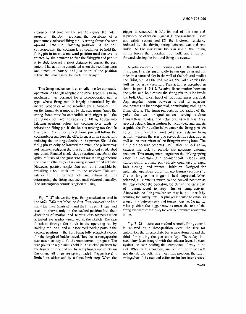
AMCP 706-260
clearance and time for the sear to engage the notch properly thereby reducing the possibility of a prematurely released firing pin. A spring forces the sear upward into the latching position. As the bolt counterrecoils, the cocking lever continues to hold the firing pin in its most rearward position until the lever is rotated by the actuator to free the firing pin and permit it to slide forward a short distance to engage the sear notch. This action is completed when the recoiling parts are almost in battery and just short of the position where the sear passes beneath the trigger.
This firing mechanism is essentially one for automatic operation. Although adaptable to other types, this firing mechanism was designed for a recoil-operated gun, a type whose firing rate is largely determined by the inertial properties of the recoiling parts. Another limit on the firing rate is imposed by the sear spring. Since the spring force must be compatible with trigger pull, the spring may not have the capacity of lifting the sear into latching position before the cocking lever tends to release the firing pin if the bolt is moving too fast. In this event, the unrestrained firing pin will follow the cocking lever and lose the effectiveness of its spring, thus reducing the striking velocity on the primer. Should the filing pin velocity be lowered too much, the primer may not initiate, reducing the gun to inadvertent single shot operation. Planned single shot operation depends on the quick reflexes of the gunner to release the trigger before the sear hits the trigger bar during second round activity. However, positive single shot control is available by installing a bolt latch unit to the receiver. This unit latches to the recoiled bolt and retains it, thus interrupting the firing sequence until released manually. The interruption permits single shot firing.
Fig. 7—27 shows the type firing mechanism used in the M60, 7.62 mm Machine Gun. Two views of the bolt show the travel limits of it and the firing pin. Trigger and sear are shown only in the cocked position but their directions of motion and relative displacements when actuated are readily visualized in the sketch. The sear functions through the notch in the operating rod by holding rod, bolt, and all associated moving parts in the cocked position — the bolt being fully retracted except for the length of buffer travel. Here the sear engages the sear notch to stop all further counterrecoil progress. The sear pivots on a pin and is held in the cocked position by the trigger on one end and by sear plunger and safety on the other. All three are spring loaded. Trigger travel is limited on either end by a fixed limit stop. When the
trigger is squeezed, it lifts its end of the sear and depresses the other end against (1) the resistance of sear and safety springs and (2) the frictional resistance induced by the driving spring between sear and sear notch. As the sear clears the sear notch, the driving spring forces the operating rod, bolt, and firing pin forward; closing the bolt and firing the round.
A yoke connects the operating rod to the bolt and firing pin. It is fastened rigidly to the operating rod but rides in a cammed slot in the wall of the bolt and cradles the firing pin. As the rod moves, the yoke carries the bolt in the same direction. This action is described in detail in par. 4—3.1.2. Relative linear motion between the yoke and bolt causes the firing pin to slide inside the bolt. Only linear travel of the firing pin is essential. Any angular motion between it and its adjacent components is inconsequential, contributing nothing to firing efforts. The firing pin rests in the saddle of the yoke, the two integral collars serving as force transmitters, guides, and retainers. As retainers, they prevent relative linear motion between yoke and pin. As a guide, the front collar helps center the firing pins. As force transmitters, the front collar serves during firing activity whereas the rear one serves during retraction as well as the transmitter of the firing pin spring force. The firing pin opening becomes useful after the locking lug engages the lock to provide the necessary external reaction. This arrangement augments the driving spring effort in maintaining a counterrecoil velocity and, subsequently, a firing pin velocity conducive to rapid bolt closing and primer initiation. Designed for automatic operation only, this mechanism continues to fire as long as the trigger is held depressed. When released, all elements return to the cocked position as the sear catches the operating rod during the early part of counterrecoil to stop further firing activity. Afterwards the firing mechanism may be put on safe by rotating the safety until its plunger is seated to establish a rigid link between sear and trigger housing. No matter what position the trigger now assumes, the rest of the firing mechanism is firmly locked to eliminate accidental firing.
Fig. 7-28 illustrates a method whereby firing control is achieved by a three-position lever: the first for automatic, the intermediate for semi-automatic, and the third for putting the gun on safety. The safety is a secondary lever integral with the selector lever. It bears against the sear, holding that component firmly in the slot. When in this position, any pull on the trigger will not disturb the bolt. In either firing position, the safety swings free of the sear and offers no further interference.
7-35
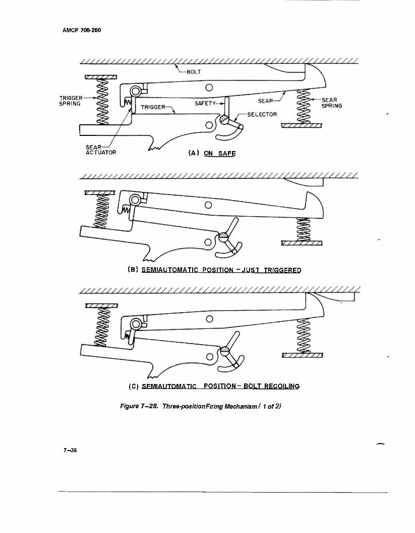
AMCP 706-260
TRIGGER »■< SPRING
SEAR ACTUATOR
-SEAR SPRING
(A) ON SAFE
(B) SEMIAUTOMATIC POSITION - JUST TRIGGERED
(C) RFMIAIITDMATIC POSITION - BOLT RECOILING
Figure 7-28. Three-position Firing Mechanism ( 1 of 2)
7-36
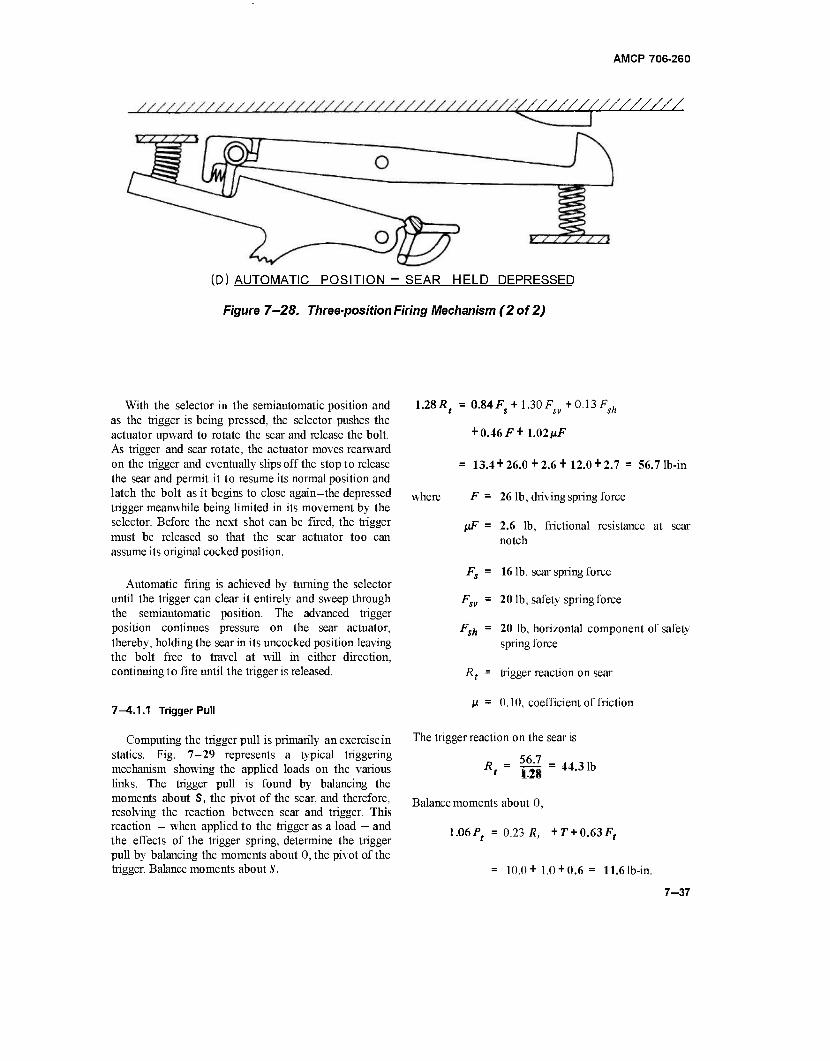
AMCP 70S-260
vyyy///////////
(D) AUTOMATIC POSITION - SEAR HELD DEPRESSED
Figure 7—28. Three-position Firing Mechanism (2 of 2)
With the selector in the semiautomatic position and as the trigger is being pressed, the selector pushes the actuator upward to rotate the sear and release the bolt. As trigger and sear rotate, the actuator moves rearward on the trigger and eventually slips off the stop to release the sear and permit it to resume its normal position and latch the bolt as it begins to close again—the depressed trigger meanwhile being limited in its movement by the selector. Before the next shot can be fired, the trigger must be released so that the sear actuator too can assume its original cocked position.
Automatic firing is achieved by turning the selector until the trigger can clear it entirely and sweep through the semiautomatic position. The advanced trigger position continues pressure on the sear actuator, thereby, holding the sear in its uncocked position leaving the bolt free to travel at will in either direction, continuing to fire until the trigger is released.
7—4.1.1 Trigger Pull
Computing the trigger pull is primarily an exercise in statics. Fig. 7-29 represents a typical triggering mechanism showing the applied loads on the various links. The trigger pull is found by balancing the moments about S, the pivot of the sear, and therefore, resolving the reaction between sear and trigger. This reaction — when applied to the trigger as a load — and the effects of the trigger spring, determine the trigger pull by balancing the moments about 0, the pivot of the trigger. Balance moments about S.
1.28/?, = 0.84^+1.30/^+0.13^
+ 0.46^+1.02//^
= 13.4 + 26.0+2.6+12.0 + 2.7 = 56.7 lb-in
where F = 26 lb, driving spring force
liF = 2.6 lb, frictional resistance at sear notch
Fs = 16 lb, sear spring force
Fsv = 201b, safety spring force
Fsh = 20 lb, horizontal component of safety spring force
R{ = trigger reaction on sear
M = 0.10, coefficient of friction
The trigger reaction on the sear is
56.7 R. = 44.31b 1.28
Balance moments about 0,
1.06Pt = 0.23 R, +T+0.63F,
= 10.0+ 1.0 + 0.6 = 11.6 lb-in.
7-37
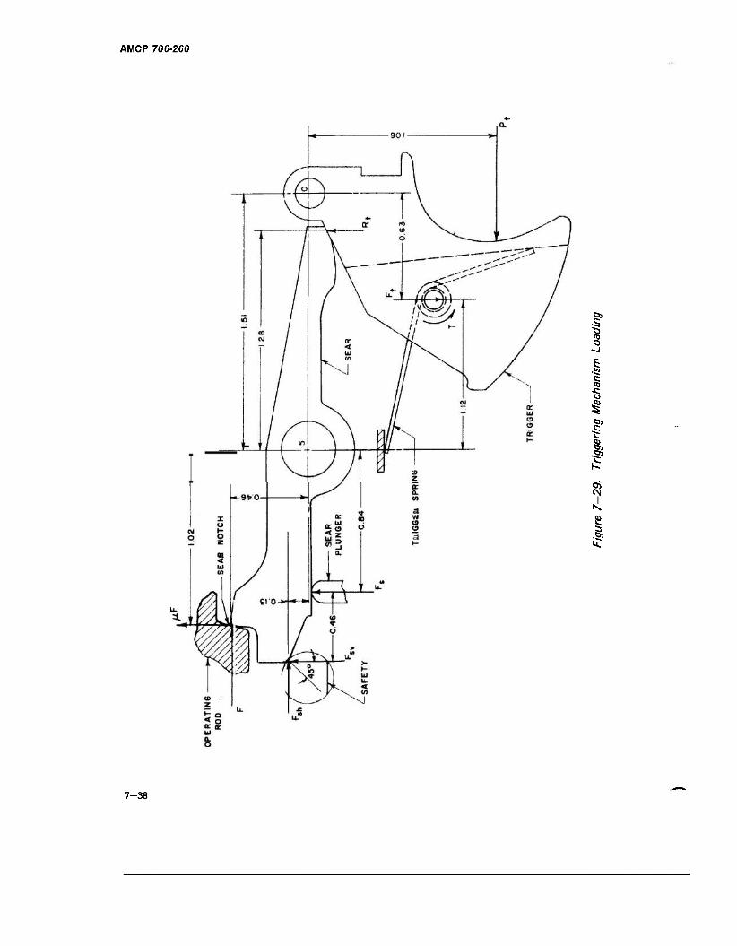
AMCP 706-260
1 o
| £ (0
"6 I .§* c
.§5
8
.a
7-38
AMCP 706-260
where T = 1.0 lb-in, applied torque of trigger spring, and Pt is the trigger pull.
T F —L-
t = 1.12
= 0.89 lb, vertical reaction of trigger spring pin
The trigger pull becomes
p* - ii ~1091b
7—4.1.2 Firing Pin Design
Design criteria for firing pins are published elsewhere22 but two basic requirements are essential for all percussion primers. A minimum amount of energy must be transmitted from firing pin to primer at a minimum striking velocity of 7 ft/sec. The energy is specified in inch-ounces. An upper limit of striking velocity also is specified to avoid puncturing the primer cap. Specifying both energy and velocity removes considerable control over the dynamics of a mechanism; control that normally should be available. For a given firing pin energy, the corresponding striking velocity is
1E_ (7-50)
where
E = energy available
M„ g
= equivalent mass of the moving parts
We = equivalent weight of the moving parts
A compressed coil spring provides the energy.
(7-51)
where Fm = FQ t Kx, maximum spring force (in initial position)
F0 = minimum spring force (in final position)
K = spring constant
x = length of travel
E = spring efficiency
The time elapsed during firing pin action according to Eq. 2-27
'M F (7-52)
Because Me is generally small and E relatively large, the striking velocity r will be large. If v exceeds safe limits, the energy should be reduced to its lower limit and the weight of the firing pin increased to proportions that are compatible with good design. Table 7—2 lists various combinations of design parameters and how they affect the velocity and time. The firing pin energy will be held constant at£" = 60 in-oz. The efficiency of the firing pin spring system is also a constant at E = 0.80. By holding the equivalent weight constant and varying the spring characteristics to be compatible with the distance, the time interval increases with respect to distance but the terminal velocity remains constant. But when weight varies and distance is constant, the time increases while terminal velocity decreases. A review of the data in Table 7—2 indicates a wide latitude in spring selection exists for any given firing pin weight. The tabulated data also show that the striking velocity can be lowered only by increasing the firing pin weight. A word of caution should be introduced here. An increase in weight may not be helpful because the vibration of the firing pin mechanism may be out of phase with the mechanical action. Past experience has proved that correcting this type of disorder can be achieved only by reducing the weight of the firing pin; altering the spring characteristics was not effective.
7-6 LINKS
Early machine gun ammunition belts were made of cloth fabric but the susceptibility of cloth to adverse climatic conditions led to its replacement by the modern metallic link belts. The metal belts consist of many links joined in series by some type of mechanical fastener, such as a pin. Many belts use the rounds themselves as pins. In addition to being able to survive most climatic conditions, the metal links have other desirable characteristics, two of which are: (1) the strength needed to transmit the high accelerations imposed by the loading devices of rapid fire guns, and (2) the ability to extend belt lengths quickly by merely joining the last link of one to the first link of another belt.
7-39
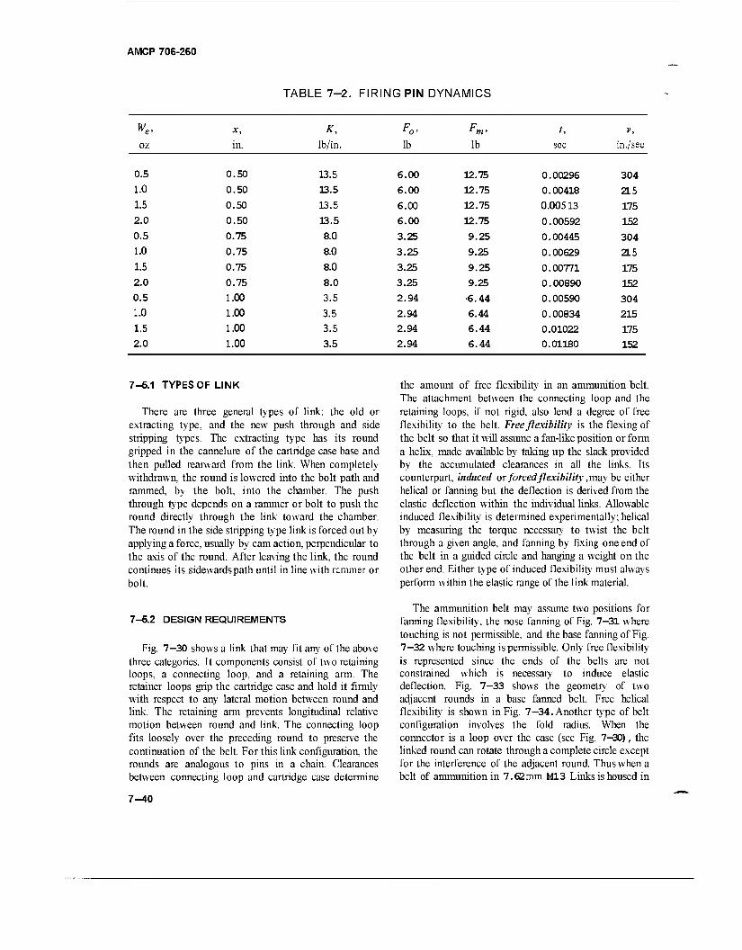
AMCP 706-260
TABLE 7-2. FIRING PIN DYNAMICS
w x, K, Fo- Fm> t, V,
OZ in. lb/in. lb lb sec in./sec
0.5 0.50 13.5 6.00 12.75 0.00296 304 1.0 0.50 13.5 6.00 12.75 0.00418 2L5 1.5 0.50 13.5 6.00 12.75 0.00513 175 2.0 0.50 13.5 6.00 12.75 0.00592 152 0.5 0.75 8.0 3.25 9.25 0.00445 304 1.0 0.75 8.0 3.25 9.25 0.00629 2L5 1.5 0.75 8.0 3.25 9.25 0.00771 175 2.0 0.75 8.0 3.25 9.25 0.00890 152 0.5 1.00 3.5 2.94 •6.44 0.00590 304 1.0 1.00 3.5 2.94 6.44 0.00834 215 1.5 1.00 3.5 2.94 6.44 0.01022 175 2.0 1.00 3.5 2.94 6.44 0.01180 152
7-6.1 TYPES OF LINK
There are three general types of link: the old or extracting type, and the new push through and side stripping types. The extracting type has its round gripped in the cannelure of the cartridge case base and then pulled rearward from the link. When completely withdrawn, the round is lowered into the bolt path and rammed, by the bolt, into the chamber. The push through type depends on a rammer or bolt to push the round directly through the link toward the chamber. The round in the side stripping type link is forced out by applying a force, usually by cam action, perpendicular to the axis of the round. After leaving the link, the round continues its sidewards path until in line with rammer or bolt.
the amount of free flexibility in an ammunition belt. The attachment between the connecting loop and the retaining loops, if not rigid, also lend a degree of free flexibility to the belt. Free flexibility is the flexing of the belt so that it will assume a fan-like position or form a helix, made available by taking up the slack provided by the accumulated clearances in all the links. Its counterpart, induced or forced flexibility, may be either helical or fanning but the deflection is derived from the elastic deflection within the individual links. Allowable induced flexibility is determined experimentally; helical by measuring the torque necessary to twist the belt through a given angle, and fanning by fixing one end of the belt in a guided circle and hanging a weight on the other end. Either type of induced flexibility must always perform within the elastic range of the link material.
7-6.2 DESIGN REQUIREMENTS
Fig. 7—30 shows a link that may fit any of the above three categories. It components consist of two retaining loops, a connecting loop, and a retaining arm. The retainer loops grip the cartridge case and hold it firmly with respect to any lateral motion between round and link. The retaining arm prevents longitudinal relative motion between round and link. The connecting loop fits loosely over the preceding round to preserve the continuation of the belt. For this link configuration, the rounds are analogous to pins in a chain. Clearances between connecting loop and cartridge case determine
The ammunition belt may assume two positions for fanning flexibility, the nose fanning of Fig. 7—31 where touching is not permissible, and the base fanning of Fig. 7—32 where touching is permissible. Only free flexibility is represented since the ends of the belts are not constrained which is necessary to induce elastic deflection. Fig. 7—33 shows the geometry of two adjacent rounds in a base fanned belt. Free helical flexibility is shown in Fig. 7—34. Another type of belt configuration involves the fold radius. When the connector is a loop over the case (see Fig. 7—30), the linked round can rotate through a complete circle except for the interference of the adjacent round. Thus when a belt of ammunition in 7.62mm M13 Links is housed in
7-40
AMCP 706-260
Figure 7—30. Ammunition Link, Cal .50 Round
a magazine or storage container (Fig. 7—35), little space is wasted since the belt can be stacked in horizontal rows. When the connector does not wrap around the case but instead merely joins the retaining loops of adjacent links, the rotation of one round about its neighbor is severely limited since the rotation center is near the case surface instead of being at the axis of the round. Ammunition belts made of links with this type connector will have some waste space when stored (see Fig 7—36 for 7.62 mm links). Another type connector, called a connecting member, operates similarly to a universal joint, i.e., it permits rotation between links about two perpendicular axes. All belts, so equipped, have unlimited free flexibility.
Initial link design is based on past experience. Belt strength is the most important requirement, to be followed closely by retention capability. Forces imposed on the belt are determined by the type of feed system (drum, chute, magazine) and the feed accelerations. Deflections in the ,links and, therefore, in the belt are not necessarily objectionable provided that round
retention is maintained. Any variation in pitch due to belt stretch is corrected by the holding pawl which insures constant pitch and, therefore, proper feeding. Later, the feeding pawl controls the round as it is extracted from the link.
Usage determines the configuration and type of link. If the belts are to be discarded after firing, disintegrating ones are used where the link drops from the belt immediately after the round is stripped from it, or is forced from the belt by the ejected cartridge case. If the belts are to be retained, then maintaining the empty belt as a unit may be desired. Open links may also be desired. They are good for camming out the round but are relatively poor with respect to belt strength, and round retention can be a problem. For this reason, tolerances are small, to insure a reasonable consistency in retention loads. Should these loads prove to be too high, lightening holes (see Fig. 7-34) are made to provide more flexibility and less snap-in force when joining two belts. The snap-in technique is superior to and preferred over the older push-through technique. In contrast to
7-41
AMCP 706-260
is
I
7-42
AMCP 706-260
E E
to
is
I ►I
.1
-7/ t / JfUfilrlW*1
n
AMCP 706-260
Figure 7-33. Geometry of Fanning
open links, closed loop links provide excellent belt strength and retentivity. Extracting the round may be a bit more troublesome than that experienced for the open loop but if a removable cover is used to complete the loop, an effective open loop link can be had by first stripping off the cover thus exposing, the round to the extracting mechanism.
A unique means has been devised to protect electric primers from being initiated inadvertently. This hazard is usually associated with aircraft since radiation emanating from communication (radio), detection (radar), and fire direction (usually on shipboard) facilities are generally associated with air terminals. A compatible antenna, such as a screwdriver, with a different potential in the
7-44
established radiation field, may induce a spark at the primer to initiate it. This hazard is primarily a ground handling one which is most prevalent during loading, connecting, or breaking ammunition belts. Effective protection is available through the use of a RADHAZ (radiation hazard) shown in Fig. 7—37. It is merely an extension of the link bent over the primer to form a cover. The primer is thus shielded from any metal rod that is brought near it.
After the initial design or subsequent modification, pilot lots are made to determine acceptability. The links are stamped out in the annealed state, then heat treated. Extreme care must be exercised to hold the small tolerances. The pilot lots are tested in accordance with operating requirements. One of these is the catenary test to check retention under shock loads. If a free span of belt exists in the installation, a similar length of belt is lifted at midspan to a prescribed height and released to approximate belt whip. If the link is found wanting from this or any of the other tests, the design is modified to strengthen the weak areas, and the manufacturing and testing procedures repeated until an acceptable link evolves. Because of its trial and error nature and because of demanding manufacturing technique, long periods of time, in some cases more than a year, are devoted to designing and producing a successful link.
7-6 MOUNTS
Machine gun mounts are either fixed to vehicles or rest on the ground. Generally simple structures, mounts are adapted to the required limits of elevation and traverse and must be stable within these limits. Stability is readily achieved on vehicles by merely fastening the mount rigidly to the structure of the vehicle. But, if it rests on the ground, a mount such as the tripod type must depend on geometric proportions for stability. For this type, stability is a function of recoil force, command height, total weight, and length of the legs. If traverse is limited to the spread of the rear legs, the position of any given angle of elevation is that at zero traverse.
7-6.1 GEOMETRY AND RESOLUTION OF FORCES
Fig. 7—38 shows the forces involved in the side view projection. Take moments about A and solve for the reaction at B
Rb = [^(W + F^sinÖ) - HFr cos öl \L (7-53)
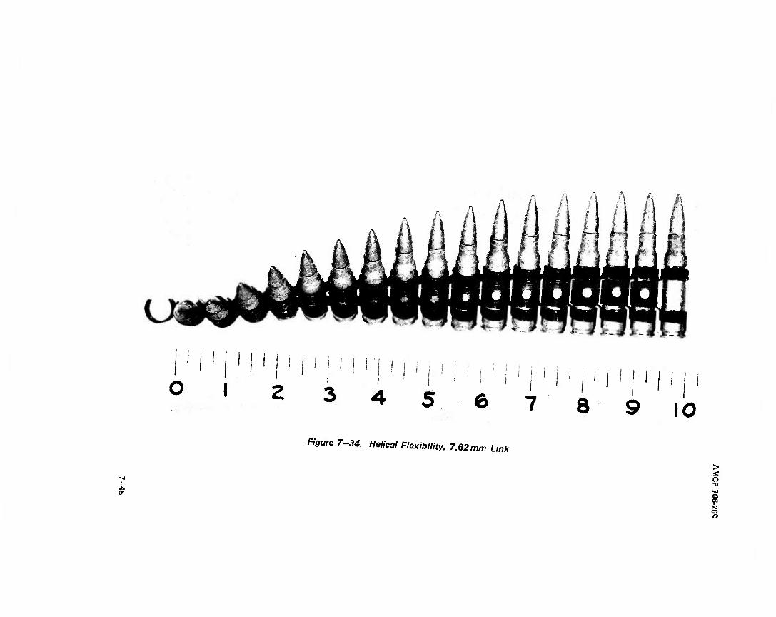
? > ." I •- i
mhlALliAlAL
'!'
8 10 Ffcure 7-M. Helical Flexibility, 7.62mm Link
•■J I o
•a
s o
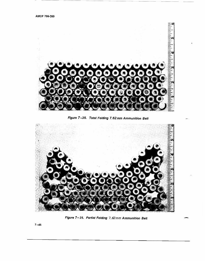
AMCP 706-260
Figure 7-35. Total Folding 7.62mm Ammunition Belt
Figure 7-36. Partial Folding 7.62mm Ammunition Belt
7-46
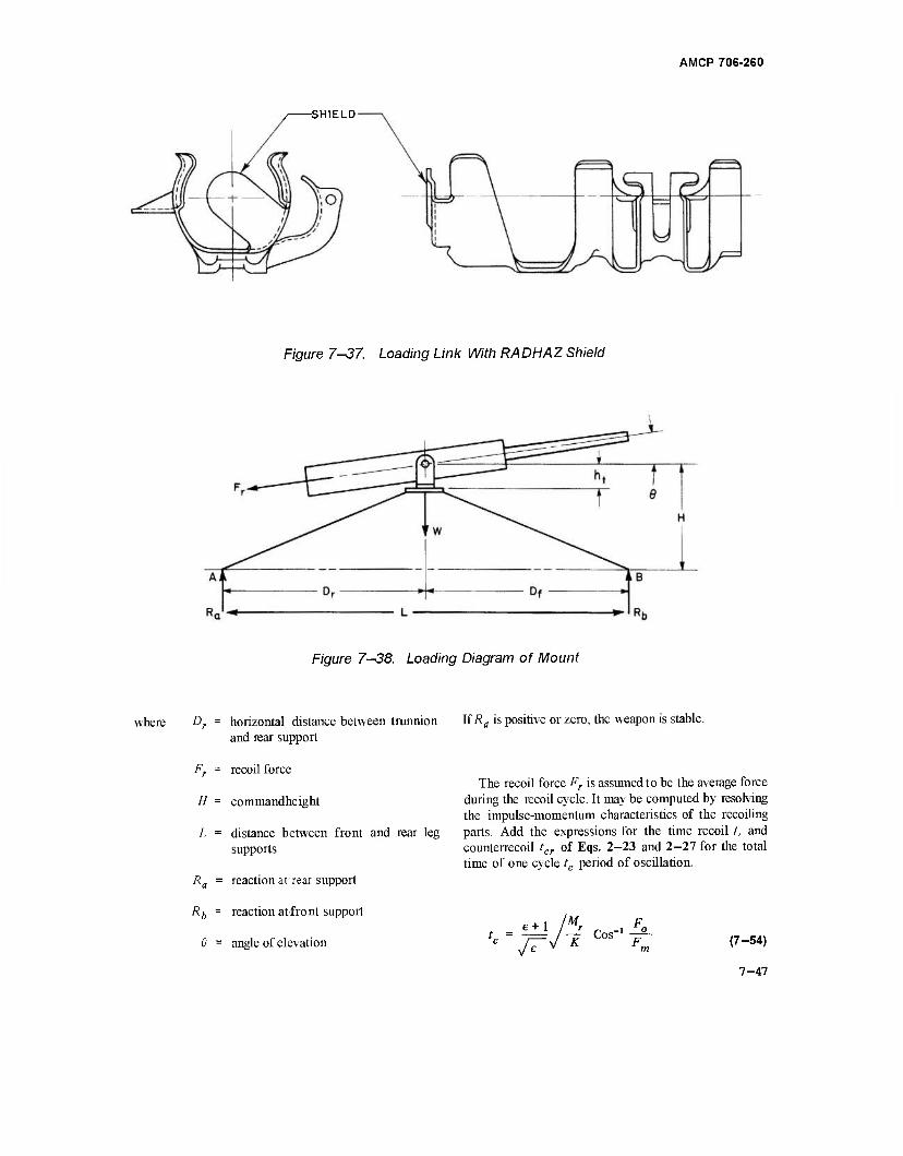
AMCP 706-260
-SHIELD
Figure 7-37. Loading Link With RADHAZ Shield
Figure 7—38. Loading Diagram of Mount
where Dr = horizontal distance between trunnion \£Ra is positive or zero, the weapon is stable, and rear support
Fr = recoil force The recoil force Fr is assumed to be the average force
during the recoil cycle. It may be computed by resolving the impulse-momentum characteristics of the recoiling
L = distance between front and rear leg parts. Add the expressions for the time recoil t, and counterrecoil tcr of Eqs. 2-23 and 2-27 for the total time of one cycle tc period of oscillation.
H = commandheight
supports
R„ = reaction at- rear support
Rb = reaction atfront support
6 = angle of elevation i+1
Mr F
It ^-t (7-54)
7-47
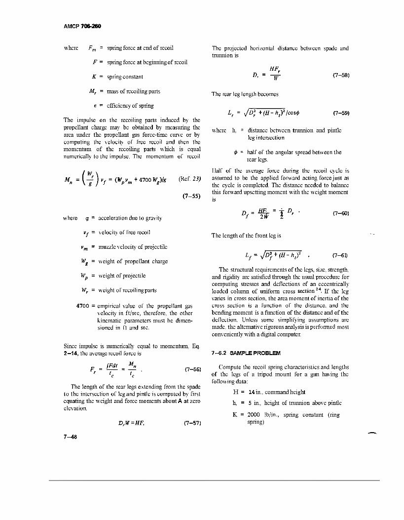
AMCP 706-260
where Fm = spring force at end of recoil
F = spring force at beginning of recoil
K = spring constant
Mr = mass of recoiling parts
e = efficiency of spring
The impulse on the recoiling parts induced by the propellant charge may be obtained by measuring the area under the propellant gas force-time curve or by computing the velocity of free recoil and then the momentum of the recoiling parts which is equal numerically to the impulse. The momentum of recoil
M. n = (7 ) "/ = OV» + 47°° WZ>lg (Ref 23)
(7-55)
where g = acceleration due to gravity
Vf = velocity of free recoil
vm = muzzle velocity of projectile
Wg = weight of propellant charge
Wp = weight of projectile
Wr = weight of recoiling parts
4700 = empirical value of the propellant gas velocity in ft/sec, therefore, the other kinematic parameters must be dimen- sioned in ft and sec.
Since impulse is numerically equal to momentum, Eq. 2—14, the average recoil force is
_ fFdt (7-56)
The length of the rear legs extending from the spade to the intersection of leg and pintle is computed by first equating the weight and force moments about A at zero elevation.
The projected horizontal distance between spade and trunnion is
HFf D'= -r
The rear leg length becomes
(7-58)
LT = JD) +(H-ht)2/cos<t> (7-59)
where h, = distance between trunnion and pintle leg intersection
$> = half of the angular spread between the rear legs.
Half of the average force during the recoil cycle is assumed to be the applied forward acting force just as the cycle is completed. The distance needed to balance this forward upsetting moment with the weight moment is
D = ÄE. = f Dr Uf ^lW 1 r
The length of the front leg is
(7-60)
Lf= jD} + (H-hf (7-61)
The structural requirements of the legs, size, strength, and rigidity are satisfied through the usual procedure for computing stresses and deflections of an eccentrically loaded column of uniform cross section24. If the leg varies in cross section, the area moment of inertia of the cross section is a function of the distance, and the bending moment is a function of the distance and of the deflection. Unless some simplifying assumptions are made, the alternative rigorous analysis is performed most conveniently with a digital computer.
7-6.2 SAMPLE PROBLEM
Compute the recoil spring characteristics and lengths of the legs of a tripod mount for a gun having the following data:
H= 14 in, command height
5 in, height of trunnion above pintle
D,W =HF, (7-57)
h,
K = 2000 lb/in.; spring)
spring constant (ring
7-48
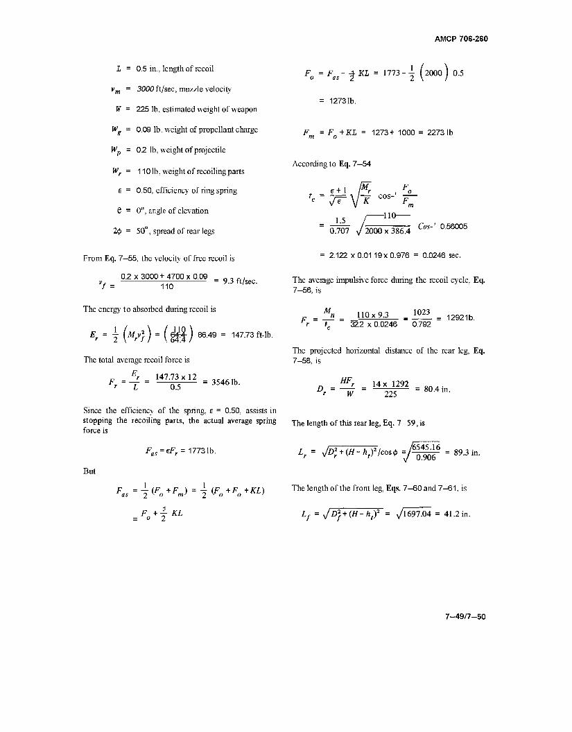
AMCP 70G-260
L = 0.5 in., length of recoil
vm = 3000 ft/sec, muzzle velocity
W = 225 lb, estimated weight of weapon
Wg = 0.09 lb, weight of propellant charge
Wp = 0.2 lb, weight of projectile
Wr = 1101b, weight of recoiling parts
£ = 0.50, efficiency of ring spring
e = 0", angle of elevation
2<j> = 50°, spread of rear legs
F = F ■ o as KL = 1773 i (2000) 0.5
12731b.
F„ = F„ +KL = 1273+ 1000 = 22731b
According to Eq. 7—54
t = e+1 rr K cos" K
-IK
0.707 J 2000x386.4 Cos-' 0.56005
From Eq. 7—55, the velocity of free recoil is
0.2 x 3000 + 4700 x 0.09 7 = 110
The energy to absorbed during recoil is
= 9.3 ft/sec.
Er = l(MrV}) = (M)86A9= 14773ft- lb.
The total average recoil force is
■> 147.73x12 r L 0.5
3546 lb.
Since the efficiency of the spring, E = 0.50, assists in stopping the recoiling parts, the actual average spring force is
= 2.122 x 0.01 19x 0.976 = 0.0246 sec.
The average impulsive force during the recoil cycle, Eq. 7-56, is
M F = —
r K
1023
32.2 x 0.0246 0.792 n 110x9.3 12921b.
The projected horizontal distance of the rear leg, Eq. 7-58, is
HFr 14 x 1292
The length of this rear leg, Eq. 7—59, is
But
Fas = eFr= 17731b.
F = -i (f +F ) = 4" {F +F +KL) as 2 ° m 2 ° °
F +-T- KL o 2
Lf = y/D*r + {H-h fleas* =J^ '6545.16 906
89.3 in.
The length of the front leg, Eqs. 7-60 and 7-61, is
Lf = y/DJ + (H-ht)2 = yi697.04 = 41.2 in.
7-49/7-50
AMCP 706-260
CHAPTER 8
LUBRICATION OF MACHINE GUNS
Conventional, good lubrication design practice is required in machine gun design. Excess, rather than insufficient, lubricant is to be avoided on most sliding parts. If the coat of oil or grease is too thick, dust will readily collect, cause excessive wear, and impede action sometimes to the extent of malfunction. Maintenance instructions stress this fact by emphasizing that all excess lubricant be wiped off all surfaces. Not all self- operating machine guns require reservoirs of lubrication. In some cases, the recoil adapter spring or the driving spring may be lubricated with a graphite grease. In electric or hydraulic-driven machine guns, the driving units are lubricated by applying grease or oil to the mov- ing parts which are usually protected from exposure to dirt by their housings.
A well-designed machine gun is inherently a readily lubricated one, particularly if only a thin coating of lubricant is needed on the sliding part. The lubricant is usually applied after cleaning, which procedure follows after prolonged firing or during periodic inspection and maintenance. Because of this practice, emphasis is generally placed on the lubricant rather than on specific design practices that are controlled by lubrication requirements.
8-1 GENERAL CONCEPT
The machine gun designer must be cognizant of the lubrication requirements for the sliding surfaces of his design. His primary objective is smooth surfaces coupled with his acquaintance with available lubricants, and their general properties and uses. If lubricant properties and required lubricating properties are compatible, the designer's problem is solved. If a proper lubricant is not available, a search for one must be made or the weapon relegated to limited specific conditions, which normally is undesirable. Another alternative involves auxiliary equipment such as heaters to keep the viscosity level of the lubricant in an acceptable range.
The lubrication of machine guns is usually confined to applying a thin film of oil, grease, or other material to sliding surfaces with the expectation that it will last until the next general cleaning time. Military Specifications define in detail the properties of available lubricants. Substitutes are acceptable only after extensive tests prove that the new product has all the necessary proper-
ties. The Specifications enumerate all known data from preparation to delivery and storage. A general outline is prepared for illustration.
1. SCOPE. Type of lubricant, general usage, and operating temperature range.
2. APPLICABLE DOCUMENTS
2.1 A list of Federal and Military Specifications supplementing the given specifications.
2.2 Standards prepared by accepted private organ- izations.
3. REQUIREMENTS
3.1 Qualification. The material must have passed qualifying tests.
3.2 Material. The ingredients of the material must conform to specification.
3.3 Physical and chemical requirements. Some of these are listed as flash point, pour point, viscosity at temperature limits, hydroelectric stability, oxidation stability, storage stability, rust prevention, gun performance, workman- ship (homogeneous, clear, and with no visibly suspended matter).
4. QUALITY ASSURANCE PROVISIONS
4.1 Specified inspection procedure.
4.2 Specifiedtests.
8-2 EXAMPLES OF LUBRICANTS
Unless a smoother finish is required, an RMS (rough machine surface) of 16 to 32 pin. will provide proper sliding action when covered with a thin layer of lubri- cant. However, under extremely adverse conditions, the designer may be helpless to cope with the sliding surface preparation. A number of activities associated with machine gun fire at high altitudes demonstrates the diffi- culties experienced in attempts to eliminate malfunc- tions. These activities deal with lubricant rather than design.
8-1
AMCP 706-260
During World War 11, high-flying airplanes had gun malfunction at temperatures below -20°F. This led to gun heaters, but the added weight and not complete reliability led to attempts to develop new lubricants that would correct the malfunctioning components' 7. The investigation yielded success in three operations. Low temperature exposure at high altitude followed by con- densation at warmer levels and again freezing after returning to high altitudes caused the triggering solenoid to become frozen in place. A free-moving solenoid was assured by spraying the unit with silicone oil to prevent the water condensate from collecting. The material is an open chain methyl silicone having a viscosity of 20 cSt at 77°F and 300 cSt at -65°?, and a pour point of -75°F. Dodecane phosphoric acid (0.1 percent by weight) was added for lubrication. This material was labeled NRL S-75-G interim. In the meantime, special attention to ammunition feeders led to "trouble-free lifetime lubrication" with the application of MIL-G-15793 (BuOrd) grease. Also, synthetic oil MIL-L-17353 (BuOrd) with 2 percent by weight of trecresyl phosphate for wear prevention was discovered to perform adequately for other moving parts of the gun.
In contrast, tests conducted with the Cal SO M3 Machine Gun, to prove the reliability of removing gun heaters, when lubricated with PD 500 oil gave totally negative results' 8. Remember that this oil made feasible the removal of heaters from the 20 mm M24A1 Gun without the gun malfunctioning at low temperatures. Apparently some inherent feature in each type of gun rendered acceptance and rejection in the particular weapon. Unfortunately, the tests were not sufficiently broad in scope to determine what design features were responsible.
A semi-fluid grease and an oil blend were developed with satisfactory performance at extreme temperatures for the M61 Multibarreled Gun' 9. Test results indicate that either lubricant satisfied all requirements, but the semi-fluid grease had longer life and was therefore selected as the lubricant for the M61 Gun.
Dry lubricants are recommended for slowly moving parts with relatively few cycles of operation. Tests of 18 resin systems pigmented with molybdenum disulfide were tested20. A pigment-to-resin ratio of 9:1 was found most effective. Epoxy-phenolic and epoxy-polyamide resin systems were best for both lubrication and storage stability.
8-3 CASE LUBRICANT
Although the gun designer is not directly involved with ammunition design, he is directly concerned with handling, loading, and extracting during firing. A smooth chamber is essential for extraction and a properly lubri- cated case is a decided asset. The lubricant should be a dry lubricant and should be applied at the factory. Considerable effort has been made to find suitable lubri- cants for this purpose. Some success has been achieved but continued search is still being advised, especially since two independent facilities are not in total agree- ment.
The Naval Research Laboratories conducted tests of brass and steel cartridge cases coated with films of polytetrafluoroethylene (Teflon)2 8. Results were out- standing in meeting required protection and lubrication properties. Laboratory results, later confirmed by firing tests, showed low friction and consequently less wear in gun barrels. Other desirable features include freedom from cartridge malfunction, no chamber deposits, decreased ice adhesion, and less chance of thermal "cook-off. Teflon can be applied to steel and brass ammunition by mass production methods. Its protective ability permits prebelting and packaging of ammunition since no further handling prior to use is necessary. Its supply is abundant and its cost reasonable. Thus the use of Teflon in this capacity seems ideal.
Aberdeen Proving Ground is more reserved in its appraisal of Teflon coating2'. Whether or not the techniques of applying the coatings were similar, those used at APG were not free of coating defects; a high cull rate existed. When tested with cartridges coated with microcrystalline wax, ceresin wax, and uncoated ammunition; the Teflon-coated wax showed many advantages but was also found wanting in some respects. Teflon and micro-wax had better extraction properties and Teflon left a much cleaner chamber than the others; micro-wax was second best. About SO percent of the Teflon-coated cases had slight bulges after extraction; other types also were similarly damaged but with no apparent significance attached to a definite choice. For dusted ammunition, the Teflon and micro-wax were far superior to the other two types with Teflon having a slight advantage, although when fired in a comparatively rough chamber, Teflon was outperformed by all. Reiter- ating, the gun designer, aside from providing smooth sliding surfaces, is almost totally dependent on the physical properties of the lubricant to make his gun per- form satisfactorily under all assigned conditions.
8-2
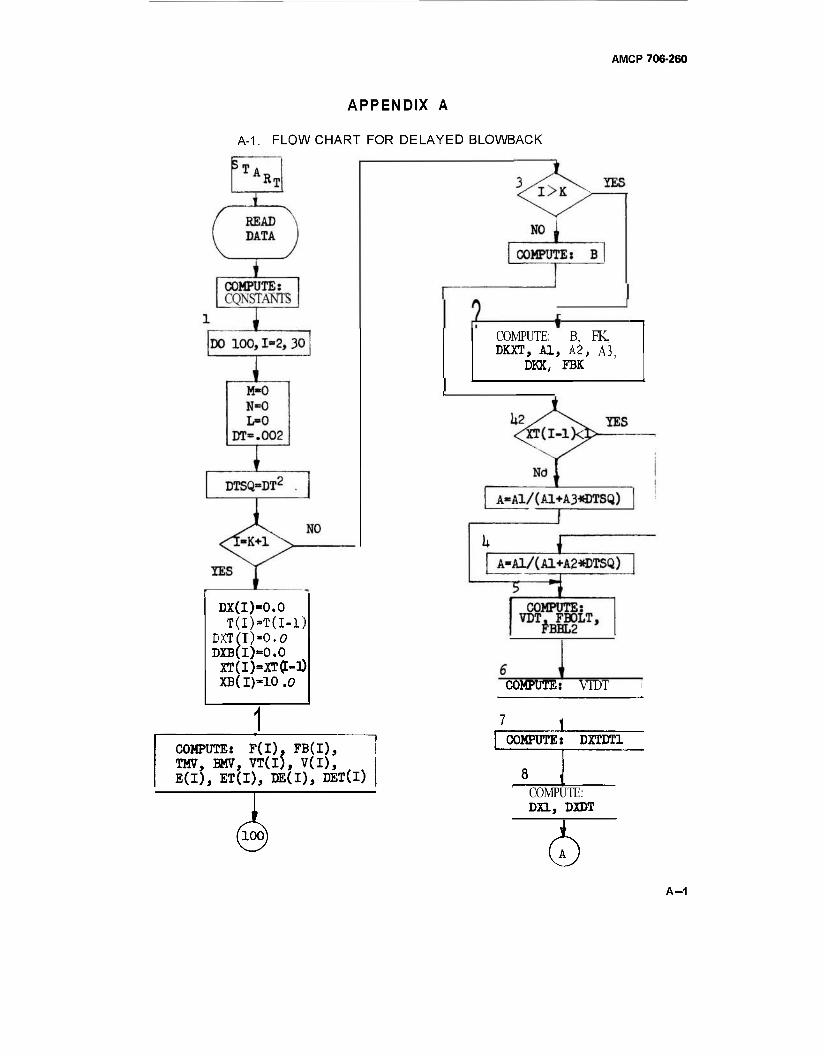
AMCP 706-260
APPENDIX A
A-1. FLOW CHART FOR DELAYED BLOWBACK
DX(I)-0.0 T(I)-T(I-1)
DXT(I)-0.O DXB(I)=0.0
XT(I)-XT(t-0) XB( I)*10 .0
COMPUTE: F(l). FB(I), TMV, BMV, VT(I), V(I), E(l), ET(I), DE(I), DET(I)
COMPUTE: B, FK. DOT, Al, A2, A3
DKX, FBK
COMPUTE: VTDT
J_ COMPUTE: DXTDT1
8 COMPUTE: DEL, DXDT
A-1
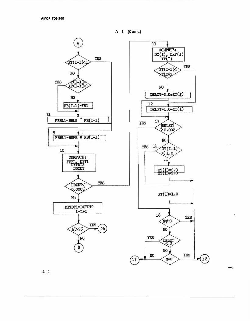
AMCP 706-260
A-1. (Con't.)
COMPUTE: DX(I), DXT(I)
XT(I)
A-2
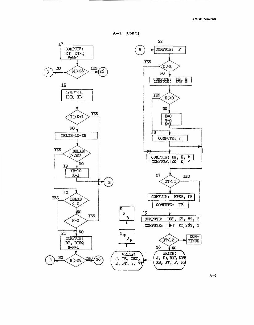
AMCP 706-260
A-1. (Con't.)
XL COMPUTE: DT, DTSQ M.=M+;
18
COMPUTE: DXB. XB
W N
COMPUTE: DE, E, V COMPUTE:I IM, il, V
COMPUTE: EPSB, FB
COMPUTE: FB
25 COMPUTE: PET, ET, VT, T
COMPUTE: D^T ET,2$T, T
WRITE: J, DE, DET, E, ET, V, VT
WRITE: J, DX,DXB,D3 XB, XT, F,
A-3
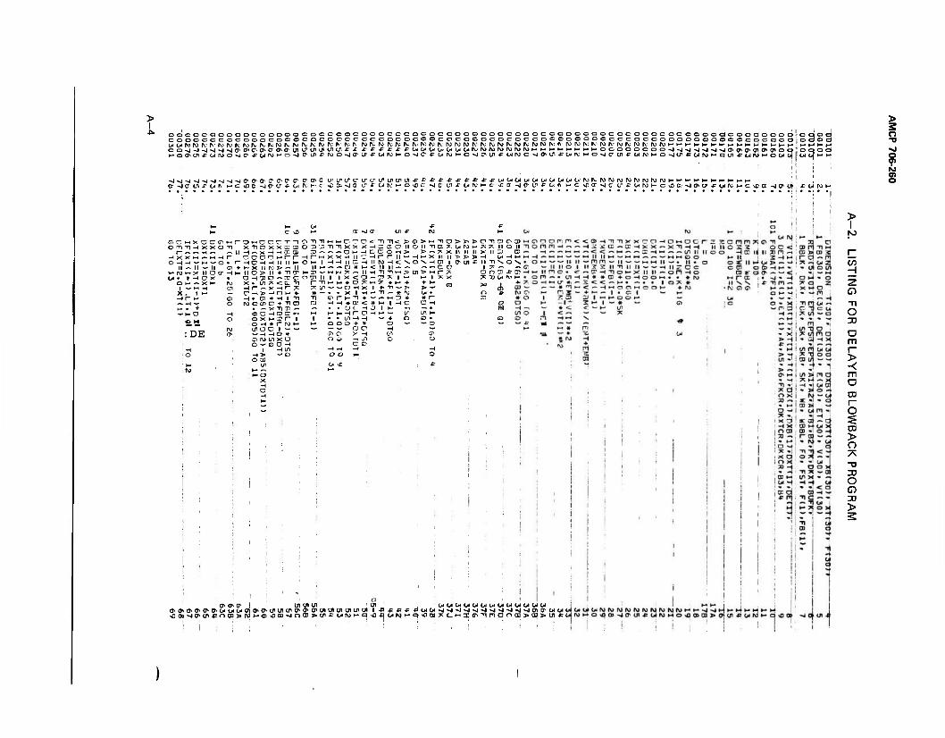
I OQOOCOOOOOOOOOOOCOCOOOCJOCOCOCOCOOOOOOOOaCOOC3COOOC5000COOOOOOOCOOOOC(COOdOOOÖ|oCIO< cooocococooococococccecccccicoooocococococioccocoooooocecacocaococtoacocacQcOt^' c-wrur^rc^ruivrviyrtteivKjfcrvf^N^^^^^r^
-J-J-J-J^J^J>J-J-JCrtr0^0-^04F'^O,C ^LPt^^7U^^^^WU1f*P*t*^t*4:wülWb.OlW0^0lO'O.'l\>^^IWI\)^)PJ^)N^MH^•HHHH^-HI- ' a3cei?c«fv*-cvcc^JCiri-fct,ii^»--c «cft-^o cn -F y ^ H o ID c -g c oi £ o< w H c vc c >i a ir f o< r ►- c %c a -J c uix-wruK-p^oa^c^crtxojtei-cxOcr^crufx-oiiviM
> s o
9 CO O)
I x n « •-< —i « _♦ — M — o « rnc l ^- it — If O + ** X > >- x it o (r -) i- no
. u H ~ x ^ -t;
> n ■ OJ O ■ 1/^ IK ■
■ Oh- I -H -t
r-i^-TM
►H »- O ™ "H -n x x *- -» O w X X -I II
11 cr CJ # i_« 1-. ;* ^- I I X <
(— t— # O CJ
C> <: "H -n<
HDCCH cnrni H 11 ro H < i- < 11 ti- ll H1T"H
*-■ H I- X II SO\HO) .~ — ~ CL
* .' + ■ ^ O
:DE
o x ►- 3 r~ r 1
yi D c 1 — — *-! — o c o +
j-»Ci x -
t X I *■ Tl — 1
1 *—-..-. !7) ■ J < * M I H t
-* O I 1- " C! -1 1- — L
?:oiMH?;7iiion X II II II X II 3) C II "> ■> > -4 Cfl-Hi— I IT'UlfllTlSON
U 17^ « ;* o r> en x 5? x 7;XUMH
00 ^
0s a» a* I u> tn ui
\Ooo-sio^tnx!Oc]>PJ^-Q*o)-Joa!>
m UUUUUUUUOIUUOIOI m ui in ui in ui 1 *^ucpwu-4>j>n>i>jNm^%iö)(j'WOi( (ji*üifwHq^Äoii\»i-q>Da»ÄCH3;(ji'nFian{nj»ai>ui*( 4 ö sp cb -j ff- en -P u rw
IU (V M h- ->| ^4 M »- i4 ►* M i- ►+
> I
c/3
0 Tl
o 3J
> -< m o I-
o CD > o 7\ -o O CD
>
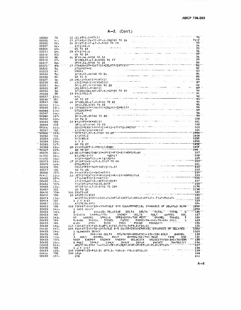
AMCP 706-260
A-2. (Con't.)
(30302 79. 00303 ÖU. 00305 61. 00307 62. 003 ID 83. 00311 8t. 00312 65. 00313 86. 00315 87. 00317 8d. 00321" 89. 00522 9u. 00323 91. 00324 92. 00326 93. 00327 94. 00330 95. 00531 96. 00333 97. 00334 9d. 00336 99. 00537 100. 00340" " 101. 00541 102. 00343 103. 00345 10t.
-00346 105. 00347 1ÜO. 00350 107. 00352 ioa. 00353 109. 00554 110. TT0356 in. 00357 112. 00360 " - 113; 00362 114. 00363 115. 00364 116.
~ 00365 117. 00366 lib.
"DC357 119. 00370 120. 00371 121. 0U372 lii. 00373 123. 00575 lit. 00376 125. 00577 120 00400 127. 0U4Ü1 12tl. 00402 129. 00403 130. 00404 131. 00405 132. 00407 133. 00410 134. 00412 135. 00414 13o. 00414 137. 00431 136. 00433 139. 00433 14u. 00433 141. 00433 142. 00433 143. 00453 144. 00433 145. 00434 140. 00435 147. 00435 148, 00435 149. 00435 1 5U. 00435 151. 00435 152. 00436 153. 00436 154. 00453 155. 0045"* 150. 00455 157.
12 ÜELXT=1.0-XTU) "" ~ " " 70" 13 IF(ABS(DELXT).GT.0.0021GO TO 16 71-2 14 IF (XT II-1) .LT. 1.0) GO TO 15 " "" ". "" 73
XT(I)=2.0 74 GO TO 18 " "" ""' --"'-- 75 15 XT(I>=1.0 76
GO TO 16 ..-..- - 77--
16 IF(N.NE.0)G0 10 18 78 IFtDELXT.LT.0.0)00 TO 17 " 79 IF(y.EG.0)6O TO 18 80
17"CT=AD5CDT*<DXTfI7 + DELXT7/TjXTrm 81^ UTS&=DT**2 82 "V,=M+1 " '" —. —- - SJ
IF(M.GT.2b)G0 TO 26 84 GO TO 3 . . -. . . — g5-
18 OXBU)=DXlI)+l.iXT(I> 86
X3(IT=XBII-U*-0XB(I) " 8T" IFII.GT. IK+l) )GO TO 22 88 UELXß=10.0-XßlI) " "" 89 IFCABMDELXB) .GT.0.U02)GO TO 20 90
19 XB(I)=10.0 -- - '■ 91 K=I 92 GO TO 22 " " 93"
20 IF(DELXB.LT.0.0IGO TO 21 94 IFUJ.EQ.OIGO TO 22 " - " ■" ■" 95
21 CT=ABS(DT*<[)XD<I)+DELXB>/DXB<I> > 96 DTSQ=DT**2 "~ 97 N=N+1 98. IF(N.GT.25>G0 TO 26 ~ 99" GO TO 3 100
22 F(I>=FO+SK*XB(I> "- "- 101 IFU.GT.KJGO TO 23 102 DE(I)=DXB(I)*(F(I)+F(I-lM/12.0*EPSr - - " -------- 103" E( I)=E( I-D-DEI I) 104
"T.FTETTT.GT.0.0TGO" TO"28" ; IflSA— E(I)=0.0 1056 V(I)=0.0" -- 105C" K = I 1050 GO TO 27 10SC—
28 V(I)=SGRT12.0*E(I)/EMB) 105F GO TO "2T " 106
23 DE(I>=ABS<DXBlI> + (FU>+FlI-l))*EPS/2.0> 107 E(D=E(I-1) «-DEU' 108" VlI)=-SGKTl2.u*E(I>/EN'B> 109
27 IFIXTU-U.LT.I.OIGO TO 24 ITO" EPSb=EPST 111 FB(I>=FST-SKT*IXT(D-1.0» TI2" GO TO 25 113
24 FaiIl=FBU)-SKB*XT<I) " " Tit"" 25 L.ET(II=CXT U>*(F3(I-l)+Fb(I> )*EPSB/2.0 115
ET(I)=ETU-1)+0ET(I> "'" TT6" \zTlI)=SOKTI2.u*ET(I)/EMT) 117 T(I)=TCI-l)+1000.0»nT """" " ITS" IF(XTII).LT.2.0IGO TO 100 119A GO TO 26 I19B
100 CONTINUE 120 26 fcRITE(6ilC2) TZT"
WRITE16.1Ü3) (J.DXU) »DXBU1 .DXT(J) » XB (J) t XT (J ) » F(J)»FB<J> > 122 1 J = I»I) T23 WRITE(6»104) 124
102 F0RMAT(lHl/12X»57HTABLf 2-5 COUNTFRRECOIL DYNAMICS OF DELAYED SLOW "125A 1 BACK GUw// 125B 2 14X-63H RELATIVE DELTA DELTA TOTAL ~ TOTAL " D \Zb 3RIVIN6 >,ARRtL/77H INCRE- DELTA BOLT BARREL BOL 127 4T BARREL SPRING SPRING/6X.70H MERT "TRAVEL TRAVEL T 128 5RAVEL TRAVEL TRAVEL FORCE FORCE/flX»1HI»7X.60H INCH I 129 6NCH INCH INCH INCH POUND POUND//) 130
1L)3 FORMAT(I9.F12.3»2F9.3iFlLi.3»F9.3.F9.2iF10.1) 131 104 FORMAT nHl/9X>62HTA3LE 2-5 C0NTD-7:T!UNTERR"CöTL""DYNAMTCS" 5F DECAYED "T3ZA""
1 BLOIn'BACK GUN// 132B 2 25X.14H DELTA DELTA/6X.6HINCRE-» 13X. 53R" BOLT BARREL "133 3 BOLT BArtREL BOLT BARREL/6X.74H MLNT TIME ENE 134 4RGY ENERGY ENERGY ENERGY VELOCITY "VEL0CITY7B* rTHI »7XVB3H 135 5 MSEC IN-LB IN-LB IN-LB IN-LB IN/SEC IN/SEC//) 136
WRITE (6. 105) (JiTlJJJDEUI iDET!J)"rE("T>".T;T<J)VV(jr,VTtJ)"»" 137" 1 J - 1.1) 138
105 FORMAT!19.F12.2r 2F9.1. F10.1» F9.1V2FI0 .1) "~ "139 199 STOP 140
END " ' '" 141
A-5
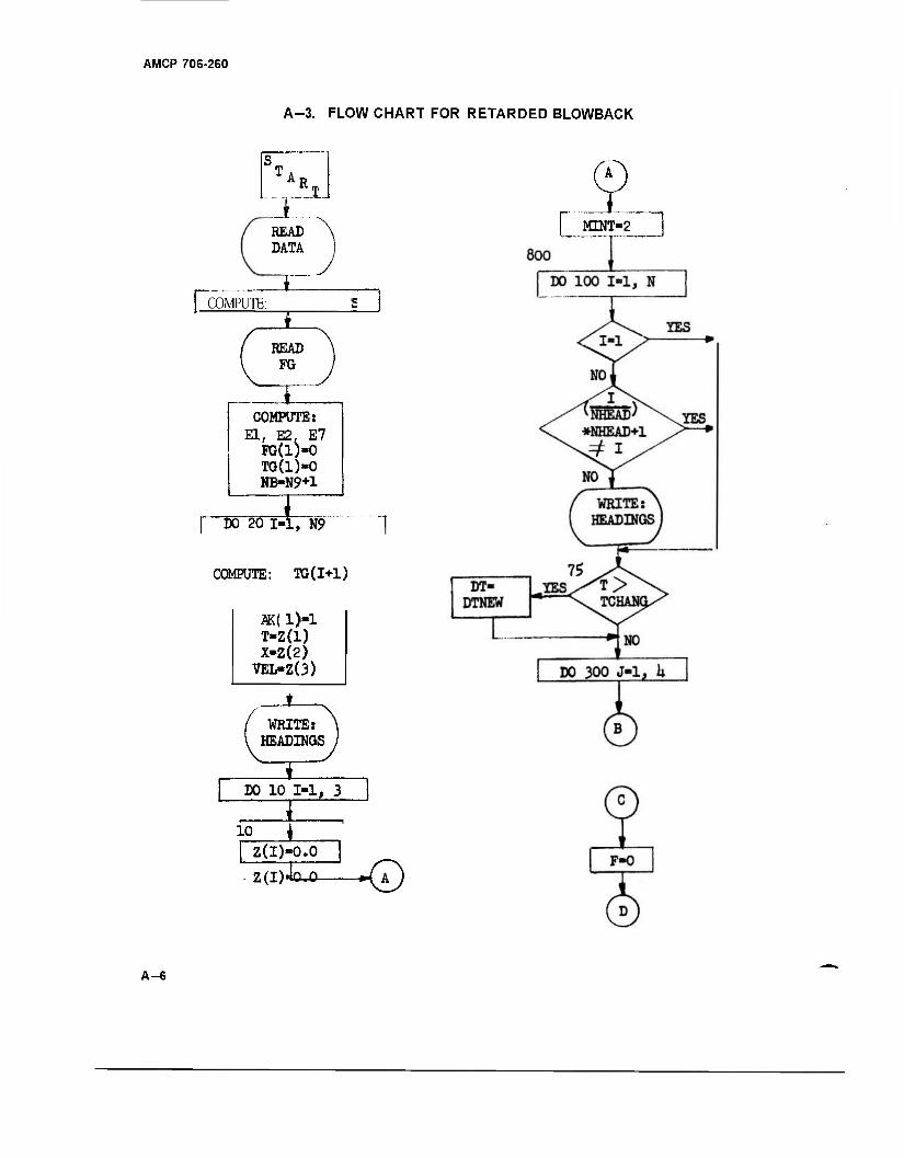
AMCP 706-260
A-3. FLOW CHART FOR RETARDED BLOWBACK
READ DATA
| COMPUTE:
READ FG
I COMPUTE:
El, E2. E7 PG(l)-0 TG(1)«0 NB-N9+1
DO 20 1-1, N9
COMPUTE: TG(I+1)
ÄK( l)«l T-Z(l) X-Z(2)
VEL-Z(3)
X WRITE: HEADINGS
I DO 10 1-1, 3
, I , 10 _^_
Z(l)«0.0
z(i)4o.o -—«\AJ
L E™^ "~|
A-6
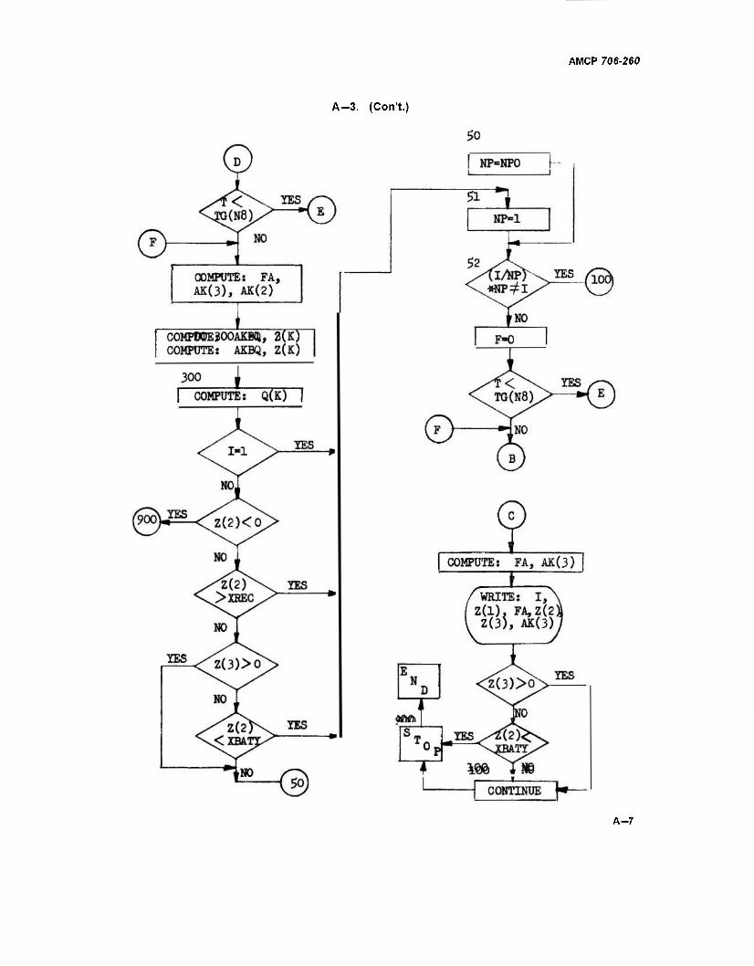
A-3. (CoiVt.)
AMCP 706-260
A-7
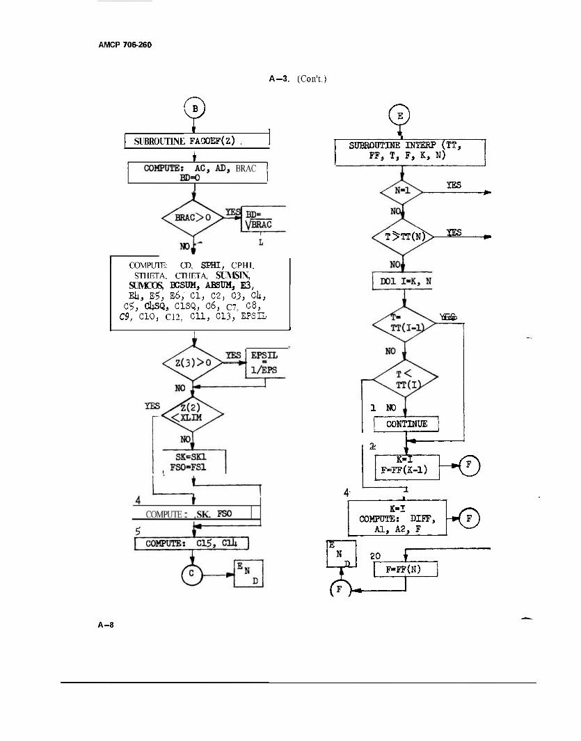
AMCP 706-260
A-3. (Con't.)
SUBROUTINE FACOEF(Z)
I
COMPUTE: CD, SEHI, CPHI, STHETA, CTHETA, SUJMSIN,
SUMOOS, BCSUM, ABSUM, E3, EU, E5, B6; Cl, 02, 03, CU,
C$, CUSQ, C1SQ, C6, C7, 08, C9, CIO, C12, Oil, 013, EPSIL
SUBROUTINE INTERP (TT, FF, T, F, K, N)
T>TT(N)> IES
IES
"üEfe
1 NO
CONTINUE
2 —K^T F=FF(K- ̂ T~©
COMPUTE: DDF, -*\FJ Al, A2, F V—/
N
<>V
20 £ F-FF(N)
A-8
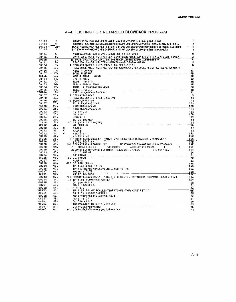
AMCP 706-260
A-4. LISTING FOR RETARDED BLOWBACK PROGRAM
00101 1. DIMENSION FG<96)>Z(3>>Q<3)iAK<3>>TG(96>»AU>'B<4)«C(t) 1 00103 2. COMMON AZ»ABC»ABSG»AB»BC»EYEB»El»E2»EYEC»E7.EMR.EPS.XLIM»Sra»FSl» 8
~QQ103 "• 31- !SK2»FS2#E3»E'»'E3»E6»Cl»C2«C3»C'»»"C5rC6.C7»C8.C9rCT0TCtTrC12»C13>tl,r -3 00103 4.
5.
2»C1S»AC»AD»BD»CD#FSO»SUMSIN»SUMCOS'SPHI»CPHI»STHETA.CTHETA 4
00104 EQUIVALENCE (Z(l)iT>i(Z(2)tX)>(Z(3)>VEL> 2 00105 6.
7. DATA A(D>C(l)>C(<»)>B<l)'B(<t)>B(2>'B13)rA(3)>C(3)>A(2)>C(2)rA(<*)/ 3
00105 D 3*.5»2*2.»2*1.»2*1.7071U678»2*.292893219».166666667/ I» 00122 S. READ 15 >1> N > DT > N9.DTFG > NP0.TCHAN6 >DTNEW > NHEAD 5 00134 9. 1 FORMATU6»E12.0»I6>E12.0>I6»2E12.0<I6) 6 00135 10. READ(5»2>XREC.XLIM>AB»BC'KB>WABiWBC.G»SKl»SK2.FSlfFS2>AZ>EPS»XBATY 7 00156 11. ABSQ = AB*AB SA 00157 12.
"'""13. BCSQ = BC*BC 8B
TJ0I65 ABC = ABSQ - BCSQ 8C 00161 14. EMB = WB/G 8D 00162 15. EMAB = WAB/G 8E 00163 16. EMR = EMB + EMAB 8F 00164 17. EYEB = EMAB*ABSQ/12.0 83 00165 18a
19. -- EMBC = WBC/G 8H 50166 EYEÖ = EMBC*BCSQ/12.0 ~ 81 00167 20. 2 FORMAT16E12.0) 9 00170 21. READlb»15) (FGII+1)»I=1.N9) 10 00176 22. 15 FORMAT19F8.0) 11 00177 23. El = EMAB*AB/2.0 12A 00200 24.
~"^25. — E2=EMBC*BC/2.U 12B -Ü02TI1" E7=EYEC/6C-E2/2.0 ""~ ----- -- - 12c 00202 26a FG(1)=0.0 13A 00203 27. TG(1)=0. 13B 00204 26. N8=N9+ 1 13C 00205 29. DO 20 1=1.N9 14 00210 30. 20 TG(I+1)=TG(I>+DTFG 15
""00212 31. AX( 11 = 1.0 " "~T6" 00212 32. C T=Z<1> 17 00212 33. c X=Z(2) 18 00212 34. c VEL=Z<3) 19A 00213 35. WRlTE(6f3) 19B 00215 36.
37. 3 F0RMAT(1H1/25X(37H TABLE 2-8 RETARDED BLOWBACK DYNAMICS/) 19C
"0ÜZI6 " WRITE (6.70'fl) I9D 00220 38. 708 F0RMAT(30X.23HAPPLIED DISTANCE/15X»tHTIME»12X»57HF0RCE 19E 00220 39. 1 FROM BREECh VELOCITY ACCELERATION/20H 1 S 19F 00220 <tU. 2ECOND»llX5hPOUND»llX<4HlNCH>llX.25H IN/SEC IN/SEC/SEC! 19G 00221 tl. DO 10 I=l>3 20 00224 <»2. Q(I>=0.0 21
"00225 »3. lÜZriTrö.Ö • 22 00227 <♦<♦. MINT=2 23 00230 <»5. 800 DO 100 I=liN 24A 00233 <»6. IFd.EQ.DGO TO 75 2<tB 00235 <*7. IF<U/NHEAD)*MHEAD+l.NE.I)GO TO 75 25A 00237 tb. WRITE(6i707) 25B "OOZTI " - "ire. "lRTTE~T6»70Br "25t 00243 50. 707 FORMAT(lHl/22XrHtH TABLE 2-8 CONTD. RETARDED BLOWBACK DYNAMICS/) 250 00244 51. 75 IF(T.GT.TChANG)DT=DTNEW 25E 00246 52. DO 300 J=l»<* 26 00251 53. CALL FACOEF(Z) 52 00252 54. F = 0.0 64 U0253 55. IF(T.LT.TG(N8) JCALLINTERPCTG»FG»T>F»MINT.FlBJ 65^- 00255 56. FA = F+(C1<*+C15*Z(21) 55 00256 57. AK<3) = <FA+C13*Z(3)**2)/CU 56 00257 58. AK(2)=Z(3) 67 00260 59. DO 300 K=l<3 60 00263 60. AKaQ=A(J)*(AK(K)-B(J)*Q(K>) 69 "00264 61. Z(K)=Z(K>+0T*AK6Q TO 00265 62. 300 Q(K>=Q(K)+3.0*AKBQ-C(J)*AK(K) 71
A-9
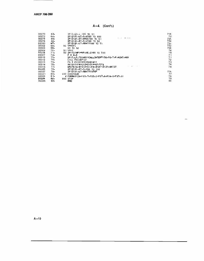
AMCP 706-260
A-4. (Con't.)
00270 63. 00272 64. 00279 65. 00276 66. 00300 67. 00302 68. 00303 69. 00304 70. 00J05 71. 00307 72. 00310 73. 00312 74. 00313 75. 00314 76. 00315 77. 0UJ25 78. 00327 79. 00331 80. 00333 81. 0033<t 82. 00335 83.
IFU.ES.l )60 TO 51 IFIZ<2>.LT.O.U)GO TO 900 IF(Z(2>.GT.XREC)G0 TO 51 - - _ .. IF(Z(3).GT.0.u)G0 TO 50 IF(Z<2).LT.XBATY)GO TO 51
50 NP=NP0 GO TO 52
51 NP=1 52 IF(d/^Pl«NP.NE.I)GO TO 100
F = 0.0 IF(T.LT.TGlN8))CALLINTERPtTG»FG«T.FrMINT»N6> CALL FACÜEF(Z) FA = F+<C1<*+C15»Z<2>> AK(3)=(FA+C13*Z(3)**2)/Cll WRITE(6»6)I.Z(1).FA»Z(2)'Z(3)»AK(3) IF(Z(3).GT.0.)GO TO 100 IF(Z(2).LT.XBATY)ST0P
100 CONTINUE 6 F0RMAT(I6»F15.7.F15.1>Fl7.6»F16.1»F17.1)
900 STOP END
71X 72
73A 73B 73c 73D 73E
74 15 71 71 72 73 74 76
77A 77 78 79 00
A-10
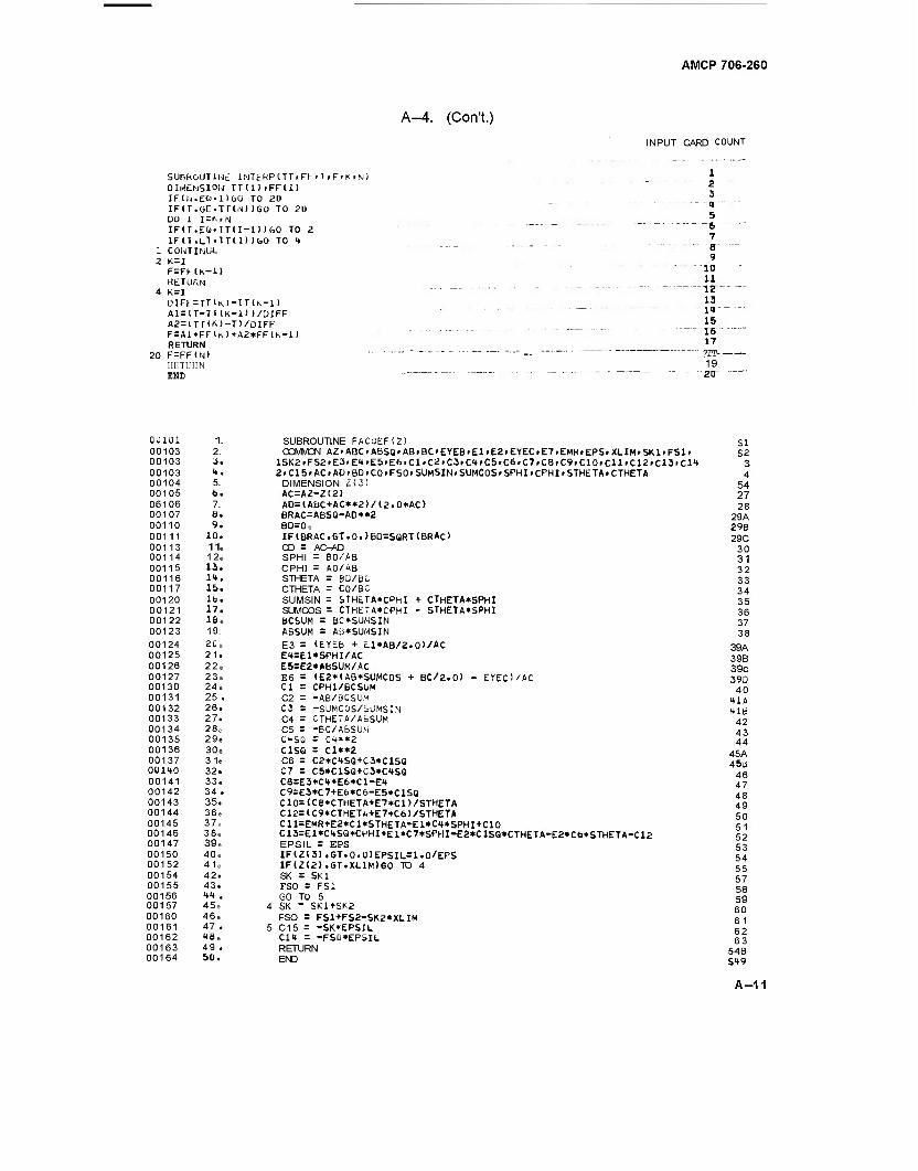
A-4. (Con't.)
AMCP 706-260
INPUT CARD COUNT
SUPROUTINt lNTERPCTTtFH »T.F'K>M) DIMENSION Till)rFF(l) IFl^.et'.Düü TO 20 IFlT.eC-TT(N))GO TO 20 DO 1 I=KrN IFlT.EQ-lTU-l) )GO TO 2. IFU.LT'TTU) )&0 TO 4
1 COUTlNUt. 2 K = I F=FMK-1> RETURN
4 K=I DIFF = TT1M-TT(K-1) A1=(T-TI IK-D 1/ÜIFF A2=ITTIK)-T)/DIFF F=Al*FFlrJ+A2*FF(K-l) RETURN
20 F=FF(N) HETUHN END
1 2 3 1 5
—6 7 8 9
10 11
-\z- 13 14 15 16 17
' 7LT-- 19 2tr
ouioi 1. 00103 2. 00103 3. 00103 4. 00104 5. 00105 6. 06106 7. 00107 6. 00110 9. 00111 10. 00113 11. 00114 12e 00115 13. 00116 14. 00117 15. 00120 lb. 00121 17. 00122 16 e 00123 19. 00124 20e 00125 21. 00126 22e 00127 23e 00130 24, 00131 25. 00132 26. 00133 27. 00134 28» 00135 29. 00136 30e 00137 31. 0U140 32. 00141 33e 00142 34 . 00143 35. 00144 36e 00145 37a 00146 38e 00147 39» 00150 40e 00152 41e 00154 42. 00155 43. 00156 44 . 00157 45e 00160 46, 00161 47 . 00162 toe 00163 49 . 00164 50.
CTHETA*SPHI STHETA*SPHI
SUBROUTINE FAC0EF1Z) COMMON A2>ABC.ABSQ<AB»BC>EYE6>El>E2.EYEC.E7.EMRfEPSfXLlMrSKl»FSl»
lSK2»FS2>E3'E4>E5.E6.ClrC<i>C3tC4fC5.C6»C7fC8fC9fC10»Cll>C12tC13<C14 2.C15> AC tAD> BD >CD.FSO >SUMSIN.SUMCOSr SPHIiCPHItSTHETA» CTHETA DIMENSION Z(3) AC=AZ-2!2) AD=(AbC+AC»«2>/(2.0*AC) BRAC=ABSQ-AD**2 BD=0e IFIBRAC.GT.0.>6D=SQRT(BRAC> CD = AC-AD SPHI = BD/AB CPHI = AO/AB STHETA = BD/BC CTHETA = CO/BC SUMSIN = STHETA*CPhI SUMCOS = CTHETA*CPHI BCSUM = BC*SUMSIN ABSUM = AB*SUMSIN
E3 = (EYEb + El*AB/2.0)/AC E4=E1*SPHI/AC E5=E2*A6SUM/AC E6 = (E2*1AB*SUMC0S + BC/2.0) - EYEO/AC Cl = CPHI/BCSUM C2 = -AB/BCSUM C3 = -SUMCÖS/SUMSIN C4 = CTHETA/ABSUM C5 = -BC/ABSUM C4SG = C1**2 C1SG = Cl**2 C6 = C2*C4SQ+C3*C1SQ C7 = C5*C1SQ+C3*C4SQ C8=E3*C4+E6*C1-E4 C9=E3*C7+E6*C6-E5*C1SQ C10=(C8*CTHETA+E7*C1)/STHETA C12=(C9*CTHET«+E7«C6)/STHETA C11=EMR+E2*C1*STHETA-E1*C4*SPHI+C10 C13=El*C4SQ*CPHI+El*C7*SPHI-E2*ClSQ*CTHETA-E2*Cb*STHETA-C12 EPSIL = EPS IF(Z(3).GT.0.U)EPSIL=1.0/EPS lF(2(2).GT.XLlMiG0 TO 4 SK = SKI FSO = FS1 GO TO 5
I SK _ SK1+SK2 FSO = FS1+FS2-SK2*XLIM
i C15 = -SK*EPSIL C14 = -FS0*EPSIL RETURN END
SI S2
3 4
54 27 28
29A 29B 29C
30 31 32 33 34 35 36 37 38
39A 39B 39c 39D
40 41A 41B
42 43 44
45A 45b
46 47 48 49 50 51 52 53 54 55 57 58 59 60 61 62 63
548 S49
A-11
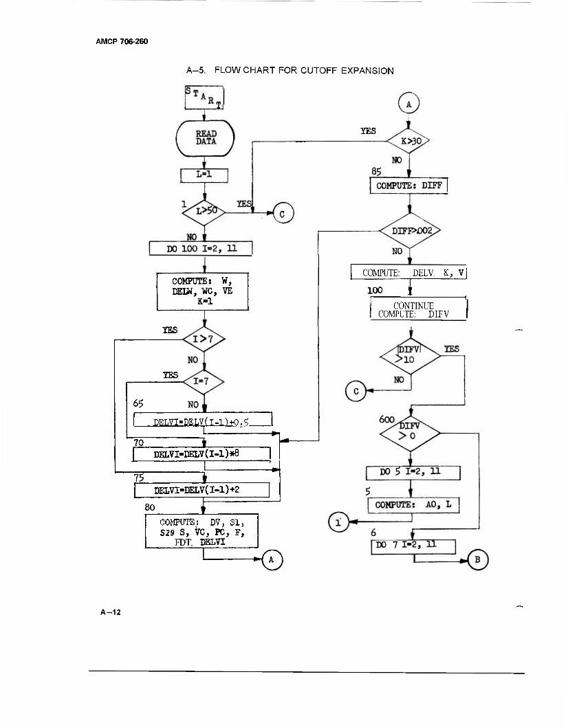
AMCP 706-260
A-5. FLOWCHART FOR CUTOFF EXPANSION
COMPUTE: W, DELW, WC, VE
K=l
XES
IES
65 NO
:DEL7T«DELV(T-I1K).^ 1 1 - ""
70 # DELVI »DELV(l-l)*8
IT 1
80
DELVI=DELV(I-l)+2
~1= COMPUTE! DV, SI, S29 S, VC, PC, F,
FDT, DELVI
■©
YES
COMPUTE: DELV, K, V
100
CONTINUE COMPUTE: DIFV
A-12
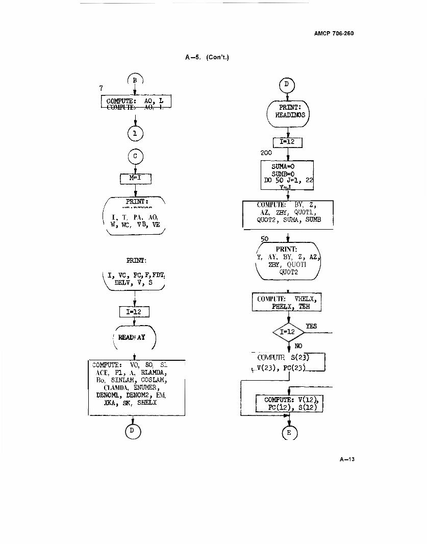
A-5. (Con't.)
AMCP 706-260
Si COMPUTE: AO, L COMPUTE:.—AO, L PRINT:
HEADINGS
M=I
/ PRINT:\
I, T, PA, AO, W, WC, VB, VE
PRINT:
I, VC, PC,F,FDT, v DELV, V, S
1=12
HZ ( IffiAD?AI
± COMPUTE: VO, SO, SI
ACE, PI, A, RLAMDA, Bo, SINLAM, COSLAM,
CLAMDA, ENUMER, DENOML, DEN0M2, EM.
XKA, SK, SHELX
1-12
200
SUMA=0 SUMB=0
DO 50 J-l, 22 W
COMPUTE: BY, Z, AZ, 2E£, QÜOTI3
QÜ0T2, SUMA, SUMB
50 i / PRINT: Y, AY, BY, Z, AZ,^
\ ZBY, QU0T1 \ QÜ0T2
COMPUTE: VHELX, PHELX, TEH
CCMPUTE: S(23)
\_V(23), PC(23)_
£ COMPUTE: 7(12), PC(l2), S(12)
A-13
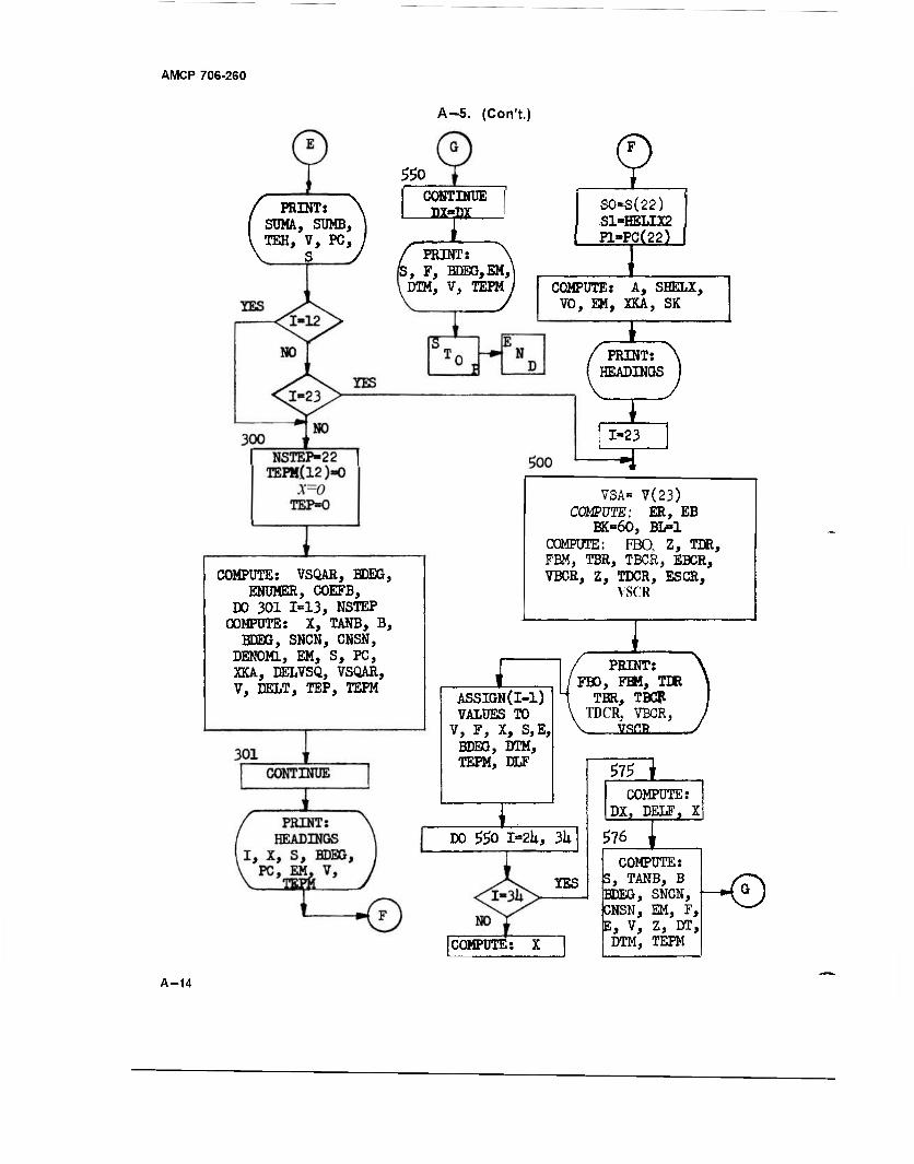
AMCP 706-260
A-5. (Con't.)
550
PRINT: SUMA, SUMB, TEH, V, PC,
CONTINUE D2HDX
PRINT: B, F, BDEG,EM,\ DTM, V, TEPM
Q SO-S(22) S1-HELIX2 P1»PC(22)
COMPUTE: VSQAR, BDEG, ENUMER, COEFB,
DO 301 1=13, NSTEP COMPUTE: X, TANB, B,
BDEG, SNCN, CNSN, DENOML, EM, S, PC, XKA, DELVSQ, VSQAR, V, DELT, TEP, TEPM
COMPUTE: A, SHELX, VO, EM, XKA, SK
PRINT: HEADINGS
1-23
VSA- V(23) COMPUTE: ER, EB
BK=60, BL=1 COMPUTE: FBO, Z, TDR, FBM, TBR, TBCR, EBCR, VBCR, Z, TDCR, ESCR,
VSCR
ASSIGN(I-l) VALUES TO
V, F, X, S,E, BDEG, DTM, TEPM, DLF
PRINT: FBO, FBM, TDR
TBR, TBCR TDCR, VBCR,
VSCR
DO 550 I-2U, 3k
YES
575 j COMPUTE:
DX, PELF, X
576 t
COMPUTE:
COMPUTE: S, TANB, B BDEG, SNCN, CNSN, EM, 5, E, V, Z, DT,
DTM, TEPM
i-0
A-14
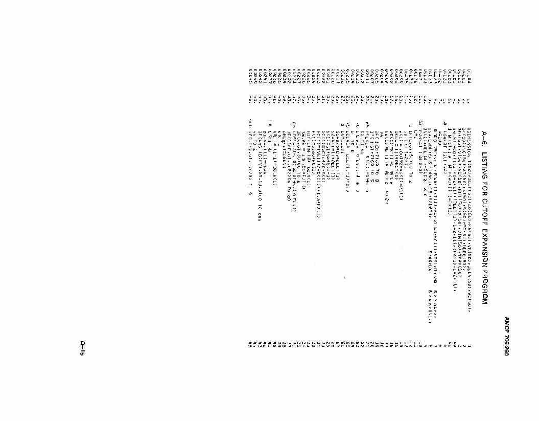
COOCC OCOCCC COOCCCCCOCOOOCOCCCCOOCCOCOCiCCCOCOCC ccooccooocroccoc ccccocr cc c coc cc c c o c: c cr e c cpcccccic c ry rv ro rj ro rv rv iv> rv tv> i\; NS r. iv iv r>. iv r r> rv rv r r ^^^^^^^lv^l-^-t-l-l-^-[.^.h^-^-H^-K .t -r ji-Fc-Jt>'t>'üJOiuirijivri.rv'^fvr;ivi—t—»-^-K»-t-c-ccc CCC«J-S|M-JO.O O-C-CCGOC C t;croH^[j cr -F rv U-JC c; J- oiroHo-jc tr-PCjroi--siu--Fwrv 1 -c c G rv t- OJ C <* rv 1- OJ GI H- t- ■-
J o-- c/i * o< P.) K c «r o J c u- -c o rv »-
•- c 1-4 O n «r r r. »- <r »-<
IE T; T X <: IT LT tr> c c <r
T'l C "n >- „pTl >-< Tl O — O O — (V ►" < PI <— Ti 9 TI ^ — »- it 11 II r*
C -H 3> <" H ■K - -n ^ < — *— 1-1 *->■—• <r 0 C1 <r J >~ C a it ±1 II * 1— 11 — — 11 — • n< »- c
ir> < C -— cr 14 11 0- 1- u r n <r !>> fc > —l n II • — <r 1-* | * <■ e n • cs • T- c^ <r n + 1— c C 0 *- 1 ■:: c U" c« »-■■ — or- -< ü" — t c
ITI —( ur !_ * ~- r rv # * r • Ti 1 ■— r • a •— *■ T i-* + + 0 r r < <: + < • "<r 0 ~ > cr rrv < CJ •-» c f>l tr k~" 0 -r r flu 0 +■»- — —
T >: iv * . w r) C/l 1 ■ 1 O —1 «r *— '<: 6 Tl _4 ^ — (_. t_11_1 c 0
£ — c di* 7^ ^3 w w +
t- »- £
<- ?. c : r *-> r w *" ö TI IT tr = ^
TI Tl m 0 m ^ c Ti 11 £M? riü ^ -. r 1- ~ K
0 n -< 0
MM r — t— n ~ "T 11 Ö 0 *
JW-. -s
7* -r oc > - -? c
n x y . / »-H O *~* • — r- - _s
—J "»J — " — C II U' &■ - C"- ' ►_ ^ * H- ^ O 0 c „ . a vD » —
^i?^ 0 0 *, A p- nj h- <r> 1- * i- 0
— -a »dt-c - OPiH-
c c ~^gra I-- r- O
fsO S3 — r- —•-» ^ __ — r\; «^ 0
L O W K- O
— »-H o <. n o
> 1
en
M — en en V) —' cr <r
■ *-» H LT. - <> Q 2 - r? -<
O > 11 CJ1 LT C 0 fV C C m
Tl r*
c 1- Tl ?■ -1 O
^" O — tr, J3 - -1 LT c
II O ! a u — » rn c - > c r —1/1 0 H -1 • — — — X LT* U"> O 1— — 0 C: — -J- — Tl ■* c * " TI l-H — TJ H *• O > m ro 0 — —
X >
1/1 ' TJ - n ^ <z 1> H-O J> 0 — m — X -< HTJUl •• I-
w ^ O
^t- II c
CO
o
o (7) DO D
o
D .1 J (T (r jr (JJ 9
01 o
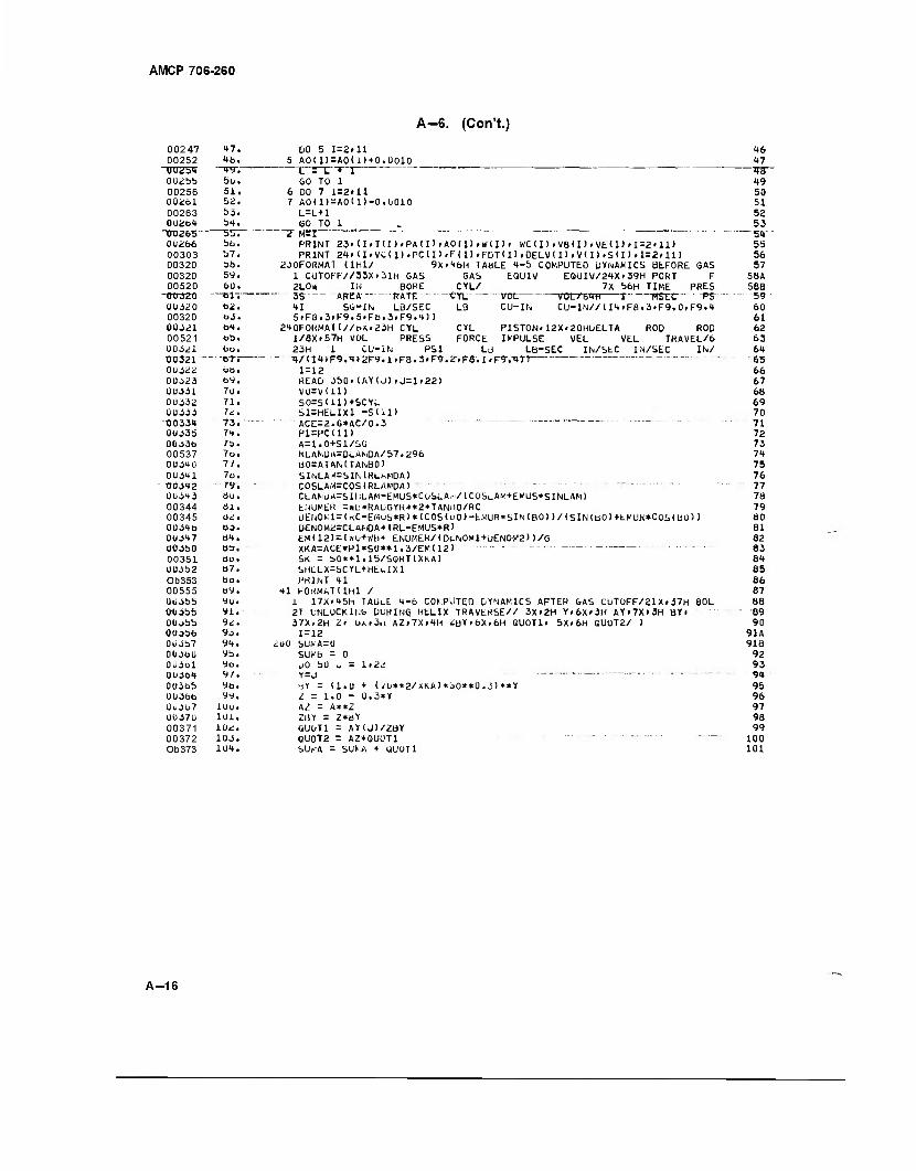
AMCP 706-260
A-G. (Con't.)
00247 00252 UU^bt 0U255 00256 0 0261 00263 002t>4 UU2bb~ 00266 00303 00320 00320 00520
"00320 00320 00320 ÜÜJ21 00521 00321 tro321" 00322 00323 00331 00332 00333 T30331 0033b 00336 00537 00340 00341 tSOiHZ 00343 00344 00345 0034b 0O347 00350 00351 003b2 Ob353 00555 003bb 0035b OOobb 003bb 003b7 00360 0U3ol 0U364 003bb 00366 0U3O7 U037U 00371 00372 Ob373
47. 4b. -«PT.- bu. 51. 52. S3. b4.
—55~7 bb. b7. 3b. 59. bU.
—MT
62. b3. b4. bb. bo. -6Tr bb. by. 7u. 71. 72. 73. 74. 7b. 7D. 77. 7b. 79. 80. öl. t>2.
bo. bit.
aa. ÖU. «7. bo. b9. yu. yi. 92. 90. 94. yb. 9D. yf. ya. yy.
luu. 1U1. 10,;. 103. 104.
DO 5 I=2>11 5 AO(I)=AO(i>+0.0010 L = L + j
GO TO 1 6 DO 7 I=2<11 7 AO(I)=AO<1>-0.0010
L=L+1 GO TO 1 _.
PRINT 23r (I,T<I)fPA(I)»AO(I),«/(I)» WC(I)>VB(I>>VE<1>«I=2>11) PRINT Zt»(IiVC(I)fPCtI)»F(l),FDT(I)»DELV(I)iV(I)»SCI)»I=2»H)
230FORMAT (lHl/ 9X»4&H TABLE 4-5 COMPUTED DYNAMICS BEFORE GAS GAS
CYL/ tYL LB
EQUIV
vot CU-IN
EQUIV/24X»39H PORT 7X b6H TIME
"V0L/64H T BSEC CU-IN//(I4>F8.3-F9.0fF9.4
F PRES
1 CUT0FF//33X>31H GAS 2LOW IN BORE ._.. JS AREA RATE 41 Su-iN LB/SEC 5>FB.3rF9.5.Fb.3iF9.4))
240FORMAt<//oA>23H CYL CYL PISTON»12Xt20HDELTA ROD ROD 1/8X»57H VOL PRESS FORCE IMPULSE VEL VEL TRAVEL/6 23H 1 CU-iN PSI LB LB-SEC IN/SEC IN/SEC IN/
■-■ H7<I4»F9.4>2F9.1>F8.3*F9.2>F8.1»F9-.-4Tl 1 = 12 READ 350»IAY(J>.J=1.22> V0=V<11) SD=S(11)+5CYL S1=HELIX1 -S(il) ACE=2.0*AC/0.3 " " P1=PCU1> A=1.0+S1/S0 RLAfoU«=OLAhDA/b7.29b U0=ATAN(TANB0) SlNLAi«l=SIMRLhMDA) COSLAM=COS(RLAMDA) CLAMUA=Sll:LAM-EMUS*COSLA-i/(COSt_AM+EMUS*SINLAM> ENUMER = Ml:*RAUGYR**2*TANl>0/RC UEIiOMl=lKC-EMuS*R)*(COS(uO)-EMUR*5INlBO))/(SIN(tiO)+EMUK*COS(BO) ) DEN0H2=CLAMDA* (RL-EMUS*R) £M112)=1«0+WB» ENUMER/(0LN0M1+ü£N0M2))/G XKA=ACE*P1*S0*»1.3/EM<12> " SK = S0**1.15/SQRT(XKA> SHLLX=SCYL+HEl-IXl PRINT 41
■»1 FORMAT I 1H1 / 1 17X'45h TAÜL.E "«-6 COf-.PUTED DYNAMICS AFTER GAS CUTOFF/21X»37H BOL 2T UNLUCK1NG DURINQ HELIX TRAVERSE// 3X»2H Y»6X>3H AYi7Xl3H BYl 37X.2H Z> UA(3n AZ.7X>4H <:DY>bXi6H QU0T1> 5X>6H QU0T2/ ) 1 = 12
<:O0 bUMA=U SUMb = 0 1)0 bO J = Y=J bY = U.U I - 1.0 - AZ = A**Z 2BY = Z*BY (iUoTl = AY(J)/ZBY QU0T2 = A2*QU0T1 SUiOA = SUM + ÜU0T1
lr2i
(i/0**2/xKA)*;>ü**ü.3>**Y 3*Y
46 47
~"TO- 49 50 51 52 53
— 54- 55 56 57
58A 58B S9 60 61 62 63 64 65 66 67 68 69 70 71 72 73 74 75 76 77 78 79 80 81 82 83 84 85 86 87 88 89 90
91A 91a 92 93 94 9b 96 97 98 99
100 101
A-16
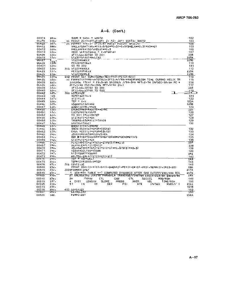
AMCP 706-260
A-6. (Con't.)
00374 IOJ. SUMB = SUMb + OUOT2 0U375 10b. bb PRINT 21»Y»AY(J) »BY» It A;» «:BY» QUOTli QU0T2 UU410 liJr; 21 f-ORMAI (r-b.l. »IJ.H, F8-1- FlO.t» 3FU.t) 00411 10b. VHELX=SQRT(XKa*((1.0/S0**0.3)-1.0/SHELX**0.3)+V0**2) 00412 1UV. PHELX=Pl*(S0/bHELX)**1.3 00413 lib. TEH= SK*<A + SU,.,b - 1.0-SU^A) 01)414 111. IF 11.LG. 12) GO TO 201 00416 11.:. S(23)-S(22)+HLLIX2
"00417 I _. vT23T=VHELX 00420 114« PC(23)=PHELX 00421 lib. GO TO 202 00422 110. 2U1 V(12)=VHELX 00423 11/. PC(12)=PHt.LX 00424 lib. SU2)=SHELX
102 103
0Ü42b 0UH35 00435 0043b 00436 00440 0U442 00443 00444 00445 00446 00447
202 PRINT 51» SUMH.SUMBiTEHWrniPCd) rSU) bl F0RrMT(//49X'oHT0TALS>2FH.4//9X»44HEXPANSI0N TIME OURING HELIX TR
lAVERSfc. (TtH) - F8.5.ÖH StCONDS //9X.3HV =F7.2»7H lN/SEC»5X»bH PC = 2F7.1.4H PSl.bA.3Hb =F7.4»4H IN.)
1F(I.L&.12)60 TO 300 IFU.EÜ.231G0 TO 500
"3D1TN5TEP=22 Ü-—
104 105 106 107 108
109A 1Q9B
110 111 112
USA 113B
UU4bO 00451 00452 004bb 00456 00457 0U460 0U<ibl 00462 00463 00464 00465 00466 00467 00470 00471 00472 00473
WJWTTf~ 00475 00476 00500 00515 00515 UUblb 00515 00515 00515 00515 00516 UUbl/ 00520
119.. 12u. 121. 122. 123. 124.
~IZ5T" 120. 127. 12b. 129. 130. 131. 13«:. 133, 134. 135. 13o. 13/. 13b. 139. 140. li+l. ItÜ. 143. 144. lib. lib. 147. 148.
= 0.0 TEPM112): X(I)=U.O TEP - O.U VSQAR=V<12>**2 b[)EG(12>=0.4426 ENUMER^rV"B*TfATDGTRT«2VrTC COEFB=RC-tMUS*R DO 301 I=13.NSTEP X(D=X(I-1)+DX TANB=2.632*X<I1+TANB0 b=ATAN(TANK) BDE6ll)=b/.2y6*B SNCN =SIN(b)+EMUR*COS(B> CNSN = COS(b)-cMUR*SIMb) UENOMI=CUEFB*CNSN/SMCN EM( B=(W0+ENUKER*TANB/(DEN0M1+DEN0M2))/S
S(I)=S.(I-1)+ÜX PCUl=PC<I-l)*<SU-l)/S<ITT«*-r3 XKA=ACE*PC(I)/EM(I> DELVSii=XKA*<SU-l)-S(I-l>**1.3/S( I )**0.3) VSQAR-DELVSS+VSQAR V(I)=SGRT(VSUAR) DEUT=2.0*L.X/(V<I)+VtI-l) )
"TtP+ÜELT I EP TEPMI) = 1000.D*TEP
301 CONTINUE PRINT 302»lI»X(I),S(I)»BLiEG(l)»PC(I)»EM(I)»V(I).TEPMlI).I = 13»22)
3020FORMATUH1/ 1 12X'45H TABLE 4-7 COMPUTED DYNAMICS AFTER GAS CUTOFF/14X.40H BOL 2T UNLOCKING DURING PAHAbOLA IWAVEHSEZ/ltXtbH fc-OUlV.glX.bH EClUIV/bb 3H PARA6 CYL CAM CYL RECOIL R00/65H 4 DIST LENGTH SLOPE PRESS MASS VEL TIME/65H 51 IN IN DEO PSI W/G IN/SEC MSEC// (
405 S0=S(22) 5T=HET-TXZ
P1=PC<22>
1 14 115 116 117 118 119
121 122
123A 123B 124 12b 126 127 128 129 130
132 133 134 135 136 T37~ 138 139 140 1*1 142
149. lbü. 151. 152. 153. 154. Ibb. 156. 157. Ibb. 159. 16U. lbl. 162.
143- 144 145 146
147A 147B 14B 149 150
151A 1518 152
—T53~ 154A
A-17
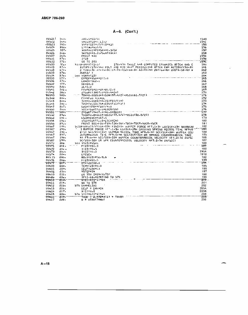
AMCP 706-260
A-G. (Con't.)
Üüb21\ lbj. A=1.0+bl/bC 1548 0Ub22 lot. bHdLX=b0thLLlA2 154C
-00523 165. V0=V(221+».C/<vvO + Wd> ~~'~ ■- 155" 0ub2t 16o. LM=li»U+ku)/G 156 00b25 107. XKA=ACE*P1*S0**1.3/EM 157 0032b lbu. SK=SÜ**l.lb/St.RT(XKA> 158 0U527 ltiy. PRIM 410 159A OUbol 17u.
171. 1=23 159B
00532 60 TO 200 """ I59C UUb33 Mi.. tlu(jFOk>,A"Mlhl/ !7x.tbH TABLE H-B COMPUTED DYNAMICS AFTER GAS C 160 00b33 17j. lUT0FF/17Xi'.bh BOLT AHO ROD UUIT RECOILLIMG AFTER CAM ACTI0N//3X>2H 161 0ub33 17t. 2 Y.bX>3H AY>7Ar3H bYt7X'lHZ<bX<3H AZ>7XitH ZBY>bX»6H QU0Tl.bXi6H 0 162 0U533 17b. 3U0T2/ ) 163 OübJ^ 17o. buu VSA=V(23) 164 00535 177. ER=EK+VSA**2/£.0 ' 165" 0Ub3b 17b. ta-ER-bb2.ü 166
0UbJ7 17Y. OK=60.0 167 OObto lau. aL=1.0 168 OObtl löl . FBU=EHS*El»-BK*BL/2.'J 169 UUbt2 1Ü2. i=büR<(JB07.Ü+20.<♦*£«> 170
UD5« " "1153. - TDR-0.002DJ*(ASIN(97.t/Z>-ASIN<61.7/Z) ) ----- - 171 0i,544 ist. FBK=FuU +t-K*LlL 172 0übt5 lab. TBR=0.00837*ACOS<FB0/FBM> 173
0Ub46 löu . TBCR=0.ülfc7b*MCOS(Friü/F B'M 174
0Ubt7 1B7. ESCR=<FBM+FBÜ)/t.O 175 Uübbü löo.
—mv,— VBCR = bliRT(2.U*EBCR/EM> 176
DV551 — Z=SQKT(94E7.0-nt0.8*EBCR> " " 177
U0bb2 19«. TDCR=u.0tübl*lASlNl97.t/Z)-ASlN(51.5/Z)> 178
0ubb3 191 . ESCR=EBCH+167.5 179 Oübbt 19*. VSCR=SG*T<<..0*ESCR/EM> 180
OUbbb iyj. PRINT 501'hBO'FBMfTDKiTBK.TBCR.TDCR.VBCRrVSCR 181
00bb7 19t. bUlOKORkAT(///2üXr23H MIM\:Ui-i BUFFER FORCE =F7.1F3H LB/2UXr23H MAXIMUM 182
00367 IVbi - 1 BUFFCR FGKCE =F7.1P3H LU/20X>29H DRIVING SPRING RECTJIL TIME -F9V6- " IB3 Uübb7 19b . 2itH St-C/2Ux.21H UUFFLH RECOIL TIME =F9.6>tH SEC/2UX.28H BUFFER CCXJ 184 Üüb67 197. 3UTE.RKLC01L Tust =F9.6»tH SEC/2UX»3lH DR SPRING COUNTEHHECOIL TIME 185
0übb7 19b. 4 = F9.b<tn SEC/20X-32H BUFFER COUMTERRECOIL VELOCITY =F7.2f7H IN/SE 186
00567 199. SC/20X.32H LR bPR COUMTERRECOIL VELOCITY =F7.2>7H IN/SEC) 187
Oub7o 20u. blU V(23)=VSCk 188 -oesfi ■'201 i - - F(23)=51.5 — ■ ■ - 189 00572 2<Ji . X(23>=Ü.5 190
0U573 2ÜJ. S(23)=0.U 191A 00b7t 2U4. E=ESCi< 1918 OUb 15 2Ub. B0i-6(23)=b2.9^6 .. 192
0Ub76 20b. -aur.-—
F(23)-51.b 193
-OC3T7— — ---0TH<23) = O.O " - - - -- - -. . — - -.— - - 194
OUfaüO 20a, TEPM23)=ü.O 195
oufaui 209. DELF=üRK*W 196
0Uö02 21«. NSTEP=34 197
U0bU3 211. L)0 55U I=24iNbTEP 198
UOtiOO 212. —213-;
IFU.LG.NSTEPIGO TO b7b 199
ÜUOlO - jrtTi-X<I~i>~ÜA, 200 - 00611 214. GO TO 576 201 00612 21b. b7S UX=HELIX1 202
ÜÜ013 21b. DELF = DRK*0X 203A odum 217. XU>=0.0 2036 0ÜO15 21b. b7b S(I)=b<I-l)+ÜX 204
205 "TO016— ^19, "" "' TANEi - 2.e>32*X(I) > TANßi* 0Ubl7 220. B = ATAN(TANü) 206
A-18
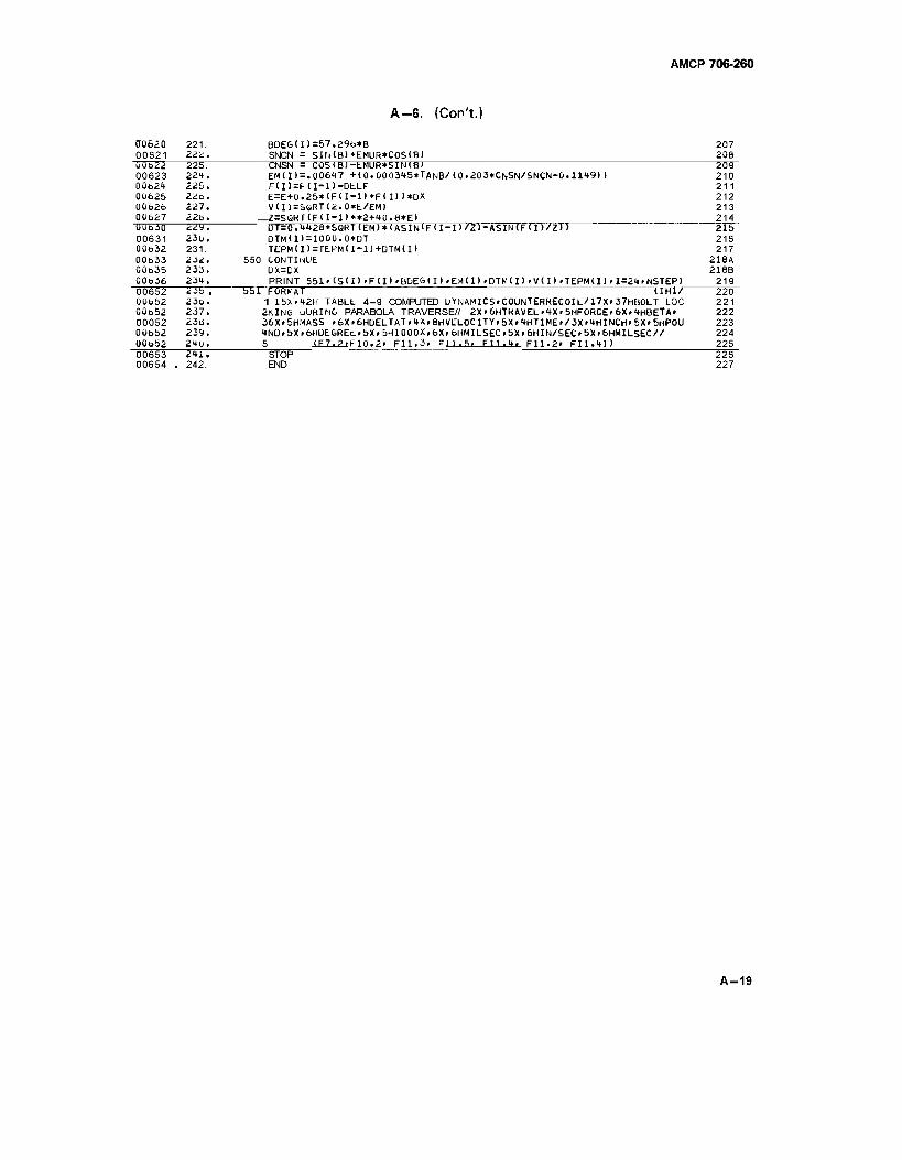
AMCP 706-260
A-G. (Con't.)
OQ620 221. ÜDEG(1)=57.296*B 207 00621 222. SNCN = SlfilB) +EMUR*C0S(B> 208 ÜÖ622 225. CNSN = COS(B)-EMUR*SIN(B' 2Ö9" 00623 22H. EM(I)=.00617 +<0.000345*TANB/(0.203*CNSN/5NCN-0.11'.9) > 210 00624 225. F<I)=HI-l)-DtLF 211 00625 22o. E=E+0.2b*lF<I-l)+FU))*DX 212 00626 227. V(I)=SöRT(2.0»E/EM) 213 00627 22b. Z=S6RT(FH-l) **2+40.8*E) 214 "DTJÖ3Ö ZZT, UT=0.4'_o*SQRTlEM)*lASIN'FlI-l>/Z.-ASIN<F<I>/_>> 2l5~ 00631 230. DTMd) = 1000.0*DT 216 00t>32 231. TEPMU>=TEPM(I-1)+DTM<I) 217 00633 232. 550 CONTINUE 218A 00o35 233. UX=DX 218B 00636 23». PRINT 551'<SII>>FII)»BDES1I)»EH1I)fDTM(I)iV(I)iTEPM(I)_=2t»NSTEP> 219 00652 235 . 55T"FORMAT (1H1/ 22Ö" 0U652 23o. 1 15X>42H TABLE 4-9 COMPUTED DYNAMICS»COUNTERRECOIL/17X>37HBOLT LOC 221 00o52 237. 2KIN6 uURING PARABOLA TRAVERSE// 2X»6HTKAVEL><*X» 5HF0RCEr6X.4HBETA» 222 00052 236. 36X.5HMASS »6X»6H0ELTAT.4X,8HVELOCITY.5X»4HTIMEP/3XF4HINCH»5X>5HP0U 223 0ÜOÜ2 239. 4NDfbXr6HUEbREL»5X.5H1000X»6Xi6HMILSEC.5Xp6HIN/SEC>5Xr6HMILSEC// 224 00o52 2<tu. 5 ____F10.2» F11.3. Fll.S. Fll.tj, F11.2» F11.4M 225 00653 2T_ STOP . . . _ 226
00654 . 242. END 227
A-19
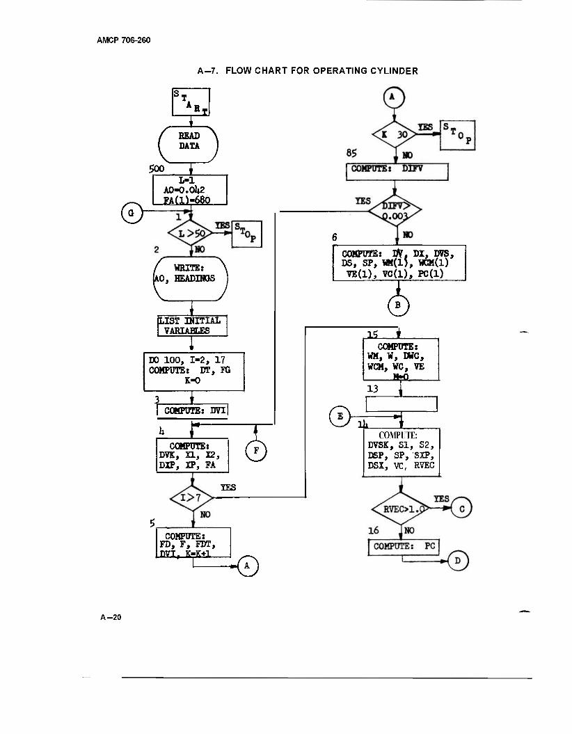
AMCP 706-260
A-7. FLOW CHART FOR OPERATING CYLINDER
R.
BEAD DATA
500
&
L-l A0«O.Ol»2 FA(l)-680
WRITE: 10, HEADINQS
ILIST INITIAL VARIABLES
DO 100, 1-2, 17 COMPUTE: DT, FG
COMPOTE: DVI
r COMPUTE:
DVK, XL, X2, DIP, XP, FA
© IES
COMPUTE: FD, F, FDT, DVI, K-K+l
■0
COMPOTE: OV, DI, DVS, DS, SP, WI(1), WCM(l) VE(1), VC(1), PC(1)
1* * COMPUTE:
WM, ¥, DWC, WCM, WC, VE M=Q__ 13
3 COMPUTE:
DVSK, SI, S2, DSP, SP, SXP, DSX, VC, RVEC
A-20
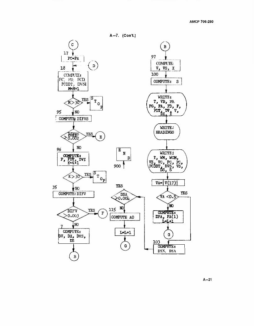
AMCP 706-260
A-7. (Con't.)
D 17
PC=PA
18
COMPUTE: FC, FD, FCD.
FC DDT, DVSI M»M+1
0
COMPUTE: F, FDT, DVI
K=K+1
COMPUTE: DV, DX, DVS,
DS
WRITE: T, VB, PA
FG, FA, FD, F,
/ WRITE: (HEADINGS
WRITE; T, WM, WCM,
VE, VC, PC, FC, FCDDT. DVS, VS,
YES
COMPUTE: DFA, FA(1)
103 COMPUTE:" DSN, DSA
A-21
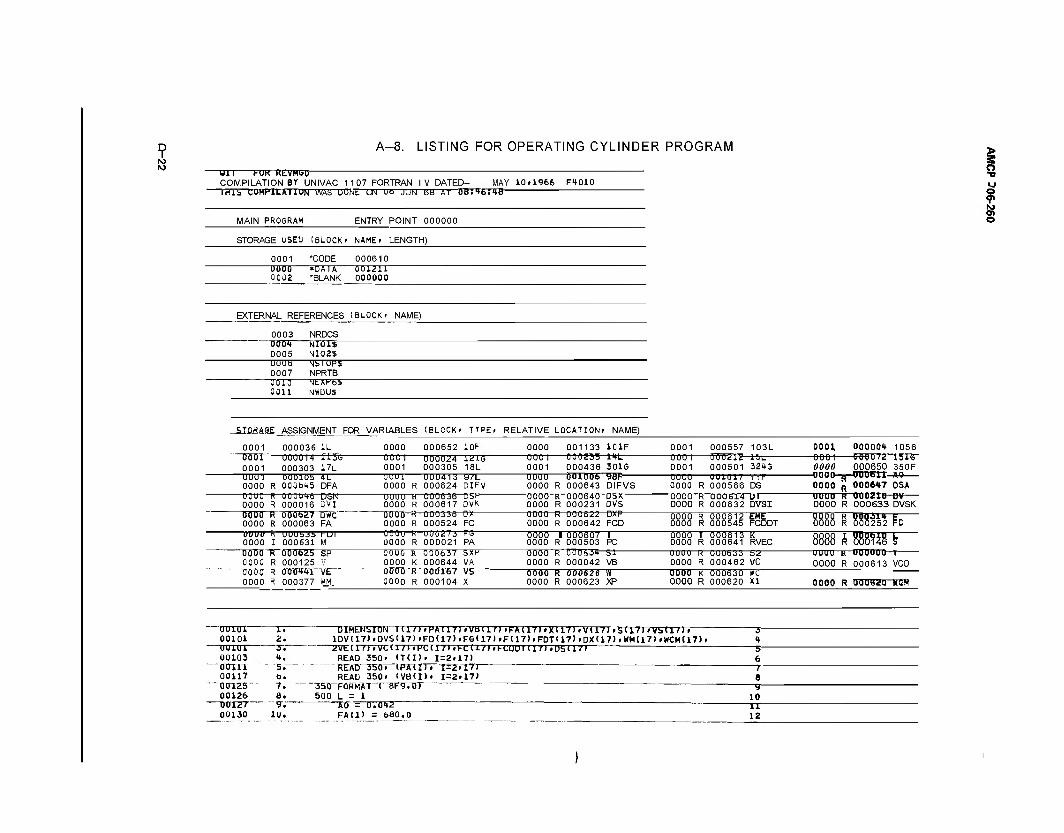
A-8. LISTING FOR OPERATING CYLINDER PROGRAM
Uli 1-OK KLVMbU COMPILATION BY UNIVAC 1107 FORTRAN IV DATED- MAY 10.1966 F4010 TMI5 CUW1LAI1UN WAS ÜONt UN Ut JUN ob Al U8:'»b:4ä
MAIN PROSRAM ENTRY POINT 000000
STORAGE USEU (BLOCK- NAME. LENGTH)
0001 'CODE 000610 U0U0 *0AIA 0002 *BLANK
001211 000000
EXTERNAL REFERENCES (BLOCK- NAME)
0003 NRDCS 000<* NlOlS 0005 NI02S UUUb NislOPi 0007 NPRTB UU10 NtXKbl 0011 NWDU$
kSE ASSIGNMENT FOR VARIABLES (BLOCK' TYPE. RELATIVE LOCATION. NAME)
0001 000036 1L 0000 000652 10F 0000 001133 101F 0001 000557 103L 0001 000004 1056 O0U1 000014 llJG 0001 000303 17L
0001 0001
000024 000305
1216 18L
0001 0001 000436
ltL 301G
0001 0001
Oflöüiü- 000501
-**t 32<»G
000 1 vwura isi6 0000 000650 350F
UUU1 Ö00105 4L 0000 R 000fai*5 DFA
UUUl 0000 R
UUU41i 000624
a/L DIFV
UUUU 0000
ÖUluuo R 000643
98F DIFVS
0000 0000 R
0 010"! ! 000566
r r r DS 0000 R 000647 OSA
UUUU R 000016 DSN 0000 R 000016 DVI
OOUO 0000
H R
UUUB3B 000617
Ü5R DVK
UUUU 0000
K UUUB4U R ÜÜÜ231
DSX DVS
UUUU 0000
R R
000614 000632
IM DVSI
UUUU K uuu£iu DV OOOO R 000633 DVSK
0000 R 000b27 DWC 0000 R 000063 FA
oouo 0000 R 000524 FC 0000 R ÜÜÜ642 FCD
0000 0000
R R
000612 000545 FCDDT OOOO R (3(58252 FD
UUUU R OUUbJb FDT 0000 I 000631 M oooo R 000021 PA
0000 0000
1 000607 R 000503 PC
st VB
ÖÖÖÖ 0000 UUUU 0000
1 R -R- R
000613 000641 UUU633 ÜÜÜ462
K RVEC 52 VC
8888 A 888W8 b 0000 Ti 00062b SP 0000 R 000125 V
üuuö 0000
R K
000637 000644
SXF VA
0000 0000
R ÜÖOAi*- R 000042
—uuuu k uououu—i 0000 R 000613 VCO
TT000 R 000~<**1 VE OOUO K 0000 R
000167 000104
vs X
0000 0000
R 000626 R 000623
w XP
0000 0000
K R
000630 000620
wc XI 0000 R 000377 WM. 0000 R 000(620 MGH
o
s ©
"uTrnn IT 00101 2. ooiui 00103 00X11 00117 00TZ5 00126
TT0T2T- 00130
DIMENSION l(l/>»PA(17>»VBTlM>FA(17)>XU'MtVa7>»SUM»VSU7)r lDV(17).DVSll7)»FD(17)»FGll7)fF(17)fF0T117)rDX(17)fWM(17)(WCM(17)r 2VElin.VCU/).MCa7).FCU7)»hCUDTII7).Ub(in
READ 350' IT(I). 1=2.17) 4. '5.~ fa. 7. a. 9V
1U.
REAir35Tr. (PAH). 1=2.17J READ 350. IVB(I). 1=2.17)
"351TFÖHMAT ( BF^rtrr 500 L = 1
AO = 0.01*2 FA(1) = 6B0.0
—9" 10
12
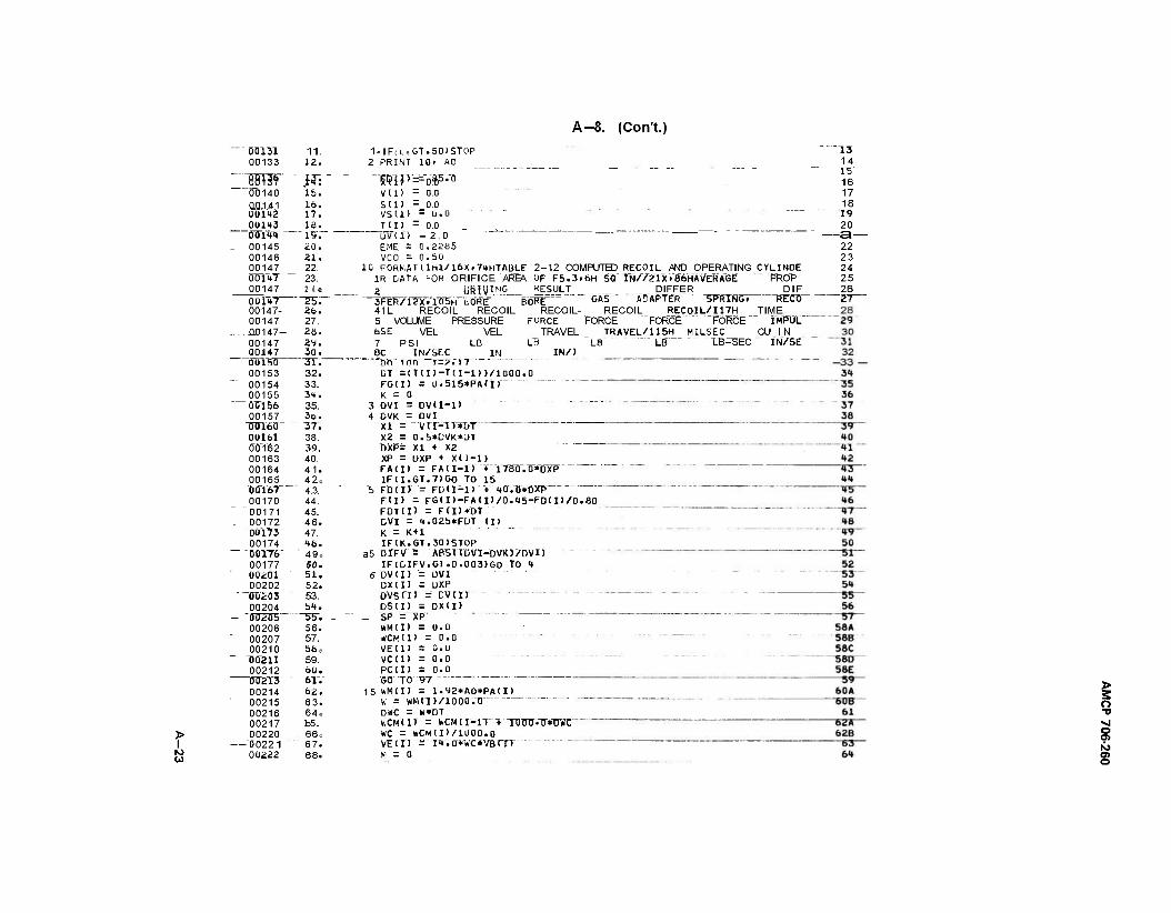
A-8. (CorVt.)
> I W
"" ÖD131 11. 00133 12.
Bin» 14: 00140 15. O0.1.41 16. 0U1H2 17. 0U143 ia. 01Tl4<>
... ig._
_ 00145 20. 00146 21. 00147 22. OOl^T 23. 00147 2 4 e
0U147 25". 00147- 26. 00147 27.
.. .0.0147- 20. 00147 2y. 00147 30. OIHÜÜ- ~~~3T."
00153 32. 00154 33. 00155 3H. ÜTJ156 35. 00157 3D.
TJOT60 37. 0U161 38. 00162 39. 00163 40. 00164 41. 00165 42, ÖÖY67 " 4.3. 00170 44. 00171 45. 00172 46. "00173 47. 00174 <ta.
_ "00176" ' 49, 00177 50. 00201 51. 00202 52.
"~<ro'203 53. 00204 bt.
- "SÜZU5' ~5W. 00206 56.
' 00207 57. 00210 böe
" D02U 59. 00212 60. DTT2T3 6V.
00214 62. 00215 63. 00216 64e 00217 b5. 00220 66 e
"00221 67. 00222 68.
1-IF(LeGT.50)ST0P 2 PRINT 10» AO
~TOF=-oFrfl
V(l) = 0.0 S (1) = 0.0 vsii) = o.u TJ1> - 0.0
DV'(l) -2.0 " " " " " EME = 0.2285 VCO = 0.50
10 F0RKATllHl/16Xr7itHTABLE 2-12 COMPUTED RECOIL AND OPERATING 1R DATA FOR ORIFICE AREA OF F5.3.6H SQ IN//21X/86HÄVERAGE 2 LiRIvING_ ÜESULT DIFFER
"~3"FlR?"lTx.Tff5'H~tÖRE"""" "BORE""" ""GAS" ÄÜÄPTER "SPRING. 41L RECOIL RECOIL RECOIL- RECOIL REC0IL/U7H 5 VOLUME PRESSURE FORCE FORCE FORCE FORCE 6SE VEL VEL TRAVEL TRAVEL/115H MILSEC_ 7 PSI LB LB LB" LB" "LB-SEC
CYLINDE PROP
DIF RXCÖ"
TIME IMPÜL"
CU IN IN/SE
"13 14 15" 16 17 18 19 20
—3— 22 23 24 25 26 _27—
IN/) ec A1^.!?.. _AM nh inn Tr?.Y"7~ DT =(T(I)-T(I-1))/1000.0 FG(I) = 0.515*PA(I) K = 0
3 ÜVI = DV(I-l) 4 ÜVK = DVI
xi = -A/rr-Tr*DT X2 = 0.5*CVK*DT nxp= xi + X2 XP = DXP + X(I-l) FA(I) = FA(I-l) + 1780.0*OXP IF(I.GT.7)G0 TO 15
5 FO(I) = FD<I-1> "+' 40.0*OXP FID = FG<I)-FA(I)/0.15-FD(I)/0.80 FDT(I) = FCI)*DT CVI = "♦.02b*FDT (I) K = K + l IF(K.GT.30)STOP
a5 DrFV"'- ABSTIDVI-DVKJTDVn IF(DIFV.GT.0.003)GO TO <*
fiövii) '= üvi DX(I) = ÜXP Dvsm = cvrn " - DS(I) = DXCI)
_ SP = XP " "- wM(l) = 0.0 *CM(1> =0.0 VE(1) = 0.0 vcu) = o.o PC(1) = 0.0 GO" TO 97
15 *M(I) = l.y2*AO*PA<I) w = wMm/iooovo DVIC = W*OT KCMUT - WCMII-D~+ TDÜÜ.TT»D¥C WC = *CM(D/1Ü00.0 VE(I) ="i«.o"*wc*vBrrT M = 0
> 3 o ■o
? o
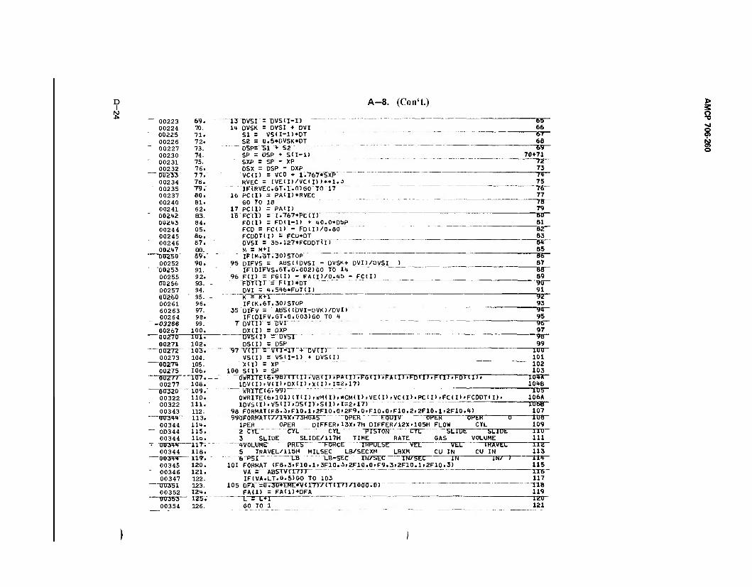
A-8. (Con't.) to
— 00223 69. 13 ÜVSI = TJVSU-1) 6b 00224 70. It OVSK = DV&I + DVI 66
" 0D225 71. SI = V5(I-1)*0T bt 00226 00227
72. 73.
S2 = 0.5*DVSK*DT 68 D5P= "51 + 52 69
00230 74. SP = ÜSP + SU-1) 70+71 " 00231 75. SXP = SP - XP 7Z
00232 — ÖTJ2K
76. 7 7.~
OSX = DSP - DXP 73 VCCI) = VC0 + 1.767*SXP 7»
00234 " 00235
78. 79.
RVEC = (VE(I)/VC(I))**1.3 75 IFtRVEC.GT.l.OlGO TO 17 76
00237 80. 16 PC(I) = PAH) »RVEC 77 00240 81. GO TO 18 78 00241
' 002<*2 62. 83.
17 PCID = PAID 79 IS FCU> = 1.767*PCtI) 80
002*3 84. F0(I> = FDII-1) + 40.0*DSP 81 00244 05. FCO = FC(I) - FD(11/0.80 82 00245 6o. FCUOTU) = FCU*DT 63 00246 87. DVSI = 35.127*FCD0T(I) 84 00247 88. M = M+l 85
QD25D' 89"." " " IF(M.GT.30)ST0P 86 00252 90. 95 DIFVS = AbSUDVSI - DVSK+ DVD/DVSI ) 87
" "00253 91. IF(DIFVS.GT.O.002)GO TO 14 88 00255 92. 96 FU> = FGU) - FA<I>/0.4S> - FC (I) 89 0TJZ56 93. - FDT(I) = FII)*DT 90 00257 CJ026Ö
94. 95. -
DVI = 4.546*FL>T(I) 91 K = K+l 92
00261 60263
96. 97.
IF<K.GT.30)STOP 93 35 DIFV = ABS((ÜVI-DVK)/DV1) 91
00264 98. IF(DIFV.GT.0.003)GO TO 4 95 -03266 99. 7 DV(t> = DVI 96 00267 100. DX(I> = OXP 97 DU27D 1U1. ÜVSW = uvsi 00271 102. DS(I) = DSP 99
""00272 103. 97 V(I) = VI1-1) + DVIIJ 101)
00273 104. VS(I) = VSII-D + ÜVS(I) 101 0Ö274 105. XI) = XP 102 00275 00277 "
10&. ~1TJ7.--
100 S(I) = SP 103 0wRlTE<6.9B>(T<I>.'VB<I).PA<I>>FG<I>>FA(I>.FDtI>.F<I>>FDTII>. 104A
00277 108. 1DV<I).V<I>>DX<I).X(I>>1=2.17) 104B
"DTJ320" _ iwr " WRTTET6.99)- " lUb
00322 110. 0WRITE(6.101)<T<I>.I»'M<I>.*CM(I>.VECI>»VC<I>.PC(I).FC<I>»FCDDT(I)» 106A 00322 in. 1DVS(I).VS<I).DS(I).S(I).I=2»17) lUbB 00343 112. 98 FORMAT(F8.3.F10.1.2F10.0'2F9.0.F10.0.F10.2.2F10.1»2F10.4> 107
—mran«»" 113. y90FORMAT(//14Xi/3HGAS OPER EOUIV OPtK OPtR U IDS 00344 lit. 1PER OPER DIFFER.13X.7H DIFFER/12X.105H FLOW CYL 109
" OD344 115. 2 CYL CYL CYL PISTON CYL SLIDt SLIDt 110 00344
- -msw~ Ho.
-"117^ - - 3 SLIDE SLIDE/117H TIME RATE GAS VOLUME 111 IVOLUMt PKLb hUKCt. IMPULSE VEL VtL IKAVtL 11£
00344 118. 119".
5 TRAVEL/115H MILSEC LB/SECXM LBXM CU IN CU IN 113 UU344 6 PSI LB LB-StC IN/b>tC IN/SEC IN IN/ ) 114 00345 120. 101 FORMAT (F8.3.F10.1.3F10.3.2F10.0.F9.3.2F10.1.2F10.3) 115
- 00346 121. VA - ABSIV(IO) " " 116 00347
■ "XlUibl 122. 123.
IF(VA.LT.0.5)GO TO 103 117 105 DFA =0.30*EME*V(17)/(T(l/)/1000.0) TIB
00352 124. FA(1) = FA(1)+DFA 119 0U353 " I25V L = L+l 1SJU
00354 126. GO TO 1 121
> 3 o •sj
§ 5?
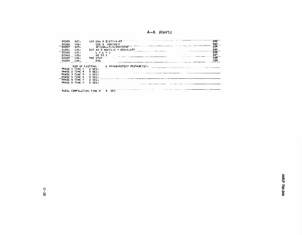
A-8. (Con't.)
(10355 00356
00361 ÖÖ362 00363 0036"»" 00365
127. 126. 129. 130. 131. 132. 133. 13t.
103 OSN = S(17)-1.67 "" DSA = ABS<0S;J) IF(DSA. LT. 0.0DHT5TÖP"- "
115 AO = AO*<1.0 - DSN/1.67) L = L + 1 60 TO 1
900 STOP END
izzr 123
TZT 125
TZB~ 127
-~rar 129
PHASE PHASE PHASE PHASE "PHASE PHASE
END OF LISTING. TIME TIME TIME TIME TIME TIME
SEC. SEC. SEC. SEC. SET." SEC.
0 »DIAGNOSTIC* MES&AGE(S>.
TOTAL COMPILATION TIME = SEC
D I
O TJ
9 O) O
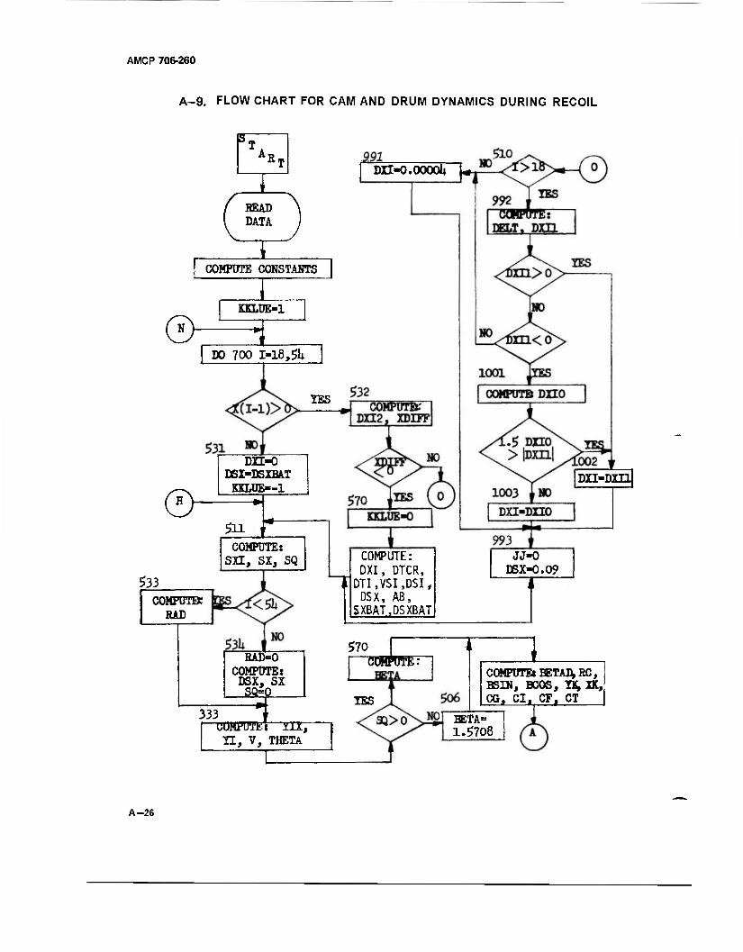
AMCP 706-260
A-9. FLOW CHART FOR CAM AND DRUM DYNAMICS DURING RECOIL
R, DXI-0.000QU «
READ DATA
COMPUTE CONSTANTS
I KKLÜE-1
$y^i I DO 700 1=18,$h
YES
d> DXI-0
DSX-DSXBAT KKLÜE--1
511 X COMPUTE: sn, sx, SQ
533 COMPUTE* RAD
DXI-DH1
COMPUTE: DXI, DTCR, DTI,VSI,DSI, DSX, AB,
SXBAT,DSXBAT
JJ-0 DSX-0.09
RAD-O COMPUTEi DSX, SX SQ»P
333
$70 i COMPUTE:
YES
CUMPUTE: Y1X, II, V, THETA
I
COMPUTE: BETAD, RC, BSIN, BCOS, YK, XK, CO, CI, CF. CT
BETA= 1.5708
A-26
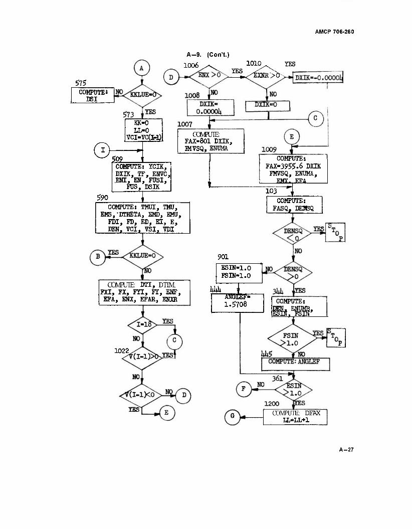
AMCP 706-260
A-9. (CorTt.)
1006
575 COMPUTE»
DSI
1010 YES
™ Äs
0 KK-0 LL»0
VCI-VC(Hj
|Q2_
COMPUTE: FAX-801 DECK, 5MVSQ, ENÜMA
590
COMPUTE: ICIK, DXIK, TF. ENVC, .ENI, EN, FUSI,
FÜS, DSIK
I COMPUTE: TMUI, TMU,
EMS/DTHETA, EMD, EMU, FDI, FD, ED, EI, E, DEN, VCI, VSI, 7DI
CCMFUIE: DTI, DTIM, FXI, FX, FTI, FT, ENF, EFA, ENX, EFAR, ENXR
1022
COMPUTE: FAX-3955.6 DECK
FMVSQ, ENUMA, KMY.,EFA
103 COMPUTE:
FASQj DE3BQ
901
ESIN-1.0 FSIN-1.0
1|)|)| AM5LEJI
,=
1.5708 COMPUTE: DEN. ENUML, Esro "FSCT*
COMPUTE: DFAX LL-LL+1
A-27
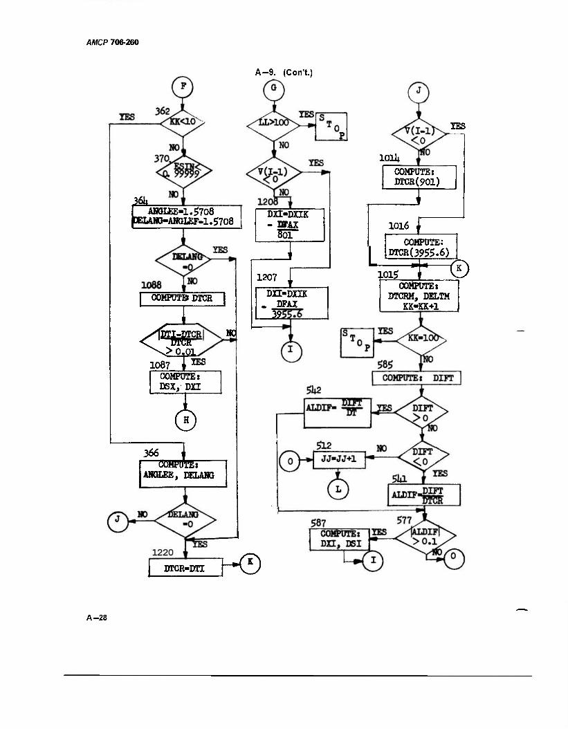
AMCP 706-260
A-9. (Con't.)
101U
m I AHOL pBLANCK
AHOI£E-1.5708 'AHGLEF-1.5708
| CQMFÜTBDTCR
I ^Q> 0,01
1087 j"8
MC
COMPUTE: DSX, DXI
366 TO —OTTOBI—
ABGLEE, DELANO
DXI-DHK - njAx
IBS
COMPUTE: DTCR(901)
1016
COMPUTE: DTCR(39#.6)
1207
DXI-DHK - DFAX _J2J
:ipr© 101$ COMPUTE:
DTCRM, DELTM KK-KK+1
DTCR-DTI KD
A-28
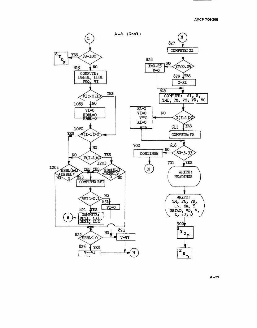
AMCP 706-260
A-9. (Con't.)
COMPUTE: SI, S, TMI, TM, VS, YD, VC
1202
/C\ COMPUTE: ( H >—DDTI, DXI,
DDSI; DSX' ■*!•
/"V
WHITE: TM, FA, FD,
EN„ SXt Y BETAD, TO. V,
90oj 82U
V-VI
V—VI L0 N
A-29
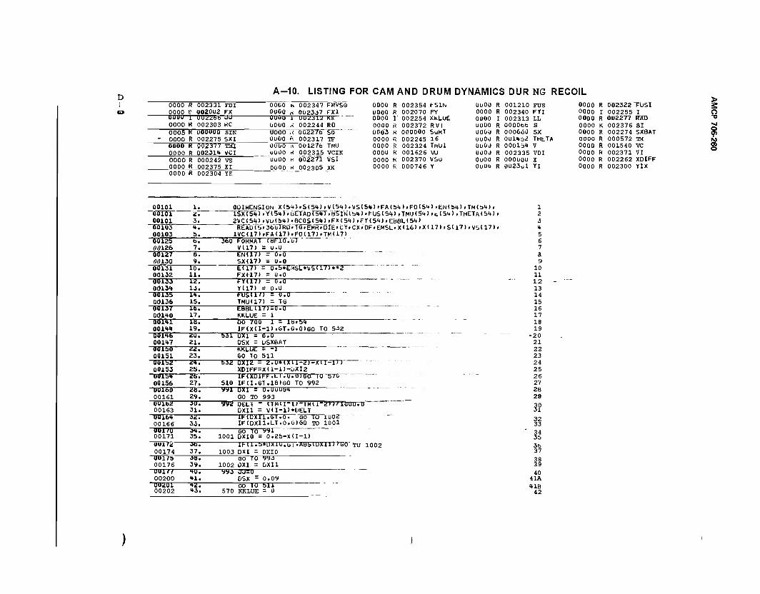
D I 0000 R 002331 FDI
0000 t> 002002 FX 0000 -U3- 1 UU2266 0000 H 002303 KC 0005 K 00ÜOUQ SIN 0000 R 002275 SXI_ 0000 R 002377 TMI 0000 R 00231t VCI 0000 R 000242 VS 0000 R 002375 XI
A-10. LISTING FOR CAM AND DRUM DYNAMICS DUR NG RECOIL 0000 n 002347 FMVSQ 0000 n 002337 FX1
0000 R 002304 YK
UuOO 1 UU2312 KK UOOO ,-i 002244J*D UOOO ."< ÖC2276 SQ ÜÜÜO ft 002317 TF 001)0 i< 001276 TMU UOOO K 002315 VCIK OUÜ0 n ÖÖ2271 VSl 0000 H 002305 XK
ClOOO R 002354 FSIN 0000 R 001210 PUS 0000 R 002322 "FÜSI 0000 fi 002070 FY 0000 R 002340 FYI 0000 I 002255 I 0000 1' 002254 KKLUE 0000 I 002313 LL 0000 R 002277 KÄD 0000 B 002372 RVI 0000 R OOOObb S 0000 K 002376 SI 0Ö03 H 000000 StlKT 0OÜO R 000660 sx 0000 R 002274 5XBAT 0000 R 002245 16 UUOO R 001462 THtTA 0000 R 000572 TM 0000 R 002324 TfoUI 0UÜÜ R 000lb4 V 0000 R 001540 VC 0000 H 001626 VU 0000 R 002335 VDI 0000 R 002371 VI 0000 R 002370 vso 0000 R 000ÜOO X oooo R 002262 XOIFF 0000 K 000746 Y ouoo R 0023ul Yl 0000 R 002300 YIX
> 2 o
9 ©
00101 00101 00101 00103 00103 "55125" 00126
00147 OUlbO 00151 00152 00153 0UI54 00156 OUlbO 00161 0U162 00163 00164 00166 001/0 00171 00172 00174
"00175 00176
-00177-
b. 7.
21. £2. 23.
T47 25. zt>. 27.
-Z&7- 29.
-3TT7-
31. SZT
Ob. 37. ■ZU. 39.
"TOT"
__0ÜIMENSION_X(54>_»SI54> »V(5l») .VS(54) »FA154) rFD(54) .EMb4> .TM(S4> , 1SX<54).Yi545.bETÄDr5Inr,BSlN(b4)«FUS(54),TMU(54)it(54)>THETA(54)>
_2VC( 54)_. VU (54) »BC0S(54); FX < 54) . FY < 54 ) . EBBL ( 54 ) REAO(S»36orRO.TG»EMR»DTE»CY.CX>DF>EMSL»X<16>iX(17)>S(17)PVS(17)P
lVCU7)rFAU7)'F0(17>»TM(17) ul 360 FORMAT foFlO
VU7) = 0.0 00127 00130
8. 9.
EN(17) = 0.0 SX(17) = 0.0
00131 00132
10. 11.
E(17) = 0.b*EttSL*VS<171**2 FX(17> = 0.0
00133 00134
12. 13.
FY(17) = 0.0 Y(17) = 0.0
00135 00136
14. 15.
FUSU/l - 0.0 TMU(17) = TG
00137 00140
16. 17.
EBBLI171=0.0 KKLUE = 1
00141 00144 19.
Dö 7ÖÖ I - lb.54 IF(X(I-D.GT.O.O)GO TO 532
00146 20. 531 UX1 - 0.0 DSX = USXBAT
KKLUE = -1 60 TO 511
532 DXI2 = 2.U*IX11-2J-XII-1>J" XDIFF=X(1-1)-UXI2 IKXD1F-F.LI. .U.U1GG 1Ü b/0
510 IFCI.GT.18)GO TO 992 yyi DXI = 0.UOÜU4
GO TO 993 yy«! UELT - nmi l.-|Mil-2))UU0U.Ü~
OXI1 = VU-1)*DELT IFtDXIl.GT. 7ÖT~ GO TO 1002
33. IF(DXIl.LT.0.ü)GO TO 1001 ~s<*i GO TO yyi 35. 1001 DXIO = 0.25-XU-l) lr-ll.b*DXi0.öi.ABblUXll)>yO"TU 1002 1003 OXI = DXIO
GO TO yyj-
1002 0X1 = DXI1 yyj JJ50
00200 41. DSX = 0.09 UU201 00202
»2. 43.
GO 10" bll 570 KKLUE = 0
1 2 3 4 5 6 7 a 9
10 11 12 13 14 15 16 17 18 19
-20 21 22 23 24 25 26 27 28 29
ll° 32 33 34 35 36 37
38 39 40
41A 41B 42
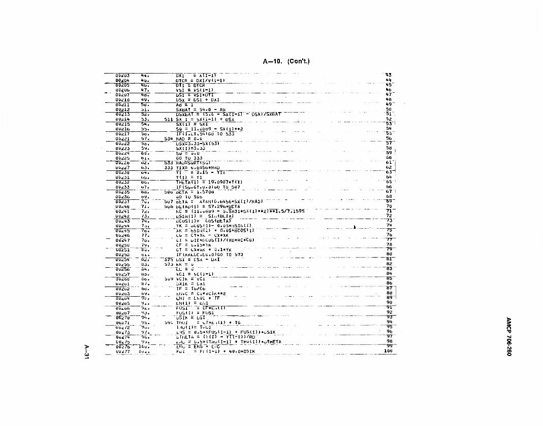
A-10. (Con't.)
00203 41. UXI = Xll-ll 00204 4». ÜTCR = DXI/VU-1) 0Ü2Ö5 4b. DTI = DTCH 00206 47. VSI = VSU-1) 00207 4e. uSI = VSI»UTI 00210 49. USX = DSi + 0X1 00211 50. Ad - 1 0O212 51. SXBAT = 54.0 - Ab 00213 52. DSXbAT = (b.O - S'x(I-l) - DSXI/SXBAT 00214 53. 511 SX I = bXli-1) + DSX 00215 54. SX(1) = SXI 0021& bb. SO = 11.0889 - SX(I)**2 00217 5o. IFU.LT.bDGO 10 533 00221 57. 534 RAD = 0.0 00<:22 5B. USX=3.33-SX(53> 00223 by. 5X(l)-3.33 00<:24 60. Su - u.O 0022b bl. GO TÜ 333 00*26 ut, 533 HAü=buRTlS<») 00227 b3. 333 YIX= 0.64bb*R«U 0Ü230 Dl. YI = 2.15 - YIX 00*31 bb. Y<I) = YI 00232 6cj. THtTA(I) = 19.0987*Y(I> 00233 b7. IFlS(*.GT.U.0)uO TO 507 0023b bb. bub üETA = 1.5708 00236 by. 60 TO 50b 00237 ~7ü. 5u7 DETA = ATAN(ü.6456*SX(l)/RA0r
00*10 71. büö bETAÜlI) = 57.29b*»ETA 00211 ?*. hC = <ll.u889 - Q.5831*SX(I)**2>**1.5/7.1595 00242 73. üSIMl) - SIn(BLTA) 0ut43 7i. t>COSU> = COSlbETA) 00*14 7D. YK - otOSU)- 0.05*bSIN<I> 0U245 70. "xk = bsiHti) "♦ 0".ö5*bC"öS'(ir 0U2t6 77. to = CY*YK - CX*XK 00217 ^7o. CI = blE*bC0S<I>/<RD*RC*CG) 00250 7y. CF = 0.1b*YK 002bl tu. CT = <-X»AK + D.1*YK 00*b2 bi. IF(KKLUE.L<i.0>GO TO 573 OUcbl B*.~ 575 LSI"= DSX - üxl 00*bb bO. 573 KK - U Tj025b o4. "■XL="o """ " " """~ 00*b7 03. vci = vcu-i) Ü02oü bo. 309 VC1K = VCi 0U2D1 b/. ÜXIK = DXl 002o2 bb. TF = Tfa/Cb 002o3 by. LI\i\,C = Cl*VClK**2 00ib4 91. ENI = EMVC + TF 002O5 v.. LN(l) = EM UUtub 52. FUSI = tF*E;.U> 00267 93. FuStII = FÜSI 0C*?0 94. ÜSIK - übl . 00271 Vb. b9U TMUI = tT*t.i(I) + T6 Ou*72 9U. iMuU> = Tl-L.1 00*73 y/. c:-AS - 0.b*(FUb(I-l) + FUS(I))*uSIK 0u274 ^. oThETA = run"- YTT=T.T17RD OOt/b yy. tMl/ = 0.b*(T,.lU(I-l) + TMU(I) )*üTHETA
> 00*76 lOu. EMU = EMS + ti-ID I 00277 iüi. FLü = Fl. (I-l) + 40.0*05IK
^3 44 45' 46
^vr 48 49 50 51" 52
~53" 54 55 56 "3r 58 59 60 61 62
"63" 64 65 66 67 1 68
70 ~71_
72
74 75" 76 T7" 78
100
> 2 o ■v
s ©
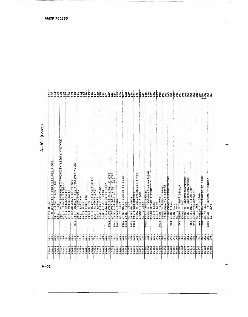
AMCP 706260
3oboortfHrtHHHrfHHHNN«N«SiBiNNNn')Oinii)i<)f)iof)**»»jjt»»*»winii)l!ji«)«iriifi
c o o
I <
A-32
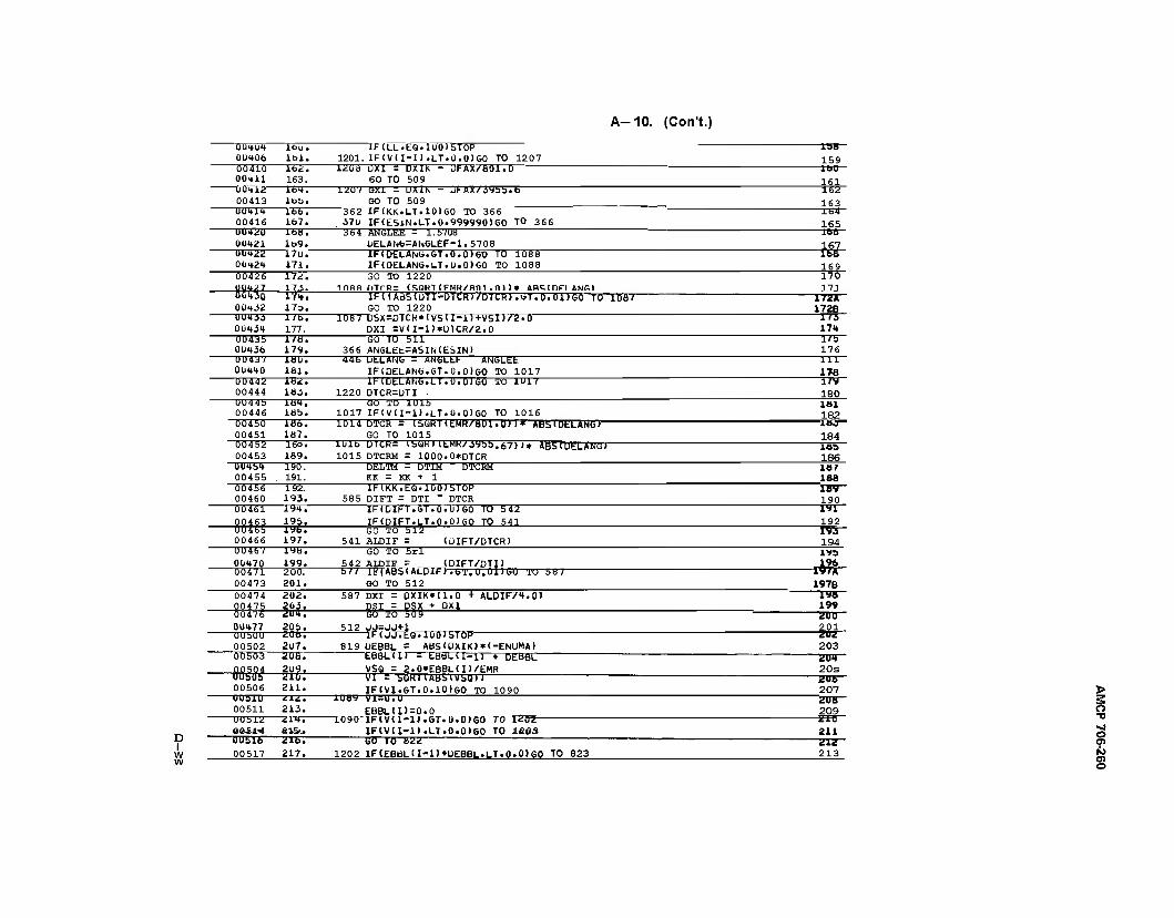
A-10. (CorTt.)
D I w w
OUHUU 00406 00410 0Ü411 -0Ü412-
00413
00416 U042U 00421 ~ÜÜ4Z2~ 00424 00426
001*30 00432 0U433 0Ü434 00435
UU4J/ 00440 00442 00444 UU44b 00446 00450 00451 00452
0Ü454 00455 00456 00460 00461 00463 0046b 00466 UU46V 00470 00471
lbu. lbl. Ib2. 163. 1D4.
los.
1201. lüüü
IF(LL.EQ.lO0)STOP 1F(V(I-1).LT.O.OIGO TO 1207 ÜX1 = DXIk - DFTOr/fiOl.O 60 TO 509
UX1K - L)FAX/jybb.6 1207 GXI GO TO 509
16b. 167. IfaH. Ib9. ~17o.~ 171.
362 37U ^3TT
1F(KK.LT.10)60 TO 366 IF(ESiN.LT.0.999990)60 TO 366 *VV*T W—■ 1—L'JMU MTGLEE = 1.570b ÜELAN6=AN6L£F-1.5708 IF<DEl-AN6.6T.0.0>GO TO 1088 IF<DELAN6.LT.0.0)60 TO 1088
172. 173.
TTHT 173. 1/b. 177. 1/B.
00436 179.
GO TO 1220 DTCR= ISQRT(EMH/fl01.0))* ARS[DFLANfil IFUABSIOTI-DTCRWDTCRJ.UT.O.üDGÖ TO 1087 GO TO 1220
1ÜH7 DSX=DTCR*r\TS(I-l)+VSI)/2.0" DXI =V(I-1)»OTCR/2.0
1HÜ. 181.
-razz- ias. 1Ü4. lob.
GO TO 511 366 ANGL££=ASIN(ESIN>
UtLANb = ANfaLEF ANGLEt IF1DELANG.GT.0.0)60 TO 1017 IMUtLANG.LT.U.0)6Ö TO 1U17
1220 OTCR=UTI ÖÖ TO 1015
lob. la7. 166.
00453 189.
1017 1014
IF(V(I-1).LT.0.0)60 TO 1016
lUlb 1015
DTCR = (SükllEMR/801.0))* ABSlGELANGr GO TO 1015
"T5o7 191.
UICM= IbUKUEMK/.i'Jbb.b/))« At)5tutLAnar DTCRM = 1000.0*DTCR DELTM = DTIM KK = KK + 1
DTCRM
192. 193.
19b. 19b. 197. 19b. 199. 200.
585 IFIKK.EQ.10Ö15TÖP DIFT = DTI " DTCR "IF(DIFT.GT.0.U)6Ö TO 542 1F(OIFT.LT.Q.O)GO TO 541
<i)IFT/DTCR)
00473 201.
SO TO 512 541 ALDIF = ÖÖ TO Sri 5 42 ALDIF = _<DIFT/DTI) bir IF(ABS~(ALÜIF7.6T.0.01T6O TU 587
GO TO 512 00474 00475 0047^" 0U477 UUbUU 00502 00503
-mi-
202. 203. 2U4.
20b. 20b. 2U7. 20a. 2U9. 210.
587 DXI = DXIK*Tr7TS + ALDIF/4.0) DSI = DSX ♦ OXI GO To 509 512JJ=ja+l
IF< JJ7E0.100)STOP 819 OEBBL =
EBBL"(ir ABS(DXIK)*(-ENUMA)
= LBBLll-1) + DEB6L VSQ = 2.0»EBBL(I)/£MR VI = SORIlABblVbOJ)
158 159 iao 161 1S2
163 164 165 166
167
170 111
T7ZJT 172B -ITT" 170
—T75-
176 —TTT- 178 i/y 180 lai 182
-IB3- 184 IBS 186 16 T 188 IB9-
190
192 "193- 194
-I97JT" 197B
1W 20D
-M- 203 201 20s
-ZOB- 00506 211. IF(VI.6T.0.10)GO TO 1090 207 UU31U 00511
212. 213. EBBL<1)=0.0
2U8 209
00512 0«S4-4
214. SIS'..
luyu 1HVU-II .ÖT.0.0)60 70 1*02 IF<V(1-1).LT.0.0)60 TO k&®3
E1U
211 uusib 00517
Ü16.
217. GO TO B22
1202 IF(EBBL<l-l)+UEBBL.LT.0.0)GO TO 823 Z1Z 213
o w 01 o
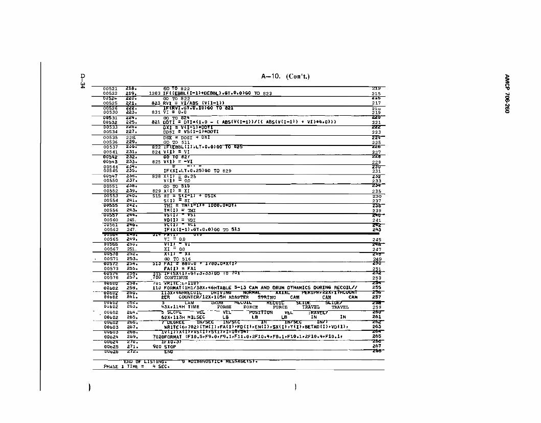
D I
CO
A-10. (Con't.)
00521 00522
216. 219.
60 TO 822 1203 IF((EBBL(I-1)+DEBBL>.GT.O,0>GO TO 823
219 215
0U524 00525
220. 221.
GO TO 822 823 RVI = VI/ABS IVU-l))
21b 217
00526 00530
222. 223.
IF(RVI.GT.0.10)60 TO S21 831 VI = 0.0
21u 219
00S31 00532
224. 22b.
GO TO 824 821 OOTI = DTI»(1.0 - ( ABS(V(I-l))/(( ABS(V(I- -11 > + VII»4 .0)))
220 221
ÖÖ533 00534
226. 227.
OXl = vn-l)*DDTI DDSI = VS<I-l)*ODTI
222 223
00535 00536
228. 229.
DSX = DOSI + DXI GO TO 511
ZZ4— 225
00537 00541
20U. 231.
822 IF(£BBL(I).LT.0.0)GÖ 10 8US) 824 Vll) = VI
22b 227
00b42 00b43
232. 233.
GO TO 827 825 VII) = -VI
228 229
00544 00545
231. 23b. IF(XI.LT.0.25>GO TO 829
23U 231
00b47 00550
236. 237.
828 X(I) - 0.25 V CI > - 0.0
232 233
00551 00552
23a. 239.
GO TO SXO 829 X<I> = XI
234 235
00553 00554
240. 241.
515 SI = 51I-1J + DSIK S(I) - SI
230 237
0Ü555 00556
242. 243.
TMI - TMU-U + 1000T0*DT1 TM(I) = TMI
2 OB 239
'UUbb/ 00560
244. 245.
vbll) " VS1 VDtl) = VDI 241
UUbbl 00562
2<*6. 247.
VCUJ " YCi IF(X(I-l).GT.0.0)GO TO 513 243
00565 249. VI - 0.0 245 ÖU555 00567
2SU. 251.
Vll) " VI XI - 0.0
246 247
UUb/U 00571
ZS2. 2b3.
XIIJ " XI GO TO 516
248"" 249
UUb/2 00573
2S4. 2bb.
bli FAI = BBU.U + 1/8U.0*X(I> FA(D = FAI
2SU
251 UUb/4 00576
2b6. 2b7.
31b lMbXU).bl.3.33)G0 IU '01 .700 CONTINUE
232 253
UUbUU 00602
2bU. 259.
101 WRITEibtllU) 110 FORMAT(1H1/38X»46HTABLE 5-13 CAM AND DRUM DYNAMICS DURING RECOIL//
254 255
UU6U2 00662
2bU. 861.
113X»4bHKtLUIL UKIVlNb NUKMAL AXIAL SER COUNTER/12X>105H ADAPTER SPRING CAM
KtKlHH» ZZXf IfHCUUNl CAM CAM
23b 257
UU6UÜ 00602
<LOtL.
263. 3 LAM UKUM PIH.U1L Kt 43XrU4H TIME FORGE FORCE
XUIL FORCE
< V LB
SLiUt TRAVEL
SLlUbV TRAVEL
Ü5B-
259
ÜU6U2 00602
264. 26b.
b SLOPE VLL VEL HOSlllOr' 62X»113H MILSEC LB LB
EL IKAVEL/ IN IN
261) 261
0U6Ü2 00603
2bfa. 267.
/ UtGKtt IN/SEC IN/SEC IN WRITEl6r702)(TM<I)rFA<I>'FO<I><EN(I>i
lN/btt SX(I)-Y(I)
IN/) rBETADU)'VD(I)'
262 263
UObUi 0062"*
übö. 269.
IVU) »XI1)» Vbll) »bill »1-I8.b4l 7020FORMAT (F10.5»F9.0fF9.1fF11.0-2F10.» F8.1» F10.1 .2F10.4<F10.1»
264 265
ÜU624 0062b
Ü/U. 271.
1F10.J) 900 STOP
266 267
UUo26 272. END 268
PHASE ENU OF
1 TIME LibllNG. U «UlAbNUbllC* MLSSAbL(b).
= 4 SEC.
^1 o
8 o
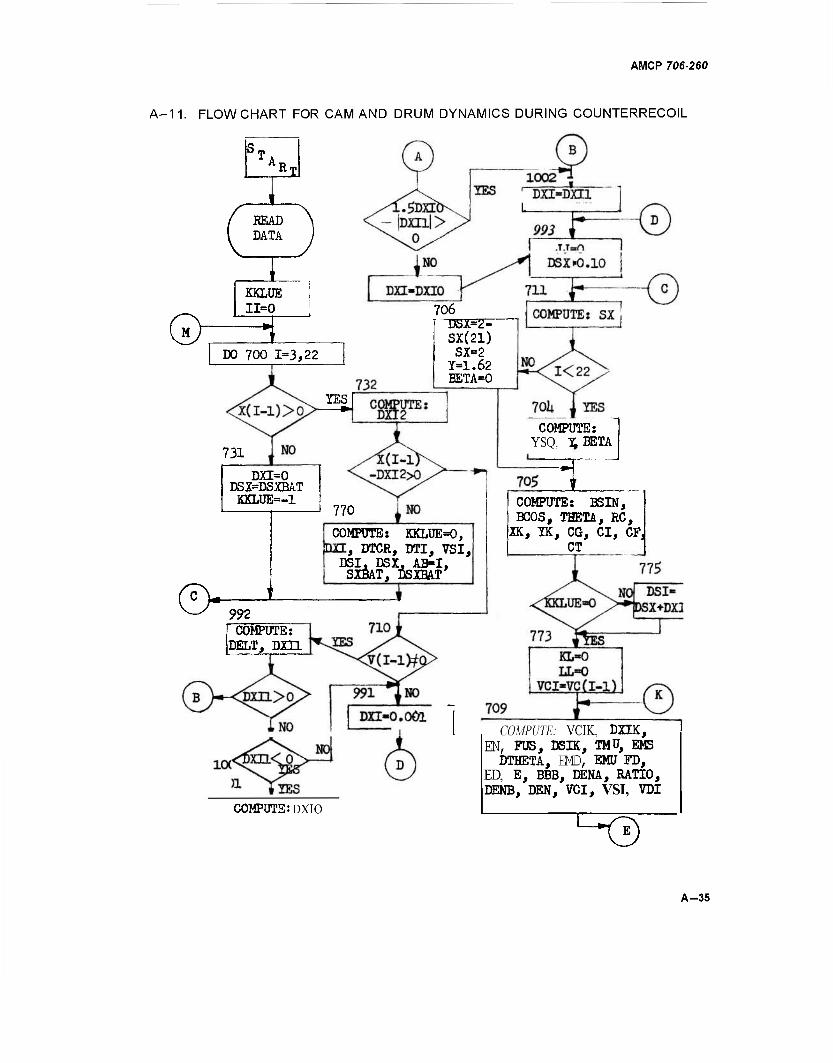
AMCP 706-260
A-11. FLOWCHART FOR CAM AND DRUM DYNAMICS DURING COUNTERRECOIL
READ DATA
I KKLUE 11=0
Gfc3 DO 700 1=3,22
706 [ DÜX=2-
SX(21) SX=2
T-1.62 BETA-0
YES
731
DXI=0 DSX=DSXBAT
KKLUE=-1
©■
) 770
COMPUTE: YSQ, ^BETA
COMPOTE» KKLUEO, DU, DTCR, DTI, VSI,
DSI. DSX, AB-I, SXBAT, DSXBAT
992 COMPUTE:
PELT, DXIl
COMPUTE: BSIN, BCOS, THETA, RC,
IK, IK, CG, CI, CF CT
COMPUTE: DXIO
COMPUTE: VCIK. DXIK, EN, FUS, DSIK, TMU, EMS DTHETA, EMD, EMU FD,
ED, E, BBB, DENA, RATIO, DENB, DEN, VCI, VSI, VDI
A-35
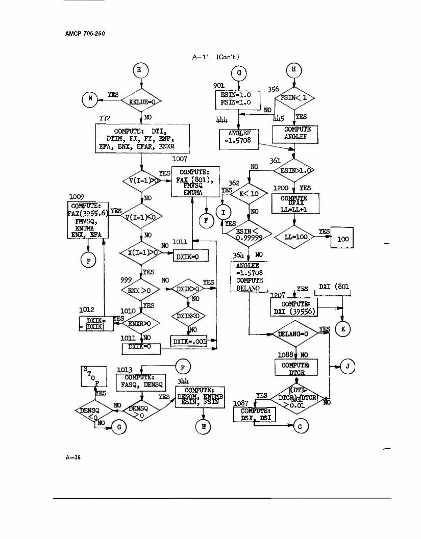
AMCP 706-260
0. YES
772
A-11. (Con't.)
901 ESEKL.O FSIN=1.0
hkk COMPUTE: DTI,
DTIM, FX, FY, ENF, EFA,-ENX, EFAR, ENXR
1009
COMPUTE: FAX (801),
FM7SQ ENUMA
COMPUTE: FAX(3955.6^
FMVSQ, ENUMÄ.
ENX, EFA
ANGLEF "1.5708
GOMPUTE ANGLEF
100
36U ^ NO ANGLEE -1.5708 COMPUTE DELANO
J1207 ♦ YES DXI (801
COMPUTE« DU (39556)
COMPUTE: DENOM, ENUMB
ESDI; FSIN COMPUTE: DSX. DSI
,1067 T >v>0.01
A-36
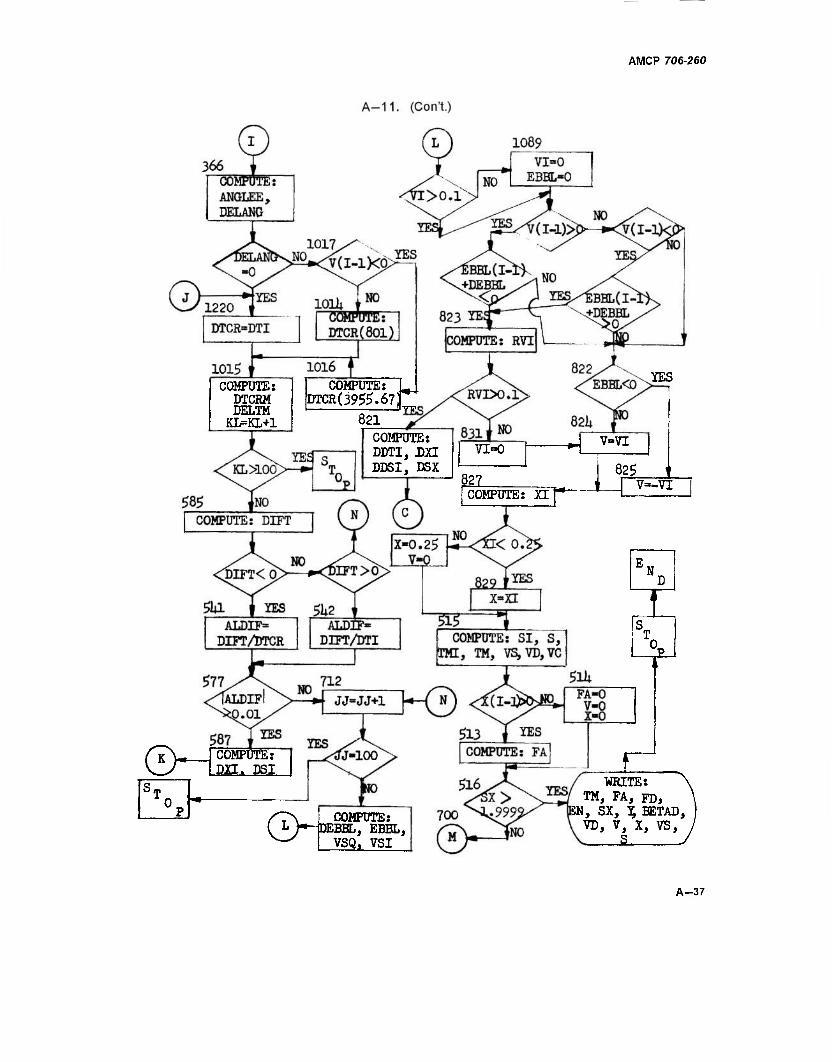
AMCP 706-260
COMPUTE: DTCHM DELTM
KL=KL+1
COMPUTE: L DTCR(39^.67f^
821
YES
COMPUTE: DDTI, LXL DDSI, DSX
822 |COMPUTE: XI
GW
V=VI
825 V—VI
'N.
! T. 0
COMPUTE: DXI. DSI
S~\ COMPUTE; ( L h-DEBBL, EBBL, ^-^ I VSQ, VSI
WRITE: TM, FA, FDf
SN, SX, % BETAD, VD, V, X, VS,
„5
A-37
> I
CO 00
A-12. LISTING FOR CAM AND DRUM DYNAMICS DURING C0UNTERREC0H
8888 1mm 161° 0000 R 001035 FAX 0000 R 000642 FX
ÖÖÖÖ R ÖÖÖ3Ö6 HU 0000 R 000670 FY
ÜÜÜÜ K ÖÖ1Ö36 mVifl 0000 I 000756 I
DOQQ I 59077* JJ 0000 R 000777 RC 0005 R 000000 si 0000 R 000130 THt*TA
0000 I Ö0075U KKLUE 0000 R 000744 RD
„00000 SORT
m f MM» a»
R 800436 TM
8888 i mm Bi 0000 R 000102 SI-
0000 R 001066 TMI
8888 & 8848B2 F UUUU K 000770 bXbAI 0000 R 000410 TMU
8888 B 882S#§ Vi 8888 1 88oeEg W 8888R 88MH MK 88881 mm VS« BOOO R 001064 XI 0000 « UUIUQO XK OOOO R 000026 Y 00C0 R 001001 YK
00101 1. [(DIMENSION X(22) >Y(22> »S(22> >SX(22) >THETA(22> rBETAD(22) rBSIN(22) • 1 001ÖI 00101
2. 3.
löe0S(2^>'FA(22WFD(22>>EN(22)tFUS(22>fTMu(22f'TM(22>>E(22>»V(22l> 2 2VC(22>fVS(22)'VD(22)'FX(22)tFY(22)>EBBL<22> 3
00103 00103
4. 5.
READ(5.37o)RD.T6»EHRrOIE»CY»CX.OPf EMSLR.X<2).S(2).SX<2>» 4 lFA(2).FD(2)fEN(2)»V(2>»VC(2)fVS<2)»FX(2).FY«2)tFUS(2)»VD(2)»E(2)t 5
00103 oomi *: 370 2TM(2)rTMUI2)>Y(2)>BETAD(2>itM(ll>X(l) 6 FORMAT I6F12.0) 7
00142 00143
a. 9.
KKLUE " 1 8 II - 0 9
0014*» 00147
10. li.
DO 700 I : 3-22 10 IF(X(I-1).6T.0.0)60 TO 732 11
00151 00152 13: 731 DXI ~ 0.0 19
DSX = DSXBAT 13 ' OUlbJ 00151
it, 15.
KKLUE - -1 14 60 TO 711 15
001SS 00156
16. 17.
732 DXI2 = 2.0*<XCi-2)-x<I-l>> 16 IFUX<I-1)-0XI2).GT.8.0)60 TO 7W 17
00160 00161
18. 19.
770 KKLUE =0 . r 18 DXI = Xll-l) w 19
00162 00163 21.
BTCR 5 BXl/yil-11 " ' ' J x- ZO OTI - DTCR t 21
00164 00165
22. 23.
VSI - VSII-D ' 22 OSI = VSI*DT1 „ 23
00166 00167
24. 25.
DS.X = Ubl " DXI " 24 AB = I , - 25
00170 00171
26. 27.
SXBAT = 22.0 - AB 26 OSXBAT = (2.0 - SX(I-l) - 0SX)/SXBAT 27
904.7S 0DI73
28, £9. 710
GO TO 711' 28 IFCVU-1UGT.0.0)60 .TO 992 29
00175 00177
3"-. 31. 991
IFlV(I-l).LI.U.U)60 TO 992 30 DXI = 0.001 31
OÜ20Ö 00201
32. 33. 992
GO TO 993 ' 32 DELT = <TM<I-l)-TMI-2>>/1000.0 33
00202 00203
34. 35.
OXI1 = V(I-1)*DELT 34 IFlDXI1.6T.0.0)GO TO 1002 35
002O5 00207
36. 37.
IF(0XI1.LT.0.0)60 TO 1001 36 GO TO 991 37
01)210 00211
38. 39.
1001 DXIO = 0.25-XII-1) 38 IF(tl.5*DXlO-ABS(OXIl)).GT.0.0)60 TO 1002 39
00213 00214
40. 41.
1003 DXI = DXIO 40 GO TO 993 »1
00215 00216
42. 43.
1002 993
DXI = DXll 42 JJ=0 »3
0U217 00220
44. 45. 711
DSX = 0.10 *4 SX(D = SX(I-l) + DSX 45
UQOO R 0007»S T« OOOO R 000512 V
8888I mm if01-
OOOO R UIMWft T5P
>
■si
D I u CD
00241 00242
00243 01)244 00245
00256 - 002b7
00260 00261 00262 UU263-
00264
00266 0026/ 00270 uuerx 00272 UU2/3
A-12. (Con't.)
00221 00223
46. 47. 706
1M1.LI.22)60 TO 704 DSX = 2.0 - SX121)
46 47
0Ü224 00225
18^ 49.
t>X(I) - 2.0 Yd) = 1.62
<»8 49
D0226 00227
bö. 51. 52. 53.
704
BETA = 0.0 GO TO 705
50 51
" 00230 00231
YSQ = SQRT(1.0-12.0 - SX(I>>»»2> Y(I) = 0.81*YSQ
52 53
0U232
00233
54.
55.
BETA = ATAN(0.ai*(2.0-SX(Il )/YS(5) BETAD(I)=57.296»BETA
b4 55
00234 00235
Ob.
57. 705 BblNdl = S1NIBLIA)
BCOS(I) = COS(BETA) 56 57
00236
00237
bö.
59.
1HL1AU) = iy.0<367*(YH)+2.15) RC = (1.0 - 0.3439*(2.0-SXd>>**2>**1.5/3.24
58 59
UU24U faü. XK -UblNU) -O.OS*BtOijll) eu 61.
"527 "CS" CI
b4. 65.
DIE«BCOS(I)/(RQ*RC«CG) CT = u.lb*TK" CT = CX*XK + 0, 1*YK
75. 74 r 75.
77.
EMI> = ABS<CI*VCIK**2 + TG/CG) "FU5TTT CH*tlJ(IJ GSIK = DSI
~1MU(1) " C1*tN<I> + 15 EMS = 0.5*<FUS(I-1) + FUS(I))*OSIK
79.
61.
UIHtIA - lllll _ fll-lJJ/KU EMD = 0.5*(TMU(I-1)+ TVUd>)*DTHETA
82. 83.
"EMO tMb + t«U FD(D = FDU-1) " 40-0*DSIK
"ED lHHI-l'+HUdl )*0.10*D5IK- E(I) =Ed-l)+ED-EMU
87.
-Ubb=BLUbTTT- DENA=EMSLR*BB8»*2
-R»TlO=BSlMTTt-/RO— DENB=DIE*RATI0**2
_UEN=0.b* <DtNA*DENUI SQRT(Ed)/ÖEN> ULI» UJIII
VCI
VDI = VCI*BSIN(I) IFlKKLUt -EG.UI
772 DI1 DSIK/1 IVSI + VS(I-1))«0.5) 1000.0*DTI u I ir*
FXd) = EN'Ij*XK
61
63 "BT" 65
UU246 66. lMKKLUt.EG.U )GU TO / /i be 00250 67, 775 DSI = DSX +DXI 67 UU2bl 66. lli KL - U bB 00252 69. LL - 0 69 0U253 10. /U 00254 71. 709 VCIK = VCI 71 0U2bb id. UXIK - UXI 72
73
75 -76" 77
-nr 79
81 —vz~ 83A
84A BIB 84C BfD 85
—BB-
87
89
003UB 00307
MB. 97. Mill ENtl»»TK
ENF = 0.5*(FX(I-l)+FXdl) td 93
0031U 00311
MB. 99,
tl-A U."»5»i-«U- ENX = ENF-EFA
94 95
00312 00313
1UU. 101.
tl-AK l-All-D/0.15 ENXR = ENF " EFAR 97
00311 102. 11- IVI1-1) .bl.O.OIGU TO 10U7 VB 00316 103. IF(Vd-l) .LT.0.0)GO TO 1009
> s o
o
o 325 00322 00323
00327 00331
~ü£T33T~
00335 00336 00337 00340
A-12. (Con't.)
105. TUST
00325 107. TUB:. 109.
TTTS7
rx(I-l).6T. GO TO 1011
9« IF(ENX.ST.0.0)GO To 1010 3007 IF(DXIK.6T.0.0)60 TO 1007
~ IF(DXIK.LT.O.OTGO TO 1012 DXIK=0.001
00333 111.
113.
_30o_e_
1010 GO TO 1007 IF(ENXR.GT.0.0)GO TO 1012
TT4". 115.
löll DV1K = O.o GO TO 1007 1012 DXIK = - ABSIQXIK)
GO TO 1009
"loTT 101
"IoT- 103
"TOTT 105
To«-
107 TUT 109
"Ho-
in 00341 00342
~TX6. 117.
1007 FAX = 801.0*DXIK FMVSQ = 801.0*EMR*V(I-1>**2
112 113
00343 00344
11Ö. 119.
ENUr/A= FAX + ENX GO TO 1013
114 115
00345 00346
120. 121. 122. 123.
10Ü9 FAX = 3955.6*DXIK FMV5Q = 3955.6«V(I-1)**2*EMR
116 .117
00347 00350
ENUMA = FAX + ENXR ENX = ENXR
He 119
ÖÜ351 00352
124. 125. 126. 127.
1013 EFA = EFAR FASQ = ENX**2
120 121
00353 00354
OENSO = FASQ + FMVSQ IF(DENSQ.GT.O.O)GO TO 344
122 123
00356 00360
126. 129.
IF(DENSQ.LT.O.O>STOP GO TO 901
124 125
00361 00362
130. 131.
344 DENOM = SQRTIDENSQ) ENUMB = ENX
126 127
00363 00364
132. 133.
ESIN = ABSIENUMA/OENOM) FSIN = ABS<ENUMB/0ENOM)
128 -129
00365 00366
134. 135. 901
GO TO 356 ESIN = 1.0
130 131
00367 00370
136. 137.
FSIN =1.0 GO TO 444
132 133
00371 00373
136. 139.
356 444
IF(FSIN.LT.1-0)GO TO 445 ANGLEF = 1.5708
134 135
00374 00375
140. 141. 445
GO TO 361 ANGLEF =ASIN<FSIN)
136 137
Ö0J76 00400
142. 143.
36T 1F(ES1N.GT.1.6)GO TO 12ÖÖ . GO TO 362
138 139
00401 00402
144. 145.
1200 DFAX = (ENUMA - DENOM) LL = LL+1
140 141
00403 00405
146. 147. 1201
IF(LL.EQ.100)STOP IF(V(I-1).LT.'0.0)GO TO 1207
1*2. 143
U0407 00410
148. 149.
1206 DXI = DXlK - DFAXVflOl.O GO TO 709
144 145
00411 00412
~T50. 151.
12Ö7 DXI = DXIK - DFAX/3955.6 GO TO 709
146 147
00413 00415
152. 153.
362 1370
IF(KL.LT.10)GO TO 366 IF(ESIN.LT.0.999990)GO TO 366
146 149
U041/ 00420
154. 155.
364 AN6LEE = 1.57U6 DELANG=ANGLEF-1.5708
150 151
00421 00423
156. 157.
IF(DELANG.GT.0.0)60 TO 1088 IF(DELANG.LT.0.0)60 TO 1088
152 153
UU42S 00426
156. 159. 1068
GO TO 1220 DTCR= (SGRT(EMR/801.0))* ABS(DELAN6>
154 155
00431 lbO.' 161.
IFIIABSIDTI-DICR)/DTCR).G1.0.0H6ö TO 1087 GO TO 1220
156 157
> 3 o •o
% IS) a o
A-12. (CorVt.)
00432 1ST. 1087 DÜX=DTCR*(VS< 1-1 >+VSI)/2.0"
00433 163. DXI =V(I-l)»DTCR/2.0
00435
00443
UU4b3 00454 UU4bb 00457
00465
00501 OUbUÜ
UUbUU 00505 UUbU I 00510
10H. 165.
00436—resr 00437 167.
-168. 169.
UU IU 111 366 ANGLEE=ASIMESIN) 446 DELANG = ANbLtl- " ANGLtt
IF(DELAMG.GT.0.O)GO TO 1017 IMULLANfci.LT.U.UIbU TO 1017 1220 DTCR=DTI
uumtt 1IU. 00445 171. 00447 TTZV 00450 173. 00451—i~rn. 06452 175.
GU TO 1015 1017 IF(V<I-1).LT.0.0)G0 TO 1016 1014 DTCR = <SQRT(EMR/801.0))*^-ABS(BELANG)~
1016 S?CR:- (SQRT(E»«R73955.67)I» ABS(DELANG> 1015 DTCRM = 1000.0*OTCR
"T7ET 177. 1 Iti. 179.
UU460 TB(J7" 00462 181. UUt6t
183.
UtLIM = ÜT1M - UILNM KL = KL +1 IFTKL.Gt.lOOJbTOP 585 DIFT = DTI - DTCR IF(DIH.LT.0.0)GO TO 501
IFfDIFT.GT.0.0)60 TO 5<t2 xo—nz
541 ALDIF = (DIFT/DTCR) —00H66 lot.
00467 185. —PTW7TJ 1MU.
00472 187. ""OTmj 188. 00474 189, (Km/5 HI). 00476 191.
TTCW77 rJ2T~
GU TO btl 542 ALDIF = b77 IF(-
GO TO 712 bB7 UXI
(DIFT/DTI) ITGT.O.UDGO TO 587
UX1K*U.Ü * AUUh/t.ur DSI = DSX + DXI GU IU /UV 712 JJ=JJ+1 II- UJ.tU.
193. "194.
ir-rsTOP 19 DEBBL = ABS(DXIK)*(-ENUMA) bBBUl) = LBBLI1-H - U1BBL-
00503 195. T<J5T"
VSQ 2.0*EBBL(I>/EMR
197.
199.
VI=bQKllAßb(VbQ)) IFCVI.GT.0.10>GO TO 1090
00511 00513 UU315 00516
dill).
201. -ZTTZ7 203.
EBBL(I)=0.0
UUbZO 00521 uu^^j
00524 —.005^5
0Ü527 00530
06531
-zum 205.
-ÜU&. 207.
-2ÖBT 209.
-2itr, 211.
1U90 lMVU-il.bl.0.0)60 TU 12U2 IF(V(I-1).LT.0.0)60 TO 1203 bU IU B22 1202 1F((EBBL(I-1)+DEBBL).LT.O.O)GO TO 823 50-^^822 1203 IF((EBBL(I-l)+DEBBL).GT.0.0)GO TO 823 oo io age 823 RVI = VI/ A8S<V<I-1>> IFtKVI.GT.U.lOlGU TO 821
GO TO 831
00532- 00b33 005JH 00535
621 DD'II - DTl»(l.U (ABS(V(I-l))/(( ABS(V(I-1)> » VI)»<«.0>)) DXI = V(I-1)*DDTI
ild, 213.
~2TWi 215.
UObifa 00537 217.
-DT73T V5(I-l)»DÜTl GSX = DDSI + DXI bU IU 711 vi = o.o
-8Z«I -uu- 822 IF(EBBL(I).LT.0.0)GO TO 825
OUSlfl 00542 219.
but V(l) = VI GO TO 82 7
158" 159
161 162 163 164
iSi 167 168
170 A 1708 "T7T" 172 1'3 174 175
164 n I
tf#- 180 181
182 lOJ
-m- -Hf- 188 tB9
190 191
194 195 196
158 199
200 -201
202 -203^ 204 205 206 207 208
"2tJ9- 210 2«- 212 213 214
O
? O
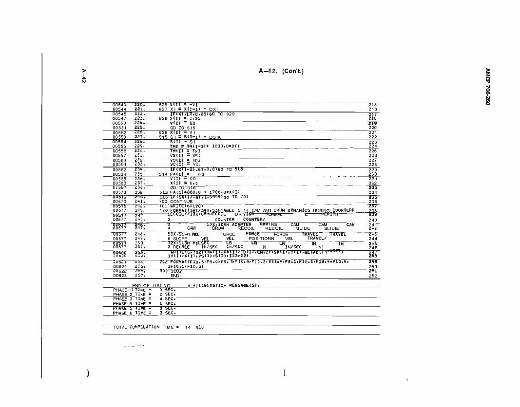
A-12. (Con't.)
00543 00544
220. 221.
825 VUJ = -VI 827 XI = Xtl-U - DXI
215 216
00545 00547
222. 223.
1FCXI.LT.0.25)60 TO 829 828 Xtl) = 0.P5
217 218
00550 00551
221. 225.
V(I) - 0.0 OO TO 515
il9 220
00552 00553
226 o 227.
829 Xdl = X I 515 SI = S(I-l> - DSIK
221 222
00554 00555
228.' 229.
S(I) - SI TMI = TM(i-D+ 1000.0*DTI _
223 224'
00556 00557
230, 231.
TM(I> = T^I VSU) - VRI
225 226
00560 00561
232. 233.
VD(I) = VDI VC(I) - VCL
227 228
00562 00564
234. 235.
IFiyil-il.GT.Ö.ÖlGO TO 513 514 FA(I) = 0.0
229 230
00565 00566
236. 237.
V(I) - 0.0 X(I) = 0.0
231 232
0U567 00570
238. 239.
GO IO 616 513 FA(I>=880.0 + l780.0*X(I>
233 234
011571 00573
2*0. 2tl.
516 IUbXllJ.Gl.i'^yjyiGO TO 701 700 CONTINUE
235 236
00575 00577
"00577 00577
212. 243.
—24* £i+5.
701 WRITE16.170) 170 FQP.MAT(1H1/34X.53HTABL£ 5-14 CAM AND DRUM DYNAMICS DURING C0UNTERR lEC0IL//r3X'85HRrreölL BR-|V"IN5 NORMAL t PERfPH
2 COUNTER COUNTER/
237 238 239 240
UUh77 00577
216. 247.
3 12X.1Ö5H ADAPTER «PING CAM CAM CAM, 4 CAM DRUM RECOIL RECOIL SLIDE SLIDE/
241 242
00577 00577
2*8. 249.
53X.lltH Wt FORCE I-ONCE FORCE TRAVEL TRAVEL 6 SLOPE VEL VEL POSITIONN VEL TRAVEL/
243 244
0Ü577 00577
250. 251.
72X.113H MILSEC L6 L6 LB l-J " "TN a DEGREE IN/SEC IN/SEC IN IN/SEC IN)
245 246
mn 3& WKITEIb«7o2> llMiP.FAHJ »FDIH .eNII)VSX»ll .Y(I)»6ETADl 1 I'TOPI) lV(I)>X(I),VS(D'S(I)>I=3r22)
247 248
0ÜO21 00621
254. 255.
702 FORMAT(Flo-5»F9.0«F9. 1»F10.Ö.F1Ö.3'fIl.»fFB.1#F10.1'F10.4.F10.4« 1F10.1-F10.3)
2<t9 250
UUb22 00623
256. 257.
yoo STOP END
251 252
END OF- LISTING. 0 »DIAGNOSTIC* MESSASE(S). PHASE PHASE
1 TIME " 2 TIhE =
3 SEC. 0 SEC.
PHASE PHASE
3 TIME = i| TIME =
4 SEC. 1 SEC.
HhASE PHASE
5 TIME 5 6 TIME =
i SEC 3 SEC.
TOTAL COMPILATION TIME = 14 SEC
> s o •o
? 01 O
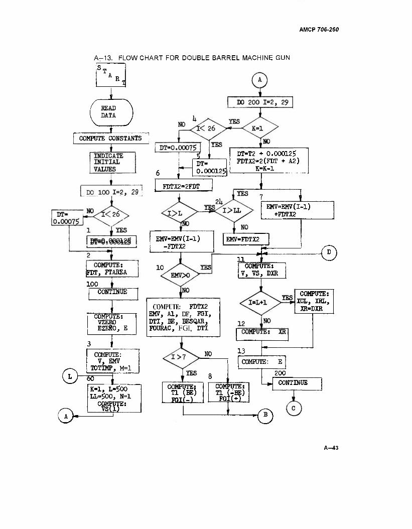
AMCP 706-260
A-13. FLOWCHART FOR DOUBLE BARREL MACHINE GUN
R
READ DATA
COMPUTE CONSTANTS
COMPUTE: FDT, FTAREA
100 J_ CONTINUE
COMPUTE: VZERO EZERO, E
COMPUTE: V, EMV
TOTIMP, M=l
"50" T. K-l, L=$00 LL=$00, N=l
COMPUTE:
±
S-L DT- 0.00012$
DT=T2 + 0.00012$ FDTX2-2(FDT + A2)
K-K-l
FDTX2=2FDT
EMV=EMV(I-1) +FDTX2
EMV-EMV(l-l) -FDTX2
EMV-FDTX2
11 ± <D COMPUTE:
V, VS, DXR
COMPUTE: FDTX2 EMV, Al, DF, FGI, DTI, BE, BESQAR, FOURAC, FGI, DTI
COMPUTE: XCL, XRL, XR-DXR
NO 13
COMfUTHi: Tl (BE) PGI(-)
COMPUTE: E
COMPUTE: Tl (- FG:
200
MS i 9
CONTINUE
A-43
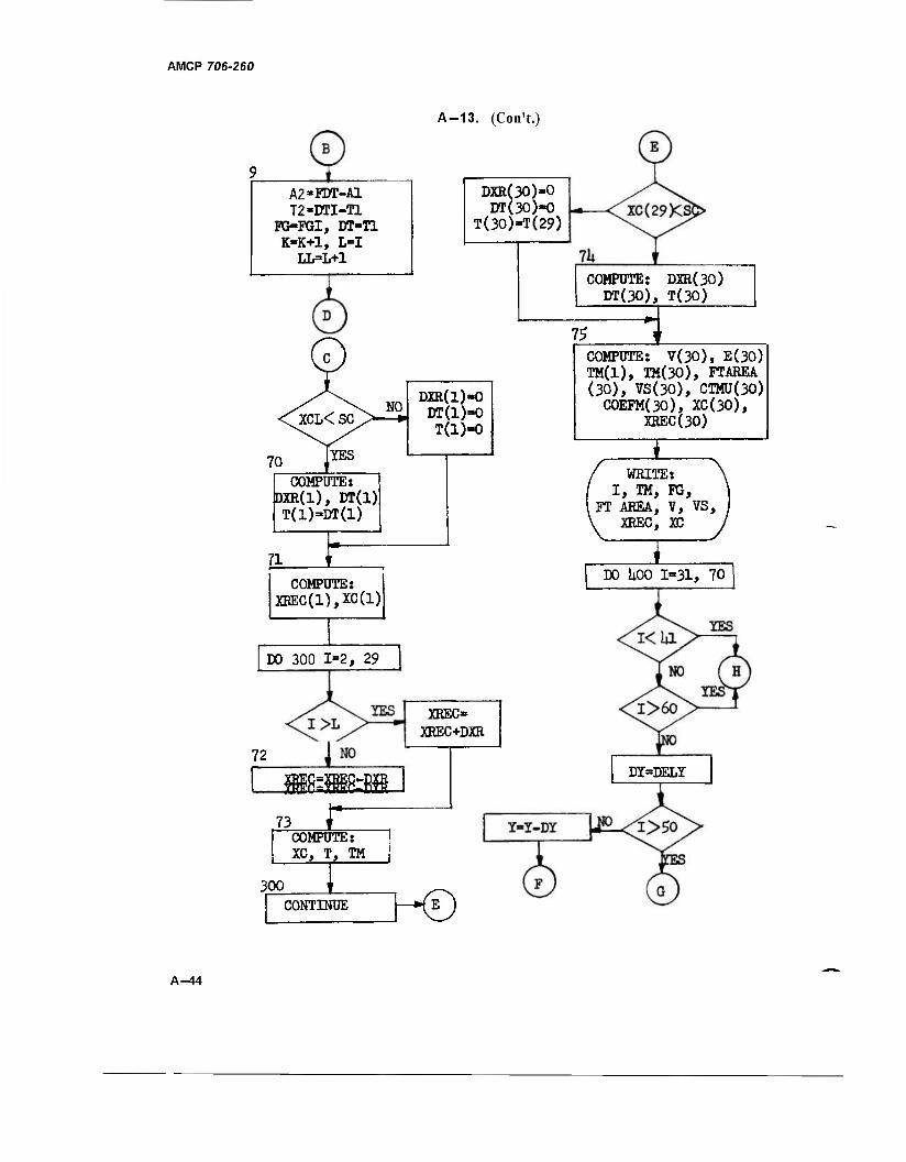
AMCP 706-260
A-13. (Con't.)
A2-FDT-A1 T2-DTI-T1
FG-FGI, DT-T1 K-K+l, L-I
LL=L+1
DXR(30)-0 DT(30)»0
T(30)»T(29)
/ /\ NO <Q[CL< SC>—*
DXR(l)«0 DT(l)=0 T(l)=0
70 liii0
COMPUTES DXR(l), DT(1) T(l)=DT(l)
71 1
COMPUTE: XREC(1),XC(1)
DO 300 1=2, 29
72
XREC» XREC+DXR
jfflEC=XEsCllM
73 r
COMPUTE: DXR(30) DT(30), T(30)
75
COMPUTE: XC, T, TM
300 CONTINUE h0
3 COMPUTE: V(30), E(30) TM(1), TM(30), FTAREA (30), VS(30), CTMU(30) C0EFM(30), XC(30),
XREC(30)
I WEITE:
I, TM, FG, FT AEEA, V, VS,
XREC, XC
T DO UOO 1=31, 70
DI=DELY
A-44
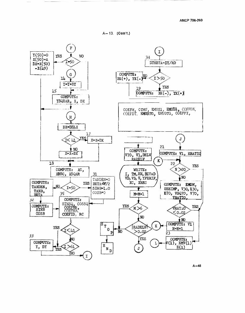
AMCP 706-260
A-13. (Con't.)
Y(50)=0 X(£0)=A DX=X(£0) -X(li9)
9 IES X^ NO
Hi Y=Y+DY
15 ■■"■■JT-
DTHETA=DY/RD
COMPUTE: YSQUAR, X, DX
COMPUTE: XK(+), YK(-
OMPUTE: XK(-), YK(+))
DX=DELX
COEFM, CTMU, EMUS1, EMUDl, COEFDX, COEFDT, EMDRIG, EMUDTG, COEFFX,
17
j<ia JE£ X=X+DX
jf NO X=X-DX
18 ± _L
COMPUTE: V70, V1,DELV BAD; f$—J(T)
COMPUTE: XC, XREC, XSQAR
WRITE: I, TM,EN,BETAD VD, VS, V, YPERIF,J
XC, XREC
E COMPUTE: EMOM, USEIMP, V30,E30, E70, VSQ70, V70,
VRATTO,
/^~\ COMPUTE: ' ( LV-7(I), EMV(l) ^ E(l) I
A-45
D I
A-14. PROGRAM LISTING FOR DOUBLE BARREL MACHINE GUN
0000 I 003353 M 0000 R 003343 RCFRAC
0000 I 003357 N 0000 R 003307 RCH
0000 R 003444 RAOELV 0000 R 003313 RD
0000 R 003306 RB 0000 R 003330 RDSO
0046 ft 9W&$m'" '•"-: 0000 R 00aM*3NHte;. 1
0000 R 003344 RHOSO 0000 R 003312 RT
0000 R 003301 RL 0000 R 003333 SC
0000 R 003310 RP 0005 R 000O00 SIN
0000 R 003322 RPORR 0000 R 003403 SINB
0000 R OÖSSWSft "."'* oooo R oovuaSitm
0003 R 000000 SORT 0000 R 003325 T6
0000 R 003317 SR 0000 R 003420 TGN
0000 R 002373 T 0000 R 003047 TM
0000 R 003402 TANB 0000 R 003352 TOT IMP
OÖOo R OOSMI^TAIJBW oooo R «►ssraiSri ,
0000 R 003360 T2 0000 R 003434 VCSQ
0000 R 003447 USEIMP 0000 R 002145 VD
0000 R 000454 V 0000 R 003454 VRATIO
0000 R 003440 VC 0000 R 002032 VS
oooo R O65*A» veew* 00Ö0 R 003*5S7VS*f*>
0000 R 003350 VZERO 0000 R 003276 MR
0000 R 003442 VI 0000 R 001356 X
0000 R 003450 V30 0000 R 002506 XC
0000 R 003441 V7A 0000 R 003373 XCL
oooo R ooszrrT« * 0000 R 003414 XK
0000 R 001015 XR 0000 R 003415 YK
0000 R 002621 XREC 0000 R 003162 YPERIF
0000 R 003374 XRL 0000 R 003377 YSOUAR
0000 R 003400 XSOUAR Ö0ÖO ft 0018*5'V
> 3 o •v »j o 9 M O) O
00101 00101 00101 00101
88i<fi 00111 00135
-3T 4.
I:
1 .EN(75)iY(75)»X(7g)>BETA(75)> COEFM(75)»CTMU(75)>VS(7S)»V0<7 "Z5TT BETAD<75>.T(75)tXCC75>»XRECC75>»FTAREA(75>» 3TM(75). YPERIF(75> ~REW50.(FG(I>r~I=1»29F
READ 50tWR« WA» 01» RL» CL» lHÜHtb »LMU >6>SR-
50 FORMAT16F12.0)
A» B> RHO» RBf RCH» RP» RR> RT» RO»
3D
IT
88119 18: IM85»8^ 7B
88141 lis ÜRfPSÖ^PORR 7S
UU142 00143 it.
OiU-ul/KU TG=FSRES* ( RCH-EMU*RB)»EMU
a 10
ÖÖ144 00105
lb. 16. —m
18.
CT=R0 - fcMU*Rt! C X=EMU*(RT+RD*RPORR)
II 12
UU146 00147
RUSO=KU**«! EMURB=EMU*RB
13 14
00150 00151
ia. 20.
CMUF=EMU*IRPORR+l.0/RHÖJ SC =CL-A
1b 1S
UU152 00153
21. 22.
OtLYsU.0Ub602b*B DELX=A/20.0 18
00155 2i. 24. BSQUAR=B*B
it 20
00156 00157
2b. 26.
AöVERBiA/'B B0VERA=B/A
21 22
ÖÖ16Ö 00161
a/. 28.
AtJ=A*B RCFRAC=(ASQUAR - BSQUAR)/ASQUAR
23 24
001ÜÜ 00163
ciy. 30.
tthOSQ=RHO**2 EFMR =0.5*EMR/RHOSQ
2i> 26
UU1B4 00165
31. 32.
EFMA =Ü.b*EMA/RHOSU EFID=0.5*DI/(RDSQ + RHOSQ)
^1 28
00166 00167
33. 34.
XKl 11=0.0 T<1)=0.0
üa h
UU1/U 00171
33. 36.
tNVJUJ-U.U EN(70)=0.0
31 32 . z^
win 00173
3/. 38.
H>>OUJ-U.U FTAREA(30)=0.0 34
UU174 00175
3V. 40.
V0(30)-0.0 YPERIF<30> = 0.0
33 36
OUl/b 00177 42.
Bfc.lMM3UI=U.U COEF M(30)=0.0 38
A-14. (Con't.)
00200 43. CTMU130>=0.0 39 00201 44.
4b. r<30)=B 40
00202 X<30)=0.0 41 -00203 4b.
47. FTAREA(1>=0.0 42
00204 DO 100 I=2>29 43 00207 4d.
49. 1F(1.LT.26)G0 TO 1 44
00211 DT(D=0. 00075 »5 0Q.212 50. GO TO 2 46 00213 si. 1 DT<I)=0.000125 47 00214 52. 2 FDT(I) =0.5*(FG(I)+FS(I-1))*DT(I) 48 00215 530 FTAREA(I)=FTAkEA(1-1>+FOT<I) 49 00216 54.
55. 100 CONTINUE. 50
00220 VZER0=FTAREA(29)/EMR 51 00221 56.
57. EZERO = 0.5»EMR*VZERO**2 52
00222 E<1)=0.7*EZERO 53 00223 5ö.
59. 3 V<1>=SQRT(2.0*E(1>/EMR) 54
00224 EMVtl)=EMR*V(l) 55A 00225 6Ü. TOTIMP = 2.0*FTAREM29) 55B 00226 610 M=l 56 00227 62.
63. b0 K = l 57
00230 L=500 5BA 00231 64.
65. LL=500 58B
00232 U - 1 58C 00233 bb.
67. VS(l>=VU>*RHO 59
00234 00 200 I=2«29 60 0U237
69. IF(K.EQ.1)60 TO 4 61
002 41 DTU>=T2+0.ÖÖ0125 62 00242 7u.
71. FDTX2=2.0*<FDT(I)+A2) 63
00243 K = K-l 64 00244 72.
73. 4 GO TO 7 IFU.LT.26)60 TO 5
65 00245 66 00247 74.
75. DTU>=0. 00075 67
00250 GO TO 6 66 00251 76.
77. S 6
LiT<I) = 0.U00125 69 00252 FDTX2 = 2.(T*FLJT(I) 70 00253 78.
79. IFU.GT.UGO TO 24 71
00255 EMV(I)=EMV(I-1)-FDTX2 72 00256 BU. GO TO 10 73A ÖQ257 - -61. 24 IFII.GT.LDGO TO 7 73B 00261 82. EMV(I)=FDTX2 73C 00262 83. GO TO 11 T56 00263 84. 7 EMV(I)=EMV(I-1)+FDTX2 73E 00264 85. GO TO 11 74" 00265 86. 10 IF(EMVU) .GT.0.0)G0 TO 11 75 00267 87. FDTX2 = EMVTI-Tr 76 00270 86. EMV(I)=0.0 77 00271 89. Al=F0TX2/2.0 ■■"-■ 78 00272 90. OF= ABS(FG(I)-FG<I-1)) 79A 00273 91. FGI = FGH! 79B" 00274 92. DTI=DT(I) 79C 0027V 93." BE= FGI»DTT/DF~ ■" " 80 00276 94. BESQAR=EE**2 81 00277 9b. F0URAC=2.0*DTI*A1/DF BZ~ 00300 96. FG1=FG(I-D 83 00301 97. DTI=DT(I) 84 00302 9a. IFU.LE.7)G0 TO 8 85 W3W -43. Tl=BE-SGRTrBESQAR-FÖURAr) Ob
00305 1ÜU. FGI=FG1-DF*T1/DTI 87
o •a o 9 M o
D 1
00306 00307
101. 102. d
GO TO 9 Tl=-BE+SQRT(BESQAR+FOURAC)
1—14. (Con't.)
00 58 69
00310 00311 00312 00313 00314 00315
103. 104. 105. 106.
9 FGI=FGI+0F*T1/DTI A2=FDT(I)-A1
90 91
T2=DTI-T1 FGU>=FGI
92 93
107. 108.
0T(I)=T1 K=K+1
94 95
00316 00317 00320 00321 00322 00323 00325 00326 00321 00330 00331 00332 00333 00335 00337 00340 00341 00342 00343' 00344 00345 00346 '00347 00350 00353 00355 00356' 00357 00360 00361 00362 " 00363 00365 00367 00370 00371 00372 " 00373 00374 00375 00376 00377 00400 00401 THF4Ü2 00403 00404 00405 00406 00407
109. 110. 111. 112. 113. 114. 115. 116. 117. llä. 119. 120. 12lY 122. 123. 124. 125. 126. 127. 12Ö. 129. 130. 131. 132. 133. 134. 135. 136. 137. 138. i39. 140. 141. 142. 143. 144. 145. 146. 147. 14a. 149. 150. rsr. ~ 152. 153.— 154. 155, ~ 156. I57i 15Ö.
L=I LL=L+1 968
11
12 13
200
70
71
72 73
300
74
75
V(I)=EMV(I)/EMR VS<J>=VU>»RHO DXR <I)=0.5*(V(I-1)+V{I))*DT(I) IF(I.NE.(L+1))GO TO 12
97A 97B ?8 99A
XCL=XR<L)*RHO XRL=XR(L) XR(I)=DXRU) GO TO 13 XR(I>=XR(I-D+DXRU) E<I)=EMR*V(I>**2/2.0 CONTINUE IF<XCL.LT.SC)GO TO 70 DXR(1)=0.0 DT<1)=0.0
99B 99C 99D 100
—
101 102 103 104
105A 105B
T<1)=0.0 GO TO 71 DXR(1)=SR-XRL DT(l)=OXR(l)/V(l) T(l)=OT(l> XREC(1)=XRL XC(l)=XREC(l)*RHO DO 300 I=2r29
105C 105D
-
106A 1068
107A 107B 106A
IFU.LE.DGO TO 72 XREC(I)=XREC(1-1)+DXR(I) GO TO 73 XREC(I)=XREC(1-1)-DXR(I)
108B 108C 108D 108E
XC(I)=XREC(I)*RHO TCD=T(I-1) +3TU)
108F 108G
TM(I) = 1000.0*T(D CONTINUE
- -■-
108H 1081
IF(XC(29).LT.SC)G0 TO 74 DXR(30)=0.0 OT(30)=0.0 T(30)=T(29) GO TO" 75 '"'"" " DXR(30)=SR -XR(29) DT(30)=DXR(301/V(29V" T(30)=T(29)+DT(30) VI30)=V(29) E<30)=E<29)
109A 1Q9B VSWT 109D
- ■--■ -■ -
10^E 110A lttB~ HOC I1TJCT HOE
TM(1I=1000.0*T(1) TM(30)=1000.0*T(30)
not HOG
FTAREA(30)=0.0 VS<30)=VS(29) CTMUC30TiCX*CTRIS+EWURB COEFM<30)=CMUF XCC3"0T=5C " XREC(30)=XC(30)/RHO
110H HOI noj HOK 111 A 1HB
•J o O)
©
A-14. (Con't.)
00410 00*10 00425 0O425_
159. 160.
"T6TT- 162.
00425 _00*25__
00425 _00*25
ÖÖ4~26 00*31 00433 00*35,
jm 00441 00443 00444 00445 00446 00447 00450 00451
00*5* 00455 00457 00*60 00*61
00464 00465 00467 00470 00471 00472 00473 00474 " 00475 00476 00477
> i
5QQ 501
00502 00503 00504 00505 00506 00507 00510 00512 0051* 00515 00516 00517 Ü0520 00522
163. _ 16*>_
1B5.
167. 160. 169. 170. 171.
. 1.72.._ 173. 17*. 175. 176. 177. 178. 179. 180.
m: 163. lb*. 18b. löo. 167. 186. 169. 190. 191. 192. 193. 194. 195. 196.
"197. 196. 199. 200.
M m- 203. 204. 205.
20o. 207.
206. 209. 210. 211. 212. 213. 21*. 215. 216.
PRINT 105.1 11HU) ,FG( l)'FTAREA<I>,V<I>.VS(I).XREC<I).XCCI>» lisa./WL.. . _
105 F0RMAT(lHl/12X»*7H TABLE 2-11 DOUBLE BARREL MACHINE GUN DYNAMICS" 1 _ //l*XillH PR0PELLANT.19Xi6H AXIAL.13X»6H AXIAL/17X.*H GA
2S.1*X.33H RECOIL CAM RECOIL CAM/7OH I TIME FOR 3CE IMPULSE VEL VEL TRAVEL TRAVEL/68H MSEC ** LB LP-SEC IN/SEC IN/SEC IN IN//
._ 5<I3.F9._3.F11.1.F9.2.2F9.1.2F10.*>> - GO' 400 1 = 31.70 '" " " ~ IFCI.LT.*l)GO TO 16 IFU.GT.601&0 TO 16 DY=PELY — IF(I.GT.50)GO TO 14
25 Y(I)=Y(I-1)-DY _. - — _ _ __ - IF"'(i.NE.S8)GO TO 15 Y(50)=0.0 X(50)=A DX = X(50) - X(*9) GO TO 18
14 Y(D=Y(I-l)+0* 15 YSOUAR=Y(I)**2 " " " " "' " "
X(I)=AOVERB*Si;RT(BSQUAR-YSQUAR) DX = ABS(Xd-l) " X(I) ) GO TO 18 .._ _
16 DX=0ELX IFU.LT.*DG0 TO 17 , __ — .. XII)=X(I-l)-OX GO TO lfl _ .._
17 X(I)=X(I-l>+Dx 18 XC(I)=SC + x(I) __ __ _
XREC(I)=XC(I)/RHO XSOUAR=X(l)**2 _ _ IF(I.EG.SO) GO TO 31 ""' " " '"' » TANDEN=SQRT(ASQUAR-XSQUAR_> TANB=bOVERA*XU)/TANOEN "" " " - -- - BETA(I)=ATAN(TANB> GO TO 32
31 TANDEN=0.0 _ - BETA(i) = l.57Ö756
SINB=1.0 COSB=0.0 GO TO 35
52 sjsraiiiiTäi]» ~~_ "' 35 S INSQ=SINB~**2
C0SSQ=C0SB**2 COEFMR=EFMR*COSSQ ~ ------■■ COEFMA=EFMA*SINSQ C0EFIU=EFID*STN5Q "" " " RC=(ASQUAR-XSQUAR«RCFRAC)*»1.5/AR F< lLT^*TJG0Tcf33
111C HID
111F lilG 111H 1111
112 113 114 115 116
_117 11BV 1188 116C 1180
119 120
TZT 122A
1228 123 124
125, 126 127 128
4m ~T29ir 129C
-~IZ9D-
130 T3TT
132 133 ■
13*A 13*H
13*C 1OTIT 135A T55B~ 135C 1J5D
135E
1356 135H
136
IFU.GT.60)60 TO 33 GO TO 3 4
33 YU)=BOVERA*TANDEN DY=ABS (Yn-TT-rrnT
34 DTHETA=DY/K0 IFTIVBT"."5D)60 TO T9~ XK=SJNB+CTRIG*COSB
13 TU 1378 137C
137
139 1*0 141
> 2 o
o
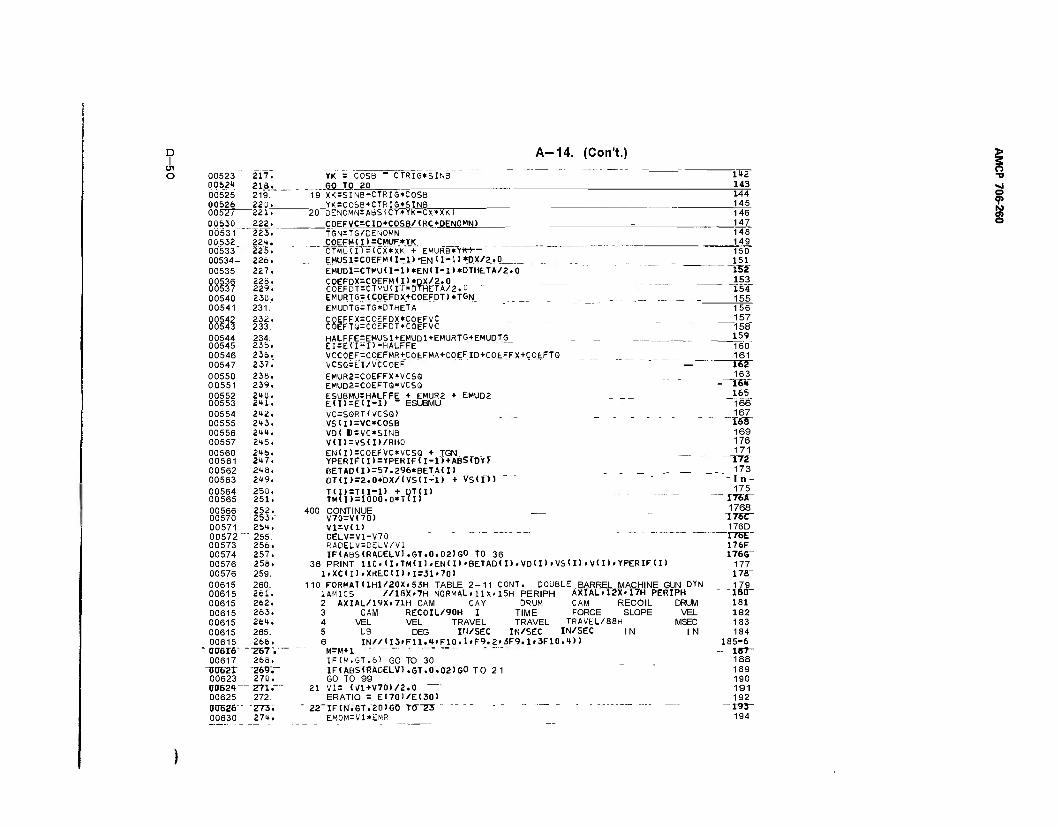
A-14. (Con't.)
o 00523 217. YK = COSB - CTRIG*SINB 142 00524 ÖÖ525
213. 219.
GO TO 20 143 19 XK=SINB-CTRIG*C0SB 144
00526 220. YK=C0SB+CTRIG*SINB 145 00527 221. 20 OENOMN=ABSICY*YK-CX*XK) 146 00530 00531
222. 223.
COEFVC=CIO*COSB/<RC*DENOMN> 147 T5N=TS/DEN0MN 148
00532 00533"
224. 225.
COEFM(D=CMUF*YK 149 CTMU(II = (CX*XK + EMURB'YKi— 150
00534- 00535
226. 227.
EMUSl=CQEFMa-i>*ENlI-l>*DX/2.0 151 EMUDl=CTMU<I-l)*EN<I-l>*DTHETA/2.0 152
00536 00537
226. 229.
COEFDX=COEFM(I)*DX/2.0 . .. 153 COEFDT=CTMU(IT*DTHETA/2.0 ~ 154
00540 230. EMURTG=(COEFDX+COEFOT)*TGN 155 00541 231. EMUDTG=TG*DTHETA 156 00542 232. C0EFFX=C0EFDX*C0EFVC .. _ _.. - _ 157 00543 233. C0EFTQ=C0EF0T»C0EFVC 158 00544 00545
234. 235.
HALFFE=EMUS1+EMUD1+EMURTG+EMU0TG ... _ 159 EI = E'('I-ir-HA"LFFE 160
00546 236. VCC0EF=C0EFMR+C0EFMA+C0EFID+COEFFX+COEFTQ 161 00547 237.' VCSG=EI/VCCOEF — 162 00550 23b. EMUR2=C0EFFX*VCSQ __ . 163 00551 239. EMUD2=C0EFTQ*VCSQ -TS 00552 240. ESUBMU=HALFFE + EMUR2 + EMUD2 _ _ ._ 165 00553 2m. EU)=E(I-D " ESUBMU 166 00554 242. VC=SQRTWCSQ> 167 00555 243. VS(I)=VC*COSB "KB" 00556 244. VD( B«VC»SINB 169 00557 245. V(I)=VSU)/RH0 176
00560 246. EN(I)=COEFVC*VCSQ + TGN . 171 00561 217. YPERIF(I)=YPERIF(I-1)+ABS(DYJ ~rrz 00562 248. 6ETA0<I>=57.296*BETAU> . . _ .- _ 173 00563 249. OT(I)=2.0*DX/IVS(I-1) + VS(D) -In- 00564 250. T(I)=T(I-1) + DT(I) .
TM(I)=1000.0*TTI)
175 00565 251. ~ I767T
00566 252. 400 CONTINUE 1768 00570 253. V70=V<70> 176C" 00571 254. V1=V(1) 176D 00572 " " 255. DELV=V1-V70 I76E" 00573 256. RADELV=DELV/V1 176F 00574 257. IF(ABS(RADELV).GT.0.02)GO TO 36 I76G~ 00576 258. 36 PRINT 110><I»TM<I)»EN<I>'BETAD<I).VD<I)»VS<I> i V( I) > YPERIFCI) 177 00576 259. l.XC(I) .XrtECU) »1=31 «70) 17B- 00615 260. 110 FORMAT<lHl/20X»53H TABLE 2-11 CONT. DOUBLE BARREL MACHINE GUN DYN 179 00615 261. 1AMICS //1SX.7H NORMAL.11X.15H PERIPH AXIAL.I2X» I7H PERIPH ior 00615 262. 2 AXIAL/19X.71H CAM CAY DRUM CAM RECOIL DRUM 181 00615 263. 3 CAM RECOIL/90H I TIME FORCE SLOPE VEL 182 00615 264. 4 VEL VEL TRAVEL TRAVEL TRAVEL/88H MSEC 183 00615 265. 5 LB DEG IN/SEC IN/SEC IN/SEC IN IN 184 00615 266. 6 IN//<I3»Fll.'t»F10.1»F9.2»3F9.1>3F10.4>) 185-6
"" 0U616' --Z67-.— M=W+I " ~ ' ' - 18T- 00617 268. IF(M.GT.6> GO TO 30 188
noser Z69.~ IF(ABS(RADELV1 .GT.0.02TSO TO 21 189 00623 270. GO TO 99 190 U062T " TTST— 21 Vis <Vl+V70)/2.0 191 00625 272. ERATIO = E(70)/E(30) 192 00626~ Z73i " 22_rFCM.GT.20TGO rO 23 " ' " 193" 00630 274. EMOM=Vl*EMR 194
> 3 o ■v •j o 9 N §
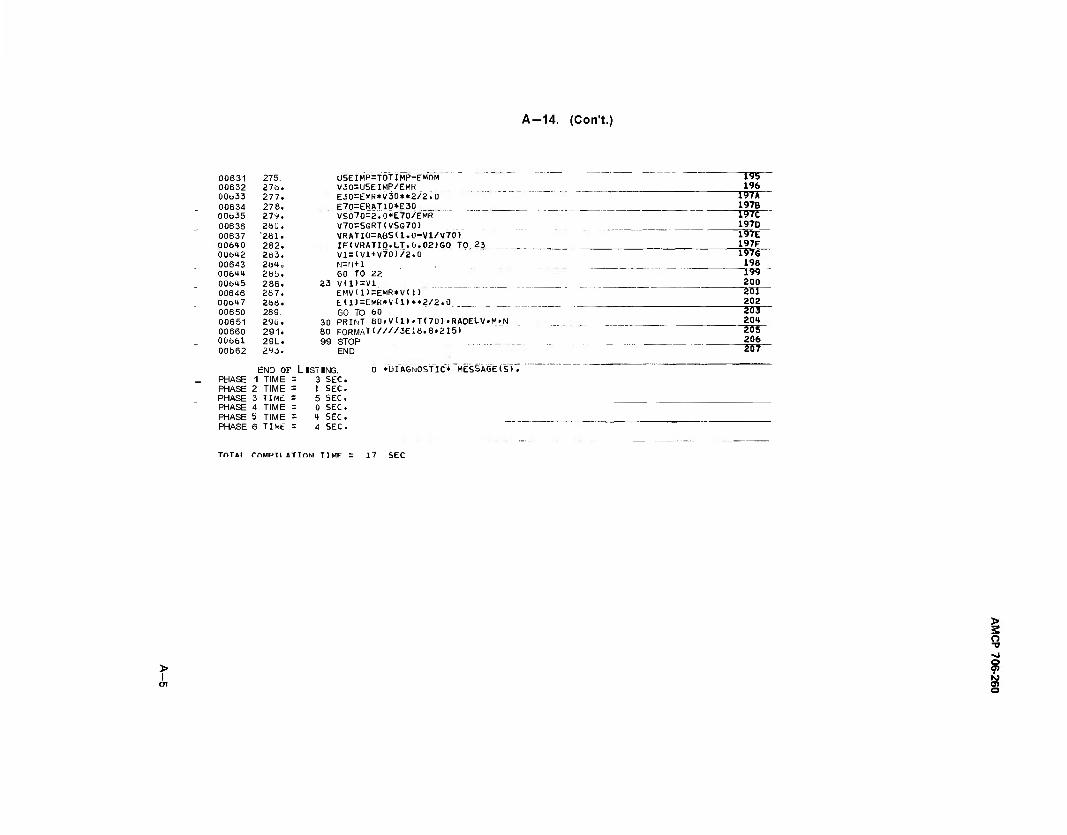
A-14. (CorTt.)
00631 275. USEIMP=TOTlMP-EMOM 00632 276. V30=USEIMP/EMR 00633 277. E30=EMR*V30**2/2.0 00634 278.
279. E70=ERATID*E30
00635 VSQ70=2.0*E70/EMR 00636 2SQ. V70=SQRT(VSQ70> 00637 '261. VRATI0=AÜS(1.0-V1/V70) 00640 282. IF(VRATIO.LT.0.02)GO TO 23 00642 263. V1=<V1+V70)/2.0 00643 264, M=fJ+l 00644 285. GO TO 22 00645 286. 23 V(1)=V1 00646 267. EMV(1)=EMR*V(1> 00647 266. EU>=EWR*YU)**2/2.0 00650 289. GO TO 60 00651 290. 30 PRINT 80»V(1).T(70)»RADELV»M»N 00660 291. 80 FORMAT<////3E18.8.215) 00661 29L. 99 STOP 00b62 293. END
END 01 ' LISTING. O »DIAGNOSTIC* MESSASEIS). PHASE 1 TIME = 3 SEC. PHASE 2 TIME = 1 SEC. PHASE 3 TIME s 5 SEC. PHASE 4 TIME = 0 SEC. PHASE 5 TIME = 4 SEC. PHASE 6 TIME = 4 SEC.
196 197A 197B 197C 197D 197E 197F 1976 198
~I99 200
~~2oir ao2 203 204 205 206
~2~57~
TnTAi rriMpn «TION TIMF = 17 SEC
> I
i o ■v ■>>
? a
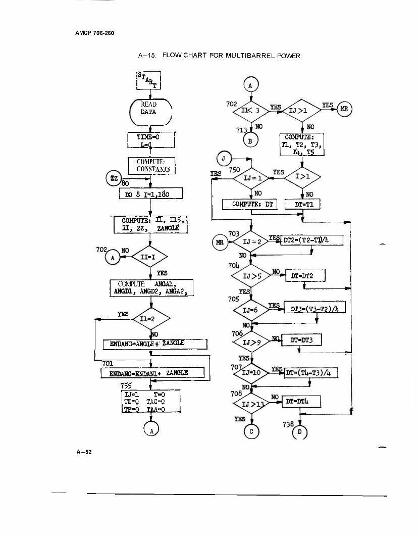
AMCP 706-260
A-15. FLOWCHART FOR MULTIBARREL POWER
ST. Rm
READ ^ DATA
TIME-0
zz
COMPUTE: CQKSTANJS
80 DO 8 1=1,160
COMPOTE: H, H5, II, ZZ, ZANGXE
CCMPUTE: ANGA1, ANGD1, ANGD2, ANGA2,
YES
ENDANG-ANGLE+ ZANGLE
f_ 701 1
ENDAMG-ENDAN1*. ZANGLE
7^ r—=
IJ=1 T-0 TEBQ TAG=Q TF-Q IMaQ
COMPOTE: Tl, T2, T3, TU, T5
YES
COMPOTE: DT T
DT-T1
DT2«(T2-T]JA
DT«DT2
DT3-(T3-T2)A
A-52
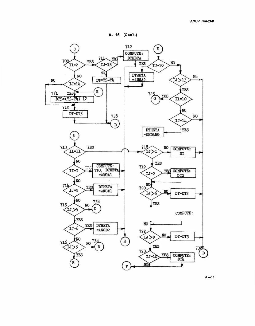
A-15. (Con't.)
AMCP 706-260
NO
7£L YESf"- DT£»(T$-TU) 12
710 1
A-53
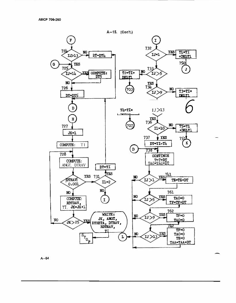
AMCP 706-260
A-15. (Con't.)
ÜT-DTU *f
COMPOTE: DTg
COMPUTE: ANGT, DTRAV DT-TI
COMPUTE": RDTRAV,
TT, JK=JK+1
NO
T2-TI+ J2EL!
Tl-TI +DELT1
75Q
0 T3-TI+ BELT1
TU-TI+ IJ>13 6 {§)
WRITE: JK, ANGT,
DTHETA, DTRAV, RDTRAV, II
T5-T1 +DELT1
737 i IES
DT-TI-Tli T^ CONTINUE T=T+DT
TAC-TAC+DT
TE=TE+DT
A-54
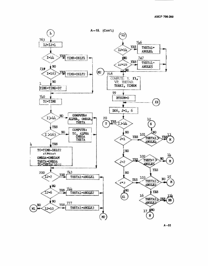
AMCP 706-260
A-15. (Con't.)
A-55
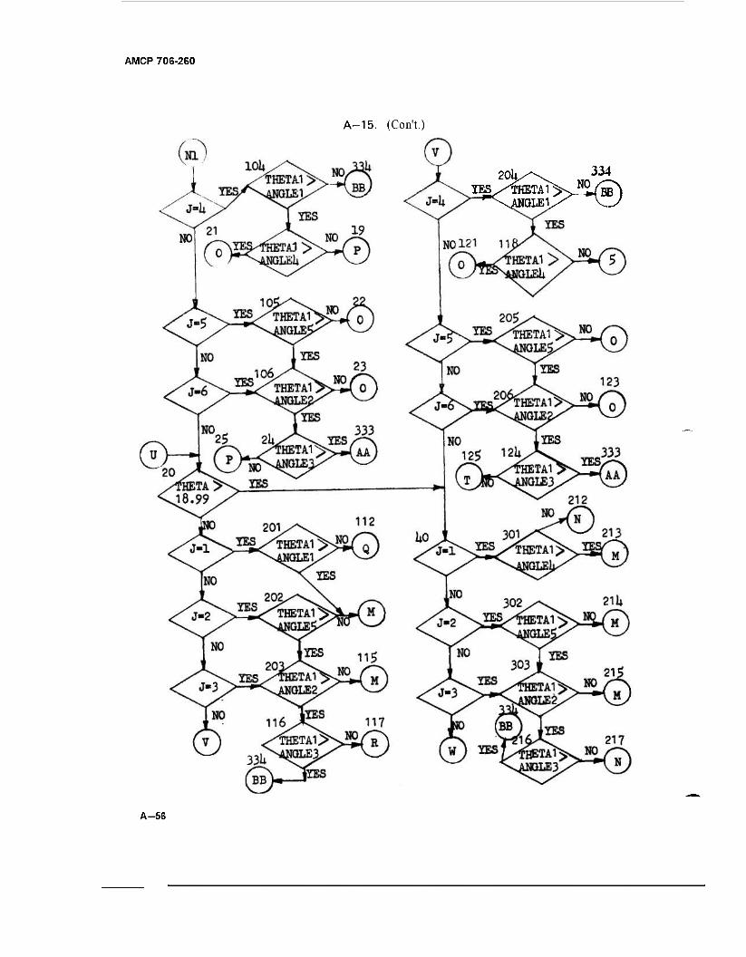
AMCP 706-260
A-15. (Con't.)
20k/\ 334
A-56
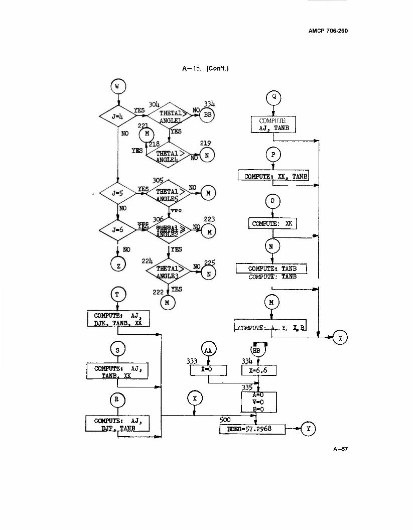
AMCP 708-2G0
A-15. (Con't.)
COMPUTE: AJ, DJEf TANB, XK
© COMPUTE: AJ,
TANB. XK
£ COMPUTE: AJ, DJFr TANB
333 X-0
COMPUTE: AJ, TANB
COMPUTE: XK, TANB
COMPUTE: XK
COMPUTE: TANB COMPUTE: TANB
COMPUTE ?• A, Y, XJBI
33Ut X-6.6
33? I ~5=0~ V-0 B-0
Soo BCEG-57.2968 H-0
A-57
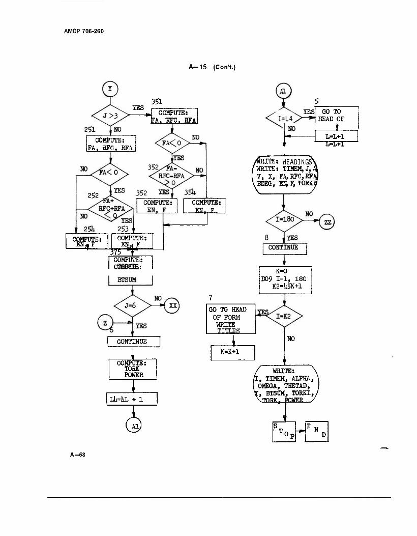
AMCP 706-260
A-15. (Con't.)
IES 351
*J_ COMPUT (FA, EFC.
'UTE: RFA
COMPUTE: FA, RFC, BFA
W&* COMPUTE: EN,i F
375 T COMPUTE: ÜD8BBTE:
CONTINUE
COMPUTE: TORK POWER
LU=lL + 1
COMPUTE:
GO TO HEAD OF FORM WRITE TITLES
K=K+1
lESJ GO TO HEAD OF
t_ L=L+1 L=L+1
ITE: HEADINGS ' WRITE: TIMEMjJ,,
V, X, FA,RFC,RFJ> ,BDEG, EN,F,TORKI
K-O D09 1*1, 180
K2-USK+1
I-K2
NO
WRITE: [, TIMEM, ALPHA, OMEGA, THETAD, [, BTSUM, TORKI,, ^TOBK. POWER
I A-58
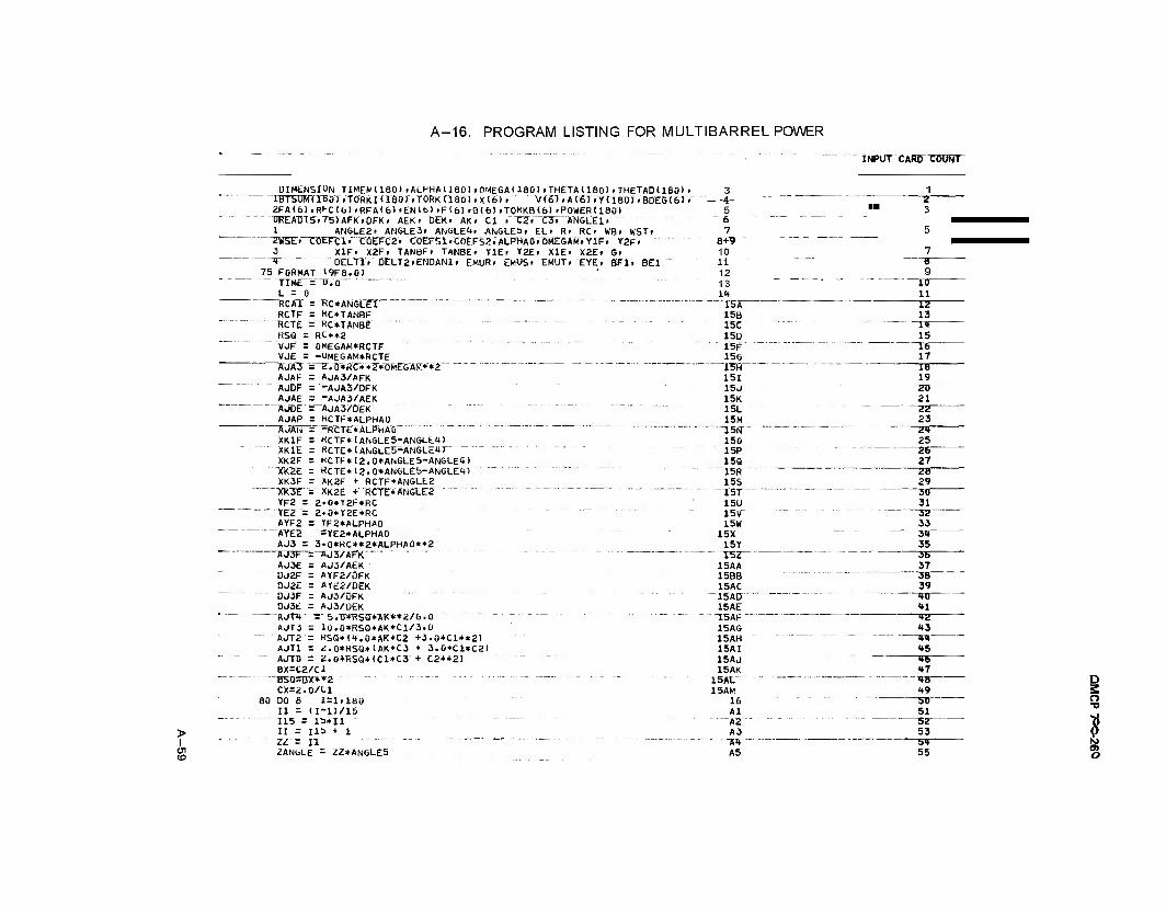
A-16. PROGRAM LISTING FOR MULTIBARREL POWER
INPUT XARDTÖUNT
DIMENSION TIMEM(IBO)IALPHA(IBO).OMEGA<180)»THETA(180).THETAD(180> . lBT5OWTTB0TiTORKI(160)»T0RKri80)»X(6)» V(6"J »A'(6T»Yl 180).BD£G(6J > 2FA(6).RFC(6).RFA<6).ENlb)«F16>.Bt6)»TQHKB16).POWER1180) T>REAIH5.T5>AFK.0FK. AEK» DEK' AK. Cl t"ZZi~ZSTA'NGLEIV 1 ANGLE2. AN6LE3r ANGLE4» ANGLES, EL» R. RC. WB> WST.
'~ "2W5ET-CÖEFCl.TÖEFC2. C0EFSl-C0EFS2rALPHAOröMETGAM.YlF. Y2F. 3 X1F. X2Fr TANQF. TANBE» VIE. Y2E. X1E> X2E» G>
~T"" ÜELT1V 0ELT2.ENDAN1. EMUR. EMUS. EMUT. EYE.BF1. BEI """" 75 FORMAT 19F8.0)
TTMt=Tr.O~ . - . . L = 0 ROTT= KC*ÄN5CET " RCTF = KC*TANBF RCTE = RC*TANBE RSQ = Rt*»a
"VJF = OMEGAM*RCTF VJE = -<JMEGAM*RCTE ~ÄUA3" =^2".Ö»KC**2*0MTGÄM*'*2 """ AJAF = AJA3/AFK AJDF = -AJA3/DFK AJAE = -AJA3/AEK AJDE = AJA3/DEK AJAPj: ^CTF»ALPHAO
—AJAu = -R~CTE*ALPHAÖ " XK1F = KCTF*(ANGLE5-ANGLf*) XK1E = RCTE*(ANGLE5-ANGLE»r " XK2F = KCTF*(2.0*ANGLE5-ANGLEt) TXZL - RCTE*(2.0*ANGL£5-ANGLEiH XK3F = *K2F + RCTF*ANGLE2
""XK3T '=• XK2E + RCTE*ANGT.E2 " -" YF2 = 2.0*Y2F*RC YE2~= 2.0*T2E*RC AYF2 r TF2*ALPHA0
"AYE2 =YE2*ALPHA0 AJ3 = 3>0*RC**2*ALPHA0**2 AJ3I- = AJ3/AFK AJ3E = AJ3/AEK DJ2F = AYF2/DFK 0J2E = AYE2/OEK
-~ DJ3F = AJ3/DFK DJ3E = AJ3/DEK AJI"* = b.U*KbQ*AK**2/b.U AJT3 = 10.0*RSG*AK*C1/3.0
—' AJT2 - K5Q*(i*.0*AK*C2 +3.0*C1**2) AJT1 = <;.0*RSa*(AK*C3 + 3.0*C1«C2)
" """" AJTD = 2.0*RS0*<C1*C3 + C2**2) BX=C2/C1
~" B5Q=BX*»2 """ "' CX=2.0/tl
80 DO 6 1=1.180 11 = (I-D/15
115 = 1S*I1 > II = lib + 1
1 ZZ = 11 en to
ZAN6LE = ZZ*ANGLE5
3 1 - -4- -
5
7 a+? - - - 10 li _ - 12
Z ™ 3
5
7
9 13 1H
10 11
15A 15B 15C 15D
12 13 1<* 15
15F 15G
16 17
15f) - 151 15J " 15K 15L 15M
18 19 JJJ 21 22 23
~\S(S 150 15P 15Q
24 25
27 15R 15S
28 29
X5T 15U
30 31
15V 15W
15X 15Y
3Z 33
— 3T 35
I5Z 15AA 15BB 15AC
~15AU 15AE
3b 37
3B 39 n— ■»l
15AF 15AG <»3 15AH 15AI
<»<» H5
15AJ 15AK
15AL 15AM
*6 "•7
-•♦8 H9
16 Al Ä2 A3
50 51
52 53
m — A5
3* 55
D 3 o ■v
* N o
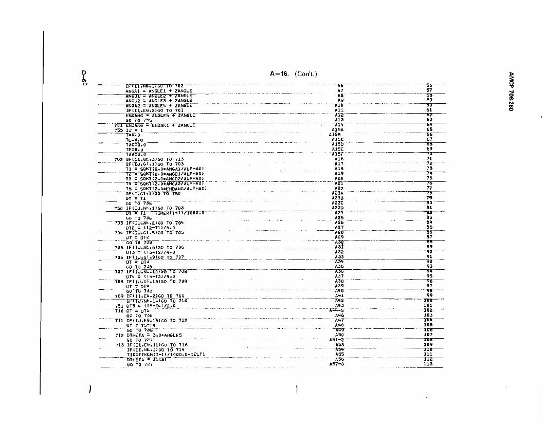
D I
o> o
A-16. (Con't.)
IFUl.Nb.llGO TO 7UÜ " " """" A6 ANGA1 = ANGLE1 + ZANGLE A7
56 57
ANGU1 = ANGLE2 + /ANGLE. "" AS ANGU2 = ANGLES + 2ANGLE A9
5B 59
ANGA2 = ANGLE"* + WANGLE AlO IF<Il.EO.2)G0 TO 701 All
6U 61
ENDAMG = ANGLE5 + ZANGLE A12 GO TO 7S5 A13
bü 63
701 ENDANG = ENOAN1 + ZANGLE Alt 755 IJ = 1 A15A
bH 65
T=0.0 AlSu TE=0.0 A15C
b6 67
TAC=O.Ö A15D TF=0.0 A15E
68 69
TAA=0.0 AlSF 702 IFUl.Gt.3>60 TO 713 A16 IF^avl.GT.DGO TO 703 A17
Tl = SQKT(2.0*ANGAl/ALPhA0) A18
/Ci 71
73 ---■ T2"~= 5äRT(2.0*ANGDl/ALPhAO) A19
T3 = SQKT(2.0*ANGD2/ALPHA0> A20 71 75
Tl* = SQKT(2."0*ANGA2/ALPhAO) A21 T5 = SQKT(2.0*ENDANG/ALPHAO) A22
/b 77
~~ lFTl.GT.n65 TO 750 A23A DT = Tl A23B 79
" " GO^ro 738 - ■-- - A2JC 750 IFdO.Nt.DGO TO 703 A23D
80 81
DT = Tl - TIMEM(I-D/1000.0 A2U GO TO 738 A25
82 83
703 IF(lj".Nt.2)G0 TO 704 A26 DT2 = ( 12-TD/t.O A27
B<* 85
704 IFlId.Gl.5)GO TO 705 A2B DT = 0T2 A29
86 87
GO TO 738 A3U 705 IF(IJ.Nt.6)G0 TO 706 A3l
88 89
DT3 = (I3-T21/4.0 A32 706 IFUJ.GI.9JG0 TO 707 A33
90 91
DT = DT3 A3"* GO TO 736 A35
92 93
707 lF(IJ.Nt.lO)GO TO 708 A36 Of* = (l'J-TSJ/'i.O A37
9H 95
708 IF(IJ.G1.13)G0 TO 709 A38 DT = DT** A39 GO TO 738 AHO
709 IFU1.EU.2)G0 TO 711 A<*1
9b 97
98 99
IPIlJ.Nt.l1*)'SÖ"TÖ 710 A42 751 DT5 = U5-T4J/2.0 A<*3
10U 101
710 DT = DT5 A<*<*-5 GO TO 738 A<*6
102 103
711 IFUJ.EU.151G0 TO 712 A"»7 DT = T5-T4 A48
104 105
GO TO 738 A4* 712 DTHETA = 3.0*ANGLE5 A50
10b 107
GO TO 727 AS1-2 713 IFUl.EU.lDGO TO 718 A53
108 109
tFUI.Nt.IJGO TO 71H A54 TIO=TIMtM(I-l)/1000.0-DELTl A55
110 111
DTHETA - ANGA1 Abb GO TO 727 A57-8
112 113
> 2 o •o
? Is) 0) o
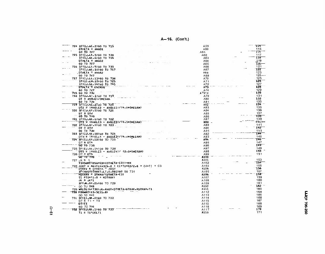
A-16. (Con't.;
D I
71* IFUJ.NE.21G0 TO 715 DTHETA = ANGOl
" SO TÖ 7Z7 715 IFUj.Lt.5>60 TO 73B
IFUJ.Nt.6)GO TO 716 DTHETA = ANGD2 GO TO 727
716 IFUJ.Lt.9)GO TO 733 IF(IJ.NE.10)GO TO 717
.DTHETA = ANGA2 GO TÖ 7Ü7
717 IFUJ.Lt.13)60 TO 73B IFU1.EÖ.10)GO TO 725
IF(lJ.JNt.li»)GO TO 745 "BTHtTA = ENDANG GO TO 7Ü7
715 GO TO 736 718 IFUJ.GI.DGO TO 719
OT = ANGLEl/ÖMEGÄh GO TO 736
"7I9""iniJ".KiE.2T&ö"TÖ"'T25 DT2 = (ANGLE2 - ANGLED/l<t.O*OMEGAM>
720 IFflJ.GT.5)G0 TO 721 DT = DT«! Go TO 738
721 IF(IJ.Nt.6)G0 TO 722 DT3""= 'TKH5LE3 -~'AN6LE2"J7Tif.Tr*0Me6WfT
722 IF<IJ.GI.9)60 TO 723 DT - DT3
GO TO 738 723 IF(IJ.NE.10)GO TO 724
DT4 = (ANGLES - AN6LE3)/(4.U*0MEGAM> 72W 1F(TJ.GT.13)G0 TO 725 " ~ - — -
DT = DTI THTTO 738
725 IF(IJ.Nt.l»t)GO TO 726 DT5 = (ANGLE5 - ANGLE1*)/ (2.0*OMEGAMJ
726 DT = DTb GO 10 738 -
727 JK = 1 TI=SQRT»BSQ+CX*(DTHETA-C3))-BX
728 ANGT = AK*TX*»3/6.0 + Cl*TI**2/2.0 + Cü*TI + C3 "OTRAV = DTHETA - ANGT
IF<ABS(UTRAV).LT.0.001)GO TO 731 RDIHAV ~ OTRTWCDTHETA-CS)
TI =TI»ll.O + ROTRAV) - JK = jKn
IF«JK.GI.25)GO TO 729 """■ GO TU 728 729 KRlTE16»730)JK»ANGT»DTHETAfUTRAVfRDTRAV.TI
RHÄT113.5E15.8) GO TO 9U0
731 IFtU.Nt.2)G0 TO 732 DT = T I - T5
DT=TI 60 TO 73ö
'73?1F(TJ.Nt.l)G0 TO 73T ' Tl = TI+UELT1
A59 TW A60 115
A61 IT6 — A62 117
A63 ~ TX8 A64 119 A65 Tzu— A66 121 A67 iaz A6B 123 A69 125 A70 125 A71 126— A72 127 .._. A73 ~~ — TZB A74 129
A75-a 130 A79 131 A80 132 A81 133
" "" " AB2 ' " I3»r— A83 135 A84 136 A85 137 A86 13Ö A87 139 A88 - ■no- A89 141 A90 1»2— A91 A92
1V3 I'm
A93 145 AW " - OTB
A95 147 A96 TVB A97 149 A98 150 " A99
_ Ann) AlOl
151
153 A102 "I5<»— A103 155 AlOl* 156 A105 A106 '
157 13Ö
A107 159 A108 160 A109 161 A110 162 A1H 163 A112 164 A113 165 A114 166 A115 167 A115 168 A116 169 A117 170 Alls 171
E 9 ©
A-16. (Con't.; o> to GO TO 7t>0
733 IFUJ.G1.5>G0 TO 734 T2 S TT'DELTl
GO TO 7U3 "734"~"IFT1J.6T.9)G0 TO 735
T3 = TI+üELTl GO TO 70b
_735 IFUJ.GI.13)G0 TO 736 ~ T4" = TI+DELTi"
60 T0_ 7U7 736 IF I H.'E«. 10) GO TO 737" T5 = TI+DELT1
GO TO 7^1 737 DT = TI-T4 738 CONTINUE
T=T+UT TAC=TAC+DT IFdJ.GLDGO TO 741 GO TO 7b3
741 TE=TE+DI IFUJ.G1.5TGÖ TO 761 GO TO 763
761 TAC=Ö.Ö TF=JF+DI IXlJ.Gl .9>G0 TO 762 GO TO 7b3
—752"TF=Ü".0 TAC=0.0
""""IFUJ.GT. 13)60 TO 742 GO TO 763
742 TF=0.0 TAC=0.0
~ _Tr=DV(r" TAA=TAA+OT
763 IJ=IJ+1 IFU.NE.44)G0 TO 739
"""" ""nrTME'"="D"ELTl"""" """' '" GO TO 740
" 739 rFTr.NT.T631 GO TO""1 TIME = UELT2 GO TO 740
1 TIME = IIME+ÜT ~740"TC="T"IME
IF(1.GT.44)60 TO 2 ÄLPHATTrrTLpHAÖ" OMEGA(I) = ALPHA(I)*TC THETATI r = OMEGA 11)*TC/2.0 GO TO 2U0 IF 11.GT.163)GO TO 4 TC= TIME - ÜELT1 ALPhACT) = AK*TC+ Cl OMEGA (H=AK*TC**2/2.+Cl*TC+C2 TH£TAirr=AK*TC**3/6.+Cl*TC**2/2.+C2*TC+C3 GO TO 2U0 TC= TIME - ÜELT2 ALPHA (P =_0'_0_ OMEGAiIT "= OMEGAM THETA(I) = OM£GA(I)*TC+ THETA(163)
Ari9 172 A120 173 A121 174 A122 175 A123 176 A124 177 A125 178 A126 179 A127 18D A128 181 A129 1S2 A130 183 A131 184 A132 185 A133 186 A134 187 A135 IBB
A136A 189 A136B 190 A136C 191 A137 192 A138 193 A139 194 A140 195 A141 19b A142 197 A143 19B A144 199
A145 200 A146 201 17A 202
17B 203 " 17C 204 17D 205 17t 206 17F 207 17G 208 17H 209 171 210 17J 211 17K 212
18 213 i^A 214
19B 215 ^0""" """ - - — 216 21 217 22 218 23 219 24-5 ~zzo— 26 221 27 " " 222 28 223 29 22«r— 30 225
31-2 226" 33 227 34 228 35 229
> s r>
to
o
A-16. (Con't.) SOTTTFT rj.E*r. ZJGO TO 743 IFUJ.EQ. 6)60 TO 744
IFCIJ.EÖiTöTSSTÖ "777 IFUJ.EU.14)G0 TO 746 IFTI J.TO".1"BTGO "TO 747 THETA1 = THETAII WANGLE GO TO 748
743 THETA1 = AN6LE1 G^TO^fB
744 THETA1 = ANGLE2
36A: 36B 36C 36D
G0~T0~748 777 THETA1 = ANGLE3
GO TO 7*8 746 THETA1 = ANGLE4
50" TO 748 747 THETA1 = ANGLES
B rriJ-=RC*THETÄT YI = YUJ-ROANGLE2
_ VP~ = RC*ÖMEGÄtil THETAD(l) = 57.296»THETA(I) TOR* I ar=-EYE*7[LPHXriT TIMEMU) = 1000.0*TIME
WBT5UM( 17=0.0 00 & J=lib rrrr;GTviofTG!TT0"2!J
10 GO TO 1101. 102» 103» lot, 105> 1U1 IF1THETA1.GT.ANSLE4J60 TO 13"" 12 A<J)=AJ3F*T **2
^5E~ 37A 37B 38A 3BB 38C 380 39A 39B 39C
Ü30 231
-Z3Z- 233
235
237 23B 239 240 2m
243 39D 39E
40A
244 245 246
40B 247 40C
41 248 249
42 250 43
44
106)>J
45 4fj 47
251 252 253
TANB = 2.0*Y(n/AFK V(J)=VP**TANB
" XTJJ = TtlJ**27AFK " B(J) = ATAN (TANB)
GO TO sovr 13 A(J) = AJAP VTJ) = TANBF*VP
XtJ)__= X1F + ((Y(I)-Y1F)*TANBF) BTJ) = BF1 GO T05UU
102 IM IHEIATTGT .ANGLLb>GO TXmi3 14 A(J) = AJAP
"~ V(J7 = TANBF*VP X<J) = T(I)*TANBF + X1F + XK1F
B(J) = BFI GO TO 5U0
1U 3 1F ( I Ht I AT. GTi ANGtEZTGO TU T6 15 X(J) = Y(I)*TANBF + X1F + XK2F
A(J) 2 AJAP V(J) = VP*TANBF BUT = BFt GO TO 5UQ
Tr6"rFtTHET»l^^T;"AI<reLE3> GOTO "334 17 A<J)=DJ2F-DJ3F*TE **2
TANB = 2.0*(Y2F-YI>/DFK V(J)= TANö*VP XtJ)=X2F-tY2F-YT)**2/DFK+XlF+KK3F B(J) = ATAN (TANB)
"""-"" GO TO 5U0 104 IFITHETAl.LE.ANGLEDGO TO 334
~4"B 49 "50TT 50B TI — 52
-Z54- 255 25b 257 I 58—
-Ü8- 261 262
263
H3~ 266 267 268 269 270 271 -272- 273 -274- 275 276 277 278 279 280 281
283 284 285 286 287
D A-16. (Con't.)
r.^r.ANStE*lGO TO 21 19 A(J) = -AJ3E*TE **2
"=-r.TJ»TTTTT=-l?CAl)TSEK VCJ) = -TANB»VP XK = <YII)-RCATJ**2/AEK~ X<J> = tL-XK B(J) = ATAN (TANB) 60 TO 5U0
21 A(J) = AJAN V(J> = "TANBE*VP XK = X1E + X(J) = tL-XK
(CYU>-Y1E-KCA1>*TANBE>
BtJ) = BEI GO TO 5UQ
105 IF(THETA1.GT.ANGLES)GÖHfÖ 1U6 22 AIJ) =_AJAN
VCJ) = -TANBE*VP XK_?_Xlt + Y(I)*TANBE + XKlt
X(J> = tL XK B(J) s /BEI GO TO 5U0
106 IF(THETA1.GT.ANGLE2)G0 TO 2<» 23 A(J> r AJAN _V(J)_= -JANBE*yP
Xk = Xlt+XK2E+(Y(I1*TÄNBE) X(J) = tL-XK BCJV~=HBEr GO TO 5UU
2<» iF<THETM.GT.ANGLE3>G0 TO 333 25 ACJ)=-DJ2E+DJ3E*TF **2
TANB = 2.0*(Y2E-YI)/DEK V(J)=-TANB*VP
Xk=XiE+Xk2F+X2E-(Y2E-Yl)**2VDEK XCJ) = tL-XK BIJ) = ATAN (TANB) GO TO 5U0
2CTTFIT.GT.163>G0 To 40 30 GO TO t201f202i203»20<w205r206)fJ
^7r-iTfTHETAi.^r.ANGLE4rGcrT0 irr AJ = A«"t*T**4 + AJT3*T**3 + AJT2*T**2 ACJ) = AJ/AFK TANB = 2.0»Y(I)/AFK V(J)= TANB*VP ," XCJ) = t(I)**2/AFK
BTjr^ATÄfrTTÄfiBT ~ GO TO 5Uo
"113 AIJ)=RCTF*(AK*TÄA+C1) • V(J) = VP*TANBF XCJl = X1F+(Y<U-Y1FJ*TANBF BIJ) = BF1 GO TÖ~5T«J
J.Q2 1F(THETA1.GT.ANGLE5)G0 TO 203 AQT=RCTF*JAk*T +C17 V(J) = VP«TAN8F X(J) = X1F7 YTITSTANeF * XK1F BIJ) = BF1
"GO TO S00 203 1FUHETA1.&T.ANGLE2>G0 TO 116
> s o -o
9 M O
A-16. (Con't.)
AU)=RCTF*CAK*TAC+C1) V(J> = vp*TAMBF XXant-XlF + YUJ*TANBF + XK2F "~ BUI = BF1 60 TO TOO " '" """ "
116 IF(THETA1.GT.AN6LE3)G0 TO 334 ~ 117 DJF = YF2*(AK*TF+C1)
AJ = AJU*TF**4 + AJT3*TF**J + AJT2*TF**2 + AJT1*TF ♦ AJTO TWJ) = tDJF -~AJ7/DFK '" " TANb = 2.0*<Y2F-YI)/DFK
" "" V(J) = Vp«TÄNB X(J)=X2I--(Y2F-YI)**2/DFK+X1F+XK3F
~ B(J) = ATAN (TANB) GO TO 5U0
"■2WTFrrHETAr.Lt;"ÄfrsLE"nsö"Tir33«" 118 IFUHETAl.GT.ANGLEt)GO TO 121
AJ = AJTit*TE**i* + AJT3*TE**3 + AJT2*TE**2 + AJT1*TE * AJTO A(J) = -AJ/AEK TANb '= 2.0*IY(I)-RCA1)7AEK V(J) =_-yP*TANB
XK=(Y(lT-RCAl)**2/AEK " X(J) = tL-XK B(J)""= ATAN (TANB) GO TO 5U0
~T2T"ATj)=-RCrE*VAK*TAA+Cl) . -- . V<J) =-'KP*TANBE XK~='"xlE Vnr(l7-Y1E-RCA-1T*TA14BE X(J) = tL-XK S(J) = B£l ■" GO TO 5UU
205 IF(THETA1.GT.ÄNGLES)60 TO 2D5 A(J)=-RLTE*IAK*T +C1) -yvjr =-W*TANBE* " XK = Xlt + Y(D*TANBE ♦ XKlE XTjrTTXL-XK" " B(J) = BEI
GO TO "500 " 206 IF(THETA1.GT.ANGLE2)G0 TO 124 STJTS-KL IE* ntK»"TAC'*CD
V(J) =-VP*TAUBE XK■- X1E+XK2E +(Y(I)*TANBE 7 X(J) = tL-XK
> I
BTjr=BEl GO TO 5UQ
I^rTF(THETÄiVGT.ANGLE3)G0 TO 533 ~ ' AJ = AJI1*TF**4 + AJT3*TF**3 + AJT2*TF**2 + AJT1*TF + AJTO
T2^DJE = Yt2*rSK*TF +C1) A(J) = IDJE + AJ1/DEK
— ■ ~ 7 TANB = 2.Tr*tT2E-YI>/DEK " V(J)=-VP»TANB
fftjr=KTKNtTANBI XK=X1E+XK3E+X2E-(Y2E-YI)**2/DEK X(J) = tL-XK GO TO 5U0
«*0~GO TO T30IV3D2f3T>3»30t.305V3F6) »J 301 IF(THETA1.GT.ANGLE4)G0 TO 213
"212~A(jr 2 AJAF ~"~ TANÜ = 2.0*r(I)/AFK
O ■o
o Ol IS]
o
> I
0>
A-16. (Con't.)
V(J) = VP*TANB XU) = r<I)**2/AFK
BUT = ATAN CTANB) GO TO 5U0
zry Aij) i D V(J) = VJF XU) = X1F + (Y<I)-Y1F)*TÄNBF
B(J)_= BF1 GO 10 SOo
^02 IF<THETA1.GT.ANGLE5)G0 10 303 214'A(J) = U ■ - - ■
V(J) = VJF X1F X(J) = t(I)»TANBF
BUI = bFl + XK1F
GO TO 5U0 303 IF(THETA1.GT.ANGLE2)G0 TO 216 215 A(J) = U
V(J) = VJF X<J> = Hl)*TANBF + X1F + XK2F
BjJ)J= BFl _ _ GO" TO ""5'0Cf """
216_IF(JHETA1.GT.ANGLE3)G0 TO 3J4 ~2~T7 AU) = ÄJDF TANb = 2.0*<Y2F-YI)/DFK
V(JT ="Vp*TANB"'"" XU)=X2F-1Y2F-YI)««2/DFK + X1F+XK3F
BTj7~="ATÄN_TTÄNBy "~ GO TO 5UÜ
304^F(TH£TAl.L£.ANGLEl)6O TO 334 218 IF(THETA1.GT.ANGLE4)G0 TO 221 219 A(J)= AJAE
TANb = Ü.0*(Y(1)-RCA1)/AEK
> 3 o »J
VTJT==VF*TÄfitr X(J> = EL-(Y(I)-RCA1)*»2/AEK B(J) = ATAN (TANB) GO TO 5U0
"22T~A~IUT ""= o ■ — V(J) =VJE
XTJI"=T:i.=TXrrT TmT^TIF^CATliTANBEr BIJ) = bEl GO TO 500
305 IF(THETA1,GT.ANGLE5)G0 TO 3U6 222 A(J) =0
V(J) =VJL XTjT = tL -"TxTET+'TTTJTTATJBTr +~XKrci B(J) = BEI
GO TO 500 306 IF(THETA1.GT.ANGLE2)G0 TO 224 223 A(J) = Ü
V(J) =VJE XT 37
"2T0 211 212" ■- —
213A 213B 214
"215" — 216 217 21B ^19
220A ~220B -
221 222 ~ 223 22,
225
»Z» «25 »2b »27 «28 429
«31 ~<f32- «33
»35 »36 »37 »38 «39
BIJ) = BEI GÖ~TÖ"~50Ö
<XlE+XK2E+Yll]*IÄNBET)
22»_IFITHETA1.GT.ANGLE3)G0 TO 333 225 A1jr = "AjO"E
TANB = 2.Q*<Y2E-YI)/DEK V(j7 = -VP»TANB X(J)=EL-X1E-XK3E-X2£+(Y2E-YJ)**2/0EK
-Z26 — 227 22B 229 230 231 232 233 23» 235 236 237 238 239 2»0 2»1 242 2»3
2»» 2»5
»»1 »»2 »»3
»»5 »»6 »»7 »»8 »»9
"»50 »51 «52 »53 »5» »55 »56 »57 «58 «59 «60 «61
A-16. (Con't.)
> I
BtJ) = ATAN (TAN'S) GO TO 5U0
2»6 2«7
«62 «63
JJJ XUJ = u.o GO. TO 335
2«8A 2«8B
«6« «65
33« XU) = 0.6 335 VIJ) = U.O
2«8C 2*9
«66 «67
ATJ) "= P.ö~ " B(J) - U.O
250 251
«68 «69
5D0 BDEGU) = 57.296*B(J> "' ' IFCJ.GTOJGO TO 351
252 253
«70 «71
251 FAU) = A(J>»<*6+WST)/G RFC(J) = R*0MEGA(I)»»2*(EMUT*WB+EMUS*WST)/G
254 255
«72 «73
RFA(J) = R*ALPHA(I)*(EMUT*WB+EMUS*l«fST)/G If (FAIJI .GE.O.IGO TO 251*
256 257
«7« «75
252 IF (FAM)+RFC(J)+RFA(J) 1253.253.25« 253 ENU) = (l-A(J)+RFC(J)+RFA(J))/i-COEFC2*COS (B t J))-C0EF52*SIN <B<J)>>
258 259
«/6 «77
F(J) =EN(J)*(EMUR*COS (B(J)l-SIN (BtJ)l) GO TO Si's
260 261
«'8 «79
25« EN<J>=lrAlJ>+RFClJ)+RFA<J)>/<C0£FCl*C05 <B<J>>-C0EFS1*SIN (B(J)>> F(J) =EMJ)*<SIN (B(J) >+EMUR»COS (BUM)
262 263
«80 «81
GO TO 3'5 351 FAU> = A(J)*(WB + WSE)/G
RFCU) = R*0MEGA<I)*«2*lEMUT»WB+EMUS*tfSET7G ""' RFAIJ) = R*ALPHA(I>*(EMUT*Wd+EMUS*WSE)/G
264 265 266 - " 267
«82 «83
«8« «85
IF(FAU'.G£.0.0)GO TO 3b« 352 IF(FAU'-RFCU)-RFA(J))3b«»35«#353
268 269
«86 «87
353 EN(J) = (rAU)-RFCU)-RFAU>>/(CöEFC2*CÖb <BU>">+C0eF52*SlN (B(J)H FtJ)=ENlJ)*(EMUR*COS (BUD-SIN (BU)>>
r GOTO 375 — ' ~" - 35« ENU) = (t-AU)-RFCU)-RFAU> )/(COEFSl*SIN leUI )-COEFCl*COS <B(J)))
27Ü 271A 2TIB" 272
«88 «89 «90 «91
F(J)iENtJ)*(blN (BU))+tMUK*COS (BtJ))' 375 TORKB(J) = FU)*RC
273 274
»92 «93
BTSUMU' S BTSUMID+TORKBfJ) 6 COIJTINUt
27bA 275B
«9« «95
10RKUJ 2 UTSUMd) + TORKHIJ - POWERII' = TORK(I)*OMEGA(I)/6600.0
276 - . - - . 277 278 279
«96 «97
L3 = L+3+1 603 IF(I.NE«L3)G0 TO 66
«98 «99
5 WKntlb'bUU L = L+l
28U 281
500 501
501 FOKMAI (lHl/37X»«3HrAULt 6-2 OU1PU1 OF EACH BOLT AT GIVEN TIME//) 66 WRITE16'601)TIMEM(I)iU>AU).VU)'XU>'FA(J).RFC(J)»RFA(J)»BDEG(J)
2B2 283 284 285
502 503
1>ENU> >MJ) >T0RKBU)>J=1'6) 601 FORMAT! /«1X.15HCAM DYNAMICS AT F7.2.13H MILLISEC0NDS//33X7«HB0LT
50« 505
1 AXIAL NORMAL ANGULAR " CAW CAM CAM 2BOLT/10ÖH BOLT BOLT 80LT AXIAL INERTIA FRICTI
286 287
506 507
30N INEKTTÄ "CURVE NORMAL DRIVING DRIVTNG/108H NO ACCE «LERATION VELOCITY TRAVEL FORCE FORCE FORCE ANGL
288 289
508 509
bE FORCE FORCE TORQUE/7X» 10WITN/SEC7SEC IN/SEC blNCH POUND POUND POUND UEGREE POUND POUND
290 291
510 511
7 LH-IN//(IH.H2.U»F12.2»FI0.3.F9.0t2F10.0>F10.3r3FlU.O> ) * CONT HUE
K = 0 DO 9 1 = I e 1 8 0
292 293A 293B 293C
512 513 5tt 515
K2 = K*«b+i IFd.NE.DGO TO 105J_ _
293Ü 293E
310
Hi 519
WM1It(b'lUbü) GO TO 1U54
2931- 2936
> 3 o ■v -j o 01
o> o
D I O) 00
A-16. (Con't.)
1052 F0RMATUH1/33X.29HTA6LE 6-3 SUN OPERATING POWER/} 802 FORMAT UH1/30X. 35HTABLE 6-3 CONTD GUN OPERATING POWER/1
"TD5I-IF{T.NE«"KjrBff"TÖ"9" - • - - . . _. . 7 WRITE(b'802)
TO5<r~WRTTe<6>1053> ....-_.....- K = K+I _ __ _
9 WRITE16• 801) I. TIMEMfI) > ALPHA! I) i"OMEGA"!I5 VTHETAD i I >"• Y(TT,BfSUM(T> l.TORKIU).TORK(I) .POWERIIJ __
1ÖS3FÖRMÄT I " """' 19X»i»6HR0T0R ROTOR 1 ROTOR BOLT TOTAL/5H IN-»13X.78HANGULAR ANGULAR A 2GÜLAR PERIPHERAL CAM ROTOR REÖUIRED REQUIRED/95H CRI-
_ 3_TIME_ ACCELERATION VELOCITY TRAVEL TRAVEL TORQUE_ TORQ ~Wt TOKäUE ""' HORSE-/9<f"H ME'NT MfLSEC RÄD/SEC/SEC RAD/SEC bOEGREE INCH LB-IN LB-Ii-I LB-IN POWER/ )
8ÖTTORKAT~~IT<» > F9. 3." 2FIT. 2TF1 1'i l"i 900 STOH
END
F1Ö.3.3F9.Ö.F11.1T
" 293H — 520 2931 521
29t 522 295A 523
" 295B - - ■ -- b2U 296 525 297 526 298 527
" 299 528 N 300 529
301 530" 0 302 531
303 532 30t 533
305 ■■— ■" 53» 306 535 307 53«"
o «j o
§
AMCP 706-260
APPENDIX B
AUTOMATIC CONTROL OF ROUNDS IN A
BURST FOR WEAPON EFFECTIVENESS
Since it is not generally possible to automatically vary the number of rounds in a burst from modern automatic weapons, it is of interest to know whether or not advan- tage could be taken of such a capability to increase the cost effectiveness of such weapons.
In the most general case, hit probability (Pr) h is a
variational problem because hit probability is repre- sented as
(Pr\ 'eh
1
/ 1-
2 / 2
dx
(B-l)
Extensive studies to date with plotted curves for vari- ous values of n have shown that, in terms of (Pr)efl, a tight control of n should reduce an excess use of ammunition. Since the value of n is generally under the trigger control of the gunner who cannot concentrate on or control discrete number of rounds in most circum- stances, it appears logical that consideration should be given to the evaluation and design of a capability in the trigger or sear area to easily preselect an automatic number of rounds in a burst. Fig. B-l illustrates the nature of (Pr)ei, in relation to the number of rounds n in a burst. In interpreting this figure
2vra'
where
(/V)eÄ = engagementhit probability
A = area of target
2 <£ = variance of dispersion
^ = variance of bias
R
»= number of rounds in burst (each round assumed independent)
['2/2a'] x= exp \r2/2ob
T = radial distance from target center
The reference for Eq. B-l and its derivation is Eq. 4-413, AMCP 706-327, Fire Control Systems - General.
Observe that (Pr)ef, is a function of, among other parameters, n. Thus, there is an optimum value of n for a burst. To exceed this optimum value of n increases the use and cost of rounds without appreciably increasing the hit probability. Use of an n smaller than the opti- mum value decreases hit probability, thereby, decreasing the effectivenessof the weapon.
For additional information on effectiveness vs the number of rounds in a burst for point fire refer to
1. Summary of Test Data and Effectiveness Evalua- tion for Special Purpose Individual Weapon, Ballis- tic Research Laboratories Technical Note 1542, Aberdeen Proving Ground, Md., August 1964.
2. Dispersions for Effective Automatic Small Arms Fire and a Comparison of the M14 Rifle With a Weapon Yielding Effective Automatic Fire, Ballis- tic Research Laboratories Technical Note 1372, Aberdeen Proving Ground, Md., January 1961.
The methods for automatically controlling the number of rounds in a burst are limited only by the ingenuity of the designer. Several methods that have been successfully employed are described briefly:
a. The M61A1 Vulcan Machine Gun employs a burst length control device which is essentially an electrical accessory that is preset by the operator. The accessory controls the length of time that power is supplied to the gun drive and firing circuits. The original design required
B-1
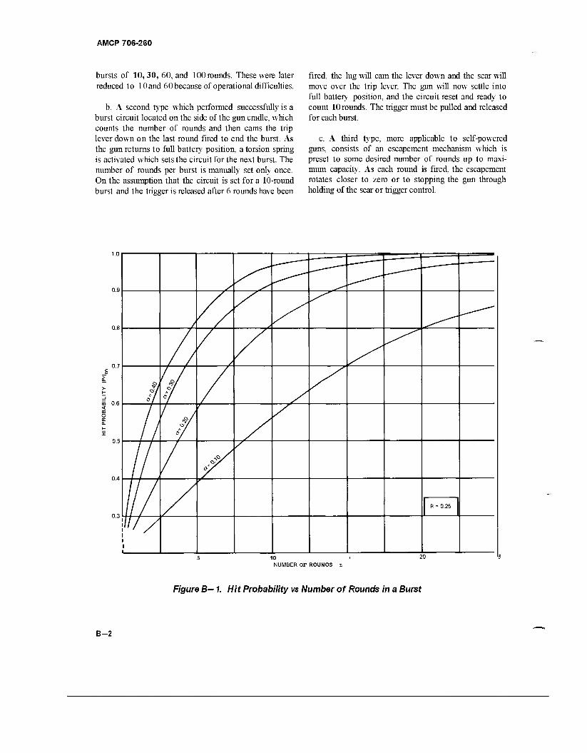
AMCP 706-260
bursts of 10,30, 60, and 100 rounds. These were later reduced to 10 and 60 because of operational difficulties.
b. A second type which performed successfully is a burst circuit located on the side of the gun cradle, which counts the number of rounds and then cams the trip lever down on the last round fired to end the burst. As the gun returns to full battery position, a torsion spring is activated which sets the circuit for the next burst. The number of rounds per burst is manually set only once. On the assumption that the circuit is set for a 10-round burst and the trigger is released after 6 rounds have been
fired, the lug will cam the lever down and the sear will move over the trip lever. The gun will now settle into full battery position, and the circuit reset and ready to count 10 rounds. The trigger must be pulled and released for each burst.
c. A third type, more applicable to self-powered guns, consists of an escapement mechanism which is preset to some desired number of rounds up to maxi- mum capacity. As each round is fired, the escapement rotates closer to zero or to stopping the gun through holding of the sear or trigger control.
l.U
0.8
0.7
> H _l CD 0.6 < OQ
O CC a.
i 0.5
0.4
0/
is 1
Rf 4/
1 if
1 4/
///
r
0.3
R - 0.25
////
5 1 0 i 0 NUMBER OF ROUNOS n
Figure B— 1. Hit Probability vs Number of Rounds in a Burst
B-2
AMCP 706-260
GLOSSARY
accelerator. A cam arrangement that converts barrel momentum to bolt momentum thereby increasing bolt velocity and decreasing time.
automatic weapon. A rapid, self-firing weapon.
barrel spring. The driving spring equivalent for the barrel.
belt, ammunition. Fabric or metal band with loops for carrying cartridges that are fed from it to an automatic weapon.
belt, disintegrating. An ammunition belt whose empty links are detached as the individual rounds are removed.
blowback The class of automatic weapon that uses the propellant gas pressure on the cartridge case base to force the bolt open, barrel and receiver remaining rela- tively fixed.
blowback, advanced primer ignition. A blowback gun that fires before the round is fully chambered.
blowback, delayed. A blowback gun that keeps the bolt locked until the projectile leaves the muzzle.
blowback, retarded. A blowback gun that has a linkage to provide a large, early resistance to recoil.
blowback, simple. A blowback gun that relies on bolt inertia for early recoil resistance.
breech closure. Complete closing of the breech by bolt or breechblock.
buffer spring. A spring that augments either driving or barrel spring during the last stages of either bolt or barrel travel.
compression time. The time during which a spring becomes compressed..
cutoff. The closing of the gas port between bore and operating cylinder.
cutoff expansion system. An expansion system that has a valve to close the gas inlet port after the operating piston moves a prescribed distance.
counterrecoil time. Time required for a counterrecoiling part to return to battery.
critical pressure. The pressure on the discharge end of a nozzle at which flow rate becomes independent regard- less of how much the down stream pressure is reduced.
cycle, time of. The time required for a gun to negotiate the firing cycle.
driving spring. The spring that stores some of the bolt recoil energy, stops the recoiling bolt, then drives it into the in-battery position.
ejector. A device in the breech mechanism which auto- matically throws out an empty cartridge case or unfired cartridge from the breech or receiver.
expansion system. An operating cylinder of a machine gun that has an initial expansion chamber at the gas inlet port.
external power unit. A unit that drives some or all oper- ating components of an automatic weapon by deriving its power from a source other than the propellant gases.
extractor. A device in the breech mechanism that pulls an empty cartridge case or unfired cartridge from the chamber.
firing cycle. The sequential activity that takes place from the time a round is fired until the next round is about to be fired.
firing mechanism. The mechanism that actuates and
controls the firing of a gun.
firing pin. The component of a firing mechanism that contacts the primer and relays the detonating energy of the firing mechanism to the primer.
flexibility. The flexing of an ammunition belt so that it will assume a fan-like attitude or form a helix.
flexibility, base fanning. The fan-like flexibility where the cartridge case bases form the inner arc.
flexibility, free. The flexibility that becomes available by taking up the slack provided by the accumulated clearances of the links.
G-l
AMCP 706-260
flexibility, helical. The flexibility that forms a helix.
flexibility, induced or forced. The flexibility that is derived from the elastic deflection of the individual links.
override. The clearance between bolt face and cartridge case base when the bolt is in its rearmost position.
propellant gas period. The time that propellant gas pres- sures are effective.
flexibility, nose fanning. The fan-like flexibility where the cartridge noses form the inner arc.
gas filling period. The time of gas activity in the oper- ating cylinder.
rate of fire. The number of rounds fired per minute.
recoil, long. A recoil-operated gun that has the barrel recoiling as far as the bolt, both recoiling as a unit but counterrecoiling separately.
gas-operated. The class of automatic weapon that uses propellant gases vented through the barrel wall to oper- ate all moving components.
recoil-operated. The class of automatic weapon that uses the energy of all recoiling parts to operate the gun.
hammer. The striking component of a firing mechanism.
impingement system. A gas-operated gun that has no initial expansion chamber at the gas inlet port.
link. The unit of an ammunition belt that firmly holds and carries one round.
link, extracting type. A link from which the round is removed axially by pulling it rearward.
link, push through type. A link from which the round is removed axially by pushing it forward by bolt or rammer.
line, side stripping type. A link from which the round is removed perpendicular to the axis.
recoil, short. A recoil-operated gun that has the barrel recoiling a short distance, with barrel and bolt moving as a unit for part of that distance, whereupon the bolt is released to continue its rearward motion.
recoil time. The time required for a recoiling part to negotiate its rearward travel.
recoil time, accelerating. The time required to accelerate the recoiling parts.
recoil time, decelerating. The time required to stop the recoilingparts.
sear. The component of a firing mechanism that releases the hammer.
locking cam, bolt. The cam that controls the locking and unlocking of the bolt.
safety. A locking or cutoff device that prevents a weapon from being fired accidentally.
locking period. The time needed to lock the bolt in its closed position.
machine gun. An automatic weapon that can sustain relatively long bursts of firing.
magazine, box. A magazine, usually detachable, of rectangular construction and of small capacity.
magazine, drum. A magazine of drum construction whose capacity is larger than that of the box magazine.
operating cylinder. The gas pressure system that powers a gas-operated machine gun.
semiautomatic. A gun that functions automatically except that each round fired must be triggered manually.
specific impetus. The unit energy, ft-Ib/lb, of a propel- lant.
surge time. The period of time required for a compres- sion wave to traverse a spring.
tappet system. An impingement system that has a very short piston travel.
trigger. The component of a firing mechanism that releases the sear to initiate all firing.
G-2

AMCP 706-260
trigger pull. The force that is required to actuate the velocity of free recoil. The maximum velocity that a trigger. recoiling part would attain if left unimpeded during
recoil.
unlocking period. The time needed to release the bolt wall ratio. The ratio of outer to inner diameter of a from its closed position. hollow cylinder.
6-3/G-4
AMCP 706-260
REFERENCES
1. Thomas J. Hays, Elements of Or dnance, John Wile}' and Sons, Inc., N. Y., 1938,page 632.
2. AMCP 706-252, Engineering Design Handbook, Guns Series, Gun Tubes, par. VI-C-1.
3. George M Chinn, The Machine Gun, Vol. IV, U. S. Government Printing Office, Washington, D. C, 1955, Chapter 1.
4. Driving Springs for Automatic Guns: Study of Static and Dynamic Loading, Springfield Armory Memorandum Report SA-MR15-1001, Springfield, Mass., 26 July 1950.
5. Reference 4, Equation 19.
6. Handbook of Mechanical Spring Design, Associated Spring Corporation, Bristol, Conn.
7. Marks Mechanical Engineers' Handbook, Fifth Edition, McGraw-Hill Book Company, Inc., N. Y., 1951,page 334.
8. TM 9-2310, Caliber .60 Automatic GunsM38 and T130E3 and 20 mm Automutic Guns M39 and T260E3.
9. Kinematic Analysis of the 20 mm Automatic Gun of the T74 Type, Springfield Armory Technical Report SA-TR7-1003, Springfield, Mass., March 1950.
10. Precalculation of the Cyclic Function for Drum- Type Guns, Cal .50, Cal .60, and20mm .Spring- field Armory Technical Report SA-TR5-3003, Springfield,Mass., Jan. 1950.
14. Equation 55 , Reference 9.
15. AMCP 706-342, Engineering Design Handbook, Car- riages and Mounts Series, Recoil Systems, page 62, Fig. 41.
16. OP-2719, GunPodMK4Mod 0,Description, Oper- ation, and Maintenance, Bureau of Naval Weapons, Dept. of Navy.
17. NRL Report 4175, All-Weather Lubrication of the 20 mm M-3 Aircraft Machine Gun and Accessories, May 27, 1953.
18. AFAC-TN-57-8, January 1957.
19. Lubricants for Rapid Fire Automatic Weapons, Frankford Arsenal Report A64-18,Philadelphia, Pa., June 1964.
20. Rock Island Arsenal Report No. 59-1515,Investiga- tion of Resin Systems or Bonding Agents for Dry Lubricants, Rock Island, 111., 4 June 1959.
21. Test of Teflon and Microcrystalllne Wax, 41st Report, Project No. TS1-47, Aberdeen Proving Ground, Md., lDec. 1954.
22. AMCP 706-270, Engineering Design Handbook, Propellant Actuated Devices.
23. AMCP 706-340, Engineering Design Handbook, Carriages and Mounts Series, Carriages and Mounts - General, Eq. 5 a, page 16.
24. S. Timoshenko, Strength of Materials, Part 11, Second Ed., Chapter I, D. Van Nostrand Company, Inc.,N. Y., 1948.
11. Notes on Development Type Material Pertaining to Gun, Automatic, 20 mm, T160 and Gun, Auto- matic, Cal .60, TI30, Armour Research Foundation (now IIT Research Institute), Chicago, III, April 1952.
12. Equation 16, Reference 10.
13. Equation 29, Reference 10.
25. AMCP 706-251, Engineering Design Handbook, Guns Series,M«zz/e Devices.
26. Silencers, Frankford Arsenal Report R-1896, Phila- delphia, Pa., August 1968.
27. Reference 7, page 295.
28. NRL Report No. 4278, Dry Lubricants and Preser- vative Coatings for Ammunition, November 1953.
R-1/R-2
(AMCRD-TV)
FOR THE COMMANDER:
P. R. HORNE COL, GS Chief, Administrative Office
DISTRIBUTION : Special
AMCP 706-260
LEO B JONES Major General, USA Chief of Staff

ENGINEERING DESIGN HANDBOOKS Listed below are the Handbooks which have been published or are currently under preparation. Handbooks with publica-
tion dates prior to 1 August 1962 were published as 20-series Ordnance Corps pamphlets. AMC Circular 310-38, 19 July 1963, redesignated those publications as 706-series AMC pamphlets (e.g. , ORDP 20-138 was redesignated AMCP 706-138). All new, reprinted, or revised Handbooks are being published as 706-series AMC pamphlets.
No. Title
100 *0esign Guidance for Producibility 104 "Value Engineering 106 Elements of Armament Engineering, Part One,
Sources of Energy 107 Elements of Armament Engineering, Part Two,
Ballistics 108 Elements of Armament Engineering, Part Three,
Weapon Systems and Components 110 Experimental Statistics, Section 1, Basic Con-
cepts and Analysis of Measurement Data 111 Experimental Statistics, Section 2, Analysis of
Enumerative and Classificatory Data 112 Experimental Statistics, Section 3, Planning
and Analysis of Comparative Experiments 113 Experimental Statistics, Section 4, Special
Topics 114 Experimental Statistics, Section 5, Tables 115 Basic Environmental Concepts 116 *Basic Environmental Factors 120 *Design Criteria for Environmental Control of
Mobile Systems 121 Packaging and Pack Engineering 123 »Hydraulic Fluids 125 Electrical Wire and Cable 127 "Infrared Military Systems. Part One 128(S) »Infrared Military Systems, Part Two (U) 130 Design for Air Transport and Airdrop of
Materiel 134 Maintainability Guide for Design 135 Inventions, Patents, and Related Matters 136 Servomechanisms, Section 1, Theory 137 Servomechanisms, Section 2, Measurement and
Signal Converters 138 Servomechanisms, Section 3, Amplification 139 Servomechanisms, Section 4, Power Elements
and System Design 140 Trajectories, Differential Effects, and Data
for Projectiles 145 »Dynamics of a Tracking Gimbal System 150 Interior Ballistics of Guns 160( S) Elements of Terminal Ballistics, Part One,
Kill Mechanisms and Vulnerability (U) 161(5) Elements of Terminal Ballistics, Part Two,
Collection and Analysis of Data Concerning Tarqets (U)
162(S-RD) Elements of Terminal Ballistics, Part Three. Application to Missile and Space Targets (U)
165 Liquid-Filled Projectile Design 170(C) Armor and Its Application to Vehicles (U) 175 Solid Propel lants. Part One 176(C) Solid Propellants, Part Two (U) 177 Properties of Explosives of Military Interest 178(C) tPrODerties of Explosives of Military Interest.
Section 2 (U) 179 Explosive Trains 180 »Principles of Explosive Behavior 185 Military Pyrotechnics, Part One, Theory and
Application 186 Military Pyrotechnics, Part Two, Safety,
Procedures and Glossary 187 Mlitary Pyrotechnics, Part Three, Properties
of Materials Used in Pyrotechnic Compositions 188 »Military Pyrotechnics, Part Four, Design of
Ammunition for Pyrotechnic Effects 189 Military Pyrotechnics, Part Five, Bibliography 190 »Army Weapon System Analysis 195 »Development Guide for Reliability, Part One 196 »Development Guide for Reliability, Part Two 197 »Development Guide for Reliability , Part Three 198 »Development Guide for Reliability, Part Four 199 »Development Guide for Reliability, Part Five 200 »Development Guide for Reliability, Part Six 201 »Rotorcraft Engineering, Part One, Prelimi-
nary Design
* UNDER PREPABATIOS—not available t OBSOLETE—out of stock
No.
202
203
205 210 211(C) 212(S) 213(S) 214(S) 215(C) 235 239(S) 240(C) 241(S) 242
244
245(C)
246
247 248
249
250 251 252 255 260 270 280
"3US-RD) 282 283 284(C) 285 286 290(C) 291
292
293 294(S)
295(S)
296
297(S)
327 329 331 335(S-RD) 340 341 342 343 344 345 346 347 350 355 356 357
Title »Rotorcraft Engineering, Part Two, Detail
Eteign »Rotorcraft Engineering, Part Three, Qualifi
cation Assurance »Timing Systems and Components
Fuzes Electrical, Part One (U) Electrical Electrical
Fuzes, Proximity Fuzes, Proximity Fuzes, Proximity Fuzes, Proximity Fuzes , Proximity
Part Two (U) , Part Three (U)
Electrical. Part Four (U) Electrical , Part Five (U)
'Hardening Weapon Systems Against RF Energy »Small Aims Ammunition (U) Grenades (U)
»Land Mines (U) Design for Control of Projectile Flight
Characteristics Ammunition, Section 1, Artillery Ammunition—
General, with Table of Contents, Glossary and Index for Series
Ammunition, Section 2. Design for Terminal Effects (U)
tAmmunition, Section 3, Design for Control of Flight Characteristics
Ammunition, Section 4, Design for Projection tAmmunition, Section 5, Inspection Aspects of
Artillery Ammunition Design Ammunition, Section 6, Manufacture of Metallic
Components of Artillery Ammunition Guns—General Muzzle Devices Gun Tubes Spectral Characteristics of Muzzle Flash Automatic Weapons Propellant Actuated Devices Design of Aerodynamically Stabilized Free
Rockets Weapon System Effectiveness (U)
tPropulsion and Propellants Aerodynamics Trajectories (U) Elements of Aircraft and Missile Propulsion Structures Warheads—General (U) Surface-to-Air Missiles, Part One, System
Integration Surface-to-Air Missiles, Part Two, Weapon
Control Surface-to-Air Missiles, Part Three, Computers Surface-to-Air Missiles, Part Four, Missile
Armament (U) Surface-to-Air Missiles,
measures (U) Surface-to-Air Missiles,
and Power Sources Surface-to-Air Missiles. Part Seven. Sample
Problem (U) Fire Control Systems—General
»Fire Control Computing Systems Compensating Elements
»Nuclear Effects on Weapon Systems (U) Carriages and Mounts—General Cradles Recoil Systems Top Carriages Bottom Carriages Equilibrators Elevating Mechanisms Traversing Mechanisms
»Wheeled Amphibians The Automotive Assembly Automotive Suspensions
*Autoirotive Bodies and Hulls
Part Five, Counter-
Part Six. Structures