guidance for use of ecdis,ais, vdr and bnwas for
TRANSCRIPT


Department of Marine Administration Ministry of Transport and Communications
Republic of the Union of Myanmar
2018
GUIDANCE FOR USE OF ECDIS,AIS, VDR AND BNWAS FOR
PURPOSE OF SAFE NAVIGATION

CONTENTS
Introduction……………………………………………………………………………...2
PART I UNIFIED INTERPRETATION ON THE APPENDIX TO THE SOLAS CONVENTION REGARDING THE RECORDS OF EQUIPMENT CONCERNING NAUTICAL CHARTS AND ECDIS ............................ 3
PART II ECDIS – GUIDANCE FOR GOOD PRACTICE …………………….. 6
PART III REVISED GUIDELINES FOR THE ONBOARD OPERATIONAL USE OF SHIPBORNE AUTOMATIC IDENTIFICATION SYSTEMS (AIS) (Resolution A. 1106(29)) (Adopted on 2 December 2015) ………… 37
PART IV AMENDMENTS TO THE GUIDELINES FOR THE INSTALLATION OF A SHIPBORNE AUTOMATIC IDENTIFICATION SYSTEM (AIS) (SN/Circ.227) …………………57
PART V GUIDELINES FOR THE INSTALLATION OF A SHIPBORNE AUTOMATIC IDENTIFICATION SYSTEM (AIS) ……………… 59
PART VI CORRIGENDA TO SN/CIRC.227 ON GUIDELINES FOR THE INSTALLATION OF A SHIPBORNE AUTOMATIC IDENTIFICATION SYSTEM (AIS) ………………………………...73
PART VII GUIDELINES ON ANNUAL TESTING OF THE AUTOMATIC IDENTIFICATION SYSTEM (AIS) …………………………... 75
PART VIII GUIDELINES ON VOYAGE DATA RECORDER (VDR) OWNERSHIP AND RECOVERY ………………………………. 81
PART IX GUIDELINES ON ANNUAL TESTING OF VOYAGE DATA RECORDERS (VDR) AND SIMPLIFIED VOYAGE DATA RECORDERS(S-VDR)………………………………………………84
PART X GUIDANCE ON THE BRIDGE NAVIGATIONAL WATCH ALARM SYSTEM (BNWAS) AUTO FUNCTION…………………… 91
1
Introduction
1 This Guidance applies to all Myanmar flagged ships fitted with ECDIS, AIS, VDR and BNWAS as referred to SOLAS Chapter V.
2 Ship owners, managers, masters and deck officers of ships fitted with ECDIS, AIS,VDRs and BNWAS are strongly encouraged to use this relevant guidance to improve their understanding and facilitate safe and efficient usage of Navigation equipment.
3 As advised by the IMO Maritime Safety Committee, the Department of Marine Administration uses IMO resolutions.
4 This Guidance may be subject to amendments from time to time and any amendments will be circulated through Directive or Guideline.
5 This Guidance is herewith set out by the Department of Marine
Administration stated in the Directive 06/2018 on 22nd January 2018.
2

PART I UNIFIED INTERPRETATION ON THE APPENDIX TO THE SOLAS
CONVENTION REGARDING THE RECORDS OF EQUIPMENT CONCERNING NAUTICAL CHARTS AND ECDIS
Completion of items 2.1 and 2.2 of part 3 of the Form E and items 2.1 and 2.2 of Part 5 of Forms P and C
1 The Maritime Safety Committee, at its ninety-fourth session (17 to 21 November 2014), approved a unified interpretation on the Appendix to the SOLAS Convention regarding the records of equipment concerning nautical charts and ECDIS, prepared by the Sub-Committee on Navigation, Communications and Search and Rescue (NCSR), at its first session, as set out in the annex.
2 Member Governments are invited to bring this unified interpretation to the attention of all parties concerned.
Note: The Department of Marine Administration brings this unified interpretation to the attention of all parties concerned
3

UNIFIED INTERPRETATION ON THE APPENDIX TO THE SOLAS CONVENTION REGARDING THE RECORDS OF EQUIPMENT
CONCERNING NAUTICAL CHARTS AND ECDIS
Completion of items 2.1 and 2.2 of Part 3 of the Form E and items 2.1 and 2.2 of Part 5 of Forms P and C
SOLAS regulation V/19.2.1.4 All ships, irrespective of size, shall have ... nautical charts and nautical
publications to plan and display the ship's route for the intended voyage and to plot and monitor positions throughout the voyage. An electronic chart display and information system (ECDIS) is also accepted as meeting the chart carriage requirements of this subparagraph. Ships to which paragraph 2.10 applies shall comply with the carriage requirements for ECDIS detailed therein;
SOLAS regulation V/27 Nautical charts and nautical publications, such as sailing directions, lists of
lights, notices to mariners, tide tables and all other nautical publications necessary for the intended voyage, shall be adequate and up to date.
Record of Equipment for the Cargo Ship Safety Equipment Certificate (Form E) – Part 3 Details of navigational systems and equipment
Item Actual provision 2.1 Nautical charts/Electronic chart display and information system (ECDIS)22.2 Back-up arrangements for ECDIS
2 Delete as appropriateRecord of Equipment for the Passenger Ship Safety Certificate (Form P) and Record of Equipment for the Cargo Ship Safety Certificate (Form C) – Part 5 Details of navigational systems and equipment
Item Actual i i2.1 Nautical charts/Electronic chart display and
information system (ECDIS)3
2.2 Back-up arrangements for ECDIS3 Delete as appropriate
Interpretation 4
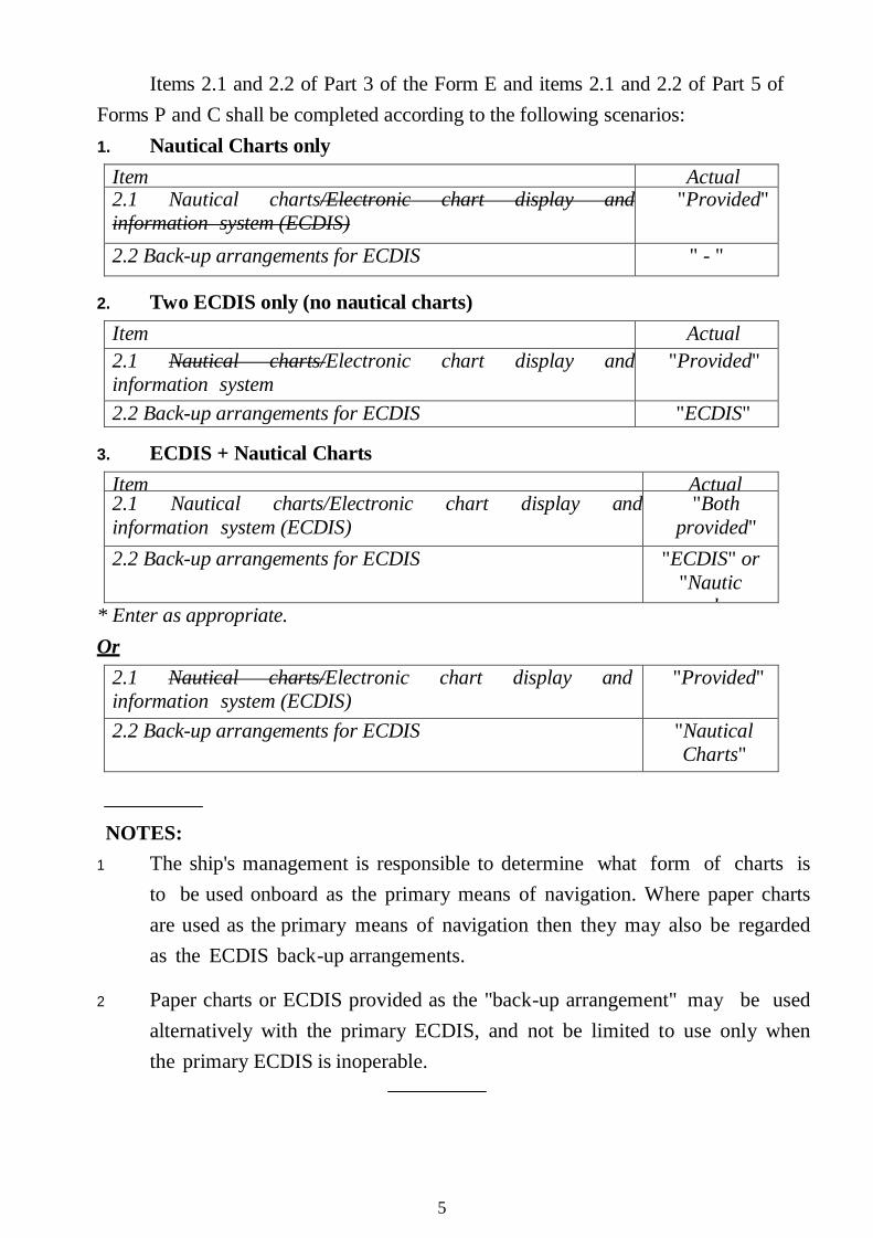
Items 2.1 and 2.2 of Part 3 of the Form E and items 2.1 and 2.2 of Part 5 of Forms P and C shall be completed according to the following scenarios: 1. Nautical Charts only
Item Actual 2.1 Nautical charts/Electronic chart display and information system (ECDIS)
"Provided"
2.2 Back-up arrangements for ECDIS " - "
2. Two ECDIS only (no nautical charts)Item Actual
2.1 Nautical charts/Electronic chart display and information system ( )
"Provided"
2.2 Back-up arrangements for ECDIS "ECDIS"
3. ECDIS + Nautical ChartsItem Actual2.1 Nautical charts/Electronic chart display and information system (ECDIS)
"Both provided"
2.2 Back-up arrangements for ECDIS "ECDIS" or "Nautic
l * Enter as appropriate.Or
2.1 Nautical charts/Electronic chart display and information system (ECDIS)
"Provided"
2.2 Back-up arrangements for ECDIS "Nautical Charts"
NOTES: 1 The ship's management is responsible to determine what form of charts is
to be used onboard as the primary means of navigation. Where paper charts are used as the primary means of navigation then they may also be regarded as the ECDIS back-up arrangements.
2 Paper charts or ECDIS provided as the "back-up arrangement" may be used alternatively with the primary ECDIS, and not be limited to use only when the primary ECDIS is inoperable.
5
PART II – ECDIS – GUIDANCE FOR GOOD PRACTICE
1 The Maritime Safety Committee, at its ninety-fifth session (3 to 12 June 2015), approved the ECDIS – Guidance for Good Practice, drawing together relevant guidance from seven previous ECDIS circulars into a single, consolidated document.
2 The undeniable safety benefits of navigating with Electronic Chart Display and Information Systems (ECDIS) were recognized through Formal Safety Assessments submitted to the Organization and experience gained by the voluntary use of ECDIS for many years. ECDIS was mandated for carriage by High-Speed Craft (HSC) as early as 1 July 2008. Subsequently, the mandatory carriage of ECDIS for ships other than HSC (depending on the ship type, size and construction date, as required by SOLAS regulation V/19.2.10) commenced in a phased manner from 1 July 2012 onwards.
3 ECDIS is a complex, safety-relevant, software-based system with multiple options for display and integration. The ongoing safe and effective use of ECDIS involves many stakeholders including seafarers, equipment manufacturers, chart producers, hardware and software maintenance providers, shipowners and operators, and training providers. It is important that all these stakeholders have a clear and common understanding of their roles and responsibilities in relation to ECDIS.
4 ECDIS was accepted as meeting the chart carriage requirements of SOLAS regulation V/19 in 2002. Over the years, IMO Member States, hydrographic offices, equipment manufacturers and other organizations have contributed to the development of guidance on a variety of ECDIS-related matters. Over the years, IMO has issued a series of complementary circulars on ECDIS.
5 While most useful IMO guidance on ECDIS was developed in this incremental manner, the information needed to be consolidated, where possible, to have ECDIS-related guidance within a single circular, which could be easily kept up to date without duplication or need for continual cross-referencing. Such consolidation of information offers clear and unambiguous understanding of the carriage requirements and use of ECDIS.
6
6 The consolidated guidance termed "ECDIS – Guidance for Good Practice" is set out in the annex to this circular (referred to as "Guidance" hereafter). Ship operators, masters and deck officers on ECDIS-fitted ships are encouraged to use this guidance to improve their understanding and facilitate safe and effective use of ECDIS.
7 The Maritime Safety Committee, at its ninety-eighth session (7 to 16 June 2017), based on a recommendation from the fourth session of the Sub-Committee on Human Element, Training and Watchkeeping (30 January to 3 February 2017), and noting the need to clarify the requirement of ECDIS familiarization as specified in the STCW Convention, 1978, as amended, and the ISM Code, approved the revision of the ECDIS – Guidance for Good Practice, as set out in the annex.
8 Members of the Organization and all Contracting Governments to the SOLAS Convention are invited to bring this circular to the attention of all entities concerned. In particular, port States are invited to make the guidance available to their port State control inspectors, and flag States to shipowners, masters, recognized organizations, flag State control inspectors and surveyors. An electronic copy of this circular can be downloaded from the Organization's website at: (http://www.imo.org/OurWork/Circulars/Pages/Home.aspx).
9. This circular revokes MSC.1/Circ.1391, MSC.1/Circ.1503 and Corrigenda 1,SN.1/Circ.207/Rev.1, SN.1/Circ.266/Rev.1, SN.1/Circ.276, SN.1/Circ.312, STCW.7/Circ.10 and STCW.7/Circ.18.
***
Note: The Department of Marine Administration brings this circular to the attention of all entities concerned.
7
ANNEX
ECDIS – GUIDANCE FOR GOOD
PRACTICE TABLE OF CONTENTS
INTRODUCTION ….………………………………………………………………9 A. CHART CARRIAGE REQUIREMENT OF SOLAS ………………… … 10
B. MAINTENANCE OF ECDIS SOFTWARE …………………………… 11
C. OPERATING ANOMALIES IDENTIFIED WITHIN ECDIS …………… 12
D DIFFERENCES BETWEEN RASTER CHART DISPLAY SYSTEM (RCDS) AND ECDIS ……………………………………………………………….. 14
E. ECDIS TRAINING ………………………………………………………… 14
F TRANSITIONING FROM PAPER CHART TO ECDIS NAVIGATION ……………………………………………………………………………… 16
G GUIDANCE ON TRAINING AND ASSESSMENT IN THE OPERATIONAL USE OF ECDIS SIMULATORS ……………………………………… …16
APPENDIX 1 – LIST OF ECDIS APPARENT OPERATING AND DISPLAY ANOMALIES ..................................................18
APPENDIX 2 – DIFFERENCES BETWEEN RASTER CHART DISPLAY SYSTEM RCDS) AND ECDIS ..........................................22
APPENDIX 3 – GUIDANCE ON TRAINING AND ASSESSMENT IN THE OPERATIONAL USE OF ECDIS SIMULATORS ..........24
REFERENCES ...............................................................................................35
8
INTRODUCTION
1 The undeniable safety benefits of navigating with Electronic Chart Display and Information Systems (ECDIS) were recognized through Formal Safety Assessments submitted to the Organization and experience gained by the voluntary use of ECDIS for many years. ECDIS was mandated for carriage by High-Speed Craft (HSC) as early as 1 July 2008. Subsequently, the mandatory carriage of ECDIS for ships other than HSC (depending on the ship type, size and construction date, as required by SOLAS regulation V/19.2.10) commenced in a phased manner from 1 July 2012 onwards.
2 ECDIS is a complex, safety-relevant, software-based system with multiple options for display and integration. The ongoing safe and effective use of ECDIS involves many stakeholders including seafarers, equipment manufacturers, chart producers, hardware and software maintenance providers, shipowners and operators, and training providers. It is important that all these stakeholders have a clear and common understanding of their roles and responsibilities in relation to ECDIS.
3 This ECDIS – Guidance for Good Practice, referred to as "Guidance" hereafter, draws together relevant guidance from seven previous ECDIS circulars into a single, consolidated document. The guidance is laid out in seven sections, namely:
A. Chart carriage requirement of SOLAS B. Maintenance of ECDIS software C. Operating anomalies identified within ECDIS D. Differences between raster chart display system (RCDS) and ECDIS E. ECDIS training F. Transitioning from paper chart to ECDIS navigation G. Guidance on training and assessment in the operational use of
ECDIS simulators
4 This guidance is intended to assist smooth implementation of ECDIS and its ongoing safe and effective use on board ships. Ship operators, masters and deck officers on ECDIS-fitted ships are encouraged to use this guidance to improve their understanding and facilitate safe and effective use of ECDIS.
5 Although this guidance replaces seven IMO ECDIS-related circulars, there remain several other IMO circulars that also address ECDIS matters to varying degree and reference should also be made to these circulars where necessary. A list
9
containing the IMO ECDIS performance standards and the other IMO circulars that relate to ECDIS is provided in the reference section.
A CHART CARRIAGE REQUIREMENT OF SOLAS
6 The mandatory carriage of ECDIS, as required by SOLAS regulation V/19.2.10, is subject to a staged entry into force between 1 July 2012 and 1 July 2018. As per SOLAS regulations V/18 and V/19, for a ship to use ECDIS to meet the chart carriage requirements of SOLAS, the ECDIS equipment must conform to the relevant IMO performance standards. ECDIS units on board are required to comply with one of two performance standards (either IMO resolution A.817(19), as amended or resolution MSC.232(82)), depending on the date of their installation. Essentially, where an ECDIS is being used to meet the chart carriage requirements of SOLAS, it must:
.1 be type-approved;
.2 use up-to-date electronic nautical charts (ENC);
.3 be maintained so as to be compatible with the latest applicable International Hydrographic Organization (IHO) standards; and
.4 have adequate, independent back-up arrangements in place.
7 According to SOLAS regulation V/18, ECDIS units on board ships must be type-approved. Type approval is the certification process that ECDIS equipment must undergo before it can be considered as complying with IMO performance standards. The process is carried out by flag Administration-accredited type-approval organizations or marine classification societies in accordance with the relevant test standards developed by, inter alia, the International Electro technical Commission (IEC) (e.g. IEC 61174).
8 In accordance with SOLAS regulation V/19.2.1.4, ships must carry all nautical charts necessary for the intended voyage. As defined by SOLAS regulation V/2.2, nautical charts are issued officially by or on the authority of a Government, authorized Hydrographic Office or other relevant government institutions. Ships required to fit ECDIS and ships choosing to use ECDIS to meet the chart carriage requirements of SOLAS should carry Electronic Navigational Charts (ENCs) or,
9 where ENCs are not available at all or are not of an appropriate scale for the planning and display of the ship's voyage plan, Raster Navigational Charts (RNC) and/or any needed paper charts should be carried.
10

10 IHO provides an online chart catalogue that details the coverage of ENCs together with references to coastal State guidance on any requirements for paper charts (where this has been provided). The catalogue also provides links to IHO Member States' websites where additional information may be found. The IHO online chart catalogue can be accessed from the IHO website at: www.iho.int
11 As per SOLAS regulation V/27, all nautical charts necessary for the intended voyage shall be adequate and up to date. For ships using ECDIS to meet the chart carriage requirement of SOLAS, all ENCs and RNCs must be of the latest available edition and be kept up to date using both the electronic chart updates (e.g. ENC updates) and the latest available notices to mariners. Additionally, ECDIS software should be kept up to date such that it is capable of displaying up-to-date electronic charts correctly according to the latest version of IHO's chart content and display standards.
12 Relevant appendices of IMO performance standards for ECDIS specify the requirements for adequate independent back-up arrangements to ensure safe navigation in case of ECDIS failure. Such arrangements include: 1) facilities enabling a safe take-over of the ECDIS functions in order to ensure that an ECDIS failure does not result in a critical situation; 2) a means to provide for safe navigation for the remaining part of the voyage in case of ECDIS failure.
B MAINTENANCE OF ECDIS SOFTWARE
13 ECDIS in operation comprises hardware, software and data. It is important for the safety of navigation that the application software within the ECDIS works fully in accordance with the Performance Standards and is capable of displaying all the relevant digital information contained within the ENC.
14 ECDIS that is not updated to the latest version of the IHO Standards may not meet the chart carriage requirements as set out in SOLAS regulation V/19.2.1.4.
15 For example, in January 2007, Supplement No.1 to the IHO ENC Product Specification was introduced in order to include, within the ENC, the then recently introduced IMO requirements for Particularly Sensitive Sea Areas (PSSA),
Archipelagic Sea Lanes (ASL) and to cater for any future safety of navigation requirements.
16 Any ECDIS which is not upgraded to be compatible with the latest version of the
11
IHO ENC Product Specification or the Presentation Library may be unable to correctly display the latest charted features. Additionally, the appropriate alarms and indications may not be activated even though the features have been included in the ENC. Similarly, any ECDIS which is not updated to be fully compliant with the latest version of the IHO Data Protection Standard may fail to decrypt or to properly authenticate some ENCs, leading to failure to load or install. An up-to-date list of all the relevant IHO standards relating to ECDIS equipment can be accessed from the IHO website (www.iho.int).
17 The need for safe navigation requires that manufacturers should provide a mechanism to ensure software maintenance arrangements are adequate. This may be achieved through the provision of software version information using a website. Such information should include the IHO Standards which have been implemented.
18 Administrations should inform shipowners and operators that proper ECDIS software maintenance is an important issue and that adequate measures need to be implemented by masters, shipowners and operators in accordance with the International Safety Management (ISM) Code.
C OPERATING ANOMALIES IDENTIFIED WITHIN ECDIS
19 A number of ECDIS operating anomalies have been identified. Due to the complex nature of ECDIS, and in particular because it involves a mix of hardware, software and data, it is possible that further anomalies may exist.
20 These anomalies are particularly apparent in ECDIS units that have been built and type-approved to ECDIS Performance Standards (resolution A.817(19), as amended), (i.e. before 2009). However, ECDIS units type-approved to the revised ECDIS Performance Standards (resolution MSC.232(82)) are still vulnerable to the limitations in as set out in appendix 1, item 5(a).
21 An ECDIS anomaly is an unexpected or unintended behaviour of an ECDIS unit which may affect the use of the equipment or navigational decisions made by the user. Examples include, but are not limited to:
.1 failure to display a navigational feature correctly, such as: .1 navigation areas recently recognized by IMO such as PSSA and ASL .2 navigational lights with complex characteristics; and .3 underwater features and isolated dangers;
12
.2 failure to detect objects by "route checking" in voyage planning mode;
.3 failure to alarm correctly; and
.4 failure to manage a number of alarms correctly.
22 The existence of such anomalies highlights the importance of maintaining ECDIS software to ensure that it is capable of displaying up-to-date electronic charts correctly according to the latest version of the IHO's chart content and display standards. It is recommended that appropriate checks are made with the equipment manufacturer. This is of particular importance where ECDIS is the only source of chart information available.
23 IHO has produced an ECDIS Data Presentation and Performance Check (DPPC) dataset that allows mariners to check some important aspects of the operation of their ECDIS. This dataset contains two fictitious ENC cells which deck officers can load into their ECDIS units to assess operating performance and to determine whether there may be any display anomalies that either need to be remedied or otherwise managed in the way that the ECDIS is operated. If the check highlights a problem, the accompanying guidance notes with the check dataset offer suggested courses of action. The check dataset and accompanying instructions can be obtained from ENC service providers, or can be downloaded from the IHO website at: www.iho.int
24 A list of the known anomalies with advice and information on whether or not the DPPC dataset checks for each anomaly is set out in appendix 1.
25 Given the widespread use and the implementation of the ECDIS carriage requirement, the Committee considered it important that any anomalies identified by mariners are reported to and investigated by the appropriate authorities to ensure their resolution.
26 In order to better understand the extent of the issue, Administrations are invited to collect, investigate and disseminate information about ECDIS anomalies. Administrations or designated bodies are invited to:
.1 encourage vessels under their flag to report such anomalies, with sufficient detail on the ECDIS equipment and ENCs, to allow analysis;
.2 treat the identity of the reporter as confidential;
.3 agree to share information with other IMO Member States and international organizations on request; and
13

.4 issue alerts to mariners where such anomalies might affect safety of navigation.
D DIFFERENCES BETWEEN RASTER CHART DISPLAY SYSTEM (RCDS) AND ECDIS
27 ECDIS may be operated in one of the two modes: .1 the ECDIS mode when ENCs are used; and .2 the RCDS mode when ENCs are not available and RNCs are used
instead. Although in recent years ENC coverage has increased rapidly there could be some areas for which suitably detailed ENCs may not have been issued.
28 The RCDS mode does not have the full functionality of ECDIS and can only be used together with an appropriate portfolio of up-to-date paper charts. Limitations of the RCDS mode is set out in appendix 2.
E ECDIS TRAINING
29 The information provided below aims to assist Member States, Parties to the 1978 STCW Convention, as amended, companies and seafarers in ensuring that
training programmes on the use of ECDIS provided to masters and deck officers1
serving on ships fitted with ECDIS meet the mandatory training requirements of the 1978 STCW Convention, as amended:
.1 under the provisions of the STCW Convention and Code, all officers in charge of a navigational watch on ships of 500 gross tonnage or more must have a thorough knowledge and ability to use nautical charts and nautical publications (refer STCW Code, Table A-II/1);
.2 masters and officers in charge of a navigational watch (both at management and operational level) serving on ships fitted with ECDIS should as a minimum, undertake appropriate generic ECDIS training, meeting the competence requirements of the 2010 Manila Amendments to the STCW Convention and Code;
.3 the 2010 Manila Amendments to the STCW Convention and Code have reinforced ECDIS training requirements and introduced several additional specific competencies in the use of ECDIS for officers both at management and operational level serving on ECDIS-fitted ships(refer
14
to STCW Code, Tables A-II/1 and A-II/2). Training in accordance with the 2010 Manila Amendments became effective from 1 July 2013;
.4 masters and officers certificated under chapter II of the STCW Convention serving on board ships fitted with ECDIS are to be familiarized (in accordance with STCW Convention, regulation I/14) with the ship's equipment including ECDIS;
.5 STCW Convention, regulation I/14, paragraph 1.5, as well as section 6.3 of the International Safety Management (ISM) Code, require companies to ensure seafarers are provided with familiarization. A ship safety management system should include familiarization with the ECDIS equipment fitted, including its backup arrangements, sensors and related peripherals. ECDIS manufacturers are encouraged to provide training resources including type-specific materials. These resources may form part of the ECDIS familiarization;
.6 STCW Convention, regulation I/14, paragraph 1.4, requires companies to maintain evidence of the training and ensures that it is readily accessible. For certificates of competency that have expiry dates beyond 1 January 2017, port State control authorities should accept the certificate issued as prima facie evidence that the seafarer has met the standard of companies should also maintain evidence of the familiarization in compliance with STCW Convention, regulation I/14, paragraph 1.5;
.7 Administrations should inform their port State control officers of the requirements for ECDIS training as detailed in sub-paragraph 6 above; and
.8 attention is also drawn to: - STCW.7/Circ.16 – Clarification of transitional provisions
relating to the 2010 Manila Amendments to the STCW Convention and Code;
1 Training and assessment in the use of ECDIS is not required for those who serve exclusively on ships not fitted with ECDIS. This limitation shall be reflected in the endorsements issued to the seafarer concerned (refer to tables A-II/1 and A-II/2 of the STCW Code).
- STCW.7/Circ.17 – Advice for port State control officers on transitional arrangements leading up to the full implementation of the requirements of the 2010 Manila Amendments to the STCW
15
Convention and Code on 1 January 2017; and
- STCW.7/Circ. 24/Rev.1 – Guidance for Parties, Administrations, port State control authorities, recognized organizations and other relevant parties on the requirements of the STCW Convention, 1978, as amended
F TRANSITIONING FROM PAPER CHART TO ECDIS NAVIGATION
29 As an initial step, shipowners and operators should undertake an assessment of the issues involved in changing from paper chart to ECDIS navigation. Ships' masters and deck officers should participate in any such assessment so as to capture any practical concerns or needs of those that would be required to use ECDIS. Such a process will help facilitate an early understanding of any issues to be addressed and will aid masters and deck officers prepare for change.
30 Documenting the assessment of issues, combined with the development of ECDIS standard operating procedures, will help lead to the adoption of robust ECDIS navigation practices, simplification of masters and deck officers' training and facilitate smooth handovers.
31 In addition, shipowners and operators should ensure that their ships' masters and deck officers are provided with a generic ECDIS training and an ECDIS familiarization programme so that the ships' masters and deck officers fully understand the use of ECDIS for passage planning and navigation.
32 In addition to national and international rules and regulations, IMO model course 1.27 on Operational Use of Electronic Chart Display and Information Systems (ECDIS) and IMO performance standards, IHO has published an online publication "Facts about electronic charts and carriage requirements". It is a recommended source of information on ECDIS hardware, training and the technical aspects of electronic chart data. Copies are available free of charge from various sources including: www.iho.int
33 Shipowners and operators should always refer to their national Administrations for the latest information on ECDIS carriage and use.
G GUIDANCE ON TRAINING AND ASSESSMENT IN THE OPERATIONAL USE OF ECDIS SIMULATORS
34 When simulators are being used for training or assessment in the operational
16
use of Electronic Chart Display and Information Systems (ECDIS), the following interim guidance should be taken into consideration in any such training or assessment.
35 Training and assessment in the operational use of the ECDIS should: .1 incorporate the use of ECDIS simulation equipment; and .2 conform to standards not inferior to those given in paragraphs 35 to 37
below.
36 ECDIS simulation equipment should, in addition to meeting all applicable performance standards set out in section A-I/12 of the STCW Code, as amended, be capable of simulating navigational equipment and bridge operational controls which meet all applicable performance standards adopted by the Organization, incorporate facilities to generate soundings and:
.1 create a real-time operating environment, including navigation control and communications instruments and equipment appropriate to the navigation and watchkeeping tasks to be carried out and the manoeuvring skills to be assessed; and
.2 realistically simulate "own ship" characteristics in open‑ water conditions, as well as the effects of weather, tidal stream and currents.
37 Demonstrations of, and practice in, ECDIS use should be undertaken, where appropriate, through the use of simulators. Training exercises should preferably be undertaken in real time, in order to increase trainees' awareness of the hazards of the improper use of ECDIS. Accelerated timescale may be used only for demonstrations.
38 Detailed guidance is provided in appendix 3.
17

Appendix 1
LIST OF ECDIS APPARENT OPERATING AND DISPLAY ANOMALIES (NOT IN PRIORITY ORDER)
In the following list, items 1, 2, 3, 4, 5(b), 6, 7, and 11 are checked against the IHO DPPC dataset dated November 2011:
1 Inability to correctly display symbols for IMO-approved features such as ASLs or PSSAs – ECDIS equipment that does not have the latest version of the IHO Presentation Library installed will, instead of displaying the correct symbol, either show question marks (?) or nothing at all. In some cases the ECDIS may fail to load an ENC that includes such data. An ECDIS retains its type approval certificate regardless of the version of the Presentation Library installed.
Workaround – interrogate any "?" symbol displayed using the "pick report" or refer to paper charts and/or publications.
2 Incorrect display of foul areas and obstructions in some ECDIS equipment – some ECDIS models do not show some underwater features in Standard display mode as expected (however they do activate appropriate alarms). These features are only displayed when the "All" or "Other" display mode is used. Also in some cases different symbols are used to depict these features.
Workaround – use Mode "All" or "Other".
3 On some occasions some stranded/dangerous wrecks and obstructions may not display in any mode; it is believed that this is limited to some ECDIS versions from a single manufacturer who has now produced a software amendment to resolve the problem.
Workaround – use paper charts.
4 An object that falls on a contour line may fail to display in "Standard" mode in some ECDIS equipment.
Workaround – use Mode "All" or "Other".
5 Small (point) land areas, especially those depicted only on small scale (usage band 1 and 2) ENCs may not always be clearly displayed and do not always activate alarms in route planning or route monitoring modes in some ECDIS equipment:
(a) it is possible for small land features to be obscured by other chart detail such as names or contour labels; and
18
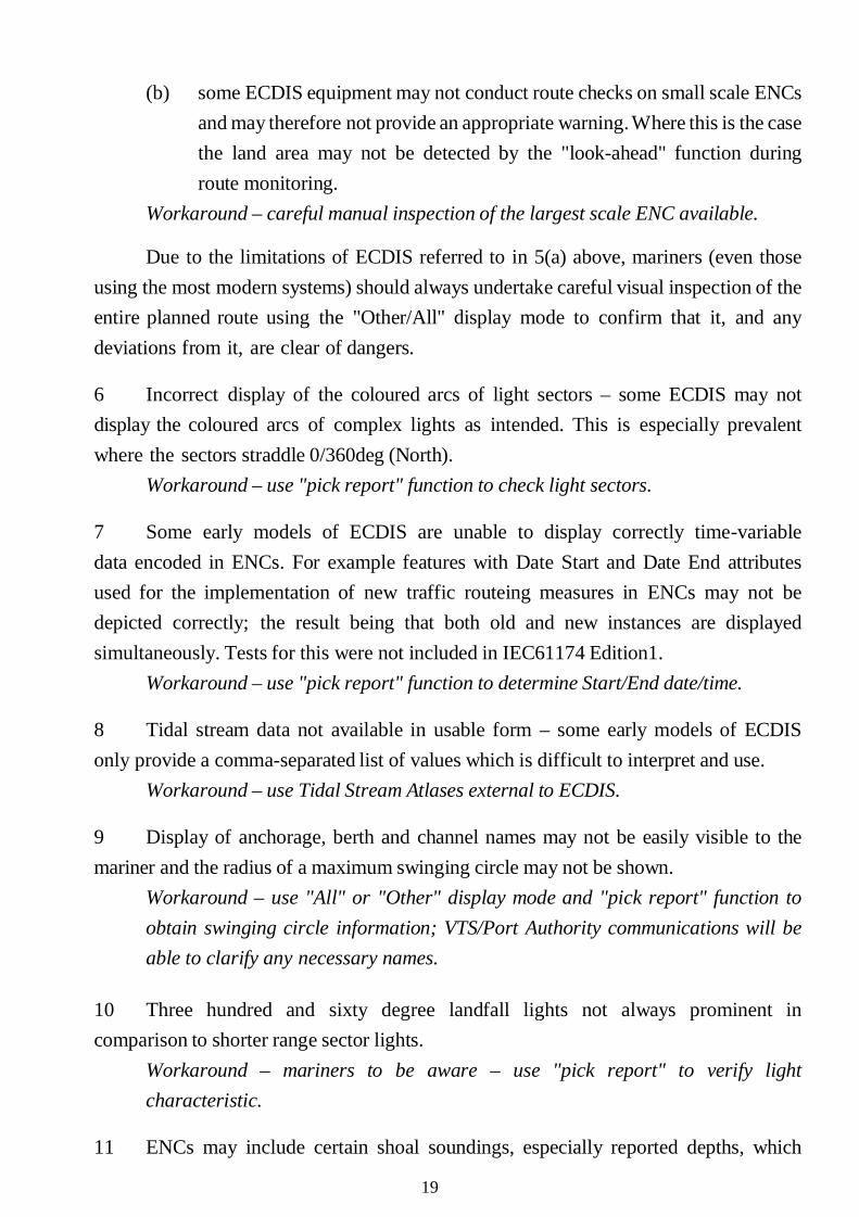
(b) some ECDIS equipment may not conduct route checks on small scale ENCs and may therefore not provide an appropriate warning. Where this is the case the land area may not be detected by the "look-ahead" function during route monitoring.
Workaround – careful manual inspection of the largest scale ENC available.
Due to the limitations of ECDIS referred to in 5(a) above, mariners (even those using the most modern systems) should always undertake careful visual inspection of the entire planned route using the "Other/All" display mode to confirm that it, and any deviations from it, are clear of dangers.
6 Incorrect display of the coloured arcs of light sectors – some ECDIS may not display the coloured arcs of complex lights as intended. This is especially prevalent where the sectors straddle 0/360deg (North).
Workaround – use "pick report" function to check light sectors.
7 Some early models of ECDIS are unable to display correctly time-variable data encoded in ENCs. For example features with Date Start and Date End attributes used for the implementation of new traffic routeing measures in ENCs may not be depicted correctly; the result being that both old and new instances are displayed simultaneously. Tests for this were not included in IEC61174 Edition1.
Workaround – use "pick report" function to determine Start/End date/time.
8 Tidal stream data not available in usable form – some early models of ECDIS only provide a comma-separated list of values which is difficult to interpret and use.
Workaround – use Tidal Stream Atlases external to ECDIS.
9 Display of anchorage, berth and channel names may not be easily visible to the mariner and the radius of a maximum swinging circle may not be shown.
Workaround – use "All" or "Other" display mode and "pick report" function to obtain swinging circle information; VTS/Port Authority communications will be able to clarify any necessary names.
10 Three hundred and sixty degree landfall lights not always prominent in comparison to shorter range sector lights.
Workaround – mariners to be aware – use "pick report" to verify light characteristic.
11 ENCs may include certain shoal soundings, especially reported depths, which
19

have been encoded in such a way that they do not display in "Standard" Mode and might not activate an alarm even where the depth is less than the safety contour setting. Most Hydrographic Offices have reported to IHO that they have updated the relevant ENCs to ensure that significant depths are displayed in Standard Mode.
Workaround – operate in a display Mode where all soundings are shown.
12 Areas of foul ground that have no known depth value may be depicted in some ECDIS as isolated dangers and shown in "Standard" mode; this can result in unnecessary screen clutter.
Workaround – no workaround for clutter problem, mariners to be aware and use "pick report" function to determine if the feature is a danger.
13 Where ECDIS includes an option to show isolated dangers in waters shoaler than the safety contour value the symbology used may vary between manufacturers.
Workaround – mariners to be aware and to use "All" or "Other" Mode when operating in such areas.
14 Screen clutter can be a problem when displaying smaller scale ENCs for areas where larger scale coverage is also loaded in ECDIS. This can be more apparent when the user zooms out. This is due to a combination of each manufacturer's ENC loading strategy and the individual ENC producer's encoding policy. Where Hydrographic Offices use SCAMIN (scale minimum) attributes on chart features then this problem is minimized. The intention of the IHO standard is that ECDIS should not display ENC data which has a compilation scale significantly different from the display scale in use. Improvements could be made, in future, by adopting a standardized ENC loading strategy based on a scale range defined within the ENC.
Workaround – the situation can be improved through use of the standard display mode during voyage monitoring and appropriate (but not over) use of the zoom function. This technique has been included in the syllabus of IMO model course 1.27 on Operational Use of Electronic Chart Display and Information Systems (ECDIS).
15 In some ECDIS equipment the text for some notes in the ENC may be truncated or not displayed at all, and therefore is not available to the mariner.
Workaround – no workaround available; mariners should advise ENC service providers where they observe this problem.
16 Unnecessary alarms and indications – feedback from mariners shows that
20

ECDIS can produce excessive and distracting alarms. This is due to a combination of the interpretation of the requirements of the ECDIS Performance Standards and the ENC encoding. Some control over the number of alarms and indications is available to the mariner in ECDIS built to the revised Performance Standards (resolution MSC.232(82)), but this is not always recognized.
Workaround – the methods available to minimize alarms are included in the syllabus of IMO model course 1.27 on Operational Use of Electronic Chart Display and Information Systems (ECDIS).
21

Appendix 2
DIFFERENCES BETWEEN RASTER CHART DISPLAY SYSTEM (RCDS) AND ECDIS
The mariners' attention is drawn to the following limitations of the RCDS mode:
1 Unlike ENC, where there are no displayed boundaries, RNCs are based on paper charts and as such have boundaries which are evident in ECDIS;
2 RNCs will not trigger automatic alarms (e.g. anti-grounding). However, alarms and indications can be generated with the manual addition, during passage planning, e.g. of clearing lines, ship safety contour lines, isolated danger markers and danger areas to mitigate these limitations;
3 Horizontal datums and chart projections may differ between RNCs. Mariners should understand how a chart's horizontal datum relates to the datum of the position fixing system in use. In some instances, this may appear as a shift in position. This difference may be most noticeable at grid intersections;
4 A number of RNCs cannot be referenced to either WGS-84 or PE 90 geodetic datums. Where this is the case, ECDIS should give a continuous indication;
5 The display of RNCs features cannot be simplified by the removal of features to suit a particular navigational circumstance or task at hand. This could affect the superimposition of radar/ARPA;
6 Without selecting different scale charts the look-ahead capability may be limited. This may lead to inconvenience when determining range and bearing or the identity of distant objects;
7 Orientation of the RCDS display to other than chart-up, may affect the readability of chart text and symbols (e.g. course-up, route-up);
8 It is not possible to interrogate RNC features to gain additional information about charted objects. Whether using ENC or RNC, in the planning process a mariner should consult all relevant publications (such as sailing directions, etc.);
9 With RNC, it is not possible to display a ship's safety contour or safety depth and highlight it on the display unless these features are manually entered during route planning;
22
10 Depending on the source of the RNC, different colours may be used to show similar chart information. There may also be differences in colours used during day and night time;
11 An RNC is intended to be used at the scale of the equivalent paper chart. Excessive zooming in or zooming out can seriously degrade the displayed image. If the RNC is displayed at a larger scale than the equivalent paper chart, the ECDIS will provide an indication; and
12 ECDIS provides an indication in the ENC which allows a determination of the quality of hydrographic the data. When using RNCs, mariners are invited to consult the source diagram or the zone of confidence diagram, if available.
23
Appendix 3
GUIDANCE ON TRAINING AND ASSESSMENT IN THE OPERATIONAL USE OF ECDIS SIMULATORS
GENERAL
Goals of an ECDIS training programme
1 The ECDIS trainee should be able to: .1 operate the ECDIS equipment, use the navigational functions of
ECDIS, select and assess all relevant information and take proper action in the case of a malfunction;
.2 state the potential errors of displayed data and the usual errors of interpretation; and
.3 explain why ECDIS should not be relied upon as the sole reliable aid to navigation.
Theory and demonstration
2 As the safe use of ECDIS requires knowledge and understanding of the basic principles governing ECDIS data and their presentation rules as well as potential errors in displayed data and ECDIS-related limitations and potential dangers, a number of lectures covering the theoretical explanation should be provided. As far as possible, such lessons should be presented within a familiar context and make use of practical examples. They should be reinforced during simulator exercises.
3 For safe operation of ECDIS equipment and ECDIS-related information (use of the navigational functions of ECDIS, selection and assessment of all relevant information, becoming familiar with ECDIS man–machine interfacing), practical exercises and training on the ECDIS simulators should constitute the main content of the course.
4 For the definition of training objectives, a structure of activities should be defined. A detailed specification of learning objectives should be developed for each topic of this structure.
24
Simulator exercises
5 Exercises should be carried out on individual ECDIS simulators, or full-mission navigation simulators including ECDIS, to enable trainees to acquire the necessary practical skills. For real‑ time navigation exercises, navigation simulators are recommended to cover the complex navigation situation. The exercises should provide training in the use of the various scales, navigational modes, and display modes which are available, so that the trainees will be able to adapt the use of the equipment to the particular situation concerned.
6 The choice of exercises and scenarios is governed by the simulator facilities available. If one or more ECDIS workstations and a full-mission simulator are available, the workstations may primarily be used for basic exercises in the use of ECDIS facilities and for passage‑ planning exercises, whereas full-mission simulators may
primarily be used for exercises related to passage‑ monitoring functions in real time, as realistic as possible in connection with the totalworkload of a navigational watch. The degree of complexity of exercises should increase throughout the training programme until the trainee has mastered all aspects of the learning subject.
7 Exercises should produce the greatest impression of realism. To achieve this, the scenarios could be located in a fictitious sea area. Situations, functions and actions for different learning objectives which occur in different sea areas can be integrated into one exercise and experienced in real time.
8 The main objective of simulator exercises is to ensure that trainees understand their responsibilities in the operational use of ECDIS in all safety-relevant aspects and are thoroughly familiar with the system and equipment used.
Principal types of ECDIS and their display characteristics
9 The trainee should gain knowledge of the principal types of ECDIS in use; their various display characteristics, data structure and an understanding of:
.1 differences between vector and raster charts;
.2 differences between ECDIS and ECS;
.3 differences between ECDIS and RCDS;
.4 characteristics of different types of ECDIS; and
25

.5 characteristics of systems for special purposes (unusual situations/ emergencies).
Risks of over-reliance on ECDIS
10 The training in ECDIS operational use should address: .1 the limitations of ECDIS as a navigational tool;
.2 potential risk of improper functioning of the system;
.3 system limitations, including those of its sensors;
.4 hydrographic data inaccuracy; limitations of vector and raster electronic charts (ECDIS vs RCDS and ENC vs RNC); and
.5 potential risk of human errors.
Emphasis should be placed on the need to keep a proper look-out and to perform periodical checking, especially of the ship's position, by ECDIS-independent methods.
Detection of misrepresentation of information
11 Knowledge of the limitations of the equipment and detection of misrepresentation of information is essential for the safe use of ECDIS. The following factors should be emphasized during training:
.1 performance standards of the equipment;
.2 radar data representation on an electronic chart, elimination of discrepancy between the radar image and the electronic chart;
.3 possible projection discrepancies between an electronic and paper charts;
.4 possible scale discrepancies (overscaling and underscaling) in displaying an electronic chart and its original scale;
.5 effects of using different reference systems for positioning;
.6 effects of using different horizontal and vertical datums;
.7 effects of the motion of the ship in a seaway;
.8 ECDIS limitations in raster chart display mode;
.9 potential errors in the display of:
.1 the own ship's position;
.2 radar data and ARPA and AIS information;
26
.3 different geodetic coordinate systems; and
.10 verification of the results of manual or automatic data correction:
.1 comparison of chart data and radar picture; and
.2 checking the own ship's position by using other independent position‑ fixing systems.
12 False interpretation of the data and proper action to be taken to avoid errors of interpretation, should be explained. The implications of the following should be emphasized:
.1 ignoring overscaling of the display;
.2 uncritical acceptance of the own ship's position;
.3 confusion of display mode;
.4 confusion of chart scale;
.5 confusion of reference systems;
.6 different modes of presentation;
.7 different modes of vector stabilization;
.8 differences between true north and gyro north (radar);
.9 using the same data reference system;
.10 using the appropriate chart scale;
.11 using the best-suited sensor to the given situation and circumstances;
.12 entering the correct values of safety data:
.1 the own ship's safety contour;
.2 safety depth (safe water); and
.3 events; and .13 proper use of all available data.
13 Appreciation that RCDS is only a navigational aid and that, when operating in the RCDS mode, the ECDIS equipment should be used together with an appropriate portfolio of up-to-date paper charts:
.1 appreciation of the differences in operation of RCDS mode as described in appendix 2; and
27
.2 ECDIS, in any mode, should be used in training with an appropriate portfolio of up‑ to-date charts.
Factors affecting system performance and accuracy
14 An elementary understanding should be attained of the principles of ECDIS, together with a full practical knowledge of:
.1 starting and setting up ECDIS; connecting data sensors: satellite and radio navigation system receivers, radar, gyro‑ compass, log, echo-sounder; accuracy and limitations of these sensors, including effects of measurement errors and ship's position accuracy, manoeuvring on the accuracy of course indicator's performance, compass error on the accuracy of course indication, shallow water on the accuracy of log performance, log correction on the accuracy of speed calculation, disturbance (sea state) on the accuracy of an echo-sounder performance; and
.2 the current performance standards for electronic chart display and
information systems adopted by the Organization2.
Practice
Setting up and maintaining display
15 Knowledge and skills should be attained in:
.1 the correct starting procedure to obtain the optimum display of ECDIS information;
.2 the selection of display presentation (standard display, display base, all other information displayed individually on demand);
.3 the correct adjustment of all variable radar/ARPA display controls for optimum display of data;
.4 the selection of convenient configuration;
.5 the selection, as appropriate, of required speed input to ECDIS;
.6 the selection of the timescale of vectors; and
2 See relevant/appropriate performance standards adopted by the Organization. 28
.7 performance checks of position, radar/ARPA, compass, speed input sensors and ECDIS.
Operational use of electronic charts
16 Knowledge and skills should be attained in:
.1 the main characteristics of the display of ECDIS data and selecting proper information for navigational tasks;
.2 the automatic functions required for monitoring ship's safety, such as display of position, heading/gyro course, speed, safety values and time;
.3 the manual functions (by the cursor, electronic bearing line, range rings);
.4 selecting and modification of electronic chart content;
.5 scaling (including underscaling and overscaling);
.6 zooming;
.7 setting of the own ship's safety data;
.8 using a daytime or night-time display mode;
.9 reading all chart symbols and abbreviations;
.10 using different kinds of cursors and electronic bars for obtaining navigational data;
.11 viewing an area in different directions and returning to the ship's position;
.12 finding the necessary area, using geographical coordinates;
.13 displaying indispensable data layers appropriate to a navigational situation;
.14 selecting appropriate and unambiguous data (position, course, speed, etc.);
.15 entering the mariner's notes;
.16 using north-up orientation presentation and other kinds of orientation; and
.17 using true- and relative‑ motion modes.
29
Route planning
17 Knowledge and skills should be attained in:
.1 loading the ship's characteristics into ECDIS;
.2 selection of a sea area for route planning:
.1 reviewing required waters for the sea passage; and
.2 changing over of chart scale;
.3 verifying that proper and updated charts are available;
.4 route planning on a display by means of ECDIS, using the graphic editor, taking into consideration rhumb line and great-circle sailing: .1 using the ECDIS database for obtaining navigational, hydro-
meteorological and other data;
.2 taking into consideration turning radius and wheel‑ over points/lines when they are displayed on chart scale;
.3 marking dangerous depths and areas and exhibiting guarding depth contours;
.4 marking waypoints with the crossing depth contours and critical cross‑ track deviations, as well as by adding, replacing and erasing of waypoints;
.5 taking into consideration safe speed;
.6 checking pre-planned route for navigational safety; and
.7 generating alarms and warnings;
.5 route planning with calculation in the table format, including: .1 waypoints selection;
.2 recalling the waypoints list;
.3 planning notes;
.4 adjustment of a planned route;
.5 checking a pre-planned route for navigational safety;
.6 alternative route planning;
.7 saving planned routes, loading and unloading or deleting routes;
.8 making a graphic copy of the monitor screen and printing a route;
30

.9 editing and modification of the planned route;
.10 setting of safety values according to the size and manoeuvring parameters of the vessel;
.11 back-route planning; and
.12 connecting several routes.
Route monitoring
18 Knowledge and skills should be attained in:
.1 using independent data to control ship's position or using alternative systems within ECDIS;
.2 using the look-ahead function:
.1 changing charts and their scales;
.2 reviewing navigational charts;
.3 vector time selecting;
.4 predicting the ship's position for some time interval;
.5 changing the pre-planned route (route modification);
.6 entering independent data for the calculation of wind drift and current allowance;
.7 reacting properly to the alarm;
.8 entering corrections for discrepancies of the geodetic datum;
.9 displaying time markers on a ship's route;
.10 entering ship's position manually; and
.11 measuring coordinates, course, bearings and distances on a chart.
Alarm handling
19 Knowledge and ability to interpret and react properly to all kinds of alarm systems, such as navigational sensors, indicators, data and charts alarms and indicator warnings, including, switching the sound and visual alarm signalling system on/off, should be attained in case of:
.1 absence of the next chart in the ECDIS database;
.2 crossing a safety contour;
.3 exceeding cross-track limits;
31
.4 deviation from planned route;
.5 approaching a waypoint;
.6 approaching a critical point;
.7 discrepancy between calculated and actual time of arrival to a waypoint;
.8 information on under-scaling or over-scaling;
.9 approaching an isolated navigational danger or danger area;
.10 crossing a specified area;
.11 selecting a different geodetic datum;
.12 approaching other ships;
.13 watch termination;
.14 switching timer;
.15 system test failure;
.16 malfunctioning of the positioning system used in ECDIS;
.17 failure of dead-reckoning; and
.18 inability to fix vessel's position using the navigational system.
Manual correction of a ship's position and motion parameters
20 Knowledge and skills should be attained in manually correcting:
.1 the ship's position in dead-reckoning mode, when the satellite and radio navigation system receiver is switched off;
.2 the ship's position, when automatically obtained coordinates are inaccurate; and
.3 course and speed values.
Records in the ship's log
21 Knowledge and skills should be attained in: .1 automatic voyage recording; .2 reconstruction of past track, taking into account:
.1 recording media;
.2 recording intervals;
.3 verification of database in use;
.3 viewing records in the electronic ship's log;
32

.4 instant recording in the electronic ship's log;
.5 changing ship's time;
.6 entering the additional data;
.7 printing the content of the electronic ship's log;
.8 setting up the automatic record time intervals;
.9 composition of voyage data and reporting; and
.10 interface with a voyage data recorder (VDR).
Chart updating
22 Knowledge and skills should be attained in:
.1 performing manual updating of electronic charts. Special attention should be paid to reference ellipsoid conformity and to conformity of the measurement units used on a chart and in the correction text;
.2 performing semi-automatic updating of electronic charts, using the data obtained on electronic media in the electronic chart format; and
.3 performing automatic updating of electronic charts, using update files obtained via electronic data communication lines.
In the scenarios where non-updated data are employed to create a critical situation, trainees should be required to perform ad hoc updating of the chart.
Operational use of ECDIS where radar/ARPA is connected
23 Knowledge and skills should be attained in:
.1 connecting ARPA to ECDIS;
.2 indicating target's speed vectors;
.3 indicating target's tracks;
.4 archiving target's tracks;
.5 viewing the table of the targets;
.6 checking alignment of radar overlay with charted geographic features;
.7 simulating one or more manoeuvres;
.8 corrections to own ship's position, using a reference point captured by ARPA; and
.9 corrections using the ARPA's cursor and electronic bar.
33

See also STCW Code section B-I/12, Guidance regarding the use of simulators (pertaining to radar and ARPA), especially paragraphs 17 to 19 and 36 to 38.
Operational use of ECDIS where AIS is connected
24 Knowledge and skills should be attained in:
.1 interface with AIS;
.2 interpretation of AIS data;
.3 indicating target's speed vectors;
.4 indicating target's tracks; and
.5 archiving target's tracks.
Operational warnings, their benefits and limitations
25 Trainees should gain an appreciation of the uses, benefits and limitations of ECDIS operational warnings and their correct setting, where applicable, to avoid spurious interference.
System operational tests
26 Knowledge and skills should be attained in: .1 methods of testing for malfunctions of ECDIS, including functional self-
testing;
.2 precautions to be taken after a malfunction occurs; and
.3 adequate back-up arrangements (take over and navigate using the back-up system).
Debriefing exercise
27 The instructor should analyse the results of all exercises completed by all trainees and print them out. The time spent on the debriefing should take between 10% and 15% of the total time used for simulator exercises.
34
REFERENCES
IMO PERFORMANCE STANDARDS FOR ECDIS
1 RESOLUTION A.817(19): PERFORMANCE STANDARDS FOR ELECTRONIC CHART DISPLAY AND INFORMATION SYSTEMS (ECDIS)
2 RESOLUTION MSC.64(67): RECOMMENDATIONS ON NEW AND AMENDED PERFORMANCE STANDARDS
3 RESOLUTION MSC.86(70): ADOPTION OF NEW AND AMENDED PERFORMANCE STANDARDS FOR NAVIGATIONAL EQUIPMENT
4 RESOLUTION MSC.232(82): ADOPTION OF THE REVISED PERFORMANCE STANDARDS FOR ELECTRONIC CHART DISPLAY AND INFORMATION SYSTEMS (ECDIS)
OTHER IMO CIRCULARS RELATED TO ECDIS
1 MSC.1/Circ.982: GUIDELINES ON ERGONOMIC CRITERIA FOR BRIDGE EQUIPMENT AND LAYOUT
2 MSC.1/Circ.1091: ISSUES TO BE CONSIDERED WHEN INTRODUCING NEW TECHNOLOGY ON BOARD SHIP
3 MSC.1/Circ.1221: VALIDITY OF TYPE APPROVAL CERTIFICATION FOR MARINE PRODUCTS
4 MSC.1/Circ.1389: GUIDANCE ON PROCEDURES FOR UPDATING SHIPBORNE NAVIGATION AND COMMUNICATION EQUIPMENT
5 SN.1/Circ.213: GUIDANCE ON CHART DATUMS AND THE ACCURACY OF POSITIONS ON CHARTS
6 SN.1/Circ.243/Rev.1 AMENDED GUIDELINES FOR THE PRESENTATION OF NAVIGATIONAL-RELATED SYMBOLS, TERMS AND ABBREVIATIONS
7 SN.1/Circ.255: ADDITIONAL GUIDANCE ON CHART DATUMS AND THE ACCURACY OF POSITIONS ON CHARTS
35

8 SN.1/Circ.265: GUIDELINES ON THE APPLICATION OF SOLAS REGULATION V/15 TO INS, IBS AND BRIDGE DESIGN
SN.1/Circ.288: GUIDELINES FOR BRIDGE EQUIPMENT AND SYSTEMS, THEIR ARRANGEMENT AND INTEGRATION (BES)
36
PART III – REVISED GUIDELINES FOR THE ONBOARD OPERATIONAL USE OF SHIPBORNE AUTOMATIC IDENTIFICATION SYSTEMS (AIS)
(Resolution A. 1106(29)) (Adopted on 2 December 2015)
THE ASSEMBLY,
RECALLING Article 15(j) of the Convention on the International Maritime Organization concerning the functions of the Assembly in relation to regulations and guidelines concerning maritime safety,
RECALLING ALSO the provisions of regulation V/19 of the International Convention for the Safety of Life at Sea (SOLAS), 1974, as amended, requiring all ships of 300 gross tonnage and upwards engaged on international voyages, cargo ships of 500 gross tonnage and upwards not engaged on international voyages and passenger ships irrespective of size to be fitted with an automatic identification system (AIS), as specified in SOLAS regulation V/19.2.4, taking into account the recommendations adopted by the Organization,
RECALLING FURTHER resolution A.917(22), as amended by resolution A.956(23), by which it adopted Guidelines for the onboard operational use of shipborne automatic identification systems (AIS),
HAVING CONSIDERED the recommendations made by the Maritime Safety Committee at its ninety-fourth session,
1 ADOPTS the Revised guidelines for the onboard operational use of shipborne automatic identification systems (AIS), set out in the annex to the present resolution;
2 INVITES Governments concerned to take into account the annexed revised guidelines when implementing SOLAS regulations V/11, 12 and 19;
3 ALSO INVITES Governments which are considering setting or have set regional frequencies or otherwise make use of AIS channel management, including changing to narrow-band operation for whatever reason, to take into account the possible impact on the use of AIS at sea and that it should only be used for urgent temporary situations. In such cases Governments should notify the Organization of such areas and designated frequencies, for urgent circulation of that information to all Member Governments;
37

4 REQUESTS the Maritime Safety Committee to keep the revised guidelines under review and amend them as appropriate;
5 REVOKES resolution A.917(22), as amended by resolution A.956(23).
38

Annex REVISED GUIDELINES FOR THE ONBOARD
OPERATIONAL USE OF SHIPBORNE AUTOMATIC IDENTIFICATION SYSTEMS (AIS)
PURPOSE
1 These Guidelines have been developed to promote the safe and effective use of shipborne Automatic Identification Systems (AIS), in particular to inform the mariner about the operational use, limits and potential uses of AIS. Consequently, AIS should be operated taking into account these Guidelines.
2 Before using shipborne AIS, the user should fully understand the principle of the current Guidelines and become familiar with the operation of the equipment, including the correct interpretation of the displayed data. A description of the AIS system, particularly with respect to shipborne AIS (including its components and connections), is contained in annex 1.
CAUTION Not all ships carry AIS. The officer of the watch (OOW) should always be aware that other ships, in particular leisure craft, fishing boats and warships, and some coastal shore stations including Vessel Traffic Service (VTS) centres, might not be fitted with AIS. The OOW should always be aware that AIS fitted on other ships as a mandatory carriage requirement might, under certain circumstances, be switched off on the master's professional judgement.
3 The internationally-adopted shipborne carriage requirements for AIS are contained in SOLAS regulation V/19. The SOLAS Convention requires AIS to be fitted on certain ships through a phased implementation period spanning from 1 July 2002 to 1 July 2008. In addition, specific ship types (e.g. warships, naval auxiliaries and ships owned/operated by Governments) are not required to be fitted with AIS. Also, small ships (e.g. leisure craft, fishing boats) and certain other ships may be exempt from carrying AIS. Moreover, ships fitted with AIS might have the equipment switched off. Users are therefore cautioned always to bear in mind that
39

information provided by AIS may not be giving a complete or correct "picture" of shipping traffic in their vicinity. The guidance in this document on the inherent limitations of AIS and their use in collision avoidance situations (see paragraphs 40 to 44) should therefore be observed.
Objectives of AIS
4 AIS is intended to enhance: safety of life at sea; the safety and efficiency of navigation; and the protection of the marine environment. SOLAS regulation V/19 requires that AIS exchange data ship-to-ship and with shore-based facilities. Therefore, the purpose of AIS is to help identify ships, assist in target tracking, assist in search and rescue operation, simplify information exchange (e.g. reduce verbal mandatory ship reporting) and provide additional information to assist situation awareness. In general, data received via AIS will improve the quality of the information available to the OOW, whether at a shore surveillance station or on board a ship. AIS is a useful source of supplementary information to that derived from navigational systems (including radar) and therefore an important 'tool' in enhancing situation awareness of traffic confronting users.
40

DESCRIPTION OF AIS
Figure 1 – AIS system overview
5 Class A shipborne equipment complies with relevant IMO AIS carriage requirement. Class B shipborne equipment provides functionalities not in full accordance with IMO AIS carriage requirement. Class B devices may be carried on ships which are not subject to the SOLAS carriage requirements.
6 Shipborne AIS (see figure 1): - transmits ship's own data to other ships and vessel traffic service
(VTS) stations; and - receives and makes available data of other ships and VTS stations and
other AIS stations, such as AIS-SARTs, AIS-ATON, etc.
7 When used with the appropriate display, shipborne AIS enables provision of fast, automatic information by calculating Closest Point of Approach (CPA) and Time to Closest Point of Approach (TCPA) from the position information transmitted by the target vessels.
8 AIS operates primarily on two dedicated VHF channels. Where these channels are not available regionally, the AIS is capable of being automatically switched to designated alternate channels by means of a message from a shore facility. Where no shore-based AIS or Global Maritime Distress and Safety System (GMDSS) Sea Area
41

A1 station is in place, the AIS should be switched manually. However, this capability should only be considered for use in urgent, temporary situations, noting the possible adverse effects on AIS at sea.
9 The capacity of the system allows for a great number of ships to be accommodated at the same time. Priority in the system is given to Class A devices. Class B devices operate at a reduced reporting rate or when free time slots are available.
10 The AIS is able to detect ships within VHF/FM range around bends and behind islands, if the landmasses are not too high. A typical value to be expected at sea is 20 to 30 nautical miles depending on antenna height. With the help of repeater stations, the coverage for both ship and VTS stations can be improved.
11 Information from a shipborne AIS is transmitted continuously and automatically without any intervention or knowledge of the OOW. An AIS shore station might require updated information from a specific ship by "polling" that ship, or alternatively, might wish to "poll" all ships within a defined sea area. However, the shore station can only increase the ships' reporting rate, not decrease it.
AIS INFORMATION SENT BY SHIPS Ship's data content
12 The AIS information transmitted by a ship is of three different types: - static information, which is entered into the AIS on installation and need
only be changed if the ship changes its name, Maritime Mobile Service Identity (MMSI), location of the electronic position fixing system (EPFS) antenna, or undergoes a major conversion from one ship type to another;
- dynamic information, which, apart from "Navigational status" information, is automatically updated from the ship sensors connected to AIS; and
- voyage-related information, which might need to be manually entered and updated during the voyage.
42
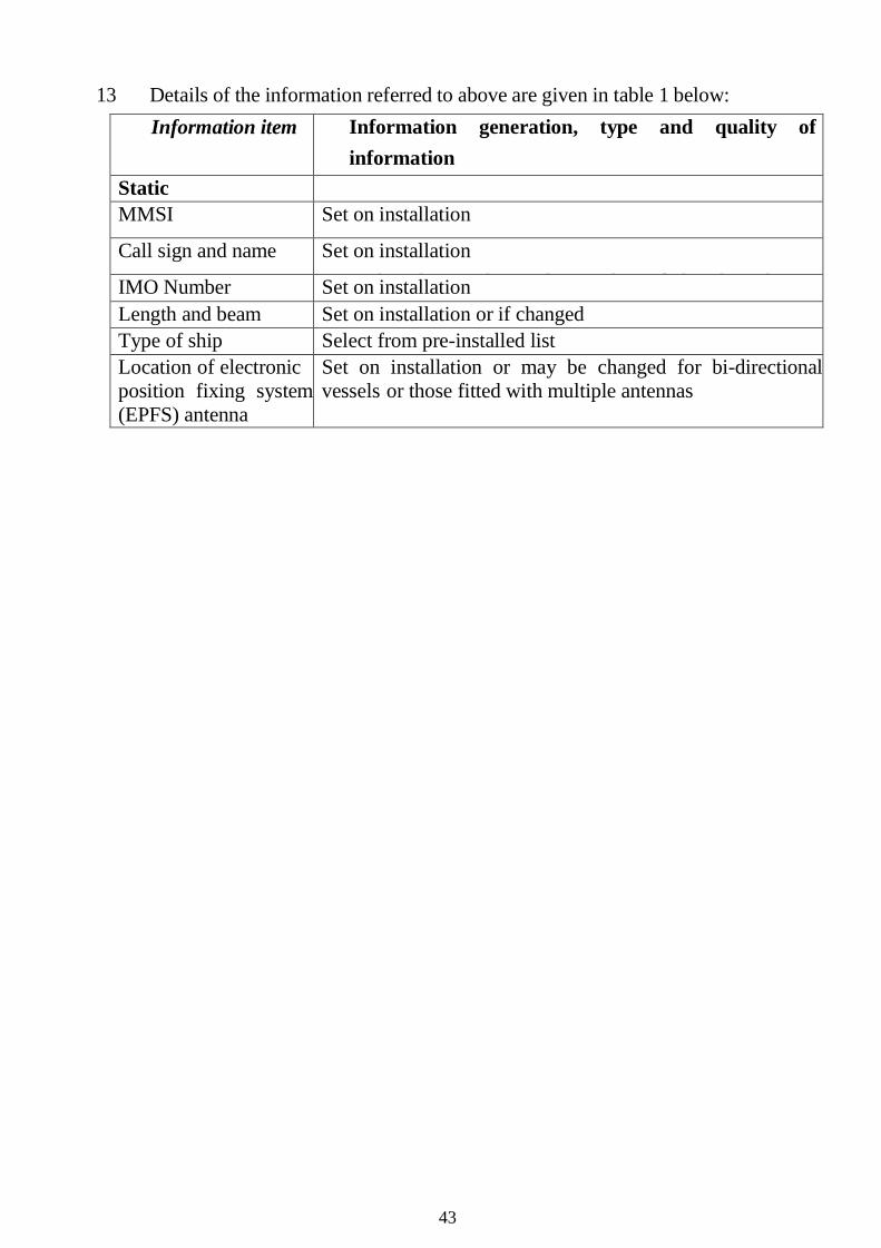
13 Details of the information referred to above are given in table 1 below: Information item Information generation, type and quality of
information Static MMSI Set on installation
h hi i h d di if h hi hCall sign and name Set on installation h hi i h d di if h hi hIMO Number Set on installation
Length and beam Set on installation or if changed Type of ship Select from pre-installed list Location of electronic position fixing system (EPFS) antenna
Set on installation or may be changed for bi-directional vessels or those fitted with multiple antennas
43

Dynamic Ship's position with accuracy indication
Automatically updated from the position sensor connected to AIS The accuracy indication is
Position Time i C
Automatically updated from ship's main position d A S Course over ground
(COG) Automatically updated from ship's main position sensor connected
Speed over ground (SOG)
Automatically updated from the position sensor d A S Heading Automatically updated from the ship's heading sensor d Navigational status Navigational status information has to be manually
entered by the OOW and changed as necessary, for example:
- underway by engines - at anchor - not under command (NUC) - restricted in ability to manoeuvre (RIATM) - moored - constrained by draught - aground - engaged in fishing
Rate of turn (ROT) Automatically updated from the ship's ROT sensor or derived from the gyro.
Voyage-related Ship's draught To be manually entered at the start of the voyage
using the maximum draft for the voyage and amended Hazardous cargo (type) To be manually entered at the start of the voyage
confirming whether or not hazardous cargo is being carried, namely:
- DG (Dangerous goods) Destination and ETA To be manually entered at the start of the voyage and
k d Route plan (waypoints) To be manually entered at the start of the voyage, at the di i
Safety-related Short safety-related messages
Free format short text messages would be manually entered,
Table 1 – Data sent by ship *Due to the amendment of MARPOL categorization of hazardous cargo byresolution MEPC.118(52), cargo type may be categorized as A, B, C or D, rather than X, Y, Z or OS on older AIS equipment, as described in SN.1/Circ.227 and SN.1/Circ.227/Corr.1.
44

The table below indicates the equivalence of the old and new category indications:
Current MARPOL Equivalent
X A Y B Z C
OS D
14 The data is autonomously sent at different update rates: - dynamic information: dependent on speed and course alteration
(see tables 2 and 3); - static and voyage-related data: every 6 minutes or on request (AIS
responds automatically without user action); and - safety-related text message: as required.
Type of ship General reporting Ship at anchor or moored and not moving faster than 3 3 min Ship at anchor or moored and moving faster than 3
10
Ship 0-14 knots 10 Ship 0-14 knots and changing course 3 1/3 s
Ship 14-23 knots 6 Ship 14-23 knots and changing course 2 Ship >23 knots 2 Ship >23 knots and changing course 2
Table 2 – Class A shipborne equipment reporting intervals
Crafts not subject to SOLAS Nominal Class B "SO" shipborne equipment not moving faster
3 min
Class B "SO" shipborne equipment moving 2-14 knots 30 Class B "SO" shipborne equipment moving 14-23 knots 15 Class B "SO" shipborne equipment moving ˃ 23 knots 5 s
Class B "CS" shipborne equipment not moving faster
3 min Class B "CS" shipborne equipment moving faster than 30
Table 3 – Class B shipborne equipment reporting intervals
45

Short safety-related messages
15 Short safety-related messages are fixed or free format text messages addressed either to a specified destination (MMSI) or all ships in the area. Their content should be relevant to the safety of navigation, e.g. an iceberg sighted or a buoy not on station. Messages should be kept as short as possible. The system allows up to 158 characters per message but the shorter the message the more easily it will find free space for transmission. At present these messages are not further regulated, to keep all possibilities open.
16 Operator acknowledgement may be requested by a text message. The operator should be aware that there are special safety-related messages and special user identities form devices such as the AIS-SART. Details are given in SN.1/Circ.322, as amended. There is no need for acknowledgement by a text message.
17 Short safety-related messages are only an additional means of broadcasting maritime safety information. Whilst their importance should not be underestimated, use of such messages does not remove any of the requirements of the GMDSS.
18 The operator should ensure that he displays and considers incoming safety-related messages and should send safety-related messages as required.
19 According to SOLAS regulation V/31 (Danger messages) "The master of every ship which meets with dangerous ice, a dangerous derelict, or any other direct danger to navigation, or ...is bound to communicate the information by all the means at his disposal to ships at his vicinity, and also to the competent authorities..."
20 Normally this is done via VHF voice communication, but "by all the means" now implies the additional use of the AIS short messages application, which has the advantage of reducing difficulties in understanding, especially when noting down the correct position.
Confidentiality
21 When entering any data manually, consideration should be given to the confidentiality of this information, especially when international agreements, rules or standards provide for the protection of navigational information.
46

OPERATION OF AIS ON BOARD
OPERATION OF THE TRANSCEIVER UNIT
Activation
22 AIS should always be in operation when ships are underway or at anchor. If the master believes that the continual operation of AIS might compromise the safety or security of his/her ship or where security incidents are imminent, the AIS may be switched off. Unless it would further compromise the safety or security, if the ship is operating in a mandatory ship reporting system, the master should report this action and the reason for doing so to the competent authority. Actions of this nature should always be recorded in the ship's logbook together with the reason for doing so. The master should however restart the AIS as soon as the source of danger has disappeared. If the AIS is shut down, static data and voyage-related information remains stored. Restart is done by switching on the power to the AIS unit. Ship's own data will be transmitted after a two-minute initialization period. In ports AIS operation should be in accordance with port requirements.
Manual input of data
23 The OOW should manually input the following data at the start of the voyage and whenever changes occur, using an input device such as a keyboard:
- ship's draught;
- hazardous cargo;
- departure, destination and ETA;
- route plan (way points);
- the correct navigational status; and
- short safety-related text messages.
It is recommended to use the United Nations Code for Trade and Transport Locations (UN/LOCODE) for the entry of the port of destination. In addition, it is recommended that the existing destination field be used for entering both the port of departure and the next port of call (space for 20 characters of 6 bit
ASCII is available) using the UN/LOCODE.1
1SN/Circ.244.
47
Check of information
24 To ensure that own ship's static information is correct and up-to-date, the OOW should check the data whenever there is a reason for it. As a minimum, this should be done once per voyage or once per month, whichever is shorter. The data may be changed only on the authority of the master.
25 The OOW should also periodically check the following dynamic information: - positions given according to WGS 84;
- speed over ground; and
- sensor information.
26 After activation, an automatic built-in integrity test (BIIT) is performed. In the case of any AIS malfunction an alarm is provided and the unit should stop transmitting.
27 The quality or accuracy of the ship sensor data input into AIS would not however be checked by the BIIT circuitry before being broadcast to other ships and shore stations. The ship should therefore carry out regular routine checks during a voyage to validate the accuracy of the information being transmitted. The frequency of those checks would need to be increased in coastal waters.
DISPLAY OF AIS DATA
28 The AIS provides data that can be presented on the minimum display or on any suitable display device, as described in annex 1.
Minimum display
29 The minimum mandated display provides not less than three lines of data consisting of bearing, range and name of a selected ship. Other data of the ship can be displayed by horizontal scrolling of data, but scrolling of bearing and range is not possible. Vertical scrolling will show all the other ships known to the AIS.
Graphical display
30 Where AIS information is used with a graphical display, the following target types may be displayed:
Sleeping target A sleeping target indicates only the presence of a vessel equipped with AIS in a certain location. No additional information is presented until activated, thus avoiding information overload.
48
Activated target If the user wants to know more about a vessel's motion, the target (sleeping) may be activated so that the display shows immediately:
- a vector (speed and course over ground);
- the heading; and
- ROT indication (if available) to display actually initiated course changes.
Selected target If the user wants detailed information on a target (activated or sleeping), it may be selected. Then the data received, as well as the calculated CPA and TCPA values, will be shown in an alpha-numeric window.
The special navigation status will also be indicated in the alpha numeric data field and not together with the target directly.
Dangerous target If an AIS target (activated or not) is calculated to pass preset CPA and TCPA limits, it will be classified and displayed as a dangerous target and an alarm will be given.
Lost target If a signal of any AIS target at a distance of less than a preset value is not received, a lost target symbol will appear at the latest position and an alarm will be given.
Other targets Other targets such as AIS-SART, AIS-AToN, may be displayed with special symbols (see SN.1/Circ.243/Rev.1 on Guidelines for the presentation of navigational-related symbols, terms and abbreviations).
Symbols
31 The user should be familiar with the symbology used in the graphical display provided.
INHERENT LIMITATIONS OF AIS
32 The OOW should always be aware that other ships, in particular leisure craft, fishing boats and warships, and some coastal shore stations including VTS centres, might not be fitted with AIS.
33 The OOW should always be aware that other ships fitted with AIS as a mandatory carriage requirement might switch off AIS under certain circumstances by professional judgement of the master.
49
34 In other words, the information given by the AIS may not be a complete picture of the situation around the ship.
35 The users must be aware that transmission of erroneous information implies a risk to other ships as well as their own. The users remain responsible for all information entered into the system and the information added by the sensors.
36 The accuracy of AIS information received is only as good as the accuracy of the AIS information transmitted.
37 The OOW should be aware that poorly configured or calibrated ship sensors (position, speed and heading sensors) might lead to incorrect information being transmitted. Incorrect information about one ship displayed on the bridge of another could be dangerously confusing.
38 If no sensor is installed or if the sensor (e.g. the gyro) fails to provide data, the AIS automatically transmits the "not available" data value. However, the built-in integrity check cannot validate the contents of the data processed by the AIS.
39 It would not be prudent for the OOW to assume that the information received from other ships is of a comparable quality and accuracy to that which might be available on its own ship.
USE OF AIS IN COLLISION AVOIDANCE SITUATIONS
40 The potential of AIS as an assistance for anti-collision device is recognized and AIS may be recommended as such a device in due time.
41 Nevertheless, AIS information may merely be used to assist in collision avoidance decision-making. When using the AIS in the ship-to-ship mode for anti-collision purposes, the following cautionary points should be borne in mind:
.1 AIS is an additional source of navigational information. It does not replace, but supports, navigational systems such as radar target-tracking and VTS; and
.2 the use of AIS does not negate the responsibility of the OOW to comply at all times with the Collision Regulations, particularly rule 7 when determining whether risk of collisions exists.
50

42 The user should not rely on AIS as the sole information system, but should make use of all safety-relevant information available.
43 The use of AIS on board ship is not intended to have any special impact on the composition of the navigational watch, which should continue to be determined in accordance with the STCW Convention.
44 Once a ship has been detected, AIS can assist in tracking it as a target. By monitoring the information broadcast by that target, its actions can also be monitored. Many of the problems common to tracking targets by radar, namely clutter, target swap as ships pass close by and target loss following a fast manoeuvre, do not affect AIS. AIS can also assist in the identification of targets, by name or call sign and by ship type and navigational status.
ADDITIONAL AND POSSIBLE FUTURE APPLICATIONS
AIS IN VTS OPERATIONS
Pseudo Targets broadcast by VTS
45 VTS centres may send information about vessels which are not carrying AIS and which are tracked only by VTS radar via the AIS to vessels equipped with AIS. Any VTS/generated/synthetic target broadcast by VTS should be clearly identified as such. Particular care should always be taken when using information which has been relayed by a third party. Accuracy of these targets may not be as complete as actual directly-received targets, and the information content may not be as extensive.
Text messages
46 VTS centres may also send short messages either to one ship, all ships, or ships within a certain range or in a special area, e.g.:
- (local) navigational warnings;
- traffic management information; and
- port management information.
47 A VTS operator may request, by a text message, an acknowledgement from the ship's operator.
Note: The VTS should continue to communicate via voice VHF. The importance of
51
verbal communication should not be underestimated. This is important to enable the VTS operator to:
- assess vessels' communicative ability; and
- establish a direct communication link which would be needed in critical situations.
(D) GNSS corrections
48 (D)GNSS corrections may be sent by VTS centres via AIS.
MANDATORY SHIP REPORTING SYSTEMS
49 AIS is expected to play a major role in ship reporting systems. The information required by coastal authorities in such systems is typically included in the static voyage-related and dynamic data automatically provided by the AIS system. The use of the AIS long-range feature, where information is exchanged via communications satellite, may be implemented to satisfy the requirements of some ship reporting systems.
AIS IN SAR OPERATIONS
50 AIS may be used in search and rescue operations. By receiving messages from AIS-SART, operators get more accurate information, especially on the position of survival craft. In combined aerial and surface searches AIS may allow the direct presentation of the position on other displays such as radar or ECS/ECDIS, which facilitates the task of SAR craft. For ships in distress without AIS, the On Scene Coordinator (OSC) could create an AIS target.
AIDS TO NAVIGATION
51 AIS, when fitted to selected fixed and floating aids to navigation can provide information to the mariner such as:
- position;
- status;
- tidal and current data; and
- weather and visibility conditions.
52
AIS IN AN OVERALL INFORMATION SYSTEM
52 AIS will play a role in an overall international maritime information system, supporting voyage planning and monitoring. This will help Administrations to monitor all the vessels in their areas of concern and to track dangerous cargo.
REFERENCE DOCUMENTS
- SOLAS Convention, chapter V
- Recommendation on performance standards for a universal shipborne Automatic Identification System (AIS), (MSC.74(69), annex 3)
- Performance Standards for survival craft AIS search and rescue transmitters (AIS-SART) for use in search and rescue operations (resolution MSC.246(83))
- Guidance on the use of the UN/LOCODE in the destination field in AIS messages (SN/Circ.244)
- ITU Radio Regulations, appendix 18, table of transmitting frequencies in the VHF maritime mobile band
- Technical characteristics for an automatic identification system using time division multiple access in the VHF maritime mobile frequency band (Recommendation ITU-R M.1371-5)
- IEC Standard 61993 Part 2: Class A shipborne equipment of the Universal Shipborne Automatic Identification System (AIS) Operational and Performance Requirements, Methods of Testing and required Test Results
53

APPENDIX 1 DESCRIPTION OF AIS
COMPONENTS
1 In general, an onboard AIS (see figure 1) consists of: - antennas;
- one VHF transmitter;
- two multi-channel VHF receivers;
- one channel 70 VHF receiver for channel management;
- a central processing unit (CPU);
- an electronic position-fixing system, Global Navigation Satellite System (GNSS) receiver for timing purposes and position redundancy;
- interfaces to heading and speed devices and to other shipborne sensors;
- interfaces to radar/Automatic Radar Plotting Aids (ARPA), Electronic Chart System/Electronic Chart Display and Information System (ECS/ECDIS) and Integrated Navigation Systems (INS);
- built-in integrity test (BIIT); and
- minimum display and keyboard to input and retrieve data.
With the integral minimum display and keyboard unit, the AIS would be able to operate as a stand-alone system. A stand-alone graphical display or the integration of the AIS data display into other devices such as INS, ECS/ECDIS or a radar/ARPA display would significantly increase the effectiveness of AIS, when achievable.
2 All onboard sensors must comply with the relevant IMO standards concerning availability, accuracy, discrimination, integrity, update rates, failure alarms, interfacing and type-testing.
3 AIS provides: - a BIIT running continuously or at appropriate intervals
- monitoring of the availability of data;
- an error detection mechanism of the transmitted data; and
- an error check on the received data.
54

Ship's sensors
AIS
Headin g device
GNSS Rx
Speed device
Rate of turn
CPU
VHF-Tx VHF- Rx
VHF-Rx
VHF-Rx
BIIT GNSS-RX
Minimum display and keyboard*
AIS graphical display
Optional item
* May be external Figure 1 – AIS Components
CONNECTIONS
The connection of AIS to external navigational display systems
4 The AIS can be connected either to an additional dedicated AIS display unit, possibly one with a large graphic display, or as an input to existing navigational system devices such as a radar display, ECS, ECDIS, or INS. Such system interconnection and data integration is recommended."
The connection of AIS to external portable navigational equipment
5 It is becoming common practice for pilots to possess their own portable navigational equipment, which they carry on board. Such devices can be connected to shipborne AIS equipment and display the targets they receive. Some Administrations require this connection to be provided at the bridge front.
55

APPENDIX 2 TECHNICAL DESCRIPTION
1 AIS operates primarily on two dedicated VHF channels (AIS1 – 161,975 MHz and AIS2 – 162,025 MHz). Where these channels are not available regionally, the AIS is capable of automatically switching to alternate designated channels. However, this capability should only be considered for use in urgent, temporary situations, noting the possible adverse effects on AIS at sea.
2 The required ship reporting capacity according to the IMO performance standard amounts to a minimum of 2000 time slots per minute (see figure 1 below). The ITU Technical Standard for the Universal AIS provides 4500 time slots per minute. The broadcast mode is based on a principle called (S)TDMA (Self-organized Time Division Multiple Access) that allows the system to be overloaded by 400 to 500% and still provide nearly 100% throughput for ships closer than 8 to 10 NM to each other in a ship-to-ship mode. In the event of system overload, only targets far away will be subject to drop-out in order to give preference to targets close by that are a primary concern for ship-to-ship operation of AIS. In practice, the capacity of the system allows for a great number of ships to be accommodated at the same time.
Figure 1 – Principles of TDMA
56

PART IV – AMENDMENTS TO THE GUIDELINES FOR THE INSTALLATION OF A SHIPBORNE AUTOMATIC IDENTIFICATION
SYSTEM (AIS) (SN/Circ.227)
1 The Sub-Committee on Safety of Navigation (NAV), at its fiftieth session (5 to 9 July 2004), agreed on the amendments to the guidelines for the installation of a shipborne Automatic Identification System (AIS) (SN/Circ.227), as set out at annex. The amendments describe the connection of the shipborne AIS installations to a power source.
2 The Maritime Safety Committee, at its seventy-ninth session (1 to 10 December 2004), concurred with the Sub-Committee's view and approved the annexed amendments.
3 Member Governments are invited to bring these amendments to the attention of all concerned.
***
Note; The Department of Marine Administration brings these amendments to the attention of all concerned
57

ANNEX
AMENDMENTS TO THE GUIDELINES FOR INSTALLATION OF A SHIPBORNE AUTOMATIC IDENTIFICATION SYSTEM (AIS)
(SN/Circ.227)
2.4 Power source
1 The existing text of paragraph 2.4 is replaced by the following: "The AIS should ideally be connected through an uninterrupted power supply (UPS) to the ship's power supply as defined in S0LAS chapter II-1."
58
PART V –GUIDELINES FOR THE INSTALLATION OF A SHIPBORNE AUTOMATIC IDENTIFICATION SYSTEM (AIS)
1 The Sub-Committee on Safety of Navigation (NAY), at its forty-eighth session (8 to 12 July 2002), agreed on guidelines for the installation of a Shipborne Automatic Identification System (AIS) and also agreed that they should be issued for use on a voluntary basis. The Guidelines describe the shipborne AIS installation matters and are meant to be used by manufacturers, installers and surveyors to ensure good installation practices.
2 The Maritime Safety Committee, at its seventy-sixth session (2 to 13 December 2002), concurred with the Sub-Committee's views, approved the Guidelines as set out at annex and encouraged their use for AIS installation purposes on a voluntary basis.
3 Member Governments are invited to bring the annexed guidelines to the attention of all concerned.
Note
***
The Department of Marine Administration brings the annexed guidelines to the attention of all concerned.
59
ANNEX
GUIDELINES FOR THE INSTALLATION OF A SHIPBORNE AUTOMATIC IDENTIFICATION SYSTEM (AIS)
1 General ............................................................................................................ 65 1.1 Survey .................................................................................................... 65 1.2 Documentation....................................................................................... 65 2 AlS lnstallation ............................................................................................ 66 2.1 Interference to the Ship's VHF Radiotelephone .................................... 66 2.2 VHF Antenna Installation ..................................................................... 66 2.3 GNSS Antenna installation ................................................................... 67 2.4 Power source.......................................................................................... 68 2.5 Synchronization. .................................................................................... 68 3 Bridge Arrangement ........................................................................................ 68 3.1 Minimum Keyboard and Display .......................................................... 68 3.2 Pilot plug ................................................................................................ 68 3.3 Display system ....................................................................................... 69 3.4 Installation of the BIIT (Built-in Integrity Test) function ..................... 69 4 Dynamic data input .......................................................................................... 69 4.1 External Sensors .................................................................................... 69 4.2 Position, COG and SOG ........................................................................ 69 4.3 Heading .................................................................................................. 70 4.4 Rate of Turn ........................................................................................... 70 4.5 Navigational Status ................................................................................ 70 5 Static lnformation ............................................................................................ 70 5.1 Entered at initial installation of AIS ...................................................... 70 5.2 Reference point of position ................................................................... 71 5.3 Ship's dimensions .................................................................................. 71 6 Long-Range function ....................................................................................... 72
Annex 1 Rate of Turn…………………………………………………………...75 Annex 2 Type of ship table ................................................................................ 77 Annex 3 Recommended IEC 61162 sentences ................................................. 78
60
1 General
The Automatic Identification System (AIS) Class A is defined by IMO and has been made a carriage requirement by the latest revision of SOLAS chapter Y. AIS provides information that may be used for the navigation of the ship. It is therefore essential that the information provided by AIS be reliable.
The AIS itself has been standardised by the International Telecommunications Union (ITU) and the International Electrotechnical Commission (IEC) and is subject to type approval. In order to fulfil the reliability requirements of information exchange, care should be taken to ensure that the AIS is correctly installed.
This document contains guidelines for manufacturers, installers, yards, suppliers and ship surveyors. It does not replace documentation supplied by the manufacturer.
The guidelines take into account the following conventions, regulations, instructions and guidelines:
• IMO resolution MSC.90(73) Annex 7, Adoption of amendments to theInternational Convention for the Safety of Life at Sea, 1974, as amended.
• IMO resolution MSC.74(69) Annex 3, Recommendation onperformance standards for AIS.
• ITU Radio Regulations (RR).
• IEC 60092 (series), Electrical Installations on Ships.
• IEC 60533 Electrical and Electronic Installations in Ships -Electromagnetic Compatibility.
1.1 Survey Surveys on Convention ships should be carried out in accordance with the rules laid down in resolution A.746(18) "Survey Guidelines under the harmonised system of survey and certification", and "Protocol of 1988 relating to the International Convention for the Safety of Life at Sea, 1974, as amended."
1.2 Documentation For the AIS installation the following drawings shall be submitted:
• Antenna layout
• AIS arrangement drawing
• Block diagram (interconnection diagram)An initial installation configuration report should be produced during installation and kept on board.
61

2 AIS Installation 2.1 lnterference to the Ship's VHF Radiotelephone
The AIS shipborne equipment, like any other shipborne transceiver operating in the YHF maritime band, may cause interference to a ship's YHF radiotelephone. Because AIS is a digital system, this interference may occur as a periodic (e.g. every 20 s) soft clicking sound on a ship's radiotelephone. This affect may become more noticeable when the YHF radiotelephone antenna is located near the AIS YHF antenna and when the radiotelephone is operating on channels near the AIS operating channels (e.g. channels 27, 28 and 86).
Attention should be paid to the location and installation of different antennas in order to obtain the best possible efficiency. Special attention should be paid to the installation of mandatory antennas like the AIS antennas.
2.2 VHF Antenna lnstallation 2.2.1 Location
Location of the mandatory AIS YHF antenna should be carefully considered. Digital communication is more sensitive than analogue/voice communication to interference created by reflections in obstructions like masts and booms. It may be necessary to relocate the YHF radiotelephone antenna to minimize interference effects.
To minimise interference effects, the following guidelines apply: • The AIS YHF antenna should have omnidirectional vertical polarisation.
• The AIS YHF antenna should be placed in an elevated position that isas free as possible with a minimum of 2 metres in horizontal directionfrom constructions made of conductive materials. The antenna shouldnot be installed close to any large vertical obstruction. The objectivefor the AIS YHF antenna is to see the horizon freely through 360°.
• The AIS YHF antenna should be installed safely away from interferinghigh-power energy sources like radar and other transmitting radioantennas, preferably at least 3 m away from and out of the transmittingbeam.
• Ideally there should not be more than one antenna on the samelevel. The AIS YHF antenna should be mounted directly above orbelow the ship's primary YHF radiotelephone antenna, with nohorizontal separation and with a minimum of 2 m vertical separation. Ifit is located on the same level as other antennas, the distance apart shouldbe at least 10 m.
62
2.2.2 Cabling The cable should be kept as short as possible to minimise attenuation of the
signal. Double screened coaxial cables equal or better than RG214 are recommended.
All outdoor installed connectors on the coaxial cables should be waterproof by design to protect against water penetration into the antenna cable.
Coaxial cables should be installed in separate signal cable channels/tubes and at least 10 cm away from power supply cables. Crossing of cables should be done at right angles (90°). Coaxial cables should not be exposed to sharp bends, which may lead to change the characteristic impedance of the cable. The minimum bend radius should be 5 times the cable's outside diameter.
2.2.3 Grounding Coaxial down-leads should be used for all antennas, and the coaxial screen
should be connected to ground at one end.
2.3 GNSS Antenna installation Class A AIS should be connected to a GNSS antenna.
2.3.1 Location The GNSS antenna should be installed where it has a clear view of the sky.
The objective is to see the horizon freely through 360° with a vertical observation of 5 to 90° above the horizon. Small diameter obstructions, such as masts and booms, do not seriously degrade signal reception, but such objects should not eclipse more than a few degrees of any given bearing.
Locate the antenna at least three meters away from and out of the transmitting beam of high- power transmitters (S-Band Radar and/or Inmarsat systems). This includes the ship's own AIS YHF antenna if it is designed and installed separately.
If a DGNSS system is included or connected to the AIS system, the installation of the antenna should be in accordance with IEC 61108-4, Ed 1, annex D.
2.3.2 Cabling To achieve optimum performance, the gain of the antenna pre-amplifier
should match the cable attenuation. The resulting installation gain (pre-amplifier gain - cable attenuation) should be within 0 to 10 dB.
The coaxial cable between the antenna and the AIS shipborne station connector should be routed directly in order to reduce electromagnetic interference effects. The cable should not be installed close to high-power lines, such as radar or
63
radio-transmitter lines or the AIS YHF antenna cable. A separation of one meter or more is recommended to avoid degradation due to RF- coupling. Crossing of antenna cables should be done at 90° to minimise magnetic field coupling.
All outdoor installed connectors on the coaxial cables should be waterproof by design to protect against water penetration into the antenna cable.
2.4 Power source The AIS should be connected to an emergency power source.
2.5 Synchronization After installation, the AIS should be synchronised properly on UTC and that
position information, if provided, should be correct and valid.
3 Bridge Arrangement
3.1 Minimum Keyboard and Display
The functionality of the Minimum Keyboard and Display (MKD) should be available to the mariner at the position from which the ship is normally operated. This can be by means of the AIS' internal MKD (integrated or remote) or through the equivalent functionality on a separate display system
3.2 Pilot plug
A pilot input/output port is part of an AIS Class A station. A plug connected to this port should be installed on the bridge near the pilot's operating position so that a pilot can connect a Personal Pilot Unit (PPU).
The pilot plug should be configured as follows: • AMP/Receptacle (Square Flanged (-1) or Free-Hanging (-2)), Shell
size 11, 9-pin, Std. Sex 206486-1/2 or equivalent with the followingterminations:- TX A is connected to Pin 1
- TX B is connected to Pin 4
- RX A is connected to Pin 5
- RX B is connected to Pin 6
- Shield is connected to Pin 9
3.3 Display system If there is navigational equipment capable of processing and displaying AIS
information such as ECDIS, radar or an integrated system available on board the
64
ship, the AIS Class A mobile system may be connected to that system via the AIS Presentation Interface (PI). The PI (input/output) should meet the requirements of IEC 61162-2.
The display system can also include the functionality of an MKD, see 3.1.
3.4 lnstallation of the BllT (Built-in lntegrity Test) function
The AIS requires that an alarm output (relay) be connected to an audible alarm device or the ships alarm system, if available.
Alternatively, the BIIT alarm system may use the alarm messages output on the PI, provided its alarm system is AIS compatible.
4 Dynamic data input
4.1 External Sensors
The AIS has interfaces (configurable as IEC 61162-1 or 61162-2) for position, heading and rate of turn (ROT) sensors. In general, sensors installed in compliance with other carriage requirements of SOLAS Chapter Y should be connected to the
AIS.1 The sensor information transmitted by AIS should be the same informationbeing used for navigation of the ship. The interfaces should be configured as given in annex 3. Interfacing problems might occur if the existing sensors found on board do not have serial (IEC 61162) outputs.
4.2 Position, COG and SOG
GNSS sensors normally have IEC 61162 outputs for position, COG and SOG suitable for directly interfacing the AIS. However, it is important to note that:
• The Geodetic Datum of the position data transmitted by the sensor isWGS 84 and that an IEC 61162 DTM sentence is configured.
• AIS is able to process two reference points for its antenna position,one for external and one for an internal sensor. If more than one externalreference point is used, the appropriate information needs to be input tothe AIS to adjust reference point information.
1 Installation of the AIS does NOT establish a need to install additional sensors above carriage requirements.
65
4.3 Heading
A compass providing heading information is a mandatory sensor input to the AIS. A converter unit (e.g. stepper to NMEA) will be needed to connect AIS if the ship's compass does not provide an IEC 61162 output. Some ships of less than 500 gross tonnage may not carry a compass providing heading information.
4.4 Rate of Turn
All ships may not carry a Rate-Of-Turn (ROT) Indicator according to resolution A.526(13). However, if a rate-of-turn indicator is available and it includes an IEC 61162 interface, it should be connected to the AIS.
If ROT information is not available from a ROT indicator, the direction of turn may (optionally) be derived from heading information through:
• The compass itself,
• An external converter unit (see paragraph 4.3),
• The AIS itself (see annex 1).
4.5 Navigational Status A simple means should be provided for the operator to input the ship's
navigational status (e.g. underway using engine, at anchor, not under command, restricted in ability to maneuver, etc) information into the AIS. The AIS may be connected to the ship's navigational status lights.
5 Static Information The AIS standards require that certain static, voyage-related, and dynamic
information be entered manually, normally by means of the MKD, or by means of IEC 61162 sentences "SSD" and "YSD" via the presentation interface if such provisions exist.
5.1 Entered at initial installation of AlS Information that should be entered at the initial installation of the AIS includes: • Maritime Mobile Service Identity (MMSI) number
• IMO vessel number
• Radio call sign
• Name of ship
• Type of ship
• Dimension/reference for position of the electronic position fixingdevice (EPFD) antenna (see paragraph 5.2)
66
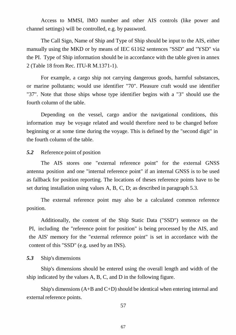
Access to MMSI, IMO number and other AIS controls (like power and channel settings) will be controlled, e.g. by password.
The Call Sign, Name of Ship and Type of Ship should be input to the AIS, either manually using the MKD or by means of IEC 61162 sentences "SSD" and "YSD" via the PI. Type of Ship information should be in accordance with the table given in annex 2 (Table 18 from Rec. ITU-R M.1371-1).
For example, a cargo ship not carrying dangerous goods, harmful substances, or marine pollutants; would use identifier "70". Pleasure craft would use identifier "37". Note that those ships whose type identifier begins with a "3" should use the fourth column of the table.
Depending on the vessel, cargo and/or the navigational conditions, this information may be voyage related and would therefore need to be changed before beginning or at some time during the voyage. This is defined by the "second digit" in the fourth column of the table.
5.2 Reference point of position
The AIS stores one "external reference point" for the external GNSS antenna position and one "internal reference point" if an internal GNSS is to be used as fallback for position reporting. The locations of theses reference points have to be set during installation using values A, B, C, D; as described in paragraph 5.3.
The external reference point may also be a calculated common reference position.
Additionally, the content of the Ship Static Data ("SSD") sentence on the PI, including the "reference point for position" is being processed by the AIS, and the AIS' memory for the "external reference point" is set in accordance with the content of this "SSD" (e.g. used by an INS).
5.3 Ship's dimensions
Ship's dimensions should be entered using the overall length and width of the ship indicated by the values A, B, C, and D in the following figure.
Ship's dimensions (A+B and C+D) should be identical when entering internal and external reference points.
57
67
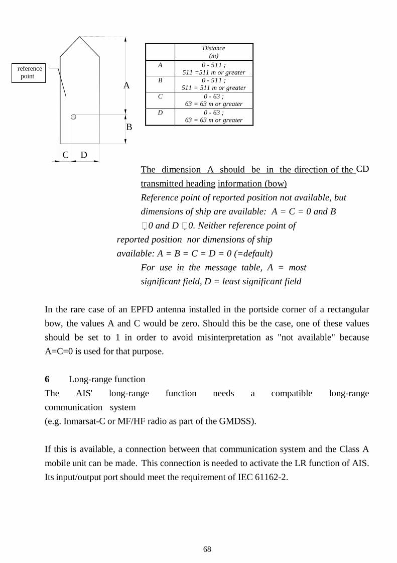
Distance (m)
A 0 - 511 ; 511 =511 m or greater
B 0 - 511 ; 511 = 511 m or greater
C 0 - 63 ; 63 = 63 m or greater
D 0 - 63 ; 63 = 63 m or greater
reference point
A
B
C D The dimension A should be in the direction of the CDtransmitted heading information (bow) Reference point of reported position not available, but dimensions of ship are available: A = C = 0 and B 0 and D 0. Neither reference point of
reported position nor dimensions of ship available: A = B = C = D = 0 (=default)
For use in the message table, A = most significant field, D = least significant field
In the rare case of an EPFD antenna installed in the portside corner of a rectangular bow, the values A and C would be zero. Should this be the case, one of these values should be set to 1 in order to avoid misinterpretation as "not available" because A=C=0 is used for that purpose.
6 Long-range function The AIS' long-range function needs a compatible long-range communication system (e.g. Inmarsat-C or MF/HF radio as part of the GMDSS).
If this is available, a connection between that communication system and the Class A mobile unit can be made. This connection is needed to activate the LR function of AIS. Its input/output port should meet the requirement of IEC 61162-2.
68
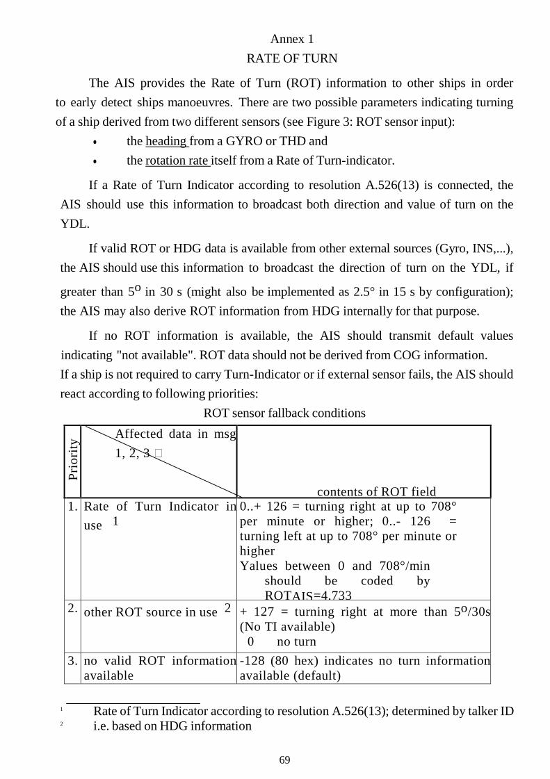
Annex 1 RATE OF TURN
The AIS provides the Rate of Turn (ROT) information to other ships in order to early detect ships manoeuvres. There are two possible parameters indicating turning of a ship derived from two different sensors (see Figure 3: ROT sensor input):
• the heading from a GYRO or THD and• the rotation rate itself from a Rate of Turn-indicator.
If a Rate of Turn Indicator according to resolution A.526(13) is connected, the AIS should use this information to broadcast both direction and value of turn on the YDL.
If valid ROT or HDG data is available from other external sources (Gyro, INS,...), the AIS should use this information to broadcast the direction of turn on the YDL, if
greater than 5o in 30 s (might also be implemented as 2.5° in 15 s by configuration);the AIS may also derive ROT information from HDG internally for that purpose.
If no ROT information is available, the AIS should transmit default values indicating "not available". ROT data should not be derived from COG information. If a ship is not required to carry Turn-Indicator or if external sensor fails, the AIS should react according to following priorities:
ROT sensor fallback conditions
Prio
rity
Affected data in msg 1, 2, 3
contents of ROT field 1. Rate of Turn Indicator in
use 10..+ 126 = turning right at up to 708° per minute or higher; 0..- 126 = turning left at up to 708° per minute or higher Yalues between 0 and 708°/min
should be coded by ROTAIS=4.733
2. other ROT source in use 2 + 127 = turning right at more than 5o/30s (No TI available)
0 no turn 3. no valid ROT information
available-128 (80 hex) indicates no turn information available (default)
1 Rate of Turn Indicator according to resolution A.526(13); determined by talker ID 2 i.e. based on HDG information
69
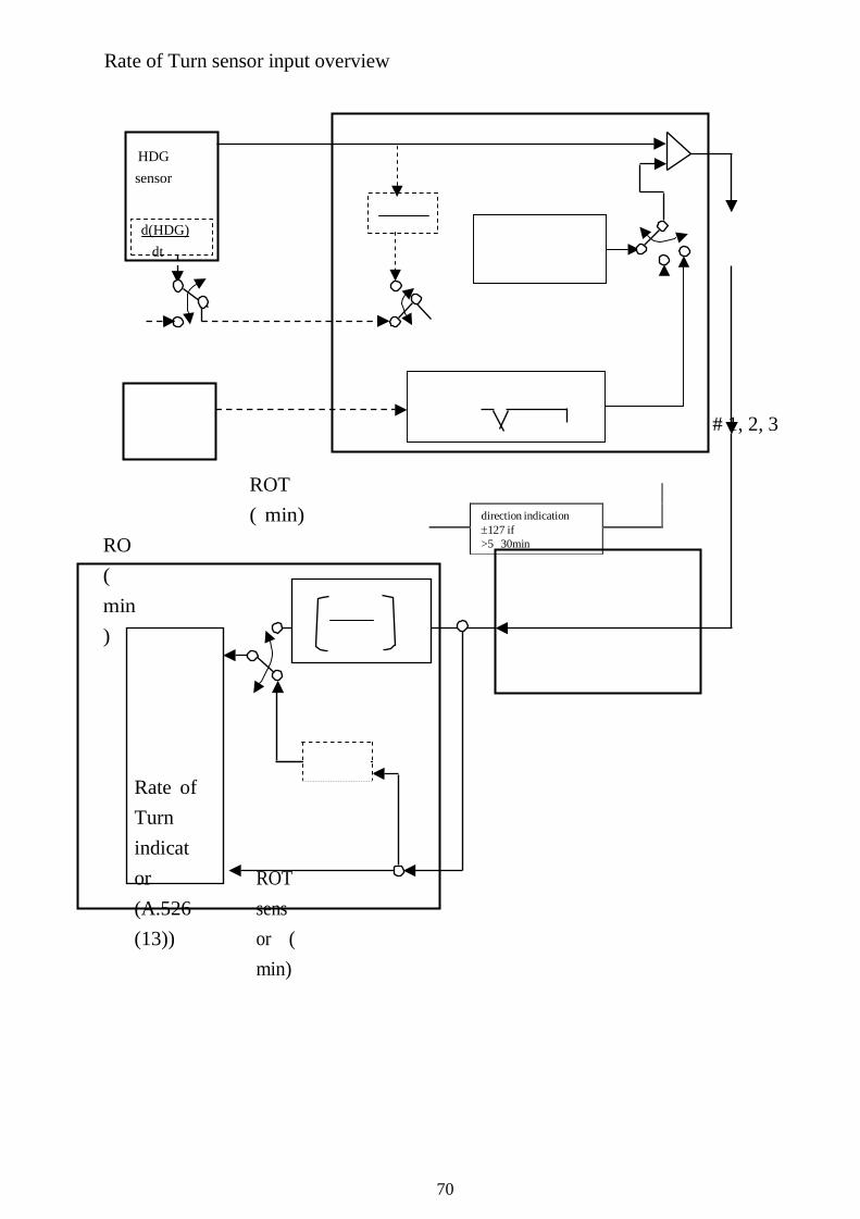
direction indication ±127 if >5 30min
Rate of Turn sensor input overview
HDG sensor
d(HDG) dt
# 1, 2, 3
RO( min)
ROT ( min)
Rate of Turn indicator (A.526(13))
ROTsensor ( min)
70

Annex 2
TYPE OF SHIP TABLE
Identifiers to be used by ships to report their type
Identifier No. Special craft 50 Pilot vessel 51 Search and rescue vessels 52 Tugs 53 Port tenders 54 Yessels with anti-pollution facilities or equipment 55 Law enforcement vessels 56 Spare - for assignments to local vessels 57 Spare - for assignments to local vessels 58 Medical transports (as defined in the 1949 Geneva Convention and Additional 59 Ships according to Resolution No 18 (Mob-83)
Other First digit (*) Second digit (*) First digit (*) Second digit (*) 1 - reserved for future use
0 - All ships of this type - 0 - Fishing
2 - WIG 1 - Carrying DG, HS, or
- 1 - Towing IMO hazard or
pollutant category A 3 - see right column
2 - Carrying DG, HS, or MP IMO hazard or pollutant
B
3 - Yessel 2 - Towing and length of the tow exceeds 200 m or breadth exceeds 25
4 - HSC 3 - Carrying DG, HS, or
- 3 - Engaged in dredging or underwater operations
IMO hazard or pollutant
C 5 - see above 4 - Carrying DG, HS, or MP IMO hazard or pollutant
- 4-Engaged in diving operations
5 - reserved for future use - 5-Engaged in military operations
6-Passenger 6 - reserved for future use - 6 - Sailing ships 7-Cargo ships 7 -reserved for future use - 7 - Pleasure Craft
8 - Tanker(s) 8 - reserved for future use - 8 - reserved for future use 9-Other types 9- No additional
- 9 - reserved for future use
of ship
DG: Dangerous Goods. HS: Harmful Substances. MP: Marine Pollutants. (*) NOTE - The identifier should be constructed by selecting the appropriate first and second digits.
71
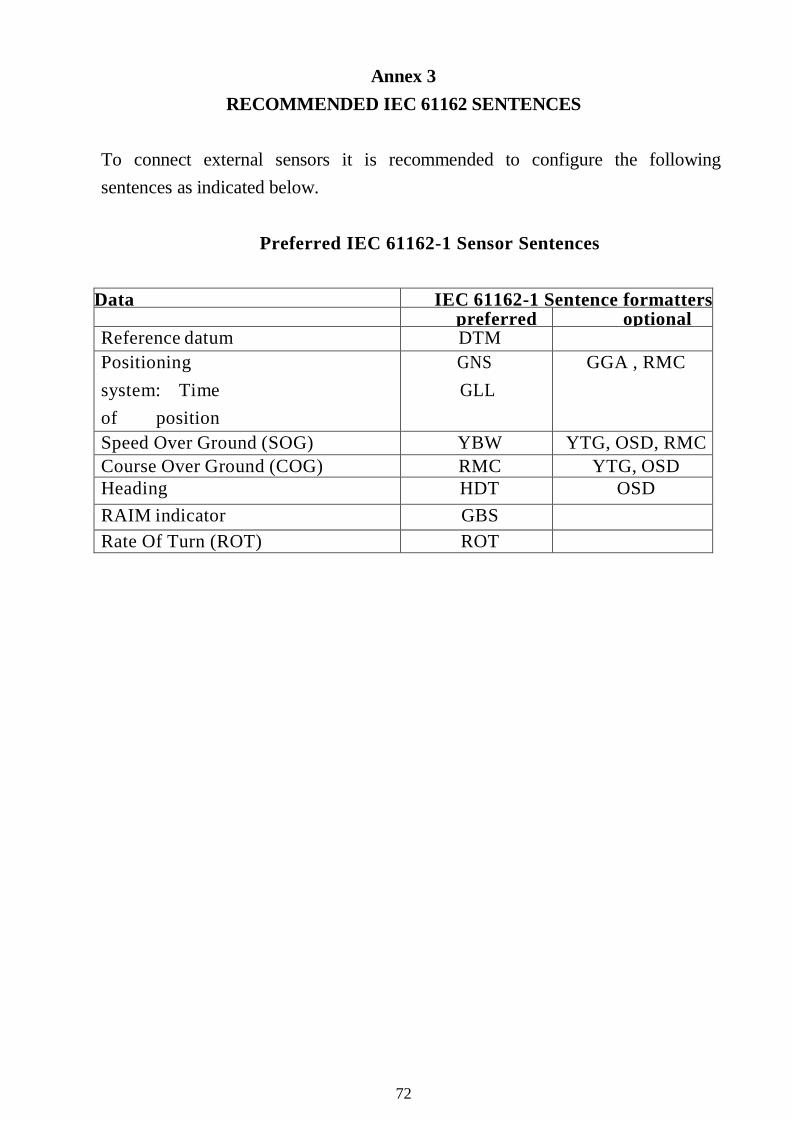
Annex 3 RECOMMENDED IEC 61162 SENTENCES
To connect external sensors it is recommended to configure the following sentences as indicated below.
Preferred IEC 61162-1 Sensor Sentences
Data IEC 61162-1 Sentence formatters preferred optional
Reference datum DTM Positioning system: Time of position
GNS GLL
GGA , RMC
Speed Over Ground (SOG) YBW YTG, OSD, RMC Course Over Ground (COG) RMC YTG, OSD Heading HDT OSD RAIM indicator GBS Rate Of Turn (ROT) ROT
72

PART VI – CORRIGENDA TO SN/CIRC.227 ON GUIDELINES FOR THE INSTALLATION OF A SHIPBORNE
AUTOMATIC IDENTIFICATION SYSTEM (AIS)
1 The Sub-Committee on Safety of Navigation (NAV), at its fifty-fourth session (30 June to 4 July 2008), agreed on an amendment to annex 2 of the guidelines for the installation of a Shipborne Automatic Identification System (AIS).
2 The amendment contains the consequential change with regard to the entry into force of resolution MEPC.118(52), concerning the change in the categorization and listing of Noxious Liquid Substances and other substances. The Sub-Committee noted that the number of categories to be reported was the same, and therefore it was sufficient to revise the reference documentation SN/Circ.227, annex 2, to reflect the new classification letters corresponding to the same digits as currently in use by the AIS shipborne equipment. Practically this means that the reference hazard or pollutant categories A, B, C and D are changed to the hazard or pollutant categories X, Y, Z and OS, by using the same digits 1, 2, 3 and 4.
3 Users of AIS equipment are invited to note this equivalence when using the displays of existing AIS installations.
4 The Maritime Safety Committee, at its eighty-fifth session (26 November to 5 December 2008), concurred with the Sub-Committee’s views, approved the corrigenda to the Guidelines for the installation of a shipborne Automatic Identification System (AIS), as set out at annex.
5 Member Governments are invited to bring the annexed amended annex 2 of the guidelines to the attention of all concerned.
***
Note: The Department of Marine Administration brings the annexed amended annex 2 of the guidelines to the attention of all concerned.
73

ANNEX ANNEX 2
TYPE OF SHIP TABLE Identifiers to be used by ships to report their type
Identifier Special craft5 Pilot vessel5 Search and rescue vessels5 Tugs5 Port tenders5 Vessels with anti-pollution facilities or equipment5 Law enforcement vessels5 Spare – for assignments to local vessels5 Spare – for assignments to local vessels5 Medical transports (as defined in the 1949 Geneva Convention and5 Ships according to Resolution No 18 (Mob-83)
OtherFirst digit Second digit (*) First digit (*) Second digit (*)1– eserved for future use
0 – All ships of this type - 0 – Fishing
2 – WIG 1 – Carrying DG, HS, or MP IMO hazard or pollutant category X (**)
- 1 – Towing
3 – see right column
2 – Carrying DG, HS, or MP IMO hazard or pollutant category Y (**)
3 – Carrying DG, HS, or MP IMO hazard or
3 – Vessel 2 – Towing and length of the tow exceeds 200 m or breadth
4 – HSC - 3 – Engaged in dredging or underwater
5– see above 4 – Carrying DG, HS, or MP IMO hazard or pollutant category OS (**)
- 4 – Engaged in diving operations
5 – reserved for future use - 5 – Engaged in military
6–senger ships
6 – reserved for future use - 6 – Sailing
7–Cargo ships 7 – reserved for future use - 7 – Pleasure Craft
8– Tanker(s) 8 – reserved for future use - 8 – reserved for future use 9–Other
types of ship
9–No additional information
- 9 – reserved for future use
DG: Dangerous Goods. HS: Harmful Substances. MP: Marine Pollutants.
(*) NOTE – The identifier should be constructed by selecting the appropriate first and second digits. (**) NOTE – The digits 1, 2, 3 and 4 reflecting categories X, Y, Z and OS formerly were
categories A, B, C and D.
74

PART VII – GUIDELINES ON ANNUAL TESTING OF THE AUTOMATIC IDENTIFICATION SYSTEM (AIS)
1 The Maritime Safety Committee, at its eighty-third session (3 - 12 October 2007), approved the Guidelines on annual testing of the Automatic Identification System (AIS) developed by the Sub-Committee on Flag State Implementation, as set out in the annex.
2 The purpose of an annual testing is to determine that AIS is operational as defined in appropriate performance standards not inferior to those adopted by the
Organization*.
3 To assist in achieving this aim, it is recommended that all AIS be subject to a standard method of testing as detailed in the annexed Guidelines.
4 Member Governments are invited to bring these Guidelines to the attention of shipping companies, shipowners, ship operators, equipment manufacturers, recognized organizations, shipmasters and all parties concerned.
***
Note: The Department of Marine Administration brings these Guidelines to the attention of shipping companies, shipowners, ship operators, equipment manufacturers, recognized organizations, shipmasters and all parties concerned.
* Refer to Recommendation on performance standards for a universal shipborneautomatic identification system (AIS) (resolution MSC.74(69), annex 4)
75

ANNEX
GUIDELINES ON ANNUAL TESTING OF THE AUTOMATIC IDENTIFICATION
SYSTEM (AIS)
1 The annual testing of the automatic identification system (AIS) should be carried out by a qualified radio inspector authorized by the administration or a recognized organization.
2 The annual testing of the AIS installation should include: .1 installation details including antenna layout, initial configuration
report, interconnection diagrams, provision of the pilot plug and power supply arrangements;
.2 checking the correct programming of the ships static information;
.3 the ability of the AIS to receive ships dynamic information from the appropriate sensors;
.4 the ability to correctly input the ships voyage related data;
.5 a performance test of the equipment including radio frequency measurements; and
.6 an on-air test that the unit is working correctly using for example an appropriate Vessel Traffic Service (VTS) station or a suitable test equipment.
3 To accommodate performance test to align with the appropriate survey under the Harmonized System of Survey and Certification (HSSC), the annual testing may be carried out:
.1 up to 3 months before the due date of the passenger ship renewal survey or the cargo ship safety equipment renewal survey; and
.2 3 months before or after the due date of the cargo ship safety equipment periodical/annual survey (the maximum period between subsequent test is governed by the time window associated to the subsequent surveys, unless either certificate has been extended as permitted by SOLAS regulation I/14, in which case a similar extension may be granted by the Administration).
76

4 The annual testing should be recorded in the form of the model test report given in the appendix. If the language used is neither English, nor French, nor Spanish, the text should include a translation into one of these languages. A copy of the test report should be retained on board the ship.
77

APPENDIX AUTOMATIC IDENTIFICATION SYSTEM (AIS) TEST REPORT
Name of ship/call sign: MMSI number: bPort of registry:
f iIMO Number bGross tonnage Date keel laid:
1. Installation detailsItem Status
1.1 AIS transponder type: 1.2 Type approval certificate 1.3 Initial installation configuration report on board? 1.4 Drawings provided? (Antenna-, AIS-arrangement and block
1.5 Main source of electrical power, 1.6 Emergency source of electrical power, 1.7 Capacity to be verified if the AIS is connected to a battery 1.8 Pilot plug near pilots operating position? 1.9 120 V AC provided near pilot plug? (Panama and St. Lawrence
2. AIS programming - Static information2.1 MMSI number 2.2 IMO number 2.3 Radio call sign 2.4 Name of ship 2.5 Type of ship 2.6 Ship length and beam 2.7 Location of GPS antenna
3. AIS programming - Dynamic information3.1 Ships position with accuracy and integrity status (Source: 3.2 Time in UTC (Source: GNSS) 3.3 Course over ground (COG) (will fluctuate at dockside) (Source 3.4 Speed over ground (SOG) (zero at dockside) (Source: GNSS) 3.5 Heading (Source: Gyro) 3.6 Navigational status 3.7 Rate of turn, where available (ROT) 3.8 Angle of heel, pitch and roll, where available
78

4. AIS programming - voyage related information4.1 Ships draught 4.2 Type of cargo 4.3 Destination and ETA (at masters discretion) 4.4 Route plan (optional) 4.5 Short safety-related messages
5. Performance test using measuring instrument5.1 Frequency measurements AIS ch. 1 and 2, GMDSS ch. 70 5.2 Transmitting output, AIS ch. 1 and 2, GMDSS ch. 70 5.3 Polling information ch. 70 5.4 Read data from AIS 5.5 Send data to AIS 5.6 Check AIS response to "virtual vessels"
6. "On air" performance test6.1 Check reception performance 6.2 Confirm reception of own signal from other ship/VTS 6.3 Polling by VTS/shore installation
Electromagnetic interference from AIS observed to other installations?:
Remarks:
79
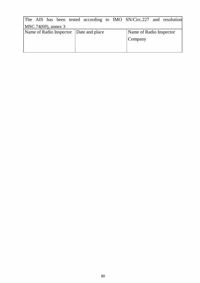
The AIS has been tested according to IMO SN/Circ.227 and resolution MSC.74(69), annex 3 Name of Radio Inspector Date and place Name of Radio Inspector
Company
80
PART VIII – GUIDELINES ON VOYAGE DATA RECORDER (VDR) OWNERSHIP AND RECOVERY
l The Maritime Safety Committee, at its seventy-fifth session (l5 to 24 May 2002), approved the annexed Guidelines on voyage data recorder (VDR) ownership and recovery which have been developed to support provisions of the revised SOLAS regulation V/l5, as amended by resolution MSC.99(73), and, in particular, to support the carriage requirements for voyage data recorders contained in the revised SOLAS regulation V/20, which are expected to enter into force on l July 2002.
2 These Guidelines reflect the five basic issues relevant to VDR ownership and recovery, which are ownership, custody, recovery, read-out and access to the VDR information, as envisaged by the revised SOLAS chapter V.
3 In view of the complexity of the matter, close co-ordination and co-operation among interested parties, as appropriate, in any recovery operation of a VDR is encouraged.
4 Member Governments are invited to bring the annexed Guidelines to the attention of all parties concerned.
***
Note: The Department of Marine Administration brings the annexed Guidelines to the attention of all parties concerned.
81

ANNEX GUIDELINES ON VOYAGE DATA RECORDER (VDR) OWNERSHIP AND
RECOVERY Ownership of VDR information
l The ship owner will, in all circumstances and at all times, own the VDR and its information. However, in the event of an accident the following guidelines would apply. The owner of the ship should make available and maintain all decoding instructions necessary to recover the recorded information.
Recovery of VDR and relevant information
2 Recovery of the VDR is conditional on the accessibility of the VDR or the information contained therein.
.l Recovery of the VDR information should be undertaken as soon as possible after an accident to best preserve the relevant evidence for use by
both the investigatorl and the ship owner. As the investigator is veryunlikely to be in a position toinstigate this action soon enough after the accident, the owner must be responsible, through its on-board standing orders, for ensuring the timely preservation of this evidence.
.2 In the case of abandonment of a vessel during an emergency, masters should, where time and other responsibilities permit, take the necessary steps to preserve the VDR information until it can be passed to the investigator.
.3 Where the VDR is inaccessible and the information has not been retrieved prior to abandonment, a decision will need to be taken by the
flag State in co-operation with any other substantially interested States2
on the viability and cost of recoveringthe VDR balanced against the potential use of the information. If it is decided to recover the VDR the investigator should be responsible for co-ordinating its recovery. The possibility of the capsule having sustained damage must be considered and specialist expertise will be required to ensure the best chance of recovering and preserving the evidence. In addition, the assistance and co- operation of the owners, insurers and the manufacturers of the VDR and those of the protective capsule may be required.
82

Custody of VDR information:
3 In all circumstances, during the course of an investigation, the investigator should have custody of the original VDR information in the same way that the investigator would have custody of other records or evidence under the Code for the Investigation of Marine Casualties and Incidents.
Read-out of VDR information:
4 In all circumstances the investigator is responsible to arrange down loading and read-out of the information and should keep the ship owner fully informed. In some cases, the assistance of specialist expertise may be required.
Access to the VDR information:
5 A copy of the VDR information must be provided to the ship owner at an early stage in all circumstances.
6 Further access to the information will be governed by the applicable domestic legislation of the flag State, coastal State and other substantially interested States as appropriate and the guidelines given in the Code for the Investigation of Marine Casualties and Incidents.
7 Any disclosure of VDR information should be in accordance with section l0 of the Code for the Investigation of Marine Casualties and Incidents.
83

PART IX – GUIDELINES ON ANNUAL TESTING OF VOYAGE DATA RECORDERS (VDR) AND SIMPLIFIED VOYAGE DATA RECORDERS
(S-VDR)
1 The Maritime Safety Committee at its seventy-third session (27 November to 6 December 2000) approved the revision of SOLAS regulation V/20 which included the requirement for voyage data recorder (VDR) systems to be the subject of an annual performance test.
2 At its seventy-ninth session (1 to 10 December 2004), the Maritime Safety Committee adopted amendments to regulation V/20 to include the requirement for VDRs which may be simplified voyage data recorders (S-VDR), to be fitted on existing cargo ships on a phased-in carriage requirement. Such VDRs were also to be the subject of an annual performance test.
3 The Maritime Safety Committee, at its eighty-second session (29 November to 8 December 2006), approved the Guidelines on annual testing of Voyage Data Recorders (VDR) and simplified Voyage Data Recorders (S-VDR), as set out in the annex.
4 The purpose of an annual performance test is to determine that a VDR/S-VDR is operational as defined in the manufacturer’s specification. In addition, because of the “black box” nature of this equipment, there is a need to have a document which clearly lists all the interfaces which have been checked to confirm compliance with the appropriate International Electrotechnical Commission (IEC) test standards. This transparency is essential for surveyors or inspectors of flag Administrations port States or recognized organizations.
5 To assist in achieving this aim, it is recommended that all VDR and S-VDR be subject to a standard method of testing as detailed in the annexed Guidelines.
6 Member Governments are invited to bring these Guidelines to the attention of shipping companies, shipowners, ship operators, equipment manufacturers, recognized organizations, shipmasters and all parties concerned.
*** Note: The Department of Marine Administration brings these Guidelines to the attention of shipping companies, shipowners, ship operators, equipment manufacturers, recognized organizations, shipmasters and all parties concerned
84

ANNEX GUIDELINES ON ANNUAL TESTING OF VDR AND S-VDR
1 The annual testing of VDR/S-VDR required by SOLAS regulation V/20 should be carried out by the manufacturer or a person authorized by the manufacturer.
2 The examination of the VDR/S-VDR installation should include: .1 confirmation that no alarms are present prior to commencement of the
test; .2 confirmation that when the external power is removed the power
supply alarm is activated, the equipment continues to operate for at least 1 h 55 min and automatically stops recording no later than 2 h 5 min after the external power is removed;
.3 confirmation that the acoustic beacon is functional using the appropriate manufacturer’s test equipment or by the substitution of a certified fully operational unit;
.4 confirmation that the overall condition of the equipment is satisfactory and that any batteries within the equipment (acoustic beacon and power supply) are in date;
.5 confirmation that accurate maintenance records of the VDR are available;
.6 confirmation that the items to be recorded, specifically those data items available and required to be recorded at the time of original commissioning as defined in resolution A.861(20) and resolution MSC.163(78) for VDR and S- VDR, respectively, are satisfactorily stored for the duration of the 12-hour recording period;
.7 confirmation that the capsule float-free arrangements, where required or fitted, are satisfactory as originally accepted at commissioning; and that any battery, release mechanism or other datable items are within their expiry date; and,
.8 confirmation that the equipment is restored to normal operation mode following completion of the tests.
3 The manufacturer must complete a review, record any changes and issue the completed test report within 45 days. To accommodate performance checks to align with the appropriate survey under the Harmonized System of Survey and Certification (HSSC), the annual performance check may be carried out up to
85

3 months before the due date for a passenger ship and -/+ 3 months of the due date for a cargo ship. (The maximum period between subsequent checks is, therefore, 15 months for passenger ships and 18 months for cargo ships, unless either certificate has been extended as permitted by SOLAS regulation I/14, in which case a similar extension may be granted.)
4 The annual test should be recorded in the form of the model test report given in the appendix to this document. If the language used is neither English nor French nor Spanish, the text should include a translation into one of these languages.
86

APPENDIX VOYAGE DATA RECORDER PERFORMANCE TEST REPORT
Note – Insert Yes for success, No for failure or N/A for non fitted interfaces in these boxes, as appropriate.
Ship’s details
Yes No N/A
Ship’s name Flag IMO number Date keel laid Gross tonnageVoyage data recorder details ManufacturerModelSystem serial numberSoftware version numberDate fittedInspection Details Name person conducting CompanyInspection dateInspection location1. Pre-existing alarms
Confirm that no alarms were present at start of procedure 2. Power supply alarm checkRemove source of external power. Confirm that alarm is Record time (hh.mm) 3. Reserve power source checkAllow VDR to continue running for 1 hour 55 minutes from ‘2’ above. Confirm that equipment is still operating at this time, with no additional
Record time (hh.mm) 4. Reserve power source shutdown check2 hours 05 minutes from ‘2’ above confirm that the VDR has automatically
Record time (hh.mm)5. Battery expiry datesBattery Expiry date (where applicable) Acoustic beacon Reserve power
6. Acoustic beacon testUsing function manufacturer’s test equipment confirm that acoustic beacon nal or by the substitution of a certified fully operational unit.
is
87
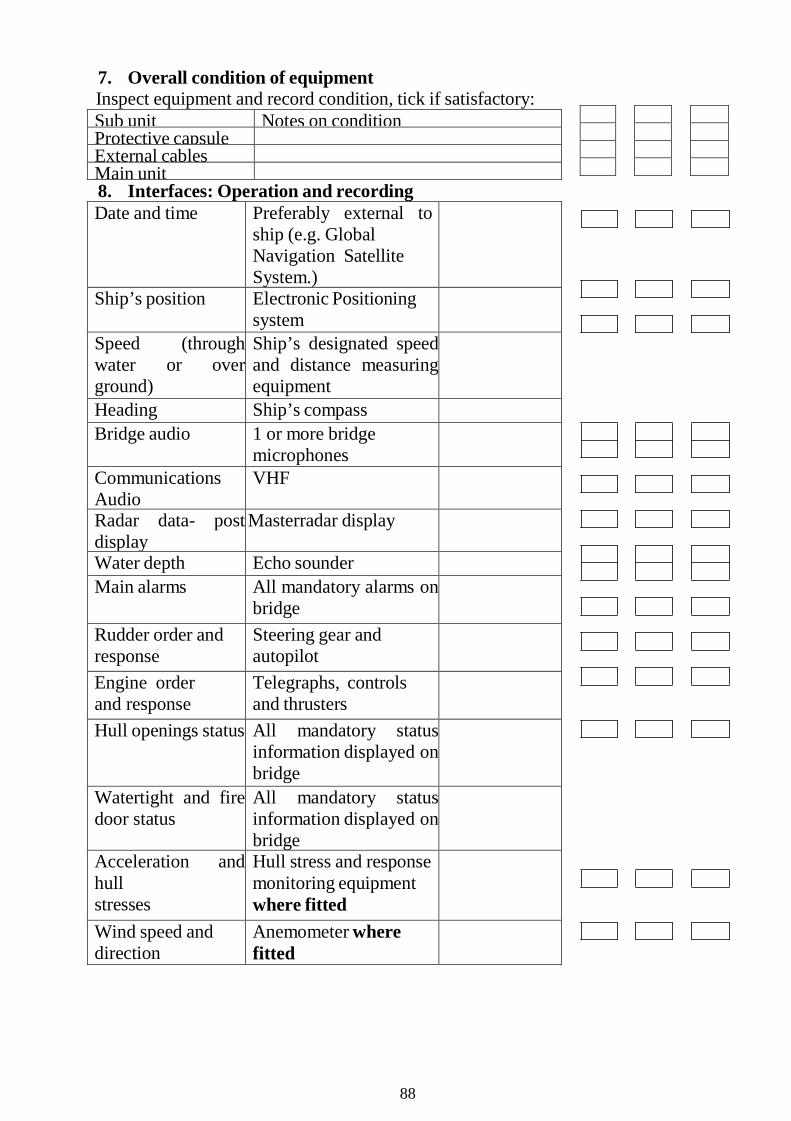
7. Overall condition of equipmentInspect equipment and record condition, tick if satisfactory: Sub unit Notes on conditionProtective capsuleExternal cablesMain unit8. Interfaces: Operation and recordingDate and time Preferably external to
ship (e.g. Global Navigation Satellite System.)
Ship’s position Electronic Positioning system
Speed (through water or over ground)
Ship’s designated speed and distance measuring equipment
Heading Ship’s compass Bridge audio 1 or more bridge
microphones Communications Audio
VHF
Radar data- post display
Masterradar display
Water depth Echo sounder Main alarms All mandatory alarms on
bridge
Rudder order and response
Steering gear and autopilot
Engine order and response
Telegraphs, controls and thrusters
Hull openings status All mandatory status information displayed on bridge
Watertight and fire door status
All mandatory status information displayed on bridge
Acceleration and hull stresses
Hull stress and response monitoring equipment where fitted
Wind speed and direction
Anemometer where fitted
88

9. Change or repair of sensorsCheck maintenance records of VDR Confirm any defects properly rectified Person authorized by the Manufacturer Ship’s representative
Date Date
89
If the manufacturer does not complete a review and issue a completed test report within 45 days, this test report should go forward for certification. 7. Manufacturer’s analysisNote − This confirms the endorsement by the manufacturer of the tests and that the master record/database has been checked. Manufacturer’s analysis of 12-hour log is attached and in accordance with International Electrotechnical Commission (IEC) 61996 Maritime navigation and radiocommunication equipment and systems – Shipborne voyage data recorder (VDR) – Performance requirements – Methods of testing and required test results section 4.6 – Data items to be recorded (resolution A.861(20), section 5.4). Confirmation that all data is available throughout the 12-hour recording. Date and time of above log.
8. Observations and additional manufacturer’s requirementsNote − This specifically provides for the logging of significant events that may have occurred on board since the previous test, including the refitting of equipment or major unit change to existing equipment. − Any or all of which may have an impact on the availability or quality of the VDR/S-VDR input signal.
This performance test was conducted in accordance with SOLAS regulation V/18.8 and forms part of the procedure for the issue of the Annual Performance Test Certificate. The results, information and any comments should be relayed to the manufacturer in accordance with the instructions contained within the Operation Manual. Subject to satisfactory results, an Annual Performance Test Certificate will then be issued.
In accordance with the principles of harmonization of Certificates, the Certificate, when issued, will remain valid until the next annual re-validation of that Certificate, subject to the equipment being maintained in appropriate operational condition.
90

PART X – GUIDANCE ON THE BRIDGE NAVIGATIONAL WATCH ALARM SYSTEM (BNWAS) AUTO FUNCTION
1 The Maritime Safety Committee, at its ninety-third session (14 to 23 May 2014), with a view to providing more specific guidance on the automatic function specified in resolution MSC.128(75) – Performance standards for a bridge navigational watch alarm system (BNWAS), approved the guidance, prepared by the Sub-Committee on Safety of Navigation at its fifty-ninth session (2 to 6 September 2013), as set out in the annex.
2 Member Governments are invited to use the guidance as an interim measure until such time as the performance standards can be reviewed and revised and, furthermore, bring this guidance to the attention of all parties concerned.
***
Note: The Department of Marine Administration uses the guidance as an interim measure until such time as the performance standards can be reviewed and revised and, furthermore, bring this guidance to the attention of all parties concerned.
91
ANNEX GUIDANCE ON THE BRIDGE NAVIGATIONAL WATCH ALARM SYSTEM
(BNWAS) AUTO FUNCTION
1 SOLAS regulation V/19.2.2.3 requires the provision of a Bridge Navigational W atch Alarm System (BNW AS), which shall be in operation whenever the ship is under way at sea, whilst SOLAS regulation V/18 requires BNW AS to conform to appropriate performance standards not inferior to those adopted by the Organization (i.e. resolution MSC.128(75)).
2 Resolution MSC.128(75) – Performance standards for a bridge navigational watch alarm system (BNWAS), section 4.1.1.1 states that "the BNWAS should incorporate the following operational modes:
- Automatic (Automatically brought into operation whenever the ships heading or track control system is activated and inhibited when this system is not activated)
- Manual ON (In operation constantly) - Manual OFF (Does not operate under any circumstances)".
3 At the fifty-fifth session of the NAV Sub-Committee, concerns were raised with respect to the use of the Automatic mode and NAV 55 concluded that the Automatic mode of the performance standard was therefore not usable on a ship compliant with the SOLAS Convention. It was considered that it would not be possible to change the performance standards before the date at which the carriage requirements came into force (1 July 2011). In order to conform with the performance standards, therefore, equipment would include the Automatic mode, despite that this operational mode should not be used on ships which are subject to the SOLAS Convention.
4 From the operational point of view, automatic interface with activation of the ship's heading or track control system (HCS/TCS) is a superfluous function because SOLAS regulation V/19.2.2.3 requires the BNW AS to be in operation whenever the ship is under way at sea. This creates an inconsistency between SOLAS regulation V/19.2.2.3 and the "Automatic mode" provisions in the performance standard. In addition, from the technical point of view, it is noted that this issue is also addressed in the "note" to section 3.1.1 of IEC 62616:2010 – Maritime navigation and radiocommunication equipment and systems – Bridge navigational watch alarm system (BNW AS), which states:
92

"NOTE: The Automatic mode is not suitable for use on a ship conforming with regulation SOLAS V/19.2.2.3 which requires the BNWAS to be in operation whenever the ship is underway at sea".
5 Accordingly, as an interim measure and pending a revision of the Performance standards for a bridge navigational watch alarm system (BNWAS) – (resolution MSC.128(75)), the automatic operational mode, if it is available, should not be used.
93