green and low-cost synthesis of pani–tio2 nanocomposite
TRANSCRIPT
RSC Advances
PAPER
Ope
n A
cces
s A
rtic
le. P
ublis
hed
on 2
8 M
ay 2
015.
Dow
nloa
ded
on 9
/15/
2022
11:
53:1
9 A
M.
Thi
s ar
ticle
is li
cens
ed u
nder
a C
reat
ive
Com
mon
s A
ttrib
utio
n-N
onC
omm
erci
al 3
.0 U
npor
ted
Lic
ence
.
View Article OnlineView Journal | View Issue
Green and low-c
aCenter for Space Human Robotics, Istitut
Torino, Italy. E-mail: simelys.hernandez@pbApplied Science and Technology Departme
Italy
† Electronic supplementary information (results for faradaic efficiency calculation.
Cite this: RSC Adv., 2015, 5, 49429
Received 14th April 2015Accepted 28th May 2015
DOI: 10.1039/c5ra06734k
www.rsc.org/advances
This journal is © The Royal Society of C
ost synthesis of PANI–TiO2
nanocomposite mesoporous films forphotoelectrochemical water splitting†
D. Hidalgo,ab S. Bocchini,a M. Fontana,ab G. Saraccob and S. Hernandez*ab
Among conductive polymers, polyaniline (PANI) has been widely used to improve electronic conductivity,
solar energy transfer and photocatalytic activity of TiO2, due to its ease preparation and excellent
environmental stability. In this study, a green and low-cost synthesis procedure was developed for the
preparation of PANI–TiO2 nanocomposite films. A non-toxic and low-cost polymerization route, starting
from aniline dimer and polystyrene sulphonate as emulsioning/doping agent in water, was employed to
synthesize the conductive form of PANI (emeraldine salt, ES). Anatase TiO2 nanocrystalline mesoporous
films were prepared by a novel and green sol–gel spin coating method, which employs titanium
tetraisopropoxide, acetic acid and a nonionic surfactant (Tween 20) in excess of water, avoiding the use
of flammable solvents. Uniform PANI–TiO2 composite films, containing PANI in either ES or pernigraniline
base (PB) forms, i.e. PANI/TiO2 and PANIox/TiO2, respectively, were then prepared by a simple
impregnation method. The films were characterized by means of XRD, ATR, FESEM and TEM techniques
and their photocatalytic activity was assessed using them as photoelectrochemical water splitting
photoanodes. Both PANI/TiO2 and PANIox/TiO2 showed an enhanced water oxidation efficiency under
AM 1.5G simulated sunlight irradiation, reaching about 2 and 1.6 fold higher photocurrent densities,
respectively, than a pure TiO2 nanoparticles film. They also demonstrated good stability after several hours
of operation. UV-Vis spectrophotometry and IPCE analysis reveal the main role of PANI, in the system
PANI/TiO2 for the PEC water oxidation, is as sensitizer of TiO2 in the UV light by significantly increasing
charges separation, electrons transport and collected photoelectrons, indirectly contributing to the
generation of O2. Indeed, PANI-ES photogenerated e� are transferred to the TiO2 conduction band while
its h+ can react with OH� to produce OH radicals that generate H2O2, which can subsequently be
photooxidized on the TiO2 NPs surface generating more O2 than such produced by the direct water
oxidation on the TiO2 holes.
Introduction
Photochemical and photoelectrochemical (PEC) water splittinghave been widely investigated in the last decades as a means ofconverting solar to chemical energy in the form of fuels,providing a viable energy resource with minimal environmentalimpact aer combustion.1,2 Hydrogen is a key solar fuel since itcan be used directly in Proton Exchange Membrane (PEM) fuelcells or combustion engines, or combined catalytically with CO2
to make carbon containing fuels.2,3
The rst example for water splitting into hydrogen andoxygen was reported by Fujishima and Honda in 1972,3 using
o Italiano di Tecnologia, IIT@POLITO,
olito.it; Tel: +39 011 0904774
nt, DISAT, Politecnico di Torino, Torino,
ESI) available: I–t measurement and GCSee DOI: 10.1039/c5ra06734k
hemistry 2015
TiO2 as photocatalyst under UV light. Subsequently, differentsemiconductors (e.g. ZnO, Fe2O3, BiVO4, WO3) have beenreported for the sun-driven water photoelectrolysis.4 However,the interest in the application of TiO2 as water splitting photo-catalyst and for other uses (e.g. photodegradation of contami-nants, photovoltaics, electrical energy storage, paint pigments,etc.) is still high, due to its non-toxicity, abundance, low-cost,good stability, excellent photocatalytic performance, easy avail-ability and possibility to be structured at the nano- and micro-scales.5 Indeed, several recent reviews deal with the generalapproaches toward the fabrication of 3D-titania morphol-ogies,4,6–8 with a particular interest in porous titania mate-rials,9–13 porous spheres,14,15 shells,16 nanosheets,17 nanorods,18
bers,19 and nanotubes,20–22 are focused on various applicationsof 3D-titania materials in solar cells,15,23 photocatalysis andphotoelectrochemistry24–28 or electrochemical energy storage.13
Nevertheless, the disadvantages of TiO2 with respect to itsapplication as water oxidation photocatalyst are its limitedabsorption of solar light (wavelengths below�380 nm) due to its
RSC Adv., 2015, 5, 49429–49438 | 49429

Fig. 1 Generalized composition of polyanilines indicating the reducedand oxidized repeating units (a), the completely reduced polymer (b),the half-oxidized polymer (c) and the fully oxidized polymer (d).Reproduced and adapted from ref. 37.
RSC Advances Paper
Ope
n A
cces
s A
rtic
le. P
ublis
hed
on 2
8 M
ay 2
015.
Dow
nloa
ded
on 9
/15/
2022
11:
53:1
9 A
M.
Thi
s ar
ticle
is li
cens
ed u
nder
a C
reat
ive
Com
mon
s A
ttrib
utio
n-N
onC
omm
erci
al 3
.0 U
npor
ted
Lic
ence
.View Article Online
large bandgap (3.20 eV), and its reduced photocatalytic activitybecause of the fast recombination of charge carriers.29 Thus, thecapability to design semiconductor photoelectrodes that func-tion as both a photosensitizer and an energy converter, withsuitable band edge energies, appropriate spectral response, andgood photostability is of fundamental importance.2
Efforts to overcome such issues have been made by modi-fying TiO2 with methods such as metal and non-metal doping,25
noble metal deposition,30 forming composites with both narrowband gap inorganic semiconductors or through dye sensitiza-tion.6,28 Regarding the last approach, in order to warrant a goodelectron/hole transfer, the bottom of the conduction band (CB)and the top of the valence band (VB) of the semiconductor (orthe lowest unoccupied molecular orbital (LUMO) and thehighest occupied molecular orbital (HOMO) of the dye) musthave higher energy than the ones of TiO2. There are few inor-ganic materials satisfying such requirements (e.g. CdS,31
Fe2O332), which in some cases have stability issues, and the
application of dye-sensitized TiO2 is restricted due to theemployment of noble-metal-containing dyes (e.g. Ru-, Rh- or Pd-containing dyes) or because of dissolution and degradation ofdyes during photocatalytic processes.33–35
In recent years, polymers with extended p-conjugated elec-tron systems have attracted considerable attention because oftheir absorption coefficients in the visible region and highconductivity, allowing high mobility of charge carriers. Amongconductive polymers, polyaniline (PANI) has been widely usedto improve electronic conductivity as well as solar energytransfer and photocatalytic activity of TiO2, due to its easiness ofpreparation, comparatively low cost and excellent environ-mental stability.36
From a chemical point of view, as shown in Fig. 1a, PANI canbe considered as being derived from two different repeatingunits, which are alternatively reduced (benzenoid diamine unit)and oxidized (quinoid diimine unit).37–40 Of the differentoxidation states of PANI, only emeraldine (Fig. 1c), the halfoxidized form,34 was proved to be electrical conductive. Themechanism of doping is linked to the protonation of theemeraldine form that is called basic form or emeraldine base(EB). The degree of protonation of the polymeric base depend-ing on its oxidation state and on the pH of the aqueous acid,because complete protonation of the imine nitrogen atoms inEB results in the formation of a delocalized polysemiquinoneradical cation.38,39,41
In the available literature different ways to produce PANIhave been demonstrated, however, aniline is classically chosenas the starting monomer. In previous works,42,43 a method toproduce polyaniline in the EB form starting from the anilinedimer (DANI), which on the contrary to aniline is non-toxic andlow-cost, was developed. Suchmethod produces PANI soluble inorganic solvents, which thus can be used to functionalize othermaterials (e.g. titanium oxide) by drop casting and impregna-tion, among other techniques.
A high number of works exploit the role of PANI–TiO2
composites for photocatalytic degradation or organicmatrix30,33,44–49 by generation of OHc radicals or for photovoltaicsolar cells.50On the other hand, there are some examples of PANI
49430 | RSC Adv., 2015, 5, 49429–49438
combined with other semiconductors for H2 generation, such asthe case of PANI–CdS composite nanoparticles synthesizedby He et al.51 for direct H2 evolution in the presence of SO3
2�/S2�
sacricial reactant. Nevertheless, there are few examples ofPANI-semiconductor supported composites tested for the PECwater splitting reaction. Only recently, Jing et al.29 reported on aternary polyaniline–graphene–TiO2 hybrids for water oxidationin Na2SO4 (pH ¼ 7) electrolyte under visible light illuminationgenerating up to 10 mA cm�2 at 0.8 V vs. SCE (�1.4 V vs. RHE).
In this study, we report for the rst time the synthesis ofPANI–TiO2 nanocomposite mesoporous lms prepared througha simple, safe, low-cost and environmentally friendly procedure.A non-toxic and low-cost oxidative polymerization route, whichstarts from aniline dimer (instead of the usually employedaniline) was applied to synthesize PANI in its emeraldine salt(ES) conductive form.42 Polystyrene sulphonate was used asemulsioning/doping agent of PANI in aqueous solution, so thatPANI could remain stable also under high pH values. On theother hand, TiO2 lms were prepared using environmentallyfriendly precursors (i.e. titanium tetraisopropoxide, acetic acid,the nonionic surfactant Tween 20 and water as solvent).52
Starting from such materials, the 3D mesoporous TiO2 nano-particles lms were impregnated in situ with the ES PANIsolution, obtaining a uniform surface coverage of the meso-porous substrate aer only ten minutes (i.e. PANI/TiO2 sample).In addition, an oxidized PANI–TiO2 sample (i.e. PANIox/TiO2)was prepared by immersion into an aqueous solution of sodiumpersulfate, in order to investigate the role of the thus formedpernigraniline base form of PANI in the photocatalytic behaviorof the nanocomposite samples.
The PANI–TiO2 nanocomposites were fully characterized intheir physico-chemical characteristics, and their photocatalyticactivity was proved by evaluating their PEC behavior for thewater splitting reaction under simulated solar light (AM 1.5G).
This journal is © The Royal Society of Chemistry 2015

Paper RSC Advances
Ope
n A
cces
s A
rtic
le. P
ublis
hed
on 2
8 M
ay 2
015.
Dow
nloa
ded
on 9
/15/
2022
11:
53:1
9 A
M.
Thi
s ar
ticle
is li
cens
ed u
nder
a C
reat
ive
Com
mon
s A
ttrib
utio
n-N
onC
omm
erci
al 3
.0 U
npor
ted
Lic
ence
.View Article Online
Results and discussionPhysico-chemical characterization of TiO2 and PANI–TiO2
lms
A typical X-ray diffraction spectrum of a TiO2 lm is illustratedin Fig. 2. The TiO2 lm was prepared with 1 spin coating layerusing a molar ratio between Tween 20/TTIP of 0.50/1 in the sol.The XRD patterns present peaks at 25.4� (101) and 47.7� (200),corresponding to the anatase phase, which is the most activephase of TiO2 for several photocatalytic applications.9,44 TheX-ray diffraction patterns of both PANI/TiO2 and PANIox/TiO2
nanocomposite lms (not shown) are similar to the one of theTiO2 NPs lm. Thus, impregnation with PANI had no inuenceon the crystallinity of the TiO2 NPs.
FESEM analysis was used to investigate the morphology andthe adhesion of the TiO2 and TiO2–PANI lms to the substrate.As can be seen from Fig. 3a and b, the pristine TiO2 lms arehomogeneous and crack-free along the whole surface, andshow good adhesion to the substrate. All the prepared TiO2
lms have a thickness of about 530 nm (see Fig. 3b) andare constituted by nanoparticles with average size in the range(10–20) nm, which are organized in a mesoporous structure.The results from this analysis are consistent with a previouslypublished work.9
Further insight into the morphology and crystalline struc-ture of the nanoparticles was obtained through TEM charac-terization. Fig. 3c presents a selected area electron diffractionpattern (SAED), which conrms that the samples are consti-tuted by polycrystalline anatase TiO2, as evidenced by thepresence of diffraction rings. By the analysis of high resolutionTEM images (Fig. 3d), it can be seen that the nanoparticles aresingle crystals, with average size consistent with the previousFESEM morphological measurements. Concerning the charac-terization of the impregnated samples, PANI/TiO2 was initiallyanalyzed by FESEM (Fig. 3e). From the morphological point ofview, there are no signicant changes with respect to the TiO2
NPs lm, suggesting that the PANI layer on the TiO2 is very thin.This assumption is in accordance with high-resolution TEMimages: Fig. 3f shows the presence of a thin layer (<5 nm) ofamorphous material surrounding the nanoparticles, which can
Fig. 2 XRD spectrum for immobilized TiO2 film calcined at 500 �C.
This journal is © The Royal Society of Chemistry 2015
be ascribed to surface coating of the TiO2 sample with PANI.Nevertheless, no information about the 3-dimensional locationof PANI with respect to the mesoporous TiO2 lm can beinferred from TEM analysis, as a consequence of the samplespreparation. It seems reasonable to assume that the PANI-covered TiO2 NPs are mostly located near the surface of thelm, because of the limited interpenetration of the highmolecular weight polymer in the mesoscopic structure. Furtherproof of the presence of PANI in the samples was obtained byFT-IR spectroscopy.
The experimental FT-IR spectra in ATR mode of both theTiO2 lm and the PANI–TiO2 lms, before and aer preliminaryoxidation, are reported in Fig. 4. Due to the low signal obtainedon ATR with the TiO2 lms impregnated in 2 wt% of PANIsolution, the FT-IR spectra reported in Fig. 4 correspond to TiO2
lms impregnated with a 10 wt% PANI solution, which wereused only for characterization purposes. These spectra conrmthe presence of PANI in the TiO2 lms and allow the analysis ofthe PANI oxidation state.
The TiO2 is well identied by two main absorbance peaks inthe (OH) stretching region (3100–4000 cm�1). The broad bandat 3400 cm�1 is associated with weakly bonded hydroxyl groups,while the absorbance peak at 3747 cm�1 is characteristic of non-hydrogen bonded hydroxyl groups.53 The other band with amaximum at 818 cm�1 is associated to vibration of bulk TiO2
skeletal frequency region.37
Regarding the samples PANI/TiO2 and PANIox/TiO2, ATRspectra present the absorbances already described for the TiO2
lm. In addition, the PANI characteristic absorbance peaks arewell distinguishable but practically super-imposable in bothsamples, thus meaning that the oxidation process in thesample PANIox/TiO2 does not degrade the PANI skeletalstructure. The 1308 cm�1 band is a ngerprint associated withthe C–N stretching typical of PANI.38 The band at 1567 cm�1
attributed to C]N stretching of quinoid diimine unit (theoxidised form of PANI). C–C aromatic ring stretching of thebenzenoid diamine unit (the reduced form of PANI) appears at1494 cm�1.54 Based on previous reports, the intensities pre-sented by these last two absorption bands should identify theoxidation state of PANI.52 Indeed, the ratio between suchintensities is indicative of the extent of oxidation state of thepolymer, which evidence the content of the quinoid diiminewith respect to the benzene ring structure. The ratio is calcu-lated as follows: R (intensity ratio) ¼ (Iquinoid)/(Ibenzenoid),where I is the absorption intensity. Obviously, the higher is theratio the higher is oxidation number. In this case R is equal to0.6 for the PANI/TiO2 sample and 0.65 for the PANIox/TiO2
lm, thus indicating a partial transformation from emeraldineto pernigraniline form aer the pre-oxidation of the sample.The difference between the intensity of bands is low, since theoxidation is limited to a very thin layer while the ATR includesa thicker layer in which oxidation does not occur. This ndingis supported by the fact that the PANI/TiO2 changed its colorfrom green (typical of emeraldine salt, ES) to violet (distinctiveof pernigraniline form of PANI) aer oxidation in the sampleimpregnated with the 2 wt% solution that has a thinner layerof PANI on the surface. In the latter case, it can be supposed
RSC Adv., 2015, 5, 49429–49438 | 49431
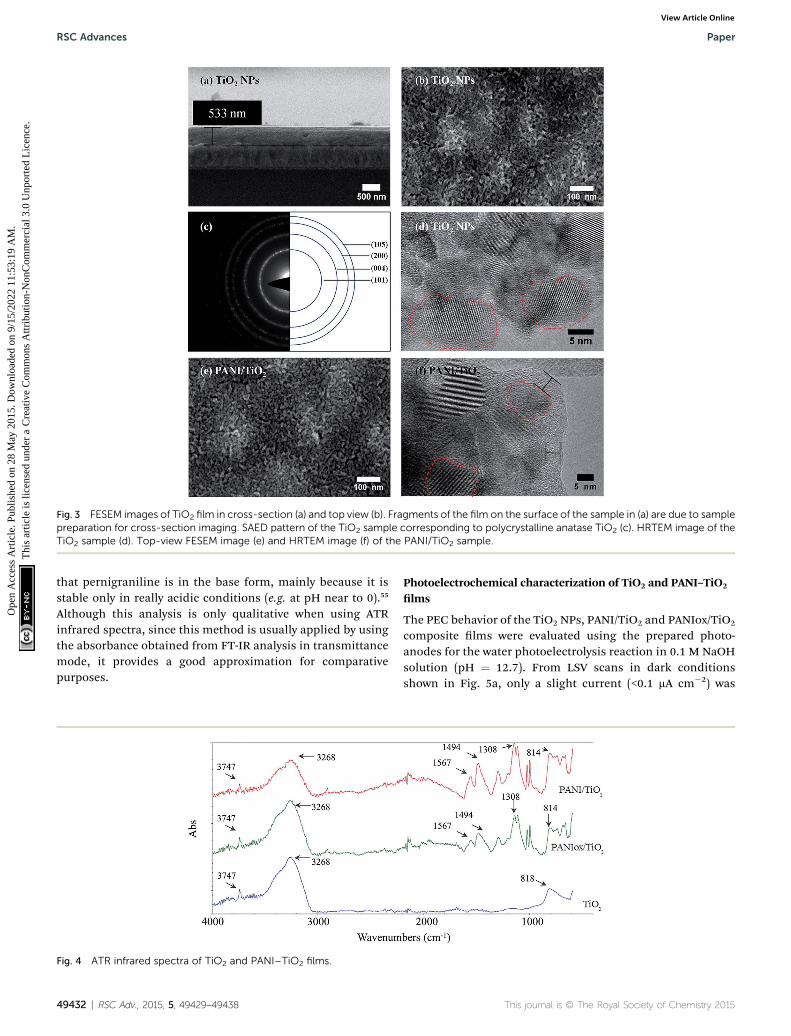
Fig. 3 FESEM images of TiO2 film in cross-section (a) and top view (b). Fragments of the film on the surface of the sample in (a) are due to samplepreparation for cross-section imaging. SAED pattern of the TiO2 sample corresponding to polycrystalline anatase TiO2 (c). HRTEM image of theTiO2 sample (d). Top-view FESEM image (e) and HRTEM image (f) of the PANI/TiO2 sample.
RSC Advances Paper
Ope
n A
cces
s A
rtic
le. P
ublis
hed
on 2
8 M
ay 2
015.
Dow
nloa
ded
on 9
/15/
2022
11:
53:1
9 A
M.
Thi
s ar
ticle
is li
cens
ed u
nder
a C
reat
ive
Com
mon
s A
ttrib
utio
n-N
onC
omm
erci
al 3
.0 U
npor
ted
Lic
ence
.View Article Online
that pernigraniline is in the base form, mainly because it isstable only in really acidic conditions (e.g. at pH near to 0).55
Although this analysis is only qualitative when using ATRinfrared spectra, since this method is usually applied by usingthe absorbance obtained from FT-IR analysis in transmittancemode, it provides a good approximation for comparativepurposes.
Fig. 4 ATR infrared spectra of TiO2 and PANI–TiO2 films.
49432 | RSC Adv., 2015, 5, 49429–49438
Photoelectrochemical characterization of TiO2 and PANI–TiO2
lms
The PEC behavior of the TiO2 NPs, PANI/TiO2 and PANIox/TiO2
composite lms were evaluated using the prepared photo-anodes for the water photoelectrolysis reaction in 0.1 M NaOHsolution (pH ¼ 12.7). From LSV scans in dark conditionsshown in Fig. 5a, only a slight current (<0.1 mA cm�2) was
This journal is © The Royal Society of Chemistry 2015
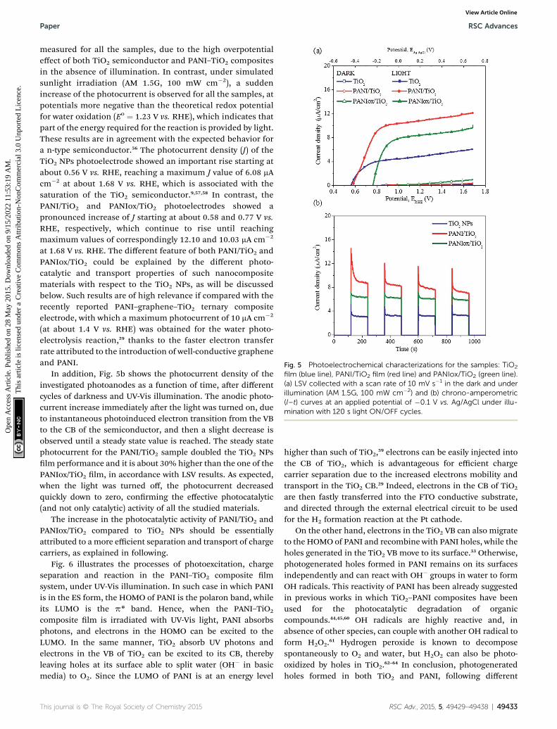
Fig. 5 Photoelectrochemical characterizations for the samples: TiO2
film (blue line), PANI/TiO2 film (red line) and PANIox/TiO2 (green line).(a) LSV collected with a scan rate of 10 mV s�1 in the dark and underillumination (AM 1.5G, 100 mW cm�2) and (b) chrono-amperometric(I–t) curves at an applied potential of �0.1 V vs. Ag/AgCl under illu-mination with 120 s light ON/OFF cycles.
Paper RSC Advances
Ope
n A
cces
s A
rtic
le. P
ublis
hed
on 2
8 M
ay 2
015.
Dow
nloa
ded
on 9
/15/
2022
11:
53:1
9 A
M.
Thi
s ar
ticle
is li
cens
ed u
nder
a C
reat
ive
Com
mon
s A
ttrib
utio
n-N
onC
omm
erci
al 3
.0 U
npor
ted
Lic
ence
.View Article Online
measured for all the samples, due to the high overpotentialeffect of both TiO2 semiconductor and PANI–TiO2 compositesin the absence of illumination. In contrast, under simulatedsunlight irradiation (AM 1.5G, 100 mW cm�2), a suddenincrease of the photocurrent is observed for all the samples, atpotentials more negative than the theoretical redox potentialfor water oxidation (Eo ¼ 1.23 V vs. RHE), which indicates thatpart of the energy required for the reaction is provided by light.These results are in agreement with the expected behavior fora n-type semiconductor.56 The photocurrent density (J) of theTiO2 NPs photoelectrode showed an important rise starting atabout 0.56 V vs. RHE, reaching a maximum J value of 6.08 mAcm�2 at about 1.68 V vs. RHE, which is associated with thesaturation of the TiO2 semiconductor.9,57,58 In contrast, thePANI/TiO2 and PANIox/TiO2 photoelectrodes showed apronounced increase of J starting at about 0.58 and 0.77 V vs.RHE, respectively, which continue to rise until reachingmaximum values of correspondingly 12.10 and 10.03 mA cm�2
at 1.68 V vs. RHE. The different feature of both PANI/TiO2 andPANIox/TiO2 could be explained by the different photo-catalytic and transport properties of such nanocompositematerials with respect to the TiO2 NPs, as will be discussedbelow. Such results are of high relevance if compared with therecently reported PANI–graphene–TiO2 ternary compositeelectrode, with which a maximum photocurrent of 10 mA cm�2
(at about 1.4 V vs. RHE) was obtained for the water photo-electrolysis reaction,29 thanks to the faster electron transferrate attributed to the introduction of well-conductive grapheneand PANI.
In addition, Fig. 5b shows the photocurrent density of theinvestigated photoanodes as a function of time, aer differentcycles of darkness and UV-Vis illumination. The anodic photo-current increase immediately aer the light was turned on, dueto instantaneous photoinduced electron transition from the VBto the CB of the semiconductor, and then a slight decrease isobserved until a steady state value is reached. The steady statephotocurrent for the PANI/TiO2 sample doubled the TiO2 NPslm performance and it is about 30% higher than the one of thePANIox/TiO2 lm, in accordance with LSV results. As expected,when the light was turned off, the photocurrent decreasedquickly down to zero, conrming the effective photocatalytic(and not only catalytic) activity of all the studied materials.
The increase in the photocatalytic activity of PANI/TiO2 andPANIox/TiO2 compared to TiO2 NPs should be essentiallyattributed to a more efficient separation and transport of chargecarriers, as explained in following.
Fig. 6 illustrates the processes of photoexcitation, chargeseparation and reaction in the PANI–TiO2 composite lmsystem, under UV-Vis illumination. In such case in which PANIis in the ES form, the HOMO of PANI is the polaron band, whileits LUMO is the p* band. Hence, when the PANI–TiO2
composite lm is irradiated with UV-Vis light, PANI absorbsphotons, and electrons in the HOMO can be excited to theLUMO. In the same manner, TiO2 absorb UV photons andelectrons in the VB of TiO2 can be excited to its CB, therebyleaving holes at its surface able to split water (OH� in basicmedia) to O2. Since the LUMO of PANI is at an energy level
This journal is © The Royal Society of Chemistry 2015
higher than such of TiO2,59 electrons can be easily injected intothe CB of TiO2, which is advantageous for efficient chargecarrier separation due to the increased electrons mobility andtransport in the TiO2 CB.29 Indeed, electrons in the CB of TiO2
are then fastly transferred into the FTO conductive substrate,and directed through the external electrical circuit to be usedfor the H2 formation reaction at the Pt cathode.
On the other hand, electrons in the TiO2 VB can also migrateto the HOMO of PANI and recombine with PANI holes, while theholes generated in the TiO2 VB move to its surface.33 Otherwise,photogenerated holes formed in PANI remains on its surfacesindependently and can react with OH� groups in water to formOH radicals. This reactivity of PANI has been already suggestedin previous works in which TiO2–PANI composites have beenused for the photocatalytic degradation of organiccompounds.44,45,60 OH radicals are highly reactive and, inabsence of other species, can couple with another OH radical toform H2O2.61 Hydrogen peroxide is known to decomposespontaneously to O2 and water, but H2O2 can also be photo-oxidized by holes in TiO2.62–64 In conclusion, photogeneratedholes formed in both TiO2 and PANI, following different
RSC Adv., 2015, 5, 49429–49438 | 49433

Fig. 6 Mechanism of UV-Vis light absorption and charges transfer inPANI–TiO2 composite films for the photoelectrochemical watersplitting reaction in basic media.
Fig. 7 Optical properties for the samples: TiO2 film (blue line), PANI/TiO2 film (red line) and PANIox/TiO2 (green line). (a) UV-Vis spectrarecorded in transmittance mode and (b) IPCE spectra recorded byvarying the wavelength of the incident light from 300 nm to 420 nm atan applied potential of 0.26 V vs. Ag/AgCl (1.23 V vs. RHE).
RSC Advances Paper
Ope
n A
cces
s A
rtic
le. P
ublis
hed
on 2
8 M
ay 2
015.
Dow
nloa
ded
on 9
/15/
2022
11:
53:1
9 A
M.
Thi
s ar
ticle
is li
cens
ed u
nder
a C
reat
ive
Com
mon
s A
ttrib
utio
n-N
onC
omm
erci
al 3
.0 U
npor
ted
Lic
ence
.View Article Online
pathways, can react with water (or OH� ions) to form O2 whichresults in higher number of collected photoelectrons,65–67 thenused for the H2 production in the cathodic electrode. Moreover,PANI itself is unable to split water toward O2 due to the unfa-vorable position of the HOMO with respect to the O2/H2O redoxpotential,68 which is supported by a control test in which nophotocurrent was observed using a PANI/FTO electrode underthe same PEC conditions. Hence, it is supposed that the TiO2
activation by UV light is essential in the previously explainedmechanism, as it was also conrmed by IPCE measurementsshown below.
The sample PANIox/TiO2 was moreover prepared and testedwith the aim to discern if the PANI in the NaOH solution isoxidized, and how this inuence the photocatalytic activity ofthe PANI/TiO2 lm. The results reported in Fig. 5 show that thePANIox/TiO2 lm perform worse than its original counterpart.The difference between PANI/TiO2 and PANIox/TiO2 can beeasily explained taking into account the presence of some per-nigraniline base (PNB) form of PANI in the oxidized material. Inthe case of PNB the benzenoid orbitals are the LUMO,69 whichhave an energy much lower than the p* band previouslyconsidered for the ES, and similar to the TiO2 CB bottom.Hence, when the PANIox absorbs UV-Vis light, the electrons inthe PNB p* band can undergo more easily to internal relaxationto the PNB benzenoid orbital, thus causing internalrecombination.
On the other hand, the open circuit voltage (OCV) of the LSVmeasurements, i.e. the voltage corresponding to J ¼ 0, is anapproximated measure of the at band potential (EFB),70 whichis close to the CB in n-type semiconductors such as the titania71
and to the VB in p-type semiconductors such as the PANI.68 Inaddition, EFB determines the band edge positions at the semi-conductor–electrolyte interface, thus xing the energies ofconduction band electrons and valence band holes reactingwith the electrolyte solution.71 In the TiO2–PANI solid inter-phase a p–n junction is formed.68 Since the TiO2 CB is close tothe HOMO (VB) of PANI in the ES form,30 the PANI/TiO2 atband potential remains close to that of the TiO2 lm (seeFig. 5a). Instead, the shi towards higher OCV values for thePANIox/TiO2 is due to the lower HOMO band of the PNB thanthat of the ES,69 which induces a more positive at bandpotential for this composite lm than for the PANI/TiO2
49434 | RSC Adv., 2015, 5, 49429–49438
(represented in Fig. 6). This fact further explains the lowerphotocatalytic activity of the PANIox/TiO2 lm.
In order to identify the portion of the solar spectra that isactually working in the TiO2 and PANI–TiO2 lms, both UV-Visand IPCE spectra were recorded and are reported in Fig. 7. Fromthe UV-Vis spectra in transmittance mode (see Fig. 7a), nosignicant differences are observed for the TiO2 NPs, PANI/TiO2
and PANIox/TiO2 lms between 300 and 330 nm. In this region,high UV light absorption (low transmittance) is observed for allthe samples. Between 330 and 420 nm the transmittanceincreased, indicating a probably related reduction of absorptionof the TiO2 NPs. However, the PANI impregnated samplesshowed an absorption higher than the pristine TiO2 NPs in theUV region up to 420 nm, in the following order: PANI/TiO2 >PANIox/TiO2 > TiO2 NPs.
The photoresponse of the different photoanodes evaluatedthrough IPCE spectra at an applied potential of 0.26 V vs. Ag/AgCl (1.23 V vs. RHE) are reported in Fig. 7b. IPCE curvesrevealed that either the TiO2 NPs or the PANI–TiO2 nano-composites here prepared have a relevant efficiency only in theUV region up to maximum 390 nm. The maximum IPCE wasobtained at 320 nm for all the samples being 6.27%, 8.17% and10.07% for the TiO2 NPs, PANIox/TiO2 and PANI/TiO2 samples,respectively. These results are in agreement with the highest UVabsorption of the PANI impregnated samples, but suggest that
This journal is © The Royal Society of Chemistry 2015

Fig. 8 Photocurrent stability vs. time of PANI/TiO2 film obtained bychrono-amperometric (I–t) technique at an applied potential of 0.26 Vvs. Ag/AgCl (1.23 V vs. RHE) under illumination with ON/OFF cycles.
Paper RSC Advances
Ope
n A
cces
s A
rtic
le. P
ublis
hed
on 2
8 M
ay 2
015.
Dow
nloa
ded
on 9
/15/
2022
11:
53:1
9 A
M.
Thi
s ar
ticle
is li
cens
ed u
nder
a C
reat
ive
Com
mon
s A
ttrib
utio
n-N
onC
omm
erci
al 3
.0 U
npor
ted
Lic
ence
.View Article Online
for the anodic water splitting reaction the role of PANI in thePANI–TiO2 composite is more important in the UV than in thevisible region of light.
In the literature is reported that PANI plays also a role assensitizer in the visible region for another redox reactions. Forinstance, PANI–TiO2 composite particles, photoexcited witheither UV or visible light, have been reported to be effective forthe photodegradation of organic compounds (i.e. Rhodamine Band Methylene blue), which involves the oxidation of water toOH radicals.45,60 In the present case, since the water oxidationrequires holes with a higher oxidation potential, holes photo-generated in PANI are not able to perform the water oxidationreaction by themselves.68
Therefore, the here reported results suggest that the mainrole of PANI, in the system PANI/TiO2 for the PEC water oxida-tion, is as sensitizer of TiO2 NPs in the UV light by signicantlyincreasing charges separation, electrons transport and collectedphotoelectrons, and indirectly contributing to the generation ofO2 (in a synergic reaction mechanism that involve photo-generated TiO2 holes, see Fig. 6), which result in an improvedphotocatalytic activity.
Finally, aer more than 4 hours of operation under photo-electrochemical conditions, the stability of the PANI/TiO2
nanocomposite photoanode was further assessed by using achronoamperometric test. Fig. 8 shows the I–t curve aerseveral hours of operation at �0.1 V vs. Ag/AgCl (0.86 V vs.RHE). This potential was chosen as a representative value inthe region of photocurrent saturation of the sample. A goodphotocurrent stability was observed under numerous lightON–OFF cycles for a long period of time (about 200 min), thusconrming: a high degree of electrochemical durability, theabsence of photodegradation of the ES form of PANI under ahighly oxidizing media (thanks to the use of PSS as dopant),and the good adhesion of the PANI/TiO2 nanocompositematerial to the substrate. Moreover, from I–t and GC analysis(see Experimental and Fig. S1 in the ESI†) it was estimated thatthe faradaic efficiency of the PANI/TiO2 lm for the H2
production is almost 100%.
This journal is © The Royal Society of Chemistry 2015
ExperimentalSol–gel synthesis and deposition of TiO2 nanoparticles
Titanium(IV) isopropoxide (TTIP, 97%), glacial acetic acid(99.7%) and Tween 20, all from Sigma Aldrich, were used aspurchased for the preparation of the sol of TiO2 nanoparticles.The synthesis procedure used to obtain the nano-TiO2 sol is asfollows: TTIP, glacial acetic acid and water were maintained inmolar ratios 1 : 10 : 300,9 whereas a molar ratio (R) betweenTween 20/TTIP of 0.5/1 was used. Firstly, the TTIP was hydro-lyzed into the glacial acetic acid and then, surfactant Tween 20was added under vigorous stirring. Subsequently, the mixturewas added drop wise into the DI-water and the nal solution wasaged under continuous stirring for 48 h at ambient temperature.Then, the TiO2 sol was treated in a rotary evaporator at 40 �C for2 h under vacuum. The nal solution was homogeneous andstable for weeks and it was used to the preparation of TiO2
nanoparticles (NPs) lms. TiO2 lms were supported ontoFluorine-doped Tin Oxide glass (FTO, 7 U sq�1 by Solaronix)substrates in an effective surface area of 4 cm2. First, thesubstrate was cleaned in acetone using an ultrasonic bath andthen rinsed with ethanol. A “piranha” solution 3 : 1 (sulfuricacid : hydrogen peroxide) was then employed to remove organicresidues on the surface. A single layer of the concentrated TiO2
solution, obtained aer the rotary evaporator treatment, wasspin-coated with a spinner model Spin 150 by using a two-stepprogram: 1500 rpm for 10 s followed by 3000 rpm for 10 s.Finally, TiO2 lms were annealed in a programmable furnace at500 �C for 15 min in air, using a heating rate of 1 �C min�1, andwere cooled down naturally. Further details of the synthesis andcharacterization of the TiO2 lms are described elsewhere.9
Polyaniline synthesis
N-Phenyl-1,4-phenylendiamine 98%, that is the aniline dimer(DANI), poly(sodium 4-styrenesulfonate) (PSS), ammoniumpersulfate (APS) 98%, sodium persulfate (SPS) 98%, hydro-chloric acid 37 wt%, dimethylsulfoxide (DMSO) 99.9% anddimethylformamide (DMF) were purchased from Aldrich andused as received.
The synthesis of PANI PSS-doped was already presentedelsewhere by Bocchini et al.42 PSS was used as emulsioning anddoping agent, so that PANI could remain stable also under thehigh pH conditions used for the PEC tests. In a typicalsynthesis, 40 mL of a solution of DANI (4 mmol, 0.9212 g) inDMSO was added drop by drop to 360 mL of a solution of PSS(0.915 g) in HCl 0.1 M. Aer that, a solution of APS (5 mmol,1.141 g) in 100 mL of HCl 0.1 M was poured slowly. Aer3 hours, the precipitate was ltered and washed several timeswith distilled water. The product was a green powder, which wasrstly separated by ltration, then washed with both doubledistilled water and ethanol, and nally dried at 60 �C untilconstant weight.
Deposition of polyaniline on TiO2 lms
PANI was deposited in the TiO2 lms by impregnation method.The PANI was dispersed in DMSO at a concentration of 2 wt%
RSC Adv., 2015, 5, 49429–49438 | 49435

RSC Advances Paper
Ope
n A
cces
s A
rtic
le. P
ublis
hed
on 2
8 M
ay 2
015.
Dow
nloa
ded
on 9
/15/
2022
11:
53:1
9 A
M.
Thi
s ar
ticle
is li
cens
ed u
nder
a C
reat
ive
Com
mon
s A
ttrib
utio
n-N
onC
omm
erci
al 3
.0 U
npor
ted
Lic
ence
.View Article Online
(or 10 wt% for chemical analysis purposes) by alternativemechanical mixing and sonication. Just before use, the PANIsolution was ultrasonicated for one hour in order to re-disperseit. The TiO2 lm was dipped into the PANI solution and thenremoved aer 10 min of impregnation. Finally, PANI/TiO2
composites lms were dried at 80 �C under vacuum for 24 h toremove all the residual DMSO. Oxidized PANI/TiO2 (PANIox/TiO2) was obtained by immersion of another similarly producedsample in a solution 0.018 M of SPS in water for 1 h.
Materials and characterization
X-ray diffraction (XRD) analysis was performed by using a X-raydiffractometer Cu-Ka X-ray tube (l ¼ 1.54 A) with an acceler-ating voltage of 40 kV, in order to determine the crystal structureand crystallinity of the TiO2 particles. Field Emission ScanningElectron Microscopy (FESEM) examinations were performedwith a Zeiss Auriga dual beam FIB-SEM microscope. RegardingFESEM sample preparation for cross-section analysis, the lmswere dipped in liquid nitrogen and subsequently cut. Trans-mission Electron Microscopy analysis was carried out with a FEITecnai F20ST operating at 200 kV. Concerning TEM samplepreparation, portions of the samples were detached bymechanical action and subsequently dispersed in ethanol(purity >99.8%, Sigma-Aldrich). Aer sonication for 5 min, thesamples were immediately inserted in the TEM column for theanalysis. Attenuated Total Reectance (ATR) spectra werecollected on a Nicolet 5700 FTIR Spectrometer (ThermoFisher)equipped with a ZnSe single crystal. A spectrophotometermodel Cary 500 by Varian was used to obtain the UV-Vistransmittance spectra of the samples, which were recorded inthe wavelength range of 300–800 nm at room temperature.
Photoelectrochemical tests of TiO2 and PANI–TiO2
composites lms
The PEC experiments were performed in a glass reactor equip-ped with a quartz window for frontal illumination.9 All the testswere carried out in a three electrodes conguration using theTiO2 NPs, PANI/TiO2 and PANIox/TiO2 nanocomposite lms asthe working electrodes for the water photoelectrolysis reaction,a platinum wire as the counter electrode, and an Ag/AgCl (KCl 3M) as the reference electrode, in 0.1 M NaOH aqueous electro-lyte (pH ¼ 12.7). The electrochemical measurements were per-formed using a multi-channel VSP potentiostat/galvanostat (byBioLogic), with EC-Lab® soware (version 10.1x) for dataacquisition. The current–voltage (I–V) characteristic curves wererecorded by means of Linear Sweep Voltammetry (LSV) at a scanrate of 10 mV s�1, when a constant open circuit voltage wasachieved, varying the applied potential from �0.7 V to 0.7 V vs.Ag/AgCl, in the dark and under 100 mW cm�2 of simulatedsunlight (using a 450 W Xe lamp by Newport with an AM 1.5Glter and a water lter model 6123NS). The irradiance wasmeasured by means of a Delta Ohm Photo-radiometer modelHD2102.1. Chronoamperometric (I–t) tests were carried out toexamine the photoresponse of the nanostructures over time at�0.1 V vs. Ag/AgCl (0.86 VRHE) under continuous ON–OFF lightcycles, with the same illumination condition used for the LSV.
49436 | RSC Adv., 2015, 5, 49429–49438
The measured potentials versus the Ag/AgCl reference electrodewere converted to the reversible hydrogen electrode (RHE) scalevia the Nernst eqn (1):
ERHE ¼ EAg/AgCl + 0.059pH + EoAg/AgCl (1)
where ERHE is the converted potential (V vs. RHE), EAg/AgCl is theexperimental potential measured against the Ag/AgCl referenceelectrode (V vs. Ag/AgCl), and EoAg/AgCl is the standard potentialof Ag/AgCl (KCl 3 M) at 25 �C (i.e. 0.21 V). Incident photon-to-electron conversion efficiency (IPCE) spectra were recordedusing a Newport Xe lamp (150 W) coupled to a monochromator(Cornestone 130 by Newport), by varying the wavelength of theincident light from 300 nm to 550 nm (step size: 10 nm), at anapplied potential of 0.26 V vs. Ag/AgCl (1.23 V vs. RHE). In thiscase, the electrode illuminated area was 1 cm2 and the lightpower density was about 1 mW cm�2 (measured at 390 nm). Thefaradaic efficiency (FE ¼ mol of H2 theoretically produced/molof H2 measured � 100%) was calculated from the data of anamperometry at 0.6 V vs. Ag/AgCl for 10 min under lightconditions, in order to produce enough gas to be measuredwithin the sensibility of the micro-gas chromatograph (Varian490 GC, equipped with a Molsieve 5A column of 10 m and amicro-TCD detector) used for the analysis, aer outgassing ofthe cell with an Ar ow rate of 25 NmL min�1 (controlled by aBronkhorst mass ow controller) under continuous stirring.
Conclusions
In order to improve the photocatalytic activity of TiO2 NPs,PANI–TiO2 nanocomposite lms have been successfullyprepared by a simple impregnation method, employing twoeasy and environmentally friendly synthesis techniques forpreparation of both TiO2 lms and PANI conductive polymer.According to FESEM and TEM observations, a thin lm of PANIwas deposited in the surface of the TiO2 NP lms, which did notsignicantly alter the morphology and crystallinity of TiO2 NPs,as was also conrmed by XRD analysis. ATR results conrmedthe presence of PANI under the form of emeraldine salt and amixture of ES and pernigraniline base in the PANI/TiO2 andPANIox/TiO2 nanocomposite lms, respectively. A remarkableenhancement of the photocatalytic activity was achieved byemploying such PANI–TiO2 nanocomposite lms for the PECwater splitting reaction. The PANI/TiO2 and PANIox/TiO2 elec-trodes showed a pronounced increase of the photocurrentunder simulated sunlight irradiation (AM 1.5G, 100 mW cm�2),reaching maximum photocurrent densities around 2 and 1.6fold higher than the pristine TiO2 NPs. These results are in goodagreement with IPCE measurements, which revealed that thePEC activity of both PANI/TiO2 and PANIox/TiO2 lms wasenhanced in 1.6 and 1.3 fold higher with respect to the pristineTiO2 NPs lm at 1.23 V vs. RHE. From the results reported inthis work, the best performance of the PANI/TiO2 sample couldbe associated to an enhanced electrons transport and chargesseparation, thanks to an increase of e� in the TiO2 CB and thegeneration of H2O2 : PANI-ES photogenerated e� are transferredto the TiO2 conduction band (due to the proper alignment
This journal is © The Royal Society of Chemistry 2015

Paper RSC Advances
Ope
n A
cces
s A
rtic
le. P
ublis
hed
on 2
8 M
ay 2
015.
Dow
nloa
ded
on 9
/15/
2022
11:
53:1
9 A
M.
Thi
s ar
ticle
is li
cens
ed u
nder
a C
reat
ive
Com
mon
s A
ttrib
utio
n-N
onC
omm
erci
al 3
.0 U
npor
ted
Lic
ence
.View Article Online
between the CB of TiO2 and the LUMO of PANI) while the h+
reacts with OH� to produce OH radicals that generate H2O2,which is subsequently reduced on the TiO2 NPs surface. Incontrast, the pernigraniline base form of PANI (present in thePANIox/TiO2 lm) has a detrimental effect on e� transfer, andthus in the PEC performance for the water oxidation reaction.The PANI/TiO2 lm showed also an exceptional electrochemicaldurability under illumination for more than 190 min, moreoverconrming the good adhesion of the composite material to thesubstrate. Such ndings could also be useful to focus furtherresearch in order to still improve the here reported results, forinstance by improving the PANI interpenetration in the TiO2
porous lms, and opens useful insights for futuredevelopments.
In Conclusion, a green and low-cost synthesis procedure wasdeveloped for the preparation of effective PANI/TiO2 compositelms, having a high surface nanocrystalline and mesoporousstructure, which can nd promising application not only in thePEC water splitting reaction, but also in other environmentalphotocatalytic applications in different redox systems.
Acknowledgements
The nancial support from the European Commission on the7th Framework Program NMP-2012 Project Eco2CO2 (no.309701) and FCH- JU Call 2011-1 Project ARTIPHYCTION (no.303435) is gratefully acknowledged.
Notes and references
1 J. A. Turner, Science, 2004, 305, 972–974.2 J. Gu, Y. Yan, J. W. Krizan, Q. D. Gibson, Z. M. Detweiler,R. J. Cava and A. B. Bocarsly, J. Am. Chem. Soc., 2014, 136,830–833.
3 A. Fujishima and K. Honda, Nature, 1972, 238, 37–38.4 X. Hu, G. Li and J. C. Yu, Langmuir, 2009, 26, 3031–3039.5 D. Fattakhova-Rohlng, A. Zaleska and T. Bein, Chem. Rev.,2014, 114, 9487–9558.
6 X. Chen and S. S. Mao, Chem. Rev., 2007, 107, 2891–2959.7 C. Yu, B. Tian and D. Zhao, Curr. Opin. Solid State Mater. Sci.,2003, 7, 191–197.
8 M. L. K. Hoa, M. Lu and Y. Zhang, Adv. Colloid Interface Sci.,2006, 121, 9–23.
9 D. Hidalgo, R. Messina, A. Sacco, D. Manfredi, S. Vankova,E. Garrone, G. Saracco and S. Hernandez, Int. J. HydrogenEnergy, 2014, 39, 21512–21522.
10 C. Boissiere, D. Grosso, A. Chaumonnot, L. Nicole andC. Sanchez, Adv. Mater., 2011, 23, 599–623.
11 P. Innocenzi and L. Malfatti, Chem. Soc. Rev., 2013, 42, 4198–4216.
12 R. Zhang, A. A. Elzatahry, S. S. Al-Deyab and D. Zhao, NanoToday, 2012, 7, 344–366.
13 M. C. Orilall and U. Wiesner, Chem. Soc. Rev., 2011, 40, 520–535.
14 W. Li and D. Zhao, Adv. Mater., 2013, 25, 142–149.15 F. Zhu, D. Wu, Q. Li, H. Dong, J. Li, K. Jiang and D. Xu, RSC
Adv., 2012, 2, 11629–11637.
This journal is © The Royal Society of Chemistry 2015
16 J. B. Joo, Q. Zhang, M. Dahl, F. Zaera and Y. Yin, J. Mater.Res., 2013, 28, 362–368.
17 Q. Xiang, J. Yu and M. Jaroniec, Nanoscale, 2011, 3, 3670–3678.
18 W. Zhou, H. Liu, R. I. Boughton, G. Du, J. Lin, J. Wang andD. Liu, J. Mater. Chem., 2010, 20, 5993–6008.
19 W. S. Tung andW. A. Daoud, J. Mater. Chem., 2011, 21, 7858–7869.
20 N. Liu, X. Chen, J. Zhang and J. W. Schwank, Catal. Today,2014, 225, 34–51.
21 P. Roy, S. Berger and P. Schmuki, Angew. Chem., Int. Ed.,2011, 50, 2904–2939.
22 A. Lamberti, A. Sacco, S. Bianco, D. Manfredi, F. Cappelluti,S. Hernandez, M. Quaglio and C. F. Pirri, Phys. Chem. Chem.Phys., 2013, 15, 2596–2602.
23 J. Yue, Z. H. Wang, K. R. Cromack, A. J. Epstein andA. G. MacDiarmid, J. Am. Chem. Soc., 1991, 113, 2665–2671.
24 D. P. Debecker, V. Hulea and P. H. Mutin, Appl. Catal., A,2013, 451, 192–206.
25 W. Zhou and H. Fu, ChemCatChem, 2013, 5, 885–894.26 H. Tong, S. Ouyang, Y. Bi, N. Umezawa, M. Oshikiri and J. Ye,
Adv. Mater., 2012, 24, 229–251.27 X. Wang and R. A. Caruso, J. Mater. Chem., 2011, 21, 20–28.28 J. Z. Zhang, MRS Bull., 2011, 36, 48–55.29 L. Jing, Z.-Y. Yang, Y.-F. Zhao, Y.-X. Zhang, X. Guo, Y.-M. Yan
and K.-N. Sun, J. Mater. Chem. A, 2014, 2, 1068–1075.30 J. Wei, Q. Zhang, Y. Liu, R. Xiong, C. Pan and J. Shi,
J. Nanopart. Res., 2011, 13, 3157–3165.31 M. Qorbani, N. Naseri, O. Moradlou, R. Azimirad and
A. Z. Moshfegh, Appl. Catal., B, 2015, 162, 210–216.32 S. Kuang, L. Yang, S. Luo and Q. Cai, Appl. Surf. Sci., 2009,
255, 7385–7388.33 F. Deng, L. Min, X. Luo, S. Wu and S. Luo, Nanoscale, 2013, 5,
8703–8710.34 D. Pei and J. Luan, Int. J. Photoenergy, 2012, 2012, 13.35 W. J. Youngblood, S.-H. A. Lee, K. Maeda and T. E. Mallouk,
Acc. Chem. Res., 2009, 42, 1966–1973.36 G. Cai, J. Tu, D. Zhou, J. Zhang, Q. Xiong, X. Zhao, X. Wang
and C. Gu, J. Phys. Chem. C, 2013, 117, 15967–15975.37 A. G. MacDiarmid and A. J. Epstein, Faraday Discuss. Chem.
Soc., 1989, 88, 317–332.38 J.-C. Chiang and A. G. MacDiarmid, Synth. Met., 1986, 13,
193–205.39 A. MacDiarmid, J. Chiang, A. Richter and A. Epstein, Synth.
Met., 1987, 18, 285–290.40 A. G. MacDiarmid, Angew. Chem., Int. Ed., 2001, 40, 2581–
2590.41 A. G. MacDiarmid, J.-C. Chiang, A. F. Richter,
N. L. D. Somasiri and A. J. Epstein, Conducting Polymers,ed. L. AlcaceAr, Reidel, Dordrecht, 1987, p. 105.
42 S. Bocchini, A. Chiolerio, S. Porro, D. Accardo, N. Garino,K. Bejtka, D. Perrone and C. Pirri, J. Mater. Chem. C, 2013,1, 5101–5109.
43 A. Chiolerio, S. Bocchini and S. Porro, Adv. Funct. Mater.,2014, 24, 3472.
44 G. A. O. Jinzhang, L. I. Shengying, Y. Wu, Z. Guohu, B. O. Liliand S. Li, Rare Met., 2007, 26, 1–7.
RSC Adv., 2015, 5, 49429–49438 | 49437

RSC Advances Paper
Ope
n A
cces
s A
rtic
le. P
ublis
hed
on 2
8 M
ay 2
015.
Dow
nloa
ded
on 9
/15/
2022
11:
53:1
9 A
M.
Thi
s ar
ticle
is li
cens
ed u
nder
a C
reat
ive
Com
mon
s A
ttrib
utio
n-N
onC
omm
erci
al 3
.0 U
npor
ted
Lic
ence
.View Article Online
45 M. Radoicic, Z. Saponjic, I. A. Jankovic, G. Ciric-Marjanovic,S. P. Ahrenkiel and M. I. Comor, Appl. Catal., B, 2013, 136–137, 133–139.
46 J. Li, L. Zhu, Y. Wu, Y. Harima, A. Zhang and H. Tang,Polymer, 2006, 47, 7361–7367.
47 X. Li, D. Wang, G. Cheng, Q. Luo, J. An and Y. Wang, Appl.Catal., B, 2008, 81, 267–273.
48 H. Zhang, R. Zong, J. Zhao and Y. Zhu, Environ. Sci. Technol.,2008, 42, 3803–3807.
49 M. O. Ansari, M. M. Khan, S. A. Ansari, K. Raju, J. Lee andM. H. Cho, ACS Appl. Mater. Interfaces, 2014, 6, 8124–8133.
50 G. Senadeera, T. Kitamura, Y. Wada and S. Yanagida, J.Photochem. Photobiol., A, 2004, 164, 61–66.
51 K. He, M. Li and L. Guo, Int. J. Hydrogen Energy, 2012, 37,755–759.
52 T. Abdiryim, Z. Xiao-Gang and R. Jamal, Mater. Chem. Phys.,2005, 90, 367–372.
53 P. Madhu Kumar, S. Badrinarayanan and M. Sastry, ThinSolid Films, 2000, 358, 122–130.
54 J. Tang, X. Jing, B. Wang and F. Wang, Synth. Met., 1988, 24,231–238.
55 G. D'Aprano, M. Leclerc and G. Zotti, Macromolecules, 1992,25, 2145–2150.
56 J. J. Kelly, Z. Hens, D. Vanmaekelbergh and Z. Hensalso, inEncyclopedia of electrochemistry, Wiley-VCH Verlag GmbH &Co. KGaA, 2007, DOI: 10.1002/9783527610426.bard060201.
57 Z. Zhang and P. Wang, Energy Environ. Sci., 2012, 5, 6506–6512.
58 S. Hernandez, D. Hidalgo, A. Sacco, A. Chiodoni,A. Lamberti, V. Cauda, E. Tresso and G. Saracco, Phys.Chem. Chem. Phys., 2015, 17, 7775–7786.
49438 | RSC Adv., 2015, 5, 49429–49438
59 M.-S. Liu, Y.-Z. Hao, X.-B. Qiao, M. Yang, M. Cai and Y. Li,Electrochemistry, 1998, 4, 246.
60 G. Liao, S. Chen, X. Quan, Y. Zhang and H. Zhao, Appl. Catal.,B, 2011, 102, 126–131.
61 P. Akhter, M. Hussain, G. Saracco and N. Russo, Fuel, 2015,149, 55–65.
62 J. R. Harbour, J. Tromp and M. L. Hair, Can. J. Chem., 1985,63, 204–208.
63 B. Jenny and P. Pichat, Langmuir, 1991, 7, 947–954.64 I. Ilisz, K. Foglein and A. Dombi, J. Mol. Catal. A: Chem., 1998,
135, 55–61.65 A. Lamberti, A. Sacco, D. Hidalgo, S. Bianco, D. Manfredi,
M. Quaglio, E. Tresso and C. F. Pirri, Acta Phys. Pol., A,2013, 123, 376.
66 S. Hernandez, V. Cauda, A. Chiodoni, S. Dallorto, A. Sacco,D. Hidalgo, E. Celasco and C. F. Pirri, ACS Appl. Mater.Interfaces, 2014, 6, 12153–12167.
67 S. Hernandez, V. Cauda, D. Hidalgo, V. Farıas Rivera,D. Manfredi, A. Chiodoni and F. C. Pirri, J. Alloys Compd.,2014, 615, S530–S537.
68 C. Belabed, A. Abdi, Z. Benabdelghani, G. Rekhila,A. Etxeberria and M. Trari, Int. J. Hydrogen Energy, 2013,38, 6593–6599.
69 W. Huang and A. MacDiarmid, Polymer, 1993, 34, 1833–1845.70 A. J. Bard and L. R. Faulkner, Electrochemical Methods:
Fundamentals and Applications, Wiley, 2000.71 K. Rajeshwar, in Encyclopedia of electrochemistry, Wiley-VCH
Verlag GmbH & Co. KGaA, 2002.
This journal is © The Royal Society of Chemistry 2015