uv-visible-light-activated photocatalysts based on bi2o3/bi4ti3o12/tio2 double-heterostructured tio2...
TRANSCRIPT

Dynamic Article LinksC<Journal ofMaterials Chemistry
Cite this: J. Mater. Chem., 2012, 22, 23395
www.rsc.org/materials PAPER
UV-visible-light-activated photocatalysts based on Bi2O3/Bi4Ti3O12/TiO2
double-heterostructured TiO2 nanobelts†
Zhenhuan Zhao,a Jian Tian,a Dongzhou Wang,a Xueliang Kang,a Yuanhua Sang,a Hong Liu,*ac Jiyang Wang,a
Shaowei Chen,*b Robert I. Boughtond and Huaidong Jianga
Received 13th July 2012, Accepted 17th September 2012
DOI: 10.1039/c2jm34580c
Surface engineering of TiO2 nanobelts by the controlled assembly of functional heterostructures
represents an effective approach for the synthesis of high-performance photocatalysts. In this study, we
prepared a novel Bi2O3/Bi4Ti3O12/TiO2 double-heterostructured nanobelt by depositing bismuth
hydroxide onto the TiO2 nanobelt surface. A thermal annealing treatment led to the formation of a
Bi4Ti3O12 interlayer that functioned as a bridge to link Bi2O3 and TiO2. The double-heterostructured
TiO2 nanobelts exhibited better UV light photocatalytic performance than commercial P25.
Importantly, the photocatalytic activity in the visible range was markedly better than that of Bi2O3 and
Bi2O3/TiO2 heterostructured TiO2 nanobelts. The enhanced performance was accounted for by the
material band structures where the matching was improved by the unique interlayer.
Introduction
Since Fujishima and Honda demonstrated the possibility of
water splitting on an illuminated TiO2 electrode surface in 1972,1
the photocatalytic properties of metal–oxide semiconductors
have been thoroughly investigated, in particular, in semi-
conductor modification and sensitization.2,3 Among this, pho-
tocatalytic degradation of toxic organic pollutants in air and
water by using TiO2-based photocatalysts has represented an
important area of research, primarily because of the materials’
chemical inertness, non-photocorrosion, low cost, and non-
toxicity.4–11 However, because of the large intrinsic materials
band gap, TiO2 lacks sensitivity to visible light, and the practical
applications of the TiO2-based materials are still quite limited
with the high recombination rate of the photogenerated
electron–hole pairs under UV light irradiation.12
Much effort has been devoted to improving the photocatalytic
performance of TiO2. For example, the performance of TiO2 can
be enhanced by, for instance, coupling with a narrow band gap
semiconductor, doping with metal or nonmetal ions,13–15 sensi-
tization with organic polymers,16,17 and deposition of noble
metals. It has been found that these strategies lead to not only
aState Key Laboratory of Crystal Materials, Center of Bio & Micro/nanoFunctional Materials, Shandong University, 27 Shandanan Road, Jinan250100, China. E-mail: [email protected]; [email protected] of Chemistry and Biochemistry, University of California,1156 High Street, Santa Cruz, California 95064, USAcBeijing Institute of Nanoenergy and Nanosystems, Chinese Academy ofScience, Beijing 100864, ChinadDepartment of Physics and Astronomy, Bowling Green State University,Bowling Green, OH 43403, USA
† Electronic supplementary information (ESI) available. See DOI:10.1039/c2jm34580c
This journal is ª The Royal Society of Chemistry 2012
improved separation of electron–hole pairs, but also manipula-
tion of the band structure. For instance, Zyoud et al. reported
that the core–shell structure of TiO2/CdS efficiently degraded
phenazopyridine under visible light illumination, and yet
decomposed and leached out hazardous Cd2+ ions into water.18
In another study, Bi2S3/TiO2 and CdS/TiO2 heterostructures
were found to absorb visible light, and exhibited apparent pho-
tocatalytic activity in the degradation of Orange II.19 Ion-doped
anatase TiO2 also exhibits absorption in the visible region. It is
proposed that Fe3+ is not only an effective electron trap, but can
also serve as a hole trap because the energy level of Fe3+/Fe4+ lies
above the valence band edge of anatase TiO2.20 Photodeposition
of Ag or Au nanoparticles on TiO2 also leads to the generation of
photoactive sites that can efficiently improve the separation of
photogenerated electron–hole pairs.21,22
In these studies, TiO2 of different structures has been devel-
oped, such as nanowires,23 nanorods,24–27 nanotubes,25,28 and
nanobelts.29–31 Further exotic surface geometries can be prepared
by surface modification to form heterostructures. For instance,
functional materials such as CdS,32,33 PbS,34 CdTe,35 Bi2WO6,36
Ag2O,37 and NiO,38 have been used to prepare heterostructures in
conjunction with one-dimensional TiO2. Our group has exerted
much effort to assemble heterostructures on TiO2 nanobelts in
order to improve the UV-visible photocatalytic performance.
However, the mismatch between some visible photocatalysts and
TiO2 is a great obstacle in obtaining high performance UV-
visible photocatalysts. Recently, a double nanoheterostructure
based on Ag/TiO2 nanoparticles/TiO2 nanobelts was prepared by
an acid-assisted hydrothermal method followed by an in situ
photoreduction process. It was found that the double nano-
heterostructure can further enhance the photocatalytic proper-
ties of the TiO2 nanobelts in a dramatic fashion.39 This result
J. Mater. Chem., 2012, 22, 23395–23403 | 23395

provides a clue that the band structures can be adjusted by the
interphase between the visible photolysis component and the
TiO2 nanobelt. We suggest that the interphase may play an
important role in separating the electron–hole pair. It should be
pointed out that the preparation of the above double hetero-
structure is factually uncontrollable.
Therefore, constructing a double-heterostructured TiO2
nanobelt under controllable conditions will be the most efficient
methodology. Bi2O3 is an important semiconductor with a band
gap of 2.8 eV that is narrower than that of TiO2 (3.2 eV).40 In
fact, Bi2O3 has been used as an effective photocatalyst under
visible light illumination, and coupling Bi2O3 with other photo-
catalysts exhibits enhanced photocatalytic efficiency in the
decomposition of organic pollutants in water.41–43 Bi4Ti3O12 has
also been found to possess photocatalytic activity in the degra-
dation of organic pollutants in water under visible light illumi-
nation.44,45 In this study, by using a simple annealing procedure,
a new Bi2O3/Bi4Ti3O12/TiO2 double-heterostructured nanobelt
was synthesized with the Bi4Ti3O12 phase functioning as a bridge
to link Bi2O3 and TiO2. The heterostructure was confirmed by
SEM, XRD, and HRTEM measurements, and the photo-
catalytic activity was highlighted by the photodegradation of
methyl orange (MO) under UV light and visible light
irradiations.
Experimental section
Materials
Sodium hydroxide (NaOH, analytic grade), hydrochloric acid
(HCl), sulfuric acid (H2SO4), bismuth nitrate (Bi(NO3)3$5H2O),
and nitric acid (HNO3) were used directly without further puri-
fication. Deionized water was used throughout the experiments.
Titania P25 (TiO2, ca. 80% anatase and 20% rutile) was used as
the Ti precursor to prepare TiO2 nanobelts.
Preparation of TiO2 nanobelts
An alkali hydrothermal process was employed for the prepara-
tion. In a typical procedure, 0.30 g of commercial TiO2 powder
(P25) was dispersed in 60 mL of a 10 M NaOH aqueous solution
and placed into a 80 mL Teflon-lined autoclave. The autoclave
was heated to and maintained at 200 �C for 72 h. The precipitate
was collected and washed thoroughly with deionized water, fol-
lowed by filtration and then immersion in 0.1 M HCl aqueous
solution for 48 h. The resulting samples were hydrogen titanate
nanobelts. These nanobelts were then added into a Teflon-lined
autoclave containing 60 mL of a 0.02 MH2SO4 aqueous solution
and maintained at 100 �C for 12 h. The products were collected
after filtration, washing and air-drying. After thermal annealing
at 600 �C for 2 h, TiO2 nanobelts with a roughened surface were
obtained.
Preparation of double-heterostructured photocatalysts
Bi2O3/Bi4Ti3O12/TiO2 photocatalysts were prepared by a chem-
ical liquid co-precipitation method combined with an annealing
process. In brief, 0.097 g of Bi(NO3)3$5H2O was added to 10 mL
of a 1.0 M nitric acid solution, followed by ultrasonification for
30 min to obtain a transparent solution. 0.08 g of TiO2 nanobelts
23396 | J. Mater. Chem., 2012, 22, 23395–23403
was added to the above solution. The mixture was sonicated for
10 min and gently stirred for another 30 min. Then 100 mL of a
0.2 M sodium hydroxide solution was dropped into the mixture
over a period of 3 h. The white precipitate was collected by
filtration, and washed with deionized water followed by drying at
70 �C. Finally, the catalysts were obtained by annealing the
precipitate at 500 �C for 1 h. Pure Bi2O3 was also prepared via a
similar procedure without the addition of TiO2 nanobelts.
Bi4Ti3O12 was prepared by the following procedure. First,
0.97 g Bi(NO3)3$5H2O was dispersed in a 10 mL nitric acid
solution at a concentration of 1.0 M to obtain a clear solution.
Then 0.0015 mol P25 powder was added to the above solution.
After sonication for 10 min, 100 mL of a sodium hydroxide
solution (0.2 M) was slowly dropped into the above mixture.
Then the precipitate was collected and washed with deionized
water, followed by filtration and drying. Finally, Bi4Ti3O12 was
obtained by annealing the product at 600 �C for 1 h.
Characterization
The X-ray powder diffraction (XRD) patterns of the catalysts
were recorded with a Bruker D8 Advance powder X-ray
diffractionmeter with Cu Ka radiation (l ¼ 0.15406 nm) over a
2q scan range between 20� and 80�. A HITACHI S-4800 field-
emission scanning electron microscope (FE-SEM) was used to
characterize the morphology and size of the synthesized cata-
lysts. High-resolution transmission electron microscope
(HRTEM) images were obtained with a JEOL JEM 2100F
microscope. The UV-vis diffuse reflectance spectra (DRS) of the
catalysts were acquired with a UV-vis spectrophotometer (UV
2550, Shimadzu) with an integrating sphere attachment. BaSO4
was used as the reflectance standard, and the analytical range was
200 to 600 nm. Photoluminescence spectra (PL) were recorded by
using a FLS920 fluorescence spectrometer with an excitation
wavelength of 380 nm. The specific surface area was calculated
using the Brunauer–Emmett–Teller (BET) method using the
measurement instrument (Micromeritics, ASAP2020). The
infrared spectrum was recorded on a Nexus 670 FT-IR
spectrometer.
Photocatalytic assessments
Methyl orange (MO), a well-known acid–base indicator, was
used as the model pollutant. In a typical experiment, 20 mL of an
MO aqueous solution at a concentration of 20 mg L�1 and 20 mg
of the as-synthesized catalyst powder were placed in a quartz
reactor. Before illumination, the suspension was magnetically
stirred in the dark for 30 min to establish an adsorption/
desorption equilibrium between MO and the surface of the
photocatalysts. The photocatalytic reaction was carried out at
room temperature. A 300 W mercury lamp with a primary
wavelength of 365 nm, and a 350WXe arc lamp were used as the
UV and visible light source, respectively. At fixed illumination
time intervals, the mixture was centrifuged to remove the catalyst
particles for analysis. The concentration of MO was analyzed
with a UV-vis spectrophotometer (UV-2102PC) by monitoring
the absorbance at 465 nm. In a similar fashion, the photo-
catalytic activities of Bi2O3, Bi4Ti3O12 and P25 powder were also
investigated and compared.
This journal is ª The Royal Society of Chemistry 2012

Fig. 2 XRD patterns of products prepared by annealing TiO2 nanobelts
deposited with bismuth hydroxide at 300 �C (a), 500 �C (b) and 600 �C(c). Bi2O3/TiO2 weight ratio is 6 : 1. (d)–(f) refer to JCPDS card no. 21-
1272 for TiO2, 35-0795 for Bi4Ti3O12 and 65-2366 for Bi2O3, respectively.
Results and discussion
Fig. 1 depicts the XRD patterns of the TiO2 nanobelts, Bi2O3,
Bi4Ti3O12 nanoparticles and Bi2O3/Bi4Ti3O12/TiO2 double-
heterostructured nanobelts prepared at 500 �C with a 1 : 2 Bi2O3/
TiO2 weight ratio. The diffraction peaks of the TiO2 nanobelts
can be indexed to anatase TiO2 with characteristic diffraction
peaks (2q) at 25.3�, 37.7�, 47.8�, 53.8�, 55�, 62.6�, 70.2� and 75.2�
(JCPDS card 21-1272) (Fig. 1a). The high intensity and sharp-
ness of the diffraction peaks of the Bi2O3 sample indicate a high
degree of crystallinity of the sample and all the peaks can be
assigned to monoclinic bismite according to JCPDS card no.
65-2366 (Fig. 2b). The XRD patterns of Bi4Ti3O12, as shown in
Fig. 1c, indicate that the prepared sample exhibits a well-crys-
tallized perovskite phase corresponding to JCPDS card no.
35-0795. As shown in Fig. 1d, the main peaks of the double-
heterostructured nanobelts (at 2q ¼ 25.2�, 27.4� and 30.01�)show that Bi2O3 and Bi4Ti3O12 coexist on the surface of the TiO2
nanobelts.
To investigate the crystalline phase of the Bi2O3–TiO2 nano-
belt composite system, TiO2 nanobelts modified with bismuth
hydroxide at the same Bi2O3/TiO2 weight ratio of 6 : 1 were
calcined at different temperatures. Fig. 2 shows the XRD
patterns of the heterostructured Bi2O3–TiO2 composites
prepared at 300 �C, 500 �C, and 600 �C, with the corresponding
camera pictures included in Fig. S1.† It can be seen from Fig. 2a
that when bismuth hydroxide was deposited onto TiO2 nanobelts
and annealed at 300 �C, no obvious peaks emerged in the
diffraction pattern of the products except a relatively broad peak
located at 2q ¼ 27.4�. This peak can be assigned to the (120)
plane of monoclinic Bi2O3 (according to JCPDF card no. 65-
2366, shown in Fig. 2d). This suggests that at this temperature
the TiO2 nanobelts were modified with monoclinic Bi2O3. When
the annealing temperature was raised to 500 �C, in addition
to the peak at 27.4�, two sharp peaks at 2q ¼ 30.01� and 32.7�
also appeared in the diffraction patterns (Fig. 2b). These can be
indexed to the (171) and (200) planes of orthorhombic Bi4Ti3O12
(according to JCPDF card no. 35-0795, shown in Fig. 2e). Note
that this temperature at which the Bi4Ti3O12 layer began to form
is different from that reported by Yao et al. where the diffraction
peak for the (171) planes started to emerge at an annealing
Fig. 1 XRD patterns of (a) TiO2 nanobelts, (b) Bi2O3 powder, (c) Bi2O3/
Bi4Ti3O12/TiO2 heterostructured nanobelts annealed at 500 �C with 1 : 2
Bi2O3/TiO2 weight ratio, and (d) Bi4Ti3O12 particles.
This journal is ª The Royal Society of Chemistry 2012
temperature of 400 �C.45 The appearance of both Bi4Ti3O12 and
Bi2O3 phases indicates that indeed Bi2O3/Bi4Ti3O12/TiO2 double-
heterostructured nanobelts were prepared at this temperature.
With a further increase of the annealing temperature to 600 �C,as shown in Fig. 2c, the diffraction peak of the (120) plane
disappears and only those of Bi4Ti3O12 remained, according to
JCPDF card no. 35-0795 (Fig. 2e), suggesting that only
Bi4Ti3O12/TiO2 heterostructured nanobelts were formed instead.
The emergence of Bi4Ti3O12 at an annealing temperature of
500 �C is most likely the result of the reactions between Bi2O3
and TiO2 particles. According to Zhou et al., when TiO2 nano-
belts were treated with acid, anatase TiO2 nanoparticles were
recrystallized on the surface of the TiO2 nanobelts,39 while Bi2O3
particles were formed due to the dehydration of bismuth
hydroxide. The etching of TiO2 nanobelts can be divided into
two processes performed at the same time. The first one is the
formation of TiO2 nanoparticles on the surface of H2Ti3O7
nanobelts. In H2SO4 solution, the H2Ti3O7 nanobelts react with
hydrogen ions to obtain Ti4+ ions which hydrolyzed to form
TiO2 nanoparticles through heterogeneous nucleation. The
second one is the formation of the large number of pits on the
surface of the H2Ti3O7 nanobelts. The pits link together to form
island-like H2Ti3O7 nanoparticles on the surface of the H2Ti3O7
nanobelts. The H2Ti3O7 nanobelts and H2Ti3O7 island-like
nanoparticles can be transferred into TiO2 by calcining at 600�C.
In addition, it should be noticed that no obvious anatase TiO2
diffraction peak can be observed in the diffraction patterns of the
products prepared at the controlled temperatures. This is due to
the large difference of the thermal expansion coefficient between
Bi2O3 (a ¼ 15 � 10�6 K�1)46 and anatase TiO2 (a ¼ 8.6 � 10�6
K�1).47 Initially only amorphous Bi(OH)3 particles were preci-
pitated onto the nanobelt surface. At elevated temperatures,
Bi(OH)3 underwent dehydration and formed Bi2O3 nano-
particles that were closely attached to the TiO2 nanobelt surface.
When the composite nanobelts cooled down, the shrinkage of the
Bi2O3 nanoparticle was much greater than that of the nanobelts.
Therefore, a strong compressive stress was applied to the nano-
belt, leading to distortion of the crystalline lattice, and hence
broadening and even disappearance of the XRD diffraction
peaks.
J. Mater. Chem., 2012, 22, 23395–23403 | 23397

The morphologies of the as-synthesized TiO2 nanobelts, acid
treated TiO2 nanobelts, Bi2O3 powders, Bi4Ti3O12 particles and
Bi2O3/Bi4Ti3O12/TiO2 double-heterostructured nanobelts were
then examined using a field-emission scanning electron micro-
scope (FESEM). As displayed in Fig. 3(a), the TiO2 nanobelt
exhibits a width of 40 to 150 nm, and length up to dozens of
micrometers. The inset in Fig. 3(a) shows the end of a nanobelt,
where a smooth surface and rectangular cross-section can be
identified. After an acid treatment, the surface of the TiO2
nanobelts became roughened and decorated with numerous TiO2
particles and pits, which were thought to be the origin of the large
specific surface area and large quantity of active facets, as shown
in Fig. 3(b). The SEM images of the as-synthesized Bi2O3
powders and Bi4Ti3O12 particles are shown in Fig. 3(c) and (d),
with the dimensions in the range of a few microns and a few
hundred nm, respectively. Fig. 3(e) is the SEM image of the
Bi2O3/Bi4Ti3O12/TiO2 double-heterostructured nanobelts
prepared at 500 �C with a 6 : 1 Bi2O3/TiO2 weight ratio. One can
see that the composites still maintain the belt shape with
numerous secondary particles deposited on the surface. The
mean size of the secondary particles is about 25 nm. Notably, the
secondary particles are uniformly distributed over the belts
Fig. 3 Typical SEM images of (a) TiO2 nanobelts, (b) TiO2 nanobelts
treated with acid, (c) Bi2O3 powder, (d) Bi4Ti3O12 particles, (e) Bi2O3/
Bi4Ti3O12/TiO2 double-heterostructured nanobelts with a Bi2O3/TiO2
weight ratio of 6 : 1 prepared at 500 �C and (f) corresponding TEM
images of the heterostructure.
23398 | J. Mater. Chem., 2012, 22, 23395–23403
without apparent aggregation. This large surface area is benefi-
cial to the growth and uniform distribution of secondary nano-
structures. A typical TEM image of an individual
heterostructural nanobelt is shown in Fig. 3(f). As can be seen,
the secondary nanoparticles display an average size of 25 nm,
which is consistent with the results from FESEM analysis.
The structure of the double-heterostructured TiO2 nanobelts
was further studied by high-resolution TEM measurements, as
shown in Fig. 4. Fig. 4(b)–(d) show the Fast-Fourier-transform
(FFT) patterns of the selected areas in panel (a). In panel (a), the
large substrate area can be identified as anatase TiO2 with a
growth direction of [010] (ref. 29) (Fig. S2†). As shown in
Fig. S2,† the prepared TiO2 nanobelts are single crystalline, and
belong to the tetragonal phase. The lattice fringes perpendicular
to the growth direction are determined to be 0.35 nm, consistent
with the lattice parameter according to JCPDF card no. 21-1272.
The nanoparticle crystalline lattice is conjoined with the TiO2
lattice to form a heterostructure. Importantly, one can see that
the interfacial region exhibited markedly different fringes in
comparison with TiO2 or Bi2O3 (panel a), and the corresponding
FFT patterns (panel c) showed a rectangular symmetry that
corresponds to the electron diffraction of an orthorhombic
Bi4Ti3O12 crystal. This is markedly different from those of Bi2O3
as shown in panels (b) and (d), where the FFT patterns showed a
diamond symmetry with an included angle of 73.9�, corre-
sponding to the electron diffraction patterns of monoclinic
Bi2O3. Note that the included angle is larger than the theoretical
value, 67.7� (JCPDF card no. 65-2366), which is probably caused
by the stress originating from the mismatch of lattice parameters
and thermal expansion between Bi4Ti3O12 and Bi2O3. The
thermal expansion coefficient of Bi4Ti3O12 is 11.5 � 10�6 K�1,48
which is in the intermediate range between Bi2O3 (a ¼ 15 � 10�6
K�1)46 and anatase TiO2 (a ¼ 8.6 � 10�6 K�1).47 Nevertheless,
both the XRD and HRTEM results confirm the existence of
Bi2O3/Bi4Ti3O12/TiO2 double-heterostructures on the TiO2
nanobelt surface, which extended the optical absorption of
nanobelts to the visible range, as detailed below.
Fig. 4 HRTEMof a double-heterostructured TiO2 nanobelt obtained at
500 �C with a Bi2O3/TiO2 weight ratio of 6 : 1 (a). (b)–(d) show Fourier
transform patterns of selected areas.
This journal is ª The Royal Society of Chemistry 2012

Fig. 5 (1) UV-vis DRS of (a) Bi4Ti3O12 particles, (b) Bi2O3 powder, (c) Bi2O3/Bi4Ti3O12/TiO2 double-heterostructured nanobelts with a Bi2O3/TiO2
weight ratio of 1 : 2 prepared at 500 �C and (d) TiO2 nanobelts; (2) and (3) photocatalytic degradation of MeO under UV light and visible light
irradiation, respectively, without the addition of any catalyst (a), and degradation in the presence of (b) TiO2 nanobelts treated with acid corrosion, (c)
Bi2O3 powder, (d) Bi4Ti3O12 particles, (e) the Bi2O3/Bi4Ti3O12/TiO2 heterostructure obtained at 500 �Cwith 6 : 1 Bi2O3/TiO2 weight ratio and (f) P25; (4)
photocatalytic degradation ofMeO under UV and visible light irradiation for 30 min in the presence of the Bi2O3/Bi4Ti3O12/TiO2 double heterostructure
obtained at 500 �C.
Fig. 5(1) shows the UV-vis absorption spectra of TiO2 nano-
belts, Bi2O3 powder, Bi4Ti3O12 particles and Bi2O3/Bi4Ti3O12/
TiO2 double-heterostructured nanobelts. Both Bi4Ti3O12 and
Bi2O3 show significant absorption up to the visible range of
600 nm (curve a and b). TiO2 nanobelts exhibit only apparent
absorption in the UV region (<380 nm, curve d). Interestingly,
the double-heterostructure shows greatly enhanced absorption in
the visible region as well (curve c). The absorption edge of TiO2
nanobelts, Bi2O3 particles, Bi4Ti3O12 nanoparticles and Bi2O3/
Bi4Ti3O12/TiO2 double-heterostructured nanobelts is determined
to be 380 nm, 460 nm, 450 nm and 475 nm, respectively,
according to Fig. 5(1). Therefore, their respective band gap
energy is evaluated to be 3.2 eV, 2.69 eV, 2.76 eV and 2.61 eV.
In order to evaluate the photocatalytic properties of the
prepared catalysts, MO was chosen as a model organic
pollutant. To eliminate the effect of MO absorption on the
photocatalytic activity, the photocatalyst suspension was placed
in the dark for 30 min to reach an adsorption–desorption
equilibrium of MO on the catalysts. The difference between the
initial absorption intensity at a certain reaction time and the
residual intensity of the MO solution (C0 � Ct) divided by
the initial absorption intensity (C0) represents the degree of
degradation. Fig. 5(2) shows the photocatalytic degradation of
MO in water as a function of time under UV irradiation in the
absence and presence of varied catalysts. Without the aid of any
catalysts, MO cannot be decomposed by itself. Bi2O3/Bi4Ti3O12/
TiO2 nanobelts display dramatic improvement in the photo-
catalytic activity with about 95% of MO decomposed after five
This journal is ª The Royal Society of Chemistry 2012
min and 100% after 30 min of UV light illumination (curve e).
This efficiency is remarkable even when compared with that of
P25 which also decomposed about 100% of MO within 30 min
of UV illumination but the reaction rate was much lower.
Overall, the results demonstrated that TiO2 nanobelts func-
tionalized with double heterostructures of Bi2O3/Bi4Ti3O12
exhibited the best photocatalytic activity in MO degradation
under UV irradiation. This may be ascribed to the reduced
recombination dynamics of photogenerated electron–hole pairs
(more details below).
The photocatalytic activities of the varied catalysts in the
visible range were also evaluated and compared. A 350 WXenon
lamp was now used as the visible light source with filters to
eliminate UV light. The photodegradation curves ofMO in water
as a function of irradiation time in the absence and presence of
varied catalysts are depicted in Fig. 5(3). Again, no degradation
of MO was observed in the absence of a catalyst (curve a). For
acid-treated TiO2 nanobelts (curve b), Bi4Ti3O12 particles (curve
d), and P25 (curve f) the photocatalytic activity was very low with
only ca. 10% of MO decomposed after 30 min of visible light
illumination. In contrast, Bi2O3 powders displayed very apparent
photocatalytic activity with 75% ofMO decomposed after 30 min
of light illumination (curve c). More interestingly, the Bi2O3/
Bi4Ti3O12/TiO2 double-heterostructured nanobelts display an
even higher visible light photocatalytic activity in the degrada-
tion of MO (curve e), again, with close to 90% of MO decom-
posed after 5 min and close to 100% after 30 min of visible light
irradiation.
J. Mater. Chem., 2012, 22, 23395–23403 | 23399
Wealso examined the impacts of theBi2O3/TiO2weight ratio on
the photocatalytic activity of the double-heterostructured nano-
belts. As shown in Fig. 5(4), under visible light irradiation, the
fraction of MO decomposed after 30 min of illumination
decreasesmonotonicallywith decreasingBi2O3/TiO2weight ratio,
with a somewhat small variation from�100% at 8 : 1 to�90% at
1 : 2, and then a much more rapid diminishment to less than 20%
at 1 : 8. This may be due to the decrease of the amount of Bi2O3
loaded onto the surface of the TiO2 nanobelts that reduced the
absorption of visible photons.A somewhat different behaviorwas
observed withUV light irradiation. At the weight ratio of 8 : 1 the
degradation of MO after 30 min of illumination was only 80%. It
increases markedly to almost 100% when the weight ratio
increases to between 6 : 1 and 1 : 1. At higher weight ratio, the
degradation efficiency exhibited an apparent diminishment, with
90% of MO decomposed at 1 : 2 to less than 40% at 1 : 8.
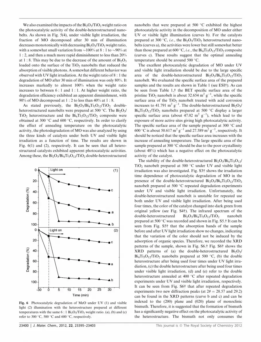
As stated previously, the Bi2O3/Bi4Ti3O12/TiO2 double-
heterostructured nanobelts were prepared at 500 �C. The Bi2O3/
TiO2 heterostructure and the Bi4Ti3O12/TiO2 composite were
obtained at 300 �C and 600 �C, respectively. In order to clarify
the effect of annealing temperature on the photocatalytic
activity, the photodegradation of MOwas also analyzed by using
the three kinds of catalysts under both UV and visible light
irradiation as a function of time. The results are shown in
Fig. 6(1) and (2), respectively. It can be seen that all hetero-
structured catalysts exhibited apparent photocatalytic activities.
Among these, the Bi2O3/Bi4Ti3O12/TiO2 double-heterostructured
Fig. 6 Photocatalytic degradation of MeO under UV (1) and visible
light (2) illumination with the heterostructure prepared at different
temperatures with the same 6 : 1 Bi2O3/TiO2 weight ratio. (a), (b) and (c)
refer to 300 �C, 500 �C and 600 �C, respectively.
23400 | J. Mater. Chem., 2012, 22, 23395–23403
nanobelts that were prepared at 500 �C exhibited the highest
photocatalytic activity in the decomposition of MO under either
UV or visible light illumination (curves b). For the catalysts
prepared at 300 �C, i.e., the Bi2O3/TiO2 heterostructured nano-
belts (curves a), the activities were lower but still somewhat better
than those prepared at 600 �C, i.e., the Bi4Ti3O12/TiO2 composite
(curves c). These results suggest that the optimal annealing
temperature should be around 500 �C.The excellent photocatalytic degradation of MO under UV
and visible light irradiation should be due to the large specific
area of the double-heterostructured Bi2O3/Bi4Ti3O12/TiO2
nanobelt. We evaluated the specific surface area of the prepared
samples and the results are shown in Table 1 (see ESI†). As can
be seen from Table 1,† the BET specific surface area of the
pristine TiO2 nanobelt is about 32.654 m2 g�1, while the specific
surface area of the TiO2 nanobelt treated with acid corrosion
increases to 41.791 m2 g�1. The double-heterostructured Bi2O3/
Bi4Ti3O12/TiO2 nanobelts prepared at 500 �C display a larger
specific surface area (about 47.02 m2 g�1), which lead to the
exposure of more active sites giving high photocatalytic activity.
The specific surface area of the sample prepared at 300 �C and
600 �C is about 50.617 m2 g�1 and 27.589 m2 g�1, respectively. It
should be noticed that the specific surface area increases with the
increase of annealing temperature. The large specific area of the
sample prepared at 300 �C should be due to the poor crystallinity
(about 48%) which has a negative effect on the photocatalytic
activity of the catalyst.
The stability of the double-heterostructured Bi2O3/Bi4Ti3O12/
TiO2 nanobelt prepared at 500 �C under UV and visible light
irradiation was also investigated. Fig. S3† shows the irradiation
time dependence of photocatalytic degradation of MO in the
presence of the double-heterostructured Bi2O3/Bi4Ti3O12/TiO2
nanobelt prepared at 500 �C repeated degradation experiments
under UV and visible light irradiation. Unfortunately, the
double-heterostructured nanobelt is unstable for repeated use
both under UV and visible light irradiation. After being used
four times, the color of the catalyst changed into dark green from
original yellow (see Fig. S4†). The infrared spectrum of the
double-heterostructured Bi2O3/Bi4Ti3O12/TiO2 nanobelt
prepared at 500 �C was recorded and shown in Fig. S5.† It can be
seen from Fig. S5† that the absorption bands of the sample
before and after UV light irradiation show no changes, indicating
that the variation of the color should not be induced by the
adsorption of organic species. Therefore, we recorded the XRD
patterns of the sample, shown in Fig. S6.† Fig. S6† shows the
XRD patterns of (a) the double-heterostructured Bi2O3/
Bi4Ti3O12/TiO2 nanobelts prepared at 500 �C, (b) the double
heterostructure after being used four times under UV light irra-
diation, (c) the double heterostructure after being used four times
under visible light irradiation, (d) and (e) refer to the double
heterostructure annealed at 400 �C after repeated degradation
experiments under UV and visible light irradiation, respectively.
It can be seen from Fig. S6† that after repeated degradation
experiments two new diffraction peaks (at 2q ¼ 28.57 and 29.2)
can be found in the XRD patterns (curve b and c) and can be
indexed to the (200) plane and (020) plane of monoclinic
bismuth. Therefore, it is suggested that the formation of bismuth
has a significantly negative effect on the photocatalytic activity of
the heterostructure. The bismuth not only consumes the
This journal is ª The Royal Society of Chemistry 2012

Fig. 8 Schematic diagrams for electron–hole pair separation under UV
(a) and visible light (b) irradiation and the band structure in the Bi2O3/
Bi4Ti3O12/TiO2 double heterostructure.
photoinduced electrons, but also inhabits the harvesting of light.
Fortunately, by annealing the dark green sample, the diffraction
peaks of monoclinic bismuth disappear (curve d and e). The
photocatalytic activity of the double heterostructure can be
recovered, shown in Fig. S7.† We also immersed the dark green
sample into hydrogen peroxide (30 wt%) and the photocatalytic
degradation efficiency can also be recovered. (curve c and d in
Fig. S7†).
In the above studies, the photocatalytic activity is closely
related to the dynamics of the separation and recombination of
photoinduced electrons and holes, which may impact the corre-
sponding photoluminescence (PL) characteristics. From Fig. 7, it
can be seen that at the excitation wavelength of 380 nm, acid-
treated TiO2 nanobelts displayed a strong and broad emission
peak at about 460 nm (curve a), and the emission intensity
significantly decreased with the loading of Bi2O3 onto the surface
of the TiO2 nanobelts (curve c). This may be because Bi2O3 and
Bi4Ti3O12 on TiO2 nanobelts acted as traps for the photoinduced
charge carriers.
The improved photocatalytic performance observed with the
Bi2O3/Bi4Ti3O12/TiO2 double-heterostructured nanobelts might
be explained by the band structure of the composite materials.
Note that the conduction and valence band positions can be
determined by using the following empirical equation,49,50
ECB ¼ X � Ee � 0.5 Eg (1)
where ECB denotes the conduction band edge potential, X the
geometric mean of the Mulliken electronegativity of the
constituent atoms, Ee the energy of free electrons on
the hydrogen scale (about 4.5 eV) and Eg the band gap. The X
values for TiO2, Bi2O3 and Bi4Ti3O12 are about 5.81 eV, 6.23 eV
and 4.12 eV, respectively,40 and the corresponding Eg values are
3.2 eV, 2.69 eV, and 2.76 eV. Thus, the positions of the
conduction band edge (ECB) at the point of zero charge are
estimated to be �0.29 eV, 0.38 eV, and�1.76 eV, respectively, as
illustrated in Fig. 8.
Under UV illumination (Fig. 8(a)), for TiO2 nanobelts alone,
the valence band electrons were excited to produce electron–
hole pairs which recombined rapidly. However, in the
Fig. 7 Photoluminescence (PL) spectra of prepared products: (a) TiO2
nanobelts, (b) Bi4Ti3O12 particles, (c) Bi2O3/Bi4Ti3O12/TiO2 double-
heterostructured nanobelts with 6 : 1 Bi2O3/TiO2 weight ratio at 500 �C,and (d) Bi2O3 powder.
This journal is ª The Royal Society of Chemistry 2012
double heterostructures, electrons in both the valence band of
TiO2 and Bi2O3 can be excited. The photoinduced holes then
flow into the valence band of the Bi4Ti3O12 layer, while the
electrons flow into the conduction bands of TiO2 and Bi2O3.
Meanwhile, the photogenerated electrons accumulate in the
conduction band of Bi2O3 and react with adsorbed oxygen
molecules to produce superoxide radical O2�, which generates
the hydroperoxy HO2_ radical through protonation and finally
produces OH_. Notably, it has been reported that Bi4Ti3O12 with
an orthorhombic symmetry consists of (Bi2O2)2+ layers and
(Bi2Ti3O10)2� units, and both of them can effectively separate
the electron–hole pairs.51 Holes in the valence band of Bi2O3
move into the valence band of Bi4Ti3O12 and disturb the charge
balance. Thus, electrons in the conduction band of Bi4Ti3O12
migrate to the closest conduction band of TiO2. With the
accumulation of valence holes of Bi2O3 and TiO2, free electrons
are produced in the conduction band of Bi4Ti3O12 (�1.76 eV)
and they tend to migrate into the adjacent conduction band of
TiO2 (�0.29 eV) rather than the lower conduction band of
Bi2O3 (0.38 eV). In addition, though the Bi4Ti3O12 interlayer did
not help increase the absorbance of light, it might play an
important role in improving the separation of photoinduced
electron–hole pairs from the (Bi2O2)2+ layers and (Bi2Ti3O10)
2�
particles. Moreover, the resistance to electron and hole trans-
port is very low due to the high crystallinity of the Bi4Ti3O12
phase. Consequently, efficient electron–hole separation
increases the lifetime of the charge carriers and enhances the
photocatalytic activity of the Bi2O3/Bi4Ti3O12/TiO2 double-
heterostructured nanobelts. The key steps of the photocatalytic
reactions may be summarized below.
J. Mater. Chem., 2012, 22, 23395–23403 | 23401
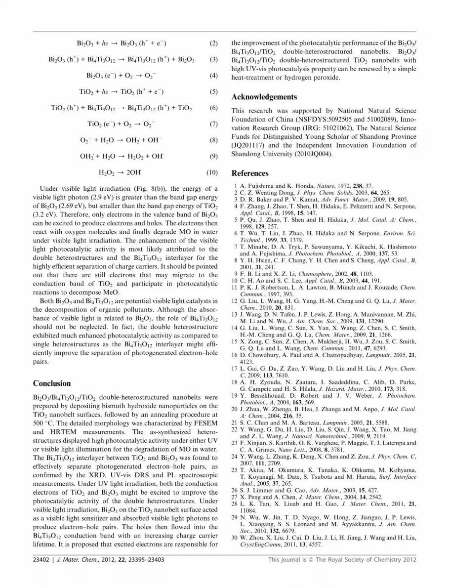
Bi2O3 + hy / Bi2O3 (h+ + e�) (2)
Bi2O3 (h+) + Bi4Ti3O12 / Bi4Ti3O12 (h
+) + Bi2O3 (3)
Bi2O3 (e�) + O2 / O2
� (4)
TiO2 + hy / TiO2 (h+ + e�) (5)
TiO2 (h+) + Bi4Ti3O12 / Bi4Ti3O12 (h
+) + TiO2 (6)
TiO2 (e�) + O2 / O2
� (7)
O2� + H2O / OH2_+ OH� (8)
OH2_+ H2O / H2O2 + OH_ (9)
H2O2 / 2OH_ (10)
Under visible light irradiation (Fig. 8(b)), the energy of a
visible light photon (2.9 eV) is greater than the band gap energy
of Bi2O3 (2.69 eV), but smaller than the band gap energy of TiO2
(3.2 eV). Therefore, only electrons in the valence band of Bi2O3
can be excited to produce electrons and holes. The electrons then
react with oxygen molecules and finally degrade MO in water
under visible light irradiation. The enhancement of the visible
light photocatalytic activity is most likely attributed to the
double heterostructures and the Bi4Ti3O12 interlayer for the
highly efficient separation of charge carriers. It should be pointed
out that there are still electrons that may migrate to the
conduction band of TiO2 and participate in photocatalytic
reactions to decompose MeO.
Both Bi2O3 and Bi4Ti3O12 are potential visible light catalysts in
the decomposition of organic pollutants. Although the absor-
bance of visible light is related to Bi2O3, the role of Bi4Ti3O12
should not be neglected. In fact, the double heterostructure
exhibited much enhanced photocatalytic activity as compared to
single heterostructures as the Bi4Ti3O12 interlayer might effi-
ciently improve the separation of photogenerated electron–hole
pairs.
Conclusion
Bi2O3/Bi4Ti3O12/TiO2 double-heterostructured nanobelts were
prepared by depositing bismuth hydroxide nanoparticles on the
TiO2 nanobelt surfaces, followed by an annealing procedure at
500 �C. The detailed morphology was characterized by FESEM
and HRTEM measurements. The as-synthesized hetero-
structures displayed high photocatalytic activity under either UV
or visible light illumination for the degradation of MO in water.
The Bi4Ti3O12 interlayer between TiO2 and Bi2O3 was found to
effectively separate photogenerated electron–hole pairs, as
confirmed by the XRD, UV-vis DRS and PL spectroscopic
measurements. Under UV light irradiation, both the conduction
electrons of TiO2 and Bi2O3 might be excited to improve the
photocatalytic activity of the double heterostructures. Under
visible light irradiation, Bi2O3 on the TiO2 nanobelt surface acted
as a visible light sensitizer and absorbed visible light photons to
produce electron–hole pairs. The holes then flowed into the
Bi4Ti3O12 conduction band with an increasing charge carrier
lifetime. It is proposed that excited electrons are responsible for
23402 | J. Mater. Chem., 2012, 22, 23395–23403
the improvement of the photocatalytic performance of the Bi2O3/
Bi4Ti3O12/TiO2 double-heterostructured nanobelts. Bi2O3/
Bi4Ti3O12/TiO2 double-heterostructured TiO2 nanobelts with
high UV-vis photocatalysis property can be renewed by a simple
heat-treatment or hydrogen peroxide.
Acknowledgements
This research was supported by National Natural Science
Foundation of China (NSFDYS:5092505 and 51002089), Inno-
vation Research Group (IRG: 51021062), The Natural Science
Funds for Distinguished Young Scholar of Shandong Province
(JQ201117) and the Independent Innovation Foundation of
Shandong University (2010JQ004).
References
1 A. Fujishima and K. Honda, Nature, 1972, 238, 37.2 C. Z. Wenting Dong, J. Phys. Chem. Solids, 2003, 64, 265.3 D. R. Baker and P. V. Kamat, Adv. Funct. Mater., 2009, 19, 805.4 F. Zhang, J. Zhao, T. Shen, H. Hidaka, E. Pelizzetti and N. Serpone,Appl. Catal., B, 1998, 15, 147.
5 P. Qu, J. Zhao, T. Shen and H. Hidaka, J. Mol. Catal. A: Chem.,1998, 129, 257.
6 T. Wu, T. Lin, J. Zhao, H. Hidaka and N. Serpone, Environ. Sci.Technol., 1999, 33, 1379.
7 T. Minabe, D. A. Tryk, P. Sawunyama, Y. Kikuchi, K. Hashimotoand A. Fujishima, J. Photochem. Photobiol., A, 2000, 137, 53.
8 Y. H. Hsien, C. F. Chang, Y. H. Chen and S. Cheng, Appl. Catal., B,2001, 31, 241.
9 F. B. Li and X. Z. Li, Chemosphere, 2002, 48, 1103.10 C. H. Ao and S. C. Lee, Appl. Catal., B, 2003, 44, 191.11 P. K. J. Robertson, L. A. Lawton, B. M€unch and J. Rouzade, Chem.
Commun., 1997, 393.12 G. Liu, L. Wang, H. G. Yang, H.-M. Cheng and G. Q. Lu, J. Mater.
Chem., 2010, 20, 831.13 J. Wang, D. N. Tafen, J. P. Lewis, Z. Hong, A. Manivannan, M. Zhi,
M. Li and N. Wu, J. Am. Chem. Soc., 2009, 131, 12290.14 G. Liu, L. Wang, C. Sun, X. Yan, X. Wang, Z. Chen, S. C. Smith,
H.-M. Cheng and G. Q. Lu, Chem. Mater., 2009, 21, 1266.15 X. Zong, C. Sun, Z. Chen, A. Mukherji, H. Wu, J. Zou, S. C. Smith,
G. Q. Lu and L. Wang, Chem. Commun., 2011, 47, 6293.16 D. Chowdhury, A. Paul and A. Chattopadhyay, Langmuir, 2005, 21,
4123.17 L. Gai, G. Du, Z. Zuo, Y. Wang, D. Liu and H. Liu, J. Phys. Chem.
C, 2009, 113, 7610.18 A. H. Zyouda, N. Zaatara, I. Saadeddina, C. Alib, D. Parkc,
G. Campetc and H. S. Hilala, J. Hazard. Mater., 2010, 173, 318.19 Y. Bessekhouad, D. Robert and J. V. Weber, J. Photochem.
Photobiol., A, 2004, 163, 569.20 J. Zhua, W. Zhenga, B. Hea, J. Zhanga and M. Anpo, J. Mol. Catal.
A: Chem., 2004, 216, 35.21 S. C. Chan and M. A. Barteau, Langmuir, 2005, 21, 5588.22 Y. Wang, G. Du, H. Liu, D. Liu, S. Qin, J. Wang, X. Tao, M. Jiang
and Z. L. Wang, J. Nanosci. Nanotechnol., 2009, 9, 2119.23 F. Xinjian, S. Karthik, O. K. Varghese, P. Maggie, T. J. Latempa and
C. A. Grimes, Nano Lett., 2008, 8, 3781.24 Y. Wang, L. Zhang, K. Deng, X. Chen and Z. Zou, J. Phys. Chem. C,
2007, 111, 2709.25 T. Akita, M. Okumura, K. Tanaka, K. Ohkuma, M. Kohyama,
T. Koyanagi, M. Date, S. Tsubota and M. Haruta, Surf. InterfaceAnal., 2005, 37, 265.
26 S. J. Limmer and G. Cao, Adv. Mater., 2003, 15, 427.27 X. Peng and A. Chen, J. Mater. Chem., 2004, 14, 2542.28 L. K. Tan, X. Liuab and H. Gao, J. Mater. Chem., 2011, 21,
11084.29 N. Wu, W. Jin, T. D. Nyago, W. Hong, Z. Jianguo, J. P. Lewis,
L. Xiaogang, S. S. Leonard and M. Ayyakkannu, J. Am. Chem.Soc., 2010, 132, 6679.
30 W. Zhou, X. Liu, J. Cui, D. Liu, J. Li, H. Jiang, J. Wang and H. Liu,CrystEngComm, 2011, 13, 4557.
This journal is ª The Royal Society of Chemistry 2012

31 W. Zhou, H. Liu, R. I. Boughton, G. Du, J. Lin, J. Wang and D. Liu,J. Mater. Chem., 2010, 20, 5993.
32 H. Jia, H. Xu, Y. Hu, Y. Tang and L. Zhang, Electrochem. Commun.,2007, 9, 354.
33 J. Cao, J.-Z. Sun, H.-Y. Li, J. Hong and M. Wang, J. Mater. Chem.,2004, 14, 1203.
34 D.Wang, H. Zhao, N. Q. Wu, M. A. E. Khakani and D.Ma, J. Phys.Chem. Lett., 2010, 1, 1030.
35 J.A. Seabold,K. Shankar,R.H.T.Wilke,M.Paulose,O.K.Varghese,C. A. Grimes and K.-S. Choi, Chem. Mater., 2008, 20, 5266.
36 M. Shang, W. Wang, L. Zhang, S. Sun, L. Wang and L. Zhou, J.Phys. Chem. C, 2009, 113, 14727.
37 W. Zhou, H. Liu, J. Wang, D. Liu, G. Du and J. Cui, ACS Appl.Mater. Interfaces, 2010, 2, 2385.
38 J. Lin, J. Shen, R. Wang, J. Cui, W. Zhou, P. Hu, D. Liu, H. Liu,J. Wang, R. I. Boughton and Y. Yue, J. Mater. Chem., 2011, 21, 5106.
39 W. Zhou, G. Du, P. Hu, G. Li, D. Wang, H. Liu, J. Wang,R. I. Boughton, D. Liu and H. Jiang, J. Mater. Chem., 2011, 21, 7937.
This journal is ª The Royal Society of Chemistry 2012
40 Y. Xu and M. A. A. Schoonen, Am. Mineral., 2000, 85, 543.41 L. Li and B. Yan, J. Non-Cryst. Solids, 2009, 355, 776.42 S. Shamaila, A. K. L. Sajjad, F. Chen and J. Zhang, Appl. Catal., B,
2010, 94, 272.43 M. Gui, W. Zhang, Q. Su and C. Chen, J. Solid State Chem., 2011,
184, 1977.44 H. Zhang,M. L€u, S. Liu, L.Wang, Z. Xiu, Y. Zhou, Z. Qiu, A. Zhang
and Q. Ma, Mater. Chem. Phys., 2009, 114, 716.45 W. F. Yao, X. H. Xu, H. Wang, J. T. Zhou, X. N. Yang, Y. Zhang,
S. X. Shang and B. B. Huang, Appl. Catal., B, 2004, 52, 109.46 N. Mochida and J. Takahashi, J. Ceram. Soc. Jpn., 1976, 84, 413.47 E. P. Meagher and G. A. Lager, Can. Mineral., 1979, 77.48 E. C. Subbarao, Phys. Rev., 1961, 122, 804.49 A. H. Nethercot Jr, Phys. Rev. Lett., 1974, 33, 1088.50 X. P. Lin, F. Q. Huang, W. D. Wang and K. L. Zhang, Appl. Catal.,
A, 2006, 307, 257.51 W. Wei, Y. Dai and B. Huang, J. Phys. Chem. C, 2009, 113,
5658.
J. Mater. Chem., 2012, 22, 23395–23403 | 23403