gps autosteer system installation manual - terre-net
TRANSCRIPT
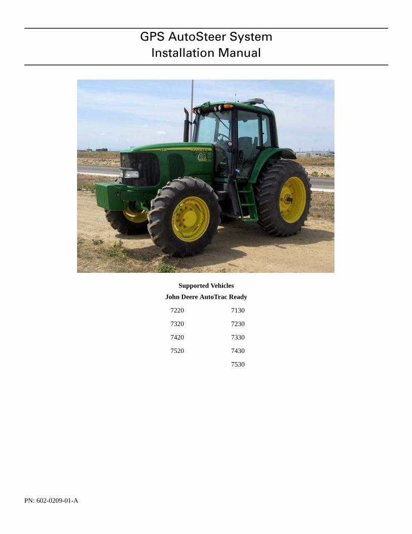
GPS AutoSteer SystemInstallation Manual
Supported Vehicles
PN: 602-0209-01-A
John Deere AutoTrac Ready
7220 7130
7320 7230
7420 7330
7520 7430
7530
LEGAL DISCLAIMER
Note: Read and follow ALL instructions in this manual carefully before installing or operating the AutoSteer system.
Note: Take careful note of the safety information in the Safety Information section and throughout this manual.
The manufacturer disclaims any liability for damage or injury that results from failure to follow the instructions and warnings set forth herein.
Please take special note of the following warnings:
1. There is NO obstacle avoidance system included in the manufacturer’s product. Therefore, users must always have an operator on the equipment when the AutoSteer system is in use to look for any obstacles including people, animals, trees, ditches, buildings, etc.
2. During installation of the AutoSteer system and during the Calibration and Tuning processes the vehicle's wheels turn from side to side and the vehicle moves. Be sure that all people and obstacles are clear of the vehicle before installation, calibra-tion and tuning, or use of the AutoSteer system.
3. Use of the AutoSteer system is NOT permitted while the vehicle is on public roads or in public areas. Ensure that the sys-tem is OFF before driving on roads or in public areas.
ii AutoSteer System
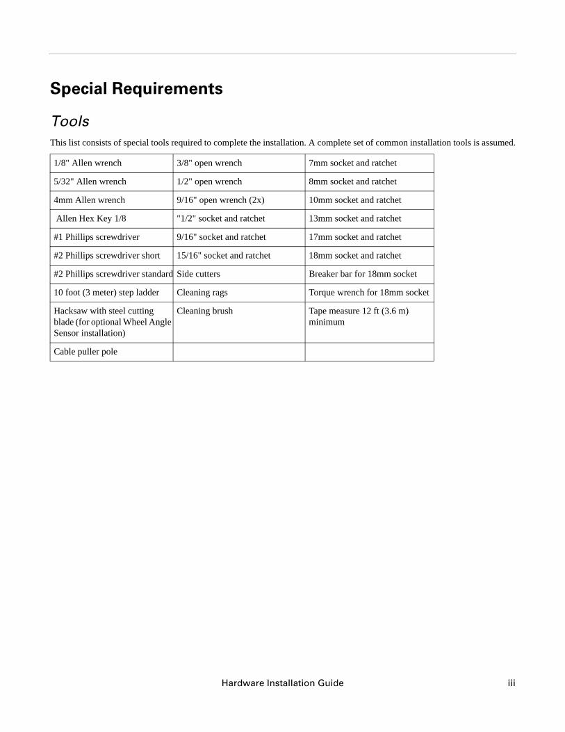
Special Requirements
ToolsThis list consists of special tools required to complete the installation. A complete set of common installation tools is assumed.
1/8" Allen wrench 3/8" open wrench 7mm socket and ratchet
5/32" Allen wrench 1/2" open wrench 8mm socket and ratchet
4mm Allen wrench 9/16" open wrench (2x) 10mm socket and ratchet
Allen Hex Key 1/8 "1/2" socket and ratchet 13mm socket and ratchet
#1 Phillips screwdriver 9/16" socket and ratchet 17mm socket and ratchet
#2 Phillips screwdriver short 15/16" socket and ratchet 18mm socket and ratchet
#2 Phillips screwdriver standard Side cutters Breaker bar for 18mm socket
10 foot (3 meter) step ladder Cleaning rags Torque wrench for 18mm socket
Hacksaw with steel cutting blade (for optional Wheel Angle Sensor installation)
Cleaning brush Tape measure 12 ft (3.6 m) minimum
Cable puller pole
Hardware Installation Guide iii
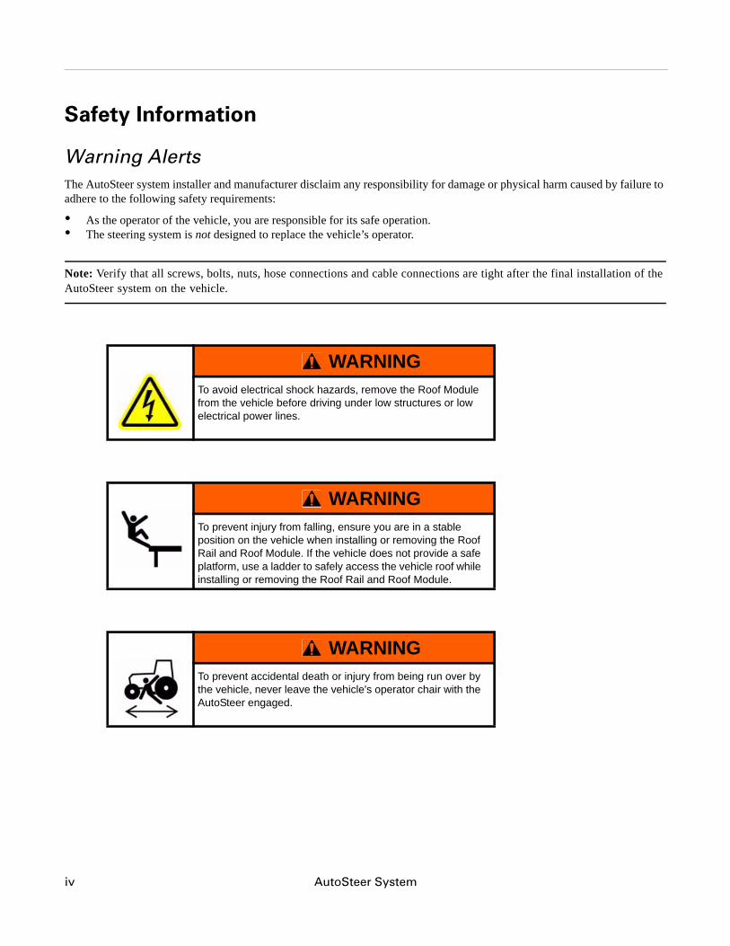
Safety Information
Warning AlertsThe AutoSteer system installer and manufacturer disclaim any responsibility for damage or physical harm caused by failure to adhere to the following safety requirements:
• As the operator of the vehicle, you are responsible for its safe operation.• The steering system is not designed to replace the vehicle’s operator.
Note: Verify that all screws, bolts, nuts, hose connections and cable connections are tight after the final installation of the AutoSteer system on the vehicle.
WARNINGTo avoid electrical shock hazards, remove the Roof Module from the vehicle before driving under low structures or low electrical power lines.
WARNINGTo prevent injury from falling, ensure you are in a stable position on the vehicle when installing or removing the Roof Rail and Roof Module. If the vehicle does not provide a safe platform, use a ladder to safely access the vehicle roof while installing or removing the Roof Rail and Roof Module.
WARNINGTo prevent accidental death or injury from being run over by the vehicle, never leave the vehicle's operator chair with the AutoSteer engaged.
iv AutoSteer System
WARNINGTo understand the potential hazards associated with the operation of AutoSteer equipment read the provided documentation before installing the AutoSteer system on a vehicle.
WARNINGTo prevent the accidental engagement of AutoSteer and loss of vehicle control while driving on roads, shut down the AutoSteer system (exit the program). Never drive on roads or in public areas with the AutoSteer system turned on.
Hardware Installation Guide v
Caution AlertsThe AutoSteer system installer and manufacturer disclaim any responsibility for damage or physical harm caused by failure to adhere to the following safety requirements:
CAUTIONThe Roof Module must be removed when transporting or driving the vehicle at speeds above 30 mph (48 km/h). The Roof Module can possibly detach due to wind loads at higher speeds.
CAUTIONThe AutoSteer system does not detect obstacles in the vehicle’s path. The operator must observe the path being driven in order to avoid obstacles.
CAUTIONWhen engaged, the AutoSteer system controls only the steering of the vehicle. The operator must control the speed of the vehicle.
CAUTIONThe AutoSteer system must be powered OFF when installing or removing the Roof Module.
vi AutoSteer System
Vehicle RequirementsThe vehicle must be AutoTrac1 ready with the factory installed steering valve, kingpin sensor, and steering wheel encoders installed.
The vehicle’s steering system must be in good working order before installing the AutoSteer system. Check for loose or worn parts. Drive the vehicle before installing the AutoSteer system and confirm that it steers straight and the wheels can be turned from lock to lock.
The vehicle’s electrical system and battery must be in good working order.
This installation kit is for an AutoTrac ready vehicle. If the vehicle is not AutoTrac ready, a different installation kit is required. Contact your AutoSteer dealer for the correct installation kit.
We recommend that the vehicle be fully cleaned before installing the AutoSteer system. A clean vehicle will facilitate the overall installation and cable routing.
CAUTIONThe Roof Module must always be firmly secured to the Roof Rail using the hardware whenever the vehicle is in operation to prevent the Roof Module from releasing from its bracket and falling.
1. AutoTrac is a trademark of Deere & Company
Hardware Installation Guide vii
Important InformationAfter the installation is complete, verify that all screws, bolts, nuts, and cable connections are tight. Before operating the system go through the final check list to ensure that all components have been installed and installed properly.
Technical SupportRefer to your display user manual for technical support information.
Contact InformationRefer to your display user manual for contact information.
Copyright © 2009 All Rights Reserved.
viii AutoSteer System
Table of Contents
Chapter 1 Installation Overview .......................................................................................................1Installation Kit Overview . . . . . . . . . . . . . . . . . . . . . . . . . . . . . . . . . . . . . . . . . . . . . . . . . . . . . 2
AutoTrac Installation Kit Components . . . . . . . . . . . . . . . . . . . . . . . . . . . . . . . . . . . . . . . . . 3Bracket Kit Components . . . . . . . . . . . . . . . . . . . . . . . . . . . . . . . . . . . . . . . . . . . . . . . . . . . . 4
Installation Procedure Outline . . . . . . . . . . . . . . . . . . . . . . . . . . . . . . . . . . . . . . . . . . . . . . . . . . 6Cable Diagram JD 7X20 . . . . . . . . . . . . . . . . . . . . . . . . . . . . . . . . . . . . . . . . . . . . . . . . . . . . . . 8Cable Diagram JD 7X30 . . . . . . . . . . . . . . . . . . . . . . . . . . . . . . . . . . . . . . . . . . . . . . . . . . . . . . 9
Chapter 2 Wheel Angle Sensor (WAS) Installation.......................................................................11Identify the Front Axle Type on the Vehicle . . . . . . . . . . . . . . . . . . . . . . . . . . . . . . . . . . . . . 12Installing Mounting Brackets on the Left Side . . . . . . . . . . . . . . . . . . . . . . . . . . . . . . . . . . . . 13Installing Brackets on the Right Side. . . . . . . . . . . . . . . . . . . . . . . . . . . . . . . . . . . . . . . . . . . . 15Cut the Wheel Angle Sensor Rods to Length . . . . . . . . . . . . . . . . . . . . . . . . . . . . . . . . . . . . . 18Assemble the Linkage Rod Hardware . . . . . . . . . . . . . . . . . . . . . . . . . . . . . . . . . . . . . . . . . . . 20Attach the Wheel Angle Sensor Rods to Brackets and Adjust . . . . . . . . . . . . . . . . . . . . . . . . 22
Chapter 3 SA Module Installation ..................................................................................................29SA Module Mounting Orientation . . . . . . . . . . . . . . . . . . . . . . . . . . . . . . . . . . . . . . . . . . . . . . 29Mount the SA Module . . . . . . . . . . . . . . . . . . . . . . . . . . . . . . . . . . . . . . . . . . . . . . . . . . . . . . . 30
Chapter 4 Roof Module Installation................................................................................................35Safety Notes . . . . . . . . . . . . . . . . . . . . . . . . . . . . . . . . . . . . . . . . . . . . . . . . . . . . . . . . . . . . . . . 35Roof Rail Installation . . . . . . . . . . . . . . . . . . . . . . . . . . . . . . . . . . . . . . . . . . . . . . . . . . . . . . . 36
Chapter 5 Display Installation.........................................................................................................41Introduction . . . . . . . . . . . . . . . . . . . . . . . . . . . . . . . . . . . . . . . . . . . . . . . . . . . . . . . . . . . . . . . 41Installation Procedure . . . . . . . . . . . . . . . . . . . . . . . . . . . . . . . . . . . . . . . . . . . . . . . . . . . . . . . 41
Chapter 6 Connecting System Cables............................................................................................45SA Module Harness . . . . . . . . . . . . . . . . . . . . . . . . . . . . . . . . . . . . . . . . . . . . . . . . . . . . . . . . . 45AutoTrac Valve Connections. . . . . . . . . . . . . . . . . . . . . . . . . . . . . . . . . . . . . . . . . . . . . . . . . . 46Wheel Angle Sensor Connection (Optional) . . . . . . . . . . . . . . . . . . . . . . . . . . . . . . . . . . . . . . 47
Optional AutoSteer Wheel Angle Sensor . . . . . . . . . . . . . . . . . . . . . . . . . . . . . . . . . . . . . . 49Steering Wheel Encoder Sensor Connection . . . . . . . . . . . . . . . . . . . . . . . . . . . . . . . . . . . . . . 53Main Cable Harness . . . . . . . . . . . . . . . . . . . . . . . . . . . . . . . . . . . . . . . . . . . . . . . . . . . . . . . . 69
Roof Module . . . . . . . . . . . . . . . . . . . . . . . . . . . . . . . . . . . . . . . . . . . . . . . . . . . . . . . . . . . . 69SA Module Harness . . . . . . . . . . . . . . . . . . . . . . . . . . . . . . . . . . . . . . . . . . . . . . . . . . . . . . . 71
Power Supply Connection . . . . . . . . . . . . . . . . . . . . . . . . . . . . . . . . . . . . . . . . . . . . . . . . . . . . 74Cab Power Connection . . . . . . . . . . . . . . . . . . . . . . . . . . . . . . . . . . . . . . . . . . . . . . . . . . . . 75Battery Power Connection. . . . . . . . . . . . . . . . . . . . . . . . . . . . . . . . . . . . . . . . . . . . . . . . . . 75
Chapter 7 Calibration and Tuning Notes .......................................................................................77Vehicle Specific Installation Calibration and Tuning Guidelines . . . . . . . . . . . . . . . . . . . . . . 77
Chapter 8 Final Hardware Installation Checklist ...........................................................................79
Hardware Installation Guide ix

x AutoSteer System
Hardware Installation Guide
1Installation Overview
This Installation Overview chapter contains part numbers, kit overview diagram, cabling diagram and the installation procedure for the Installation Kit.
• Installation Kit Overview • AutoTrac Installation Kit Components
• AutoTrac Installation Kit Components • Bracket Kit Components • Termination Kit
• Installation Procedure Outline • Cable Diagram JD 7X20
The kit overview provides diagrams and kit and component part numbers for the AutoSteer installation kit PN 188-0019-01.
This AutoSteer installation kit and manual will work on several series and models of John Deere vehicles. These vehicles include:
• 7X20 Small Frame AutoTrac Ready MFWD series (7220, 7320, 7420, and 7520)• 7X30 Small Frame AutoTrac Ready MFWD series (7130, 7230, 7330, 7430, and 7530)
Note: If you are installing an electric steering wheel actuator such as OnTrac II, skip the Steering Valve, SA Module, and SA Module Harness installation information in this book and refer to your electric steering product manual for further instructions.
1
Installation Overview
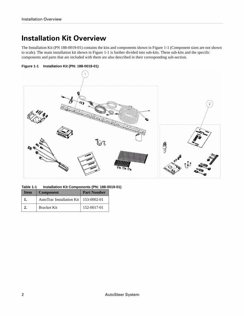
Installation Kit OverviewThe Installation Kit (PN 188-0019-01) contains the kits and components shown in Figure 1-1 (Component sizes are not shown to scale). The main installation kit shown in Figure 1-1 is further divided into sub-kits. These sub-kits and the specific components and parts that are included with them are also described in their corresponding sub-section.
Figure 1-1 Installation Kit (PN: 188-0019-01)
Table 1-1 Installation Kit Components (PN: 188-0019-01)Item Component Part Number
1. AutoTrac Installation Kit 153-0002-01
2. Bracket Kit 152-0017-01
2 AutoSteer System
Installation Overview
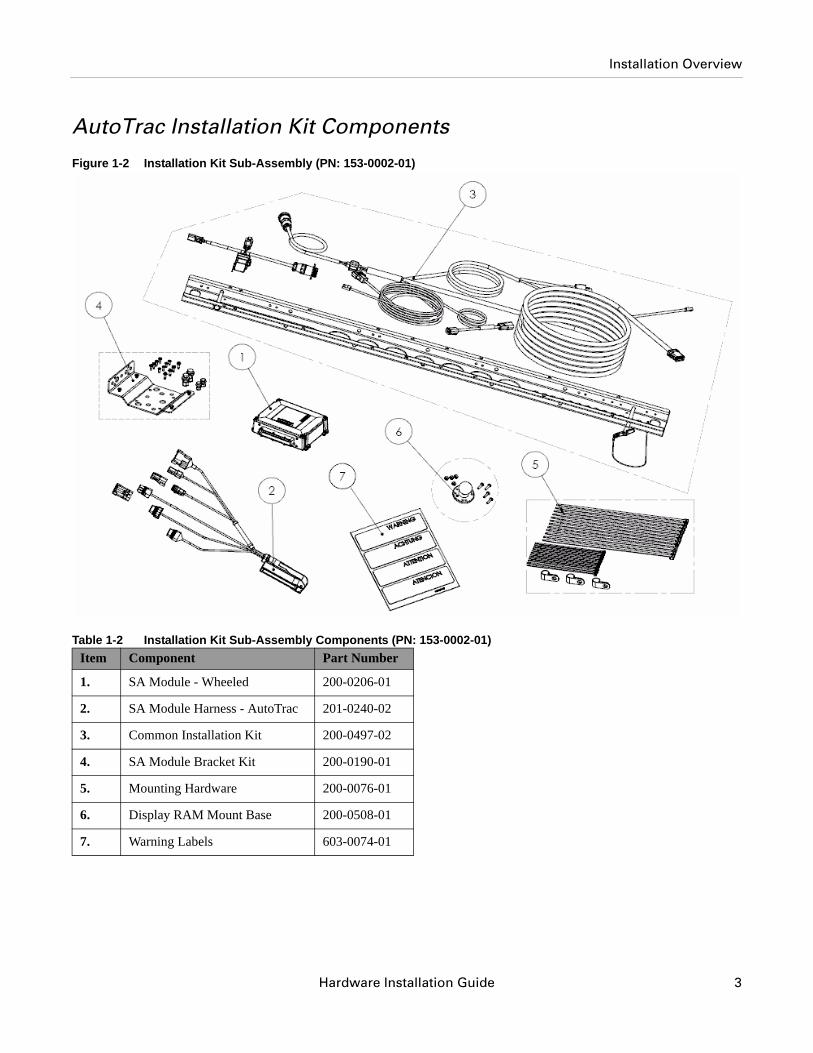
AutoTrac Installation Kit ComponentsFigure 1-2 Installation Kit Sub-Assembly (PN: 153-0002-01)
Table 1-2 Installation Kit Sub-Assembly Components (PN: 153-0002-01)Item Component Part Number
1. SA Module - Wheeled 200-0206-01
2. SA Module Harness - AutoTrac 201-0240-02
3. Common Installation Kit 200-0497-02
4. SA Module Bracket Kit 200-0190-01
5. Mounting Hardware 200-0076-01
6. Display RAM Mount Base 200-0508-01
7. Warning Labels 603-0074-01
Hardware Installation Guide 3
Installation Overview
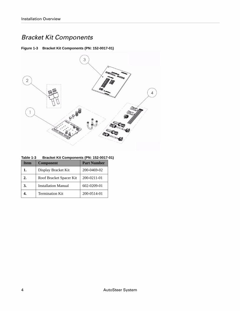
Bracket Kit ComponentsFigure 1-3 Bracket Kit Components (PN: 152-0017-01)
Table 1-3 Bracket Kit Components (PN: 152-0017-01)Item Component Part Number
1. Display Bracket Kit 200-0469-02
2. Roof Bracket Spacer Kit 200-0211-01
3. Installation Manual 602-0209-01
4. Termination Kit 200-0514-01
4 AutoSteer System
Installation Overview
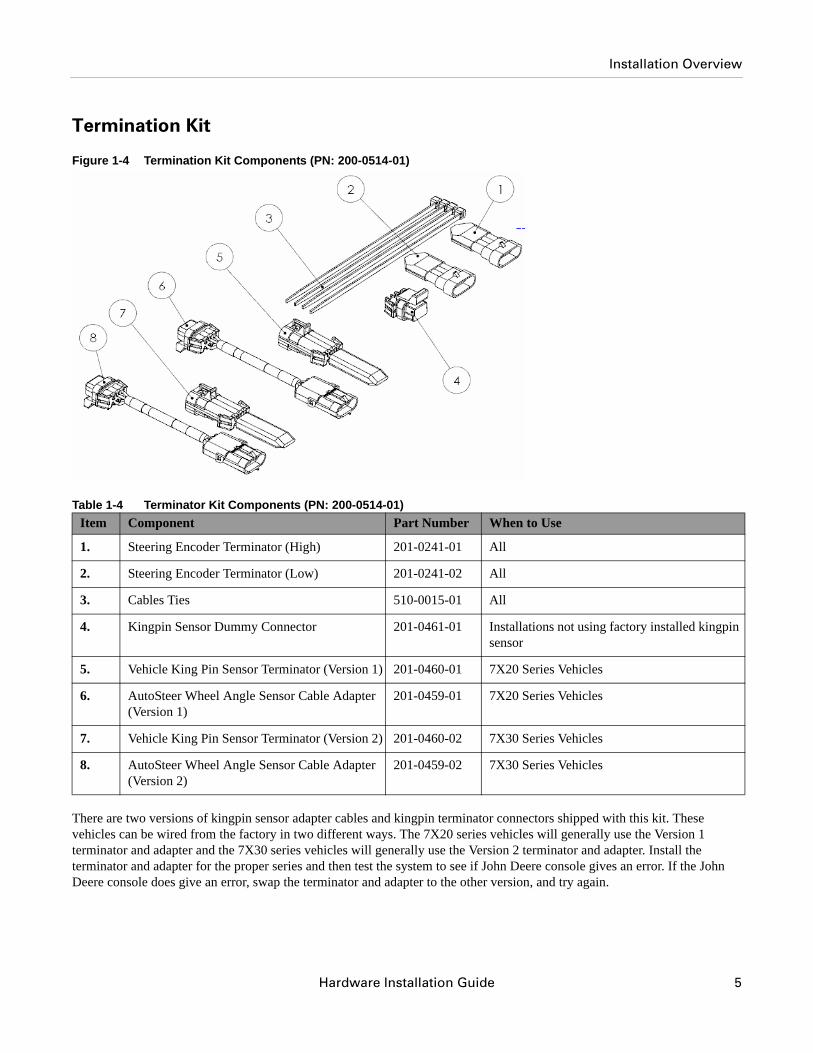
Termination Kit
Figure 1-4 Termination Kit Components (PN: 200-0514-01)
Table 1-4 Terminator Kit Components (PN: 200-0514-01)
There are two versions of kingpin sensor adapter cables and kingpin terminator connectors shipped with this kit. These vehicles can be wired from the factory in two different ways. The 7X20 series vehicles will generally use the Version 1 terminator and adapter and the 7X30 series vehicles will generally use the Version 2 terminator and adapter. Install the terminator and adapter for the proper series and then test the system to see if John Deere console gives an error. If the John Deere console does give an error, swap the terminator and adapter to the other version, and try again.
Item Component Part Number When to Use
1. Steering Encoder Terminator (High) 201-0241-01 All
2. Steering Encoder Terminator (Low) 201-0241-02 All
3. Cables Ties 510-0015-01 All
4. Kingpin Sensor Dummy Connector 201-0461-01 Installations not using factory installed kingpin sensor
5. Vehicle King Pin Sensor Terminator (Version 1) 201-0460-01 7X20 Series Vehicles
6. AutoSteer Wheel Angle Sensor Cable Adapter (Version 1)
201-0459-01 7X20 Series Vehicles
7. Vehicle King Pin Sensor Terminator (Version 2) 201-0460-02 7X30 Series Vehicles
8. AutoSteer Wheel Angle Sensor Cable Adapter (Version 2)
201-0459-02 7X30 Series Vehicles
Hardware Installation Guide 5
Installation Procedure Outline
Kingpin Sensor Terminator Test1. Install the appropriate version of the kingpin sensor terminator for your vehicle series.
2. Start the vehicle.
3. Check the vehicle's information screen (not the AutoSteer Display) for an error message about the Wheel Angle Sensor.
4. If there is an error, shut down the vehicle, install the other version of terminator, and then repeat the test to see if an error appears.
5. If no error shows up, the correct kingpin sensor terminator has been installed.
AutoSteer Wheel Angle Sensor Adapter
Note: This test must be performed after the entire system, including the Roof Module and Display, has been installed.
1. Install the same version AutoSteer Wheel Angle Sensor adapter as the version of the kingpin sensor terminator that worked.
2. Start the vehicle and AutoSteer system.
3. Follow the instructions in the Display user manual to navigate to the Vehicle window from the AutoSteer Setup screen.
4. Select the Steering Components, and then select Wheel Angle Sensor.
5. Manually turn the steering wheel and observe the Wheel Angle Sensor counts.
6. If the counts do not increase or decrease as the steering wheel is turned, the wrong version has been installed. Replace it with the other one and then retest.
Installation Procedure Outline1. Verify that all the components have been shipped.
Note: Steps 2, 3, 6, 8, and 9 are skipped if installing an electric steering actuator.
2. Install the AutoSteer Wheel Angle Sensor (optional)
3. Install the SA Module.
4. Install the Roof Rail on the cab roof.
5. Install the Roof Module on the Roof Module.
6. Install the SA Module Harness and route cables to the various sensors.
7. Install the Display mounting bracket and RAM mount ball inside the cab
8. Install the SA Module Harness
9. Install the AutoTrac terminators.
10. Install the Display using the RAM mount arm.
6 AutoSteer System
Installation Procedure Outline
11. Install the Main Cable Harness harness.
Note: Instructions installing the Display and for connecting the vehicle's installation kit cables to the Display's cables can be found in the display user manual.
12. Verify all connectors are properly coupled and secured.
13. Power ON the AutoSteer system.
14. Calibrate the vehicle.
15. Tune the vehicle if necessary.
16. Verify the system has been installed properly and operates satisfactorily.
Hardware Installation Guide 7
Installation Procedure Outline
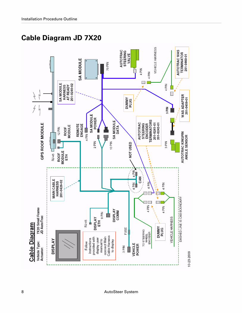
Cable Diagram JD 7X20
8 AutoSteer System
Installation Procedure Outline
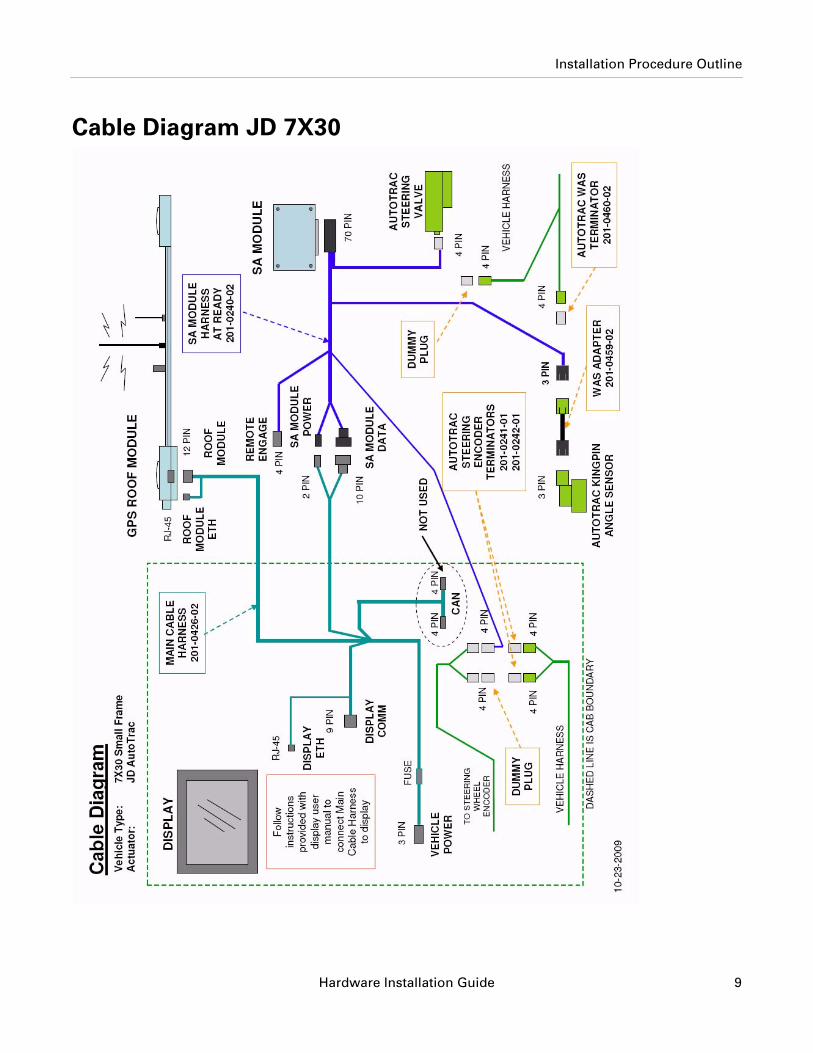
Cable Diagram JD 7X30
Hardware Installation Guide 9

Installation Procedure Outline
10 AutoSteer System
Hardware Installation Guide
2Wheel Angle Sensor (WAS) Installation
This Wheel Angle Sensor Installation chapter information is provided in the following sections:
• Identify the Front Axle Type on the Vehicle • Installing Mounting Brackets on the Left Side • Installing Brackets on the Right Side• Cut the Wheel Angle Sensor Rods to Length• Assemble the Linkage Rod Hardware• Attach the Wheel Angle Sensor Rods to Brackets and Adjust
Note: The Wheel Angle Sensor is optional equipment and is not provided with the installation kit. The Wheel Angle Sensor installation instructions are provided for special installations, when required.
11
Wheel Angle Sensor (WAS) Installation
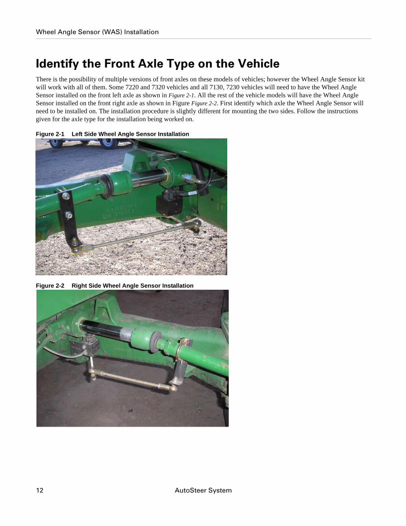
Identify the Front Axle Type on the VehicleThere is the possibility of multiple versions of front axles on these models of vehicles; however the Wheel Angle Sensor kit will work with all of them. Some 7220 and 7320 vehicles and all 7130, 7230 vehicles will need to have the Wheel Angle Sensor installed on the front left axle as shown in Figure 2-1. All the rest of the vehicle models will have the Wheel Angle Sensor installed on the front right axle as shown in Figure Figure 2-2. First identify which axle the Wheel Angle Sensor will need to be installed on. The installation procedure is slightly different for mounting the two sides. Follow the instructions given for the axle type for the installation being worked on.
Figure 2-1 Left Side Wheel Angle Sensor Installation
Figure 2-2 Right Side Wheel Angle Sensor Installation
12 AutoSteer System
Installing Mounting Brackets on the Left Side
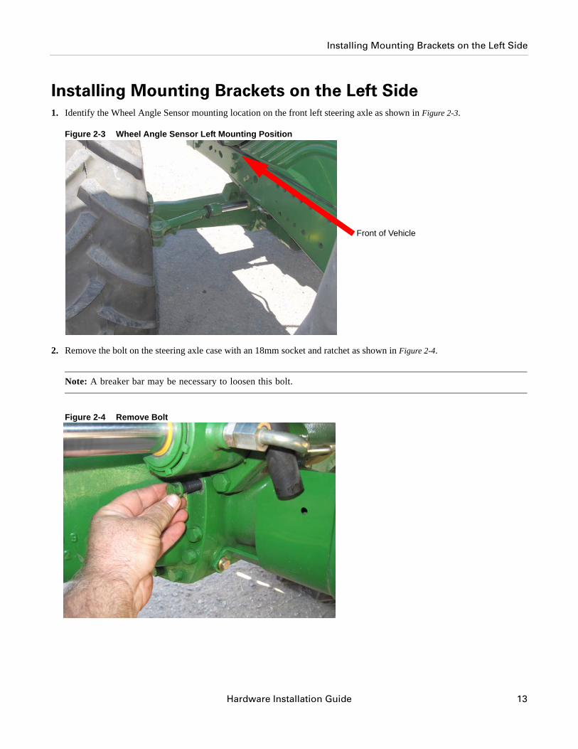
Installing Mounting Brackets on the Left Side1. Identify the Wheel Angle Sensor mounting location on the front left steering axle as shown in Figure 2-3.
Figure 2-3 Wheel Angle Sensor Left Mounting Position
2. Remove the bolt on the steering axle case with an 18mm socket and ratchet as shown in Figure 2-4.
Note: A breaker bar may be necessary to loosen this bolt.
Figure 2-4 Remove Bolt
Front of Vehicle
Hardware Installation Guide 13
Installing Mounting Brackets on the Left Side
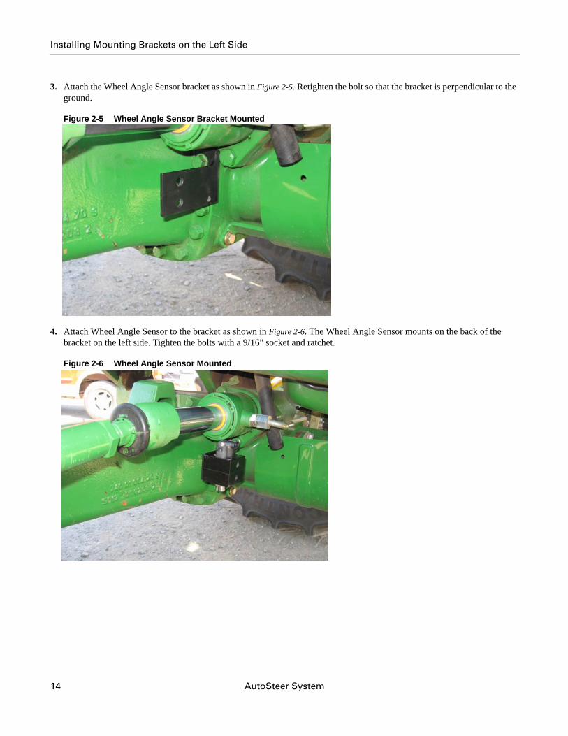
3. Attach the Wheel Angle Sensor bracket as shown in Figure 2-5. Retighten the bolt so that the bracket is perpendicular to the ground.
Figure 2-5 Wheel Angle Sensor Bracket Mounted
4. Attach Wheel Angle Sensor to the bracket as shown in Figure 2-6. The Wheel Angle Sensor mounts on the back of the bracket on the left side. Tighten the bolts with a 9/16" socket and ratchet.
Figure 2-6 Wheel Angle Sensor Mounted
14 AutoSteer System
Installing Brackets on the Right Side
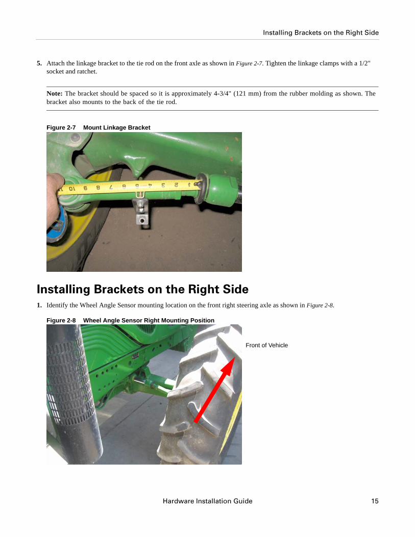
5. Attach the linkage bracket to the tie rod on the front axle as shown in Figure 2-7. Tighten the linkage clamps with a 1/2" socket and ratchet.
Note: The bracket should be spaced so it is approximately 4-3/4" (121 mm) from the rubber molding as shown. The bracket also mounts to the back of the tie rod.
Figure 2-7 Mount Linkage Bracket
Installing Brackets on the Right Side1. Identify the Wheel Angle Sensor mounting location on the front right steering axle as shown in Figure 2-8.
Figure 2-8 Wheel Angle Sensor Right Mounting Position
Front of Vehicle
Hardware Installation Guide 15
Installing Brackets on the Right Side
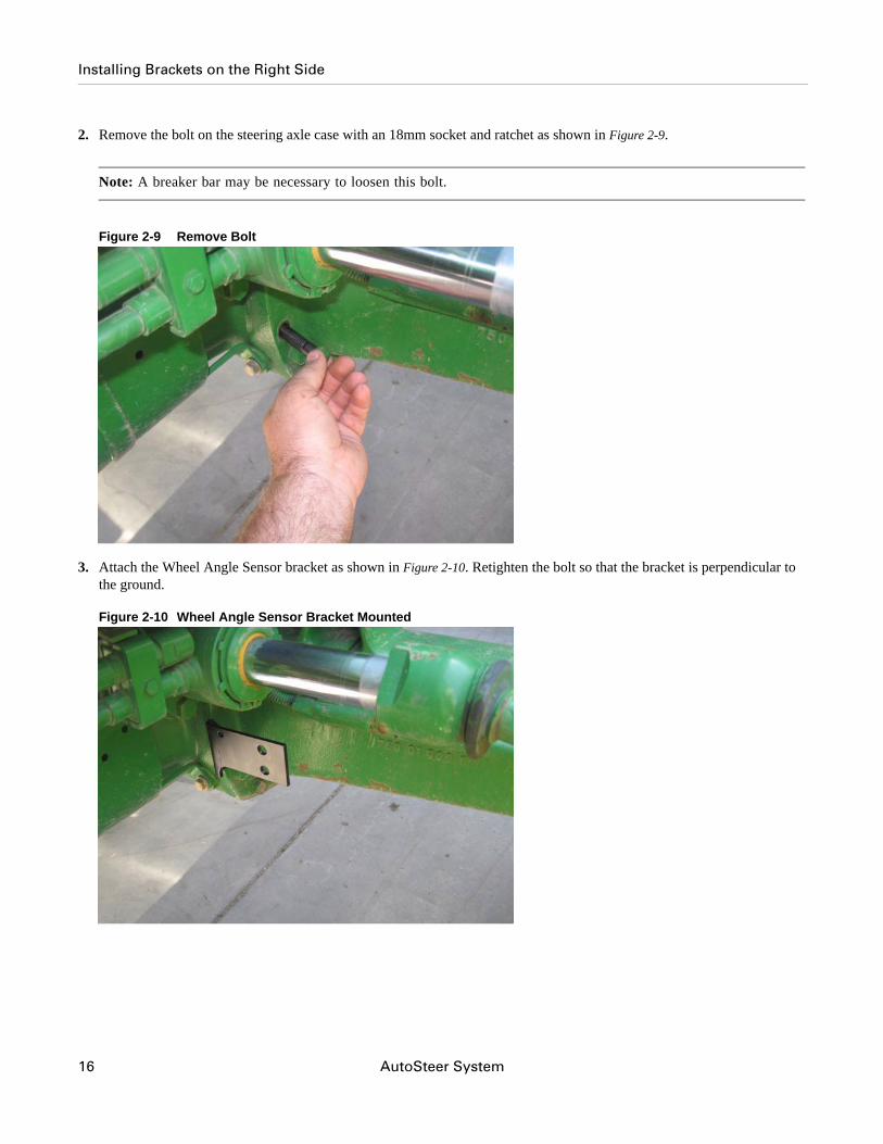
2. Remove the bolt on the steering axle case with an 18mm socket and ratchet as shown in Figure 2-9.
Note: A breaker bar may be necessary to loosen this bolt.
Figure 2-9 Remove Bolt
3. Attach the Wheel Angle Sensor bracket as shown in Figure 2-10. Retighten the bolt so that the bracket is perpendicular to the ground.
Figure 2-10 Wheel Angle Sensor Bracket Mounted
16 AutoSteer System
Installing Brackets on the Right Side
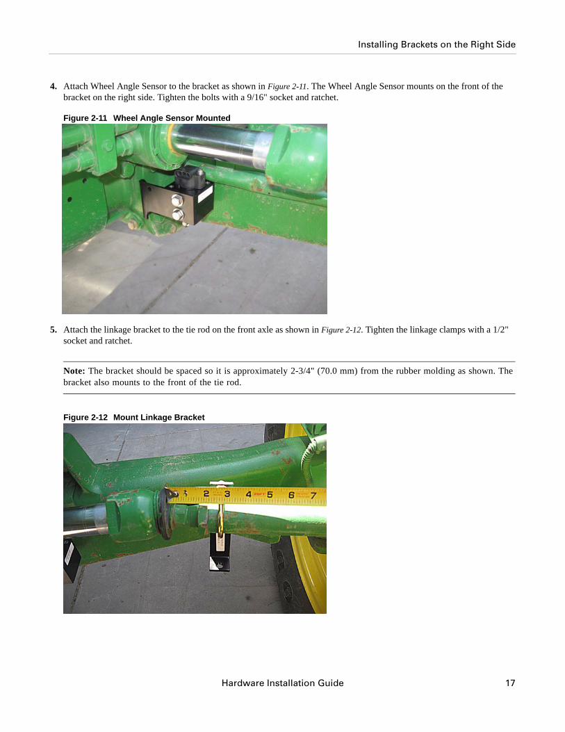
4. Attach Wheel Angle Sensor to the bracket as shown in Figure 2-11. The Wheel Angle Sensor mounts on the front of the bracket on the right side. Tighten the bolts with a 9/16" socket and ratchet.
Figure 2-11 Wheel Angle Sensor Mounted
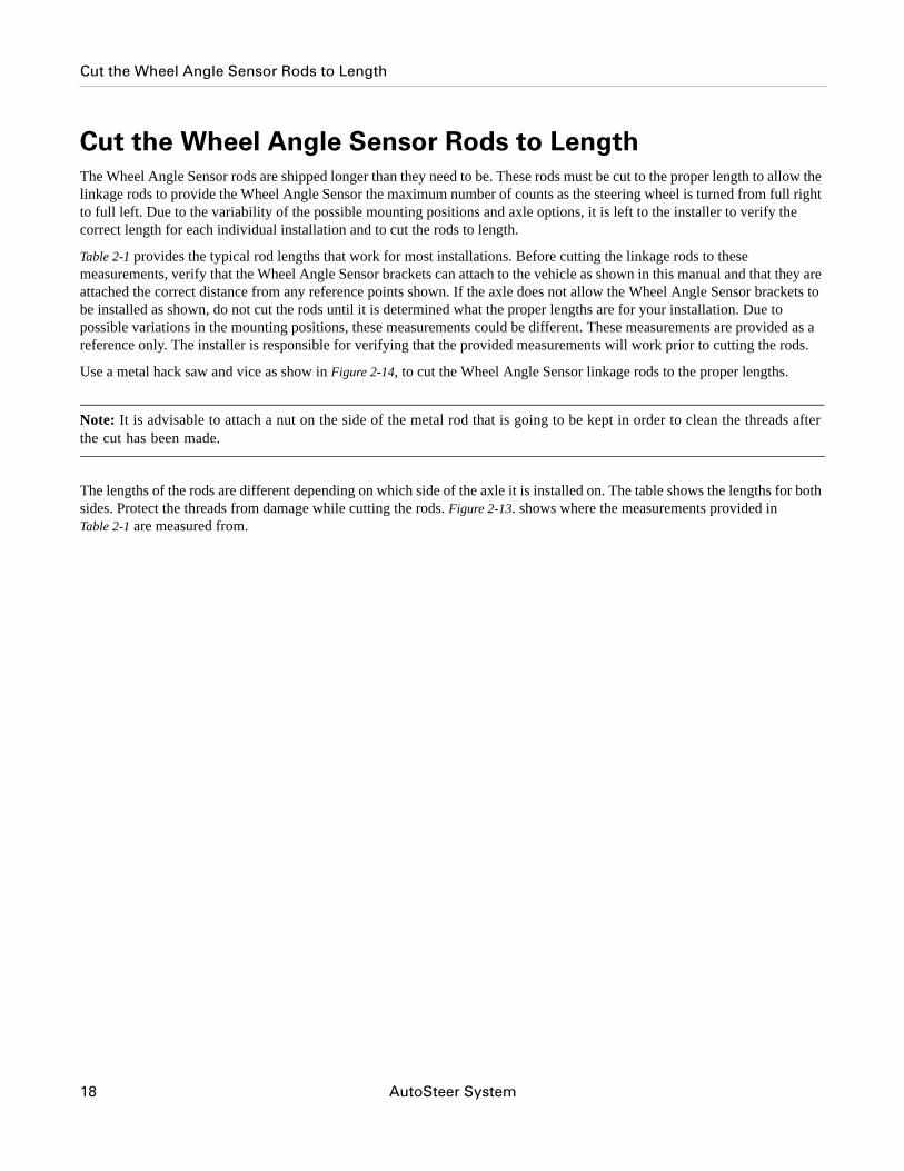
5. Attach the linkage bracket to the tie rod on the front axle as shown in Figure 2-12. Tighten the linkage clamps with a 1/2" socket and ratchet.
Note: The bracket should be spaced so it is approximately 2-3/4" (70.0 mm) from the rubber molding as shown. The bracket also mounts to the front of the tie rod.
Figure 2-12 Mount Linkage Bracket
Hardware Installation Guide 17
Cut the Wheel Angle Sensor Rods to Length
Cut the Wheel Angle Sensor Rods to LengthThe Wheel Angle Sensor rods are shipped longer than they need to be. These rods must be cut to the proper length to allow the linkage rods to provide the Wheel Angle Sensor the maximum number of counts as the steering wheel is turned from full right to full left. Due to the variability of the possible mounting positions and axle options, it is left to the installer to verify the correct length for each individual installation and to cut the rods to length.
Table 2-1 provides the typical rod lengths that work for most installations. Before cutting the linkage rods to these measurements, verify that the Wheel Angle Sensor brackets can attach to the vehicle as shown in this manual and that they are attached the correct distance from any reference points shown. If the axle does not allow the Wheel Angle Sensor brackets to be installed as shown, do not cut the rods until it is determined what the proper lengths are for your installation. Due to possible variations in the mounting positions, these measurements could be different. These measurements are provided as a reference only. The installer is responsible for verifying that the provided measurements will work prior to cutting the rods.
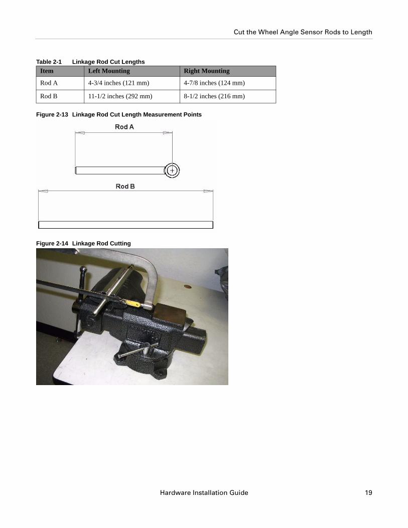
Use a metal hack saw and vice as show in Figure 2-14, to cut the Wheel Angle Sensor linkage rods to the proper lengths.
Note: It is advisable to attach a nut on the side of the metal rod that is going to be kept in order to clean the threads after the cut has been made.
The lengths of the rods are different depending on which side of the axle it is installed on. The table shows the lengths for both sides. Protect the threads from damage while cutting the rods. Figure 2-13. shows where the measurements provided in Table 2-1 are measured from.
18 AutoSteer System
Cut the Wheel Angle Sensor Rods to Length
Table 2-1 Linkage Rod Cut Lengths
Figure 2-13 Linkage Rod Cut Length Measurement Points
Figure 2-14 Linkage Rod Cutting
Item Left Mounting Right Mounting
Rod A 4-3/4 inches (121 mm) 4-7/8 inches (124 mm)
Rod B 11-1/2 inches (292 mm) 8-1/2 inches (216 mm)
Hardware Installation Guide 19
Assemble the Linkage Rod Hardware
Assemble the Linkage Rod Hardware1. Attach a jam nut to the end of Rod A.
2. Connect the eye connector to the end of the Wheel Angle Sensor rod. As shown in Figure 2-15.
Figure 2-15 Rod A Assembled
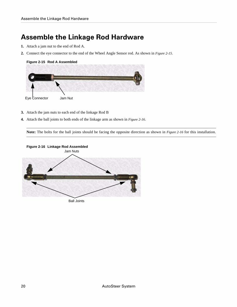
3. Attach the jam nuts to each end of the linkage Rod B
4. Attach the ball joints to both ends of the linkage arm as shown in Figure 2-16.
Note: The bolts for the ball joints should be facing the opposite direction as shown in Figure 2-16 for this installation.
Figure 2-16 Linkage Rod Assembled
Jam NutEye Connector
Ball Joints
Jam Nuts
20 AutoSteer System
Assemble the Linkage Rod Hardware
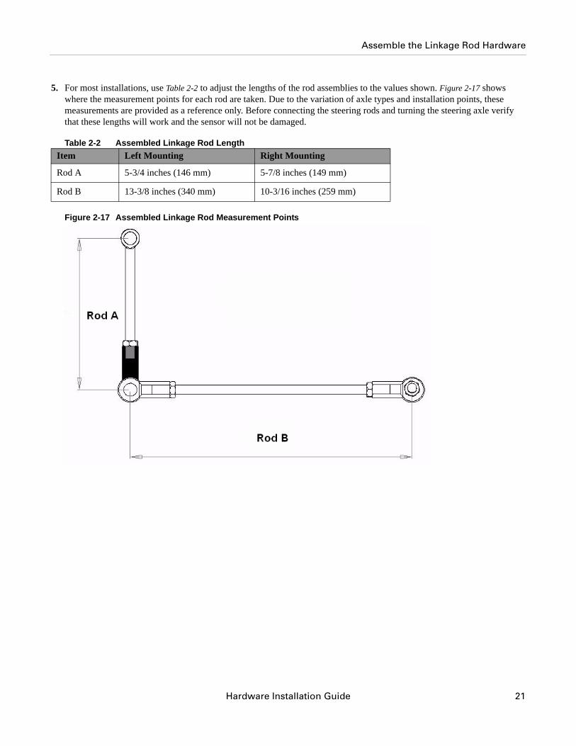
5. For most installations, use Table 2-2 to adjust the lengths of the rod assemblies to the values shown. Figure 2-17 shows where the measurement points for each rod are taken. Due to the variation of axle types and installation points, these measurements are provided as a reference only. Before connecting the steering rods and turning the steering axle verify that these lengths will work and the sensor will not be damaged.
Table 2-2 Assembled Linkage Rod Length
Figure 2-17 Assembled Linkage Rod Measurement Points
Item Left Mounting Right Mounting
Rod A 5-3/4 inches (146 mm) 5-7/8 inches (149 mm)
Rod B 13-3/8 inches (340 mm) 10-3/16 inches (259 mm)
Hardware Installation Guide 21
Attach the Wheel Angle Sensor Rods to Brackets and Adjust
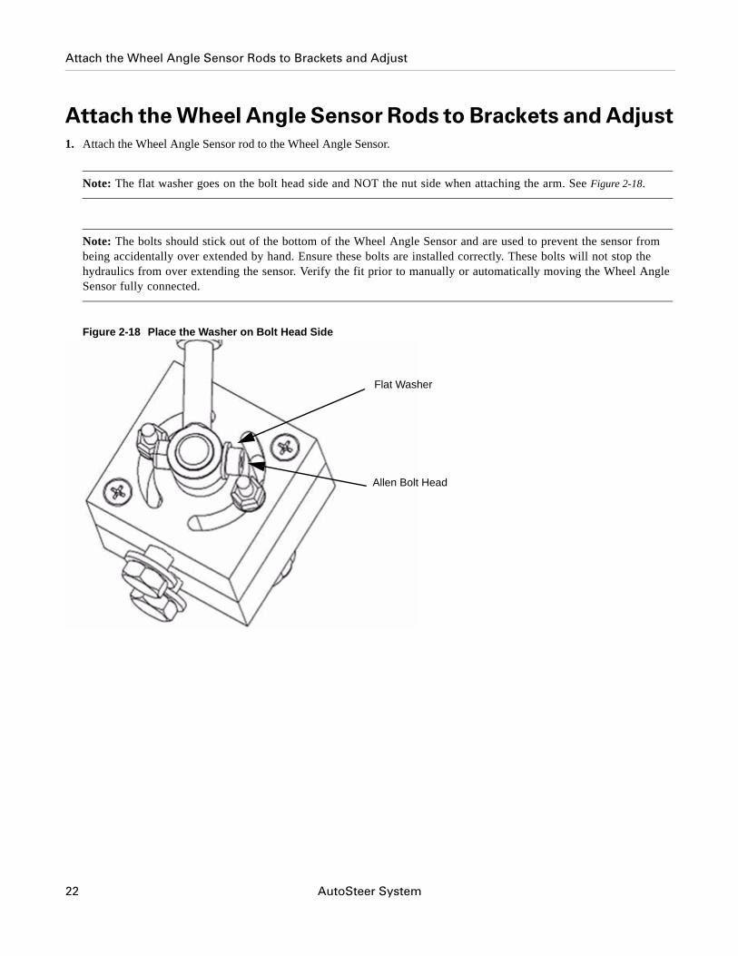
Attach the Wheel Angle Sensor Rods to Brackets and Adjust1. Attach the Wheel Angle Sensor rod to the Wheel Angle Sensor.
Note: The flat washer goes on the bolt head side and NOT the nut side when attaching the arm. See Figure 2-18.
Note: The bolts should stick out of the bottom of the Wheel Angle Sensor and are used to prevent the sensor from being accidentally over extended by hand. Ensure these bolts are installed correctly. These bolts will not stop the hydraulics from over extending the sensor. Verify the fit prior to manually or automatically moving the Wheel Angle Sensor fully connected.
Figure 2-18 Place the Washer on Bolt Head Side
Flat Washer
Allen Bolt Head
22 AutoSteer System
Attach the Wheel Angle Sensor Rods to Brackets and Adjust
2. Tighten the Wheel Angle Sensor arm with a 3/8" wrench and 1/8" Allen wrench.
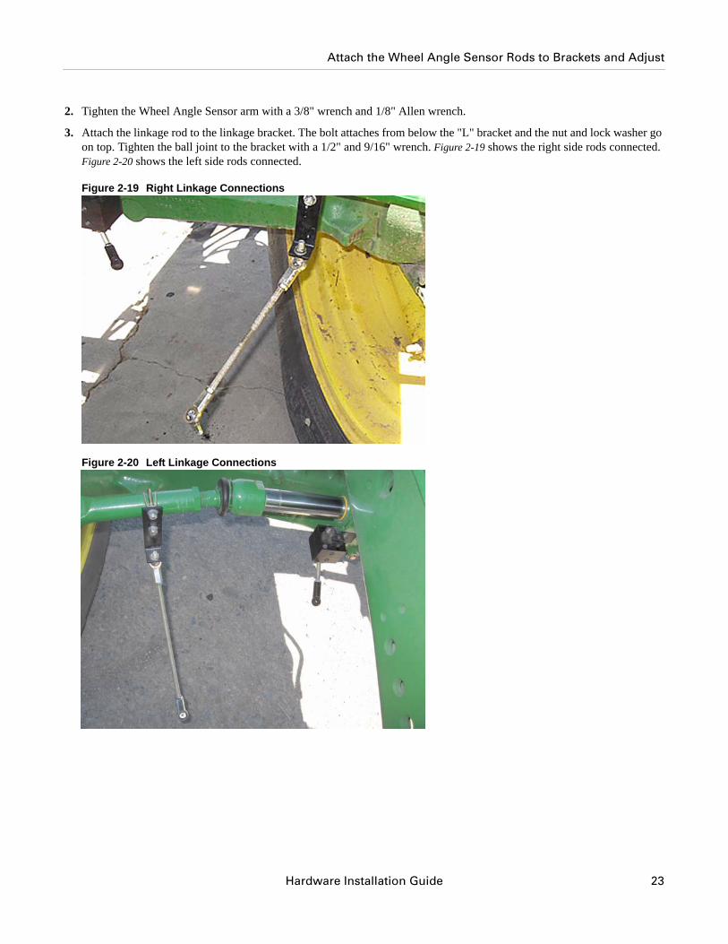
3. Attach the linkage rod to the linkage bracket. The bolt attaches from below the "L" bracket and the nut and lock washer go on top. Tighten the ball joint to the bracket with a 1/2" and 9/16" wrench. Figure 2-19 shows the right side rods connected. Figure 2-20 shows the left side rods connected.
Figure 2-19 Right Linkage Connections
Figure 2-20 Left Linkage Connections
Hardware Installation Guide 23
Attach the Wheel Angle Sensor Rods to Brackets and Adjust
Note: Never attach the linkage rods to Wheel Angle Sensor rod and turn the steering wheels manual or automatically until the fit has been verified. The linkage rods must remain apart while the steering wheels are turned to the maximum right and left positions and then temporarily attached at these positions. Failure to do this may cause the Wheel Angle Sensor or vehicle to become damaged.
Note: After the linkage rods are assembled in the following steps, they should move freely without touching any other parts and without overextending. Make any necessary adjustments to the linkage rods if there is an interference problem.
4. With the linkage rods disconnected, manually turn the steering wheel so that the wheels are centered (the vehicle will travel straight ahead when moving).
5. Temporarily attach the linkage rods.
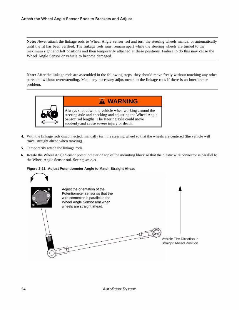
6. Rotate the Wheel Angle Sensor potentiometer on top of the mounting block so that the plastic wire connector is parallel to the Wheel Angle Sensor rod. See Figure 2-21.
Figure 2-21 Adjust Potentiometer Angle to Match Straight Ahead
WARNINGAlways shut down the vehicle when working around the steering axle and checking and adjusting the Wheel Angle Sensor rod lengths. The steering axle could move suddenly and cause severe injury or death.
Vehicle Tire Direction in Straight Ahead Position
Adjust the orientation of the Potentiometer sensor so that the wire connector is parallel to the Wheel Angle Sensor arm when wheels are straight ahead.
24 AutoSteer System
Attach the Wheel Angle Sensor Rods to Brackets and Adjust
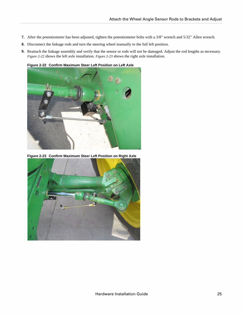
7. After the potentiometer has been adjusted, tighten the potentiometer bolts with a 3/8" wrench and 5/32" Allen wrench.
8. Disconnect the linkage rods and turn the steering wheel manually to the full left position.
9. Reattach the linkage assembly and verify that the sensor or rods will not be damaged. Adjust the rod lengths as necessary. Figure 2-22 shows the left axle installation. Figure 2-23 shows the right axle installation.
Figure 2-22 Confirm Maximum Steer Left Position on Left Axle
Figure 2-23 Confirm Maximum Steer Left Position on Right Axle
Hardware Installation Guide 25
Attach the Wheel Angle Sensor Rods to Brackets and Adjust
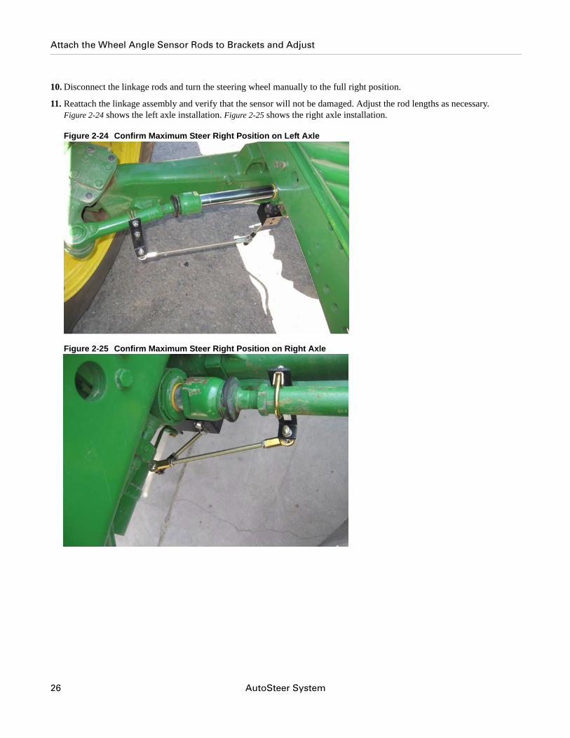
10. Disconnect the linkage rods and turn the steering wheel manually to the full right position.
11. Reattach the linkage assembly and verify that the sensor will not be damaged. Adjust the rod lengths as necessary. Figure 2-24 shows the left axle installation. Figure 2-25 shows the right axle installation.
Figure 2-24 Confirm Maximum Steer Right Position on Left Axle
Figure 2-25 Confirm Maximum Steer Right Position on Right Axle
26 AutoSteer System
Attach the Wheel Angle Sensor Rods to Brackets and Adjust
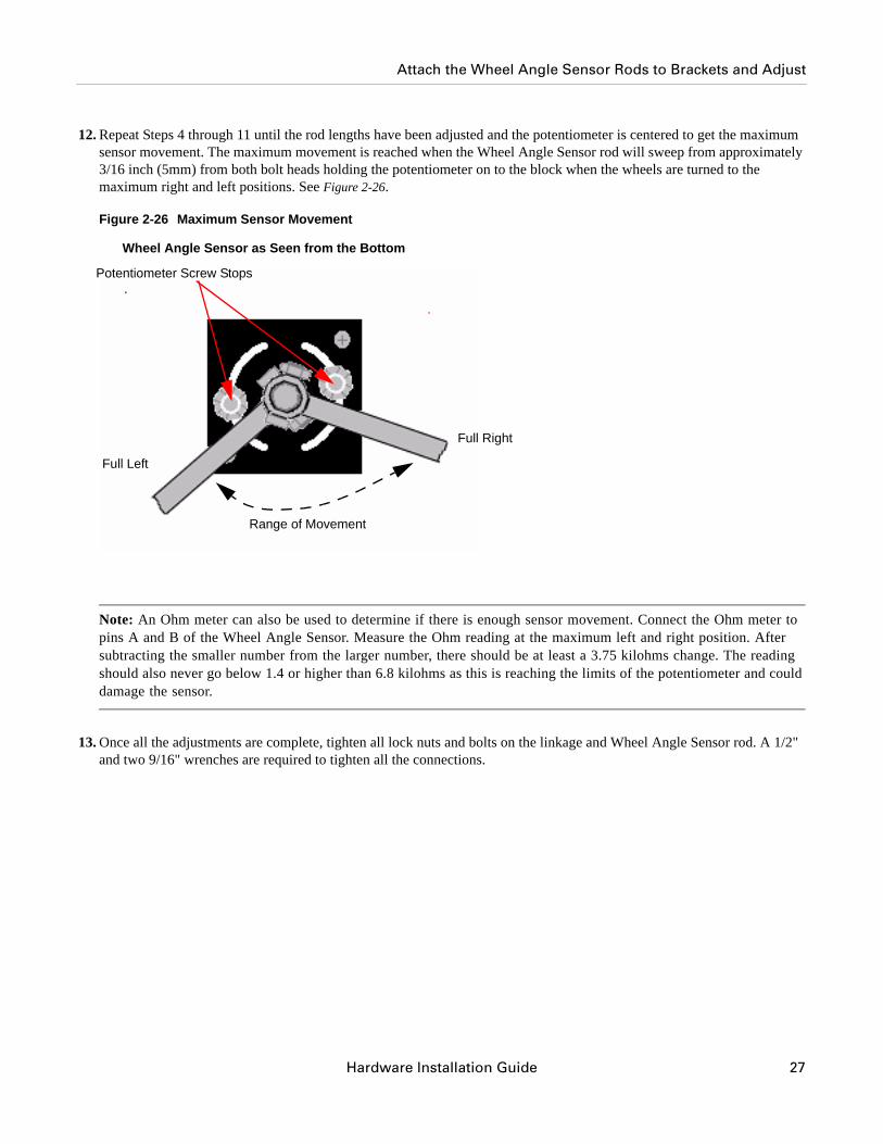
12. Repeat Steps 4 through 11 until the rod lengths have been adjusted and the potentiometer is centered to get the maximum sensor movement. The maximum movement is reached when the Wheel Angle Sensor rod will sweep from approximately 3/16 inch (5mm) from both bolt heads holding the potentiometer on to the block when the wheels are turned to the maximum right and left positions. See Figure 2-26.
Figure 2-26 Maximum Sensor Movement
Note: An Ohm meter can also be used to determine if there is enough sensor movement. Connect the Ohm meter to pins A and B of the Wheel Angle Sensor. Measure the Ohm reading at the maximum left and right position. After subtracting the smaller number from the larger number, there should be at least a 3.75 kilohms change. The reading should also never go below 1.4 or higher than 6.8 kilohms as this is reaching the limits of the potentiometer and could damage the sensor.
13. Once all the adjustments are complete, tighten all lock nuts and bolts on the linkage and Wheel Angle Sensor rod. A 1/2" and two 9/16" wrenches are required to tighten all the connections.
Wheel Angle Sensor as Seen from the Bottom
Potentiometer Screw Stops
Full Left
Range of Movement
Full Right
Hardware Installation Guide 27

Attach the Wheel Angle Sensor Rods to Brackets and Adjust
28 AutoSteer System
Hardware Installation Guide
3SA Module Installation
The SA Module Installation chapter contains information in the following sections:
• SA Module Mounting Orientation• Mount the SA Module
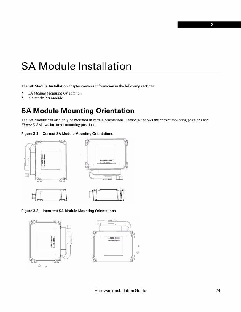
SA Module Mounting OrientationThe SA Module can also only be mounted in certain orientations. Figure 3-1 shows the correct mounting positions and Figure 3-2 shows incorrect mounting positions.
Figure 3-1 Correct SA Module Mounting Orientations
Figure 3-2 Incorrect SA Module Mounting Orientations
29
Mount the SA Module
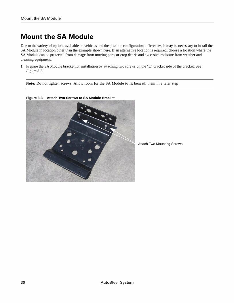
Mount the SA ModuleDue to the variety of options available on vehicles and the possible configuration differences, it may be necessary to install the SA Module in location other than the example shown here. If an alternative location is required, choose a location where the SA Module can be protected from damage from moving parts or crop debris and excessive moisture from weather and cleaning equipment.
1. Prepare the SA Module bracket for installation by attaching two screws on the "L" bracket side of the bracket. See Figure 3-3.
Note: Do not tighten screws. Allow room for the SA Module to fit beneath them in a later step
Figure 3-3 Attach Two Screws to SA Module Bracket
Attach Two Mounting Screws
30 AutoSteer System
Mount the SA Module
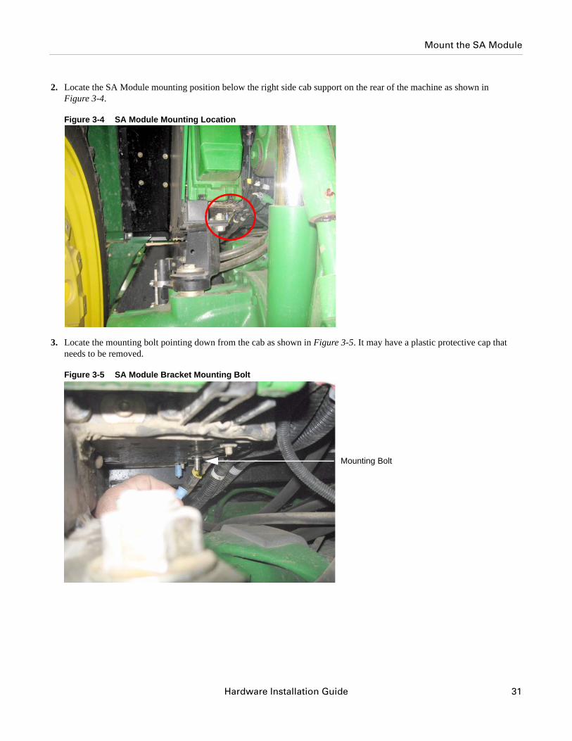
2. Locate the SA Module mounting position below the right side cab support on the rear of the machine as shown in Figure 3-4.
Figure 3-4 SA Module Mounting Location
3. Locate the mounting bolt pointing down from the cab as shown in Figure 3-5. It may have a plastic protective cap that needs to be removed.
Figure 3-5 SA Module Bracket Mounting Bolt
Mounting Bolt
Hardware Installation Guide 31
Mount the SA Module
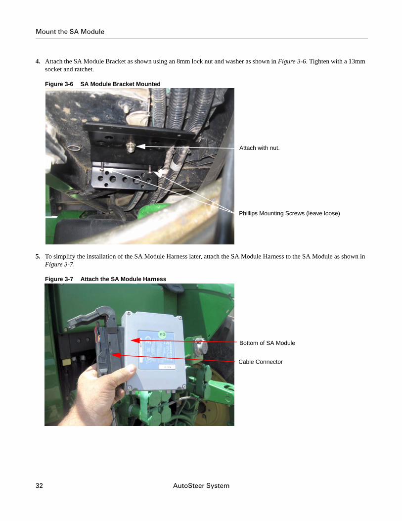
4. Attach the SA Module Bracket as shown using an 8mm lock nut and washer as shown in Figure 3-6. Tighten with a 13mm socket and ratchet.
Figure 3-6 SA Module Bracket Mounted
5. To simplify the installation of the SA Module Harness later, attach the SA Module Harness to the SA Module as shown in Figure 3-7.
Figure 3-7 Attach the SA Module Harness
Attach with nut.
Phillips Mounting Screws (leave loose)
Bottom of SA Module
Cable Connector
32 AutoSteer System
Mount the SA Module
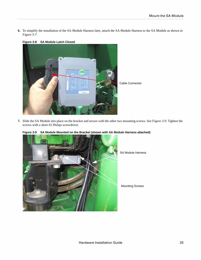
6. To simplify the installation of the SA Module Harness later, attach the SA Module Harness to the SA Module as shown in Figure 3-7.
Figure 3-8 SA Module Latch Closed
7. Slide the SA Module into place on the bracket and secure with the other two mounting screws. See Figure 3-9. Tighten the screws with a short #2 Philips screwdriver.
Figure 3-9 SA Module Mounted on the Bracket (shown with SA Module Harness attached)
Cable Connector
Mounting Screws
SA Module Harness
Hardware Installation Guide 33

Mount the SA Module
34 AutoSteer System
Hardware Installation Guide
4Roof Module Installation
This Roof Module Installation chapter contains information in the following sections:
• Safety Notes • Roof Rail Installation
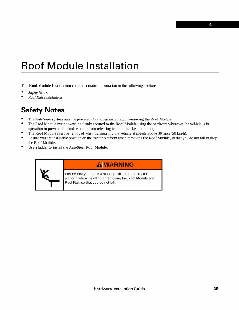
Safety Notes• The AutoSteer system must be powered OFF when installing or removing the Roof Module.• The Roof Module must always be firmly secured to the Roof Module using the hardware whenever the vehicle is in
operation to prevent the Roof Module from releasing from its bracket and falling.• The Roof Module must be removed when transporting the vehicle at speeds above 30 mph (50 km/h).• Ensure you are in a stable position on the tractor platform when removing the Roof Module, so that you do not fall or drop
the Roof Module.• Use a ladder to install the AutoSteer Roof Module.
WARNINGEnsure that you are in a stable position on the tractor platform when installing or removing the Roof Module and Roof Rail, so that you do not fall.
35
Safety Notes
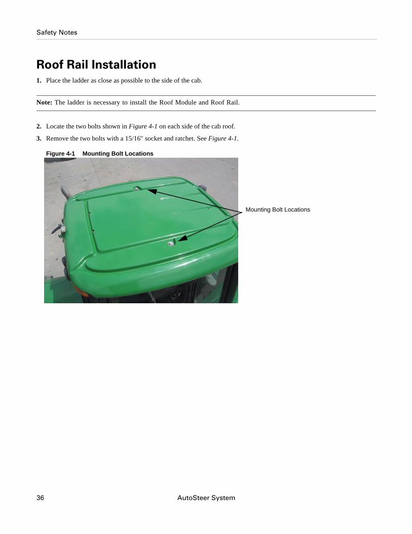
Roof Rail Installation1. Place the ladder as close as possible to the side of the cab.
Note: The ladder is necessary to install the Roof Module and Roof Rail.
2. Locate the two bolts shown in Figure 4-1 on each side of the cab roof.
3. Remove the two bolts with a 15/16" socket and ratchet. See Figure 4-1.
Figure 4-1 Mounting Bolt Locations
Mounting Bolt Locations
36 AutoSteer System
Safety Notes
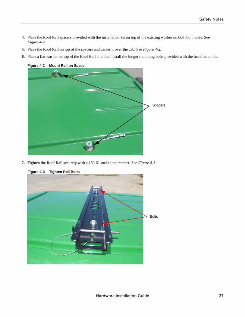
4. Place the Roof Rail spacers provided with the installation kit on top of the existing washer on both bolt holes. See Figure 4-2.
5. Place the Roof Rail on top of the spacers and center it over the cab. See Figure 4-2.
6. Place a flat washer on top of the Roof Rail and then install the longer mounting bolts provided with the installation kit.
Figure 4-2 Mount Rail on Spacer
7. Tighten the Roof Rail securely with a 15/16" socket and ratchet. See Figure 4-3.
Figure 4-3 Tighten Rail Bolts
Spacers
Bolts
Hardware Installation Guide 37
Safety Notes
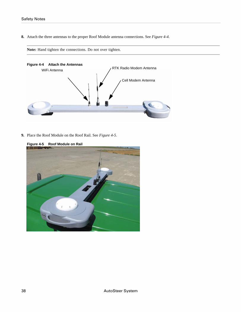
8. Attach the three antennas to the proper Roof Module antenna connections. See Figure 4-4.
Note: Hand tighten the connections. Do not over tighten.
Figure 4-4 Attach the Antennas
9. Place the Roof Module on the Roof Rail. See Figure 4-5.
Figure 4-5 Roof Module on Rail
RTK Radio Modem Antenna
Cell Modem Antenna
WiFi Antenna
38 AutoSteer System
Safety Notes
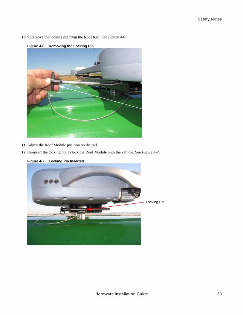
10. 9.Remove the locking pin from the Roof Rail. See Figure 4-6.
Figure 4-6 Removing the Locking Pin
11. Adjust the Roof Module position on the rail.
12. Re-insert the locking pin to lock the Roof Module onto the vehicle. See Figure 4-7.
Figure 4-7 Locking Pin Inserted
Locking Pin
Hardware Installation Guide 39

Safety Notes
40 AutoSteer System
Hardware Installation Guide
5Display Installation
This Display Installation chapter contains information for installing and adjusting the Display in the following sections:
• Introduction • Installation Procedure
IntroductionThis manual provides the instructions for installing the RAM mount ball in the cab so that the Display can be attached later. Refer to your display’s User Manual for instructions on installing the display.
Installation Procedure
Note: There are a number of mounting threads behind the plastic post cover which enable different display vertical mounting positions. If you need to change the vertical position of the display from the existing position, you need to remove the cab post plastic cover and cut holes through it using the marked positions on the inside of the plastic cover as a reference. You should hold the bracket up to the new set of holes you are going to use to verify vertical position and clearance of the display before cutting holes through the plastic cover.
41
Installation Procedure
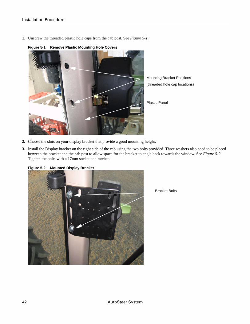
1. Unscrew the threaded plastic hole caps from the cab post. See Figure 5-1.
Figure 5-1 Remove Plastic Mounting Hole Covers
2. Choose the slots on your display bracket that provide a good mounting height.
3. Install the Display bracket on the right side of the cab using the two bolts provided. Three washers also need to be placed between the bracket and the cab post to allow space for the bracket to angle back towards the window. See Figure 5-2. Tighten the bolts with a 17mm socket and ratchet.
Figure 5-2 Mounted Display Bracket
Mounting Bracket Positions
(threaded hole cap locations)
Plastic Panel
Bracket Bolts
42 AutoSteer System
Installation Procedure
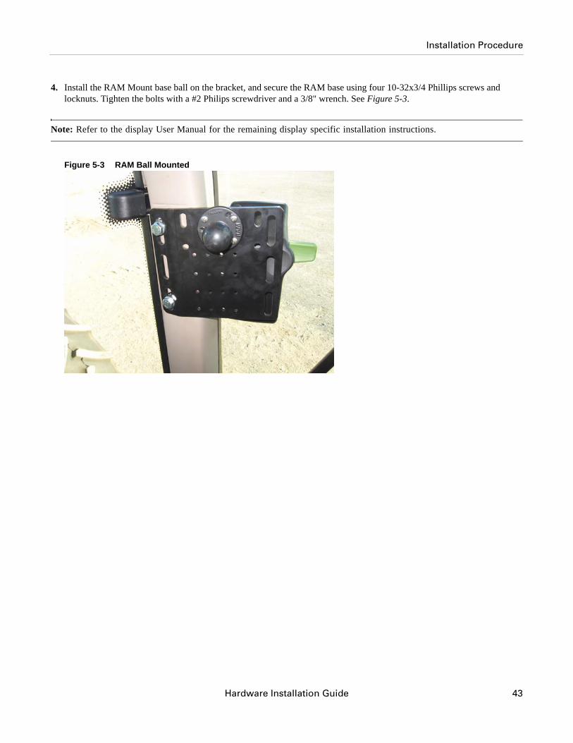
4. Install the RAM Mount base ball on the bracket, and secure the RAM base using four 10-32x3/4 Phillips screws and locknuts. Tighten the bolts with a #2 Philips screwdriver and a 3/8" wrench. See Figure 5-3.
Note: Refer to the display User Manual for the remaining display specific installation instructions.
Figure 5-3 RAM Ball Mounted
Hardware Installation Guide 43

Installation Procedure
44 AutoSteer System
Hardware Installation Manual
6Connecting System Cables
This Connecting System Cables chapter provides information in the following sections for connecting the Main Cable Harness and the SA Module Cable Harness to various vehicle and AutoSteer components:
• SA Module Harness • AutoTrac Valve Connections• Wheel Angle Sensor Connection (Optional)
• Optional AutoSteer Wheel Angle Sensor • Steering Wheel Encoder Sensor Connection• Main Cable Harness
• Roof Module• SA Module Harness
• Power Supply Connection• Cab Power Connection• Battery Power Connection
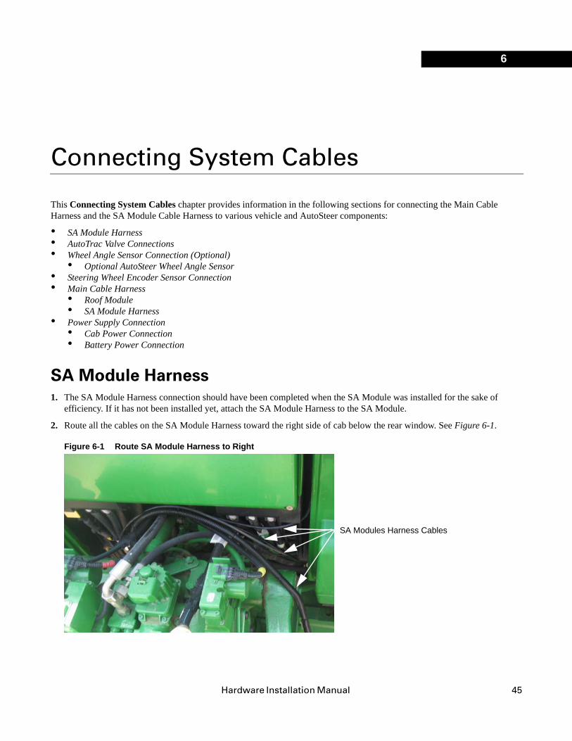
SA Module Harness1. The SA Module Harness connection should have been completed when the SA Module was installed for the sake of
efficiency. If it has not been installed yet, attach the SA Module Harness to the SA Module.
2. Route all the cables on the SA Module Harness toward the right side of cab below the rear window. See Figure 6-1.
Figure 6-1 Route SA Module Harness to Right
SA Modules Harness Cables
45
AutoTrac Valve Connections
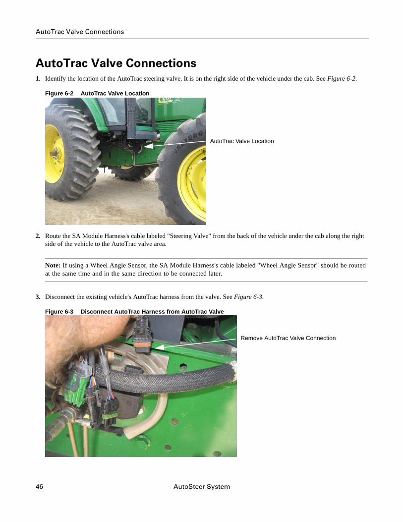
AutoTrac Valve Connections1. Identify the location of the AutoTrac steering valve. It is on the right side of the vehicle under the cab. See Figure 6-2.
Figure 6-2 AutoTrac Valve Location
2. Route the SA Module Harness's cable labeled "Steering Valve" from the back of the vehicle under the cab along the right side of the vehicle to the AutoTrac valve area.
Note: If using a Wheel Angle Sensor, the SA Module Harness's cable labeled "Wheel Angle Sensor" should be routed at the same time and in the same direction to be connected later.
3. Disconnect the existing vehicle's AutoTrac harness from the valve. See Figure 6-3.
Figure 6-3 Disconnect AutoTrac Harness from AutoTrac Valve
AutoTrac Valve Location
Remove AutoTrac Valve Connection
46 AutoSteer System
Wheel Angle Sensor Connection (Optional)
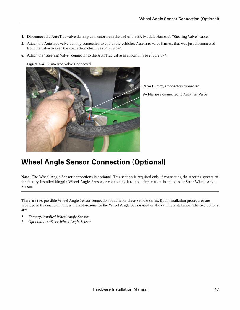
4. Disconnect the AutoTrac valve dummy connector from the end of the SA Module Harness's "Steering Valve" cable.
5. Attach the AutoTrac valve dummy connection to end of the vehicle's AutoTrac valve harness that was just disconnected from the valve to keep the connection clean. See Figure 6-4.
6. Attach the "Steering Valve" connector to the AutoTrac valve as shown in See Figure 6-4.
Figure 6-4 AutoTrac Valve Connected
Wheel Angle Sensor Connection (Optional)
Note: The Wheel Angle Sensor connections is optional. This section is required only if connecting the steering system to the factory-installed kingpin Wheel Angle Sensor or connecting it to and after-market-installed AutoSteer Wheel Angle Sensor.
There are two possible Wheel Angle Sensor connection options for these vehicle series. Both installation procedures are provided in this manual. Follow the instructions for the Wheel Angle Sensor used on the vehicle installation. The two options are:
• Factory-Installed Wheel Angle Sensor • Optional AutoSteer Wheel Angle Sensor
Valve Dummy Connector Connected
SA Harness connected to AutoTrac Valve
Hardware Installation Manual 47
Wheel Angle Sensor Connection (Optional)
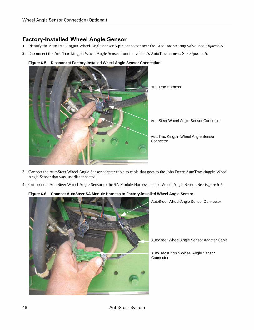
Factory-Installed Wheel Angle Sensor1. Identify the AutoTrac kingpin Wheel Angle Sensor 6-pin connector near the AutoTrac steering valve. See Figure 6-5.
2. Disconnect the AutoTrac kingpin Wheel Angle Sensor from the vehicle's AutoTrac harness. See Figure 6-5.
Figure 6-5 Disconnect Factory-installed Wheel Angle Sensor Connection
3. Connect the AutoSteer Wheel Angle Sensor adapter cable to cable that goes to the John Deere AutoTrac kingpin Wheel Angle Sensor that was just disconnected.
4. Connect the AutoSteer Wheel Angle Sensor to the SA Module Harness labeled Wheel Angle Sensor. See Figure 6-6.
Figure 6-6 Connect AutoSteer SA Module Harness to Factory-installed Wheel Angle Sensor
AutoSteer Wheel Angle Sensor Connector
AutoTrac Kingpin Wheel Angle Sensor Connector
AutoTrac Harness
AutoSteer Wheel Angle Sensor Adapter Cable
AutoSteer Wheel Angle Sensor Connector
AutoTrac Kingpin Wheel Angle Sensor Connector
48 AutoSteer System
Wheel Angle Sensor Connection (Optional)
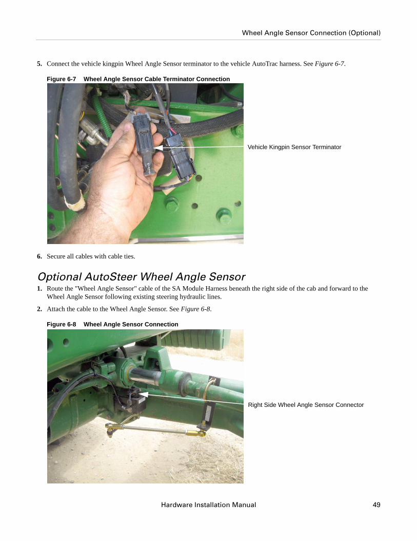
5. Connect the vehicle kingpin Wheel Angle Sensor terminator to the vehicle AutoTrac harness. See Figure 6-7.
Figure 6-7 Wheel Angle Sensor Cable Terminator Connection
6. Secure all cables with cable ties.
Optional AutoSteer Wheel Angle Sensor1. Route the "Wheel Angle Sensor" cable of the SA Module Harness beneath the right side of the cab and forward to the
Wheel Angle Sensor following existing steering hydraulic lines.
2. Attach the cable to the Wheel Angle Sensor. See Figure 6-8.
Figure 6-8 Wheel Angle Sensor Connection
Vehicle Kingpin Sensor Terminator
Right Side Wheel Angle Sensor Connector
Hardware Installation Manual 49
Wheel Angle Sensor Connection (Optional)
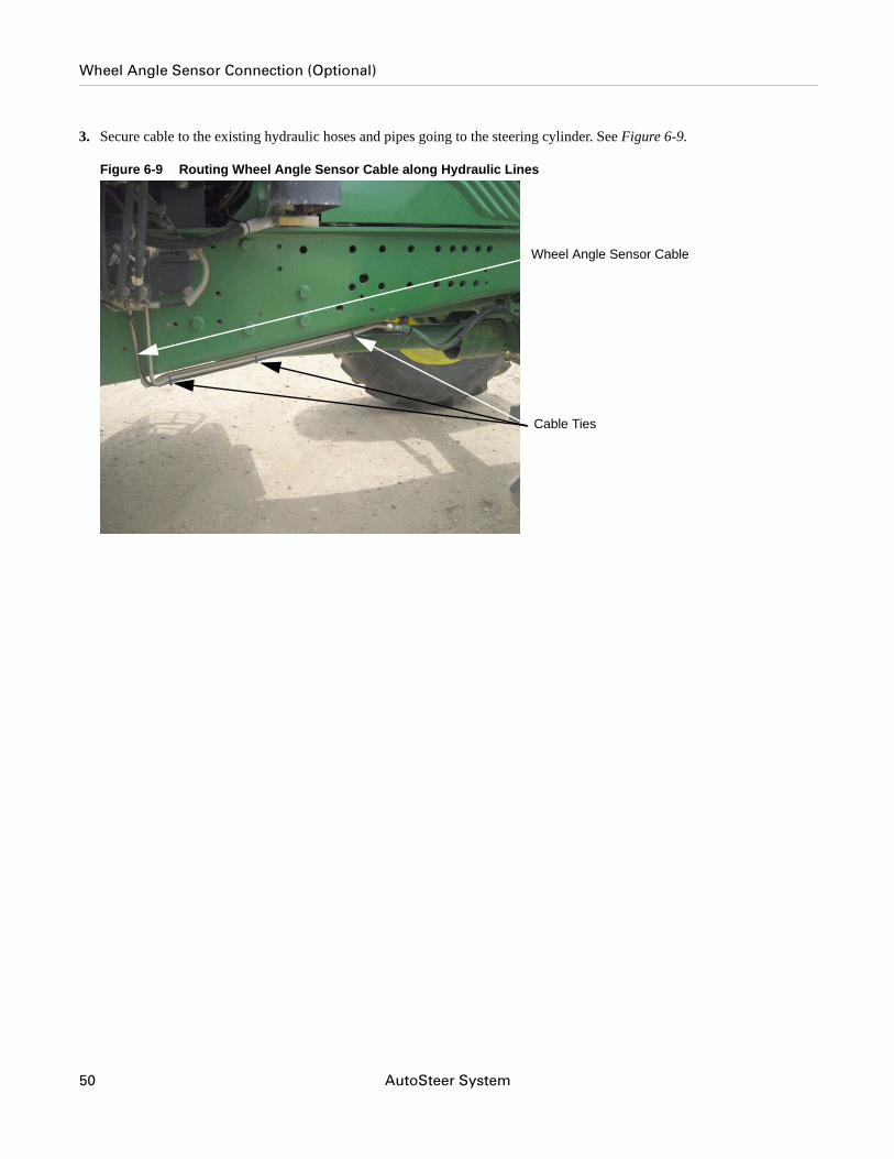
3. Secure cable to the existing hydraulic hoses and pipes going to the steering cylinder. See Figure 6-9.
Figure 6-9 Routing Wheel Angle Sensor Cable along Hydraulic Lines
Wheel Angle Sensor Cable
Cable Ties
50 AutoSteer System
Wheel Angle Sensor Connection (Optional)
Note: The previous figures showed the Wheel Angle Sensor mounted on the right side. If the Wheel Angle Sensor is mounted on the left, modify the cable route accordingly to attach it to the Wheel Angle Sensor.
Note: The John Deere AutoTrac system expects to see a signal coming from the factory installed kingpin Wheel Angle Sensor. This signal must match what is provided by the steering wheel encoder. If the two signals do not match, the vehicle's diagnostic display will throw an error code. Even if a Wheel Angle Sensor is not being used this connection must be terminated in order to prevent the vehicle from throwing steering codes.
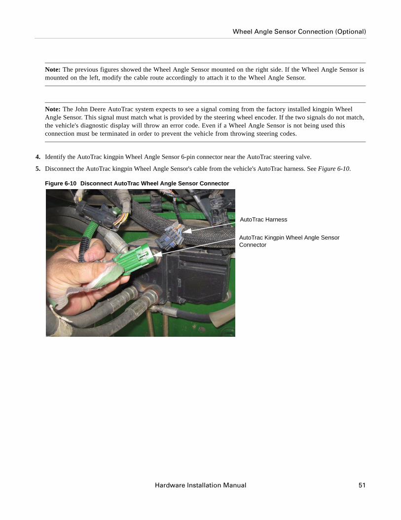
4. Identify the AutoTrac kingpin Wheel Angle Sensor 6-pin connector near the AutoTrac steering valve.
5. Disconnect the AutoTrac kingpin Wheel Angle Sensor's cable from the vehicle's AutoTrac harness. See Figure 6-10.
Figure 6-10 Disconnect AutoTrac Wheel Angle Sensor Connector
AutoTrac Harness
AutoTrac Kingpin Wheel Angle Sensor Connector
Hardware Installation Manual 51
Wheel Angle Sensor Connection (Optional)
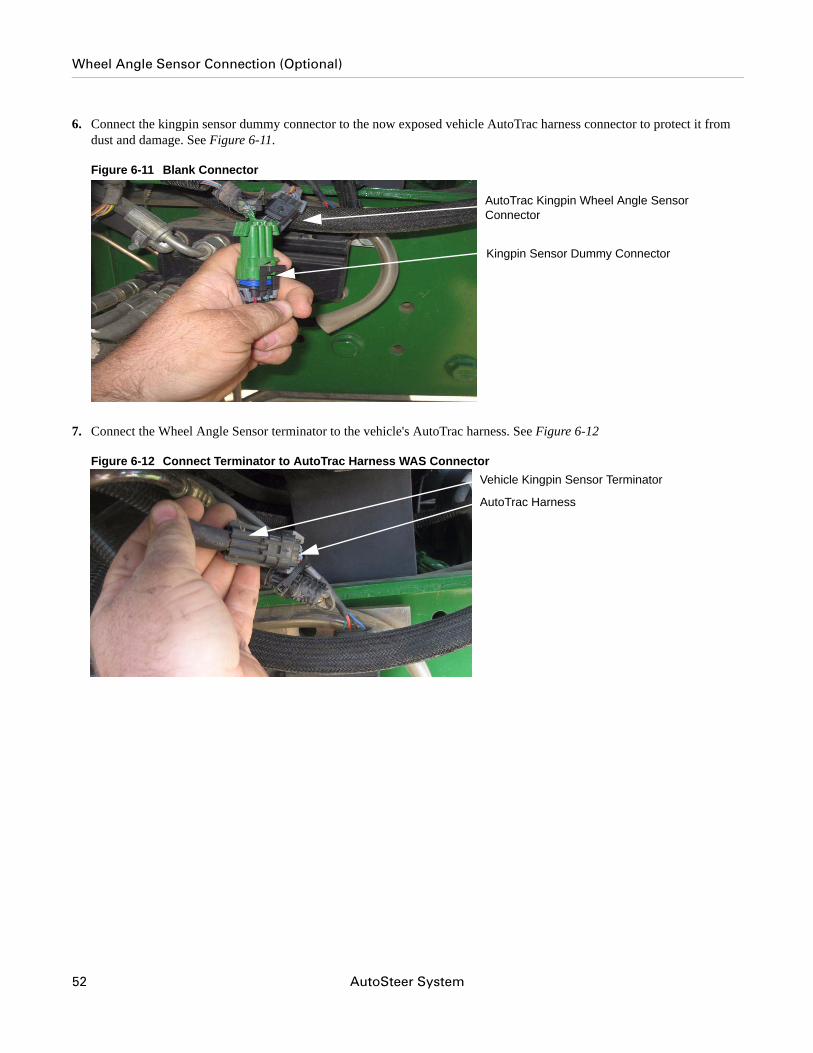
6. Connect the kingpin sensor dummy connector to the now exposed vehicle AutoTrac harness connector to protect it from dust and damage. See Figure 6-11.
Figure 6-11 Blank Connector
7. Connect the Wheel Angle Sensor terminator to the vehicle's AutoTrac harness. See Figure 6-12
Figure 6-12 Connect Terminator to AutoTrac Harness WAS Connector
AutoTrac Kingpin Wheel Angle Sensor Connector
Kingpin Sensor Dummy Connector
Vehicle Kingpin Sensor Terminator
AutoTrac Harness
52 AutoSteer System
Steering Wheel Encoder Sensor Connection
8. Secure all cables with cable ties.
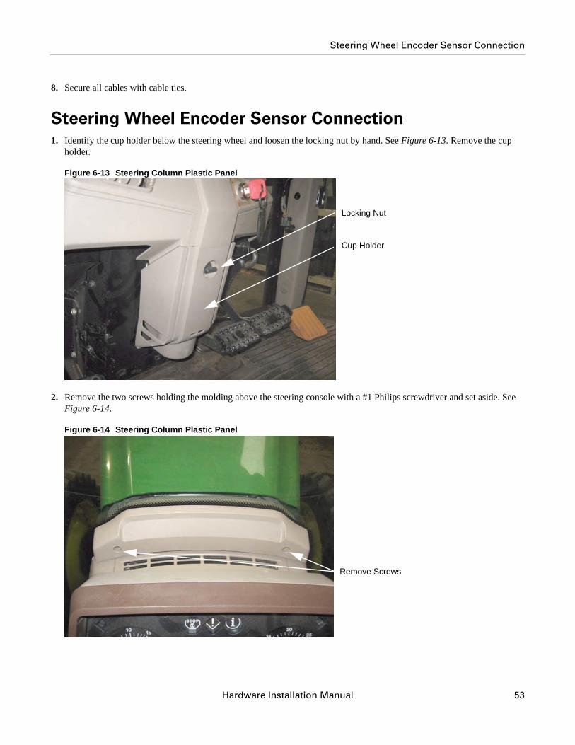
Steering Wheel Encoder Sensor Connection1. Identify the cup holder below the steering wheel and loosen the locking nut by hand. See Figure 6-13. Remove the cup
holder.
Figure 6-13 Steering Column Plastic Panel
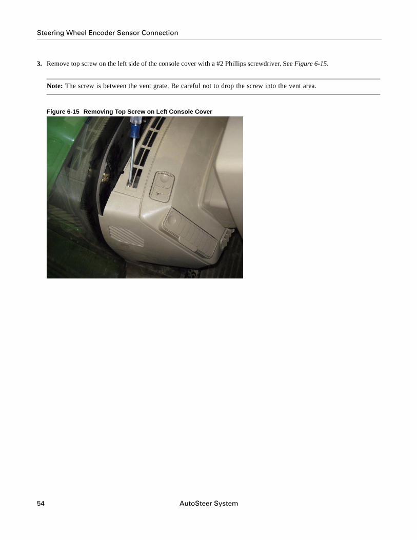
2. Remove the two screws holding the molding above the steering console with a #1 Philips screwdriver and set aside. See Figure 6-14.
Figure 6-14 Steering Column Plastic Panel
Locking Nut
Cup Holder
Remove Screws
Hardware Installation Manual 53
Steering Wheel Encoder Sensor Connection
3. Remove top screw on the left side of the console cover with a #2 Phillips screwdriver. See Figure 6-15.
Note: The screw is between the vent grate. Be careful not to drop the screw into the vent area.
Figure 6-15 Removing Top Screw on Left Console Cover
54 AutoSteer System
Steering Wheel Encoder Sensor Connection
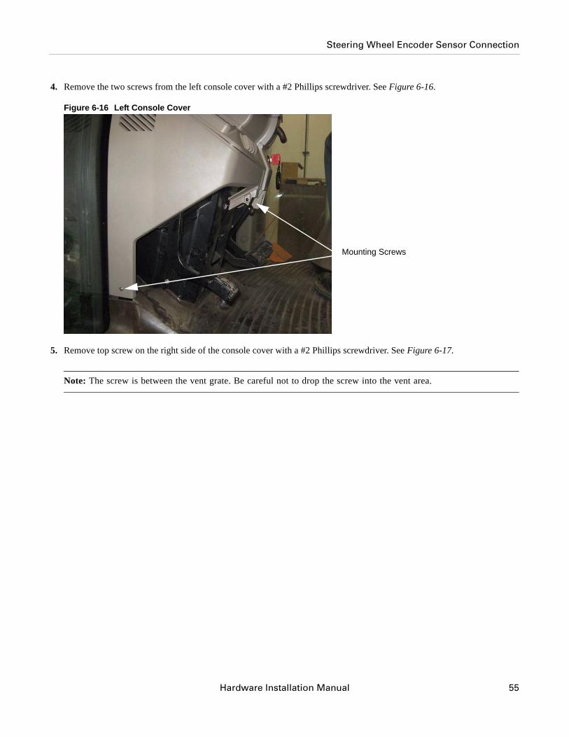
4. Remove the two screws from the left console cover with a #2 Phillips screwdriver. See Figure 6-16.
Figure 6-16 Left Console Cover
5. Remove top screw on the right side of the console cover with a #2 Phillips screwdriver. See Figure 6-17.
Note: The screw is between the vent grate. Be careful not to drop the screw into the vent area.
Mounting Screws
Hardware Installation Manual 55
Steering Wheel Encoder Sensor Connection
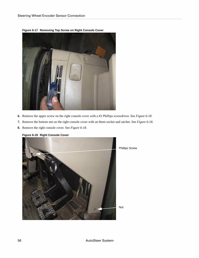
Figure 6-17 Removing Top Screw on Right Console Cover
6. Remove the upper screw on the right console cover with a #2 Phillips screwdriver. See Figure 6-18.
7. Remove the bottom nut on the right console cover with an 8mm socket and ratchet. See Figure 6-18.
8. Remove the right console cover. See Figure 6-18.
Figure 6-18 Right Console Cover
Phillips Screw
Nut
56 AutoSteer System
Steering Wheel Encoder Sensor Connection
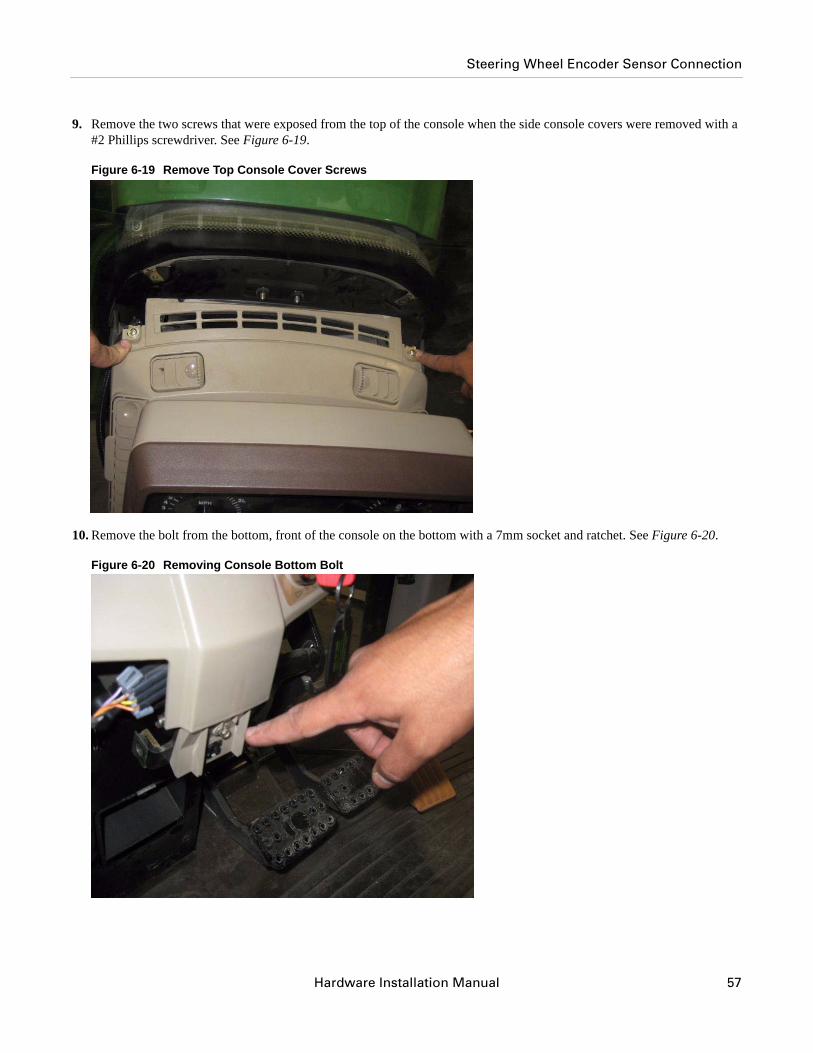
9. Remove the two screws that were exposed from the top of the console when the side console covers were removed with a #2 Phillips screwdriver. See Figure 6-19.
Figure 6-19 Remove Top Console Cover Screws
10. Remove the bolt from the bottom, front of the console on the bottom with a 7mm socket and ratchet. See Figure 6-20.
Figure 6-20 Removing Console Bottom Bolt
Hardware Installation Manual 57
Steering Wheel Encoder Sensor Connection
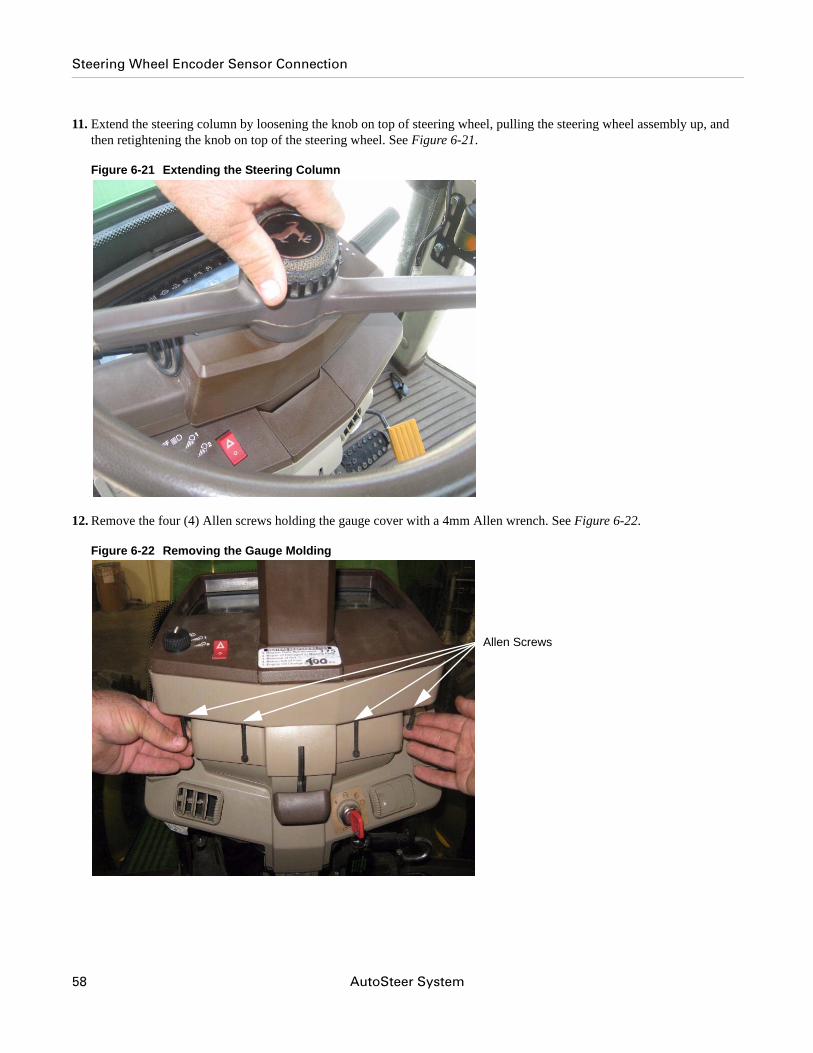
11. Extend the steering column by loosening the knob on top of steering wheel, pulling the steering wheel assembly up, and then retightening the knob on top of the steering wheel. See Figure 6-21.
Figure 6-21 Extending the Steering Column
12. Remove the four (4) Allen screws holding the gauge cover with a 4mm Allen wrench. See Figure 6-22.
Figure 6-22 Removing the Gauge Molding
Allen Screws
58 AutoSteer System
Steering Wheel Encoder Sensor Connection
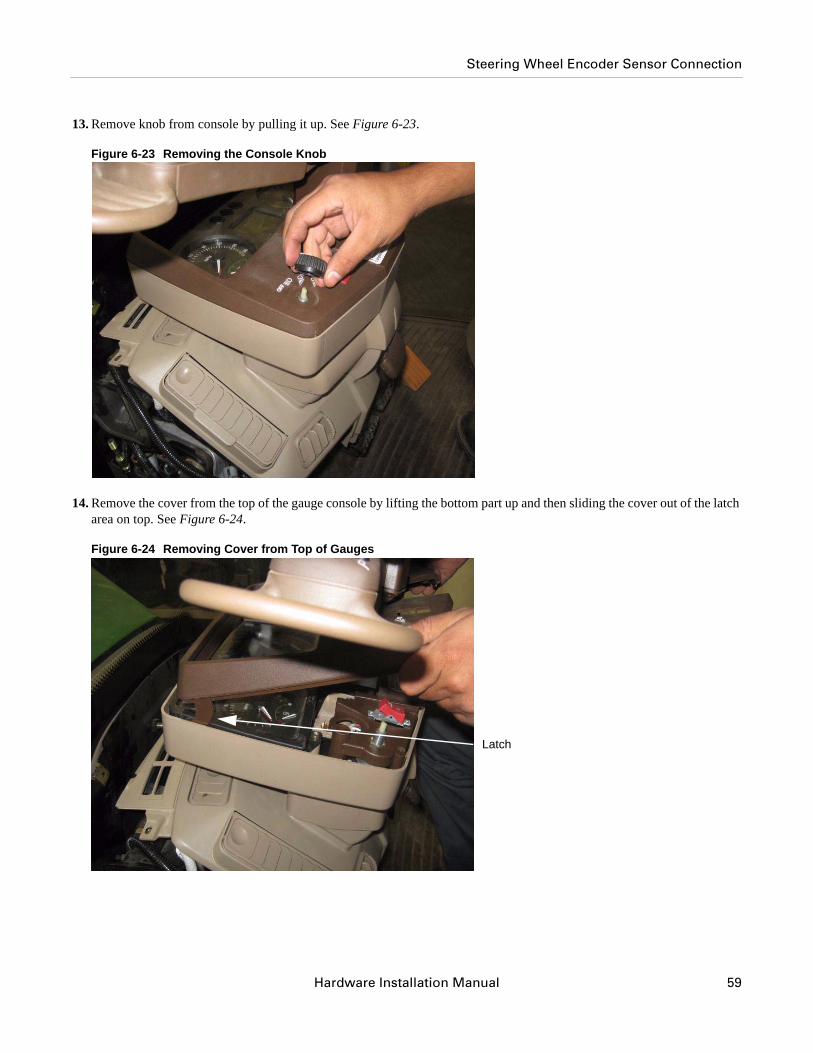
13. Remove knob from console by pulling it up. See Figure 6-23.
Figure 6-23 Removing the Console Knob
14. Remove the cover from the top of the gauge console by lifting the bottom part up and then sliding the cover out of the latch area on top. See Figure 6-24.
Figure 6-24 Removing Cover from Top of Gauges
Latch
Hardware Installation Manual 59
Steering Wheel Encoder Sensor Connection
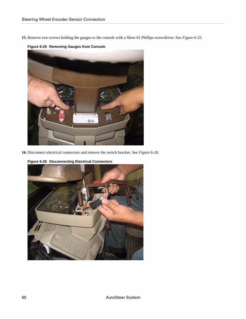
15. Remove two screws holding the gauges to the console with a Short #2 Phillips screwdriver. See Figure 6-25.
Figure 6-25 Removing Gauges from Console
16. Disconnect electrical connectors and remove the switch bracket. See Figure 6-26.
Figure 6-26 Disconnecting Electrical Connectors
60 AutoSteer System
Steering Wheel Encoder Sensor Connection
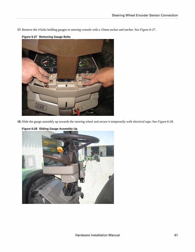
17. Remove the 4 bolts holding gauges to steering console with a 10mm socket and ratchet. See Figure 6-27.
Figure 6-27 Removing Gauge Bolts
18. Slide the gauge assembly up towards the steering wheel and secure it temporarily with electrical tape. See Figure 6-28.
Figure 6-28 Sliding Gauge Assembly Up
Hardware Installation Manual 61
Steering Wheel Encoder Sensor Connection
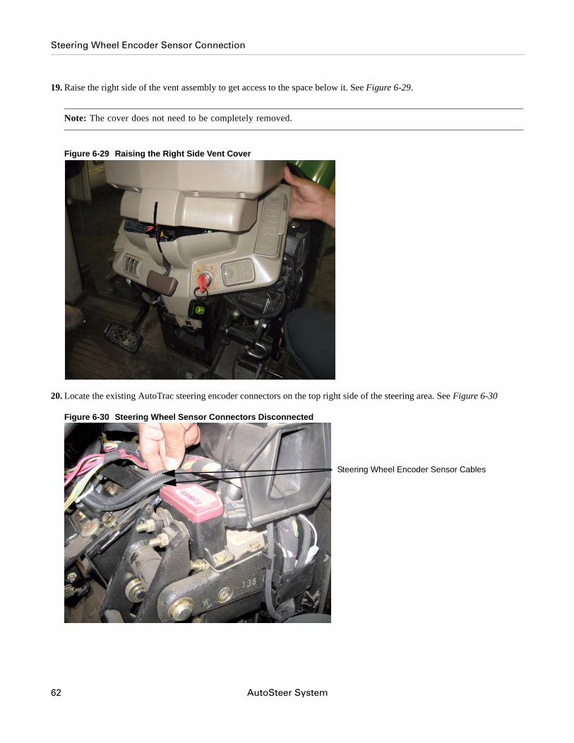
19. Raise the right side of the vent assembly to get access to the space below it. See Figure 6-29.
Note: The cover does not need to be completely removed.
Figure 6-29 Raising the Right Side Vent Cover
20. Locate the existing AutoTrac steering encoder connectors on the top right side of the steering area. See Figure 6-30
Figure 6-30 Steering Wheel Sensor Connectors Disconnected
Steering Wheel Encoder Sensor Cables
62 AutoSteer System
Steering Wheel Encoder Sensor Connection
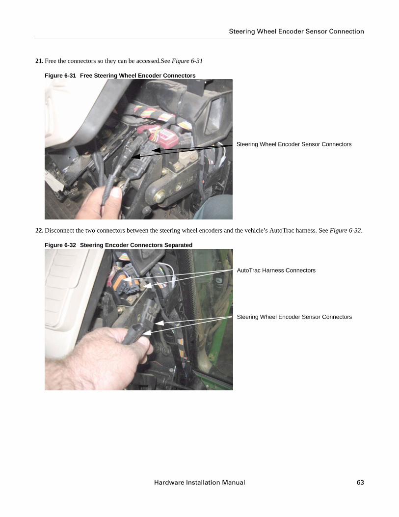
21. Free the connectors so they can be accessed.See Figure 6-31
Figure 6-31 Free Steering Wheel Encoder Connectors
22. Disconnect the two connectors between the steering wheel encoders and the vehicle’s AutoTrac harness. See Figure 6-32.
Figure 6-32 Steering Encoder Connectors Separated
Steering Wheel Encoder Sensor Connectors
AutoTrac Harness Connectors
Steering Wheel Encoder Sensor Connectors
Hardware Installation Manual 63
Steering Wheel Encoder Sensor Connection
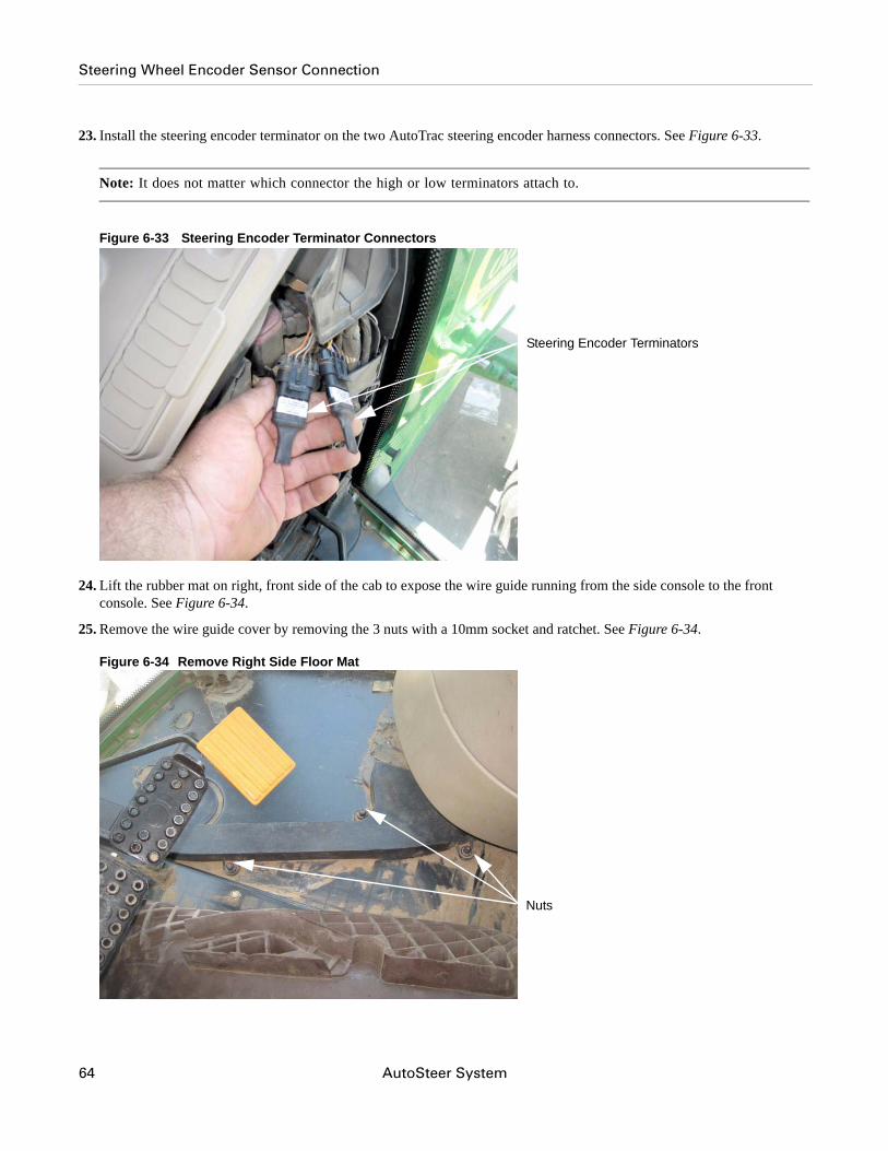
23. Install the steering encoder terminator on the two AutoTrac steering encoder harness connectors. See Figure 6-33.
Note: It does not matter which connector the high or low terminators attach to.
Figure 6-33 Steering Encoder Terminator Connectors
24. Lift the rubber mat on right, front side of the cab to expose the wire guide running from the side console to the front console. See Figure 6-34.
25. Remove the wire guide cover by removing the 3 nuts with a 10mm socket and ratchet. See Figure 6-34.
Figure 6-34 Remove Right Side Floor Mat
Steering Encoder Terminators
Nuts
64 AutoSteer System
Steering Wheel Encoder Sensor Connection
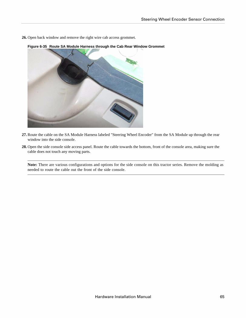
26. Open back window and remove the right wire cab access grommet.
Figure 6-35 Route SA Module Harness through the Cab Rear Window Grommet
27. Route the cable on the SA Module Harness labeled "Steering Wheel Encoder" from the SA Module up through the rear window into the side console.
28. Open the side console side access panel. Route the cable towards the bottom, front of the console area, making sure the cable does not touch any moving parts.
Note: There are various configurations and options for the side console on this tractor series. Remove the molding as needed to route the cable out the front of the side console.
Hardware Installation Manual 65
Steering Wheel Encoder Sensor Connection
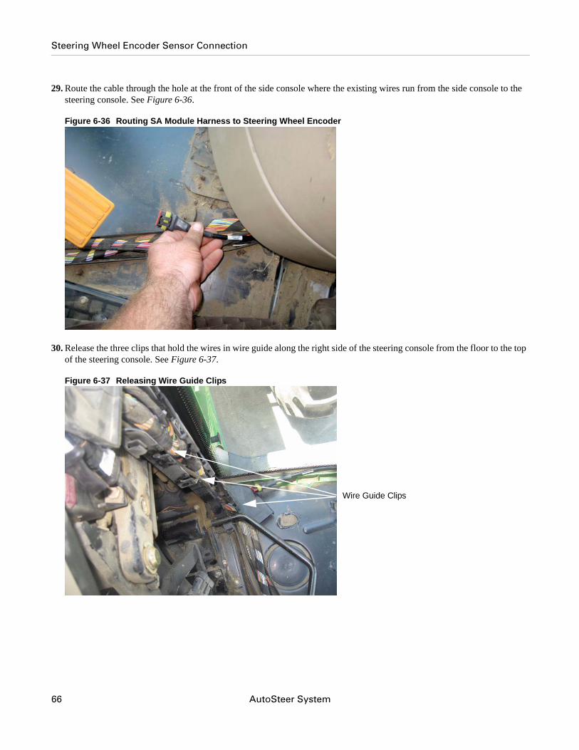
29. Route the cable through the hole at the front of the side console where the existing wires run from the side console to the steering console. See Figure 6-36.
Figure 6-36 Routing SA Module Harness to Steering Wheel Encoder
30. Release the three clips that hold the wires in wire guide along the right side of the steering console from the floor to the top of the steering console. See Figure 6-37.
Figure 6-37 Releasing Wire Guide Clips
Wire Guide Clips
66 AutoSteer System
Steering Wheel Encoder Sensor Connection
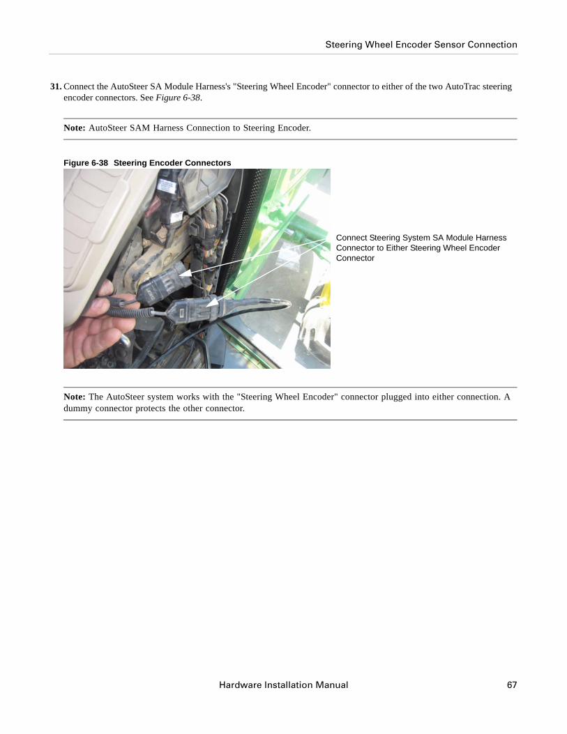
31. Connect the AutoSteer SA Module Harness's "Steering Wheel Encoder" connector to either of the two AutoTrac steering encoder connectors. See Figure 6-38.
Note: AutoSteer SAM Harness Connection to Steering Encoder.
Figure 6-38 Steering Encoder Connectors
Note: The AutoSteer system works with the "Steering Wheel Encoder" connector plugged into either connection. A dummy connector protects the other connector.
Connect Steering System SA Module Harness Connector to Either Steering Wheel Encoder Connector
Hardware Installation Manual 67
Steering Wheel Encoder Sensor Connection
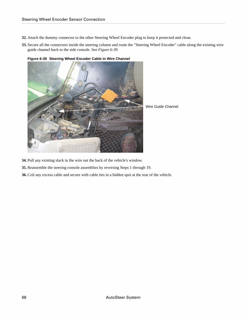
32. Attach the dummy connector to the other Steering Wheel Encoder plug to keep it protected and clean.
33. Secure all the connectors inside the steering column and route the "Steering Wheel Encoder" cable along the existing wire guide channel back to the side console. See Figure 6-39.
Figure 6-39 Steering Wheel Encoder Cable in Wire Channel
34. Pull any existing slack in the wire out the back of the vehicle's window.
35. Reassemble the steering console assemblies by reversing Steps 1 through 19.
36. Coil any excess cable and secure with cable ties in a hidden spot at the rear of the vehicle.
Wire Guide Channel
68 AutoSteer System
Steering Wheel Encoder Sensor Connection
Main Cable Harness
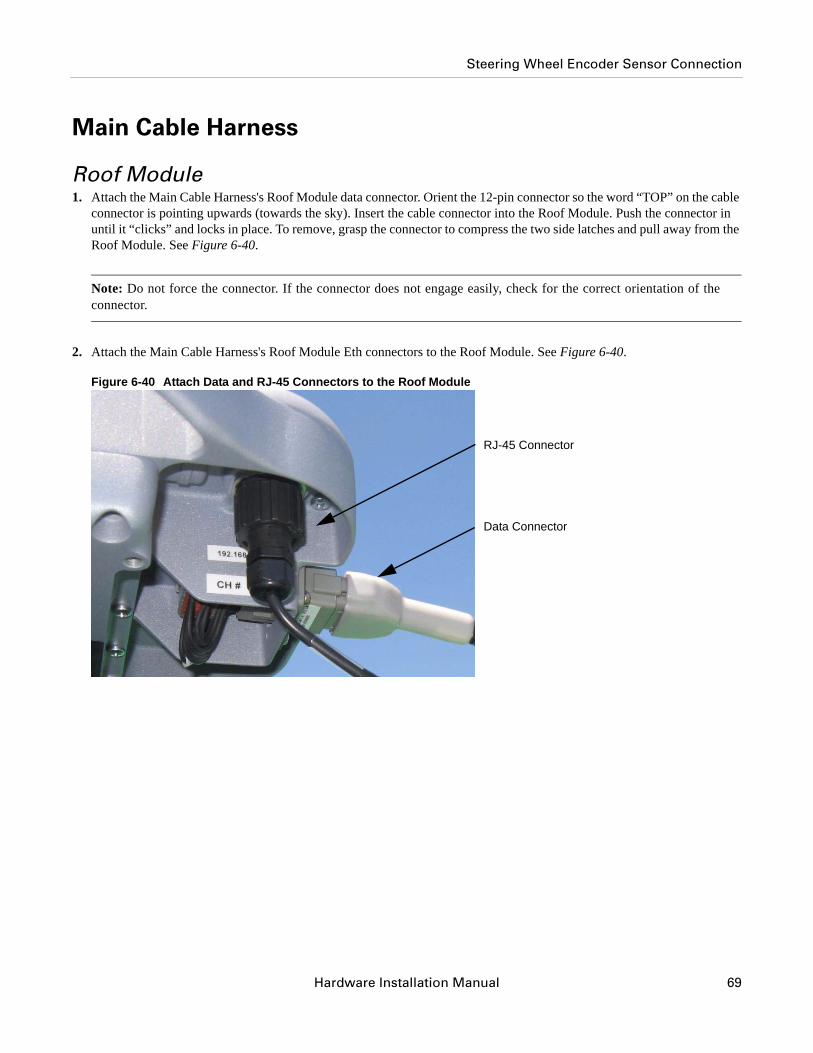
Roof Module1. Attach the Main Cable Harness's Roof Module data connector. Orient the 12-pin connector so the word “TOP” on the cable
connector is pointing upwards (towards the sky). Insert the cable connector into the Roof Module. Push the connector in until it “clicks” and locks in place. To remove, grasp the connector to compress the two side latches and pull away from the Roof Module. See Figure 6-40.
Note: Do not force the connector. If the connector does not engage easily, check for the correct orientation of the connector.
2. Attach the Main Cable Harness's Roof Module Eth connectors to the Roof Module. See Figure 6-40.
Figure 6-40 Attach Data and RJ-45 Connectors to the Roof Module
RJ-45 Connector
Data Connector
Hardware Installation Manual 69
Steering Wheel Encoder Sensor Connection
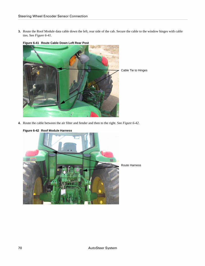
3. Route the Roof Module data cable down the left, rear side of the cab. Secure the cable to the window hinges with cable ties. See Figure 6-41.
Figure 6-41 Route Cable Down Left Rear Post
4. Route the cable between the air filter and fender and then to the right. See Figure 6-42.
Figure 6-42 Roof Module Harness
Cable Tie to Hinges
Route Harness
70 AutoSteer System
Steering Wheel Encoder Sensor Connection
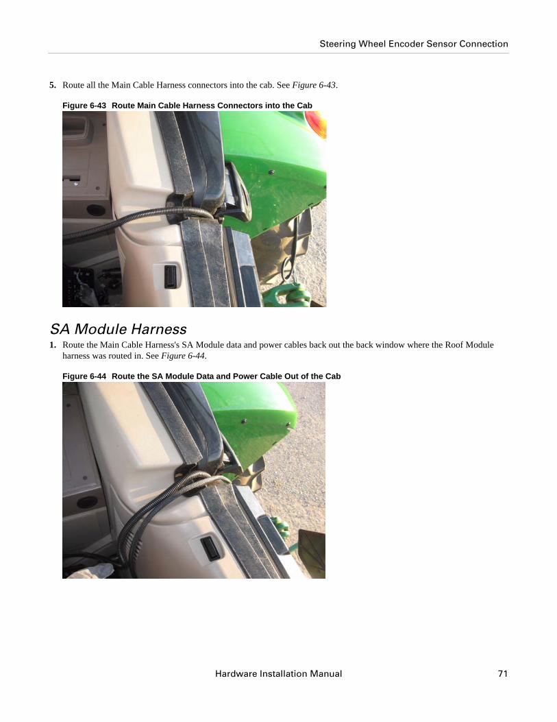
5. Route all the Main Cable Harness connectors into the cab. See Figure 6-43.
Figure 6-43 Route Main Cable Harness Connectors into the Cab
SA Module Harness1. Route the Main Cable Harness's SA Module data and power cables back out the back window where the Roof Module
harness was routed in. See Figure 6-44.
Figure 6-44 Route the SA Module Data and Power Cable Out of the Cab
Hardware Installation Manual 71
Steering Wheel Encoder Sensor Connection
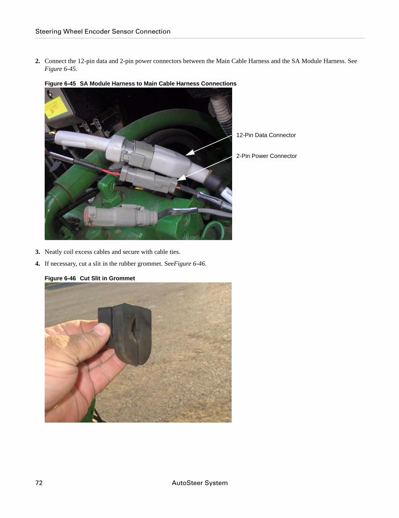
2. Connect the 12-pin data and 2-pin power connectors between the Main Cable Harness and the SA Module Harness. See Figure 6-45.
Figure 6-45 SA Module Harness to Main Cable Harness Connections
3. Neatly coil excess cables and secure with cable ties.
4. If necessary, cut a slit in the rubber grommet. SeeFigure 6-46.
Figure 6-46 Cut Slit in Grommet
12-Pin Data Connector
2-Pin Power Connector
72 AutoSteer System
Steering Wheel Encoder Sensor Connection
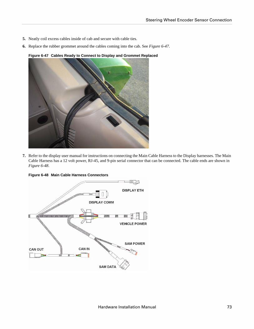
5. Neatly coil excess cables inside of cab and secure with cable ties.
6. Replace the rubber grommet around the cables coming into the cab. See Figure 6-47.
Figure 6-47 Cables Ready to Connect to Display and Grommet Replaced
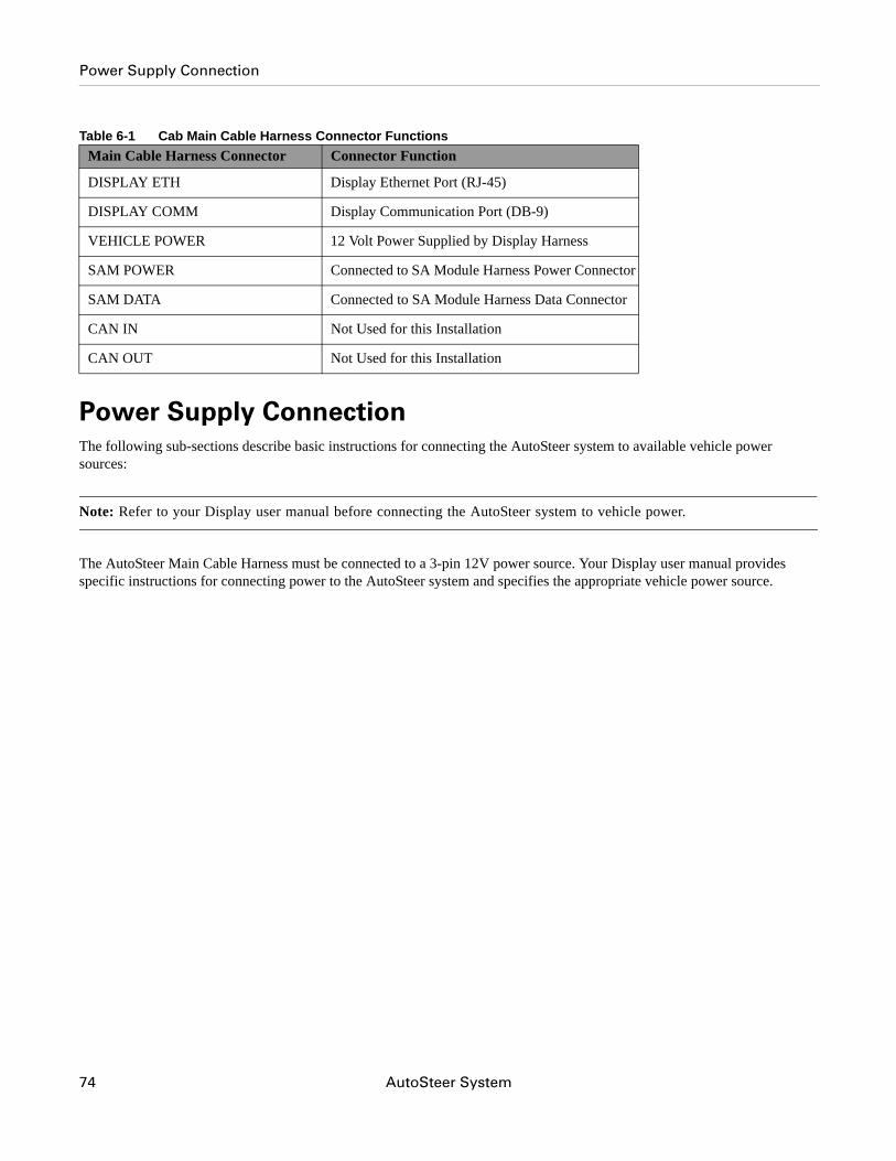
7. Refer to the display user manual for instructions on connecting the Main Cable Harness to the Display harnesses. The Main Cable Harness has a 12 volt power, RJ-45, and 9-pin serial connector that can be connected. The cable ends are shown in Figure 6-48.
Figure 6-48 Main Cable Harness Connectors
Hardware Installation Manual 73
Power Supply Connection
Table 6-1 Cab Main Cable Harness Connector Functions
Power Supply ConnectionThe following sub-sections describe basic instructions for connecting the AutoSteer system to available vehicle power sources:
Note: Refer to your Display user manual before connecting the AutoSteer system to vehicle power.
The AutoSteer Main Cable Harness must be connected to a 3-pin 12V power source. Your Display user manual provides specific instructions for connecting power to the AutoSteer system and specifies the appropriate vehicle power source.
Main Cable Harness Connector Connector Function
DISPLAY ETH Display Ethernet Port (RJ-45)
DISPLAY COMM Display Communication Port (DB-9)
VEHICLE POWER 12 Volt Power Supplied by Display Harness
SAM POWER Connected to SA Module Harness Power Connector
SAM DATA Connected to SA Module Harness Data Connector
CAN IN Not Used for this Installation
CAN OUT Not Used for this Installation
74 AutoSteer System
Power Supply Connection
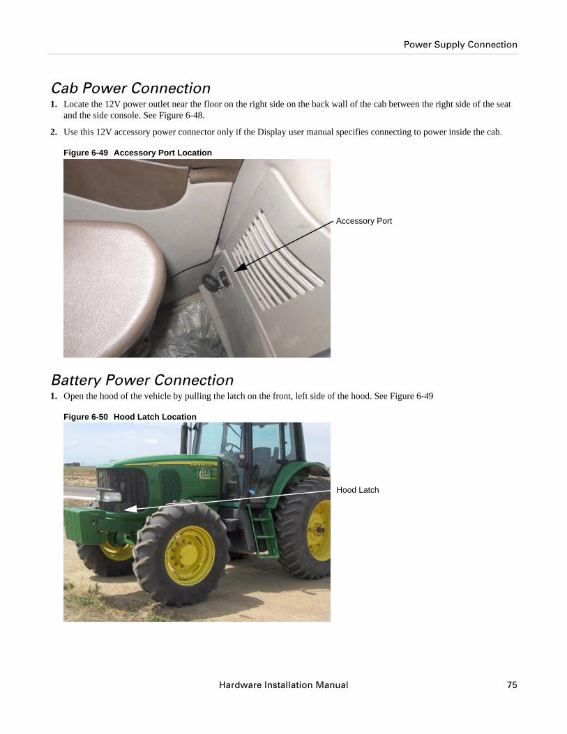
Cab Power Connection1. Locate the 12V power outlet near the floor on the right side on the back wall of the cab between the right side of the seat
and the side console. See Figure 6-48.
2. Use this 12V accessory power connector only if the Display user manual specifies connecting to power inside the cab.
Figure 6-49 Accessory Port Location
Battery Power Connection1. Open the hood of the vehicle by pulling the latch on the front, left side of the hood. See Figure 6-49
Figure 6-50 Hood Latch Location
Accessory Port
Hood Latch
Hardware Installation Manual 75

Power Supply Connection
2. After the latch has been pulled out, lift the hood up.
3. Locate the vehicle battery at the very front of the vehicle.
4. Connect to the vehicle battery only if the Display user manual specifies a direct battery connection.
Note: A battery cable is provided with the AutoSteer system when a direct battery connection is required.
76 AutoSteer System
Hardware Installation Guide
7Calibration and Tuning Notes
This Calibration and Tuning Notes chapter contains information for starting the Calibration and Tuning procedures in the following sections.
• Vehicle Specific Installation Calibration and Tuning Guidelines
Vehicle Specific Installation Calibration and Tuning Guidelines
Note: For optimal steering performance, the AutoSteer system must be fully calibrated and then tuned.
Select the appropriate John Deere AutoTrac vehicle model during the vehicle setup process to establish initial calibration and tuning parameters. Refer to your Display User Manual for vehicle setup procedure details.
77

Vehicle Specific Installation Calibration and Tuning Guidelines
78 AutoSteer System
Hardware Installation Guide
8Final Hardware Installation Checklist
This Final Checklist chapter contains the verifications steps necessary after the installation of the AutoSteer system.
Note: The Final Hardware Installation Checklist is on the back of this page. Tear this page out of your manual and fill in the checklist after the installation. You should keep a copy of this checklist for future reference when servicing the vehicle.
Machine Model: _________________________________ Year: _________ Serial #: _________________________
Customer Name: _______________________________________________________________________________
Location/Address: ______________________________________________________________________________
AutoSteer Installation Kit Part Number: ______________________________________________________________
NOTES
____________________________________________________________________________________________________
____________________________________________________________________________________________________
____________________________________________________________________________________________________
____________________________________________________________________________________________________
____________________________________________________________________________________________________
____________________________________________________________________________________________________
Name of Installer: __________________________________________ Date: ________________
79
Final Hardware Installation Checklist
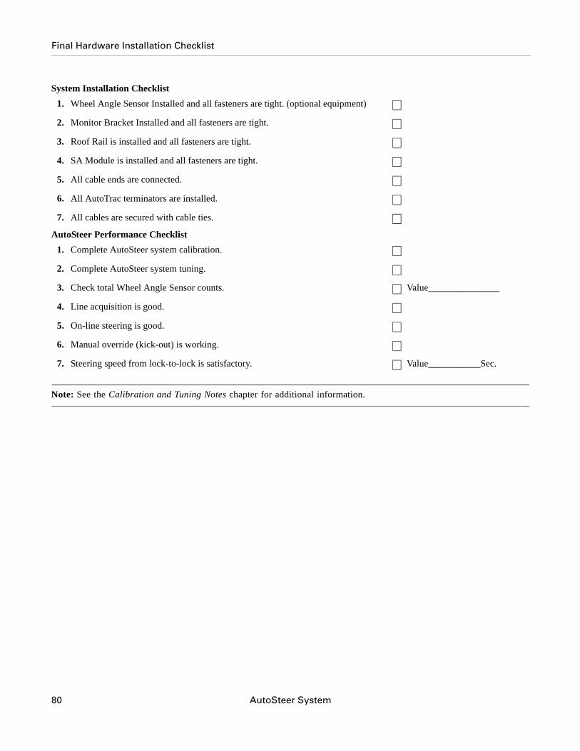
System Installation Checklist
AutoSteer Performance Checklist
Note: See the Calibration and Tuning Notes chapter for additional information.
1. Wheel Angle Sensor Installed and all fasteners are tight. (optional equipment)
2. Monitor Bracket Installed and all fasteners are tight.
3. Roof Rail is installed and all fasteners are tight.
4. SA Module is installed and all fasteners are tight.
5. All cable ends are connected.
6. All AutoTrac terminators are installed.
7. All cables are secured with cable ties.
1. Complete AutoSteer system calibration.
2. Complete AutoSteer system tuning.
3. Check total Wheel Angle Sensor counts. Value_______________
4. Line acquisition is good.
5. On-line steering is good.
6. Manual override (kick-out) is working.
7. Steering speed from lock-to-lock is satisfactory. Value___________Sec.
80 AutoSteer System