gp4000 series hardware manual - hmi store
TRANSCRIPT
2
The information provided in this documentation contains general descriptions and/or technical characteristics of the performance of the products contained herein. This documentation is not intended as a substitute for and is not to be used for determining suitability or reliability of these products for specific user applications. It is the duty of any such user or integrator to perform the appropriate and complete risk analysis, evaluation and testing of the products with respect to the relevant specific application or use thereof. Neither Pro-face nor any of its affiliates or subsidiaries shall be responsible or liable for misuse of the information that is contained herein. If you have any suggestions for improvements or amendments or have found errors in this publication, please notify us.
No part of this document may be reproduced in any form or by any means, electronic or mechanical, including photocopying, without express written permission of Pro-face.
All pertinent state, regional, and local safety regulations must be observed when installing and using this product. For reasons of safety and to help ensure compliance with documented system data, only the manufacturer should perform repairs to components.
When devices are used for applications with technical safety requirements, the relevant instructions must be followed.
Failure to use Pro-face software or approved software with our hardware products may result in injury, harm, or improper operating results.
Failure to observe this information can result in injury or equipment damage.
Copyright © 2013. 8 Digital Electronics Corporation. All Rights Reserved.
3
GP4000 Series Hardware Manual
Table of Contents
Safety Information . . . . . . . . . . . . . . . . . . . . . . . . . . . . . . 5About the Book . . . . . . . . . . . . . . . . . . . . . . . . . . . . . . . . . 9
Chapter 1 Overview . . . . . . . . . . . . . . . . . . . . . . . . . . . . . . . . . . . . . . 11GP unit Package Contents . . . . . . . . . . . . . . . . . . . . . . . . . . . . . . . . . . . . 12Certifications and Standards . . . . . . . . . . . . . . . . . . . . . . . . . . . . . . . . . . . 13GP Series of Panels . . . . . . . . . . . . . . . . . . . . . . . . . . . . . . . . . . . . . . . . . 15
Chapter 2 Device Connectivity . . . . . . . . . . . . . . . . . . . . . . . . . . . . . 17System Design . . . . . . . . . . . . . . . . . . . . . . . . . . . . . . . . . . . . . . . . . . . . . 18Accessories . . . . . . . . . . . . . . . . . . . . . . . . . . . . . . . . . . . . . . . . . . . . . . . . 27
Chapter 3 Parts Identification and Functions . . . . . . . . . . . . . . . . . 31Parts Identification and Functions . . . . . . . . . . . . . . . . . . . . . . . . . . . . . . . 31
Chapter 4 Specifications . . . . . . . . . . . . . . . . . . . . . . . . . . . . . . . . . . 434.1 GP-4200 Series. . . . . . . . . . . . . . . . . . . . . . . . . . . . . . . . . . . . . . . . . . . . . 44
Electrical Specifications. . . . . . . . . . . . . . . . . . . . . . . . . . . . . . . . . . . . . . . 45Environmental Specifications . . . . . . . . . . . . . . . . . . . . . . . . . . . . . . . . . . 46Structural Specifications . . . . . . . . . . . . . . . . . . . . . . . . . . . . . . . . . . . . . . 47Display Specifications . . . . . . . . . . . . . . . . . . . . . . . . . . . . . . . . . . . . . . . . 49Memory, Clock, and Touch Panel . . . . . . . . . . . . . . . . . . . . . . . . . . . . . . . 50Interface Specifications . . . . . . . . . . . . . . . . . . . . . . . . . . . . . . . . . . . . . . . 52Specifications of Serial Interface COM1 . . . . . . . . . . . . . . . . . . . . . . . . . . 53Specifications of Serial Interface COM2 . . . . . . . . . . . . . . . . . . . . . . . . . . 57Dimensions . . . . . . . . . . . . . . . . . . . . . . . . . . . . . . . . . . . . . . . . . . . . . . . . 58
4.2 GP-4300 Series. . . . . . . . . . . . . . . . . . . . . . . . . . . . . . . . . . . . . . . . . . . . . 64Electrical Specifications. . . . . . . . . . . . . . . . . . . . . . . . . . . . . . . . . . . . . . . 65Environmental Specifications . . . . . . . . . . . . . . . . . . . . . . . . . . . . . . . . . . 66Structural Specifications . . . . . . . . . . . . . . . . . . . . . . . . . . . . . . . . . . . . . . 67Display Specifications . . . . . . . . . . . . . . . . . . . . . . . . . . . . . . . . . . . . . . . . 69Memory, Clock, and Touch Panel . . . . . . . . . . . . . . . . . . . . . . . . . . . . . . . 70Interface Specifications . . . . . . . . . . . . . . . . . . . . . . . . . . . . . . . . . . . . . . . 72Specifications of Serial Interface COM1 . . . . . . . . . . . . . . . . . . . . . . . . . . 73Specifications of Serial Interface COM2 . . . . . . . . . . . . . . . . . . . . . . . . . . 75Dimensions . . . . . . . . . . . . . . . . . . . . . . . . . . . . . . . . . . . . . . . . . . . . . . . . 77
4.3 GP-4400 Series. . . . . . . . . . . . . . . . . . . . . . . . . . . . . . . . . . . . . . . . . . . . . 82Electrical Specifications. . . . . . . . . . . . . . . . . . . . . . . . . . . . . . . . . . . . . . . 83Environmental Specifications . . . . . . . . . . . . . . . . . . . . . . . . . . . . . . . . . . 84Structural Specifications . . . . . . . . . . . . . . . . . . . . . . . . . . . . . . . . . . . . . . 85Display Specifications . . . . . . . . . . . . . . . . . . . . . . . . . . . . . . . . . . . . . . . . 87Memory, Clock, and Touch Panel . . . . . . . . . . . . . . . . . . . . . . . . . . . . . . . 88Interface Specifications . . . . . . . . . . . . . . . . . . . . . . . . . . . . . . . . . . . . . . . 89Specifications of Serial Interface COM1 . . . . . . . . . . . . . . . . . . . . . . . . . . 90Specifications of Serial Interface COM2 . . . . . . . . . . . . . . . . . . . . . . . . . . 92Dimensions . . . . . . . . . . . . . . . . . . . . . . . . . . . . . . . . . . . . . . . . . . . . . . . . 93
4
4.4 GP-4500 Series . . . . . . . . . . . . . . . . . . . . . . . . . . . . . . . . . . . . . . . . . . . . 97Electrical Specifications . . . . . . . . . . . . . . . . . . . . . . . . . . . . . . . . . . . . . . 98Environmental Specifications. . . . . . . . . . . . . . . . . . . . . . . . . . . . . . . . . . 99Structural Specifications . . . . . . . . . . . . . . . . . . . . . . . . . . . . . . . . . . . . . 100Display Specifications . . . . . . . . . . . . . . . . . . . . . . . . . . . . . . . . . . . . . . . 102Memory, Clock, and Touch Panel . . . . . . . . . . . . . . . . . . . . . . . . . . . . . . 103Interface Specifications . . . . . . . . . . . . . . . . . . . . . . . . . . . . . . . . . . . . . . 104Specifications of Serial Interface COM1 . . . . . . . . . . . . . . . . . . . . . . . . . 105Specifications of Serial Interface COM2 . . . . . . . . . . . . . . . . . . . . . . . . . 107Dimensions . . . . . . . . . . . . . . . . . . . . . . . . . . . . . . . . . . . . . . . . . . . . . . . 109
4.5 GP-4600 Series . . . . . . . . . . . . . . . . . . . . . . . . . . . . . . . . . . . . . . . . . . . . 117Electrical Specifications . . . . . . . . . . . . . . . . . . . . . . . . . . . . . . . . . . . . . . 118Environmental Specifications. . . . . . . . . . . . . . . . . . . . . . . . . . . . . . . . . . 119Structural Specifications . . . . . . . . . . . . . . . . . . . . . . . . . . . . . . . . . . . . . 120Display Specifications . . . . . . . . . . . . . . . . . . . . . . . . . . . . . . . . . . . . . . . 122Memory, Clock, and Touch Panel . . . . . . . . . . . . . . . . . . . . . . . . . . . . . . 123Interface Specifications . . . . . . . . . . . . . . . . . . . . . . . . . . . . . . . . . . . . . . 124Specifications of Serial Interface COM1 . . . . . . . . . . . . . . . . . . . . . . . . . 125Specifications of Serial Interface COM2 . . . . . . . . . . . . . . . . . . . . . . . . . 127Dimensions . . . . . . . . . . . . . . . . . . . . . . . . . . . . . . . . . . . . . . . . . . . . . . . 129
Chapter 5 Installation and Wiring . . . . . . . . . . . . . . . . . . . . . . . . . . . 1355.1 Installation . . . . . . . . . . . . . . . . . . . . . . . . . . . . . . . . . . . . . . . . . . . . . . . . 136
Installation Procedures . . . . . . . . . . . . . . . . . . . . . . . . . . . . . . . . . . . . . . 1365.2 Wiring Principles . . . . . . . . . . . . . . . . . . . . . . . . . . . . . . . . . . . . . . . . . . . 141
Connecting the AC Power Cord. . . . . . . . . . . . . . . . . . . . . . . . . . . . . . . . 142Connecting the DC Power Cord. . . . . . . . . . . . . . . . . . . . . . . . . . . . . . . . 144Connecting the Power Supply . . . . . . . . . . . . . . . . . . . . . . . . . . . . . . . . . 147Grounding . . . . . . . . . . . . . . . . . . . . . . . . . . . . . . . . . . . . . . . . . . . . . . . . 149
5.3 SD Card Insertion/Removal . . . . . . . . . . . . . . . . . . . . . . . . . . . . . . . . . . . 150Introduction . . . . . . . . . . . . . . . . . . . . . . . . . . . . . . . . . . . . . . . . . . . . . . . 151Inserting the SD Card . . . . . . . . . . . . . . . . . . . . . . . . . . . . . . . . . . . . . . . 152Before Removing the SD Card . . . . . . . . . . . . . . . . . . . . . . . . . . . . . . . . 154Removing the SD Card . . . . . . . . . . . . . . . . . . . . . . . . . . . . . . . . . . . . . . 155SD Card Data Backup . . . . . . . . . . . . . . . . . . . . . . . . . . . . . . . . . . . . . . . 156
5.4 USB Cable Clamp . . . . . . . . . . . . . . . . . . . . . . . . . . . . . . . . . . . . . . . . . . 157USB Cable Clamp for USB (Type A) . . . . . . . . . . . . . . . . . . . . . . . . . . . . 158USB Holder for USB (mini-B). . . . . . . . . . . . . . . . . . . . . . . . . . . . . . . . . . 160
Chapter 6 Maintenance . . . . . . . . . . . . . . . . . . . . . . . . . . . . . . . . . . . . 163Regular Cleaning . . . . . . . . . . . . . . . . . . . . . . . . . . . . . . . . . . . . . . . . . . . 164Replacing the Installation Gasket . . . . . . . . . . . . . . . . . . . . . . . . . . . . . . 165Periodic Check Points . . . . . . . . . . . . . . . . . . . . . . . . . . . . . . . . . . . . . . . 167Replacing the Primary Battery . . . . . . . . . . . . . . . . . . . . . . . . . . . . . . . . . 168
Chapter 7 Rear Mount Model . . . . . . . . . . . . . . . . . . . . . . . . . . . . . . . 171Package Contents . . . . . . . . . . . . . . . . . . . . . . . . . . . . . . . . . . . . . . . . . . 172Certifications and Standards . . . . . . . . . . . . . . . . . . . . . . . . . . . . . . . . . . 173Options/Maintenance Option . . . . . . . . . . . . . . . . . . . . . . . . . . . . . . . . . . 175Parts Identification and Functions . . . . . . . . . . . . . . . . . . . . . . . . . . . . . . 176Structural Specifications . . . . . . . . . . . . . . . . . . . . . . . . . . . . . . . . . . . . . 182Dimensions . . . . . . . . . . . . . . . . . . . . . . . . . . . . . . . . . . . . . . . . . . . . . . . 184Installation . . . . . . . . . . . . . . . . . . . . . . . . . . . . . . . . . . . . . . . . . . . . . . . . 220
5
§
GP4000 Series Hardware Manual
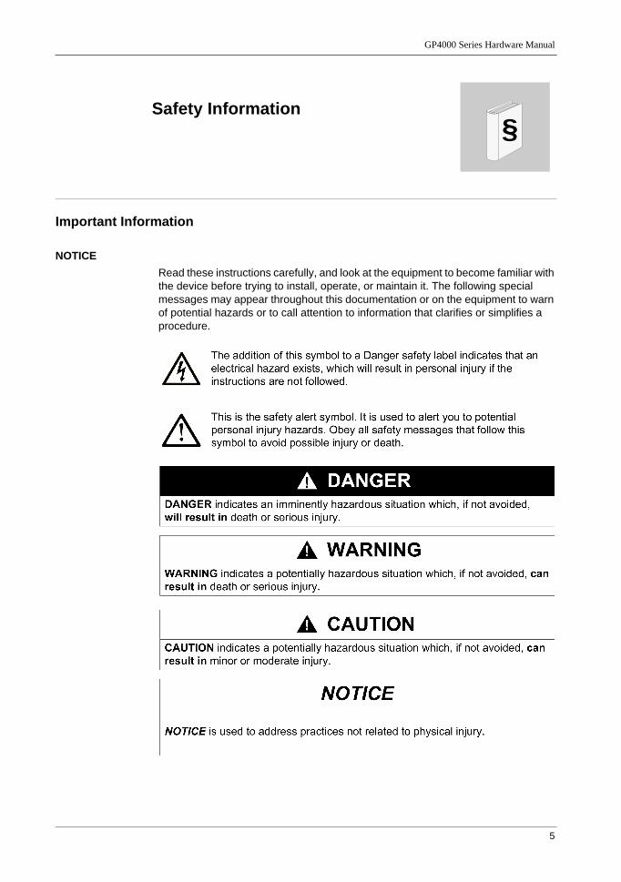
Safety Information
Important Information
NOTICERead these instructions carefully, and look at the equipment to become familiar with the device before trying to install, operate, or maintain it. The following special messages may appear throughout this documentation or on the equipment to warn of potential hazards or to call attention to information that clarifies or simplifies a procedure.
6
PLEASE NOTEElectrical equipment should be installed, operated, serviced, and maintained only by qualified personnel. No responsibility is assumed by Pro-face for any consequences arising out of the use of this material.
A qualified person is one who has skills and knowledge related to the construction and operation of electrical equipment and its installation, and has received safety training to recognize and avoid the hazards involved.
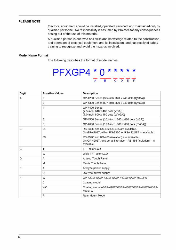
Model Name FormatThe following describes the format of model names.
Digit Possible Values Description
A 2 GP-4200 Series (3.5-inch, 320 x 240 dots (QVGA))
3 GP-4300 Series (5.7-inch, 320 x 240 dots (QVGA))
4 GP-4400 Series(7.5-inch, 640 x 480 dots (VGA))(7.0-inch, 800 x 480 dots (WVGA))
5 GP-4500 Series (10.4-inch, 640 x 480 dots (VGA))
6 GP-4600 Series (12.1-inch, 800 x 600 dots (SVGA))
B 01 RS-232C and RS-422/RS-485 are available.On GP-4201T, either RS-232C or RS-422/485 is available.
03 RS-232C and RS-485 (isolation) are available.On GP-4203T, one serial interface – RS-485 (isolation) – is available.
C T TFT color LCD
W Wide TFT color LCD
D A Analog Touch Panel
M Matrix Touch Panel
E A AC type power supply
D DC type power supply
F W GP-4201TW/GP-4301TW/GP-4401WW/GP-4501TW
C Coating model
WC Coating model of GP-4201TW/GP-4301TW/GP-4401WW/GP-4501TW
R Rear Mount Model
GP4000 Series Hardware Manual
7
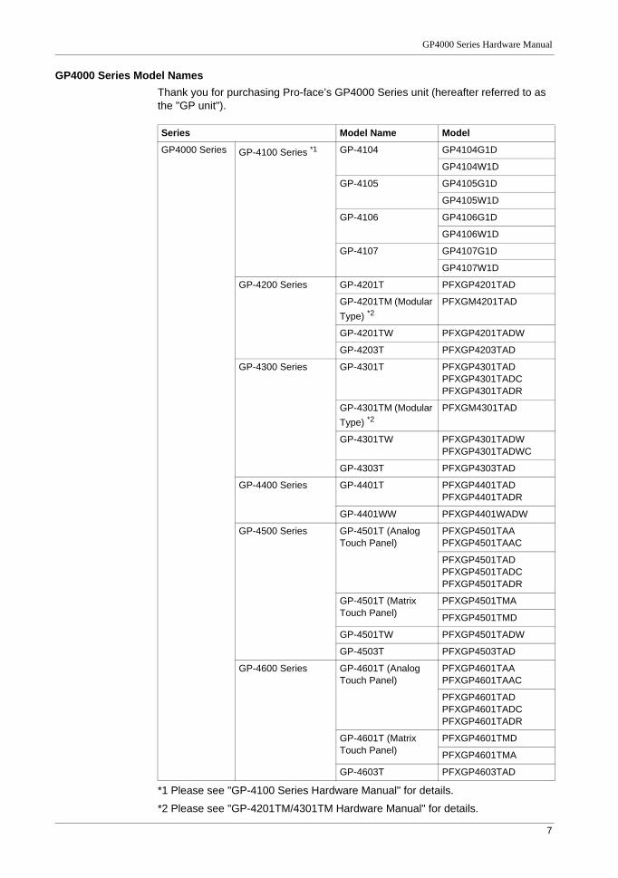
GP4000 Series Model NamesThank you for purchasing Pro-face’s GP4000 Series unit (hereafter referred to as the "GP unit").
*1 Please see "GP-4100 Series Hardware Manual" for details.
*2 Please see "GP-4201TM/4301TM Hardware Manual" for details.
Series Model Name Model
GP4000 Series GP-4100 Series *1 GP-4104 GP4104G1D
GP4104W1D
GP-4105 GP4105G1D
GP4105W1D
GP-4106 GP4106G1D
GP4106W1D
GP-4107 GP4107G1D
GP4107W1D
GP-4200 Series GP-4201T PFXGP4201TAD
GP-4201TM (Modular Type) *2
PFXGM4201TAD
GP-4201TW PFXGP4201TADW
GP-4203T PFXGP4203TAD
GP-4300 Series GP-4301T PFXGP4301TADPFXGP4301TADCPFXGP4301TADR
GP-4301TM (Modular Type) *2
PFXGM4301TAD
GP-4301TW PFXGP4301TADWPFXGP4301TADWC
GP-4303T PFXGP4303TAD
GP-4400 Series GP-4401T PFXGP4401TADPFXGP4401TADR
GP-4401WW PFXGP4401WADW
GP-4500 Series GP-4501T (Analog Touch Panel)
PFXGP4501TAAPFXGP4501TAAC
PFXGP4501TADPFXGP4501TADCPFXGP4501TADR
GP-4501T (Matrix Touch Panel)
PFXGP4501TMA
PFXGP4501TMD
GP-4501TW PFXGP4501TADW
GP-4503T PFXGP4503TAD
GP-4600 Series GP-4601T (Analog Touch Panel)
PFXGP4601TAAPFXGP4601TAAC
PFXGP4601TADPFXGP4601TADCPFXGP4601TADR
GP-4601T (Matrix Touch Panel)
PFXGP4601TMD
PFXGP4601TMA
GP-4603T PFXGP4603TAD

8
Global CodeA global code is assigned to every Pro-face product as a universal model number.
For more information on product models and their matching global codes, please
refer to the following URL.
http://www.pro-face.com/product/globalcode.html
9
GP4000 Series Hardware Manual
About the Book
At a Glance
Document ScopeThis document describes how to use the GP unit.
Validity NoteThis document is valid for the GP unit with GP-Pro EX version 3.0 or later.
The technical characteristics of the device(s) described in this manual also appear online at http://www.pro-face.com/otasuke/.
The characteristics presented in this manual should be the same as those that appear online. In line with our policy of constant improvement we may revise content over time to improve clarity and accuracy. In the event that you see a difference between the manual and online information, use the online information as your reference.
Related Documents
You can download these technical publications and other technical information from our website "Otasuke Pro!" at http://www.pro-face.com/otasuke/.
Product Related Information
Title of Documentation
GP-Pro EX Reference ManualGP-Pro EX Maintenance/Troubleshooting ManualGP-Pro EX Device/PLC Connection Manual
WARNINGUNINTENDED EQUIPMENT OPERATIONThe application of this product requires expertise in the design and programming of control systems. Only persons with such expertise should be allowed to program, install, alter, and apply this product.
Follow all local and national safety standards.
Failure to follow these instructions can result in death, serious injury, or equipment damage.

10
11
GP4000 Series Hardware Manual
1
GP4000 Series Hardware Manual
Overview
KanpaiHardwareManual 10/2011
Overview
OverviewThis chapter describes the GP unit panels and general topics such as package contents and standards.
What Is in This Chapter?This chapter contains the following topics:
Topic Page
GP unit Package Contents 12
Certifications and Standards 13
GP Series of Panels 15
Overview
12
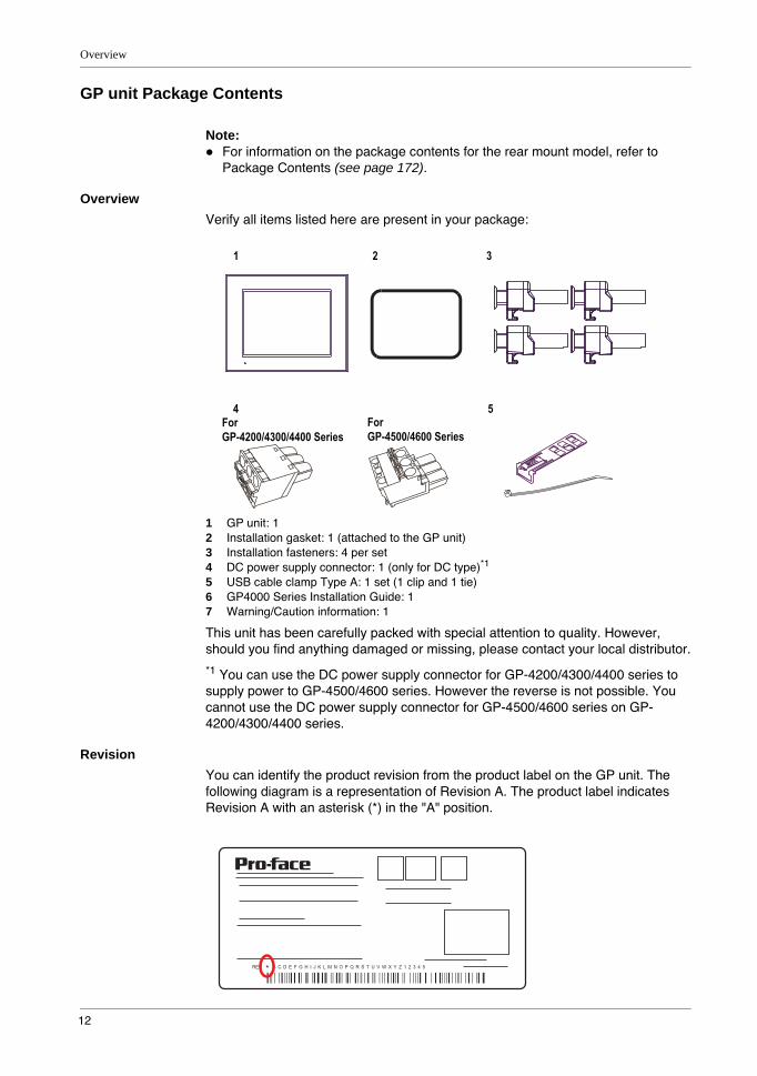
GP unit Package Contents
Note:For information on the package contents for the rear mount model, refer to Package Contents (see page 172).
OverviewVerify all items listed here are present in your package:
1 GP unit: 12 Installation gasket: 1 (attached to the GP unit)3 Installation fasteners: 4 per set4 DC power supply connector: 1 (only for DC type)*1
5 USB cable clamp Type A: 1 set (1 clip and 1 tie)6 GP4000 Series Installation Guide: 17 Warning/Caution information: 1
This unit has been carefully packed with special attention to quality. However, should you find anything damaged or missing, please contact your local distributor.
*1 You can use the DC power supply connector for GP-4200/4300/4400 series to supply power to GP-4500/4600 series. However the reverse is not possible. You cannot use the DC power supply connector for GP-4500/4600 series on GP-4200/4300/4400 series.
RevisionYou can identify the product revision from the product label on the GP unit. The following diagram is a representation of Revision A. The product label indicates Revision A with an asterisk (*) in the "A" position.
REV * B C D E F G H I J K L M N O P Q R S T U V W X Y Z 1 2 3 4 5
GP4000 Series Hardware Manual
13
Certifications and Standards
Note:For information on the certifications and standards of the rear mount model, refer to Certifications and Standards (see page 173).
IntroductionPro-face submitted this product for independent testing and qualification by third-party listing agencies. These agencies have certified this product as meeting the following standards.
Agency CertificationsThe GP unit is manufactured in accordance with:
UL 508 and CSA C22.2 n°142 for Industrial Control EquipmentStandard ANSI/ISA - 12.12.01 and CSA C22.2 n°213 for Electrical Equipment for Use in Class I, Division 2 Hazardous Locations
Note:For use in Pollution Degree 2 environments.For use on a flat surface of a Type 1, Type 4X (Indoor Use Only) or Type 13 Enclosure.24 Vdc input panel must be used with a Class 2 power supply.Suitable for use in Class I, Division 2 Groups A, B, C, and D Hazardous Locations.
Hazardous SubstancesThe GP is a device for use in factory systems. When using the GP in a system, the system should comply with the following standards in regards to the installation environment and handling:
WEEE, Directive 2012/19/EURoHS, Directive 2011/65/EURoHS China, Standard SJ/T 11363-2006
CE MarkingsThis product conforms to the necessary requirements of the following Directives for applying the CE label:
2006/95/EC Low Voltage Directive2004/108/EC EMC Directive
This conformity is based on compliance with EN61000-6-4, EN61000-6-2 (DC model, AC model)
This conformity is based on compliance with EN60950-1 (AC model)
For information on Standards and Regulations, such as certified models and certificates, see the following.http://www.pro-face.com/worldwide.html
Overview
14
KC Markings
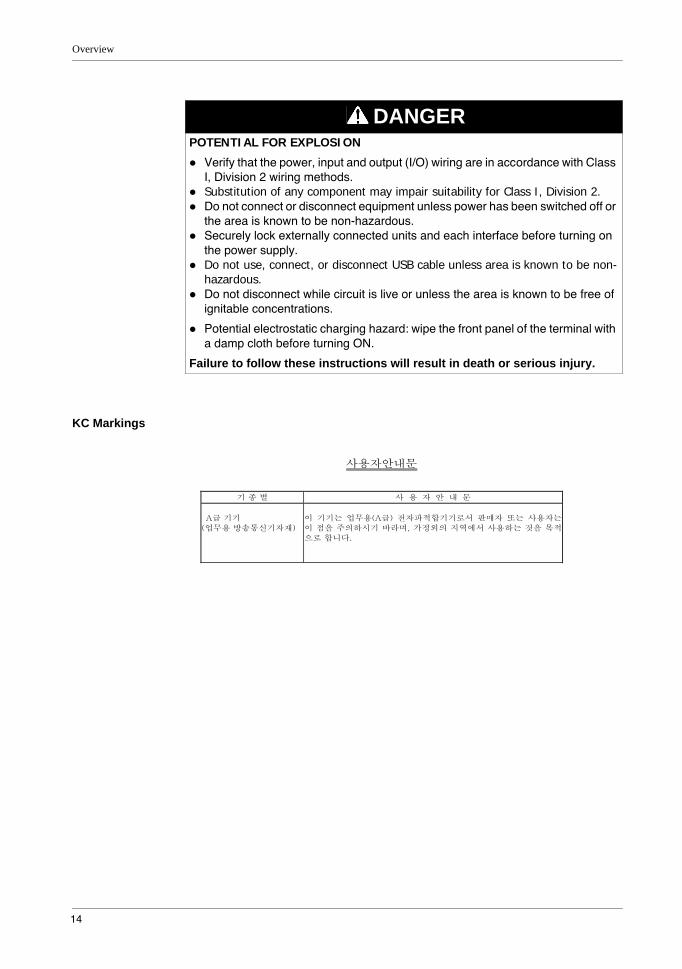
DANGERPOTENTIAL FOR EXPLOSION
Verify that the power, input and output (I/O) wiring are in accordance with Class I, Division 2 wiring methods.Substitution of any component may impair suitability for Class I, Division 2.Do not connect or disconnect equipment unless power has been switched off or the area is known to be non-hazardous.Securely lock externally connected units and each interface before turning on the power supply.Do not use, connect, or disconnect USB cable unless area is known to be non-hazardous.Do not disconnect while circuit is live or unless the area is known to be free of ignitable concentrations.
Potential electrostatic charging hazard: wipe the front panel of the terminal with a damp cloth before turning ON.
Failure to follow these instructions will result in death or serious injury.
GP4000 Series Hardware Manual
15
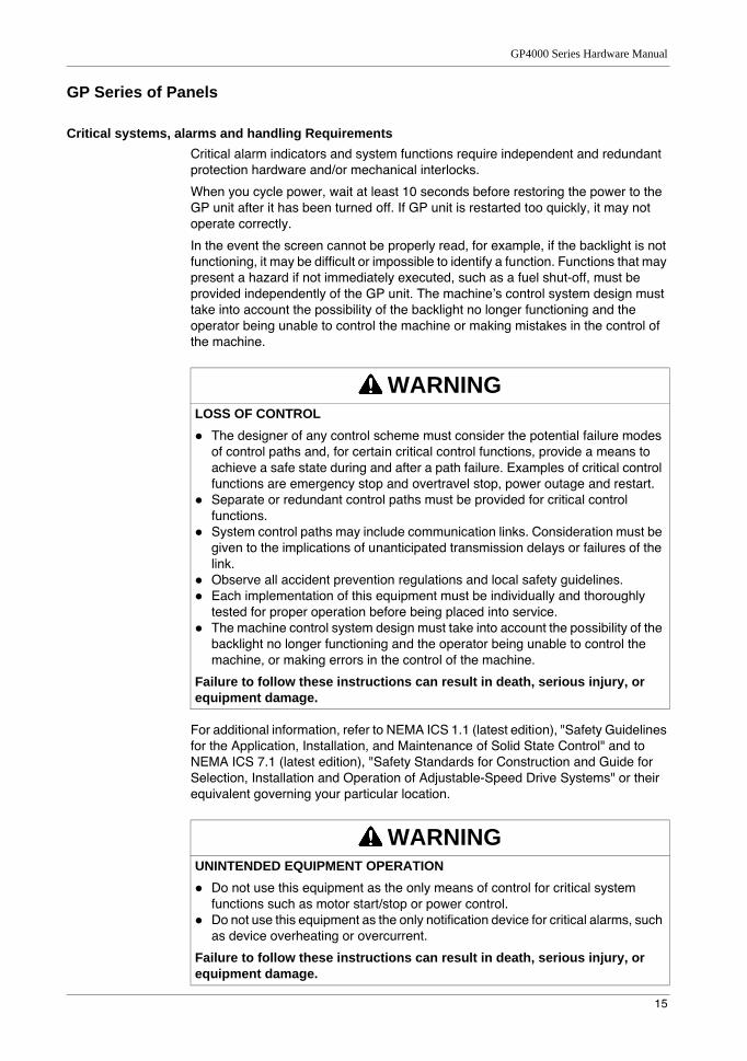
GP Series of Panels
Critical systems, alarms and handling RequirementsCritical alarm indicators and system functions require independent and redundant protection hardware and/or mechanical interlocks.
When you cycle power, wait at least 10 seconds before restoring the power to the GP unit after it has been turned off. If GP unit is restarted too quickly, it may not operate correctly.
In the event the screen cannot be properly read, for example, if the backlight is not functioning, it may be difficult or impossible to identify a function. Functions that may present a hazard if not immediately executed, such as a fuel shut-off, must be provided independently of the GP unit. The machine’s control system design must take into account the possibility of the backlight no longer functioning and the operator being unable to control the machine or making mistakes in the control of the machine.
For additional information, refer to NEMA ICS 1.1 (latest edition), "Safety Guidelines for the Application, Installation, and Maintenance of Solid State Control" and to NEMA ICS 7.1 (latest edition), "Safety Standards for Construction and Guide for Selection, Installation and Operation of Adjustable-Speed Drive Systems" or their equivalent governing your particular location.
WARNINGLOSS OF CONTROL
The designer of any control scheme must consider the potential failure modes of control paths and, for certain critical control functions, provide a means to achieve a safe state during and after a path failure. Examples of critical control functions are emergency stop and overtravel stop, power outage and restart.Separate or redundant control paths must be provided for critical control functions.System control paths may include communication links. Consideration must be given to the implications of unanticipated transmission delays or failures of the link.Observe all accident prevention regulations and local safety guidelines.Each implementation of this equipment must be individually and thoroughly tested for proper operation before being placed into service.The machine control system design must take into account the possibility of the backlight no longer functioning and the operator being unable to control the machine, or making errors in the control of the machine.
Failure to follow these instructions can result in death, serious injury, or equipment damage.
WARNINGUNINTENDED EQUIPMENT OPERATION
Do not use this equipment as the only means of control for critical system functions such as motor start/stop or power control.Do not use this equipment as the only notification device for critical alarms, such as device overheating or overcurrent.
Failure to follow these instructions can result in death, serious injury, or equipment damage.
Overview
16
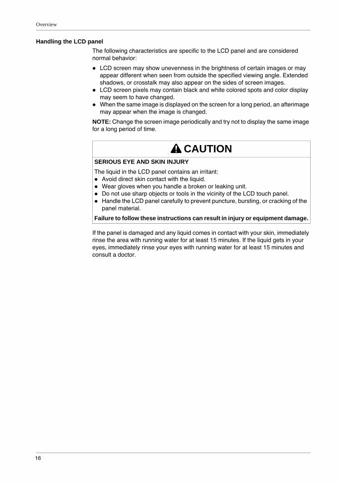
Handling the LCD panelThe following characteristics are specific to the LCD panel and are considered normal behavior:
LCD screen may show unevenness in the brightness of certain images or may appear different when seen from outside the specified viewing angle. Extended shadows, or crosstalk may also appear on the sides of screen images.LCD screen pixels may contain black and white colored spots and color display may seem to have changed.When the same image is displayed on the screen for a long period, an afterimage may appear when the image is changed.
NOTE: Change the screen image periodically and try not to display the same image for a long period of time.
If the panel is damaged and any liquid comes in contact with your skin, immediately rinse the area with running water for at least 15 minutes. If the liquid gets in your eyes, immediately rinse your eyes with running water for at least 15 minutes and consult a doctor.
CAUTIONSERIOUS EYE AND SKIN INJURYThe liquid in the LCD panel contains an irritant:
Avoid direct skin contact with the liquid.Wear gloves when you handle a broken or leaking unit.Do not use sharp objects or tools in the vicinity of the LCD touch panel.Handle the LCD panel carefully to prevent puncture, bursting, or cracking of the panel material.
Failure to follow these instructions can result in injury or equipment damage.
17
GP4000 Series Hardware Manual
2
GP4000 Series Hardware ManualConnectivityKanpaiHardwareManual 10/2011
Device Connectivity
IntroductionThis chapter presents the equipment you can connect to the GP unit.
What Is in This Chapter?This chapter contains the following topics:
Topic Page
System Design 18
Accessories 27
Connectivity
18
System Design
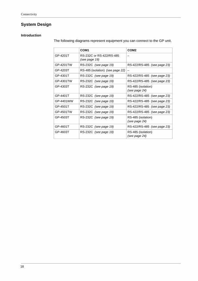
IntroductionThe following diagrams represent equipment you can connect to the GP unit.
COM1 COM2
GP-4201T RS-232C or RS-422/RS-485 (see page 19)
–
GP-4201TW RS-232C (see page 19) RS-422/RS-485 (see page 23)
GP-4203T RS-485 (isolation) (see page 22) –
GP-4301T RS-232C (see page 19) RS-422/RS-485 (see page 23)
GP-4301TW RS-232C (see page 19) RS-422/RS-485 (see page 23)
GP-4303T RS-232C (see page 19) RS-485 (isolation) (see page 24)
GP-4401T RS-232C (see page 19) RS-422/RS-485 (see page 23)
GP-4401WW RS-232C (see page 19) RS-422/RS-485 (see page 23)
GP-4501T RS-232C (see page 19) RS-422/RS-485 (see page 23)
GP-4501TW RS-232C (see page 19) RS-422/RS-485 (see page 23)
GP-4503T RS-232C (see page 19) RS-485 (isolation) (see page 24)
GP-4601T RS-232C (see page 19) RS-422/RS-485 (see page 23)
GP-4603T RS-232C (see page 19) RS-485 (isolation) (see page 24)
GP4000 Series Hardware Manual
19
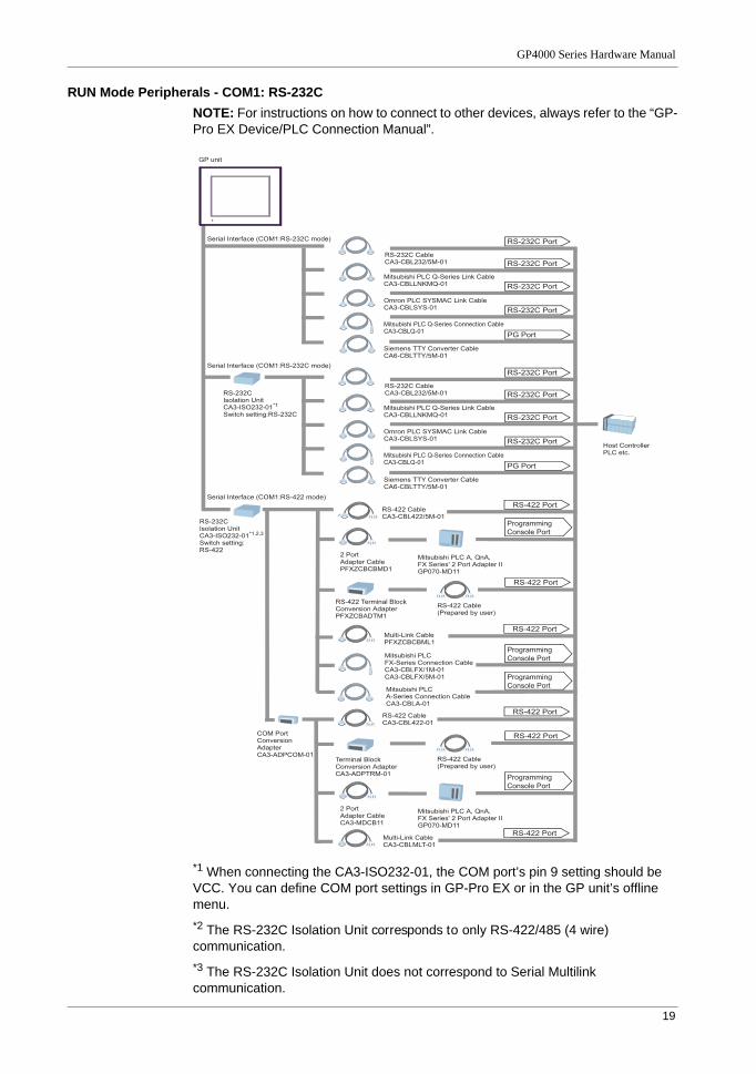
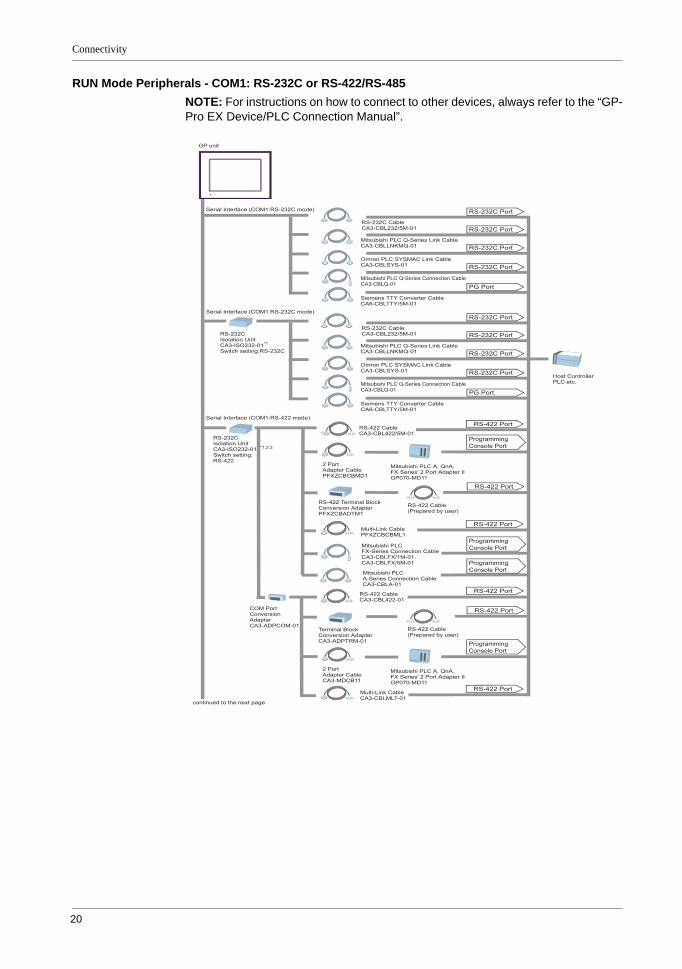
RUN Mode Peripherals - COM1: RS-232CNOTE: For instructions on how to connect to other devices, always refer to the “GP-Pro EX Device/PLC Connection Manual”.
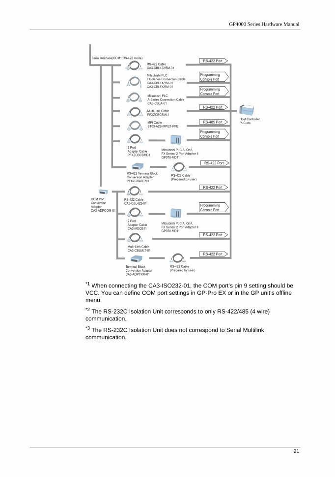
*1 When connecting the CA3-ISO232-01, the COM port’s pin 9 setting should be VCC. You can define COM port settings in GP-Pro EX or in the GP unit’s offline menu.*2 The RS-232C Isolation Unit corresponds to only RS-422/485 (4 wire) communication.*3 The RS-232C Isolation Unit does not correspond to Serial Multilink communication.
GP unit
Host ControllerPLC etc.
Serial Interface (COM1:RS-232C mode)
Serial Interface (COM1:RS-232C mode)
Serial Interface (COM1:RS-422 mode)
RS-232C CableCA3-CBL232/5M-01
Mitsubishi PLC Q-Series Link CableCA3-CBLLNKMQ-01
Omron PLC SYSMAC Link CableCA3-CBLSYS-01
Mitsubishi PLC Q-Series Connection CableCA3-CBLQ-01
Siemens TTY Converter CableCA6-CBLTTY/5M-01
RS-232C Port
RS-232C Port
RS-232C Port
RS-232C Port
PG Port
RS-232C CableCA3-CBL232/5M-01
Mitsubishi PLC Q-Series Link CableCA3-CBLLNKMQ-01
Omron PLC SYSMAC Link CableCA3-CBLSYS-01
Mitsubishi PLC Q-Series Connection CableCA3-CBLQ-01
Siemens TTY Converter CableCA6-CBLTTY/5M-01
RS-232C Port
RS-232C Port
RS-232C Port
RS-232C Port
PG Port
RS-422 Port
RS-422 Port
RS-232CIsolation UnitCA3-ISO232-01*1
Switch setting:RS-232C
RS-232CIsolation UnitCA3-ISO232-01*1,2,3
Switch setting:RS-422
RS-422 CableCA3-CBL422-01
COM Port Conversion AdapterCA3-ADPCOM-01
RS-422 Cable (Prepared by user)
Terminal Block Conversion AdapterCA3-ADPTRM-01
RS-422 Port
Mitsubishi PLC A, QnA, FX Series' 2 Port Adapter IIGP070-MD11
2 PortAdapter CablePFXZCBCBMD1
Programming Console Port
Mitsubishi PLC A, QnA, FX Series' 2 Port Adapter IIGP070-MD11
2 PortAdapter CableCA3-MDCB11
Programming Console Port
RS-422 CableCA3-CBL422/5M-01
RS-422 Terminal Block Conversion AdapterPFXZCBADTM1
RS-422 Port
RS-422 Cable (Prepared by user)
RS-422 PortMulti-Link CablePFXZCBCBML1
RS-422 PortMulti-Link CableCA3-CBLMLT-01
Mitsubishi PLC A-Series Connection CableCA3-CBLA-01
Mitsubishi PLC FX-Series Connection CableCA3-CBLFX/1M-01CA3-CBLFX/5M-01
Programming Console Port
Programming Console Port
Connectivity
20
RUN Mode Peripherals - COM1: RS-232C or RS-422/RS-485 NOTE: For instructions on how to connect to other devices, always refer to the “GP-Pro EX Device/PLC Connection Manual”.
GP unit
Host ControllerPLC etc.
Serial Interface (COM1:RS-232C mode)
Serial Interface (COM1:RS-232C mode)
Serial Interface (COM1:RS-422 mode)
RS-232C CableCA3-CBL232/5M-01
Mitsubishi PLC Q-Series Link CableCA3-CBLLNKMQ-01
Omron PLC SYSMAC Link CableCA3-CBLSYS-01
Mitsubishi PLC Q-Series Connection CableCA3-CBLQ-01
Siemens TTY Converter CableCA6-CBLTTY/5M-01
RS-232C Port
RS-232C Port
RS-232C Port
RS-232C Port
PG Port
RS-232C CableCA3-CBL232/5M-01
Mitsubishi PLC Q-Series Link CableCA3-CBLLNKMQ-01
Omron PLC SYSMAC Link CableCA3-CBLSYS-01
Mitsubishi PLC Q-Series Connection CableCA3-CBLQ-01
Siemens TTY Converter CableCA6-CBLTTY/5M-01
RS-232C Port
RS-232C Port
RS-232C Port
RS-232C Port
PG Port
RS-422 Port
RS-422 Port
RS-232CIsolation UnitCA3-ISO232-01*1
Switch setting:RS-232C
RS-232CIsolation UnitCA3-ISO232-01 *1,2,3
Switch setting:RS-422
RS-422 CableCA3-CBL422-01
COM Port Conversion AdapterCA3-ADPCOM-01
RS-422 Cable (Prepared by user)
Terminal Block Conversion AdapterCA3-ADPTRM-01
continued to the next page
RS-422 Port
Mitsubishi PLC A, QnA, FX Series' 2 Port Adapter IIGP070-MD11
2 PortAdapter CablePFXZCBCBMD1
Programming Console Port
Mitsubishi PLC A, QnA, FX Series' 2 Port Adapter IIGP070-MD11
2 PortAdapter CableCA3-MDCB11
Programming Console Port
RS-422 CableCA3-CBL422/5M-01
RS-422 Terminal Block Conversion AdapterPFXZCBADTM1
RS-422 Port
RS-422 Cable (Prepared by user)
RS-422 PortMulti-Link CablePFXZCBCBML1
RS-422 PortMulti-Link CableCA3-CBLMLT-01
Mitsubishi PLC A-Series Connection CableCA3-CBLA-01
Mitsubishi PLC FX-Series Connection CableCA3-CBLFX/1M-01CA3-CBLFX/5M-01
Programming Console Port
Programming Console Port
GP4000 Series Hardware Manual
21
*1 When connecting the CA3-ISO232-01, the COM port’s pin 9 setting should be VCC. You can define COM port settings in GP-Pro EX or in the GP unit’s offline menu.*2 The RS-232C Isolation Unit corresponds to only RS-422/485 (4 wire) communication.*3 The RS-232C Isolation Unit does not correspond to Serial Multilink communication.
Host ControllerPLC etc.
Mitsubishi PLC A-Series Connection CableCA3-CBLA-01
Mitsubishi PLC FX-Series Connection CableCA3-CBLFX/1M-01CA3-CBLFX/5M-01
MPI Cable ST03-A2B-MPI21-PFE
RS-422 Port
RS-485 Port
RS-422 Port
RS-422 Port
Programming Console Port
Programming Console Port
Serial Interface(COM1:RS-422 mode)
RS-422 CableCA3-CBL422-01
Mitsubishi PLC A, QnA, FX Series' 2 Port Adapter IIGP070-MD11
RS-422 CableCA3-CBL422/5M-01
2 PortAdapter CableCA3-MDCB11
COM Port Conversion AdapterCA3-ADPCOM-01
Programming Console Port
RS-422 Port
RS-422 Cable (Prepared by user)
Terminal Block Conversion AdapterCA3-ADPTRM-01
RS-422 Port
Mitsubishi PLC A, QnA, FX Series' 2 Port Adapter IIGP070-MD11
2 PortAdapter CablePFXZCBCBMD1
Programming Console Port
Multi-Link CableCA3-CBLMLT-01
Multi-Link CablePFXZCBCBML1
RS-422 Terminal Block Conversion AdapterPFXZCBADTM1
RS-422 Port
RS-422 Cable (Prepared by user)
Connectivity
22
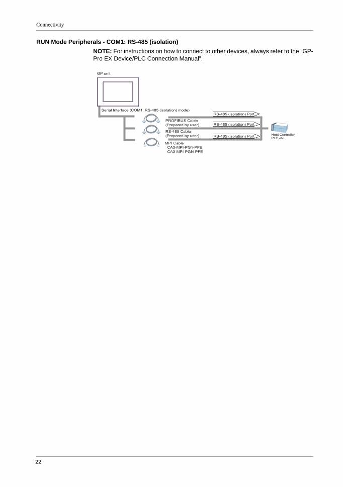
RUN Mode Peripherals - COM1: RS-485 (isolation)NOTE: For instructions on how to connect to other devices, always refer to the “GP-Pro EX Device/PLC Connection Manual”.
GP unit
Host ControllerPLC etc.
Serial Interface (COM1: RS-485 (isolation) mode)
PROFIBUS Cable(Prepared by user)
RS-485 Cable(Prepared by user)
MPI Cable CA3-MPI-PG1-PFE CA3-MPI-PGN-PFE
RS-485 (isolation) Port
RS-485 (isolation) Port
RS-485 (isolation) Port
GP4000 Series Hardware Manual
23
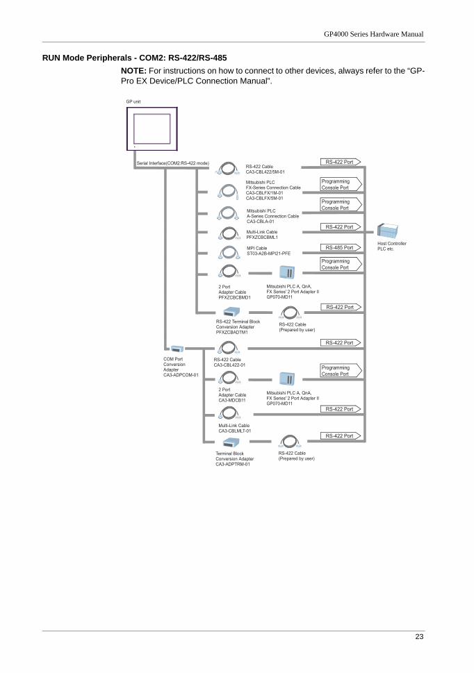
RUN Mode Peripherals - COM2: RS-422/RS-485NOTE: For instructions on how to connect to other devices, always refer to the “GP-Pro EX Device/PLC Connection Manual”.
Host ControllerPLC etc.
Mitsubishi PLC A-Series Connection CableCA3-CBLA-01
Mitsubishi PLC FX-Series Connection CableCA3-CBLFX/1M-01CA3-CBLFX/5M-01
MPI Cable ST03-A2B-MPI21-PFE
RS-422 Port
RS-485 Port
RS-422 Port
RS-422 Port
Programming Console Port
Programming Console Port
Serial Interface(COM2:RS-422 mode)
RS-422 CableCA3-CBL422-01
Mitsubishi PLC A, QnA, FX Series' 2 Port Adapter IIGP070-MD11
RS-422 CableCA3-CBL422/5M-01
2 PortAdapter CableCA3-MDCB11
COM Port Conversion AdapterCA3-ADPCOM-01
Programming Console Port
RS-422 Port
RS-422 Cable (Prepared by user)
Terminal Block Conversion AdapterCA3-ADPTRM-01
RS-422 Port
Mitsubishi PLC A, QnA, FX Series' 2 Port Adapter IIGP070-MD11
2 PortAdapter CablePFXZCBCBMD1
Programming Console Port
Multi-Link CableCA3-CBLMLT-01
Multi-Link CablePFXZCBCBML1
GP unit
RS-422 Terminal Block Conversion AdapterPFXZCBADTM1
RS-422 Port
RS-422 Cable (Prepared by user)
Connectivity
24
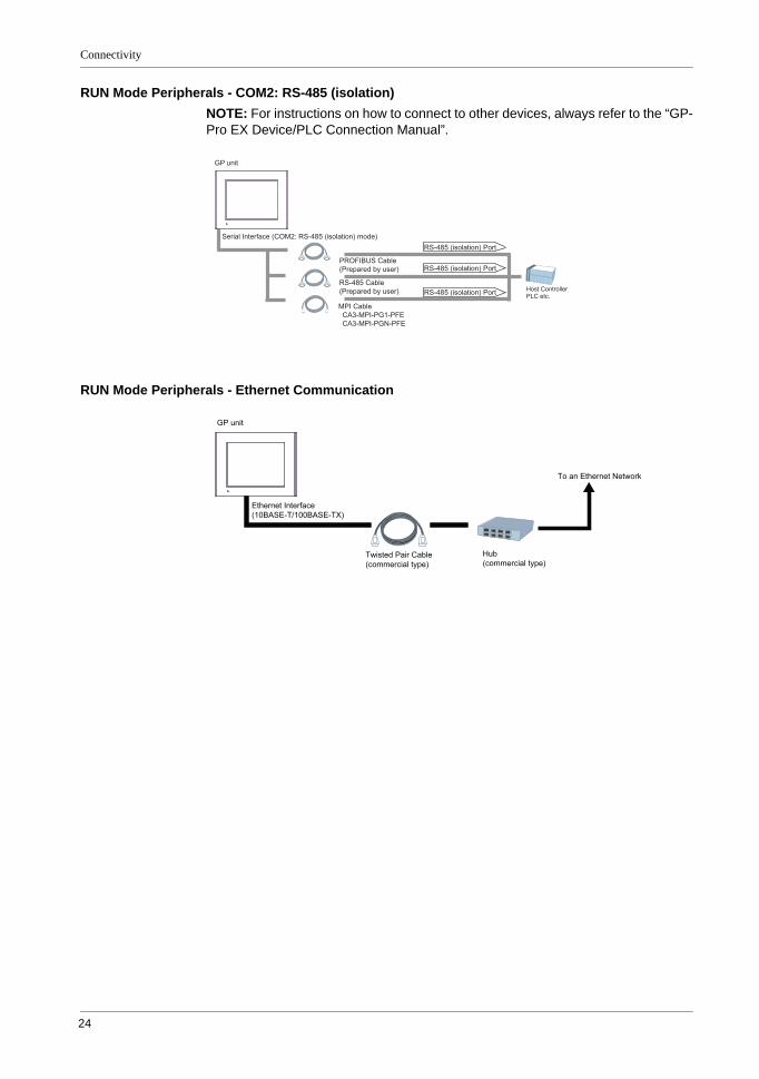
RUN Mode Peripherals - COM2: RS-485 (isolation)NOTE: For instructions on how to connect to other devices, always refer to the “GP-Pro EX Device/PLC Connection Manual”.
RUN Mode Peripherals - Ethernet Communication
GP unit
Host ControllerPLC etc.
Serial Interface (COM2: RS-485 (isolation) mode)
PROFIBUS Cable(Prepared by user)
RS-485 Cable(Prepared by user)
MPI Cable CA3-MPI-PG1-PFE CA3-MPI-PGN-PFE
RS-485 (isolation) Port
RS-485 (isolation) Port
RS-485 (isolation) Port
GP unit
Ethernet Interface (10BASE-T/100BASE-TX)
Twisted Pair Cable (commercial type)
Hub (commercial type)
To an Ethernet Network
GP4000 Series Hardware Manual
25
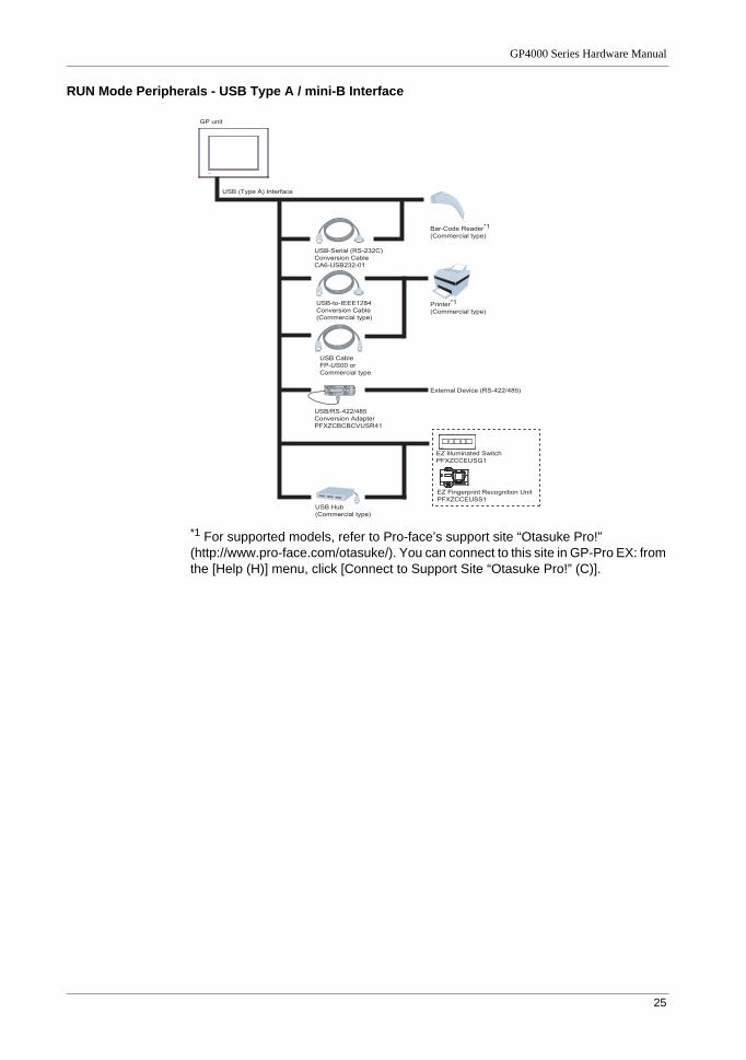
RUN Mode Peripherals - USB Type A / mini-B Interface
*1 For supported models, refer to Pro-face’s support site “Otasuke Pro!” (http://www.pro-face.com/otasuke/). You can connect to this site in GP-Pro EX: from the [Help (H)] menu, click [Connect to Support Site “Otasuke Pro!” (C)].
GP unit
USB (Type A) Interface
Bar-Code Reader*1(Commercial type)
Printer*1(Commercial type)
External Device (RS-422/485)
USB CableFP-US00 or Commercial type
USB-to-IEEE1284Conversion Cable(Commercial type)
USB-Serial (RS-232C) Conversion CableCA6-USB232-01
USB/RS-422/485Conversion AdapterPFXZCBCBCVUSR41
EZ Illuminated SwitchPFXZCCEUSG1
EZ Fingerprint Recognition UnitPFXZCCEUSS1
USB Hub(Commercial type)
Connectivity
26
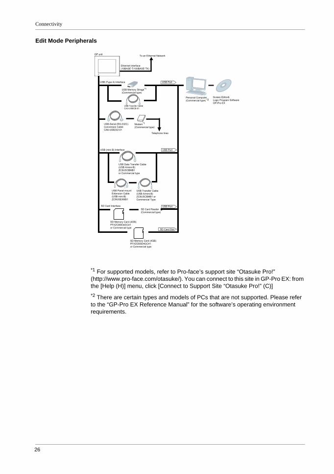
Edit Mode Peripherals
*1 For supported models, refer to Pro-face’s support site “Otasuke Pro!” (http://www.pro-face.com/otasuke/). You can connect to this site in GP-Pro EX: from the [Help (H)] menu, click [Connect to Support Site “Otasuke Pro!” (C)]*2 There are certain types and models of PCs that are not supported. Please refer to the “GP-Pro EX Reference Manual” for the software’s operating environment requirements.
GP unit
USB (Type A) Interface
Ethernet Interface(10BASE-T/100BASE-TX)
To an Ethernet Network
USB Memory Strage*1(Commercial type)
Modem*1(Commercial type)
USB Port
Personal Computer(Commercial type) *2
Screen Editor&Logic Program SoftwareGP-Pro EX
USB Transfer CableCA3-USBCB-01
USB (mini B) Interface
SD Card Interface
USB Port
USB Port
SD Card Slot
USB Data Transfer Cable(USB A/mini-B)ZC9USCBMB1or Commercial type
USB Transfer Cable(USB A/mini-B)ZC9USCBMB1 or Commercial Type
USB Panel-mountExtension Cable(USB mini-B)ZC9USEXMB1
SD Memory Card (4GB) PFXZCBSD4GC41or Commercial type
SD Card Reader(Commercial type)
SD Memory Card (4GB) PFXZCBSD4GC41or Commercial type
USB-Serial (RS-232C)Conversion CableCA6-USB232-01
Telephone lines
GP4000 Series Hardware Manual
27
Accessories
Serial Interface Items
Product Name Product Number Description
RS-232C Cable (5m) CA3-CBL232/5M-01 Connects a host controller to the GP unit. (RS-232C)
RS-422 Cable (5m) CA3-CBL422/5M-01 Connects a host controller to the GP unit. (RS-422 / Socket Type)
Mitsubishi PLC Q-Series Link Cable (5m)
CA3-CBLLNKMQ-01 Connects Mitsubishi PLC Q-Series (or other host controller) to the GP unit. (RS-232C)
Omron PLC SYSMAC Link Cable (5m)
CA3-CBLSYS-01 Connects Omron PLC SYSMAC Series unit (or other host controller) to the GP unit. (RS-232C)
Mitsubishi PLC A-Series Connection Cable (5m)
CA3-CBLA-01 Connects Mitsubishi PLC A or QnA Series programming console I/F to GP unit. (Simultaneous use of programming consoles is not possible.)
Mitsubishi PLC Q-Series Connection Cable (5m)
CA3-CBLQ-01 Connects Mitsubishi PLC Q-Series programming console I/F to GP unit. (Simultaneous use of programming consoles is not possible.)
Mitsubishi PLC FX-Series Connection Cable
CA3-CBLFX/1M-01 (1m)CA3-CBLFX/5M-01 (5m)
Connects Mitsubishi PLC FX-Series programming console I/F and GP unit. (Simultaneous use of programming consoles is not possible.)
RS-422 Cable (5m) CA3-CBL422-01 Connects a host controller to the GP unit. (RS-422 / Plug Type)
2 Port Adapter Cable (5m) CA3-MDCB11 Connects Mitsubishi PLC to the GP unit using 2 port adapter II (RS-422). Please see "GP-Pro EX Device/PLC Connection Manual" for how to connect the cable.
PFXZCBCBMD1 Connects Mitsubishi PLC directly to the GP unit (D-sub 9 pin plug) using 2 port adapter II (RS-422).
Mitsubishi PLC A, QnA, FX Series 2 Port Adapter II
GP070-MD11 Enables simultaneous use of a GP unit and a Mitsubishi PLC A, QnA, or FX Series peripheral device.
Terminal Block Conversion Adapter
CA3-ADPTRM-01 Connects output from a GP unit’s Serial Interface (D-sub 9 pin plug) directly with an RS-422 terminal block.
RS-422 Terminal Block Conversion Adapter
PFXZCBADTM1 Connects output from a GP unit’s Serial Interface (D-sub 9 pin plug) directly with an RS-422 terminal block.
COM Port Conversion Adapter CA3-ADPCOM-01 Connects optional RS-422 communication items to GP unit’s Serial Interface.
Multi-Link Cable (5m) CA3-CBLMLT-01 Connects a host controller to the GP unit for multi-link (n:1) communication. Please see "GP-Pro EX Device/PLC Connection Manual" for how to connect the cable.
PFXZCBCBML1 Connects a host controller directly to the GP unit (D-sub 9 pin plug) for multi-link (n:1) communication.
Connectivity
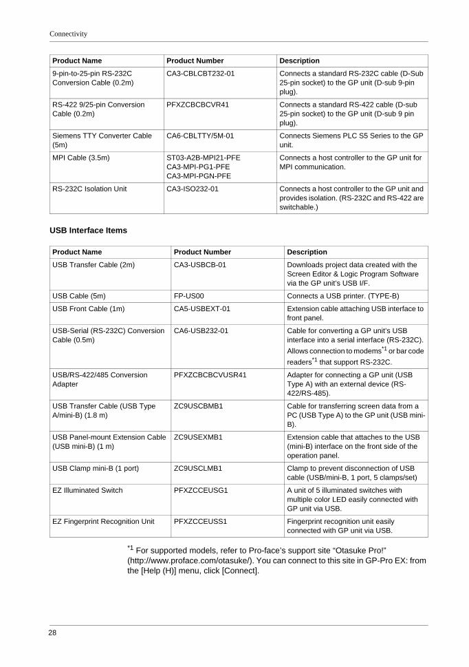
28
USB Interface Items
*1 For supported models, refer to Pro-face’s support site “Otasuke Pro!” (http://www.proface.com/otasuke/). You can connect to this site in GP-Pro EX: from the [Help (H)] menu, click [Connect].
9-pin-to-25-pin RS-232C Conversion Cable (0.2m)
CA3-CBLCBT232-01 Connects a standard RS-232C cable (D-Sub 25-pin socket) to the GP unit (D-sub 9-pin plug).
RS-422 9/25-pin Conversion Cable (0.2m)
PFXZCBCBCVR41 Connects a standard RS-422 cable (D-sub 25-pin socket) to the GP unit (D-sub 9 pin plug).
Siemens TTY Converter Cable (5m)
CA6-CBLTTY/5M-01 Connects Siemens PLC S5 Series to the GP unit.
MPI Cable (3.5m) ST03-A2B-MPI21-PFECA3-MPI-PG1-PFECA3-MPI-PGN-PFE
Connects a host controller to the GP unit for MPI communication.
RS-232C Isolation Unit CA3-ISO232-01 Connects a host controller to the GP unit and provides isolation. (RS-232C and RS-422 are switchable.)
Product Name Product Number Description
Product Name Product Number Description
USB Transfer Cable (2m) CA3-USBCB-01 Downloads project data created with the Screen Editor & Logic Program Software via the GP unit’s USB I/F.
USB Cable (5m) FP-US00 Connects a USB printer. (TYPE-B)
USB Front Cable (1m) CA5-USBEXT-01 Extension cable attaching USB interface to front panel.
USB-Serial (RS-232C) Conversion Cable (0.5m)
CA6-USB232-01 Cable for converting a GP unit’s USB interface into a serial interface (RS-232C).Allows connection to modems*1 or bar code readers*1 that support RS-232C.
USB/RS-422/485 Conversion Adapter
PFXZCBCBCVUSR41 Adapter for connecting a GP unit (USB Type A) with an external device (RS-422/RS-485).
USB Transfer Cable (USB Type A/mini-B) (1.8 m)
ZC9USCBMB1 Cable for transferring screen data from a PC (USB Type A) to the GP unit (USB mini-B).
USB Panel-mount Extension Cable (USB mini-B) (1 m)
ZC9USEXMB1 Extension cable that attaches to the USB (mini-B) interface on the front side of the operation panel.
USB Clamp mini-B (1 port) ZC9USCLMB1 Clamp to prevent disconnection of USB cable (USB/mini-B, 1 port, 5 clamps/set)
EZ Illuminated Switch PFXZCCEUSG1 A unit of 5 illuminated switches with multiple color LED easily connected with GP unit via USB.
EZ Fingerprint Recognition Unit PFXZCCEUSS1 Fingerprint recognition unit easily connected with GP unit via USB.
GP4000 Series Hardware Manual
29
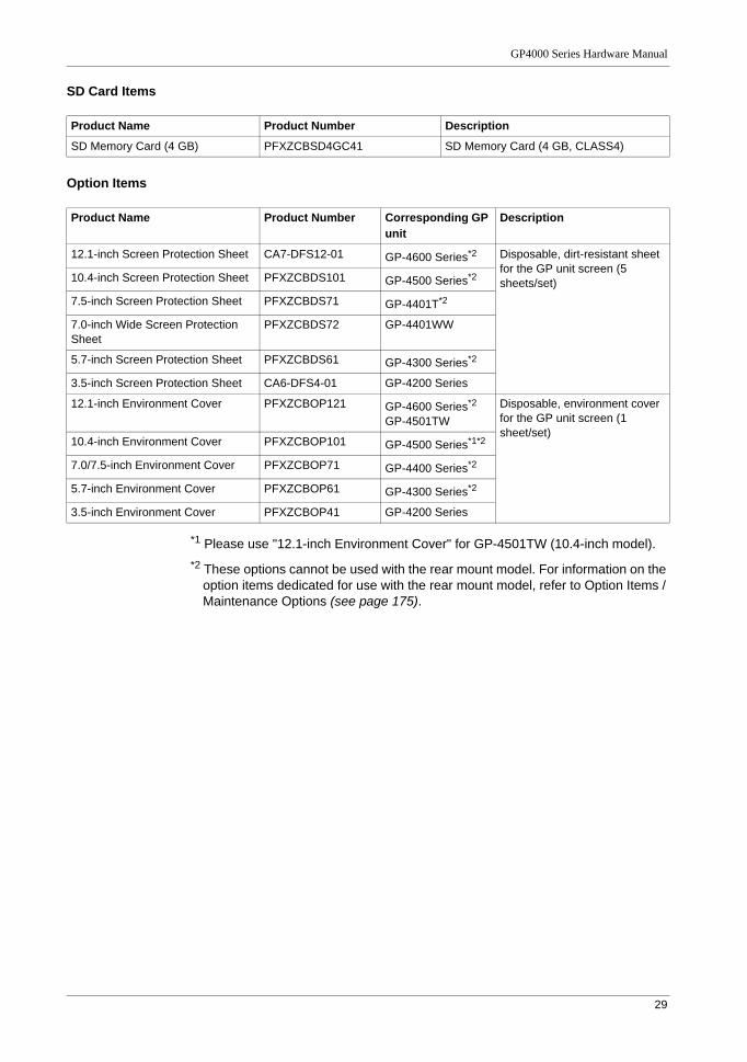
SD Card Items
Option Items
*1 Please use "12.1-inch Environment Cover" for GP-4501TW (10.4-inch model).*2 These options cannot be used with the rear mount model. For information on the
option items dedicated for use with the rear mount model, refer to Option Items / Maintenance Options (see page 175).
Product Name Product Number Description
SD Memory Card (4 GB) PFXZCBSD4GC41 SD Memory Card (4 GB, CLASS4)
Product Name Product Number Corresponding GP unit
Description
12.1-inch Screen Protection Sheet CA7-DFS12-01 GP-4600 Series*2 Disposable, dirt-resistant sheet for the GP unit screen (5 sheets/set)10.4-inch Screen Protection Sheet PFXZCBDS101 GP-4500 Series*2
7.5-inch Screen Protection Sheet PFXZCBDS71 GP-4401T*2
7.0-inch Wide Screen Protection Sheet
PFXZCBDS72 GP-4401WW
5.7-inch Screen Protection Sheet PFXZCBDS61 GP-4300 Series*2
3.5-inch Screen Protection Sheet CA6-DFS4-01 GP-4200 Series
12.1-inch Environment Cover PFXZCBOP121 GP-4600 Series*2
GP-4501TWDisposable, environment cover for the GP unit screen (1 sheet/set)
10.4-inch Environment Cover PFXZCBOP101 GP-4500 Series*1*2
7.0/7.5-inch Environment Cover PFXZCBOP71 GP-4400 Series*2
5.7-inch Environment Cover PFXZCBOP61 GP-4300 Series*2
3.5-inch Environment Cover PFXZCBOP41 GP-4200 Series
Connectivity
30
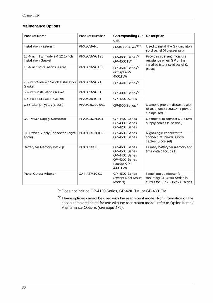
Maintenance Options
*1 Does not include GP-4100 Series, GP-4201TM, or GP-4301TM.*2 These options cannot be used with the rear mount model. For information on the
option items dedicated for use with the rear mount model, refer to Option Items / Maintenance Options (see page 175).
Product Name Product Number Corresponding GP unit
Description
Installation Fastener PFXZCBAF1 GP4000 Series*1*2 Used to install the GP unit into a solid panel (4 pieces/ set)
10.4-inch TW models & 12.1-inch Installation Gasket
PFXZCBWG121 GP-4600 Series*2
GP-4501TWProvides dust and moisture resistance when GP unit is installed into a solid panel (1 piece)10.4-inch Installation Gasket PFXZCBWG101 GP-4500 Series*2
(except GP-4501TW)
7.0-inch Wide & 7.5-inch Installation Gasket
PFXZCBWG71 GP-4400 Series*2
5.7-inch Installation Gasket PFXZCBWG61 GP-4300 Series*2
3.5-inch Installation Gasket PFXZCBWG41 GP-4200 Series
USB Clamp TypeA (1 port) PFXZCBCLUSA1 GP4000 Series*1 Clamp to prevent disconnection of USB cable (USB/A, 1 port, 5 clamps/set)
DC Power Supply Connector PFXZCBCNDC1 GP-4400 SeriesGP-4300 SeriesGP-4200 Series
Connector to connect DC power supply cables (5 pcs/set)
DC Power Supply Connector (Right-angle)
PFXZCBCNDC2 GP-4600 SeriesGP-4500 Series
Right-angle connector to connect DC power supply cables (5 pcs/set)
Battery for Memory Backup PFXZCBBT1 GP-4600 SeriesGP-4500 SeriesGP-4400 SeriesGP-4300 Series (except GP-4301TW)
Primary battery for memory and time data backup (1)
Panel Cutout Adapter CA4-ATM10-01 GP-4500 Series (except Rear Mount Models)
Panel cutout adapter for mounting GP-4500 Series in cutout for GP-2500/2600 series.
31
GP4000 Series Hardware Manual
3
GP4000 Series Hardware Manual
Parts/Functions
KanpaiHardwareManual 10/2011
Parts Identification and Functions
Parts Identification and Functions
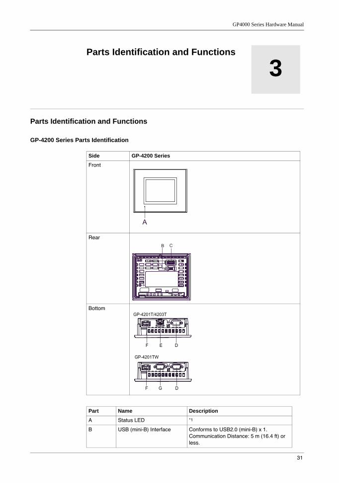
GP-4200 Series Parts Identification
Side GP-4200 Series
Front
Rear
Bottom
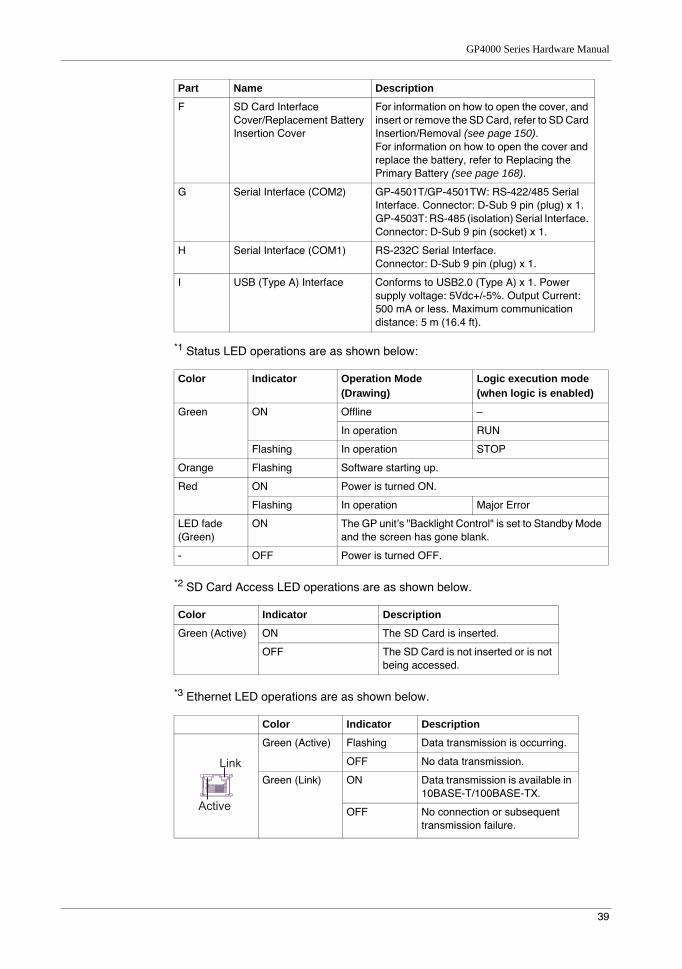
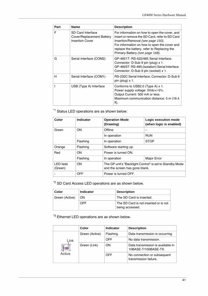
Part Name Description
A Status LED *1
B USB (mini-B) Interface Conforms to USB2.0 (mini-B) x 1. Communication Distance: 5 m (16.4 ft) or less.
A
B C
GP-4201T/4203T
GP-4201TW
F E D
F G D
Parts/Functions
32
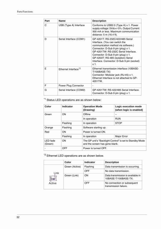
*1 Status LED operations are as shown below:
*2 Ethernet LED operations are as shown below.
C USB (Type A) Interface Conforms to USB2.0 (Type A) x 1. Power supply voltage: 5Vdc+/-5%. Output Current: 500 mA or less. Maximum communication distance: 5 m (16.4 ft).
D Serial Interface (COM1) GP-4201T: RS-232C/422/485 Serial Interface. (You can switch the communication method via software.) Connector: D-Sub 9 pin (plug) x 1.GP-4201TW: RS-232C Serial Interface. Connector: D-Sub 9 pin (plug) x 1.GP-4203T: RS-485 (isolation) Serial Interface. Connector: D-Sub 9 pin (socket) x 1.
E Ethernet Interface*2 Ethernet transmission interface (10BASE-T/100BASE-TX)Connector: Modular jack (RJ-45) x 1. Ethernet Interface is not attached to GP-4201TW.
F Power Plug Connector -
G Serial Interface (COM2) GP-4201TW: RS-422/485 Serial Interface. Connector: D-Sub 9 pin (plug) x 1.
Color Indicator Operation Mode (Drawing)
Logic execution mode (when logic is enabled)
Green ON Offline –
In operation RUN
Flashing In operation STOP
Orange Flashing Software starting up.
Red ON Power is turned ON.
Flashing In operation Major Error
LED fade (Green)
ON The GP unit’s "Backlight Control" is set to Standby Mode and the screen has gone blank.
- OFF Power is turned OFF.
Color Indicator Description
Green (Active) Flashing Data transmission is occurring.
OFF No data transmission.
Green (Link) ON Data transmission is available in 10BASE-T/100BASE-TX.
OFF No connection or subsequent transmission failure.
Part Name Description
Link
Active
GP4000 Series Hardware Manual
33
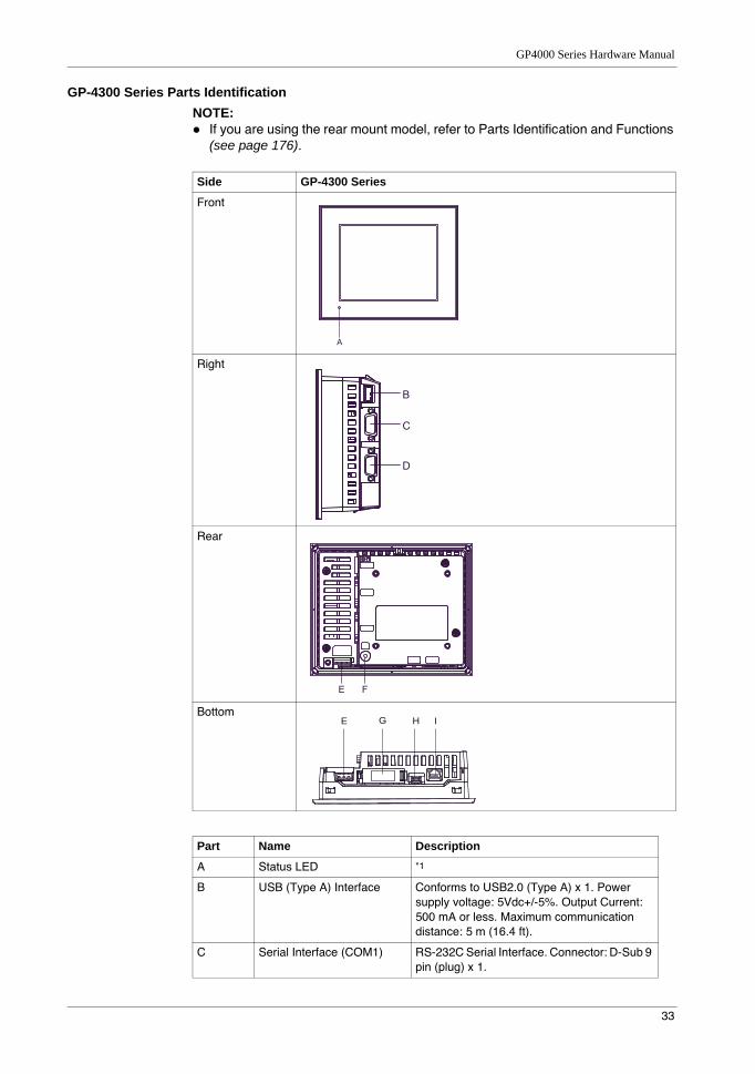
GP-4300 Series Parts IdentificationNOTE:
If you are using the rear mount model, refer to Parts Identification and Functions (see page 176).
Side GP-4300 Series
Front
Right
Rear
Bottom
Part Name Description
A Status LED *1
B USB (Type A) Interface Conforms to USB2.0 (Type A) x 1. Power supply voltage: 5Vdc+/-5%. Output Current: 500 mA or less. Maximum communication distance: 5 m (16.4 ft).
C Serial Interface (COM1) RS-232C Serial Interface. Connector: D-Sub 9 pin (plug) x 1.
A
B
C
D
E F
E G H I
Parts/Functions
34
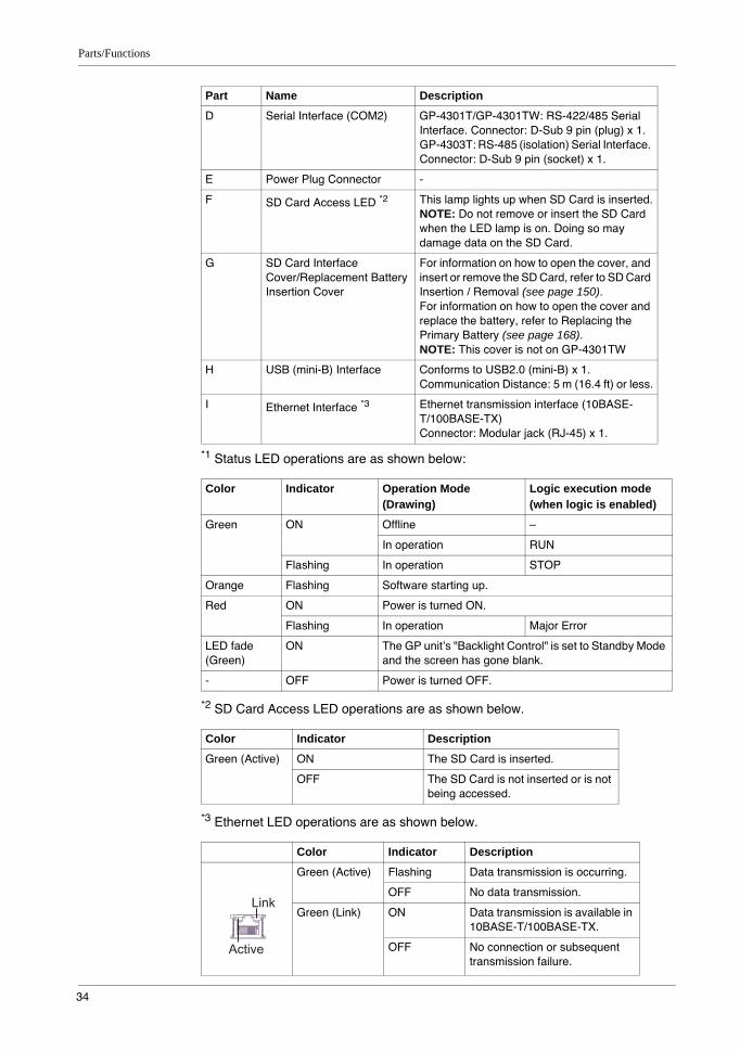
*1 Status LED operations are as shown below:
*2 SD Card Access LED operations are as shown below.
*3 Ethernet LED operations are as shown below.
D Serial Interface (COM2) GP-4301T/GP-4301TW: RS-422/485 Serial Interface. Connector: D-Sub 9 pin (plug) x 1.GP-4303T: RS-485 (isolation) Serial Interface. Connector: D-Sub 9 pin (socket) x 1.
E Power Plug Connector -
F SD Card Access LED *2 This lamp lights up when SD Card is inserted.NOTE: Do not remove or insert the SD Card when the LED lamp is on. Doing so may damage data on the SD Card.
G SD Card Interface Cover/Replacement Battery Insertion Cover
For information on how to open the cover, and insert or remove the SD Card, refer to SD Card Insertion / Removal (see page 150).For information on how to open the cover and replace the battery, refer to Replacing the Primary Battery (see page 168).NOTE: This cover is not on GP-4301TW
H USB (mini-B) Interface Conforms to USB2.0 (mini-B) x 1. Communication Distance: 5 m (16.4 ft) or less.
I Ethernet Interface *3 Ethernet transmission interface (10BASE-T/100BASE-TX)Connector: Modular jack (RJ-45) x 1.
Color Indicator Operation Mode (Drawing)
Logic execution mode (when logic is enabled)
Green ON Offline –
In operation RUN
Flashing In operation STOP
Orange Flashing Software starting up.
Red ON Power is turned ON.
Flashing In operation Major Error
LED fade (Green)
ON The GP unit’s "Backlight Control" is set to Standby Mode and the screen has gone blank.
- OFF Power is turned OFF.
Color Indicator Description
Green (Active) ON The SD Card is inserted.
OFF The SD Card is not inserted or is not being accessed.
Color Indicator Description
Green (Active) Flashing Data transmission is occurring.
OFF No data transmission.
Green (Link) ON Data transmission is available in 10BASE-T/100BASE-TX.
OFF No connection or subsequent transmission failure.
Part Name Description
Link
Active
GP4000 Series Hardware Manual
35
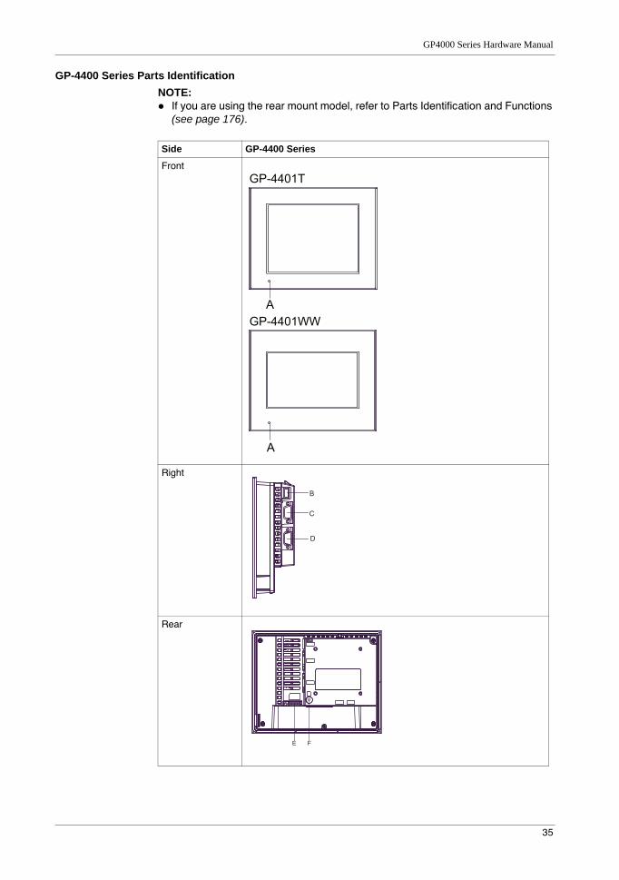
GP-4400 Series Parts IdentificationNOTE:
If you are using the rear mount model, refer to Parts Identification and Functions (see page 176).
Side GP-4400 Series
Front
Right
Rear
A
A
GP-4401T
GP-4401WW
B
C
D
E F
Parts/Functions
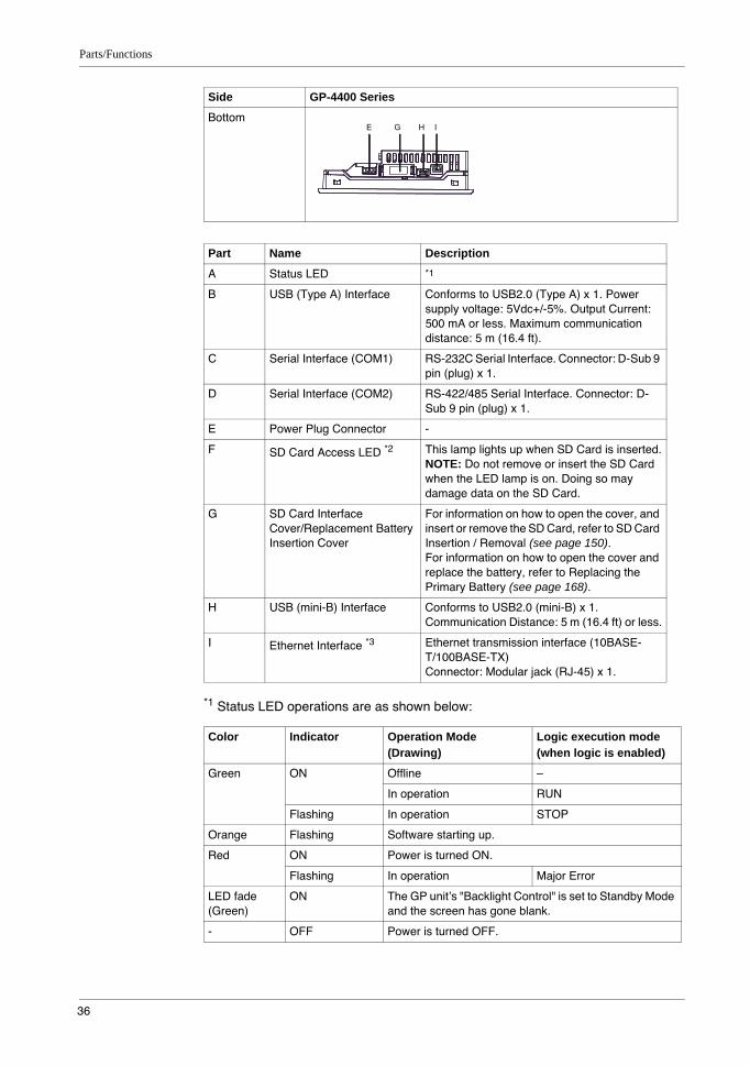
36
*1 Status LED operations are as shown below:
Bottom
Part Name Description
A Status LED *1
B USB (Type A) Interface Conforms to USB2.0 (Type A) x 1. Power supply voltage: 5Vdc+/-5%. Output Current: 500 mA or less. Maximum communication distance: 5 m (16.4 ft).
C Serial Interface (COM1) RS-232C Serial Interface. Connector: D-Sub 9 pin (plug) x 1.
D Serial Interface (COM2) RS-422/485 Serial Interface. Connector: D-Sub 9 pin (plug) x 1.
E Power Plug Connector -
F SD Card Access LED *2 This lamp lights up when SD Card is inserted.NOTE: Do not remove or insert the SD Card when the LED lamp is on. Doing so may damage data on the SD Card.
G SD Card Interface Cover/Replacement Battery Insertion Cover
For information on how to open the cover, and insert or remove the SD Card, refer to SD Card Insertion / Removal (see page 150).For information on how to open the cover and replace the battery, refer to Replacing the Primary Battery (see page 168).
H USB (mini-B) Interface Conforms to USB2.0 (mini-B) x 1.Communication Distance: 5 m (16.4 ft) or less.
I Ethernet Interface *3 Ethernet transmission interface (10BASE-T/100BASE-TX)Connector: Modular jack (RJ-45) x 1.
Color Indicator Operation Mode (Drawing)
Logic execution mode (when logic is enabled)
Green ON Offline –
In operation RUN
Flashing In operation STOP
Orange Flashing Software starting up.
Red ON Power is turned ON.
Flashing In operation Major Error
LED fade (Green)
ON The GP unit’s "Backlight Control" is set to Standby Mode and the screen has gone blank.
- OFF Power is turned OFF.
Side GP-4400 Series
E G H I
GP4000 Series Hardware Manual
37
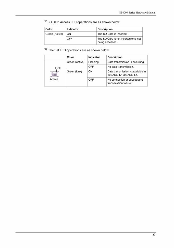
*2 SD Card Access LED operations are as shown below.
*3 Ethernet LED operations are as shown below.
Color Indicator Description
Green (Active) ON The SD Card is inserted.
OFF The SD Card is not inserted or is not being accessed.
Color Indicator Description
Green (Active) Flashing Data transmission is occurring.
OFF No data transmission.
Green (Link) ON Data transmission is available in 10BASE-T/100BASE-TX.
OFF No connection or subsequent transmission failure.
Link
Active
Parts/Functions
38
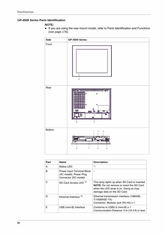
GP-4500 Series Parts IdentificationNOTE:
If you are using the rear mount model, refer to Parts Identification and Functions (see page 176).
Side GP-4500 Series
Front
Rear
Bottom
Part Name Description
A Status LED *1
B Power Input Terminal Block (AC model), Power Plug Connector (DC model)
-
C SD Card Access LED *2 This lamp lights up when SD Card is inserted.NOTE: Do not remove or insert the SD Card when the LED lamp is on. Doing so may damage data on the SD Card.
D Ethernet Interface *3 Ethernet transmission interface (10BASE-T/100BASE-TX)Connector: Modular jack (RJ-45) x 1.
E USB (mini-B) Interface Conforms to USB2.0 (mini-B) x 1.Communication Distance: 5 m (16.4 ft) or less.
A
B C
B F E D
I H G
GP4000 Series Hardware Manual
39
*1 Status LED operations are as shown below:
*2 SD Card Access LED operations are as shown below.
*3 Ethernet LED operations are as shown below.
F SD Card Interface Cover/Replacement Battery Insertion Cover
For information on how to open the cover, and insert or remove the SD Card, refer to SD Card Insertion/Removal (see page 150).For information on how to open the cover and replace the battery, refer to Replacing the Primary Battery (see page 168).
G Serial Interface (COM2) GP-4501T/GP-4501TW: RS-422/485 Serial Interface. Connector: D-Sub 9 pin (plug) x 1.GP-4503T: RS-485 (isolation) Serial Interface. Connector: D-Sub 9 pin (socket) x 1.
H Serial Interface (COM1) RS-232C Serial Interface.Connector: D-Sub 9 pin (plug) x 1.
I USB (Type A) Interface Conforms to USB2.0 (Type A) x 1. Power supply voltage: 5Vdc+/-5%. Output Current: 500 mA or less. Maximum communication distance: 5 m (16.4 ft).
Color Indicator Operation Mode (Drawing)
Logic execution mode (when logic is enabled)
Green ON Offline –
In operation RUN
Flashing In operation STOP
Orange Flashing Software starting up.
Red ON Power is turned ON.
Flashing In operation Major Error
LED fade (Green)
ON The GP unit’s "Backlight Control" is set to Standby Mode and the screen has gone blank.
- OFF Power is turned OFF.
Color Indicator Description
Green (Active) ON The SD Card is inserted.
OFF The SD Card is not inserted or is not being accessed.
Color Indicator Description
Green (Active) Flashing Data transmission is occurring.
OFF No data transmission.
Green (Link) ON Data transmission is available in 10BASE-T/100BASE-TX.
OFF No connection or subsequent transmission failure.
Part Name Description
Link
Active
Parts/Functions
40
GP-4600 Series Parts IdentificationNOTE:
If you are using the rear mount model, refer to Parts Identification and Functions (see page 176).
Side GP-4600 Series
Front
Rear
Bottom
Part Name Description
A Status LED *1
B Power Input Terminal Block (AC model), Power Plug Connector (DC model)
-
C SD Card Access LED *2 This lamp lights up when SD Card is inserted.NOTE: Do not remove or insert the SD Card when the LED lamp is on. Doing so may damage data on the SD Card.
D Ethernet Interface *3 Ethernet transmission interface (10BASE-T/100BASE-TX)Connector: Modular jack (RJ-45) x 1.
E USB (mini-B) Interface Conforms to USB2.0 (mini-B) x 1.Communication Distance: 5 m (16.4 ft) or less.
A
B C
B I H G
F E D
GP4000 Series Hardware Manual
41
*1 Status LED operations are as shown below:
*2 SD Card Access LED operations are as shown below.
*3 Ethernet LED operations are as shown below.
F SD Card Interface Cover/Replacement Battery Insertion Cover
For information on how to open the cover, and insert or remove the SD Card, refer to SD Card Insertion/Removal (see page 150).For information on how to open the cover and replace the battery, refer to Replacing the Primary Battery (see page 168).
G Serial Interface (COM2) GP-4601T: RS-422/485 Serial Interface. Connector: D-Sub 9 pin (plug) x 1.GP-4603T: RS-485 (isolation) Serial Interface. Connector: D-Sub 9 pin (socket) x 1.
H Serial Interface (COM1) RS-232C Serial Interface. Connector: D-Sub 9 pin (plug) x 1.
I USB (Type A) Interface Conforms to USB2.0 (Type A) x 1.Power supply voltage: 5Vdc+/-5%.Output Current: 500 mA or less.Maximum communication distance: 5 m (16.4 ft).
Color Indicator Operation Mode (Drawing)
Logic execution mode (when logic is enabled)
Green ON Offline –
In operation RUN
Flashing In operation STOP
Orange Flashing Software starting up.
Red ON Power is turned ON.
Flashing In operation Major Error
LED fade (Green)
ON The GP unit’s "Backlight Control" is set to Standby Mode and the screen has gone blank.
- OFF Power is turned OFF.
Color Indicator Description
Green (Active) ON The SD Card is inserted.
OFF The SD Card is not inserted or is not being accessed.
Color Indicator Description
Green (Active) Flashing Data transmission is occurring.
OFF No data transmission.
Green (Link) ON Data transmission is available in 10BASE-T/100BASE-TX.
OFF No connection or subsequent transmission failure.
Part Name Description
Link
Active

Parts/Functions
42
43
GP4000 Series Hardware Manual
4
GP4000 Series Hardware Manual
Specifications
KanpaiHardwareManual 10/2011
Specifications
OverviewThis chapter presents the GP unit specifications.
What Is in This Chapter?This chapter contains the following sections:
Section Topic Page
4.1 GP-4200 Series 44
4.2 GP-4300 Series 64
4.3 GP-4400 Series 82
4.4 GP-4500 Series 97
4.5 GP-4600 Series 117

Specifications
44
4.1 GP-4200 Series
What Is in This Section?This section contains the following topics:
Topic Page
Electrical Specifications 45
Environmental Specifications 46
Structural Specifications 47
Display Specifications 49
Memory, Clock, and Touch Panel 50
Interface Specifications 52
Specifications of Serial Interface COM1 53
Specifications of Serial Interface COM2 57
Dimensions 58
GP4000 Series Hardware Manual
45
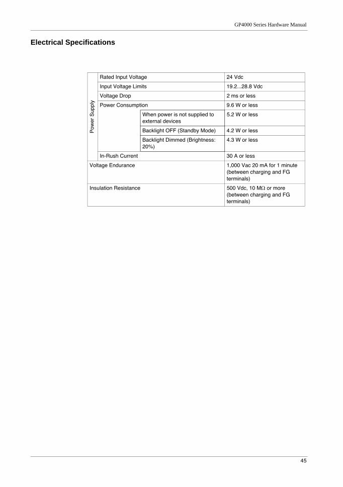
Electrical Specifications
Pow
er S
uppl
y
Rated Input Voltage 24 Vdc
Input Voltage Limits 19.2...28.8 Vdc
Voltage Drop 2 ms or less
Power Consumption 9.6 W or less
When power is not supplied to external devices
5.2 W or less
Backlight OFF (Standby Mode) 4.2 W or less
Backlight Dimmed (Brightness: 20%)
4.3 W or less
In-Rush Current 30 A or less
Voltage Endurance 1,000 Vac 20 mA for 1 minute (between charging and FG terminals)
Insulation Resistance 500 Vdc, 10 MΩ or more (between charging and FG terminals)
Specifications
46
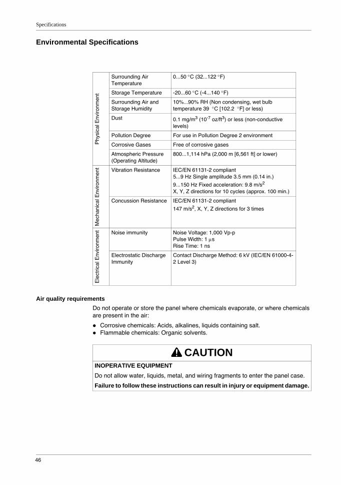
Environmental Specifications
Air quality requirementsDo not operate or store the panel where chemicals evaporate, or where chemicals are present in the air:
Corrosive chemicals: Acids, alkalines, liquids containing salt.Flammable chemicals: Organic solvents.
Phy
sica
l Env
ironm
ent
Surrounding Air Temperature
0...50 °C (32...122 °F)
Storage Temperature -20...60 °C (-4...140 °F)
Surrounding Air and Storage Humidity
10%...90% RH (Non condensing, wet bulb temperature 39 °C [102.2 °F] or less)
Dust 0.1 mg/m3 (10-7 oz/ft3) or less (non-conductive levels)
Pollution Degree For use in Pollution Degree 2 environment
Corrosive Gases Free of corrosive gases
Atmospheric Pressure (Operating Altitude)
800...1,114 hPa (2,000 m [6,561 ft] or lower)
Mec
hani
cal E
nviro
nmen
t Vibration Resistance IEC/EN 61131-2 compliant5...9 Hz Single amplitude 3.5 mm (0.14 in.)
9...150 Hz Fixed acceleration: 9.8 m/s2
X, Y, Z directions for 10 cycles (approx. 100 min.)
Concussion Resistance IEC/EN 61131-2 compliant
147 m/s2, X, Y, Z directions for 3 times
Ele
ctric
al E
nviro
nmen
t Noise immunity Noise Voltage: 1,000 Vp-pPulse Width: 1 µsRise Time: 1 ns
Electrostatic Discharge Immunity
Contact Discharge Method: 6 kV (IEC/EN 61000-4-2 Level 3)
CAUTIONINOPERATIVE EQUIPMENTDo not allow water, liquids, metal, and wiring fragments to enter the panel case.
Failure to follow these instructions can result in injury or equipment damage.
GP4000 Series Hardware Manual
47
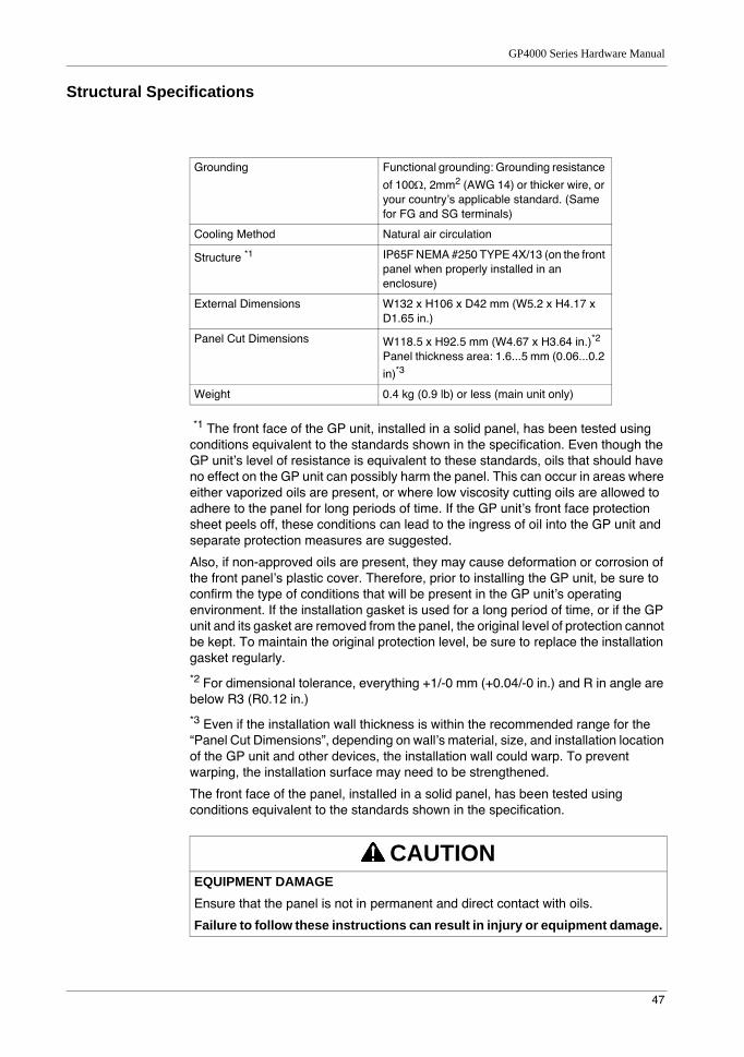
Structural Specifications
*1 The front face of the GP unit, installed in a solid panel, has been tested using conditions equivalent to the standards shown in the specification. Even though the GP unit’s level of resistance is equivalent to these standards, oils that should have no effect on the GP unit can possibly harm the panel. This can occur in areas where either vaporized oils are present, or where low viscosity cutting oils are allowed to adhere to the panel for long periods of time. If the GP unit’s front face protection sheet peels off, these conditions can lead to the ingress of oil into the GP unit and separate protection measures are suggested.
Also, if non-approved oils are present, they may cause deformation or corrosion of the front panel’s plastic cover. Therefore, prior to installing the GP unit, be sure to confirm the type of conditions that will be present in the GP unit’s operating environment. If the installation gasket is used for a long period of time, or if the GP unit and its gasket are removed from the panel, the original level of protection cannot be kept. To maintain the original protection level, be sure to replace the installation gasket regularly.
*2 For dimensional tolerance, everything +1/-0 mm (+0.04/-0 in.) and R in angle are below R3 (R0.12 in.)
*3 Even if the installation wall thickness is within the recommended range for the “Panel Cut Dimensions”, depending on wall’s material, size, and installation location of the GP unit and other devices, the installation wall could warp. To prevent warping, the installation surface may need to be strengthened.
The front face of the panel, installed in a solid panel, has been tested using conditions equivalent to the standards shown in the specification.
Grounding Functional grounding: Grounding resistance
of 100Ω, 2mm2 (AWG 14) or thicker wire, or your country’s applicable standard. (Same for FG and SG terminals)
Cooling Method Natural air circulation
Structure *1 IP65F NEMA #250 TYPE 4X/13 (on the front panel when properly installed in an enclosure)
External Dimensions W132 x H106 x D42 mm (W5.2 x H4.17 x D1.65 in.)
Panel Cut Dimensions W118.5 x H92.5 mm (W4.67 x H3.64 in.)*2
Panel thickness area: 1.6...5 mm (0.06...0.2
in)*3
Weight 0.4 kg (0.9 lb) or less (main unit only)
CAUTIONEQUIPMENT DAMAGEEnsure that the panel is not in permanent and direct contact with oils.
Failure to follow these instructions can result in injury or equipment damage.

Specifications
48
NOTICESTORAGE AND OPERATION OUTSIDE OF SPECIFICATIONS
Store the panel in areas where temperatures are within the panel’s specifications.Do not restrict or block the panel’s rear-face ventilation slots.
Failure to follow these instructions can result in equipment damage.
NOTICEGASKET AGING
Inspect the gasket periodically as required by your operating environment to keep the initial IP level.Change the gasket at least once a year, or as soon as scratches or dirt become visible.
Failure to follow these instructions can result in equipment damage.
GP4000 Series Hardware Manual
49
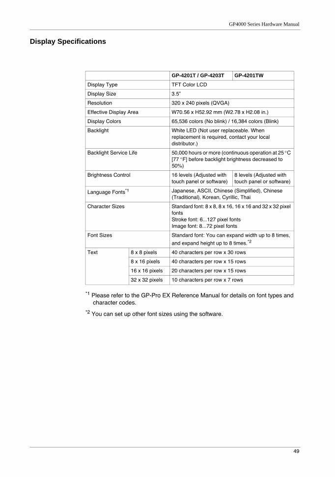
Display Specifications
*1 Please refer to the GP-Pro EX Reference Manual for details on font types and character codes.
*2 You can set up other font sizes using the software.
GP-4201T / GP-4203T GP-4201TW
Display Type TFT Color LCD
Display Size 3.5”
Resolution 320 x 240 pixels (QVGA)
Effective Display Area W70.56 x H52.92 mm (W2.78 x H2.08 in.)
Display Colors 65,536 colors (No blink) / 16,384 colors (Blink)
Backlight White LED (Not user replaceable. When replacement is required, contact your local distributor.)
Backlight Service Life 50,000 hours or more (continuous operation at 25 °C [77 °F] before backlight brightness decreased to 50%)
Brightness Control 16 levels (Adjusted with touch panel or software)
8 levels (Adjusted with touch panel or software)
Language Fonts*1 Japanese, ASCII, Chinese (Simplified), Chinese (Traditional), Korean, Cyrillic, Thai
Character Sizes Standard font: 8 x 8, 8 x 16, 16 x 16 and 32 x 32 pixel fontsStroke font: 6...127 pixel fontsImage font: 8...72 pixel fonts
Font Sizes Standard font: You can expand width up to 8 times,
and expand height up to 8 times.*2
Text 8 x 8 pixels 40 characters per row x 30 rows
8 x 16 pixels 40 characters per row x 15 rows
16 x 16 pixels 20 characters per row x 15 rows
32 x 32 pixels 10 characters per row x 7 rows
Specifications
50
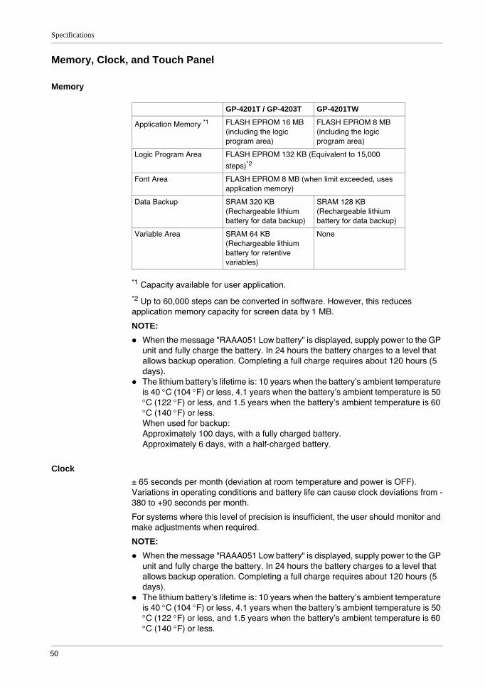
Memory, Clock, and Touch Panel
Memory
*1 Capacity available for user application.
*2 Up to 60,000 steps can be converted in software. However, this reduces application memory capacity for screen data by 1 MB.
NOTE: When the message "RAAA051 Low battery" is displayed, supply power to the GP unit and fully charge the battery. In 24 hours the battery charges to a level that allows backup operation. Completing a full charge requires about 120 hours (5 days).The lithium battery’s lifetime is: 10 years when the battery’s ambient temperature is 40 °C (104 °F) or less, 4.1 years when the battery’s ambient temperature is 50 °C (122 °F) or less, and 1.5 years when the battery’s ambient temperature is 60 °C (140 °F) or less.When used for backup:Approximately 100 days, with a fully charged battery.Approximately 6 days, with a half-charged battery.
Clock± 65 seconds per month (deviation at room temperature and power is OFF). Variations in operating conditions and battery life can cause clock deviations from -380 to +90 seconds per month.
For systems where this level of precision is insufficient, the user should monitor and make adjustments when required.
NOTE: When the message "RAAA051 Low battery" is displayed, supply power to the GP unit and fully charge the battery. In 24 hours the battery charges to a level that allows backup operation. Completing a full charge requires about 120 hours (5 days).The lithium battery’s lifetime is: 10 years when the battery’s ambient temperature is 40 °C (104 °F) or less, 4.1 years when the battery’s ambient temperature is 50 °C (122 °F) or less, and 1.5 years when the battery’s ambient temperature is 60 °C (140 °F) or less.
GP-4201T / GP-4203T GP-4201TW
Application Memory *1 FLASH EPROM 16 MB (including the logic program area)
FLASH EPROM 8 MB (including the logic program area)
Logic Program Area FLASH EPROM 132 KB (Equivalent to 15,000
steps)*2
Font Area FLASH EPROM 8 MB (when limit exceeded, uses application memory)
Data Backup SRAM 320 KB (Rechargeable lithium battery for data backup)
SRAM 128 KB (Rechargeable lithium battery for data backup)
Variable Area SRAM 64 KB (Rechargeable lithium battery for retentive variables)
None
GP4000 Series Hardware Manual
51
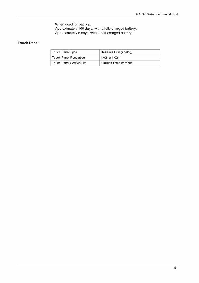
When used for backup:Approximately 100 days, with a fully charged battery.Approximately 6 days, with a half-charged battery.
Touch Panel
Touch Panel Type Resistive Film (analog)
Touch Panel Resolution 1,024 x 1,024
Touch Panel Service Life 1 million times or more
Specifications
52
Interface Specifications
Serial Interface COM1
Serial Interface COM2
USB Interface
Ethernet Interface
NOTE: GP-4201TW does not have an Ethernet interface.
GP-4201T GP-4201TW GP-4203T
Asynchronous Transmission
RS-232C / RS-422 / RS-485
RS-232C RS-485 (isolation)
Data Length 7 or 8 bits
Stop Bit 1 or 2 bits
Parity None, odd or even
Data Transmission Speed
2,400...115,200 bps, 187,500 bps (MPI)
2,400...115,200 bps 2,400...115,200 bps, 187,500 bps (MPI)
Connector D-Sub 9 pin (plug) D-Sub 9 pin (socket)
GP-4201TW
Asynchronous Transmission RS-422 / RS-485
Data Length 7 or 8 bits
Stop Bit 1 or 2 bits
Parity None, odd or even
Data Transmission Speed 2,400...115,200 bps, 187,500 bps (MPI)
Connector D-Sub 9 pin (plug)
USB (Type A) Interface USB (mini-B) Interface
Connector USB 2.0 (Type A) x 1 USB 2.0 (mini-B) x 1
Power Supply Voltage 5 Vdc ±5% -
Maximum Current Supplied
500 mA -
Maximum Transmission Distance
5 m (16.4 ft)
GP-4201T / GP-4203T
Ethernet (LAN) IEEE802.3i / IEEE802.3u, 10BASE-T/100BASE-TX
Connector Modular jack (RJ45) x 1
GP4000 Series Hardware Manual
53
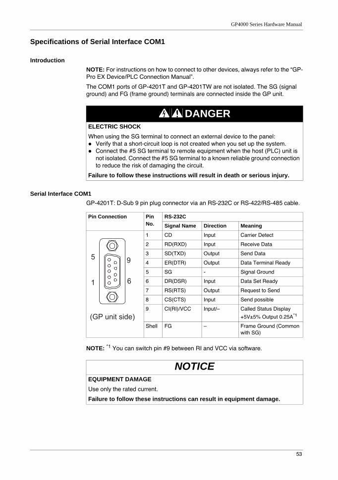
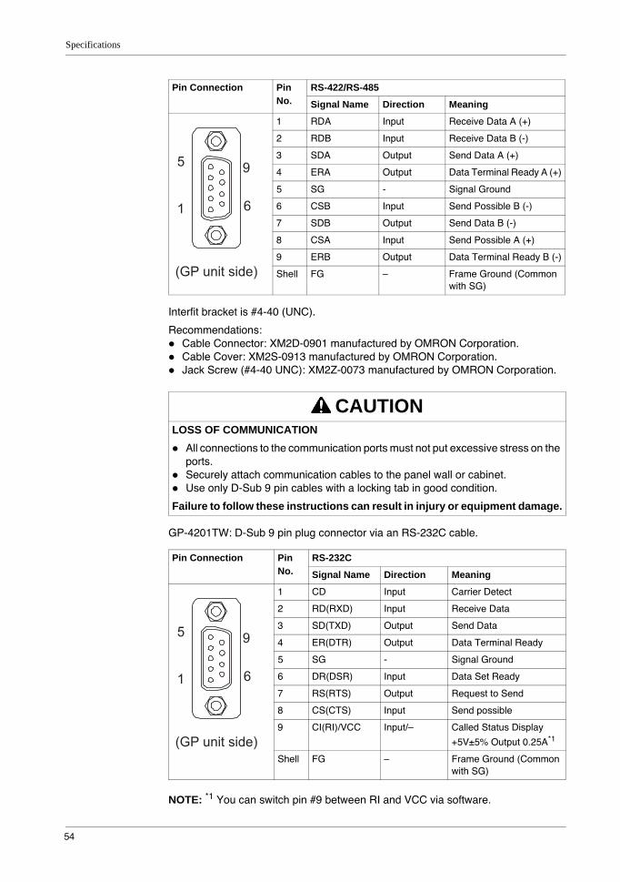
Specifications of Serial Interface COM1
IntroductionNOTE: For instructions on how to connect to other devices, always refer to the “GP-Pro EX Device/PLC Connection Manual”.
The COM1 ports of GP-4201T and GP-4201TW are not isolated. The SG (signal ground) and FG (frame ground) terminals are connected inside the GP unit.
Serial Interface COM1GP-4201T: D-Sub 9 pin plug connector via an RS-232C or RS-422/RS-485 cable.
NOTE: *1 You can switch pin #9 between RI and VCC via software.
DANGERELECTRIC SHOCKWhen using the SG terminal to connect an external device to the panel:
Verify that a short-circuit loop is not created when you set up the system.Connect the #5 SG terminal to remote equipment when the host (PLC) unit is not isolated. Connect the #5 SG terminal to a known reliable ground connection to reduce the risk of damaging the circuit.
Failure to follow these instructions will result in death or serious injury.
Pin Connection Pin No.
RS-232C
Signal Name Direction Meaning
1 CD Input Carrier Detect
2 RD(RXD) Input Receive Data
3 SD(TXD) Output Send Data
4 ER(DTR) Output Data Terminal Ready
5 SG - Signal Ground
6 DR(DSR) Input Data Set Ready
7 RS(RTS) Output Request to Send
8 CS(CTS) Input Send possible
9 CI(RI)/VCC Input/– Called Status Display
+5V±5% Output 0.25A*1
Shell FG – Frame Ground (Common with SG)
NOTICEEQUIPMENT DAMAGEUse only the rated current.
Failure to follow these instructions can result in equipment damage.
9
6
5
1
(GP unit side)
Specifications
54
Interfit bracket is #4-40 (UNC).
Recommendations:Cable Connector: XM2D-0901 manufactured by OMRON Corporation.Cable Cover: XM2S-0913 manufactured by OMRON Corporation.Jack Screw (#4-40 UNC): XM2Z-0073 manufactured by OMRON Corporation.
GP-4201TW: D-Sub 9 pin plug connector via an RS-232C cable.
NOTE: *1 You can switch pin #9 between RI and VCC via software.
Pin Connection Pin No.
RS-422/RS-485
Signal Name Direction Meaning
1 RDA Input Receive Data A (+)
2 RDB Input Receive Data B (-)
3 SDA Output Send Data A (+)
4 ERA Output Data Terminal Ready A (+)
5 SG - Signal Ground
6 CSB Input Send Possible B (-)
7 SDB Output Send Data B (-)
8 CSA Input Send Possible A (+)
9 ERB Output Data Terminal Ready B (-)
Shell FG – Frame Ground (Common with SG)
CAUTIONLOSS OF COMMUNICATION
All connections to the communication ports must not put excessive stress on the ports.Securely attach communication cables to the panel wall or cabinet.Use only D-Sub 9 pin cables with a locking tab in good condition.
Failure to follow these instructions can result in injury or equipment damage.
Pin Connection Pin No.
RS-232C
Signal Name Direction Meaning
1 CD Input Carrier Detect
2 RD(RXD) Input Receive Data
3 SD(TXD) Output Send Data
4 ER(DTR) Output Data Terminal Ready
5 SG - Signal Ground
6 DR(DSR) Input Data Set Ready
7 RS(RTS) Output Request to Send
8 CS(CTS) Input Send possible
9 CI(RI)/VCC Input/– Called Status Display
+5V±5% Output 0.25A*1
Shell FG – Frame Ground (Common with SG)
9
6
5
1
(GP unit side)
9
6
5
1
(GP unit side)
GP4000 Series Hardware Manual
55
Interfit bracket is #4-40 (UNC).
Recommendations:Cable Connector: XM2D-0901 manufactured by OMRON Corporation.Cable Cover: XM2S-0913 manufactured by OMRON Corporation.Jack Screw (#4-40 UNC): XM2Z-0073 manufactured by OMRON Corporation.
GP-4203T: D-Sub 9 pin socket connector via a RS-485, PROFIBUS, or MPI cable.
NOTE: *1 You can supply power to the Siemens PROFIBUS connector only. You cannot supply power to the device/PLC.
*2 The SG and FG terminals are isolated.
Interfit bracket is #4-40 (UNC).
Recommendations:Cable Connector: XM2A-0901 manufactured by OMRON Corporation.Cable Cover: XM2S-0913 manufactured by OMRON Corporation.Jack Screw (#4-40 UNC): XM2Z-0073 manufactured by OMRON Corporation.
NOTICEEQUIPMENT DAMAGEUse only the rated current.
Failure to follow these instructions can result in equipment damage.
CAUTIONLOSS OF COMMUNICATION
All connections to the communication ports must not put excessive stress on the ports.Securely attach communication cables to the panel wall or cabinet.Use only D-Sub 9 pin cables with a locking tab in good condition.
Failure to follow these instructions can result in injury or equipment damage.
Pin Connection Pin No.
RS-485 (isolation)
Signal Name Direction Meaning
1 NC – no connection
2 NC – no connection
3 Line A Input/Output Data A (+)
4 RS(RTS) Output Request to Send
5 SG – Signal Ground
6 VCC – +5V±5% External Output*1
7 NC – no connection
8 Line B Input/Output Data B (-)
9 NC – no connection
Shell FG – Frame Ground*2 (Not connected with SG)
6
9
1
5
(GP unit side)
Specifications
56
CAUTIONLOSS OF COMMUNICATION
All connections to the communication ports must not put excessive stress on the ports.Securely attach communication cables to the panel wall or cabinet.Use only D-Sub 9 pin cables with a locking tab in good condition.
Failure to follow these instructions can result in injury or equipment damage.

GP4000 Series Hardware Manual
57
Specifications of Serial Interface COM2
IntroductionNOTE: For instructions on how to connect to other devices, always refer to the “GP-Pro EX Device/PLC Connection Manual”.
The serial port is not isolated. The SG (signal ground) and FG (frame ground) terminals are connected inside the GP unit.
Serial Interface COM2GP-4201TW: D-Sub 9 pin plug connector via an RS-422/485 cable.
Interfit bracket is #4-40 (UNC).
Recommendations:Cable Connector: XM2D-0901 manufactured by OMRON Corporation.Cable Cover: XM2S-0913 manufactured by OMRON Corporation.Jack Screw (#4-40 UNC): XM2Z-0073 manufactured by OMRON Corporation.
DANGERELECTRIC SHOCKWhen using the SG terminal to connect an external device to the panel:
Verify that a short-circuit loop is not created when you set up the system.Connect the #5 SG terminal to remote equipment when the host (PLC) unit is not isolated. Connect the #5 SG terminal to a known reliable ground connection to reduce the risk of damaging the circuit.
Failure to follow these instructions will result in death or serious injury.
Pin Connection Pin No.
RS-422/RS-485
Signal Name Direction Meaning
1 RDA Input Receive Data A (+)
2 RDB Input Receive Data B (-)
3 SDA Output Send Data A (+)
4 ERA Output Data Terminal Ready A (+)
5 SG - Signal Ground
6 CSB Input Send Possible B (-)
7 SDB Output Send Data B (-)
8 CSA Input Send Possible A (+)
9 ERB Output Data Terminal Ready B (-)
Shell FG – Frame Ground (Common with SG)
CAUTIONLOSS OF COMMUNICATION
All connections to the communication ports must not put excessive stress on the ports.Securely attach communication cables to the panel wall or cabinet.Use only D-Sub 9 pin cables with a locking tab in good condition.
Failure to follow these instructions can result in injury or equipment damage.
9
6
5
1
(GP unit side)
Specifications
58
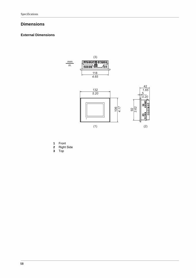
Dimensions
External Dimensions
1 Front2 Right Side3 Top
GP4000 Series Hardware Manual
59
Installation with Installation Fasteners
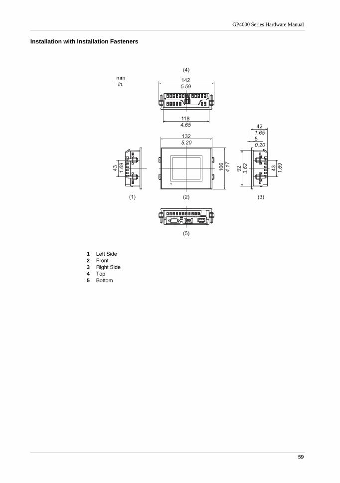
1 Left Side2 Front3 Right Side4 Top5 Bottom
Specifications
60
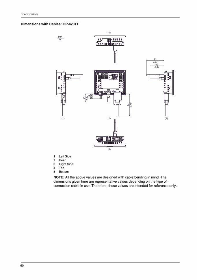
Dimensions with Cables: GP-4201T
1 Left Side2 Rear3 Right Side4 Top5 Bottom
NOTE: All the above values are designed with cable bending in mind. The dimensions given here are representative values depending on the type of connection cable in use. Therefore, these values are intended for reference only.
73
(1) (2)
(5)
(4)
(3)
59
94
21
36
mm in.
2.87
1.42
2.32
0.83
3.70
GP4000 Series Hardware Manual
61
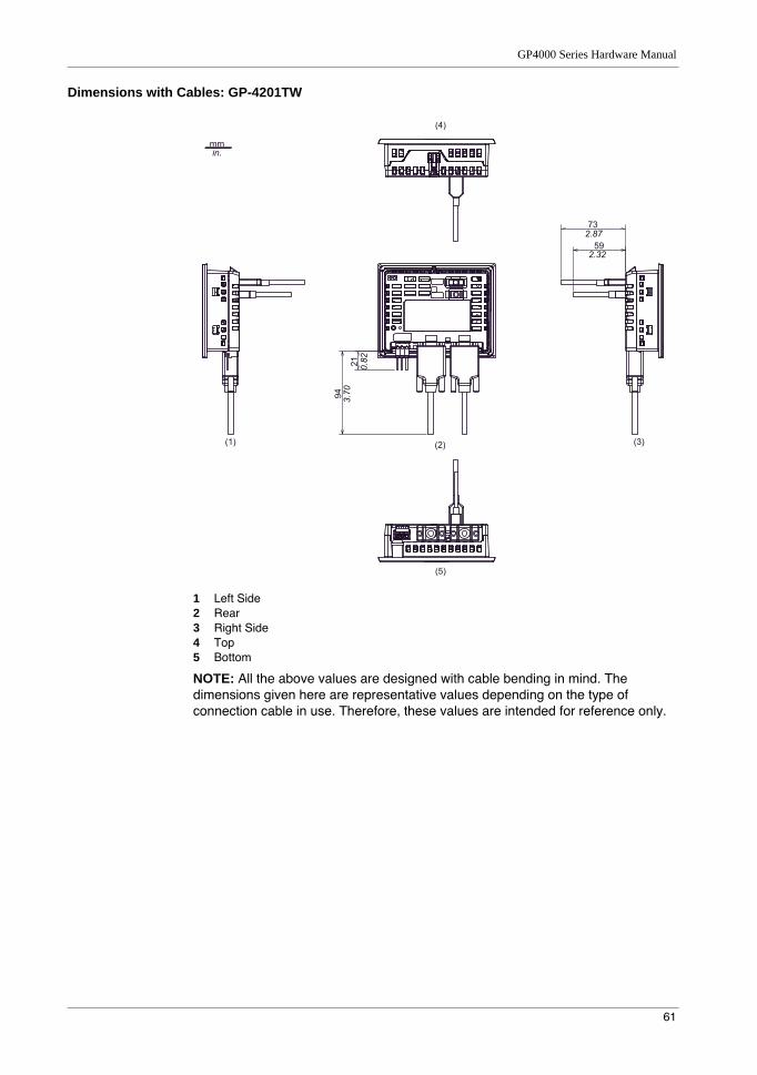
Dimensions with Cables: GP-4201TW
1 Left Side2 Rear3 Right Side4 Top5 Bottom
NOTE: All the above values are designed with cable bending in mind. The dimensions given here are representative values depending on the type of connection cable in use. Therefore, these values are intended for reference only.
mm in.
21
94
73
59
(1) (2)
(5)
(4)
(3)
2.87
3.70
0.82
2.32
Specifications
62
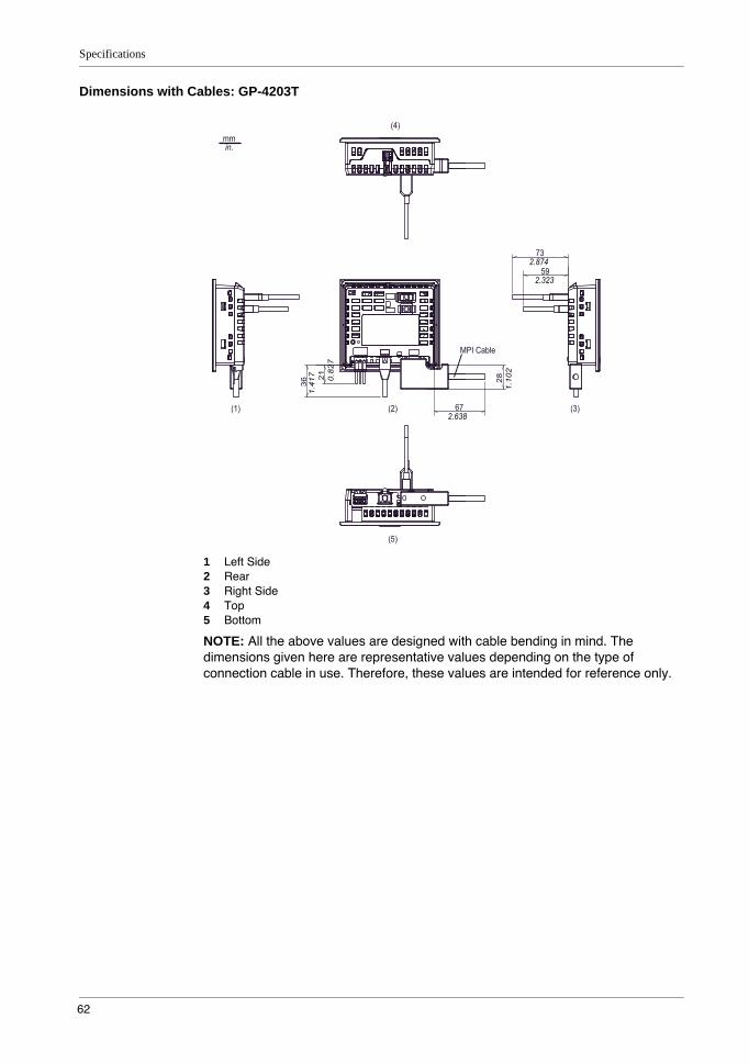
Dimensions with Cables: GP-4203T
1 Left Side2 Rear3 Right Side4 Top5 Bottom
NOTE: All the above values are designed with cable bending in mind. The dimensions given here are representative values depending on the type of connection cable in use. Therefore, these values are intended for reference only.
21
36
28
67
MPI Cable
73
59
2.638
2.874
1.41
7 0.82
7
1.10
2
2.323
mm in.
(1) (2)
(5)
(4)
(3)
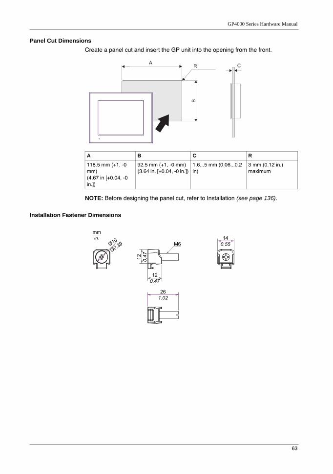
GP4000 Series Hardware Manual
63
Panel Cut DimensionsCreate a panel cut and insert the GP unit into the opening from the front.
NOTE: Before designing the panel cut, refer to Installation (see page 136).
Installation Fastener Dimensions
A B C R
118.5 mm (+1, -0 mm)(4.67 in [+0.04, -0 in.])
92.5 mm (+1, -0 mm)(3.64 in. [+0.04, -0 in.])
1.6...5 mm (0.06...0.2 in)
3 mm (0.12 in.) maximum
A CR
B
12
0.47
12
0.47
14
0.55M6
26
1.02
mm
in.
Ø10
Ø0.39
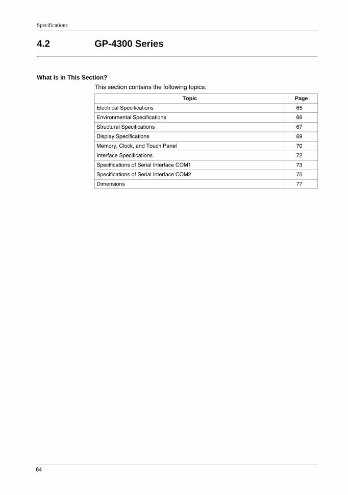
Specifications
64
4.2 GP-4300 Series
What Is in This Section?This section contains the following topics:
Topic Page
Electrical Specifications 65
Environmental Specifications 66
Structural Specifications 67
Display Specifications 69
Memory, Clock, and Touch Panel 70
Interface Specifications 72
Specifications of Serial Interface COM1 73
Specifications of Serial Interface COM2 75
Dimensions 77

GP4000 Series Hardware Manual
65
Electrical Specifications
Pow
er S
uppl
y
Rated Input Voltage 24 Vdc
Input Voltage Limits 19.2...28.8 Vdc
Voltage Drop 5 ms or less
Power Consumption 10.5 W or less
When power is not supplied to external devices
6.5 W or less
Backlight OFF (Standby Mode) 4.5 W or less
Backlight Dimmed (Brightness: 20%)
5 W or less
In-Rush Current 30 A or less
Voltage Endurance 1,000 Vac, 20 mA for 1 minute (between charging and FG terminals)
Insulation Resistance 500 Vdc, 10 MΩ or more (between charging and FG terminals)
Specifications
66
Environmental Specifications
Air quality requirementsDo not operate or store the panel where chemicals evaporate, or where chemicals are present in the air:
Corrosive chemicals: Acids, alkalines, liquids containing salt.Flammable chemicals: Organic solvents.
GP-4301T / GP-4303T GP-4301TW
Phy
sica
l Env
ironm
ent
Surrounding Air Temperature
0...55 °C (32 °F...131 °F) 0...50 °C (32...122 °F)
Storage Temperature -20...60 °C (-4...140 °F)
Surrounding Air and Storage Humidity
10...90% RH (Non condensing, wet bulb temperature 39 °C [102.2 °F] or less)
Dust 0.1 mg/m3 (10-7 oz/ft3) or less (non-conductive levels)
Pollution Degree For use in Pollution Degree 2 environment
Corrosive Gases Free of corrosive gases
Atmospheric Pressure (Operating Altitude)
800...1,114 hPa (2,000 m [6,561 ft] or lower)
Mec
hani
cal E
nviro
nmen
t Vibration Resistance IEC/EN 61131-2 compliant5...9 Hz Single amplitude 3.5 mm (0.14 in.)
9...150 Hz Fixed acceleration: 9.8 m/s2
X, Y, Z directions for 10 cycles (approx. 100 min)
Concussion Resistance IEC/EN 61131-2 compliant
147 m/s2, X, Y, Z directions for 3 times
Ele
ctric
al E
nviro
nmen
t Noise Immunity Noise Voltage: 1,000 Vp-pPulse Width: 1 µsRise Time: 1 ns
Electrostatic Discharge Immunity
Contact Discharge Method: 6 kV (IEC/EN 61000-4-2 Level 3)
CAUTIONINOPERATIVE EQUIPMENTDo not allow water, liquids, metal, and wiring fragments to enter the panel case.
Failure to follow these instructions can result in injury or equipment damage.
GP4000 Series Hardware Manual
67
Structural Specifications
NOTE: If you are using the rear mount model, refer to Structural Specifications (see page 182).
NOTE: *1 The front face of the GP unit, installed in a solid panel, has been tested using conditions equivalent to the standards shown in the specification. Even though the GP unit’s level of resistance is equivalent to these standards, oils that should have no effect on the GP unit can possibly harm the panel. This can occur in areas where either vaporized oils are present, or where low viscosity cutting oils are allowed to adhere to the panel for long periods of time. If the GP unit’s front face protection sheet peels off, these conditions can lead to the ingress of oil into the GP unit and separate protection measures are suggested.
Also, if non-approved oils are present, they may cause deformation or corrosion of the front panel’s plastic cover. Therefore, prior to installing the GP unit, be sure to confirm the type of conditions that will be present in the GP unit’s operating environment. If the installation gasket is used for a long period of time, or if the GP unit and its gasket are removed from the panel, the original level of protection cannot be kept. To maintain the original protection level, be sure to replace the installation gasket regularly.
*2 For dimensional tolerance, everything +1/-0 mm (+0.04/-0 in.) and R in angle are below R3 (R0.12 in.)
*3 Even if the installation wall thickness is within the recommended range for the “Panel Cut Dimensions”, depending on wall’s material, size, and installation location of the GP unit and other devices, the installation wall could warp. To prevent warping, the installation surface may need to be strengthened.
Grounding Functional grounding: Grounding resistance
of 100 Ω, 2 mm2 (AWG 14) or thicker wire, or your country’s applicable standard. (Same for FG and SG terminals)
Cooling Method Natural air circulation
Structure*1 IP65F NEMA #250 TYPE 4X/13 (on the front panel when properly installed in an enclosure)
External Dimensions W169.5 x H137 x D59.5 mm (W6.67 x H5.39 x D2.34 in.)
Panel Cut Dimensions W156 x H123.5 mm (W6.14 x H4.86 in.) *2
Panel thickness area: 1.6...5 mm (0.06...0.2
in.) *3
Weight 0.8 kg (1.8 lb) or less (main unit only)
CAUTIONEQUIPMENT DAMAGEEnsure that the panel is not in permanent and direct contact with oils.
Failure to follow these instructions can result in injury or equipment damage.
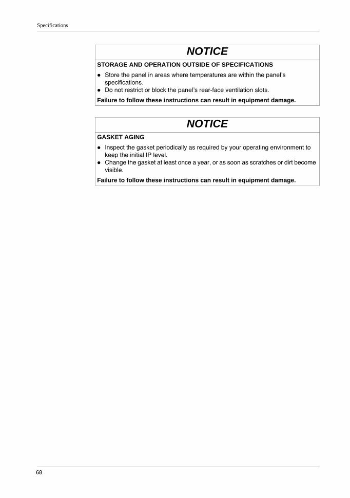
Specifications
68
NOTICESTORAGE AND OPERATION OUTSIDE OF SPECIFICATIONS
Store the panel in areas where temperatures are within the panel’s specifications.Do not restrict or block the panel’s rear-face ventilation slots.
Failure to follow these instructions can result in equipment damage.
NOTICEGASKET AGING
Inspect the gasket periodically as required by your operating environment to keep the initial IP level.Change the gasket at least once a year, or as soon as scratches or dirt become visible.
Failure to follow these instructions can result in equipment damage.
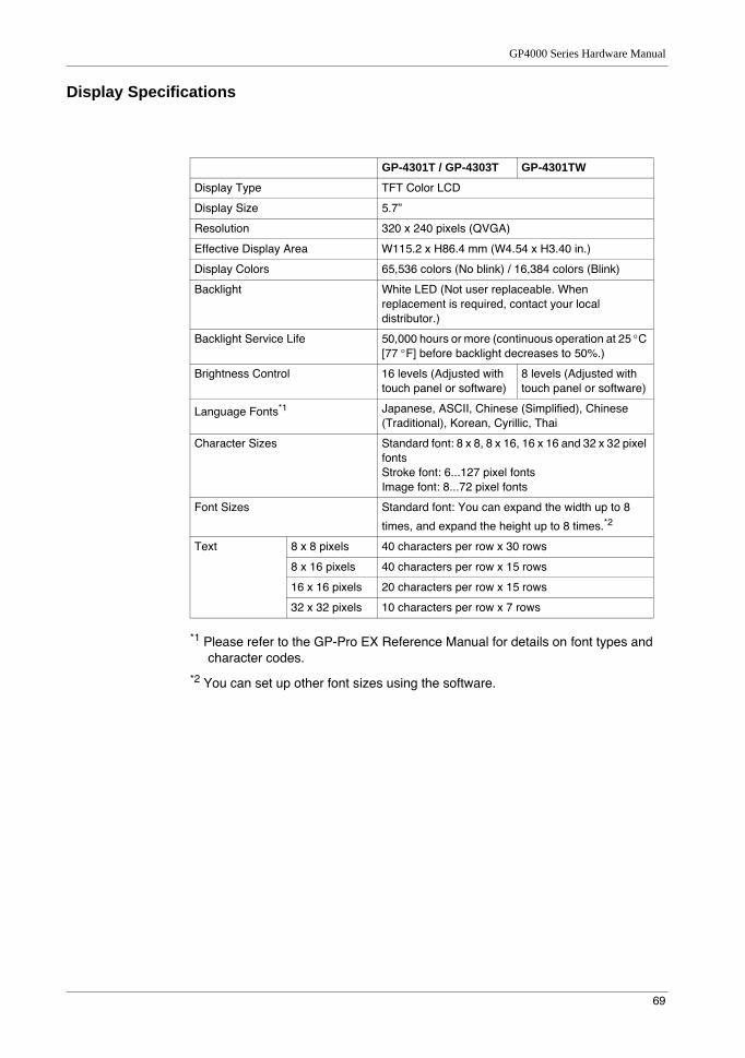
GP4000 Series Hardware Manual
69
Display Specifications
*1 Please refer to the GP-Pro EX Reference Manual for details on font types and character codes.
*2 You can set up other font sizes using the software.
GP-4301T / GP-4303T GP-4301TW
Display Type TFT Color LCD
Display Size 5.7”
Resolution 320 x 240 pixels (QVGA)
Effective Display Area W115.2 x H86.4 mm (W4.54 x H3.40 in.)
Display Colors 65,536 colors (No blink) / 16,384 colors (Blink)
Backlight White LED (Not user replaceable. When replacement is required, contact your local distributor.)
Backlight Service Life 50,000 hours or more (continuous operation at 25 °C [77 °F] before backlight decreases to 50%.)
Brightness Control 16 levels (Adjusted with touch panel or software)
8 levels (Adjusted with touch panel or software)
Language Fonts*1 Japanese, ASCII, Chinese (Simplified), Chinese (Traditional), Korean, Cyrillic, Thai
Character Sizes Standard font: 8 x 8, 8 x 16, 16 x 16 and 32 x 32 pixel fontsStroke font: 6...127 pixel fontsImage font: 8...72 pixel fonts
Font Sizes Standard font: You can expand the width up to 8
times, and expand the height up to 8 times.*2
Text 8 x 8 pixels 40 characters per row x 30 rows
8 x 16 pixels 40 characters per row x 15 rows
16 x 16 pixels 20 characters per row x 15 rows
32 x 32 pixels 10 characters per row x 7 rows
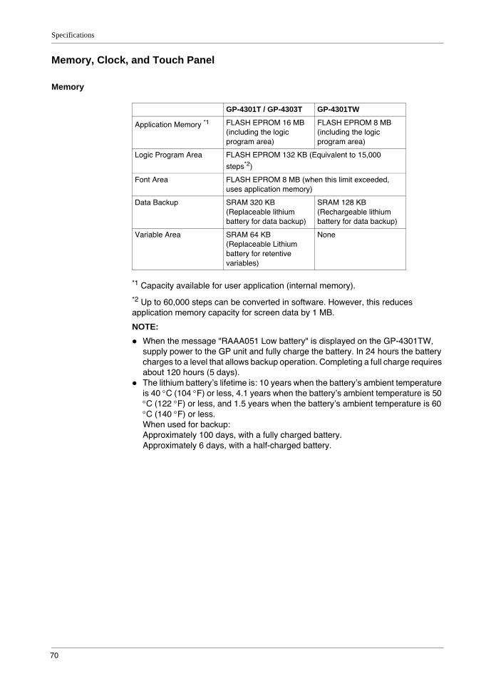
Specifications
70
Memory, Clock, and Touch Panel
Memory
*1 Capacity available for user application (internal memory).
*2 Up to 60,000 steps can be converted in software. However, this reduces application memory capacity for screen data by 1 MB.
NOTE: When the message "RAAA051 Low battery" is displayed on the GP-4301TW, supply power to the GP unit and fully charge the battery. In 24 hours the battery charges to a level that allows backup operation. Completing a full charge requires about 120 hours (5 days).The lithium battery’s lifetime is: 10 years when the battery’s ambient temperature is 40 °C (104 °F) or less, 4.1 years when the battery’s ambient temperature is 50 °C (122 °F) or less, and 1.5 years when the battery’s ambient temperature is 60 °C (140 °F) or less.When used for backup:Approximately 100 days, with a fully charged battery.Approximately 6 days, with a half-charged battery.
GP-4301T / GP-4303T GP-4301TW
Application Memory *1 FLASH EPROM 16 MB (including the logic program area)
FLASH EPROM 8 MB (including the logic program area)
Logic Program Area FLASH EPROM 132 KB (Equivalent to 15,000
steps*2)
Font Area FLASH EPROM 8 MB (when this limit exceeded, uses application memory)
Data Backup SRAM 320 KB (Replaceable lithium battery for data backup)
SRAM 128 KB (Rechargeable lithium battery for data backup)
Variable Area SRAM 64 KB (Replaceable Lithium battery for retentive variables)
None
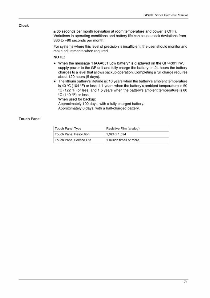
GP4000 Series Hardware Manual
71
Clock± 65 seconds per month (deviation at room temperature and power is OFF). Variations in operating conditions and battery life can cause clock deviations from -380 to +90 seconds per month.
For systems where this level of precision is insufficient, the user should monitor and make adjustments when required.
NOTE: When the message "RAAA051 Low battery" is displayed on the GP-4301TW, supply power to the GP unit and fully charge the battery. In 24 hours the battery charges to a level that allows backup operation. Completing a full charge requires about 120 hours (5 days).The lithium battery’s lifetime is: 10 years when the battery’s ambient temperature is 40 °C (104 °F) or less, 4.1 years when the battery’s ambient temperature is 50 °C (122 °F) or less, and 1.5 years when the battery’s ambient temperature is 60 °C (140 °F) or less.When used for backup:Approximately 100 days, with a fully charged battery.Approximately 6 days, with a half-charged battery.
Touch Panel
Touch Panel Type Resistive Film (analog)
Touch Panel Resolution 1,024 x 1,024
Touch Panel Service Life 1 million times or more
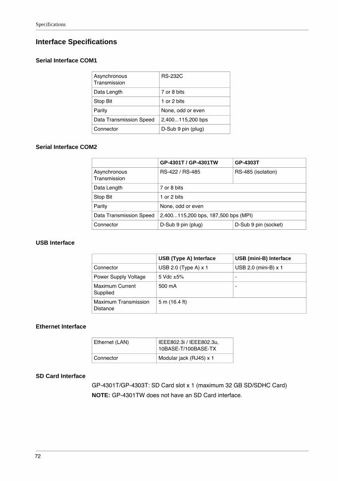
Specifications
72
Interface Specifications
Serial Interface COM1
Serial Interface COM2
USB Interface
Ethernet Interface
SD Card InterfaceGP-4301T/GP-4303T: SD Card slot x 1 (maximum 32 GB SD/SDHC Card)
NOTE: GP-4301TW does not have an SD Card interface.
Asynchronous Transmission
RS-232C
Data Length 7 or 8 bits
Stop Bit 1 or 2 bits
Parity None, odd or even
Data Transmission Speed 2,400...115,200 bps
Connector D-Sub 9 pin (plug)
GP-4301T / GP-4301TW GP-4303T
Asynchronous Transmission
RS-422 / RS-485 RS-485 (isolation)
Data Length 7 or 8 bits
Stop Bit 1 or 2 bits
Parity None, odd or even
Data Transmission Speed 2,400...115,200 bps, 187,500 bps (MPI)
Connector D-Sub 9 pin (plug) D-Sub 9 pin (socket)
USB (Type A) Interface USB (mini-B) Interface
Connector USB 2.0 (Type A) x 1 USB 2.0 (mini-B) x 1
Power Supply Voltage 5 Vdc ±5% -
Maximum Current Supplied
500 mA -
Maximum Transmission Distance
5 m (16.4 ft)
Ethernet (LAN) IEEE802.3i / IEEE802.3u, 10BASE-T/100BASE-TX
Connector Modular jack (RJ45) x 1
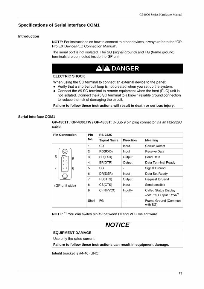
GP4000 Series Hardware Manual
73
Specifications of Serial Interface COM1
IntroductionNOTE: For instructions on how to connect to other devices, always refer to the “GP-Pro EX Device/PLC Connection Manual”.
The serial port is not isolated. The SG (signal ground) and FG (frame ground) terminals are connected inside the GP unit.
Serial Interface COM1GP-4301T / GP-4301TW / GP-4303T: D-Sub 9 pin plug connector via an RS-232C cable.
NOTE: *1 You can switch pin #9 between RI and VCC via software.
Interfit bracket is #4-40 (UNC).
DANGERELECTRIC SHOCKWhen using the SG terminal to connect an external device to the panel:
Verify that a short-circuit loop is not created when you set up the system.Connect the #5 SG terminal to remote equipment when the host (PLC) unit is not isolated. Connect the #5 SG terminal to a known reliable ground connection to reduce the risk of damaging the circuit.
Failure to follow these instructions will result in death or serious injury.
Pin Connection Pin No.
RS-232C
Signal Name Direction Meaning
1 CD Input Carrier Detect
2 RD(RXD) Input Receive Data
3 SD(TXD) Output Send Data
4 ER(DTR) Output Data Terminal Ready
5 SG - Signal Ground
6 DR(DSR) Input Data Set Ready
7 RS(RTS) Output Request to Send
8 CS(CTS) Input Send possible
9 CI(RI)/VCC Input/– Called Status Display
+5V±5% Output 0.25A*1
Shell FG – Frame Ground (Common with SG)
NOTICEEQUIPMENT DAMAGEUse only the rated current.
Failure to follow these instructions can result in equipment damage.
9
6
5
1
(GP unit side)

Specifications
74
Recommendations:Cable Connector: XM2D-0901 manufactured by OMRON Corporation.Cable Cover: XM2S-0913 manufactured by OMRON Corporation.Jack Screw (#4-40 UNC): XM2Z-0073 manufactured by OMRON Corporation.
CAUTIONLOSS OF COMMUNICATION
All connections to the communication ports must not put excessive stress on the ports.Securely attach communication cables to the panel wall or cabinet.Use only D-Sub 9 pin cables with a locking tab in good condition.
Failure to follow these instructions can result in injury or equipment damage.
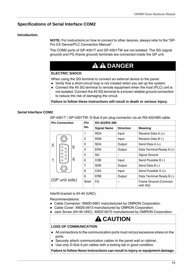
GP4000 Series Hardware Manual
75
Specifications of Serial Interface COM2
IntroductionNOTE: For instructions on how to connect to other devices, always refer to the “GP-Pro EX Device/PLC Connection Manual”.
The COM2 ports of GP-4301T and GP-4301TW are not isolated. The SG (signal ground) and FG (frame ground) terminals are connected inside the GP unit.
Serial Interface COM2GP-4301T / GP-4301TW: D-Sub 9 pin plug connector via an RS-422/485 cable.
Interfit bracket is #4-40 (UNC).
Recommendations:Cable Connector: XM2D-0901 manufactured by OMRON Corporation.Cable Cover: XM2S-0913 manufactured by OMRON Corporation.Jack Screw (#4-40 UNC): XM2Z-0073 manufactured by OMRON Corporation.
DANGERELECTRIC SHOCKWhen using the SG terminal to connect an external device to the panel:
Verify that a short-circuit loop is not created when you set up the system.Connect the #5 SG terminal to remote equipment when the host (PLC) unit is not isolated. Connect the #5 SG terminal to a known reliable ground connection to reduce the risk of damaging the circuit.
Failure to follow these instructions will result in death or serious injury.
Pin Connection Pin No.
RS-422/RS-485
Signal Name Direction Meaning
1 RDA Input Receive Data A (+)
2 RDB Input Receive Data B (-)
3 SDA Output Send Data A (+)
4 ERA Output Data Terminal Ready A (+)
5 SG - Signal Ground
6 CSB Input Send Possible B (-)
7 SDB Output Send Data B (-)
8 CSA Input Send Possible A (+)
9 ERB Output Data Terminal Ready B (-)
Shell FG – Frame Ground (Common with SG)
CAUTIONLOSS OF COMMUNICATION
All connections to the communication ports must not put excessive stress on the ports.Securely attach communication cables to the panel wall or cabinet.Use only D-Sub 9 pin cables with a locking tab in good condition.
Failure to follow these instructions can result in injury or equipment damage.
9
6
5
1
(GP unit side)
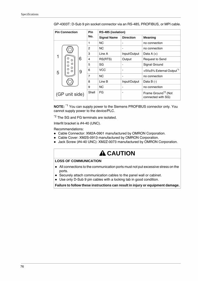
Specifications
76
GP-4303T: D-Sub 9 pin socket connector via an RS-485, PROFIBUS, or MPI cable.
NOTE: *1 You can supply power to the Siemens PROFIBUS connector only. You cannot supply power to the device/PLC.
*2 The SG and FG terminals are isolated.
Interfit bracket is #4-40 (UNC).
Recommendations:Cable Connector: XM2A-0901 manufactured by OMRON Corporation.Cable Cover: XM2S-0913 manufactured by OMRON Corporation.Jack Screw (#4-40 UNC): XM2Z-0073 manufactured by OMRON Corporation.
Pin Connection Pin No.
RS-485 (isolation)
Signal Name Direction Meaning
1 NC - no connection
2 NC - no connection
3 Line A Input/Output Data A (+)
4 RS(RTS) Output Request to Send
5 SG - Signal Ground
6 VCC - +5V±5% External Output*1
7 NC - no connection
8 Line B Input/Output Data B (-)
9 NC - no connection
Shell FG - Frame Ground*2 (Not connected with SG)
CAUTIONLOSS OF COMMUNICATION
All connections to the communication ports must not put excessive stress on the ports.Securely attach communication cables to the panel wall or cabinet.Use only D-Sub 9 pin cables with a locking tab in good condition.
Failure to follow these instructions can result in injury or equipment damage.
6
9
1
5
(GP unit side)
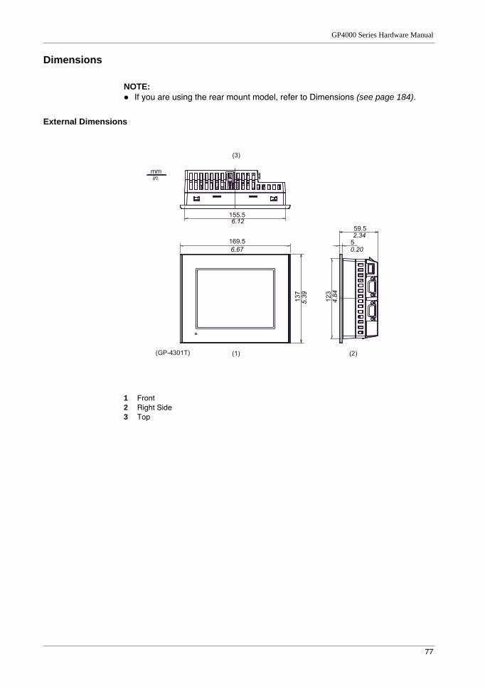
GP4000 Series Hardware Manual
77
Dimensions
NOTE: If you are using the rear mount model, refer to Dimensions (see page 184).
External Dimensions
1 Front2 Right Side3 Top
137
169.5
155.5
123
59.5
5
6.12
4.84
2.34
6.67
5.39
0.20
mm in.
(1)
(3)
(GP-4301T) (2)
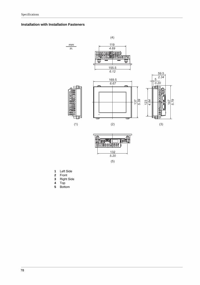
Specifications
78
Installation with Installation Fasteners
1 Left Side2 Front3 Right Side4 Top5 Bottom
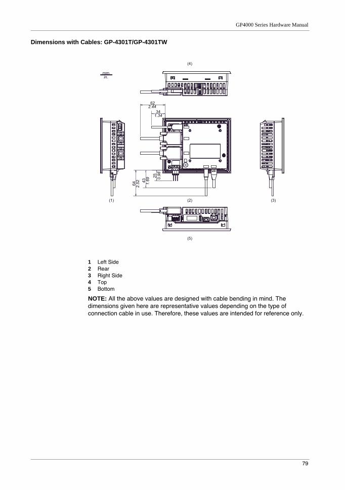
GP4000 Series Hardware Manual
79
Dimensions with Cables: GP-4301T/GP-4301TW
1 Left Side2 Rear3 Right Side4 Top5 Bottom
NOTE: All the above values are designed with cable bending in mind. The dimensions given here are representative values depending on the type of connection cable in use. Therefore, these values are intended for reference only.
34
62
25
43
64
2.44
2.52 1.
69 0.98
1.34
mm in.
(1) (2)
(5)
(4)
(3)
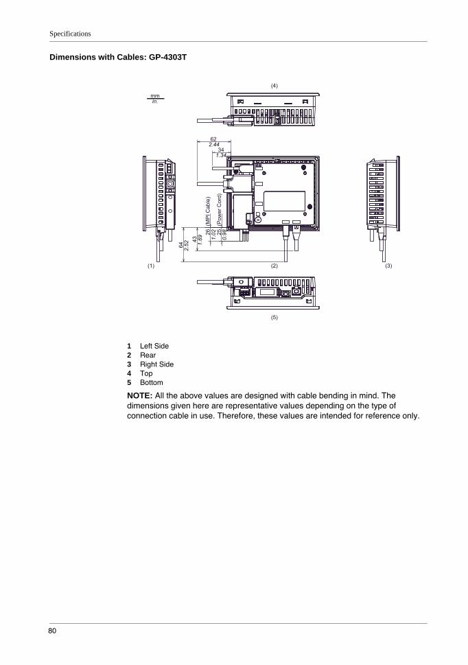
Specifications
80
Dimensions with Cables: GP-4303T
1 Left Side2 Rear3 Right Side4 Top5 Bottom
NOTE: All the above values are designed with cable bending in mind. The dimensions given here are representative values depending on the type of connection cable in use. Therefore, these values are intended for reference only.
34
62
26 (
MP
I Cab
le)
25 (
Pow
er C
ord)
43
64
2.44
2.52
1.34
1.69 1.
02
0.98
mm in.
(1) (2)
(5)
(4)
(3)
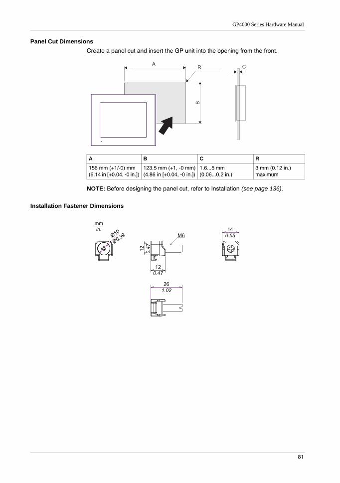
GP4000 Series Hardware Manual
81
Panel Cut DimensionsCreate a panel cut and insert the GP unit into the opening from the front.
NOTE: Before designing the panel cut, refer to Installation (see page 136).
Installation Fastener Dimensions
A B C R
156 mm (+1/-0) mm(6.14 in [+0.04, -0 in.])
123.5 mm (+1, -0 mm)(4.86 in [+0.04, -0 in.])
1.6...5 mm(0.06...0.2 in.)
3 mm (0.12 in.) maximum
A CR
B
12
0.47
12
0.47
14
0.55M6
26
1.02
mm
in.
Ø10
Ø0.39

Specifications
82
4.3 GP-4400 Series
What Is in This Section?This section contains the following topics:
Topic Page
Electrical Specifications 83
Environmental Specifications 84
Structural Specifications 85
Display Specifications 87
Memory, Clock, and Touch Panel 88
Interface Specifications 89
Specifications of Serial Interface COM1 90
Specifications of Serial Interface COM2 92
Dimensions 93

GP4000 Series Hardware Manual
83
Electrical Specifications
Pow
er S
uppl
y
Rated Input Voltage 24 Vdc
Input Voltage Limits 19.2...28.8 Vdc
Voltage Drop 5 ms or less
Power Consumption 12 W or less
When power is not supplied to external devices
8 W or less
Backlight OFF (Standby Mode) 5 W or less
Backlight Dimmed (Brightness: 20%)
5.5 W or less
In-Rush Current 30 A or less
Voltage Endurance 1,000 Vac, 20 mA for 1 minute (between charging and FG terminals)
Insulation Resistance 500 Vdc, 10 MΩ or more (between charging and FG terminals)
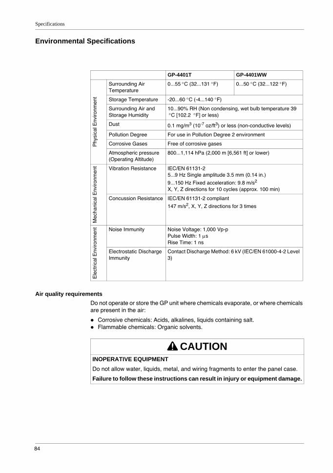
Specifications
84
Environmental Specifications
Air quality requirementsDo not operate or store the GP unit where chemicals evaporate, or where chemicals are present in the air:
Corrosive chemicals: Acids, alkalines, liquids containing salt.Flammable chemicals: Organic solvents.
GP-4401T GP-4401WW
Phy
sica
l Env
ironm
ent
Surrounding Air Temperature
0...55 °C (32...131 °F) 0...50 °C (32...122 °F)
Storage Temperature -20...60 °C (-4...140 °F)
Surrounding Air and Storage Humidity
10...90% RH (Non condensing, wet bulb temperature 39 °C [102.2 °F] or less)
Dust 0.1 mg/m3 (10-7 oz/ft3) or less (non-conductive levels)
Pollution Degree For use in Pollution Degree 2 environment
Corrosive Gases Free of corrosive gases
Atmospheric pressure (Operating Altitude)
800...1,114 hPa (2,000 m [6,561 ft] or lower)
Mec
hani
cal E
nviro
nmen
t Vibration Resistance IEC/EN 61131-25...9 Hz Single amplitude 3.5 mm (0.14 in.)
9...150 Hz Fixed acceleration: 9.8 m/s2
X, Y, Z directions for 10 cycles (approx. 100 min)
Concussion Resistance IEC/EN 61131-2 compliant
147 m/s2, X, Y, Z directions for 3 times
Ele
ctric
al E
nviro
nmen
t Noise Immunity Noise Voltage: 1,000 Vp-pPulse Width: 1 µsRise Time: 1 ns
Electrostatic Discharge Immunity
Contact Discharge Method: 6 kV (IEC/EN 61000-4-2 Level 3)
CAUTIONINOPERATIVE EQUIPMENTDo not allow water, liquids, metal, and wiring fragments to enter the panel case.
Failure to follow these instructions can result in injury or equipment damage.
GP4000 Series Hardware Manual
85
Structural Specifications
NOTE: If you are using the rear mount model, refer to Structural Specifications (see page 182).
NOTE: *1 The front face of the GP unit, installed in a solid panel, has been tested using conditions equivalent to the standards shown in the specification. Even though the GP unit’s level of resistance is equivalent to these standards, oils that should have no effect on the GP unit can possibly harm the panel. This can occur in areas where either vaporized oils are present, or where low viscosity cutting oils are allowed to adhere to the panel for long periods of time. If the GP unit’s front face protection sheet peels off, these conditions can lead to the ingress of oil into the GP unit and separate protection measures are suggested.
Also, if non-approved oils are present, they may cause deformation or corrosion of the front panel’s plastic cover. Therefore, prior to installing the GP unit, be sure to confirm the type of conditions that will be present in the GP unit’s operating environment. If the installation gasket is used for a long period of time, or if the GP unit and its gasket are removed from the panel, the original level of protection cannot be kept. To maintain the original protection level, be sure to replace the installation gasket regularly.
*2 For dimensional tolerance, everything +1/-0 mm (+0.04/-0 in.) and R in angle are below R3 (R0.12 in.)
*3 Even if the installation wall thickness is within the recommended range for the “Panel Cut Dimensions”, depending on wall’s material, size, and installation location of the GP unit and other devices, the installation wall could warp. To prevent warping, the installation surface may need to be strengthened.
Grounding Functional grounding: Grounding resistance of
100 Ω, 2 mm2 (AWG 14) or thicker wire, or your country’s applicable standard. (Same for FG and SG terminals)
Cooling Method Natural air circulation
Structure*1 IP65F NEMA #250 TYPE 4X/13 (on the front panel when properly installed in an enclosure)
External Dimensions W218 x H173 x D60 mm (W8.58 x H6.81 x D2.36 in.)
Panel Cut Dimensions W204.5 x H159.5 mm (W8.05 x H6.28 in.)*2
Panel thickness area: 1.6...5 mm (0.06...0.2 in.)*3
Weight 1.2 kg (2.6 lb) or less (main unit only)
CAUTIONEQUIPMENT DAMAGEEnsure that the panel is not in permanent and direct contact with oils.
Failure to follow these instructions can result in injury or equipment damage.

Specifications
86
NOTICESTORAGE AND OPERATION OUTSIDE OF SPECIFICATIONS
Store the panel in areas where temperatures are within the panel’s specifications.Do not restrict or block the panel’s rear-face ventilation slots.
Failure to follow these instructions can result in equipment damage.
NOTICEGASKET AGING
Inspect the gasket periodically as required by your operating environment to keep the initial IP level.Change the gasket at least once a year, or as soon as scratches or dirt become visible.
Failure to follow these instructions can result in equipment damage.
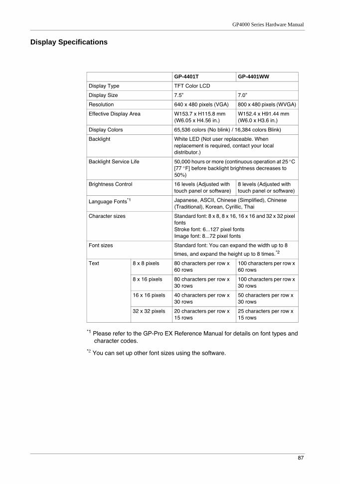
GP4000 Series Hardware Manual
87
Display Specifications
*1 Please refer to the GP-Pro EX Reference Manual for details on font types and character codes.
*2 You can set up other font sizes using the software.
GP-4401T GP-4401WW
Display Type TFT Color LCD
Display Size 7.5” 7.0”
Resolution 640 x 480 pixels (VGA) 800 x 480 pixels (WVGA)
Effective Display Area W153.7 x H115.8 mm(W6.05 x H4.56 in.)
W152.4 x H91.44 mm(W6.0 x H3.6 in.)
Display Colors 65,536 colors (No blink) / 16,384 colors Blink)
Backlight White LED (Not user replaceable. When replacement is required, contact your local distributor.)
Backlight Service Life 50,000 hours or more (continuous operation at 25 °C [77 °F] before backlight brightness decreases to 50%)
Brightness Control 16 levels (Adjusted with touch panel or software)
8 levels (Adjusted with touch panel or software)
Language Fonts*1 Japanese, ASCII, Chinese (Simplified), Chinese (Traditional), Korean, Cyrillic, Thai
Character sizes Standard font: 8 x 8, 8 x 16, 16 x 16 and 32 x 32 pixel fontsStroke font: 6...127 pixel fontsImage font: 8...72 pixel fonts
Font sizes Standard font: You can expand the width up to 8
times, and expand the height up to 8 times.*2
Text 8 x 8 pixels 80 characters per row x 60 rows
100 characters per row x 60 rows
8 x 16 pixels 80 characters per row x 30 rows
100 characters per row x 30 rows
16 x 16 pixels 40 characters per row x 30 rows
50 characters per row x 30 rows
32 x 32 pixels 20 characters per row x 15 rows
25 characters per row x 15 rows
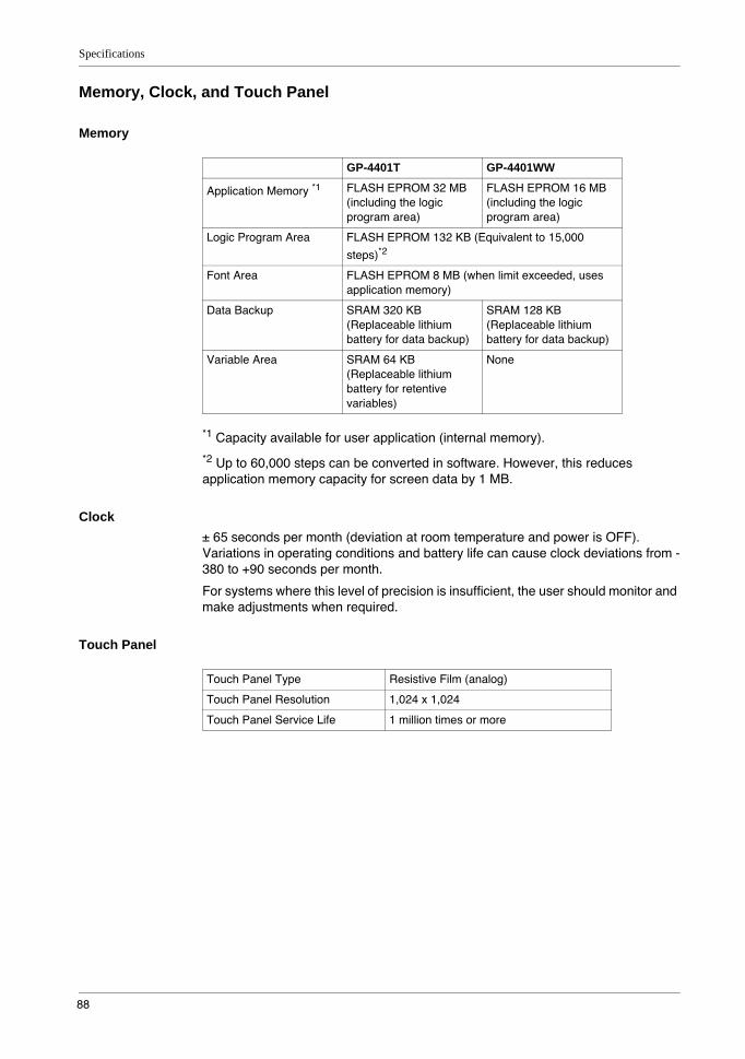
Specifications
88
Memory, Clock, and Touch Panel
Memory
*1 Capacity available for user application (internal memory).
*2 Up to 60,000 steps can be converted in software. However, this reduces application memory capacity for screen data by 1 MB.
Clock± 65 seconds per month (deviation at room temperature and power is OFF). Variations in operating conditions and battery life can cause clock deviations from -380 to +90 seconds per month.
For systems where this level of precision is insufficient, the user should monitor and make adjustments when required.
Touch Panel
GP-4401T GP-4401WW
Application Memory *1 FLASH EPROM 32 MB (including the logic program area)
FLASH EPROM 16 MB (including the logic program area)
Logic Program Area FLASH EPROM 132 KB (Equivalent to 15,000
steps)*2
Font Area FLASH EPROM 8 MB (when limit exceeded, uses application memory)
Data Backup SRAM 320 KB (Replaceable lithium battery for data backup)
SRAM 128 KB (Replaceable lithium battery for data backup)
Variable Area SRAM 64 KB (Replaceable lithium battery for retentive variables)
None
Touch Panel Type Resistive Film (analog)
Touch Panel Resolution 1,024 x 1,024
Touch Panel Service Life 1 million times or more
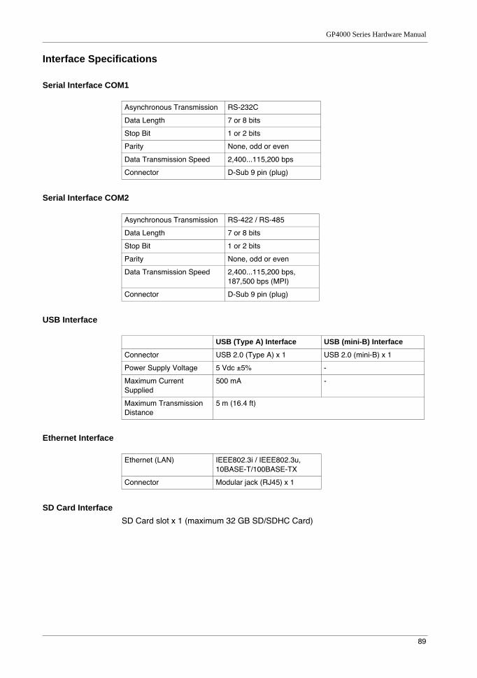
GP4000 Series Hardware Manual
89
Interface Specifications
Serial Interface COM1
Serial Interface COM2
USB Interface
Ethernet Interface
SD Card InterfaceSD Card slot x 1 (maximum 32 GB SD/SDHC Card)
Asynchronous Transmission RS-232C
Data Length 7 or 8 bits
Stop Bit 1 or 2 bits
Parity None, odd or even
Data Transmission Speed 2,400...115,200 bps
Connector D-Sub 9 pin (plug)
Asynchronous Transmission RS-422 / RS-485
Data Length 7 or 8 bits
Stop Bit 1 or 2 bits
Parity None, odd or even
Data Transmission Speed 2,400...115,200 bps, 187,500 bps (MPI)
Connector D-Sub 9 pin (plug)
USB (Type A) Interface USB (mini-B) Interface
Connector USB 2.0 (Type A) x 1 USB 2.0 (mini-B) x 1
Power Supply Voltage 5 Vdc ±5% -
Maximum Current Supplied
500 mA -
Maximum Transmission Distance
5 m (16.4 ft)
Ethernet (LAN) IEEE802.3i / IEEE802.3u, 10BASE-T/100BASE-TX
Connector Modular jack (RJ45) x 1
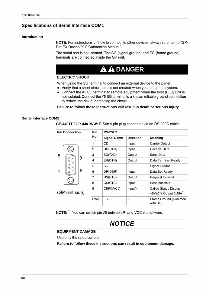
Specifications
90
Specifications of Serial Interface COM1
IntroductionNOTE: For instructions on how to connect to other devices, always refer to the “GP-Pro EX Device/PLC Connection Manual”.
The serial port is not isolated. The SG (signal ground) and FG (frame ground) terminals are connected inside the GP unit.
Serial Interface COM1GP-4401T / GP-4401WW: D-Sub 9 pin plug connector via an RS-232C cable.
NOTE: *1 You can switch pin #9 between RI and VCC via software.
DANGERELECTRIC SHOCKWhen using the SG terminal to connect an external device to the panel:
Verify that a short-circuit loop is not created when you set up the system.Connect the #5 SG terminal to remote equipment when the host (PLC) unit is not isolated. Connect the #5 SG terminal to a known reliable ground connection to reduce the risk of damaging the circuit.
Failure to follow these instructions will result in death or serious injury.
Pin Connection Pin No.
RS-232C
Signal Name Direction Meaning
1 CD Input Carrier Detect
2 RD(RXD) Input Receive Data
3 SD(TXD) Output Send Data
4 ER(DTR) Output Data Terminal Ready
5 SG - Signal Ground
6 DR(DSR) Input Data Set Ready
7 RS(RTS) Output Request to Send
8 CS(CTS) Input Send possible
9 CI(RI)/VCC Input/– Called Status Display
+5V±5% Output 0.25A*1
Shell FG – Frame Ground (Common with SG)
NOTICEEQUIPMENT DAMAGEUse only the rated current.
Failure to follow these instructions can result in equipment damage.
9
6
5
1
(GP unit side)
GP4000 Series Hardware Manual
91
Interfit bracket is #4-40 (UNC).
Recommendations:Cable Connector: XM2D-0901 manufactured by OMRON Corporation.Cable Cover: XM2S-0913 manufactured by OMRON Corporation.Jack Screw (#4-40 UNC): XM2Z-0073 manufactured by OMRON Corporation.
CAUTIONLOSS OF COMMUNICATION
All connections to the communication ports must not put excessive stress on the ports.Securely attach communication cables to the panel wall or cabinet.Use only D-Sub 9 pin cables with a locking tab in good condition.
Failure to follow these instructions can result in injury or equipment damage.

Specifications
92
Specifications of Serial Interface COM2
IntroductionNOTE: For instructions on how to connect to other devices, always refer to the “GP-Pro EX Device/PLC Connection Manual”.
The serial port is not isolated. The SG (signal ground) and FG (frame ground) terminals are connected inside the GP unit.
Serial Interface COM2GP-4401T/GP-4401WW: D-Sub 9 pin plug connector via an RS-422/485 cable.
Interfit bracket is #4-40 (UNC).
Recommendations:Cable Connector: XM2D-0901 manufactured by OMRON Corporation.Cable Cover: XM2S-0913 manufactured by OMRON Corporation.Jack Screw (#4-40 UNC): XM2Z-0073 manufactured by OMRON Corporation.
DANGERELECTRIC SHOCKWhen using the SG terminal to connect an external device to the panel:
Verify that a short-circuit loop is not created when you set up the system.Connect the #5 SG terminal to remote equipment when the host (PLC) unit is not isolated. Connect the #5 SG terminal to a known reliable ground connection to reduce the risk of damaging the circuit.
Failure to follow these instructions will result in death or serious injury.
Pin Connection Pin No.
RS-422/RS-485
Signal Name Direction Meaning
1 RDA Input Receive Data A (+)
2 RDB Input Receive Data B (-)
3 SDA Output Send Data A (+)
4 ERA Output Data Terminal Ready A (+)
5 SG - Signal Ground
6 CSB Input Send Possible B (-)
7 SDB Output Send Data B (-)
8 CSA Input Send Possible A (+)
9 ERB Output Data Terminal Ready B (-)
Shell FG – Frame Ground (Common with SG)
CAUTIONLOSS OF COMMUNICATION
All connections to the communication ports must not put excessive stress on the ports.Securely attach communication cables to the panel wall or cabinet.Use only D-Sub 9 pin cables with a locking tab in good condition.
Failure to follow these instructions can result in injury or equipment damage.
9
6
5
1
(GP unit side)
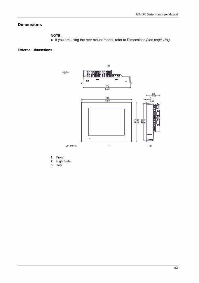
GP4000 Series Hardware Manual
93
Dimensions
NOTE: If you are using the rear mount model, refer to Dimensions (see page 184).
External Dimensions
1 Front2 Right Side3 Top
173
218
204
60
5
159
2.36
8.03
8.58
6.81
6.26
0.20
mm in.
(1) (2)
(3)
(GP-4401T)
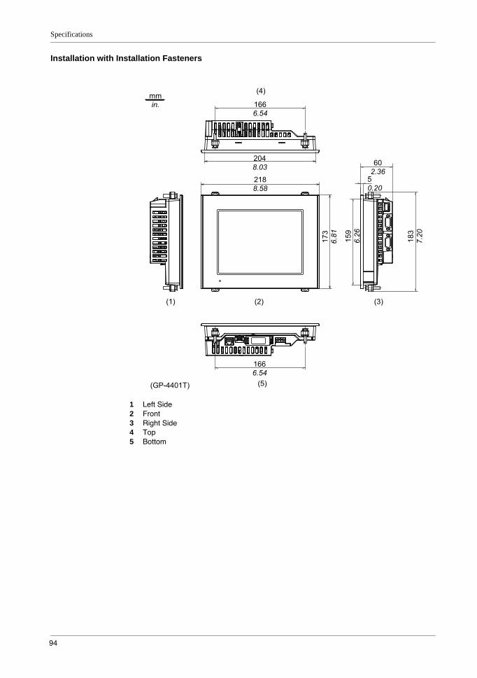
Specifications
94
Installation with Installation Fasteners
1 Left Side2 Front3 Right Side4 Top5 Bottom
218
8.58
173
6.81
159
6.26
204
8.03
5
0.20
60
2.36
166
6.54
166
6.54
183
7.20
mm
in.
(1) (2) (3)
(4)
(5)(GP-4401T)
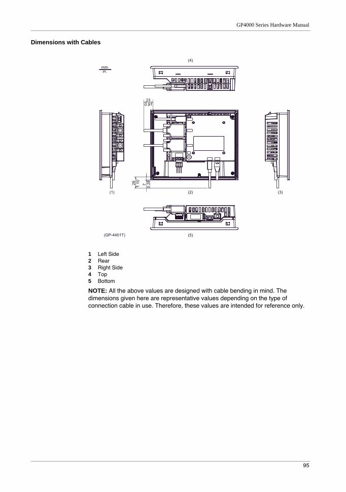
GP4000 Series Hardware Manual
95
Dimensions with Cables
1 Left Side2 Rear3 Right Side4 Top5 Bottom
NOTE: All the above values are designed with cable bending in mind. The dimensions given here are representative values depending on the type of connection cable in use. Therefore, these values are intended for reference only.
23
7 28
mm in.
(1) (2)
(5)
(4)
(3)
0.91
1.10
0.28
(GP-4401T)
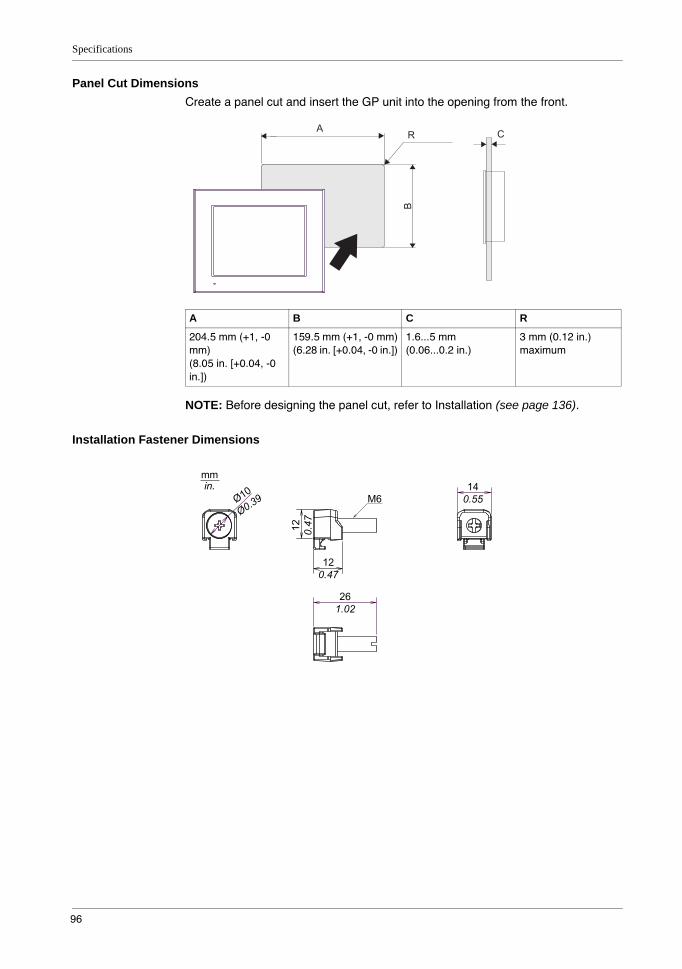
Specifications
96
Panel Cut DimensionsCreate a panel cut and insert the GP unit into the opening from the front.
NOTE: Before designing the panel cut, refer to Installation (see page 136).
Installation Fastener Dimensions
A B C R
204.5 mm (+1, -0 mm)(8.05 in. [+0.04, -0 in.])
159.5 mm (+1, -0 mm)(6.28 in. [+0.04, -0 in.])
1.6...5 mm(0.06...0.2 in.)
3 mm (0.12 in.) maximum
A CR
B
12
0.4
7
12
0.47
14
0.55M6
26
1.02
mm
in.
Ø10
Ø0.3
9
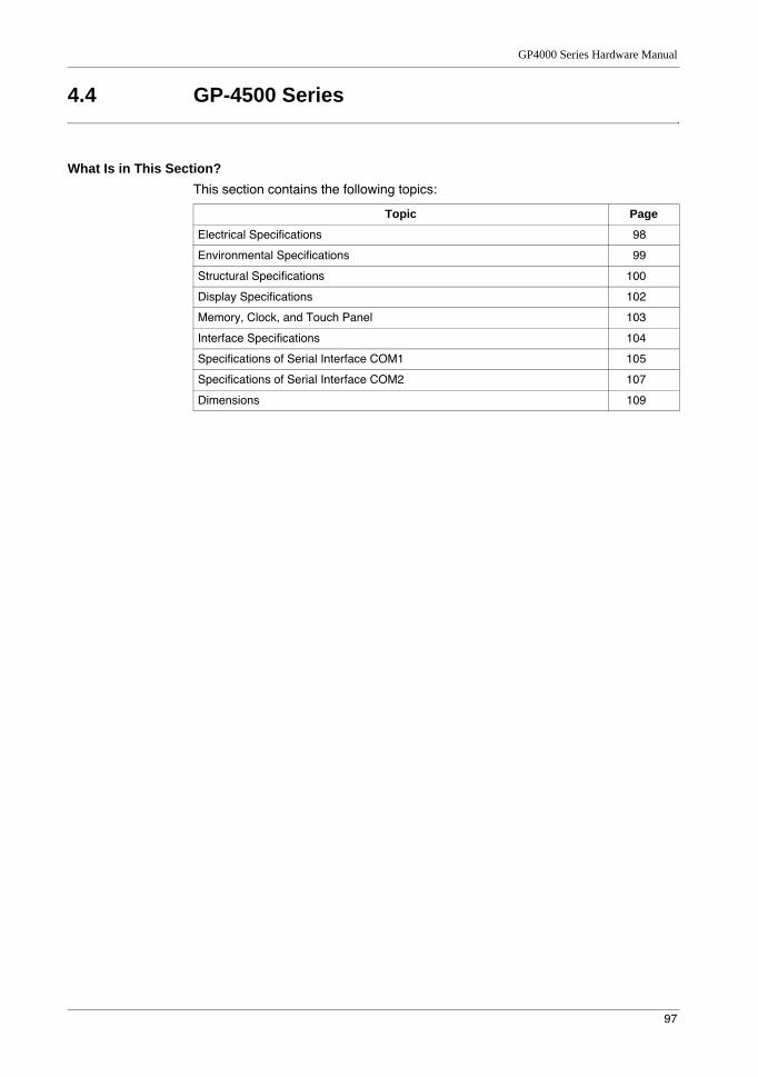
GP4000 Series Hardware Manual
97
4.4 GP-4500 Series
What Is in This Section?This section contains the following topics:
Topic Page
Electrical Specifications 98
Environmental Specifications 99
Structural Specifications 100
Display Specifications 102
Memory, Clock, and Touch Panel 103
Interface Specifications 104
Specifications of Serial Interface COM1 105
Specifications of Serial Interface COM2 107
Dimensions 109
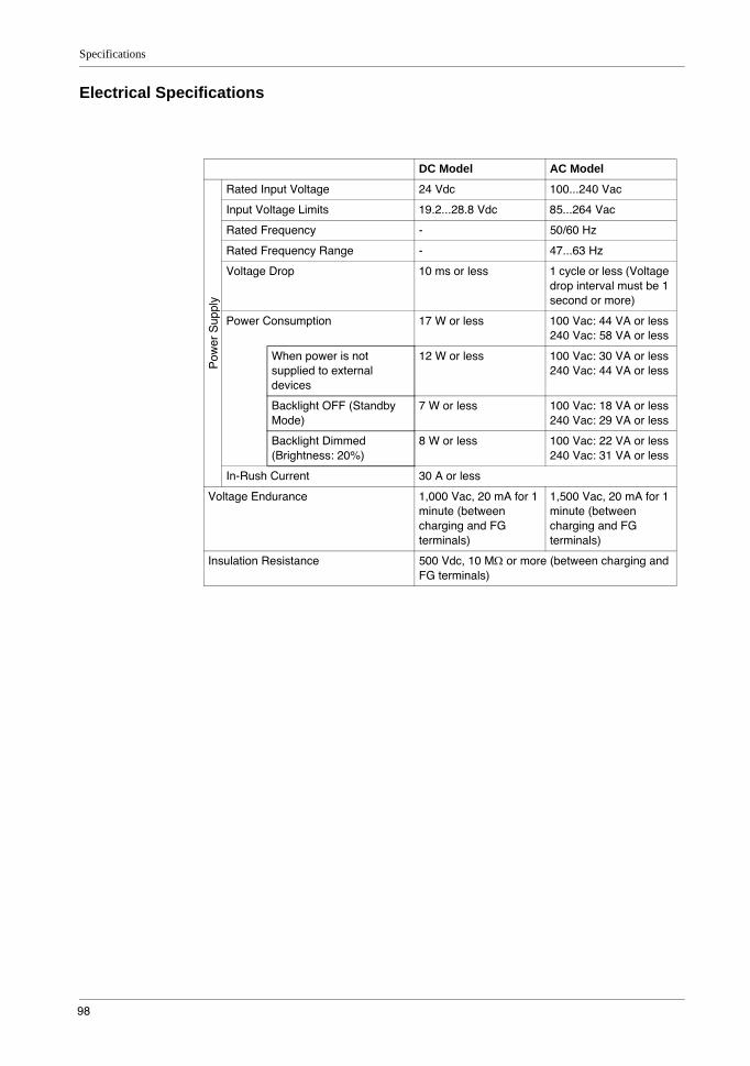
Specifications
98
Electrical Specifications
DC Model AC Model
Pow
er S
uppl
y
Rated Input Voltage 24 Vdc 100...240 Vac
Input Voltage Limits 19.2...28.8 Vdc 85...264 Vac
Rated Frequency - 50/60 Hz
Rated Frequency Range - 47...63 Hz
Voltage Drop 10 ms or less 1 cycle or less (Voltage drop interval must be 1 second or more)
Power Consumption 17 W or less 100 Vac: 44 VA or less240 Vac: 58 VA or less
When power is not supplied to external devices
12 W or less 100 Vac: 30 VA or less240 Vac: 44 VA or less
Backlight OFF (Standby Mode)
7 W or less 100 Vac: 18 VA or less240 Vac: 29 VA or less
Backlight Dimmed (Brightness: 20%)
8 W or less 100 Vac: 22 VA or less240 Vac: 31 VA or less
In-Rush Current 30 A or less
Voltage Endurance 1,000 Vac, 20 mA for 1 minute (between charging and FG terminals)
1,500 Vac, 20 mA for 1 minute (between charging and FG terminals)
Insulation Resistance 500 Vdc, 10 MΩ or more (between charging and FG terminals)
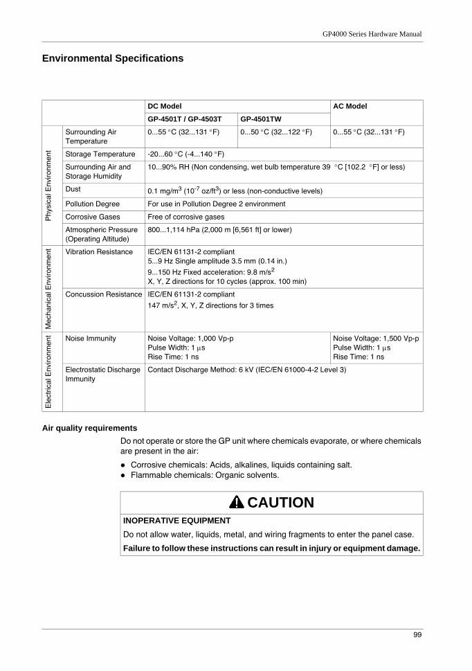
GP4000 Series Hardware Manual
99
Environmental Specifications
Air quality requirementsDo not operate or store the GP unit where chemicals evaporate, or where chemicals are present in the air:
Corrosive chemicals: Acids, alkalines, liquids containing salt.Flammable chemicals: Organic solvents.
DC Model AC Model
GP-4501T / GP-4503T GP-4501TW
Phy
sica
l Env
ironm
ent
Surrounding Air Temperature
0...55 °C (32...131 °F) 0...50 °C (32...122 °F) 0...55 °C (32...131 °F)
Storage Temperature -20...60 °C (-4...140 °F)
Surrounding Air and Storage Humidity
10...90% RH (Non condensing, wet bulb temperature 39 °C [102.2 °F] or less)
Dust 0.1 mg/m3 (10-7 oz/ft3) or less (non-conductive levels)
Pollution Degree For use in Pollution Degree 2 environment
Corrosive Gases Free of corrosive gases
Atmospheric Pressure (Operating Altitude)
800...1,114 hPa (2,000 m [6,561 ft] or lower)
Mec
hani
cal E
nviro
nmen
t Vibration Resistance IEC/EN 61131-2 compliant5...9 Hz Single amplitude 3.5 mm (0.14 in.)
9...150 Hz Fixed acceleration: 9.8 m/s2
X, Y, Z directions for 10 cycles (approx. 100 min)
Concussion Resistance IEC/EN 61131-2 compliant
147 m/s2, X, Y, Z directions for 3 times
Ele
ctric
al E
nviro
nmen
t Noise Immunity Noise Voltage: 1,000 Vp-pPulse Width: 1 µsRise Time: 1 ns
Noise Voltage: 1,500 Vp-pPulse Width: 1 µsRise Time: 1 ns
Electrostatic Discharge Immunity
Contact Discharge Method: 6 kV (IEC/EN 61000-4-2 Level 3)
CAUTIONINOPERATIVE EQUIPMENTDo not allow water, liquids, metal, and wiring fragments to enter the panel case.
Failure to follow these instructions can result in injury or equipment damage.
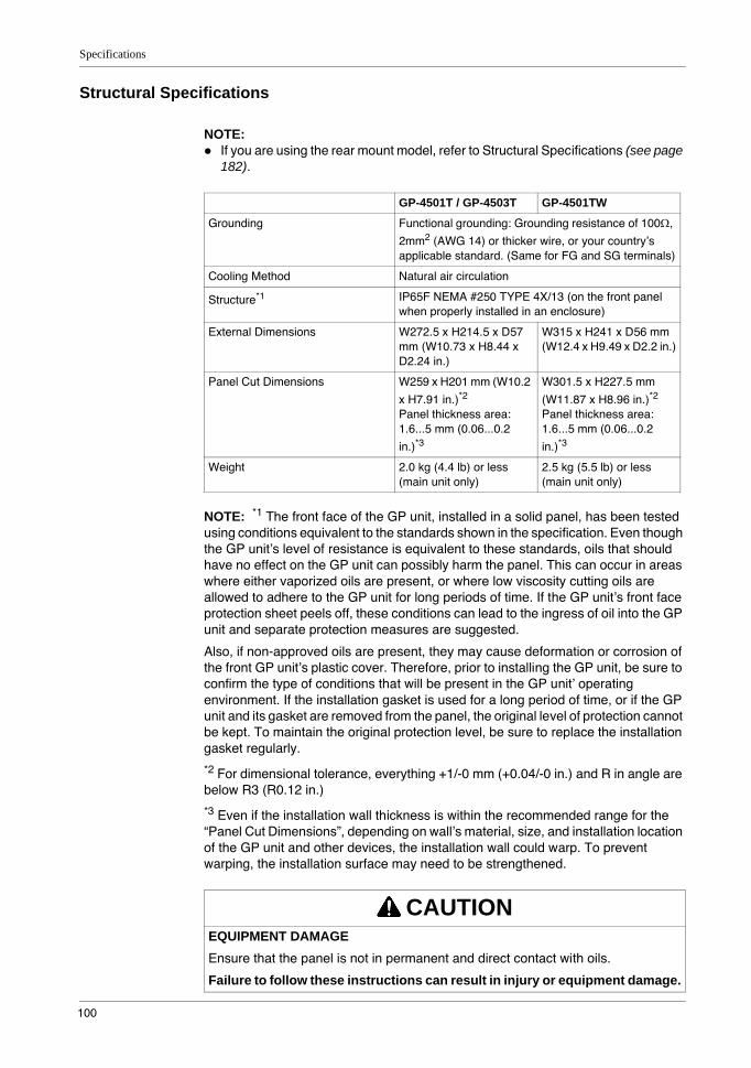
Specifications
100
Structural Specifications
NOTE: If you are using the rear mount model, refer to Structural Specifications (see page 182).
NOTE: *1 The front face of the GP unit, installed in a solid panel, has been tested using conditions equivalent to the standards shown in the specification. Even though the GP unit’s level of resistance is equivalent to these standards, oils that should have no effect on the GP unit can possibly harm the panel. This can occur in areas where either vaporized oils are present, or where low viscosity cutting oils are allowed to adhere to the GP unit for long periods of time. If the GP unit’s front face protection sheet peels off, these conditions can lead to the ingress of oil into the GP unit and separate protection measures are suggested.
Also, if non-approved oils are present, they may cause deformation or corrosion of the front GP unit’s plastic cover. Therefore, prior to installing the GP unit, be sure to confirm the type of conditions that will be present in the GP unit’ operating environment. If the installation gasket is used for a long period of time, or if the GP unit and its gasket are removed from the panel, the original level of protection cannot be kept. To maintain the original protection level, be sure to replace the installation gasket regularly.
*2 For dimensional tolerance, everything +1/-0 mm (+0.04/-0 in.) and R in angle are below R3 (R0.12 in.)
*3 Even if the installation wall thickness is within the recommended range for the “Panel Cut Dimensions”, depending on wall’s material, size, and installation location of the GP unit and other devices, the installation wall could warp. To prevent warping, the installation surface may need to be strengthened.
GP-4501T / GP-4503T GP-4501TW
Grounding Functional grounding: Grounding resistance of 100Ω,
2mm2 (AWG 14) or thicker wire, or your country’s applicable standard. (Same for FG and SG terminals)
Cooling Method Natural air circulation
Structure*1 IP65F NEMA #250 TYPE 4X/13 (on the front panel when properly installed in an enclosure)
External Dimensions W272.5 x H214.5 x D57 mm (W10.73 x H8.44 x D2.24 in.)
W315 x H241 x D56 mm (W12.4 x H9.49 x D2.2 in.)
Panel Cut Dimensions W259 x H201 mm (W10.2
x H7.91 in.)*2
Panel thickness area: 1.6...5 mm (0.06...0.2
in.)*3
W301.5 x H227.5 mm
(W11.87 x H8.96 in.)*2
Panel thickness area: 1.6...5 mm (0.06...0.2
in.)*3
Weight 2.0 kg (4.4 lb) or less (main unit only)
2.5 kg (5.5 lb) or less (main unit only)
CAUTIONEQUIPMENT DAMAGEEnsure that the panel is not in permanent and direct contact with oils.
Failure to follow these instructions can result in injury or equipment damage.

GP4000 Series Hardware Manual
101
NOTICESTORAGE AND OPERATION OUTSIDE OF SPECIFICATIONS
Store the panel in areas where temperatures are within the panel’s specifications.Do not restrict or block the panel’s rear-face ventilation slots.
Failure to follow these instructions can result in equipment damage.
NOTICEGASKET AGING
Inspect the gasket periodically as required by your operating environment to keep the initial IP level.Change the gasket at least once a year, or as soon as scratches or dirt become visible.
Failure to follow these instructions can result in equipment damage.
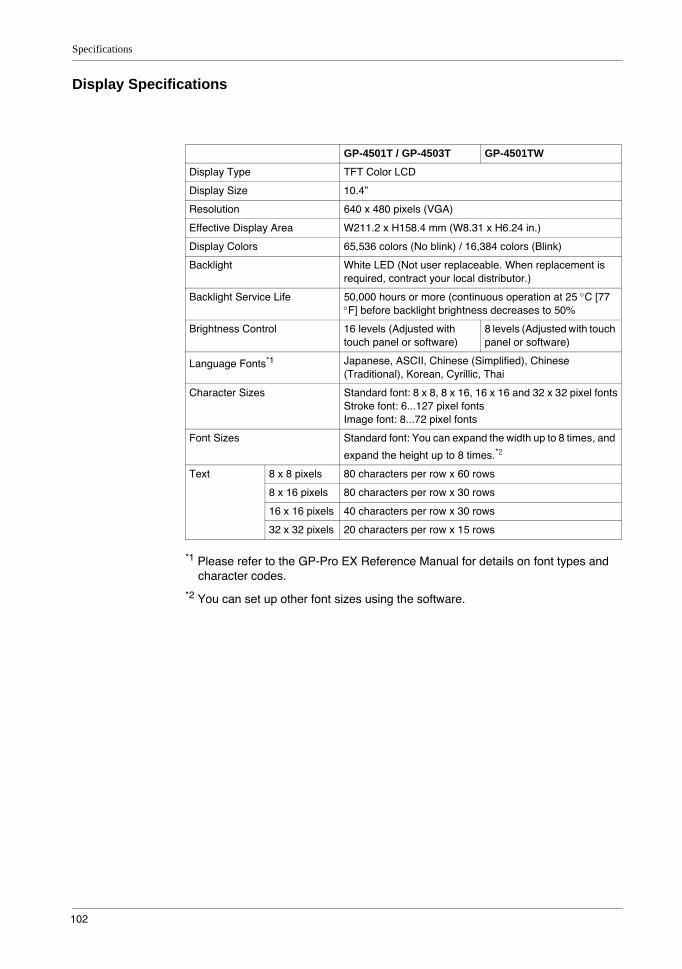
Specifications
102
Display Specifications
*1 Please refer to the GP-Pro EX Reference Manual for details on font types and character codes.
*2 You can set up other font sizes using the software.
GP-4501T / GP-4503T GP-4501TW
Display Type TFT Color LCD
Display Size 10.4”
Resolution 640 x 480 pixels (VGA)
Effective Display Area W211.2 x H158.4 mm (W8.31 x H6.24 in.)
Display Colors 65,536 colors (No blink) / 16,384 colors (Blink)
Backlight White LED (Not user replaceable. When replacement is required, contract your local distributor.)
Backlight Service Life 50,000 hours or more (continuous operation at 25 °C [77 °F] before backlight brightness decreases to 50%
Brightness Control 16 levels (Adjusted with touch panel or software)
8 levels (Adjusted with touch panel or software)
Language Fonts*1 Japanese, ASCII, Chinese (Simplified), Chinese (Traditional), Korean, Cyrillic, Thai
Character Sizes Standard font: 8 x 8, 8 x 16, 16 x 16 and 32 x 32 pixel fontsStroke font: 6...127 pixel fontsImage font: 8...72 pixel fonts
Font Sizes Standard font: You can expand the width up to 8 times, and
expand the height up to 8 times.*2
Text 8 x 8 pixels 80 characters per row x 60 rows
8 x 16 pixels 80 characters per row x 30 rows
16 x 16 pixels 40 characters per row x 30 rows
32 x 32 pixels 20 characters per row x 15 rows
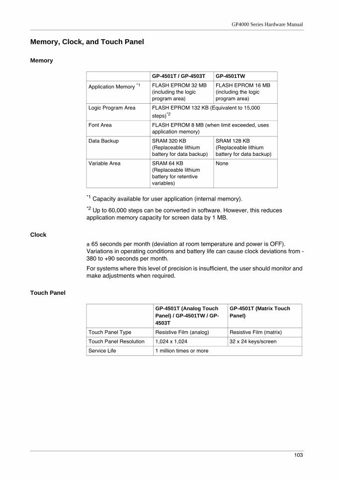
GP4000 Series Hardware Manual
103
Memory, Clock, and Touch Panel
Memory
*1 Capacity available for user application (internal memory).
*2 Up to 60,000 steps can be converted in software. However, this reduces application memory capacity for screen data by 1 MB.
Clock± 65 seconds per month (deviation at room temperature and power is OFF). Variations in operating conditions and battery life can cause clock deviations from -380 to +90 seconds per month.
For systems where this level of precision is insufficient, the user should monitor and make adjustments when required.
Touch Panel
GP-4501T / GP-4503T GP-4501TW
Application Memory *1 FLASH EPROM 32 MB (including the logic program area)
FLASH EPROM 16 MB (including the logic program area)
Logic Program Area FLASH EPROM 132 KB (Equivalent to 15,000
steps)*2
Font Area FLASH EPROM 8 MB (when limit exceeded, uses application memory)
Data Backup SRAM 320 KB (Replaceable lithium battery for data backup)
SRAM 128 KB (Replaceable lithium battery for data backup)
Variable Area SRAM 64 KB (Replaceable lithium battery for retentive variables)
None
GP-4501T (Analog Touch Panel) / GP-4501TW / GP-4503T
GP-4501T (Matrix Touch Panel)
Touch Panel Type Resistive Film (analog) Resistive Film (matrix)
Touch Panel Resolution 1,024 x 1,024 32 x 24 keys/screen
Service Life 1 million times or more
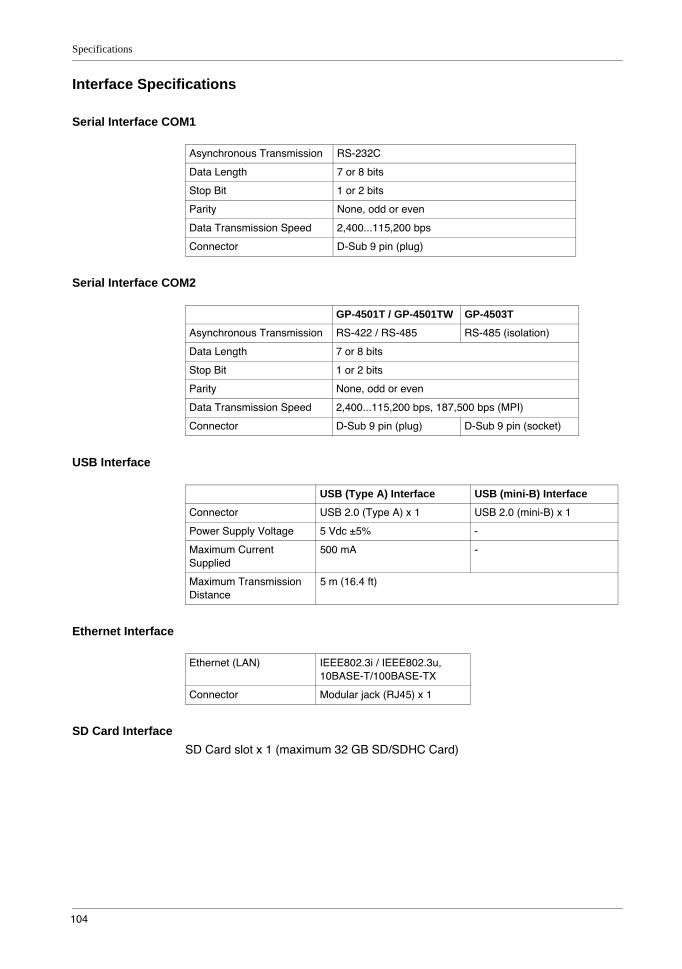
Specifications
104
Interface Specifications
Serial Interface COM1
Serial Interface COM2
USB Interface
Ethernet Interface
SD Card InterfaceSD Card slot x 1 (maximum 32 GB SD/SDHC Card)
Asynchronous Transmission RS-232C
Data Length 7 or 8 bits
Stop Bit 1 or 2 bits
Parity None, odd or even
Data Transmission Speed 2,400...115,200 bps
Connector D-Sub 9 pin (plug)
GP-4501T / GP-4501TW GP-4503T
Asynchronous Transmission RS-422 / RS-485 RS-485 (isolation)
Data Length 7 or 8 bits
Stop Bit 1 or 2 bits
Parity None, odd or even
Data Transmission Speed 2,400...115,200 bps, 187,500 bps (MPI)
Connector D-Sub 9 pin (plug) D-Sub 9 pin (socket)
USB (Type A) Interface USB (mini-B) Interface
Connector USB 2.0 (Type A) x 1 USB 2.0 (mini-B) x 1
Power Supply Voltage 5 Vdc ±5% -
Maximum Current Supplied
500 mA -
Maximum Transmission Distance
5 m (16.4 ft)
Ethernet (LAN) IEEE802.3i / IEEE802.3u, 10BASE-T/100BASE-TX
Connector Modular jack (RJ45) x 1

GP4000 Series Hardware Manual
105
Specifications of Serial Interface COM1
IntroductionNOTE: For instructions on how to connect to other devices, always refer to the “GP-Pro EX Device/PLC Connection Manual”.
The serial port is not isolated. The SG (signal ground) and FG (frame ground) terminals are connected inside the GP unit.
Serial Interface COM1GP-4501T / GP-4501TW / GP-4503T: D-Sub 9 pin plug connector via an RS-232C cable.
NOTE: *1 You can switch pin #9 between RI and VCC via software.
Interfit bracket is #4-40 (UNC).
DANGERELECTRIC SHOCKWhen using the SG terminal to connect an external device to the panel:
Verify that a short-circuit loop is not created when you set up the system.Connect the #5 SG terminal to remote equipment when the host (PLC) unit is not isolated. Connect the #5 SG terminal to a known reliable ground connection to reduce the risk of damaging the circuit.
Failure to follow these instructions will result in death or serious injury.
Pin Connection Pin No.
RS-232C
Signal Name Direction Meaning
1 CD Input Carrier Detect
2 RD(RXD) Input Receive Data
3 SD(TXD) Output Send Data
4 ER(DTR) Output Data Terminal Ready
5 SG - Signal Ground
6 DR(DSR) Input Data Set Ready
7 RS(RTS) Output Request to Send
8 CS(CTS) Input Send possible
9 CI(RI)/VCC Input/– Called Status Display
+5V±5% Output 0.25A*1
Shell FG – Frame Ground (Common with SG)
NOTICEEQUIPMENT DAMAGEUse only the rated current.
Failure to follow these instructions can result in equipment damage.
9
6
5
1
(GP unit side)
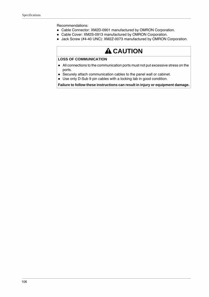
Specifications
106
Recommendations:Cable Connector: XM2D-0901 manufactured by OMRON Corporation.Cable Cover: XM2S-0913 manufactured by OMRON Corporation.Jack Screw (#4-40 UNC): XM2Z-0073 manufactured by OMRON Corporation.
CAUTIONLOSS OF COMMUNICATION
All connections to the communication ports must not put excessive stress on the ports.Securely attach communication cables to the panel wall or cabinet.Use only D-Sub 9 pin cables with a locking tab in good condition.
Failure to follow these instructions can result in injury or equipment damage.
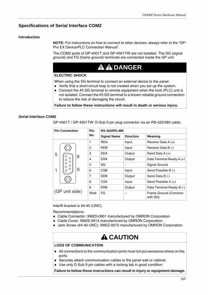
GP4000 Series Hardware Manual
107
Specifications of Serial Interface COM2
IntroductionNOTE: For instructions on how to connect to other devices, always refer to the “GP-Pro EX Device/PLC Connection Manual”.
The COM2 ports of GP-4501T and GP-4501TW are not isolated. The SG (signal ground) and FG (frame ground) terminals are connected inside the GP unit.
Serial Interface COM2GP-4501T / GP-4501TW: D-Sub 9 pin plug connector via an RS-422/485 cable.
Interfit bracket is #4-40 (UNC).
Recommendations:Cable Connector: XM2D-0901 manufactured by OMRON Corporation.Cable Cover: XM2S-0913 manufactured by OMRON Corporation.Jack Screw (#4-40 UNC): XM2Z-0073 manufactured by OMRON Corporation.
DANGERELECTRIC SHOCKWhen using the SG terminal to connect an external device to the panel:
Verify that a short-circuit loop is not created when you set up the system.Connect the #5 SG terminal to remote equipment when the host (PLC) unit is not isolated. Connect the #5 SG terminal to a known reliable ground connection to reduce the risk of damaging the circuit.
Failure to follow these instructions will result in death or serious injury.
Pin Connection Pin No.
RS-422/RS-485
Signal Name Direction Meaning
1 RDA Input Receive Data A (+)
2 RDB Input Receive Data B (-)
3 SDA Output Send Data A (+)
4 ERA Output Data Terminal Ready A (+)
5 SG - Signal Ground
6 CSB Input Send Possible B (-)
7 SDB Output Send Data B (-)
8 CSA Input Send Possible A (+)
9 ERB Output Data Terminal Ready B (-)
Shell FG – Frame Ground (Common with SG)
CAUTIONLOSS OF COMMUNICATION
All connections to the communication ports must not put excessive stress on the ports.Securely attach communication cables to the panel wall or cabinet.Use only D-Sub 9 pin cables with a locking tab in good condition.
Failure to follow these instructions can result in injury or equipment damage.
9
6
5
1
(GP unit side)
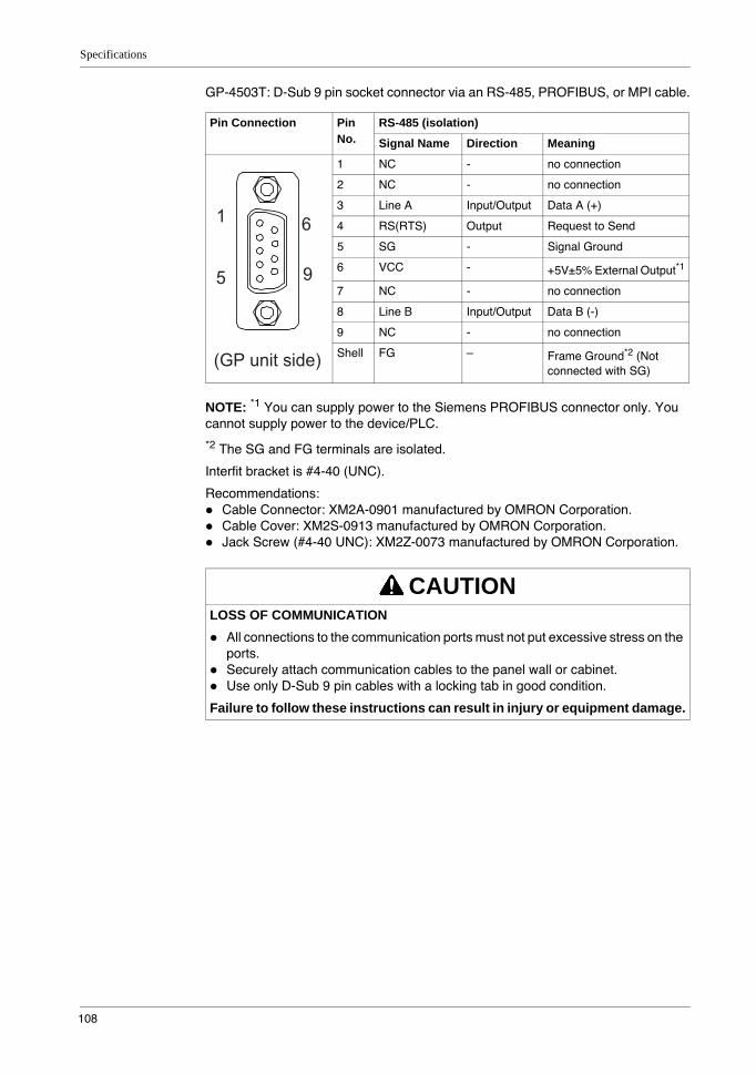
Specifications
108
GP-4503T: D-Sub 9 pin socket connector via an RS-485, PROFIBUS, or MPI cable.
NOTE: *1 You can supply power to the Siemens PROFIBUS connector only. You cannot supply power to the device/PLC.
*2 The SG and FG terminals are isolated.
Interfit bracket is #4-40 (UNC).
Recommendations:Cable Connector: XM2A-0901 manufactured by OMRON Corporation.Cable Cover: XM2S-0913 manufactured by OMRON Corporation.Jack Screw (#4-40 UNC): XM2Z-0073 manufactured by OMRON Corporation.
Pin Connection Pin No.
RS-485 (isolation)
Signal Name Direction Meaning
1 NC - no connection
2 NC - no connection
3 Line A Input/Output Data A (+)
4 RS(RTS) Output Request to Send
5 SG - Signal Ground
6 VCC - +5V±5% External Output*1
7 NC - no connection
8 Line B Input/Output Data B (-)
9 NC - no connection
Shell FG – Frame Ground*2 (Not connected with SG)
CAUTIONLOSS OF COMMUNICATION
All connections to the communication ports must not put excessive stress on the ports.Securely attach communication cables to the panel wall or cabinet.Use only D-Sub 9 pin cables with a locking tab in good condition.
Failure to follow these instructions can result in injury or equipment damage.
6
9
1
5
(GP unit side)
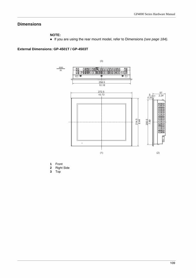
GP4000 Series Hardware Manual
109
Dimensions
NOTE: If you are using the rear mount model, refer to Dimensions (see page 184).
External Dimensions: GP-4501T / GP-4503T
1 Front2 Right Side3 Top
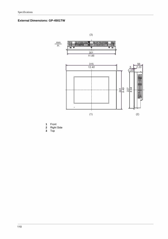
Specifications
110
External Dimensions: GP-4501TW
1 Front2 Right Side3 Top
GP4000 Series Hardware Manual
111
Installation with Installation Fasteners: GP-4501T / GP-4503T
1 Left Side2 Front3 Right Side4 Top5 Bottom
Specifications
112
Installation with Installation Fasteners: GP-4501TW
1 Left Side2 Front3 Right Side4 Top5 Bottom
GP4000 Series Hardware Manual
113
Dimensions with Cables: GP-4501T
1 Left Side2 Rear3 Right Side4 Top5 Bottom6 DC type units have power supply terminals
NOTE: All the above values are designed with cable bending in mind. The dimensions given here are representative values depending on the type of connection cable in use. Therefore, these values are intended for reference only.
Specifications
114
Dimensions with Cables: GP-4501TW
1 Left Side2 Rear3 Right Side4 Top5 Bottom
NOTE: All the above values are designed with cable bending in mind. The dimensions given here are representative values depending on the type of connection cable in use. Therefore, these values are intended for reference only.
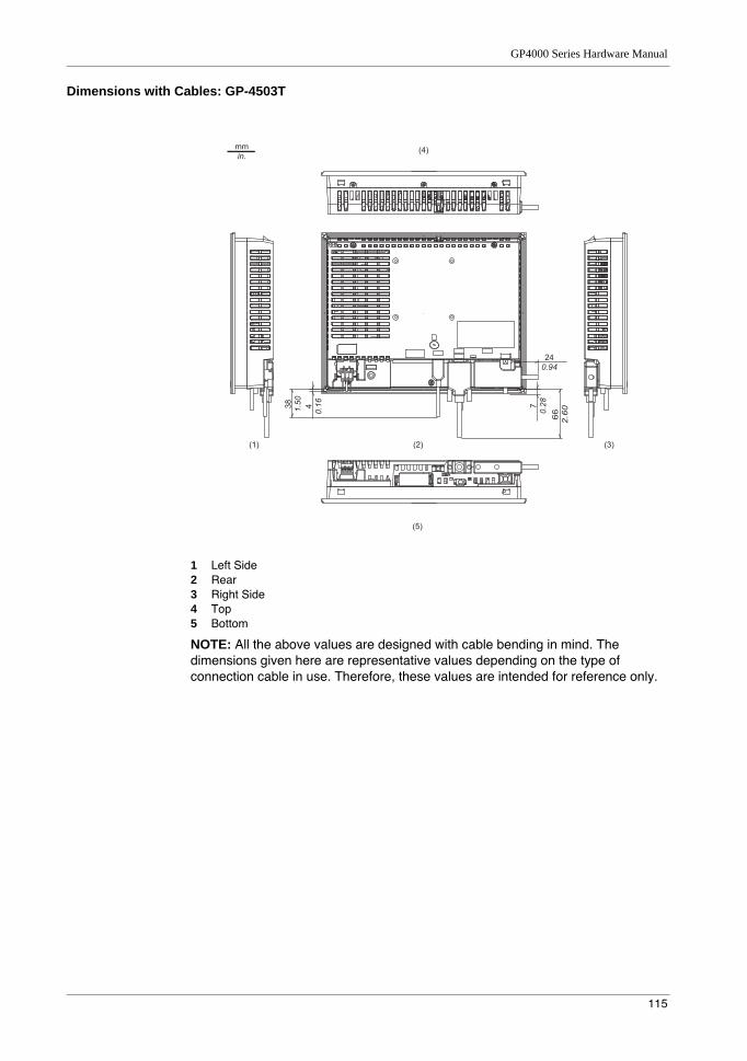
GP4000 Series Hardware Manual
115
Dimensions with Cables: GP-4503T
1 Left Side2 Rear3 Right Side4 Top5 Bottom
NOTE: All the above values are designed with cable bending in mind. The dimensions given here are representative values depending on the type of connection cable in use. Therefore, these values are intended for reference only.
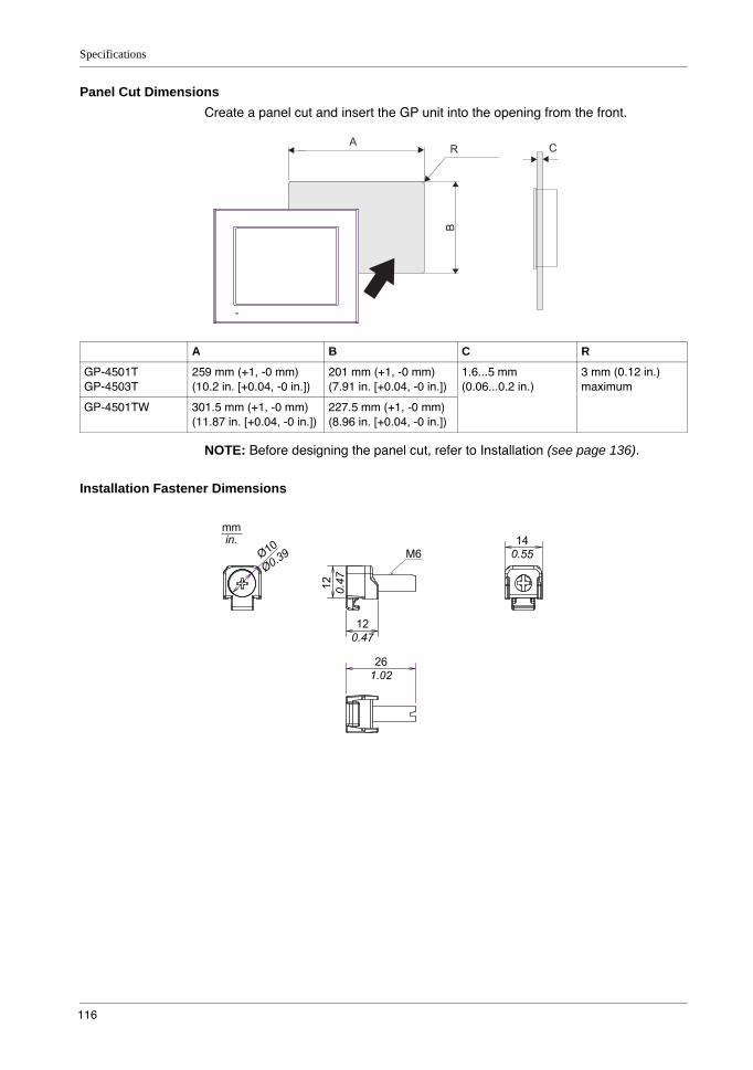
Specifications
116
Panel Cut DimensionsCreate a panel cut and insert the GP unit into the opening from the front.
NOTE: Before designing the panel cut, refer to Installation (see page 136).
Installation Fastener Dimensions
A CR
B
A B C R
GP-4501TGP-4503T
259 mm (+1, -0 mm)(10.2 in. [+0.04, -0 in.])
201 mm (+1, -0 mm)(7.91 in. [+0.04, -0 in.])
1.6...5 mm(0.06...0.2 in.)
3 mm (0.12 in.) maximum
GP-4501TW 301.5 mm (+1, -0 mm)(11.87 in. [+0.04, -0 in.])
227.5 mm (+1, -0 mm)(8.96 in. [+0.04, -0 in.])
12
0.4
7
12
0.47
14
0.55M6
26
1.02
mm
in.
Ø10
Ø0.3
9

GP4000 Series Hardware Manual
117
4.5 GP-4600 Series
What Is in This Section?This section contains the following topics:
Topic Page
Electrical Specifications 118
Environmental Specifications 119
Structural Specifications 120
Display Specifications 122
Memory, Clock, and Touch Panel 123
Interface Specifications 124
Specifications of Serial Interface COM1 125
Specifications of Serial Interface COM2 127
Dimensions 129

Specifications
118
Electrical Specifications
DC Model AC Model
Pow
er S
uppl
y
Rated Input Voltage 24 Vdc 100...240 Vac
Input Voltage Limits 19.2...28.8 Vdc 85...264 Vac
Rated Frequency - 50/60 Hz
Rated Frequency Range - 47...63 Hz
Voltage Drop 10 ms or less 1 cycle or less (Voltage drop interval must be 1 second or more)
Power Consumption 17 W or less 100 Vac: 44 VA or less240 Vac: 58 VA or less
When power is not supplied to external devices
12 W or less 100 Vac: 30 VA or less240 Vac: 44 VA or less
Backlight OFF (Standby Mode)
7 W or less 100 Vac: 18 VA or less240 Vac: 29 VA or less
Backlight Dimmed (Brightness: 20%)
8 W or less 100 Vac: 22 VA or less240 Vac: 31 VA or less
In-Rush Current 30 A or less
Voltage Endurance 1,000 Vac, 20 mA for 1 minute (between charging and FG terminals)
1,500 Vac, 20 mA for 1 minute (between charging and FG terminals)
Insulation Resistance 500 Vdc, 10 MΩ or more (between charging and FG terminals)
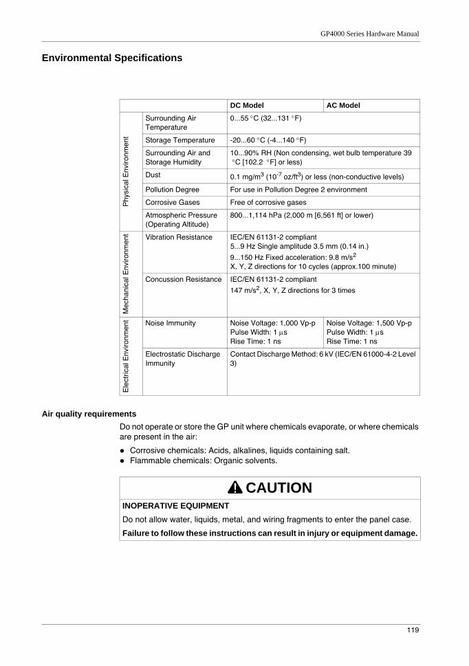
GP4000 Series Hardware Manual
119
Environmental Specifications
Air quality requirementsDo not operate or store the GP unit where chemicals evaporate, or where chemicals are present in the air:
Corrosive chemicals: Acids, alkalines, liquids containing salt.Flammable chemicals: Organic solvents.
DC Model AC Model
Phy
sica
l Env
ironm
ent
Surrounding Air Temperature
0...55 °C (32...131 °F)
Storage Temperature -20...60 °C (-4...140 °F)
Surrounding Air and Storage Humidity
10...90% RH (Non condensing, wet bulb temperature 39 °C [102.2 °F] or less)
Dust 0.1 mg/m3 (10-7 oz/ft3) or less (non-conductive levels)
Pollution Degree For use in Pollution Degree 2 environment
Corrosive Gases Free of corrosive gases
Atmospheric Pressure (Operating Altitude)
800...1,114 hPa (2,000 m [6,561 ft] or lower)
Mec
hani
cal E
nviro
nmen
t Vibration Resistance IEC/EN 61131-2 compliant5...9 Hz Single amplitude 3.5 mm (0.14 in.)
9...150 Hz Fixed acceleration: 9.8 m/s2
X, Y, Z directions for 10 cycles (approx.100 minute)
Concussion Resistance IEC/EN 61131-2 compliant
147 m/s2, X, Y, Z directions for 3 times
Ele
ctric
al E
nviro
nmen
t Noise Immunity Noise Voltage: 1,000 Vp-pPulse Width: 1 µsRise Time: 1 ns
Noise Voltage: 1,500 Vp-pPulse Width: 1 µsRise Time: 1 ns
Electrostatic Discharge Immunity
Contact Discharge Method: 6 kV (IEC/EN 61000-4-2 Level 3)
CAUTIONINOPERATIVE EQUIPMENTDo not allow water, liquids, metal, and wiring fragments to enter the panel case.
Failure to follow these instructions can result in injury or equipment damage.
Specifications
120
Structural Specifications
NOTE: If you are using the rear mount model, refer to Structural Specifications (see page 182).
NOTE: *1 The front face of the GP unit, installed in a solid panel, has been tested using conditions equivalent to the standards shown in the specification. Even though the GP unit’s level of resistance is equivalent to these standards, oils that should have no effect on the GP unit can possibly harm the panel. This can occur in areas where either vaporized oils are present, or where low viscosity cutting oils are allowed to adhere to the GP unit for long periods of time. If the GP unit’s front face protection sheet peels off, these conditions can lead to the ingress of oil into the GP unit and separate protection measures are suggested.
Also, if non-approved oils are present, they may cause deformation or corrosion of the front GP unit’s plastic cover. Therefore, prior to installing the GP unit, be sure to confirm the type of conditions that will be present in the GP unit’s operating environment. If the installation gasket is used for a long period of time, or if the GP unit and its gasket are removed from the panel, the original level of protection cannot be kept. To maintain the original protection level, be sure to replace the installation gasket regularly.
*2 For dimensional tolerance, everything +1/-0 mm (+0.04/-0 in.) and R in angle are below R3 (R0.12in.)
*3 Even if the installation wall thickness is within the recommended range for the “Panel Cut Dimensions”, depending on wall’s material, size, and installation location of the GP unit and other devices, the installation wall could warp. To prevent warping, the installation surface may need to be strengthened.
Grounding Functional grounding: Grounding resistance
of 100 Ω, 2 mm2 (AWG 14) or thicker wire, or your country’s applicable standard. (Same for FG and SG terminals)
Cooling Method Natural air circulation
Structure*1 IP65F NEMA #250 TYPE 4X/13 (on the front panel when properly installed in an enclosure)
External Dimensions W315 x H241 x D56 mm (W12.4 x H9.49 x D2.2 in.)
Panel Cut Dimensions W301.5 x H227.5 mm (W11.87 x H8.96
in.)*2
Panel thickness area: 1.6...5 mm (0.06...0.2
in.)*3
Weight 2.5 kg (5.5 lb) or less (main unit only)
CAUTIONEQUIPMENT DAMAGEEnsure that the panel is not in permanent and direct contact with oils.
Failure to follow these instructions can result in injury or equipment damage.
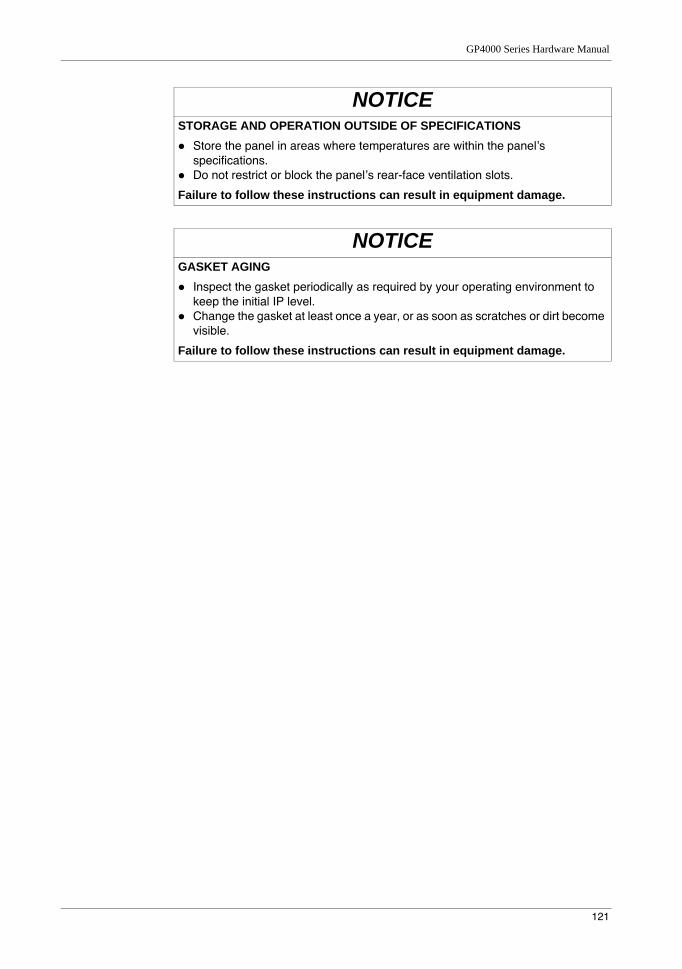
GP4000 Series Hardware Manual
121
NOTICESTORAGE AND OPERATION OUTSIDE OF SPECIFICATIONS
Store the panel in areas where temperatures are within the panel’s specifications.Do not restrict or block the panel’s rear-face ventilation slots.
Failure to follow these instructions can result in equipment damage.
NOTICEGASKET AGING
Inspect the gasket periodically as required by your operating environment to keep the initial IP level.Change the gasket at least once a year, or as soon as scratches or dirt become visible.
Failure to follow these instructions can result in equipment damage.
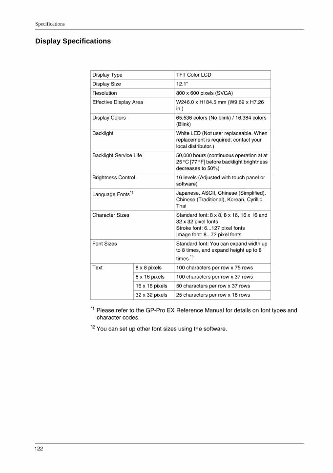
Specifications
122
Display Specifications
*1 Please refer to the GP-Pro EX Reference Manual for details on font types and character codes.
*2 You can set up other font sizes using the software.
Display Type TFT Color LCD
Display Size 12.1”
Resolution 800 x 600 pixels (SVGA)
Effective Display Area W246.0 x H184.5 mm (W9.69 x H7.26 in.)
Display Colors 65,536 colors (No blink) / 16,384 colors (Blink)
Backlight White LED (Not user replaceable. When replacement is required, contact your local distributor.)
Backlight Service Life 50,000 hours (continuous operation at at 25 °C [77 °F] before backlight brightness decreases to 50%)
Brightness Control 16 levels (Adjusted with touch panel or software)
Language Fonts*1 Japanese, ASCII, Chinese (Simplified), Chinese (Traditional), Korean, Cyrillic, Thai
Character Sizes Standard font: 8 x 8, 8 x 16, 16 x 16 and 32 x 32 pixel fontsStroke font: 6...127 pixel fontsImage font: 8...72 pixel fonts
Font Sizes Standard font: You can expand width up to 8 times, and expand height up to 8
times.*2
Text 8 x 8 pixels 100 characters per row x 75 rows
8 x 16 pixels 100 characters per row x 37 rows
16 x 16 pixels 50 characters per row x 37 rows
32 x 32 pixels 25 characters per row x 18 rows
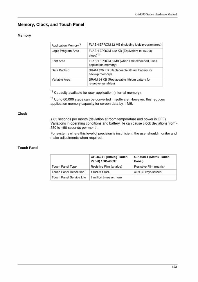
GP4000 Series Hardware Manual
123
Memory, Clock, and Touch Panel
Memory
*1 Capacity available for user application (internal memory).
*2 Up to 60,000 steps can be converted in software. However, this reduces application memory capacity for screen data by 1 MB.
Clock± 65 seconds per month (deviation at room temperature and power is OFF). Variations in operating conditions and battery life can cause clock deviations from -380 to +90 seconds per month.
For systems where this level of precision is insufficient, the user should monitor and make adjustments when required.
Touch Panel
Application Memory*1 FLASH EPROM 32 MB (including logic program area)
Logic Program Area FLASH EPROM 132 KB (Equivalent to 15,000
steps)*2)
Font Area FLASH EPROM 8 MB (when limit exceeded, uses application memory)
Data Backup SRAM 320 KB (Replaceable lithium battery for backup memory)
Variable Area SRAM 64 KB (Replaceable lithium battery for retentive variables)
GP-4601T (Analog Touch Panel) / GP-4603T
GP-4601T (Matrix Touch Panel)
Touch Panel Type Resistive Film (analog) Resistive Film (matrix)
Touch Panel Resolution 1,024 x 1,024 40 x 30 keys/screen
Touch Panel Service Life 1 million times or more
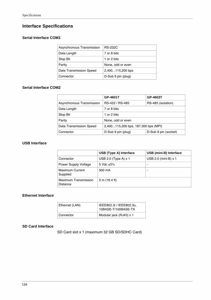
Specifications
124
Interface Specifications
Serial Interface COM1
Serial Interface COM2
USB Interface
Ethernet Interface
SD Card InterfaceSD Card slot x 1 (maximum 32 GB SD/SDHC Card)
Asynchronous Transmission RS-232C
Data Length 7 or 8 bits
Stop Bit 1 or 2 bits
Parity None, odd or even
Data Transmission Speed 2,400...115,200 bps
Connector D-Sub 9 pin (plug)
GP-4601T GP-4603T
Asynchronous Transmission RS-422 / RS-485 RS-485 (isolation)
Data Length 7 or 8 bits
Stop Bit 1 or 2 bits
Parity None, odd or even
Data Transmission Speed 2,400...115,200 bps, 187,500 bps (MPI)
Connector D-Sub 9 pin (plug) D-Sub 9 pin (socket)
USB (Type A) Interface USB (mini-B) Interface
Connector USB 2.0 (Type A) x 1 USB 2.0 (mini-B) x 1
Power Supply Voltage 5 Vdc ±5% -
Maximum Current Supplied
500 mA -
Maximum Transmission Distance
5 m (16.4 ft)
Ethernet (LAN) IEEE802.3i / IEEE802.3u, 10BASE-T/100BASE-TX
Connector Modular jack (RJ45) x 1
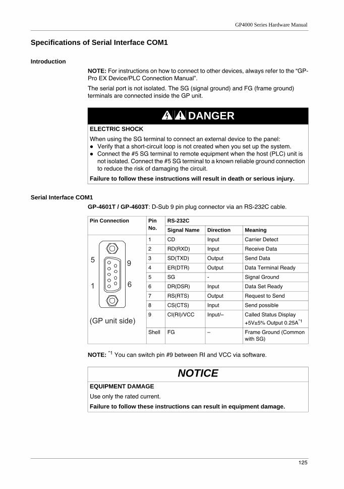
GP4000 Series Hardware Manual
125
Specifications of Serial Interface COM1
IntroductionNOTE: For instructions on how to connect to other devices, always refer to the “GP-Pro EX Device/PLC Connection Manual”.
The serial port is not isolated. The SG (signal ground) and FG (frame ground) terminals are connected inside the GP unit.
Serial Interface COM1GP-4601T / GP-4603T: D-Sub 9 pin plug connector via an RS-232C cable.
NOTE: *1 You can switch pin #9 between RI and VCC via software.
DANGERELECTRIC SHOCKWhen using the SG terminal to connect an external device to the panel:
Verify that a short-circuit loop is not created when you set up the system.Connect the #5 SG terminal to remote equipment when the host (PLC) unit is not isolated. Connect the #5 SG terminal to a known reliable ground connection to reduce the risk of damaging the circuit.
Failure to follow these instructions will result in death or serious injury.
Pin Connection Pin No.
RS-232C
Signal Name Direction Meaning
1 CD Input Carrier Detect
2 RD(RXD) Input Receive Data
3 SD(TXD) Output Send Data
4 ER(DTR) Output Data Terminal Ready
5 SG - Signal Ground
6 DR(DSR) Input Data Set Ready
7 RS(RTS) Output Request to Send
8 CS(CTS) Input Send possible
9 CI(RI)/VCC Input/– Called Status Display
+5V±5% Output 0.25A*1
Shell FG – Frame Ground (Common with SG)
NOTICEEQUIPMENT DAMAGEUse only the rated current.
Failure to follow these instructions can result in equipment damage.
9
6
5
1
(GP unit side)
Specifications
126
Interfit bracket is #4-40 (UNC).
Recommendations:Cable Connector: XM2D-0901 manufactured by OMRON Corporation.Cable Cover: XM2S-0913 manufactured by OMRON Corporation.Jack Screw (#4-40 UNC): XM2Z-0073 manufactured by OMRON Corporation.
CAUTIONLOSS OF COMMUNICATION
All connections to the communication ports must not put excessive stress on the ports.Securely attach communication cables to the panel wall or cabinet.Use only D-Sub 9 pin cables with a locking tab in good condition.
Failure to follow these instructions can result in injury or equipment damage.
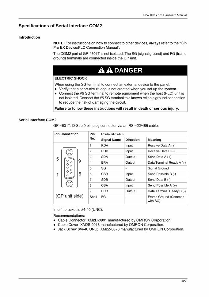
GP4000 Series Hardware Manual
127
Specifications of Serial Interface COM2
IntroductionNOTE: For instructions on how to connect to other devices, always refer to the “GP-Pro EX Device/PLC Connection Manual”.
The COM2 port of GP-4601T is not isolated. The SG (signal ground) and FG (frame ground) terminals are connected inside the GP unit.
Serial Interface COM2GP-4601T: D-Sub 9 pin plug connector via an RS-422/485 cable.
Interfit bracket is #4-40 (UNC).
Recommendations:Cable Connector: XM2D-0901 manufactured by OMRON Corporation.Cable Cover: XM2S-0913 manufactured by OMRON Corporation.Jack Screw (#4-40 UNC): XM2Z-0073 manufactured by OMRON Corporation.
DANGERELECTRIC SHOCKWhen using the SG terminal to connect an external device to the panel:
Verify that a short-circuit loop is not created when you set up the system.Connect the #5 SG terminal to remote equipment when the host (PLC) unit is not isolated. Connect the #5 SG terminal to a known reliable ground connection to reduce the risk of damaging the circuit.
Failure to follow these instructions will result in death or serious injury.
Pin Connection Pin No.
RS-422/RS-485
Signal Name Direction Meaning
1 RDA Input Receive Data A (+)
2 RDB Input Receive Data B (-)
3 SDA Output Send Data A (+)
4 ERA Output Data Terminal Ready A (+)
5 SG - Signal Ground
6 CSB Input Send Possible B (-)
7 SDB Output Send Data B (-)
8 CSA Input Send Possible A (+)
9 ERB Output Data Terminal Ready B (-)
Shell FG – Frame Ground (Common with SG)
9
6
5
1
(GP unit side)
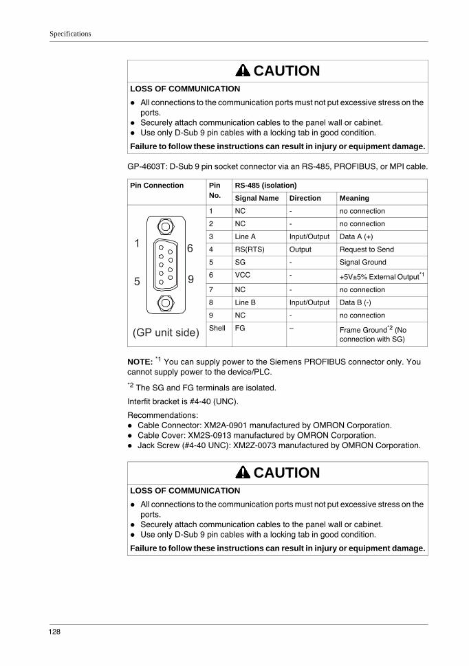
Specifications
128
GP-4603T: D-Sub 9 pin socket connector via an RS-485, PROFIBUS, or MPI cable.
NOTE: *1 You can supply power to the Siemens PROFIBUS connector only. You cannot supply power to the device/PLC.
*2 The SG and FG terminals are isolated.
Interfit bracket is #4-40 (UNC).
Recommendations:Cable Connector: XM2A-0901 manufactured by OMRON Corporation.Cable Cover: XM2S-0913 manufactured by OMRON Corporation.Jack Screw (#4-40 UNC): XM2Z-0073 manufactured by OMRON Corporation.
CAUTIONLOSS OF COMMUNICATION
All connections to the communication ports must not put excessive stress on the ports.Securely attach communication cables to the panel wall or cabinet.Use only D-Sub 9 pin cables with a locking tab in good condition.
Failure to follow these instructions can result in injury or equipment damage.
Pin Connection Pin No.
RS-485 (isolation)
Signal Name Direction Meaning
1 NC - no connection
2 NC - no connection
3 Line A Input/Output Data A (+)
4 RS(RTS) Output Request to Send
5 SG - Signal Ground
6 VCC - +5V±5% External Output*1
7 NC - no connection
8 Line B Input/Output Data B (-)
9 NC - no connection
Shell FG – Frame Ground*2 (No connection with SG)
CAUTIONLOSS OF COMMUNICATION
All connections to the communication ports must not put excessive stress on the ports.Securely attach communication cables to the panel wall or cabinet.Use only D-Sub 9 pin cables with a locking tab in good condition.
Failure to follow these instructions can result in injury or equipment damage.
6
9
1
5
(GP unit side)
GP4000 Series Hardware Manual
129
Dimensions
NOTE: If you are using the rear mount model, refer to Dimensions (see page 184).
External Dimensions
1 Front2 Right Side3 Top
301
11.85
315
12.40
56
2.205
0.20
241
9.4
9
227
8.9
4
mm
in.
(1)
(3)
(2)(GP-4601T)
Specifications
130
Installation with Installation Fasteners
1 Left Side2 Front3 Right Side4 Top5 Bottom
260
10.24
301
11.85
315
12.40
56
2.205
0.20
241
9.4
9
227
8.9
4
251
9.88
mm
in.
(1) (2)
(4)
(5)
(3)
260
10.24
(GP-4601T)
GP4000 Series Hardware Manual
131
Dimensions with Cables: GP-4601T
1 Left Side2 Rear3 Right Side4 Top5 Bottom6 DC type units have power supply terminals
NOTE: All the above values are designed with cable bending in mind. The dimensions given here are representative values depending on the type of connection cable in use. Therefore, these values are intended for reference only.
Specifications
132
Dimensions with Cables: GP-4603T
1 Left Side2 Rear3 Right Side4 Top5 Bottom
NOTE: All the above values are designed with cable bending in mind. The dimensions given here are representative values depending on the type of connection cable in use. Therefore, these values are intended for reference only.

GP4000 Series Hardware Manual
133
Panel Cut DimensionsCreate a panel cut and insert the GP unit into the opening from the front.
NOTE: Before designing the panel cut, refer to Installation (see page 136).
Installation Fastener Dimensions
A B C R
301.5 mm (+1, -0 mm)(11.87 [+0.04, -0 in.])
227.5 mm (+1, -0 mm)(8.96 in. [+0.04, -0 in.])
1.6...5 mm(0.06...0.2 in.)
3 mm (0.12 in.) maximum
A CR
B
12
0.4
7
12
0.47
14
0.55M6
26
1.02
mm
in.
Ø10
Ø0.3
9

Specifications
134
135
GP4000 Series Hardware Manual
5
GP4000 Series Hardware Manual
Installation and Wiring
KanpaiHardwareManual 10/2011
Installation and Wiring
What Is in This Chapter?This chapter contains the following sections:
Section Topic Page
5.1 Installation 136
5.2 Wiring Principles 141
5.3 SD Card Insertion/Removal 150
5.4 USB Cable Clamp 157
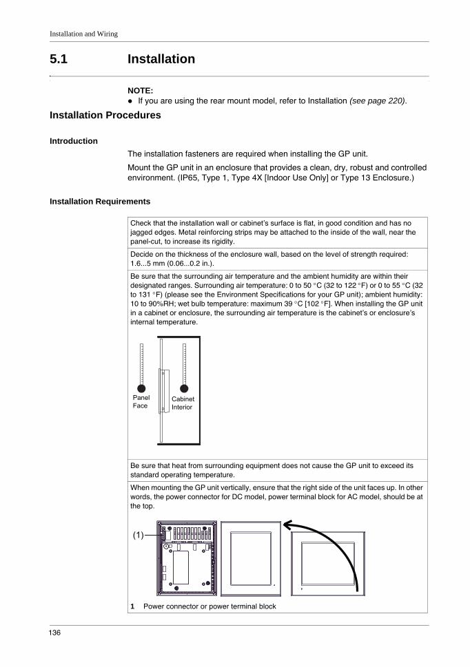
Installation and Wiring
136
5.1 Installation
NOTE: If you are using the rear mount model, refer to Installation (see page 220).
Installation Procedures
IntroductionThe installation fasteners are required when installing the GP unit.
Mount the GP unit in an enclosure that provides a clean, dry, robust and controlled environment. (IP65, Type 1, Type 4X [Indoor Use Only] or Type 13 Enclosure.)
Installation Requirements
Check that the installation wall or cabinet’s surface is flat, in good condition and has no jagged edges. Metal reinforcing strips may be attached to the inside of the wall, near the panel-cut, to increase its rigidity.
Decide on the thickness of the enclosure wall, based on the level of strength required: 1.6...5 mm (0.06...0.2 in.).
Be sure that the surrounding air temperature and the ambient humidity are within their designated ranges. Surrounding air temperature: 0 to 50 °C (32 to 122 °F) or 0 to 55 °C (32 to 131 °F) (please see the Environment Specifications for your GP unit); ambient humidity: 10 to 90%RH; wet bulb temperature: maximum 39 °C [102 °F]. When installing the GP unit in a cabinet or enclosure, the surrounding air temperature is the cabinet’s or enclosure’s internal temperature.
Be sure that heat from surrounding equipment does not cause the GP unit to exceed its standard operating temperature.
When mounting the GP unit vertically, ensure that the right side of the unit faces up. In other words, the power connector for DC model, power terminal block for AC model, should be at the top.
1 Power connector or power terminal block
PanelFace
Cabinet Interior
(1)
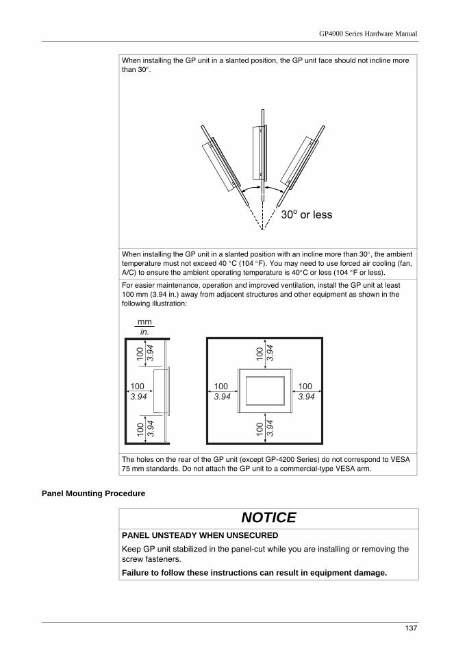
GP4000 Series Hardware Manual
137
Panel Mounting Procedure
When installing the GP unit in a slanted position, the GP unit face should not incline more than 30°.
When installing the GP unit in a slanted position with an incline more than 30°, the ambient temperature must not exceed 40 °C (104 °F). You may need to use forced air cooling (fan, A/C) to ensure the ambient operating temperature is 40°C or less (104 °F or less).
For easier maintenance, operation and improved ventilation, install the GP unit at least 100 mm (3.94 in.) away from adjacent structures and other equipment as shown in the following illustration:
The holes on the rear of the GP unit (except GP-4200 Series) do not correspond to VESA 75 mm standards. Do not attach the GP unit to a commercial-type VESA arm.
mmin.
1003.94
1003.94
1003.94
100
3.94
100
3.94
100
3.94
100
3.94
NOTICEPANEL UNSTEADY WHEN UNSECUREDKeep GP unit stabilized in the panel-cut while you are installing or removing the screw fasteners.
Failure to follow these instructions can result in equipment damage.
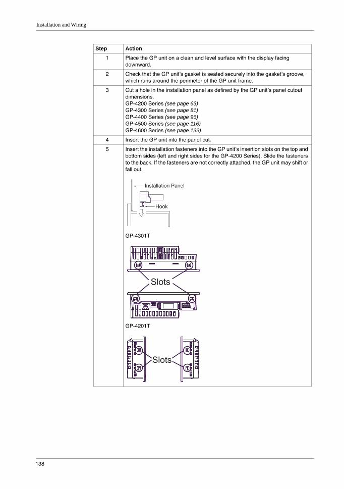
Installation and Wiring
138
Step Action
1 Place the GP unit on a clean and level surface with the display facing downward.
2 Check that the GP unit’s gasket is seated securely into the gasket’s groove, which runs around the perimeter of the GP unit frame.
3 Cut a hole in the installation panel as defined by the GP unit’s panel cutout dimensions.GP-4200 Series (see page 63)GP-4300 Series (see page 81)GP-4400 Series (see page 96)GP-4500 Series (see page 116)GP-4600 Series (see page 133)
4 Insert the GP unit into the panel-cut.
5 Insert the installation fasteners into the GP unit’s insertion slots on the top and bottom sides (left and right sides for the GP-4200 Series). Slide the fasteners to the back. If the fasteners are not correctly attached, the GP unit may shift or fall out.
GP-4301T
GP-4201T
Installation Panel
Hook
Slots
Slots
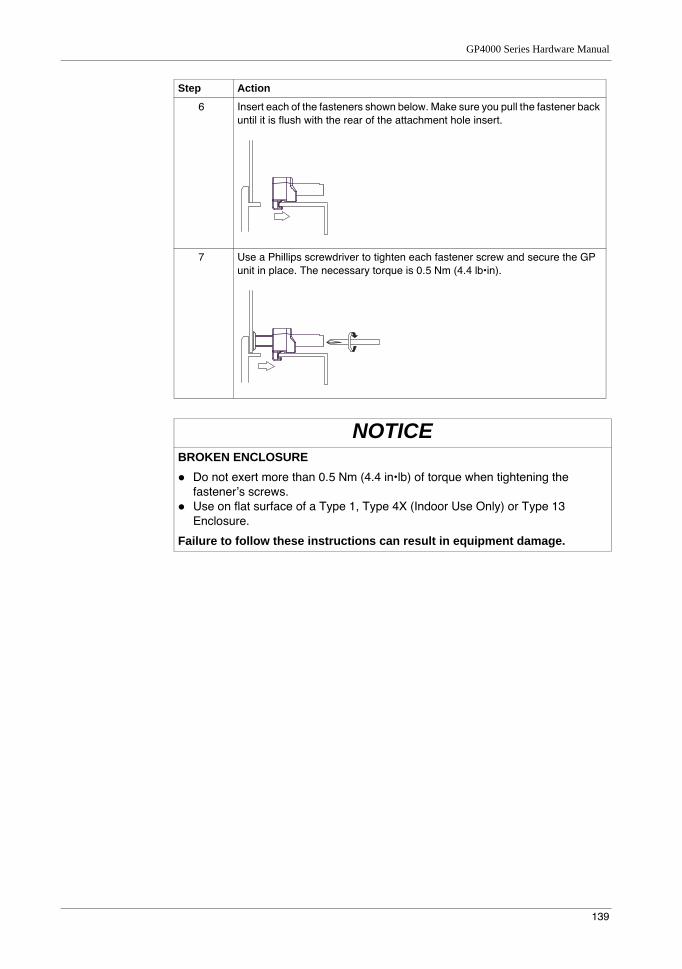
GP4000 Series Hardware Manual
139
6 Insert each of the fasteners shown below. Make sure you pull the fastener back until it is flush with the rear of the attachment hole insert.
7 Use a Phillips screwdriver to tighten each fastener screw and secure the GP unit in place. The necessary torque is 0.5 Nm (4.4 lb•in).
NOTICEBROKEN ENCLOSURE
Do not exert more than 0.5 Nm (4.4 in•lb) of torque when tightening the fastener’s screws.Use on flat surface of a Type 1, Type 4X (Indoor Use Only) or Type 13 Enclosure.
Failure to follow these instructions can result in equipment damage.
Step Action
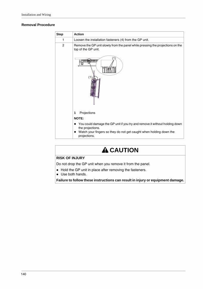
Installation and Wiring
140
Removal Procedure
Step Action
1 Loosen the installation fasteners (4) from the GP unit.
2 Remove the GP unit slowly from the panel while pressing the projections on the top of the GP unit.
1 Projections
NOTE:
You could damage the GP unit if you try and remove it without holding down the projections.Watch your fingers so they do not get caught when holding down the projections.
CAUTIONRISK OF INJURYDo not drop the GP unit when you remove it from the panel.
Hold the GP unit in place after removing the fasteners.Use both hands.
Failure to follow these instructions can result in injury or equipment damage.
(1)
(1)
GP4000 Series Hardware Manual
141
5.2 Wiring Principles
OverviewThis section presents the GP unit wiring principles.
What Is in This Section?This section contains the following topics:
Topic Page
Connecting the AC Power Cord 142
Connecting the DC Power Cord 144
Connecting the Power Supply 147
Grounding 149
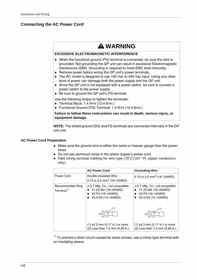
Installation and Wiring
142
Connecting the AC Power Cord
NOTE: The shield ground (SG) and FG terminals are connected internally in the GP unit unit.
AC Power Cord PreparationMake sure the ground wire is either the same or heavier gauge than the power wires.Do not use aluminum wires in the power supply’s power cord.Field wiring terminal marking for wire type (75°C [167 °F] copper conductors only).
*1 To prevent a short circuit caused by loose screws, use a crimp-type terminal with an insulating sleeve.
WARNINGEXCESSIVE ELECTROMAGNETIC INTERFERENCE
When the functional ground (FG) terminal is connected, be sure the wire is grounded. Not grounding the GP unit can result in excessive Electromagnetic Interference (EMI). Grounding is required to meet EMC level immunity.Remove power before wiring the GP unit’s power terminals.The AC model is designed to use 100 Vac to 240 Vac input. Using any other level of power can damage both the power supply and the GP unit.Since the GP unit is not equipped with a power switch, be sure to connect a power switch to the power supply.Be sure to ground the GP unit’s FG terminal.
Use the following torque to tighten the terminals:Terminal Block: 1.4 N•m (12.4 lb•in.)Functional Ground (FG) Terminal: 1.4 N•m (12.4 lb•in.)
Failure to follow these instructions can result in death, serious injury, or equipment damage.
AC Power Cord Grounding Wire
Power Cord Double-insulated Wire
0.75 to 3.5 mm2 (18-12AWG)0.75 to 3.5 mm2 (18-12AWG)
Recommended Ring
Terminal*1J.S.T Mfg. Co., Ltd compatible:
V1.25-M4 (18-16AWG)V2-P4 (16-14AWG)V5.5-S4 (14-12AWG)
(1) φ4.3 mm (0.17 in.) or more(2) Less than 7.2 mm (0.28 in.)
J.S.T Mfg. Co., Ltd compatible:V1.25-M4 (18-16AWG)V2-P4 (16-14AWG)V5.5-S4 (14-12AWG)
(1) φ4.3 mm (0.17 in.) or more(2) Less than 7.2 mm (0.28 in.)
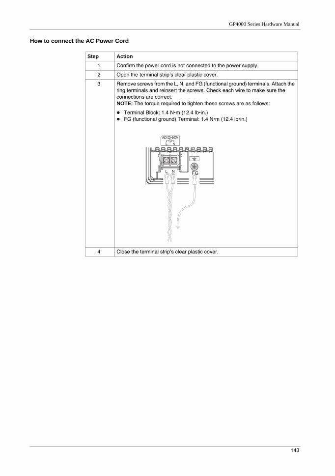
GP4000 Series Hardware Manual
143
How to connect the AC Power Cord
Step Action
1 Confirm the power cord is not connected to the power supply.
2 Open the terminal strip’s clear plastic cover.
3 Remove screws from the L, N, and FG (functional ground) terminals. Attach the ring terminals and reinsert the screws. Check each wire to make sure the connections are correct.NOTE: The torque required to tighten these screws are as follows:
Terminal Block: 1.4 N•m (12.4 lb•in.)FG (functional ground) Terminal: 1.4 N•m (12.4 lb•in.)
4 Close the terminal strip’s clear plastic cover.
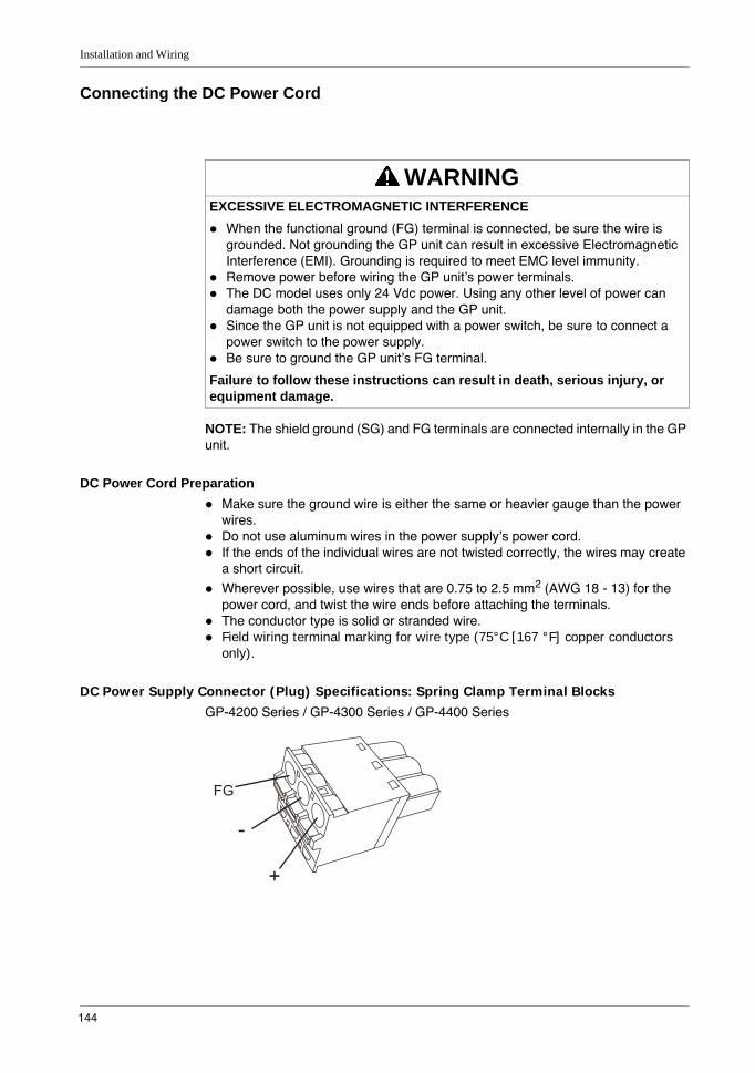
Installation and Wiring
144
Connecting the DC Power Cord
NOTE: The shield ground (SG) and FG terminals are connected internally in the GP unit.
DC Power Cord PreparationMake sure the ground wire is either the same or heavier gauge than the power wires.Do not use aluminum wires in the power supply’s power cord.If the ends of the individual wires are not twisted correctly, the wires may create a short circuit.Wherever possible, use wires that are 0.75 to 2.5 mm2 (AWG 18 - 13) for the power cord, and twist the wire ends before attaching the terminals.The conductor type is solid or stranded wire.Field wiring terminal marking for wire type (75°C [167 °F] copper conductors only).
DC Power Supply Connector (Plug) Specifications: Spring Clamp Terminal BlocksGP-4200 Series / GP-4300 Series / GP-4400 Series
WARNINGEXCESSIVE ELECTROMAGNETIC INTERFERENCE
When the functional ground (FG) terminal is connected, be sure the wire is grounded. Not grounding the GP unit can result in excessive Electromagnetic Interference (EMI). Grounding is required to meet EMC level immunity.Remove power before wiring the GP unit’s power terminals.The DC model uses only 24 Vdc power. Using any other level of power can damage both the power supply and the GP unit.Since the GP unit is not equipped with a power switch, be sure to connect a power switch to the power supply.Be sure to ground the GP unit’s FG terminal.
Failure to follow these instructions can result in death, serious injury, or equipment damage.
FG
-
+
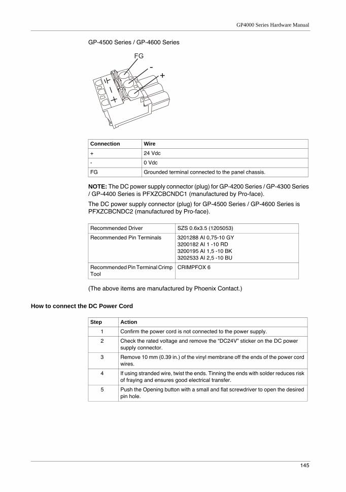
GP4000 Series Hardware Manual
145
GP-4500 Series / GP-4600 Series
NOTE: The DC power supply connector (plug) for GP-4200 Series / GP-4300 Series / GP-4400 Series is PFXZCBCNDC1 (manufactured by Pro-face).
The DC power supply connector (plug) for GP-4500 Series / GP-4600 Series is PFXZCBCNDC2 (manufactured by Pro-face).
(The above items are manufactured by Phoenix Contact.)
How to connect the DC Power Cord
Connection Wire
+ 24 Vdc
- 0 Vdc
FG Grounded terminal connected to the panel chassis.
Recommended Driver SZS 0.6x3.5 (1205053)
Recommended Pin Terminals 3201288 AI 0,75-10 GY3200182 AI 1 -10 RD3200195 AI 1,5 -10 BK3202533 AI 2,5 -10 BU
Recommended Pin Terminal Crimp Tool
CRIMPFOX 6
FG
-+
Step Action
1 Confirm the power cord is not connected to the power supply.
2 Check the rated voltage and remove the “DC24V” sticker on the DC power supply connector.
3 Remove 10 mm (0.39 in.) of the vinyl membrane off the ends of the power cord wires.
4 If using stranded wire, twist the ends. Tinning the ends with solder reduces risk of fraying and ensures good electrical transfer.
5 Push the Opening button with a small and flat screwdriver to open the desired pin hole.
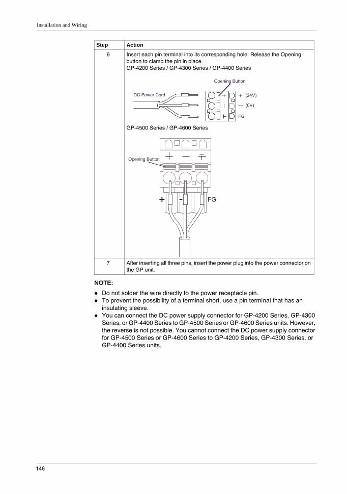
Installation and Wiring
146
NOTE: Do not solder the wire directly to the power receptacle pin.To prevent the possibility of a terminal short, use a pin terminal that has an insulating sleeve.You can connect the DC power supply connector for GP-4200 Series, GP-4300 Series, or GP-4400 Series to GP-4500 Series or GP-4600 Series units. However, the reverse is not possible. You cannot connect the DC power supply connector for GP-4500 Series or GP-4600 Series to GP-4200 Series, GP-4300 Series, or GP-4400 Series units.
6 Insert each pin terminal into its corresponding hole. Release the Opening button to clamp the pin in place.GP-4200 Series / GP-4300 Series / GP-4400 Series
GP-4500 Series / GP-4600 Series
7 After inserting all three pins, insert the power plug into the power connector on the GP unit.
Step Action
(24V)DC Power Cord
Opening Button
(0V)
FG
Opening Button
+ FG-
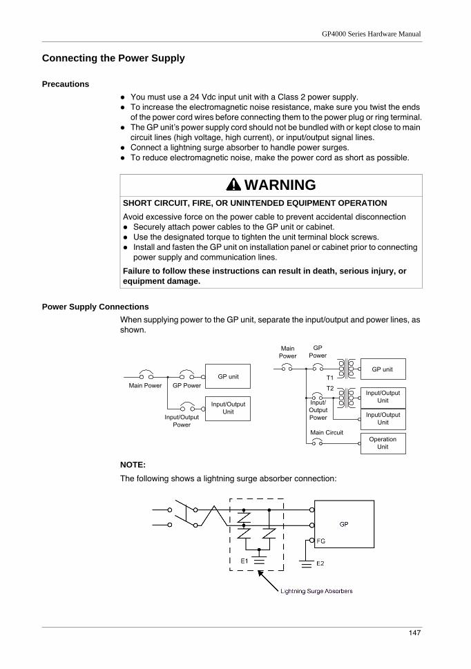
GP4000 Series Hardware Manual
147
Connecting the Power Supply
PrecautionsYou must use a 24 Vdc input unit with a Class 2 power supply.To increase the electromagnetic noise resistance, make sure you twist the ends of the power cord wires before connecting them to the power plug or ring terminal.The GP unit’s power supply cord should not be bundled with or kept close to main circuit lines (high voltage, high current), or input/output signal lines.Connect a lightning surge absorber to handle power surges.To reduce electromagnetic noise, make the power cord as short as possible.
Power Supply ConnectionsWhen supplying power to the GP unit, separate the input/output and power lines, as shown.
NOTE: The following shows a lightning surge absorber connection:
WARNINGSHORT CIRCUIT, FIRE, OR UNINTENDED EQUIPMENT OPERATIONAvoid excessive force on the power cable to prevent accidental disconnection
Securely attach power cables to the GP unit or cabinet.Use the designated torque to tighten the unit terminal block screws.Install and fasten the GP unit on installation panel or cabinet prior to connecting power supply and communication lines.
Failure to follow these instructions can result in death, serious injury, or equipment damage.
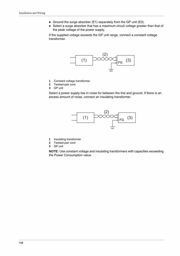
Installation and Wiring
148
Ground the surge absorber (E1) separately from the GP unit (E2).Select a surge absorber that has a maximum circuit voltage greater than that of the peak voltage of the power supply.
If the supplied voltage exceeds the GP unit range, connect a constant voltage transformer.
1 Constant voltage transformer2 Twisted-pair cord3 GP unit
Select a power supply low in noise for between the line and ground. If there is an excess amount of noise, connect an insulating transformer.
1 Insulating transformer2 Twisted-pair cord3 GP unit
NOTE: Use constant voltage and insulating transformers with capacities exceeding the Power Consumption value.
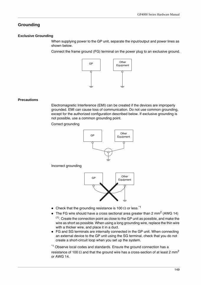
GP4000 Series Hardware Manual
149
Grounding
Exclusive GroundingWhen supplying power to the GP unit, separate the input/output and power lines as shown below.
Connect the frame ground (FG) terminal on the power plug to an exclusive ground.
PrecautionsElectromagnetic Interference (EMI) can be created if the devices are improperly grounded. EMI can cause loss of communication. Do not use common grounding, except for the authorized configuration described below. If exclusive grounding is not possible, use a common grounding point.
Correct grounding
Incorrect grounding
Check that the grounding resistance is 100 Ω or less.*1
The FG wire should have a cross sectional area greater than 2 mm2 (AWG 14) (1). Create the connection point as close to the GP unit as possible, and make the wire as short as possible. When using a long grounding wire, replace the thin wire with a thicker wire, and place it in a duct.FG and SG terminals are internally connected in the GP unit. When connecting an external device to the GP unit using the SG terminal, check that you do not create a short-circuit loop when you set up the system.
*1 Observe local codes and standards. Ensure the ground connection has a resistance of 100 Ω and that the ground wire has a cross-section of at least 2 mm2 or AWG 14.
Installation and Wiring
150
5.3 SD Card Insertion/Removal
What Is in This Section?This section contains the following topics:
Topic Page
Introduction 151
Inserting the SD Card 152
Before Removing the SD Card 154
Removing the SD Card 155
SD Card Data Backup 156
GP4000 Series Hardware Manual
151
Introduction
NOTICELOSS OF DATAWhen using the GP unit and a SD Card, observe the following to avoid losing valuable data:
Since accidental data loss can occur at any time, back up GP unit screen and SD Card data regularly. Once GP unit data is lost, it cannot be recovered.Before removing the SD Card from the GP unit, make sure you run the Offline Mode’s hardware removal process. If you do not run the removal process and forcibly extract the SD Card, data on the SD Card may become corrupted.While a SD Card is accessed, do not turn OFF or reset the GP unit, and do not insert or remove the SD Card. Doing so could damage the SD Card, or corrupt its data.Before using the SD Card, familiarize yourself with the SD Card’s front and rear face orientation, as well as the position of the SD Card connectors. If the SD Card is not positioned correctly when inserted into the GP unit, the card’s internal data and GP unit could become damaged.
Failure to follow these instructions can result in equipment damage.
NOTICELOSS OF DATAWhen handling the SD Card, follow the instructions below to prevent internal data on the SD Card from being destroyed or a SD Card malfunction from occurring:
Avoid storing the SD Card where there is static electricity or electromagnetic waves.Avoid storing the SD Card in direct sunlight, near a heater, or other locations where high temperatures can occur.Do not bend the SD Card.Do not drop or strike the SD Card against another object.Keep the SD Card dry.Do not touch the SD Card connectors.Do not disassemble or modify the SD Card.Use only SD Cards formatted using FAT or FAT32. The GP unit does not recognize NTFS formatted SD Cards. Format the SD Card on your computer using FAT or FAT32.
Failure to follow these instructions can result in equipment damage.
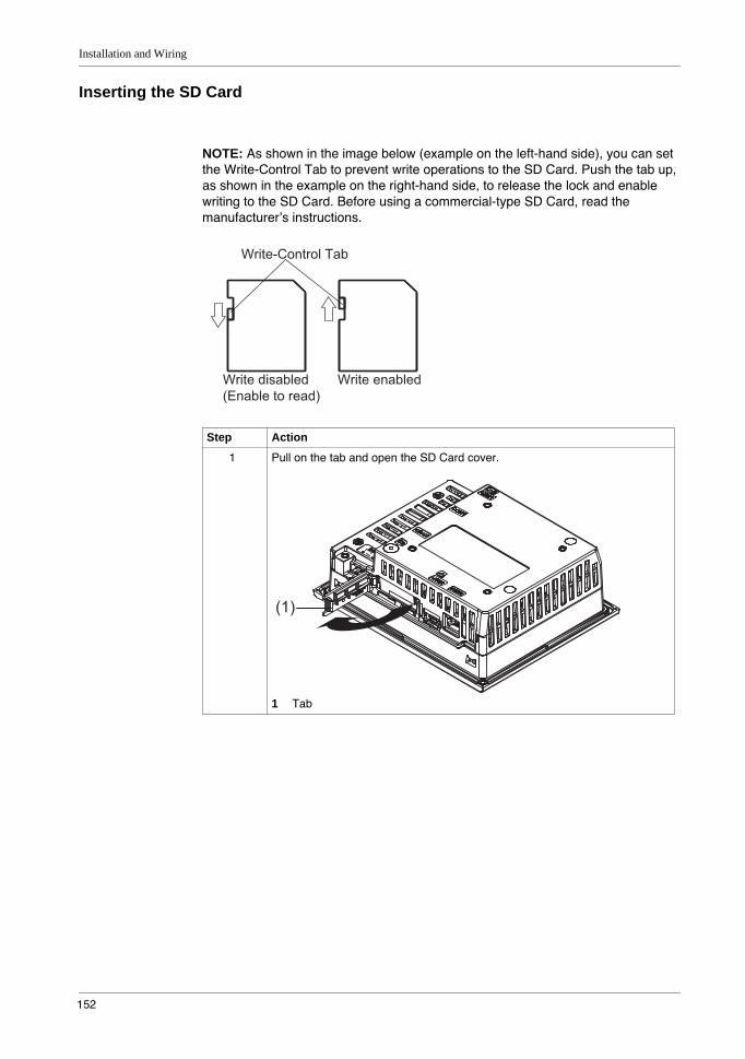
Installation and Wiring
152
Inserting the SD Card
NOTE: As shown in the image below (example on the left-hand side), you can set the Write-Control Tab to prevent write operations to the SD Card. Push the tab up, as shown in the example on the right-hand side, to release the lock and enable writing to the SD Card. Before using a commercial-type SD Card, read the manufacturer’s instructions.
Step Action
1 Pull on the tab and open the SD Card cover.
1 Tab
Write-Control Tab
Write disabled(Enable to read)
Write enabled
(1)
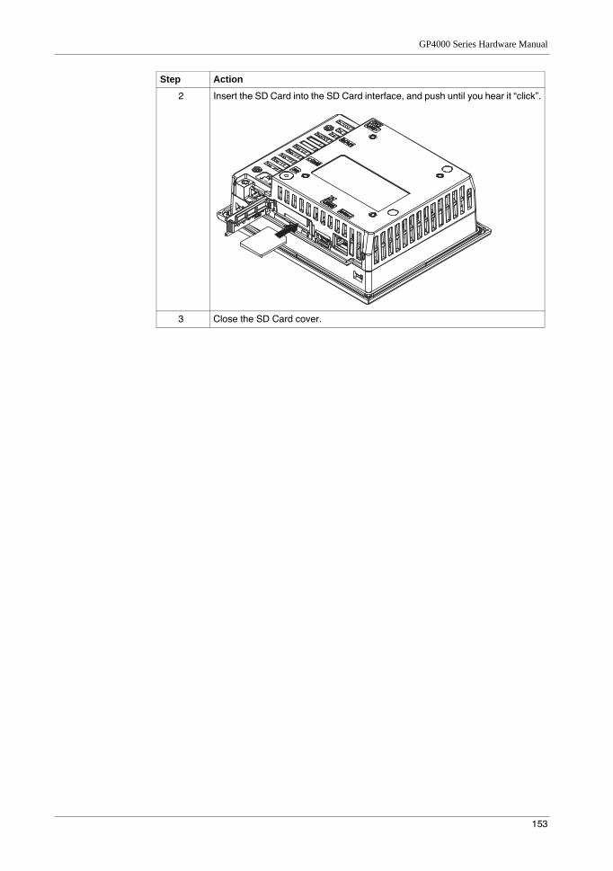
GP4000 Series Hardware Manual
153
2 Insert the SD Card into the SD Card interface, and push until you hear it “click”.
3 Close the SD Card cover.
Step Action
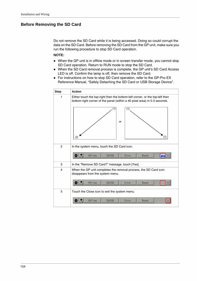
Installation and Wiring
154
Before Removing the SD Card
Do not remove the SD Card while it is being accessed. Doing so could corrupt the data on the SD Card. Before removing the SD Card from the GP unit, make sure you run the following procedure to stop SD Card operation.
NOTE: When the GP unit is in offline mode or in screen transfer mode, you cannot stop SD Card operation. Return to RUN mode to stop the SD Card.When the SD Card removal process is complete, the GP unit’s SD Card Access LED is off. Confirm the lamp is off, then remove the SD Card.For instructions on how to stop SD Card operation, refer to the GP-Pro EX Reference Manual, “Safely Detaching the SD Card or USB Storage Device”.
Step Action
1 Either touch the top-right then the bottom-left corner, or the top-left then bottom-right corner of the panel (within a 40 pixel area) in 0.5 seconds.
2 In the system menu, touch the SD Card icon.
3 In the “Remove SD Card?” message, touch [Yes].
4 When the GP unit completes the removal process, the SD Card icon disappears from the system menu.
5 Touch the Close icon to exit the system menu.
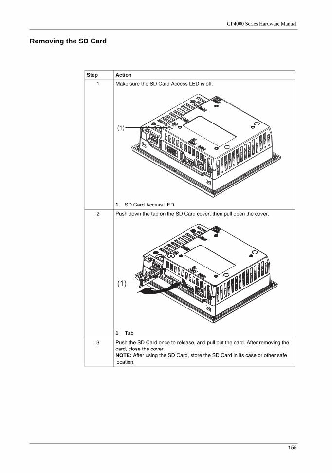
GP4000 Series Hardware Manual
155
Removing the SD Card
Step Action
1 Make sure the SD Card Access LED is off.
1 SD Card Access LED
2 Push down the tab on the SD Card cover, then pull open the cover.
1 Tab
3 Push the SD Card once to release, and pull out the card. After removing the card, close the cover.NOTE: After using the SD Card, store the SD Card in its case or other safe location.
(1)
(1)
Installation and Wiring
156
SD Card Data Backup
To make your backups, you can either insert the SD Card directly into the SD Card interface on your computer, or use a commercially available SD Card reader.
GP4000 Series Hardware Manual
157
5.4 USB Cable Clamp
OverviewThis section presents the USB cable clamp.
What Is in This Section?This section contains the following topics:
Topic Page
USB Cable Clamp for USB (Type A) 158
USB Holder for USB (mini-B) 160
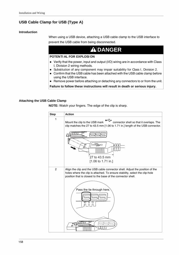
Installation and Wiring
158
USB Cable Clamp for USB (Type A)
IntroductionWhen using a USB device, attaching a USB cable clamp to the USB interface to
prevent the USB cable from being disconnected.
Attaching the USB Cable ClampNOTE: Watch your fingers. The edge of the clip is sharp.
DANGERPOTENTIAL FOR EXPLOSION
Verify that the power, input and output (I/O) wiring are in accordance with Class I, Division 2 wiring methods.Substitution of any component may impair suitability for Class I, Division 2.Confirm that the USB cable has been attached with the USB cable clamp before using the USB interface.Remove power before attaching or detaching any connectors to or from the unit.
Failure to follow these instructions will result in death or serious injury.
Step Action
1Mount the clip to the USB mark connector shell so that it overlaps. The clip matches the 27 to 43.5 mm [1.06 to 1.71 in.] length of the USB connector.
2 Align the clip and the USB cable connector shell. Adjust the position of the holes where the clip is attached. To ensure stability, select the clip-hole position that is closest to the base of the connector shell.
27 to 43.5 mm [1.06 to 1.71 in.]
Pass the tie through here.
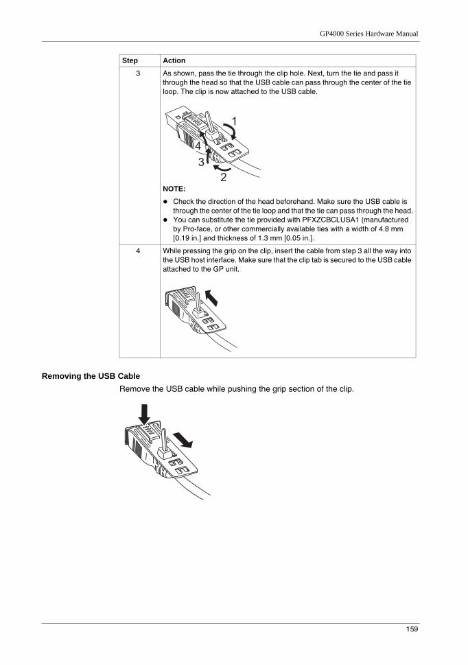
GP4000 Series Hardware Manual
159
Removing the USB CableRemove the USB cable while pushing the grip section of the clip.
3 As shown, pass the tie through the clip hole. Next, turn the tie and pass it through the head so that the USB cable can pass through the center of the tie loop. The clip is now attached to the USB cable.
NOTE:
Check the direction of the head beforehand. Make sure the USB cable is through the center of the tie loop and that the tie can pass through the head.You can substitute the tie provided with PFXZCBCLUSA1 (manufactured by Pro-face, or other commercially available ties with a width of 4.8 mm [0.19 in.] and thickness of 1.3 mm [0.05 in.].
4 While pressing the grip on the clip, insert the cable from step 3 all the way into the USB host interface. Make sure that the clip tab is secured to the USB cable attached to the GP unit.
Step Action
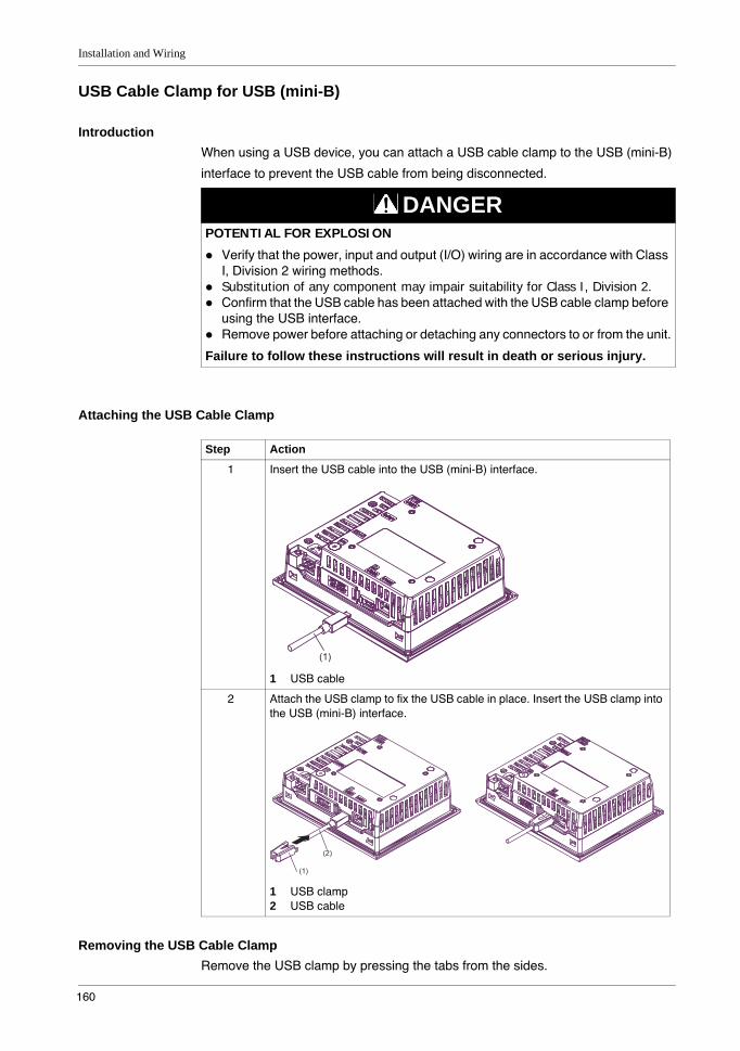
Installation and Wiring
160
USB Cable Clamp for USB (mini-B)
IntroductionWhen using a USB device, you can attach a USB cable clamp to the USB (mini-B)
interface to prevent the USB cable from being disconnected.
Attaching the USB Cable Clamp
Removing the USB Cable ClampRemove the USB clamp by pressing the tabs from the sides.
DANGERPOTENTIAL FOR EXPLOSION
Verify that the power, input and output (I/O) wiring are in accordance with Class I, Division 2 wiring methods.Substitution of any component may impair suitability for Class I, Division 2.Confirm that the USB cable has been attached with the USB cable clamp before using the USB interface.Remove power before attaching or detaching any connectors to or from the unit.
Failure to follow these instructions will result in death or serious injury.
Step Action
1 Insert the USB cable into the USB (mini-B) interface.
1 USB cable
2 Attach the USB clamp to fix the USB cable in place. Insert the USB clamp into the USB (mini-B) interface.
1 USB clamp2 USB cable
(1)
(2)
(1)
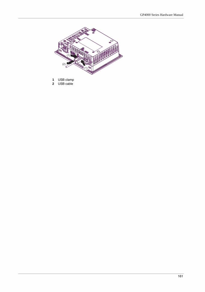
GP4000 Series Hardware Manual
161
1 USB clamp2 USB cable
(2)
(1)
(1)

Installation and Wiring
162
163
GP4000 Series Hardware Manual
6
GP4000 Series Hardware Manual
KanpaiHardwareManual 10/2011
Maintenance
OverviewThis chapter explains how to maintain your GP unit.
What Is in This Chapter?This chapter contains the following topics:
Topic Page
Regular Cleaning 164
Replacing the Installation Gasket 165
Periodic Check Points 167
Replacing the Primary Battery 168
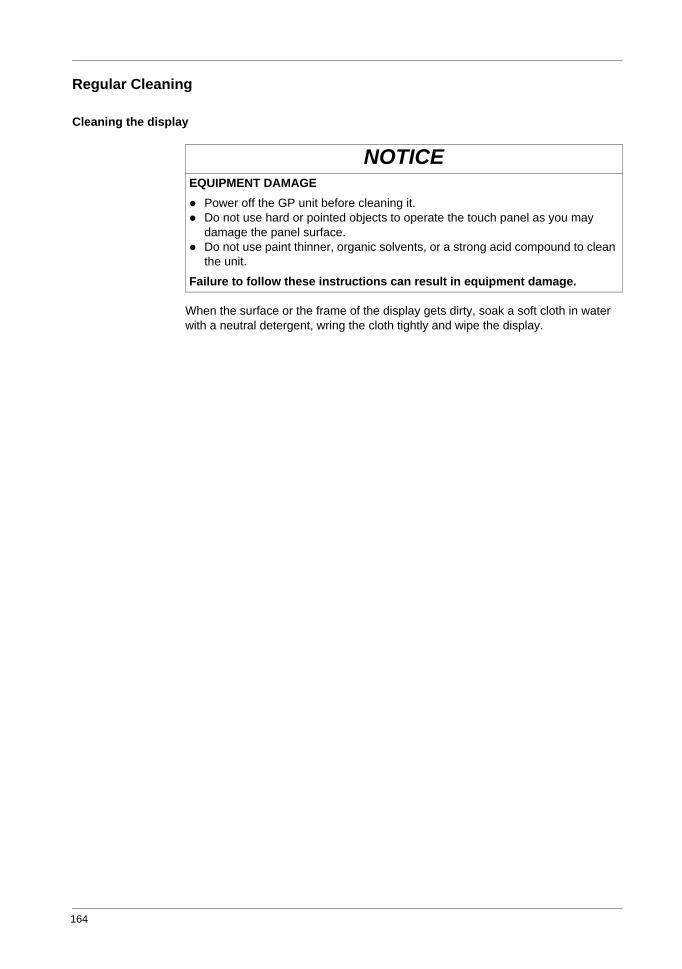
164
Regular Cleaning
Cleaning the display
When the surface or the frame of the display gets dirty, soak a soft cloth in water with a neutral detergent, wring the cloth tightly and wipe the display.
NOTICEEQUIPMENT DAMAGE
Power off the GP unit before cleaning it.Do not use hard or pointed objects to operate the touch panel as you may damage the panel surface.Do not use paint thinner, organic solvents, or a strong acid compound to clean the unit.
Failure to follow these instructions can result in equipment damage.
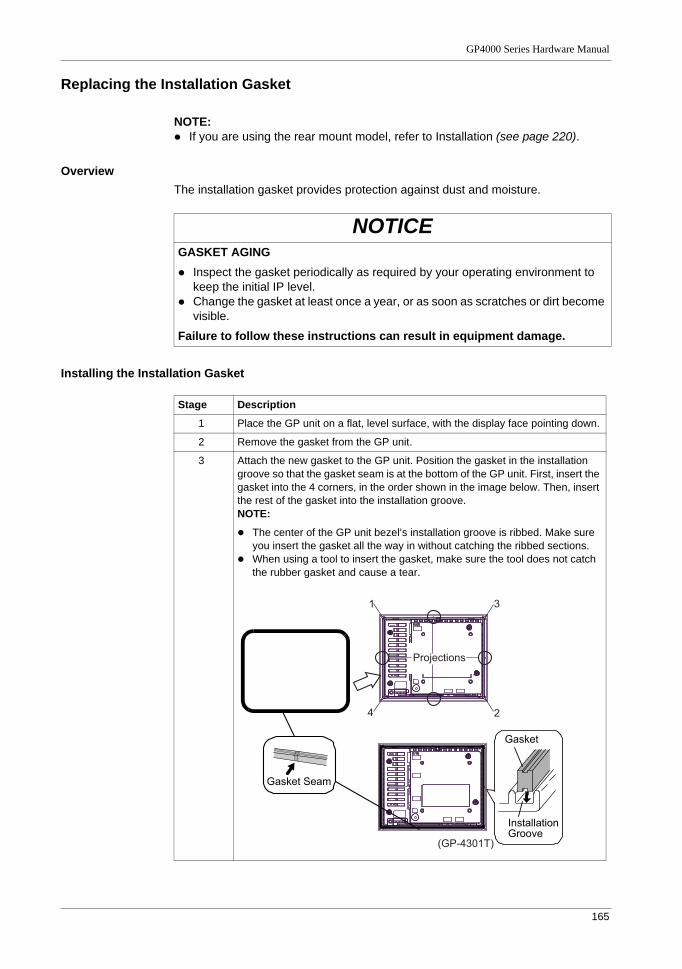
GP4000 Series Hardware Manual
165
Replacing the Installation Gasket
NOTE: If you are using the rear mount model, refer to Installation (see page 220).
OverviewThe installation gasket provides protection against dust and moisture.
Installing the Installation Gasket
NOTICEGASKET AGING
Inspect the gasket periodically as required by your operating environment to keep the initial IP level.Change the gasket at least once a year, or as soon as scratches or dirt become visible.
Failure to follow these instructions can result in equipment damage.
Stage Description
1 Place the GP unit on a flat, level surface, with the display face pointing down.
2 Remove the gasket from the GP unit.
3 Attach the new gasket to the GP unit. Position the gasket in the installation groove so that the gasket seam is at the bottom of the GP unit. First, insert the gasket into the 4 corners, in the order shown in the image below. Then, insert the rest of the gasket into the installation groove.NOTE:
The center of the GP unit bezel’s installation groove is ribbed. Make sure you insert the gasket all the way in without catching the ribbed sections.When using a tool to insert the gasket, make sure the tool does not catch the rubber gasket and cause a tear.
(GP-4301T)
1
2
3
4
Projections
Gasket
Installation Groove
Gasket Seam
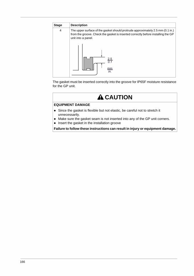
166
The gasket must be inserted correctly into the groove for IP65F moisture resistance for the GP unit.
4 The upper surface of the gasket should protrude approximately 2.5 mm (0.1 in.) from the groove. Check the gasket is inserted correctly before installing the GP unit into a panel.
CAUTIONEQUIPMENT DAMAGE
Since the gasket is flexible but not elastic, be careful not to stretch it unnecessarily.Make sure the gasket seam is not inserted into any of the GP unit corners.Insert the gasket in the installation groove
Failure to follow these instructions can result in injury or equipment damage.
Stage Description
mmin.
2.50.1
GP4000 Series Hardware Manual
167
Periodic Check Points
Operation EnvironmentIs the operating temperature within the allowable range? Refer to Environmental Specifications (see page 46), (see page 66), (see page 84), (see page 99), (see page 119).Is the operating humidity within the specified range? (10%RH to 90%RH, dry bulb temperature of 39 °C [102.2 °F] or less)Is the operating atmosphere free of corrosive gasses?
When the GP unit is inside a panel, the ambient environment refers to the interior of the panel.
Electrical SpecificationsIs the input voltage appropriate?
100 Vac to 240 Vac 50/60 Hz19.2 Vdc to 28.8 Vdc
Related ItemsAre all power cords and cables connected properly? Are there any loose cables?Are all mounting brackets holding the unit securely?Are there scratches or traces of dirt on the installation gasket?
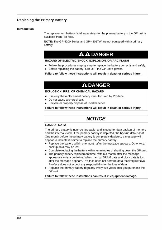
168
Replacing the Primary Battery
IntroductionThe replacement battery (sold separately) for the primary battery in the GP unit is available from Pro-face.
NOTE: The GP-4200 Series and GP-4301TW are not equipped with a primary battery.
DANGERHAZARD OF ELECTRIC SHOCK, EXPLOSION, OR ARC FLASH
Follow the procedures step by step to replace the battery correctly and safely.Before replacing the battery, turn OFF the GP unit’s power.
Failure to follow these instructions will result in death or serious injury.
DANGEREXPLOSION, FIRE, OR CHEMICAL HAZARD
Use only the replacement battery manufactured by Pro-face.Do not cause a short circuit.Recycle or properly dispose of used batteries.
Failure to follow these instructions will result in death or serious injury.
NOTICELOSS OF DATAThe primary battery is non-rechargeable, and is used for data backup of memory and the internal clock. If the primary battery is depleted, the backup data is lost. One month before the primary battery is completely depleted, a message will appear to indicate it is time to replace the primary battery.
Replace the battery within one month after the message appears. Otherwise, backup data may be lost.Complete replacing the battery within ten minutes of shutting down the GP unit.The primary battery replacement time (within a month after the message appears) is only a guideline. When backup SRAM data and clock data is lost after the message appears, Pro-face does not perform data recovery/retrieval. Pro-face does not accept any responsibility for the loss of data.Replace the primary battery regularly every five years after you purchase the GP unit.
Failure to follow these instructions can result in equipment damage.
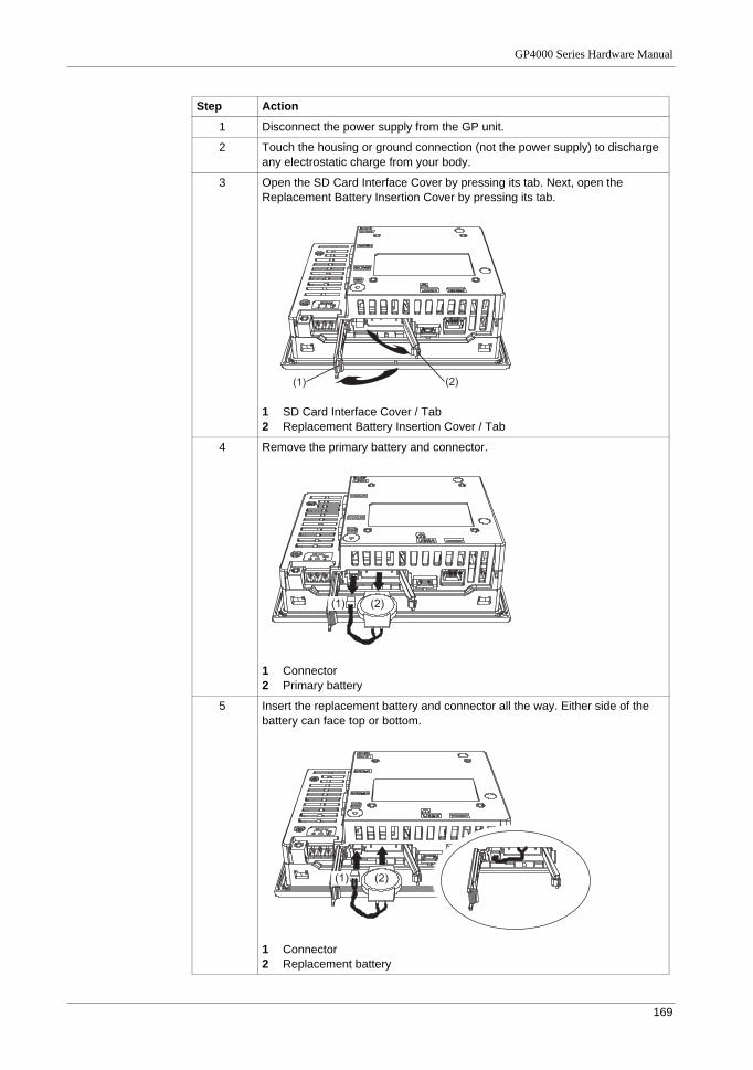
GP4000 Series Hardware Manual
169
Step Action
1 Disconnect the power supply from the GP unit.
2 Touch the housing or ground connection (not the power supply) to discharge any electrostatic charge from your body.
3 Open the SD Card Interface Cover by pressing its tab. Next, open the Replacement Battery Insertion Cover by pressing its tab.
1 SD Card Interface Cover / Tab2 Replacement Battery Insertion Cover / Tab
4 Remove the primary battery and connector.
1 Connector2 Primary battery
5 Insert the replacement battery and connector all the way. Either side of the battery can face top or bottom.
1 Connector2 Replacement battery
(1) (2)
(1) (2)
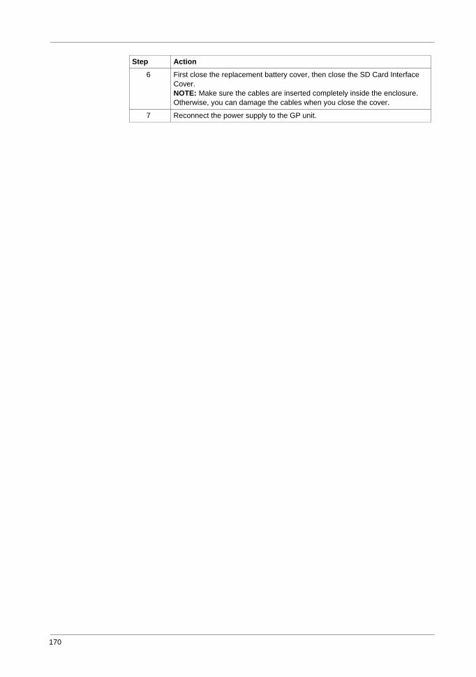
170
6 First close the replacement battery cover, then close the SD Card Interface Cover.NOTE: Make sure the cables are inserted completely inside the enclosure. Otherwise, you can damage the cables when you close the cover.
7 Reconnect the power supply to the GP unit.
Step Action
171
GP4000 Series Hardware Manual
7
GP4000 Series Hardware Manual
KanpaiHardwareManual 10/2011
Rear Mount Model
OverviewThis chapter presents the Rear Mount Model.
What Is in This Chapter?
This chapter contains the following sections.
Section Topic Page
7.1 Package Contents 172
7.2 Certifications and Standards 173
7.3 Options Items/Maintenance Option 175
7.4 Parts Identification and Functions 176
7.5 Structural Specifications 182
7.6 Dimensions 184
7.7 Installation 220
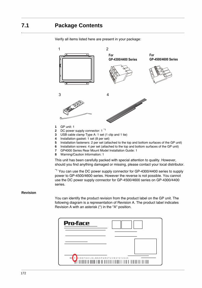
172
7.1 Package Contents
Verify all items listed here are present in your package:
1 GP unit: 12 DC power supply connector: 1 *1
3 USB cable clamp Type A: 1 set (1 clip and 1 tie)4 Installation gasket: 1 set (8 per set)5 Installation fasteners: 2 per set (attached to the top and bottom surfaces of the GP unit)6 Installation screws: 4 per set (attached to the top and bottom surfaces of the GP unit)7 GP4000 Series Rear Mount Model Installation Guide: 18 Warning/Caution Information: 1
This unit has been carefully packed with special attention to quality. However, should you find anything damaged or missing, please contact your local distributor.
*1 You can use the DC power supply connector for GP-4300/4400 series to supply power to GP-4500/4600 series. However the reverse is not possible. You cannot use the DC power supply connector for GP-4500/4600 series on GP-4300/4400 series.
RevisionYou can identify the product revision from the product label on the GP unit. The following diagram is a representation of Revision A. The product label indicates Revision A with an asterisk (*) in the "A" position.
REV * B C D E F G H I J K L M N O P Q R S T U V W X Y Z 1 2 3 4 5
GP4000 Series Hardware Manual
173
7.2 Certifications and Standards
IntroductionPro-face submitted this product for independent testing and qualification by third-party listing agencies. These agencies have certified this product as meeting the following standards.
Agency CertificationsThe GP unit is manufactured in accordance with:
UL 508 and CSA C22.2 n°142 for Industrial Control Equipment
Note:For use in Pollution Degree 2 environments.For use on a flat surface of a Type 1 Enclosure.24 Vdc input panel must be used with a Class 2 power supply.
Hazardous SubstancesThe GP is a device for use in factory systems. When using the GP in a system, the system should comply with the following standards in regards to the installation environment and handling:
WEEE, Directive 2012/19/EURoHS, Directive 2011/65/EURoHS China, Standard SJ/T 11363-2006
CE MarkingsThis product conforms to the necessary requirements of the following Directives for applying the CE label:
2004/108/EC EMC Directive
This conformity is based on compliance with EN61000-6-4, EN61000-6-2
For information on Standards and Regulations, such as certified models and certificates, see the following.http://www.pro-face.com/worldwide.html
174
KC Markings
DANGERPOTENTIAL FOR EXPLOSION
Verify that the power, input and output (I/O) wiring are in accordance with Class I, Division 2 wiring methods.Substitution of any component may impair suitability for Class I, Division 2.Do not connect or disconnect equipment unless power has been switched off or the area is known to be non-hazardous.Securely lock externally connected units and each interface before turning on the power supply.Do not use, connect, or disconnect USB cable unless area is known to be non-hazardous.Do not disconnect while circuit is live or unless the area is known to be free of ignitable concentrations.
Potential electrostatic charging hazard: wipe the front panel of the terminal with a damp cloth before turning ON.
Failure to follow these instructions will result in death or serious injury.
GP4000 Series Hardware Manual
175
7.3 Option Items / Maintenance Options
This section explains the option items and maintenance options dedicated for use with the rear mount model. Read this section together with chapter 2, "Accessories" (see page 27).
Option Items
Maintenance Options
Product Name Model Number Corresponding GP unit
Description
12.1-inch Overlay PFXZGPFSR12W1 PFXGP4601TADR Overlay (Front Sheet) for Flat Mount of GP4000 Series Rear Mount Model (Color: White, 1 piece)
10.4-inch Overlay PFXZGPFSR10W1 PFXGP4501TADR
7.5-inch Overlay PFXZGPFSR7W1 PFXGP4401TADR
5.7-inch Overlay PFXZGPFSR6W1 PFXGP4301TADR
Product Name Model Number Corresponding GP unit
Description
12.1-inch & 10.4-inch Rear mount Installation Fastener
PFXZGPAFRL1 PFXGP4601TADRPFXGP4501TADR
Used to install the GP4000 Series Rear Mount model into a solid panel (2 pieces/ set). Includes the installation screws (4 pieces/set).
7.5-inch & 5.7-inch Rear mount Installation Fastener
PFXZGPAFRM1 PFXGP4401TADRPFXGP4301TADR
Rear mount Installation Gasket PFXZGPWGR1 PFXGP4601TADRPFXGP4501TADRPFXGP4401TADRPFXGP4301TADR
GP4000 Series Rear Mount model Installation Gasket (1 piece)
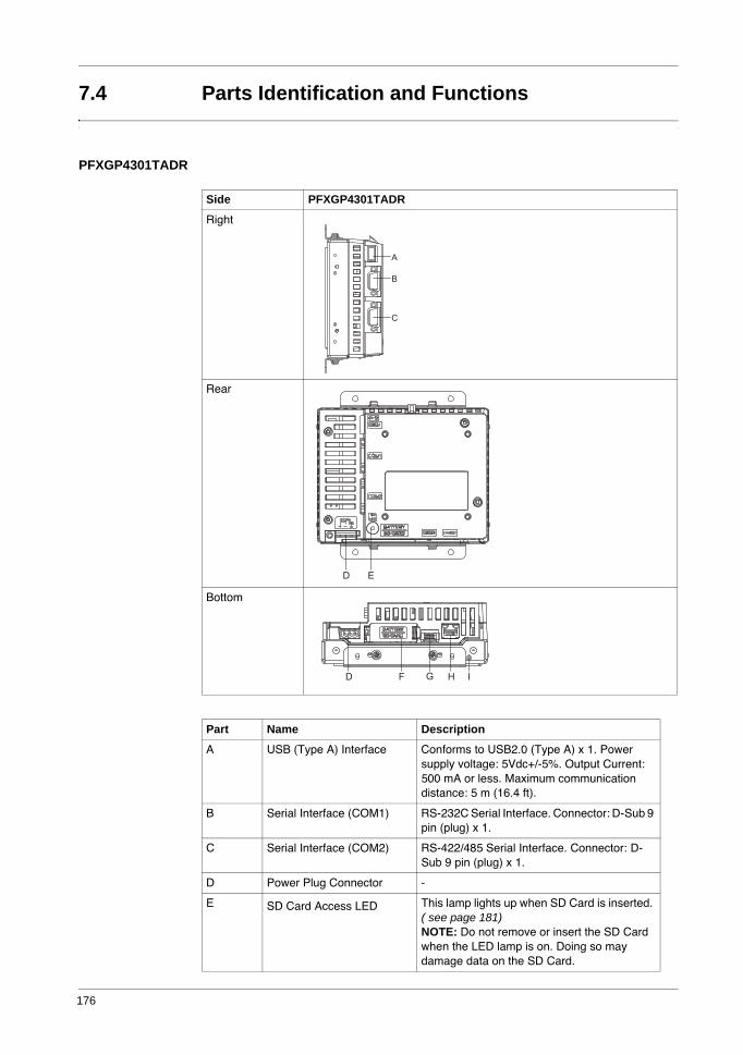
176
7.4 Parts Identification and Functions
PFXGP4301TADR
Side PFXGP4301TADR
Right
Rear
Bottom
Part Name Description
A USB (Type A) Interface Conforms to USB2.0 (Type A) x 1. Power supply voltage: 5Vdc+/-5%. Output Current: 500 mA or less. Maximum communication distance: 5 m (16.4 ft).
B Serial Interface (COM1) RS-232C Serial Interface. Connector: D-Sub 9 pin (plug) x 1.
C Serial Interface (COM2) RS-422/485 Serial Interface. Connector: D-Sub 9 pin (plug) x 1.
D Power Plug Connector -
E SD Card Access LED This lamp lights up when SD Card is inserted. ( see page 181)NOTE: Do not remove or insert the SD Card when the LED lamp is on. Doing so may damage data on the SD Card.
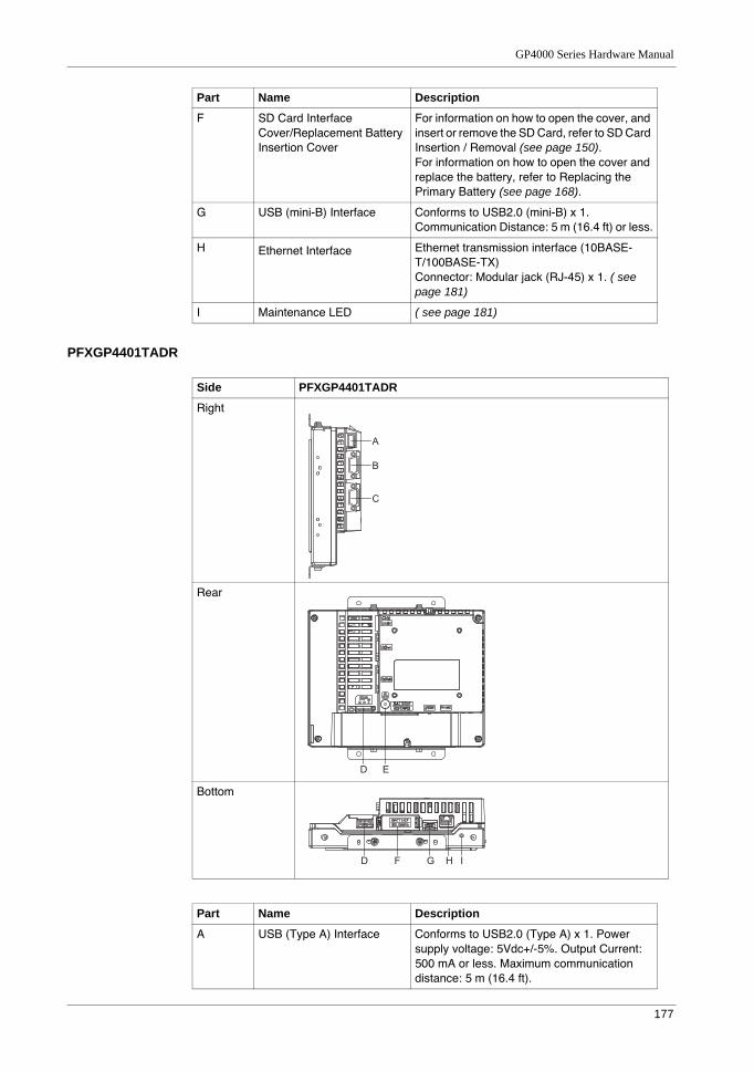
GP4000 Series Hardware Manual
177
PFXGP4401TADR
F SD Card Interface Cover/Replacement Battery Insertion Cover
For information on how to open the cover, and insert or remove the SD Card, refer to SD Card Insertion / Removal (see page 150).For information on how to open the cover and replace the battery, refer to Replacing the Primary Battery (see page 168).
G USB (mini-B) Interface Conforms to USB2.0 (mini-B) x 1. Communication Distance: 5 m (16.4 ft) or less.
H Ethernet Interface Ethernet transmission interface (10BASE-T/100BASE-TX)Connector: Modular jack (RJ-45) x 1. ( see page 181)
I Maintenance LED ( see page 181)
Part Name Description
Side PFXGP4401TADR
Right
Rear
Bottom
Part Name Description
A USB (Type A) Interface Conforms to USB2.0 (Type A) x 1. Power supply voltage: 5Vdc+/-5%. Output Current: 500 mA or less. Maximum communication distance: 5 m (16.4 ft).
178
B Serial Interface (COM1) RS-232C Serial Interface. Connector: D-Sub 9 pin (plug) x 1.
C Serial Interface (COM2) RS-422/485 Serial Interface. Connector: D-Sub 9 pin (plug) x 1.
D Power Plug Connector -
E SD Card Access LED This lamp lights up when SD Card is inserted. ( see page 181) NOTE: Do not remove or insert the SD Card when the LED lamp is on. Doing so may damage data on the SD Card.
F SD Card Interface Cover/Replacement Battery Insertion Cover
For information on how to open the cover, and insert or remove the SD Card, refer to SD Card Insertion / Removal (see page 150).For information on how to open the cover and replace the battery, refer to Replacing the Primary Battery (see page 168).
G USB (mini-B) Interface Conforms to USB2.0 (mini-B) x 1.Communication Distance: 5 m (16.4 ft) or less.
H Ethernet Interface Ethernet transmission interface (10BASE-T/100BASE-TX)Connector: Modular jack (RJ-45) x 1. ( see page 181)
I Maintenance LED ( see page 181)
Part Name Description
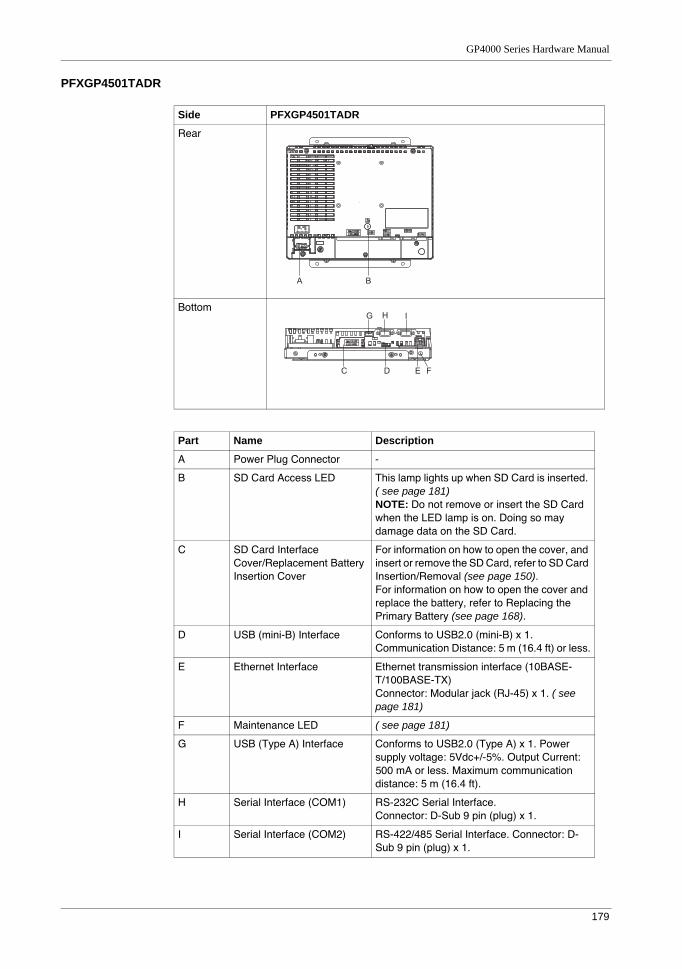
GP4000 Series Hardware Manual
179
PFXGP4501TADR
Side PFXGP4501TADR
Rear
Bottom
Part Name Description
A Power Plug Connector -
B SD Card Access LED This lamp lights up when SD Card is inserted. ( see page 181)NOTE: Do not remove or insert the SD Card when the LED lamp is on. Doing so may damage data on the SD Card.
C SD Card Interface Cover/Replacement Battery Insertion Cover
For information on how to open the cover, and insert or remove the SD Card, refer to SD Card Insertion/Removal (see page 150).For information on how to open the cover and replace the battery, refer to Replacing the Primary Battery (see page 168).
D USB (mini-B) Interface Conforms to USB2.0 (mini-B) x 1.Communication Distance: 5 m (16.4 ft) or less.
E Ethernet Interface Ethernet transmission interface (10BASE-T/100BASE-TX)Connector: Modular jack (RJ-45) x 1. ( see page 181)
F Maintenance LED ( see page 181)
G USB (Type A) Interface Conforms to USB2.0 (Type A) x 1. Power supply voltage: 5Vdc+/-5%. Output Current: 500 mA or less. Maximum communication distance: 5 m (16.4 ft).
H Serial Interface (COM1) RS-232C Serial Interface.Connector: D-Sub 9 pin (plug) x 1.
I Serial Interface (COM2) RS-422/485 Serial Interface. Connector: D-Sub 9 pin (plug) x 1.
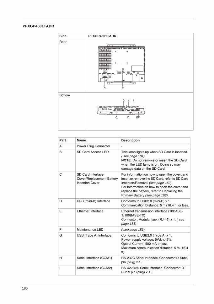
180
PFXGP4601TADR
Side PFXGP4601TADR
Rear
Bottom
Part Name Description
A Power Plug Connector -
B SD Card Access LED This lamp lights up when SD Card is inserted. ( see page 181)NOTE: Do not remove or insert the SD Card when the LED lamp is on. Doing so may damage data on the SD Card.
C SD Card Interface Cover/Replacement Battery Insertion Cover
For information on how to open the cover, and insert or remove the SD Card, refer to SD Card Insertion/Removal (see page 150).For information on how to open the cover and replace the battery, refer to Replacing the Primary Battery (see page 168).
D USB (mini-B) Interface Conforms to USB2.0 (mini-B) x 1.Communication Distance: 5 m (16.4 ft) or less.
E Ethernet Interface Ethernet transmission interface (10BASE-T/100BASE-TX)Connector: Modular jack (RJ-45) x 1. ( see page 181)
F Maintenance LED ( see page 181)
G USB (Type A) Interface Conforms to USB2.0 (Type A) x 1.Power supply voltage: 5Vdc+/-5%.Output Current: 500 mA or less.Maximum communication distance: 5 m (16.4 ft).
H Serial Interface (COM1) RS-232C Serial Interface. Connector: D-Sub 9 pin (plug) x 1.
I Serial Interface (COM2) RS-422/485 Serial Interface. Connector: D-Sub 9 pin (plug) x 1.
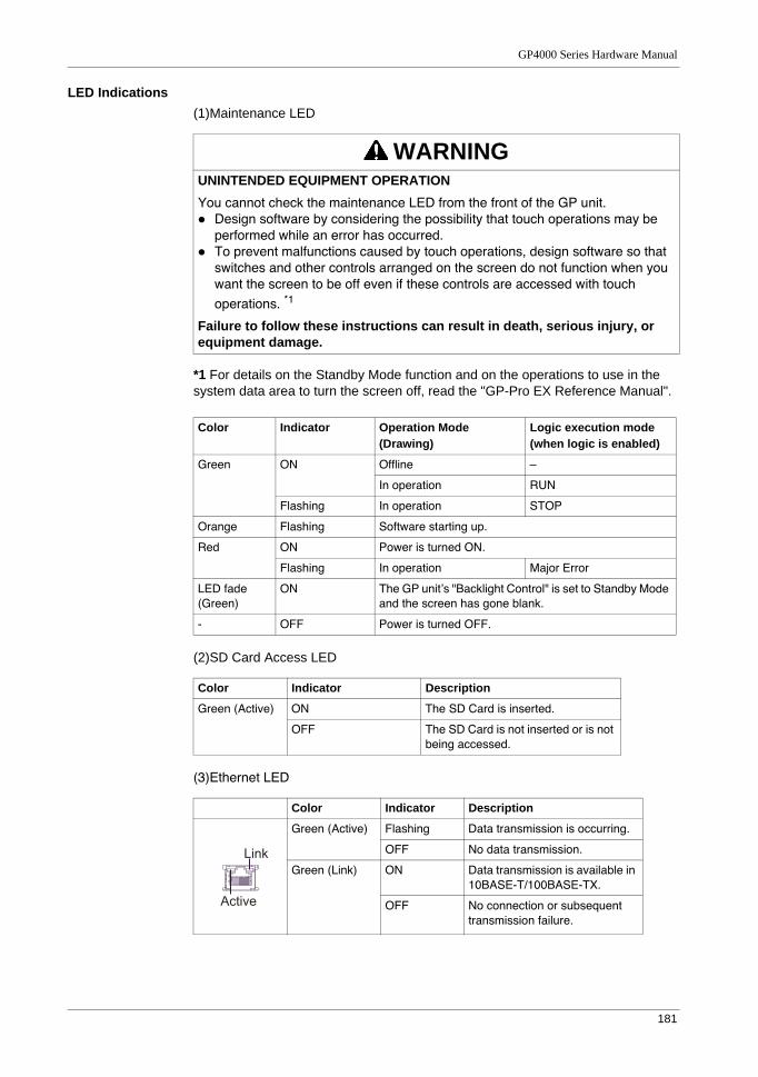
GP4000 Series Hardware Manual
181
LED Indications(1)Maintenance LED
*1 For details on the Standby Mode function and on the operations to use in the system data area to turn the screen off, read the "GP-Pro EX Reference Manual".
(2)SD Card Access LED
(3)Ethernet LED
WARNINGUNINTENDED EQUIPMENT OPERATIONYou cannot check the maintenance LED from the front of the GP unit.
Design software by considering the possibility that touch operations may be performed while an error has occurred.To prevent malfunctions caused by touch operations, design software so that switches and other controls arranged on the screen do not function when you want the screen to be off even if these controls are accessed with touch operations. *1
Failure to follow these instructions can result in death, serious injury, or equipment damage.
Color Indicator Operation Mode (Drawing)
Logic execution mode (when logic is enabled)
Green ON Offline –
In operation RUN
Flashing In operation STOP
Orange Flashing Software starting up.
Red ON Power is turned ON.
Flashing In operation Major Error
LED fade (Green)
ON The GP unit’s "Backlight Control" is set to Standby Mode and the screen has gone blank.
- OFF Power is turned OFF.
Color Indicator Description
Green (Active) ON The SD Card is inserted.
OFF The SD Card is not inserted or is not being accessed.
Color Indicator Description
Green (Active) Flashing Data transmission is occurring.
OFF No data transmission.
Green (Link) ON Data transmission is available in 10BASE-T/100BASE-TX.
OFF No connection or subsequent transmission failure.
Link
Active
182
7.5 Structural Specifications
NOTE: (1) Protection structure equivalent to IP65F*1 can be expected if you affix the Overlay (sold separately) on the screen of the GP unit and the surroundings. Pro-face does not guarantee the protective structure.
Consider the the protective structure in combination with a panel or a resin plate within your quality assurance range.
Use the Overlay manufactured by Pro-face. Use one of the following models.
PFXZGPFSR6W1 (for the PFXGP4301TADR)PFXZGPFSR7W1 (for the PFXGP4401TADR)PFXZGPFSR10W1 (for the PFXGP4501TADR)PFXZGPFSR12W1 (for the PFXGP4601TADR)
*1 This is a protective structure for the front face of the Overlay manufactured by Pro-face and that has been correctly affixed to a panel or to a resin sheet. The performance of the sheet according to the material properties of the overlay in combination with a panel or a resin sheet has been confirmed under appropriate test conditions, but this does not guarantee that the protective structure enables the Pro-face Overlay to be used in any and all environments. In certain situations, the sheet can be damaged. This can occur in areas where either vaporized oils are present, or where low viscosity cutting oils are allowed to adhere to the Overlay for long periods of time. If the Overlay becomes peeled off, these conditions can lead to the ingress of oil into the GP unit and separate protection measures are suggested.
PFXGP4301TADR
PFXGP4401TADR
PFXGP4501TADR
PFXGP4601TADR
Grounding Functional grounding:Grounding resistance of 100Ω, 2mm2 (AWG 14) or thicker wire, or your country's applicable standard. (Same for FG and SG terminals)
Cooling Method Natural air circulation
Protection structure
IP20 (1)(2)
External dimensions(not attached installation fasteners)
W155.6 x H123.4 x D59.7 mm (W6.13 x H4.86 x D2.35 in.)
W204 x H159.4 x D60.4 mm (W8.03 x H6.28 x D2.38 in.)
W259.7 x H201.5 x D57.6mm (W10.22 x H7.93 x D2.27 in.)
W302 x H228 x D56.6mm (W11.89 x H8.98 x D2.23 in.)
Panel cut
dimensions(3)(4)(5)depends on the installation method. Refer to "Panel Cut Dimensions" (page. 223)
Weight approx. ≤ 1 kg (2.2 lb.) (including the installation fasteners)
≤ 1.4 kg (3.1 lb.) (including the installation fasteners)
≤ 2.3 kg (5.1 lb.) (including the installation fasteners)
≤ 2.8 kg (6.2 lb.) (including the installation fasteners)
GP4000 Series Hardware Manual
183
Also, if non-approved oils are present, it may cause deformation or corrosion of the front panel's plastic cover. Therefore, prior to installing the GP unit be sure to confirm the type of conditions that will be present in the GP unit's operating environment. If the Rear Mount Installation Gasket is used for a long period of time, or if the unit and its gasket are removed from the panel, the original level of the protection cannot be guaranteed. To maintain the original protection level, be sure to replace the Rear Mount Installation Gasket regularly.
(2) Affix the Overlay to the front of the GP unit. Use a material with the material properties of one of the following objects for the resin board or paints.
Polybutylene terepthalate resinA mixture of polybutylene terepthalate resin and polycarbonate resinA mixture of acrylonitrile butadiene styrene resin and polybutylene
terepthalate resin
Stainless steelPolyester paintAcrylic paint
(3) As for dimensional tolerance everything +0.5/-0 mm (+0.02/-0 in.) and R in angle are below R1 (R0.04in.).
(4) Even if panel thickness is within recommend range for "Panel Cut Dimensions", the panel could warp, depending on panel's material, size, and installation location of GP unit or other devices. To prevent panel warpage, the installation surface may need to be strengthened.
(5) For the details about the installation method, refer to Installation (see page 220).
CAUTIONEQUIPMENT DAMAGEEnsure that the panel is not in permanent and direct contact with oils.
Failure to follow these instructions can result in injury or equipment damage.
NOTICESTORAGE AND OPERATION OUTSIDE OF SPECIFICATIONS
Store the panel in areas where temperatures are within the panel’s specifications.Do not restrict or block the panel’s rear-face ventilation slots.
Failure to follow these instructions can result in equipment damage.
NOTICEGASKET AGING
Inspect the gasket periodically as required by your operating environment not to damage the GP unit.Change the gasket at least once a year, or as soon as scratches or dirt become visible.
Failure to follow these instructions can result in equipment damage.
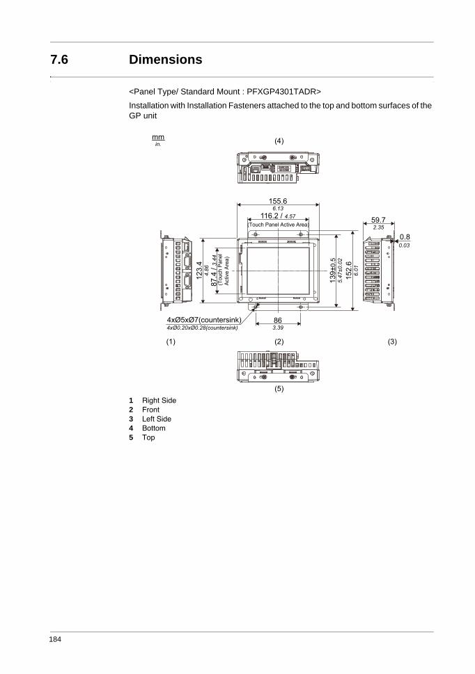
184
7.6 Dimensions
<Panel Type/ Standard Mount : PFXGP4301TADR>
Installation with Installation Fasteners attached to the top and bottom surfaces of the GP unit
1 Right Side2 Front3 Left Side4 Bottom5 Top
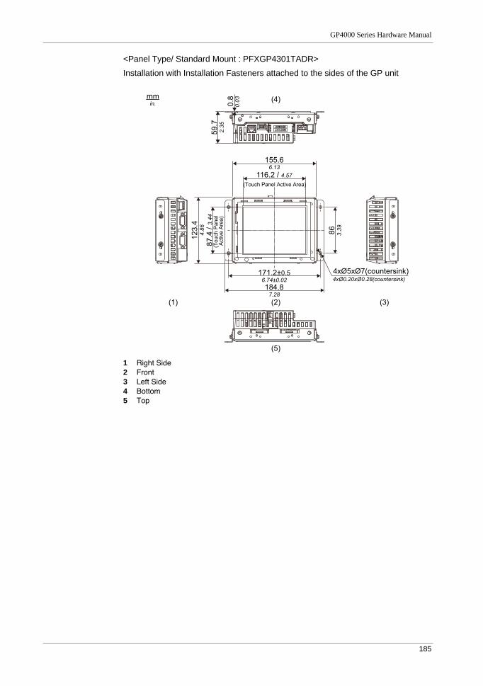
GP4000 Series Hardware Manual
185
<Panel Type/ Standard Mount : PFXGP4301TADR>
Installation with Installation Fasteners attached to the sides of the GP unit
1 Right Side2 Front3 Left Side4 Bottom5 Top
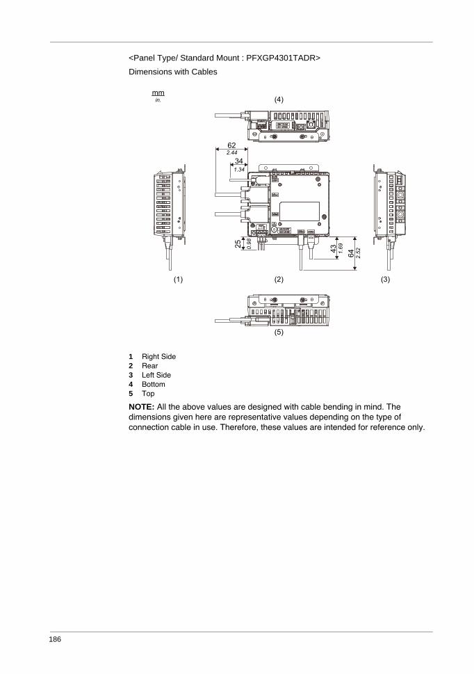
186
<Panel Type/ Standard Mount : PFXGP4301TADR>
Dimensions with Cables
1 Right Side2 Rear3 Left Side4 Bottom5 Top
NOTE: All the above values are designed with cable bending in mind. The dimensions given here are representative values depending on the type of connection cable in use. Therefore, these values are intended for reference only.
mm
in.
(2)
(5)
(4)
(3)(1)
62
2.44
34
1.34
43
1.6925
0.98
64
2.52
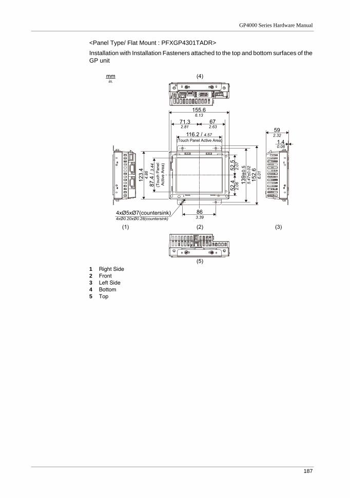
GP4000 Series Hardware Manual
187
<Panel Type/ Flat Mount : PFXGP4301TADR>
Installation with Installation Fasteners attached to the top and bottom surfaces of the GP unit
1 Right Side2 Front3 Left Side4 Bottom5 Top
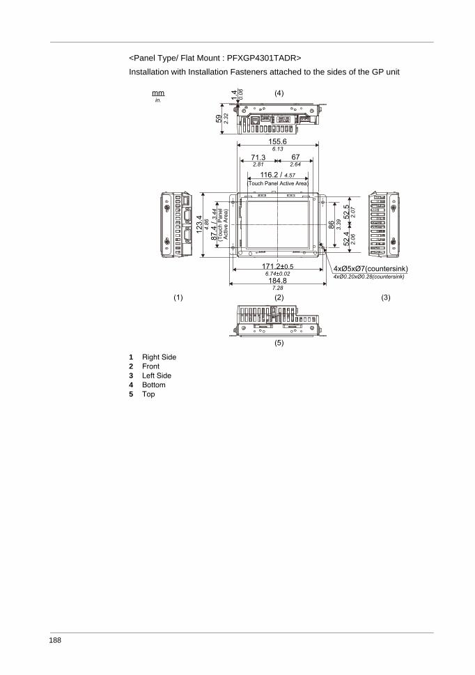
188
<Panel Type/ Flat Mount : PFXGP4301TADR>
Installation with Installation Fasteners attached to the sides of the GP unit
1 Right Side2 Front3 Left Side4 Bottom5 Top
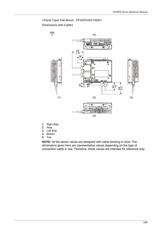
GP4000 Series Hardware Manual
189
<Panel Type/ Flat Mount : PFXGP4301TADR>
Dimensions with Cables
1 Right Side2 Rear3 Left Side4 Bottom5 Top
NOTE: All the above values are designed with cable bending in mind. The dimensions given here are representative values depending on the type of connection cable in use. Therefore, these values are intended for reference only.
mm
in.
(2)
(5)
(4)
(3)(1)
62
2.44
34
1.34
43
1.6925
0.98
64
2.52
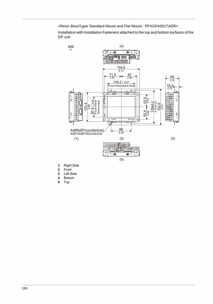
190
<Resin BossType/ Standard Mount and Flat Mount : PFXGP4301TADR>
Installation with Installation Fasteners attached to the top and bottom surfaces of the GP unit
1 Right Side2 Front3 Left Side4 Bottom5 Top
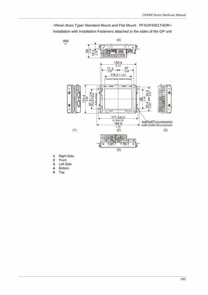
GP4000 Series Hardware Manual
191
<Resin Boss Type/ Standard Mount and Flat Mount : PFXGP4301TADR>
Installation with Installation Fasteners attached to the sides of the GP unit
1 Right Side2 Front3 Left Side4 Bottom5 Top
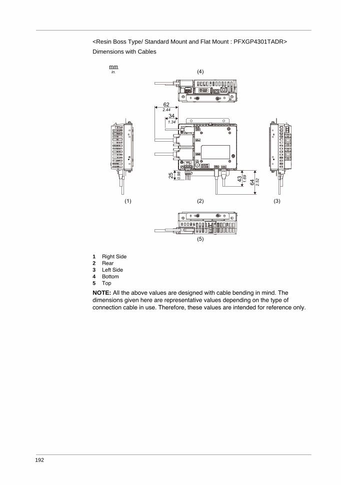
192
<Resin Boss Type/ Standard Mount and Flat Mount : PFXGP4301TADR>
Dimensions with Cables
1 Right Side2 Rear3 Left Side4 Bottom5 Top
NOTE: All the above values are designed with cable bending in mind. The dimensions given here are representative values depending on the type of connection cable in use. Therefore, these values are intended for reference only.
(2)
(5)
(4)
(3)(1)
mm
in.
62
2.44
34
1.34
43
1.6925
0.98
64
2.52
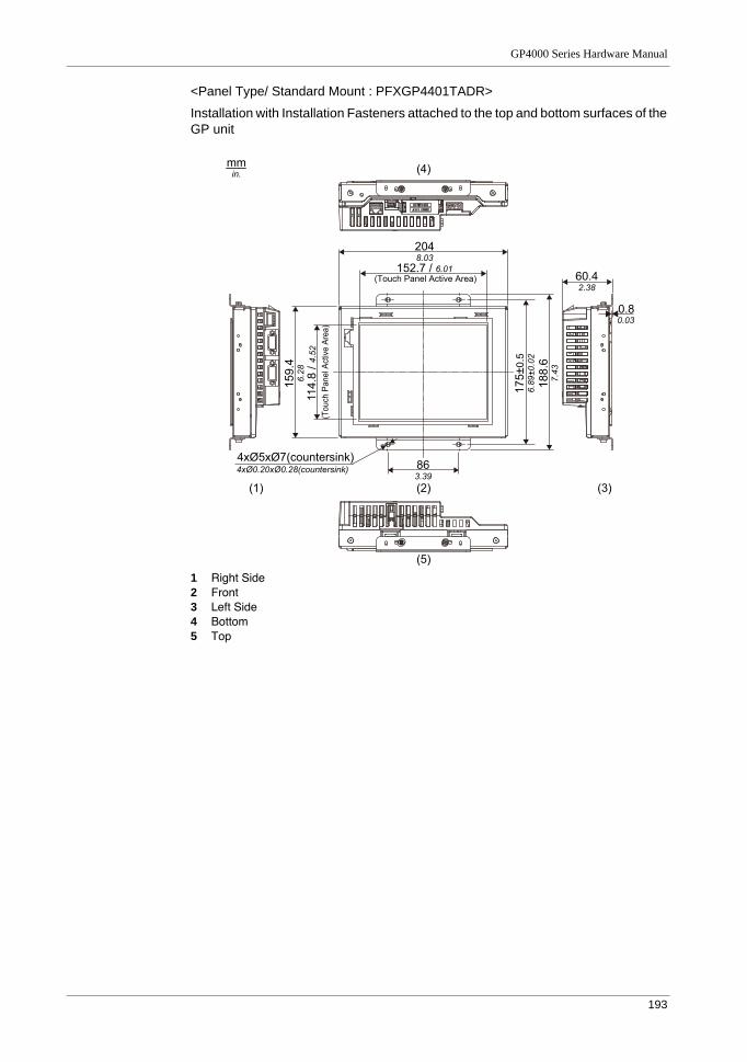
GP4000 Series Hardware Manual
193
<Panel Type/ Standard Mount : PFXGP4401TADR>
Installation with Installation Fasteners attached to the top and bottom surfaces of the GP unit
1 Right Side2 Front3 Left Side4 Bottom5 Top
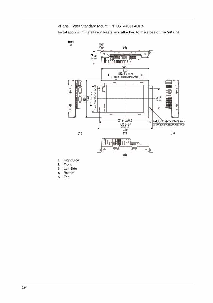
194
<Panel Type/ Standard Mount : PFXGP4401TADR>
Installation with Installation Fasteners attached to the sides of the GP unit
1 Right Side2 Front3 Left Side4 Bottom5 Top
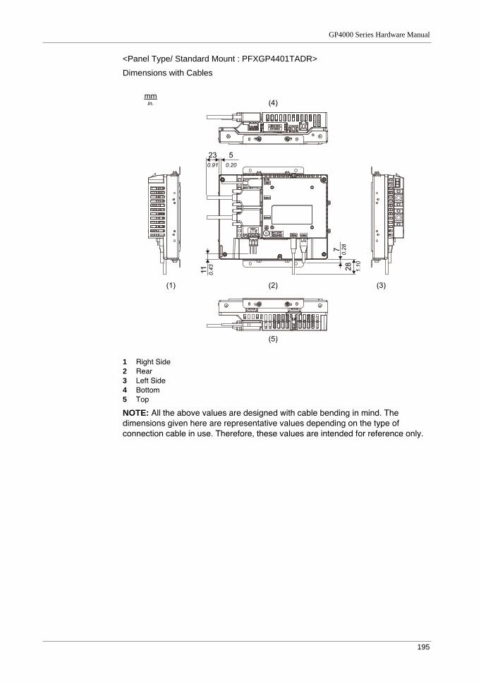
GP4000 Series Hardware Manual
195
<Panel Type/ Standard Mount : PFXGP4401TADR>
Dimensions with Cables
1 Right Side2 Rear3 Left Side4 Bottom5 Top
NOTE: All the above values are designed with cable bending in mind. The dimensions given here are representative values depending on the type of connection cable in use. Therefore, these values are intended for reference only.
mm
in.
(2)
(5)
(4)
(3)(1)
23
0.91
5
0.20
11
0.43
7
0.28
28
1.10
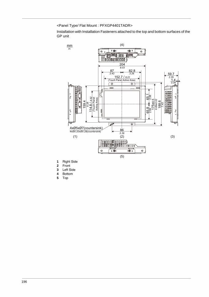
196
<Panel Type/ Flat Mount : PFXGP4401TADR>
Installation with Installation Fasteners attached to the top and bottom surfaces of the GP unit
1 Right Side2 Front3 Left Side4 Bottom5 Top
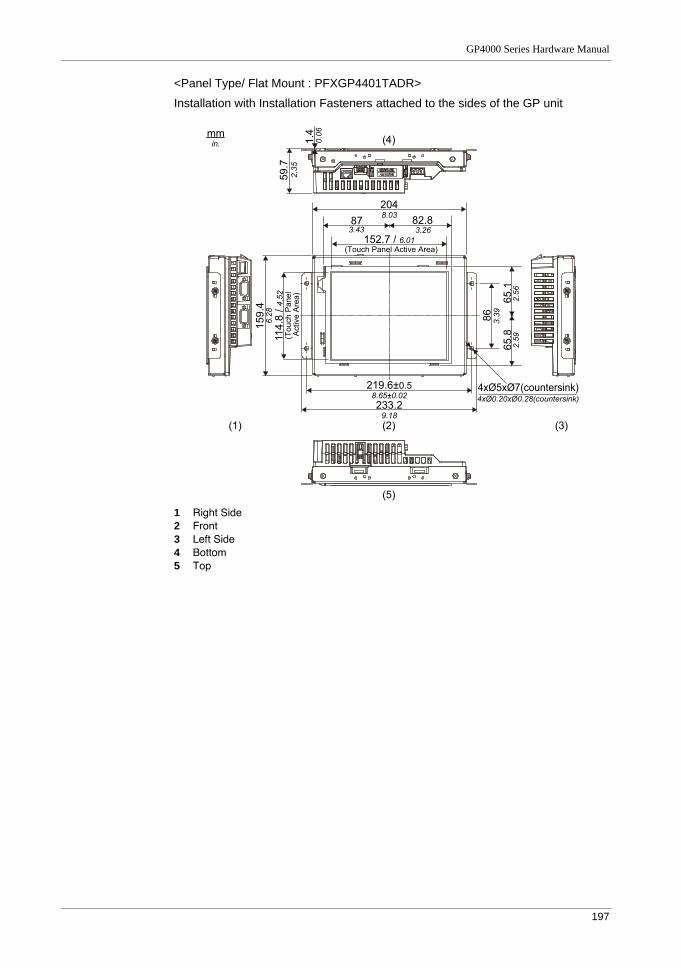
GP4000 Series Hardware Manual
197
<Panel Type/ Flat Mount : PFXGP4401TADR>
Installation with Installation Fasteners attached to the sides of the GP unit
1 Right Side2 Front3 Left Side4 Bottom5 Top
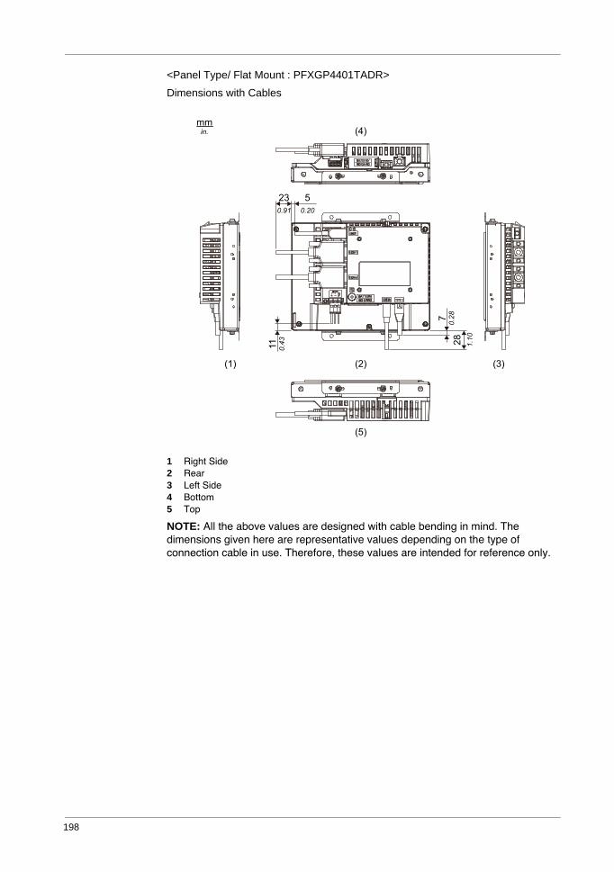
198
<Panel Type/ Flat Mount : PFXGP4401TADR>
Dimensions with Cables
1 Right Side2 Rear3 Left Side4 Bottom5 Top
NOTE: All the above values are designed with cable bending in mind. The dimensions given here are representative values depending on the type of connection cable in use. Therefore, these values are intended for reference only.
mm
in.
(2)
(5)
(4)
(3)(1)
23
0.91
5
0.20
11
0.43
7
0.28
28
1.10
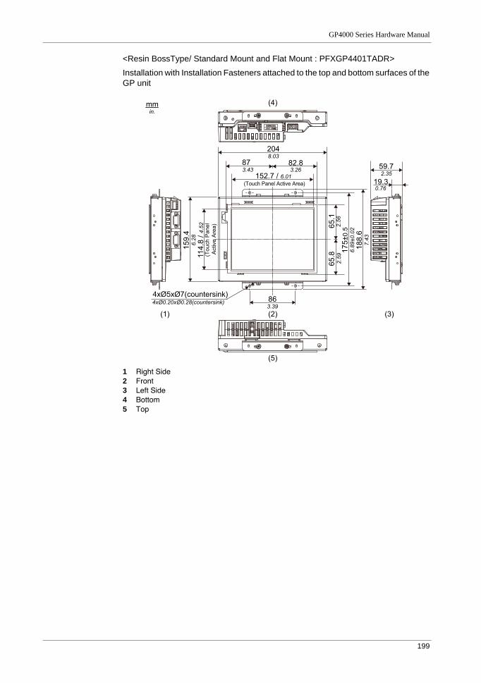
GP4000 Series Hardware Manual
199
<Resin BossType/ Standard Mount and Flat Mount : PFXGP4401TADR>
Installation with Installation Fasteners attached to the top and bottom surfaces of the GP unit
1 Right Side2 Front3 Left Side4 Bottom5 Top
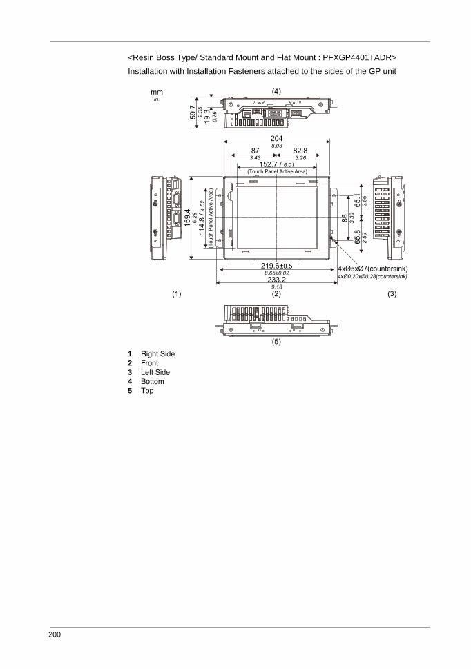
200
<Resin Boss Type/ Standard Mount and Flat Mount : PFXGP4401TADR>
Installation with Installation Fasteners attached to the sides of the GP unit
1 Right Side2 Front3 Left Side4 Bottom5 Top
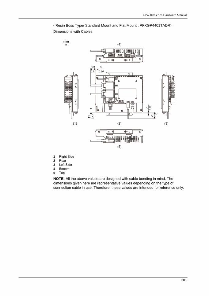
GP4000 Series Hardware Manual
201
<Resin Boss Type/ Standard Mount and Flat Mount : PFXGP4401TADR>
Dimensions with Cables
1 Right Side2 Rear3 Left Side4 Bottom5 Top
NOTE: All the above values are designed with cable bending in mind. The dimensions given here are representative values depending on the type of connection cable in use. Therefore, these values are intended for reference only.
mm
in.
(2)
(5)
(4)
(3)(1)
23
0.91
5
0.20
11
0.43
7
0.28
28
1.10
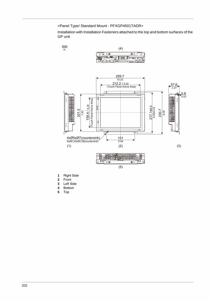
202
<Panel Type/ Standard Mount : PFXGP4501TADR>
Installation with Installation Fasteners attached to the top and bottom surfaces of the GP unit
1 Right Side2 Front3 Left Side4 Bottom5 Top
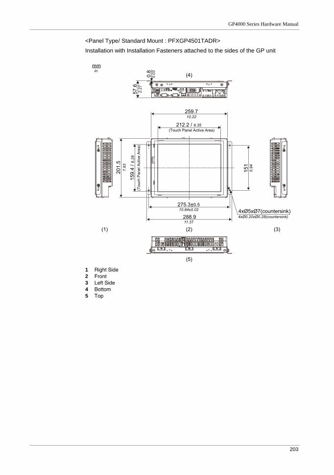
GP4000 Series Hardware Manual
203
<Panel Type/ Standard Mount : PFXGP4501TADR>
Installation with Installation Fasteners attached to the sides of the GP unit
1 Right Side2 Front3 Left Side4 Bottom5 Top
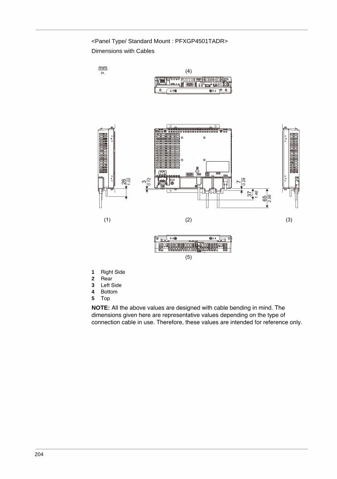
204
<Panel Type/ Standard Mount : PFXGP4501TADR>
Dimensions with Cables
1 Right Side2 Rear3 Left Side4 Bottom5 Top
NOTE: All the above values are designed with cable bending in mind. The dimensions given here are representative values depending on the type of connection cable in use. Therefore, these values are intended for reference only.
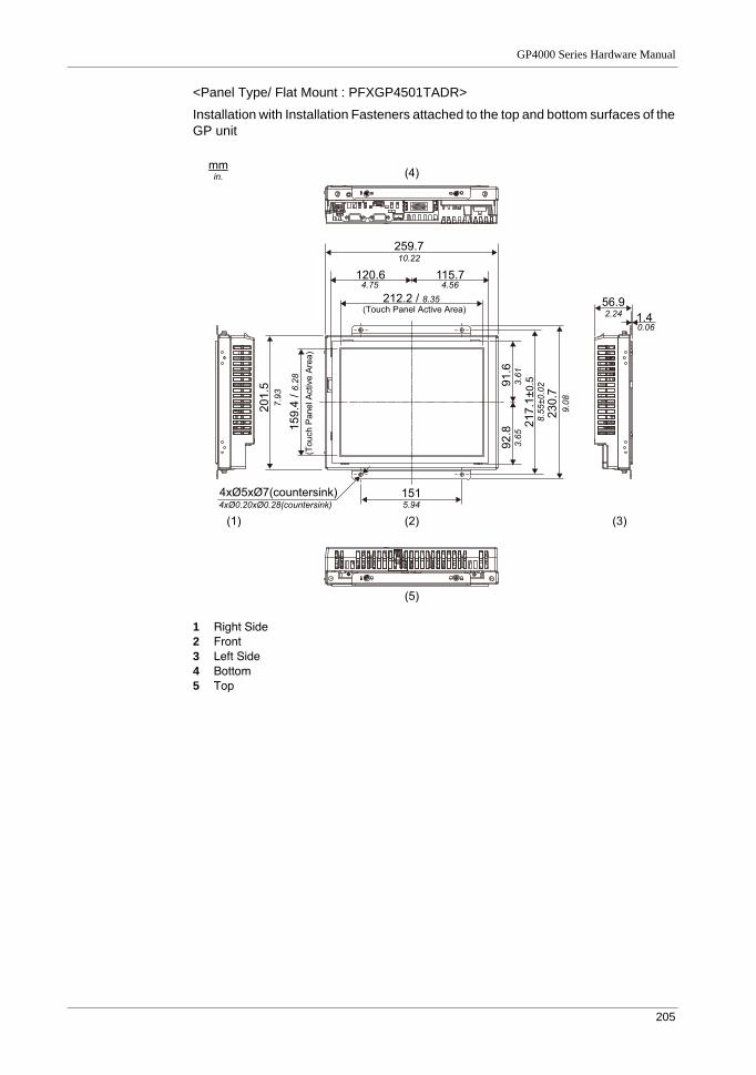
GP4000 Series Hardware Manual
205
<Panel Type/ Flat Mount : PFXGP4501TADR>
Installation with Installation Fasteners attached to the top and bottom surfaces of the GP unit
1 Right Side2 Front3 Left Side4 Bottom5 Top
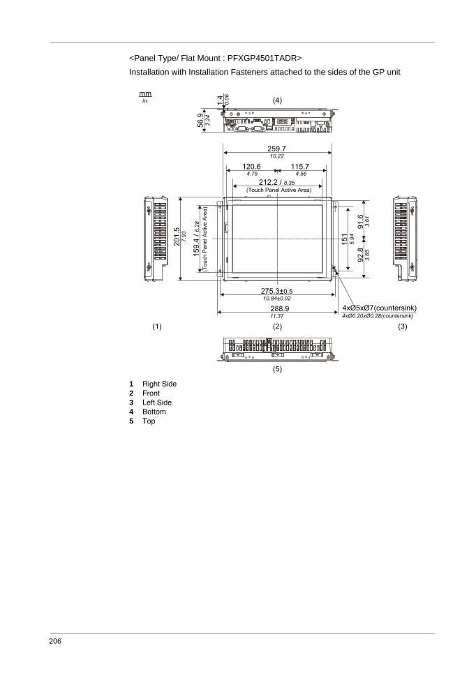
206
<Panel Type/ Flat Mount : PFXGP4501TADR>
Installation with Installation Fasteners attached to the sides of the GP unit
1 Right Side2 Front3 Left Side4 Bottom5 Top
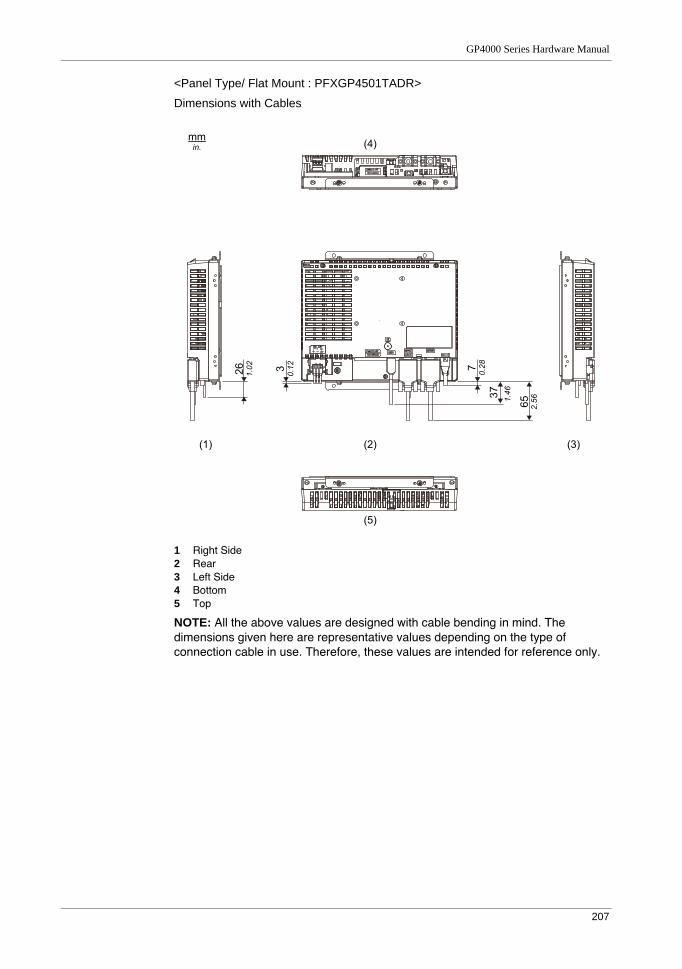
GP4000 Series Hardware Manual
207
<Panel Type/ Flat Mount : PFXGP4501TADR>
Dimensions with Cables
1 Right Side2 Rear3 Left Side4 Bottom5 Top
NOTE: All the above values are designed with cable bending in mind. The dimensions given here are representative values depending on the type of connection cable in use. Therefore, these values are intended for reference only.
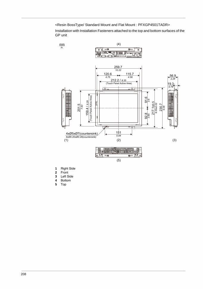
208
<Resin BossType/ Standard Mount and Flat Mount : PFXGP4501TADR>
Installation with Installation Fasteners attached to the top and bottom surfaces of the GP unit
1 Right Side2 Front3 Left Side4 Bottom5 Top
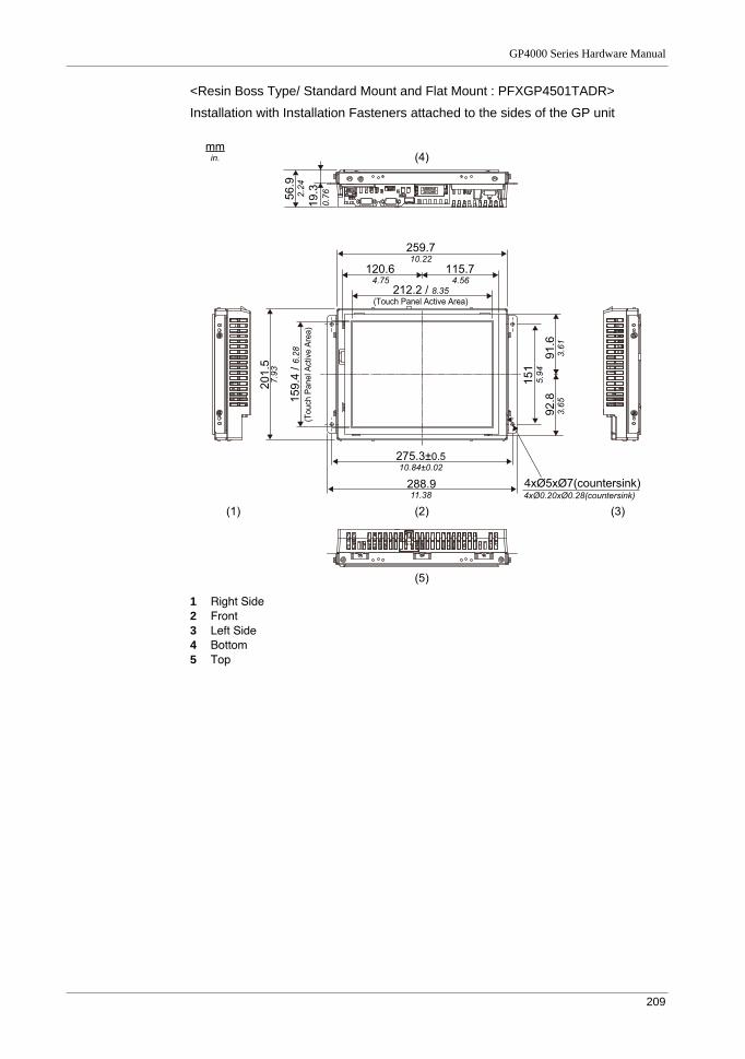
GP4000 Series Hardware Manual
209
<Resin Boss Type/ Standard Mount and Flat Mount : PFXGP4501TADR>
Installation with Installation Fasteners attached to the sides of the GP unit
1 Right Side2 Front3 Left Side4 Bottom5 Top
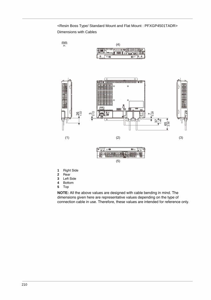
210
<Resin Boss Type/ Standard Mount and Flat Mount : PFXGP4501TADR>
Dimensions with Cables
1 Right Side2 Rear3 Left Side4 Bottom5 Top
NOTE: All the above values are designed with cable bending in mind. The dimensions given here are representative values depending on the type of connection cable in use. Therefore, these values are intended for reference only.
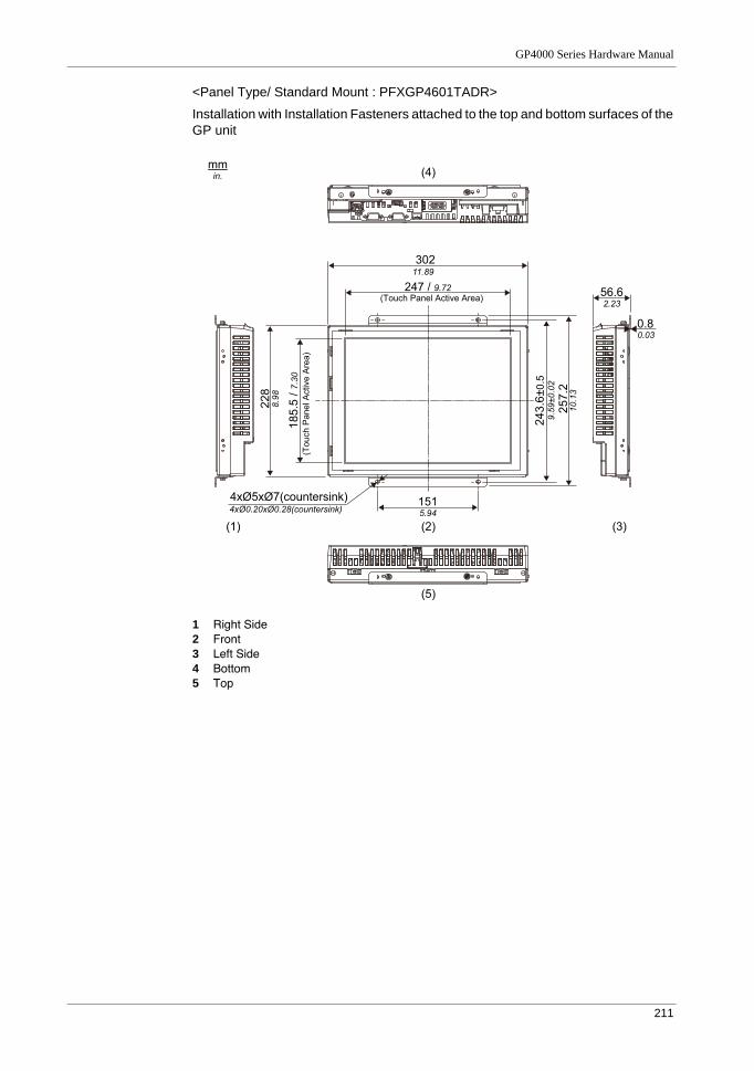
GP4000 Series Hardware Manual
211
<Panel Type/ Standard Mount : PFXGP4601TADR>
Installation with Installation Fasteners attached to the top and bottom surfaces of the GP unit
1 Right Side2 Front3 Left Side4 Bottom5 Top
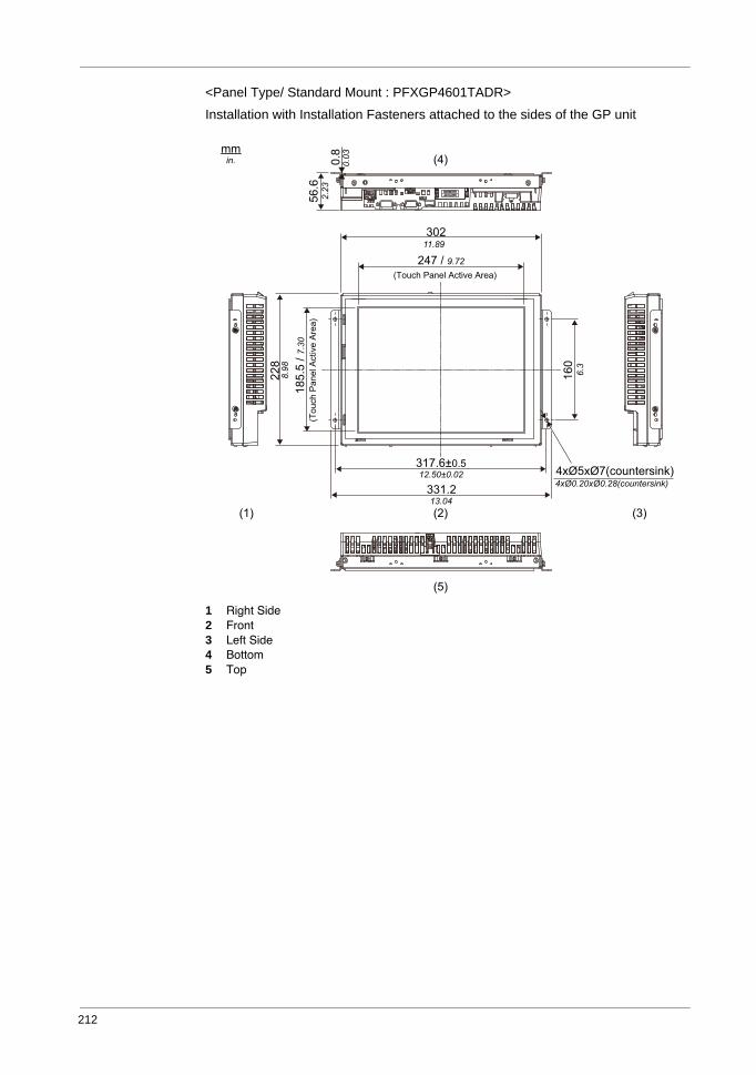
212
<Panel Type/ Standard Mount : PFXGP4601TADR>
Installation with Installation Fasteners attached to the sides of the GP unit
1 Right Side2 Front3 Left Side4 Bottom5 Top
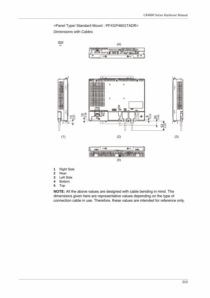
GP4000 Series Hardware Manual
213
<Panel Type/ Standard Mount : PFXGP4601TADR>
Dimensions with Cables
1 Right Side2 Rear3 Left Side4 Bottom5 Top
NOTE: All the above values are designed with cable bending in mind. The dimensions given here are representative values depending on the type of connection cable in use. Therefore, these values are intended for reference only.
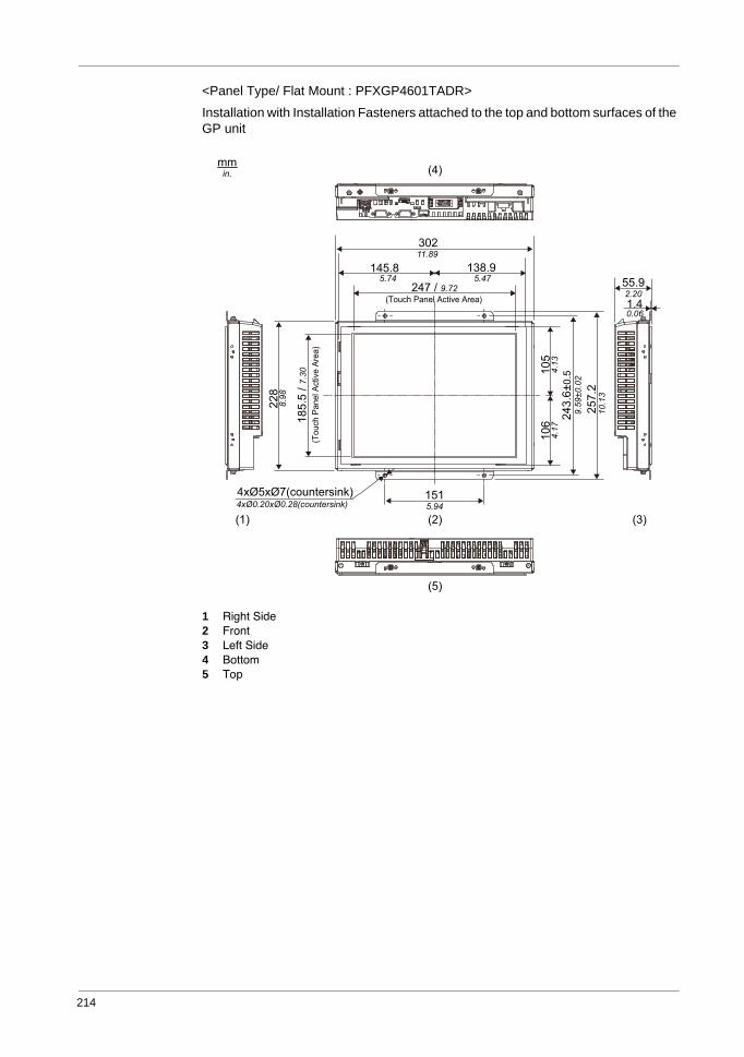
214
<Panel Type/ Flat Mount : PFXGP4601TADR>
Installation with Installation Fasteners attached to the top and bottom surfaces of the GP unit
1 Right Side2 Front3 Left Side4 Bottom5 Top
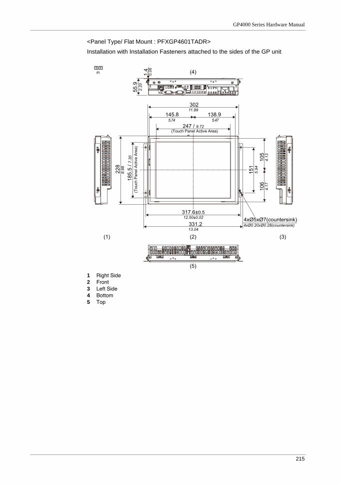
GP4000 Series Hardware Manual
215
<Panel Type/ Flat Mount : PFXGP4601TADR>
Installation with Installation Fasteners attached to the sides of the GP unit
1 Right Side2 Front3 Left Side4 Bottom5 Top
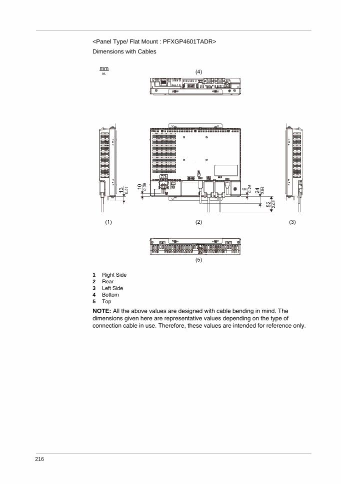
216
<Panel Type/ Flat Mount : PFXGP4601TADR>
Dimensions with Cables
1 Right Side2 Rear3 Left Side4 Bottom5 Top
NOTE: All the above values are designed with cable bending in mind. The dimensions given here are representative values depending on the type of connection cable in use. Therefore, these values are intended for reference only.
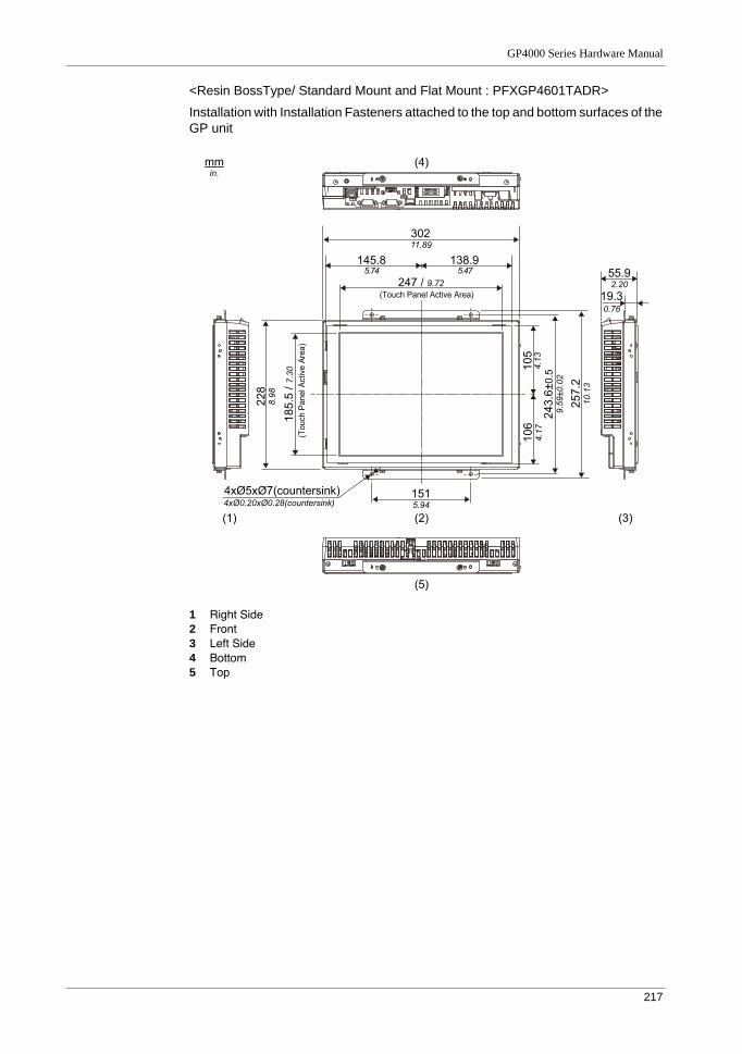
GP4000 Series Hardware Manual
217
<Resin BossType/ Standard Mount and Flat Mount : PFXGP4601TADR>
Installation with Installation Fasteners attached to the top and bottom surfaces of the GP unit
1 Right Side2 Front3 Left Side4 Bottom5 Top
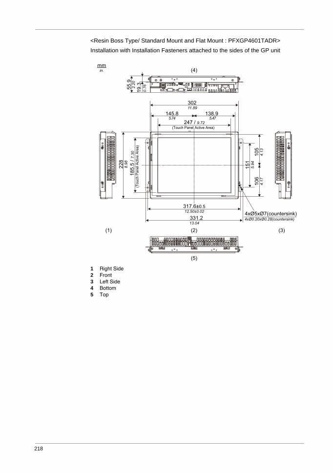
218
<Resin Boss Type/ Standard Mount and Flat Mount : PFXGP4601TADR>
Installation with Installation Fasteners attached to the sides of the GP unit
1 Right Side2 Front3 Left Side4 Bottom5 Top
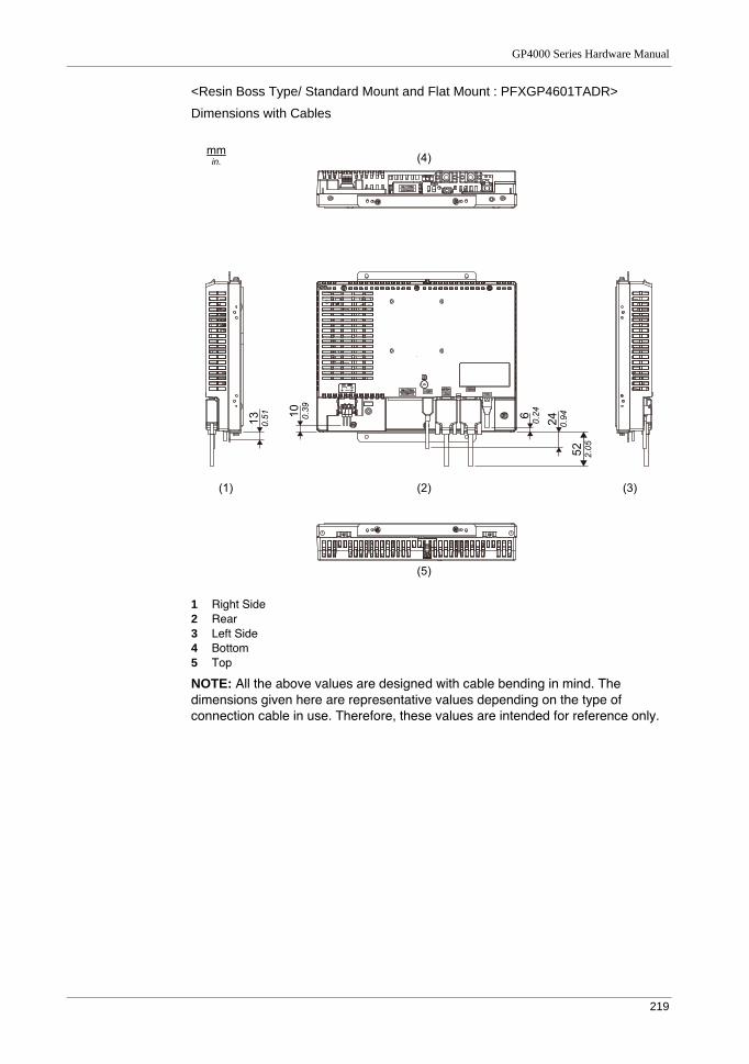
GP4000 Series Hardware Manual
219
<Resin Boss Type/ Standard Mount and Flat Mount : PFXGP4601TADR>
Dimensions with Cables
1 Right Side2 Rear3 Left Side4 Bottom5 Top
NOTE: All the above values are designed with cable bending in mind. The dimensions given here are representative values depending on the type of connection cable in use. Therefore, these values are intended for reference only.
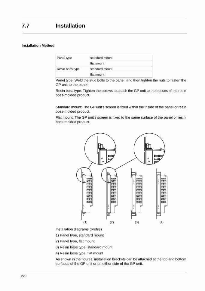
220
7.7 Installation
Installation Method
Panel type: Weld the stud bolts to the panel, and then tighten the nuts to fasten the GP unit to the panel.
Resin boss type: Tighten the screws to attach the GP unit to the bosses of the resin boss-molded product.
Standard mount: The GP unit's screen is fixed within the inside of the panel or resin boss-molded product.
Flat mount: The GP unit's screen is fixed to the same surface of the panel or resin boss-molded product.
Installation diagrams (profile)
1) Panel type, standard mount
2) Panel type, flat mount
3) Resin boss type, standard mount
4) Resin boss type, flat mount
As shown in the figures, installation brackets can be attached at the top and bottom surfaces of the GP unit or on either side of the GP unit.
Panel type standard mount
flat mount
Resin boss type standard mount
flat mount
(1) (2) (3) (4)
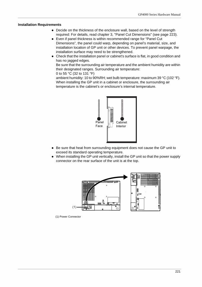
GP4000 Series Hardware Manual
221
Installation RequirementsDecide on the thickness of the enclosure wall, based on the level of strength required: For details, read chapter 3, "Panel Cut Dimensions" (see page 223).Even if panel thickness is within recommended range for “Panel Cut Dimensions”, the panel could warp, depending on panel’s material, size, and installation location of GP unit or other devices. To prevent panel warpage, the installation surface may need to be strengthened.Check that the installation panel or cabinet's surface is flat, in good condition and has no jagged edges.Be sure that the surrounding air temperature and the ambient humidity are within their designated ranges. Surrounding air temperature: 0 to 55 °C (32 to 131 °F)ambient humidity: 10 to 90%RH; wet bulb temperature: maximum 39 °C (102 °F). When installing the GP unit in a cabinet or enclosure, the surrounding air temperature is the cabinet’s or enclosure’s internal temperature.
Be sure that heat from surrounding equipment does not cause the GP unit to exceed its standard operating temperature.When installing the GP unit vertically, install the GP unit so that the power supply connector on the rear surface of the unit is at the top.
PanelFace
Cabinet Interior
(1)
(1) Power Connector
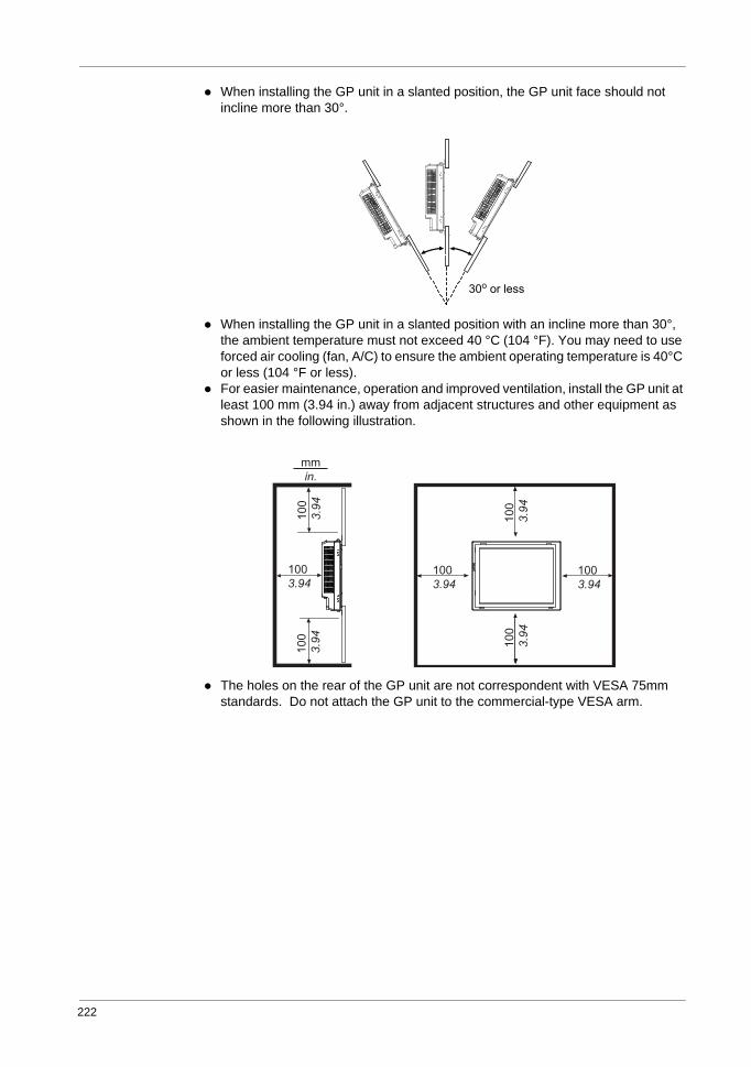
222
When installing the GP unit in a slanted position, the GP unit face should not incline more than 30°.
When installing the GP unit in a slanted position with an incline more than 30°, the ambient temperature must not exceed 40 °C (104 °F). You may need to use forced air cooling (fan, A/C) to ensure the ambient operating temperature is 40°C or less (104 °F or less).For easier maintenance, operation and improved ventilation, install the GP unit at least 100 mm (3.94 in.) away from adjacent structures and other equipment as shown in the following illustration.
The holes on the rear of the GP unit are not correspondent with VESA 75mm standards. Do not attach the GP unit to the commercial-type VESA arm.
mmin.
1003.94
1003.94
1003.94
100
3.94
100
3.94
100
3.94
100
3.94
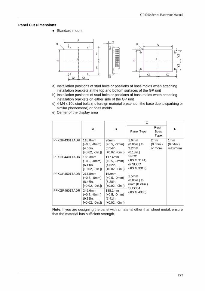
GP4000 Series Hardware Manual
223
Panel Cut DimensionsStandard mount
a) Installation positions of stud bolts or positions of boss molds when attaching installation brackets at the top and bottom surfaces of the GP unit
b) Installation positions of stud bolts or positions of boss molds when attaching installation brackets on either side of the GP unit
d) 4-M4 x 10L stud bolts (no foreign material present on the base due to sparking or similar phenomena) or boss molds
e) Center of the display area
Note: If you are designing the panel with a material other than sheet metal, ensure that the material has sufficient strength.
A B
C
RPanel Type
Resin Boss Type
PFXGP4301TADR 118.8mm (+0.5, -0mm)(4.68in.[+0.02, -0in.])
90mm (+0.5, -0mm)(3.54in.[+0.02, -0in.])
1.6mm (0.06in.) to 3.2mm (0.13in.) SPCC(JIS G 3141) or SECC(JIS G 3313)
1.5mm (0.06in.) to 6mm (0.24in.) SUS304(JIS G 4305)
2mm (0.08in.) or more
1mm (0.04in.) maximum
PFXGP4401TADR 155.3mm (+0.5, -0mm)(6.11in.[+0.02, -0in.])
117.4mm (+0.5, -0mm)(4.62in.[+0.02, -0in.])
PFXGP4501TADR 214.8mm (+0.5, -0mm)(8.46in.[+0.02, -0in.])
162mm (+0.5, -0mm)(6.38in.[+0.02, -0in.])
PFXGP4601TADR 249.6mm (+0.5, -0mm)(9.83in.[+0.02, -0in.])
188.1mm (+0.5, -0mm)(7.41in.[+0.02, -0in.])
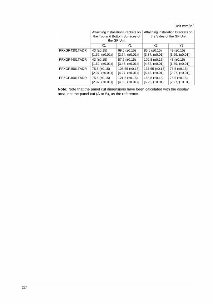
224
Unit mm[in.]
Note: Note that the panel cut dimensions have been calculated with the display area, not the panel cut (A or B), as the reference.
Attaching Installation Brackets on the Top and Bottom Surfaces of
the GP Unit
Attaching Installation Brackets on the Sides of the GP Unit
X1 Y1 X2 Y2PFXGP4301TADR 43 (±0.15)
[1.69, (±0.01)]69.5 (±0.15)[2.74, (±0.01)]
85.6 (±0.15)[3.37, (±0.01)]
43 (±0.15)[1.69, (±0.01)]
PFXGP4401TADR 43 (±0.15)[1.69, (±0.01)]
87.5 (±0.15)[3.45, (±0.01)]
109.8 (±0.15)[4.32, (±0.01)]
43 (±0.15)[1.69, (±0.01)]
PFXGP4501TADR 75.5 (±0.15)[2.97, (±0.01)]
108.55 (±0.15)[4.27, (±0.01)]
137.65 (±0.15)[5.42, (±0.01)]
75.5 (±0.15)[2.97, (±0.01)]
PFXGP4601TADR 75.5 (±0.15)[2.97, (±0.01)]
121.8 (±0.15)[4.80, (±0.01)]
158.8 (±0.15)[6.25, (±0.01)]
75.5 (±0.15)[2.97, (±0.01)]
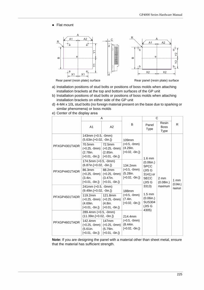
GP4000 Series Hardware Manual
225
Flat mount
a) Installation positions of stud bolts or positions of boss molds when attaching installation brackets at the top and bottom surfaces of the GP unit
b) Installation positions of stud bolts or positions of boss molds when attaching installation brackets on either side of the GP unit
d) 4-M4 x 10L stud bolts (no foreign material present on the base due to sparking or similar phenomena) or boss molds
e) Center of the display area
Note: If you are designing the panel with a material other than sheet metal, ensure that the material has sufficient strength.
A
B
C
RA1 A2 Panel
Type
Resin Boss Type
PFXGP4301TADR
143mm (+0.5, -0mm)(5.63in.[+0.02, -0in.]) 109mm
(+0.5, -0mm)(4.29in.[+0.02, -0in.])
1.6 mm (0.06in.) SPCC(JIS G 3141) or SECC(JIS G 3313)
1.5 mm (0.06in.) SUS304(JIS G 4305)
2 mm (0.08in.)maximum
1 mm (0.04in.) maximum
70.5mm (+0.25, -0mm)(2.78in.[+0.01, -0in.])
72.5mm (+0.25, -0mm)(2.85in.[+0.01, -0in.])
PFXGP4401TADR
174.5mm (+0.5, -0mm)(6.87in.[+0.02, -0in.]) 134.2mm
(+0.5, -0mm)(5.28in.[+0.02, -0in.])
86.3mm (+0.25, -0mm)(3.4in.[+0.01, -0in.])
88.2mm (+0.25, -0mm)(3.47in.[+0.01, -0in.])
PFXGP4501TADR
241mm (+0.5, -0mm)(9.49in.[+0.02, -0in.]) 188mm
(+0.5, -0mm)(7.4in.[+0.02, -0in.])
119.2mm (+0.25, -0mm)(4.69in.[+0.01, -0in.])
121.8mm (+0.25, -0mm)(4.8in.[+0.01, -0in.])
PFXGP4601TADR
289.4mm (+0.5, -0mm)(11.39in.[+0.02, -0in.]) 214.4mm
(+0.5, -0mm)(8.44in.[+0.02, -0in.])
142.4mm (+0.25, -0mm)(5.61in.[+0.01, -0in.])
147mm (+0.25, -0mm)(5.79in.[+0.01, -0in.])
Rear panel (resin plate) surfaceRear panel (resin plate) surface
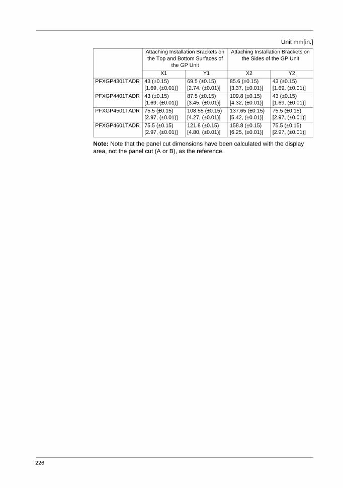
226
Unit mm[in.]
Note: Note that the panel cut dimensions have been calculated with the display area, not the panel cut (A or B), as the reference.
Attaching Installation Brackets on the Top and Bottom Surfaces of
the GP Unit
Attaching Installation Brackets on the Sides of the GP Unit
X1 Y1 X2 Y2PFXGP4301TADR 43 (±0.15)
[1.69, (±0.01)]69.5 (±0.15)[2.74, (±0.01)]
85.6 (±0.15)[3.37, (±0.01)]
43 (±0.15)[1.69, (±0.01)]
PFXGP4401TADR 43 (±0.15)[1.69, (±0.01)]
87.5 (±0.15)[3.45, (±0.01)]
109.8 (±0.15)[4.32, (±0.01)]
43 (±0.15)[1.69, (±0.01)]
PFXGP4501TADR 75.5 (±0.15)[2.97, (±0.01)]
108.55 (±0.15)[4.27, (±0.01)]
137.65 (±0.15)[5.42, (±0.01)]
75.5 (±0.15)[2.97, (±0.01)]
PFXGP4601TADR 75.5 (±0.15)[2.97, (±0.01)]
121.8 (±0.15)[4.80, (±0.01)]
158.8 (±0.15)[6.25, (±0.01)]
75.5 (±0.15)[2.97, (±0.01)]
GP4000 Series Hardware Manual
227
Panel Type
NOTICEPANEL UNSTEADY WHEN UNSECURED
Keep GP unit stabilized in the panel-cut while you are installing or removing the screw fasteners.
Failure to follow the instruction can result in equipment damage.
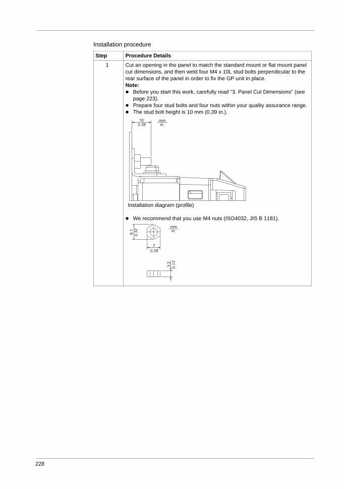
228
Installation procedure
Step Procedure Details
1 Cut an opening in the panel to match the standard mount or flat mount panel cut dimensions, and then weld four M4 x 10L stud bolts perpendicular to the rear surface of the panel in order to fix the GP unit in place. Note:
Before you start this work, carefully read "3. Panel Cut Dimensions" (see page 223).Prepare four stud bolts and four nuts within your quality assurance range.The stud bolt height is 10 mm (0.39 in.).
We recommend that you use M4 nuts (ISO4032, JIS B 1181).
Installation diagram (profile)
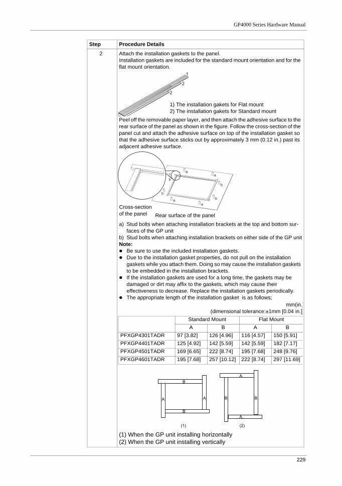
GP4000 Series Hardware Manual
229
2 Attach the installation gaskets to the panel.Installation gaskets are included for the standard mount orientation and for the flat mount orientation.
Peel off the removable paper layer, and then attach the adhesive surface to the rear surface of the panel as shown in the figure. Follow the cross-section of the panel cut and attach the adhesive surface on top of the installation gasket so that the adhesive surface sticks out by approximately 3 mm (0.12 in.) past its adjacent adhesive surface.
a) Stud bolts when attaching installation brackets at the top and bottom sur-faces of the GP unit
b) Stud bolts when attaching installation brackets on either side of the GP unitNote:
Be sure to use the included installation gaskets.Due to the installation gasket properties, do not pull on the installation gaskets while you attach them. Doing so may cause the installation gaskets to be embedded in the installation brackets.If the installation gaskets are used for a long time, the gaskets may be damaged or dirt may affix to the gaskets, which may cause their effectiveness to decrease. Replace the installation gaskets periodically.The appropriate length of the installation gasket is as follows;
(1) When the GP unit installing horizontally(2) When the GP unit installing vertically
Step Procedure Details
1) The installation gakets for Flat mount2) The installation gakets for Standard mount
Rear surface of the panelCross-section of the panel
mm(in.)(dimensional tolerance:±1mm [0.04 in.])
Standard Mount Flat MountA B A B
PFXGP4301TADR 97 [3.82] 126 [4.96] 116 [4.57] 150 [5.91]PFXGP4401TADR 125 [4.92] 142 [5.59] 142 [5.59] 182 [7.17]PFXGP4501TADR 169 [6.65] 222 [8.74] 195 [7.68] 248 [9.76]PFXGP4601TADR 195 [7.68] 257 [10.12] 222 [8.74] 297 [11.69]
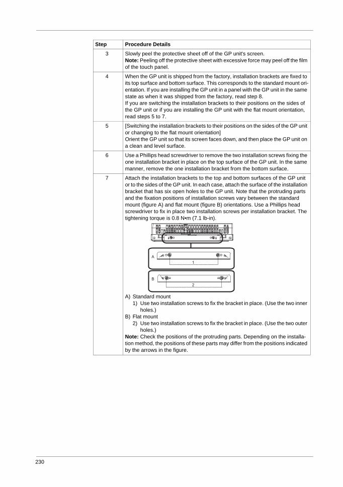
230
3 Slowly peel the protective sheet off of the GP unit's screen.Note: Peeling off the protective sheet with excessive force may peel off the film of the touch panel.
4 When the GP unit is shipped from the factory, installation brackets are fixed to its top surface and bottom surface. This corresponds to the standard mount ori-entation. If you are installing the GP unit in a panel with the GP unit in the same state as when it was shipped from the factory, read step 8.If you are switching the installation brackets to their positions on the sides of the GP unit or if you are installing the GP unit with the flat mount orientation, read steps 5 to 7.
5 [Switching the installation brackets to their positions on the sides of the GP unit or changing to the flat mount orientation]Orient the GP unit so that its screen faces down, and then place the GP unit on a clean and level surface.
6 Use a Phillips head screwdriver to remove the two installation screws fixing the one installation bracket in place on the top surface of the GP unit. In the same manner, remove the one installation bracket from the bottom surface.
7 Attach the installation brackets to the top and bottom surfaces of the GP unit or to the sides of the GP unit. In each case, attach the surface of the installation bracket that has six open holes to the GP unit. Note that the protruding parts and the fixation positions of installation screws vary between the standard mount (figure A) and flat mount (figure B) orientations. Use a Phillips head screwdriver to fix in place two installation screws per installation bracket. The tightening torque is 0.8 N•m (7.1 lb-in).
A) Standard mount1) Use two installation screws to fix the bracket in place. (Use the two inner
holes.)B) Flat mount
2) Use two installation screws to fix the bracket in place. (Use the two outer holes.)
Note: Check the positions of the protruding parts. Depending on the installa-tion method, the positions of these parts may differ from the positions indicated by the arrows in the figure.
Step Procedure Details
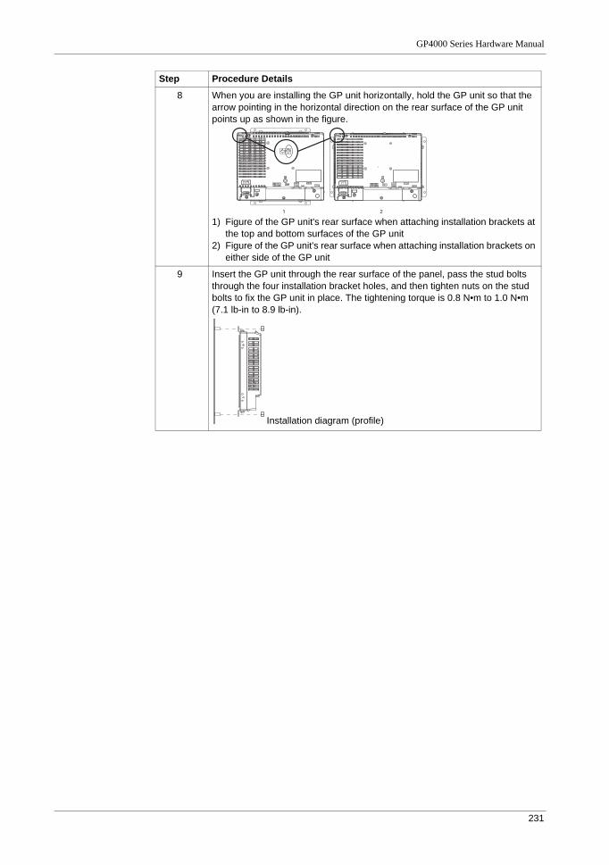
GP4000 Series Hardware Manual
231
8 When you are installing the GP unit horizontally, hold the GP unit so that the arrow pointing in the horizontal direction on the rear surface of the GP unit points up as shown in the figure.
1) Figure of the GP unit's rear surface when attaching installation brackets at the top and bottom surfaces of the GP unit
2) Figure of the GP unit's rear surface when attaching installation brackets on either side of the GP unit
9 Insert the GP unit through the rear surface of the panel, pass the stud bolts through the four installation bracket holes, and then tighten nuts on the stud bolts to fix the GP unit in place. The tightening torque is 0.8 N•m to 1.0 N•m (7.1 lb-in to 8.9 lb-in).
Step Procedure Details
Installation diagram (profile)
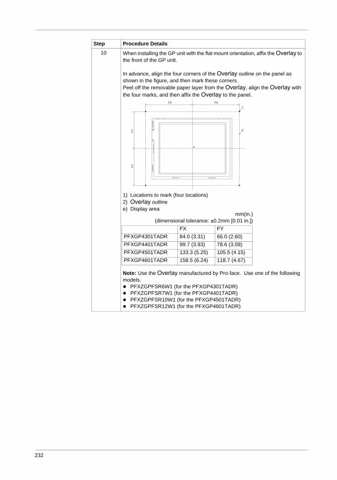
232
10 When installing the GP unit with the flat mount orientation, affix the Overlay to the front of the GP unit.
In advance, align the four corners of the Overlay outline on the panel as shown in the figure, and then mark these corners.Peel off the removable paper layer from the Overlay, align the Overlay with the four marks, and then affix the Overlay to the panel.
1) Locations to mark (four locations)2) Overlay outlinee) Display area
Note: Use the Overlay manufactured by Pro-face. Use one of the following models.
PFXZGPFSR6W1 (for the PFXGP4301TADR)PFXZGPFSR7W1 (for the PFXGP4401TADR)PFXZGPFSR10W1 (for the PFXGP4501TADR)PFXZGPFSR12W1 (for the PFXGP4601TADR)
Step Procedure Details
mm(in.)(dimensional tolerance: ±0.2mm [0.01 in.])
FX FYPFXGP4301TADR 84.0 (3.31) 66.0 (2.60)PFXGP4401TADR 99.7 (3.93) 78.6 (3.09)PFXGP4501TADR 133.3 (5.25) 105.5 (4.15)PFXGP4601TADR 158.5 (6.24) 118.7 (4.67)
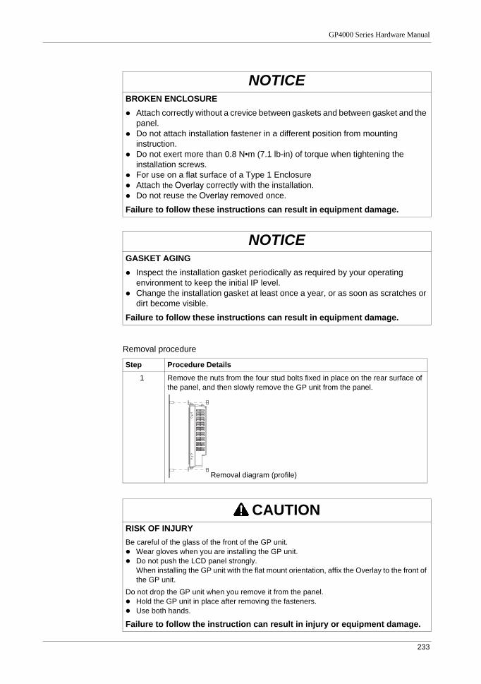
GP4000 Series Hardware Manual
233
Removal procedure
NOTICEBROKEN ENCLOSURE
Attach correctly without a crevice between gaskets and between gasket and the panel.Do not attach installation fastener in a different position from mounting instruction.Do not exert more than 0.8 N•m (7.1 lb-in) of torque when tightening the installation screws.For use on a flat surface of a Type 1 EnclosureAttach the Overlay correctly with the installation.Do not reuse the Overlay removed once.
Failure to follow these instructions can result in equipment damage.
NOTICEGASKET AGING
Inspect the installation gasket periodically as required by your operating environment to keep the initial IP level.Change the installation gasket at least once a year, or as soon as scratches or dirt become visible.
Failure to follow these instructions can result in equipment damage.
Step Procedure Details
1 Remove the nuts from the four stud bolts fixed in place on the rear surface of the panel, and then slowly remove the GP unit from the panel.
CAUTIONRISK OF INJURYBe careful of the glass of the front of the GP unit.
Wear gloves when you are installing the GP unit.Do not push the LCD panel strongly.When installing the GP unit with the flat mount orientation, affix the Overlay to the front of the GP unit.
Do not drop the GP unit when you remove it from the panel.Hold the GP unit in place after removing the fasteners.Use both hands.
Failure to follow the instruction can result in injury or equipment damage.
Removal diagram (profile)
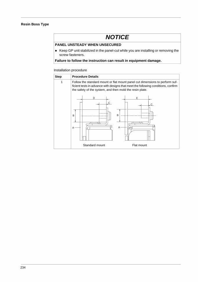
234
Resin Boss Type
Installation procedure
NOTICEPANEL UNSTEADY WHEN UNSECURED
Keep GP unit stabilized in the panel-cut while you are installing or removing the screw fasteners.
Failure to follow the instruction can result in equipment damage.
Step Procedure Details
1 Follow the standard mount or flat mount panel cut dimensions to perform suf-ficient tests in advance with designs that meet the following conditions, confirm the safety of the system, and then mold the resin plate.
Standard mount Flat mount
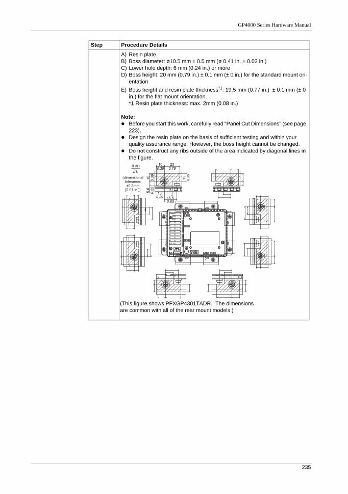
GP4000 Series Hardware Manual
235
A) Resin plateB) Boss diameter: ø10.5 mm ± 0.5 mm (ø 0.41 in. ± 0.02 in.)C) Lower hole depth: 6 mm (0.24 in.) or moreD) Boss height: 20 mm (0.79 in.) ± 0.1 mm (± 0 in.) for the standard mount ori-
entationE) Boss height and resin plate thickness*1: 19.5 mm (0.77 in.) ± 0.1 mm (± 0
in.) for the flat mount orientation*1 Resin plate thickness: max. 2mm (0.08 in.)
Note:Before you start this work, carefully read "Panel Cut Dimensions" (see page 223).Design the resin plate on the basis of sufficient testing and within your quality assurance range. However, the boss height cannot be changed.Do not construct any ribs outside of the area indicated by diagonal lines in the figure.
Step Procedure Details
C
mm
in.
10
0.39
20
0.79
10
0.39
10
0.39
5.6
0.22
10
0.39 16.5
0.65
(dimensional
tolerance:
±0.2mm
[0.01 in.])
(This figure shows PFXGP4301TADR. The dimensions are common with all of the rear mount models.)
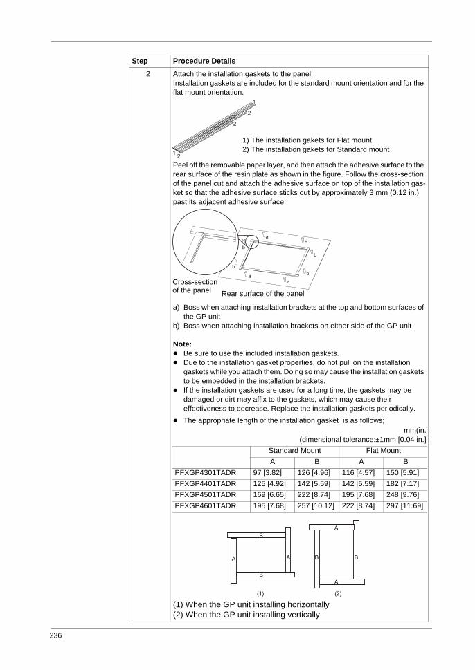
236
2 Attach the installation gaskets to the panel.Installation gaskets are included for the standard mount orientation and for the flat mount orientation.
Peel off the removable paper layer, and then attach the adhesive surface to the rear surface of the resin plate as shown in the figure. Follow the cross-section of the panel cut and attach the adhesive surface on top of the installation gas-ket so that the adhesive surface sticks out by approximately 3 mm (0.12 in.) past its adjacent adhesive surface.
a) Boss when attaching installation brackets at the top and bottom surfaces of the GP unit
b) Boss when attaching installation brackets on either side of the GP unit
Note:Be sure to use the included installation gaskets.Due to the installation gasket properties, do not pull on the installation gaskets while you attach them. Doing so may cause the installation gaskets to be embedded in the installation brackets.If the installation gaskets are used for a long time, the gaskets may be damaged or dirt may affix to the gaskets, which may cause their effectiveness to decrease. Replace the installation gaskets periodically.The appropriate length of the installation gasket is as follows;
(1) When the GP unit installing horizontally(2) When the GP unit installing vertically
Step Procedure Details
1) The installation gakets for Flat mount2) The installation gakets for Standard mount
Rear surface of the panelCross-section of the panel
mm(in.)(dimensional tolerance:±1mm [0.04 in.])
Standard Mount Flat MountA B A B
PFXGP4301TADR 97 [3.82] 126 [4.96] 116 [4.57] 150 [5.91]PFXGP4401TADR 125 [4.92] 142 [5.59] 142 [5.59] 182 [7.17]PFXGP4501TADR 169 [6.65] 222 [8.74] 195 [7.68] 248 [9.76]PFXGP4601TADR 195 [7.68] 257 [10.12] 222 [8.74] 297 [11.69]
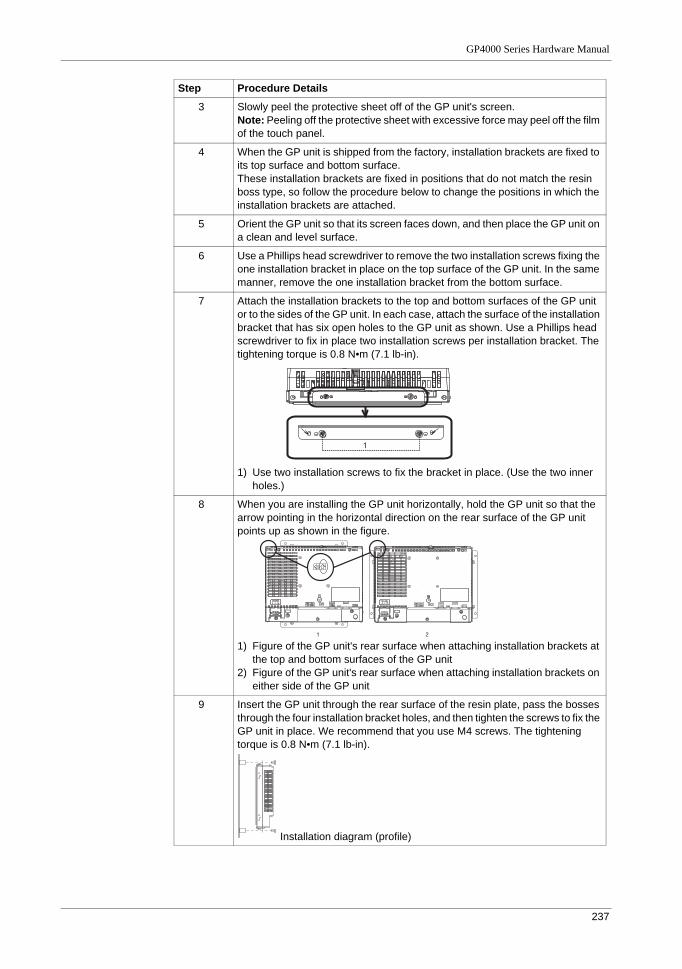
GP4000 Series Hardware Manual
237
3 Slowly peel the protective sheet off of the GP unit's screen.Note: Peeling off the protective sheet with excessive force may peel off the film of the touch panel.
4 When the GP unit is shipped from the factory, installation brackets are fixed to its top surface and bottom surface.These installation brackets are fixed in positions that do not match the resin boss type, so follow the procedure below to change the positions in which the installation brackets are attached.
5 Orient the GP unit so that its screen faces down, and then place the GP unit on a clean and level surface.
6 Use a Phillips head screwdriver to remove the two installation screws fixing the one installation bracket in place on the top surface of the GP unit. In the same manner, remove the one installation bracket from the bottom surface.
7 Attach the installation brackets to the top and bottom surfaces of the GP unit or to the sides of the GP unit. In each case, attach the surface of the installation bracket that has six open holes to the GP unit as shown. Use a Phillips head screwdriver to fix in place two installation screws per installation bracket. The tightening torque is 0.8 N•m (7.1 lb-in).
1) Use two installation screws to fix the bracket in place. (Use the two inner holes.)
8 When you are installing the GP unit horizontally, hold the GP unit so that the arrow pointing in the horizontal direction on the rear surface of the GP unit points up as shown in the figure.
1) Figure of the GP unit's rear surface when attaching installation brackets at the top and bottom surfaces of the GP unit
2) Figure of the GP unit's rear surface when attaching installation brackets on either side of the GP unit
9 Insert the GP unit through the rear surface of the resin plate, pass the bosses through the four installation bracket holes, and then tighten the screws to fix the GP unit in place. We recommend that you use M4 screws. The tightening torque is 0.8 N•m (7.1 lb-in).
Step Procedure Details
Installation diagram (profile)
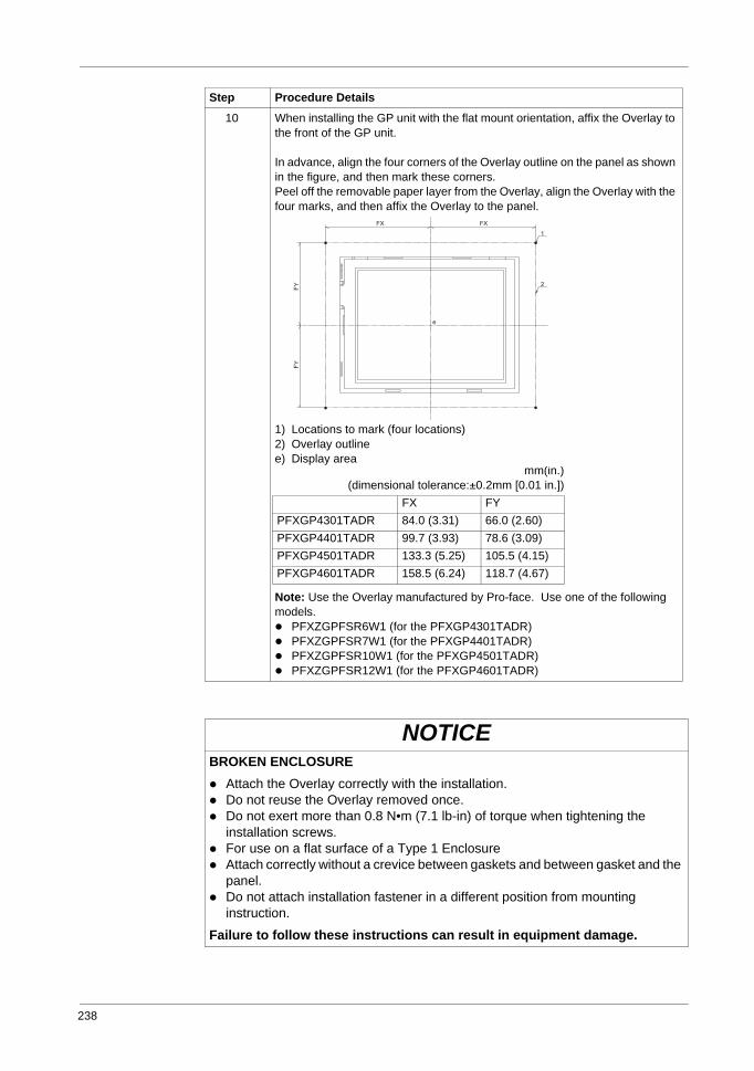
238
10 When installing the GP unit with the flat mount orientation, affix the Overlay to the front of the GP unit.
In advance, align the four corners of the Overlay outline on the panel as shown in the figure, and then mark these corners.Peel off the removable paper layer from the Overlay, align the Overlay with the four marks, and then affix the Overlay to the panel.
1) Locations to mark (four locations)2) Overlay outlinee) Display area
Note: Use the Overlay manufactured by Pro-face. Use one of the following models.
PFXZGPFSR6W1 (for the PFXGP4301TADR)PFXZGPFSR7W1 (for the PFXGP4401TADR)PFXZGPFSR10W1 (for the PFXGP4501TADR)PFXZGPFSR12W1 (for the PFXGP4601TADR)
NOTICEBROKEN ENCLOSURE
Attach the Overlay correctly with the installation.Do not reuse the Overlay removed once. Do not exert more than 0.8 N•m (7.1 lb-in) of torque when tightening the installation screws.For use on a flat surface of a Type 1 EnclosureAttach correctly without a crevice between gaskets and between gasket and the panel.Do not attach installation fastener in a different position from mounting instruction.
Failure to follow these instructions can result in equipment damage.
Step Procedure Details
mm(in.)(dimensional tolerance:±0.2mm [0.01 in.])
FX FYPFXGP4301TADR 84.0 (3.31) 66.0 (2.60)PFXGP4401TADR 99.7 (3.93) 78.6 (3.09)PFXGP4501TADR 133.3 (5.25) 105.5 (4.15)PFXGP4601TADR 158.5 (6.24) 118.7 (4.67)
GP4000 Series Hardware Manual
239
NOTICEGASKET AGING
Inspect the installation gasket periodically as required by your operating environment to keep the initial IP level.Change the installation gasket at least once a year, or as soon as scratches or dirt become visible.
Failure to follow these instructions can result in equipment damage.
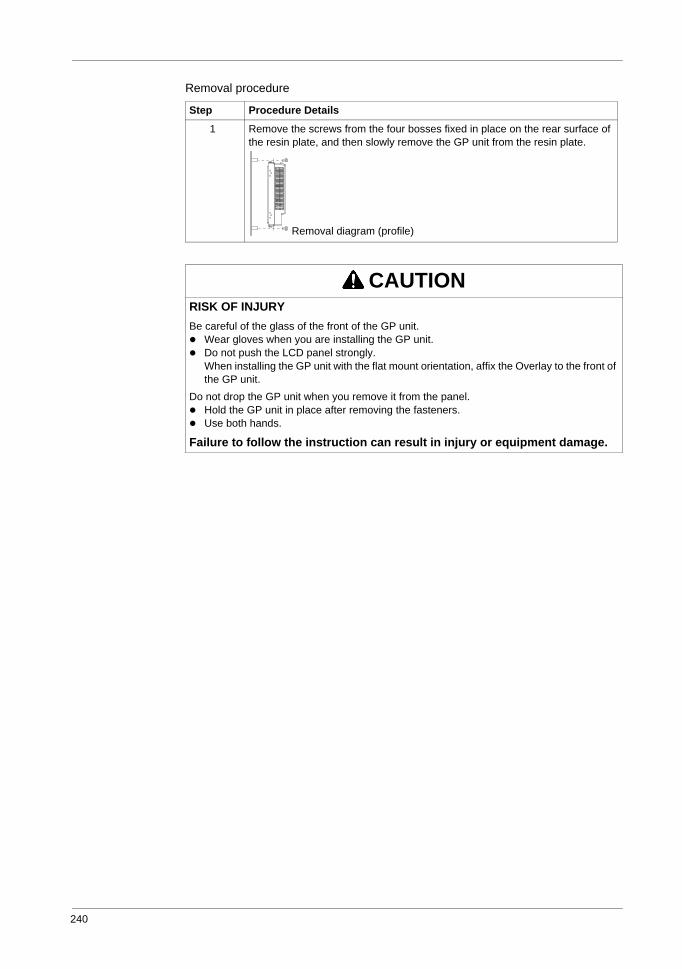
240
Removal procedure
Step Procedure Details
1 Remove the screws from the four bosses fixed in place on the rear surface of the resin plate, and then slowly remove the GP unit from the resin plate.
CAUTIONRISK OF INJURYBe careful of the glass of the front of the GP unit.
Wear gloves when you are installing the GP unit.Do not push the LCD panel strongly.When installing the GP unit with the flat mount orientation, affix the Overlay to the front of the GP unit.
Do not drop the GP unit when you remove it from the panel.Hold the GP unit in place after removing the fasteners.Use both hands.
Failure to follow the instruction can result in injury or equipment damage.
Removal diagram (profile)
All trademarks are the property of Schneider Electric SE, its subsidiaries, and affiliated companies.
Todas las marcas comerciales son propiedad de Schneider Electric SE, sus filiales y compañías afiliadas.
Toutes les marques commerciales sont la propriété de Schneider Electric SE, ses filiales et compagnies affiliées.
Schneider Electric USA, Inc.800 Federal StreetAndover, MA 01810 USA888-778-2733www.schneider-electric.us
Importado en México por:Schneider Electric México, S.A. de C.V.Av. Ejercito Nacional No. 904Col. Palmas, Polanco 11560 México, D.F.55-5804-5000www.schneider-electric.com.mx
Schneider Electric Canada, Inc.5985 McLaughlin RoadMississauga, ON L5R 1B8 Canada800-565-6699www.schneider-electric.ca
PHA9947808/2018
California Proposition 65 Warning—Lead and Lead Compounds Advertencia de la Proposición 65 de California—Plomo y compuestos de plomo Avertissement concernant la Proposition 65 de Californie—Plomb et composés de plomb
Addendum Anexo Annexe
© 2018 Schneider Electric All Rights Reserved / Reservados todos los derechos / Tous droits réservés
WARNING: This product can expose you to chemicals including lead and lead compounds, which are known to the State of California to cause cancer and birth defects or other reproductive harm. For more information go to: www.P65Warnings.ca.gov.
ADVERTENCIA: Este producto puede exponerle a químicos incluyendo plomo y compuestos de plomo, que es (son) conocido(s) por el Estado de California como causante(s) de cáncer y defectos de nacimiento u otros daños reproductivos. Para mayor información, visite : www.P65Warnings.ca.gov.
AVERTISSEMENT: Ce produit peut vous exposer à des agents chimiques, y compris plomb et composés de plomb, identifiés par l'État de Californie comme pouvant causer le cancer et des malformations congénitales ou autres troubles de l’appareil reproducteur. Pour de plus amples informations, prière de consulter: www.P65Warnings.ca.gov.