glleeennndddiiinnnnnniiinnngg - cablemaster - shop
TRANSCRIPT
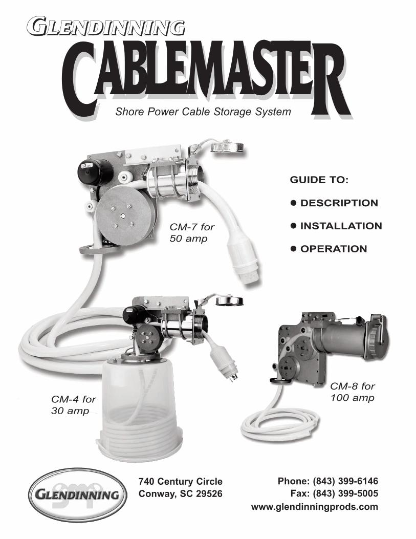
GUIDE TO:
!! DESCRIPTION
!! INSTALLATION
!! OPERATION
740 Century CircleConway, SC 29526
Phone: (843) 399-6146Fax: (843) 399-5005
www.glendinningprods.com
GGGGLLLLEEEENNNNDDDDIIIINNNNNNNNIIIINNNNGGGG
CCABLEMASTEABLEMASTERRShore Power Cable Storage System
SML-CMMANPRINT DATE: 06/08
740 CENTURY CIRCLECONWAY, SC 29526-8274USA
PRODUCT WARRANTY INFORMATION
PLACESTAMPHERE
CM-7 for 50 amp
CM-4 for 30 amp
CM-8 for 100 amp
Diameter 3-5/8"cut on outsideof line
Diameter 17/64" 4 Plcs.
Hawse Pipe Template

1
THANK YOU... PAGE 1
INTRODUCTION PAGE 1
GETTING TO KNOW YOUR CABLEMASTER PAGE 2
INSTALLATION OVERVIEW PAGE 3
Location for Power Unit & Cable PAGE 3
Hawse Pipe & Cable Plug Exit PAGE 3
Connection to Electrical System PAGE 3
TYPES OF INSTALLATIONS PAGE 4
INSTALLATION INSTRUCTIONS PAGE 5
WIRING INSTRUCTIONS PAGE 6
POWER CABLE INSTALLATION PAGE 8
CABLE ADJUSTMENT PAGE 8
AC WIRING INSTRUCTIONS PAGE 9
MAINTENANCE PAGE 9
OPERATION OF CABLEMASTER PAGE 10
TROUBLESHOOTING GUIDE PAGE 10
CABLEMASTER DIMENSIONS PAGE 11
CABLEMASTER WIRING DIAGRAM PAGE 15
CABLEMASTER ACCESSORIES PAGE 17
for buying the Glendinning Cablemaster. AtGlendinning, we are committed to providing you, ourcustomer, with a product that will yield trouble-freeservice. Care has been taken during each phase of themanufacturing process to guarantee a lifetime of qual-ity and performance—after all, our name is on it!
Paul & John Glendinning
Welcome to the Glendinning family of quality marineproducts. Your new Cablemaster carries the same assur-ance of quality that has stood behind every product fromGlendinning Marine Products for over 30 years—we’reproud of our reputation for quality products and service.
While installation on most boats is straight forwardand easy, for those perplexing situations, nothing beats aqualified marine electrician. Using common sense aboutsafety and a sound mechanical approach during theinstallation, the Cablemaster will provide many hours oftrouble-free service.
All Cablemasters have been designed to pay out andretract shore power cables without overloading the motorwithin the system’s power unit. Properly adjusted, aCablemaster will drag 75 feet (maximum) of shore powercable without slippage.
The Cablemaster consists of two major components;the hawse pipe and power unit. The chromed hawsepipe is designed to accommodate varying sizes of shorepower cables with the attached 30 or 50amp shorepower plug cover. Within the hawse pipe, a neoprenegasket/wiper prevents the entrance of water and helpsclean the cable as it is retracted into the boat. When thecable is retracted completely, the plug cover actuates thein-limit switch which is mounted on the face of the gasketplate inside the hawse pipe.
The drive motor, reduction gearing, guide rollerassembly and the relay assembly comprise the powerunit. The power unit is connected to the hawse pipe witha hawse pipe clamp and a length of extruded aluminumangle. The hawse pipe clamp allows the power unit to beangled to either side of vertical directing the shore powercable toward the storage compartment. The main pulleyof the Cablemaster is also freewheeling which allows thecable to be manually payed in or out.
The out-limit switch is located in the guide rollerassembly. The nylon safety collar, which is installedaround the shore power cable, activates the out-limitswitch. This collar also serves as a mechanical stoppingdevice should the limit switch fail or should the shorepower cable be forcibly pulled outward.
TABLE OF CONTENTS
THANK YOU...
INTRODUCTION
In preparing this manual, Glendinning Marine Products, Inc. has reliedupon the standards established by the National Electric Code and therecommended practices and standards for AC electrical systems forvessels prepared by the American Boat and Yacht Council, Inc. This
manual reflects practices and standards in effect at the time of publica-tion and is intended only as a guide to understand the Cablemaster.
Glendinning Marine Products, Inc. will not be liable for any loss, dam-age, incidental or consequential damages of any kind, arising in con-
nection with the use or reliance upon this manual.
ATTENTION:
18
Please take a moment to validate your product warranty by mailing in this card with the proper information.
FOLLOW THESE SIMPLE STEPS :
STEP 1: Fill in the registration card.STEP 2: Cut along dotted line.STEP 3: Affix correct postage.STEP 4: Drop in mailbox.
_______________________________________________________________________NAME
_______________________________________________________________________ADDRESS
_______________________________________________________________________CITY STATE ZIP
_______________________________________________________________________COUNTRY PHONE EMAIL
_________________________________________BOAT MODEL & YEAR OF MANUFACTURE
_________________________________________CABLEMASTER SERIAL NUMER
_______________________________________________________WHAT WOULD YOU LIKE TO SEE IMPROVED / CHANGED? THANK YOU!
CABLEMASTER WARRANTY REGISTRATION
WOULD YOU LIKE TO RECEIVE INFO ONNEW PRODUCTS FROM GLENDINNING?
YES NO
CABLEMASTER PRODUCT REGISTRATIONO
DANGER: ELECTRICAL CORD REELS CAN BE HAZARDOUS. MISUSE CAN RESULT IN FIRE OR DEATH BY ELEC-TRICAL SHOCK. PLEASE READ CAREFULLY AND FOLLOW INSTRUCTIONS:
HAZARDS STATEMENTN
OR SEND VIA FAX TO:
(843) 399-5005
!
"A cord reel marked for indoor use is to be used indoors only.
"Inspect thoroughly before each use. DO NOT USE if damaged.
"Look for the number of watts or amperes on appliances to be
plugged into cord reel.
"See label on cord reel for specific watts or amperes.
"DO NOT plug more than the specified number of watts or
amperes into this cord reel.
"DO NOT run through doorways, holes in ceilings, walls or floors.
"Make sure appliance is OFF before connecting cord reel to outlet.
"FULLY INSERT plug into outlet.
"DO NOT remove, bend or modify any metal prongs or pins of cord
reel.
"DO NOT use excessive force to make connections.
"DO NOT connect a three-prong plug to a two-prong cord reel.
"Keep away from water.
"DO NOT USE WHEN WET.
"Keep children and pets away from cord reel.
"DO NOT plug one cord reel into another.
"AVOID OVERHEATING.
"DO NOT cover with any materials.
"DO NOT drive, drag, or place objects over cord.
"DO NOT walk on cord.
"GRASP PLUG to remove from outlet.
"Always store cord reels INDOORS.
"Always unplug when not in use.
"DO NOT unplug by pulling on cord.
THIS IS A POLARIZED CORD REEL
2
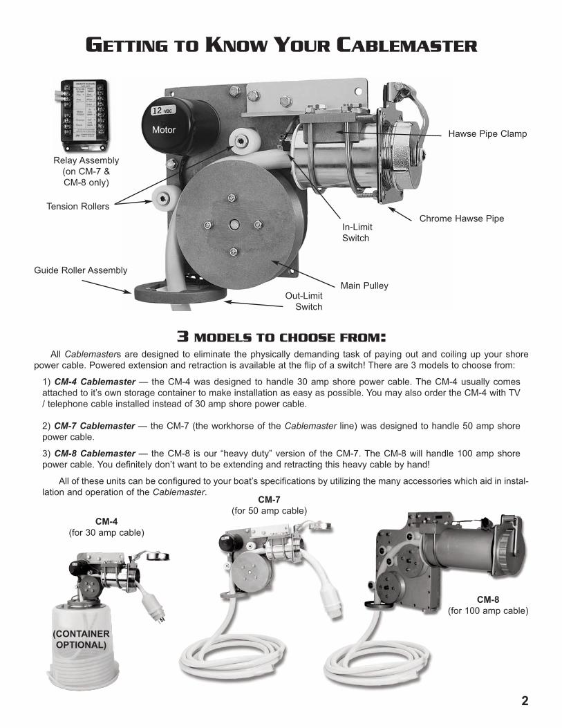
GETTING TO KNOW YOUR CABLEMASTER
Guide Roller Assembly
Chrome Hawse Pipe
Hawse Pipe Clamp
In-LimitSwitch
Relay Assembly(on CM-7 & CM-8 only)
Tension Rollers
Out-LimitSwitch
Main Pulley
CM-4(for 30 amp cable)
17
3 MODELS TO CHOOSE FROM:
Motor
All Cablemasters are designed to eliminate the physically demanding task of paying out and coiling up your shorepower cable. Powered extension and retraction is available at the flip of a switch! There are 3 models to choose from:
1) CM-4 Cablemaster — the CM-4 was designed to handle 30 amp shore power cable. The CM-4 usually comesattached to it’s own storage container to make installation as easy as possible. You may also order the CM-4 with TV/ telephone cable installed instead of 30 amp shore power cable.
2) CM-7 Cablemaster — the CM-7 (the workhorse of the Cablemaster line) was designed to handle 50 amp shorepower cable.
3) CM-8 Cablemaster — the CM-8 is our “heavy duty” version of the CM-7. The CM-8 will handle 100 amp shorepower cable. You definitely don’t want to be extending and retracting this heavy cable by hand!
All of these units can be configured to your boat’s specifications by utilizing the many accessories which aid in instal-lation and operation of the Cablemaster.
CM-8(for 100 amp cable)
CABLEMASTER ACCESSORIESM
PART NUMBER
9400494008940059400794006
99408994099941099415
DESCRIPTION
SHORE POWER CABLE — power cable sold in bulk.6/3 Yellow Jacket Cable — 50 amp 125 volt6/3 White Jacket Cable — 50 amp 125 volt6/4 Yellow Jacket Cable — 50 amp 125/250 volt6/4 White Jacket Cable — 50 amp 125/250 volt10/3 Yellow Jacket Cable — 30 amp 125 voltSHORE POWER PLUGS AND COVERS — Marinco brand50 amp 125/250 volt Shore Power Cable Plug — 6365CR50 amp 125 volt Shore Power Cable Plug — 6361CR50 amp Shore Power Cable plug cover — Yellow50 amp Shore Power Cable plug cover — White
04146041470415304034
RADIO REMOTE CONTROL OPTION — this option allows the remoteoperation of the Cablemaster unit.
Radio Remote Control Kit - includes 2 transmitters!Spare / replacement transmitterRF Noise Filter - improves operational range of transmitterRelay Unit - required for addition of Remote on CM-4 models
85448854248542085421
POWER CABLE STORAGE CONTAINERS — rotationally molded styrenecontainers used to store shore power cord.
16” diameter x 13” height — approx. capacity of 40’ of cable18” diameter x 18” height — approx. capacity of 55’ of cable20” diameter x 18” height — approx. capacity of 75’ of cable22” diameter x 15” height — approx. capacity of 75’ of cable
04043
04044
04062—30º04064—60º04066—90º
04063—120º04067—150º04065—180º
04045
INSTALLATION ACCESSORIES — these accessories are used to aid ininstallation of the Cablemaster unit.
Horizontal Pipe Extension kit — allows Power Unit to be extend-ed away from the Hawse Pipe
Vertical Pipe Extension kit — allows the Power Unit to be extend-ed away from the cable storage area
Angling Assemblies — used to direct the cable from 30 degree -180 degree bends (in increments of 30 degrees)
Pipe tp Pipe Angling Assembly — used with the Vertical PipeExtension kit for angling the 3” PVC pipe to a desired angle
Stop Collar
(CONTAINEROPTIONAL)
CM-7(for 50 amp cable)
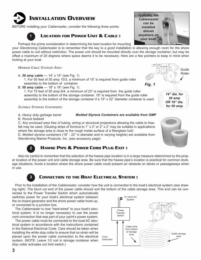
BEFORE installing your Cablemaster, consider the following three points:
LOCATION FOR POWER UNIT & CABLE :
Perhaps the prime consideration in determining the best location for mountingyour Glendinning Cablemaster is to remember that the key to a good installation is allowing enough room for the shorepower cable to coil without restriction. The power unit should be mounted directly over the storage container, but may beoffset a maximum of 20 degrees where space deems it to be necessary. Here are a few pointers to keep in mind whenlooking at your boat.
MINIMUM CABLE STORAGE AREA:
A. 30 amp cable — 14” x 14” (see Fig. 1)1. For 50 feet of 30 amp 10/3, a minimum of 15” is required from guide roller assembly to the bottom of container.
B. 50 amp cable — 18” x 18” (see Fig. 1)1. For 75 feet of 50 amp 6/4, a minimum of 23” is required from the guide rollerassembly to the bottom of the storage container. 18” is required from the guide rollerassembly to the bottom of the storage container if a 15” x 22” diameter container is used.
SUITABLE STORAGE CONTAINERS:
A. Heavy duty garbage barrelB. Round baitwellC. Any enclosed area free of tubing, wiring or structural projections allowing the cable to free-fall may be used. (Glueing strips of formica to 1” x 2” or 2” x 2” may be suitable in applications where the storage area is close to the rough inside surface of a fiberglass hull)D. Molded styrene containers (18” - 22” in diameter and in varying heights) are available from Glendinning Marine Products, Inc. (see accessory page)
HAWSE PIPE & POWER CORD PLUG EXIT :
Also be careful to remember that the selection of the hawse pipe location is in a large measure determined by the prop-er location of the power unit and cable storage area. Be sure that the hawse pipe’s location is practical for common dock-age situations. Avoid a location where the shore power cable could present an obstacle on decks or passageways whenin use.
CONNECTION TO THE BOAT ELECTRICAL SYSTEM :
Prior to the installation of the Cablemaster, consider how the unit is connected to the boat’s electrical system (see draw-ing right). The blunt cut end of the power cable should exit the bottom of the cable storage area. This end can be con-nected to the Power Transfer Switch which automaticallyswitches power for your boat’s electrical system betweenthe on-board generator and the shore power cable hook-up,or connected to a junction box.
The Cablemaster is now “hard-wired” to your boat’s elec-trical system. It is no longer necessary to use the powercord connection that was part of your yacht’s power system.
The power cable must be connected to the boat AC elec-trical system in accordance with the instructions containedin the National Electrical Code. Care should be taken wheninstalling the white stop collar to ensure that no strain will beplaced upon the power cable connection to the electricalsystem. (NOTE: Leave 1/2 coil in storage container whenstop collar activates out limit switch.)
3
INSTALLATION OVERVIEWA
1
2
3
Typically, theCablemaster
can beinstalledalmost
anywhere onyour boat!
16
PowerTransferSwtich
Cable exitsfrom bottomof storage
areaFrom Generator
To Yacht ACSystem
WARRANTY
PRODUCT COVERED BY THIS LIMITED WARRANTY: CABLEMASTER
1. GLENDINNING MARINE PRODUCTS, INC. warrants to the original consumer purchaser that the Cablemaster will be
free from defects in material and workmanship under normal use and service for a period of one (1) year from the date of pur-
chase.
2. This LIMITED WARRANTY applies to defects in material and workmanship. It does not apply to chromeplated or anodized
finish or to power cable damage caused by inadequate cable storage area or installation not in accordance with GLENDIN-
NING MARINE PRODUCTS, INC. specifications.
3. This LIMITED WARRANTY is void if the product has been damaged by accident or unreasonable use, neglect, improper
installation, or other causes not arising out of defects in material or workmanship.
4. To obtain performance of this LIMITED WARRANTY obligation the original purchaser should contact GLENDINNING
MARINE PRODUCTS, INC. for instructions concerning removal and shipping of the defective component. Upon compliance of
the foregoing procedure all warranted defects will be repaired, or at GLENDINNING MARINE PRODUCTS, INC. option, the
complete unit replaced and returned to the consumer, shipping charges prepaid.
5. GLENDINNING MARINE PRODUCTS, INC. does not assume the costs of removal and/or installation of the product or any
other incidental costs which may arise as a result of any defect in materials or workmanship.
THIS WARRANTY IS IN LIEU OF ALL OTHER EXPRESS WARRANTIES. ANY WARRANTY IMPLIED BY LAW INCLUDING WAR-
RANTIES OF MERCHANTABILITY OR FITNESS, IS IN EFFECT ONLY FOR THE DURATION OF THE EXPRESS WARRANTIES
SET FORTH IN THE FIRST PARAGRAPH ABOVE. NO REPRESENTATIVE OR PERSON IS AUTHORIZED TO GIVE ANY OTHER
WARRANTY OR TO ASSUME FOR GLENDINNING MARINE PRODUCTS, INC. ANY OTHER LIABILITY IN CONNECTION WITH
THE SALE OF IT’S PRODUCTS. GLENDINNING MARINE PRODUCTS, INC. WILL NOT BE LIABLE FOR ANY CONSEQUEN-
TIAL DAMAGES RESULTING FROM THE USE OR INSTALLATION OF IT’S PRODUCTS.
14” dia. for30 amp
OR 18” dia.for 50 amp
Fig. 1
Molded Styrene Containers are available from GMP
Guide Roller
Cable storagearea
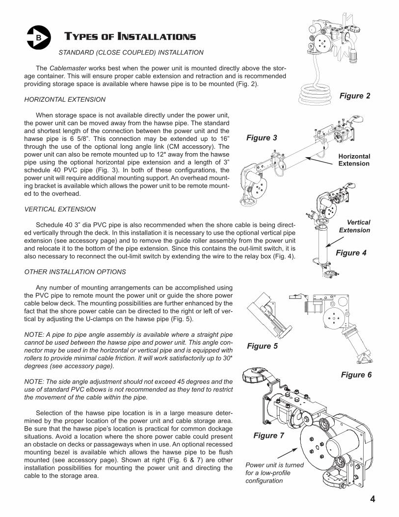
TYPES OF INSTALLATIONS
STANDARD (CLOSE COUPLED) INSTALLATION
The Cablemaster works best when the power unit is mounted directly above the stor-age container. This will ensure proper cable extension and retraction and is recommendedproviding storage space is available where hawse pipe is to be mounted (Fig. 2).
HORIZONTAL EXTENSION
When storage space is not available directly under the power unit,the power unit can be moved away from the hawse pipe. The standardand shortest length of the connection between the power unit and thehawse pipe is 6 5/8”. This connection may be extended up to 16”through the use of the optional long angle link (CM accessory). Thepower unit can also be remote mounted up to 12* away from the hawsepipe using the optional horizontal pipe extension and a length of 3”schedule 40 PVC pipe (Fig. 3). In both of these configurations, thepower unit will require additional mounting support. An overhead mount-ing bracket is available which allows the power unit to be remote mount-ed to the overhead.
VERTICAL EXTENSION
Schedule 40 3” dia PVC pipe is also recommended when the shore cable is being direct-ed vertically through the deck. In this installation it is necessary to use the optional vertical pipeextension (see accessory page) and to remove the guide roller assembly from the power unitand relocate it to the bottom of the pipe extension. Since this contains the out-limit switch, it isalso necessary to reconnect the out-limit switch by extending the wire to the relay box (Fig. 4).
OTHER INSTALLATION OPTIONS
Any number of mounting arrangements can be accomplished usingthe PVC pipe to remote mount the power unit or guide the shore powercable below deck. The mounting possibilities are further enhanced by thefact that the shore power cable can be directed to the right or left of ver-tical by adjusting the U-clamps on the hawse pipe (Fig. 5).
NOTE: A pipe to pipe angle assembly is available where a straight pipecannot be used between the hawse pipe and power unit. This angle con-nector may be used in the horizontal or vertical pipe and is equipped withrollers to provide minimal cable friction. It will work satisfactorily up to 30*degrees (see accessory page).
NOTE: The side angle adjustment should not exceed 45 degrees and theuse of standard PVC elbows is not recommended as they tend to restrictthe movement of the cable within the pipe.
Selection of the hawse pipe location is in a large measure deter-mined by the proper location of the power unit and cable storage area.Be sure that the hawse pipe’s location is practical for common dockagesituations. Avoid a location where the shore power cable could presentan obstacle on decks or passageways when in use. An optional recessedmounting bezel is available which allows the hawse pipe to be flushmounted (see accessory page). Shown at right (Fig. 6 & 7) are otherinstallation possibilities for mounting the power unit and directing thecable to the storage area.
4
B
15
Red 1
White 2
Black 3
PowerSwitch
Pos. +
Neg. -
12 / 24v DC Input
Motor Output
CABLEMASTER RELAY ASSEMBLY # 04034 (12, 24 volt DC)
12v DC use 20 amp breaker24v DC use 5 amp breaker
OUT OUT LimitSwitchSwitch
(Remote - RED)
(Remote - BLACK)
Orange
Black
GLENDINNING MARINE PRODUCTS, INC. Conway, SC 843-399-6146
4 4
5 5
6
7
IN LimitSwitch
(Rmt - Green or Tan)
(Rmt - Yellow or Purple)
ORANGE
BLACK
OFFOUT
INPOWERSWITCH
REDWHITE
BLACK
IN-LIMITSWITCH
OUT-LIMITSWITCH
M12!or!24vMOTOR
BATERY!POSITIVE!(+)
BATTERY!NEGATIVE!(-)
WHITE
RED
BLACK
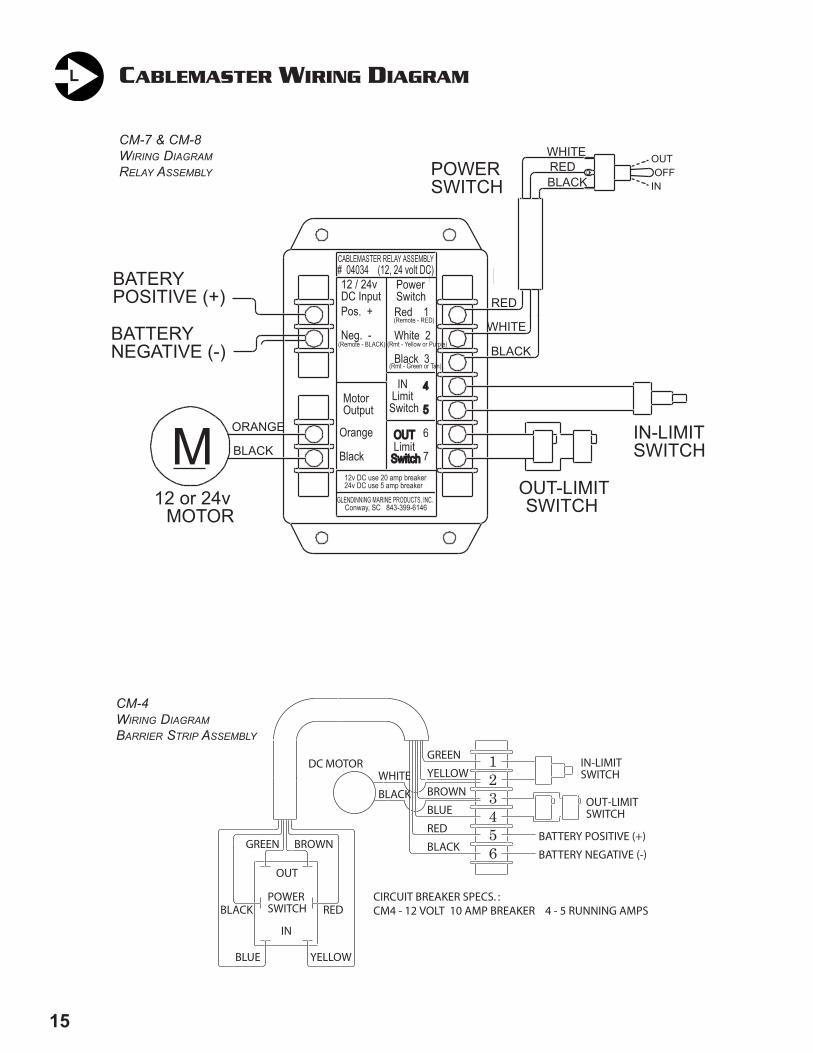
CABLEMASTER WIRING DIAGRAML
Figure 2
HorizontalExtension
CM-7 & CM-8WIRING DIAGRAMRELAY ASSEMBLY
VerticalExtension
Figure 4
Figure 5
Figure 6
Figure 7
Figure 3
123456
IN-LIMITSWITCH
OUT-LIMITSWITCH
BATTERY POSITIVE (+)
BATTERY NEGATIVE (-)
GREEN
YELLOW
BROWN
BLUE
BLACK
RED
CIRCUIT BREAKER SPECS. :CM4 - 12 VOLT 10 AMP BREAKER 4 - 5 RUNNING AMPS
BLACK
WHITEDC MOTOR
BROWN
OUT
GREEN
POWERSWITCH
IN
BLACK RED
YELLOWBLUE
CM-4WIRING DIAGRAMBARRIER STRIP ASSEMBLY
Power unit is turnedfor a low-profileconfiguration
145
INSTALLATION INSTRUCTIONS
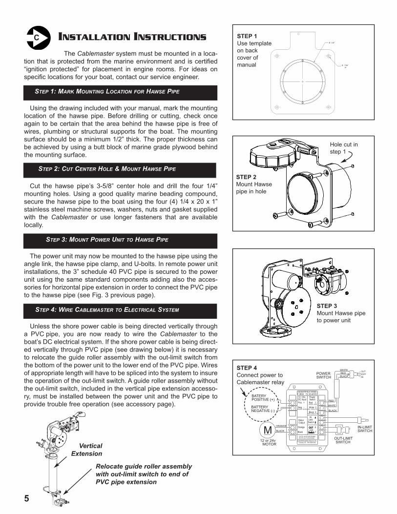
The Cablemaster system must be mounted in a loca-tion that is protected from the marine environment and is certified“ignition protected” for placement in engine rooms. For ideas onspecific locations for your boat, contact our service engineer.
Using the drawing included with your manual, mark the mountinglocation of the hawse pipe. Before drilling or cutting, check onceagain to be certain that the area behind the hawse pipe is free ofwires, plumbing or structural supports for the boat. The mountingsurface should be a minimum 1/2” thick. The proper thickness canbe achieved by using a butt block of marine grade plywood behindthe mounting surface.
Cut the hawse pipe’s 3-5/8” center hole and drill the four 1/4”mounting holes. Using a good quality marine beading compound,secure the hawse pipe to the boat using the four (4) 1/4 x 20 x 1”stainless steel machine screws, washers, nuts and gasket suppliedwith the Cablemaster or use longer fasteners that are availablelocally.
The power unit may now be mounted to the hawse pipe using theangle link, the hawse pipe clamp, and U-bolts. In remote power unitinstallations, the 3” schedule 40 PVC pipe is secured to the powerunit using the same standard components adding also the acces-sories for horizontal pipe extension in order to connect the PVC pipeto the hawse pipe (see Fig. 3 previous page).
Unless the shore power cable is being directed vertically througha PVC pipe, you are now ready to wire the Cablemaster to theboat’s DC electrical system. If the shore power cable is being direct-ed vertically through PVC pipe (see drawing below) it is necessaryto relocate the guide roller assembly with the out-limit switch fromthe bottom of the power unit to the lower end of the PVC pipe. Wiresof appropriate length will have to be spliced into the system to insurethe operation of the out-limit switch. A guide roller assembly withoutthe out-limit switch, included in the vertical pipe extension accesso-ry, must be installed between the power unit and the PVC pipe toprovide trouble free operation (see accessory page).
CØ 3 5/8"
x4Ø 17/64"
HINGE
65002
SPACERS
HAW
SE F
LANGE
70427
HINGE BO
LT74410
ACORN
NUT
04800
POWER
SWITCH
ASSEM
BLY
(incl. switch,
cover, 3ft.
wire)
85414
LIP RO
LLER
50416
PULLEY
- INSIDE HAL
F
50417
PULLEY
- OUTSIDE HAL
F
50416
OFFSET PLATE
(included
with
04046 assy.)
04046
GUIDE RO
LLER
ASSEM
BLY
(incl. guide, rollers
4X,
offset
plate)
75412
#9 WOODRU
FF KEY
50005
CONNECTOR
LINK
50421
HAW
SE PIPE C
LAMP
04053
HAW
SE PIPE C
LAMP ASSY.
04050
HAW
SE PIPE ASSEMBLY
(incl. hawse
pipe with
flange,
hinge, cap)
04051
HINGE & CAP
ASSEM
BLY
50421
HINGE
50420
CAP
RELAY
ASSEM
BLY
04034 -- 12
/ 24
VO
LTS
70005
U-BO
LT (2X)
65001
Spacer
50415
CHASSIS COVER
50414
CHASSIS
04812
IN-LIMIT
SWITCH
ASSY.
(incl. switch,
2 ft. wire
assy.,
protective boot)
04830
IN-LIMIT
SWITCH
ASSY.
(incl. hawse
pipe ring)
86402
CAP
GASKET
60001
HAW
SEPIPE
RING
86403
HAW
SEPIPE
GASKET
70432
ALLEN
SCREW
04824
OUTLIMIT
SWITCH
ASSEM
BLY
(incl. (2)
switches,
2 ft. wire
assy.)87404
CHASSIS GASKET
MOTOR
ASSEM
BLY
(incl. drive gear
and
mounting screws)
04035 -- 12
VO
LTS
04036 -- 24
VO
LTS
86401
HAW
SE PIPE
GASKET
04051
CAP
& HINGE
ASSEMBLY90004
POWER
SWITCH
COVER
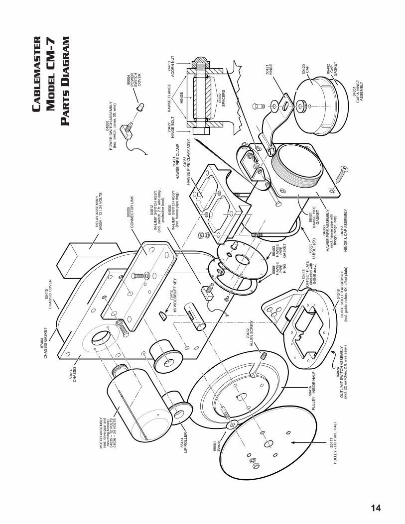
CableMaster
Model
CM7
Parts
Diagram
Glendinning
Marine Products, Inc.
STEP 1Use templateon backcover ofmanual
STEP 2Mount Hawsepipe in hole
Hole cut instep 1
STEP 3Mount Hawse pipeto power unit
Red 1
White 2
Black 3
PowerSwitch
Pos. +
Neg. -
12 / 24v DC Input
Motor Output
CABLEMASTER RELAY ASSEMBLY # 04034 (12, 24 volt DC)
12v DC use 20 amp breaker24v DC use 5 amp breaker
OUT OUT LimitSwitchSwitch
(Remote - RED)
(Remote - BLACK)
Orange
Black
GLENDINNING MARINE PRODUCTS, INC. Conway, SC 843-399-6146
4 4
5 5
6
7
IN LimitSwitch
(Rmt - Green or Tan)
(Rmt - Yellow or Purple)
ORANGE
BLACK
OFFOUT
INPOWERSWITCH
REDWHITE
BLACK
IN-LIMITSWITCH
OUT-LIMITSWITCH
M12!or!24vMOTOR
BATERY!POSITIVE!(+)
BATTERY!NEGATIVE!(-)
WHITE
RED
BLACK
STEP 4Connect power toCablemaster relay
STEP 1: MARK MOUNTING LOCATION FOR HAWSE PIPE
STEP 2: CUT CENTER HOLE & MOUNT HAWSE PIPE
STEP 3: MOUNT POWER UNIT TO HAWSE PIPE
STEP 4: WIRE CABLEMASTER TO ELECTRICAL SYSTEM
VerticalExtension
Relocate guide roller assemblywith out-limit switch to end ofPVC pipe extension
CA
BL
EM
AS
TE
R
MO
DE
LC
M-7
PA
RT
SD
IAG
RA
M
CABLEMASTER WIRING INSTRUCTIONS (see wiring diagram, page 15)
Some wiring instructions are basic to the wiring of the Cablemaster regardless what model (CM-4, CM-7or CM-8) you purchased.
FIRST, all wiring should be done in accordance with the instructions contained in the National Electrical Code. If thereis any uncertainty as to the proper methods of wiring, a qualified and competent electrician should do the wiring.
SECOND, overcurrent protection (fuse or circuit breaker) must be provided in the power supply to the Cablemaster. On12v DC systems, a 20 amp fuse or circuit breaker should be used; on 24v DC systems, a 15 amp fuse or circuit breakeris required. In addition to providing electrical “overload” protection, a separate breaker for the Cablemaster allows the unitto be turned “off” thus preventing the unauthorized useof the unit when left unattended. This is especiallyIMPORTANT if the switch is located where it can easily beactuated by children.
Follow the instructions below for the specific modelyou purchased:
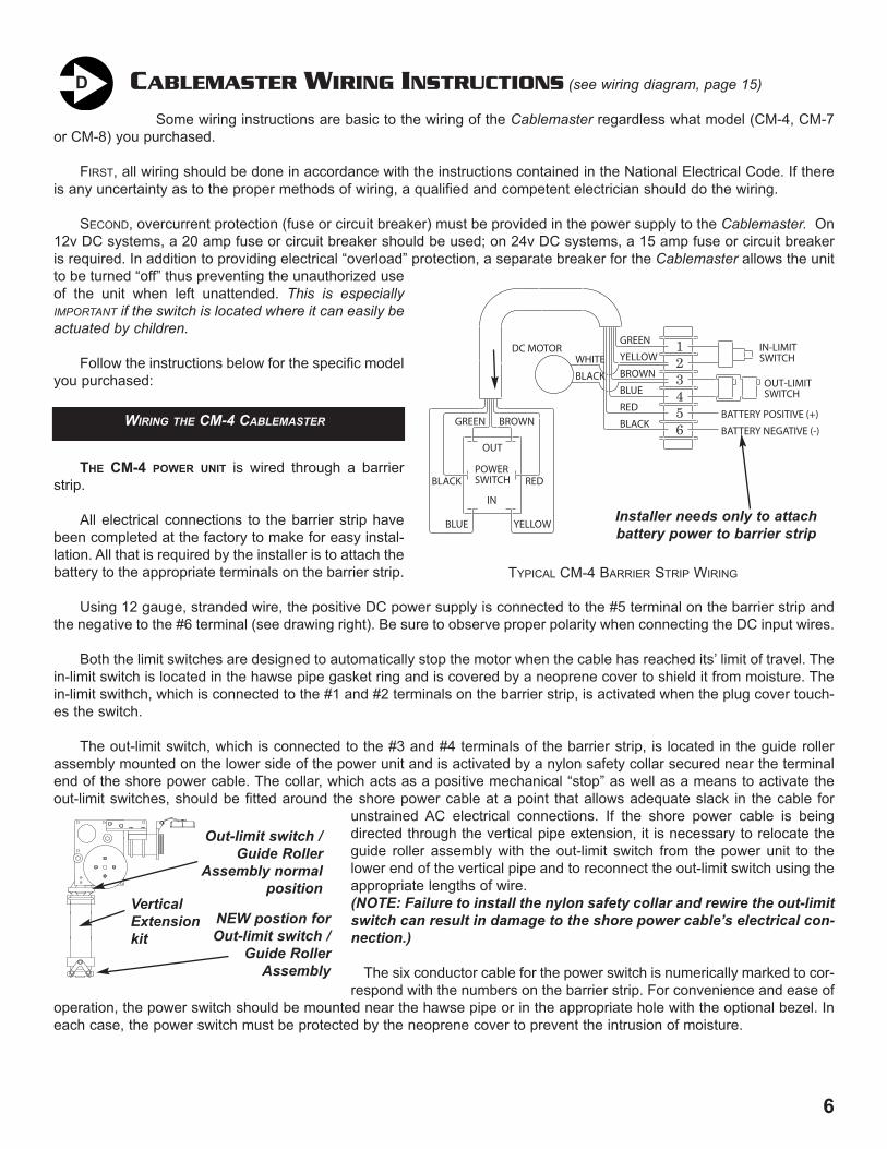
THE CM-4 POWER UNIT is wired through a barrierstrip.
All electrical connections to the barrier strip havebeen completed at the factory to make for easy instal-lation. All that is required by the installer is to attach thebattery to the appropriate terminals on the barrier strip.
Using 12 gauge, stranded wire, the positive DC power supply is connected to the #5 terminal on the barrier strip andthe negative to the #6 terminal (see drawing right). Be sure to observe proper polarity when connecting the DC input wires.
Both the limit switches are designed to automatically stop the motor when the cable has reached its’ limit of travel. Thein-limit switch is located in the hawse pipe gasket ring and is covered by a neoprene cover to shield it from moisture. Thein-limit swithch, which is connected to the #1 and #2 terminals on the barrier strip, is activated when the plug cover touch-es the switch.
The out-limit switch, which is connected to the #3 and #4 terminals of the barrier strip, is located in the guide rollerassembly mounted on the lower side of the power unit and is activated by a nylon safety collar secured near the terminalend of the shore power cable. The collar, which acts as a positive mechanical “stop” as well as a means to activate theout-limit switches, should be fitted around the shore power cable at a point that allows adequate slack in the cable for
unstrained AC electrical connections. If the shore power cable is beingdirected through the vertical pipe extension, it is necessary to relocate theguide roller assembly with the out-limit switch from the power unit to thelower end of the vertical pipe and to reconnect the out-limit switch using theappropriate lengths of wire. (NOTE: Failure to install the nylon safety collar and rewire the out-limitswitch can result in damage to the shore power cable’s electrical con-nection.)
The six conductor cable for the power switch is numerically marked to cor-respond with the numbers on the barrier strip. For convenience and ease of
operation, the power switch should be mounted near the hawse pipe or in the appropriate hole with the optional bezel. Ineach case, the power switch must be protected by the neoprene cover to prevent the intrusion of moisture.
D
123456
IN-LIMITSWITCH
OUT-LIMITSWITCH
BATTERY POSITIVE (+)
BATTERY NEGATIVE (-)
GREEN
YELLOW
BROWN
BLUE
BLACK
RED
CIRCUIT BREAKER SPECS. :CM4 - 12 VOLT 10 AMP BREAKER 4 - 5 RUNNING AMPS
BLACK
WHITEDC MOTOR
BROWN
OUT
GREEN
POWERSWITCH
IN
BLACK RED
YELLOWBLUE
TYPICAL CM-4 BARRIER STRIP WIRING
6
Installer needs only to attach battery power to barrier strip
WIRING THE CM-4 CABLEMASTER
MOTOR
25-5/8" (651 m
m)
Minim
um distance to
center of storage space
14-1/8"(359 m
m)
13"(330 m
m)
6" (152 mm
)7" (178 m
m)
28-1/4"(718 m
m)
12-3/4"(324 m
m)
8-1/2" (216 mm
)
18" (457 mm
)
5-1/2" (140 mm
)
8-3/8"(213 m
m)
4"(102 m
m)
SPECIFIC
ATION
S
Voltage: 12v DC
(24v DC
available).Current: 7 - 11 A
mps under load
Weight: 40 lbs. (Pow
er unit) 12 lbs. (H
awse pipe)
Cable size: up to 2 gauge - 5 conductor, 100am
p A
djustable (1.325" - 1.650" dia.)
Length capacity: Determ
ined by size of storage location
Material: 6061 A
luminum
Finish: Power U
nit: Gold A
nodize H
awse Pipe: G
old or Clear A
nodize
CM
-8 DIM
ENSIO
NS
Vertical Extension kit
NEW postion forOut-limit switch /
Guide RollerAssembly
Out-limit switch /Guide Roller
Assembly normalposition
CABLEMASTER WIRING INSTRUCTIONS (CON’
T.)
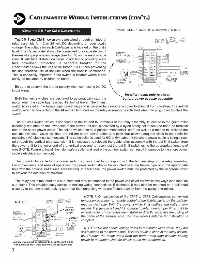
THE CM-7 AND CM-8 POWER UNITS are wired through an integralrelay assembly for 12 or 24 volt DC depending on your boat’svoltage. The voltage for each Cablemaster is located on the unit’slabel. The Cablemaster should be connected to a separate circuitbreaker of appropriate amperage (see Fig. 9) on the main or aux-iliary DC electrical distribution panel. In addition to providing elec-trical “overload” protection, a separate breaker for theCablemaster allows the unit to be turned “OFF” thus preventingthe unauthorized use of the unit when the boat is unattended.This is especially important if the switch is located where it caneasily be actuated by children on board.
Be sure to observe the proper polarity when connecting the DCimput wires.
Both the limit switches are designed to automatically stop themotor when the cable has reached it’s limit of travel. The in-limitswitch is located in the hawse pipe gasket ring and is covered by a neoprene cover to shield it from moisture. The in-limitswitch, which is connected to the #4 and #5 terminals on the relay assembly, is activated when the plug cover touches theswitch.
The out-limit switch, which is connected to the #6 and #7 terminals of the relay assembly, is located in the guide rollerassembly mounted on the lower side of the power unit and is activated by a nylon safety collar secured near the terminalend of the shore power cable. The collar, which acts as a positive mechanical “stop” as well as a means to activate theout-limit swithces, would be fitted around the shore power cable at a point that allows adequate slack in the cable forunstrained AC electrical connections (The same collar is used for 6/3 or 6/4 cable). If the shore power cable is being direct-ed through the vertical pipe extension, it is necessary to relocate the guide roller assembly with the out-limit switch fromthe power unit to the lower end of the vertical pipe and to reconnect the out-limit switch using the appropriate lengths ofwire (NOTE: Failure to install the nylon safety collar and rewire the out-limit switch can result in damage to the shore powercable’s electrical connection).
The 3 conductor cable for the power switch is color coded to correspond with the terminal strip on the relay assembly.For convenience and ease of operation, the power switch should be mounted near the hawse pipe or in the appropriatehole with the optional bezel (see accessories). In each case, the power switch must be protected by the neoprene coverto prevent the intrusion of moisture.
The relay box is mounted on a sub-plate and may be attached to the power unit cover screws in two ways (see label onsub-plate). This provides easy access in making wiring connections. If desirable, it may also be mounted on a bulkheadclose by to the power unit making sure that the connecting wires are fastened away from the pulley and rollers.
NOTE 1: On installation of the CM-7 or CM-8 Cablemaster, convenienttemporary operation or remote control of the Cablemaster by the installermay be desirable. With the power switch, limit swithes and battery con-nected, first jumper #1 and #2 to retract cable, then jumper #1 and #3 toextend cable. This enables the installer to directly supervise the coiling ofthe cable at the storage area. Remove when Cablemaster installation iscomplete.
NOTE 2: Do not attach voltage wires to the motor wires while they arestill fastened to the barrier strip. This will cause a short in the relay assem-bly. Remove the motor wires from the barrier strip then connect batterypower to the motor wires for check-out of motor operation.
D
127
WIRING THE CM-7 OR CM-8 CABLEMASTER
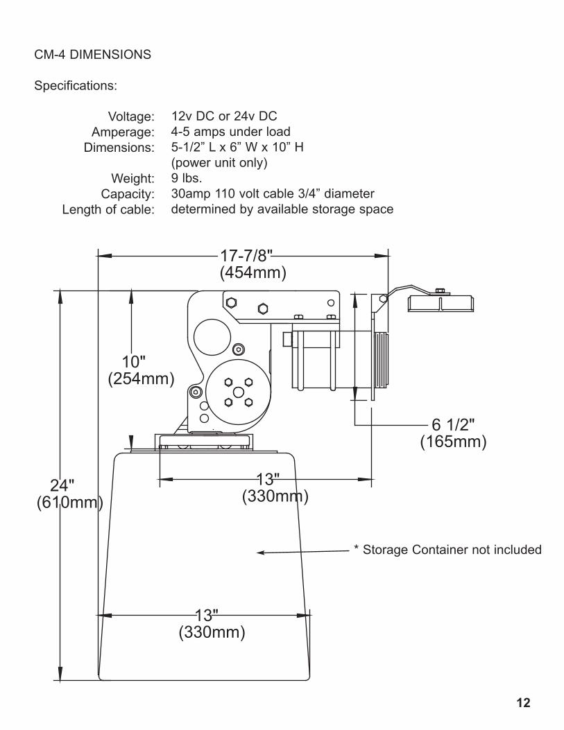
10"(254mm)
13"(330mm)24"
(610mm)
13"(330mm)
17-7/8"(454mm)
6 1/2"(165mm)
CM-4 DIMENSIONS
Specifications:
Voltage:Amperage:
Dimensions:
Weight:Capacity:
Length of cable:
12v DC or 24v DC4-5 amps under load5-1/2” L x 6” W x 10” H(power unit only)9 lbs.30amp 110 volt cable 3/4” diameterdetermined by available storage space
* Storage Container not included
Red 1
White 2
Black 3
PowerSwitch
Pos. +
Neg. -
12 / 24v DC Input
Motor Output
CABLEMASTER RELAY ASSEMBLY # 04034 (12, 24 volt DC)
12v DC use 20 amp breaker24v DC use 5 amp breaker
OUT OUT LimitSwitchSwitch
(Remote - RED)
(Remote - BLACK)
Orange
Black
GLENDINNING MARINE PRODUCTS, INC. Conway, SC 843-399-6146
4 4
5 5
6
7
IN LimitSwitch
(Rmt - Green or Tan)
(Rmt - Yellow or Purple)
ORANGE
BLACK
OFFOUT
INPOWERSWITCH
REDWHITE
BLACK
IN-LIMITSWITCH
OUT-LIMITSWITCH
M12!or!24vMOTOR
BATERY!POSITIVE!(+)
BATTERY!NEGATIVE!(-)
WHITE
RED
BLACK
TYPICAL CM-7 / CM-8 RELAY ASSEMBLY WIRING
Installer needs only to attach battery power to relay assembly
12 or 24vMOTOR
V
24v
Red 1
White 2
Black 3
PowerSwitch
Pos. +
Neg. -
12 / 24v DC Input
Motor Output
CABLEMASTER RELAY ASSEMBLY # 04034 (12, 24 volt DC)
12v DC use 20 amp breaker24v DC use 5 amp breaker
OUT OUT LimitSwitchSwitch
(Remote - RED)
(Remote - BLACK)
Orange
Black
GLENDINNING MARINE PRODUCTS, INC. Conway, SC 843-399-6146
4 4
5 5
6
7
IN LimitSwitch
(Rmt - Green or Tan)
(Rmt - Yellow or Purple)
ORANGE
BLACK
OFFOUT
INPOWERSWITCH
REDWHITE
BLACK
IN-LIMITSWITCH
OUT-LIMITSWITCH
M12!or!24vMOTOR
BATERY!POSITIVE!(+)
BATTERY!NEGATIVE!(-)
WHITE
RED
BLACK
12 or 24vMOTOR
Jumper#1 & #2for IN
Jumper#1 & #3
forOUT
Jumper wires must be attached to #4 & #5, and #6 & #7if IN Limit and OUT Limit Switches are not connected
NOTE 1
POWER CABLE INSTALLATION
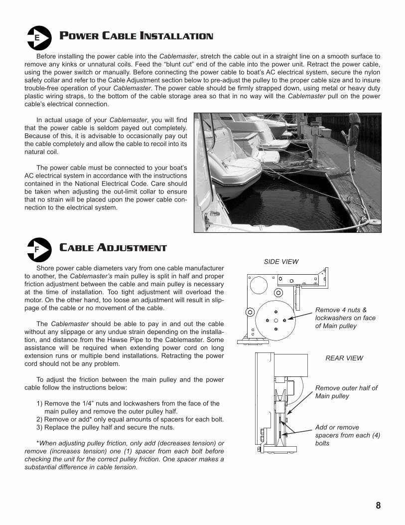
Before installing the power cable into the Cablemaster, stretch the cable out in a straight line on a smooth surface toremove any kinks or unnatural coils. Feed the “blunt cut” end of the cable into the power unit. Retract the power cable,using the power switch or manually. Before connecting the power cable to boat’s AC electrical system, secure the nylonsafety collar and refer to the Cable Adjustment section below to pre-adjust the pulley to the proper cable size and to insuretrouble-free operation of your Cablemaster. The power cable should be firmly strapped down, using metal or heavy dutyplastic wiring straps, to the bottom of the cable storage area so that in no way will the Cablemaster pull on the powercable’s electrical connection.
In actual usage of your Cablemaster, you will findthat the power cable is seldom payed out completely.Because of this, it is advisable to occasionally pay outthe cable completely and allow the cable to recoil into itsnatural coil.
The power cable must be connected to your boat’sAC electrical system in accordance with the instructionscontained in the National Electrical Code. Care shouldbe taken when adjusting the out-limit collar to ensurethat no strain will be placed upon the power cable con-nection to the electrical system.
E
CABLE ADJUSTMENT
Shore power cable diameters vary from one cable manufacturerto another, the Cablemaster’s main pulley is split in half and properfriction adjustment between the cable and main pulley is necessaryat the time of installation. Too tight adjustment will overload themotor. On the other hand, too loose an adjustment will result in slip-page of the cable or no movement of the cable.
The Cablemaster should be able to pay in and out the cablewithout any slippage or any undue strain depending on the installa-tion, and distance from the Hawse Pipe to the Cablemaster. Someassistance will be required when extending power cord on longextension runs or multiple bend installations. Retracting the powercord should not be any problem.
To adjust the friction between the main pulley and the powercable follow the instructions below:
1) Remove the 1/4” nuts and lockwashers from the face of the main pulley and remove the outer pulley half.
2) Remove or add* only equal amounts of spacers for each bolt.3) Replace the pulley half and secure the nuts.
*When adjusting pulley friction, only add (decreases tension) orremove (increases tension) one (1) spacer from each bolt beforechecking the unit for the correct pulley friction. One spacer makes asubstantial difference in cable tension.
F
Remove 4 nuts &lockwashers on faceof Main pulley
SIDE VIEW
REAR VIEW
Remove outer half ofMain pulley
Add or remove spacers from each (4)bolts
811
SPECIFIC
ATION
SVoltage: 12v D
C (24/32v D
C available)
Current: 7-9 Am
ps under loadW
eight: 21 lbs. (power unit)
8 lbs. (haw
se pipe)C
able size: 6/4, 50 amp, 220 v
A
djustable (7/8” - 1-1/4” dia.)Length capacity: D
etermined by size
of storage location
CM
-7 DIM
ENSIO
NS
5" 5"(127 m
m)
Haw
se PipeFlange D
im.
5" x 6 1/2"
3 1/2"(89 m
m)
4 3/4"(121 m
m)
9 3/4"(248 m
m)
15 3/4"(400 m
m)
6 1/4"(159 m
m)
3"(76 m
m)
3 3/4"(95 m
m)
4 1/4"(108 m
m)
8 1/8"(206 m
m)
6 3/4" Min
(171 mm
)
13" Min.
(330 mm
)
6 1/2"(165 m
m)
12 1/4"(311 m
m)
CABLEMASTER DIMENSIONSK

10
MAINTENANCE
Experience has shown that when only a short section of the power cable is regularly used, the cable may be subjectto sharper than normal coiling which in turn causes undue “kinking” of the cable. To relieve this condition, routinely pay thecable out completely and stretch it on any smooth surface. Allow the Cablemaster to then retract the cable into the cablestorage area.
At least once a year, check all AC and DC wiring connections to be sure they are secure and free of corrosion. Checkthe neoprene covers on the in-limit switch and power switch to be sure they are free of cracks or fracture.
Periodically, inspect the exterior jacket of your shore power cable for nicks or cuts. If your shore power cable is dirtyDO NOT USE any cleaner that will leave a waxy film on the shore power cable. The waxy film will cause slippage betweenthe Cablemaster’s main pulley and your shore power cable. It is recommended to use a mild soap and water to clean yourcable.
H
OPERATION OF THE CABLEMASTERAC WIRING INSTRUCTIONS
WARNING: It is extremely important that the wiring of the power cord to your boat’s electrical system be done properly. Ifthere is any uncertainty as to the proper methods of working with AC wiring, a qualified and competent electrician shoulddo this wiring. Failure to wire correctly may result in DEATH, INJURY, OR DAMAGE TO PERSONS OR VESSEL.
In all electrical applications, minimizing the entranceor accumulation of moisture or water is of prime impor-tance. Junction boxes, receptacles, breakers and otherenclosures in which electrical connections are madeshould be waterproof or be installed in a protected area.
Electricity enters the boat through the power cable.The cable is connected to the Power Transfer Switchwhich automatically switches power for your boat’s elec-trical system between the on-board generator and theshore power cable hook up. The Power Transfer Switch isthen connected to the AC panel board through a main cir-cuit breaker. The power is transferred to the variousbranch circuits by way of individual branch circuit break-ers.
Good practice when installing the Cablemaster is to place a waterproof circuit breaker in the system on the boat’s exte-rior in close proximity to the Cablemaster hawse pipe. This circuit breaker automatically interrupts the flow of current if thecurrent exceeds the amount the circuit is designed to handle (ie: 30amp or 50amp). This is common practice recom-mended by ABYC where the distance from the shore power cable inlet is more than 10’ away from the AC panelboard.
When two Cablemaster units are used on port and starboard installations, the shore power cables must be wiredthrough an approved rotary transfer switch before connection to the main circuit breaker on the AC panelboard. This willprovide a safe interlock when switching from one shoreside power source to another.
Remember also that your boat’s AC electrical system is “polarized.” Polarization of conductors must be observed inthe shore cable connections and throughout the entire AC system.
G
9
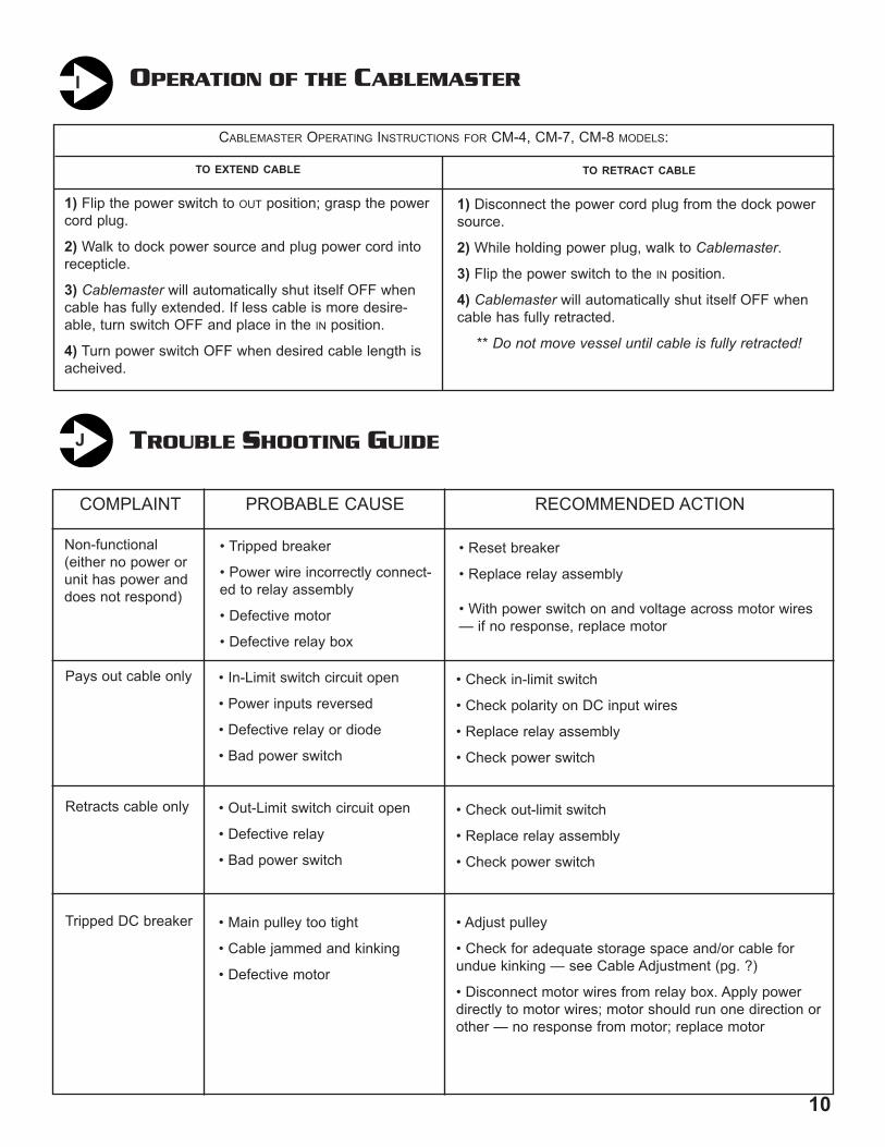
TO EXTEND CABLE
1) Flip the power switch to OUT position; grasp the powercord plug.
2) Walk to dock power source and plug power cord intorecepticle.
3) Cablemaster will automatically shut itself OFF whencable has fully extended. If less cable is more desire-able, turn switch OFF and place in the IN position.
4) Turn power switch OFF when desired cable length isacheived.
TO RETRACT CABLE
1) Disconnect the power cord plug from the dock powersource.
2) While holding power plug, walk to Cablemaster.
3) Flip the power switch to the IN position.
4) Cablemaster will automatically shut itself OFF whencable has fully retracted.
** Do not move vessel until cable is fully retracted!
CABLEMASTER OPERATING INSTRUCTIONS FOR CM-4, CM-7, CM-8 MODELS:
I
PowerTransferSwtich
Cable exitsfrom bottomof storagecontainer
From Generator
To Boat ACSystem
TROUBLE SHOOTING GUIDEJ
COMPLAINT
Non-functional(either no power orunit has power anddoes not respond)
• Tripped breaker
• Power wire incorrectly connect-ed to relay assembly
• Defective motor
• Defective relay box
• Reset breaker
• Replace relay assembly
• With power switch on and voltage across motor wires— if no response, replace motor
Retracts cable only • Out-Limit switch circuit open
• Defective relay
• Bad power switch
• Check out-limit switch
• Replace relay assembly
• Check power switch
Tripped DC breaker • Main pulley too tight
• Cable jammed and kinking
• Defective motor
• Adjust pulley
• Check for adequate storage space and/or cable forundue kinking — see Cable Adjustment (pg. ?)
• Disconnect motor wires from relay box. Apply powerdirectly to motor wires; motor should run one direction orother — no response from motor; replace motor
Pays out cable only • In-Limit switch circuit open
• Power inputs reversed
• Defective relay or diode
• Bad power switch
• Check in-limit switch
• Check polarity on DC input wires
• Replace relay assembly
• Check power switch
PROBABLE CAUSE RECOMMENDED ACTION
Cable storagearea
10
MAINTENANCE
Experience has shown that when only a short section of the power cable is regularly used, the cable may be subjectto sharper than normal coiling which in turn causes undue “kinking” of the cable. To relieve this condition, routinely pay thecable out completely and stretch it on any smooth surface. Allow the Cablemaster to then retract the cable into the cablestorage area.
At least once a year, check all AC and DC wiring connections to be sure they are secure and free of corrosion. Checkthe neoprene covers on the in-limit switch and power switch to be sure they are free of cracks or fracture.
Periodically, inspect the exterior jacket of your shore power cable for nicks or cuts. If your shore power cable is dirtyDO NOT USE any cleaner that will leave a waxy film on the shore power cable. The waxy film will cause slippage betweenthe Cablemaster’s main pulley and your shore power cable. It is recommended to use a mild soap and water to clean yourcable.
H
OPERATION OF THE CABLEMASTERAC WIRING INSTRUCTIONS
WARNING: It is extremely important that the wiring of the power cord to your boat’s electrical system be done properly. Ifthere is any uncertainty as to the proper methods of working with AC wiring, a qualified and competent electrician shoulddo this wiring. Failure to wire correctly may result in DEATH, INJURY, OR DAMAGE TO PERSONS OR VESSEL.
In all electrical applications, minimizing the entranceor accumulation of moisture or water is of prime impor-tance. Junction boxes, receptacles, breakers and otherenclosures in which electrical connections are madeshould be waterproof or be installed in a protected area.
Electricity enters the boat through the power cable.The cable is connected to the Power Transfer Switchwhich automatically switches power for your boat’s elec-trical system between the on-board generator and theshore power cable hook up. The Power Transfer Switch isthen connected to the AC panel board through a main cir-cuit breaker. The power is transferred to the variousbranch circuits by way of individual branch circuit break-ers.
Good practice when installing the Cablemaster is to place a waterproof circuit breaker in the system on the boat’s exte-rior in close proximity to the Cablemaster hawse pipe. This circuit breaker automatically interrupts the flow of current if thecurrent exceeds the amount the circuit is designed to handle (ie: 30amp or 50amp). This is common practice recom-mended by ABYC where the distance from the shore power cable inlet is more than 10’ away from the AC panelboard.
When two Cablemaster units are used on port and starboard installations, the shore power cables must be wiredthrough an approved rotary transfer switch before connection to the main circuit breaker on the AC panelboard. This willprovide a safe interlock when switching from one shoreside power source to another.
Remember also that your boat’s AC electrical system is “polarized.” Polarization of conductors must be observed inthe shore cable connections and throughout the entire AC system.
G
9
TO EXTEND CABLE
1) Flip the power switch to OUT position; grasp the powercord plug.
2) Walk to dock power source and plug power cord intorecepticle.
3) Cablemaster will automatically shut itself OFF whencable has fully extended. If less cable is more desire-able, turn switch OFF and place in the IN position.
4) Turn power switch OFF when desired cable length isacheived.
TO RETRACT CABLE
1) Disconnect the power cord plug from the dock powersource.
2) While holding power plug, walk to Cablemaster.
3) Flip the power switch to the IN position.
4) Cablemaster will automatically shut itself OFF whencable has fully retracted.
** Do not move vessel until cable is fully retracted!
CABLEMASTER OPERATING INSTRUCTIONS FOR CM-4, CM-7, CM-8 MODELS:
I
PowerTransferSwtich
Cable exitsfrom bottomof storagecontainer
From Generator
To Boat ACSystem
TROUBLE SHOOTING GUIDEJ
COMPLAINT
Non-functional(either no power orunit has power anddoes not respond)
• Tripped breaker
• Power wire incorrectly connect-ed to relay assembly
• Defective motor
• Defective relay box
• Reset breaker
• Replace relay assembly
• With power switch on and voltage across motor wires— if no response, replace motor
Retracts cable only • Out-Limit switch circuit open
• Defective relay
• Bad power switch
• Check out-limit switch
• Replace relay assembly
• Check power switch
Tripped DC breaker • Main pulley too tight
• Cable jammed and kinking
• Defective motor
• Adjust pulley
• Check for adequate storage space and/or cable forundue kinking — see Cable Adjustment (pg. ?)
• Disconnect motor wires from relay box. Apply powerdirectly to motor wires; motor should run one direction orother — no response from motor; replace motor
Pays out cable only • In-Limit switch circuit open
• Power inputs reversed
• Defective relay or diode
• Bad power switch
• Check in-limit switch
• Check polarity on DC input wires
• Replace relay assembly
• Check power switch
PROBABLE CAUSE RECOMMENDED ACTION
Cable storagearea

POWER CABLE INSTALLATION
Before installing the power cable into the Cablemaster, stretch the cable out in a straight line on a smooth surface toremove any kinks or unnatural coils. Feed the “blunt cut” end of the cable into the power unit. Retract the power cable,using the power switch or manually. Before connecting the power cable to boat’s AC electrical system, secure the nylonsafety collar and refer to the Cable Adjustment section below to pre-adjust the pulley to the proper cable size and to insuretrouble-free operation of your Cablemaster. The power cable should be firmly strapped down, using metal or heavy dutyplastic wiring straps, to the bottom of the cable storage area so that in no way will the Cablemaster pull on the powercable’s electrical connection.
In actual usage of your Cablemaster, you will findthat the power cable is seldom payed out completely.Because of this, it is advisable to occasionally pay outthe cable completely and allow the cable to recoil into itsnatural coil.
The power cable must be connected to your boat’sAC electrical system in accordance with the instructionscontained in the National Electrical Code. Care shouldbe taken when adjusting the out-limit collar to ensurethat no strain will be placed upon the power cable con-nection to the electrical system.
E
CABLE ADJUSTMENT
Shore power cable diameters vary from one cable manufacturerto another, the Cablemaster’s main pulley is split in half and properfriction adjustment between the cable and main pulley is necessaryat the time of installation. Too tight adjustment will overload themotor. On the other hand, too loose an adjustment will result in slip-page of the cable or no movement of the cable.
The Cablemaster should be able to pay in and out the cablewithout any slippage or any undue strain depending on the installa-tion, and distance from the Hawse Pipe to the Cablemaster. Someassistance will be required when extending power cord on longextension runs or multiple bend installations. Retracting the powercord should not be any problem.
To adjust the friction between the main pulley and the powercable follow the instructions below:
1) Remove the 1/4” nuts and lockwashers from the face of the main pulley and remove the outer pulley half.
2) Remove or add* only equal amounts of spacers for each bolt.3) Replace the pulley half and secure the nuts.
*When adjusting pulley friction, only add (decreases tension) orremove (increases tension) one (1) spacer from each bolt beforechecking the unit for the correct pulley friction. One spacer makes asubstantial difference in cable tension.
F
Remove 4 nuts &lockwashers on faceof Main pulley
SIDE VIEW
REAR VIEW
Remove outer half ofMain pulley
Add or remove spacers from each (4)bolts
811
SPECIFIC
ATION
SVoltage: 12v D
C (24/32v D
C available)
Current: 7-9 Am
ps under loadW
eight: 21 lbs. (power unit)
8 lbs. (haw
se pipe)C
able size: 6/4, 50 amp, 220 v
A
djustable (7/8” - 1-1/4” dia.)Length capacity: D
etermined by size
of storage location
CM
-7 DIM
ENSIO
NS
5" 5"(127 m
m)
Haw
se PipeFlange D
im.
5" x 6 1/2"
3 1/2"(89 m
m)
4 3/4"(121 m
m)
9 3/4"(248 m
m)
15 3/4"(400 m
m)
6 1/4"(159 m
m)
3"(76 m
m)
3 3/4"(95 m
m)
4 1/4"(108 m
m)
8 1/8"(206 m
m)
6 3/4" Min
(171 mm
)
13" Min.
(330 mm
)
6 1/2"(165 m
m)
12 1/4"(311 m
m)
CABLEMASTER DIMENSIONSK
CABLEMASTER WIRING INSTRUCTIONS (CON’
T.)
THE CM-7 AND CM-8 POWER UNITS are wired through an integralrelay assembly for 12 or 24 volt DC depending on your boat’svoltage. The voltage for each Cablemaster is located on the unit’slabel. The Cablemaster should be connected to a separate circuitbreaker of appropriate amperage (see Fig. 9) on the main or aux-iliary DC electrical distribution panel. In addition to providing elec-trical “overload” protection, a separate breaker for theCablemaster allows the unit to be turned “OFF” thus preventingthe unauthorized use of the unit when the boat is unattended.This is especially important if the switch is located where it caneasily be actuated by children on board.
Be sure to observe the proper polarity when connecting the DCimput wires.
Both the limit switches are designed to automatically stop themotor when the cable has reached it’s limit of travel. The in-limitswitch is located in the hawse pipe gasket ring and is covered by a neoprene cover to shield it from moisture. The in-limitswitch, which is connected to the #4 and #5 terminals on the relay assembly, is activated when the plug cover touches theswitch.
The out-limit switch, which is connected to the #6 and #7 terminals of the relay assembly, is located in the guide rollerassembly mounted on the lower side of the power unit and is activated by a nylon safety collar secured near the terminalend of the shore power cable. The collar, which acts as a positive mechanical “stop” as well as a means to activate theout-limit swithces, would be fitted around the shore power cable at a point that allows adequate slack in the cable forunstrained AC electrical connections (The same collar is used for 6/3 or 6/4 cable). If the shore power cable is being direct-ed through the vertical pipe extension, it is necessary to relocate the guide roller assembly with the out-limit switch fromthe power unit to the lower end of the vertical pipe and to reconnect the out-limit switch using the appropriate lengths ofwire (NOTE: Failure to install the nylon safety collar and rewire the out-limit switch can result in damage to the shore powercable’s electrical connection).
The 3 conductor cable for the power switch is color coded to correspond with the terminal strip on the relay assembly.For convenience and ease of operation, the power switch should be mounted near the hawse pipe or in the appropriatehole with the optional bezel (see accessories). In each case, the power switch must be protected by the neoprene coverto prevent the intrusion of moisture.
The relay box is mounted on a sub-plate and may be attached to the power unit cover screws in two ways (see label onsub-plate). This provides easy access in making wiring connections. If desirable, it may also be mounted on a bulkheadclose by to the power unit making sure that the connecting wires are fastened away from the pulley and rollers.
NOTE 1: On installation of the CM-7 or CM-8 Cablemaster, convenienttemporary operation or remote control of the Cablemaster by the installermay be desirable. With the power switch, limit swithes and battery con-nected, first jumper #1 and #2 to retract cable, then jumper #1 and #3 toextend cable. This enables the installer to directly supervise the coiling ofthe cable at the storage area. Remove when Cablemaster installation iscomplete.
NOTE 2: Do not attach voltage wires to the motor wires while they arestill fastened to the barrier strip. This will cause a short in the relay assem-bly. Remove the motor wires from the barrier strip then connect batterypower to the motor wires for check-out of motor operation.
D
127
WIRING THE CM-7 OR CM-8 CABLEMASTER
10"(254mm)
13"(330mm)24"
(610mm)
13"(330mm)
17-7/8"(454mm)
6 1/2"(165mm)
CM-4 DIMENSIONS
Specifications:
Voltage:Amperage:
Dimensions:
Weight:Capacity:
Length of cable:
12v DC or 24v DC4-5 amps under load5-1/2” L x 6” W x 10” H(power unit only)9 lbs.30amp 110 volt cable 3/4” diameterdetermined by available storage space
* Storage Container not included
Red 1
White 2
Black 3
PowerSwitch
Pos. +
Neg. -
12 / 24v DC Input
Motor Output
CABLEMASTER RELAY ASSEMBLY # 04034 (12, 24 volt DC)
12v DC use 20 amp breaker24v DC use 5 amp breaker
OUT OUT LimitSwitchSwitch
(Remote - RED)
(Remote - BLACK)
Orange
Black
GLENDINNING MARINE PRODUCTS, INC. Conway, SC 843-399-6146
4 4
5 5
6
7
IN LimitSwitch
(Rmt - Green or Tan)
(Rmt - Yellow or Purple)
ORANGE
BLACK
OFFOUT
INPOWERSWITCH
REDWHITE
BLACK
IN-LIMITSWITCH
OUT-LIMITSWITCH
M12!or!24vMOTOR
BATERY!POSITIVE!(+)
BATTERY!NEGATIVE!(-)
WHITE
RED
BLACK
TYPICAL CM-7 / CM-8 RELAY ASSEMBLY WIRING
Installer needs only to attach battery power to relay assembly
12 or 24vMOTOR
V
24v
Red 1
White 2
Black 3
PowerSwitch
Pos. +
Neg. -
12 / 24v DC Input
Motor Output
CABLEMASTER RELAY ASSEMBLY # 04034 (12, 24 volt DC)
12v DC use 20 amp breaker24v DC use 5 amp breaker
OUT OUT LimitSwitchSwitch
(Remote - RED)
(Remote - BLACK)
Orange
Black
GLENDINNING MARINE PRODUCTS, INC. Conway, SC 843-399-6146
4 4
5 5
6
7
IN LimitSwitch
(Rmt - Green or Tan)
(Rmt - Yellow or Purple)
ORANGE
BLACK
OFFOUT
INPOWERSWITCH
REDWHITE
BLACK
IN-LIMITSWITCH
OUT-LIMITSWITCH
M12!or!24vMOTOR
BATERY!POSITIVE!(+)
BATTERY!NEGATIVE!(-)
WHITE
RED
BLACK
12 or 24vMOTOR
Jumper#1 & #2for IN
Jumper#1 & #3
forOUT
Jumper wires must be attached to #4 & #5, and #6 & #7if IN Limit and OUT Limit Switches are not connected
NOTE 1

CABLEMASTER WIRING INSTRUCTIONS (see wiring diagram, page 15)
Some wiring instructions are basic to the wiring of the Cablemaster regardless what model (CM-4, CM-7or CM-8) you purchased.
FIRST, all wiring should be done in accordance with the instructions contained in the National Electrical Code. If thereis any uncertainty as to the proper methods of wiring, a qualified and competent electrician should do the wiring.
SECOND, overcurrent protection (fuse or circuit breaker) must be provided in the power supply to the Cablemaster. On12v DC systems, a 20 amp fuse or circuit breaker should be used; on 24v DC systems, a 15 amp fuse or circuit breakeris required. In addition to providing electrical “overload” protection, a separate breaker for the Cablemaster allows the unitto be turned “off” thus preventing the unauthorized useof the unit when left unattended. This is especiallyIMPORTANT if the switch is located where it can easily beactuated by children.
Follow the instructions below for the specific modelyou purchased:
THE CM-4 POWER UNIT is wired through a barrierstrip.
All electrical connections to the barrier strip havebeen completed at the factory to make for easy instal-lation. All that is required by the installer is to attach thebattery to the appropriate terminals on the barrier strip.
Using 12 gauge, stranded wire, the positive DC power supply is connected to the #5 terminal on the barrier strip andthe negative to the #6 terminal (see drawing right). Be sure to observe proper polarity when connecting the DC input wires.
Both the limit switches are designed to automatically stop the motor when the cable has reached its’ limit of travel. Thein-limit switch is located in the hawse pipe gasket ring and is covered by a neoprene cover to shield it from moisture. Thein-limit swithch, which is connected to the #1 and #2 terminals on the barrier strip, is activated when the plug cover touch-es the switch.
The out-limit switch, which is connected to the #3 and #4 terminals of the barrier strip, is located in the guide rollerassembly mounted on the lower side of the power unit and is activated by a nylon safety collar secured near the terminalend of the shore power cable. The collar, which acts as a positive mechanical “stop” as well as a means to activate theout-limit switches, should be fitted around the shore power cable at a point that allows adequate slack in the cable for
unstrained AC electrical connections. If the shore power cable is beingdirected through the vertical pipe extension, it is necessary to relocate theguide roller assembly with the out-limit switch from the power unit to thelower end of the vertical pipe and to reconnect the out-limit switch using theappropriate lengths of wire. (NOTE: Failure to install the nylon safety collar and rewire the out-limitswitch can result in damage to the shore power cable’s electrical con-nection.)
The six conductor cable for the power switch is numerically marked to cor-respond with the numbers on the barrier strip. For convenience and ease of
operation, the power switch should be mounted near the hawse pipe or in the appropriate hole with the optional bezel. Ineach case, the power switch must be protected by the neoprene cover to prevent the intrusion of moisture.
D
123456
IN-LIMITSWITCH
OUT-LIMITSWITCH
BATTERY POSITIVE (+)
BATTERY NEGATIVE (-)
GREEN
YELLOW
BROWN
BLUE
BLACK
RED
CIRCUIT BREAKER SPECS. :CM4 - 12 VOLT 10 AMP BREAKER 4 - 5 RUNNING AMPS
BLACK
WHITEDC MOTOR
BROWN
OUT
GREEN
POWERSWITCH
IN
BLACK RED
YELLOWBLUE
TYPICAL CM-4 BARRIER STRIP WIRING
6
Installer needs only to attach battery power to barrier strip
WIRING THE CM-4 CABLEMASTER
MOTOR
25-5/8" (651 m
m)
Minim
um distance to
center of storage space
14-1/8"(359 m
m)
13"(330 m
m)
6" (152 mm
)7" (178 m
m)
28-1/4"(718 m
m)
12-3/4"(324 m
m)
8-1/2" (216 mm
)
18" (457 mm
)
5-1/2" (140 mm
)
8-3/8"(213 m
m)
4"(102 m
m)
SPECIFIC
ATION
S
Voltage: 12v DC
(24v DC
available).Current: 7 - 11 A
mps under load
Weight: 40 lbs. (Pow
er unit) 12 lbs. (H
awse pipe)
Cable size: up to 2 gauge - 5 conductor, 100am
p A
djustable (1.325" - 1.650" dia.)
Length capacity: Determ
ined by size of storage location
Material: 6061 A
luminum
Finish: Power U
nit: Gold A
nodize H
awse Pipe: G
old or Clear A
nodize
CM
-8 DIM
ENSIO
NS
Vertical Extension kit
NEW postion forOut-limit switch /
Guide RollerAssembly
Out-limit switch /Guide Roller
Assembly normalposition
145
INSTALLATION INSTRUCTIONS
The Cablemaster system must be mounted in a loca-tion that is protected from the marine environment and is certified“ignition protected” for placement in engine rooms. For ideas onspecific locations for your boat, contact our service engineer.
Using the drawing included with your manual, mark the mountinglocation of the hawse pipe. Before drilling or cutting, check onceagain to be certain that the area behind the hawse pipe is free ofwires, plumbing or structural supports for the boat. The mountingsurface should be a minimum 1/2” thick. The proper thickness canbe achieved by using a butt block of marine grade plywood behindthe mounting surface.
Cut the hawse pipe’s 3-5/8” center hole and drill the four 1/4”mounting holes. Using a good quality marine beading compound,secure the hawse pipe to the boat using the four (4) 1/4 x 20 x 1”stainless steel machine screws, washers, nuts and gasket suppliedwith the Cablemaster or use longer fasteners that are availablelocally.
The power unit may now be mounted to the hawse pipe using theangle link, the hawse pipe clamp, and U-bolts. In remote power unitinstallations, the 3” schedule 40 PVC pipe is secured to the powerunit using the same standard components adding also the acces-sories for horizontal pipe extension in order to connect the PVC pipeto the hawse pipe (see Fig. 3 previous page).
Unless the shore power cable is being directed vertically througha PVC pipe, you are now ready to wire the Cablemaster to theboat’s DC electrical system. If the shore power cable is being direct-ed vertically through PVC pipe (see drawing below) it is necessaryto relocate the guide roller assembly with the out-limit switch fromthe bottom of the power unit to the lower end of the PVC pipe. Wiresof appropriate length will have to be spliced into the system to insurethe operation of the out-limit switch. A guide roller assembly withoutthe out-limit switch, included in the vertical pipe extension accesso-ry, must be installed between the power unit and the PVC pipe toprovide trouble free operation (see accessory page).
CØ 3 5/8"
x4Ø 17/64"
HINGE
65002
SPACERS
HAW
SE F
LANGE
70427
HINGE BO
LT74410
ACORN
NUT
04800
POWER
SWITCH
ASSEM
BLY
(incl. switch,
cover, 3ft.
wire)
85414
LIP RO
LLER
50416
PULLEY
- INSIDE HAL
F
50417
PULLEY
- OUTSIDE HAL
F
50416
OFFSET PLATE
(included
with
04046 assy.)
04046
GUIDE RO
LLER
ASSEM
BLY
(incl. guide, rollers
4X,
offset
plate)
75412
#9 WOODRU
FF KEY
50005
CONNECTOR
LINK
50421
HAW
SE PIPE C
LAMP
04053
HAW
SE PIPE C
LAMP ASSY.
04050
HAW
SE PIPE ASSEMBLY
(incl. hawse
pipe with
flange,
hinge, cap)
04051
HINGE & CAP
ASSEM
BLY
50421
HINGE
50420
CAP
RELAY
ASSEM
BLY
04034 -- 12
/ 24
VO
LTS
70005
U-BO
LT (2X)
65001
Spacer
50415
CHASSIS COVER
50414
CHASSIS
04812
IN-LIMIT
SWITCH
ASSY.
(incl. switch,
2 ft. wire
assy.,
protective boot)
04830
IN-LIMIT
SWITCH
ASSY.
(incl. hawse
pipe ring)
86402
CAP
GASKET
60001
HAW
SEPIPE
RING
86403
HAW
SEPIPE
GASKET
70432
ALLEN
SCREW
04824
OUTLIMIT
SWITCH
ASSEM
BLY
(incl. (2)
switches,
2 ft. wire
assy.)87404
CHASSIS GASKET
MOTOR
ASSEM
BLY
(incl. drive gear
and
mounting screws)
04035 -- 12
VO
LTS
04036 -- 24
VO
LTS
86401
HAW
SE PIPE
GASKET
04051
CAP
& HINGE
ASSEMBLY90004
POWER
SWITCH
COVER
CableMaster
Model
CM7
Parts
Diagram
Glendinning
Marine Products, Inc.
STEP 1Use templateon backcover ofmanual
STEP 2Mount Hawsepipe in hole
Hole cut instep 1
STEP 3Mount Hawse pipeto power unit
Red 1
White 2
Black 3
PowerSwitch
Pos. +
Neg. -
12 / 24v DC Input
Motor Output
CABLEMASTER RELAY ASSEMBLY # 04034 (12, 24 volt DC)
12v DC use 20 amp breaker24v DC use 5 amp breaker
OUT OUT LimitSwitchSwitch
(Remote - RED)
(Remote - BLACK)
Orange
Black
GLENDINNING MARINE PRODUCTS, INC. Conway, SC 843-399-6146
4 4
5 5
6
7
IN LimitSwitch
(Rmt - Green or Tan)
(Rmt - Yellow or Purple)
ORANGE
BLACK
OFFOUT
INPOWERSWITCH
REDWHITE
BLACK
IN-LIMITSWITCH
OUT-LIMITSWITCH
M12!or!24vMOTOR
BATERY!POSITIVE!(+)
BATTERY!NEGATIVE!(-)
WHITE
RED
BLACK
STEP 4Connect power toCablemaster relay
STEP 1: MARK MOUNTING LOCATION FOR HAWSE PIPE
STEP 2: CUT CENTER HOLE & MOUNT HAWSE PIPE
STEP 3: MOUNT POWER UNIT TO HAWSE PIPE
STEP 4: WIRE CABLEMASTER TO ELECTRICAL SYSTEM
VerticalExtension
Relocate guide roller assemblywith out-limit switch to end ofPVC pipe extension
CA
BL
EM
AS
TE
R
MO
DE
LC
M-7
PA
RT
SD
IAG
RA
M
TYPES OF INSTALLATIONS
STANDARD (CLOSE COUPLED) INSTALLATION
The Cablemaster works best when the power unit is mounted directly above the stor-age container. This will ensure proper cable extension and retraction and is recommendedproviding storage space is available where hawse pipe is to be mounted (Fig. 2).
HORIZONTAL EXTENSION
When storage space is not available directly under the power unit,the power unit can be moved away from the hawse pipe. The standardand shortest length of the connection between the power unit and thehawse pipe is 6 5/8”. This connection may be extended up to 16”through the use of the optional long angle link (CM accessory). Thepower unit can also be remote mounted up to 12* away from the hawsepipe using the optional horizontal pipe extension and a length of 3”schedule 40 PVC pipe (Fig. 3). In both of these configurations, thepower unit will require additional mounting support. An overhead mount-ing bracket is available which allows the power unit to be remote mount-ed to the overhead.
VERTICAL EXTENSION
Schedule 40 3” dia PVC pipe is also recommended when the shore cable is being direct-ed vertically through the deck. In this installation it is necessary to use the optional vertical pipeextension (see accessory page) and to remove the guide roller assembly from the power unitand relocate it to the bottom of the pipe extension. Since this contains the out-limit switch, it isalso necessary to reconnect the out-limit switch by extending the wire to the relay box (Fig. 4).
OTHER INSTALLATION OPTIONS
Any number of mounting arrangements can be accomplished usingthe PVC pipe to remote mount the power unit or guide the shore powercable below deck. The mounting possibilities are further enhanced by thefact that the shore power cable can be directed to the right or left of ver-tical by adjusting the U-clamps on the hawse pipe (Fig. 5).
NOTE: A pipe to pipe angle assembly is available where a straight pipecannot be used between the hawse pipe and power unit. This angle con-nector may be used in the horizontal or vertical pipe and is equipped withrollers to provide minimal cable friction. It will work satisfactorily up to 30*degrees (see accessory page).
NOTE: The side angle adjustment should not exceed 45 degrees and theuse of standard PVC elbows is not recommended as they tend to restrictthe movement of the cable within the pipe.
Selection of the hawse pipe location is in a large measure deter-mined by the proper location of the power unit and cable storage area.Be sure that the hawse pipe’s location is practical for common dockagesituations. Avoid a location where the shore power cable could presentan obstacle on decks or passageways when in use. An optional recessedmounting bezel is available which allows the hawse pipe to be flushmounted (see accessory page). Shown at right (Fig. 6 & 7) are otherinstallation possibilities for mounting the power unit and directing thecable to the storage area.
4
B
15
Red 1
White 2
Black 3
PowerSwitch
Pos. +
Neg. -
12 / 24v DC Input
Motor Output
CABLEMASTER RELAY ASSEMBLY # 04034 (12, 24 volt DC)
12v DC use 20 amp breaker24v DC use 5 amp breaker
OUT OUT LimitSwitchSwitch
(Remote - RED)
(Remote - BLACK)
Orange
Black
GLENDINNING MARINE PRODUCTS, INC. Conway, SC 843-399-6146
4 4
5 5
6
7
IN LimitSwitch
(Rmt - Green or Tan)
(Rmt - Yellow or Purple)
ORANGE
BLACK
OFFOUT
INPOWERSWITCH
REDWHITE
BLACK
IN-LIMITSWITCH
OUT-LIMITSWITCH
M12!or!24vMOTOR
BATERY!POSITIVE!(+)
BATTERY!NEGATIVE!(-)
WHITE
RED
BLACK
CABLEMASTER WIRING DIAGRAML
Figure 2
HorizontalExtension
CM-7 & CM-8WIRING DIAGRAMRELAY ASSEMBLY
VerticalExtension
Figure 4
Figure 5
Figure 6
Figure 7
Figure 3
123456
IN-LIMITSWITCH
OUT-LIMITSWITCH
BATTERY POSITIVE (+)
BATTERY NEGATIVE (-)
GREEN
YELLOW
BROWN
BLUE
BLACK
RED
CIRCUIT BREAKER SPECS. :CM4 - 12 VOLT 10 AMP BREAKER 4 - 5 RUNNING AMPS
BLACK
WHITEDC MOTOR
BROWN
OUT
GREEN
POWERSWITCH
IN
BLACK RED
YELLOWBLUE
CM-4WIRING DIAGRAMBARRIER STRIP ASSEMBLY
Power unit is turnedfor a low-profileconfiguration

BEFORE installing your Cablemaster, consider the following three points:
LOCATION FOR POWER UNIT & CABLE :
Perhaps the prime consideration in determining the best location for mountingyour Glendinning Cablemaster is to remember that the key to a good installation is allowing enough room for the shorepower cable to coil without restriction. The power unit should be mounted directly over the storage container, but may beoffset a maximum of 20 degrees where space deems it to be necessary. Here are a few pointers to keep in mind whenlooking at your boat.
MINIMUM CABLE STORAGE AREA:
A. 30 amp cable — 14” x 14” (see Fig. 1)1. For 50 feet of 30 amp 10/3, a minimum of 15” is required from guide roller assembly to the bottom of container.
B. 50 amp cable — 18” x 18” (see Fig. 1)1. For 75 feet of 50 amp 6/4, a minimum of 23” is required from the guide rollerassembly to the bottom of the storage container. 18” is required from the guide rollerassembly to the bottom of the storage container if a 15” x 22” diameter container is used.
SUITABLE STORAGE CONTAINERS:
A. Heavy duty garbage barrelB. Round baitwellC. Any enclosed area free of tubing, wiring or structural projections allowing the cable to free-fall may be used. (Glueing strips of formica to 1” x 2” or 2” x 2” may be suitable in applications where the storage area is close to the rough inside surface of a fiberglass hull)D. Molded styrene containers (18” - 22” in diameter and in varying heights) are available from Glendinning Marine Products, Inc. (see accessory page)
HAWSE PIPE & POWER CORD PLUG EXIT :
Also be careful to remember that the selection of the hawse pipe location is in a large measure determined by the prop-er location of the power unit and cable storage area. Be sure that the hawse pipe’s location is practical for common dock-age situations. Avoid a location where the shore power cable could present an obstacle on decks or passageways whenin use.
CONNECTION TO THE BOAT ELECTRICAL SYSTEM :
Prior to the installation of the Cablemaster, consider how the unit is connected to the boat’s electrical system (see draw-ing right). The blunt cut end of the power cable should exit the bottom of the cable storage area. This end can be con-nected to the Power Transfer Switch which automaticallyswitches power for your boat’s electrical system betweenthe on-board generator and the shore power cable hook-up,or connected to a junction box.
The Cablemaster is now “hard-wired” to your boat’s elec-trical system. It is no longer necessary to use the powercord connection that was part of your yacht’s power system.
The power cable must be connected to the boat AC elec-trical system in accordance with the instructions containedin the National Electrical Code. Care should be taken wheninstalling the white stop collar to ensure that no strain will beplaced upon the power cable connection to the electricalsystem. (NOTE: Leave 1/2 coil in storage container whenstop collar activates out limit switch.)
3
INSTALLATION OVERVIEWA
1
2
3
Typically, theCablemaster
can beinstalledalmost
anywhere onyour boat!
16
PowerTransferSwtich
Cable exitsfrom bottomof storage
areaFrom Generator
To Yacht ACSystem
WARRANTY
PRODUCT COVERED BY THIS LIMITED WARRANTY: CABLEMASTER
1. GLENDINNING MARINE PRODUCTS, INC. warrants to the original consumer purchaser that the Cablemaster will be
free from defects in material and workmanship under normal use and service for a period of one (1) year from the date of pur-
chase.
2. This LIMITED WARRANTY applies to defects in material and workmanship. It does not apply to chromeplated or anodized
finish or to power cable damage caused by inadequate cable storage area or installation not in accordance with GLENDIN-
NING MARINE PRODUCTS, INC. specifications.
3. This LIMITED WARRANTY is void if the product has been damaged by accident or unreasonable use, neglect, improper
installation, or other causes not arising out of defects in material or workmanship.
4. To obtain performance of this LIMITED WARRANTY obligation the original purchaser should contact GLENDINNING
MARINE PRODUCTS, INC. for instructions concerning removal and shipping of the defective component. Upon compliance of
the foregoing procedure all warranted defects will be repaired, or at GLENDINNING MARINE PRODUCTS, INC. option, the
complete unit replaced and returned to the consumer, shipping charges prepaid.
5. GLENDINNING MARINE PRODUCTS, INC. does not assume the costs of removal and/or installation of the product or any
other incidental costs which may arise as a result of any defect in materials or workmanship.
THIS WARRANTY IS IN LIEU OF ALL OTHER EXPRESS WARRANTIES. ANY WARRANTY IMPLIED BY LAW INCLUDING WAR-
RANTIES OF MERCHANTABILITY OR FITNESS, IS IN EFFECT ONLY FOR THE DURATION OF THE EXPRESS WARRANTIES
SET FORTH IN THE FIRST PARAGRAPH ABOVE. NO REPRESENTATIVE OR PERSON IS AUTHORIZED TO GIVE ANY OTHER
WARRANTY OR TO ASSUME FOR GLENDINNING MARINE PRODUCTS, INC. ANY OTHER LIABILITY IN CONNECTION WITH
THE SALE OF IT’S PRODUCTS. GLENDINNING MARINE PRODUCTS, INC. WILL NOT BE LIABLE FOR ANY CONSEQUEN-
TIAL DAMAGES RESULTING FROM THE USE OR INSTALLATION OF IT’S PRODUCTS.
14” dia. for30 amp
OR 18” dia.for 50 amp
Fig. 1
Molded Styrene Containers are available from GMP
Guide Roller
Cable storagearea
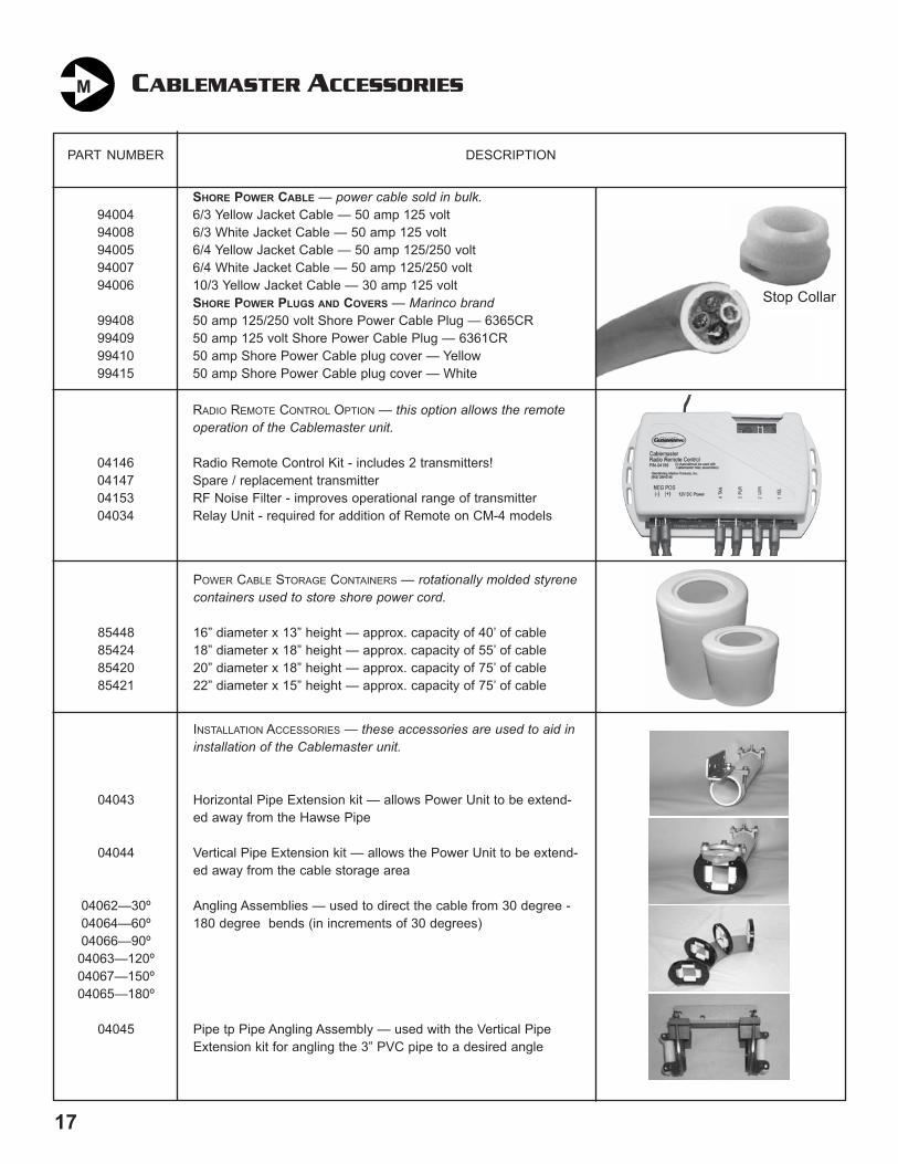
2
GETTING TO KNOW YOUR CABLEMASTER
Guide Roller Assembly
Chrome Hawse Pipe
Hawse Pipe Clamp
In-LimitSwitch
Relay Assembly(on CM-7 & CM-8 only)
Tension Rollers
Out-LimitSwitch
Main Pulley
CM-4(for 30 amp cable)
17
3 MODELS TO CHOOSE FROM:
Motor
All Cablemasters are designed to eliminate the physically demanding task of paying out and coiling up your shorepower cable. Powered extension and retraction is available at the flip of a switch! There are 3 models to choose from:
1) CM-4 Cablemaster — the CM-4 was designed to handle 30 amp shore power cable. The CM-4 usually comesattached to it’s own storage container to make installation as easy as possible. You may also order the CM-4 with TV/ telephone cable installed instead of 30 amp shore power cable.
2) CM-7 Cablemaster — the CM-7 (the workhorse of the Cablemaster line) was designed to handle 50 amp shorepower cable.
3) CM-8 Cablemaster — the CM-8 is our “heavy duty” version of the CM-7. The CM-8 will handle 100 amp shorepower cable. You definitely don’t want to be extending and retracting this heavy cable by hand!
All of these units can be configured to your boat’s specifications by utilizing the many accessories which aid in instal-lation and operation of the Cablemaster.
CM-8(for 100 amp cable)
CABLEMASTER ACCESSORIESM
PART NUMBER
9400494008940059400794006
99408994099941099415
DESCRIPTION
SHORE POWER CABLE — power cable sold in bulk.6/3 Yellow Jacket Cable — 50 amp 125 volt6/3 White Jacket Cable — 50 amp 125 volt6/4 Yellow Jacket Cable — 50 amp 125/250 volt6/4 White Jacket Cable — 50 amp 125/250 volt10/3 Yellow Jacket Cable — 30 amp 125 voltSHORE POWER PLUGS AND COVERS — Marinco brand50 amp 125/250 volt Shore Power Cable Plug — 6365CR50 amp 125 volt Shore Power Cable Plug — 6361CR50 amp Shore Power Cable plug cover — Yellow50 amp Shore Power Cable plug cover — White
04146041470415304034
RADIO REMOTE CONTROL OPTION — this option allows the remoteoperation of the Cablemaster unit.
Radio Remote Control Kit - includes 2 transmitters!Spare / replacement transmitterRF Noise Filter - improves operational range of transmitterRelay Unit - required for addition of Remote on CM-4 models
85448854248542085421
POWER CABLE STORAGE CONTAINERS — rotationally molded styrenecontainers used to store shore power cord.
16” diameter x 13” height — approx. capacity of 40’ of cable18” diameter x 18” height — approx. capacity of 55’ of cable20” diameter x 18” height — approx. capacity of 75’ of cable22” diameter x 15” height — approx. capacity of 75’ of cable
04043
04044
04062—30º04064—60º04066—90º
04063—120º04067—150º04065—180º
04045
INSTALLATION ACCESSORIES — these accessories are used to aid ininstallation of the Cablemaster unit.
Horizontal Pipe Extension kit — allows Power Unit to be extend-ed away from the Hawse Pipe
Vertical Pipe Extension kit — allows the Power Unit to be extend-ed away from the cable storage area
Angling Assemblies — used to direct the cable from 30 degree -180 degree bends (in increments of 30 degrees)
Pipe tp Pipe Angling Assembly — used with the Vertical PipeExtension kit for angling the 3” PVC pipe to a desired angle
Stop Collar
(CONTAINEROPTIONAL)
CM-7(for 50 amp cable)
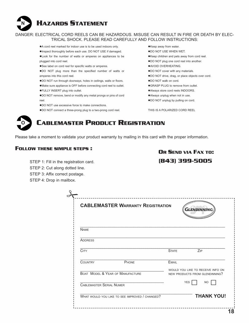
1
THANK YOU... PAGE 1
INTRODUCTION PAGE 1
GETTING TO KNOW YOUR CABLEMASTER PAGE 2
INSTALLATION OVERVIEW PAGE 3
Location for Power Unit & Cable PAGE 3
Hawse Pipe & Cable Plug Exit PAGE 3
Connection to Electrical System PAGE 3
TYPES OF INSTALLATIONS PAGE 4
INSTALLATION INSTRUCTIONS PAGE 5
WIRING INSTRUCTIONS PAGE 6
POWER CABLE INSTALLATION PAGE 8
CABLE ADJUSTMENT PAGE 8
AC WIRING INSTRUCTIONS PAGE 9
MAINTENANCE PAGE 9
OPERATION OF CABLEMASTER PAGE 10
TROUBLESHOOTING GUIDE PAGE 10
CABLEMASTER DIMENSIONS PAGE 11
CABLEMASTER WIRING DIAGRAM PAGE 15
CABLEMASTER ACCESSORIES PAGE 17
for buying the Glendinning Cablemaster. AtGlendinning, we are committed to providing you, ourcustomer, with a product that will yield trouble-freeservice. Care has been taken during each phase of themanufacturing process to guarantee a lifetime of qual-ity and performance—after all, our name is on it!
Paul & John Glendinning
Welcome to the Glendinning family of quality marineproducts. Your new Cablemaster carries the same assur-ance of quality that has stood behind every product fromGlendinning Marine Products for over 30 years—we’reproud of our reputation for quality products and service.
While installation on most boats is straight forwardand easy, for those perplexing situations, nothing beats aqualified marine electrician. Using common sense aboutsafety and a sound mechanical approach during theinstallation, the Cablemaster will provide many hours oftrouble-free service.
All Cablemasters have been designed to pay out andretract shore power cables without overloading the motorwithin the system’s power unit. Properly adjusted, aCablemaster will drag 75 feet (maximum) of shore powercable without slippage.
The Cablemaster consists of two major components;the hawse pipe and power unit. The chromed hawsepipe is designed to accommodate varying sizes of shorepower cables with the attached 30 or 50amp shorepower plug cover. Within the hawse pipe, a neoprenegasket/wiper prevents the entrance of water and helpsclean the cable as it is retracted into the boat. When thecable is retracted completely, the plug cover actuates thein-limit switch which is mounted on the face of the gasketplate inside the hawse pipe.
The drive motor, reduction gearing, guide rollerassembly and the relay assembly comprise the powerunit. The power unit is connected to the hawse pipe witha hawse pipe clamp and a length of extruded aluminumangle. The hawse pipe clamp allows the power unit to beangled to either side of vertical directing the shore powercable toward the storage compartment. The main pulleyof the Cablemaster is also freewheeling which allows thecable to be manually payed in or out.
The out-limit switch is located in the guide rollerassembly. The nylon safety collar, which is installedaround the shore power cable, activates the out-limitswitch. This collar also serves as a mechanical stoppingdevice should the limit switch fail or should the shorepower cable be forcibly pulled outward.
TABLE OF CONTENTS
THANK YOU...
INTRODUCTION
In preparing this manual, Glendinning Marine Products, Inc. has reliedupon the standards established by the National Electric Code and therecommended practices and standards for AC electrical systems forvessels prepared by the American Boat and Yacht Council, Inc. This
manual reflects practices and standards in effect at the time of publica-tion and is intended only as a guide to understand the Cablemaster.
Glendinning Marine Products, Inc. will not be liable for any loss, dam-age, incidental or consequential damages of any kind, arising in con-
nection with the use or reliance upon this manual.
ATTENTION:
18
Please take a moment to validate your product warranty by mailing in this card with the proper information.
FOLLOW THESE SIMPLE STEPS :
STEP 1: Fill in the registration card.STEP 2: Cut along dotted line.STEP 3: Affix correct postage.STEP 4: Drop in mailbox.
_______________________________________________________________________NAME
_______________________________________________________________________ADDRESS
_______________________________________________________________________CITY STATE ZIP
_______________________________________________________________________COUNTRY PHONE EMAIL
_________________________________________BOAT MODEL & YEAR OF MANUFACTURE
_________________________________________CABLEMASTER SERIAL NUMER
_______________________________________________________WHAT WOULD YOU LIKE TO SEE IMPROVED / CHANGED? THANK YOU!
CABLEMASTER WARRANTY REGISTRATION
WOULD YOU LIKE TO RECEIVE INFO ONNEW PRODUCTS FROM GLENDINNING?
YES NO
CABLEMASTER PRODUCT REGISTRATIONO
DANGER: ELECTRICAL CORD REELS CAN BE HAZARDOUS. MISUSE CAN RESULT IN FIRE OR DEATH BY ELEC-TRICAL SHOCK. PLEASE READ CAREFULLY AND FOLLOW INSTRUCTIONS:
HAZARDS STATEMENTN
OR SEND VIA FAX TO:
(843) 399-5005
"
!A cord reel marked for indoor use is to be used indoors only.
!Inspect thoroughly before each use. DO NOT USE if damaged.
!Look for the number of watts or amperes on appliances to be
plugged into cord reel.
!See label on cord reel for specific watts or amperes.
!DO NOT plug more than the specified number of watts or
amperes into this cord reel.
!DO NOT run through doorways, holes in ceilings, walls or floors.
!Make sure appliance is OFF before connecting cord reel to outlet.
!FULLY INSERT plug into outlet.
!DO NOT remove, bend or modify any metal prongs or pins of cord
reel.
!DO NOT use excessive force to make connections.
!DO NOT connect a three-prong plug to a two-prong cord reel.
!Keep away from water.
!DO NOT USE WHEN WET.
!Keep children and pets away from cord reel.
!DO NOT plug one cord reel into another.
!AVOID OVERHEATING.
!DO NOT cover with any materials.
!DO NOT drive, drag, or place objects over cord.
!DO NOT walk on cord.
!GRASP PLUG to remove from outlet.
!Always store cord reels INDOORS.
!Always unplug when not in use.
!DO NOT unplug by pulling on cord.
THIS IS A POLARIZED CORD REEL
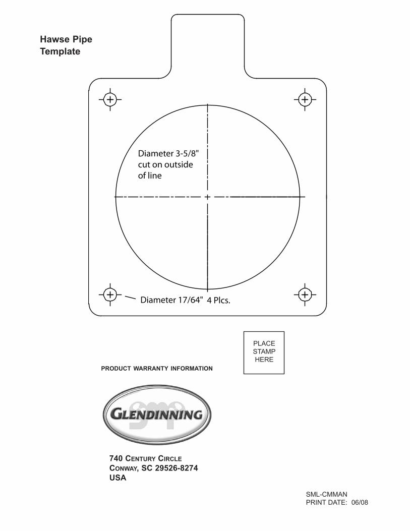
GUIDE TO:
"" DESCRIPTION
"" INSTALLATION
"" OPERATION
740 Century CircleConway, SC 29526
Phone: (843) 399-6146Fax: (843) 399-5005
www.glendinningprods.com
GGGGLLLLEEEENNNNDDDDIIIINNNNNNNNIIIINNNNGGGG
CCABLEMASTEABLEMASTERRShore Power Cable Storage System
SML-CMMANPRINT DATE: 06/08
740 CENTURY CIRCLECONWAY, SC 29526-8274USA
PRODUCT WARRANTY INFORMATION
PLACESTAMPHERE
CM-7 for 50 amp
CM-4 for 30 amp
CM-8 for 100 amp
Diameter 3-5/8"cut on outsideof line
Diameter 17/64" 4 Plcs.
Hawse Pipe Template