general catalogue - cembre
TRANSCRIPT
G E N E R A L CATA L O G U E

Cembre S.p.A. factory in Brescia (ITALY)covers an area of approximately 121.000 sqm
QUALITY POLICY AND OBJECTIVES
This catalogue illustrates the range of our standard products.For each product family we indicate the principal features, and some-times the most frequent applica-tions and the necessary guidelines for a correct application. Our sales personnel are at your disposal to supply more detailed information and our design and development engineers are available to study new solutions to particular appli-cations.
On 14th December 1990 Cembre SpA Quality Management System was certified by Lloyd’s Register of Quality Assurance (LRQA) accord-ing to ISO 9002-1987 EN 29002 - 1987 BS 5750: Part 2: 1987 for the manufacture of insulated and uninsulated copper crimping connectors.Then on 22nd December 1992 Cembre SpA was certified ISO 9001 for the design and manufac-ture of cable accessories, electrical connectors and associated tools.The activities of the main premises in Brescia, the Italian regional offi-cies and the subsidiary companies in Great Britain, France, Spain, Germany and USA are governed by a single Quality System, assessed by Lloyd’s Register of Quality as conforming to the ISO 9001:2008 norm, for the design, manufacture and sales of electrical connectors and associated tools, cable acces-sories, marking systems, tooling and products for railway applica-tions. In house repair, refurbish-ment and calibration of tooling.This guarantees a homoge-neous and high quality level of the prod-ucts and services that Cembre offers to its customers.
Cembre S.p.A. has recently rec-ognised the need to align its Envi-ronmental Management System with the spirit and content of UNI EN ISO 14001: 2004 as funda-mental to future development. To this end the company under-took a wide-ranging review of all functions including development and design stages, material se-lection, usage and manufacturing processes. The resulting definition of opera-tional procedures in line with these aims and provisions has enabled Cembre S.p.A. to achieve Environ-mental Certification, further high-lighting the companies sensitive and careful approach to environ-mental protection.
Cembre S.p.A. has recently en-hanced its business processes with the certification by Lloyd's Register of Quality Assurance, of its Management System for the Health and Safety of Workers,
in accordance with the standard OHSAS18001:2007 (Occupation-al Health and Safety Management System).The project, launched in early 2011, was strategically designed to facili-tate the active participation of all employees at every level in the appli-cation of systems management, in order to optimise compliance of risk management capability with regard to laws and regulations concerning the health and safety of workers. All employees have received exhaustive training and are involved, by exercis-ing their individual responsibility and competence, as key players in the identification of residual risk situa-tions and the proposal of corrective solutions.For Cembre then, this certification is not only the proper recognition of the quality of work performed, but also an incentive to maintain a de-termined competitive advantage in increasingly difficult and aggressive international markets.
All Cembre products comply with Directive 2011/65/EU of the European Parliament and Council dated 8 June 2011 (and subse-quent amendment).

Cembre Ltd.factory in Curdworth (Birmingham)
ProductionUnits
1
Index page page
2
CONNECTORS FOR CONTROL, POWER AND DISTRIBUTION
Halogen free insulated terminals type VP, RP, BP, GP . . . . . . . . . . . . . . 4-5Insulated chain terminals type CRP, CBP, CGP . . . . . . . . . . . . . . . . . . . 6-7PVC insulated crimp terminals type RF, BF, GF . . . . . . . . . . . . . . . . . . 8-9Reinforced PA 6.6 insulated terminals type RKY, BKY, GKY . . . . . . . . . 10-11Female disconnect terminals type RF-F, BF-F, GF-F . . . . . . . . . . . . . . . . 12Male disconnect terminals type RF-M, BF-M, GF-M . . . . . . . . . . . . . . . 12Partially insulated male/female connectors type RF-FM, BF-FM. . . . . . . 12Insulated bullet and socket connectors type RF-B, BF-B . . . . . . . . . . . . 12Butt and parallel connectors type PL-M, PL-P . . . . . . . . . . . . . . . . . . . 13Butt connectors type NL-M . . . . . . . . . . . . . . . . . . . . . . . . . . . . . . . 13PE HD insulated, heat shrinkable type WL-M . . . . . . . . . . . . . . . . . . . 13Close end connectors type NL-P . . . . . . . . . . . . . . . . . . . . . . . . . . . . 13Reinforced disconnect terminals type RKF, BKF, GKF . . . . . . . . . . . . . . 14Female connectors, open barrel type RN-FA, BN-FA . . . . . . . . . . . . . . 14Male conectors, open barrel type RN-MA, BN-MA . . . . . . . . . . . . . . . 15Male tabs, for board mounting type MP, MPD . . . . . . . . . . . . . . . . . . 15Connector sleeves type CFA, CMA . . . . . . . . . . . . . . . . . . . . . . . . . . 15Insulated end sleeves type PKE, PKC, CPKD. . . . . . . . . . . . . . . . . . . . 16“Twin” insulated end sleeves type PKET, PKCT. . . . . . . . . . . . . . . . . . . 17Uninsulated end sleeves type KE . . . . . . . . . . . . . . . . . . . . . . . . . . . . 17Uninsulated terminals type S . . . . . . . . . . . . . . . . . . . . . . . . . . . . . . 18-19Uninsulated terminals type RN, BN, GN . . . . . . . . . . . . . . . . . . . . . . 20-21Copper tube crimping lugs type A-M . . . . . . . . . . . . . . . . . . . . . . . . . 22-23Ring tongue terminals with contained palm for L.V. circuit breakers type A-M . . 24Copper tube crimping lugs type A-L angled 90°. . . . . . . . . . . . . . . . . . 25Copper tube terminals type A-2M . . . . . . . . . . . . . . . . . . . . . . . . . . . 26Through connectors type L-M. . . . . . . . . . . . . . . . . . . . . . . . . . . . . . 27Parallel connectors type L-P. . . . . . . . . . . . . . . . . . . . . . . . . . . . . . . 27PA6.6 insulated Copper tube lugs type ANE-M . . . . . . . . . . . . . . . . . . 28PA6.6 insulated fork terminals type ANE-U. . . . . . . . . . . . . . . . . . . . . 29Flexible braids type FL . . . . . . . . . . . . . . . . . . . . . . . . . . . . . . . . . . . 29PA6.6 insulated pin terminals type ANE-P . . . . . . . . . . . . . . . . . . . . . 30Uninsulated pin connectors type A-P . . . . . . . . . . . . . . . . . . . . . . . . . 30PA6.6 insulated Copper tube lugs type ANE-M, for extra flexible Copper conductor . 31Copper tube crimping lugs type A-M, for extra flexible Copper conductor . 32Copper tube lugs 4ESI fixing . . . . . . . . . . . . . . . . . . . . . . . . . . . . . . . 33Insulated covers type ES . . . . . . . . . . . . . . . . . . . . . . . . . . . . . . . . . 33Copper tube crimping lugs according to DIN 46235 type DR . . . . . . . . 34-35Crimping through connectors according DIN 46267 T.1 type DSV . . . . 35Colour coded Copper crimping lugs type C . . . . . . . . . . . . . . . . . . . . . 36-37Colour coded Copper crimping lugs type CL . . . . . . . . . . . . . . . . . . . . 38Colour coded Copper crimping lugs type C-D . . . . . . . . . . . . . . . . . . . 39Colour coded splices type BSCL . . . . . . . . . . . . . . . . . . . . . . . . . . . . 40
CONNECTORS FOR DERIVATIONS AND EARTHING
Sleeve connectors type C-C . . . . . . . . . . . . . . . . . . . . . . . . . . . . . . . 41Mechanical fixing lugs . . . . . . . . . . . . . . . . . . . . . . . . . . . . . . . . . . . 42Cable clamps . . . . . . . . . . . . . . . . . . . . . . . . . . . . . . . . . . . . . . . . 43
HIGH VOLTAGE COPPER TERMINALS
High voltage terminals type 2A-M . . . . . . . . . . . . . . . . . . . . . . . . . . . 44High voltage terminals type 2A-2M . . . . . . . . . . . . . . . . . . . . . . . . . . 45High voltage heavy duty Copper terminals type CA-M . . . . . . . . . . . . . 46High voltage heavy duty Copper terminals type CA-2M . . . . . . . . . . . . 47High voltage terminals type 2A-2M/55° . . . . . . . . . . . . . . . . . . . . . . 47High voltage stalk connectors type MT-C . . . . . . . . . . . . . . . . . . . . . . 48High voltage Copper through connectors type MT-TD, MT-GC . . . . . . . . 49
CONNECTORS FOR ALUMINIUM CONDUCTORS
Aluminium terminals type AA-M . . . . . . . . . . . . . . . . . . . . . . . . . . . . 50Through connectors type MTMA-GC, MTMA/1 . . . . . . . . . . . . . . . . . 51Reducer through connectors type MTMA-GC . . . . . . . . . . . . . . . . . . . 51Aluminium terminals type AAD-M . . . . . . . . . . . . . . . . . . . . . . . . . . . 52Aluminium through connectors type DSVA . . . . . . . . . . . . . . . . . . . . . 53Bimetallic connectors, Copper palm fixing type CAA-M . . . . . . . . . . . . . 54Bimetallic connectors, Copper pin type MTA-C . . . . . . . . . . . . . . . . . . 54
TERMINAL BLOCKS
ZETApiù single pole terminal blocks . . . . . . . . . . . . . . . . . . . . . . . 56-59
ZETAblock power distribution blocks . . . . . . . . . . . . . . . . . . . . . . . 60-61
ZETAmini one way terminal blocks. . . . . . . . . . . . . . . . . . . . . . . . 62
CABLE GLANDS AND ACCESSORIES
cable glands, Polyamide, IP68. . . . . . . . . . . . . . . . . . . .64-66 cable glands, Polyamide, IP68. . . . . . . . . . . . . . . . . . . .67 ATEX cable glands, Polyamide, IP65 . . . . . . . . . . . . . . .68Compression cable glands, Polyamide PA6, IP54 . . . . . . . . . . . . . . . .69-70Compression cable glands & hole plugs, Polystyrene, IP54 . . . . . . . . .71 cable glands, Nickel plated Brass, IP68 . . . . . . . . . . . .72-75 ATEX cable glands, Nickel plated Brass, IP65 . . . . . . . .76EMC cable glands & locknuts, Nickel plated Brass, IP68 . . . . . . . . . .76Compression cable glands, Nickel plated & plain Brass, IP54 . . . . . . .77 cable glands, Stainless Steel, IP68 . . . . . . . . . . . . . . . . .78-79Locknuts with & without collar, Polyamide . . . . . . . . . . . . . . . . . . . . .80-81Locknuts, Nickel plated & plain Brass . . . . . . . . . . . . . . . . . . . . . . . .82EMC locknuts, Nickel plated Brass . . . . . . . . . . . . . . . . . . . . . . . . .83 locknuts, Stainless Steel . . . . . . . . . . . . . . . . . . . . . . . .83Internal plugs & multi-entry seals for cable glands . . . . . . . . . . . . . . . .84-85Thread enlargers, reducers and converters, Nickel plated Brass . . . . .86-87Accessories. . . . . . . . . . . . . . . . . . . . . . . . . . . . . . . . . . . . . . . . . .88O-rings, sealing rings and compression washers . . . . . . . . . . . . . . . .89-91Entry plugs, Polyamide PA6, Polystyrene, IP54 . . . . . . . . . . . . . . . . .92-93Entry bushes, Polyamide PA6 . . . . . . . . . . . . . . . . . . . . . . . . . . . . .94Entry plugs & bushes, Nickel plated & plain Brass, IP54 . . . . . . . . . . .95RUTASEAL grommets, EPDM, IP67 . . . . . . . . . . . . . . . . . . . . . . . . .96
CABLE & CONDUIT ACCESSORIES
retaining clips for cable & conduit, ABS . . . . . . . . . . .96
MECHANICAL TOOLS
Mechanical tools . . . . . . . . . . . . . . . . . . . . . . . . . . . . . . . . . . . . . .98-115Pneumatic press and bench tools . . . . . . . . . . . . . . . . . . . . . . . . . . .117-122
HYDRAULIC TOOLS
Hydraulic crimping tools . . . . . . . . . . . . . . . . . . . . . . . . . . . . . . . . . . .124-135Hydraulic cable cutters . . . . . . . . . . . . . . . . . . . . . . . . . . . . . . . . . . . .136-144Special tools . . . . . . . . . . . . . . . . . . . . . . . . . . . . . . . . . . . . . . . . . . .145-147Accessories. . . . . . . . . . . . . . . . . . . . . . . . . . . . . . . . . . . . . . . . . . . .148Crimping force gauges & pressure test devices . . . . . . . . . . . . . . . . . . .148
CORDLESS HYDRAULIC TOOLS . . . . . . . . . . . . . . . . . . . . . . . . . . . .150-168
HYDRAULIC PUMPS . . . . . . . . . . . . . . . . . . . . . . . . . . . . . . . . . . . .170-174
HYDRAULIC UNITS . . . . . . . . . . . . . . . . . . . . . . . . . . . . . . . . . . . .175-176
DIE SELECTOR CHART . . . . . . . . . . . . . . . . . . . . . . . . . . . . . . . . .178-190
APPENDIX
Reference/Code cross-chart. . . . . . . . . . . . . . . . . . . . . . . . . . . . . . . .192-201Comparison of AWG, MCM and Metric conductor cross sections . . . . . .202IEC 60228 : 2004 - 11 Conductor Tables . . . . . . . . . . . . . . . . . . . . .203-205System of denomination of harmonised cablesaccording to CENELEC HD 361 . . . . . . . . . . . . . . . . . . . . . . . . . . . . . .206UL & VDE approvals . . . . . . . . . . . . . . . . . . . . . . . . . . . . . . . . . . . . .207IP ratings, flammability tests, torque settings . . . . . . . . . . . . . . . . . . . .208-210
cable glands, Polyamide, IP68 cable glands, Polyamide, IP68 cable glands, Polyamide, IP68 cable glands, Polyamide, IP68 cable glands, Polyamide, IP68 cable glands, Polyamide, IP68
cable glands, Nickel plated Brass, IP68 cable glands, Nickel plated Brass, IP68 cable glands, Nickel plated Brass, IP68 cable glands, Nickel plated Brass, IP68 cable glands, Nickel plated Brass, IP68 cable glands, Nickel plated Brass, IP68 cable glands, Nickel plated Brass, IP68 cable glands, Nickel plated Brass, IP68
spiral
spiral
ATEX cable glands, Nickel plated Brass, IP65 ATEX cable glands, Nickel plated Brass, IP65 ATEX cable glands, Nickel plated Brass, IP65 ATEX cable glands, Nickel plated Brass, IP65 ATEX cable glands, Nickel plated Brass, IP65 ATEX cable glands, Nickel plated Brass, IP65 ATEX cable glands, Nickel plated Brass, IP65
EL
EC
TR
IC
AL
C
ON
NE
CT
OR
S
4
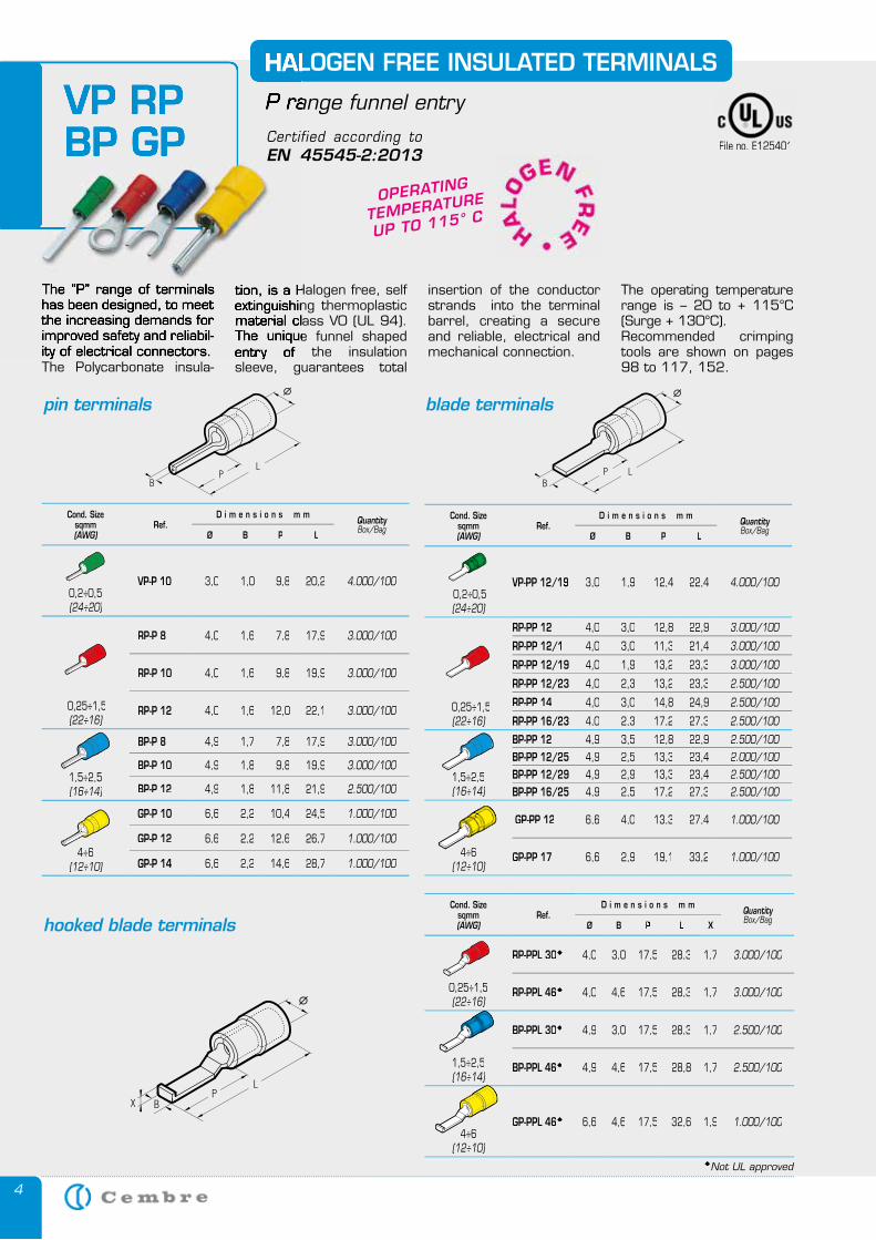
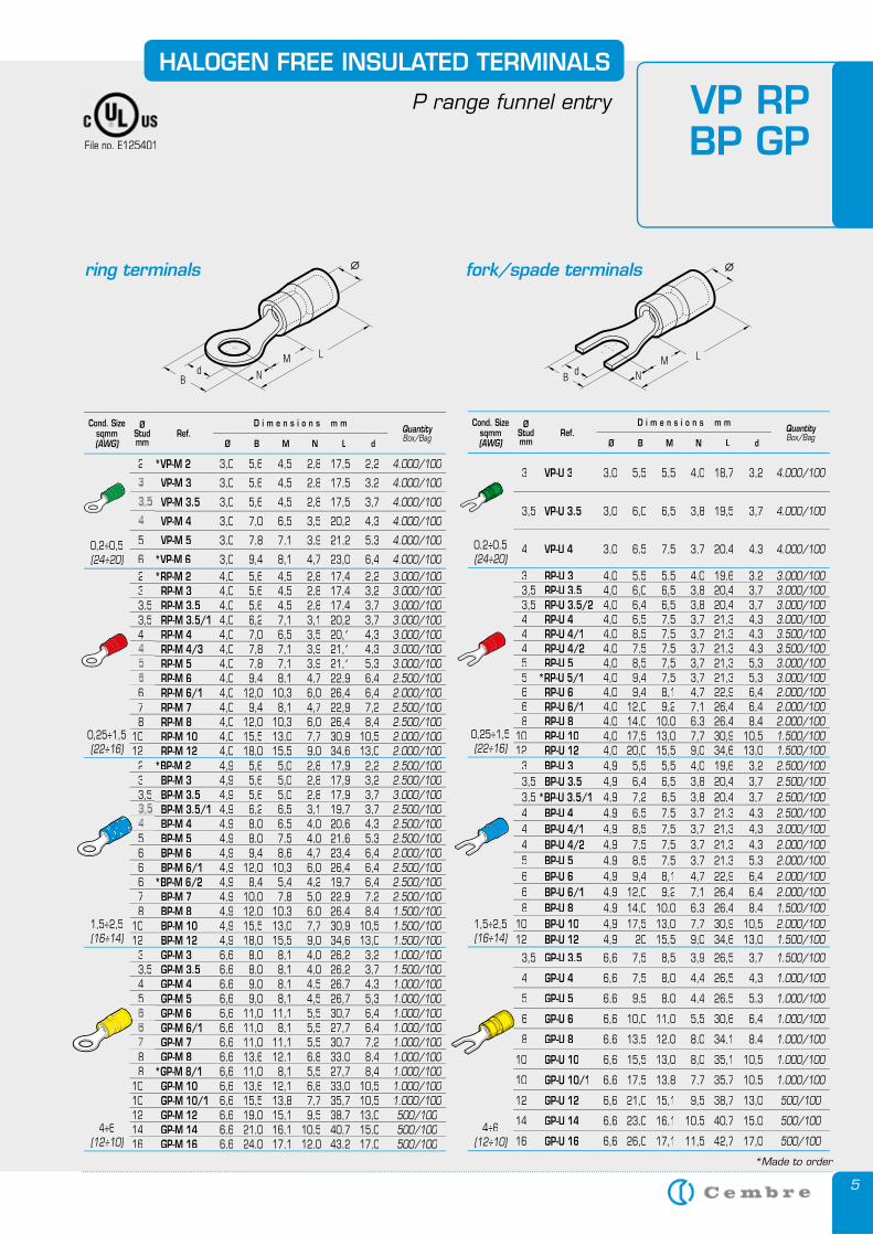
The “P” range of terminals has been designed, to meet the increasing demands for improved safety and reliabil-ity of electrical connectors. The Polycarbonate insula-
HALOGEN FREE INSULATED TERMINALS
P range funnel entry
tion, is a Halogen free, self extinguishing thermoplastic material class V0 (UL 94). The unique funnel shaped entry of the insulation sleeve, guarantees total
insertion of the conductor strands into the terminal barrel, creating a secure and reliable, electrical and mechanical connection.
The operating temperature range is – 20 to + 115°C (Surge + 130°C).Recommended crimping tools are shown on pages 98 to 117, 152.
OPERATING
TEMPERATURE
UP TO 115° C
pin terminals blade terminals
hooked blade terminals
VP RP BP GP
The “P” range of terminals has been designed, to meet the increasing demands for improved safety and reliabil-ity of electrical connectors.
HALOGEN FREE INSULATED TERMINALS
P range funnel entry
tion, is a Halogen free, self extinguishing thermoplastic material class V0 (UL 94). The unique funnel shaped entry of the insulation
VP RP BP GP File no. E125401
Cond. Sizesqmm(AWG)
Ref.D i m e n s i o n s m m
QuantityBox/Bag
Ø B P L
0,2÷0,5(24÷20)
VP-P 10 3,0 1,0 9,8 20,2 4.000/100
0,25÷1,5(22÷16)
RP-P 8 4,0 1,6 7,8 17,9 3.000/100
RP-P 10 4,0 1,6 9,8 19,9 3.000/100
RP-P 12 4,0 1,6 12,0 22,1 3.000/100
1,5÷2,5(16÷14)
BP-P 8 4,9 1,7 7,8 17,9 3.000/100
BP-P 10 4,9 1,8 9,8 19,9 3.000/100
BP-P 12 4,9 1,8 11,8 21,9 2.500/100
4÷6(12÷10)
GP-P 10 6,6 2,2 10,4 24,5 1.000/100
GP-P 12 6,6 2,2 12,6 26,7 1.000/100
GP-P 14 6,6 2,2 14,6 28,7 1.000/100
Cond. Sizesqmm(AWG)
Ref.D i m e n s i o n s m m
QuantityBox/Bag
Ø B P L
0,2÷0,5(24÷20)
VP-PP 12/19 3,0 1,9 12,4 22,4 4.000/100
0,25÷1,5(22÷16)
RP-PP 12 4,0 3,0 12,8 22,9 3.000/100
RP-PP 12/1 4,0 3,0 11,3 21,4 3.000/100
RP-PP 12/19 4,0 1,9 13,2 23,3 3.000/100
RP-PP 12/23 4,0 2,3 13,2 23,3 2.500/100
RP-PP 14 4,0 3,0 14,8 24,9 2.500/100
RP-PP 16/23 4,0 2,3 17,2 27,3 2.500/100
1,5÷2,5(16÷14)
BP-PP 12 4,9 3,5 12,8 22,9 2.500/100BP-PP 12/25 4,9 2,5 13,3 23,4 2.000/100BP-PP 12/29 4,9 2,9 13,3 23,4 2.500/100BP-PP 16/25 4,9 2,5 17,2 27,3 2.500/100
4÷6(12÷10)
GP-PP 12 6,6 4,0 13,3 27,4 1.000/100
GP-PP 17 6,6 2,9 19,1 33,2 1.000/100
Cond. Sizesqmm(AWG)
Ref.D i m e n s i o n s m m
QuantityBox/Bag
Ø B P L X
0,25÷1,5(22÷16)
RP-PPL 30 4,0 3,0 17,5 28,3 1,7 3.000/100
RP-PPL 46 4,0 4,6 17,5 28,3 1,7 3.000/100
1,5÷2,5(16÷14)
BP-PPL 30 4,9 3,0 17,5 28,3 1,7 2.500/100
BP-PPL 46 4,9 4,6 17,5 28,8 1,7 2.500/100
4÷6(12÷10)
GP-PPL 46 6,6 4,6 17,5 32,6 1,9 1.000/100
Not UL approved
Certified according to EN 45545-2:2013
5
HALOGEN FREE INSULATED TERMINALS
P range funnel entry
ring terminals fork/spade terminals
*Made to order
VP RP BP GPFile no. E125401
Cond. Sizesqmm(AWG)
ØStudmm
Ref.D i m e n s i o n s m m
QuantityBox/Bag
Ø B M N L d
0,2÷0,5(24÷20)
2 *VP-M 2 3,0 5,6 4,5 2,8 17,5 2,2 4.000/100
VP-M 3 3,0 5,6 4,5 2,8 17,5 3,2 4.000/100
VP-M 3.5 3,0 5,6 4,5 2,8 17,5 3,7 4.000/100
VP-M 4 3,0 7,0 6,5 3,5 20,2 4,3 4.000/100
5 VP-M 5 3,0 7,8 7,1 3,9 21,2 5,3 4.000/100
6 *VP-M 6 3,0 9,4 8,1 4,7 23,0 6,4 4.000/100
0,25÷1,5(22÷16) (22÷16) (22÷16)
2 *RP-M 2 4,0 5,6 4,5 2,8 17,4 2,2 3.000/1003 RP-M 3 4,0 5,6 4,5 2,8 17,4 3,2 3.000/1003,5 RP-M 3.5 4,0 5,6 4,5 2,8 17,4 3,7 3.000/1003,5 RP-M 3.5/1 4,0 6,2 7,1 3,1 20,2 3,7 3.000/1004 RP-M 4 4,0 7,0 6,5 3,5 20,1 4,3 3.000/100
RP-M 4/3 4,0 7,8 7,1 3,9 21,1 4,3 3.000/100RP-M 5 4,0 7,8 7,1 3,9 21,1 5,3 3.000/100RP-M 6 4,0 9,4 8,1 4,7 22,9 6,4 2.500/100
6 RP-M 6/1 4,0 12,0 10,3 6,0 26,4 6,4 2.000/1007 RP-M 7 4,0 9,4 8,1 4,7 22,9 7,2 2.500/1008 RP-M 8 4,0 12,0 10,3 6,0 26,4 8,4 2.500/100
10 RP-M 10 4,0 15,5 13,0 7,7 30,9 10,5 2.000/10012 RP-M 12 4,0 18,0 15,5 9,0 34,6 13,0 2.000/100
1,5÷2,5(16÷14) (16÷14) (16÷14)
2 *BP-M 2 4,9 5,6 5,0 2,8 17,9 2,2 2.500/1003 BP-M 3 4,9 5,6 5,0 2,8 17,9 3,2 2.500/1003,5 BP-M 3.5 4,9 5,6 5,0 2,8 17,9 3,7 3.000/100
BP-M 3.5/1 4,9 6,2 6,5 3,1 19,7 3,7 2.500/100BP-M 4 4,9 8,0 6,5 4,0 20,6 4,3 2.500/100
5 BP-M 5 4,9 8,0 7,5 4,0 21,6 5,3 2.500/1006 BP-M 6 4,9 9,4 8,6 4,7 23,4 6,4 2.000/1006 BP-M 6/1 4,9 12,0 10,3 6,0 26,4 6,4 2.500/1006 *BP-M 6/2 4,9 8,4 5,4 4,2 19,7 6,4 2.500/1007 BP-M 7 4,9 10,0 7,8 5,0 22,9 7,2 2.500/1008 BP-M 8 4,9 12,0 10,3 6,0 26,4 8,4 1.500/100
10 BP-M 10 4,9 15,5 13,0 7,7 30,9 10,5 1.500/10012 BP-M 12 4,9 18,0 15,5 9,0 34,6 13,0 1.500/100
4÷6(12÷10) (12÷10) (12÷10)
3 GP-M 3 6,6 8,0 8,1 4,0 26,2 3,2 1.000/1003,5 GP-M 3.5 6,6 8,0 8,1 4,0 26,2 3,7 1.500/1004 GP-M 4 6,6 9,0 8,1 4,5 26,7 4,3 1.000/1005 GP-M 5 6,6 9,0 8,1 4,5 26,7 5,3 1.000/100
GP-M 6 6,6 11,0 11,1 5,5 30,7 6,4 1.000/100GP-M 6/1 6,6 11,0 8,1 5,5 27,7 6,4 1.000/100GP-M 7 6,6 11,0 11,1 5,5 30,7 7,2 1.000/100
8 GP-M 8 6,6 13,6 12,1 6,8 33,0 8,4 1.000/1008 *GP-M 8/1 6,6 11,0 8,1 5,5 27,7 8,4 1.000/100
10 GP-M 10 6,6 13,6 12,1 6,8 33,0 10,5 1.000/10010 GP-M 10/1 6,6 15,5 13,8 7,7 35,7 10,5 1.000/10012 GP-M 12 6,6 19,0 15,1 9,5 38,7 13,0 500/10014 GP-M 14 6,6 21,0 16,1 10,5 40,7 15,0 500/10016 GP-M 16 6,6 24,0 17,1 12,0 43,2 17,0 500/100
Cond. Sizesqmm(AWG)
ØStudmm
Ref.D i m e n s i o n s m m
QuantityBox/Bag
Ø B M N L d
0,2÷0,5(24÷20)
3 VP-U 3 3,0 5,5 5,5 4,0 18,7 3,2 4.000/100
3,5 VP-U 3.5 3,0 6,0 6,5 3,8 19,5 3,7 4.000/100
4 VP-U 4 3,0 6,5 7,5 3,7 20,4 4,3 4.000/100
0,25÷1,5(22÷16)
3 RP-U 3 4,0 5,5 5,5 4,0 19,6 3,2 3.000/1003,5 RP-U 3.5 4,0 6,0 6,5 3,8 20,4 3,7 3.000/1003,5 RP-U 3.5/2 4,0 6,4 6,5 3,8 20,4 3,7 3.000/1004 RP-U 4 4,0 6,5 7,5 3,7 21,3 4,3 3.000/1004 RP-U 4/1 4,0 8,5 7,5 3,7 21,3 4,3 3.500/1004 RP-U 4/2 4,0 7,5 7,5 3,7 21,3 4,3 3.500/1005 RP-U 5 4,0 8,5 7,5 3,7 21,3 5,3 3.000/1005 *RP-U 5/1 4,0 9,4 7,5 3,7 21,3 5,3 3.000/1006 RP-U 6 4,0 9,4 8,1 4,7 22,9 6,4 2.000/1006 RP-U 6/1 4,0 12,0 9,2 7,1 26,4 6,4 2.000/1008 RP-U 8 4,0 14,0 10,0 6,3 26,4 8,4 2.000/100
10 RP-U 10 4,0 17,5 13,0 7,7 30,9 10,5 1.500/10012 RP-U 12 4,0 20,0 15,5 9,0 34,6 13,0 1.500/100
1,5÷2,5(16÷14)
3 BP-U 3 4,9 5,5 5,5 4,0 19,6 3,2 2.500/1003,5 BP-U 3.5 4,9 6,4 6,5 3,8 20,4 3,7 2.500/1003,5 *BP-U 3.5/1 4,9 7,2 6,5 3,8 20,4 3,7 2.500/1004 BP-U 4 4,9 6,5 7,5 3,7 21,3 4,3 2.500/1004 BP-U 4/1 4,9 8,5 7,5 3,7 21,3 4,3 3.000/1004 BP-U 4/2 4,9 7,5 7,5 3,7 21,3 4,3 2.000/1005 BP-U 5 4,9 8,5 7,5 3,7 21,3 5,3 2.000/1006 BP-U 6 4,9 9,4 8,1 4,7 22,9 6,4 2.000/1006 BP-U 6/1 4,9 12,0 9,2 7,1 26,4 6,4 2.000/1008 BP-U 8 4,9 14,0 10,0 6,3 26,4 8,4 1.500/100
10 BP-U 10 4,9 17,5 13,0 7,7 30,9 10,5 2.000/10012 BP-U 12 4,9 20 15,5 9,0 34,6 13,0 1.500/100
4÷6(12÷10)
3,5 GP-U 3.5 6,6 7,5 8,5 3,9 26,5 3,7 1.500/100
4 GP-U 4 6,6 7,5 8,0 4,4 26,5 4,3 1.000/100
5 GP-U 5 6,6 9,5 8,0 4,4 26,5 5,3 1.000/100
6 GP-U 6 6,6 10,0 11,0 5,5 30,6 6,4 1.000/100
8 GP-U 8 6,6 13,5 12,0 8,0 34,1 8,4 1.000/100
10 GP-U 10 6,6 15,5 13,0 8,0 35,1 10,5 1.000/100
10 GP-U 10/1 6,6 17,5 13,8 7,7 35,7 10,5 1.000/100
12 GP-U 12 6,6 21,0 15,1 9,5 38,7 13,0 500/100
14 GP-U 14 6,6 23,0 16,1 10,5 40,7 15,0 500/100
16 GP-U 16 6,6 26,0 17,1 11,5 42,7 17,0 500/100
6
*Made to order
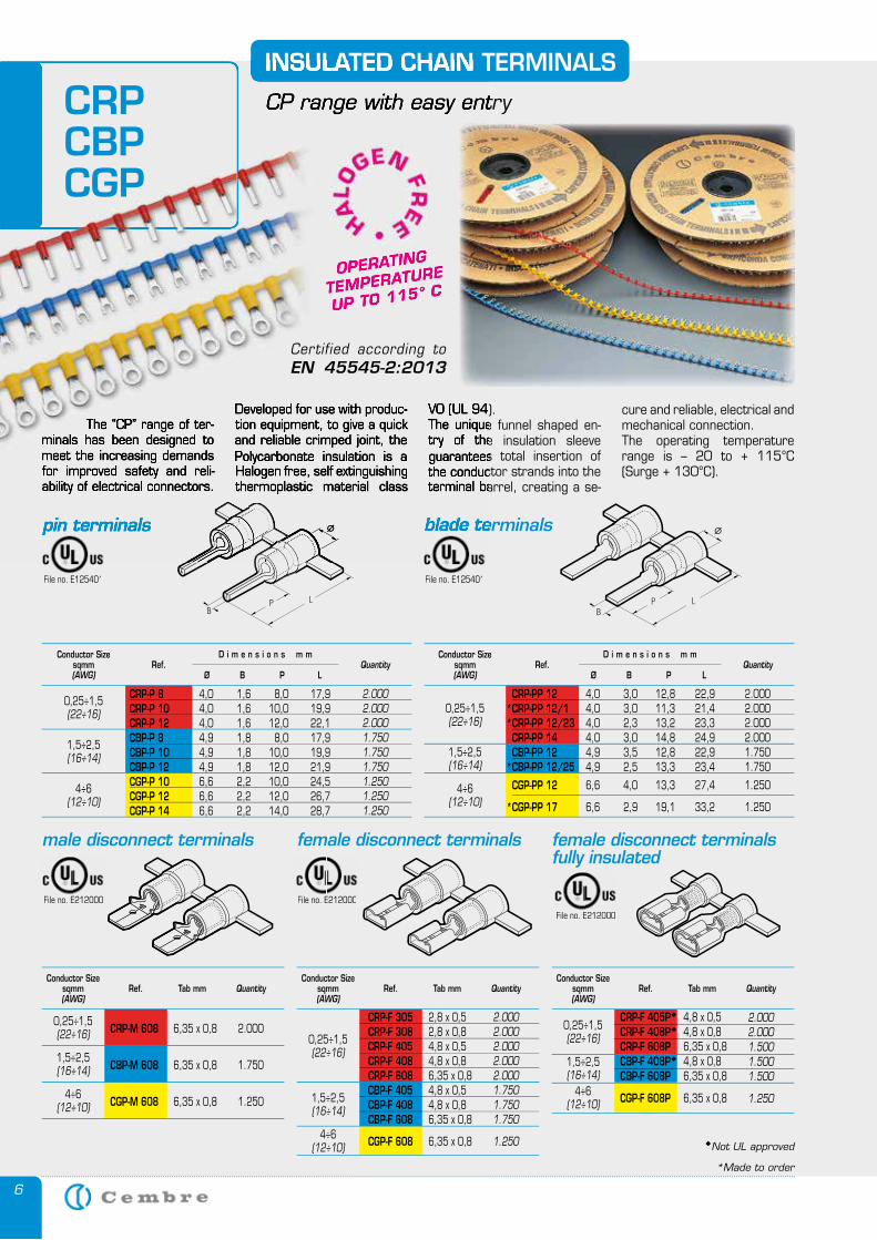
The “CP” range of ter-minals has been designed to meet the increasing demands for improved safety and reli-ability of electrical connectors.
INSULATED CHAIN TERMINALS
CP range with easy entry
Developed for use with produc-tion equipment, to give a quick and reliable crimped joint, the Polycarbonate insulation is a Halogen free, self extinguishing thermoplastic material class
V0 (UL 94). The unique funnel shaped en-try of the insulation sleeve guarantees total insertion of the conductor strands into the terminal barrel, creating a se-
cure and reliable, electrical and mechanical connection. The operating temperature range is – 20 to + 115°C (Surge + 130°C).
CRP-P 8 4,0 1,6 8,0 17,9 CRP-P 10 4,0 1,6 10,0 19,9 CRP-P 12 4,0 1,6 12,0 22,1 CBP-P 8 4,9 1,8 8,0 17,9 CBP-P 10 4,9 1,8 10,0 19,9 CBP-P 12 4,9 1,8 12,0 21,9 CGP-P 10 6,6 2,2 10,0 24,5 CGP-P 12 6,6 2,2 12,0 26,7 CGP-P 14 6,6 2,2 14,0 28,7
Conductor Sizesqmm(AWG)
QuantityØ
D i m e n s i o n s m m
LPBRef.
1,5÷2,5(16÷14)
0,25÷1,5(22÷16)
4÷6(12÷10)
CRP-PP 12 4,0 3,0 12,8 22,9 CRP-PP 12/1 4,0 3,0 11,3 21,4 CRP-PP 12/23 4,0 2,3 13,2 23,3 CRP-PP 14 4,0 3,0 14,8 24,9 CBP-PP 12 4,9 3,5 12,8 22,9 CBP-PP 12/25 4,9 2,5 13,3 23,4
CGP-PP 12 6,6 4,0 13,3 27,4
CGP-PP 17 6,6 2,9 19,1 33,2
**
*
*
Conductor Sizesqmm(AWG)
QuantityØ
D i m e n s i o n s m m
LPBRef.
1,5÷2,5(16÷14)
0,25÷1,5(22÷16)
4÷6(12÷10)
pin terminals blade terminals
CRP-M 608 6,35 x 0,8
CBP-M 608 6,35 x 0,8
CGP-M 608 6,35 x 0,8
Conductor Sizesqmm(AWG)
QuantityRef. Tab mmConductor Size
sqmm(AWG)
QuantityRef. Tab mm
1,5÷2,5(16÷14)
0,25÷1,5(22÷16)
4÷6(12÷10)
CRP-F 305 2,8 x 0,5 CRP-F 308 2,8 x 0,8 CRP-F 405 4,8 x 0,5 CRP-F 408 4,8 x 0,8 CRP-F 608 6,35 x 0,8 CBP-F 405 4,8 x 0,5 CBP-F 408 4,8 x 0,8 CBP-F 608 6,35 x 0,8
CGP-F 608 6,35 x 0,8
1,5÷2,5(16÷14)
0,25÷1,5(22÷16)
4÷6(12÷10)
male disconnect terminals female disconnect terminals female disconnect terminalsfully insulated
2.0002.0002.0001.7501.7501.7501.2501.2501.250
2.0002.0002.0002.0001.7501.750
1.250
1.250
2.000
1.750
1.250
2.0002.0002.0002.0002.0001.7501.7501.750
1.250
OPERATING
TEMPERATURE
UP TO 115° C
The “CP” range of ter-minals has been designed to meet the increasing demands for improved safety and reli-ability of electrical connectors.
INSULATED CHAIN TERMINALS
CP range with easy entry
Developed for use with produc-tion equipment, to give a quick and reliable crimped joint, the Polycarbonate insulation is a Halogen free, self extinguishing thermoplastic material class
V0 (UL 94). The unique funnel shaped en-try of the insulation sleeve guarantees total insertion of the conductor strands into the terminal barrel, creating a se-
pin terminals blade terminals
OPERATING
TEMPERATURE
UP TO 115° C
CRPCBPCGP
Conductor Sizesqmm(AWG)
QuantityRef. Tab mm
CRP-F 405P 4,8 x 0,5 CRP-F 408P 4,8 x 0,8 CRP-F 608P 6,35 x 0,8 CBP-F 408P 4,8 x 0,8 CBP-F 608P 6,35 x 0,8
CGP-F 608P 6,35 x 0,8
2.0002.0001.5001.5001.500
1.250
1,5÷2,5(16÷14)
4÷6(12÷10)
0,25÷1,5(22÷16)
File no. E125401 File no. E125401
File no. E212000 File no. E212000
File no. E212000
Not UL approved
Certified according to EN 45545-2:2013
7
INSULATED CHAIN TERMINALS
CP range with easy entry
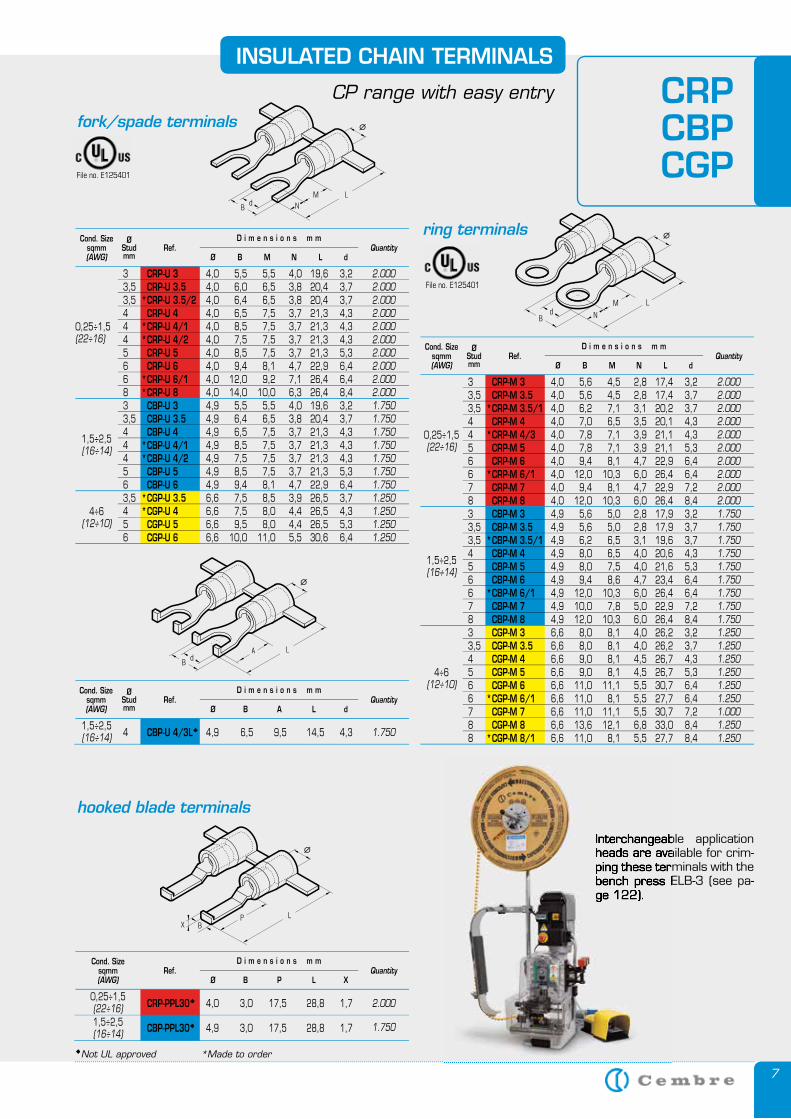
Not UL approved *Made to order
Interchangeable application heads are available for crim-ping these terminals with the bench press ELB-3 (see pa-ge 122).
3 CRP-M 3 4,0 5,6 4,5 2,8 17,4 3,2 3,5 CRP-M 3.5 4,0 5,6 4,5 2,8 17,4 3,7 3,5 CRP-M 3.5/1 4,0 6,2 7,1 3,1 20,2 3,7 4 CRP-M 4 4,0 7,0 6,5 3,5 20,1 4,3 4 CRP-M 4/3 4,0 7,8 7,1 3,9 21,1 4,3 5 CRP-M 5 4,0 7,8 7,1 3,9 21,1 5,3 6 CRP-M 6 4,0 9,4 8,1 4,7 22,9 6,4 6 CRP-M 6/1 4,0 12,0 10,3 6,0 26,4 6,4 7 CRP-M 7 4,0 9,4 8,1 4,7 22,9 7,2 8 CRP-M 8 4,0 12,0 10,3 6,0 26,4 8,4 3 CBP-M 3 4,9 5,6 5,0 2,8 17,9 3,2 3,5 CBP-M 3.5 4,9 5,6 5,0 2,8 17,9 3,7 3,5 CBP-M 3.5/1 4,9 6,2 6,5 3,1 19,6 3,7 4 CBP-M 4 4,9 8,0 6,5 4,0 20,6 4,3 5 CBP-M 5 4,9 8,0 7,5 4,0 21,6 5,3 6 CBP-M 6 4,9 9,4 8,6 4,7 23,4 6,4 6 CBP-M 6/1 4,9 12,0 10,3 6,0 26,4 6,4 7 CBP-M 7 4,9 10,0 7,8 5,0 22,9 7,2 8 CBP-M 8 4,9 12,0 10,3 6,0 26,4 8,4 3 CGP-M 3 6,6 8,0 8,1 4,0 26,2 3,2 3,5 CGP-M 3.5 6,6 8,0 8,1 4,0 26,2 3,7 4 CGP-M 4 6,6 9,0 8,1 4,5 26,7 4,3 5 CGP-M 5 6,6 9,0 8,1 4,5 26,7 5,3 6 CGP-M 6 6,6 11,0 11,1 5,5 30,7 6,4 6 CGP-M 6/1 6,6 11,0 8,1 5,5 27,7 6,4 7 CGP-M 7 6,6 11,0 11,1 5,5 30,7 7,2 8 CGP-M 8 6,6 13,6 12,1 6,8 33,0 8,4 8 CGP-M 8/1 6,6 11,0 8,1 5,5 27,7 8,4
2.0002.0002.0002.0002.0002.0002.0002.0002.0002.0001.7501.7501.7501.7501.7501.7501.7501.7501.7501.2501.2501.2501.2501.2501.2501.0001.2501.250
*
*
*
*
*
*
*
Cond. Size sqmm(AWG)
QuantityØ
D i m e n s i o n s m m
dLNMBRef.
ØStudmm
0,25÷1,5(22÷16)
1,5÷2,5(16÷14)
4÷6(12÷10)
ring terminals
fork/spade terminals
1,5÷2,5(16÷14)
4÷6(12÷10)
3 CRP-U 3 4,0 5,5 5,5 4,0 19,6 3,2 3,5 CRP-U 3.5 4,0 6,0 6,5 3,8 20,4 3,7 3,5 CRP-U 3.5/2 4,0 6,4 6,5 3,8 20,4 3,7 4 CRP-U 4 4,0 6,5 7,5 3,7 21,3 4,3 4 CRP-U 4/1 4,0 8,5 7,5 3,7 21,3 4,3 4 CRP-U 4/2 4,0 7,5 7,5 3,7 21,3 4,3 5 CRP-U 5 4,0 8,5 7,5 3,7 21,3 5,3 6 CRP-U 6 4,0 9,4 8,1 4,7 22,9 6,4 6 CRP-U 6/1 4,0 12,0 9,2 7,1 26,4 6,4 8 CRP-U 8 4,0 14,0 10,0 6,3 26,4 8,4 3 CBP-U 3 4,9 5,5 5,5 4,0 19,6 3,2 3,5 CBP-U 3.5 4,9 6,4 6,5 3,8 20,4 3,7 4 CBP-U 4 4,9 6,5 7,5 3,7 21,3 4,3 4 CBP-U 4/1 4,9 8,5 7,5 3,7 21,3 4,3 4 CBP-U 4/2 4,9 7,5 7,5 3,7 21,3 4,3 5 CBP-U 5 4,9 8,5 7,5 3,7 21,3 5,3 6 CBP-U 6 4,9 9,4 8,1 4,7 22,9 6,4 3,5 CGP-U 3.5 6,6 7,5 8,5 3,9 26,5 3,7 4 CGP-U 4 6,6 7,5 8,0 4,4 26,5 4,3 5 CGP-U 5 6,6 9,5 8,0 4,4 26,5 5,3 6 CGP-U 6 6,6 10,0 11,0 5,5 30,6 6,4
2.0002.0002.0002.0002.0002.0002.0002.0002.0002.0001.7501.7501.7501.7501.7501.7501.7501.2501.2501.2501.250
*
**
**
**
**
Cond. Size sqmm(AWG)
QuantityØ
D i m e n s i o n s m m
dLNMBRef.
ØStudmm
0,25÷1,5(22÷16)
4 CBP-U 4/3L 4,9 6,5 9,5 14,5 4,3 1.750
Cond. Size sqmm(AWG)
QuantityØ
D i m e n s i o n s m m
dLABRef.
ØStudmm
1,5÷2,5(16÷14)
CRPCBPCGP
CRP-PPL30 4,0 3,0 17,5 28,8 1,7 CBP-PPL30 4,9 3,0 17,5 28,8 1,7
2.000
1.750
Cond. Size sqmm(AWG)
QuantityØ
D i m e n s i o n s m m
XLPBRef.
0,25÷1,5(22÷16)1,5÷2,5(16÷14)
hooked blade terminals
File no. E125401
File no. E125401
Interchangeable application heads are available for crim-ping these terminals with the bench press ELB-3 (see pa-ge 122).
8
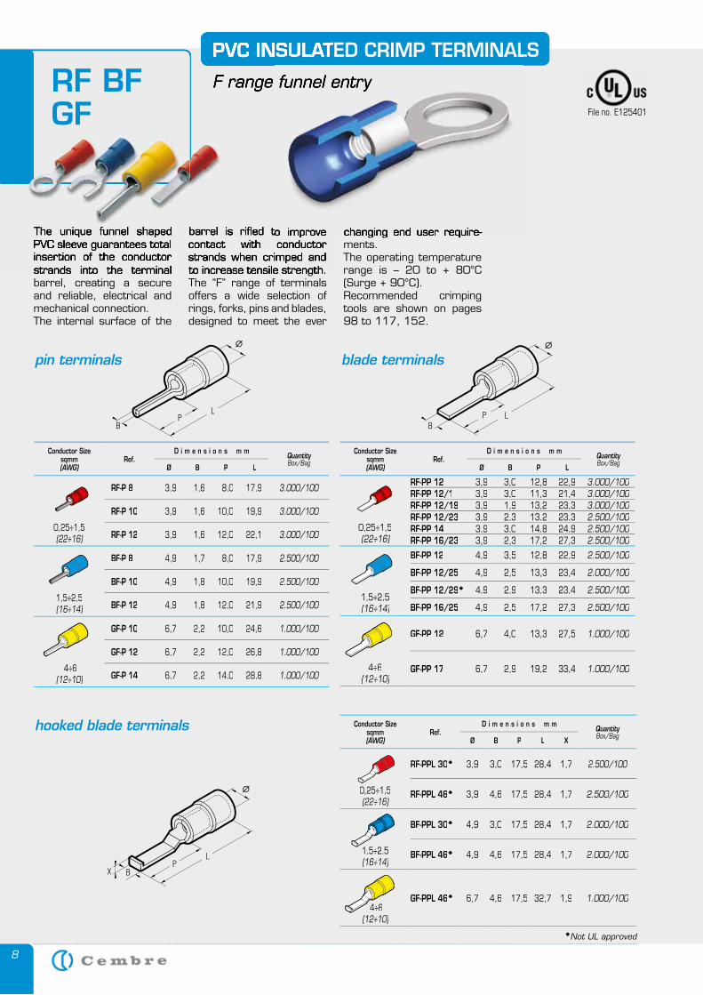
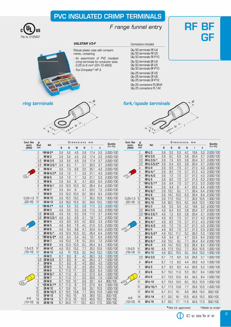
The unique funnel shaped PVC sleeve guarantees total insertion of the conductor strands into the terminal barrel, creating a secure and reliable, electrical and mechanical connection.The internal surface of the
PVC INSULATED CRIMP TERMINALS
F range funnel entry
barrel is rifled to improve contact with conductor strands when crimped and to increase tensile strength.The “F” range of terminals offers a wide selection of rings, forks, pins and blades, designed to meet the ever
pin terminals blade terminals
changing end user require-ments.The operating temperature range is – 20 to + 80°C (Surge + 90°C).Recommended crimping tools are shown on pages 98 to 117, 152.
hooked blade terminals
The unique funnel shaped PVC sleeve guarantees total insertion of the conductor strands into the terminal
PVC INSULATED CRIMP TERMINALS
F range funnel entry
barrel is rifled to improve contact with conductor strands when crimped and to increase tensile strength.
RF BFGF
PVC INSULATED CRIMP TERMINALS
F range funnel entry
changing end user require-
PVC INSULATED CRIMP TERMINALS
F range funnel entry
barrel is rifled to improve
File no. E125401
Conductor Sizesqmm(AWG)
Ref.D i m e n s i o n s m m
QuantityBox/Bag
Ø B P L
0,25÷1,5(22÷16)
RF-P 8 3,9 1,6 8,0 17,9 3.000/100
RF-P 10 3,9 1,6 10,0 19,9 3.000/100
RF-P 12 3,9 1,6 12,0 22,1 3.000/100
1,5÷2,5(16÷14)
BF-P 8 4,9 1,7 8,0 17,9 2.500/100
BF-P 10 4,9 1,8 10,0 19,9 2.500/100
BF-P 12 4,9 1,8 12,0 21,9 2.500/100
4÷6(12÷10)
GF-P 10 6,7 2,2 10,0 24,6 1.000/100
GF-P 12 6,7 2,2 12,0 26,8 1.000/100
GF-P 14 6,7 2,2 14,0 28,8 1.000/100
Conductor Sizesqmm(AWG)
Ref.D i m e n s i o n s m m
QuantityBox/Bag
Ø B P L
0,25÷1,5(22÷16)
RF-PP 12 3,9 3,0 12,8 22,9 3.000/100RF-PP 12/1 3,9 3,0 11,3 21,4 3.000/100RF-PP 12/19 3,9 1,9 13,2 23,3 3.000/100RF-PP 12/23 3,9 2,3 13,2 23,3 2.500/100RF-PP 14 3,9 3,0 14,8 24,9 2.500/100RF-PP 16/23 3,9 2,3 17,2 27,3 2.500/100
1,5÷2,5(16÷14)
BF-PP 12 4,9 3,5 12,8 22,9 2.500/100
BF-PP 12/25 4,9 2,5 13,3 23,4 2.000/100
BF-PP 12/29 4,9 2,9 13,3 23,4 2.500/100
BF-PP 16/25 4,9 2,5 17,2 27,3 2.500/100
4÷6(12÷10)
GF-PP 12 6,7 4,0 13,3 27,5 1.000/100
GF-PP 17 6,7 2,9 19,2 33,4 1.000/100
Conductor Sizesqmm(AWG)
Ref.D i m e n s i o n s m m
QuantityBox/Bag
Ø B P L X
0,25÷1,5(22÷16)
RF-PPL 30 3,9 3,0 17,5 28,4 1,7 2.500/100
RF-PPL 46 3,9 4,6 17,5 28,4 1,7 2.500/100
1,5÷2,5(16÷14)
BF-PPL 30 4,9 3,0 17,5 28,4 1,7 2.000/100
BF-PPL 46 4,9 4,6 17,5 28,4 1,7 2.000/100
4÷6(12÷10)
GF-PPL 46 6,7 4,6 17,5 32,7 1,9 1.000/100
Not UL approved
9
PVC INSULATED CRIMP TERMINALS
F range funnel entry
Not UL approved *Made to order
ring terminals fork/spade terminals
RF BFGFFile no. E125401
Cond. Size sqmm(AWG)
ØStudmm
Ref.D i m e n s i o n s m m
QuantityBox/Bag
Ø B M N L d
0,25÷1,5(22÷16)
3 RF-U 3 3,9 5,5 5,5 4,0 19,6 3,2 3.000/1003,5 RF-U 3.5 3,9 6,0 6,5 3,8 20,4 3,7 3.000/1003,5 RF-U 3.5/1 3,9 7,2 6,5 3,8 20,4 3,7 3.000/1003,5 RF-U 3.5/2 3,9 6,4 6,5 3,8 20,4 3,7 3.000/1004 RF-U 4 3,9 6,5 7,5 3,7 21,3 4,3 3.000/1004 RF-U 4/1 3,9 8,5 7,5 3,7 21,3 4,3 3.000/1004 RF-U 4/2 3,9 7,5 7,5 3,7 21,3 4,3 3.000/1005 RF-U 5 3,9 8,5 7,5 3,7 21,3 5,3 2.500/1005 *RF-U 5/1 3,9 9,4 7,5 3,7 21,3 5,3 3.000/1006 RF-U 6 3,9 9,4 8,1 4,7 22,9 6,4 2.000/1006 RF-U 6/1 3,9 12,0 9,2 7,1 26,4 6,4 2.500/1008 RF-U 8 3,9 14,0 10,0 6,3 26,4 8,4 2.000/100
10 RF-U 10 3,9 17,5 13,0 7,7 30,9 10,5 1.500/10012 RF-U 12 3,9 20,0 15,5 9,0 34,6 13,0 1.500/100
1,5÷2,5(16÷14)
3 BF-U 3 4,9 5,5 5,5 4,0 19,6 3,2 2.500/1003,5 BF-U 3.5 4,9 6,4 6,5 3,8 20,4 3,7 2.500/1003,5 *BF-U 3.5/1 4,9 7,2 6,5 3,8 20,4 3,7 3.000/1004 BF-U 4 4,9 6,5 7,5 3,7 21,3 4,3 2.500/1004 BF-U 4/1 4,9 8,5 7,5 3,7 21,3 4,3 2.000/1004 BF-U 4/2 4,9 7,5 7,5 3,7 21,3 4,3 2.000/1005 BF-U 5 4,9 8,5 7,5 3,7 21,3 5,3 2.000/1005 BF-U 5/2 4,9 12,0 11,3 5,0 26,3 5,3 1.500/1006 BF-U 6 4,9 9,4 8,1 4,7 22,9 6,4 2.000/1006 BF-U 6/1 4,9 12,0 9,2 7,1 26,4 6,4 2.000/1008 BF-U 8 4,9 14,0 10,0 6,3 26,4 8,4 1.500/100
10 BF-U 10 4,9 17,5 13,0 7,7 30,9 10,5 1.000/10012 BF-U 12 4,9 20,0 15,5 9,0 34,6 13,0 1.500/100
4÷6(12÷10) (12÷10) (12÷10)
3,5 GF-U 3.5 6,7 7,5 8,5 3,9 26,6 3,7 1.000/100
4 GF-U 4 6,7 7,5 8,0 4,4 26,6 4,3 1.000/100
5 GF-U 5 6,7 9,5 8,0 4,4 26,6 5,3 1.000/100
6 GF-U 6 6,7 10,0 11,0 5,5 30,7 6,4 1.000/100
8 GF-U 8 6,7 13,5 12,0 8,0 34,2 8,4 1.000/100
10 GF-U 10 6,7 15,5 13,0 8,0 35,2 10,5 1.000/100
10 GF-U 10/1 6,7 17,5 13,8 7,7 35,8 10,5 1.000/100
12 GF-U 12 6,7 21,0 15,1 9,5 38,8 13,0 500/100
14 GF-U 14 6,7 23,0 16,1 10,5 40,8 15,0 500/100
16 GF-U 16 6,7 26,0 17,1 11,5 42,8 17,0 500/100
Cond. Size sqmm(AWG)
ØStudmm
Ref.D i m e n s i o n s m m
QuantityBox/Bag
Ø B M N L d
0,25÷1,5(22÷16)
2 *RF-M 2 3,9 5,6 4,5 2,8 17,4 2,2 3.000/1003 RF-M 3 3,9 5,6 4,5 2,8 17,4 3,2 3.000/1003,5 RF-M 3.5 3,9 5,6 4,5 2,8 17,4 3,7 3.000/1003,5 RF-M 3.5/1 3,9 6,2 7,1 3,1 20,3 3,7 3.000/100
RF-M 4 3,9 7,0 6,5 3,5 20,1 4,3 3.000/100RF-M 4/3 3,9 7,8 7,1 3,9 21,1 4,3 3.000/100RF-M 5 3,9 7,8 7,1 3,9 21,1 5,3 2.500/100
6 RF-M 6 3,9 9,4 8,1 4,7 22,9 6,4 2.500/1006 RF-M 6/1 3,9 12,0 10,3 6,0 26,4 6,4 2.000/1007 RF-M 7 3,9 9,4 8,1 4,7 22,9 7,2 2.500/1008 RF-M 8 3,9 12,0 10,3 6,0 26,4 8,4 2.000/100
10 RF-M 10 3,9 15,5 13,0 7,7 30,9 10,5 1.500/10012 RF-M 12 3,9 18,0 15,5 9,0 34,6 13,0 1.500/100
1,5÷2,5(16÷14)
2 *BF-M 2 4,9 5,6 5,0 2,8 17,9 2,2 3.000/1003 BF-M 3 4,9 5,6 5,0 2,8 17,9 3,2 2.500/1003,5 BF-M 3.5 4,9 5,6 5,0 2,8 17,9 3,7 2.500/1003,5 BF-M 3.5/1 4,9 6,2 6,5 3,1 19,7 3,7 2.500/1004 BF-M 4 4,9 8,0 6,5 4,0 20,6 4,3 2.500/100
BF-M 5 4,9 8,0 7,5 4,0 21,6 5,3 2.000/100BF-M 6 4,9 9,4 8,6 4,7 23,4 6,4 2.000/100BF-M 6/1 4,9 12,0 10,3 6,0 26,4 6,4 2.000/100
6 *BF-M 6/2 4,9 8,4 5,4 4,2 19,7 6,4 2.500/1007 BF-M 7 4,9 10,0 7,8 5,0 22,9 7,2 2.000/1008 BF-M 8 4,9 12,0 10,3 6,0 26,4 8,4 1.500/100
10 BF-M 10 4,9 15,5 13,0 7,7 30,9 10,5 1.500/10012 BF-M 12 4,9 18 15,5 9,0 34,6 13,0 1.000/100
4÷6(12÷10) (12÷10) (12÷10)
3 GF-M 3 6,7 8,0 8,1 4,0 26,3 3,2 1.000/1003,5 GF-M 3.5 6,7 8,0 8,1 4,0 26,3 3,7 1.000/1004 GF-M 4 6,7 9,0 8,1 4,5 26,8 4,3 1.000/1005 GF-M 5 6,7 9,0 8,1 4,5 26,8 5,3 1.000/1006 GF-M 6 6,7 11,0 11,1 5,5 30,8 6,4 1.000/1006 GF-M 6/1 6,7 11,0 8,1 5,5 27,8 6,4 1.000/1007 GF-M 7 6,7 11,0 11,1 5,5 30,8 7,2 1.000/1008 GF-M 8 6,7 13,6 12,1 6,8 33,1 8,4 800/1008 *GF-M 8/1 6,7 11,0 8,1 5,5 27,8 8,4 1.000/100
10 GF-M 10 6,7 13,6 12,1 6,8 33,1 10,5 1.000/10010 GF-M 10/1 6,7 15,5 13,8 7,7 35,8 10,5 1.000/10012 GF-M 12 6,7 19,0 15,1 9,5 38,8 13,0 500/10014 GF-M 14 6,7 21,0 16,1 10,5 40,8 15,0 500/10016 GF-M 16 6,7 24,0 17,1 12,0 43,3 17,0 500/100
VALSTAR V3-F Connectors included:
Qty 50 terminals RF-U4 Qty 50 terminals RF-U5 Qty 50 terminals RF-P10 Qty 50 terminals BF-U4 Qty 50 terminals BF-U5 Qty 50 terminals BF-P10 Qty 25 terminals GF-U5 Qty 25 terminals GF-U6 Qty 25 terminals GF-P12 Qty 25 connectors PL06-M Qty 25 connectors PL1-M
Robust plastic case with compart-ments, containing:- An assortment of PVC insulated
crimp terminals for conductor sizes 0,25 to 6 mm2 (22÷10 AWG).- Tool Crimpstar® HP 3.
10
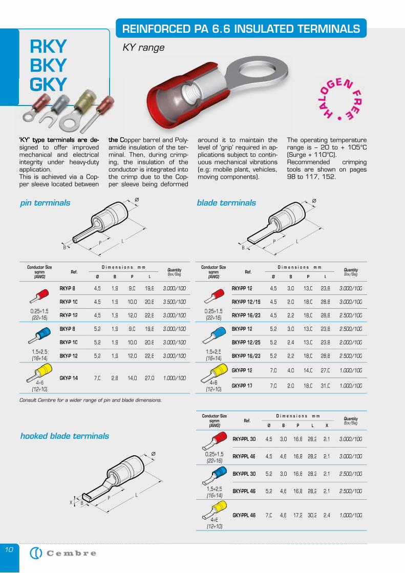
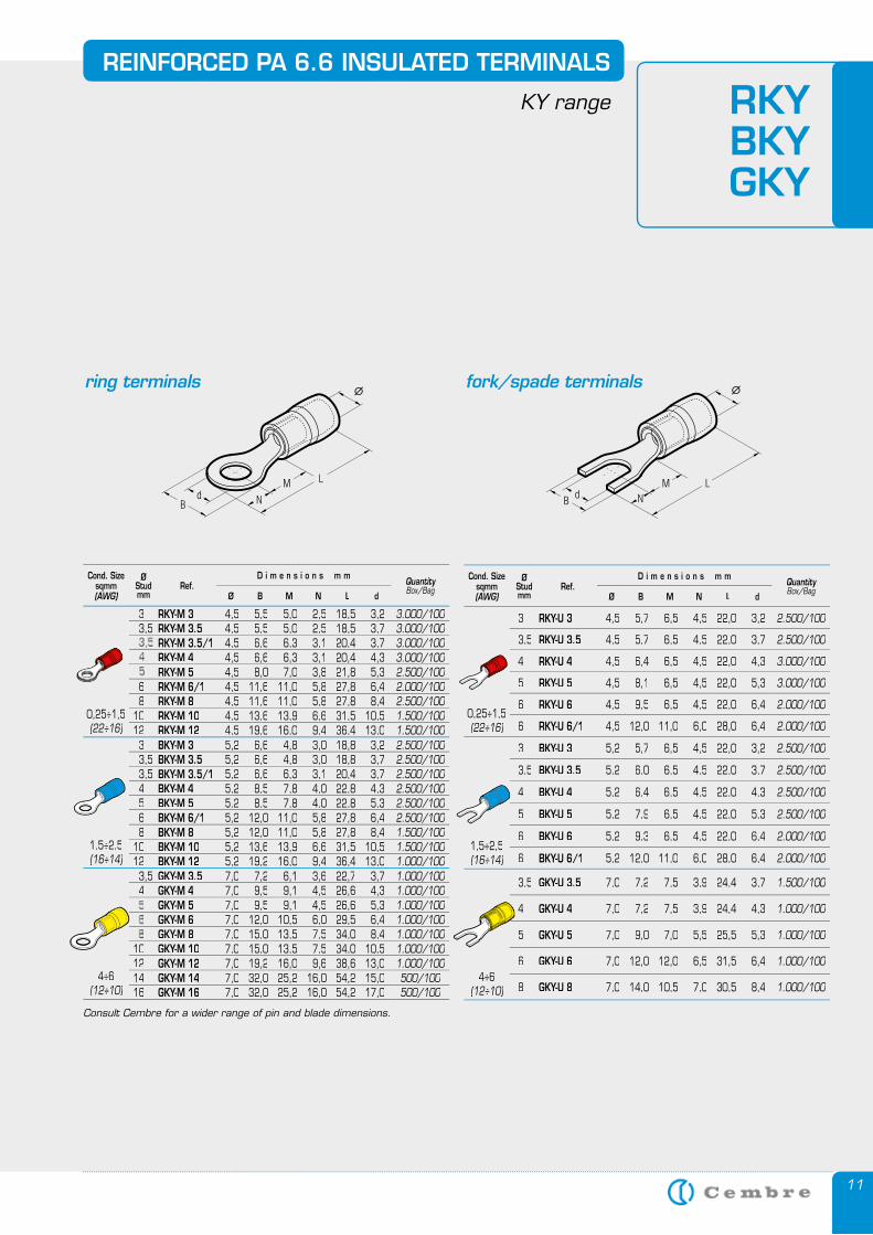
‘KY’ type terminals are de-signed to offer improved mechanical and electrical integrity under heavy-duty application. This is achieved via a Cop-per sleeve located between
REINFORCED PA 6.6 INSULATED TERMINALS
KY range
the Copper barrel and Poly-amide insulation of the ter-minal. Then, during crimp-ing, the insulation of the conductor is integrated into the crimp due to the Cop-per sleeve being deformed
around it to maintain the level of ‘grip’ required in ap-plications subject to contin-uous mechanical vibrations (e.g: mobile plant, vehicles, moving components).
The operating temperature range is – 20 to + 105°C (Surge + 110°C).Recommended crimping tools are shown on pages 98 to 117, 152.
RKY BKYGKY
‘KY’ type terminals are de-signed to offer improved
the Copper barrel and Poly-amide insulation of the ter-
GKY
pin terminals blade terminals
hooked blade terminals
Conductor Sizesqmm(AWG)
Ref.D i m e n s i o n s m m
QuantityBox/Bag
Ø B P L X
0,25÷1,5(22÷16)
RKY-PPL 30 4,5 3,0 16,8 28,2 2,1 3.000/100
RKY-PPL 46 4,5 4,6 16,8 28,2 2,1 3.000/100
1,5÷2,5(16÷14)
BKY-PPL 30 5,2 3,0 16,8 28,2 2,1 2.500/100
BKY-PPL 46 5,2 4,6 16,8 28,2 2,1 2.500/100
4÷6(12÷10)
GKY-PPL 46 7,0 4,6 17,2 30,2 2,4 1.000/100
Conductor Sizesqmm(AWG)
Ref.D i m e n s i o n s m m
QuantityBox/Bag
Ø B P L
0,25÷1,5(22÷16)
RKY-P 8 4,5 1,9 9,0 19,8 3.000/100
RKY-P 10 4,5 1,9 10,0 20,8 3.500/100
RKY-P 12 4,5 1,9 12,0 22,8 3.000/100
1,5÷2,5(16÷14)
BKY-P 8 5,2 1,9 9,0 19,8 3.000/100
BKY-P 10 5,2 1,9 10,0 20,8 3.000/100
BKY-P 12 5,2 1,9 12,0 22,8 3.000/100
(12÷10)
GKY-P 14 7,0 2,8 14,0 27,0 1.000/100
Conductor Sizesqmm(AWG)
Ref.D i m e n s i o n s m m
QuantityBox/Bag
Ø B P L
0,25÷1,5(22÷16)
RKY-PP 12 4,5 3,0 13,0 23,8 3.000/100
RKY-PP 12/19 4,5 2,0 18,0 28,8 3.000/100
RKY-PP 16/23 4,5 2,2 18,0 28,8 2.500/100
1,5÷2,5(16÷14)
BKY-PP 12 5,2 3,0 13,0 23,8 2.500/100
BKY-PP 12/25 5,2 2,4 13,0 23,8 2.000/100
BKY-PP 16/23 5,2 2,2 18,0 28,8 2.500/100
4÷6(12÷10)
GKY-PP 12 7,0 4,0 14,0 27,0 1.000/100
GKY-PP 17 7,0 2,0 18,0 31,0 1.000/100
Consult Cembre for a wider range of pin and blade dimensions.
11
REINFORCED PA 6.6 INSULATED TERMINALS
KY range RKY BKYGKY
ring terminals fork/spade terminals
Consult Cembre for a wider range of pin and blade dimensions.
Cond. Size sqmm(AWG)
ØStudmm
Ref.D i m e n s i o n s m m
QuantityBox/Bag
Ø B M N L d
0,25÷1,5(22÷16)
3 RKY-M 3 4,5 5,5 5,0 2,5 18,5 3,2 3.000/100 3,5 RKY-M 3.5 4,5 5,5 5,0 2,5 18,5 3,7 3.000/100
RKY-M 3.5/1 4,5 6,6 6,3 3,1 20,4 3,7 3.000/100RKY-M 4 4,5 6,6 6,3 3,1 20,4 4,3 3.000/100RKY-M 5 4,5 8,0 7,0 3,8 21,8 5,3 2.500/100
6 RKY-M 6/1 4,5 11,6 11,0 5,8 27,8 6,4 2.000/100 8 RKY-M 8 4,5 11,6 11,0 5,8 27,8 8,4 2.500/10010 RKY-M 10 4,5 13,6 13,9 6,6 31,5 10,5 1.500/100 12 RKY-M 12 4,5 19,6 16,0 9,4 36,4 13,0 1.500/100
1,5÷2,5(16÷14)
3 BKY-M 3 5,2 6,6 4,8 3,0 18,8 3,2 2.500/100 3,5 BKY-M 3.5 5,2 6,6 4,8 3,0 18,8 3,7 2.500/100 3,5 BKY-M 3.5/1 5,2 6,6 6,3 3,1 20,4 3,7 2.500/100 4 BKY-M 4 5,2 8,5 7,8 4,0 22,8 4,3 2.500/100 5 BKY-M 5 5,2 8,5 7,8 4,0 22,8 5,3 2.500/100 6 BKY-M 6/1 5,2 12,0 11,0 5,8 27,8 6,4 2.500/100 8 BKY-M 8 5,2 12,0 11,0 5,8 27,8 8,4 1.500/10010 BKY-M 10 5,2 13,6 13,9 6,6 31,5 10,5 1.500/100 12 BKY-M 12 5,2 19,2 16,0 9,4 36,4 13,0 1.000/100
4÷6(12÷10)
3,5 GKY-M 3.5 7,0 7,2 6,1 3,6 22,7 3,7 1.000/100 4 GKY-M 4 7,0 9,5 9,1 4,5 26,6 4,3 1.000/100
GKY-M 5 7,0 9,5 9,1 4,5 26,6 5,3 1.000/100GKY-M 6 7,0 12,0 10,5 6,0 29,5 6,4 1.000/100GKY-M 8 7,0 15,0 13,5 7,5 34,0 8,4 1.000/100
10 GKY-M 10 7,0 15,0 13,5 7,5 34,0 10,5 1.000/100 12 GKY-M 12 7,0 19,2 16,0 9,6 38,6 13,0 1.000/10014 GKY-M 14 7,0 32,0 25,2 16,0 54,2 15,0 500/10016 GKY-M 16 7,0 32,0 25,2 16,0 54,2 17,0 500/100
Cond. Size sqmm(AWG)
ØStudmm
Ref.D i m e n s i o n s m m
QuantityBox/Bag
Ø B M N L d
0,25÷1,5(22÷16)
3 RKY-U 3 4,5 5,7 6,5 4,5 22,0 3,2 2.500/100
3,5 RKY-U 3.5 4,5 5,7 6,5 4,5 22,0 3,7 2.500/100
4 RKY-U 4 4,5 6,4 6,5 4,5 22,0 4,3 3.000/100
5 RKY-U 5 4,5 8,1 6,5 4,5 22,0 5,3 3.000/100
6 RKY-U 6 4,5 9,5 6,5 4,5 22,0 6,4 2.000/100
6 RKY-U 6/1 4,5 12,0 11,0 6,0 28,0 6,4 2.000/100
1,5÷2,5(16÷14)
3 BKY-U 3 5,2 5,7 6,5 4,5 22,0 3,2 2.500/100
3,5 BKY-U 3.5 5,2 6,0 6,5 4,5 22,0 3,7 2.500/100
4 BKY-U 4 5,2 6,4 6,5 4,5 22,0 4,3 2.500/100
5 BKY-U 5 5,2 7,9 6,5 4,5 22,0 5,3 2.500/100
6 BKY-U 6 5,2 9,3 6,5 4,5 22,0 6,4 2.000/100
6 BKY-U 6/1 5,2 12,0 11,0 6,0 28,0 6,4 2.000/100
4÷6(12÷10)
3,5 GKY-U 3.5 7,0 7,2 7,5 3,9 24,4 3,7 1.500/100
4 GKY-U 4 7,0 7,2 7,5 3,9 24,4 4,3 1.000/100
5 GKY-U 5 7,0 9,0 7,0 5,5 25,5 5,3 1.000/100
6 GKY-U 6 7,0 12,0 12,0 6,5 31,5 6,4 1.000/100
8 GKY-U 8 7,0 14,0 10,5 7,0 30,5 8,4 1.000/100
12
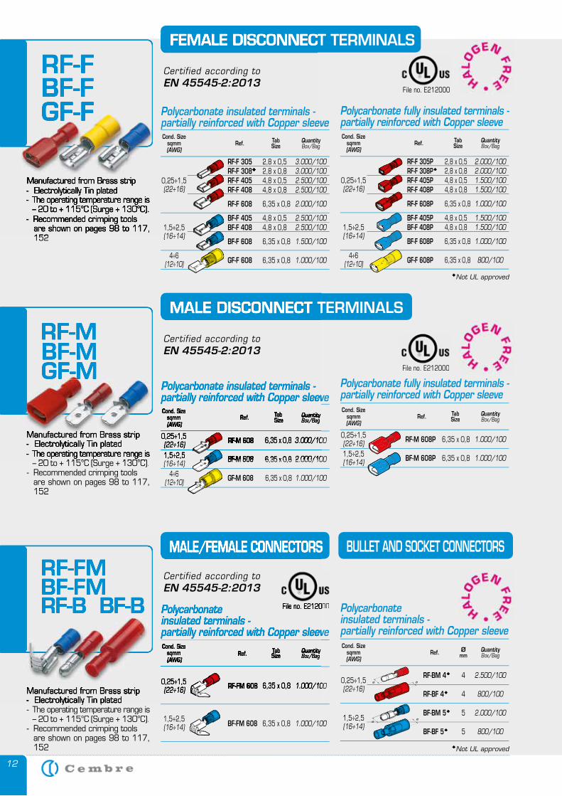
Manufactured from Brass strip - Electrolytically Tin plated
- Recommended crimping tools are shown on pages 98 to 117,
152
FEMALE DISCONNECT TERMINALS
Manufactured from Brass strip - Electrolytically Tin plated
– 20 to + 115°C (Surge + 130°C).- Recommended crimping tools are shown on pages 98 to 117,
152
Cond. Sizesqmm(AWG)
QuantityBox/BagRef. Tab
Size
RF-M 608 6,35 x 0,8
BF-M 608 6,35 x 0,8
GF-M 608 6,35 x 0,8
3.000/100
2.000/100
1.000/100
1,5÷2,5(16÷14)
0,25÷1,5(22÷16)
4÷6(12÷10)
Manufactured from Brass strip - Electrolytically Tin plated- The operating temperature range is
– 20 to + 115°C (Surge + 130°C).- Recommended crimping tools are shown on pages 98 to 117,
152
MALE/FEMALE CONNECTORS BULLET AND SOCKET CONNECTORS
Cond. Sizesqmm(AWG)
QuantityBox/BagRef. Tab
Size
RF-FM 608 6,35 x 0,8
BF-FM 608 6,35 x 0,8
1.000/100
1.000/1001,5÷2,5(16÷14)
0,25÷1,5(22÷16)
MALE DISCONNECT TERMINALS
Polycarbonate insulated terminals -partially reinforced with Copper sleeve
Polycarbonate insulated terminals -partially reinforced with Copper sleeve
RF-FBF-FGF-F
Manufactured from Brass strip - Electrolytically Tin plated- The operating temperature range is
– 20 to + 115°C (Surge + 130°C).- Recommended crimping tools are shown on pages 98 to 117,
152
FEMALE DISCONNECT TERMINALS
RF-FBF-FGF-F
RF-MBF-MGF-M
Manufactured from Brass strip - Electrolytically Tin plated- The operating temperature range is
– 20 to + 115°C (Surge + 130°C).
Cond. Sizesqmm(AWG)
QuantityBox/BagQuantityBox/BagQuantityRef. Tab
Size
RF-M 608 6,35 x 0,8
BF-M 608 6,35 x 0,8
3.000/100
2.000/1001,5÷2,5
0,25÷1,5(22÷16)
MALE DISCONNECT TERMINALS
Polycarbonate insulated terminals -partially reinforced with Copper sleeve
RF-MBF-MGF-M
RF-FMBF-FMRF-B BF-B
Manufactured from Brass strip - Electrolytically Tin plated
MALE/FEMALE CONNECTORS
Cond. Sizesqmm(AWG)
QuantityBox/BagQuantityBox/BagQuantityRef. Tab
Size
RF-FM 608 6,35 x 0,8 1.000/1000,25÷1,5(22÷16)
Polycarbonateinsulated terminals -partially reinforced with Copper sleeve
RF-FMBF-FMRF-B BF-B
File no. E212000
File no. E212000
File no. E212000File no. E212000
Cond. Sizesqmm(AWG)
QuantityBox/BagRef. Tab
Size
RF-F 305 2,8 x 0,5 RF-F 308 2,8 x 0,8 RF-F 405 4,8 x 0,5 RF-F 408 4,8 x 0,8
RF-F 608 6,35 x 0,8
BF-F 405 4,8 x 0,5 BF-F 408 4,8 x 0,8
BF-F 608 6,35 x 0,8
GF-F 608 6,35 x 0,8
3.000/1003.000/1002.500/1002.500/100
2.000/100
2.500/1002.500/100
1.500/100
1.000/100
1,5÷2,5(16÷14)
0,25÷1,5(22÷16)
4÷6(12÷10)
Polycarbonate insulated terminals -partially reinforced with Copper sleeve
Cond. Sizesqmm(AWG)
QuantityBox/BagRef. Tab
Size
RF-M 608P 6,35 x 0,8
BF-M 608P 6,35 x 0,8
1.000/100
1.000/100
Polycarbonate fully insulated terminals - partially reinforced with Copper sleeve
0,25÷1,5(22÷16)1,5÷2,5(16÷14)
Cond. Sizesqmm(AWG)
QuantityBox/BagRef. Ø
mm
RF-BM 4 4
RF-BF 4 4
BF-BM 5 5
BF-BF 5 5
2.500/100
800/100
2.000/100
800/100
Polycarbonate insulated terminals -partially reinforced with Copper sleeve
0,25÷1,5(22÷16)
1,5÷2,5(16÷14)
Not UL approved
Cond. Sizesqmm(AWG)
QuantityBox/BagRef. Tab
Size
RF-F 305P 2,8 x 0,5 RF-F 308P 2,8 x 0,8 RF-F 405P 4,8 x 0,5 RF-F 408P 4,8 x 0,8
RF-F 608P 6,35 x 0,8
BF-F 405P 4,8 x 0,5 BF-F 408P 4,8 x 0,8
BF-F 608P 6,35 x 0,8
GF-F 608P 6,35 x 0,8
2.000/1002.000/1001.500/1001.500/100
1.000/100
1.500/1001.500/100
1.000/100
800/100
Polycarbonate fully insulated terminals - partially reinforced with Copper sleeve
0,25÷1,5(22÷16)
1,5÷2,5(16÷14)
4÷6(12÷10)
Not UL approved
Certified according to EN 45545-2:2013
Certified according to EN 45545-2:2013
Certified according to EN 45545-2:2013
13
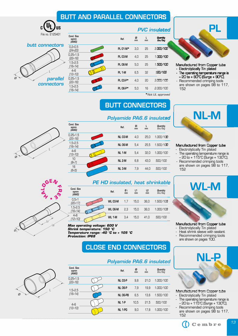
BUTT AND PARALLEL CONNECTORS
PVC insulatedCond. Size
sqmm(AWG)
QuantityBox/BagRef. Ø
mmL
mm
PL 01-M 3,0 25
PL 03-M 4,0 25
PL 06-M 5,0 25
PL 1-M 6,5 32
PL 03-P 4,0 20
PL 06-P 5,0 16
3.000/100
1.000/100
1.500/100
500/100
3.000/100
2.000/100
1,5÷2,5(16÷14)
4÷6(12÷10)
0,25÷1,5(22÷16)
0,2÷0,5(24÷20)
1,5÷2,5(16÷14)
butt connectors
parallel connectors
Manufactured from Copper tube - Electrolytically Tin plated
- Recommended crimping tools are shown on pages 98 to 117,
152
0,25÷1,5(22÷16)
BUTT CONNECTORS
Cond. Sizesqmm(AWG)
QuantityBox/BagRef. Øi
mmL
mm
NL 03-M 4,0 25,0
NL 06-M 5,4 25,5
NL 1-M 5,4 32,0
NL 2-M 6,8 43,0
NL 3-M 7,9 44,0
1.000/100
1.500/100
1.000/100
500/100
500/100
1,5÷2,5(16÷14)
4÷6(12÷10)
0,25÷1,5(22÷16)
16(6÷5)
Manufactured from Copper tube - Electrolytically Tin plated- The operating temperature range is
– 20 to + 115°C (Surge + 130°C).- Recommended crimping tools are shown on pages 98 to 117,
152
10(8÷7)
CLOSE END CONNECTORS
Manufactured from Copper tube - Electrolytically Tin plated- The operating temperature range is
– 20 to + 115°C (Surge + 130°C).- Recommended crimping tools are shown on pages 98 to 117,
152
Polyamide PA6.6 insulated
Manufactured from Copper tube - Electrolytically Tin plated- Heat shrink sleeve with sealant- Recommended crimping tools are shown on pages 100.
Cond. Sizesqmm(AWG)
QuantityBox/BagRef. Ø i
mmL1mm
L2mm
WL 03-M 1,7 15,0 36,0
WL 06-M 2,3 15,0 36,0
WL 1-M 3,4 15,0 41,0
1.500/100
1.000/100
500/100
1,5÷2,5(16÷14)
4÷6(12÷10)
0,5÷1(20÷17)
PE HD insulated, heat shrinkable
Max operating voltage: 600 VShrink temperature: 150 °C Temperature range: -40 °C to + 105 °CProtection: IP68
PL
NL-M
1.000/100
1.500/100 Manufactured from Copper tube - Electrolytically Tin plated
Polyamide PA6.6 insulated NL-M
WL-M
Manufactured from Copper tube
1.500/100
1.000/100
PE HD insulated, heat shrinkable WL-M
NL-P
Manufactured from Copper tube
NL-P
File no. E125401
Ømm
Lmm
NL 03-P 9,8 21,0
NL 06-P 7,9 19,9
NL 06-PB 6,5 13,6
NL 1-P 10,5 21,5
NL 1-PG 9,0 17,8
1.000/100
1.000/100
1.500/100
500/100
1.000/100
1,5÷2,5(16÷14)
4÷6(12÷10)
Polyamide PA6.6 insulatedCond. Size
sqmm(AWG)
QuantityBox/BagRef.
0,25÷1,5(22÷16)
BUTT AND PARALLEL CONNECTORS
PVC insulatedQuantityBox/BagQuantityBox/BagQuantity
3.000/100
1.000/100
1.500/100
500/100
3.000/100
Manufactured from Copper tube - Electrolytically Tin plated- The operating temperature range is
– 20 to + 80°C (Surge + 90°C).
PL
Not UL approved
14
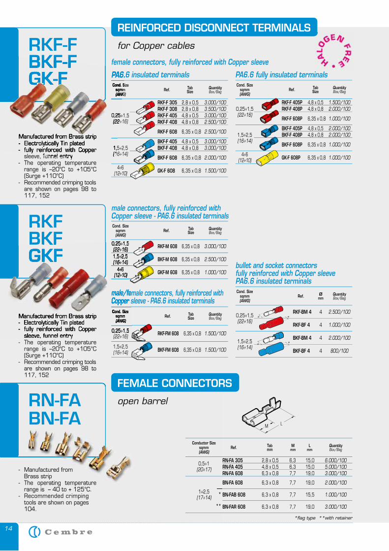
- Manufactured from Brass strip- The operating temperature
range is – 40 to + 125°C.- Recommended crimping
tools are shown on pages 104.
RN-FABN-FA
FEMALE CONNECTORS
open barrel
Conductor Sizesqmm(AWG)
QuantityBox/Bag
TabmmRef. M
mmL
mm
RN-FA 305 2,8 x 0,5 6,3 15,0 RN-FA 405 4,8 x 0,5 6,3 15,0 RN-FA 608 6,3 x 0,8 7,7 19,0
BN-FA 608 6,3 x 0,8 7,7 19,0
BN-FAB 608 6,3 x 0,8 7,7 15,5
BN-FAR 608 6,3 x 0,8 7,7 19,0
6.000/1005.000/1003.000/100
2.000/100
1.000/100
3.000/100
1÷2,5(17÷14)
0,5÷1(20÷17)
*
**
*flag type **with retainer
RKF-F BKF-FGK-F
REINFORCED DISCONNECT TERMINALS
for Copper cables
Manufactured from Brass strip - Electrolytically Tin plated- fully reinforced with Copper
sleeve, funnel entry- The operating temperature
range is –20°C to +105°C (Surge +110°C)
- Recommended crimping tools are shown on pages 98 to
117, 152
Cond. Sizesqmm(AWG)
QuantityBox/BagRef. Tab
Size
RKF-F 305 2,8 x 0,5 RKF-F 308 2,8 x 0,8 RKF-F 405 4,8 x 0,5 RKF-F 408 4,8 x 0,8
RKF-F 608 6,35 x 0,8
BKF-F 405 4,8 x 0,5 BKF-F 408 4,8 x 0,8
BKF-F 608 6,35 x 0,8
GK-F 608 6,35 x 0,8
3.000/1003.500/1003.000/1002.500/100
2.500/100
3.000/1003.000/100
2.000/100
1.500/100
1,5÷2,5(16÷14)
0,25÷1,5(22÷16)
4÷6(12÷10)
PA6.6 insulated terminals PA6.6 fully insulated terminalsCond. Size
sqmm(AWG)
QuantityBox/BagRef. Tab
Size
RKF-F 405P 4,8 x 0,5 RKF-F 408P 4,8 x 0,8
RKF-F 608P 6,35 x 0,8
BKF-F 405P 4,8 x 0,5 BKF-F 408P 4,8 x 0,8
BKF-F 608P 6,35 x 0,8
GK-F 608P 6,35 x 0,8
1.500/1002.000/100
1.000/100
2.000/1002.000/100
1.000/100
1.000/100
0,25÷1,5(22÷16)
1,5÷2,5(16÷14)
4÷6(12÷10)
female connectors, fully reinforced with Copper sleeve
Cond. Sizesqmm(AWG)
QuantityBox/BagRef. Tab
Size
RKF-FM 608 6,35 x 0,8
BKF-FM 608 6,35 x 0,8
1.500/100
1.500/1001,5÷2,5(16÷14)
0,25÷1,5(22÷16)
male/female connectors, fully reinforced with Copper sleeve - PA6.6 insulated terminals
Cond. Sizesqmm(AWG)
QuantityBox/BagRef. Ø
mm
RKF-BM 4 4
RKF-BF 4 4
BKF-BM 4 4
BKF-BF 4 4
2.500/100
1.000/100
2.000/100
800/100
bullet and socket connectorsfully reinforced with Copper sleeve PA6.6 insulated terminals
0,25÷1,5(22÷16)
1,5÷2,5(16÷14)
male connectors, fully reinforced with Copper sleeve - PA6.6 insulated terminalsCond. Size
sqmm(AWG)
QuantityBox/BagRef. Tab
Size
RKF-M 608 6,35 x 0,8
BKF-M 608 6,35 x 0,8
GKF-M 608 6,35 x 0,8
3.000/100
2.500/100
1.000/100
1,5÷2,5(16÷14)
0,25÷1,5(22÷16)
4÷6(12÷10)
RKF BKFGKF
Manufactured from Brass strip - Electrolytically Tin plated- fully reinforced with Copper
sleeve, funnel entry- The operating temperature
range is –20°C to +105°C (Surge +110°C)
- Recommended crimping tools are shown on pages 98 to
117, 152
BKF-FGK-F
Manufactured from Brass strip - Electrolytically Tin plated- fully reinforced with Copper
sleeve, funnel entry- The operating temperature
Cond. Sizesqmm(AWG)
1,5÷2,5(16÷14)
0,25÷1,5(22÷16)
PA6.6 GK-FGK-F
Cond. Sizesqmm(AWG)
0,25÷1,5
male/female connectors, fully reinforced with Copper sleeve - PA6.6 insulated terminals
1,5÷2,5(16÷14)
0,25÷1,5(22÷16)
4÷6(12÷10)
BKFGKF
Manufactured from Brass strip - Electrolytically Tin plated- fully reinforced with Copper
sleeve, funnel entry
15
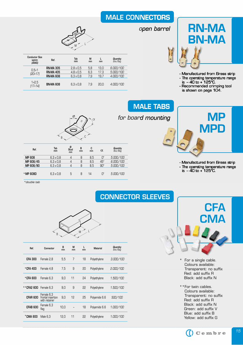
CONNECTOR SLEEVES
CFACMA
Conductor Sizesqmm(AWG)
QuantityBox/Bag
TabmmRef. M
mmL
mm
RN-MA 305 2,8 x 0,5 5,8 13,0 RN-MA 405 4,8 x 0,5 6,3 17,3 RN-MA 608 6,3 x 0,8 7,9 19,7
BN-MA 608 6,3 x 0,8 7,9 20,0
6.000/1005.000/1004.000/100
4.000/1001÷2,5
(17÷14)
0,5÷1(20÷17)
3.000/100
2.000/100
1.500/100
1.500/100
500/100
1.000/100
1.000/100
Ref. QuantityBox/BagConnector M
mmB
mmL
mm Material
CFA 300 Female 2,8 5,5 7 18 Polyethylene
CFA 400 Female 4,8 7,5 9 20 Polyethylene
CFA 600 Female 6,3 9,0 11 24 Polyethylene
CFA2 600 Female 6,3 9,0 9 22 Polyethylene
CFAR 600 Female 6,3
9,0 12 25 Polyamide 6.6 frontal insertion with retainer
CFAB 600 Female 6,3
10,0 – 18 Polyamide 6.6 flag
CMA 600 Male 6,3 12,0 11 22 Polyethylene
*double tab
Ref. QuantityBox/Bag
Tabmm
Cmm
Bmm
ØStudmm α
MP 608 6,3 x 0,8 4 8 8,5 0° MP 608/45 6,3 x 0,8 4 8 8,5 45° MP 608/90 6,3 x 0,8 4 8 8,5 90°
MP 608D 6,3 x 0,8 5 8 14 0°
5.000/1006.000/1005.000/100
5.000/100*
* For a single cable. Colours available: Transparent: no suffix Red: add suffix R Black: add suffix N
**For twin cables. Colours available: Transparent: no suffix Red: add suffix R Black: add suffix N Green: add suffix V Blue: add suffix B Yellow: add suffix G
MALE TABS
for board mounting MPMPD
- Manufactured from Brass strip
MALE TABS
for board mounting MPMPD
- Manufactured from Brass strip- The operating temperature range is – 40 to + 125°C.
MALE CONNECTORS
open barrel RN-MABN-MA
- Manufactured from Brass strip
- Recommended crimping tool is shown on page 104.
MALE CONNECTORS
open barrel RN-MABN-MA
- Manufactured from Brass strip- The operating temperature range is – 40 to + 125°C.
- Recommended crimping tool is shown on page 104.
female connectors, fully reinforced with Copper sleeve
*
*
**
*
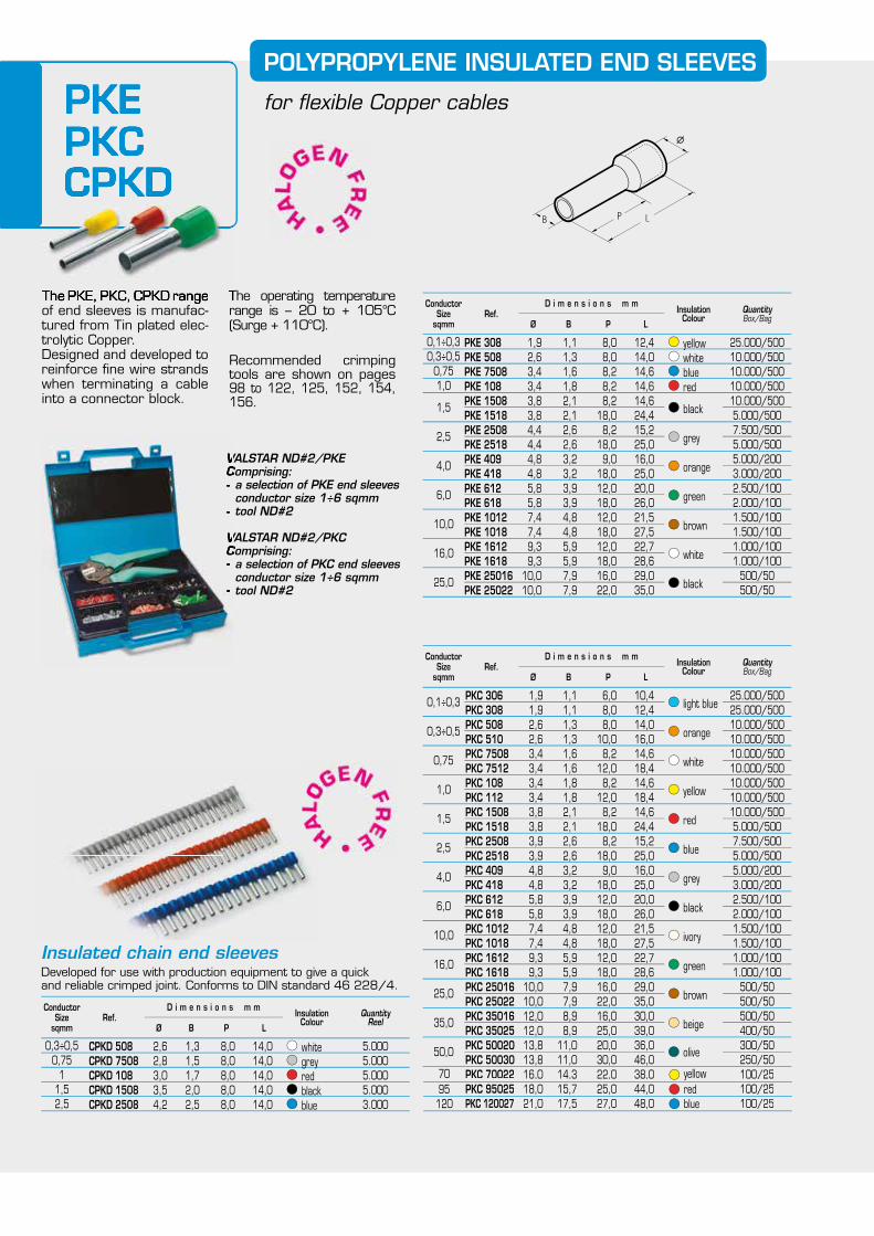
PKEPKCCPKD
POLYPROPYLENE INSULATED END SLEEVES
for flexible Copper cables
Conductor Size
sqmm
QuantityBox/Bag
Insulation Colour
Ø
D i m e n s i o n s m m
LPBRef.
PKC 306 1,9 1,1 6,0 10,4 PKC 308 1,9 1,1 8,0 12,4 PKC 508 2,6 1,3 8,0 14,0 PKC 510 2,6 1,3 10,0 16,0 PKC 7508 3,4 1,6 8,2 14,6 PKC 7512 3,4 1,6 12,0 18,4 PKC 108 3,4 1,8 8,2 14,6 PKC 112 3,4 1,8 12,0 18,4 PKC 1508 3,8 2,1 8,2 14,6 PKC 1518 3,8 2,1 18,0 24,4 PKC 2508 3,9 2,6 8,2 15,2 PKC 2518 3,9 2,6 18,0 25,0 PKC 409 4,8 3,2 9,0 16,0 PKC 418 4,8 3,2 18,0 25,0 PKC 612 5,8 3,9 12,0 20,0 PKC 618 5,8 3,9 18,0 26,0 PKC 1012 7,4 4,8 12,0 21,5 PKC 1018 7,4 4,8 18,0 27,5 PKC 1612 9,3 5,9 12,0 22,7 PKC 1618 9,3 5,9 18,0 28,6 PKC 25016 10,0 7,9 16,0 29,0 PKC 25022 10,0 7,9 22,0 35,0 PKC 35016 12,0 8,9 16,0 30,0 PKC 35025 12,0 8,9 25,0 39,0 PKC 50020 13,8 11,0 20,0 36,0 PKC 50030 13,8 11,0 30,0 46,0
PKC 70022 16,0 14,3 22,0 38,0PKC 95025 18,0 15,7 25,0 44,0PKC 120027 21,0 17,5 27,0 48,0
25.000/50025.000/50010.000/50010.000/50010.000/50010.000/50010.000/50010.000/50010.000/5005.000/5007.500/5005.000/5005.000/2003.000/2002.500/1002.000/1001.500/1001.500/1001.000/1001.000/100
500/50500/50500/50400/50300/50250/50100/25100/25100/25
0,1÷0,3
0,3÷0,5
0,75
1,0
1,5
2,5
4,0
6,0
10,0
16,0
25,0
35,0
50,0
light blue
orange
white
yellow
red
blue
grey
black
ivory
green
brown
beige
olive
The PKE, PKC, CPKD range of end sleeves is manufac-tured from Tin plated elec-trolytic Copper. Designed and developed to reinforce fine wire strands when terminating a cable into a connector block.
The operating temperature range is – 20 to + 105°C (Surge + 110°C).
Recommended crimping tools are shown on pages 98 to 122, 125, 152, 154, 156.
VALSTAR ND#2/PKEComprising:- a selection of PKE end sleeves conductor size 1÷6 sqmm- tool ND#2
VALSTAR ND#2/PKCComprising:- a selection of PKC end sleeves conductor size 1÷6 sqmm- tool ND#2
Conductor Size
sqmm
QuantityBox/Bag
InsulationColour
Ø
D i m e n s i o n s m m
LPBRef.
PKE 308 1,9 1,1 8,0 12,4 PKE 508 2,6 1,3 8,0 14,0 PKE 7508 3,4 1,6 8,2 14,6 PKE 108 3,4 1,8 8,2 14,6 PKE 1508 3,8 2,1 8,2 14,6 PKE 1518 3,8 2,1 18,0 24,4 PKE 2508 4,4 2,6 8,2 15,2 PKE 2518 4,4 2,6 18,0 25,0 PKE 409 4,8 3,2 9,0 16,0 PKE 418 4,8 3,2 18,0 25,0 PKE 612 5,8 3,9 12,0 20,0 PKE 618 5,8 3,9 18,0 26,0 PKE 1012 7,4 4,8 12,0 21,5 PKE 1018 7,4 4,8 18,0 27,5 PKE 1612 9,3 5,9 12,0 22,7 PKE 1618 9,3 5,9 18,0 28,6 PKE 25016 10,0 7,9 16,0 29,0 PKE 25022 10,0 7,9 22,0 35,0
25.000/50010.000/50010.000/50010.000/50010.000/5005.000/5007.500/5005.000/5005.000/2003.000/2002.500/1002.000/1001.500/1001.500/1001.000/1001.000/100
500/50500/50
0,1÷0,30,3÷0,5
0,751,0
yellowwhitebluered
black
grey
orange
green
brown
white
black
1,5
2,5
4,0
6,0
10,0
16,0
25,0
ConductorSize
sqmm
QuantityReel
InsulationColour
Ø
D i m e n s i o n s m m
LPBRef.
CPKD 508 2,6 1,3 8,0 14,0 CPKD 7508 2,8 1,5 8,0 14,0 CPKD 108 3,0 1,7 8,0 14,0 CPKD 1508 3,5 2,0 8,0 14,0 CPKD 2508 4,2 2,5 8,0 14,0
5.0005.0005.0005.0003.000
0,3÷0,50,75
11,52,5
whitegrey
blue
redblack
Insulated chain end sleevesDeveloped for use with production equipment to give a quickand reliable crimped joint. Conforms to DIN standard 46 228/4.
PKEPKCCPKD
The PKE, PKC, CPKD range The operating temperature
VALSTAR ND#2/PKEComprising:- a selection of PKE end sleeves conductor size 1÷6 sqmm- tool ND#2
VALSTAR ND#2/PKCComprising:- a selection of PKC end sleeves conductor size 1÷6 sqmm- tool ND#2
yellowredblue
7095
120
17
*To DIN standard 46 228/1
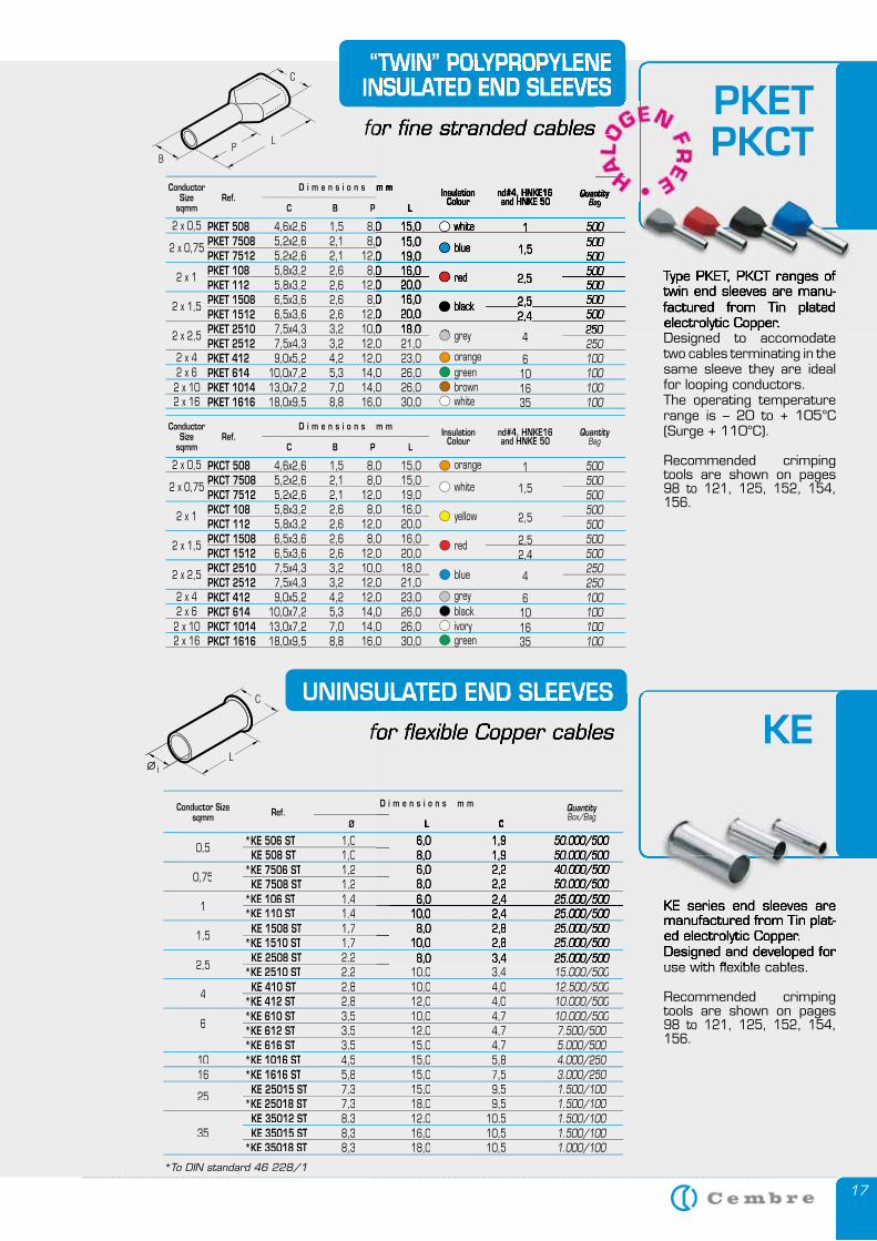
UNINSULATED END SLEEVES
for flexible Copper cables
KE series end sleeves are manufactured from Tin plat-ed electrolytic Copper.Designed and developed for use with flexible cables.
Recommended crimping tools are shown on pages 98 to 121, 125, 152, 154, 156.
UNINSULATED END SLEEVES
for flexible Copper cables
KE series end sleeves are manufactured from Tin plat-ed electrolytic Copper.Designed and developed for use with flexible cables.
KE
“TWIN” POLYPROPYLENEINSULATED END SLEEVES
for fine stranded cables
ConductorSize
sqmm
nd#4, HNKE16and HNKE 50
QuantityBag
InsulationColour
C
D i m e n s i o n s m m
LPBRef.
PKET 508 4,6x2,6 1,5 8,0 15,0 PKET 7508 5,2x2,6 2,1 8,0 15,0 PKET 7512 5,2x2,6 2,1 12,0 19,0 PKET 108 5,8x3,2 2,6 8,0 16,0 PKET 112 5,8x3,2 2,6 12,0 20,0 PKET 1508 6,5x3,6 2,6 8,0 16,0 PKET 1512 6,5x3,6 2,6 12,0 20,0 PKET 2510 7,5x4,3 3,2 10,0 18,0 PKET 2512 7,5x4,3 3,2 12,0 21,0 PKET 412 9,0x5,2 4,2 12,0 23,0 PKET 614 10,0x7,2 5,3 14,0 26,0 PKET 1014 13,0x7,2 7,0 14,0 26,0 PKET 1616 18,0x9,5 8,8 16,0 30,0
500500500500500500500250250100100100100
2 x 0,75
2 x 1
2 x 1,5
2 x 2,5
2 x 42 x 62 x 10
2 x 0,5
2 x 16
blue
red
black
grey
orangegreenbrownwhite
1,5
2,5
2,52,4
4
6
1
101635
white
ConductorSize
sqmm
nd#4, HNKE16and HNKE 50
QuantityBag
InsulationColour
C
D i m e n s i o n s m m
LPBRef.
PKCT 508 4,6x2,6 1,5 8,0 15,0 PKCT 7508 5,2x2,6 2,1 8,0 15,0 PKCT 7512 5,2x2,6 2,1 12,0 19,0 PKCT 108 5,8x3,2 2,6 8,0 16,0 PKCT 112 5,8x3,2 2,6 12,0 20,0 PKCT 1508 6,5x3,6 2,6 8,0 16,0 PKCT 1512 6,5x3,6 2,6 12,0 20,0 PKCT 2510 7,5x4,3 3,2 10,0 18,0 PKCT 2512 7,5x4,3 3,2 12,0 21,0 PKCT 412 9,0x5,2 4,2 12,0 23,0 PKCT 614 10,0x7,2 5,3 14,0 26,0 PKCT 1014 13,0x7,2 7,0 14,0 26,0 PKCT 1616 18,0x9,5 8,8 16,0 30,0
500500500500500500500250250100100100100
2 x 0,75
2 x 1
2 x 1,5
2 x 2,5
2 x 42 x 62 x 10
2 x 0,5
2 x 16
white
yellow
red
blue
greyblackivorygreen
1,5
2,5
2,52,4
4
6
1
101635
orange
Type PKET, PKCT ranges of twin end sleeves are manu-factured from Tin plated electrolytic Copper.Designed to accomodate two cables terminating in the same sleeve they are ideal for looping conductors.The operating temperature range is – 20 to + 105°C (Surge + 110°C).
Recommended crimping tools are shown on pages 98 to 121, 125, 152, 154, 156.
“TWIN” POLYPROPYLENEINSULATED END SLEEVES
for fine stranded cables
nd#4, HNKE16and HNKE 50
QuantityBag
QuantityBag
QuantityInsulationColour
D i m e n s i o n s m m
L
4,6x2,6 1,5 8,0 15,0 5,2x2,6 2,1 8,0 15,0 5,2x2,6 2,1 12,0 19,0
5,8x3,2 2,6 8,0 16,0 5,8x3,2 2,6 12,0 20,0
6,5x3,6 2,6 8,0 16,0 6,5x3,6 2,6 12,0 20,0 7,5x4,3 3,2 10,0 18,0
500500500500500500500250
blue
red
black
1,5
2,5
2,52,52,42,4
4
1white
Type PKET, PKCT ranges of twin end sleeves are manu-factured from Tin plated electrolytic Copper.Designed to accomodate
PKETPKCTcables
QuantityBag
QuantityBag
Quantity
Conductor Sizesqmm Ref.
D i m e n s i o n s m m QuantityBox/Bag
Ø L C
0,5*KE 506 ST 1,0 6,0 1,9 50.000/500
KE 508 ST 1,0 8,0 1,9 50.000/500
0,75*KE 7506 ST 1,2 6,0 2,2 40.000/500
KE 7508 ST 1,2 8,0 2,2 50.000/500
1*KE 106 ST 1,4 6,0 2,4 25.000/500*KE 110 ST 1,4 10,0 2,4 25.000/500
1,5KE 1508 ST 1,7 8,0 2,8 25.000/500
*KE 1510 ST 1,7 10,0 2,8 25.000/500
2,5KE 2508 ST 2,2 8,0 3,4 25.000/500
*KE 2510 ST 2,2 10,0 3,4 15.000/500
4KE 410 ST 2,8 10,0 4,0 12.500/500
*KE 412 ST 2,8 12,0 4,0 10.000/500
6*KE 610 ST 3,5 10,0 4,7 10.000/500*KE 612 ST 3,5 12,0 4,7 7.500/500*KE 616 ST 3,5 15,0 4,7 5.000/500
10 *KE 1016 ST 4,5 15,0 5,8 4.000/25016 *KE 1616 ST 5,8 15,0 7,5 3.000/250
25KE 25015 ST 7,3 15,0 9,5 1.500/100
*KE 25018 ST 7,3 18,0 9,5 1.500/100
35KE 35012 ST 8,3 12,0 10,5 1.500/100KE 35015 ST 8,3 16,0 10,5 1.500/100
*KE 35018 ST 8,3 18,0 10,5 1.000/100
18
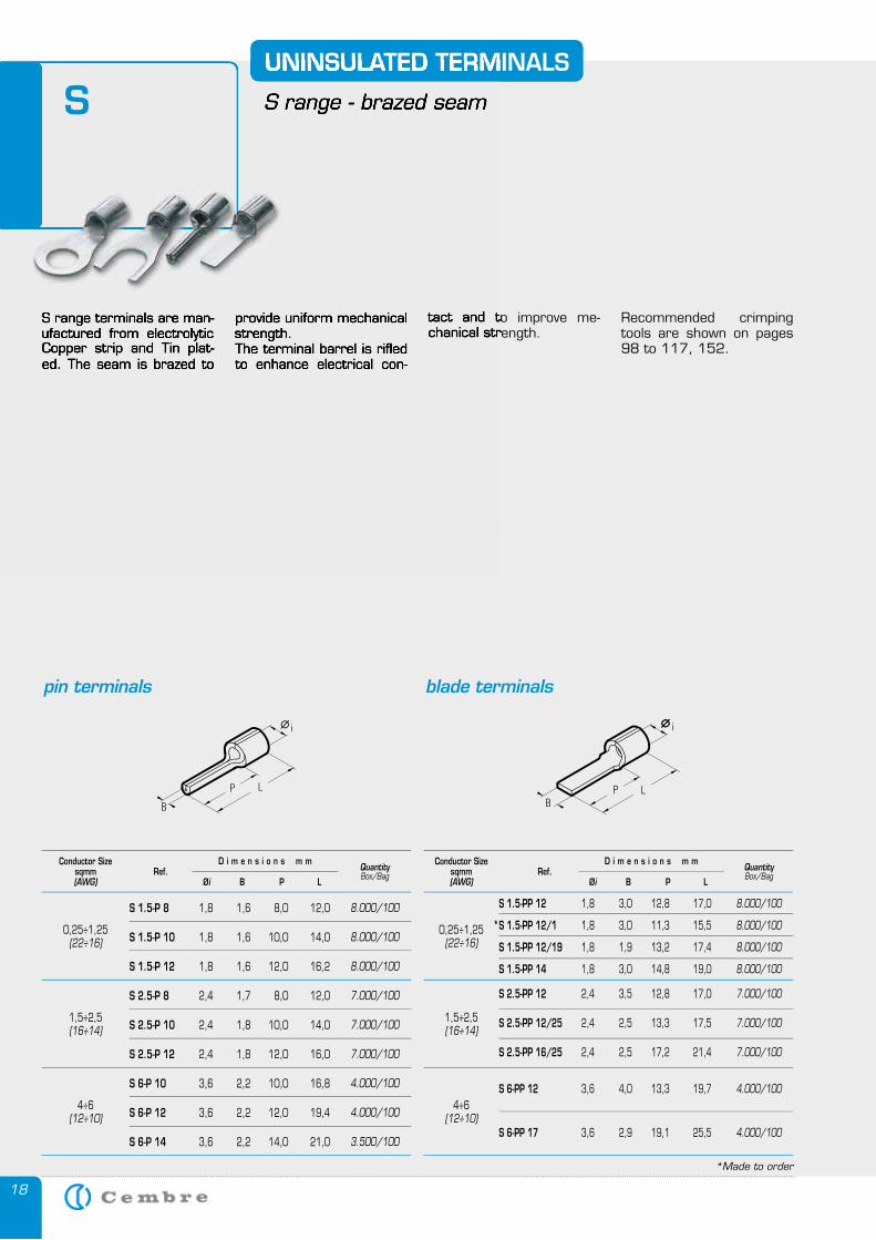
S 1.5-PP 12 1,8 3,0 12,8 17,0
S 1.5-PP 12/1 1,8 3,0 11,3 15,5
S 1.5-PP 12/19 1,8 1,9 13,2 17,4
S 1.5-PP 14 1,8 3,0 14,8 19,0
S 2.5-PP 12 2,4 3,5 12,8 17,0
S 2.5-PP 12/25 2,4 2,5 13,3 17,5
S 2.5-PP 16/25 2,4 2,5 17,2 21,4
S 6-PP 12 3,6 4,0 13,3 19,7
S 6-PP 17 3,6 2,9 19,1 25,5
8.000/100
8.000/100
8.000/100
8.000/100
7.000/100
7.000/100
7.000/100
4.000/100
4.000/100
*Made to order
S range terminals are man-ufactured from electrolytic Copper strip and Tin plat-ed. The seam is brazed to
UNINSULATED TERMINALS
S range - brazed seam
provide uniform mechanical strength. The terminal barrel is rifled to enhance electrical con-
tact and to improve me-chanical strength.
Recommended crimping tools are shown on pages 98 to 117, 152.
S 1.5-P 8 1,8 1,6 8,0 12,0
S 1.5-P 10 1,8 1,6 10,0 14,0
S 1.5-P 12 1,8 1,6 12,0 16,2
S 2.5-P 8 2,4 1,7 8,0 12,0
S 2.5-P 10 2,4 1,8 10,0 14,0
S 2.5-P 12 2,4 1,8 12,0 16,0
S 6-P 10 3,6 2,2 10,0 16,8
S 6-P 12 3,6 2,2 12,0 19,4
S 6-P 14 3,6 2,2 14,0 21,0
8.000/100
8.000/100
8.000/100
7.000/100
7.000/100
7.000/100
4.000/100
4.000/100
3.500/100
Conductor Sizesqmm(AWG)
QuantityBox/Bag
Øi
D i m e n s i o n s m m
LPBRef.
Conductor Sizesqmm(AWG)
QuantityBox/Bag
Øi
D i m e n s i o n s m m
LPBRef.
0,25÷1,25(22÷16)
1,5÷2,5(16÷14)
4÷6(12÷10)
0,25÷1,25(22÷16)
1,5÷2,5(16÷14)
4÷6(12÷10)
pin terminals blade terminals
*
S range terminals are man-ufactured from electrolytic Copper strip and Tin plat-ed. The seam is brazed to
UNINSULATED TERMINALS
S range - brazed seam
provide uniform mechanical strength. The terminal barrel is rifled to enhance electrical con-
tact and to improve me-chanical strength.
S
19
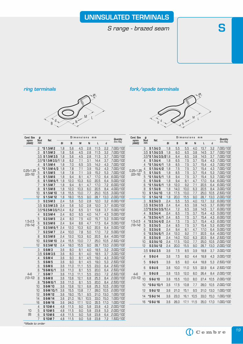
2 S 1.5-M 2 1,8 5,6 4,5 2,8 11,5 2,2 3 S 1.5-M 3 1,8 5,6 4,5 2,8 11,5 3,2 3,5 S 1.5-M 3.5 1,8 5,6 4,5 2,8 11,5 3,7 3,5 S 1.5-M 3.5/1 1,8 6,2 7,1 3,1 14,4 3,7 4 S 1.5-M 4 1,8 7,0 6,5 3,5 14,2 4,3 4 S 1.5-M 4/3 1,8 7,8 7,1 3,9 15,2 4,3 5 S 1.5-M 5 1,8 7,8 7,1 3,9 15,2 5,3 6 S 1.5-M 6 1,8 9,4 8,1 4,7 17,0 6,4 6 S 1.5-M 6/1 1,8 12,0 10,3 6,0 20,5 6,4 7 S 1.5-M 7 1,8 9,4 8,1 4,7 17,0 7,2 8 S 1.5-M 8 1,8 12,0 10,3 6,0 20,5 8,4 10 S 1.5-M 10 1,8 15,5 13,0 7,7 25,0 10,5 12 S 1.5-M 12 1,8 18,0 15,5 9,0 28,7 13,0 3 S 2.5-M 3 2,4 5,6 5,0 2,8 12,0 3,2 3,5 S 2.5-M 3.5 2,4 5,6 5,0 2,8 12,0 3,7 3,5 S 2.5-M 3.5/1 2,4 6,2 6,5 3,1 13,8 3,7 4 S 2.5-M 4 2,4 8,0 6,5 4,0 14,7 4,3 5 S 2.5-M 5 2,4 8,0 7,5 4,0 15,7 5,3 6 S 2.5-M 6 2,4 9,4 8,6 4,7 17,5 6,4 6 S 2.5-M 6/1 2,4 12,0 10,3 6,0 20,5 6,4 7 S 2.5-M 7 2,4 10,0 7,8 5,0 17,0 7,2 8 S 2.5-M 8 2,4 12,0 10,3 6,0 20,5 8,4 10 S 2.5-M 10 2,4 15,5 13,0 7,7 25,0 10,5 12 S 2.5-M 12 2,4 18,0 15,5 9,0 28,7 13,0 3 S 6-M 3 3,6 8,0 8,1 4,0 18,5 3,2 3,5 S 6-M 3.5 3,6 8,0 8,1 4,0 18,5 3,7 4 S 6-M 4 3,6 9,0 8,1 4,5 19,0 4,3 5 S 6-M 5 3,6 9,0 8,1 4,5 19,0 5,3 6 S 6-M 6 3,6 11,0 11,1 5,5 23,0 6,4 6 S 6-M 6/1 3,6 11,0 8,1 5,5 20,0 6,4 7 S 6-M 7 3,6 11,0 11,1 5,5 23,0 7,2 8 S 6-M 8 3,6 13,6 12,1 6,8 25,3 8,4 8 S 6-M 8/1 3,6 11,0 8,1 5,5 20,0 8,4 10 S 6-M 10 3,6 13,6 12,1 6,8 25,3 10,5 10 S 6-M 10/1 3,6 15,5 13,8 7,7 28,0 10,5 12 S 6-M 12 3,6 19,0 15,1 9,5 31,0 13,0 14 S 6-M 14 3,6 21,0 16,1 10,5 33,0 15,0 16 S 6-M 16 3,6 24,0 17,1 12,0 35,5 17,0 4 S 10-M 4 4,8 11,5 9,0 5,8 23,8 4,3 5 S 10-M 5 4,8 11,5 9,0 5,8 23,8 5,3 6 S 10-M 6 4,8 11,5 9,0 5,8 23,8 6,4 7 S 10-M 7 4,8 11,5 9,0 5,8 23,8 7,2
7.000/1007.000/1007.000/1007.000/1007.000/1007.000/1007.000/1006.000/1005.000/1006.000/1004.000/1003.000/1002.000/1006.000/1006.000/1005.000/1005.000/1005.000/1005.000/1005.000/1005.000/1004.000/1002.500/1002.000/1003.000/1003.000/1003.000/1002.500/1002.500/1002.500/1002.500/1002.000/1002.500/1002.000/1002.000/1001.000/1001.000/1001.000/1002.000/1002.000/1002.000/1001.500/100
*
*
*
*
*
*
Cond. Sizesqmm(AWG)
QuantityBox/Bag
Øi
D i m e n s i o n s m m
dLNMBRef.
ØStudmm
UNINSULATED TERMINALS
S range - brazed seam
0,25÷1,25(22÷16)
1,5÷2,5(16÷14)
4÷6(12÷10)
10(8)
*Made to order
ring terminals fork/spade terminals
3 S 1.5-U 3 1,8 5,5 5,5 4,0 13,7 3,2 3,5 S 1.5-U 3.5 1,8 6,0 6,5 3,8 14,5 3,7 3,5 S 1.5-U 3.5/2 1,8 6,4 6,5 3,8 14,5 3,7 4 S 1.5-U 4 1,8 6,5 7,5 3,7 15,4 4,3 4 S 1.5-U 4/1 1,8 8,5 7,5 3,7 15,4 4,3 4 S 1.5-U 4/2 1,8 7,5 7,5 3,7 15,4 4,3 5 S 1.5-U 5 1,8 8,5 7,5 3,7 15,4 5,3 5 S 1.5-U 5/1 1,8 9,4 7,5 3,7 15,4 5,3 6 S 1.5-U 6 1,8 9,4 8,1 4,7 17,0 6,4 6 S 1.5-U 6/1 1,8 12,0 9,2 7,1 20,5 6,4 8 S 1.5-U 8 1,8 14,0 10,0 6,3 20,5 8,4 10 S 1.5-U 10 1,8 17,5 13,0 7,7 25,0 10,5 12 S 1.5-U 12 1,8 20,0 15,5 9,0 28,7 13,0 3 S 2.5-U 3 2,4 5,5 5,5 4,0 13,7 3,2 3,5 S 2.5-U 3.5 2,4 6,4 6,5 3,8 14,5 3,7 3,5 S 2.5-U 3.5/1 2,4 7,2 6,5 3,8 14,5 3,7 4 S 2.5-U 4 2,4 6,5 7,5 3,7 15,4 4,3 4 S 2.5-U 4/1 2,4 8,5 7,5 3,7 15,4 4,3 4 S 2.5-U 4/2 2,4 7,5 7,5 3,7 15,4 4,3 5 S 2.5-U 5 2,4 8,5 7,5 3,7 15,4 5,3 6 S 2.5-U 6 2,4 9,4 8,1 4,7 17,0 6,4 6 S 2.5-U 6/1 2,4 12,0 9,2 7,1 20,5 6,4 8 S 2.5-U 8 2,4 14,0 10,0 6,3 20,5 8,4 10 S 2.5-U 10 2,4 17,5 13,0 7,7 25,0 10,5 12 S 2.5-U 12 2,4 20,0 15,5 9,0 28,7 13,0
3,5 S 6-U 3.5 3,6 7,5 8,5 3,9 18,8 3,7
4 S 6-U 4 3,6 7,5 8,0 4,4 18,8 4,3
5 S 6-U 5 3,6 9,5 8,0 4,4 18,8 5,3
6 S 6-U 6 3,6 10,0 11,0 5,5 22,9 6,4
8 S 6-U 8 3,6 13,5 12,0 8,0 26,4 8,4
10 S 6-U 10 3,6 15,5 13,0 8,0 27,4 10,5
10 S 6-U 10/1 3,6 17,5 13,8 7,7 28,0 10,5
12 S 6-U 12 3,6 21,0 15,1 9,5 31,0 13,0
14 S 6-U 14 3,6 23,0 16,1 10,5 33,0 15,0
16 S 6-U 16 3,6 26,0 17,1 11,5 35,0 17,0
7.000/1007.000/1007.000/1007.000/1007.000/1007.000/1007.000/1007.000/1006.000/1006.000/1003.000/1002.500/1002.000/1006.000/1006.000/1006.000/1005.000/1006.000/1006.000/1006.000/1005.000/1004.000/1002.500/1002.000/1002.000/100
3.000/100
3.000/100
2.500/100
2.500/100
2.000/100
2.000/100
2.000/100
1.000/100
1.000/100
1.000/100
*
*
*
*
*
**
*
*
*
*
Cond. Sizesqmm(AWG)
QuantityBox/Bag
Øi
D i m e n s i o n s m m
dLNMBRef.
ØStudmm
0,25÷1,25(22÷16)
1,5÷2,5(16÷14)
4÷6(12÷10)
S
20
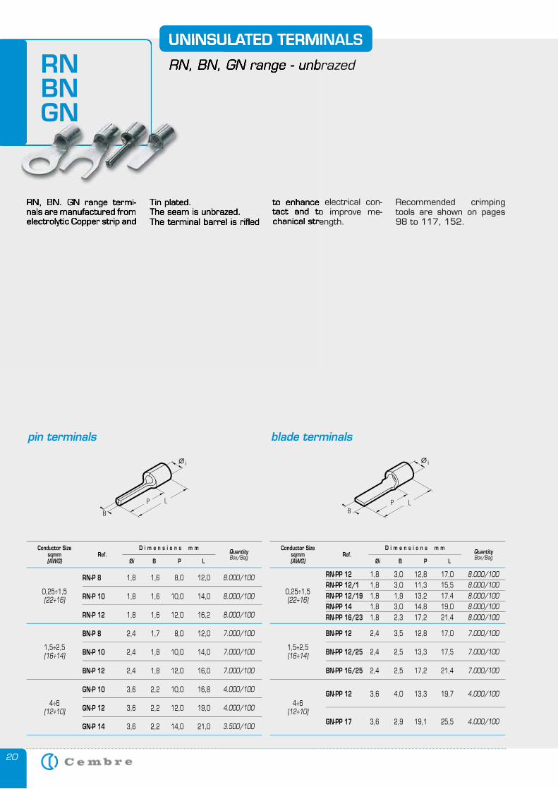
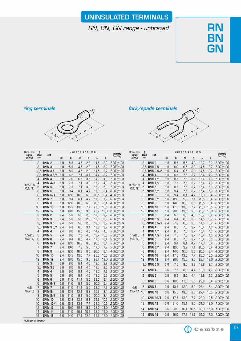
RN, BN. GN range termi-nals are manufactured from electrolytic Copper strip and
UNINSULATED TERMINALS
RN, BN, GN range - unbrazed
Tin plated. The seam is unbrazed. The terminal barrel is rifled
to enhance electrical con-tact and to improve me-chanical strength.
Recommended crimping tools are shown on pages 98 to 117, 152.
RN-P 8 1,8 1,6 8,0 12,0
RN-P 10 1,8 1,6 10,0 14,0
RN-P 12 1,8 1,6 12,0 16,2
BN-P 8 2,4 1,7 8,0 12,0
BN-P 10 2,4 1,8 10,0 14,0
BN-P 12 2,4 1,8 12,0 16,0
GN-P 10 3,6 2,2 10,0 16,8
GN-P 12 3,6 2,2 12,0 19,0
GN-P 14 3,6 2,2 14,0 21,0
8.000/100
8.000/100
8.000/100
7.000/100
7.000/100
7.000/100
4.000/100
4.000/100
3.500/100
Conductor Sizesqmm(AWG)
QuantityBox/Bag
Øi
D i m e n s i o n s m m
LPBRef.
0,25÷1,5(22÷16)
1,5÷2,5(16÷14)
4÷6(12÷10)
pin terminals blade terminals
RN, BN. GN range termi-nals are manufactured from electrolytic Copper strip and
UNINSULATED TERMINALS
RN, BN, GN range - unbrazed
Tin plated. The seam is unbrazed. The terminal barrel is rifled
to enhance electrical con-tact and to improve me-chanical strength.
RNBNGN
RN-PP 12 1,8 3,0 12,8 17,0 RN-PP 12/1 1,8 3,0 11,3 15,5 RN-PP 12/19 1,8 1,9 13,2 17,4 RN-PP 14 1,8 3,0 14,8 19,0 RN-PP 16/23 1,8 2,3 17,2 21,4
BN-PP 12 2,4 3,5 12,8 17,0
BN-PP 12/25 2,4 2,5 13,3 17,5
BN-PP 16/25 2,4 2,5 17,2 21,4
GN-PP 12 3,6 4,0 13,3 19,7
GN-PP 17 3,6 2,9 19,1 25,5
8.000/1008.000/1008.000/1008.000/1008.000/100
7.000/100
7.000/100
7.000/100
4.000/100
4.000/100
Conductor Sizesqmm(AWG)
QuantityBox/Bag
Øi
D i m e n s i o n s m m
LPBRef.
0,25÷1,5(22÷16)
1,5÷2,5(16÷14)
4÷6(12÷10)
21
2 RN-M 2 1,8 5,6 4,5 2,8 11,5 2,2 3 RN-M 3 1,8 5,6 4,5 2,8 11,5 3,2 3,5 RN-M 3.5 1,8 5,6 4,5 2,8 11,5 3,7 3,5 RN-M 3.5/1 1,8 6,2 7,1 3,1 14,4 3,7 4 RN-M 4 1,8 7,0 6,5 3,5 14,2 4,3 4 RN-M 4/3 1,8 7,8 7,1 3,9 15,2 4,3 5 RN-M 5 1,8 7,8 7,1 3,9 15,2 5,3 6 RN-M 6 1,8 9,4 8,1 4,7 17,0 6,4 6 RN-M 6/1 1,8 12,0 10,3 6,0 20,5 6,4 7 RN-M 7 1,8 9,4 8,1 4,7 17,0 7,2 8 RN-M 8 1,8 12,0 10,3 6,0 20,5 8,4 10 RN-M 10 1,8 15,5 13,0 7,7 25,0 10,5 12 RN-M 12 1,8 18,0 15,5 9,0 28,7 13,0 2 BN-M 2 2,4 5,6 5,0 2,8 12,0 2,2 3 BN-M 3 2,4 5,6 5,0 2,8 12,0 3,2 3,5 BN-M 3.5 2,4 5,6 5,0 2,8 12,0 3,7 3,5 BN-M 3.5/1 2,4 6,2 6,5 3,1 13,8 3,7 4 BN-M 4 2,4 8,0 6,5 4,0 14,7 4,3 5 BN-M 5 2,4 8,0 7,5 4,0 15,7 5,3 6 BN-M 6 2,4 9,4 8,6 4,7 17,5 6,4 6 BN-M 6/1 2,4 12,0 10,3 6,0 20,5 6,4 7 BN-M 7 2,4 10,0 7,8 5,0 17,0 7,2 8 BN-M 8 2,4 12,0 10,3 6,0 20,5 8,4 10 BN-M 10 2,4 15,5 13,0 7,7 25,0 10,5 12 BN-M 12 2,4 18,0 15,5 9,0 28,7 13,0 3 GN-M 3 3,6 8,0 8,1 4,0 18,5 3,2 3,5 GN-M 3.5 3,6 8,0 8,1 4,0 18,5 3,7 4 GN-M 4 3,6 9,0 8,1 4,5 19,0 4,3 5 GN-M 5 3,6 9,0 8,1 4,5 19,0 5,3 6 GN-M 6 3,6 11,0 11,1 5,5 23,0 6,4 6 GN-M 6/1 3,6 11,0 8,1 5,5 20,0 6,4 7 GN-M 7 3,6 11,0 11,1 5,5 23,0 7,2 8 GN-M 8 3,6 13,6 12,1 6,8 25,3 8,4 8 GN-M 8/1 3,6 11,0 8,1 5,5 20,0 8,4 10 GN-M 10 3,6 13,6 12,1 6,8 25,3 10,5 10 GN-M 10/1 3,6 15,5 13,8 7,7 28,0 10,5 12 GN-M 12 3,6 19,0 15,1 9,5 31,0 13,0 14 GN-M 14 3,6 21,0 16,1 10,5 33,0 15,0 16 GN-M 16 3,6 24,0 17,1 12,0 35,5 17,0
7.000/1007.000/1007.000/1007.000/1007.000/1007.000/1007.000/1006.000/1004.000/1006.000/1004.000/1003.000/1002.000/1006.000/1006.000/1006.000/1006.000/1005.000/1005.000/1005.000/1005.000/1005.000/1004.000/1002.500/1002.000/1003.000/1003.000/1003.000/1002.500/1002.500/1002.500/1002.500/1002.000/1002.500/1002.000/1002.000/1001.000/1001.000/1001.000/100
*
*
*
Cond. Sizesqmm(AWG)
QuantityBox/Bag
Øi
D i m e n s i o n s m m
dLNMBRef.
ØStudmm
UNINSULATED TERMINALS
RN, BN, GN range - unbrazed
0,25÷1,5(22÷16)
1,5÷2,5(16÷14)
4÷6(12÷10)
*Made to order
ring terminals fork/spade terminals
3 RN-U 3 1,8 5,5 5,5 4,0 13,7 3,2 3,5 RN-U 3.5 1,8 6,0 6,5 3,8 14,5 3,7 3,5 RN-U 3.5/2 1,8 6,4 6,5 3,8 14,5 3,7 4 RN-U 4 1,8 6,5 7,5 3,7 15,4 4,3 4 RN-U 4/1 1,8 8,5 7,5 3,7 15,4 4,3 4 RN-U 4/2 1,8 7,5 7,5 3,7 15,4 4,3 5 RN-U 5 1,8 8,5 7,5 3,7 15,4 5,3 5 RN-U 5/1 1,8 9,4 7,5 3,7 15,4 5,3 6 RN-U 6 1,8 9,4 8,1 4,7 17,0 6,4 6 RN-U 6/1 1,8 12,0 9,2 7,1 20,5 6,4 8 RN-U 8 1,8 14,0 10,0 6,3 20,5 8,4 10 RN-U 10 1,8 17,5 13,0 7,7 25,0 10,5 12 RN-U 12 1,8 20,0 15,5 9,0 28,7 13,0 3 BN-U 3 2,4 5,5 5,5 4,0 13,7 3,2 3,5 BN-U 3.5 2,4 6,4 6,5 3,8 14,5 3,7 3,5 BN-U 3.5/1 2,4 7,2 6,5 3,8 14,5 3,7 4 BN-U 4 2,4 6,5 7,5 3,7 15,4 4,3 4 BN-U 4/1 2,4 8,5 7,5 3,7 15,4 4,3 4 BN-U 4/2 2,4 7,5 7,5 3,7 15,4 4,3 5 BN-U 5 2,4 8,5 7,5 3,7 15,4 5,3 6 BN-U 6 2,4 9,4 8,1 4,7 17,0 6,4 6 BN-U 6/1 2,4 12,0 9,2 7,1 20,5 6,4 8 BN-U 8 2,4 14,0 10,0 6,3 20,5 8,4 10 BN-U 10 2,4 17,5 13,0 7,7 25,0 10,5 12 BN-U 12 2,4 20,0 15,5 9,0 28,7 13,0
3,5 GN-U 3.5 3,6 7,5 8,5 3,9 18,8 3,7
4 GN-U 4 3,6 7,5 8,0 4,4 18,8 4,3
5 GN-U 5 3,6 9,5 8,0 4,4 18,8 5,3
6 GN-U 6 3,6 10,0 11,0 5,5 22,9 6,4
8 GN-U 8 3,6 13,5 12,0 8,0 26,4 8,4
10 GN-U 10 3,6 15,5 13,0 8,0 27,4 10,5
10 GN-U 10/1 3,6 17,5 13,8 7,7 28,0 10,5
12 GN-U 12 3,6 21,0 15,1 9,5 31,0 13,0
14 GN-U 14 3,6 23,0 16,1 10,5 33,0 15,0
16 GN-U 16 3,6 26,0 17,1 11,5 35,0 17,0
7.000/1007.000/1007.000/1007.000/1007.000/1007.000/1005.000/1005.000/1006.000/1003.000/1002.500/1003.000/1002.000/1006.000/1006.000/1006.000/1006.000/1006.000/1006.000/1005.000/1005.000/1004.000/1004.000/1002.000/1002.000/100
3.000/100
3.000/100
2.500/100
2.500/100
2.000/100
2.000/100
2.000/100
1.000/100
1.000/100
1.000/100
*
*
Cond. Sizesqmm(AWG)
QuantityBox/Bag
Øi
D i m e n s i o n s m m
dLNMBRef.
ØStudmm
4÷6(12÷10)
1,5÷2,5(16÷14)
0,25÷1,5(22÷16)
RNBNGN
22
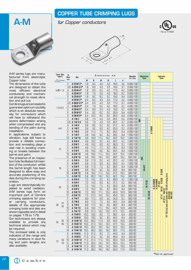
A-M series lugs are manu-factured from electrolytic Copper tube.The dimensions of the tube are designed to obtain the most efficient electrical conductivity and mechani-cal strength to resist vibra-tion and pull out.Cembre lugs are annealed to guarantee optimum ductility which is an absolute neces-sity for connectors which will have to withstand the severe deformation arising when compressed and any bending of the palm during installation.In applications subject to vibration, lugs still have to provide a reliable connec-tion and annealing plays a vital role in avoiding crack-ing or breaks between the barrel and palm.The presence of an inspec-tion hole facilitates full inser-tion of the conductor, whilst the barrel length has been designed to allow easy and accurate positioning of the dies during the crimping op-eration.Lugs are electrolytically tin-plated to avoid oxidation. A-M series lugs form an important part of Cembre crimping systems for pow-er carrying conductors, details of the appropriate crimping tools and dies are shown opposite and in detail on pages 178 to 179. Our technicians are always available to provide any technical advice which may be required.The enclosed table is only indicative of the range and many variations in stud fix-ing and palm lengths are also available.
COPPER TUBE CRIMPING LUGS
for Copper conductorsA-M for Copper conductorsA-M
Cond. Sizesqmm
ØStudmm
Ref.D i m e n s i o n s m m Quantity
Box/BagMechanical
ToolsHydraulic
Toolslow
stranded flexible* Øi B M N L d
0,25÷1,5
3 A 03-M 3 1,8 6,0 4,5 3,5 16,0 3,2 5.000/100
HN1
B 15
MDE
3,5 A 03-M 3.5 1,8 6,5 4,5 3,5 16,0 3,7 5.000/1004 A 03-M 4 1,8 6,5 5,0 4,0 17,0 4,3 5.000/1005 A 03-M 5 1,8 7,5 5,5 4,5 18,0 5,3 5.000/1006 A 03-M 6 1,8 9,0 6,0 5,0 19,0 6,4 5.000/100
1,5÷2,5
3 A 06-M 3 2,4 6,0 4,5 3,5 17,0 3,2 4.000/1003,5 A 06-M 3.5 2,4 6,5 4,5 3,5 17,0 3,7 4.000/1004 A 06-M 4 2,4 7,5 5,0 4,0 18,0 4,3 4.000/1005 A 06-M 5 2,4 8,5 5,5 4,5 19,0 5,3 4.000/1006 A 06-M 6 2,4 9,0 6,0 5,0 20,0 6,4 4.000/1008 A 06-M 8 2,4 12,0 9,0 8,0 26,0 8,4 2.500/100
4÷6
3 A 1-M 3 3,6 7,5 4,5 3,5 20,5 3,2 2.000/100
TN 7
0 SE
B 35
-45M
DEB
35-5
0MDE
HT 4
5-E
HT 5
1
RH
50
B 5
00E
B
550
E
3,5 A 1-M 3.5 3,6 7,5 4,5 3,5 20,5 3,7 2.000/1004 A 1-M 4 3,6 8,0 5,0 4,0 21,5 4,3 2.000/1005 A 1-M 5 3,6 9,0 6,5 6,0 25,0 5,3 2.000/1006 A 1-M 6 3,6 11,0 7,0 6,0 25,5 6,4 2.000/1008 A 1-M 8 3,6 14,0 9,0 8,0 29,5 8,4 1.500/100
10 A 1-M 10 3,6 16,5 11,0 10,0 33,5 10,5 1.000/100
10
4 A 2-M 4 4,6 10,0 5,0 4,0 22,5 4,3 1.500/100HN
5HN
-A25
TN 1
20 S
E
HT 8
1-U
RH
U 81
HT 1
20 a
nd to
ols
and
head
s wi
th 1
30 k
N c
rimpi
ng fo
rce
ECW
-H3D
RHU
520
5 A 2-M 5 4,6 10,0 6,5 6,0 26,0 5,3 1.500/1006 A 2-M 6 4,6 11,0 7,0 6,0 26,5 6,4 1.500/1008 A 2-M 8 4,6 15,0 9,0 8,0 30,5 8,4 1.000/100
10 A 2-M 10 4,6 18,0 11,0 10,0 34,5 10,5 1.000/10012 A 2-M 12 4,6 19,0 14,0 12,0 39,5 13,2 500/100
16
4 A 3-M 4 5,8 11,5 5,0 4,0 25,5 4,3 1.000/1005 A 3-M 5 5,8 11,5 6,5 6,0 29,0 5,3 1.000/1006 A 3-M 6 5,8 11,5 7,0 6,0 29,5 6,4 1.000/1008 A 3-M 8 5,8 15,0 9,0 8,0 33,5 8,4 500/100
10 A 3-M 10 5,8 18,0 11,0 10,0 37,5 10,5 500/10012 A 3-M 12 5,8 20,0 14,0 12,0 42,5 13,2 500/100
25
4 A 5-M 4 7,0 14,0 5,0 4,0 28,0 4,3 1.000/1005 A 5-M 5 7,0 14,0 6,5 6,0 31,5 5,3 500/1006 A 5-M 6 7,0 14,0 7,0 6,0 32,0 6,4 500/1008 A 5-M 8 7,0 15,0 9,0 8,0 36,0 8,4 500/100
10 A 5-M 10 7,0 18,0 11,0 10,0 40,0 10,5 500/10012 A 5-M 12 7,0 21,0 14,0 12,0 45,0 13,2 500/100
35 2535
5 A 7-M 5 8,9 17,0 6,5 6,0 34,0 5,3 500/1006 A 7-M 6 8,9 17,0 7,0 6,0 34,5 6,4 500/1008 A 7-M 8 8,9 17,0 9,0 8,0 38,5 8,4 400/100
10 A 7-M 10 8,9 19,0 11,0 10,0 42,5 10,5 400/10012 A 7-M 12 8,9 21,0 14,0 12,0 47,5 13,2 300/50
50 3550
6 A 10-M 6 10,0 19,0 8,0 7,0 38,5 6,4 200/508 A 10-M 8 10,0 19,0 9,0 8,0 40,5 8,4 200/50
10 A 10-M 10 10,0 20,0 11,5 9,5 44,5 10,5 200/5012 A 10-M 12 10,0 21,0 12,0 12,0 47,5 13,2 200/5014 A 10-M 14 10,0 25,0 16,0 14,0 55,5 15,0 200/5016 A 10-M 16 10,0 26,0 18,0 16,0 59,5 17,0 200/50
70 5070
6 A 14-M 6 11,3 21,0 8,0 7,0 44,0 6,4 200/508 A 14-M 8 11,3 21,0 9,0 8,0 46,0 8,4 200/50
10 A 14-M 10 11,3 21,0 11,0 10,0 50,0 10,5 200/5012 A 14-M 12 11,3 22,0 14,0 12,0 55,0 13,2 150/5014 A 14-M 14 11,3 25,0 16,0 14,0 59,0 15,0 100/5016 A 14-M 16 11,3 26,0 18,0 16,0 63,0 17,0 100/50
Not UL approved
File no. E125401
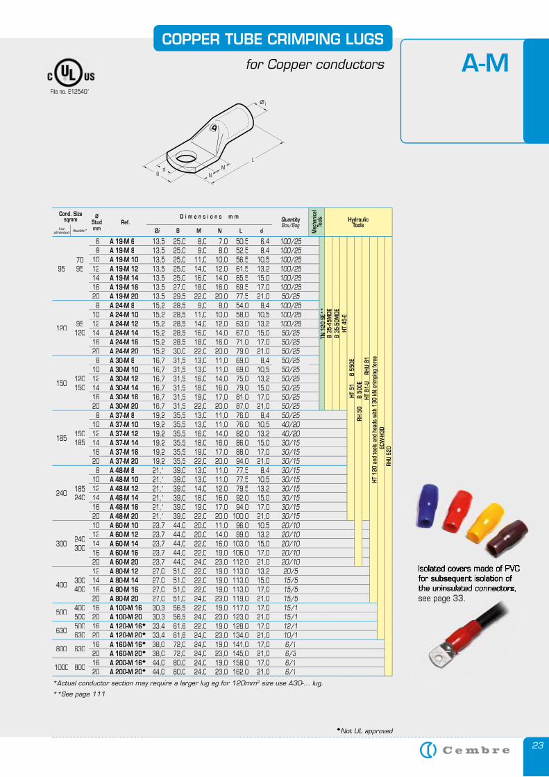
23
COPPER TUBE CRIMPING LUGS
for Copper conductors
*Actual conductor section may require a larger lug eg for 120mm2 size use A30-... lug.
A-M
**See page 111
Cond. Sizesqmm Ø
Studmm
Ref.D i m e n s i o n s m m Quantity
Box/Bag
Mec
hanic
al To
ols HydraulicTools
lowstranded flexible* Øi B M N L d
957095
6 A 19-M 6 13,5 25,0 8,0 7,0 50,5 6,4 100/25
TN 1
20 S
E**
B 35
-45M
DE
B 35
-50M
DEHT
45-
EHT
51
B
550
ERH
50
B
500
EHT
81-
U
RHU
81HT
120
and
tool
s an
d he
ads
with
130
kN
crim
ping
forc
eEC
W-H
3DRH
U 52
0
8 A 19-M 8 13,5 25,0 9,0 8,0 52,5 8,4 100/2510 A 19-M 10 13,5 25,0 11,0 10,0 56,5 10,5 100/2512 A 19-M 12 13,5 25,0 14,0 12,0 61,5 13,2 100/2514 A 19-M 14 13,5 25,0 16,0 14,0 65,5 15,0 100/2516 A 19-M 16 13,5 27,0 18,0 16,0 69,5 17,0 100/2520 A 19-M 20 13,5 29,5 22,0 20,0 77,5 21,0 50/25
120 95120
8 A 24-M 8 15,2 28,5 9,0 8,0 54,0 8,4 100/2510 A 24-M 10 15,2 28,5 11,0 10,0 58,0 10,5 100/2512 A 24-M 12 15,2 28,5 14,0 12,0 63,0 13,2 100/2514 A 24-M 14 15,2 28,5 16,0 14,0 67,0 15,0 50/2516 A 24-M 16 15,2 28,5 18,0 16,0 71,0 17,0 50/2520 A 24-M 20 15,2 30,0 22,0 20,0 79,0 21,0 50/25
150 120150
8 A 30-M 8 16,7 31,5 13,0 11,0 69,0 8,4 50/2510 A 30-M 10 16,7 31,5 13,0 11,0 69,0 10,5 50/2512 A 30-M 12 16,7 31,5 16,0 14,0 75,0 13,2 50/2514 A 30-M 14 16,7 31,5 18,0 16,0 79,0 15,0 50/2516 A 30-M 16 16,7 31,5 19,0 17,0 81,0 17,0 50/2520 A 30-M 20 16,7 31,5 22,0 20,0 87,0 21,0 50/25
185 150185
8 A 37-M 8 19,2 35,5 13,0 11,0 76,0 8,4 50/2510 A 37-M 10 19,2 35,5 13,0 11,0 76,0 10,5 40/2012 A 37-M 12 19,2 35,5 16,0 14,0 82,0 13,2 40/2014 A 37-M 14 19,2 35,5 18,0 16,0 86,0 15,0 30/1516 A 37-M 16 19,2 35,5 19,0 17,0 88,0 17,0 30/1520 A 37-M 20 19,2 35,5 22,0 20,0 94,0 21,0 30/15
240 185240
8 A 48-M 8 21,1 39,0 13,0 11,0 77,5 8,4 30/1510 A 48-M 10 21,1 39,0 13,0 11,0 77,5 10,5 30/1512 A 48-M 12 21,1 39,0 14,0 12,0 79,5 13,2 30/1514 A 48-M 14 21,1 39,0 18,0 16,0 92,0 15,0 30/1516 A 48-M 16 21,1 39,0 19,0 17,0 94,0 17,0 30/1520 A 48-M 20 21,1 39,0 22,0 20,0 100,0 21,0 30/15
300 240300
10 A 60-M 10 23,7 44,0 20,0 11,0 96,0 10,5 20/1012 A 60-M 12 23,7 44,0 20,0 14,0 99,0 13,2 20/1014 A 60-M 14 23,7 44,0 22,0 16,0 103,0 15,0 20/1016 A 60-M 16 23,7 44,0 22,0 19,0 106,0 17,0 20/1020 A 60-M 20 23,7 44,0 24,0 23,0 112,0 21,0 20/10
400 300400
12 A 80-M 12 27,0 51,0 22,0 19,0 113,0 13,2 20/514 A 80-M 14 27,0 51,0 22,0 19,0 113,0 15,0 15/516 A 80-M 16 27,0 51,0 22,0 19,0 113,0 17,0 15/520 A 80-M 20 27,0 51,0 24,0 23,0 119,0 21,0 15/5
500 400500
16 A 100-M 16 30,3 56,5 22,0 19,0 117,0 17,0 15/120 A 100-M 20 30,3 56,5 24,0 23,0 123,0 21,0 15/1
630 500630
16 A 120-M 16 33,4 61,6 22,0 19,0 128,0 17,0 12/120 A 120-M 20 33,4 61,6 24,0 23,0 134,0 21,0 10/1
800 63016 A 160-M 16 38,0 72,0 24,0 19,0 141,0 17,0 6/120 A 160-M 20 38,0 72,0 24,0 23,0 145,0 21,0 6/3
1000 80016 A 200-M 16 44,0 80,0 24,0 19,0 158,0 17,0 6/120 A 200-M 20 44,0 80,0 24,0 23,0 162,0 21,0 6/1
Not UL approved
File no. E125401
Isolated covers made of PVC for subsequent isolation ofthe uninsulated connectors, see page 33.the uninsulated connectors,
Isolated covers made of PVC for subsequent isolation ofthe uninsulated connectors, the uninsulated connectors,
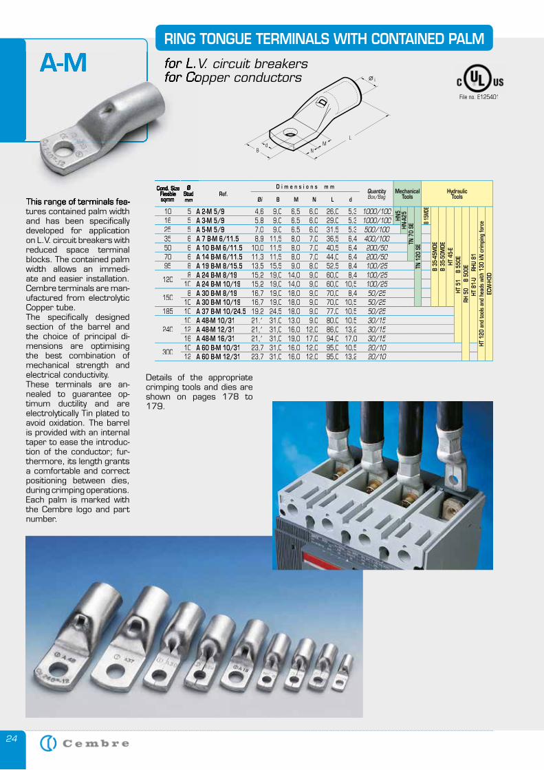
24
Cond. SizeFlexiblesqmm
ØStudmm
Ref.D i m e n s i o n s m m
QuantityBox/Bag
MechanicalTools
HydraulicToolsØi B M N L d
10 5 A 2-M 5/9 4,6 9,0 6,5 6,0 26,0 5,3 1000/100
HN5
HN-A
25TN
70
SETN
120
SE
B 15
MDE
B 35
-45M
DEB
35-5
0MDE
HT 4
5-E
HT 5
1
B 55
0ERH
50
B
500E
HT 8
1-U
RH
U 81
HT 1
20 a
nd to
ols
and
head
s wi
th 1
30 k
N c
rimpi
ng fo
rce
ECW
-H3D
16 5 A 3-M 5/9 5,8 9,0 6,5 6,0 29,0 5,3 1000/10025 5 A 5-M 5/9 7,0 9,0 6,5 6,0 31,5 5,3 500/10035 6 A 7 B-M 6/11.5 8,9 11,5 8,0 7,0 36,5 6,4 400/10050 6 A 10 B-M 6/11.5 10,0 11,5 8,0 7,0 40,5 6,4 200/5070 6 A 14 B-M 6/11.5 11,3 11,5 8,0 7,0 44,0 6,4 200/5095 8 A 19 B-M 8/15.5 13,5 15,5 9,0 8,0 52,5 8,4 100/25
1208 A 24 B-M 8/19 15,2 19,0 14,0 9,0 60,0 8,4 100/25
10 A 24 B-M 10/19 15,2 19,0 14,0 9,0 60,0 10,5 100/25
1508 A 30 B-M 8/19 16,7 19,0 18,0 9,0 70,0 8,4 50/25
10 A 30 B-M 10/19 16,7 19,0 18,0 9,0 70,0 10,5 50/25185 10 A 37 B-M 10/24.5 19,2 24,5 18,0 9,0 77,0 10,5 50/25
24010 A 48-M 10/31 21,1 31,0 13,0 9,0 80,0 10,5 30/1512 A 48-M 12/31 21,1 31,0 16,0 12,0 86,0 13,2 30/1516 A 48-M 16/31 21,1 31,0 19,0 17,0 94,0 17,0 30/15
30010 A 60 B-M 10/31 23,7 31,0 16,0 12,0 95,0 10,5 20/1012 A 60 B-M 12/31 23,7 31,0 16,0 12,0 95,0 13,2 20/10
This range of terminals fea-tures contained palm width and has been specifically developed for application on L.V. circuit breakers with reduced space terminal blocks. The contained palm width allows an immedi-ate and easier installation. Cembre terminals are man-ufactured from electrolytic Copper tube. The specifically designed section of the barrel and the choice of principal di-mensions are optimising the best combination of mechanical strength and electrical conductivity.These terminals are an-nealed to guarantee op-timum ductility and are electrolytically Tin plated to avoid oxidation. The barrel is provided with an internal taper to ease the introduc-tion of the conductor; fur-thermore, its length grants a comfortable and correct positioning between dies, during crimping operations.Each palm is marked with the Cembre logo and part number.
RING TONGUE TERMINALS WITH CONTAINED PALM
for L.V. circuit breakersfor Copper conductors
A-M
Cond. SizeFlexiblesqmm
ØStudmmThis range of terminals fea-
for L.V. circuit breakersfor Copper conductors
A-M
Details of the appropriate crimping tools and dies are shown on pages 178 to 179.
File no. E125401
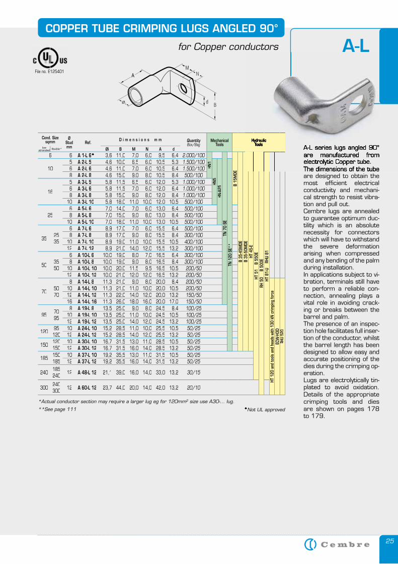
25
A-LCOPPER TUBE CRIMPING LUGS ANGLED 90°
for Copper conductors
A-L series lugs angled 90° are manufactured from electrolytic Copper tube.The dimensions of the tube are designed to obtain the most efficient electrical conductivity and mechani-cal strength to resist vibra-tion and pull out.Cembre lugs are annealed to guarantee optimum duc-tility which is an absolute necessity for connectors which will have to withstand the severe deformation arising when compressed and any bending of the palm during installation.In applications subject to vi-bration, terminals still have to perform a reliable con-nection, annealing plays a vital role in avoiding crack-ing or breaks between the barrel and palm.The presence of an inspec-tion hole facilitates full inser-tion of the conductor, whilst the barrel length has been designed to allow easy and accurate positioning of the dies during the crimping op-eration.Lugs are electrolytically tin-plated to avoid oxidation. Details of the appropriate crimping tools and dies are shown on pages 178 to 179.
Cond. Sizesqmm
ØStudmm
Ref.D i m e n s i o n s m m Quantity
Box/BagMechanical
ToolsHydraulic
Toolslow
stranded flexible* Øi B M N A d6 6 A 1-L 6 3,6 11,0 7,0 6,0 9,5 6,4 2.000/100
HN1
TN 7
0 SE
B 15
MDE
B 35
-45M
DEB
35-5
0MDE
HT 4
5-E
HT 5
1
B 55
0ERH
50
B
500
EHT
81-
U
RHU
81
105 A 2-L 5 4,6 10,0 6,5 6,0 10,5 5,3 1.500/100
HN5
HN-A
25
TN 1
20 S
E**
6 A 2-L 6 4,6 11,0 7,0 6,0 10,5 6,4 1.500/1008 A 2-L 8 4,6 15,0 9,0 8,0 10,5 8,4 500/100
16
5 A 3-L 5 5,8 11,5 6,5 6,0 12,0 5,3 1.000/1006 A 3-L 6 5,8 11,5 7,0 6,0 12,0 6,4 1.000/1008 A 3-L 8 5,8 15,0 9,0 8,0 12,0 8,4 1.000/100
10 A 3-L 10 5,8 18,0 11,0 10,0 12,0 10,5 500/100
256 A 5-L 6 7,0 14,0 7,0 6,0 13,0 6,4 500/1008 A 5-L 8 7,0 15,0 9,0 8,0 13,0 8,4 500/100
10 A 5-L 10 7,0 18,0 11,0 10,0 13,0 10,5 500/100
35 2535
6 A 7-L 6 8,9 17,0 7.0 6,0 15,5 6,4 500/1008 A 7-L 8 8,9 17,0 9,0 8,0 15,5 8,4 300/100
10 A 7-L 10 8,9 19,0 11,0 10,0 15,5 10,5 400/10012 A 7-L 12 8,9 21,0 14,0 12,0 15,5 13,2 300/100
50 3550
6 A 10-L 6 10,0 19,0 8,0 7,0 16,5 6,4 300/1008 A 10-L 8 10,0 19,0 9,0 8,0 16,5 8,4 300/100
10 A 10-L 10 10,0 20,0 11,5 9,5 16,5 10,5 200/5012 A 10-L 12 10,0 21,0 12,0 12,0 16,5 13,2 200/50
70 5070
8 A 14-L 8 11,3 21,0 9,0 8,0 20,0 8,4 200/50
HT 1
20 a
nd to
ols
and
head
s wi
th 1
30 k
N c
rimpi
ng fo
rce
ECW
-H3D
RHU
520
10 A 14-L 10 11,3 21,0 11,0 10,0 20,0 10,5 200/5012 A 14-L 12 11,3 22,0 14,0 12,0 20,0 13,2 150/5016 A 14-L 16 11,3 26,0 18,0 16,0 20,0 17,0 150/50
95 7095
8 A 19-L 8 13,5 25,0 9,0 8,0 24,5 8,4 100/2510 A 19-L 10 13,5 25,0 11,0 10,0 24,5 10,5 100/2512 A 19-L 12 13,5 25,0 14,0 12,0 24,5 13,2 100/25
120 95120
10 A 24-L 10 15,2 28,5 11,0 10,0 25,5 10,5 50/2512 A 24-L 12 15,2 28,5 14,0 12,0 25,5 13,2 50/25
150 120150
10 A 30-L 10 16,7 31,5 13,0 11,0 28,5 10,5 50/2512 A 30-L 12 16,7 31,5 16,0 14,0 28,5 13,2 50/25
185 150185
10 A 37-L 10 19,2 35,5 13,0 11,0 31,5 10,5 50/2512 A 37-L 12 19,2 35,5 16,0 14,0 31,5 13,2 50/25
240 185240 12 A 48-L 12 21,1 39,0 16,0 14,0 33,0 13,2 30/15
300 240300 12 A 60-L 12 23,7 44,0 20,0 14,0 42,0 13,2 20/10
A-L series lugs angled 90° are manufactured from electrolytic Copper tube.The dimensions of the tube
HydraulicTools
HydraulicTools
Hydraulic
*Actual conductor section may require a larger lug eg for 120mm2 size use A30-... lug.
**See page 111
File no. E125401
Not UL approved
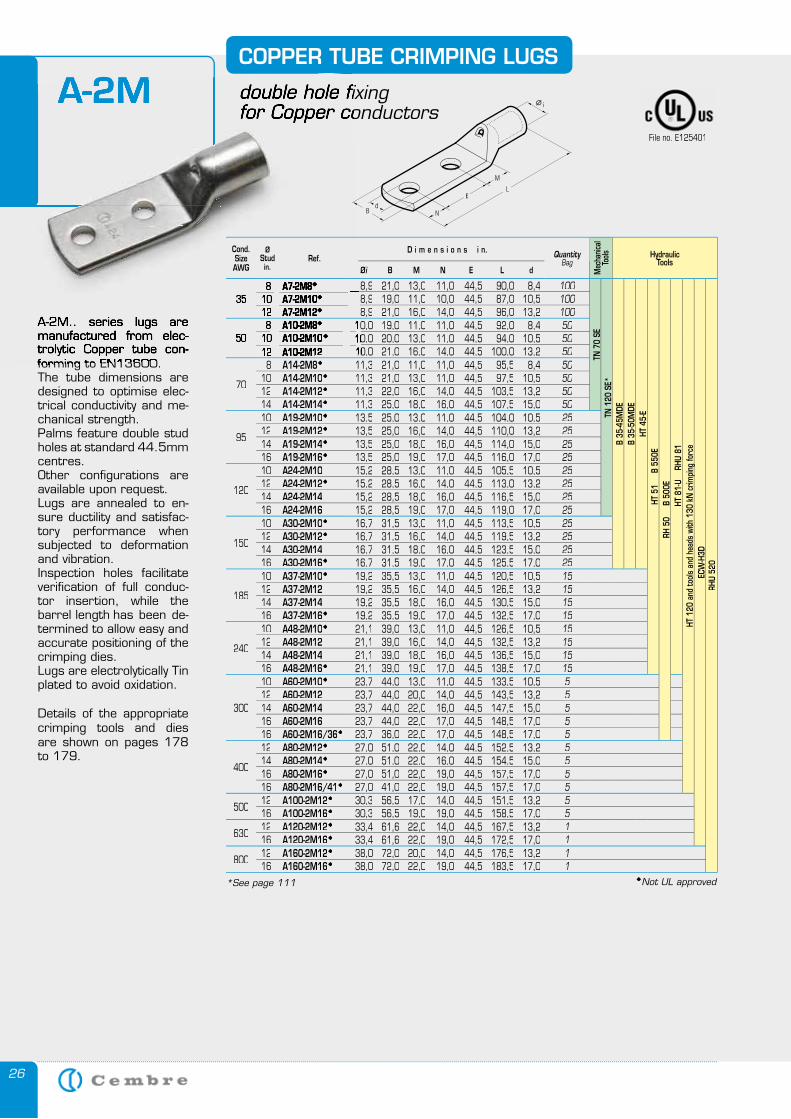
26
A-2M.. series lugs are manufactured from elec-trolytic Copper tube con-forming to EN13600. The tube dimensions are designed to optimise elec-trical conductivity and me-chanical strength. Palms feature double stud holes at standard 44.5mm centres. Other configurations are available upon request. Lugs are annealed to en-sure ductility and satisfac-tory performance when subjected to deformation and vibration. Inspection holes facilitate verification of full conduc-tor insertion, while the barrel length has been de-termined to allow easy and accurate positioning of the crimping dies. Lugs are electrolytically Tin plated to avoid oxidation.
Details of the appropriate crimping tools and dies are shown on pages 178 to 179.
COPPER TUBE CRIMPING LUGS
double hole fixingfor Copper conductors
A-2M
A-2M.. series lugs are manufactured from elec-trolytic Copper tube con-forming to EN13600.
double hole fixingfor Copper conductors
A-2M
E
Cond. SizeAWG
ØStudin.
Ref.D i m e n s i o n s i n. Quantity
Bag
Mec
hanic
al To
ols HydraulicTools
Øi B M N E L d
358 A7-2M8 8,9 21,0 13,0 11,0 44,5 90,0 8,4 100
TN 7
0 SE
TN 1
20 S
E*B
35-4
5MDE
B 35
-50M
DEHT
45-
EHT
51
B
550
ERH
50
B
500
E H
T 81
-U
RHU
81
HT 1
20 a
nd to
ols
and
head
s wi
th 1
30 k
N c
rimpi
ng fo
rce
ECW
-H3D
RHU
520
10 A7-2M10 8,9 19,0 11,0 10,0 44,5 87,0 10,5 10012 A7-2M12 8,9 21,0 16,0 14,0 44,5 96,0 13,2 100
508 A10-2M8 10,010,0 19,0 11,0 11,0 44,5 92,0 8,4 50
10 A10-2M10 10,010,0 20,0 13,0 11,0 44,5 94,0 10,5 5012 A10-2M12A10-2M12 10,010,0 21,0 16,0 14,0 44,5 100,0 13,2 50
70
8 A14-2M8 11,3 21,0 11,0 11,0 44,5 95,5 8,4 5010 A14-2M10 11,3 21,0 13,0 11,0 44,5 97,5 10,5 5012 A14-2M12 11,3 22,0 16,0 14,0 44,5 103,5 13,2 5014 A14-2M14 11,3 25,0 18,0 16,0 44,5 107,5 15,0 50
95
10 A19-2M10 13,5 25,0 13,0 11,0 44,5 104,0 10,5 2512 A19-2M12 13,5 25,0 16,0 14,0 44,5 110,0 13,2 2514 A19-2M14 13,5 25,0 18,0 16,0 44,5 114,0 15,0 2516 A19-2M16 13,5 25,0 19,0 17,0 44,5 116,0 17,0 25
120
10 A24-2M10 15,2 28,5 13,0 11,0 44,5 105,5 10,5 2512 A24-2M12 15,2 28,5 16,0 14,0 44,5 113,0 13,2 2514 A24-2M14 15,2 28,5 18,0 16,0 44,5 116,5 15,0 2516 A24-2M16 15,2 28,5 19,0 17,0 44,5 119,0 17,0 25
150
10 A30-2M10 16,7 31,5 13,0 11,0 44,5 113,5 10,5 2512 A30-2M12 16,7 31,5 16,0 14,0 44,5 119,5 13,2 2514 A30-2M14 16,7 31,5 18,0 16,0 44,5 123,5 15,0 2516 A30-2M16 16,7 31,5 19,0 17,0 44,5 125,5 17,0 25
185
10 A37-2M10 19,2 35,5 13,0 11,0 44,5 120,5 10,5 1512 A37-2M12 19,2 35,5 16,0 14,0 44,5 126,5 13,2 1514 A37-2M14 19,2 35,5 18,0 16,0 44,5 130,5 15,0 1516 A37-2M16 19,2 35,5 19,0 17,0 44,5 132,5 17,0 15
240
10 A48-2M10 21,1 39,0 13,0 11,0 44,5 126,5 10,5 1512 A48-2M12 21,1 39,0 16,0 14,0 44,5 132,5 13,2 1514 A48-2M14 21,1 39,0 18,0 16,0 44,5 136,5 15,0 1516 A48-2M16 21,1 39,0 19,0 17,0 44,5 138,5 17,0 15
300
10 A60-2M10 23,7 44,0 13,0 11,0 44,5 133,5 10,5 512 A60-2M12 23,7 44,0 20,0 14,0 44,5 143,5 13,2 514 A60-2M14 23,7 44,0 22,0 16,0 44,5 147,5 15,0 516 A60-2M16 23,7 44,0 22,0 17,0 44,5 148,5 17,0 516 A60-2M16/36 23,7 36,0 22,0 17,0 44,5 148,5 17,0 5
400
12 A80-2M12 27,0 51,0 22,0 14,0 44,5 152,5 13,2 514 A80-2M14 27,0 51,0 22,0 16,0 44,5 154,5 15,0 516 A80-2M16 27,0 51,0 22,0 19,0 44,5 157,5 17,0 516 A80-2M16/41 27,0 41,0 22,0 19,0 44,5 157,5 17,0 5
50012 A100-2M12 30,3 56,5 17,0 14,0 44,5 151,5 13,2 516 A100-2M16 30,3 56,5 19,0 19,0 44,5 158,5 17,0 5
63012 A120-2M12 33,4 61,6 22,0 14,0 44,5 167,5 13,2 116 A120-2M16 33,4 61,6 22,0 19,0 44,5 172,5 17,0 1
80012 A160-2M12 38,0 72,0 20,0 14,0 44,5 176,5 13,2 116 A160-2M16 38,0 72,0 22,0 19,0 44,5 183,5 17,0 1
File no. E125401
Not UL approved *See page 111
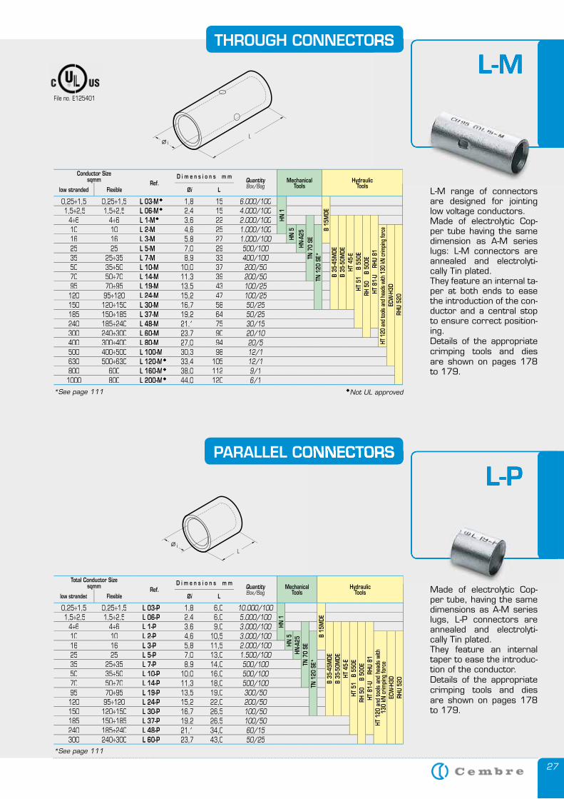
27
THROUGH CONNECTORS
L-M range of connectors are designed for jointing low voltage conductors.Made of electrolytic Cop-per tube having the same dimension as A-M series lugs: L-M connectors are annealed and electrolyti-cally Tin plated.They feature an internal ta-per at both ends to ease the introduction of the con-ductor and a central stop to ensure correct position-ing.Details of the appropriate crimping tools and dies are shown on pages 178 to 179.
PARALLEL CONNECTORS
Made of electrolytic Cop-per tube, having the same dimensions as A-M series lugs, L-P connectors are annealed and electrolyti-cally Tin plated.They feature an internal taper to ease the introduc-tion of the conductor.Details of the appropriate crimping tools and dies are shown on pages 178 to 179.
L-MTHROUGH CONNECTORS
L-M
L-PPARALLEL CONNECTORS
L-P
Conductor Sizesqmm Ref.
D i m e n s i o n s m mQuantityBox/Bag
MechanicalTools
HydraulicToolslow stranded Flexible Øi L
0,25÷1,5 0,25÷1,5 L 03-M 1,8 15 6.000/100
HN 1
B 15
MDE 1,5÷2,5 1,5÷2,5 L 06-M 2,4 15 4.000/100
4÷6 4÷6 L 1-M 3,6 22 2.000/100
TN 7
0 SE
B 35
-45M
DEB
35-5
0MDE
HT 4
5-E
HT 5
1
B 55
0ERH
50
B
500E
HT 8
1-U
RH
U 81
10 10 L 2-M 4,6 25 1.000/100
HN 5
HN-A
25
TN 1
20 S
E*
HT 1
20 a
nd to
ols a
nd h
eads
with
130
kN cr
impin
g fo
rce
ECW
-H3D
RHU
520
16 16 L 3-M 5,8 27 1.000/10025 25 L 5-M 7,0 29 500/10035 25÷35 L 7-M 8,9 33 400/10050 35÷50 L 10-M 10,0 37 200/5070 50÷70 L 14-M 11,3 39 200/5095 70÷95 L 19-M 13,5 43 100/25120 95÷120 L 24-M 15,2 47 100/25150 120÷150 L 30-M 16,7 58 50/25185 150÷185 L 37-M 19,2 64 50/25240 185÷240 L 48-M 21,1 75 30/15300 240÷300 L 60-M 23,7 90 20/10400 300÷400 L 80-M 27,0 94 20/5500 400÷500 L 100-M 30,3 98 12/1630 500÷630 L 120-M 33,4 105 12/1800 600 L 160-M 38,0 112 9/11000 800 L 200-M 44,0 120 6/1
Total Conductor Sizesqmm Ref.
D i m e n s i o n s m mQuantityBox/Bag
MechanicalTools
HydraulicToolslow stranded Flexible Øi L
0,25÷1,5 0,25÷1,5 L 03-P 1,8 6,0 10.000/100
HN 1
B 15
MDE 1,5÷2,5 1,5÷2,5 L 06-P 2,4 6,0 5.000/100
4÷6 4÷6 L 1-P 3,6 9,0 3.000/100
TN 7
O SE
B 35
-45M
DEB
35-5
0MDE
HT 4
5-E
HT 5
1 B
550
ERH
50
B
500E
HT 8
1-U
RH
U 81
10 10 L 2-P 4,6 10,5 3.000/100
HN 5
HN-A
25
TN 1
20 S
E*
HT 1
20 a
nd to
ols
and
head
s wi
th
130
kN c
rimpi
ng fo
rce
ECW
-H3D
RHU
520
16 16 L 3-P 5,8 11,5 2.000/10025 25 L 5-P 7,0 13,0 1.500/10035 25÷35 L 7-P 8,9 14,0 500/10050 35÷50 L 10-P 10,0 16,0 500/10070 50÷70 L 14-P 11,3 18,0 500/10095 70÷95 L 19-P 13,5 19,0 300/50120 95÷120 L 24-P 15,2 22,0 200/50150 120÷150 L 30-P 16,7 26,5 100/50185 150÷185 L 37-P 19,2 26,5 100/50240 185÷240 L 48-P 21,1 34,0 60/15300 240÷300 L 60-P 23,7 43,0 50/25
*See page 111
*See page 111
File no. E125401
Not UL approved
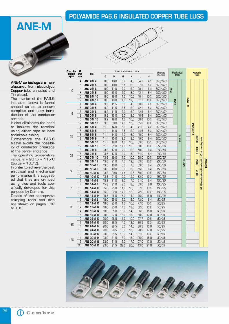
28
ANE-MPOLYAMIDE PA6.6 INSULATED COPPER TUBE LUGS
ANE-M series lugs are man-ufactured from electrolytic Copper tube annealed and Tin plated.The interior of the PA6.6 insulated sleeve is funnel shaped so as to ensure complete and easy intro-duction of the conductor strands.It also eliminates the need to insulate the terminal using either tape or heat shrinkable tubing.Furthermore the PA6.6 sleeve avoids the possibil-ity of conductor breakage at the barrel entrance.The operating temperature range is – 20 to + 115°C (Surge + 130°C).In order to achieve the best electrical and mechanical performance it is suggest-ed that they are crimped using dies and tools spe-cifically developed for this purpose by Cembre.Details of the appropriate crimping tools and dies are shown on pages 182 to 183.
Cond. SizeFlexiblesqmm
ØStudmm
Ref.D i m e n s i o n s m m
QuantityBox/Bag
MechanicalTools
HydraulicTools
Ø B M N L d
10
ANE 2-M 4 8,0 10,0 5,0 4,0 34,1 4,3 500/100
HNN
3
HNN
4
TNN
70
TNN
120
B 15
MDE
B 35
-50M
DE
HT 5
1
RH
50
B 50
0 E
B
550
E
HT 1
20 a
nd to
ols
and
head
s wi
th 1
30 k
N c
rimpi
ng fo
rce
ECW
-H3D
ANE 2-M 5 8,0 10,0 6,5 6,0 37,6 5,3 500/100ANE 2-M 6 8,0 11,0 7,0 6,0 38,1 6,4 500/100
8 ANE 2-M 8 8,0 15,0 9,0 8,0 42,1 8,4 500/10010 ANE 2-M 10 8,0 18,0 11,0 10,0 46,1 10,5 500/10012 ANE 2-M 12 8,0 19,0 14,0 12,0 51,1 13,2 500/100
16
4 ANE 3-M 4 9,2 11,5 5,0 4,0 38,6 4,3 500/1005 ANE 3-M 5 9,2 11,5 6,5 6,0 42,1 5,3 500/1006 ANE 3-M 6 9,2 11,5 7,0 6,0 42,6 6,4 500/1008 ANE 3-M 8 9,2 15,0 9,0 8,0 46,6 8,4 500/100
10 ANE 3-M 10 9,2 18,0 11,0 10,0 50,6 10,5 400/10012 ANE 3-M 12 9,2 20,0 14,0 12,0 55,6 13,2 300/100
25
4 ANE 5-M 4 11,1 14,0 5,0 4,0 41,0 4,3 300/1005 ANE 5-M 5 11,1 14,0 6,5 6,0 44,5 5,3 300/1006 ANE 5-M 6 11,1 14,0 7,0 6,0 45,0 6,4 300/1008 ANE 5-M 8 11,1 15,0 9,0 8,0 49,0 8,4 300/100
10 ANE 5-M 10 11,1 18,0 11,0 10,0 53,0 10,5 300/10012 ANE 5-M 12 11,1 21,0 14,0 12,0 58,0 13,2 250/50
35
6 ANE 7-M 6 13,6 17,0 7,0 6,0 50,0 6,4 200/508 ANE 7-M 8 13,6 17,0 9,0 8,0 54,0 8,4 200/50
10 ANE 7-M 10 13,6 19,0 11,0 10,0 58,0 10,5 200/5012 ANE 7-M 12 13,6 21,0 14,0 12,0 63,0 13,2 200/50
50
6 ANE 10-M 6 13,8 19,0 8,0 7,0 53,0 6,4 200/508 ANE 10-M 8 13,8 19,0 9,0 8,0 55,0 8,4 150/50
10 ANE 10-M 10 13,8 20,0 11,5 9,5 59,0 10,5 150/5012 ANE 10-M 12 13,8 21,0 12,0 12,0 62,0 13,2 150/50
70
6 ANE 14-M 6 15,8 21,0 8,0 7,0 61,0 6,4 100/258 ANE 14-M 8 15,8 21,0 9,0 8,0 63,0 8,0 100/25
10 ANE 14-M 10 15,8 21,0 11,0 10,0 67,0 10,5 100/2512 ANE 14-M 12 15,8 22,0 14,0 12,0 72,0 13,2 100/2514 ANE 14-M 14 15,8 25,0 16,0 14,0 76,0 15,0 100/25
95
8 ANE 19-M 8 18,0 25,0 9,0 8,0 73,0 8,4 50/2510 ANE 19-M 10 18,0 25,0 11,0 10,0 77,0 10,5 50/2512 ANE 19-M 12 18,0 25,0 14,0 12,0 82,0 13,2 50/2514 ANE 19-M 14 18,0 25,0 16,0 14,0 86,0 15,0 50/2516 ANE 19-M 16 18,0 27,0 18,0 16,0 80,0 17,0 50/25
120
10 ANE 24-M 10 20,0 28,5 11,0 10,0 77,7 10,5 50/2512 ANE 24-M 12 20,0 28,5 14,0 12,0 86,5 13,2 50/2514 ANE 24-M 14 20,0 28,5 16,0 14,0 88,5 15,0 50/2516 ANE 24-M 16 20,0 28,5 18,0 16,0 90,5 17,0 50/25
150
12 ANE 30-M 12 23,0 31,5 16,0 14,0 101,0 13,2 30/1514 ANE 30-M 14 23,0 31,5 18,0 16,0 105,0 15,0 30/1516 ANE 30-M 16 23,0 31,5 19,0 17,0 107,0 17,0 30/1520 ANE 30-M 20 23,0 31,5 22,0 20,0 113,0 21,0 30/15
ANE-M
ANE-M series lugs are man-ufactured from electrolytic Copper tube annealed and
Cond. SizeFlexiblesqmm
ØStudmm
Ref.
10
4 ANE 2-M 45 ANE 2-M 56 ANE 2-M 68 ANE 2-M 8
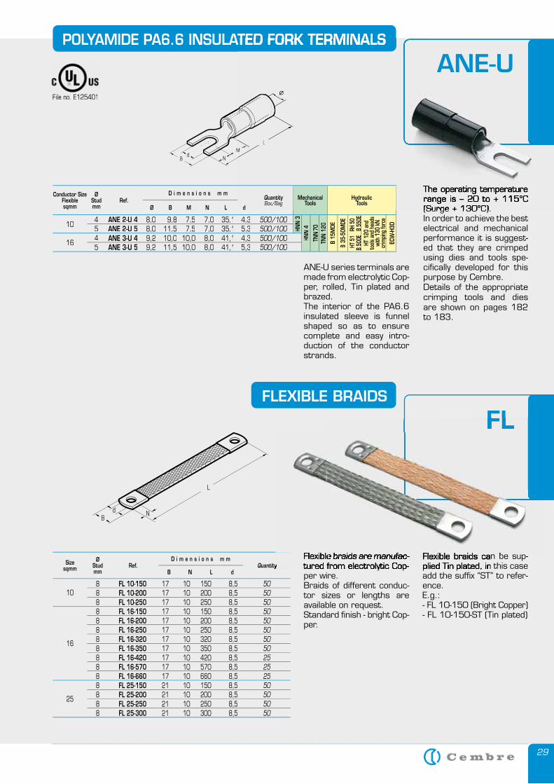
29
POLYAMIDE PA6.6 INSULATED FORK TERMINALS
The operating temperature range is – 20 to + 115°C (Surge + 130°C).In order to achieve the best electrical and mechanical performance it is suggest-ed that they are crimped using dies and tools spe-cifically developed for this purpose by Cembre.Details of the appropriate crimping tools and dies are shown on pages 182 to 183.
FLEXIBLE BRAIDS
8 FL 10-150 17 10 150 8,5 8 FL 10-200 17 10 200 8,5 8 FL 10-250 17 10 250 8,5 8 FL 16-150 17 10 150 8,5 8 FL 16-200 17 10 200 8,5 8 FL 16-250 17 10 250 8,5 8 FL 16-320 17 10 320 8,5 8 FL 16-350 17 10 350 8,5 8 FL 16-420 17 10 420 8,5 8 FL 16-570 17 10 570 8,5 8 FL 16-660 17 10 660 8,5 8 FL 25-150 21 10 150 8,5 8 FL 25-200 21 10 200 8,5 8 FL 25-250 21 10 250 8,5 8 FL 25-300 21 10 300 8,5
505050505050505025252550505050
Sizesqmm
ØStudmm
QuantityB N L d
D i m e n s i o n s m mRef.
10
16
25
Flexible braids can be sup-plied Tin plated, in this case add the suffix “ST” to refer-ence.E.g.: - FL 10-150 (Bright Copper)- FL 10-150-ST (Tin plated)
Flexible braids are manufac-tured from electrolytic Cop-per wire.Braids of different conduc-tor sizes or lengths are available on request.Standard finish - bright Cop-per.
POLYAMIDE PA6.6 INSULATED FORK TERMINALS
The operating temperature range is – 20 to + 115°C (Surge + 130°C).
ANE-U
FL
QuantityFlexible braids can be sup-plied Tin plated, in this case
Flexible braids are manufac-tured from electrolytic Cop-
Flexible braids can be sup-
FL
Flexible braids can be sup-Flexible braids are manufac-
Conductor SizeFlexiblesqmm
ØStudmm
Ref.D i m e n s i o n s m m
QuantityBox/Bag
MechanicalTools
HydraulicTools
Ø B M N L d
104 ANE 2-U 4 8,0 9,8 7,5 7,0 35,1 4,3 500/100
HNN
3HN
N 4
TNN
70TN
N 1
20
B 15
MDE
B 35
-50M
DEHT
51
RH
50
B 50
0E
B 55
0EHT
120
and
to
ols a
nd h
eads
wi
th 1
30 k
N cr
impin
g fo
rce
ECW
-H3D5 ANE 2-U 5 8,0 11,5 7,5 7,0 35,1 5,3 500/100
164 ANE 3-U 4 9,2 10,0 10,0 8,0 41,1 4,3 500/1005 ANE 3-U 5 9,2 11,5 10,0 8,0 41,1 5,3 500/100
ANE-U series terminals are made from electrolytic Cop-per, rolled, Tin plated and brazed. The interior of the PA6.6 insulated sleeve is funnel shaped so as to ensure complete and easy intro-duction of the conductor strands.
File no. E125401
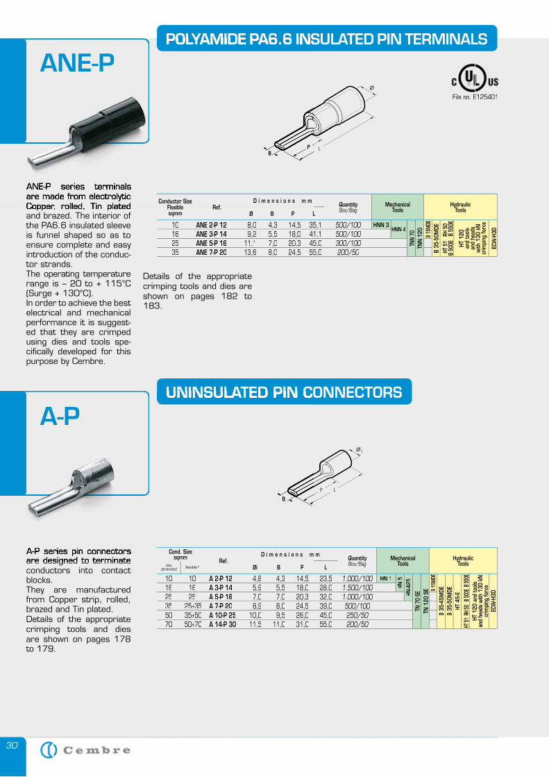
30
ANE-P series terminals are made from electrolytic Copper, rolled, Tin plated and brazed. The interior of the PA6.6 insulated sleeve is funnel shaped so as to ensure complete and easy introduction of the conduc-tor strands.The operating temperature range is – 20 to + 115°C (Surge + 130°C).In order to achieve the best electrical and mechanical performance it is suggest-ed that they are crimped using dies and tools spe-cifically developed for this purpose by Cembre.
POLYAMIDE PA6.6 INSULATED PIN TERMINALS
Details of the appropriate crimping tools and dies are shown on pages 182 to 183.
A-P series pin connectors are designed to terminate conductors into contact blocks. They are manufactured from Copper strip, rolled, brazed and Tin plated.Details of the appropriate crimping tools and dies are shown on pages 178 to 179.
UNINSULATED PIN CONNECTORS
ANE-P series terminals are made from electrolytic Copper, rolled, Tin plated
POLYAMIDE PA6.6 INSULATED PIN TERMINALS
ANE-P
UNINSULATED PIN CONNECTORS
A-P series pin connectors are designed to terminate
A-P
Conductor SizeFlexiblesqmm
Ref.D i m e n s i o n s m m
QuantityBox/Bag
Mechanical Tools
HydraulicTools
Ø B P L
10 ANE 2-P 12 8,0 4,3 14,5 35,1 500/100 HNN 3HNN 4
TNN
70
TNN
120
B 15
MDE
B 35
-50M
DEHT
51
RH
50B
500E
B
550E
HT 1
20
and
tool
s an
d he
ads
with
130
kN
cr
impi
ng fo
rce
ECW
-H3D16 ANE 3-P 14 9,2 5,5 18,0 41,1 500/100
25 ANE 5-P 16 11,1 7,0 20,3 45,0 300/10035 ANE 7-P 20 13,6 8,0 24,5 55,0 200/50
Cond. Sizesqmm Ref.
D i m e n s i o n s m mQuantityBox/Bag
Mechanical Tools
HydraulicToolslow
stranded flexible* Øi B P L
10 10 A 2-P 12 4,8 4,3 14,5 23,5 1.000/100 HN 1
HN 5
HN-A
25TN
70
SETN
120
SE B
15MD
EB
35-4
5MDE
B 35
-50M
DEHT
45-
EHT
51 R
H 50
B 50
0E B
550E
HT 1
20 a
nd to
ols
and
head
s wi
th 1
30 k
N
crim
ping
forc
eEC
W-H
3D
16 16 A 3-P 14 5,9 5,5 18,0 28,0 1.500/10025 25 A 5-P 16 7,0 7,0 20,3 32,0 1.000/10035 25÷35 A 7-P 20 8,9 8,0 24,5 39,0 500/10050 35÷50 A 10-P 25 10,0 9,5 26,0 45,0 250/5070 50÷70 A 14-P 30 11,5 11,0 31,0 55,0 200/50
File no. E125401
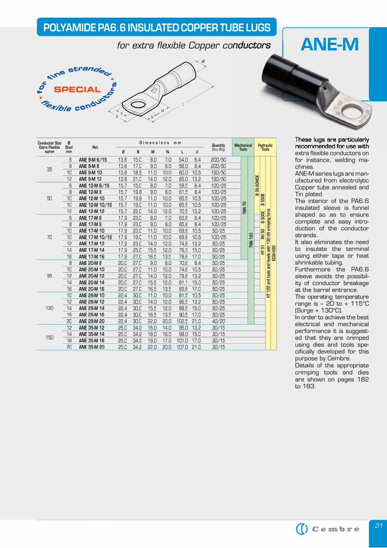
31
POLYAMIDE PA6.6 INSULATED COPPER TUBE LUGS
for extra flexible Copper conductors
These lugs are particularly recommended for use with extra flexible conductors on for instance, welding ma-chines.ANE-M series lugs are man-ufactured from electrolytic Copper tube annealed and Tin plated.The interior of the PA6.6 insulated sleeve is funnel shaped so as to ensure complete and easy intro-duction of the conductor strands.It also eliminates the need to insulate the terminal using either tape or heat shrinkable tubing.Furthermore the PA6.6 sleeve avoids the possibil-ity of conductor breakage at the barrel entrance.The operating temperature range is – 20 to + 115°C (Surge + 130°C).In order to achieve the best electrical and mechanical performance it is suggest-ed that they are crimped using dies and tools spe-cifically developed for this purpose by Cembre.Details of the appropriate crimping tools and dies are shown on pages 182 to 183.
ANE-Mfor extra flexible Copper conductors
These lugs are particularly recommended for use with
ANE-M
Conductor SizeExtra Flexible
sqmm
ØStudmm
Ref.D i m e n s i o n s m m
QuantityBox/Bag
MechanicalTools
HydraulicTools
Ø B M N L d
35
6 ANE 9-M 6/15 13,6 15,0 8,0 7,0 54,0 6,4 200/50
TNN
70
TNN
120
B 35
-50M
DEHT
51
R
H 50
B
500
E
B 5
50E
HT 1
20 a
nd to
ols
and
head
s wi
th 1
30 k
N c
rimpi
ng fo
rce
ECW
-H3D
8 ANE 9-M 8 13,6 17,0 9,0 8,0 56,0 8,4 200/5010 ANE 9-M 10 13,6 18,5 11,0 10.0 60,0 10,5 150/5012 ANE 9-M 12 13,6 21,0 14,0 12,0 65,0 13,2 150/50
50
6 ANE 12-M 6/15 15,7 15,0 8,0 7,0 59,5 6,4 100/258 ANE 12-M 8 15,7 19,8 9,0 8,0 61,5 8,4 100/25
10 ANE 12-M 10 15,7 19,8 11,0 10,0 65,5 10,5 100/2510 ANE 12-M 10/19 15,7 19,0 11,0 10,0 65,5 10,5 100/2512 ANE 12-M 12 15,7 22,0 14,0 12,0 70,5 13,2 100/25
70
6 ANE 17-M 6 17,9 23,0 8,0 7,0 63,8 6,4 100/258 ANE 17-M 8 17,9 23,0 9,0 8,0 65,8 8,4 100/25
10 ANE 17-M 10 17,9 23,0 11,0 10,0 69,8 10,5 50/2510 ANE 17-M 10/19 17,9 19,0 11,0 10,0 69,8 10,5 100/2512 ANE 17-M 12 17,9 23,0 14,0 12,0 74,8 13,2 50/2514 ANE 17-M 14 17,9 25,0 15,5 12,0 76,3 15,0 50/2516 ANE 17-M 16 17,9 27,0 16,5 13,5 78,8 17,0 50/25
95
8 ANE 20-M 8 20,0 27,0 9,0 8,0 70,6 8,4 50/2510 ANE 20-M 10 20,0 27,0 11,0 10,0 74,6 10,5 50/2512 ANE 20-M 12 20,0 27,0 14,0 12,0 79,6 13,2 50/2514 ANE 20-M 14 20,0 27,0 15,5 12,0 81,1 15,0 50/2516 ANE 20-M 16 20,0 27,0 16,5 13,5 83,6 17,0 50/25
120
10 ANE 29-M 10 22,4 30,0 11,0 10,0 81,5 10,5 50/2512 ANE 29-M 12 22,4 30,0 14,0 12,0 86,5 13,2 50/2514 ANE 29-M 14 22,4 30,0 15,5 12,0 88,5 15,0 50/2516 ANE 29-M 16 22,4 30,0 16,5 13,5 90,5 17,0 50/2520 ANE 29-M 20 22,4 30.0 22,0 20,0 102,5 21,0 40/20
150
12 ANE 35-M 12 25,0 34,2 16,0 14,0 95,0 13,2 30/1514 ANE 35-M 14 25,0 34,2 18,0 16,0 99,0 15,0 30/1516 ANE 35-M 16 25,0 34,2 19,0 17,0 101,0 17,0 30/1520 ANE 35-M 20 25,0 34,2 22,0 20,0 107,0 21,0 30/15
fl exible conductor
s
• fo
r fine
stranded • SPECIAL
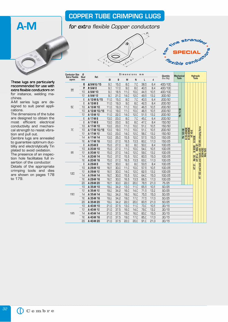
32
COPPER TUBE CRIMPING LUGS
for extra flexible Copper conductors
These lugs are particularly recommended for use with extra flexible conductors on for instance, welding ma-chines.A-M series lugs are de-signed to suit panel appli-cations.The dimensions of the tube are designed to obtain the most efficient electrical conductivity and mechani-cal strength to resist vibra-tion and pull out. Cembre lugs are annealed to guarantee optimum duc-tility and electrolytically Tin plated to avoid oxidation.The presence of an inspec-tion hole facilitates full in-sertion of the conductor.Details of the appropriate crimping tools and dies are shown on pages 178 to 179.
A-M for extra flexible Copper conductors
These lugs are particularly recommended for use with extra flexible conductors on for instance, welding ma-
A-M
Conductor SizeExtra Flexible
sqmm
ØStudmm
Ref.D i m e n s i o n s m m
QuantityBox/Bag
MechanicalTools
HydraulicTools
Øi B M N L d
3535
6 A 9-M 6/15A 9-M 6/15 9,3 15,0 8,0 7,0 38,5 6,4 400/100
TN 7
0 SE
TN 1
20 S
EB
35-4
5MDE
B 35
-50M
DEHT
45-
EHT
51
RH
50
B
500E
B
550
EHT
81-
U
RHU
81HT
120
and
tool
s an
d he
ads
with
130
kN
crim
ping
forc
eEC
W-H
3DRH
U 52
0
88 A 9-M 8A 9-M 8 9,3 17,0 9,0 8,0 40,5 8,4 400/10010 A 9-M 10 9,3 18,5 11,0 10,0 44,5 10,5 400/10012 A 9-M 12 9,3 21,0 14,0 12,0 49,5 13,2 300/50
50
6 A 12-M 6/15 11,0 15,0 8,0 7,0 40,5 6,4 200/508 A 12-M 8 11,0 19,3 9,0 8,0 42,5 8,4 200/50
10 A 12-M 10 11,0 19,3 11,0 10,0 46,5 10,5 200/5010 A 12-M 10/19 11,0 19,0 11,0 10,0 46,5 10,5 200/5012 A 12-M 12 11,0 22,0 14,0 12,0 51,5 13,2 200/50
70
6 A 17-M 6 13,0 23,0 8,0 7,0 45,0 6,4 200/508 A 17-M 8 13,0 23,0 9,0 8,0 47,0 8,4 150/50
10 A 17-M 10 13,0 23,0 11,0 10,0 51,0 10,5 150/5010 A 17-M 10/19 13,0 19,0 11,0 10,0 51,0 10,5 200/5012 A 17-M 12 13,0 23,0 14,0 12,0 56,0 13,2 150/5014 A 17-M 14 13,0 25,0 15,5 12,0 57,5 15,0 150/2516 A 17-M 16 13,0 27,0 16,5 13,5 60,0 17,0 150/25
95
8 A 20-M 8 15,0 27,0 9,0 8,0 50,0 8,4 100/2510 A 20-M 10 15,0 27,0 11,0 10,0 54,0 10,5 100/2512 A 20-M 12 15,0 27,0 14,0 12,0 59,0 13,2 100/2514 A 20-M 14 15,0 27,0 15,5 12,0 60,5 15,0 100/2516 A 20-M 16 15,0 27,0 16,5 13,5 63,0 17,0 100/25
120
8 A 29-M 8 16,5 30,0 9,0 8,0 53,5 8,4 100/2510 A 29-M 10 16,5 30,0 11,0 10,0 57,5 10,5 100/2512 A 29-M 12 16,5 30,0 14,0 12,0 62,5 13,2 100/2514 A 29-M 14 16,5 30,0 15,5 12,0 64,0 15,0 100/2516 A 29-M 16 16,5 30,0 16,5 13,5 66,5 17,0 100/2520 A 29-M 20 16,5 30,0 22,0 20,0 78,5 21,0 75/25
150
10 A 35-M 10 19,2 34,2 13,0 11,0 65,5 10,5 50/2512 A 35-M 12 19,2 34,2 16,0 14,0 71,5 13,2 50/2514 A 35-M 14 19,2 34,2 18,0 16,0 75,5 15,0 50/2516 A 35-M 16 19,2 34,2 19,0 17,0 77,5 17,0 50/2520 A 35-M 20 19,2 34,2 22,0 20,0 83,5 21,0 50/25
185
10 A 40-M 10 21,0 37,5 13,0 11,0 73,0 10,5 30/1512 A 40-M 12 21,0 37,5 16,0 14,0 79,0 13,2 30/1514 A 40-M 14 21,0 37,5 18,0 16,0 83,0 15,0 30/1516 A 40-M 16 21,0 37,5 19,0 17,0 85,0 17,0 30/1520 A 40-M 20 21,0 37,5 22,0 20,0 91,0 21,0 30/15
fl exible conduct
ors
• fo
r fine
stranded • SPECIAL
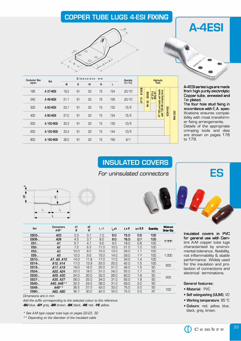
33
COPPER TUBE LUGS 4-ESI FIXING
A-4ESI series lugs are made from high purity electrolytic Copper tube, annealed and Tin plated.The four hole stud fixing in accordance with E.A. spec-ifications ensures compat-ibility with most transform-er fixing arrangements.Details of the appropriate crimping tools and dies are shown on pages 178 to 179.
A-4ESICOPPER TUBE LUGS 4-ESI FIXING
A-4ESI series lugs are made from high purity electrolytic Copper tube, annealed and Tin plated.The four hole stud fixing in accordance with E.A. spec-ifications ensures compat-
A-4ESI
HydraulicTools
185 A 37-4ESI 19,2 61 20 15 124
240 A 48-4ESI 21,1 61 20 15 128
300 A 60-4ESI 23,7 61 20 15 133
400 A 80-4ESI 27,0 61 20 15 134
500 A 100-4ESI 30,3 61 20 15 139
630 A 120-4ESI 33,4 61 20 15 144
800 A 160-4ESI 38,0 61 20 15 158
20/10
20/10
15/5
15/5
10/5
10/5
8/1
QuantityBox/Bag
Øi B M N L
D i m e n s i o n s m mRef.Conductor Size
sqmm
ECW
-H3D
RHU
520
HT 8
1-U
RHU
81
HT 1
20 a
nd to
ols
and
head
s wi
th 1
30 k
N c
rimpi
ng fo
rce
HT 5
1 B
550
E
RH 5
0 B
500E
General features:
• Material: PVC
• Self extinguishing (UL94): V0
• Working temperature: 85 °C
• Colours: red, yellow, blue, black, grey, brown.
l2 l1
d2s
L
d1d1
INSULATED COVERS
For uninsulated connectors
Insulated covers in PVC for general use with Cem-bre A-M copper tube lugs characterised by environ-mental tolerance, flexibility, not inflammability & stable performance. Widely used for the insulation and pro-tection of connections and electrical terminations.
ES
Insulated covers in PVC for general use with Cem-
Ref. ConnectorsA-M*
d1Ø
d2Ø l1 ±1 l2 ±1 L ± 2 s ± 0.2 Quantity Minimum
Order Qty
ES03-.. A03 3.3 3.1 7.0 8.0 15.0 0.6 100
3.0003.000ES06-.. A06 4.5 3.7 8.0 8.0 16.0 0.7 100ES1-.. A1 5.7 4.1 9.0 9.0 18.0 0.8 100ES2-.. A2 7.2 6.2 11.0 10.0 21.0 1.0 100ES3-.. A3 10.0 8.0 15.0 13.0 28.0 1.1 100
1.000ES5-.. A5 12.0 9.5 15.0 14.0 29.0 1.2 100ES10-.. A7, A9, A10 14.0 11.8 17.0 17.0 34.0 1.4 100ES14-.. A12, A14 17.0 13.9 22.0 20.0 42.0 1.5 100
500ES19-.. A17, A19 19.0 16.0 25.0 21.0 46.0 1.5 50ES24-.. A20, A24 22.0 18.0 31.0 24.0 55.0 1.7 50
200ES30-.. A29, A30 24.0 20.0 32.0 28.0 60.0 1.8 50ES37-.. A35, A37 26.0 22.0 34.0 31.0 65.0 1.8 50ES40-.. A40, A48** 32.2 24.0 38.0 31.0 69.0 2.0 50ES48-.. A48** 36.5 27.2 42.0 33.0 75.0 2.0 50
100ES80-.. A60, A80 36.7 30.0 42.0 33.0 75.0 2.0 25
Dimensions are in mmAdd the suffi x corresponding to the selected colour to the reference:-BU blue, -BU blue, -BU -GY grey, -GY grey, -GY -BR brown, -BR brown, -BR -BK black, -BK black, -BK -RE red, -RE red, -RE -YE yellow,-YE yellow,-YE
* See A-M type copper tube lugs on pages 22-23, 32** Depending on the diameter of the insulated cable
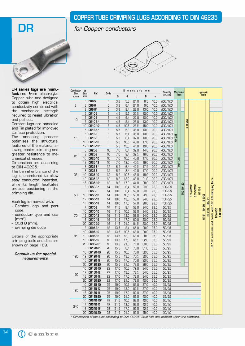
34
DR series lugs are manu-factured from electrolytic Copper tube and designed to obtain high electrical conductivity combined with the mechanical strength required to resist vibration and pull out.Cembre lugs are annealed and Tin plated for improved surface protection. The annealing process optimises the structural features of the material al-lowing easier crimping and greater resistance to me-chanical stresses.Dimensions are according to DIN 46235.The barrel entrance of the lug is chamfered to allow easy conductor insertion, while its length facilitates precise positioning in the crimping die.
Each lug is marked with:- Cembre logo and part
code.- conductor type and csa
(mm2).- Stud Ø (mm).- crimping die code
Details of the appropriate crimping tools and dies are shown on page 189.
Consult us for special requirements
COPPER TUBE CRIMPING LUGS ACCORDING TO DIN 46235
for Copper conductorsDR
DR series lugs are manu-factured from electrolytic
for Copper conductors
ConductorSize
sqmm
ØStudmm
Ref. CodeD i m e n s i o n s m m
QuantityBox/Bag
Mechanical Tools
HydraulicTools
Øi d L B a
65 DR6-5 5 3,8 5,3 24,0 8,5 10,0 800/100
TND
6-70
B 15
MDE
B 35
-45M
DE
B 35
-50M
0E
HT 4
5-E
HT 5
1
RH 5
0
B 50
0E
HT 8
1-U
RH
U 81
6 DR6-6 5 3,8 6,4 24,0 9,0 10,0 800/1008 DR6-8* 5 3,8 8,4 26,0 13,0 10,0 800/100
10
5 DR10-5 6 4,5 5,3 27,5 10,0 10,0 800/100
HN-D
25
TND
10-1
20
HT
12
0 a
nd t
ools
and
hea
ds w
ith
13
0 k
N c
rim
ping
for
ce
ECW
-H3D
RHU
520
6 DR10-6 6 4,5 6,4 27,0 10,0 10,0 800/1008 DR10-8* 6 4,5 8,4 28,0 13,0 10,0 800/100
10 DR10-10* 6 4,5 10,5 28,5 15,0 10,0 800/100
16
5 DR16-5* 8 5,5 5,3 36,0 13,0 20,0 400/1006 DR16-6 8 5,5 6,4 36,0 13,0 20,0 400/1008 DR16-8 8 5,5 8,4 37,0 13,0 20,0 400/100
10 DR16-10 8 5,5 10,5 40,0 17,0 20,0 400/10012 DR16-12* 8 5,5 13,0 41,0 19,0 20,0 400/100
25
6 DR25-6 10 7,0 6,4 39,0 14,6 20,0 400/1008 DR25-8 10 7,0 8,4 39,5 16,0 20,0 400/100
10 DR25-10 10 7,0 10,5 40,0 17,0 20,0 200/10012 DR25-12 10 7,0 13,0 40,5 19,0 20,0 200/100
35
6 DR35-6* 12 8,2 6,4 42,5 17,5 20,0 200/1008 DR35-8 12 8,2 8,4 42,0 17,0 20,0 200/100
10 DR35-10 12 8,2 10,5 43,0 19,0 20,0 200/10012 DR35-12 12 8,2 13,0 43,0 21,0 20,0 200/10016 DR35-16* 12 8,2 17,0 44,0 28,0 20,0 200/100
50
6 DR50-6* 14 10,0 6,4 52,0 20,0 28,0 100/258 DR50-8 14 10,0 8,4 52,0 20,0 28,0 100/25
10 DR50-10 14 10,0 10,5 53,0 22,0 28,0 100/2512 DR50-12 14 10,0 13,0 53,0 24,0 28,0 100/2516 DR50-16 14 10,0 17,0 57,0 28,0 28,0 100/25
70
8 DR70-8 16 11,5 8,4 56,0 24,0 28,0 50/2510 DR70-10 16 11,5 10,5 56,0 24,0 28,0 50/2512 DR70-12 16 11,5 13,0 56,0 24,0 28,0 50/2516 DR70-16 16 11,5 17,0 60,0 30,0 28,0 50/2520 DR70-20* 16 11,5 21,0 84,5 30,0 28,0 50/25
95
8 DR95-8* 18 13,5 8,4 65,0 28,0 35,0 50/2510 DR95-10 18 13,5 10,5 66,0 28,0 35,0 50/2512 DR95-12 18 13,5 13,0 66,0 28,0 35,0 50/2516 DR95-16 18 13,5 17,0 65,5 32,0 35,0 50/2520 DR95-20* 18 13,5 21,0 71,0 33,0 35,0 50/25
120
8 DR120-8* 20 15,5 8,4 70,0 31,0 35,0 50/2510 DR120-10 20 15,5 10,5 70,0 32,0 35,0 50/2512 DR120-12 20 15,5 13,0 70,5 32,0 35,0 50/2516 DR120-16 20 15,5 17,0 70,0 32,0 35,0 50/2520 DR120-20 20 15,5 21,0 72,0 36,0 35,0 50/25
150
10 DR150-10 22 17,0 10,5 79,0 34,0 35,0 50/2512 DR150-12 22 17,0 13,0 78,5 34,0 35,0 50/2516 DR150-16 22 17,0 17,0 78,0 34,0 35,0 50/2520 DR150-20 22 17,0 21,0 78,0 40,0 35,0 50/25
185
10 DR185-10 25 19,0 10,5 83,0 37,0 40,0 25/2512 DR185-12 25 19,0 13,0 82,5 37,0 40,0 25/2516 DR185-16 25 19,0 17,0 82,0 37,0 40,0 25/2520 DR185-20 25 19,0 21,0 83,0 40,0 40,0 25/25
240
10 DR240-10* 28 21,5 10,5 92,0 42,0 40,0 20/1012 DR240-12 28 21,5 13,0 92,0 42,5 40,0 20/1016 DR240-16 28 21,5 17,0 92,0 42,5 40,0 20/1020 DR240-20 28 21,5 21,0 92,0 45,0 40,0 20/10
* Dimensions of the tube according to DIN 46235; Stud hole not included within the standard.
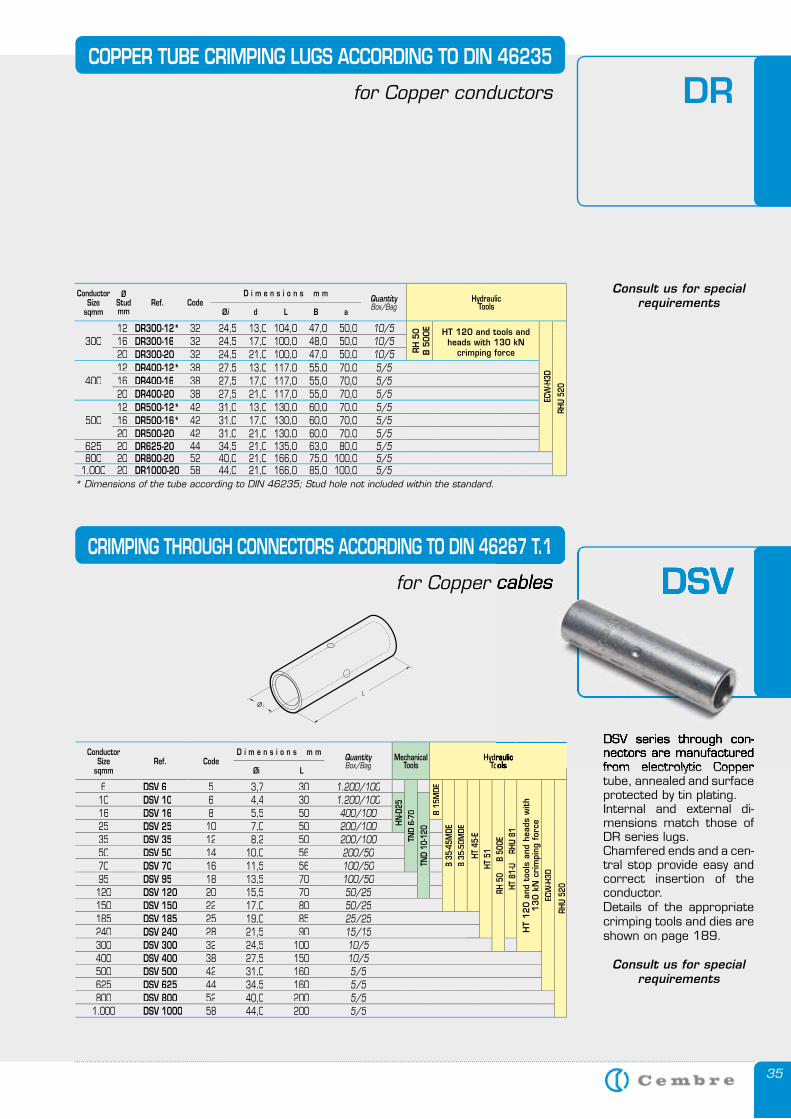
35
COPPER TUBE CRIMPING LUGS ACCORDING TO DIN 46235
for Copper conductors DR
DSV series through con-nectors are manufactured from electrolytic Copper tube, annealed and surface protected by tin plating.Internal and external di-mensions match those of DR series lugs.Chamfered ends and a cen-tral stop provide easy and correct insertion of the conductor.Details of the appropriate crimping tools and dies are shown on page 189.
Consult us for special requirements
CRIMPING THROUGH CONNECTORS ACCORDING TO DIN 46267 T.1
for Copper cables DSV
Consult us for special requirements
ConductorSize
sqmm
ØStudmm
Ref. CodeD i m e n s i o n s m m
QuantityBox/Bag
HydraulicTools
Øi d L B a
30012 DR300-12* 32 24,5 13,0 104,0 47,0 50,0 10/5
RH
50
B 5
00E HT 120 and tools and
heads with 130 kN crimping force
ECW
-H3D
RHU
520
16 DR300-16 32 24,5 17,0 100,0 48,0 50,0 10/520 DR300-20 32 24,5 21,0 100,0 47,0 50,0 10/5
40012 DR400-12* 38 27,5 13,0 117,0 55,0 70,0 5/516 DR400-16 38 27,5 17,0 117,0 55,0 70,0 5/520 DR400-20 38 27,5 21,0 117,0 55,0 70,0 5/5
50012 DR500-12* 42 31,0 13,0 130,0 60,0 70,0 5/516 DR500-16* 42 31,0 17,0 130,0 60,0 70,0 5/520 DR500-20 42 31,0 21,0 130,0 60,0 70,0 5/5
625 20 DR625-20 44 34,5 21,0 135,0 63,0 80,0 5/5800 20 DR800-20 52 40,0 21,0 166,0 75,0 100,0 5/5
1.000 20 DR1000-20 58 44,0 21,0 166,0 85,0 100,0 5/5* Dimensions of the tube according to DIN 46235; Stud hole not included within the standard.
ConductorSize
sqmmRef. Code
D i m e n s i o n s m mQuantityBox/Bag
Mechanical Tools
HydraulicTools
Øi L
6 DSV 6 5 3,7 30 1.200/100
TND
6-70 B
15M
DEB
35-4
5MDE
B 35
-50M
DE
HT 4
5-E
HT 5
1 RH
50
B
500
EHT
81-
U
RHU
81
HT
12
0 a
nd t
ools
and
hea
ds w
ith
13
0 k
N c
rim
ping
for
ceEC
W-H
3D
RHU
520
10 DSV 10 6 4,4 30 1.200/100
HN-D
25
TND
10-1
20
16 DSV 16 8 5,5 50 400/10025 DSV 25 10 7,0 50 200/10035 DSV 35 12 8,2 50 200/10050 DSV 50 14 10,0 56 200/5070 DSV 70 16 11,5 56 100/5095 DSV 95 18 13,5 70 100/50120 DSV 120 20 15,5 70 50/25150 DSV 150 22 17,0 80 50/25185 DSV 185 25 19,0 85 25/25240 DSV 240 28 21,5 90 15/15300 DSV 300 32 24,5 100 10/5400 DSV 400 38 27,5 150 10/5500 DSV 500 42 31,0 160 5/5625 DSV 625 44 34,5 160 5/5800 DSV 800 52 40,0 200 5/5
1.000 DSV 1000 58 44,0 200 5/5
DSV series through con-nectors are manufactured from electrolytic Copper
CRIMPING THROUGH CONNECTORS ACCORDING TO DIN 46267 T.1
for Copper cables DSV
HydraulicTools
HydraulicTools
Hydraulic
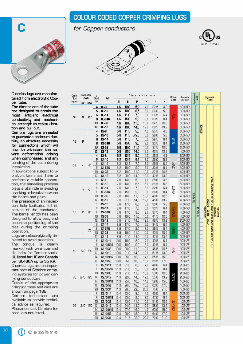
36
C series lugs are manufac-tured from electrolytic Cop-per tube.The dimensions of the tube are designed to obtain the most efficient electrical conductivity and mechani-cal strength to resist vibra-tion and pull out.Cembre lugs are annealed to guarantee optimum duc-tility, an absolute necessity for connectors which will have to withstand the se-vere deformation arising when compressed and any bending of the palm during installation.In applications subject to vi-bration, terminals have to perform a reliable connec-tion, the annealing process plays a vital role in avoiding cracking or breaks between the barrel and palm.The presence of an inspec-tion hole facilitates full in-sertion of the conductor. The barrel length has been designed to allow easy and accurate positioning of the dies during the crimping operation.Lugs are electrolytically tin-plated to avoid oxidation. The tongue is clearly marked with wire size and die index for Cembre tools.UL listed for US and Canada per UL486A up to 35 KV.C series lugs are an impor-tant part of Cembre crimp-ing systems for power car-rying conductors. Details of the appropriate crimping tools and dies are shown on page 188. Cembre technicians are available to provide techni-cal advice as required.Please consult Cembre for products not listed.
C
C series lugs are manufac-tured from electrolytic Cop-per tube.The dimensions of the tube are designed to obtain the most efficient electrical conductivity and mechani-cal strength to resist vibra-tion and pull out.Cembre lugs are annealed to guarantee optimum duc-tility, an absolute necessity for connectors which will have to withstand the se-vere deformation arising when compressed and any
CFile no. E125401
Cond.Size
sqmm
ConductorAWG
ØStudmm
Ref.D i m e n s i o n s m m
ColourCode
QuantityBox/Bag
Mec
hanic
alTo
ols HydraulicTools
Øi B M N L dSize Navy
10 8 23
4 C8-8 4,6 10,0 5,05,0 4,0 22,5 4,3
RED
600/50
TN 7
0 SE
TN 1
20 S
EB1
5MDE
B35-
50M
DEHT
51
RH
50
B
500E
HT
12
0 a
nd t
ools
and
hea
ds w
ith
13
0 k
N c
rim
ping
for
ceEC
W-H
3DRH
U 52
0
5 C8-10 4,6 10,0 6,56,5 6,0 26,0 5,3 600/50 6 C8-14 4,6 11,0 7,07,0 6,0 26,5 6,4 600/50 8 C8-516 4,6 15,0 9,09,0 8,0 30,5 8,4 600/50
10 C8-38 4,6 18,0 11,011,0 10,0 34,5 10,5 600/50 12 C8-12 4,6 19,0 14,014,0 12,0 39,5 13,2 600/50
16 6
4 C6-8 5,8 11,5 5,05,0 4,0 25,5 4,3
BLUE
600/50 5 C6-10 5,8 11,5 6,5,06,5,0 6,0 29,0 5,3 600/50 6 C6-14 5,8 11,5 7,07,0 6,0 29,5 6,4 600/50 8 C6-516 5,8 15,0 9,09,0 8,0 33,5 8,4 600/50
10 C6-38 5,8 18,0 11,011,0 10,0 37,5 10,5 600/50 12 C6-12 5,8 20,0 14,014,0 12,0 42,5 13,2 400/50
25 4 40
4 C4-8 6,2 12,5 5,05,0 4,0 25,5 4,3
GREY
600/50 55 C4-10C4-10 6,26,2 12,512,5 6,56,5 6,0 29,0 5,3 600/50 6 C4-14 6,2 12,5 7,0 6,0 29,5 6,4 600/50 8 C4-516 6,2 15,0 9,0 8,0 33,5 8,4 600/50
10 C4-38 6,2 18,0 11,0 10,0 37,5 10,5 400/50 12 C4-12 6,2 20,0 14,0 12,0 42,5 13,2 400/50
3 50
4 C3-8 7,0 14,0 5,0 4,0 28,0 4,3
WHI
TE
600/50 5 C3-10 7,0 14,0 6,5 6,0 31,5 5,3 600/50 6 C3-14 7,0 14,0 7,0 6,0 32,0 6,4 600/50 8 C3-516 7,0 15,0 9,0 8,0 36,0 8,4 600/50
10 C3-38 7,0 18,0 11,0 10,0 40,0 10,5 400/5012 C3-12 7,0 21,0 14,0 12,0 45,0 13,2 400/50
35 2 60
5 C2-10 7,6 17,0 6,5 6,0 33,0 5,3
BROW
N
400/50 6 C2-14 7,6 17,0 7,0 6,0 33,5 6,4 400/50 8 C2-516 7,6 17,0 9,0 8,0 37,5 8,4 400/50
10 C2-38 7,6 19,0 11,0 10,0 41,5 10,5 400/50 12 C2-12 7,6 21,0 14,0 12,0 46,5 13,2 200/50
1 75
6 C1-14 8,9 17,0 7,0 6,0 34,5 6,4
GREE
N
400/50 8 C1-516 8,9 17,0 9,0 8,0 38,5 8,4 400/50
10 C1-38 8,9 19,0 11,0 10,0 42,5 10,5 400/50 12 C1-12 8,9 21,0 14,0 12,0 47,5 13,2 200/50
50 1/0 100
6 C1/0-14 10,0 19,0 8,0 7,0 40,5 6,4
PINK
200/25 8 C1/0-516 10,0 19,0 9,0 8,0 42,5 8,4 200/25
10 C1/0-38 10,0 20,0 11,0 10,0 46,5 10,5 200/25 12 C1/0-12 10,0 21,0 14,0 12,0 51,5 13,2 200/25 14 C1/0-916 10,0 25,0 16,0 14,0 55,5 15,0 200/25 16 C1/0-58 10,0 26,0 18,0 16,0 59,5 17,0 200/25
70 2/0 125
6 C2/0-14 11,3 21,0 8,0 7,0 44,0 6,4
BLAC
K
200/25 8 C2/0-516 11,3 21,0 9,0 8,0 46,0 8,4 200/25
10 C2/0-38 11,3 21,0 11,0 10,0 50,0 10,5 200/25 12 C2/0-12 11,3 22,0 14,0 12,0 55,0 13,2 200/25 14 C2/0-916 11,3 25,0 16,0 14,0 59,0 15,0 100/2516 C2/0-58 11,3 26,0 18,0 16,0 63,0 17,0 100/25 20 C2/0-34 11,3 29,5 22,0 20,0 75,0 21,0 100/25
95 3/0 150
6 C3/0-14 12,4 23,0 8,0 7,0 45,0 6,4
ORAN
GE
200/258 C3/0-516 12,4 23,0 9,0 8,0 47,0 8,4 200/25
10 C3/0-38 12,4 23,0 11,0 10,0 51,0 10,5 100/2512 C3/0-12 12,4 24,0 14,0 12,0 56,0 13,2 100/25 14 C3/0-916 12,4 27,0 16,0 14,0 60,0 15,0 100/25 16 C3/0-58 12,4 28,0 18,0 16,0 64,0 17,0 100/25 20 C3/0-34 12,4 31,5 22,0 20,0 72,0 21,0 100/25
COLOUR CODED COPPER CRIMPING LUGS
for Copper conductors
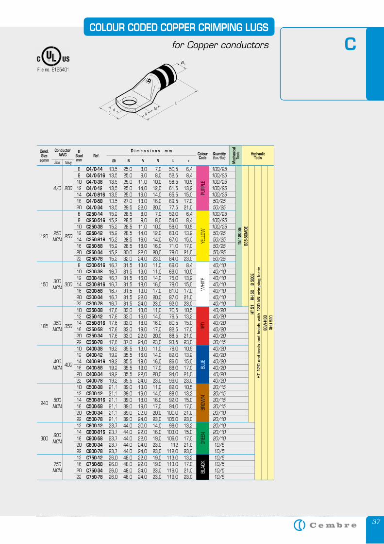
37
COLOUR CODED COPPER CRIMPING LUGS
for Copper conductors CFile no. E125401
Cond.Size
sqmm
ConductorAWG
ØStudmm
Ref.D i m e n s i o n s m m
ColourCode
QuantityBox/Bag
Mec
hanic
alTo
ols HydraulicTools
Øi B M N L dSize Navy
4/0 200
6 C4/0-14 13,5 25,0 8,0 7,0 50,5 6,4
PURP
LE
100/25
TN 1
20 S
EB3
5-50
MDE
HT 5
1
RH 5
0
B 50
0EH
T 1
20
and
too
ls a
nd h
eads
wit
h 1
30
kN
cri
mpi
ng f
orce
ECW
-H3D
RHU
520
8 C4/0-516 13,5 25,0 9,0 8,0 52,5 8,4 100/25 10 C4/0-38 13,5 25,0 11,0 10,0 56,5 10,5 100/25 12 C4/0-12 13,5 25,0 14,0 12,0 61,5 13,2 100/25 14 C4/0-916 13,5 25,0 16,0 14,0 65,5 15,0 100/25 16 C4/0-58 13,5 27,0 18,0 16,0 69,5 17,0 50/2520 C4/0-34 13,5 29,5 22,0 20,0 77,5 21,0 50/25
120 250MCM 250
6 C250-14 15,2 28,5 8,0 7,0 52,0 6,4
YELL
OW
100/25 8 C250-516 15,2 28,5 9,0 8,0 54,0 8,4 100/25 10 C250-38 15,2 28,5 11,0 10,0 58,0 10,5 100/25 12 C250-12 15,2 28,5 14,0 12,0 63,0 13,2 50/25 14 C250-916 15,2 28,5 16,0 14,0 67,0 15,0 50/25 16 C250-58 15,2 28,5 18,0 16,0 71,0 17,0 50/25 20 C250-34 15,2 30,0 22,0 20,0 79,0 21,0 50/25 22 C250-78 15,2 32,0 24,0 23,0 84,0 23,0 50/25
150 300MCM 300
8 C300-516 16,7 31,5 13,0 11,0 69,0 8,4
WHI
TE
40/1010 C300-38 16,7 31,5 13,0 11,0 69,0 10,5 40/10 12 C300-12 16,7 31,5 16,0 14,0 75,0 13,2 40/10 14 C300-916 16,7 31,5 18,0 16,0 79,0 15,0 40/10 16 C300-58 16,7 31,5 19,0 17,0 81,0 17,0 40/10 20 C300-34 16,7 31,5 22,0 20,0 87,0 21,0 40/10 22 C300-78 16,7 31,5 24,0 23,0 92,0 23,0 40/10
185 350MCM 350
10 C350-38 17,6 33,0 13,0 11,0 70,5 10,5
RED
40/2012 C350-12 17,6 33,0 16,0 14,0 76,5 13,2 40/20 14 C350-916 17,6 33,0 18,0 16,0 80,5 15,0 40/20 16 C350-58 17,6 33,0 19,0 17,0 82,5 17,0 40/20 20 C350-34 17,6 33,0 22,0 20,0 88,5 21,0 40/20 22 C350-78 17,6 37,0 24,0 23,0 93,5 23,0 30/15
400MCM 400
10 C400-38 19,2 35,5 13,0 11,0 76,0 10,5
BLUE
40/20 12 C400-12 19,2 35,5 16,0 14,0 82,0 13,2 40/20 14 C400-916 19,2 35,5 18,0 16,0 86,0 15,0 40/20 16 C400-58 19,2 35,5 19,0 17,0 88,0 17,0 40/20 20 C400-34 19,2 35,5 22,0 20,0 94,0 21,0 40/20 22 C400-78 19,2 35,5 24,0 23,0 99,0 23,0 40/20
240 500MCM
10 C500-38 21,1 39,0 13,0 11,0 82,0 10,5
BROW
N
30/1512 C500-12 21,1 39,0 16,0 14,0 88,0 13,2 30/15 14 C500-916 21,1 39,0 18,0 16,0 92,0 15,0 30/15 16 C500-58 21,1 39,0 19,0 17,0 94,0 17,0 30/15 20 C500-34 21,1 39,0 22,0 20,0 100,0 21,0 20/1022 C500-78 21,1 39,0 24,0 23,0 105,0 23,0 20/10
300 600MCM
12 C600-12 23,7 44,0 20,0 14,0 99,0 13,2
GREE
N
20/10 14 C600-916 23,7 44,0 22,0 16,0 103,0 15,0 20/10 16 C600-58 23,7 44,0 22,0 19,0 106,0 17,0 20/10 20 C600-34 23,7 44,0 24,0 23,0 112 21,0 10/522 C600-78 23,7 44,0 24,0 23,0 112,0 23,0 10/5
750MCM
12 C750-12 26,0 48,0 22,0 19,0 113,0 13,2
BLAC
K
10/5 16 C750-58 26,0 48,0 22,0 19,0 113,0 17,0 10/5 20 C750-34 26,0 48,0 24,0 23,0 119,0 21,0 10/5 22 C750-78 26,0 48,0 24,0 23,0 119,0 23,0 10/5
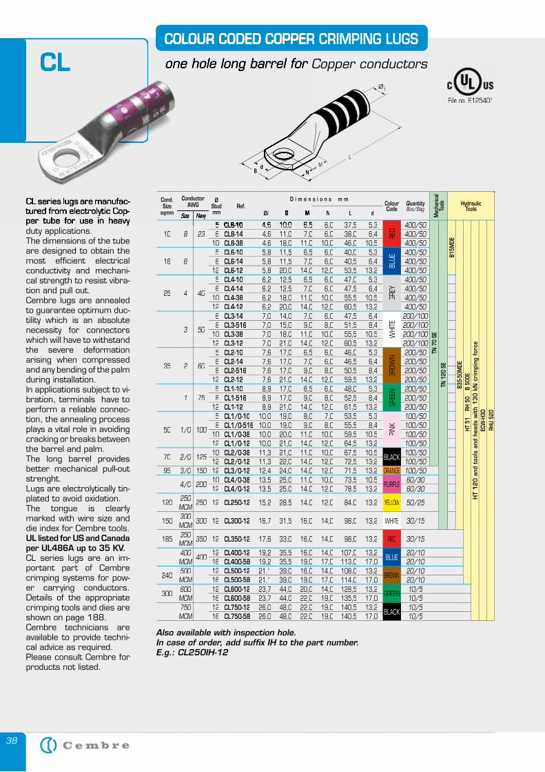
38
CL
CL series lugs are manufac-tured from electrolytic Cop-per tube for use in heavy duty applications.The dimensions of the tube are designed to obtain the most efficient electrical conductivity and mechani-cal strength to resist vibra-tion and pull out.Cembre lugs are annealed to guarantee optimum duc-tility which is an absolute necessity for connectors which will have to withstand the severe deformation arising when compressed and any bending of the palm during installation.In applications subject to vi-bration, terminals have to perform a reliable connec-tion, the annealing process plays a vital role in avoiding cracking or breaks between the barrel and palm.The long barrel provides better mechanical pull-out strenght.Lugs are electrolytically tin-plated to avoid oxidation. The tongue is clearly marked with wire size and die index for Cembre tools.UL listed for US and Canada per UL486A up to 35 KV.CL series lugs are an im-portant part of Cembre crimping systems for pow-er carrying conductors. Details of the appropriate crimping tools and dies are shown on page 188. Cembre technicians are available to provide techni-cal advice as required.Please consult Cembre for products not listed.
Also available with inspection hole.In case of order, add suffix IH to the part number.E.g.: CL250IH-12
COLOUR CODED COPPER CRIMPING LUGS
one hole long barrel for Copper conductorsCL
CL series lugs are manufac-tured from electrolytic Cop-per tube for use in heavy
COLOUR CODED COPPER CRIMPING LUGS
one hole long barrel for Copper conductors
Cond.Size
sqmm
ConductorAWG
ØStudmm
Ref.D i m e n s i o n s m m
ColourCode
QuantityBox/Bag
Mec
hanic
alTo
ols HydraulicTools
Øi B M N L dSize Navy
10 8 2355 CL8-10CL8-10 4,64,6 10,010,0 6,56,5 6,0 37,5 5,3
RED
400/50
TN 7
0 SE
TN 1
20 S
EB1
5MDE
B35-
50M
DEHT
51
RH
50
B
500E
HT
12
0 a
nd t
ools
and
hea
ds w
ith
13
0 k
N c
rim
ping
for
ceEC
W-H
3DRH
U 52
0
6 CL8-14 4,6 11,0 7,0 6,0 38,0 6,4 400/5010 CL8-38 4,6 18,0 11,0 10,0 46,0 10,5 400/50
16 65 CL6-10 5,8 11,5 6,5 6,0 40,0 5,3
BLUE
400/506 CL6-14 5,8 11,5 7,0 6,0 40,5 6,4 400/50
12 CL6-12 5,8 20,0 14,0 12,0 53,5 13,2 400/50
25 4 40
5 CL4-10 6,2 12,5 6,5 6,0 47,0 5,3
GREY
400/506 CL4-14 6,2 12,5 7,0 6,0 47,5 6,4 400/50
10 CL4-38 6,2 18,0 11,0 10,0 55,5 10,5 400/5012 CL4-12 6,2 20,0 14,0 12,0 60,5 13,2 400/50
3 50
6 CL3-14 7,0 14,0 7,0 6,0 47,5 6,4
WHI
TE
200/1008 CL3-516 7,0 15,0 9,0 8,0 51,5 8,4 200/100
10 CL3-38 7,0 18,0 11,0 10,0 55,5 10,5 200/10012 CL3-12 7,0 21,0 14,0 12,0 60,5 13,2 200/100
35 2 60
5 CL2-10 7,6 17,0 6,5 6,0 46,0 5,3
BROW
N 200/506 CL2-14 7,6 17,0 7,0 6,0 46,5 6,4 200/508 CL2-516 7,6 17,0 9,0 8,0 50,5 8,4 200/50
12 CL2-12 7,6 21,0 14,0 12,0 59,5 13,2 200/50
1 755 CL1-10 8,9 17,0 6,5 6,0 48,0 5,3
GREE
N 200/508 CL1-516 8,9 17,0 9,0 8,0 52,5 8,4 200/50
12 CL1-12 8,9 21,0 14,0 12,0 61,5 13,2 200/50
50 1/0 100
5 CL1/0-10 10,0 19,0 8,0 7,0 53,5 5,3
PINK
100/508 CL1/0-516 10,0 19,0 9,0 8,0 55,5 8,4 100/50
10 CL1/0-38 10,0 20,0 11,0 10,0 59,5 10,5 100/5012 CL1/0-12 10,0 21,0 14,0 12,0 64,5 13,2 100/50
70 2/0 12510 CL2/0-38 11,3 21,0 11,0 10,0 67,5 10,5
BLACK100/50
12 CL2/0-12 11,3 22,0 14,0 12,0 72,5 13,2 100/5095 3/0 150 12 CL3/0-12 12,4 24,0 14,0 12,0 71,5 13,2 ORANGE 100/50
4/0 20010 CL4/0-38 13,5 25,0 11,0 10,0 73,5 10,5
PURPLE60/30
12 CL4/0-12 13,5 25,0 14,0 12,0 78,5 13,2 60/30
120 250MCM 250 12 CL250-12 15,2 28,5 14,0 12,0 84,0 13,2 YELLOW 50/25
150 300MCM 300 12 CL300-12 16,7 31,5 16,0 14,0 98,0 13,2 WHITE 30/15
185 350MCM 350 12 CL350-12 17,6 33,0 16,0 14,0 98,0 13,2 RED 30/15
400MCM 400
12 CL400-12 19,2 35,5 16,0 14,0 107,0 13,2BLUE
20/1016 CL400-58 19,2 35,5 19,0 17,0 113,0 17,0 20/10
240 500MCM
12 CL500-12 21,1 39,0 16,0 14,0 108,0 13,2BROWN
20/1016 CL500-58 21,1 39,0 19,0 17,0 114,0 17,0 20/10
300 600MCM
12 CL600-12 23,7 44,0 20,0 14,0 128,5 13,2GREEN
10/516 CL600-58 23,7 44,0 22,0 19,0 135,5 17,0 10/5
750MCM
12 CL750-12 26,0 48,0 22,0 19,0 140,5 13,2BLACK
10/516 CL750-58 26,0 48,0 22,0 19,0 140,5 17,0 10/5
File no. E125401
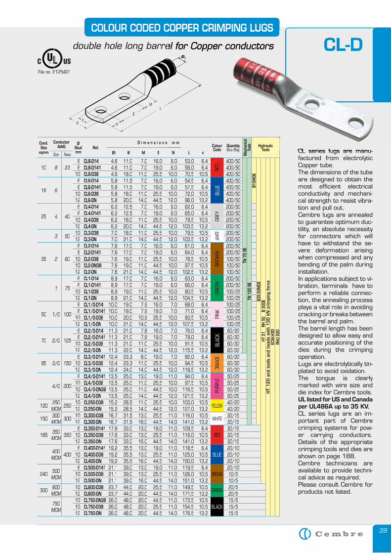
39
CL-D
CL series lugs are manu-factured from electrolytic Copper tube.The dimensions of the tube are designed to obtain the most efficient electrical conductivity and mechani-cal strength to resist vibra-tion and pull out.Cembre lugs are annealed to guarantee optimum duc-tility, an absolute necessity for connectors which will have to withstand the se-vere deformation arising when compressed and any bending of the palm during installation.In applications subject to vi-bration, terminals have to perform a reliable connec-tion, the annealing process plays a vital role in avoiding cracking or breaks between the barrel and palm.The barrel length has been designed to allow easy and accurate positioning of the dies during the crimping operation.Lugs are electrolytically tin-plated to avoid oxidation. The tongue is clearly marked with wire size and die index for Cembre tools.UL listed for US and Canada per UL486A up to 35 KV.CL series lugs are an im-portant part of Cembre crimping systems for pow-er carrying conductors. Details of the appropriate crimping tools and dies are shown on page 188. Cembre technicians are available to provide techni-cal advice as required.Please consult Cembre for products not listed.
COLOUR CODED COPPER CRIMPING LUGS
double hole long barrel for Copper conductors CL-D
CL series lugs are manu-
COLOUR CODED COPPER CRIMPING LUGS
double hole long barrel for Copper conductors
File no. E125401
Cond.Size
sqmm
ConductorAWG
ØStudmm
Ref.D i m e n s i o n s m m
ColourCode
QuantityBox/Bag
Mec
hanic
alTo
ols HydraulicTools
Øi B M E N L dSize Navy
10 8 236 CL8-D14 4,6 11,0 7,0 16,0 6,0 53,0 6,4
RED
400/50
TN 7
0 SE
TN 1
20 S
EB1
5MDE
B35-
50M
DEHT
51
RH
50
B
500E
HT
12
0 a
nd t
ools
and
hea
ds w
ith
13
0 k
N c
rim
ping
for
ceEC
W-H
3DRH
U 52
0
6 CL8-D141 4,6 11,0 7,0 19,0 6,0 56,0 6,4 400/50 10 CL8-D38 4,6 18,0 11,0 25,5 10,0 70,5 10,5 400/50
16 6
6 CL6-D14 5,8 11,5 7,0 16,0 6,0 54,5 6,4
BLUE
400/50 6 CL6-D141 5,8 11,5 7,0 19,0 6,0 57,5 6,4 400/50
10 CL6-D38 5,8 18,0 11,0 25,5 10,0 72,0 10,5 400/50 12 CL6-DN 5,8 20,0 14,0 44,5 12,0 96,0 13,2 400/50
25 4 40
6 CL4-D14 6,2 12,5 7,0 16,0 6,0 62,0 6,4
GREY
200/50 6 CL4-D141 6,2 12,5 7,0 19,0 6,0 65,0 6,4 200/50
10 CL4-D38 6,2 18,0 11,0 25,5 10,0 79,5 10,5 200/50 12 CL4-DN 6,2 20,0 14,0 44,5 12,0 103,5 13,2 200/50
3 5010 CL3-D38 7,0 18,0 11,0 25,5 10,0 79,5 10,5
WHIT
E 200/50 12 CL3-DN 7,0 21,0 14,0 44,5 12,0 103,5 13,2 200/50
35 2 60
6 CL2-D14 7,6 17,0 7,0 16,0 6,0 61,0 6,4
BROW
N
200/50 6 CL2-D141 7,6 17,0 7,0 19,0 6,0 64,0 6,4 200/50
10 CL2-D38 7,6 19,0 11,0 25,5 10,0 78,5 10,5 100/50 10 CL2-DN38 7,6 19,0 11,0 44,5 10,0 97,5 10,5 100/50 12 CL2-DN 7,6 21,0 14,0 44,5 12,0 102,5 13,2 100/50
1 75
6 CL1-D14 8,9 17,0 7,0 16,0 6,0 63,0 6,4
GREE
N
200/50 6 CL1-D141 8,9 17,0 7,0 19,0 6,0 66,0 6,4 200/50
10 CL1-D38 8,9 19,0 11,0 25,5 10,0 80,5 10,5 100/25 12 CL1-DN 8,9 21,0 14,0 44,5 12,0 104,5 13,2 100/25
50 1/0 100
6 CL1/0-D14 10,0 19,0 7,9 16,0 7,0 68,0 6,4
PINK
100/25 6 CL1/0-D141 10,0 19,0 7,9 19,0 7,0 71,0 6,4 100/25
10 CL1/0-D38 10,0 20,0 10,9 25,5 10,0 83,5 10,5 100/25 12 CL1/0-DN 10,0 21,0 14,0 44,5 12,0 107,5 13,2 100/25
70 2/0 125
6 CL2/0-D14 11,3 21,0 7,8 16,0 7,0 76,0 6,4
BLAC
K
60/30 6 CL2/0-D141 11,3 21,0 7,8 19,0 7,0 79,0 6,4 60/30
10 CL2/0-D38 11,3 21,0 11,0 25,5 10,0 91,5 10,5 60/30 12 CL2/0-DN 11,3 22,0 14,0 44,5 12,0 115,5 13,2 60/30
95 3/0 1506 CL3/0-D141 12,4 23,3 8,0 19,0 7,0 82,0 6,4
ORAN
GE 60/30 10 CL3/0-D38 12,4 23,3 11,0 25,5 10,0 94,5 10,5 60/30 12 CL3/0-DN 12,4 24,0 14,0 44,5 12,0 118,5 13,2 60/30
4/0 200
6 CL4/0-D141 13,5 25,0 13,0 19,0 11,0 94,0 6,4
PURP
LE
50/25 10 CL4/0-D38 13,5 25,0 11,0 25,5 10,0 97,5 10,5 50/25 10 CL4/0-DN38 13,5 25,0 11,0 44,5 10,0 116,5 10,5 50/25 12 CL4/0-DN 13,5 25,0 14,0 44,5 12,0 121,5 13,2 50/25
120 250MCM 250
10 CL250-D38 15,2 28,5 11,0 25,5 10,0 103,0 10,5YELLOW
40/2012 CL250-DN 15,2 28,5 14,0 44,5 12,0 127,0 13,2 40/20
150 300MCM 300
10 CL300-D38 16,7 31,5 13,0 25,5 11,0 116,0 10,5WHITE
30/15 12 CL300-DN 16,7 31,5 16,0 44,5 14,0 141,0 13,2 30/15
185 350MCM 350
6 CL350-D141 17,6 33,0 13,0 19,0 11,0 109,5 6,4RED
30/15 10 CL350-D38 17,6 33,0 13,0 25,5 11,0 116,0 10,5 30/15 12 CL350-DN 17,6 33,0 16,0 44,5 14,0 141,0 13,2 30/15
400MCM 400
6 CL400-D141 19,2 35,5 13,0 19,0 11,0 118,5 6,4BLUE
20/1010 CL400-D38 19,2 35,5 13,0 25,5 11,0 125,0 10,5 20/10 12 CL400-DN 19,2 35,5 16,0 44,5 14,0 150,0 13,2 20/10
240 500MCM
6 CL500-D141 21,1 39,0 13,0 19,0 11,0 119,5 6,4BROWN
20/10 10 CL500-D38 21,1 39,0 13,0 25,5 11,0 126,0 10,5 10/5 12 CL500-DN 21,1 39,0 16,0 44,5 14,0 151,0 13,2 10/5
300 600MCM
10 CL600-D38 23,7 44,0 20,0 25,5 11,0 149,5 10,5GREEN
20/5 12 CL600-DN 23,7 44,0 20,0 44,5 14,0 171,5 13,2 20/5
750MCM
10 CL750-DN38 26,0 48,0 20,0 44,5 11,0 173,5 10,5BLACK
15/5 10 CL750-D38 26,0 48,0 20,0 25,5 11,0 154,5 10,5 15/5 12 CL750-DN 26,0 48,0 20,0 44,5 14,0 176,5 13,2 15/5
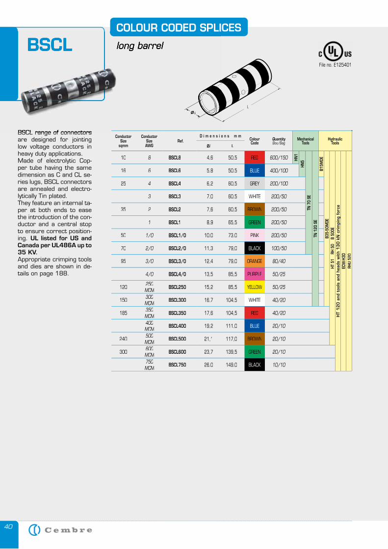
40
BSCLCOLOUR CODED SPLICES
long barrel
BSCL range of connectors are designed for jointing low voltage conductors in heavy duty applications. Made of electrolytic Cop-per tube having the same dimension as C and CL se-ries lugs, BSCL connectors are annealed and electro-lytically Tin plated. They feature an internal ta-per at both ends to ease the introduction of the con-ductor and a central stop to ensure correct position-ing. UL listed for US and Canada per UL486A up to 35 KV. Appropriate crimping tools and dies are shown in de-tails on page 188.
COLOUR CODED SPLICES
long barrelBSCL
BSCL range of connectors
File no. E125401
ConductorSize
sqmm
ConductorSizeAWG
Ref.D i m e n s i o n s m m
ColourCode
QuantityBox/Bag
MechanicalTools
HydraulicTools
Øi L
10 8 BSCL8 4,6 50,5 RED 600/150 HN1
HN5
TN 7
0 SE
TN 1
20 S
EB1
5MDE
B35-
50M
DEHT
51
RH
50
B
500E
HT
12
0 a
nd t
ools
and
hea
ds w
ith
13
0 k
N c
rim
ping
for
ceEC
W-H
3DRH
U 52
0
16 6 BSCL6 5,8 50,5 BLUE 400/100
25 4 BSCL4 6,2 60,5 GREY 200/100
3 BSCL3 7,0 60,5 WHITE 200/50
35 2 BSCL2 7,6 60,5 BROWN 200/50
1 BSCL1 8,9 65,5 GREEN 200/50
50 1/0 BSCL1/0 10,0 73,0 PINK 200/50
70 2/0 BSCL2/0 11,3 79,0 BLACK 100/50
95 3/0 BSCL3/0 12,4 79,0 ORANGE 80/40
4/0 BSCL4/0 13,5 85,5 PURPLE 50/25
120 250 MCM BSCL250 15,2 85,5 YELLOW 50/25
150 300MCM BSCL300 16,7 104,5 WHITE 40/20
185 350MCM BSCL350 17,6 104,5 RED 40/20
400MCM BSCL400 19,2 111,0 BLUE 20/10
240 500MCM BSCL500 21,1 117,0 BROWN 20/10
300 600MCM BSCL600 23,7 139,5 GREEN 20/10
750MCM BSCL750 26,0 149,0 BLACK 10/10
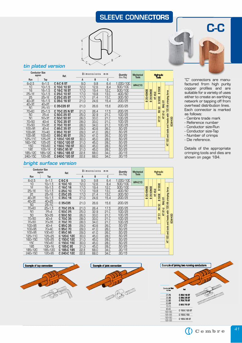
41
SLEEVE CONNECTORS
“C” connectors are manu-factured from high purity copper profiles and are suitable for a variety of uses either to create an earthing network or tapping off from overhead distribution lines.Each connector is marked as follows:- Cembre trade mark- Reference number- Conductor size-Run- Conductor size-Tap- Number of crimps- Die reference.
Details of the appropriate crimping tools and dies are shown on page 184.
C-C
Ref.Conductor Sizesqmm
25-25 C 35-C 16 ST 35-35 C 35-C 35 ST 50-50 C 70-C 70 ST 63-63
C 95-C 70 ST 70-70 95-95
C 150-C 120 ST 120-120 125-125 C 150-C 150 120-120
C 185-C 95 ST 125-125
Example of tap connection Example of joint connection Example of joining two running conductors Example of tap connection Example of joint connection
Conductor Sizesqmm Ref.
D i m e n s i o n s m m QuantityBox/Bag
MechanicalTools
HydraulicTools
Run Tap A B C
6÷2,56÷2,5 6÷1,56÷1,5 C 6-C 6 ST 9,09,0 9,89,8 6,46,4 1.000/100 HP4-C10
B 35
-45M
DE
B 35
-50M
DE
HT 4
5-E
HT 5
1
RH 5
0
B 50
0E
B 55
0E
HT 8
1-U
RH
U 81
10 10÷1,5 C 10-C 10 ST 12,0 12,6 8,4 500/100
HT 1
20 a
nd to
ols
and
head
s wi
th 1
30 k
N c
rimpi
ng fo
rce
ECW
-H3D
16 16÷1,5 C 16-C 16 ST 17,0 19,4 12,0 500/10025÷16 10÷1,5 C 25-C 10 ST 17,0 19,8 13,0 400/50
25 25÷16 C 25-C 25 ST 17,0 21,4 13,0 300/5040÷35 16÷1,5 C 35-C 16 ST 21,0 24,6 15,4 200/2540÷35 40÷25 C 35-C35 ST 21,0 26,6 15,6 200/2550 25÷1070÷63 25÷1,5 C 70-C 25 N ST 21,0 26,4 17,5 200/25
50 25÷4 C 50-C 25 ST 25,0 32,9 21,0 100/2550 50÷35 C 50-C 50 ST 26,0 33,0 21,0 100/25
70÷50 40÷4 C 70-C 35 ST 28,0 33,0 21,0 100/2570÷50 70÷35 C 70-C 70 ST 28,0 34,0 21,0 100/25
100÷95 40÷4 C 95-C 35 ST 29,0 40,6 26,0 50/25100÷95 70÷40 C 95-C 70 ST 29,0 41,0 26,0 50/25100÷95 100÷63 C 95-C 95 ST 29,0 41,0 26,0 50/25125÷110 125÷25 C 120-C 120 ST 30,0 45,0 28,0 50/25160÷150 125÷25 C 150-C 120 ST 31,0 45,0 28,0 50/25
150 150÷63 C 150-C 150 ST 30,0 45,0 28,0 50/25185 100÷16 C 185-C 95 ST 31,0 45,0 28,0 50/25
185÷120 185÷120 C 185-C 185 ST 22,6 68,0 34,0 30/15240÷150 120÷95 C 240-C 120 ST 22,622,6 68,068,0 34,034,0 30/15
Conductor Sizesqmm Ref.
D i m e n s i o n s m m QuantityBox/Bag
MechanicalTools
HydraulicTools
Run Tap A B C
6÷2,56÷2,5 6÷1,56÷1,5 C 6-C 6 9,09,0 9,89,8 6,46,4 1.000/100 HP4-C10
B 35
-45M
DE
B 35
-50M
DE
HT 4
5-E
HT 5
1
RH 5
0
B 50
0E
B 5
50E
HT 8
1-U
RH
U 81
10 10÷1,5 C 10-C 10 12,0 12,6 8,4 500/100
HT 1
20 a
nd to
ols
and
head
s wi
th 1
30 k
N c
rimpi
ng fo
rce
ECW
-H3D
16 16÷1,5 C 16-C 16 17,0 19,4 12,0 500/10025÷16 10÷1,5 C 25-C 10 17,0 19,8 13,0 400/50
25 25÷16 C 25-C 25 17,0 21,4 13,0 300/5040÷35 16÷1,5 C 35-C 16 21,0 24,6 15,4 200/2540÷35 40÷25 C 35-C35 21,0 26,6 15,6 200/2550 25÷1070÷63 25÷1,5 C 70-C 25 N 21,0 26,4 17,5 200/25
50 25÷4 C 50-C 25 25,0 32,9 21,0 100/2550 50÷35 C 50-C 50 26,0 33,0 21,0 100/25
70÷50 40÷4 C 70-C 35 28,0 33,0 21,0 100/2570÷50 70÷35 C 70-C 70 28,0 34,0 21,0 100/25100÷95 40÷4 C 95-C 35 29,0 40,6 26,0 50/25100÷95 70÷40 C 95-C 70 29,0 41,0 26,0 50/25100÷95 100÷63 C 95-C 95 29,0 41,0 26,0 50/25125÷110 125÷25 C 120-C 120 30,0 45,0 28,0 50/25160÷150 125÷25 C 150-C 120 31,0 45,0 28,0 50/25
150 150÷63 C 150-C 150 30,0 45,0 28,0 50/25185 100÷16 C 185-C 95 31,0 45,0 28,0 50/25
185÷120 185÷120 C 185-C 185 22,6 68,0 34,0 30/15240÷150 120÷95 C 240-C 120 22,622,6 68,068,0 34,034,0 30/15
C-CSLEEVE CONNECTORSSLEEVE CONNECTORS
HydraulicTools
HydraulicTools
Hydraulic
C-C
bright surface version
tin plated version
Ref.Conductor Sizesqmm
25-25 C 35-C 16 ST 35-35 C 35-C 35 ST 50-50 C 70-C 70 ST 63-63
C 95-C 70 ST
Example of joining two running conductors
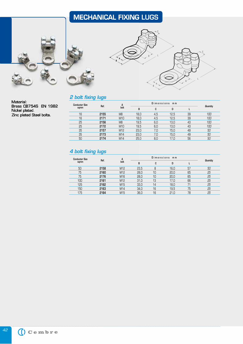
42
Material:Brass CB754S EN 1982 Nickel plated.Zinc plated Steel bolts.
MECHANICAL FIXING LUGS
Material:Brass CB754S EN 1982 Nickel plated.Zinc plated Steel bolts.
MECHANICAL FIXING LUGS
50 2158 M12 23,5 8 16,0 57 75 2160 M12 28,0 10 20,0 65 75 2176 M16 28,0 10 20,0 65 100 2161 M12 31,0 13 17,0 66 125 2162 M15 33,0 14 18,0 71 150 2163 M14 34,0 16 19,5 75 175 2164 M15 36,0 16 21,0 78
50252525252525
Conductor Sizesqmm
Abolt Quantity
B C D L
D i m e n s i o n s m m
4 bolt fixing lugs
Ref.
16 2155 M8 18,0 4,5 12,5 39 16 2171 M10 18,0 4,5 12,5 39 25 2156 M8 19,5 6,0 13,0 43 25 2172 M10 19,5 6,0 13,0 43 35 2157 M12 23,0 7,0 15,0 49 35 2173 M14 23,0 7,0 15,0 49 50 2174 M14 25,0 8,0 17,0 56
100100100100505050
Conductor Sizesqmm
Abolt Quantity
B C D L
D i m e n s i o n s m m
2 bolt fixing lugs
Ref.
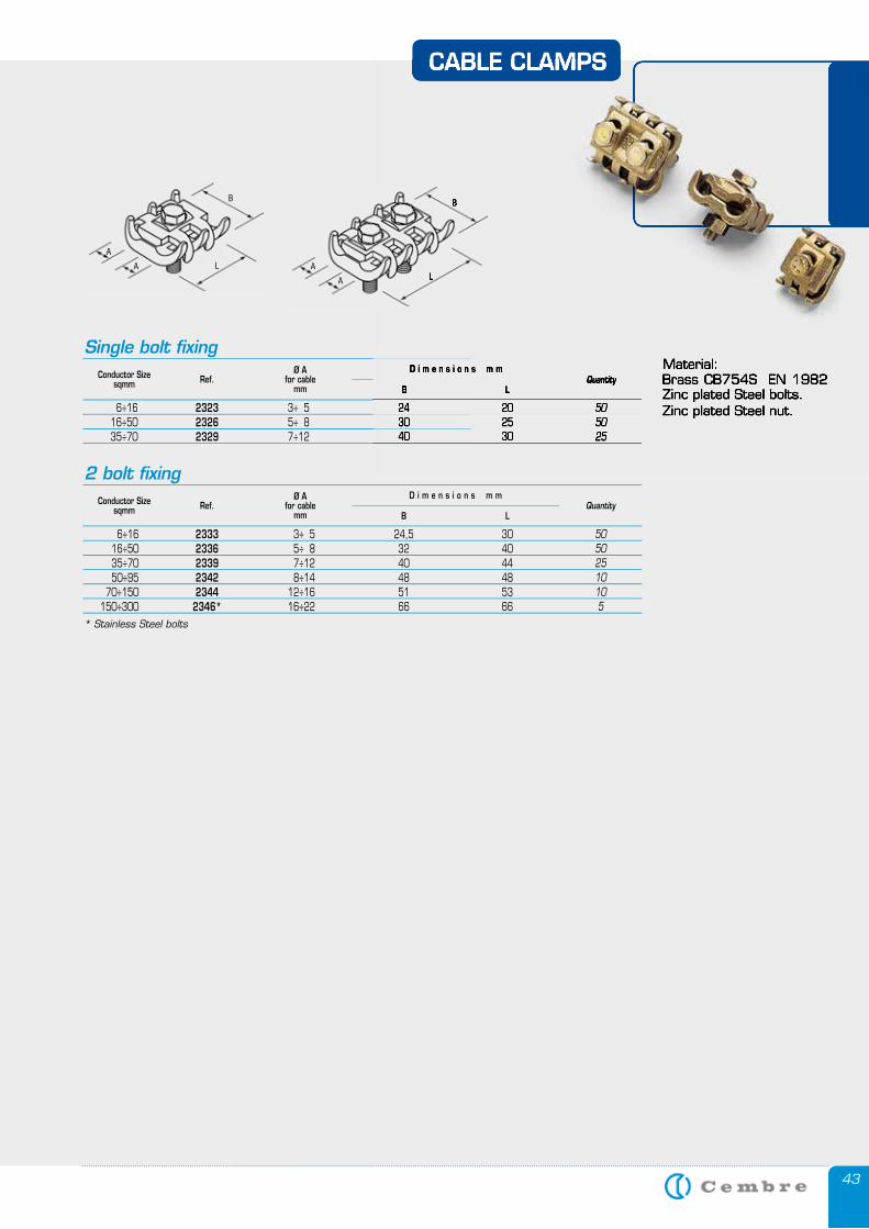
43
CABLE CLAMPS
Material:Brass CB754S EN 1982 Zinc plated Steel bolts.Zinc plated Steel nut. 6÷16 2323 3÷ 5 24 20
16÷50 2326 5÷ 8 30 25 35÷70 2329 7÷12 40 30
505025
Conductor Sizesqmm
Ø Afor cable
mmQuantity
B L
D i m e n s i o n s m m
Conductor Sizesqmm
Ø Afor cable
mmQuantity
B L
D i m e n s i o n s m m
6÷16 2333 3÷ 5 24,5 30 16÷50 2336 5÷ 8 32 40 35÷70 2339 7÷12 40 44 50÷95 2342 8÷14 48 48 70÷150 2344 12÷16 51 53 150÷300 2346* 16÷22 66 66
50502510105
Single bolt fixing
2 bolt fixing
Ref.
Ref.
A
A L
B
L
B
A
A
CABLE CLAMPS
Material:Brass CB754S EN 1982 Zinc plated Steel bolts.Zinc plated Steel nut. 3÷ 5 24 20
5÷ 8 30 257÷12 40 30
505025
QuantityB L
D i m e n s i o n s m m
L
B
* Stainless Steel bolts
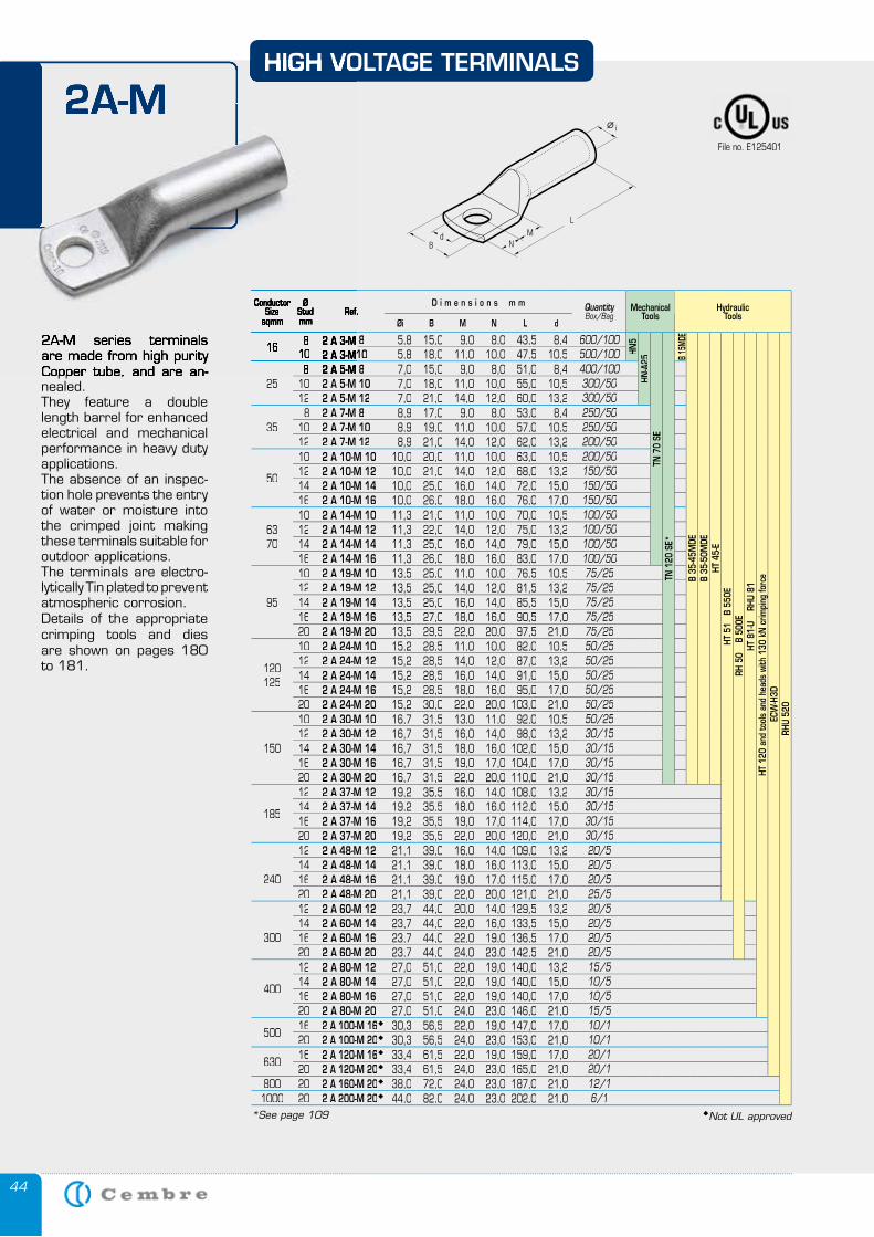
44
2A-M series terminals are made from high purity Copper tube, and are an-nealed. They feature a double length barrel for enhanced electrical and mechanical performance in heavy duty applications.The absence of an inspec-tion hole prevents the entry of water or moisture into the crimped joint making these terminals suitable for outdoor applications.The terminals are electro-lytically Tin plated to prevent atmospheric corrosion.Details of the appropriate crimping tools and dies are shown on pages 180 to 181.
2A-MHIGH VOLTAGE TERMINALS
Conductor Size
sqmm
ØStudmm
Ref.D i m e n s i o n s m m Quantity
Box/BagMechanical
ToolsHydraulic
ToolsØi B M N L d
2 A 3-M 8 5,8 15,0 9,0 8,0 43,5 8,4 600/100
HN5
HN-A
25TN
70
SETN
120
SE*
B 15
MDE
B 35
-45M
DEB
35-5
0MDE
HT 4
5-E
HT 5
1 B
550
ERH
50
B
500E
HT 8
1-U
RH
U 81
HT 1
20 a
nd to
ols
and
head
s wi
th 1
30 k
N c
rimpi
ng fo
rce
ECW
-H3D
RHU
520
2 A 3-M10 5,8 18,0 11,0 10,0 47,5 10,5 500/100
252 A 5-M 8 7,0 15,0 9,0 8,0 51,0 8,4 400/100
10 2 A 5-M 10 7,0 18,0 11,0 10,0 55,0 10,5 300/5012 2 A 5-M 12 7,0 21,0 14,0 12,0 60,0 13,2 300/50
358 2 A 7-M 8 8,9 17,0 9,0 8,0 53,0 8,4 250/50
10 2 A 7-M 10 8,9 19,0 11,0 10,0 57,0 10,5 250/5012 2 A 7-M 12 8,9 21,0 14,0 12,0 62,0 13,2 200/50
50
10 2 A 10-M 10 10,0 20,0 11,0 10,0 63,0 10,5 200/5012 2 A 10-M 12 10,0 21,0 14,0 12,0 68,0 13,2 150/5014 2 A 10-M 14 10,0 25,0 16,0 14,0 72,0 15,0 150/5016 2 A 10-M 16 10,0 26,0 18,0 16,0 76,0 17,0 150/50
6370
10 2 A 14-M 10 11,3 21,0 11,0 10,0 70,0 10,5 100/5012 2 A 14-M 12 11,3 22,0 14,0 12,0 75,0 13,2 100/5014 2 A 14-M 14 11,3 25,0 16,0 14,0 79,0 15,0 100/5016 2 A 14-M 16 11,3 26,0 18,0 16,0 83,0 17,0 100/50
95
10 2 A 19-M 10 13,5 25,0 11,0 10,0 76,5 10,5 75/2512 2 A 19-M 12 13,5 25,0 14,0 12,0 81,5 13,2 75/2514 2 A 19-M 14 13,5 25,0 16,0 14,0 85,5 15,0 75/2516 2 A 19-M 16 13,5 27,0 18,0 16,0 90,5 17,0 75/2520 2 A 19-M 20 13,5 29,5 22,0 20,0 97,5 21,0 75/25
120125
10 2 A 24-M 10 15,2 28,5 11,0 10,0 82,0 10,5 50/2512 2 A 24-M 12 15,2 28,5 14,0 12,0 87,0 13,2 50/2514 2 A 24-M 14 15,2 28,5 16,0 14,0 91,0 15,0 50/2516 2 A 24-M 16 15,2 28,5 18,0 16,0 95,0 17,0 50/2520 2 A 24-M 20 15,2 30,0 22,0 20,0 103,0 21,0 50/25
150
10 2 A 30-M 10 16,7 31,5 13,0 11,0 92,0 10,5 50/2512 2 A 30-M 12 16,7 31,5 16,0 14,0 98,0 13,2 30/1514 2 A 30-M 14 16,7 31,5 18,0 16,0 102,0 15,0 30/1516 2 A 30-M 16 16,7 31,5 19,0 17,0 104,0 17,0 30/1520 2 A 30-M 20 16,7 31,5 22,0 20,0 110,0 21,0 30/15
185
12 2 A 37-M 12 19,2 35,5 16,0 14,0 108,0 13,2 30/1514 2 A 37-M 14 19,2 35,5 18,0 16,0 112,0 15,0 30/1516 2 A 37-M 16 19,2 35,5 19,0 17,0 114,0 17,0 30/1520 2 A 37-M 20 19,2 35,5 22,0 20,0 120,0 21,0 30/15
240
12 2 A 48-M 12 21,1 39,0 16,0 14,0 109,0 13,2 20/514 2 A 48-M 14 21,1 39,0 18,0 16,0 113,0 15,0 20/516 2 A 48-M 16 21,1 39,0 19,0 17,0 115,0 17,0 20/520 2 A 48-M 20 21,1 39,0 22,0 20,0 121,0 21,0 25/5
300
12 2 A 60-M 12 23,7 44,0 20,0 14,0 129,5 13,2 20/514 2 A 60-M 14 23,7 44,0 22,0 16,0 133,5 15,0 20/516 2 A 60-M 16 23,7 44,0 22,0 19,0 136,5 17,0 20/520 2 A 60-M 20 23,7 44,0 24,0 23,0 142,5 21,0 20/5
400
12 2 A 80-M 12 27,0 51,0 22,0 19,0 140,0 13,2 15/514 2 A 80-M 14 27,0 51,0 22,0 19,0 140,0 15,0 10/516 2 A 80-M 16 27,0 51,0 22,0 19,0 140,0 17,0 10/520 2 A 80-M 20 27,0 51,0 24,0 23,0 146,0 21,0 15/5
50016 2 A 100-M 16 30,3 56,5 22,0 19,0 147,0 17,0 10/120 2 A 100-M 20 30,3 56,5 24,0 23,0 153,0 21,0 10/1
63016 2 A 120-M 16 33,4 61,5 22,0 19,0 159,0 17,0 20/120 2 A 120-M 20 33,4 61,5 24,0 23,0 165,0 21,0 20/1
800 20 2 A 160-M 20 38,0 72,0 24,0 23,0 187,0 21,0 12/11000 20 2 A 200-M 20 44,0 82,0 24,0 23,0 202,0 21,0 6/1
2A-M series terminals are made from high purity Copper tube, and are an-
2A-MHIGH VOLTAGE TERMINALS
Conductor Size
sqmm
ØStudmm
Ref.
168 2 A 3-M 8
10 2 A 3-M108 2 A 5-M 8
*See page 109 Not UL approved
File no. E125401
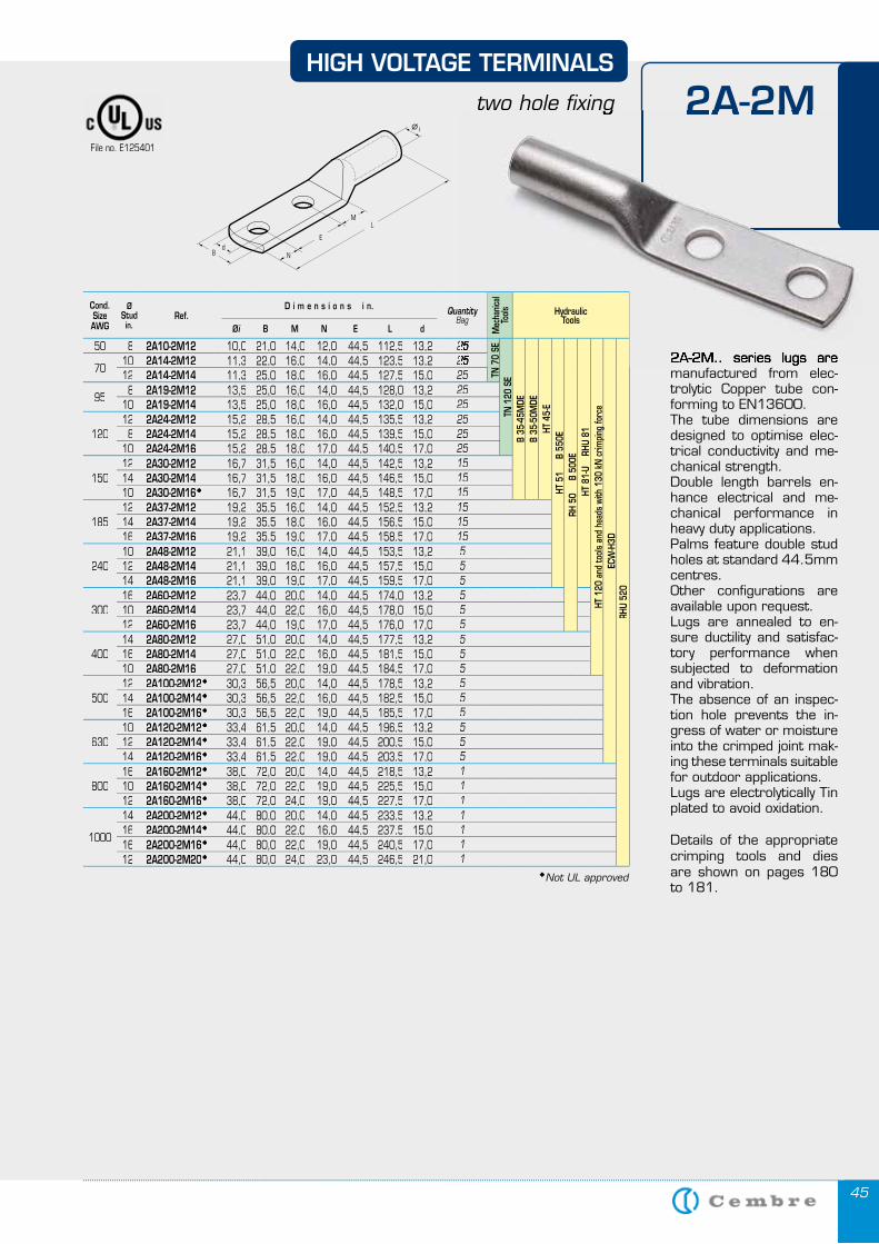
4545
2A-2M.. series lugs are manufactured from elec-trolytic Copper tube con-forming to EN13600. The tube dimensions are designed to optimise elec-trical conductivity and me-chanical strength.Double length barrels en-hance electrical and me-chanical performance in heavy duty applications.Palms feature double stud holes at standard 44.5mm centres. Other configurations are available upon request.Lugs are annealed to en-sure ductility and satisfac-tory performance when subjected to deformation and vibration.The absence of an inspec-tion hole prevents the in-gress of water or moisture into the crimped joint mak-ing these terminals suitable for outdoor applications.Lugs are electrolytically Tin plated to avoid oxidation.
Details of the appropriate crimping tools and dies are shown on pages 180 to 181.
E
HIGH VOLTAGE TERMINALS
two hole fixing 2A-2M2A-2M
2A-2M.. series lugs are
two hole fixing
Cond. SizeAWG
ØStudin.
Ref.D i m e n s i o n s i n. Quantity
Bag
Mec
hanic
al To
ols HydraulicTools
Øi B M N E L d
50 8 2A10-2M12 10,0 21,0 14,0 12,0 44,5 112,5 13,2 2525
TN 7
0 SE
TN 1
20 S
EB
35-4
5MDE
B 35
-50M
DEHT
45-
EHT
51
B
550
ERH
50
B
500
E H
T 81
-U
RHU
81
HT 1
20 a
nd to
ols
and
head
s wi
th 1
30 k
N c
rimpi
ng fo
rce
ECW
-H3D
RHU
520
7010 2A14-2M12 11,3 22,0 16,0 14,0 44,5 123,5 13,2 252512 2A14-2M14 11,3 25,0 18,0 16,0 44,5 127,5 15,0 25
958 2A19-2M12 13,5 25,0 16,0 14,0 44,5 128,0 13,2 25
10 2A19-2M14 13,5 25,0 18,0 16,0 44,5 132,0 15,0 25
12012 2A24-2M12 15,2 28,5 16,0 14,0 44,5 135,5 13,2 258 2A24-2M14 15,2 28,5 18,0 16,0 44,5 139,5 15,0 25
10 2A24-2M16 15,2 28,5 18,0 17,0 44,5 140,5 17,0 25
15012 2A30-2M12 16,7 31,5 16,0 14,0 44,5 142,5 13,2 1514 2A30-2M14 16,7 31,5 18,0 16,0 44,5 146,5 15,0 1510 2A30-2M16 16,7 31,5 19,0 17,0 44,5 148,5 17,0 15
18512 2A37-2M12 19,2 35,5 16,0 14,0 44,5 152,5 13,2 1514 2A37-2M14 19,2 35,5 18,0 16,0 44,5 156,5 15,0 1516 2A37-2M16 19,2 35,5 19,0 17,0 44,5 158,5 17,0 15
24010 2A48-2M12 21,1 39,0 16,0 14,0 44,5 153,5 13,2 512 2A48-2M14 21,1 39,0 18,0 16,0 44,5 157,5 15,0 514 2A48-2M16 21,1 39,0 19,0 17,0 44,5 159,5 17,0 5
30016 2A60-2M12 23,7 44,0 20,0 14,0 44,5 174,0 13,2 510 2A60-2M14 23,7 44,0 22,0 16,0 44,5 178,0 15,0 512 2A60-2M16 23,7 44,0 19,0 17,0 44,5 176,0 17,0 5
40014 2A80-2M12 27,0 51,0 20,0 14,0 44,5 177,5 13,2 516 2A80-2M14 27,0 51,0 22,0 16,0 44,5 181,5 15,0 510 2A80-2M16 27,0 51,0 22,0 19,0 44,5 184,5 17,0 5
50012 2A100-2M12 30,3 56,5 20,0 14,0 44,5 178,5 13,2 514 2A100-2M14 30,3 56,5 22,0 16,0 44,5 182,5 15,0 516 2A100-2M16 30,3 56,5 22,0 19,0 44,5 185,5 17,0 5
63010 2A120-2M12 33,4 61,5 20,0 14,0 44,5 196,5 13,2 512 2A120-2M14 33,4 61,5 22,0 19,0 44,5 200,5 15,0 514 2A120-2M16 33,4 61,5 22,0 19,0 44,5 203,5 17,0 5
80016 2A160-2M12 38,0 72,0 20,0 14,0 44,5 218,5 13,2 110 2A160-2M14 38,0 72,0 22,0 19,0 44,5 225,5 15,0 112 2A160-2M16 38,0 72,0 24,0 19,0 44,5 227,5 17,0 1
1000
14 2A200-2M12 44,0 80,0 20,0 14,0 44,5 233,5 13,2 116 2A200-2M14 44,0 80,0 22,0 16,0 44,5 237,5 15,0 116 2A200-2M16 44,0 80,0 22,0 19,0 44,5 240,5 17,0 112 2A200-2M20 44,0 80,0 24,0 23,0 44,5 246,5 21,0 1
File no. E125401
Not UL approved
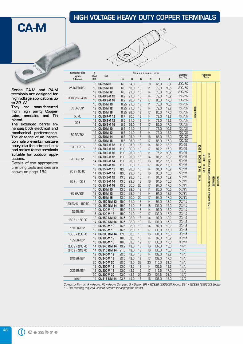
46
Series CA-M and 2A-M terminals are designed for high voltage applications up to 33 kV.They are manufactured from high purity Copper tube, annealed and Tin plated.The extended barrel en-hances both electrical and mechanical performance. The absence of an inspec-tion hole prevents moisture entry into the crimped joint and makes these terminals suitable for outdoor appli-cations.Details of the appropriate crimping tools and dies are shown on page 184.
HIGH VOLTAGE HEAVY DUTY COPPER TERMINALS
CA-M
Series CA-M and 2A-M terminals are designed for high voltage applications up to 33 kV.They are manufactured from high purity Copper tube, annealed and Tin plated.The extended barrel en-hances both electrical and mechanical performance. The absence of an inspec-tion hole prevents moisture entry into the crimped joint and makes these terminals suitable for outdoor appli-cations.
HIGH VOLTAGE HEAVY DUTY COPPER TERMINALS
CA-M
Hydraulic Tools
8 CA 25-M 8 6,8 14,0 9 8 65,0 8,4 10 CA 25-M 10 6,8 18,0 13 11 72,0 10,5 12 CA 25-M 12 6,8 21,0 16 14 78,0 13,2 12 CA 40 S-M 12 8,2 21,0 16 14 79,0 13,2 16 CA 40 S-M 16 8,2 26,0 19 17 85,0 17,0 10 CA 35-M 10 8,25 21,0 13 11 73,0 10,5 12 CA 35-M 12 8,25 21,0 16 14 79,0 13,2 16 CA 35-M 16 8,25 26,0 19 17 85,0 17,0 12 CA 50 R-M 12 8,7 20,5 16 14 79,0 13,2 12 CA 50 S-M 12 9,5 21,0 16 14 79,0 13,2 16 CA 50 S-M 16 9,5 26,0 19 17 85,0 17,0 10 CA 50-M 10 9,5 21,0 13 11 73,0 10,5 12 CA 50-M 12 9,5 21,0 16 14 79,0 13,2 14 CA 50-M 14 9,5 25,0 18 16 83,0 15,0 16 CA 50-M 16 9,5 26,0 19 17 85,0 17,0 12 CA 70 S-M 12 11,0 28,0 16 14 81,2 13,2 16 CA 70 S-M 16 11,0 30,0 19 17 87,2 17,0 10 CA 70 S-M 10 11,0 26,0 13 11 75,2 10,5 12 CA 70 S-M 12 11,0 28,0 16 14 81,2 13,2 14 CA 70 S-M 14 11,0 28,0 18 16 85,2 15,0 16 CA 70 S-M 16 11,0 30,0 19 17 87,2 17,0 12 CA 95 R-M 12 12,0 28,0 16 14 91,0 13,2 14 CA 95 R-M 14 12,0 29,0 18 16 95,0 15,0 12 CA 95 S-M 12 13,5 28,0 16 14 91,0 13,2 14 CA 95 S-M 14 13,5 29,0 18 16 94,5 15,0 16 CA 95 S-M 16 13,5 30,0 20 17 97,0 17,0 10 CA 95-M 10 13,5 28,0 13 11 85,0 10,5 12 CA 95-M 12 13,5 28,0 16 14 91,0 13,2 16 CA 95-M 16 13,5 30,0 20 17 97,0 17,0 12 CA 150 R-M 12 15,0 31,0 16 14 97,0 13,2 14 CA 150 R-M 14 15,0 31,0 18 16 101,0 15,0 12 CA 120-M 12 15,0 31,0 16 14 97,0 13,2 16 CA 120-M 16 15,0 31,0 19 17 103,0 17,0 12 CA 150 S-M 12 16,5 32,0 16 14 97,0 13,2 14 CA 150 S-M 14 16,5 32,0 18 16 101,0 15,0 12 CA 150-M 12 16,5 32,0 16 14 97,0 13,2 16 CA 150-M 16 16,5 32,0 19 17 103,0 17,0 14 CA 200 R-M 14 17,0 32,5 18 16 101,0 15,0 12 CA 185-M 12 18,0 33,5 16 14 97,0 13,2 16 CA 185-M 16 18,0 33,5 19 17 103,0 17,0 14 CA 240 R-M 14 19,2 43,0 18 16 107,0 15,0 14 CA 315 R-M 14 21,5 43,0 18 16 105,0 15,0 12 CA 240-M 12 20,5 42,0 16 14 103,0 13,2 16 CA 240-M 16 20,5 42,0 19 17 109,0 17,0 20 CA 240-M 20 20,5 42,0 22 20 115,0 21,0 12 CA 300-M 12 23,0 43,5 16 14 109,5 13,2 16 CA 300-M 16 23,0 43,5 19 17 115,5 17,0 20 CA 300-M 20 23,0 43,5 22 20 121,5 21,0 14 CA 315 S-M 14 23,7 44,0 18 16 105,0 15,0
300/50200/50200/50150/50100/50150/50150/50150/50150/50150/50100/50150/50150/50100/50100/5050/2550/2550/2550/2550/2550/2550/2550/2550/2550/2550/2550/2550/2550/2530/1530/1530/1530/1530/1530/1530/1530/1530/1530/1530/1515/515/515/515/515/515/515/515/515/5
Conductor Size(sqmm)
& Format
ØStudmm
QuantityBox/Bag
Øi B M N L d
D i m e n s i o n s m mRef.
25 R/BR/BS*
35 BR/BS*
30 RC/S ÷ 40 S
50 RC
50 S
50 BR/BS*
63 S ÷ 70 S
70 BR/BS*
80 S ÷ 95 RC
95 S ÷ 100 S
95 BR/BS*
120 RC/S ÷ 150 RC
120 BR/BS*
150 S ÷ 160 RC
150 BR/BS*
185 BR/BS*
240 BR/BS*
300 BR/BS*
160 S ÷ 200 RC
200 S ÷ 240 RC240 S ÷ 315 RC
315 S
Conductor Format: R = Round, RC = Round Compact, S = Sector, BR = IEC228 (BS6360) Round, BS* = IEC228 (BS6360) Sector* = Pre-rounding required, consult Cembre for appropriate die set
HT 8
1-U
RH
U 81
HT 1
20 a
nd to
ols
and
head
s wi
th 1
30 k
N c
rimpi
ng fo
rce
ECW
-H3D
RHU
520
HT 5
1
RH 5
0
B 50
0E
B 5
50E
B35-
50M
DE
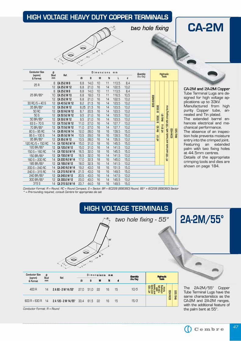
4747
CA-2M and 2A-2M Copper Tube Terminal Lugs are de-signed for high voltage ap-plications up to 33kV. Manufactured from high purity Copper tube, an-nealed and Tin plated. The extended barrel en-hances electrical and me-chanical performance. The absence of an inspec-tion hole prevents moisture entry into the crimped joint. Featuring an extended palm with two fixing holes at 44.5mm centres.Details of the appropriate crimping tools and dies are shown on page 184.
Conductor Format: R = Round
The 2A-2M/55° Copper Tube Terminal Lugs have the same characteristics as the CA-2M and 2A-2M ranges, with the additional feature of the palm bent at 55°.
HydraulicTools
14 2 A 80 - 2 M 14/55° 27,0 51,0 22 16 15
14 2 A 120 - 2 M 14/55° 33,4 61,5 22 16 15
10/5
15/3
Conductor Size(sqmm)
& Format
ØStudmm
QuantityBox/Bag
Øi B M N d
D i m e n s i o n s m mRef.
400 R
600 R ÷ 630 R
HT 1
20
and
tool
s an
d he
ads
with
13
0 kN
cr
impi
ng
forc
e
ECW
-H3D
RHU
520
HIGH VOLTAGE HEAVY DUTY COPPER TERMINALS
two hole fixing CA-2M
CA-2M and 2A-2M Copper
HIGH VOLTAGE HEAVY DUTY COPPER TERMINALS
two hole fixing CA-2M
2A-2M/55°
HydraulicTools
HydraulicTools
HydraulicQuantityBox/BagQuantityBox/BagQuantity
M N d
D i m e n s i o n s m m
and
head
s
2A-2M/55°
HydraulicTools
8 CA 25-2 M 8 6,8 14,0 10 11 113,5 8,4 12 CA 25-2 M 12 6,8 21,0 16 14 122,5 13,2 8 CA 25-2 M 8 6,8 14,0 10 11 113,5 8,4 10 CA 25-2 M 10 6,8 18,0 13 11 116,5 10,5 12 CA 25-2 M 12 6,8 21,0 16 14 122,5 13,2 12 CA 40 S-2 M 12 8,2 21,5 16 14 123,5 13,2 12 CA 35-2 M 12 8,25 21,5 16 14 123,5 13,2 12 CA 50 R-2 M 12 8,7 20,5 16 14 123,5 13,2 12 CA 50 S-2 M 12 9,5 21,0 16 14 123,5 13,2 12 CA 50-2 M 12 9,5 21,0 16 14 123,5 13,2 12 CA 70 S-2 M 12 11,0 27,0 16 14 127,7 13,2 12 CA 70 S-2 M 12 11,0 27,0 16 14 127,7 13,2 14 CA 95 R-2 M 14 12,0 28,0 18 16 139,5 15,0 14 CA 95 S-2 M 14 13,5 29,0 18 16 139,5 15,0 12 CA 95-2 M 12 13,5 28,0 16 14 135,5 13,2 14 CA 150 R-2 M 14 15,0 31,0 18 16 145,5 15,0 12 CA 120-2 M 12 15,0 31,0 16 14 141,5 13,2 14 CA 150 S-2 M 14 16,5 32,0 18 16 145,5 15,0 12 CA 150-2 M 12 16,5 32,0 16 14 141,5 13,2 14 CA 200 R-2 M 14 17,0 32,5 18 16 145,0 15,0 12 CA 185-2 M 12 18,0 32,5 16 14 141,5 13,2 14 CA 240 R-2 M 14 19,2 43,0 18 16 151,5 15,0 14 CA 315 R-2 M 14 21,5 43,0 18 16 149,5 15,0 12 CA 240-2 M 12 20,5 43,0 16 14 147,5 13,2 12 CA 300-2 M 12 23,0 43,0 16 14 145,5 13,2 14 CA 315 S-2 M 14 23,7 44,0 18 16 149,5 15,0
Conductor Size(sqmm)
& Format
ØStudmm
QuantityBox/Bag
Øi B M N L d
D i m e n s i o n s m mRef.
25 R
25 BR/BS*
30 RC/S ÷ 40 S35 BR/BS*
50 RC50 S
50 BR/BS*63 S ÷ 70 S70 BR/BS*
80 S ÷ 95 RC95 S ÷ 100 S95 BR/BS*
120 RC/S ÷ 150 RC120 BR/BS*
150 S ÷ 160 RC150 BR/BS*
160 S ÷ 200 RC185 BR/BS*
200 S ÷ 240 RC240 S ÷ 315 RC
240 BR/BS*300 BR/BS*
315 S
Conductor Format: R = Round, RC = Round Compact, S = Sector, BR = IEC228 (BS6360) Round, BS* = IEC228 (BS6360) Sector* = Pre-rounding required, consult Cembre for appropriate die set
HT 8
1-U
RH
U 81
HT 1
20 a
nd to
ols
and
head
s wi
th 1
30 k
N c
rimpi
ng fo
rce
ECW
-H3D
RHU
520
HT 5
1
RH 5
0
B 50
0E
B 5
50EB3
5-50
MDE
HIGH VOLTAGE TERMINALS
two hole fixing - 55°
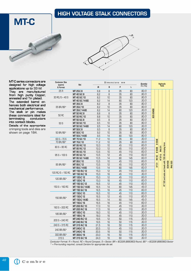
48
MT-C series connectors are designed for high voltage applications up to 33 kV. They are manufactured from high purity Copper, annealed and Tin plated.The extended barrel en-hances both electrical and mechanical performance.The stalk or pin makes these connectors ideal for terminating conductors into contact blocks.Details of the appropriate crimping tools and dies are shown on page 184.
HIGH VOLTAGE STALK CONNECTORS
MT-C
MT-C series connectors are designed for high voltage applications up to 33 kV. They are manufactured from high purity Copper, annealed and Tin plated.The extended barrel en-hances both electrical and mechanical performance.The stalk or pin makes these connectors ideal for terminating conductors into contact blocks.Details of the appropriate
HIGH VOLTAGE STALK CONNECTORS
MT-C
MT 25-C 8 6,8 8 35 80 MT 40 S-C 8 8,2 8 35 80 MT 40 S-C 10 8,2 10 35 80 MT 40 S-C 14-80 8,2 14 80 123 MT 35-C 8 8,2 8 35 80 MT 35-C 10 8,2 10 35 80 MT 35-C 14-80 8,2 14 80 123 MT 50 R-C 8 8,8 8 35 80 MT 50 R-C 10 8,8 10 35 80 MT 50 S-C 8 9,5 8 35 80 MT 50 S-C 10 9,5 10 35 80 MT 50 S-C 14-80 9,5 14 80 123 MT 50-C 8 9,5 8 35 80 MT 50-C 10 9,2 10 35 80 MT 50-C 14-80 9,5 14 80 123 MT 70 S-C 10 11,2 10 35 90 MT 70-C 10 11,2 10 35 90 MT 95 R-C 10 12,0 10 45 110 MT 95 R-C 12 12,0 12 45 110 MT 95 S-C 10 13,5 10 45 110 MT 95 S-C 12 13,5 12 45 110 MT 95 S-C 14-80 13,5 14 80 145 MT 95-C 10 13,5 10 45 110 MT 95-C 12 13,5 12 45 110 MT 95-C 14-80 13,5 14 80 145 MT 150 R-C 12 15,0 12 45 110 MT 150 R-C 16 15,0 16 45 110 MT 120-C 12 15,0 12 45 110 MT 120-C 16 15,0 16 45 110 MT 150 S-C 12 16,5 12 45 110 MT 150 S-C 14-80 16,5 14 80 145 MT 150 S-C 16 16,5 16 45 110 MT 150-C 10 16,5 10 45 110 MT 150-C 12 16,5 12 45 110 MT 150-C 14-80 16,5 14 80 145 MT 150-C 16 16,5 16 45 110 MT 200 R-C 10 17,0 10 45 110 MT 200 R-C 16 17,0 16 45 110 MT 185-C 10 18,0 10 45 110 MT 185-C 16 18,0 16 45 110 MT 240 R-C 12 19,5 12 50 115 MT 240 R-C 16 19,5 16 50 115 MT 315 R-C 16 21,5 16 50 115 MT 240-C 12 20,5 12 45 110 MT 240-C 16 20,5 16 50 115 MT 300-C 16 23,0 16 50 115 MT 315 S-C 16 24,0 16 60 130
HydraulicTools
Conductor Size(sqmm)
& Format
QuantityBox/Bag
LPBØi
D i m e n s i o n s m mRef.
25 R
30 RC/S ÷ 40 S
35 BR/BS*
50 RC
50 S
50 BR/BS*
63 S ÷ 70 S70 BR/BS*
80 S ÷ 95 RC
95 S ÷ 100 S
95 BR/BS*
120 RC/S ÷ 150 RC
120 BR/BS*
150 S ÷ 160 RC
150 BR/BS*
160 S ÷ 200 RC
185 BR/BS*
Conductor Format: R = Round, RC = Round Compact, S = Sector, BR = IEC228 (BS6360) Round, BS* = IEC228 (BS6360) Sector* = Pre-rounding required, consult Cembre for appropriate die set
90/390/390/330/390/390/330/390/390/390/390/330/390/390/390/330/330/360/360/360/360/360/360/360/360/360/330/360/360/360/345/360/360/360/345/360/330/330/330/330/330/330/330/330/330/330/330/3
200 S ÷ 240 RC
240 BR/BS*
240 S ÷ 315 RC
315 S300 BR/BS*
HT 8
1-U
RH
U 81
HT 1
20 a
nd to
ols
and
head
s wi
th 1
30 k
N c
rimpi
ng fo
rce
ECW
-H3D
RHU
520
HT 5
1
RH 5
0
B 50
0E
B 5
50E
B35-
50M
DE
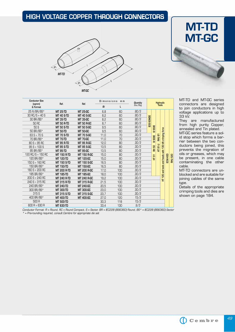
4949
HIGH VOLTAGE COPPER THROUGH CONNECTORS
MT-TD and MT-GC series connectors are designed to join conductors in high voltage applications up to 33 kV. They are manufactured from high purity Copper, annealed and Tin plated.MT-GC series feature a sol-id stop which forms a bar-rier between the two con-ductors being joined, this prevents the migration of oils or greases, which may be present, in one cable contaminating the other cable.MT-TD connectors are un-blocked and are suitable for joining cables of the same type.Details of the appropriate crimping tools and dies are shown on page 184.
MT-TD
MT-GC
MT-TDMT-GC
HIGH VOLTAGE COPPER THROUGH CONNECTORS
MT-TDMT-GC
HydraulicTools
MT 25-TD MT 25-GC 6,8 60 MT 40 S-TD MT 40 S-GC 8,2 60 MT 35-TD MT 35-GC 8,2 60 MT 50 R-TD MT 50 R-GC 8,7 60 MT 50 S-TD MT 50 S-GC 9,5 60 MT 50-TD MT 50-GC 9,5 60 MT 70 S-TD MT 70 S-GC 11,0 70 MT 70-TD MT 70-GC 11,0 70 MT 95 R-TD MT 95 R-GC 12,0 80 MT 95 S-TD MT 95 S-GC 13,5 80 MT 95-TD MT 95-GC 13,5 80 MT 150 R-TD MT 150 R-GC 15,0 80 MT 120-TD MT 120-GC 15,0 80 MT 150 S-TD MT 150 S-GC 16,5 80 MT 150-TD MT 150-GC 16,5 80 MT 200 R-TD MT 200 R-GC 17,0 100 MT 185-TD MT 185-GC 18,0 100 MT 240 R-TD MT 240 R-GC 19,2 100 MT 315 R-TD MT 315 R-GC 21,5 100 MT 240-TD MT 240-GC 20,5 100 MT 300-TD MT 300-GC 23,0 100 MT 315 S-TD MT 315 S-GC 23,7 100 MT 400-TD MT 400-GC 27,0 120 MT 500-TD 30,3 118 MT 630-TD 33,4 130
90/390/390/390/390/390/330/330/330/330/330/330/330/330/330/330/330/330/330/330/330/330/315/315/39/3
Conductor Size(sqmm)
& Format
QuantityBox/Bag
Øi L
D i m e n s i o n s m mRef. Ref.
25 R/BR/BS*30 RC/S ÷ 40 S
30 BR/BS*50 RC50 S
50 BR/BS*63 S ÷ 70 S70 BR/BS*
80 S ÷ 95 RC95 S ÷ 100 S95 BR/BS*
120 RC/S ÷ 150 RC120 BR/BS*
150 S ÷ 160 RC150 BR/BS*
160 S ÷ 200 RC185 BR/BS*
200 S ÷ 240 RC240 S ÷ 315 RC
240 BR/BS*300 BR/BS*
315 S400 BR/BS*
500 R600 R ÷ 630 R
Conductor Format: R = Round, RC = Round Compact, S = Sector, BR = IEC228 (BS6360) Round, BS* = IEC228 (BS6360) Sector* = Pre-rounding required, consult Cembre for appropriate die set
HT 8
1-U
RH
U 81
HT 1
20 a
nd to
ols
and
head
s wi
th 1
30 k
N c
rimpi
ng fo
rce
ECW
-H3D
RHU
520
HT 5
1
RH 5
0
B 50
0E
B 5
50EB3
5-50
MDE
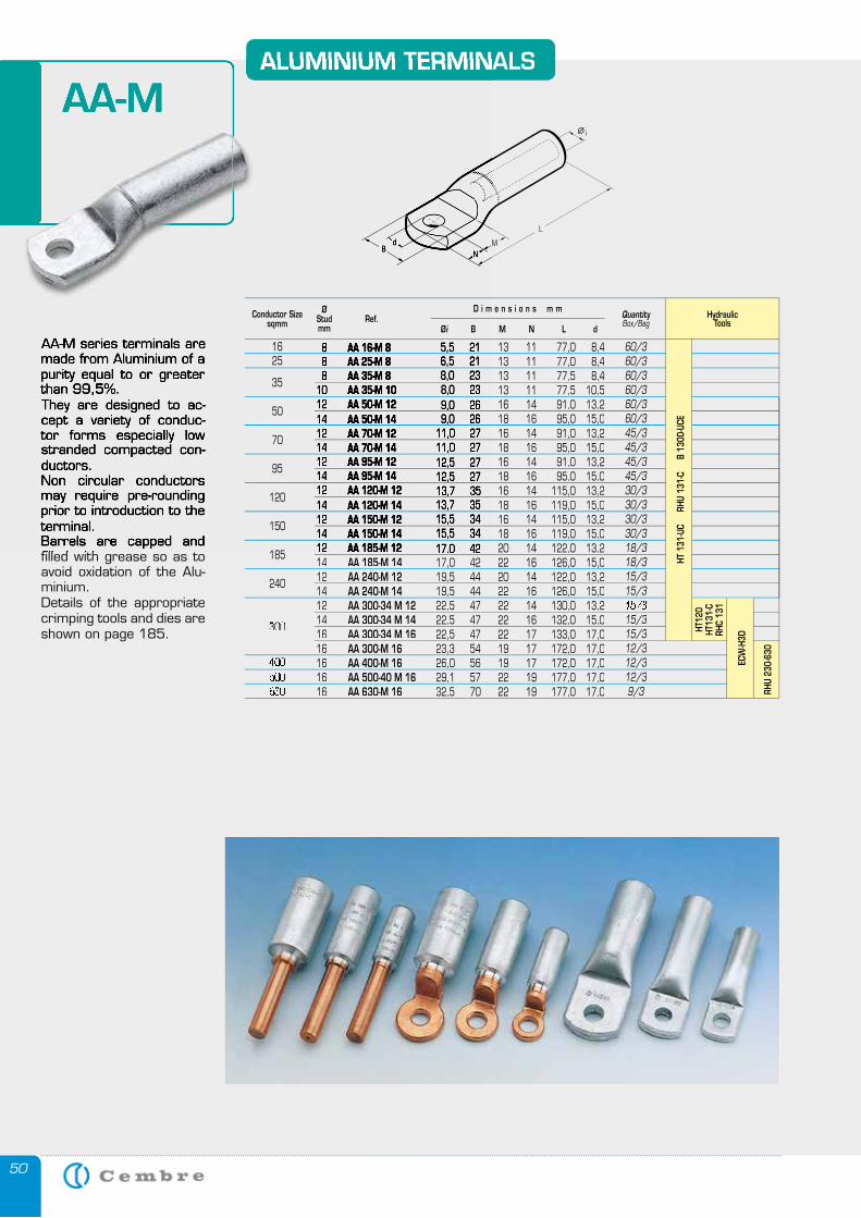
50
AA-M series terminals are made from Aluminium of a purity equal to or greater than 99,5%.They are designed to ac-cept a variety of conduc-tor forms especially low stranded compacted con-ductors. Non circular conductors may require pre-rounding prior to introduction to the terminal.Barrels are capped and filled with grease so as to avoid oxidation of the Alu-minium.Details of the appropriate crimping tools and dies are shown on page 185.
ALUMINIUM TERMINALS
AA-M
AA-M series terminals are made from Aluminium of a purity equal to or greater than 99,5%.They are designed to ac-cept a variety of conduc-tor forms especially low stranded compacted con-ductors. Non circular conductors may require pre-rounding prior to introduction to the terminal.Barrels are capped and filled with grease so as to
ALUMINIUM TERMINALS
AA-M
HydraulicTools
8 AA 16-M 8 5,5 21 13 11 77,0 8,4 5,5 21 13 11 77,0 8,4 8 AA 25-M 8 6,5 21 13 11 77,0 8,4 6,5 21 13 11 77,0 8,4 8 AA 35-M 8 8,0 23 13 11 77,5 8,4 8,0 23 13 11 77,5 8,4 10 AA 35-M 10 8,0 23 13 11 77,5 10,5 8,0 23 13 11 77,5 10,5 12 AA 50-M 12 9,0 26 16 14 91,0 13,2 9,0 26 16 14 91,0 13,2 14 AA 50-M 14 9,0 26 18 16 95,0 15,0 9,0 26 18 16 95,0 15,0 12 AA 70-M 12 11,0 27 16 14 91,0 13,2 11,0 27 16 14 91,0 13,2 14 AA 70-M 14 11,0 27 18 16 95,0 15,0 11,0 27 18 16 95,0 15,0 12 AA 95-M 12 12,5 27 16 14 91,0 13,2 12,5 27 16 14 91,0 13,2 14 AA 95-M 14 12,5 27 18 16 95,0 15,0 12,5 27 18 16 95,0 15,0 12 AA 120-M 12 13,7 35 16 14 115,0 13,213,7 35 16 14 115,0 13,2 14 AA 120-M 14 13,7 35 18 16 119,0 15,0 13,7 35 18 16 119,0 15,0 12 AA 150-M 12 15,5 34 16 14 115,0 13,2 15,5 34 16 14 115,0 13,2 14 AA 150-M 14 15,5 34 18 16 119,0 15,0 15,5 34 18 16 119,0 15,0 12 12 AA 185-M 12AA 185-M 12 17,0 42 20 14 122,0 13,2 17,0 42 20 14 122,0 13,2 14 AA 185-M 14 17,0 42 22 16 126,0 15,0 12 AA 240-M 12 19,5 44 20 14 122,0 13,2 14 AA 240-M 14 19,5 44 22 16 126,0 15,0 12 AA 300-34 M 12 22,5 47 22 14 130,0 13,2 14 AA 300-34 M 14 22,5 47 22 16 132,0 15,0 16 AA 300-34 M 16 22,5 47 22 17 133,0 17,0 16 AA 300-M 16 23,3 54 19 17 172,0 17,0 16 AA 400-M 16 26,0 56 19 17 172,0 17,0 16 AA 500-40 M 16 29,1 57 22 19 177,0 17,0 16 AA 630-M 16 32,5 70 22 19 177,0 17,0
60/360/360/360/360/360/345/345/345/345/330/330/330/330/318/318/315/315/315/315/315/312/312/312/39/3
Conductor Sizesqmm
ØStudmm
QuantityBox/Bag
Øi B M N L d
D i m e n s i o n s m mRef.
50
70
95
120
150
185
240
300 14 300 14 16
300 16
400 16 400 16
630 16 630 16 500 16 500 16
RHU
230-
630
HT12
0HT
131-
CRH
C 13
1
ECW
-H3D
35
2516
HT 1
31-U
C
RHU
131
-C
B 1
300-
UCE
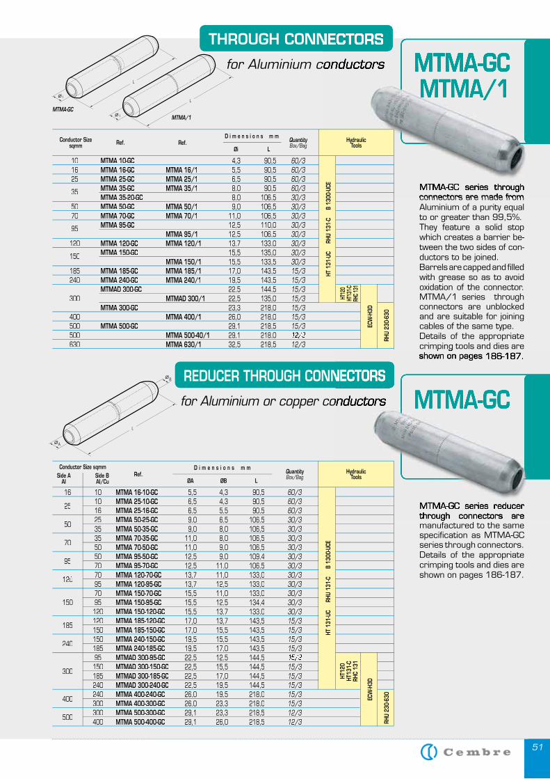
5151
THROUGH CONNECTORS
for Aluminium conductors
REDUCER THROUGH CONNECTORS
for Aluminium or copper conductors
MTMA-GCMTMA/1
MTMA-GCMTMA/1
MTMA-GC
MTMA-GC
MTMA-GC series through connectors are made from Aluminium of a purity equal to or greater than 99,5%.They feature a solid stop which creates a barrier be-tween the two sides of con-ductors to be joined.Barrels are capped and filled with grease so as to avoid oxidation of the connector. MTMA/1 series through connectors are unblocked and are suitable for joining cables of the same type.Details of the appropriate crimping tools and dies are shown on pages 186-187.
MTMA-GC series reducer through connectors are manufactured to the same specification as MTMA-GC series through connectors.Details of the appropriate crimping tools and dies are shown on pages 186-187.
THROUGH CONNECTORS
for Aluminium conductors
MTMA-GC series through connectors are made from
MTMA/1MTMA-GCMTMA-GCMTMA-GC
REDUCER THROUGH CONNECTORS
for Aluminium or copper conductors MTMA-GC
crimping tools and dies are shown on pages 186-187.
MTMA-GC series reducer through connectors are
HydraulicTools
10 MTMA 10-GC 4,3 90,5 16 MTMA 16-GC MTMA 16/1 5,5 90,5 25 MTMA 25-GC MTMA 25/1 6,5 90,5
35 MTMA 35-GC MTMA 35/1 8,0 90,5 MTMA 35-20-GC 8,0 106,5 50 MTMA 50-GC MTMA 50/1 9,0 106,5 70 MTMA 70-GC MTMA 70/1 11,0 106,5
95 MTMA 95-GC 12,5 110,0 MTMA 95/1 12,5 106,5 120 MTMA 120-GC MTMA 120/1 13,7 133,0
150 MTMA 150-GC 15,5 135,0 MTMA 150/1 15,5 133,5 185 MTMA 185-GC MTMA 185/1 17,0 143,5 240 MTMA 240-GC MTMA 240/1 19,5 143,5 MTMAD 300-GC 22,5 144,5 300 MTMAD 300/1 22,5 135,0 MTMA 300-GC 23,3 218,0 400 MTMA 400/1 26,0 218,0 500 MTMA 500-GC 29,1 218,5 500 MTMA 500-40/1 29,1 218,0 630 MTMA 630/1 32,5 218,5
60/360/360/360/330/330/330/330/330/330/330/330/315/315/315/315/315/315/315/312/329,1 218,0 12/329,1 218,0 12/3
Conductor Sizesqmm
QuantityBox/Bag
LØi
D i m e n s i o n s m mRef.
HydraulicTools
16 10 MTMA 16-10-GC 5,5 4,3 90,5
25 10 MTMA 25-10-GC 6,5 4,3 90,5
16 25
16 25
MTMA 25-16-GC 6,5 5,5 90,5
50 25 MTMA 50-25-GC 9,0 6,5 106,5
35 50
35 50
MTMA 50-35-GC 9,0 8,0 106,5
70 35 MTMA 70-35-GC 11,0 8,0 106,5
50 70
50 70
MTMA 70-50-GC 11,0 9,0 106,5
95 50 MTMA 95-50-GC 12,5 9,0 109,4
70 95
70 95
MTMA 95-70-GC 12,5 11,0 106,5 70 MTMA 120-70-GC 13,7 11,0 133,0
120 70
120 70
95 MTMA 120-95-GC 13,7 12,5 133,0 70 MTMA 150-70-GC 15,5 11,0 133,0 150 95 MTMA 150-95-GC 15,5 12,5 134,4 120 MTMA 150-120-GC 15,5 13,7 133,0
185 120 MTMA 185-120-GC 17,0 13,7 143,5
150 185
150 185
MTMA 185-150-GC 17,0 15,5 143,5
240 150 MTMA 240-150-GC 19,5 15,5 143,5
185 240
185 240
MTMA 240-185-GC 19,5 17,0 143,5 95 MTMAD 300-95-GC 22,5 12,5 144,5
300 150 MTMAD 300-150-GC 22,5 15,5 144,5
185 300
185 300
MTMAD 300-185-GC 22,5 17,0 144,5 240 MTMAD 300-240-GC 22,5 19,5 144,5
400 240 MTMA 400-240-GC 26,0 19,5 218,0
300 400
300 400
MTMA 400-300-GC 26,0 23,3 218,0
500 300 MTMA 500-300-GC 29,1 23,3 218,5
400 500
400 500
MTMA 500-400-GC 29,1 26,0 218,5
60/360/360/330/330/330/330/330/330/330/330/330/330/330/315/315/315/315/315/315/315/315/315/315/312/312/3
Conductor Size sqmm Side A Side B AI AI/Cu
QuantityBox/Bag
ØB LØA
D i m e n s i o n s m mRef.
RHU
230-
630
HT 1
31-U
C
RHU
131
-C
B 1
300-
UCE
ECW
-H3D
HT12
0HT
131-
CRH
C 13
1
Ref.
RHU
230-
630
HT12
0HT
131-C
RHC 1
31
HT 1
31-U
C
RHU
131
-C
B 1
300-
UCE
ECW
-H3D
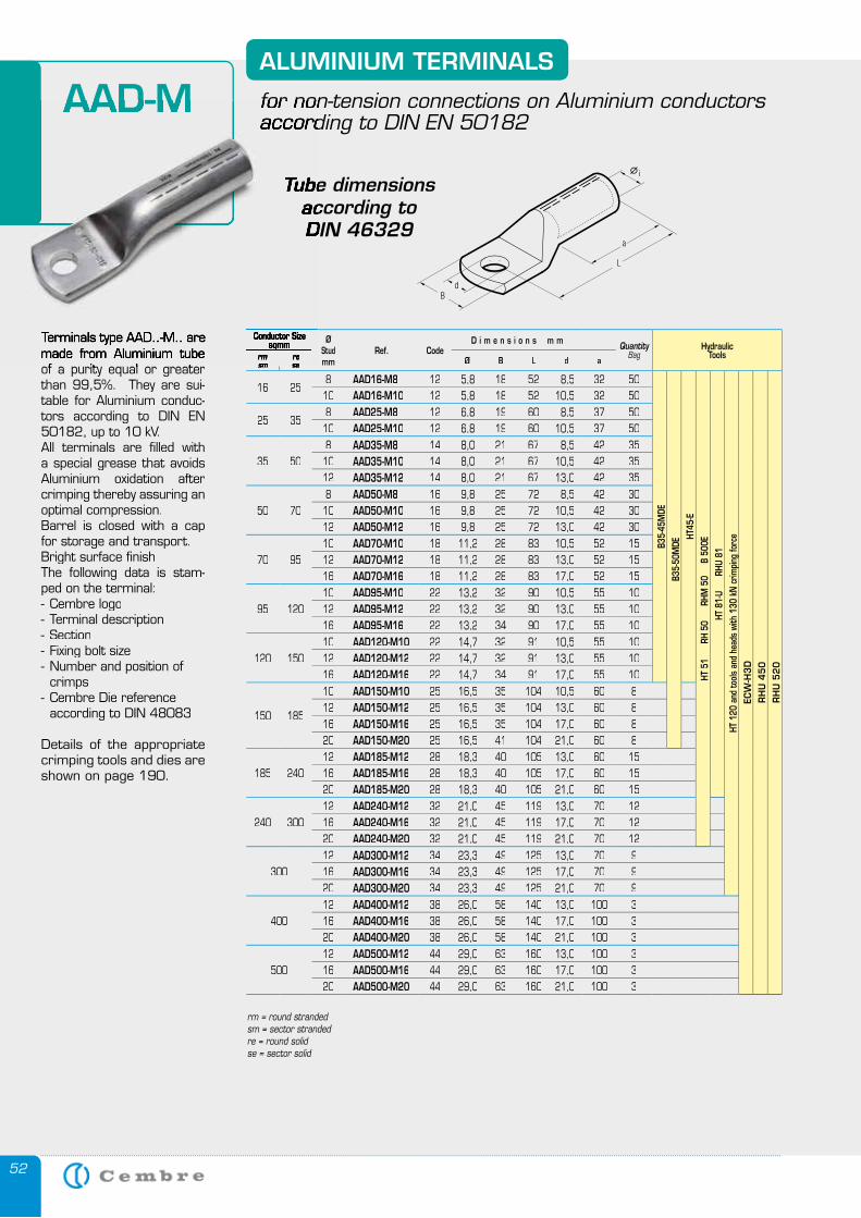
52
ALUMINIUM TERMINALS
for non-tension connections on Aluminium conductors according to DIN EN 50182
AAD-M
of a purity equal or greater than 99,5%. They are sui-table for Aluminium conduc-tors according to DIN EN 50182, up to 10 kV.All terminals are fi lled with a special grease that avoids Aluminium oxidation after crimping thereby assuring an optimal compression.Barrel is closed with a cap for storage and transport.Bright surface fi nishThe following data is stam-ped on the terminal:- Cembre logo- Terminal description- Section- Fixing bolt size - Number and position of crimps- Cembre Die reference according to DIN 48083
Details of the appropriate crimping tools and dies are shown on page 190.
Conductor Sizesqmm Ø
Studmm
Ref. CodeD i m e n s i o n s m m Quantity
BagHydraulic
Toolssm se Øi B L d a
16 258 AAD16-M8 12 5,8 18 52 8,5 32 50
B35-
45M
DEB3
5-50
MDE
HT45
-EHT
51
R
H 50
RHM
50
B
500
E
HT 8
1-U
R
HU 8
1
HT 1
20 a
nd to
ols
and
head
s wi
th 1
30 k
N c
rimpi
ng fo
rce
ECW
-H3
DR
HU
45
0R
HU
52
0
10 AAD16-M10 12 5,8 18 52 10,5 32 50
25 358 AAD25-M8 12 6,8 19 60 8,5 37 5010 AAD25-M10 12 6,8 19 60 10,5 37 50
35 508 AAD35-M8 14 8,0 21 67 8,5 42 3510 AAD35-M10 14 8,0 21 67 10,5 42 3512 AAD35-M12 14 8,0 21 67 13,0 42 35
50 708 AAD50-M8 16 9,8 25 72 8,5 42 3010 AAD50-M10 16 9,8 25 72 10,5 42 3012 AAD50-M12 16 9,8 25 72 13,0 42 30
70 9510 AAD70-M10 18 11,2 28 83 10,5 52 1512 AAD70-M12 18 11,2 28 83 13,0 52 1516 AAD70-M16 18 11,2 28 83 17,0 52 15
95 12010 AAD95-M10 22 13,2 32 90 10,5 55 1012 AAD95-M12 22 13,2 32 90 13,0 55 1016 AAD95-M16 22 13,2 34 90 17,0 55 10
120 15010 AAD120-M10 22 14,7 32 91 10,5 55 1012 AAD120-M12 22 14,7 32 91 13,0 55 1016 AAD120-M16 22 14,7 34 91 17,0 55 10
150 185
10 AAD150-M10 25 16,5 35 104 10,5 60 812 AAD150-M12 25 16,5 35 104 13,0 60 816 AAD150-M16 25 16,5 35 104 17,0 60 820 AAD150-M20 25 16,5 41 104 21,0 60 8
185 24012 AAD185-M12 28 18,3 40 105 13,0 60 1516 AAD185-M16 28 18,3 40 105 17,0 60 1520 AAD185-M20 28 18,3 40 105 21,0 60 15
240 30012 AAD240-M12 32 21,0 45 119 13,0 70 1216 AAD240-M16 32 21,0 45 119 17,0 70 1220 AAD240-M20 32 21,0 45 119 21,0 70 12
30012 AAD300-M12 34 23,3 49 125 13,0 70 916 AAD300-M16 34 23,3 49 125 17,0 70 920 AAD300-M20 34 23,3 49 125 21,0 70 9
40012 AAD400-M12 38 26,0 58 140 13,0 100 316 AAD400-M16 38 26,0 58 140 17,0 100 320 AAD400-M20 38 26,0 58 140 21,0 100 3
50012 AAD500-M12 44 29,0 63 160 13,0 100 316 AAD500-M16 44 29,0 63 160 17,0 100 320 AAD500-M20 44 29,0 63 160 21,0 100 3
Tube dimensions according to DIN 46329
for non-tension connections on Aluminium conductors according to DIN EN 50182
AAD-M
Terminals type AAD..-M.. are made from Aluminium tube of a purity equal or greater
Conductor Sizesqmmsqmmsqmm
rmsm
rese
Tube dimensions according to DIN 46329
rm = round stranded sm = sector stranded re = round solid se = sector solid
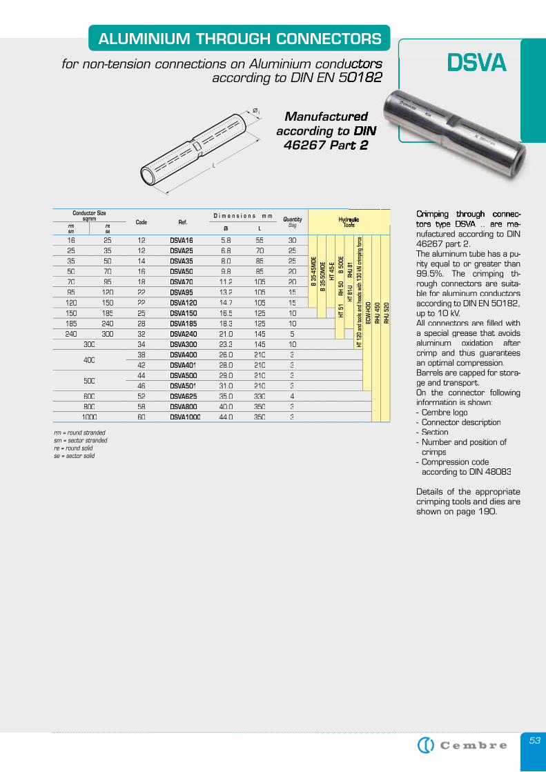
53
ALUMINIUM THROUGH CONNECTORS
for non-tension connections on Aluminium conductors according to DIN EN 50182
DSVA
tors type DSVA .. are ma-nufactured according to DIN 46267 part 2.The aluminum tube has a pu-rity equal to or greater than 99.5%. The crimping th-rough connectors are suita-ble for aluminum conductors according to DIN EN 50182, up to 10 kV.All connectors are fi lled with a special grease that avoids aluminum oxidation after crimp and thus guarantees an optimal compression.Barrels are capped for stora-ge and transport.On the connector following information is shown:- Cembre logo- Connector description- Section- Number and position of crimps- Compression code according to DIN 48083
Details of the appropriate crimping tools and dies are shown on page 190.
Manufactured according to DIN 46267 Part 2
Conductor Sizesqmm
Code Ref.D i m e n s i o n s m m Quantity
BagHydraulic
Toolsrmsm
rese Øi L
16 25 12 DSVA16 5.8 55 30
B 35
-45M
DEB
35-5
0MDE
HT 4
5-E
HT 5
1
RH
50
B 5
00E
HT
81-
U
RHU
81
HT 1
20 a
nd to
ols a
nd h
eads
with
130
kN cr
impin
g for
ceEC
W-H
3DRH
U 45
0RH
U 52
0
25 35 12 DSVA25 6.8 70 2535 50 14 DSVA35 8.0 85 2550 70 16 DSVA50 9.8 85 2070 95 18 DSVA70 11.2 105 2095 120 22 DSVA95 13.2 105 15120 150 22 DSVA120 14.7 105 15150 185 25 DSVA150 16.5 125 10185 240 28 DSVA185 18.3 125 10240 300 32 DSVA240 21.0 145 5
300 34 DSVA300 23.3 145 10
40038 DSVA400 26.0 210 342 DSVA401 28.0 210 3
50044 DSVA500 29.0 210 346 DSVA501 31.0 210 3
600 52 DSVA625 35.0 330 4800 58 DSVA800 40.0 350 31000 60 DSVA1000 44.0 350 3
for non-tension connections on Aluminium conductors according to DIN EN 50182
DSVA
Crimping through connec-tors type DSVA .. are ma-
Manufactured according to DIN 46267 Part 2
HydraulicTools
HydraulicTools
Hydraulic
rm = round stranded sm = sector stranded re = round solid se = sector solid
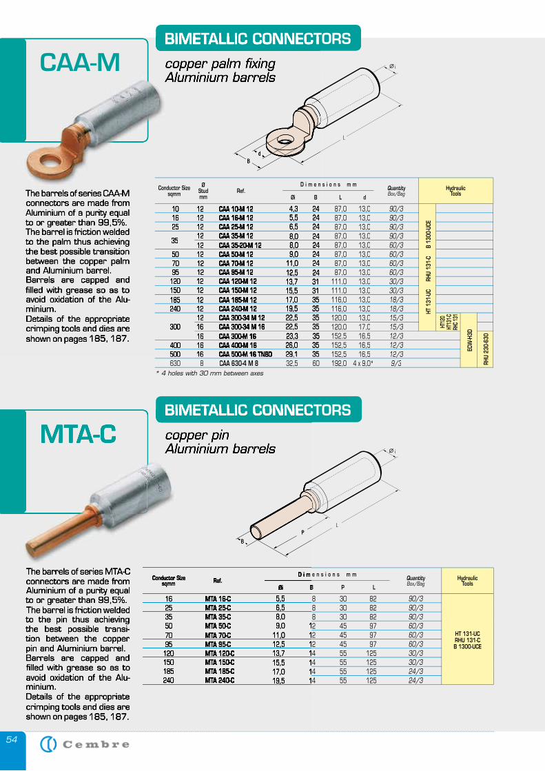
54
The barrels of series CAA-M connectors are made from Aluminium of a purity equal to or greater than 99,5%.The barrel is friction welded to the palm thus achieving the best possible transition between the copper palm and Aluminium barrel.Barrels are capped and filled with grease so as to avoid oxidation of the Alu-minium.Details of the appropriate crimping tools and dies are shown on pages 185, 187.
BIMETALLIC CONNECTORS
copper palm fixingAluminium barrels
The barrels of series MTA-C connectors are made from Aluminium of a purity equal to or greater than 99,5%.The barrel is friction welded to the pin thus achieving the best possible transi-tion between the copper pin and Aluminium barrel.Barrels are capped and filled with grease so as to avoid oxidation of the Alu-minium.Details of the appropriate crimping tools and dies are shown on pages 185, 187.
BIMETALLIC CONNECTORS
copper pinAluminium barrels
HydraulicTools
16 MTA 16-C 5,5 8 30 82 25 MTA 25-C 6,5 8 30 82 35 MTA 35-C 8,0 8 30 82 50 MTA 50-C 9,0 12 45 97 70 MTA 70-C 11,0 12 45 97 95 MTA 95-C 12,5 12 45 97 120 MTA 120-C 13,7 14 55 125 150 MTA 150-C 15,5 14 55 125 185 MTA 185-C 17,0 14 55 125 240 MTA 240-C 19,5 14 55 125
90/390/3 90/3 60/360/360/3 30/330/324/324/3
Conductor Sizesqmm
QuantityBox/Bag
LPBØi
D i m e n s i o n s m mRef.
HT 131-UCRHU 131-CB 1300-UCE
The barrels of series CAA-M connectors are made from Aluminium of a purity equal to or greater than 99,5%.The barrel is friction welded to the palm thus achieving the best possible transition between the copper palm and Aluminium barrel.Barrels are capped and filled with grease so as to avoid oxidation of the Alu-minium.Details of the appropriate crimping tools and dies are shown on pages 185, 187.
BIMETALLIC CONNECTORS
copper palm fixingAluminium barrels
CAA-M
MTA-CBIMETALLIC CONNECTORS
The barrels of series MTA-C connectors are made from Aluminium of a purity equal to or greater than 99,5%.The barrel is friction welded to the pin thus achieving the best possible transi-tion between the copper pin and Aluminium barrel.Barrels are capped and filled with grease so as to avoid oxidation of the Alu-minium.Details of the appropriate crimping tools and dies are shown on pages 185, 187.
16 MTA 16-C 5,5 8 30 82 25 MTA 25-C 6,5 8 30 82 35 MTA 35-C 8,0 8 30 82 50 MTA 50-C 9,0 12 45 97 70 MTA 70-C 11,0 12 45 97 95 MTA 95-C 12,5 12 45 97 120 MTA 120-C 13,7 14 55 125 150 MTA 150-C 15,5 14 55 125 185 MTA 185-C 17,0 14 55 125 240 MTA 240-C 19,5 14 55 125
sqmm BØi
copper pinAluminium barrels
Conductor Size D i m e n s i o n s m mRef.
MTA-C
HydraulicTools
10 12 CAA 10-M 12 4,3 24 87,0 13,04,3 24 87,0 13,0 16 12 CAA 16-M 12 5,5 24 87,0 13,0 5,5 24 87,0 13,0 25 12 CAA 25-M 12 6,5 24 87,0 13,0 6,5 24 87,0 13,0 12 CAA 35-M 12 8,0 24 87,0 13,0 8,0 24 87,0 13,0
35 12
35 12
12 CAA 35-20-M 12 8,0 24 87,0 13,0 8,0 24 87,0 13,0 50 12 CAA 50-M 12 9,0 24 87,0 13,0 9,0 24 87,0 13,0 70 12 CAA 70-M 12 11,0 24 87,0 13,0 11,0 24 87,0 13,0 95 12 CAA 95-M 12 12,5 24 87,0 13,0 12,5 24 87,0 13,0 120 12 CAA 120-M 12 13,7 31 111,0 13,0 13,7 31 111,0 13,0 150 12 CAA 150-M 12 15,5 31 111,0 13,0 15,5 31 111,0 13,0 185 12 CAA 185-M 12 17,0 35 116,0 13,0 17,0 35 116,0 13,0 240 12 CAA 240-M 12 19,5 35 116,0 13,0 19,5 35 116,0 13,0 12 CAA 300-34 M 12 22,5 35 120,0 13,0 22,5 35 120,0 13,0 300 16 CAA 300-34 M 16 22,5 35 120,0 17,0 22,5 35 120,0 17,0 16 CAA 300-M 16 23,3 35 152,5 16,5 23,3 35 152,5 16,5 400 16 CAA 400-M 16 26,0 35 152,5 16,5 26,0 35 152,5 16,5 500 16 500 16 CAA 500-M 16 TNBD CAA 500-M 16 TNBD 29,1 35 152,5 16,529,1 35 152,5 16,5 630 8 CAA 630-4 M 8 32,5 60 192,0 4 x 9,0*
90/390/390/390/360/360/360/360/330/330/318/318/315/315/312/312/312/39/3
Conductor Sizesqmm
ØStudmm
QuantityBox/Bag
dLBØi
D i m e n s i o n s m mRef.
RHU
230-
630
HT12
0HT
131-C
RHC 1
31
HT 1
31-U
C
RHU
131
-C
B 1
300-
UCE
ECW
-H3D
* 4 holes with 30 mm between axes
5555
TE
RM
IN
AL
B
LO
CK
S
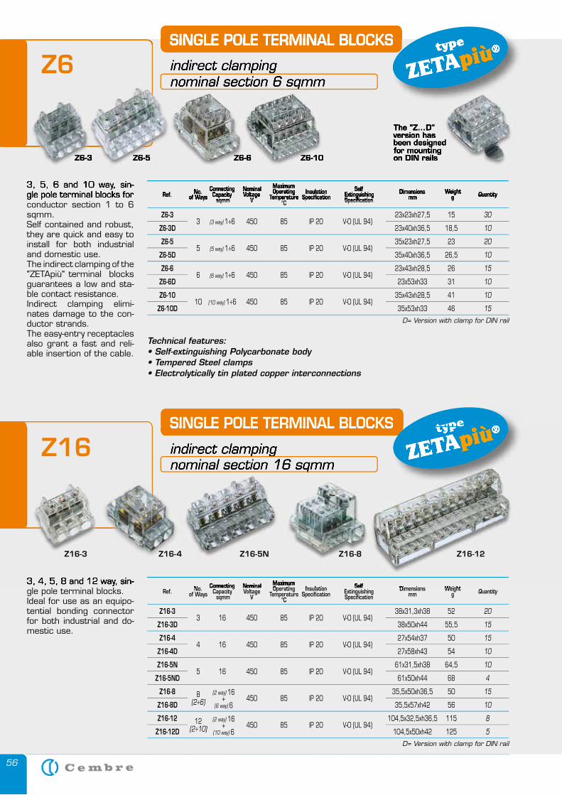
56
3, 4, 5, 8 and 12 way, sin-gle pole terminal blocks.Ideal for use as an equipo-tential bonding connector for both industrial and do-mestic use.
SINGLE POLE TERMINAL BLOCKS
indirect clampingnominal section 16 sqmm
3, 5, 6 and 10 way, sin-gle pole terminal blocks for conductor section 1 to 6 sqmm.Self contained and robust, they are quick and easy to install for both industrial and domestic use.The indirect clamping of the "ZETApiù" terminal blocks guarantees a low and sta-ble contact resistance. Indirect clamping elimi-nates damage to the con-ductor strands.The easy-entry receptacles also grant a fast and reli-able insertion of the cable.
SINGLE POLE TERMINAL BLOCKS
indirect clamping nominal section 6 sqmm
QuantityRef. No.of Ways
ConnectingCapacity sqmm
NominalVoltage
V
MaximumOperating
Temperature°C
InsulationSpecification
Self ExtinguishingSpecification
Dimensions mm
Weightg
QuantityRef. No.of Ways
ConnectingCapacity sqmm
NominalVoltage
V
MaximumOperating
Temperature°C
InsulationSpecification
Self ExtinguishingSpecification
Dimensions mm
Weightg
Z6-3 3 (3 way) 1÷6 450 85 IP 20 V-0 (UL 94)
23x23xh27,5 15
Z6-3D 23x40xh36,5 18,5
Z6-5 5 (5 way) 1÷6 450 85 IP 20 V-0 (UL 94)
35x23xh27,5 23
Z6-5D 35x40xh36,5 26,5
Z6-6 6 (6 way) 1÷6 450 85 IP 20 V-0 (UL 94)
23x43xh28,5 26
Z6-6D 23x53xh33 31
Z6-10 10 (10 way) 1÷6 450 85 IP 20 V-0 (UL 94)
35x43xh28,5 41
Z6-10D 35x53xh33 46
30
10
20
10
15
10
10
15
D= Version with clamp for DIN rail
Z16-3 3 16 450 85 IP 20 V-0 (UL 94)
38x31,3xh38 52
Z16-3D 38x50xh44 55,5
Z16-4 4 16 450 85 IP 20 V-0 (UL 94)
27x54xh37 50
Z16-4D 27x58xh43 54
Z16-5N 5 16 450 85 IP 20 V-0 (UL 94)
61x31,5xh38 64,5
Z16-5ND 61x50xh44 68
Z16-8 8 450 85 IP 20 V-0 (UL 94)
35,5x50xh36,5 50
Z16-8D (2÷6) 35,5x57xh42 56
Z16-12 12 450 85 IP 20 V-0 (UL 94) 104,5x32,5xh36,5 115
Z16-12D (2÷10) 104,5x50xh42 125
20
15
15
10
10
4
15
10
8
5
D= Version with clamp for DIN rail
Technical features:• Self-extinguishing Polycarbonate body• Tempered Steel clamps• Electrolytically tin plated copper interconnections
Z6-3 Z6-5 Z6-6 Z6-10
The “Z...D” version has been designed for mounting on DIN rails
(2 way) 16+
(6 way) 6
(2 way) 16+
(10 way) 6
SINGLE POLE TERMINAL BLOCKS type
ZETApiù®
SINGLE POLE TERMINAL BLOCKS type
ZETApiù®
3, 5, 6 and 10 way, sin-gle pole terminal blocks for
SINGLE POLE TERMINAL BLOCKS
indirect clamping nominal section 6 sqmm
QuantityRef. No.of Ways
ConnectingCapacity
ConnectingCapacity
Connecting
sqmm
NominalVoltage
VVoltage
VVoltage
MaximumOperating
TemperatureOperating
TemperatureOperating Insulation
SpecificationSelf
ExtinguishingSpecificationExtinguishingSpecificationExtinguishing Dimensions
mmWeight
g
Z6-3 Z6-5 Z6-6 Z6-10
The “Z...D” version has been designed for mounting on DIN rails
SINGLE POLE TERMINAL BLOCKS type
ZETApiù®
Z6
3, 4, 5, 8 and 12 way, sin-
SINGLE POLE TERMINAL BLOCKS
indirect clampingnominal section 16 sqmm
No. Connecting Nominal MaximumOperating Insulation Self Dimensions Weight
SINGLE POLE TERMINAL BLOCKS type
ZETApiù®
Z16-3 Z16-5NZ16-4 Z16-8 Z16-12
Z16
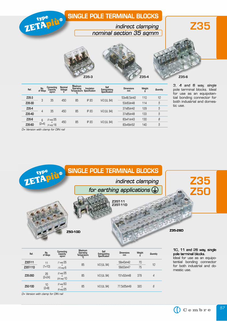
57
SINGLE POLE TERMINAL BLOCKS
indirect clampingnominal section 35 sqmm
3, 4 and 6 way, single pole terminal blocks. Ideal for use as an equipoten-tial bonding connector for both industrial and domes-tic use.
Z35-3 3 35 450 85 IP 20 V-0 (UL 94)
53x48,5xh42 110
Z35-3D 53x50xh48 114
Z35-4 4 35 450 85 IP 20 V-0 (UL 94)
37x85xh42 129
Z35-4D 37x85xh48 133
Z35-6 450 85 IP 20 V-0 (UL 94)
83x41xh43 130
Z35-6D 83x49xh52 140
10
5
5
5
8
5
D= Version with clamp for DIN rail
(2 way) 35+
(4 way) 166
(2+4)
SINGLE POLE TERMINAL BLOCKS
indirect clamping
for earthing applications �
10, 11 and 26 way, single pole terminal blocks.Ideal for use as an equipo-tential bonding connector for both industrial and do-mestic use.
QuantityRef. No.of Ways
ConnectingCapacity sqmm
NominalVoltage
V
MaximumOperating
Temperature°C
InsulationSpecification
Self ExtinguishingSpecification
Dimensions mm
Weightg
SINGLE POLE TERMINAL BLOCKStype
ZETApiù®
SINGLE POLE TERMINAL BLOCKStype
ZETApiù®
SINGLE POLE TERMINAL BLOCKS
indirect clampingnominal section 35 sqmm
3, 4 and 6 way, single Maximum
SINGLE POLE TERMINAL BLOCKStype
ZETApiù®
Z35-4Z35-3 Z35-6
Z35
Z35-26DZ50-10D
Z35Z50
SINGLE POLE TERMINAL BLOCKS
indirect clamping
for earthing applications �
10, 11 and 26 way, single pole terminal blocks.
SINGLE POLE TERMINAL BLOCKStype
ZETApiù®
Z35-26DZ50-10D
Z35Z50
Z35T-11Z35T-11D
QuantityRef. No.of Ways
ConnectingCapacity sqmm
MaximumOperating
Temperature°C
Self ExtinguishingSpecification
Dimensions mm
Weightg
85 V-0 (UL 94)
Z35-26D 85 V-0 (UL 94) 151x52xh48 379
Z50-10D 85 V-0 (UL 94) 77,5x55xh49 320
10
4
6
D= Version with clamp for DIN rail
(1 way) 35+
(10 way) 6
(2 way) 35+
(24 way) 10
(2 way) 50+
(8 way) 25
11(1+10)
26(2+24)
10(2+8)
Z35T-11
Z35T-11D
58x43xh42
58x53xh47
70
75
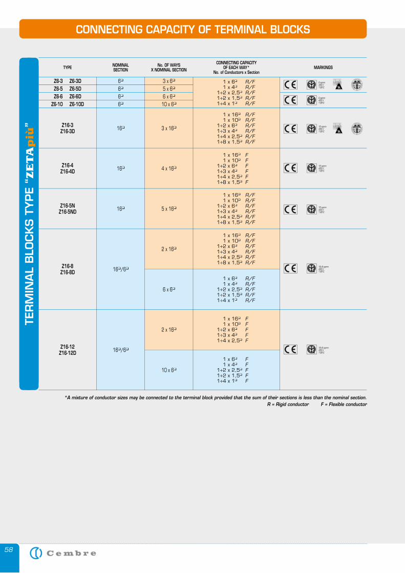
58
16�/6�
2 x 16�
1 x 6� F 1 x 4� F 1÷2 x 2,5� F 1÷2 x 1,5� F 1÷4 x 1� F
10 x 6�
1 x 16� F 1 x 10� F 1÷2 x 6� F 1÷3 x 4� F 1÷4 x 2,5� F
CONNECTING CAPACITY OF TERMINAL BLOCKS
TYPE NOMINALSECTION
No. OF WAYSX NOMINAL SECTION
CONNECTING CAPACITY OF EACH WAY*
No. of Conductors x SectionMARKINGS
Z6-3 Z6-3D 6� 3 x 6� 1 x 6� R/F 1 x 4� R/F 1÷2 x 2,5� R/F 1÷2 x 1,5� R/F 1÷4 x 1� R/F
1 x 16� R/F 1 x 10� R/F 1÷2 x 6� R/F 1÷3 x 4� R/F 1÷4 x 2,5� R/F 1÷8 x 1,5� R/F
Z6-5 Z6-5D 6� 5 x 6�
Z6-6 Z6-6D 6� 6 x 6�
Z6-10 Z6-10D 6� 10 x 6�
Z16-3Z16-3D 16� 3 x 16�
16� 5 x 16�
Z16-8Z16-8D 16�/6�
2 x 16�
*A mixture of conductor sizes may be connected to the terminal block provided that the sum of their sections is less than the nominal section.R = Rigid conductor F = Flexible conductor
6 sqmm450 VT 85°C
6 sqmm450 VT 85°C
16 sqmm450 VT 85°C
16 sqmm450 VT 85°C
Z16-5NZ16-5ND
16 sqmm450 VT 85°C
16� 4 x 16�Z16-4Z16-4D
1 x 6� R/F 1 x 4� R/F 1÷2 x 2,5� R/F 1÷2 x 1,5� R/F 1÷4 x 1� R/F
6 x 6�
16÷6 sqmm450 VT 85°C
Z16-12Z16-12D
16÷6 sqmm450 VT 85°C
TER
MIN
AL
BLO
CK
S T
YPE “
ZE
TA
più
”
1 x 16� F 1 x 10� F 1÷2 x 6� F 1÷3 x 4� F 1÷4 x 2,5� F 1÷8 x 1,5� F
1 x 16� R/F 1 x 10� R/F 1÷2 x 6� R/F 1÷3 x 4� R/F 1÷4 x 2,5� R/F 1÷8 x 1,5� R/F
1 x 16� R/F 1 x 10� R/F 1÷2 x 6� R/F 1÷3 x 4� R/F 1÷4 x 2,5� R/F 1÷8 x 1,5� R/F
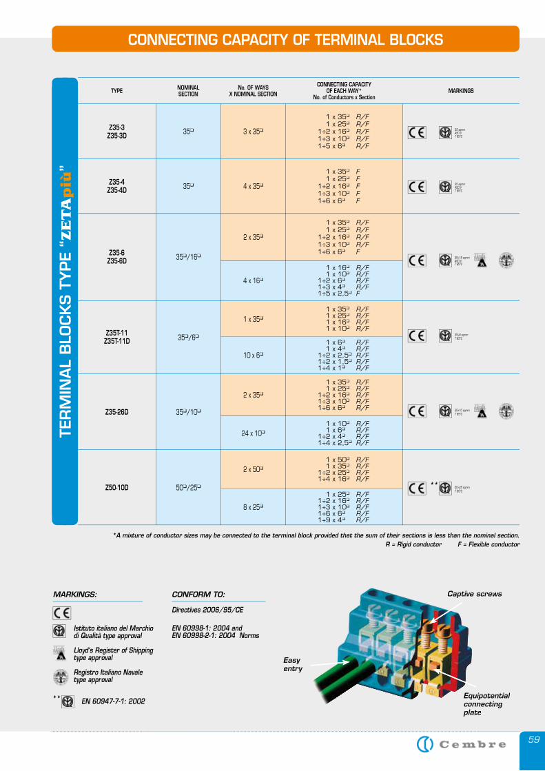
59
CONNECTING CAPACITY OF TERMINAL BLOCKS
TYPE NOMINALSECTION
No. OF WAYSX NOMINAL SECTION
CONNECTING CAPACITY OF EACH WAY*
No. of Conductors x SectionMARKINGS
1 x 35� R/F 1 x 25� R/F 1 x 16� R/F 1 x 10� R/F
1 x 6� R/F 1 x 4� R/F 1÷2 x 2,5� R/F 1÷2 x 1,5� R/F 1÷4 x 1� R/F
Z35T-11Z35T-11D 35�/6�
1 x 35�
10 x 6�
1 x 35� R/F 1 x 25� R/F 1÷2 x 16� R/F 1÷3 x 10� R/F 1÷6 x 6� F
1 x 16� R/F 1 x 10� R/F 1÷2 x 6� R/F 1÷3 x 4� R/F 1÷5 x 2,5� F
Z35-3Z35-3D
Z35-6Z35-6D
35�
35�/16�
3 x 35�
Z35-4Z35-4D 35� 4 x 35�
2 x 35�
4 x 16�
1 x 35� R/F 1 x 25� R/F 1÷2 x 16� R/F 1÷3 x 10� R/F 1÷6 x 6� R/F
1 x 10� R/F 1 x 6� R/F 1÷2 x 4� R/F 1÷4 x 2,5� R/F
Z35-26D 35�/10�
2 x 35�
24 x 10�
1 x 50� R/F 1 x 35� R/F 1÷2 x 25� R/F 1÷4 x 16� R/F
1 x 25� R/F 1÷2 x 16� R/F 1÷3 x 10� R/F 1÷6 x 6� R/F 1÷9 x 4� R/F
Z50-10D 50�/25�
2 x 50�
8 x 25�
*A mixture of conductor sizes may be connected to the terminal block provided that the sum of their sections is less than the nominal section.R = Rigid conductor F = Flexible conductor
35 sqmm450 VT 85°C
35 sqmm450 VT 85°C
35÷16 sqmm450 VT 85°C
35÷6 sqmmT 85°C
35÷10 sqmmT 85°C
50÷25 sqmmT 85°C
TER
MIN
AL
BLO
CK
S T
YPE “
ZE
TA
più
” 1 x 35� F 1 x 25� F 1÷2 x 16� F 1÷3 x 10� F 1÷6 x 6� F
1 x 35� R/F 1 x 25� R/F 1÷2 x 16� R/F 1÷3 x 10� R/F 1÷5 x 6� R/F
**
Easy entry
Captive screws
Equipotential connecting plate
MARKINGS: CONFORM TO:
Istituto italiano del Marchio di Qualità type approval
Lloyd‘s Register of Shippingtype approval
Registro Italiano Navale type approval
Directives 2006/95/CE
EN 60998-1: 2004 and EN 60998-2-1: 2004 Norms
EN 60947-7-1: 2002 **
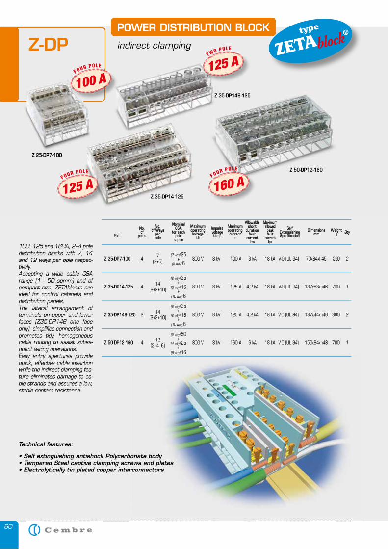
60
Z-DP
QtyRef.
No.of Ways
perpole
Nominal CSA
for each pole
sqmm
Allowable short
duration fault
current Icw
Maximum allowed peak fault
current Ipk
Maximumoperatingvoltage
Ui
ImpulsevoltageUimp
Maximumoperatingcurrent
In
Self ExtinguishingSpecification
Dimensionsmm
Weightg
Z 25-DP7-100 800 V 8 kV 100 A V-0 (UL 94) 70x84xh45 290 27(2+5)
Z 35-DP14-125 800 V 8 kV 125 A V-0 (UL 94) 137x83xh46 700 114(2+2+10)
Z 35-DP14B-125 800 V 8 kV 125 A V-0 (UL 94) 137x44xh46 360 214(2+2+10)
Z 50-DP12-160 800 V 8 kV 160 A V-0 (UL 94) 150x84xh48 780 112(2+4+6)
No.of
poles
4
4
2
4
3 kA
4,2 kA
4,2 kA
6 kA
18 kA
18 kA
18 kA
18 kA
(2 way) 25+
(5 way) 6
(2 way) 35+
(2 way) 16+
(10 way) 6
(2 way) 35+
(2 way) 16+
(10 way) 6
(2 way) 50+
(4 way) 25+
(6 way) 16
100, 125 and 160A, 2–4 pole distribution blocks with 7, 14 and 12 ways per pole respec-tively.Accepting a wide cable CSA range (1 - 50 sqmm) and of compact size, ZETAblocks are ideal for control cabinets and distribution panels.The lateral arrangement of terminals on upper and lower faces (Z35-DP14B one face only), simplifies connection and promotes tidy, homogeneous cable routing to assist subse-quent wiring operations.Easy entry apertures provide quick, effective cable insertion while the indirect clamping fea-ture eliminates damage to ca-ble strands and assures a low, stable contact resistance.
POWER DISTRIBUTION BLOCK
indirect clamping
Z 50-DP12-160
Z 35-DP14-125
Z 35-DP14B-125
Z 25-DP7-100
POWER DISTRIBUTION BLOCK type
ZETAblock®
Technical features:
• Self extinguishing antishock Polycarbonate body• Tempered Steel captive clamping screws and plates• Electrolytically tin plated copper interconnectors
100 A FOUR POLE
160 A FOUR POLE
125 A FOUR POLE
125 A T
WO POLE
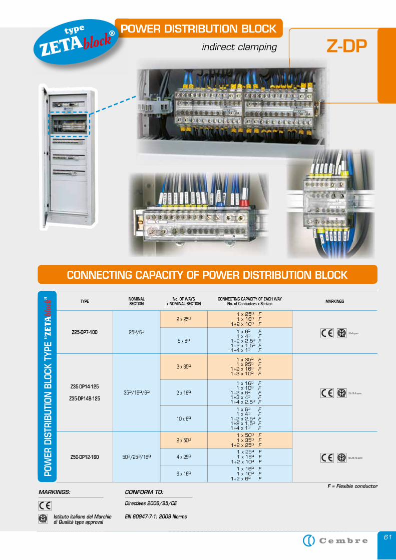
61
POWER DISTRIBUTION BLOCK
indirect clamping
POWER DISTRIBUTION BLOCKtype
ZETAblock®
Z-DP
1 x 50� F 1 x 35� F 1÷2 x 25� F 1 x 25� F 1 x 16� F 1÷2 x 10� F
Z50-DP12-160 50�/25�/16�
2 x 50�
1 x 16� F 1 x 10� F 1÷2 x 6� F
6 x 16�
4 x 25�
1 x 25� F 1 x 16� F 1÷2 x 10� F
2 x 25�
TYPE NOMINALSECTION
No. OF WAYSx NOMINAL SECTION
CONNECTING CAPACITY OF EACH WAYNo. of Conductors x Section MARKINGS
50÷25÷16 sqmm
35÷16÷6 sqmm
F = Flexible conductor
Z35-DP14-125
Z35-DP14B-12535�/16�/6�
Z25-DP7-100 25�/6� 25÷6 sqmm
1 x 35� F 1 x 25� F 1÷2 x 16� F 1÷3 x 10� F
2 x 35�
1 x 16� F 1 x 10� F 1÷2 x 6� F 1÷3 x 4� F 1÷4 x 2,5� F
2 x 16�
1 x 6� F 1 x 4� F 1÷2 x 2,5� F 1÷2 x 1,5� F 1÷4 x 1� F
10 x 6�
1 x 6� F 1 x 4� F 1÷2 x 2,5� F 1÷2 x 1,5� F 1÷4 x 1� F
5 x 6�
POW
ER D
ISTR
IBUT
ION
BLO
CK T
YPE
“ZET
Abl
ock ”
CONNECTING CAPACITY OF POWER DISTRIBUTION BLOCK
MARKINGS: CONFORM TO:
Istituto italiano del Marchio di Qualità type approval
Directives 2006/95/CE
EN 60947-7-1: 2009 Norms
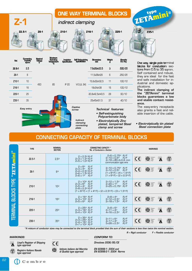
62
ONE WAY TERMINAL BLOCKS
indirect clamping
One way, single pole terminal blocks for conductors sec-tions from 0.5 to 35 sqmm.Self contained and robust, they are ideal for the fast and safe installation for in-dustrial and domestic ap-plications.The indirect clamping of the "ZETAmini" terminal blocks guarantees a low and stable contact resist-ance. The easy-entry receptacle also grants a fast and reli-able insertion of the cable.
QuantityBox/BagRef.
ConnectingCapacity sqmm
NominalVoltage
V
MaximumOperating
Temperature°C
InsulationSpecification
Self ExtinguishingSpecification
Dimensions mm
Weightg
2,5
85450 IP 20 V-0 (UL 94)
7,6x20xh23,5 3 500/25
250/25
100/10
100/10
50/10
40/10
Z2.5-1
6 11,5x28xh29 6Z6-1
10 15,6x32xh32,5 11Z10-1
16 18x34xh38 15Z16-1
25 20,8x42,5xh43,5 29Z25-1
35 25x45xh51,5 37Z35-1
Technical features:• Self-extinguishing Polycarbonate body• Electrolytically Zinc plated, tempered Steel clamp and screw
• Electrolytically tin plated Steel connection plate
CONNECTING CAPACITY OF TERMINAL BLOCKS
type
ZETAmini®
Easy entryCaptive screw
Indirect clamping connecting plate
Z-1Z2.5-1 Z6-1 Z10-1 Z16-1 Z25-1 Z35-1
ONE WAY TERMINAL BLOCKS
indirect clamping
One way, single pole terminal blocks for conductors sec-tions from 0.5 to 35 sqmm.
QuantityBox/BagQuantityBox/BagQuantityRef.
ConnectingCapacity
ConnectingCapacity
Connecting
sqmm
NominalVoltage
VVoltage
VVoltage
MaximumOperating
TemperatureOperating
TemperatureOperating
°CTemperature
°CTemperature
InsulationSpecification
Self ExtinguishingSpecification
Self ExtinguishingSpecification
Self Extinguishing Dimensions mm
Weightg
2,5 7,6x20xh23,5 3 500/25Z2.5-1
type
ZETAminiZ-1
Z2.5-1 Z6-1 Z10-1 Z16-1 Z25-1 Z35-1Z35-1
TYPE NOMINALSECTION
CONNECTING CAPACITY *No. of Conductors x Section MARKINGS
2,5�Z2.5-1 2 x 2,5� R/F 2÷3 x 1,5� R/F 2÷5 x 1,0� R/F
2÷6 x 0,75� R/F 2÷10 x 0,5� R/F 2÷18 x Ø0,4÷0,6 mm
communication type wire
6�Z6-1
2 x 6� R/F 2÷3 x 4� R/F 2÷4 x 2,5� R/F 2÷6 x 1,5� R/F 2÷6 x 1� R/F
2÷10 x 0,75� R/F 2÷12 x 0,5� R/F
10�Z10-1
2 x 10� R/F 2÷3 x 6� R/F 2÷5 x 4� R/F 2÷8 x 2,5� R/F
2÷12 x 1,5� R/F 2÷20 x 1� R/F 2÷25 x 0,75� R/F
16�Z16-1 2 x 16� R/F 2÷3 x 10� R/F 2÷5 x 6� R/F
2÷8 x 4� R/F 2÷12 x 2,5� R/F 2÷18 x 1,5� R/F
25�Z25-1 2 x 25� R/F 2÷3 x 16� R/F 2÷4 x 10� R/F
2÷8 x 6� R/F 2÷11 x 4� R/F 4÷16 x 2,5� R/F
35�Z35-1 2 x 35� R/F 2÷3 x 25� R/F 2÷4 x 16� R/F 2÷7 x 10� R/F
2÷11 x 6� R/F 4÷17 x 4� R/F 5÷28 x 2,5� R/F
*A mixture of conductor sizes may be connected to the terminal block provided that the sum of their sections is less than twice the nominal section.
R = Rigid conductor F = Flexible conductor
2,5 sqmm450 VT 85°CIP 20
6 sqmm450 VT 85°CIP 20
10 sqmm450 VT 85°CIP 20
16 sqmm450 VT 85°CIP 20
25 sqmm450 VT 85°CIP 20
35 sqmm450 VT 85°CIP 20
TERM
INAL
BLO
CKS
TYPE
“ZE
TA
min
i”
(1 x 6� F) + (4 x 1,5� F)
(1 x 6� F) + (1 x 4� F) + (2 x 2,5� F) + (3 x 1,5� F)
(1 x 6� F) + (2 x 2,5� F)
CONFORM TO:
Istituto italiano del Marchio di Qualità type approval
Directives 2006/95/CE
EN 60998-1: 2004 and EN 60998-2-1: 2004 Norms
MARKINGS:
Lloyd‘s Register of Shippingtype approval
Registro Italiano Navale type approval
6363
CA
BLE
GLA
ND
S A
ND
AC
CE
SS
OR
IES
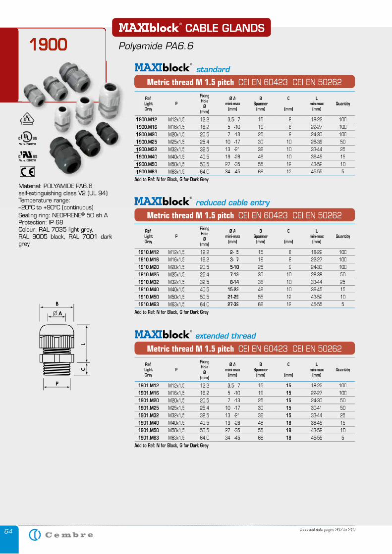
64
Metric thread M 1.5 pitch CEI EN 60423 CEI EN 50262
reduced cable entry
Metric thread M 1.5 pitch CEI EN 60423 CEI EN 50262
extended thread
Technical data pages 207 to 210
1900
Metric thread M 1.5 pitch CEI EN 60423 CEI EN 50262
1900 CABLE GLANDS
Polyamide PA6.6
standard
Material: POLYAMIDE PA6.6 self-extinguishing class V2 (UL 94)Temperature range: –20°C to +90°C (continuous)Sealing ring: NEOPRENE® 50 sh AProtection: IP 68Colour: RAL 7035 light grey,RAL 9005 black, RAL 7001 dark grey
File no. E220310File no. E220310
File no. E220310File no. E220310
Ref.LightGrey
P
Fixing Hole
Ø(mm)
Ø A mini-max
(mm)
BSpanner
(mm)
C
(mm)
Lmin-max
(mm)Quantity
1900.M121900.M12 M12x1,5 12,2 3,5- 7 15 8 18-22 1001900.M161900.M16 M16x1,5 16,2 5 -10 19 8 22-27 1001900.M201900.M20 M20x1,5 20,5 7 -13 25 9 24-30 1001900.M251900.M25 M25x1,5 25,4 10 -17 30 10 28-39 501900.M321900.M32 M32x1,5 32,5 13 -21 36 10 33-44 251900.M401900.M40 M40x1,5 40,5 19 -28 46 10 36-45 151900.M501900.M50 M50x1,5 50,5 27 -35 55 12 43-52 101900.M631900.M63 M63x1,5 64,0 34 -45 66 12 45-55 5
Add to Ref: N for Black, G for Dark Grey
Ref.LightGrey
P
Fixing Hole
Ø(mm)
Ø A mini-max
(mm)
BSpanner
(mm)
C
(mm)
Lmin-max
(mm)Quantity
1910.M12 M12x1,5 12,2 2- 5 15 8 18-22 1001910.M16 M16x1,5 16,2 3- 7 19 8 22-27 1001910.M20 M20x1,5 20,5 5-10 25 9 24-30 1001910.M25 M25x1,5 25,4 7-13 30 10 28-39 501910.M32 M32x1,5 32,5 8-14 36 10 33-44 251910.M40 M40x1,5 40,5 15-23 46 10 36-45 151910.M50 M50x1,5 50,5 21-29 55 12 43-52 101910.M63 M63x1,5 64,0 27-39 66 12 45-55 5
Add to Ref: N for Black, G for Dark Grey
Ref.LightGrey
P
Fixing Hole
Ø(mm)
Ø A mini-max
(mm)
BSpanner
(mm)
C
(mm)
Lmin-max
(mm)Quantity
1901.M12 M12x1,5 12,2 3,5- 7 15 15 18-22 1001901.M16 M16x1,5 16,2 5 -10 19 15 22-27 1001901.M20 M20x1,5 20,5 7 -13 25 15 24-30 501901.M25 M25x1,5 25,4 10 -17 30 15 30-41 501901.M32 M32x1,5 32,5 13 -21 36 15 33-44 251901.M40 M40x1,5 40,5 19 -28 46 18 36-45 151901.M50 M50x1,5 50,5 27 -35 55 18 43-52 101901.M63 M63x1,5 64,0 34 -45 66 18 45-55 5
Add to Ref: N for Black, G for Dark Grey
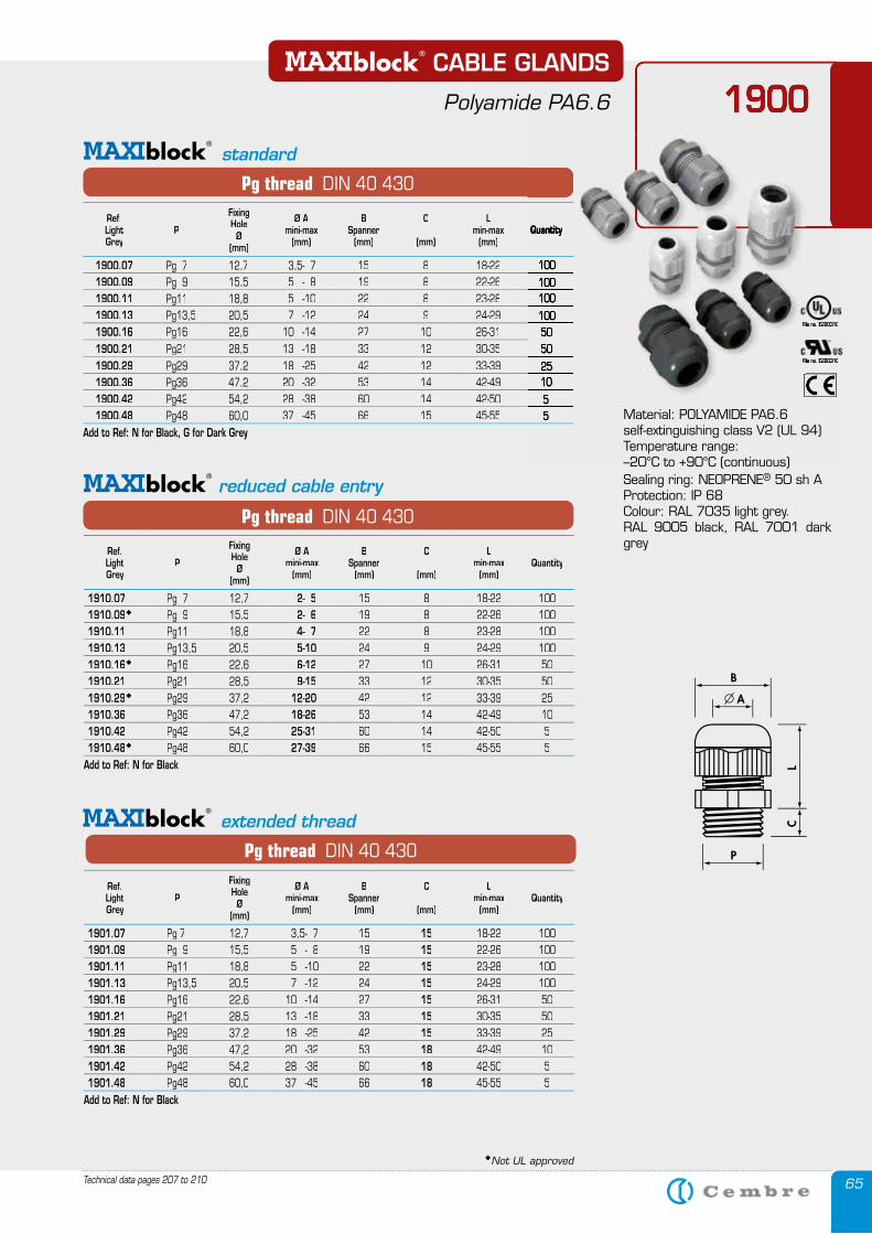
65
Pg thread DIN 40 430
extended thread
Technical data pages 207 to 210
1900
Pg thread DIN 40 430
Pg thread DIN 40 430
reduced cable entry
1900 CABLE GLANDS
Polyamide PA6.6
Material: POLYAMIDE PA6.6 self-extinguishing class V2 (UL 94)Temperature range: –20°C to +90°C (continuous)Sealing ring: NEOPRENE® 50 sh AProtection: IP 68Colour: RAL 7035 light grey.RAL 9005 black, RAL 7001 dark grey
standard
File no. E220310File no. E220310File no. E220310
File no. E220310File no. E220310File no. E220310
Ref.LightGrey
P
Fixing Hole
Ø(mm)
Ø A mini-max
(mm)
BSpanner
(mm)
C
(mm)
Lmin-max
(mm)Quantity
1910.07 Pg 7 12,7 2- 5 15 8 18-22 1001910.09 Pg 9 15,5 2- 6 19 8 22-26 1001910.11 Pg11 18,8 4- 7 22 8 23-28 1001910.13 Pg13,5 20,5 5-10 24 9 24-29 1001910.16 Pg16 22,6 6-12 27 10 26-31 501910.21 Pg21 28,5 9-15 33 12 30-35 501910.29 Pg29 37,2 12-20 42 12 33-39 251910.36 Pg36 47,2 18-26 53 14 42-49 101910.42 Pg42 54,2 25-31 60 14 42-50 51910.48 Pg48 60,0 27-39 66 15 45-55 5
Add to Ref: N for Black
Ref.LightGrey
P
Fixing Hole
Ø(mm)
Ø A mini-max
(mm)
BSpanner
(mm)
C
(mm)
Lmin-max
(mm)Quantity
1900.07 Pg 7 12,7 3,5- 7 15 8 18-22 1001900.09 Pg 9 15,5 5 - 8 19 8 22-26 1001900.11 Pg11 18,8 5 -10 22 8 23-28 1001900.13 Pg13,5 20,5 7 -12 24 9 24-29 1001900.16 Pg16 22,6 10 -14 27 10 26-31 501900.21 Pg21 28,5 13 -18 33 12 30-35 501900.29 Pg29 37,2 18 -25 42 12 33-39 251900.36 Pg36 47,2 20 -32 53 14 42-49 101900.42 Pg42 54,2 28 -38 60 14 42-50 51900.48 Pg48 60,0 37 -45 66 15 45-55 5
Add to Ref: N for Black, G for Dark Grey
Ref.LightGrey
P
Fixing Hole
Ø(mm)
Ø A mini-max
(mm)
BSpanner
(mm)
C
(mm)
Lmin-max
(mm)Quantity
1901.07 Pg 7 12,7 3,5- 7 15 15 18-22 1001901.09 Pg 9 15,5 5 - 8 19 15 22-26 1001901.11 Pg11 18,8 5 -10 22 15 23-28 1001901.13 Pg13,5 20,5 7 -12 24 15 24-29 1001901.16 Pg16 22,6 10 -14 27 15 26-31 501901.21 Pg21 28,5 13 -18 33 15 30-35 501901.29 Pg29 37,2 18 -25 42 15 33-39 251901.36 Pg36 47,2 20 -32 53 18 42-49 101901.42 Pg42 54,2 28 -38 60 18 42-50 51901.48 Pg48 60,0 37 -45 66 18 45-55 5
Add to Ref: N for Black
Not UL approved
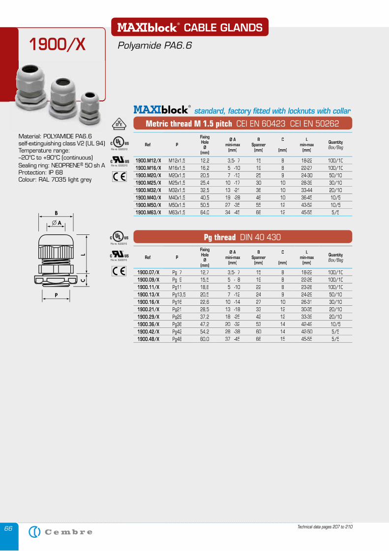
66 Technical data pages 207 to 210
CABLE GLANDS
Polyamide PA6.6
Metric thread M 1.5 pitch CEI EN 60423 CEI EN 50262
standard, factory fitted with locknuts with collar
Pg thread DIN 40 430
1900/X
Material: POLYAMIDE PA6.6 self-extinguishing class V2 (UL 94)Temperature range: –20°C to +90°C (continuous)Sealing ring: NEOPRENE® 50 sh AProtection: IP 68Colour: RAL 7035 light grey
File no. E220310
File no. E220310
File no. E220310
File no. E220310
Ref. P
Fixing Hole
Ø(mm)
Ø A mini-max
(mm)
BSpanner
(mm)
C
(mm)
Lmin-max
(mm)
QuantityBox/Bag
1900.M12/X M12x1,5 12,2 3,5- 7 15 8 18-22 100/101900.M16/X M16x1,5 16,2 5 -10 19 8 22-27 100/101900.M20/X M20x1,5 20,5 7 -13 25 9 24-30 50/101900.M25/X M25x1,5 25,4 10 -17 30 10 28-39 30/101900.M32/X M32x1,5 32,5 13 -21 36 10 33-44 20/101900.M40/X M40x1,5 40,5 19 -28 46 10 36-45 10/51900.M50/X M50x1,5 50,5 27 -35 55 12 43-52 10/51900.M63/X M63x1,5 64,0 34 -45 66 12 45-55 5/5
Ref. P
Fixing Hole
Ø(mm)
Ø A mini-max
(mm)
BSpanner
(mm)
C
(mm)
Lmin-max
(mm)
QuantityBox/Bag
1900.07/X Pg 7 12,7 3,5- 7 15 8 18-22 100/101900.09/X Pg 9 15,5 5 - 8 19 8 22-26 100/101900.11/X Pg11 18,8 5 -10 22 8 23-28 100/101900.13/X Pg13,5 20,5 7 -12 24 9 24-29 50/101900.16/X Pg16 22,6 10 -14 27 10 26-31 30/101900.21/X Pg21 28,5 13 -18 33 12 30-35 20/101900.29/X Pg29 37,2 18 -25 42 12 33-39 20/101900.36/X Pg36 47,2 20 -32 53 14 42-49 10/51900.42/X Pg42 54,2 28 -38 60 14 42-50 5/51900.48/X Pg48 60,0 37 -45 66 15 45-55 5/5
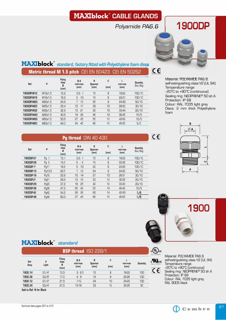
67Technical data pages 207 to 210
Material: POLYAMIDE PA6.6 self-extinguishing class V2 (UL 94)Temperature range:–20°C to +90°C (continuous)Sealing ring: NEOPRENE® 50 sh AProtection: IP 68Colour: RAL 7035 light grey, RAL 9005 black
File no. E220310
File no. E220310
BSP thread ISO 228/1
standard
Ref. Grey
P Light
Fixing Hole
Ø(mm)
Ø A mini-max
(mm)
BSpanner
(mm)
C
(mm)
Lmin-max
(mm)Quantity
1900.14 G1/4’’ 13,5 3- 6,5 15 8 18-22 1001900.38 G3/8’’ 17,0 4- 8 19 8 22-26 1001900.12 G1/2’’ 21,5 7-12 24 10 24-29 1001900.34 G3/4’’ 27,0 13-18 33 12 30-35 50
Add to Ref: N for Black
1900DP CABLE GLANDS
Polyamide PA6.6
Metric thread M 1.5 pitch CEI EN 60423 CEI EN 50262
standard, factory fitted with Polyethylene foam discs
Pg thread DIN 40 430
Ref. P
Fixing Hole
Ø(mm)
Ø A mini-max
(mm)
BSpanner
(mm)
C
(mm)
Lmin-max
(mm)
QuantityBox/Bag
1900DP.M12 M12x1,5 12,2 3,5- 7 15 8 18-22 100/101900DP.M16 M16x1,5 16,2 5 -10 19 8 22-27 100/101900DP.M20 M20x1,5 20,5 7 -13 25 9 24-30 50/101900DP.M25 M25x1,5 25,4 10 -17 30 10 28-39 30/101900DP.M32 M32x1,5 32,5 13 -21 36 10 33-44 20/101900DP.M40 M40x1,5 40,5 19 -28 46 10 36-45 10/51900DP.M50 M50x1,5 50,5 27 -35 55 12 43-52 10/51900DP.M63 M63x1,5 64,0 34 -45 66 12 45-55 5/5
Ref. P
Fixing Hole
Ø(mm)
Ø A mini-max
(mm)
BSpanner
(mm)
C
(mm)
Lmin-max
(mm)
QuantityBox/Bag
1900DP.07 Pg 7 12,7 3,5- 7 15 8 18-22 100/101900DP.09 Pg 9 15,5 5 - 8 19 8 22-26 100/101900DP.11 Pg11 18,8 5 -10 22 8 23-28 100/101900DP.13 Pg13,5 20,5 7 -12 24 9 24-29 50/101900DP.16 Pg16 22,6 10 -14 27 10 26-31 30/101900DP.21 Pg21 28,5 13 -18 33 12 30-35 20/101900DP.29 Pg29 37,2 18 -25 42 12 33-39 20/101900DP.36 Pg36 47,2 20 -32 53 14 42-49 10/51900DP.42 Pg42 54,2 28 -38 60 14 42-50 5/51900DP.48 Pg48 60,0 37 -45 66 15 45-55 5/5
Material: POLYAMIDE PA6.6 self-extinguishing class V2 (UL 94)Temperature range: –20°C to +90°C (continuous)Sealing ring: NEOPRENE® 50 sh AProtection: IP 68Colour: RAL 7035 light greyDiscs: 2 mm thick Polyethylene foam
1900
5/55/5
19001900
1900DP Polyamide PA6.6
standard, factory fitted with Polyethylene foam discs
Material: POLYAMIDE PA6.6
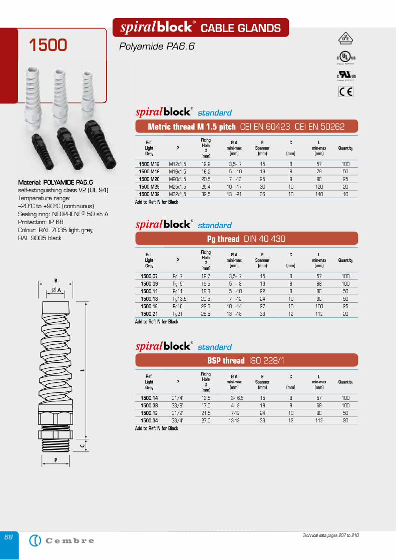
68
1500 CABLE GLANDS
Polyamide PA6.6
Material: POLYAMIDE PA6.6 self-extinguishing class V2 (UL 94)Temperature range:–20°C to +90°C (continuous)Sealing ring: NEOPRENE® 50 sh AProtection: IP 68Colour: RAL 7035 light grey, RAL 9005 black
Material: POLYAMIDE PA6.6
File no. E220310
File no. E220310
Pg thread DIN 40 430
BSP thread ISO 228/1
Metric thread M 1.5 pitch CEI EN 60423 CEI EN 50262
standard
standard
standard
Ref.LightGrey
P
Fixing Hole
Ø(mm)
Ø A mini-max
(mm)
BSpanner
(mm)
C
(mm)
Lmin-max
(mm)Quantity
1500.M12 M12x1,5 12,2 3,5- 7 15 8 57 1001500.M16 M16x1,5 16,2 5 -10 19 8 79 501500.M20 M20x1,5 20,5 7 -13 25 9 90 251500.M25 M25x1,5 25,4 10 -17 30 10 120 201500.M32 M32x1,5 32,5 13 -21 36 10 140 10
Add to Ref: N for Black
Ref.LightGrey
P
Fixing Hole
Ø(mm)
Ø A mini-max
(mm)
BSpanner
(mm)
C
(mm)
Lmin-max
(mm)Quantity
1500.07 Pg 7 12,7 3,5- 7 15 8 57 1001500.09 Pg 9 15,5 5 - 8 19 8 68 1001500.11 Pg11 18,8 5 -10 22 8 80 501500.13 Pg13,5 20,5 7 -12 24 10 90 501500.16 Pg16 22,6 10 -14 27 10 100 251500.21 Pg21 28,5 13 -18 33 12 112 20
Add to Ref: N for Black
Ref.LightGrey
P
Fixing Hole
Ø(mm)
Ø A mini-max
(mm)
BSpanner
(mm)
C
(mm)
Lmin-max
(mm)Quantity
1500.14 G1/4’’ 13,5 3- 6,5 15 8 57 1001500.38 G3/8’’ 17,0 4- 8 19 9 68 1001500.12 G1/2’’ 21,5 7-12 24 10 90 501500.34 G3/4’’ 27,0 13-18 33 12 112 20
Add to Ref: N for Black
Technical data pages 207 to 210
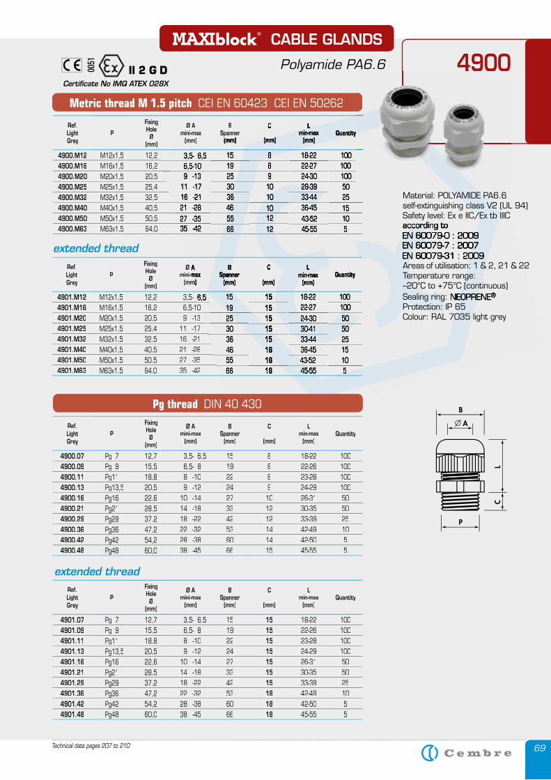
69
Material: POLYAMIDE PA6.6 self-extinguishing class V2 (UL 94)Safety level: Ex e IIC/Ex tb IIICaccording toEN 60079-0 : 2009EN 60079-7 : 2007EN 60079-31 : 2009Areas of utilisation: 1 & 2, 21 & 22Temperature range: –20°C to +75°C (continuous)Sealing ring: NEOPRENE®
Protection: IP 65Colour: RAL 7035 light grey
II 2 G D0051
Certificate No IMQ ATEX 028X
Metric thread M 1.5 pitch CEI EN 60423 CEI EN 50262
Pg thread DIN 40 430
extended thread
extended thread
Ref.LightGrey
P
Fixing Hole
Ø(mm)
Ø A mini-max
(mm)
BSpannerSpanner
(mm)(mm)
CC
(mm)
Lmin-max
(mm)Quantity
4900.M12 M12x1,5 12,2 3,5- 6,5 15 8 18-22 1004900.M16 M16x1,5 16,2 6,5-10 19 8 22-27 1004900.M20 M20x1,5 20,5 9 -13 25 9 24-30 1004900.M25 M25x1,5 25,4 11 -17 30 10 28-39 504900.M32 M32x1,5 32,5 16 -21 36 10 33-44 254900.M40 M40x1,5 40,5 21 -28 46 10 36-45 154900.M50 M50x1,5 50,5 27 -35 55 12 43-52 104900.M63 M63x1,5 64,0 35 -42 66 12 45-55 5
Ref.LightGrey
P
Fixing Hole
Ø(mm)
Ø A Ø A mini-maxmini-max
(mm)(mm)
BSpanner
(mm)
C
(mm)
Lmin-max
(mm)Quantity
4901.M12 M12x1,5 12,2 3,5- 6,5 3,5- 6,5 15 15 18-22 1004901.M16 M16x1,5 16,2 6,5-10 6,5-10 19 15 22-27 1004901.M20 M20x1,5 20,5 9 -13 25 15 24-30 504901.M25 M25x1,5 25,4 11 -17 30 15 30-41 504901.M32 M32x1,5 32,5 16 -21 36 15 33-44 254901.M40 M40x1,5 40,5 21 -28 46 18 36-45 154901.M50 M50x1,5 50,5 27 -35 55 18 43-52 104901.M63 M63x1,5 64,0 35 -42 66 18 45-55 5
Ref.LightGrey
P
Fixing Hole
Ø(mm)
Ø A mini-max
(mm)
BSpannerSpanner
(mm)
C
(mm)
Lmin-max
(mm)Quantity
4900.07 Pg 7 12,7 3,5- 6,5 15 8 18-22 1004900.09 Pg 9 15,5 6,5- 8 19 8 22-26 1004900.11 Pg11 18,8 8 -10 22 8 23-28 1004900.13 Pg13,5 20,5 9 -12 24 9 24-29 1004900.16 Pg16 22,6 10 -14 27 10 26-31 504900.21 Pg21 28,5 14 -18 33 12 30-35 504900.29 Pg29 37,2 18 -22 42 12 33-39 254900.36 Pg36 47,2 22 -32 53 14 42-49 104900.42 Pg42 54,2 28 -38 60 14 42-50 54900.48 Pg48 60,0 38 -45 66 15 45-55 5
Ref.LightGrey
P
Fixing Hole
Ø(mm)
Ø A mini-max
(mm)
BSpanner
(mm)
C
(mm)
Lmin-max
(mm)Quantity
4901.07 Pg 7 12,7 3,5- 6,5 15 15 18-22 1004901.09 Pg 9 15,5 6,5- 8 19 15 22-26 1004901.11 Pg11 18,8 8 -10 22 15 23-28 1004901.13 Pg13,5 20,5 9 -12 24 15 24-29 1004901.16 Pg16 22,6 10 -14 27 15 26-31 504901.21 Pg21 28,5 14 -18 33 15 30-35 504901.29 Pg29 37,2 18 -22 42 15 33-39 254901.36 Pg36 47,2 22 -32 53 18 42-49 104901.42 Pg42 54,2 28 -38 60 18 42-50 54901.48 Pg48 60,0 38 -45 66 18 45-55 5
4900 CABLE GLANDS
Polyamide PA6.6 4900Polyamide PA6.6
Technical data pages 207 to 210
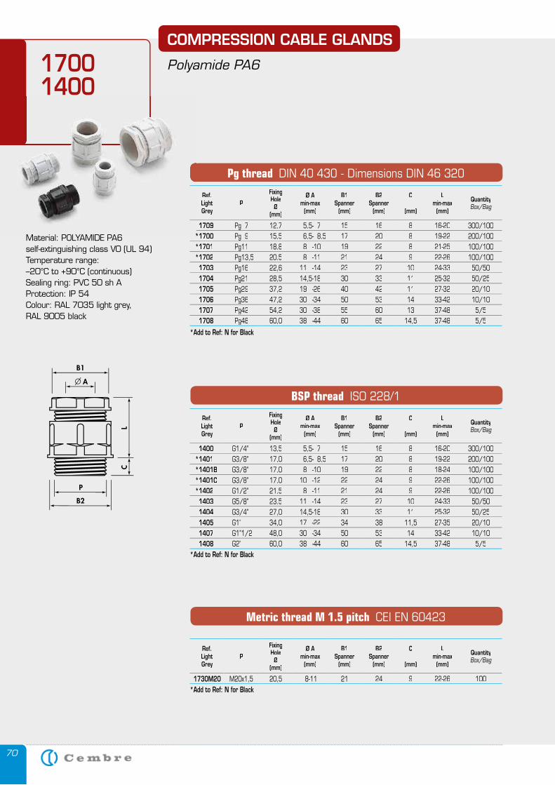
70
COMPRESSION CABLE GLANDS
Polyamide PA617001400
Material: POLYAMIDE PA6 self-extinguishing class V0 (UL 94)Temperature range:–20°C to +90°C (continuous)Sealing ring: PVC 50 sh AProtection: IP 54Colour: RAL 7035 light grey,RAL 9005 black
Pg thread DIN 40 430 - Dimensions DIN 46 320
BSP thread ISO 228/1
Metric thread M 1.5 pitch CEI EN 60423
Ref.LightGrey
P
Fixing Hole
Ø(mm)
Ø Amin-max
(mm)
B1Spanner
(mm)
B2Spanner
(mm)
C
(mm)
Lmin-max
(mm)
QuantityBox/Bag
1709 1709 Pg 7 12,7 5,5- 7 15 16 8 16-20 300/100*1700*1700 Pg 9 15,5 6,5- 8,5 17 20 8 19-22 200/100*1701 Pg11 18,8 8 -10 19 22 8 21-25 100/100*1702 Pg13,5 20,5 8 -11 21 24 9 22-26 100/100 1703 Pg16 22,6 11 -14 23 27 10 24-33 50/50 1704 Pg21 28,5 14,5-18 30 33 11 25-32 50/25 1705 Pg29 37,2 19 -26 40 42 11 27-32 20/10 1706 Pg36 47,2 30 -34 50 53 14 33-42 10/10 1707 Pg42 54,2 30 -38 55 60 13 37-48 5/5 1708 Pg48 60,0 38 -44 60 65 14,5 37-48 5/5
*Add to Ref: N for Black
Ref.LightGrey
P
Fixing Hole
Ø(mm)
Ø Amin-max
(mm)
B1Spanner
(mm)
B2Spanner
(mm)
C
(mm)
Lmin-max
(mm)
QuantityBox/Bag
1400 G1/4’’ 13,5 5,5- 7 15 16 8 16-20 300/100*1401 G3/8’’ 17,0 6,5- 8,5 17 20 8 19-22 200/100*1401B G3/8’’ 17,0 8 -10 19 22 8 18-24 100/100*1401C G3/8’’ 17,0 10 -12 22 24 9 22-26 100/100*1402 G1/2’’ 21,5 8 -11 21 24 9 22-26 100/100 1403 G5/8’’ 23,5 11 -14 23 27 10 24-33 50/50 1404 G3/4’’ 27,0 14,5-18 30 33 11 25-32 50/25 1405 G1’’ 34,0 17 -22 34 38 11,5 27-35 20/10 1407 G1’’1/2 48,0 30 -34 50 53 14 33-42 10/10 1408 G2’’ 60,0 38 -44 60 65 14,5 37-48 5/5
*Add to Ref: N for Black
Ref.LightGrey
P
Fixing Hole
Ø(mm)
Ø Amin-max
(mm)
B1Spanner
(mm)
B2Spanner
(mm)
C
(mm)
Lmin-max
(mm)
QuantityBox/Bag
1730M20 M20x1,5 20,5 8-11 21 24 9 22-26 100*Add to Ref: N for Black
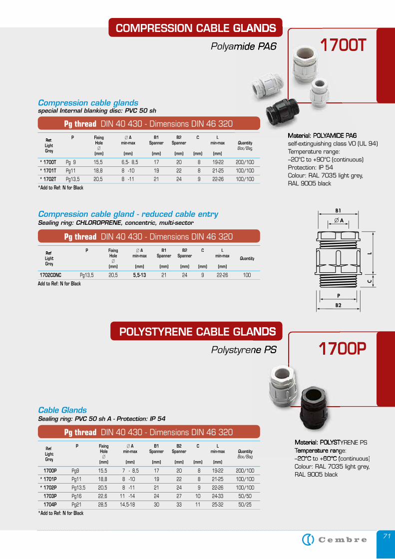
71
POLYSTYRENE CABLE GLANDS
Polystyrene PS 1700P POLYSTYRENE CABLE GLANDS
Polystyrene PS 1700P
Compression cable gland - reduced cable entrySealing ring: CHLOROPRENE, concentric, multi-sector
P Fixing � A B1 B2 C L Ref P Fixing Ref P Fixing . Hole min-max Spanner Spanner min-max QuantityLight. Hole min-max Spanner Spanner min-max Light. Hole min-max Spanner Spanner min-max � Grey (mm) (mm) (mm) (mm) (mm) (mm) Grey (mm) (mm) (mm) (mm) (mm) (mm) Grey
1702CONC Pg13,5 20,5 5,5-13 21 24 9 22-26 100
Add to Ref: N for Black
Pg thread DIN 40 430 - Dimensions DIN 46 320
Material: POLYAMIDE PA6 self-extinguishing class V0 (UL 94)Temperature range:–20°C to +90°C (continuous)Protection: IP 54Colour: RAL 7035 light grey,RAL 9005 black
Cable GlandsSealing ring: PVC 50 sh A - Protection: IP 54
P Fixing � A B1 B2 C L A B1 B2 C L Ref. P Fixing Ref. P Fixing Hole min-max Spanner Spanner min-max QuantityLight Hole min-max Spanner Spanner min-max Light Hole min-max Spanner Spanner min-max � Box/BagGrey (mm) (mm) (mm) (mm) (mm) (mm) Grey (mm) (mm) (mm) (mm) (mm) (mm) Grey
1700P Pg9 15,5 7 - 8,5 17 20 8 19-22 200/100
* 1701P Pg11 18,8 8 -10 19 22 8 21-25 100/100
* 1702P Pg13,5 20,5 8 -11 21 24 9 22-26 100/100
1703P Pg16 22,6 11 -14 24 27 10 24-33 50/50
1704P Pg21 28,5 14,5-18 30 33 11 25-32 50/25
*Add to Ref: N for Black
Pg thread DIN 40 430 - Dimensions DIN 46 320Material: POLYSTYRENE PSMaterial: POLYSTYRENE PSTemperature range:Temperature range:–20°C to +60°C (continuous)–20°C to +60°C (continuous)Colour: RAL 7035 light grey, RAL 9005 black
P Fixing � A B1 B2 C L Ref. P Fixing Ref. P Fixing Hole min-max Spanner Spanner min-max QuantityLight Hole min-max Spanner Spanner min-max Light Hole min-max Spanner Spanner min-max � Box/BagGrey (mm) (mm) (mm) (mm) (mm) (mm) Grey (mm) (mm) (mm) (mm) (mm) (mm) Grey
* 1700T Pg 9 15,5 6,5- 8,5 17 20 8 19-22 200/100
* 1701T Pg11 18,8 8 -10 19 22 8 21-25 100/100
* 1702T Pg13,5 20,5 8 -11 21 24 9 22-26 100/100
*Add to Ref: N for Black
Pg thread DIN 40 430 - Dimensions DIN 46 320
Compression cable glandsspecial Internal blanking disc: PVC 50 sh
COMPRESSION CABLE GLANDS
Polyamide PA6 1700T
Material: POLYAMIDE PA6 A B1 B2 C L
COMPRESSION CABLE GLANDS
Polyamide PA6 1700T
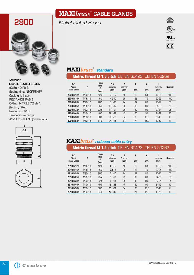
72
CABLE GLANDS
Nickel Plated Brass2900
Metric thread M 1.5 pitch CEI EN 60423 CEI EN 50262
Metric thread M 1.5 pitch CEI EN 60423 CEI EN 50262
reduced cable entry
Technical data pages 207 to 210
Material:NICKEL PLATED BRASS NICKEL PLATED BRASS (CuZn 40 Pb 3)Sealing-ring: NEOPRENE®
Cable grip insert: POLYAMIDE PA6.6O-Ring: NITRILE 70 sh A (factory fi tted)Protection: IP 68Temperature range:-25°C to +100°C (continuous)
standard
File no. E220310
File no. E220310
Ref.Nickel
Plated BrassP
Fixing Hole
Ø(mm)
Ø Amin-max
(mm)
BSpanner
(mm)
E
(mm)
C
(mm)
Lmin-max
(mm)Quantity
2900.M12N M12x1,5 12,2 3 - 7 16 18 6,5 16-20 1002900.M16N M16x1,5 16,2 4,5-10 20 23 7,0 20-25 1002900.M20N M20x1,5 20,5 7 -13 24 27 8,0 20-27 502900.M25N M25x1,5 25,4 10 -17 29 32 8,0 24-30 502900.M32N M32x1,5 32,5 11 -21 36 40 9,0 27-34 252900.M40N M40x1,5 40,5 19 -28 45 50 9,0 34-42 102900.M50N M50x1,5 50,5 26 -35 54 60 10,0 35-43 82900.M63N M63x1,5 64,0 34 -45 67 74 15,0 40-52 5
Ref.Nickel
Plated BrassP
Fixing Hole
Ø(mm)
Ø Amin-max
(mm)
BSpanner
(mm)
E
(mm)
C
(mm)
Lmin-max
(mm)Quantity
2910.M12N M12x1,5 12,2 1 - 5 16 18 6,5 16-20 1002910.M16N M16x1,5 16,2 2,5- 7 20 23 7,0 20-25 1002910.M20N M20x1,5 20,5 5 -10 24 27 8,0 20-27 502910.M25N M25x1,5 25,4 6 -13 29 32 8,0 24-30 502910.M32N M32x1,5 32,5 7 -14 36 40 9,0 27-34 252910.M40N M40x1,5 40,5 13 -23 45 50 9,0 34-42 102910.M50N M50x1,5 50,5 20 -29 54 60 10,0 35-43 82910.M63N M63x1,5 64,0 27 -39 67 74 15,0 40-52 5
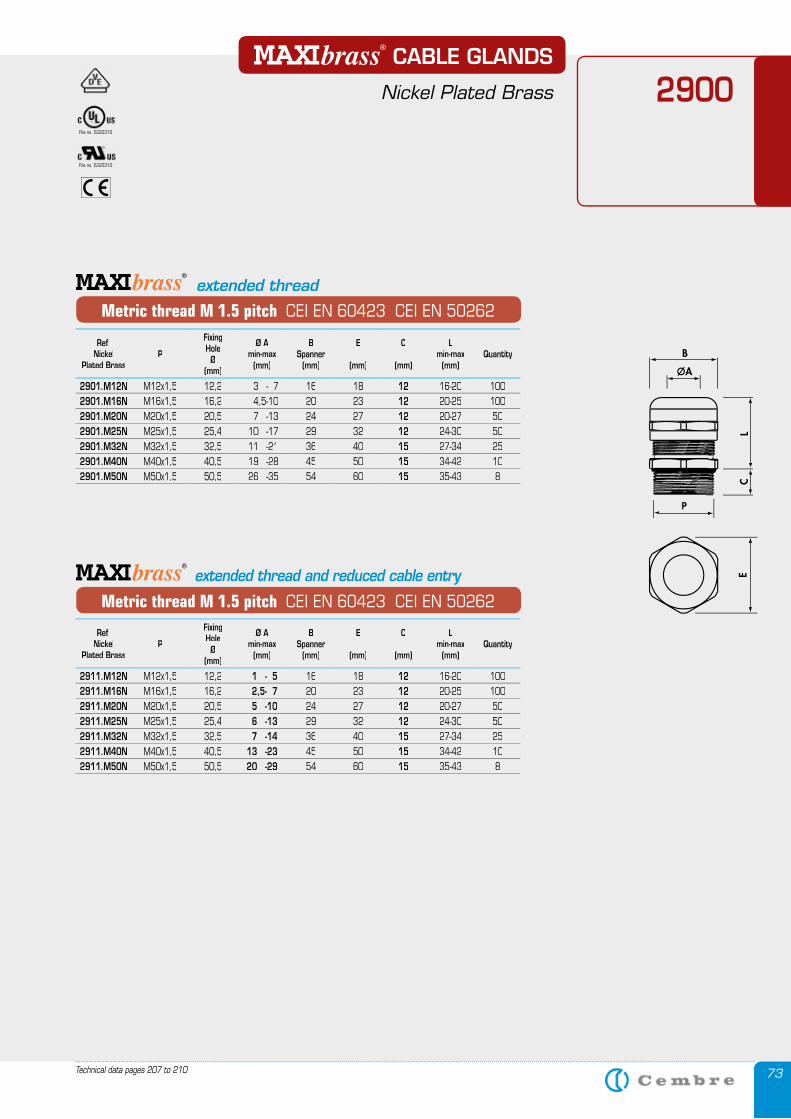
73Technical data pages 207 to 210
CABLE GLANDS
Nickel Plated Brass 2900
Metric thread M 1.5 pitch CEI EN 60423 CEI EN 50262
extended thread
Metric thread M 1.5 pitch CEI EN 60423 CEI EN 50262
extended thread and reduced cable entry
File no. E220310
File no. E220310
Ref.Nickel
Plated BrassP
Fixing Hole
Ø(mm)
Ø Amin-max
(mm)
BSpanner
(mm)
E
(mm)
C
(mm)
Lmin-max
(mm)Quantity
2901.M12N M12x1,5 12,2 3 - 7 16 18 12 16-20 1002901.M16N M16x1,5 16,2 4,5-10 20 23 12 20-25 1002901.M20N M20x1,5 20,5 7 -13 24 27 12 20-27 502901.M25N M25x1,5 25,4 10 -17 29 32 12 24-30 502901.M32N M32x1,5 32,5 11 -21 36 40 15 27-34 252901.M40N M40x1,5 40,5 19 -28 45 50 15 34-42 102901.M50N M50x1,5 50,5 26 -35 54 60 15 35-43 8
Ref.Nickel
Plated BrassP
Fixing Hole
Ø(mm)
Ø Amin-max
(mm)
BSpanner
(mm)
E
(mm)
C
(mm)
Lmin-max
(mm)Quantity
2911.M12N M12x1,5 12,2 1 - 5 16 18 12 16-20 1002911.M16N M16x1,5 16,2 2,5- 7 20 23 12 20-25 1002911.M20N M20x1,5 20,5 5 -10 24 27 12 20-27 502911.M25N M25x1,5 25,4 6 -13 29 32 12 24-30 502911.M32N M32x1,5 32,5 7 -14 36 40 15 27-34 252911.M40N M40x1,5 40,5 13 -23 45 50 15 34-42 102911.M50N M50x1,5 50,5 20 -29 54 60 15 35-43 8
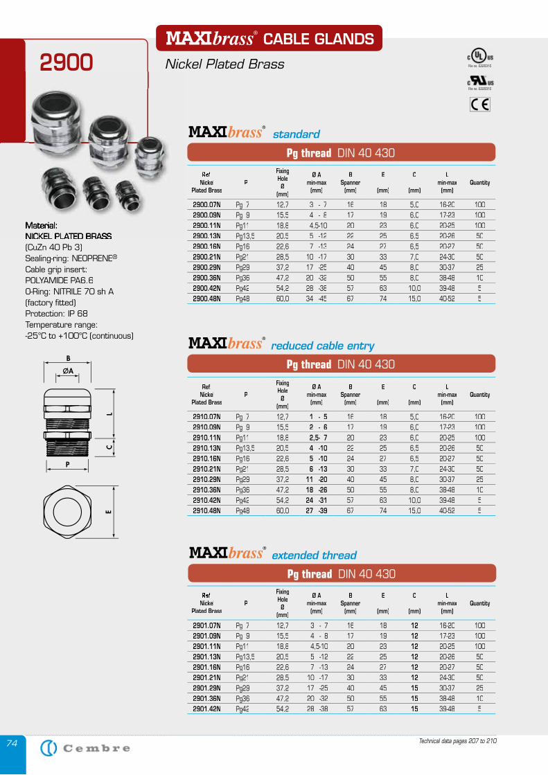
74 Technical data pages 207 to 210
NICKEL PLATED BRASS (CuZn 40 Pb 3)Sealing-ring: NEOPRENE®
Cable grip insert: POLYAMIDE PA6.6O-Ring: NITRILE 70 sh A (factory fi tted)Protection: IP 68Temperature range:-25°C to +100°C (continuous)
2900
Material: NICKEL PLATED BRASS
Pg thread DIN 40 430
Pg thread DIN 40 430
reduced cable entry
Pg thread DIN 40 430
extended thread
CABLE GLANDS
Nickel Plated Brass
standard
File no. E220310
File no. E220310
Ref.Nickel
Plated BrassP
Fixing Hole
Ø(mm)
Ø Amin-max
(mm)
BSpanner
(mm)
E
(mm)
C
(mm)
Lmin-max
(mm)Quantity
2900.07N Pg 7 12,7 3 - 7 16 18 5,0 16-20 1002900.09N Pg 9 15,5 4 - 8 17 19 6,0 17-23 1002900.11N Pg11 18,8 4,5-10 20 23 6,0 20-25 1002900.13N Pg13,5 20,5 5 -12 22 25 6,5 20-26 502900.16N Pg16 22,6 7 -13 24 27 6,5 20-27 502900.21N Pg21 28,5 10 -17 30 33 7,0 24-30 502900.29N Pg29 37,2 17 -25 40 45 8,0 30-37 252900.36N Pg36 47,2 20 -32 50 55 8,0 38-48 102900.42N Pg42 54,2 28 -38 57 63 10,0 39-48 52900.48N Pg48 60,0 34 -45 67 74 15,0 40-52 5
Ref.Nickel
Plated BrassP
Fixing Hole
Ø(mm)
Ø Amin-max
(mm)
BSpanner
(mm)
E
(mm)
C
(mm)
Lmin-max
(mm)Quantity
2901.07N Pg 7 12,7 3 - 7 16 18 12 16-20 1002901.09N Pg 9 15,5 4 - 8 17 19 12 17-23 1002901.11N Pg11 18,8 4,5-10 20 23 12 20-25 1002901.13N Pg13,5 20,5 5 -12 22 25 12 20-26 502901.16N Pg16 22,6 7 -13 24 27 12 20-27 502901.21N Pg21 28,5 10 -17 30 33 12 24-30 502901.29N Pg29 37,2 17 -25 40 45 15 30-37 252901.36N Pg36 47,2 20 -32 50 55 15 38-48 102901.42N Pg42 54,2 28 -38 57 63 15 39-48 5
Ref.Nickel
Plated BrassP
Fixing Hole
Ø(mm)
Ø Amin-max
(mm)
BSpanner
(mm)
E
(mm)
C
(mm)
Lmin-max
(mm)Quantity
2910.07N Pg 7 12,7 1 - 5 16 18 5,0 16-20 1002910.09N Pg 9 15,5 2 - 6 17 19 6,0 17-23 1002910.11N Pg11 18,8 2,5- 7 20 23 6,0 20-25 1002910.13N Pg13,5 20,5 4 -10 22 25 6,5 20-26 502910.16N Pg16 22,6 5 -10 24 27 6,5 20-27 502910.21N Pg21 28,5 6 -13 30 33 7,0 24-30 502910.29N Pg29 37,2 11 -20 40 45 8,0 30-37 252910.36N Pg36 47,2 18 -26 50 55 8,0 38-48 102910.42N Pg42 54,2 24 -31 57 63 10,0 39-48 52910.48N Pg48 60,0 27 -39 67 74 15,0 40-52 5
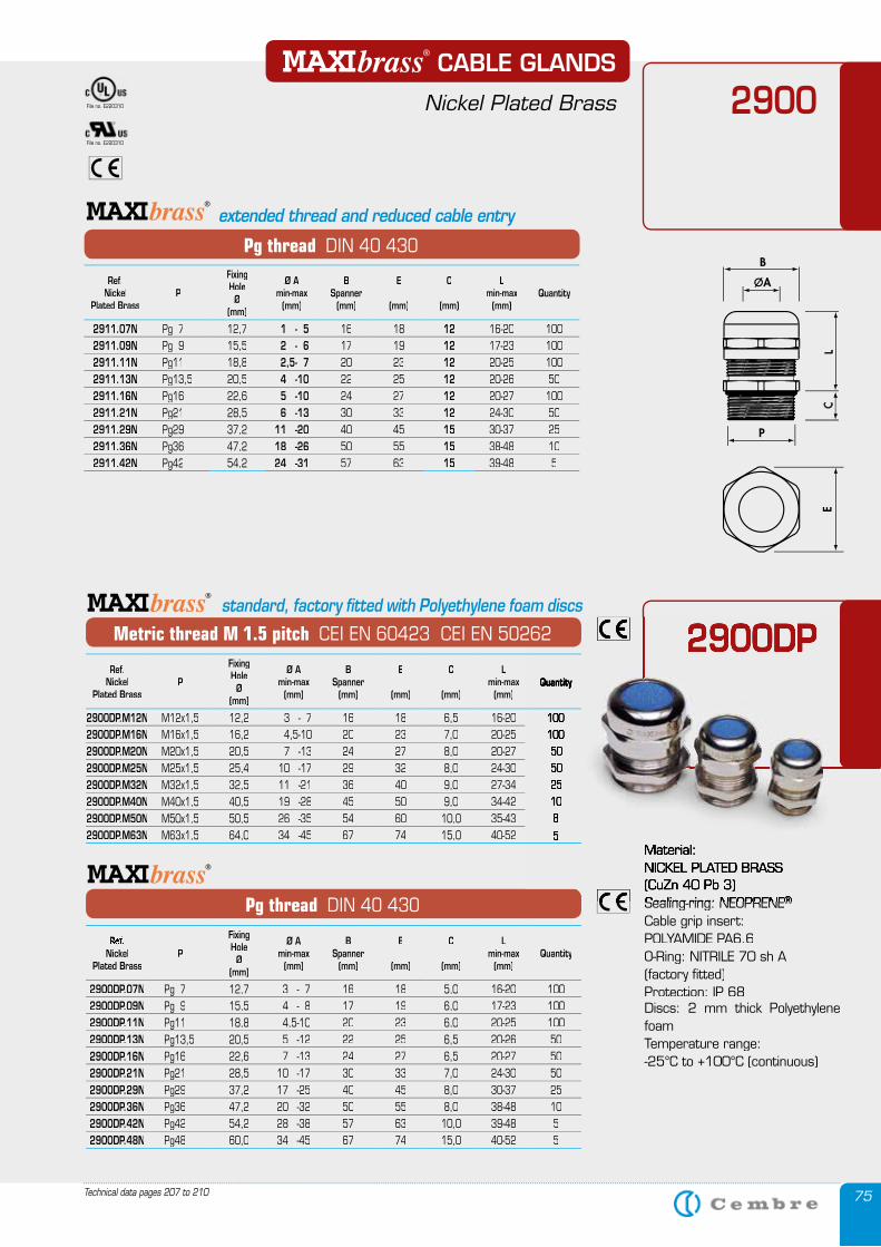
75Technical data pages 207 to 210
2900
Pg thread DIN 40 430
extended thread and reduced cable entry
CABLE GLANDS
Nickel Plated BrassFile no. E220310
File no. E220310
Ref.Nickel
Plated BrassP
Fixing Hole
Ø(mm)
Ø Amin-max
(mm)
BSpanner
(mm)
E
(mm)
C
(mm)
Lmin-max
(mm)Quantity
2911.07N Pg 7 12,7 1 - 5 16 18 12 16-20 1002911.09N Pg 9 15,5 2 - 6 17 19 12 17-23 1002911.11N Pg11 18,8 2,5- 7 20 23 12 20-25 1002911.13N Pg13,5 20,5 4 -10 22 25 12 20-26 502911.16N Pg16 22,6 5 -10 24 27 12 20-27 1002911.21N Pg21 28,5 6 -13 30 33 12 24-30 502911.29N Pg29 37,2 11 -20 40 45 15 30-37 252911.36N Pg36 47,2 18 -26 50 55 15 38-48 102911.42N Pg42 54,2 24 -31 57 63 15 39-48 5
Pg thread DIN 40 430
2900DP
Ref.Nickel
Plated BrassP
Fixing Hole
Ø(mm)
Ø Amin-max
(mm)
BSpanner
(mm)
E
(mm)
C
(mm)
Lmin-max
(mm)Quantity
2900DP.07N Pg 7 12,7 3 - 7 16 18 5,0 16-20 1002900DP.09N Pg 9 15,5 4 - 8 17 19 6,0 17-23 1002900DP.11N Pg11 18,8 4,5-10 20 23 6,0 20-25 1002900DP.13N Pg13,5 20,5 5 -12 22 25 6,5 20-26 502900DP.16N Pg16 22,6 7 -13 24 27 6,5 20-27 502900DP.21N Pg21 28,5 10 -17 30 33 7,0 24-30 502900DP.29N Pg29 37,2 17 -25 40 45 8,0 30-37 252900DP.36N Pg36 47,2 20 -32 50 55 8,0 38-48 102900DP.42N Pg42 54,2 28 -38 57 63 10,0 39-48 52900DP.48N Pg48 60,0 34 -45 67 74 15,0 40-52 5
2900DPMetric thread M 1.5 pitch CEI EN 60423 CEI EN 50262
standard, factory fitted with Polyethylene foam discs
Ref.Nickel
Plated BrassP
Fixing Hole
Ø(mm)
Ø Amin-max
(mm)
BSpanner
(mm)
E
(mm)
C
(mm)
Lmin-max
(mm)Quantity
2900DP.M12N M12x1,5 12,2 3 - 7 16 18 6,5 16-20 1002900DP.M16N M16x1,5 16,2 4,5-10 20 23 7,0 20-25 1002900DP.M20N M20x1,5 20,5 7 -13 24 27 8,0 20-27 502900DP.M25N M25x1,5 25,4 10 -17 29 32 8,0 24-30 502900DP.M32N M32x1,5 32,5 11 -21 36 40 9,0 27-34 252900DP.M40N M40x1,5 40,5 19 -28 45 50 9,0 34-42 102900DP.M50N M50x1,5 50,5 26 -35 54 60 10,0 35-43 82900DP.M63N M63x1,5 64,0 34 -45 67 74 15,0 40-52 5
Material:NICKEL PLATED BRASS (CuZn 40 Pb 3)Sealing-ring: NEOPRENESealing-ring: NEOPRENE®®
Cable grip insert: POLYAMIDE PA6.6O-Ring: NITRILE 70 sh A (factory fi tted)Protection: IP 68Discs: 2 mm thick Polyethylene foamTemperature range:-25°C to +100°C (continuous)
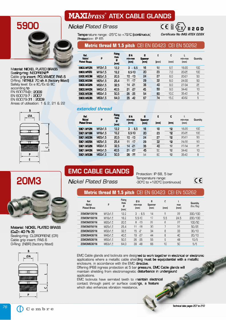
76
Material: NICKEL PLATED BRASS Sealing-ring: NEOPRENECable grip insert: POLYAMIDE PA6.6Cable grip insert: POLYAMIDE PA6.6O-Ring: NITRILE 70 sh A (factory fi tted)O-Ring: NITRILE 70 sh A (factory fi tted)Safety level: Ex e IIC/Ex tb IIICaccording toaccording toEN 60079-0 : 2009EN 60079-0 : 2009EN 60079-7 : 2007EN 60079-7 : 2007EN 60079-31 : 2009EN 60079-31 : 2009Areas of utilisation: 1 & 2, 21 & 22
Temperature range: -25°C to +75°C (continuous)Temperature range: -25°C to +75°C (continuous)Protection: IP 65
Technical data pages 207 to 210
Metric thread M 1.5 pitch CEI EN 60423 CEI EN 50262
Material: NICKEL PLATED BRASS (CuZn 40 Pb 3)Sealing-ring: CLOROPRENE (CR)Cable grip insert: PA6.6O-Ring: (NBR) (factory fitted)
EMC Cable glands and locknuts are designed to work together in electrical or electronic applications where a metallic cable shielding must be equipotential with a metallic enclosure, in accordance with the EMC directive. Offering IP68 ingress protection at 5 bar pressure, EMC Cable glands will maintain shielding from electromagnetic disturbance in undergound applications. EMC locknuts have serrated teeth to maintain electrical contact through paint or surface coatings, a feature which also enhances vibration resistance.
Technical data pages 207 to 210
EMC Cable glands and locknuts are designed to work together in electrical or electronic applications where a metallic cable shielding must be equipotential with a metallic enclosure, in accordance with the EMC directive. Offering IP68 ingress protection at 5 bar pressure, EMC Cable glands will maintain shielding from electromagnetic disturbance in undergound
EMC locknuts have serrated teeth to maintain electrical contact through paint or surface coatings, a feature which also enhances vibration resistance.
EMC CABLE GLANDS
Nickel Plated Brass20M3
Material: NICKEL PLATED BRASS (CuZn 40 Pb 3)
Nickel Plated Brass20M3
Metric thread M 1.5 pitch CEI EN 60423 CEI EN 50262
Protection: IP 68, 5 barTemperature range: -30°C to +120°C (continuous)
ATEX CABLE GLANDS
Nickel Plated Brass5900
Material: NICKEL PLATED BRASS Material: NICKEL PLATED BRASS Sealing-ring: NEOPRENESealing-ring: NEOPRENE®
Cable grip insert: POLYAMIDE PA6.6Cable grip insert: POLYAMIDE PA6.6
Temperature range: -25°C to +75°C (continuous)Protection: IP 65
Metric thread M 1.5 pitch
Nickel Plated Brass5900 II 2 G D0051
Certificate No IMQ ATEX 028X
extended thread
Ref.NickelNickel
Plated BrassPlated BrassP
Fixing Hole
Ø(mm)
Ø Amin-max
(mm)
BSpanner
(mm)
E
(mm)(mm)
C
(mm)
Lmin-max
(mm)Quantity
5900.M12N5900.M12N M12x1,5 12,2 3 - 6,5 16 1818 6,5 16-20 1005900.M16N5900.M16N M16x1,5 16,2 6,5-10 20 2323 7,0 20-25 1005900.M20N5900.M20N M20x1,5 20,5 10 -13 24 27 8,0 20-27 505900.M25N M25x1,5 25,4 11 -17 29 32 8,0 24-30 505900.M32N M32x1,5 32,5 14 -21 36 40 9,0 27-34 255900.M40N M40x1,5 40,5 21 -27 45 50 9,0 34-42 105900.M50N M50x1,5 50,5 26 -35 54 60 10,0 35-43 85900.M63N M63x1,5 64,0 35 -42 67 74 15,0 40-52 5
Ref.Nickel
Plated BrassP
Fixing Hole
Ø(mm)
Ø Amin-max
(mm)
BSpanner
(mm)
E
(mm)
CC
(mm)(mm)
Lmin-max
(mm)Quantity
5901.M12N M12x1,5 12,2 3 - 6,5 16 18 12 16-20 1005901.M16N M16x1,5 16,2 6,5-10 20 23 12 20-25 1005901.M20N M20x1,5 20,5 10 -13 24 27 12 20-27 505901.M25N M25x1,5 25,4 11 -17 29 32 12 24-30 505901.M32N M32x1,5 32,5 14 -21 36 40 1212 27-34 255901.M40N M40x1,5 40,5 21 -27 4545 50 12 34-42 105901.M50N M50x1,5 50,5 26 -35 26 -35 54 60 12 35-43 8
Ref.Nickel
Plated BrassP
Fixing Hole
Ø(mm)
Ø Amin-max
(mm)
BSpanner
(mm)
C
(mm)
Lmax(mm)
QuantityBox/Bag
20M3M1261N M12x1,5 12,2 3 - 6,5 14 5 22 300/10020M3M1661N M16x1,5 16,2 5,5-10 17 5,5 24,5 200/10020M3M2061N M20x1,5 20,5 8 -13 22 6 27 100/5020M3M2561N M25x1,5 25,4 11 -18 30 7 31 50/2520M3M3261N M32x1,5 32,5 15 -21 34 8 33 30/1020M3M4061N M40x1,5 40,5 19 -27 44 8 40 20/1020M3M5061N M50x1,5 50,5 26 -35 55 9 48 10/520M3M6361N M63x1,5 64,0 39 -48 66 10 50 5/5
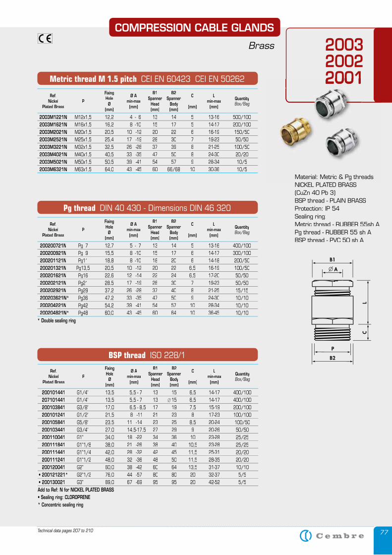
77Technical data pages 207 to 210
200320022001
Pg thread DIN 40 430 - Dimensions DIN 46 320
BSP thread ISO 228/1
Metric thread M 1.5 pitch CEI EN 60423 CEI EN 50262 2001
COMPRESSION CABLE GLANDS
Brass
Material: Metric & Pg threads NICKEL PLATED BRASS (CuZn 40 Pb 3)BSP thread - PLAIN BRASSProtection: IP 54Sealing ring:Metric thread - RUBBER 55sh A Pg thread - RUBBER 55 sh A BSP thread - PVC 50 sh A
Ref.Nickel
Plated BrassP
Fixing Hole
Ø(mm)
Ø Amin-max
(mm)
B1Spanner
Head(mm)
B2Spanner
Body(mm)
C
(mm)
Lmin-max
(mm)
QuantityBox/Bag
2003M1221N M12x1,5 12,2 4 - 6 13 14 5 13-16 500/1002003M1621N M16x1,5 16,2 8 -10 15 17 5 14-17 200/1002003M2021N M20x1,5 20,5 10 -12 20 22 6 16-19 150/502003M2521N M25x1,5 25,4 17 -19 28 30 7 19-23 50/502003M3221N M32x1,5 32,5 26 -28 37 39 8 21-25 100/502003M4021N M40x1,5 40,5 33 -35 47 50 8 24-30 20/202003M5021N M50x1,5 50,5 39 -41 54 57 9 28-34 10/52003M6321N M63x1,5 64,0 43 -45 60 66/68 10 30-36 10/5
Ref.Nickel
Plated BrassP
Fixing Hole
Ø(mm)
Ø Amin-max
(mm)
B1Spanner
Head(mm)
B2Spanner
Body(mm)
C
(mm)
Lmin-max
(mm)
QuantityBox/Bag
200200721N Pg 7 12,7 5 - 7 13 14 5 13-16 400/100200200921N Pg 9 15,5 8 -10 15 17 6 14-17 300/100200201121N Pg11 18,8 8 -10 18 20 6 14-18 200/50200201321N Pg13,5 20,5 10 -12 20 22 6,5 16-19 100/50200201621N Pg16 22,6 12 -14 22 24 6,5 17-20 50/50200202121N Pg21 28,5 17 -19 28 30 7 19-23 50/50200202921N Pg29 37,2 26 -28 37 40 8 21-25 15/15
200203621N* Pg36 47,2 33 -35 47 50 9 24-30 10/10200204221N Pg42 54,2 39 -41 54 57 10 28-34 10/10
200204821N* Pg48 60,0 43 -45 60 64 10 36-45 10/10* Double sealing ring
Ref.Nickel
Plated BrassP
Fixing Hole
Ø(mm)
Ø Amin-max
(mm)
B1Spanner
Head(mm)
B2Spanner
Body(mm)
C
(mm)
Lmin-max
(mm)
QuantityBox/Bag
200101441 G1/4’’ 13,5 5,5 - 7 13 15 6,5 14-17 400/100207101441 G1/4’’ 13,5 5,5 - 7 13 � 15 6,5 14-17 400/100200103841 G3/8’’ 17,0 6,5 - 8,5 17 19 7,5 15-19 200/100200101241 G1/2’’ 21,5 8 -11 21 23 8 17-23 100/100200105841 G5/8’’ 23,5 11 -14 23 25 8,5 20-24 100/50200103441 G3/4’’ 27,0 14,5-17,5 27 29 9 20-26 50/50200110041 G1’’ 34,0 18 -22 34 36 10 23-28 25/25200111841 G1’’1/8 38,0 21 -26 38 40 10,5 23-28 25/25200111441 G1’’1/4 42,0 28 -32 42 45 11,5 25-31 20/20200111241 G1’’1/2 48,0 32 -36 48 50 11,5 28-35 20/20200120041 G2’’ 60,0 38 -42 60 64 13,5 31-37 10/10
• 200121221* G2’’1/2 76,0 44 -57 80 80 20 32-37 5/5• 200130021 G3’’ 89,0 67 -69 95 95 20 42-52 5/5Add to Ref: N for NICKEL PLATED BRASS• Sealing ring: CLOROPRENE* Concentric sealing ring
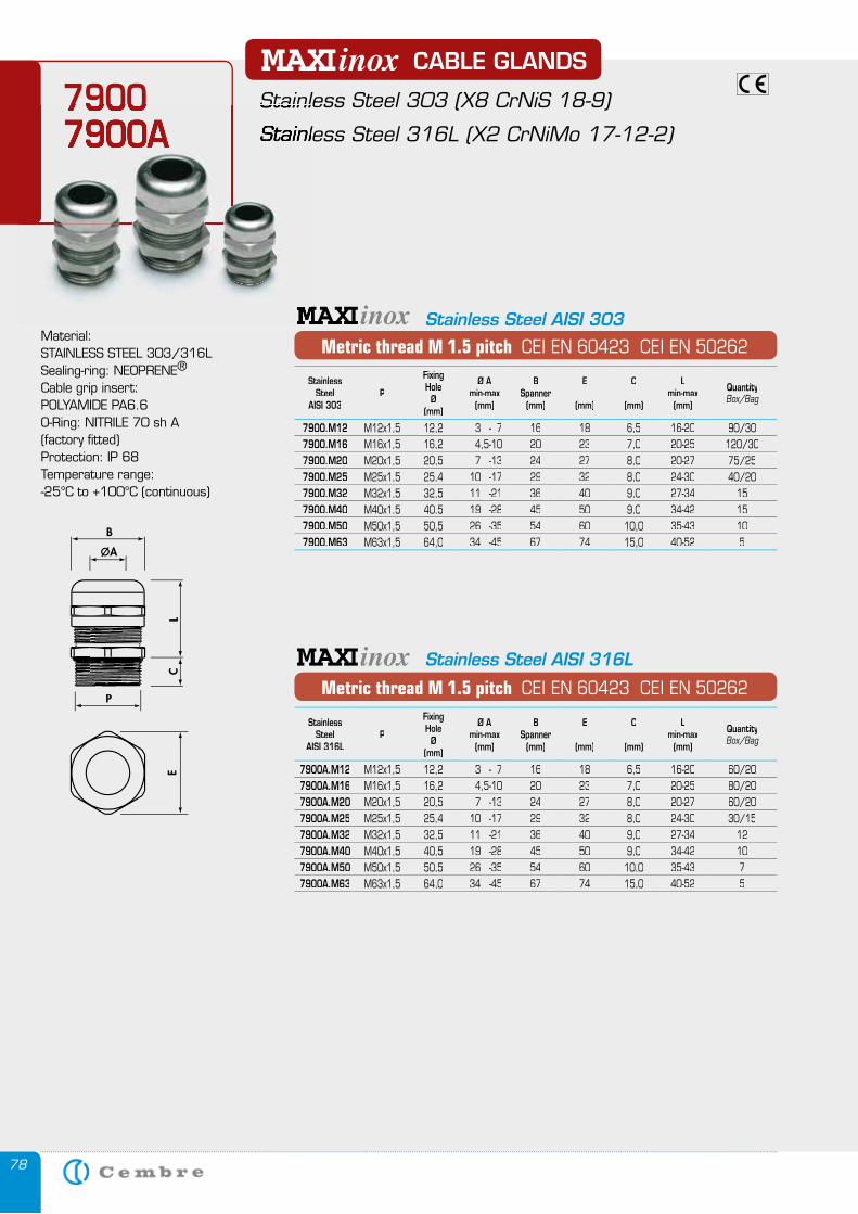
78
spiral
Metric thread M 1.5 pitch CEI EN 60423 CEI EN 50262
CABLE GLANDS
Stainless Steel 303 (X8 CrNiS 18-9)
Stainless Steel 316L (X2 CrNiMo 17-12-2)
79007900A
Stainless Steel 303 (X8 CrNiS 18-9)
Stainless Steel 316L (X2 CrNiMo 17-12-2)
79007900A
Material: STAINLESS STEEL 303/316LSealing-ring: NEOPRENE®
Cable grip insert: POLYAMIDE PA6.6O-Ring: NITRILE 70 sh A (factory fitted)Protection: IP 68Temperature range:-25°C to +100°C (continuous)
spiral
Metric thread M 1.5 pitch CEI EN 60423 CEI EN 50262
Stainless Steel AISI 316L
Stainless Steel AISI 303
StainlessSteel
AISI 303P
Fixing Hole
Ø(mm)
Ø Amin-max
(mm)
BSpanner
(mm)
E
(mm)
C
(mm)
Lmin-max
(mm)
QuantityBox/Bag
7900.M12 M12x1,5 12,2 3 - 7 16 18 6,5 16-20 90/307900.M16 M16x1,5 16,2 4,5-10 20 23 7,0 20-25 120/307900.M20 M20x1,5 20,5 7 -13 24 27 8,0 20-27 75/257900.M25 M25x1,5 25,4 10 -17 29 32 8,0 24-30 40/207900.M32 M32x1,5 32,5 11 -21 36 40 9,0 27-34 157900.M40 M40x1,5 40,5 19 -28 45 50 9,0 34-42 157900.M50 M50x1,5 50,5 26 -35 54 60 10,0 35-43 107900.M63 M63x1,5 64,0 34 -45 67 74 15,0 40-52 5
StainlessSteel
AISI 316LP
Fixing Hole
Ø(mm)
Ø Amin-max
(mm)
BSpanner
(mm)
E
(mm)
C
(mm)
Lmin-max
(mm)
QuantityBox/Bag
7900A.M12 M12x1,5 12,2 3 - 7 16 18 6,5 16-20 60/207900A.M16 M16x1,5 16,2 4,5-10 20 23 7,0 20-25 80/207900A.M20 M20x1,5 20,5 7 -13 24 27 8,0 20-27 60/207900A.M25 M25x1,5 25,4 10 -17 29 32 8,0 24-30 30/157900A.M32 M32x1,5 32,5 11 -21 36 40 9,0 27-34 127900A.M40 M40x1,5 40,5 19 -28 45 50 9,0 34-42 107900A.M50 M50x1,5 50,5 26 -35 54 60 10,0 35-43 77900A.M63 M63x1,5 64,0 34 -45 67 74 15,0 40-52 5
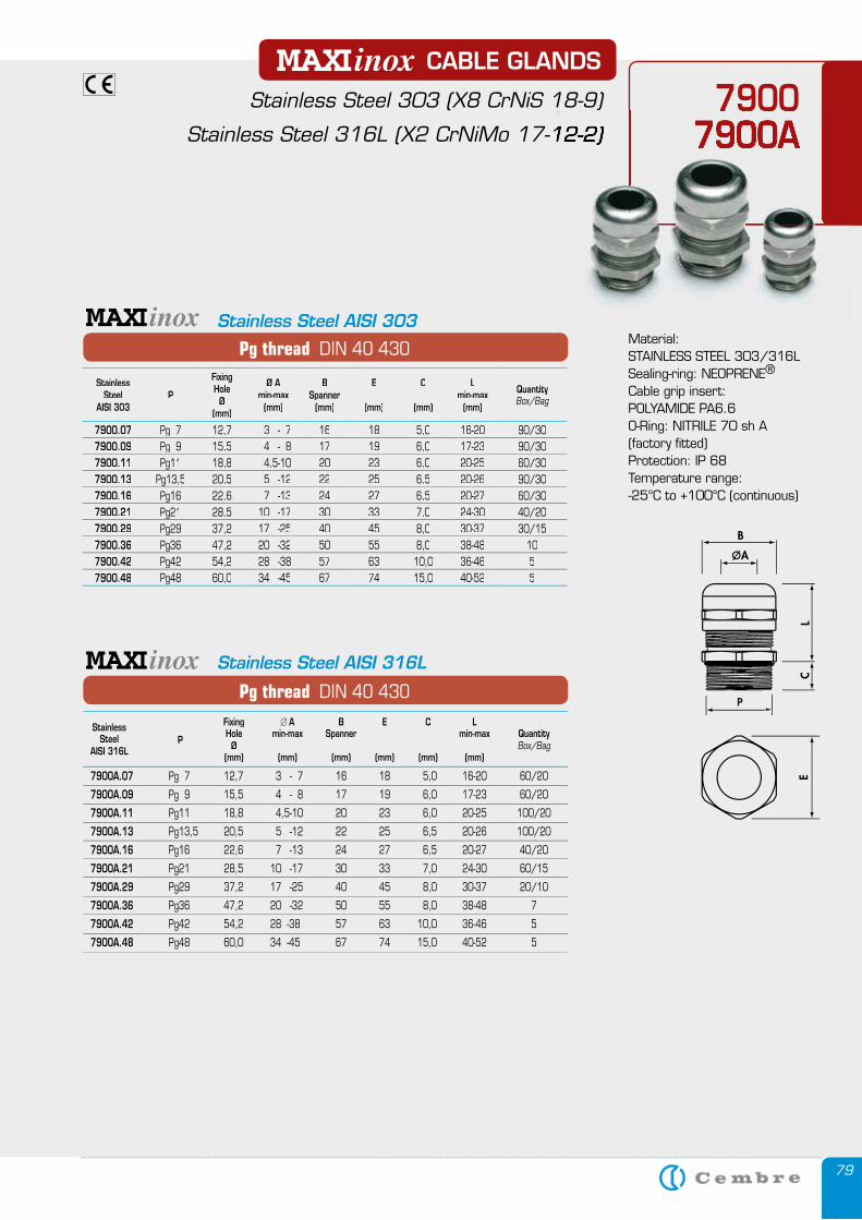
79
79007900A
CABLE GLANDS
Stainless Steel 303 (X8 CrNiS 18-9)
Stainless Steel 316L (X2 CrNiMo 17-12-2)
Material: STAINLESS STEEL 303/316LSealing-ring: NEOPRENE®
Cable grip insert: POLYAMIDE PA6.6O-Ring: NITRILE 70 sh A (factory fitted)Protection: IP 68Temperature range:-25°C to +100°C (continuous)
79007900A
Stainless Steel 303 (X8 CrNiS 18-9)
Stainless Steel 316L (X2 CrNiMo 17-12-2)
Pg thread DIN 40 430
Stainless Fixing � A B E C L Steel Hole min-max Spanner min-max Quantity AISI 316L P Ø Box/Bag (mm) (mm) (mm) (mm) (mm) (mm)
7900A.07 Pg 7 12,7 3 - 7 16 18 5,0 16-20 60/20
7900A.09 Pg 9 15,5 4 - 8 17 19 6,0 17-23 60/20
7900A.11 Pg11 18,8 4,5-10 20 23 6,0 20-25 100/20
7900A.13 Pg13,5 20,5 5 -12 22 25 6,5 20-26 100/20
7900A.16 Pg16 22,6 7 -13 24 27 6,5 20-27 40/20
7900A.21 Pg21 28,5 10 -17 30 33 7,0 24-30 60/15
7900A.29 Pg29 37,2 17 -25 40 45 8,0 30-37 20/10
7900A.36 Pg36 47,2 20 -32 50 55 8,0 38-48 7
7900A.42 Pg42 54,2 28 -38 57 63 10,0 36-46 5
7900A.48 Pg48 60,0 34 -45 67 74 15,0 40-52 5
spiral
Pg thread DIN 40 430
spiral
Stainless Steel AISI 316L
Stainless Steel AISI 303
StainlessSteel
AISI 303P
Fixing Hole
Ø(mm)
Ø Amin-max
(mm)
BSpanner
(mm)
E
(mm)
C
(mm)
Lmin-max
(mm)
QuantityBox/Bag
7900.07 Pg 7 12,7 3 - 7 16 18 5,0 16-20 90/307900.09 Pg 9 15,5 4 - 8 17 19 6,0 17-23 90/307900.11 Pg11 18,8 4,5-10 20 23 6,0 20-25 60/307900.13 Pg13,5 20,5 5 -12 22 25 6,5 20-26 90/307900.16 Pg16 22,6 7 -13 24 27 6,5 20-27 60/307900.21 Pg21 28,5 10 -17 30 33 7,0 24-30 40/207900.29 Pg29 37,2 17 -25 40 45 8,0 30-37 30/157900.36 Pg36 47,2 20 -32 50 55 8,0 38-48 107900.42 Pg42 54,2 28 -38 57 63 10,0 36-46 57900.48 Pg48 60,0 34 -45 67 74 15,0 40-52 5
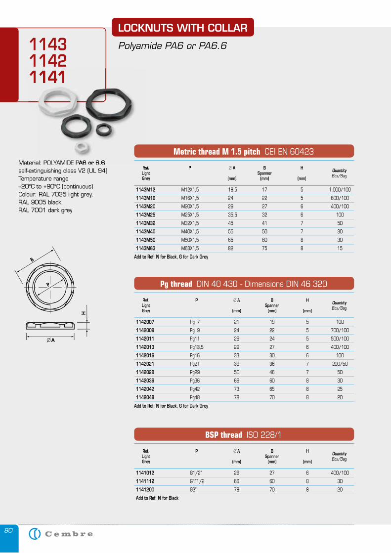
80
1143114211411141
Ref. P � A B H Light Spanner Quantity
Grey (mm) (mm) (mm) Box/Bag
1142007 Pg 7 21 19 5 100
1142009 Pg 9 24 22 5 700/100
1142011 Pg11 26 24 5 500/100
1142013 Pg13,5 29 27 6 400/100
1142016 Pg16 33 30 6 100
1142021 Pg21 39 36 7 200/50
1142029 Pg29 50 46 7 50
1142036 Pg36 66 60 8 30
1142042 Pg42 73 65 8 25
1142048 Pg48 78 70 8 20
Add to Ref: N for Black, G for Dark Grey
Pg thread DIN 40 430 - Dimensions DIN 46 320
Ref. P � A B H Light Spanner Quantity
Grey (mm) (mm) (mm) Box/Bag
1141012 G1/2” 29 27 6 400/100
1141112 G1”1/2 66 60 8 30
1141200 G2” 78 70 8 20
Add to Ref: N for Black
BSP thread ISO 228/1
Ref. P � A B H Light Spanner Quantity
Grey (mm) (mm) (mm) Box/Bag
1143M12 M12X1,5 18,5 17 5 1.000/100
1143M16 M16X1,5 24 22 5 600/100
1143M20 M20X1,5 29 27 6 400/100
1143M25 M25X1,5 35,5 32 6 100
1143M32 M32X1,5 45 41 7 50
1143M40 M40X1,5 55 50 7 30
1143M50 M50X1,5 65 60 8 30
1143M63 M63X1,5 82 75 8 15
Add to Ref: N for Black, G for Dark Grey
Metric thread M 1.5 pitch CEI EN 60423Material: POLYAMIDE PA6 or 6.6Material: POLYAMIDE PA6 or 6.6self-extinguishing class V2 (UL 94)Temperature range:–20°C to +90°C (continuous)Colour: RAL 7035 light grey, RAL 9005 black, RAL 7001 dark grey
LOCKNUTS WITH COLLAR
Polyamide PA6 or PA6.6
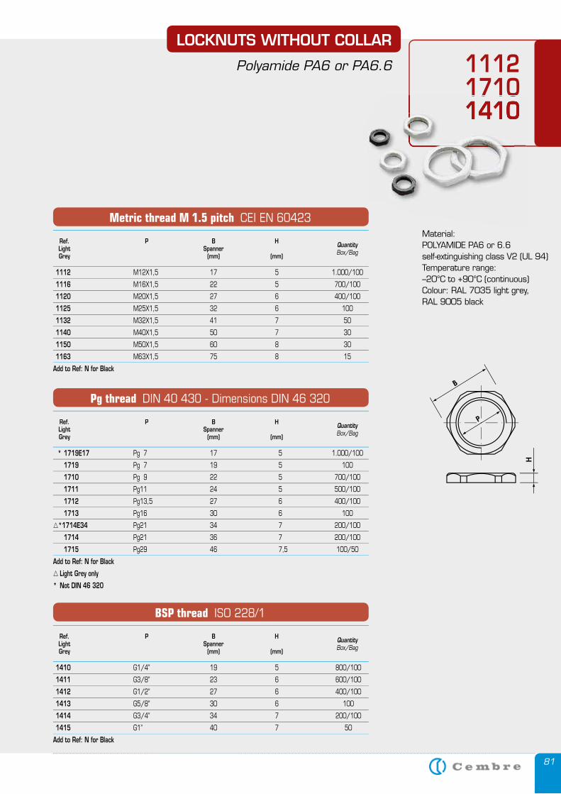
81
Material: POLYAMIDE PA6 or 6.6self-extinguishing class V2 (UL 94)Temperature range:–20°C to +90°C (continuous)Colour: RAL 7035 light grey, RAL 9005 black
LOCKNUTS WITHOUT COLLAR
Polyamide PA6 or PA6.6 111217101410171014101410
Ref. P B H Light Spanner Quantity
Grey (mm) (mm) Box/Bag
* 1719E17 Pg 7 17 5 1.000/100
1719 Pg 7 19 5 100
1710 Pg 9 22 5 700/100
1711 Pg11 24 5 500/100
1712 Pg13,5 27 6 400/100
1713 Pg16 30 6 100
*1714E34 Pg21 34 7 200/100
1714 Pg21 36 7 200/100
1715 Pg29 46 7,5 100/50
Add to Ref: N for Black
Light Grey only
* Not DIN 46 320
Pg thread DIN 40 430 - Dimensions DIN 46 320
Ref. P B H Light Spanner Quantity
Grey (mm) (mm) Box/Bag
1410 G1/4’’ 19 5 800/100
1411 G3/8’’ 23 6 600/100
1412 G1/2’’ 27 6 400/100
1413 G5/8’’ 30 6 100
1414 G3/4’’ 34 7 200/100
1415 G1’’ 40 7 50
Add to Ref: N for Black
BSP thread ISO 228/1
Ref. P B H Light Spanner Quantity
Grey (mm) (mm) Box/Bag
1112 M12X1,5 17 5 1.000/100
1116 M16X1,5 22 5 700/100
1120 M20X1,5 27 6 400/100
1125 M25X1,5 32 6 100
1132 M32X1,5 41 7 50
1140 M40X1,5 50 7 30
1150 M50X1,5 60 8 30
1163 M63X1,5 75 8 15
Add to Ref: N for Black
Metric thread M 1.5 pitch CEI EN 60423
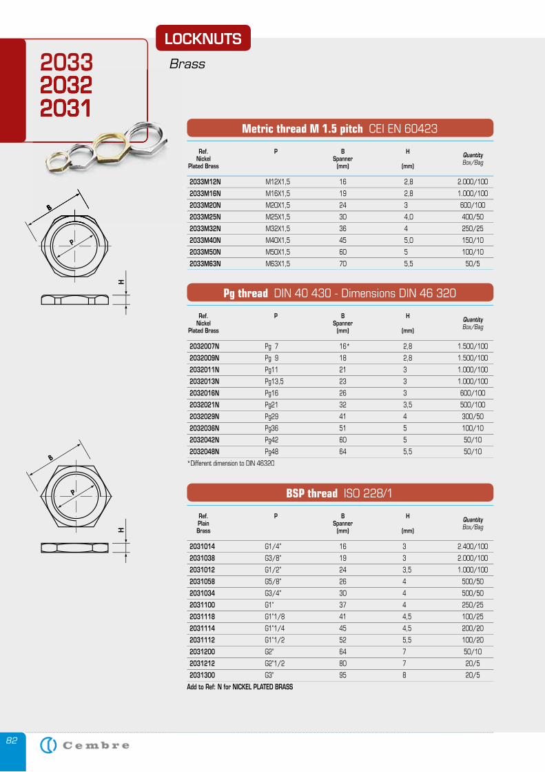
82
Ref. P B H Nickel Spanner Quantity
Plated Brass (mm) (mm) Box/Bag
2033M12N M12X1,5 16 2,8 2.000/100
2033M16N M16X1,5 19 2,8 1.000/100
2033M20N M20X1,5 24 3 600/100
2033M25N M25X1,5 30 4,0 400/50
2033M32N M32X1,5 36 4 250/25
2033M40N M40X1,5 45 5,0 150/10
2033M50N M50X1,5 60 5 100/10
2033M63N M63X1,5 70 5,5 50/5
Metric thread M 1.5 pitch CEI EN 60423
Ref. P B H Nickel Spanner Quantity
Plated Brass (mm) (mm) Box/Bag
2032007N Pg 7 16* 2,8 1.500/100
2032009N Pg 9 18 2,8 1.500/100
2032011N Pg11 21 3 1.000/100
2032013N Pg13,5 23 3 1.000/100
2032016N Pg16 26 3 600/100
2032021N Pg21 32 3,5 500/100
2032029N Pg29 41 4 300/50
2032036N Pg36 51 5 100/10
2032042N Pg42 60 5 50/10
2032048N Pg48 64 5,5 50/10
*Different dimension to DIN 46320
Pg thread DIN 40 430 - Dimensions DIN 46 320
Ref. P B H Plain Spanner Quantity
Brass (mm) (mm) Box/Bag
2031014 G1/4’’ 16 3 2.400/100
2031038 G3/8’’ 19 3 2.000/100
2031012 G1/2’’ 24 3,5 1.000/100
2031058 G5/8’’ 26 4 500/50
2031034 G3/4’’ 30 4 500/50
2031100 G1’’ 37 4 250/25
2031118 G1’’1/8 41 4,5 100/25
2031114 G1’’1/4 45 4,5 200/20
2031112 G1’’1/2 52 5,5 100/20
2031200 G2’’ 64 7 50/10
2031212 G2’’1/2 80 7 20/5
2031300 G3’’ 95 8 20/5
Add to Ref: N for NICKEL PLATED BRASS
BSP thread ISO 228/1
LOCKNUTS
Brass203320322031
203320322031
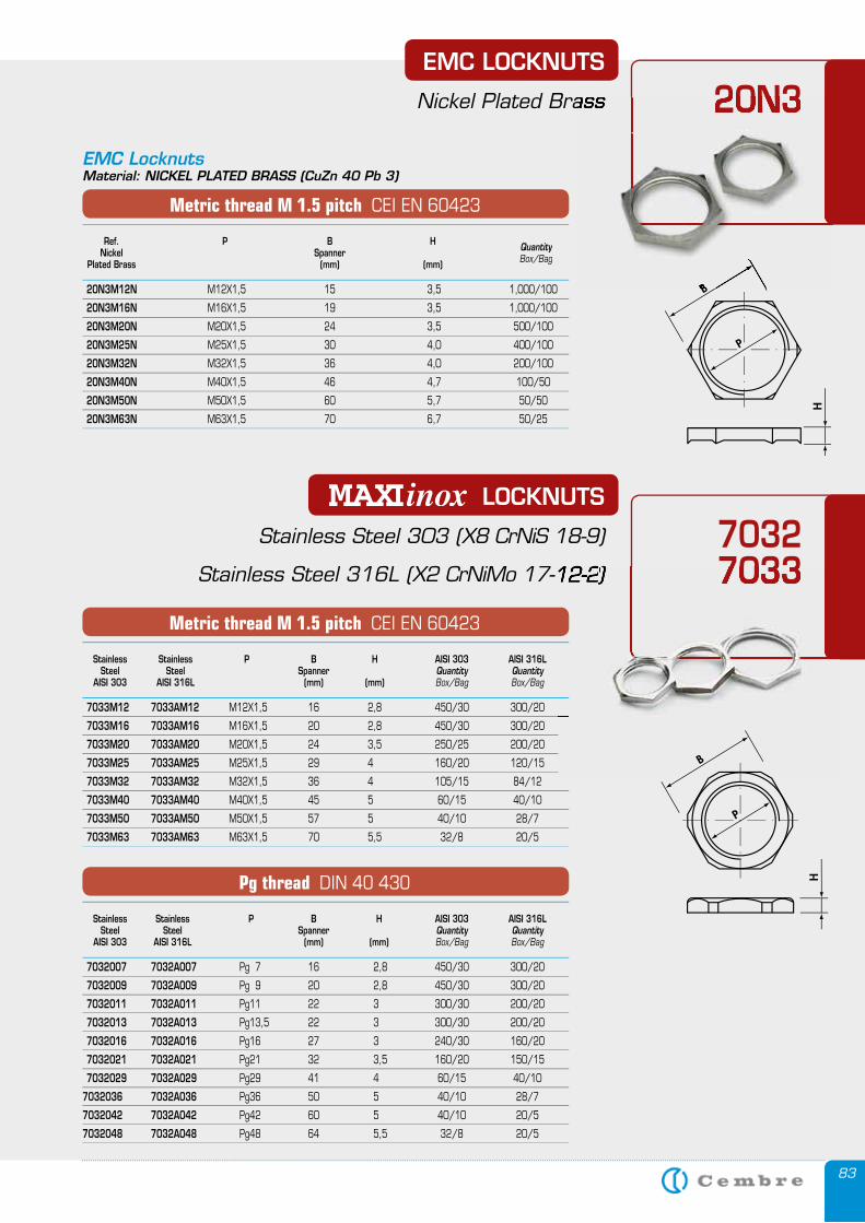
83
20N3 EMC LOCKNUTS
Nickel Plated Brass
Ref. P B H Nickel Spanner Quantity
Plated Brass (mm) (mm) Box/Bag
20N3M12N M12X1,5 15 3,5 1,000/100
20N3M16N M16X1,5 19 3,5 1,000/100
20N3M20N M20X1,5 24 3,5 500/100
20N3M25N M25X1,5 30 4,0 400/100
20N3M32N M32X1,5 36 4,0 200/100
20N3M40N M40X1,5 46 4,7 100/50
20N3M50N M50X1,5 60 5,7 50/50
20N3M63N M63X1,5 70 6,7 50/25
Metric thread M 1.5 pitch CEI EN 60423
20N3 Nickel Plated Brass
70327033
LOCKNUTS
Stainless Steel 303 (X8 CrNiS 18-9)
Stainless Steel 316L (X2 CrNiMo 17-12-2) 7033X2 CrNiMo 17-12-2)X2 CrNiMo 17-12-2)X2 CrNiMo 17-12-2
EMC LocknutsMaterial: NICKEL PLATED BRASS (CuZn 40 Pb 3)
Stainless Stainless P B H AISI 303 AISI 316L Steel Steel Spanner Quantity Quantity AISI 303 AISI 316L (mm) (mm) Box/Bag Box/Bag
7033M12 7033AM12 M12X1,5 16 2,8 450/30 300/20
7033M16 7033AM16 M16X1,5 20 2,8 450/30 300/20
7033M20 7033AM20 M20X1,5 24 3,5 250/25 200/20
7033M25 7033AM25 M25X1,5 29 4 160/20 120/15
7033M32 7033AM32 M32X1,5 36 4 105/15 84/12
7033M40 7033AM40 M40X1,5 45 5 60/15 40/10
7033M50 7033AM50 M50X1,5 57 5 40/10 28/7
7033M63 7033AM63 M63X1,5 70 5,5 32/8 20/5
Metric thread M 1.5 pitch CEI EN 60423
Stainless Stainless P B H AISI 303 AISI 316L Steel Steel Spanner Quantity Quantity AISI 303 AISI 316L (mm) (mm) Box/Bag Box/Bag
7032007 7032A007 Pg 7 16 2,8 450/30 300/20
7032009 7032A009 Pg 9 20 2,8 450/30 300/20
7032011 7032A011 Pg11 22 3 300/30 200/20
7032013 7032A013 Pg13,5 22 3 300/30 200/20
7032016 7032A016 Pg16 27 3 240/30 160/20
7032021 7032A021 Pg21 32 3,5 160/20 150/15
7032029 7032A029 Pg29 41 4 60/15 40/10
7032036 7032A036 Pg36 50 5 40/10 28/7
7032042 7032A042 Pg42 60 5 40/10 20/5
7032048 7032A048 Pg48 64 5,5 32/8 20/5
Pg thread DIN 40 430
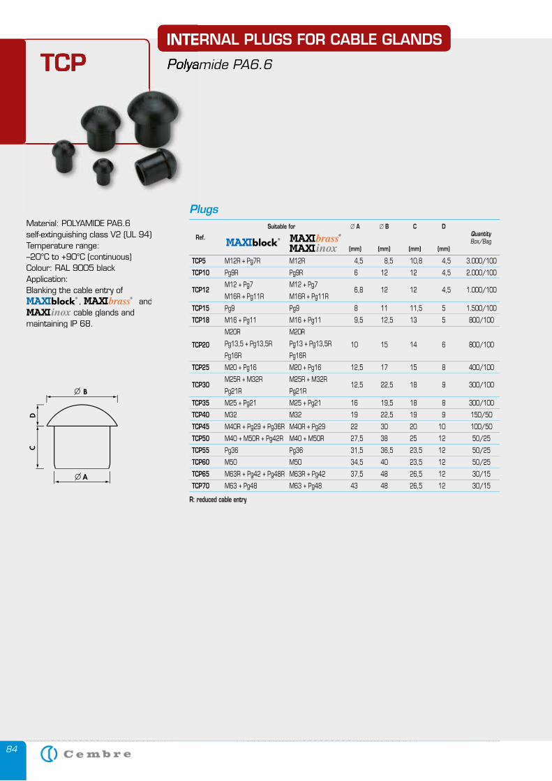
84
Material: POLYAMIDE PA6.6self-extinguishing class V2 (UL 94)Temperature range:–20°C to +90°C (continuous)Colour: RAL 9005 blackApplication:Blanking the cable entry of , and cable glands and maintaining IP 68.
INTERNAL PLUGS FOR CABLE GLANDS
Polyamide PA6.6TCPINTERNAL PLUGS FOR CABLE GLANDS
Polyamide PA6.6TCP
spiral
Plugs � A � B C D Ref.
Suitable for Quantity
Box/Bag (mm) (mm) (mm) (mm)
TCP5 M12R + Pg7R M12R 4,5 8,5 10,8 4,5 3.000/100
TCP10 Pg9R Pg9R 6 12 12 4,5 2.000/100
M12 + Pg7 M12 + Pg7
TCP12
M16R + Pg11R M16R + Pg11R 6,8 12 12 4,5 1.000/100
TCP15 Pg9 Pg9 8 11 11,5 5 1.500/100
TCP18 M16 + Pg11 M16 + Pg11 9,5 12,5 13 5 800/100
TCP20
M20R M20R
Pg13,5 + Pg13,5R Pg13 + Pg13,5R 10 15 14 6 800/100 Pg16R Pg16R
TCP25 M20 + Pg16 M20 + Pg16 12,5 17 15 8 400/100
TCP30
M25R + M32R M25R + M32R 12,5 22,5 18 9 300/100
Pg21R Pg21R
TCP35 M25 + Pg21 M25 + Pg21 16 19,5 18 8 300/100
TCP40 M32 M32 19 22,5 19 9 150/50
TCP45 M40R + Pg29 + Pg36R M40R + Pg29 22 30 20 10 100/50
TCP50 M40 + M50R + Pg42R M40 + M50R 27,5 38 25 12 50/25
TCP55 Pg36 Pg36 31,5 36,5 23,5 12 50/25
TCP60 M50 M50 34,5 40 23,5 12 50/25
TCP65 M63R + Pg42 + Pg48R M63R + Pg42 37,5 48 26,5 12 30/15
TCP70 M63 + Pg48 M63 + Pg48 43 48 26,5 12 30/15
R: reduced cable entry
spiral
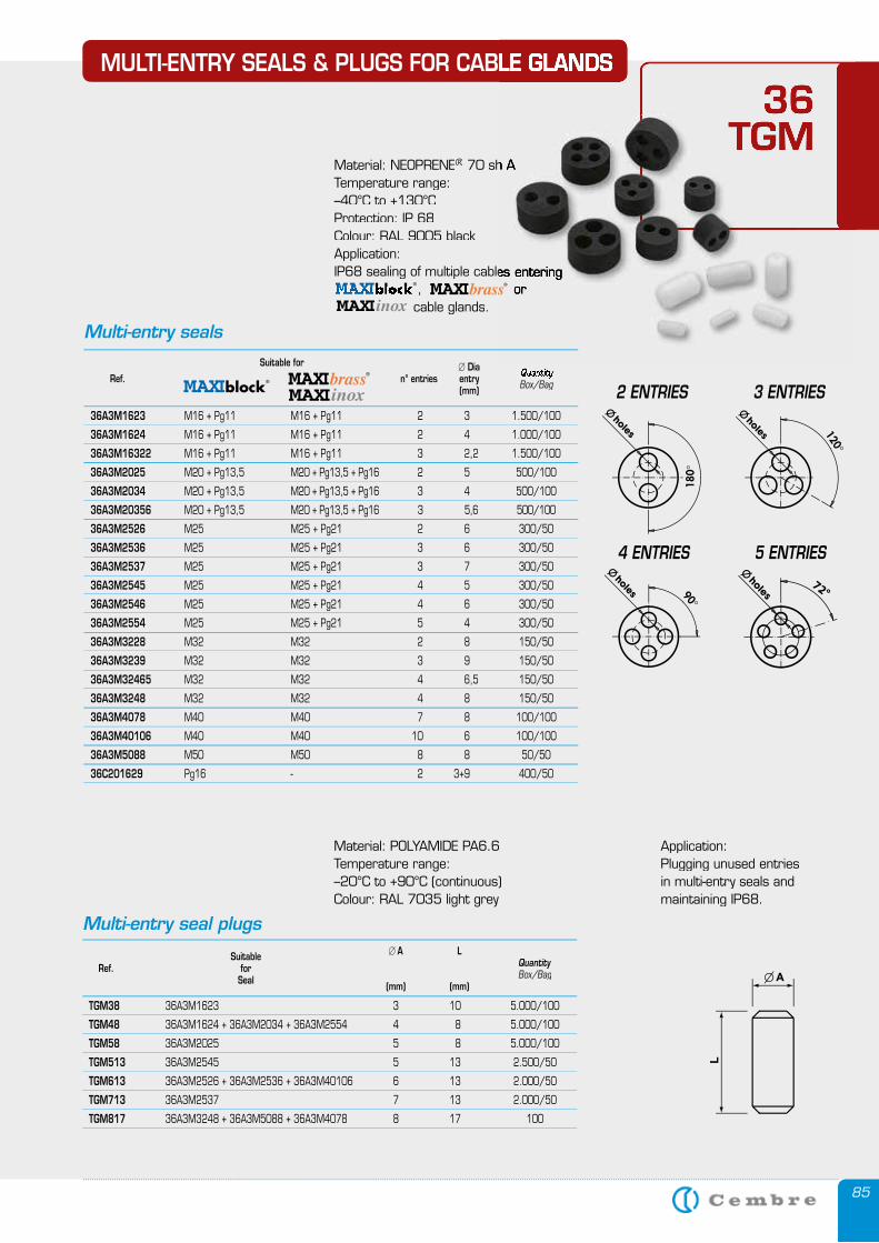
85
Suitable � A L Ref. for Quantity Seal Box/Bag (mm) (mm)
TGM38 36A3M1623 3 10 5.000/100
TGM48 36A3M1624 + 36A3M2034 + 36A3M2554 4 8 5.000/100
TGM58 36A3M2025 5 8 5.000/100
TGM513 36A3M2545 5 13 2.500/50
TGM613 36A3M2526 + 36A3M2536 + 36A3M40106 6 13 2.000/50
TGM713 36A3M2537 7 13 2.000/50
TGM817 36A3M3248 + 36A3M5088 + 36A3M4078 8 17 100
Multi-entry seal plugs
Material: POLYAMIDE PA6.6Temperature range:–20°C to +90°C (continuous)Colour: RAL 7035 light grey
MULTI-ENTRY SEALS & PLUGS FOR CABLE GLANDS
36 TGM
Application: Plugging unused entries in multi-entry seals and maintaining IP68.
MULTI-ENTRY SEALS & PLUGS FOR CABLE GLANDS
36 TGM TGM
Material: NEOPRENE® 70 sh A 70 sh A 70 sh A® 70 sh A®
Temperature range: –40°C to +130°CProtection: IP 68Colour: RAL 9005 blackApplication:IP68 sealing of multiple cables entering IP68 sealing of multiple cables entering IP68 sealing of multiple cables entering , or , or , or , or cable glands. , or , or , or , or , or , or
spiral 2 ENTRIES 3 ENTRIES
4 ENTRIES 5 ENTRIES
Multi-entry seals
Suitable for � Dia Ref. n° entries entry Quantity
(mm) Box/Bag
36A3M1623 M16 + Pg11 M16 + Pg11 2 3 1.500/100
36A3M1624 M16 + Pg11 M16 + Pg11 2 4 1.000/100
36A3M16322 M16 + Pg11 M16 + Pg11 3 2,2 1.500/100
36A3M2025 M20 + Pg13,5 M20 + Pg13,5 + Pg16 2 5 500/100
36A3M2034 M20 + Pg13,5 M20 + Pg13,5 + Pg16 3 4 500/100
36A3M20356 M20 + Pg13,5 M20 + Pg13,5 + Pg16 3 5,6 500/100
36A3M2526 M25 M25 + Pg21 2 6 300/50
36A3M2536 M25 M25 + Pg21 3 6 300/50
36A3M2537 M25 M25 + Pg21 3 7 300/50
36A3M2545 M25 M25 + Pg21 4 5 300/50
36A3M2546 M25 M25 + Pg21 4 6 300/50
36A3M2554 M25 M25 + Pg21 5 4 300/50
36A3M3228 M32 M32 2 8 150/50
36A3M3239 M32 M32 3 9 150/50
36A3M32465 M32 M32 4 6,5 150/50
36A3M3248 M32 M32 4 8 150/50
36A3M4078 M40 M40 7 8 100/100
36A3M40106 M40 M40 10 6 100/100
36A3M5088 M50 M50 8 8 50/50
36C201629 Pg16 - 2 3+9 400/50
spiral
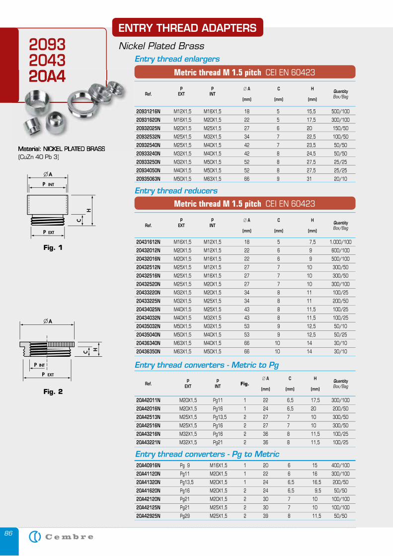
86
Fig. 2
Fig. 1
ENTRY THREAD ADAPTERS
Nickel Plated Brass
Entry thread converters - Metric to Pg
P P � A C H Ref. EXT INT Fig. Quantity
(mm) (mm) (mm) Box/Bag
20A42011N M20X1,5 Pg11 1 22 6,5 17,5 300/100
20A42016N M20X1,5 Pg16 1 24 6,5 20 200/50
20A42513N M25X1,5 Pg13,5 2 27 7 10 300/50
20A42516N M25X1,5 Pg16 2 27 7 10 300/50
20A43216N M32X1,5 Pg16 2 36 8 11,5 100/25
20A43221N M32X1,5 Pg21 2 36 8 11,5 100/25
Entry thread converters - Pg to Metric 20A40916N Pg 9 M16X1,5 1 20 6 15 400/100
20A41120N Pg11 M20X1,5 1 22 6 16 300/100
20A41320N Pg13,5 M20X1,5 1 24 6,5 16,5 200/50
20A41620N Pg16 M20X1,5 2 24 6,5 9,5 50/50
20A42120N Pg21 M20X1,5 2 30 7 10 100/100
20A42125N Pg21 M25X1,5 2 30 7 10 100/100
20A42925N Pg29 M25X1,5 2 39 8 11,5 50/50
P P � A C H Ref. EXT INT Quantity
(mm) (mm) (mm) Box/Bag
20931216N M12X1,5 M16X1,5 18 5 15,5 500/100
20931620N M16X1,5 M20X1,5 22 5 17,5 300/100
20932025N M20X1,5 M25X1,5 27 6 20 150/50
20932532N M25X1,5 M32X1,5 34 7 22,5 100/50
20932540N M25X1,5 M40X1,5 42 7 23,5 50/50
20933240N M32X1,5 M40X1,5 42 8 24,5 50/50
20933250N M32X1,5 M50X1,5 52 8 27,5 25/25
20934050N M40X1,5 M50X1,5 52 8 27,5 25/25
20935063N M50X1,5 M63X1,5 66 9 31 20/10
Metric thread M 1.5 pitch CEI EN 60423
P P � A C H Ref. EXT INT Quantity
(mm) (mm) (mm) Box/Bag
20431612N M16X1,5 M12X1,5 18 5 7,5 1.000/100
20432012N M20X1,5 M12X1,5 22 6 9 600/100
20432016N M20X1,5 M16X1,5 22 6 9 500/100
20432512N M25X1,5 M12X1,5 27 7 10 300/50
20432516N M25X1,5 M16X1,5 27 7 10 300/50
20432520N M25X1,5 M20X1,5 27 7 10 300/100
20433220N M32X1,5 M20X1,5 34 8 11 100/25
20433225N M32X1,5 M25X1,5 34 8 11 200/50
20434025N M40X1,5 M25X1,5 43 8 11,5 100/25
20434032N M40X1,5 M32X1,5 43 8 11,5 100/25
20435032N M50X1,5 M32X1,5 53 9 12,5 50/10
20435040N M50X1,5 M40X1,5 53 9 12,5 50/25
20436340N M63X1,5 M40X1,5 66 10 14 30/10
20436350N M63X1,5 M50X1,5 66 10 14 30/10
Metric thread M 1.5 pitch CEI EN 60423
Entry thread enlargers
Entry thread reducers
Material: NICKEL PLATED BRASS(CuZn 40 Pb 3)
2093204320A4
Material: NICKEL PLATED BRASS
20A420A4
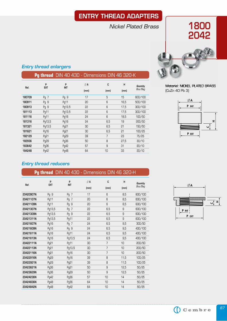
87
ENTRY THREAD ADAPTERS
Nickel Plated Brass
P P � A C H Ref. EXT INT Quantity
(mm) (mm) (mm) Box/Bag
180709 Pg 7 Pg 9 17 5 15 600/100
180911 Pg 9 Pg11 20 6 16,5 500/100
180913 Pg 9 Pg13,5 22 6 17,5 300/100
181113 Pg11 Pg13,5 22 6 17,5 300/100
181116 Pg11 Pg16 24 6 18,5 100/50
181316 Pg13,5 Pg16 24 6,5 19 200/50
181321 Pg13,5 Pg21 30 6,5 21 150/50
181621 Pg16 Pg21 30 6,5 21 100/25
182129 Pg21 Pg29 39 7 23 75/25
182936 Pg29 Pg36 50 8 27,5 30/10
183642 Pg36 Pg42 57 9 31 20/10
184248 Pg42 Pg48 64 10 33 20/10
P P � A C H Ref. EXT INT Quantity
(mm) (mm) (mm) Box/Bag
20420907N Pg 9 Pg 7 17 6 8,5 800/100
20421107N Pg11 Pg 7 20 6 8,5 600/100
20421109N Pg11 Pg 9 20 6 8,5 600/100
20421307N Pg13,5 Pg 7 22 6,5 9 600/100
20421309N Pg13,5 Pg 9 22 6,5 9 600/100
20421311N Pg13,5 Pg11 22 6,5 9 600/100
20421607N Pg16 Pg 7 24 6,5 9,5 300/50
20421609N Pg16 Pg 9 24 6,5 9,5 400/100
20421611N Pg16 Pg11 24 6,5 9,5 400/100
20421613N Pg16 Pg13,5 24 6,5 9,5 400/100
20422111N Pg21 Pg11 30 7 10 200/50
20422113N Pg21 Pg13,5 30 7 10 200/50
20422116N Pg21 Pg16 30 7 10 200/50
20422916N Pg29 Pg16 39 8 11,5 100/25
20422921N Pg29 Pg21 39 8 11,5 100/25
20423621N Pg36 Pg21 50 9 12,5 50/25
20423629N Pg36 Pg29 50 9 12,5 50/25
20424236N Pg42 Pg36 57 10 14 50/25
20424836N Pg48 Pg36 64 10 14 50/25
20424842N Pg48 Pg42 64 10 14 50/25
Pg thread DIN 40 430 - Dimensions DIN 46 320-K
Pg thread DIN 40 430 - Dimensions DIN 46 320-H
Entry thread enlargers
Entry thread reducers
Material: NICKEL PLATED BRASS(CuZn 40 Pb 3)
18002042
Material: NICKEL PLATED BRASS
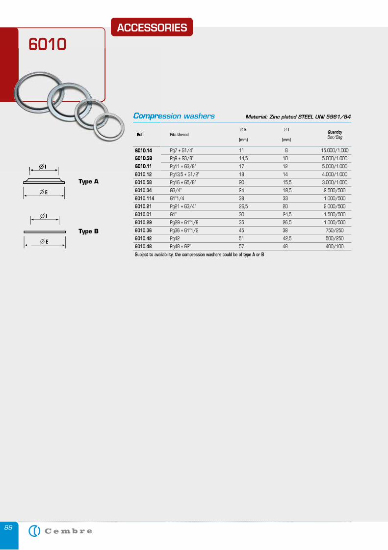
88
ACCESSORIES
6010
� E � I Ref. Fits thread Quantity
(mm) (mm) Box/Bag
6010.14 Pg7 + G1/4” 11 8 15.000/1.000
6010.38 Pg9 + G3/8” 14,5 10 5.000/1.000
6010.11 Pg11 + G3/8” 17 12 5.000/1.000
6010.12 Pg13,5 + G1/2” 18 14 4.000/1.000
6010.58 Pg16 + G5/8” 20 15,5 3.000/1.000
6010.34 G3/4” 24 18,5 2.500/500
6010.114 G1”1/4 38 33 1.000/500
6010.21 Pg21 + G3/4” 26,5 20 2.000/500
6010.01 G1” 30 24,5 1.500/500
6010.29 Pg29 + G1”1/8 35 26,5 1.000/500
6010.36 Pg36 + G1”1/2 45 38 750/250
6010.42 Pg42 51 42,5 500/250
6010.48 Pg48 + G2” 57 48 400/100
Subject to availability, the compression washers could be of type A or B
Compression washers Material: Zinc plated STEEL UNI 5961/84
Type A
Type B
6010
Ref. Fits thread (mm) (mm)
6010.14
6010.38
6010.11 P
Compression washers
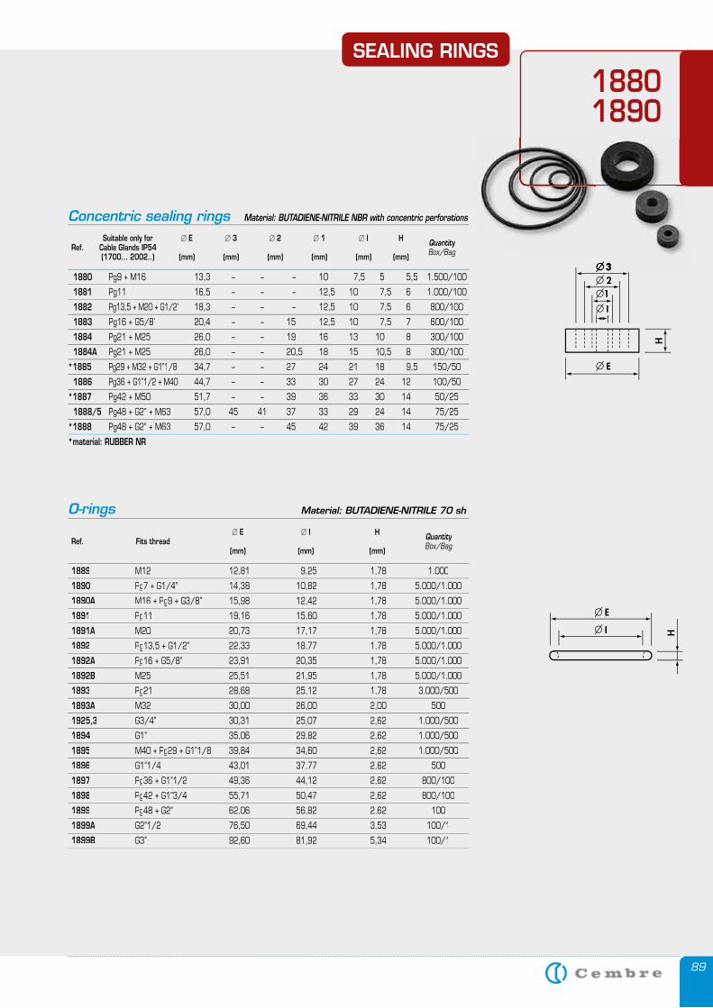
89
� E � I H Ref. Fits thread Quantity
(mm) (mm) (mm) Box/Bag
1889 M12 12,81 9,25 1,78 1.000
1890 Pg7 + G1/4’’ 14,38 10,82 1,78 5.000/1.000
1890A M16 + P1890A M16 + P1890A g9 + G3/8’’ 15,98 12,42 1,78 5.000/1.000
1891 Pg11 19,16 15,60 1,78 5.000/1.000
1891A M20 20,73 17,17 1,78 5.000/1.0001891A M20 20,73 17,17 1,78 5.000/1.0001891A
1892 Pg13,5 + G1/2’’ 22,33 18,77 1,78 5.000/1.000
1892A P1892A P1892A g16 + G5/8’’ 23,91 20,35 1,78 5.000/1.000
1892B M25 25,51 21,95 1,78 5.000/1.000
1893 Pg21 28,68 25,12 1,78 3.000/500
1893A M32 30,00 26,00 2,00 5001893A M32 30,00 26,00 2,00 5001893A
1925,3 G3/4’’ 30,31 25,07 2,62 1.000/500
1894 G1’’ 35,06 29,82 2,62 1.000/500
1895 M40 + Pg29 + G1’’1/8 39,84 34,60 2,62 1.000/500
1896 G1’’1/4 43,01 37,77 2,62 500
1897 Pg36 + G1’’1/2 49,36 44,12 2,62 800/100
1898 Pg42 + G1’’3/4 55,71 50,47 2,62 800/100
1899 Pg48 + G2’’ 62,06 56,82 2,62 100
1899A G2’’1/2 76,50 69,44 3,53 100/11899A G2’’1/2 76,50 69,44 3,53 100/11899A
1899B G3’’ 92,60 81,92 5,34 100/1
O-rings Material: BUTADIENE-NITRILE 70 sh
SEALING RINGS
18801890
Concentric sealing rings Material: BUTADIENE-NITRILE NBR with concentric perforations
Suitable only for � E � 3 � 2 � 1 � I H Ref. Cable Glands IP54 Quantity
(1700... 2002..) (mm) (mm) (mm) (mm) (mm) (mm) Box/Bag
1880 Pg9 + M16 13,3 – – – 10 7,5 5 5,5 1.500/100
1881 Pg11 16,5 – – – 12,5 10 7,5 6 1.000/100
1882 Pg13,5 + M20 + G1/2’’ 18,3 – – – 12,5 10 7,5 6 800/100
1883 Pg16 + G5/8’’ 20,4 – – 15 12,5 10 7,5 7 600/100
1884 Pg21 + M25 26,0 – – 19 16 13 10 8 300/100
1884A Pg21 + M25 26,0 – – 20,5 18 15 10,5 8 300/100
*1885 Pg29 + M32 + G1’’1/8 34,7 – – 27 24 21 18 9,5 150/50
1886 Pg36 + G1’’1/2 + M40 44,7 – – 33 30 27 24 12 100/50
*1887 Pg42 + M50 51,7 – – 39 36 33 30 14 50/25
1888/5 Pg48 + G2’’ + M63 57,0 45 41 37 33 29 24 14 75/25
*1888 Pg48 + G2’’ + M63 57,0 – – 45 42 39 36 14 75/25
*material: RUBBER NR
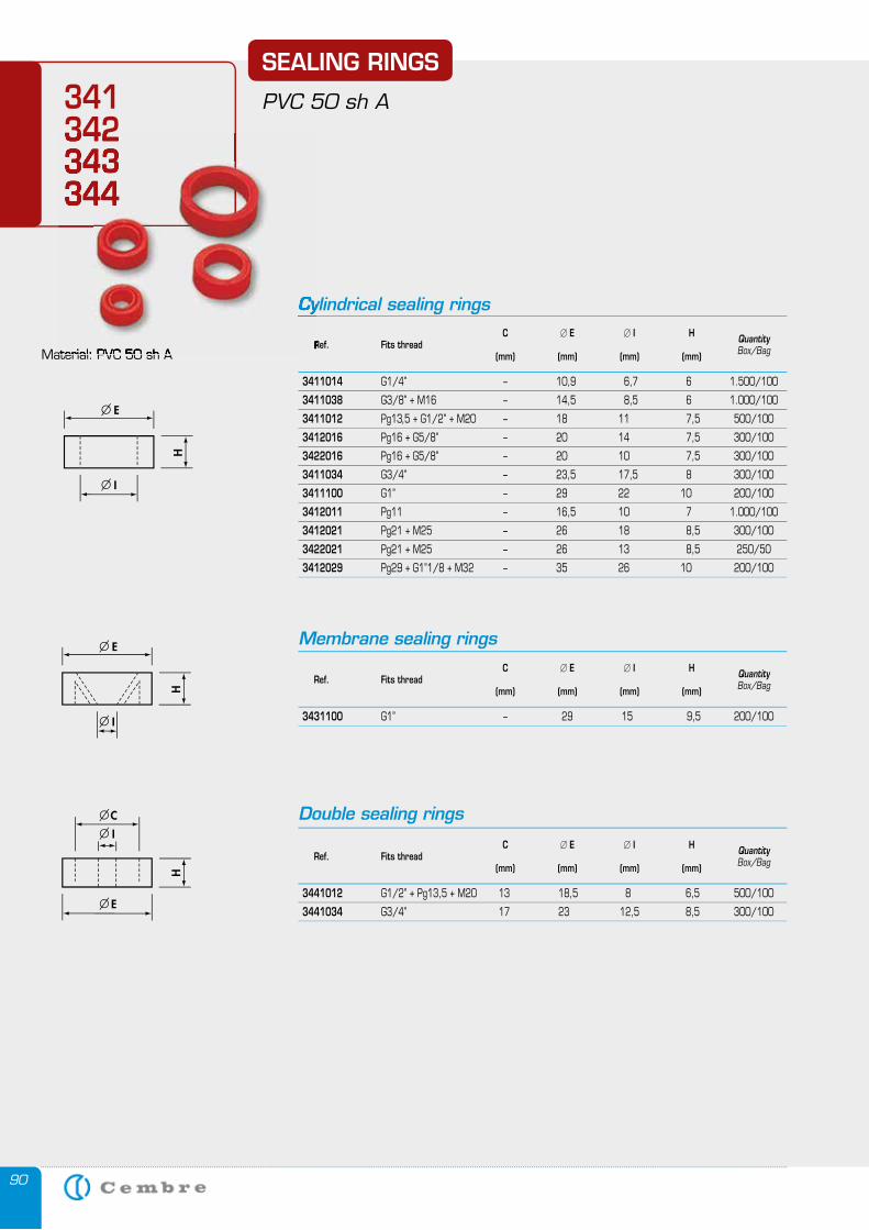
90
Cylindrical sealing rings
Membrane sealing rings
Double sealing rings
C � E � I H Ref. Fits thread Quantity
(mm) (mm) (mm) (mm) Box/Bag
3411014 G1/4’’ – 10,9 6,7 6 1.500/100
3411038 G3/8’’ + M16 – 14,5 8,5 6 1.000/100
3411012 Pg13,5 + G1/2” + M20 – 18 11 7,5 500/100
3412016 Pg16 + G5/8’’ – 20 14 7,5 300/100
3422016 Pg16 + G5/8’’ – 20 10 7,5 300/100
3411034 G3/4’’ – 23,5 17,5 8 300/100
3411100 G1” – 29 22 10 200/100
3412011 Pg11 – 16,5 10 7 1.000/100
3412021 Pg21 + M25 – 26 18 8,5 300/100
3422021 Pg21 + M25 – 26 13 8,5 250/50
3412029 Pg29 + G1’’1/8 + M32 – 35 26 10 200/100
C � E � I H Ref. Fits thread Quantity
(mm) (mm) (mm) (mm) Box/Bag
3431100 G1’’ – 29 15 9,5 200/100
C � E � I H Ref. Fits thread Quantity
(mm) (mm) (mm) (mm) Box/Bag
3441012 G1/2’’ + Pg13,5 + M20 13 18,5 8 6,5 500/100
3441034 G3/4’’ 17 23 12,5 8,5 300/100
SEALING RINGS
PVC 50 sh A
Material: PVC 50 sh A
341342343344
Cylindrical sealing rings C Ref. Fits thread (mm) (mm) (mm) (mm) Material: PVC 50 sh A
342343344343344
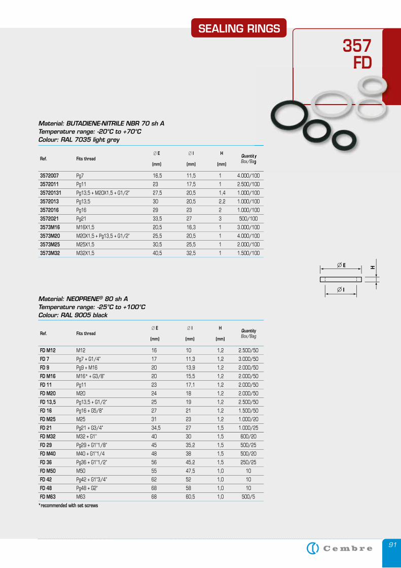
91
� E � I H Ref. Fits thread Quantity
(mm) (mm) (mm) Box/Bag
3572007 Pg7 16,5 11,5 1 4.000/100
3572011 Pg11 23 17,5 1 2.500/100
35720131 Pg13,5 + M20X1,5 + G1/2’’ 27,5 20,5 1,4 1.000/100
3572013 Pg13,5 30 20,5 2,2 1.000/100
3572016 Pg16 29 23 2 1.000/100
3572021 Pg21 33,5 27 3 500/100
3573M16 M16X1,5 20,5 16,3 1 3.000/100
3573M20 M20X1,5 + Pg13,5 + G1/2’’ 25,5 20,5 1 4.000/100
3573M25 M25X1,5 30,5 25,5 1 2.000/100
3573M32 M32X1,5 40,5 32,5 1 1.500/100
Material: BUTADIENE-NITRILE NBR 70 sh ATemperature range: -20°C to +70°C Colour: RAL 7035 light grey
SEALING RINGS
357FD
QuantityBox/Bag
FD
Material: NEOPRENE® 80 sh ATemperature range: -25°C to +100°CColour: RAL 9005 black
� E � I H Ref. Fits thread Quantity
(mm) (mm) (mm) Box/Bag
FD M12 M12 16 10 1,2 2.500/50
FD 7 Pg7 + G1/4” 17 11,3 1,2 3.000/50
FD 9 Pg9 + M16 20 13,9 1,2 2.000/50
FD M16 M16* + G3/8” 20 15,5 1,2 2.000/50
FD 11 Pg11 23 17,1 1,2 2.000/50
FD M20 M20 24 18 1,2 2.000/50
FD 13,5 Pg13,5 + G1/2” 25 19 1,2 2.500/50
FD 16 Pg16 + G5/8” 27 21 1,2 1.500/50
FD M25 M25 31 23 1,2 1.000/20
FD 21 Pg21 + G3/4” 34,5 27 1,5 1.000/25
FD M32 M32 + G1” 40 30 1,5 600/20
FD 29 Pg29 + G1”1/8” 45 35,2 1,5 500/25
FD M40 M40 + G1”1/4 48 38 1,5 500/20
FD 36 Pg36 + G1”1/2” 56 45,2 1,5 250/25
FD M50 M50 55 47,5 1,0 10
FD 42 Pg42 + G1”3/4” 62 52 1,0 10
FD 48 Pg48 + G2” 68 58 1,0 10
FD M63 M63 68 60,5 1,0 500/5
*recommended with set screws
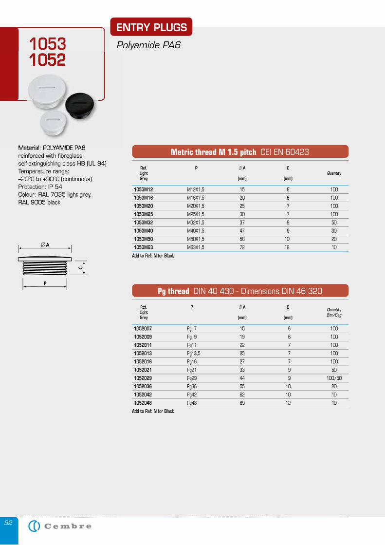
92
Material: POLYAMIDE PA6reinforced with fibreglassself-extinguishing class HB (UL 94)Temperature range:–20°C to +90°C (continuous)Protection: IP 54Colour: RAL 7035 light grey, RAL 9005 black
Ref. P � A C Light Quantity Grey (mm) (mm)
1053M12 M12X1,5 15 6 100
1053M16 M16X1,5 20 6 100
1053M20 M20X1,5 25 7 100
1053M25 M25X1,5 30 7 100
1053M32 M32X1,5 37 9 50
1053M40 M40X1,5 47 9 30
1053M50 M50X1,5 58 10 20
1053M63 M63X1,5 72 12 10
Add to Ref: N for Black
Metric thread M 1.5 pitch CEI EN 60423
Ref. P � A C Light Quantity
Grey (mm) (mm) Box/Bag
1052007 Pg 7 15 6 100
1052009 Pg 9 19 6 100
1052011 Pg11 22 7 100
1052013 Pg13,5 25 7 100
1052016 Pg16 27 7 100
1052021 Pg21 33 9 50
1052029 Pg29 44 9 100/50
1052036 Pg36 55 10 20
1052042 Pg42 62 10 10
1052048 Pg48 69 12 10
Add to Ref: N for Black
Pg thread DIN 40 430 - Dimensions DIN 46 320
ENTRY PLUGS
Polyamide PA610531052
Material: POLYAMIDE PA6
1052
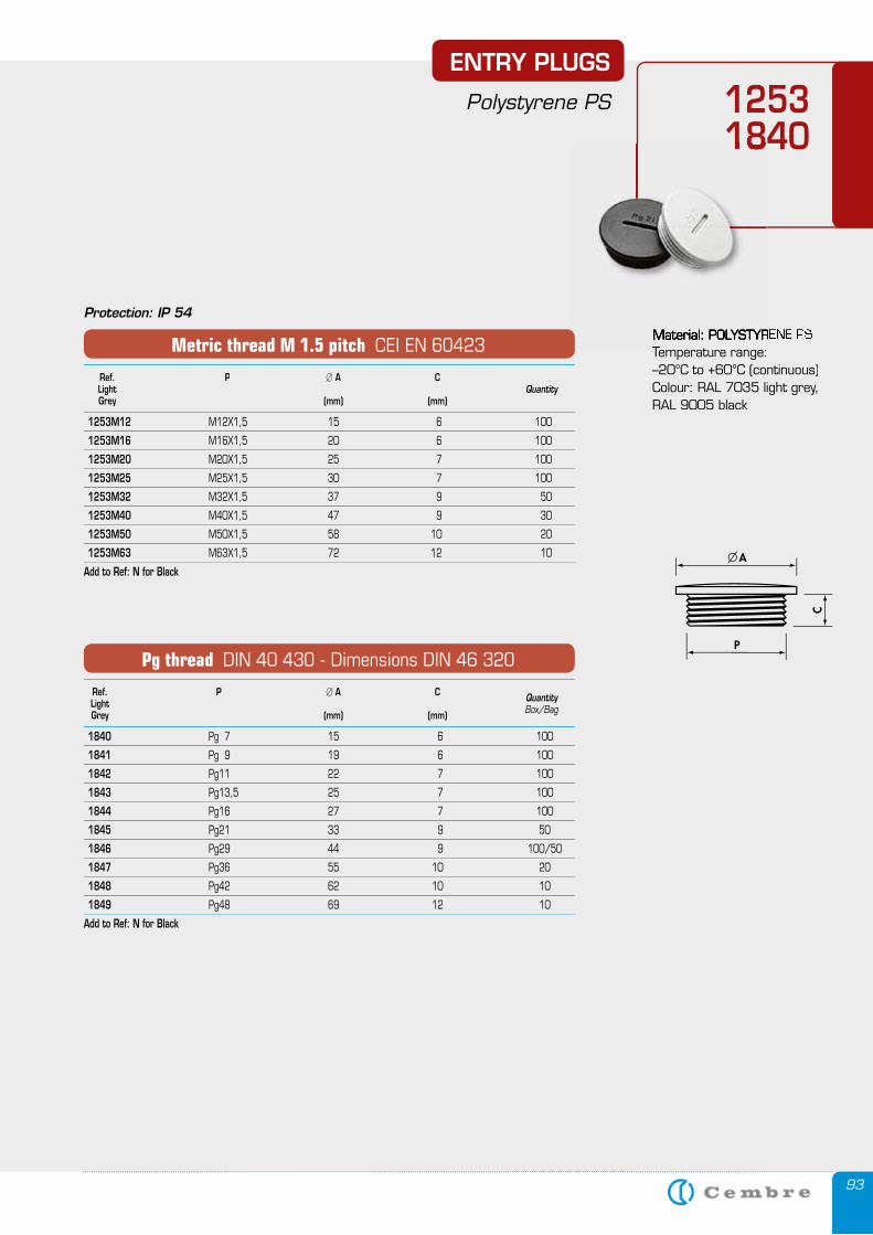
93
ENTRY PLUGS
Polystyrene PS 125318401840
Ref. P � A C Light Quantity
Grey (mm) (mm) Box/Bag
1840 Pg 7 15 6 100
1841 Pg 9 19 6 100
1842 Pg11 22 7 100
1843 Pg13,5 25 7 100
1844 Pg16 27 7 100
1845 Pg21 33 9 50
1846 Pg29 44 9 100/50
1847 Pg36 55 10 20
1848 Pg42 62 10 10
1849 Pg48 69 12 10
Add to Ref: N for Black
Pg thread DIN 40 430 - Dimensions DIN 46 320
Ref. P � A C Light Quantity Grey (mm) (mm)
1253M12 M12X1,5 15 6 100
1253M16 M16X1,5 20 6 100
1253M20 M20X1,5 25 7 100
1253M25 M25X1,5 30 7 100
1253M32 M32X1,5 37 9 50
1253M40 M40X1,5 47 9 30
1253M50 M50X1,5 58 10 20
1253M63 M63X1,5 72 12 10
Add to Ref: N for Black
Metric thread M 1.5 pitch CEI EN 60423
Protection: IP 54
Material: POLYSTYRENE PSMaterial: POLYSTYRENE PSTemperature range:Temperature range:–20°C to +60°C (continuous)Colour: RAL 7035 light grey, RAL 9005 black
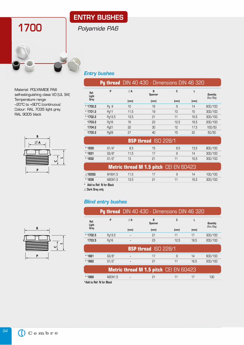
94
ENTRY BUSHES
Polyamide PA61700
Material: POLYAMIDE PA6 self-extinguishing class V0 (UL 94)Temperature range:–20°C to +90°C (continuous)Colour: RAL 7035 light grey,RAL 9005 black
Entry bushes
Blind entry bushes
P � A B C L Ref. Spanner Quantity Light Box/Bag Grey (mm) (mm) (mm) (mm)
* 1700.2 Pg 9 10 16 9 14 600/100
* 1701.2 Pg11 11,5 19 10 15 300/100
* 1702.2 Pg13,5 13,5 21 11 16,5 300/100
1703.2 Pg16 16 23 12,5 18,5 200/100
1704.2 Pg21 22 30 12 17,5 100/50
1705.2 Pg29 27 40 15 22 50/50
* 1830 G1/4’’ 8,5 15 8,5 13,5 800/100
* 1831 G3/8’’ 11,5 17 9 14 300/100
* 1832 G1/2’’ 13 21 11 16,5 300/100
1835G M16X1,5 11,5 17 9 14 100/100
* 1836 M20X1,5 13,5 21 11 16,5 300/100
* Add to Ref: N for Black Dark Grey only
Pg thread DIN 40 430 - Dimensions DIN 46 320
BSP thread ISO 228/1
Metric thread M 1.5 pitch CEI EN 60423
Metric thread M 1.5 pitch CEI EN 60423
P � A B C L Ref. Spanner Quantity Light Box/Bag Grey (mm) (mm) (mm) (mm)
* 1702.5 Pg13,5 – 21 11 17 300/100
1703.5 Pg16 – 23 12,5 18,5 200/100
* 1861 G3/8’’ – 17 9 14 600/100
* 1862 G1/2’’ – 21 11 16,5 200/100
* 1866 M20X1,5 – 21 11 17 100
*Add to Ref: N for Black
Pg thread DIN 40 430 - Dimensions DIN 46 320
BSP thread ISO 228/1
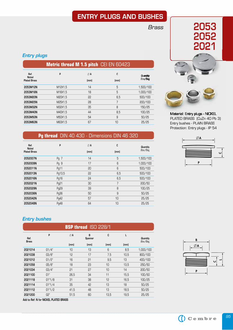
95
ENTRY PLUGS AND BUSHES
Brass 2053205220212021
Entry plugs
Entry bushes
Ref. P � A C Quantity Nickel Box/Bag Plated Brass (mm) (mm)
2052007N Pg 7 14 5 1,500/100
2052009N Pg 9 17 6 1,000/100
2052011N Pg11 20 6 500/100
2052013N Pg13,5 22 6,5 500/100
2052016N Pg16 24 6,5 500/100
2052021N Pg21 30 7 200/50
2052029N Pg29 39 8 100/25
2052036N Pg36 50 9 50/25
2052042N Pg42 57 10 25/25
2052048N Pg48 64 10 25/25
Pg thread DIN 40 430 - Dimensions DIN 46 320
Ref. P � A C QuantityQuantity Nickel Box/BagBox/Bag Plated Brass (mm) (mm)
2053M12N M12X1,5 14 5 1,500/100
2053M16N M16X1,5 18 5 1,000/100
2053M20N M20X1,5 22 6,5 500/100
2053M25N M25X1,5 28 7 200/100
2053M32N M32X1,5 35 8 150/25
2053M40N M40X1,5 44 8,5 100/25
2053M50N M50X1,5 54 9 50/25
2053M63N M63X1,5 67 10 25/25
Metric thread M 1.5 pitch CEI EN 60423
P � A B C L Ref. Spanner Quantity Brass Box/Bag (mm) (mm) (mm) (mm)
2021014 G1/4’’ 10 13 6 8,5 1,000/100
2021038 G3/8’’ 12 17 7,5 10,5 800/100
2021012 G1/2’’ 16 21 9,5 13 400/100
2021058 G5/8’’ 18 23 10 13,5 250/50
2021034 G3/4’’ 21 27 10 14 200/50
2021100 G1’’ 26,5 34 11 15,5 100/50
2021118 G1’’1/8 31 38 12 16,5 100/25
2021114 G1’’1/4 35 42 13 18 50/25
2021112 G1’’1/2 41,5 48 13 18,5 50/25
2021200 G2’’ 51,5 60 13,5 19,5 25/25
Add to Ref: N for NICKEL PLATED BRASS
BSP thread ISO 228/1
Material: Entry plugs - NICKEL Material: Entry plugs - NICKEL PLATED BRASS (CuZn 40 Pb 3)Entry bushes - PLAIN BRASSProtection: Entry plugs - IP 54
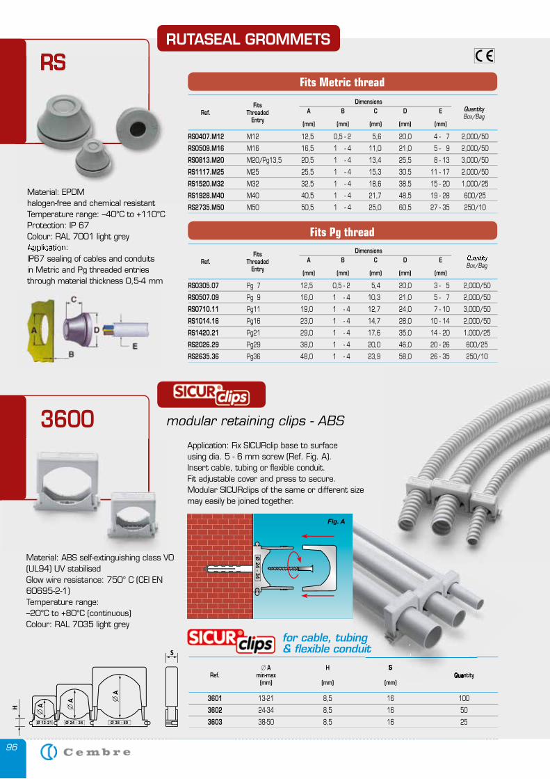
96
RUTASEAL GROMMETS
RSRS Fits Dimensions Ref. Threaded A B C D E Quantity Entry Box/Bag (mm) (mm) (mm) (mm) (mm)
RS0407.M12 M12 12,5 0,5 - 2 5,6 20,0 4 - 7 2,000/50
RS0509.M16 M16 16,5 1 - 4 11,0 21,0 5 - 9 2,000/50
RS0813.M20 M20/Pg13,5 20,5 1 - 4 13,4 25,5 8 - 13 3,000/50
RS1117.M25 M25 25,5 1 - 4 15,3 30,5 11 - 17 2,000/50
RS1520.M32 M32 32,5 1 - 4 18,6 38,5 15 - 20 1,000/25
RS1928.M40 M40 40,5 1 - 4 21,7 48,5 19 - 28 600/25
RS2735.M50 M50 50,5 1 - 4 25,0 60,5 27 - 35 250/10
Fits Metric thread
Fits Dimensions Ref. Threaded A B C D E Quantity Entry Box/Bag (mm) (mm) (mm) (mm) (mm)
RS0305.07 Pg 7 12,5 0,5 - 2 5,4 20,0 3 - 5 2,000/50
RS0507.09 Pg 9 16,0 1 - 4 10,3 21,0 5 - 7 2,000/50
RS0710.11 Pg11 19,0 1 - 4 12,7 24,0 7 - 10 3,000/50
RS1014.16 Pg16 23,0 1 - 4 14,7 28,0 10 - 14 2,000/50
RS1420.21 Pg21 29,0 1 - 4 17,6 35,0 14 - 20 1,000/25
RS2026.29 Pg29 38,0 1 - 4 20,0 46,0 20 - 26 600/25
RS2635.36 Pg36 48,0 1 - 4 23,9 58,0 26 - 35 250/10
Fits Pg thread
Material: EPDM halogen-free and chemical resistant Temperature range: –40°C to +110°CProtection: IP 67Colour: RAL 7001 light grey Application: IP67 sealing of cables and conduits in Metric and Pg threaded entriesthrough material thickness 0,5-4 mm
modular retaining clips - ABS
Material: ABS self-extinguishing class V0 (UL94) UV stabilisedGlow wire resistance: 750° C (CEI EN 60695-2-1)Temperature range:–20°C to +80°C (continuous)Colour: RAL 7035 light grey
� A H S Ref. min-max Quantity (mm) (mm) (mm)
3601 13-21 8,5 16 100
3602 24-34 8,5 16 50
3603 38-50 8,5 16 25
Application: Fix SICURclip base to surface using dia. 5 - 6 mm screw (Ref. Fig. A).Insert cable, tubing or flexible conduit.Fit adjustable cover and press to secure.Modular SICURclips of the same or different size may easily be joined together.
A H S Ref. min-max Quantity
Fig. A
for cable, tubing& flexible conduit
3600
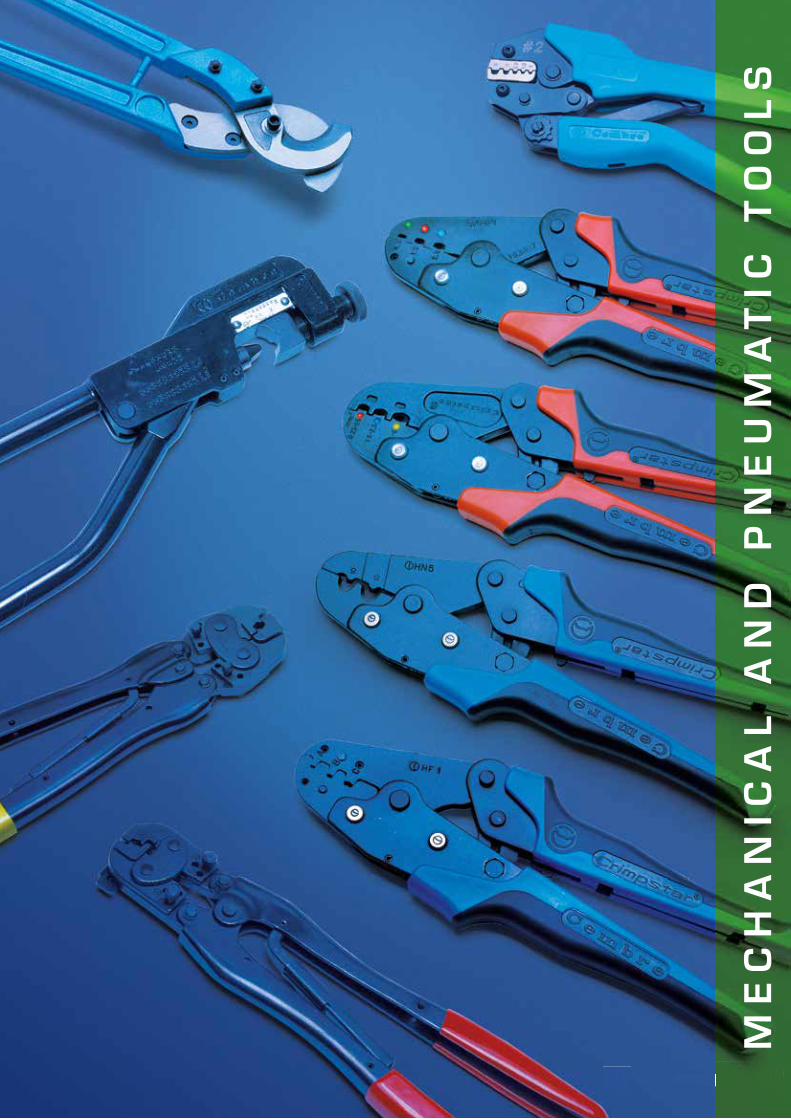
9797
ME
CH
AN
ICA
L A
ND
P
NE
UM
AT
IC T
OO
LS
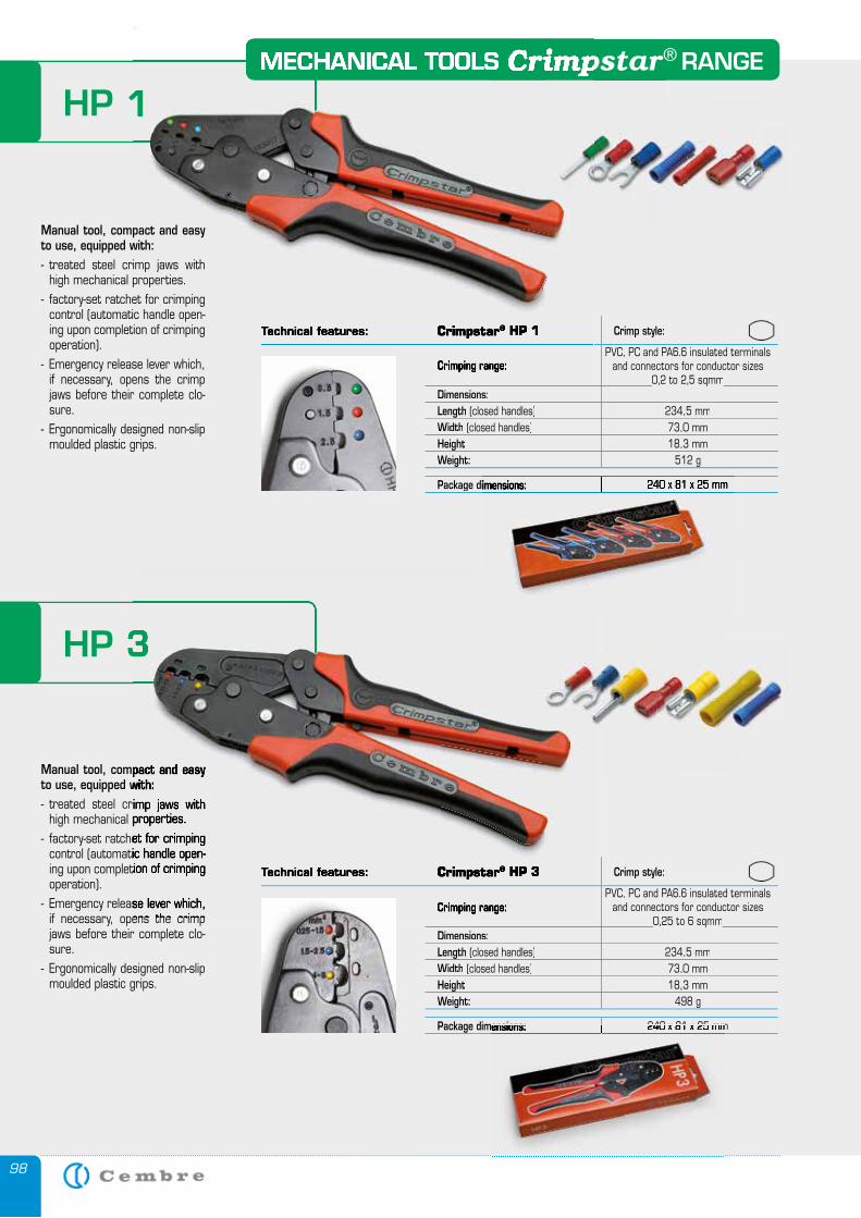
98
MECHANICAL TOOLS RANGECrimpstar®
HP 1
Crimp style:
PVC, PC and PA6.6 insulated terminals and connectors for conductor sizes
0,2 to 2,5 sqmm0,2 to 2,5 sqmmDimensions:Length (closed handles) 234,5 mmWidth (closed handles) 73,0 mmHeight 18,3 mmWeight: 512 g
Package dimensions:
MECHANICAL TOOLS RANGECrimpstarMECHANICAL TOOLS RANGECrimpstarMECHANICAL TOOLS RANGE
HP 1
Technical features: Crimpstar® HP 1
Crimping range:
Manual tool, compact and easy to use, equipped with:- treated steel crimp jaws with
high mechanical properties.- factory-set ratchet for crimping
control (automatic handle open-ing upon completion of crimping operation).
- Emergency release lever which, if necessary, opens the crimp jaws before their complete clo-sure.
- Ergonomically designed non-slip moulded plastic grips.
HP 3
Manual tool, compact and easy to use, equipped with:- treated steel crimp jaws with
high mechanical properties.- factory-set ratchet for crimping
control (automatic handle open-ing upon completion of crimping
- Emergency release lever which, if necessary, opens the crimp
Technical features: Crimpstar® HP 3 Crimp style:
Crimping range:PVC, PC and PA6.6 insulated terminals
and connectors for conductor sizes 0,25 to 6 sqmm0,25 to 6 sqmm
Dimensions:Length (closed handles) 234,5 mmWidth (closed handles) 73,0 mmHeight 18,3 mmWeight: 498 g
Package dimensions: 240 x 81 x 25 mm Package dimensions: 240 x 81 x 25 mm
Package dimensions: 240 x 81 x 25 mm
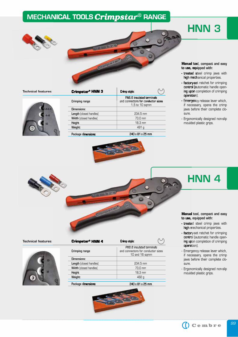
99
HNN 3MECHANICAL TOOLS RANGECrimpstar®
Manual tool, compact and easy to use, equipped with:- treated steel crimp jaws with
high mechanical properties.- factory-set ratchet for crimping
control (automatic handle open-ing upon completion of crimping operation).
- Emergency release lever which, if necessary, opens the crimp jaws before their complete clo-sure.
- Ergonomically designed non-slip moulded plastic grips.
Technical features:
Crimping range:PA6.6 insulated terminals
and connectors for conductor sizes 1,5 to 10 sqmm
Dimensions:Length (closed handles) 234,5 mmWidth (closed handles) 73,0 mmHeight 18,3 mmWeight: 491 g
Package dimensions:Package dimensions: 240 x 81 x 25 mm
Technical features:
Crimping range:PA6.6 insulated terminals
and connectors for conductor sizes 10 and 16 sqmm
Dimensions:Length (closed handles) 234,5 mmWidth (closed handles) 73,0 mmHeight 18,3 mmWeight: 492 g
Package dimensions:Package dimensions: 240 x 81 x 25 mm
HNN 4
Manual tool, compact and easy to use, equipped with:- treated steel crimp jaws with
high mechanical properties.- factory-set ratchet for crimping
control (automatic handle open-ing upon completion of crimping operation).
- Emergency release lever which, if necessary, opens the crimp jaws before their complete clo-sure.
- Ergonomically designed non-slip moulded plastic grips.
HNN 3MECHANICAL TOOLS RANGECrimpstarMECHANICAL TOOLS RANGECrimpstarMECHANICAL TOOLS RANGEMECHANICAL TOOLS RANGE®MECHANICAL TOOLS RANGE
Manual tool, compact and easy to use, equipped with:- treated steel crimp jaws with
high mechanical properties.- factory-set ratchet for crimping
control (automatic handle open-ing upon completion of crimping operation).
- Emergency release lever which,
Crimpstar® HNN 3 Crimp style:
PA6.6 insulated terminals and connectors for conductor sizes
Crimpstar® HNN 4 Crimp style:
PA6.6 insulated terminals
HNN 4
Manual tool, compact and easy to use, equipped with:- treated steel crimp jaws with
high mechanical properties.- factory-set ratchet for crimping
control (automatic handle open-ing upon completion of crimping operation).
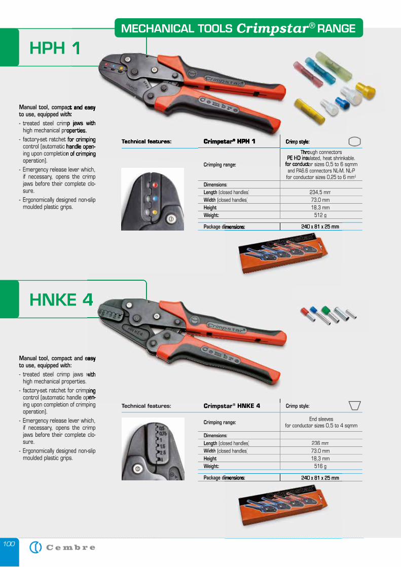
100
HPH 1
Crimping range:
Through connectors PE HD insulated, heat shrinkable.
for conductor sizes 0,5 to 6 sqmmand PA6.6 connectors NL-M, NL-P for conductor sizes 0,25 to 6 mm2
Dimensions:Length (closed handles) 234,5 mmWidth (closed handles) 73,0 mmHeight 18,3 mmWeight: 512 g
Package dimensions:
Manual tool, compact and easy to use, equipped with:- treated steel crimp jaws with
high mechanical properties.- factory-set ratchet for crimping
control (automatic handle open-ing upon completion of crimping operation).
- Emergency release lever which, if necessary, opens the crimp jaws before their complete clo-sure.
- Ergonomically designed non-slip moulded plastic grips.
HNKE 4
Manual tool, compact and easy to use, equipped with:- treated steel crimp jaws with
high mechanical properties.- factory-set ratchet for crimping
control (automatic handle open-ing upon completion of crimping operation).
- Emergency release lever which, if necessary, opens the crimp jaws before their complete clo-sure.
- Ergonomically designed non-slip moulded plastic grips.
Technical features: Crimpstar® HNKE 4 Crimp style:
Crimping range: End sleevesfor conductor sizes 0,5 to 4 sqmm
Dimensions:Length (closed handles) 236 mmWidth (closed handles) 73,0 mmHeight 18,3 mmWeight: 516 g
Package dimensions:
Package dimensions: 240 x 81 x 25 mm
Package dimensions: 240 x 81 x 25 mm
HNKE 4
Manual tool, compact and easy
- treated steel crimp jaws with
- factory-set ratchet for crimping control (automatic handle open-ing upon completion of crimping
HPH 1
Technical features: Crimpstar® HPH 1 Crimp style:
Crimping range:
Through connectors PE HD insulated, heat shrinkable.
for conductor sizes 0,5 to 6 sqmm
Manual tool, compact and easy to use, equipped with:- treated steel crimp jaws with
high mechanical properties.- factory-set ratchet for crimping
control (automatic handle open-ing upon completion of crimping
MECHANICAL TOOLS RANGECrimpstar®
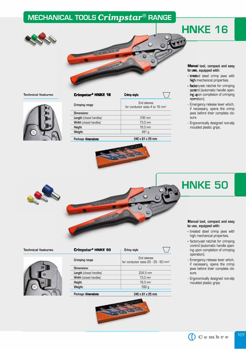
101
HNKE 16
Manual tool, compact and easy to use, equipped with:- treated steel crimp jaws with
high mechanical properties.- factory-set ratchet for crimping
control (automatic handle open-ing upon completion of crimping operation).
- Emergency release lever which, if necessary, opens the crimp jaws before their complete clo-sure.
- Ergonomically designed non-slip moulded plastic grips.
Technical features:
Crimping range: End sleevesfor conductor sizes 4 to 16 mm2
Dimensions:Length (closed handles) 236 mmWidth (closed handles) 73,0 mmHeight 18,3 mmWeight: 491 g
Package dimensions:Package dimensions: 240 x 81 x 25 mm
Technical features: Crimpstar® HNKE 50 Crimp style:
Crimping range: End sleevesfor conductor sizes 25 - 35 - 50 mm2
Dimensions:Length (closed handles) 234,5 mmWidth (closed handles) 73,0 mmHeight 18,3 mmWeight: 590 g
Package dimensions:Package dimensions: 240 x 81 x 25 mm
HNKE 50
Manual tool, compact and easy to use, equipped with:- treated steel crimp jaws with
high mechanical properties.- factory-set ratchet for crimping
control (automatic handle open-ing upon completion of crimping operation).
- Emergency release lever which, if necessary, opens the crimp jaws before their complete clo-sure.
- Ergonomically designed non-slip moulded plastic grips.
HNKE 16
Manual tool, compact and easy to use, equipped with:- treated steel crimp jaws with
high mechanical properties.- factory-set ratchet for crimping
control (automatic handle open-ing upon completion of crimping operation).
Crimpstar® HNKE 16 Crimp style:
Crimpstar® HNKE 50 Crimp style:
HNKE 50
Manual tool, compact and easy to use, equipped with:- treated steel crimp jaws with
- factory-set ratchet for crimping
MECHANICAL TOOLS RANGECrimpstar®
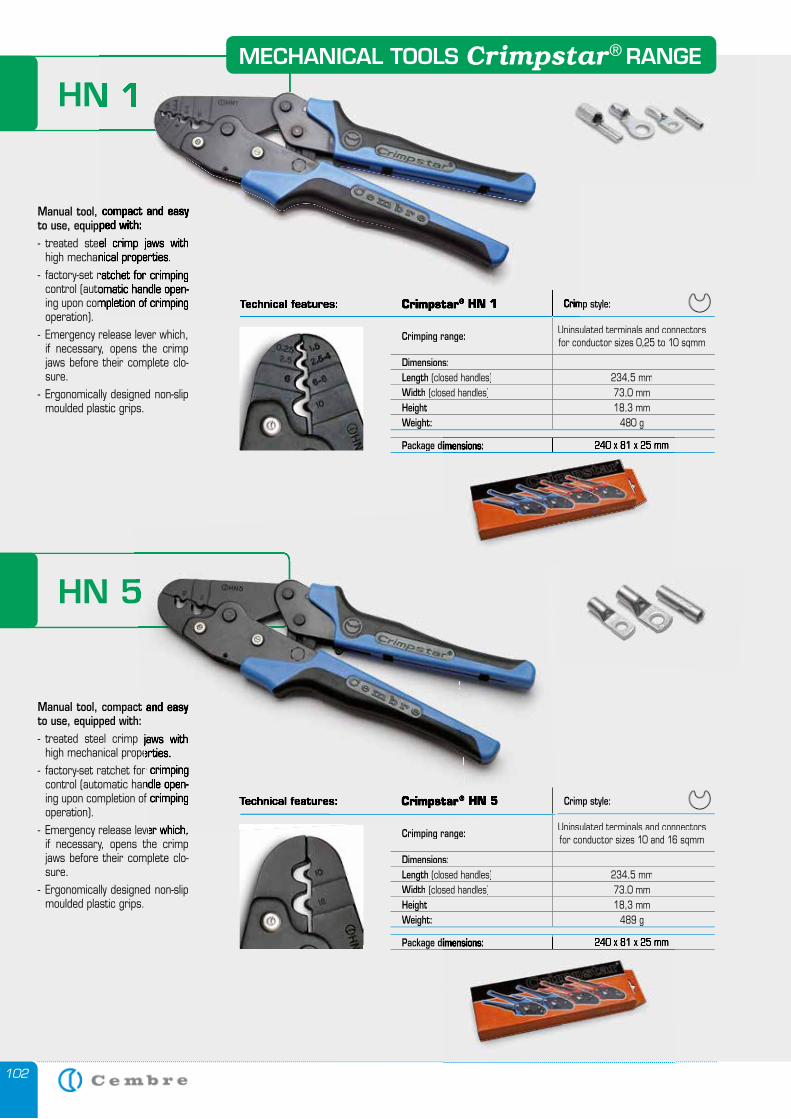
102
HN 1
Crimp style:
Crimping range: Uninsulated terminals and connectorsfor conductor sizes 0,25 to 10 sqmm
Dimensions:Length (closed handles) 234,5 mmWidth (closed handles) 73,0 mmHeight 18,3 mmWeight: 480 g
Package dimensions:
Manual tool, compact and easy to use, equipped with:- treated steel crimp jaws with
high mechanical properties.- factory-set ratchet for crimping
control (automatic handle open-ing upon completion of crimping operation).
- Emergency release lever which, if necessary, opens the crimp jaws before their complete clo-sure.
- Ergonomically designed non-slip moulded plastic grips.
HN 5
Manual tool, compact and easy to use, equipped with:- treated steel crimp jaws with
high mechanical properties.- factory-set ratchet for crimping
control (automatic handle open-ing upon completion of crimping operation).
- Emergency release lever which, if necessary, opens the crimp jaws before their complete clo-sure.
- Ergonomically designed non-slip moulded plastic grips.
Crimp style:
Crimping range: Uninsulated terminals and connectorsfor conductor sizes 10 and 16 sqmm
Dimensions:Length (closed handles) 234,5 mmWidth (closed handles) 73,0 mmHeight 18,3 mmWeight: 489 g
Package dimensions:
Package dimensions: 240 x 81 x 25 mm
HN 5
Manual tool, compact and easy
- treated steel crimp jaws with high mechanical properties.
- factory-set ratchet for crimping control (automatic handle open-ing upon completion of crimping
- Emergency release lever which,
Technical features: Crimpstar® HN 5
Package dimensions: 240 x 81 x 25 mm
HN 1
Technical features: Crimpstar® HN 1 Crimp style:
Manual tool, compact and easy to use, equipped with:- treated steel crimp jaws with
high mechanical properties.- factory-set ratchet for crimping
control (automatic handle open-ing upon completion of crimping
MECHANICAL TOOLS RANGECrimpstar®
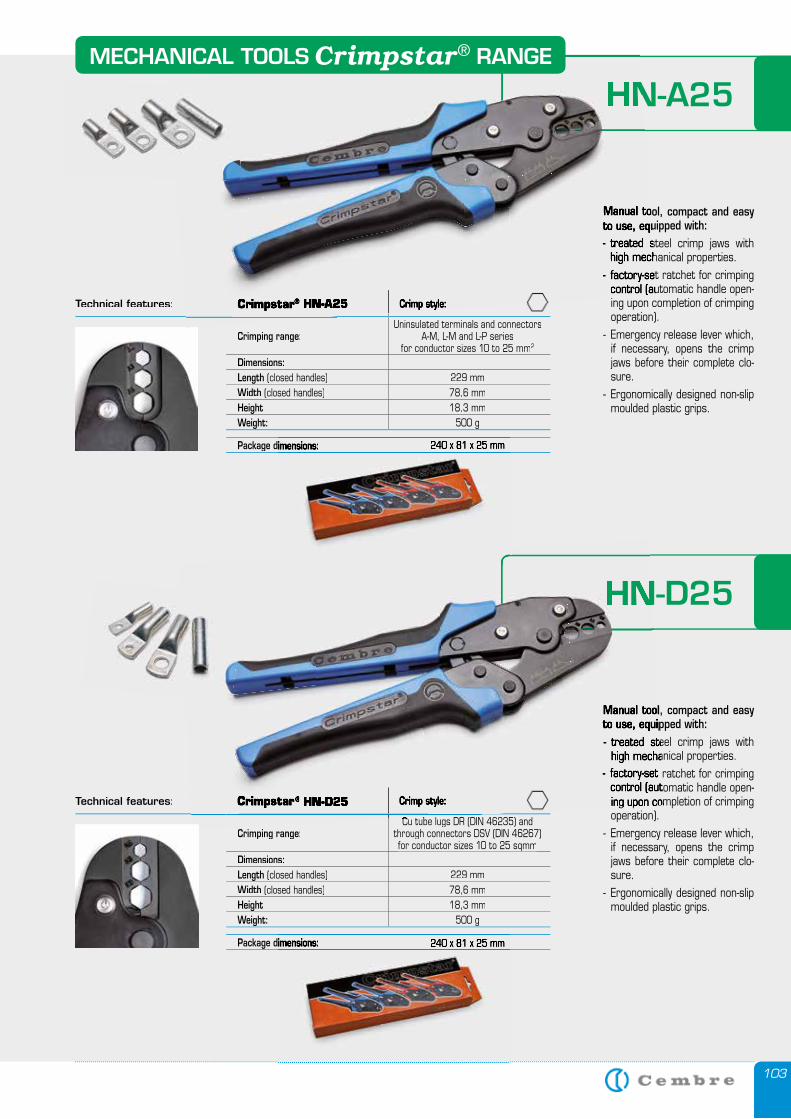
103
HN-A25
Manual tool, compact and easy to use, equipped with:- treated steel crimp jaws with
high mechanical properties.- factory-set ratchet for crimping
control (automatic handle open-ing upon completion of crimping operation).
- Emergency release lever which, if necessary, opens the crimp jaws before their complete clo-sure.
- Ergonomically designed non-slip moulded plastic grips.
Technical features: Crimp style:
Crimping range:Uninsulated terminals and connectors
A-M, L-M and L-P seriesfor conductor sizes 10 to 25 mm2
Dimensions:Length (closed handles) 229 mmWidth (closed handles) 78,6 mmHeight 18,3 mmWeight: 500 g
Package dimensions:Package dimensions: 240 x 81 x 25 mm
Technical features:
Crimping range:Cu tube lugs DR (DIN 46235) and
through connectors DSV (DIN 46267)for conductor sizes 10 to 25 sqmmfor conductor sizes 10 to 25 sqmm
Dimensions:Length (closed handles) 229 mmWidth (closed handles) 78,6 mmHeight 18,3 mmWeight: 500 g
Package dimensions:Package dimensions: 240 x 81 x 25 mm
HN-D25
Manual tool, compact and easy to use, equipped with:- treated steel crimp jaws with
high mechanical properties.- factory-set ratchet for crimping
control (automatic handle open-ing upon completion of crimping operation).
- Emergency release lever which, if necessary, opens the crimp jaws before their complete clo-sure.
- Ergonomically designed non-slip moulded plastic grips.
HN-A25
Manual tool, compact and easy to use, equipped with:- treated steel crimp jaws with
high mechanical properties.- factory-set ratchet for crimping
control (automatic handle open-Crimpstar® HN-A25 Crimp style:
Crimpstar® HN-D25 Crimp style:
Cu tube lugs DR (DIN 46235) and
HN-D25
Manual tool, compact and easy to use, equipped with:- treated steel crimp jaws with
high mechanical properties.- factory-set ratchet for crimping
control (automatic handle open-ing upon completion of crimping
MECHANICAL TOOLS RANGECrimpstar®
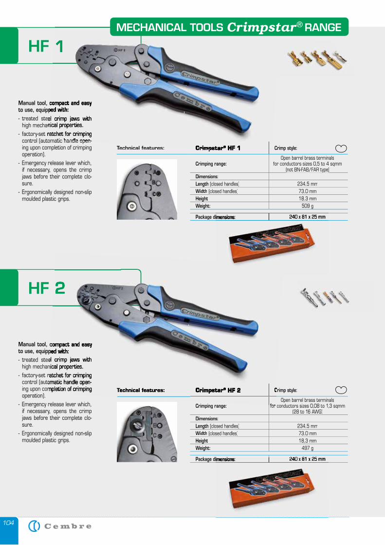
104
HF 1
Technical features: Crimpstar Crimp style:
Crimping range:Open barrel brass terminals
for conductors sizes 0,5 to 4 sqmm (not BN-FAB/FAR type)(not BN-FAB/FAR type)
Dimensions:Length (closed handles) 234,5 mmWidth (closed handles) 73,0 mmHeight 18,3 mmWeight: 509 g
Package dimensions:
Manual tool, compact and easy to use, equipped with:- treated steel crimp jaws with
high mechanical properties.- factory-set ratchet for crimping
control (automatic handle open-ing upon completion of crimping operation).
- Emergency release lever which, if necessary, opens the crimp jaws before their complete clo-sure.
- Ergonomically designed non-slip moulded plastic grips.
HF 2
Manual tool, compact and easy to use, equipped with:- treated steel crimp jaws with
high mechanical properties.- factory-set ratchet for crimping
control (automatic handle open-ing upon completion of crimping operation).
- Emergency release lever which, if necessary, opens the crimp jaws before their complete clo-sure.
- Ergonomically designed non-slip moulded plastic grips.
Crimp style:
Crimping range:Open barrel brass terminals
for conductors sizes 0,08 to 1,3 sqmm (28 to 16 AWG)
Dimensions:Length (closed handles) 234,5 mmWidth (closed handles) 73,0 mmHeight 18,3 mmWeight: 497 g
Package dimensions: 240 x 81 x 25 mm
Package dimensions: 240 x 81 x 25 mm
Package dimensions: 240 x 81 x 25 mm
HF 1
Technical features: Crimpstar® HF 1
Manual tool, compact and easy to use, equipped with:- treated steel crimp jaws with
high mechanical properties.- factory-set ratchet for crimping
control (automatic handle open-
HF 2
Manual tool, compact and easy to use, equipped with:- treated steel crimp jaws with
high mechanical properties.- factory-set ratchet for crimping
control (automatic handle open-ing upon completion of crimping Technical features: Crimpstar® HF 2 Crimp style:
for conductors sizes 0,08 to 1,3 sqmm
MECHANICAL TOOLS RANGECrimpstar®
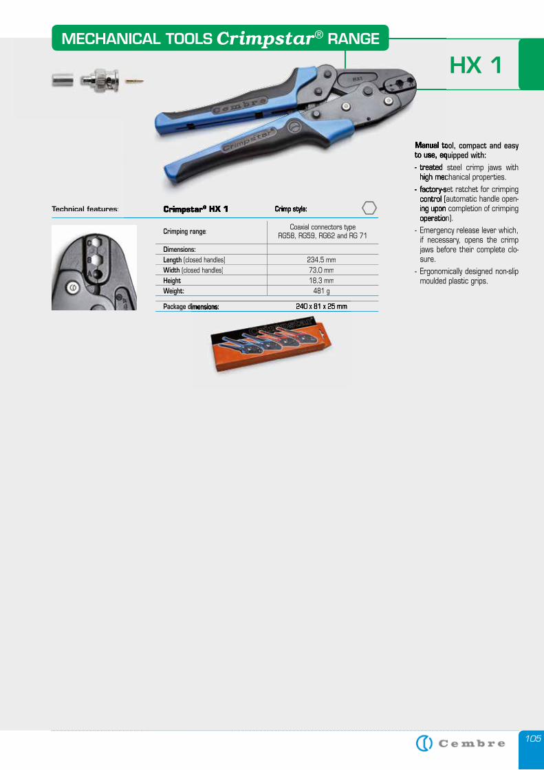
105
HX 1
Manual tool, compact and easy to use, equipped with:- treated steel crimp jaws with
high mechanical properties.- factory-set ratchet for crimping
control (automatic handle open-ing upon completion of crimping operation).
- Emergency release lever which, if necessary, opens the crimp jaws before their complete clo-sure.
- Ergonomically designed non-slip moulded plastic grips.
Technical features:
Crimping range: Coaxial connectors type RG58, RG59, RG62 and RG 71
Dimensions:Length (closed handles) 234,5 mmWidth (closed handles) 73,0 mmHeight 18,3 mmWeight: 481 g
Package dimensions:Package dimensions: 240 x 81 x 25 mm
Manual tool, compact and easy to use, equipped with:- treated steel crimp jaws with
high mechanical properties.- factory-set ratchet for crimping
control (automatic handle open-ing upon completion of crimping operation).
Crimpstar® HX 1 Crimp style:
MECHANICAL TOOLS RANGECrimpstar®
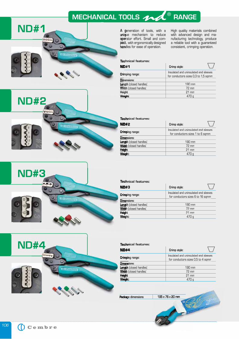
106
MECHANICAL TOOLS RANGE
ND#1 A generation of tools, with a unique mechanism to reduce operator effort. Small and com-pact, with ergonomically designed handles for ease of operation.
High quality materials combined with advanced design and ma-nufacturing technology, produce a reliable tool with a guaranteed consistent, crimping operation.
ND#2
ND#3
ND#4
Technical features:
ND#1 Crimp style:
Crimping range: Insulated and uninsulated end sleeves for conductors sizes 0,3 to 1,5 sqmmfor conductors sizes 0,3 to 1,5 sqmm
Dimensions:LengthLength (closed handles) 190 mmWidth (closed handles) 72 mmHeightHeight 21 mmWeight: Weight: 470 g 470 g
ND#1 A generation of tools, with a unique mechanism to reduce operator effort. Small and com-pact, with ergonomically designed handles for ease of operation.
Technical features:
ND#1
Crimping range:
Dimensions:LengthLengthWidth
Technical features:
ND#2 Crimp style:
Crimping range: Insulated and uninsulated end sleeves for conductors sizes 1 to 6 sqmmfor conductors sizes 1 to 6 sqmm
Dimensions:LengthLength (closed handles) 190 mmWidth (closed handles) 72 mmHeightHeight 21 mmWeight: Weight: 470 g 470 g
ND#2Weight: Weight:
Technical features:
ND#2
Crimping range:
Dimensions:LengthLengthWidthHeightHeightWeight: Weight:
ND#3Technical features:Technical features:
ND#3ND#3 Crimp style:
Crimping range:Crimping range: Insulated and uninsulated end sleeves for conductors sizes 6 to 16 sqmmfor conductors sizes 6 to 16 sqmm
Dimensions:Dimensions:LengthLengthLengthLength (closed handles) 190 mmWidthWidth (closed handles) 72 mmHeightHeightHeightHeightHeightHeight 21 mmWeight: Weight: Weight: 470 g 470 g
ND#4 Technical features:Technical features:
ND#4ND#4 Crimp style:
Crimping range:Crimping range: Insulated and uninsulated end sleeves for conductors sizes 0,5 to 4 sqmmfor conductors sizes 0,5 to 4 sqmm
Dimensions:Dimensions:LengthLength (closed handles) (closed handles) 190 mmWidth (closed handles) (closed handles) 72 mmHeightHeight 21 mmWeight: Weight: Weight: 470 g 470 g
Package dimensions:Package dimensions: 195 x 76 x 20 mm
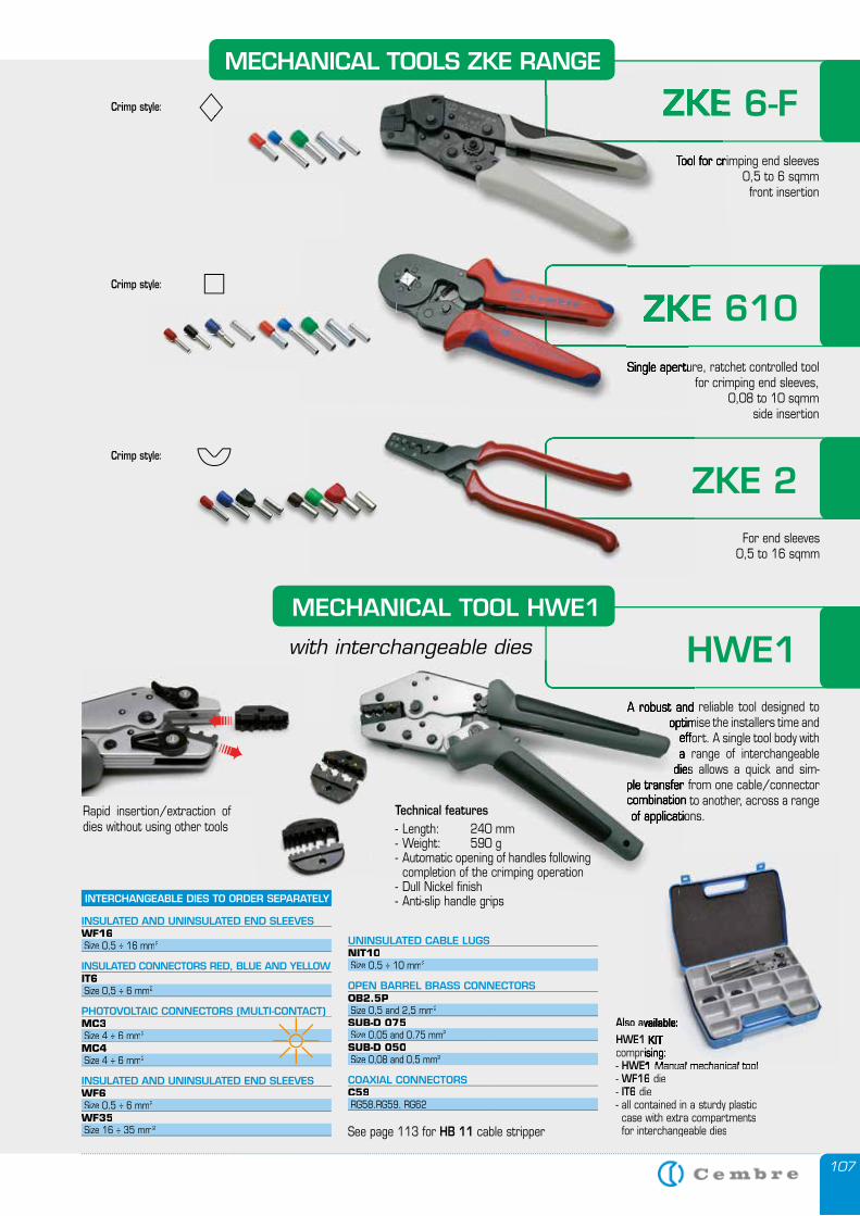
107
ZKE 6-FTool for crimping end sleeves
0,5 to 6 sqmmfront insertion
ZKE 6-FTool for crimping end sleeves
ZKE 610Single aperture, ratchet controlled tool
for crimping end sleeves, 0,08 to 10 sqmm
side insertion
ZKE 2For end sleeves
0,5 to 16 sqmm
ZKE 2
ZKE 610ZKE 610Single aperture, ratchet controlled tool
Crimp style:
Crimp style:
Crimp style:
MECHANICAL TOOLS ZKE RANGE
A robust and reliable tool designed to optimise the installers time and
effort. A single tool body with a range of interchangeable
dies allows a quick and sim-ple transfer from one cable/connector combination to another, across a range of applications.
�
�
Also available:HWE1 KITcomprising:- HWE1 Manual mechanical tool - WF16 die- IT6 die- all contained in a sturdy plastic case with extra compartments for interchangeable dies
INTERCHANGEABLE DIES TO ORDER SEPARATELY
INSULATED AND UNINSULATED END SLEEVESWF16 Size 0,5 ÷ 16 mm2
INSULATED CONNECTORS RED, BLUE AND YELLOWIT6 Size 0,5 ÷ 6 mm2
PHOTOVOLTAIC CONNECTORS (MULTI-CONTACT) MC3 Size 4 ÷ 6 mm2
MC4 Size 4 ÷ 6 mm2
INSULATED AND UNINSULATED END SLEEVESWF6 Size 0,5 ÷ 6 mm2
WF35 Size 16 ÷ 35 mm2
Also available:HWE1 KITcomprising:HWE1 Manual mechanical tool
Rapid insertion/extraction of dies without using other tools
See page 113 for HB 11 cable stripper
HWE1A robust and reliable tool designed to
optimise the installers time and effort. A single tool body with a range of interchangeable
dies allows a quick and sim-ple transfer from one cable/connector combination to another, across a range of applications.
UNINSULATED CABLE LUGSNIT10 Size 0,5 ÷ 10 mm2
OPEN BARREL BRASS CONNECTORSOB2.5P Size 0,5 and 2,5 mm2
SUB-D 075 Size 0,05 and 0,75 mm2
SUB-D 050 Size 0,08 and 0,5 mm2
COAXIAL CONNECTORSC59 RG58,RG59, RG62
Technical features- Length: 240 mm- Weight: 590 g- Automatic opening of handles following
completion of the crimping operation- Dull Nickel finish- Anti-slip handle grips
MECHANICAL TOOL HWE1
with interchangeable dies
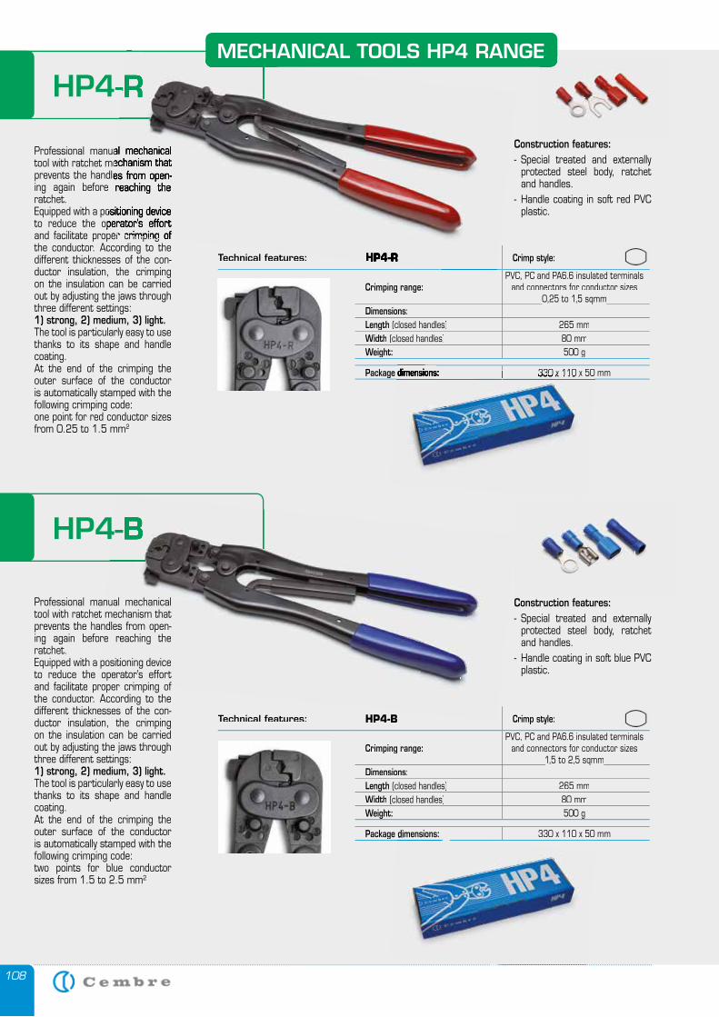
108
MECHANICAL TOOLS HP4 RANGE
HP4-R
Technical features: HP4-R Crimp style:
Crimping range:PVC, PC and PA6.6 insulated terminals
and connectors for conductor sizes0,25 to 1,5 sqmm0,25 to 1,5 sqmm
Dimensions:Length (closed handles) 265 mmWidth (closed handles) 80 mmWeight: 500 g
Package dimensions: 330 x 110 x 50 mm
Professional manual mechanical tool with ratchet mechanism that prevents the handles from open-ing again before reaching the ratchet. Equipped with a positioning device to reduce the operator’s effort and facilitate proper crimping of the conductor. According to the different thicknesses of the con-ductor insulation, the crimping on the insulation can be carried out by adjusting the jaws through three different settings: 1) strong, 2) medium, 3) light.The tool is particularly easy to use thanks to its shape and handle coating. At the end of the crimping the outer surface of the conductor is automatically stamped with the following crimping code:one point for red conductor sizes from 0.25 to 1.5 mm2
HP4-R
Technical features: HP4-R
Professional manual mechanical tool with ratchet mechanism that prevents the handles from open-ing again before reaching the
Equipped with a positioning device to reduce the operator’s effort and facilitate proper crimping of
HP4-B
Technical features: HP4-B Crimp style:
Crimping range:PVC, PC and PA6.6 insulated terminals
and connectors for conductor sizes1,5 to 2,5 sqmm1,5 to 2,5 sqmm
Dimensions:Length (closed handles) 265 mmWidth (closed handles) 80 mmWeight: 500 g
Package dimensions: 330 x 110 x 50 mm
HP4-B
Construction features:- Special treated and externally
protected steel body, ratchet and handles.
- Handle coating in soft red PVC plastic.
Professional manual mechanical tool with ratchet mechanism that prevents the handles from open-ing again before reaching the ratchet. Equipped with a positioning device to reduce the operator’s effort and facilitate proper crimping of the conductor. According to the different thicknesses of the con-ductor insulation, the crimping on the insulation can be carried out by adjusting the jaws through three different settings: 1) strong, 2) medium, 3) light.The tool is particularly easy to use thanks to its shape and handle coating. At the end of the crimping the outer surface of the conductor is automatically stamped with the following crimping code:two points for blue conductor sizes from 1.5 to 2.5 mm2
Construction features:- Special treated and externally
protected steel body, ratchet and handles.
- Handle coating in soft blue PVC plastic.
Package dimensions: 330 x 110 x 50 mm
Package dimensions:
MECHANICAL TOOLS HP4 RANGE
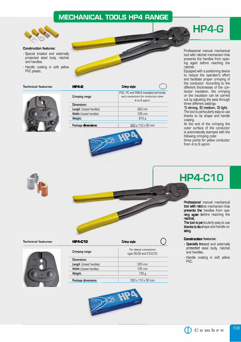
109
HP4-GMECHANICAL TOOLS HP4 RANGE
HP4-C10
Technical features:
Crimping range:PVC, PC and PA6.6 insulated terminals
and connectors for conductor sizes4 to 6 sqmm4 to 6 sqmm
Dimensions:Length (closed handles) 320 mmWidth (closed handles) 105 mmWeight: 810 g
Package dimensions: 330 x 110 x 50 mm
Technical features:
Crimping range: For sleeve connectorstype C6-C6 and C10-C10
Dimensions:Length (closed handles) 325 mmWidth (closed handles) 105 mmWeight: 730 g
Package dimensions: 330 x 110 x 50 mm
Package dimensions: 330 x 110 x 50 mm
Package dimensions:
HP4-GMECHANICAL TOOLS HP4 RANGE
HP4-G Crimp style:
Professional manual mechanical tool with ratchet mechanism that prevents the handles from open-ing again before reaching the ratchet. Equipped with a positioning device to reduce the operator’s effort and facilitate proper crimping of the conductor. According to the different thicknesses of the con-ductor insulation, the crimping on the insulation can be carried out by adjusting the jaws through three different settings: 1) strong, 2) medium, 3) light.The tool is particularly easy to use thanks to its shape and handle coating. At the end of the crimping the outer surface of the conductor is automatically stamped with the following crimping code:three points for yellow conductor from 4 to 6 sqmm
Construction features:- Special treated and externally
protected steel body, ratchet and handles.
- Handle coating in soft yellow PVC plastic.
Professional manual mechanical tool with ratchet mechanism that prevents the handles from ope-ning again before reaching the ratchet.The tool is particularly easy to use thanks to its shape and handle co-ating.
Construction features:- Specially treated and externally
protected steel body, ratchet and handles.
- Handle coating in soft yellow PVC.
HP4-C10
HP4-C10 Crimp style:
Professional manual mechanical tool with ratchet mechanism that prevents the handles from ope-ning again before reaching the ratchet.The tool is particularly easy to use thanks to its shape and handle co-ating.
Construction features:- Specially treated and externally
protected steel body, ratchet
Construction features:
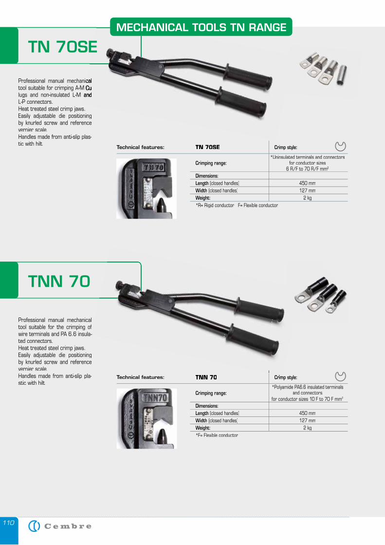
110
Technical features: TN 70SE Crimp style:
Crimping range:*Uninsulated terminals and connectors
for conductor sizes 6 R/F to 70 R/F mm2
Dimensions:Length (closed handles) 450 mmWidth (closed handles) 127 mmWeight: 2 kg *R= Rigid conductor F= Flexible conductor
Technical features: TNN 70 Crimp style:
Crimping range:*Polyamide PA6.6 insulated terminals
and connectors for conductor sizes 10 F to 70 F mm2
Dimensions:Length (closed handles) 450 mmWidth (closed handles) 127 mmWeight: 2 kg *F= Flexible conductor
Professional manual mechanical tool suitable for crimping A-M Cu lugs and non-insulated L-M and L-P connectors. Heat treated steel crimp jaws. Easily adjustable die positioning by knurled screw and reference vernier scale.Handles made from anti-slip plas-tic with hilt.
Professional manual mechanical tool suitable for the crimping of wire terminals and PA 6.6 insula-ted connectors. Heat treated steel crimp jaws. Easily adjustable die positioning by knurled screw and reference vernier scale.Handles made from anti-slip pla-stic with hilt.
Professional manual mechanical tool suitable for crimping A-M Cu lugs and non-insulated L-M and
Crimp style:
wire terminals and PA 6.6 insula-
MECHANICAL TOOLS TN RANGE
TNN 70
TN 70SE
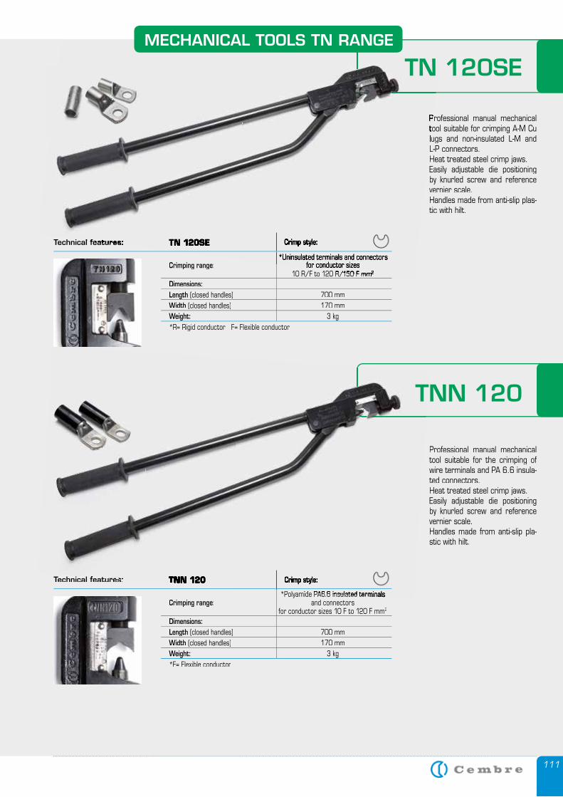
111
Technical features:Technical features: TN 120SE Crimp style:
Crimping range:*Uninsulated terminals and connectors
for conductor sizes for conductor sizes 10 R/F to 120 R/150 F mm10 R/F to 120 R/150 F mm2
Dimensions:Length (closed handles) 700 mmWidth (closed handles) 170 mmWeight: 3 kg *R= Rigid conductor F= Flexible conductor
Technical features:Technical features: TNN 120TNN 120 Crimp style:
Crimping range:*Polyamide PA6.6 insulated terminals *Polyamide PA6.6 insulated terminals
and connectors for conductor sizes 10 F to 120 F mm2
Dimensions:Length (closed handles) 700 mmWidth (closed handles) 170 mmWeight: 3 kg *F= Flexible conductor
Professional manual mechanical Professional manual mechanical tool suitable for crimping A-M Cu tool suitable for crimping A-M Cu lugs and non-insulated L-M and lugs and non-insulated L-M and L-P connectors. Heat treated steel crimp jaws. Easily adjustable die positioning by knurled screw and reference vernier scale.Handles made from anti-slip plas-tic with hilt.
Professional manual mechanical tool suitable for the crimping of wire terminals and PA 6.6 insula-ted connectors. Heat treated steel crimp jaws. Easily adjustable die positioning by knurled screw and reference vernier scale.Handles made from anti-slip pla-stic with hilt.
TN 120SE
TNN 120
MECHANICAL TOOLS TN RANGE
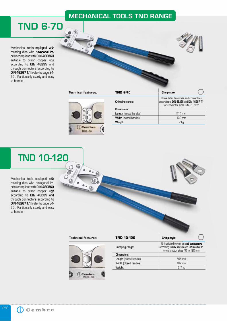
112
Mechanical tools equipped with rotating dies with hexagonal im-print compliant with DIN 480863 suitable to crimp copper lugs according to DIN 46235 and through connectors according to DIN 46267 T.1 (refer to page 34-35), Particularly sturdy and easy to handle.
Mechanical tools equipped with rotating dies with hexagonal im-print compliant with DIN 480863 suitable to crimp copper lugs according to DIN 46235 and through connectors according to DIN 46267 T.1 (refer to page 34-35), Particularly sturdy and easy to handle.
Technical features: TND 6-70 Crimp style:
Crimping range:Uninsulated terminals and connectors
according to DIN 46235 and DIN 46267 T.1for conductor sizes 6 to 70 mm2
Dimensions:Length (closed handles) 515 mmWidth (closed handles) 132 mmWeight: 2 kg
Technical features: TND 10-120 Crimp style:
Crimping range:Uninsulated terminals and connectors
according to DIN 46235 and DIN 46267 T.1for conductor sizes 10 to 120 mm2
Dimensions:Length (closed handles) 665 mmWidth (closed handles) 162 mmWeight: 3,7 kg
MECHANICAL TOOLS TND RANGE
TND 6-70
TND 10-120
Mechanical tools equipped with rotating dies with hexagonal im-
DIN 480863 suitable to crimp copper lugs
and
Crimp style:
Uninsulated terminals and connectors DIN 46267 T.1
TND 10-120
Crimp style:
Mechanical tools equipped with rotating dies with hexagonal im-
TND 6-70
Mechanical tools equipped with rotating dies with hexagonal im-
Crimp style:
TND 6-70
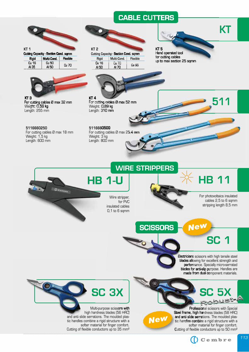
113
HB 1-UHB 1-UWire stripper,
for PVC insulated cables 0,1 to 6 sqmm
KT 4For cutting cables Ø max 52 mmWeight: 0,89 kgLength: 310 mm
KT 3For cutting cables Ø max 32 mmWeight: 0,59 kgLength: 255 mm
For cutting cables Ø max 52 mmKT 3For cutting cables Ø max 32 mmWeight: 0,59 kgLength: 255 mm
KT 4For cutting cables Ø max 52 mmKT 4For cutting cables Ø max 52 mm
CABLE CUTTERS
KT
KT 3For cutting cables Ø max 32 mm
5116660500For cutting cables Ø max 25.4 mmWeight: 3 kgLength: 800 mm
5116660250For cutting cables Ø max 18 mmWeight: 1,5 kgLength: 600 mm
HB 11For photovoltaics insulated
cables 2,5 to 6 sqmmstripping length 8,5 mm
WIRE STRIPPERS
511For cutting cables Ø max 52 mmWeight: 0,89 kgLength: 310 mm
For cutting cables Ø max 52 mm
5116660500
511
For cutting cables Ø max 25.4 mmFor cutting cables Ø max 25.4 mm
Electricians scissors with high tensile steel blades allowing for excellent strength and
performance. Specially micro-serrated blades for anti-slip purpose. Handles are
made from dual component materials.
SC 3X
SC 1SCISSORS
SC 3XMulti-purpose scissors with
high hardness blades (56 HRC) and anti slide serrations. The moulded plas-tic handles combine a rigid structure with a
softer material for finger comfort.Cutting of flexible conductors up to 35 mm²
Professional scissors with Special Steel frame, high hardness blades (58 HRC) and anti slide serrations. The moulded plas-tic handles combine a rigid structure with a
softer material for finger comfort.Cutting of flexible conductors up to 50 mm²
SC 5X
tic handles combine a rigid structure with a
Cutting of flexible conductors up to 50 mm²
New
Electricians scissors with high tensile steel blades allowing for excellent strength and
performance. Specially micro-serrated
SCISSORS
SC 1New
KT 5Hand operated toolfor cutting cablesup to max section 25 sqmm
CABLE CUTTERS
KT 5Hand operated toolfor cutting cablesup to max section 25 sqmm
CABLE CUTTERS
KT 2Cutting Capacity - Section Cond. sqmmCutting Capacity - Section Cond. sqmmCutting Capacity - Section Cond. sqmm
Rigid Multi-Cond. FlexibleCu 16Cu 16Cu 16Al 50
Cu 70Cu 70Al 70 Cu 95Cu 95
KT 1Cutting Capacity - Section Cond. sqmmCutting Capacity - Section Cond. sqmmCutting Capacity - Section Cond. sqmm
Rigid Multi-Cond. FlexibleFlexibleCu 16Al 35
Cu 50Al 50 Cu 70
performance. Specially micro-serrated blades for anti-slip purpose. Handles are
made from dual component materials.
SC 3XMulti-purpose scissors with
high hardness blades (56 HRC) Professional scissors with Special
Steel frame, high hardness blades (58 HRC) and anti slide serrations. The moulded plas-tic handles combine a rigid structure with a
SC 5X
Steel frame, high hardness blades (58 HRC) and anti slide serrations. The moulded plas-
New
performance. Specially micro-serrated blades for anti-slip purpose. Handles are
made from dual component materials.
Professional scissors with Special
SC 5XProfessional scissors with Special
SC 5XSC 5XSC 5X
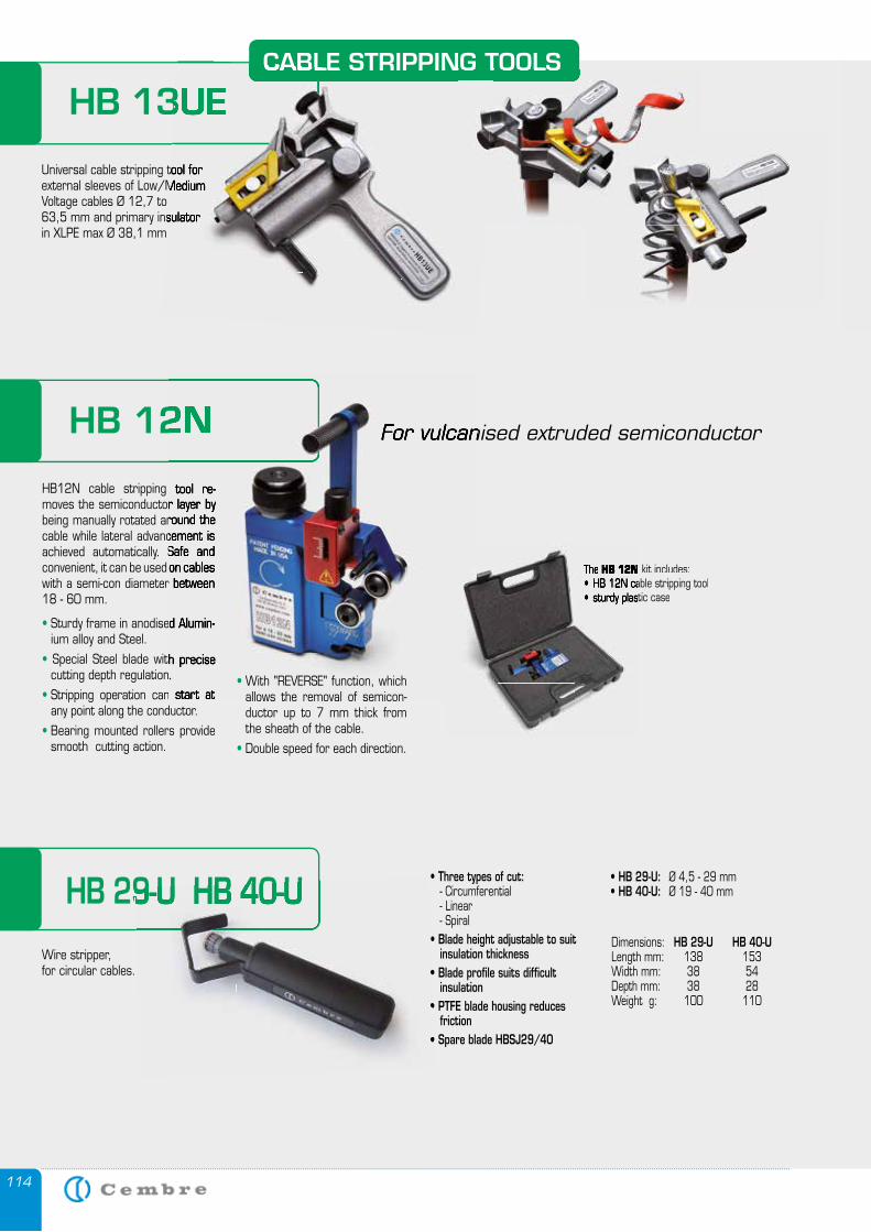
114
HB 13UE
Universal cable stripping tool for external sleeves of Low/Medium Voltage cables Ø 12,7 to 63,5 mm and primary insulatorin XLPE max Ø 38,1 mm
CABLE STRIPPING TOOLS
HB 13UE
Universal cable stripping tool for external sleeves of Low/Medium
63,5 mm and primary insulator
CABLE STRIPPING TOOLSCABLE STRIPPING TOOLS
HB 12N kit includes:• HB 12N cable stripping tool• sturdy plastic case
HB 12N For vulcanised extruded semiconductor
HB12N cable stripping tool re-moves the semiconductor layer by being manually rotated around the cable while lateral advancement is achieved automatically. Safe and convenient, it can be used on cables with a semi-con diameter between 18 - 60 mm.
• Sturdy frame in anodised Alumin-ium alloy and Steel.
• Special Steel blade with precise cutting depth regulation.
• Stripping operation can start at any point along the conductor.
• Bearing mounted rollers provide smooth cutting action.
The HB 12N• HB 12N cable stripping tool• sturdy plastic case
HB 12N For vulcanised extruded semiconductor
HB12N cable stripping tool re-moves the semiconductor layer by being manually rotated around the cable while lateral advancement is achieved automatically. Safe and convenient, it can be used on cables with a semi-con diameter between
Sturdy frame in anodised Alumin-
Special Steel blade with precise cutting depth regulation.
Stripping operation can start at • With "REVERSE" function, which
allows the removal of semicon-ductor up to 7 mm thick from the sheath of the cable.
• Double speed for each direction.
HB 29-U HB 40-U
Wire stripper,for circular cables.
• Three types of cut: - Circumferential - Linear - Spiral• Blade height adjustable to suit insulation thickness• Blade profile suits difficult insulation• PTFE blade housing reduces friction• Spare blade HBSJ29/40
• HB 29-U: Ø 4,5 - 29 mm• HB 40-U: Ø 19 - 40 mm
Dimensions: HB 29-U HB 40-ULength mm: 138 153Width mm: 38 54Depth mm: 38 28Weight g: 100 110
HB 29-U HB 40-U
insulation thickness• insulation• friction•

115
Plastic pipe cutting tool Cutting capacity: Ø 6 to Ø 42 mm.
Body: die-cast aluminium alloyBlade material: hardened Carbon Steel
Cuts and seals flexible plasticconduit in a single operation.Lightweight and easy to operate.Suitable for flexible conduitsfrom Ø16 to Ø32 mm.
Length: 230 mmWidth: 58 mmThickness: 32 mm.Weight: 0,32 kg.
KTS 1632
PC 1
HAND TOOL FOR CUTTING AND SEALING FLEXIBLE CONDUIT
Lightweight and easy tooperate, designed for
punching holes up to 47,2 mm diameter in the side wall of trunking without the need for pre drilling.
Max centre of hole to edge of trunking: 53,5 mm
Length : 251,5 mmWidth: 224 mmThickness : 66 mmWeight: 3,28 kg
Table denotes the punch/die set reference, for each hole size.Suitable for punching holes in mild steel, fibreglass or plastic material,up to 2 mm thick.
MT-FC48NFRAME-TYPE HOLE PUNCHING TOOL FOR CABLE TRUNKING
VAL P30 Lightweight and easy tooperate, designed for
punching holes up to 47,2 mm diameter in the side wall of trunking without the need for pre drilling.
MT-FC48N
VAL P30Supplied in a robust plastic case.
Cuts and seals flexible plasticconduit in a single operation.Lightweight and easy to operate.Suitable for flexible conduitsfrom Ø16 to Ø32 mm.
Length: 230 mmWidth: 58 mmThickness: 32 mm.Weight: 0,32 kg.
KTS 1632HAND TOOL FOR CUTTING AND SEALING FLEXIBLE CONDUIT
H o l e d i m e n s i o n s Maximumthickness ofmild steel
(mm)CodeNominal Pg ISO InchØ (mm) Ø (inch)
15,5 .610 Pg9 - -
2
RD 15.5 SS-FC 16,2 .638 - ISO-16 - RD 16.2 SS-FC RD 16.2 SS-FC 17,5 .689 - - - RD 17.5 SS-FC 18,8 .740 Pg11 - - RD 18.8 SS-FC RD 18.8 SS-FC 19,1 .752 - - - RD 19.1 SS 20,5 .807 Pg 13,5 ISO-20 - RD 20.5 SS RD 20.5 SS 22,6 .890 Pg16 - - RD 22.6 SS 23,8 .937 - - 5/8” RD 23.8 SS RD 23.8 SS 25,4 1.000 - ISO-25 - RD 25.4 SS 27,0 1.063 - - 3/4” RD 27.0 SS RD 27.0 SS 28,5 1.122 Pg21 - - RD 28.5 SS 30,5 1.201 - - 7/8” RD 30.5 SS RD 30.5 SS 31,8 1.252 - - - RD 31.8 SS 32,5 1.279 - ISO-32 - RD 32.5 SS RD 32.5 SS 34,6 1.362 - - - RD 34.6 SS 37,2 1.464 Pg29 - - RD 37.2 SS 38,1 1.500 - - - RD 38.1 SS 40,5 1.594 - ISO-40 - RD 40.5 SS-FC 41,3 1.626 - - - RD 41.3 SS-FC 42,5 1.673 - - 1”1/4” RD 42.5 SS-FC 43,2 1.701 - - - RD 43.2 SS-FC 44,5 1.752 - - - RD 44.5 SS-FC 47,2 1.858 Pg36 - - RD 47.2 SS-FC
plastic case.
For vulcanised extruded semiconductor
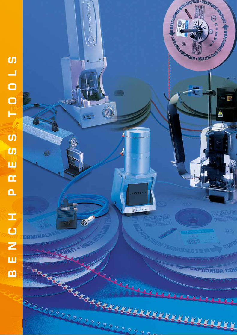
116116
BE
NC
H
PR
ES
S
TO
OL
S
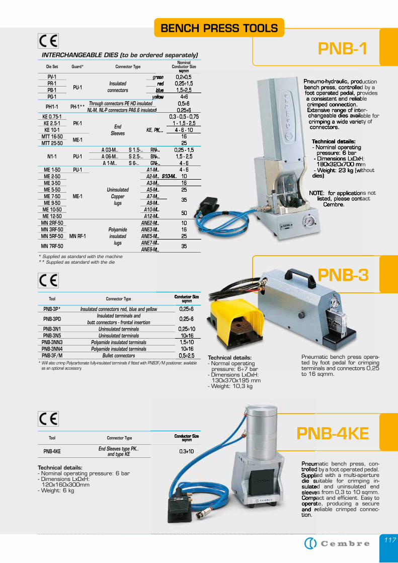
117
Die Set Guard* Connector TypeNominal
Conductor Sizesqmm
PV-1 green 0,2÷0,5 PR-1 Insulated red 0,25÷1,5 PB-1 PU-1 connectors blue 1,5÷2,5 PG-1 yellow 4÷6
PH1-1
PH-1** Through connectors PE HD insulated 0,5÷6
NL-M, NL-P connectors PA6.6 insulated 0,25÷6 KE 0.75-1 0,3 - 0,5 - 0,75 KE 2.5-1 PK-1
End 1 - 1,5 - 2,5
KE 10-1 Sleeves
KE, PK... 4 - 6 - 10 MTT 16-50
ME-1 16
MTT 25-50 25 A 03-M.. S 1.5-.. RN-.. 0,25 - 1,5 N1-1 PU-1 A 06-M.. S 2.5-.. BN-.. 1,5 - 2,5 A 1-M.. S 6-.. GN-.. 4 - 6 ME 1-50 PU-1 A1-M.. 4 - 6 ME 2-50 A2-M.. S10-M.. 10 ME 3-50 A3-M.. 16 ME 5-50 Uninsulated A5-M.. 25 ME 7-50 ME-1 Copper A7-M..
35 ME 9-50 lugs A9-M.. ME 10-50 A10-M..
50 ME 12-50 A12-M.. MN 2RF-50 ANE2-M.. 10 MN 3RF-50 Polyamide ANE3-M.. 16 MN 5RF-50 MN RF-1 insulated ANE5-M.. 25
MN 7RF-50 lugs ANE7-M..
35 ANE9-M..* Supplied as standard with the machine ** Supplied as standard with the die
INTERCHANGEABLE DIES (to be ordered separately)
Connector Type Conductor Sizesqmm
PNB-3P* Insulated connectors red, blue and yellow 0,25÷6
PNB-3PD Insulated terminals and
0,25÷6 butt connectors - frontal insertion PNB-3N1 Uninsulated terminals 0,25÷10 PNB-3N5 Uninsulated terminals 10÷16 PNB-3NN3 Polyamide insulated terminals 1,5÷10 PNB-3NN4 Polyamide insulated terminals 10÷16 PNB-3F/M Bullet connectors 0,5÷2,5
Tool
Connector Type Conductor Sizesqmm
End Sleeves type PK.. PNB-4KE and type KE 0.3÷10
Tool
Conductor Sizesqmm
0,25÷6
0,25÷6
0,25÷1010÷161,5÷1010÷160,5÷2,5
PNB-1
PNB-3
Pneumo-hydraulic, production bench press, controlled by a foot operated pedal, provides a consistent and reliable crimped connection.Extensive range of inter-changeable dies available for crimping a wide variety of connectors.
Technical details:- Nominal operating pressure: 6 bar- Dimensions LxDxH: 180x320x700 mm- Weight: 23 kg (without dies)
NOTE: for applications not listed, please contact
Cembre.
Pneumatic bench press opera-ted by foot pedal for crimping terminals and connectors 0,25 to 16 sqmm.
Technical details:- Normal operating pressure: 6÷7 bar- Dimensions LxDxH: 130x370x195 mm- Weight: 10,3 kg
Pneumatic bench press, con-trolled by a foot operated pedal. Supplied with a multi-aperture die suitable for crimping in-sulated and uninsulated end sleeves from 0,3 to 10 sqmm. Compact and efficient. Easy to operate, producing a secure and reliable crimped connec-tion.
Technical details:- Nominal operating pressure: 6 bar- Dimensions LxDxH: 120x160x300mm- Weight: 6 kg
PNB-4KE
Pneumatic bench press, con-trolled by a foot operated pedal. Supplied with a multi-aperture die suitable for crimping in-sulated and uninsulated end sleeves from 0,3 to 10 sqmm. Compact and efficient. Easy to operate, producing a secure and reliable crimped connec-
PNB-4KEConductor Sizesqmm
0.3÷10
Pneumatic bench press, con-trolled by a foot operated pedal. Supplied with a multi-aperture die suitable for crimping in-sulated and uninsulated end sleeves from 0,3 to 10 sqmm. Compact and efficient. Easy to operate, producing a secure and reliable crimped connec-tion.
PNB-4KE
sqmm green 0,2÷0,5
Insulated red 0,25÷1,5connectors blue 1,5÷2,5
yellow 4÷6 yellow 4÷6 yellow 0,5÷6
NL-M, NL-P connectors PA6.6 insulated NL-M, NL-P connectors PA6.6 insulated NL-M, NL-P connectors PA6.6 insulated 0,25÷6 KE 0.75-1 0,3 - 0,5 - 0,75
1 - 1,5 - 2,5 KE, PK... 4 - 6 - 10
16 MTT 25-50 25 A 03-M.. S 1.5-.. RN-.. 0,25 - 1,5 N1-1 PU-1 A 06-M.. S 2.5-.. BN-.. 1,5 - 2,5 A 1-M.. S 6-.. GN-.. 4 - 6
A1-M.. 4 - 6A2-M.. S10-M.. 10A3-M.. 16A5-M.. 25A7-M..
35A9-M..
A10-M.. 50
A12-M..ANE2-M.. 10ANE3-M.. 16ANE5-M.. 25ANE7-M..
35ANE9-M..
Conductor SizeConductor Size
PNB-3
Pneumo-hydraulic, production bench press, controlled by a foot operated pedal, provides a consistent and reliable crimped connection.Extensive range of inter-changeable dies available for crimping a wide variety of connectors.
Technical details:- Nominal operating pressure: 6 bar- Dimensions LxDxH: 180x320x700 mm- Weight: 23 kg (without dies)
NOTE: for applications not listed, please contact
Cembre.
BENCH PRESS TOOLS
* Will also crimp Polycarbonate fully-insulated terminals if fitted with PNB3F/M positioner, available as an optional accessory.
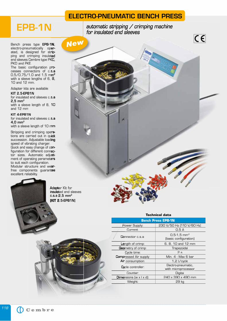
118
EPB-1NELECTRO-PNEUMATIC BENCH PRESS
automatic stripping / crimping machine for insulated end sleeves
Bench press type EPB-1Nelectro-pneumatically oper-ated, is designed for strip-ping and crimping insulated end sleeves Cembre type PKC, PKD and PKE.The basic configuration pro-cesses connectors of c.s.a 0,5/0,75/1,0 and 1,5 mmwith a sleeve lengths of 6, 8, 10 and 12 mm.
Adapter kits are available:KIT 2.5-EPB1Nfor insulated end sleeves c.s.a 2,5 mm2
with a sleeve length of 8, 10 and 12 mm
KIT 4-EPB1Nfor insulated end sleeves c.s.a 4,0 mm2
with a sleeve length of 10 mm
Stripping and crimping opera-tions are carried out in quick succession. Adjustable loading speed of vibrating charger. Quick and easy change of con-figuration for different connec-tor sizes. Automatic adjust-ment of operating perameters to suit each configuration. Modular structure and wear-free components guarantee excellent reliability.
Technical data
Bench Press EPB-1NPower Supply: 230 V/50 Hz (110 V/60 Hz)
Current: 0,5 A
Connector c.s.a: 0,5-1,5 mm2
(basic configuration)
Length of crimp: 6, 8, 10 and 12 mmGeometry of crimp: Trapezoidal
Cycle time: 2 sCompressed Air supply: Min. 4 - Max 6 bar
Air consumption: 1,2 l/cycle
Cycle controller: Electro-pneumatic, with microprocessorwith microprocessor
Counter: DigitalDimensions (w x l x d): 240 x 390 x 490 mm
Weight: 29 kg
automatic stripping / crimping machine for insulated end sleeves
EPB-1N, electro-pneumatically oper-ated, is designed for strip-ping and crimping insulated end sleeves Cembre type PKC,
The basic configuration pro-cesses connectors of c.s.a 0,5/0,75/1,0 and 1,5 mm2
with a sleeve lengths of 6, 8,
for insulated end sleeves c.s.a
with a sleeve length of 8, 10
for insulated end sleeves c.s.a
with a sleeve length of 10 mm
Stripping and crimping opera-tions are carried out in quick succession. Adjustable loading
Quick and easy change of con-figuration for different connec-tor sizes. Automatic adjust-ment of operating perameters
Modular structure and wear-free components guarantee
Adapter Kit for Adapter Kit for Adapter Kit for Adapter Kit for insulated end sleevesinsulated end sleevesc.s.a 2,5 mm2,5 mm2
(KIT 2.5-EPB1N)(KIT 2.5-EPB1N)
Power Supply:
Connector c.s.a:
Length of crimp:Geometry of crimp:
Compressed Air supply:Air consumption:
Cycle controller:
Dimensions (w x l x d):
New
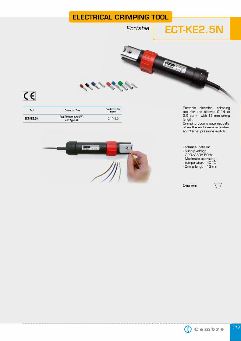
119
ECT-KE2.5NELECTRO-PNEUMATIC BENCH PRESS
automatic stripping / crimping machine for insulated end sleeves ECT-KE2.5N
Crimp style:
Portable electrical crimping tool for end sleeves 0,14 to 2,5 sqmm with 13 mm crimp length.Crimping occurs automatically when the end sleeve activates an internal pressure switch.
Technical details:- Supply voltage: 220/230V 50Hz- Maximum operating temperature: 40 °C- Crimp length: 13 mm
ELECTRICAL CRIMPING TOOL
Portable
Connector Type Conductor Sizesqmm
End Sleeves type PK.. ECT-KE2.5N and type KE 0.14÷2.5
Tool
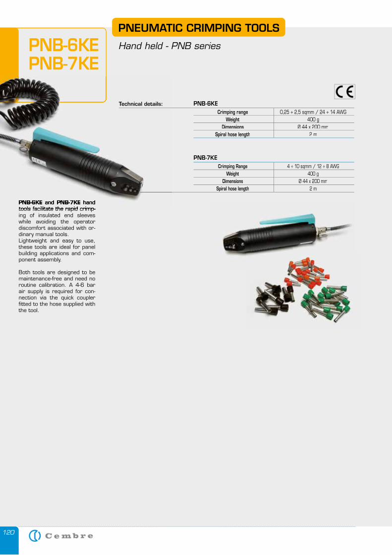
120
PNB-7KECrimping Range 4 ÷ 10 sqmm / 12 ÷ 8 AWG
Weight 400 g Dimensions Ø 44 x 200 mm
Spiral hose length 2 m
PNB-6KE and PNB-7KE hand tools facilitate the rapid crimp-ing of insulated end sleeves while avoiding the operator discomfort associated with or-dinary manual tools. Lightweight and easy to use, these tools are ideal for panel building applications and com-ponent assembly.
Both tools are designed to be maintenance-free and need no routine calibration. A 4-6 bar air supply is required for con-nection via the quick coupler fitted to the hose supplied with the tool.
PNEUMATIC CRIMPING TOOLS
Hand held - PNB seriesPNB-6KEPNB-7KE
PNB-6KE and PNB-7KE hand tools facilitate the rapid crimp-
Technical details: PNB-6KECrimping range 0,25 ÷ 2,5 sqmm / 24 ÷ 14 AWG
Weight 400 g Dimensions Ø 44 x 200 mm
Spiral hose length 2 m
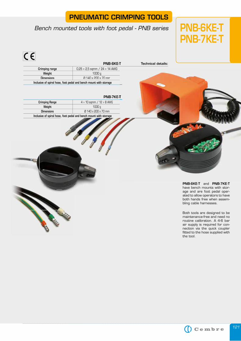
121
PNEUMATIC CRIMPING TOOLS
Bench mounted tools with foot pedal - PNB series PNB-6KE-TPNB-7KE-T
PNB-7KE-TCrimping Range 4 ÷ 10 sqmm / 12 ÷ 8 AWG
Weight 1000 gDimensions Ø 140 x 200 x 70 mm
Inclusive of spiral hose, foot pedal and bench mount with storage
PNB-6KE-T and PNB-7KE-T have bench mounts with stor-age and are foot pedal oper-ated to allow operators to have both hands free when assem-bling cable harnesses.
Both tools are designed to be maintenance-free and need no routine calibration. A 4-6 bar air supply is required for con-nection via the quick coupler fitted to the hose supplied with the tool.
PNB-6KE-T Technical details:
Crimping range 0,25 ÷ 2,5 sqmm / 24 ÷ 14 AWG Weight 1000 g
Dimensions Ø 140 x 200 x 70 mm Inclusive of spiral hose, foot pedal and bench mount with storage
PNB-7KE-T
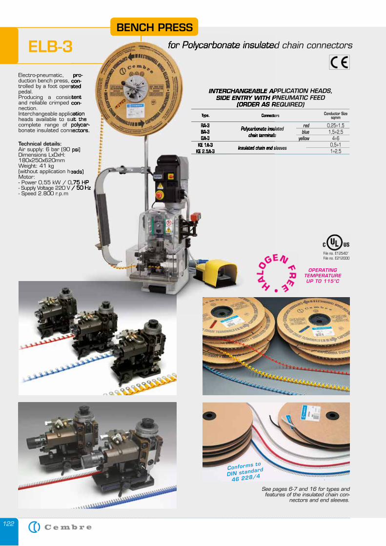
122
INTERCHANGEABLE APPLICATION HEADS, SIDE ENTRY WITH PNEUMATIC FEED
(ORDER AS REQUIRED)
Connectors Conductor Sizesqmm
RA-3 Polycarbonate insulated
red 0,25÷1,5 BA-3
chain terminals blue 1,5÷2,5
GA-3 yellow 4÷6 KE 1A-3 0,5÷1 KE 2.5A-3
Insulated chain end sleeves 1÷2,5
Type.
ELB-3
Electro-pneumatic, pro-duction bench press, con-trolled by a foot operated pedal. Producing a consistent and reliable crimped con-nection.Interchangeable application heads available to suit the complete range of polycar-bonate insulated connectors.
Technical details:Air supply: 6 bar (90 psi)Dimensions LxDxH: 180x250x620mmWeight: 41 kg (without application heads)Motor:- Power 0,55 kW / 0,75 HP- Supply Voltage 220 V / 50 Hz- Speed 2.800 r.p.m
See pages 6-7 and 16 for types and features of the insulated chain con-
nectors and end sleeves.
BENCH PRESS
for Polycarbonate insulated chain connectors
OPERATINGTEMPERATURE UP TO 115°C
Conforms to
DIN standard
46 228/4
File no. E125401File no. E212000
INTERCHANGEABLE APPLICATIONSIDE ENTRY WITH PNEUMATIC FEED
(ORDER AS REQUIRED)
Connectors
RA-3 Polycarbonate insulated
BA-3chain terminals
GA-3 yellow chain terminals
yellow chain terminals
KE 1A-3KE 2.5A-3
Insulated chain end sleeves
Insulated chain end sleeves
Type.
ELB-3
Electro-pneumatic, pro-duction bench press, con-trolled by a foot operated
Producing a consistent and reliable crimped con-
Interchangeable application heads available to suit the complete range of polycar-bonate insulated connectors.
Air supply: 6 bar (90 psi)
(without application heads)
- Power 0,55 kW / 0,75 HP- Supply Voltage 220 V / 50 Hz
for Polycarbonate insulated chain connectors

123123
HY
DR
AU
LIC
CR
IMP
ING
TO
OLS
AN
D C
UTTER
S
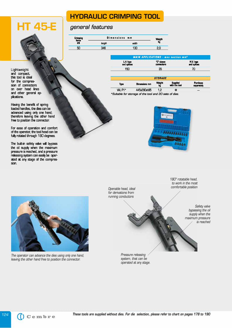
124
Lightweight and compact, this tool is ideal for the compres-sion of connectors on over head lines and other general ap-plications.
Having the benefit of spring loaded handles, the dies can be advanced using only one hand; therefore leaving the other hand free to position the connector.
For ease of operation and comfort of the operator, the tool head can be fully rotated through 180 degrees.
The built-in safety valve will by-pass the oil supply when the maximum pressure is reached, and a pressure releasing system can easily be oper-ated at any stage of the compres-sion.
HYDRAULIC CRIMPING TOOL
general features
CrimpingforcekN
Weigthkglength width
D i m e n s i o n s m m
50 346 130 2,0
M A I N A P P L I C A T I O N S - m a x s e c t i o n m m 2
L.V. lugsand splices
“C” sleeveconnectors
H.V. lugsand splices
150 35 70
S T O R A G E
Type Dimensions mm Weightkg
Suppliedwith the tool
Purchase separately
VAL P1* 445x290xh95 1,2 � —*Suitable for storage of the tool and 20 sets of dies.
The operator can advance the dies using only one hand,leaving the other hand free to position the connector.
180° rotatable head, to work in the most
comfortable positionOpenable head, idealfor derivations fromrunning conductors
Pressure releasingsystem, that can beoperated at any stage.
Safety valvebypassing the oilsupply when the
maximum pressureis reached
These tools are supplied without dies. For die selection, please refer to chart on pages 178 to 190
HT 45-E
Lightweight and compact, this tool is ideal for the compres-sion of connectors on over head lines and other general ap-plications.
Having the benefit of spring loaded handles, the dies can be advanced using only one hand; therefore leaving the other hand free to position the connector.
For ease of operation and comfort of the operator, the tool head can be fully rotated through 180 degrees.
The built-in safety valve will by-pass the oil supply when the maximum pressure is reached, and a pressure releasing system can easily be oper-ated at any stage of the compres-sion.
general features
CrimpingforcekN
Weigthkglength width
D i m e n s i o n s m m
50 346 130 2,0
M A I N A P P L I C A T I O N S - m a x s e c t i o n m m 2
L.V. lugsand splices
“C” sleeveconnectors
H.V. lugsand splices
150 35 70
S T O R A G E
Type Dimensions mm Weightkg
Suppliedwith the tool
Purchase separately
VAL P1* 445x290xh95 1,2 � —*Suitable for storage of the tool and 20 sets of dies.
HT 45-E
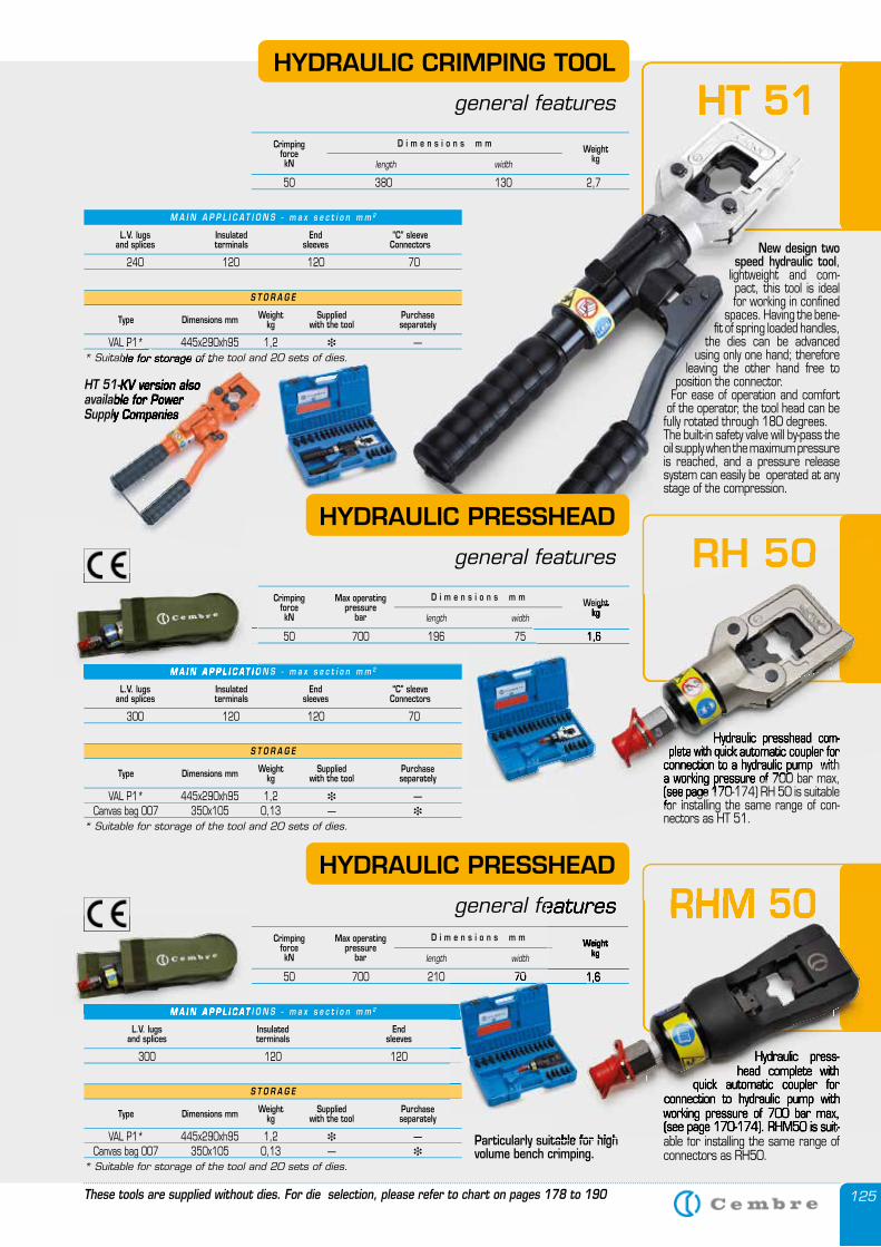
125
HT 51HT 51
CrimpingforcekN
Max operatingpressure
barWeight
kglength width
D i m e n s i o n s m m
50 700 196 75 1,6
S T O R A G E
Type Dimensions mm Weightkg
Suppliedwith the tool
Purchase separately
VAL P1* 445x290xh95 1,2 � — Canvas bag 007 350x105 0,13 — �
* Suitable for storage of the tool and 20 sets of dies.
L.V. lugsand splices
Insulatedterminals
Endsleeves
“C” sleeveConnectors
300 120 120 70
S T O R A G E
Type Dimensions mm Weightkg
Suppliedwith the tool
Purchase separately
VAL P1* 445x290xh95 1,2 � —* Suitable for storage of the tool and 20 sets of dies.
L.V. lugsand splices
Insulatedterminals
Endsleeves
“C” sleeveConnectors
240 120 120 70
M A I N A P P L I C A T I O N S - m a x s e c t i o n m m 2
M A I N A P P L I C A T I O N S - m a x s e c t i o n m m 2
New design two speed hydraulic tool,
lightweight and com-pact, this tool is ideal for working in confined
spaces. Having the bene-fit of spring loaded handles,
the dies can be advanced using only one hand; therefore
leaving the other hand free to position the connector.
For ease of operation and comfort of the operator, the tool head can be fully rotated through 180 degrees.The built-in safety valve will by-pass the oil supply when the maximum pressure is reached, and a pressure release system can easily be operated at any stage of the compression.
CrimpingforcekN
Weightkglength width
D i m e n s i o n s m m
50 380 130 2,7
HYDRAULIC CRIMPING TOOL
general features
Hydraulic presshead com-plete with quick automatic coupler for
connection to a hydraulic pump with a working pressure of 700 bar max, (see page 170-174) RH 50 is suitable for installing the same range of con-nectors as HT 51.
HYDRAULIC PRESSHEAD
general features
Hydraulic press-head complete with
quick automatic coupler for connection to hydraulic pump with working pressure of 700 bar max, (see page 170-174). RHM50 is suit-able for installing the same range of connectors as RH50.
HYDRAULIC PRESSHEAD
general features
M A I N A P P L I C A T I O N S - m a x s e c t i o n m m 2
S T O R A G E
Type Dimensions mm Weightkg
Suppliedwith the tool
Purchase separately
VAL P1* 445x290xh95 1,2 � — Canvas bag 007 350x105 0,13 — �
* Suitable for storage of the tool and 20 sets of dies.
L.V. lugsand splices
Insulatedterminals
Endsleeves
300 120 120
Particularly suitable for high volume bench crimping.
50 700 210 70 1,6
CrimpingforcekN
Max operatingpressure
barWeight
kglength width
D i m e n s i o n s m m
These tools are supplied without dies. For die selection, please refer to chart on pages 178 to 190
HT 51-KV version also available for Power Supply Companies
RH 50
RHM 50
VAL P1* 445x290xh95 1,2 * Suitable for storage of the tool and 20 sets of dies.
HT 51-KV version also available for Power Supply Companies
50 700 196 75 1,6
M A I N A P P L I C A T I O N S - m a x s e c t i o n m m
M A I N A P P L I C A T I O N S - m a x s e c t i o n m m
50 700 210 70 1,6
Weightkg
50 700 196 75 1,6
Hydraulic presshead com-plete with quick automatic coupler for with quick automatic coupler for with quick
connection to a hydraulic pump with a working pressure of 700 bar max, (see page 170-174) RH 50 is suitable for installing the same range of con-
RH 50
Hydraulic press-head complete with
quick automatic coupler for connection to hydraulic pump with working pressure of 700 bar max, (see page 170-174). RHM50 is suit-able for installing the same range of
general features
Particularly suitable for high
50 700 210 70 1,6
Weightkg
RHM 50
50 700 210 70 1,6 50 700 210 70 1,6
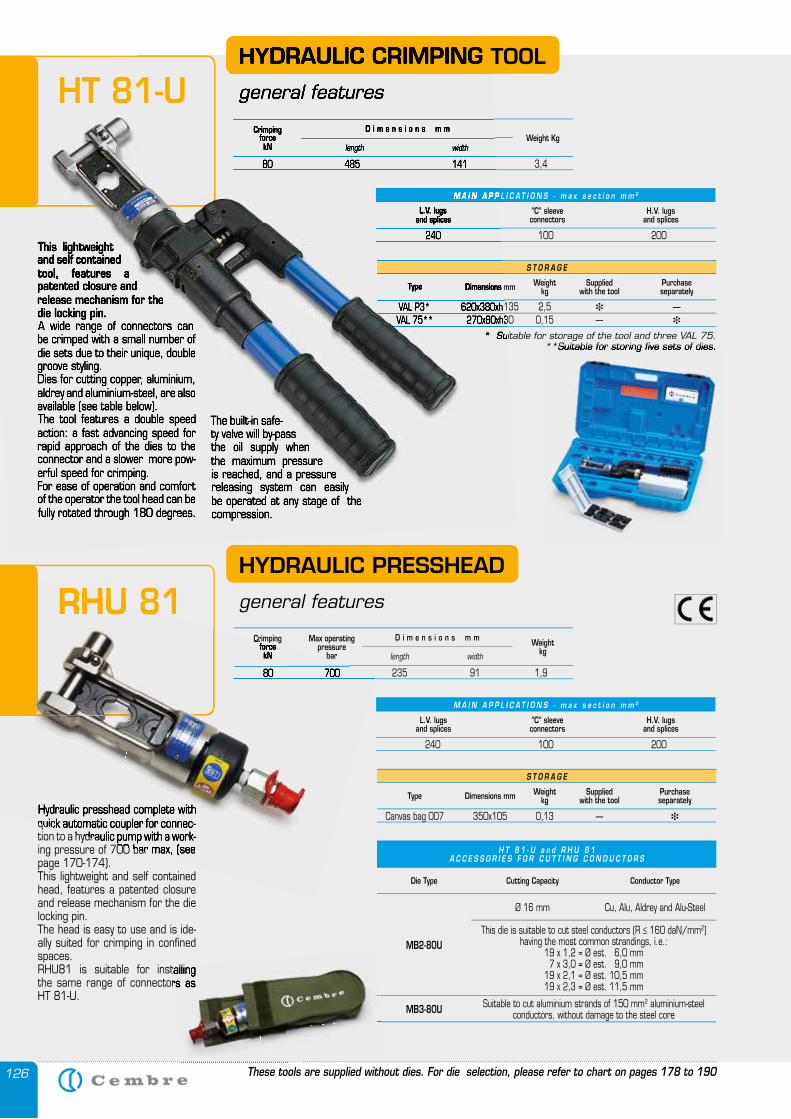
126
Hydraulic presshead complete with quick automatic coupler for connec-tion to a hydraulic pump with a work-ing pressure of 700 bar max, (see page 170-174).This lightweight and self contained head, features a patented closure and release mechanism for the die locking pin. The head is easy to use and is ide-ally suited for crimping in confined spaces. RHU81 is suitable for installing the same range of connectors as HT 81-U.
HYDRAULIC PRESSHEAD
general features
S T O R A G E
Type Dimensions mm Weightkg
Supplied with the tool
Purchase separately
Canvas bag 007 350x105 0,13 — �
H T 8 1 - U a n d R H U 8 1 A C C E S S O R I E S F O R C U T T I N G C O N D U C T O R S
Die Type Cutting Capacity Conductor Type
MB2-80U
MB3-80U
Ø 16 mm
This die is suitable to cut steel conductors (R ≤ 160 daN/mm2) having the most common strandings, i.e.:
19 x 1,2 = Ø est. 6,0 mm 7 x 3,0 = Ø est. 9,0 mm19 x 2,1 = Ø est. 10,5 mm19 x 2,3 = Ø est. 11,5 mm
Suitable to cut aluminium strands of 150 mm2 aluminium-steel conductors, without damage to the steel core
Cu, Alu, Aldrey and Alu-Steel
This lightweight and self contained tool, features a patented closure and release mechanism for the die locking pin. A wide range of connectors can be crimped with a small number of die sets due to their unique, double groove styling.Dies for cutting copper, aluminium, aldrey and aluminium-steel, are also available (see table below).The tool features a double speed action: a fast advancing speed for rapid approach of the dies to the connector and a slower more pow-erful speed for crimping.For ease of operation and comfort of the operator the tool head can be fully rotated through 180 degrees.
The built-in safe-ty valve will by-pass the oil supply when the maximum pressure is reached, and a pressure releasing system can easily be operated at any stage of the compression.
HYDRAULIC CRIMPING TOOL
general features
CrimpingforcekN
Weight Kglength width
D i m e n s i o n s m m
80 485 141 3,4
S T O R A G E
Type Dimensions mm Weightkg
Suppliedwith the tool
Purchase separately
VAL P3* 620x380xh135 2,5 � — VAL 75** 270x80xh30 0,15 — �
* Suitable for storage of the tool and three VAL 75.**Suitable for storing five sets of dies.
CrimpingforcekN
Max operatingpressure
barWeight
kglength width
D i m e n s i o n s m m
80 700 235 91 1,9
L.V. lugsand splices
“C” sleeveconnectors
H.V. lugsand splices
240 100 200
M A I N A P P L I C A T I O N S - m a x s e c t i o n m m 2
L.V. lugsand splices
“C” sleeveconnectors
H.V. lugsand splices
240 100 200
M A I N A P P L I C A T I O N S - m a x s e c t i o n m m 2
These tools are supplied without dies. For die selection, please refer to chart on pages 178 to 190
This lightweight and self contained tool, features a patented closure and release mechanism for the die locking pin. A wide range of connectors can be crimped with a small number of die sets due to their unique, double groove styling.Dies for cutting copper, aluminium, aldrey and aluminium-steel, are also available (see table below).The tool features a double speed action: a fast advancing speed for rapid approach of the dies to the connector and a slower more pow-erful speed for crimping.For ease of operation and comfort of the operator the tool head can be fully rotated through 180 degrees.
The built-in safe-ty valve will by-pass the oil supply when the maximum pressure is reached, and a pressure releasing system can easily be operated at any stage of the compression.
HYDRAULIC CRIMPING TOOL
general features
CrimpingforcekN length width
D i m e n s i o n s m m
80 485 141 3,4
Type Dimensions mm
VAL P3* 620x380xh135 2,5 VAL 75** 270x80xh30 0,15 —
* Suitable for storage of the tool and three VAL 75.
L.V. lugsand splices
240 100 200
M A I N A P P L I C A T I O N S - m a x s e c t i o n m m
HT 81-U
RHU 81
**Suitable for storing five sets of dies.
RHU81 is suitable for installing the same range of connectors as
Hydraulic presshead complete with quick automatic coupler for connec-tion to a hydraulic pump with a work-ing pressure of 700 bar max, (see
CrimpingforcekN
80 700 235 91 1,9
RHU 81
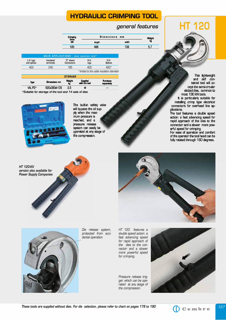
127
This lightweight and self con-
tained tool will ac-cept the semi-circular
slotted dies, common to most 130 kN tools.
It is particularly suitable for installing crimp type electrical
connectors for overhead line ap-plications.The tool features a double speed action: a fast advancing speed for rapid approach of the dies to the connector and a slower more pow-erful speed for crimping.For ease of operation and comfort of the operator the tool head can be fully rotated through 180 degrees.
CrimpingforcekN
Weightkglength width
D i m e n s i o n s m m
120 488 138 5,7
S T O R A G E
Type Dimensions mm Weightkg
Suppliedwith the tool
Purchase separately
VAL P3* 620x380xh135 2,5 � —*Suitable for storage of the tool and 14 sets of dies.
HYDRAULIC CRIMPING TOOL
general features
HT 120 features a double speed action: a fast advancing speed for rapid approach of the dies to the con-nector and a slower more powerful speed for crimping.
Die release system, protected from acci-dental operation
Pressure release trig-ger, which can be ope-rated at any stage of the compression.
The built-in safety valve will by-pass the oil sup-ply when the maxi-mum pressure is reached, and a pressure release system can easily be operated at any stage of the compression.
�
These tools are supplied without dies. For die selection, please refer to chart on pages 178 to 190
HT 120-KV version also available for Power Supply Companies
This lightweight and self con-
tained tool will ac-cept the semi-circular
slotted dies, common to most 130 kN tools.
It is particularly suitable for installing crimp type electrical
connectors for overhead line ap-plications.The tool features a double speed action: a fast advancing speed for rapid approach of the dies to the connector and a slower more pow-erful speed for crimping.For ease of operation and comfort of the operator the tool head can be fully rotated through 180 degrees.
CrimpingforcekN
Weightkglength width
D i m e n s i o n s m m
120 488 138 5,7
S T O R A G E
Type Dimensions mm Weightkg
Suppliedwith the tool
Purchase separately
VAL P3* 620x380xh135 2,5 � —*Suitable for storage of the tool and 14 sets of dies.
HYDRAULIC CRIMPING TOOL
general features
The built-in safety valve will by-pass the oil sup-ply when the maxi-mum pressure is reached, and a pressure release system can easily be operated at any stage of the compression.
HT 120
The built-in safety valve will by-pass the oil sup-ply when the maxi-mum pressure is reached, and a pressure release system can easily be operated at any stage of the compression.
M A I N A P P L I C A T I O N S - m a x s e c t i o n m m 2
L.V. lugsand splices
Insulatedterminals
“C” sleeveConnectors
H.V. lugs
H.V. Splices
400 240 185 400 400**limited to the cable insulation diameter
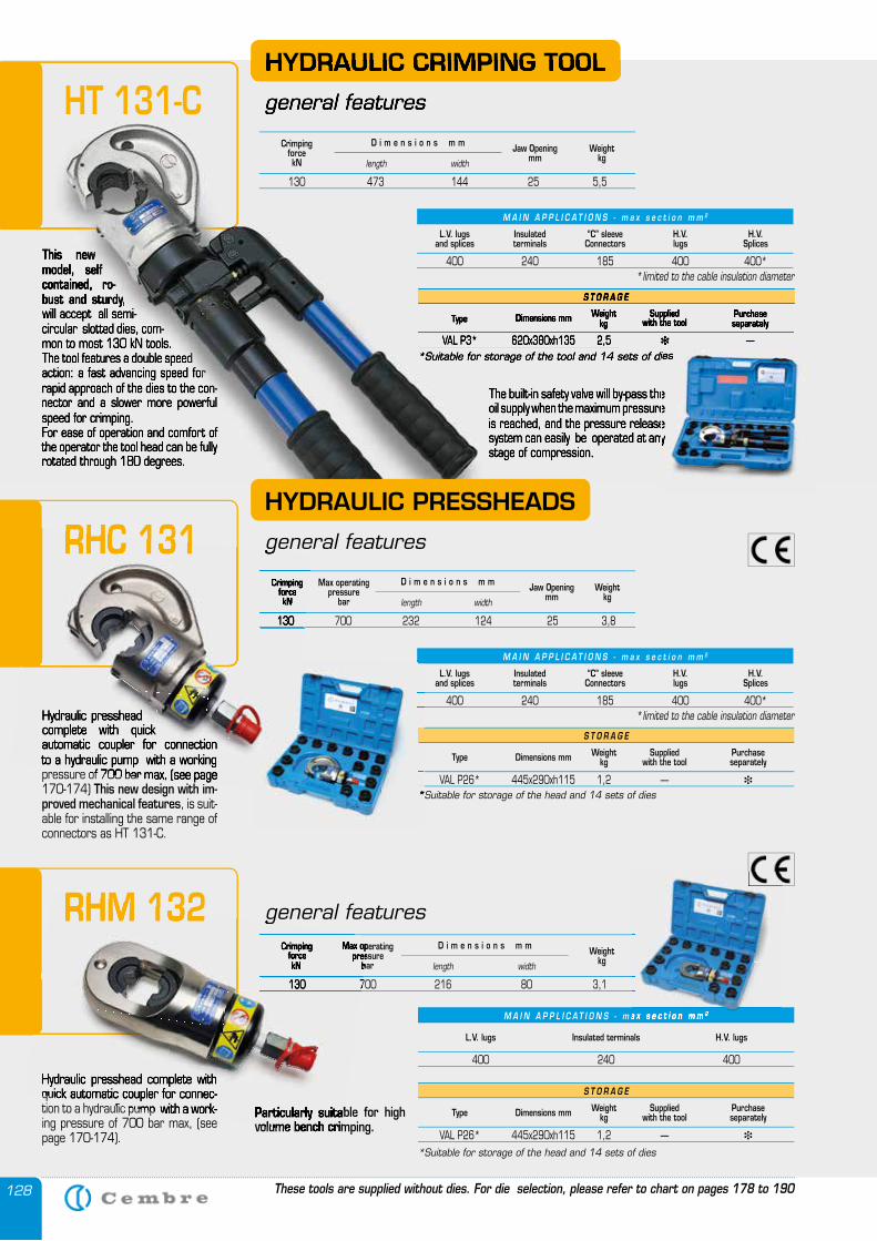
128
Hydraulic presshead complete with quick automatic coupler for connection to a hydraulic pump with a working pressure of 700 bar max, (see page 170-174) This new design with im-proved mechanical features, is suit-able for installing the same range of connectors as HT 131-C.
This new model, self contained, ro-bust and sturdy, will accept all semi-circular slotted dies, com-mon to most 130 kN tools.The tool features a double speed action: a fast advancing speed for rapid approach of the dies to the con-nector and a slower more powerful speed for crimping.For ease of operation and comfort of the operator the tool head can be fully rotated through 180 degrees.
The built-in safety valve will by-pass the oil supply when the maximum pressure is reached, and the pressure release system can easily be operated at any stage of compression.
HYDRAULIC CRIMPING TOOL
general features
S T O R A G E
Type Dimensions mm Weightkg
Suppliedwith the tool
Purchase separately
VAL P3* 620x380xh135 2,5 � —*Suitable for storage of the tool and 14 sets of dies
S T O R A G E
Dimensions mm Weightkg
Suppliedwith the tool
Purchase separately
*Suitable for storage of the head and 14 sets of dies
Hydraulic presshead complete with quick automatic coupler for connec-tion to a hydraulic pump with a work-ing pressure of 700 bar max, (see page 170-174).
M A I N A P P L I C A T I O N S - m a x s e c t i o n m m 2
L.V. lugs Insulated terminals H.V. lugs
400 240 400
S T O R A G E
Type Dimensions mm Weightkg
Suppliedwith the tool
Purchase separately
VAL P26* 445x290xh115 1,2 — �
*Suitable for storage of the head and 14 sets of dies
CrimpingforcekN
Max operatingpressure
barWeight
kglength width
D i m e n s i o n s m m
130 700 216 80 3,1
VAL P26* 445x290xh115 1,2 — �
Type
general features
Particularly suitable for high volume bench crimping.
These tools are supplied without dies. For die selection, please refer to chart on pages 178 to 190
This new model, self contained, ro-bust and sturdy, will accept all semi-circular slotted dies, com-mon to most 130 kN tools.The tool features a double speed action: a fast advancing speed for rapid approach of the dies to the con-nector and a slower more powerful speed for crimping.For ease of operation and comfort of the operator the tool head can be fully rotated through 180 degrees.
The built-in safety valve will by-pass the oil supply when the maximum pressure is reached, and the pressure release system can easily be operated at any stage of compression.
HYDRAULIC CRIMPING TOOL
general features
S T O R A G E
Type Dimensions mm Weightkg
Suppliedwith the tool
Purchase separately
VAL P3* 620x380xh135 2,5 � —*Suitable for storage of the tool and 14 sets of dies
HT 131-C
RHC 131
RHM 132
HYDRAULIC PRESSHEADS
general features
The built-in safety valve will by-pass the oil supply when the maximum pressure is reached, and the pressure release system can easily be operated at any
*Suitable for storage of the tool and 14 sets of dies
M A I N A P P L I C A T I O N S - m a x s e c t i o n m m 2
CrimpingforcekN
Weightkglength width
D i m e n s i o n s m m
130 473 144 25 5,5
Jaw Openingmm
CrimpingforcekN
Max operatingpressure
barWeight
kglength width
D i m e n s i o n s m m
130 700 232 124 25 3,8
Jaw Openingmm
M A I N A P P L I C A T I O N S - m a x s e c t i o n m m 2
L.V. lugsand splices
Insulatedterminals
“C” sleeveConnectors
H.V. lugs
H.V. Splices
400 240 185 400 400**limited to the cable insulation diameter
M A I N A P P L I C A T I O N S - m a x s e c t i o n m m 2
L.V. lugsand splices
Insulatedterminals
“C” sleeveConnectors
H.V. lugs
H.V. Splices
400 240 185 400 400**limited to the cable insulation diameterHydraulic presshead
complete with quick automatic coupler for connection to a hydraulic pump with a working pressure of 700 bar max, (see page
This new design with im-
RHC 131 general features
CrimpingforcekN
130 700 232 124 25 3,8
*Suitable for storage of the head and 14 sets of dies VAL P26* 445x290xh115 1,2 —
400 240 185 400 400*
Hydraulic presshead complete with quick automatic coupler for connec-tion to a hydraulic pump with a work-ing pressure of 700 bar max, (see
CrimpingforcekN
Max operatingpressure
bar
130 700 216 80 3,1
general features
Particularly suitable for high volume bench crimping.
RHM 132
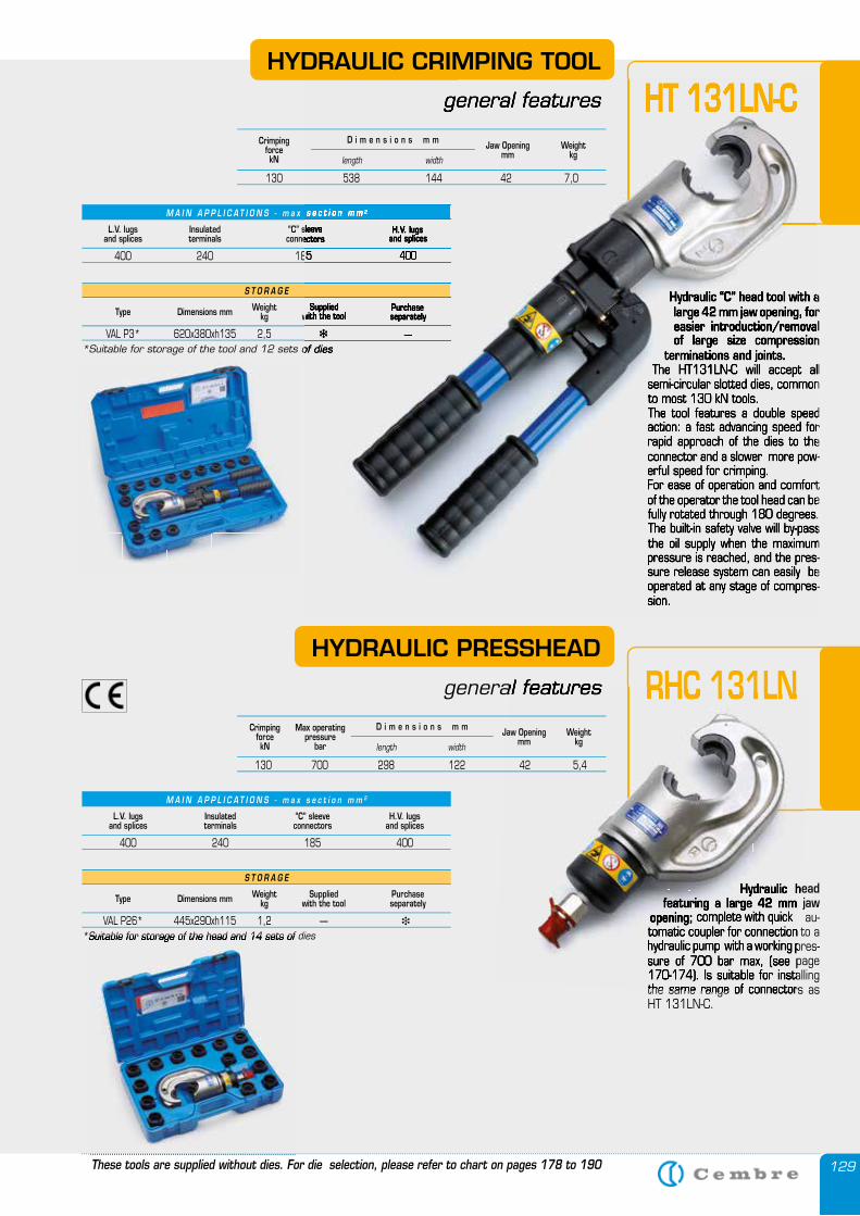
129
Hydraulic “C” head tool with a large 42 mm jaw opening, for easier introduction/removal of large size compression
terminations and joints. The HT131LN-C will accept all
semi-circular slotted dies, common to most 130 kN tools. The tool features a double speed action: a fast advancing speed for rapid approach of the dies to the connector and a slower more pow-erful speed for crimping.For ease of operation and comfort of the operator the tool head can be fully rotated through 180 degrees.The built-in safety valve will by-pass the oil supply when the maximum pressure is reached, and the pres-sure release system can easily be operated at any stage of compres-sion.
M A I N A P P L I C A T I O N S - m a x s e c t i o n m m 2
S T O R A G E
Type Dimensions mm Weightkg
Suppliedwith the tool
Purchase separately
HYDRAULIC CRIMPING TOOL
general features
L.V. lugsand splices
Insulatedterminals
“C” sleeveconnectors
H.V. lugsand splices
400 240 185 400
VAL P3* 620x380xh135 2,5 � —*Suitable for storage of the tool and 12 sets of dies
Hydraulic head featuring a large 42 mm jaw
opening; complete with quick au-tomatic coupler for connection to a hydraulic pump with a working pres-sure of 700 bar max, (see page 170-174). Is suitable for installing the same range of connectors as HT 131LN-C.
M A I N A P P L I C A T I O N S - m a x s e c t i o n m m 2
S T O R A G E
Type Dimensions mm Weightkg
Suppliedwith the tool
Purchase separately
HYDRAULIC PRESSHEAD
general features
L.V. lugsand splices
Insulatedterminals
“C” sleeveconnectors
H.V. lugsand splices
400 240 185 400
*Suitable for storage of the head and 14 sets of dies VAL P26* 445x290xh115 1,2 — �
These tools are supplied without dies. For die selection, please refer to chart on pages 178 to 190
HT 131LN-C
RHC 131LN
Hydraulic “C” head tool with a large 42 mm jaw opening, for easier introduction/removal of large size compression
terminations and joints.The HT131LN-C will accept all
semi-circular slotted dies, common to most 130 kN tools. The tool features a double speed action: a fast advancing speed for rapid approach of the dies to the connector and a slower more pow-erful speed for crimping.For ease of operation and comfort of the operator the tool head can be fully rotated through 180 degrees.The built-in safety valve will by-pass the oil supply when the maximum pressure is reached, and the pres-sure release system can easily be operated at any stage of compres-sion.
M A I N A P P L I C A T I O N S - m a x s e c t i o n m m 2
Suppliedwith the tool
Purchase separately
general features
“C” sleeveconnectors
H.V. lugsand splices
400 240 185 400
� —*Suitable for storage of the tool and 12 sets of dies
HT 131LN-C
Hydraulic head featuring a large 42 mm jaw
opening; complete with quick au-tomatic coupler for connection to a hydraulic pump with a working pres-sure of 700 bar max, (see page 170-174). Is suitable for installing the same range of connectors as
general features RHC 131LN
*Suitable for storage of the head and 14 sets of dies
CrimpingforcekN
Weightkglength width
D i m e n s i o n s m m
130 538 144 42 7,0
Jaw Openingmm
CrimpingforcekN
Max operatingpressure
barWeight
kglength width
D i m e n s i o n s m m
130 700 298 122 42 5,4
Jaw Openingmm
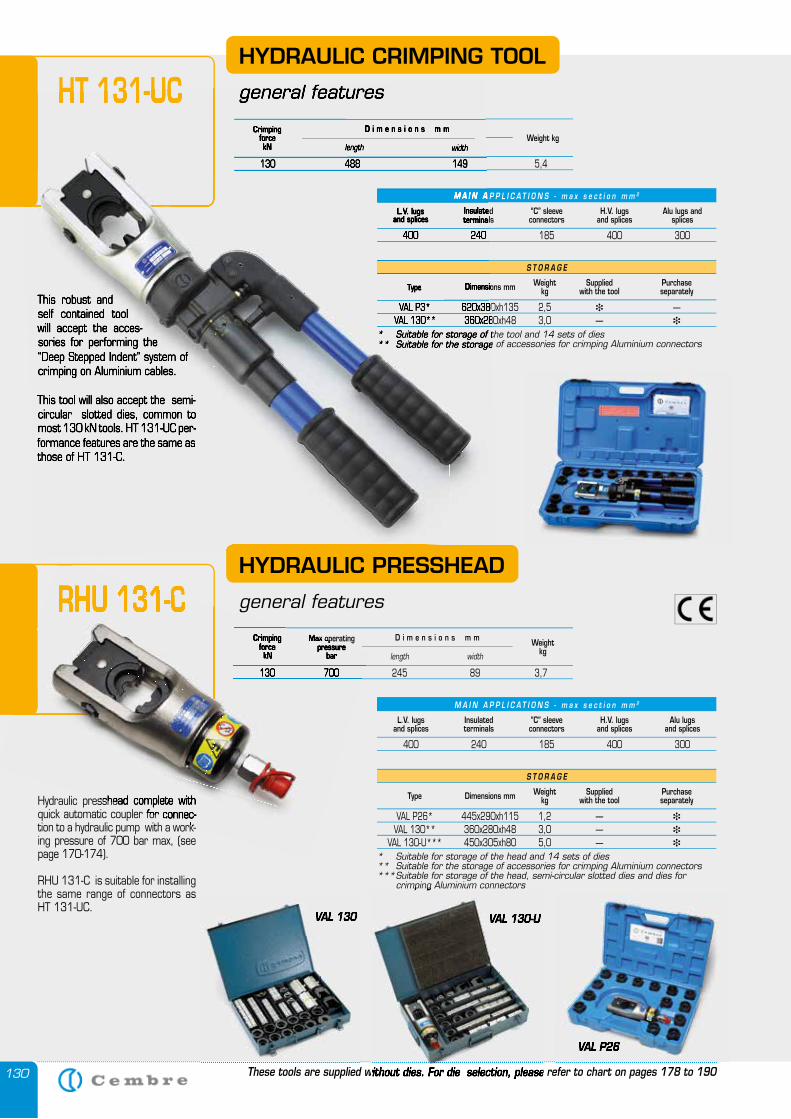
130
Hydraulic presshead complete with quick automatic coupler for connec-tion to a hydraulic pump with a work-ing pressure of 700 bar max, (see page 170-174).
RHU 131-C is suitable for installing the same range of connectors as HT 131-UC.
HYDRAULIC PRESSHEAD
general features
This robust and self contained tool will accept the acces-sories for performing the “Deep Stepped Indent” system of crimping on Aluminium cables.
This tool will also accept the semi-circular slotted dies, common to most 130 kN tools. HT 131-UC per-formance features are the same as those of HT 131-C.
CrimpingforcekN
Weight kglength width
D i m e n s i o n s m m
130 488 149 5,4
M A I N A P P L I C A T I O N S - m a x s e c t i o n m m 2
S T O R A G E
Type Dimensions mm Weightkg
Suppliedwith the tool
Purchase separately
VAL P3* 620x380xh135 2,5 � — VAL 130** 360x280xh48 3,0 — �
* Suitable for storage of the tool and 14 sets of dies** Suitable for the storage of accessories for crimping Aluminium connectors
L.V. lugsand splices
Insulatedterminals
“C” sleeveconnectors
H.V. lugsand splices
Alu lugs and splices
400 240 185 400 300
M A I N A P P L I C A T I O N S - m a x s e c t i o n m m 2
S T O R A G E
Type Dimensions mm Weightkg
Suppliedwith the tool
Purchase separately
VAL P26* 445x290xh115 1,2 — �
VAL 130** 360x280xh48 3,0 — �
VAL 130-U*** 450x305xh80 5,0 — �
* Suitable for storage of the head and 14 sets of dies** Suitable for the storage of accessories for crimping Aluminium connectors*** Suitable for storage of the head, semi-circular slotted dies and dies for crimping Aluminium connectors
L.V. lugsand splices
Insulatedterminals
“C” sleeveconnectors
H.V. lugsand splices
Alu lugsand splices
400 240 185 400 300
CrimpingforcekN
Max operatingpressure
barWeight
kglength width
D i m e n s i o n s m m
130 700 245 89 3,7
VAL 130
VAL P26
VAL 130-U
HYDRAULIC CRIMPING TOOL
general features
These tools are supplied without dies. For die selection, please refer to chart on pages 178 to 190
HT 131-UC
This robust and self contained tool will accept the acces-sories for performing the “Deep Stepped Indent” system of crimping on Aluminium cables.
This tool will also accept the semi-circular slotted dies, common to most 130 kN tools. HT 131-UC per-formance features are the same as those of HT 131-C.
CrimpingforcekN length width
D i m e n s i o n s m m
130 488 149 5,4
M A I N A P P L I C A T I O N S - m a x s e c t i o n m m
Type Dimensions mm
VAL P3* 620x380xh135 2,5 VAL 130** 360x280xh48 3,0 — * Suitable for storage of the tool and 14 sets of dies** Suitable for the storage of accessories for crimping Aluminium connectors
L.V. lugsand splices
Insulatedterminals
400 240 185 400 300
general featuresHT 131-UC
RHU 131-C
VAL 130
These tools are supplied without dies. For die selection, please refer to chart on pages 178 to 190
VAL P26
Hydraulic presshead complete with quick automatic coupler for connec-tion to a hydraulic pump with a work-
CrimpingforcekN
Max operatingpressure
bar
130 700 245 89 3,7
RHU 131-C
crimping Aluminium connectors
VAL 130-U
These tools are supplied without dies. For die selection, please refer to chart on pages 178 to 190
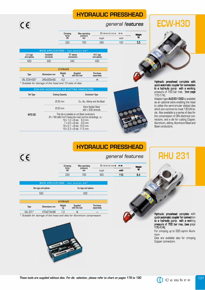
131These tools are supplied without dies. For die selection, please refer to chart on pages 178 to 190
HYDRAULIC PRESSHEAD
general features
Hydraulic presshead complete with quick automatic coupler for connection to a hydraulic pump with a working pressure of 700 bar max, (see page 170-174).Adaptor type AU230-130D is available as an optional extra enabling the head to utilise the semi-circular slotted dies which are common to most 130 kN to-ols. Also available is a series of dies for the compression of DIN electrical con-nectors, and a die for cutting Copper, Aluminium, aldrey, Aluminium-Steel and Steel conductors.
ECW-H3D
M A I N A P P L I C A T I O N S - m a x s e c t i o n m m 2
L.V. lugsand splices
Insulatedterminals
“C” sleeveconnectors
H.V. lugsand splices
630 300 240 630
S T O R A G E
Type Dimensions mm Weightkg
Suppliedwith the tool
Purchase separately
VAL ECW-H3D* 345x305xh90 4,2 — �
* Suitable for storage of the head and 10 sets of dies
Die Type Cutting Capacity Conductor Type
WT2-3D
Ø 20 mm
This die is suitable to cut Steel conductors (R ≤ 160 daN/mm2) having the most common strandings, i.e.:
19 x 1,2 = Ø est. 6,0 mm 7 x 3,0 = Ø est. 9,0 mm19 x 2,1 = Ø est. 10,5 mm19 x 2,3 = Ø est. 11,5 mm
Cu, Alu, Aldrey and Alu-Steel
Ø 20 mm Extra flexible Steel with ≥ 200 strands
CrimpingforcekN
Max operatingpressure
barWeight
kglength width
D i m e n s i o n s m m
230 700 290 120 5,5
HYDRAULIC PRESSHEAD
general features
Hydraulic presshead complete with quick automatic coupler for connection to a hydraulic pump with a working pressure of 700 bar max, (see page 170-174).For crimping up to 500 sqmm Alumi-nium.Dies are available also for crimping Copper connectors.
RHU 231
S T O R A G E
Type Dimensions mm Weightkg
Suppliedwith the tool
Purchase separately
VAL 231* 470x273xh96 7,2 � —* Suitable for storage of the head and dies for Aluminium compression
CrimpingforcekN
Max operatingpressure
barWeight
kglength width
D i m e n s i o n s m m
230 700 320 110 6,4
M A I N A P P L I C A T I O N S - m a x s e c t i o n m m 2
Alu lugs and splices Cu lugs and splices
500 630
E C W - H 3 D A C C E S S O R I E S F O R C U T T I N G C O N D U C T O R S
general features
Hydraulic presshead complete with quick automatic coupler for connection to a hydraulic pump with a working pressure of 700 bar max, (see page
ECW-H3DWeight
kg
230 700 290 120 5,5
general features
Hydraulic presshead complete with quick automatic coupler for connection to a hydraulic pump with a working pressure of 700 bar max, (see page 170-174).For crimping up to 500 sqmm Alumi-
Weightkgwidth
D i m e n s i o n s m m
230 700 320 110 6,4
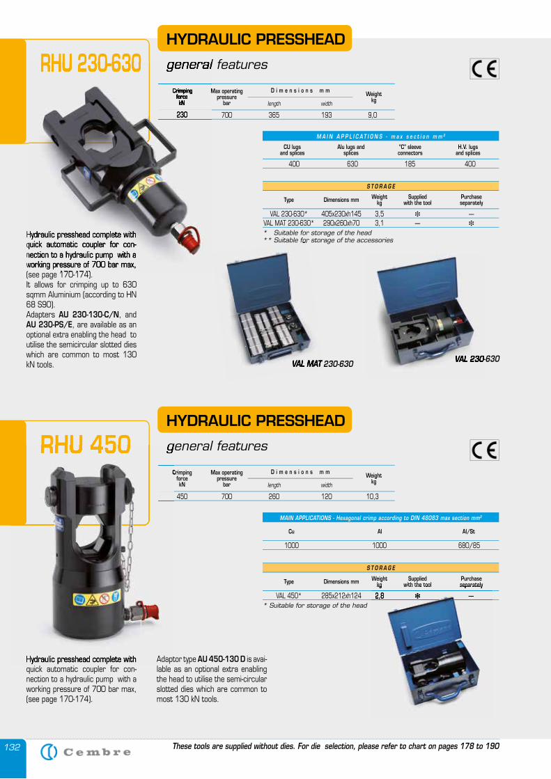
132
Hydraulic presshead complete with quick automatic coupler for con-nection to a hydraulic pump with a working pressure of 700 bar max, (see page 170-174).
Hydraulic presshead complete with quick automatic coupler for con-nection to a hydraulic pump with a working pressure of 700 bar max, (see page 170-174). It allows for crimping up to 630 sqmm Aluminium (according to HN 68 S90). Adapters AU 230-130-C/N, and AU 230-PS/E, are available as an optional extra enabling the head to utilise the semicircular slotted dies which are common to most 130 kN tools.
M A I N A P P L I C A T I O N S - m a x s e c t i o n m m 2
S T O R A G E
Type Dimensions mm Weightkg
Suppliedwith the tool
Purchase separately
VAL 230-630* 405x230xh145 3,5 � — VAL MAT 230-630* 290x260xh70 3,1 — �
* Suitable for storage of the head** Suitable for storage of the accessories
CU lugsand splices
“C” sleeveconnectors
H.V. lugsand splices
Alu lugs and splices
400 630 185 400
HYDRAULIC PRESSHEAD
general featuresRHU 230-630
VAL 230-630VAL MAT 230-630 VAL 230-630
** Suitable for storage of the accessories
VAL MAT 230-630
CrimpingforcekN
Max operatingpressure
barWeight
kglength width
D i m e n s i o n s m m
230 700 365 193 9,0
MAIN APPLICATIONS - Hexagonal crimp according to DIN 48083 max section mm2
Cu Al Al/St
1000 1000 680/85
HYDRAULIC PRESSHEAD
general featuresRHU 450Crimping
forcekN
Max operatingpressure
barWeight
kglength width
D i m e n s i o n s m m
450 700 260 120 10,3
These tools are supplied without dies. For die selection, please refer to chart on pages 178 to 190
Hydraulic presshead complete with quick automatic coupler for con-nection to a hydraulic pump with a working pressure of 700 bar max, (see page 170-174).
general featuresRHU 230-630Crimping
forcekN
Max operating
230 700 365 193 9,0
Hydraulic presshead complete with quick automatic coupler for con-
general featuresRHU 450Crimping
450 700 260 120 10,3
Adaptor type AU 450-130 D is avai-lable as an optional extra enabling the head to utilise the semi-circular slotted dies which are common to most 130 kN tools.
S T O R A G E
Type Dimensions mm Weightkg
Suppliedwith the tool
Purchase separately
VAL 450* 285x212xh124 2,8 � —* Suitable for storage of the head
kg with the tool separately
VAL 450* 285x212xh124 2,8 � —
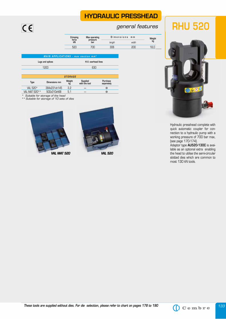
133
Hydraulic presshead complete with quick automatic coupler for con-nection to a hydraulic pump with a working pressure of 700 bar max, (see page 170-174).Adaptor type AU520-130C is avai-lable as an optional extra enabling the head to utilise the semi-circular slotted dies which are common to most 130 kN tools.
RHU 520
S T O R A G E
Type Dimensions mm Weightkg
Suppliedwith the tool
Purchase separately
VAL 520* 384x231xh145 3,2 — �
VAL MAT 520** 500x310xh68 5,1 — �
* Suitable for storage of the head** Suitable for storage of 10 sets of dies
VAL MAT 520 VAL 520
HYDRAULIC PRESSHEAD
general features
VAL 520VAL MAT 520
CrimpingforcekN
Max operatingpressure
barWeight
kglength width
D i m e n s i o n s m m
520 700 306 200 18,0
M A I N A P P L I C A T I O N S - m a x s e c t i o n m m 2
Lugs and splices H.V. overhead lines
1200 630
These tools are supplied without dies. For die selection, please refer to chart on pages 178 to 190
Weight
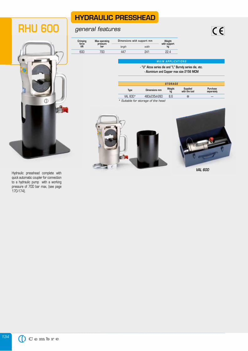
134
Hydraulic presshead complete with quick automatic coupler for connection to a hydraulic pump with a working pressure of 700 bar max, (see page 170-174).
HYDRAULIC PRESSHEAD
general featuresRHU 600
VAL 600
CrimpingforcekN
Max operatingpressure
bar
Weightwith support
kglength width
Dimensions with support mm
600 700 447 241 22.4
S T O R A G E
Type Dimensions mm Weightkg
Suppliedwith the tool
Purchase separately
VAL 600* 480x235xh260 8,6 � —* Suitable for storage of the head
M A I N A P P L I C A T I O N S
- "U" Alcoa series die and "L" Burndy series die, etc.- Aluminium and Copper max size 2156 MCM
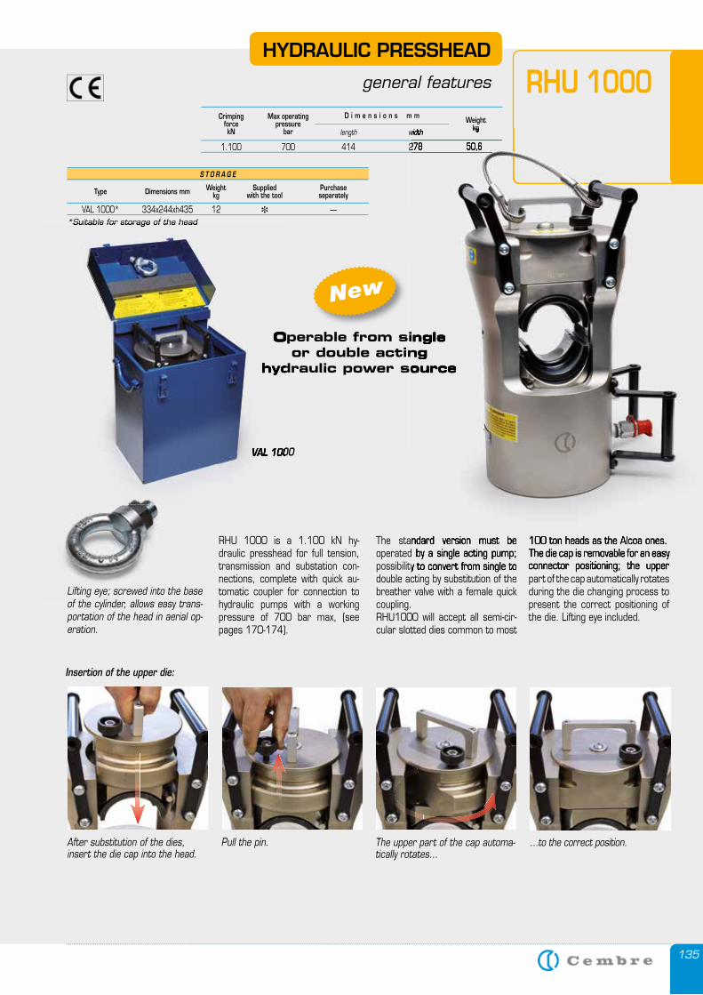
135
The standard version must be operated by a single acting pump; possibility to convert from single to double acting by substitution of the breather valve with a female quick coupling. RHU1000 will accept all semi-cir-cular slotted dies common to most
RHU 1000HYDRAULIC PRESSHEAD
general features
CrimpingforcekN
Max operatingpressure
barWeight
kglength width
D i m e n s i o n s m m
1.100 700 414 278 50,6
S T O R A G E
Type Dimensions mm Weightkg
Suppliedwith the tool
Purchase separately
VAL 1000* 334x244xh435 12 � —*Suitable for storage of the head
Pull the pin. …to the correct position.The upper part of the cap automa-tically rotates…
Insertion of the upper die:
After substitution of the dies, insert the die cap into the head.
RHU 1000 is a 1.100 kN hy-draulic presshead for full tension, transmission and substation con-nections, complete with quick au-tomatic coupler for connection to hydraulic pumps with a working pressure of 700 bar max, (see pages 170-174).
100 ton heads as the Alcoa ones. The die cap is removable for an easy connector positioning; the upper part of the cap automatically rotates during the die changing process to present the correct positioning of the die. Lifting eye included.
Lifting eye; screwed into the base of the cylinder, allows easy trans-portation of the head in aerial op-eration.
Operable from single or double acting
hydraulic power source
VAL 1000
*Suitable for storage of the head
Operable from single
hydraulic power source
VAL 1000
The standard version must be operated by a single acting pump; possibility to convert from single to
kgwidth
1.100 700 414 278 50,6
100 ton heads as the Alcoa ones. The die cap is removable for an easy connector positioning; the upper
Operable from single or double acting
hydraulic power source
New
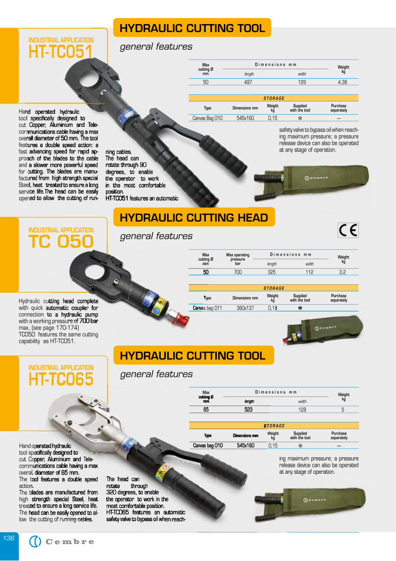
136
INDUSTRIAL APPLICATION
TC 050
Hand operated hydraulic tool specifically designed to cut Copper, Aluminium and Tele-communications cable having a max overall diameter of 50 mm. The tool features a double speed action: a fast advancing speed for rapid ap-proach of the blades to the cable and a slower more powerful speed for cutting. The blades are manu-factured from high strength special Steel, heat treated to ensure a long service life.The head can be easily opened to allow the cutting of run-
ning cables.The head can rotate through 90 degrees, to enable the operator to work in the most comfortable position. HT-TC051 features an automatic
Hydraulic cutting head complete with quick automatic coupler for connection to a hydraulic pump with a working pressure of 700 bar max, (see page 170-174)TC050 features the same cutting capability as HT-TC051.
Hand operated hydraulic tool specifically designed to cut Copper, Aluminium and Tele-communications cable having a max overall diameter of 50 mm. The tool features a double speed action: a fast advancing speed for rapid ap-proach of the blades to the cable and a slower more powerful speed for cutting. The blades are manu-factured from high strength special Steel, heat treated to ensure a long service life.The head can be easily opened to allow the cutting of run-
ning cables.The head can rotate through 90 degrees, to enable the operator to work in the most comfortable position. HT-TC051 features an automatic
HYDRAULIC CUTTING HEAD
general features
Hand operated hydraulic tool specifically designed to cut Copper, Aluminium and Tele-communications cable having a max overall diameter of 65 mm. The tool features a double speed action. The blades are manufactured from high strength special Steel, heat treated to ensure a long service life. The head can be easily opened to al-low the cutting of running cables.
HYDRAULIC CUTTING TOOL
general features
The head can rotate through 320 degrees, to enable the operator to work in the most comfortable position.HT-TC065 features an automatic safety valve to bypass oil when reach-
ing maximum pressure; a pressure release device can also be operated at any stage of operation.
safety valve to bypass oil when reach-ing maximum pressure; a pressure release device can also be operated at any stage of operation.
HYDRAULIC CUTTING TOOL
general features
S T O R A G E
Type Dimensions mm Weightkg
Suppliedwith the tool
Purchase separately
Canvas Bag 010 545x160 0,15 � —
Maxcutting Ø
mmWeight
kglength width
D i m e n s i o n s m m
50 497 129 4,38
INDUSTRIAL APPLICATION
HT-TC051
INDUSTRIAL APPLICATION
HT-TC065
S T O R A G E
Type Dimensions mm Weightkg
Suppliedwith the tool
Purchase separately
Canvas bag 010 545x160 0,15 � —
Maxcutting Ø
mmWeight
kglength width
D i m e n s i o n s m m
65 523 129 5
S T O R A G E
Type Dimensions mm Weightkg
Suppliedwith the tool
Purchase separately
Canvas bag 011 360x137 0,13 � —
Maxcutting Ø
mm
Max operatingpressure
barWeight
kglength width
D i m e n s i o n s m m
50 700 325 112 3,2
at any stage of operation.
at any stage of operation.
Hand operated hydraulic tool specifically designed to cut Copper, Aluminium and Tele-communications cable having a max overall diameter of 65 mm. The tool features a double speed action. The blades are manufactured from high strength special Steel, heat treated to ensure a long service life. The head can be easily opened to al-low the cutting of running cables.
The head can rotate through 320 degrees, to enable the operator to work in the most comfortable position.HT-TC065 features an automatic safety valve to bypass oil when reach-
HT-TC065
S T O R A G E
Type Dimensions mm Weight
Canvas bag 010 545x160 0,15
cutting Ømm length
65 523 129 5
TC 050
Hydraulic cutting head complete with quick automatic coupler for connection to a hydraulic pump with a working pressure of 700 bar
Type
Canvas bag 011 360x137 0,13
mm
50 700 325 112 3,2
Canvas bag 011 360x137 0,13 � —
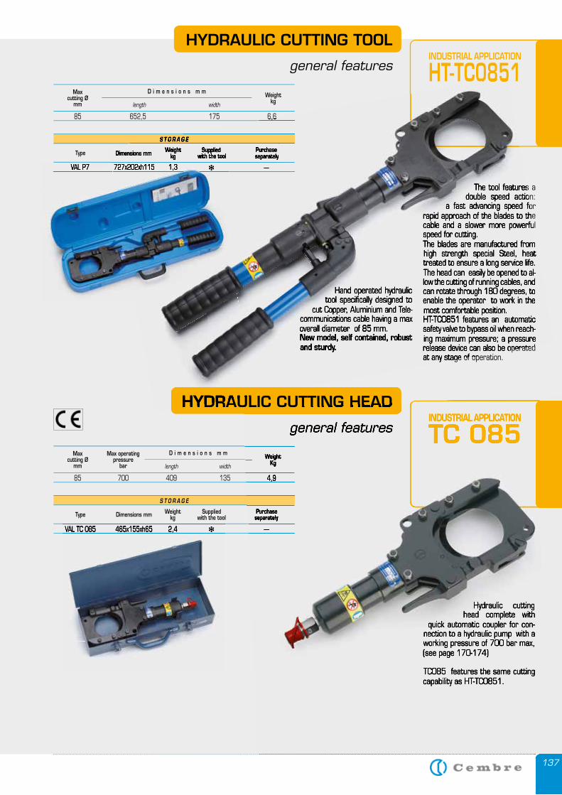
137
Hand operated hydraulic tool specifically designed to
cut Copper, Aluminium and Tele-communications cable having a max overall diameter of 85 mm.New model, self contained, robust and sturdy.
The tool features a double speed action:
a fast advancing speed for rapid approach of the blades to the cable and a slower more powerful speed for cutting.The blades are manufactured from high strength special Steel, heat treated to ensure a long service life.The head can easily be opened to al-low the cutting of running cables, and can rotate through 180 degrees, to enable the operator to work in the most comfortable position.HT-TC0851 features an automatic safety valve to bypass oil when reach-ing maximum pressure; a pressure release device can also be operated at any stage of operation.
HYDRAULIC CUTTING TOOL
general features
Hydraulic cutting head complete with
quick automatic coupler for con-nection to a hydraulic pump with a working pressure of 700 bar max, (see page 170-174)
TC085 features the same cutting capability as HT-TC0851.
HYDRAULIC CUTTING HEAD
general features
S T O R A G E
Type Dimensions mm Weightkg
Suppliedwith the tool
Purchase separately
VAL P7 727x202xh115 1,3 � —
Maxcutting Ø
mmWeight
kglength width
D i m e n s i o n s m m
85 652,5 175 6,6
S T O R A G E
Type Dimensions mm Weightkg
Suppliedwith the tool
Purchase separately
VAL TC 085 465x155xh65 2,4 � —
Maxcutting Ø
mm
Max operatingpressure
barWeight
Kglength width
D i m e n s i o n s m m
85 700 409 135 4,9
INDUSTRIAL APPLICATION
HT-TC0851
INDUSTRIAL APPLICATION
TC 085INDUSTRIAL APPLICATION
TC 085
Hydraulic cutting head complete with
quick automatic coupler for con-nection to a hydraulic pump with a working pressure of 700 bar max, (see page 170-174)
TC085 features the same cutting capability as HT-TC0851.
HYDRAULIC CUTTING HEAD
general features
Purchase separately
—
WeightKg
85 700 409 135 4,9
Hand operated hydraulic tool specifically designed to
cut Copper, Aluminium and Tele-communications cable having a max overall diameter of 85 mm.New model, self contained, robust and sturdy.
The tool features a double speed action:
a fast advancing speed for rapid approach of the blades to the cable and a slower more powerful speed for cutting.The blades are manufactured from high strength special Steel, heat treated to ensure a long service life.The head can easily be opened to al-low the cutting of running cables, and can rotate through 180 degrees, to enable the operator to work in the most comfortable position.HT-TC0851 features an automatic safety valve to bypass oil when reach-ing maximum pressure; a pressure release device can also be operated at any stage of operation.
HYDRAULIC CUTTING HEAD
S T O R A G E
Dimensions mm Weightkg
Suppliedwith the tool
Purchase separately
—
85 652,5 175 6,6
HT-TC0851
VAL TC 085 465x155xh65 2,4 �
VAL P7 727x202xh115 1,3 VAL P7 727x202xh115 1,3 �
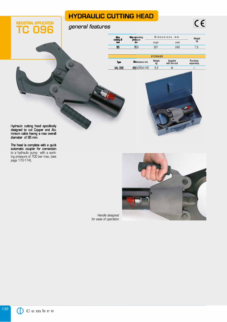
138
Hydraulic cutting head specifically designed to cut Copper and Alu-minium cable having a max overall diameter of 95 mm.
The head is complete with a quick automatic coupler for connection to a hydraulic pump with a work-ing pressure of 700 bar max, (see page 170-174).
HYDRAULIC CUTTING HEAD
general features
S T O R A G E
Type Dimensions mm Weightkg
Suppliedwith the tool
Purchase separately
VAL 096 450x265xh145 6,8 � —
Maxcutting Ø
mm
Max operatingpressure
barWeight
kglength width
D i m e n s i o n s m m
95 700 397 249 7,9
Handle designed for ease of operation
INDUSTRIAL APPLICATION
TC 096
Hydraulic cutting head specifically designed to cut Copper and Alu-minium cable having a max overall diameter of 95 mm.
The head is complete with a quick automatic coupler for connection to a hydraulic pump with a work-
HYDRAULIC CUTTING HEAD
general features
Type Dimensions mm
VAL 096 450x265xh145 6,8
Maxcutting Ø
mm
Max operatingpressure
bar
95 700 397 249 7,9
INDUSTRIAL APPLICATION
TC 096
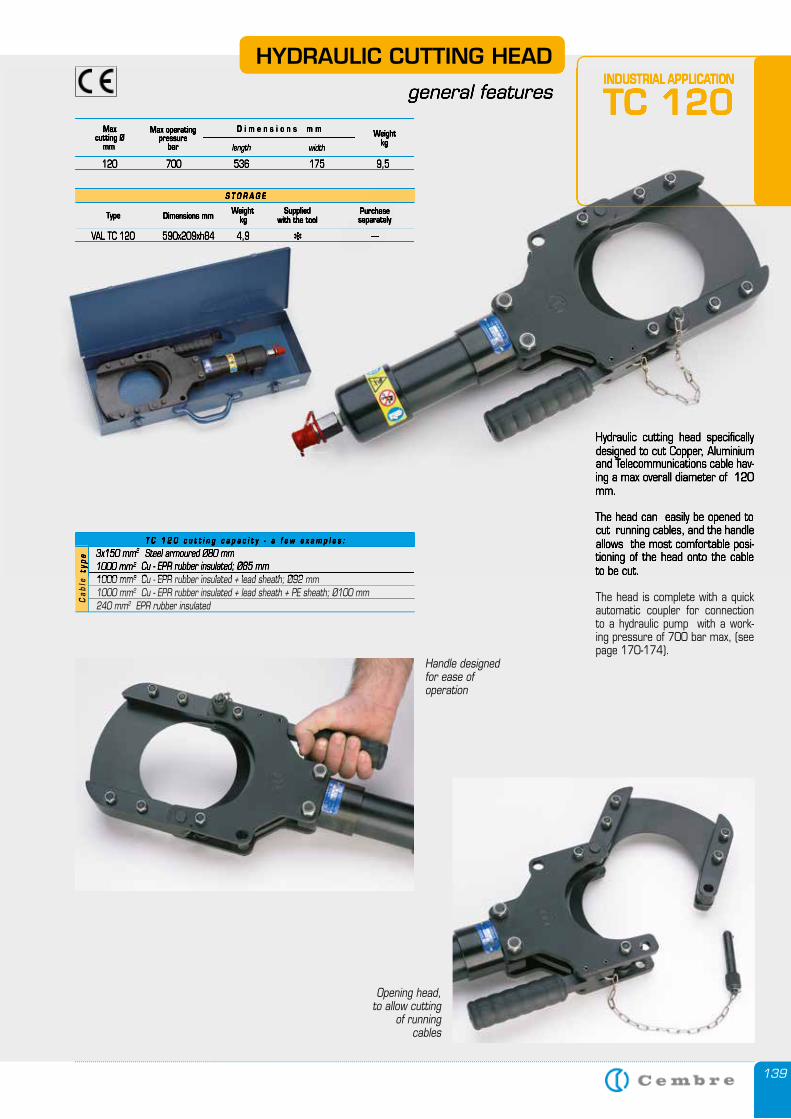
139
Hydraulic cutting head specifically designed to cut Copper, Aluminium and Telecommunications cable hav-ing a max overall diameter of 120 mm.
The head can easily be opened to cut running cables, and the handle allows the most comfortable posi-tioning of the head onto the cable to be cut.
The head is complete with a quick automatic coupler for connection to a hydraulic pump with a work-ing pressure of 700 bar max, (see page 170-174).
HYDRAULIC CUTTING HEAD
general features
S T O R A G E
Type Dimensions mm Weightkg
Suppliedwith the tool
Purchase separately
VAL TC 120 590x209xh84 4,9 � —
Maxcutting Ø
mm
Max operatingpressure
barWeight
kglength width
D i m e n s i o n s m m
120 700 536 175 9,5
T C 1 2 0 c u t t i n g c a p a c i t y - a f e w e x a m p l e s :
3x150 mm2 Steel armoured Ø80 mm1000 mm2 Cu - EPR rubber insulated; Ø85 mm1000 mm2 Cu - EPR rubber insulated + lead sheath; Ø92 mm1000 mm2 Cu - EPR rubber insulated + lead sheath + PE sheath; Ø100 mm240 mm2 EPR rubber insulated
Ca
ble
typ
e
Opening head, to allow cutting
of running cables
Handle designed for ease of operation
INDUSTRIAL APPLICATION
TC 120
Hydraulic cutting head specifically designed to cut Copper, Aluminium and Telecommunications cable hav-ing a max overall diameter of 120 mm.
The head can easily be opened to cut running cables, and the handle allows the most comfortable posi-tioning of the head onto the cable to be cut.
general features
S T O R A G E
Type Dimensions mm Weightkg
Suppliedwith the tool
Purchase separately
VAL TC 120 590x209xh84 4,9 � —
Maxcutting Ø
mm
Max operatingpressure
barWeight
kglength width
D i m e n s i o n s m m
120 700 536 175 9,5
T C 1 2 0 c u t t i n g c a p a c i t y - a f e w e x a m p l e s :
3x150 mm2 Steel armoured Ø80 mm2 Steel armoured Ø80 mm2
1000 mm2 Cu - EPR rubber insulated; Ø85 mm2 Cu - EPR rubber insulated; Ø85 mm2
1000 mm2 Cu - EPR rubber insulated + lead sheath; Ø92 mm2 Cu - EPR rubber insulated + lead sheath; Ø92 mm2
Ca
ble
typ
eINDUSTRIAL APPLICATION
TC 120
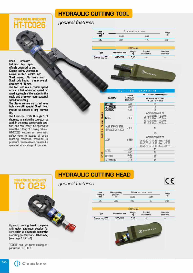
140
C U T T I N G C A P A C I T Y
MATERIALTENSILE
STRENGTH(daN/mm2)
MAX CUTTING DIAMETER (mm)
HT-TC026 HT-TC026YTC 025 B-TC250E
RO
PE
S &
CO
ND
UC
TO
RS
COPPER ≤ 41 25ALUMINIUM ≤ 20 25ALMELEC ≤ 34 25
STEEL ≤ 180
INDICATIVE EXAMPLES: 7 x 3,0 : Ø est. = 9,0 mm19 x 2,1 : Ø est. = 10,5 mm19 x 2,2 : Ø est. = 11,0 mm19 x 2,3 : Ø est. = 11,5 mm
MULTI STRANDS STEEL (STRANDS Qty ≥ 200)
≤ 180 18
ACSR ≤ 180
25
INDICATIVE EXAMPLES:
26 x 2,50 + 7 x 1,95 : Ø est. = 15,8526 x 3,06 + 7 x 2,38 : Ø est. = 19,3826 x 3,60 + 7 x 2,80 : Ø est. = 22,80
RO
DS STEEL ≤ 60 13
≤ 42 16
COPPER ≤ 30 20≤ 25 23
ALUMINIUM ≤ 16 25
Hydraulic cutting head complete with quick automatic coupler for connection to a hydraulic pump with a working pressure of 700 bar max, (see page 170-174)
TC025 has the same cutting ca-pability as HT-TC026.
HYDRAULIC CUTTING HEAD
general features
Hand operated hydraulic tool spe-cifically designed to cut Copper, aldrey, Aluminium, Aluminium-Steel cables and Steel ropes, Aluminium and Steel rods having a max overall diameter of 25 mm.The tool features a double speed action: a fast advancing speed for rapid approach of the blades to the cable and a slower more powerful speed for cutting.The blades are manufactured from high strength special Steel, heat treated to ensure a long service life.The head can rotate through 180 degrees, to enable the operator to work in the most comfortable posi-tion, and can easily be opened to allow the cutting of running cables.HT-TC026 features an automatic safety valve to bypass oil when reaching maximum pressure; a pressure release device can also be operated at any stage of operation.
HYDRAULIC CUTTING TOOL
general features
S T O R A G E
Type Dimensions mm Weightkg
Suppliedwith the tool
Purchase separately
Canvas bag 001 430x155 0,15 � —
S T O R A G E
Type Dimensions mm Weightkg
Suppliedwith the tool
Purchase separately
Canvas bag 007 350x105 0,13 � —
Maxcutting Ø
mm
Max operatingpressure
barWeight
kglength width
D i m e n s i o n s m m
25 700 213 82 2,0
Maxcutting Ø
mmWeight
kglength width
D i m e n s i o n s m m
25 382 129 3,2
OVERHEAD LINE APPLICATION
HT-TC026
OVERHEAD LINE APPLICATION
TC 025
MATERIAL
RO
PE
S &
CO
ND
UC
TO
RS
COPPERALUMINIUMALMELEC
STEEL
Hand operated hydraulic tool spe-cifically designed to cut Copper, aldrey, Aluminium, Aluminium-Steel cables and Steel ropes, Aluminium and Steel rods having a max overall diameter of 25 mm.The tool features a double speed action: a fast advancing speed for rapid approach of the blades to the cable and a slower more powerful speed for cutting.The blades are manufactured from high strength special Steel, heat treated to ensure a long service life.The head can rotate through 180 degrees, to enable the operator to work in the most comfortable posi-
HYDRAULIC CUTTING TOOL
general features
Type Dimensions mm
Canvas bag 001 430x155 0,15
Maxcutting Ø
mm
25 382 129 3,2
OVERHEAD LINE APPLICATION
HT-TC026
C U T T I N G C A P A C I T Y
MAX CUTTING DIAMETER (mm)
Canvas bag 001 430x155 0,15
Dimensions mm
Canvas bag 001 430x155 0,15
TC 025
Hydraulic cutting head complete with quick automatic coupler for connection to a hydraulic pump with a working pressure of 700 bar max,
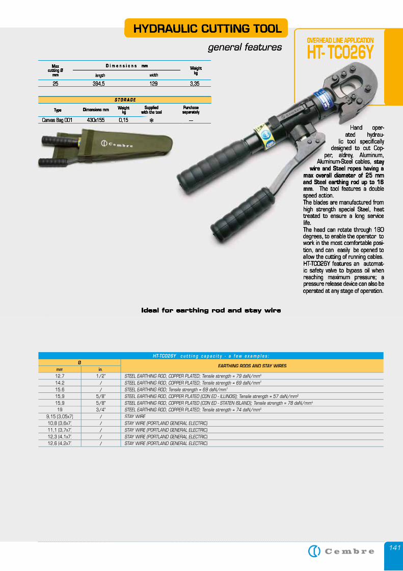
141
HYDRAULIC CUTTING TOOL
general features
S T O R A G E
Type Dimensions mm Weightkg
Suppliedwith the tool
Purchase separately
Canvas Bag 001 430x155 0,15 � —
Maxcutting Ø
mmWeight
kglength width
D i m e n s i o n s mm
25 394,5 129 3,35
OVERHEAD LINE APPLICATION
HT- TC026Y
Hand oper-ated hydrau-
lic tool specifically designed to cut Cop-
per, aldrey, Aluminum, Aluminum-Steel cables, stay
wire and Steel ropes having a max overall diameter of 25 mm and Steel earthing rod up to 16 mm. The tool features a double speed action.The blades are manufactured from high strength special Steel, heat treated to ensure a long service life.The head can rotate through 180 degrees, to enable the operator to work in the most comfortable posi-tion, and can easily be opened to allow the cutting of running cables.HT-TC026Y features an automat-ic safety valve to bypass oil when reaching maximum pressure; a pressure release device can also be operated at any stage of operation.
Ideal for earthing rod and stay wire
HT-TCO26Y c u t t i n g c a p a c i t y - a f e w e x a m p l e s : Ø
EARTHING RODS AND STAY WIRESmm in.12,7 1/2” STEEL EARTHING ROD, COPPER PLATED; Tensile strength = 79 daN/mm2
14,2 / STEEL EARTHING ROD, COPPER PLATED; Tensile strength = 69 daN/mm2
15,6 / STEEL EARTHING ROD; Tensile strength = 69 daN/mm2
15,9 5/8” STEEL EARTHING ROD, COPPER PLATED (CON ED - ILLINOIS); Tensile strength = 57 daN/mm2
15,9 5/8" STEEL EARTHING ROD, COPPER PLATED (CON ED - STATEN ISLAND); Tensile strength = 78 daN/mm2
19 3/4” STEEL EARTHING ROD, COPPER PLATED; Tensile strength = 74 daN/mm2
9,15 (3,05x7) / STAY WIRE10,8 (3,6x7) / STAY WIRE (PORTLAND GENERAL ELECTRIC)11,1 (3,7x7) / STAY WIRE (PORTLAND GENERAL ELECTRIC)12,3 (4,1x7) / STAY WIRE (PORTLAND GENERAL ELECTRIC)12,6 (4,2x7) / STAY WIRE (PORTLAND GENERAL ELECTRIC)
HYDRAULIC CUTTING TOOL
general features
S T O R A G E
Type Dimensions mm Weightkg
Suppliedwith the tool
Purchase separately
—
Maxcutting Ø
mmWeight
kglength width
D i m e n s i o n s mm
25 394,5 129 3,35
Hand oper-ated hydrau-
lic tool specifically designed to cut Cop-
per, aldrey, Aluminum, Aluminum-Steel cables, stay
wire and Steel ropes having a max overall diameter of 25 mm and Steel earthing rod up to 16 mm. The tool features a double speed action.The blades are manufactured from high strength special Steel, heat treated to ensure a long service life.The head can rotate through 180 degrees, to enable the operator to work in the most comfortable posi-tion, and can easily be opened to allow the cutting of running cables.HT-TC026Y features an automat-ic safety valve to bypass oil when reaching maximum pressure; a pressure release device can also be operated at any stage of operation.
Ideal for earthing rod and stay wire
OVERHEAD LINE APPLICATION
HT- TC026Y
Canvas Bag 001 430x155 0,15 �
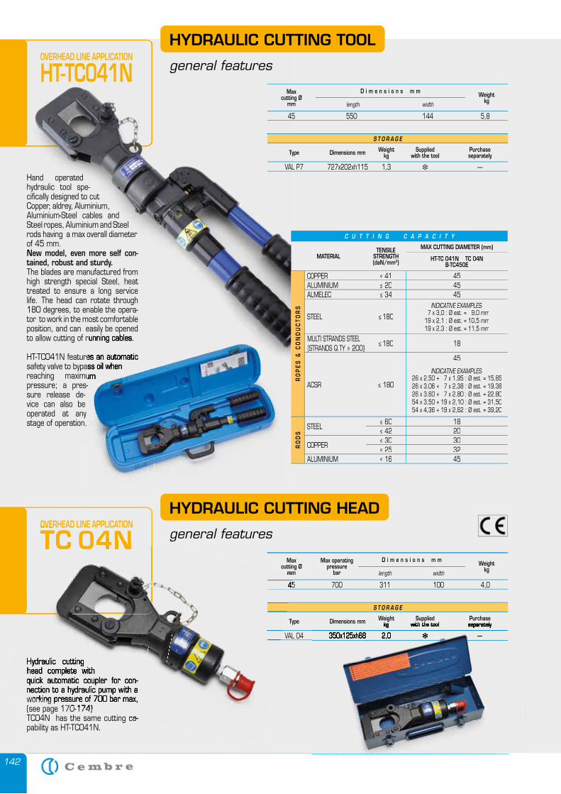
142
S T O R A G E
Type Dimensions mm Weightkg
Suppliedwith the tool
Purchase separately
VAL P7 727x202xh115 1,3 � —
Maxcutting Ø
mmWeight
kglength width
D i m e n s i o n s m m
45 550 144 5,8
HYDRAULIC CUTTING HEAD
general features
HYDRAULIC CUTTING TOOL
general features
Hydraulic cutting head complete with quick automatic coupler for con-nection to a hydraulic pump with a working pressure of 700 bar max, (see page 170-174)TC04N has the same cutting ca-pability as HT-TC041N.
OVERHEAD LINE APPLICATION
TC 04N
Hand operated hydraulic tool spe-cifically designed to cut Copper, aldrey, Aluminium, Aluminium-Steel cables and Steel ropes, Aluminium and Steel rods having a max overall diameter of 45 mm.New model, even more self con-tained, robust and sturdy.The blades are manufactured from high strength special Steel, heat treated to ensure a long service life. The head can rotate through 180 degrees, to enable the opera-tor to work in the most comfortable position, and can easily be opened to allow cutting of running cables.
HT-TC041N features an automatic safety valve to bypass oil when reaching maximum pressure; a pres-sure release de-vice can also be operated at any stage of operation.
OVERHEAD LINE APPLICATION
HT-TC041N
Maxcutting Ø
mm
Max operatingpressure
barWeight
kglength width
D i m e n s i o n s m m
45 700 311 100 4,0
S T O R A G E
Type Dimensions mm Weightkg
Suppliedwith the tool
Purchase separately
VAL 04 350x125xh68 2,0 � —
to allow cutting of running cables.
HT-TC041N features an automatic safety valve to bypass oil when reaching maximum
C U T T I N G C A P A C I T Y
MATERIALTENSILE
STRENGTH(daN/mm2)
MAX CUTTING DIAMETER (mm)
HT-TC 041N TC 04N B-TC450E
RO
PE
S &
CO
ND
UC
TO
RS
COPPER ≤ 41 45ALUMINIUM ≤ 20 45ALMELEC ≤ 34 45
STEEL ≤ 180
INDICATIVE EXAMPLES: 7 x 3,0 : Ø est. = 9,0 mm19 x 2,1 : Ø est. = 10,5 mm19 x 2,3 : Ø est. = 11,5 mm
MULTI STRANDS STEEL (STRANDS Q.TY ≥ 200)
≤ 180 18
ACSR ≤ 180
45
INDICATIVE EXAMPLES:26 x 2,50 + 7 x 1,95 : Ø est. = 15,8526 x 3,06 + 7 x 2,38 : Ø est. = 19,3826 x 3,60 + 7 x 2,80 : Ø est. = 22,8054 x 3,50 + 19 x 2,10 : Ø est. = 31,5054 x 4,36 + 19 x 2,62 : Ø est. = 39,20
RO
DS
STEEL ≤ 60 18≤ 42 20
COPPER ≤ 30 30≤ 25 32
ALUMINIUM ≤ 16 45
Hydraulic cutting head complete with quick automatic coupler for con-nection to a hydraulic pump with a working pressure of 700 bar max, (see page 170-174)TC04N has the same cutting ca-
OVERHEAD LINE APPLICATION
TC 04Nmm
45 700 311 100 4,0
VAL 04 350x125xh68 2,0
kg with the tool separately
VAL 04 350x125xh68 2,0 � —
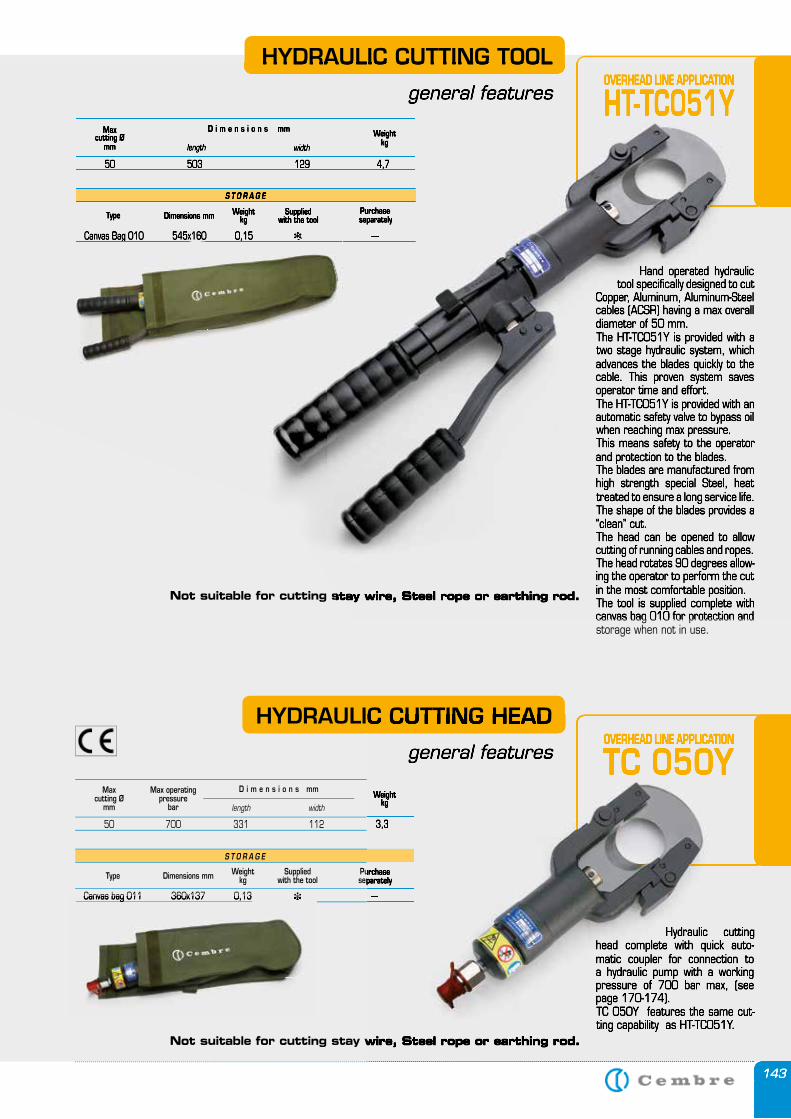
143
HYDRAULIC CUTTING TOOL
general features
S T O R A G E
Type Dimensions mm Weightkg
Suppliedwith the tool
Purchase separately
Canvas Bag 010 545x160 0,15 � —
Maxcutting Ø
mmWeight
kglength width
D i m e n s i o n s mm
50 503 129 4,7
Hand operated hydraulic tool specifically designed to cut
Copper, Aluminum, Aluminum-Steel cables (ACSR) having a max overall diameter of 50 mm.The HT-TC051Y is provided with a two stage hydraulic system, which advances the blades quickly to the cable. This proven system saves operator time and effort.The HT-TC051Y is provided with an automatic safety valve to bypass oil when reaching max pressure.This means safety to the operator and protection to the blades.The blades are manufactured from high strength special Steel, heat treated to ensure a long service life.The shape of the blades provides a “clean” cut. The head can be opened to allow cutting of running cables and ropes. The head rotates 90 degrees allow-ing the operator to perform the cut in the most comfortable position.The tool is supplied complete with canvas bag 010 for protection and storage when not in use.
OVERHEAD LINE APPLICATION
HT-TC051Y
Hydraulic cutting head complete with quick auto-matic coupler for connection to a hydraulic pump with a working pressure of 700 bar max, (see page 170-174).TC 050Y features the same cut-ting capability as HT-TC051Y.
HYDRAULIC CUTTING HEAD
general featuresOVERHEAD LINE APPLICATION
TC 050Y
S T O R A G E
Type Dimensions mm Weightkg
Suppliedwith the tool
Purchase separately
Canvas bag 011 360x137 0,13 � —
Maxcutting Ø
mm
Max operatingpressure
barWeight
kglength width
D i m e n s i o n s mm
50 700 331 112 3,3
Not suitable for cutting stay wire, Steel rope or earthing rod.
Not suitable for cutting stay wire, Steel rope or earthing rod.
OVERHEAD LINE APPLICATION
HT-TC051YHYDRAULIC CUTTING TOOL
general features
S T O R A G E
Type Dimensions mm Weightkg
Suppliedwith the tool
Purchase separately
Canvas Bag 010 545x160 0,15 � —
Maxcutting Ø
mmWeight
kglength width
D i m e n s i o n s mm
50 503 129 4,7
Hand operated hydraulic tool specifically designed to cut
Copper, Aluminum, Aluminum-Steel cables (ACSR) having a max overall diameter of 50 mm.The HT-TC051Y is provided with a two stage hydraulic system, which advances the blades quickly to the cable. This proven system saves operator time and effort.The HT-TC051Y is provided with an automatic safety valve to bypass oil when reaching max pressure.This means safety to the operator and protection to the blades.The blades are manufactured from high strength special Steel, heat treated to ensure a long service life.The shape of the blades provides a “clean” cut. The head can be opened to allow cutting of running cables and ropes. The head rotates 90 degrees allow-ing the operator to perform the cut in the most comfortable position.The tool is supplied complete with canvas bag 010 for protection and
Not suitable for cutting stay wire, Steel rope or earthing rod.
Canvas Bag 010 545x160 0,15 �
Canvas bag 011 360x137 0,13 �
143
Hydraulic cutting head complete with quick auto-matic coupler for connection to a hydraulic pump with a working pressure of 700 bar max, (see page 170-174).TC 050Y features the same cut-ting capability as HT-TC051Y.
HYDRAULIC CUTTING HEAD
general featuresOVERHEAD LINE APPLICATION
TC 050Y
Purchase separately
—
Weight kg
50 700 331 112 3,3
Not suitable for cutting stay wire, Steel rope or earthing rod.
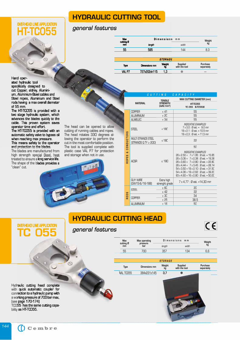
144
Hand oper-ated hydraulic tool specifically designed to cut Copper, aldrey, Alumini-um, Aluminium-Steel cables and Steel ropes, Aluminium and Steel rods having a max overall diameter of 55 mm.The HT-TC055 is provided with a two stage hydraulic system, which advances the blades quickly to the cable. This proven system saves operator time and effort.The HT-TC055 is provided with an automatic safety valve to bypass oil when reaching max pressure.This means safety to the operator and protection to the blades.The blades are manufactured from high strength special Steel, heat treated to ensure a long service life.The shape of the blades provides a “clean” cut.
HYDRAULIC CUTTING TOOL
general features
Maxcutting Ø
mmWeight
kglength width
D i m e n s i o n s m m
55 595 144 8,3
S T O R A G E
Type Dimensions mm Weightkg
Suppliedwith the tool
Purchase separately
VAL P7 727x202xh115 1,3 � —
OVERHEAD LINE APPLICATION
HT-TC055
Hand oper-ated hydraulic tool specifically designed to cut Copper, aldrey, Alumini-um, Aluminium-Steel cables and Steel ropes, Aluminium and Steel rods having a max overall diameter of 55 mm.The HT-TC055 is provided with a two stage hydraulic system, which advances the blades quickly to the cable. This proven system saves operator time and effort.The HT-TC055 is provided with an automatic safety valve to bypass oil when reaching max pressure.This means safety to the operator and protection to the blades.
general features
Maxcutting Ø
mm length
D i m e n s i o n s m m
55 595 144 8,3
S T O R A G E
Type Dimensions mm Weightkg
VAL P7 727x202xh115 1,3
OVERHEAD LINE APPLICATION
HT-TC055
high strength special Steel, heat treated to ensure a long service life.The shape of the blades provides a
HYDRAULIC CUTTING HEAD
general features
Hydraulic cutting head complete with quick automatic coupler for connection to a hydraulic pump with a working pressure of 700 bar max, (see page 170-174)TC055 has the same cutting capa-bility as HT-TC055.
S T O R A G E
Type Dimensions mm Weightkg
Suppliedwith the tool
Purchase separately
VAL TC055 384x231x145 3,7 � —
Maxcutting Ø
mm
Max operatingpressure
barWeight
kglength width
D i m e n s i o n s m m
55 700 357 134 6,6
The head can be opened to allow cutting of running cables and ropes. The head rotates 330 degrees al-lowing the operator to perform the cut in the most comfortable position.The tool is supplied complete with plastic case VAL P7 for protection and storage when not in use.
OVERHEAD LINE APPLICATION
TC 055
C U T T I N G C A P A C I T Y
MATERIALTENSILE
STRENGTH(daN/mm2)
MAX CUTTING DIAMETER (mm)
HT-TC055TC 055 B-TC550E
RO
PE
S &
CO
ND
UC
TO
RS
COPPER ≤ 41 55ALUMINIUM ≤ 20 55ALMELEC ≤ 34 55
STEEL ≤ 180
INDICATIVE EXAMPLES: 7 x 3,0 : Ø est. = 9,0 mm19 x 2,1 : Ø est. = 10,5 mm19 x 2,3 : Ø est. = 11,5 mm
MULTI STRANDS STEEL (STRANDS Q.TY ≥ 200)
≤ 180 22
ACSR ≤ 180
50
INDICATIVE EXAMPLES:26 x 2,50 + 7 x 1,95 : Ø est. = 15,8526 x 3,06 + 7 x 2,38 : Ø est. = 19,3826 x 3,60 + 7 x 2,80 : Ø est. = 22,8026 x 4,44 + 7 x 3,45 : Ø est. = 28,1454 x 3,50 + 19 x 2,10 : Ø est. = 31,5054 x 4,36 + 19 x 2,62 : Ø est. = 39,2083 x 4,60 + 16 x 2,80 : Ø est. = 50,00
GUY WIRE (GW15-9/16-188)
Extra high strenght grade 7 x 4,77 : Ø est. =14,30 mm
RO
DS
STEEL ≤ 60 20≤ 42 22
COPPER ≤ 30 34≤ 25 38,5
ALUMINIUM ≤≤ 16 16 5050
general features
Hydraulic cutting head complete with quick automatic coupler for connection to a hydraulic pump with a working pressure of 700 bar max, (see page 170-174)TC055 has the same cutting capa-bility as HT-TC055.
VAL TC055 384x231x145 3,7
cutting Ø
55 700 357 134 6,6
OVERHEAD LINE APPLICATION
TC 055
VAL TC055 384x231x145 3,7 � —
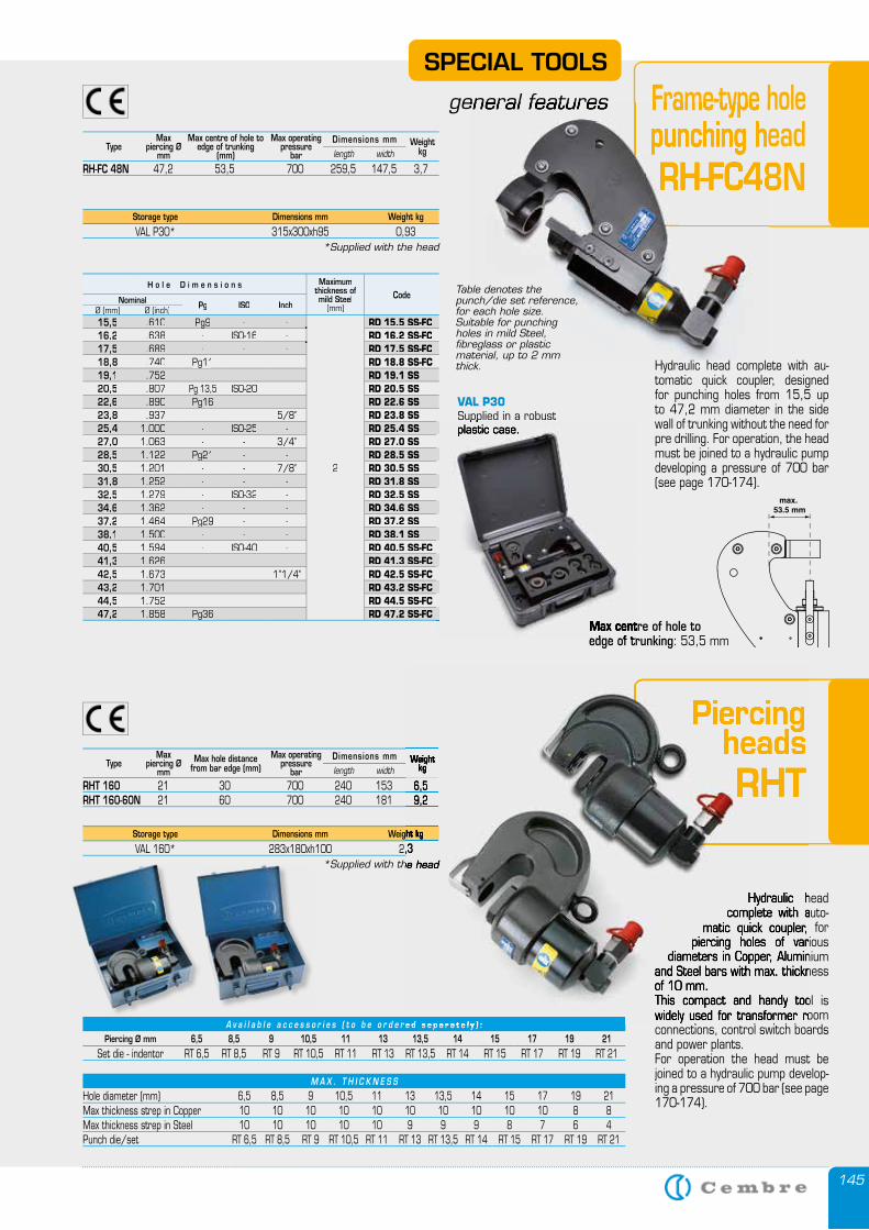
145
Hydraulic head complete with auto-
matic quick coupler, for piercing holes of various
diameters in Copper, Aluminium and Steel bars with max. thickness of 10 mm.This compact and handy tool is widely used for transformer room connections, control switch boards and power plants.For operation the head must be joined to a hydraulic pump develop-ing a pressure of 700 bar (see page 170-174).
Piercing headsRHT
Max piercing Ø
mmType
Max operatingpressure
bar Max hole distance
from bar edge (mm)Weight
kglength width
Dimensions mm
RHT 160 21 30 700 240 153 6,5RHT 160-60N 21 60 700 240 181 9,2
Storage type Dimensions mm Weight kg
VAL 160* 283x180xh100 2,3*Supplied with the head
SPECIAL TOOLS
general features Frame-type hole punching head RH-FC48N
Storage type Dimensions mm Weight kg
VAL P30* 315x300xh95 0,93*Supplied with the head
Max piercing Ø
mmType
Max operatingpressure
bar
Max centre of hole to edge of trunking
(mm)Weight
kglength width
Dimensions mm
RH-FC 48N 47,2 53,5 700 259,5 147,5 3,7
general features Frame-type holepunching headRH-FC48N
max. 53.5 mm
Max centre of hole to edge of trunking: 53,5 mm
Table denotes the punch/die set reference, for each hole size.Suitable for punching holes in mild Steel, fibreglass or plastic material, up to 2 mm thick. Hydraulic head complete with au-
tomatic quick coupler, designed for punching holes from 15,5 up to 47,2 mm diameter in the side wall of trunking without the need for pre drilling. For operation, the head must be joined to a hydraulic pump developing a pressure of 700 bar (see page 170-174).
H o l e D i m e n s i o n s Maximumthickness ofmild Steel
(mm)CodeNominal Pg ISO InchØ (mm) Ø (inch)
15,5 .610 Pg9Pg9 - -
2
RD 15.5 SS-FC 16,2 .638 - ISO-16 - RD 16.2 SS-FC 17,5 .689 - - - RD 17.5 SS-FC 18,8 .740 Pg11Pg11 - - RD 18.8 SS-FC 19,1 .752 - - - RD 19.1 SS 20,5 .807 Pg 13,5Pg 13,5 ISO-20 - RD 20.5 SS 22,6 .890 Pg16Pg16 - - RD 22.6 SS 23,8 .937 - - 5/8” RD 23.8 SS 25,4 1.000 - ISO-25 - RD 25.4 SS 27,0 1.063 - - 3/4” RD 27.0 SS 28,5 1.122 Pg21Pg21 - - RD 28.5 SS 30,5 1.201 - - 7/8” RD 30.5 SS 31,8 1.252 - - - RD 31.8 SS 32,5 1.279 - ISO-32 - RD 32.5 SS 34,6 1.362 - - - RD 34.6 SS 37,2 1.464 Pg29Pg29 - - RD 37.2 SS 38,1 1.500 - - - RD 38.1 SS 40,5 1.594 - ISO-40 - RD 40.5 SS-FC 41,3 1.626 - - - RD 41.3 SS-FC 42,5 1.673 - - 1”1/4” RD 42.5 SS-FC 43,2 1.701 - - - RD 43.2 SS-FC 44,5 1.752 - - - RD 44.5 SS-FC 47,2 1.858 Pg36Pg36 - - RD 47.2 SS-FC
Max centre of hole to edge of trunking
VAL P30Supplied in a robust Supplied in a robust plastic case.
M A X . T H I C K N E S S
Hole diameter (mm) 6,5 8,5 9 10,5 11 13 13,5 14 15 17 19 21Max thickness strep in Copper 10 10 10 10 10 10 10 10 10 10 8 8Max thickness strep in Steel 10 10 10 10 10 9 9 9 8 7 6 4Punch die/set RT 6,5 RT 8,5 RT 9 RT 10,5 RT 11 RT 13 RT 13,5 RT 14 RT 15 RT 17 RT 19 RT 21
A v a i l a b l e a c c e s s o r i e s ( t o b e o r d e r e d s e p a r a t e l y ) :Piercing Ø mm 6,5 8,5 9 10,5 11 13 13,5 14 15 17 19 21
Set die - indentor RT 6,5 RT 8,5 RT 9 RT 10,5 RT 11 RT 13 RT 13,5 RT 14 RT 15 RT 17 RT 19 RT 21
Hydraulic head complete with auto-
matic quick coupler, for piercing holes of various
diameters in Copper, Aluminium and Steel bars with max. thickness of 10 mm.This compact and handy tool is widely used for transformer room connections, control switch boards
Piercing heads
Piercing heads
Piercing
RHTWeight
kg
21 30 700 240 153 6,5 21 60 700 240 181 9,2
Weight kg
VAL 160* 283x180xh100 2,3*Supplied with the head
A v a i l a b l e a c c e s s o r i e s ( t o b e o r d e r e d s e p a r a t e l y ) :
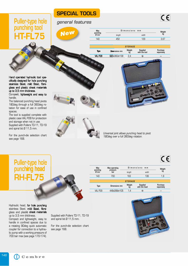
146
SPECIAL TOOLS
general featuresPuller-type hole punching tool HT-FL75
Hand operated hydraulic tool spe-cifically designed for hole punching stainless Steel, mild Steel, fibre-glass and plastic sheet materials up to 3,5 mm thickness. Compact, lightweight and easy to handle. The balanced punching head pivots 180deg through a full 360deg ro-tation for ease of use in confined spaces.The tool is supplied complete with plastic case VAL P28 for protection and storage when not in use. Supplied with Pullers TD-11, TD-19 and spiral bit Ø 11,5 mm.
For the punch-die selection chart see page 168.
New
Puller-type hole punching head RH-FL75
Hydraulic head, for hole punching stainless Steel, mild Steel, fibre-glass and plastic sheet materials up to 3,5 mm thickness. Compact and lightweight, easy to handle in confined spaces due to a rotating 90deg quick automatic coupler for connection to a hydrau-lic pump with a working pressure of 700 bar max (see page 170-174).
Supplied with Pullers TD-11, TD-19 and spiral bit Ø 11,5 mm.
For the punch-die selection chart see page 168.
punching headRH-FL75
Hydraulic head, for hole punching stainless Steel, mild Steel, fibre-glass and plastic sheet materials up to 3,5 mm thickness.
Universal joint allows punching head to pivot 180deg over a full 360deg rotation.
Max punching
Ø mmWeight
kglength width
D i m e n s i o n s m m
140 452 129 3,67
S T O R A G E
Type Dimensions mm Weightkg
Suppliedwith the tool
Purchase separately
VAL P28 620x360xh138 2,4 � —
punching toolHT-FL75
Hand operated hydraulic tool spe-cifically designed for hole punching stainless Steel, mild Steel, fibre-glass and plastic sheet materials up to 3,5 mm thickness. Compact, lightweight and easy to
Type Dimensions mm
VAL P28 620x360xh138 2,4 � —
Max punching
Ø mm
Max operatingpressure
barWeight
kglength width
D i m e n s i o n s m m
140 700 163 106 1,9
S T O R A G E
Type Dimensions mm Weightkg
Suppliedwith the head
Purchase separately
VAL P29 448x288xh105 1,4 � —
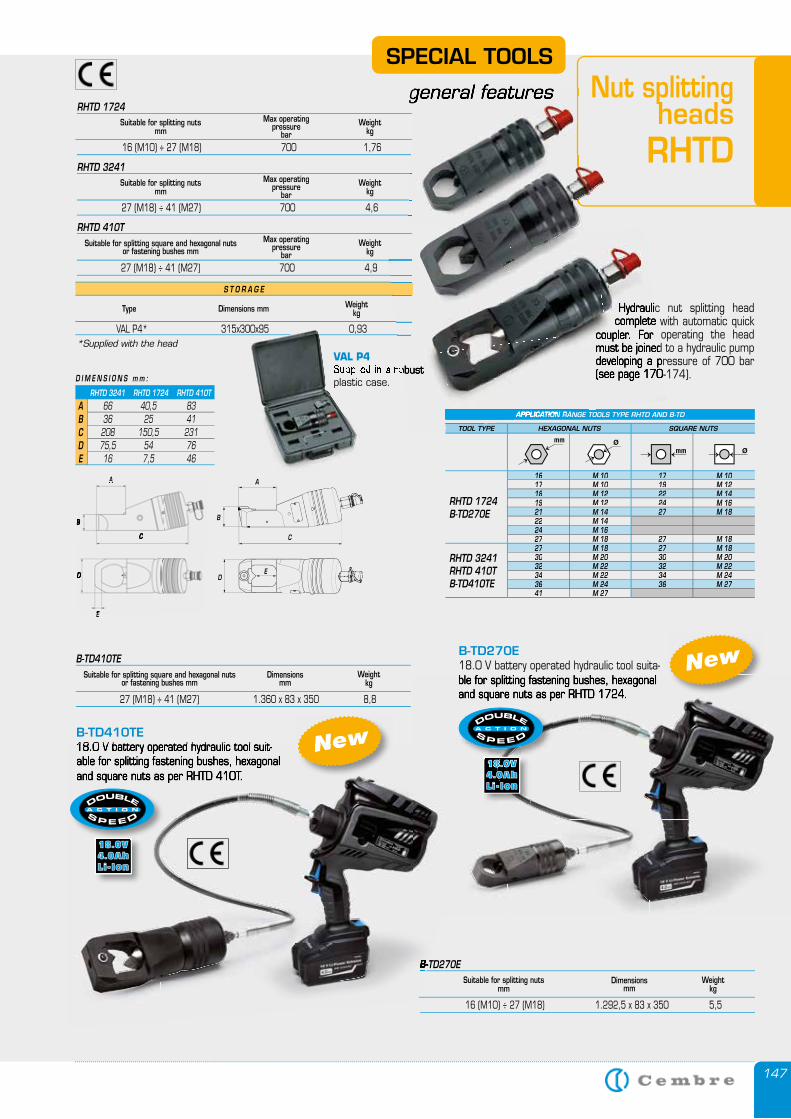
147
RHTD 3241 RHTD 1724 RHTD 410T
66 40,5 83 36 25 41 208 150,5 231 75,5 54 76 16 7,5 46
ABCDE
D I M E N S I O N S m m :
A
C
B
A
C
B
E
D
E
D
SPECIAL TOOLS
general features Nut splitting heads RHTD
Hydraulic nut splitting head complete with automatic quick
coupler. For operating the head must be joined to a hydraulic pump developing a pressure of 700 bar (see page 170-174).
VAL P4Supplied in a robust plastic case.
Suitable for splitting nutsmm
Max operatingpressure
bar Weight
kg
16 (M10) ÷ 27 (M18) 700 1,76
RHTD 1724
Suitable for splitting nutsmm
Max operatingpressure
bar Weight
kg
27 (M18) ÷ 41 (M27) 700 4,6
RHTD 3241
Suitable for splitting square and hexagonal nuts or fastening bushes mm
Max operatingpressure
bar Weight
kg
27 (M18) ÷ 41 (M27) 700 4,9
RHTD 410T
*Supplied with the head
S T O R A G E
Type Dimensions mm Weight kg
VAL P4* 315x300x95 0,93
A
B
C
ED
B-TD270E 18.0 V battery operated hydraulic tool suita-ble for splitting fastening bushes, hexagonal and square nuts as per RHTD 1724.
B-TD410TE18.0 V battery operated hydraulic tool suit-
Suitable for splitting nutsmm
Dimensionsmm
Weight kg
16 (M10) ÷ 27 (M18) 1.292,5 x 83 x 350 5,5
B-TD270E
Suitable for splitting square and hexagonal nuts or fastening bushes mm
Dimensionsmm
Weight kg
27 (M18) ÷ 41 (M27) 1.360 x 83 x 350 8,8
B-TD410TE
New
New
18.0 V battery operated hydraulic tool suit-able for splitting fastening bushes, hexagonal and square nuts as per RHTD 410T.
B-TD270E
New
APPLICATION RANGE TOOLS TYPE RHTD AND B-TD
TOOL TYPE HEXAGONAL NUTS SQUARE NUTS
RHTD 1724B-TD270E
16 M 10 17 M 1017 M 10 19 M 1218 M 12 22 M 1419 M 12 24 M 1621 M 14 27 M 1822 M 1424 M 1627 M 18 27 M 18
RHTD 3241RHTD 410TB-TD410TE
27 M 18 27 M 1830 M 20 30 M 2032 M 22 32 M 2234 M 22 34 M 2436 M 24 36 M 2741 M 27
general features
Hydraulic nut splitting head complete with automatic quick
coupler. For operating the head must be joined to a hydraulic pump developing a pressure of 700 bar (see page 170-174).Supplied in a robust
APPLICATION RANGE TOOLS TYPE RHTD AND B-TD
TOOL TYPE
VAL P4* 315x300x95 0,93
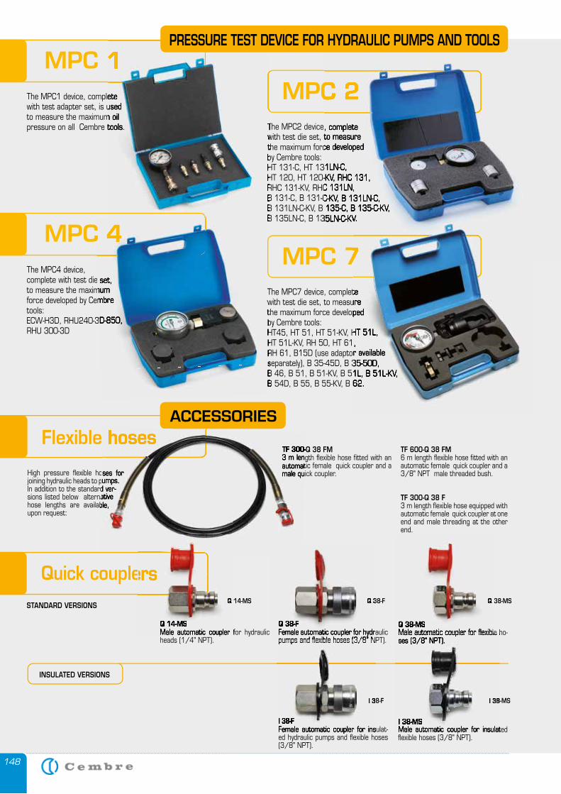
148
MPC 1The MPC1 device, complete with test adapter set, is used to measure the maximum oil pressure on all Cembre tools. The MPC2 device, complete
with test die set, to measure the maximum force developed by Cembre tools: HT 131-C, HT 131LN-C, HT 120, HT 120-KV, RHC 131, RHC 131-KV, RHC 131LN, B 131-C, B 131-C-KV, B 131LN-C, B 131LN-C-KV, B 135-C, B 135-C-KV, B 135LN-C, B 135LN-C-KV.
MPC 2MPC 1
The MPC1 device, complete with test adapter set, is used to measure the maximum oil pressure on all Cembre tools. The MPC2 device, complete
with test die set, to measure the maximum force developed by Cembre tools: HT 131-C, HT 131LN-C, HT 120, HT 120-KV, RHC 131, RHC 131-KV, RHC 131LN, B 131-C, B 131-C-KV, B 131LN-C, B 131LN-C-KV, B 135-C, B 135-C-KV, B 135LN-C, B 135LN-C-KV.
The MPC2 device, complete with test die set, to measure the maximum force developed
HT 131-C, HT 131LN-C, HT 120, HT 120-KV, RHC 131, RHC 131-KV, RHC 131LN, B 131-C, B 131-C-KV, B 131LN-C, B 131LN-C-KV, B 135-C, B 135-C-KV, B 135LN-C, B 135LN-C-KV.
MPC 2
PRESSURE TEST DEVICE FOR HYDRAULIC PUMPS AND TOOLS
MPC 4The MPC4 device, complete with test die set, to measure the maximum force developed by Cembre tools: ECW-H3D, RHU240-3D-850, RHU 300-3D
The MPC7 device, complete with test die set, to measure the maximum force developed by Cembre tools: HT45, HT 51, HT 51-KV, HT 51L, HT 51L-KV, RH 50, HT 61, RH 61, B15D (use adaptor available separately), B 35-45D, B 35-50D, B 46, B 51, B 51-KV, B 51L, B 51L-KV, B 54D, B 55, B 55-KV, B 62.
MPC 7MPC 4
complete with test die set, to measure the maximum force developed by Cembre
ECW-H3D, RHU240-3D-850,
with test die set, to measure the maximum force developed by Cembre tools: HT45, HT 51, HT 51-KV, HT 51L, HT 51L-KV, RH 50, HT 61, RH 61, B15D (use adaptor available separately), B 35-45D, B 35-50D, B 46, B 51, B 51-KV, B 51L, B 51L-KV, B 54D, B 55, B 55-KV, B 62.
B 135LN-C, B 135LN-C-KV.
The MPC7 device, complete with test die set, to measure the maximum force developed
HT45, HT 51, HT 51-KV, HT 51L, HT 51L-KV, RH 50, HT 61, RH 61, B15D (use adaptor available separately), B 35-45D, B 35-50D, B 46, B 51, B 51-KV, B 51L, B 51L-KV, B 54D, B 55, B 55-KV, B 62.
MPC 7MPC 7
Quick couplers
Q 14-MSMale automatic coupler for hydraulic heads (1/4" NPT).
Q 38-FFemale automatic coupler for hydraulic pumps and flexible hoses (3/8" NPT).
Q 38-MSMale automatic coupler for flexible ho-ses (3/8" NPT).
INSULATED VERSIONS
High pressure flexible hoses for joining hydraulic heads to pumps.In addition to the standard ver-sions listed below alternative hose lengths are available, upon request:
Flexible hosesACCESSORIES
TF 300-Q 38 FM 3 m length flexible hose fitted with an automatic female quick coupler and a male quick coupler.
TF 600-Q 38 FM6 m length flexible hose fitted with an automatic female quick coupler and a 3/8" NPT male threaded bush.
TF 300-Q 38 F3 m length flexible hose equipped with automatic female quick coupler at one end and male threading at the other end.
High pressure flexible hoses for joining hydraulic heads to pumps.In addition to the standard ver-sions listed below alternative hose lengths are available,
Flexible hosesTF 300-Q 38 FM 3 m length flexible hose fitted with an automatic female quick coupler and a male quick coupler.
Q 38-MSQ 38-FQ 14-MS
Q 38-FFemale automatic coupler for hydraulic pumps and flexible hoses (3/8" NPT).
Q 38-F
Q 38-MSMale automatic coupler for flexible ho-
Q 38-MS
Quick couplers
Q 14-MSMale automatic coupler for hydraulic
Q 14-MSSTANDARD VERSIONS
I 38-FFemale automatic coupler for insulat-ed hydraulic pumps and flexible hoses (3/8" NPT).
I 38-MSMale automatic coupler for insulated flexible hoses (3/8" NPT).
I 38-MSI 38-F
pumps and flexible hoses (3/8" NPT).
I 38-FFemale automatic coupler for insulat-
I 38-F
Male automatic coupler for flexible ho-ses (3/8" NPT).Male automatic coupler for flexible ho-
I 38-MSMale automatic coupler for insulated
I 38-MS

CO
RD
LE
SS
HY
DR
AU
LIC
TO
OL
S

150
CB 1840L, 18.0 V - 4.0 Ah Li-Ion high power battery (2 pcs.)
ASC 30-36 UK 27045000 Battery charger. (INPUT 220-240 V / 50-60 Hz; OUTPUT 12-42 V DC / 3.0 A max.)
USB cable.
4 Shoulder strap.
• Plastic or Metal carrying case.
SUPPLIED WITH
18.0 V - 4.0 Ah CORDLESS TOOL FEATURES
Multifunction OLED display:
Tool service required to maintain optimum condition
Pressure level check
Battery power availability
General operating information
Crimping force check
Head rotates through 180°. Switch protected against accidental operation. Pressure release button.4 Slot-in battery with release button.5 LED lighting of the working area. 6 Motor ventilation.7 Bi-component body for increased impact resistance.
8 Multifunction OLED display with touch button.9 Improved balance for better handling. Anatomically shaped grip for greater comfort. 18.0 V - 4.0 Ah Li-Ion high power batteries. SMARTOOL technology for viewing and downloading operational
data.
18V Li-Ion B A T T E RY
NEW
New
4
5
69
8
7
4
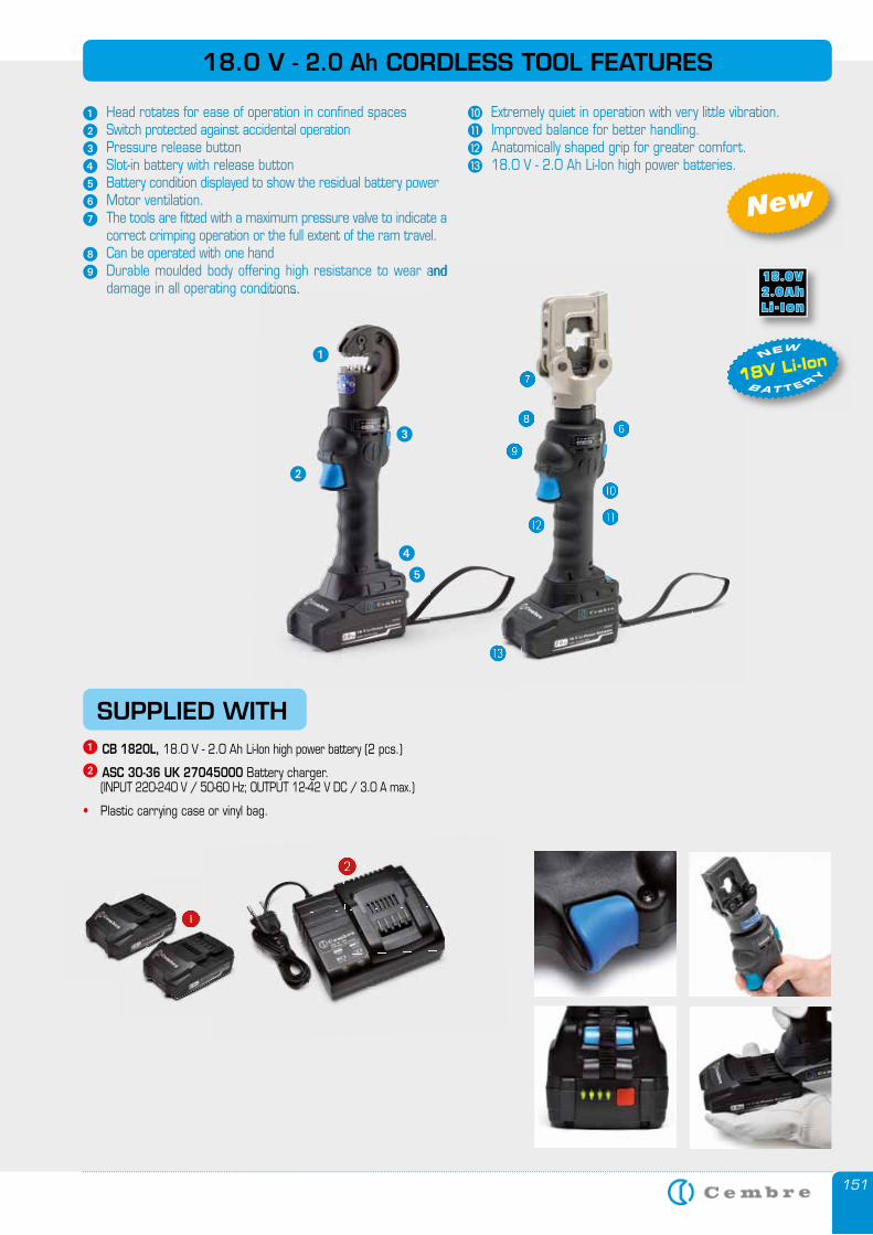
151
18V Li-Ion B A T T E RY
NEW
SUPPLIED WITH� CB 1820L, 18.0 V - 2.0 Ah Li-Ion high power battery (2 pcs.)
� ASC 30-36 UK 27045000 Battery charger. (INPUT 220-240 V / 50-60 Hz; OUTPUT 12-42 V DC / 3.0 A max.)
• Plastic carrying case or vinyl bag.
18.0 V - 2.0 Ah CORDLESS TOOL FEATURES
� Head rotates for ease of operation in confined spaces� Switch protected against accidental operation� Pressure release button� Slot-in battery with release button� Battery condition displayed to show the residual battery power� Motor ventilation.� The tools are fitted with a maximum pressure valve to indicate a
correct crimping operation or the full extent of the ram travel.� Can be operated with one hand� Durable moulded body offering high resistance to wear and
damage in all operating conditions.
� Extremely quiet in operation with very little vibration.� Improved balance for better handling.� Anatomically shaped grip for greater comfort.� 18.0 V - 2.0 Ah Li-Ion high power batteries.18.0 V - 2.0 Ah Li-Ion high power batteries.
New
�
�
��
�
damage in all operating conditions.
�
�
�
�
�
�
�
�
�
�
�
�
�
18V Li-Ion
Durable moulded body offering high resistance to wear and
�
��
�
�
�
���
�
�
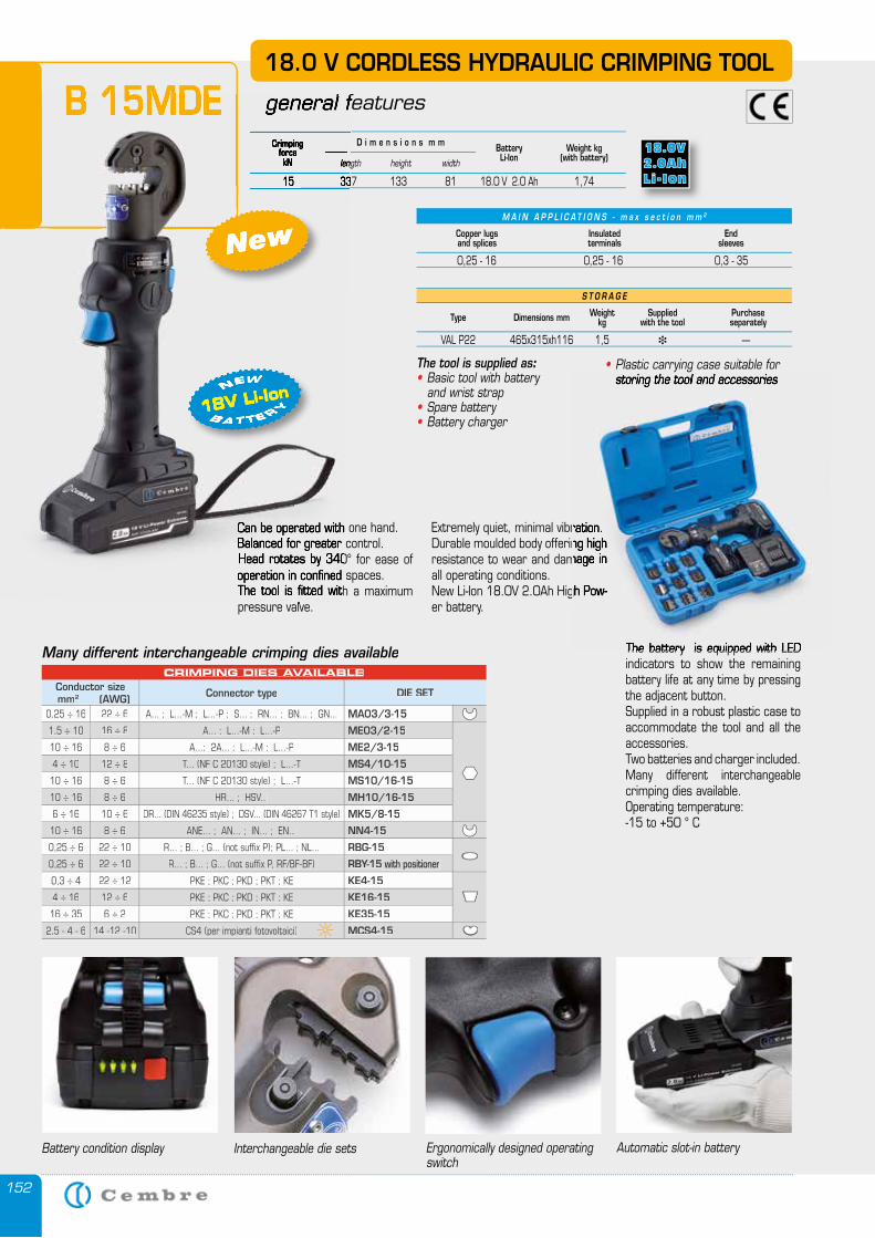
152
M A I N A P P L I C A T I O N S - m a x s e c t i o n m m 2
S T O R A G E
Type Dimensions mm Weightkg
Suppliedwith the tool
Purchase separately
VAL P22 465x315xh116 1,5 � —
Copper lugsand splices
Insulatedterminals
Endsleeves
0,25 - 16 0,25 - 16 0,3 - 35
The tool is supplied as:• Basic tool with battery and wrist strap• Spare battery• Battery charger
• Plastic carrying case suitable for storing the tool and accessories
Many different interchangeable crimping dies available
18.0 V CORDLESS HYDRAULIC CRIMPING TOOL
general featuresB 15MDECrimping
forcekN
Weight kg(with battery)
BatteryLi-Ionlength height width
D i m e n s i o n s m m
15 337 133 81 18.0 V 2.0 Ah 1,74
Battery condition display Ergonomically designed operating switch
Automatic slot-in batteryInterchangeable die sets
CRIMPING DIES AVAILABLEConductor size
mm2 (AWG) Connector type DIE SET
0,25 ÷ 16 22 ÷ 6 A... ; L...-M ; L...-P ; S... ; RN... ; BN... ; GN... MA03/3-15
1,5 ÷ 10 16 ÷ 8 A... ; L...-M ; L...-P ME03/2-15
10 ÷ 16 8 ÷ 6 A...; 2A... ; L...-M ; L...-P ME2/3-15
4 ÷ 10 12 ÷ 8 T... (NF C 20130 style) ; L...-T MS4/10-15
10 ÷ 16 8 ÷ 6 T... (NF C 20130 style) ; L...-T MS10/16-15
10 ÷ 16 8 ÷ 6 HR... ; HSV... MH10/16-15
6 ÷ 16 10 ÷ 6 DR... (DIN 46235 style) ; DSV... (DIN 46267 T1 style) MK5/8-15
10 ÷ 16 8 ÷ 6 ANE... ; AN... ; IN... ; EN... NN4-15
0,25 ÷ 6 22 ÷ 10 R... ; B... ; G... (not suffix P); PL... ; NL... RBG-15
0,25 ÷ 6 22 ÷ 10 R... ; B... ; G... (not suffix P, RF/BF-BF) RBY-15 with positioner
0,3 ÷ 4 22 ÷ 12 PKE ; PKC ; PKD ; PKT ; KE KE4-15
4 ÷ 16 12 ÷ 6 PKE ; PKC ; PKD ; PKT ; KE KE16-15
16 ÷ 35 6 ÷ 2 PKE ; PKC ; PKD ; PKT ; KE KE35-15
2,5 - 4 - 6 14 -12 -10 CS4 (per impianti fotovoltaici) MCS4-15
18V Li-Ion B A T T E RY
NEW
New
Can be operated with one hand. Balanced for greater control.Head rotates by 340° for ease of operation in confined spaces.The tool is fitted with a maximum pressure valve.
The battery is equipped with LED indicators to show the remaining battery life at any time by pressing the adjacent button.Supplied in a robust plastic case to accommodate the tool and all the accessories. Two batteries and charger included.Many different interchangeable crimping dies available.Operating temperature: -15 to +50 ° C
Extremely quiet, minimal vibration. Durable moulded body offering high resistance to wear and damage in all operating conditions. New Li-Ion 18.0V 2.0Ah High Pow-er battery.
general featuresB 15MDECrimping
forcekN length
15 337 133 81 18.0 V 2.0 Ah 1,74
18V Li-IonB A T T E RY
NEW
New
Can be operated with one hand. Balanced for greater control.Head rotates by 340° for ease of operation in confined spaces.The tool is fitted with a maximum pressure valve.
storing the tool and accessories
The battery is equipped with LED
Extremely quiet, minimal vibration. Durable moulded body offering high resistance to wear and damage in
New Li-Ion 18.0V 2.0Ah High Pow-
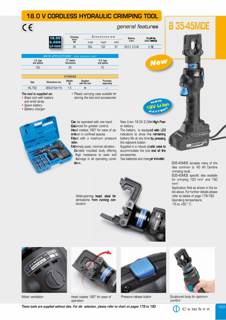
153
18.0 V CORDLESS HYDRAULIC CRIMPING TOOL
general features B 35-45MDE
These tools are supplied without dies. For die selection, please refer to chart on pages 178 to 190
CrimpingforcekN
Weight kg(with battery)
BatteryLi-Ionlength height width
D i m e n s i o n s m m
35 354 133 81 18.0 V 2.0 Ah 2,19
The tool is supplied as:• Basic tool with battery and wrist strap• Spare battery• Battery charger
Motor ventilation Pressure release button Sculptured body for optimum comfort
Head rotates 180° for ease of operation
Wide-opening head, ideal for derivations from running con-ductors
M A I N A P P L I C A T I O N S - m a x s e c t i o n m m 2
L.V. lugsand splices
“C” sleeveConnectors
H.V. lugsand splices
150 35 70
• Plastic carrying case suitable for storing the tool and accessories
S T O R A G E
Type Dimensions mm Weightkg
Suppliedwith the tool
Purchase separately
VAL P22 465x315xh116 1,5 � —
Wide-opening head, ideal for derivations from running con-
Can be operated with one hand.Balanced for greater control.Head rotates 180° for ease of op-eration in confined spaces.Fitted with a maximum pressure valve.Extremely quiet, minimal vibration.
Durable moulded body offering high resistance to wear and damage in all operating condi-
tions.
New Li-Ion 18.0V 2.0Ah High Pow-er battery. The battery is equipped with LED indicators to show the remaining battery life at any time by pressing the adjacent button.Supplied in a robust plastic case to accommodate the tool and all the accessories. Two batteries and charger included.
35 354 133 81 18.0 V 2.0 Ah 2,19
New
18V Li-Ion B A T T E RY
NEW
general features B 35-45MDEWeight kg
(with battery)
35 354 133 81 18.0 V 2.0 Ah 2,19
New Li-Ion 18.0V 2.0Ah High Pow-
The battery is equipped with LED indicators to show the remaining battery life at any time by pressing
Supplied in a robust plastic case to accommodate the tool and all the
Two batteries and charger included.
New
18V Li-IonB A T T E RY
NEW
Can be operated with one hand.Balanced for greater control.Head rotates 180° for ease of op-eration in confined spaces.Fitted with a maximum pressure valve.Extremely quiet, minimal vibration.
Durable moulded body offering high resistance to wear and damage in all operating condi-
tions. B35-45MDE accepts many of the dies common to 45 kN Cembre crimping tools. B35-45MDE specific dies avaiable for crimping 120 mm2 and 150 mm2. Application field as shown in the ta-ble above. For further details please refer to tables of page 178-190.Operating temperature: -15 to +50 ° C
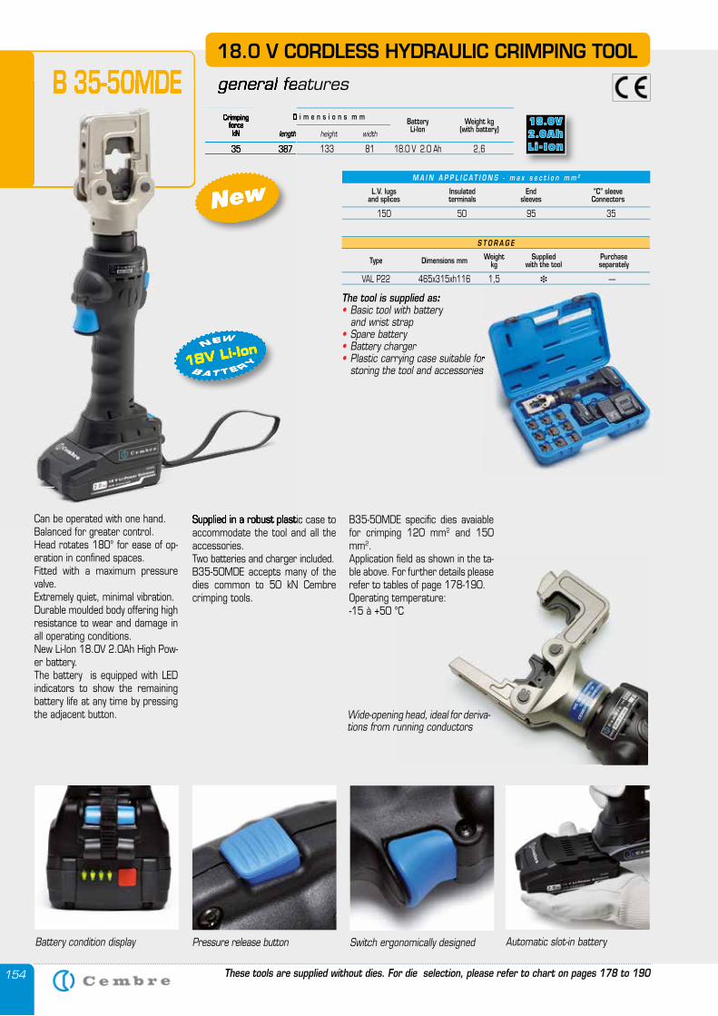
154
18.0 V CORDLESS HYDRAULIC CRIMPING TOOL
general featuresB 35-50MDE
Pressure release buttonBattery condition display Automatic slot-in batterySwitch ergonomically designed
These tools are supplied without dies. For die selection, please refer to chart on pages 178 to 190
L.V. lugsand splices
Insulatedterminals
Endsleeves
“C” sleeveConnectors
150 50 95 35
M A I N A P P L I C A T I O N S - m a x s e c t i o n m m 2
CrimpingforcekN
Weight kg(with battery)
BatteryLi-Ionlength height width
D i m e n s i o n s m m
35 387 133 81 18.0 V 2.0 Ah 2,6
S T O R A G E
Type Dimensions mm Weightkg
Suppliedwith the tool
Purchase separately
VAL P22 465x315xh116 1,5 � —
Wide-opening head, ideal for deriva-tions from running conductors
Supplied in a robust plastic case to accommodate the tool and all the accessories. Two batteries and charger included.B35-50MDE accepts many of the dies common to 50 kN Cembre crimping tools.
B35-50MDE specific dies avaiable for crimping 120 mm2 and 150 mm2. Application field as shown in the ta-ble above. For further details please refer to tables of page 178-190.Operating temperature:-15 à +50 °C
The tool is supplied as:• Basic tool with battery and wrist strap• Spare battery• Battery charger• Plastic carrying case suitable for storing the tool and accessories
18V Li-Ion B A T T E RY
NEW
New
general featuresB 35-50MDECrimping
forcekN length
D i m e n s i o n s m m
35 387 133 81 18.0 V 2.0 Ah 2,6
Supplied in a robust plastic case to
18V Li-IonB A T T E RY
NEW
New
Plastic carrying case suitable for storing the tool and accessories
Can be operated with one hand.Balanced for greater control.Head rotates 180° for ease of op-eration in confined spaces.Fitted with a maximum pressure valve.Extremely quiet, minimal vibration.Durable moulded body offering high resistance to wear and damage in all operating conditions.New Li-Ion 18.0V 2.0Ah High Pow-er battery. The battery is equipped with LED indicators to show the remaining battery life at any time by pressing the adjacent button.
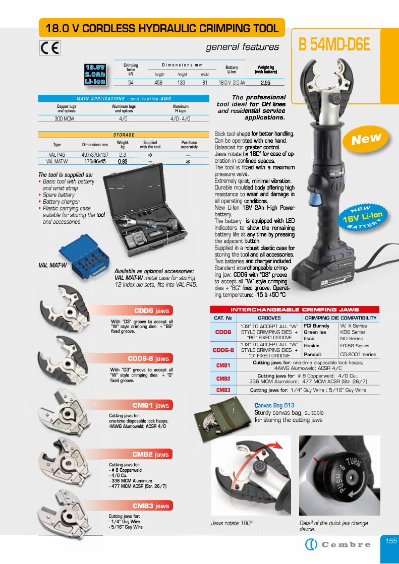
155
18.0 V CORDLESS HYDRAULIC CRIMPING TOOL
general features
M A I N A P P L I C A T I O N S - m a x s e c t i o n A W G
300 MCM 4/0 4/0 - 4/0
CrimpingforcekN
Weight kg(with battery)
BatteryLi-Ionlength height width
D i m e n s i o n s m m
54 458 133 81 18.0 V 2.0 Ah 2,95
B 54MD-D6E
Copper lugsand splices
Aluminum lugsand splices
Aluminum H taps
The professionaltool ideal for and residential
applications.
The tool is supplied as:• Basic tool with battery and wrist strap• Spare battery• Battery charger• Plastic carrying case suitable for storing the tool
and accessories
Stick tool shape for better handling. Can be operated with one hand.Balanced for greater control.Jaws rotate by 180° for ease of op-eration in confined spaces.The tool is fitted with a maximum pressure valve. Extremely quiet, minimal vibration. Durable moulded body offering high resistance to wear and damage in all operating conditions. New Li-Ion 18V 2Ah High Power battery. The battery is equipped with LED indicators to show the remaining battery life at any time by pressing the adjacent button. Supplied in a robust plastic case for storing the tool and all accessories.Two batteries and charger included.Standard interchangeable crimp-ing jaw: CDD6 with “D3” groove to accept all “W” style crimping dies + “BG” fixed groove. Operat-ing temperature: -15 à +50 °C
Jaws rotate 180° Detail of the quick jaw change device.
S T O R A G E
Type Dimensions mm Weightkg
Suppliedwith the tool
Purchase separately
VAL P45 497x370x137 2,3 � — VAL MAT-W 175x96x45 0,93 — �
VAL MAT-WAvailable as optional accessories:VAL MAT-W metal case for storing 12 Index die sets, fits into VAL-P45.
Canvas Bag 013Sturdy canvas bag, suitable for storing the cutting jaws
Canvas Bag 013Sturdy canvas bag, suitable for storing the cutting jaws
INTERCHANGEABLE CRIMPING JAWS
CAT. No GROOVES CRIMPING DIE COMPATIBILITY
CDD6“D3” TO ACCEPT ALL “W” STYLE CRIMPING DIES +
“BG” FIXED GROOVE
FCI Burndy W, X SeriesGreen lee KD6 SeriesIlsco ND Series
CDD6-8“D3” TO ACCEPT ALL “W” STYLE CRIMPING DIES +
“O” FIXED GROOVE
Huskie HT-58 Series
Panduit CD-2001 series
CMB1 Cutting jaws for: one-time disposable lock hasps; 4AWG Alumoweld; ACSR 4/0
CMB2 Cutting jaws for: # 8 Copperweld; 4/0 Cu.;336 MCM Aluminium; 477 MCM ACSR (Str. 26/7)
CMB3 Cutting jaws for: 1/4" Guy Wire ; 5/16" Guy Wire
CDD6 jaws
With “D3” groove to accept all “W” style crimping dies + “BG” fixed groove.
CDD6-8 jaws
With “D3” groove to accept all “W” style crimping dies + “O” fixed groove.
CMB1 jaws Cutting jaws for: one-time disposable lock hasps, 4AWG Alumoweld; ACSR 4/0
CMB2 jaws
Cutting jaws for: - # 8 Copperweld- 4/0 Cu.- 336 MCM Aluminium- 477 MCM ACSR (Str. 26/7)
CMB3 jaws
Cutting jaws for: - 1/4" Guy Wire- 5/16" Guy Wire
general features
Weight kg(with battery)
54 458 133 81 18.0 V 2.0 Ah 2,95
B 54MD-D6E
The professionaltool ideal for OH lines and residential service and residential service and residential
applications.
Stick tool shape for better handling. Can be operated with one hand.Balanced for greater control.Jaws rotate by 180° for ease of op-eration in confined spaces.The tool is fitted with a maximum pressure valve. Extremely quiet, minimal vibration. Durable moulded body offering high resistance to wear and damage in all operating conditions. New Li-Ion 18V 2Ah High Power
The battery is equipped with LED indicators to show the remaining battery life at any time by pressing the adjacent button. Supplied in a robust plastic case for storing the tool and all accessories.Two batteries and charger included.Standard interchangeable crimp-
CDD6 with “D3” groove to accept all “W” style crimping dies + “BG” fixed groove. Operat-ing temperature: -15 à +50 °C
INTERCHANGEABLE CRIMPING JAWS
suitable for storing the tool
� — VAL MAT-W 175x96x45 0,93 — � VAL MAT-W 175x96x45 0,93 —
New
18V Li-Ion B A T T E RY
NEW
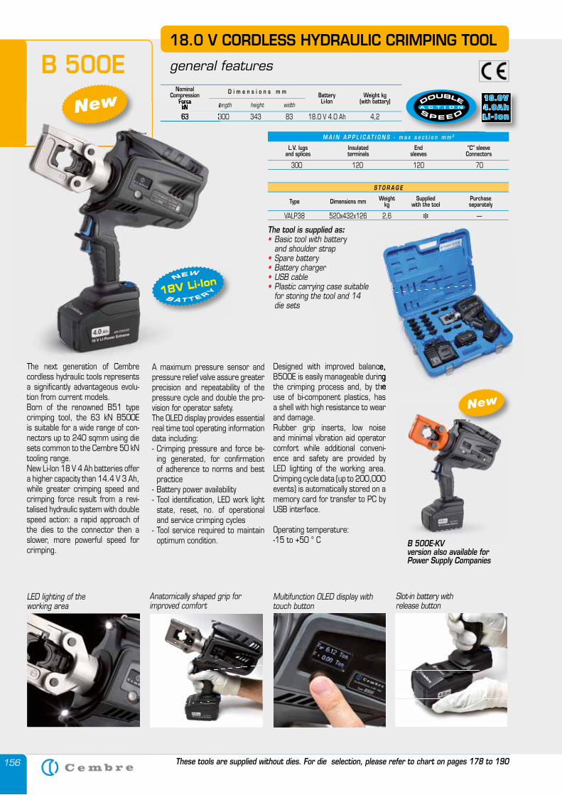
156
B 500E
S T O R A G E
Type Dimensions mm Weightkg
Suppliedwith the tool
Purchase separately
VALP38 520x432x126 2,6 � —
The tool is supplied as:• Basic tool with battery and shoulder strap• Spare battery• Battery charger• USB cable• Plastic carrying case suitable
for storing the tool and 14 die sets
18.0 V CORDLESS HYDRAULIC CRIMPING TOOL
general features
These tools are supplied without dies. For die selection, please refer to chart on pages 178 to 190
The next generation of Cembre cordless hydraulic tools represents a significantly advantageous evolu-tion from current models.Born of the renowned B51 type crimping tool, the 63 kN B500E is suitable for a wide range of con-nectors up to 240 sqmm using die sets common to the Cembre 50 kN tooling range.New Li-Ion 18 V 4 Ah batteries offer a higher capacity than 14.4 V 3 Ah, while greater crimping speed and crimping force result from a revi-talised hydraulic system with double speed action: a rapid approach of the dies to the connector then a slower, more powerful speed for crimping.
M A I N A P P L I C A T I O N S - m a x s e c t i o n m m 2
L.V. lugsand splices
Insulatedterminals
Endsleeves
“C” sleeveConnectors
300 120 120 70
A maximum pressure sensor and pressure relief valve assure greater precision and repeatability of the pressure cycle and double the pro-vision for operator safety.The OLED display provides essential real time tool operating information data including: - Crimping pressure and force be-
ing generated, for confirmation of adherence to norms and best practice
- Battery power availability- Tool identification, LED work light
state, reset, no. of operational and service crimping cycles
- Tool service required to maintain optimum condition.
Nominal Compression
ForcekN
Weight kg(with battery)
BatteryLi-Ionlength height width
D i m e n s i o n s m m
63 300 343 83 18.0 V 4.0 Ah 4,2
The next generation of Cembre
ForcekN length
63 300 343 83 18.0 V 4.0 Ah 4,2
Designed with improved balance, B500E is easily manageable during the crimping process and, by the use of bi-component plastics, has a shell with high resistance to wear and damage. Rubber grip inserts, low noise and minimal vibration aid operator comfort while additional conveni-ence and safety are provided by LED lighting of the working area. Crimping cycle data (up to 200,000 events) is automatically stored on a memory card for transfer to PC by USB interface.
Operating temperature: -15 to +50 ° C
18V Li-Ion B A T T E RY
NEW
New
Multifunction OLED display with touch button
Slot-in battery with release button
LED lighting of the working area
Anatomically shaped grip for improved comfort
B 500E-KV version also available for Power Supply Companies
New
Designed with improved balance, B500E is easily manageable during the crimping process and, by the use of bi-component plastics, has
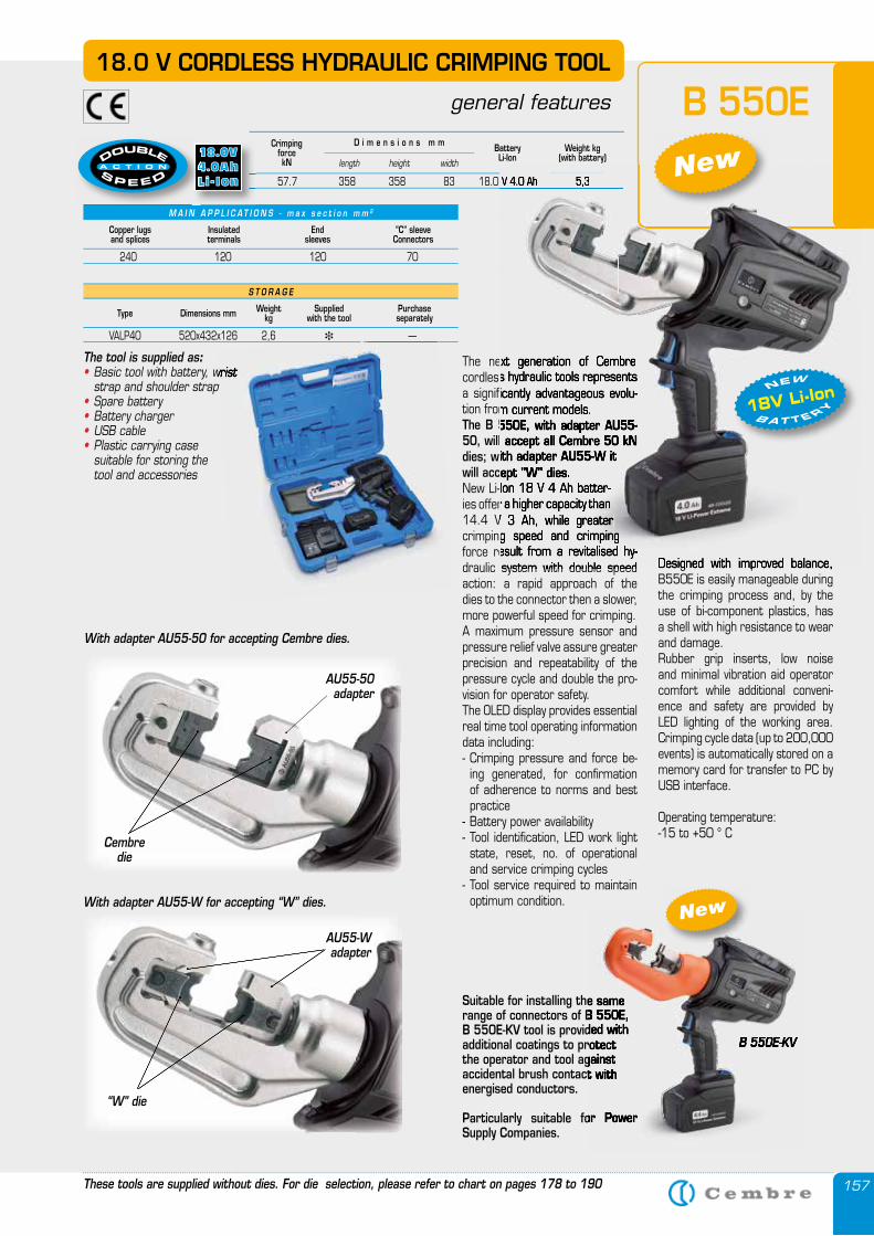
157
The next generation of Cembre cordless hydraulic tools represents a significantly advantageous evolu-tion from current models.The B 550E, with adapter AU55-50, will accept all Cembre 50 kN dies; with adapter AU55-W it will accept "W" dies.New Li-Ion 18 V 4 Ah batter-ies offer a higher capacity than 14.4 V 3 Ah, while greater crimping speed and crimping force result from a revitalised hy-draulic system with double speed action: a rapid approach of the dies to the connector then a slower, more powerful speed for crimping.A maximum pressure sensor and pressure relief valve assure greater precision and repeatability of the pressure cycle and double the pro-vision for operator safety.The OLED display provides essential real time tool operating information data including: - Crimping pressure and force be-
ing generated, for confirmation of adherence to norms and best practice
- Battery power availability- Tool identification, LED work light
state, reset, no. of operational and service crimping cycles
- Tool service required to maintain optimum condition.
Designed with improved balance, B550E is easily manageable during the crimping process and, by the use of bi-component plastics, has a shell with high resistance to wear and damage. Rubber grip inserts, low noise and minimal vibration aid operator comfort while additional conveni-ence and safety are provided by LED lighting of the working area. Crimping cycle data (up to 200,000 events) is automatically stored on a memory card for transfer to PC by USB interface.
Operating temperature: -15 to +50 ° C
With adapter AU55-50 for accepting Cembre dies.
Cembredie
AU55-50 adapter
Suitable for installing the same range of connectors of B 550E, B 550E-KV tool is provided with additional coatings to protect the operator and tool against accidental brush contact with energised conductors.
Particularly suitable for Power Supply Companies.
B 550E18.0 V CORDLESS HYDRAULIC CRIMPING TOOL
general features
M A I N A P P L I C A T I O N S - m a x s e c t i o n m m 2
Copper lugsand splices
Insulatedterminals
Endsleeves
“C” sleeveConnectors
240 120 120 70
CrimpingforcekN
Weight kg(with battery)
BatteryLi-Ionlength height width
D i m e n s i o n s m m
57.7 358 358 83 18.0 V 4.0 Ah 5,3
The tool is supplied as:• Basic tool with battery, wrist
strap and shoulder strap• Spare battery• Battery charger• USB cable• Plastic carrying case suitable for storing the tool and accessories
S T O R A G E
Type Dimensions mm Weightkg
Suppliedwith the tool
Purchase separately
VALP40 520x432x126 2,6 � —
These tools are supplied without dies. For die selection, please refer to chart on pages 178 to 190
With adapter AU55-W for accepting “W” dies.
“W” die
AU55-Wadapter
B 550E-KV
Basic tool with battery, wrist strap and shoulder strap
—
Suitable for installing the same range of connectors of B 550E, B 550E-KV tool is provided with additional coatings to protect the operator and tool against accidental brush contact with
Particularly suitable for Power
B 550E-KV
New
57.7 358 358 83 18.0 V 4.0 Ah 5,3
The next generation of Cembre cordless hydraulic tools represents a significantly advantageous evolu-tion from current models.The B 550E, with adapter AU55-50, will accept all Cembre 50 kN dies; with adapter AU55-W it will accept "W" dies.New Li-Ion 18 V 4 Ah batter-ies offer a higher capacity than 14.4 V 3 Ah, while greater crimping speed and crimping force result from a revitalised hy-draulic system with double speed Designed with improved balance,
57.7 358 358 83 18.0 V 4.0 Ah 5,3New
18V Li-Ion B A T T E RY
NEW
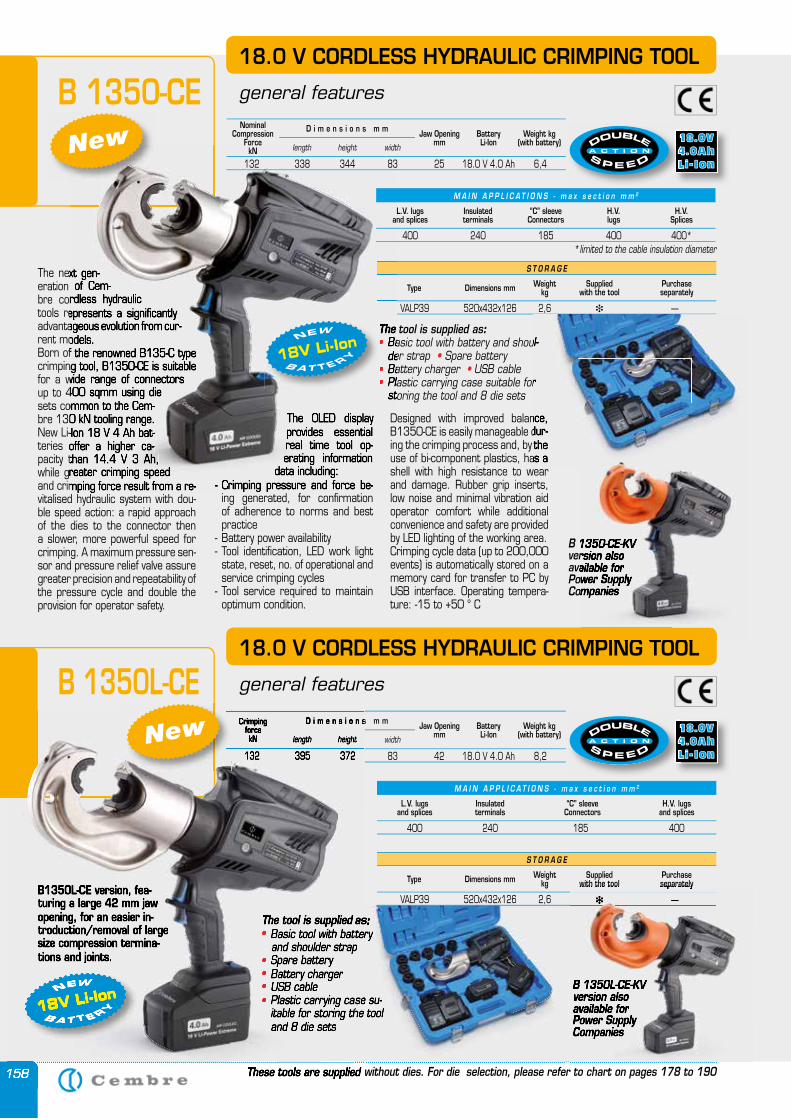
158
The next gen-eration of Cem-bre cordless hydraulic tools represents a significantly advantageous evolution from cur-rent models. Born of the renowned B135-C type crimping tool, B1350-CE is suitable for a wide range of connectors up to 400 sqmm using die sets common to the Cem-bre 130 kN tooling range. New Li-Ion 18 V 4 Ah bat-teries offer a higher ca-pacity than 14.4 V 3 Ah, while greater crimping speed and crimping force result from a re-vitalised hydraulic system with dou-ble speed action: a rapid approach of the dies to the connector then a slower, more powerful speed for crimping. A maximum pressure sen-sor and pressure relief valve assure greater precision and repeatability of the pressure cycle and double the provision for operator safety.
The OLED display provides essential real time tool op-erating information
data including: - Crimping pressure and force be-
ing generated, for confirmation of adherence to norms and best practice
- Battery power availability- Tool identification, LED work light
state, reset, no. of operational and service crimping cycles
- Tool service required to maintain optimum condition.
B1350L-CE version, fea-turing a large 42 mm jaw opening, for an easier in-troduction/removal of large size compression termina-tions and joints.
B 1350L-CE
B 1350-CE18.0 V CORDLESS HYDRAULIC CRIMPING TOOL
general features
S T O R A G E
Type Dimensions mm Weightkg
Suppliedwith the tool
Purchase separately
VALP39 520x432x126 2,6 � —
The tool is supplied as:• Basic tool with battery and shoul-
der strap • Spare battery• Battery charger • USB cable• Plastic carrying case suitable for
storing the tool and 8 die sets
S T O R A G E
Type Dimensions mm Weightkg
Suppliedwith the tool
Purchase separately
VALP39 520x432x126 2,6 � —
The tool is supplied as:• Basic tool with battery and shoulder strap• Spare battery• Battery charger• USB cable• Plastic carrying case su-
itable for storing the tool and 8 die sets
These tools are supplied without dies. For die selection, please refer to chart on pages 178 to 190
M A I N A P P L I C A T I O N S - m a x s e c t i o n m m 2
L.V. lugsand splices
Insulatedterminals
“C” sleeveConnectors
H.V. lugsand splices
400 240 185 400
CrimpingforcekN
BatteryLi-Ion
Weight kg(with battery)length height width
D i m e n s i o n s m m
132 395 372 83 42 18.0 V 4.0 Ah 8,2
Jaw Openingmm
The next gen-eration of Cem-bre cordless hydraulic tools represents a significantly advantageous evolution from cur-rent models. Born of the renowned B135-C type crimping tool, B1350-CE is suitable for a wide range of connectors up to 400 sqmm using die sets common to the Cem-bre 130 kN tooling range. New Li-Ion 18 V 4 Ah bat-teries offer a higher ca-pacity than 14.4 V 3 Ah, while greater crimping speed and crimping force result from a re-
The OLED display provides essential real time tool op-erating information
data including: - Crimping pressure and force be-
VALP39 520x432x126 2,6
The tool is supplied as• Basic tool with battery and shoul-• Basic tool with battery and shoul-•
der strap • Battery charger • Battery charger •• Plastic carrying case suitable for • Plastic carrying case suitable for •
storing the tool and 8 die sets
The tool is supplied as
18V Li-Ion B A T T E RY
NEW
NewNominal
CompressionForcekN
BatteryLi-Ion
Weight kg(with battery)length height width
D i m e n s i o n s m m
132 338 344 83 25 18.0 V 4.0 Ah 6,4
Jaw Openingmm
Designed with improved balance, B1350-CE is easily manageable dur-ing the crimping process and, by the use of bi-component plastics, has a shell with high resistance to wear and damage. Rubber grip inserts, low noise and minimal vibration aid operator comfort while additional convenience and safety are provided by LED lighting of the working area. Crimping cycle data (up to 200,000 events) is automatically stored on a memory card for transfer to PC by USB interface. Operating tempera-ture: -15 to +50 ° C
18.0 V CORDLESS HYDRAULIC CRIMPING TOOL
general features
18V Li-Ion B A T T E RY
NEW
158
B1350L-CE version, fea-turing a large 42 mm jaw opening, for an easier in-troduction/removal of large size compression termina-tions and joints.
The tool is supplied as• Basic tool with battery• Basic tool with battery• and shoulder strap• Spare battery• Spare battery•• Battery charger• Battery charger•• USB cable• USB cable•• Plastic carrying case su-• Plastic carrying case su-•
itable for storing the tool and 8 die sets
These tools are supplied without dies. For die selection, please refer to chart on pages 178 to 190
CrimpingforcekN length height
D i m e n s i o n s m m
132 395 372 83 42 18.0 V 4.0 Ah 8,2
18V Li-IonB A T T E RY
NEW
132 395 372 83 42 18.0 V 4.0 Ah 8,2New
M A I N A P P L I C A T I O N S - m a x s e c t i o n m m 2
L.V. lugsand splices
Insulatedterminals
“C” sleeveConnectors
H.V. lugs
H.V. Splices
400 240 185 400 400**limited to the cable insulation diameter
Basic tool with battery and shoul-
Plastic carrying case suitable for
Designed with improved balance, B1350-CE is easily manageable dur-ing the crimping process and, by the use of bi-component plastics, has a shell with high resistance to wear
The tool is supplied as: Basic tool with battery
Plastic carrying case su-itable for storing the tool
The tool is supplied as Basic tool with battery
and shoulder strap
Plastic carrying case su-itable for storing the tool
B 1350-CE-KV version also available for Power Supply Companies
18.0 V CORDLESS HYDRAULIC CRIMPING TOOL
B 1350-CE-KV version also available for Power Supply Companies
B 1350L-CE-KV version also available for Power Supply Companies
with the tool separately
� —
B 1350L-CE-KV version also available for Power Supply Companies
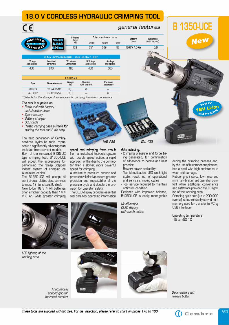
159
B 1350-UCE
The tool is supplied as:• Basic tool with battery and shoulder strap• Spare battery• Battery charger• USB cable• Plastic carrying case suitable for
storing the tool and 8 die sets
CrimpingforcekN
Weight kg(with battery)
BatteryLi-Ionlength height width
D i m e n s i o n s m m
132 351 369 83 18.0 V 4.0 Ah 5,9
These tools are supplied without dies. For die selection, please refer to chart on pages 178 to 190
M A I N A P P L I C A T I O N S - m a x s e c t i o n m m 2
L.V. lugsand splices
Insulatedterminals
“C” sleeveConnectors
H.V. lugsand splices
Alu lugsand splices
400 240 185 400 300
18.0 V CORDLESS HYDRAULIC CRIMPING TOOL
general features
132 351 369 83 18.0 V 4.0 Ah
Anatomically shaped grip for
improved comfort
Multifunction OLED display with touch button
Slot-in battery with release button
LED lighting of the working area
data including: - Crimping pressure and force be-
ing generated, for confirmation of adherence to norms and best practice
- Battery power availability- Tool identification, LED work light
state, reset, no. of operational and service crimping cycles
- Tool service required to maintain optimum condition.
Designed with improved balance, B1350-UCE is easily manageable
during the crimping process and, by the use of bi-component plastics, has a shell with high resistance to wear and damage. Rubber grip inserts, low noise and minimal vibration aid operator com-fort while additional convenience and safety are provided by LED light-ing of the working area. Crimping cycle data (up to 200,000 events) is automatically stored on a memory card for transfer to PC by USB interface.
Operating temperature: -15 to +50 ° C
speed and crimping force result from a revitalised hydraulic system with double speed action: a rapid approach of the dies to the connec-tor then a slower, more powerful speed for crimping.A maximum pressure sensor and pressure relief valve assure greater precision and repeatability of the pressure cycle and double the pro-vision for operator safety.The OLED display provides essential real time tool operating information
The next generation of Cembre cordless hydraulic tools repre-sents a significantly advantageous evolution from current models. Born of the renowned B135-UC type crimping tool, B1350-UCE will accept the accessories for performing the “Deep Stepped Indent” system of crimping on Aluminium cables. The B1350-UCE will accept all semi-circular slotted dies, common to most 12 tons tools (U dies).New Li-Ion 18 V 4 Ah batteries offer a higher capacity than 14.4 V 3 Ah, while greater crimping
132 351 369 83 18.0 V 4.0 Ah 5,9
data including: - Crimping pressure and force be-
18V Li-Ion B A T T E RY
NEW
New
Plastic carrying case suitable for storing the tool and 8 die sets
data including: speed and crimping force result
The next generation of Cembre cordless hydraulic tools repre-sents a significantly advantageous
VAL P39 VAL 130
S T O R A G E
Type Dimensions mm Weightkg
Suppliedwith the tool
Purchase separately
VALP39 520x432x126 2,6 � — VAL 130* 360x280xh48 3,0 — �
*Suitable for the storage of accessories for crimping Aluminium connectors
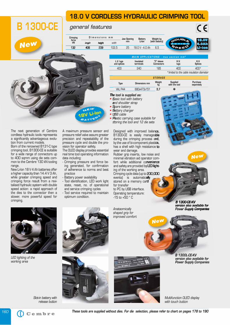
160
S T O R A G E
Type Dimensions mm Weightkg
Suppliedwith the tool
Purchase separately
VAL P44 680x473x151 3,7 � —
These tools are supplied without dies. For die selection, please refer to chart on pages 178 to 190
CrimpingforcekN
BatteryLi-Ion
Weight kg(with battery)length height width
D i m e n s i o n s m m
132 406 239 102,5 25 18.0 V - 4.0 Ah 6,5
Jaw Openingmm
18.0 V CORDLESS HYDRAULIC CRIMPING TOOL
general featuresB 1300-CE
The next generation of Cembre cordless hydraulic tools represents a significantly advantageous evolu-tion from current models. Born of the renowned B131-C type crimping tool, B1300-CE is suitable for a wide range of connectors up to 400 sqmm using die sets com-mon to the Cembre 130 kN tooling range. New Li-Ion 18 V 4 Ah batteries offer a higher capacity than 14.4 V 3 Ah, while greater crimping speed and crimping force result from a revi-talised hydraulic system with double speed action: a rapid approach of the dies to the connector then a slower, more powerful speed for crimping.
A maximum pressure sensor and pressure relief valve assure greater precision and repeatability of the pressure cycle and double the pro-vision for operator safety.The OLED display provides essential real time tool operating information data including: - Crimping pressure and force be-
ing generated, for confirmation of adherence to norms and best practice
- Battery power availability- Tool identification, LED work light
state, reset, no. of operational and service crimping cycles
- Tool service required to maintain optimum condition.
Designed with improved balance, B1300-CE is easily manageable during the crimping process and, by the use of bi-component plastics, has a shell with high resistance to wear and damage. Rubber grip inserts, low noise and minimal vibration aid operator com-fort while additional convenience and safety are provided by LED light-ing of the working area. Crimping cycle data (up to 200,000 events) is automatically stored on a memory card for transfer to PC by USB interface.Operating temperature: -15 to +50 ° C
The tool is supplied as:• Basic tool with battery and shoulder strap• Spare battery• Battery charger • USB cable• Plastic carrying case suitable for
storing the tool and 12 die sets
VAL P44 680x473x151 3,7
length height
132 406 239 102,5 25 18.0 V - 4.0 Ah 6,5
The tool is supplied as• Basic tool with battery• Basic tool with battery• and shoulder strap• Spare battery• Spare battery•• Battery charger • Battery charger •• USB cable• USB cable•• Plastic carrying case suitable for • Plastic carrying case suitable for •
storing the tool and 12 die sets
Multifunction OLED display with touch button
Anataomically shaped grip for improved comfort
Slot-in battery with release button
LED lighting of the working area
18V Li-Ion B A T T E RY
NEW
B 1300-CE-KV version also available for Power Supply Companies
New
New
fort while additional convenience and safety are provided by LED light-
Crimping cycle data (up to 200,000 events) is automatically stored on a memory card
B 1300-CE-KV version also available for Power Supply Companies
New
B 1300L-CE-KV version also available for Power Supply Companies
M A I N A P P L I C A T I O N S - m a x s e c t i o n m m 2
L.V. lugsand splices
Insulatedterminals
“C” sleeveConnectors
H.V. lugs
H.V. Splices
400 240 185 400 400**limited to the cable insulation diameter
VAL P44 680x473x151 3,7 � —
Designed with improved balance, B1300-CE is easily manageable during the crimping process and, by the use of bi-component plastics, has a shell with high resistance to
Plastic carrying case suitable for
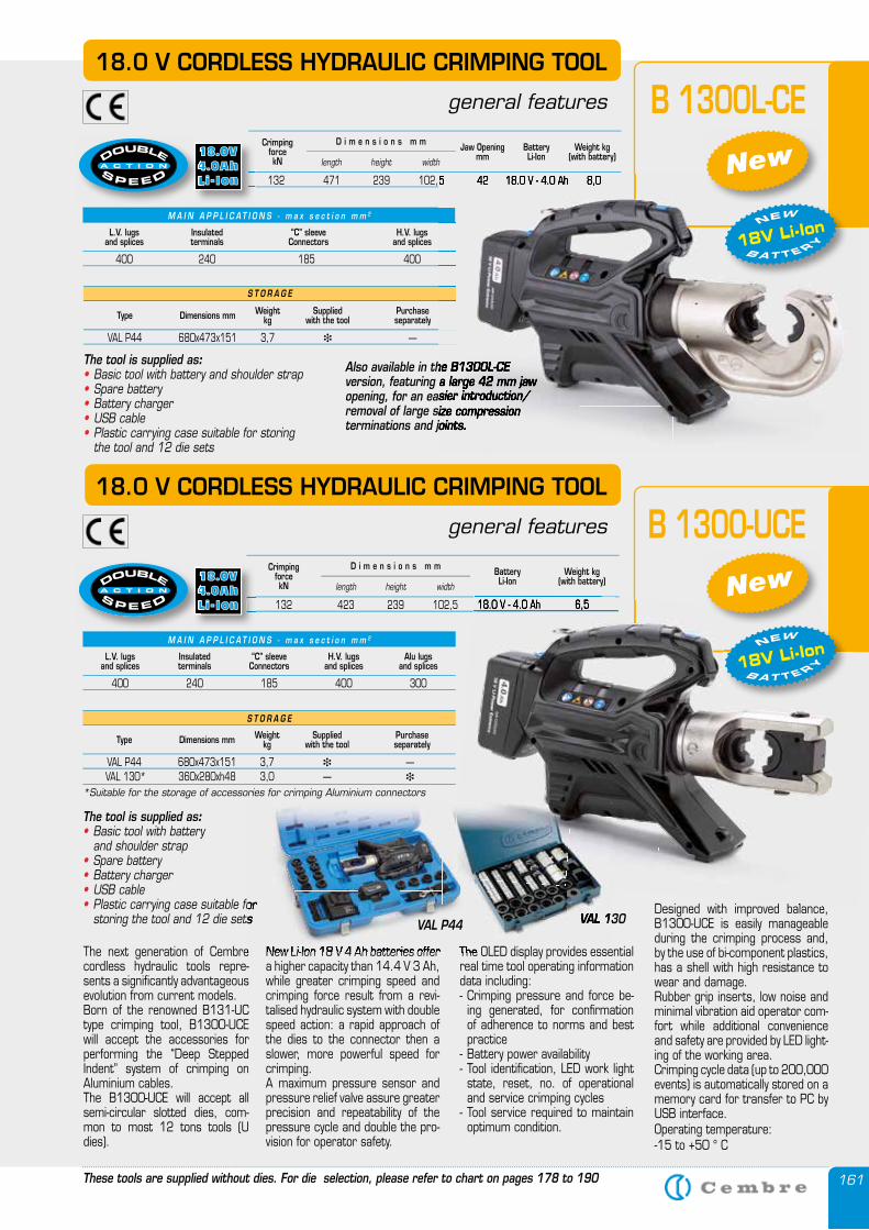
161
M A I N A P P L I C A T I O N S - m a x s e c t i o n m m 2
L.V. lugsand splices
Insulatedterminals
“C” sleeveConnectors
H.V. lugsand splices
Alu lugsand splices
400 240 185 400 300
CrimpingforcekN
BatteryLi-Ion
Weight kg(with battery)length height width
D i m e n s i o n s m m
132 423 239 102,5 18.0 V - 4.0 Ah 6,5
Also available in the B1300L-CEversion, featuring a large 42 mm jaw opening, for an easier introduction/removal of large size compression terminations and joints.
M A I N A P P L I C A T I O N S - m a x s e c t i o n m m 2
L.V. lugsand splices
Insulatedterminals
“C” sleeveConnectors
H.V. lugsand splices
400 240 185 400
S T O R A G E
Type Dimensions mm Weightkg
Suppliedwith the tool
Purchase separately
VAL P44 680x473x151 3,7 � —
These tools are supplied without dies. For die selection, please refer to chart on pages 178 to 190
CrimpingforcekN
BatteryLi-Ion
Weight kg(with battery)length height width
D i m e n s i o n s m m
132 471 239 102,5 42 18.0 V - 4.0 Ah 8,0
Jaw Openingmm
18.0 V CORDLESS HYDRAULIC CRIMPING TOOL
general features B 1300-UCE
The OLED display provides essential real time tool operating information data including: - Crimping pressure and force be-
ing generated, for confirmation of adherence to norms and best practice
- Battery power availability- Tool identification, LED work light
state, reset, no. of operational and service crimping cycles
- Tool service required to maintain optimum condition.
Designed with improved balance, B1300-UCE is easily manageable during the crimping process and, by the use of bi-component plastics, has a shell with high resistance to wear and damage. Rubber grip inserts, low noise and minimal vibration aid operator com-fort while additional convenience and safety are provided by LED light-ing of the working area. Crimping cycle data (up to 200,000 events) is automatically stored on a memory card for transfer to PC by USB interface.Operating temperature: -15 to +50 ° C
New Li-Ion 18 V 4 Ah batteries offer a higher capacity than 14.4 V 3 Ah, while greater crimping speed and crimping force result from a revi-talised hydraulic system with double speed action: a rapid approach of the dies to the connector then a slower, more powerful speed for crimping.A maximum pressure sensor and pressure relief valve assure greater precision and repeatability of the pressure cycle and double the pro-vision for operator safety.
The next generation of Cembre cordless hydraulic tools repre-sents a significantly advantageous evolution from current models. Born of the renowned B131-UC type crimping tool, B1300-UCE will accept the accessories for performing the “Deep Stepped Indent” system of crimping on Aluminium cables. The B1300-UCE will accept all semi-circular slotted dies, com-mon to most 12 tons tools (U dies).
18.0 V CORDLESS HYDRAULIC CRIMPING TOOL
general features B 1300L-CE
The tool is supplied as:• Basic tool with battery and shoulder strap• Spare battery• Battery charger • USB cable• Plastic carrying case suitable for
storing the tool and 12 die sets
Also available in the B1300L-CEversion, featuring a large 42 mm jaw opening, for an easier introduction/removal of large size compression terminations and joints.
132 471 239 102,5 42 18.0 V - 4.0 Ah 8,0
The tool is supplied as:• Basic tool with battery and shoulder strap• Spare battery• Battery charger • USB cable• Plastic carrying case suitable for storing
the tool and 12 die sets
132 423 239 102,5 18.0 V - 4.0 Ah 6,5
Designed with improved balance,
New
18V Li-Ion B A T T E RY
NEW
New
18V Li-Ion B A T T E RY
NEW
132 471 239 102,5 42 18.0 V - 4.0 Ah 8,0
132 423 239 102,5 18.0 V - 4.0 Ah 6,5
The OLED display provides essential New Li-Ion 18 V 4 Ah batteries offer The next generation of Cembre
Plastic carrying case suitable for storing the tool and 12 die sets VAL 130VAL 130VAL P44
S T O R A G E
Type Dimensions mm Weightkg
Suppliedwith the tool
Purchase separately
VAL P44 680x473x151 3,7 � — VAL 130* 360x280xh48 3,0 — �
*Suitable for the storage of accessories for crimping Aluminium connectors
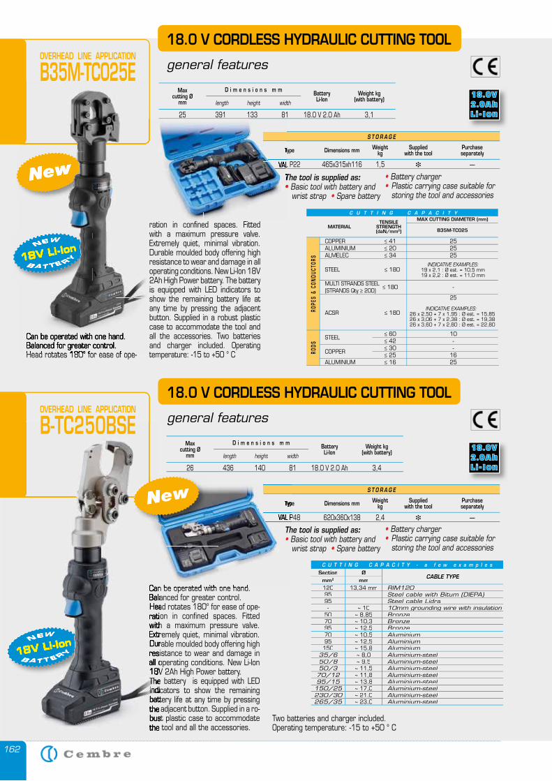
162
Can be operated with one hand.Balanced for greater control.Head rotates 180° for ease of ope-
S T O R A G E
Type Dimensions mm Weightkg
Suppliedwith the tool
Purchase separately
VAL P22 465x315xh116 1,5 � —
18.0 V CORDLESS HYDRAULIC CUTTING TOOL
general features
Maxcutting Ø
mmWeight kg
(with battery)BatteryLi-Ionlength height width
D i m e n s i o n s m m
25 391 133 81 18.0 V 2.0 Ah 3,1
OVERHEAD LINE APPLICATION
B35M-TC025E
The tool is supplied as:• Basic tool with battery and wrist strap • Spare battery
ration in confined spaces. Fitted with a maximum pressure valve. Extremely quiet, minimal vibration. Durable moulded body offering high resistance to wear and damage in all operating conditions. New Li-Ion 18V 2Ah High Power battery. The battery is equipped with LED indicators to show the remaining battery life at any time by pressing the adjacent button. Supplied in a robust plastic case to accommodate the tool and all the accessories. Two batteries and charger included. Operating temperature: -15 to +50 ° C
• Battery charger • Plastic carrying case suitable for
storing the tool and accessories
C U T T I N G C A P A C I T Y
MATERIALTENSILE
STRENGTH(daN/mm2)
MAX CUTTING DIAMETER (mm)
COPPER ≤ 41 25 ALUMINIUM ≤ 20 25 ALMELEC ≤ 34 25
MULTI STRANDS STEEL ≤ 180 -
(STRANDS Qty ≥ 200) 25
STEEL
≤ 60 10 ≤ 42 -
COPPER ≤ 30 -
≤ 25 16 ALUMINIUM ≤ 16 25
ROPE
S &
CON
DUCT
ORS
RODS
INDICATIVE EXAMPLES:19 x 2,1 : Ø est. = 10,5 mm19 x 2,2 : Ø est. = 11,0 mm
STEEL ≤ 180
ACSR ≤ 180
B35M-TC025
INDICATIVE EXAMPLES:26 x 2,50 + 7 x 1,95 : Ø est. = 15,8526 x 3,06 + 7 x 2,38 : Ø est. = 19,3826 x 3,60 + 7 x 2,80 : Ø est. = 22,80
New
18V Li-Ion B A T T E RY
NEW
Can be operated with one hand.Balanced for greater control.Head rotates 180° for ease of ope-
B35M-TC025E
New
18V Li-IonB A T T E RY
NEW
Type
VAL P22 465x315xh116 1,5
The tool is supplied as• wrist strap
VAL P22 465x315xh116 1,5
18.0 V CORDLESS HYDRAULIC CUTTING TOOL
general features
S T O R A G E
Type Dimensions mm Weightkg
Suppliedwith the tool
Purchase separately
VAL P48 620x360x138 2,4 � —
Can be operated with one hand.Balanced for greater control.Head rotates 180° for ease of ope-ration in confined spaces. Fitted with a maximum pressure valve. Extremely quiet, minimal vibration. Durable moulded body offering high resistance to wear and damage in all operating conditions. New Li-Ion 18V 2Ah High Power battery. The battery is equipped with LED indicators to show the remaining battery life at any time by pressing the adjacent button. Supplied in a ro-bust plastic case to accommodate the tool and all the accessories.
Two batteries and charger included.Operating temperature: -15 to +50 ° C
Maxcutting Ø
mmWeight kg
(with battery)BatteryLi-Ionlength height width
D i m e n s i o n s m m
26 436 140 81 18.0 V 2.0 Ah 3,4
Type
VAL P48 620x360x138 2,4
Can be operated with one hand.
VAL P48 620x360x138 2,4
New
18V Li-Ion B A T T E RY
NEW
Can be operated with one hand.Balanced for greater control.Head rotates 180° for ease of ope-ration in confined spaces. Fitted with a maximum pressure valve. Extremely quiet, minimal vibration. Durable moulded body offering high resistance to wear and damage in all operating conditions. New Li-Ion 18V 2Ah High Power battery. The battery is equipped with LED indicators battery life at any time by pressing the adjacent button. Supplied in a ro-bust plastic case to accommodate the tool and all the accessories.
Can be operated with one hand.
New
18V Li-IonB A T T E RY
N
The battery is equipped with LED indicators
EW
18V 2Ah High Power battery. The battery is equipped with LED indicators
C U T T I N G C A P A C I T Y - a f e w e x a m p l e s
Section ØCABLE TYPE
mm2 mm120 13,34 mm RIM12095 - Steel cable with Bitum (DIEPA)95 - Steel cable Lidra- ~ 10 10mm grounding wire with insulation10mm grounding wire with insulation
50 ~ 8,85 Bronze70 ~ 10,3 Bronze95 ~ 12,5 Bronze70 ~ 10,5 Aluminium95 ~ 12,5 Aluminium
150 ~ 15,8 Aluminium35/6 ~ 8,0 Aluminium-steel50/8 ~ 9,5 Aluminium-steel50/3 ~ 11,5 Aluminium-steel
70/12 ~ 11,8 Aluminium-steel95/15 ~ 13,8 Aluminium-steel
150/25 ~ 17,0 Aluminium-steel230/30 ~ 21,0 Aluminium-steel265/35 ~ 23,0 Aluminium-steel
OVERHEAD LINE APPLICATION
B-TC250BSE
The tool is supplied as:• Basic tool with battery and wrist strap • Spare battery
• Battery charger • Plastic carrying case suitable for
storing the tool and accessories
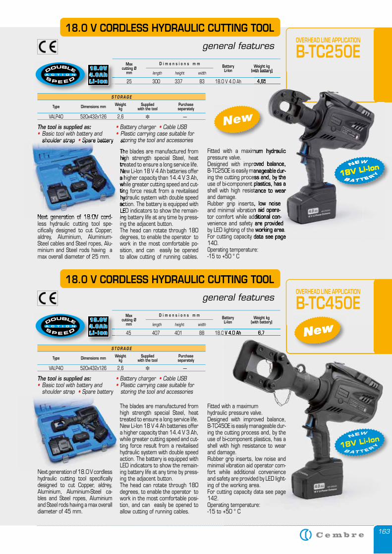
163
18.0 V CORDLESS HYDRAULIC CUTTING TOOL
general features
S T O R A G E
Type Dimensions mm Weightkg
Suppliedwith the tool
Purchase separately
VALP40 520x432x126 2,6 � —
Maxcutting Ø
mmWeight kg
(with battery)BatteryLi-Ionlength height width
D i m e n s i o n s m m
45 407 401 88 18.0 V 4.0 Ah 6,7
The tool is supplied as:• Basic tool with battery and
shoulder strap • Spare battery
OVERHEAD LINE APPLICATION
B-TC450E
New 45 407 401 88 18.0 V 4.0 Ah 6,7 New
18V Li-Ion B A T T E RY
NEW
45 407 401 88 18.0 V 4.0 Ah 6,7
Maxcutting Ø
mmWeight kg
(with battery)BatteryLi-Ionlength height width
D i m e n s i o n s m m
25 300 337 83 18.0 V 4.0 Ah 4,65
Spare battery Spare battery
• Battery charger • Cable USB• Plastic carrying case suitable for
storing the tool and accessories
Fitted with a maximum hydraulic pressure valve. Designed with improved balance, B-TC450E is easily manageable dur-ing the cutting process and, by the use of bi-component plastics, has a shell with high resistance to wear and damage. Rubber grip inserts, low noise and minimal vibration aid operator com-fort while additional convenience and safety are provided by LED light-ing of the working area. For cutting capacity data see page 142.Operating temperature: -15 to +50 ° C
The blades are manufactured from high strength special Steel, heat treated to ensure a long service life. New Li-Ion 18 V 4 Ah batteries offer a higher capacity than 14.4 V 3 Ah, while greater cutting speed and cut-ting force result from a revitalised hydraulic system with double speed action. The battery is equipped with LED indicators to show the remain-ing battery life at any time by press-ing the adjacent button. The head can rotate through 180 degrees, to enable the operator to work in the most comfortable posi-tion, and can easily be opened to allow cutting of running cables.
Next generation of 18.0 V cordless hydraulic cutting tool specifically designed to cut Copper, aldrey, Aluminium, Aluminium-Steel ca-bles and Steel ropes, Aluminium and Steel rods having a max overall diameter of 45 mm.
18.0 V CORDLESS HYDRAULIC CUTTING TOOL
general features
S T O R A G E
Type Dimensions mm Weightkg
Suppliedwith the tool
Purchase separately
VALP40 520x432x126 2,6 � —
The tool is supplied as:• Basic tool with battery and
shoulder strap • Spare battery
OVERHEAD LINE APPLICATION
B-TC250E
New
18V Li-Ion B A T T E RY
NEW
25 300 337 83 18.0 V 4.0 Ah 4,65
• Battery charger • Cable USB• Plastic carrying case suitable for
storing the tool and accessories
Fitted with a maximum hydraulic pressure valve. Designed with improved balance, B-TC250E is easily manageable dur-ing the cutting process and, by the use of bi-component plastics, has a shell with high resistance to wear and damage. Rubber grip inserts, low noise and minimal vibration aid opera-tor comfort while additional con-venience and safety are provided by LED lighting of the working area. For cutting capacity data see page 140.Operating temperature: -15 to +50 ° C
The blades are manufactured from high strength special Steel, heat treated to ensure a long service life. New Li-Ion 18 V 4 Ah batteries offer a higher capacity than 14.4 V 3 Ah, while greater cutting speed and cut-ting force result from a revitalised hydraulic system with double speed action. The battery is equipped with LED indicators to show the remain-ing battery life at any time by press-ing the adjacent button. The head can rotate through 180 degrees, to enable the operator to work in the most comfortable po-sition, and can easily be opened to allow cutting of running cables.
Next generation of 18.0V cord-less hydraulic cutting tool spe-cifically designed to cut Copper, aldrey, Aluminium, Aluminium-Steel cables and Steel ropes, Alu-minium and Steel rods having a max overall diameter of 25 mm.
(with battery)
25 300 337 83 18.0 V 4.0 Ah 4,65
18V Li-IonB A T T E RY
NEW
Fitted with a maximum hydraulic
Designed with improved balance, B-TC250E is easily manageable dur-ing the cutting process and, by the use of bi-component plastics, has a shell with high resistance to wear
Rubber grip inserts, low noise and minimal vibration aid opera-tor comfort while additional con-venience and safety are provided by LED lighting of the working area.For cutting capacity data see page
Spare battery storing the tool and accessories
The blades are manufactured from high strength special Steel, heat treated to ensure a long service life. New Li-Ion 18 V 4 Ah batteries offer a higher capacity than 14.4 V 3 Ah, while greater cutting speed and cut-ting force result from a revitalised hydraulic system with double speed action. The battery is equipped with LED indicators to show the remain-ing battery life at any time by press-Next generation of 18.0V cord-
shoulder strap • Spare battery • Spare battery •
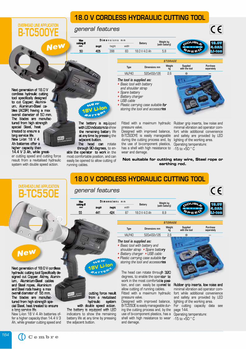
164
Maxcutting Ø
mmWeight kg
(with battery)Batterylength height width
D i m e n s i o n s m m
50 405 398 83 18.0 V 4.0 Ah 5,8
Next generation of 18.0 V cordless hydraulic cutting tool specifically designed to cut Copper, Alumini-um, Aluminum-Steel ca-bles (ACSR) having a max overall diameter of 50 mm. The blades are manufac-tured from high strength special Steel, heat treated to ensure a long service life. New Li-Ion 18 V 4 Ah batteries offer a higher capacity than 14.4 V 3 Ah, while great-er cutting speed and cutting force result from a revitalised hydraulic system with double speed action.
18.0 V CORDLESS HYDRAULIC CUTTING TOOL
general features
The battery is equipped with LED indicators to show the remaining battery life at any time by pressing the adjacent button. The head can rotate through 90 degrees, to en-
able the operator to work in the most comfortable position, and can easily be opened to allow cutting of running cables.
Fitted with a maximum hydraulic pressure valve. Designed with improved balance, B-TC500YE is easily manageable during the cutting process and, by the use of bi-component plastics, has a shell with high resistance to wear and damage.
Not suitable for cutting stay wire, Steel rope or earthing rod.
Next generation of 18.0 V cordless hydraulic cutting tool Specifically de-signed cut Copper, Aldrey, Alumin-ium, Aluminium-Steel cables and Steel ropes, Aluminium and Steel rods having a max overall diameter of 55 mm. The blades are manufac-tured from high strength spe-cial Steel, heat treated to ensure a long service life. New Li-Ion 18 V 4 Ah batteries of-fer a higher capacity than 14.4 V 3 Ah, while greater cutting speed and
18.0 V CORDLESS HYDRAULIC CUTTING TOOL
general features
cutting force result from a revitalised hydraulic system
with double speed action. The battery is equipped with LED indicators to show the remaining battery life at any time by pressing the adjacent button.
The head can rotate through 320 degrees, to enable the operator to work in the most comfortable posi-tion, and can easily be opened to allow cutting of running cables. Fitted with a maximum hydraulic pressure valve. Designed with improved balance, B-TC550E is easily manageable dur-ing the cutting process and, by the use of bi-component plastics, has a shell with high resistance to wear and damage.
The tool is supplied as:• Basic tool with battery and shoulder strap • Spare battery • Battery charger • USB cable • Plastic carrying case suitable for
storing the tool and accessories
S T O R A G E
Type Dimensions mm Weightkg
Suppliedwith the tool
Purchase separately
VALP40 520x432x126 2,6 � —
Maxcutting Ø
mmWeight kg
(with battery)Batterylength height width
D i m e n s i o n s m m
55 441 424 87 18.0 V 4.0 Ah 8,9
S T O R A G E
Type Dimensions mm Weightkg
Suppliedwith the tool
Purchase separately
VALP40 520x432x126 2,6 � —
The tool is supplied as:• Basic tool with battery and shoulder strap• Spare battery• Battery charger• USB cable• Plastic carrying case suitable for
storing the tool and accessories
The battery is equipped
18V Li-Ion B A T T E RY
NEW
Rubber grip inserts, low noise and minimal vibration aid operator com-fort while additional convenience and safety are provided by LED lighting of the working area.Operating temperature: -15 to +50 ° C
Maxcutting Ø
mm length
D i m e n s i o n s m m
50 405 398 83 18.0 V 4.0 Ah 5,8
Next generation of 18.0 V cordless hydraulic cutting tool specifically designed to cut Copper, Alumini-um, Aluminum-Steel ca-bles (ACSR) having a max overall diameter of 50 mm. The blades are manufac-tured from high strength special Steel, heat treated to ensure a long service life. New Li-Ion 18 V 4 Ah batteries offer a higher capacity than 14.4 V 3 Ah, while great-er cutting speed and cutting force
general features
The battery is equipped with LED indicators to show the remaining battery life at any time by pressing the adjacent button. The head can rotate through 90 degrees, to en-
able the operator to work in the
The battery is equipped
18V Li-IonB A T T E RY
NEW
50 405 398 83 18.0 V 4.0 Ah 5,8New
Rubber grip inserts, low noise and minimal vibration aid operator com-fort while additional convenience and safety are provided by LED lighting of the working area.For cutting capacity data see page 144. Operating temperature: -15 to +50 ° C
Next generation of 18.0 V cordless hydraulic cutting tool Specifically de-signed cut Copper, Aldrey, Alumin-ium, Aluminium-Steel cables and Steel ropes, Aluminium and Steel rods having a max overall diameter of 55 mm. The blades are manufac-tured from high strength spe-cial Steel, heat treated to ensure a long service life.
cutting force result from a revitalised hydraulic system
with double speed action. The battery is equipped with LED
Maxcutting Ø
mm length height
D i m e n s i o n s m m
55 441 424 87 18.0 V 4.0 Ah 8,9
OVERHEAD LINE APPLICATION
B-TC550E
New• Plastic carrying case suitable for • Plastic carrying case suitable for •
18V Li-Ion B A T T E RY
NEW
Plastic carrying case suitable for storing the tool and accessories
The head can rotate through 320degrees, to enable the operator to work in the most comfortable posi-tion, and can easily be opened to
Spare battery USB cable
Plastic carrying case suitable for storing the tool and accessories
Rubber grip inserts, low noise and
OVERHEAD LINE APPLICATION
B-TC500YE
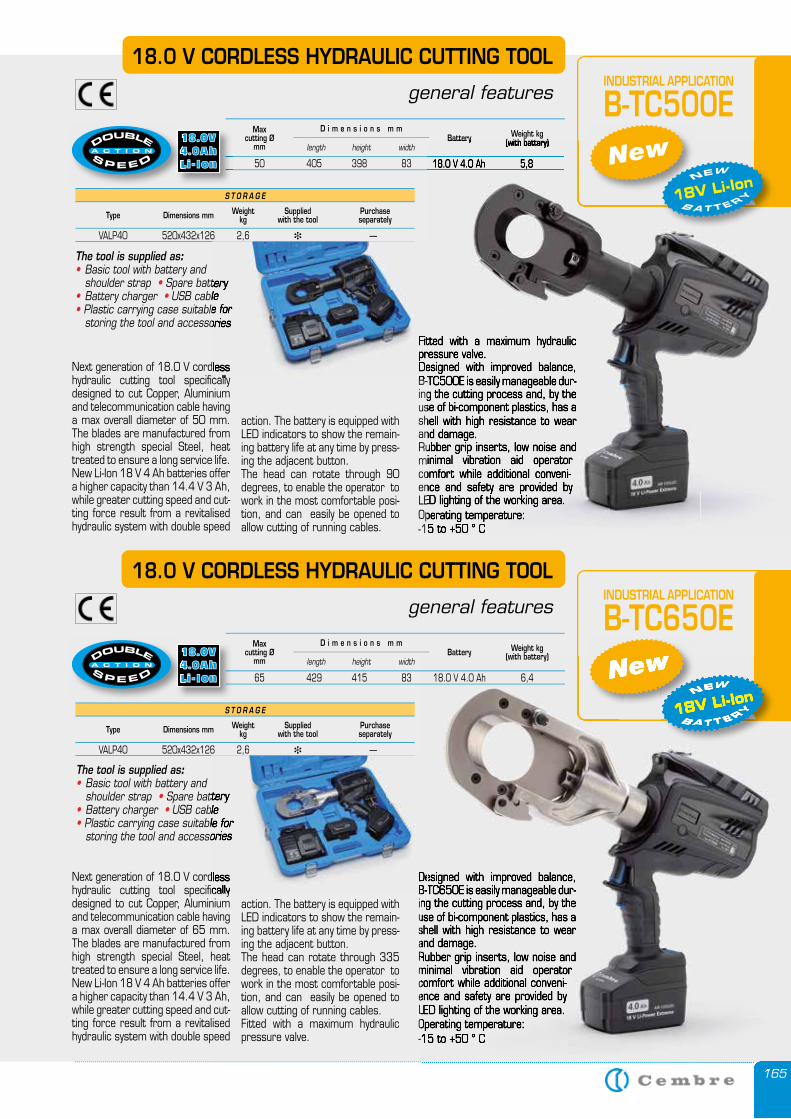
165
18.0 V CORDLESS HYDRAULIC CUTTING TOOL
general features
S T O R A G E
Type Dimensions mm Weightkg
Suppliedwith the tool
Purchase separately
VALP40 520x432x126 2,6 � —
The tool is supplied as:• Basic tool with battery and shoulder strap • Spare battery • Battery charger • USB cable • Plastic carrying case suitable for
storing the tool and accessories
INDUSTRIAL APPLICATION
B-TC650E
Fitted with a maximum hydraulic pressure valve. Designed with improved balance, B-TC500E is easily manageable dur-ing the cutting process and, by the use of bi-component plastics, has a shell with high resistance to wear and damage. Rubber grip inserts, low noise and minimal vibration aid operator comfort while additional conveni-ence and safety are provided by LED lighting of the working area.Operating temperature: -15 to +50 ° C
18.0 V CORDLESS HYDRAULIC CUTTING TOOL
general features
action. The battery is equipped with LED indicators to show the remain-ing battery life at any time by press-ing the adjacent button. The head can rotate through 90 degrees, to enable the operator to work in the most comfortable posi-tion, and can easily be opened to allow cutting of running cables.
The tool is supplied as:• Basic tool with battery and shoulder strap • Spare battery • Battery charger • USB cable • Plastic carrying case suitable for
storing the tool and accessories
Maxcutting Ø
mmWeight kg
(with battery)Batterylength height width
D i m e n s i o n s m m
50 405 398 83 18.0 V 4.0 Ah 5,8
INDUSTRIAL APPLICATION
B-TC500E
Fitted with a maximum hydraulic pressure valve. Designed with improved balance, B-TC500E is easily manageable dur-ing the cutting process and, by the use of bi-component plastics, has a shell with high resistance to wear and damage. Rubber grip inserts, low noise and minimal vibration aid operator comfort while additional conveni-ence and safety are provided by LED lighting of the working area.Operating temperature: -15 to +50 ° C
(with battery)Battery
50 405 398 83 18.0 V 4.0 Ah 5,8 New
18V Li-Ion B A T T E RY
NEW
Next generation of 18.0 V cordless hydraulic cutting tool specifically designed to cut Copper, Aluminium and telecommunication cable having a max overall diameter of 50 mm. The blades are manufactured from high strength special Steel, heat treated to ensure a long service life. New Li-Ion 18 V 4 Ah batteries offer a higher capacity than 14.4 V 3 Ah, while greater cutting speed and cut-ting force result from a revitalised hydraulic system with double speed
S T O R A G E
Type Dimensions mm Weightkg
Suppliedwith the tool
Purchase separately
VALP40 520x432x126 2,6 � —
New
18V Li-Ion B A T T E RY
NEW
Designed with improved balance, B-TC650E is easily manageable dur-ing the cutting process and, by the use of bi-component plastics, has a shell with high resistance to wear and damage. Rubber grip inserts, low noise and minimal vibration aid operator comfort while additional conveni-ence and safety are provided by LED lighting of the working area.Operating temperature: -15 to +50 ° C
action. The battery is equipped with LED indicators to show the remain-ing battery life at any time by press-ing the adjacent button. The head can rotate through 335 degrees, to enable the operator to work in the most comfortable posi-tion, and can easily be opened to allow cutting of running cables. Fitted with a maximum hydraulic pressure valve.
Next generation of 18.0 V cordless hydraulic cutting tool specifically designed to cut Copper, Aluminium and telecommunication cable having a max overall diameter of 65 mm. The blades are manufactured from high strength special Steel, heat treated to ensure a long service life. New Li-Ion 18 V 4 Ah batteries offer a higher capacity than 14.4 V 3 Ah, while greater cutting speed and cut-ting force result from a revitalised hydraulic system with double speed
165
New
18V Li-IonB A T T E RY
NEW
Designed with improved balance, B-TC650E is easily manageable dur-ing the cutting process and, by the use of bi-component plastics, has a shell with high resistance to wear and damage. Rubber grip inserts, low noise and minimal vibration aid operator comfort while additional conveni-ence and safety are provided by LED lighting of the working area.Operating temperature: -15 to +50 ° C
Maxcutting Ø
mmWeight kg
(with battery)Batterylength height width
D i m e n s i o n s m m
65 429 415 83 18.0 V 4.0 Ah 6,4
50 405 398 83 18.0 V 4.0 Ah 5,8
Spare battery USB cable
Plastic carrying case suitable for storing the tool and accessories
Designed with improved balance, B-TC650E is easily manageable dur-
Next generation of 18.0 V cordless hydraulic cutting tool specifically
Designed with improved balance, B-TC650E is easily manageable dur-
Fitted with a maximum hydraulic pressure valve. Designed with improved balance, B-TC500E is easily manageable dur-
Spare battery USB cable
Plastic carrying case suitable for storing the tool and accessories
Fitted with a maximum hydraulic pressure valve. Designed with improved balance, B-TC500E is easily manageable dur-
Next generation of 18.0 V cordless hydraulic cutting tool specifically
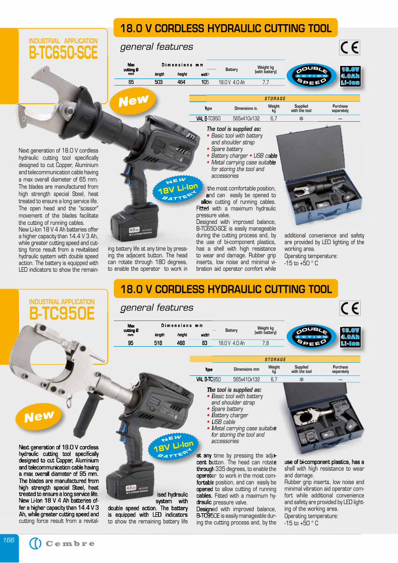
166
Next generation of 18.0 V cordless hydraulic cutting tool specifically designed to cut Copper, Aluminium and telecommunication cable having a max overall diameter of 95 mm. The blades are manufactured from high strength special Steel, heat treated to ensure a long service life. New Li-Ion 18 V 4 Ah batteries of-fer a higher capacity than 14.4 V 3 Ah, while greater cutting speed and cutting force result from a revital-
18.0 V CORDLESS HYDRAULIC CUTTING TOOL
general features
ised hydraulic system with
double speed action. The battery is equipped with LED indicators to show the remaining battery life
at any time by pressing the adja-cent button. The head can rotate through 335 degrees, to enable the operator to work in the most com-fortable position, and can easily be opened to allow cutting of running cables. Fitted with a maximum hy-draulic pressure valve. Designed with improved balance, B-TC950E is easily manageable dur-ing the cutting process and, by the
S T O R A G E
Type Dimensions mm Weightkg
Suppliedwith the tool
Purchase separately
VAL B-TC950 565x410x132 6,7 � —
Maxcutting Ø
mmWeight kg
(with battery)Batterylength height width
D i m e n s i o n s m m
95 518 468 83 18.0 V 4.0 Ah 7,8
The tool is supplied as:• Basic tool with battery and shoulder strap• Spare battery• Battery charger• USB cable• Metal carrying case suitable for storing the tool and accessories
Maxcutting Ø
mmWeight kg
(with battery)Batterylength height width
D i m e n s i o n s m m
65 503 464 105 18.0 V 4.0 Ah 7,7
18.0 V CORDLESS HYDRAULIC CUTTING TOOL
general features
S T O R A G E
Type Dimensions in. Weightkg
Suppliedwith the tool
Purchase separately
VAL B-TC950 565x410x132 6,7 � —
The tool is supplied as:• Basic tool with battery and shoulder strap• Spare battery• Battery charger • USB cable• Metal carrying case suitable for storing the tool and accessories
INDUSTRIAL APPLICATION
B-TC650-SCE
New
Maxcutting Ø
mm length height width
D i m e n s i o n s m m
65 503 464 105 18.0 V 4.0 Ah 7,7
Type
VAL B-TC950 565x410x132 6,7
and shoulder strap
for storing the tool and accessories
B-TC650-SCE
New
USB cable Metal carrying case suitable
Next generation of 18.0 V cordless hydraulic cutting tool specifically designed to cut Copper, Aluminium and telecommunication cable having a max overall diameter of 65 mm. The blades are manufactured from high strength special Steel, heat treated to ensure a long service life.The open head and the "scissor" movement of the blades facilitate the cutting of running cables.New Li-Ion 18 V 4 Ah batteries offer a higher capacity than 14.4 V 3 Ah, while greater cutting speed and cut-ting force result from a revitalised hydraulic system with double speed action. The battery is equipped with LED indicators to show the remain-
ing battery life at any time by press-ing the adjacent button. The head can rotate through 180 degrees, to enable the operator to work in
the most comfortable position, and can easily be opened to
allow cutting of running cables. Fitted with a maximum hydraulic pressure valve. Designed with improved balance, B-TC650-SCE is easily manageable during the cutting process and, by the use of bi-component plastics, has a shell with high resistance to wear and damage. Rubber grip inserts, low noise and minimal vi-bration aid operator comfort while
additional convenience and safety are provided by LED lighting of the working area. Operating temperature: -15 to +50 ° C
accessories accessories
the most comfortable position, and can easily be opened to and can easily be opened to
allow cutting of running cables. allow cutting of running cables. Fitted with a maximum hydraulic Fitted with a maximum hydraulic
18V Li-Ion B A T T E RY
NEW
use of bi-component plastics, has a shell with high resistance to wear and damage. Rubber grip inserts, low noise and minimal vibration aid operator com-fort while additional convenience and safety are provided by LED light-ing of the working area.Operating temperature: -15 to +50 ° C
Next generation of 18.0 V cordless hydraulic cutting tool specifically designed to cut Copper, Aluminium and telecommunication cable having a max overall diameter of 95 mm. The blades are manufactured from high strength special Steel, heat treated to ensure a long service life. New Li-Ion 18 V 4 Ah batteries of-fer a higher capacity than 14.4 V 3 Ah, while greater cutting speed and
general features
ised hydraulic system with
double speed action. The battery is equipped with LED indicators
at any time by pressing the adja-cent button. The head can rotate through 335 degrees, to enable the operator to work in the most com-fortable position, and can easily be opened to allow cutting of running cables. Fitted with a maximum hy-draulic pressure valve. Designed with improved balance, B-TC950E is easily manageable dur-
Type
VAL B-TC950 565x410x132 6,7
Maxcutting Ø
mm length height width
D i m e n s i o n s m m
95 518 468 83 18.0 V 4.0 Ah 7,8
The tool is supplied as• Basic tool with battery• Basic tool with battery• and shoulder strap• Spare battery• Spare battery•• Battery charger• Battery charger•• USB cable• USB cable•• Metal carrying case suitable • Metal carrying case suitable • for storing the tool and accessories
at any time by pressing the adja-cent button. The head can rotate through 335 degrees, to enable the
Metal carrying case suitable
use of bi-component plastics, has a shell with high resistance to wear
INDUSTRIAL APPLICATION
B-TC950E
at any time by pressing the adja-cent button. The head can rotate through 335 degrees, to enable the
18V Li-Ion B A T T E RY
NEW
New
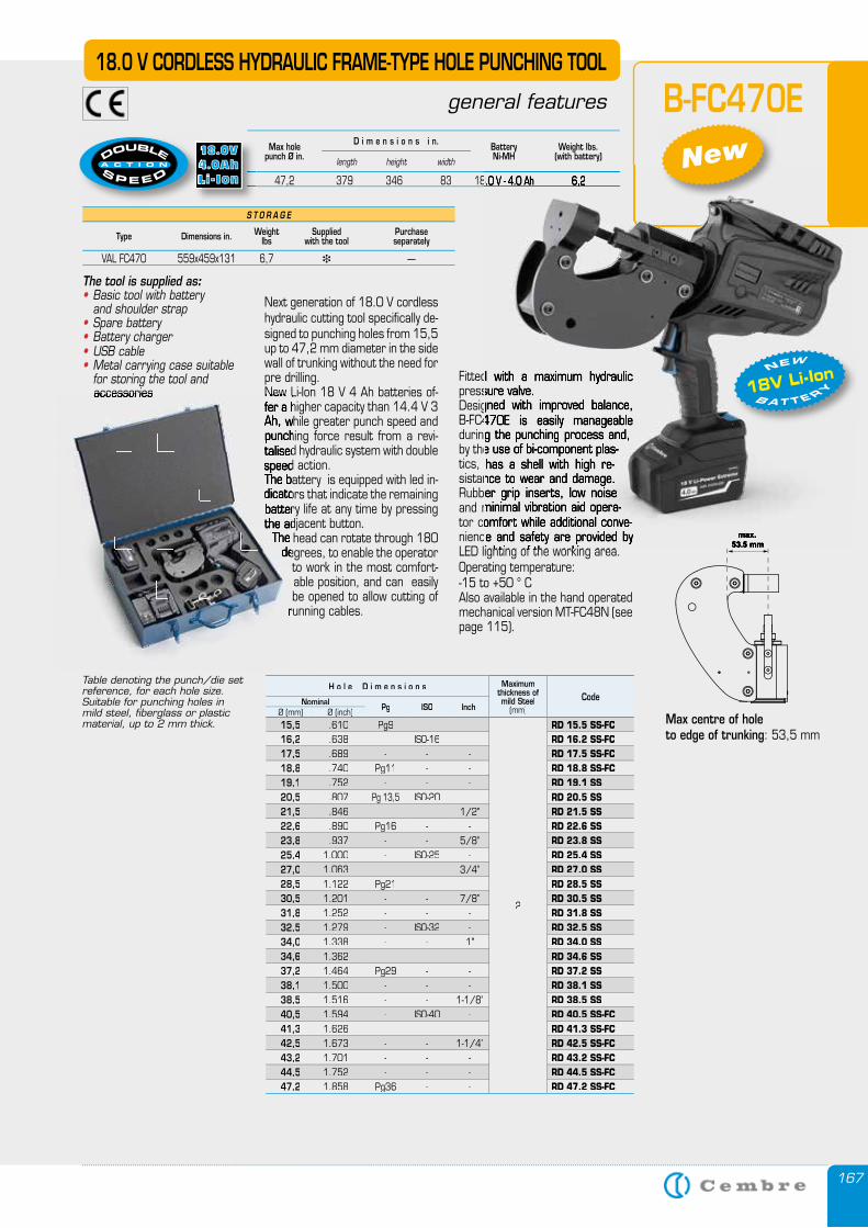
167
max. 53.5 mm
S T O R A G E
Type Dimensions in. Weightlbs
Suppliedwith the tool
Purchase separately
VAL FC470 559x459x131 6,7 � —
Max holepunch Ø in.
Weight lbs.(with battery)
BatteryNi-MHlength height width
D i m e n s i o n s i n.
47,2 379 346 83 18.0 V - 4.0 Ah 6,2
Fitted with a maximum hydraulic pressure valve. Designed with improved balance, B-FC470E is easily manageable during the process and, by the use of bi-component plas-tics, has a shell with high re-sistance to wear and damage. Rubber grip inserts, low noise and minimal vibration aid opera-tor comfort while additional conve-nience and safety are provided by LED lighting of the working area. Operating temperature: -15 to +50 ° CAlso available in the hand operated mechanical version MT-FC48N (see page 115).
18.0 V CORDLESS HYDRAULIC FRAME-TYPE HOLE PUNCHING TOOL
general features
Next generation of 18.0 V cordless hydraulic cutting tool specifically de-signed to punching holes from 15,5 up to 47,2 mm diameter in the side wall of trunking without the need for pre drilling. New Li-Ion 18 V 4 Ah batteries of-fer a higher capacity than 14.4 V 3 Ah, while greater punch speed and punching force result from a revi-talised hydraulic system with double speed action. The battery is equipped with led in-dicators that indicate the remaining battery life at any time by pressing the adjacent button.
The head can rotate through 180 degrees, to enable the operator
to work in the most comfort-able position, and can easily be opened to allow cutting of
running cables.
The tool is supplied as:• Basic tool with battery and shoulder strap• Spare battery• Battery charger• USB cable• Metal carrying case suitable for storing the tool and accessories
B-FC470E
Table denoting the punch/die set reference, for each hole size.Suitable for punching holes in mild steel, fiberglass or plastic material, up to 2 mm thick.
47,2 379 346 83 18.0 V - 4.0 Ah 6,2
max. 53.5 mm
47,2 379 346 83 18.0 V - 4.0 Ah 6,2
Fitted with a maximum hydraulic pressure valve. Designed with improved balance, B-FC470E is easily manageable during the punching process and, by the use of bi-component plas-tics, has a shell with high re-sistance to wear and damage. Rubber grip inserts, low noise and minimal vibration aid opera-tor comfort while additional conve-nience and safety are provided by LED lighting of the working area.
New Li-Ion 18 V 4 Ah batteries of-fer a higher capacity than 14.4 V 3 Ah, while greater punch speed and punching force result from a revi-talised hydraulic system with double speed actionThe battery is equipped with led in-dicators that indicate the remaining battery life at any time by pressing the adjacent button.
The head can rotate through 180 degrees, to enable the operator
running cables.
accessories
H o l e D i m e n s i o n s Maximumthickness ofmild Steel
(mm)CodeNominal Pg ISO InchØ (mm) Ø (inch)
15,5 .610 Pg9 - -
2
RD 15.5 SS-FC 16,2 .638 - ISO-16 - RD 16.2 SS-FC 17,5 .689 - - - RD 17.5 SS-FC 18,8 .740 Pg11 - - RD 18.8 SS-FC 19,1 .752 - - - RD 19.1 SS 20,5 .807 Pg 13,5 ISO-20 - RD 20.5 SS 21,5 .846 - - 1/2" RD 21.5 SS 22,6 .890 Pg16 - - RD 22.6 SS 23,8 .937 - - 5/8” RD 23.8 SS 25,4 1.000 - ISO-25 - RD 25.4 SS 27,0 1.063 - - 3/4” RD 27.0 SS 28,5 1.122 Pg21 - - RD 28.5 SS 30,5 1.201 - - 7/8” RD 30.5 SS 31,8 1.252 - - - RD 31.8 SS 32,5 1.279 - ISO-32 - RD 32.5 SS 34,0 1.338 - - 1" RD 34.0 SS34,6 1.362 - - - RD 34.6 SS 37,2 1.464 Pg29 - - RD 37.2 SS 38,1 1.500 - - - RD 38.1 SS 38,5 1.516 - - 1-1/8" RD 38.5 SS 40,5 1.594 - ISO-40 - RD 40.5 SS-FC 41,3 1.626 - - - RD 41.3 SS-FC 42,5 1.673 - - 1-1/4” RD 42.5 SS-FC 43,2 1.701 - - - RD 43.2 SS-FC 44,5 1.752 - - - RD 44.5 SS-FC 47,2 1.858 Pg36 - - RD 47.2 SS-FC
New
18V Li-Ion B A T T E RY
NEW
Max centre of hole to edge of trunking: 53,5 mm
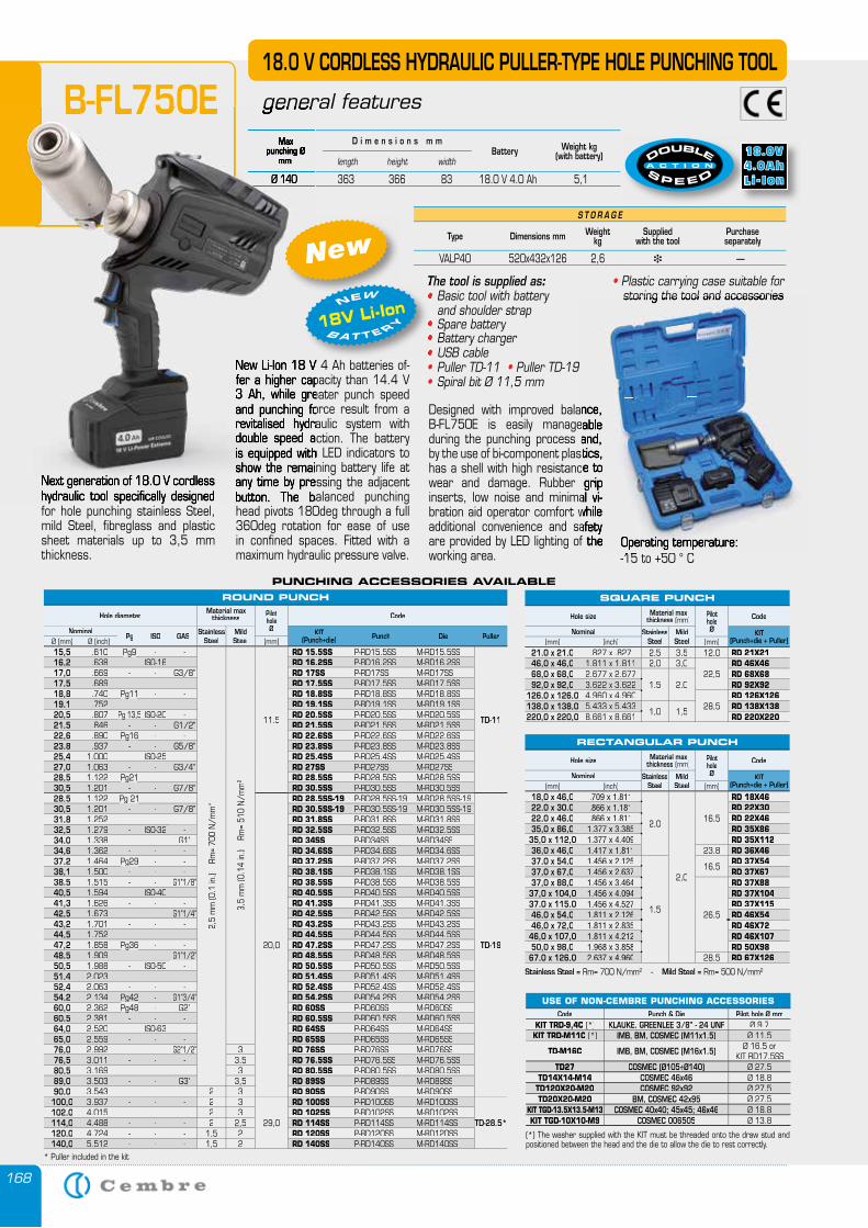
168
Next generation of 18.0 V cordless hydraulic tool specifically designed for hole punching stainless Steel, mild Steel, fibreglass and plastic sheet materials up to 3,5 mm thickness.
18.0 V CORDLESS HYDRAULIC PULLER-TYPE HOLE PUNCHING TOOL
general features
New Li-Ion 18 V 4 Ah batteries of-fer a higher capacity than 14.4 V 3 Ah, while greater punch speed and punching force result from a revitalised hydraulic system with double speed action. The battery is equipped with LED indicators to show the remaining battery life at any time by pressing the adjacent button. The balanced punching head pivots 180deg through a full 360deg rotation for ease of use in confined spaces. Fitted with a maximum hydraulic pressure valve.
Designed with improved balance, B-FL750E is easily manageable during the punching process and, by the use of bi-component plastics, has a shell with high resistance to wear and damage. Rubber grip inserts, low noise and minimal vi-bration aid operator comfort while additional convenience and safety are provided by LED lighting of the working area.
S T O R A G E
Type Dimensions mm Weightkg
Suppliedwith the tool
Purchase separately
VALP40 520x432x126 2,6 � —
Max punching Ø
mmWeight kg
(with battery)Batterylength height width
D i m e n s i o n s m m
Ø 140 363 366 83 18.0 V 4.0 Ah 5,1
The tool is supplied as:• Basic tool with battery and shoulder strap• Spare battery• Battery charger• USB cable• Puller TD-11 • Puller TD-19• Spiral bit Ø 11,5 mm
B-FL750E
• Plastic carrying case suitable for storing the tool and accessories
Operating temperature:-15 to +50 ° C
New
Next generation of 18.0 V cordless hydraulic tool specifically designed
general features
New Li-Ion 18 V 4 Ah batteries of-fer a higher capacity than 14.4 V 3 Ah, while greater punch speed and punching force result from a revitalised hydraulic system with double speed action. The battery is equipped with LED indicators to show the remaining battery life at any time by pressing the adjacent button. The balanced punching
Max punching Ø
mm
Ø 140 363 366 83 18.0 V 4.0 Ah 5,1
B-FL750E
NewThe tool is supplied as• and shoulder strap•••
18V Li-Ion B A T T E RY
NEW
PUNCHING ACCESSORIES AVAILABLE
Designed with improved balance, B-FL750E is easily manageable during the punching process and, by the use of bi-component plastics, has a shell with high resistance to wear and damage. Rubber grip inserts, low noise and minimal vi-bration aid operator comfort while additional convenience and safety are provided by LED lighting of the
storing the tool and accessories
Operating temperature:-15 to +50 ° C
ROUND PUNCH
Hole diameterMaterial max
thickness Pilot holeØ
Code
NominalPg ISO GAS Stainless
SteelMild Steel
KIT (Punch+die) Punch Die Puller
Ø (mm) Ø (inch) (mm)15,5 .610 Pg9Pg9Pg9Pg9 - -
2,5
mm
(0.1
in.)
Rm
= 70
0 N
/mm
2
3,5
mm
(0.1
4 in
.)
Rm=
510
N/m
m2
11,5
RD 15.5SS P-RD15.5SS M-RD15.5SS
TD-11
16,2 .638 - ISO-16 - RD 16.2SS P-RD16.2SS M-RD16.2SS17,0 .669 - - G3/8” RD 17SS P-RD17SS M-RD17SS 17,5 .689 - - - RD 17.5SS P-RD17.5SS M-RD17.5SS18,8 .740 Pg11Pg11Pg11Pg11 - - RD 18.8SS P-RD18.8SS M-RD18.8SS 19,1 .752 - - - RD 19.1SS P-RD19.1SS M-RD19.1SS20,5 .807 Pg 13,5Pg 13,5Pg 13,5Pg 13,5 ISO-20 - RD 20.5SS P-RD20.5SS M-RD20.5SS21,5 .846 - - G1/2" RD 21.5SS P-RD21.5SS M-RD21.5SS22,6 .890 Pg16Pg16Pg16Pg16 - - RD 22.6SS P-RD22.6SS M-RD22.6SS23,8 .937 - - G5/8” RD 23.8SS P-RD23.8SS M-RD23.8SS25,4 1.000 - ISO-25 - RD 25.4SS P-RD25.4SS M-RD25.4SS27,0 1.063 - - G3/4” RD 27SS P-RD27SS M-RD27SS28,5 1.122 Pg21Pg21Pg21Pg21 - - RD 28.5SS P-RD28.5SS M-RD28.5SS30,5 1.201 - - G7/8” RD 30.5SS P-RD30.5SS M-RD30.5SS28,5 1.122 Pg 21Pg 21Pg 21Pg 21 - -
20,0
RD 28.5SS-19 P-RD28.5SS-19 M-RD28.5SS-19
TD-19
30,5 1.201 - - G7/8” RD 30.5SS-19 P-RD30.5SS-19 M-RD30.5SS-1931,8 1.252 - - - RD 31.8SS P-RD31.8SS M-RD31.8SS32,5 1.279 - ISO-32 - RD 32.5SS P-RD32.5SS M-RD32.5SS34,0 1.338 - - G1" RD 34SS P-RD34SS M-RD34SS34,6 1.362 - - - RD 34.6SS P-RD34.6SS M-RD34.6SS37,2 1.464 Pg29Pg29Pg29Pg29 - - RD 37.2SS P-RD37.2SS M-RD37.2SS38,1 1.500 - - - RD 38.1SS P-RD38.1SS M-RD38.1SS38,5 1.515 - - G1"1/8" RD 38.5SS P-RD38.5SS M-RD38.5SS40,5 1.594 - ISO-40 - RD 40.5SS P-RD40.5SS M-RD40.5SS41,3 1.626 - - - RD 41.3SS P-RD41.3SS M-RD41.3SS42,5 1.673 - - G1”1/4” RD 42.5SS P-RD42.5SS M-RD42.5SS43,2 1.701 - - - RD 43.2SS P-RD43.2SS M-RD43.2SS44,5 1.752 - - - RD 44.5SS P-RD44.5SS M-RD44.5SS47,2 1.858 Pg36Pg36Pg36Pg36 - - RD 47.2SS P-RD47.2SS M-RD47.2SS48,5 1.909 - - G1”1/2” RD 48.5SS P-RD48.5SS M-RD48.5SS50,5 1.988 - ISO-50 - RD 50.5SS P-RD50.5SS M-RD50.5SS51,4 2.023 - - - RD 51.4SS P-RD51.4SS M-RD51.4SS52,4 2.063 - - - RD 52.4SS P-RD52.4SS M-RD52.4SS54,2 2.134 Pg42Pg42Pg42Pg42 - G1”3/4” RD 54.2SS P-RD54.2SS M-RD54.2SS60,0 2.362 Pg48Pg48Pg48Pg48 - G2” RD 60SS P-RD60SS M-RD60SS60,5 2.381 - - - RD 60.5SS P-RD60.5SS M-RD60.5SS64,0 2.520 - ISO-63 - RD 64SS P-RD64SS M-RD64SS65,0 2.559 - - - RD 65SS P-RD65SS M-RD65SS76,0 2.992 - - G2”1/2” 3 RD 76SS P-RD76SS M-RD76SS76,5 3.011 - - - 3,5 RD 76.5SS P-RD76.5SS M-RD76.5SS80,5 3.169 - - - 3 RD 80.5SS P-RD80.5SS M-RD80.5SS89,0 3.503 - - G3" 3,5 RD 89SS P-RD89SS M-RD89SS90,0 3.543 - - - 2 3 RD 90SS P-RD90SS M-RD90SS
100,0 3.937 - - - 2 3
29,0
RD 100SS P-RD100SS M-RD100SS
TD-28.5*102,0 4.015 - - - 2 3 RD 102SS P-RD102SS M-RD102SS114,0 4.488 - - - 2 2,5 RD 114SS P-RD114SS M-RD114SS120,0 4.724 - - - 1,5 2 RD 120SS P-RD120SS M-RD120SS140,0 5.512 - - - 1,5 2 RD 140SS P-RD140SS M-RD140SS
SQUARE PUNCH
Hole size Material max thickness (mm)
Pilot holeØ
Code
Nominal Stainless Steel
Mild Steel
KIT (Punch+die + Puller)(mm) (inch) (mm)
21,0 x 21,0 .827 x .827 2,5 3,5 12,0 RD 21X2146,0 x 46,0 1.811 x 1.811 2,0 3,0
22,5RD 46X46
68,0 x 68,0 2.677 x 2.6771,5 2,0
RD 68X6892,0 x 92,0 3.622 x 3.622 RD 92X92
126,0 x 126,0 4.960 x 4.96028,5
RD 126X126138,0 x 138,0 5.433 x 5.433
1,0 1,5RD 138X138
220,0 x 220,0 8.661 x 8.661 RD 220X220
USE OF NON-CEMBRE PUNCHING ACCESSORIESCode Punch & Die Pilot hole Ø mm
KIT TRD-9,4C (*) KLAUKE, GREENLEE 3/8" - 24 UNF Ø 9.7KIT TRD-M11C (*) IMB, BM, COSMEC (M11x1.5) Ø 11.5
TD-M16C IMB, BM, COSMEC (M16x1.5) Ø 16.5 or KIT RD17.5SS
TD27 COSMEC (Ø105÷Ø140) Ø 27.5TD14X14-M14 COSMEC 46x46 Ø 18.8
TD120X20-M20 COSMEC 92x92 Ø 27.5TD20X20-M20 BM, COSMEC 42x95 Ø 27.5
KIT TGD-13.5X13.5-M13 COSMEC 40x40; 45x45; 46x46 Ø 18.8KIT TGD-10X10-M9 COSMEC 006505 Ø 13.8
(*) The washer supplied with the KIT must be threaded onto the draw stud and positioned between the head and the die to allow the die to rest correctly.
* Puller included in the kit
Stainless Steel = Rm= 700 N/mm2 - Mild Steel = Rm= 500 N/mm2
RECTANGULAR PUNCH
Hole size Material max thickness (mm)
Pilot holeØ
Code
Nominal Stainless Steel
Mild Steel
KIT (Punch+die + Puller)(mm) (inch) (mm)
18,0 x 46,0 .709 x 1.811
2,0
2,0
16,5
RD 18X4622,0 x 30,0 .866 x 1.181 RD 22X3022,0 x 46,0 .866 x 1.811 RD 22X4635,0 x 86,0 1.377 x 3.385 RD 35X86
35,0 x 112,0 1.377 x 4.409 RD 35X11236,0 x 46,0 1.417 x 1.811 23,8 RD 36X4637,0 x 54,0 1.456 x 2.125
1,5
16,5RD 37X54
37,0 x 67,0 1.456 x 2.637 RD 37X6737,0 x 88,0 1.456 x 3.464
26,5
RD 37X8837,0 x 104,0 1.456 x 4.094 RD 37X10437,0 x 115,0 1.456 x 4.527 RD 37X11546,0 x 54,0 1.811 x 2.126 RD 46X5446,0 x 72,0 1.811 x 2.835 RD 46X72
46,0 x 107,0 1.811 x 4.212 RD 46X10750,0 x 98,0 1.968 x 3.858 RD 50X98
67,0 x 126,0 2.637 x 4.960 28,5 RD 67X126
169169
HY
DR
AU
LIC
P
UM
PS
A
ND
U
NIT
S
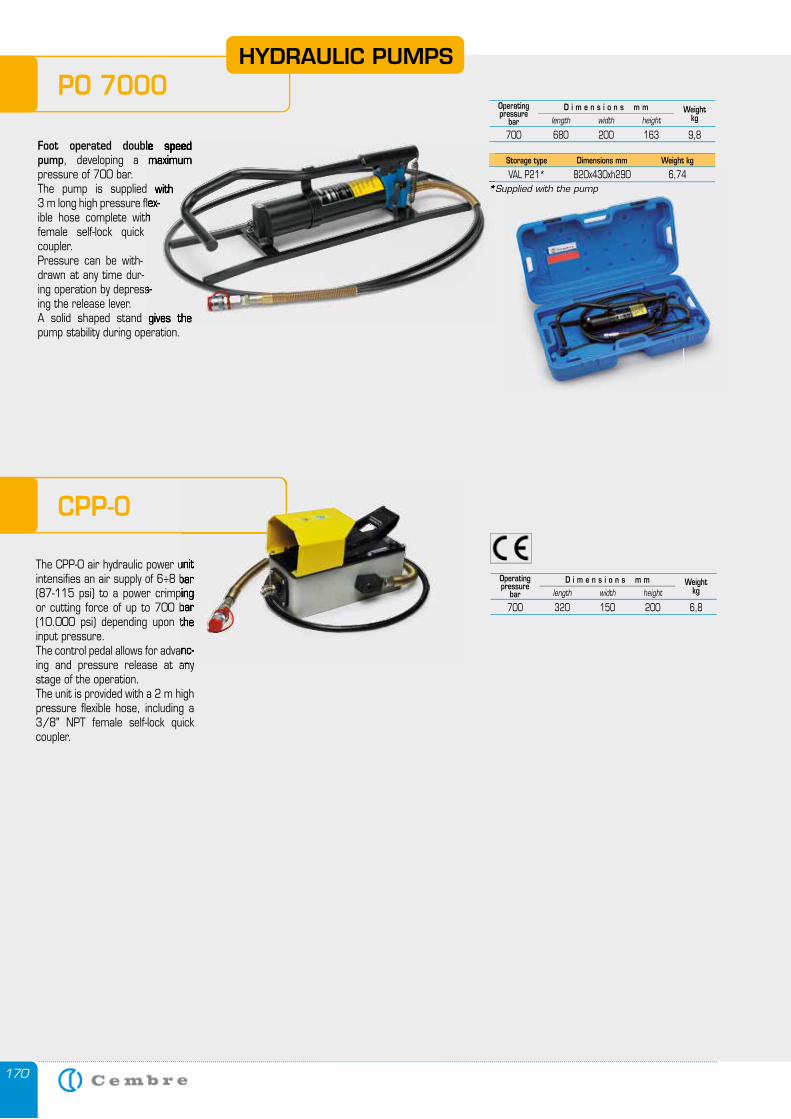
170
HYDRAULIC PUMPS
Foot operated double speed pump, developing a maximum pressure of 700 bar. The pump is supplied with 3 m long high pressure flex-ible hose complete with female self-lock quick coupler.Pressure can be with-drawn at any time dur-ing operation by depress-ing the release lever. A solid shaped stand gives the pump stability during operation.
PO 7000
CPP-0
*Supplied with the pump
Storage type Dimensions mm Weight kg
VAL P21* 820x430xh290 6,74
Operatingpressure
barWeight
kg
700 680 200 163 9,8length width height
D i m e n s i o n s m m
Operatingpressure
barWeight
kg
700 320 150 200 6,8length width height
D i m e n s i o n s m m
The CPP-0 air hydraulic power unit intensifies an air supply of 6÷8 bar (87-115 psi) to a power crimping or cutting force of up to 700 bar (10.000 psi) depending upon the input pressure.The control pedal allows for advanc-ing and pressure release at any stage of the operation.The unit is provided with a 2 m high pressure flexible hose, including a 3/8" NPT female self-lock quick coupler.
The CPP-0 air hydraulic power unit intensifies an air supply of 6÷8 bar (87-115 psi) to a power crimping or cutting force of up to 700 bar (10.000 psi) depending upon the
The control pedal allows for advanc-ing and pressure release at any
Foot operated double speed developing a maximum
The pump is supplied with 3 m long high pressure flex-ible hose complete with
ing operation by depress-
A solid shaped stand gives the
*Supplied with the pump VAL P21* 820x430xh290 6,74
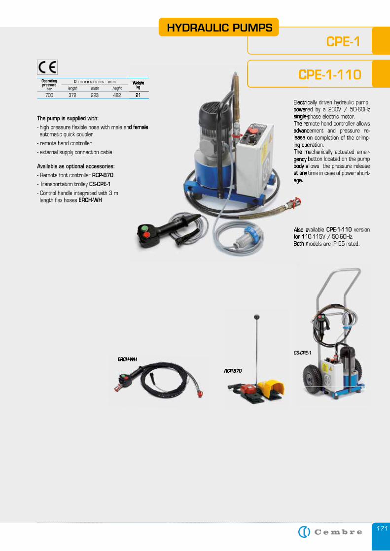
171
Operatingpressure
barWeight
kg
700 372 223 482 21length width height
D i m e n s i o n s m m
CS-CPE-1
Electrically driven hydraulic pump, powered by a 230V / 50-60Hz single-phase electric motor. The remote hand controller allows advancement and pressure re-lease on completion of the crimp-ing operation.The mechanically actuated emer-gency button located on the pump body allows the pressure release at any time in case of power short-age.
Also available CPE-1-110 version for 110-115V / 50-60Hz. Both models are IP 55 rated.
The pump is supplied with:- high pressure flexible hose with male and female automatic quick coupler
- remote hand controller
- external supply connection cable
Available as optional accessories: - Remote foot controller RCP-B70.
- Transportation trolley CS-CPE-1- Control handle integrated with 3 m length fl ex hoses ERCH-WH
RCP-B70RCP-B70
CPE-1 HYDRAULIC PUMPS
CPE-1-110 Weight
kg
700 372 223 482 21Electrically driven hydraulic pump, powered by a 230V / 50-60Hz single-phase electric motor. The remote hand controller allows advancement and pressure re-lease on completion of the crimp-ing operation.The mechanically actuated emer-gency button located on the pump body allows the pressure release at any time in case of power short-age.
Also available for 110-115V / 50-60Hz. Both models are IP 55 rated.
- high pressure flexible hose with male and female
CPE-1-110
ERCH-WHERCH-WH
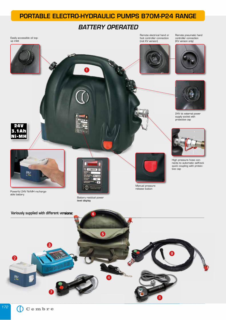
172
Remote electrical hand or foot controller connection (not KV version)
24V dc external power supply socket with protective cap
Easily accessible oil top-up inlet
High pressure hose con-nects to automatic self-lock quick coupling with protec-tive cap
Battery residual power level display
Manual pressure release button
Powerful 24V Ni-MH recharge-able battery
PORTABLE ELECTRO-HYDRAULIC PUMPS B70M-P24 RANGE
BATTERY OPERATED
�
Remote pneumatic hand controller connection (KV version only)
��
���
�
�
�
Variously supplied with different versions:
�
level display
Variously supplied with different versions: �
�
�
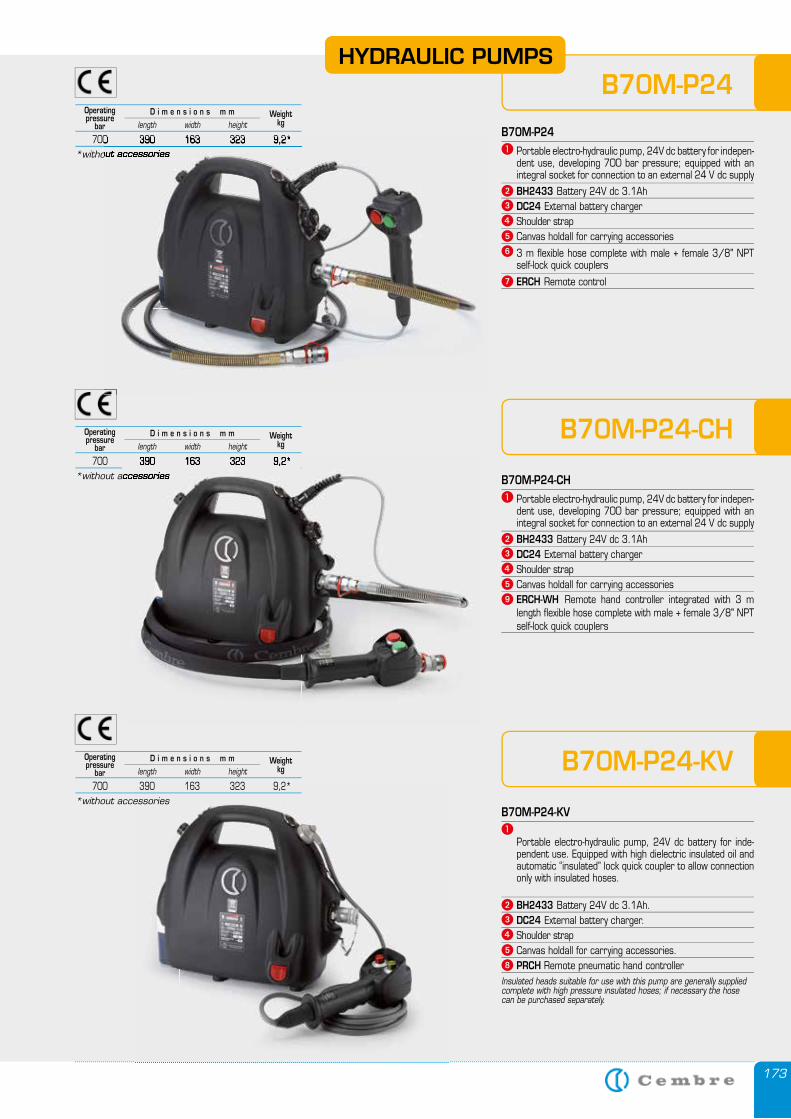
173
B70M-P24
B70M-P24� Portable electro-hydraulic pump, 24V dc battery for indepen-
dent use, developing 700 bar pressure; equipped with an integral socket for connection to an external 24 V dc supply
� BH2433 Battery 24V dc 3.1Ah� DC24 External battery charger� Shoulder strap� Canvas holdall for carrying accessories� 3 m flexible hose complete with male + female 3/8" NPT
self-lock quick couplers� ERCH Remote control
B70M-P24-CH
B70M-P24-CH� Portable electro-hydraulic pump, 24V dc battery for indepen-
dent use, developing 700 bar pressure; equipped with an integral socket for connection to an external 24 V dc supply
� BH2433 Battery 24V dc 3.1Ah� DC24 External battery charger� Shoulder strap� Canvas holdall for carrying accessories� ERCH-WH Remote hand controller integrated with 3 m
length flexible hose complete with male + female 3/8" NPTself-lock quick couplers
B70M-P24-KV
B70M-P24-KV�
Portable electro-hydraulic pump, 24V dc battery for inde-pendent use. Equipped with high dielectric insulated oil and automatic “insulated” lock quick coupler to allow connection only with insulated hoses.
� BH2433 Battery 24V dc 3.1Ah.� DC24 External battery charger.� Shoulder strap� Canvas holdall for carrying accessories.� PRCH Remote pneumatic hand controllerInsulated heads suitable for use with this pump are generally supplied complete with high pressure insulated hoses; if necessary the hose can be purchased separately.
Operatingpressure
barWeight
kg
700 390 163 323 9,2*length width height
D i m e n s i o n s m m
*without accessories
Operatingpressure
barWeight
kg
700 390 163 323 9,2*length width height
D i m e n s i o n s m m
*without accessories
Operatingpressure
barWeight
kg
700 390 163 323 9,2*length width height
D i m e n s i o n s m m
*without accessories
HYDRAULIC PUMPS
700 390 163 323 9,2**without accessories
700 390 163 323 9,2**without accessories
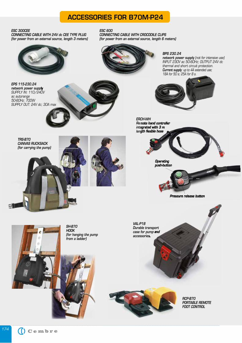
174
ACCESSORIES FOR B70M-P24
ESC 300CEECONNECTING CABLE WITH 24V dc CEE TYPE PLUG(for power from an external source, length 3 meters)
ESC 600CONNECTING CABLE WITH CROCODILE CLIPS(for power from an external source, length 6 meters)
SH-B70HOOK(for hanging the pumpfrom a ladder)
RCP-B70PORTABLE REMOTE FOOT CONTROL
TRS-B70CANVAS RUCKSACK(for carrying the pump)
ERCH-WHRemote hand controller integrated with 3 m length flexible hose
Operating push-button
Pressure release button
VAL-P18Durable transport case for pump and accessories.
Durable transport case for pump and accessories.
EPS 115-230.24network power supplynetwork power supplySUPPLY IN: 110/240Vac autorange 50-60Hz; 700WSUPPLY OUT: 24V dc; 30A max
BPS 230.24network power supply (not for intensive use)INPUT 230V ac 50-60Hz; OUTPUT 24V dcthermal and short circuit protection.Current supply: up to 4A extended use; 18A for 50 s; 25A for 8 s.
push-button
Pressure release button
Remote hand controller integrated with 3 m length flexible hose
Operating push-button
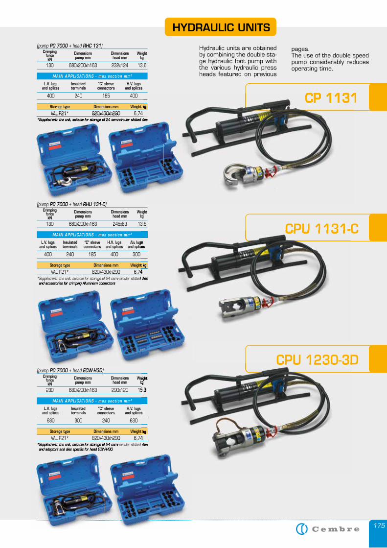
175
(pump P0 7000 + head ECW-H3D)Crimping
forcekN
Dimensionspump mm
Dimensionshead mm
Weightkg
230 680x200xh163 290x120 15,3
Storage type Dimensions mm Weight kg
VAL P21* 820x430xh290 6,74*Supplied with the unit, suitable for storage of 24 semi-circular slotted dies and adaptors and dies specific for head ECW-H3D
L.V. lugsand splices
MAIN APPL ICAT IONS - max sec t i on mm 2
Insulatedterminals
“C” sleeveconnectors
H.V. lugsand splices
630 300 240 630
(pump P0 7000 + head RHU 131-C)Crimping
forcekN
Dimensionspump mm
Dimensionshead mm
Weightkg
130 680x200xh163 245x89 13,5
Storage type Dimensions mm Weight kg
VAL P21* 820x430xh290 6,74*Supplied with the unit, suitable for storage of 24 semi-circular slotted dies and accessories for crimping Aluminium connectors
L.V. lugsand splices
MAIN APPL ICAT IONS - max sec t i on mm 2
Insulatedterminals
“C” sleeveconnectors
H.V. lugsand splices
Alu lugsand splices
400 240 185 400 300
(pump P0 7000 + head RHC 131)Crimping
forcekN
Dimensionspump mm
Dimensionshead mm
Weightkg
130 680x200xh163 232x124 13,6
Storage type Dimensions mm Weight kg
VAL P21* 820x430xh290 6,74*Supplied with the unit, suitable for storage of 24 semi-circular slotted dies
L.V. lugsand splices
MAIN APPL ICAT IONS - max sec t i on mm 2
Insulatedterminals
“C” sleeveconnectors
H.V. lugsand splices
400 240 185 400
*Supplied with the unit, suitable for storage of 24 semi-circular slotted dies and adaptors and dies specific for head ECW-H3D and adaptors and dies specific for head ECW-H3D
*Supplied with the unit, suitable for storage of 24 semi-circular slotted dies and accessories for crimping Aluminium connectors and accessories for crimping Aluminium connectors
VAL P21* 820x430xh290 6,74*Supplied with the unit, suitable for storage of 24 semi-circular slotted dies*Supplied with the unit, suitable for storage of 24 semi-circular slotted dies*Supplied with the unit, suitable for storage of 24 semi-circular slotted dies
CPU 1230-3D
CPU 1131-C
CP 1131
Weightkg
230 680x200xh163 290x120 15,3
Weight kg
VAL P21* 820x430xh290 6,74*Supplied with the unit, suitable for storage of 24 semi-circular slotted dies
and splices
CPU 1230-3D
Weight kg
VAL P21* 820x430xh290 6,74*Supplied with the unit, suitable for storage of 24 semi-circular slotted dies
Alu lugsand splices
CPU 1131-C
Hydraulic units are obtained by combining the double sta-ge hydraulic foot pump with the various hydraulic press heads featured on previous
pages.The use of the double speed pump considerably reduces operating time.
HYDRAULIC UNITS
Weight kg
*Supplied with the unit, suitable for storage of 24 semi-circular slotted dies
CP 1131
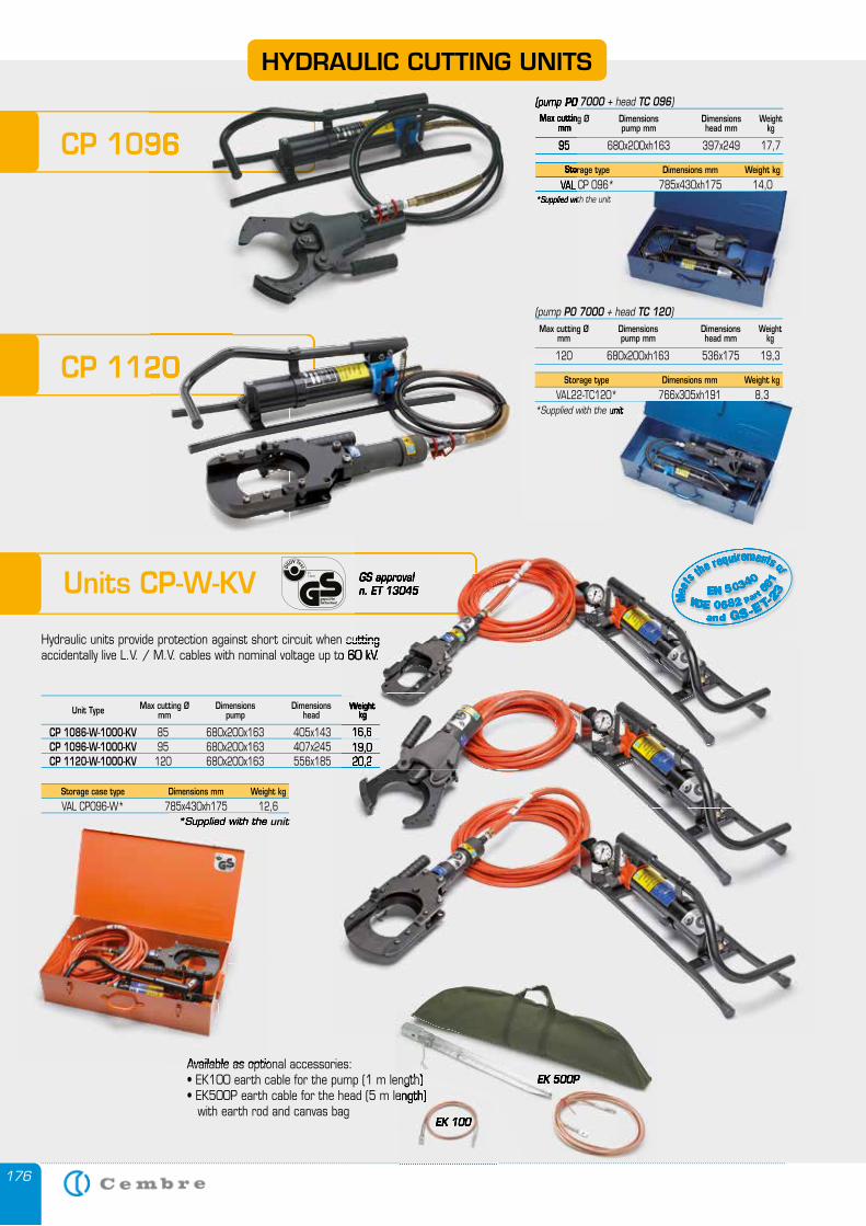
176
HYDRAULIC CUTTING UNITS
Units CP-W-KV
Hydraulic units provide protection against short circuit when cutting accidentally live L.V. / M.V. cables with nominal voltage up to 60 kV.
Max cutting ØmmUnit Type Dimensions
pumpDimensions
headWeight
kg
CP 1086-W-1000-KV 85 680x200x163 405x143 16,6 CP 1096-W-1000-KV 95 680x200x163 407x245 19,0 CP 1120-W-1000-KV 120 680x200x163 556x185 20,2
Storage case type Dimensions mm Weight kg
VAL CP096-W* 785x430xh175 12,6*Supplied with the unit
GS approval
and GS-ET-23Meet
s the requirements of
VDE 0682 part 6
61EN 50340
Available as optional accessories:• EK100 earth cable for the pump (1 m length)• EK500P earth cable for the head (5 m length) with earth rod and canvas bag
• EK100 earth cable for the pump (1 m length)• EK100 earth cable for the pump (1 m length)• EK500P earth cable for the head (5 m length)
EK 100
EK 500PEK 500P
(pump P0 7000 + head TC 096)Max cutting Ø
mmDimensionspump mm
Dimensionshead mm
Weightkg
95 680x200xh163 397x249 17,7
Storage type Dimensions mm Weight kg
VAL CP 096* 785x430xh175 14,0*Supplied with the unit
Hydraulic units provide protection against short circuit when cutting
GS approval n. ET 13045
and GS-ET-T-T 23232MeMeMet
s the requirementstst ofofo
VDVDV EDED 0682828 partrtr66666
1616EN 503030 4343 0404
Hydraulic units provide protection against short circuit when cutting accidentally live L.V. / M.V. cables with nominal voltage up to 60 kV.
Weight
85 680x200x163 405x143 16,6 95 680x200x163 407x245 19,0 120 680x200x163 556x185 20,2
Hydraulic units provide protection against short circuit when cutting accidentally live L.V. / M.V. cables with nominal voltage up to 60 kV.
Weightkg
85 680x200x163 405x143 16,6 95 680x200x163 407x245 19,0 120 680x200x163 556x185 20,2
*Supplied with the
Available as optional accessories:
CP 1096
(pump P0 7000 Max cutting Ø
mm
95 680x200xh163 397x249 17,7
Storage type
VAL CP 096* 785x430xh175 14,0*Supplied with the unit
CP 1096
CP 1120
(pump P0 7000 + head TC 120)Max cutting Ø
mmDimensionspump mm
Dimensionshead mm
Weightkg
120 680x200xh163 536x175 19,3
Storage type Dimensions mm Weight kg
VAL22-TC120* 766x305xh191 8,3*Supplied with the unit
CP 1120CP 1120*Supplied with the unit
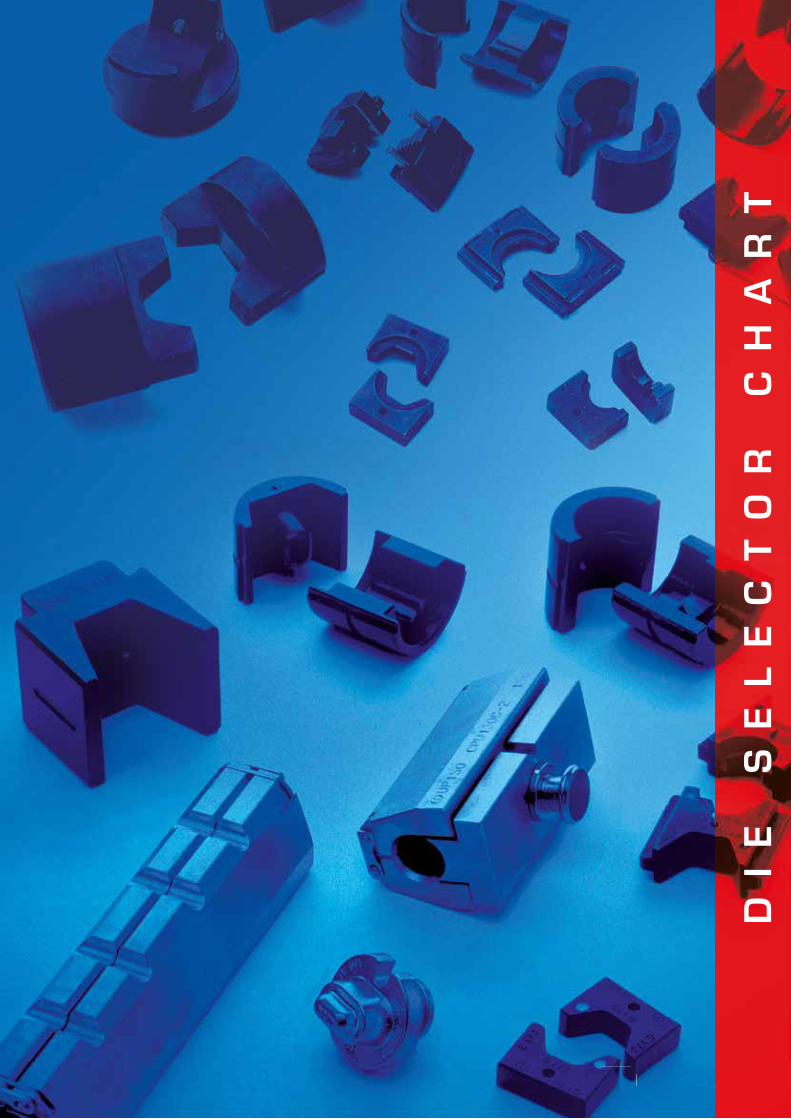
177177
DI
E
SE
LE
CT
OR
C
HA
RT
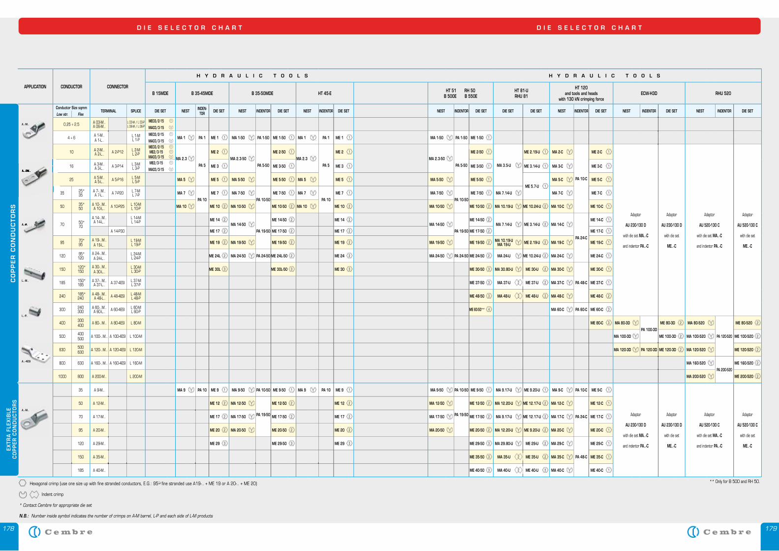
178 179
CO
PP
ER
CO
ND
UC
TO
RS
EXTR
A F
LEX
IBLE
CO
PP
ER C
ON
DU
CTO
RS
APPLICATION CONDUCTOR CONNECTOR
H Y D R A U L I C T O O L S H Y D R A U L I C T O O L S
B 15MDE B 35-45MDE B 35-50MDE HT 45-E HT 51 RH 50B 500E B 550E
HT 81-URHU 81
HT 120 and tools and heads
with 130 kN crimping forceECW-H3D RHU 520
Conductor Size sqmmTERMINAL SPLICE DIE SET NEST INDEN-
TOR DIE SET NEST INDENTOR DIE SET NEST INDENTOR DIE SET NEST INDENTOR DIE SET DIE SET DIE SET NEST INDENTOR DIE SET NEST INDENTOR DIE SET NEST INDENTOR DIE SETLow str. Flex
0,25 ÷ 2,5 A 03-M..A 06-M..
L 03-M / L 03-PL 06-M / L 06-P
ME03/2-15 1
MA03/3-15 1
4 ÷ 6 A 1-M..A 1-L..
L 1-ML 1-P
ME03/2-15 1
MA 1 1 PA 1 ME 1 1 MA 1-50 1 PA 1-50 ME 1-50 1 MA 1 1 PA 1 ME 1 1 MA 1-50 1 PA 1-50 ME 1-50 1MA03/3-15 1
10 A 2-M..A 2-L.. A 2-P12 L 2-M
L 2-P
ME03/2-15 1
MA 2.3 1
PA 5
ME 2 1
MA 2.3-50 1
PA 5-50
ME 2-50 1
MA 2.3 1
PA 5
ME 2 1
MA 2.3-50 1
PA 5-50
ME 2-50 1
MA 3.5-U 1
ME 2.19-U 1 MA 2-C 1
PA 10-C
ME 2-C 1
Adaptor
AU 230-130 D
with die set MA..-C
and indentor PA..-C
Adaptor
AU 230-130 D
with die set
ME..-C
Adaptor
AU 520-130 C
with die set MA..-C
and indentor PA..-C
Adaptor
AU 520-130 C
with die set
ME..-C
ME2/3-15 1
MA03/3-15 1
16 A 3-M..A 3-L.. A 3-P14 L 3-M
L 3-PME2/3-15 1
ME 3 1 ME 3-50 1 ME 3 1 ME 3-50 1 ME 3.14-U 1 MA 3-C 1 ME 3-C 1MA03/3-15 1
25 A 5-M..A 5-L.. A 5-P16 L 5-M
L 5-P MA 5 1 ME 5 1 MA 5-50 1 ME 5-50 1 MA 5 1 ME 5 1 MA 5-50 1 ME 5-50 1
ME 5.7-U 1
MA 5-C 1 ME 5-C 1
35 25*35
A 7-..M..A 7-L.. A 7-P20 L 7-M
L 7-P MA 7 1
PA 10
ME 7 1 MA 7-50 1
PA 10-50
ME 7-50 1 MA 7 1
PA 10
ME 7 1 MA 7-50 1
PA 10-50
ME 7-50 1 MA 7.14-U 1 MA 7-C 1 ME 7-C 1
50 35*50
A 10-..M..A 10-L.. A 10-P25 L 10-M
L 10-P MA 10 1 ME 10 2 MA 10-50 1 ME 10-50 2 MA 10 1 ME 10 2 MA 10-50 1 ME 10-50 2 MA 10.19-U 1 ME 10.24-U 2 MA 10-C 1 ME 10-C 1
70 50*70
A 14-..M..A 14-L..
L 14-ML 14-P ME 14 2
MA 14-50 1
PA 19-50
ME 14-50 2 ME 14 2MA 14-50 1
PA 19-50
ME 14-50 2MA 7.14-U 1 ME 3.14-U 2 MA 14-C 1
PA 24-C
ME 14-C 1
A 14-P30 ME 17 2 ME 17-50 2 ME 17 2 ME 17-50 2 ME 17-C 1
95 70*95
A 19-..M..A 19-L..
L 19-ML 19-P ME 19 2 MA 19-50 1 ME 19-50 2 ME 19 2 MA 19-50 1 ME 19-50 2 MA 10.19-U
MA 19-U 1 ME 2.19-U 2 MA 19-C 1 ME 19-C 1
120 95*120
A 24-..M..A 24-L..
L 24-ML 24-P ME 24L 2 MA 24-50 1 PA 24-50 ME 24L-50 2 ME 24 2 MA 24-50 1 PA 24-50 ME 24-50 2 MA 24-U 1 ME 10.24-U 2 MA 24-C 1 ME 24-C 1
150 120*150
A 30-..M..A 30-L..
L 30-ML 30-P ME 30L 3 ME 30L-50 3 ME 30 3 ME 30-50 3 MA 30.80-U 1 ME 30-U 2 MA 30-C 1
PA 48-C
ME 30-C 1
185 150*185
A 37-..M..A 37-L.. A 37-4ESI L 37-M
L 37-P ME 37-50 3 MA 37-U 2 ME 37-U 2 MA 37-C 1 ME 37-C 1
240 185*240
A 48-..M.. A 48-L.. A 48-4ESI L 48-M
L 48-P ME 48-50 3 MA 48-U 3 ME 48-U 3 MA 48-C 1 ME 48-C 2
300 240300
A 60-..M..A 60-L.. A 60-4ESI L 60-M
L 60-P ME 60-50** 4 MA 60-C 1 PA 60-C ME 60-C 3
400 300400 A 80-..M.. A 80-4ESI L 80-M ME 80-C 3 MA 80-3D 1
PA 100-3D
ME 80-3D 2 MA 80-520 1
PA 120-520
ME 80-520 2
500 400500 A 100-..M.. A 100-4ESI L 100-M MA 100-3D 1 ME 100-3D 2 MA 100-520 1 ME 100-520 2
630 500630 A 120-..M.. A 120-4ESI L 120-M MA 120-3D 1 PA 120-3D ME 120-3D 2 MA 120-520 1 ME 120-520 2
800 630 A 160-..M.. A 160-4ESI L 160-M MA 160-520 1
PA 200-520
ME 160-520 2
1000 800 A 200-M.. L 200-M MA 200-520 1 ME 200-520 2
35 A 9-M.. MA 9 1 PA 10 ME 9 1 MA 9-50 1 PA 10-50 ME 9-50 1 MA 9 1 PA 10 ME 9 1 MA 9-50 1 PA 10-50 ME 9-50 1 MA 9.17-U 1 ME 9.20-U 1 MA 9-C 1 PA 10-C ME 9-C 1
Adaptor
AU 230-130 D
with die set MA..-C
and indentor PA..-C
Adaptor
AU 230-130 D
with die set
ME..-C
Adaptor
AU 520-130 C
with die set MA..-C
and indentor PA..-C
Adaptor
AU 520-130 C
with die set
ME..-C
50 A 12-M.. ME 12 2 MA 12-50 1
PA 19-50
ME 12-50 2 ME 12 2 MA 12-50 1
PA 19-50
ME 12-50 2 MA 12.20-U 1 ME 12.17-U 2 MA 12-C 1
PA 24-C
ME 12-C 1
70 A 17-M.. ME 17 2 MA 17-50 1 ME 17-50 2 ME 17 2 MA 17-50 1 ME 17-50 2 MA 9.17-U 1 ME 12.17-U 2 MA 17-C 1 ME 17-C 1
95 A 20-M.. ME 20 2 MA 20-50 1 ME 20-50 2 ME 20 2 MA 20-50 1 ME 20-50 2 MA 12.20-U 1 ME 9.20-U 2 MA 20-C 1 ME 20-C 1
120 A 29-M.. ME 29 3 ME 29-50 3 ME 29 3 ME 29-50 3 MA 29.80-U 1 ME 29-U 2 MA 29-C 1
PA 48-C
ME 29-C 1
150 A 35-M.. ME 35-50 3 MA 35-U 2 ME 35-U 2 MA 35-C 1 ME 35-C 1
185 A 40-M.. ME 40-50 3 MA 40-U 2 ME 40-U 3 MA 40-C 1 ME 40-C 1
D I E S E L E C T O R C H A R T D I E S E L E C T O R C H A R T
A..-M..
A..-M..
A..-P..A..-P..
N.B.: Number inside symbol indicates the number of crimps on A-M barrel, L-P and each side of L-M products
Hexagonal crimp (use one size up with fine stranded conductors, E.G.: 95� fine stranded use A19-.. + ME 19 or A 20-.. + ME 20)
Indent crimp
* Contact Cembre for appropriate die set
A..-4ESI
** Only for B 500 and RH 50.
A..-2M..A..-2M..
L..-P..
L..-M..
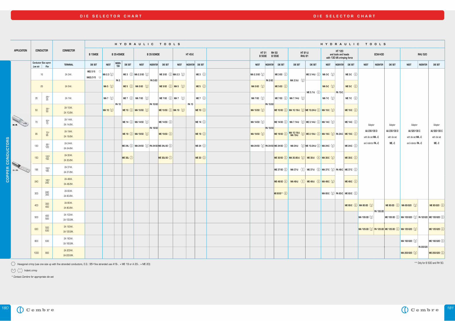
180 181
CO
PP
ER
CO
ND
UC
TO
RS
APPLICATION CONDUCTOR CONNECTOR
H Y D R A U L I C T O O L S H Y D R A U L I C T O O L S
B 15MDE B 35-45MDE B 35-50MDE HT 45-E HT 51 RH 50B 500E B 550E
HT 81-URHU 81
HT 120 and tools and heads
with 130 kN crimping forceECW-H3D RHU 520
Conductor Size sqmmTERMINAL DIE SET NEST INDEN-
TOR DIE SET NEST INDENTOR DIE SET NEST INDENTOR DIE SET NEST INDENTOR DIE SET DIE SET DIE SET NEST INDENTOR DIE SET NEST INDENTOR DIE SET NEST INDENTOR DIE SETLow str. Flex
16 2A 3-M..ME2/3-15 -
MA 2.3 2
PA 5
ME 3 2 MA 2.3-50 2
PA 5-50
ME 3-50 2 MA 2.3 2 ME 3 2 MA 2.3-50 2
PA 5-50
ME 3-50 2
MA 3.5-U 2
ME 3.14-U 2 MA 3-C 2
PA 10-C
ME 3-C 2
Adaptor
AU 230-130 D
with die set MA..-C
and indentor PA..-C
Adaptor
AU 230-130 D
with die set
ME..-C
Adaptor
AU 520-130 C
with die set MA..-C
and indentor PA..-C
Adaptor
AU 520-130 C
with die set
ME..-C
MA03/3-15 2
25 2A 5-M.. MA 5 2 ME 5 2 MA 5-50 2 ME 5-50 2 MA 5 2 ME 5 2 MA 5-50 2 ME 5-50 2
ME 5.7-U 2
MA 5-C 2 ME 5-C 2
35 25*35 2A 7-M.. MA 7 2
PA 10
ME 7 2 MA 7-50 2
PA 10-50
ME 7-50 2 MA 7 2
PA 10
ME 7 2 MA 7-50 2
PA 10-50
ME 7-50 2 MA 7.14-U 2 MA 7-C 2 ME 7-C 2
50 35*50
2A 10-M..
2A 10-2M..MA 10 2 ME 10 3 MA 10-50 2 ME 10-50 3 MA 10 2 ME 10 3 MA 10-50 2 ME 10-50 3 MA 10.19-U 2 ME 10.24-U 3 MA 10-C 2 ME 10-C 2
70 50*70
2A 14-M..
2A 14-2M..ME 14 3 MA 14-50 2
PA 19-50
ME 14-50 3 ME 14 3 MA 14-50 2
PA 19-50
ME 14-50 3 MA 7.14-U 2 ME 3.14-U 3 MA 14-C 2
PA 24-C
ME 14-C 2
95 70*95
2A 19-M..
2A 19-2M..ME 19 3 MA 19-50 2 ME 19-50 3 ME 19 3 MA 19-50 2 ME 19-50 3 MA 10.19-U
MA 19-U 2 ME 2.19-U 3 MA 19-C 2 ME 19-C 2
120 95*120
2A 24-M..
2A 24-2M..ME 24L 5 MA 24-50 2 PA 24-50 ME 24L-50 5 ME 24 4 MA 24-50 2 PA 24-50 ME 24-50 4 MA 24-U 2 ME 10.24-U 4 MA 24-C 2 ME 24-C 3
150 120*150
2A 30-M..
2A 30-2M..ME 30L 7 ME 30L-50 7 ME 30 5 ME 30-50 5 MA 30.80-U 2 ME 30-U 4 MA 30-C 2
PA 48-C
ME 30-C 3
185 150*185
2A 37-M..
2A 37-2M..ME 37-50 5 MA 37-U 5 ME 37-U 5 MA 37-C 2 ME 37-C 3
240 185*240
2A 48-M..
2A 48-2M..ME 48-50 6 MA 48-U 5 ME 48-U 5 MA 48-C 2 ME 48-C 3
300 240300
2A 60-M..
2A 60-2M..ME 60-50** 8 MA 60-C 2 PA 60-C ME 60-C 5
400 300400
2A 80-M..
2A 80-2M..ME 80-C 6 MA 80-3D 2
PA 100-3D
ME 80-3D 3 MA 80-520 2
PA 120-520
ME 80-520 3
500 400500
2A 100-M..
2A 100-2M..MA 100-3D 2 ME 100-3D 3 MA 100-520 2 ME 100-520 3
630 500630
2A 120-M..
2A 120-2M..MA 120-3D 2 PA 120-3D ME 120-3D 4 MA 120-520 2 ME 120-520 4
800 6302A 160-M..
2A 160-2M..MA 160-520 2
PA 200-520
ME 160-520 3
1000 8002A 200-M..
2A 200-2M..MA 200-520 2 ME 200-520 3
D I E S E L E C T O R C H A R T D I E S E L E C T O R C H A R T
2A..-M..2A..-M..
Hexagonal crimp (use one size up with fine stranded conductors, E.G.: 95� fine stranded use A19-.. + ME 19 or A 20-.. + ME 20)
Indent crimp
* Contact Cembre for appropriate die set
** Only for B 500 and RH 50.
CO
PP
ER
CO
ND
UC
TO
RS
2A..-2M..
182 183
CO
PP
ER
CO
ND
UC
TO
RS
EXTR
A F
LEX
IBLE
CO
PP
ER C
ON
DU
CTO
RS
D I E S E L E C T O R C H A R T D I E S E L E C T O R C H A R T
APPLICATION CONDUCTOR CONNECTOR
H Y D R A U L I C T O O L S
B 15MDE B 35-45MDE B 35-50MDE HT 45-E HT 51 RH 50B 500E B 550E
HT 81-URHU 81
HT 120 and tools and heads
with 130 kN crimping forceECW-H3D
Conductor SizeFlex sqmm TERMINAL DIE SET DIE SET DIE SET NEST INDENTOR DIE SET NEST INDENTOR
10 ANE 2-M.. ANE 2-P12 ANE 2-U..NN4-15
MN 2 RF-50 MN 2 RF-50 MN 2-C
PN 7-C
MN 2 RF-C
Adaptor
AU 230-130 D
with die set MN..-C
and indentor PN..-C
or
with die set MN..-RF-C
and die set MN..F-C
16 ANE 3-M.. ANE 3-P14 ANE 3-U.. MN 3 RF-50 MN 3 RF-50 MN 3-C MN 3 RF-C
25 ANE 5-M.. ANE 5-P16 MN 5 RF-50 MN 5 RF-50 MN 5-C MN 5 RF-C
35 ANE 7-M.. ANE 7-P20 MN 7 RF-50 MN 7 RF-50 MN 7-C MN 7 RF-C
50 ANE 10-M.. MN 10 RF-50 MN 10 RF-50 MN 10-CPN 14-C
MN 10 RF-C
70 ANE 14-M.. MN 14 RF-50 MN 14-C MN 14 RF-C
95 ANE 19-M.. MN 19 RF-50 MN 19-CPN 24-C
MN 19 RF-C
120 ANE 24-M.. MN 24 RF-50 MN 24-C MN 24 RF-C
150 ANE 30-M.. MN 30-C PN 37-C MN 30 RF-C
35 ANE 9-M.. MN 7 RF-50 MN 7 RF-50 MN 9-CPN 14-C
MN 7 RF-CAdaptor
AU 230-130 D
with die set MN..-C
and indentor PN..-C
or
with die set MN..-RF-C
and die set MN..F-C
50 ANE 12-M.. MN 12 F-50 MN 12 F-50 MN 12-C MN 12 F-C
70 ANE 17-M.. MN 17 F-50 MN 17-CPN 24-C
MN 17 F-C
95 ANE 20-M.. MN 20 F-50 MN 20-C MN 20 F-C
120 ANE 29-M.. MN 29-CPN 37-C
MN 29 F-C
150 ANE 35-M.. MN 35-C MN 35 F-C
Conductor SizeFlex sqmm TERMINAL DIE SET DIE SET DIE SET
0,3 ÷ 4 PKD 506 ÷ PKD 418 PKE 508 ÷ PKE 418 PKC 508 ÷ PKC 418 KE 506 ÷ KE 412 KE 4-15
4 ÷ 16 PKD 410 ÷ PKD 1618 PKE 410 ÷ PKE 1618 PKC 410 ÷ PKC 1618 KE 410 ÷ KE 1616 KE 16-15
16 PKD 16.. PKE 16.. PKC 16.. KE 16..
KE 35-15
MTT 16-50 MTT 16-50
25 PKD 25.. PKE 25.. PKC 25.. KE 25.. MTT 25-50 MTT 25-50
35 PKD 35.. PKC 35.. KE 35.. MTT 35-50 MTT 35-50
50 PKD 50.. PKC 50.. MTT 50-50 MTT 50-50
70 PKC 70.. MTT 70-50 MTT 70-50
95 PKC 95.. MTT 95-50 MTT 95-50
120 PKC 120.. MTT 120-50
Conductor SizeFlex sqmm TERMINAL DIE SET COMP.
APERTURE DIE SET DIE SET
2 x 0,5PKT 508PKT 510
KE 4-15
1
2 x 0,75PKT 7508PKT 7512 1,5
2 x 1PKT 108PKT 112 2,5
2 x 1,5PKT 1508PKT 1512 2,5
2 x 2,5PKT 2510PKT 2512
KE 4-15 KE 16-15 4
2 x 4 PKT 412KE 16-15
6
2 x 6 PKT 614 10
2 x 10 PKT 1014 KE 16-15 KE 35-15 16 MTT 16-50 MTT 16-50
2 x 16 PKT 1614 KE 35-15 35 MTT 35-50 MTT 35-50
CO
PP
ER
CO
ND
UC
TO
RS
ANE..-M..
ANE..-P..
ANE..-U..
ANE..-M..ANE..-M..
ANE..-P..
ANE..-U..
Indent crimp Radial crimp Trapezium crimp
PK ...
KE ...
PKT ...
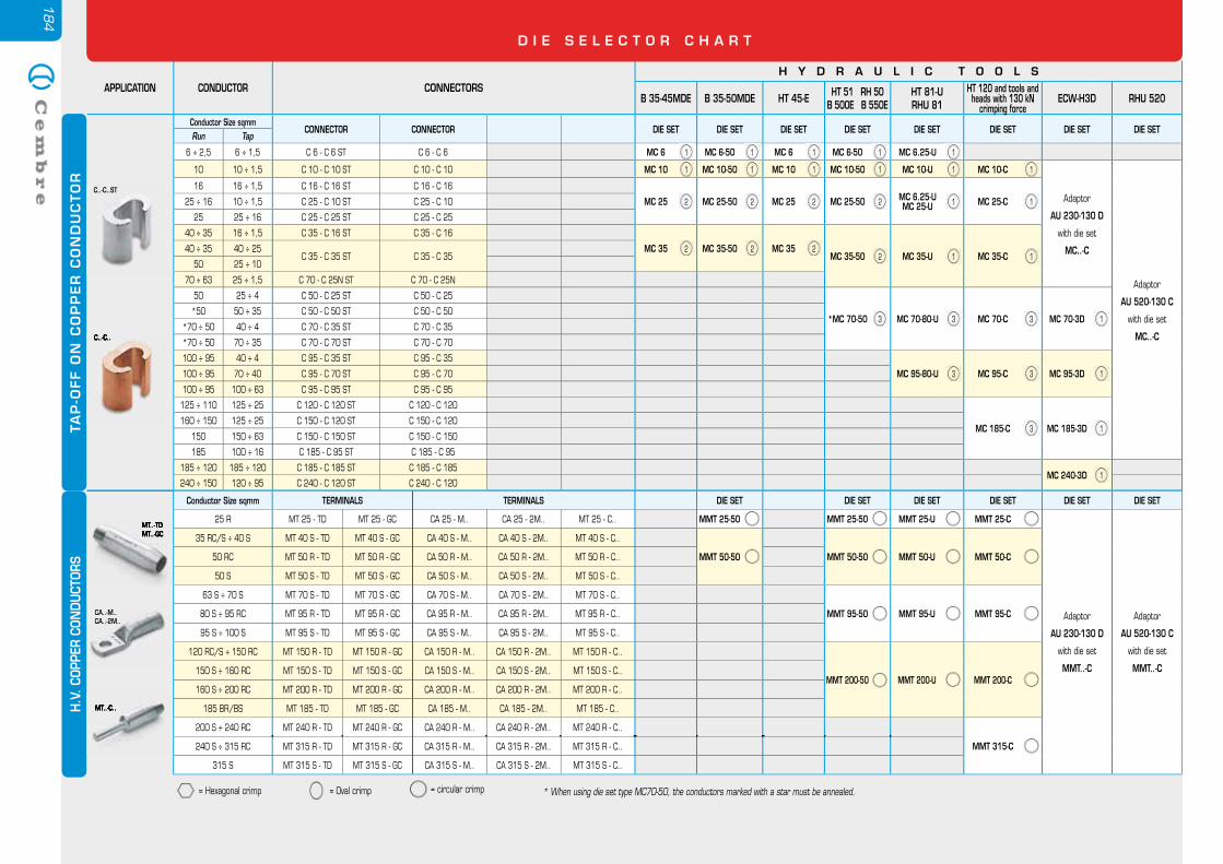
184
APPLICATION CONDUCTOR CONNECTORSH Y D R A U L I C T O O L S
B 35-45MDE B 35-50MDE HT 45-E HT 51 RH 50B 500E B 550E
HT 81-URHU 81
HT 120 and tools and heads with 130 kN
crimping forceECW-H3D RHU 520
Conductor Size sqmmCONNECTOR CONNECTOR DIE SET DIE SET DIE SET DIE SET DIE SET DIE SET DIE SET DIE SET
Run Tap
6 ÷ 2,5 6 ÷ 1,5 C 6 - C 6 ST C 6 - C 6 MC 6 1 MC 6-50 1 MC 6 1 MC 6-50 1 MC 6.25-U 1
10 10 ÷ 1,5 C 10 - C 10 ST C 10 - C 10 MC 10 1 MC 10-50 1 MC 10 1 MC 10-50 1 MC 10-U 1 MC 10-C 1
Adaptor
AU 230-130 D
with die set
MC..-C
Adaptor
AU 520-130 C
with die set
MC..-C
16 16 ÷ 1,5 C 16 - C 16 ST C 16 - C 16
MC 25 2 MC 25-50 2 MC 25 2 MC 25-50 2 MC 6.25-UMC 25-U 1 MC 25-C 125 ÷ 16 10 ÷ 1,5 C 25 - C 10 ST C 25 - C 10
25 25 ÷ 16 C 25 - C 25 ST C 25 - C 25
40 ÷ 35 16 ÷ 1,5 C 35 - C 16 ST C 35 - C 16
MC 35 2 MC 35-50 2 MC 35 2MC 35-50 2 MC 35-U 1 MC 35-C 1
40 ÷ 35 40 ÷ 25C 35 - C 35 ST C 35 - C 35
50 25 ÷ 10
70 ÷ 63 25 ÷ 1,5 C 70 - C 25N ST C 70 - C 25N
50 25 ÷ 4 C 50 - C 25 ST C 50 - C 25
*MC 70-50 3 MC 70-80-U 3 MC 70-C 3 MC 70-3D 1*50 50 ÷ 35 C 50 - C 50 ST C 50 - C 50
*70 ÷ 50 40 ÷ 4 C 70 - C 35 ST C 70 - C 35
*70 ÷ 50 70 ÷ 35 C 70 - C 70 ST C 70 - C 70
100 ÷ 95 40 ÷ 4 C 95 - C 35 ST C 95 - C 35
MC 95-80-U 3 MC 95-C 3 MC 95-3D 1100 ÷ 95 70 ÷ 40 C 95 - C 70 ST C 95 - C 70
100 ÷ 95 100 ÷ 63 C 95 - C 95 ST C 95 - C 95
125 ÷ 110 125 ÷ 25 C 120 - C 120 ST C 120 - C 120
MC 185-C 3 MC 185-3D 1160 ÷ 150 125 ÷ 25 C 150 - C 120 ST C 150 - C 120
150 150 ÷ 63 C 150 - C 150 ST C 150 - C 150
185 100 ÷ 16 C 185 - C 95 ST C 185 - C 95
185 ÷ 120 185 ÷ 120 C 185 - C 185 ST C 185 - C 185MC 240-3D 1
240 ÷ 150 120 ÷ 95 C 240 - C 120 ST C 240 - C 120
TA
P-O
FF O
N C
OP
PE
R C
ON
DU
CTO
R
D I E S E L E C T O R C H A R T
C..-C..ST
C..-C..C..-C..
H.V
. COP
PER
CON
DU
CTOR
S
MT..-TDMT..-GC
CA..-M..CA..-2M..
MT..-C..
MT..-TDMT..-GC
MT..-C..
Conductor Size sqmm TERMINALS TERMINALS DIE SET DIE SET DIE SET DIE SET DIE SET DIE SET
25 R MT 25 - TD MT 25 - GC CA 25 - M.. CA 25 - 2M.. MT 25 - C.. MMT 25-50 MMT 25-50 MMT 25-U MMT 25-C
Adaptor
AU 230-130 D
with die set
MMT..-C
Adaptor
AU 520-130 C
with die set
MMT..-C
35 RC/S ÷ 40 S MT 40 S - TD MT 40 S - GC CA 40 S - M.. CA 40 S - 2M.. MT 40 S - C..
MMT 50-50 MMT 50-50 MMT 50-U MMT 50-C50 RC MT 50 R - TD MT 50 R - GC CA 50 R - M.. CA 50 R - 2M.. MT 50 R - C..
50 S MT 50 S - TD MT 50 S - GC CA 50 S - M.. CA 50 S - 2M.. MT 50 S - C..
63 S ÷ 70 S MT 70 S - TD MT 70 S - GC CA 70 S - M.. CA 70 S - 2M.. MT 70 S - C..
MMT 95-50 MMT 95-U MMT 95-C80 S ÷ 95 RC MT 95 R - TD MT 95 R - GC CA 95 R - M.. CA 95 R - 2M.. MT 95 R - C..
95 S ÷ 100 S MT 95 S - TD MT 95 S - GC CA 95 S - M.. CA 95 S - 2M.. MT 95 S - C..
120 RC/S ÷ 150 RC MT 150 R - TD MT 150 R - GC CA 150 R - M.. CA 150 R - 2M.. MT 150 R - C..
MMT 200-50 MMT 200-U MMT 200-C150 S ÷ 160 RC MT 150 S - TD MT 150 S - GC CA 150 S - M.. CA 150 S - 2M.. MT 150 S - C..
160 S ÷ 200 RC MT 200 R - TD MT 200 R - GC CA 200 R - M.. CA 200 R - 2M.. MT 200 R - C..
185 BR/BS MT 185 - TD MT 185 - GC CA 185 - M.. CA 185 - 2M.. MT 185 - C..
200 S ÷ 240 RC MT 240 R - TD MT 240 R - GC CA 240 R - M.. CA 240 R - 2M.. MT 240 R - C..
MMT 315-C240 S ÷ 315 RC MT 315 R - TD MT 315 R - GC CA 315 R - M.. CA 315 R - 2M.. MT 315 R - C..
315 S MT 315 S - TD MT 315 S - GC CA 315 S - M.. CA 315 S - 2M.. MT 315 S - C..
* When using die set type MC70-50, the conductors marked with a star must be annealed.= Hexagonal crimp = Oval crimp = circular crimp
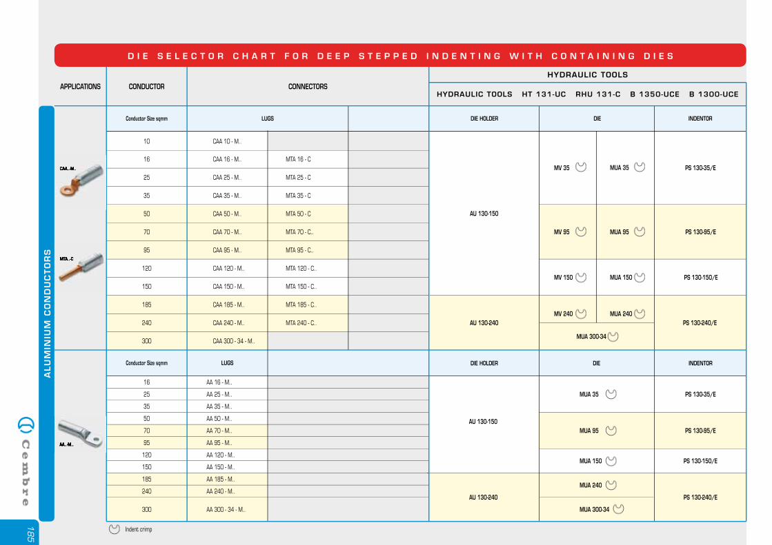
185
AU 130-150
AU 130-240
PS 130-35/E
PS 130-95/E
PS 130-150/E
PS 130-240/E
MV 35
MV 95
MV 150
MV 240
ALU
MIN
IUM
CO
ND
UC
TO
RS
Conductor Size sqmm LUGS DIE HOLDER DIE INDENTOR
Conductor Size sqmm LUGS DIE HOLDER DIE INDENTOR
CONDUCTORAPPLICATIONS
HYDRAULIC TOOLS
CONNECTORSHYDRAULIC TOOLS HT 131-UC RHU 131-C B 1350-UCE B 1300-UCE
16 CAA 16 - M..
CAA 25 - M..
CAA 35 - M..
CAA 70 - M..
CAA 95 - M..
CAA 120 - M..
CAA 150 - M..
CAA 185 - M..
CAA 240 - M..
MTA 35 - C
MTA 25 - C
MTA 16 - C
MTA 70 - C..
MTA 95 - C..
MTA 120 - C..
MTA 150 - C..
MTA 185 - C..
MTA 240 - C..
AA 50 - M..
AA 35 - M..
AA 25 - M..
AA 16 - M..
AA 70 - M..
AA 95 - M..
AA 120 - M..
AA 150 - M..
AA 185 - M..
AA 240 - M..
25
35
70
CAA 50 - M.. MTA 50 - C50
95
120
150
185
240
CAA 300 - 34 - M..300
50
35
25
16
70
95
120
150
185
240
AA 300 - 34 - M..300
Indent crimp
AU 130-150
AU 130-240
PS 130-35/E
PS 130-95/E
PS 130-240/E
MUA 35
MUA 95
MUA 240
MUA 300-34
MUA 300-34
MUA 35
MUA 95
MUA 150
MUA 240
PS 130-150/EMUA 150
D I E S E L E C T O R C H A R T F O R D E E P S T E P P E D I N D E N T I N G W I T H C O N T A I N I N G D I E S
CAA..-M..
MTA..-C
CAA..-M..
MTA..-C
AA..-M..AA..-M..
10 CAA 10 - M..
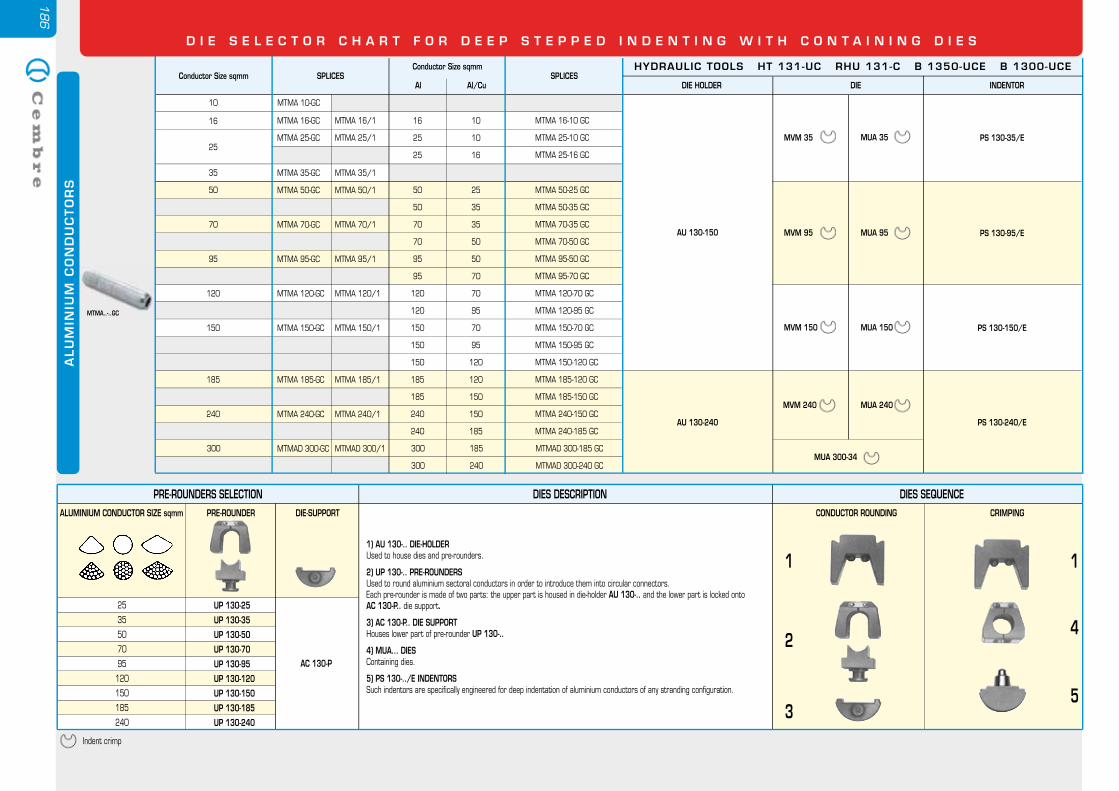
186
D I E S E L E C T O R C H A R T F O R D E E P S T E P P E D I N D E N T I N G W I T H C O N T A I N I N G D I E S
PRE-ROUNDERS SELECTION DIES DESCRIPTION DIES SEQUENCE
50
70
95
120
150
185
240
UP 130-50
ALUMINIUM CONDUCTOR SIZE sqmm PRE-ROUNDER DIE-SUPPORT CRIMPINGCONDUCTOR ROUNDING
UP 130-70
UP 130-95
UP 130-120
UP 130-150
UP 130-185
UP 130-240
1) AU 130-.. DIE-HOLDERUsed to house dies and pre-rounders.
2) UP 130-.. PRE-ROUNDERSUsed to round aluminium sectoral conductors in order to introduce them into circular connectors.Each pre-rounder is made of two parts: the upper part is housed in die-holder AU 130-.. and the lower part is locked onto AC 130-P.. die support.
3) AC 130-P.. DIE SUPPORTHouses lower part of pre-rounder UP 130-..
4) MUA... DIESContaining dies.
5) PS 130-../E INDENTORSSuch indentors are specifically engineered for deep indentation of aluminium conductors of any stranding configuration.
1 1
4
5
2
3Indent crimp
25
35 UP 130-35
UP 130-25
AC 130-P
ALU
MIN
IUM
CO
ND
UC
TO
RS
MTMA..-..GC
16
MTMA 50-25 GC
MTMA 50-35 GC
MTMA 70-35 GC
MTMA 70-50 GC
MTMA 95-50 GC
MTMA 95-70 GC
MTMA 120-70 GC
MTMA 120-95 GC
MTMA 150-70 GC
MTMA 150-95 GC
MTMA 150-120 GC
MTMA 185-120 GC
MTMA 185-150 GC
MTMA 240-150 GC
MTMA 240-185 GC
25
35
50 50
50
70
70
95
95
120
120
150
150
150
185
185
240
240
25
35
35
50
50
70
70
95
70
95
120
120
150
150
185
70
95
120
150
185
240
AU 130-150
AU 130-240
PS 130-35/E
PS 130-95/E
PS 130-150/E
PS 130-240/E
10 MTMA 10-GC
MTMA 25-10 GC
MTMA 16-10 GC
25 10
16 10
MTMA 25-16 GC25 16
MTMAD 300-185 GC
MTMAD 300-240 GC
300
300
185
240
300MUA 300-34
MTMA 16-GC
MTMA 25-GC
MTMA 35-GC
MTMA 50-GC
MTMA 70-GC
MTMA 95-GC
MTMA 120-GC
MTMA 150-GC
MTMA 185-GC
MTMA 240-GC
MTMAD 300-GC
MTMA 16/1
MTMA 25/1
MTMA 35/1
MTMA 50/1
MTMA 70/1
MTMA 95/1
MTMA 120/1
MTMA 150/1
MTMA 185/1
MTMA 240/1
MTMAD 300/1
MVM 35
MVM 95
MVM 150
MVM 240
MUA 35
MUA 95
MUA 150
MUA 240
Conductor Size sqmm SPLICESHYDRAULIC TOOLS HT 131-UC RHU 131-C B 1350-UCE B 1300-UCE
DIE HOLDER DIE INDENTOR
Conductor Size sqmm
Al Al/CuSPLICES
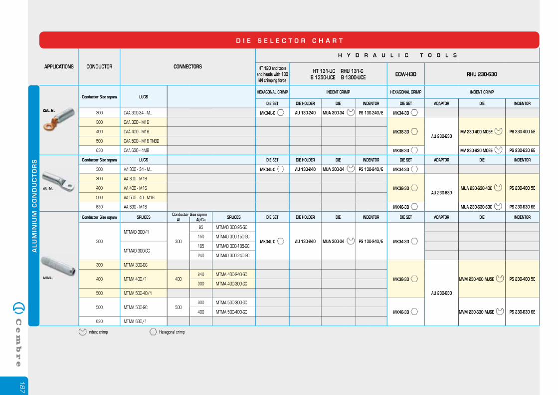
187
APPLICATIONS CONDUCTOR CONNECTORS
H Y D R A U L I C T O O L S
HT 120 and tools and heads with 130 kN crimping force
HT 131-UC RHU 131-C B 1350-UCE B 1300-UCE ECW-H3D RHU 230-630
Conductor Size sqmm LUGSHEXAGONAL CRIMP INDENT CRIMP HEXAGONAL CRIMP INDENT CRIMP
DIE SET DIE HOLDER DIE INDENTOR DIE SET ADAPTOR DIE INDENTOR
300 CAA 300-34 - M.. MK34L-C AU 130-240 MUA 300-34 PS 130-240/E MK34-3D 300 CAA 300 - M16
MK38-3D AU 230-630MV 230-400 MC5E PS 230-400 5E400 CAA 400 - M16
500 CAA 500 - M16 TNBD
630 CAA 630 - 4M8 MK46-3D MV 230-630 MC6E PS 230-630 6E
Conductor Size sqmm LUGS DIE SET DIE HOLDER DIE INDENTOR DIE SET ADAPTOR DIE INDENTOR
300 AA 300 - 34 - M.. MK34L-C AU 130-240 MUA 300-34 PS 130-240/E MK34-3D 300 AA 300 - M16
MK38-3D AU 230-630MUA 230-630-400 PS 230-400 5E400 AA 400 - M16
500 AA 500 - 40 - M16
630 AA 630 - M16 MK46-3D MUA 230-630-630 PS 230-630 6E
Conductor Size sqmm SPLICESConductor Size sqmm
SPLICES DIE SET DIE HOLDER DIE INDENTOR DIE SET ADAPTOR DIE INDENTORAl Al/Cu
300
MTMAD 300/1
300
95 MTMAD 300-95-GC
MK34L-C AU 130-240 MUA 300-34 PS 130-240/E MK34-3D 150 MTMAD 300-150-GC
MTMAD 300-GC185 MTMAD 300-185-GC
240 MTMAD 300-240-GC
300 MTMA 300-GC
MK38-3D
AU 230-630
MVM 230-400 MJ5E PS 230-400 5E400 MTMA 400/1 400240 MTMA 400-240-GC
300 MTMA 400-300-GC
500 MTMA 500-40/1
500 MTMA 500-GC 500300 MTMA 500-300-GC
MK46-3D MVM 230-630 MJ6E PS 230-630 6E400 MTMA 500-400-GC
630 MTMA 630/1
Indent crimp Hexagonal crimp
AA..-M..
CAA..-M..CAA..-M..
ALU
MIN
IUM
CO
ND
UC
TO
RS
MTMA..
D I E S E L E C T O R C H A R T
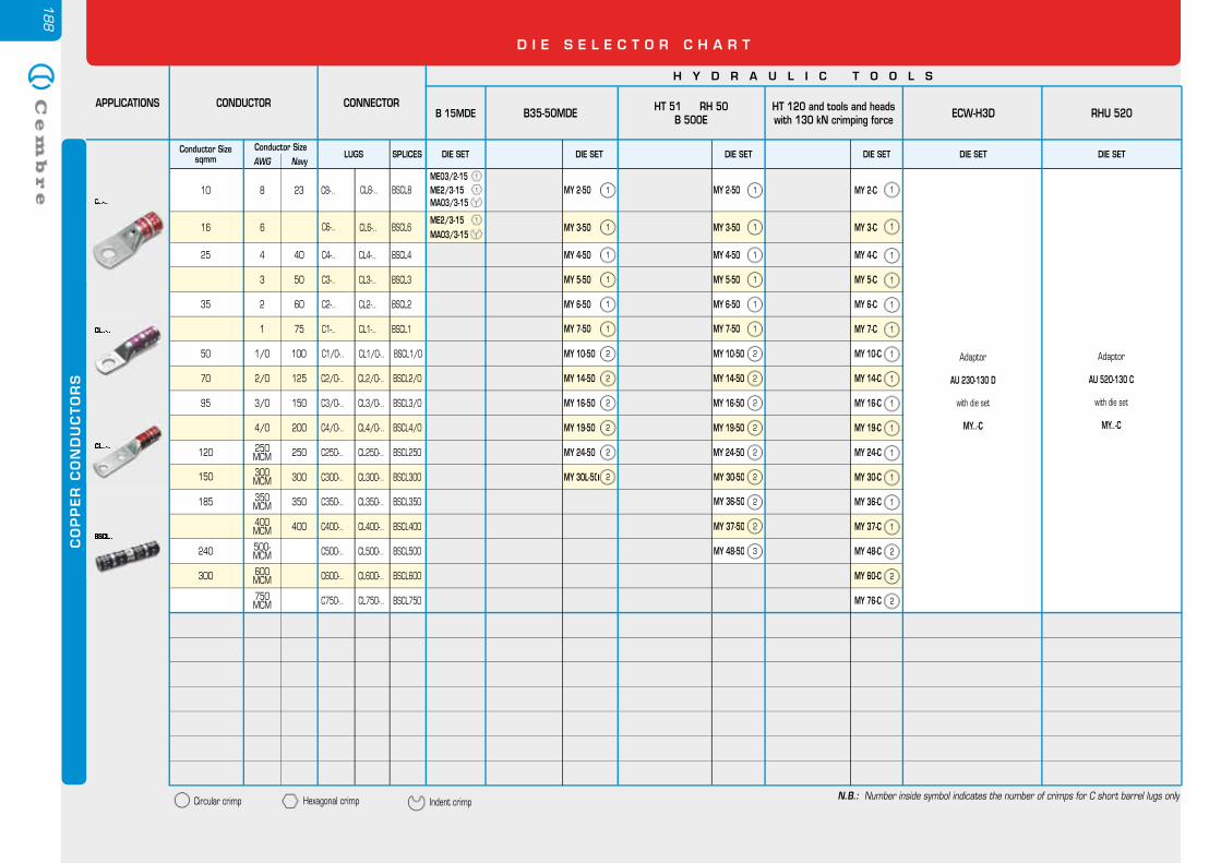
188
D I E S E L E C T O R C H A R T
CO
PP
ER
CO
ND
UC
TO
RS
Conductor SizeLUGS SPLICES DIE SETDIE SET
AWG Navy
CONDUCTORAPPLICATIONS
H Y D R A U L I C T O O L S
CONNECTOR HT 51 RH 50B 500E RHU 520
8 23 C8-.. CL8-..
MY 10-50
MY 14-50
MY 16-50
MY 19-50
MY 24-50
C2/0-..
C3/0-..
C4/0-..
C250-..
C300-..
C350-..
C400-..
C500-..
C600-..
C750-.. CL750-..
6
4 40
3 50
2 60
1 75
1/0 100
2/0 125
3/0 150
4/0 200
250 MCM 250
300MCM 300
350 MCM 350
C6-.. CL6-..
C4-..
C3-..
C2-..
C1-..
C1/0-..
BSCL8
BSCL2/0
BSCL3/0
BSCL4/0
BSCL250
BSCL300
BSCL350
BSCL400
BSCL500
BSCL600
BSCL750
BSCL6
BSCL4
BSCL3
BSCL2
BSCL1
BSCL1/0
CL2/0-..
CL3/0-..
CL4/0-..
CL250-..
CL300-..
CL350-..
CL400-..
CL500-..
CL600-..
CL4-..
CL3-..
CL2-..
CL1-..
CL1/0-..
400 MCM 400
500-MCM
600 MCM
750 MCM
MY 2-50
MY 3-50
MY 4-50
MY 5-50
MY 6-50
MY 7-50
MY 37-50
MY 48-50
MY 30-50
MY 36-50
1
1
1
1
1
1
2
2
2
2
2
MY 30-50 2
MY 36-50 2
MY 37-50 2
MY 48-50 3
C..-..
CL..-..
DIE SET
ECW-H3D
Adaptor
AU 230-130 D
with die set
MY..-C
CL..-..
BSCL..
Adaptor
AU 520-130 C
with die set
MY..-C
DIE SET
HT 120 and tools and heads with 130 kN crimping force
MY 3-C
MY 4-C
MY 5-C
MY 6-C
MY 7-C
MY 10-C
MY 14-C
MY 16-C
MY 19-C
MY 24-C
MY 2-C 1
1
1
1
1
1
1
1
1
1
1
1
1
1
2
2
2
MY 30-C
MY 36-C
MY 37-C
MY 48-C
MY 60-C
MY 76-C
C..-..
CL..-..
CL..-..
BSCL..
DIE SET
B35-50MDE
MY 10-50
MY 14-50
MY 16-50
MY 19-50
MY 24-50
MY 2-50
MY 3-50
MY 4-50
MY 5-50
MY 6-50
MY 7-50
MY 30L-50
1
1
1
1
1
1
2
2
2
2
2
MY 30L-50 2
B 15MDE
ME03/2-15 1
ME2/3-15 1
MA03/3-15 1
ME2/3-15 1
MA03/3-15 1
DIE SET
Circular crimp Hexagonal crimp Indent crimpN.B.: Number inside symbol indicates the number of crimps for C short barrel lugs only
10
16
25
35
50
70
95
120
150
185
240
300
Conductor Size sqmm
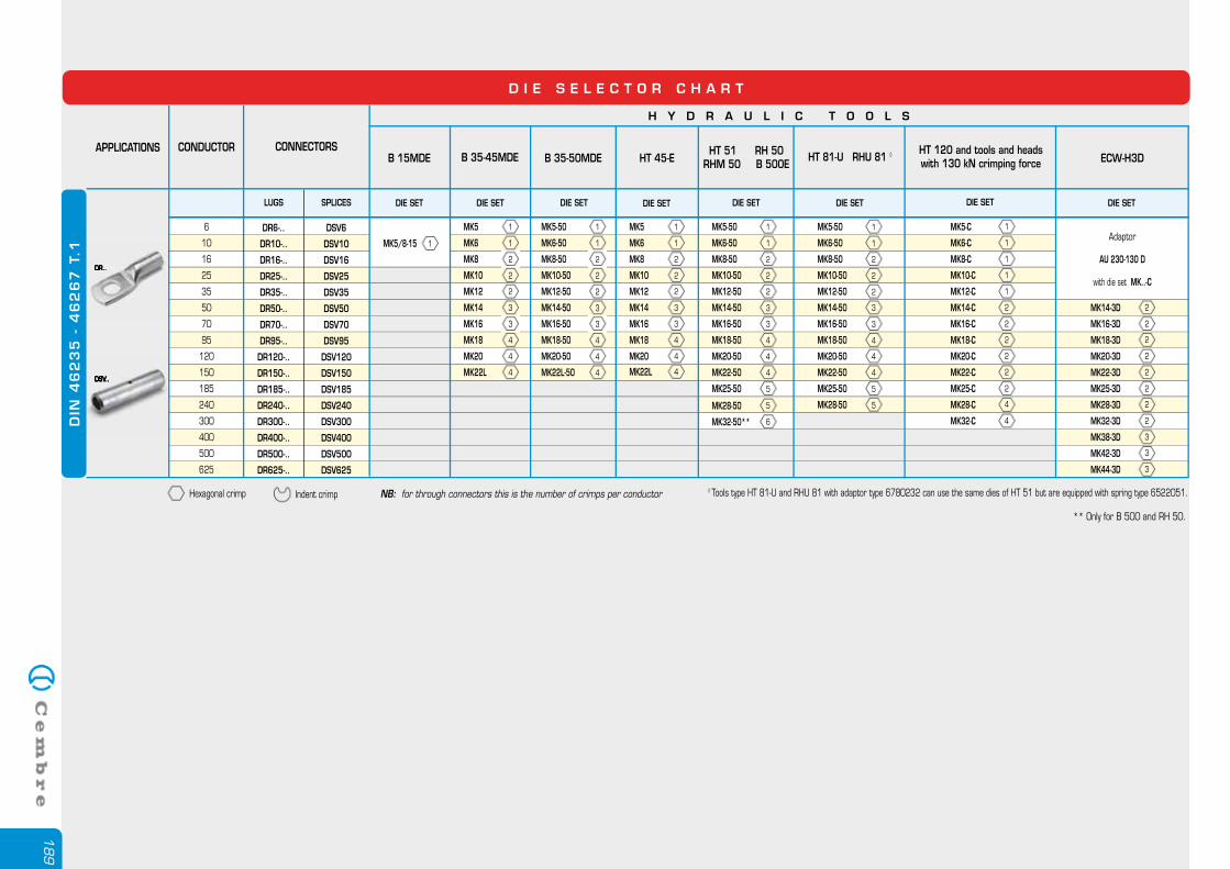
189
Hexagonal crimp NB: for through connectors this is the number of crimps per conductorIndent crimp
D I E S E L E C T O R C H A R T
◊ Tools type HT 81-U and RHU 81 with adaptor type 6780232 can use the same dies of HT 51 but are equipped with spring type 6522051.
DR..
DSV..
DR..
DSV..
LUGS SPLICES DIE SET DIE SET DIE SET DIE SETDIE SET
CONDUCTORAPPLICATIONS
H Y D R A U L I C T O O L S
CONNECTORSHT 45-E
HT 51 RH 50RHM 50 B 500E
HT 81-U RHU 81 ◊ HT 120 and tools and heads with 130 kN crimping force ECW-H3D
6
10
16
25
120
95
70
50
35
150
185
240
300
400
500
625
MK5 1
MK6 1
MK8 2
MK10 2
MK12 2
MK14 3
MK16 3
MK18 4
MK20 4
MK5-50 1
MK6-50 1
MK8-50 2
MK10-50 2
MK12-50 2
MK14-50 3
MK16-50 3
MK18-50 4
MK20-50 4
MK22-50 4
MK25-50 5
MK28-50 5
MK5-50 1
MK6-50 1
MK8-50 2
MK10-50 2
MK12-50 2
MK14-50 3
MK16-50 3
MK18-50 4
MK20-50 4
MK22-50 4
MK25-50 5
MK28-50 5
MK5-C
MK6-C
MK8-C
MK10-C
MK12-C
MK14-C
MK16-C
MK18-C
MK20-C
MK22-C
MK25-C
MK28-C
MK32-C 4
4
2
2
2
2
2
2
1
1
1
1
1
MK14-3D 2
MK16-3D 2
MK18-3D 2
MK20-3D 2
MK22-3D 2
MK25-3D 2
MK28-3D 2
MK32-3D 2
MK38-3D 3
MK42-3D 3
MK44-3D 3
Adaptor
AU 230-130 D
with die set MK..-C
DR6-..
DR10-..
DR16-..
DR25-..
DR35-..
DR50-..
DR70-..
DR95-..
DR120-..
DR150-..
DR185-..
DR240-..
DR300-..
DR400-..
DR500-..
DR625-..
DSV6
DSV10
DSV16
DSV25
DSV35
DSV50
DSV70
DSV95
DSV120
DSV150
DSV185
DSV240
DSV300
DSV400
DSV500
DSV625
B 15MDE
DIE SET
MK5/8-15 1
B 35-45MDE B 35-50MDE
MK5 1
MK6 1
MK8 2
MK10 2
MK12 2
MK14 3
MK16 3
MK18 4
MK20 4
MK5-50 1
MK6-50 1
MK8-50 2
MK10-50 2
MK12-50 2
MK14-50 3
MK16-50 3
MK18-50 4
MK20-50 4
MK22L-50 4
DIE SET DIE SET
MK22L 4
DIN
46
23
5 -
46
26
7 T
.1
MK22L 4
MK32-50** 6
** Only for B 500 and RH 50.
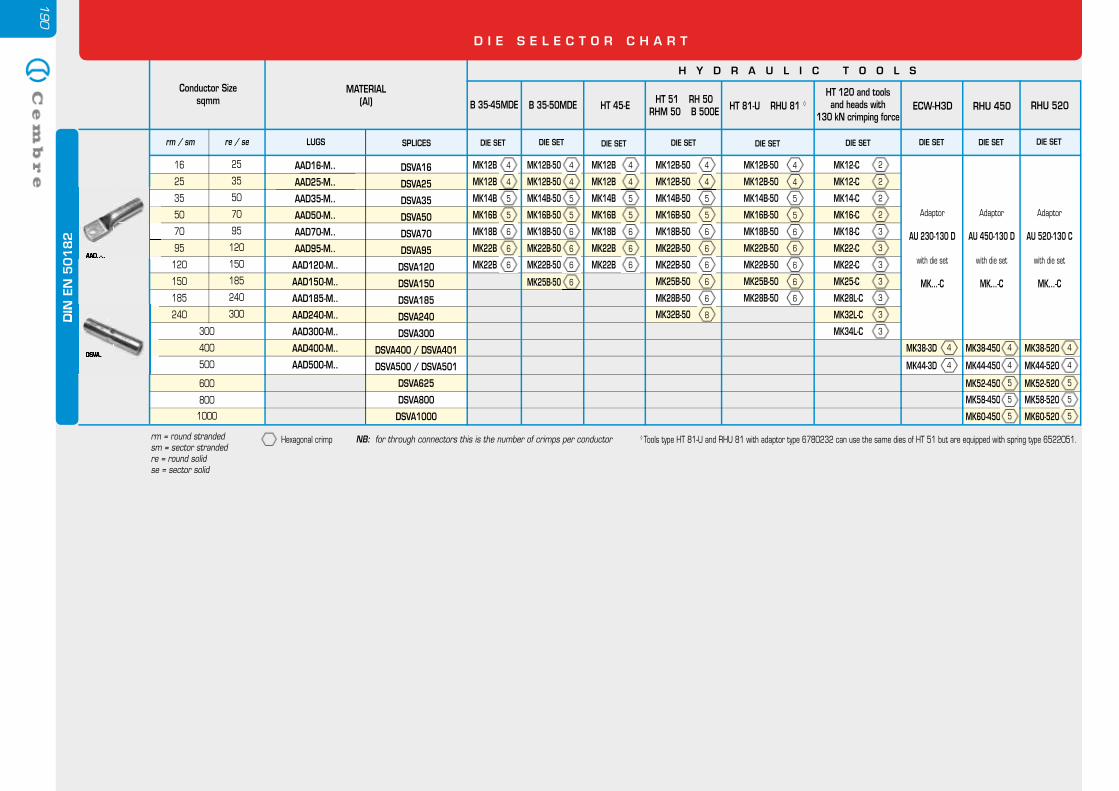
190
Hexagonal crimp ◊ Tools type HT 81-U and RHU 81 with adaptor type 6780232 can use the same dies of HT 51 but are equipped with spring type 6522051.NB: for through connectors this is the number of crimps per conductor
LUGS SPLICES DIE SET DIE SETDIE SET
Conductor Size sqmm
H Y D R A U L I C T O O L S
MATERIAL(Al) HT 81-U RHU 81
HT 120 and tools and heads with
130 kN crimping forceECW-H3D
16
25
120
95
70
50
35
150
185
240
300
500
4
4
5
5
6
6
6
6
6
MK12-C
MK12-C
MK14-C
MK16-C
MK18-C
MK22-C
MK22-C
MK25-C
MK28L-C
MK32L-C
MK34L-C 3
3
3
3
3
3
3
2
2
2
2
MK38-3D 4
MK44-3D 4
AAD16-M..
AAD25-M..
AAD35-M..
AAD50-M..
AAD70-M..
AAD95-M..
AAD120-M..
AAD150-M..
AAD185-M..
AAD240-M..
AAD300-M..
AAD400-M..
AAD500-M..
DSVA16
DSVA25
DSVA35
DSVA50
DSVA70
DSVA95
DSVA120
DSVA150
DSVA185
DSVA240
DSVA300
DSVA400 / DSVA401
DSVA500 / DSVA501
DSVA625
DSVA800
DSVA1000
25
120
95
70
50
35
150
185
240
300
rm / sm re / se DIE SET
HT 51 RH 50RHM 50 B 500E
4
4
5
5
6
6
6
6
6
8
MK12B-50
MK12B-50
MK14B-50
MK16B-50
MK18B-50
MK22B-50
MK22B-50
MK25B-50
MK28B-50
MK32B-50
MK12B-50
MK12B-50
MK14B-50
MK16B-50
MK18B-50
MK22B-50
MK22B-50
MK25B-50
MK28B-50
DIE SET
RHU 450
DIE SET
HT 45-E
4
4
5
5
6
6
6
MK12B
MK12B
MK14B
MK16B
MK18B
MK22B
MK22B
DIE SET
B 35-50MDE
4
4
5
5
6
6
6
MK12B-50
MK12B-50
MK14B-50
MK16B-50
MK18B-50
MK22B-50
MK22B-50
6MK25B-50
4
4
5
5
6
6
6
MK12B
MK12B
MK14B
MK16B
MK18B
MK22B
MK22B
DIE SET
B 35-45MDE
400
Adaptor
AU 230-130 D
with die set
MK...-C
Adaptor
AU 450-130 D
with die set
MK...-C
DIE SET
RHU 520
Adaptor
AU 520-130 C
with die set
MK...-C
MK38-450MK38-450 4
MK44-450MK44-450 4
MK38-520 4
MK44-520 4
AAD..-..
DSVA..
DIN
EN
50
18
2
AAD..-..
DIN
EN
50
18
2
DSVA..
DIN
EN
50
18
2
MK52-450MK52-450 5
MK58-450MK58-450 5
MK52-520 5
MK58-520 5
MK60-450MK60-450 5 MK60-520 5
600
800
1000
D I E S E L E C T O R C H A R T
rm = round stranded sm = sector stranded re = round solid se = sector solid

AP
PE
ND
IX
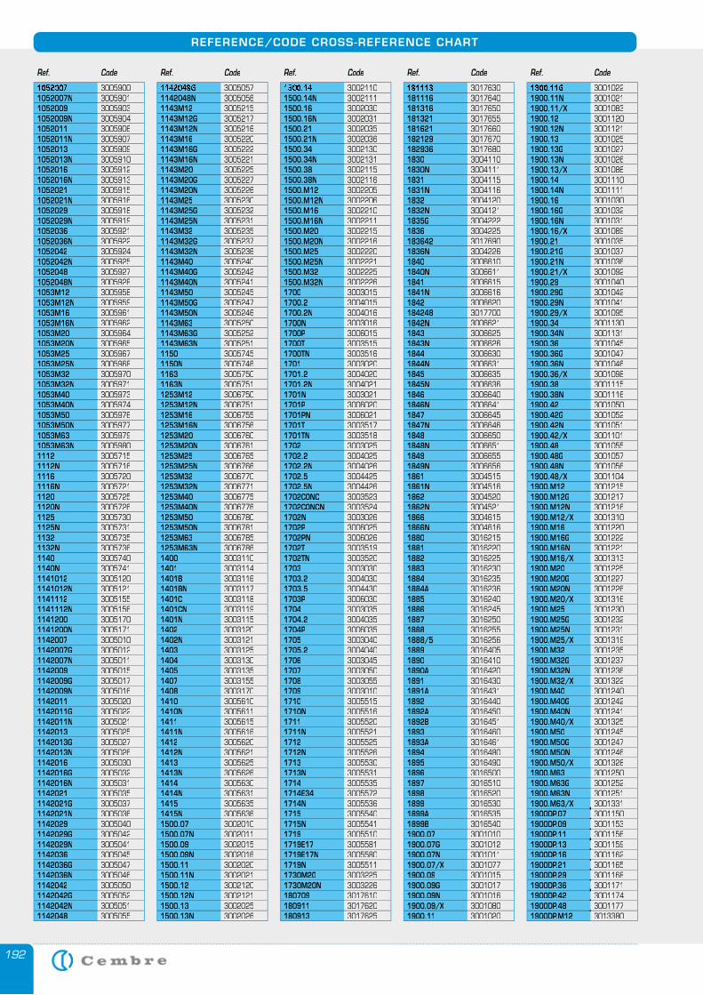
192
REFERENCE/CODE CROSS-REFERENCE CHART
1052007 30059001052007N 30059011052009 30059031052009N 30059041052011 30059061052011N 30059071052013 30059091052013N 30059101052016 30059121052016N 30059131052021 30059151052021N 30059161052029 30059181052029N 30059191052036 30059211052036N 30059221052042 30059241052042N 30059251052048 30059271052048N 30059281053M12 30059581053M12N 30059591053M16 30059611053M16N 30059621053M20 30059641053M20N 30059651053M25 30059671053M25N 30059681053M32 30059701053M32N 30059711053M40 30059731053M40N 30059741053M50 30059761053M50N 30059771053M63 30059791053M63N 30059801112 30057151112N 30057161116 30057201116N 30057211120 30057251120N 30057261125 30057301125N 30057311132 30057351132N 30057361140 30057401140N 30057411141012 30051201141012N 30051211141112 30051551141112N 30051561141200 30051701141200N 30051711142007 30050101142007G 30050121142007N 30050111142009 30050151142009G 30050171142009N 30050161142011 30050201142011G 30050221142011N 30050211142013 30050251142013G 30050271142013N 30050261142016 30050301142016G 30050321142016N 30050311142021 30050351142021G 30050371142021N 30050361142029 30050401142029G 30050421142029N 30050411142036 30050451142036G 30050471142036N 30050461142042 30050501142042G 30050521142042N 30050511142048 3005055
1142048G 30050571142048N 30050561143M12 30052151143M12G 30052171143M12N 30052161143M16 30052201143M16G 30052221143M16N 30052211143M20 30052251143M20G 30052271143M20N 30052261143M25 30052301143M25G 30052321143M25N 30052311143M32 30052351143M32G 30052371143M32N 30052361143M40 30052401143M40G 30052421143M40N 30052411143M50 30052451143M50G 30052471143M50N 30052461143M63 30052501143M63G 30052521143M63N 30052511150 30057451150N 30057461163 30057501163N 30057511253M12 30067501253M12N 30067511253M16 30067551253M16N 30067561253M20 30067601253M20N 30067611253M25 30067651253M25N 30067661253M32 30067701253M32N 30067711253M40 30067751253M40N 30067761253M50 30067801253M50N 30067811253M63 30067851253M63N 30067861400 30031101401 30031141401B 30031161401BN 30031171401C 30031181401CN 30031191401N 30031151402 30031201402N 30031211403 30031251404 30031301405 30031351407 30031551408 30031701410 30056101410N 30056111411 30056151411N 30056161412 30056201412N 30056211413 30056251413N 30056261414 30056301414N 30056311415 30056351415N 30056361500.07 30020101500.07N 30020111500.09 30020151500.09N 30020161500.11 30020201500.11N 30020211500.12 30021201500.12N 30021211500.13 30020251500.13N 3002026
1500.14 30021101500.14N 30021111500.16 30020301500.16N 30020311500.21 30020351500.21N 30020361500.34 30021301500.34N 30021311500.38 30021151500.38N 30021161500.M12 30022051500.M12N 30022061500.M16 30022101500.M16N 30022111500.M20 30022151500.M20N 30022161500.M25 30022201500.M25N 30022211500.M32 30022251500.M32N 30022261700 30030151700.2 30040151700.2N 30040161700N 30030161700P 30060151700T 30035151700TN 30035161701 30030201701.2 30040201701.2N 30040211701N 30030211701P 30060201701PN 30060211701T 30035171701TN 30035181702 30030251702.2 30040251702.2N 30040261702.5 30044251702.5N 30044261702CONC 30035231702CONCN 30035241702N 30030261702P 30060251702PN 30060261702T 30035191702TN 30035201703 30030301703.2 30040301703.5 30044301703P 30060301704 30030351704.2 30040351704P 30060351705 30030401705.2 30040401706 30030451707 30030501708 30030551709 30030101710 30055151710N 30055161711 30055201711N 30055211712 30055251712N 30055261713 30055301713N 30055311714 30055351714E34 30055721714N 30055361715 30055401715N 30055411719 30055101719E17 30055811719E17N 30055801719N 30055111730M20 30032251730M20N 3003226180709 3017610180911 3017620180913 3017625
181113 3017630181116 3017640181316 3017650181321 3017655181621 3017660182129 3017670182936 30176801830 30041101830N 30041111831 30041151831N 30041161832 30041201832N 30041211835G 30042221836 3004225183642 30176901836N 30042261840 30066101840N 30066111841 30066151841N 30066161842 3006620184248 30177001842N 30066211843 30066251843N 30066261844 30066301844N 30066311845 30066351845N 30066361846 30066401846N 30066411847 30066451847N 30066461848 30066501848N 30066511849 30066551849N 30066561861 30045151861N 30045161862 30045201862N 30045211866 30046151866N 30046161880 30162151881 30162201882 30162251883 30162301884 30162351884A 3016236 1885 30162401886 30162451887 30162501888 30162551888/5 30162561889 30164051890 30164101890A 30164201891 30164301891A 30164311892 30164401892A 30164501892B 30164511893 30164601893A 30164611894 30164801895 30164901896 30165001897 30165101898 30165201899 30165301899A 30165351899B 30165401900.07 30010101900.07G 30010121900.07N 30010111900.07/X 30010771900.09 30010151900.09G 30010171900.09N 30010161900.09/X 30010801900.11 3001020
1900.11G 30010221900.11N 30010211900.11/X 30010831900.12 30011201900.12N 30011211900.13 30010251900.13G 30010271900.13N 30010261900.13/X 30010861900.14 30011101900.14N 30011111900.16 30010301900.16G 30010321900.16N 30010311900.16/X 30010891900.21 30010351900.21G 30010371900.21N 30010361900.21/X 30010921900.29 30010401900.29G 30010421900.29N 30010411900.29/X 30010951900.34 30011301900.34N 30011311900.36 30010451900.36G 30010471900.36N 30010461900.36/X 30010981900.38 30011151900.38N 30011161900.42 30010501900.42G 30010521900.42N 30010511900.42/X 30011011900.48 30010551900.48G 30010571900.48N 30010561900.48/X 30011041900.M12 30012151900.M12G 30012171900.M12N 30012161900.M12/X 30013101900.M16 30012201900.M16G 30012221900.M16N 30012211900.M16/X 30013131900.M20 30012251900.M20G 30012271900.M20N 30012261900.M20/X 30013161900.M25 30012301900.M25G 30012321900.M25N 30012311900.M25/X 30013191900.M32 30012351900.M32G 30012371900.M32N 30012361900.M32/X 30013221900.M40 30012401900.M40G 30012421900.M40N 30012411900.M40/X 30013251900.M50 30012451900.M50G 30012471900.M50N 30012461900.M50/X 30013281900.M63 30012501900.M63G 30012521900.M63N 30012511900.M63/X 30013311900DP.07 30011501900DP.09 30011531900DP.11 30011561900DP.13 30011591900DP.16 30011621900DP.21 30011651900DP.29 30011681900DP.36 30011711900DP.42 30011741900DP.48 30011771900DP.M12 3013380
Ref. Code Ref. Code Ref. Code Ref. Code Ref. Code
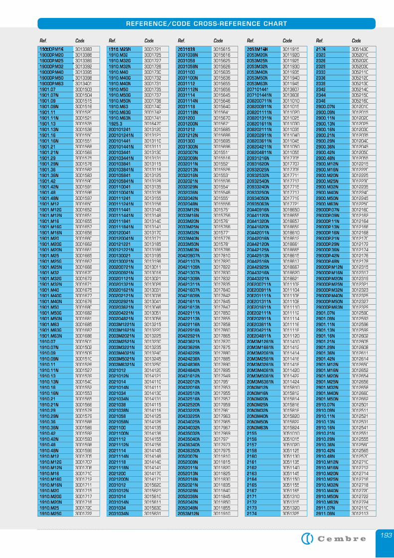
193
REFERENCE/CODE CROSS-REFERENCE CHART
1900DP.M16 30133831900DP.M20 30133861900DP.M25 30133891900DP.M32 30133921900DP.M40 30133951900DP.M50 30133981900DP.M63 30134011901.07 30015031901.07N 30015041901.09 30015151901.09N 30015161901.11 30015201901.11N 30015211901.13 30015351901.13N 30015361901.16 30015501901.16N 30015511901.21 30015681901.21N 30015691901.29 30015751901.29N 30015761901.36 30015821901.36N 30015831901.42 30015901901.42N 30015911901.48 30015961901.48N 30015971901.M12 30016501901.M12G 30016521901.M12N 30016511901.M16 30016551901.M16G 30016571901.M16N 30016561901.M20 30016601901.M20G 30016621901.M20N 30016611901.M25 30016651901.M25G 30016671901.M25N 30016661901.M32 30016701901.M32G 30016721901.M32N 30016711901.M40 30016751901.M40G 30016771901.M40N 30016761901.M50 30016801901.M50G 30016821901.M50N 30016811901.M63 30016851901.M63G 30016871901.M63N 30016861910.07 30015011910.07N 30015021910.09 30015091910.09N 30015101910.11 30015261910.11N 30015271910.13 30015391910.13N 30015401910.16 30015521910.16N 30015531910.21 30015651910.21N 30015661910.29 30015781910.29N 30015791910.36 30015881910.36N 30015891910.42 30015921910.42N 30015931910.48 30015981910.48N 30015991910.M12 30017051910.M12G 30017071910.M12N 30017061910.M16 30017101910.M16G 30017121910.M16N 30017111910.M20 30017151910.M20G 30017171910.M20N 30017161910.M25 30017201910.M25G 3001722
1910.M25N 30017211910.M32 30017251910.M32G 30017271910.M32N 30017261910.M40 30017301910.M40G 30017321910.M40N 30017311910.M50 30017351910.M50G 30017371910.M50N 30017361910.M63 30017401910.M63G 30017421910.M63N 30017411925.3 3016470200101241 3013120200101241N 3013121200101441 3013110200101441N 3013111200103441 3013130200103441N 3013131200103841 3013115200103841N 3013116200105841 3013125200105841N 3013126200110041 3013135200110041N 3013136200111241 3013155200111241N 3013156200111441 3013145200111441N 3013146200111841 3013140200111841N 3013141200120041 3013170200120041N 3013171200121221 3013185200121221N 3013186200130021 3013195200130021N 3013196200200721N 3013011200200921N 3013016200201121N 3013021200201321N 3013026200201621N 3013031200202121N 3013036200202921N 3013041200203621N 3013046200204221N 3013051200204821N 30130562003M1221N 30132152003M1621N 30132202003M2021N 30132252003M2521N 30132302003M3221N 30132352003M4021N 30132402003M5021N 30132452003M6321N 30132502021012 30141202021012N 30141212021014 30141102021014N 30141112021034 30141302021034N 30141312021038 30141152021038N 30141162021058 30141252021058N 30141262021100 30141352021100N 30141362021112 30141552021112N 30141562021114 30141452021114N 30141462021118 30141402021118N 30141412021200 30141702021200N 30141712031012 30156202031012N 30156212031014 30156102031014N 30156112031034 30156302031034N 3015631
2031038 30156152031038N 30156162031058 30156252031058N 30156262031100 30156352031100N 30156362031112 30156552031112N 30156562031114 30156452031114N 30156462031118 30156402031118N 30156412031200 30156702031200N 30156712031212 30156852031212N 30156862031300 30156952031300N 30156962032007N 30155112032009N 30155162032011N 30155212032013N 30155262032016N 30155312032021N 30155362032029N 30155412032036N 30155462032042N 30155512032048N 30155562033M12N 30157512033M16N 30157562033M20N 30157612033M25N 30157662033M32N 30157712033M40N 30157762033M50N 30157812033M63N 301578620420907N 301781020421107N 301782020421109N 301782220421307N 301783020421309N 301783220421311N 301783520421607N 301784020421609N 301784220421611N 301784520421613N 301784720422111N 301785020422113N 301785520422116N 301785820422916N 301786020422921N 301786520423621N 301787020423629N 301787520424229N 301788020424236N 301788520424836N 301789020424842N 301789520431612N 301794920432012N 301795120432016N 301795320432512N 301795520432516N 301795720432520N 301795920433220N 301796120433225N 301796320434025N 301796520434032N 301796720435032N 301796920435040N 301797120436340N 301797320436350N 30179752052007N 30118102052009N 30118152052011N 30118202052013N 30118252052016N 30118302052021N 30118352052029N 30118402052036N 30118452052042N 30118502052048N 30118552053M12N 3011910
2053M16N 30119152053M20N 30119202053M25N 30119252053M32N 30119302053M40N 30119352053M50N 30119402053M63N 3011945207101441 3013607207101441N 3013608208200711N 3011010208200911N 3011015208201111N 3011020208201311N 3011025208201611N 3011030208202111N 3011035208202911N 3011040208203611N 3011045208204211N 3011050208204811N 301105520931216N 301770520931620N 301770720932025N 301770920932532N 301771120932540N 301771320933240N 301771520933250N 301771720934050N 301771920935063N 301772120A40916N 301865020A41120N 301865520A41320N 301865720A41620N 301865920A42011N 301861020A42016N 301861220A42120N 301866120A42125N 301866520A42513N 301861520A42516N 301861720A42925N 301866720A43216N 301862020A43221N 301862120E200711N 301110220E200911N 301110420E201111N 301110620E201311N 301110820E201611N 301111020E202111N 301111220E202911N 301111420E203611N 301111620E204211N 301111820E204811N 301112020M3M1261N 301141020M3M1661N 301141220M3M2061N 301141420M3M2561N 301141620M3M3261N 301141820M3M4061N 301142020M3M5061N 301142220M3M6361N 301142420N3M12N 301581020N3M16N 301581220N3M20N 301581420N3M25N 301581620N3M32N 301581820N3M40N 301582020N3M50N 301582220N3M63N 30158242155 30510102156 30510152157 30510202158 30511252160 30511302161 30511352162 30511402163 30511452164 30511502165 30511552167 30511652171 30513102172 30513152173 30513202174 3051325
2176 30514302323 30520102326 30520202329 30520302333 30521102336 30521202339 30521302342 30521402344 30521502346 30521602900.07N 30120102900.09N 30120152900.11N 30120202900.13N 30120252900.16N 30120302900.21N 30120352900.29N 30120402900.36N 30120452900.42N 30120502900.48N 30120552900.M12N 30122152900.M16N 30122202900.M20N 30122252900.M25N 30122302900.M32N 30122352900.M40N 30122402900.M50N 30122452900.M63N 30122502900DP.07N 30121602900DP.09N 30121622900DP.11N 30121642900DP.13N 30121662900DP.16N 30121682900DP.21N 30121702900DP.29N 30121722900DP.36N 30121742900DP.42N 30121762900DP.48N 30121782900DP.M12N 30123152900DP.M16N 30123172900DP.M20N 30123192900DP.M25N 30123212900DP.M32N 30123232900DP.M40N 30123252900DP.M50N 30123272900DP.M63N 30123292901.07N 30125902901.09N 30125932901.11N 30125962901.13N 30125992901.16N 30126022901.21N 30126052901.29N 30126082901.36N 30126112901.42N 30126142901.M12N 30126502901.M16N 30126522901.M20N 30126542901.M25N 30126562901.M32N 30126582901.M40N 30126602901.M50N 30126622910.07N 30125012910.09N 30125112910.11N 30125212910.13N 30125312910.16N 30125412910.21N 30125512910.29N 30125552910.36N 30125602910.42N 30125652910.48N 30125702910.M12N 30127102910.M16N 30127122910.M20N 30127142910.M25N 30127162910.M32N 30127182910.M40N 30127202910.M50N 30127222910.M63N 30127242911.07N 30121102911.09N 3012113
Ref. Code Ref. Code Ref. Code Ref. Code Ref. Code
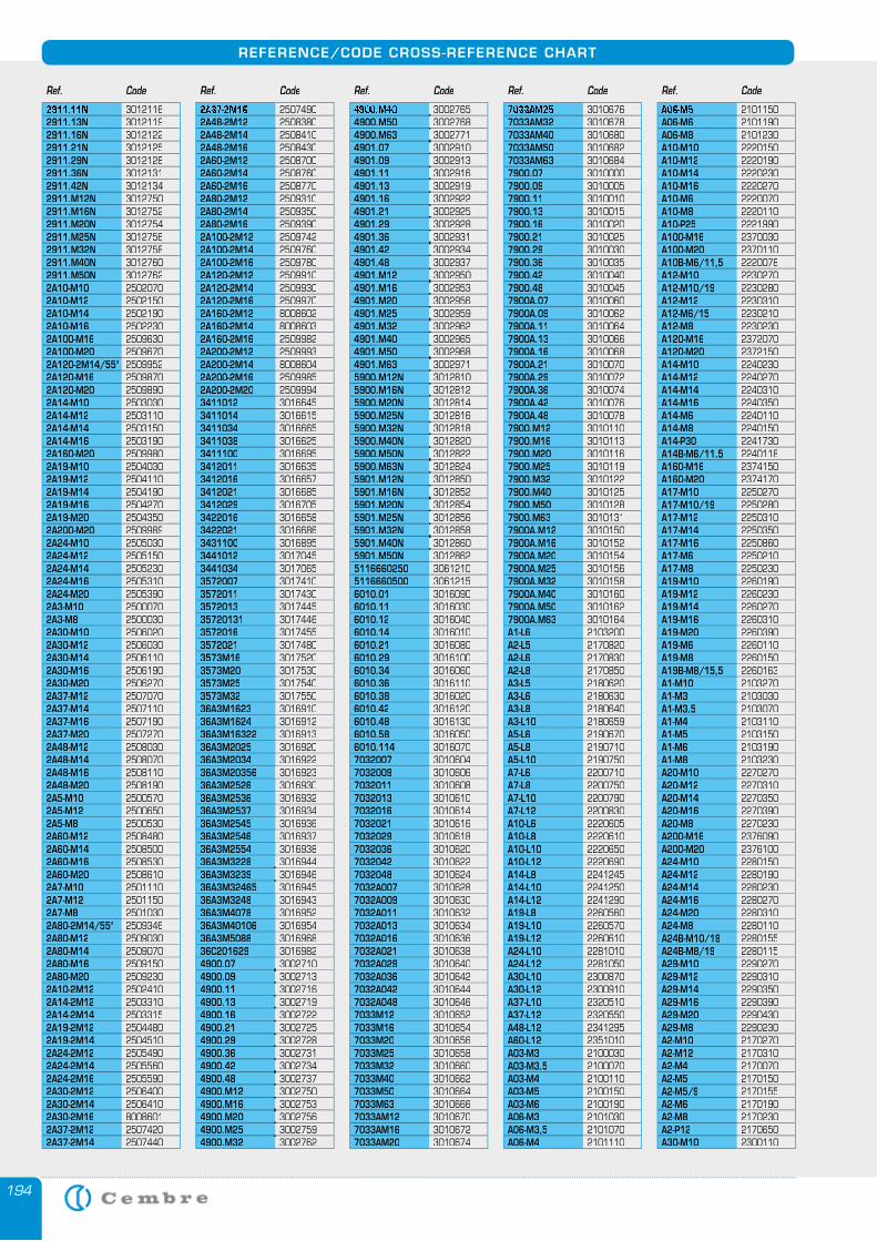
194
REFERENCE/CODE CROSS-REFERENCE CHART
2911.11N 30121162911.13N 30121192911.16N 30121222911.21N 30121252911.29N 30121282911.36N 30121312911.42N 30121342911.M12N 30127502911.M16N 30127522911.M20N 30127542911.M25N 30127562911.M32N 30127582911.M40N 30127602911.M50N 30127622A10-M10 25020702A10-M12 25021502A10-M14 25021902A10-M16 25022302A100-M16 25096302A100-M20 25096702A120-2M14/55° 25099522A120-M16 25098702A120-M20 25098902A14-M10 25030302A14-M12 25031102A14-M14 25031502A14-M16 25031902A160-M20 25099802A19-M10 25040302A19-M12 25041102A19-M14 25041902A19-M16 25042702A19-M20 25043502A200-M20 25099892A24-M10 25050302A24-M12 25051502A24-M14 25052302A24-M16 25053102A24-M20 25053902A3-M10 25000702A3-M8 25000302A30-M10 25060202A30-M12 25060302A30-M14 25061102A30-M16 25061902A30-M20 25062702A37-M12 25070702A37-M14 25071102A37-M16 25071902A37-M20 25072702A48-M12 25080302A48-M14 25080702A48-M16 25081102A48-M20 25081902A5-M10 25005702A5-M12 25006502A5-M8 25005302A60-M12 25084802A60-M14 25085002A60-M16 25085302A60-M20 25086102A7-M10 25011102A7-M12 25011502A7-M8 25010302A80-2M14/55° 25093462A80-M12 25090302A80-M14 25090702A80-M16 25091502A80-M20 25092302A10-2M12 25024102A14-2M12 25033102A14-2M14 25033152A19-2M12 25044802A19-2M14 25045102A24-2M12 25054902A24-2M14 25055602A24-2M16 25055902A30-2M12 25064002A30-2M14 25064102A30-2M16 80086012A37-2M12 25074202A37-2M14 2507440
2A37-2M16 25074902A48-2M12 25083802A48-2M14 25084102A48-2M16 25084302A60-2M12 25087002A60-2M14 25087602A60-2M16 25087702A80-2M12 25093102A80-2M14 25093502A80-2M16 25093902A100-2M12 25097422A100-2M14 25097602A100-2M16 25097802A120-2M12 25099102A120-2M14 25099302A120-2M16 25099702A160-2M12 80086022A160-2M14 80086032A160-2M16 25099822A200-2M12 25099932A200-2M14 80086042A200-2M16 25099852A200-2M20 25099943411012 30166453411014 30166153411034 30166653411038 30166253411100 30166953412011 30166353412016 30166573412021 30166853412029 30167053422016 30166583422021 30166863431100 30168953441012 30170453441034 30170653572007 30174103572011 30174303572013 301744535720131 30174463572016 30174553572021 30174803573M16 30175203573M20 30175303573M25 30175403573M32 301755036A3M1623 301691036A3M1624 301691236A3M16322 301691336A3M2025 301692036A3M2034 301692236A3M20356 301692336A3M2526 301693036A3M2536 301693236A3M2537 301693436A3M2545 301693636A3M2546 301693736A3M2554 301693836A3M3228 301694436A3M3239 301694636A3M32465 301694536A3M3248 301694336A3M4078 301695236A3M40106 301695436A3M5088 301696836C201629 30169824900.07 3002710 4900.09 3002713 4900.11 3002716 4900.13 3002719 4900.16 3002722 4900.21 3002725 4900.29 3002728 4900.36 3002731 4900.42 3002734 4900.48 3002737 4900.M12 3002750 4900.M16 3002753 4900.M20 3002756 4900.M25 3002759 4900.M32 3002762
4900.M40 3002765 4900.M50 3002768 4900.M63 3002771 4901.07 3002910 4901.09 3002913 4901.11 3002916 4901.13 3002919 4901.16 3002922 4901.21 3002925 4901.29 3002928 4901.36 3002931 4901.42 3002934 4901.48 3002937 4901.M12 3002950 4901.M16 3002953 4901.M20 3002956 4901.M25 3002959 4901.M32 3002962 4901.M40 3002965 4901.M50 3002968 4901.M63 3002971 5900.M12N 3012810 5900.M16N 3012812 5900.M20N 3012814 5900.M25N 3012816 5900.M32N 3012818 5900.M40N 3012820 5900.M50N 3012822 5900.M63N 3012824 5901.M12N 3012850 5901.M16N 3012852 5901.M20N 3012854 5901.M25N 3012856 5901.M32N 3012858 5901.M40N 3012860 5901.M50N 3012862 5116660250 30612105116660500 30612156010.01 30160906010.11 30160306010.12 30160406010.14 30160106010.21 30160806010.29 30161006010.34 30160606010.36 30161106010.38 30160206010.42 30161206010.48 30161306010.58 30160506010.114 30160707032007 30106047032009 30106067032011 30106087032013 30106107032016 30106147032021 30106167032029 30106187032036 30106207032042 30106227032048 30106247032A007 30106287032A009 30106307032A011 30106327032A013 30106347032A016 30106367032A021 30106387032A029 30106407032A036 30106427032A042 30106447032A048 30106467033M12 30106527033M16 30106547033M20 30106567033M25 30106587033M32 30106607033M40 30106627033M50 30106647033M63 30106667033AM12 30106707033AM16 30106727033AM20 3010674
7033AM25 30106767033AM32 30106787033AM40 30106807033AM50 30106827033AM63 30106847900.07 30100007900.09 30100057900.11 30100107900.13 30100157900.16 30100207900.21 30100257900.29 30100307900.36 30100357900.42 30100407900.48 30100457900A.07 30100607900A.09 30100627900A.11 30100647900A.13 30100667900A.16 30100687900A.21 30100707900A.29 30100727900A.36 30100747900A.42 30100767900A.48 30100787900.M12 30101107900.M16 30101137900.M20 30101167900.M25 30101197900.M32 30101227900.M40 30101257900.M50 30101287900.M63 30101317900A.M12 30101507900A.M16 30101527900A.M20 30101547900A.M25 30101567900A.M32 30101587900A.M40 30101607900A.M50 30101627900A.M63 3010164A1-L6 2103200A2-L5 2170820A2-L6 2170830A2-L8 2170850A3-L5 2180620A3-L6 2180630A3-L8 2180640A3-L10 2180659A5-L6 2190670A5-L8 2190710A5-L10 2190750A7-L6 2200710A7-L8 2200750A7-L10 2200790A7-L12 2200830A10-L6 2220605A10-L8 2220610A10-L10 2220650A10-L12 2220690A14-L8 2241245A14-L10 2241250A14-L12 2241290A19-L8 2260560A19-L10 2260570A19-L12 2260610A24-L10 2281010A24-L12 2281050A30-L10 2300870A30-L12 2300910A37-L10 2320510A37-L12 2320550A48-L12 2341295A60-L12 2351010A03-M3 2100030A03-M3,5 2100070A03-M4 2100110A03-M5 2100150A03-M6 2100190A06-M3 2101030A06-M3,5 2101070A06-M4 2101110
A06-M5 2101150A06-M6 2101190A06-M8 2101230A10-M10 2220150A10-M12 2220190A10-M14 2220230A10-M16 2220270A10-M6 2220070A10-M8 2220110A10-P25 2221990A100-M16 2370030A100-M20 2370110A10B-M6/11,5 2220078A12-M10 2230270A12-M10/19 2230280A12-M12 2230310A12-M6/15 2230210A12-M8 2230230A120-M16 2372070A120-M20 2372150A14-M10 2240230A14-M12 2240270A14-M14 2240310A14-M16 2240350A14-M6 2240110A14-M8 2240150A14-P30 2241730A14B-M6/11,5 2240118A160-M16 2374150A160-M20 2374170A17-M10 2250270A17-M10/19 2250280A17-M12 2250310A17-M14 2250350A17-M16 2250860A17-M6 2250210A17-M8 2250230A19-M10 2260190A19-M12 2260230A19-M14 2260270A19-M16 2260310A19-M20 2260390A19-M6 2260110A19-M8 2260150A19B-M8/15,5 2260163A1-M10 2103270A1-M3 2103030A1-M3,5 2103070A1-M4 2103110A1-M5 2103150A1-M6 2103190A1-M8 2103230A20-M10 2270270A20-M12 2270310A20-M14 2270350A20-M16 2270390A20-M8 2270230A200-M16 2376090A200-M20 2376100A24-M10 2280150A24-M12 2280190A24-M14 2280230A24-M16 2280270A24-M20 2280310A24-M8 2280110A24B-M10/19 2280155A24B-M8/19 2280115A29-M10 2290270A29-M12 2290310A29-M14 2290350A29-M16 2290390A29-M20 2290430A29-M8 2290230A2-M10 2170270A2-M12 2170310A2-M4 2170070A2-M5 2170150A2-M5/9 2170155A2-M6 2170190A2-M8 2170230A2-P12 2170650A30-M10 2300110
Ref. Code Ref. Code Ref. Code Ref. Code Ref. Code
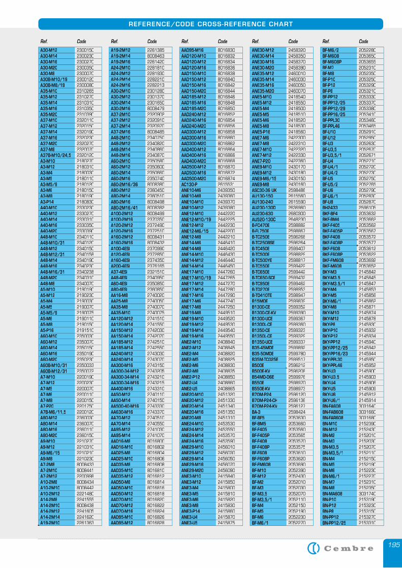
195
REFERENCE/CODE CROSS-REFERENCE CHART
A30-M12 2300150A30-M14 2300230A30-M16 2300270A30-M20 2300350A30-M8 2300070A30B-M10/19 2300120A30B-M8/19 2300080A35-M10 2310265A35-M12 2310270A35-M14 2310310A35-M16 2310350A35-M20 2310390A37-M10 2320110A37-M12 2320150A37-M14 2320190A37-M16 2320230A37-M20 2320270A37-M8 2320070A37B-M10/24,5 2320120A3-M10 2180270A3-M12 2180310A3-M4 2180030A3-M5 2180110A3-M5/9 2180120A3-M6 2180150A3-M8 2180190A3-P14 2180830A40-M10 2330230A40-M12 2330270A40-M14 2330310A40-M16 2330350A40-M20 2330390A48-M10 2340110A48-M10/31 2340120A48-M12 2340150A48-M12/31 2340158A48-M14 2340190A48-M16 2340230A48-M16/31 2340238A48-M20 2340310A48-M8 2340070A5-M10 2190190A5-M12 2190230A5-M4 2190030A5-M5 2190070A5-M5/9 2190075A5-M6 2190110A5-M8 2190150A5-P16 2191510A60-M10 2350030A60-M12 2350070A60-M14 2350150A60-M16 2350190A60-M20 2350230A60B-M10/31 2350033A60B-M12/31 2350072A7-M10 2200190A7-M12 2200230A7-M5 2200070A7-M6 2200110A7-M8 2200150A7-P20 2201750A7B-M6/11,5 2200120A80-M12 2360030A80-M14 2360070A80-M16 2360110A80-M20 2360150A9-M10 2210270A9-M12 2210310A9-M6/15 2210210A9-M8 2210230A7-2M8 8008433A7-2M10 8008441A7-2M12 2200998A10-2M8 8008434A10-2M10 8008442A10-2M12 2221480A14-2M8 2241555A14-2M10 8008438A14-2M12 2241605A14-2M14 2241620A19-2M10 2261363
A19-2M12 2261385A19-2M14 8008463A19-2M16 2261420A24-2M10 2281810A24-2M12 2281930A24-2M14 2282210A24-2M16 2282213A30-2M10 2301280A30-2M12 2301370A30-2M14 2301650A30-2M16 8008479A37-2M10 2320902A37-2M12 2320910A37-2M14 2320970A37-2M16 8008485A48-2M10 2340750A48-2M12 2340820A48-2M14 2340860A48-2M16 2340870A60-2M10 2350580A60-2M12 2350600A60-2M14 2350660A60-2M16 2350740A60-2M16/36 8008380A80-2M12 2360450A80-2M14 2360510A80-2M16 8008498A80-2M16/41 8008382A100-2M12 8008499A100-2M16 2370350A120-2M12 2372490A120-2M16 2372510A160-2M12 8008431A160-2M16 8008432A100-4ESI 2370990A120-4ESI 2372850A160-4ESI 2374350A200-4ESI 2376165A37-4ESI 2321510A48-4ESI 2340950A60-4ESI 2350850A80-4ESI 2360850AA16-M8 2740020AA25-M8 2740050AA35-M8 2740070AA35-M10 2740075AA120-M12 2741510AA120-M14 2741550AA150-M12 2742030AA150-M14 2742070AA185-M12 2742510AA185-M14 2742550AA240-M12 2743030AA240-M14 2743070AA300-M16 2743150AA300-34-M12 2743205AA300-34-M14 2743210AA300-34-M16 2743215AA400-M16 2743310AA50-M12 2740110AA50-M14 2740150AA500-40-M16 2743330AA630-M16 2743370AA70-M12 2740510AA70-M14 2740550AA95-M12 2741030AA95-M14 2741070AAD16-M8 8016800AAD16-M10 8016802AAD25-M8 8016804AAD25-M10 8016806AAD35-M8 8016808AAD35-M10 8016810AAD35-M12 8016812AAD50-M8 8016814AAD50-M10 8016816AAD50-M12 8016818AAD70-M10 8016820AAD70-M12 8016822AAD70-M16 8016824AAD95-M10 8016826AAD95-M12 8016828
AAD95-M16 8016830AAD120-M10 8016832AAD120-M12 8016834AAD120-M16 8016836AAD150-M10 8016838AAD150-M12 8016840AAD150-M16 8016842AAD150-M20 8016844AAD185-M12 8016846AAD185-M16 8016848AAD185-M20 8016850AAD240-M12 8016852AAD240-M16 8016854AAD240-M20 8016856AAD300-M12 8016858AAD300-M16 8016860AAD300-M20 8016862AAD400-M12 8016864AAD400-M16 8016866AAD400-M20 8016868AAD500-M12 8016870AAD500-M16 8016872AAD500-M20 8016874AC130-P 2615531ANE10-M6 2439350ANE10-M8 2439360ANE10-M10 2439370ANE10-M12 2439380ANE12-M10 2442220ANE12-M10/19 2442225ANE12-M12 2442230ANE12-M6/15 2442200ANE12-M8 2442210ANE14-M6 2446410ANE14-M8 2446420ANE14-M10 2446430ANE14-M12 2446440ANE14-M14 2446450ANE17-M10 2447260ANE17-M10/19 2447265ANE17-M12 2447270ANE17-M14 2447280ANE17-M16 2447290ANE17-M6 2447240ANE17-M8 2447250ANE19-M8 2449510ANE19-M10 2449520ANE19-M12 2449530ANE19-M14 2449540ANE19-M16 2449550ANE2-M10 2408840ANE2-M12 2408845ANE2-M4 2408820ANE2-M5 2408825ANE2-M6 2408830ANE2-M8 2408835ANE2-P12 2408850ANE2-U4 2408860ANE2-U5 2408865ANE20-M10 2451320ANE20-M12 2451330ANE20-M14 2451340ANE20-M16 2451350ANE20-M8 2451310ANE24-M10 2453530ANE24-M12 2453550ANE24-M14 2453570ANE24-M16 2453590ANE29-M10 2456010ANE29-M12 2456030ANE29-M14 2456050ANE29-M16 2456070ANE29-M20 2456090ANE3-M10 2415840ANE3-M12 2415850ANE3-M4 2415800ANE3-M5 2415810ANE3-M6 2415820ANE3-M8 2415830ANE3-P14 2415860ANE3-U4 2415870ANE3-U5 2415875
ANE30-M12 2458320ANE30-M14 2458350ANE30-M16 2458370ANE30-M20 2458390ANE35-M12 2460010ANE35-M14 2460030ANE35-M16 2460050ANE35-M20 2460070ANE5-M10 2418540ANE5-M12 2418550ANE5-M4 2418500ANE5-M5 2418510ANE5-M6 2418520ANE5-M8 2418530ANE5-P16 2418560ANE7-M6 2422300ANE7-M8 2422310ANE7-M10 2422320ANE7-M12 2422330ANE7-P20 2422360ANE9-M10 2430170ANE9-M12 2430180ANE9-M6/15 2430150ANE9-M8 2430160ASC30-36 UK 2598486AU130-150 2615560AU130-240 2615590AU230-130D 2636960AU230-630 2680300AU520-130C 2648230B-FC470E 2598882B-FL750E 2598867B-TC250E 2596268B-TC250BSE 2596264B-TC450E 2599407B-TC500E 2598829B-TC500YE 2598817B-TC550E 2599422B-TC650E 2599442B-TC650-SCE 2599432B-TC950E 2599462B-TD270E 2598953B-TD410TE 2598947B15MDE 2599839B1300-CE 2599352B1300-CE-KV 2599390B1300-UCE 2599367B1300L-CE 2599360B1350-CE 2599323B1350L-CE 2599329B1350-UCE 2599337B35-45MDE 2599892B35-50MDE 2599780B35M-TC025E 2599517B500E 2596212B500E-KV 2596208B54MD-D6E 2599976B550E 2598970B550E-KV 2598973B70M-P24 2596120B70M-P24-CH 2596136B70M-P24-KV 2596127BA-3 2598424BF-BF5 2053630BF-BM5 2053660BF-F405 2053560BF-F405P 2053565BF-F408 2053570BF-F408P 2053575BF-F608 2053610BF-F608P 2053620BF-FM608 2053690BF-M10 2052390BF-M12 2052430BF-M2 2052010BF-M3 2052030BF-M3,5 2052070BF-M3,5/1 2052110BF-M4 2052150BF-M5 2052190BF-M6 2052230BF-M6/1 2052270
BF-M6/2 2052280BF-M608 2053650BF-M608P 2053655BF-M7 2052310BF-M8 2052350BF-P10 2053250BF-P12 2053290BF-P8 2053210BF-PP12 2053330BF-PP12/25 2053370BF-PP12/29 2053380BF-PP16/25 2053410BF-PPL30 2053460BF-PPL46 2053465BF-U10 2052910BF-U12 2052950BF-U3 2052630BF-U3,5 2052670BF-U3,5/1 2052671BF-U4 2052710BF-U4/1 2052720BF-U4/2 2052730BF-U5 2052750BF-U5/2 2052765BF-U6 2052790BF-U6/1 2052830BF-U8 2052870BH2433 2596105BKF-BF4 2053632BKF-BM4 2053662BKF-F405 2053562BKF-F405P 2053567BKF-F408 2053572BKF-F408P 2053577BKF-F608 2053612BKF-F608P 2053622BKF-FM608 2053692BKF-M608 2053652BKY-M3 2145842BKY-M3.5 2145845BKY-M3.5/1 2145847BKY-M4 2145853BKY-M5 2145856BKY-M6/1 2145862BKY-M8 2145871BKY-M10 2145874BKY-M12 2145878BKY-P8 2145930BKY-P10 2145932BKY-P12 2145934BKY-PP12 2145940BKY-PP12/25 2145942BKY-PP16/23 2145944BKY-PPL30 2145950BKY-PPL46 2145952BKY-U3 2145900BKY-U3.5 2145903BKY-U4 2145906BKY-U5 2145909BKY-U6 2145912BKY-U6/1 2145914BN-FA608 3031640BN-FAB608 3031660BN-FAR608 3031680BN-M10 2152390BN-M12 2152430BN-M2 2152010BN-M3 2152030BN-M3,5 2152070BN-M3,5/1 2152110BN-M4 2152150BN-M5 2152190BN-M6 2152230BN-M6/1 2152270BN-M7 2152310BN-M8 2152350BN-MA608 3031740BN-P10 2153190BN-P12 2153230BN-P8 2153150BN-PP12 2153270BN-PP12/25 2153310
Ref. Code Ref. Code Ref. Code Ref. Code Ref. Code
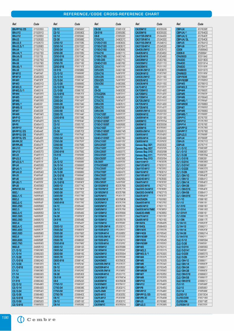
196
REFERENCE/CODE CROSS-REFERENCE CHART
BN-PP16/25 2153350BN-U10 2152910BN-U12 2152950BN-U3 2152630BN-U3,5 2152670BN-U3,5/1 2152680BN-U4 2152710BN-U4/1 2152730BN-U4/2 2152732BN-U5 2152750BN-U6 2152790BN-U6/1 2152830BN-U8 2152870BP-M10 2046345BP-M12 2046350BP-M2 2046305BP-M3 2046310BP-M3,5 2046315BP-M3,5/1 2046316BP-M4 2046320BP-M5 2046325BP-M6 2046330BP-M6/1 2046331BP-M6/2 2046332BP-M7 2046335BP-M8 2046340BP-P10 2046415BP-P12 2046420BP-P8 2046410BP-PP12 2046440BP-PP12/25 2046445BP-PP12/29 2046450BP-PP16/25 2046455BP-PPL30 2046470BP-PPL46 2046475BP-U10 2046565BP-U12 2046570BP-U3 2046510BP-U3,5 2046515BP-U3,5/1 2046516BP-U4 2046530BP-U4/1 2046531BP-U4/2 2046540BP-U5 2046545BP-U6 2046555BP-U6/1 2046556BP-U8 2046560BPS230.24 2596093BSCL1 2489535BSCL1/0 2489540BSCL2 2489530BSCL2/0 2489545BSCL250 2489560BSCL3 2489525BSCL3/0 2489550BSCL300 2489565BSCL350 2489570BSCL4 2489520BSCL4/0 2489555BSCL400 2489575BSCL500 2489580BSCL6 2489515BSCL600 2489585BSCL750 2489590BSCL8 2489510C1/0-12 2396280C1/0-14 2396220C1/0-38 2396260C1/0-516 2396240C1/0-58 2396320C1/0-916 2396300C1-12 2396080C1-14 2396020C1-38 2396060C1-516 2396040C2/0-12 2396480C2/0-14 2396420C2/0-34 2396540C2/0-38 2396460C2/0-516 2396440C2/0-58 2396520C2/0-916 2396500
C2-10 2395820C2-12 2395900C2-14 2395840C2-38 2395880C250-12 2397080C250-14 2397020C250-34 2397140C250-38 2397060C250-516 2397040C250-58 2397120C250-78 2397160C250-916 2397100C2-516 2395860C3/0-12 2396680C3/0-14 2396620C3/0-34 2396740C3/0-38 2396660C3/0-516 2396640C3/0-58 2396720C3/0-916 2396700C300-12 2397360C300-34 2397420C300-38 2397340C300-516 2397320C300-58 2397400C300-78 2397440C300-916 2397380C3-10 2395640C3-12 2395720C3-14 2395660C3-38 2395700C350-12 2397540C350-34 2397600C350-38 2397520C350-58 2397580C350-78 2397620C350-916 2397560C3-516 2395680C3-8 2395620C4/0-12 2396880C4/0-14 2396820C4/0-34 2396940C4/0-38 2396860C4/0-516 2396840C4/0-58 2396920C4/0-916 2396900C400-12 2397740C400-34 2397800C400-38 2397720C400-58 2397780C400-78 2397820C400-916 2397760C4-10 2395440C4-12 2395520C4-14 2395460C4-38 2395500C4-516 2395480C4-8 2395420C500-12 2397940C500-34 2398000C500-38 2397920C500-58 2397980C500-78 2398020C500-916 2397960C600-12 2398120C600-34 2398180C600-58 2398160C600-78 2398200C600-916 2398140C6-10 2395240C6-12 2395320C6-14 2395260C6-38 2395300C6-516 2395280C6-8 2395220C750-12 2398320C750-34 2398380C750-58 2398360C750-78 2398400C8-10 2395040C8-12 2395120C8-14 2395060
C8-38 2395100C8-516 2395080C8-8 2395020C10-C10 2490070C120-C120 2490630C150-C120 2490670C150-C150 2490690C16-C16 2490110C185-C185 2490745C185-C95 2490710C240-C120 2490760C25-C10 2490150C25-C25 2490190C35-C16 2490230C35-C35 2490270C50-C25 2490350C50-C50 2490390C59 8420035C6-C6 2490030C70-C25N 2490310C70-C35 2490430C70-C70 2490470C95-C35 2490510C95-C70 2490550C95-C95 2490590C10-C10ST 2492070C120-C120ST 2492630C150-C120ST 2492670C150-C150ST 2492690C16-C16ST 2492110C185-C185ST 2492745C185-C95ST 2492710C240-C120ST 2492760C25-C10ST 2492150C25-C25ST 2492190C35-C16ST 2492230C35-C35ST 2492270C50-C25ST 2492350C50-C50ST 2492390C6-C6ST 2492030C70-C25NST 2492310C70-C35ST 2492430C70-C70ST 2492470C95-C35ST 2492510C95-C70ST 2492550C95-C95ST 2492590CA1202M12 8005766CA1502M12 8005776CA1852M12 8005786CA252M10 2530170CA3002M12 8005806CA352M12 8005726CA502M12 8005736CA952M12 8005756CA120M12 8005566CA120M16 8005570CA150M12 8005576CA150M16 8005580CA150R-2M14 2533010CA150R-M12 2532810CA150R-M14 2532850CA150S-2M14 2533330CA150S-M12 2533210CA150S-M14 2533250CA185M12 8005586CA185M16 8005590CA240M12 8005594CA240M16 8005596CA240M20 8005600CA200R-2M14 2533570CA200R-M14 2533530CA240R-2M14 2533850CA240R-M14 2533770CA300M12 8005604CA300M16 8005608CA300M20 8005610CA25-2M12 2530210CA25-2M8 2530130CA25-M10 2530050CA25-M12 2530090CA25-M8 2530010CA35M10 8005524
CA35M12 8005526CA35M16 8005530CA315R-2M14 2534430CA315R-M14 2534330CA315S-2M14 2534610CA315S-M14 2534530CA40S-2M12 2530510CA40S-M12 2530450CA40S-M16 2530490CA50RM12 2530790CA50SM12 2531110CA50SM16 2531150CA50R-2M12 2530870CA50R-M12 2530790CA50S-2M12 2531190CA50S-M12 2531110CA50S-M16 2531150CA70-M12 2531870CA70SM10 2531420CA70SM12 2531430CA70SM14 2531450CA70S-2M12 2531510CA70S-M12 2531430CA70S-M16 2531470CA95R-2M14 2532230CA95R-M12 2532150CA95R-M14 2532190CA95M10 8005554CA95M12 8005556CA95M16 8005560CA95S-2M14 2532610CA95S-M12 2532450CA95S-M14 2532490CA95S-M16 2532500Canvas Bag 001Canvas Bag 001 2593300Canvas Bag 007Canvas Bag 007 2593295Canvas Bag 010Canvas Bag 010 2593298Canvas Bag 011Canvas Bag 011 2593299Canvas Bag 013Canvas Bag 013 2593294CAA10-M12 2760005CAA120-M12 2760310CAA150-M12 2760350CAA16-M12 2760012CAA185-M12 2760430CAA240-M12 2760590CAA25-M12 2760030CAA300-M16 2760710CAA300-34-M12 2760680CAA300-34-M16 2760715CAA35-M12 2760070CAA35ADN 2762260CAA400-M16 2760750CAA50-M12 2760110CAA500-M16-TNBD 2760852CAA630-4M8 2760950CAA70-M12 2760150CAA95-M12 2760190CB1820L 2598495CB1840L 2598493CBP-F405 2076535CBP-F408 2076540CBP-F408P 2076543CBP-F608 2076545CBP-F608P 2076550CBP-M3 2076310CBP-M3,5 2076315CBP-M3,5/1 2076320CBP-M4 2076325CBP-M5 2076335CBP-M6 2076340CBP-M6/1 2076345CBP-M608 2076560CBP-M7 2076350CBP-M8 2076355CBP-P10 2076455CBP-P12 2076460CBP-P8 2076450CBP-PP12 2076480CBP-PP12/25 2076490CBP-PPL30 2076498CBP-U3 2076380CBP-U3,5 2076385
CBP-U4 2076395CBP-U4/1 2076400CBP-U4/2 2076405CBP-U4/3L 2076408CBP-U5 2076410CBP-U6 2076415CDD6 2599940CDD6-8 2599941CFA2600 3031942CFA300 3031900CFA400 3031914CFA600 3031928CFAB600 3031970CFAR600 3031956CGP-F608 2076845CGP-F608P 2076850CGP-M3 2076610CGP-M3,5 2076615CGP-M4 2076625CGP-M5 2076635CGP-M6 2076640CGP-M6/1 2076645CGP-M608 2076860CGP-M7 2076650CGP-M8 2076660CGP-M8/1 2076665CGP-P10 2076755CGP-P12 2076760CGP-P14 2076765CGP-PP12 2076780CGP-PP17 2076790CGP-U3,5 2076685CGP-U4 2076695CGP-U5 2076710CGP-U6 2076715CL1/0-10 2396385CL1/0-12 2396397CL1/0-38 2396394CL1/0-516 2396391CL1/0-D14 2396360CL1/0-D141 2396361CL1/0-D38 2396370CL1/0-DN 2396375CL1/0IH-10 2396405CL1/0IH-12 2396413CL1/0IH-14 2396407CL1/0IH-38 2396411CL1/0IH-516 2396409CL1/0IH-58 2396417CL1/0IH-916 2396415CL1-10 2396183CL1-12 2396191CL1-516 2396187CL1-D14 2396160CL1-D141 2396161CL1-D38 2396170CL1-DN 2396175CL1IH-10 2396205CL1IH-12 2396217CL1IH-14 2396208CL1IH-38 2396214CL1IH-516 2396211CL2/0-12 2396594CL2/0-38 2396591CL2/0-D14 2396560CL2/0-D141 2396561CL2/0-D38 2396570CL2/0-DN 2396575CL2/0IH-12 2396611CL2/0IH-14 2396605CL2/0IH-34 2396617CL2/0IH-38 2396609CL2/0IH-516 2396607CL2/0IH-58 2396615CL2/0IH-916 2396613CL2-10 2395985CL2-12 2395997CL2-14 2395988CL250-12 2397204CL250-D38 2397180CL250-DN 2397185CL250IH-12 2397229
Ref. Code Ref. Code Ref. Code Ref. Code Ref. Code
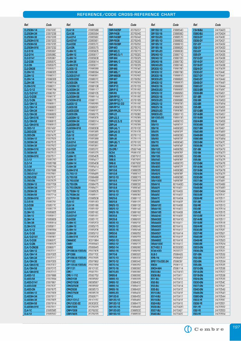
197
REFERENCE/CODE CROSS-REFERENCE CHART
CL250IH-14 2397220CL250IH-34 2397238CL250IH-38 2397226CL250IH-516 2397223CL250IH-58 2397235CL250IH-916 2397232CL2-516 2395991CL2-D14 2395960CL2-D141 2395961CL2-D38 2395970CL2-DN 2395975CL2-DN38 2395971CL2IH-10 2396005CL2IH-12 2396017CL2IH-14 2396008CL2IH-38 2396014CL2IH-516 2396011CL3/0-12 2396794CL3/0-D141 2396761CL3/0-D38 2396770CL3/0-DN 2396775CL3/0IH-12 2396811CL3/0IH-14 2396805CL3/0IH-34 2396817CL3/0IH-38 2396809CL3/0IH-516 2396807CL3/0IH-58 2396815CL3/0IH-916 2396813CL300-12 2397491CL300-D38 2397470CL300-DN 2397475CL300IH-12 2397509CL300IH-34 2397515CL300IH-38 2397507CL300IH-516 2397505CL300IH-58 2397513CL300IH-916 2397511CL3-12 2395797CL3-14 2395788CL3-38 2395794CL350-12 2397688CL350-D141 2397661CL350-D38 2397670CL350-DN 2397675CL350IH-12 2397708CL350IH-34 2397717CL350IH-38 2397705CL350IH-58 2397714CL350IH-916 2397711CL3-516 2395791CL3-D38 2395770CL3-DN 2395775CL3IH-10 2395805CL3IH-12 2395817CL3IH-14 2395808CL3IH-38 2395814CL3IH-516 2395811CL4/0-12 2396994CL4/0-38 2396991CL4/0-D141 2396961CL4/0-D38 2396970CL4/0-DN 2396975CL4/0-DN38 2396971CL4/0IH-12 2397011CL4/0IH-14 2397005CL4/0IH-34 2397017CL4/0IH-38 2397009CL4/0IH-516 2397007CL4/0IH-58 2397015CL4/0IH-916 2397013CL400-12 2397888CL400-58 2397894CL400-D141 2397861CL400-D38 2397870CL400-DN 2397875CL400IH-12 2397908CL400IH-34 2397917CL400IH-38 2397905CL400IH-58 2397914CL400IH-916 2397911CL4-10 2395585CL4-12 2395597
CL4-14 2395588CL4-38 2395594CL4-D14 2395560CL4-D141 2395561CL4-D38 2395570CL4-DN 2395575CL4IH-10 2395605CL4IH-12 2395617CL4IH-14 2395608CL4IH-38 2395614CL4IH-516 2395611CL500-12 2398088CL500-58 2398094CL500-D141 2398061CL500-D38 2398070CL500-DN 2398075CL500IH-12 2398108CL500IH-34 2398117CL500IH-38 2398105CL500IH-58 2398114CL500IH-916 2398111CL600-12 2398285CL600-58 2398291CL600-D38 2398270CL600-DN 2398275CL600IH-12 2398305CL600IH-34 2398314CL600IH-58 2398311CL600IH-916 2398308CL6-10 2395385CL6-12 2395397CL6-14 2395388CL6-D14 2395360CL6-D141 2395361CL6-D38 2395370CL6-DN 2395375CL6IH-10 2395405CL6IH-12 2395417CL6IH-14 2395408CL6IH-38 2395414CL6IH-516 2395411CL750-12 2398485CL750-58 2398488CL750-D38 2398470CL750-DN 2398475CL750-DN38 2398471CL750IH-12 2398505CL750IH-34 2398511CL750IH-58 2398508CL8-10 2395183CL8-14 2395186CL8-38 2395192CL8-D14 2395160CL8-D141 2395161CL8-D38 2395170CL8IH-10 2395203CL8IH-12 2395215CL8IH-14 2395206CL8IH-38 2395212CL8IH-516 2395209CMA600 3031984CMB1 2599943CMB2 2599945CP1086-W-1000-KV 2597905CP1096 2597700CP1096-W-1000-KV 2597695CP1120 2597962CP1120-W-1000-KV 2597958CP1131 2610120CPE-1 2592751CPE-1-110 2592752CPKD108 2808582CPKD1508 2808587CPKD2508 2808592CPKD508 2808573CPKD7508 2808578CPP-0 2592671CPU1131-C 2610150CPU1230-3D 2630200CRP-F305 2076225CRP-F308 2076230CRP-F405 2076235
CRP-F405P 2076237CRP-F408 2076240CRP-F408P 2076242CRP-F608 2076245CRP-F608P 2076250CRP-M3 2076010CRP-M3,5 2076015CRP-M3,5/1 2076020CRP-M4 2076025CRP-M4/3 2076030CRP-M5 2076035CRP-M6 2076040CRP-M6/1 2076045CRP-M608 2076260CRP-M7 2076050CRP-M8 2076055CRP-P10 2076155CRP-P12 2076160CRP-P8 2076150CRP-PP12 2076180CRP-PP12/1 2076185CRP-PP12/23 2076190CRP-PP14 2076195CRP-PPL30 2076205CRP-U3 2076080CRP-U3,5 2076085CRP-U3,5/2 2076090CRP-U4 2076095CRP-U4/1 2076100CRP-U4/2 2076105CRP-U5 2076110CRP-U6 2076115CRP-U6/1 2076120CRP-U8 2076125CS-CPE-1 2592748DC24 2596100DR6-5 2387910DR6-6 2387920DR6-8 2387930DR10-5 2388000DR10-6 2388005DR10-8 2388010DR10-10 2388015DR16-5 2388025DR16-6 2388030DR16-8 2388040DR16-10 2388050DR16-12 2388060DR25-6 2388110DR25-8 2388120DR25-10 2388130DR25-12 2388140DR25-16 2388160DR35-6 2388210DR35-8 2388220DR35-10 2388230DR35-12 2388240DR35-16 2388246DR50-6 2388250DR50-8 2388255DR50-10 2388260DR50-12 2388270DR50-14 2388280DR50-16 2388290DR70-8 2388320DR70-10 2388330DR70-12 2388340DR70-14 2388350DR70-16 2388360DR70-20 2388380DR95-8 2388390DR95-10 2388395DR95-12 2388400DR95-14 2388410DR95-16 2388420DR95-20 2388430DR120-8 2388450DR120-10 2388460DR120-12 2388470DR120-16 2388490DR120-20 2388500DR150-10 2388530
DR150-12 2388540DR150-16 2388560DR150-20 2388570DR185-10 2388600DR185-12 2388610DR185-16 2388620DR185-20 2388630DR240-10 2388710DR240-12 2388720DR240-16 2388730DR240-20 2388740DR300-10 2388780DR300-12 2388790DR300-16 2388810DR300-20 2388820DR400-12 2388870DR400-16 2388890DR400-20 2388900DR500-12 2388950DR500-16 2388970DR500-20 2388980DR625-12 2389030DR625-16 2389050DR625-20 2389060DR800-20 2389110DR1000-20 2389130DSV6 2489010DSV10 2489015DSV16 2489020DSV25 2489025DSV35 2489030DSV50 2489035DSV70 2489040DSV95 2489045DSV120 2489050DSV150 2489055DSV185 2489060DSV240 2489065DSV300 2489070DSV400 2489075DSV500 2489080DSV625 2489085DSV800 2489090DSV1000 2489095DSVA16 8016400DSVA25 8016401DSVA35 8016402DSVA50 8016403DSVA70 8016404DSVA95 8016405DSVA120 8016406DSVA150 8016407DSVA185 8016408DSVA240 8016409DSVA300 8016410DSVA400 8016411DSVA500 8016412DSVA401 8016413DSVA501 8016414DSVA625 8016415DSVA800 8016416DSVA1000 8016417ECT-KE2.5 8030200ECW-H3D 2630073ELB-3 2598422EPB-1N 2598453EPS115-230.24 2596091ERCH 2596112ERCH-WH 2596114ES03-BU 2470410ES06-BU 2470411ES1-BU 2470412ES2-BU 2470413ES3-BU 2470414ES5-BU 2470415ES10-BU 2470416ES14-BU 2470417ES19-BU 2470418ES24-BU 2470419ES30-BU 2470420ES37-BU 2470421ES40-BU 2470422
ES48-BU 2470423ES80-BU 2470424ES03-GY 2470430ES06-GY 2470431ES1-GY 2470432ES2-GY 2470433ES3-GY 2470434ES5-GY 2470435ES10-GY 2470436ES14-GY 2470437ES19-GY 2470438ES24-GY 2470439ES30-GY 2470440ES37-GY 2470441ES40-GY 2470442ES48-GY 2470443ES80-GY 2470444ES03-BR 2470450ES06-BR 2470451ES1-BR 2470452ES2-BR 2470453ES3-BR 2470454ES5-BR 2470455ES10-BR 2470456ES14-BR 2470457ES19-BR 2470458ES24-BR 2470459ES30-BR 2470460ES37-BR 2470461ES40-BR 2470462ES48-BR 2470463ES80-BR 2470464ES03-BK 2470470ES06-BK 2470471ES1-BK 2470472ES2-BK 2470473ES3-BK 2470474ES5-BK 2470475ES10-BK 2470476ES14-BK 2470477ES19-BK 2470478ES24-BK 2470479ES30-BK 2470480ES37-BK 2470481ES40-BK 2470482ES48-BK 2470483ES80-BK 2470484ES03-RE 2470510ES06-RE 2470511ES1-RE 2470512ES2-RE 2470513ES3-RE 2470514ES5-RE 2470515ES10-RE 2470516ES14-RE 2470517ES19-RE 2470518ES24-RE 2470519ES30-RE 2470520ES37-RE 2470521ES40-RE 2470522ES48-RE 2470523ES80-RE 2470524ES03-GN 2470530ES06-GN 2470531ES1-GN 2470532ES2-GN 2470533ES3-GN 2470534ES5-GN 2470535ES10-GN 2470536ES14-GN 2470537ES19-GN 2470538ES24-GN 2470539ES30-GN 2470540ES37-GN 2470541ES40-GN 2470542ES48-GN 2470543ES80-GN 2470544ES03-YE 2470550ES06-YE 2470551ES1-YE 2470552ES2-YE 2470553ES3-YE 2470554
Ref. Code Ref. Code Ref. Code Ref. Code Ref. Code
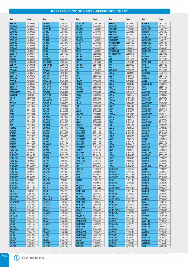
198
REFERENCE/CODE CROSS-REFERENCE CHART
Ref. Code Ref. Code Ref. Code Ref. Code Ref. Code
ES5-YE 2470555ES10-YE 2470556ES14-YE 2470557ES19-YE 2470558ES24-YE 2470559ES30-YE 2470560ES37-YE 2470561ES40-YE 2470562ES48-YE 2470563ES80-YE 2470564ES03-PK 2470570ES06-PK 2470571ES1-PK 2470572ES2-PK 2470573ES3-PK 2470574ES5-PK 2470575ES10-PK 2470576ES14-PK 2470577ES19-PK 2470578ES24-PK 2470579ES30-PK 2470580ES37-PK 2470581ES40-PK 2470582ES48-PK 2470583ES80-PK 2470584ESC300CEE 2596110ESC600 2599001F1-15 2599865FD11 3017354FD13,5 3017356FD16 3017358FD21 3017360FD29 3017362FD36 3017364FD42 3017366FD48 3017368FD7 3017350FD9 3017352FDM12 3017375FDM16 3017374FDM20 3017377FDM25 3017379FDM32 3017381FDM40 3017383FDM50 3017385FDM63 3017387FL10-150 2510070FL10-200 2510150FL10-250 2510190FL16-150 2510470FL16-200 2510550FL16-250 2510590FL16-320 2510670FL16-350 2510690FL16-420 2510710FL16-570 2510750FL16-660 2510790FL25-150 2510950FL25-200 2511070FL25-250 2511110FL25-300 2511190GA-3 2598429GF-F608 2055630GF-F608P 2055650GF-M10 2054250GF-M10/1 2054290GF-M12 2054330GF-M14 2054370GF-M16 2054410GF-M3 2054010GF-M3,5 2054030GF-M4 2054070GF-M5 2054110GF-M6 2054150GF-M6/1 2054160GF-M608 2055670GF-M7 2054170GF-M8 2054210GF-M8/1 2054220GF-P10 2055310GF-P12 2055350GF-P14 2055370
GF-PP12 2055390GF-PP17 2055430GF-PPL46 2055465GF-U10 2054810GF-U10/1 2054850GF-U12 2054890GF-U14 2054930GF-U16 2054970GF-U3,5 2054610GF-U4 2054650GF-U5 2054690GF-U6 2054730GF-U8 2054770GK-F608 2145500GK-F608P 2145502GKF-M608 2055672GKY-M3.5 2145982GKY-M4 2145985GKY-M5 2145988GKY-M6 2145991GKY-M8 2145994GKY-M10 2145997GKY-M12 2146000GKY-M14 2146003GKY-M16 2146006GKY-P14 2146040GKY-PP12 2146045GKY-PP17 2146047GKY-PPL46 2146055GKY-U3.5 2146020GKY-U4 2146023GKY-U5 2146026GKY-U6 2146029GKY-U8 2146032GN-M10 2154250GN-M10/1 2154290GN-M12 2154330GN-M14 2154370GN-M16 2154410GN-M3 2154010GN-M3,5 2154030GN-M4 2154070GN-M5 2154110GN-M6 2154150GN-M6/1 2154160GN-M7 2154170GN-M8 2154210GN-M8/1 2154220GN-P10 2155250GN-P12 2155290GN-P14 2155310GN-PP12 2155330GN-PP17 2155370GN-U10 2154850GN-U10/1 2154890GN-U12 2154930GN-U14 2154970GN-U16 2155010GN-U3,5 2154650GN-U4 2154690GN-U5 2154730GN-U6 2154770GN-U8 2154810GP-M10 2046645GP-M10/1 2046646GP-M12 2046650GP-M14 2046655GP-M16 2046660GP-M3 2046610GP-M3,5 2046615GP-M4 2046620GP-M5 2046625GP-M6 2046630GP-M6/1 2046631GP-M7 2046635GP-M8 2046640GP-M8/1 2046641GP-P10 2046715GP-P12 2046720GP-P14 2046725GP-PP12 2046740GP-PP17 2046750
GP-PPL46 2046755GP-U10 2046865GP-U10/1 2046866GP-U12 2046870GP-U14 2046875GP-U16 2046880GP-U3,5 2046825GP-U4 2046830GP-U5 2046845GP-U6 2046855GP-U8 2046860HB1-U 2598062HB29-U 8060030HB40-U 8060035HB11 2591343HB12N 2591345HB13UE 2591347HF1 2590900HF2 2590905HN1 2590300HN5 2590291HNA25 2590401HND25 2590403HNKE4 2590299HNKE16 2590329HNKE50 2590342HNN3 2590296HNN4 2590292HP1 2590500HP1-1 2590502HP3 2590531HP3-1 2590532HP4-B 2590032HP4-C10 2590040HP4-G 2590033HP4-R 2590031HPH-1 2590029HT-FL75 2665030HT-TC026 2591406HT-TC026Y 2591408HT-TC041N 2591427HT-TC051 2591472HT-TC051Y 2591475HT-TC055 2591445HT-TC065 2591477HT-TC0851 2591496HT120 2610420HT120-KV 2610430HT131-C 2610416HT131-UC 2610436HT131LN-C 2610419HT45-E 2650040HT51 2670610HT51-KV 2670611HT81-U 2600036HWE-1 8420010I38-F 6060130I38-MS 6060128IT6 8420016KE0,75-1 2591050KE10-1 2591049KE1016ST 2803150KE106ST 2802310KE110ST 2802390KE1508ST 2802510KE1510ST 2802550KE16-15 2599861KE1616ST 2803190KE1A-3 2598430KE2,5-1 2598459KE2,5A-3 2598432KE25015ST 2803455KE25018ST 2803460KE2508ST 2802670KE2510ST 2802710KE35-15 2599862KE35012ST 2803470KE35015ST 2803475KE35018ST 2803480KE4-15 2599860KE410ST 2802870KE412ST 2802910
KE506ST 2802030KE508ST 2802070KE610ST 2802990KE612ST 2803030KE616ST 2803070KE7506ST 2802110KE7508ST 2802150KIT2.5EPB1N 2598463KIT4EPB1N 2598464KITHWE1 8420012 KITTRD-9.4C 2685015 KITTRD-M11C 2685016 KT1 2591319KT2 2591320KT3 2591330KT4 2598060KT5 2591279KTS1632 2590700L03-M 2480020L03-P 2485010L06-M 2480050L06-P 2485040L10-M 2480330L10-P 2485270L100-M 2480930L120-M 2481010L14-M 2480410L14-P 2485350L160-M 2481050L19-M 2480490L19-P 2485430L1-M 2480090L1-P 2485070L200-M 2481090L24-M 2480570L24-P 2485510L2-M 2480130L2-P 2485100L30-M 2480650L30-P 2485590L37-M 2480730L37-P 2485670L3-M 2480170L3-P 2485130L48-M 2480810L48-P 2485680L5-M 2480210L5-P 2485160L60-M 2480850L60-P 2485690L7-M 2480250L7-P 2485190L80-M 2480890M108-520 2648752M108-C 2611860M108.215-U 2603723M110-520 2648754M113 2651130M113-50 2675855M113-C 2611870M113.173-U 2603730M118 2651150M118-50 2675860M118-C 2611910M118.158-U 2603725M140 2651170M140-50 2675870M140-C 2612010M140.190-U 2603800M145-520 2648770M158 2651200M158-50 2675880M158-C 2612130M160-520 2648771M173 2651210M173-50 2675890M173-C 2612230M173L-C 2612240M190-50 2675900M190-520 2648772M190-C 2612330M208-C 2612420
M208-U 2603780M215-50 2675910M215-520 2648773M215-C 2612490M220-520 2648774M232-C 2612590M255-520 2648776M295-520 2648780M340-520 2648784M440-520 2648840M540-520 2648910M70 2651090M70-50 2675800M70-C 2611590M70.140-U 2603710M75 2651100M75-50 2675805M75-C 2611650M75.96-U 2603715M96 2651110M96-50 2675850M96-C 2611800MA03/3-15 2599870MA1 2650110MA10 2650190MA10-50 2675666MA10-C 2610860MA10.19-U 2600290MA100-3D 2631790MA100-520 2645690MA12-C 2610870MA12.20-U 2600310MA120-3D 2631810MA120-520 2645711MA14-50 2675670MA14-C 2610880MA160-520 2645731MA17-50 2675672MA17-C 2610890MA19-50 2675674MA19-C 2610900MA19-U 2600320MA2-C 2610810MA2.3 2650130MA2.3-50 2675660MA20-50 2675675MA20-C 2610910MA200-520 2645750MA24-50 2675676MA24-C 2610920MA24-U 2600330MA29-C 2610930MA29.80-U 2600360MA3-C 2610820MA3.5-U 2600210MA30-80-U 2600380MA30-C 2610940MA35-C 2610950MA35-U 2600390MA37-C 2610960MA37-U 2600410MA40-C 2610970MA40-U 2600430MA48-C 2610980MA48-U 2600450MA5 2650150MA5-50 2675662MA5-C 2610830MA60-C 2610990MA7 2650170MA7-50 2675664MA7-C 2610840MA7.14-U 2600250MA80-3D 2631770MA80-520 2645671MA9 2650180MA9-50 2675665MA9-C 2610850MA9.17-U 2600270MB2-80U 2604350MB3-80U 2604400MC0 2650490
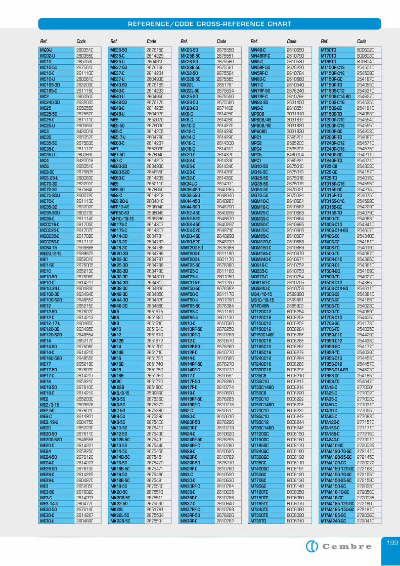
199
REFERENCE/CODE CROSS-REFERENCE CHART
Ref. Code Ref. Code Ref. Code Ref. Code Ref. Code
MC0-U 2603510MC02-U 2603550MC10 2650530MC10-50 2675610MC10-C 2611100MC10-U 2600610MC185-3D 2632030MC185-C 2611150MC2 2650500MC240-3D 2632035MC25 2650550MC25-50 2675620MC25-C 2611110MC25-U 2600650MC3 8420018MC35 2650570MC35-50 2675630MC35-C 2611120MC35-U 2600690MC4 8420019MC6 2650510MC6-50 2675605MC6.25-U 2600630MC70-3D 2632010MC70-50 2675640MC70-80U 2600720MC70-C 2611130MC95-3D 2632020MC95-80U 2600730MC95-C 2611140MCCC16-C 2617050MCCC25-C 2617070MCCC35-C 2617090MCCC50-C 2617110MCS4-15 2599868ME03/2-15 2599875ME1 2652010ME1-50 2676005ME10 2652130ME10-50 2676060ME10-C 2614211ME10.24-U 2604830ME100-3D 2634940ME100-520 2648552ME12 2652150ME12-50 2676070ME12-C 2614213ME12.17-U 2604850ME120-3D 2634950ME120-520 2648554ME14 2652170ME14-50 2676080ME14-C 2614215ME160-520 2648556ME17 2652190ME17-50 2676090ME17-C 2614217ME19 2652210ME19-50 2676100ME19-C 2614219ME2 2652030ME2/3-15 2599876ME2-50 2676010ME2-C 2614201ME2.19-U 2604750ME20 2652230ME20-50 2676110ME200-520 2648558ME20-C 2614221ME24 2652250ME24-50 2676120ME24-C 2614223ME29-50 2676130ME29-C 2614225ME29-U 2604870ME3 2652050ME3-50 2676020ME3-C 2614203ME3.14-U 2604770ME30-50 2676140ME30-C 2614227ME30-U 2604890
ME35-50 2676150ME35-C 2614229ME35-U 2604910ME37-50 2676160ME37-C 2614231ME37-U 2604930ME40-50 2676165ME40-C 2614233ME40-U 2604950ME48-50 2676170ME48-C 2614235ME48-U 2604970ME5 2652070ME5-50 2676030ME5-C 2614205ME5.7-U 2604790ME60-C 2614237ME7 2652090ME7-50 2676040ME7-C 2614207ME80-3D 2634930ME80-520 2648550ME80-C 2614239ME9 2652110ME9-50 2676050ME9-C 2614209ME9.20-U 2604810MFB13-40 2598040MFB50-63 2598045MH10/16-15 2599886MK17S-C 2614307MK17S-C 2614307MK14-3D 2634781MK16-3D 2634783MK18-3D 2634785MK20-3D 2634786MK22-3D 2634787MK25-3D 2634788MK28-3D 2634790MK32-3D 2634800MK34-3D 2634810MK38-3D 2634830MK42-3D 2634850MK44-3D 2634870MK46-3D 2634880MK5 2651575MK6 2651580MK8 2651610MK10 2651640MK12 2651670MK12B 2651672MK14 2651700MK14B 2651710MK16 2651730MK16B 2651740MK18 2651750MK18B 2651760MK20 2651770MK22B 2651800MK5/8-15 2599890MK5-50 2675360MK6-50 2675370MK7-50 2675380MK8-50 2675390MK9-50 2675400MK10-50 2675410MK12-50 2675430MK12B-50 2675431MK13-50 2675440MK14-50 2675450MK14B-50 2675451MK16-50 2675470MK16B-50 2675471MK18-50 2675490MK18B-50 2675491MK19-50 2675500MK20-50 2675510MK20B-50 2675511MK22-50 2675530MK22L 2651791MK22L-50 2675534MK22B-50 2675531
MK25-50 2675550MK25B-50 2675551MK28-50 2675560MK28B-50 2675561MK32-50 2675564MK32B-50 2675565MK22L 2651791MK22L-50 2675534MK25-50 2675550MK28-50 2675560MK28-60 2671460MK6-C 2614250MK8-C 2614260MK10-C 2614270MK12-C 2614280MK14-C 2614290MK16-C 2614300MK18-C 2614310MK20-C 2614320MK22-C 2614330MK25-C 2614340MK28-C 2614350MK32-C 2614360MK34L-C 2614371MK38-450 2640285MK38-520 2648640MK44-450 2640287MK44-520 2648700MK52-450 2640295MK52-520 2648670MK58-450 2640297MK58-520 2648710MK60-450 2640298MK60-520 2648730MMT200-50 2676388MMT200-C 2611190MMT200-U 2601170MMT25-50 2676380MMT25-C 2611160MMT25-U 2601050MMT315-C 2611200MMT50-50 2676382MMT50-C 2611170MMT50-U 2601090MMT95-50 2676384MMT95-C 2611180MMT95-U 2601130MN10-C 2610560MN10RF-50 2676250MN10RF-C 2610768MN12-C 2610570MN12F-50 2676260MN12F-C 2610770MN14-C 2610580MN14RF-50 2676270MN14RF-C 2610772MN17-C 2610591MN17F-50 2676280MN17F-C 2610774MN19-C 2610600MN19RF-50 2676285MN19RF-C 2610776MN2-C 2610511MN20-C 2610610MN20F-50 2676290MN20F-C 2610778MN24-C 2610620MN24RF-50 2676295MN24RF-C 2610780MN29-C 2610625MN29F-C 2610782MN2RF-50 2676210MN2RF-C 2610760MN3-C 2610520MN30-C 2610630MN30RF-C 2610784MN35-C 2610635MN35F-C 2610786MN37-C 2610640MN37RF-C 2610788MN3RF-50 2676220MN3RF-C 2610762
MN48-C 2610650MN48RF-C 2610790MN5-C 2610530MN5RF-50 2676230MN5RF-C 2610764MN60-C 2610660MN7-C 2610540MN7RF-50 2676240MN7RF-C 2610766MN80-3D 2631450MN9-C 2610551MP608 3031810MP608/45 3031815MP608/90 3031820MP608D 3031830MPC1 2595201MPC2 2595203MPC4 2595208MPC5 8460004MPC7 2595221MQ10-50 2675010MQ16-50 2675013MQ25-50 2675016MQ35-50 2675019MQ50-50 2675021MQ70-50 2675024MQM10-C 2610661 MQM16-C 2610662 MQM25-C 2610663 MQM35-C 2610664 MQM50-C 2610665 MQM70-C 2610666 MQM95-C 2610667 MQM120-C 2610668 MQM150-C 2610669 MQM185-C 2610670 MQM240-C 2610671 MQS16-C 2610752 MQS35-C 2610753 MQS70-C 2610754 MQS150-C 2610755 MQS240-C 2610756 MS4/10-15 2599880MS10/16-15 2599881MT-FC48N 2685903MT120C12 8006254MT120C16 8006258MT150C10 8006252MT150C12 8006264MT150C1480 8006266MT150C16 8006268MT185C10 8006262MT185C16 8006278MT240C12 8006284MT240C16 8006288MT300C16 8006298MT35C8 8006210MT35C10 8006212MT35C1480 8006216MT50C8 8006220MT50C10 8006222MT50C1480 8006226MT70C10 8006232MT95C10 8006242MT95C12 8006244MT95C1480 8006246MT120GC 8006150MT150GC 8006160MT185GC 8006170MT240GC 8006180MT300GC 8006190MT35GC 8006110MT400GC 8006195MT50GC 8006120MT70GC 8006130MT95GC 8006140MT120TD 8006050MT150TD 8006060MT185TD 8006070MT240TD 8006080MT300TD 8006090MT35TD 8006010
MT50TD 8006020MT70TD 8006030MT95TD 8006040MT150R-C12 2545010MT150R-C16 2545090MT150R-GC 2541870MT150R-TD 2540550MT150S-C12 2545310MT150S-C14-80 2546270MT150S-C16 2545350MT150S-GC 2541910MT150S-TD 2540630MT200R-C10 2545540MT200R-C16 2545550MT200R-GC 2542030MT200R-TD 2540670MT240R-C12 2545710MT240R-C16 2545750MT240R-GC 2542110MT240R-TD 2540710MT25-C8 2543030MT25-GC 2541570MT25-TD 2540150MT315R-C16 2545950MT315R-GC 2542150MT315R-TD 2540750MT315S-C16 2545990MT315S-GC 2542290MT315S-TD 2540790MT400-TD 2540830MT40S-C10 2543410MT40S-C14-80 2546070MT40S-C8 2543400MT40S-GC 2541610MT40S-TD 2540190MT500-TD 2540870MT50R-C10 2543650MT50R-C8 2543610MT50R-GC 2541690MT50R-TD 2540270MT50S-C10 2543850MT50S-C14-80 2546110MT50S-C8 2543810MT50S-GC 2541650MT50S-TD 2540230MT630-TD 2540890MT70S-C10 2544050MT70S-GC 2541730MT70S-TD 2540350MT95R-C10 2544290MT95R-C12 2544330MT95R-GC 2541770MT95R-TD 2540390MT95S-C10 2544530MT95S-C12 2544570MT95S-C14-80 2546230MT95S-GC 2541850MT95S-TD 2540470MTA16-C 2770001MTA25-C 2770020MTA35-C 2770030MTA50-C 2770310MTA70-C 2770550MTA95-C 2770830MTA120-C 2771510MTA150-C 2771710MTA185-C 2772150MTA240-C 2773010MTMA10-GC 2720025MTMA120-70-GC 2721410MTMA120-95-GC 2721450MTMA120-GC 2720272MTMA150-120-GC 2721630MTMA150-70-GC 2721550MTMA150-95-GC 2721590MTMA150-GC 2720330MTMA16-10-GC 2720560MTMA16-GC 2720035MTMA185-120-GC 2721900MTMA185-150-GC 2721910MTMA185-GC 2720360MTMA240-GC 2720410
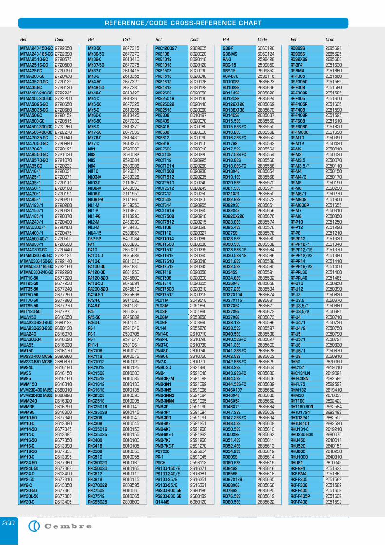
200
REFERENCE/CODE CROSS-REFERENCE CHART
Ref. Code Ref. Code Ref. Code Ref. Code Ref. Code
MTMA240-150-GC 2722050MTMA240-185-GC 2722090MTMA25-10-GC 2720575MTMA25-16-GC 2720580MTMA25-GC 2720090MTMA300-GC 2720430MTMA35-20-GC 2720135MTMA35-GC 2720130MTMA400-240-GC 2722245MTMA400-300-GC 2722250MTMA50-25-GC 2720650MTMA50-35-GC 2720660MTMA50-GC 2720152MTMA500-GC 2720515MTMA500-300-GC 2722260MTMA500-400-GC 2722270MTMA70-35-GC 2720940MTMA70-50-GC 2720980MTMA70-GC 2720195MTMA95-50-GC 2721030MTMA95-70-GC 2721070MTMA95-GC 2720232MTMA16/1 2720031MTMA25/1 2720071MTMA35/1 2720111MTMA50/1 2720160MTMA70/1 2720191MTMA95/1 2720250MTMA120/1 2720280MTMA150/1 2720320MTMA185/1 2720370MTMA240/1 2720400MTMAD300/1 2720460MTMA400/1 2720475MTMA500-40/1 2720509MTMA630/1 2720530MTMAD300-GC 2720440MTMAD300-95-GC 2722121MTMAD300-150-GC 2722140MTMAD300-185-GC 2722160MTMAD300-240-GC 2722220MTT16-50 2677220MTT25-50 2677230MTT35-50 2677240MTT50-50 2677250MTT70-50 2677260MTT95-50 2677270MTT120-50 2677275MUA150 2616050MUA230-630-400 2680129MUA230-630-630 2680130MUA240 2616070MUA300-34 2616090MUA95 2616030MV150 2616170MV230-400 MC5E 2680860MV230-630 MC6E 2680870MV240 2616180MV35 2616150MV95 2616160MVM150 2616310MVM230-400 MJ5E 2680910MVM230-630 MJ6E 2680920MVM240 2616320MVM35 2616290MVM95 2616300MY10-50 2677340MY10-C 2613380MY14-50 2677345MY14-C 2613385MY16-50 2677350MY16-C 2613390MY19-50 2677355MY19-C 2613395MY24-50 2677360MY24L-50 2677362MY24-C 2613400MY2-50 2677310MY2-C 2613350MY30-50 2677365MY30L-50 2677366MY30-C 2613405
MY3-50 2677315MY36-50 2677370MY36-C 2613410MY37-50 2677375MY37-C 2613415MY3-C 2613355MY4-50 2677320MY48-50 2677380MY48-C 2613420MY4-C 2613360MY5-50 2677325MY5-C 2613365MY60-C 2613425MY6-50 2677330MY6-C 2613370MY7-50 2677335MY76-C 2613430MY7-C 2613375ND1 2590080ND2 2590082ND3 2590084ND4 2590086NIT10 8420017NL03-M 2469328NL03-P 2110870NL06-M 2469330NL06-P 2111950NL06-PB 2111960NL1-M 2469350NL1-P 2113970NL1-PG 2113990NL2-M 2469390NL3-M 2469430NN4-15 2599867OB2.5P 8420034PA1 2650230PA10 2650290PA10-50 2675686PA10-C 2611010PA100-3D 2631930PA120-3D 2631950PA120-520 2645600PA19-50 2675694PA200-520 2645610PA24-50 2675696PA24-C 2611020PA48-C 2611030PA5 2650250PA5-50 2675682PA60-C 2611040PB-1 2591046PC-1 2590705PG-1 2591047PH1-1 2591061PKC108 8010070PKC112 8010075PKC1012 8010120PKC1018 8010125PKC1508 8010080PKC1518 8010085PKC1612 8010130PKC1618 8010135PKC2508 8010090PKC2518 8010095PKC25016 8010140PKC25022 8010145PKC306 8010040PKC308 8010045PKC35016 8010150PKC35025 8010155PKC409 8010100PKC418 8010105PKC508 8010050PKC510 8010055PKC50020 8010160PKC50030 8010165PKC612 8010110PKC618 8010115PKC70022 2809595PKC7508 8010060PKC7512 8010065PKC95025 2809600
PKC120027 2809605PKE108 8020020PKE1012 8020110PKE1018 8020120PKE1508 8020030PKE1518 8020040PKE1612 8020126PKE1618 8020128PKE2508 8020050PKE25016 8020130PKE25022 8020140PKE2518 8020060PKE308 8010197PKE409 8020070PKE418 8020080PKE508 8020000PKE612 8020090PKE618 8020100PKE7508 8020010PKCT108 8020220PKCT112 8020225PKCT1014 8020260PKCT1508 8020230PKCT1512 8020235PKCT2510 8020240PKCT2512 8020245PKCT412 8020250PKCT508 8020200PKCT614 8020255PKCT1616 8020265PKCT7508 8020210PKCT7512 8020215PKET108 8020320PKET112 8020327PKET1014 8020360PKET1508 8020330PKET1512 8020335PKET1616 8020365PKET2510 8020340PKET2512 8020345PKET412 8020350PKET508 8020300PKET614 8020355PKET7508 8020310PKET7512 8020315PL01-M 2049510PL03-M 2051850PL03-P 2051860PL06-M 2053850PL06-P 2053860PL1-M 2055870PN14-C 2610710PN24-C 2610720PN37-C 2610730PN48-C 2610740PN60-C 2610750PN7-C 2610700PN80-3D 2631460PNB-1 2591040PNB-3F/M 2591088PNB-3N1 2591092PNB-3N5 2591096PNB-3NN3 2591094PNB-3NN4 2591095PNB-3P 2591090PNB-3P1 2591084PNB-3PD 2591091PNB-4KE 2591251PNB-6KE 2591260PNB-6KE-T 2591262PNB-7KE 2591268PNB-7KE-T 2591270PO7000 2595904PR-1 2591045PRCH 2596113PS130-150/E 2616371PS130-240/E 2616381PS130-35/E 2616351PS130-95/E 2616361PS230-400 5E 2680186PS230-630 6E 2680189Q14-MS 6060120
Q38-F 6060126Q38-MS 6060124RA-3 2598428RBG-15 2599850RBY-15 2599852RCP-B70 2596116RD100SS 2685623RD102SS 2685636RD114SS 2685626RD120SS 2685624RD126X126 2685669RD138X138 2685670RD140SS 2685637RD15.5SS 2685560RD15.5SS-FC 2685550 RD16.2SS 2685562RD16.2SS-FC 2685552 RD17SS 2685563RD17.5SS 2685564RD17.5SS-FC 2685554RD18.8SS 2685566 RD18.8SS-FC 2685556RD18X46 2685654RD19.1SS 2685568RD20.5SS 2685570RD21.5SS 2685571RD21X21 2685650RD22.6SS 2685572RD22X30 2685651RD22X46 2685656RD220X220 2685676RD23.8SS 2685574RD25.4SS 2685576RD27SS 2685578RD28.5SS 2685580RD30.5SS 2685582RD28.5SS-19 2685584RD30.5SS-19 2685586RD31.8SS 2685588RD32.5SS 2685590RD34SS 2685591RD34.6SS 2685592RD36X46 2685658RD37.2SS 2685594RD37X104 2685674RD37X115 2685661RD37X54 2685671RD37X67 2685672RD37X88 2685673RD38.1SS 2685596RD38.5SS 2685597RD40.5SS 2685598RD40.5SS-FC 2685627RD41.3SS 2685600RD41.3SS-FC 2685628RD42.5SS 2685602RD42.5SS-FC 2685629RD43.2SS 2685604RD43.2SS-FC 2685630RD44.5SS 2685606RD44.5SS-FC 2685632RD46X107 2685652RD46X46 2685660RD46X54 2685662RD46X72 2685664RD47.2SS 2685608RD47.2SS-FC 2685634RD48.5SS 2685609RD50.5SS 2685610RD50X98 2685663RD51.4SS 2685611RD52.4SS 2685613RD54.2SS 2685612RD60SS 2685614RD60.5SS 2685615RD64SS 2685616RD65SS 2685618RD67X126 2685665RD68X68 2685666RD76SS 2685620RD76.5SS 2685619RD80.5SS 2685622
RD89SS 2685621RD90SS 2685625RD92X92 2685668RF-BF4 2051630RF-BM4 2051660RF-F305 2051560RF-F305P 2051565RF-F308 2051580RF-F308P 2051585RF-F405 2051600RF-F405P 2051605RF-F408 2051590RF-F408P 2051595RF-F608 2051610RF-F608P 2051620RF-FM608 2051690RF-M10 2050390RF-M12 2050430RF-M2 2050010RF-M3 2050030RF-M3,5 2050070RF-M3,5/1 2050110RF-M4 2050150RF-M4/3 2050170RF-M5 2050190RF-M6 2050230RF-M6/1 2050270RF-M608 2051650RF-M608P 2051655RF-M7 2050310RF-M8 2050350RF-P10 2051250RF-P12 2051290RF-P8 2051210RF-PP12 2051330RF-PP12/1 2051340RF-PP12/19 2051370RF-PP12/23 2051380RF-PP14 2051410RF-PP16/23 2051450RF-PPL30 2051460RF-PPL46 2051465RF-U10 2050950RF-U12 2050990RF-U3 2050630RF-U3,5 2050670RF-U3,5/1 2050680RF-U3,5/2 2050681RF-U4 2050710RF-U4/1 2050730RF-U4/2 2050750RF-U5 2050790RF-U5/1 2050791RF-U6 2050830RF-U6/1 2050870RF-U8 2050910RH50 2670050RHC131 2619010RHC131LN 2619021RH-FC48N 2592596RH-FL75 2592597RHM132 2619410RHM50 2670035RHT160 2592422RHT160-60N 2592584RHTD1724 2682482RHTD3241 2682502RHTD410T 2682520RHU131-C 2619210RHU230-630 2680075RHU450 2640011RHU520 2640151RHU600 2640250RHU1000 2640810RHU81 2600045RKF-BF4 2051632RKF-BM4 2051662RKF-F305 2051562RKF-F308 2051582RKF-F405 2051602RKF-F405P 2051607RKF-F408 2051592
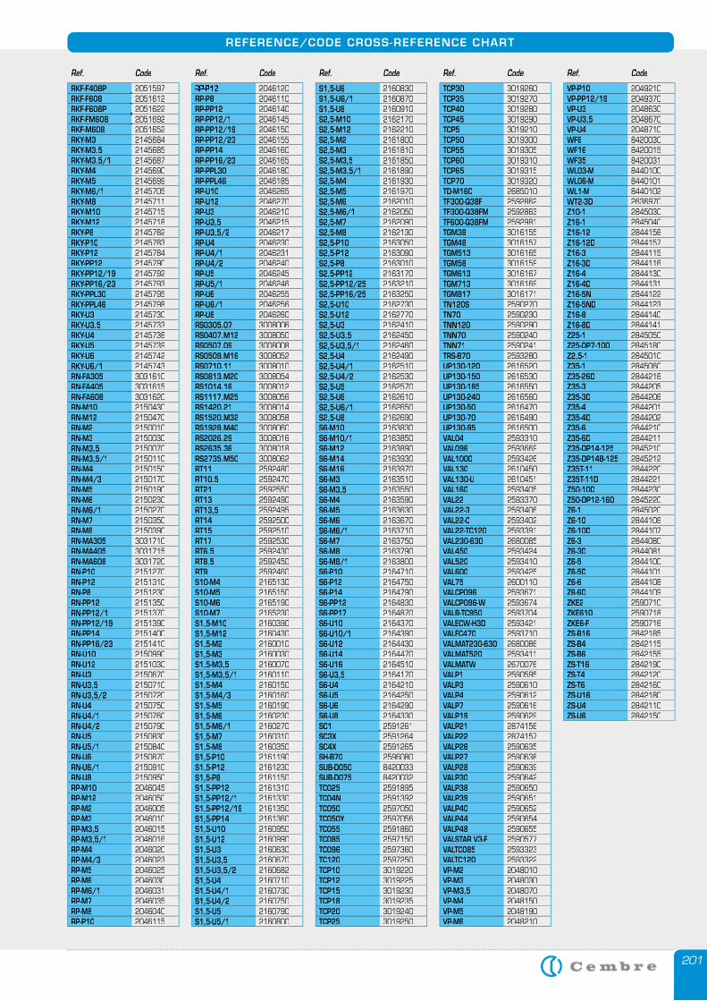
201
REFERENCE/CODE CROSS-REFERENCE CHART
Ref. Code Ref. Code Ref. Code Ref. Code Ref. Code
RKF-F408P 2051597RKF-F608 2051612RKF-F608P 2051622RKF-FM608 2051692RKF-M608 2051652RKY-M3 2145684RKY-M3.5 2145685RKY-M3.5/1 2145687RKY-M4 2145690RKY-M5 2145699RKY-M6/1 2145705RKY-M8 2145711RKY-M10 2145715RKY-M12 2145718RKY-P8 2145782RKY-P10 2145783RKY-P12 2145784RKY-PP12 2145790RKY-PP12/19 2145792RKY-PP16/23 2145793RKY-PPL30 2145795RKY-PPL46 2145798RKY-U3 2145730RKY-U3.5 2145733RKY-U4 2145736RKY-U5 2145739RKY-U6 2145742RKY-U6/1 2145743RN-FA305 3031610RN-FA405 3031615RN-FA608 3031620RN-M10 2150430RN-M12 2150470RN-M2 2150010RN-M3 2150030RN-M3,5 2150070RN-M3,5/1 2150110RN-M4 2150150RN-M4/3 2150170RN-M5 2150190RN-M6 2150230RN-M6/1 2150270RN-M7 2150350RN-M8 2150390RN-MA305 3031710RN-MA405 3031715RN-MA608 3031720RN-P10 2151270RN-P12 2151310RN-P8 2151230RN-PP12 2151350RN-PP12/1 2151370RN-PP12/19 2151390RN-PP14 2151400RN-PP16/23 2151410RN-U10 2150990RN-U12 2151030RN-U3 2150670RN-U3,5 2150710RN-U3,5/2 2150720RN-U4 2150750RN-U4/1 2150760RN-U4/2 2150790RN-U5 2150830RN-U5/1 2150840RN-U6 2150870RN-U6/1 2150910RN-U8 2150950RP-M10 2046045RP-M12 2046050RP-M2 2046005RP-M3 2046010RP-M3,5 2046015RP-M3,5/1 2046016RP-M4 2046020RP-M4/3 2046023RP-M5 2046025RP-M6 2046030RP-M6/1 2046031RP-M7 2046035RP-M8 2046040RP-P10 2046115
RP-P12 2046120RP-P8 2046110RP-PP12 2046140RP-PP12/1 2046145RP-PP12/19 2046150RP-PP12/23 2046155RP-PP14 2046160RP-PP16/23 2046165RP-PPL30 2046180RP-PPL46 2046185RP-U10 2046265RP-U12 2046270RP-U3 2046210RP-U3,5 2046215RP-U3,5/2 2046217RP-U4 2046230RP-U4/1 2046231RP-U4/2 2046240RP-U5 2046245RP-U5/1 2046246RP-U6 2046255RP-U6/1 2046256RP-U8 2046260RS0305.07 3008006RS0407.M12 3008050RS0507.09 3008008RS0509.M16 3008052RS0710.11 3008010RS0813.M20 3008054RS1014.16 3008012RS1117.M25 3008056RS1420.21 3008014RS1520.M32 3008058RS1928.M40 3008060RS2026.29 3008016RS2635.36 3008018RS2735.M50 3008062RT11 2592480RT10.5 2592470RT21 2592550RT13 2592490RT13,5 2592495RT14 2592500RT15 2592510RT17 2592530RT6.5 2592430RT8.5 2592450RT9 2592460S10-M4 2165130S10-M5 2165150S10-M6 2165190S10-M7 2165230S1,5-M10 2160390S1,5-M12 2160430S1,5-M2 2160010S1,5-M3 2160030S1,5-M3,5 2160070S1,5-M3,5/1 2160110S1,5-M4 2160150S1,5-M4/3 2160160S1,5-M5 2160190S1,5-M6 2160230S1,5-M6/1 2160270S1,5-M7 2160310S1,5-M8 2160350S1,5-P10 2161190S1,5-P12 2161230S1,5-P8 2161150S1,5-PP12 2161310S1,5-PP12/1 2161330S1,5-PP12/19 2161350S1,5-PP14 2161360S1,5-U10 2160950S1,5-U12 2160990S1,5-U3 2160630S1,5-U3,5 2160670S1,5-U3,5/2 2160682S1,5-U4 2160710S1,5-U4/1 2160730S1,5-U4/2 2160750S1,5-U5 2160790S1,5-U5/1 2160800
S1,5-U6 2160830S1,5-U6/1 2160870S1,5-U8 2160910S2,5-M10 2162170S2,5-M12 2162210S2,5-M2 2161800S2,5-M3 2161810S2,5-M3,5 2161850S2,5-M3,5/1 2161890S2,5-M4 2161930S2,5-M5 2161970S2,5-M6 2162010S2,5-M6/1 2162050S2,5-M7 2162090S2,5-M8 2162130S2,5-P10 2163050S2,5-P12 2163090S2,5-P8 2163010S2,5-PP12 2163170S2,5-PP12/25 2163210S2,5-PP16/25 2163250S2,5-U10 2162730S2,5-U12 2162770S2,5-U3 2162410S2,5-U3,5 2162450S2,5-U3,5/1 2162460S2,5-U4 2162490S2,5-U4/1 2162510S2,5-U4/2 2162530S2,5-U5 2162570S2,5-U6 2162610S2,5-U6/1 2162650S2,5-U8 2162690S6-M10 2163830S6-M10/1 2163850S6-M12 2163890S6-M14 2163930S6-M16 2163970S6-M3 2163510S6-M3,5 2163550S6-M4 2163590S6-M5 2163630S6-M6 2163670S6-M6/1 2163710S6-M7 2163750S6-M8 2163790S6-M8/1 2163800S6-P10 2164710S6-P12 2164750S6-P14 2164790S6-PP12 2164830S6-PP17 2164870S6-U10 2164370S6-U10/1 2164390S6-U12 2164430S6-U14 2164470S6-U16 2164510S6-U3,5 2164170S6-U4 2164210S6-U5 2164250S6-U6 2164290S6-U8 2164330SC1 2591261SC3X 2591264SC4X 2591265SH-B70 2596080SUB-D050 8420033SUB-D075 8420032TC025 2591895TC04N 2591392TC050 2597050TC050Y 2597056TC055 2591860TC085 2597150TC096 2597360TC120 2597250TCP10 3019220TCP12 3019225TCP15 3019230TCP18 3019235TCP20 3019240TCP25 3019250
TCP30 3019260TCP35 3019270TCP40 3019280TCP45 3019290TCP5 3019210TCP50 3019300TCP55 3019305TCP60 3019310TCP65 3019315TCP70 3019320TD-M16C 2685010TF300-Q38F 2592862TF300-Q38FM 2592863TF600-Q38FM 2592981TGM38 3016155TGM48 3016157TGM513 3016165TGM58 3016159TGM613 3016167TGM713 3016169TGM817 3016171TN120S 2590270TN70 2590230TNN120 2590290TNN70 2590240TNN71 2590241TRS-B70 2593280UP130-120 2616520UP130-150 2616530UP130-185 2616550UP130-240 2616560UP130-50 2616470UP130-70 2616490UP130-95 2616500VAL04 2593310VAL096 2593669VAL1000 2593426VAL130 2610450VAL130-U 2610451VAL160 2593405VAL22 2593370VAL22-3 2593406VAL22-C 2593402VAL22-TC120 2593391VAL230-630 2680085VAL450 2593424VAL520 2593410VAL600 2593425VAL75 2600110VALCP096 2593671VALCP096-W 2593674VALB-TC950 2593704VALECW-H3D 2593421VALFC470 2593710VALMAT230-630 2680086VALMAT520 2593411VALMATW 2670076VALP1 2590595VALP3 2590610VALP4 2590612VALP7 2590616VALP19 2590629VALP21 2874156VALP22 2874157VALP26 2590635VALP27 2590638VALP28 2590639VALP30 2590642VALP38 2590650VALP39 2590651VALP40 2590652VALP44 2590654VALP48 2590655VALSTAR V3-F 2590577VALTC085 2593323VALTC120 2593322VP-M2 2048010VP-M3 2048030VP-M3,5 2048070VP-M4 2048150VP-M5 2048190VP-M6 2048210
VP-P10 2049210VP-PP12/19 2049370VP-U3 2048630VP-U3,5 2048670VP-U4 2048710WF6 8420030WF16 8420015WF35 8420031WL03-M 8440100WL06-M 8440101WL1-M 8440102WT2-3D 2636970Z10-1 2845030Z16-1 2845040Z16-12 2844156Z16-12D 2844157Z16-3 2844115Z16-3D 2844116Z16-4 2844130Z16-4D 2844131Z16-5N 2844122Z16-5ND 2844123Z16-8 2844140Z16-8D 2844141Z25-1 2845050Z25-DP7-100 2845180Z2,5-1 2845010Z35-1 2845060Z35-26D 2844216Z35-3 2844205Z35-3D 2844206Z35-4 2844201Z35-4D 2844202Z35-6 2844210Z35-6D 2844211Z35-DP14-125 2845210Z35-DP14B-125 2845212Z35T-11 2844220Z35T-11D 2844221Z50-10D 2844230Z50-DP12-160 2845220Z6-1 2845020Z6-10 2844106Z6-10D 2844107Z6-3 2844080Z6-3D 2844081Z6-5 2844100Z6-5D 2844101Z6-6 2844108Z6-6D 2844109ZKE2 2590710ZKE610 2590718ZKE6-F 2590716ZS-B16 2842185ZS-B4 2842115ZS-B6 2842155ZS-T16 2842190ZS-T4 2842120ZS-T6 2842160ZS-U16 2842180ZS-U4 2842110ZS-U6 2842150
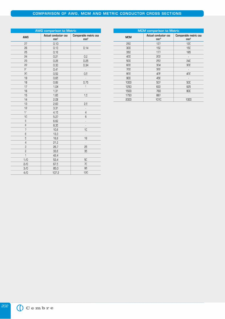
202
COMPARISON OF AWG, MCM AND METRIC CONDUCTOR CROSS SECTIONS
AWG comparison to Metric
AWG Actual conductor csamm2
Comparable metric csa mm2
27 0,1026 0,13 0,1425 0,16 -24 0,21 0,223 0,26 0,2522 0,33 0,3421 0,41 -20 0,52 0,519 0,65 -18 0,82 0,7517 1,04 116 1,31 -15 1,65 1,514 2,08 -13 2,63 2,512 3,31 -11 4,15 410 5,27 69 6,62 -8 8,35 -7 10,6 106 13,3 -5 16,8 164 21,2 -3 26,7 252 33,6 351 42,4 -
1/0 53,4 502/0 67,5 703/0 85,0 954/0 107,2 120
MCM comparison to Metric
MCM Actual conductor csamm2
Comparable metric csa mm2
250 127 120300 152 150350 177 185400 203 -500 253 240600 304 300700 355 -800 405 400900 456 -1000 507 5001250 633 6251500 760 8001750 887 -2000 1010 1000
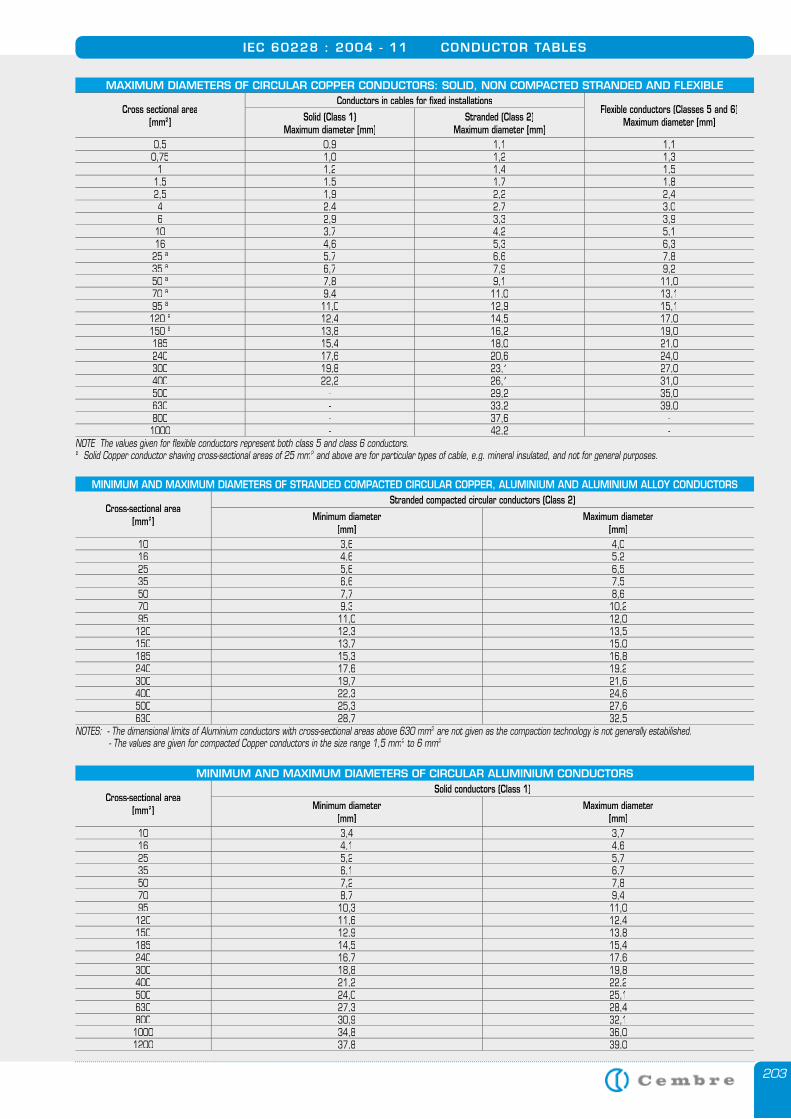
203
IEC 60228 : 2004 - 11 CONDUCTOR TABLES
MINIMUM AND MAXIMUM DIAMETERS OF STRANDED COMPACTED CIRCULAR COPPER, ALUMINIUM AND ALUMINIUM ALLOY CONDUCTORS
Cross-sectional area [mm2]
Stranded compacted circular conductors (Class 2)
Minimum diameter[mm]
Maximum diameter[mm]
10 3,6 4,016 4,6 5,225 5,6 6,535 6,6 7,550 7,7 8,670 9,3 10,295 11,0 12,0120 12,3 13,5150 13,7 15,0185 15,3 16,8240 17,6 19,2300 19,7 21,6400 22,3 24,6500 25,3 27,6630 28,7 32,5
NOTES: - The dimensional limits of Aluminium conductors with cross-sectional areas above 630 mm2 are not given as the compaction technology is not generally estabilished.2 are not given as the compaction technology is not generally estabilished.2
- The values are given for compacted Copper conductors in the size range 1,5 mm2 to 6 mm2 to 6 mm2 2.
MAXIMUM DIAMETERS OF CIRCULAR COPPER CONDUCTORS: SOLID, NON COMPACTED STRANDED AND FLEXIBLE
Cross sectional area[mm2]
Conductors in cables for fi xed installationsFlexible conductors (Classes 5 and 6)
Maximum diameter [mm]Solid (Class 1)Maximum diameter [mm]
Stranded (Class 2)Maximum diameter [mm]
0,5 0,9 1,1 1,10,75 1,0 1,2 1,3
1 1,2 1,4 1,51,5 1,5 1,7 1,82,5 1,9 2,2 2,44 2,4 2,7 3,06 2,9 3,3 3,910 3,7 4,2 5,116 4,6 5,3 6,3
25 a 5,7 6,6 7,835 a 6,7 7,9 9,250 a 7,8 9,1 11,070 a 9,4 11,0 13,195 a 11,0 12,9 15,1
120 a 12,4 14,5 17,0150 a 13,8 16,2 19,0185 15,4 18,0 21,0240 17,6 20,6 24,0300 19,8 23,1 27,0400 22,2 26,1 31,0500 - 29,2 35,0630 - 33,2 39,0800 - 37,6 -
1000 - 42,2 -NOTE The values given for flexible conductors represent both class 5 and class 6 conductors.a Solid Copper conductor shaving cross-sectional areas of 25 mma Solid Copper conductor shaving cross-sectional areas of 25 mma 2 and above are for particular types of cable, e.g. mineral insulated, and not for general purposes.2 and above are for particular types of cable, e.g. mineral insulated, and not for general purposes.2
MINIMUM AND MAXIMUM DIAMETERS OF CIRCULAR ALUMINIUM CONDUCTORS
Cross-sectional area [mm2]
Solid conductors (Class 1)
Minimum diameter[mm]
Maximum diameter[mm]
10 3,4 3,716 4,1 4,625 5,2 5,735 6,1 6,750 7,2 7,870 8,7 9,495 10,3 11,0120 11,6 12,4150 12,9 13,8185 14,5 15,4240 16,7 17,6300 18,8 19,8400 21,2 22,2500 24,0 25,1630 27,3 28,4800 30,9 32,11000 34,8 36,01200 37,8 39,0
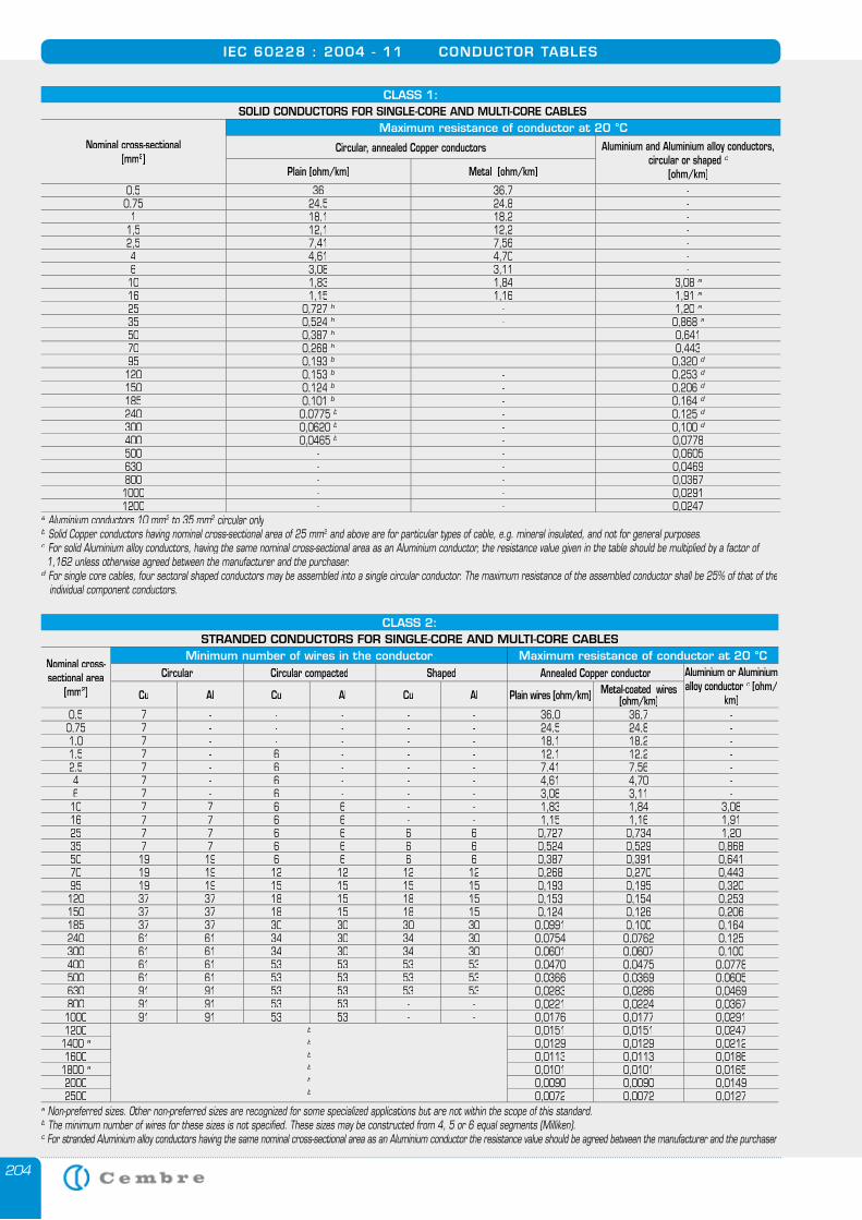
204
IEC 60228 : 2004 - 11 CONDUCTOR TABLES
CLASS 1: SOLID CONDUCTORS FOR SINGLE-CORE AND MULTI-CORE CABLES
Nominal cross-sectional [mm2]
Maximum resistance of conductor at 20 °C
Circular, annealed Copper conductors Aluminium and Aluminium alloy conductors,circular or shaped c
[ohm/km]Plain [ohm/km] Metal [ohm/km]
0,5 36 36,7 -0,75 24,5 24,8 -
1 18,1 18,2 -1,5 12,1 12,2 -2,5 7,41 7,56 -4 4,61 4,70 -6 3,08 3,11 -10 1,83 1,84 3,08 a16 1,15 1,16 1,91 a25 0,727 b - 1,20 a35 0,524 b - 0,868 a50 0,387 b - 0,64170 0,268 b - 0,44395 0,193 b - 0,320 d120 0,153 b - 0,253 d150 0,124 b - 0,206 d185 0,101 b - 0,164 d240 0,0775 b - 0,125 d300 0,0620 b - 0,100 d400 0,0465 b - 0,0778500 - - 0,0605630 - - 0,0469800 - - 0,03671000 - - 0,02911200 - - 0,0247
a a a Aluminium conductors 10 mm2 to 35 mm2 to 35 mm2 2 circular only2 circular only2
b b b Solid Copper conductors having nominal cross-sectional area of 25 mm2 and above are for particular types of cable, e.g. mineral insulated, and not for general purposes.2 and above are for particular types of cable, e.g. mineral insulated, and not for general purposes.2
c c c For solid Aluminium alloy conductors, having the same nominal cross-sectional area as an Aluminium conductor, the resistance value given in the table should be multiplied by a factor of 1,162 unless otherwise agreed between the manufacturer and the purchaser.d d d For single core cables, four sectoral shaped conductors may be assembled into a single circular conductor. The maximum resistance of the assembled conductor shall be 25% of that of the individual component conductors.
CLASS 2:STRANDED CONDUCTORS FOR SINGLE-CORE AND MULTI-CORE CABLES
Nominal cross-sectional area
[mm2]
Minimum number of wires in the conductor Maximum resistance of conductor at 20 °CCircular Circular compacted Shaped Annealed Copper conductor Aluminium or Aluminium
alloy conductor c [ohm/km]Cu Al Cu Al Cu Al Plain wires [ohm/km] Metal-coated wires
[ohm/km]0,5 7 - - - - - 36,0 36,7 -0,75 7 - - - - - 24,5 24,8 -1,0 7 - - - - - 18,1 18,2 -1,5 7 - 6 - - - 12,1 12,2 -2,5 7 - 6 - - - 7,41 7,56 -4 7 - 6 - - - 4,61 4,70 -6 7 - 6 - - - 3,08 3,11 -10 7 7 6 6 - - 1,83 1,84 3,0816 7 7 6 6 - - 1,15 1,16 1,9125 7 7 6 6 6 6 0,727 0,734 1,2035 7 7 6 6 6 6 0,524 0,529 0,86850 19 19 6 6 6 6 0,387 0,391 0,64170 19 19 12 12 12 12 0,268 0,270 0,44395 19 19 15 15 15 15 0,193 0,195 0,320120 37 37 18 15 18 15 0,153 0,154 0,253150 37 37 18 15 18 15 0,124 0,126 0,206185 37 37 30 30 30 30 0,0991 0,100 0,164240 61 61 34 30 34 30 0,0754 0,0762 0,125300 61 61 34 30 34 30 0,0601 0,0607 0,100400 61 61 53 53 53 53 0,0470 0,0475 0,0778500 61 61 53 53 53 53 0,0366 0,0369 0,0605630 91 91 53 53 53 53 0,0283 0,0286 0,0469800 91 91 53 53 - - 0,0221 0,0224 0,03671000 91 91 53 53 - - 0,0176 0,0177 0,02911200 b
b
b
b
b
b
0,0151 0,0151 0,02471400 a 0,0129 0,0129 0,02121600 0,0113 0,0113 0,0186
1800 a 0,0101 0,0101 0,01652000 0,0090 0,0090 0,01492500 0,0072 0,0072 0,0127
a Non-preferred sizes. Other non-preferred sizes are recognized for some specialized applications but are not within the scope of this standard.a Non-preferred sizes. Other non-preferred sizes are recognized for some specialized applications but are not within the scope of this standard.a
b The minimum number of wires for these sizes is not specified. These sizes may be constructed from 4, 5 or 6 equal segments (Milliken). b The minimum number of wires for these sizes is not specified. These sizes may be constructed from 4, 5 or 6 equal segments (Milliken). b
c For stranded Aluminium alloy conductors having the same nominal cross-sectional area as an Aluminium conductor the resistance value should be agreed between the manufacturer and the purchaser.
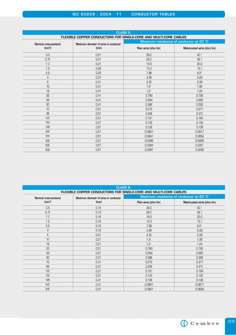
205
IEC 60228 : 2004 - 11 CONDUCTOR TABLES
CLASS 5:FLEXIBLE COPPER CONDUCTORS FOR SINGLE-CORE AND MULTI-CORE CABLES
Nominal cross-sectional[mm2]
Maximum diameter of wires in conductor [mm]
Maximum resistance of conductor at 20 °C
Plain wires [ohm/km] Metal-coated wires [ohm/km]
0,5 0,21 39,0 40,10,75 0,21 26,0 26,71,0 0,21 19,5 20,01,5 0,26 13,3 13,72,5 0,26 7,98 8,214 0,31 4,95 5,096 0,31 3,30 3,39
10 0,41 1,91 1,9516 0,41 1,21 1,2425 0,41 0,780 0,79535 0,41 0,554 0,56550 0,41 0,386 0,39370 0,51 0,272 0,27795 0,51 0,206 0,210120 0,51 0,161 0,164150 0,51 0,129 0,132185 0,51 0,106 0,108240 0,51 0,0801 0,0817300 0,51 0,0641 0,0654400 0,51 0,0486 0,0495500 0,61 0,0384 0,0391630 0,61 0,0287 0,0292
CLASS 6:FLEXIBLE COPPER CONDUCTORS FOR SINGLE-CORE AND MULTI-CORE CABLES
Nominal cross-sectional[mm2]
Maximum diameter of wires in conductor [mm]
Maximum resistance of conductor at 20 °C
Plain wires [ohm/km] Metal-coated wires [ohm/km]
0,5 0,16 39,0 40,10,75 0,16 26,0 26,71.0 0,16 19,5 20,01,5 0,16 13,3 13,72,5 0,16 7,98 8,214 0,16 4,95 5,096 0,21 3,30 3,39
10 0,21 1,91 1,9516 0,21 1,21 1,2425 0,21 0,780 0,79535 0,21 0,554 0,56550 0,31 0,386 0,39370 0,31 0,272 0,27795 0,31 0,206 0,210120 0,31 0,161 0,164150 0,31 0,129 0,132185 0,41 0,106 0,108240 0,41 0,0801 0,0817300 0,41 0,0641 0,0654
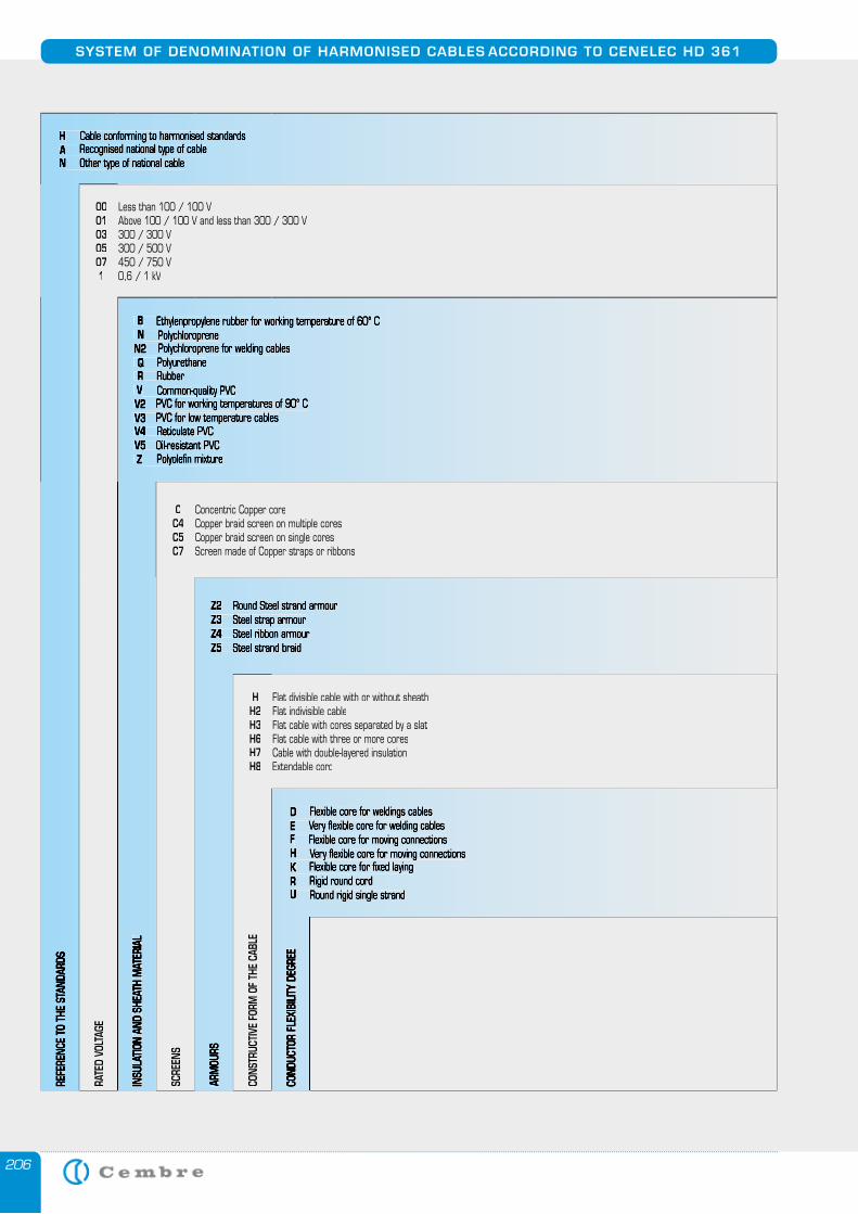
206
SYSTEM OF DENOMINATION OF HARMONISED CABLES ACCORDING TO CENELEC HD 361
H Cable conforming to harmonised standardsA Recognised national type of cableA Recognised national type of cableAN Other type of national cable
REFE
RENC
E TO
THE
STA
NDAR
DS
00 Less than 100 / 100 V01 Above 100 / 100 V and less than 300 / 300 V03 300 / 300 V05 300 / 500 V07 450 / 750 V 1 0,6 / 1 kV
RATE
D VO
LTAG
E
B Ethylenpropylene rubber for working temperature of 60° C N PolychloropreneN2 Polychloroprene for welding cables Q Polyurethane Q Polyurethane Q R Rubber V Common-quality PVC V Common-quality PVC VV2 PVC for working temperatures of 90° CV3 PVC for low temperature cables V4 Reticulate PVCV5 Oil-resistant PVC Z Polyolefi n mixture
INSU
LATIO
N AN
D SH
EATH
MAT
ERIA
L
C Concentric Copper coreC4 Copper braid screen on multiple coresC5 Copper braid screen on single coresC7 Screen made of Copper straps or ribbons
SCRE
ENS
Z2 Round Steel strand armourZ3 Steel strap armourZ4 Steel ribbon armourZ5 Steel strand braid
ARM
OURS
H Flat divisible cable with or without sheathH2 Flat indivisible cableH3 Flat cable with cores separated by a slatH6 Flat cable with three or more coresH7 Cable with double-layered insulationH8 Extendable cord
CONS
TRUC
TIVE
FORM
OF
THE
CABL
E
D Flexible core for weldings cablesE Very fl exible core for welding cablesF Flexible core for moving connectionsH Very fl exible core for moving connectionsK Flexible core for fi xed layingK Flexible core for fi xed layingKR Rigid round cordU Round rigid single strand
COND
UCTO
R FL
EXIB
ILITY
DEG
REE
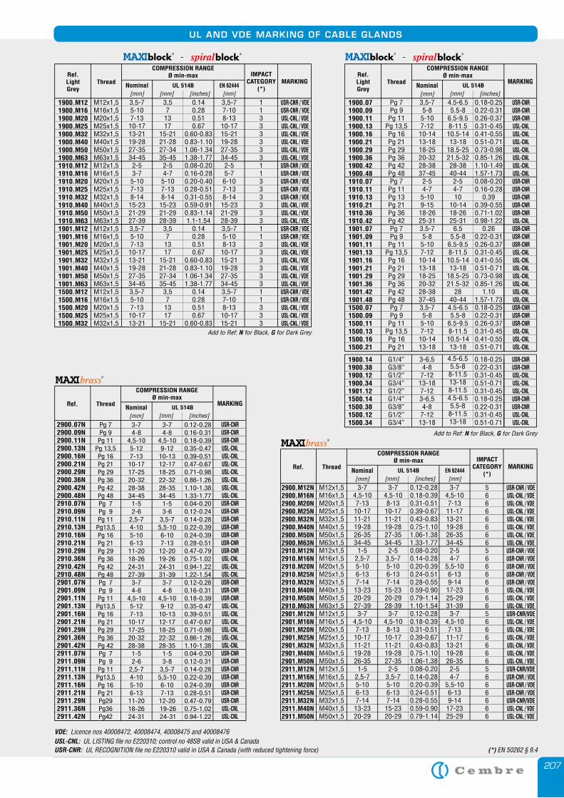
207
UL AND VDE MARKING OF CABLE GLANDS
VDE: Licence nos 40008472, 40008474, 40008475 and 40008476USL-CNL: UL LISTING file no E220310; control no 48SB valid in USA & CanadaUSR-CNR: UL RECOGNITION file no E220310 valid in USA & Canada (with reduced tightening force) (*) EN 50262 § 9.4
Ref. Thread MARKING
M12x1,5M16x1,5M20x1,5M25x1,5M32x1,5M40x1,5M50x1,5M63x1,5M12x1,5M16x1,5M20x1,5M25x1,5M32x1,5M40x1,5M50x1,5M63x1,5M12x1,5M16x1,5M20x1,5M25x1,5M32x1,5M40x1,5M50x1,5M12x1,5M16x1,5M20x1,5M25x1,5M32x1,5M40x1,5M50x1,5
3-7 4,5-107-1310-1711-2119-2826-3534-45
1-52,5-75-106-137-1413-2320-29 27-39
3-7 4,5-107-1310-1711-2119-2826-35
1-52,5-75-106-137-1413-2320-29
3-74,5-108-1310-1711-2119-2827-3534-45
2-53,5-75-106-137-14 15-2320-2928-39
3-74,5-108-1310-1711-2119-2827-35
2-53,5-75-106-137-14 15-23 20-29
0.12-0.280.18-0.390.31-0.510.39-0.670.43-0.830.75-1.101.06-1.381.33-1.770.08-0.200.14-0.280.20-0.390.24-0.510.28-0.550.59-0.900.79-1.141.10-1.540.12-0.280.18-0.390.31-0.510.39-0.670.43-0.830.75-1.101.06-1.380.08-0.200.14-0.280.20-0.390.24-0.510.28-0.55 0.59-0.90 0.79-1.14
3-7 4,5-107-1311-1713-2119-2826-3534-45
2-5 4-7
5,5-106-139-1417-2325-2931-39
3-7 4,5-107-1311-1713-2119-2826-35
2-54-7
5,5-106-139-1417-2325-29
USR-CNR / VDEUSL-CNL / VDE USL-CNL / VDE USL-CNL / VDE USL-CNL / VDE USL-CNL / VDE USL-CNL / VDE USL-CNL / VDE USR-CNR / VDE USR-CNR / VDEUSR-CNR / VDEUSR-CNR / VDEUSR-CNR / VDE USL-CNL / VDE USL-CNL / VDEUSL-CNL / VDEUSR-CNR/VDE USL-CNL / VDE USL-CNL / VDE USL-CNL / VDE USL-CNL / VDE USL-CNL / VDE USL-CNL / VDEUSR-CNR/VDE USR-CNR / VDEUSR-CNR / VDEUSR-CNR / VDEUSR-CNR/VDEUSL-CNL / VDEUSL-CNL / VDE
2900.M12N2900.M16N2900.M20N2900.M25N2900.M32N2900.M40N2900.M50N2900.M63N2910.M12N2910.M16N2910.M20N2910.M25N2910.M32N2910.M40N2910.M50N2910.M63N2901.M12N2901.M16N2901.M20N2901.M25N2901.M32N2901.M40N2901.M50N2911.M12N2911.M16N2911.M20N2911.M25N2911.M32N2911.M40N2911.M50N
EN 62444[mm]
UL 514B [mm] [inches]
Nominal[mm]
COMPRESSION RANGEØ min-max IMPACT
CATEGORY(*)
566666665666666656666665666666
Ref. Thread MARKING
Pg 7Pg 9
Pg 11Pg 13,5Pg 16Pg 21Pg 29Pg 36Pg 42Pg 48Pg 7Pg 9Pg 11
Pg13,5Pg 16Pg 21Pg 29Pg 36Pg 42Pg 48Pg 7Pg 9Pg 11
Pg13,5Pg 16Pg 21Pg 29Pg 36Pg 42Pg 7Pg 9Pg 11
Pg13,5Pg 16Pg 21Pg29Pg36Pg42
3-74-8
4,5-105-127-13
10-1717-2520-3228-3834-451-52-6
2,5-74-105-106-13
11-2018-2624-3127-393-74-8
4,5-105-127-13
10-1717-2520-3228-381-52-6
2,5-74-105-106-13
11-2018-2624-31
3-74-8
4,5-109-12
10-1312-1718-2522-3228-3534-451-53-6
3,5-75,5-106-107-13
12-2019-2624-3131-393-74-8
4,5-109-12
10-1312-1718-2522-3228-351-53-8
3,5-75,5-106-107-13
12-20 19-26 24-31
0.12-0.280.16-0.310.18-0.390.35-0.470.39-0.510.47-0.670.71-0.980.86-1.261.10-1.381.33-1.770.04-0.200.12-0.240.14-0.280.22-0.390.24-0.390.28-0.510.47-0.790.75-1.020.94-1.221.22-1.540.12-0.280.16-0.310.18-0.390.35-0.470.39-0.510.47-0.670.71-0.980.86-1.261.10-1.380.04-0.200.12-0.310.14-0.280.22-0.390.24-0.390.28-0.510.47-0.790.75-1.020.94-1.22
USR-CNRUSR-CNRUSR-CNRUSL-CNLUSL-CNLUSL-CNLUSL-CNLUSL-CNLUSL-CNLUSL-CNLUSR-CNRUSR-CNRUSR-CNRUSR-CNRUSR-CNRUSR-CNRUSR-CNRUSL-CNLUSL-CNLUSL-CNLUSR-CNRUSR-CNRUSR-CNRUSL-CNLUSL-CNLUSL-CNLUSL-CNLUSL-CNLUSL-CNLUSR-CNRUSR-CNRUSR-CNRUSR-CNRUSR-CNRUSR-CNRUSR-CNRUSL-CNLUSL-CNL
2900.07N2900.09N2900.11N2900.13N2900.16N2900.21N2900.29N2900.36N2900.42N2900.48N2910.07N2910.09N2910.11N2910.13N2910.16N2910.21N2910.29N2910.36N2910.42N2910.48N2901.07N2901.09N2901.11N2901.13N2901.16N2901.21N2901.29N2901.36N2901.42N2911.07N2911.09N2911.11N2911.13N2911.16N2911.21N2911.29N2911.36N2911.42N
UL 514B [mm] [inches]
Nominal[mm]
COMPRESSION RANGEØ min-max
-
USR-CNRUSR-CNRUSR-CNRUSL-CNLUSL-CNLUSL-CNLUSL-CNLUSL-CNLUSL-CNLUSL-CNLUSR-CNRUSR-CNRUSR-CNRUSR-CNRUSR-CNRUSL-CNLUSR-CNRUSR-CNRUSR-CNRUSL-CNLUSL-CNLUSL-CNLUSL-CNLUSL-CNLUSL-CNLUSL-CNLUSR-CNRUSR-CNRUSR-CNRUSL-CNLUSL-CNLUSL-CNL
Pg 7Pg 9Pg 11
Pg 13,5Pg 16Pg 21Pg 29Pg 36Pg 42Pg 48Pg 7Pg 11Pg 13Pg 21Pg 36Pg 42Pg 7Pg 9Pg 11
Pg 13,5Pg 16Pg 21Pg 29Pg 36Pg 42Pg 48Pg 7Pg 9Pg 11
Pg 13,5Pg 16Pg 21
3,5-75-85-107-1210-1413-1818-2520-3228-3837-45
2-54-75-109-1518-2625-313.5-75-85-107-1210-1413-1818-2520-3228-3837-453,5-75-85-107-1210-1413-18
4.5-6.55.5-8
6.5-9.58-11.510.5-1413-18
18.5-2521.5-3228-3840-44
2-54-710
10-1418-2625-31
6.55.5-8
6.5-9.58-11.510.5-1413-18
18.5-2521.5-32
2840-444.5-6.55.5-8
6.5-9.58-11.510.5-1413-18
0.18-0.250.22-0.310.26-0.370.31-0.450.41-0.550.51-0.710.73-0.980.85-1.261.10-1.491.57-1.730.08-0.200.16-0.28
0.390.39-0.550.71-1.020.98-1.22
0.260.22-0.310.26-0.370.31-0.450.41-0.550.51-0.710.73-0.980.85-1.26
1.101.57-1.730.18-0.250.22-0.310.26-0.370.31-0.450.41-0.550.51-0.71
1900.071900.091900.111900.131900.161900.211900.291900.361900.421900.481910.071910.111910.131910.211910.361910.421901.071901.091901.111901.131901.161901.211901.291901.361901.421901.481500.071500.091500.111500.131500.161500.21
COMPRESSION RANGEØ min-maxRef.
Light Grey
ThreadUL 514B
[mm] [inches]
MARKINGNominal
[mm]
USR-CNRUSR-CNRUSL-CNLUSL-CNLUSL-CNLUSR-CNRUSR-CNRUSL-CNLUSL-CNL
G1/4”G3/8”G1/2”G3/4”G1/2” G1/4”G3/8”G1/2”G3/4”
3-6,54-87-1213-187-123-6,54-87-1213-18
4.5-6.55.5-88-11.5 13-188-11.54.5-6.55.5-88-11.5 13-18
0.18-0.250.22-0.310.31-0.45 0.51-0.710.31-0.450.18-0.250.22-0.310.31-0.45 0.51-0.71
1900.141900.381900.121900.341901.121500.141500.381500.121500.34
Add to Ref: N for Black, G for Dark Grey
-
USR-CNR / VDEUSR-CNR / VDEUSL-CNL / VDE USL-CNL / VDE USL-CNL / VDE USL-CNL / VDE USL-CNL / VDE USL-CNL / VDE USR-CNR / VDE USR-CNR / VDEUSR-CNR / VDEUSR-CNR / VDEUSR-CNR / VDEUSL-CNL / VDEUSL-CNL / VDEUSL-CNL / VDEUSR-CNR / VDEUSR-CNR / VDEUSL-CNL / VDEUSL-CNL / VDEUSL-CNL / VDEUSL-CNL / VDEUSL-CNL / VDEUSL-CNL / VDEUSR-CNR / VDEUSR-CNR / VDEUSL-CNL / VDEUSL-CNL / VDE USL-CNL / VDE
M12x1,5M16x1,5M20x1,5M25x1,5M32x1,5M40x1,5M50x1,5M63x1,5M12x1,5M16x1,5M20x1,5M25x1,5M32x1,5M40x1,5M50x1,5M63x1,5M12x1,5M16x1,5M20x1,5M25x1,5M32x1,5M40x1,5M50x1,5M63x1,5M12x1,5M16x1,5M20x1,5M25x1,5M32x1,5
3,5-75-107-13
10-1713-2119-2827-3534-45
2-53-7
5-107-138-14
15-2321-2927-393,5-75-107-13
10-1713-2119-2827-3534-453,5-75-107-13
10-1713-21
3,57
1317
15-2121-2827-3435-45
2-54-7
5-107-138-14
15-2321-2928-39
3,57
1317
15-2121-2827-3435-45
3,57
1317
15-21
0.140.280.510.67
0.60-0.830.83-1.101.06-1.341.38-1.770.08-0.200.16-0.280.20-0.400.28-0.510.31-0.550.59-0.910.83-1.141.1-1.54
0.140.280.510.67
0.60-0.830.83-1.101.06-1.341.38-1.77
0.140.280.510.67
0.60-0.83
3,5-77-108-13
10-1715-2119-2827-3534-45
2-55-7
6-107-138-14
15-2321-2928-393,5-75-108-13
10-1715-2119-2827-3534-453,5-77-108-13
10-1715-21
1900.M121900.M161900.M201900.M251900.M321900.M401900.M501900.M631910.M121910.M161910.M201910.M251910.M321910.M401910.M501910.M631901.M121901.M161901.M201901.M251901.M321901.M401901.M501901.M631500.M121500.M161500.M201500.M251500.M32
COMPRESSION RANGEØ min-maxRef.
Light Grey
ThreadUL 514B
[mm] [inches] EN 62444
[mm]
MARKINGNominal
[mm]
IMPACT CATEGORY
(*)
11333333113333331133333311333
Add to Ref: N for Black, G for Dark Grey
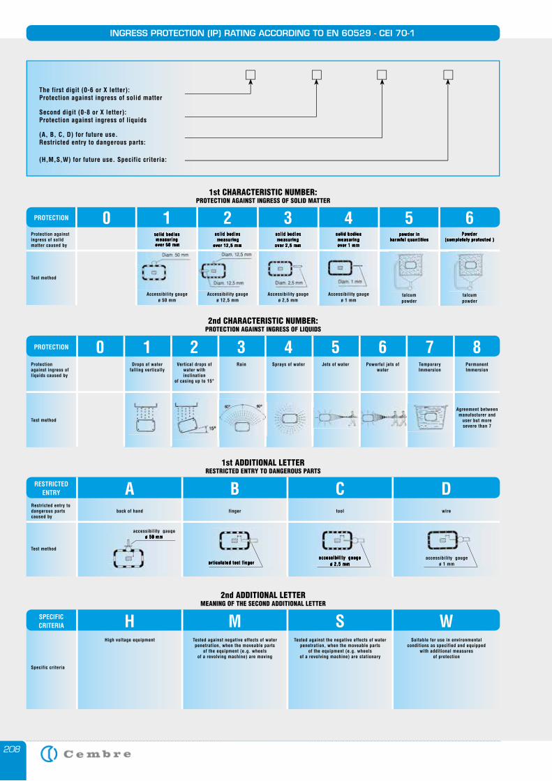
208
INGRESS PROTECTION (IP) RATING ACCORDING TO EN 60529 - CEI 70-1
1st CHARACTERISTIC NUMBER: PROTECTION AGAINST INGRESS OF SOLID MATTER
Protection againstingress of solid matter caused by
Test method
Accessibility gaugeø 50 mm
Accessibility gaugeø 12,5 mm
Accessibility gaugeø 2,5 mm
Accessibility gaugeø 1 mm
talcumpowder
talcumpowder
solid bodies measuring
over 12,5 mm
solid bodies measuring
over 2,5 mm
solid bodies measuringover 1 mm
powder inharmful quantities
Powder(completely protected )
0 1PROTECTION 2 3 4 5 6
2nd CHARACTERISTIC NUMBER: PROTECTION AGAINST INGRESS OF LIQUIDS
1st ADDITIONAL LETTER RESTRICTED ENTRY TO DANGEROUS PARTS
Protectionagainst ingress of liquids caused by
Test method
PermanentImmersion
PROTECTION 8TemporaryImmersion
7Powerful jets of
water
6Jets of water
5Sprays of water
4Rain
3Vertical drops of
water with inclination
of casing up to 15°
2Drops of water
falling vertically
10
Agreement betweenmanufacturer and
user but more severe than 7
solid bodies measuring
over 50 mm
ARESTRICTEDENTRY B C D
Test method
accessibility gauge ø 50 mm
articulated test fingeraccessibility gauge
ø 2,5 mm
Restricted entry to dangerous parts caused by
back of hand finger tool wire
accessibility gauge ø 50 mm
articulated test fingeraccessibility gauge
ø 2,5 mm
2nd ADDITIONAL LETTER MEANING OF THE SECOND ADDITIONAL LETTER
HSPECIFIC CRITERIA M S W
Specific criteria
High voltage equipment Tested against negative effects of water penetration, when the moveable parts
of the equipment (e.g. wheels of a revolving machine) are moving
Tested against the negative effects of water penetration, when the moveable parts
of the equipment (e.g. wheels of a revolving machine) are stationary
Suitable for use in environmentalconditions as specified and equipped
with additional measures of protection
The first digit (0-6 or X letter):Protection against ingress of solid matter
Second digit (0-8 or X letter):Protection against ingress of liquids
(A, B, C, D) for future use.Restricted entry to dangerous parts:
(H,M,S,W) for future use. Specific criteria:
accessibility gauge ø 1 mm
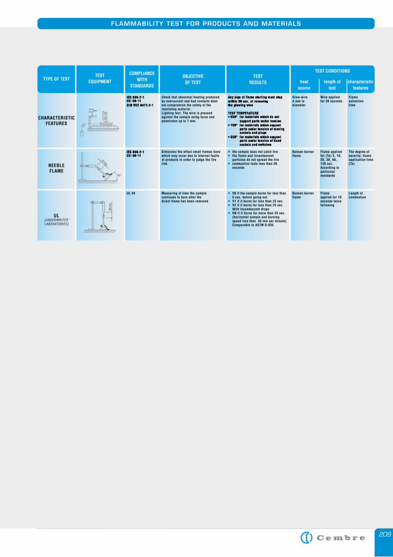
209
FLAMMABILITY TEST FOR PRODUCTS AND MATERIALS
CHARACTERISTIC FEATURES
Glow-wire4 mm indiameter
Any sign of flame starting must stopwithin 30 sec. of removingthe glowing wire
TEST TEMPERATURE• 650° for materials which do not support parts under tension• 750° for materials which support parts under tension of moving sockets and plugs• 850° for materials which support parts under tension of fixed sockets and switches
Check that abnormal heating produced by overcurrent and bad contacts does not compromise the safety of the insulating material. Lighting test. The wire is pressed against the sample using force and penetrates up to 7 mm.
IEC 695-2-1CEI 50-11DIN VDE 0471-2-1
Wire appliedfor 30 seconds
Flame extinctiontime
NEEDLE FLAME
Bunsen burnerflame
• the sample does not catch fire • the flame and incandescent particles do not spread the fire• combustion lasts less than 30 seconds
Simulates the effect small flames havewhich may occur due to internal faults of products in order to judge the fire risk.
IEC 695-2-1CEI 50-11
Flame applied for (Ta) 5, 10, 20, 30, 60,120 sec.According to particularstandards
The degree of severity: flame application time(Ta)
UL(UNDERWRITER’LABORATORIES)
Bunsen burnerflame
• V0 if the sample burns for less than 5 sec. before going out.• V1 if it burns for less than 25 sec. • V2 if it burns for less than 25 sec. With incandescent drops• HB if it burns for more than 25 sec. (horizontal sample and burning speed less than 38 mm per minute) Comparable to ASTM D-635
Measuring of time the samplecontinues to burn after the direct flame has been removed
UL 94 Flameapplied for 10seconds twice following
Length of combustion
TYPE OF TEST TEST
EQUIPMENT
COMPLIANCE WITH
STANDARDS
OBJECTIVEOF TEST
TESTRESULTS heat
sourcelength of
testcharacteristic
features
TEST CONDITIONS
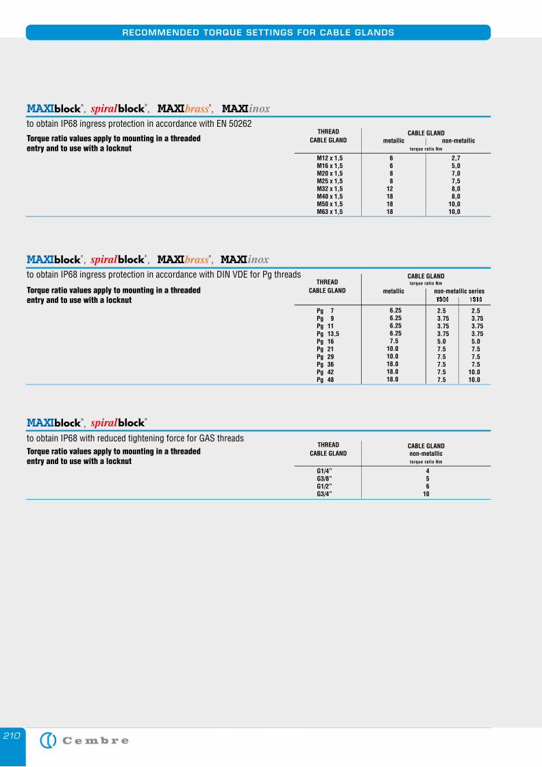
210
RECOMMENDED TORQUE SETTINGS FOR CABLE GLANDS
Torque ratio values apply to mounting in a threaded entry and to use with a locknut
Torque ratio values apply to mounting in a threaded entry and to use with a locknut
THREAD CABLE GLAND metallic non-metallic
M12 x 1,5M16 x 1,5M20 x 1,5M25 x 1,5M32 x 1,5M40 x 1,5M50 x 1,5M63 x 1,5
6 6 8 8 12 18 18 18
2,7 5,0 7,0 7,5 8,0 8,0 10,0 10,0
torque ratio Nm
, , ,
to obtain IP68 ingress protection in accordance with EN 50262CABLE GLAND
Torque ratio values apply to mounting in a threaded entry and to use with a locknut
THREAD CABLE GLAND non-metallic
G1/4”G3/8”G1/2”G3/4”
4 5 6 10
torque ratio Nm
,
to obtain IP68 with reduced tightening force for GAS threadsCABLE GLAND
, , ,
to obtain IP68 ingress protection in accordance with DIN VDE for Pg threadsTHREAD
CABLE GLAND
CABLE GLAND
metallic non-metallic series1900 1910
Pg 7Pg 9Pg 11Pg 13,5Pg 16Pg 21Pg 29Pg 36Pg 42Pg 48
6.25 6.25 6.25 6.25 7.5 10.0 10.0 18.0 18.0 18.0
2.5 3.75 3.75 3.75 5.0 7.5 7.5 7.5 7.5 7.5
torque ratio Nm
2.5 3.75 3.75 3.75 5.0 7.5 7.5 7.5 10.0 10.0
spiral
spiral

211
NOTES

212
NOTES

SIGNstick-onsys
cablesysRING
The information contained in this catalogue is toaid the commercial selection of products.
It is not intended for use as an instruction manual.Information concerning application and the correctoperational use is provided by the specific manual
delivered with the products.
printing: IGB Group Brescia.
This catalogue is the property of Cembre.Any reproduction (in full or in part) is forbidden withoutthe prior written permission of Cembre.
Cembre reserve the right to modify the specificationsin this catalogue without prior notice.
are registered trademarks of Cembre S.p.A.
ZETAblock
ZETApiù
ZETAminiCrimpstar
ndÆ
Also available in the Cembre product range
“Industrial Marking Systems”
MANUAL CABLE MARKING SYSTEMS
PC-DRIVEN THERMAL TRANSFER MARKER PRINTING SYSTEM
WARNING, PROHIBITIONAND MANDATORY SIGNS
NEW MARKERS FOR THE IDENTIFICATION OFTERMINAL BLOCKS AND CABLES
THERMAL TRANSFER SYSTEMFOR REEL MEDIA PRINTING
www.cembre.co.uk
Cod.
626
0567
Dunton ParkKingsbury Road, CurdworthSutton Coldfield - West Midlands B76 9EB UKTel.: 01675 470440Fax: 01675 470220 E-mail: [email protected]: www.cembre.co.uk
Design, manufacture and sales of electrical connectors and associated tools, cable accessories, marking systems, tooling and products for railway applica-tions. In house repair, refurbishment and calibration of tooling.
Ltd.