gdgmv borehole database interface user guide
TRANSCRIPT
GDGMV Borehole Database Interface User Guide
BGS Global
Open Report OR/21/018

BRITISH GEOLOGICAL SURVEY
BGS GLOBAL PROGRAMME
INTERNAL REPORT OR/21/018
Keywords
Report; borehole log; geodatabase; borehole coding; digital workflow; borehole database.
Bibliographical reference
Graham, R.L., Lawrie, K.I.G., Nayembil, M.L., Nguyen Ho. K., Dao Trung, H., Le Quoc, H Ford, J., and Bricker, S. 2020. GDGMV Borehole Database Interface User Guide. British Geological Survey Internal Report, OR/21/018. 44pp.
Copyright in materials derived from the British Geological Survey’s work is owned by UK Research and Innovation (UKRI). You may not copy or adapt this publication without first obtaining permission. Contact the BGS Intellectual Property Rights Section, British Geological Survey, Keyworth, e-mail [email protected]. You may quote extracts of a reasonable length without prior permission, provided a full acknowledgement is given of the source of the extract.
GDGMV Borehole Database Interface User Guide
Graham1, R.L., Lawrie2, K.I.G., Nayembil1, M.L., Nguyen3 Ho. K., Dao3 Trung, H., Le Quoc3, H., Ford1, J., and Bricker1, S.
1 British Geological Survey, Keyworth
2 British Geological Survey, Edinburgh
3 General Department of Geology and Minerals, Vietnam
© UKRI 2020. All rights reserved Keyworth, Nottingham British Geological Survey 2020

The full range of our publications is available from BGS shops at Nottingham, Edinburgh, London and Cardiff (Welsh publications only) see contact details below or shop online at www.geologyshop.com
The London Information Office also maintains a reference collection of BGS publications, including maps, for consultation.
We publish an annual catalogue of our maps and other publications; this catalogue is available online or from any of the BGS shops.
The British Geological Survey carries out the geological survey of Great Britain and Northern Ireland (the latter as an agency service for the government of Northern Ireland), and of the surrounding continental shelf, as well as basic research projects. It also undertakes programmes of technical aid in geology in developing countries.
The British Geological Survey is a component body of UK Research and Innovation.
British Geological Survey offices
Nicker Hill, Keyworth, Nottingham NG12 5GG
Tel 0115 936 3100
BGS Central Enquiries Desk
Tel 0115 936 3143 email [email protected]
BGS Sales
Tel 0115 936 3241 email [email protected]
The Lyell Centre, Research Avenue South, Edinburgh EH14 4AP
Tel 0131 667 1000 email [email protected]
Natural History Museum, Cromwell Road, London SW7 5BD
Tel 020 7589 4090 Tel 020 7942 5344/45 email [email protected]
Cardiff University, Main Building, Park Place, Cardiff CF10 3AT
Tel 029 2167 4280
Maclean Building, Crowmarsh Gifford, Wallingford OX10 8BB
Tel 01491 838800
Geological Survey of Northern Ireland, Department of Enterprise, Trade & Investment, Dundonald House, Upper Newtownards Road, Ballymiscaw, Belfast, BT4 3SB
Tel 01232 666595 www.bgs.ac.uk/gsni/
Natural Environment Research Council, Polaris House, North Star Avenue, Swindon SN2 1EU
Tel 01793 411500 Fax 01793 411501 www.nerc.ac.uk
UK Research and Innovation, Polaris House, Swindon SN2 1FL
Tel 01793 444000 www.ukri.org
Website www.bgs.ac.uk Shop online at www.geologyshop.com
BRITISH GEOLOGICAL SURVEY
i
Foreword
This report is the published product of a collaboration between the British Geological Survey (BGS) and the General Department of Geology and Minerals Vietnam (GDGMV) and Ministry of Natural Resources and Environment (MONRE) as part of the Hanoi Urban Geology Project. The project has been ongoing since 2016, funded through the by BGS NC-ODA: Geoscience for Sustainable Futures Programme. The project delivers against three priority themes:
1) Development of Digital Systems and Workflows
2) Urban Geology for Planning Policy and Construction
3) Training, Knowledge Exchange and Stakeholder Engagement
These tasks are delivering new digital data technology, new working practices, and increased institutional capacity with respect to urban geoscience.
The GDGMV Borehole Database Interface outlined in this document is one of many systems developed and put in place. This report should be used in conjunction with the other reports related to this collaboration, including:
OR/21/019 – GDGMV Lexicon Database User Guide
OR/20/55 – Considerations for Borehole Coding and Coded Borehole Data Checking
There is also a toolbox of documents, data tools, and workflows available.
Acknowledgements
Within the BGS, the authors would like to acknowledge the support of Martin Smith, Andrew McKenzie, Martin Nice and the large number of individuals from GDGMV who have been instrumental in guiding this process, and we thank them all. In addition to the collection of data, many individuals have freely given their time and advice, and provided the local knowledge so important to this collaboration being a success. We would particularly like to thank the geologists and data scientists at the General Dept. of Geology and Minerals Vietnam and the Centre for Information and Archive of Geology, Vietnam for their support, guidance and regular input. This project was funded as part of the BGS NC-ODA: Geoscience for Sustainable Futures Programme (Grant no. NE/R000069/1).
ii
Contents
Foreword ..................................................................................................................................... i
Acknowledgements ..................................................................................................................... i
Contents ...................................................................................................................................... ii
1 Introduction .......................................................................................................................... 1
2 Interface set up .................................................................................................................... 2
2.1 Prerequisites .............................................................................................................. 2
3 Interface log in ..................................................................................................................... 5
4 How to create and select a project ....................................................................................... 6
5 The Borehole Entry Form – Main Sections .......................................................................... 8
5.1 Borehole Index data entry - simplified ......................................................................... 8
5.2 Borehole index data entry - extended ....................................................................... 11
5.3 Lithology log data entry ............................................................................................ 13
5.4 Lithology log Additional properties data entry ........................................................... 15
5.5 Stratigraphic log data entry ....................................................................................... 20
5.6 Stratigraphy .............................................................................................................. 21
5.7 Stratigraphy Notes .................................................................................................... 21
5.8 Top / Base / thickness .............................................................................................. 21
5.9 Depth reliability ......................................................................................................... 21
5.10 Base Bed ................................................................................................................. 22
6 Borehole search function ................................................................................................... 23
6.1 Order By ................................................................................................................... 23
6.2 Search by Location ID .............................................................................................. 23
6.3 Search by name ....................................................................................................... 23
7 Dictionary Control .............................................................................................................. 25
7.1 Examining some of the more important and regularly used dictionaries ................... 25
8 Borehole Entry Form – Additional sections ........................................................................ 27
8.1 Rock Quality Designation ......................................................................................... 27
8.2 Weathering Assessment........................................................................................... 27
8.3 Standard Penetration Test ........................................................................................ 27
8.4 Water Levels ............................................................................................................ 28
8.5 Aquifer Property Log ................................................................................................ 28
9 Data Export ....................................................................................................................... 29
9.1 Data Export Form ..................................................................................................... 29
Appendix 1 ............................................................................................................................... 30
Example ............................................................................................................................ 30
References ............................................................................................................................... 36
iii
FIGURES
Figure 1: Steps for creating an ODBC link. ................................................................................. 3
Figure 2: Linking the application to the database. ....................................................................... 4
Figure 3: Forms to Database table mapping. .............................................................................. 4
Figure 4: GDW Logon form for the Borehole Data Entry System. ............................................... 5
Figure 5: Enable Content for the Borehole Data Entry System. .................................................. 5
Figure 6: GDW Switchboard form (initial view) for the Borehole Data Entry System. .................. 6
Figure 7: GDW Activity form for the Borehole Data Entry System. .............................................. 7
Figure 8 - Borehole Entry form for the Borehole Data Entry System – opening view. ................. 8
Figure 9: The Lithology Log tab of the Borehole Data Entry form. ............................................ 13
Figure 10: Example of Colour data entry in the Additional Properties form. .............................. 15
Figure 11: Colour Qualifier drop down demonstrated. .............................................................. 15
Figure 12: Example of Mineralogical Qualifier data entry in the Additional Properties form. ...... 16
Figure 13: Example of Sedimentary Structure data entry in the Additional Properties form. ..... 16
Figure 14: Example of Grain Sorting data entry in the Additional Properties form. .................... 16
Figure 15: Example of Dominant Grain Size data entry in the Additional Properties form. ........ 17
Figure 16: Illustration of grain shape and relationship of triaxial dimensions. Alternative terminology includes: Oblate – Disc; Equant – Spheroid; Prolate – Rod. Modified after Nichols, 1999. .................................................................................................................... 18
Figure 17: Example of Grain Shape Properties data entry in the Additional Properties form. .... 18
Figure 18: Example of Grain Sphericity data entry in the Additional Properties form. ............... 19
Figure 19: Grain sphericity and Grain angularity. Modified from Powers 1953. ......................... 19
Figure 20: Example of Grain Angularity data entry in the Additional Properties form. ............... 20
Figure 21: The Stratigraphy Log tab of the Borehole Data Entry form. ...................................... 21
Figure 22: Search and Group By tool locations are highlighted by the thick red box. ................ 23
Figure 23: Scrolling to the required Borehole ............................................................................ 23
Figure 24: Using the Bằng Tên search function to scroll to and then select a borehole. ........... 24
Figure 25: By selecting the TÐ3 record in Figure 23, the data for the TÐ3 borehole will be displayed in the Forms and be available for viewing and editing. ....................................... 24
Figure 26: The Dictionary Control Form showing Stratigraphy Dictionary Tab values. .............. 25
Figure 27: Current path to the root folder for any documents stored on the server. .................. 26
Figure 28: Rock Quality Designation data entry example. ........................................................ 27
Figure 29: Weathering assessment data entry example. .......................................................... 27
Figure 30: Standard Penetration Test data entry example. ....................................................... 28
Figure 31: Water Levels data entry example. ........................................................................... 28
Figure 32: The Aquifer Property Log data entry form. ............................................................... 28
Figure 33: Data Export Form. ................................................................................................... 29
Figure 34: Borehole Index data entry for H7DA coding example. ............................................ 32
Figure 35: Fully coded Lithology Log example for borehole H7DA, refer to sections 9.1.1 to 9.1.2.10 for more specific details. ....................................................................................... 34
iv
PLATES
No table of figures entries found.
TABLES
Table 1: EPSG defined Min./Max. X/Y coordinates for the most commonly used coordinate systems in Vietnam. ............................................................................................................. 9
Table 2: Approximate Min. and Max. X/Y coordinates covering the landmass of Vietnam for the most commonly used coordinate systems in Vietnam. For reference of potential incorrectly assigned coordinate systems only – see Table 1 for official EPSG defined boundaries. .... 10
Table 3: GDGMV Unlithified Coding Scheme. .......................................................................... 14
Table 4: Borehole Index and Log data table for H7DA coding example. ................................... 30

1
1 Introduction
This report details how to use the borehole database created by the British Geological Survey (BGS) for the General Department of Geology and Minerals of Vietnam (GDGMV) and forms one of a suite of publications outlining good practice approaches for the implementation of Digital Data Workflows. Activities to increase informatics capacity and adoption of digital workflows within GDGMV have been undertaken as part of a wider, ODA-funded project focused on the sustainable development of Asian cities. Insufficient understanding of ground conditions is widely recognised by the construction industry as one of the main causes of project overspending, project delays, and overly conservative design. Furthermore geoscience information has traditionally been under-utilised in planning and development, as it is difficult to access and its significance is often misunderstood or underappreciated. Digitisation of borehole data and geotechnical information is a vital step in improving the digital workflow between industry, geoscience experts and urban planning professionals. Digital approaches provide rapid, large volumes of data for interrogation and re-use. It improves operational efficiency, increases innovation, and provides a curated dataset to support data-driven decision making for urban development.
The report focuses on how to set up and log in to the interface, followed by how to create a project. Once a project has been selected, the main sections of the Borehole Entry Form are detailed; the Borehole Index data, Lithology Log and Additional Properties; and the Stratigraphic Log. Nuances and caveats for each aspect of the Borehole Entry Form are dealt with in the appropriate sections, acknowledging the specific functionality included for GDGMV data and preferences. Use and tips for using the Dictionary Control is then outlined. Additional sections of the Borehole Entry Form are further explained; the Rock Quality Designation (RQD) Log; the Weathering Log; the Standard Penetration Test (SPT) Log; the Groundwater Level (GWL) Log; the Aquifer Properties (AQP) Log. Finally, the different types of data export types are addressed.
The Appendix contains several worked examples of using the Borehole Entry Form to input real GDGMV borehole data.
Subsequent updates of the GDGMV Borehole Database Application may affect its appearance, so there may be differences between the figures contained within this report and the most recent version of the interface.

2
2 Interface set up
Once the database has been setup on the server, the client machines need to be setup – more information on how this is done can be found in the additional files and reports supplied as part of this work package.
2.1 PREREQUISITES
2.1.1 Microsoft Access
Microsoft Access 2019 should be installed on each client machine as part of the Microsoft Office 2019 Suite.
Consideration 1 – Ideally the 32-bit version should be used, however the application is 64-bit
compatible and Microsoft Access 2019 64bit may be used.
Consideration 2 – You must install only one version of Microsoft Office on any given client machine. You cannot mix 64-bit and 32-bit Office applications
Consideration 3 – It is important that your client machine is set up correctly for your way of working. Whichever regionalisation you use (Vietnamese or UK) you must continue to be consistent in the way you enter numerical values in the application.
For Vietnamese regionalisation then the decimal separator should be a comma (“,”) and
any grouping (thousands or millions) used should be a dot (“.”) e.g. 1.000.000,12
For UK regionalisation then the decimal separator should be a dot (“.”) and any grouping
(thousands or millions) used should be a (“,”) e.g. 1,000,000.12
How to check / change your region in Windows 10
1. Select Start > Settings > Time & Language > Region. 2. Under Country or region, select your new region. 3. You can switch back to your original region at any time.
For further details, follow the instructions in this link:
https://support.microsoft.com/en-us/account-billing/change-your-country-or-region-in-microsoft-store-5895e006-34f4-10f7-16b1-999e40adb048
3
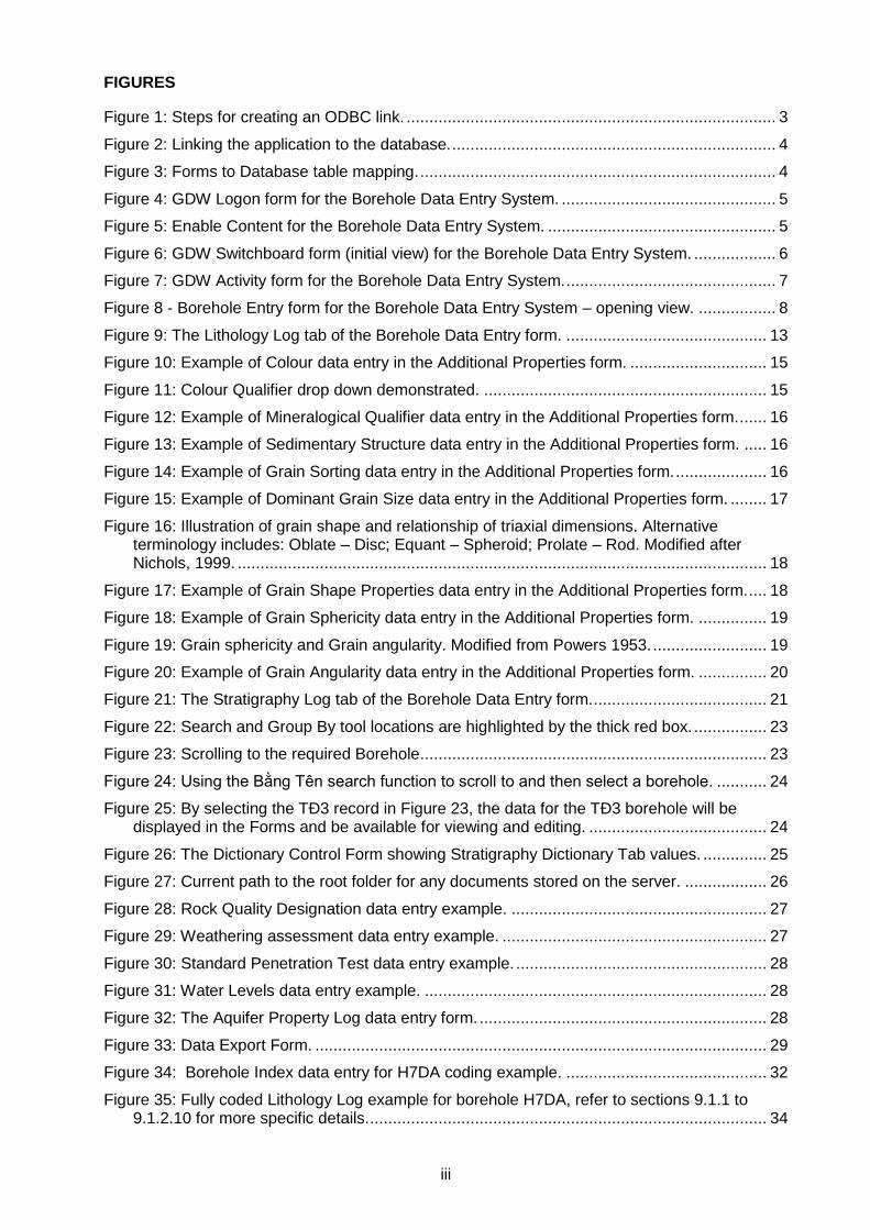
2.1.2 Open Database Connectivity ODBC
To enable the borehole entry application to communicate with the database, a link has to be made using ODBC – in general the user will not be required to set this up as the application is normally ‘pre-linked’, however for completeness the process can be found in Figure 1.
Figure 1: Steps for creating an ODBC link.
2.1.3 The MS Access Front End
In order to enter, edit and output the data stored in the database you will need to use the Microsoft Access front end. This application is built using MS Access forms, code and features.
The application has to be copied to the computer you will be using to work from – do not work directly from the file on the server. In order to do this you will have to navigate to the folder holding the file (it will be an [‘xxxx’.accdb] file where ‘xxxx’ represents the latest version name of the application) and copy the file onto your local machine (place it in a suitably named folder on your machine). Do not attempt to run the master version stored on the server, or make a shortcut to the master copy on your desktop.
4
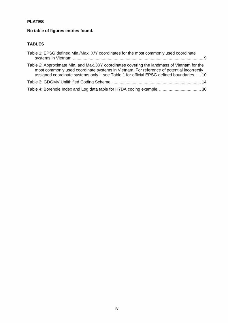
2.1.4 How the application works
The application works by making a connection to the tables stored in the PostgreSQL database held on your server.
Figure 2: Linking the application to the database.
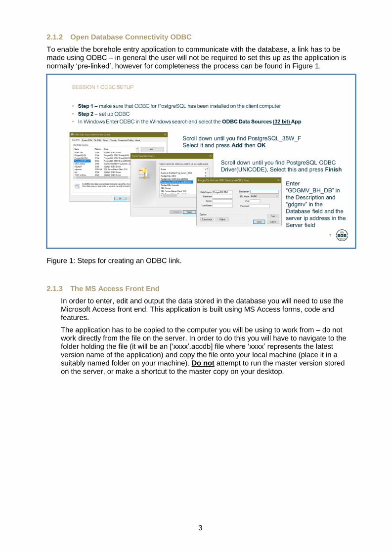
2.1.5 How the application forms and sub-forms map to the database tables
The forms and sub-forms in the front-end map to the data held in tables in the PostgreSQL database.
Figure 3: Forms to Database table mapping.
5
3 Interface log in
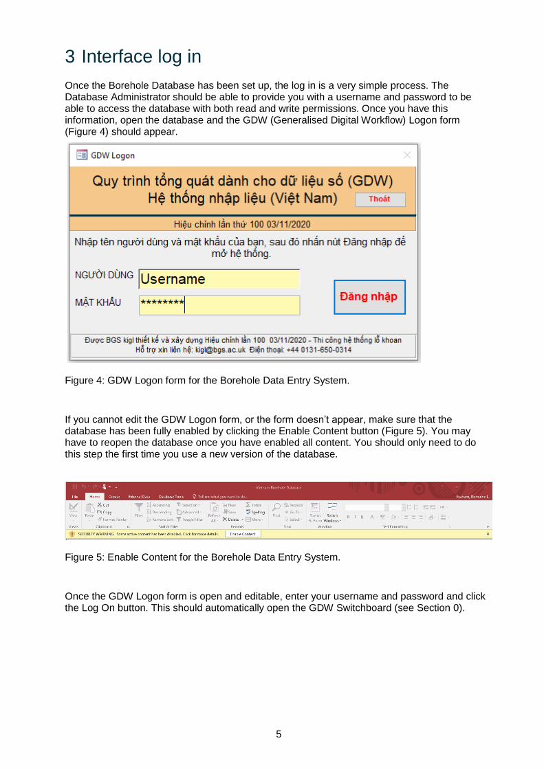
Once the Borehole Database has been set up, the log in is a very simple process. The Database Administrator should be able to provide you with a username and password to be able to access the database with both read and write permissions. Once you have this information, open the database and the GDW (Generalised Digital Workflow) Logon form (Figure 4) should appear.
Figure 4: GDW Logon form for the Borehole Data Entry System.
If you cannot edit the GDW Logon form, or the form doesn’t appear, make sure that the database has been fully enabled by clicking the Enable Content button (Figure 5). You may have to reopen the database once you have enabled all content. You should only need to do this step the first time you use a new version of the database.
Figure 5: Enable Content for the Borehole Data Entry System.
Once the GDW Logon form is open and editable, enter your username and password and click the Log On button. This should automatically open the GDW Switchboard (see Section 0).
6
4 How to create and select a project
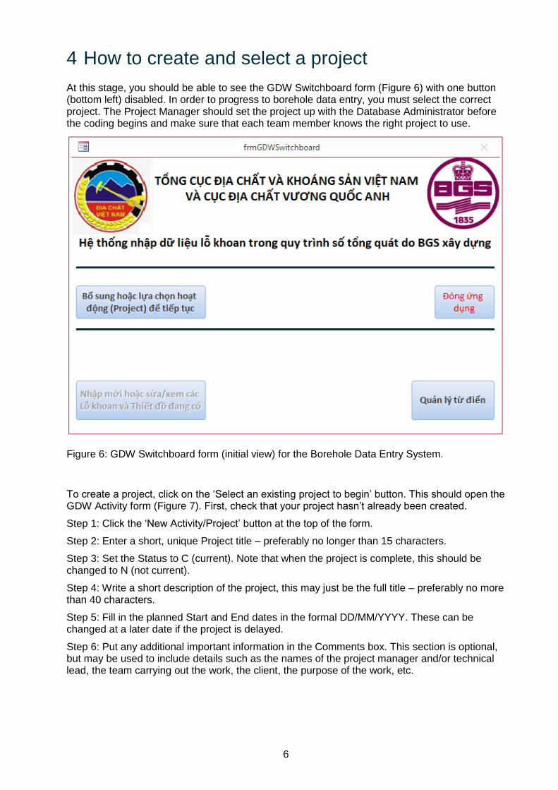
At this stage, you should be able to see the GDW Switchboard form (Figure 6) with one button (bottom left) disabled. In order to progress to borehole data entry, you must select the correct project. The Project Manager should set the project up with the Database Administrator before the coding begins and make sure that each team member knows the right project to use.
Figure 6: GDW Switchboard form (initial view) for the Borehole Data Entry System.
To create a project, click on the ‘Select an existing project to begin’ button. This should open the GDW Activity form (Figure 7). First, check that your project hasn’t already been created.
Step 1: Click the ‘New Activity/Project’ button at the top of the form.
Step 2: Enter a short, unique Project title – preferably no longer than 15 characters.
Step 3: Set the Status to C (current). Note that when the project is complete, this should be changed to N (not current).
Step 4: Write a short description of the project, this may just be the full title – preferably no more than 40 characters.
Step 5: Fill in the planned Start and End dates in the formal DD/MM/YYYY. These can be changed at a later date if the project is delayed.
Step 6: Put any additional important information in the Comments box. This section is optional, but may be used to include details such as the names of the project manager and/or technical lead, the team carrying out the work, the client, the purpose of the work, etc.
7
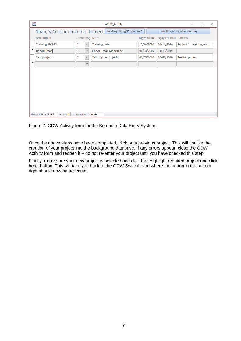
Figure 7: GDW Activity form for the Borehole Data Entry System.
Once the above steps have been completed, click on a previous project. This will finalise the creation of your project into the background database. If any errors appear, close the GDW Activity form and reopen it – do not re-enter your project until you have checked this step.
Finally, make sure your new project is selected and click the ‘Highlight required project and click here’ button. This will take you back to the GDW Switchboard where the button in the bottom right should now be activated.
8
5 The Borehole Entry Form – Main Sections
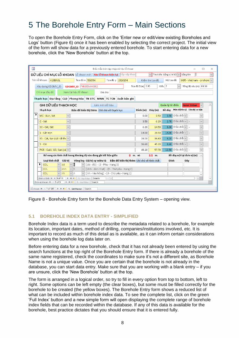
To open the Borehole Entry Form, click on the ‘Enter new or edit/view existing Boreholes and Logs’ button (Figure 6) once it has been enabled by selecting the correct project. The initial view of the form will show data for a previously entered borehole. To start entering data for a new borehole, click the ‘New Borehole’ button at the top.
Figure 8 - Borehole Entry form for the Borehole Data Entry System – opening view.
5.1 BOREHOLE INDEX DATA ENTRY - SIMPLIFIED
Borehole Index data is a term used to describe the metadata related to a borehole, for example its location, important dates, method of drilling, companies/institutions involved, etc. It is important to record as much of this detail as is available, as it can inform certain considerations when using the borehole log data later on.
Before entering data for a new borehole, check that it has not already been entered by using the search functions at the top right of the Borehole Entry form. If there is already a borehole of the same name registered, check the coordinates to make sure it’s not a different site, as Borehole Name is not a unique value. Once you are certain that the borehole is not already in the database, you can start data entry. Make sure that you are working with a blank entry – if you are unsure, click the ‘New Borehole’ button at the top.
The form is arranged in a logical order, so try to fill in every option from top to bottom, left to right. Some options can be left empty (the clear boxes), but some must be filled correctly for the borehole to be created (the yellow boxes). The Borehole Entry form shows a reduced list of what can be included within borehole index data. To see the complete list, click on the green ‘Full Index’ button and a new simple form will open displaying the complete range of borehole index fields that can be recorded within the database. If any of this data is available for the borehole, best practice dictates that you should ensure that it is entered fully.
9
5.1.1 Borehole Name
Borehole Name is not a unique value and can therefore be used when there are multiple boreholes of the same name. To mitigate any issues this may cause with data confusion, each Borehole entry is given a unique GDGMV ID (see Section 5.1.5 for more details). The borehole name should be entered as simply as possible. The prefix of ‘LK’ should not be included within the name. Any symbols should be entered as the documents specify. An additional check on Borehole Name should be carried out to ensure that the borehole name hasn’t previously been entered in a different format.
5.1.2 X and Y coordinates
Getting the coordinates correct is one of the most vital parts of the borehole data entry process. Without accurate location data, all other data stored for the borehole will be of limited value. With this in mind, it is important to take the time to ensure that the X and Y coordinates are correct. See Section 5.1.3 for information on the in-built coordinate checking system.
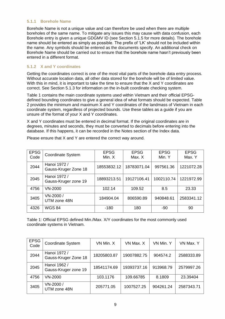
Table 1 contains the main coordinate systems used within Vietnam and their official EPSG-defined bounding coordinates to give a general idea of what formats should be expected. Table 2 provides the minimum and maximum X and Y coordinates of the landmass of Vietnam in each coordinate system, regardless of projected bounds. Use these tables as a guide if you are unsure of the format of your X and Y coordinates.
X and Y coordinates must be entered in decimal format. If the original coordinates are in degrees, minutes and seconds, they must be converted to decimals before entering into the database. If this happens, it can be recorded in the Notes section of the Index data.
Please ensure that X and Y are entered the correct way around.
EPSG Code
Coordinate System EPSG Min. X
EPSG Max. X
EPSG Min. Y
EPSG Max. Y
2044 Hanoi 1972 / Gauss-Kruger Zone 18
18553832.12 18783071.04 997561.36 1221072.28
2045 Hanoi 1972 / Gauss-Kruger zone 19
18893213.51 19127106.41 1002110.74 1221972.99
4756 VN-2000 102.14 109.52 8.5 23.33
3405 VN-2000 / UTM zone 48N
184904.04 806590.89 940848.61 2583341.12
4326 WGS 84 -180 180 -90 90
Table 1: Official EPSG defined Min./Max. X/Y coordinates for the most commonly used coordinate systems in Vietnam.
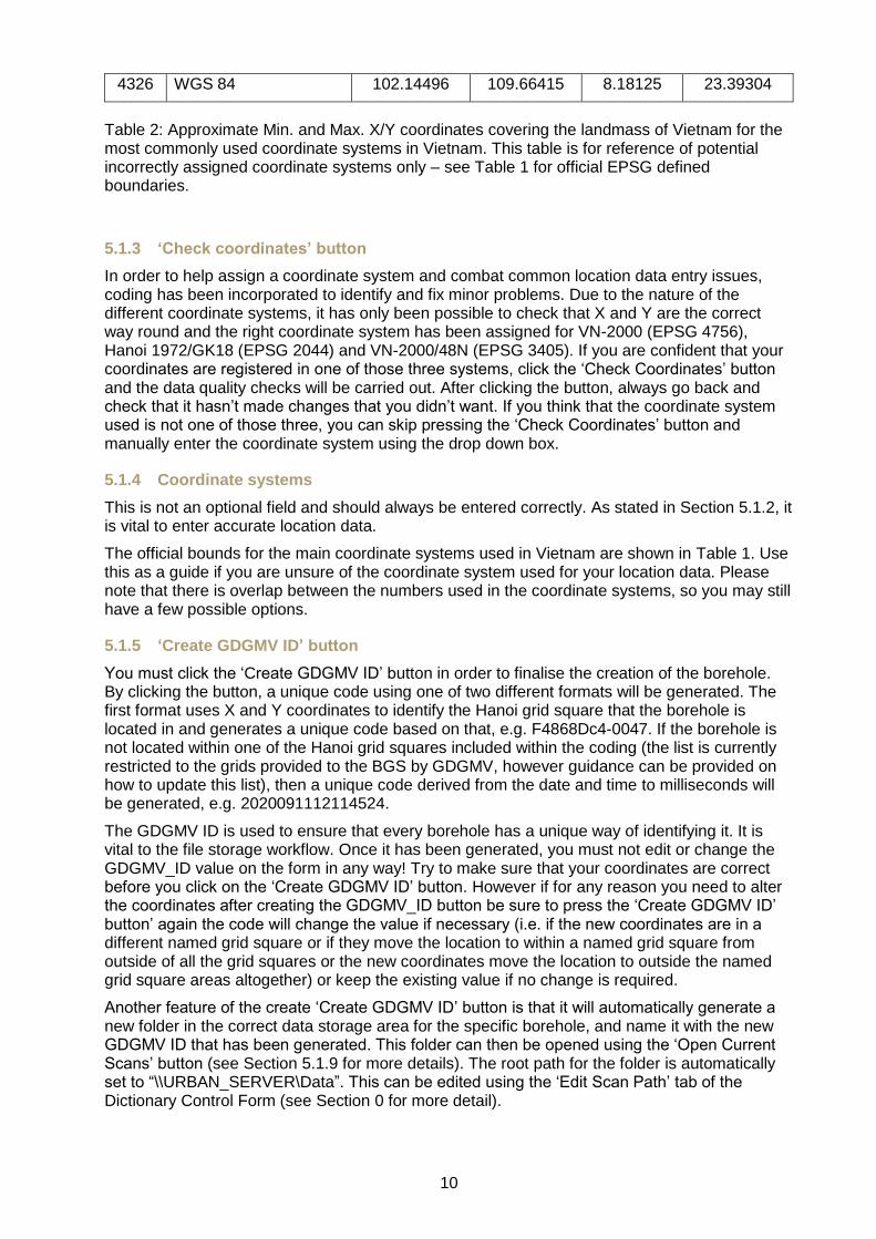
EPSG Code
Coordinate System VN Min. X VN Max. X VN Min. Y VN Max. Y
2044 Hanoi 1972 / Gauss-Kruger Zone 18
18205803.87 19007882.75 904574.2 2588333.89
2045 Hanoi 1962 / Gauss-Kruger zone 19
18541174.69 19393737.16 913968.79 2579997.26
4756 VN-2000 103.1176 109.66785 8.1809 23.39404
3405 VN-2000 / UTM zone 48N
205771.05 1007527.25 904261.24 2587343.71
10
4326 WGS 84 102.14496 109.66415 8.18125 23.39304
Table 2: Approximate Min. and Max. X/Y coordinates covering the landmass of Vietnam for the most commonly used coordinate systems in Vietnam. This table is for reference of potential incorrectly assigned coordinate systems only – see Table 1 for official EPSG defined boundaries.
5.1.3 ‘Check coordinates’ button
In order to help assign a coordinate system and combat common location data entry issues, coding has been incorporated to identify and fix minor problems. Due to the nature of the different coordinate systems, it has only been possible to check that X and Y are the correct way round and the right coordinate system has been assigned for VN-2000 (EPSG 4756), Hanoi 1972/GK18 (EPSG 2044) and VN-2000/48N (EPSG 3405). If you are confident that your coordinates are registered in one of those three systems, click the ‘Check Coordinates’ button and the data quality checks will be carried out. After clicking the button, always go back and check that it hasn’t made changes that you didn’t want. If you think that the coordinate system used is not one of those three, you can skip pressing the ‘Check Coordinates’ button and manually enter the coordinate system using the drop down box.
5.1.4 Coordinate systems
This is not an optional field and should always be entered correctly. As stated in Section 5.1.2, it is vital to enter accurate location data.
The official bounds for the main coordinate systems used in Vietnam are shown in Table 1. Use this as a guide if you are unsure of the coordinate system used for your location data. Please note that there is overlap between the numbers used in the coordinate systems, so you may still have a few possible options.
5.1.5 ‘Create GDGMV ID’ button
You must click the ‘Create GDGMV ID’ button in order to finalise the creation of the borehole. By clicking the button, a unique code using one of two different formats will be generated. The first format uses X and Y coordinates to identify the Hanoi grid square that the borehole is located in and generates a unique code based on that, e.g. F4868Dc4-0047. If the borehole is not located within one of the Hanoi grid squares included within the coding (the list is currently restricted to the grids provided to the BGS by GDGMV, however guidance can be provided on how to update this list), then a unique code derived from the date and time to milliseconds will be generated, e.g. 2020091112114524.
The GDGMV ID is used to ensure that every borehole has a unique way of identifying it. It is vital to the file storage workflow. Once it has been generated, you must not edit or change the GDGMV_ID value on the form in any way! Try to make sure that your coordinates are correct before you click on the ‘Create GDGMV ID’ button. However if for any reason you need to alter the coordinates after creating the GDGMV_ID button be sure to press the ‘Create GDGMV ID’ button’ again the code will change the value if necessary (i.e. if the new coordinates are in a different named grid square or if they move the location to within a named grid square from outside of all the grid squares or the new coordinates move the location to outside the named grid square areas altogether) or keep the existing value if no change is required.
Another feature of the create ‘Create GDGMV ID’ button is that it will automatically generate a new folder in the correct data storage area for the specific borehole, and name it with the new GDGMV ID that has been generated. This folder can then be opened using the ‘Open Current Scans’ button (see Section 5.1.9 for more details). The root path for the folder is automatically set to “\\URBAN_SERVER\Data”. This can be edited using the ‘Edit Scan Path’ tab of the Dictionary Control Form (see Section 0 for more detail).
11
5.1.6 Start height and type
The start height of a borehole is also known as its elevation, or z-value. It should be recorded in metres with up to 2 decimal places. The type of start height should be defined if known, with the most common type being ‘ground level’, meaning that the borehole start height measurement was measured from the level of the ground, rather than a drilling platform, or rotary table. Be aware that for the centre of Hanoi and downstream on the Red River Delta, the elevation is unlikely to be a large number so if you are finding numbers over 100, you will need to consider the units that you are dealing and potentially convert them to metres. Elsewhere in Vietnam, elevations may be much higher.
5.1.7 Total depth
Total depth, also known as TD, should be recorded in metres with up to 2 decimal places. It includes the entire depth that was drilled, not just the cored interval.
5.1.8 ‘Full Index’ button
The ‘Full Index’ button opens a separate simple form that contains all the available options for inputting borehole index data. The Full Index form is discussed in more detail in Section 5.2.
5.1.9 ‘Open Current Scans’ button
The ‘Open Current Scans’ button will open the folder where the data for the borehole is stored. When entering index data initially this folder will be empty. As part of the index data entry process, it is vital that any files referencing the borehole are stored within this folder. This file storage workflow will enable the simple and easy pinpointing of borehole data when coding borehole log data and referring back to specific boreholes.
5.1.10 Notes
This is a free text data option. Store all information that may provide additional understanding of the borehole or the data stored here, e.g. whether you have had to convert the coordinate system to enable entry into the database, or whether the drilling failed partway through, etc. Any information that has been included using other data entry points does not need to be repeated here.
5.2 BOREHOLE INDEX DATA ENTRY - EXTENDED
5.2.1 Purpose
This data type denotes the specific purpose that the borehole drilling was carried out for, e.g. site investigation, groundwater, etc.
5.2.2 Drilling method
This data type describes the method used to drill the borehole, e.g. rotary core, hand auger, etc.
5.2.3 Borehole status
This data type describes the current status of the borehole, e.g. drilling currently in progress, projected, cased, etc. The status of the borehole may change over time and should be reflected in subsequent updates of this value.
5.2.4 Confidentiality
This data type describes how confidential the data attributed to this borehole is, e.g. non-confidential, restricted, confidential, etc. The confidentiality of borehole date may change over time and should be reflected in subsequent updates of this value. Many Geological Survey Organisations (GSOs) in Europe make their borehole data freely available under the EU INSPIRE Directive which aims to enhance the sharing on environmental spatial information.
12
Maintaining an open borehole dataset, accessible to industry and government, encourages the donation of additional data by e.g. engineering and groundwater companies on a share-and-share alike. This methodology has resulted in a much larger dataset than would otherwise have been achievable. Within this data model, borehole data owners grant the GSO a non-exclusive, in-perpetuity, royalty free licence to hold and disseminate the data. GSOs are still able to hold confidential data where appropriate.
5.2.5 Client organisation
This data type denotes the name of the company/organisation who commissioned the drilling of the borehole. This may be GDGMV itself, another area of the Ministry or government, or a private company, etc.
5.2.6 Driller organisation
This data type denotes the name of the company/organisation that carried out the drilling of the borehole. This may be GDGMV itself, or a separate private drilling company.
5.2.7 Drilling start/end date and precision
Drilling start date is the date that the drilling commenced. Drilling end date is similar, but the day that the drilling processed concluded. Both of these data types should preferably be exact to the day, however that is not always possible. If the available dates are exact to the month, enter the first of that month, e.g. when the date says May 2012, enter 01/05/2012. If the dates are exact to the year, enter the first day of that year, e.g. when the date just says 2012, enter 01/01/2012. The start/end date precision is used to highlight whether the dates are accurate to the day, month, year, etc.
5.2.8 Original start point/length unit
As the majority of Vietnamese data is recorded in metres, the original unit is automatically set to metres. If the data has originally been recorded in feet this should be captured here. All unit tops, bases, and thicknesses are recorded in the database as metres, so will need to be converted before data entry.
5.2.9 Inclination type
This data type is used to describe the inclination of a borehole, e.g. vertical, inclined downwards, etc. As the majority of boreholes in the Hanoi Urban Project are drilled vertically, that option has been automatically selected.
5.2.10 Data source
The Data source data type is used to specify the location from where the data has come from, e.g. the data was supplied directly by GDGMV, or by VIGMR, or HUPI, etc.
5.2.11 User/date entered
As a borehole data entry is made, the username of the person making the data entry and the date when the entry was made are automatically infilled.
5.2.12 User/date updated
Upon initial data entry, this is automatically infilled with the same data as user/date entered (Section 5.2.11). If edits are made after the initial entry, the username of the person making the edits and the date when they were made is automatically captured.
13
5.3 LITHOLOGY LOG DATA ENTRY
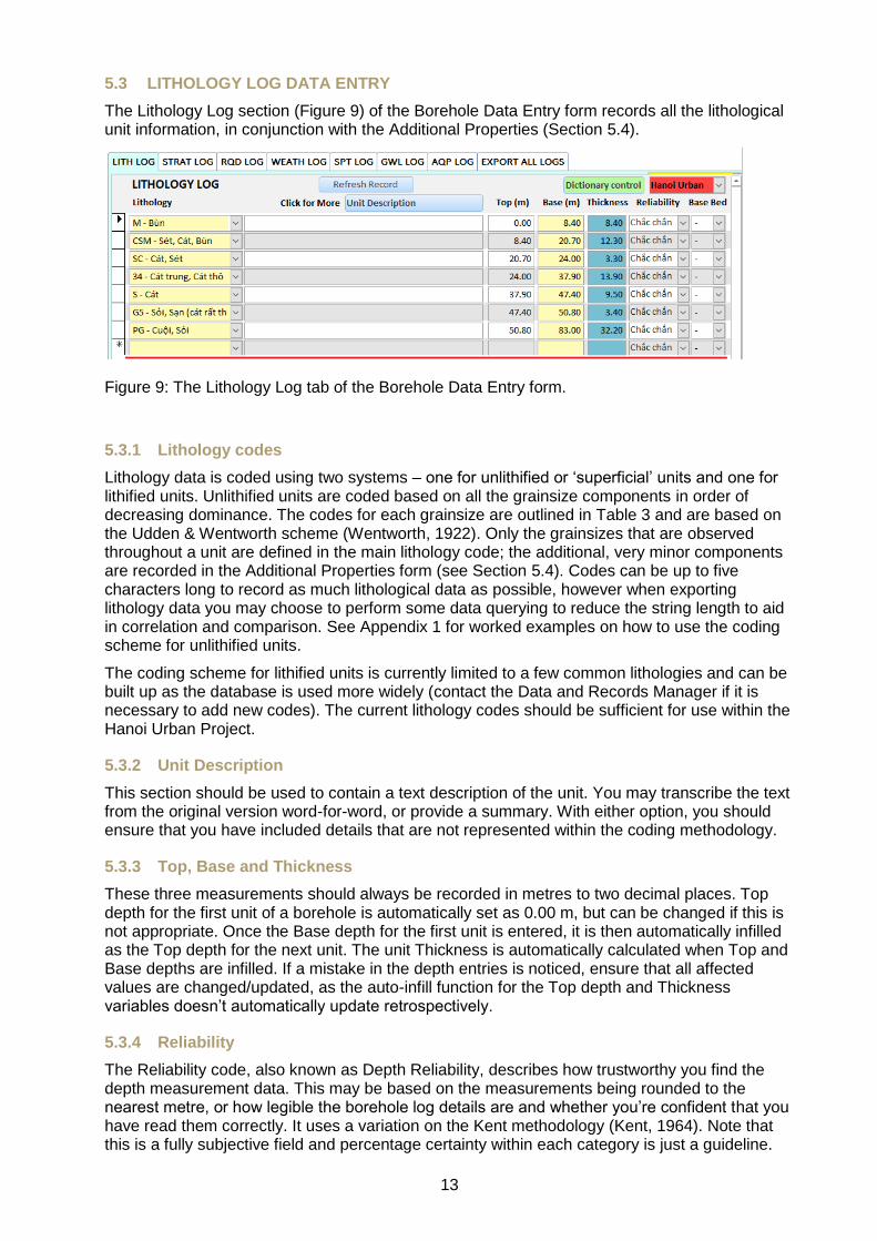
The Lithology Log section (Figure 9) of the Borehole Data Entry form records all the lithological unit information, in conjunction with the Additional Properties (Section 5.4).
Figure 9: The Lithology Log tab of the Borehole Data Entry form.
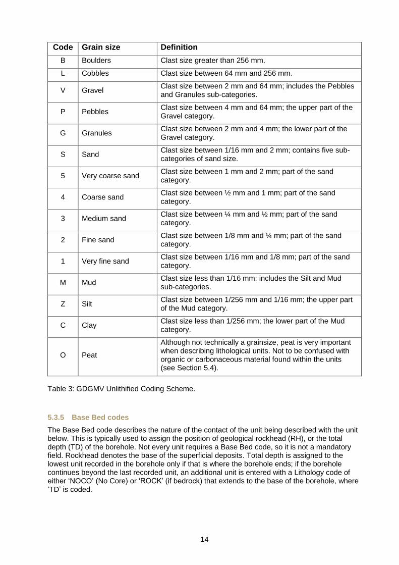
5.3.1 Lithology codes
Lithology data is coded using two systems – one for unlithified or ‘superficial’ units and one for lithified units. Unlithified units are coded based on all the grainsize components in order of decreasing dominance. The codes for each grainsize are outlined in Table 3 and are based on the Udden & Wentworth scheme (Wentworth, 1922). Only the grainsizes that are observed throughout a unit are defined in the main lithology code; the additional, very minor components are recorded in the Additional Properties form (see Section 5.4). Codes can be up to five characters long to record as much lithological data as possible, however when exporting lithology data you may choose to perform some data querying to reduce the string length to aid in correlation and comparison. See Appendix 1 for worked examples on how to use the coding scheme for unlithified units.
The coding scheme for lithified units is currently limited to a few common lithologies and can be built up as the database is used more widely (contact the Data and Records Manager if it is necessary to add new codes). The current lithology codes should be sufficient for use within the Hanoi Urban Project.
5.3.2 Unit Description
This section should be used to contain a text description of the unit. You may transcribe the text from the original version word-for-word, or provide a summary. With either option, you should ensure that you have included details that are not represented within the coding methodology.
5.3.3 Top, Base and Thickness
These three measurements should always be recorded in metres to two decimal places. Top depth for the first unit of a borehole is automatically set as 0.00 m, but can be changed if this is not appropriate. Once the Base depth for the first unit is entered, it is then automatically infilled as the Top depth for the next unit. The unit Thickness is automatically calculated when Top and Base depths are infilled. If a mistake in the depth entries is noticed, ensure that all affected values are changed/updated, as the auto-infill function for the Top depth and Thickness variables doesn’t automatically update retrospectively.
5.3.4 Reliability
The Reliability code, also known as Depth Reliability, describes how trustworthy you find the depth measurement data. This may be based on the measurements being rounded to the nearest metre, or how legible the borehole log details are and whether you’re confident that you have read them correctly. It uses a variation on the Kent methodology (Kent, 1964). Note that this is a fully subjective field and percentage certainty within each category is just a guideline.
14
Code Grain size Definition
B Boulders Clast size greater than 256 mm.
L Cobbles Clast size between 64 mm and 256 mm.
V Gravel Clast size between 2 mm and 64 mm; includes the Pebbles and Granules sub-categories.
P Pebbles Clast size between 4 mm and 64 mm; the upper part of the Gravel category.
G Granules Clast size between 2 mm and 4 mm; the lower part of the Gravel category.
S Sand Clast size between 1/16 mm and 2 mm; contains five sub-categories of sand size.
5 Very coarse sand Clast size between 1 mm and 2 mm; part of the sand category.
4 Coarse sand Clast size between ½ mm and 1 mm; part of the sand category.
3 Medium sand Clast size between ¼ mm and ½ mm; part of the sand category.
2 Fine sand Clast size between 1/8 mm and ¼ mm; part of the sand category.
1 Very fine sand Clast size between 1/16 mm and 1/8 mm; part of the sand category.
M Mud Clast size less than 1/16 mm; includes the Silt and Mud sub-categories.
Z Silt Clast size between 1/256 mm and 1/16 mm; the upper part of the Mud category.
C Clay Clast size less than 1/256 mm; the lower part of the Mud category.
O Peat
Although not technically a grainsize, peat is very important when describing lithological units. Not to be confused with organic or carbonaceous material found within the units (see Section 5.4).
Table 3: GDGMV Unlithified Coding Scheme.
5.3.5 Base Bed codes
The Base Bed code describes the nature of the contact of the unit being described with the unit below. This is typically used to assign the position of geological rockhead (RH), or the total depth (TD) of the borehole. Not every unit requires a Base Bed code, so it is not a mandatory field. Rockhead denotes the base of the superficial deposits. Total depth is assigned to the lowest unit recorded in the borehole only if that is where the borehole ends; if the borehole continues beyond the last recorded unit, an additional unit is entered with a Lithology code of either ‘NOCO’ (No Core) or ‘ROCK’ (if bedrock) that extends to the base of the borehole, where ‘TD’ is coded.
15
5.4 LITHOLOGY LOG ADDITIONAL PROPERTIES DATA ENTRY
The Additional Properties function allows for the organised storage of further detail for each lithological unit that is not covered by the Lithology code. They range from specifics on grain sizes and shapes to mineralogical components and sedimentological features. To use the multiple functions, select the Additional Property that you want to assign from the list under Property Type. This will then adapt the rest of the form to match the Property Type that you are editing. See below for details on each Additional Property Type. If a certain Property value is only noted within one section of the unit, new Top and Base values can be added for that specific property.
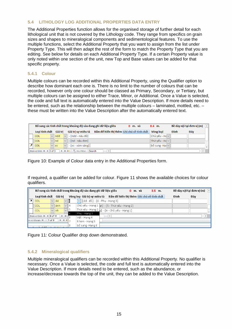
5.4.1 Colour
Multiple colours can be recorded within this Additional Property, using the Qualifier option to describe how dominant each one is. There is no limit to the number of colours that can be recorded, however only one colour should be classed as Primary, Secondary, or Tertiary, but multiple colours can be assigned to either Trace, Minor, or Additional. Once a Value is selected, the code and full text is automatically entered into the Value Description. If more details need to be entered, such as the relationship between the multiple colours – laminated, mottled, etc. – these must be written into the Value Description after the automatically entered text.
Figure 10: Example of Colour data entry in the Additional Properties form.
If required, a qualifier can be added for colour. Figure 11 shows the available choices for colour qualifiers.
Figure 11: Colour Qualifier drop down demonstrated.
5.4.2 Mineralogical qualifiers
Multiple mineralogical qualifiers can be recorded within this Additional Property. No qualifier is necessary. Once a Value is selected, the code and full text is automatically entered into the Value Description. If more details need to be entered, such as the abundance, or increase/decrease towards the top of the unit, they can be added to the Value Description.

16
Figure 12: Example of Mineralogical Qualifier data entry in the Additional Properties form.
5.4.3 Sedimentary Structures
Multiple sedimentary structures can be recorded within this Additional Property. This Additional Property records numerous different types of sedimentary structure, and as such you may enter multiple values for a single lithological unit. Depositional sedimentary structures, as well as bioturbation, and diagenetic structures are included within this Additional Property. Once a Value is selected, the code and full text is automatically entered into the Value Description. If further details need to be added, they can be entered into the Value Description.
Figure 13: Example of Sedimentary Structure data entry in the Additional Properties form.
5.4.4 Grain Sorting
The grain sorting codes are based on the standard five option dictionary used within sedimentological descriptions. It is preferable that only one grain sorting Value is recorded, however it is recognised that there may be some occasions when multiple grain sorting values are required. Currently there is no option to describe a range of grain sorting. Once a Value is selected, the code and full text is automatically entered into the Value Description. If further details need to be added, they can be entered into the Value Description.
Code Grain sorting Definition
VWS Very well sorted Grains sorted to 0.35 SD
WS Well sorted Grains sorted to 0.5 SD
MS Moderately sorted Grains sorted to 0.7 SD
PS Poorly sorted Grains sorted to 1.0 SD
VPS Very poorly sorted Grains sorted to 2.0 SD
Figure 14: Example of Grain Sorting data entry in the Additional Properties form.
17
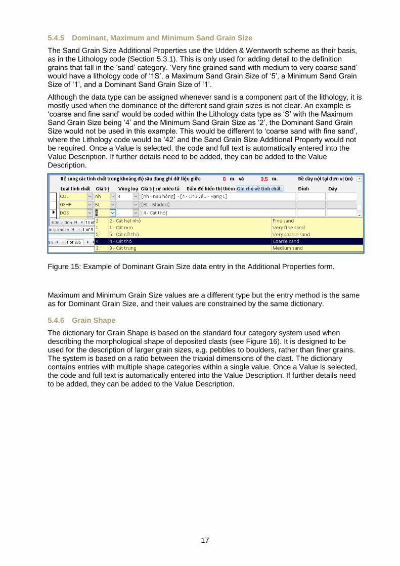
5.4.5 Dominant, Maximum and Minimum Sand Grain Size
The Sand Grain Size Additional Properties use the Udden & Wentworth scheme as their basis, as in the Lithology code (Section 5.3.1). This is only used for adding detail to the definition grains that fall in the ‘sand’ category. ‘Very fine grained sand with medium to very coarse sand’ would have a lithology code of ‘1S’, a Maximum Sand Grain Size of ‘5’, a Minimum Sand Grain Size of ‘1’, and a Dominant Sand Grain Size of ‘1’.
Although the data type can be assigned whenever sand is a component part of the lithology, it is mostly used when the dominance of the different sand grain sizes is not clear. An example is ‘coarse and fine sand’ would be coded within the Lithology data type as ‘S’ with the Maximum Sand Grain Size being ‘4’ and the Minimum Sand Grain Size as ‘2’, the Dominant Sand Grain Size would not be used in this example. This would be different to ‘coarse sand with fine sand’, where the Lithology code would be ‘42’ and the Sand Grain Size Additional Property would not be required. Once a Value is selected, the code and full text is automatically entered into the Value Description. If further details need to be added, they can be added to the Value Description.
Figure 15: Example of Dominant Grain Size data entry in the Additional Properties form.
Maximum and Minimum Grain Size values are a different type but the entry method is the same as for Dominant Grain Size, and their values are constrained by the same dictionary.
5.4.6 Grain Shape
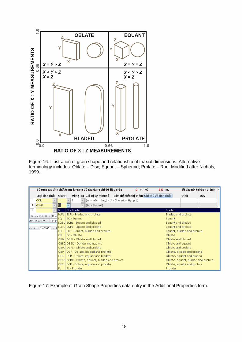
The dictionary for Grain Shape is based on the standard four category system used when describing the morphological shape of deposited clasts (see Figure 16). It is designed to be used for the description of larger grain sizes, e.g. pebbles to boulders, rather than finer grains. The system is based on a ratio between the triaxial dimensions of the clast. The dictionary contains entries with multiple shape categories within a single value. Once a Value is selected, the code and full text is automatically entered into the Value Description. If further details need to be added, they can be added to the Value Description.
18
Figure 16: Illustration of grain shape and relationship of triaxial dimensions. Alternative terminology includes: Oblate – Disc; Equant – Spheroid; Prolate – Rod. Modified after Nichols, 1999.
Figure 17: Example of Grain Shape Properties data entry in the Additional Properties form.
19
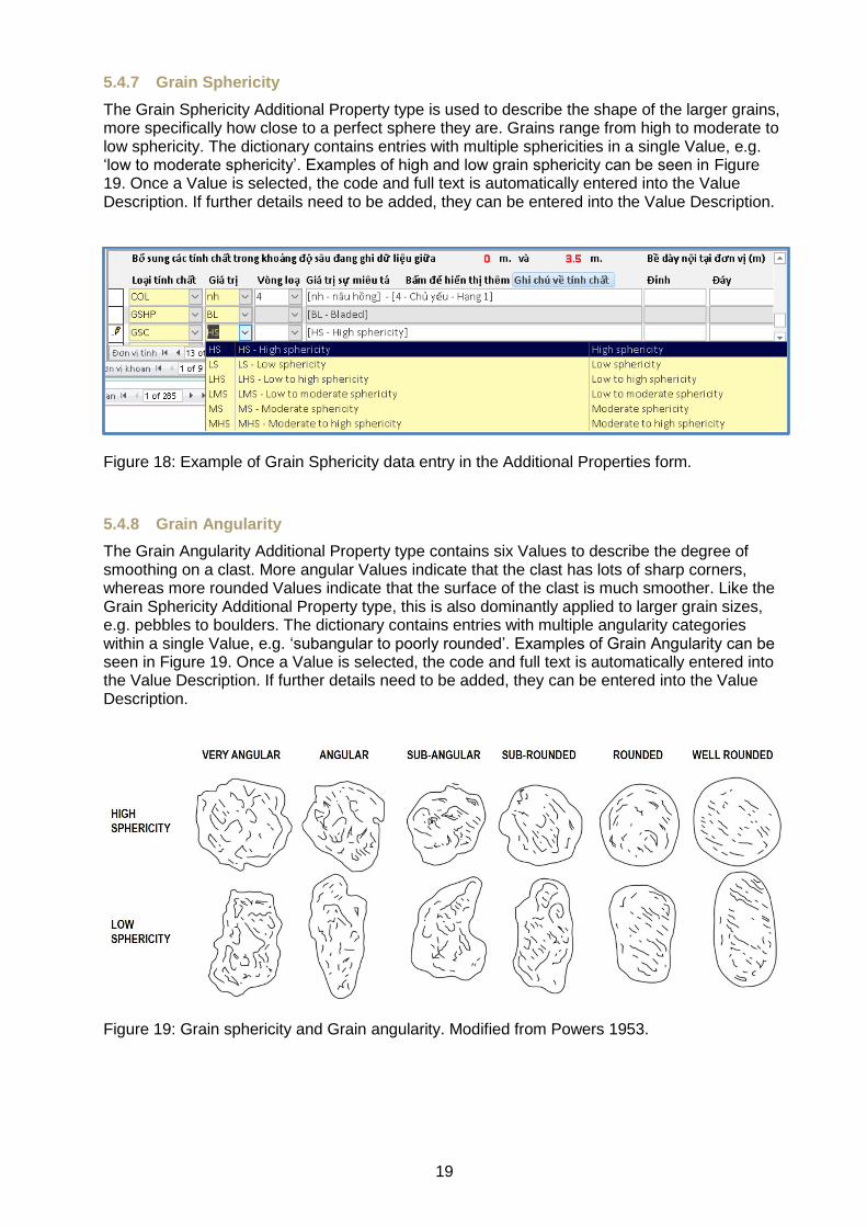
5.4.7 Grain Sphericity
The Grain Sphericity Additional Property type is used to describe the shape of the larger grains, more specifically how close to a perfect sphere they are. Grains range from high to moderate to low sphericity. The dictionary contains entries with multiple sphericities in a single Value, e.g. ‘low to moderate sphericity’. Examples of high and low grain sphericity can be seen in Figure 19. Once a Value is selected, the code and full text is automatically entered into the Value Description. If further details need to be added, they can be entered into the Value Description.
Figure 18: Example of Grain Sphericity data entry in the Additional Properties form.
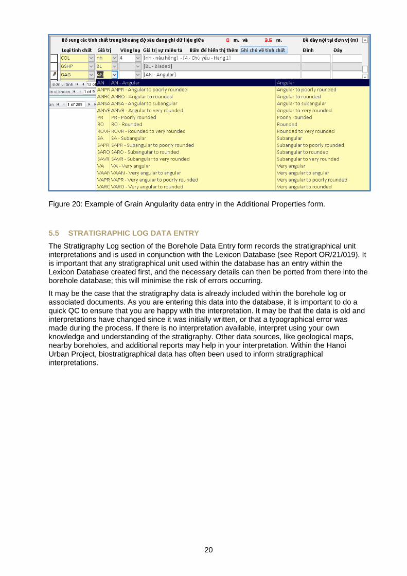
5.4.8 Grain Angularity
The Grain Angularity Additional Property type contains six Values to describe the degree of smoothing on a clast. More angular Values indicate that the clast has lots of sharp corners, whereas more rounded Values indicate that the surface of the clast is much smoother. Like the Grain Sphericity Additional Property type, this is also dominantly applied to larger grain sizes, e.g. pebbles to boulders. The dictionary contains entries with multiple angularity categories within a single Value, e.g. ‘subangular to poorly rounded’. Examples of Grain Angularity can be seen in Figure 19. Once a Value is selected, the code and full text is automatically entered into the Value Description. If further details need to be added, they can be entered into the Value Description.
Figure 19: Grain sphericity and Grain angularity. Modified from Powers 1953.
20
Figure 20: Example of Grain Angularity data entry in the Additional Properties form.
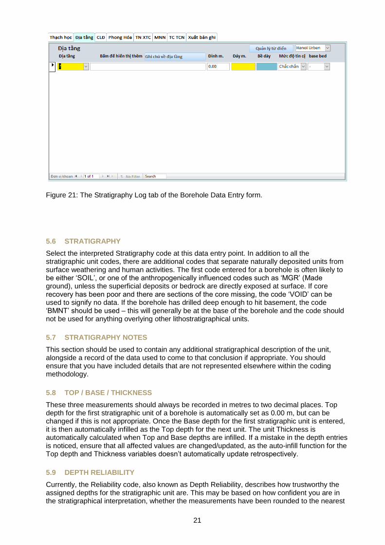
5.5 STRATIGRAPHIC LOG DATA ENTRY
The Stratigraphy Log section of the Borehole Data Entry form records the stratigraphical unit interpretations and is used in conjunction with the Lexicon Database (see Report OR/21/019). It is important that any stratigraphical unit used within the database has an entry within the Lexicon Database created first, and the necessary details can then be ported from there into the borehole database; this will minimise the risk of errors occurring.
It may be the case that the stratigraphy data is already included within the borehole log or associated documents. As you are entering this data into the database, it is important to do a quick QC to ensure that you are happy with the interpretation. It may be that the data is old and interpretations have changed since it was initially written, or that a typographical error was made during the process. If there is no interpretation available, interpret using your own knowledge and understanding of the stratigraphy. Other data sources, like geological maps, nearby boreholes, and additional reports may help in your interpretation. Within the Hanoi Urban Project, biostratigraphical data has often been used to inform stratigraphical interpretations.
21
Figure 21: The Stratigraphy Log tab of the Borehole Data Entry form.
5.6 STRATIGRAPHY
Select the interpreted Stratigraphy code at this data entry point. In addition to all the stratigraphic unit codes, there are additional codes that separate naturally deposited units from surface weathering and human activities. The first code entered for a borehole is often likely to be either ‘SOIL’, or one of the anthropogenically influenced codes such as ‘MGR’ (Made ground), unless the superficial deposits or bedrock are directly exposed at surface. If core recovery has been poor and there are sections of the core missing, the code ‘VOID’ can be used to signify no data. If the borehole has drilled deep enough to hit basement, the code ‘BMNT’ should be used – this will generally be at the base of the borehole and the code should not be used for anything overlying other lithostratigraphical units.
5.7 STRATIGRAPHY NOTES
This section should be used to contain any additional stratigraphical description of the unit, alongside a record of the data used to come to that conclusion if appropriate. You should ensure that you have included details that are not represented elsewhere within the coding methodology.
5.8 TOP / BASE / THICKNESS
These three measurements should always be recorded in metres to two decimal places. Top depth for the first stratigraphic unit of a borehole is automatically set as 0.00 m, but can be changed if this is not appropriate. Once the Base depth for the first stratigraphic unit is entered, it is then automatically infilled as the Top depth for the next unit. The unit Thickness is automatically calculated when Top and Base depths are infilled. If a mistake in the depth entries is noticed, ensure that all affected values are changed/updated, as the auto-infill function for the Top depth and Thickness variables doesn’t automatically update retrospectively.
5.9 DEPTH RELIABILITY
Currently, the Reliability code, also known as Depth Reliability, describes how trustworthy the assigned depths for the stratigraphic unit are. This may be based on how confident you are in the stratigraphical interpretation, whether the measurements have been rounded to the nearest
22
metre, how legible the borehole log details are and whether you’re confident that you have read them correctly, etc. It uses a variation on the Kent methodology (Kent, 1964). Note that this is a fully subjective field and percentage certainty within each category is just a guideline.
An alternative use for the Reliability code could be used instead. GDGMV can discuss the use of the Reliability code to refer to the entire unit definition, rather than just the reliability of the depths. If this use is decided upon then this section should be updated to represent that.
5.10 BASE BED
The Base Bed code describes the nature of the contact of the stratigraphical unit being described with the unit below. This is typically used as standard to assign the position of geological rockhead (RH), or the total depth (TD) of the borehole. Rockhead denotes the base of the superficial deposits. Base Bed can also be used to indicate where a contact is unconformable or gradational, etc. Not every unit requires a Base Bed code, so it is not a mandatory field. Total depth is assigned to the lowest unit recorded in the borehole only if that is where the borehole ends; if the borehole continues beyond the last recorded unit, TD is not assigned, or an additional unit is entered with a Lithology code of ‘NOCO’ (No Core) that extends to the base of the borehole.
23
6 Borehole search function
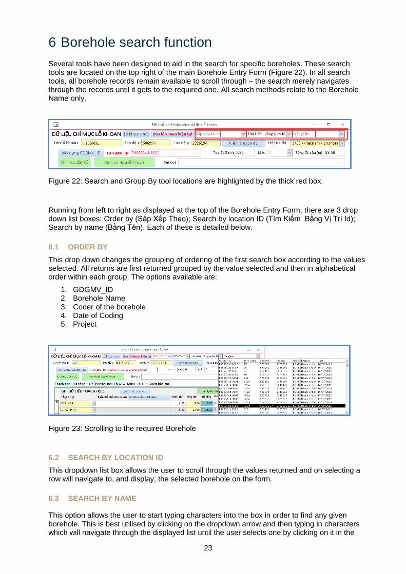
Several tools have been designed to aid in the search for specific boreholes. These search tools are located on the top right of the main Borehole Entry Form (Figure 22). In all search tools, all borehole records remain available to scroll through – the search merely navigates through the records until it gets to the required one. All search methods relate to the Borehole Name only.
Figure 22: Search and Group By tool locations are highlighted by the thick red box.
Running from left to right as displayed at the top of the Borehole Entry Form, there are 3 drop down list boxes: Order by (Sắp Xếp Theo); Search by location ID (Tìm Kiếm Bằng Vị Trí Id); Search by name (Bằng Tên). Each of these is detailed below.
6.1 ORDER BY
This drop down changes the grouping of ordering of the first search box according to the values selected. All returns are first returned grouped by the value selected and then in alphabetical order within each group. The options available are:
1. GDGMV_ID 2. Borehole Name 3. Coder of the borehole 4. Date of Coding 5. Project
Figure 23: Scrolling to the required Borehole
6.2 SEARCH BY LOCATION ID
This dropdown list box allows the user to scroll through the values returned and on selecting a row will navigate to, and display, the selected borehole on the form.
6.3 SEARCH BY NAME
This option allows the user to start typing characters into the box in order to find any given borehole. This is best utilised by clicking on the dropdown arrow and then typing in characters which will navigate through the displayed list until the user selects one by clicking on it in the
24
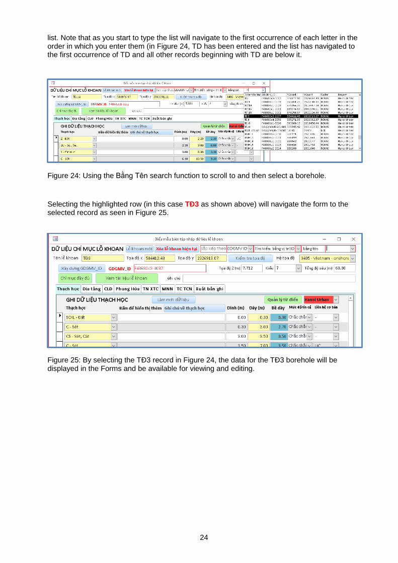
list. Note that as you start to type the list will navigate to the first occurrence of each letter in the order in which you enter them (in Figure 24, TD has been entered and the list has navigated to the first occurrence of TD and all other records beginning with TD are below it.
Figure 24: Using the Bằng Tên search function to scroll to and then select a borehole.
Selecting the highlighted row (in this case TÐ3 as shown above) will navigate the form to the selected record as seen in Figure 25.
Figure 25: By selecting the TÐ3 record in Figure 24, the data for the TÐ3 borehole will be displayed in the Forms and be available for viewing and editing.
25
7 Dictionary Control
7.1 EXAMINING SOME OF THE MORE IMPORTANT AND REGULARLY USED DICTIONARIES
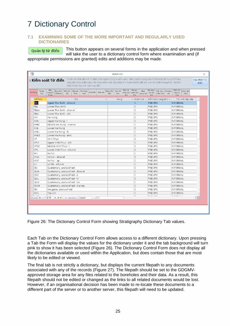
This button appears on several forms in the application and when pressed will take the user to a dictionary control form where examination and (if
appropriate permissions are granted) edits and additions may be made.
Figure 26: The Dictionary Control Form showing Stratigraphy Dictionary Tab values.
Each Tab on the Dictionary Control Form allows access to a different dictionary. Upon pressing a Tab the Form will display the values for the dictionary under it and the tab background will turn pink to show it has been selected (Figure 26). The Dictionary Control Form does not display all the dictionaries available or used within the Application, but does contain those that are most likely to be edited or viewed.
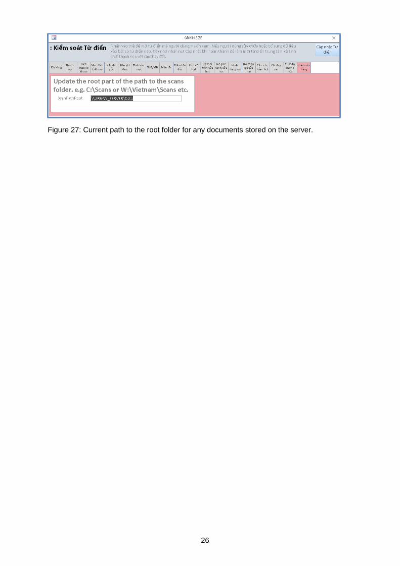
The final tab is not strictly a dictionary, but displays the current filepath to any documents associated with any of the records (Figure 27). The filepath should be set to the GDGMV-approved storage area for any files related to the boreholes and their data. As a result, this filepath should not be edited or changed as the links to all related documents would be lost. However, if an organisational decision has been made to re-locate these documents to a different part of the server or to another server, this filepath will need to be updated.
26
Figure 27: Current path to the root folder for any documents stored on the server.
27
8 Borehole Entry Form – Additional sections
For further details on any of the following data types and techniques, please contact the relevant specialist within GDGMV.
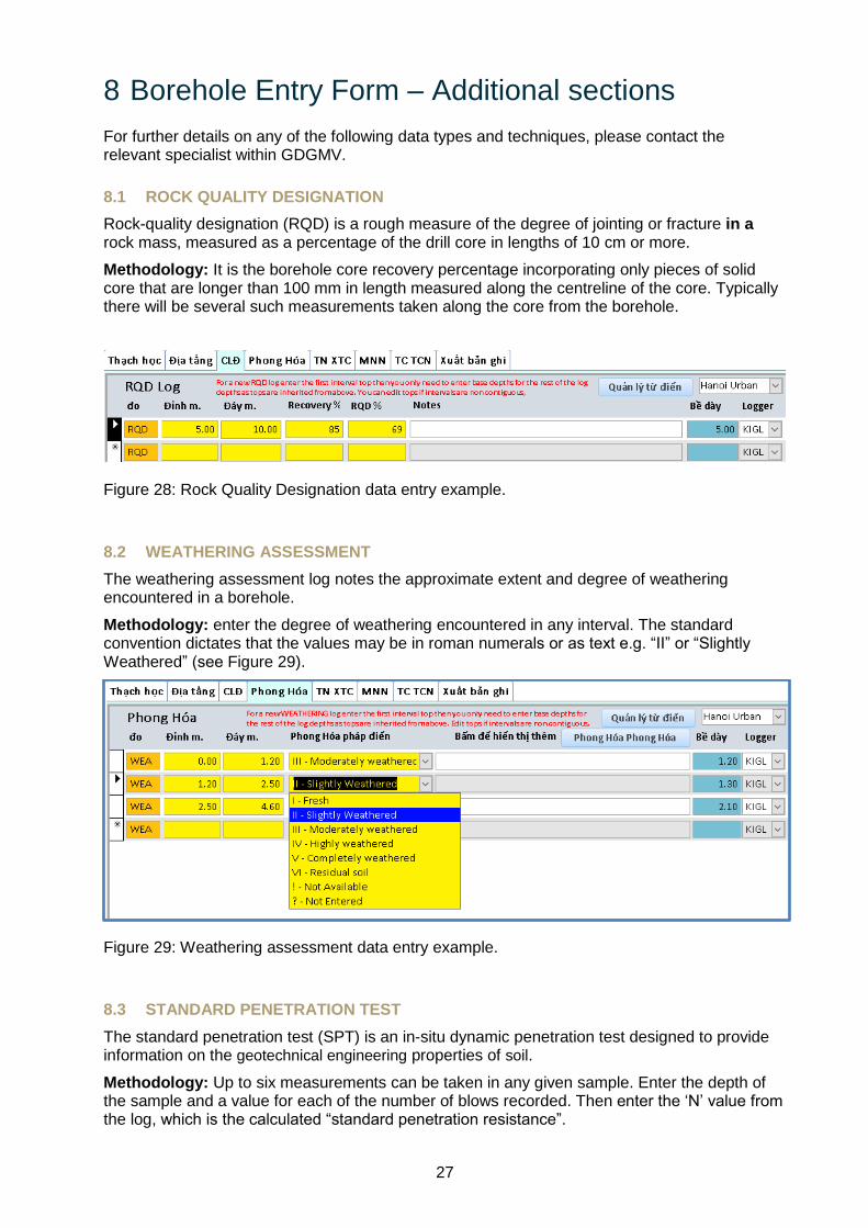
8.1 ROCK QUALITY DESIGNATION
Rock-quality designation (RQD) is a rough measure of the degree of jointing or fracture in a rock mass, measured as a percentage of the drill core in lengths of 10 cm or more.
Methodology: It is the borehole core recovery percentage incorporating only pieces of solid core that are longer than 100 mm in length measured along the centreline of the core. Typically there will be several such measurements taken along the core from the borehole.
Figure 28: Rock Quality Designation data entry example.
8.2 WEATHERING ASSESSMENT
The weathering assessment log notes the approximate extent and degree of weathering encountered in a borehole.
Methodology: enter the degree of weathering encountered in any interval. The standard convention dictates that the values may be in roman numerals or as text e.g. “II” or “Slightly Weathered” (see Figure 29).
Figure 29: Weathering assessment data entry example.
8.3 STANDARD PENETRATION TEST
The standard penetration test (SPT) is an in-situ dynamic penetration test designed to provide information on the geotechnical engineering properties of soil.
Methodology: Up to six measurements can be taken in any given sample. Enter the depth of the sample and a value for each of the number of blows recorded. Then enter the ‘N’ value from the log, which is the calculated “standard penetration resistance”.

28
Figure 30: Standard Penetration Test data entry example.
8.4 WATER LEVELS
Generally speaking this log records the level at which water was struck in a borehole. Often there is only a reference to a water strike and not what type of measurement has been taken. However, if any further data is available then in should also be recorded here. If available, make sure to enter the date and time that the measurement was taken.
GWL – Bị kẹt nước is used where there is no explicit water level ‘type’ value present, e.g. RWL, SWL and PWL are not recorded.
SWL - Strike Water Level is the depth at which water was first struck.
RWL - Rest Water Level is the level measured after a period of time has passed and is measured by dipping the level.
PWL - Pumped Water Level is another dipped measurement taken after a designated amount of pumping out of the water has taken place.
Figure 31: Water Levels data entry example.
8.5 AQUIFER PROPERTY LOG
The Aquifer Property Log is used to store data on specific aquifers that the well intersects. Enter the AQP Type followed value and measurement units. Then enter the date that the measurements were taken. Any additional details can be recorded in the Notes section.
Figure 32: The Aquifer Property Log data entry form.

29
9 Data Export
9.1 DATA EXPORT FORM
The data export form tab opens shows the three data export options that are currently available within the Borehole Database Application. The system stores these spreadsheets and files to a folder called “Exports” specially created by the system in the directory where you saved your user entry file (*.accdb file) as explained in the red text on the form itself (see Figure 33). The system creates a unique filename for every export you make.
• Export all data to an Excel Comma delimited Spreadsheet.
• Export all data to an external CSV file
• Export all data to a set of CSV files formatted for easy use in Groundhog.
Select the required export format by ticking in the box to the left of your chosen option and press the button above (Xuất bản ghi). You will see a few message boxes detailing the progress of the process and reminding you where the files are saved.
Figure 33: Data Export Form.
30
Appendix 1
Appendix 1 contains a worked example to illustrate the real-world application of the digital borehole coding workflow.
EXAMPLE
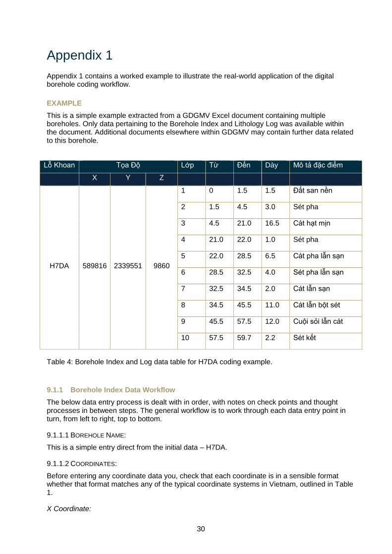
This is a simple example extracted from a GDGMV Excel document containing multiple boreholes. Only data pertaining to the Borehole Index and Lithology Log was available within the document. Additional documents elsewhere within GDGMV may contain further data related to this borehole.
Lỗ Khoan Tọa Độ Lớp Từ Đến Dày Mô tả đặc điểm
X Y Z
H7DA 589816 2339551 9860
1 0 1.5 1.5 Đất san nền
2 1.5 4.5 3.0 Sét pha
3 4.5 21.0 16.5 Cát hạt mịn
4 21.0 22.0 1.0 Sét pha
5 22.0 28.5 6.5 Cát pha lẫn sạn
6 28.5 32.5 4.0 Sét pha lẫn sạn
7 32.5 34.5 2.0 Cát lẫn sạn
8 34.5 45.5 11.0 Cát lẫn bột sét
9 45.5 57.5 12.0 Cuội sỏi lẫn cát
10 57.5 59.7 2.2 Sét kết
Table 4: Borehole Index and Log data table for H7DA coding example.
9.1.1 Borehole Index Data Workflow
The below data entry process is dealt with in order, with notes on check points and thought processes in between steps. The general workflow is to work through each data entry point in turn, from left to right, top to bottom.
9.1.1.1 BOREHOLE NAME:
This is a simple entry direct from the initial data – H7DA.
9.1.1.2 COORDINATES:
Before entering any coordinate data you, check that each coordinate is in a sensible format whether that format matches any of the typical coordinate systems in Vietnam, outlined in Table 1.
X Coordinate:
31
Having checked that the X coordinate value is in a sensible format, this is a simple entry direct from the initial data – 589816.
Y Coordinate:
Having checked that the Y coordinate value is in a sensible format, this is a simple entry direct from the initial data – 2339551.
Coordinate System:
In this case, the coordinates within the original data match with the coordinate system EPSG 3405 – VN-2000 / UTM zone 48N. At this point the coordinates for the borehole can be checked in a variety of ways to ensure everything is correctly entered, including a search for the location on the EPSG website to make sure that it is plotting in the correct area. The linked GIS project will not show the borehole at this stage, as a GDGMV ID needs to be generated first.
9.1.1.3 GDGMV ID:
Only click on the ‘Create GDGMV ID’ button when you are sure that the coordinate data is completely correct. Clicking the button generated the GDGMV ID ‘F4868Da4-007’. This translates to grid square F4868Da4, and it is the 7th borehole that has been entered within that grid square. Clicking the button also creates a new folder named with the GDGMV ID that can be opened by clicking the ‘Open Current Scans’ button. Once you have the correct folder open, copy the document or documents that are associated with the borehole database entry into that folder.
If the data was derived from a spreadsheet with multiple logs entered into it the procedure is as follows.
1. Manually create a folder named after the spreadsheet in the \\URBAN_SERVER\Data\boreholes\Borehole_scans\spreadsheet1
2. Create a shortcut to that folder. 3. Rename the shortcut to the name of the spreadsheet e.g. spreadsheet1. 4. Now copy the shortcut and paste it into the folder created above in the ‘Create GDGMV
ID button’. 5. Repeat action number 4 for every borehole in the spreadsheet.
9.1.1.4 Z VALUE / ELEVATION:
As the location of this borehole is in Hanoi, we know that it is unlikely to have an elevation of 9860 m, or even 98.6 m. We can then conclude that the elevation data has been recorded in millimetres. As the standard data entry unit is metres, we must convert 9860 mm to metres. The resulting data entry is 9.86 m.
9.1.1.5 ELEVATION TYPE:
As there is no data available for this data type within the current document, there are two options. Firstly, assign the value ‘!’, which means ‘not available’. The second option is to search for additional data relating to the borehole in the archives. If additional data is found, a digital copy should be saved in the folder previously mentioned (see the GDGMV ID section above). Any additional data should also be checked for more details Borehole Index information (see Section 5.2).
9.1.1.6 TOTAL DEPTH:
As the only depth data available is as part of the lithological log and there is no other data that conflicts, the total depth is recorded as the base depth of the lowest logged unit – 59.7 m.
32
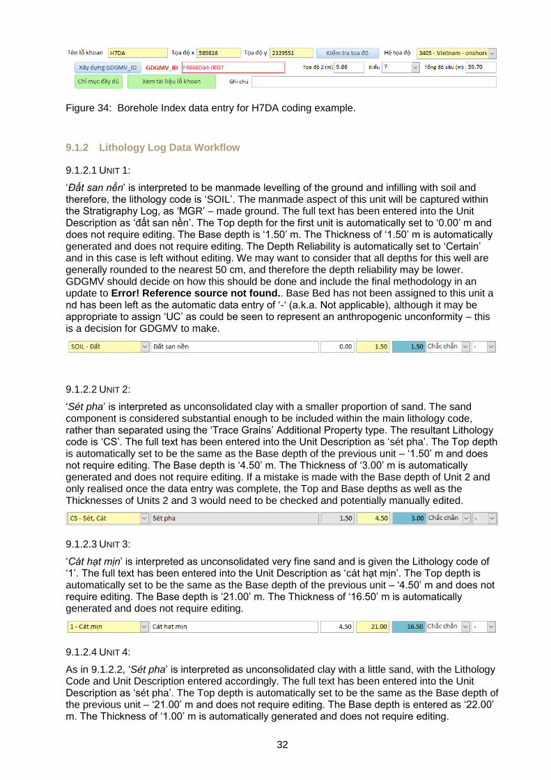
Figure 34: Borehole Index data entry for H7DA coding example.
9.1.2 Lithology Log Data Workflow
9.1.2.1 UNIT 1:
‘Đất san nền’ is interpreted to be manmade levelling of the ground and infilling with soil and therefore, the lithology code is ‘SOIL’. The manmade aspect of this unit will be captured within the Stratigraphy Log, as ‘MGR’ – made ground. The full text has been entered into the Unit Description as ‘đất san nền’. The Top depth for the first unit is automatically set to ‘0.00’ m and does not require editing. The Base depth is ‘1.50’ m. The Thickness of ‘1.50’ m is automatically generated and does not require editing. The Depth Reliability is automatically set to ‘Certain’ and in this case is left without editing. We may want to consider that all depths for this well are generally rounded to the nearest 50 cm, and therefore the depth reliability may be lower. GDGMV should decide on how this should be done and include the final methodology in an update to Error! Reference source not found.. Base Bed has not been assigned to this unit and has been left as the automatic data entry of ‘-‘ (a.k.a. Not applicable), although it may be appropriate to assign ‘UC’ as could be seen to represent an anthropogenic unconformity – this is a decision for GDGMV to make.
9.1.2.2 UNIT 2:
‘Sét pha’ is interpreted as unconsolidated clay with a smaller proportion of sand. The sand component is considered substantial enough to be included within the main lithology code, rather than separated using the ‘Trace Grains’ Additional Property type. The resultant Lithology code is ‘CS’. The full text has been entered into the Unit Description as ‘sét pha’. The Top depth is automatically set to be the same as the Base depth of the previous unit – ‘1.50’ m and does not require editing. The Base depth is ‘4.50’ m. The Thickness of ‘3.00’ m is automatically generated and does not require editing. If a mistake is made with the Base depth of Unit 2 and only realised once the data entry was complete, the Top and Base depths as well as the Thicknesses of Units 2 and 3 would need to be checked and potentially manually edited.
9.1.2.3 UNIT 3:
‘Cát hạt mịn’ is interpreted as unconsolidated very fine sand and is given the Lithology code of ‘1’. The full text has been entered into the Unit Description as ‘cát hạt mịn’. The Top depth is automatically set to be the same as the Base depth of the previous unit – ‘4.50’ m and does not require editing. The Base depth is ‘21.00’ m. The Thickness of ‘16.50’ m is automatically generated and does not require editing.
9.1.2.4 UNIT 4:
As in 9.1.2.2, ‘Sét pha’ is interpreted as unconsolidated clay with a little sand, with the Lithology Code and Unit Description entered accordingly. The full text has been entered into the Unit Description as ‘sét pha’. The Top depth is automatically set to be the same as the Base depth of the previous unit – ‘21.00’ m and does not require editing. The Base depth is entered as ‘22.00’ m. The Thickness of ‘1.00’ m is automatically generated and does not require editing.
33
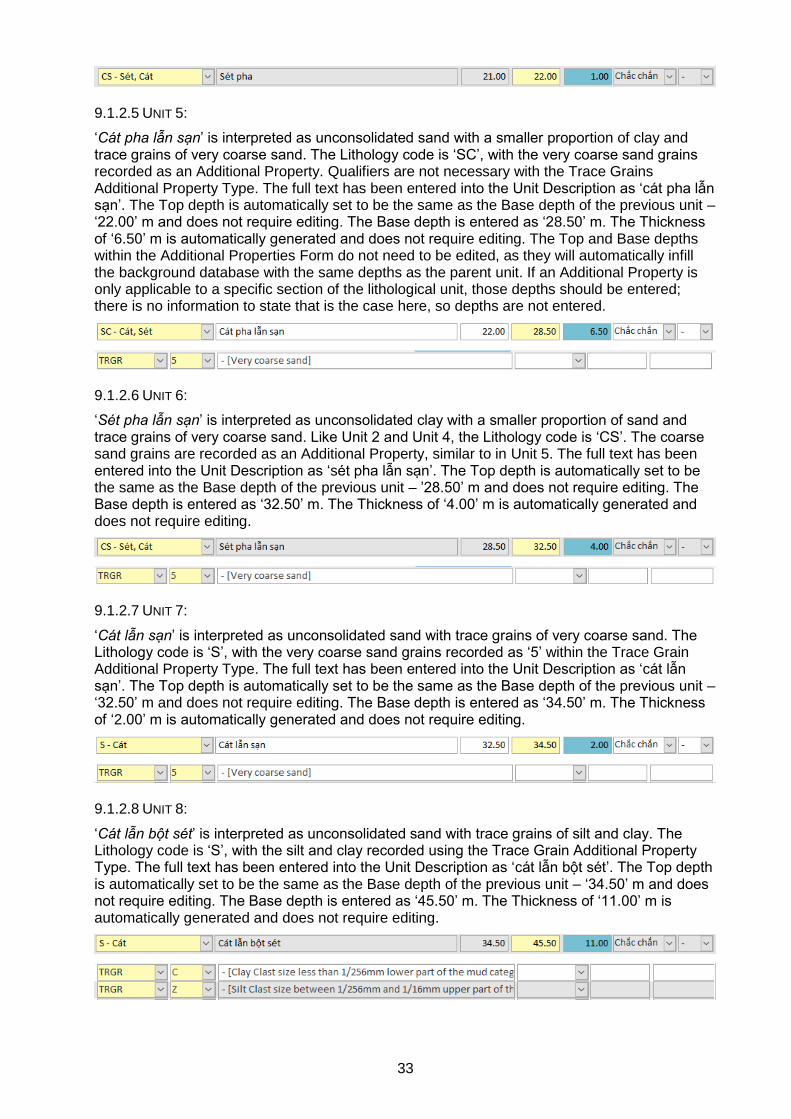
9.1.2.5 UNIT 5:
‘Cát pha lẫn sạn’ is interpreted as unconsolidated sand with a smaller proportion of clay and trace grains of very coarse sand. The Lithology code is ‘SC’, with the very coarse sand grains recorded as an Additional Property. Qualifiers are not necessary with the Trace Grains Additional Property Type. The full text has been entered into the Unit Description as ‘cát pha lẫn sạn’. The Top depth is automatically set to be the same as the Base depth of the previous unit – ‘22.00’ m and does not require editing. The Base depth is entered as ‘28.50’ m. The Thickness of ‘6.50’ m is automatically generated and does not require editing. The Top and Base depths within the Additional Properties Form do not need to be edited, as they will automatically infill the background database with the same depths as the parent unit. If an Additional Property is only applicable to a specific section of the lithological unit, those depths should be entered; there is no information to state that is the case here, so depths are not entered.
9.1.2.6 UNIT 6:
‘Sét pha lẫn sạn’ is interpreted as unconsolidated clay with a smaller proportion of sand and trace grains of very coarse sand. Like Unit 2 and Unit 4, the Lithology code is ‘CS’. The coarse sand grains are recorded as an Additional Property, similar to in Unit 5. The full text has been entered into the Unit Description as ‘sét pha lẫn sạn’. The Top depth is automatically set to be the same as the Base depth of the previous unit – ’28.50’ m and does not require editing. The Base depth is entered as ‘32.50’ m. The Thickness of ‘4.00’ m is automatically generated and does not require editing.
9.1.2.7 UNIT 7:
‘Cát lẫn sạn’ is interpreted as unconsolidated sand with trace grains of very coarse sand. The Lithology code is ‘S’, with the very coarse sand grains recorded as ‘5’ within the Trace Grain Additional Property Type. The full text has been entered into the Unit Description as ‘cát lẫn sạn’. The Top depth is automatically set to be the same as the Base depth of the previous unit – ‘32.50’ m and does not require editing. The Base depth is entered as ‘34.50’ m. The Thickness of ‘2.00’ m is automatically generated and does not require editing.
9.1.2.8 UNIT 8:
‘Cát lẫn bột sét’ is interpreted as unconsolidated sand with trace grains of silt and clay. The Lithology code is ‘S’, with the silt and clay recorded using the Trace Grain Additional Property Type. The full text has been entered into the Unit Description as ‘cát lẫn bột sét’. The Top depth is automatically set to be the same as the Base depth of the previous unit – ‘34.50’ m and does not require editing. The Base depth is entered as ‘45.50’ m. The Thickness of ‘11.00’ m is automatically generated and does not require editing.
34
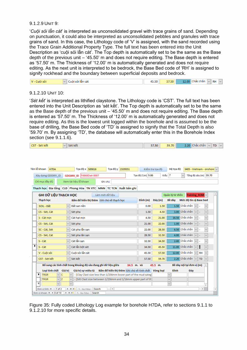
9.1.2.9 UNIT 9:
‘Cuội sỏi lẫn cát’ is interpreted as unconsolidated gravel with trace grains of sand. Depending on punctuation, it could also be interpreted as unconsolidated pebbles and granules with trace grains of sand. In this case, the Lithology code of ‘V’ is assigned, with the sand recorded using the Trace Grain Additional Property Type. The full text has been entered into the Unit Description as ‘cuội sỏi lẫn cát’. The Top depth is automatically set to be the same as the Base depth of the previous unit – ‘45.50’ m and does not require editing. The Base depth is entered as ‘57.50’ m. The Thickness of ‘12.00’ m is automatically generated and does not require editing. As the next unit is interpreted to be bedrock, the Base Bed code of ‘RH’ is assigned to signify rockhead and the boundary between superficial deposits and bedrock.
9.1.2.10 UNIT 10:
‘Sét kết’ is interpreted as lithified claystone. The Lithology code is ‘CST’. The full text has been entered into the Unit Description as ‘sét kết’. The Top depth is automatically set to be the same as the Base depth of the previous unit – ‘45.50’ m and does not require editing. The Base depth is entered as ‘57.50’ m. The Thickness of ‘12.00’ m is automatically generated and does not require editing. As this is the lowest unit logged within the borehole and is assumed to be the base of drilling, the Base Bed code of ‘TD’ is assigned to signify that the Total Depth is also ’59.70’ m. By assigning ‘TD’, the database will automatically enter this in the Borehole Index section (see 9.1.1.6).
Figure 35: Fully coded Lithology Log example for borehole H7DA, refer to sections 9.1.1 to 9.1.2.10 for more specific details.
35
9.1.3 Stratigraphy Log Data Workflow
No stratigraphical data is directly available for this borehole in the current documents. There are a few options from this point, dependant on the project manager’s, or borehole coder’s chosen workflow. The first option is to start interpreting the borehole as stand-alone data. This may include the use of a geological map and a rough idea of the geology in that particular location. As stated in section 9.1.2.1, the first unit to code within the Stratigraphy Log is made ground. The coder may make the decision that this unit is simple ‘made ground’ (‘MGR’), or they may be able to make further observations of interpretations, for example that the type of made ground at this location is ‘raised fill’ (‘MRU’). These additional interpretations will make it simpler to evaluate the differences that may be recorded between borehole heights/depths and any DTM data that will be used in the future modelling process. It may be preferable not to code this top unit until the coder is ready to create a full Stratigraphic Log, as by coding a single unit the Stratigraphy Log will be recorded as ‘present’ in additional data views, e.g. the linked GIS project.
If the interpreter is not confident in their stratigraphical interpretation within the context of a stand-alone borehole, or the lithological data is not detailed enough to inform a confident interpretation, the interpreter may move on to code additional boreholes that have more confident stratigraphical interpretations. Once an appropriate number of stratigraphical logs have been entered into the borehole database, it is possible to view these using the linked GIS project. It is also possible to export the initial data (see Section 9) and import it into an additional software, such as GroundHog. Using the stratigraphical interpretations that have been made already, a borehole coder may be able to extrapolate these units and use them to inform the stratigraphical interpretation of another borehole. The ideal conclusion is for the majority of boreholes to have fully interpreted Stratigraphy Logs to go alongside the fully coded Lithology Logs. Once an appropriate number of these are available, the first iteration of 3D Modelling workflows can begin. For more details on the 3D modelling workflow using GroundHog software, please contact the BGS team at [email protected].
36
References
British Geological Survey holds most of the references listed below, and copies may be obtained via the library service subject to copyright legislation (contact [email protected] for details). The library catalogue is available at: https://envirolib.apps.nerc.ac.uk/olibcgi.
Kent, S. (1964). Words of Estimative Probability. CIA Studies in Intelligence.
Nichols, G. (1999). Sedimentology and Stratigraphy. Chichester: Blackwell Publishing / John Wiley & Sons.
Powers, M. (1953). A New Roundness Scale for Sedimentary Particles, vol. 23, no. 2. Journal of Sedimentary Petrology, 117-119.
Wentworth, C. (1922). A Scale of Grade and Class Terms for Clastic Sediments. The Journal of Geology.