gaf fiberglass mat slitter blade sharpener - cal poly digital
TRANSCRIPT

GAF Fiberglass Mat Slitter Blade Sharpener
Final Design Report
Presented by:
Mark Breaux, [email protected]
Esteban Carrillo, [email protected]
Carlos Paredes Espinoza, [email protected]
Bradley Smith, [email protected]
Mechanical Engineering Department
California Polytechnic State University
San Luis Obispo
Winter 2021 – Fall 2022
Sponsors:
Anthony Gutierrez
Javier Davila
GAF, Shafter, CA

Statement of Disclaimer
Since this project is a result of a class assignment, it has been graded and accepted as fulfillment
of the course requirements. Acceptance does not imply technical accuracy or reliability. Any use
of information in this report is done at the risk of the user. These risks may include catastrophic
failure of the device or infringement of patent or copyright laws. California Polytechnic State
University at San Luis Obispo and its staff cannot be held liable for any use or misuse of the
project.

Abstract This document contains an overview for the offline slitter blade sharpening system created
for GAF to sharpen their current cutting tools in a timely and safe manner without hindering the
timeline and production of their assembly line. This design was developed by four undergraduate
students at from Cal Poly, San Luis Obispo. This document first investigates background
information of any patents, current sharpening device, sharpening safety standards, or literature
review that may be useful in a sharpening mechanism device. This document also contains our
design concept prototype, which consists of three main features, the use of a top guard for safety,
the use of abrasive pads to redefine the slitter blade profile, and the use of a solenoid switch to
activate the abrasive pads. The manufacturing process and verification of the device are also shown
to verify the concept and requirements for the sharpening device. This document shows some
aspects of the project that can be improved upon based on the results of testing.
Table of Contents
1.0 Introduction ......................................................................................................................... 1
2.0 Background ......................................................................................................................... 2
2.1 Existing Resources ........................................................................................................... 2
2.2 Patent Research ................................................................................................................ 6
2.3 Research Reports .............................................................................................................. 8
2.3.1 Experiment on Knife Sharpening.............................................................................. 9
2.4 Government Standards ................................................................................................... 10
3.0 Objectives ......................................................................................................................... 10
3.1 Problem Statement ......................................................................................................... 10
3.2 Boundary Sketch ............................................................................................................ 11
3.3 Stakeholder’s Wants and Needs Summary .................................................................... 11
3.4 Quality Functional Deployment (QFD) Description ...................................................... 12
3.5 Engineering Specifications Table................................................................................... 13
3.6 Numbered List of Specifications .................................................................................... 14
3.7 High-Risk Specifications................................................................................................ 14
4.0 Concept Design ................................................................................................................. 14
4.1 Concept Development: Functional Decomposition &Prototypes .................................. 15
4.2 Filtration Matrices .......................................................................................................... 15
4.3 Selected Concept and CAF Model ................................................................................. 18
4.4 Preliminary Analysis and Testing .................................................................................. 19
4.5 Design Hazards and Safety Plans ................................................................................... 21
4.6 Outstanding Challenges, Concerns or Unknowns .......................................................... 23
5.0 Final Design ...................................................................................................................... 23
5.0.1 Guard Assembly...................................................................................................... 24
5.0.1.1 Top Guard ........................................................................................................ 25
5.0.1.2 Bottom Guard .................................................................................................. 25
5.0.2 Sharpener Assembly ............................................................................................... 25
5.0.2.1 Solenoid ........................................................................................................... 25
5.0.2.2 Solenoid Platform ............................................................................................ 26

5.0.2.3 Mounting Plates ............................................................................................... 26
5.0.2.2 Shoe Design ..................................................................................................... 26
5.0.2.3 Retention Guard ............................................................................................... 26
5.1 System Functionality ...................................................................................................... 26
5.2 Structural Prototype........................................................................................................ 28
5.3 Safety, Maintenance and Repair Considerations............................................................ 31
5.4 Remaining Concerns After Structural Prototype ........................................................... 32
6.0 Manufacturing Plan ........................................................................................................... 33
6.1 Blade Guard Assembly................................................................................................... 34
6.1.2 Bottom Guard.......................................................................................................... 35
6.2 Sharpener Assembly ....................................................................................................... 36
6.2.1 Solenoid with Retention Spring .............................................................................. 36
6.2.2 Fiberglass Rejection Assembly ............................................................................... 38
6.2.3 Shoe Assembly........................................................................................................ 38
6.2.4 Solenoid Mount Point System ................................................................................ 40
6.2.4.1 Mounting Brackets .......................................................................................... 40
6.2.4.2 Solenoid Platform ............................................................................................ 41
6.2.5 Retention Guard ...................................................................................................... 43
6.3 Final Assembly ............................................................................................................... 44
6.4 Manufacturing Budget.................................................................................................... 45
7.0 Design Verification ........................................................................................................... 46
7.1 Test Preformed ............................................................................................................... 47
7.1.1 Sharpen Blade Profile ............................................................................................. 47
7.1.1.1 Purpose and Scope of Test............................................................................... 47
7.1.1.2 Description of Test .......................................................................................... 47
7.1.1.3 Collected Data ................................................................................................. 48
7.1.1.4 Analysis of Data with Error Propagation ........................................................ 48
7.1.1.5 Uncertainty Analysis ....................................................................................... 50
7.1.1.6 Challenges Encountered .................................................................................. 51
7.1.2 Variable Speed Capability ...................................................................................... 51
7.1.3 Solenoid Functionality ............................................................................................ 52
7.1.4 Abrasive Pad Wear Pattern ..................................................................................... 55
7.2 Lessons Learned from Testing ....................................................................................... 58
8.0 Project Management ......................................................................................................... 58
9.0 Conclusion ........................................................................................................................ 60
References ..................................................................................................................................... 65
Appendix A – QFD ..................................................................................................................... A-1
Appendix B – Gantt Chart .......................................................................................................... B-1
Appendix C – Ideation ................................................................................................................ C-1
Appendix D - Prototypes ............................................................................................................ D-1
Appendix E – Pugh Matrix .......................................................................................................... E-1
Appendix F – Morphological Matrix ........................................................................................... F-1
Appendix G – Weighted Decision Matrix .................................................................................. G-1
Appendix H – Design Verification Plan ..................................................................................... H-1
Appendix I – Intended Bill of Materials ....................................................................................... I-1
Appendix J – Drawing Package for Design ................................................................................. J-1
Appendix K – Total Budget ........................................................................................................ K-1
Appendix L – Test Procedures ..................................................................................................... L-1
Appendix M – Error Propagation .............................................................................................. M-1
Appendix N – Design Hazard Checklist ..................................................................................... N-1
Appendix O – Risk Assessment .................................................................................................. O-1
Appendix P – Failure Modes & Effects ....................................................................................... P-1
Appendix Q – User Manual ........................................................................................................ Q-1
List of Tables
Table 1. Advantages and disadvantages of three main candidates ................................................. 3
Table 2. Engineering Specification Table ..................................................................................... 13
Table 3. Design Hazard Checklist ................................................................................................ 22
Table 4. Purcahse Order for Structural Prototype ......................................................................... 29
Table 5. Purchased parts for final design prototype. .................................................................... 45
Table 6. Design Verification Specifications and Test Descriptions ............................................. 46

Table 7. These are the heights measured from the test on blade #1 through blade #3. Please note
that the data for blade #3 is incomplete due to the unexpected fatigue failure of the welds. ....... 48
Table 8. Data collected with angle calculation and error propagation. ........................................ 49
Table 9. Temperature of solenoid during operation time. ............................................................ 55
Table 10. Abrasive pad test data comparing decreasing thickness as a function of time. ............ 56
Table 11. Project deliverables ....................................................................................................... 59
List of Figures
Figure 1: Slitter Blades used by GAF to cut diverse types of roofing shingles .............................. 1
Figure 2. Mount slitter blade mechanism ....................................................................................... 1
Figure 3. Colonial saw’s Businaro CK300-TH circular knife grinder............................................ 4
Figure 4. Knuth KSW 200 universal T&C grinder and during operation ...................................... 5
Figure 5. Steel magic’s laser Esge-450 saw blade sharpening machine and during operation ...... 5
Figure 6. Chicago’s 120 Volt circular saw blade sharpener ........................................................... 6
Figure 7. Techtongda sharpener’s 220V electric circular saw blade sharpener ............................. 6
Figure 8. Patent US20120184186A1 Applicable feature that uses two grinders to simultaneously
sharpen the blade............................................................................................................................. 6
Figure 9. Patent US2998683A shows a tool that sharpen a dull blade ........................................... 7
Figure 10. Patent US3766806A shows an adjustable feature that can used to sharpen the blades at
different angles................................................................................................................................ 7
Figure 11. Fixture mechanism concept that will be modified from this patent and incorporated
onto our design ................................................................................................................................ 8
Figure 12. Gear mechanism illustrated in Patent US8448340B2 ................................................... 8
Figure 13. Two different orientations of abrasion when sharpening a blade .................................. 9
Figure 14: Boundary sketch outlining area of our design ............................................................. 11
Figure 15. Functional Decomposition Tree Diagram for Slitter Blade Sharpening Design ......... 15
Figure 16. Idea #1 concept drawing, featuring the solenoid idea oriented in a brake caliber
configuration. ................................................................................................................................ 16
Figure 17. Idea #2 concept drawing, featuring the abrasive pads tucked closer to the body of the
air cylinder. ................................................................................................................................... 17
Figure 18. Idea #3 concept drawing, showing the collection cup and caliper style abrasive pad
system. .......................................................................................................................................... 17

Figure 19. Idea #4 concept drawing, showing the circular magnet tucked between the blade and
the air cylinder. ............................................................................................................................. 18
Figure 20. Front, side and rear views of our concept prototype, respectively. ............................. 19
Figure 21. Existing slitter blade assembly and Concept CAD Mode ........................................... 19
Figure 22. FEA mesh and colorized results .................................................................................. 20
Figure 23. Top Guard Convergence Study ................................................................................... 21
Figure 24. Final design of Slitter Blade Sharpening System ........................................................ 24
Figure 25. Abrasive pad shoe decomposition ............................................................................... 27
Figure 26. Abrasive pad shoe half ................................................................................................ 27
Figure 27. Shoe and slitter blade engagement .............................................................................. 28
Figure 28. TAKAHA solenoid before and after being modified .................................................. 29
Figure 29. Bend test of the top plate. ............................................................................................ 30
Figure 30. 3D printed abrasive shoe developed for the Structural Prototype. .............................. 31
Figure 31. Safety guard implementations to reduced work related injury. ................................... 31
Figure 32. Primary components of user engagement.................................................................... 32
Figure 33. Top Retention Guard implanted to prevent unwanted rotation ................................... 33
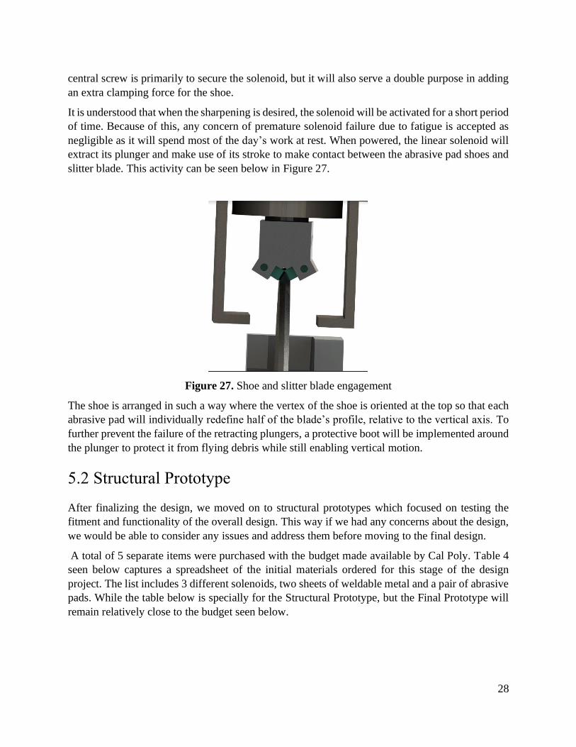
Figure 34. Complete assembly and manufacture of design. ......................................................... 34
Figure 35. Top guard manufactured.............................................................................................. 34
Figure 36. Bottom guard post modification. ................................................................................. 35
Figure 37. Solenoid purchased before modification. .................................................................... 36
Figure 38. Manufactured part to connect the solenoid to the abrasive shoes. .............................. 37
Figure 39. Depiction of solenoid plunger to the connecting piece. .............................................. 37
Figure 40. Depiction of boot to reject fiberglass from getting into the solenoid. ......................... 38
Figure 41. Additive manufactured steel shoes to hold the abrasive pads. .................................... 39
Figure 42. Mark tapping holes on the shoes for the set screws to hold the abrasive pad. ............ 39
Figure 43. Shoes assembled together using bolts and nuts. .......................................................... 40
Figure 44. Manufactured mounting bracket to connect the solenoid to the platform. .................. 40
Figure 45. Esteban ensuring holes on the bracket line up with the solenoid switch..................... 41
Figure 46. Manufactured solenoid platform. ................................................................................ 42
Figure 47. Square tubing cut down to size before the window and slit inserts............................. 42
Figure 48. Mark on manual mill cutting pocket in the solenoid platform. ................................... 43

Figure 49. Retention guard net shape. .......................................................................................... 43
Figure 50. Bending the retention guard int shape using a finger break. ....................................... 44
Figure 51. Final Assembly of design on test bench. ..................................................................... 44
Figure 52. Picture of test bench in operation with solenoid energized and roller in motion. ....... 47
Figure 53. Composite plot of angle change over grinding time for each blade. ........................... 49
Figure 54. Asymmetric war pattern on the blade profile due to crooked solenoid stack.............. 50
Figure 55. Test bench and structural prototype setup. .................................................................. 52
Figure 56. Timer inside transformer. ............................................................................................ 53
Figure 57. Experimental set up for solenoid functionality test. .................................................... 54
Figure 58. Solenoid Temperature compared to operation time. ................................................... 54
Figure 59. Abrasive pad sharpened for 1 minute and 2 minutes. ................................................. 56
Figure 60. Decreasing abrasive pad thickness as a function of time. ........................................... 57
Figure 61. Profile of abrasive pad shoe to avoid direct contact with slitter blade. ....................... 57
Figure 62. Increasing the thickness of the guard as shown so that it is above the circular clamp of
the blade. ....................................................................................................................................... 61
Figure 63. Modified plunger design with thicker cross-sectional area. ........................................ 62
Figure 64. Cracking seen on the top guard. .................................................................................. 62
Figure 65. Microcrack forming on the opposite side of the top guard. ........................................ 63
Figure 66. Increasing material in red locations by changing the length of top guard side plates. 63

1
1.0 Introduction
GAF is a roofing manufacturing company that was founded in 1886 with German roots. The
headquarters of the company are in Parsippany, New Jersey. Currently, GAF employs more than
3000 employees and obtains an average annual revenue of $3 Billion. GAF produces many
products, such as residential roofing systems, solar products, and commercial roofing systems
[1]. GAF uses circular slitter blades to cut their large fiberglass sheets into smaller manageable
rolls. The slitter blade illustrated in Figure 1 manufactured by Dienes is made from D2 Steel.
Figure 1. Slitter Blades used by GAF to cut diverse types of roofing shingles [1].
The slitter blades are mounted onto the system illustrated in Figure 2 and are used to cut fiberglass
sheets.
Figure 2. Mount slitter blade mechanism [2].
Due to the high volume of material that GAF cuts each day the blades tend to wear quickly. The
blades are periodically hand sharpened using a makeshift tool while the blades are still on the

2
cutting line. GAF requires the development of a slitter blade sharpener system to sharpen their
blades offline. However, this mechanism must also be capable of being incorporated into their
operation lines, while the machines are in operation. Currently, GAF sends their dull blades to a
qualified machinist and this process costs money and is not efficient because the operation lines
are interrupted. GAF needs a solution that allows them to accurately sharpen the blades in-house
with their existing workforce skill level. This would reduce time, save money, and increase
productivity. The project was completed by four senior mechanical engineering undergraduate
students at Cal Poly Polytechnic University, San Luis Obispo: Mark Breaux, Esteban Carrillo,
Carlos Paredes Espinoza, and Bradley Smith. This report outlines the project process and the steps
taken in order to complete this project.
2.0 Background
Our sponsors, Anthony Gutierrez, and Javier Davila discussed the details of the project. The
primary needs of the stakeholders are summarized in the following list:
1. Safe to use – GAF’s number one priority is the safety of their employees. The
sharpening system must include built in safety features such as an emergency
shutoff button to reduce the likelihood of a job-related injury.
2. Compatible with offline/online system – For this project, GAF will provide an
offline benchmark device that will replicate the online assembly line to develop
the sharpening system. That is, the development of the sharpening device will be
tested away from the assembly line and outside of the GAF production plant.
However, the goal is for the sharpening system to be compatible and eventually
be permanently mounted onto the online assembly line. The use of an offline
replica is only a temporarily supplement for the development stages.
3. Sharpen Blade to desired profile – The angle of the blade is important to create
a crushing action of the fiber glass material. The process isn’t slicing the
fiberglass but a compression process, implying the importance of the cutting angle
specified by GAF
4. Variable speed capability – This would enable the user to adjust the angular
velocity of the blade or sharpener depending on the time or quality desired for the
sharpening.
5. Operatable by a typical line worker – Despite the accessibility of an in-house
machinery, the user-friendly nature of the system would further increase the
likelihood of completing the sharpening task.
2.1 Existing Resources Currently, there are two main solutions that GAF’s uses or has considered as a solution to their
problem. The first includes sending batches of blades to a machine shop where a qualified
machinist performs the sharpening. This calls for a considerable loss in money, time, and resources
to the company. This is the current method by which GAF achieves the sharpening process for
their slitter blades. The second option considers the use of a stationary sharpening machine made

3
by Colonial Saw, serial number MVM LA500. This method has not been implemented but instead
was mentioned as a viable option.
During the early stage of research, our sponsors mentioned that GAF has considered the use of
sharpening machinery made by Colonial Saw, the MVM LA500 model [3]. While such machine
satisfies all functional concerns, the machine is estimated to be a lot more expensive than the
project proposed here. If a design could be developed in such a way where it meets or exceeds the
performance of the MVM LA500 at a fraction of the cost, then the assignment would exceed
expectations. A summary seen in Table 1 below collects the main attributes that each of the three
main candidates offer.
Table 1. Advantages and disadvantages of three main candidates.
GAF’s current
Machining Shop of use
Colonial Saw – MVM
LA500 sharpening machinery
Winter 2021 Design
Team
Advantage • Proven and reliable
• Relatively small fee for
single time
• Accessibility to store in-
house
• Meets or exceeds
sharpening expectations
• Optional accessories
available
• Operatable by
typical line worker
• Variable speed
• Functions online
• Relatively
inexpensive
Disadvantage • Requires shipment to
external facility
• Requires qualified
mechanic
• Requires dismounting of
slitter blades
• Relatively expensive
• Under development
• Limited experience
from developers
Pricing
Comparison • $24/ blade • Estimated in the tens of
thousands
• Budget target set at
less than $5000
It is important to note that this Scope of Work was created during the early stages of the design
project. The attributes seen listed at the right most column for Design Team are the main objectives
of the project and not the results of the final product. Similarly, notice that the pricing comparison
for the three candidates are not measured on the same basis. Therefore, the price ranges do not
give a fair comparison but instead aim to put the cost into perspective. For example, the purchase
of the MVM LA500 or the investment into Cal Poly’s Design Team would eventually pay itself
off if there is no way around the rate imposed by the machine shop.
4
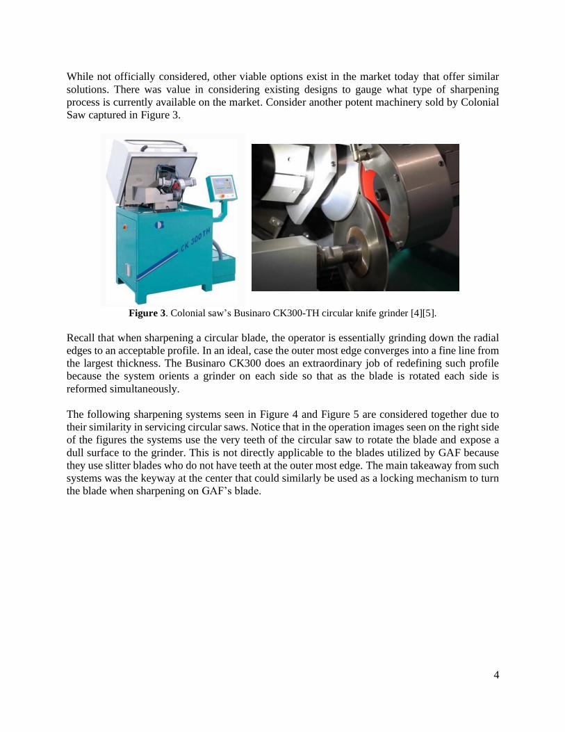
While not officially considered, other viable options exist in the market today that offer similar
solutions. There was value in considering existing designs to gauge what type of sharpening
process is currently available on the market. Consider another potent machinery sold by Colonial
Saw captured in Figure 3.
Figure 3. Colonial saw’s Businaro CK300-TH circular knife grinder [4][5].
Recall that when sharpening a circular blade, the operator is essentially grinding down the radial
edges to an acceptable profile. In an ideal, case the outer most edge converges into a fine line from
the largest thickness. The Businaro CK300 does an extraordinary job of redefining such profile
because the system orients a grinder on each side so that as the blade is rotated each side is
reformed simultaneously.
The following sharpening systems seen in Figure 4 and Figure 5 are considered together due to
their similarity in servicing circular saws. Notice that in the operation images seen on the right side
of the figures the systems use the very teeth of the circular saw to rotate the blade and expose a
dull surface to the grinder. This is not directly applicable to the blades utilized by GAF because
they use slitter blades who do not have teeth at the outer most edge. The main takeaway from such
systems was the keyway at the center that could similarly be used as a locking mechanism to turn
the blade when sharpening on GAF’s blade.

5
Figure 4. Knuth KSW 200 universal T&C grinder and during operation [6][7].
Figure 5. Steel magic’s laser Esge-450 saw blade sharpening machine and during operation [8][9].
For a final pairing, consider the economic options seen in Figure 6 and Figure 7. Both are available
on Amazon and they are priced at $69.99 and $299.99, respectively. To be clear, neither would be
a feasible solution to GAF’s problem but once again there is value to be taken for the future
designing aspect of the project. For example, the mounting of the motor, the lubrication system
and rotary dials can all be applied to the project. Given the short timeline of the project the use of
common hardware and proven systems will enable acquiring materials and assembling.

6
Figure 6. Chicago’s 120 Volt circular saw blade sharpener [10].
Figure 7. Techtongda sharpener’s 220V electric circular saw blade sharpener [11].
2.2 Patent Research The following patents were analyzed in the preliminary design process. Patent US20120184186A1
illustrated below in Figure 8, illustrates a similar sharpening process. As observed in Figure 8,
there are two grinders, on the top and below the blade, that grind and sharpen the blade.
Figure 8. Patent US20120184186A1 Applicable feature that uses two grinders to simultaneously sharpen
the blade [12].

7
Figure 9, illustrated below, highlights the feature of designing a tool that has sharpening device on
one side showcased in Patent US2998683A. Instead of simply having one sharpening device on
only one side, our design can have 2 sharpening tools on each side of the blade. This patent
demonstrated the possibility of using tools to define both side profiles at the same time. This
process was coupled with the abrasive pad holder mechanism that will be discussed later in the
report.
Figure 9. Patent US2998683A shows a tool that sharpen a dull blade [13].
Figure 10 illustrates Patent US3766806A whose main component of interest is its tiltable blade.
During the research phase, it was considered to use a tiltable blade to form the desired blade profile.
It was ultimately not feasible due to the on-line requirement. The blade would be in a fixed
configuration and unable to tilt.
Figure 10. Patent US3766806A shows an adjustable feature that can used to sharpen the blades at
different angles [14].
Patent US2993312A is illustrated below in Figure 11. During the early stages of the project, the
team was looking into quick ways that we can remove the blade from the on-line operation and to
our sharpening device in a quick manner. This patent provided an idea of a quick release type
mechanism. In the end, the project went to a fully on-line process and this patent wasn’t used.

8
Figure 11. Fixture mechanism concept that will be modified from this patent and incorporated onto our
design [15].
Figure 12, illustrated below, shows Patent US8448340B2, which uses a gear to rotate the
mechanism and sharpen the blades. Originally when doing research, we were gathering research
on having a motor run the blade, after talking with the sponsors we have developed a clear
understanding that the device will not require a motored system.
Figure 12. Gear mechanism illustrated in Patent US8448340B2 [16].
2.3 Research Reports The research reports cited below, were used as a springboard to utilize the experience of other
researchers to inspire our design decisions. The reports cited below were the most beneficial and
relative to the current project at hand.
The first report discussed here [17] covers the topic of vibrations while a circular blade is being
sharpened, and while the blade is in operation. Specifically, the beginning of the paper discusses
the forces that act on a wobbling blade and how this wobbling was correlated with imperfections
in the blade’s cutting profile, drastically affecting performance and durability. The report

9
concluded that a careful modal analysis of the natural frequencies of the blade and of the grinding
apparatus can significantly reduce unwanted resonant vibration during the grinding process,
increasing the integrity of the cutting-edge profile and drastically increasing duration of use.
The second report [18] covers the substitution of abrasives with sandpaper when sharpening steel
microtome knives. Although this application is not directly related to the sharpening of large steel
blades, the article discusses the feasibility of the idea of using sandpaper.
The third and final report covered here [19] discusses the effect of the surface finish and blade
edge angle had on the forces and moments exerted on the blade during the cutting process. Much
like the previously discussed report, this report focuses on the particulars with traditional meat
cutting knives. After testing various blade edge angles and surface finishes, they concluded that
the blade edge angle had no significant effect upon the forces and moments exerted on the blade
but found that the surface was quite significant to the reduction in forces and moments exerted on
the blade.
2.3.1 Experiment on Knife Sharpening – Burr Formation
In September of 2004, Professor John D. Verhoeven from the Department of Materials Science
and Engineering at Iowa State University [22], conducted Experiments on Knife Sharpening.
While, most experiments were conducted using a commercial stainless-steel razor strip, the report
does an excellent job in analyzing the burr that builds at the edge of poorly sharpened blades. It
turns out that (1) Debris Deposit and (2) Bending is two of the main contributors towards the
formation of burr, an undesirable rough edge or ridge left behind on a blade from the misuse of a
tool or machine. Consider the two different sharpening orientations seen in Figure 13 below.
Figure 13. Two different orientations of abrasion when sharpening a blade [21].
The article suggests that orientation “I”, which works away from the edge is most desirable. This
is because as another surface is pushes against the face of the blade microscopic debris is left
behind. In the case of orientation, “I”, the debris is moved away from the edge and reduces the
chance of causing any damage. While in the case of orientation “A”, one is moving towards the
edge and such debris is pushed to the opposing side of the blade.

10
Plastic flow is the bending phenomenon which occurs when the edge of the blade with minimal
thickness is exposed to large stresses. From engineering it is observed that stress can be measured
by the application of a force per unit area. Since a large force is applied when sharpening over the
relatively small area of the edge’s face, a large stress accumulates.
2.4 Government Standards Standards have been developed for each engineering project that has been invented. Standards are
in place to keep Engineers organized as well as a collective way to withhold a level of
professionalism and safety. GAF has provided the team with their list of standards and general
equipment specifications for any product or device they use. These standards include manuals,
safety precautions for mechanical use, OSHA requirements for safety guards and paint, and
emergency stop buttons just to name a few. These standards and specifications will be used to
guide the team in the ideation and development project. Ensuring the safety, cleanliness, ease of
accessibility, as well as required maintenance manuals required. GAF has also provided a list of
preferred products and components when designing a device. The team will use this list as a guide
when designing and collecting a purchasing list in the future.
In addition to companies creating their own standards, there are corporations like ASTM that
develops standards and publishes the standards ranging from all different types of common
practices and classifications of materials [20]. Having these standards make it easier for a designer
to reference material and practices that are safe and efficient. Standards that are used include
material property classifications. In compliance with these standards, the design team will be able
to use these standards as a guide and help the engineering design. For material properties, the team
knows that D2 steel is the blade material. A list of standards and material properties are used to
classify this material, and the design team were able to use these classifications to know how the
material will react under the sharpening procedure.
3.0 Objectives
For there to be a clear guide and direction of the project, the team had established goals, evaluation
criteria and deliverables for this project. The following section goes into details about the project
deliverables and boundaries set for the project.
3.1 Problem Statement
Currently, GAF uses steel blades to cut the fiberglass mats needed for their roofing material. When
these blades wear out, they are currently shipped off-site to a machine shop to be resharpened,
incurring extra shipping, machining expenses and downtime. GAF is looking for an on-site, on-
line solution that utilizes their current workforce aptitudes to sharpen the blades safely and
accurately with minimal worker intervention. The proposed solution will be tested on an off-line
test bench as a proof of concept for the design before moving to on-line operations. A solution to
this problem would increase productivity and reduce overhead cost of manufacturing.

11
3.2 Boundary Sketch
Boundary sketches are meant to visually define the scope of the project by clearly labeling what
is inside the purview of the project and what is outside of it. In this case, our project scope is to
design, build and test a fixture to sharpen a rotating circular blade, and test the design on a
testbench that will be built by GAF. Below in Figure 14 is the boundary sketch for our project.
Figure 14: Boundary sketch outlining area of our design.
3.3 Stakeholder’s Wants and Needs Summary
Below is a list of the requirements specified by GAF. This list has been created from the Quality
Functional Deployment (QFD). The QFD is tool is defined later in this report. This tool was used
to demonstrate the most important wants and need of our sponsor.
1. On-line capable device
GAF first asked us to make a device that would be able to sharpen their tools on a separate
mechanical machine that would be used in the shop. After speaking with our sponsors, they asked
us to create a device that they would be able to use on the fiber glass cutting line. This way it would
save time and money to operate off-line. To ensure out project will work properly, GAF has
provided the team with a test bench that mimics the on-line operations.
2. Sharpens cutting edge of blade
Our design should grind or cut the blade to the correct cutting profile, which includes a flat surface
and a bevel with a particular angle relative to the flat surface. This profile is important to provide
a crushing type cut. If the blade is to sharp, it will ruin the fiberglass

12
3. Zero-risk
4. safety operation
This requires that we follow all of GAF’s safety guidelines and procedures, as well as design
protective coverings and cages for all rotating or sharp objects. We want to ensure that each user
is provided with maximum safety and that the user is not at risk while using the device.
5. Integrates into existing blade/cylinder assembly
In lines with the on-line operation criteria, our design should cleanly integrate into the current
assembly line machinery and not interfere with current production procedures.
6. Operates on 120 Vac The device will operate on normal power coming from a conventional 120-volt outlet.
7. Useable by GAF line worker
The design shouldn’t be overly complex or confusing to operate.
8. Bill of Materials Cost below $5000
To be competitive with other sharpening devices, we would need our overall project to be within
the budget for this project.
3.4 Quality Functional Deployment (QFD) Description
The Quality Functional Deployment (QFD) seen in Appendix A is a common tool used in
engineering to organize customers’ requirements, methods of testing, competitors, targeted
specifications as well as the correlation between projects. The tool is broken up into 5 main
sections: who, what, how, now, and how much. Each section holds important information that will
be used to compare each section.
The “who” section identifies the customers for this project. We identified the customers as GAF
executives, our sponsors, and the assembly workers as the customers. We determined that these
individuals would have the most contact and stake in the project.
We then identified the “what” and “how” for this project. The “what” section of QFD are all the
requirements on what would make a successful project, where the “how” section identifies how
we are going to test or measure the requirements of the project.
The “now” portion of the tool looks at the current methods GAF uses as well as potential other
solutions to achieve the same goals and requirements. We choose to look at three options, GAF’s
current method of sending the blades to a machine shop to be sharpened, The MVM-LA500
machine from Colonial, and our project. Each project was given a rating from 1-5 to determine if
this project will meet the standards listed in the “what” section.
Lastly, the bottom section of the page indicates a “how much” section which identities the metric
being used to identify the target values of the “how” section. These metrics usually are associated
with a numerical value that can be compared and measured to.

13
This method helps identify any correlations between projects, identifies their strengths and
weaknesses, and also sparks new ideas to improve on the current design to fit GAF’s
3.5 Engineering Specifications Table
Table 2 is our list of specifications that came from our analysis with the QFD. The targets and
tolerances are summarized here, as well as an assessment of how at risk of meeting the
specification and how we will test our design’s compliance with the specifications. Ideally we
want to ensure that we meet all specifications at the highest level. This tool would help assess and
prioritize what specifications we needed to focus to ensure each one was satisfied.
Table 2. Engineering Specifications Table
Spec
#
Specification Description Requirement or
Target
Toleranc
e
Risk* Compliance**
1 Degree of sharpened blade profile 60°
+5°
- 0° H A, T
2 Meets GAF’s Safety Standard 100% N/A M A, I
3 Operatable by a typical line
worker ≥ 90% of users’
approval
+10 %
- 5 % M A, I
4 Variable Speed Capability 1050-1500 RPM N/A L T
5 Compatible with online slitting
production line Compatible N/A H A
6 Easy to Clean ≥ 90% of users
agree N/A L A, I
7 Robust and Reliable System Factor of
Safety ≥ 1.5 N/A M A
8 Cost ≤ $5000 (USD)
+ $200
- $1000 L A
9 Ease of Setup and Maintenance ≥ 90% of user
approval
+10 %
- 5 % L I
* Risk of meeting specifications: (H) High, (M) Medium, (L) Low
** Compliance Methods: (A) Analysis, (I) Inspection, (S) Similar to Existing, (T) Test

14
The process of specification development achieved a couple things for the team. The first is that it
clarified what specifications need to be tested once the final product was completed. It was also a
guide to help us focus on what aspect of the project needed the most focus and attention to ensure
we met the specifications of the project. Lastly it created a standard for which these specifications
can be compared to.
3.6 Numbered List of Specifications
Each of the specifications were given a requirement or target that we will use to evaluate to ensure
a successful project, more notable ones are the following. The slitter blade sharpening mechanism
needs to sharpen the blades with a 60-degree cutting edge with a 0.07±0.002-inch flat tip. This
requirement was set by GAF to ensure that their blades will have the crushing force required to
cut the fiber glass. This standard is the same standard that they currently use. As engineers we need
to hold safety paramount to ensure the safety of GAF employees. Thus, we wanted to stress the
importance in the specification table. For the project to be successful, the project must be easy to
operate and safe for all users. Thus, we have created other requirements to ensure that it is easy for
the operator by using the requirements of user approval.
3.7 High-Risk Specifications
Like stated earlier, the risk section is used to evaluate the risk of us meeting the requirement.
Having this column provides a guide for what aspects we needed to ensure we focus the most on
to ensure we meet these specifications. By evaluating the table there were two main high-risk
specifications: sharpen blade profile, and compatible with on-line operations.
The first high-risk specification on the list was the sharpen blade profile. This specification is
needed to cut the fiber glass. This specification is the main aspect if the project. If this specification
is not meet than we would not be able to perform the main task of this project. This was listed as
a high priority early in the project for us to focus on to ensure that the specification was satisfied.
We consider the compatibility with an online operation a high-risk specification because of the
complexities involved with designing around previously established assemblies. Difficulties
include designing the new assembly without conflicts with existing assemblies while still
maintaining appropriate accuracy with the grinding or cutting operation performed on the slitter
blade. Although this is deemed a high-risk, this is one of the key requirements specified by GAF
for the efficacy of the project.
4.0 Concept Design
After identifying the specifications and knowing what is required for this project, the next step was
to brainstorm. This process will allow the engineers to create a plethora of ideas which lead to the
final design. This section of the report will outline the different techniques that were used to create
these designs.

15
4.1 Concept Development: Functional Decomposition & Prototypes
In the beginning of the ideation process, we developed a functional decomposition tree diagram to
clearly specify the different functions required for our design. The functional decomposition tree
diagram, illustrated below in Figure 15, highlights that the primary function is to sharpen GAF’s
slitter blades. These key functions led to the creation of another Google Jamboard, where each
slide aimed to brainstorm ideas for each different function. The Jamboard ideation can be seen in
Appendix C.
Figure 15. Functional Decomposition Tree Diagram for Slitter Blade Sharpening Design.
Based on the Function Decomposition, each team member developed five prototypes that targeted
specific functions of our design challenge. The protypes developed by the team focused on
different functions such as developing a barrier between the employee and the machine,
approaching blade mechanisms, mounting to existing assembly lines, and debris collection. Each
prototype can be found in Appendix D. Each prototype was a starting point that sparked ideas into
the final design. Each prototype was discussed with the group of engineers to evaluate and identify
how each function could work together as a fill prototype. Not only did this design process create
ideas of what the final prototype would look like, but it also sparked new ideas that lead to our
final design.
4.2 Filtration Matrices (Pugh, Morphological, Weight Decision)
After creating twenty prototypes, each one was classified under a specific function. This led to the
creation of five Pugh Matrices for each function. The Pugh Matrices can be found in Appendix E.
Note that the criterion to evaluate these ideas were taken from the most important aspects of the
Quality Function Decomposition found in Appendix A. Each concept was then given a scoring
between better (+), worse (-) or same (S) in comparison to the datum idea seen at the left-most
column. Moreover, the scoring of better, worse, or same was assigned to a numerical value of 1, -
1 and 0, respectively. After each concept was given a score, a total was added at the bottom most
row and this sum was then used to carry the winning candidates to the Morphological matrix.

16
We used a decision matrix to weight our top concept protypes and from here decide on our top
candidate for our design. However, in this case, each winning concept was now compared to the
primary functions. The primary functions are taken from the Functional Decomposition Diagram,
which can be found in Figure 15. For this matrix, there was no scoring assigned to the derived
concepts. Instead, an option from each function was combined to form complete prototypes. The
combination of the functions, which is seen by the red, dark blue, pink, and light blue marking,
can be found in the second matrix of Appendix F. From this analysis a total of four newly formed
systems were considered in a final Weighted Decision Matrix.
In idea #1, the sharpening is arranged in a similar fashion that cantilever breaks are seen on a
bicycle. The sharpening assembly is bolted onto the structure of the slitter machine by use of some
standard brackets. As for idea #2, two semicircular disks are used to form the desired sharpening
angle. Once again, the system would be bolted onto the slitter machine and now a magnet would
be used to catch unwanted debris. Idea #3 performs in a similar fashion to idea #2, except a debris
collection cup is implanted towards the bottom and the abrasive pads are attached to the top of the
assembly. Lastly, idea #4 uses the same cantilever break style set up as idea #1 except it also
includes the debris collecting magnet and the bottom guard. Below are concept drawings of each
of these designs.
Figure 16. Idea #1 concept drawing, featuring the solenoid idea oriented in a brake caliber
configuration.

17
Figure 17. Idea #2 concept drawing, featuring the abrasive pads tucked closer to the body of the
air cylinder.
Figure 18. Idea #3 concept drawing, showing the collection cup and caliper style abrasive pad
system.

18
Figure 19. Idea #4 concept drawing, showing the circular magnet tucked between the blade and
the air cylinder.
Finally, we considered the Weighted Decision Matrix, seen in Appendix G, where one option was
chosen to continue with the project from the resulting complete systems. In this case, the criteria
listed in the Weighted Decision Matrix are assigned a weight, which indicates how important each
topic is to the success of the design. Each idea was rated using a standard scaling system to rate
how well each idea satisfied the corresponding criteria. In this conventional scoring, a scale of 1
(poor) to 5 (optimal) was implemented. The sum of the weighted scores proved that Idea #1 and
Idea #2 (Figures 16 and 17) were the strongest concepts to perform the assigned task. However,
Idea #1 was ultimately chosen as the final concept for the project.
4.3 Selected Concept and CAD Model
The concepts that formed Idea #1 led the team to the Concept Model seen in Figure 20, and a
concept cad model of our prototype in Figure 21 (right). The sharpening is made possible by
arranging two abrasive pads such that a normal force is applied to the slitter blade’s cutting profile
with the help of a solenoid switch.

19
Figure 20. Front, side, and rear views of our concept prototype, respectively.
Figure 21. Existing slitter blade assembly and Concept CAD Model
The sharpening system makes use of the existing slitter machine itself to mount onto the active
assembly line. Notice that in Figure 21 (left) the slitter blade is arranged in such a way that it
allows for the sharpening system to be mounted directly above. This would not interfere with the
fiberglass cutting operation because the fiber glass does not contact the slitter blade where the
sharpening system will mount. That is, the manufacturing process can go on simultaneously as the
blades are sharpened. Along with this, the implementation of an electric solenoid will allow the
employee to remotely engage the sharpener as desired.
4.4 Preliminary Analysis and Testing
For this project, we intend to incorporate our prototype onto the existing assembly line in for GAF
to sharpen their slitter blades on-line. While strength and stiffness will play a part in this design,
considerations were taken to ensure that our design can be integrated to the existing bolting holes

20
that are located on the device. With the placement of these tapped holes, considerations were taken
to account for forces and moments that would be asked from the mounting locations.
We used FEA as a preliminary analysis tool to decide on an approximate gauge for the sheet metal
that we were going to use. We decided to run the FEA with .060” steel sheet metal (which works
out to 16 gauge in thickness), and you can see the colorized image below in Figure 22. We chose
16-gauge sheet metal as our test thickness because it seemed “thick enough” for a test and common
enough to be easily purchased.
Figure 22. FEA mesh and colorized results
As can be seen in Figure 22, the maximum stress that occurred was around 5,200 psi. A probe was
placed at a single location that measured the non-localized maximum stress experienced by the
material. The results of this probe can be seen in Figure 23, shown below.

21
Figure 23. Top Guard Convergence Study
This convergence study confirms that using an element size smaller than 1/8” did not significantly
add accuracy to this analysis, and it also shows that the maximum probed stress plateaus at around
2,500 psi.
Research online indicates that the approximate yield strength of cold rolled steel sheet metal is
approximately 85 ksi. Reducing this number for a conservative estimate down to 80 ksi and given
our maximum probed stress from the convergence study, this produces a factor of safety of about
33, which is quite large. This factor of safety is large exceeded the 1.5 FOS which was specified
in Table 2 identifying the engineering specifications.
Paired with the FEA was a displacement study, which isn’t shown here. However, using the same
element size, the study found that under 10 lbf of load in shear along the weld line for the solenoid
platform, the entire system only displaced around .0012”, which would not significantly impact
the operation of the system.
Our conclusion from this study is that 16 gauge cold rolled steel sheet metal will be more than
sufficient for our requirements.
4.5 Design Hazards and Safety Plans
A standard Design Hazard Checklist is seen in Table 3 where it works to consider common
engineering hazards that may lead to a work-related injury. By inspection, the sharpening system
raised a concern in five of the prompted questions. The five risk areas include: the use of shearing
parts, projectiles, high voltage, noise, and unsafe use.

22
Table 3. Design Hazard Checklist Y N Description of Hazard Concern
Y
1. Will any part of the design create hazardous revolving, reciprocating, running, shearing, punching,
pressing, squeezing, drawing, cutting, rolling, mixing or similar action, including pinch points and sheer
points?
N 2. Can any part of the design undergo high accelerations/decelerations?
N 3. Will the system have any large moving masses or large forces?
Y
4. Will the system produce a projectile?
N 5. Would it be possible for the system to fall under gravity creating injury?
N 6. Will a user be exposed to overhanging weights as part of the design?
N 7. Will the system have any sharp edges?
N 8. Will any part of the electrical systems not be grounded?
Y
9. Will there be any large batteries or electrical voltage in the system above 40 V?
N 10. Will there be any stored energy in the system such as batteries, flywheels, hanging weights or
pressurized fluids?
N 11. Will there be any explosive or flammable liquids, gases, or dust fuel as part of the system?
N 12. Will the user of the design be required to exert any abnormal effort or physical posture during the
use of the design?
N 13. Will there be any materials known to be hazardous to humans involved in either the design or the
manufacturing of the design?
Y
14. Can the system generate high levels of noise?
N 15. Will the device/system be exposed to extreme environmental conditions such as fog, humidity, cold,
high temperatures, etc?
Y
16. Is it possible for the system to be used in an unsafe manner?
N 17. Will there be any other potential hazards not listed above? If yes, please explain on reverse.
Since the abrasive pads will apply a normal force onto the slitter blades to perform the sharpening
the concern of a shearing parts is unavoidable. However, the implementation of a shield will work
to protect the user from any direct contact with the retracting pads.
The flying debris also raises a dangerous concern since the small particles of shaved metal will
take on projectile motion during the sharpening. Once again, the safety shield that encompasses
the mechanism will work to capture any flying debris. That is, the projectiles will collide with the
guard before contacting an employee. The shield will also serve to funnel the debris into a single
location.
During a virtual meeting with the sponsors, it was specified that any electrical component will
make use of a standard 120AC Volt outlet. This is out of the team’s domain as it is a factor imposed
by the company. However, the contact between the system user and any electrical connections will

23
be reduced using a permanently mounted system and electrical controls. Since the power supply
is endorsed by the engineers overseeing the design team, this concern is accepted.
Like any other sharpening system, it is expected that the system will make a significant amount of
noise. If necessary, sound deadening material may be added onto the protective shield for a quiet
operation. However, recall that the sharpening device will mount directly onto a live assembly line
with many other moving parts. Because of this, a low decibel rating is accepted as not being a high
priority.
Since the abrasive pads will engage repeatedly while the blade rotates at high angular speeds the
system can be mishandled in an unsafe manner. Because of this nature, it is imperative for the user
to always operate the system with the protective shield in place. The use of electrical controls will
also be applied with this concern in mind so that the sharpening device can be activated from a
relatively safe distance.
4.6 Outstanding Challenges, Concerns or Unknowns
After evaluating prototypes and identifying safety concerns, there were a few design concerns
before moving on to the final design. There were some initial concerns that needed to be resolved.
Each concern was identified and resolved before moving on to final design. For instance, the
collection of the debris produced from sharpening the slitter blades was not required by GAF, but
they were concerned that the metal particles would become rolled into the final customer product.
This was resolved by asking our sponsor if this was a concern to him. He identified that this was
not a concern.
Another challenge ahead of us is asymmetrical wear on the abrasive pads. Asymmetrical wear
would not make use of the full abrasive pad and reduce the accuracy of the desired profile angle,
reducing the life of the blade. Also, the process to replace the pads needs to be determined. CAD
modeling of our design enabled the team to get a better understanding for the mechanics of the
pads and resolve the issue.
Lastly, a consideration was made for the ease of removing the blade with the device attached to
the assembly. This does not affect the sharpening itself but instead the accessibility and
serviceability of the abrasive pads. The insert of an access door or a removable assembly was
mentioned to accommodate this concern. This was resolved during the final assembly resulting in
us having the final prototype in our hands and we were able to adjust the design such that the blade
was removable.
5.0 Final Design
The final design is captured below in Figure 24, where the primary components are labeled
accordingly. The retention guard impedes the solenoid from rotating. The mounting plates and the
solenoid platform are mounted onto the blade and arm assemblies. Recall that the proposed
sharpening system is intended to mount onto an existing assembly line. Components such as the
24
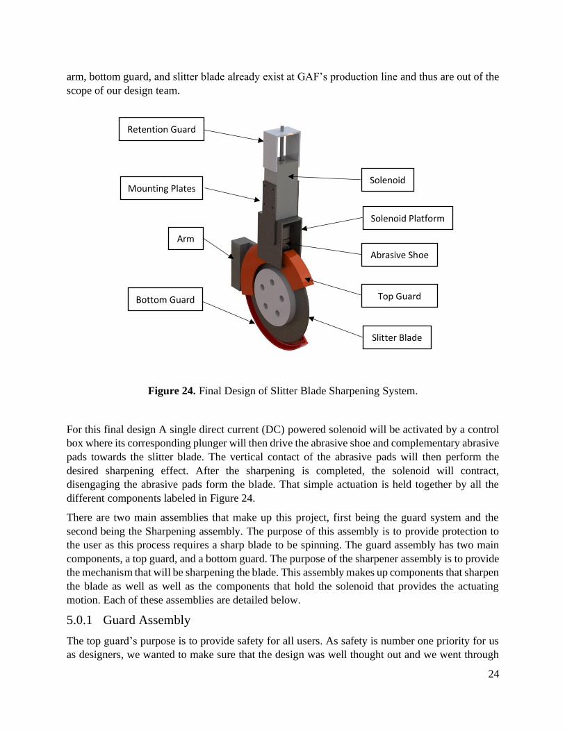
arm, bottom guard, and slitter blade already exist at GAF’s production line and thus are out of the
scope of our design team.
Figure 24. Final Design of Slitter Blade Sharpening System.
For this final design A single direct current (DC) powered solenoid will be activated by a control
box where its corresponding plunger will then drive the abrasive shoe and complementary abrasive
pads towards the slitter blade. The vertical contact of the abrasive pads will then perform the
desired sharpening effect. After the sharpening is completed, the solenoid will contract,
disengaging the abrasive pads form the blade. That simple actuation is held together by all the
different components labeled in Figure 24.
There are two main assemblies that make up this project, first being the guard system and the
second being the Sharpening assembly. The purpose of this assembly is to provide protection to
the user as this process requires a sharp blade to be spinning. The guard assembly has two main
components, a top guard, and a bottom guard. The purpose of the sharpener assembly is to provide
the mechanism that will be sharpening the blade. This assembly makes up components that sharpen
the blade as well as well as the components that hold the solenoid that provides the actuating
motion. Each of these assemblies are detailed below.
5.0.1 Guard Assembly
The top guard’s purpose is to provide safety for all users. As safety is number one priority for us
as designers, we wanted to make sure that the design was well thought out and we went through
Solenoid Mounting Plates
Solenoid Platform
Arm
Retention Guard
Abrasive Shoe
Top Guard
Slitter Blade
Bottom Guard
25
all possible options. The second purpose of the guard is to hold the sharpener assembly. The guard
is the main connection to their current set up for cutting fiber glass. We wanted to make sure the
guard was rigid enough to support sharpening assembly as well as not shear off the connection
between the two.
5.0.1.1 Top Guard
The top guard is our main guard design. This top guard is responsible for holding the sharpening
assembly as well as shield the blade from the users. You can see above in Figure 24 that the guard
is connected to the main sharpener assembly though the solenoid platform. We decided to place
slits in the top guard to allow the solenoid platform to sit within guard assembly so that we create
a rigid body and to have more surface area for welding during the manufacturing process. There
is also a slit at the top of the guard assembly to allow the shoe design to move in a linear up and
down motion when the solenoid is energized. Not depicted in Figure 24 but can be seen in Figure
34 in this report is the two (2) holes that will be used as a connection mechanism to the current
assembly. During design, there was concern about the rigidity of the top guard under load, this
was mitigated with the use of finite element analysis (FEA) that was performed on the guard to
ensure it would not fail. In the analysis section above, it showed that the guard would be able to
withstand the load.
5.0.1.2 Bottom Guard
The bottom guard was also included in the design for safety. This part was a part of the original
assembly and was cut and modified to length to allow for the upper guard to be assembled. The
original guard was kept because in would decrease our manufacturing time as well it being the
right fit around the blade. We wanted to ensure that the user was always protected and that no
fingers would be injured while in use.
5.0.2 Sharpener Assembly
The Sharpener Assembly is the main component that is responsible for sharpening the blade as
well as the supports that connect to the guard assembly. This assembly is the main objective that
GAF had presented us with.
5.0.2.1 Solenoid
The Solenoid is the main component is that is adding the actuating motion. This device was
designed around the idea that the blade did not need to be sharpening the entire time. There needed
to be a device that would be used to bring the sharpening device to blade. We decided to go with
a DC powered solenoid switch that would be retracted on it off configuration, then when energized
it would be in its extended configuration thus sharpening the blade. We wanted the ability to have
the solenoid connected to a regular 120VAC outlet. We asked the electrical team at GAF if they
would be able to create a transformer box to change the 120VAC to the required DC voltage of

26
the solenoid. This allows GAF the opportunity to have the device on the assembly line or off in
the machine shop to be sharpened off-line.
5.0.2.2 Solenoid Platform
There needed to be a way that we can connect the solenoid to the top guard. The team went with a
platform design that can be seen in Figure 24. This device was designed to provide the space
needed between the blade and the shoe design when the solenoid us unenergized, but also close
enough to the blade that when the solenoid was activated that it would be able to sharpen the blade.
The platform was also designed such that if the solenoid was filly extended that it would reach the
minimum diameter requirements by GAF. This would provide a visual representation to the line
workers that if the blade is not sharpening the blade that it might be time to replace the blades with
a new one.
5.0.2.3 Mounting Plates
The main purpose of the mounting plates is to connect the solenoids to the solenoid platform. We
intended the design to have bolts so that the solenoid would be easily removed for maintenance as
well as cleaning if need be.
5.0.2.2 Shoe Design
The shoe design is the main mechanism that sharpens the blade. This shoe holds the abrasive pads
that are in contact with the blade that provides the 60 angle. The shoe would be connected to the
solenoid via the plunger. This is the main function if the device and details will be explained in
the system functionality portion of this report. This device was the most crucial to design and have
the measurements correct, having it be the device that controls the sharpening aspect of the design.
5.0.2.3 Retention Guard
The Retention Guard came to mind during the prototype phase of this project. We received three
(3) different solenoids that were possible candidates for this project. We noticed that the plunger
would be free to rotate about its axis. having the shoe connected to the end of the plunger, we
didn’t want to have any rotation as it might not be in full contact of the blade and our shoes
would be destroyed. Thus, we deiced to create the retention guard as it would be in line with the
solenoid and prevent unwanted rotation.
5.1 System Functionality
After presenting the Preliminary Design Report (PDR) to members of GAF’s management, the
design team was warned about the expectation of the solenoid plungers seizing due to the debris
in the environment. Instead of a previous iteration to have a double solenoid, we went with a
single solenoid, thus the shoe design needed to be change as well. The new iteration of the key
sharpening component is seen below in Figure 25.

27
Figure 25. Abrasive pad shoe decomposition
The driving solenoid will be attached to the shoe using the plunger end of the solenoid. The plunger
will be encased inside the shoe and retained by a single screw located at the center. The shoe itself
also houses the two abrasive pads seen at the bottom. Each pad will be held in place by a single
set screw that can be accessed easily when removal is necessary.
In considering the most efficient manufacturing approach, it was determined that machining the
shoe as a single unit would be relatively difficult. Because of this, the final shoe will be made up
of two halves. During one of many meeting with the project’s sponsor, the use of a 3D metal printer
was mentioned as a viable option. After analyzing the different designs and manufacturing
processes for the shoe, we opted for the 3D metal printed prototype. An individual half of the shoe
is captured below in Figure 26.
Figure 26. Abrasive pad shoe half
The half of the shoe exposes the three screw holes that will be driven horizontally. The outer
screws will work to bind the two halves of the shoe to make up a single unit. The purpose of the
28
central screw is primarily to secure the solenoid, but it will also serve a double purpose in adding
an extra clamping force for the shoe.
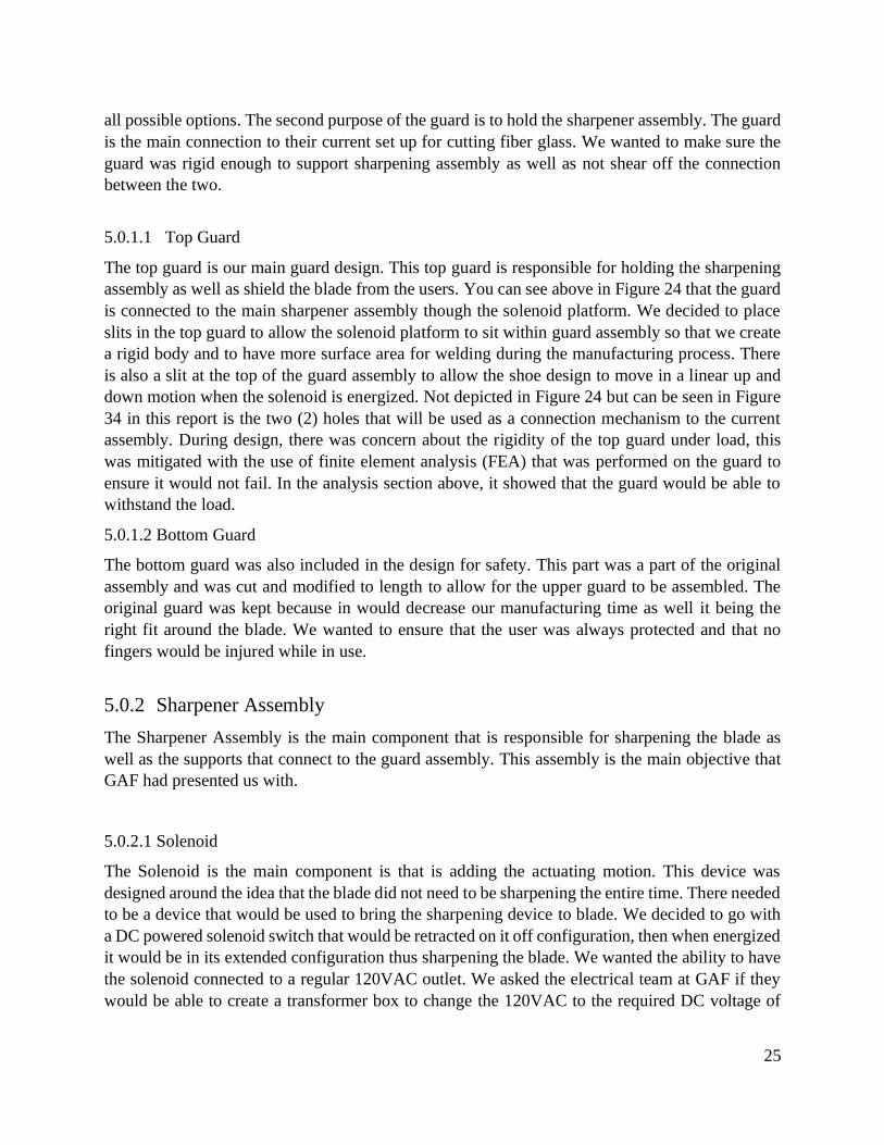
It is understood that when the sharpening is desired, the solenoid will be activated for a short period
of time. Because of this, any concern of premature solenoid failure due to fatigue is accepted as
negligible as it will spend most of the day’s work at rest. When powered, the linear solenoid will
extract its plunger and make use of its stroke to make contact between the abrasive pad shoes and
slitter blade. This activity can be seen below in Figure 27.
Figure 27. Shoe and slitter blade engagement
The shoe is arranged in such a way where the vertex of the shoe is oriented at the top so that each
abrasive pad will individually redefine half of the blade’s profile, relative to the vertical axis. To
further prevent the failure of the retracting plungers, a protective boot will be implemented around
the plunger to protect it from flying debris while still enabling vertical motion.
5.2 Structural Prototype
After finalizing the design, we moved on to structural prototypes which focused on testing the
fitment and functionality of the overall design. This way if we had any concerns about the design,
we would be able to consider any issues and address them before moving to the final design.
A total of 5 separate items were purchased with the budget made available by Cal Poly. Table 4
seen below captures a spreadsheet of the initial materials ordered for this stage of the design
project. The list includes 3 different solenoids, two sheets of weldable metal and a pair of abrasive
pads. While the table below is specially for the Structural Prototype, but the Final Prototype will
remain relatively close to the budget seen below.

29
Table 4. Purcahse Order for Structural Prototype
Vendor Product Name Part Number Qty Price/Ea Total
Amazon TAKAHA Stroke 35mm Push Pull Long Stroke
Solenoid Electromagnet CH 1284 1 $ 47.62 $ 51.79
Amazon
Tulead Stroke 10mm Push-Pull Solenoid Micro Solenoid Electromagnet
20N Suction
ADD 06190484
1 $ 9.99 $ 10.86
Amazon
Tulead 12V DC Solenoid Push Pull Electronic
Actuator Micro Solenoid Electromagnet 5N
Suction
ADD0619483 1 $ 10.59 $ 11.52
Home Depot 12 in x 12 in. 16-gage
Weldable Sheet SKU#
1001195244 2 $ 10.98 $ 25.00
Boride Engineered Abrasives
CS-HD Silicon Carbide Polishing Stone 400 grit,
1/4 x 1/4 x 6
Item#: 036629
1 $ 38.88 $ 49.87
Total $ 149.04
Remaining Balance $ 850.96
Notice that contrary to the chapter’s introduction, a total of three different solenoids were placed
in the order. During a meeting with the project sponsors it was estimated that a force of less than
10 Newtons will be required. This was inconclusive because the amount of force needed was only
a suspicion as opposed to a verified value. Therefore, multiple solenoids were ordered for
experimental purposes where each solenoid offers a different input of force. However, the
TAKAHA solenoid seen in Figure 28 was chosen because it offered the largest stroke.
Figure 28. TAKAHA solenoid before and after being modified.

30
With a potential solenoid at our disposal, we were able to test the device and get a better
understanding of the functionality and operation. When received, the device had the spring in such
a way that in the off configuration the plunger was extended to its max length (Figure 28, Left).
For this application, it is desired to have the opposite phenomenon happen in its resting state. The
spring was then relocated to the opposite end of the solenoid so that when disactivated, the plunger
could retract inward and disengage the abrasive pads from the blade (Figure 28, Right). Contrary,
when the solenoid is activated, it will now extract outward and engage the abrasive pad with the
dull blade. Figure 28 shows the solenoid in its off configuration with the plunger fully retracted.
The sheets of metal were ordered to cut and weld the solenoid’s mounting plates. A shop tech
present at a lab meeting explained that such components were very simple to make. With this
knowledge, we decided to obtain a 0.6-inch-thick sheet metal and practice bending the sheet metal
that would hold the solenoid switch. This attempt can be seen below in Figure 29.
Figure 29. Bend test of the top plate.
As you can see, we ran into issues using the finger break to bend the last tab into place. This led
us to find another solution by utilizing square tubing and modifying it to fit our needs. This
operation is explained in the manufacturing section.
For the sharpening aspect of the design, we needed to research about abrasive pads that would
provide the sharpening procedure. The abrasive pads were intentionally chosen as conventional
rectangular pieces. After contacting the abrasive pad manufacturer, the team was informed that a
custom-made abrasive pad could be made to our liking. But this option was avoided in the efforts
to make acquiring replacement pads readily available and cost effective. To see how the abrasive
pads would sit in the shoes, the abrasive pad shoe was 3D printed (Figure 30) by Cal Poly’s
Innovation Sandbox, an on-campus prototyping facility for students of all majors. This was a great
visual to see how small the abrasive pads would be and to be able to see how we would be able to
manufacture them in the hanger. Our original plan was to manufacture the parts utilizing a manual
mill, but after evaluating the complexity, we decided to go with an additive manufacturing process.

31
Figure 30. 3D printed abrasive shoe developed for the Structural Prototype.
5.3 Safety, Maintenance and Repair Considerations
The safety and ease of accessibility of the GAF assembly line workers was an objective
prioritized earlier in the project development. For a detailed analysis of general safety concerns,
please refer to the Hazard Checklist found in Table 3. The overall sharpening system can be seen
in the two views of Figure 31.
Figure 31. Safety guard implementations to reduced work related injury.
It is very well understood that there will be two primary forms of reciprocating motion. This
includes the angular rotation of the blade and the vertical engagement of the abrasive pad with the
slitter blade. To complement GAF’s existing bottom guard, an additional top guard was added to
act as a barrier between an employee and the machinery. The use of red color was chosen as it is
a universal symbol for danger or alertness. Similarly, when the vertical displacement of the plunger
punctures through the top plates, the mounting system of the system acts as an additional safety
guard in the areas where the top guard fails to do so. The solenoid activation switch is also intended
to be arranged in such a way where the user operates the machine at a safe distance.
Top Guard
Bottom Guard
Solenoid
Mounting
System

32
When developing the sharpening system, each removable component was designed or oriented in
such a way to require a minimal amount of effort. Figure 32 seen below captures the primary
components where the user will frequently interact with during maintenance.
Figure 32. Primary components of user engagement.
At left, Figure 32 shows that the number of screws needed to bind the two shoe halves or secure
the abrasive pads was minimized to provide the clamping force needed while making disassembly
easy. For example, each abrasive pad will fall by gravity by turning a simple screw
counterclockwise. The two halves will also require the same minimalist hardware but still enable
access to the interior bore of the solenoid plunger in the case that debris accumulates excessively.
At right, notice that newly added top guard was arranged in such a way to not interfere with the
removal of the slitter blade through the bottom. That is, removing the central hub of the disk will
allow the user to slip the blade from beneath without any interference from the top guard. The use
of common off the shelf parts and the open accessibility is intended to make servicing the system
very easy. In general, the components can be dissembled independently of one another. Since the
sharpening system will reside in a manufacturing plan, an employee can easily clean the area with
compressed air when production is low. Except for the abrasive pad shoe, the abrasive pads and
hardware are open to the public for purchase.
5.4 Remaining Concerns After Structural Prototype
After completing our structural prototype, we still had some concerns that were answered after the
final prototype was constructed. We wanted to document the concerns that we had at the end of
the structural prototype phase of the project. In the Fall of 2021, the final prototype was tested for
a few concerns that could not be clearly addressed through computational analysis. This includes:
(1) an unwanted retention guard rotation, (2) abrasive life and wear pattern and (3) the moment
carried by the solenoid plunger. Other honorable mentions include (4) the amount of stalling force
imposed by the solenoid and lastly, (5) the structural rigidity of the top guard. The testing itself
will be expedited when the test bench, an offline system that mocks the online operation, is made
available by GAF.
After completing the sharpening system model on SolidWorks, we were observed that the retention
guard may undergo an unwanted rotation about the vertical axis. To accommodate for this, the Top
Retention Guard (Figure 33) was included at the top of the assembly where it binds against the
solenoid’s body in the efforts to mitigate the unwanted rotation.

33
Figure 33. Top Retention Guard implanted to prevent unwanted rotation.
When reconsidering Figure 25, realize that the two abrasive pads attack the dull slitter blade from
the slides, where each works to redefine a single side of the blade as opposed to the tip. Another
valid concern was the even wear the and life expectancy of the abrasive pads. The abrasive pads
had to be chosen to be relatively small to fit well inside the abrasive shoe. Recall that the abrasive
show was restricted by the control volume imposed by top guard.
During the PDR presentation to GAF management, the team was encouraged to explore the stall
force that when vertically applied would prevent any angular movement of the slitter blade. This
can be experimented by mounting a lower force TAKAHA electromagnetic solenoid to prevent
stall
When in contact, it is expected that the slitter blade will incur a friction force onto the abrasive
pads. As a result, this may cause a considerable moment acting about the base of the solenoid
plunger. If the moment arm is directly prototypal to moment, this undesirable moment will be the
highest when the solenoid is at its full stroke length since the length of the plunger will serve as
the moment arm.
6.0 Manufacturing
This section outlines the manufacturing process of the final design. Each component is
broken down into the main overall assemblies of the blade guard and the sharpening mechanism.
Each part outlines the process used to obtain or manufacture the part. A final Bill of Materials will
be outlined in Appendix K, where more information on the materials and their corresponding part
numbers can be found.
Top Retention Guard
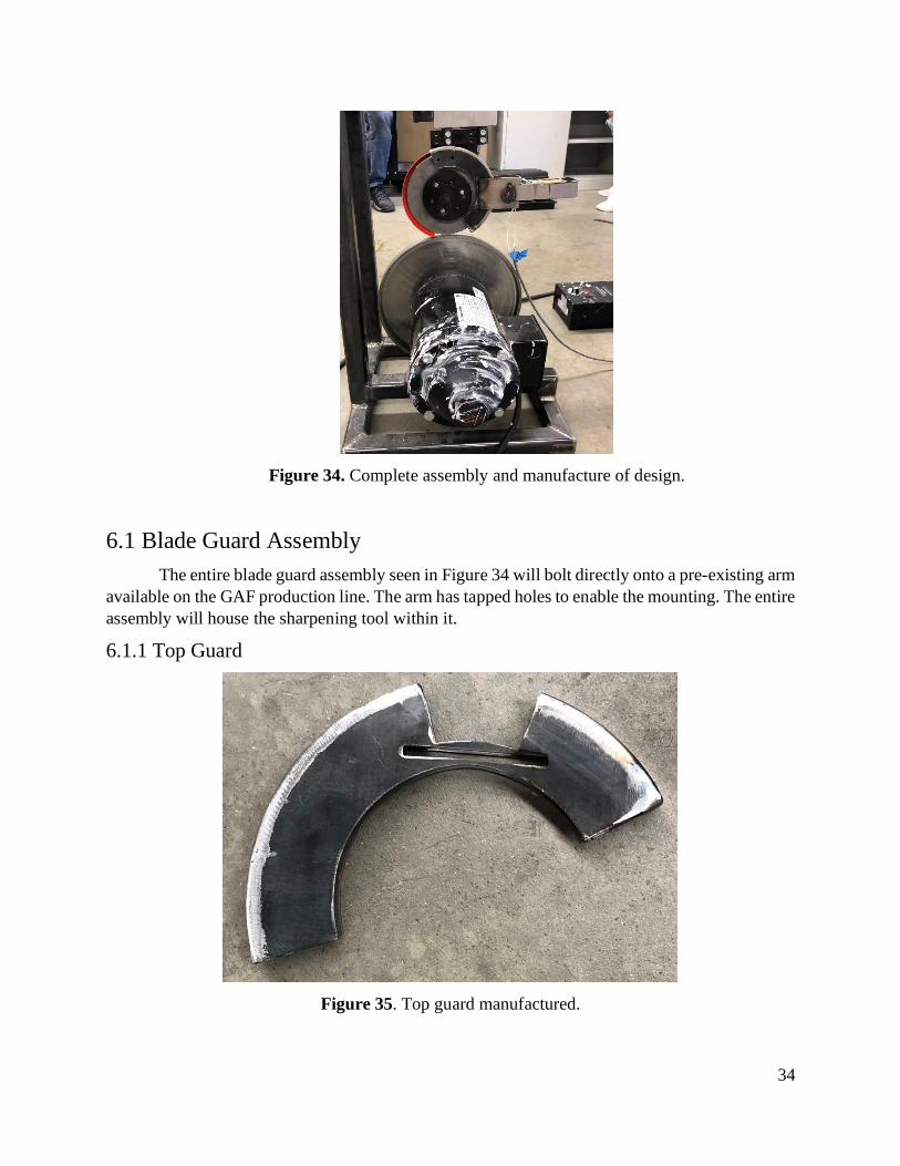
34
Figure 34. Complete assembly and manufacture of design.
6.1 Blade Guard Assembly
The entire blade guard assembly seen in Figure 34 will bolt directly onto a pre-existing arm
available on the GAF production line. The arm has tapped holes to enable the mounting. The entire
assembly will house the sharpening tool within it.
6.1.1 Top Guard
Figure 35. Top guard manufactured.
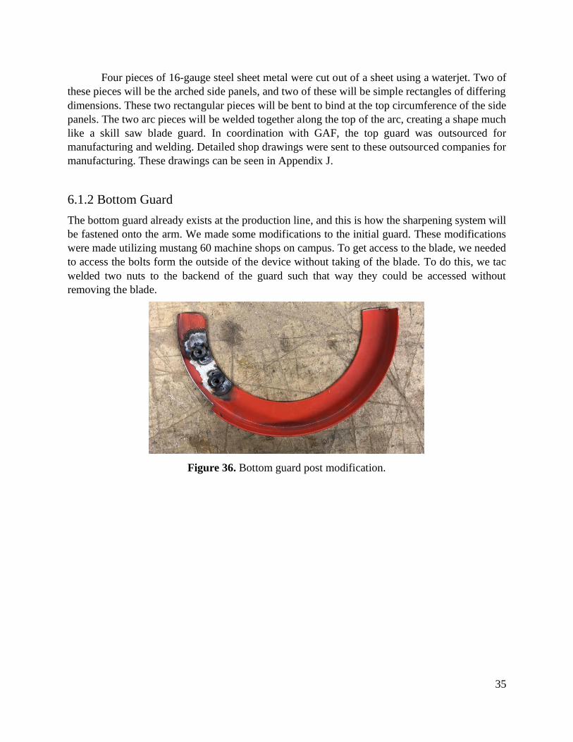
35
Four pieces of 16-gauge steel sheet metal were cut out of a sheet using a waterjet. Two of
these pieces will be the arched side panels, and two of these will be simple rectangles of differing
dimensions. These two rectangular pieces will be bent to bind at the top circumference of the side
panels. The two arc pieces will be welded together along the top of the arc, creating a shape much
like a skill saw blade guard. In coordination with GAF, the top guard was outsourced for
manufacturing and welding. Detailed shop drawings were sent to these outsourced companies for
manufacturing. These drawings can be seen in Appendix J.
6.1.2 Bottom Guard
The bottom guard already exists at the production line, and this is how the sharpening system will
be fastened onto the arm. We made some modifications to the initial guard. These modifications
were made utilizing mustang 60 machine shops on campus. To get access to the blade, we needed
to access the bolts form the outside of the device without taking of the blade. To do this, we tac
welded two nuts to the backend of the guard such that way they could be accessed without
removing the blade.
Figure 36. Bottom guard post modification.

36
6.2 Sharpener Assembly
This assembly contains the solenoid, shoe, abrasives, and retention guard. This is the part of the
design that contains the moving parts to the sharpening process, which is why this assembly is
broken into other sub-assemblies.
6.2.1 Solenoid Modifications and Adapters
A main component of the sharpening assembly is the solenoid. For the design, we needed the
solenoid to be retracted in its off configuration. As you can see in Figure 37, the short end of the
solenoid is retracted in its off configuration.
Figure 37. Solenoid purchased before modification.
We initially had the design idea that we could reverse the polarity of the wires and thus inducing
a magnetic force in the opposite direction. We found out that this theory is not true. No matter
what direction we flip the solenoid wires it still retraced in the spring side in. This was a concern
due to our whole design relying in the dimensions of this solenoid. Thus, we needed to come up
with another solution. We contacted the manufacture of the solenoid and they informed us that the
“push” aspect on their advertising comes from the skinny shaft of the solenoid. We decided to flip
the whole solenoid over such that the skinny portion of the plunger was orientated such that it will
engage the blade. We needed an adapter to connect the solenoid to the abrasive pads. This
connecting piece can be seen in Figure 38.
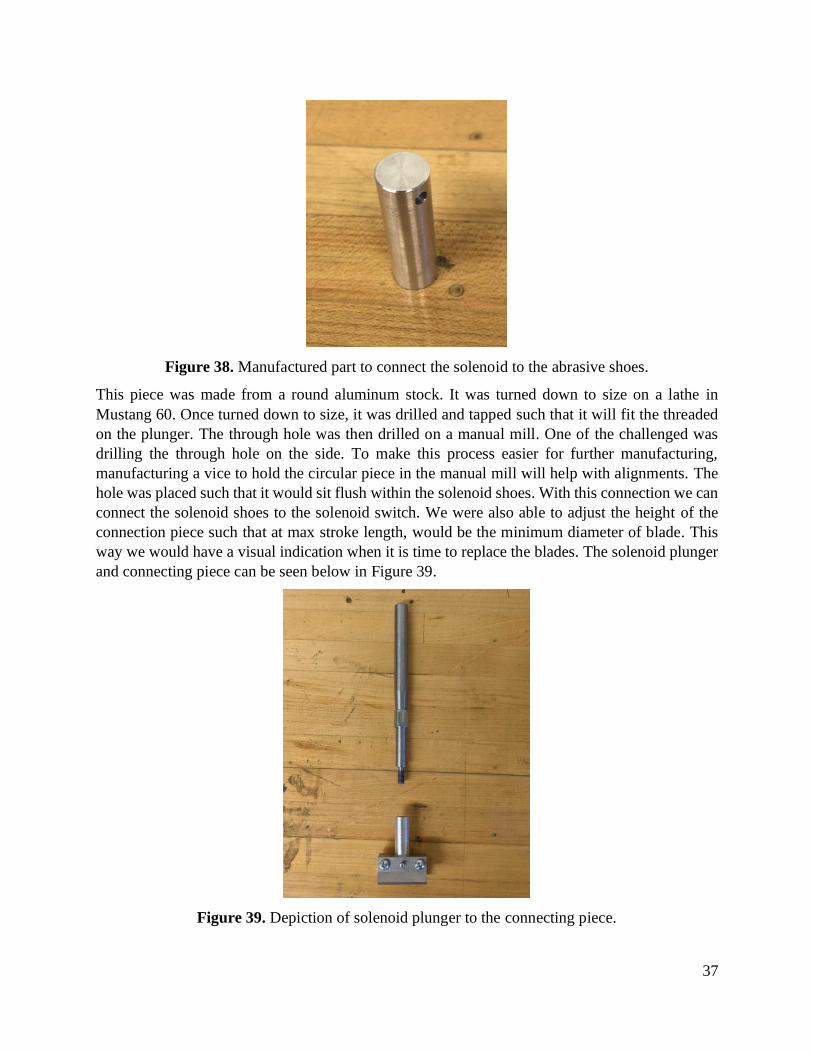
37
Figure 38. Manufactured part to connect the solenoid to the abrasive shoes.
This piece was made from a round aluminum stock. It was turned down to size on a lathe in
Mustang 60. Once turned down to size, it was drilled and tapped such that it will fit the threaded
on the plunger. The through hole was then drilled on a manual mill. One of the challenged was
drilling the through hole on the side. To make this process easier for further manufacturing,
manufacturing a vice to hold the circular piece in the manual mill will help with alignments. The
hole was placed such that it would sit flush within the solenoid shoes. With this connection we can
connect the solenoid shoes to the solenoid switch. We were also able to adjust the height of the
connection piece such that at max stroke length, would be the minimum diameter of blade. This
way we would have a visual indication when it is time to replace the blades. The solenoid plunger
and connecting piece can be seen below in Figure 39.
Figure 39. Depiction of solenoid plunger to the connecting piece.

38
As you can see in Figure 39, the solenoid plunger had to be modified, due to failure of the original
solenoid plunger breading in shear forces during testing. The part the broke due to shear was in
the skinny part of the solenoid, this a larger diameter was machined out of round steel stock. This
part was constructed on the manual lathe located in Mustang 60. The top was tapped so that it
would be able to fit a screw to secure the retention guard. The bottom was still died so that the
modified solenoid part would still be of use.
6.2.2 Fiberglass Rejection Assembly
The rubber boot will be fixed to the end of the plunger with a retainer ring, and the other end of
the boot will be attached to the lip of the plunger fitting by a similar retainer ring.
Figure 40. Depiction of boot to reject fiberglass from getting into the solenoid.
6.2.3 Shoe Assembly
To connect the abrasive pads to the solenoid, we needed to create a device to hold the abrasive
pads at the correct angle. Due to the complexity of the abrasive shoe design, we decided to
investigate different manufacturing processes rather than using a manual mill. Discussing with our
sponsor, they recommended an additive manufacturing process. This piece was manufactured by
Protolabs. The additive piece can be seen below in Figure 41.

39
Figure 41. Additive manufactured steel shoes to hold the abrasive pads.
This shoe was made of stainless steel and ordered over the summer such that it would come in
time for fall testing and the remaining bit of manufacturing. We also needed to tap the holes on
the side of the shoe so that they would be able to hold set screws that would be used to hold the
abrasive pad in place. This was challenging due to the strength of stainless steel. One
recommendation would be to make the shoes from steel or aluminum so that to would be easier to
tap. Figure 42 depicts Mark taping the holes in the shoe utilizing the manual mill in Mustang 60.
Figure 42. Mark tapping holes on the shoes for the set screws to hold the abrasive pad.
The two half shoes would be combined using bolts and nuts. This configuration can be seen in
Figure 43. This method was used instead of tapping one end of the shoe due to things we learned
about tapping the side holes to hold the abrasive pads. There are also locating pins that are used to

40
guide the shoes to the solenoid adapter. This way we can ensure that the shoes are installed
correctly as well as keep the shoes attached to the plunger.
Figure 43. Shoes assembled together using bolts and nuts.
6.2.4 Solenoid Mount Point System
The mount point assembly will fix the solenoid to the top plate via fasteners that fit into pre-
existing drilled and tapped holes in the solenoid body, and into holes drilled and tapped for ease
of removal into the top plate.
6.2.4.1 Mounting Brackets
Figure 44. Manufactured mounting bracket to connect the solenoid to the platform.
The mounting brackets were cut with a water jet located in Mustang 60 from a 12”x12” welded
steel plate down to their desired widths. They were then cut down to the required height using a
kick shear. We initially tried to use the kick shear to cut the material to length, but the material
was too thick for the machine. The corners were sanded off and the holes were drilled with an 1/8-
inch drill bit. We checked each piece to ensure that they were in line with the solenoid casing.
Below in Figure 45 you can see Esteban checking each piece to ensure that the holes were aligned.

41
Figure 45: Esteban ensuring holes on the bracket line up with the solenoid switch.
Using the manual drill press was a challenge for lining the holes up with the solenoid switch. To
keep the holes aligned with the solenoid as well as parallel to the edge of the solenoid. The sheet
metal was aligned behind the solenoids outside metal casing. There was just enough space so that
the sheet metal would be able to slip between the metal casing and the coil wrapping so that the
holes could be marked with a sharpie. This helped immensely with the alignment of the holes while
drilling.
6.2.4.2 Solenoid Platform
For the solenoid to connect to the top guard and have a place to rest on we created the top
platform that can be seen below in Figure 46.

42
Figure 46. Manufactured solenoid platform.
The part was initially going to manufactured out of sheet metal and bent to shape. After preliminary
testing with the finger break in the machine shop, we realized that we could not get the inside tab.
The solution to this was to purchase square tubing and cut the stock to the desired shape. Figure
47 shows the initial stock that we started with, cut to the appropriate size.
Figure 47. Square tubing cut down to size before the window and slit inserts.
The stock, purchased from McMaster-Carr, was cut down using a circular saw. The edges and burs
were sanded down to eliminate sharp edges. The pocket on top as well as the bottom slit were both
machined using a manual mill in Mustang 60. The pocket was dimensioned with a datum and
centered with an edge finder. Using a quarter inch end mill, the center pocket was cut. In Figure
48 depicts Mark using the manual mill to cut out the pocket.

43
Figure 48. Mark on manual mill cutting pocket in the solenoid platform.
During this process we learned about making sure to double check your dimensions, especially
when creating a symmetric hole. Fortunately, we had extra material for mistakes, and we were able
to make extra parts. To create the slot on the bottom, we flipped the orientation of the platform
180 from the orientation in Figure 48 so that the window is facing down. To clamp the square
stock, we needed to clamp it such that when the slot would be cut through that there was no force
on the sides to break the part or tool. From Figure 48, the part was fixtured at a 90 rotation from
its current state.
6.2.5 Retention Guard
Figure 49. Retention guard, net shape.

44
This retention guard main purpose is to keep the plunger from rotating during the sharpening
process. This piece was made from the same 16-gauge steel, purchased from Home Depot, that the
mounting brackets were made from. Instead of using the water jet, we used a plasma cuter to get
the steel down to length. The hole was created using a drill press. The corners were folded in using
a finger break. All these manufacturing processes were completed in Mustang 60. Below in Figure
50 depicts the clamping of the material before bending it into its shape. Once we got one bend in
the retention guard, we had complications with bending the other end to shape. We used a hammer
and a wood support to get the other bend into the guard.
Figure 50. Bending the retention guard into shape using a finger break.
6.3 Final Assembly
Each component plays an important part to the design, but it cannot stand alone to be a successful
project. Each individual assembly must come together to form the final project. Below in Figure
51 demonstrates the final assembly of the project.
Figure 51. Final Assembly of design on test bench.

45
Figure 51 shows how the guard assembly is attached to the main cutting device. The top guard is
welded to the solenoid platform. This platform also has welded mounting brackets that hold the
solenoid in place. The solenoid is connected to the shoes design that is connected to the abrasive
pads that are the main component for sharpening the device. The plunger mechanism and
connecting points can be seen in detail in the solenoid section. This overall assembly is also held
to together with bolts, nuts, set screws and pins. Each part playing an important role for the overall
design.
6.4 Manufacturing Budget
Below is the total cost for the final design of the project. The Entire budget for the used including
the cost for prototypes and other items during this process can be seen in Appendix K. With all
cost taking into consideration with the structural prototype as well as the final prototype, we had a
remaining budget of $390 with the Cal Poly Budget and $4,319 remaining with GAF’s budget.
Table 5. Purchased parts for final design prototype.
Date purchased Vendor Description of items purchased Cost
4/12/2021 Amazon TAKAHA Electromagnet Solenoid $51.79
4/12/2021 Home Depot 12 in. x 12 in. 16-Gauge Weldable Sheet $11.94
4/13/2021 Boride Engineered CS-HD SILICON CARBIDE POLISHING STONE 400 grit, 1/4 x 1/4 x 6 $49.87 5/13/2021 Home Depot 12 in. x 12 in. 16-Gauge Weldable Sheet $73.80
5/20/2021 Online Metals 1.5" x 3" x 0.12" Carbon Steel Rectangle Tube A500/A513 HR $42.59
9/23/2021 McMaster-Carr Head Hex Drive Screws M5 x 0.8 mm, 8 mm Long $11.82
9/23/2021 McMaster-Carr 18-8 Stainless Steel Button Head Hex Drive Screw 8-32 Thread $5.83 9/23/2021 McMaster-Carr Dowel Pin 316 Stainless Steel, 1/8" Diameter, 1/2" Long $8.70
9/23/2021 McMaster-Carr 18-8 Stainless Steel Flat-Tip Set Screws 4-40 Thread, 1/8" Long $6.63
9/23/2021 McMaster-Carr 316 Stainless Hex Drive Screws M3 x 0.5mm Thread, 5mm Long $3.85 9/23/2021 McMaster-Carr Zinc-Plated Steel Hex Nut Medium-Strength, Class 8, M3x0.5 mm $3.06
9/23/2021 McMaster-Carr Medium-Strength Steel Nylon-Insert Locknut Class 8 $4.15
10/7/2021 McMaster-Carr Round Bellows with Cuff Ends, Light Duty, 5/16" x 5/8" ID, 3/4" $64.27
9/28/2021 Protolabs 3D Printed Metal Abrasive Shoes Parts $585.29 10/26/2021 McMaster-Carr Aluminum Unthreaded Spacer 3/4" OD, 1/4" Long, for 3/8" $ 15.00
11/4/2021 Round Steel Stock $3.11
Total: $926.70

46
7.0 Design Verification
To verify that our slitter blade sharpening mechanism would satisfy the requirements set by GAF,
we developed a Design Verification Plan to analyze and plan every specification required. Table
5 below contains the testable specification for our design. The main objective of this device is to
sharpen the blade to a profile of 60°, which is specified in Table 5 below. To test the blade profile,
we will be using an Edge Reader at the machine shop on Campus. An additional test that we
performed was that our mechanism needs to operate at speeds between 1050 and 1550 ft/min. We
will be testing the maximum speeds of the blade’s rotation to determine if the blade can properly
cut the fiberglass rolls. Another test that was performed was the solenoid’s functionality. GAF will
provide a test bench that we will be using to test our design. Most of our tests will be conducted at
Cal Poly’s Machine Shops. The entire and detailed Design Verification Plan can be found in
Appendix H.
Table 6. Design Verification Specifications and Test Descriptions.
Test #
Specification Test
Description Measurements
Acceptance Criteria
Testing Location
1 Sharpen
Blade Profile
Design must sharpen blade accurately to desired profile of 60°
60° 60° ± 5° CP
Machine Shops
2 Variable Speed
Capability
Speed of device needs to be accommodated to operate 1050 ft/min and 1450 ft/min to sharpen the slitter blades
1050 & 1400 ft/min
Pass/No Pass
CP Machine Shops
3 Solenoid
Functionality
Evaluate failure point of the solenoid.
- Pass/ No
Pass
CP Machine Shops
4 Abrasive Pad Wear Pattern
Evaluate the wear pattern of the solenoid.
0.1 in (0.1 ± .002)
in
CP Machine Shops

47
7.1 Tests Preformed
In Table 6 we listed four of the tests that we wanted to conduct to verify the functionality of our
design. Each test meets the requirements set GAF to be a successful project. The tests were
designed around to ensure it solved the problem that GAF proposed to us.
7.1.1 Sharpen Blade Profile
7.1.1.1 Purpose and Scope of Test
The purpose of this test was to be able to relate grinding time to the blade profile angle. If the
duration of our testing (60 seconds of grinding time) was insufficient to determine improvement
in the angle of the blade, then this test will act as an indicator if the process removes material from
the blade and grinds the blade profile angle closer to 60 degrees.
7.1.1.2 Description of Test
We planned on sharpening four different blades at two different speeds. Once in hand, running the
test bench at higher speeds was deemed unsafe. It was decided that only three blades would be
tested, all at the lower speed setting.
Each test would comprise of 6 sets of 10 second grinding operations for a total of 60 seconds of
grinding on each blade. Between each 10 second grind, the height of the blade profile was
measured with digital calipers and recorded. This meant that a total of 18 height measurements
were planned on being taken. The measurement was taken from the top of the blade to where the
shoulder of the profile intersected with the sides of the blade.
Due to unexpected fatigue failure of the welds on the top guard, only 16 height measurements were
collected, leaving the test on blade #3 incomplete.
Figure 52 Picture of test bench in operation, with solenoid energized and roller in motion.

48
7.1.1.3 Collected Data
The results of this test are displayed below. The data was collected with digital calipers.
Table 7. These are the heights measured from the test on blade #1 through blade #3. Please note
that the data for blade #3 is incomplete due to the unexpected fatigue failure of the welds.
Grind Time (s) Blade 1 (in) Blade 2 (in) Blade 3 (in)
0 0.075 0.081 0.072
10 0.074 0.078 0.077
20 0.075 0.072 0.075
30 0.069 0.076 0.080
40 0.059 0.071 0.079
50 0.060 0.069 NaN
60 0.059 0.071 NaN
7.1.1.4 Analysis of Data with Error Propagation
We used the height data collected to calculate a blade profile angle. We did this by making a
couple assumptions, outlined below.
• The blade profile is symmetrical.
• The sides of the blade are flat.
Although these are simplifying assumptions, these assumptions can create an “effective” internal
blade profile angle, which can be used to approximate a rounded blade profile with a sharp angle.
This is important, as a method is needed to compare blade profiles at any point in the life of the
blade. Secondly, these assumptions allow us to use simpler tools (such as hand-held calipers)
instead of an optical comparator to be able to an effective blade angle.
Using these assumptions, and knowing the thickness of the blade, we can use trigonometry to
determine the internal angle of the blade profile.
𝜃 = 2 ∗ tan−1(ℎ
12 ∗ 𝑎
)
Using this equation, we calculated the internal angle of the blade (θ), given the height of the profile,
h and the thickness of the blade, a. We also included uncertainty calculations within this analysis.
See section 7.1.1.5 for uncertainty details.

49
Table 8. Data collected with angle calculation and error propagation.
Blade 1 Blade 2 Blade 3 (incomplete)
Test
Duration
(s)
Nominal
height
(in)
Nominal
angle
(deg)
Angle
Uncertainty
(deg)
Nominal
height
(in)
Nominal
angle
(deg)
Angle
Uncertainty
(deg)
Nominal
height
(in)
Nominal
angle
(deg)
Angle
Uncertainty
(deg)
0 0.075 75 6.8 0.081 71 6.2 0.072 77 7.2
10 0.074 76 6.9 0.078 73 6.5 0.077 74 6.6
20 0.075 75 6.8 0.072 77 7.2 0.075 75 6.8
30 0.069 80 7.5 0.076 74 6.7 0.080 71 6.3
40 0.059 89 9.0 0.071 78 7.3 0.079 72 6.4
50 0.060 88 8.8 0.069 80 7.5
60 0.059 89 9.0 0.071 78 7.3
Using the data in Table 8, the plots in Figure 53 were generated.
Figure 53. Composite plot of angle change over grinding time for each blade.
The data shown here does not show a definite trend in how the angle changed over time. The
propagated uncertainty within the data makes the results of this analysis unclear, as calculated
change in angle falls within the total propagated uncertainty for each measurement.

50
For blade #1, an increase can be seen in the nominal angle value. Due to a slight manufacturing
inconsistency, the solenoid was mounted slightly crooked, which caused the sharpening process
to over sharpen one side of the profile compared to the other side. The data taken for blade #1 was
taken on the side that was under sharpened. As a result, the calculated angle increases due to the
overall height of the under sharpened side of the blade to be lower than what was expected. We
estimate that the actual angle of the blade was being improved, but due to one of our guiding
assumptions with our calculation of the angle, our model does not reflect this.
Figure 54. Asymmetric wear pattern on the blade profile due to crooked solenoid stack.
7.1.1.5 Uncertainty Analysis
We propagated the uncertainty calculated from the profile height measurement by using the
sensitivity method. To calculate the uncertainty from the profile height, we used the traditional
equation:
The bias uncertainty was zero because the calipers were zeroed before every use. The precision
uncertainty was 0.001in, which was the approximate reading resolution assigned to the calipers.
The repeatability uncertainty was assumed to be .010in, as there was a general fluctuation in the
measurements, we took of about 0.010 in. Using the above equation, we got an overall
measurement uncertainty of 0.010 in.
Using this measurement uncertainty, we used basic trigonometry to calculate the angle of the blade
profile (as described above). To calculate the error propagation, we used the sensitivity method,
which involved finding the difference between the nominal angle and the angle plus the measured
uncertainty.

51
Since there was only one measurement used in this propagation, the sensitivity is our propagated
uncertainty.
7.1.1.6 Challenges Encountered
We encountered several challenges over the course of this test. The first challenge was a result of
flipping the solenoid over to work with the polarity of the solenoid design. This forced us to use
the skinny side of the plunger, which dramatically reduced its strength and reduced its cyclic
loading capacity. After about 60 seconds of grinding, the plunger broke. We modified the solenoid
body to accept a thicker plunger and turned a custom plunger, which worked well.
The next challenge we ran into was several of the welds on the top guard cracking due to excessive
vibrations. These excessive vibrations were caused by the roller being cut out of round with respect
to the axis of the hub. This caused about an 1/8” vibration amplitude, which added significant
cyclic stress to the welds due to the solenoid stack being oriented horizontally.
Finally, we noticed asymmetric grinding patterns on the profile of the blade. This is due to a slight
misalignment of the solenoid stack with respect to the rotating plane of the blade.
7.1.2 Variable Speed Capability
The purpose of this test was to validate that the prototype would be able to sharpen the profile of
the blade at a range of 1050 ft/min to 1500 ft/min. This speed correlates to the minimum and
maximum speeds that would be seen at GAF’s factory. The scope of this test was to ensure that
the blade would be sharpened in the allotted time and would be able to cut the fiberglass mat
material.
Due to failure of the structural prototype during the sharpening blade profile section of testing, the
variable speed test was not performed. If the structural prototype did not fail during the initial
testing, this is how we would have performed the test.
First, we would have set the test bench and sharpening mechanism up to mimic the conditions that
we would see on the fiberglass line. Figure 55 below is a depiction of the setup for the test bench
and structural prototype.
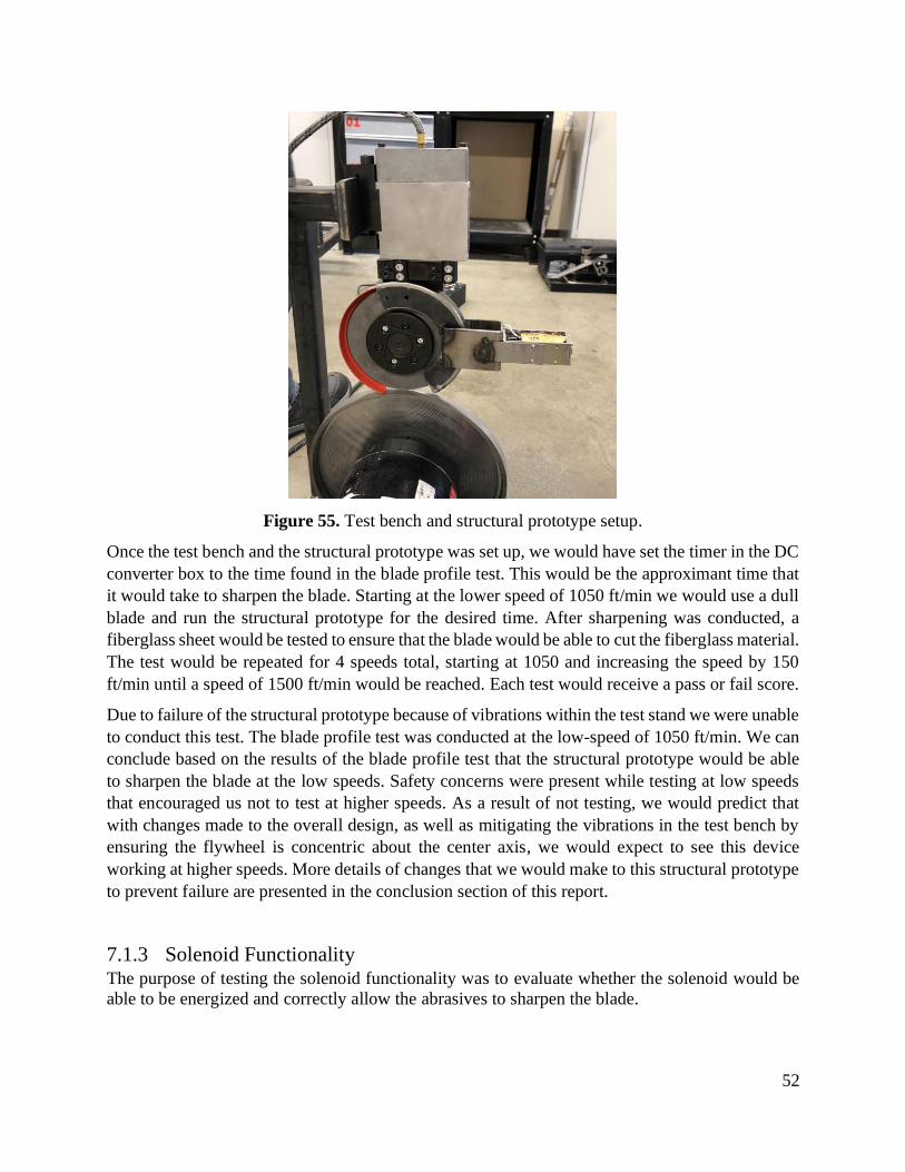
52
Figure 55. Test bench and structural prototype setup.
Once the test bench and the structural prototype was set up, we would have set the timer in the DC
converter box to the time found in the blade profile test. This would be the approximant time that
it would take to sharpen the blade. Starting at the lower speed of 1050 ft/min we would use a dull
blade and run the structural prototype for the desired time. After sharpening was conducted, a
fiberglass sheet would be tested to ensure that the blade would be able to cut the fiberglass material.
The test would be repeated for 4 speeds total, starting at 1050 and increasing the speed by 150
ft/min until a speed of 1500 ft/min would be reached. Each test would receive a pass or fail score.
Due to failure of the structural prototype because of vibrations within the test stand we were unable
to conduct this test. The blade profile test was conducted at the low-speed of 1050 ft/min. We can
conclude based on the results of the blade profile test that the structural prototype would be able
to sharpen the blade at the low speeds. Safety concerns were present while testing at low speeds
that encouraged us not to test at higher speeds. As a result of not testing, we would predict that
with changes made to the overall design, as well as mitigating the vibrations in the test bench by
ensuring the flywheel is concentric about the center axis, we would expect to see this device
working at higher speeds. More details of changes that we would make to this structural prototype
to prevent failure are presented in the conclusion section of this report.
7.1.3 Solenoid Functionality The purpose of testing the solenoid functionality was to evaluate whether the solenoid would be
able to be energized and correctly allow the abrasives to sharpen the blade.
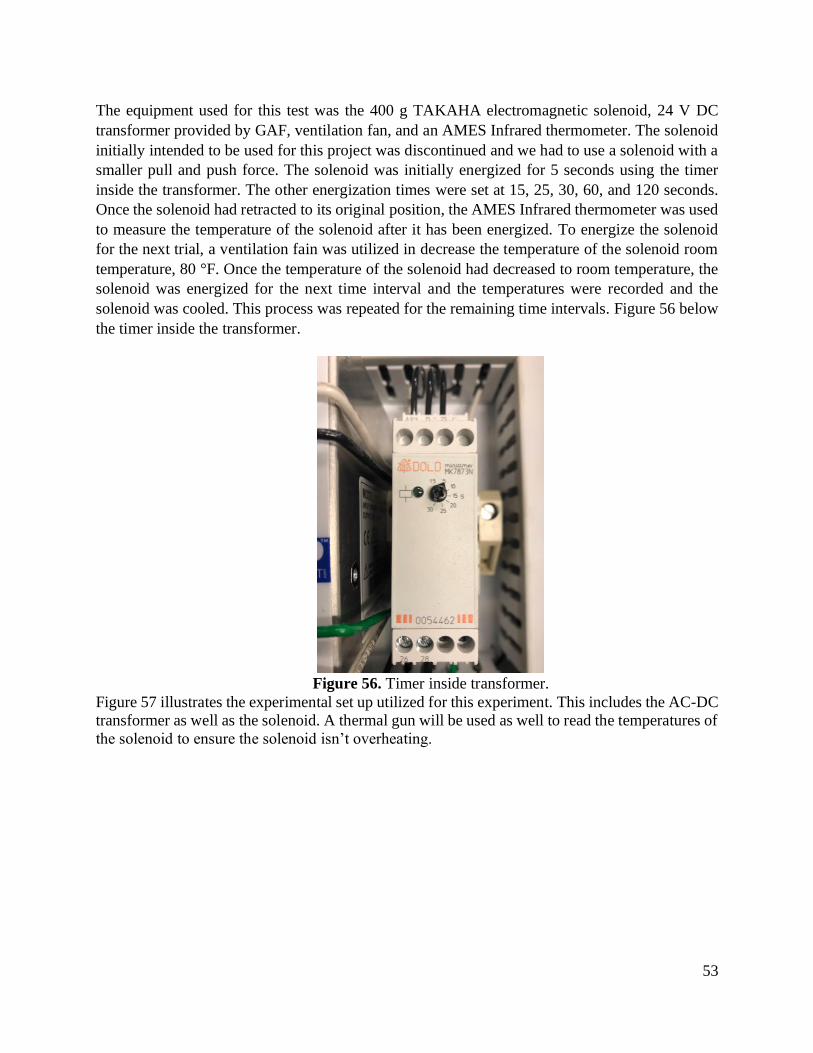
53
The equipment used for this test was the 400 g TAKAHA electromagnetic solenoid, 24 V DC
transformer provided by GAF, ventilation fan, and an AMES Infrared thermometer. The solenoid
initially intended to be used for this project was discontinued and we had to use a solenoid with a
smaller pull and push force. The solenoid was initially energized for 5 seconds using the timer
inside the transformer. The other energization times were set at 15, 25, 30, 60, and 120 seconds.
Once the solenoid had retracted to its original position, the AMES Infrared thermometer was used
to measure the temperature of the solenoid after it has been energized. To energize the solenoid
for the next trial, a ventilation fain was utilized in decrease the temperature of the solenoid room
temperature, 80 °F. Once the temperature of the solenoid had decreased to room temperature, the
solenoid was energized for the next time interval and the temperatures were recorded and the
solenoid was cooled. This process was repeated for the remaining time intervals. Figure 56 below
the timer inside the transformer.
Figure 56. Timer inside transformer.
Figure 57 illustrates the experimental set up utilized for this experiment. This includes the AC-DC
transformer as well as the solenoid. A thermal gun will be used as well to read the temperatures of
the solenoid to ensure the solenoid isn’t overheating.

54
Figure 57. Experimental set up of solenoid functionality test.
Once we got all the tests, we wanted to illustrate the temperature change of the solenoid over a
time as the experimented was conducted. The results can be seen below in Figure 58.
Figure 58. Solenoid Temperature compared to operation time.
The trendlines in Figure 58 suggests that the temperature of the solenoid will simply continue to
increase operation time increases, but we do not predict the operators of this device at GAF to be
running the sharpening mechanism for more than 60 seconds at time, for which case the maximum
temperature that the solenoid reached at 60 seconds was 134.6 ° F. Table 9 shows the tabulated
data collected for this experiment.

55
Table 9. Temperature of solenoid during operation time.
Operation Time (sec)
Solenoid Temperature
(° F)
Trial 1 5 86.7
Trial 2 15 94.2
Trial 3 25 102.2
Trail 4 30 107.7
Trial 5 60 134.6
Trail 6 120 167.2
Furthermore, according to the manufacturer of the solenoid, the solenoid was rated at 100% duty
cycle. This is further emphasized by the observations collected during the experiment such the fact
that there was no smoke and the solenoid did not stall during the operation time. After conducting
this experiment, the solenoid overheating is not an issue that concerns GAF.
7.1.4 Abrasive Pad Wear Pattern
The purpose of this test was to provide GAF with a calculated indication of how much use could
be granted from a single pair of abrasive pads. From the results, the employees in the assembly
line could have a gauge as to when it is time to replace the abrasive pads. Please note that the
abrasive pad life is limited by the undesired contact with the shoe. While abrasive pad material
exists inside the shoe’s rectangular cavity, it is not ideal to run the sharpening in such a way that
would enable direct contact between a slitter blade and the abrasive shoes.
To perform this test, a pair of abrasive pads were running for one minute of sharpening while a
second pair of abrasive pads ran for two minutes. At the end of each run, digital calipers were used
to measure the decreasing thickness of each pad. Figure 59 shows the abrasive pads after being
subjected to the sharpening system.

56
Figure 59. Abrasive pads sharpened for 1 minute (LEFT) and 2 minutes (RIGHT).
Notice that the abrasive pads are subjected to wear predominantly along the central portion of the
pad’s length as marked with the red ellipses. This is because the slitter blades align concentrically
with respect to the abrasive pad’s length. Also, the abrasive pads that were ran for 2 minutes show
more signs of wear as opposed to the pads who were ran for 1 minute.
Due to the system failing prematurely, only three data points were recorded. This includes a
measurement of the pads thickness as received from the manufacturer, as well as their decreasing
thickness for the two increments of run time. Table 10 shows the experimental recordings during
the testing phase of the abrasive pad life.
Table 10. Abrasive pad test data comparing decreasing thickness as a function of time.
Run No.
Run Time, t (min.)
Pad 1 Thickness,
t (in.)
Pad 2 Thickness,
t (in.)
Average Thickness,
tavg (in.)
1 0 0.25 0.255 0.2525
2 1 0.239 0.248 0.2435
3 2 0.2365 0.2455 0.241
Notice that from the manufacturer, there was some variation in the nominal thickness of the
abrasive pads. But more importantly, the average thickness seen at the right most column verify
that the abrasive pads decrease with time. This is acceptable and to be expected for any blade in
operation.
Figure 60 seen below shows the graphical representation of the decreasing thickness of each pad
as a function of time. The plot superimposes the data for Pad 1, Pad 2, and for the Average
Thickness.
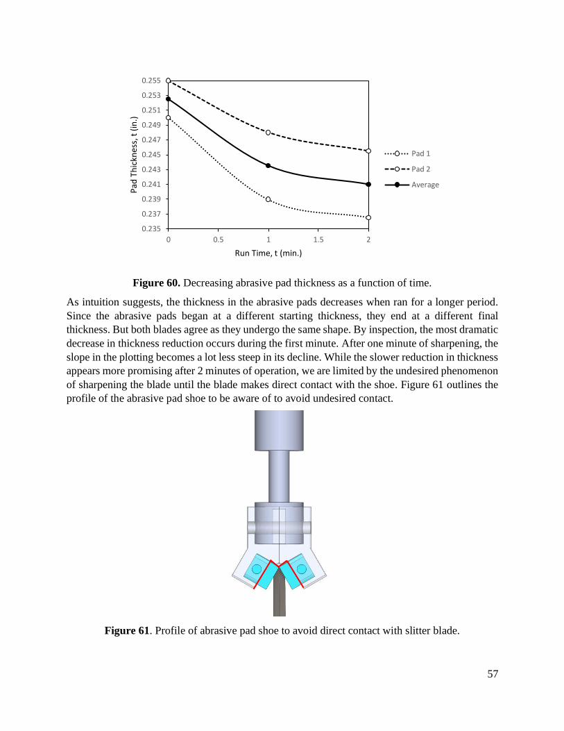
57
Figure 60. Decreasing abrasive pad thickness as a function of time.
As intuition suggests, the thickness in the abrasive pads decreases when ran for a longer period.
Since the abrasive pads began at a different starting thickness, they end at a different final
thickness. But both blades agree as they undergo the same shape. By inspection, the most dramatic
decrease in thickness reduction occurs during the first minute. After one minute of sharpening, the
slope in the plotting becomes a lot less steep in its decline. While the slower reduction in thickness
appears more promising after 2 minutes of operation, we are limited by the undesired phenomenon
of sharpening the blade until the blade makes direct contact with the shoe. Figure 61 outlines the
profile of the abrasive pad shoe to be aware of to avoid undesired contact.
Figure 61. Profile of abrasive pad shoe to avoid direct contact with slitter blade.
0.235
0.237
0.239
0.241
0.243
0.245
0.247
0.249
0.251
0.253
0.255
0 0.5 1 1.5 2
Pad
Th
ickn
ess
, t (
in.)
Run Time, t (min.)
Pad 1
Pad 2
Average

58
Since an insufficient amount of data was collected during the experiment, the abrasive pads were
not running to their full use. However, this test shows that the abrasive pads can be ran for a
minimum of two minutes. At the end of the second run, all abrasive pads showed to have plenty
of life left so it is anticipated that the abrasive pads could be ran for at least 1 minute more, 3
minutes total. Be mindful that this test was conducted using GAF’s provided test bench that
introduced a considerable amount of vibration. Also, the conclusions for this test were made
possible by treating a separate pad from each run time as a single pad. For example, the data points
collected in Figure 60 for Pad 1 were the measurements from two separate pads as opposed to the
same pad ran for two different run times. If premature failure had not occurred, a better
representation of the abrasive pad wear could have been conducted.
7.2 Lessons Learned from Testing
During testing of the prototype there were key takeaways from this process. The first takeaway
was the importance of vibrations seen by the mechanism. We were not concerned by any vibrations
during the design stages of the device due to the lines being smooth in GAF’s factory. With the
test bench we were seeing an increasingly amounts of vibrations that lead to failure of the deceive
in multiple locations. The first failure that was seen was in the plunger. This failure was due to the
vibrations and shear force. We didn’t see this being a failure mode at first due to the idea that we
wanted to use the larger cross section area of the solenoid and didn’t see shear as a failure mode.
This resulted in us creating a modified solenoid by increasing the cross-sectional area of this failure
region. The last failure that leads us to stop testing completely due to safety reasons was the
cracking of the top guard. We believe that this cracking was due to the vibrations as well but also
prompted us to make recommendations for design changes to that the top guard would be thicker
as well as have more surface areas for welding. We did learn that the concept of the structural
prototype was maintained. The actuating motion of the solenoid to sharpen the blade was satisfied
as we did see material being removed from the blade. Seeing the shine of the blade was a visual
indicator to us that the blade was being sharpened.
8.0 Project Management
This project went through three main segments: design, build and test. Each segment correlated to
each quarter of the Cal Poly ten-week school schedule. Project management tools, including a
Gantt Chart in Appendix B, were implemented to keep the project organized and on track for
deadlines. Our key dates and deliverables over the course of this project are listed below in Table
11.

59
Table 11. Project deliverables.
Deliverable Due Date
Scope of Work 2/4/2021
Conceptual Model 2/11/2021
Conceptual Prototype 2/23/2021
Preliminary Design Review (PDR) 3/5/2021
Critical Design Review (CDR) 5/6/2021
Manufacturing & Test Review 6/3/2021
Manufacturing on Test Verification Prototype 10/14/2021
Testing on Test Verification Prototype 11/4/2021
Final Design Report (FDR) 11/17/2021
Expo 11/19/2021
The design process began with the research and understanding of existing blade sharpeners that
are on the market. This led us to have a better understanding of current devices on the market. This
helped the team define the project and have a better understanding of the project that the customers
desire. The use of a House of Quality index, in Appendix A, helped us compare the customers'
requirements with the current available projects and metrics that can be used to validate these
requirements.
The next milestone in this project was preliminary design review (PDR). To prepare for PDR, the
team went through the ideation process. In this ideation process the team began brainstorming the
different solutions to meet the sponsors' requirements. In the ideation process, the team developed
conceptual models that will be used to evaluate the best solution. Computer aided design software
was used to get a visualization of what the final design would look like. The team then used 3D
printers as well as the on-campus machine shop to create a structural prototype that was used to
get a better idea of the manufacturing process as well as the functionality of the design.
After the critical design review (CDR) with GAF, the team moved to building and verifying the
prototype. As this was our last quarter on the project, a tight deadline was needed to stay on project.
It was beneficial to have a team member in charge of all deadlines and responsibilities that needed
to be completed by the team. This member was also responsible for assigning tasked based on the
skill that each team member had and their contributions to the project. Having this one member
know all the deadlines and requirements made it an easy reference for the other team members as
well allowed the team to focus on the tasked assigned with their own internal deadline.
Overall project management is a very important part of the design process. The team didn’t realize
the importance of assigning a project manager early in the design stages on order to stay on top of
deadlines. It was only until the last quarter that this was implemented to ensure the project was
kept on track. To organize all material used for this class, a mixture of OneNote and Google Drive
was used to store information. From what we learned from this project to use in future projects
would be the importance of the organizational tools that you use. It is important to label your files

60
and folders with a purposeful title so that you are not spending time trying to find an old document
because it was poorly labeled. Each person likes to organize and keep track of things their own
way. Thus, it is important to ensure that each team member agrees on the organization and how
files and information would be found.
9.0 Conclusion
Reflecting back to the beginning of the project, it was our goal to create a device that would sharpen
the blade profile to the desired 60 angle while running it on an online operation. We designed a
device that is capable of creating the desired angle as well as a frame that would allow GAF to
attach it to their current online setup. The team wanted to utilize the current bolt holes that were
available on their blade mechanism in order to make minimal changes to their current device. We
were also able to test the grit of the abrasive as well ensure that a sharpening process was achieved.
It was a goal of the team to keep the overall cost of the device to a minimum due to the multiple
devices that they wanted to create for each cutting tool.
Things that the project didn’t achieve was the longevity of the prototype. The team started to see
cracking of the material during the testing phase of the project due to the unpredicted vibration
due asymmetry of the flywheel on the test bench. The team also went through different iteration
for the solenoid as each component experienced failure due to a misunderstanding of the physics
associated with a solenoid. There was also a miscommunication and miscalculation with the
spacing that the top guard that would allow the blade to slip under the guard for installation. Due
to this underestimate, the blade was not able to be installed with the top guard on, thus modification
was needed in order for it to be secured to the cutting mechanism.
During the testing phase, the team ran into some issues of concern. The flywheel when installed
was not fully concentric with the center of the collar causing vibrations to occur in the test bench.
This caused the test bench to create vibrations that would cause the machine to vibrate at higher
speeds. Due to this concern, the team placed steel plates around the device to hold it in place during
lower speed tests. This did not stop the vibrations of the prototype but did prevent the test bench
from moving. Thus, there were a few failures that were observed, resulting in the immediate stop
of testing due to safety concerns.
After the completion of the testing and design phase, there are design recommendation that we
would have if we had to do the project over again.
The first unplanned modification was tack welding bolts to the back side of the bottom guard so
that we could access the bolts from the outside of the prototype. The reason we did this was because
we could not slide the blade into place without interference with the top guard. Thus, in order to
replace the blades, we would need to remove the top and bottom guard before replacing the blade.
To fix this issue, we would recommend increasing the thickness between the back and front guard
plates so that there is enough space to slide a blade up into place without removing the guard.

61
Figure 62. Increasing the thickness of the guard as shown so that it is above the circular clamp
of the blade.
The second complication that the team faced was the orientation of the solenoid. The advertising
of the solenoid indicated that it was a “push pull solenoid” thus the team thought that flipping the
polarity wires of the solenoid would also flip the magnetic field of the solenoid. The team planned
to modify the solenoid by flipping the retention spring to the other side of the solenoid and we
would be able to use the larger diameter of the solenoid. During initial testing of the solenoid to
ensure that our theory was correct, we realized that it didn’t matter the polarity of the wires, the
magnetic field would always be in the same direction. This the team decided to flip the solenoid
and create an attachment for the other end of the solenoid. The other side of the solenoid had a
significantly smaller cross-sectional area. As a result, during testing the solenoid failed due to shear
stress. The solution to this was to create a new plunger with a larger cross-sectional area. The
modified plunger can be seen below in Figure 63.
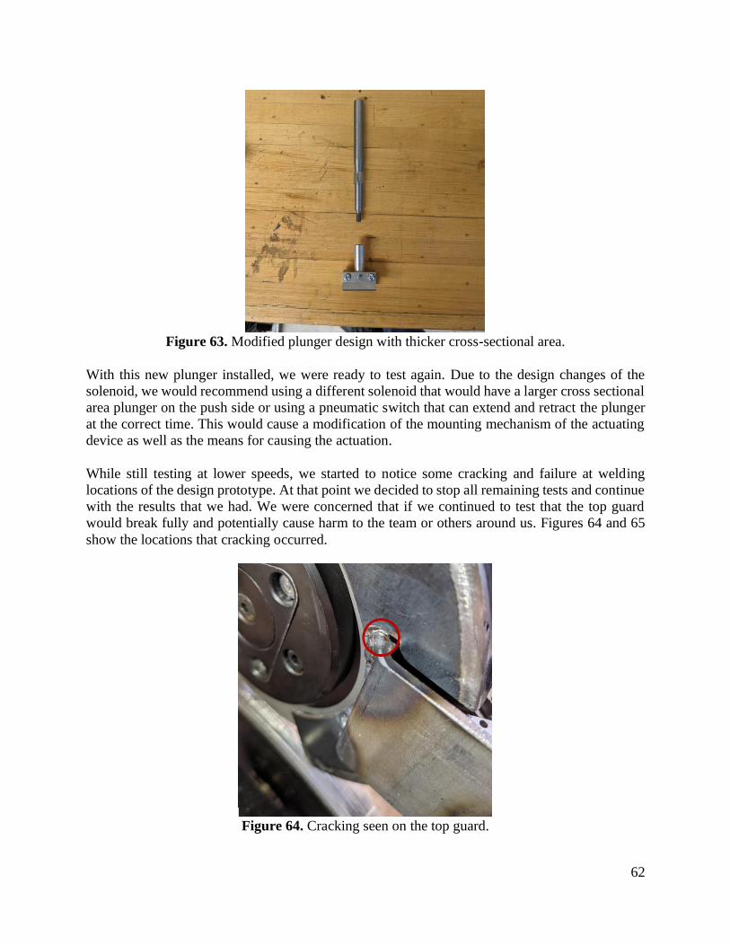
62
Figure 63. Modified plunger design with thicker cross-sectional area.
With this new plunger installed, we were ready to test again. Due to the design changes of the
solenoid, we would recommend using a different solenoid that would have a larger cross sectional
area plunger on the push side or using a pneumatic switch that can extend and retract the plunger
at the correct time. This would cause a modification of the mounting mechanism of the actuating
device as well as the means for causing the actuation.
While still testing at lower speeds, we started to notice some cracking and failure at welding
locations of the design prototype. At that point we decided to stop all remaining tests and continue
with the results that we had. We were concerned that if we continued to test that the top guard
would break fully and potentially cause harm to the team or others around us. Figures 64 and 65
show the locations that cracking occurred.
Figure 64. Cracking seen on the top guard.
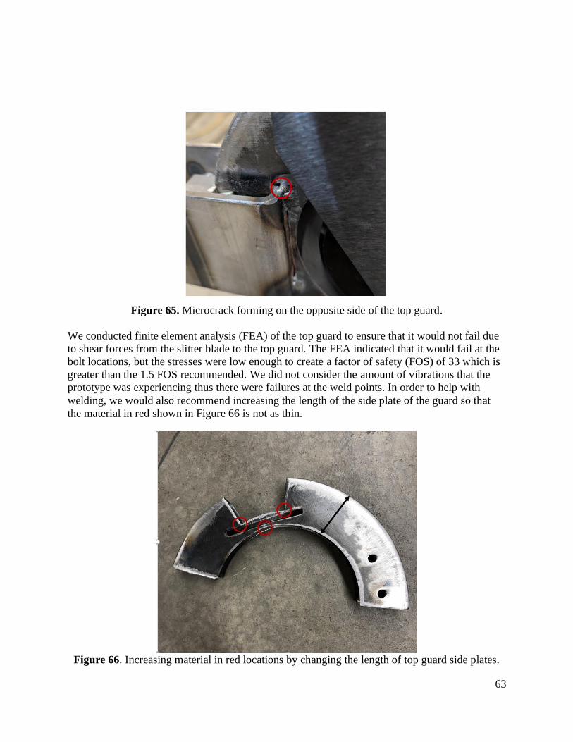
63
Figure 65. Microcrack forming on the opposite side of the top guard.
We conducted finite element analysis (FEA) of the top guard to ensure that it would not fail due
to shear forces from the slitter blade to the top guard. The FEA indicated that it would fail at the
bolt locations, but the stresses were low enough to create a factor of safety (FOS) of 33 which is
greater than the 1.5 FOS recommended. We did not consider the amount of vibrations that the
prototype was experiencing thus there were failures at the weld points. In order to help with
welding, we would also recommend increasing the length of the side plate of the guard so that
the material in red shown in Figure 66 is not as thin.
Figure 66. Increasing material in red locations by changing the length of top guard side plates.

64
The locations circled in red are the places where we saw challenges for weddings as well as the
locations where we saw cracking of the top guard. If there is more surface area in those locations
it would help with welding as well as decreasing the chances for cracking. We also intended the
welds to extend across the entire base of platform. Due to the lack of material, only tack welds
were possible. If we could redo this project adding more material would allow us to create a line
of weld beads.
Overall, we were pleased that we could create a design that would help GAF towards creating a
reliable sharpening device. We are also pleased that we were able to start initial testing of the
device as well as expose failure points in the test bench as well as the overall prototype. We would
like to thank our sponsor GAF and Javier for opportunity to create and test this device. We would
also like to thank Cal Poly and our coach Dr. Rossman for guiding us during this project.

65
References
[1] “GAF: About us.” [Online]. Available: https://www.gaf.com/en-us/about-us. [Accessed: 17-
Feb-2021].
[2] “PQA-DF-30 Holder Archives,” Dienes USA. [Online]. Available: https://www.dienesusa.com,
1/31/2021.
[3] “DigitalCommons@CalPoly: California Polytechnic State University, San Luis Obispo
Research,” Digital Commons Cal Poly. [Online]. Available: https://digitalcommons.calpoly.edu,
1/15/2021.
[4] Saw, C. (2020, May 18). MVM LA500 Rotary Surface and circular knife grinder. Retrieved January
28, 2021, from https://www.csaw.com
[5] Saw, C. (Director). (2020, January 23). Businaro CK300-TH Circular Knife Grinder [Video file].
Retrieved January 29, 2021, from https://www.youtube.com
[6] Saw, C. (2020, May 18). CNC twin head circular knife grinder for double bevel knives under 12".
Retrieved January 31, 2021, from https://www.csaw.com
[7] Gotteswinter, S. (Director). (2017, October 7). Resharpening slitting saws [Video file]. Retrieved
January 29, 2021, from https://www.youtube.com
[8] Gotteswinter, S. (n.d.). Knuth KSW 200 tool- and cuttergrinder. Retrieved January 31, 2021, from
https://gtwr.de/knuth-ksw-200-tool-and-cuttergrinder/
[9] Magic, S. (n.d.). LAZER EDGE -450. Retrieved January 31, 2021, from
https://5.imimg.com/data5/VD/PR/LM/SELLER-2809253/lazer-edge-tct-hss-circular-saw-
sharpening.pdf
[10] Magic, S. (Director). (2020, April 13). Saw Blade Sharpening Machine - HSS Saw Blade Sharpener
Machine, Sharpening Machine. [Video file]. Retrieved January 29, 2021, from
https://www.youtube.com
[11] (n.d.). 120 Volt Circular Saw Blade Sharpener. Retrieved January 31, 2021, from
https://www.amazon.com
[12] (n.d.). 220V Electric Circular Saw Blade Sharpener Water Injection Grinder Machine. Retrieved
January 31, 2021, from https://www.amazon.com
[13] “US20120184186A1 - Blade sharpening system and method,” Google Patents. [Online]. Available:
https://patents.google.com/patent/US20120184186A1/en, 1/15/2021.
[14] “US2998683A - Tool holding and sharpening device,” Google Patents. [Online]. Available:
https://patents.google.com/patent/US2998683A/en, 1/16/2021.
[15] “US3766806A - Saw sharpening device,” Google Patents. [Online]. Available:
https://patents.google.com/patent/US3766806A/en, 1/16/201.
[16] “US2993312A - Blade sharpening device,” Google Patents. [Online]. Available:
https://patents.google.com/patent/US2993312A/en, 1/16/2021.
[17] “US8448340B2 - Large diameter notched blade and blade housing for power operated rotary
knife,” Google Patents. [Online]. Available: https://patents.google.com/patent/US8448340B2/en,
1/16/2021
[18] C. Carmignani, P. Forte, and E. Rustighi, “Experimental simulation of the sharpening process of a
disc blade and analysis of its dynamic response,” Journal of Sound and Vibration, 21-Jun-2006.
[Online]. Available: https://www.sciencedirect.com
[19] A. C. F. Barbosa, G. R. O. Costa, V. Angyalossy, T. C. D. Santos, and M. R. Pace, “A simple and
inexpensive method for sharpening permanent steel knives with sandpaper,” Brill, 05-Nov-2018.
[Online]. Available: https://doi.org. [Accessed: 02-Feb-2021].

66
[20] R. W. McGorry, P. C. Dowd, and P. G. Dempsey, “The effect of blade finish and blade edge angle
on forces used in meat cutting operation,” Science Direct, Jan-2005. [Online]. Available:
https://doi.org [Accessed: 17-Jan-2021].
[21] ASTM International. A681-08(2015) Standard Specification for Tool Steels Alloy. West
Conshohocken, PA; ASTM International, 2015. doi: https://doi-org.ezproxy.lib.calpoly.edu
[22] Verhoeven, J. D. (2004). Experiments on Knife Sharpening (pp. 1-55, Rep. No. 1). Ames, IA: Iowa
State University. Retrieved January, 2021, from https://www.relentlessknives.com

A-1
Appendix A - QFD
Revised Quality Function Deployment (QFD) for development of sharpening system.

B-1
Appendix B – Gantt Chart
Winter Quarter 2021 to SOW

B-2
Post SOW- End of Winter Quarter

B-3
Spring Quarter 2021

B-4
Fall 2021-2022

C-1
Appendix C – Ideation
Jam board
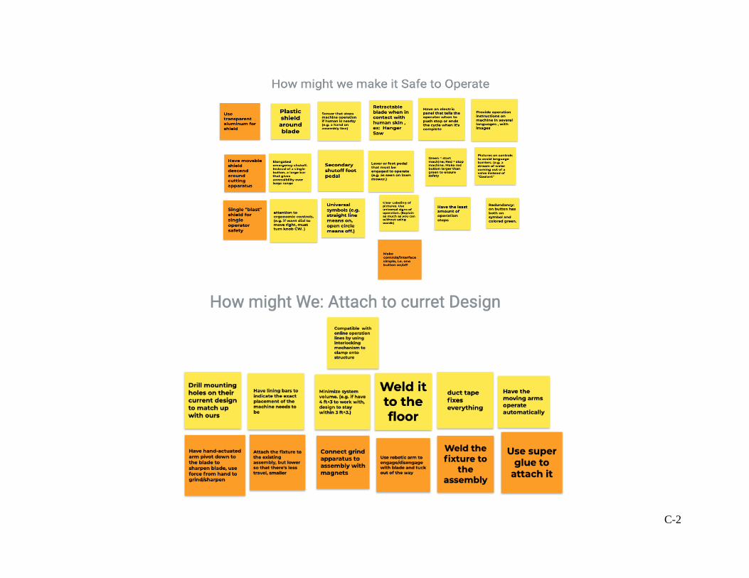
C-2

C-3
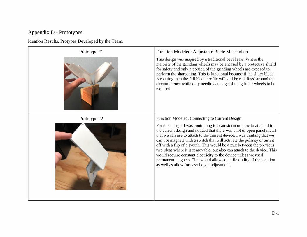
D-1
Appendix D - Prototypes
Ideation Results, Protypes Developed by the Team.
Prototype #1
Function Modeled: Adjustable Blade Mechanism
This design was inspired by a traditional bevel saw. Where the
majority of the grinding wheels may be encased by a protective shield
for safety and only a portion of the grinding wheels are exposed to
perform the sharpening. This is functional because if the slitter blade
is rotating then the full blade profile will still be redefined around the
circumference while only needing an edge of the grinder wheels to be
exposed.
Prototype #2
Function Modeled: Connecting to Current Design
For this design, I was continuing to brainstorm on how to attach it to
the current design and noticed that there was a lot of open panel metal
that we can use to attach to the current device. I was thinking that we
can use magnets with a switch that will activate the polarity or turn it
off with a flip of a switch. This would be a mix between the previous
two ideas where it is removable, but also can attach to the device. This
would require constant electricity to the device unless we used
permanent magnets. This would allow some flexibility of the location
as well as allow for easy height adjustment.

D-2
Prototype #3
Function Modeled: Connecting to Current Design
For my first concept model, I focused on the “Attach to existing
design” aspect of our function tree. This concept is a design that
would roll up to their current line and be able to sharpen the blades.
This would allow the user to move it off the line and not to interfere
with their current set up. When thinking about this design, it would be
easier to get it out of the way, but also has some negative aspects. This
design would have to have some aligning tools to ensure it doesn’t hit
the blade when approaching the design. Also, if it is removable, the
design would have to work around the safety guards that are currently
in place. Thinking about this design as well, we would have to ensure
that the weight is evenly distributed so that it doesn’t tip over when
sharpening. This might not also be feasible for blades that are in hard-
to-reach areas. This led me to think about different ways that we can
attach to the current design that is more that attaches to their current
set up and not something that approaches it.
Prototype #4
Function Modeled: Connecting to Current Design
After being inspired from my first idea, I wanted to attach it to their
current setup. On their device there’s a gap that might be a good place
for a mounting location. There might be enough space for 2 pieces of
steel to slide over and then have a bolt there to sandwich the two
together to create a clamping force and then we can build up from
there. The only issue that I saw with this is the amount of space that we have available, especially because it close to the blade that is
varying with diameter based on the sharpness of the blade, there might
not be enough space to have it attach there. This led me to think about
different mounting locations of there are different screw hole locations
that are predrilled that we can tap into.

D-3
Prototype #5
Function Modeled: Connecting to Current Assembly
If the slitter blades used by GAF come with a keyway at the center,
the keyway itself can be used as a locking mechanism from a
shaft/motor.
Prototype #6
Function Modeled: Debris Collection
Consider that in a typical gasoline car, several components like the
alternator, power steering pump and water pump are driven by the
very rotation of the engine with the use of a serpentine belt. Also
recall that the use of a flood lubricant system is useful in machining
because it removes any unwanted debris and cools the system. If the
grinding wheel(s) or blades will be spinning, a pump to circulate a
lubricant can be powered by the very rotation of the grinding wheel(s)
or blades. In this prototype, the shaft seen at the far left would be the
input shaft from the same motor that drives the grinding wheels or
blades. Where the coolant can fall to a reservoir by gravity and be
picked up by an inlet (orange straw) and streamed onto the grinder
and blade at the outlet (green straw).

D-4
Prototype #7
Function Modeled: Connect to Existing Assembly
My idea was to slip it over the rectangular air cylinder, and either fit it
on by friction or spot weld it into place. The protruding popsicle stick
would pivot about its connection point on the attached popsicle stick
to sharpen the blade. One thought I had was that it may not be
possible to weld to the air cylinder due to thermal warping that may
occur. An idea that I had stemming from this is to use a lead screw or
spring instead of a swinging arm to engage the abrasive with the
blade.
Protype #8
Function Modeled: Adjustable Blade Mechanism
The main concept of this idea is to position the grinding mechanism
between the air cylinder and the blade and have a servo motor
(represented as a cotton ball) turn a screw (the labeled wood popsicle
stick) which extends the abrasive into the blade. The abrasive is
represented with the partial popsicle stick with the groove. I learned
that this wouldn’t account for a shrinking blade diameter as the blade
gets sharpened, and it would introduce wear patterns into the abrasive
that would hinder future accurate sharpening.
Idea #2

D-5
Prototype #9
Function Modeled: Connecting to Existing Assembly
This idea is pretty like idea #2, but instead of holding on with
friction it would be continuously welded to the air cylinder, and a
lead screw would be used to engage the abrasive with the blade.
The added benefit of using this configuration is that the abrasive
position relative to the blade can be modified with added
hardware, and that it can account for differing diameters. Another
idea that came from this model is to simply spot weld or use
magnets and attach it to the front face of the air cylinder, instead of
welding it to the sides and using a secondary arm to attach the
abrasive to the cylinder.
Idea #4
Prototype #10
Function Modeled: Adjustable Mount onto Exiting Assembly Line
This idea shows a thin blade that is adjustable and be easily moved to
sharpen GAF’s blades as desired.

E-1
Appendix E – Pugh Matrix
Pugh Matrix for Sharpen Profile function

E-2
Pugh Matrix for Collect Debris function
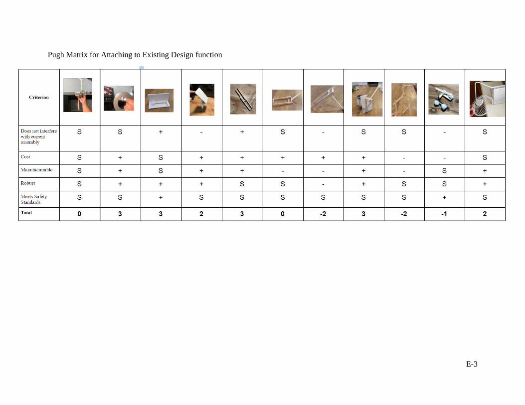
E-3
Pugh Matrix for Attaching to Existing Design function

E-4
Pugh Matrix for Safe Operation
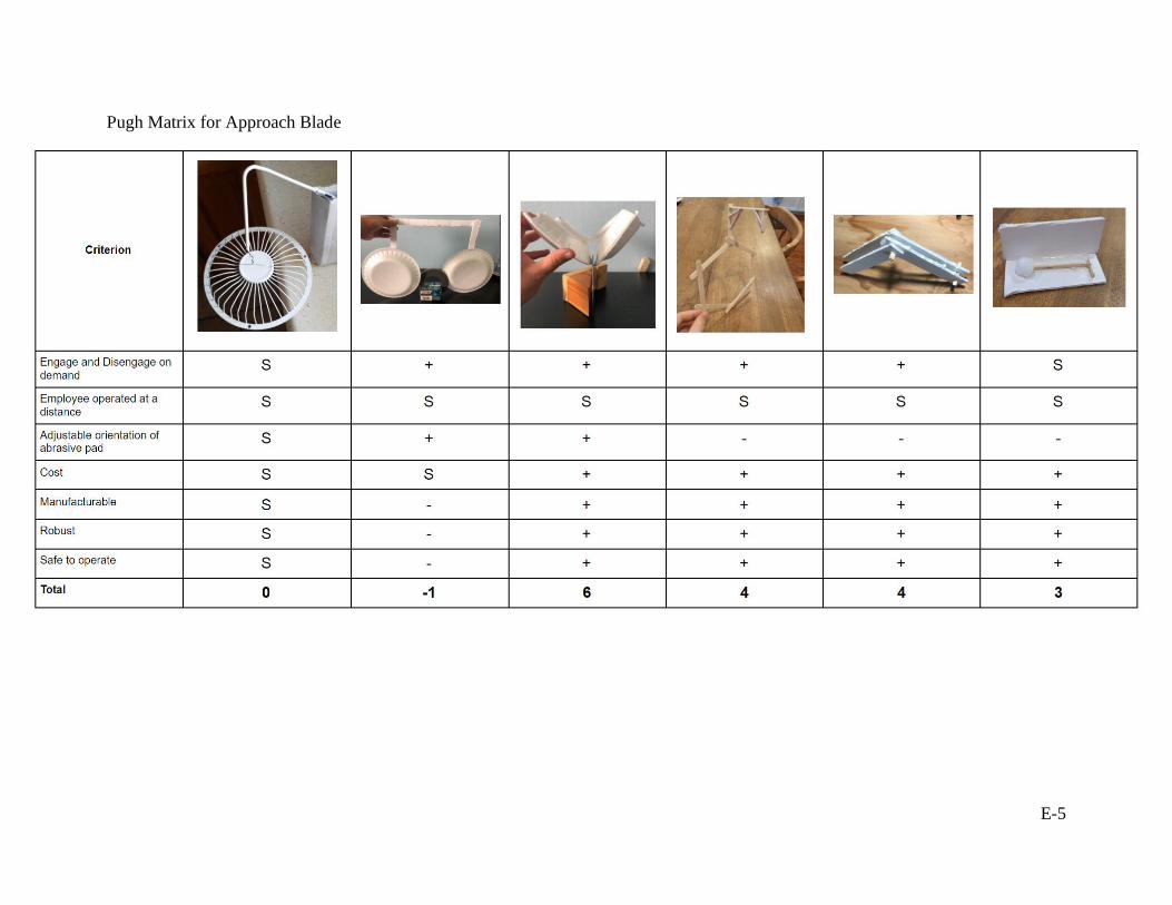
E-5
Pugh Matrix for Approach Blade

F-1
Appendix F – Morphological Matrix
Morphological Matrix of 5 Main Ideas

F-2

G-1
Appendix G – Weighted Decision Matrix
Weight Decision Matrix

H-1
Appendix H - Design Verification Plan

I-1
Appendix I – Intended Bill of Materials

J-1
Appendix J – Drawing Package for Design

DRAWING TITLE SLITTER BLADE SHARPENER
Scale:
CHECKED BY <INSERT NAME>
11/22/21
<DATE>
MARK BREAUX
0000
X.XXXX =
.01
X.XXX = THIS DRAWING SHOULD BE INTERPRETED PER ASME Y14.5-2018
Part No.
.0005
DRAWN BY
MATERIAL
.005
Default Tolerances
X.X = .1
X.XX =
1:2
ITEM NO. PART NUMBER DESCRIPTION QTY.
1 N/A DIENES BLADE ASSEMBLY 1
2 1000 BLADE GUARD ASSEMBLY 1
3 2100 SHOE ASSEMBLY 1
4 2300 CLAMPING ASSEMBLY 1
5 2200SOLENOID STACK WITHOUT
SHOES1
4
1
2
5
3
SOLIDWORKS Educational Product. For Instructional Use Only.

BLADE GUARD ASSEMBLY
Scale:
CHECKED BY BRADLEY SMITH
7/24/21
7/25/21
MARK BREAUXDRAWN BY
DRAWING TITLE
.0005
1000
.01
Part No.
X.XXX = THIS DRAWING SHOULD BE INTERPRETED PER ASME Y14.5-2018
MATERIAL
.005
X.XXXX =
Default Tolerances
X.X = .1
X.XX =
1:2
4
2
3
1
ITEM NO. PART NUMBER DESCRIPTION QTY.
1 1100 TOP GUARD 1
2 1200 BOTTOM GUARD 1
3 1300 TOP GUARD FINGER PROTECTOR 1
4 1400BOTTOM GUARD FINGER
PROTECTOR1
SOLIDWORKS Educational Product. For Instructional Use Only.

TOP GUARD
Scale:
CHECKED BY BRADLEY SMITH
07/24/21
07/25/21
MARK BREAUXDRAWN BY
DRAWING TITLE
.0005
1100
.01
Part No.
X.XXX = THIS DRAWING SHOULD BE INTERPRETED PER ASME Y14.5-2018
MATERIAL
.005
X.XXXX =
Default Tolerances
X.X = .1
X.XX =
1:1
3
2
1
4
ITEM NO. PART NUMBER DESCRIPTION QTY.
1 1102 SIDE PANNEL WITH HOLES 1
2 1103 SHORT RIBBON 1
3 1104 LONG RIBBON 1
4 1101 SIDE PANEL NO HOLES 1
SOLIDWORKS Educational Product. For Instructional Use Only.

GUARD SIDE PANEL NO HOLES
Scale:
CHECKED BY BRADLEY SMITH
07/17/21
07/25/21
MARK BREAUX
DRAWING TITLE
DRAWN BY
1101
16 GA STEEL
THIS DRAWING SHOULD BE INTERPRETED PER ASME Y14.5-2018
MATERIAL
.0005
Part No.
Default Tolerances
X.X = .1
X.XX = .01
X.XXX = .005
X.XXXX =
COLD ROLLED
1:2
NOTES:PART THICKNESS NOT MODIFIED FROM STOCK1.BREAK SHARP EDGES .01 - .015 MAX2.
32°
R2.10
R3.40
R2.50
0.000.01+
2.20
0.14
2.25 + 0.010.00
19°
SOLIDWORKS Educational Product. For Instructional Use Only.
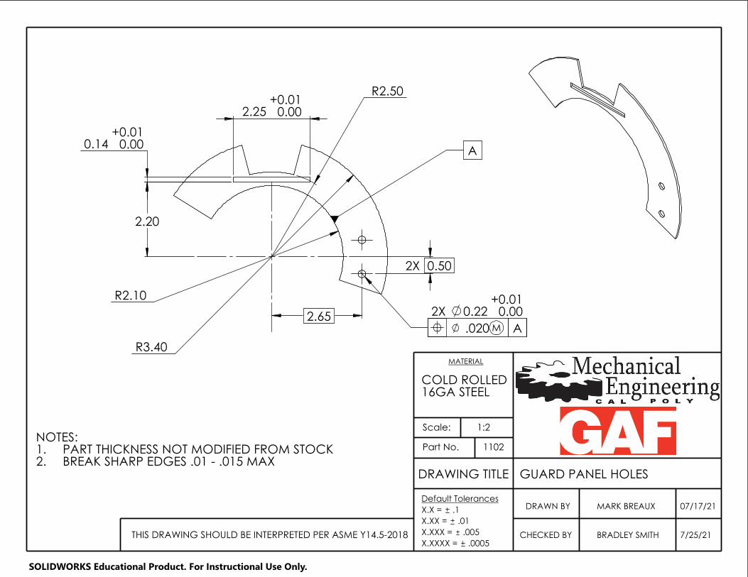
GUARD PANEL HOLES
Scale:
CHECKED BY BRADLEY SMITH
07/17/21
7/25/21
MARK BREAUX
DRAWING TITLE
DRAWN BY
1102
16GA STEEL
THIS DRAWING SHOULD BE INTERPRETED PER ASME Y14.5-2018
MATERIAL
.0005
Part No.
Default Tolerances
X.X = .1
X.XX = .01
X.XXX = .005
X.XXXX =
COLD ROLLED
1:2
NOTES:PART THICKNESS NOT MODIFIED FROM STOCK1.BREAK SHARP EDGES .01 - .015 MAX2.
M.020 A
A 0.00 0.14
R2.10
0.00
0.01
R3.40
2.25
2.65
R2.50 +
0.00
2X 0.22 +0.01
2.20
0.01+
2X 0.50
SOLIDWORKS Educational Product. For Instructional Use Only.
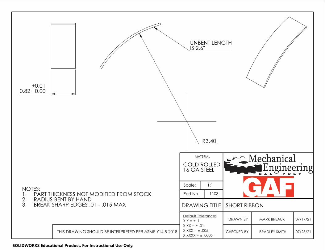
SHORT RIBBON
Scale:
CHECKED BY BRADLEY SMITH
07/17/21
07/25/21
MARK BREAUX
DRAWING TITLE
DRAWN BY
1103
16 GA STEEL
THIS DRAWING SHOULD BE INTERPRETED PER ASME Y14.5-2018
MATERIAL
.0005
Part No.
Default Tolerances
X.X = .1
X.XX = .01
X.XXX = .005
X.XXXX =
COLD ROLLED
1:1
0.82 + 0.010.00
NOTES:PART THICKNESS NOT MODIFIED FROM STOCK1.RADIUS BENT BY HAND2.BREAK SHARP EDGES .01 - .015 MAX3.
UNBENT LENGTHIS 2.6"
R3.40
SOLIDWORKS Educational Product. For Instructional Use Only.

DRAWING TITLE LONG RIBBON
Scale:
CHECKED BY BRADLEY SMITH
07/17/21
07/25/21
1104
MARK BREAUX
16 GA STEEL
MATERIAL
Part No.
.0005THIS DRAWING SHOULD BE INTERPRETED PER ASME Y14.5-2018
DRAWN BYDefault Tolerances
X.X = .1
X.XX = .01
X.XXX = .005
X.XXXX =
COLD ROLLED
1:2
UNBENT LENGTHIS 5.6"
R3.40
NOTE:PART THICKNESS NOT MODIFIED FROM STOCK1.BREAK SHARP EDGES .01 - .015 MAX2.RADIUS BENT BY HAND3.
0.82 + 0.010.00
SOLIDWORKS Educational Product. For Instructional Use Only.

FINGER PROTECTOR, TOP GUARD
Scale:
CHECKED BY BRADLEY SMITH
7/24/21
7/25/21
MARK BREAUX
DRAWING TITLE
DRAWN BY
1300
16 GA STEEL
THIS DRAWING SHOULD BE INTERPRETED PER ASME Y14.5-2018
MATERIAL
.0005
Part No.
Default Tolerances
X.X = .1
X.XX = .01
X.XXX = .005
X.XXXX =
COLD ROLLED
2:1NOTE:BREAK SHARP EDGES .01 - .015 MAX1.MATERIAL THICKNESS FROM 16 GA STOCK2.
1.25
0.25
0.73
0.35
R0.13
SOLIDWORKS Educational Product. For Instructional Use Only.

COLD ROLLED
GUARD
Scale:
CHECKED BY BRADLEY SMITH
7/24/21
7/25/21THIS DRAWING SHOULD BE INTERPRETED PER ASME Y14.5-2018
DRAWN BY
Part No.
16 GA STEEL
MARK BREAUX
MATERIAL
.0005
1400
DRAWING TITLE
Default Tolerances
X.X = .1
X.XX = .01
X.XXX = .005
X.XXXX =
FINGER PROTECTOR, BOTTOM
2:1
1.25
0.50
0.35
0.25
R0.13
NOTES:BREAK SHARP CORNERS .01 - .015 MAX1.MATERIAL THICKNESS IS 16 GA STOCK2.
SOLIDWORKS Educational Product. For Instructional Use Only.

SHARPENER ASSEMBLY
Scale:
CHECKED BY <INSERT NAME>
11/22/21
<DATE>
MARK BREAUXDRAWN BY
DRAWING TITLE
.0005
2000
.01
Part No.
X.XXX = THIS DRAWING SHOULD BE INTERPRETED PER ASME Y14.5-2018
MATERIAL
.005
X.XXXX =
Default Tolerances
X.X = .1
X.XX =
1:1
1
3
2
ITEM NO. PART NUMBER DESCRIPTION QTY.
1 2200 SOLENOID STACK WITHOUT SHOES 1
2 2100 SHOE ASSEMBLY 1
3 2300 CLAMPING ASSEMBLY 1
SOLIDWORKS Educational Product. For Instructional Use Only.

DRAWING TITLE SHOE ASSEMBLY
Scale:
CHECKED BY BRADLEY SMITH
7/25/21
7/25/21
MARK BREAUX
2100
X.XXXX =
.01
X.XXX = THIS DRAWING SHOULD BE INTERPRETED PER ASME Y14.5-2018
Part No.
.0005
DRAWN BY
MATERIAL
.005
Default Tolerances
X.X = .1
X.XX =
1:1
ITEM NO. PART NUMBER DESCRIPTION QTY.
1 2110 SHOE BODY 2
2 2120 1/4 x 1/4 x 6 ABRASIVE 2
3 2160 8-32 x 0.75in BHSS 2
4 2170 8-32 HEX NUT 2
5 2140 4-40 SET SCREW 2
2
1
4
3
5
SOLIDWORKS Educational Product. For Instructional Use Only.

MATERIAL
ALUMINUM
2110
DRAWING TITLE SHOE HALF
Scale:
CHECKED BY 07/25/21 .0005
BRADLEY SMITHTHIS DRAWING SHOULD BE INTERPRETED PER ASME Y14.5-2018
Drawing No.
DRAWN BY 07/13/21MARK BREAUXDefault Tolerances
X.X = .1
X.XX = .01
X.XXX = .005
X.XXXX =
6061-T6
2:1
C
.40
2X R.03
.250
NOTE:1. BREAK SHARP CORNERS .01 - .015 MAX
A B C.014 M
B
3X
.525 .525
.120 THRU
1.45
3X .200
.005 M C B A
.470
VIEW A .19
1.06
4X R.031
.250
.19
A CB.005 M
A
A .30
.30
30°
4-40 UNC THRU
.075
.303
.175
SOLIDWORKS Educational Product. For Instructional Use Only.

DRAWING TITLE SOLENOID STACK
Scale:
CHECKED BY <INSERT NAME>
11/22/21
<DATE>
MARK BREAUX
2200
X.XXXX =
.01
X.XXX = THIS DRAWING SHOULD BE INTERPRETED PER ASME Y14.5-2018
Part No.
.0005
DRAWN BY
MATERIAL
.005
Default Tolerances
X.X = .1
X.XX =
1:1
1
5
ITEM NO. PART NUMBER DESCRIPTION QTY.
1 2210 CUSTOM PLUNGER 1
2 2211 CUSTOM ADAPTER 1
3 2212 SOLENOID BODY 1
4 2213 SHOE ALIGNER 1
5 2214M5x0.8 x 10mm BHSS, MCM
97763A8201
6 2217 1/8" x 3/4" SS PIN 1
4
3
1
2
SOLIDWORKS Educational Product. For Instructional Use Only.

CUSTOM PLUNGER
Scale:
CHECKED BY <INSERT NAME>
11/21/21
<DATE>
MARK BREAUX
DRAWING TITLE
2210
(MAGNETIC)
DRAWN BY
X.XXXX = THIS DRAWING SHOULD BE INTERPRETED PER ASME Y14.5-2018
MATERIAL
.0005
Part No.
Default Tolerances
X.X = .1
X.XX = .01
X.XXX = .005
COLD ROLLED STEEL
1:1
M6 x 1.0
0.75
0.360
5.41
0.471 ±0.001
1.66
3.00 0.53
0.38
M5x0.8 0.50
SOLIDWORKS Educational Product. For Instructional Use Only.

PLUNGER SHOE ADAPTER
Scale:
CHECKED BY <INSERT NAME>
11/21/21
<DATE>
MARK BREAUX
DRAWING TITLE
2211
(MAGNETIC)
DRAWN BY
X.XXXX = THIS DRAWING SHOULD BE INTERPRETED PER ASME Y14.5-2018
MATERIAL
.0005
Part No.
Default Tolerances
X.X = .1
X.XX = .01
X.XXX = .005
COLD ROLLED STEEL
2:1
1. ALL HOLES THAT APPEAR COAXIAL TO DATUM ARE
CONCENTRIC WITHIN .010 M A .
0.158
THRU
0.458 ±0.001
0.0000.119 + 0.001
1.45
A
M6x1.0 0.47
SOLIDWORKS Educational Product. For Instructional Use Only.
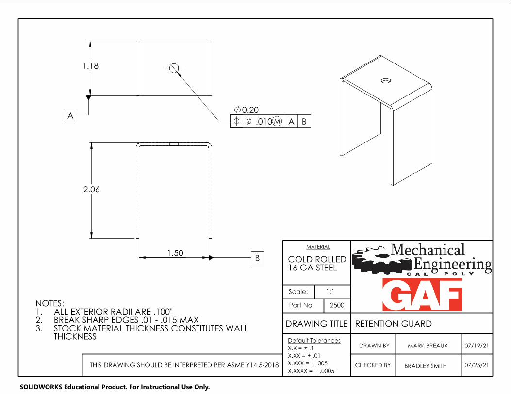
DRAWING TITLE RETENTION GUARD
Scale:
CHECKED BY BRADLEY SMITH
07/19/21
07/25/21
2500
MARK BREAUX
16 GA STEEL
MATERIAL
Part No.
.0005THIS DRAWING SHOULD BE INTERPRETED PER ASME Y14.5-2018
DRAWN BYDefault Tolerances
X.X = .1
X.XX = .01
X.XXX = .005
X.XXXX =
COLD ROLLED
1:1
BAM.010A
1.18
0.20
NOTES:ALL EXTERIOR RADII ARE .100"1.BREAK SHARP EDGES .01 - .015 MAX2.STOCK MATERIAL THICKNESS CONSTITUTES WALL 3.THICKNESS
B 1.50
2.06
SOLIDWORKS Educational Product. For Instructional Use Only.

DRAWING TITLE SOLENOID MOUNT POINT
Scale:
CHECKED BY BRADLEY SMITH
7/25/21
7/25/21
MARK BREAUX
2300
X.XXXX =
.01
X.XXX = THIS DRAWING SHOULD BE INTERPRETED PER ASME Y14.5-2018
Part No.
.0005
DRAWN BY
MATERIAL
.005
Default Tolerances
X.X = .1
X.XX =
1:1
ITEM NO. PART NUMBER DESCRIPTION QTY.
1 2320 SOLENOID PLATFORM 1
2 2310 MOUNTING BRACKET 2
3 2330 M3 x 5mm BHSS 4
3
1
2
3
SOLIDWORKS Educational Product. For Instructional Use Only.

MOUNTING BRACKET
Scale:
CHECKED BY BRADLEY SMITH
07/19/21
07/25/21
MARK BREAUX
DRAWING TITLE
DRAWN BY
2310
16 GA STEEL
THIS DRAWING SHOULD BE INTERPRETED PER ASME Y14.5-2018
MATERIAL
.0005
Part No.
Default Tolerances
X.X = .1
X.XX = .01
X.XXX = .005
X.XXXX =
COLD ROLLED
1:1NOTES:BREAK SHARP EDGES .01 - .015 MAX1.
BA.010 M
A
2X
2.8
0.79
1.2
0.14
2X 0.6
0.062 (STK)
SOLIDWORKS Educational Product. For Instructional Use Only.

K-1
Appendix K – Total Budget
Date purchased Vendor Description of items purchased Transaction
amount
04/12/21 Amazon TAKAHA Stroke 35mm Push Pull Long Stroke (1.38 in.) Electromagnet Solenoid $ 51.79
04/12/21 Amazon Tulead Stroke 10mm Push Pull Solenoid Micro Solenoid Electromagnet 20N Suction $ 10.86
04/12/21 Amazon Tulead 12V DC Solenoid Pull Push Electronic Actuator $ 11.52
04/12/21 Home Depot 12 in. x 12 in. 16-Gauge Weldable Sheet $ 11.94
04/13/21 Boride Engineered
Abrasives CS-HD SILICON CARBIDE POLISHING STONE 400 grit, 1/4 x 1/4 x 6 $ 49.87
05/13/21 Home Depot 12 in. x 12 in. 16-Gauge Weldable Sheet $ 73.80
05/13/21 Online Metals 0.5" x 1.25" Aluminum Rectangle Bar 6061-T6511-Extruded $ 24.60
05/20/21 Online Metals 1.5" x 3" x 0.12" Carbon Steel Rectangle Tube A500/A513 Hot Rolled $ 42.59
09/23/21 McMaster-Carr
Stainless Steel Thread-Locking Button Head Hex Drive Screws M5 x 0.8 mm, 8 mm Long $ 11.82
09/23/21 McMaster-Carr
18-8 Stainless Steel Button Head Hex Drive Screw 8-32 Thread Size, 1/2" Long $ 5.83
09/23/21 McMaster-Carr Dowel Pin 316 Stainless Steel, 1/8" Diameter, 1/2" Long $ 8.70
09/23/21 McMaster-Carr 18-8 Stainless Steel Flat-Tip Set Screws 4-40 Thread, 1/8" Long $ 6.63
09/23/21 McMaster-Carr
316 Stainless Steel Button Head Hex Drive Screws M3 x 0.5mm Thread, 5mm Long $ 3.85
09/23/21 McMaster-Carr Zinc-Plated Steel Hex Nut Medium-Strength, Class 8, M3 x 0.5 mm Thread $ 3.06
09/23/21 McMaster-Carr
Medium-Strength Steel Nylon-Insert Locknut Class 8, Zinc Plated, M3 x
0.5 mm Thread, 4 mm High $ 4.15
10/07/21 Amazon TAKAHA Stroke 35mm Push Pull Long Stroke (1.38 in.) Electromagnet Solenoid $ 51.07
10/07/21 McMaster-Carr Round Bellows with Cuff Ends, Light Duty, 5/16" x 5/8" ID, 3/4" OD $ 64.27
10/26/21 McMaster-Carr Aluminum Unthreaded Spacer 3/4" OD, 1/4" Long, for 3/8" Screw Size $ 15.69
09/28/21 Protolabs 3D Printed Metal Abrasive Shoes Parts $ 585.29
09/28/21 Protolabs 3D Printed Plastic Abrasive Shoe Parts $ 96.45
Total Cost $ 1,133.78

L-1
Appendix L – Test Procedures
Test Name: Sharpen Blade Profile Performed By: Team W23
Test Date(s): Oct 21 - Oct 25
Purpose:
Verify the function of the sharpening mechanism and determine the amount of time it takes to sharpen the
blade profile to the desired 60-degree angle indicated on the blade schematic sheet.
Scope:
This test is used to evaluate the time required to sharpen the blade profile to a desired 60 degrees.
Equipment:
• Blade Sharpening Device
• Testing Bench (created by GAF)
o motor
o test stand
o Driving wheel
o Shingle(s) test strip
• Electrical Power outlet (AC)
• Compressed Air
• Microvu Inspection equipment (go/no go gauge)
• Safety Goggles - For ALL participants
• Allen Keys
• Screwdriver
• Infrared Thermometer
Hazards:
• Potential Sparks
• Sharp blades
• Pinch points
• Finger entrapment
PPE Requirements:
• Safety goggles
• Ear protection
• Hand protection (gloves)
• Fire Extinguisher
• Pants
• Closed toe shoes
Facility:
• Bonderson/Mustang 60
Procedure:

L-2
1. Set up the test fixture.
2. Measure blunted blade deviation from specified internal angle with optical comparator and/or
calipers, and measure OD with calipers, then install blunted blade into fixture
3. Ramp up motor to test speed.
4. Energize solenoid, perform grinding operation for 10 seconds.
5. Take out the blade, measure the change in blade profile, and the OD. Install a fresh blunt blade.
6. Repeat this procedure to a second specimen. Repeat step #3, increasing the operation time by 10
seconds until 50 seconds is reached, unless duration is deemed unsafe for heat considerations.
7. Repeat the entire procedure for each blade surface speed, 1050 ft/min and 1500 ft/min.
8. Record the data in excel, run error propagation calculations on each operation time test with the
spreadsheet.
Results:
We plan on collecting 5 sets of data for 4 different blades at 2 different surface speeds. This will give us a
sanity check for whether the system can produce somewhat consistent results, and also will give us an
idea for how much grind time is too much or too little. Finally, it will provide some preliminary data for
our time duration recommendations that we will deliver to GAF.
Test Results:
Surface speed of 1050 ft/min:
Time 10s 20s 30s 40s 50s
Blade 1 Profile Score
Blade 2 Profile Score
Surface speed of 1500 ft/min:
Time 10s 20s 30s 40s 50s
Blade 3 Profile Score
Blade 4 Profile Score
Safety Hazards
Potential Hazard Response
Finger, extremity or clothing
cut/trapped in guard/. Cut power to system with off-switch, gently release trapped
extremity.
Burns from potential sparks escaping
the top guard. Move away from the test bench, swipe any remaining cooling
sparks from clothing/skin.
Burn on skin from overheating solenoid.
Remove hand, and use caution in the future to avoid the solenoid.

L-3
Test Name: Variable Speed Capability Performed By: Team W23
Test Date(s): Oct. 26 - Oct. 28
Purpose:
To test and validate that W23’s design of a blade sharpening device will be able to sharpen a blade for an
operation speed of 1050 ft/min to approximately max line speed of 1500 ft/min
Scope:
To ensure that the blade will be sharpened in the allotted tested time and will be able to cut the fiberglass
materials.
Equipment:
• Blade Sharpening Device (Created by W23)
• Testing Bench (created by GAF)
o motor
o test stand
o Deriving wheel
o Shingles test strip
• Electrical Power (via an outlet)
• Compressed Air (for actuating air cylinder)
o Note: Can have a fixed length for air cylinder machine if compressed air is not available
• Test Fiberglass material
• Allen Keys
• Screwdriver
Hazards:
• Potential Sparks
• Sharp blades
• Pinch points
• Finger entrapment
PPE Requirements:
• Safety goggles
• Ear protection
• Hand protection (gloves)
• Fire Extinguisher
• Pants
• Closed toe shoes
Facility:
• Bonderson/Mustang 60
Procedure:
1. Ensure GAF designed test bench is constructed to its proper form

L-4
2. Plug GAF equipment into the outlet and ensure that the equipment is running properly and will
increase in speed
3. Turn off the test bench and connect the sharpening blade device to the test bench
4. Insert a dull blade into the mechanism
5. Turn on the test bench again and turn it to the lowest speed of 1050ft/min begin the sharpening
process (time dependent based on other test results)
6. After sharpening, run a piece of fiberglass material though the testing section to see if the
fiberglass will be cut.
7. Repeat steps 3-7 by increasing the speed by 150 ft/min to ensure that the blade will be sharpened
for an array of speeds until speeds of 1500 ft/min are reached.
8. Once all measurements are recorded, turn off power to the motor and unplug from the outlet.
Ensure the motor has come to a complete stop before disassembling and cleaning up.
Results:
Results are on a pass/fail criteria. If the blade can cut the fiberglass it will be denoted as a pass, if it
cannot cut it will be denoted as a fail.
Test Results:
Table 1: Results of Variable Speed Capability
Speeds (ft/min) 1050 1200 1350 1500
Pass/Fail
Table 2: Potential Safety Issues and Responses
Solenoid
catches on
fire
Disconnect the power supply from the wall, find the nearest fire extinguisher
Fingers
Pinch Points PLEASE ENSURE ALL HANDS ARE AWAY FROM THE SPINNING BLADE. If a
hand is caught then contact mustang 60 and the nearest faculty or staff. If medical
attention is needed call 911 or go to the health office for non serious injuries.
Safety is the number one priority during all testing. Ensure that each member is following safety
procedures set by the campus.

L-5
Test Name: Solenoid Failure Evaluation Performed By: Team W23
Test Date(s): Oct 28 - Nov 2
Purpose:
Determine the failing/breaking point of the solenoid to determine the amount of time that it takes
for the solenoid to burnout, stall, or stop engaging properly with the abrasive shoe holder
mechanism and the blade.
Scope:
This test is used to evaluate and determine the failure point of the solenoid which will result in
the solenoid not working properly with the rest of the mechanism. Failure will occur when the
solenoid stops retracting or stalling.
Equipment:
• DC - Power Source
• Heat Protective Gloves
• Safety Goggles – MUST BE WORN BY ALL PARTICIPANTS
• Solenoid
• Brick
• Stopwatch
Hazards:
• Smoke
• Fire
• Sparks
• Electric shock
PPE Requirements:
• Safety goggles
• Heat Protective Gloves
• Fire Extinguisher
• Pants
• Closed toe shoes
Facility: (Where the test should occur)
• Bonderson Mustang 60

L-6
Safety Procedures
1. All participants or observers must put on safety glasses before the start of the
experiment.
2. The solenoid will be heated, therefore, anyone intending to be in direct contact with
the solenoid must wear heat protective gloves.
3. All members must wear closed toe shoes and pants without any holes to prevent any
serious burns.
Procedure:
1. Set up Solenoid on top of the brick.
2. Connect Solenoid to 24V DC power supply.
3. Energize solenoid TAKAHA Stroke 35mm Push Pull Long Stroke 1.38 (in) solenoid by
connecting to DC 24V.
4. Maintain the solenoid energized by the 24V DC until failure is reached. Failure will be
reached or determined when the solenoid stalls, stops retracting or when smoke starts to
form.
5. Turn off power supply once the solenoid does not retract as intended.
6. Disconnect solenoid from power supply.
Results:
We plan on collecting the amount of time that the solenoid can perform correctly while being
powered by 24V DC. We will record the time that the solenoid takes to stop working properly or
when it reaches the failure point. This will provide an idea on the recommended operation time
of the solenoid, as well as an estimate of its life cycle. This test will also help to generate
recommended engagement times and durations between the solenoid and abrasive shoe holder
that we will provide to GAF.

L-7
79.5 = room temperature
Test Results:
Operation Time
(sec)
Stall (YES or
NO)
Burn (YES
or NO)
Smoke (YES
or No)
Temperature
(F)
Trial
1
5 No No No 86.7
Trial
2
15 No No No 94.2
Trial
3
25 No No No 102.2
Trail
4
30 No No No 107.7
Trial
5
60 No No No 134.6
Trail
6
120 No No No 167.2
Results

L-8
Test Name: Abrasive Pad Life and Performance Performed By: Team W23 Test Date(s): Nov 2- Nov 9
Purpose: The purpose of this test is to determine the expected abrasive pad life for the predicted load conditions and to inspect if the abrasive pad and shoe mechanism work as intended.
Scope: Feature: The features being considered for this test include the abrasive pads (2). Function: This test is designed to perform the sharpening effect as the key function.
Equipment: - Dull blade(s) -Test Bench (created by GAF)
• motor
• test stand
• Driving wheel
• Fiberglass sample for test
- sharpening system (created by W23)
• top guard
• solenoid
• solenoid mounting sys
• abrasive pad shoe
• abrasive pads (qty: 2)
-Standard 120 V outlet source, DC -Micrometer/Vernier calipers
Hazards: -flying debris -excessive heat -high velocity rotating parts -pinch points
Potential Safety Issues and Responses
Excessive
heat Allow for air cooling time immediately after sharpening or dulling the blade. If
required to handle when hot, use a tool to grab the abrasive pads (e.g. locking pliers or
high resistant gloves). Never touch directly with your bare hands.
high velocity
rotating parts Before engaging the sharpening process, ensure that blades and abrasive pads are
fastened securely. Also ensure that any objects are not invading the space that the
rotating parts will occupy. Make use of PPE at all times and stand as far as possible
during testing. Always disconnect power supply from outlet before interacting with
system.
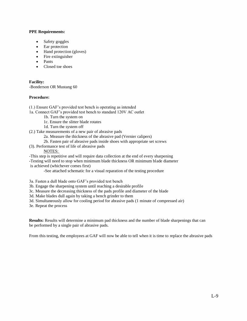
L-9
PPE Requirements:
• Safety goggles
• Ear protection
• Hand protection (gloves)
• Fire extinguisher
• Pants
• Closed toe shoes
Facility: -Bonderson OR Mustang 60 Procedure: (1.) Ensure GAF’s provided test bench is operating as intended 1a. Connect GAF’s provided test bench to standard 120V AC outlet 1b. Turn the system on 1c. Ensure the slitter blade rotates 1d. Turn the system off (2.) Take measurements of a new pair of abrasive pads 2a. Measure the thickness of the abrasive pad (Vernier calipers) 2b. Fasten pair of abrasive pads inside shoes with appropriate set screws (3). Performance test of life of abrasive pads NOTES: -This step is repetitive and will require data collection at the end of every sharpening -Testing will need to stop when minimum blade thickness OR minimum blade diameter is achieved (whichever comes first) -See attached schematic for a visual reparation of the testing procedure 3a. Fasten a dull blade onto GAF’s provided test bench 3b. Engage the sharpening system until reaching a desirable profile 3c. Measure the decreasing thickness of the pads profile and diameter of the blade 3d. Make blades dull again by taking a bench grinder to them 3d. Simultaneously allow for cooling period for abrasive pads (1 minute of compressed air) 3e. Repeat the process
Results: Results will determine a minimum pad thickness and the number of blade sharpenings that can be performed by a single pair of abrasive pads.
From this testing, the employees at GAF will now be able to tell when it is time to replace the abrasive pads
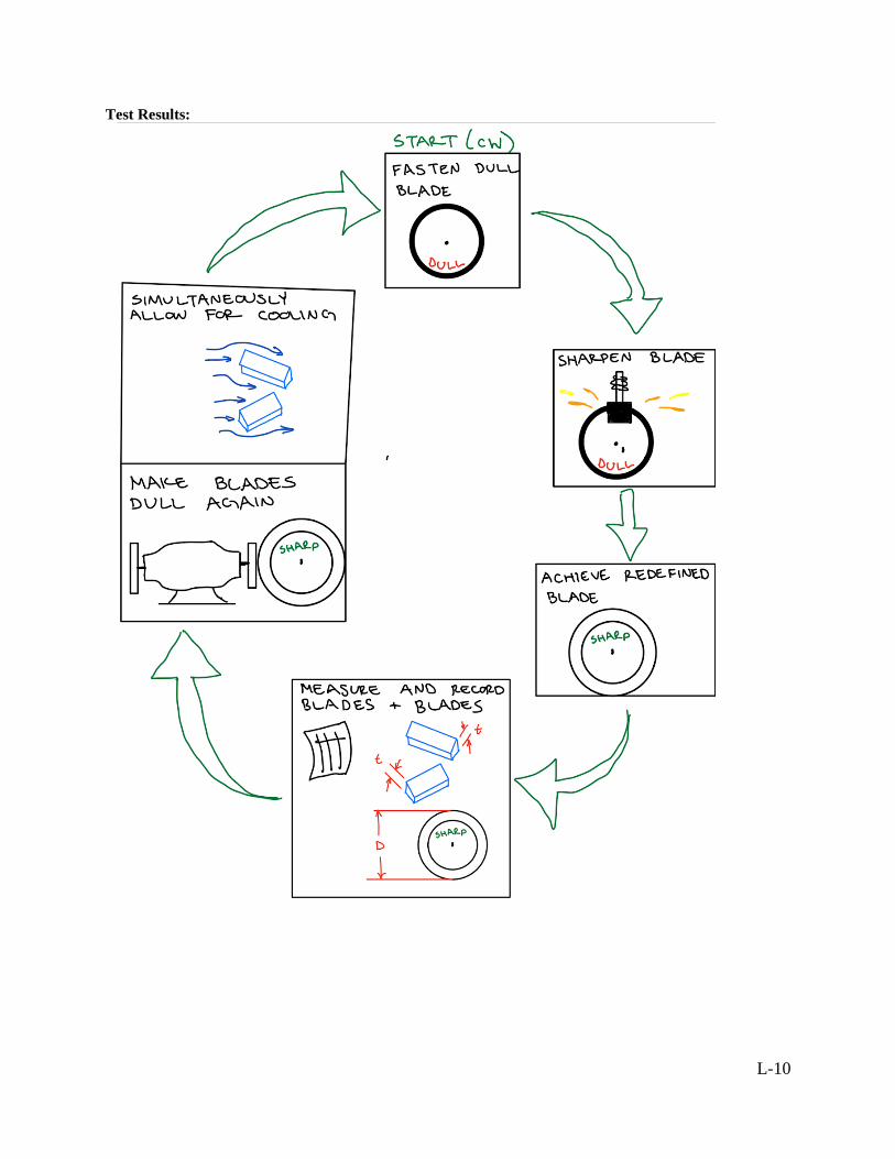
L-10
Test Results:

L-11
Table 1: Decreasing thickness of abrasive pads as a function of time.
Run No.
Run Time, t (min.)
Pad 1 Thickness,
t (in.)
Pad 2 Thickness,
t (in.)
Average Thickness,
tavg (in.)
1 0 0.25 0.255 0.2525
2 1 0.239 0.248 0.2435
3 2 0.2365 0.2455 0.241
NOTE: These are the results of a compromised test as a result of premature failure due to
excessive vibrations.

M-1
Appendix M – Error Propagation
We tracked the statistical error propagation from measurement to final results on the blade
profile test. This was done by making a couple of assumptions about the condition of the blade,
seen below.
1. The profile of the blade exhibited straight sides (i.e. no non-linear curvature).
2. The profile of the blade was symmetrical.
These assumptions allowed us to assess the condition of the blade empirically, regardless of the
condition of the blade and the specific shape of the profile. This was done by measuring the total
height of the blade profile. We defined the total height of the blade as the distance between the
end, or shoulder, of the blade profile and the highest point on the blade. Using this and basic
trigonometry, we developed a function to calculate the internal angle of the blade profile, seen
below.
𝑡ℎ𝑒𝑡𝑎 (ℎ) = 2 ∗ atan (𝑎
2ℎ)
Where theta is the blade profile angle, a is the width of the blade, and h is the measured height of
the blade profile. To propagate the error of the blade height measurement to the blade profile
angle, we used the sensitivity method instead of using partial derivatives, where the sensitivity
takes place of the partial derivative term in the RSS of the total error. Because we only had one
source of error for this measurement, the calculation of the RSS for a single source of error
means that the sensitivity of the measurement represents the total propagated uncertainty. We
calculated the sensitivity (i.e., the uncertainty of the angle) with this equation below.
𝑆𝑚 = 𝑡ℎ𝑒𝑡𝑎 (ℎ + 𝑈𝑥) − 𝑡ℎ𝑒𝑡𝑎 (ℎ)
We calculated the uncertainty of the measurement by using the basic equation of uncertainty for
a measurement, as shown below.
𝑈𝑥 = [𝐵2 + 𝑃2 + 𝑅2]0.5
The three variables represented under the radical are bias, precision and repeatability error,
respectively. The bias error was assumed to be zero, because we zeroed the calipers each
measurement. The precision (or reading) error was .0005”, and we increased it to .001” for a
conservative estimate. The repeatability error was seen to be about .010”. This came from some
preliminary testing of the calipers. Overall, combining these sources of error, the total
uncertainty in the measurement of the blade profile height was .010”, with the repeatability
factor contributing the most error to the uncertainty.

N-1
Appendix N – Design Hazard Checklist
Y N Description of Hazard Concern
Y
1. Will any part of the design create hazardous revolving, reciprocating, running, shearing, punching,
pressing, squeezing, drawing, cutting, rolling, mixing or similar action, including pinch points and sheer
points?
N 2. Can any part of the design undergo high accelerations/decelerations?
N 3. Will the system have any large moving masses or large forces?
Y
4. Will the system produce a projectile?
N 5. Would it be possible for the system to fall under gravity creating injury?
N 6. Will a user be exposed to overhanging weights as part of the design?
N 7. Will the system have any sharp edges?
N 8. Will any part of the electrical systems not be grounded?
Y
9. Will there be any large batteries or electrical voltage in the system above 40 V?
N 10. Will there be any stored energy in the system such as batteries, flywheels, hanging weights or
pressurized fluids?
N 11. Will there be any explosive or flammable liquids, gases, or dust fuel as part of the system?
N 12. Will the user of the design be required to exert any abnormal effort or physical posture during the
use of the design?
N 13. Will there be any materials known to be hazardous to humans involved in either the design or the
manufacturing of the design?
Y
14. Can the system generate high levels of noise?
N 15. Will the device/system be exposed to extreme environmental conditions such as fog, humidity, cold,
high temperatures, etc?
Y
16. Is it possible for the system to be used in an unsafe manner?
N 17. Will there be any other potential hazards not listed above? If yes, please explain on reverse.

O-1
Appendix O – Risk Assessment
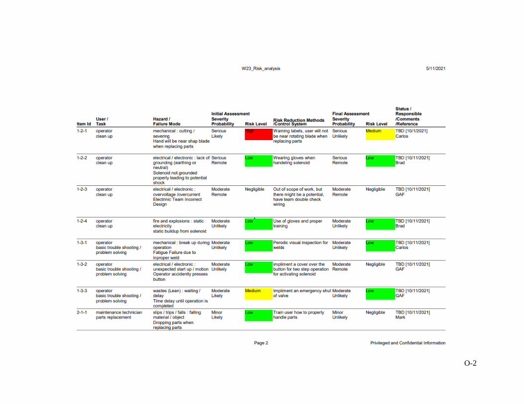
O-2

O-3

P-1
Appendix P– Failure Modes & Effects

Q-1
Appendix Q – User Manual
Slitter Blade Sharpening System – User Manual
Overview
The slitter blade sharpening system is designed to mount directly onto a Dienes
PQADF30 hydraulic slitter blade assembly. The sharpening system makes use of an electric
solenoid and abrasive pad assembly to provide the sharpening effect. The electric solenoid is
wired to a control panel that when energized extends the solenoid to its full length and in turn the
abrasive pad makes direct contact with the dull blade. When the control panel energizes the
solenoid plunger retracts and as a result break contact between the abrasive pad and blade.
Safety Concerns
It is imperative for the user to employee Personal Protective Equipment (PPE) when
operating the system. Please use safety glasses since debris is expected to be a direct product of
the sharpening system. In the absence of safety glasses, a full-face shield can be used as a
replacement. The sharpening system will also experience rotating parts at high velocities.
Because of this dynamic environment, it is advised that the user does not have any part of their
body in a vulnerable position when the system is powered. Instead, please stand back when the
system is operating. The assembly also makes use of sharp objects that are assembled in a tight
area. When disassembling or assembling the system for inspection and service, please make use
of gloves and handle all pieces carefully to avoid bodily injuries.

Q-2
List of Parts
• Guard Assembly
o Top Guard
o Bottom Guard
o Dienes PQADF30 assembly
o Two (2) 8-32x1 bolts (modified to length) (McMaster-Carr)
o Philips Screwdriver
o Slitter Blade
• Sharpener Assembly
o Two (2) Shoes
o Two (2) 400 Grit Abrasive Pads (Boride Engineered Abrasives)
o Two (2) 4/40 X 1/8 set screws (socket set) (McMaster-Carr)
o Two (2) 8-32x1 bolts and low-profile bolts
o Solenoid Extender Part
o TAHAKA 35mm long stroke electromagnetic solenoid (Amazon)
o Retention Guard
o One (1) 1/4 – 28 bolt – (Home Depot/McMaster-Carr)
o Four (4) M3 button cap screws (Home Depot/McMaster-Carr)
o Metric and Standard Hex key set
o Screwdriver
o Needle nose pliers (any pliers would work; needle nose works the best)
• Test Bench (no assembly required)
• AC to DC transformer (no assembly required)

Q-3
Components
Figure Q1 shows an overview of key components that make up the Slitter Blade
Sharpening System. This labeling will be referenced in the following step-by-step assembly
procedure.
Figure Q1. Key Components of Slitter Blade Sharpening System.
Top and Bottom Guard Assembly
Step 1. In assembling the sharpening system, we begin by mounting the slitter blade onto the
Dienes PQADF30 assembly hub. Remove the three Hd. M5x12 bolts that fasten the circular
endcap with the triangular cutout. These bolts come with the dienes assembly The bolts are
outlined in red below.

Q-4
Figure Q2. Dienes PQADF30 assembly hub.
Step 2. Drop the slitter blade in such a way where its inner diameter aligns with the circular
profile of the PQADF30 assembly hub. The following pictures outline the two circular mating
profiles in red. The slitter blade’s keyway serves no purpose and can be ignored.
Figure Q3. Dienes blade aligned with the assembly hub.
Step 3. Apply the circular endcap with the triangular cutout over the slitter blade and fasten the
three M5x12 bolts to secure the blade in place.

Q-5
Figure Q4. Clamping Dienes blade with triangular cutout.
Step 4. Next, we install the top guard which will serve as the basis for the solenoid subassembly.
Locate the 2 tapped holes found on the existing arm as outlined in red below.
Figure Q5. Reverse side of Dienes Blade assembly with guard bolt insets.

Q-6
Step 5. Slide the top guard behind the slitter blade and align the top guard’s hole with the arm’s
tapped holes in such a way where the solenoid will be oriented on the top and the opening of the
top guard will be located furthest from the arm.
Figure Q6. Top guard location on the Dienes assembly.
Step 6. The bottom guard will make use of the same bolts that fasten the top guard. Without
misaligning the top guard, slide the bottom guard behind the slitter blade 180° across from the
top guard. Be sure to insert the bottom guard inside the top guard’s C-channel as below at right.
Figure Q7. Top and bottom guard alignment with holes on back side of Dienes Mechanism.

Q-7
Step 7. When both guards are in alignment with the arm’s tapped holes, fasten the two 8-32x1
bolts from the outside surface of the arm. The bolts will bind with the welded nuts found on the
inside of the bottom guard.
Figure Q8. Inserting bolts to secure top guard assembly.
Troubleshooting Recommendations: There can be some difficulty lining up the holes with the
two guards. It was easier to first get the right-hand screw in Figure Q8 above in the bolt before
aligning the right-hand bolt. We would recommend getting both bolts lined up before tightening
the device
Figure Q9 below shows the system with the solenoid subassembly. Notice that the solenoid is not
attached to the assembly now.
Figure Q9. Complete Guard Assembly onto the Dienes mechanism.
Solenoid
Entry
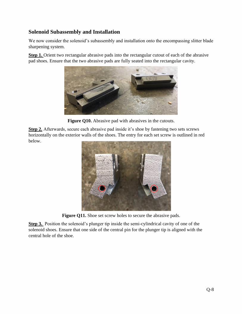
Q-8
Solenoid Subassembly and Installation
We now consider the solenoid’s subassembly and installation onto the encompassing slitter blade
sharpening system.
Step 1. Orient two rectangular abrasive pads into the rectangular cutout of each of the abrasive
pad shoes. Ensure that the two abrasive pads are fully seated into the rectangular cavity.
Figure Q10. Abrasive pad with abrasives in the cutouts.
Step 2. Afterwards, secure each abrasive pad inside it’s shoe by fastening two sets screws
horizontally on the exterior walls of the shoes. The entry for each set screw is outlined in red
below.
Figure Q11. Shoe set screw holes to secure the abrasive pads.
Step 3. Position the solenoid’s plunger tip inside the semi-cylindrical cavity of one of the
solenoid shoes. Ensure that one side of the central pin for the plunger tip is aligned with the
central hole of the shoe.
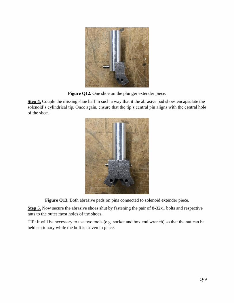
Q-9
Figure Q12. One shoe on the plunger extender piece.
Step 4. Couple the missing shoe half in such a way that it the abrasive pad shoes encapsulate the
solenoid’s cylindrical tip. Once again, ensure that the tip’s central pin aligns with the central hole
of the shoe.
Figure Q13. Both abrasive pads on pins connected to solenoid extender piece.
Step 5. Now secure the abrasive shoes shut by fastening the pair of 8-32x1 bolts and respective
nuts to the outer most holes of the shoes.
TIP: It will be necessary to use two tools (e.g. socket and box end wrench) so that the nut can be
held stationary while the bolt is driven in place.
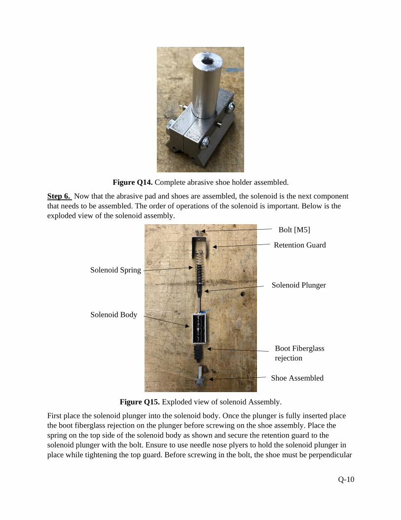
Q-10
Figure Q14. Complete abrasive shoe holder assembled.
Step 6. Now that the abrasive pad and shoes are assembled, the solenoid is the next component
that needs to be assembled. The order of operations of the solenoid is important. Below is the
exploded view of the solenoid assembly.
Figure Q15. Exploded view of solenoid Assembly.
First place the solenoid plunger into the solenoid body. Once the plunger is fully inserted place
the boot fiberglass rejection on the plunger before screwing on the shoe assembly. Place the
spring on the top side of the solenoid body as shown and secure the retention guard to the
solenoid plunger with the bolt. Ensure to use needle nose plyers to hold the solenoid plunger in
place while tightening the top guard. Before screwing in the bolt, the shoe must be perpendicular
Bolt [M5]
Retention Guard
Solenoid Spring
Solenoid Plunger
Solenoid Body
Boot Fiberglass
rejection
Shoe Assembled

Q-11
to the retention guard, such that when the solenoid is engaged, the retention guard will keep the
abrasive pad from rotating and the abrasives will be in contact with the blade.
Step 7. With the abrasive pad shoes now fastened onto the solenoid, slide abrasive pad shoes
through the square cutout found on the top of the solenoid platform. The abrasive pad shoes will
always reside between the top of the slitter blade and the bottom of the solenoid platform.
Figure Q16. Inserting Solenoid into the top guard assembly.
Troubleshooting Recommendations: Some portions of the solenoid platform are easy to slip the
plunger in than others, recommendations would be to adjust the angle of attack at location at
which the shoes are going into.
Step 8.
Fasten the four M4 screws that will fix the solenoid body onto the solenoid plates using a metric
hex key set.
Figure Q17. Inserting M4 screws to secure solenoid to the top guard.

Q-12
Sharpening Procedure Walkthrough
The following schematic outlines the electrical circuit that powers the electric solenoid using the
test best provided by GAF.
Figure Q18. Electrical schematic for TAKAHA 24V [DC] Solenoid.
The motor control is used to provide power and a variable speed to the electric motor. Recall that
the electric motor and flywheel are representative of the slitter blade system used to cut
fiberglass material on the production line. The transformer was provided by GAF to convert
alternating current (AC) from a standard wall outlet to the direct current (DC) powered solenoid.
The transformer provides power to the solenoid and an adjustment timer setting.

Q-13
NOTE: THE FOLLOWING INSTRUCTIONS ARE WRITTEN FOR GAF’S TEST BENCH
ASSEMBLY. FOR USE IN THE PRODUCTION LINE, PLEASE SKIP TO STEP 2.
Step 1.
Begin by powering the electric motor by flicking the kill switch to its ON position. The electric
motor must undergo angular momentum before reaching an idle speed. Begin by setting the
variable speed knob to setting 20. The flywheel will begin to show signs of rotation. Play with
the variable speed by rotating the knob clockwise and counterclockwise until the flywheel
reaches a steady speed. The black button seen at left is the result of a reused control panel and
can be ignored.
Figure Q19. Power and variable speed control for electric motor.
Troubleshooting/Recommendations: There can be some difficulty when starting the motor. We
would recommend starting at the 20-25 range to kickstart the motor before running. If it does
start completing full rotations, turn off the device. Set the knob to zero, increase to 25 and hit the
switch again.
Step 2.
Now we engage the solenoid so that the abrasive pads can contact the dull blade. Before
powering the solenoid, remove the two screws seen on the right side of the transformer. This will
give you access to the adjustable timer setting found inside the transformer’s casing. Using a
small Philips screwdriver, turn the rotary dial to the desired operating interval.

Q-14
Figure Q20. Adjustment timer setting for solenoid energizing interval.
Step 3.
On the transformer seen below, turn the red dial clockwise to it’s on position. Note that this does
not energize the solenoid but instead primes the power. Press the white button so that the
solenoid’s plunger can extend. When the solenoid has been energized for its timed setting, the
plunger will retract to its resting position. If more sharpening is desired, simply press the white
activation button again and make use of the adjustment timer setting as needed.
Figure Q21. Adjustment timer setting for solenoid energizing interval.

Q-15
Maintenance Guideline
In this application, the parts do not require maintenance at a set interval. Instead, it is recommended
that the user maintains a clean apparatus for optimal performance. During repetitive sharpening
cycles, a considerable amount of debris is expected to accumulate from both the blade and the
abrasive pads. There may be other elements of debris attributed from the assembly line itself such
as dust.
The main area of concern for debris build up is outlined with red markings in Figure Q22. This is
the circumferential clearance around the solenoid plunger that allows for a thin film of debris.
Figure Q22. Primarily area of debris build up around solenoid plunger.
This is the most critical area because the solenoid will be retracting repeatedly to engage and
disengage the abrasive pads with the dull blades. If debris build up does occur, the solenoid may
seize and prevent the sharpening effect. Seizure of the plunger can also cause the abrasive pads
to stay engaged well after the blade has been sharpened and cause excess heat and premature
wear.
To accommodate these concerns it is advised to blow off any debris build up with a jet of
compressed air. The use of a mechanical brush may all be helpful. It is important the user does
not perform the maintenance cleaning while the system is powered.

Q-16
Abrasive Pad Replacement
To remove the abrasive pads and replace them, the abrasive shoe assembly must be disconnected
from the solenoid. This process is like the solenoid subassembly installation. Please being by
unfastening the four M4 screws that fix the solenoid body onto the solenoid plates using a metric
hex key set, shown below in Figure Q23.
Figure Q23. Unfastening M4 screws to secure solenoid to the top guard.
Next remove the abrasive shoe from the top guard assembly. After, disassemble the abrasive shoe
holder assembly following the reverse steps from the abrasive shoe assembly installation.
Once the abrasive shoe holder assembly has been disassembled, unfasten the hex screws on the
side of the shoes to remove the abrasives. Figure Q24 shows the abrasive shoes before removal.
Figure Q24. Abrasive pad with abrasives in the cutouts.
Use a needle nose ply tool to remove the abrasives the abrasives. Lastly, cut the abrasives to the
length of the cutout and follow the installation instructions for the solenoid and abrasive shoe
assembly to incorporate the abrasive shoe and solenoid to the top guard assembly.