future picmicro® microcontroller products guide
TRANSCRIPT
2000 Microchip Technology Inc. DS00168C
Future PICmicro® Microcontroller
Products Guide
2000

DATA SHEET MARKINGS
Microchip uses various data sheet markings to designate each document phase as it relates to the productdevelopment stage. The markings appear at the bottom of the data sheet, between the copyright and document andpage numbers. The definitions for each marking are provided below for your use.
Marking Description
Advance Information The information is on products in the design phase. Your designs should not befinalized with this information as revised information will be published when theproduct becomes available.
Preliminary This is preliminary information on new products in production but not yet fullycharacterized. The specifications in these data sheets are subject to change withoutnotice. Before you finalize your design, please ensure that you have the most currentrevision of the data sheet by contacting your Microchip sales office, representative ordistributor.
No Marking Information contained in the data sheet is on products in full production.
“All rights reserved. Copyright © 2000, Microchip Technology Incorpo-rated, USA. Information contained in this publication regarding deviceapplications and the like is intended through suggestion only and maybe superseded by updates. No representation or warranty is givenand no liability is assumed by Microchip Technology Incorporated withrespect to the accuracy or use of such information, or infringement ofpatents or other intellectual property rights arising from such use orotherwise. Use of Microchip’s products as critical components in lifesupport systems is not authorized except with express writtenapproval by Microchip. No licenses are conveyed, implicitly or other-wise, under any intellectual property rights. The Microchip logo andname are registered trademarks of Microchip Technology Inc. in theU.S.A. and other countries. All rights reserved. All other trademarksmentioned herein are the property of their respective companies. Nolicenses are conveyed, implicitly or otherwise, under any intellectualproperty rights.”
DS00168C - page ii
Trademarks
The Microchip name and logo, KEELOQ, PIC, PICMASTER, PICmicro,PRO MATE, PICSTART, MPLAB, and SEEVAL are registered trade-marks of Microchip Technology Incorporated in the U.S.A. and othercountries.
Total Endurance, In-Circuit Serial Programming (ICSP), microID, FilterLab are trademarks of Microchip Technology Incorporated in theU.S.A.
Serialized Quick Term Programming (SQTP) is a service mark ofMicrochip Technology Incorporated in the U.S.A.
All other trademarks mentioned herein are property of their respectivecompanies.
© 2000, Microchip Technology Incorporated, Printed in the U.S.A., AllRights Reserved.
2000 Microchip Technology Inc.

PAGE
Table of Contents
SECTION 1 INTRODUCTION
Building for the Future and Future Product Roadmaps..................................................................................... 1-1
SECTION 2 PICmicro® 8-PIN RISC MICROCONTROLLERS
PIC18F0X0 8-Pin Enhanced FLASH Microcontroller Product Brief ................................................................. 2-1PIC18F0X2 8-Pin Enhanced FLASH Microcontroller with 10-bit A/D Product Brief.......................................... 2-3
SECTION 3 PICmicro® 18/20/28-PIN RISC MICROCONTROLLERS
PIC16F812/816 18-Pin Enhanced FLASH Microcontrollers with 10-bit A/D and CCP Product Brief................ 3-1PIC16F62X FLASH-Based 8-bit CMOS Microcontrollers.................................................................................. 3-3PIC18F1X2 20-Pin Enhanced FLASH Microcontrollers with 10-bit A/D, ECCP and USART Product Brief...... 3-5PIC16CR73/76 28-Pin CMOS ROM Microcontroller Product Brief ................................................................... 3-7PIC16F73/76 28-Pin CMOS FLASH Microcontroller Product Brief ................................................................... 3-9PIC16F745 28-Pin Enhanced FLASH Microcontrollers with Low Speed USB, 8-bit A/D and USART Product Brief .............................................................................................................................. 3-11PIC16F747 28-Pin Enhanced FLASH Microcontrollers with Low Speed USB, 8-bit A/D and MSSP Product Brief ................................................................................................................................. 3-13PIC16F872A 28-Pin Enhanced FLASH Microcontroller Product Brief ........................................................... 3-15PIC16F873A/876A 28-Pin Enhanced FLASH Microcontroller Product Brief .................................................. 3-17PIC18F2X2 28-Pin Enhanced FLASH Microcontroller w/10-bit A/D Product Brief ......................................... 3-19PIC18F258 28-Pin Enhanced FLASH Microcontrollers with CAN, 10-bit A/D and USART Product Brief ...... 3-21
SECTION 4 PICmicro® 40-PIN RISC MICROCONTROLLERS
PIC16CR74/77 40-Pin CMOS ROM Microcontroller Product Brief ................................................................... 4-1PIC16F74/77 40-Pin CMOS FLASH Microcontroller Product Brief ................................................................... 4-3PIC16F765 40-Pin Enhanced FLASH Microcontrollers with Low Speed USB, 8-bit A/D and USART Product Brief ................................................................................................................................ 4-5PIC16F767 40-Pin Enhanced FLASH Microcontrollers with Low Speed USB, 8-bit A/D and MSSP Product Brief ................................................................................................................................... 4-7PIC16F874A/877A 40-Pin Enhanced FLASH Microcontroller Product Brief..................................................... 4-9PIC18F4X2 40-Pin Enhanced FLASH Microcontroller w/10-bit A/D Product Brief ......................................... 4-11PIC18F458 40-Pin Enhanced FLASH Microcontrollers with CAN, 10-bit A/D and USART Product Brief ...... 4-13
SECTION 5 PICmicro® 64/68-PIN RISC MICROCONTROLLERS
PIC16C925/926 CMOS Microcontroller with LCD Product Brief ....................................................................... 5-1PIC18F653 64-Pin Enhanced FLASH Motor Control Microcontroller Product Brief.......................................... 5-3PIC18F668 64-Pin Enhanced FLASH CAN Bus Microcontroller Product Brief................................................. 5-5PIC18C658 64/68-Pin High-Performance Microcontroller with CAN Module Product Brief .............................. 5-7PIC18F6X2 64/68-Pin Enhanced FLASH Microcontroller Product Brief ......................................................... 5-9PIC18C601 64/68-Pin ROMless Microcontroller w/10-bit A/D Product Brief................................................... 5-11
2000 Microchip Technology Inc. DS00168C-page iii
PAGE
Table of Contents (Continued)
SECTION 6 PICmicro® 80/84-PIN RISC MICROCONTROLLERS
PIC18F868 80-Pin Enhanced FLASH CAN Bus Microcontroller Product Brief................................................. 6-1PIC18C858 80/84-Pin High-Performance Microcontroller with CAN Module Product Brief ............................. 6-3PIC18F8X2 80/84-Pin Enhanced FLASH Microcontroller Product Brief 6-5PIC18C801 80/84-Pin ROMless Microcontroller w/10-bit A/D Product Brief..................................................... 6-7
SECTION 7 PICmicro® 100-PIN RISC MICROCONTROLLERS
PIC18C958 100-Pin High-Performance Microcontroller with CAN Module and External Memory Bus Product Brief ............................................................................................................................... 7-1
APPENDIX A
Company Profile ...............................................................................................................................................A-1
DS00168C-page iv 2000 Microchip Technology Inc.
SECTION 1INTRODUCTION
Building for the Future and Future Product Roadmaps ............................................................................................... 1-1
2000 Microchip Technology Inc. DS00168C-page 1-i

DS00168C-page 1-ii 2000 Microchip Technology Inc.
Building for the Future
INTRODUCTION
Today you are creating the products of tomorrow.Products with more complex features, faster operatingspeeds, reduced time-to-market, and optimized cost.Well-informed design engineers and their manufactur-ing partners understand the selection of a microcontrol-ler architecture, and the company behind it, is a criticalfactor for success. It’s a decision made not only for thepresent, but also for the future.
To help design engineers balance the demands of anever-changing market, Microchip Technology Inc. com-bines its worldwide design expertise, process technol-ogy innovation, world-class manufacturing capabilityand commitment to quality to offer a complete productsolution. Our highly integrated products, developmenttools, technical resources and global support ensureyour competitive edge, while making your world just alittle easier.
The 2000 edition of Microchip’s Future PICmicro®Microcontroller Products Guide, a compilation of prod-uct briefs on the planned members in the PICmicro®
microcontroller (MCU) product line. In this guide youwill find comprehensive technical references for keycomponents in our PICmicro product roadmap. Webelieve that by sharing these devices with you now, youwill be better prepared to plan your designs and makethe right architecture selection for the future.
We invite you to join the thousands of designers andtheir manufacturing partners around the world whohave specified more than a billion PICmicro MCUs to-date, and today look toward a bright future with Micro-chip Technology at their side.
2000 Microchip Technology Inc. DS00168C-page 1-1
Microchip Technology Inc.
8
7
6
5
1
2
3
4
8-p
in
PIC
mic
ro®
F
amily
VDD
GP5/OSC1/CLKIN
GP4/OSC2/AN3/CLKOUT
GP3/MCLR/VPP
GP2/TOCKI/AN2/INT
GP1/AN1/VREF
GP0/AN0VSS
RA1/AN1RA0/AN0
OSC2/CLKOUT/RA6VDDRB7/T1OSIRB6/T1OSO/T1CKIRB5RB4/PGM
OSC1/CLKIN/RA7
RA2/AN2/VREFOUT
RA3/AN3/CMP1/VREFIN
MCLR/VPP/RA5/THVVSS
RB0/INTRB1/RX/DTRB2/TX/CKRB3/CCP1
RA4/T0CKI/CMP2 2 3 4 5 6 7 8 9
•1 1817
151413121110
16
18-p
in
PIC
mic
ro®
F
amily
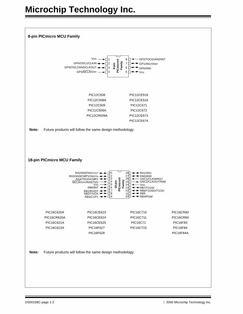
8-pin PICmicro MCU Family
Note: Future products will follow the same design methodology.
PIC12C508 PIC12CE518
PIC12C508A PIC12CE519
PIC12C509 PIC12C671
PIC12C509A PIC12C672
PIC12CR509A PIC12CE673
PIC12CE674
Note: Future products will follow the same design methodology.
PIC16C620A PIC16CE623 PIC16C710 PIC16CR83
PIC16CR620A PIC16CE624 PIC16C711 PIC16CR84
PIC16C621A PIC16CE625 PIC16C71 PIC16F83
PIC16C622A PIC16F627 PIC16C715 PIC16F84
PIC16F628 PIC16F84A
18-pin PICmicro MCU Family
DS00168C-page 1-2 2000 Microchip Technology Inc.
Microchip Technology Inc.
40-p
in
PIC
mic
ro®
F
amily
RB7/PGO/KB13RB6/PGC/KB12RB5/KBI1RB4/KBI0RB3/PGM/CCP2/CANRXRB2/INT2/CANTXRB1/INT1RB0/INT0VDD
VSS
RD7/PSP7/PDRD6/PSP6/PCRD5/PSP5/PBRD4/PSP4/ECC/PARC7/RX/DTRC6/TX/CKRC5/SKO/D+
RC4/SDI/SDA/D-RD3/PSP3/C2IN-RD2/PSP2/C2IN+
MCLR/VPP
RA0/AN0RA1/AN1
RA2/AN2/VRL/VREF-RA3/AN3/VRH/VREF+
RA4/T0CKIRA5/SS/AN4/LVDIN
RE0/RD/AN5RE1/WR/AN6RE3/CS/AN7
AVDD
AVSS
OSC1/CLKIOSC2/CLKO/RA6
RC0/T1OSO/T1CKIRC1/T1OSI/CCP2
RC2/CCP1
RC3/SCK/SCLRD0/PSP0/C1IN+RD1/PSP1/C1IN-
1234567891011121314151617181920
4039383736353433323130292827262524232221
1011
23456
1
87
9
121314 15
1617181920
232425262728
2221
MCLR/VPP
RA0/AN0RA1/AN1
RA2/AN2/VRL/VREF-RA3/AN3/VRH/VREF+
RA4/T0CKIRA5/SS/AN4/AVDD/LVDIN
VSS
OSC1/CLKIOSC2/CLKO/RA6
RC0/T1OSO/T1CKIRC1/T1OS/CCP2I
RC2/CCP1RC3/SKC/SCL
RB7/PGORB6/PGCRB5RB4RB3/PGM/CCP2RB2/INT2RB1/INT1RB0/INTVDD
VSS
RC7/RX/DTRC6/TX/CKRC5/SDO/D+RC4/SKI/SDA/D-
28-p
in
PIC
mic
ro®
F
amily
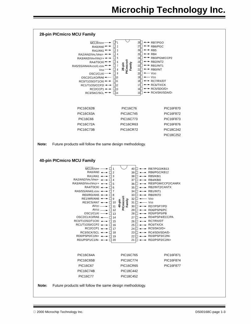
Note: Future products will follow the same design methodology.
PIC16C62B PIC16C76 PIC16F870
PIC16C63A PIC16C745 PIC16F872
PIC16C66 PIC16C773 PIC16F873
PIC16C72A PIC16CR63 PIC16F876
PIC16C73B PIC16CR72 PIC18C242
PIC18C252
28-pin PICmicro MCU Family
40-pin PICmicro MCU Family
Note: Future products will follow the same design methodology.
PIC16C64A PIC16C765 PIC16F871
PIC16C65B PIC16C774 PIC16F874
PIC16C67 PIC16CR65 PIC16F877
PIC16C74B PIC18C442
PIC16C77 PIC18C452
2000 Microchip Technology Inc. DS00168C-page 1-3

Microchip Technology Inc.
2000 – 2001 PICmicro FLASH Product Roadmap
PIC18F1324K/256, 128 EE
4X PLL, 10b A/D, MPY, Int. OSC
18/20-pin 28-pin18-pin
PIC16F6282KW/224, 128 EE
CCP, USART,
PIC16F8162KW/128, 128 EE10b A/D, CCP,
Int. OSC
8-pin
PIC18F0222KW/256, 64 EE10b A/D, MPY,
PIC18F0121KW/256, 64 EE,10b A/D, MPY,
PIC18F0202KW/256, 64 EE,
MPY, Int. OSC
PIC18F0101KW/256, 64 EE,
MPY, Int. OSC
PIC16F8121KW/128, 128 EE10b A/D, CCP,
Int. OSC
COMP, Int. OSC
PIC16F6271KW/224, 128 EE
CCP, USART, COMP, Int. OSC
PIC16F84A1KW/68, 64 EE
WDT, 13 I/0
PIC16F83512/36, 64 EEWDT, 13 I/0
Int. OSC
Int. OSC
PIC18F1222K/256, 128 EE
4X PLL, 10b A/D, MPY, Int. OSC
PIC16F7478K/256, USB1.1,
2CCP, BOR, SSP/SCI
28-pin
PIC16F7458KW/256, USB1.1,
2CCP, BOR, USART
PIC16F876A8KW/368, 256 EE,10b A/D, 2CCP,
USART, I2C/SPI, ICD
PIC16F873A4KW/192, 128 EE,10b A/D, 2CCP,
USART, I2C/SPI, ICD
PIC16F872A2KW/128, 64 EE,10B A/D, 2CCP
I2C/SPI, ICD
PIC16F8702KW/128, 64 EE,10b A/D, CCP,
USART
PIC16F768KW/368,
8b A/D, 2CCP USART, I2C/SPI
PIC18F25816KW/1.5K, 256 EE,4X PLL, CAN 2.0B,
USART, I2C/SPI, 2CCP
PIC16F734KW/192,
8b A/D, 2CCP USART, I2C/SPI
PIC18F25216KW/1.5K, 256 EE,
4X PLL, 10b A/D, 2CCP, USART, I2C/SPI
PIC18F2428KW/512, 256 EE,4X PLL, 10b A/D,
2CCP, USART, I2C/SPI
DS00168C-page 1-4 2000 Microchip Technology Inc.

Microchip Technology Inc.
2000 – 2001 PICmicro FLASH Product Roadmap
16KW/1536, 256 EE,
I2C/SPI, USART, CAN 2.0B
40-pin 68-pin40-pin 84-pin
PIC18F458
PIC18F86832KW/3072, 256 EE,
10b A/D, 2CCP,I2C/SPI, USART, CAN 2.0B
PIC16F877A8KW/368, 256 EE,
10b A/D, 2CCP,USART, I2C/SPI
PIC16F7678KW/256
USB 1.1, 2CCP,BOR, SSP/SCI
PIC16F7658KW/256
USB 1.1, 2CCP,BOR, USART
PIC16F874A4KW/192, 128 EE,
10b A/D, 2CCP,USART, I2C/SPI
PIC16F8712KW/128, 64 EE, 10b A/D, USART,
CCP
PIC16F778KW/368
8b A/D, 2CCP,USART, I2C/SPI
PIC16F744KW/192
8b A/D, 2CCP,USART, I2C/SPI
10b A/D, 2CCP,
16KW/1536, 256 EE,
I2C/SPI, USART, 2CCP
PIC18F452
10b A/D, 4X PLL,
8KW/512, 256 EE,
I2C/SPI, USART, 2CCP
PIC18F442
10b A/D, 4X PLL,
16KW/1536, 256 EE,
I2C/SPI, USART, CAN 2.0B,
PIC18F653
10b A/D, 2CCP,
32KW/3072, 256 EE,
I2C/SPI, USART, CAN 2.0B
PIC18F668
10b A/D, 2CCP,
64KW/3968, 256 EE,
I2C/SPI, USART, 2CCP
PIC18F672
10b A/D, 4X PLL,
32KW/3072, 256 EE,
I2C/SPI, USART, 2CCP
PIC18F662
10b A/D, 4X PLL,
16KW/1536, 256 EE,
I2C/SPI, USART, 2CCP
PIC18F652
10b A/D, 4X PLL,
Quad. Encoder
PIC18F87264KW/3968, 256 EE,
10b A/D, 4X PLL,I2C/SPI, USART, 2CCP
PIC18F86232KW/3072, 256 EE,
10b A/D, 4X PLL,I2C/SPI, USART, 2CCP
PIC18F85216KW/1536, 256 EE,
10b A/D, 4X PLL,I2C/SPI, USART, 2CCP
6-ch, 12-bit PWM
2000 Microchip Technology Inc. DS00168C-page 1-5

Microchip Technology Inc.
28-pin
2000 – 2001 PICmicro OTP, ROM, ROMless
PIC18C65816KW/1.5K, 10b A/D,
I2C/SPI, USART, PBOR,PLVD, 2CCP, CAN2.0B
68-pin 84-pin40-pin 100-pin
Future Product Roadmap
PIC16C9268KW/336, 10b A/D, I2C/SPI, CCP, BOR,
LCD 32 seg
PIC16C9254KW/176, 10b A/D, I2C/SPI, CCP, BOR,
LCD 32 seg
PIC18C601128K ROMless/1.5K
10b A/D, I2C/SPI, USARTPLVD, 2CCP
PIC18C85816KW/1.5K, 10b A/D,
I2C/SPI, USART, PBOR,PLVD, 2CCP, CAN 2.0B
PIC18C8011M ROMless/1.5K
10b A/D, I2C/SPI, USARTPLVD, 2CCP
PIC16CR734KW/192, 8b A/D, I2C/SPI, USART
2CCP, BOR
PIC16CR768KW/368, 8b A/D, I2C/SPI, USART
2CCP, BOR
PIC16CR744KW/192, 8b A/D, I2C/SPI, USART
2CCP, BOR
PIC16CR778KW/368, 8b A/D, I2C/SPI, USART
2CCP, BOR
PIC18C95816KW/1.5K, 10b A/D,
I2C/SPI, USART, PBOR,PLVD, 2CCP, CAN 2.0B
DS00168C-page 1-6 2000 Microchip Technology Inc.

SECTION 2PICmicro® 8-PIN RISC
MICROCONTROLLERS
PIC18F0X0 8-Pin Enhanced FLASH Microcontroller Product Brief ............................................................................ 2-1PIC18F0X2 8-Pin Enhanced FLASH Microcontroller with 10-bit A/D Product Brief..................................................... 2-3
2000 Microchip Technology Inc. DS00168C-page 2-i

DS00168C-page 2-ii 2000 Microchip Technology Inc.
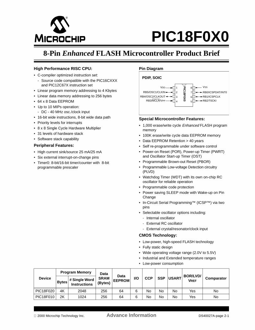
PIC18F0X08-Pin Enhanced FLASH Microcontroller Product Brief
High Performance RISC CPU:
• C-compiler optimized instruction set:
- Source code compatible with the PIC16CXXX and PIC12C67X instruction set
• Linear program memory addressing to 4 Kbytes• Linear data memory addressing to 256 bytes• 64 x 8 Data EEPROM
• Up to 10 MIPs operation: - DC - 40 MHz osc./clock input
• 16-bit wide instructions, 8-bit wide data path• Priority levels for interrupts • 8 x 8 Single Cycle Hardware Multiplier• 31 levels of hardware stack• Software stack capability
Peripheral Features:
• High current sink/source 25 mA/25 mA• Six external interrupt-on-change pins• Timer0: 8-bit/16-bit timer/counter with 8-bit
programmable prescaler
Pin Diagram
Special Microcontroller Features:
• 1,000 erase/write cycle Enhanced FLASH program memory
• 100K erase/write cycle data EEPROM memory• Data EEPROM Retention > 40 years
• Self re-programmable under software control• Power-on Reset (POR), Power-up Timer (PWRT)
and Oscillator Start-up Timer (OST) • Programmable Brown-out Reset (PBOR)• Programmable Low-voltage Detection circuitry
(PLVD)• Watchdog Timer (WDT) with its own on-chip RC
oscillator for reliable operation• Programmable code protection
• Power saving SLEEP mode with Wake-up on Pin Change
• In-Circuit Serial Programming™ (ICSP™) via two pins
• Selectable oscillator options including:- Internal oscillator- External RC oscillator
- External crystal/resonator/clock input
CMOS Technology:
• Low-power, high-speed FLASH technology• Fully static design
• Wide operating voltage range (2.0V to 5.5V) • Industrial and Extended temperature ranges• Low-power consumption
PDIP, SOIC
8
7
6
5
1
2
3
4
PIC
18F0X
0
VDD
RB5/OSC1/CLKIN
RB4/OSC2/CLKOUT
RB3/MCLR/VPP
VSS
RB0/ICSPDAT/INT0
RB1/ICSPCLK
RB2/T0CKI
Device
Program Memory DataSRAM (Bytes)
DataEEPROM
I/O CCP SSP USARTBOR/LVD/
VREFComparator
Bytes# Single Word Instructions
PIC18F020 4K 2048 256 64 6 No No No Yes No
PIC18F010 2K 1024 256 64 6 No No No Yes No
2000 Microchip Technology Inc. Advance Information DS40027A-page 2-1

PIC18F0X0
NOTES:
DS40027A-page 2-2 Advance Information 2000 Microchip Technology Inc.

PIC18F0X28-Pin Enhanced FLASH Microcontroller with 10-bit A/D
Product Brief
High Performance RISC CPU:
• C-compiler optimized instruction set- Source code compatible with the PIC16CXXX
and PIC12C67X instruction set• Linear program memory addressing to 4 Kbytes• Linear data memory addressing to 256 bytes
• 64 x 8 Data EEPROM• Up to 10 MIPs operation:
- DC - 40 MHz osc./clock input
• 16-bit wide instructions, 8-bit wide data path• Priority levels for interrupts • 8 x 8 Single Cycle Hardware Multiplier
• 31 levels of hardware stack• Software stack capability
Peripheral Features:
• High current sink/source 25 mA/25 mA
• Six external interrupt-on-change pins• Timer0: 8-bit/16-bit timer/counter with 8-bit
programmable prescaler
Analog Features:
• 10-bit/4-channel Analog-to-Digital Converter module (A/D)
Pin Diagram
Special Microcontroller Features:
• 1,000 erase/write cycle Enhanced FLASH program memory
• 100K erase/write cycle data EEPROM memory
• Data EEPROM Retention > 40 years• Self re-programmable under software control• Power-on Reset (POR), Power-up Timer (PWRT)
and Oscillator Start-up Timer (OST) • Programmable Brown-out Reset (PBOR)
• Programmable Low-voltage Detection circuitry (PLVD)• Watchdog Timer (WDT) with its own on-chip RC
oscillator for reliable operation• Programmable code protection• Power saving SLEEP mode with Wake-up on Pin
Change• In-Circuit Serial Programming (ICSP™) via two pins
• Selectable oscillator options including:- Internal oscillator- External RC oscillator
- External crystal/resonator/clock input
CMOS Technology:
• Low-power, high-speed FLASH technology• Fully static design
• Wide operating voltage range (2.0V to 5.5V) • Industrial and Extended temperature ranges• Low-power consumption
PDIP, SOIC
8
7
6
5
1
2
3
4
PIC
18F0X
2
VDD
RB5/OSC1/CLKINRB4/AN3/OSC2/
RB3/MCLR/VPP
VSSRB0/AN0/ICSPDAT/INT0RB1/AN1/VREF/ICSPCLKRB2/AN2/T0CKI
CLKOUT
Device
Program Memory DataSRAM (Bytes)
Data EEPROM
I/O10-bit
A/D (ch)CCP SSP USART
BOR/LVD/VREF
ComparatorBytes
# Single Word Instructions
PIC18F022 4K 2048 256 64 6 4 No No No Yes No
PIC18F012 2K 1024 256 64 6 4 No No No Yes No
2000 Microchip Technology Inc. Advance Information DS40028A-page 2-3

PIC18F0X2
NOTES:
DS40028A-page 2-4 Advance Information 2000 Microchip Technology Inc.
SECTION 3PICmicro® 18/20/28-PIN RISC
MICROCONTROLLERS
PIC16F812/816 18-Pin Enhanced FLASH Microcontrollers with 10-bit A/D and CCP Product Brief .......................... 3-1PIC16F62X FLASH-Based 8-bit CMOS Microcontrollers ........................................................................................... 3-3PIC18F1X2 20-Pin Enhanced FLASH Microcontrollers with 10-bit A/D, ECCP and USART Product Brief ................ 3-5PIC16CR73/76 28-Pin CMOS ROM Microcontroller Product Brief ............................................................................. 3-7PIC16F73/76 28-Pin CMOS FLASH Microcontroller Product Brief ............................................................................. 3-9PIC16F745 28-Pin Enhanced FLASH Microcontrollers with Low Speed USB, 8-bit A/D and USART Product Brief ......................................................................................................................................... 3-11PIC16F747 28-Pin Enhanced FLASH Microcontrollers with Low Speed USB, 8-bit A/D and MSSP Product Brief ............................................................................................................................................ 3-13PIC16F872A 28-Pin Enhanced FLASH Microcontroller Product Brief ...................................................................... 3-15PIC16F873A/876A 28-Pin Enhanced FLASH Microcontroller Product Brief ............................................................. 3-17PIC18F2X2 28-Pin Enhanced FLASH Microcontroller w/10-bit A/D Product Brief ................................................... 3-19PIC18F258 28-Pin Enhanced FLASH Microcontrollers with CAN, 10-bit A/D and USART Product Brief ................ 3-21
2000 Microchip Technology Inc. DS00168C-page 3-i

DS00168C-page 3-ii 2000 Microchip Technology Inc.
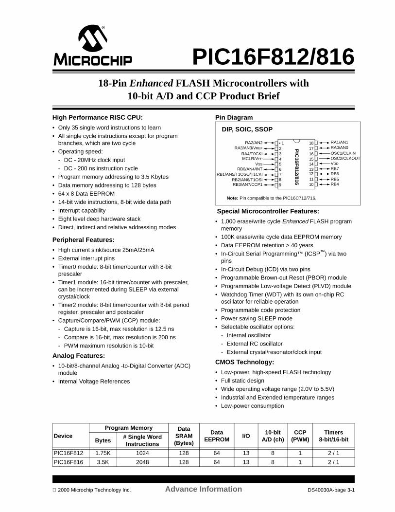
PIC16F812/81618-Pin Enhanced FLASH Microcontrollers with
10-bit A/D and CCP Product Brief
High Performance RISC CPU:
• Only 35 single word instructions to learn• All single cycle instructions except for program
branches, which are two cycle• Operating speed:
- DC - 20MHz clock input- DC - 200 ns instruction cycle
• Program memory addressing to 3.5 Kbytes
• Data memory addressing to 128 bytes• 64 x 8 Data EEPROM• 14-bit wide instructions, 8-bit wide data path
• Interrupt capability• Eight level deep hardware stack• Direct, indirect and relative addressing modes
Peripheral Features:
• High current sink/source 25mA/25mA• External interrupt pins
• Timer0 module: 8-bit timer/counter with 8-bit prescaler
• Timer1 module: 16-bit timer/counter with prescaler, can be incremented during SLEEP via external crystal/clock
• Timer2 module: 8-bit timer/counter with 8-bit period register, prescaler and postscaler
• Capture/Compare/PWM (CCP) module:
- Capture is 16-bit, max resolution is 12.5 ns- Compare is 16-bit, max resolution is 200 ns- PWM maximum resolution is 10-bit
Analog Features:
• 10-bit/8-channel Analog -to-Digital Converter (ADC) module
• Internal Voltage References
Pin Diagram
Special Microcontroller Features:
• 1,000 erase/write cycle Enhanced FLASH program memory
• 100K erase/write cycle data EEPROM memory• Data EEPROM retention > 40 years
• In-Circuit Serial Programming™ (ICSP™) via two pins
• In-Circuit Debug (ICD) via two pins• Programmable Brown-out Reset (PBOR) module• Programmable Low-voltage Detect (PLVD) module
• Watchdog Timer (WDT) with its own on-chip RC oscillator for reliable operation
• Programmable code protection• Power saving SLEEP mode• Selectable oscillator options:
- Internal oscillator- External RC oscillator- External crystal/resonator/clock input
CMOS Technology:
• Low-power, high-speed FLASH technology• Full static design• Wide operating voltage range (2.0V to 5.5V)
• Industrial and Extended temperature ranges• Low-power consumption
PIC
16F
812/8
16
RA2/AN2
RA4/T0CKI
RB0/AN4/INTRB1/AN5/T1OSO/T1CKI
RA0/AN0OSC1/CLKIN
RB7RB6
• 123456
181716151413
78
1211
DIP, SOIC, SSOP
MCLR/VPP
RA3/AN3/VREF
RB2/AN6/T1OSIRB3/AN7/CCP1 RB4
RB5
RA1/AN1
VDD
OSC2/CLKOUTVSS
9 10
Note: Pin compatible to the PIC16C712/716.
DeviceProgram Memory Data
SRAM (Bytes)
Data EEPROM
I/O10-bit
A/D (ch)CCP
(PWM)Timers
8-bit/16-bitBytes# Single Word Instructions
PIC16F812 1.75K 1024 128 64 13 8 1 2 / 1
PIC16F816 3.5K 2048 128 64 13 8 1 2 / 1
2000 Microchip Technology Inc. Advance Information DS40030A-page 3-1
PIC16F812/816
NOTES:
DS40030A-page 3-2 Advance Information 2000 Microchip Technology Inc.
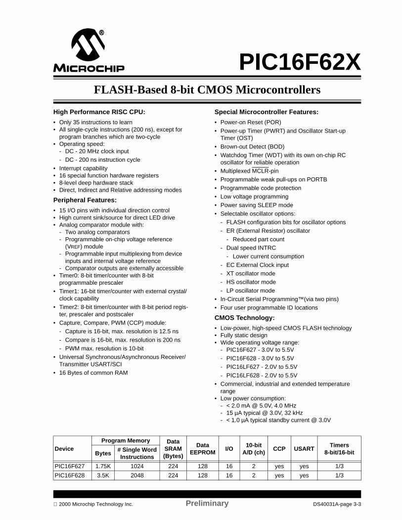
FLASH-Based 8-bit CMOS Microcontrollers
PIC16F62X
High Performance RISC CPU:
• Only 35 instructions to learn• All single-cycle instructions (200 ns), except for
program branches which are two-cycle• Operating speed:
- DC - 20 MHz clock input- DC - 200 ns instruction cycle
• Interrupt capability• 16 special function hardware registers• 8-level deep hardware stack• Direct, Indirect and Relative addressing modes
Peripheral Features:
• 15 I/O pins with individual direction control• High current sink/source for direct LED drive• Analog comparator module with:
- Two analog comparators- Programmable on-chip voltage reference
(VREF) module- Programmable input multiplexing from device
inputs and internal voltage reference- Comparator outputs are externally accessible
• Timer0: 8-bit timer/counter with 8-bit programmable prescaler
• Timer1: 16-bit timer/counter with external crystal/clock capability
• Timer2: 8-bit timer/counter with 8-bit period regis-ter, prescaler and postscaler
• Capture, Compare, PWM (CCP) module:- Capture is 16-bit, max. resolution is 12.5 ns
- Compare is 16-bit, max. resolution is 200 ns- PWM max. resolution is 10-bit
• Universal Synchronous/Asynchronous Receiver/Transmitter USART/SCI
• 16 Bytes of common RAM
2000 Microchip Technology Inc. Prelim
DeviceProgram Memory Data
SRAM (Bytes)
DataEEPROBytes
# Single Word Instructions
PIC16F627 1.75K 1024 224 128
PIC16F628 3.5K 2048 224 128
Special Microcontroller Features:
• Power-on Reset (POR)
• Power-up Timer (PWRT) and Oscillator Start-up Timer (OST)
• Brown-out Detect (BOD)• Watchdog Timer (WDT) with its own on-chip RC
oscillator for reliable operation• Multiplexed MCLR-pin• Programmable weak pull-ups on PORTB
• Programmable code protection• Low voltage programming• Power saving SLEEP mode
• Selectable oscillator options:- FLASH configuration bits for oscillator options- ER (External Resistor) oscillator
- Reduced part count- Dual speed INTRC
- Lower current consumption
- EC External Clock input- XT oscillator mode- HS oscillator mode
- LP oscillator mode• In-Circuit Serial Programming™(via two pins)• Four user programmable ID locations
CMOS Technology:
• Low-power, high-speed CMOS FLASH technology• Fully static design• Wide operating voltage range:
- PIC16F627 - 3.0V to 5.5V- PIC16F628 - 3.0V to 5.5V- PIC16LF627 - 2.0V to 5.5V
- PIC16LF628 - 2.0V to 5.5V• Commercial, industrial and extended temperature
range• Low power consumption:
- < 2.0 mA @ 5.0V, 4.0 MHz- 15 µA typical @ 3.0V, 32 kHz- < 1.0 µA typical standby current @ 3.0V
inary DS40031A-page 3-3
M
I/O10-bit
A/D (ch)CCP USART
Timers8-bit/16-bit
16 2 yes yes 1/3
16 2 yes yes 1/3
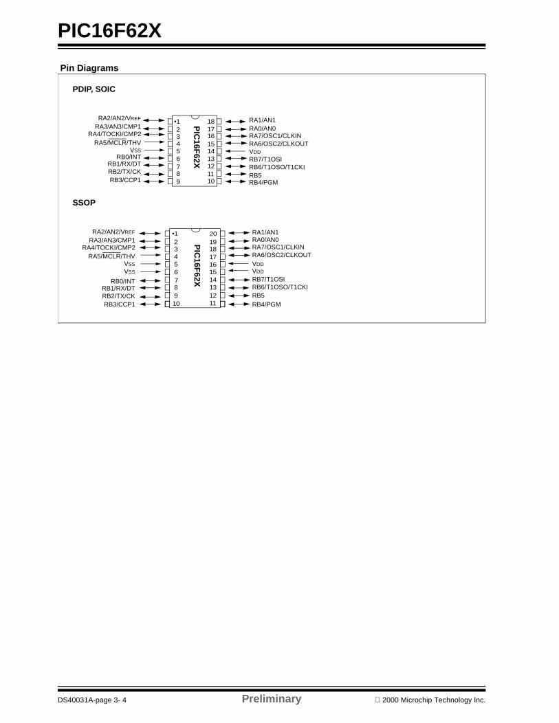
PIC16F62X
Pin Diagrams
2 3 4 5 6 7 8 910
•1
2 3 4 5 6 7 8 9
•1
1918
161514131211
17
1817
151413121110
16
20
PDIP, SOIC
SSOP
PIC
16F62X
PIC
16F62X
RA6/OSC2/CLKOUTRA7/OSC1/CLKIN
VSS
VSS
VDD
VDD
RA1/AN1RA0/AN0
RB6/T1OSO/T1CKIRB7/T1OSI
RB1/RX/DTRB2/TX/CKRB3/CCP1 RB4/PGM
RB5
RA3/AN3/CMP1RA4/TOCKI/CMP2
RA5/MCLR/THV
RB0/INT
RA2/AN2/VREF
VSS
RB1/RX/DTRB2/TX/CKRB3/CCP1
RA3/AN3/CMP1RA4/TOCKI/CMP2
RA5/MCLR/THV
RB0/INT
RA2/AN2/VREF
RA6/OSC2/CLKOUTRA7/OSC1/CLKIN
VDD
RA1/AN1RA0/AN0
RB6/T1OSO/T1CKIRB7/T1OSI
RB4/PGMRB5
DS40031A-page 3- 4 Preliminary 2000 Microchip Technology Inc.
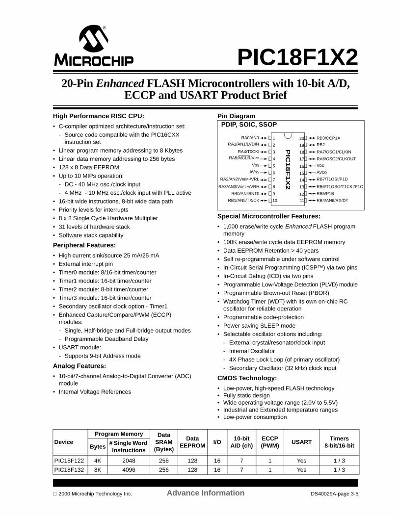
PIC18F1X220-Pin Enhanced FLASH Microcontrollers with 10-bit A/D,
ECCP and USART Product Brief
High Performance RISC CPU:
• C-compiler optimized architecture/instruction set:
- Source code compatible with the PIC16CXX instruction set
• Linear program memory addressing to 8 Kbytes• Linear data memory addressing to 256 bytes • 128 x 8 Data EEPROM
• Up to 10 MIPs operation: - DC - 40 MHz osc./clock input- 4 MHz - 10 MHz osc./clock input with PLL active
• 16-bit wide instructions, 8-bit wide data path• Priority levels for interrupts • 8 x 8 Single Cycle Hardware Multiplier
• 31 levels of hardware stack• Software stack capability
Peripheral Features:
• High current sink/source 25 mA/25 mA
• External interrupt pin• Timer0 module: 8/16-bit timer/counter• Timer1 module: 16-bit timer/counter
• Timer2 module: 8-bit timer/counter• Timer3 module: 16-bit timer/counter• Secondary oscillator clock option - Timer1
• Enhanced Capture/Compare/PWM (ECCP) modules:
- Single, Half-bridge and Full-bridge output modes- Programmable Deadband Delay
• USART module:
- Supports 9-bit Address mode
Analog Features:
• 10-bit/7-channel Analog-to-Digital Converter (ADC) module
• Internal Voltage References
Pin Diagram
Special Microcontroller Features:
• 1,000 erase/write cycle Enhanced FLASH program memory
• 100K erase/write cycle data EEPROM memory• Data EEPROM Retention > 40 years
• Self re-programmable under software control• In-Circuit Serial Programming (ICSP™) via two pins• In-Circuit Debug (ICD) via two pins
• Programmable Low-Voltage Detection (PLVD) module• Programmable Brown-out Reset (PBOR)• Watchdog Timer (WDT) with its own on-chip RC
oscillator for reliable operation
• Programmable code-protection• Power saving SLEEP mode• Selectable oscillator options including:
- External crystal/resonator/clock input- Internal Oscillator- 4X Phase Lock Loop (of primary oscillator)
- Secondary Oscillator (32 kHz) clock input
CMOS Technology:
• Low-power, high-speed FLASH technology• Fully static design• Wide operating voltage range (2.0V to 5.5V) • Industrial and Extended temperature ranges• Low-power consumption
RB3/CCP1A
RB2
RA7/OSC1/CLKIN
RA6/OSC2/CLKOUT
VDD
RB7/T1OSI/P1D
RB6/T1OSO/T1CKI/P1C
RB5/P1B
RB4/AN6/RX/DT
RA0/AN0
RA1/AN1/LVDIN
RA4/T0CKI
RA5/MCLR/VPP
VSS
RA2/AN2/VREF-/VRL
RA3/AN3/VREF+/VRH
RB0/AN4/INT0
RB1/AN5/TX/CK
1
2
3
4
5
6
7
8
9
20
19
18
17
16
15
14
13
12
PIC
18F
1X
2
AVDDAVSS
10 11
PDIP, SOIC, SSOP
DeviceProgram Memory Data
SRAM (Bytes)
Data EEPROM
I/O10-bit
A/D (ch)ECCP (PWM)
USARTTimers
8-bit/16-bitBytes# Single Word Instructions
PIC18F122 4K 2048 256 128 16 7 1 Yes 1 / 3
PIC18F132 8K 4096 256 128 16 7 1 Yes 1 / 3
2000 Microchip Technology Inc. Advance Information DS40029A-page 3-5

PIC18F1X2
NOTES:
DS40029A-page 3-6 Advance Information 2000 Microchip Technology Inc.
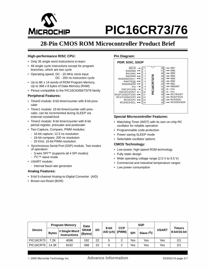
PIC16CR73/7628-Pin CMOS ROM Microcontroller Product Brief
High-performance RISC CPU:
• Only 35 single word instructions to learn
• All single cycle instructions except for program branches, which are two cycle
• Operating speed: DC - 20 MHz clock inputDC - 200 ns instruction cycle
• Up to 8K x 14 words of ROM Program Memory, Up to 368 x 8 bytes of Data Memory (RAM)
• Pinout compatible to the PIC16C63/66/73/76 family
Peripheral Features:
• Timer0 module: 8-bit timer/counter with 8-bit pres-caler
• Timer1 module: 16-bit timer/counter with pres-caler, can be incremented during SLEEP via external crystal/clock
• Timer2 module: 8-bit timer/counter with 8-bit period register, prescaler and postscaler
• Two Capture, Compare, PWM modules:- 16-bit capture; 12.5 ns resolution- 16-bit compare; 200 ns resolution- 20 KHz; 10-bit PWM resolution
• Synchronous Serial Port (SSP) module. Two modes of operation:- 3-wire SPI™ (supports all 4 SPI modes)- I2C™ slave mode
• USART module:- Internal baud rate generator
Analog Features:
• 8-bit 5-channel Analog-to-Digital Converter (A/D) • Brown-out Reset (BOR)
Pin Diagram:
Special Microcontroller Features:
• Watchdog Timer (WDT) with its own on-chip RC oscillator for reliable operation
• Programmable code-protection
• Power saving SLEEP mode• Selectable oscillator options
CMOS Technology:
• Low-power, high-speed ROM technology
• Fully static design• Wide operating voltage range (2.0 V to 5.5 V) • Commercial and Industrial temperature ranges
• Low power consumption
PIC
16C
R73
/76
1011
23456
1
87
9
121314 15
1617181920
232425262728
2221
MCLRRA0/AN0RA1/AN1RA2/AN2
RA3/AN3/VREF+RA4/T0CKI
RA5/AN4/SSVSS
OSC1/CLKINOSC2/CLKOUT
RC0/T1OSO/T1CKIRC1/T1OSI/CCP2
RC2/CCP1RC3/SCK/SCL
RB7RB6RB5RB4RB3RB2RB1RB0/INTVDDVSSRC7/RX/DTRC6/TX/CKRC5/SDORC4/SDI/SDA
PDIP, SOIC, SSOP
Device
Program Memory Data SRAM (Bytes)
I/O8-bit
A/D (ch)CCP
(PWM)
SSP
USARTTimers
8-bit/16-bitBytes# Single Word Instructions
SPI Slave I2C
PIC16CR73 7.2K 4096 192 22 5 2 Yes Yes Yes 2/1
PIC16CR76 14.3K 8192 368 22 5 2 Yes Yes Yes 2/1
2000 Microchip Technology Inc. Advance Information DS30317A-page 3-7
PIC16CR73/76
NOTES:
DS30317A-page 3-8 Advance Information 2000 Microchip Technology Inc.
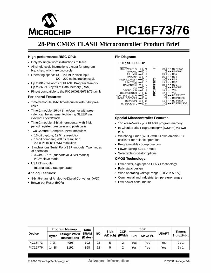
PIC16F73/7628-Pin CMOS FLASH Microcontroller Product Brief
High-performance RISC CPU:
• Only 35 single word instructions to learn
• All single cycle instructions except for program branches, which are two cycle
• Operating speed: DC - 20 MHz clock inputDC - 200 ns instruction cycle
• Up to 8K x 14 words of FLASH Program Memory, Up to 368 x 8 bytes of Data Memory (RAM)
• Pinout compatible to the PIC16C63/66/73/76 family
Peripheral Features:
• Timer0 module: 8-bit timer/counter with 8-bit pres-caler
• Timer1 module: 16-bit timer/counter with pres-caler, can be incremented during SLEEP via external crystal/clock
• Timer2 module: 8-bit timer/counter with 8-bit period register, prescaler and postscaler
• Two Capture, Compare, PWM modules:- 16-bit capture; 12.5 ns resolution- 16-bit compare; 200 ns resolution- 20 kHz; 10-bit PWM resolution
• Synchronous Serial Port (SSP) module. Two modes of operation:- 3-wire SPI™ (supports all 4 SPI modes)- I2C™ slave mode
• USART module:- Internal baud rate generator
Analog Features:
• 8-bit 5-channel Analog-to-Digital Converter (A/D)• Brown-out Reset (BOR)
Pin Diagram:
Special Microcontroller Features:
• 100 erase/write cycle FLASH program memory
• In-Circuit Serial Programming™ (ICSP™) via two pins
• Watchdog Timer (WDT) with its own on-chip RC oscillator for reliable operation
• Programmable code-protection• Power saving SLEEP mode• Selectable oscillator options
CMOS Technology:
• Low-power, high-speed FLASH technology• Fully static design• Wide operating voltage range (2.0 V to 5.5 V)
• Commercial and Industrial temperature ranges• Low power consumption
PIC
16F
73/7
6
1011
23456
1
87
9
121314 15
1617181920
232425262728
2221
MCLR/VPP/THVRA0/AN0RA1/AN1RA2/AN2
RA3/AN3/VREF+RA4/T0CKI
RA5/AN4/SSVSS
OSC1/CLKINOSC2/CLKOUT
RC0/T1OSO/T1CKIRC1/T1OSI/CCP2
RC2/CCP1RC3/SCK/SCL
RB7/PGDRB6/PGCRB5RB4RB3RB2RB1RB0/INTVDDVSSRC7/RX/DTRC6/TX/CKRC5/SDORC4/SDI/SDA
PDIP, SOIC, SSOP
DeviceProgram Memory Data
SRAM (Bytes)
I/O8-bit
A/D (ch)CCP
(PWM)
SSPUSART
Timers8-bit/16-bitBytes
# Single Word Instructions
SPI Slave I2C
PIC16F73 7.2K 4096 192 22 5 2 Yes Yes Yes 2 / 1
PIC16F76 14.3K 8192 368 22 5 2 Yes Yes Yes 2 / 1
2000 Microchip Technology Inc. Advance Information DS30311A-page 3-9

PIC16F73/76
NOTES:
DS30311A-page 3-10 Advance Information 2000 Microchip Technology Inc.
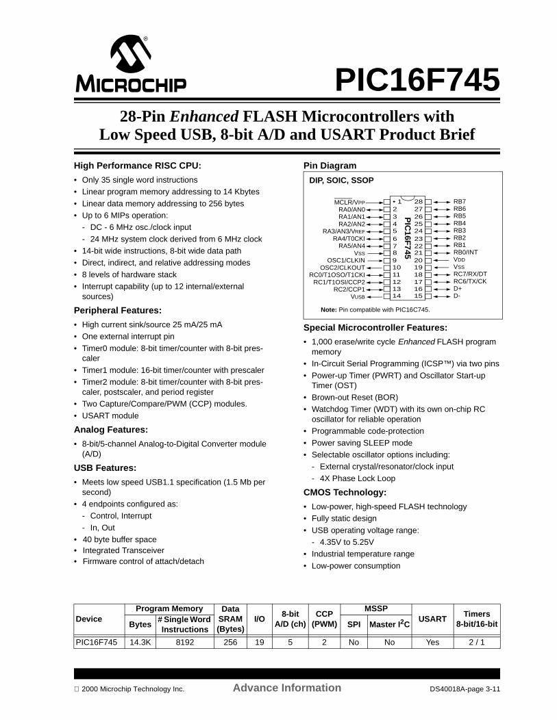
PIC16F74528-Pin Enhanced FLASH Microcontrollers with
Low Speed USB, 8-bit A/D and USART Product Brief
High Performance RISC CPU:
• Only 35 single word instructions• Linear program memory addressing to 14 Kbytes
• Linear data memory addressing to 256 bytes • Up to 6 MIPs operation:
- DC - 6 MHz osc./clock input
- 24 MHz system clock derived from 6 MHz clock• 14-bit wide instructions, 8-bit wide data path• Direct, indirect, and relative addressing modes
• 8 levels of hardware stack• Interrupt capability (up to 12 internal/external
sources)
Peripheral Features:
• High current sink/source 25 mA/25 mA• One external interrupt pin
• Timer0 module: 8-bit timer/counter with 8-bit pres-caler
• Timer1 module: 16-bit timer/counter with prescaler • Timer2 module: 8-bit timer/counter with 8-bit pres-
caler, postscaler, and period register• Two Capture/Compare/PWM (CCP) modules.
• USART module
Analog Features:
• 8-bit/5-channel Analog-to-Digital Converter module (A/D)
USB Features:
• Meets low speed USB1.1 specification (1.5 Mb per second)
• 4 endpoints configured as:- Control, Interrupt
- In, Out• 40 byte buffer space• Integrated Transceiver• Firmware control of attach/detach
Pin Diagram
Special Microcontroller Features:
• 1,000 erase/write cycle Enhanced FLASH program memory
• In-Circuit Serial Programming (ICSP™) via two pins
• Power-up Timer (PWRT) and Oscillator Start-up Timer (OST)
• Brown-out Reset (BOR)• Watchdog Timer (WDT) with its own on-chip RC
oscillator for reliable operation• Programmable code-protection
• Power saving SLEEP mode• Selectable oscillator options including:
- External crystal/resonator/clock input
- 4X Phase Lock Loop
CMOS Technology:
• Low-power, high-speed FLASH technology• Fully static design
• USB operating voltage range:- 4.35V to 5.25V
• Industrial temperature range
• Low-power consumption
MCLR/VPPRA0/AN0RA1/AN1RA2/AN2
RA3/AN3/VREF
RA4/T0CKIRA5/AN4
VSSOSC1/CLKIN
OSC2/CLKOUTRC0/T1OSO/T1CKI
RC1/T1OSI/CCP2RC2/CCP1
VUSB
RB7RB6RB5RB4RB3RB2RB1RB0/INTVDD
VSSRC7/RX/DTRC6/TX/CKD+D-
• 1234567891011121314
2827262524232221201918171615
PIC
16F745
DIP, SOIC, SSOP
Note: Pin compatible with PIC16C745.
DeviceProgram Memory Data
SRAM (Bytes)
I/O8-bit
A/D (ch)CCP
(PWM)
MSSPUSART
Timers8-bit/16-bitBytes
# Single Word Instructions
SPI Master I2C
PIC16F745 14.3K 8192 256 19 5 2 No No Yes 2 / 1
2000 Microchip Technology Inc. Advance Information DS40018A-page 3-11

PIC16F745
NOTES:
DS40018A-page 3-12 Advance Information 2000 Microchip Technology Inc.

PIC16F74728-Pin Enhanced FLASH Microcontrollers with
Low Speed USB, 8-bit A/D and MSSP Product Brief
High Performance RISC CPU:
• Only 35 single word instructions• Linear program memory addressing to 14 Kbytes• Linear data memory addressing to 256 bytes
• Up to 6 MIPs operation: - DC - 6 MHz osc./clock input- 24 MHz system clock derived from 6 MHz clock
• 14-bit wide instructions, 8-bit wide data path• Direct, indirect, and relative addressing modes• 8 levels of hardware stack
• Interrupt capability (up to 12 internal/external sources)
Peripheral Features:
• High current sink/source 25 mA/25 mA• One external interrupt pin• Timer0 module: 8-bit timer/counter with 8-bit
prescaler
• Timer1 module: 16-bit timer/counter with prescaler • Timer2 module: 8-bit timer/counter with 8-bit
prescaler, postscaler, and period register• Two Capture/Compare/PWM (CCP) modules • Master Synchronous Serial Port (MSSP) module.
Two modes of operation:- 3-wire SPI™ (supports all 4 SPI modes)
- I2C™ Master and Slave mode
Analog Features:
• 8-bit/5-channel Analog-to-Digital Converter module (A/D)
USB Features:
• Meets low speed USB1.1 specification (1.5 Mb per second)
• 4 endpoints configured as:
- Control, Interrupt- In, Out
• 40 byte buffer space• Integrated Transceiver• Firmware control of attach/detach
Pin Diagram
Special Microcontroller Features:
• 1,000 erase/write cycle Enhanced FLASH program memory
• In-Circuit Serial Programming (ICSP™) via two pins• Power-up Timer (PWRT) and Oscillator Start-up
Timer (OST)• Brown-out Reset (BOR)
• Watchdog Timer (WDT) with its own on-chip RC oscillator for reliable operation
• Programmable code protection• Power saving SLEEP mode• Selectable oscillator options including:
- External crystal/resonator/clock input- 4X Phase Lock Loop
CMOS Technology:
• Low-power, high-speed FLASH technology
• Fully static design• USB operating voltage range:
- 4.35V to 5.25V
• Industrial temperature range• Low-power consumption
MCLR/VPP
RA0/AN0RA1/AN1RA2/AN2
RA3/AN3/VREF
RA4/T0CKIRA5/AN4
VSSOSC1/CLKIN
OSC2/CLKOUTRC0/T1OSO/T1CKI
RC1/T1OSI/CCP2RC2/CCP1/SCK/SCL
VUSB
RB7RB6RB5RB4RB3RB2RB1RB0/INTVDD
VSSRC7/SDORC6/SDI/SDAD+D-
• 1234567891011121314
2827262524232221201918171615
PIC
16F747
DIP, SOIC, SSOP
DeviceProgram Memory Data
SRAM (Bytes)
I/O8-bit
A/D (ch)CCP
(PWM)
MSSPUSART
Timers8-bit/16-bitBytes
# Single Word Instructions
SPI Master I2C
PIC16F747 14.3K 8192 256 19 5 2 Yes Yes No 2 / 1
2000 Microchip Technology Inc. Advance Information DS40023A-page 3-13

PIC16F747
NOTES:
DS40023A-page 3-14 Advance Information 2000 Microchip Technology Inc.
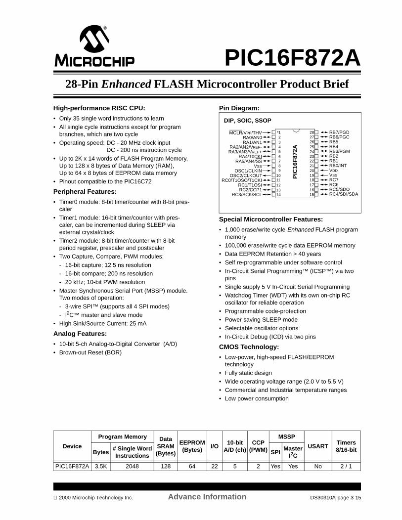
PIC16F872A28-Pin Enhanced FLASH Microcontroller Product Brief
High-performance RISC CPU:
• Only 35 single word instructions to learn
• All single cycle instructions except for program branches, which are two cycle
• Operating speed: DC - 20 MHz clock input DC - 200 ns instruction cycle
• Up to 2K x 14 words of FLASH Program Memory, Up to 128 x 8 bytes of Data Memory (RAM), Up to 64 x 8 bytes of EEPROM data memory
• Pinout compatible to the PIC16C72
Peripheral Features:
• Timer0 module: 8-bit timer/counter with 8-bit pres-caler
• Timer1 module: 16-bit timer/counter with pres-caler, can be incremented during SLEEP via external crystal/clock
• Timer2 module: 8-bit timer/counter with 8-bit period register, prescaler and postscaler
• Two Capture, Compare, PWM modules:
- 16-bit capture; 12.5 ns resolution- 16-bit compare; 200 ns resolution- 20 kHz; 10-bit PWM resolution
• Master Synchronous Serial Port (MSSP) module. Two modes of operation:
- 3-wire SPI™ (supports all 4 SPI modes)- I2C™ master and slave mode
• High Sink/Source Current: 25 mA
Analog Features:
• 10-bit 5-ch Analog-to-Digital Converter (A/D) • Brown-out Reset (BOR)
Pin Diagram:
Special Microcontroller Features:
• 1,000 erase/write cycle Enhanced FLASH program memory
• 100,000 erase/write cycle data EEPROM memory• Data EEPROM Retention > 40 years• Self re-programmable under software control
• In-Circuit Serial Programming™ (ICSP™) via two pins
• Single supply 5 V In-Circuit Serial Programming• Watchdog Timer (WDT) with its own on-chip RC
oscillator for reliable operation• Programmable code-protection• Power saving SLEEP mode
• Selectable oscillator options• In-Circuit Debug (ICD) via two pins
CMOS Technology:
• Low-power, high-speed FLASH/EEPROM technology
• Fully static design
• Wide operating voltage range (2.0 V to 5.5 V) • Commercial and Industrial temperature ranges• Low power consumption
PIC
16F
872A
1011
23456
1
87
9
121314 15
1617181920
232425262728
2221
MCLR/VPP/THVRA0/AN0RA1/AN1
RA2/AN2/VREF-RA3/AN3/VREF+
RA4/T0CKIRA5/AN4/SS
VSSOSC1/CLKIN
OSC2/CLKOUTRC0/T1OSO/T1CKI
RC1/T1OSIRC2/CCP1
RC3/SCK/SCL
RB7/PGDRB6/PGCRB5RB4RB3/PGMRB2RB1RB0/INTVDDVSSRC7RC6RC5/SDORC4/SDI/SDA
DIP, SOIC, SSOP
Device
Program Memory DataSRAM(Bytes)
EEPROM(Bytes)
I/O10-bit
A/D (ch)CCP
(PWM)
MSSP
USARTTimers8/16-bitBytes
# Single WordInstructions
SPIMaster
I2C
PIC16F872A 3.5K 2048 128 64 22 5 2 Yes Yes No 2 / 1
2000 Microchip Technology Inc. Advance Information DS30310A-page 3-15

PIC16F872A
NOTES:
DS30310A-page 3-16 Advance Information 2000 Microchip Technology Inc.

PIC16F873A/876A28-Pin Enhanced FLASH Microcontroller Product Brief
High-performance RISC CPU:
• Only 35 single word instructions to learn
• All single cycle instructions except for program branches, which are two cycle
• Operating speed: DC - 20 MHz clock inputDC - 200 ns instruction cycle
• Up to 8K x 14 words of FLASH Program Memory, Up to 368 x 8 bytes of Data Memory (RAM), Up to 256 x 8 bytes of EEPROM data memory
• Pinout compatible to the PIC16C63/66/73/76 family
Peripheral Features:
• Timer0 module: 8-bit timer/counter with 8-bit pres-caler
• Timer1 module: 16-bit timer/counter with pres-caler, can be incremented during SLEEP via external crystal/clock
• Timer2 module: 8-bit timer/counter with 8-bit period register, prescaler and postscaler
• Two Capture, Compare, PWM modules
• Master Synchronous Serial Port (MSSP) module. Two modes of operation:
- 3-wire SPI™ (supports all 4 SPI modes)- I2C™ master and slave mode
• Addressable USART module:
- Supports interrupt on Address bit• High Sink/Source Current: 25 mA
Analog Features:
• 10-bit 5-ch Analog-to-Digital Converter (A/D)
• Brown-out Reset (BOR)
Pin Diagram:
Special Microcontroller Features:
• 1,000 erase/write cycle Enhanced FLASH program memory
• 100,000 erase/write cycle data EEPROM memory• Data EEPROM Retention > 40 years
• Self re-programmable under software control• In-Circuit Serial Programming™ (ICSP™) via two
pins• Single supply 5 V In-Circuit Serial Programming• Watchdog Timer (WDT) with its own on-chip RC
oscillator for reliable operation• Programmable code-protection
• Power saving SLEEP mode• Selectable oscillator options• In-Circuit Debug (ICD) via two pins
CMOS Technology:
• Low-power, high-speed FLASH/EEPROM technology
• Fully static design• Wide operating voltage range (2.0 V to 5.5 V) • Commercial and Industrial temperature ranges
• Low power consumption
PIC
16F
873A
/876
A
1011
23456
1
87
9
121314 15
1617181920
232425262728
2221
MCLR/VPP/THVRA0/AN0RA1/AN1
RA2/AN2/VREF-RA3/AN3/VREF+
RA4/T0CKIRA5/AN4/SS
VSSOSC1/CLKIN
OSC2/CLKOUTRC0/T1OSO/T1CKI
RC1/T1OSI/CCP2RC2/CCP1
RC3/SCK/SCL
RB7/PGDRB6/PGCRB5RB4RB3/PGMRB2RB1RB0/INTVDDVSSRC7/RX/DTRC6/TX/CKRC5/SDORC4/SDI/SDA
DIP, SOIC, SSOP
DeviceProgram Memory Data
SRAM(Bytes)
EEPROM(Bytes)
I/O10-bit
A/D (ch)CCP
(PWM)
MSSPUSART
Timers8/16-bitBytes
# Single WordInstructions
SPIMaster
I2C
PIC16F873A 7.2K 4096 192 64 22 5 2 Yes Yes Yes 2 / 1
PIC16F876A 14.3K 8192 368 256 22 5 2 Yes Yes Yes 2 / 1
2000 Microchip Technology Inc. Advance Information DS30303A-page 3-17
PIC16F873A/876A
NOTES:
DS30303A-page 3-18 Advance Information 2000 Microchip Technology Inc.

PIC18F2X228-Pin Enhanced FLASH Microcontroller w/10-bit A/D
Product Brief
High Performance RISC CPU: • C-compiler optimized architecture/instruction set:
- Source code compatible with the PIC16CXXX instruction set
• Linear program memory addressing to 32 Kbytes Linear data memory addressing to 1.5 Kbytes
• Up to 256 x 8 bytes of EEPROM data memory• Up to 10 MIPs operation:
- DC - 40 MHz clock- 4 MHz - 10 MHz clock with PLL active
• 16-bit wide instructions, 8-bit wide data path• Priority levels for interrupts • 8 x 8 Single Cycle Hardware Multiplier• Pinout compatible to PIC16C63/66/73/76 family
Peripheral Features:• High current sink/source 25 mA/25 mA• Three external interrupt pins• Timer0 module: 8/16-bit timer/counter• Timer1 module: 16-bit timer/counter • Timer2 module: 8-bit timer/counter• Timer3 module: 16-bit timer/counter • Secondary oscillator clock option - Timer1/Timer3• Two Capture/Compare/PWM (CCP) modules.
CCP pins can be configured as:- Capture is 16-bit, max resolution 6.25 ns- Compare is 16-bit, max resolution 100 ns- PWM output: PWM resolution is 1- to 10-bit.- Max. PWM freq. @: 8-bit resolution = 156 kHz- 10-bit resolution = 39 kHz
• Master Synchronous Serial Port (MSSP) module. Two modes of operation:- 3-wire SPI™ (supports all 4 SPI modes)- I2C™ master and slave mode
• Addressable USART module:- Supports interrupt on Address bit
Analog Features:• 10-bit 5-ch Analog-to-Digital Converter (A/D)• Low-Voltage Detection (LVD) module• Programmable Brown-out Reset (BOR)
Pin Diagram:
Special Microcontroller Features:• 1,000 erase/write cycle Enhanced FLASH program
memory• 100,000 erase/write cycle data EEPROM memory• Data EEPROM Retention > 40 years• Self re-programmable under software control• In-Circuit Serial Programming™ (ICSP™) via two
pins
• Single supply 5 V In-Circuit Serial Programming• Watchdog Timer (WDT) with its own on-chip RC
oscillator for reliable operation• Programmable code-protection• Power saving SLEEP mode• Selectable oscillator options including:
- 4X Phase Lock Loop (of primary oscillator)- Secondary Oscillator (32 kHz) clock input
• In-Circuit Debug (ICD) via two pins
CMOS Technology:• Low-power, high-speed FLASH/EEPROM
technology• Fully static design• Wide operating voltage range (2.5 V to 5.5 V) • Industrial and Extended temperature ranges• Low power consumption
PIC
18F
2X2
1011
2
345
6
1
87
9
12
1314 15
16
17
181920
232425
262728
2221
MCLR/VPP
RA0/AN0RA1/AN1
RA2/AN2/VREF-RA3/AN3/VREF+
RA4/T0CKIRA5/AN4/SS/LVDIN
VSS
OSC1/CLKIOSC2/CLKO/RA6
RC0/T1OSO/T1CKIRC1/T1OSI/CCP2*
RC2/CCP1RC3/SCK/SCL
RB7RB6RB5RB4RB3/CCP2*RB2/INT2RB1/INT1RB0/INT0VDD
VSS
RC7/RX/DTRC6/TX/CKRC5/SDORC4/SDI/SDA
* RB3 is the alternate pin for the CCP2 pin multiplexing.
PDIP, SOIC, SSOP
DeviceProgram Memory Data
SRAM(Bytes)
EEPROM(Bytes)
I/O10-bit
A/D (ch)CCP
(PWM)
MSSPUSART
Timers8-bit/16-bitBytes
# Single WordInstructions
SPIMaster
I2C
PIC18F242 16K 8192 512 256 23 5 2 Yes Yes Yes 1 / 3
PIC18F252 32K 16384 1536 256 23 5 2 Yes Yes Yes 1 / 3
2000 Microchip Technology Inc. Advanced Information DS30299A-page 3-19

PIC18F2x2
NOTES:
DS30299A-page 3-20 Advanced Information 2000 Microchip Technology Inc.
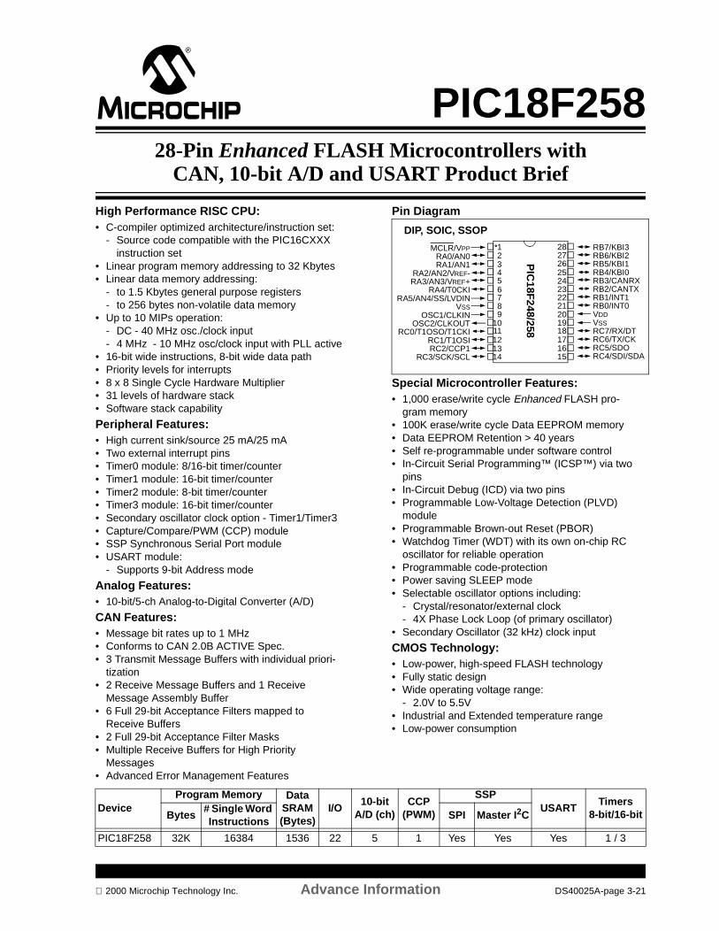
PIC18F25828-Pin Enhanced FLASH Microcontrollers with
CAN, 10-bit A/D and USART Product Brief
High Performance RISC CPU: • C-compiler optimized architecture/instruction set:
- Source code compatible with the PIC16CXXX instruction set
• Linear program memory addressing to 32 Kbytes• Linear data memory addressing:
- to 1.5 Kbytes general purpose registers- to 256 bytes non-volatile data memory
• Up to 10 MIPs operation: - DC - 40 MHz osc./clock input- 4 MHz - 10 MHz osc/clock input with PLL active
• 16-bit wide instructions, 8-bit wide data path• Priority levels for interrupts • 8 x 8 Single Cycle Hardware Multiplier• 31 levels of hardware stack• Software stack capability
Peripheral Features:• High current sink/source 25 mA/25 mA• Two external interrupt pins• Timer0 module: 8/16-bit timer/counter• Timer1 module: 16-bit timer/counter • Timer2 module: 8-bit timer/counter• Timer3 module: 16-bit timer/counter • Secondary oscillator clock option - Timer1/Timer3• Capture/Compare/PWM (CCP) module• SSP Synchronous Serial Port module• USART module:
- Supports 9-bit Address mode
Analog Features:• 10-bit/5-ch Analog-to-Digital Converter (A/D)
CAN Features:• Message bit rates up to 1 MHz• Conforms to CAN 2.0B ACTIVE Spec.• 3 Transmit Message Buffers with individual priori-
tization• 2 Receive Message Buffers and 1 Receive
Message Assembly Buffer• 6 Full 29-bit Acceptance Filters mapped to
Receive Buffers• 2 Full 29-bit Acceptance Filter Masks• Multiple Receive Buffers for High Priority
Messages• Advanced Error Management Features
Pin Diagram
Special Microcontroller Features:• 1,000 erase/write cycle Enhanced FLASH pro-
gram memory• 100K erase/write cycle Data EEPROM memory• Data EEPROM Retention > 40 years• Self re-programmable under software control• In-Circuit Serial Programming™ (ICSP™) via two
pins• In-Circuit Debug (ICD) via two pins• Programmable Low-Voltage Detection (PLVD)
module• Programmable Brown-out Reset (PBOR)• Watchdog Timer (WDT) with its own on-chip RC
oscillator for reliable operation• Programmable code-protection• Power saving SLEEP mode• Selectable oscillator options including:
- Crystal/resonator/external clock- 4X Phase Lock Loop (of primary oscillator)
• Secondary Oscillator (32 kHz) clock input
CMOS Technology:• Low-power, high-speed FLASH technology• Fully static design• Wide operating voltage range:
- 2.0V to 5.5V• Industrial and Extended temperature range• Low-power consumption
PIC
18F248/25810
11
23456
1
87
9
121314 15
1617181920
232425262728
2221
MCLR/VPPRA0/AN0RA1/AN1
RA2/AN2/VREF-RA3/AN3/VREF+
RA4/T0CKIRA5/AN4/SS/LVDIN
VSSOSC1/CLKIN
OSC2/CLKOUTRC0/T1OSO/T1CKI
RC1/T1OSIRC2/CCP1
RC3/SCK/SCL
RB7/KBI3RB6/KBI2RB5/KBI1RB4/KBI0RB3/CANRXRB2/CANTXRB1/INT1RB0/INT0VDDVSSRC7/RX/DTRC6/TX/CKRC5/SDORC4/SDI/SDA
DIP, SOIC, SSOP
DeviceProgram Memory Data
SRAM (Bytes)
I/O10-bit
A/D (ch)CCP
(PWM)
SSPUSART
Timers8-bit/16-bitBytes
# Single Word Instructions
SPI Master I2C
PIC18F258 32K 16384 1536 22 5 1 Yes Yes Yes 1 / 3
2000 Microchip Technology Inc. Advance Information DS40025A-page 3-21
PIC18F258
DS40025A-page 3-22 Advance Information 2000 Microchip Technology Inc.
SECTION 4PICmicro® 40-PIN RISC
MICROCONTROLLERS
PIC16CR74/77 40-Pin CMOS ROM Microcontroller Product Brief ............................................................................. 4-1PIC16F74/77 40-Pin CMOS FLASH Microcontroller Product Brief ............................................................................. 4-3
PIC16F765 40-Pin Enhanced FLASH Microcontrollers with Low Speed USB, 8-bit A/D and USART Product Brief .. 4-5PIC16F767 40-Pin Enhanced FLASH Microcontrollers with Low Speed USB, 8-bit A/D and MSSP Product Brief .... 4-7PIC16F874A/877A 40-Pin Enhanced FLASH Microcontroller Product Brief ............................................................... 4-9
PIC18F4X2 40-Pin Enhanced FLASH Microcontroller w/10-bit A/D Product Brief ................................................... 4-11PIC18F458 40-Pin Enhanced FLASH Microcontrollers with CAN, 10-bit A/D and USART Product Brief ................ 4-13
2000 Microchip Technology Inc. DS00168C-page 4-i

DS00168C-page 4-ii 2000 Microchip Technology Inc.
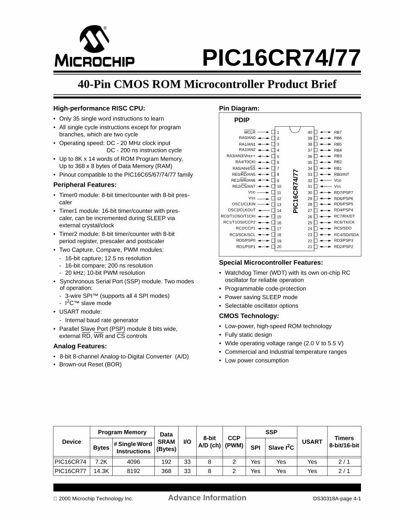
PIC16CR74/7740-Pin CMOS ROM Microcontroller Product Brief
High-performance RISC CPU:
• Only 35 single word instructions to learn
• All single cycle instructions except for program branches, which are two cycle
• Operating speed: DC - 20 MHz clock inputDC - 200 ns instruction cycle
• Up to 8K x 14 words of ROM Program Memory, Up to 368 x 8 bytes of Data Memory (RAM)
• Pinout compatible to the PIC16C65/67/74/77 family
Peripheral Features:
• Timer0 module: 8-bit timer/counter with 8-bit pres-caler
• Timer1 module: 16-bit timer/counter with pres-caler, can be incremented during SLEEP via external crystal/clock
• Timer2 module: 8-bit timer/counter with 8-bit period register, prescaler and postscaler
• Two Capture, Compare, PWM modules:- 16-bit capture; 12.5 ns resolution- 16-bit compare; 200 ns resolution- 20 kHz; 10-bit PWM resolution
• Synchronous Serial Port (SSP) module. Two modes of operation:- 3-wire SPI™ (supports all 4 SPI modes)- I2C™ slave mode
• USART module:- Internal baud rate generator
• Parallel Slave Port (PSP) module 8 bits wide, external RD, WR and CS controls
Analog Features:
• 8-bit 8-channel Analog-to-Digital Converter (A/D) • Brown-out Reset (BOR)
Pin Diagram:
Special Microcontroller Features:
• Watchdog Timer (WDT) with its own on-chip RC oscillator for reliable operation
• Programmable code-protection
• Power saving SLEEP mode• Selectable oscillator options
CMOS Technology:
• Low-power, high-speed ROM technology
• Fully static design• Wide operating voltage range (2.0 V to 5.5 V) • Commercial and Industrial temperature ranges
• Low power consumption
RB7RB6
RB5
RB4RB3
RB2
RB1
RB0/INT
VDD
VSS
RD7/PSP7
RD6/PSP6RD5/PSP5
RD4/PSP4
RC7/RX/DT
RC6/TX/CK
RC5/SDO
RC4/SDI/SDARD3/PSP3
RD2/PSP2
MCLRRA0/AN0
RA1/AN1RA2/AN2
RA3/AN3/VREF+
RA4/T0CKI
RA5/AN4/SS
RE0/RD/AN5
RE1/WR/AN6
RE2/CS/AN7VDD
VSS
OSC1/CLKIN
OSC2/CLKOUT
RC0/T1OSO/T1CKI
RC1/T1OSI/CCP2
RC2/CCP1
RC3/SCK/SCLRD0/PSP0
RD1/PSP1
1
2
3
4
5
6
7
8
910
11
12
13
14
15
16
17
18
1920
40
39
38
37
36
35
34
33
3231
30
2928
27
26
25
24
23
2221
PIC
16C
R74
/77
PDIP
Device
Program Memory Data SRAM (Bytes)
I/O8-bit
A/D (ch)CCP
(PWM)
SSP
USARTTimers
8-bit/16-bitBytes# Single Word Instructions
SPI Slave I2C
PIC16CR74 7.2K 4096 192 33 8 2 Yes Yes Yes 2 / 1
PIC16CR77 14.3K 8192 368 33 8 2 Yes Yes Yes 2 / 1
2000 Microchip Technology Inc. Advance Information DS30318A-page 4-1
PIC16CR74/77
NOTES:
DS30318A-page 4-2 Advance Information 2000 Microchip Technology Inc.

PIC16F74/7740-Pin CMOS FLASH Microcontroller Product Brief
High-performance RISC CPU:
• Only 35 single word instructions to learn
• All single cycle instructions except for program branches, which are two cycle
• Operating speed: DC - 20 MHz clock inputDC - 200 ns instruction cycle
• Up to 8K x 14 words of FLASH Program Memory, Up to 368 x 8 bytes of Data Memory (RAM)
• Pinout compatible to the PIC16C65/67/74/77 family
Peripheral Features:
• Timer0 module: 8-bit timer/counter with 8-bit pres-caler
• Timer1 module: 16-bit timer/counter with pres-caler, can be incremented during SLEEP via external crystal/clock
• Timer2 module: 8-bit timer/counter with 8-bit period register, prescaler and postscaler
• Two Capture, Compare, PWM modules:- 16-bit capture; 12.5 ns resolution- 16-bit compare; 200 ns resolution- 20KHz; 10-bit PWM resolution
• Synchronous Serial Port (SSP) module. Two modes of operation:- 3-wire SPI™ (supports all 4 SPI modes)- I2C™ slave mode
• USART module:- Internal baud rate generator
• Parallel Slave Port (PSP) module, 8 bits wide, external RD, WR and CS controls
Analog Features:
• 8-bit 8-channel Analog-to-Digital Converter (A/D)• Brown-out Reset (BOR)
Pin Diagram:
Special Microcontroller Features:
• 100 erase/write cycle FLASH program memory
• In-Circuit Serial Programming™ (ICSP™) via two pins
• Watchdog Timer (WDT) with its own on-chip RC oscillator for reliable operation
• Programmable code-protection• Power saving SLEEP mode• Selectable oscillator options
CMOS Technology:
• Low-power, high-speed FLASH/EEPROM technology
• Fully static design• Wide operating voltage range (2.0 V to 5.5 V) • Commercial and Industrial temperature ranges
• Low power consumption
RB7/PGDRB6/PGC
RB5
RB4RB3
RB2
RB1
RB0/INT
VDD
VSS
RD7/PSP7
RD6/PSP6RD5/PSP5
RD4/PSP4
RC7/RX/DT
RC6/TX/CK
RC5/SDO
RC4/SDI/SDARD3/PSP3
RD2/PSP2
MCLR/VPP/THVRA0/AN0
RA1/AN1RA2/AN2
RA3/AN3/VREF+
RA4/T0CKI
RA5/AN4/SS
RE0/RD/AN5
RE1/WR/AN6
RE2/CS/AN7VDD
VSS
OSC1/CLKIN
OSC2/CLKOUT
RC0/T1OSO/T1CKI
RC1/T1OSI/CCP2
RC2/CCP1
RC3/SCK/SCLRD0/PSP0
RD1/PSP1
1
2
3
4
5
6
7
8
910
11
12
13
14
15
16
17
18
1920
40
39
38
37
36
35
34
33
3231
30
2928
27
26
25
24
23
2221
PIC
16F
74/7
7
PDIP
DeviceProgram Memory Data
SRAM (Bytes)
I/O8-bit
A/D (ch)CCP
(PWM)
SSPUSART
Timers8-bit/16-bitBytes
# Single Word Instructions
SPI Slave I2C
PIC16F74 7.2K 4096 192 33 8 2 Yes Yes Yes 2 / 1
PIC16F77 14.3K 8192 368 33 8 2 Yes Yes Yes 2 / 1
2000 Microchip Technology Inc. Advance Information DS30308A-page 4-3

PIC16F74/77
NOTES:
DS30308A-page 4-4 Advance Information 2000 Microchip Technology Inc.
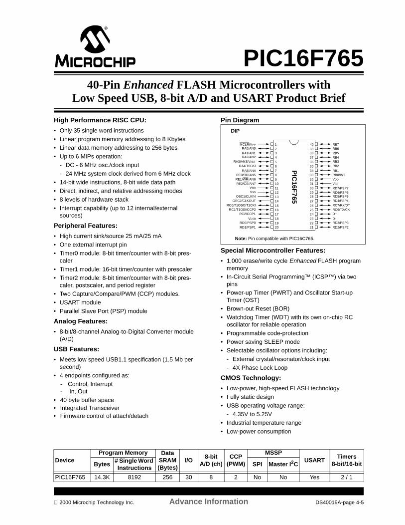
PIC16F76540-Pin Enhanced FLASH Microcontrollers with
Low Speed USB, 8-bit A/D and USART Product Brief
High Performance RISC CPU:
• Only 35 single word instructions• Linear program memory addressing to 8 Kbytes• Linear data memory addressing to 256 bytes
• Up to 6 MIPs operation: - DC - 6 MHz osc./clock input- 24 MHz system clock derived from 6 MHz clock
• 14-bit wide instructions, 8-bit wide data path• Direct, indirect, and relative addressing modes• 8 levels of hardware stack
• Interrupt capability (up to 12 internal/external sources)
Peripheral Features:
• High current sink/source 25 mA/25 mA• One external interrupt pin• Timer0 module: 8-bit timer/counter with 8-bit pres-
caler
• Timer1 module: 16-bit timer/counter with prescaler • Timer2 module: 8-bit timer/counter with 8-bit pres-
caler, postscaler, and period register• Two Capture/Compare/PWM (CCP) modules. • USART module
• Parallel Slave Port (PSP) module
Analog Features:
• 8-bit/8-channel Analog-to-Digital Converter module (A/D)
USB Features:
• Meets low speed USB1.1 specification (1.5 Mb per second)
• 4 endpoints configured as:- Control, Interrupt- In, Out
• 40 byte buffer space• Integrated Transceiver• Firmware control of attach/detach
Pin Diagram
Special Microcontroller Features:
• 1,000 erase/write cycle Enhanced FLASH program memory
• In-Circuit Serial Programming™ (ICSP™) via two pins
• Power-up Timer (PWRT) and Oscillator Start-up Timer (OST)
• Brown-out Reset (BOR)• Watchdog Timer (WDT) with its own on-chip RC
oscillator for reliable operation• Programmable code-protection
• Power saving SLEEP mode• Selectable oscillator options including:
- External crystal/resonator/clock input
- 4X Phase Lock Loop
CMOS Technology:
• Low-power, high-speed FLASH technology• Fully static design
• USB operating voltage range:- 4.35V to 5.25V
• Industrial temperature range
• Low-power consumption
RB7RB6RB5RB4RB3RB2
RB1RB0/INTVDD
VSS
RD7/PSP7RD6/PSP6RD5/PSP5RD4/PSP4RC7/RX/DTRC6/TX/CKD+D-RD3/PSP3RD2/PSP2
MCLR/VPP
RA0/AN0
RA1/AN1RA2/AN2
RA3/AN3/VREF
RA4/T0CKI
RA5/AN4RE0/RD/AN5RE1/WR/AN6RE2/CS/AN7
VDD
VSS
OSC1/CLKINOSC2/CLKOUT
RC0/T1OSO/T1CKIRC1/T1OSI/CCP2
RC2/CCP1VUSB
RD0/PSP0RD1/PSP1
1234567891011121314151617181920
4039383736353433323130292827262524232221
PIC
16F765
DIP
Note: Pin compatible with PIC16C765.
DeviceProgram Memory Data
SRAM (Bytes)
I/O8-bit
A/D (ch)CCP
(PWM)
MSSPUSART
Timers8-bit/16-bitBytes
# Single Word Instructions
SPI Master I2C
PIC16F765 14.3K 8192 256 30 8 2 No No Yes 2 / 1
2000 Microchip Technology Inc. Advance Information DS40019A-page 4-5
PIC16F765
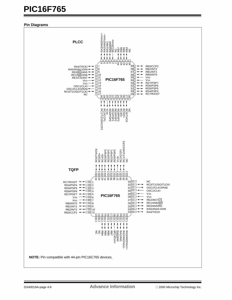
Pin Diagrams
101112131415161718 19 20 21 22 23 24 25 26
44
87
6 5 4 3 2 1
27 28 2930313233343536373839
40414243
9
PIC16F765
RA4/T0CKIRA5/AN4/LVDIN
RE0/RD/AN5
OSC2/CLKO/RA6
NC
RE1/WR/AN6RE2/CS/AN7
VDD
OSC1/CLKI
RB3/CCP2RB2/INT2RB1/INT1RB0/INT0VDDVSSRD7/PSP7RD6/PSP6RD5/PSP5RD4/PSP4RC7/RX/DT
RA
3/A
N3/
VR
EF+
RA
2/A
N2/
VR
EF-
RA
1/A
N1
RA
0/A
N0
MC
LR/V
PP
NC
RB
7R
B6
RB
5R
B4
NC
NC
RC
6/TX
/CK
RC
5/D+
RC
4/D-
RD
3/PS
P3
RD
2/PS
P2
RD
1/PS
P1
RD
0/PS
P0
VU
SB
RC
2/CC
P1
RC
1/T1O
SI/C
CP
2
1011
23456
1
18 19 20 21 2212 13 14 15
38
87
44 43 42 41 40 39
16 17
2930313233
232425262728
36 3435
9
PIC16F765
37
RA
3/AN
3/VR
EF+
RA
2/AN
2/VR
EF-
RA
1/AN
1R
A0/A
N0
MC
LR/V
PP
NC
RB
7R
B6
RB
5R
B4
NC
RC
6/T
X/C
KR
C5/
D+
RC
4/D
-R
D3/
PS
P3
RD
2/P
SP
2R
D1/
PS
P1
RD
0/P
SP
0V
US
B
RC
2/C
CP
1R
C1/
T1O
SI/C
CP
2N
C
NCRC0/T1OSO/T1CKIOSC2/CLKO/RA6OSC1/CLKIVSS
VDD
RE2/AN7/CSRE1/AN6/WRRE0/AN5/RDRA5/AN4/LVDINRA4/T0CKI
RC7/RX/DTRD4/PSP4RD5/PSP5RD6/PSP6RD7/PSP7
VSS
VDD
RB0/INT0RB1/INT1RB2/INT2
RB3/CCP2
PLCC
TQFP
NOTE: Pin compatible with 44-pin PIC16C765 devices.
VSS
RC0/T1OSO/T1CKI
DS40019A-page 4-6 Advance Information 2000 Microchip Technology Inc.
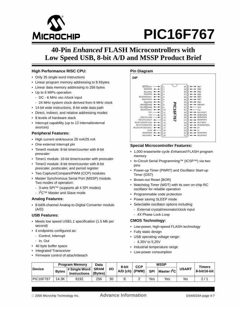
PIC16F76740-Pin Enhanced FLASH Microcontrollers with
Low Speed USB, 8-bit A/D and MSSP Product Brief
High Performance RISC CPU:
• Only 35 single word instructions• Linear program memory addressing to 8 Kbytes
• Linear data memory addressing to 256 bytes • Up to 6 MIPs operation:
- DC - 6 MHz osc./clock input
- 24 MHz system clock derived from 6 MHz clock• 14-bit wide instructions, 8-bit wide data path• Direct, indirect, and relative addressing modes
• 8 levels of hardware stack• Interrupt capability (up to 12 internal/external
sources)
Peripheral Features:
• High current sink/source 25 mA/25 mA• One external interrupt pin
• Timer0 module: 8-bit timer/counter with 8-bit prescaler
• Timer1 module: 16-bit timer/counter with prescaler • Timer2 module: 8-bit timer/counter with 8-bit
prescaler, postscaler, and period register• Two Capture/Compare/PWM (CCP) modules
• Master Synchronous Serial Port (MSSP) module. Two modes of operation:
- 3-wire SPI™ (supports all 4 SPI modes)- I2C™ Master and Slave mode
Analog Features:
• 8-bit/8-channel Analog-to-Digital Converter module (A/D)
USB Features:
• Meets low speed USB1.1 specification (1.5 Mb per second)
• 4 endpoints configured as:
- Control, Interrupt- In, Out
• 40 byte buffer space• Integrated Transceiver• Firmware control of attach/detach
Pin Diagram
Special Microcontroller Features:
• 1,000 erase/write cycle Enhanced FLASH program memory
• In-Circuit Serial Programming™ (ICSP™) via two pins
• Power-up Timer (PWRT) and Oscillator Start-up Timer (OST)
• Brown-out Reset (BOR)
• Watchdog Timer (WDT) with its own on-chip RC oscillator for reliable operation
• Programmable code protection• Power saving SLEEP mode• Selectable oscillator options including:
- External crystal/resonator/clock input- 4X Phase Lock Loop
CMOS Technology:
• Low-power, high-speed FLASH technology
• Fully static design• USB operating voltage range:
- 4.35V to 5.25V
• Industrial temperature range• Low-power consumption
RB7RB6RB5RB4RB3RB2
RB1RB0/INTVDD
VSS
RD7/PSP7RD6/PSP6RD5/PSP5RD4/PSP4RC7/SDORC6/SDI/SDAD+
D-RD3/PSP3RD2/PSP2
MCLR/VPP
RA0/AN0
RA1/AN1RA2/AN2
RA3/AN3/VREF
RA4/T0CKI
RA5/AN4RE0/RD/AN5RE1/WR/AN6RE2/CS/AN7
VDD
VSS
OSC1/CLKINOSC2/CLKOUT
RC0/T1OSO/T1CKIRC1/T1OSI/CCP2
RC2/CCP1/SCK/SCLVUSB
RD0/PSP0RD1/PSP1
1234567891011121314151617181920
4039383736353433323130292827262524232221
PIC
16F767
DIP
DeviceProgram Memory Data
SRAM (Bytes)
I/O8-bit
A/D (ch)CCP
(PWM)
MSSPUSART
Timers8-bit/16-bitBytes
# Single Word Instructions
SPI Master I2C
PIC16F767 14.3K 8192 256 30 8 2 Yes Yes No 2 / 1
2000 Microchip Technology Inc. Advance Information DS40024A-page 4-7

PIC16F767
Pin Diagrams
101112131415161718 19 20 21 22 23 24 25 26
44
87
6 5 4 3 2 1
27 28 2930313233343536373839
40414243
9
PIC16F767
RA4/T0CKIRA5/AN4/LVDIN
RE0/RD/AN5
OSC2/CLKO/RA6
NC
RE1/WR/AN6RE2/CS/AN7
VDD
OSC1/CLKI
RB3/CCP2RB2/INT2RB1/INT1RB0/INT0VDDVSSRD7/PSP7RD6/PSP6RD5/PSP5RD4/PSP4RC7/SDO
RA
3/A
N3/
VR
EF+
RA
2/A
N2/
VR
EF-
RA
1/A
N1
RA
0/A
N0
MC
LR/V
PP
NC
RB
7R
B6
RB
5R
B4
NC
NC
RC
6/SD
I/SD
AR
C5/D
+R
C4/D
-R
D3/P
SP
3R
D2/P
SP
2R
D1/P
SP
1R
D0/P
SP
0V
US
BR
C2/C
CP
1/SC
K/S
CL
RC
1/T1O
SI/C
CP
2
1011
23456
1
18 19 20 21 2212 13 14 15
38
87
44 43 42 41 40 39
16 17
2930313233
232425262728
36 3435
9
PIC16F767
37
RA
3/AN
3/VR
EF+
RA
2/AN
2/VR
EF-
RA
1/AN
1R
A0/A
N0
MC
LR/V
PP
NC
RB
7R
B6
RB
5R
B4
NC
RC
6/S
DI/S
DA
RC
5/D
+R
C4/
D-
RD
3/P
SP
3R
D2/
PS
P2
RD
1/P
SP
1R
D0/
PS
P0
VU
SB
RC
2/C
CP
1/S
CK
/SC
LR
C1/
T1O
SI/C
CP
2N
C
NCRC0/T1OSO/T1CKIOSC2/CLKO/RA6OSC1/CLKIVSS
VDD
RE2/AN7/CSRE1/AN6/WRRE0/AN5/RDRA5/AN4/LVDINRA4/T0CKI
RC7/SDORD4/PSP4RD5/PSP5RD6/PSP6RD7/PSP7
VSS
VDD
RB0/INT0RB1/INT1RB2/INT2
RB3/CCP2
PLCC
TQFP
VSS
RC0/T1OSO/T1CKI
DS40024A-page 4-8 Advance Information 2000 Microchip Technology Inc.
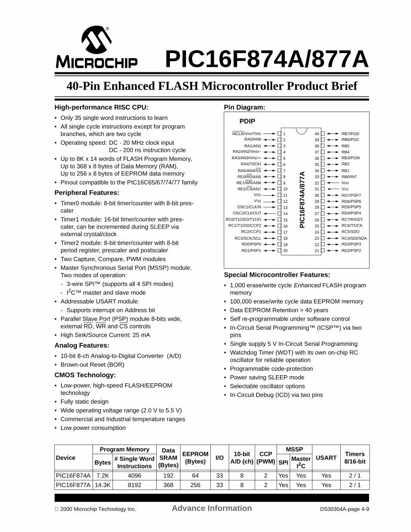
PIC16F874A/877A40-Pin Enhanced FLASH Microcontroller Product Brief
High-performance RISC CPU:
• Only 35 single word instructions to learn• All single cycle instructions except for program
branches, which are two cycle• Operating speed: DC - 20 MHz clock input
DC - 200 ns instruction cycle• Up to 8K x 14 words of FLASH Program Memory,
Up to 368 x 8 bytes of Data Memory (RAM), Up to 256 x 8 bytes of EEPROM data memory
• Pinout compatible to the PIC16C65/67/74/77 family
Peripheral Features:
• Timer0 module: 8-bit timer/counter with 8-bit pres-caler
• Timer1 module: 16-bit timer/counter with pres-caler, can be incremented during SLEEP via external crystal/clock
• Timer2 module: 8-bit timer/counter with 8-bit period register, prescaler and postscaler
• Two Capture, Compare, PWM modules• Master Synchronous Serial Port (MSSP) module.
Two modes of operation:- 3-wire SPI™ (supports all 4 SPI modes)- I2C™ master and slave mode
• Addressable USART module:- Supports interrupt on Address bit
• Parallel Slave Port (PSP) module 8-bits wide, external RD, WR and CS controls
• High Sink/Source Current: 25 mA
Analog Features:
• 10-bit 8-ch Analog-to-Digital Converter (A/D) • Brown-out Reset (BOR)
CMOS Technology:
• Low-power, high-speed FLASH/EEPROM technology
• Fully static design
• Wide operating voltage range (2.0 V to 5.5 V) • Commercial and Industrial temperature ranges• Low power consumption
Pin Diagram:
Special Microcontroller Features:
• 1,000 erase/write cycle Enhanced FLASH program memory
• 100,000 erase/write cycle data EEPROM memory• Data EEPROM Retention > 40 years• Self re-programmable under software control
• In-Circuit Serial Programming™ (ICSP™) via two pins
• Single supply 5 V In-Circuit Serial Programming• Watchdog Timer (WDT) with its own on-chip RC
oscillator for reliable operation• Programmable code-protection• Power saving SLEEP mode
• Selectable oscillator options• In-Circuit Debug (ICD) via two pins
RB7/PGDRB6/PGC
RB5
RB4RB3/PGM
RB2
RB1
RB0/INT
VDD
VSS
RD7/PSP7
RD6/PSP6RD5/PSP5
RD4/PSP4
RC7/RX/DT
RC6/TX/CK
RC5/SDO
RC4/SDI/SDARD3/PSP3
RD2/PSP2
MCLR/VPP/THVRA0/AN0
RA1/AN1RA2/AN2/VREF-
RA3/AN3/VREF+
RA4/T0CKI
RA5/AN4/SS
RE0/RD/AN5
RE1/WR/AN6
RE2/CS/AN7VDD
VSS
OSC1/CLKIN
OSC2/CLKOUT
RC0/T1OSO/T1CKI
RC1/T1OSI/CCP2
RC2/CCP1
RC3/SCK/SCLRD0/PSP0
RD1/PSP1
1
2
3
4
5
6
7
8
9
10
11
12
13
14
15
16
17
18
19
20
40
39
38
37
36
35
34
33
32
31
30
2928
27
26
25
24
23
22
21
PIC
16F
874A
/877
A
PDIP
DeviceProgram Memory Data
SRAM(Bytes)
EEPROM(Bytes)
I/O10-bit
A/D (ch)CCP
(PWM)
MSSPUSART
Timers8/16-bitBytes
# Single WordInstructions
SPIMaster
I2C
PIC16F874A 7.2K 4096 192 64 33 8 2 Yes Yes Yes 2 / 1
PIC16F877A 14.3K 8192 368 256 33 8 2 Yes Yes Yes 2 / 1
2000 Microchip Technology Inc. Advance Information DS30304A-page 4-9
PIC16F874A/877A
NOTES:
DS30304A-page 4-10 Advance Information 2000 Microchip Technology Inc.

PIC18F4X240-Pin Enhanced FLASH Microcontroller w/10-bit A/D
Product Brief
High Performance RISC CPU: • C-compiler optimized architecture/instruction set:
- Source code compatible with the PIC16CXXX instruction set
• Linear program memory addressing to 32 Kbytes Linear data memory addressing to 1.5 Kbytes
• Up to 256 x 8 bytes of EEPROM data memory• Up to 10 MIPs operation:
- DC - 40 MHz clock- 4 MHz - 10 MHz clock with PLL active
• 16-bit wide instructions, 8-bit wide data path• Priority levels for interrupts • 8 x 8 Single Cycle Hardware Multiplier• Pinout compatible to PIC16C65/67/74/77 family
Peripheral Features:• High current sink/source 25 mA/25 mA• Three external interrupt pins• Timer0 module: 8/16-bit timer/counter• Timer1 module: 16-bit timer/counter • Timer2 module: 8-bit timer/counter• Timer3 module: 16-bit timer/counter • Secondary oscillator clock option - Timer1/Timer3• Two Capture/Compare/PWM (CCP) modules.
CCP pins can be configured as:- Capture is 16-bit, max resolution 6.25 ns- Compare is 16-bit, max resolution 100 ns- PWM output: PWM resolution is 1- to 10-bit.- Max. PWM freq. @: 8-bit resolution = 156 kHz- 10-bit resolution = 39 kHz
• Master Synchronous Serial Port (MSSP) module. Two modes of operation:- 3-wire SPI™ (supports all 4 SPI modes)- I2C™ master and slave mode
• Addressable USART module:- Supports interrupt on Address bit
Analog Features:• 10-bit 8-ch Analog-to-Digital Converter (A/D) • Low-Voltage Detection (LVD) module• Programmable Brown-out Reset (BOR)
Pin Diagram:
Special Microcontroller Features:• 1,000 erase/write cycle Enhanced FLASH program
memory• 100,000 erase/write cycle data EEPROM memory• Data EEPROM Retention > 40 years• Self re-programmable under software control• In-Circuit Serial Programming (ICSP™) via two pins
• Single supply 5 V In-Circuit Serial Programming• Watchdog Timer (WDT) with its own on-chip RC
oscillator for reliable operation• Programmable code-protection• Power saving SLEEP mode• Selectable oscillator options including:
- 4X Phase Lock Loop (of primary oscillator)- Secondary Oscillator (32 kHz) clock input
• In-Circuit Debug (ICD) via two pins
CMOS Technology:• Low-power, high-speed FLASH/EEPROM
technology• Fully static design• Wide operating voltage range (2.5 V to 5.5 V) • Industrial and Extended temperature ranges• Low power consumption
RB7RB6RB5RB4RB3/CCP2*RB2/INT2RB1/INT1RB0/INT0VDD
VSS
RD7/PSP7RD6/PSP6RD5/PSP5RD4/PSP4RC7/RX/DTRC6/TX/CKRC5/SDORC4/SDI/SDARD3/PSP3RD2/PSP2
MCLR/VPP
RA0/AN0RA1/AN1
RA2/AN2/VREF-RA3/AN3/VREF+
RA4/T0CKIRA5/AN4/SS/LVDIN
RE0/RD/AN5RE1/WR/AN6RE2/CS/AN7
VDD
VSS
OSC1/CLKIOSC2/CLKO/RA6
RC0/T1OSO/T1CKIRC1/T1OSI/CCP2*
RC2/CCP1RC3/SCK/SCL
RD0/PSP0RD1/PSP1
1234567891011121314151617181920
4039383736353433323130292827262524232221
PIC
18F
4X2
* RB3 is the alternate pin for the CCP2 pin multiplexing.
PDIP
DeviceProgram Memory Data
SRAM(Bytes)
EEPROM(Bytes)
I/O10-bit
A/D (ch)CCP
(PWM)
MSSPUSART
Timers8-bit/16-bitBytes
# Single WordInstructions
SPIMaster
I2C
PIC18F442 16K 8192 512 256 34 8 2 Yes Yes Yes 1 / 3
PIC18F452 32K 16384 1536 256 34 8 2 Yes Yes Yes 1 / 3
2000 Microchip Technology Inc. Advanced Information DS30300A-page 4-11

PIC18F4x2
NOTES:
DS30300A-page 4-12 Advanced Information 2000 Microchip Technology Inc.
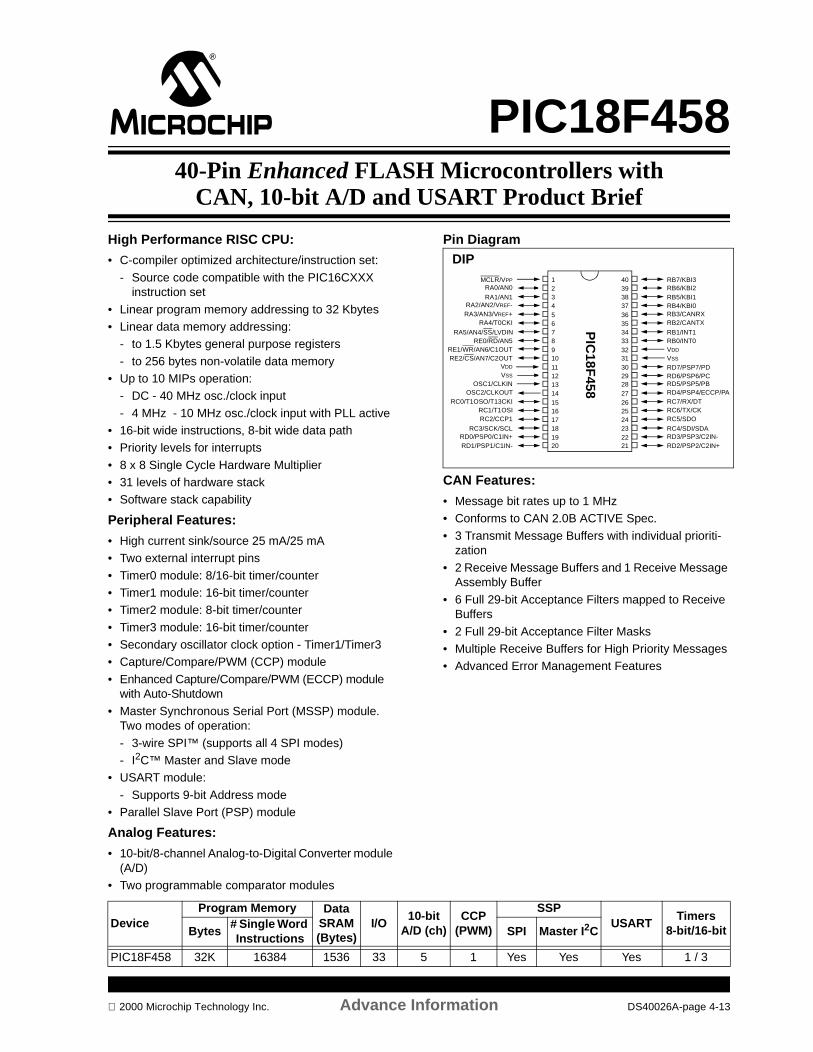
PIC18F45840-Pin Enhanced FLASH Microcontrollers with
CAN, 10-bit A/D and USART Product Brief
High Performance RISC CPU:
• C-compiler optimized architecture/instruction set:
- Source code compatible with the PIC16CXXX instruction set
• Linear program memory addressing to 32 Kbytes• Linear data memory addressing:
- to 1.5 Kbytes general purpose registers
- to 256 bytes non-volatile data memory • Up to 10 MIPs operation:
- DC - 40 MHz osc./clock input
- 4 MHz - 10 MHz osc./clock input with PLL active• 16-bit wide instructions, 8-bit wide data path• Priority levels for interrupts • 8 x 8 Single Cycle Hardware Multiplier• 31 levels of hardware stack• Software stack capability
Peripheral Features:
• High current sink/source 25 mA/25 mA• Two external interrupt pins
• Timer0 module: 8/16-bit timer/counter• Timer1 module: 16-bit timer/counter • Timer2 module: 8-bit timer/counter
• Timer3 module: 16-bit timer/counter • Secondary oscillator clock option - Timer1/Timer3• Capture/Compare/PWM (CCP) module
• Enhanced Capture/Compare/PWM (ECCP) module with Auto-Shutdown
• Master Synchronous Serial Port (MSSP) module. Two modes of operation:
- 3-wire SPI™ (supports all 4 SPI modes)- I2C™ Master and Slave mode
• USART module:
- Supports 9-bit Address mode• Parallel Slave Port (PSP) module
Analog Features:
• 10-bit/8-channel Analog-to-Digital Converter module (A/D)
• Two programmable comparator modules
Pin Diagram
CAN Features:
• Message bit rates up to 1 MHz• Conforms to CAN 2.0B ACTIVE Spec.
• 3 Transmit Message Buffers with individual prioriti-zation
• 2 Receive Message Buffers and 1 Receive Message Assembly Buffer
• 6 Full 29-bit Acceptance Filters mapped to Receive Buffers
• 2 Full 29-bit Acceptance Filter Masks• Multiple Receive Buffers for High Priority Messages • Advanced Error Management Features
DIPRB7/KBI3RB6/KBI2RB5/KBI1RB4/KBI0RB3/CANRXRB2/CANTX
RB1/INT1RB0/INT0VDD
VSS
RD7/PSP7/PDRD6/PSP6/PCRD5/PSP5/PBRD4/PSP4/ECCP/PARC7/RX/DTRC6/TX/CKRC5/SDO
RC4/SDI/SDARD3/PSP3/C2IN-RD2/PSP2/C2IN+
MCLR/VPP
RA0/AN0
RA1/AN1RA2/AN2/VREF-RA3/AN3/VREF+
RA4/T0CKI
RA5/AN4/SS/LVDINRE0/RD/AN5
RE1/WR/AN6/C1OUTRE2/CS/AN7/C2OUT
VDD
VSS
OSC1/CLKINOSC2/CLKOUT
RC0/T1OSO/T13CKIRC1/T1OSIRC2/CCP1
RC3/SCK/SCLRD0/PSP0/C1IN+RD1/PSP1/C1IN-
1234567891011121314151617181920
4039383736353433323130292827262524232221
PIC
18F458
DeviceProgram Memory Data
SRAM (Bytes)
I/O10-bit
A/D (ch)CCP
(PWM)
SSPUSART
Timers8-bit/16-bitBytes
# Single Word Instructions
SPI Master I2C
PIC18F458 32K 16384 1536 33 5 1 Yes Yes Yes 1 / 3
2000 Microchip Technology Inc. Advance Information DS40026A-page 4-13
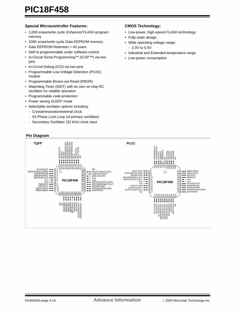
PIC18F458
Special Microcontroller Features:
• 1,000 erase/write cycle Enhanced FLASH program memory
• 100K erase/write cycle Data EEPROM memory
• Data EEPROM Retention > 40 years • Self re-programmable under software control• In-Circuit Serial Programming™ (ICSP™) via two
pins• In-Circuit Debug (ICD) via two pins
• Programmable Low-Voltage Detection (PLVD) module
• Programmable Brown-out Reset (PBOR)• Watchdog Timer (WDT) with its own on-chip RC
oscillator for reliable operation• Programmable code-protection• Power saving SLEEP mode
• Selectable oscillator options including:- Crystal/resonator/external clock- 4X Phase Lock Loop (of primary oscillator)
- Secondary Oscillator (32 kHz) clock input
CMOS Technology:
• Low-power, high-speed FLASH technology
• Fully static design• Wide operating voltage range:
- 2.0V to 5.5V
• Industrial and Extended temperature range• Low-power consumption
Pin Diagram
NCRC0/T1OSO/T1CKIOSC2/CLKOUTOSC1/CLKINVSSVDDRE2/CS/AN7/C2OUTRE1/WR/AN6/C1OUTRE0/RD/AN5RA5/AN4/SS/LVDINRA4/T0CKI
RC7/RX/DTRD4/PSP4/ECCP/PA
RD5/PSP5/PBRD6/PSP6/PCRD7/PSP7/PD
VSSVDD
RB0/INT0RB1/INT1
RB2/CANTXRB3/CANRX
RC
6/T
X/C
KR
C5/
D+
RC
4/D
-R
D3/
PS
P3/
C2I
N-
RD
2/P
SP
2/C
2IN
+R
D1/
PS
P1/
C1I
N-
RD
0/P
SP
0/C
1IN
+R
C3
RC
2/C
CP
1R
C1/
T1O
SI
NC
1234567891011
3332313029282726252423
RA
3/A
N3/
VR
EF+
RA
2/A
N2/
VR
EF-
RA
1/A
N1
RA
0/A
N0
MC
LR/V
PP
RB
7/K
BI3
RB
6/K
BI2
RB
5/K
BI1
RB
4/K
BI0
NC
NC
44 43 42 41 40 39 38 37 36 35 342221201918171615141312
TQFP
PIC18F458
RB3/CANRXRB2/CANTXRB1/INT1RB0/INT0VDDVSSRD7/PSP7/PDRD6/PSP6/PCRD5/PSP5/PBRD4/PSP4/ECCP/PARC7/RX/DT
RA4/T0CKIRA5/AN4/SS/LVDIN
RE0/RD/AN5RE1/WR/AN6/C1OUTRE2/CS/AN7/C2OUT
VDDVSS
OSC1/CLKINOSC2/CLKOUT
RC0/T1OSO/T1CKINC
RA
3/A
N3/
VR
EF+
RA
2/A
N2/
VR
EF-
RA
1/A
N1
RA
0/A
N0
MC
LR/V
PP
NC
RB
7/K
BI3
RB
6/K
BI2
RB
5/K
BI1
RB
4/K
BI0
NC
7891011121314151617
3938373635343332313029
NC
RC
6/T
X/C
KR
C5
/SD
OR
C4/
SD
I/SD
AR
D3/
PS
P3/
C2I
N-
RD
2/P
SP
2/C
2IN
+R
D1/
PS
P1/
C1I
N-
RD
0/P
SP
0/C
1IN
+R
C3/
SC
K/S
CL
RC
2/C
CP
16 5 4 3 2 1 44 43 42 41 40
28
27
26
25
24
23
22
21
20
19
18
PIC18F458
PLCC
RC
1/T
1O
SI
DS40026A-page 4-14 Advance Information 2000 Microchip Technology Inc.
SECTION 5PICmicro® 64/68-PIN RISC
MICROCONTROLLERS
PIC16C925/926 CMOS Microcontroller with LCD Product Brief.................................................................................. 5-1PIC18F653 64-Pin Enhanced FLASH Motor Control Microcontroller Product Brief .................................................... 5-3PIC18F668 64-Pin Enhanced FLASH CAN Bus Microcontroller Product Brief............................................................ 5-5PIC18C658 64/68-Pin High-Performance Microcontroller with CAN Module Product Brief ........................................ 5-7PIC18F6X2 64/68-Pin Enhanced FLASH Microcontroller Product Brief .................................................................... 5-9PIC18C601 64/68-Pin ROMless Microcontroller w/10-bit A/D Product Brief ............................................................. 5-11
2000 Microchip Technology Inc. DS00168C-page 5-i

DS00168C-page 5-ii 2000 Microchip Technology Inc.
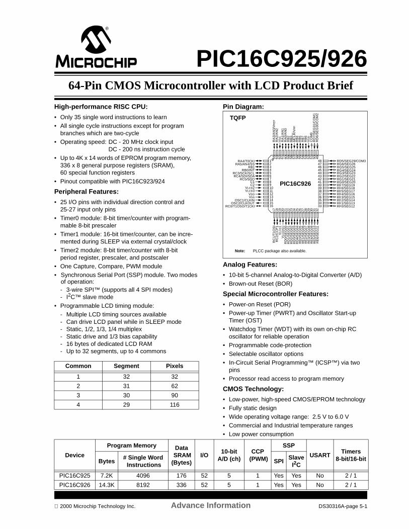
PIC16C925/92664-Pin CMOS Microcontroller with LCD Product Brief
High-performance RISC CPU:
• Only 35 single word instructions to learn• All single cycle instructions except for program
branches which are two-cycle• Operating speed: DC - 20 MHz clock input
DC - 200 ns instruction cycle• Up to 4K x 14 words of EPROM program memory,
336 x 8 general purpose registers (SRAM), 60 special function registers
• Pinout compatible with PIC16C923/924
Peripheral Features:
• 25 I/O pins with individual direction control and 25-27 input only pins
• Timer0 module: 8-bit timer/counter with program-mable 8-bit prescaler
• Timer1 module: 16-bit timer/counter, can be incre-mented during SLEEP via external crystal/clock
• Timer2 module: 8-bit timer/counter with 8-bit period register, prescaler, and postscaler
• One Capture, Compare, PWM module• Synchronous Serial Port (SSP) module. Two modes
of operation:- 3-wire SPI™ (supports all 4 SPI modes)- I2C™ slave mode
• Programmable LCD timing module:- Multiple LCD timing sources available- Can drive LCD panel while in SLEEP mode- Static, 1/2, 1/3, 1/4 multiplex- Static drive and 1/3 bias capability- 16 bytes of dedicated LCD RAM- Up to 32 segments, up to 4 commons
Pin Diagram:
Analog Features:
• 10-bit 5-channel Analog-to-Digital Converter (A/D)
• Brown-out Reset (BOR)
Special Microcontroller Features:
• Power-on Reset (POR)• Power-up Timer (PWRT) and Oscillator Start-up
Timer (OST) • Watchdog Timer (WDT) with its own on-chip RC
oscillator for reliable operation• Programmable code-protection
• Selectable oscillator options• In-Circuit Serial Programming™ (ICSP™) via two
pins• Processor read access to program memory
CMOS Technology:
• Low-power, high-speed CMOS/EPROM technology
• Fully static design• Wide operating voltage range: 2.5 V to 6.0 V• Commercial and Industrial temperature ranges
• Low power consumption
Common Segment Pixels
1 32 32
2 31 62
3 30 90
4 29 116
TQFP
12345678910111213141516
48474645444342414039383736353433
64 63 62 61 60 59 58 57 56 55 54 53 52 51 50 49
17 18 19 20 21 22 23 24 25 26 27 28 29 30 31 32
PIC16C926
RD5/SEG29/COM3RG6/SEG26
RG3/SEG23RG2/SEG22RG1/SEG21RG0/SEG20RF7/SEG19RF6/SEG18RF5/SEG17RF4/SEG16RF3/SEG15RF2/SEG14RF1/SEG13RF0/SEG12
RA4/T0CKIRA5/AN4/SS
RB1RB0/INT
RC3/SCK/SCLRC4/SDI/SDA
RC5/SDO
VLCD2VLCD3
VDDVSS
C1C2
OSC1/CLKINOSC2/CLKOUT
RC0/T1OSO/T1CKI
RA
3/A
N3/
VR
EF
RA
2/A
N2
VS
SR
A1/
AN
1R
A0/
AN
0R
B2
RB
3
RB
4R
B5
RB
7R
B6
VD
DC
OM
0R
D7/
SE
G31
/CO
M1
RD
6/S
EG
30/C
OM
2
RC
1/T
1O
SI
RC
2/C
CP
1V
LCD
1V
LCD
AD
JR
D0
/SE
G00
RD
1/S
EG
01R
D2
/SE
G02
RD
3/S
EG
03R
D4
/SE
G04
RE
0/S
EG
05R
E1
/SE
G06
RE
2/S
EG
07R
E3
/SE
G08
RE
4/S
EG
09
RE
6/S
EG
11R
E5
/SE
G10
RG5/SEG25RG4/SEG24
MC
LR/V
PP
Note: PLCC package also available.
Device
Program Memory Data SRAM(Bytes)
I/O10-bit
A/D (ch)CCP
(PWM)
SSP
USARTTimers
8-bit/16-bitBytes# Single Word Instructions
SPISlave
I2C
PIC16C925 7.2K 4096 176 52 5 1 Yes Yes No 2 / 1
PIC16C926 14.3K 8192 336 52 5 1 Yes Yes No 2 / 1
2000 Microchip Technology Inc. Advance Information DS30316A-page 5-1
PIC16C925/926
DS30316A-page 5-2 Advance Information 2000 Microchip Technology Inc.

PIC18F65364-Pin Enhanced FLASH Motor Control Microcontroller
Product Brief
High Performance RISC CPU: • C-compiler optimized architecture/instruction set:
- Source code compatible with the PIC16CXXX instruction set
• Up to 10 MIPs operation: - DC - 40 MHz clock- 4 MHz - 10 MHz clock with PLL active
• 16-bit wide instructions, 8-bit wide data path• Priority levels for interrupts • 8 x 8 Single Cycle Hardware Multiplier• Pinout similar to PIC18C658 family
Peripheral Features:• PWM module: 6 channel, 12-bit PWMs:
- 6 independent or 3 complementary PWMs- Supports edge or center aligned operation- Flexible deadband generator
(resolution 100 ns at 10 MIPS)- Hardware fault protection
• Timer0 module: 8/16-bit timer/counter• Timer1 module: 16-bit timer/counter • Timer2 module: 8-bit timer/counter• Timer3 module: 16-bit timer/counter • Secondary oscillator clock option - Timer1/Timer3• Two Capture/Compare/PWM (CCP) modules• CAN module:
- Conforms to 2.0B specification• Addressable USART module:
- Supports interrupt on Address bit• Master Synchronous Serial Port (MSSP) module.
Two modes of operation:- 3-wire SPI™ (supports all 4 SPI modes)- I2C™ master and slave mode
• High current sink/source 25 mA/25 mA• Three external interrupt pins
Analog Features:• 10-bit Analog-to-Digital Converter (A/D):
- 10 input channels- 200 K sps conversion rate- Simultaneous sampling on 2 channels
• Two programmable voltage Comparators• Low-Voltage Detection (LVD) module• Programmable Brown-out Reset (BOR)
Pin Diagram:
Special Microcontroller Features:• 1,000 erase/write cycle Enhanced FLASH program
memory• 100,000 erase/write cycle data EEPROM memory• Data EEPROM Retention > 40 years• Self re-programmable under software control• In-Circuit Serial Programming (ICSP™) via two pins• Single supply 5 V In-Circuit Serial Programming• Watchdog Timer (WDT) with its own on-chip RC
oscillator for reliable operation• Selectable oscillator options including:
- 4X Phase Lock Loop (of primary oscillator)- Secondary Oscillator (32 kHz) clock input
• In-Circuit Debug (ICD) via two pins
CMOS Technology:• Low-power, high-speed FLASH technology• Fully static design• Wide operating voltage range (2.5 V to 5.5 V) • Industrial and Extended temperature ranges• Low power consumption
TQFP
12345678910111213141516
48474645444342414039383736353433
64636261605958575655545352515049
17181920212223242526272829303132
RE
2R
E3
RE
4/Q
E0A
RE
5/Q
E0B
RE
6/Q
E1A
RE
7/Q
E1B
RD
0/P
WM
0V
DD
VS
S
RD
1/P
WM
1R
D2
/PW
M2
RD
3/P
WM
3R
D4
/PW
M4
RD
5/P
WM
5R
D6
/FA
ULT
1R
D7
/FA
ULT
0
RE1RE0
RG0/CANTX1RG1/CCP2
RG2/CANTX2RG3/CANRX
MCLR/VPP
RG4/PGMVSS
VDD
RF7RF6/AN11/C1IN1RF5/AN10/C1IN2
RF4/AN9/C2IN1RF3/AN8/C2IN2
RF2/AN7/C1OUT
RB0/INT0RB1/INT1RB2/INT2RB3/INT3RB4RB5RB6VSS
OSC2/CLKO/RA6OSC1/CLKINVDD
RB7
RC4/SDI/SDARC3/SCK/SCLRC2/CCP1
RF
0/A
N5
RF
1/A
N6/
C2O
UT
AV
DD
AV
SS
RA
3/A
N3/
VR
EF+
RA
2/A
N2/
VR
EF-
RA
1/A
N1
RA
0/A
N0
VS
S
VD
D
RA
4/T
0CK
IR
A5/
SS
/AN
4/LV
DIN
RC
1/T
1OS
IR
C0/
T1O
SO
/T13
CLK
RC
7/R
X/D
TR
C6/
TX
/CK
RC5/SDO
PIC18F653(Preliminary PinoutSubject to Change)
Note: PLCC package also available.
Device
Program Memory Data Memory
I/O10-bitA/D (ch)
Co
mp
arat
or
Timers8/16-bit
12-bitPWM(ch)
Qu
adra
ture
En
cod
er
CCP(PWM)
MSSP
AU
SA
RT
CAN2.0BBytes # Single Word
InstructionsSRAM(Bytes)
EEPROM(Bytes) SPI Master
I2C
PIC18F653 32K 16384 1536 256 52 10 2 1 / 3 6 2 2 Yes Yes Yes Yes
2000 Microchip Technology Inc. Advanced Information DS30302A-page 5-3

PIC18F653
NOTES:
DS30302A-page 5-4 Advanced Information 2000 Microchip Technology Inc.
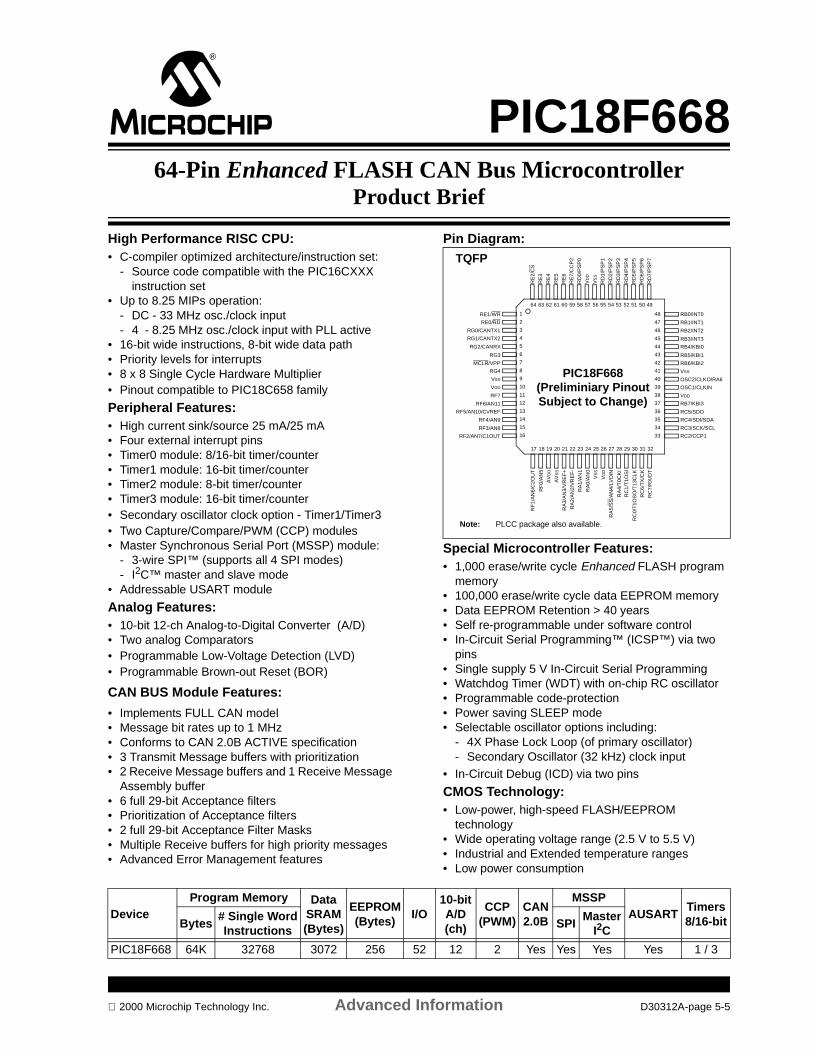
PIC18F66864-Pin Enhanced FLASH CAN Bus Microcontroller
Product Brief
High Performance RISC CPU: • C-compiler optimized architecture/instruction set:
- Source code compatible with the PIC16CXXX instruction set
• Up to 8.25 MIPs operation: - DC - 33 MHz osc./clock input- 4 - 8.25 MHz osc./clock input with PLL active
• 16-bit wide instructions, 8-bit wide data path• Priority levels for interrupts • 8 x 8 Single Cycle Hardware Multiplier• Pinout compatible to PIC18C658 family
Peripheral Features:• High current sink/source 25 mA/25 mA• Four external interrupt pins• Timer0 module: 8/16-bit timer/counter• Timer1 module: 16-bit timer/counter • Timer2 module: 8-bit timer/counter• Timer3 module: 16-bit timer/counter • Secondary oscillator clock option - Timer1/Timer3• Two Capture/Compare/PWM (CCP) modules• Master Synchronous Serial Port (MSSP) module:
- 3-wire SPI™ (supports all 4 SPI modes)- I2C™ master and slave mode
• Addressable USART module
Analog Features:• 10-bit 12-ch Analog-to-Digital Converter (A/D) • Two analog Comparators• Programmable Low-Voltage Detection (LVD)• Programmable Brown-out Reset (BOR)
CAN BUS Module Features:
• Implements FULL CAN model• Message bit rates up to 1 MHz• Conforms to CAN 2.0B ACTIVE specification• 3 Transmit Message buffers with prioritization• 2 Receive Message buffers and 1 Receive Message
Assembly buffer• 6 full 29-bit Acceptance filters • Prioritization of Acceptance filters• 2 full 29-bit Acceptance Filter Masks• Multiple Receive buffers for high priority messages • Advanced Error Management features
Pin Diagram:
Special Microcontroller Features:• 1,000 erase/write cycle Enhanced FLASH program
memory• 100,000 erase/write cycle data EEPROM memory• Data EEPROM Retention > 40 years• Self re-programmable under software control• In-Circuit Serial Programming™ (ICSP™) via two
pins• Single supply 5 V In-Circuit Serial Programming• Watchdog Timer (WDT) with on-chip RC oscillator• Programmable code-protection• Power saving SLEEP mode• Selectable oscillator options including:
- 4X Phase Lock Loop (of primary oscillator)- Secondary Oscillator (32 kHz) clock input
• In-Circuit Debug (ICD) via two pins
CMOS Technology:• Low-power, high-speed FLASH/EEPROM
technology• Wide operating voltage range (2.5 V to 5.5 V) • Industrial and Extended temperature ranges• Low power consumption
1
2
3
4
5
6
7
8
9
10
11
12
13
14
15
16
48
47
46
45
44
43
42
41
40
39
38
37
36
35
34
33
64 63 62 61 60 59 58 57 56 55 54 53 52 51 50 49
17 18 19 20 21 22 23 24 25 26 27 28 29 30 31 32
RE
2/C
S
RE
3
RE
4
RE
5
RE
6
RE
7/C
CP
2
RD
0/P
SP
0
VD
D
VS
S
RD
1/P
SP
1
RD
2/P
SP
2
RD
3/P
SP
3
RD
4/P
SP
4
RD
5/P
SP
5
RD
6/P
SP
6
RD
7/P
SP
7
RE1/WR
RE0/RD
RG0/CANTX1
RG1/CANTX2
RG2/CANRX
RG3
MCLR/VPP
RG4
VSS
VDD
RF7
RF6/AN11
RF5/AN10/CVREF
RF4/AN9
RF3/AN8
RF2/AN7/C1OUT
RB0/INT0
RB1/INT1
RB2/INT2
RB3/INT3
RB4/KBI0
RB5/KBI1
RB6/KBI2
VSS
OSC2/CLKO/RA6
OSC1/CLKIN
VDD
RB7/KBI3
RC4/SDI/SDA
RC3/SCK/SCL
RC2/CCP1
RF
0/A
N5
RF
1/A
N6/
C2O
UT
AV
DD
AV
SS
RA
3/A
N3/
VR
EF
+
RA
2/A
N2/
VR
EF
-
RA
1/A
N1
RA
0/A
N0
VS
S
VD
D
RA
4/T
0CK
I
RA
5/S
S/A
N4/
LVD
IN
RC
1/T
1OS
I
RC
0/T
1OS
O/T
13C
LK
RC
7/R
X/D
T
RC
6/T
X/C
K
RC5/SDO
PIC18F668
TQFP
(Preliminiary PinoutSubject to Change)
Note: PLCC package also available.
DeviceProgram Memory Data
SRAM(Bytes)
EEPROM(Bytes)
I/O10-bitA/D(ch)
CCP(PWM)
CAN2.0B
MSSPAUSART
Timers8/16-bitBytes
# Single WordInstructions
SPIMaster
I2C
PIC18F668 64K 32768 3072 256 52 12 2 Yes Yes Yes Yes 1 / 3
2000 Microchip Technology Inc. Advanced Information D30312A-page 5-5

PIC18F668
NOTES:
D30312A-page 5-6 Advanced Information 2000 Microchip Technology Inc.
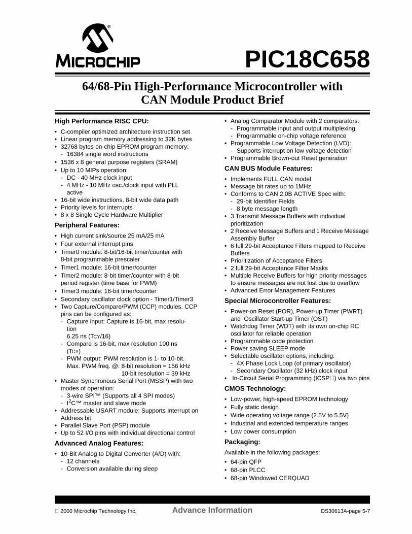
PIC18C65864/68-Pin High-Performance Microcontroller with
CAN Module Product Brief
High Performance RISC CPU:
• C-compiler optimized architecture instruction set• Linear program memory addressing to 32K bytes• 32768 bytes on-chip EPROM program memory:
- 16384 single word instructions• 1536 x 8 general purpose registers (SRAM)• Up to 10 MIPs operation:
- DC - 40 MHz clock input- 4 MHz - 10 MHz osc./clock input with PLL
active• 16-bit wide instructions, 8-bit wide data path• Priority levels for interrupts• 8 x 8 Single Cycle Hardware Multiplier
Peripheral Features:
• High current sink/source 25 mA/25 mA• Four external interrupt pins• Timer0 module: 8-bit/16-bit timer/counter with
8-bit programmable prescaler• Timer1 module: 16-bit timer/counter• Timer2 module: 8-bit timer/counter with 8-bit
period register (time base for PWM)• Timer3 module: 16-bit timer/counter• Secondary oscillator clock option - Timer1/Timer3• Two Capture/Compare/PWM (CCP) modules. CCP
pins can be configured as:- Capture input: Capture is 16-bit, max resolu-
tion 6.25 ns (TCY/16)
- Compare is 16-bit, max resolution 100 ns (TCY)
- PWM output: PWM resolution is 1- to 10-bit.Max. PWM freq. @: 8-bit resolution = 156 kHz
10-bit resolution = 39 kHz• Master Synchronous Serial Port (MSSP) with two
modes of operation:- 3-wire SPI™ (Supports all 4 SPI modes)- I2C™ master and slave mode
• Addressable USART module: Supports Interrupt on Address bit
• Parallel Slave Port (PSP) module• Up to 52 I/O pins with individual directional control
Advanced Analog Features:
• 10-Bit Analog to Digital Converter (A/D) with:- 12 channels- Conversion available during sleep
• Analog Comparator Module with 2 comparators:- Programmable input and output multiplexing- Programmable on-chip voltage reference
• Programmable Low Voltage Detection (LVD):- Supports interrupt on low voltage detection
• Programmable Brown-out Reset generation
CAN BUS Module Features:
• Implements FULL CAN model• Message bit rates up to 1MHz• Conforms to CAN 2.0B ACTIVE Spec with:
- 29-bit Identifier Fields- 8 byte message length
• 3 Transmit Message Buffers with individual prioritization
• 2 Receive Message Buffers and 1 Receive Message Assembly Buffer
• 6 full 29-bit Acceptance Filters mapped to Receive Buffers
• Prioritization of Acceptance Filters• 2 full 29-bit Acceptance Filter Masks• Multiple Receive Buffers for high priority messages
to ensure messages are not lost due to overflow• Advanced Error Management Features
Special Microcontroller Features:
• Power-on Reset (POR), Power-up Timer (PWRT) and Oscillator Start-up Timer (OST)
• Watchdog Timer (WDT) with its own on-chip RC oscillator for reliable operation
• Programmable code protection• Power saving SLEEP mode• Selectable oscillator options, including:
- 4X Phase Lock Loop (of primary oscillator)- Secondary Oscillator (32 kHz) clock input
• In-Circuit Serial Programming (ICSP) via two pins
CMOS Technology:
• Low-power, high-speed EPROM technology• Fully static design• Wide operating voltage range (2.5V to 5.5V)• Industrial and extended temperature ranges• Low power consumption
Packaging:
Available in the following packages:
• 64-pin QFP• 68-pin PLCC• 68-pin Windowed CERQUAD
2000 Microchip Technology Inc. Advance Information DS30613A-page 5-7

PIC18C658
1
2
3
4
5
6
7
8
9
10
11
12
13
14
15
16
48
47
46
45
44
43
42
41
40
39
38
37
36
35
34
33
64 63 62 61 60 59 58 57 56 55 54 53 52 51 50 49
17 18 19 20 21 22 23 24 25 26 27 28 29 30 31 32
RE
2/C
SR
E3
RE
4R
E5
RE
6R
E7/
CC
P2
RD
0/P
SP
0V
DD
VS
S
RD
1/P
SP
1R
D2/
PS
P2
RD
3/P
SP
3R
D4/
PS
P4
RD
5/P
SP
5R
D6/
PS
P6
RD
7/P
SP
7
RE1/WR
RE0/RDRG0/CANTX1
RG1/CANTX2RG2/CANRX
RG3MCLR/VPP
RG4
VSS
VDD
RF7RF6/AN11
RF5/AN10/CVREF
RF4/AN9RF3/AN8
RF2/AN7/C1OUT
RB0/INT0
RB1/INT1
RB2/INT2RB3/INT3RB4/KBI0RB5/KBI1
RB6/KBI2VSS
OSC2/CLKO/RA6
OSC1/CLKINVDD
RB7/KBI3
RC4/SDI/SDARC3/SCK/SCL
RC2/CCP1
RF
0/A
N5
RF
1/A
N6/
C2O
UT
AV
DD
AV
SS
RA
3/A
N3/
VR
EF+
RA
2/A
N2/
VR
EF-
RA
1/A
N1
RA
0/A
N0
VS
S
VD
D
RA
4/T
0CK
IR
A5/
SS
/AN
4/LV
DIN
RC
1/T
1OS
IR
C0/
T1O
SO
/T13
CLK
RC
7/R
X/D
TR
C6/
TX
/CK
RC5/SDO
PIC18C658
1011121314151617181920212223242526
6059585756555453525150494847464544
9 8 7 6 5 4 3 2 1 68 67 66 65 64 63 62 61
2728 29 30 31 32 33 34 35 36 37 38 39 40 41 42 43
RB0/INT0RB1/INT1RB2/INT2RB3/INT3RB4/KBI0RB5/KBI1RB6/KBI2VSSN/C
OSC1/CLKINVDDRB7/KBI3
RC4/SDI/SDARC3/SCK/SCLRC2/CCP1
RE1/WRRE0/RD
RG0/CANTX1RG1/CANTX2RG2/CANRX
RG3MCLR/VPP
RG4
VSSVDD
RF7RF6/AN11
RF5/AN10/CVREFRF4/AN9RF3/AN8
RF2/AN7/C1OUT
RE
2/C
SR
E3
RE
4R
E5
RE
6R
E7/
CC
P2
RD
0/P
SP
0V
DD
VS
SR
D1/
PS
P1
RD
2/P
SP
2R
D3/
PS
P3
RD
4/P
SP
4R
D5/
PS
P5
RD
6/P
SP
6R
D7/
PS
P7
RF
1/A
N6/
C2O
UT
RF
0/A
N5
AV
DD
AV
SS
RA
3/A
N3/
VR
EF+
RA
2/A
N2/
VR
EF-
RA
1/A
N1
RA
0/A
N0
VD
D
RA
4/T
0CK
IR
A5/
SS
/AN
4/LV
DIN
RC
1/T
1OS
IR
C0/
T1O
SO
/T13
CLK
RC
7/R
X/D
TR
C6/
TX
/CK
RC5/SDO
OSC2/CLKO/RA6
N/C
N/C
N/C
VS
S
PIC18C658
64-PIN QFP
68-PIN QFP
DS30613A-page 5-8 Advance Information 2000 Microchip Technology Inc.

PIC18F6X264/68-Pin Enhanced FLASH Microcontroller Product Brief
High Performance RISC CPU: • C-compiler optimized architecture/instruction set:
- Source code compatible with the PIC16CXXX instruction set
• Up to 10 MIPs operation: - DC - 40 MHz osc./clock input- 4 - 10 MHz osc./clock input with PLL active
• 16-bit wide instructions, 8-bit wide data path• Priority levels for interrupts • 8 x 8 Single Cycle Hardware Multiplier
Peripheral Features:• High current sink/source 25 mA/25 mA• Four external interrupt pins• Timer0 module: 8/16-bit timer/counter• Timer1 module: 16-bit timer/counter • Timer2 module: 8-bit timer/counter• Timer3 module: 16-bit timer/counter• Secondary oscillator clock option - Timer1/Timer3• Two Capture/Compare/PWM (CCP) modules• Master Synchronous Serial Port (MSSP) module.
Two modes of operation:- 3-wire SPI™ (supports all 4 SPI modes)- I2C™ master and slave mode
• Two Addressable USART modules• Parallel Slave Port (PSP) module
Analog Features:• 10-bit 12-ch Analog-to-Digital Converter (A/D):
- High speed conversion rate (25 µs)- Can operate during SLEEP- DNL = +/-1 LSb- INL = +/-1 LSb
• Two analog Comparators with programmable on-chip reference voltage
• Low-Voltage Detection (LVD) module• Programmable Brown-out Reset (BOR)
Pin Diagram:
Special Microcontroller Features:• 1,000 erase/write cycle Enhanced FLASH program
memory• 100,000 erase/write cycle data EEPROM memory• Data EEPROM Retention > 40 years• Self re-programmable under software control• In-Circuit Serial Programming (ICSP™) via two pins• Single supply 5 V In-Circuit Serial Programming• Watchdog Timer (WDT) with its own on-chip RC
oscillator for reliable operation• Programmable code-protection• Selectable oscillator options including:
- 4X Phase Lock Loop (of primary oscillator)- Secondary Oscillator (32 kHz) clock input
• In-Circuit Debug (ICD) via two pins
CMOS Technology:• Low-power, high-speed FLASH/EEPROM
technology• Wide operating voltage range (2.0 V to 5.5 V) • Industrial and Extended temperature ranges• Low power consumption
12345678910111213141516
48474645444342414039383736353433
64636261605958575655545352515049
17181920212223242526272829303132
RE
2/C
SR
E3
RE
4R
E5
RE
6R
E7
RD
0/P
SP
0V
DD
VS
S
RD
1/P
SP
1R
D2/
PS
P2
RD
3/P
SP
3R
D4/
PS
P4
RD
5/P
SP
5R
D6/
PS
P6
RD
7/P
SP
7
RE1/WRRE0/RD
RG0RG1/CCP2
RG2/TX2/CK2RG3/RX2/DT2
MCLR/VPPRG4VSS
VDD
RF7/SSRF6/AN11
RF5/AN10/CVREFRF4/AN9RF3/AN8
RF2/AN7/C1OUT
RB0/INT0RB1/INT1RB2/INT2RB3/INT3RB4/KBI0RB5/KBI1RB6/KBI2VSS
OSC2/CLKO/RA6OSC1/CLKINVDD
RB7/KBI3
RC4/SDI/SDARC3/SCK/SCLRC2/CCP1
RF
0/A
N5
RF
1/A
N6/
C2O
UT
AV
DD
AV
SS
RA
3/A
N3/
VR
EF
+R
A2/
AN
2/V
RE
F-
RA
1/A
N1
RA
0/A
N0
VS
SV
DD
RA
4/T
0CK
IR
A5/
AN
4/LV
DIN
RC
1/T
1OS
IR
C0/
T1O
SO
/T13
CLK
RC
7/R
X1/
DT
1R
C6/
TX
1/C
K1
RC5/SDO
PIC18F6X2
TQFP
Note: PLCC package also available.
Device
Program Memory Data SRAM(Bytes)
EEPROM(Bytes)
I/O10-bitA/D (ch)
CCP(PWM)
MSSP
AUSARTTimers8/16-bitBytes
# Single Word Instructions
SPI Master I2C
PIC18F652 32K 16384 1536 256 52 12 2 Yes Yes 2 1 / 3
PIC18F662 64K 32768 3072 256 52 12 2 Yes Yes 2 1 / 3
PIC18F672 128K 65536 3968 256 52 12 2 Yes Yes 2 1 / 3
2000 Microchip Technology Inc. Advanced Information DS30313A-page 5-9
PIC18F6X2
NOTES:
DS30313A-page 5-10 Advanced Information 2000 Microchip Technology Inc.

PIC18C60164/68-Pin ROMless Microcontroller w/10-bit A/D Product Brief
High Performance RISC CPU:
• C-compiler optimized architecture/instruction set:
- Source code compatible with the PIC16CXXX instruction set
• Up to 6.25 MIPs operation:- DC - 25 MHz clock- 4 - 6.25 MHz clock with PLL active
• 16-bit wide instructions, 8-bit wide data path• External system bus capable of addressing
256 Kbytes or 128 K instructions• 1536 x 8 general purpose registers (SRAM)
• Priority levels for interrupts• 8 x 8 Single Cycle Hardware Multiplier• Pinout similar to PIC18F6XX family
Peripheral Features:
• High current sink/source 25 mA/25 mA• Three external interrupt pins• Timer0 module: 8/16-bit timer/counter
• Timer1 module: 16-bit timer/counter • Timer2 module: 8-bit timer/counter• Timer3 module: 16-bit timer/counter
• Two Capture/Compare/PWM (CCP) modules. CCP pins can be configured as:
- Capture is 16-bit, max resolution 6.25 ns - Compare is 16-bit, max resolution 160 ns- PWM output: PWM resolution is 1- to 10-bit.- Max. PWM freq. @:8-bit resolution = 98 kHz- 10-bit resolution = 24 kHz
• Master Synchronous Serial Port (MSSP) module. Two modes of operation:- 3-wire SPI™ (supports all 4 SPI modes)- I2C™ master and slave mode
• Addressable USART module
Analog Features:
• 10-bit 8-ch Analog-to-Digital Converter (A/D):
- High speed conversion rate (25 µs)- DNL = +/-1 LSb- INL = +/-1 LSb
• Low-Voltage Detection (LVD) module
Pin Diagram:
Special Microcontroller Features:
• Watchdog Timer (WDT) with its own on-chip RC oscillator for reliable operation
• Programmable code-protection
• Power saving SLEEP mode• Selectable oscillator options including:
- 4X Phase Lock Loop (of primary oscillator)- Secondary Oscillator (32 kHz) clock input
• In-Circuit Debug (ICD) via two pins
CMOS Technology:
• Low-power, high-speed CMOS technology• Fully static design
• Wide operating voltage range (2.0 V to 5.5 V) • Industrial and Extended temperature ranges• Low power consumption
1
2
3
4
5
6
7
8
9
10
11
12
13
14
15
16
48
47
46
45
44
43
42
41
40
39
38
37
36
35
34
33
64 63 62 61 60 59 58 57 56 55 54 53 52 51 50 49
17 18 19 20 21 22 23 24 25 26 27 28 29 30 31 32
RE
2/A
D10
RE
3/A
D11
RE
4/A
D12
RE
5/A
D13
RE
6/A
D14
RE
7/A
D15
RD
0/A
D0
VD
D
VS
S
RD
1/A
D1
RD
2/A
D2
RD
3/A
D3
RD
4/A
D4
RD
5/A
D5
RD
6/A
D6
RD
7/A
D7
RE1/AD9
RE0/AD8
RG0ALE
RG1/OE
RG2/WRL
RG3/WRH
MCLR/VPP
RG4/BA0
VSS
VDD
RF7/UB
RF6/LB
RF5/CS1
RF4/AD16
RF3/CSIO
RF2/AN7
RB0/INT0
RB1/INT1
RB2/INT2
RB3/CCP2
RB4/KBI0
RB5/KBI1
RB6/KBI2
VSS
OSC2/CLKO
OSC1/CLKI
VDD
RB7/KBI3
RC4/SDI/SDA
RC3/SCK/SCL
RC2/CCP1
RF
0/A
N5
RF
1/A
N6
AV
DD
AV
SS
RA
3/A
N3/
VR
EF+
RA
2/A
N2/
VR
EF-
RA
1/A
N1
RA
0/A
N0
VS
S
VD
D
RA
4/T
0CK
I
RA
5/S
S/A
N4/
LVD
IN
RC
1/T
1OS
I
RC
0/T
1OS
O/T
13C
LK
RC
7/R
X/D
T
RC
6/T
X/C
K
RC5/SDO
PIC18C601
TQFP
Note: PLCC package also available.
Device
External Program MemoryData SRAM
(Bytes)I/O
10-bitA/D (ch)
CCP(PWM)
MSSP
AUSARTTimers8/16-bitBytes
# Single Word Instructions
SPIMaster
I2C
PIC18C601 256K 131072 1536 52 8 2 Yes Yes Yes 1 / 3
2000 Microchip Technology Inc. Advanced Information DS30305A-page 5-11

PIC18C601
NOTES:
DS30305A-page 5-12 Advanced Information 2000 Microchip Technology Inc.
SECTION 6PICmicro® 80/84-PIN RISC
MICROCONTROLLERS
PIC18F868 80-Pin Enhanced FLASH CAN Bus Microcontroller Product Brief............................................................ 6-1PIC18C858 80/84-Pin High-Performance Microcontroller with CAN Module Product Brief ........................................ 6-3PIC18F8X2 80/84-Pin Enhanced FLASH Microcontroller Product Brief ..................................................................... 6-5PIC18C801 80/84-Pin ROMless Microcontroller w/10-bit A/D Product Brief ............................................................... 6-7
2000 Microchip Technology Inc. DS00168C-page 6-i

DS00168C-page 6-ii 2000 Microchip Technology Inc.
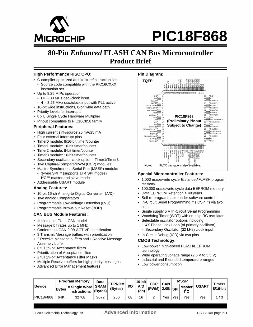
PIC18F86880-Pin Enhanced FLASH CAN Bus Microcontroller
Product Brief
High Performance RISC CPU: • C-compiler optimized architecture/instruction set:
- Source code compatible with the PIC16CXXX instruction set
• Up to 8.25 MIPs operation: - DC - 33 MHz osc./clock input- 4 - 8.25 MHz osc./clock input with PLL active
• 16-bit wide instructions, 8-bit wide data path• Priority levels for interrupts • 8 x 8 Single Cycle Hardware Multiplier• Pinout compatible to PIC18C858 family
Peripheral Features:• High current sink/source 25 mA/25 mA• Four external interrupt pins• Timer0 module: 8/16-bit timer/counter• Timer1 module: 16-bit timer/counter • Timer2 module: 8-bit timer/counter• Timer3 module: 16-bit timer/counter • Secondary oscillator clock option - Timer1/Timer3• Two Capture/Compare/PWM (CCP) modules• Master Synchronous Serial Port (MSSP) module:
- 3-wire SPI™ (supports all 4 SPI modes)- I2C™ master and slave mode
• Addressable USART module
Analog Features:• 10-bit 16-ch Analog-to-Digital Converter (A/D) • Two analog Comparators• Programmable Low-Voltage Detection (LVD)• Programmable Brown-out Reset (BOR)
CAN BUS Module Features:
• Implements FULL CAN model• Message bit rates up to 1 MHz• Conforms to CAN 2.0B ACTIVE specification• 3 Transmit Message buffers with prioritization• 2 Receive Message buffers and 1 Receive Message
Assembly buffer• 6 full 29-bit Acceptance filters • Prioritization of Acceptance filters• 2 full 29-bit Acceptance Filter Masks• Multiple Receive buffers for high priority messages• Advanced Error Management features
Pin Diagram:
Special Microcontroller Features:• 1,000 erase/write cycle Enhanced FLASH program
memory• 100,000 erase/write cycle data EEPROM memory• Data EEPROM Retention > 40 years• Self re-programmable under software control• In-Circuit Serial Programming™ (ICSP™) via two
pins• Single supply 5 V In-Circuit Serial Programming• Watchdog Timer (WDT) with on-chip RC oscillator• Selectable oscillator options including:
- 4X Phase Lock Loop (of primary oscillator)- Secondary Oscillator (32 kHz) clock input
• In-Circuit Debug (ICD) via two pins
CMOS Technology:• Low-power, high-speed FLASH/EEPROM
technology• Wide operating voltage range (2.5 V to 5.5 V) • Industrial and Extended temperature ranges• Low power consumption
PIC18F868
345
67
89
1011
1213
1415
16
4847
4645
4443
4241
4039
64636261
212223 242526 27 282930 3132
RE
2/C
SR
E3
RE
4R
E5
RE
6R
E7/
CC
P2
RD
0/P
SP
0V
DD
VS
S
RD
1/P
SP
1R
D2/
PS
P2
RD
3/P
SP
3R
D4/
PS
P4
RD
5/P
SP
5R
D6/
PS
P6
RD
7/P
SP
7
RE1/WRRE0/RD
RG0/CANTX1RG1/CANTX2
RG2/CANRX
RG3MCLR/VPP
RG4
VSS
VDD
RF7RF6/AN11
RF5/AN10/CVREF
RF4/AN9
RF3/AN8RF2/AN7/C1OUT
RB0/INT0
RB1/INT1
RB2/INT2
RB3/INT3RB4/KBI0
RB5/KBI1RB6/KBI2
VSS
OSC2/CLKO/RA6OSC1/CLKIN
VDD
RB7/KBI3
RC4/SDI/SDARC3/SCK/SCLRC2/CCP1
RF
0/A
N5
RF
1/A
N6/
C2O
UT
AV
DD
AV
SS
RA
3/A
N3/
VR
EF+
RA
2/A
N2/
VR
EF-
RA
1/A
N1
RA
0/A
N0
VS
S
VD
D
RA
4/T
0CK
IR
A5/
SS
/AN
4/LV
DIN
RC
1/T
1OS
IR
C0/
T1O
SO
/T13
CLK
RC
7/R
X/D
TR
C6/
TX
/CK
RC5/SDO
RJ0
RJ1
RH
1R
H0
12
RH2RH3
1718
RH7/AN15RH6/AN14
RH
5/A
N13
RH
4/A
N12
RK
1R
K0
37
RK3RK2
50
49
RJ2
RJ3
1920
33343536 38
58
575655
54
5352
51
60
59
68 6766 657271706974 737877 76757980
TQFP
(Preliminary PinoutSubject to Change)
Note: PLCC package is also available.
DeviceProgram Memory Data
SRAM(Bytes)
EEPROM(Bytes)
I/O10-bitA/D (ch)
CCP(PWM)
CAN2.0B
MSSPUSART
Timers8/16-bitBytes
# Single WordInstructions
SPIMaster
I2C
PIC18F868 64K 32768 3072 256 68 16 2 Yes Yes Yes Yes 1 / 3
2000 Microchip Technology Inc. Advanced Information DS30314A-page 6-1

PIC18F868
NOTES:
DS30314A-page 6-2 Advanced Information 2000 Microchip Technology Inc.
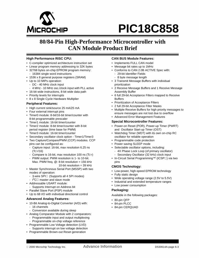
PIC18C85880/84-Pin High-Performance Microcontroller with
CAN Module Product Brief
High Performance RISC CPU:• C-compiler optimized architecture instruction set• Linear program memory addressing to 32K bytes• 32768 bytes on-chip EPROM program memory:
- 16384 single word instructions• 1536 x 8 general purpose registers (SRAM)• Up to 10 MIPs operation:
- DC - 40 MHz clock input- 4 MHz - 10 MHz osc./clock input with PLL active
• 16-bit wide instructions, 8-bit wide data path• Priority levels for interrupts• 8 x 8 Single Cycle Hardware Multiplier
Peripheral Features:• High current sink/source 25 mA/25 mA• Four external interrupt pins• Timer0 module: 8-bit/16-bit timer/counter with
8-bit programmable prescaler• Timer1 module: 16-bit timer/counter• Timer2 module: 8-bit timer/counter with 8-bit
period register (time base for PWM)• Timer3 module: 16-bit timer/counter• Secondary oscillator clock option - Timer1/Timer3• Two Capture/Compare/PWM (CCP) modules. CCP
pins can be configured as:- Capture input: 16-bit, max resolution 6.25 ns
(TCY/16)- Compare is 16-bit, max resolution 100 ns (TCY)- PWM output: PWM resolution is 1- to 10-bit.
Max. PWM freq. @: 8-bit resolution = 156 kHz10-bit resolution = 39 kHz
• Master Synchronous Serial Port (MSSP) with two modes of operation:- 3-wire SPI (Supports all 4 SPI modes)- I2C master and slave mode
• Addressable USART module: - Supports Interrupt on Address bit
• Parallel Slave Port (PSP) module• Up to 68 I/O with individual directional control
Advanced Analog Features:• 10-Bit Analog-to-Digital Converter (A/D) with:
- 16 channels- Conversion available during sleep
• Analog Comparator Module with 2 comparators:- Programmable input and output multiplexing- Programmable on-chip voltage reference
• Programmable Low Voltage detection (LVD)- Supports interrupt on low voltage detection
• Programmable Brown-out Reset generation
CAN BUS Module Features:• Implements FULL CAN model• Message bit rates up to 1MHz• Conforms to CAN 2.0B ACTIVE Spec with:
- 29-bit Identifier Fields- 8 byte message length
• 3 Transmit Message Buffers with individual prioritization
• 2 Receive Message Buffers and 1 Receive Message Assembly Buffer
• 6 full 29-bit Acceptance Filters mapped to Receive Buffers
• Prioritization of Acceptance Filters• 2 full 29-bit Acceptance Filter Masks• Multiple Receive Buffers for high priority messages to
ensure messages are not lost due to overflow• Advanced Error Management Features
Special Microcontroller Features:• Power-on Reset (POR), Power-up Timer (PWRT)
and Oscillator Start-up Timer (OST)• Watchdog Timer (WDT) with its own on-chip RC
oscillator for reliable operation• Programmable code protection• Power saving SLEEP mode• Selectable oscillator options, including:
- 4X Phase Lock Loop (of primary oscillator)- Secondary Oscillator (32 kHz) clock input
• In-Circuit Serial Programming™ (ICSP) via two pins
CMOS Technology:• Low-power, high-speed EPROM technology• Fully static design• Wide operating voltage range (2.5V to 5.5V)• Industrial and extended temperature ranges• Low power consumption
Packaging:
Available in the following packages:
• 80-pin QFP• 84-pin PLCC• 84-pin CERQUAD
2000 Microchip Technology Inc. Advance Information DS30614A-page 6-3
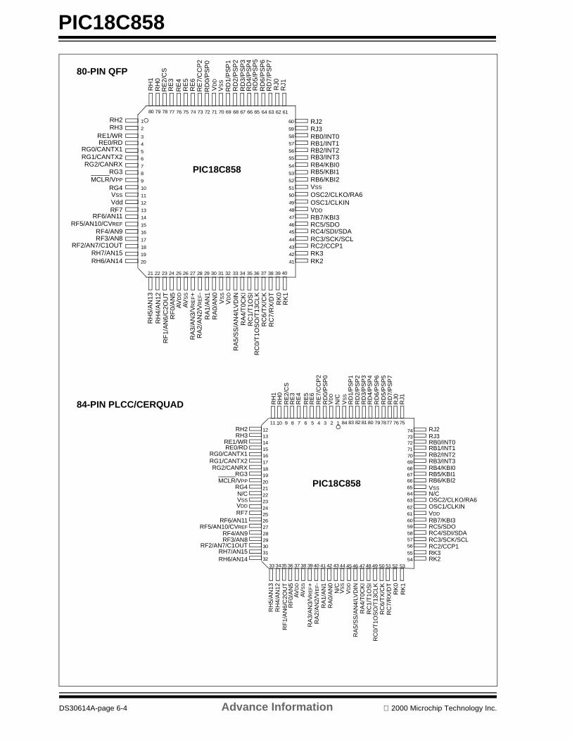
PIC18C858
PIC18C858
3
4
5
6
7
8
9
10
11
12
13
14
15
16
48
47
46
45
44
43
42
41
4039
64 63 62 61
21 22 23 24 25 26 27 28 29 30 31 32
RE
2/C
SR
E3
RE
4R
E5
RE
6R
E7/
CC
P2
RD
0/P
SP
0V
DD
VS
SR
D1/
PS
P1
RD
2/P
SP
2R
D3/
PS
P3
RD
4/P
SP
4R
D5/
PS
P5
RD
6/P
SP
6R
D7/
PS
P7
RE1/WRRE0/RD
RG0/CANTX1RG1/CANTX2RG2/CANRX
RG3MCLR/VPP
RG4VSS
VddRF7
RF6/AN11RF5/AN10/CVREF
RF4/AN9RF3/AN8
RF2/AN7/C1OUT
RB0/INT0RB1/INT1RB2/INT2RB3/INT3RB4/KBI0RB5/KBI1RB6/KBI2VSS
OSC2/CLKO/RA6OSC1/CLKINVDD
RB7/KBI3
RC4/SDI/SDARC3/SCK/SCLRC2/CCP1
RF
0/A
N5
RF
1/A
N6/
C2O
UT
AV
DD
AV
SS
RA
3/A
N3/
VR
EF+
RA
2/A
N2/
VR
EF-
RA
1/A
N1
RA
0/A
N0
VS
SV
DD
RA
4/T
0CK
IR
A5/
SS
/AN
4/LV
DIN
RC
1/T
1OS
IR
C0/
T1O
SO
/T13
CLK
RC
7/R
X/D
TR
C6/
TX
/CK
RC5/SDO
RJ0
RJ1
RH
1R
H0
1
2
RH2RH3
17
18RH7/AN15RH6/AN14
RH
5/A
N13
RH
4/A
N12
RK
1R
K0
37
RK3RK2
50
49
RJ2RJ3
19
20
33 34 35 36 38
58
57
56
55
54
53
52
51
60
59
68 67 66 6572 71 70 6974 7378 77 76 757980
80-PIN QFP
PIC18C858
1011
121314151617181920212223242526 60
59585756
5554
53525150494847464544
9 8 7 6 5 4 3 2 1
272829303132
33 3435 36 37 38 39 40 41 42 43
RB0/INT0RB1/INT1RB2/INT2RB3/INT3RB4/KBI0RB5/KBI1RB6/KBI2VSSN/C
OSC1/CLKINVDDRB7/KBI3
RC4/SDI/SDARC3/SCK/SCLRC2/CCP1
RE1/WRRE0/RD
RG0/CANTX1RG1/CANTX2RG2/CANRX
RG3MCLR/VPP
RG4
VSSVDD
RF7RF6/AN11
RF5/AN10/CVREFRF4/AN9RF3/AN8
RF2/AN7/C1OUT
RE
2/C
SR
E3
RE
4R
E5
RE
6R
E7/
CC
P2
RD
0/P
SP
0V
DD
VS
SR
D1/
PS
P1
RD
2/P
SP
2R
D3/
PS
P3
RD
4/P
SP
4
RD
5/P
SP
5R
D6/
PS
P6
RD
7/P
SP
7
RF
1/A
N6/
C2O
UT
RF
0/A
N5
AV
DD
AV
SS
RA
3/A
N3/
VR
EF+
RA
2/A
N2/
Vr E
F-
RA
1/A
N1
RA
0/A
N0
VS
SV
DD
RA
4/T
0CK
IR
A5/
SS
/AN
4/LV
DIN
RC
1/T
1OS
IR
C0/
T1O
SO
/T13
CLK
RC
7/R
X/D
TR
C6/
TX
/CK
RC5/SDO
RJ2RJ3
RJ0
RJ1
RK
0R
K1
RK3RK2
RH
1R
H0
RH2RH3
RH
5/A
N13
RH
4/A
N12
RH7/AN15RH6/AN14
6766656463
6261
68
7473727170
767978778083 82 8184 75
69
OSC2/CLKO/RA6
N/C
N/C
N/C
84-PIN PLCC/CERQUAD
DS30614A-page 6-4 Advance Information 2000 Microchip Technology Inc.

PIC18F8X280/84-Pin Enhanced FLASH Microcontroller Product Brief
High Performance RISC CPU: • C-compiler optimized architecture/instruction set:
- Source code compatible with the PIC16CXXX instruction set
• Up to 10 MIPs operation: - DC - 40 MHz osc./clock input- 4 - 10 MHz osc./clock input with PLL active
• 16-bit wide instructions, 8-bit wide data path• External system bus capable of addressing
2 Megabytes of program memory• Priority levels for interrupts • 8 x 8 Single Cycle Hardware Multiplier
Peripheral Features:• High current sink/source 25 mA/25 mA• Four external interrupt pins• Timer0 module: 8/16-bit timer/counter• Timer1 module: 16-bit timer/counter • Timer2 module: 8-bit timer/counter• Timer3 module: 16-bit timer/counter • Secondary oscillator clock option - Timer1/Timer3• Two Capture/Compare/PWM (CCP) modules• Master Synchronous Serial Port (MSSP) module.
Two modes of operation:- 3-wire SPI™ (supports all 4 SPI modes)- I2C™ master and slave mode
• Two Addressable USART modules• Parallel Slave Port (PSP) module
Analog Features:• 10-bit 12-ch Analog-to-Digital Converter (A/D):
- High speed conversion rate (25 µs)- Can operate during SLEEP- DNL = +/-1 LSb- INL = +/-1 LSb
• Two analog Comparators with programmable on-chip reference voltage
• Low-Voltage Detection (LVD) module• Programmable Brown-out Reset (BOR)
Special Microcontroller Features:• 1,000 erase/write cycle Enhanced FLASH program
memory• 100,000 erase/write cycle data EEPROM memory• Data EEPROM Retention > 40 years• Self re-programmable under software control• In-Circuit Serial Programming (ICSP™) via two pins• Single supply 5 V In-Circuit Serial Programming• Watchdog Timer (WDT) with on-chip RC oscillator• Programmable code-protection• Selectable oscillator options including:
- 4X Phase Lock Loop (of primary oscillator)- Secondary Oscillator (32 kHz) clock input
• In-Circuit Debug (ICD) via two pins
CMOS Technology:• Low-power, high-speed FLASH/EEPROM
technology• Wide operating voltage range (2.0 V to 5.5 V) • Industrial and Extended temperature ranges• Low power consumption
Device
Program Memory Data SRAM(Bytes)
EEPROM(Bytes)
I/O10-bitA/D (ch)
CCP(PWM)
MSSP
USARTTimers8/16-bitBytes
#Single WordInstructions
SPI Master I2C
PIC18F852 32K 16384 1536 256 68 12 2 Yes Yes 2 1 / 3
PIC18F862 64K 32768 3072 256 68 12 2 Yes Yes 2 1 / 3
PIC18F872 128K 65536 3968 256 68 12 2 Yes Yes 2 1 / 3
2000 Microchip Technology Inc. Advanced Information DS30315A-page 6-5

PIC18F8X2
Pin Diagram:
PIC18F8X2
345678910111213141516
48474645
44434241
4039
64 63 62 61
21 22 23 24 25 26 27 28 29 30 31 32
RE
2/A
D10
/CS
RE
3/A
D11
RE
4/A
D12
RE
5/A
D13
RE
6/A
D14
RE
7/A
D15
RD
0//A
D0/
PS
P0
VD
DV
SS
RD
1/A
D1/
PS
P1
RD
2/A
D2/
PS
P2
RD
3/A
D3/
PS
P3
RD
4/A
D4/
PS
P4
RD
5/A
D5/
PS
P5
RD
6/A
D6/
PS
P6
RD
7/A
D7/
PS
P7
RE1/AD9/WRRE0/AD8/RD
RG0/ALERG1/CCP2
RG2/TX2/CK2RG3/RX2/DT2
MCLR/VPPRG4VSSVDD
RF7/SSRF6/AN11
RF5/AN10/CVREFRF4/AN9RF3/AN8
RF2/AN7/C1OUT
RB0/INT0RB1/INT1RB2/INT2RB3/INT3RB4/KBI0RB5/KBI1RB6/KBI2VSSOSC2/CLKO/RA6OSC1/CLKINVDDRB7/KBI3
RC4/SDI/SDARC3/SCK/SCLRC2/CCP1
RF
0/A
N5
RF
1/A
N6/
C2O
UT
AV
DD
AV
SS
RA
3/A
N3/
VR
EF+
RA
2/A
N2/
VR
EF-
RA
1/A
N1
RA
0/A
N0
VS
SV
DD
RA
4/T
0CK
IR
A5/
AN
4/LV
DIN
RC
1/T
1OS
IR
C0/
T1O
SO
/T13
CLK
RC
7/R
X1/
DT
1R
C6/
TX
1/C
K1
RC5/SDO
RJ7
/BA
0R
J6/O
E
RH
1/A
17R
H0/
A16
12
RH2/A18RH3/A19
1718
RH7/AN15RH6/AN14
RH
5/A
N13
RH
4/A
N12
RJ1
RJ0
37
RJ3/UBRJ2/LB
5049
RJ5/WRLRJ4/WRH
1920
33 34 35 36 38
58575655
54535251
6059
68 67 66 6572 71 70 6974 7378 77 76 757980
TQFP
Note: PLCC package also available.
DS30315A-page 6-6 Advanced Information 2000 Microchip Technology Inc.

PIC18C80180/84-Pin ROMless Microcontroller w/10-bit A/D Product Brief
High Performance RISC CPU:
• C-compiler optimized architecture/instruction set:
- Source code compatible with the PIC16CXXX instruction set
• Up to 6.25 MIPs operation:- DC - 25 MHz clock- 4 - 6.25 MHz clock with PLL active
• 16-bit wide instructions, 8-bit wide data path• External system bus capable of addressing
2 Megabytes or 1 Mega-instructions• 1536 x 8 general purpose registers (SRAM)
• Priority levels for interrupts• 8 x 8 Single Cycle Hardware Multiplier• Pinout similar to PIC18F8XX family
Peripheral Features:
• High current sink/source 25 mA/25 mA• Three external interrupt pins• Timer0 module: 8/16-bit timer/counter
• Timer1 module: 16-bit timer/counter • Timer2 module: 8-bit timer/counter• Timer3 module: 16-bit timer/counter
• Two Capture/Compare/PWM (CCP) modules. CCP pins can be configured as:
- Capture is 16-bit, max resolution 6.25 ns - Compare is 16-bit, max resolution 160 ns- PWM output: PWM resolution is 1- to 10-bit.- Max. PWM freq. @:8-bit resolution = 98 kHz- 10-bit resolution = 24 kHz
• Master Synchronous Serial Port (MSSP) module. Two modes of operation:- 3-wire SPI™ (supports all 4 SPI modes)- I2C™ master and slave mode
• Addressable USART module
Analog Features:
• 10-bit 12-ch Analog-to-Digital Converter (A/D):
- High speed conversion rate (25 µs)- DNL = +/-1 LSb- INL = +/-1 LSb
• Low-Voltage Detection (LVD) module
Pin Diagram:
Special Microcontroller Features:
• Watchdog Timer (WDT) with its own on-chip RC oscillator for reliable operation
• Programmable code-protection• Power saving SLEEP mode• Selectable oscillator options including:
- 4X Phase Lock Loop (of primary oscillator)- Secondary Oscillator (32 kHz) clock input
• In-Circuit Debug (ICD) via two pins
CMOS Technology:
• Low-power, high-speed CMOS technology• Fully static design
• Wide operating voltage range (2.0 V to 5.5 V) • Industrial and Extended temperature ranges• Low power consumption
PIC18C801
345678910111213141516
4847464544434241
4039
64636261
212223242526272829303132
RE
2/A
D10
RE
3/A
D11
RE
4/A
D12
RE
5/A
D13
RE
6/A
D14
RE
7/A
D15
RD
0//A
D0
VD
DV
SS
RD
1/A
D1
RD
2/A
D2
RD
3/A
D3
RD
4/A
D4
RD
5/A
D5
RD
6/A
D6
RD
7/A
D7
RE1/AD9RE0/AD8RG0/ALERG1/OE
RG2/WRLRG3/WRHMCLR/VPP
RG4/BA0VSSVDD
RF7/UBRF6/LB
RF5/CS1RF4/CS2
RF3/CSIORF2/AN7
RB0/INT0RB1/INT1RB2/INT2RB3/CCP2RB4/KBI0RB5/KBI1RB6/KBI2VSSOSC2/CLKOOSC1/CLKINVDDRB7/KBI3
RC4/SDI/SDARC3/SCK/SCLRC2/CCP1
RF
0/A
N5
RF
1/A
N6
AV
DD
AV
SS
RA
3/A
N3/
VR
EF+
RA
2/A
N2/
VR
EF-
RA
1/A
N1
RA
0/A
N0
VS
SV
DD
RA
4/T
0CK
IR
A5/
SS
/AN
4/LV
DIN
RC
1/T
1OS
IR
C0/
T1O
SO
/T13
CLK
RC
7/R
X/D
TR
C6/
TX
/CK
RC5/SDO
RJ7
/D7
RJ6
/D6
RH
1/A
17R
H0/
A16
12
RH2/A18RH3/A19
1718
RH7/AN8RH6/AN9
RH
5/A
N10
RH
4/A
N11
RJ1
/D1
RJ0
/D0
37
RJ3/D3RJ2/D2
5049
RJ5/D5RJ4/D4
1920
33343536 38
5857565554535251
6059
68676665727170697473787776757980
TQFP
Note: PLCC package also available.
Device
External Program MemoryData SRAM
(Bytes)I/O
10-bitA/D (ch)
CCP(PWM)
MSSP
AUSARTTimers8/16-bitBytes
# Single Word Instructions
SPIMaster
I2C
PIC18C801 2M 1048576 1536 68 12 2 Yes Yes Yes 1 / 3
2000 Microchip Technology Inc. Advanced Information DS30306A-page 6-7

PIC18C801
NOTES:
DS30306A-page 6-8 Advanced Information 2000 Microchip Technology Inc.

SECTION 7PICmicro® 100-PIN RISCMICROCONTROLLERS
PIC18C958 100-Pin High-Performance Microcontroller with CAN Module and External Memory Bus Product Brief .......................................................................................................................................... 7-1
2000 Microchip Technology Inc. DS00168C-page 7-i

DS00168C-page 7-ii 2000 Microchip Technology Inc.
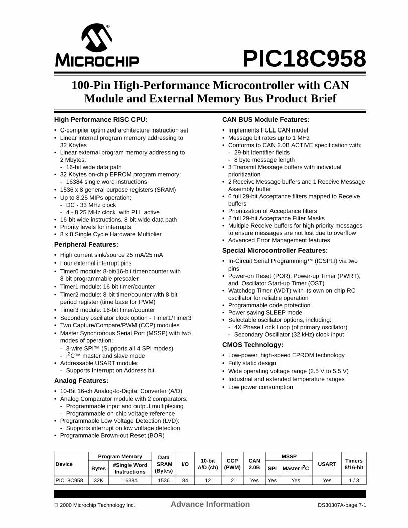
PIC18C958100-Pin High-Performance Microcontroller with CAN
Module and External Memory Bus Product Brief
High Performance RISC CPU:
• C-compiler optimized architecture instruction set• Linear internal program memory addressing to
32 Kbytes• Linear external program memory addressing to
2 Mbytes:- 16-bit wide data path
• 32 Kbytes on-chip EPROM program memory:- 16384 single word instructions
• 1536 x 8 general purpose registers (SRAM)• Up to 8.25 MIPs operation:
- DC - 33 MHz clock - 4 - 8.25 MHz clock with PLL active
• 16-bit wide instructions, 8-bit wide data path• Priority levels for interrupts• 8 x 8 Single Cycle Hardware Multiplier
Peripheral Features:
• High current sink/source 25 mA/25 mA• Four external interrupt pins• Timer0 module: 8-bit/16-bit timer/counter with
8-bit programmable prescaler• Timer1 module: 16-bit timer/counter• Timer2 module: 8-bit timer/counter with 8-bit
period register (time base for PWM)• Timer3 module: 16-bit timer/counter• Secondary oscillator clock option - Timer1/Timer3• Two Capture/Compare/PWM (CCP) modules• Master Synchronous Serial Port (MSSP) with two
modes of operation:- 3-wire SPI™ (Supports all 4 SPI modes)- I2C™ master and slave mode
• Addressable USART module:- Supports Interrupt on Address bit
Analog Features:
• 10-Bit 16-ch Analog-to-Digital Converter (A/D)• Analog Comparator module with 2 comparators:
- Programmable input and output multiplexing- Programmable on-chip voltage reference
• Programmable Low Voltage Detection (LVD):- Supports interrupt on low voltage detection
• Programmable Brown-out Reset (BOR)
CAN BUS Module Features:
• Implements FULL CAN model• Message bit rates up to 1 MHz• Conforms to CAN 2.0B ACTIVE specification with:
- 29-bit Identifier fields- 8 byte message length
• 3 Transmit Message buffers with individual prioritization
• 2 Receive Message buffers and 1 Receive Message Assembly buffer
• 6 full 29-bit Acceptance filters mapped to Receive buffers
• Prioritization of Acceptance filters• 2 full 29-bit Acceptance Filter Masks• Multiple Receive buffers for high priority messages
to ensure messages are not lost due to overflow• Advanced Error Management features
Special Microcontroller Features:
• In-Circuit Serial Programming™ (ICSP) via two pins
• Power-on Reset (POR), Power-up Timer (PWRT), and Oscillator Start-up Timer (OST)
• Watchdog Timer (WDT) with its own on-chip RC oscillator for reliable operation
• Programmable code protection• Power saving SLEEP mode• Selectable oscillator options, including:
- 4X Phase Lock Loop (of primary oscillator)- Secondary Oscillator (32 kHz) clock input
CMOS Technology:
• Low-power, high-speed EPROM technology• Fully static design• Wide operating voltage range (2.5 V to 5.5 V)• Industrial and extended temperature ranges• Low power consumption
DeviceProgram Memory Data
SRAM(Bytes)
I/O10-bit
A/D (ch)CCP
(PWM)CAN2.0B
MSSPUSART
Timers8/16-bitBytes
#Single WordInstructions
SPI Master I2C
PIC18C958 32K 16384 1536 84 12 2 Yes Yes Yes Yes 1 / 3
2000 Microchip Technology Inc. Advance Information DS30307A-page 7-1
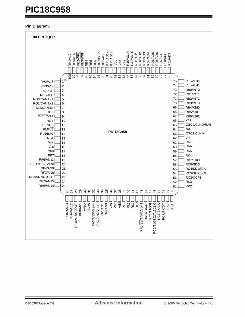
PIC18C958
Pin Diagram:
9294 93 91 90 89 88 87 86 85 84 83 82 81 80 79 7820
23456789101112
13141516
65646362616059
26
56
4544434241403928 29 30 31 32 33 34 35 36 37 38
171819
2122
95
1
7677
72717069686766
757473
5857
2423
25
9698 979927 46 47 48 49 50
5554535251
100
RD
1/A
D1
RD
2/A
D2
RD
3/A
D3
RD
4/A
D4
RD
5/A
D5
RD
6/A
D6
RD
7/A
D7
RJ0
/AD
8R
J1/A
D9
RE
2/W
RL
RE
3/W
RH
RE
4R
E5
RE
6R
E7/
CC
P2
RD
0/A
D0
RH
1/A
17R
H0/
A16
VD
D
Vss
RB0/INT0RB1/INT1RB2/INT2RB3/INT3RB4/KBI0RB5/KBI1RB6/KBI2Vss
OSC2/CLKO/RA6
OSC1/CLKINVDD
RB7/KBI3
RC4/SDI/SDARC3/SCK/SCLRC2/CCP1
RC5/SDO
RK3RK2
RJ2/AD10RJ3/AD11
RF
0/A
N5
RF
1/A
N6/
C2O
UT
AV
DD
AV
ssR
A3/
AN
3/V
RE
F+
RA
2/A
N2/
VR
EF-
RA
1/A
N1
RA
0/A
N0
Vss Vdd
RA
4/T
0CK
IR
A5/
SS
/AN
4/LV
DIN
RC
1/T
1OS
IR
C0/
T1O
SO
/T13
CLK
RC
7/R
X/D
T
RC
6/T
X/C
K
RH
5/A
N13
RH
4/A
N12
RK
1R
K0
RE1/OERE0/ALE
RG0/CANTX1RG1/CANTX2RG2/CANRX
RG3MCLR/VPP
RG4
VssVDD
RF7RF6/AN11
RF5/AN10/CVREF
RF4/AN9RF3/AN8
RF2/AN7/C1OUT
RL7/UBRL6/LB
RH7/AN15RH6/AN14
RH2/A18RH3/A19
RL4RL5/BA0
RL3
RL2
RL1
RL0
RJ4
/AD
12R
J5/A
D13
RJ6
/AD
14R
J7/A
D15
RK7RK6
RK5
RK4
Vss
Vdd
N/C
VD
D
PIC18C958
100-PIN TQFP
DS30307A-page 7-2 Advance Information 2000 Microchip Technology Inc.
APPENDIX ACOMPANY PROFILE
Company Profile - Microchip Technology Inc. .............................................................................................................A-1
2000 Microchip Technology Inc. DS00168C-page A-i
DS00168C-page A-ii 2000 Microchip Technology Inc.
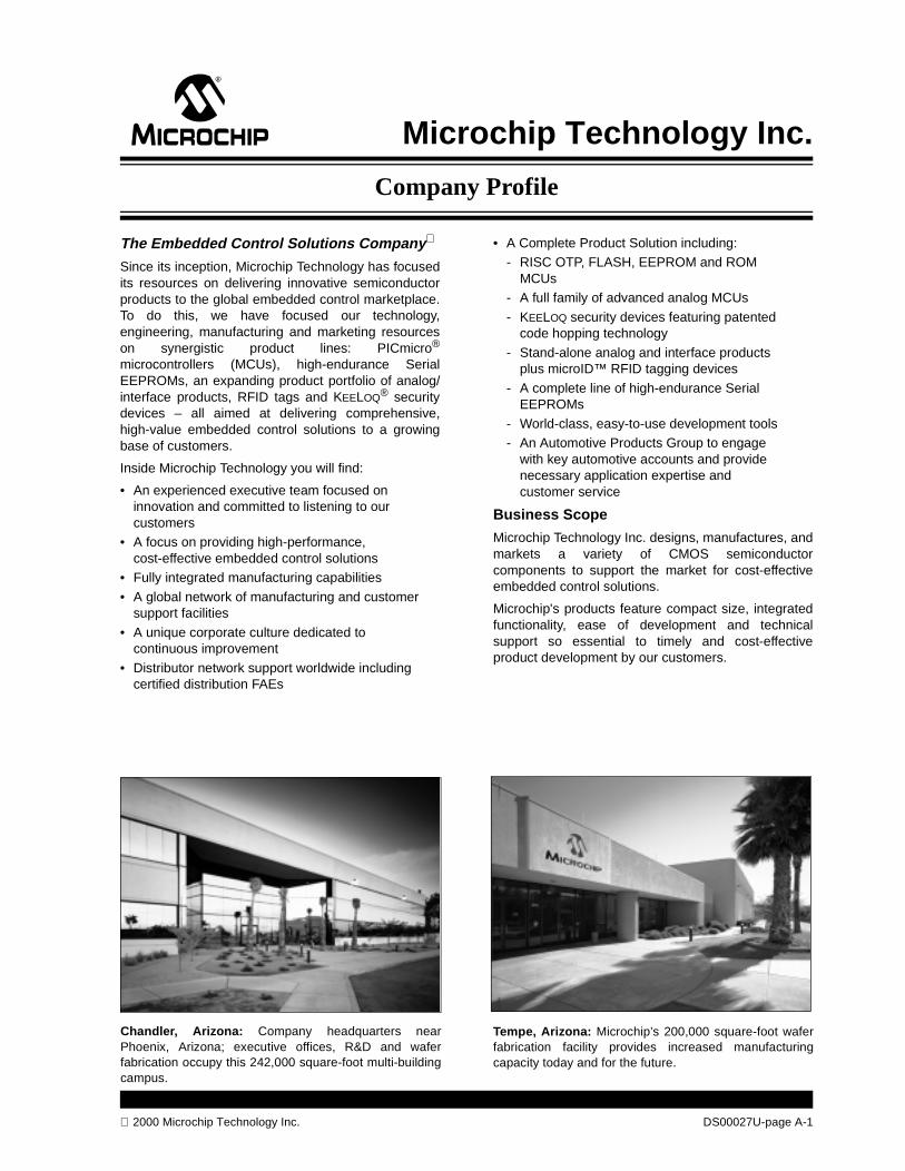
Company Profile
Microchip Technology Inc.
The Embedded Control Solutions Company
Since its inception, Microchip Technology has focusedits resources on delivering innovative semiconductorproducts to the global embedded control marketplace.To do this, we have focused our technology,engineering, manufacturing and marketing resourceson synergistic product lines: PICmicro®
microcontrollers (MCUs), high-endurance SerialEEPROMs, an expanding product portfolio of analog/interface products, RFID tags and KEELOQ® securitydevices – all aimed at delivering comprehensive,high-value embedded control solutions to a growingbase of customers.
Inside Microchip Technology you will find:
• An experienced executive team focused on innovation and committed to listening to our customers
• A focus on providing high-performance, cost-effective embedded control solutions
• Fully integrated manufacturing capabilities
• A global network of manufacturing and customer support facilities
• A unique corporate culture dedicated to continuous improvement
• Distributor network support worldwide including certified distribution FAEs
2000 Microchip Technology Inc.
Chandler, Arizona: Company headquarters nearPhoenix, Arizona; executive offices, R&D and waferfabrication occupy this 242,000 square-foot multi-buildingcampus.
• A Complete Product Solution including:- RISC OTP, FLASH, EEPROM and ROM
MCUs- A full family of advanced analog MCUs
- KEELOQ security devices featuring patented code hopping technology
- Stand-alone analog and interface products plus microID™ RFID tagging devices
- A complete line of high-endurance Serial EEPROMs
- World-class, easy-to-use development tools- An Automotive Products Group to engage
with key automotive accounts and provide necessary application expertise and customer service
Business Scope
Microchip Technology Inc. designs, manufactures, andmarkets a variety of CMOS semiconductorcomponents to support the market for cost-effectiveembedded control solutions.
Microchip's products feature compact size, integratedfunctionality, ease of development and technicalsupport so essential to timely and cost-effectiveproduct development by our customers.
DS00027U-page A-1
Tempe, Arizona: Microchip’s 200,000 square-foot waferfabrication facility provides increased manufacturingcapacity today and for the future.
Microchip Technology Inc.
Market Focus
Microchip targets select markets where our advanceddesigns, progressive process technology andindustry-leading product performance enables us todeliver decidedly superior performance. Our Companyis positioned to provide a complete product solution forembedded control applications found throughout theconsumer, automotive, telecommunication, officeautomation and industrial control markets. Microchipproducts are also meeting the unique designrequirements of targeted embedded applicationsincluding internet, safety and security.
Certified Quality Systems
Microchip’s quality systems have been certified toQS-9000 requirements. Its worldwide headquartersand wafer fabrication facilities in Chandler and Tempe,Arizona, received certification on July 23, 1999. Thescope of this certification is the design andmanufacture of RISC-based MCUs, relatednon-volatile memory products and microperipheraldevices. The quality systems for Microchip’s producttest facility in Bangkok, Thailand, were QS-9000certified on February 26, 1999. The scope of thiscertification is the design and testing of integratedcircuits. In addition, Microchip’s quality system for thedesign and manufacture of development systems isISO 9001 certified.
QS-9000 was developed by Chrysler, Ford andGeneral Motors to establish fundamental qualitysystems that provide for continuous improvement,emphasizing defect prevention and the reduction ofvariation and waste in the supply chain. Microchip wasaudited by QS-9000 registrar Det Norske VeritasCertification Inc. of Houston, the same firm whichgranted Microchip its ISO 9001 Quality Systemcertification in 1997. QS-9000 certification recognizesMicrochip’s quality systems conform to the stringentstandards set forth by the automotive industry,benefiting all customers.
Fully Integrated Manufacturing
Microchip delivers fast turnaround and consistentquality through total control over all phases ofproduction. Research and development, design, maskmaking, wafer fabrication, and the major part ofassembly and quality assurance testing are conducted
DS00027U-page A-2
at facilities wholly-owned and operated by Microchip.Our integrated approach to manufacturing along withrigorous use of advanced Statistical Process Control(SPC) and a continuous improvement culture hasresulted in high and consistent yields which havepositioned Microchip as a quality leader in its globalmarkets. Microchip’s unique approach to SPC providescustomers with excellent pricing, quality, reliability andon-time delivery.
A Global Network of Plants and Facilities
Microchip is a global competitor providing localservices to the world’s technology centers. TheCompany’s design and technology advancementfacilities, and wafer fabrication sites are located inChandler and Tempe, Arizona.
The Tempe facility provides an additional 200,000square feet of manufacturing space that meets theincreased production requirements of a growingcustomer base, and provides production capacitywhich more than doubles that of Chandler.
Microchip facilities in Bangkok, Thailand, andShanghai, China, serve as the foundation ofMicrochip’s extensive assembly and test capabilitylocated throughout Asia. The use of multiplefabrication, assembly and test sites, with more than640,000-square-feet of facilities worldwide, ensuresMicrochip’s ability to meet the increased productionrequirements of a fast growing customer base.
Microchip supports its global customer base from directsales and engineering offices in Asia, North America,Europe and Japan. Offices are staffed to meet the highquality expectations of our customers, and can beaccessed for technical and business support. TheCompany also franchises more than 60 distributors anda network of technical manufacturer’s representativesserving 24 countries worldwide.
Bangkok, Thailand: Microchip’s 200,000 square-footmanufacturing facility houses the technology andassembly/test equipment for high speed testing andpackaging.
2000 Microchip Technology Inc.

Microchip Technology Inc.
Embedded Control Overview
Unlike “processor” applications such as personalcomputers and workstations, the computing orcontrolling elements of embedded control applicationsare embedded inside the application. The consumer isonly concerned with the very top-level user interfacesuch as keypads, displays and high-level commands.Very rarely does an end-user know (or care to know)the embedded controller inside (unlike theconscientious PC users, who are intimately familiar notonly with the processor type, but also its clock speed,DMA capabilities and so on).
It is, however, most vital for designers of embeddedcontrol products to select the most suitable controllerand companion devices. Embedded control productsare found in all market segments: consumer,commercial, PC peripherals, telecommunications,automotive and industrial. Most embedded controlproducts must meet special requirements: costeffectiveness, low-power, small-footprint and a highlevel of system integration.
Typically, most embedded control systems aredesigned around an MCU which integrates on-chipprogram memory, data memory (RAM) and variousperipheral functions, such as timers and serialcommunication. In addition, these systems usuallyrequire complementary Serial EEPROM,analog/interface devices, display drivers, keypads orsmall displays.
Microchip has established itself as a leading supplier ofembedded control solutions. The combination ofhigh-performance PIC12CXXX, PIC16C5X,PIC16CXXX, PIC17CXXX and PIC18CXXX MCUfamilies with Migratable Memory™ technology, alongwith non-volatile memory products, provide the basisfor this leadership. By further expanding our productportfolio to provide precision analog and interfaceproducts, Microchip is committed to continuousinnovation and improvement in design, manufacturingand technical support to provide the best possibleembedded control solutions to you.
PICmicro MCU Overview and Roadmap
Microchip PICmicro MCUs combine high-performance,low-cost, and small package size, offering the bestprice/performance ratio in the industry. More than onebillion of these devices have shipped to customersworldwide since 1990. Microchip offers five families ofMCUs to best fit your application needs:
• PIC12CXXX 8-pin 12-bit/14-bit program word• PIC16C5X 12-bit program word
• PIC16CXXX 14-bit program word• PIC17CXXX 16-bit program word• PIC18CXXX enhanced 16-bit program word
All families offer OTP, low-voltage and low-poweroptions, with a variety of package options. Selectedmembers are available in ROM, EEPROM orreprogrammable FLASH versions.
2000 Microchip Technology Inc.
PIC12CXXX: 8-Pin, FamilyThe PIC12CXXX family packs Microchip’s powerfulRISC-based PICmicro architecture into 8-pin DIP andSOIC packages. These PIC12CXXX products areavailable with either a 12-bit or 14-bit wide instructionset, a low operating voltage of 2.5V, small packagefootprints, interrupt handling, a deeper hardware stack,multiple channels and EEPROM data memory. All ofthese features provide an intelligence level notpreviously available in applications because of cost orsize considerations.
PIC16C5X: 12-Bit Architecture FamilyThe PIC16C5X is the well-established base-line familythat offers the most cost-effective solution. ThesePIC16C5X products have a 12-bit wide instruction setand are currently offered in 14-, 18-, 20- and 28-pinpackages. In the SOIC and SSOP packaging options,these devices are among the smallest footprint MCUsin the industry. Low-voltage operation, down to 2.0V forOTP MCUs, makes this family ideal for batteryoperated applications. Additionally, the PIC16HV5XXcan operate up to 15 volts for use directly with a battery.
PIC16CXXX: 14-Bit Architecture FamilyWith the introduction of new PIC16CXXX familymembers, Microchip now provides the industry’shighest performance Analog-to-Digital Convertercapability at 12-bits for an MCU. The PIC16CXXXfamily offers a wide-range of options, from 18- to 68-pinpackages as well as low to high levels of peripheralintegration. This family has a 14-bit wide instruction set,interrupt handling capability and a deep, 8-levelhardware stack. The PIC16CXXX family provides theperformance and versatility to meet the moredemanding requirements of today’s cost-sensitivemarketplace for mid-range applications.
PIC17CXXX: 16-Bit Architecture FamilyThe PIC17CXXX family offers the world’s fastestexecution performance of any MCU family in theindustry. The PIC17CXXX family extends the PICmicroMCU’s high-performance RISC architecture with a16-bit instruction word, enhanced instruction set andpowerful vectored interrupt handling capabilities. Apowerful array of precise on-chip peripheral featuresprovides the performance for the most demandingapplications.
PIC18CXXX: 16-Bit Enhanced Architecture FamilyThe PIC18CXXX is a family of high performance,CMOS, fully static, 16-bit MCUs with integratedanalog-to-digital (A/D) converter. All PIC18CXXXMCUs incorporate an advanced RISC architecture.The PIC18CXXX has enhanced core features, 32level-deep stack, and multiple internal and externalinterrupts sources. The separate instruction and databusses of the Harvard architecture allow a 16-bit wideinstruction word with the separate 8-bit wide data. Thetwo-stage instruction pipeline allows all instructions toexecute in a single cycle, except for program branches,which require two cycles. A total of 77 instructions(reduced instruction set) are available. Additionally, alarge register set gives some of the architectural
DS00027U-page A-3

Microchip Technology Inc.
innovations used to achieve a very high performance of10 MIPS for an MCU. The PIC18CXXX family hasspecial features to reduce external components, thusreducing cost, enhancing system reliability andreducing power consumption. These includeprogrammable Low Voltage Detect (LVD) andprogrammable Brown-Out Detect (BOD).
The Mechatronics Revolution
The nature of the revolution is the momentous shiftfrom analog/electro-mechanical timing and control todigital electronics. It is called the MechatronicsRevolution, and it is being staged in companiesthroughout the world, with design engineers right on
the front lines: make it smarter, make it smaller, make itdo more, make it cost less to manufacture – and makeit snappy.
To meet the needs of this growing customer base,Microchip is rapidly expanding its already broad line ofPICmicro MCUs. The PIC12CXXX family’s size opensup new possibilities for product design.
PICmicro MCU Naming Convention
The PICmicro architecture offers users a wider range ofcost/performance options than any MCU family. Inorder to identify the families, the following namingconventions have been applied to the PICmicro MCUs:
DS00027U-page A-4 2000 Microchip Technology Inc.
TABLE 1: PICmicro MCU NAMING CONVENTION*
*Please check with your local Microchip distributor, sales representative or sales office for the latest product information.
Family Architectural Features Name Technology
PIC
18C
XX
X
8-bit High-Performance MCU Family
• 10 MIPS @ 40 MHz• 4x PLL clock• 16-bit wide instruction set• C compiler efficient
instruction set• Internal/external vec-
tored interrupts
PIC18CXX2PIC18FXXX
OTP program memory with higher resolution analog functionsFLASH program memory
PIC
17C
XX
X
8-bit High-Performance
MCU Family
• 16-bit wide instruction set
• Internal/external vectored interrupts
• DC - 33 MHz clock speed
• 120 ns instruction cycle(@ 33 MHz)
• Hardware multiply
PIC17C4X OTP program memory, digital onlyPIC17CR4X ROM program memory, digital onlyPIC17C7XX OTP program memory with mixed-signal functions
PIC
16C
XX
X
8-bit Mid-Range
MCU Family
• 14-bit wide instruction set
• Internal/external interrupts
• DC - 20 MHz clock speed (Note 1)
• 200 ns instruction cycle(@ 20 MHz)
PIC14CXXX OTP program memory with A/D and D/A functionsPIC16C55X OTP program memory, digital onlyPIC16C6X OTP program memory, digital only
PIC16CR6X ROM program memory, digital onlyPIC16C62X OTP program memory with comparators
PIC16CR62X ROM program memory with comparatorsPIC16CE62X OTP program memory with comparators and EEPROM data
memoryPIC16F62X FLASH program memory with comparators and EEPROM data
memoryPIC16C64X OTP program memory with comparatorsPIC16C66X OTP program memory with comparatorsPIC16C7X OTP program memory with analog functions (i.e. A/D)
PIC16CR7X ROM program memory with analog functions PIC16C7XX OTP program memory with higher resolution analog functionsPIC16F8X FLASH program memory and EEPROM data memory
PIC16CR8X ROM program memory and EEPROM data memoryPIC16F87X FLASH program memory with higher resolution analog functionsPIC16C9XX OTP program memory, LCD driver
PIC
16C
5X
8-bit Base-Line
MCU Family
• 12-bit wide instruction set
• DC - 20 MHz clock speed
• 200 ns instruction cycle (@ 20 MHz)
PIC16C5X OTP program memory, digital onlyPIC16CR5X ROM program memory, digital onlyPIC16C505 OTP program memory, digital only, internal 4 MHz oscillator
PIC16HV540 OTP program memory with high voltage operation
PIC
12C
XX
X
8-bit, 8-pinMCU Family
• 12- or 14-bit wideinstruction set
• DC - 10 MHz clock speed
• 400 ns instruction cycle (@ 10 MHz)
• Internal 4 MHz oscillator
PIC12C5XX OTP program memory, digital onlyPIC12CE5XX OTP program memory, digital only with EEPROM data memoryPIC12CR5XX ROM program memory, digital onlyPIC12C67X OTP program memory with analog functions
PIC12CE67X OTP program memory with analog functions and EEPROM data memory
Note 1: The maximum clock speed for some devices is less than 20 MHz.
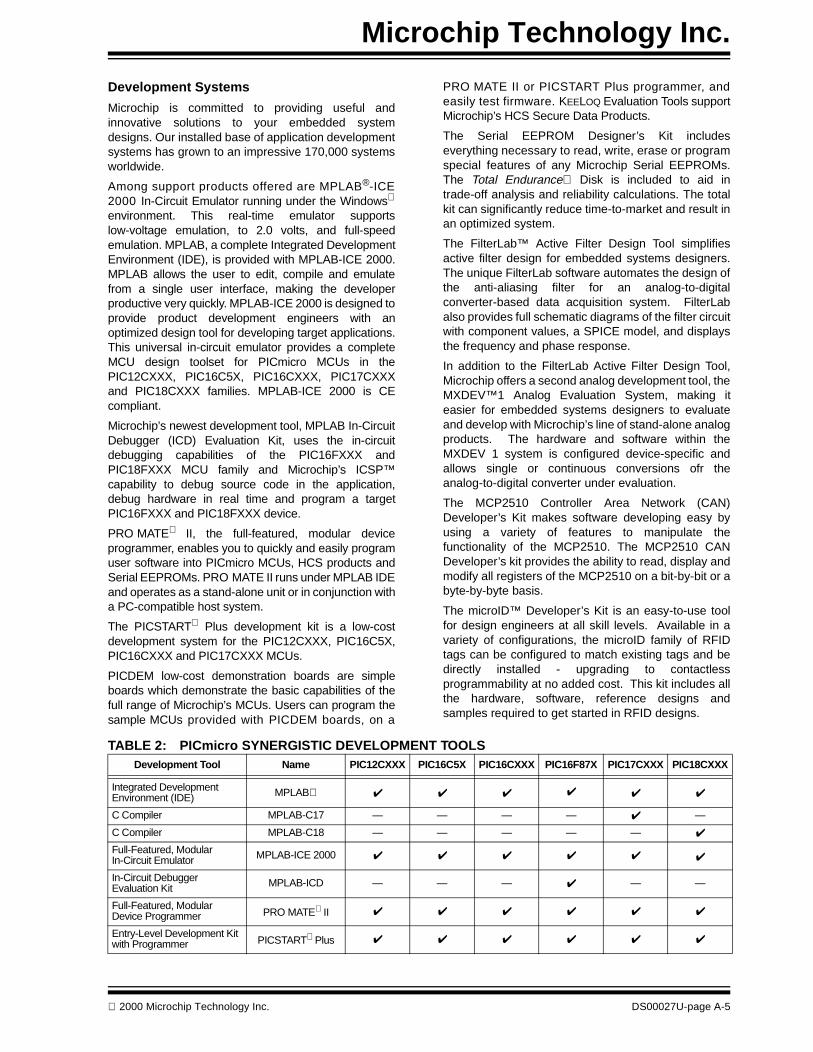
Microchip Technology Inc.
Development Systems
Microchip is committed to providing useful andinnovative solutions to your embedded systemdesigns. Our installed base of application developmentsystems has grown to an impressive 170,000 systemsworldwide.
Among support products offered are MPLAB®-ICE2000 In-Circuit Emulator running under the Windows
environment. This real-time emulator supportslow-voltage emulation, to 2.0 volts, and full-speedemulation. MPLAB, a complete Integrated DevelopmentEnvironment (IDE), is provided with MPLAB-ICE 2000.MPLAB allows the user to edit, compile and emulatefrom a single user interface, making the developerproductive very quickly. MPLAB-ICE 2000 is designed toprovide product development engineers with anoptimized design tool for developing target applications.This universal in-circuit emulator provides a completeMCU design toolset for PICmicro MCUs in thePIC12CXXX, PIC16C5X, PIC16CXXX, PIC17CXXXand PIC18CXXX families. MPLAB-ICE 2000 is CEcompliant.
Microchip’s newest development tool, MPLAB In-CircuitDebugger (ICD) Evaluation Kit, uses the in-circuitdebugging capabilities of the PIC16FXXX andPIC18FXXX MCU family and Microchip’s ICSP™capability to debug source code in the application,debug hardware in real time and program a targetPIC16FXXX and PIC18FXXX device.
PRO MATE II, the full-featured, modular deviceprogrammer, enables you to quickly and easily programuser software into PICmicro MCUs, HCS products andSerial EEPROMs. PRO MATE II runs under MPLAB IDEand operates as a stand-alone unit or in conjunction witha PC-compatible host system.
The PICSTART Plus development kit is a low-costdevelopment system for the PIC12CXXX, PIC16C5X,PIC16CXXX and PIC17CXXX MCUs.
PICDEM low-cost demonstration boards are simpleboards which demonstrate the basic capabilities of thefull range of Microchip’s MCUs. Users can program thesample MCUs provided with PICDEM boards, on a
2000 Microchip Technology Inc.
PRO MATE II or PICSTART Plus programmer, andeasily test firmware. KEELOQ Evaluation Tools supportMicrochip’s HCS Secure Data Products.
The Serial EEPROM Designer’s Kit includeseverything necessary to read, write, erase or programspecial features of any Microchip Serial EEPROMs.The Total Endurance Disk is included to aid intrade-off analysis and reliability calculations. The totalkit can significantly reduce time-to-market and result inan optimized system.
The FilterLab™ Active Filter Design Tool simplifiesactive filter design for embedded systems designers.The unique FilterLab software automates the design ofthe anti-aliasing filter for an analog-to-digitalconverter-based data acquisition system. FilterLabalso provides full schematic diagrams of the filter circuitwith component values, a SPICE model, and displaysthe frequency and phase response.
In addition to the FilterLab Active Filter Design Tool,Microchip offers a second analog development tool, theMXDEV™1 Analog Evaluation System, making iteasier for embedded systems designers to evaluateand develop with Microchip’s line of stand-alone analogproducts. The hardware and software within theMXDEV 1 system is configured device-specific andallows single or continuous conversions ofr theanalog-to-digital converter under evaluation.
The MCP2510 Controller Area Network (CAN)Developer’s Kit makes software developing easy byusing a variety of features to manipulate thefunctionality of the MCP2510. The MCP2510 CANDeveloper’s kit provides the ability to read, display andmodify all registers of the MCP2510 on a bit-by-bit or abyte-by-byte basis.
The microID™ Developer’s Kit is an easy-to-use toolfor design engineers at all skill levels. Available in avariety of configurations, the microID family of RFIDtags can be configured to match existing tags and bedirectly installed - upgrading to contactlessprogrammability at no added cost. This kit includes allthe hardware, software, reference designs andsamples required to get started in RFID designs.
TABLE 2: PICmicro SYNERGISTIC DEVELOPMENT TOOLSDevelopment Tool Name PIC12CXXX PIC16C5X PIC16CXXX PIC16F87X PIC17CXXX PIC18CXXX
Integrated Development Environment (IDE) MPLAB ✔ ✔ ✔ ✔ ✔ ✔
C Compiler MPLAB-C17 — — — — ✔ —
C Compiler MPLAB-C18 — — — — — ✔
Full-Featured, Modular In-Circuit Emulator MPLAB-ICE 2000 ✔ ✔ ✔ ✔ ✔ ✔
In-Circuit Debugger Evaluation Kit MPLAB-ICD — — — ✔ — —
Full-Featured, Modular Device Programmer PRO MATE II ✔ ✔ ✔ ✔ ✔ ✔
Entry-Level Development Kit with Programmer PICSTART Plus ✔ ✔ ✔ ✔ ✔ ✔
DS00027U-page A-5
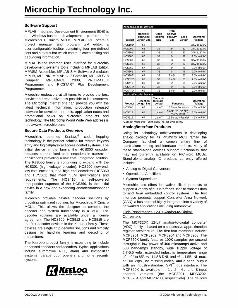
Microchip Technology Inc.
Software Support
MPLAB Integrated Development Environment (IDE) isa Windows-based development platform forMicrochip’s PICmicro MCUs. MPLAB IDE offers aproject manager and program text editor, auser-configurable toolbar containing four pre-definedsets and a status bar which communicates editing anddebugging information.
MPLAB is the common user interface for Microchipdevelopment systems tools including MPLAB Editor,MPASM Assembler, MPLAB-SIM Software Simulator,MPLIB, MPLINK, MPLAB-C17 Compiler, MPLAB-C18Compiler, MPLAB-ICE 2000, PRO MATE IIProgrammer and PICSTART Plus DevelopmentProgrammer.
Microchip endeavors at all times to provide the bestservice and responsiveness possible to its customers.The Microchip Internet site can provide you with thelatest technical information, production releasedsoftware for development tools, application notes andpromotional news on Microchip products andtechnology. The Microchip World Wide Web address ishttp://www.microchip.com.
Secure Data Products Overview
Microchip’s patented KEELOQ® code hoppingtechnology is the perfect solution for remote keylessentry and logical/physical access control systems. Theinitial device in the family, the HCS300 encoder,replaces current fixed code encoders in transmitterapplications providing a low cost, integrated solution.The KEELOQ family is continuing to expand with theHCS301 (high voltage encoder), HCS200 (low-end,low-cost encoder), and high-end encoders (HCS360and HCS361) that meet OEM specifications andrequirements. The HCS410, a self-poweredtransponder superset of the HCS360, is the initialdevice in a new and expanding encoder/transponderfamily.
Microchip provides flexible decoder solutions byproviding optimized routines for Microchip’s PICmicroMCUs. This allows the designer to combine thedecoder and system functionality in a MCU. Thedecoder routines are available under a licenseagreement. The HCS500, HCS512 and HCS515 arethe first decoder devices in the KEELOQ family. Thesedevices are single chip decoder solutions and simplifydesigns by handling learning and decoding oftransmitters.
The KEELOQ product family is expanding to includeenhanced encoders and decoders. Typical applicationsinclude automotive RKE, alarm and immobilizersystems, garage door openers and home securitysystems.
DS00027U-page A-6
*Contact Microchip Technology Inc. for availability.
Analog/Interface Products
Using its technology achievements in developinganalog circuitry for its PICmicro MCU family, theCompany launched a complementary line ofstand-alone analog and interface products. Many ofthese stand-alone devices support functionality thatmay not currently available on PICmicro MCUs.Stand-alone analog IC products currently offeredinclude:
• Analog-to-Digital Converters• Operational Amplifiers
• System Supervisors
Microchip also offers innovative silicon products tosupport a variety of bus interfaces used to transmit datato and from embedded control systems. The firstinterface products support Controller Area Network(CAN), a bus protocol highly integrated into a variety ofnetworked applications including automotive.
High-Performance 12-Bit Analog-to-Digital Converters
The MCP320X 12-bit analog-to-digital converter(ADC) family is based on a successive approximationregister architecture. The first four members include:MCP3201, MCP3202, MCP3204 and MCP3208. TheMCP320X family features 100K samples per secondthroughput, low power of 400 microamps active and500 nanoamps standby, wide supply voltage of2.7-5.5 volts, extended industrial temperature rangeof –40° to 85°, +/- 1 LSB DNL and +/- 1 LSB INL max.at 100 ksps., no missing codes, and a serial outputwith an industry-standard SPI™ bus interface. TheMCP320X is available in 1-, 2-, 4-, and 8-inputchannel versions (the MCP3201, MPC3202,MCP3204 and MCP3208, respectively). The devices
KEELOQ Encoder Devices
Product
Transmis-sion Code
Length Bits
Code Hopping
Bits
Prog. Encryp-tion Key
BitsSeed
Length Operating
Voltage
HCS101* 66 — — — 3.5V to 13.0V
HCS200 66 32 64 32 3.5V to 13.0V
HCS201* 66 32 64 32 3.5V to 13.0V
HCS300 66 32 64 32 2.0V to 6.3V
HCS301 66 32 64 32 3.5V to 13.0V
HCS320 66 32 64 32 3.5V to 13.0V
HCS360 67 32 64 48 2.0V to 6.6V
HCS361 67 32 64 48 2.0V to 6.6V
HCS365* 69 32 2 x 64 60 2.0V to 6.6V
HCS370* 69 32 2 x 64 60 2.0V to 6.6V
HCS410 69 32 64 60 2.0V to 6.6V
HCS412* 69 32 64 60 2.0V to 6.6V
HCS470* 69 32 2 x 64 60 2.0V to 6.6V
KEELOQ Decoder Devices
ProductReception
Length Bits
Transmit-ters Sup-
ported FunctionsOperating
VoltageHCS500 67 Up to 7 15 Serial Functions 4.5V to 5.5V
HCS512 67 Up to 4 15 (S0, S1, S2, S3); VLOW, Serial 3.0V to 6.0V
HCS515 67 Up to 7 15 Serial; 3 Parallel 4.5V to 5.5V
2000 Microchip Technology Inc.
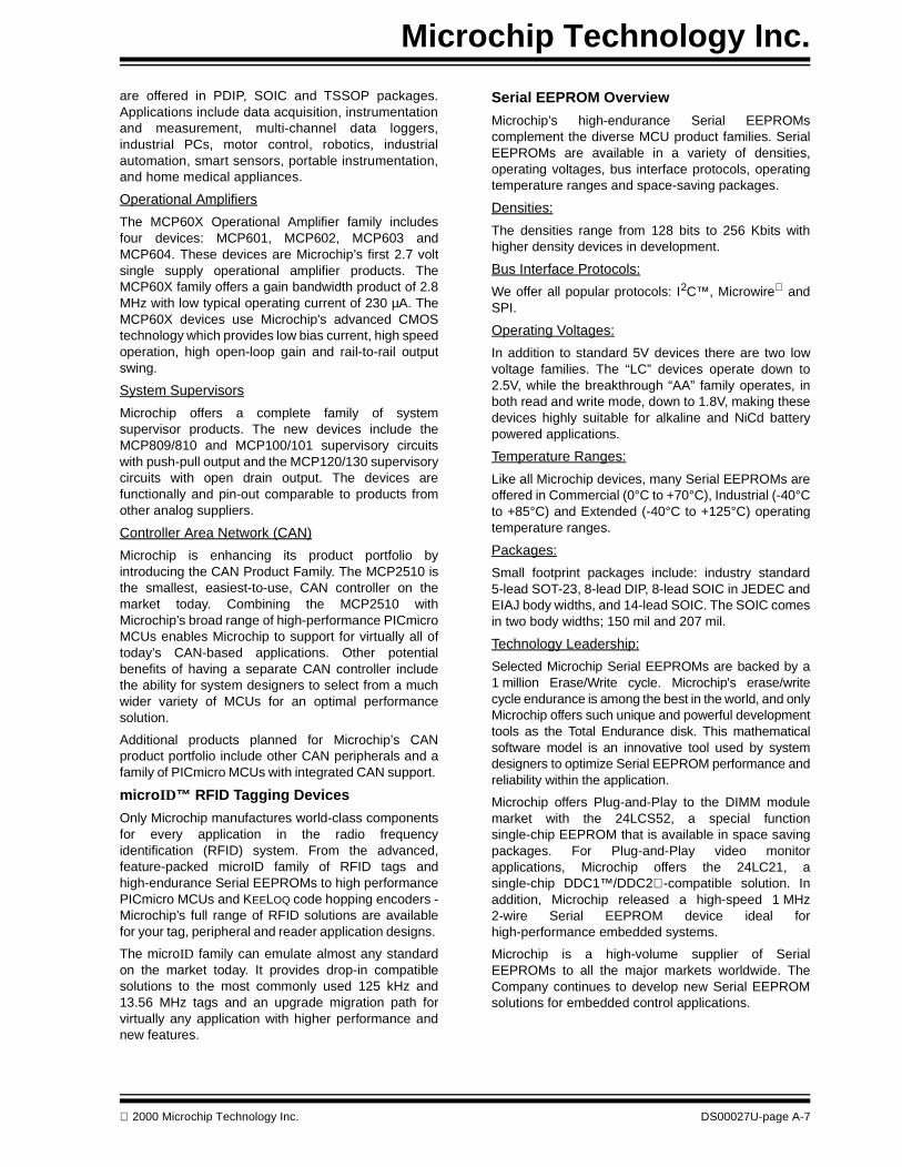
Microchip Technology Inc.
are offered in PDIP, SOIC and TSSOP packages.Applications include data acquisition, instrumentationand measurement, multi-channel data loggers,industrial PCs, motor control, robotics, industrialautomation, smart sensors, portable instrumentation,and home medical appliances.
Operational Amplifiers
The MCP60X Operational Amplifier family includesfour devices: MCP601, MCP602, MCP603 andMCP604. These devices are Microchip’s first 2.7 voltsingle supply operational amplifier products. TheMCP60X family offers a gain bandwidth product of 2.8MHz with low typical operating current of 230 µA. TheMCP60X devices use Microchip's advanced CMOStechnology which provides low bias current, high speedoperation, high open-loop gain and rail-to-rail outputswing.
System Supervisors
Microchip offers a complete family of systemsupervisor products. The new devices include theMCP809/810 and MCP100/101 supervisory circuitswith push-pull output and the MCP120/130 supervisorycircuits with open drain output. The devices arefunctionally and pin-out comparable to products fromother analog suppliers.
Controller Area Network (CAN)
Microchip is enhancing its product portfolio byintroducing the CAN Product Family. The MCP2510 isthe smallest, easiest-to-use, CAN controller on themarket today. Combining the MCP2510 withMicrochip’s broad range of high-performance PICmicroMCUs enables Microchip to support for virtually all oftoday’s CAN-based applications. Other potentialbenefits of having a separate CAN controller includethe ability for system designers to select from a muchwider variety of MCUs for an optimal performancesolution.
Additional products planned for Microchip’s CANproduct portfolio include other CAN peripherals and afamily of PICmicro MCUs with integrated CAN support.
microID™ RFID Tagging Devices
Only Microchip manufactures world-class componentsfor every application in the radio frequencyidentification (RFID) system. From the advanced,feature-packed microID family of RFID tags andhigh-endurance Serial EEPROMs to high performancePICmicro MCUs and KEELOQ code hopping encoders -Microchip’s full range of RFID solutions are availablefor your tag, peripheral and reader application designs.
The microID family can emulate almost any standardon the market today. It provides drop-in compatiblesolutions to the most commonly used 125 kHz and13.56 MHz tags and an upgrade migration path forvirtually any application with higher performance andnew features.
2000 Microchip Technology Inc.
Serial EEPROM Overview
Microchip’s high-endurance Serial EEPROMscomplement the diverse MCU product families. SerialEEPROMs are available in a variety of densities,operating voltages, bus interface protocols, operatingtemperature ranges and space-saving packages.
Densities:
The densities range from 128 bits to 256 Kbits withhigher density devices in development.
Bus Interface Protocols:
We offer all popular protocols: I2C™, Microwire andSPI.
Operating Voltages:
In addition to standard 5V devices there are two lowvoltage families. The “LC” devices operate down to2.5V, while the breakthrough “AA” family operates, inboth read and write mode, down to 1.8V, making thesedevices highly suitable for alkaline and NiCd batterypowered applications.
Temperature Ranges:
Like all Microchip devices, many Serial EEPROMs areoffered in Commercial (0°C to +70°C), Industrial (-40°Cto +85°C) and Extended (-40°C to +125°C) operatingtemperature ranges.
Packages:
Small footprint packages include: industry standard5-lead SOT-23, 8-lead DIP, 8-lead SOIC in JEDEC andEIAJ body widths, and 14-lead SOIC. The SOIC comesin two body widths; 150 mil and 207 mil.
Technology Leadership:
Selected Microchip Serial EEPROMs are backed by a1 million Erase/Write cycle. Microchip's erase/writecycle endurance is among the best in the world, and onlyMicrochip offers such unique and powerful developmenttools as the Total Endurance disk. This mathematicalsoftware model is an innovative tool used by systemdesigners to optimize Serial EEPROM performance andreliability within the application.
Microchip offers Plug-and-Play to the DIMM modulemarket with the 24LCS52, a special functionsingle-chip EEPROM that is available in space savingpackages. For Plug-and-Play video monitorapplications, Microchip offers the 24LC21, asingle-chip DDC1™/DDC2-compatible solution. Inaddition, Microchip released a high-speed 1 MHz2-wire Serial EEPROM device ideal forhigh-performance embedded systems.
Microchip is a high-volume supplier of SerialEEPROMs to all the major markets worldwide. TheCompany continues to develop new Serial EEPROMsolutions for embedded control applications.
DS00027U-page A-7
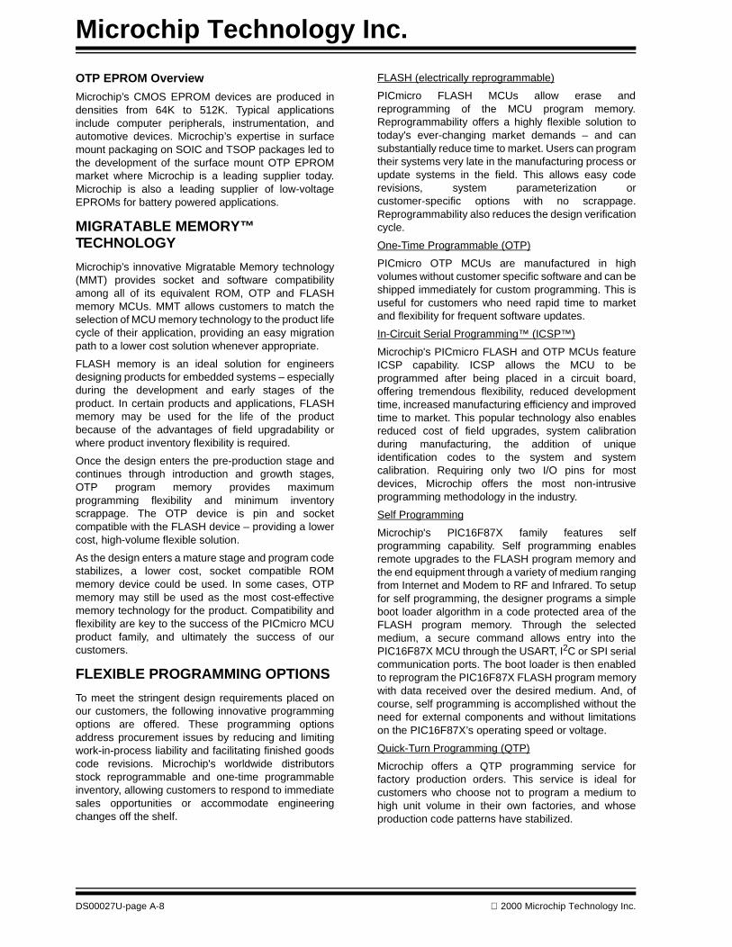
Microchip Technology Inc.
OTP EPROM Overview
Microchip’s CMOS EPROM devices are produced indensities from 64K to 512K. Typical applicationsinclude computer peripherals, instrumentation, andautomotive devices. Microchip’s expertise in surfacemount packaging on SOIC and TSOP packages led tothe development of the surface mount OTP EPROMmarket where Microchip is a leading supplier today.Microchip is also a leading supplier of low-voltageEPROMs for battery powered applications.
MIGRATABLE MEMORY™ TECHNOLOGY
Microchip’s innovative Migratable Memory technology(MMT) provides socket and software compatibilityamong all of its equivalent ROM, OTP and FLASHmemory MCUs. MMT allows customers to match theselection of MCU memory technology to the product lifecycle of their application, providing an easy migrationpath to a lower cost solution whenever appropriate.
FLASH memory is an ideal solution for engineersdesigning products for embedded systems – especiallyduring the development and early stages of theproduct. In certain products and applications, FLASHmemory may be used for the life of the productbecause of the advantages of field upgradability orwhere product inventory flexibility is required.
Once the design enters the pre-production stage andcontinues through introduction and growth stages,OTP program memory provides maximumprogramming flexibility and minimum inventoryscrappage. The OTP device is pin and socketcompatible with the FLASH device – providing a lowercost, high-volume flexible solution.
As the design enters a mature stage and program codestabilizes, a lower cost, socket compatible ROMmemory device could be used. In some cases, OTPmemory may still be used as the most cost-effectivememory technology for the product. Compatibility andflexibility are key to the success of the PICmicro MCUproduct family, and ultimately the success of ourcustomers.
FLEXIBLE PROGRAMMING OPTIONS
To meet the stringent design requirements placed onour customers, the following innovative programmingoptions are offered. These programming optionsaddress procurement issues by reducing and limitingwork-in-process liability and facilitating finished goodscode revisions. Microchip's worldwide distributorsstock reprogrammable and one-time programmableinventory, allowing customers to respond to immediatesales opportunities or accommodate engineeringchanges off the shelf.
DS00027U-page A-8
FLASH (electrically reprogrammable)
PICmicro FLASH MCUs allow erase andreprogramming of the MCU program memory.Reprogrammability offers a highly flexible solution totoday's ever-changing market demands – and cansubstantially reduce time to market. Users can programtheir systems very late in the manufacturing process orupdate systems in the field. This allows easy coderevisions, system parameterization orcustomer-specific options with no scrappage.Reprogrammability also reduces the design verificationcycle.
One-Time Programmable (OTP)
PICmicro OTP MCUs are manufactured in highvolumes without customer specific software and can beshipped immediately for custom programming. This isuseful for customers who need rapid time to marketand flexibility for frequent software updates.
In-Circuit Serial Programming™ (ICSP™)
Microchip's PICmicro FLASH and OTP MCUs featureICSP capability. ICSP allows the MCU to beprogrammed after being placed in a circuit board,offering tremendous flexibility, reduced developmenttime, increased manufacturing efficiency and improvedtime to market. This popular technology also enablesreduced cost of field upgrades, system calibrationduring manufacturing, the addition of uniqueidentification codes to the system and systemcalibration. Requiring only two I/O pins for mostdevices, Microchip offers the most non-intrusiveprogramming methodology in the industry.
Self Programming
Microchip's PIC16F87X family features selfprogramming capability. Self programming enablesremote upgrades to the FLASH program memory andthe end equipment through a variety of medium rangingfrom Internet and Modem to RF and Infrared. To setupfor self programming, the designer programs a simpleboot loader algorithm in a code protected area of theFLASH program memory. Through the selectedmedium, a secure command allows entry into thePIC16F87X MCU through the USART, I2C or SPI serialcommunication ports. The boot loader is then enabledto reprogram the PIC16F87X FLASH program memorywith data received over the desired medium. And, ofcourse, self programming is accomplished without theneed for external components and without limitationson the PIC16F87X’s operating speed or voltage.
Quick-Turn Programming (QTP)
Microchip offers a QTP programming service forfactory production orders. This service is ideal forcustomers who choose not to program a medium tohigh unit volume in their own factories, and whoseproduction code patterns have stabilized.
2000 Microchip Technology Inc.
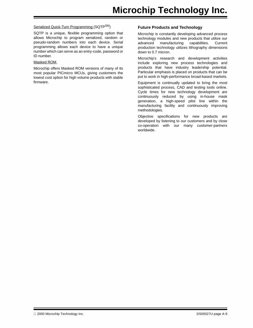
Microchip Technology Inc.
Serialized Quick-Turn Programming (SQTPSM)
SQTP is a unique, flexible programming option thatallows Microchip to program serialized, random orpseudo-random numbers into each device. Serialprogramming allows each device to have a uniquenumber which can serve as an entry-code, password orID number.
Masked ROM
Microchip offers Masked ROM versions of many of itsmost popular PICmicro MCUs, giving customers thelowest cost option for high volume products with stablefirmware.
2000 Microchip Technology Inc.
Future Products and Technology
Microchip is constantly developing advanced processtechnology modules and new products that utilize ouradvanced manufacturing capabilities. Currentproduction technology utilizes lithography dimensionsdown to 0.7 micron.
Microchip’s research and development activitiesinclude exploring new process technologies andproducts that have industry leadership potential.Particular emphasis is placed on products that can beput to work in high-performance broad-based markets.
Equipment is continually updated to bring the mostsophisticated process, CAD and testing tools online.Cycle times for new technology development arecontinuously reduced by using in-house maskgeneration, a high-speed pilot line within themanufacturing facility and continuously improvingmethodologies.
Objective specifications for new products aredeveloped by listening to our customers and by closeco-operation with our many customer-partnersworldwide.
DS00027U-page A-9
Microchip Technology Inc.
DS00027U-page A-10
2000 Microchip Technology Inc.
2000 Microchip Technology Inc. DS00168C
Information contained in this publication regarding device applications and the like is intended through suggestion only and may be superseded by updates.It is your responsibility to ensure that your application meets with your specifications. No representation or warranty is given and no liability is assumed byMicrochip Technology Incorporated with respect to the accuracy or use of such information, or infringement of patents or other intellectual property rightsarising from such use or otherwise. Use of Microchip’s products as critical components in life support systems is not authorized except with express writtenapproval by Microchip. No licenses are conveyed, implicitly or otherwise, except as maybe explicitly expressed herein, under any intellectual propertyrights. The Microchip logo and name are registered trademarks of Microchip Technology Inc. in the U.S.A. and other countries. All rights reserved. All othertrademarks mentioned herein are the property of their respective companies.
DS00168C 2000 Microchip Technology Inc.
All rights reserved. © 2000 Microchip Technology Incorporated. Printed in the USA. 5/00 Printed on recycled paper.
AMERICASCorporate OfficeMicrochip Technology Inc.2355 West Chandler Blvd.Chandler, AZ 85224-6199Tel: 480-786-7200 Fax: 480-786-7277Technical Support: 480-786-7627Web Address: http://www.microchip.com
AtlantaMicrochip Technology Inc.500 Sugar Mill Road, Suite 200BAtlanta, GA 30350Tel: 770-640-0034 Fax: 770-640-0307BostonMicrochip Technology Inc.5 Mount Royal AvenueMarlborough, MA 01752Tel: 508-480-9990 Fax: 508-480-8575ChicagoMicrochip Technology Inc.333 Pierce Road, Suite 180Itasca, IL 60143Tel: 630-285-0071 Fax: 630-285-0075DallasMicrochip Technology Inc.4570 Westgrove Drive, Suite 160Addison, TX 75248Tel: 972-818-7423 Fax: 972-818-2924DaytonMicrochip Technology Inc.Two Prestige Place, Suite 150Miamisburg, OH 45342Tel: 937-291-1654 Fax: 937-291-9175DetroitMicrochip Technology Inc.Tri-Atria Office Building 32255 Northwestern Highway, Suite 190Farmington Hills, MI 48334Tel: 248-538-2250 Fax: 248-538-2260Los AngelesMicrochip Technology Inc.18201 Von Karman, Suite 1090Irvine, CA 92612Tel: 949-263-1888 Fax: 949-263-1338New YorkMicrochip Technology Inc.150 Motor Parkway, Suite 202Hauppauge, NY 11788Tel: 631-273-5305 Fax: 631-273-5335San JoseMicrochip Technology Inc.2107 North First Street, Suite 590San Jose, CA 95131Tel: 408-436-7950 Fax: 408-436-7955
AMERICAS (continued)TorontoMicrochip Technology Inc.5925 Airport Road, Suite 200Mississauga, Ontario L4V 1W1, Canada Tel: 905-405-6279 Fax: 905-405-6253
ASIA/PACIFICChina - BeijingMicrochip Technology, Beijing Unit 915, 6 Chaoyangmen Bei Dajie Dong Erhuan Road, Dongcheng District New China Hong Kong Manhattan BuildingBeijing, 100027, P.R.C. Tel: 86-10-85282100 Fax: 86-10-85282104China - ShanghaiMicrochip Technology Unit B701, Far East International Plaza,No. 317, Xianxia RoadShanghai, 200051, P.R.C.Tel: 86-21-6275-5700 Fax: 86-21-6275-5060Hong KongMicrochip Asia PacificUnit 2101, Tower 2Metroplaza223 Hing Fong RoadKwai Fong, N.T., Hong KongTel: 852-2-401-1200 Fax: 852-2-401-3431IndiaMicrochip Technology Inc.India Liaison OfficeNo. 6, Legacy, Convent RoadBangalore, 560 025, IndiaTel: 91-80-229-0061 Fax: 91-80-229-0062JapanMicrochip Technology Intl. Inc.Benex S-1 6F3-18-20, ShinyokohamaKohoku-Ku, Yokohama-shiKanagawa, 222-0033, JapanTel: 81-45-471- 6166 Fax: 81-45-471-6122KoreaMicrochip Technology Korea168-1, Youngbo Bldg. 3 FloorSamsung-Dong, Kangnam-KuSeoul, KoreaTel: 82-2-554-7200 Fax: 82-2-558-5934
ASIA/PACIFIC (continued)SingaporeMicrochip Technology Singapore Pte Ltd.200 Middle Road#07-02 Prime CentreSingapore, 188980Tel: 65-334-8870 Fax: 65-334-8850TaiwanMicrochip Technology Taiwan10F-1C 207Tung Hua North RoadTaipei, TaiwanTel: 886-2-2717-7175 Fax: 886-2-2545-0139
EUROPEDenmarkMicrochip Technology Denmark ApSRegus Business CentreLautrup hoj 1-3Ballerup DK-2750 DenmarkTel: 45 4420 9895 Fax: 45 4420 9910FranceArizona Microchip Technology SARLParc d’Activite du Moulin de Massy43 Rue du Saule TrapuBatiment A - ler Etage91300 Massy, FranceTel: 33-1-69-53-63-20 Fax: 33-1-69-30-90-79GermanyArizona Microchip Technology GmbHGustav-Heinemann-Ring 125D-81739 München, GermanyTel: 49-89-627-144 0 Fax: 49-89-627-144-44ItalyArizona Microchip Technology SRLCentro Direzionale Colleoni Palazzo Taurus 1 V. Le Colleoni 120041 Agrate BrianzaMilan, Italy Tel: 39-039-65791-1 Fax: 39-039-6899883United KingdomArizona Microchip Technology Ltd.505 Eskdale RoadWinnersh TriangleWokingham Berkshire, England RG41 5TUTel: 44 118 921 5858 Fax: 44-118 921-5835
03/23/00
WORLDWIDE SALES AND SERVICE
Microchip received QS-9000 quality system certification for its worldwide headquarters, design and wafer fabrication facilities in Chandler and Tempe, Arizona in July 1999. The Company’s quality system processes and procedures are QS-9000 compliant for its PICmicro® 8-bit MCUs, KEELOQ® code hopping devices, Serial EEPROMs and microperipheral products. In addition, Microchip’s quality system for the design and manufacture of development systems is ISO 9001 certified.