fuel processor module for hydrogen production for a fuel cell engine using pressure swing adsorption
TRANSCRIPT

(12) United States Patent
US007276095B2
(10) Patent N0.: US 7,276,095 B2 Gittleman et a]. (45) Date of Patent: Oct. 2, 2007
(54) FUEL PROCESSOR MODULE FOR 4,587,114 A 5/1986 Hirai et al. ............... .. 423/247 HYDROGEN PRODUCTION FOR A FUEL _
CELL ENGINE USING PRESSURE SWING (Con?rmed)
ABSORPTION FOREIGN PATENT DOCUMENTS
(75) Inventors: Craig S. Gittleman, Rochester, NY W0 WO 99/28013 6/1999 (US); John B. Ruhl, Rochester, NY _ (US); Yan Zhang, Victor, NY (U S); (comlnued)
(73) Assignee: General Motors Corporation, Detroit, Olsen, John C, “Unit Process and Principles of Chemical Engineer MI (Us) ing”, 1932, D. Van Norstrand Company, Inc., Chapter I, pp. 1-3.*
( * ) Notice: Subject to any disclaimer, the term of this jrimlllryziimmilferféein ?aldgrlola patent is extended or adjusted under 35 “IS an xammeri 2“ y, an a . . U S C 1546)) b 431 da S (74) Attorney, Agent, or Fzrmilohn A. M1ller; M1ller 1P
' ' ' y y ' Group, PLC
(21) Appl. No.: 10/389,375 (57) ABSTRACT
(22) Filed: Mar. 14, 2003 _ A stand-alone fuel processor (10) for producmg hydrogen
(65) Prior Publication Data from a hydrocarbon fuel for a fuel cell engine in a vehicle. The fuel processor (10) includes a primary reactor (14) that
Us 2004/0179998 A1 Sep' 16’ 2004 dissociates hydrogen and other by-products from the hydro 51 I t Cl carbon fuel as a reformate gas. The reforrnate gas is applied
( ) /04 2006 01 to a WGS reactor (48) to convert carbon monoxide and ( ' ) _ _ _ Water to hydrogen and carbon dioxide. The WGS reactor
(52) US. Cl. ................... ..~ .... .. 48/128, 48/1279, 48/75, (14) may include an adsorbent for adsorbing Carbon mon_ 48/102 R’ 48/94’ 48/ 07’ 48/95’ 48/119f oxide. The reformate gas from the WGS reactor (48) is then
422/190’ 422_/191’ 422_/193’ 42'2/194’ 422009’ sent to a rapid-cycle PSA device (12) for adsorbing the _ 422/_211’ 022/222’ 429/17’ 429/19’ 429/20 undesirable by-products in the gas and generates a stream of
(58) Field of Classi?cation Search .............. .. 422/190; pure hydrogen Ahquid Water Separator (70) Separates Water _ _ 429/34’ 17; 48/128; 95/9_6; 423/15 from the reforrnate gas before it is applied to the PSA device
See aPPhCaUOn ?le for Complete Search hlstory- (12). The PSA device (12) uses a portion of the separated (56) References Cited hydrogen as a desorbing gas to purify the adsorbent in the
PSA dev1ce (12). The by-products of the reforrnate gas can U.S. PATENT DOCUMENTS be used as a fuel in a combustor (30) that generates heat for
3,430,418 A 3/1969 Wagner .... .. 95/100 the Pnmary reactor (14)‘
3,564,816 A 2/1971 Batta . . . . . . . . . . . . . . . . . . .. 95/100
3,986,849 A 10/1976 Fuderer et a1. ............. .. 95/100 52 Claims, 3 Drawing Sheets
COMBUSTOR
US 7,276,095 B2 Page 2
US. PATENT DOCUMENTS 6,458,478 B1 * 10/2002 Wang et a1. ................ .. 429/17 6,514,318 B2* 2/2003 Keefer ......... .. 95/96
4,696,682 A 9/1987 Hirai et a1. ................. .. 95/140 6,964,692 132* 110005 Gittleman et a1‘ """"""" “ 48/128 4917711 A 4/1990 Xie et a1 95/106 2002/0004157 A1 1/2002 Keefer et a1. ............... .. 429/34
4,925,464 A 5/1990 Rabenau er a1 96/124 2002/0110504 A1 8/2002 Gittleman e161. . 422/190 5,112,367 A 5/1992 H111 ............................. .. 95/98 2004/0034l11 A1>I< 2/2004 Tonkovich et a1‘ _______ u 518/726 5,112,590 A 5/1992 Krishnamurthy e161. 423/4182 5,268,021 A 12/1993 Hill e161. .................... .. 95/98 FOREIGN PATENT DOCUMENTS
5,366,541 A 11/1994 Hill et a1. 96/124 5,441,559 A 8/1995 Petit et a1. .. 96/125 W0 WO 00/16425 3/2000
5,529,763 A 6/1996 Peng et a1. ............... .. 423/246 * cited by examiner

U.S. Patent 0a. 2, 2007 Sheet 1 of3 US 7,276,095 B2
U.S. Patent
he PRIMARY REACTOR
Oct. 2, 2007 Sheet 2 0f 3 US 7,276,095 B2
50
W65 REACTOR 3o/_\ COMBUSTQR
1
56 52 43
7K 80 62 64
1 2
B6 74
92
7° / J 76
94
FIGU RE 2

U.S. Patent 0a. 2, 2007
PRIMARY ' REACTOR
WGS REACTOR
48
52 56
62 64
104 66
70\ T4
72
12
Sheet 3 0f 3 US 7,276,095 B2
(‘i-28
COMBUSTOR
K ,0
PSA 1" FIGURE 3
US 7,276,095 B2 1
FUEL PROCESSOR MODULE FOR HYDROGEN PRODUCTION FOR A FUEL CELL ENGINE USING PRESSURE SWING
ADSORPTION
BACKGROUND OF THE INVENTION
1. Field of the Invention This invention relates generally to a stand-alone fuel
processor for a hydrogen fuel cell engine and, more particu larly, to a stand-alone fuel processor for a hydrogen fuel cell engine in a vehicle that employs a rapid-cycle pressure sWing adsorber device for removing carbon monoxide (CO) and other by-products from the reformate gas to produce high purity hydrogen.
2. Discussion of the Related Art Hydrogen is a very attractive source of fuel because it is
clean and can be used to ef?ciently produce electricity in a fuel cell. The automotive industry expends signi?cant resources in the development of hydrogen fuel cells as a source of poWer for vehicles. Such vehicles Would be more ef?cient and generate feWer emissions than today’s vehicles With internal combustion engines. A hydrogen fuel cell is an electro-chemical device that includes an anode and a cath ode having, an electrolyte therebetWeen. The anode receives a hydrogen gas and the cathode receives oxygen. The hydrogen gas is ioniZed in the anode to generate free hydrogen ions and electrons. The hydrogen ions pass through the electrolyte to the cathode. The hydrogen ions react With the oxygen and, the electrons in the cathode to generate Water as a by-product. The electrons from the anode cannot pass through the electrolyte, and thus are directed through a load to perform Work, before being sent to the cathode. The Work acts to operate the vehicle. Many fuels cells are combined in a stack to generate the desired poWer.
Proton exchange membrane (PEM) type fuel cells are a popular fuel cell for vehicles. In a PEM fuel cell, hydrogen (H2) is the anode reactant, i.e., fuel, and oxygen is the cathode reactant, i.e., oxidant. The cathode reactant can be either pure oxygen (02) or air (a mixture of O2 and N2). The PEM fuel cell typically includes a solid polymer electrolyte, typically made from ion exchange resins, such as per?uor onated sulfonic acid. The anode/ cathode typically comprises ?nely divided catalytic particles, Which are often supported on carbon particles and mixed With a proton conductive resin. The catalytic particles are typically precious metal particles, and thus are costly. These membrane electrode assemblies are relatively expensive to manufacturer and require certain conditions for effective operation. These conditions include proper Water management and humidi? cation, and control of catalyst fouling constituents, such as CO.
In vehicle fuel cell applications, it is desirable to use a liquid fuel, such as alcohols (methanol or ethanol), hydro carbons (gasoline), and/or mixtures thereof, such as blends of ethanol/methanol and gasoline, as a source of hydrogen for the fuel cell. Such liquid fuels for the vehicle are easy to store on the vehicle. Further, there is a nationWide infra structure for supplying liquid fuels. Gaseous hydrocarbons, such as methane, propane, natural gas, LPG, etc., are also suitable fuels for both vehicle and non-vehicle fuel cell applications.
Hydrocarbon-based fuels must be disassociated to release the hydrogen therefrom for fueling the cell. The disassocia tion reaction is accomplished Within a chemical fuel pro cessor or reformer. The fuel processor contains one or more
20
25
30
35
40
45
50
55
60
65
2 reactors Where the fuel reacts With steam, and sometimes air, to generate a reformate gas comprising primarily hydrogen and carbon dioxide. For example, in a steam-methanol reformation process, methanol and Water are reacted to generate hydrogen and carbon dioxide. HoWever, carbon monoxide and Water are also produced. In a gasoline refor mation process, steam, air and gasoline are reacted in a fuel processor that contains tWo sections. One section is prima rily a partial oxidation reactor (POX) and the other section is primarily a steam reformer (SR). The fuel processor produces hydrogen, carbon dioxide, carbon monoxide and Water.
The knoWn fuel processors also typically include doWn stream reactors, such as a Water/ gas shift (WGS) reactor and a preferential oxidation (PROX) reactor. The PROX reactor is used to remove carbon monoxide in the reformate gas because carbon monoxide contaminates the catalytic par ticles in the PEM fuel cell. The PROX reactor selectively oxidiZes carbon monoxide in the presence of hydrogen to produce carbon dioxide (CO2) using oxygen from air as an oxidant. HoWever, the use of a PROX reactor in a fuel processor adversely effects processor performance. For example, control of the air feed is important to selectively oxidiZe CO to CO2. Also, the PROX reactor is not 100% selective, and thus results in consumption of hydrogen. Thus, the hydrogen that Would normally be available to provide poWer is consumed by the PROX reactor. Further, the heat generated from the PROX reactor is at a loW temperature, resulting in excess loW-grade heat. Also, typi cal catalysts used in a PROX reactor contain precious metals, such as platinum or iridium, Which are very expen sive. The gasoline fuel processor technology to date requires
large start-up durations, large mass and large volume. The start-up time for such a system is limited by the time until the combination of the WGS reactor and the PROX reactor can reduce CO to an acceptable level to supply stack grade hydrogen. The start-up duration is determined by the mass of the catalyst system used for start-up, and the energy needed to get the catalyst system up to temperature. Another limi tation of the current technology is hoW to utiliZe all of the loW-grade heat that the system Will generate. Any excess heat loss causes a reduction in fuel processor ef?ciency.
The H2 generated in a fuel processor using a PROX reactor for CO clean-up typically contains less than 50% H2, Where the balance of the hydrogen-rich reformate consists primarily of carbon dioxide, nitrogen and Water. Thus, the reformate is not suitable for compression and storage because much energy Would be Wasted in compressing the non-H2 components in the reformate gas. Also, valuable storage space Would be Wasted to contain the non-H2 components. Some techniques do exist in the art for generating nearly
pure H2 in non-automotive fuel processing systems. One technique of generating pure H2 in a fuel processing system involves the use of H2 permeable membranes. These mem branes selectively alloW the H2 to pass through and prevent the other by-product constituents in the reformate gas from permeating through. Typical membranes for these applica tions contain palladium, Which is very expensive. Also, these membranes only operate at relatively high tempera tures (250-5500 C.), and thus, it takes a long time after the loW temperature start-up for a fuel processing system con taining H2 permeable membranes to be able to generate H2. Additionally, these membranes operate at very high pres sures (>5 bar), Which leads to exorbitant compressor loads and inef?cient systems.

US 7,276,095 B2 3
Another technique of generating essentially pure H2 from a fuel processor using a hydrocarbon fuel employs adsorp tion. For example, a pressure sWing adsorber (PSA) could be used to generate pure hydrogen from the reformate gas of a WGS reactor. Such a process is described in commonly oWned US. patent application Ser. No. 09/780,184, pub lished Aug. 15, 2002 as publication No. US 2002/0110504 A1, and herein incorporated by reference. In the fuel cell system disclosed in the ’184 application, the PSA is inte grated With the fuel cell stack. The PSA uses the anode off-gas from the fuel cell as a purge stream Within the PSA or uses the cathode off-gas from the fuel cell to combust the loW-pressure exhaust gas from the PSA. Additionally, both the anode and cathode off-gas can be used. Such a system could not be used as a stand-alone H2 generator, Where the H2 gas is stored for subsequent use in a fuel cell engine. Similar processes for H2 generation for fuel cells using a PSA are described in US. patent application Ser. No. 09/808,175, published Jan. 10, 2002, Publication No. US 2002/0004157 A1, and International Patent application, No. WO 00/16425, published Mar. 23, 2000.
SUMMARY OF THE INVENTION
In accordance With the teachings of the present invention, a stand-alone fuel processor for producing hydrogen from a hydrocarbon fuel for a fuel cell engine is disclosed. The fuel processor includes a primary reactor that disassociates hydrogen and other by-products, such as carbon monoxide, carbon dioxide and nitrogen, from the hydrocarbon fuel as a reformate gas. The reformate gas is applied to a WGS reactor to convert carbon monoxide and Water to hydrogen and carbon dioxide. The WGS reactor may include an adsorbent for adsorbing carbon monoxide at loW tempera tures and to desorb carbon monoxide at high temperatures. A liquid Water separator can be used to remove Water from the reformate gas for further processing.
The reformate gas from the WGS reactor is then sent to an adsorber device that includes an adsorbent for adsorbing the undesirable by-products in the gas, such as carbon monoxide, carbon dioxide, nitrogen, Water and methane. In one embodiment, the adsorber device is a rapid-cycle pres sure sWing adsorber that includes either a rotating mass of adsorbent or a rotating valve. The pressure sWing adsorber uses the separated hydrogen as a desorbing gas to purify the adsorbent in the adsorber. The by-products of the reformate gas can be used as fuel in a combustor that generates heat for the primary reactor. The highly rich hydrogen from the pressure sWing adsorber can be sent to a storage tank so that the fuel processor operates as a stand-alone fuel processing system.
Additional advantages and features of the present inven tion Will become apparent from the folloWing description and appended claims, taken in conjunction With the accom panying draWings.
BRIEF DESCRIPTION OF THE DRAWINGS
FIG. 1 is a plan vieW of a fuel processor system, according to an embodiment of the present invention;
FIG. 2 is a plan vieW of a fuel processor system, according to another embodiment of the present invention; and
FIG. 3 is a plan vieW of a fuel processor system, according to another embodiment of the present invention.
20
25
30
35
40
50
55
60
65
4 DETAILED DESCRIPTION OF THE
EMBODIMENTS
The folloWing discussion of the embodiments of the invention directed to a stand-alone fuel processor for gen erating nearly pure hydrogen for a fuel cell engine is merely exemplary in nature, and is in no Way intended to limit the invention or its application or uses.
According to the invention, a fuel processor for a fuel cell associated With a vehicle is disclosed that includes a tech nique to remove carbon monoxide from the hydrogen refor mate gas before the hydrogen enters the fuel cell stack, thereby advantageously eliminating the need for a PROX reactor. Also, the fuel processor of the invention generates highly rich hydrogen that alloWs it to be a stand-alone unit Where the hydrogen can be stored in tanks and the like Without storing other process by-products. Furthermore, the fuel processor of the invention is able to recover 70% of the hydrogen in the reformate gas. Further, the fuel processor of the invention provides quick carbon monoxide uptake on start-up, thereby shortening the start-up duration. Addition ally, the fuel processor of the invention does not require precious metals for CO clean-up, thus reducing system cost.
FIG. 1 is a plan vieW of a fuel processor system 10 for generating nearly pure H2 to be used in a fuel cell engine. According to the invention, the fuel processor system 10 employs a rapid-cycle pressure sWing adsorber (PSA) device 12 as a primary device for removing carbon monoxide and other by-products from the reformate gas to generate pure hydrogen. As discussed above, it is necessary to remove carbon monoxide from the hydrogen gas being used in a fuel cell because carbon monoxide contaminates the catalytic particles used in the fuel cell. A hydrocarbon fuel, such as gasoline, natural gas, meth
ane, propane, methanol and/or mixtures thereof, is fed to a primary reactor 14, such as an autothermal reactor, from a suitable source (not shoWn) on a line 16. The hydrocarbon fuel reacts With a steam/air mixture received on a line 18 from a heat exchanger 20 to create hydrogen from the fuel and generate a reformate gas including hydrogen. The reactor 14 includes a steam reforming and/or partial oxida tion catalyst suitable for the speci?c fuel being used. The temperature of the reactor 14 depends on the nature of the fuel and the relative compositions of fuel, air and Water, and is typically between 3000 C. and 12000 C. The fuel is converted to hydrogen in the reactor 14 either by partial oxidation, steam reforming or autothermal reforming. The reformate gas exiting the primary reactor 14 on a line 44 contains primarily hydrogen, nitrogen, carbon monoxide, carbon dioxide, Water and possibly methane. The carbon monoxide concentration of the reformate gas on the line 44 is typically betWeen about 5 mole percent and about 20 mole percent. The steam for the steam/air mixture is generated in a heat
exchanger 24, Where liquid Water is provided on a line 26 is heated and vaporiZed in the heat exchanger 24 by a hot exhaust stream on a line 28 from a combustor 30, discussed beloW. The steam exits the heat exchanger 24 on a line 34 and is mixed With compressed air provided on a line 36 in a mixing valve 38. The steam/air mixture exits the valve 38 on a line 40 to be sent to the heat exchanger 20 to form the hot steam/air mixture on the line 18 sent to the reactor 14. The heat required to raise the temperature of the steam on the line 40 in the heat exchanger 20 is generated by the reformate gas from the reactor 14 on the line 44. Alternately, the air and Water can be heated separately and mixed either Within or before the primary reactor 14.

US 7,276,095 B2 5
The reformate gas on the line 44 is cooled in the heat exchanger 20 to the operational temperature of a WGS reactor 48. The cooled reformate gas is then applied to the WGS reactor 48 on a line 50, Where carbon monoxide and Water are converted to hydrogen and carbon dioxide by a reaction process that is Well understood in the art. The WGS reactor 48 is either a high temperature WGS reactor (320° C.-500° C.), a medium temperature WGS reactor (250° C.-400° C.), or a loW temperature WGS reactor (150° C.-250° C.). Altemately, the reactor 48 can include a com bination of high, medium and loW temperature WGS reac tors that employ a technique for cooling the reformate gas as it ?oWs betWeen the different temperature reaction Zones. Generally, the temperature of the WGS reactor 48 decreases With the direction of the reformate gas ?oW.
According to the invention, it is possible to employ a single high temperature WGS reactor or a single medium temperature WGS reactor. These types of reactors are gen erally smaller than a loW temperature WGS reactor or a system With one or more WGS reactors, even though the high temperature WGS reactor does not reduce the CO to very loW levels because of equilibrium constraints. This is possible because of the ability of the PSA device 12 to handle relatively high CO levels that cannot be tolerated by conventional systems that use PROX reactors to convert CO to CO2. Conventional catalysts, such as Fe3O4/Cr2O3 for high temperature shifts or CuO/ZnO/Al2O3 for loW tempera ture shifts, may be used, as Well as any other knoWn WGS catalyst.
The WGS reactor 48 generates a reformate gas How on a line 52 that is primarily hydrogen, nitrogen, carbon mon oxide, carbon dioxide and Water. The reformate gas Will typically include about 0.3-3 mole percent CO depending on the exit temperature of the WGS reactor 48, the space velocity of the reformate gas in the WGS reactor 48, the steam to carbon ratio and the catalyst used. The reformate gas on the line 52 is cooled in a heat
exchanger 56 to the operating temperature of the PSA device 12 (60° C.-100° C.) by a coolant stream on a line 62 applied to the heat exchanger 56 that exits the heat exchanger on line 64. The coolant stream on the line 62 can be air that is preheated and subsequently fed into the system 10 on the line 36. The heat exchanger 56 also acts as a condenser because Water in the reformate gas on the line 52 condenses as it is cooled. The cooled reformate gas leaves the heat exchanger 56 on a line 66 as a tWo-phase ?uid consisting of a reformate gas and liquid Water. The cooled reformate gas is applied to a separator 70 Where the liquid Water is separated from the reformate gas. The liquid Water exits the separator 70 on a line 72. The Water on the line 72 may then be reintroduced into the system 10 on the line 26, or any other place in the system 10 Where Water is used. The cooled reformate gas exits the separator 70 on a line 74, and is saturated With Water vapor at a temperature betWeen 60° C. and 100° C.
The cooled reformate gas on the line 74 is applied to the PSA device 12, Where it is puri?ed. The reformate gas on the line 74 Will enter the PSA device 12 at a pressure betWeen about 1.5 and about 7 bara. Even higher pressures, up to 15 bara, may be used if the primary reactor 14 is a steam reformer. The PSA device 12 contains an adsorbent or combination of adsorbents Which adsorb all of the species in the reformate gas, except for H2, as Will be discussed in detail beloW. The H2 gas exits the PSA device 12 on a line 76, and includes at least 90% H2, and possibly up to 99.9% H2. The CO level of the gas on the line 76 is less than about 100 ppm, and possibly less than 1 ppm. The remaining
20
25
30
35
40
45
50
55
60
65
6 portion of the gas on the line 76 is primarily N2, but may also contain up to 1% methane. If it is desired to reduce the CO concentration in the gas on the line 76 to loWer levels, the gas may be fed over a methanation catalyst (not shoWn) Where the remaining CO Will react With H2 to form methane. The gas on the line 76 leaves the PSA device 12 at
essentially the same pressure at Which it entered, typically betWeen 1.5 and 5 bara, alloWing for a slight pressure drop of no more than 2 psi. All of the non-hydrogen gases (C0, C02, N2, H20 and CH4), as Well as a fraction of the hydrogen, exits the PSA device 12 at about atmospheric pressure on a line 78. At least 70% of the hydrogen on the line 74 should be recovered to be sent on the line 76. It Would be desirable if at least 80% of the hydrogen on the line 74 is recovered on the line 76, and most desirable 87% of the hydrogen be recovered. The PSA device 12 is a rapid-cycle device that may
include various vessels operating at different pressures. When the vessels are under pressure, the adsorbent or combination of adsorbents in the vessel Will adsorb the constituents being discussed herein. When the pressure is reduced in the vessel, the adsorbed species are desorbed to be exhausted on the line 78. According to the invention, a portion of the How of the hydrogen gas applied to the line 74 is used to How through a depressuriZed vessel in the PSA device 12 to remove or desorb the unWanted by-products. Thus, some of the hydrogen does exit the PSA device 12 on the line 78. The H2 gas on the line 76 may either be fed directly into
the anode side of a fuel cell stack (not shoWn) or stored via compression, liquefaction, in a solid form, such as hydride, or in an adsorbed state, such as on carbon nanotubes. The stored H2 may then be subsequently sent to a fuel cell engine (not shoWn) to be used for generating electricity. The exhaust gas on the line 78 is sent to the combustor 30,
and may or may not be heated before entering the combustor 30. This exhaust gas heating could be achieved by exchang ing With a temperature regulating ?uid, such as air, Water, glycol, or any other suitable coolant. The hydrogen and carbon monoxide in the exhaust gas on the line 78 react With oxygen in an air stream on a line 80 in the combustor 30 to form carbon dioxide and Water. The air stream on the line 80 may be the exhaust gas from the cathode side of a fuel cell stack or an independent air source. If there is methane in the exhaust How on the line 78, that may also be burned in the combustor 30. If the system 10 is integrated With a fuel cell stack, anode exhaust, Which is primarily made up of hydro gen, may also be burned in the combustor 30.
Heat is generated in the combustor 30 by exothermic combustion reactions and leaves the combustor 30 as a hot combustor exhaust gas on the line 28. As discussed above, the heat is used to vaporiZe the Water on the line 26 in the heat exchanger 24. The combustion How on the line 28 contains primarily nitrogen, carbon dioxide and Water. A cooled combustion gas stream from the heat exchanger 24 is provided on a line 82. Altemately, the combustion exhaust gas may be used to preheat the air stream on the line 36. Liquid Water may be collected from the cooled stream on the line 82, and used as Water to be fed into the system 10 on the line 26.
Thus, the system 10 can operate as a stand-alone system in that it does not need to be directly integrated With a fuel cell stack to provide hydrogen to the stack. The system 10 can be located at a residence, service station, or the like, Where the hydrogen is stored in tanks to be transferred to tanks on the vehicle. Certain of the lines discussed above, such as the line 80, can come from the fuel cell. HoWever,
US 7,276,095 B2 7
this is by Way of example in that the ?uid on the particular line can come from any other suitable source.
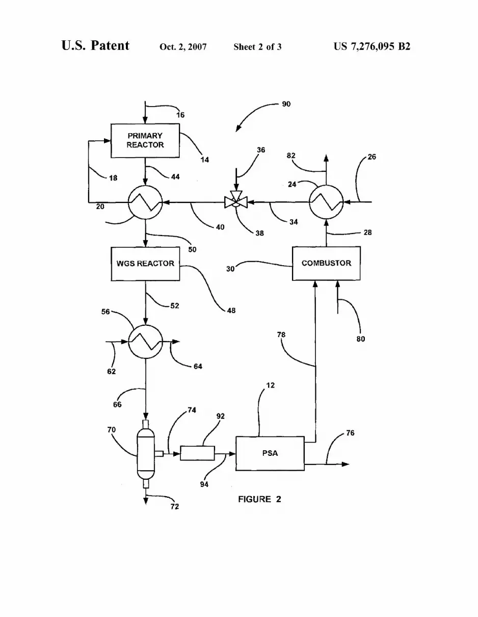
FIG. 2 is a plan vieW of a fuel processor system 90, according to another embodiment of the present invention, that is similar to the fuel processor system 10 discussed above, Where like reference numerals represent the same elements. In this embodiment, the reformate gas on the line 74 is applied to a heater 92, and the heated reformate gas from the heater 92 is then sent to the PSA device 12 on a line 94. The reformate gas is heated by the heater 92 to prevent liquid Water from condensing in the PSA device 12 because condensed Water could potentially damage the absorbent, electronics or valve system Within the PSA device 12. In one embodiment, the heater 92 Will raise the temperature of the reformate gas by about 5-100 C. The heater 92 can be an electric heater or a heat exchanger. The heat exchanger could employ a hot stream from Within the fuel processor system 90 or employ a temperature regulating ?uid, such as glycol, Water, oil or air.
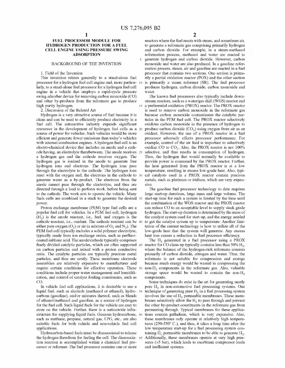
FIG. 3 is a plan vieW of a fuel processor system 100, according to another embodiment of the present invention, that is similar to the fuel processor systems 10 and 90 discussed above, Where like reference numerals represent the same elements. The system 100 includes a different technique for preventing Water condensation in the PSA device 12 than using the heater 92. Particularly, Water vapor is removed from the reformate gas on the line 74 by a Water vapor transfer (WVT) device 102. The WVT device 102 transfers Water vapor from a Wet stream to a dry stream. This vapor transfer process can be accomplished by using a membrane device made of a suitable material, such as Na?on®. A membrane device containing a bundle of Na?on® tubes could be provided by Penna Pure. In this embodiment, the Wet reformate gas on the line 74 passes through the device 102, and Water vapor is transferred through the membrane tubes (not shoWn) to a dry gas ?oWing on the outside of the tubes. In this embodiment, the dry gas is air applied to the WTV device 102 on a line 104, and could subsequently be applied to the valve 38 on a line 106.
Altemately, the WVT device 102 can be an adsorption device, such as a heat Wheel or an energy Wheel, such as provided by Emprise. Such energy Wheels contain a rotating drum that is made up of a desiccant, such as Zeolite, silica gel or activated alumina. Water from the Wet reformate on the line 74 adsorbs on the desiccant as the Wet stream passes over a section of the rotating drum. The drum then rotates so that the dry stream on the line 104 ?oWs over a second section of the drum, Where it is used to desorb the adsorbed Water. Thus, the Water is transferred from the Wet reformate gas to the dry gas stream as the drum rotates from the Wet stream section and the dry stream section of the device 102. An advantage of the systems 10, 90 and 100 described
herein is the ability of the PSA device 12 to adsorb CO at start-up When the WGS reactor 48 is still beloW its operating temperature or Water is not available for the WGS reaction. This enables stack-grade H2 (<l00 ppm CO) to be generated almost immediately. At start-up, the mixing valve 38 is set so that only air, and
not Water, enters the primary reactor 14 along With fuel until heat has been generated in the combustor 30 to produce steam. Hydrogen and carbon monoxide are formed in the primary reactor 14 and How into the WGS reactor 48, Which is still beloW its operating temperature, and thus unable to shift CO and Water into CO2 and hydrogen. At this point, one of tWo things may happen, depending on the exact nature of the system. A loW temperature CO adsorbent may be added
20
25
30
35
40
45
50
55
60
65
8 into or before the WGS reactor 48 as described beloW. In that situation, the CO in the cold reformate gas Will adsorb on the adsorbent in the WGS reactor 48. As the WGS reactor 48 comes up to its operating tem
perature, the CO Will desorb from the CO adsorbent, and Will be shifted to CO2 on the WGS catalyst. At that point, normal operation Will commence. If there is no CO adsor bent either inside or before the WGS reactor 48, or there is not enough absorbent to adsorb all of the CO in the refor mate gas on the line 50, then the CO Will pass through the WGS reactor 48 and continue to the PSA device 12, as discussed above. The remaining CO in the gas on the line 66 Will adsorb in the high-pressure section of the PSA device 12. In general, adsorbers operate more effectively at loWer temperatures When adsorption capacities are higher. There fore, the PSA device 12 Will be able to adsorb CO effectively even before it reaches its ?nal operating temperature. In both cases, normal operation Will begin When the WGS reactor 48 has reached its operating temperature and enough heat has been generated in the combustor 30 to produce the steam required for normal operation of the reactors 14 and 48. The present invention is not intended to be limited to the
speci?cs of the system 10, 90 and 100, as many changes and variations to these embodiments can be made Without departing from the spirit of the invention as discussed herein. For example, additional heating and cooling of any gas or liquid stream outside of the three heat exchangers 20, 24 and 56 may be easily accomplished. Additionally, Water may be readily recovered from a variety of gas streams, such as on the lines 66, 74, 78 and 82, for reintroduction into the system 10, 90 and 100. The adsorbent or combination of adsorbents employed in
the PSA device 12 must be able to adsorb carbon monoxide, carbon dioxide, Water and nitrogen. This could be accom plished using a single adsorbent material, such as Zeolite. Commercial Zeolite adsorbents, such as type 5A and type 13X, and mixtures thereof, are knoWn to adsorb all of these materials. Any number of alkaline or alkaline earth cations, such as sodium, potassium, lithium or calcium, may be exchanged into these materials, either individually or in combination, using techniques that are Well knoWn in the art. Commercial activated carbon adsorbents may also be used for adsorbing CO2 and light hydrocarbons, such as methane, ethane and propane, if present in trace amounts. HoWever, the capacity of the Zeolites and activated carbon adsorbents for carbon monoxide is relatively loW compared to those of the other adsorbent gases. Therefore, it is sometimes desir able to add an adsorbent that has a relatively high capacity for carbon monoxide. For example, the carbon monoxide adsorbent may be a copper or silver salt impregnated or exchanged on activated carbon, alumina or Zeolites, and mixtures thereof. These carbon monoxide adsorbents may selectively adsorb Water instead of carbon monoxide. There fore, a layer of desiccant (Water adsorbent) may be put in the adsorber vessel upstream of the carbon monoxide adsorbent. The desiccant may be any conventional Water adsorbent, such as a Zeolite molecular sieve, activated alumina, silica gel or mixtures thereof. The combining of materials can be accomplished by
preparing layers of distinct particles, such as beads or extrudates, of the various adsorbents. The adsorbent mate rials may also be forrned together into a single particle such as a bead or an extrudate, or formulated into monoliths, foams, honeycombs or the like.
Further, the WGS reactor 48 may also contain a carbon monoxide adsorbent that Will adsorb carbon monoxide at temperatures beloW the activation temperature of the WGS
US 7,276,095 B2
catalyst. This Will help to insure that carbon monoxide Will not break through the reactor 48 during start-up from ambient temperatures, When the WGS catalyst is still rela tively cold, until the operating temperature of the reactor 48 has been achieved. The carbon monoxide adsorbent Will have a much loWer capacity for carbon monoxide at the higher steady-state operating temperature of the reactor 48. A layer of the carbon monoxide adsorbent can be placed in front of the WGS catalyst, or the tWo materials may be combined into a single layer. The carbon monoxide adsor bent may be a copper or silver salt impregnated on activated carbon, alumina or zeolite. The carbon monoxide is regen erated from the adsorbent as the reactor 48 is heated to its operating temperature, and can then be either converted to carbon dioxide in the WGS reactor 48 or readsorbed doWn stream in the PSA device 12. The PSA device 12 can be any suitable pressure sWing
adsorption system knoWn in the art. Conventional pressure sWing adsorption systems are typically very large and con sist of a minimum of tWo separate adsorption vessels com plete With numerous valves and manifolds. In a tWo-vessel system, one vessel Would be in the adsorption mode and the other vessel Would be in various stages of equalization, bloW-doWn, purge and pressurization. Many commercial hydrogen PSA cycles use four vessels, With one vessel in the production stage at any given time, and the other three vessels in the various stages of equalization, bloW-doWn, purge and pressurization. Also, some commercial hydrogen PSA cycles use tWelve vessels, With four vessels in the production stage at any given time, and the other eight vessels in the various stages of equalization, bloW-doWn, purge and pressurization. It is Well known that PSA systems With more than tWo vessels exhibit higher hydrogen recov eries and reduced poWer consumption by incorporating pressure equalization steps. These multiple, staged ?xed-bed PSA systems, hoWever, contain complex valve arrangements and are non-continuous due to the cycling of these valves.
There are tWo types of knoWn PSA designs that alloW for continuous production in a relatively small system With minimum valving. One type uses a rotating bed of adsor bent, similar to that described above for the energy Wheel, Which is made more complex by the requirement to operate in a pressure sWing mode. The Wheel of adsorbent must be divided into discreet sections that can operate over a suitable range of pressures. The other type of PSA design alloWs for continuous production in a relatively small system With minimum valving employs a rotating valve to distribute the gas ?oWs of the PSA cycle to multiple beds of adsorbent. One rotating valve can achieve the same PSA cycle that Would take upWards of tWenty valves in a conventional ?xed-bed PSA system.
In one embodiment, the fuel processor system 10, 90 or 100 of the invention uses either a PSA device that consists of a rotating adsorbent bed or a PSA device that utilizes a rotary valve to make the fuel processor system 10, 90 or 100 small enough to ?t in a vehicle or a compact hydrogen generation module. Both of these techniques alloW the adsorbent mixture to cycle betWeen ?xed regions for adsorp tion, depressurization, purge, equalization and pressuriza tion With cycle times much smaller than those of conven tional PSA systems. The cycle time for the PSA device 12 employed in this invention should be no more than tWenty seconds, and desirably should be less than one second. The cycle of the PSA device 12 can be characterized as
folloWs. During the production step, the reformate gas from the WGS reactor 48 is fed over the adsorbent or combination of adsorbents at the higher feed pressure. Carbon monoxide,
20
25
30
35
40
45
50
55
60
65
10 carbon dioxide, Water and nitrogen all adsorb on the adsor bent so the product gas contains primarily hydrogen. Light hydrocarbons, such as methane, ethane, ethylene, propane and propylene, heavier hydrocarbons, such as unreacted gasoline, and other trace impurities such a ammonia and hydrogen sul?de, may also be adsorbed if present in the gas How to the PSA device 12 on the line 74. The production step is stopped before carbon monoxide breaks through the outlet of the adsorber vessel. At the end of the production step, the adsorbent is nearly saturated With adsorbed gases, and the vessel is pressurized With hydrogen, carbon mon oxide, carbon dioxide, Water and nitrogen.
After the production step, the pressurized vessel is placed in direct contact With a second vessel that is at loWer pressure. The gas from the high-pressure vessel ?oWs into the loW-pressure vessel until the pressures in both vessels are the same or have equalized. This step is called doWn equalization. The tWo vessels can be connected either from the product ends of the vessels, the feed ends of the vessels, or from both the product and feed ends simultaneously. Any number of doWn equalization steps can proceed in series to further reduce the pressure from the high-pressure vessel. Desirably, the cycle Will include no more than three doWn equalization steps.
After the doWn equalization step or series of doWn equalization steps, the adsorber vessel is depressurized from the equalization pressure to the purge pressure by exhausting the gas in the direction counter-current to the production direction. During depressurization, the product end of the adsorber vessel is sealed. Altemately, the vessel can be depressurized concurrently, and the feed end of the vessel is sealed. The depressurization exhaust gas contains hydrogen, carbon monoxide, carbon dioxide, Water and nitrogen. The exhaust gas exits the adsorber vessel at essentially atmo spheric pressure and is sent to the combustor 30, as described above.
After depressurization, the adsorber vessel is purged With a fraction of the H2 product generated during the production step. The pressure of the fraction of the H2 product to be used as purge gas is reduced to close to ambient pressure by ?oWing through an ori?ce. The purged stream-?ow is at essentially ambient pressure, desirably in a direction counter-current to the production direction. The adsorber vessel may also be purged by pulling a vacuum from the direction counter-current to the production direction using a vacuum pump. The exhausted purged gas Will contain most of the adsorbed carbon monoxide, carbon dioxide, Water and nitrogen. The purged exhaust gas exits the adsorber vessel at essentially atmospheric pressure and is sent to the combustor 30. The purge step is terminated When essentially all of the carbon monoxide and other adsorbed gases have been des orbed from the adsorbent.
After the purge step, the vessel is placed in direct contact With a second vessel that is at higher pressure, typically folloWing the production step described above. The loW pressure vessel is undergoing up equalization While the high-pressure vessel is undergoing doWn equalization. The gas from the high-pressure vessel ?oWs into the loW-pres sure vessel until the pressures in both vessels are the same or equalized. The tWo vessels can be connected either from the product ends of the vessels, the feed ends of the vessels or from both the product and feed ends simultaneously. Any number of up equalization steps can proceed in series to further increase the pressure of the loW-pressure vessel. Ideally, not more than three up equalization steps are required.

US 7,276,095 B2 11
After the up equalization step, the adsorber vessel is pressurized back up to the production pressure in the same direction as the production step using the cooled hydrogen rich reformate gas from the WGS reactor 48. During pres surization, the product end of the vessel is sealed. Alter nately, the vessel may be pressurized using a fraction of the hydrogen-rich product from the adsorber on the line 76 in a direction counter-current to the production direction, and the feed end of the vessel is sealed. After pressurization, the adsorber returns to the production step and the cycle con tinues inde?nitely.
The foregoing discussion discloses and describes merely exemplary embodiments of the present invention. One skilled in the art Will readily recognize from such discussion and from the accompanying draWings and claims that vari ous changes, modi?cations and variations can be made therein Without departing from the spirit and scope of the invention as de?ned in the folloWing claims. What is claimed is: 1. A fuel processing system for producing hydrogen, said
system comprising: a primary reactor, said primary reactor generating hydro
gen from a hydrocarbon fuel to generate a reformate gas including hydrogen and other by-products;
an adsorber device, said adsorber device receiving the reformate gas from the primary reactor and adsorbing the other by-products in the reformate gas to generate a nearly pure stream of hydrogen gas;
a combustor, said combustor generating heat for the primary reactor, Wherein a line couples the adsorber device directly to the combustor and a portion of the pure hydrogen gas stream is used to desorb by-products in the adsorber device Where the desorbed by-products are sent to the combustor on the line to be used as fuel;
a separator receiving the reformate gas from the primary reactor prior to the reformate gas being applied to the adsorber device, said separator separating liquid Water from the reformate gas to generate a reformate gas including primarily hydrogen, nitrogen, Water vapor, carbon monoxide and carbon dioxide; and
a Water vapor transfer device receiving the reformate gas from the separator, said Water vapor transfer device removing Water vapor from the reformate gas.
2. The system according to claim 1 Wherein the adsorber device adsorbs carbon monoxide, carbon dioxide, nitrogen, and Water.
3. The system according to claim 2 Wherein the adsorber device also adsorbs light hydrocarbons, methane, ethane, ethylene, propane and propylene, heavier hydrocarbons, unreacted gasoline, and other trace impurities, such as ammonia and hydrogen sul?de.
4. The system according to claim 1 Wherein the adsorber device generates a stream of hydrogen gas that includes at least 70% of the hydrogen available in the reformate gas.
5. The system according to claim 1 Wherein the adsorber device generates a stream of hydrogen gas that includes at least 87% of the hydrogen available in the reformate gas.
6. The system according to claim 1 Wherein the reformate gas enters the adsorber device at a pressure betWeen 1.5 and 7 bara.
7. The system according to claim 1 Wherein the adsorber device includes a plurality of vessels, Wherein each vessel operates in one of adsorption, equalization, bloW-doWn, purge or pressurization.
8. The system according to claim 1 Wherein the adsorber device includes a ?rst adsorbent selected from the group consisting of activated carbon, alumina, and zeolites, such as
20
25
30
35
40
45
50
55
60
65
12 type 5A and type 13X, and mixtures thereof, Wherein the zeolites contain alkaline or alkaline earth cations, such as sodium, potassium, lithium or calcium, and mixtures thereof.
9. The system according to claim 8 Wherein the adsorber device includes a second adsorbent selected from the group consisting zeolites, such as type A, X, Y, or mordenite, alumina and activated carbon and combinations thereof, Wherein the second adsorbent is impregnated With a copper or silver salt, and mixtures and combinations thereof.
10. The system according to claim 1 Where the adsorber device is a rapid-cycle pressure sWing adsorber (PSA) device.
11. The system according to claim 10 Wherein the PSA device includes a rotating adsorbent bed or a rotary valve.
12. The system according to claim 1 further comprising a Water/gas shift (WGS) reactor, said WGS reactor receiving the reformate gas from the primary reactor prior to the reformate gas being applied to the adsorber device, said WGS reactor converting carbon monoxide and Water in the reformate gas to hydrogen and carbon dioxide, and gener ating a reformate gas that is primarily hydrogen, nitrogen, carbon monoxide, carbon dioxide and Water.
13. The system according to claim 12 Wherein the WGS reactor includes an adsorbent for adsorbing carbon monox ide.
14. The system according to claim 12 Wherein the WGS reactor includes a combination of one or more of a high
temperature WGS reactor, a medium temperature WGS reactor and a loW temperature WGS reactor.
15. The system according to claim 1 further comprising a heat exchanger, said heat exchanger cooling the reformate gas from the primary reactor prior to the reformate gas being applied to the separator.
16. The system according to claim 1 further comprising a ?rst heat exchanger and a mixing valve for generating a steam/ air mixture to be sent to the primary reactor, Wherein liquid Water is heated and vaporized in the heat exchanger, and steam exiting the ?rst heat exchanger is mixed With compressed air in the mixing valve.
17. The system according to claim 16 further comprising a second heat exchanger, said second heat exchanger receiv ing the steam/ air mixture from the mixing valve prior to the steam/air mixture being sent to the primary reactor and receiving the reformate gas from the primary reactor, said second heat exchanger heating the steam/ air mixture prior to the steam/air mixture being sent to the primary reactor and cooling the reformate gas.
18. The system according to claim 1 further comprising a heater receiving the reformate gas prior to the reformate gas being sent to the adsorber device, said heater heating the reformate gas to prevent liquid Water from condensing in the adsorber device.
19. The system according to claim 18 Wherein the heater heats the reformate gas by about 5-100 C.
20. The system according to claim 1 Wherein the Water vapor transfer device employs a device selected from the group consisting of a membrane device and an adsorption device.
21. The system according to claim 1 Wherein the system is a stand-alone unit.
22. The system according to claim 1 Wherein the system is coupled to a fuel cell for generating electricity.
23. The system according to claim 22 Wherein the fuel cell is in a vehicle.
24. A fuel processing system for producing hydrogen, said system comprising:

US 7,276,095 B2 13
a primary reactor, said primary reactor receiving a steam/ air mixture and a hydrocarbon fuel, said primary reac tor generating hydrogen from the hydrocarbon fuel to generate a reformate gas including hydrogen and other by-products;
a Water/ gas shift (WGS) reactor, said WGS reactor receiv ing the reformate gas from the primary reactor and converting carbon monoxide and Water in the reformate gas to hydrogen and carbon dioxide, said WGS reactor generating a reformate gas that is primarily hydrogen, nitrogen, carbon monoxide, carbon dioxide and Water;
a heat exchanger, said heat exchanger receiving the refor mate gas from the WGS reactor and cooling the refor mate gas to a predetermined operating temperature, said heat exchanger condensing a fraction of the Water in the reformate gas from the WGS reactor;
a liquid Water separator, said liquid Water separator receiving the reformate gas from the heat exchanger and separating the liquid Water from the reformate gas to generate a reformate gas including primarily hydro gen, nitrogen, carbon monoxide, carbon dioxide and Water vapor;
a Water vapor transfer device receiving the reformate gas from the separator, said Water vapor transfer device removing Water vapor from the reformate gas;
a rapid-cycle pressure sWing adsorber (PSA) device, said PSA device receiving the reformate gas from the liquid Water separator and adsorbing the other by-products in the reformate gas to generate a nearly pure stream of hydrogen gas, Wherein a portion of the stream of hydrogen gas is used to desorb the by-products in the PSA device, and Wherein the desorbed by-products are emitted from the PSA device on a separate line than the stream of hydrogen gas, and Wherein the predetermined temperature is the operating temperature of the PSA device; and a combustor, said combustor receiving the desorbed
by-products on the separate line from the PSA device and generating heat that is applied to the primary reactor to generate the hydrogen from the hydrocar bon fuel.
25. The system according to claim 24 Wherein the PSA device adsorbs carbon monoxide, carbon dioxide, nitrogen and Water.
26. The system according to claim 25 Wherein the adsorber device also adsorbs light hydrocarbons, such as methane, ethane, ethylene, propane and propylene, heavier hydrocarbons, such as unreacted gasoline, and other trace impurities, such a ammonia and hydrogen sul?de.
27. The system according to claim 24 Wherein the PSA device generates a stream of hydrogen gas that includes at least 70% of the hydrogen available in the reformate gas.
28. The system according to claim 24 Wherein the PSA device generates a stream of hydrogen gas that includes at least 87% of the hydrogen available in the reformate gas.
29. The system according to claim 24 Wherein the refor mate gas enters the PSA device at a pressure betWeen 1.5 and 7 bara.
30. The system according to claim 24 Wherein the PSA device includes a plurality of vessels, Wherein each vessel operates in one of adsorption, equaliZation, bloW-doWn, purge or pressurization.
31. The system according to claim 24 Wherein the adsorber device includes a ?rst adsorbent selected from the group consisting of activated carbon, alumina, and Zeolites, such as type 5A and type 13X, and mixtures thereof, Wherein
20
25
30
35
40
45
50
55
60
65
14 the Zeolites contain alkaline or alkaline earth cations, such as sodium, potassium, lithium or calcium, and mixtures thereof.
32. The system according to claim 31 Wherein the adsorber device includes a second adsorbent selected from the group consisting Zeolites, such as type A, X, Y, or mordenite, alumina and activated carbon and combinations thereof, Wherein the second adsorbent is impregnated With a copper or silver salt, and mixtures and combinations thereof.
33. The system according to claim 24 Wherein the PSA device includes a rotating adsorbent bed or a rotary valve.
34. The system according to claim 24 Wherein the WGS reactor includes an adsorbent for adsorbing carbon monox ide.
35. The system according to claim 34 Wherein the adsor bent in the WGS reactor is selected from the group consist ing Zeolites, such as type A, X, Y, or mordenite, alumina and activated carbon and combinations thereof, Wherein the adsorbent is impregnated With a copper or silver salt, and mixtures and combinations thereof.
36. The system according to claim 24 Wherein the WGS reactor includes a combination of one or more of a high
temperature WOS reactor, a medium temperature WGS reactor and a loW temperature WGS reactor.
37. The system according to claim 24 further comprising a ?rst heat exchanger and a mixing valve for generating a steam/ air mixture to be sent to the primary reactor, Wherein liquid Water is heated and vaporiZed in the heat exchanger, and steam exiting the heat exchanger is mixed With com pressed air in the mixing valve.
38. The system according to claim 37 further comprising a second heat exchanger, said second heat exchanger receiv ing the steam/ air mixture from the mixing valve prior to the steam/ air mixture being sent to the primary reactor and receiving the reformate gas from the primary reactor, said second heat exchanger heating the steam/ air mixture prior to the steam/air mixture being sent to the primary reactor and cooling the reformate gas.
39. The system according to claim 24 further comprising a heater receiving the reformate gas from the liquid Water separator, said heater heating the reformate gas to prevent liquid Water from condensing in the PSA device.
40. The system according to claim 39 Wherein the heater heats the reformate gas by about 5-100 C.
41. The system according to claim 24 further comprising a Water vapor transfer device, said Water vapor transfer device receiving the reformate gas from the liquid Water separator, said Water vapor transfer device removing Water vapor from the reformate gas.
42. The system according to claim 41 Wherein the Water vapor transfer device employs a device selected from the group consisting of a membrane device and an adsorption device.
43. The system according to claim 24 Wherein the system is a stand-alone unit.
44. The system according to claim 24 Wherein the system is coupled to a fuel cell for generating electricity.
45. The system according to claim 44 Wherein the fuel cell is in a vehicle.
46. A fuel processing system for producing hydrogen, said system comprising:
a primary reactor, said primary reactor generating hydro gen from a hydrocarbon fuel to generate a reformate gas including hydrogen and other by-products;
a Water/ gas shift (WGS) reactor, said WGS reactor receiv ing the reformate gas from the primary reactor and converting carbon monoxide and Water in the reformate

US 7,276,095 B2 15
gas to hydrogen and carbon dioxide, said WGS reactor generating a reformate gas including hydrogen, carbon dioxide, carbon monoxide and other by-products; and
a separator receiving the reformate gas from the WGS reactor and removing liquid Water from the reformate gas;
a Water vapor transfer device, said Water vapor transfer device receiving the reformate gas and removing Water therefrom; and
a rapid-cycle pressure sWing adsorber (PSA) device, said 10 PSA device receiving the reformate gas from the Water vapor transfer device and adsorbing the carbon mon oxide and other by-products in the reformate gas to generate a nearly pure stream of hydrogen gas.
47. The system according to claim 46 Wherein a portion 15 of the stream of hydrogen gas is used to desorb the by products in the PSA device, Wherein the desorbed by products are emitted from the PSA device on a separate stream than the stream of hydrogen gas.
16 48. The system according to claim 46 Wherein the PSA
device generates a stream of hydrogen gas that includes at least 70% of the hydrogen available in the reformate gas.
49. The system according to claim 46 Wherein the PSA device includes a plurality of vessels, Wherein each vessel operates in one of adsorption, equalization, bloW-doWn, purge or pressuriZation.
50. The system according to claim 46 Wherein the PSA device includes a rotating adsorbent bed or a rotary valve.
51. The system according to claim 46 Wherein the WGS reactor includes an adsorbent for adsorbing carbon monox ide.
52. The system according to claim 47 further comprising a combustor, said combustor receiving the desorbed by products from the PSA device and generating heat that is applied to the primary reactor to generate the hydrogen from the hydrocarbon fuel.