front axle - 4x4 brasil
TRANSCRIPT
FAX-1
FRONT AXLE
D DRIVELINE/AXLE
CONTENTS
C
E
F
G
H
I
J
K
L
M
SECTION
A
B
FAX
PRECAUTIONS .......................................................... 2Precautions .............................................................. 2
PREPARATION ........................................................... 3Special Service Tools ............................................... 3Commercial Service Tools ........................................ 3
NOISE, VIBRATION, AND HARSHNESS (NVH) TROUBLESHOOTING ................................................ 4
NVH Troubleshooting Chart ..................................... 4ON-VEHICLE SERVICE ............................................. 5
Front Axle Parts ....................................................... 5Front Wheel Bearing ................................................ 5
PRELOAD ADJUSTMENT (2WD MODELS) ........ 5PRELOAD ADJUSTMENT (4WD MODELS) ........ 6
Drive Shaft ............................................................... 8WHEEL HUB AND KNUCKLE ................................... 9
Removal and Installation .......................................... 9AUTO-LOCK FREE-RUNNING HUB ........................11
Description ..............................................................11Removal and Installation .........................................11Inspection ............................................................... 12Trouble Diagnosis For Noise .................................. 12
WHEEL HUB AND ROTOR DISC ............................ 14Removal and Installation ........................................ 14Disassembly ........................................................... 15Inspection ............................................................... 15
WHEEL BEARINGS ............................................ 15WHEEL HUB ....................................................... 15
Assembly ................................................................ 15KNUCKLE SPINDLE ................................................ 17
Removal ................................................................. 17Inspection ............................................................... 18
KNUCKLE SPINDLE ........................................... 18BEARING SPACER (2WD MODELS) ................. 18NEEDLE BEARING (4WD MODELS) ................. 18
Installation .............................................................. 18DRIVE SHAFT ........................................................... 20
Removal and Installation ........................................ 20Removal ................................................................. 20Disassembly ........................................................... 21
FINAL DRIVE SIDE (TS82F) ............................... 21WHEEL SIDE (ZF100) ........................................ 22
Inspection After Disassembly ................................. 22DRIVE SHAFT ..................................................... 22BOOT .................................................................. 22JOINT ASSEMBLY (FINAL DRIVE SIDE) ........... 22JOINT ASSEMBLY (WHEEL SIDE) .................... 23
Assembly ................................................................ 23FINAL DRIVE SIDE(TS82F) ................................ 23WHEEL SIDE(ZF100) ......................................... 24
Installation .............................................................. 25SERVICE DATA AND SPECIFICATIONS (SDS) ...... 27
Wheel Bearing (Front) ............................................ 272WD MODELS .................................................... 274WD MODELS .................................................... 27
Drive Shaft (4WD models) ...................................... 27DRIVE SHAFT AXIAL END PLAY ....................... 27DRIVE SHAFT END SNAP RING ....................... 28
FAX-2
PRECAUTIONS
PRECAUTIONS PFP:00001
Precautions EDS000BN
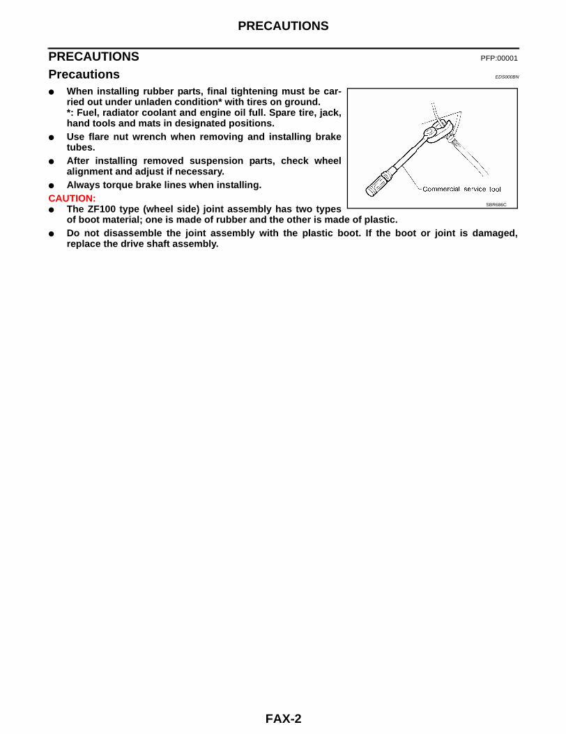
● When installing rubber parts, final tightening must be car-ried out under unladen condition* with tires on ground.*: Fuel, radiator coolant and engine oil full. Spare tire, jack,hand tools and mats in designated positions.
● Use flare nut wrench when removing and installing braketubes.
● After installing removed suspension parts, check wheelalignment and adjust if necessary.
● Always torque brake lines when installing.CAUTION:● The ZF100 type (wheel side) joint assembly has two types
of boot material; one is made of rubber and the other is made of plastic.● Do not disassemble the joint assembly with the plastic boot. If the boot or joint is damaged,
replace the drive shaft assembly.
SBR686C

PREPARATION
FAX-3
C
E
F
G
H
I
J
K
L
M
A
B
FAX
PREPARATION PFP:00002
Special Service Tools EDS000BO
The actual shapes of Kent-Moore tools may differ from those of special service tools illustrated here.
Commercial Service Tools EDS000BP
Tool number(Kent-Moore No.)Tool name
Description
ST29020001(J24319-01)Gear arm puller
Removing ball joint for knuckle spindlea: 34 mm (1.34 in)b: 6.5 mm (0.256 in)c: 61.5 mm (2.421 in)
HT72520000(J25730-B)Ball joint remover
Removing tie-rod outer end and lower ball jointa: 33 mm (1.30 in)b: 50 mm (1.97 in)r: R11.5 mm (0.453 in)
KV401021S0( — )Bearing race drift
Installing wheel bearing outer race
KV40105400(J36001)Wheel bearing lock nut wrench
Removing and installing wheel bearing lock nut(4WD models only)
NT694
NT546
NT153
NT154
Tool name Description
1 Flare nut crowfoot2 Torque wrench
Removing and installing each brake pipinga: 10 mm (0.39 in)
S-NT360

FAX-4
NOISE, VIBRATION, AND HARSHNESS (NVH) TROUBLESHOOTING
NOISE, VIBRATION, AND HARSHNESS (NVH) TROUBLESHOOTING PFP:00003
NVH Troubleshooting Chart EDS000CE
Use the chart below to help you find the cause of the symptom. If necessary, repair or replace these parts.
×: Applicable
Reference page
PR
-4, "
Pro
pelle
r S
haft
Vib
ratio
n"
FAX
-22,
"In
spec
tion
Afte
r D
isas
sem
bly"
PR
-4, "
Pro
pelle
r S
haft
Vib
ratio
n"
FAX
-9, "
Rem
oval
and
Inst
alla
tion"
—
FAX
-5, "
Fro
nt W
heel
Bea
ring"
PR
-3, "
NV
H T
roub
lesh
ootin
g C
hart
"
FF
D-5
, "N
VH
Tro
uble
shoo
ting
Cha
rt"
Ref
er to
DR
IVE
SH
AF
T in
this
cha
rt.
Ref
er to
AX
LE in
this
cha
rt.
FS
U-4
, "N
VH
Tro
uble
shoo
ting
Cha
rt"
WT-
3, "
NV
H T
roub
lesh
ootin
g C
hart
"
WT-
3, "
NV
H T
roub
lesh
ootin
g C
hart
"
BR
-6, "
NV
H T
roub
lesh
ootin
g C
hart
"
PS
-5, "
NV
H T
roub
lesh
ootin
g C
hart
"
Possible cause and SUSPECTED PARTS
Exc
essi
ve jo
int a
ngle
Join
t slid
ing
resi
stan
ce
Imba
lanc
e
Impr
oper
inst
alla
tion,
loos
enes
s
Par
ts in
terf
eren
ce
Whe
el b
earin
g da
mag
e
PR
OP
ELL
ER
SH
AF
T
DIF
FE
RE
NT
IAL
DR
IVE
SH
AF
T
AX
LE
SU
SP
EN
SIO
N
TIR
ES
RO
AD
WH
EE
L
BR
AK
ES
ST
EE
RIN
G
Symptom
DRIVE SHAFTNoise, Vibration × × × × × × × × × ×
Shake × × × × × × × × ×
AXLE
Noise × × × × × × × × × ×
Shake × × × × × × × × ×
Vibration × × × × × × ×
Shimmy × × × × × × ×
Judder × × × × × ×
Poor quality ride or handling
× × × × × ×

ON-VEHICLE SERVICE
FAX-5
C
E
F
G
H
I
J
K
L
M
A
B
FAX
ON-VEHICLE SERVICE PFP:00000
Front Axle Parts EDS000BR
Check front axle parts for excessive play, cracks, wear and otherdamage.● Shake each front wheel to check for excessive play.
If looseness is noted, adjust wheel bearing end play, then checkball joint end play.
● Make sure that the cotter pin is inserted.● Retighten all nuts and bolts to the specified torque. Refer to:
FAX-9, "Removal and Installation" .
Front Wheel Bearing EDS000BS
● Check that wheel bearings operate smoothly.● Check axial end play.
● Adjust wheel bearing preload if there is any axial end play orwheel bearing does not turn smoothly.
PRELOAD ADJUSTMENT (2WD MODELS)CAUTION:Adjust wheel bearing preload after wheel bearing has beenreplaced or front axle has been reassembled.1. Before adjustment, thoroughly clean all parts to prevent dirt
entry.2. Apply multi-purpose grease sparingly to the following parts:
● Threaded area of spindle● Contact surface between lock washer and outer wheel bear-
ing● Hub cap
● Grease seal lip
3. Tighten wheel bearing lock nut to the specified torque.
4. Turn wheel hub several times in both directions to seat wheelbearing correctly.
5. Tighten wheel bearing lock nut to the specified torque.
SMA525A
Axial end play : 0 mm (0 in)
SMA571A
Specified amount of grease : 18 - 22 g (0.63 - 0.78 oz) SFA847BA
Tightening torque : 34 - 39 N·m (3.5 - 4.0 kg-m, 25 - 29 ft-lb)
Tightening torque : 34 - 39 N·m (3.5 - 4.0 kg-m, 25 - 29 ft-lb)
SFA890

FAX-6
ON-VEHICLE SERVICE
6. Turn wheel bearing lock nut back 45 degrees.7. Fit adjusting cap and new cotter pin. Align cotter pin slot by loos-
ening nut 15 degrees or less.
8. Measure wheel bearing preload and axial end play.
9. Repeat above procedures until correct bearing preload is obtained.10. Spread cotter pin.11. Install hub cap.
PRELOAD ADJUSTMENT (4WD MODELS)CAUTION:Adjust wheel bearing preload after wheel bearing has been replaced or front axle has been reassem-bled.Adjust wheel bearing preload as follows:1. Before adjustment, thoroughly clean all parts to prevent dirt entry.2. Apply multi-purpose grease sparingly to the following parts:
● Threaded portion of spindle● Contact surface between wheel bearing washer and outer
wheel bearing● Grease seal lip● Wheel hub
SFA452B
Axial end play : 0 mm (0 in)
Wheel bearing preload (As measured at wheel hub bolt)New grease seal : 9.8 - 28.4 N (1.0 - 2.9 kg, 2.2 -
6.4 lb)Used grease seal : 9.8 - 23.5 N (1.0 - 2.4 kg, 2.2 -
5.3 lb)SMA574A
SRA417
Specified amount of grease 18-23 g (0.63 -0.81 oz)
SFA891-C

ON-VEHICLE SERVICE
FAX-7
C
E
F
G
H
I
J
K
L
M
A
B
FAX
3. Tighten wheel bearing lock nut with Tool.
4. Turn wheel hub several times in both directions.5. Loosen wheel bearing lock nut so that torque becomes 0 N·m (0
kg-m, 0 ft-lb).6. Retighten wheel bearing lock nut with Tool.
7. Turn wheel hub several times in both directions.8. Retighten wheel bearing lock nut with Tool.
9. Measure wheel bearing axial end play.
10. Measure starting force “A” at wheel hub bolt.
11. Install lock washer by tightening the lock nut within 15 to 30degrees to align screw holes.
12. Turn wheel hub several times in both directions to seat wheelbearing correctly.
13. Measure starting force “B” at wheel hub bolt. Refer to step 10.14. Wheel bearing preload “C” can be calculated as shown below.
15. If wheel bearing preload “C” is outside specifications, removelock washer. Tighten or loosen lock nut within ±15 degrees (Refer to step 11). Install lock washer, thenrepeat steps 12, 13 and 14.
16. Repeat above procedures until correct axial end play and wheel bearing preload are obtained.17. Tighten screws.
18. Install free-running hub.19. Tighten bolts.
Tightening torque : 78 - 98 N·m (8 - 10 kg-m, 58 - 72 ft-lb)
Tightening torque : 0.5 - 1.5 N·m (0.05 - 0.15 kg-m, 4.3 - 13.0 in-lb) AFA148
Tightening torque : 0.5 - 1.5 N·m (0.05 - 0.15 kg-m, 4.3 - 13.0 in-lb)
Axial end play : 0 mm (0 in)
SFA845B
SMA580A
C = B − AWheel bearing preload “C”
7.06 - 20.99 N (0.72 - 2.14 kg, 1.59 - 4.72 lb)
Tightening torque : 1.2 - 1.8 N·m (0.12 - 0.18 kg-m, 10.4 - 15.6 in-lb)
SFA830

FAX-8
ON-VEHICLE SERVICE
Drive Shaft EDS000BT
● Check for grease leakage and damage.CAUTION:● The ZF100 type (wheel side) joint assembly has two types
of boot material; one is made of rubber and the other ismade of plastic.
● Do not disassemble the joint assembly with the plasticboot. If the boot or joint is damaged, replace the drive shaftassembly.
Tightening torque : 25 - 34 N·m (2.5 - 3.5 kg-m, 18 - 25 ft-lb)
SFA901

WHEEL HUB AND KNUCKLE
FAX-9
C
E
F
G
H
I
J
K
L
M
A
B
FAX
WHEEL HUB AND KNUCKLE PFP:40202
Removal and Installation EDS000CF
WAX029

FAX-10
WHEEL HUB AND KNUCKLE
WAX026

AUTO-LOCK FREE-RUNNING HUB
FAX-11
C
E
F
G
H
I
J
K
L
M
A
B
FAX
AUTO-LOCK FREE-RUNNING HUB PFP:40260
Description EDS000BV
Auto-lock free-running hubs are locked by placing the transfer case into the 4WD mode and moving the vehi-cle. They are unlocked by placing the transfer case into 2WD mode and moving the vehicle in reverse gear ina straight line for at least 2–3 meters (7–10 feet).In most cases, the “ratcheting” noise sometimes heard in auto-lock free-running hubs occurs when one hub islocked and the opposite hub is unlocked. The noise is heard in the side opposite to the locked hub. For exam-ple, if the noise is heard at the left front wheel, the right front hub is still locked and is not unlocking. This con-dition may be caused by a mechanical condition in one of the hubs or by incorrect operation on the part of thevehicle driver, for example by not backing up in a straight line to unlock the hubs, by not backing up enough, orby shifting into 4WD at too high a vehicle speed, etc.The ratcheting noise does not necessarily cause damage to the good hub. If the noise is caused by incorrectoperation, counsel the driver of the vehicle. If replacement is necessary, replace only the defective parts. It isnot necessary to replace auto-lock free-running hubs in pairs.Use the trouble diagnosis chart to isolate the cause of the noise. Refer to FAX-12, "Trouble Diagnosis ForNoise" .
Removal and Installation EDS000BW
1. Remove auto-lock free-running hub assembly.
AAX008
SFA828B

FAX-12
AUTO-LOCK FREE-RUNNING HUB
2. Remove snap ring.3. Remove spindle washer and fixed cam assembly.4. Install fixed cam assembly. Be sure to align the tabs of the fixed
cam assembly to the notches of the knuckle.CAUTION:During installation, apply recommended grease to the parts.
5. Place the spindle washer and then the snap ring over the axleshaft positioning them between the two locking grooves.
6. While supporting the axle shaft behind the knuckle, use anappropriate sized deep socket to securely seat the snap ring intothe inner locking groove.CAUTION:Visually verify that the snap ring is fully seated into the locking groove.
7. After installing auto-lock free-running hub, check operation.
Inspection EDS000BX
1. Check axle axial end play. Refer to FAX-25, "Installation" .2. Inspect fixed cam (thrust washer) assembly. If this part shows evidence of galling or heat damage—usu-
ally caused by too little axle axial end play—replace as necessary. Check axle axial end play if this part isreplaced. Refer to FAX-25, "Installation" .
3. Inspect hub assembly. Hold inner splines on a finger and spin the outer body. If the hub shows signs ofdamage, or if there is excessive metallic clicking when the hub is spun, replace with a new one.NOTE:New hubs are greased during manufacture. No additional grease is required.New hubs are supplied with fixed cam assemblies.CAUTION:Any hub, the original or a new one, should go onto the axle freely by hand and fit flush against itsseat. If it does not fit flush, do not pull the hub into place by tightening the bolts. The hub is pos-sibly misaligned inside and tightening the bolts will cause damage. Remove the hub and turn toalign correctly before continuing.
4. Once repair is complete, test drive to check for correct operation and the absence of noise.
Trouble Diagnosis For Noise EDS000BY
AFA143
Symptom Possible cause Repair order
Ratchet noise in hub after shifting the transfer case into 4WD at speeds higher than 40 km/h (25 mph).
Shifting into 4WD at higher speeds is difficult and may cause damage to transfer case
Stop the vehicle or decrease speed to less than 40 km/h (25 mph). Return the transfer case lever to the 2H position once, then re-shift to the 4H position. Move forward until the hubs lock.
Ratchet noise in hub after shifting or attempting to shift the transfer case into 4WD at speeds less than 40 km/h (25 mph).
Transfer case was not fully engaged or shifting was stopped halfway so that only one hub locked
Make sure the 4WD lamp on the dash is "ON" when shifting into 4WD. Slow or stop the vehicle. Shift into 2H, then back to 4H. Move forward until the hubs lock.
Ratchet noise in hub after shifting the transfer case into 4WD on snowy or muddy roads or on slopes.
If the rear wheels slip during the hub locking operation, noise can occur in the hubs
Reduce engine speed and drive forward slowly. The hubs will lock evenly and the noise will stop.
Ratchet noise in hub after shifting the transfer case into 2WD and backing up to unlock the hubs.
The hubs may not be fully released Stop the vehicle, make sure the transfer case lever is fully in the 2H position, then back up slowly in a straight line at least 2-3 meters (7-10 feet).

AUTO-LOCK FREE-RUNNING HUB
FAX-13
C
E
F
G
H
I
J
K
L
M
A
B
FAX
Ratchet noise in hub when driving in extremely cold weather.
The viscosity of differential oil grows higher in extreme cold, increasing the possibility that one hub may lock. A lower viscosity differential fluid may be required for extreme cold temperatures. See owner's manual
Shift the transfer case into 4H and drive the vehicle for 10 minutes or more to warm the differential oil. Then shift to 2WD and back up in a straight line for at least 2-3 meters (7-10 feet) to disengage the hubs.
Continual ratchet noise in one wheel when mov-ing forward.
A hub may be mechanically locked either by damage or incorrect instal-lation
Remove hubs and inspect. Refer to FAX-12, "Inspection" . Pay special attention to the hub opposite the noisy side. The ratcheting does not necessarily cause damage to the good hub.
Symptom Possible cause Repair order

FAX-14
WHEEL HUB AND ROTOR DISC
WHEEL HUB AND ROTOR DISC PFP:40202
Removal and Installation EDS000BZ
CAUTION:If equipped with ABS, disconnect the ABS wheel sensor from the assembly before removing the frontaxle assembly. Then move it away from the front axle assembly area. Failure to do so may result indamage to the sensor wires and the sensor becoming inoperative.1. Remove free-running hub assembly (4WD models).
Refer to FAX-11, "Removal and Installation" .2. Remove brake caliper assembly without disconnecting hydraulic
line.CAUTION:● Brake hose need not be disconnected from brake caliper.
In this case, suspend caliper assembly with wire so asnot to stretch brake hose.
● Be careful not to depress brake pedal, or piston will popout.
● Make sure brake hose is not twisted.
3. Remove lock washer (4WD models).
4. Remove wheel bearing lock nut.2WD Models: With suitable tool4WD Models: With Tool
5. Remove wheel hub and wheel bearings.CAUTION:Be careful not to drop outer bearing.
6. After installing wheel hub and wheel bearings, adjust wheelbearing preload.Refer to FAX-5, "PRELOAD ADJUSTMENT (2WD MODELS)"or FAX-6, "PRELOAD ADJUSTMENT (4WD MODELS)" .
SFA825B
SFA364BB
AFA141
SFA827B

WHEEL HUB AND ROTOR DISC
FAX-15
C
E
F
G
H
I
J
K
L
M
A
B
FAX
Disassembly EDS000C0
● Remove grease seal and bearing outer races with suitable brassbar.
Inspection EDS000C1
Thoroughly clean wheel bearings and wheel hub.
WHEEL BEARINGS● Make sure wheel bearings roll freely and are free from noise, cracks, pitting and wear.
WHEEL HUB● Check wheel hub for cracks by using a magnetic exploration or dyeing test.
Assembly EDS000C2
1. Install bearing races with Tool until it is fully seated in hub.
2. Install the sensor rotor using suitable drift and press.Always replace sensor rotor with new one.Pay attention to the direction of front sensor rotor as shown infigure.
3. Pack multi-purpose grease in wheel hub and hub cap (2WDmodels).
FA858
WAX028
SBR400DA
AFA122
FAX-16
WHEEL HUB AND ROTOR DISC
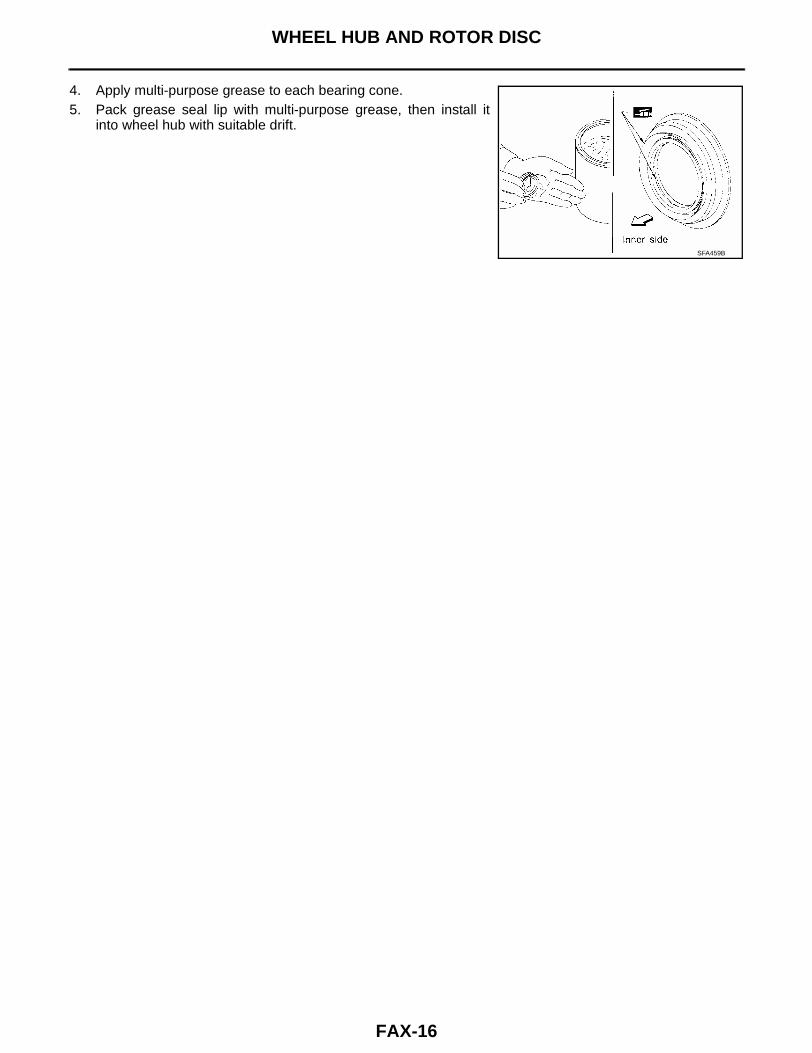
4. Apply multi-purpose grease to each bearing cone.5. Pack grease seal lip with multi-purpose grease, then install it
into wheel hub with suitable drift.
SFA459B

KNUCKLE SPINDLE
FAX-17
C
E
F
G
H
I
J
K
L
M
A
B
FAX
KNUCKLE SPINDLE PFP:40014
Removal EDS000C3
1. Remove auto-lock free-running hub assembly (4WD models).Refer to FAX-11, "Removal and Installation" .
2. Remove wheel hub and rotor disc.Refer to FAX-14, "Removal and Installation" .
3. Separate drive shaft from knuckle spindle by slightly tappingdrive shaft end (4WD models).
4. Separate tie-rod from knuckle spindle with Tool.CAUTION:Install stud nut conversely on stud bolt so as not to damagestud bolt.
5. Separate knuckle spindle from ball joints.a. Loosen (do not remove) upper and lower ball joint tightening
nuts.
SFA828B
SFA844-A
AFA139
SFA829B
FAX-18
KNUCKLE SPINDLE
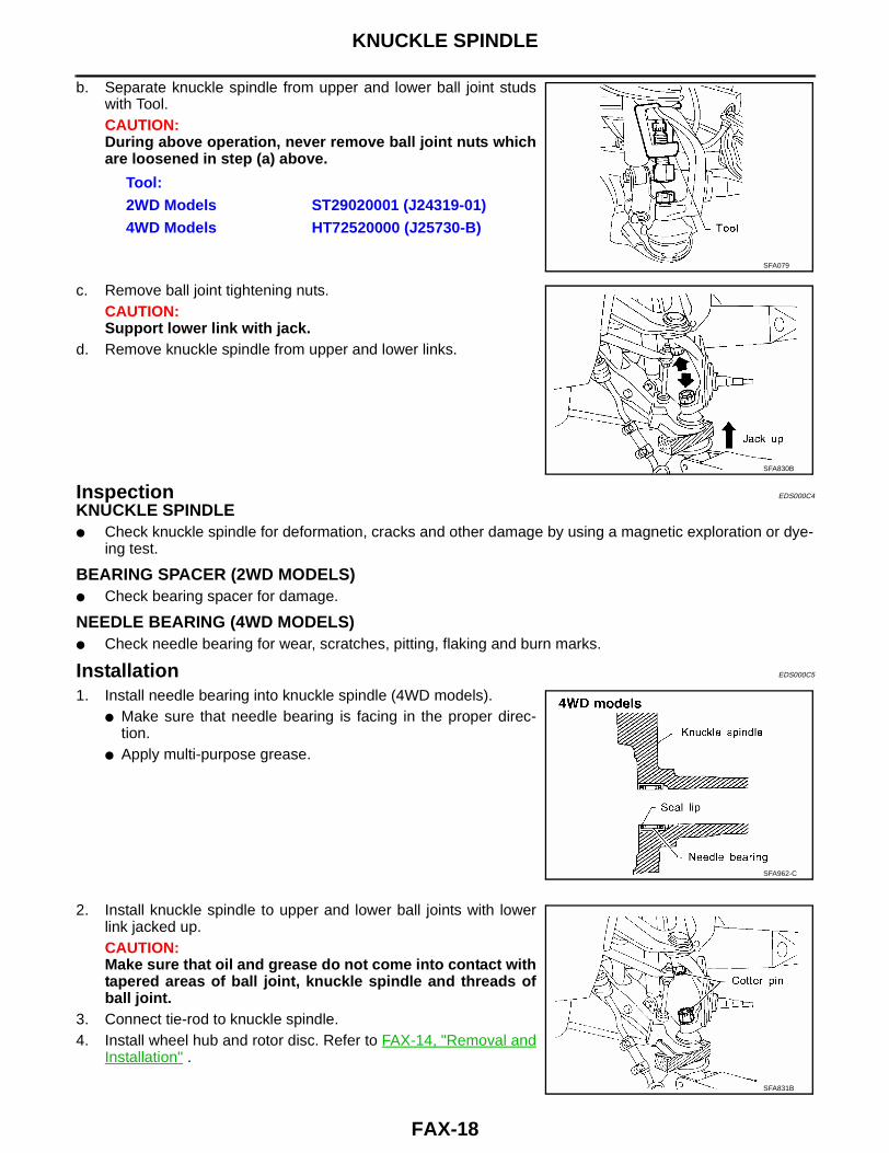
b. Separate knuckle spindle from upper and lower ball joint studswith Tool.CAUTION:During above operation, never remove ball joint nuts whichare loosened in step (a) above.
c. Remove ball joint tightening nuts.CAUTION:Support lower link with jack.
d. Remove knuckle spindle from upper and lower links.
Inspection EDS000C4
KNUCKLE SPINDLE● Check knuckle spindle for deformation, cracks and other damage by using a magnetic exploration or dye-
ing test.
BEARING SPACER (2WD MODELS)● Check bearing spacer for damage.
NEEDLE BEARING (4WD MODELS)● Check needle bearing for wear, scratches, pitting, flaking and burn marks.
Installation EDS000C5
1. Install needle bearing into knuckle spindle (4WD models).● Make sure that needle bearing is facing in the proper direc-
tion.● Apply multi-purpose grease.
2. Install knuckle spindle to upper and lower ball joints with lowerlink jacked up.CAUTION:Make sure that oil and grease do not come into contact withtapered areas of ball joint, knuckle spindle and threads ofball joint.
3. Connect tie-rod to knuckle spindle.4. Install wheel hub and rotor disc. Refer to FAX-14, "Removal and
Installation" .
Tool:2WD Models ST29020001 (J24319-01)4WD Models HT72520000 (J25730-B)
SFA079
SFA830B
SFA962-C
SFA831B
KNUCKLE SPINDLE
FAX-19
C
E
F
G
H
I
J
K
L
M
A
B
FAX
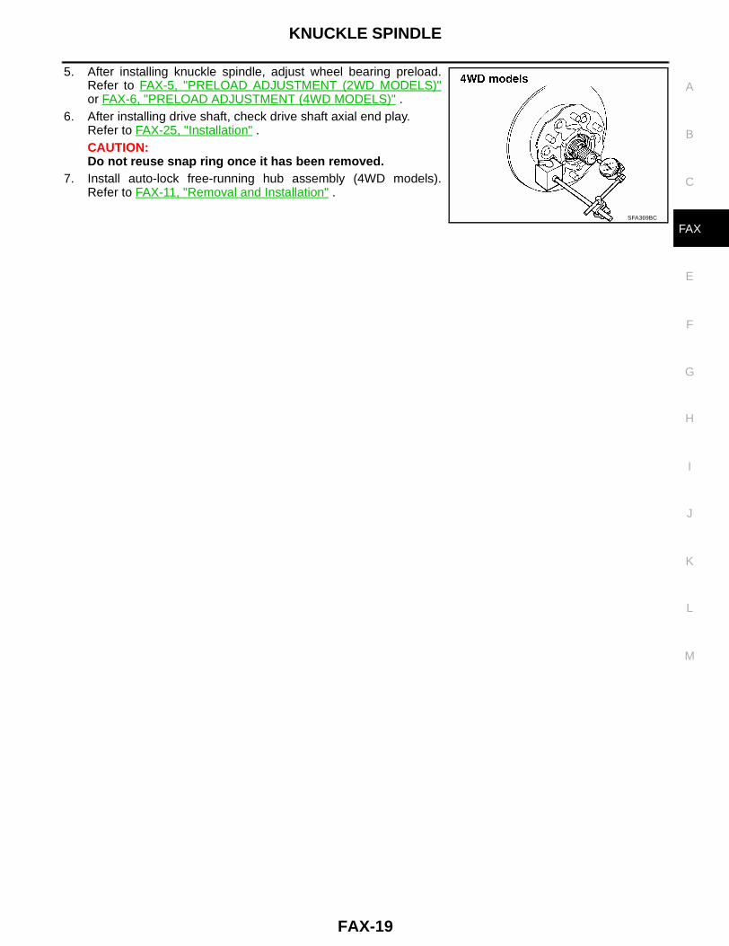
5. After installing knuckle spindle, adjust wheel bearing preload.Refer to FAX-5, "PRELOAD ADJUSTMENT (2WD MODELS)"or FAX-6, "PRELOAD ADJUSTMENT (4WD MODELS)" .
6. After installing drive shaft, check drive shaft axial end play.Refer to FAX-25, "Installation" .CAUTION:Do not reuse snap ring once it has been removed.
7. Install auto-lock free-running hub assembly (4WD models).Refer to FAX-11, "Removal and Installation" .
SFA369BC

FAX-20
DRIVE SHAFT
DRIVE SHAFT PFP:39100
Removal and Installation EDS000C6
CAUTION:● The ZF100 type (wheel side) joint assembly has two types of boot material; one is made of rubber
and the other is made of plastic.● Do not disassemble the joint assembly with the plastic boot. If the boot or joint is damaged,
replace the drive shaft assembly.
Removal EDS000C7
1. Remove auto-lock free-running hub or drive flange and snapring. Refer to FAX-11, "Removal and Installation" .
2. Remove torsion bar spring. Refer to FSU-17, "Removal" .3. Remove shock absorber lower bolt.4. Remove lower link bolts.
CAUTION:Support lower link with jack.
5. Remove drive shaft to final drive bolts.
SFA874-B
SFA832B
SFA236

DRIVE SHAFT
FAX-21
C
E
F
G
H
I
J
K
L
M
A
B
FAX
6. Separate drive shaft from knuckle spindle by slightly tapping endof drive shaft.
Disassembly EDS000C8
FINAL DRIVE SIDE (TS82F)1. Remove plug seal from slide joint housing by lightly tapping
around slide joint housing.2. Remove boot bands.
3. Move boot and slide joint housing toward wheel side, and applymatching marks.
4. Remove snap ring.
SFA833B
SFA880
SFA963
SFA964

FAX-22
DRIVE SHAFT
5. Detach spider assembly with press.
6. Draw out boot.CAUTION:Cover drive shaft serration with tape to prevent damagingthe boot.
WHEEL SIDE (ZF100)CAUTION:● The ZF100 type (wheel side) joint assembly has two types of boot material; one is made of rubber
and the other is made of plastic.● Do not disassemble the joint assembly with the plastic boot. If the boot or joint is damaged,
replace the drive shaft assembly.The procedures for the joint with the rubber boot are as follows:● Before separating joint assembly, put matching marks on drive shaft and joint assembly.● Separate joint assembly with suitable tool.
CAUTION:Be careful not to damage threads on drive shaft.
● Remove boot bands.
Inspection After Disassembly EDS000C9
Thoroughly clean all parts in cleaning solvent, and dry with compressed air. Check parts for evidence of defor-mation and other damage.
DRIVE SHAFTReplace drive shaft if it is twisted, cracked or bent.
BOOTCheck boot for fatigue, cracks and wear. Replace boot and boot bands with new ones.
JOINT ASSEMBLY (FINAL DRIVE SIDE)● Replace any parts of double offset joint which show signs of scorching, rust, wear or excessive play.● Check serration for deformation. Replace if necessary.● Check slide joint housing for any damage. Replace if necessary.
SFA392
SFA799
SFA455

DRIVE SHAFT
FAX-23
C
E
F
G
H
I
J
K
L
M
A
B
FAX
JOINT ASSEMBLY (WHEEL SIDE)CAUTION:● The ZF100 type (wheel side) joint assembly has two types of boot material; one is made of rubber
and the other is made of plastic.● Do not disassemble the joint assembly with the plastic boot. If the boot or joint is damaged,
replace the drive shaft assembly.● Replace joint assembly if it is deformed or damaged.
Assembly EDS000CA
● After drive shaft has been assembled, ensure that it moves smoothly over its entire range withoutbinding.
● Use NISSAN Genuine Grease or equivalent after every overhaul.
FINAL DRIVE SIDE(TS82F)1. Install new small boot band, boot and side joint housing to drive
shaft.CAUTION:Cover drive shaft serration with tape to prevent damagingboot during installation.
2. Install spider assembly securely, making sure marks are prop-erly aligned.● Press-fit with spider assembly serration chamfer facing shaft.
3. Install new snap ring.
4. Pack with grease.
5. Make sure that the boot is properly installed on the drive shaftgroove. Set the boot so that it does not swell or deform when itslength is “L1 ”.
SFA800
SFA397
Specified amount of grease
: 95 - 105 g (3.35 - 3.70 oz)
Length “L1 ” : 95 - 97 mm (3.74 - 3.82 in)
SFA460BA

FAX-24
DRIVE SHAFT
6. Lock new large boot band securely with a suitable tool, then locknew small boot band.
7. Install new plug seal to slide joint housing by lightly tapping it.● Apply suitable sealant to mating surface of plug seal.
WHEEL SIDE(ZF100)CAUTION:● The ZF100 type (wheel side) joint assembly has two types of boot material; one is made of rubber
and the other is made of plastic.● Do not disassemble the joint assembly with the plastic boot. If the boot or joint is damaged,
replace the drive shaft assembly.The procedures for the joint with the rubber boot are as follows:1. Install new small boot band and boot on drive shaft.
CAUTION:Cover drive shaft serration with tape to prevent damagingboot during installation.
2. Set joint assembly onto drive shaft by lightly tapping it.Install joint assembly securely, ensuring that marks which weremade during disassembly are properly aligned.
3. Pack drive shaft with specified amount of grease.
4. Make sure that the boot is properly installed on the drive shaftgroove. Set the boot so that it does not swell or deform when itslength is “L2 ”.
SFA443B
SFA800
SFA884
Specified amount of grease
: 115 - 125 g (4.06 - 4.41 oz)
Length “L2 ” : 96 - 98 mm (3.78 - 3.86 in)
SFA473BA

DRIVE SHAFT
FAX-25
C
E
F
G
H
I
J
K
L
M
A
B
FAX
5. Lock new large boot band securely with a suitable tool, then locknew small boot band.
Installation EDS000CB
1. Apply multi-purpose grease.
2. Install bearing spacer onto drive shaft.CAUTION:Make sure that the bearing spacer is facing in the properdirection.
3. After installing wheel hub and wheel bearing, adjust wheel bear-ing preload. Refer to FAX-5, "PRELOAD ADJUSTMENT (2WDMODELS)" or FAX-6, "PRELOAD ADJUSTMENT (4WD MOD-ELS)" .
4. When installing drive shaft, adjust drive shaft axial end play byselecting a suitable snap ring.
a. Temporarily install new snap ring on drive shaft in the samethickness as the one that was removed.
SFA443B
SFA887
SFA846
SFA940

FAX-26
DRIVE SHAFT
b. Set dial gauge on drive shaft end.c. Measure axial end play of drive shaft.
d. If axial end play is not within the specified limit, select anothersnap ring. Refer to FAX-27, "DRIVE SHAFT AXIAL END PLAY" .
5. Install torsion bar spring. Refer to FSU-18, "Installation andAdjustment" .
6. Install auto-lock free-running hub or drive flange and snap ring.Refer to FAX-11, "Removal and Installation" .
Axial end play : 0.10 – 0.45 mm (0.004 – 0.0177 in)
SFA847
SFA832B

SERVICE DATA AND SPECIFICATIONS (SDS)
FAX-27
C
E
F
G
H
I
J
K
L
M
A
B
FAX
SERVICE DATA AND SPECIFICATIONS (SDS) PFP:00030
Wheel Bearing (Front) EDS000CC
2WD MODELS
4WD MODELS
Drive Shaft (4WD models) EDS000CD
*: The ZF100 type (wheel side) joint assembly has two types of boot material; one is made of rubber and the other is made of plastic. Donot disassemble the joint assembly with the plastic boot. If the boot or joint is damaged, replace the drive shaft assembly.
DRIVE SHAFT AXIAL END PLAY
Wheel bearing axial end play mm (in) 0 (0)
Wheel bearing lock nutTightening torque N·m (kg-m, ft-lb) 34 - 39 (3.5 - 4.0, 25 - 29)
Return angle degree 45° - 60°
Wheel bearing starting torque
At wheel hub boltWith new grease seal N (kg, lb)
9.8 - 28.4 (1.0 - 2.9, 2.2 - 6.4)
With used grease seal N (kg, lb) 9.8 - 23.5 (1.0 - 2.4, 2.2 - 5.3)
Wheel bearing lock nut
Tightening torque N·m (kg-m, ft-lb) 78 - 98 (8 - 10, 58 - 72)
Retightening torque after loosening wheel bearing lock nut N·m (kg-m, in-lb)
0.5 - 1.5 (0.05 - 0.15, 4.3 - 13)
Axial end play mm (in) 0 (0)
Turning angle degree 15° - 30°
Wheel bearing preload at wheel hub bolt N (kg, lb) 7.06 - 20.99 (0.72 - 2.14, 1.59 - 4.72)
Drive shaft joint type
Final drive side TS82F
Wheel side ZF100*
Fixed joint axial end play limit mm (in) 1 (0.04)
Diameter mm (in) Wheel side (D1 ) 29.0 (1.142)
Grease
QualityNissan Genuine Grease or
equivalent
Capacity g (oz)Final drive side 95 - 105 (3.35 - 3.70)
Wheel side 115 - 125 (4.06 - 4.41)
Boot length mm (in)Final drive side (L1 ) 95 - 97 (3.74 - 3.82)
Wheel side (L2 ) 96 - 98 (3.78 - 3.86)
LDIA0022E
Drive shaft axial end play mm (in) 0.10 – 0.45 (0.004 – 0.0177)
FAX-28
SERVICE DATA AND SPECIFICATIONS (SDS)
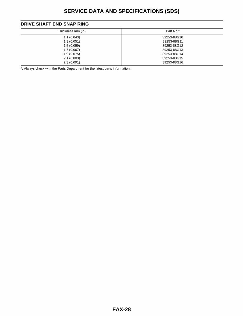
DRIVE SHAFT END SNAP RING
*: Always check with the Parts Department for the latest parts information.
Thickness mm (in) Part No.*
1.1 (0.043)1.3 (0.051)1.5 (0.059)1.7 (0.067)1.9 (0.075)2.1 (0.083)2.3 (0.091)
39253-88G1039253-88G1139253-88G1239253-88G1339253-88G1439253-88G1539253-88G16