f.r.l. unit modular type - jag-mar
TRANSCRIPT
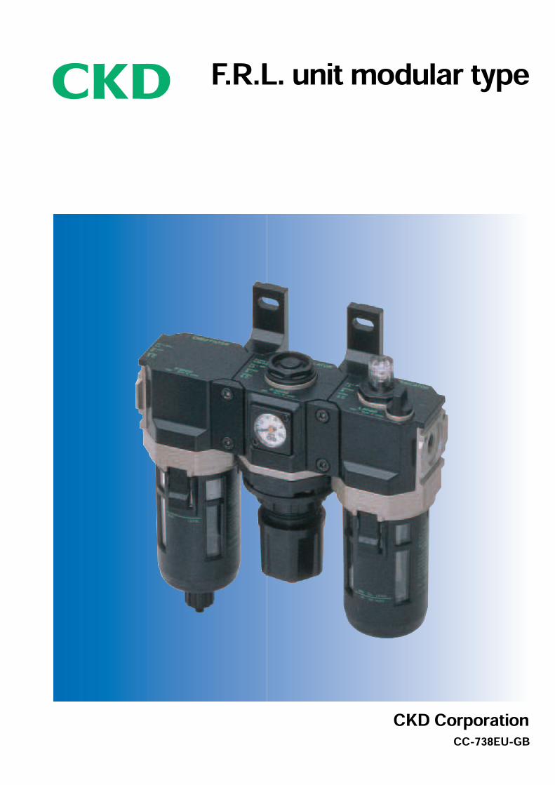
F.R.L. unit modular type
CKD CorporationCC-738EU-GB
A BASIC CONCEPTPursuing high performance for all aspects,
functionality, operability, serviceability,
and safety.Compressed air filter, regulator, lubricator, and other devices
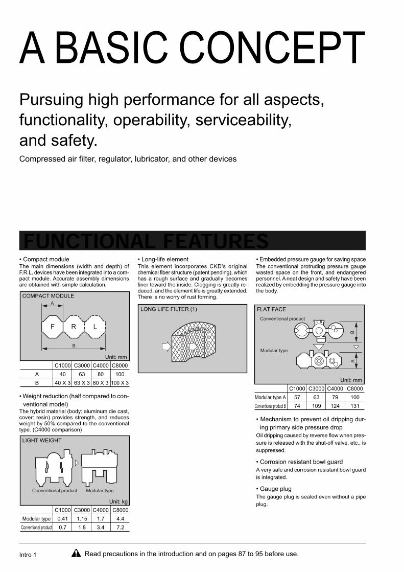
FUNCTIONAL FEATURES• Compact moduleThe main dimensions (width and depth) ofF.R.L. devices have been integrated into a com-pact module. Accurate assembly dimensionsare obtained with simple calculation.
• Long-life elementThis element incorporates CKD's originalchemical fiber structure (patent pending), whichhas a rough surface and gradually becomesfiner toward the inside. Clogging is greatly re-duced, and the element life is greatly extended.There is no worry of rust forming.
• Embedded pressure gauge for saving spaceThe conventional protruding pressure gaugewasted space on the front, and endangeredpersonnel. A neat design and safety have beenrealized by embedding the pressure gauge intothe body.
• Weight reduction (half compared to con-
ventional model)The hybrid material (body: aluminum die cast,cover: resin) provides strength, and reducesweight by 50% compared to the conventionaltype. (C4000 comparison)
• Mechanism to prevent oil dripping dur-
ing primary side pressure drop
Oil dripping caused by reverse flow when pres-
sure is released with the shut-off valve, etc., is
suppressed.
• Corrosion resistant bowl guard
A very safe and corrosion resistant bowl guard
is integrated.
• Gauge plug
The gauge plug is sealed even without a pipe
plug.
A
B
C1000
40
40 X 3
C3000
63
63 X 3
C4000
80
80 X 3
C8000
100
100 X 3
COMPACT MODULE
Unit: mm
Modular type
Conventional product
C1000
0.41
0.7
C3000
1.15
1.8
C4000
1.7
3.4
C8000
4.4
7.2
LIGHT WEIGHT
Unit: kg
LONG LIFE FILTER (1)
Modular type A
Conventional product B
C1000
57
74
C3000
63
109
C4000
79
124
C8000
100
131
FLAT FACE
Unit: mm
Read precautions in the introduction and on pages 87 to 95 before use.
A
B
F R L
Conventional product Modular type
Conventional product
Modular typeA
B
Intro 1
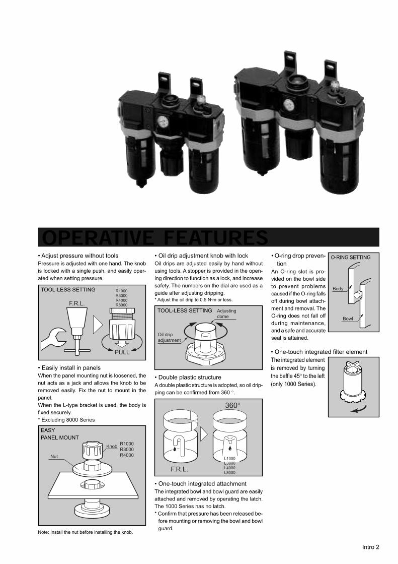
OPERATIVE FEATURES• Adjust pressure without tools
Pressure is adjusted with one hand. The knob
is locked with a single push, and easily oper-
ated when setting pressure.
• Oil drip adjustment knob with lock
Oil drips are adjusted easily by hand without
using tools. A stopper is provided in the open-
ing direction to function as a lock, and increase
safety. The numbers on the dial are used as a
guide after adjusting dripping.
* Adjust the oil drip to 0.5 N·m or less.
• O-ring drop preven-
tion
An O-ring slot is pro-
vided on the bowl side
to prevent problems
caused if the O-ring falls
off during bowl attach-
ment and removal. The
O-ring does not fall off
during maintenance,
and a safe and accurate
seal is attained.
• Easily install in panels
When the panel mounting nut is loosened, the
nut acts as a jack and allows the knob to be
removed easily. Fix the nut to mount in the
panel.
When the L-type bracket is used, the body is
fixed securely.
* Excluding 8000 Series
TOOL-LESS SETTING
TOOL-LESS SETTING
EASY
PANEL MOUNT
• Double plastic structure
A double plastic structure is adopted, so oil drip-
ping can be confirmed from 360 °.
Note: Install the nut before installing the knob.
• One-touch integrated attachment
The integrated bowl and bowl guard are easily
attached and removed by operating the latch.
The 1000 Series has no latch.
* Confirm that pressure has been released be-
fore mounting or removing the bowl and bowl
guard.
O-RING SETTING
F.R.L.
PULL
R1000R3000R4000R8000
Nut
KnobR1000
R3000
R4000
Adjusting
dome
Oil drip
adjustment
360°
F.R.L.
L1000L3000L4000L8000
Body
Bowl
• One-touch integrated filter element
The integrated element
is removed by turning
the baffle 45° to the left
(only 1000 Series).
Intro 2
Intro 3
AUXILLIARY COMPONENTS INDEX
• Shut-off valve 47
• Lockout valve (OSHA conformed) 51
• Bracket / Joiner (B/J) 53
• Distributor 55
• Piping adapter (A***) 57
• Repair parts 62
• Miniature Regulator RB500 67
• Small Filter Regulator WB500 69
• Precision Regulator RP1000 / 2000 73
• Slow Start Valves V3301 / 3321 83
Safety precautions 87
F.R.L module unit is a standard series that the major
dimensions (width / depth) are compactly designed
and unified per filter (F), regulator (R), and lubricator
(L), etc, seeking ultimate performance in all of
functionality, operation, maintainability, and safety, etc.
Overview
(1) Standard modular design
Compact modular design whose major dimensions
such as filters, regulators, and lubricator, etc. are
unified.
(2) Hybrid materials
Aluminum is used for the body, while resin is used
for the cover. Light weight and also durable.
(3) Supplying various clean air.
Supplying clean air and oil free air, etc. according
to applications / purposes.
(4) Long service life element is used.
Clogging is dramatically eliminated due to original
chemical fiber structure.
(5) Embedded pressure gauge for space saving.
Simple front surface design.
Features
Seriesvariation
• F.R.L. combinationP1 = 7 bar
P2 = 5 bar
P2 = 1 bar
• W.L. combinationP1 = 7 bar
P2 = 5 bar
P2 = 1 bar
Series
[Combination]
Series
[Unit]
• Filter / regulatorP1 = 7 bar
P2 = 5 bar
P2 = 1 bar
• Air FilterP1 = 7 bar
P = 0.2 bar
• Oil mist filterP1 = 7 bar
P = 0.1 bar
• Regulator• Reverse Regulator
P1 = 7 bar
P2 = 5 bar
P2 = 1 bar
• LubricatorP1 = 5 bar
P = 0.3 bar
Intro 4
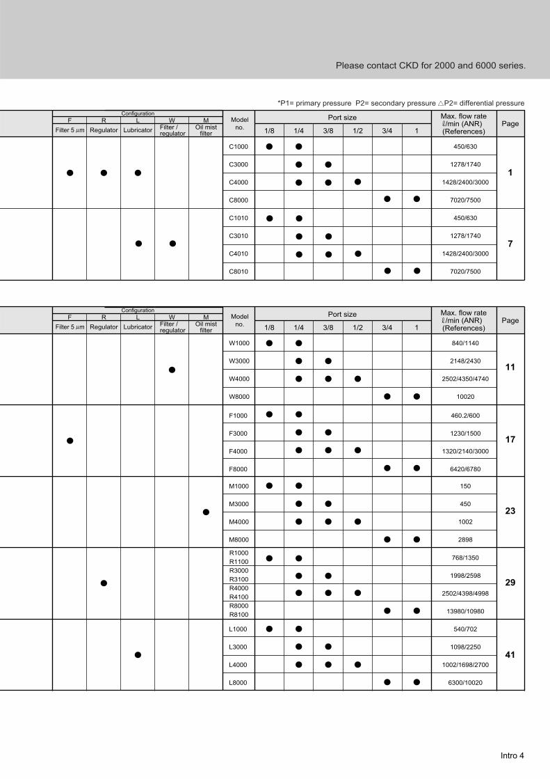
Model
no.RF L W M
Filter 5 m Regulator Lubricator Filter / regulator
Oil mistfilter
Configuration
450/630
1278/1740
1428/2400/3000
7020/7500
450/630
1278/1740
1428/2400/3000
7020/7500
Max. flow rate/min (ANR)
(References)Page
Port size
1/21/41/8 3/43/8 1
C1000
C3000
C4000
C8000
C1010
C3010
C4010
C8010
1
7
*P1= primary pressure P2= secondary pressure P2= differential pressure
Model
no.RF L W M
Filter 5 m Regulator Lubricator Filter / regulator
Oil mistfilter
Configuration
840/1140
2148/2430
2502/4350/4740
10020
PagePort size
1/21/41/8 3/43/8 1
W1000
W3000
W4000
W8000
11
460.2/600
1230/1500
1320/2140/3000
6420/6780
F1000
F3000
F4000
F8000
17
150
450
1002
2898
M1000
M3000
M4000
M8000
23
768/1350
1998/2598
2502/4398/4998
13980/10980
R1000
R1100
R3000
R3100
R4000
R4100
R8000
R8100
L1000
L3000
L4000
L8000
29
540/702
1098/2250
1002/1698/2700
6300/10020
41
Max. flow rate/min (ANR)
(References)
Please contact CKD for 2000 and 6000 series.
1
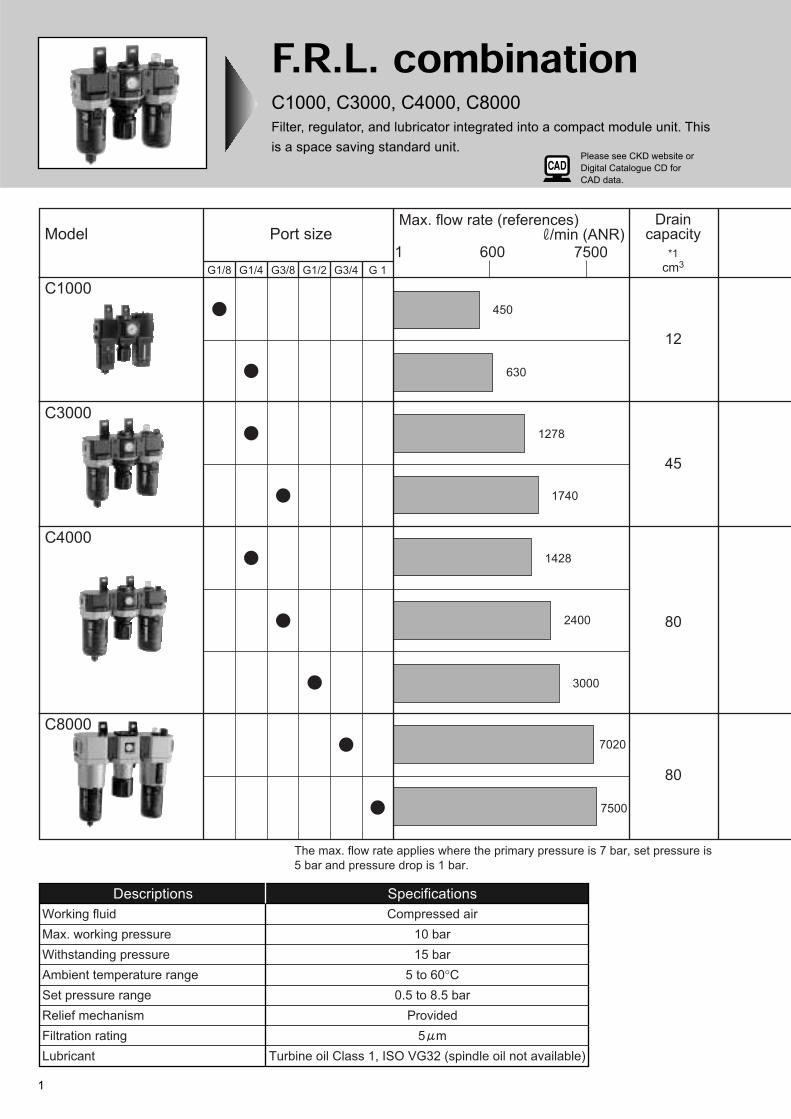
F.R.L. combinationC1000, C3000, C4000, C8000
Filter, regulator, and lubricator integrated into a compact module unit. This
is a space saving standard unit.
Model
C1000
C3000
C4000
C8000
G1/8 G1/4 G3/8 G1/2 G3/4 G 1
Port size1 600 7500
Max. flow rate (references)/min (ANR)
Draincapacity
*1
cm3
450
630
1278
1740
1428
2400
3000
7020
7500
12
45
80
80
The max. flow rate applies where the primary pressure is 7 bar, set pressure is
5 bar and pressure drop is 1 bar.
Working fluid
Max. working pressure
Withstanding pressure
Ambient temperature range
Set pressure range
Relief mechanism
Filtration rating
Lubricant
Descriptions Specifications
Compressed air
10 bar
15 bar
5 to 60°C
0.5 to 8.5 bar
Provided
5 m
Turbine oil Class 1, ISO VG32 (spindle oil not available)
Please see CKD website or
Digital Catalogue CD for
CAD data.
Please contact CKD for 2000 and 6000 series. 2
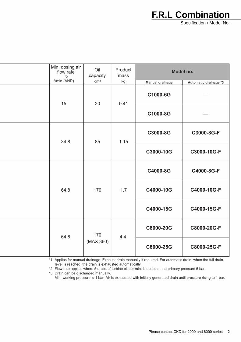
Oil
capacity
Product
mass
cm3 kg Manual drainage Automatic drainage *3
Model no.Min. dosing air
flow rate*2
/min (ANR)
15 20 0.41
C1000-6G
C1000-8G
C3000-8G
C3000-10G
C4000-8G
C4000-10G
C4000-15G
C8000-20G
C8000-25G
—
—
C3000-8G-F
C3000-10G-F
C4000-8G-F
C4000-10G-F
C4000-15G-F
C8000-20G-F
C8000-25G-F
34.8 85 1.15
64.8 170 1.7
64.8 170 4.4(MAX 360)
*1 Applies for manual drainage. Exhaust drain manually if required. For automatic drain, when the full drain
level is reached, the drain is exhausted automatically.
*2 Flow rate applies where 5 drops of turbine oil per min. is dosed at the primary pressure 5 bar.
*3 Drain can be discharged manually.
Min. working pressure is 1 bar. Air is exhausted with initially generated drain until pressure rising to 1 bar.
F.R.L CombinationSpecification / Model No.
3
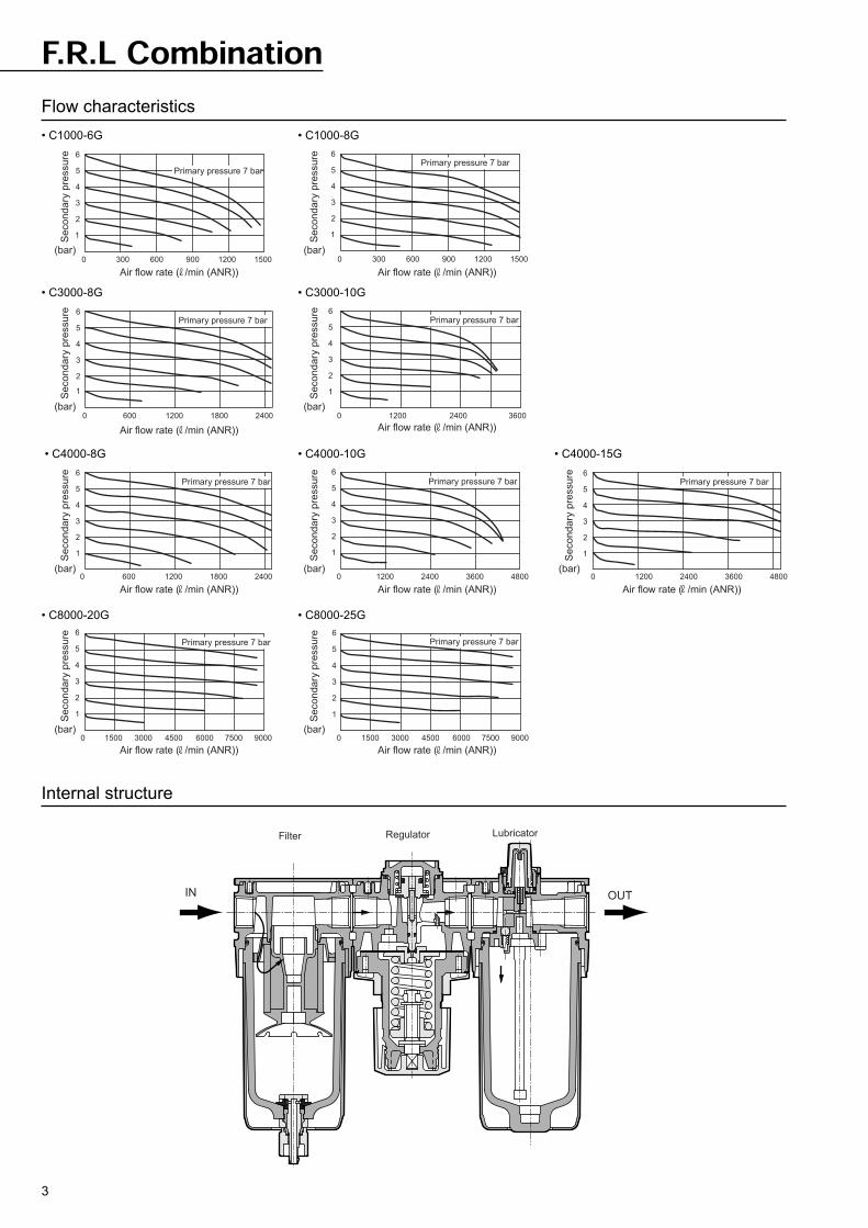
F.R.L Combination
Internal structure
Flow characteristics
• C1000-6G • C1000-8G
• C3000-8G • C3000-10G
• C4000-8G • C4000-10G
• C8000-20G • C8000-25G
• C4000-15G
OUTIN
Filter Regulator Lubricator
15001200900600
5
6
4
3
2
300
1
0
360024001200
6
5
4
3
2
0
1
240018001200600
6
5
4
3
2
0
1
4800360024001200
6
5
4
3
2
0
1
6
5
4
3
2
0
1
90007500600045003000
6
5
3
2
15000
1
4
6
5
3
2
0
1
4
4800360024001200
6
5
4
3
2
0
1
5
6
4
3
2
0
1
Air flow rate ( /min (ANR)) Air flow rate ( /min (ANR))
Air flow rate ( /min (ANR)) Air flow rate ( /min (ANR))
Air flow rate ( /min (ANR)) Air flow rate ( /min (ANR)) Air flow rate ( /min (ANR))
Primary pressure 7 barPrimary pressure 7 bar
Primary pressure 7 bar Primary pressure 7 bar
Primary pressure 7 bar
Secondary
pre
ssure
(bar)
Secondary
pre
ssure
(bar)
Secondary
pre
ssure
(bar)
Secondary
pre
ssure
(bar)
Secondary
pre
ssure
(bar)
Secondary
pre
ssure
(bar)
Air flow rate ( /min (ANR)) Air flow rate ( /min (ANR))
Primary pressure 7 bar Primary pressure 7 bar
Secondary
pre
ssure
(bar)
Secondary
pre
ssure
(bar)
Secondary
pre
ssure
(bar)
15001200900600300
240018001200600
900075006000450030001500
Primary pressure 7 bar
Primary pressure 7 bar
Please contact CKD for 2000 and 6000 series. 4
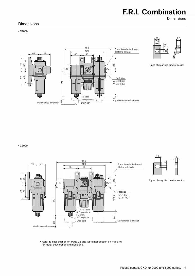
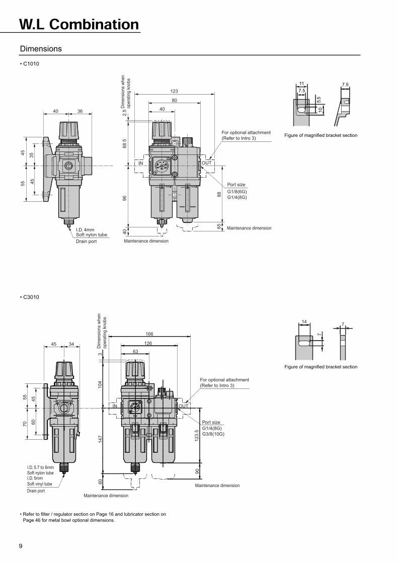
F.R.L CombinationDimensions
Dimensions
• C1000
• C3000
Figure of magnified bracket section
120
Drain portMaintenance dimension
Maintenance dimension
Port size
G1/8(6G)
G1/4(8G)
For optional attachment(Refer to Intro 3)
IN OUT
55
45
35
45
40 36
163
40 40
96
40
I.D. 4mm
Soft nylon tube 65
88
(45)
11
7.5
5.5
10
7.5
70
55
60
45
45 34229
189
63 63
147
60
IN OUT
I.D. 5.7 to 6mm
I.D. 5mmSoft nylon tube
Soft vinyl tube
For optional attachment
(Refer to Intro 3)
Port size
G1/4(8G)
G3/8(10G)
90
123.5
(46)
Maintenance dimension
Maintenance dimension
Drain port
14
7
7
Figure of magnified bracket section
• Refer to filter section on Page 22 and lubricator section on Page 46for metal bowl optional dimensions.
5
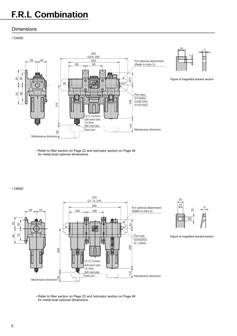
F.R.L CombinationDimensions
• C4000
• C8000
Figure of magnified bracket section
Figure of magnified bracket section
70
55
60
45
55 42 240
80 80
170
60
IN OUT
I.D. 5.7 to 6mm
I.D. 5mmSoft nylon tube
Soft vinyl tube
For optional attachment
(Refer to Intro 3)
Port size
G1/4(8G)
G3/8(10G)
G1/2(15G)
115
149
(47)
Maintenance dimension
Maintenance dimension
Drain port
280
G3/4: 290
85
65
70
50
65 53
370
G1 1/4: 376
300
100 100
60
248
I.D. 5.7 to 6mm
I.D. 5mm
Soft nylon tube
Soft vinyl tube
Drain port
For optional attachment
(Refer to Intro 3)
Port size
G3/4(20G)
G 1 (25G)
54
228
115
Maintenance dimension
Maintenance dimension
IN OUT
8
15
20
14
9
14
7
7
• Refer to filter section on Page 22 and lubricator section on Page 46for metal bowl optional dimensions.
• Refer to filter section on Page 22 and lubricator section on Page 46for metal bowl optional dimensions.
7
W.L. combinationC1010, C3010, C4010, C8010
Filter, regulator, and lubricator integrated into a compact module unit. This
is a space saving standard unit.
Model
C1010
C3010
C4010
C8010
G1/8 G1/4 G3/8 G1/2 G3/4 G 1
Port size1 600 7500
Max. flow rate (references)/min (ANR)
Draincapacity
*1
cm3
450
630
1278
1740
1428
2400
3000
7020
7500
12
45
80
80
The max. flow rate applies where the primary pressure is 7 bar, set pressure is
5 bar and pressure drop is 1 bar.
Working fluid
Max. working pressure
Withstanding pressure
Ambient temperature range
Set pressure range
Relief mechanism
Filtration rating
Lubricant
Descriptions Specifications
Compressed air
10 bar
15 bar
5 to 60°C
0.5 to 8.5 bar
Provided
5 m
Turbine oil Class 1, ISO VG32 (spindle oil not available)
Please see CKD website or
Digital Catalogue CD for
CAD data.
Please contact CKD for 2000 and 6000 series. 8
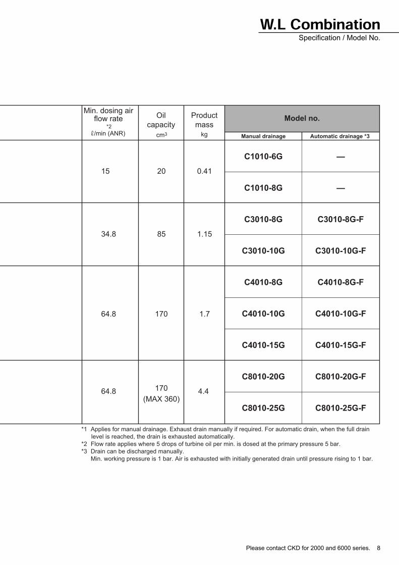
Oil
capacity
Product
mass
cm3 kg Manual drainage Automatic drainage *3
Model no.
15 20 0.41
C1010-6G
C1010-8G
C3010-8G
C3010-10G
C4010-8G
C4010-10G
C4010-15G
C8010-20G
C8010-25G
—
—
C3010-8G-F
C3010-10G-F
C4010-8G-F
C4010-10G-F
C4010-15G-F
C8010-20G-F
C8010-25G-F
34.8 85 1.15
64.8 170 1.7
64.8 170 4.4(MAX 360)
*1 Applies for manual drainage. Exhaust drain manually if required. For automatic drain, when the full drain
level is reached, the drain is exhausted automatically.
*2 Flow rate applies where 5 drops of turbine oil per min. is dosed at the primary pressure 5 bar.
*3 Drain can be discharged manually.
Min. working pressure is 1 bar. Air is exhausted with initially generated drain until pressure rising to 1 bar.
Min. dosing airflow rate
*2
/min (ANR)
W.L CombinationSpecification / Model No.
9
W.L CombinationDimensions
• C1010
• C3010
• Refer to filter / regulator section on Page 16 and lubricator section on
Page 46 for metal bowl optional dimensions.
55
45
40 36
45
35
I.D. 4mmSoft nylon tube
123
80
40
2.5
Dim
en
sio
ns
wh
en
op
era
ting
kn
ob
s68.5
96
40
IN OUT
For optional attachment
(Refer to Intro 3)
Port size
G1/8(6G)
G1/4(8G)
65
88
Drain port
Maintenance dimension
Maintenance dimension
45 34
70
55
60
45
I.D. 5.7 to 6mmSoft nylon tubeI.D. 5mm
Soft vinyl tube
Drain port
166
126
63
For optional attachment
(Refer to Intro 3)
Port size
G1/4(8G)
G3/8(10G)
IN OUT
12
3.5
90
14
76
03
Dim
en
sio
ns w
he
n
op
era
tin
g k
no
bs
Maintenance dimension
Maintenance dimension
10
4
147
7
Figure of magnified bracket section
Figure of magnified bracket section
11
7.5
5.5
10
7.5
Please contact CKD for 2000 and 6000 series. 10
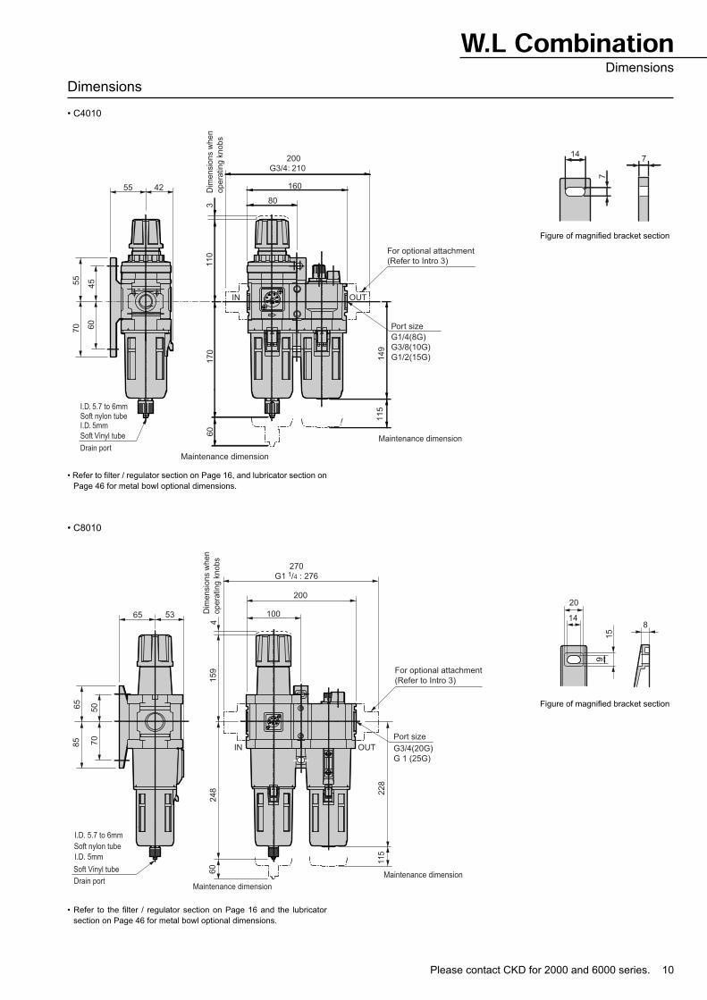
W.L CombinationDimensions
Dimensions
• C4010
• C8010
• Refer to the filter / regulator section on Page 16 and the lubricator
section on Page 46 for metal bowl optional dimensions.
Figure of magnified bracket section
• Refer to filter / regulator section on Page 16, and lubricator section on
Page 46 for metal bowl optional dimensions.
Figure of magnified bracket section
55 42
70
55
60
45
I.D. 5.7 to 6mmSoft nylon tubeI.D. 5mm
Soft Vinyl tube
Drain port
160
80
For optional attachment
(Refer to Intro 3)
Port size
G1/4(8G)
G3/8(10G)
G1/2(15G)
IN OUT
149
115
170
60
3D
ime
nsio
ns w
he
n
op
era
tin
g k
no
bs
Maintenance dimension
Maintenance dimension
110
200
G3/4: 210
65 53
85
65
70
50
I.D. 5.7 to 6mm
Soft nylon tube
I.D. 5mm
Soft Vinyl tube
270
G1 1/4 : 276
200
100
4159
248
60
Drain port
For optional attachment
(Refer to Intro 3)
Port size
G3/4(20G)
G 1 (25G)
228
115
Maintenance dimension
Maintenance dimension
Dim
en
sio
ns w
he
n
op
era
tin
g k
no
bs
IN OUT
8
15
20
14
9
14
7
7
11
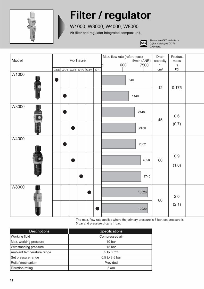
Filter / regulatorW1000, W3000, W4000, W8000
Air filter and regulator integrated compact unit.
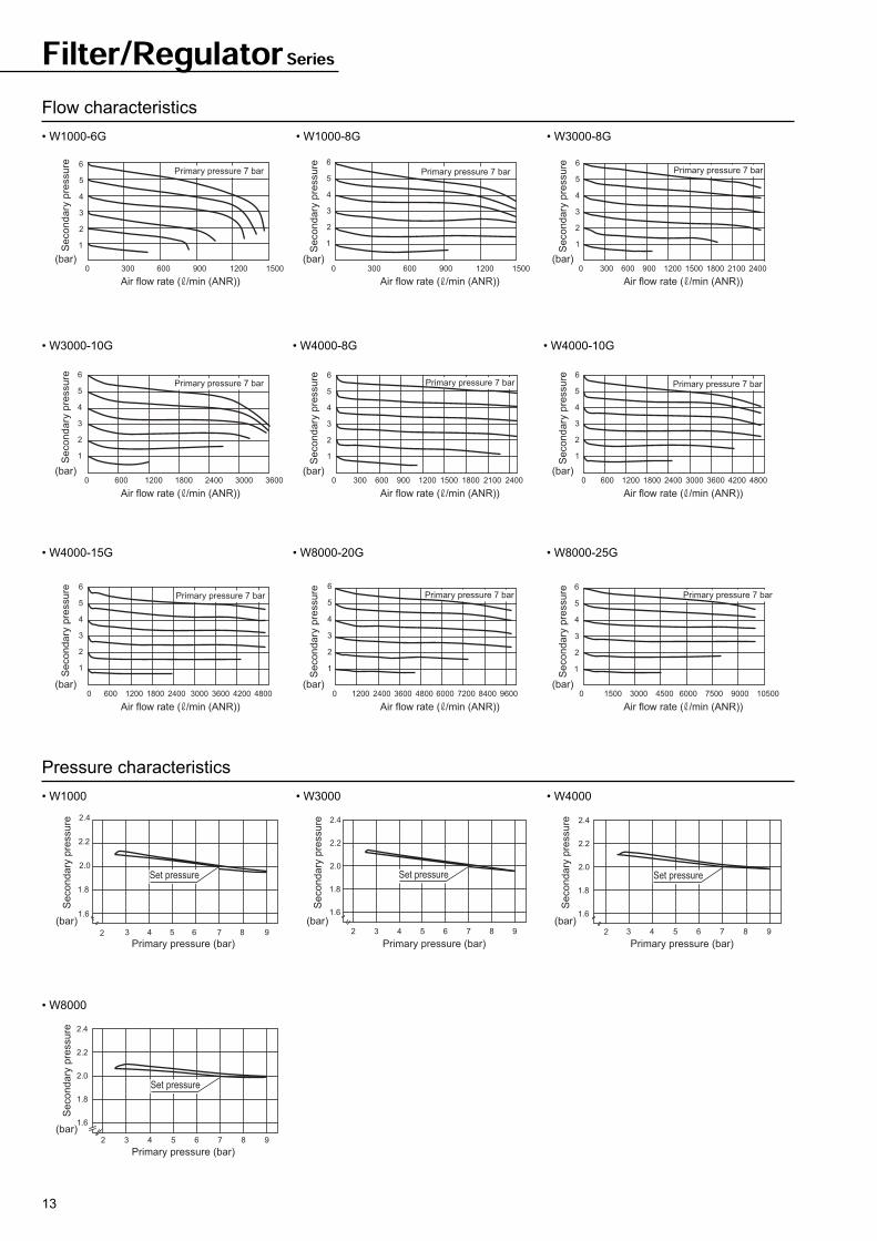
The max. flow rate applies where the primary pressure is 7 bar, set pressure is
5 bar and pressure drop is 1 bar.
Model
W4000
W8000
W1000
W3000
1 600 7500
Max. flow rate (references)
/min (ANR)
840
1140
2148
2430
2502
4350
4740
10020
10020
G1/8 G1/4 G3/8 G1/2 G3/4 G 1
Port sizeDrain
capacity
*1
cm3
Product
mass
*2
kg
0.175
0.6
(0.7)
0.9
(1.0)
2.0
(2.1)
12
45
80
80
Descriptions Specifications
Working fluid Compressed air
Max. working pressure 10 bar
Withstanding pressure 15 bar
Ambient temperature range 5 to 60°C
Set pressure range 0.5 to 8.5 bar
Relief mechanism Provided
Filtration rating 5 m
Please see CKD website or
Digital Catalogue CD for
CAD data.
Please contact CKD for 2000 and 6000 series. 12
*1 Applies for manual drainage. Exhaust drain manually if required. For automatic drain, when the full drain
level is reached, drain is discharged automatically.
*2 Mass in ( ) is for optional metal bowl.
*3 Model no. applies for C type bracket. Model no. in ( ) is for L type bracket. If a bracket is required, place an
order separately.
*4 Drainage can be discharged manually.
Min. working pressure is 1 bar. Air is exhausted with initially generated drain until pressure rising to 1 bar.
*5 With G1/4 plug (sealed). The plug is removed and the direction of gasket is changed to open the port.
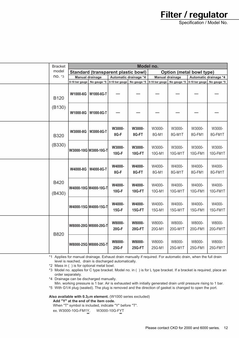
Also available with 0.3µm element. (W1000 series excluded)
Add "Y" at the end of the item code.
When "T" symbol is included, indicate "Y" before "T".
ex. W3000-10G-FM1Y, W3000-10G-FYT
Bracket
model
no. *3
B120
(B130)
B320
(B330)
B420
(B430)
B820
Manual drainage
0-10 bar gauge No gauge *5 0-10 bar gauge No gauge *5 0-10 bar gauge No gauge *5 0-10 bar gauge No gauge *5
Automatic drainage *4 Manual drainage Automatic drainage *4
Model no.
Standard (transparent plastic bowl) Option (metal bowl type)
W1000-6G
W1000-8G
W3000-8G
W3000-10G
W4000-8G
W4000-10G
W4000-15G
W8000-20G
W8000-25G
W1000-6G-T
W1000-8G-T
W3000-8G-T
W3000-10G-T
W4000-8G-T
W4000-10G-T
W4000-15G-T
W8000-20G-T
W8000-25G-T
W3000-
8G-FM1T
W3000-
10G-FM1T
W4000-
8G-FM1T
W4000-
10G-FM1T
W4000-
15G-FM1T
W8000-
20G-FM1T
W8000-
25G-FM1T
—
—
—
—
—
—
—
—
—
—
—
—
W3000-
8G-M1
W3000-
10G-M1
W4000-
8G-M1
W4000-
10G-M1
W4000-
15G-M1
W8000-
20G-M1
W8000-
25G-M1
W3000-
8G-FM1
W3000-
10G-FM1
W4000-
8G-FM1
W4000-
10G-FM1
W4000-
15G-FM1
W8000-
20G-FM1
W8000-
25G-FM1
W3000-
8G-M1T
W3000-
10G-M1T
W4000-
8G-M1T
W4000-
10G-M1T
W4000-
15G-M1T
W8000-
20G-M1T
W8000-
25G-M1T
W3000-
8G-FT
W3000-
10G-FT
W4000-
8G-FT
W4000-
10G-FT
W4000-
15G-FT
W8000-
20G-FT
W8000-
25G-FT
W3000-
8G-F
W3000-
10G-F
W4000-
8G-F
W4000-
10G-F
W4000-
15G-F
W8000-
20G-F
W8000-
25G-F
Filter / regulatorSpecification / Model No.
13
Filter/Regulator Series
Flow characteristics
• W1000-6G • W1000-8G • W3000-8G
• W3000-10G • W4000-8G • W4000-10G
• W4000-15G • W8000-20G • W8000-25G
Pressure characteristics
• W1000 • W3000 • W4000
• W8000
15001200900600
6
5
4
2
3
300
1
0 15001200900600
5
6
4
3
2
3000
1
240021001500 18001200600 900
6
5
4
3
2
3000
1
360024001200
6
4
5
3
2
0
1
600 1800 3000 24002100180015001200900
6
4
5
3
2
3000
1
600 48003600300024001200 1800 4200
6
5
4
3
2
6000
1
48003600300024001200 1800 4200
6
4
5
3
2
6000
1
96007200600048002400 3600 8400
6
5
3
2
12000
1
4
105006000 750045003000 9000
6
5
3
2
15000
1
4
Air flow rate ( /min (ANR)) Air flow rate ( /min (ANR)) Air flow rate ( /min (ANR))
Se
co
nd
ary
pre
ssu
re
(bar) (bar) (bar)
Air flow rate ( /min (ANR)) Air flow rate ( /min (ANR)) Air flow rate ( /min (ANR))
Se
co
nd
ary
pre
ssu
re
(bar) (bar) (bar)
Air flow rate ( /min (ANR)) Air flow rate ( /min (ANR)) Air flow rate ( /min (ANR))
Se
co
nd
ary
pre
ssu
re
(bar) (bar) (bar)
Primary pressure 7 bar Primary pressure 7 bar Primary pressure 7 bar
Primary pressure 7 bar Primary pressure 7 bar Primary pressure 7 bar
Primary pressure 7 bar Primary pressure 7 bar Primary pressure 7 bar
Se
co
nd
ary
pre
ssu
reS
eco
nd
ary
pre
ssu
reS
eco
nd
ary
pre
ssu
re
Se
co
nd
ary
pre
ssu
reS
eco
nd
ary
pre
ssu
reS
eco
nd
ary
pre
ssu
re
98754 6
2.4
2.2
2.0
1.6
1.8
32 986 754
2.4
2.2
2.0
1.8
1.6
32 986 754
2.4
2.2
2.0
1.6
1.8
32
986 7543
2.0
2.2
2.4
1.8
1.6
2
Set pressure
Set pressure
Set pressure Set pressure
Primary pressure (bar)
Secondary
pre
ssure
(bar)
Primary pressure (bar)
Secondary
pre
ssure
(bar)
Primary pressure (bar)
Secondary
pre
ssure
(bar)
Primary pressure (bar)
Secondary
pre
ssure
(bar)
Please contact CKD for 2000 and 6000 series. 14
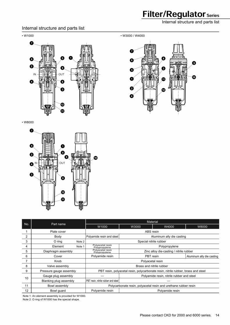
Filter/Regulator SeriesInternal structure and parts list
Internal structure and parts list
• W1000 • W3000 / W4000
• W8000
Part nameNo.W1000 W3000 W4000 W8000
Material
1
2
3
4
5
6
7
8
9
10
11
12
Plate cover
Body
O ring
Element
Diaphragm assembly
Cover
Knob
Valve assembly
Pressure gauge assembly
Gauge plug assembly
Blanking plug assembly
Bowl assembly
Bowl guard
Note 1: An element assembly is provided for W1000.
Note 2: O ring of W1000 has the special shape.
ABS resin
Special nitrile rubber
PBT resin
Polyacetal resin
Brass and nitrile rubber
PBT resin, polyacetal resin, polycarbonate resin, nitrile rubber, brass and steel
Polycarbonate resin, polyacetal resin and urethane rubber resin
Aluminum ally die casting
Polypropylene
Zinc alloy die-casting / nitrile rubber
Polyamide resin, nitrile rubber and steel
—
Polyamide resin
Polyamide resin and steel
Polyacetal resinPolypropylene
Polyacetal resinPolypropylene
Polyamide resin
—
PBT resin, nitrile rubber and steel
Polyamide resin
Aluminum ally die casting
Note 2
Note 1
1
2
3
6 5
4
9
7
12
11
8
IN OUT
1
2
3
11
12
6
5
4
9
10
7
8
1
9
5
10
8
12
11
7
6
2
4
3
IN OUT
15
83
4036
40
40
22
Tubecenter
Port size
G1/8(6G)G1/4(8G)
26.5
IN
68.5
35
43.5 53.5
45
2.5
Dim
ensio
ns w
hen o
pera
ting k
nobs
96
40
OUT
I.D. 4mmSoft nylon tube
Drain port
Maintenance dimension
For optional attachment(Refer to Intro 3)
Dimensions
• W1000
Filter/Regulator Series
• W3000
68
4410
6.5
35
43
.5
Tube center
68
4410
6.5
45
53
.5
Tube center26
.5 d
ia.
Panel plate thickness: Max. 6mm
Panel cut dimension
C type bracket
L type bracket
103
63 34.5
4545
2.32.3
Tubecenter
Port size
G1/4(8G)G3/8(10G)
31.5
IN
104
45
53.5 7
263.5
3147
60
OUT
Drain port
Maintenance dimension
For optional attachment(Refer to Intro 3)
I.D. 5.7 to 6mmSoft nylon tubeI.D. 5mmSoft vinyl tube
Dim
ensio
ns w
hen o
pera
ting k
nobs
Panel cut dimension
C type bracket
L type bracket
67
34.516.5
7
53
.5
45
Tube center
67
34.516.5
7
72
63
.5
Tube center
40 d
ia.
Panel plate thickness: Max. 4mm
• Dimensions of manual cock
and automatic drain are same
for a plastic bowl.
Please contact CKD for 2000 and 6000 series. 16
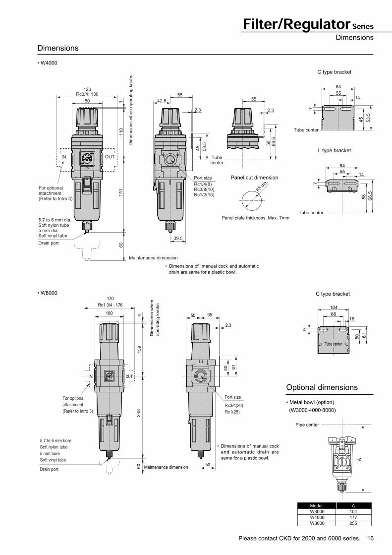
Filter/Regulator SeriesDimensions
Dimensions
• W4000
• W8000
120
80 42.5
5555
2.32.3
Tubecenter
Port size
39.5
IN
110
45
53.5 66.5
58
3
Dim
ensio
ns w
hen o
pera
ting k
nobs
170
60
OUT
Drain port
Maintenance dimension
For optionalattachment(Refer to Intro 3)
5.7 to 6 mm dia.Soft nylon tube5 mm dia.Soft vinyl tube
Rc3/4: 130
Rc1/4(8)Rc3/8(10)Rc1/2(15)
Panel cut dimension
C type bracket
L type bracket
84
5514
7
53.5
45
Tube center
84
5514
7
66.5
58
Tube center
63 d
ia.
Panel plate thickness: Max. 7mm
2.3
6550100
170
Rc1 3/4 : 176
15
92
48
60
4
For optional
attachment
(Refer to Intro 3)
50 61
Maintenance dimension
Dim
en
sio
ns w
he
n
op
era
tin
g k
no
bs
IN OUT
50
5.7 to 6 mm bore
Soft nylon tube
5 mm bore
Soft vinyl tube
Drain port
Port size
Rc3/4(20)
Rc1(25)
104
6816
9
61
50
Tube center
C type bracket
• Dimensions of manual cock and automatic
drain are same for a plastic bowl.
• Dimensions of manual cock
and automatic drain are
same for a plastic bowl.
Optional dimensions
• Metal bowl (option)
(W3000·4000·8000)
PRESSTURN
Pipe center
A
Model
W3000
W4000
W8000
A
154
177
255
17
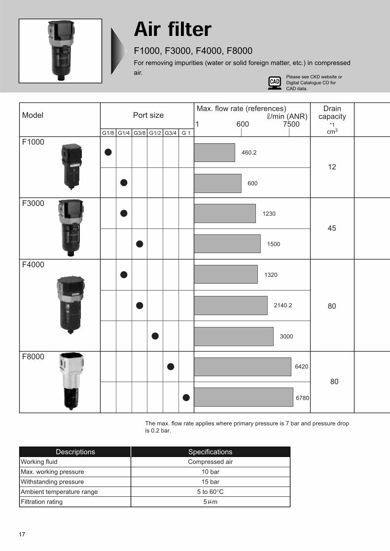
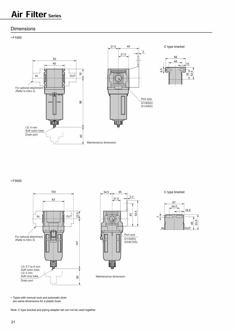
Air filterF1000, F3000, F4000, F8000
For removing impurities (water or solid foreign matter, etc.) in compressed
air.
Model
F1000
F3000
F4000
F8000
G1/8 G1/4 G3/8 G1/2 G3/4 G 1
Port size1 600 7500
Max. flow rate (references) /min (ANR)
Draincapacity
*1
cm3
460.2
600
1230
1500
1320
2140.2
3000
6420
6780
12
45
80
80
The max. flow rate applies where primary pressure is 7 bar and pressure drop
is 0.2 bar.
5 m
Descriptions Specifications
Working fluid Compressed air
Max. working pressure 10 bar
Withstanding pressure 15 bar
Ambient temperature range 5 to 60°C
Filtration rating
Please see CKD website or
Digital Catalogue CD for
CAD data.
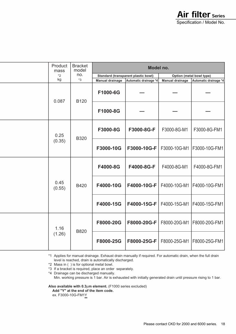
Please contact CKD for 2000 and 6000 series. 18
*2
*3
Productmass
kg
Bracketmodel
no. Standard (transparent plastic bowl) Option (metal bowl type)
Manual drainage Automatic drainage *4 Manual drainage Automatic drainage *4
Model no.
0.087
F1000-6G
F1000-8G
F3000-8G
F3000-10G
F4000-8G
F4000-10G
F4000-15G
F8000-20G
F8000-25G
—
—
F3000-8G-F
F3000-10G-F
F4000-8G-F
F4000-10G-F
F4000-15G-F
F8000-20G-F
F8000-25G-F
—
—
F3000-8G-M1
F3000-10G-M1
F4000-8G-M1
F4000-10G-M1
F4000-15G-M1
F8000-20G-M1
F8000-25G-M1
—
—
F3000-8G-FM1
F3000-10G-FM1
F4000-8G-FM1
F4000-10G-FM1
F4000-15G-FM1
F8000-20G-FM1
F8000-25G-FM1
0.25
(0.35)
0.45
(0.55)
B120
B320
B420
B8201.16
(1.26)
*1 Applies for manual drainage. Exhaust drain manually if required. For automatic drain, when the full drain
level is reached, drain is automatically discharged.
*2 Mass in ( ) is for optional metal bowl.
*3 If a bracket is required, place an order separately.
*4 Drainage can be discharged manually.
Min. working pressure is 1 bar. Air is exhausted with initially generated drain until pressure rising to 1 bar.
Also available with 0.3µm element. (F1000 series excluded)
Add "Y" at the end of the item code.
ex. F3000-10G-FM1Y
Air filter SeriesSpecification / Model No.
19
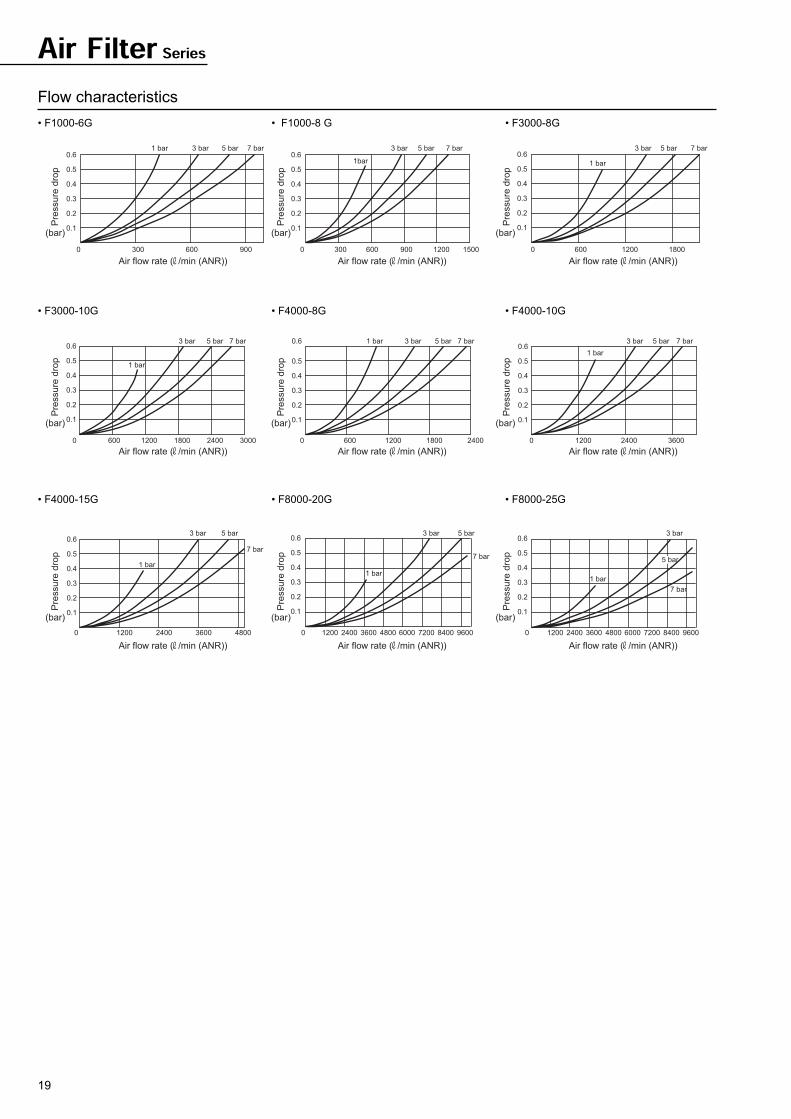
Air Filter Series
Flow characteristics
• F1000-6G • F1000-8 G • F3000-8G
• F3000-10G • F4000-8G • F4000-10G
• F4000-15G • F8000-20G • F8000-25G
7 bar5 bar3 bar1 bar
900600300
0.6
0.5
0.4
0.3
0.2
0
0.1
7 bar5 bar
1bar
3 bar
15001200900600
0.5
0.4
0.6
0.3
0.2
3000
0.1
5 bar
1 bar
3 bar 7 bar
18001200600
0.6
0.5
0.4
0.3
0.2
0
0.1
7 bar5 bar3 bar
24001200
0.6
0.5
0.4
0.3
0.2
0
0.1
1 bar
30001800600
7 bar5 bar3 bar1 bar
240018001200600
0.6
0.5
0.4
0.3
0.2
0
0.1
7 bar5 bar
1 bar
3 bar
360024001200
0.6
0.5
0.4
0.3
0.2
0
0.1
5 bar3 bar
1 bar
4800360024001200
7 bar
0.6
0.5
0.4
0.3
0.2
0
0.1
3 bar 5 bar
960084006000 720048003600
7 bar
1 bar
0.6
0.4
0.5
0.3
0.2
12000
0.1
2400
3 bar
960084006000 7200
1 bar
48002400 3600
7 bar
0.6
0.4
0.5
0.3
0.2
12000
0.1
5 bar
Air flow rate ( /min (ANR)) Air flow rate ( /min (ANR)) Air flow rate ( /min (ANR))
Pre
ssu
re d
rop
(bar)
Pre
ssu
re d
rop
(bar)
Pre
ssu
re d
rop
(bar)
Air flow rate ( /min (ANR)) Air flow rate ( /min (ANR)) Air flow rate ( /min (ANR))
Pre
ssu
re d
rop
(bar)
Pre
ssu
re d
rop
(bar)
Pre
ssu
re d
rop
(bar)
Air flow rate ( /min (ANR)) Air flow rate ( /min (ANR)) Air flow rate ( /min (ANR))
Pre
ssu
re d
rop
(bar)
Pre
ssu
re d
rop
(bar)
Pre
ssu
re d
rop
(bar)
Please contact CKD for 2000 and 6000 series. 20
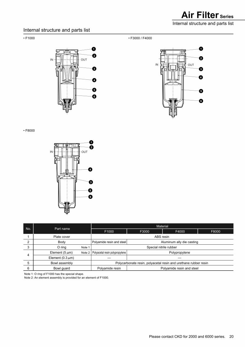
Air Filter Series
Internal structure and parts list
Internal structure and parts list
• F1000 • F3000 / F4000
• F8000
Part nameNo.F1000 F3000 F4000 F8000
Material
1
2
3
4
5
6
Plate cover
Body
O ring
Element (5 m)
Element (0.3 m)
Bowl assembly
Bowl guard
Note 1: O ring of F1000 has the special shape.
Note 2: An element assembly is provided for an element of F1000.
ABS resin
Special nitrile rubber
Polycarbonate resin, polyacetal resin and urethane rubber resin
Aluminum ally die casting
Polypropylene
—
Polyamide resin and steel
Polyamide resin and steel
Polyacetal resin polypropylene
—
Polyamide resin
Note 1
Note 2
IN OUT
1
2
3
4
5
6
IN OUT
1
2
3
4
5
6
1
2
4
5
6
3
IN OUT
21
Dimensions
• F1000
Air Filter Series
• F3000
• Types with manual cock and automatic drain
are same dimensions for a plastic bowl.
Note: C type bracket and piping adapter set can not be used together.
C type bracket
40
83
21.5
2
40
21.5
18
96
40
For optional attachment(Refer to Intro 3)
I.D. 4 mmSoft nylon tube
Drain port
Port size
Maintenance dimension
G1/8(6G)G1/4(8G)
OUTIN
68
4410
6.5
35
43.5
C type bracket
63
103 34.5
2.3
45
31.5
22
.5
45
53
.5
14
76
0
For optional attachment(Refer to Intro 3)
Drain port
Port size
Maintenance dimension
G1/4(8G)G3/8(10G)
OUTIN
I.D. 5.7 to 6 mmSoft nylon tubeI.D. 5 mmSoft vinyl tube
67
34.5
IN OUT
16.5
7
53.5
45
Please contact CKD for 2000 and 6000 series. 22
Air Filter SeriesDimensions
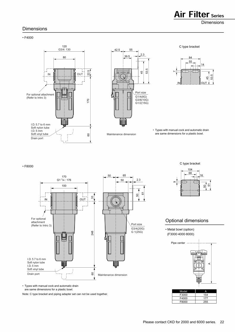
Dimensions
• F4000
• F8000
• Types with manual cock and automatic drain
are same dimensions for a plastic bowl.
Note: C type bracket and piping adapter set can not be used together.
• Types with manual cock and automatic drain
are same dimensions for a plastic bowl.
80
120
42.5
2.3
55
39.5
22.5
45
53.5
170
60
For optional attachment(Refer to Intro 3)
Drain port
Port size
Maintenance dimension
OUTIN
I.D. 5.7 to 6 mmSoft nylon tubeI.D. 5 mmSoft vinyl tube
G3/4: 130
G1/4(8G)G3/8(10G)G1/2(15G)
84
55
IN OUT
14
7
53.5
45
C type bracket
100
170
G1 1/4 : 176 50 2.3
6550
248
33
60
50 6
1
IN OUT
Port size
G3/4(20G)
G 1(25G)
Drain port Maintenance dimension
For optional
attachment
(Refer to Intro 3)
I.D. 5.7 to 6 mm
Soft nylon tube
I.D. 5 mm
Soft vinyl tube
104
6816
9
61
50
C type bracket
Optional dimensions
• Metal bowl (option)
(F3000·4000·8000)
PRESSTURN
Pipe center
A
Model
F3000
F4000
F8000
A
154
177
255
23
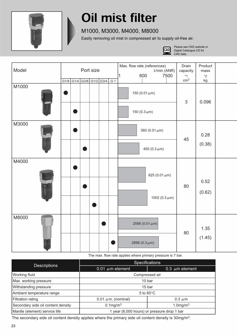
Oil mist filterM1000, M3000, M4000, M8000
Easily removing oil mist in compressed air to supply oil-free air.
The max. flow rate applies where primary pressure is 7 bar.
Model
M4000
M8000
M1000
M3000
1 600 7500
Max. flow rate (references)
/min (ANR)
150 (0.01 m)
G1/8 G1/4 G3/8 G1/2 G3/4 G 1
Port sizeDrain
capacity
*1
cm3
Product
mass
*2
kg
0.096
0.28
(0.38)
0.52
(0.62)
1.35
(1.45)
3
45
80
80
DescriptionsSpecifications
0.01 m element 0.3 m element
Working fluid Compressed air
Max. working pressure 10 bar
Withstanding pressure 15 bar
Ambient temperature range 5 to 60°C
Filtration rating 0.01 m, (nominal)
Secondary side oil content density 0.1mg/m3
Mantle (element) service life 1 year (6,000 hours) or pressure drop 1 bar
0.3 m
1.0mg/m3
150 (0.3 m)
450 (0.3 m)
1002 (0.3 m)
2898 (0.3 m)
2598 (0.01 m)
825 (0.01 m)
360 (0.01 m)
The secondary side oil content density applies where the primary side oil content density is 30mg/m3.
Please see CKD website or
Digital Catalogue CD for
CAD data.
Please contact CKD for 2000 and 6000 series. 24
*1 Applies for manual drainage. Exhaust drain manually if required. For automatic drain, when the full drain
level is reached, drain is automatically discharged.
*2 Mass in ( ) is for optional metal bowl.
*3 If a bracket is required, place an order separately.
*4 Drainage can be discharged manually. Min. working pressure is 1.5 bar.
Min. working pressure is 1.5 bar.
0.3 element
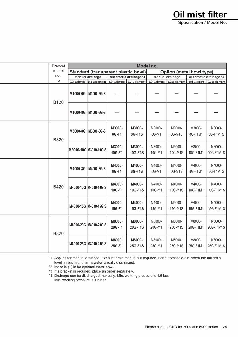
Bracket
model
no.
*3
B120
B320
B420
B820
Manual drainage
0.01 element 0.3 element0.01 element 0.3 element0.01 element 0.3 element0.01 element
Automatic drainage *4 Manual drainage Automatic drainage *4
Model no.
Standard (transparent plastic bowl) Option (metal bowl type)
M1000-6G
M1000-8G
M3000-8G
M3000-10G
M4000-8G
M4000-10G
M4000-15G
M8000-20G
M8000-25G
M1000-6G-S
M1000-8G-S
M3000-8G-S
M3000-10G-S
M4000-8G-S
M4000-10G-S
M4000-15G-S
M8000-20G-S
M8000-25G-S
—
—
—
—
—
—
—
—
—
—
—
—
M3000-
8G-F1
M3000-
10G-F1
M4000-
8G-F1
M4000-
10G-F1
M4000-
15G-F1
M8000-
20G-F1
M8000-
25G-F1
M3000-
8G-F1M1S
M3000-
10G-F1M1S
M4000-
8G-F1M1S
M4000-
10G-F1M1S
M4000-
15G-F1M1S
M8000-
20G-F1M1S
M8000-
25G-F1M1S
M3000-
8G-F1M1
M3000-
10G-F1M1
M4000-
8G-F1M1
M4000-
10G-F1M1
M4000-
15G-F1M1
M8000-
20G-F1M1
M8000-
25G-F1M1
M3000-
8G-M1S
M3000-
10G-M1S
M4000-
8G-M1S
M4000-
10G-M1S
M4000-
15G-M1S
M8000-
20G-M1S
M8000-
25G-M1S
M3000-
8G-M1
M3000-
10G-M1
M4000-
8G-M1
M4000-
10G-M1
M4000-
15G-M1
M8000-
20G-M1
M8000-
25G-M1
M3000-
8G-F1S
M3000-
10G-F1S
M4000-
8G-F1S
M4000-
10G-F1S
M4000-
15G-F1S
M8000-
20G-F1S
M8000-
25G-F1S
Oil mist filterSpecification / Model No.
25
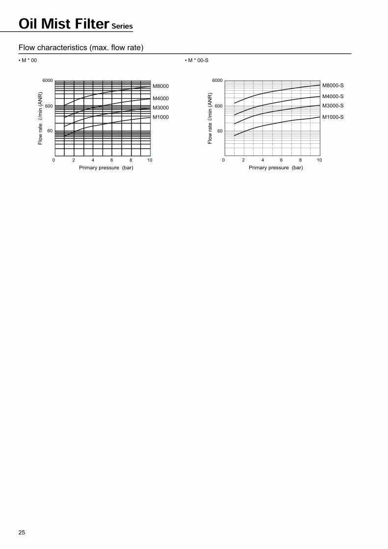
Oil Mist Filter Series
Flow characteristics (max. flow rate)
• M * 00 • M * 00-S
0 2 4 6 8 10
600
60
6000
Primary pressure (bar)
Flo
w r
ate
/m
in (
AN
R)
M8000
M4000
M3000
M1000
0 2 4 6 8 10
60
600
6000
Primary pressure (bar)
Flo
w r
ate
/m
in (
AN
R)
M8000-S
M4000-S
M3000-S
M1000-S
Please contact CKD for 2000 and 6000 series. 26
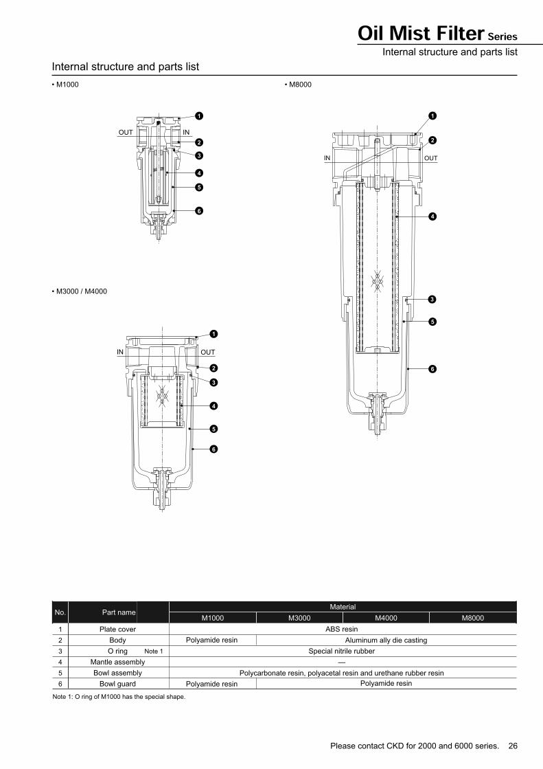
Oil Mist Filter SeriesInternal structure and parts list
Internal structure and parts list
• M1000 • M8000
• M3000 / M4000
OUT IN
1
2
3
4
5
6
IN OUT
1
2
3
4
5
6
IN OUT
2
3
4
5
6
1
Plate cover
Body
O ring
Mantle assembly
Bowl assembly
Bowl guard
Note 1
ABS resin
Special nitrile rubber
—
Polycarbonate resin, polyacetal resin and urethane rubber resin
Polyamide resin
Polyamide resin
MaterialNo. Part name
Note 1: O ring of M1000 has the special shape.
1
2
3
4
5
6
M1000 M3000 M4000 M8000
Aluminum ally die casting
Polyamide resin
27
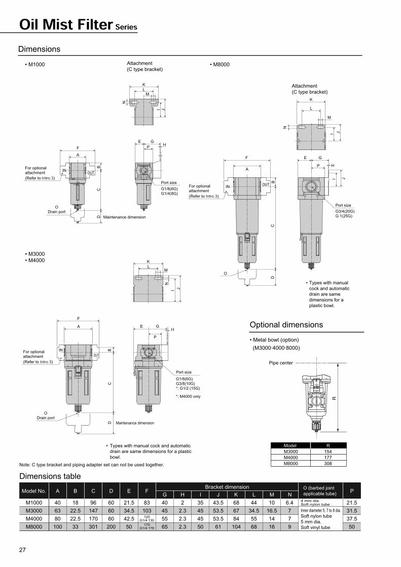
Oil Mist Filter Series
Dimensions
• M1000
G H I J K L M N
M1000
M3000
M4000
M8000
40
63
80
100
18
22.5
22.5
33
96
147
170
301
60
60
60
200
21.5
34.5
42.5
50
40
45
55
65
2
2.3
2.3
2.3
35
45
45
50
43.5
53.5
53.5
61
68
67
84
104
44
34.5
55
68
10
16.5
14
16
6.4
7
7
9
21.5
31.5
37.5
50
83
103
Bracket dimension
Dimensions table
AModel No. B C D PO (barbed joint
applicable tube) E F
120G1/4 130
170G1/4 176
4 mm dia.Soft nylon tube
Inner diameter 5, 7 to 8 dia.
Soft nylon tube
5 mm dia.
Soft vinyl tube
Note: C type bracket and piping adapter set can not be used together.
• M8000
• M3000
• M4000
OUTIN
IN
A
F
OUT
OUTIN
Attachment
(C type bracket)
Attachment
(C type bracket)
K
LM
N
I J
K
LM
I
N
J
BC
D
F
A
ODrain port
For optional attachment
(Refer to Intro 3)
For optional attachment
(Refer to Intro 3)
Maintenance dimension
CB
D
ODrain port
For optionalattachment
(Refer to Intro 3)
Maintenance dimension
E G
PH
G1/8(6G)G1/4(8G)
Port size
G3/4(20G)G 1(25G)
Port size
G1/8(6G)G3/8(10G)*: G1/2 (15G)
*: M4000 only
Port size
E G
P
H
• Types with manual
cock and automatic
drain are same
dimensions for a
plastic bowl.
K
L
M
N
JI
F
A
E G
P
B
I J
CD
O
H
• Types with manual cock and automatic
drain are same dimensions for a plastic
bowl.
Optional dimensions
• Metal bowl (option)
(M3000·4000·8000)
PRESSTURN
Pipe center
R
Model
M3000
M4000
M8000
R
154
177
308
29
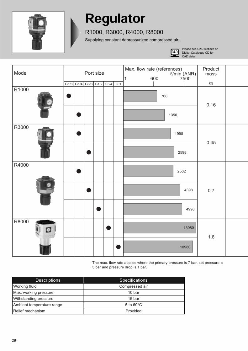
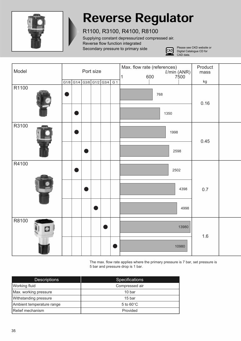
RegulatorR1000, R3000, R4000, R8000
Supplying constant depressurized compressed air.
Model
R1000
R3000
R4000
R8000
G1/8 G1/4 G3/8 G1/2 G3/4 G 1
Port size1 600 7500
Max. flow rate (references) /min (ANR)
768
1350
1998
2598
2502
4398
4998
13980
10980
Productmass
kg
0.16
0.45
0.7
1.6
The max. flow rate applies where the primary pressure is 7 bar, set pressure is
5 bar and pressure drop is 1 bar.
Descriptions Specifications
Working fluid Compressed air
Max. working pressure 10 bar
Withstanding pressure 15 bar
Ambient temperature range 5 to 60°C
Relief mechanism Provided
Please see CKD website or
Digital Catalogue CD for
CAD data.
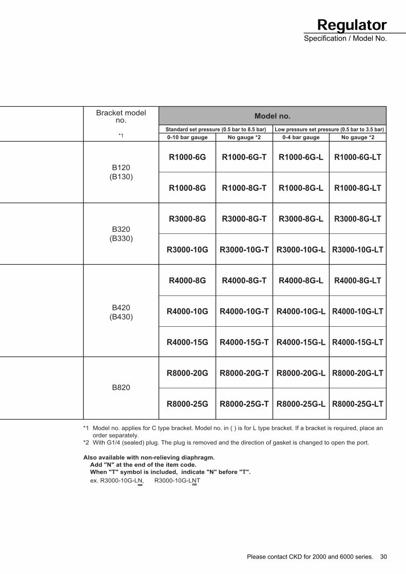
Please contact CKD for 2000 and 6000 series. 30
*1
Bracket modelno.
Standard set pressure (0.5 bar to 8.5 bar) Low pressure set pressure (0.5 bar to 3.5 bar)
0-10 bar gauge No gauge *2 0-4 bar gauge No gauge *2
Model no.
R1000-6G
R1000-8G
R3000-8G
R3000-10G
R4000-8G
R4000-10G
R4000-15G
R8000-20G
R8000-25G
R1000-6G-T
R1000-8G-T
R3000-8G-T
R3000-10G-T
R4000-8G-T
R4000-10G-T
R4000-15G-T
R8000-20G-T
R8000-25G-T
R1000-6G-L
R1000-8G-L
R3000-8G-L
R3000-10G-L
R4000-8G-L
R4000-10G-L
R4000-15G-L
R8000-20G-L
R8000-25G-L
R1000-6G-LT
R1000-8G-LT
R3000-8G-LT
R3000-10G-LT
R4000-8G-LT
R4000-10G-LT
R4000-15G-LT
R8000-20G-LT
R8000-25G-LT
B120
(B130)
B320
(B330)
B420
(B430)
B820
*1 Model no. applies for C type bracket. Model no. in ( ) is for L type bracket. If a bracket is required, place an
order separately.
*2 With G1/4 (sealed) plug. The plug is removed and the direction of gasket is changed to open the port.
Also available with non-relieving diaphragm.
Add "N" at the end of the item code.
When "T" symbol is included, indicate "N" before "T".
ex. R3000-10G-LN, R3000-10G-LNT
RegulatorSpecification / Model No.

31
Regulator Series
Flow characteristics
• R1000-6G • R1000-8G • R3000-8G
• R3000-10G • R4000-8G • R4000-10G
• R4000-15G • R8000-20G • R8000-25G
Pressure characteristics
• R1000 • R3000 • R4000
• R8000
15001200900600 1800
5
6
4
3
2
3000
1
24001800 21001500900 1200
5
6
4
3
2
300 6000
1
240018001200600
6
5
4
3
2
0
1
6
5
4
3
1
2
0 1200 2400 3600 4800
240018001200600
6
5
4
3
2
0
1
4800360024001200
6
5
4
3
2
0
1
4800360024001200
6
5
4
3
2
0
1
6
5
3
2
0
1
4
3000 6000 9000 12000 90006000 12000
6
5
3
2
0
1
4
3000
Air flow rate ( /min (ANR)) Air flow rate ( /min (ANR)) Air flow rate ( /min (ANR))
Air flow rate ( /min (ANR))
Air flow rate ( /min (ANR)) Air flow rate ( /min (ANR))
Air flow rate ( /min (ANR)) Air flow rate ( /min (ANR)) Air flow rate ( /min (ANR))
Primary pressure 7 bar Primary pressure 7 bar Primary pressure 7 bar
Primary pressure 7 bar Primary pressure 7 bar Primary pressure 7 bar
Primary pressure 7 bar
Primary pressure 7 bar Primary pressure 7 bar
Secondary
pre
ssure
(bar)
Secondary
pre
ssure
(bar)
Secondary
pre
ssure
(bar)
Secondary
pre
ssure
(bar)
Secondary
pre
ssure
(bar)
Secondary
pre
ssure
(bar)
Secondary
pre
ssure
(bar)
Secondary
pre
ssure
(bar)
Secondary
pre
ssure
(bar)
2
2.2
2.0
1.8
1.6
3 4 5 6 7 8 9
2.4
986 754
2.4
2.2
2.0
1.8
1.6
32 986 754
2.4
2.2
2.0
1.6
1.8
32
986 7543
2.0
2.2
2.4
1.8
1.6
2
Set pressure
Set pressure Set pressure
Primary pressure (bar)
Secondary
pre
ssure
(bar)
Primary pressure (bar)
Secondary
pre
ssure
(bar)
Set pressure
Primary pressure (bar)
Secondary
pre
ssure
(bar)
Primary pressure (bar)
Secondary
pre
ssure
(bar)
Please contact CKD for 2000 and 6000 series. 32
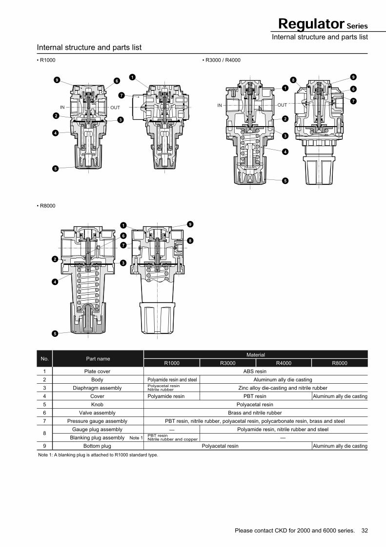
Regulator SeriesInternal structure and parts list
Internal structure and parts list
• R1000 • R3000 / R4000
• R8000
Part nameNo.R1000 R3000 R4000 R8000
Material
1
2
3
4
5
6
7
8
9
Plate cover
Body
Diaphragm assembly
Cover
Knob
Valve assembly
Pressure gauge assembly
Gauge plug assembly
Blanking plug assembly
Bottom plug
Note 1: A blanking plug is attached to R1000 standard type.
ABS resin
PBT resin
Polyacetal resin
Brass and nitrile rubber
PBT resin, nitrile rubber, polyacetal resin, polycarbonate resin, brass and steel
Aluminum ally die casting
Zinc alloy die-casting and nitrile rubber
Polyamide resin, nitrile rubber and steel
—
Polyamide resin and steelPolyacetal resinNitrile rubber
Polyamide resin
PBT resinNitrile rubber and copper
Aluminum ally die casting
Aluminum ally die castingPolyacetal resin
Note 1
—
91
7
6
32
4
5
IN OUT
1
9
7
6
8
2
3
4
5
IN OUT
2
1
7
9
8
4
6
3
5
33
Regulator Series
Dimensions
• R1000
• R3000
Attachment (C type bracket) Attachment (L type bracket)
Panel cut dimension
Attachment (C type bracket) Attachment (L type bracket)
Panel cut dimension
Note 1: Non-rotating fixing can be done by M4 screw. Screw length is to be plate thickness + 8mm or less,
and can be screwed in without female thread machining.
83
40
36 40
40
2
2
Tube center
Port size
G1/8(6G)G1/4(8G)
IN
24.5 35
43.5
53.5452
9
Dimensions when operating knobs
68.5
2.5
OUT
For optional attachment
(Refer to Intro 3)
26.5
26.5
dia.
Panel plate thickness: Max. 6mm
68
4410
6.5
35
43.5
Tube center68
4410
6.5
45
53.5
Tube center
63
IN
103
OUT 32.5
104
45
53.5
2.332 45
31.5 45
2.3
584
0
66.5
3
For optional attachment(Refer to Intro 3)
Dimensions when operating knobs
Port size
G1/4(8G)G3/8(10G)
67
34.5
16.5
7
53.5
45
Tube center IN OUT
67
34.5
16.5
7
66.558
Tube center
40 d
ia.
522-4.5 dia.
(Note 1)
Panel plate thickness: Max. 7mm
Please contact CKD for 2000 and 6000 series. 34
Regulator SeriesDimensions
Dimensions
• R4000
Attachment (C type bracket) Attachment (L type bracket)
Panel cut dimension
• R8000
Attachment (C type bracket)
Note 1: Non-rotating fixing can be done by M4 screw. Screw length is to be plate thickness + 8mm or less,
and can be screwed in without female thread machining.
80
IN
120
OUT
35
110
45
53.5
2.340 55
39.5 55
2.3
5840
65.6
3
For optional attachment(Refer to Intro 3)
Dimensions when operating knobs
Port size
G3/4: 130
G1/4(8G)G3/8(10G)G1/2(15G)
84
55
14
7
53.5
45
Tube center IN OUT
84
55
14
7
65.6
58
Tube center
45 d
ia.
632-4.5 dia.
(Note 1)
Panel plate thickness: Max. 7mm
2.365
50
50
100
170G1 1/4 : 176
159
40
4
For optional attachment(Refer to Intro 3)
50 61
Dimensions when operating knobs
IN OUT
Port size
G3/4(20G)G 1(25G)
104
68
Tube center
16
9
61
50
35
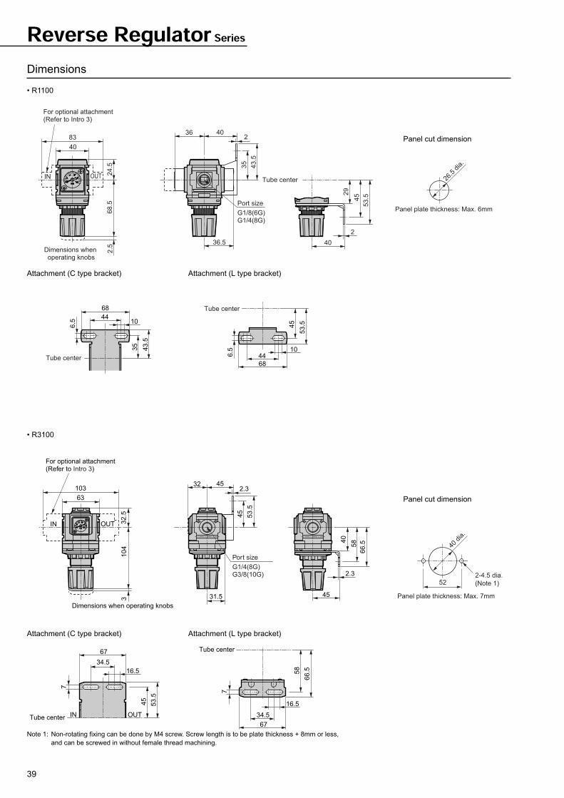
Reverse RegulatorR1100, R3100, R4100, R8100Supplying constant depressurized compressed air.
Reverse flow function integrated
Secondary pressure to primary side
Model
R1100
R3100
R4100
R8100
G1/8 G1/4 G3/8 G1/2 G3/4 G 1
Port size1 600 7500
Max. flow rate (references) /min (ANR)
768
1350
1998
2598
2502
4398
4998
13980
10980
Productmass
kg
0.16
0.45
0.7
1.6
The max. flow rate applies where the primary pressure is 7 bar, set pressure is
5 bar and pressure drop is 1 bar.
Descriptions Specifications
Working fluid Compressed air
Max. working pressure 10 bar
Withstanding pressure 15 bar
Ambient temperature range 5 to 60°C
Relief mechanism Provided
Please see CKD website or
Digital Catalogue CD for
CAD data.
Please contact CKD for 2000 and 6000 series. 36
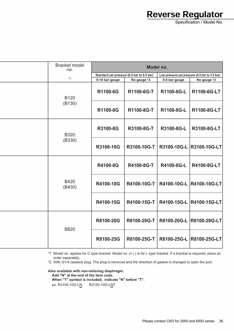
*1
Bracket modelno.
Standard set pressure (0.5 bar to 8.5 bar) Low pressure set pressure (0.5 bar to 3.5 bar)
0-10 bar gauge No gauge *2 0-4 bar gauge No gauge *2
Model no.
R1100-6G
R1100-8G
R3100-8G
R3100-10G
R4100-8G
R4100-10G
R4100-15G
R8100-20G
R8100-25G
R1100-6G-T
R1100-8G-T
R3100-8G-T
R3100-10G-T
R4100-8G-T
R4100-10G-T
R4100-15G-T
R8100-20G-T
R8100-25G-T
R1100-6G-L
R1100-8G-L
R3100-8G-L
R3100-10G-L
R4100-8G-L
R4100-10G-L
R4100-15G-L
R8100-20G-L
R8100-25G-L
R1100-6G-LT
R1100-8G-LT
R3100-8G-LT
R3100-10G-LT
R4100-8G-LT
R4100-10G-LT
R4100-15G-LT
R8100-20G-LT
R8100-25G-LT
B120
(B130)
B320
(B330)
B420
(B430)
B820
*1 Model no. applies for C type bracket. Model no. in ( ) is for L type bracket. If a bracket is required, place an
order separately.
*2 With G1/4 (sealed) plug. The plug is removed and the direction of gasket is changed to open the port.
Also available with non-relieving diaphragm.
Add "N" at the end of the item code.
When "T" symbol is included, indicate "N" before "T".
ex. R3100-10G-LN, R3100-10G-LNT
Reverse RegulatorSpecification / Model No.
37
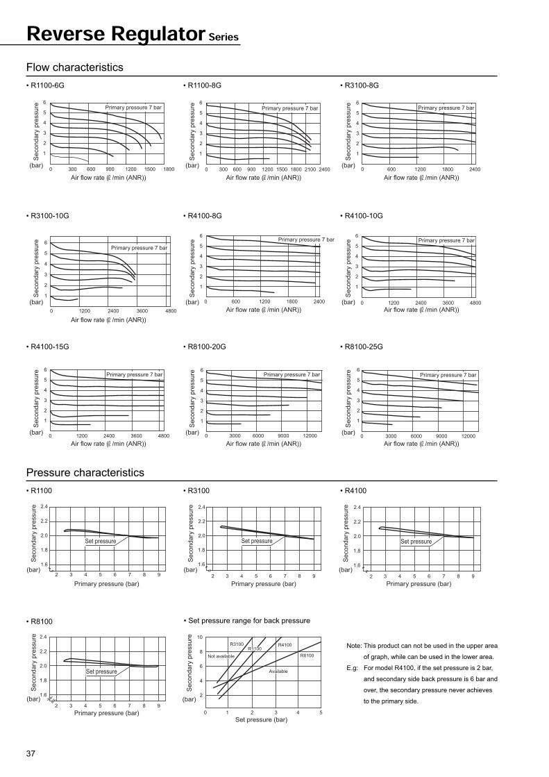
Reverse Regulator Series
Flow characteristics
• R1100-6G • R1100-8G • R3100-8G
• R3100-10G • R4100-8G • R4100-10G
• R4100-15G • R8100-20G • R8100-25G
Pressure characteristics
• R1100 • R3100 • R4100
• R8100 • Set pressure range for back pressure
Note: This product can not be used in the upper area
of graph, while can be used in the lower area.
E.g: For model R4100, if the set pressure is 2 bar,
and secondary side back pressure is 6 bar and
over, the secondary pressure never achieves
to the primary side.
15001200900600 1800
5
6
4
3
2
3000
1
24001800 21001500900 1200
5
6
4
3
2
300 6000
1
240018001200600
6
5
4
3
2
0
1
6
5
4
3
1
2
0 1200 2400 3600 4800
240018001200600
6
5
4
3
2
0
1
4800360024001200
6
5
4
3
2
0
1
4800360024001200
6
5
4
3
2
0
1
6
5
3
2
0
1
4
3000 6000 9000 12000 90006000 12000
6
5
3
2
0
1
4
3000
Air flow rate ( /min (ANR)) Air flow rate ( /min (ANR)) Air flow rate ( /min (ANR))
Air flow rate ( /min (ANR))
Air flow rate ( /min (ANR)) Air flow rate ( /min (ANR))
Air flow rate ( /min (ANR)) Air flow rate ( /min (ANR)) Air flow rate ( /min (ANR))
Primary pressure 7 bar Primary pressure 7 bar Primary pressure 7 bar
Primary pressure 7 bar Primary pressure 7 bar Primary pressure 7 bar
Primary pressure 7 bar
Primary pressure 7 bar Primary pressure 7 bar
Secondary
pre
ssure
(bar)
Secondary
pre
ssure
(bar)
Secondary
pre
ssure
(bar)
Secondary
pre
ssure
(bar)
Secondary
pre
ssure
(bar)
Secondary
pre
ssure
(bar)
Secondary
pre
ssure
(bar)
Secondary
pre
ssure
(bar)
Secondary
pre
ssure
(bar)
2
2.2
2.0
1.8
1.6
3 4 5 6 7 8 9
2.4
986 754
2.4
2.2
2.0
1.8
1.6
32 986 754
2.4
2.2
2.0
1.6
1.8
32
986 7543
2.0
2.2
2.4
1.8
1.6
2
Set pressure
Set pressure Set pressure
Primary pressure (bar)
Secondary
pre
ssure
(bar)
Primary pressure (bar)
Seconda
ry p
ressu
re
(bar)
Set pressure
Primary pressure (bar)
Seconda
ry p
ressu
re
(bar)
Primary pressure (bar)
Seconda
ry p
ressu
re
(bar)
542 310
6
8
10
4
2
Set pressure (bar)
Secondary
pre
ssure
(bar)
R8100
R4100R3100
Not available
Available
R1100
Please contact CKD for 2000 and 6000 series. 38
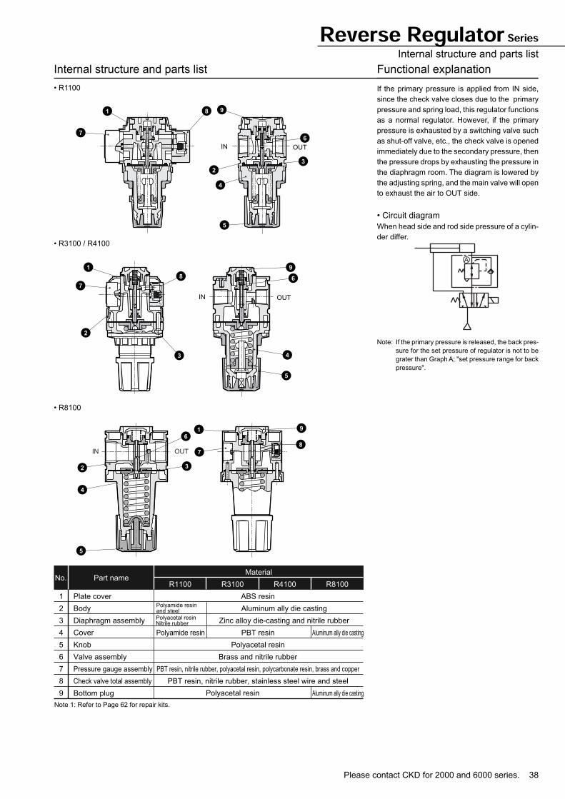
Reverse Regulator SeriesInternal structure and parts list
Internal structure and parts list
• R1100
• R8100
Part nameNo.R1100 R3100 R4100 R8100
Material
1
2
3
4
5
6
7
8
9
Plate cover
Body
Diaphragm assembly
Cover
Knob
Valve assembly
Pressure gauge assembly
Check valve total assembly
Bottom plug
ABS resin
PBT resin
Polyacetal resin
Brass and nitrile rubber
PBT resin, nitrile rubber, polyacetal resin, polycarbonate resin, brass and copper
PBT resin, nitrile rubber, stainless steel wire and steel
Aluminum ally die casting
Zinc alloy die-casting and nitrile rubber
Polyamide resin Aluminum ally die casting
Aluminum ally die castingPolyacetal resin
Polyamide resin and steel
Polyacetal resinNitrile rubber
Note 1: Refer to Page 62 for repair kits.
Functional explanation
If the primary pressure is applied from IN side,
since the check valve closes due to the primary
pressure and spring load, this regulator functions
as a normal regulator. However, if the primary
pressure is exhausted by a switching valve such
as shut-off valve, etc., the check valve is opened
immediately due to the secondary pressure, then
the pressure drops by exhausting the pressure in
the diaphragm room. The diagram is lowered by
the adjusting spring, and the main valve will open
to exhaust the air to OUT side.
• Circuit diagram
When head side and rod side pressure of a cylin-
der differ.• R3100 / R4100
Note: If the primary pressure is released, the back pres-
sure for the set pressure of regulator is not to be
grater than Graph A; "set pressure range for back
pressure".
1 9
2
4
5
8
6
3
7
IN OUT
1
7
2
3
8
9
6
4
5
IN OUT
2
61 9
8
7
3
4
5
IN OUT
A
39
Reverse Regulator Series
Dimensions
• R1100
• R3100
Attachment (C type bracket) Attachment (L type bracket)
Panel cut dimension
Attachment (C type bracket) Attachment (L type bracket)
Panel cut dimension
Note 1: Non-rotating fixing can be done by M4 screw. Screw length is to be plate thickness + 8mm or less,
and can be screwed in without female thread machining.
83
40
36 40
40
2
2
Tube center
Port size
G1/8(6G)G1/4(8G)
IN
24.5 35
43.5
53.5452
9
Dimensions when operating knobs
68.5
2.5
OUT
For optional attachment(Refer to Intro 3)
36.5
26.5
dia.
Panel plate thickness: Max. 6mm
68
4410
6.5
35
43.5
Tube center68
4410
6.5
45
53.5
Tube center
63
IN
103
OUT 32.5
104
45
53.5
2.332 45
31.5 45
2.3
584
0
66.5
3
For optional attachment(Refer to Intro 3)
Dimensions when operating knobs
Port size
G1/4(8G)G3/8(10G)
67
34.5
16.5
7
53.5
45
Tube center IN OUT
67
34.5
16.5
7
66.558
Tube center
40 d
ia.
522-4.5 dia.
(Note 1)
Panel plate thickness: Max. 7mm
Please contact CKD for 2000 and 6000 series. 40
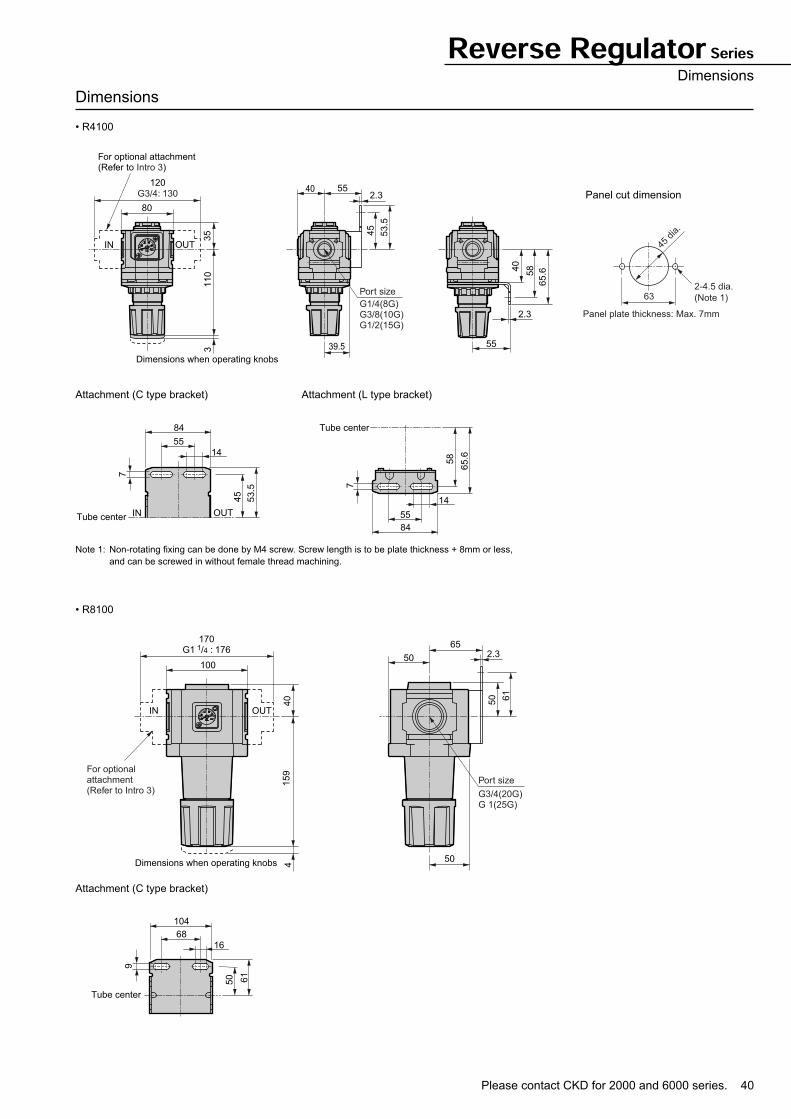
Reverse Regulator SeriesDimensions
Dimensions
• R4100
Attachment (C type bracket) Attachment (L type bracket)
Panel cut dimension
• R8100
Attachment (C type bracket)
Note 1: Non-rotating fixing can be done by M4 screw. Screw length is to be plate thickness + 8mm or less,
and can be screwed in without female thread machining.
80
IN
120
OUT
35
110
45
53.5
2.340 55
39.5 55
2.3
5840
65.6
3
For optional attachment(Refer to Intro 3)
Dimensions when operating knobs
Port size
G3/4: 130
G1/4(8G)G3/8(10G)G1/2(15G)
84
55
14
7
53.5
45
Tube center IN OUT
84
55
14
7
65.6
58
Tube center
45 d
ia.
632-4.5 dia.
(Note 1)
Panel plate thickness: Max. 7mm
2.365
50
50
100
170G1 1/4 : 176
159
40
4
For optional attachment(Refer to Intro 3)
50 61
Dimensions when operating knobs
IN OUT
Port size
G3/4(20G)G 1(25G)
104
68
Tube center
16
9
61
50
41
Model
L1000
L3000
L4000
L8000
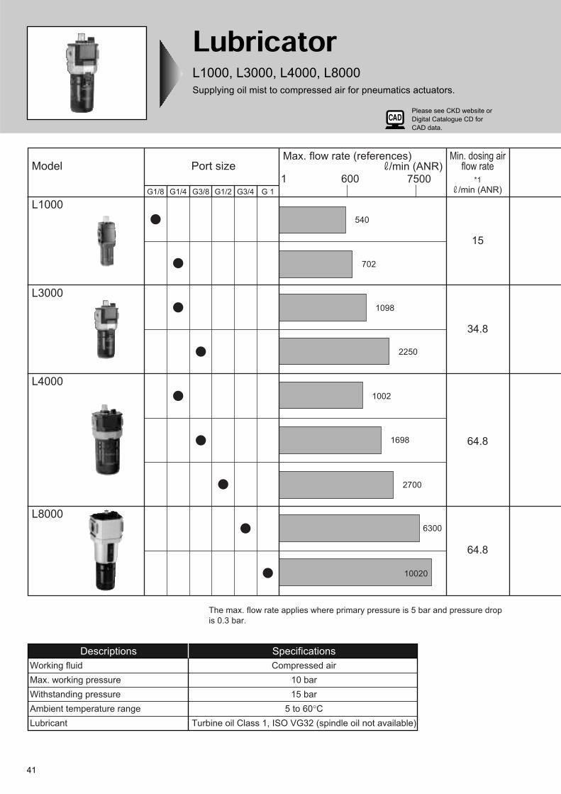
G1/8 G1/4 G3/8 G1/2 G3/4 G 1
Port size1 600 7500
Max. flow rate (references) /min (ANR)
540
702
1098
2250
1002
1698
2700
6300
10020
15
34.8
64.8
64.8
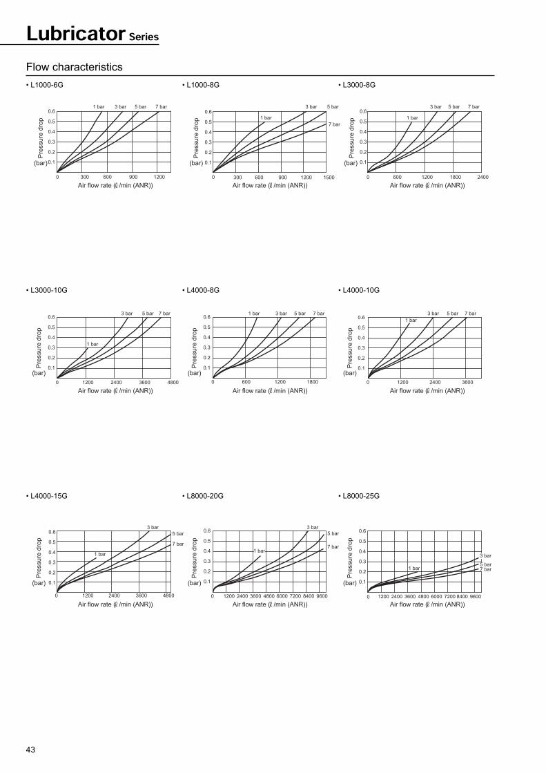
The max. flow rate applies where primary pressure is 5 bar and pressure drop
is 0.3 bar.
Min. dosing airflow rate
*1
/min (ANR)
Descriptions Specifications
Working fluid Compressed air
Max. working pressure 10 bar
Withstanding pressure 15 bar
Ambient temperature range 5 to 60°C
Lubricant Turbine oil Class 1, ISO VG32 (spindle oil not available)
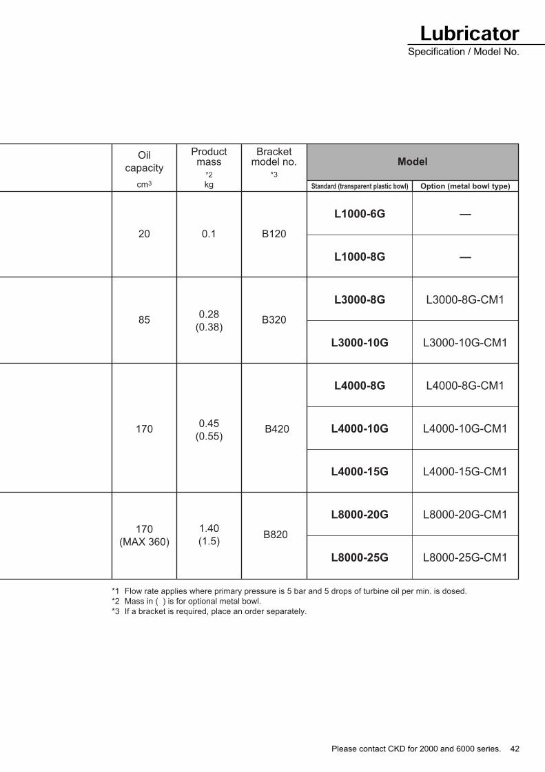
LubricatorL1000, L3000, L4000, L8000
Supplying oil mist to compressed air for pneumatics actuators.
Please see CKD website or
Digital Catalogue CD for
CAD data.
Please contact CKD for 2000 and 6000 series. 42
Oil
capacity
Productmass
cm3 kg Standard (transparent plastic bowl) Option (metal bowl type)
Model
20 0.1 B120
L1000-6G
L1000-8G
L3000-8G
L3000-10G
L4000-8G
L4000-10G
L4000-15G
L8000-20G
L8000-25G
—
—
L3000-8G-CM1
L3000-10G-CM1
L4000-8G-CM1
L4000-10G-CM1
L4000-15G-CM1
L8000-20G-CM1
L8000-25G-CM1
850.28
(0.38)B320
1700.45
(0.55)B420
170
(MAX 360)
1.40
(1.5)B820
*1 Flow rate applies where primary pressure is 5 bar and 5 drops of turbine oil per min. is dosed.
*2 Mass in ( ) is for optional metal bowl.
*3 If a bracket is required, place an order separately.
*2
Bracketmodel no.
*3
LubricatorSpecification / Model No.
43
Flow characteristics
• L1000-6G • L1000-8G • L3000-8G
• L3000-10G • L4000-8G • L4000-10G
• L4000-15G • L8000-20G • L8000-25G
Lubricator Series
Air flow rate ( /min (ANR)) Air flow rate ( /min (ANR)) Air flow rate ( /min (ANR))
Air flow rate ( /min (ANR)) Air flow rate ( /min (ANR)) Air flow rate ( /min (ANR))
Air flow rate ( /min (ANR)) Air flow rate ( /min (ANR)) Air flow rate ( /min (ANR))
Pre
ssure
dro
p
(bar)
Pre
ssure
dro
p
(bar)
Pre
ssure
dro
p
(bar)
Pre
ssure
dro
p
(bar)
Pre
ssure
dro
p
(bar)
Pre
ssure
dro
p
(bar)
Pre
ssure
dro
p
(bar)
Pre
ssure
dro
p
(bar)
Pre
ssure
dro
p
(bar)
7 bar5 bar3 bar1 bar
1200900600
0.6
0.5
0.4
0.3
0.2
3000
0.1
5 bar
7 bar
3 bar
1 bar
15001200900600
0.6
0.5
0.4
0.3
0.2
3000
0.1
5 bar
1 bar
3 bar 7 bar
240018001200600
0.6
0.5
0.4
0.3
0.2
0
0.1
5 bar3 bar 7 bar
48003600
1 bar
24001200
0.6
0.5
0.4
0.3
0.2
0
0.1
7 bar5 bar1 bar 3 bar
18001200600
0.6
0.5
0.4
0.3
0.2
0
0.1
7 bar5 bar3 bar
1 bar
360024001200
0.6
0.5
0.4
0.3
0.2
0
0.1
3 bar
5 bar
4800360024001200
7 bar
1 bar
0.6
0.5
0.4
0.3
0.2
0
0.1
0.6
0.5
0.3
0.2
0.1
0.4
5 bar
7 bar
3 bar
96007200600048002400 3600 840012000
3 bar
5 bar7 bar
960072006000
1 bar
48002400 3600 8400
0.6
0.4
0.5
0.3
0.2
12000
0.1
1 bar
Please contact CKD for 2000 and 6000 series. 44
Lubricator SeriesInternal structure and parts list
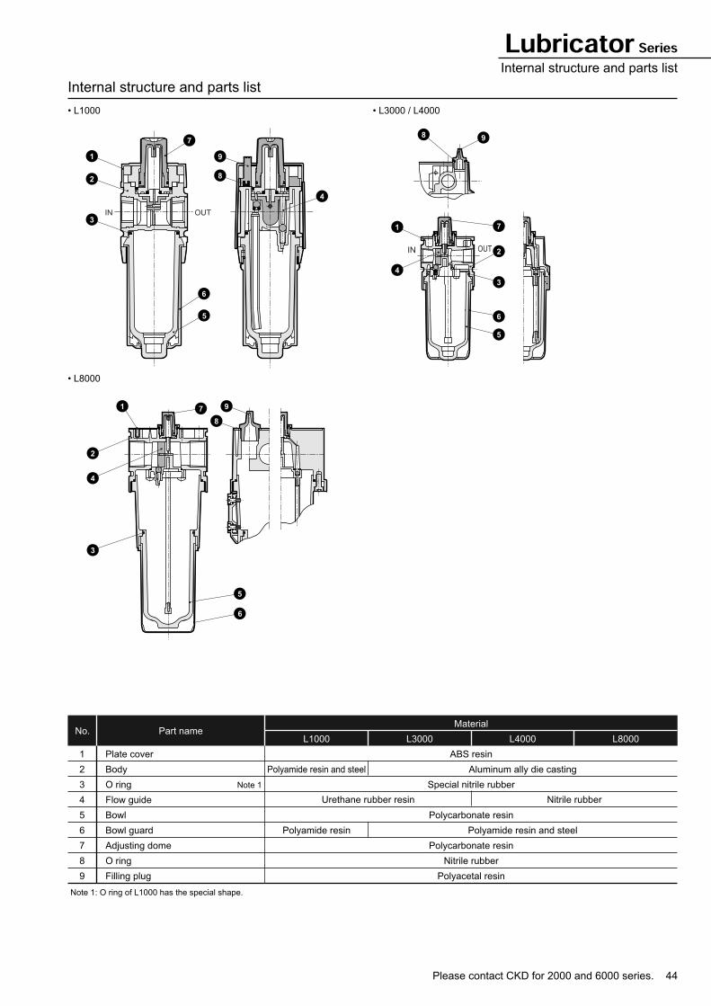
Internal structure and parts list
• L1000 • L3000 / L4000
• L8000
Part nameNo.L1000 L3000 L4000 L8000
Material
1
2
3
4
5
6
7
8
9
Plate cover
Body
O ring
Flow guide
Bowl
Bowl guard
Adjusting dome
O ring
Filling plug
Note 1: O ring of L1000 has the special shape.
ABS resin
Special nitrile rubber
Polycarbonate resin
Polycarbonate resin
Nitrile rubber
Polyacetal resin
Aluminum ally die casting
Polyamide resin and steel
Polyamide resin and steel
Polyamide resin
Note 1
Nitrile rubberUrethane rubber resin
1
2
3
9
8
6
4
7
5
IN OUT
8 9
71
4
2
3
6
5
IN OUT
2
1 9
8
4
3
5
7
6
45
Lubricator Series
Dimensions
• L1000
• L3000
40
(45)
83
21.5 2
4021.5
65
88
For optional attachment(Refer to Intro 3)
Port size
G1/8(6G)G1/4(8G)
OUTIN
Maintenance dimension
68
4410
6.5
35
43.5
31.5
34.5 45
(46)
123.5
90
45 53.5
2.363
103
For optional attachment(Refer to Intro 3)
Port size
Maintenance dimension
OUTIN
G1/4(8G)G3/8(10G)
IN OUT
67
34.5
16.5
7
53.5
45
Attachment
(C type bracket)
Attachment
(C type bracket)
Note: In attachments, C type
bracket and piping adapter
set can not be used together.
Note: In attachments, C type
bracket and piping adapter
set can not be used together.
Please contact CKD for 2000 and 6000 series. 46
Lubricator SeriesDimensions
Dimensions
• L4000
• L8000
Note: In attachments, C type bracket and piping adapter set can not be used together.
39.5
42.5 55
(47
)1
49
11
5
45 53
.5
2.380
120
For optional attachment(Refer to Intro 3)
Port size
Maintenance dimension
OUTIN
G1/4(8G)G3/8(10G)G1/2(15G)
G3/4: 130
IN OUT
84
55
14
7
53.5
45
2.3
50 65170G1 1/4 : 176
54
228
115
50 6
1
50100
For optional attachment(Refer to Intro 3)
G3/4(20G)G1(25G)
OUTIN
Maintenance dimension
Port size
104
68
16
9
61
50
Attachment
(C type bracket)
Attachment
(C type bracket)
Note: In attachments, C type
bracket and piping
adapter set can not be
used together.
Note: In attachments, C type
bracket and piping
adapter set can not be
used together.
Optional dimensions
• Metal bowl (option)
(L3000·4000·8000)
PRESSTURN
Pipe center
A
Model
L3000
L4000
L8000
A
154
177
255
47
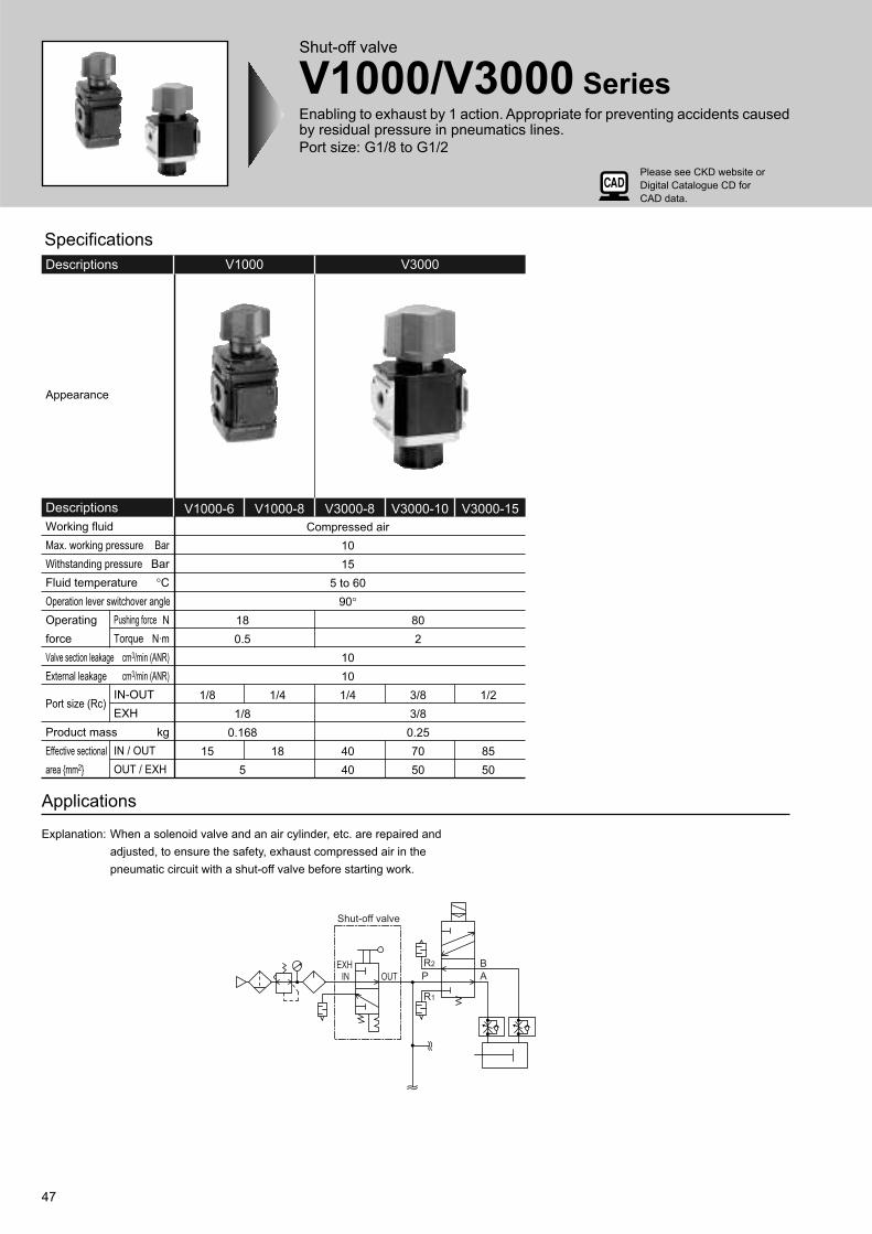
Shut-off valve
V1000/V3000 SeriesEnabling to exhaust by 1 action. Appropriate for preventing accidents causedby residual pressure in pneumatics lines.
Port size: G1/8 to G1/2
Applications
Explanation: When a solenoid valve and an air cylinder, etc. are repaired and
adjusted, to ensure the safety, exhaust compressed air in the
pneumatic circuit with a shut-off valve before starting work.
V1000 V3000Descriptions
V1000-6 V1000-8 V3000-8 V3000-10 V3000-15Descriptions
Appearance
Working fluid
Max. working pressure
Withstanding pressure
Fluid temperature
Operation lever switchover angle
Operating
force
Valve section leakage
External leakage
Port size (Rc)
Product mass
Effective sectional
area {mm2}
Pushing force
Torque
IN-OUT
EXH
IN / OUT
OUT / EXH
Compressed air
10
15
5 to 60
90°
10
10
1/4
40
40
18
0.5
1/8
0.168
5
1/8
15
1/4
18
80
2
3/8
3/8
0.25
70
50
1/2
85
50
Bar
Bar
°C
N
N·m
cm3/min (ANR)
cm3/min (ANR)
kg
Specifications
Shut-off valve
EXHIN OUT
R2
P A
B
R1
Please see CKD website or
Digital Catalogue CD for
CAD data.
Please contact CKD for 2000 and 6000 series. 48
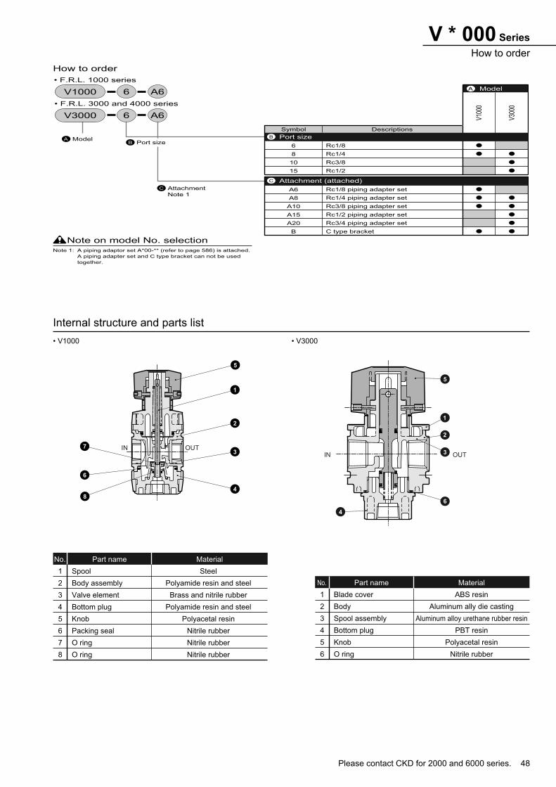
V * 000 Series
How to order
Internal structure and parts list
• V1000 • V3000
Symbol Descriptions
6
8
10
15
A6
A8
A10
A15
A20
B
Rc1/8
Rc1/4
Rc3/8
Rc1/2
Rc1/8 piping adapter set
Rc1/4 piping adapter set
Rc3/8 piping adapter set
Rc1/2 piping adapter set
Rc3/4 piping adapter set
C type bracket
V10
00
V30
00
Model
How to order
A
Attachment (attached) C
Port sizeBModelAPort sizeB
Attachment
Note 1
C
Note on model No. selectionNote 1: A piping adaptor set A*00-** (refer to page 586) is attached.
A piping adapter set and C type bracket can not be used
together.
6 A6V1000
6 A6V3000
• F.R.L. 1000 series
• F.R.L. 3000 and 4000 series
Part nameNo. Material
1
2
3
4
5
6
7
8
Spool
Body assembly
Valve element
Bottom plug
Knob
Packing seal
O ring
O ring
Steel
Polyamide resin and steel
Brass and nitrile rubber
Polyamide resin and steel
Polyacetal resin
Nitrile rubber
Nitrile rubber
Nitrile rubber
Part nameNo. Material
1
2
3
4
5
6
Blade cover
Body
Spool assembly
Bottom plug
Knob
O ring
ABS resin
Aluminum ally die casting
Aluminum alloy urethane rubber resin
PBT resin
Polyacetal resin
Nitrile rubber
IN OUT7
2
3
4
8
1
5
6
5
1
2
3
6
4
IN OUT
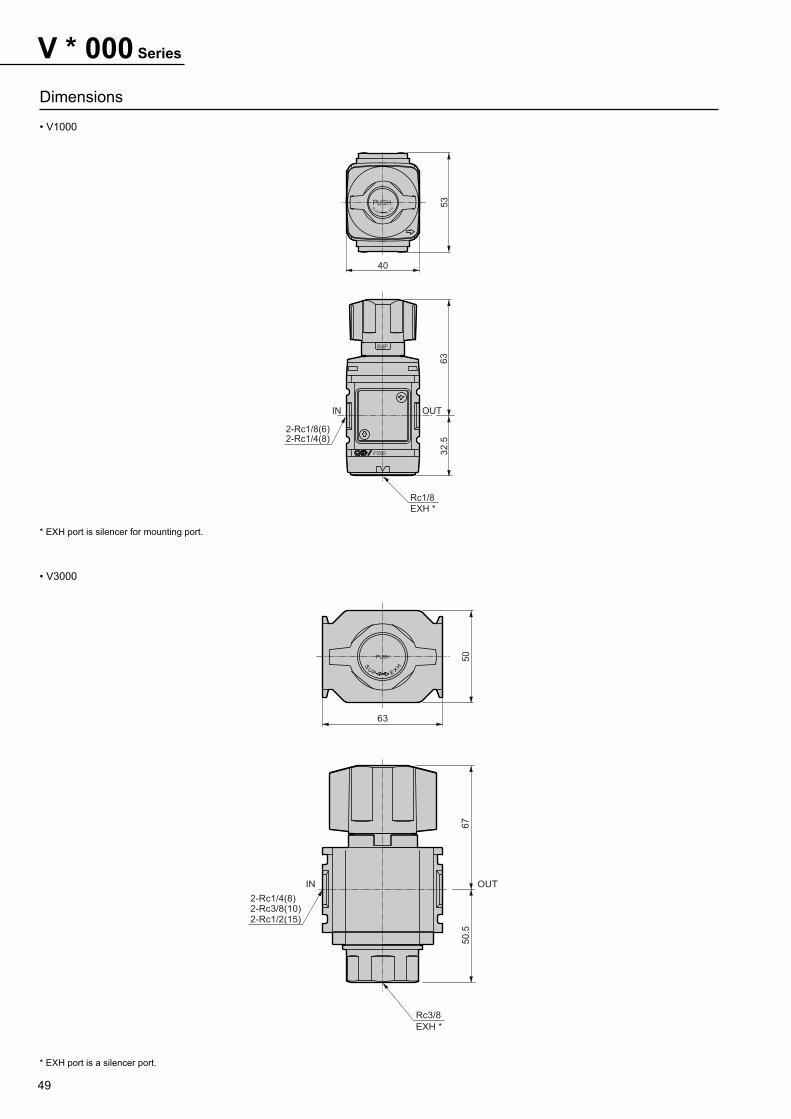
49
V * 000 Series
Dimensions
• V1000
• V3000
* EXH port is silencer for mounting port.
* EXH port is a silencer port.
V1000-
PUSH
S
E X
HUP
SUP
53
40
63
32.5
Rc1/8
EXH *
2-Rc1/8(6)2-Rc1/4(8)
IN OUT
PUSH
S
PU H
EX
50
63
67
50.5
Rc3/8
EXH *
2-Rc1/4(8)2-Rc3/8(10)2-Rc1/2(15)
IN OUT
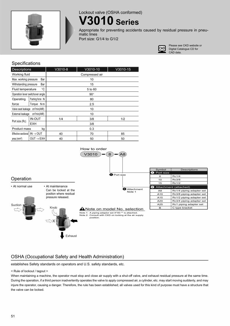
51
Lockout valve (OSHA conformed)
V3010 SeriesAppropriate for preventing accidents caused by residual pressure in pneu-matic lines
Port size: G1/4 to G1/2
Operation
• At normal use • At maintenance
Can be locked at theposition where residualpressure released.
OSHA (Occupational Safety and Health Administration)
establishes Safety standards on operators and U.S. safety standards, etc.
< Rule of lockout / tagout >
When maintaining a machine, the operator must stop and close air supply with a shut-off valve, and exhaust residual pressure at the same time.
During the operation, if a third person inadvertently operates the valve to apply compressed air, a cylinder, etc. may start moving suddenly, and may
injure the operator, causing a danger. Therefore, the rule has been established; all valves used for this kind of purpose must have a structure that
the valve can be locked.
V3010-8 V3010-10 V3010-15Descriptions
Working fluid
Max. working pressure
Withstanding pressure
Fluid temperature
Operation lever switchover angle
Operating
force
Valve seat leakage
External leakage
Port size (Rc)
Product mass
Effective sectional
area (mm2)
Pushing force
Torque
IN-OUT
EXH
IN → OUT
OUT → EXH
Compressed air
10
15
5 to 60
90°
80
2.5
10
10
3/8
3/8
0.3
70
50
1/4
40
40
1/2
85
50
Bar
Bar
°C
N
N·m
cm3/min(ANR)
cm3/min(ANR)
kg
Specifications
Symbol Descriptions
8
10
15
A8
A10
A15
A20
A25
B
Rc1/4
Rc3/8
Rc1/2
Rc1/4 piping adapter set
Rc3/8 piping adapter set
Rc1/2 piping adapter set
Rc3/4 piping adapter set
Rc1 piping adapter set
C type bracket
Attachment (attached) B
Port sizeA
Port sizeA
Attachment
Note 1
B
Note on model No. selectionNote 1: A piping adaptor set A*00-** is attached.
Note 2: Consult with CKD on locking at the air supply
position.
8 A8V3010
How to order
SuctionKnob
X
Exhaust
Please see CKD website or
Digital Catalogue CD for
CAD data.
Please contact CKD for 2000 and 6000 series. 52
Internal structure and parts list
Dimensions
• V3010 • With C type bracket
Part nameNo. Material
1
2
3
4
5
6
Plate cover
Body
Spool assembly
Bottom plug
Knob
O ring
ABS resin
Aluminum ally die casting
PBT resin
Aluminum ally die casting
Nitrile rubber
Aluminum alloy urethane rubber resin
Descriptions C
V3010-8
V3010-10
V3010-15
Rc1/4
Rc3/8
Rc1/2
* EXH port is a silencer port.
C type bracket is attached at shipment.
C type bracket and piping adapter set can not be used together.
5
1
2
6
4
3
IN OUT
SUP
PU
SH
SU
P
EXH
63
50
56
10 dia.
11
11
7.5
EXH Rc3/8
2-C
IN OUT
SUP
PU
SH
SU
P
EXH
634
5
10 dia.
C type bracket
11
7.52-A
IN OUT
67
51
1816.5 16.5
7
45
EXH Rc3/8
V3010 Series
53
Bracket
B SeriesJoiner
J Series
Model No.
B110
B310
B410
B810
Applicable model A B C D E F G H I J K
1000 series
3000 series
4000 series
8000 series
80
105
105
120
35
45
45
50
10
10
10
15
100
125
125
150
5.5
7
7
9
2
7
7
5
16
22
22
27
25
27
37
37
7
7
7
8
JASO-2013
JISB2401-P21
JISB2401-P21
AS568-127
40
45
55
65
Dimensions and applications
• ApplicationsT type bracket set
• Applications
• Model no.:J100 (C1000)
J400 (C3000 / C4000)
J800 (C8000)
Joiner set
Model No.
C1000-J100
C4000-J400
C8000-J800
Applicable model A B C D E
1000 series
3000 series
4000
8000 series
10
21
26
36
44
65
26
32
50
M3.5
M5
M6
JASO-2013
JIS
B2401-P21
AS568-127
• Applications
• Model no.: B130 / B330 / B430
• Attachment: B3
L type bracket
Model No.
B130
B330
B430
Applicable model A B C D E F G H I J Other
1000 series
3000 series
4000 series
44
34.5
55
68
67
84
10
16.5
14
6.5
7
7
16
18
18
24.5
26
26
45
58
(63.5)
58
40
45
55
59
76
94
26.5 dia.
40 dia.
47 dia.
Number in ( )is for
W3000 / 3100.
Loosen the mounting nut to remove the knob.
After inserting L type bracket, fix the bracket
by the mounting nut. Finally, press-fit the knob
by a hand from the top.
• Applications
• Model no.: B120 / B320 / B420 / B820
• Attachment: B
C type bracket
Model No.
B120
B320
B420
B820
Applicable model A B C D E F G H I J K L
1000 series
3000 series
4000 series
8000 series
44
34.5
55
68
68
67
84
104
40
63
80
100
t2.0
t2.3
t2.3
t2.3
10
16.5
14.0
16
6.5
7
7
9
35
45
45
50
8.5
9
9
11
61.5
75.5
75.5
93.5
40
45
55
65
14 dia.
21.7 dia.
21.7 dia.
35 dia.
60
69
69
102
I
C
A
B
D E
F
G
H
J
K(Wall s
urface)
(Center of port size)
A
B
CD
EF
G
H
I
J
K
L
(Inside dim
ension)
A
B
C
D
EF
G
HI
J
(Fro
m p
ort s
ize
cent
er)
A
B
C
D
E
Knob
Mounting nut
• Model no.: B110 / B310 / B410 / B810
Note: If 3000 series and 4000 series are
combined, use B410.This bracket has two holes on the
top and bottom to fix the device,
with the system upgrading device, to
a wall.
The 3000 Series and 4000 Series
are coupled using B410.
This bracket fixes independent parts
simply.
This bracket fixes parts
using the panel
mounting nut on the filter
regulator or regulator.
Use this as a joint when upgrading
the system.
The J400 is also used to couple the
3000 Series and 4000 Series.
Please see CKD website or
Digital Catalogue CD for
CAD data.
55
Distributor
D101/D401/D801 SeriesUse for pipe branch
Port size: G1/8 to G 1
1/4, 3/8, 1/2
0.13
Compressed air
10
15
1
5 to 60
3/4, 1
0.35
1/8, 1/4
0.045
Specifications
Descriptions
Working fluid
Max. working pressure
Withstanding pressure
Branch no. of port
Port size
Working temperature
Product mass
bar
bar
G
°C
kg
D401-00 D801-00D101-00
How to order
Symbol Descriptions
D101
D401
D801
6G
8G
10G
15G
20G
25G
B11
B31
B41
B81
Distributor
Distributor
Distributor
G1/8
G1/4
G3/8
G1/2
G3/4
G 1
1000 series
3000 series
4000 series
8000 series
Port sizeB
T type bracketC
Model No .A
Model No .A
B Port size
T type bracketC
Note on model No. selectionNote 1. A joiner set (joiner / bolt / O ring) and a
gasket are attached as standard.
Note 2. Consult with CKD for 2 way branch.
Note 3. D401 can be connected to both 3000 and
4000 series.
00 6GD101 B11
D101 D401 D801
Assembly method (D101-00, D401-00 and D801-00)
Note 1: When installing at the
primary side, insert an
O ring, while installing
at the secondary side,
insert a gasket.
Note 2: When inserting O ring
and gasket to as-
semble, O ring and
gasket must not be
folded.
T type bracket
Port
O ring
Joiner
Gasket
Circuit
Applications (D101-00, D401-00 and D801-00)
Please see CKD website or
Digital Catalogue CD for
CAD data.
56
Note: Please consult with CKD for 2 way branch type. Note: Please consult with CKD for 2 way branch type.
Dimensions
• D101-00 • D401-00
• D801-00
Note: Please consult with CKD for 2 way branch type.
Top view
Front view Cross section A-A
Port size
G1/8(6G)
G1/4(8G)
40
28
36
A A
A A
50
31.5
30
Front view
G1/4(8G)
G3/8(10G)
G1/2(15G)
Port size
60
37.5
15
Top view Cross section A-A
A A
81
50
41
Front view
G3/4(20G)
G 1(25G)
Port size
86
53
20
Top view Cross section A-A
Auxiliary components (modular design)
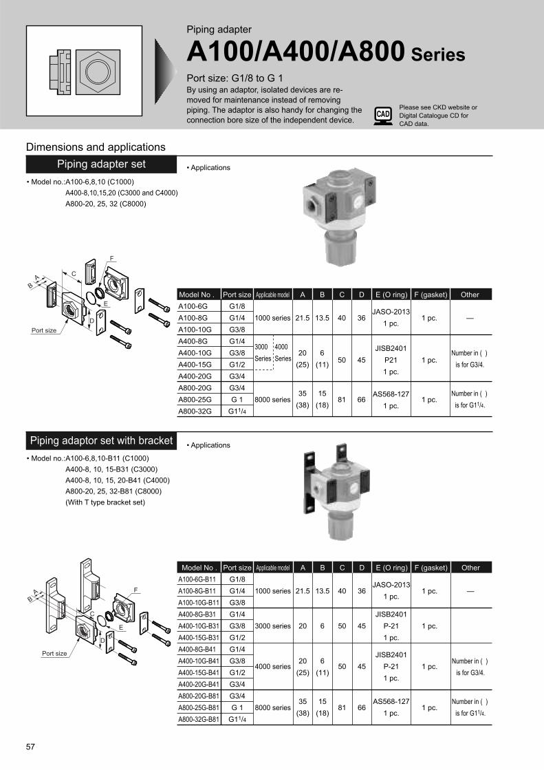
57
Dimensions and applications
• Applications
• Model no.:A100-6,8,10 (C1000)
A400-8,10,15,20 (C3000 and C4000)
A800-20, 25, 32 (C8000)
Piping adapter set
Piping adapter
A100/A400/A800 SeriesPort size: G1/8 to G 1By using an adaptor, isolated devices are re-
moved for maintenance instead of removing
piping. The adaptor is also handy for changing the
connection bore size of the independent device.
Model No .
A100-6G
A100-8G
A100-10G
A400-8G
A400-10G
A400-15G
A400-20G
A800-20G
A800-25G
A800-32G
Applicable modelPort size BA C D E (O ring) F (gasket) Other
1000 series
3000 4000
Series Series
8000 series
G1/8
G1/4
G3/8
G1/4
G3/8
G1/2
G3/4
G3/4
G 1
G11/4
21.5
20
(25)
35
(38)
13.5
6
(11)
15
(18)
40
50
81
36
45
66
JASO-2013
1 pc.
JISB2401
P21
1 pc.
AS568-127
1 pc.
1 pc.
1 pc.
1 pc.
—
Number in ( )
is for G3/4.
Number in ( )
is for G11/4.
• Applications
• Model no.:A100-6,8,10-B11 (C1000)
A400-8, 10, 15-B31 (C3000)
A400-8, 10, 15, 20-B41 (C4000)
A800-20, 25, 32-B81 (C8000)
(With T type bracket set)
Piping adaptor set with bracket
Model No .
A100-6G-B11
A100-8G-B11
A100-10G-B11
A400-8G-B31
A400-10G-B31
A400-15G-B31
A400-8G-B41
A400-10G-B41
A400-15G-B41
A400-20G-B41
A800-20G-B81
A800-25G-B81
A800-32G-B81
Applicable modelPort size BA C D E (O ring) F (gasket) Other
1000 series
3000 series
4000 series
8000 series
G1/8
G1/4
G3/8
G1/4
G3/8
G1/2
G1/4
G3/8
G1/2
G3/4
G3/4
G 1
G11/4
21.5
20
20
(25)
35
(38)
13.5
6
6
(11)
15
(18)
40
50
50
81
36
45
45
66
JASO-2013
1 pc.
JISB2401
P-21
1 pc.
JISB2401
P-21
1 pc.
AS568-127
1 pc.
1 pc.
1 pc.
1 pc.
1 pc.
—
Number in ( )
is for G3/4.
Number in ( )
is for G11/4.
A
D
C
Port size
F
E
B
F
E
D
C
Port size
AB
Please see CKD website or
Digital Catalogue CD for
CAD data.
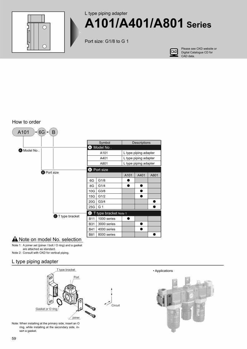
59
L type piping adapter
A101/A401/A801 Series
Port size: G1/8 to G 1
How to order
L type piping adapter
• Applications
Note: When installing at the primary side, insert an O
ring, while installing at the secondary side, in-
sert a gasket.
6G
8G
10G
15G
20G
25G
B11
B31
B41
B81
G1/8
G1/4
G3/8
G1/2
G3/4
G 1
1000 series
3000 series
4000 series
8000 series
A101 A401 A801
Symbol Descriptions
A101
A401
A801
L type piping adapter
L type piping adapter
L type piping adapter
Port sizeB
T type bracket Note 1C
Model No .A
Model No .A
B Port size
T type bracketC
Note on model No. selectionNote 1: A joiner set (joiner / bolt / O ring) and a gasket
are attached as standard.
Note 2: Consult with CKD for vertical piping.
6GA101 B
T type bracket
Gasket or O ring
joiner
Port
Circuit
Please see CKD website or
Digital Catalogue CD for
CAD data.
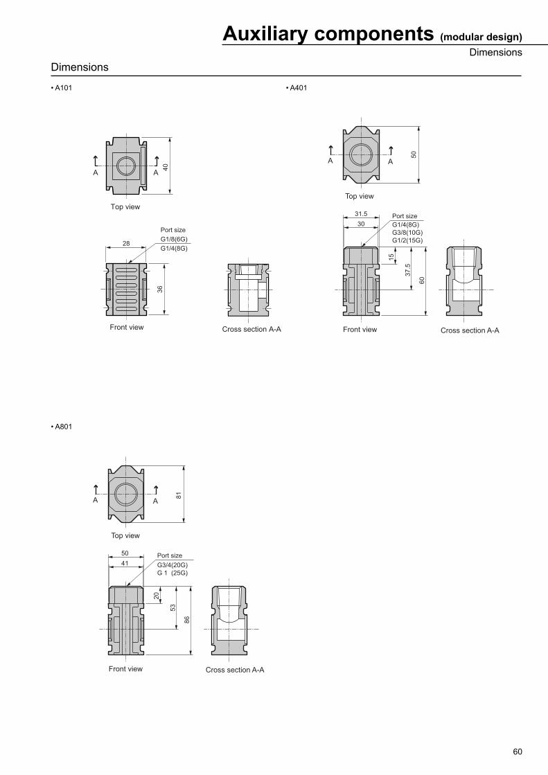
60
Dimensions
• A101 • A401
• A801
Top view
40
28
36
AA
Front view Cross section A-A
Port size
G1/8(6G)
G1/4(8G)
G1/4(8G)
G3/8(10G)
G1/2(15G)
A A
50
31.5
30
Top view
Port size
60
37.5
15
Front view Cross section A-A
A A
81
50
41
Top view
Port size
86
53
20
Front view Cross section A-A
G3/4(20G)
G 1 (25G)
Auxiliary components (modular design)
Dimensions
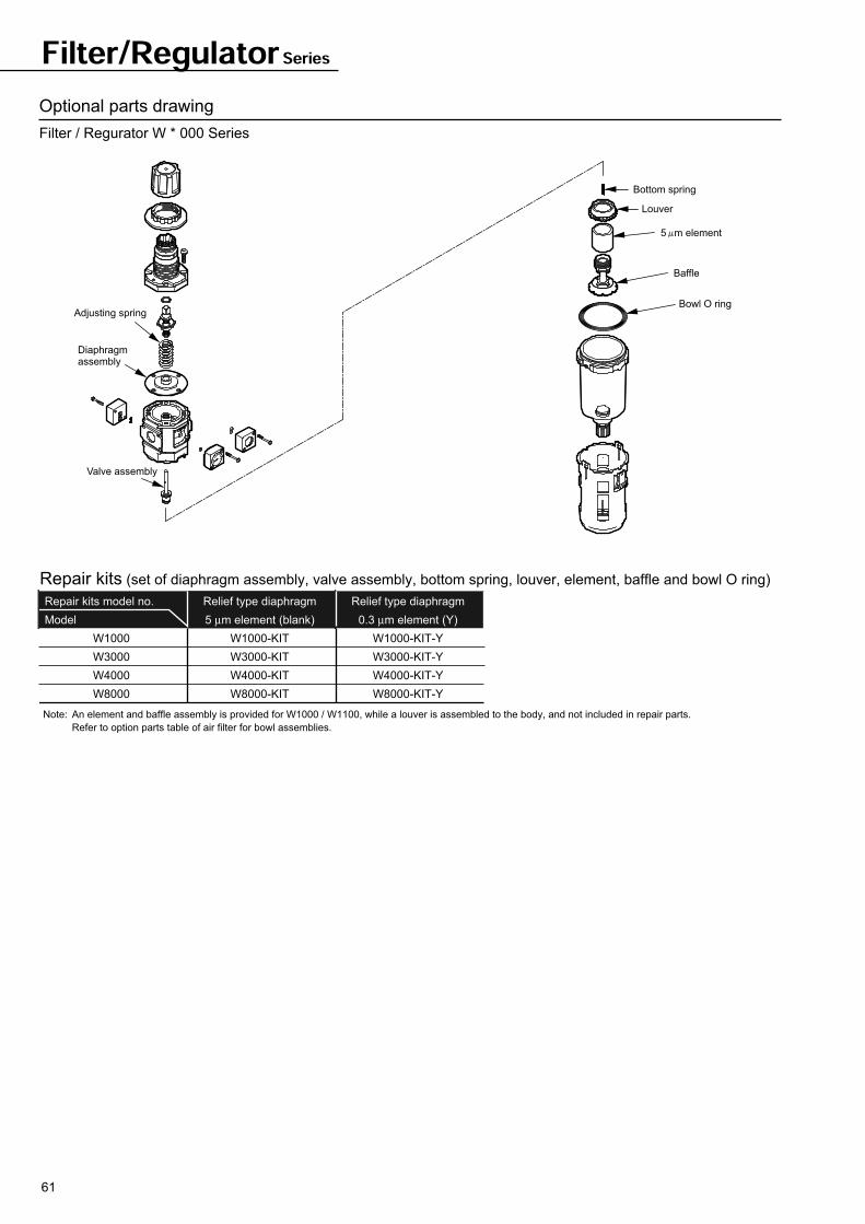
61
Filter/Regulator Series
Optional parts drawing
Filter / Regurator W * 000 Series
Repair kits model no.
Model
W1000
W3000
W4000
W8000
Relief type diaphragm
0.3 µm element (Y)
W1000-KIT-Y
W3000-KIT-Y
W4000-KIT-Y
W8000-KIT-Y
Relief type diaphragm
5 µm element (blank)
W1000-KIT
W3000-KIT
W4000-KIT
W8000-KIT
Repair kits (set of diaphragm assembly, valve assembly, bottom spring, louver, element, baffle and bowl O ring)
Note: An element and baffle assembly is provided for W1000 / W1100, while a louver is assembled to the body, and not included in repair parts.
Refer to option parts table of air filter for bowl assemblies.
Bottom spring
Louver
Baffle
Bowl O ring
5 m element
Adjusting spring
Diaphragmassembly
Valve assembly
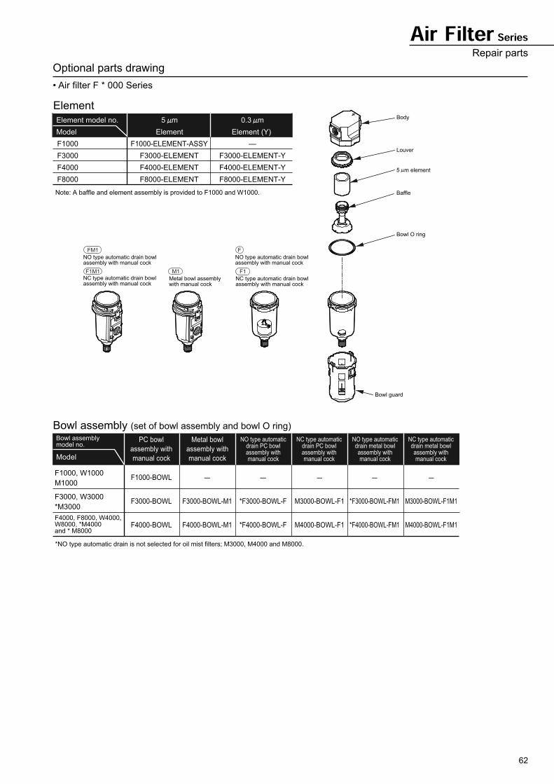
62
Body
Louver
5 m element
Baffle
Bowl O ring
Bowl guard
NO type automatic drain bowl assembly with manual cock
NC type automatic drain bowl assembly with manual cock
Metal bowl assembly with manual cock
FM1
NO type automatic drain bowl assembly with manual cock
NC type automatic drain bowl assembly with manual cock
F1F1M1 M1
F
Air Filter SeriesRepair parts
Optional parts drawing
• Air filter F * 000 Series
Element model no.
Model
F1000
F3000
F4000
F8000
5 m
Element
F1000-ELEMENT-ASSY
F3000-ELEMENT
F4000-ELEMENT
F8000-ELEMENT
—
F3000-ELEMENT-Y
F4000-ELEMENT-Y
F8000-ELEMENT-Y
0.3 m
Element (Y)
Element
Note: A baffle and element assembly is provided to F1000 and W1000.
Model
F1000, W1000
M1000
F3000, W3000
*M3000
F4000, F8000, W4000, W8000, *M4000 and * M8000
PC bowl
assembly with
manual cock
Metal bowl
assembly with
manual cock
NO type automaticdrain PC bowlassembly withmanual cock
NC type automaticdrain PC bowlassembly withmanual cock
NO type automaticdrain metal bowlassembly withmanual cock
NC type automaticdrain metal bowlassembly withmanual cock
F1000-BOWL
F3000-BOWL
F4000-BOWL
—
F3000-BOWL-M1
F4000-BOWL-M1
—
*F3000-BOWL-F
*F4000-BOWL-F
—
M3000-BOWL-F1
M4000-BOWL-F1
—
*F3000-BOWL-FM1
*F4000-BOWL-FM1
—
M3000-BOWL-F1M1
M4000-BOWL-F1M1
Bowl assembly model no.
Bowl assembly (set of bowl assembly and bowl O ring)
*NO type automatic drain is not selected for oil mist filters; M3000, M4000 and M8000.
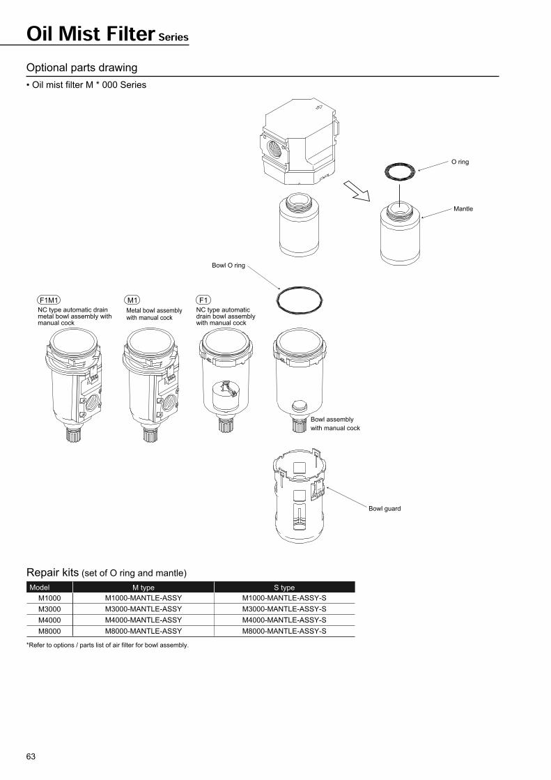
63
Oil Mist Filter Series
M1
Metal bowl assembly with manual cock
F1
NC type automatic drain bowl assembly with manual cock
*Refer to options / parts list of air filter for bowl assembly.
M1000
M3000
M4000
M8000
M1000-MANTLE-ASSY
M3000-MANTLE-ASSY
M4000-MANTLE-ASSY
M8000-MANTLE-ASSY
M1000-MANTLE-ASSY-S
M3000-MANTLE-ASSY-S
M4000-MANTLE-ASSY-S
M8000-MANTLE-ASSY-S
M type S typeModel
Repair kits (set of O ring and mantle)
TURNPRESS
PRESS
TURN
PRESS
TURN
F1M1
NC type automatic drain metal bowl assembly with manual cock
Bowl O ring
Bowl guard
O ring
Mantle
Bowl assembly
with manual cock
Optional parts drawing
• Oil mist filter M * 000 Series
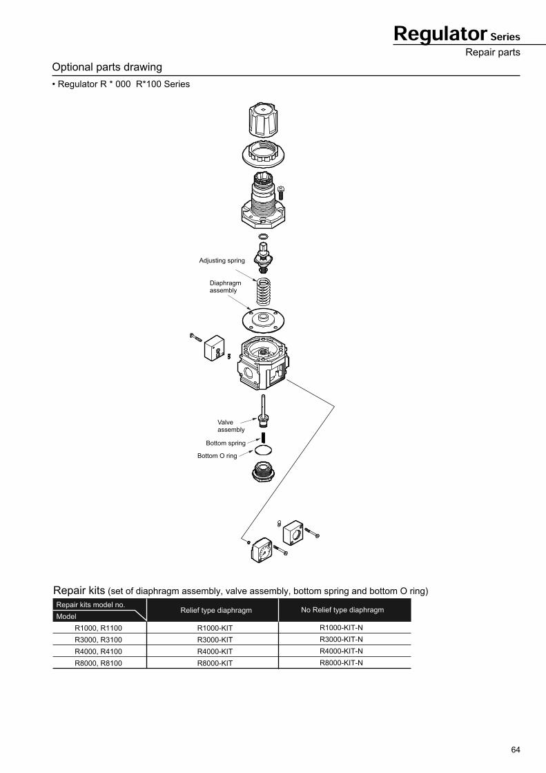
64
Regulator SeriesRepair parts
Optional parts drawing
• Regulator R * 000 R*100 Series
Repair kits model no.
Model
R1000, R1100
R3000, R3100
R4000, R4100
R8000, R8100
Relief type diaphragm
R1000-KIT
R3000-KIT
R4000-KIT
R8000-KIT
No Relief type diaphragm
R1000-KIT-N
R3000-KIT-N
R4000-KIT-N
R8000-KIT-N
Repair kits (set of diaphragm assembly, valve assembly, bottom spring and bottom O ring)
Bottom spring
Bottom O ring
Adjusting spring
Diaphragmassembly
Valveassembly
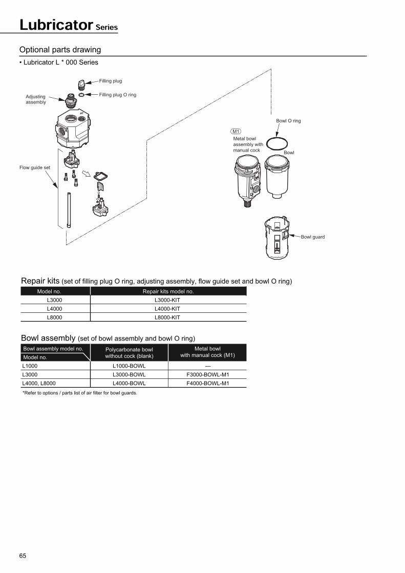
65
Optional parts drawing
• Lubricator L * 000 Series
Lubricator Series
Model no.
L3000
L4000
L8000
Repair kits model no.
L3000-KIT
L4000-KIT
L8000-KIT
Repair kits (set of filling plug O ring, adjusting assembly, flow guide set and bowl O ring)
Bowl assembly model no.
Model no.
L1000
L3000
L4000, L8000
Polycarbonate bowl
without cock (blank)
Metal bowl
with manual cock (M1)
L1000-BOWL
L3000-BOWL
L4000-BOWL
—
F3000-BOWL-M1
F4000-BOWL-M1
Bowl assembly (set of bowl assembly and bowl O ring)
*Refer to options / parts list of air filter for bowl guards.
TURN
PRESS
PRESS
TURN
Filling plug
Filling plug O ringAdjustingassembly
Flow guide set
Bowl O ring
M1
Metal bowl
assembly with
manual cockBowl
Bowl guard
67
Miniature regulator
RB500 SeriesCompact / space saving structure
Port size: Push-in joint 4 and 6 dia.
JIS symbol Please see CKD website or
Digital Catalogue CD for
CAD data.
Symbol Descriptions
Blank
P
L
N
T
Blank
Note 1
G39
P11
Standard
Option
S
L
S
L
C4
C6Port size
Direction IN
OUT
Standard products
Panel mount Note 2
For low pressure
Non-relief
Without pressure gauge
21dia. 0 to 10 Bar gauge
27 dia. 0 to 4 Bar gauge
27 dia. 0 to 10 Bar gauge
Ozone proof specifications (custom order)
Straight
Elbow
Straight
Elbow
4 dia.
6 dia.
How to order
AccessoryC
OptionB
ConnectionA
Model ConnectionA
AccessoryC
OptionB
SSC4 P G39RB500
Ozone proofD
Note on model No. selection
Note 1: 21 dia. 0 to 10 Bar pressure gauge is provided
as standard.
However for low pressure, 27 dia. 0 to 4 Bar low
pressure gauge is provided.
Note 2: For panel installation, indicate option symbol "P".
Compressed air
10
15
5 to 60
0.5 to 7 (Note 1)
With relief mechanism
Push-in joint: 4, 6 dia.
Rc1/8
80
Specifications
Descriptions
Working fluid
Max. working pressure
Withstanding pressure
Ambient temperature range
Set pressure range
Relief
Port size
Product mass
Note 1: 0.5 to 3.5 Bar for low pressure specifications.
IN-OUT
GAUGE
Bar
Bar
°C
Bar
g
RB500
Flow characteristics
• RB500-SSC4 • RB500-SSC6
4000 200 300
6
100
1
2
3
4
5
( /min ANR)
Primary pressure
7 Bar
Se
co
nd
ary
pre
ssu
re
(Bar)
Air flow rate
1
Air flow rate ( /min ANR)
4
3
2
5
4000 200 300
6
100(Bar)
Primary pressure
7 Bar
Se
co
nd
ary
pre
ssu
re
Pressure characteristics
3.0
2.5
2.0
2 4 6 8 10
Se
co
nd
ary
pre
ssu
re
(Bar)
Primary pressure (Bar)
Setting point
68
Internal structure and parts list
Dimensions
• RB500 axial piping Please see CKD website or Digital Catalogue CD for CAD data.
No. Parts name Material
1
2
3
4
5
6
7
8
9
10
11
12
13
14
15
16
Knob
Cover
Piston assembly
Piston guide
O ring
O ring
Body
Valve element
Pipe block assembly
Body packing seal
Packing seal
Stop pin
Gauge plug
Cartridge joint
Pressure gauge
Mounting nut
Polyacetal resin
Polyamide resin
Polyacetal resin / nitrile rubber
Polyacetal resin
Nitrile rubber
Nitrile rubber
Polyamide resin
Aluminum / nitrile rubber
Polyamide resin / steel
Nitrile rubber
Nitrile rubber
Stainless steel
Polyamide resin
Polyacetal resin
• RB500 elbows pipe Please see CKD website or Digital Catalogue CD for CAD data.
RB500 SeriesInternal structure and parts list
(47)
Push-in joint 4 and 6 dia.
IN-OUT port size
(Only for option symbol "P")
Mounting nut
Panel mount hole dimension 19 dia.
85
21.5
dia
.
9
8
41
27.5
45
11
25
32
1.8
(at a
djus
ting
pres
sure
)
22 dia.
42
Max. 4
35
39
8
Hexagon head across flats 24
4.5
dia.
A
D
C
Port size
F
E
B
(47)
85
44
[45
]
9
8
41
27.5
32
42
35
39
8
44
[45
]
36[40]
1.8
(at a
djus
ting
pres
sure
)
Ma
x.
4
22 dia.
4.5
dia.
(Only for option symbol "P")
Mounting nut
Hexagon head across flats 24
Panel mount hole dimension 19 dia.
Push-in joint 4 and 6 dia.
IN-OUT port size
21
.5 d
ia.
· Dimension in [ ] is for push-in joint 6 dia.
69
Specifications
Descriptions WB500
Bar
Bar
°C
m
Bar
cm3
IN-OUT
GAUGE
g
Working fluid
Max. working pressure
Withstanding pressure
Ambient temperature range
Filtration rating
Set pressure range
Relief
Drain capacity
Drainage method
Port size
Product mass
Compressed air
10
15
5 to 60
5
0.5 to 7 (Note 1)
With relief mechanism
1.0
Manual
Push-in joint: 4, 6 dia.
Rc1/8
100
Note 1: 0.5 Bar to 3.5 Bar for low pressure specifications
How to order
Features
• Compact
Push-in joint and bracket is integrated to
reduce total space.
• Light weight
Resin is used in body material to reduce
weight.
• Increased workability
Push-in joint is provided as standard. 2
types of piping direction; straight or
elbow are available. Plumbing is also
easy.
WB500 PSSC4 G39
B Option
C Accessory
Note on model No. selection
Note 1: Opaque material (nylon) as same as the body is applied.
Note 2: For 21 dia., 0 to 10 Bar pressure gauge is provided as standard.
If low pressure specifications, low pressure gauge with 0 to
4 Bar range for 27 dia. is provided.
Note 3: Select option symbol "P" for panel installation.
A
Connection (direction) : Straight for IN-OUT
Connection (port size) : 4 dia.
Option : Panel mount
Accessory : 27 dia. 0 to 1 Bar pressure gauge
[Example of model number]
WB500-SSC4-PG39
B
C
A
Connection
S
L
S
L
C4
C6
Blank
P
L
N
T
X1
Z
Blank
G39
Straight
Elbow
Straight
Elbow
4 dia.
6 dia.
Standard product
Panel mount Note 3
For low pressure
Non-relief
Without pressure gauge
IN-OUT reverse
Opaque drain plug Note 1
21 dia. 0 to 10 Bar gauge
27 dia. 0 to 4 Bar gauge
27 dia. 0 to 10 Bar gauge
ConnectionA
Symbol Descriptions
Direction
Port size
IN
OUT
AccessoryC
StandardNote 2
Option
OptionB
Small filter / regulator
WB500 Series
JIS symbolPlease see CKD website or
Digital Catalogue CD for
CAD data.
70
* Pipe cautions
• Do not use the product where organic solvent or chemicals, etc. are present in the atmosphere or adhered to the product.
• Avoid direct sun lay.
• Do not use the product where vibration or impact could occur.
• Install the product vertically facing the drain plug downward.
• Avoid using the product where large drain may be generated. If unavoidable, install an air dryer and automatic drain before IN port.
• Air-flush the air pipe carefully before connection.
• Use CKD soft nylon tube or urethane tube for piping material.
• Insert piping tube into push-in joint securely before starting use.
• If the pressure adjustment knob is rotated clockwise, the secondary pressure will increase, while rotated counterclockwise, the pressure will drop.
• Check the primary pressure before setting the pressure.
• When maintenance, stop the primary pressure, and release the residual pressure before starting work.
• When assembling a pressure gauge, tighten the gauge with tightening torque 3.5N·m or less.
Primary pressure 7 Bar
6
5
4
3
2
1
0 100 200 300 400
Secondary
pre
ssure
Air flow rate ( /min ANR)
(Bar)
Primary pressure 7 Bar
6
5
4
3
2
1
0 100 200 300 400
Secondary
pre
ssure
Air flow rate ( /min ANR)
(Bar)
Setting point
3.0
2.5
2.0
2 4 6 8 10
Se
co
nd
ary
pre
ssu
re
Primary pressure (Bar)
(Bar)
Flow characteristics
• WB500-**C4 • WB500-**C6
Pressure characteristics
• WB500
Precautions
WB500 SeriesFlow characteristics
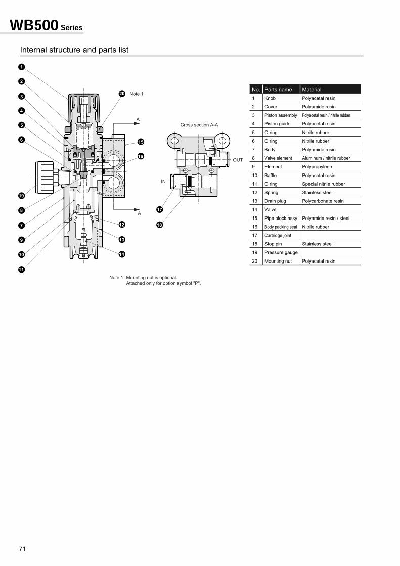
71
WB500 Series
No. Parts name Material
1
2
3
4
5
6
7
8
9
10
11
12
13
14
15
16
17
18
19
20
Knob
Cover
Piston assembly
Piston guide
O ring
O ring
Body
Valve element
Element
Baffle
O ring
Spring
Drain plug
Valve
Pipe block assy
Body packing seal
Cartridge joint
Stop pin
Pressure gauge
Mounting nut
Polyacetal resin
Polyamide resin
Polyacetal resin / nitrile rubber
Polyacetal resin
Nitrile rubber
Nitrile rubber
Polyamide resin
Aluminum / nitrile rubber
Polypropylene
Polyacetal resin
Special nitrile rubber
Stainless steel
Polycarbonate resin
Polyamide resin / steel
Nitrile rubber
Stainless steel
Polyacetal resin
Note 1: Mounting nut is optional.
Attached only for option symbol "P".
Note 1
Cross section A-A
A
A
OUT
IN
6
5
4
3
2
1
19
11
10
9
7
8
14
13
12 18
17
16
15
20
Internal structure and parts list
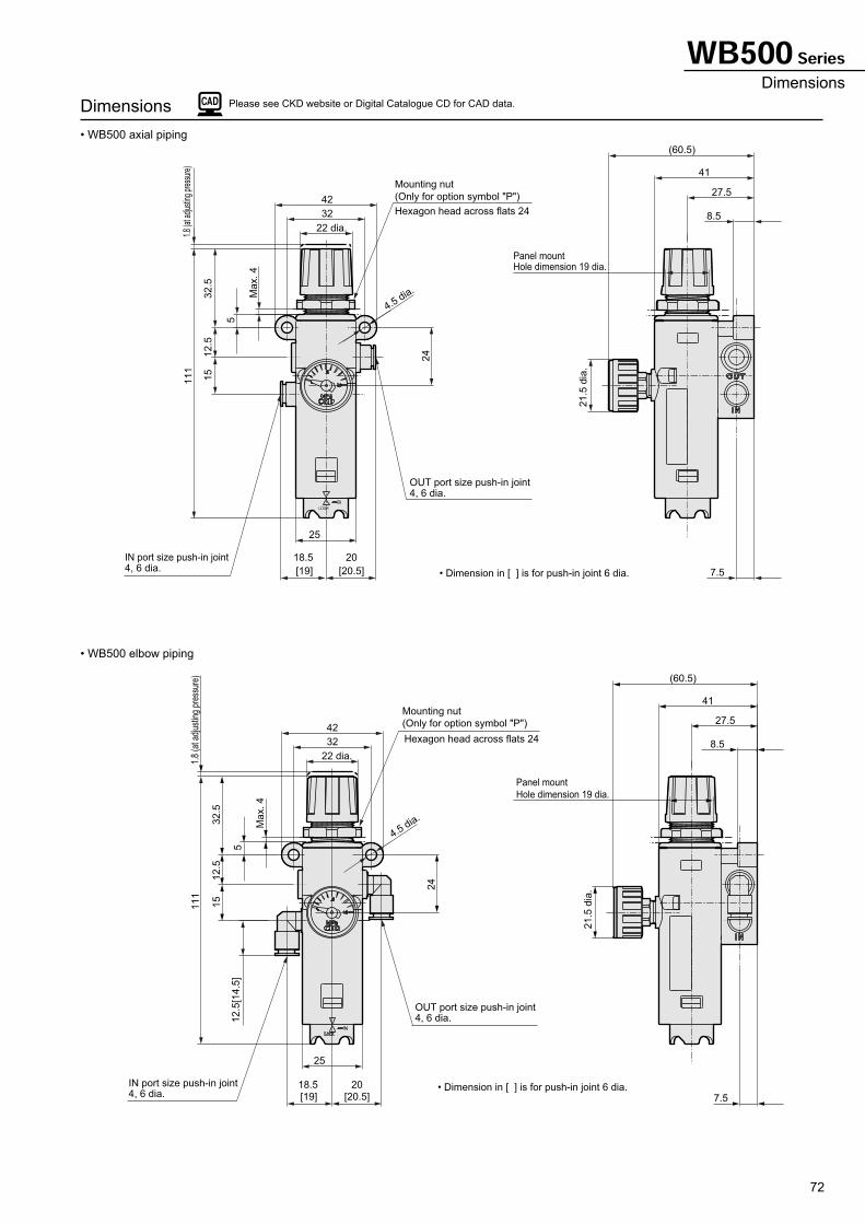
72
Dimensions
• WB500 axial piping
• WB500 elbow piping
Please see CKD website or Digital Catalogue CD for CAD data.
(Only for option symbol "P")
Mounting nut
Hole dimension 19 dia.Panel mount
4, 6 dia.OUT port size push-in joint
4, 6 dia.IN port size push-in joint
(60.5)
Max. 4
5
7.5
41
8.522 dia.
[20.5]
20
[19]
18.5
32.5
24
15
4.5 dia.
21.5
dia
.
27.5
25
111
12.5
32
42
1.8
(at a
djusti
ng p
ress
ure)
Hexagon head across flats 24
• Dimension in [ ] is for push-in joint 6 dia.
12
.5[1
4.5
]
Mounting nut
42
32
12
.5
11
1
25
4, 6 dia.IN port size push-in joint
4.5 dia.
15
24
32
.5
[19]
18.5
[20.5]
20
22 dia.
5
Ma
x.
4
4, 6 dia.OUT port size push-in joint
1.8
(at a
djus
ting
pres
sure
)
Hexagon head across flats 24
(Only for option symbol "P")
Hole dimension 19 dia.
Panel mount
27.5
21
.5 d
ia.
8.5
41
7.5
(60.5)
• Dimension in [ ] is for push-in joint 6 dia.
WB500 SeriesDimensions
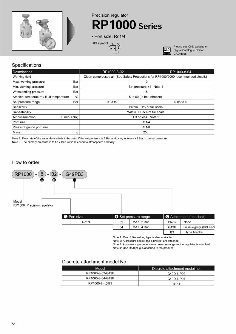
73
Precision regulator
RP1000 Series• Port size: Rc1/4
JIS symbol
Specifications
Descriptions
0.03 to 2 0.05 to 4
RP1000-8-02 RP1000-8-04
Clean compressed air (See Safety Precautions for RP1000/2000 recommended circuit.)
10
Set pressure +1 Note 1
15
-5 to 60 (to be unfrozen)
Within 0.1% of full scale
Within ± 0.5% of full scale
1.3 or less Note 2
Rc1/4
Rc1/8
250
Working fluid
Max. working pressure
Min. working pressure
Withstanding pressure
Ambient temperature / fluid temperature
Set pressure range
Sensitivity
Repeatability
Air consumption
Port size
Pressure gauge port size
Mass
Bar
Bar
Bar
°C
Bar
/ min(ANR)
g
Note 1. Flow rate of the secondary side is to be zero. If the set pressure is 3 Bar and over, increase +2 Bar in the set pressure.
Note 2. The primary pressure is to be 7 Bar. Air is released to atmosphere normally.
Discrete attachment model No.
Model Discrete attachment model no.
G49D-6-P02
G49D-6-P04
B131
How to order
RP1000 028 G49PB3
8 02
04
Blank
G49P
B3
Rc1/4 MAX. 2 Bar
MAX. 4 Bar
None
Pressure gauge (G49D-6-*)
L type bracket
Port sizeA Set pressure rangeB Attachment (attached) C
Model
RP1000: Precision regulator
A B C
RP1000-8-02-G49P
RP1000-8-04-G49P
RP1000-8-02-B304
Note 1: Max. 7 Bar setting type is also available.
Note 2: A pressure gauge and a bracket are attached.
Note 3: A pressure gauge as same pressure range as the regulator is attached.
Note 4: One R1/8 plug is attached to the product.
Please see CKD website or
Digital Catalogue CD for
CAD data.
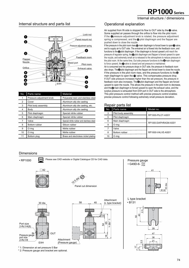
74
IN OUT
Panel cut dimension
EXH
* 1: Dimension at set pressure 0 Bar
* 2: Pressure gauge and bracket are optional.
12.5 d
ia.
65
54
18
42
9
Pressure gauge port size2-Rc1/8
Port size2-Rc1/4(8)
58 4030 dia.
Attachment
(Pressure gauge)
Attachment
(L type bracket)
5.5
28
36
47
50 4
0
2.3
111
7
21
43 d
ia.
41
R1/8
99
* 1
Internal structure and parts list
No.
1
2
3
4
5
6
7
8
9
10
11
Parts name
Pressure adjustment knob
Cover
Pilot body assembly
Body
Pilot diaphragm
Main diaphragm
Valve
Bottom rubber
O ring
O ring
Bottom plug
Material
Polyacetal resin and stainless steel
Aluminum ally die casting
Aluminum ally die casting, etc.
Aluminum ally die casting
Special nitrile rubber
Special nitrile rubber
Special nitrile rubber and stainless steel
Silicon rubber
Nitrile rubber
Nitrile rubber
Brass and electroless nickel plating
No.
3
5
6
9
7
8
10
Parts name
Pilot body assembly
Pilot diaphragm
Main diaphragm
O ring
Valve
Bottom rubber
O ring
Model no.
RP1000-PILOT-ASSY
RP1000-DIAPHRAGM-ASSY
RP1000-VALVE-ASSY
Repair parts list
Operational explanation
• RP1000 Pressure gauge
Dimensions
• G49D-6- P02P04
L type bracket
• B131
1
2
3
9
6
4
10
Orifice
Flapper
Nozzle
8
11
7
5
Pressure adjustment spring
Feedback room
Pilot room
Panel mount nut
Lock nut
Exhaust valve
IN
EXH
OUT
Bleed port
Air supplied from IN side is stopped its flow to OUT side by the valve.
Some supplied air passes through the orifice to flow into the pilot room.
If the pressure adjustment knob is rotated, the pressure adjustment
spring is compressed, and the pilot diaphragm and the flapper are
pushed down to close the nozzle.
If the pressure in the pilot room rises, main diaphragm is forced lower to open valve,
and to supply air to OUT side. The entrained air is flowed into the feedback room, and
functions to the pilot diaphragm. If the diaphragm is forced upward until reach the
pressure of regulator spring, the pilot diaphragm and flapper is forced upward to open
the nozzle, and extremely small air is released to the atmosphere to reduce pressure in
the pilot room. At the same time, Out side pressure functions to the main diaphragm
to force upward, the valve is closed and set pressure is maintained.
Air is consumed and the pressure drops in OUT side, the pressure in feedback room
also drops. The pilot diaphragm and the flapper are forced lower to close the nozzle.
If the pressure in the pilot room rises, and the pressure functions to the
main diaphragm to open the valve. This compensates pressure drop.
If OUT side pressure increases higher than the set pressure, the pressure in
feedback room also increases. The pilot diaphragm and the flapper are forced
upward to open the nozzle. This allows the pressure in the pilot room to decrease,
and the main diaphragm is forced upward to open the exhaust valve, and the
surplus pressure is exhausted from EXH port in OUT side to the atmosphere.
This pilot pressure control method with precise pressure control enables
precise pressure control following extremely small pressure deviation.
7
7
7
7
1
5
5
5
5
5
6
6
6
6
RP1000 SeriesInternal structure / dimensions
Please see CKD website or Digital Catalogue CD for CAD data.
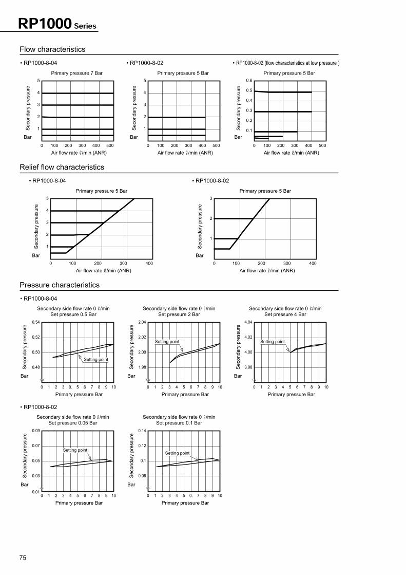
75
Flow characteristics
• RP1000-8-04
Relief flow characteristics
• RP1000-8-04 • RP1000-8-02
Pressure characteristics
• RP1000-8-04
• RP1000-8-02 • RP1000-8-02 (flow characteristics at low pressure )
0 100 200 300 400 500
1
2
3
4
5
1
2
3
4
5
Primary pressure 7 Bar
Air flow rate /min (ANR)
0 100 200 300 400 500
1
2
3
4
5
Primary pressure 5 Bar
Air flow rate /min (ANR)
0 100 200 300 400 500
0.1
0.2
0.3
0.4
0.5
0.6
Primary pressure 5 Bar
Air flow rate /min (ANR)
0.48
0 1 2 3 0. 5 6 7 98 10
0.50
0.52
0.54
Secondary side flow rate 0 /min
Set pressure 0.5 Bar
Primary pressure Bar
0 100 200 300 400
Primary pressure 5 Bar
Air flow rate /min (ANR)
3
0 100 200 300 400
1
2
Primary pressure 5 Bar
Air flow rate /min (ANR)
1.98
0 1 2 3 4 5 6 7 98 10
2.00
2.02
2.04
Secondary side flow rate 0 /min
Set pressure 2 Bar
Primary pressure Bar
3.98
0 1 2 3 4 5 6 7 98 10
4.00
4.02
4.04
Secondary side flow rate 0 /min
Set pressure 4 Bar
Primary pressure Bar
• RP1000-8-02
0.08
0 1 2 3 4 5 0. 7 98 10
0.1
0.12
0.14
Secondary side flow rate 0 /min
Set pressure 0.1 Bar
Primary pressure Bar
0.03
0.010 1 2 3 4 5 6 7 98 10
0.05
0.07
0.09
Secondary side flow rate 0 /min
Set pressure 0.05 Bar
Primary pressure Bar
Secondary
pre
ssure
BarS
econdary
pre
ssure
Bar
Secondary
pre
ssure
Bar
Secondary
pre
ssure
Bar
Secondary
pre
ssure
Bar
Secondary
pre
ssure
Bar
Secondary
pre
ssure
Bar
Secondary
pre
ssure
Bar
Secondary
pre
ssure
Bar
Secondary
pre
ssure
Bar
Setting point
Setting point Setting point
Setting pointSetting point
RP1000 Series
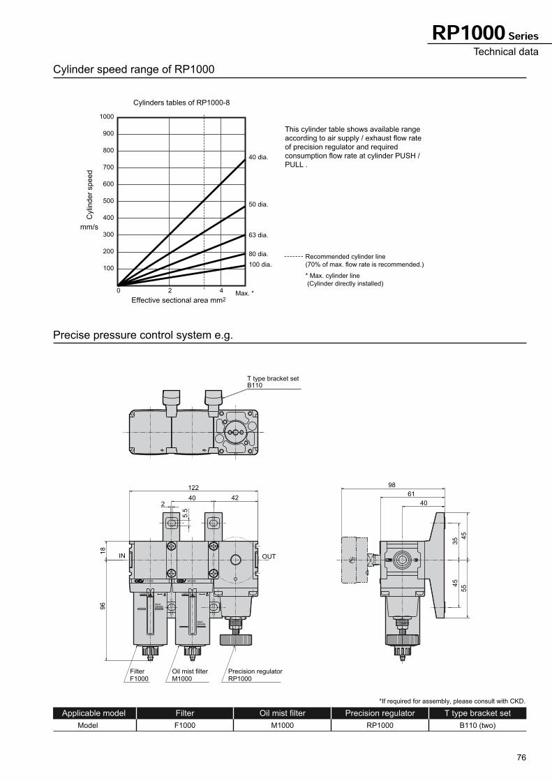
76
F1000- M1000-
MAX.DRAIN
MAX.DRAIN
IN OUT
2
5.5
18
96
40
45
35
55
45
40
61122
42
98
FilterF1000
Oil mist filterM1000
Precision regulatorRP1000
T type bracket setB110
Cylinder speed range of RP1000
100
200
300
400
500
600
700
800
900
1000
40 dia.
50 dia.
63 dia.
80 dia.
100 dia.
0 2 4
Cylinders tables of RP1000-8
Effective sectional area mm2
Precise pressure control system e.g.
Applicable model Filter
Model F1000
Oil mist filter
M1000
Precision regulator
RP1000
T type bracket set
B110 (two)
Recommended cylinder line
(70% of max. flow rate is recommended.)
* Max. cylinder line
(Cylinder directly installed)
*If required for assembly, please consult with CKD.
Max. *
Cylin
de
r sp
ee
d
mm/s
This cylinder table shows available range
according to air supply / exhaust flow rate
of precision regulator and required
consumption flow rate at cylinder PUSH /
PULL .
RP1000 SeriesTechnical data
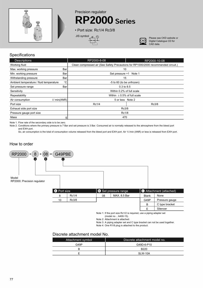
77
Precision regulator
RP2000 Series• Port size: Rc1/4 Rc3/8
JIS symbol
Specifications
Descriptions
Rc1/4 Rc3/8
RP2000-8-08 RP2000-10-08
Clean compressed air (See Safety Precautions for RP1000/2000 recommended circuit.)
10
Set pressure +1 Note 1
15
-5 to 60 (to be unfrozen)
0.3 to 8.5
Within 0.2% of full scale
Within ± 0.5% of full scale
5 or less Note 2
Rc3/8
Rc1/8
470
Working fluid
Max. working pressure
Min. working pressure
Withstanding pressure
Ambient temperature / fluid temperature
Set pressure range
Sensitivity
Repeatability
Air consumption
Port size
Exhaust side port size
Pressure gauge port size
Mass
Bar
Bar
Bar
°C
Bar
/ min(ANR)
g
Note 1. Flow rate of the secondary side is to be zero.
Note 2. Conditions where the primary pressure is 7 Bar and set pressure is 3 Bar. Consumed air is normally released to the atmosphere from the bleed port
and EXH port.
So, air consumption is the total of consumption volume released from the bleed port and EXH port. Air 1 /min (ANR) or less is released from EXH port.
Discrete attachment model No.
Attachment symbol Discrete attachment model no.
G49P
B
E
G49D-6-P10
B220
SLW-10A
How to order
RP2000 088 G49PBE
8
10
08 Blank
G49P
B
E
Rc1/4
Rc3/8
MAX. 8.5 Bar None
Pressure gauge
C type bracket
Silencer
Port sizeA Set pressure rangeB Attachment (attached) C
Model
RP2000: Precision regulator
A B C
Note 1: If the port size Rc1/2 is required, use a piping adapter set
(model no .: A400-15).
Note 2: Attachment is attached.
Note 3: A piping adapter set and C type bracket can not be used together.
Note 4: One R1/8 plug is attached to the product.
Please see CKD website or
Digital Catalogue CD for
CAD data.
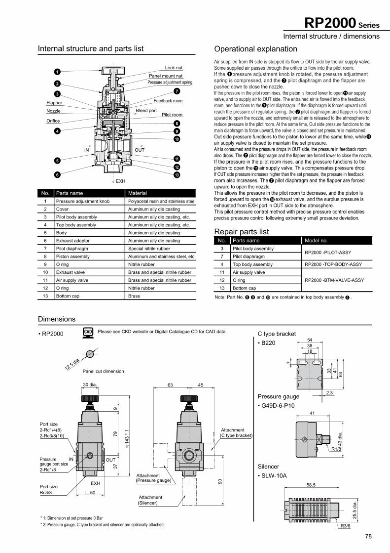
78
54
18
38
7
33 41
63
43 d
ia.
41
2.3
25.5
dia
.
58.5
Note: Part No. and are contained in top body assembly .
Internal structure and parts list
No.
1
2
3
4
5
6
7
8
9
10
11
12
13
Parts name
Pressure adjustment knob
Cover
Pilot body assembly
Top body assembly
Body
Exhaust adaptor
Pilot diaphragm
Piston assembly
O ring
Exhaust valve
Air supply valve
O ring
Bottom cap
Material
Polyacetal resin and stainless steel
Aluminum ally die casting
Aluminum ally die casting, etc.
Aluminum ally die casting, etc.
Aluminum ally die casting
Aluminum ally die casting
Special nitrile rubber
Aluminum and stainless steel, etc.
Nitrile rubber
Brass and special nitrile rubber
Brass and special nitrile rubber
Nitrile rubber
Brass
No.
3
7
4
11
12
13
Parts name
Pilot body assembly
Pilot diaphragm
Top body assembly
Air supply valve
O ring
Bottom cap
Model no.
RP2000 -PILOT-ASSY
RP2000 -TOP-BODY-ASSY
RP2000 -BTM-VALVE-ASSY
Repair parts list
Operational explanation
• RP2000 C type bracket
Dimensions
• B220
Pressure gauge
• G49D-6-P10
Silencer
• SLW-10A
R1/8
R3/8
Air supplied from IN side is stopped its flow to OUT side by the air supply valve.
Some supplied air passes through the orifice to flow into the pilot room.
If the pressure adjustment knob is rotated, the pressure adjustment
spring is compressed, and the pilot diaphragm and the flapper are
pushed down to close the nozzle.
If the pressure in the pilot room rises, the piston is forced lower to open air supply
valve, and to supply air to OUT side. The entrained air is flowed into the feedback
room, and functions to the pilot diaphragm. If the diaphragm is forced upward until
reach the pressure of regulator spring, the pilot diaphragm and flapper is forced
upward to open the nozzle, and extremely small air is released to the atmosphere to
reduce pressure in the pilot room. At the same time, Out side pressure functions to the
main diaphragm to force upward, the valve is closed and set pressure is maintained.
Out side pressure functions to the piston to lower at the same time, while
air supply valve is closed to maintain the set pressure.
Air is consumed and the pressure drops in OUT side, the pressure in feedback room
also drops. The pilot diaphragm and the flapper are forced lower to close the nozzle.
If the pressure in the pilot room rises, and the pressure functions to the
piston to open the air supply valve. This compensates pressure drop.
If OUT side pressure increases higher than the set pressure, the pressure in feedback
room also increases. The pilot diaphragm and the flapper are forced
upward to open the nozzle.
This allows the pressure in the pilot room to decrease, and the piston is
forced upward to open the exhaust valve, and the surplus pressure is
exhausted from EXH port in OUT side to the atmosphere.
This pilot pressure control method with precise pressure control enables
precise pressure control following extremely small pressure deviation.
7
7
7
7
7
1
11
11
11
10
8 49 10
EXH
Nozzle
Orifice
Flapper
OUTIN
Lock nut
Panel mount nut
Pressure adjustment spring
Bleed portPilot room
Feedback room
1
7
8
9
10
13
12
11
2
3
4
5
6
IN OUT
EXH
37
143 *
1
45
Pressuregauge port size
2-Rc1/8
Port size
2-Rc1/4(8)
2-Rc3/8(10)
Port size
Rc3/8
63
79
30 dia.
9
Attachment(Pressure gauge)
Attachment
(Silencer)
90
Attachment
(C type bracket)
Panel cut dimension12.5
dia.
* 1: Dimension at set pressure 0 Bar
* 2: Pressure gauge, C type bracket and silencer are optionally attached.
50
RP2000 SeriesInternal structure / dimensions
Please see CKD website or Digital Catalogue CD for CAD data.
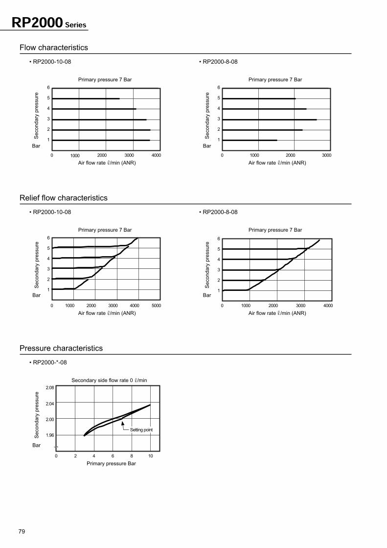
79
RP2000 Series
Flow characteristics
Relief flow characteristics
• RP2000-10-08 • RP2000-8-08
Pressure characteristics
0 1000 2000 3000 5000
Air flow rate /min (ANR)
• RP2000-10-08 • RP2000-8-08
1
2
3
4
5
6
0 1000 2000 3000 4000
Primary pressure 7 Bar
Primary pressure 7 Bar
Air flow rate /min (ANR)
1
2
3
4
5
6
0 1000 2000 3000
Primary pressure 7 Bar
Air flow rate /min (ANR)
• RP2000-*-08
1.96
2.00
2.04
2.08
0
Primary pressure Bar
1
2
3
4
5
6
0 1000 2000 4000
Air flow rate /min (ANR)
Primary pressure 7 Bar
1
2
3
4
5
6
Secondary side flow rate 0 /min
2 4 6 8 10
4000 3000
Se
co
nd
ary
pre
ssu
re
Bar
Se
co
nd
ary
pre
ssu
re
Bar
Se
co
nd
ary
pre
ssu
re
Bar
Se
co
nd
ary
pre
ssu
re
Bar
Se
co
nd
ary
pre
ssu
re
Bar
Setting point
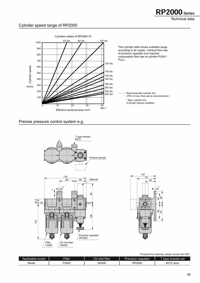
80
RP2000 SeriesTechnical data
IN OUT
FilterF3000
Oil mist filterM3000
Precision regulatorRP2000
T type bracketB310
22
176
63
90
45
60
70
55
106
7
50
Pressure gauge
Silencer
107
7945
TURNPRESS
TURNPRESS
7
7
22.5
147
Cylinder speed range of RP2000
100
200
300
400
500
600
700
800
900
1000100 dia.80 dia.63 dia.
125 dia.
140 dia.
150 dia.
160 dia.
180 dia.
200 dia.
250 dia.
230 dia.
0 10 20 30 40
Cylinders tables of RP2000-10
Effective sectional area mm2
Precise pressure control system e.g.
Applicable model Filter
Model F3000
Oil mist filter
M3000
Precision regulator
RP2000
T type bracket set
B310 (two)
Recommended cylinder line
(70% of max. flow rate is recommended.)
* Max. cylinder line
(Cylinder directly installed)
Max. *
Cylin
der
speed
mm/s
This cylinder table shows available range
according to air supply / exhaust flow rate
of precision regulator and required
consumption flow rate at cylinder PUSH /
PULL .
*If required for assembly, please consult with CKD.
81
Workpiece
W
Tank
Major applications
*Liquid discharge control *Balance
*Pilot pressure control *Extremely low pressure blow
*Quick pressure adjustment in tank *Leak test
*Tension control
RP1000/2000 Series
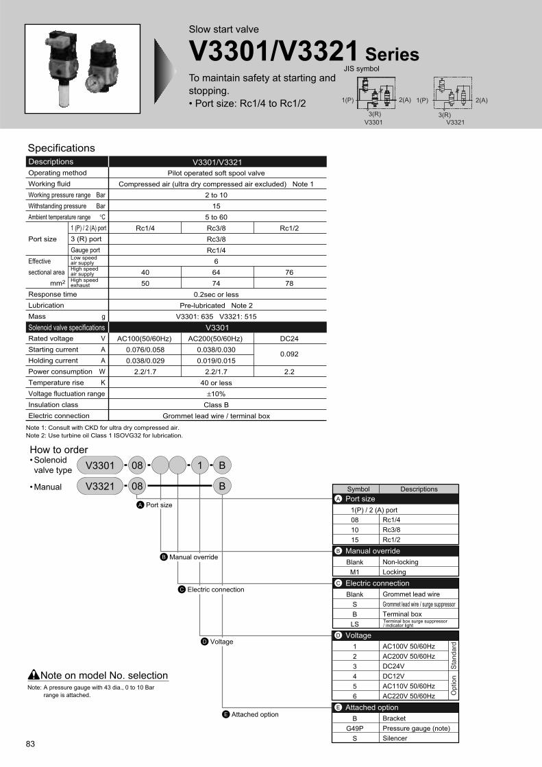
83
Slow start valve
V3301/V3321 SeriesTo maintain safety at starting and
stopping.
• Port size: Rc1/4 to Rc1/2
JIS symbol
V3301/V3321Descriptions
V3301Solenoid valve specifications
Operating method
Working fluid
Working pressure range
Withstanding pressure
Ambient temperature range
Port size
Effective
sectional area
mm2
Response time
Lubrication
Mass
Rated voltage
Starting current
Holding current
Power consumption
Temperature rise
Voltage fluctuation range
Insulation class
Electric connection
1 (P) / 2 (A) port
3 (R) port
Gauge port
Pilot operated soft spool valve
Compressed air (ultra dry compressed air excluded) Note 1
2 to 10
15
5 to 60
Rc3/8
Rc3/8
Rc1/4
6
64
74
0.2sec or less
Pre-lubricated Note 2
V3301: 635 V3321: 515
AC200(50/60Hz)
0.038/0.030
0.019/0.015
2.2/1.7
40 or less
±10%
Class B
Grommet lead wire / terminal box
Rc1/4
40
50
AC100(50/60Hz)
0.076/0.058
0.038/0.029
2.2/1.7
Rc1/2
76
78
DC24
0.092
2.2
Bar
Bar
°C
g
V
A
A
W
K
Specifications
Note 1: Consult with CKD for ultra dry compressed air.
Note 2: Use turbine oil Class 1 ISOVG32 for lubrication.
Low speed air supplyHigh speed air supplyHigh speed exhaust
Symbol Descriptions
1(P) / 2 (A) port
08
10
15
Blank
M1
Blank
S
B
LS
1
2
3
4
5
6
B
G49P
S
Rc1/4
Rc3/8
Rc1/2
Non-locking
Locking
Grommet lead wire
Grommet lead wire / surge suppressor
Terminal box
AC100V 50/60Hz
AC200V 50/60Hz
DC24V
DC12V
AC110V 50/60Hz
AC220V 50/60Hz
Bracket
Pressure gauge (note)
Silencer
Port sizeA
Manual overrideB
Electric connectionC
VoltageD
Attached optionE
Port sizeA
B Manual override
Electric connectionC
D Voltage
E Attached option
Note on model No. selection
08 B1V3301• Solenoid
valve type
• Manual 08 BV3321
Sta
nd
ard
Op
tio
n
Terminal box surge suppressor / indicator light
Note: A pressure gauge with 43 dia., 0 to 10 Bar
range is attached.
How to order
2(A)
3(R)
1(P)
V3301
2(A)1(P)
3(R)V3321
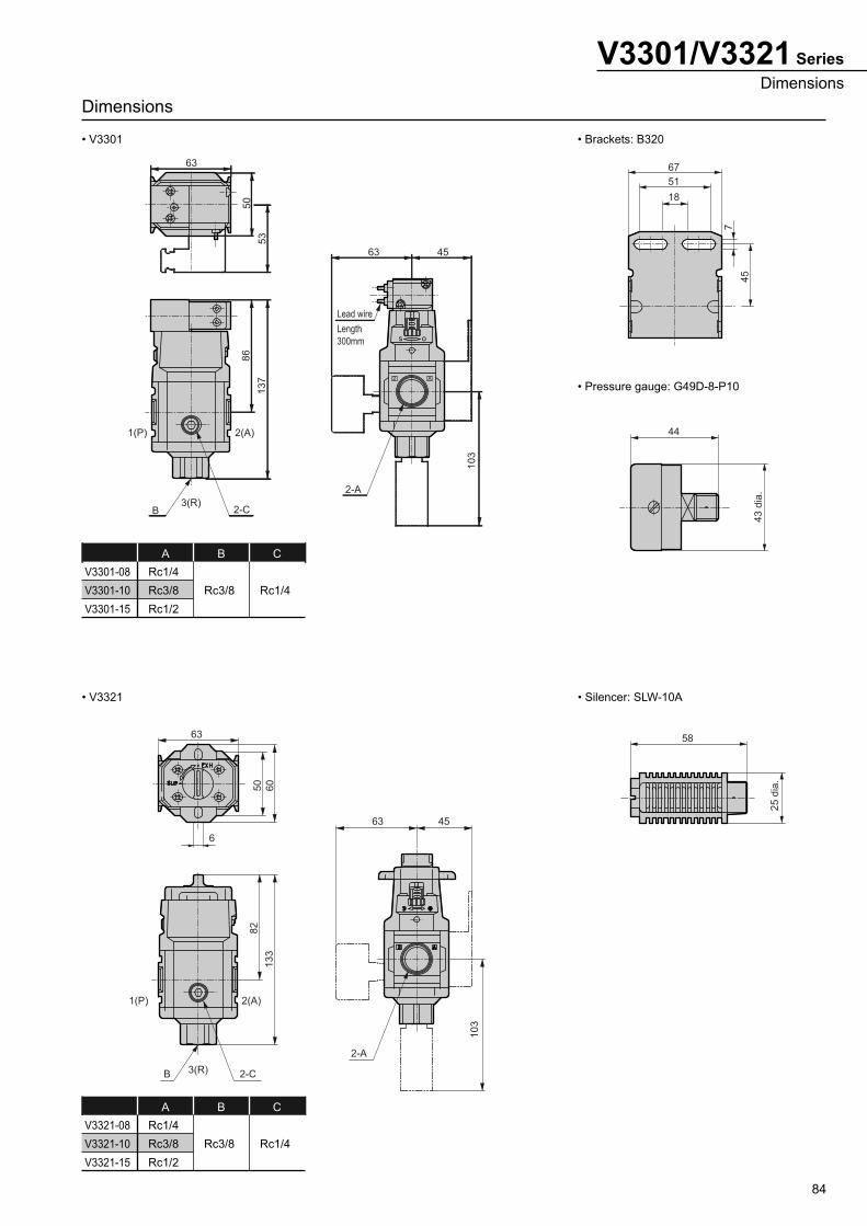
84
V3301/V3321 Series
Dimensions
Dimensions
• V3301 • Brackets: B320
• Pressure gauge: G49D-8-P10
• V3321 • Silencer: SLW-10A
V3301-08
V3301-10
V3301-15
Rc1/4
Rc3/8
Rc1/2
Rc3/8 Rc1/4
A CB
V3321-08
V3321-10
V3321-15
Rc1/4
Rc3/8
Rc1/2
Rc3/8 Rc1/4
A CB
63
63
Lead wire
Length
300mm
455
0
53
86
13
7
10
3
B 2-C3(R)
2(A)1(P)
2-A
67
51
18
7
45
44
43 d
ia.
63
6
50
60
82
133
1(P) 2(A)
B 2-C
2-A
103
63 45
3(R)
58
25
dia
.
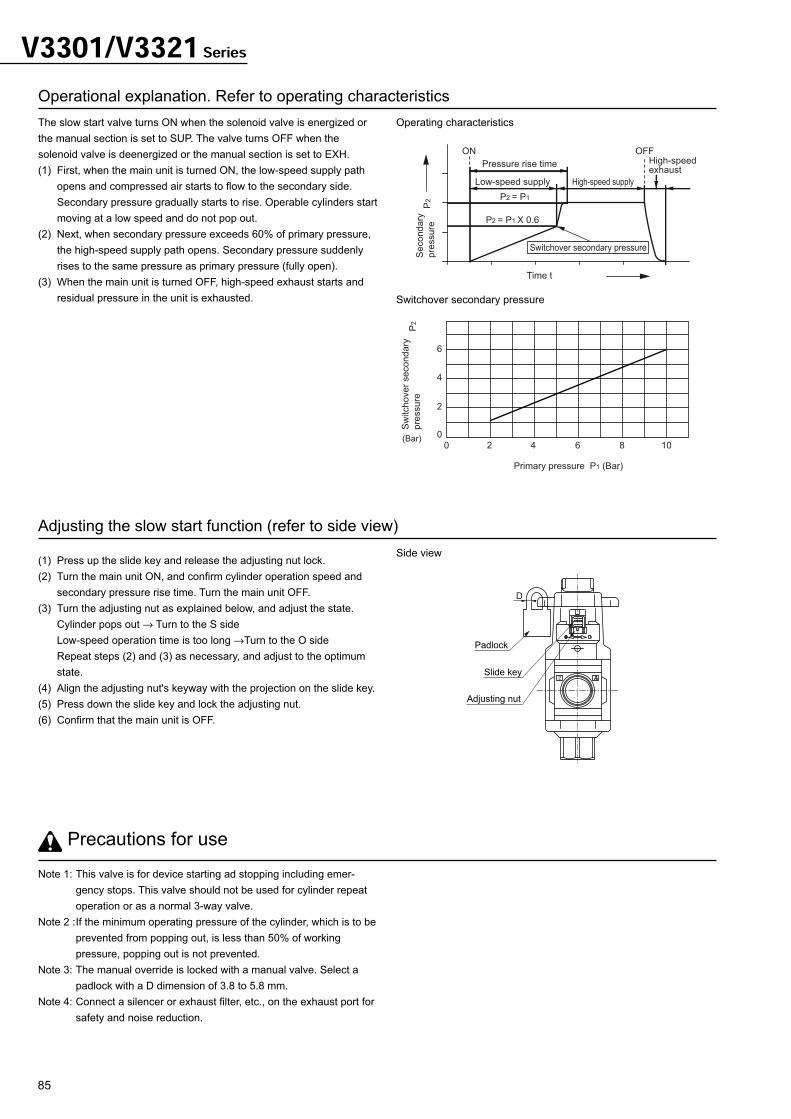
85
V3301/V3321 Series
Operational explanation. Refer to operating characteristics
Adjusting the slow start function (refer to side view)
Note 1: This valve is for device starting ad stopping including emer-
gency stops. This valve should not be used for cylinder repeat
operation or as a normal 3-way valve.
Note 2 :If the minimum operating pressure of the cylinder, which is to be
prevented from popping out, is less than 50% of working
pressure, popping out is not prevented.
Note 3: The manual override is locked with a manual valve. Select a
padlock with a D dimension of 3.8 to 5.8 mm.
Note 4: Connect a silencer or exhaust filter, etc., on the exhaust port for
safety and noise reduction.
Precautions for use
The slow start valve turns ON when the solenoid valve is energized or
the manual section is set to SUP. The valve turns OFF when the
solenoid valve is deenergized or the manual section is set to EXH.
(1) First, when the main unit is turned ON, the low-speed supply path
opens and compressed air starts to flow to the secondary side.
Secondary pressure gradually starts to rise. Operable cylinders start
moving at a low speed and do not pop out.
(2) Next, when secondary pressure exceeds 60% of primary pressure,
the high-speed supply path opens. Secondary pressure suddenly
rises to the same pressure as primary pressure (fully open).
(3) When the main unit is turned OFF, high-speed exhaust starts and
residual pressure in the unit is exhausted.
(1) Press up the slide key and release the adjusting nut lock.
(2) Turn the main unit ON, and confirm cylinder operation speed and
secondary pressure rise time. Turn the main unit OFF.
(3) Turn the adjusting nut as explained below, and adjust the state.
Cylinder pops out → Turn to the S side
Low-speed operation time is too long →Turn to the O side
Repeat steps (2) and (3) as necessary, and adjust to the optimum
state.
(4) Align the adjusting nut's keyway with the projection on the slide key.
(5) Press down the slide key and lock the adjusting nut.
(6) Confirm that the main unit is OFF.
Operating characteristics
Side view
Switchover secondary pressure
ON OFF
Pressure rise time
Low-speed supply High-speed supply
High-speedexhaust
Switchover secondary pressure
Time t
Secondary
pre
ssure
P2 P2 = P1
P2 = P1 X 0.6
6
4
2
0
20
Primary pressure P1 (Bar)
4 6 8 10
Sw
itchover
secondary
pre
ssure
P2
(Bar)
D
Padlock
Slide key
Adjusting nut