framework 8.0 t-server for cisco unified communications
TRANSCRIPT
Framework 8.0
T-Server for Cisco Unified Communications Manager
Deployment Guide
The information contained herein is proprietary and confidential and cannot be disclosed or duplicated without the prior written consent of Genesys Telecommunications Laboratories, Inc.
Copyright © 2002–2010 Genesys Telecommunications Laboratories, Inc. All rights reserved.
About GenesysGenesys Telecommunications Laboratories, Inc., a subsidiary of Alcatel-Lucent, is 100% focused on software for contact centers. Genesys recognizes that better interactions drive better business and build company reputations. Customer service solutions from Genesys deliver on this promise for Global 2000 enterprises, government organizations, and telecommunications service providers across 80 countries, directing more than 100 million customer interactions every day. Sophisticated routing and reporting across voice, e-mail, and Web channels ensure that customers are quickly connected to the best available resource—the first time. Genesys offers solutions for customer service, help desks, order desks, collections, outbound telesales and service, and workforce management. Visit www.genesyslab.com for more information.
Each product has its own documentation for online viewing at the Genesys Technical Support website or on the Documentation Library DVD, which is available from Genesys upon request. For more information, contact your sales representative.
NoticeAlthough reasonable effort is made to ensure that the information in this document is complete and accurate at the time of release, Genesys Telecommunications Laboratories, Inc., cannot assume responsibility for any existing errors. Changes and/or corrections to the information contained in this document may be incorporated in future versions.
Your Responsibility for Your System’s SecurityYou are responsible for the security of your system. Product administration to prevent unauthorized use is your responsibility. Your system administrator should read all documents provided with this product to fully understand the features available that reduce your risk of incurring charges for unlicensed use of Genesys products.
TrademarksGenesys, the Genesys logo, and T-Server are registered trademarks of Genesys Telecommunications Laboratories, Inc. All other trademarks and trade names referred to in this document are the property of other companies. The Crystal monospace font is used by permission of Software Renovation Corporation, www.SoftwareRenovation.com.
Technical Support from VARsIf you have purchased support from a value-added reseller (VAR), please contact the VAR for technical support.
Technical Support from GenesysIf you have purchased support directly from Genesys, please contact Genesys Technical Support at the regional numbers provided on page 13. For complete contact information and procedures, refer to the Genesys Technical Support Guide.
Ordering and Licensing InformationComplete information on ordering and licensing Genesys products can be found in the Genesys Licensing Guide.
Released by
Genesys Telecommunications Laboratories, Inc. www.genesyslab.com
Document Version: 80fr_dep-ts_cisco_07-2010_v8.0.101.00
T-Server—Deployment Guide 3
Table of ContentsList ofProcedures ................................................................................................................... 9
Preface ................................................................................................................. 11
About T-Server for Cisco Unified Communications Manager .................. 11Intended Audience................................................................................... 12
Reading Prerequisites ........................................................................ 13Making Comments on This Document .................................................... 13Contacting Genesys Technical Support................................................... 13Document Change History ...................................................................... 14
Part 1 Common Functions and Procedures ........................ 15
New for All T-Servers in 8.0..................................................................... 15
Chapter 1 T-Server Fundamentals........................................................................ 17
Learning About T-Server ......................................................................... 18Framework and Media Layer Architecture.......................................... 18T-Server Requests and Events ........................................................... 20
Advanced Disconnect Detection Protocol ............................................... 23Redundant T-Servers .............................................................................. 24Multi-Site Support .................................................................................... 28Agent Reservation ................................................................................... 28Client Connections .................................................................................. 29Next Steps ............................................................................................... 29
Chapter 2 T-Server General Deployment ............................................................. 31
Prerequisites............................................................................................ 31Software Requirements ...................................................................... 32Hardware and Network Environment Requirements .......................... 33Licensing Requirements ..................................................................... 33About Configuration Options............................................................... 35
Deployment Sequence ............................................................................ 36
Table of Contents
4 Framework 8.0
Wizard Deployment of T-Server .............................................................. 36Wizard Configuration of T-Server ....................................................... 37Wizard Installation of T-Server............................................................ 37
Manual Deployment of T-Server.............................................................. 39Manual Configuration of Telephony Objects ....................................... 40Manual Configuration of T-Server....................................................... 42Manual Installation of T-Server ........................................................... 44
Next Steps ............................................................................................... 46
Chapter 3 High-Availability Deployment.............................................................. 49
Warm Standby Redundancy Type ........................................................... 50Hot Standby Redundancy Type ............................................................... 51Prerequisites............................................................................................ 53
Requirements...................................................................................... 53Synchronization Between Redundant T-Servers ................................ 53
Warm Standby Deployment ..................................................................... 54General Order of Deployment............................................................. 54Manual Modification of T-Servers for Warm Standby.......................... 55Warm Standby Installation of Redundant T-Servers ........................... 56
Hot Standby Deployment......................................................................... 56General Order of Deployment............................................................. 56Manual Modification of T-Servers for Hot Standby.............................. 57Hot Standby Installation of Redundant T-Servers ............................... 60
Next Steps ............................................................................................... 60
Chapter 4 Multi-Site Support................................................................................. 61
Multi-Site Fundamentals.......................................................................... 62ISCC Call Data Transfer Service ............................................................. 63
ISCC Call Flows.................................................................................. 64ISCC Transaction Types ..................................................................... 70T-Server Transaction Type Support .................................................... 78Transfer Connect Service Feature...................................................... 82
ISCC/Call Overflow Feature .................................................................... 83Number Translation Feature.................................................................... 87
Number Translation Rules .................................................................. 88Network Attended Transfer/Conference Feature..................................... 95Event Propagation Feature...................................................................... 97
User Data Propagation ....................................................................... 98Party Events Propagation ................................................................... 99Switch Partitioning ............................................................................ 100Event Propagation Configuration ...................................................... 101
ISCC Transaction Monitoring Feature ................................................... 104
T-Server—Deployment Guide 5
Table of Contents
Configuring Multi-Site Support............................................................... 104Applications ...................................................................................... 105Switches and Access Codes ............................................................ 106DNs................................................................................................... 112Configuration Examples.................................................................... 117
Next Steps ............................................................................................. 118
Chapter 5 Start and Stop T-Server Components .............................................. 119
Command-Line Parameters .................................................................. 119Starting and Stopping with the Management Layer ............................... 121Starting with Startup Files ...................................................................... 122Starting Manually ................................................................................... 123
HA Proxy........................................................................................... 126T-Server ............................................................................................ 127
Verifying Successful Startup .................................................................. 129Stopping Manually ................................................................................. 129Starting and Stopping with Windows Services Manager ....................... 130Next Steps ............................................................................................. 130
Part 2 Reference Information .............................................. 131
New in T-Server for Cisco Unified Communications Manager .............. 132
Chapter 6 Switch-Specific Configuration .......................................................... 133
Known Limitations ................................................................................. 133Configuring the Java Virtual Machine on a T-Server Host..................... 134Configuring the Cisco Unified Communications Manager switch for
T-Server ............................................................................................ 135JTAPI and Configuring JTAPI Options................................................... 136
Chapter 7 Supported Functionality ................................................................... 139
T-Library Functionality ........................................................................... 140Error Messages ..................................................................................... 150Agent Login and Agent States ............................................................... 152Agent After Call Work ............................................................................ 153Agent Ring Redirect Timeout................................................................. 154ACD Queues ......................................................................................... 154Music and Announcements ................................................................... 154
Announcement Treatments on Routing Points ................................. 156Music Treatment on ACD Queues .................................................... 156Music Treatments on Routing Points (TreatmentMusic) ................... 157
Table of Contents
6 Framework 8.0
Call Recording (RecordUserAnnouncement) ................................... 157Busy, Fast Busy, Silence and RingBack Treatments
on Routing Points ......................................................................... 159Predictive Dialing................................................................................... 159
Outbound dialing with TMakePredictiveCall ..................................... 160Outbound Calling with Dialogic Dialer .............................................. 160
Dual-Tone Multi-Frequency ................................................................... 161User-Data Display to IP Phones............................................................ 161User-Data Display to IP Phones Not on a Call ...................................... 162Voice Monitoring .................................................................................... 163Shared Lines ......................................................................................... 163Extension Mobility.................................................................................. 167Call Pickup............................................................................................. 170Group Call Pickup.................................................................................. 170Call Parking ........................................................................................... 170ACD-like Default Routing....................................................................... 171Route Points with Multiple Partitions ..................................................... 171Calling Search Space Feature............................................................... 171Socket Mode of Communication............................................................ 172Customer Matters Code and Forced Authorization Code...................... 173Cisco Unified Communications Manager Partition ................................ 174Retrieval and Distribution of Modified CLID........................................... 175Call Recording ....................................................................................... 176
Regular Call Recording..................................................................... 176Feature Configuration ....................................................................... 177Emergency (Manual) Call Recording................................................ 177
Supervisor Monitoring............................................................................ 178Logging of Network Connection Failures Between JTAPI and T-Server183Call Parking with 3PCC ......................................................................... 184
Chapter 8 Common Configuration Options....................................................... 185
Setting Configuration Options................................................................ 186Mandatory Options ................................................................................ 186Log Section............................................................................................ 186
Log Output Options........................................................................... 192Examples .......................................................................................... 197Debug Log Options........................................................................... 198
Log-Extended Section ........................................................................... 200Log-Filter Section .................................................................................. 202Log-Filter-Data Section.......................................................................... 203SML Section .......................................................................................... 203
T-Server—Deployment Guide 7
Table of Contents
Common Section ................................................................................... 203
Chapter 9 T-Server Common Configuration Options ....................................... 205
Setting Configuration Options................................................................ 205Mandatory Options ................................................................................ 206T-Server Section.................................................................................... 206License Section ..................................................................................... 211Agent-Reservation Section.................................................................... 214Multi-Site Support Section ..................................................................... 215
ISCC Transaction Options ................................................................ 217Transfer Connect Service Options.................................................... 221ISCC/COF Options ........................................................................... 222Event Propagation Options ............................................................... 224Number Translation Option............................................................... 225
Translation Rules Section...................................................................... 225Backup-Synchronization Section........................................................... 226Call-Cleanup Section............................................................................. 227Security Section..................................................................................... 229Timeout Value Format ........................................................................... 229
Chapter 10 Configuration Options forT-Server for Cisco Unified Communications Manager ............. 231
Application-Level Options...................................................................... 231Mandatory Options ........................................................................... 232T-Server Section ............................................................................... 233JTAPI Section ................................................................................... 241Global Group Section ....................................................................... 248Link Section ...................................................................................... 249
DN-Specific Section............................................................................... 250Changes from 8.0 to 8.0.1 ..................................................................... 251
Chapter 11 Stream Manager Configuration ......................................................... 253
Stream Manager Configuration Options with T-Server .......................... 253Stream Manager Configuration Options ................................................ 256
Chapter 12 HA Configuration and Operation with CUCM JTAPI ....................... 257
HA configuration of T-Server with 4 JTAPI links .................................... 257Description of how HA works when primary T-Server fails.................... 259Description of how HA works when one JTAPI link fails........................ 259Description of how HA works when all JTAPI links fail .......................... 260
Table of Contents
8 Framework 8.0
Supplements Related Documentation Resources ................................................... 261
Document Conventions ...................................................................... 263
Index ............................................................................................................... 265
T-Server—Deployment Guide 9
List of ProceduresInstalling T-Server on UNIX using Wizard . . . . . . . . . . . . . . . . . . . . . . . 38
Installing T-Server on Windows using Wizard . . . . . . . . . . . . . . . . . . . . 39
Configuring T-Server manually. . . . . . . . . . . . . . . . . . . . . . . . . . . . . . . . 42
Configuring multiple ports . . . . . . . . . . . . . . . . . . . . . . . . . . . . . . . . . . . 43
Installing T-Server on UNIX manually . . . . . . . . . . . . . . . . . . . . . . . . . . 44
Installing T-Server on Windows manually . . . . . . . . . . . . . . . . . . . . . . . 45
Verifying the manual installation of T-Server . . . . . . . . . . . . . . . . . . . . . 46
Modifying the primary T-Server configuration for warm standby . . . . . . 55
Modifying the backup T-Server configuration for warm standby . . . . . . 56
Modifying the primary T-Server configuration for hot standby . . . . . . . . 57
Modifying the backup T-Server configuration for hot standby . . . . . . . . 59
Activating Transfer Connect Service . . . . . . . . . . . . . . . . . . . . . . . . . . . 82
Configuring Number Translation. . . . . . . . . . . . . . . . . . . . . . . . . . . . . . . 95
Activating Event Propagation: basic configuration . . . . . . . . . . . . . . . . 102
Modifying Event Propagation: advanced configuration . . . . . . . . . . . . 102
Configuring T-Server Applications . . . . . . . . . . . . . . . . . . . . . . . . . . . . 105
Configuring Default Access Codes. . . . . . . . . . . . . . . . . . . . . . . . . . . . 107
Configuring Access Codes . . . . . . . . . . . . . . . . . . . . . . . . . . . . . . . . . . 108
Configuring access resources for the route transaction type . . . . . . . . 112
Configuring access resources for the dnis-pool transaction type . . . . . 114
Configuring access resources for direct-* transaction types . . . . . . . . 114
Configuring access resources for ISCC/COF. . . . . . . . . . . . . . . . . . . . 115
Configuring access resources for non-unique ANI . . . . . . . . . . . . . . . . 115
Modifying DNs for isolated switch partitioning . . . . . . . . . . . . . . . . . . . 116
Configuring T-Server to start with the Management Layer. . . . . . . . . . 121
Starting T-Server on UNIX with a startup file . . . . . . . . . . . . . . . . . . . . 122
Starting T-Server on Windows with a startup file . . . . . . . . . . . . . . . . . 123
Starting HA Proxy on UNIX manually . . . . . . . . . . . . . . . . . . . . . . . . . . 127
Starting HA Proxy on Windows manually . . . . . . . . . . . . . . . . . . . . . . . 127
List of Procedures
10 Framework 8.0
Starting T-Server on UNIX manually . . . . . . . . . . . . . . . . . . . . . . . . . . 128
Starting T-Server on Windows manually . . . . . . . . . . . . . . . . . . . . . . . 128
Stopping T-Server on UNIX manually . . . . . . . . . . . . . . . . . . . . . . . . . 129
Stopping T-Server on Windows manually . . . . . . . . . . . . . . . . . . . . . . 129
Configuring a DN in Configuration Manager to use Cisco Unified Communications Manager Music On Hold Server . . . . . . . . . . . . . 155
Configuration using MAC address suffixes. . . . . . . . . . . . . . . . . . . . . . 164
Configuration using user-friendly address suffixes. . . . . . . . . . . . . . . . 165
T-Server—Deployment Guide 11
PrefaceWelcome to the Framework 8.0 T-Server for Cisco Unified Communications Manager Deployment Guide. This document introduces you to the concepts, terminology, and procedures relevant to T-Servers® in general and provides detailed reference information about T-Server for Cisco Unified Communications Manager. The reference information includes, but is not limited to, configuration options, limitations, and switch-specific functionality. You must configure the configuration objects and options described in this document in the Framework Configuration Layer.
Use this document only after you have read through the Framework 8.0 Deployment Guide, and the Release Note for your T-Server.
This preface contains the following sections: About T-Server for Cisco Unified Communications Manager, page 11 Intended Audience, page 12 Making Comments on This Document, page 13 Contacting Genesys Technical Support, page 13 Document Change History, page 14
For information about related resources and about the conventions that are used in this document, see the supplementary material starting on page 261.
About T-Server for Cisco Unified Communications Manager
T-Server is the Genesys software component that provides an interface between your telephony hardware and the rest of the Genesys software components in your enterprise. It translates and keeps track of events and requests that come from, and are sent to, the CTI (computer-telephony
Note: For versions of this document created for other releases of this product, visit the Genesys Technical Support website, or request the Documentation Library DVD, which you can order by e-mail from Genesys Order Management at [email protected].
12 Framework 8.0
Preface Intended Audience
integration) link in the telephony device. T-Server is a TCP/IP-based server that can also act as a messaging interface between T-Server clients. It is the critical point in allowing your Genesys solution to facilitate and track the contacts that flow through your enterprise.
Note that the T-Server name has changed over the course of previous releases for various reasons (including, but not limited to, changes in vendor name or in Genesys policy). The former names include:
• T-Server for Cisco CallManager.
The current name is T-Server for Cisco Unified Communications Manager.
Intended AudienceThis guide is intended primarily for system administrators, both those who are new to T-Server and those who are familiar with it.
• If you are new to T-Server, read the Framework 8.0 Deployment Guide and the Release Note mentioned earlier, and then read all of the sections of this document that apply to your software and its accompanying components. Refer back to the Framework 8.0 Deployment Guide as needed.
• If you are an experienced T-Server user—someone with computer expertise, who is used to installing, configuring, testing, or maintaining Genesys software—you may find it more time efficient to go to the Index to see what is new or different in T-Server release 8.0. If you take that approach, please also read Release Notes and refer to other related resources, such as the Genesys 7 Events and Models Reference Manual and Voice Platform SDK 8.0 .NET (or Java) API Reference for technical details of T-Library functions.
In general, this document assumes that you have a basic understanding of, and familiarity with:
• Computer-telephony integration concepts, processes, terminology, and applications.
• Network design and operation.
• Your own network configurations.
• Your telephony hardware and software.
• Genesys Framework architecture and functions.
• Configuration Manager interface and object-managing operations.
Based on your specific contact center environment and your responsibilities in it, you may need to be familiar with a much wider range of issues as you deploy T-Server.
T-Server—Deployment Guide 13
Preface Making Comments on This Document
Reading Prerequisites
You must read the Framework 8.0 Deployment Guide before using this T-Server Deployment Guide. That book contains information about the Genesys software you must deploy before deploying T-Server.
Making Comments on This DocumentIf you especially like or dislike anything about this document, feel free to e-mail your comments to [email protected].
You can comment on what you regard as specific errors or omissions, and on the accuracy, organization, subject matter, or completeness of this document. Please limit your comments to the scope of this document only and to the way in which the information is presented. Contact your Genesys Account Representative or Genesys Technical Support if you have suggestions about the product itself.
When you send us comments, you grant Genesys a nonexclusive right to use or distribute your comments in any way it believes appropriate, without incurring any obligation to you.
Contacting Genesys Technical SupportIf you have purchased support directly from Genesys, contact Genesys Technical Support at the following regional numbers:
Region Telephone E-Mail
North America and Latin America
+888-369-5555 (toll-free)+506-674-6767
Europe, Middle East, and Africa
+44-(0)-1276-45-7002 [email protected]
Asia Pacific +61-7-3368-6868 [email protected]
Malaysia 1-800-814-472 (toll-free)+61-7-3368-6868
India 000-800-100-7136 (toll-free)+91 (022) 3918 0537 (toll)
Japan +81-3-6361-8950 [email protected]
Before contacting technical support, refer to the Genesys Technical Support Guide for complete contact information and procedures.
14 Framework 8.0
Preface Document Change History
Document Change HistoryThis section lists topics that are new or that have changed significantly since the first release of this document.
The new features that were introduced in T-Server for Cisco UCM release 8.0.1 can be found at “New in T-Server for Cisco Unified Communications Manager” on page 132 and the new features that are common to all T-Servers are located at “New for All T-Servers in 8.0” on page 15.
T-Server—Deployment Guide 15
Part
1 Common Functions and ProceduresPart One of this T-Server Deployment Guide familiarizes the reader with T-Server in general. It addresses architectural, functional, and procedural information common to all T-Servers.
The information in Part One is divided into the following chapters:
• Chapter 1, “T-Server Fundamentals,” on page 17, describes T-Server, its place in the Framework 8 architecture, T-Server redundancy, and multi-site issues. It stops short of providing configuration and installation information.
• Chapter 2, “T-Server General Deployment,” on page 31, presents configuration and installation procedures for all T-Servers.
• Chapter 3, “High-Availability Deployment,” on page 49, addresses high availability (HA).
• Chapter 4, “Multi-Site Support,” on page 61, details the variations available for T-Server implementations across geographical locations.
• Chapter 5, “Start and Stop T-Server Components,” on page 119, describes how, and in what order, to start up T-Server among other Framework components. It also provides possible stopping commands.
New for All T-Servers in 8.0Before looking at T-Server’s place in Genesys solutions and in the architecture of the Genesys Framework, note the following general changes that have been implemented in the 8.0 release of T-Server:
• Enhanced Event Propagation support for switch partitioning. T-Server now supports the Event Propagation feature in deployments that use switch partitioning or intelligent trunks. See “Switch Partitioning” on page 100.
16 Framework 8.0
Part 1: Common Functions and Procedures New for All T-Servers in 8.0
• Enhanced ISCC Transaction Monitoring support. T-Server now supports new key-value pairs in AttributeExtensions with ISCC transaction data requested using TGetAccessNumber in the following requests: TMakeCall, TRouteCall, TSingleStepTransfer, TInitiateTransfer, TInitiateConference, and TMuteTransfer. The ISCC Transaction Monitoring allows T-Server clients to monitor ISCC transactions of the call data transfer between T-Servers in a multi-site environment. See “ISCC Transaction Monitoring Feature” on page 104 and the Genesys 7 Events and Models Reference Manual for details about key-value pairs in AttributeExtensions.
• Enhanced Agent Reservation support. T-Server now supports Agent Reservation failure optimization, to ensure that only agent reservation requests of the highest priority are collected. This functionality can now be controlled with the collect-lower-priority-requests configuration option. See “Agent Reservation” on page 28 for details.
• Link bandwidth reporting support. T-Server now supports notification of link bandwidth utilization. The following two new log events have been introduced: 20009|STANDARD|MSG_TS_COMMON_LINK_ALARM_HIGH
20010|STANDARD|MSG_TS_COMMON_LINK_ALARM_LOW
Refer to Framework 8.0 Combined Log Events Help for information about the log events.
• Notification of failed routing attempts and failed ISCC transactions. T-Server now supports notification of failed routing attempts and failed ISCC transactions. The following new log events have been introduced: 20011|STANDARD|MSG_TS_COMMON_ALARM_ROUTE_FAILURE_HIGH_WATER_MARK
20012|STANDARD|MSG_TS_COMMON_ALARM_ROUTE_FAILURE_LOW_WATER_MARK
21019|STANDARD|ISCC_LOGMSG_TRANSACTION_FAILED
Refer to Framework 8.0 Combined Log Events Help for information about the log events.
• Real-time SDN licenses query support. T-Server can now report how many SDN licenses are currently available and in use, using the following key-value pairs in AttributeExtensions in EventServerInfo messages: sdn-licenses-in-use and sdn-licenses-available. See Part Two of this document for details on the use of AttributeExtensions in a particular T-Server.
Note: For information about the new features that are available in your T-Server in the initial 8.0 release, see Part Two of this document.
T-Server—Deployment Guide 17
Chapter
1 T-Server FundamentalsThis chapter provides general information about T-Server features and functionality and about its configuration and installation. For reference information about your specific T-Server and about options for all T-Servers, see “Part Two: Reference Information.”
This chapter has various levels of information, some of it intended for people who have configured, installed, and used previous releases of T-Server, and some of it aimed at those less familiar with such T-Server operations. That means some sections will not necessarily be relevant for you.
• If you are an experienced user of T-Server, start with “New for All T-Servers in 8.0” on page 15, and then move to the chapters comprising Part Two of this document, where specific information about your T-Server is available.
• If you are new to T-Server, begin with “Learning About T-Server.” Once you have read through that and subsequent sections, you are ready for the other chapters in Part One that go into detail about T-Server configuration and installation.
Generally, this chapter presents overview information that applies to all T-Servers (and Network T-Servers) and their deployment. This chapter is divided into the following sections: Learning About T-Server, page 18 Advanced Disconnect Detection Protocol, page 23 Redundant T-Servers, page 24 Multi-Site Support, page 28 Agent Reservation, page 28 Client Connections, page 29 Next Steps, page 29
18 Framework 8.0
Chapter 1: T-Server Fundamentals Learning About T-Server
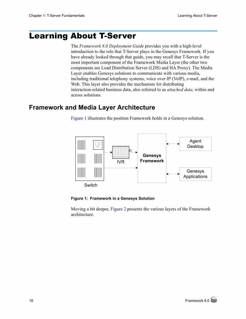
Learning About T-ServerThe Framework 8.0 Deployment Guide provides you with a high-level introduction to the role that T-Server plays in the Genesys Framework. If you have already looked through that guide, you may recall that T-Server is the most important component of the Framework Media Layer (the other two components are Load Distribution Server (LDS) and HA Proxy). The Media Layer enables Genesys solutions to communicate with various media, including traditional telephony systems, voice over IP (VoIP), e-mail, and the Web. This layer also provides the mechanism for distributing interaction-related business data, also referred to as attached data, within and across solutions.
Framework and Media Layer Architecture
Figure 1 illustrates the position Framework holds in a Genesys solution.
Figure 1: Framework in a Genesys Solution
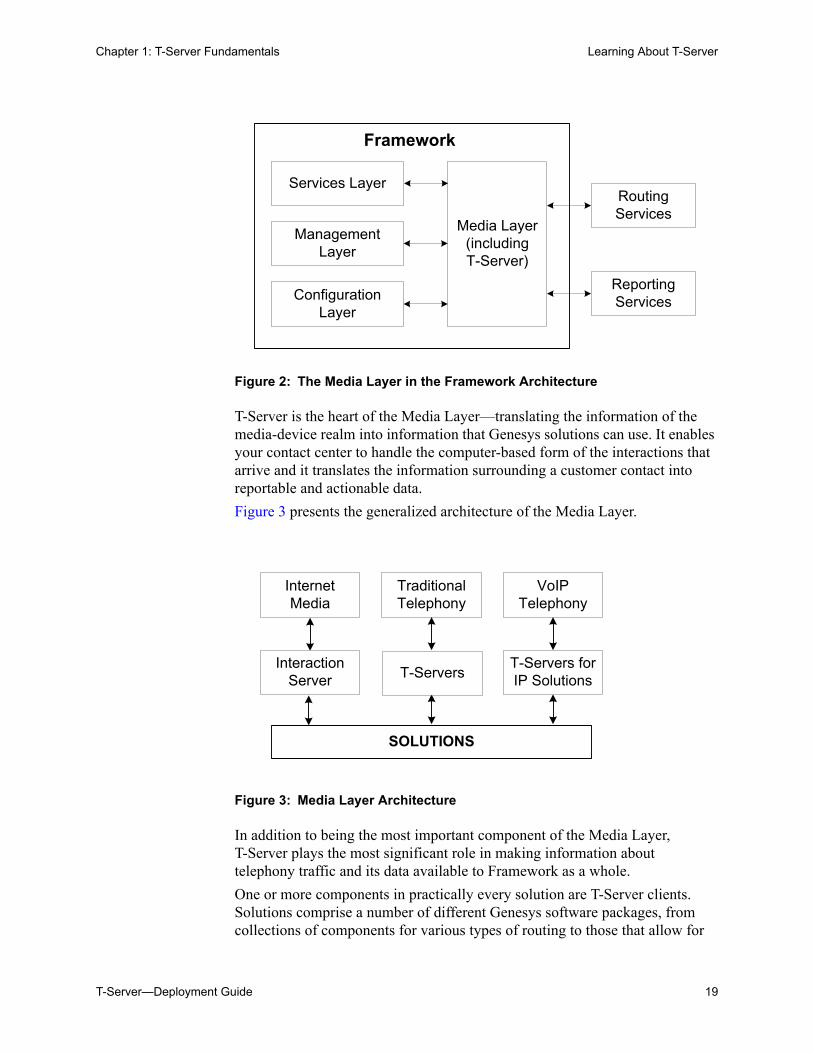
Moving a bit deeper, Figure 2 presents the various layers of the Framework architecture.
GenesysFramework
Agent Desktop
Genesys Applications
Switch
IVR
Chapter 1: T-Server Fundamentals Learning About T-Server
T-Server—Deployment Guide 19
Figure 2: The Media Layer in the Framework Architecture
T-Server is the heart of the Media Layer—translating the information of the media-device realm into information that Genesys solutions can use. It enables your contact center to handle the computer-based form of the interactions that arrive and it translates the information surrounding a customer contact into reportable and actionable data.
Figure 3 presents the generalized architecture of the Media Layer.
Figure 3: Media Layer Architecture
In addition to being the most important component of the Media Layer, T-Server plays the most significant role in making information about telephony traffic and its data available to Framework as a whole.
One or more components in practically every solution are T-Server clients. Solutions comprise a number of different Genesys software packages, from collections of components for various types of routing to those that allow for
Services Layer
Media Layer(includingT-Server)
Routing Services
Reporting Services
Framework
Management Layer
Configuration Layer
SOLUTIONS
Internet Media
Traditional Telephony
VoIP Telephony
Interaction Server
T-Servers for IP SolutionsT-Servers
20 Framework 8.0
Chapter 1: T-Server Fundamentals Learning About T-Server
outbound dialing to still others. Framework in general, and T-Server in particular, enable these solutions to function in your enterprise.
T-Server has several typical clients: Stat Server, Call Concentrator, Universal Routing Server, and agent desktop applications. T-Server gets the information it needs about the enterprise from Configuration Server. Additionally, if you use the Management Layer, T-Server provides its ongoing status and various other log messages to server components of the Management Layer (for instance, allowing you to set alarms).
T-Server Requests and Events
This section outlines the roles that T-Server plays in a contact center. While it is possible to describe roles for all T-Servers, at a detailed level, T-Server’s functionality depends on the hardware to which it is connected. (For example, when connected to a traditional switch, it performs CTI functions, but when connected to a VOIP-based telephony device, it controls IP traffic.) The CTI connection is only for the switch.
Details of T-Server Functionality
T-Server is a TCP/IP server that enables intelligent communication between media-specific protocols (such as the various CTI protocols, including CSTA and ASAI) and TCP/IP-based clients of T-Server. Applications that are clients to T-Server use the T-Library format to transmit requests to T-Server through a TCP/IP socket. T-Server can then either translate those requests to CTI protocol for switch use or relay them directly to other TCP/IP clients.
T-Server performs three general functions in the contact center: Bridging, Messaging, and Interaction Tracking.
Bridging
T-Server acts as a platform-independent interface between media devices and business applications. In the case of a telephony device, for instance, it receives messages from and sends commands to the telephony equipment using either CTI links provided by the switch manufacturer or interface protocols provided by telephony network vendors.
On the client-application end, T-Server offers three models (call model, agent model, and device model) unified for all switches. The core functionality (such as processing an inbound call, an agent login, or a call-forwarding request) translates into a unified application programming interface (API) called T-Library, so that applications do not need to know what specific switch model they are dealing with. On the other hand, T-Library accommodates many functions that are unique to a specific switch, so that client applications are able to derive the maximum functionality offered by a particular switch.
Refer to the Genesys 7 Events and Models Reference Manual for complete information on all T-Server events and call models and to the
Chapter 1: T-Server Fundamentals Learning About T-Server
T-Server—Deployment Guide 21
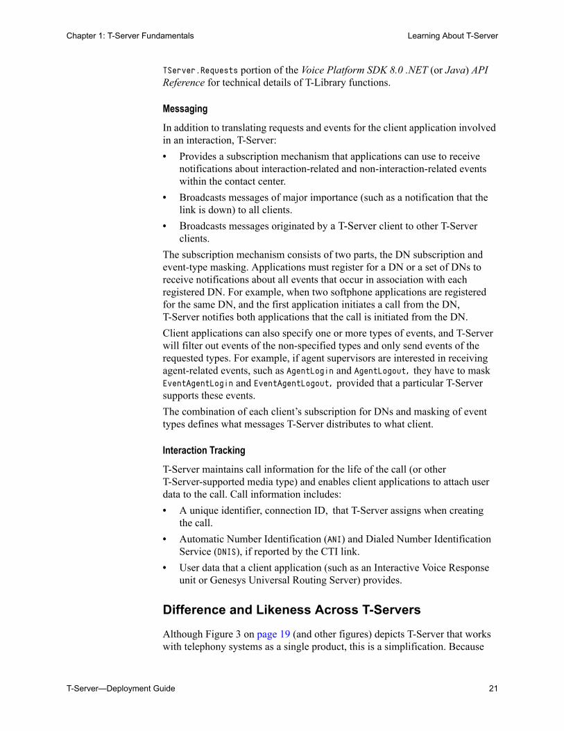
TServer.Requests portion of the Voice Platform SDK 8.0 .NET (or Java) API Reference for technical details of T-Library functions.
Messaging
In addition to translating requests and events for the client application involved in an interaction, T-Server:
• Provides a subscription mechanism that applications can use to receive notifications about interaction-related and non-interaction-related events within the contact center.
• Broadcasts messages of major importance (such as a notification that the link is down) to all clients.
• Broadcasts messages originated by a T-Server client to other T-Server clients.
The subscription mechanism consists of two parts, the DN subscription and event-type masking. Applications must register for a DN or a set of DNs to receive notifications about all events that occur in association with each registered DN. For example, when two softphone applications are registered for the same DN, and the first application initiates a call from the DN, T-Server notifies both applications that the call is initiated from the DN.
Client applications can also specify one or more types of events, and T-Server will filter out events of the non-specified types and only send events of the requested types. For example, if agent supervisors are interested in receiving agent-related events, such as AgentLogin and AgentLogout, they have to mask EventAgentLogin and EventAgentLogout, provided that a particular T-Server supports these events.
The combination of each client’s subscription for DNs and masking of event types defines what messages T-Server distributes to what client.
Interaction Tracking
T-Server maintains call information for the life of the call (or other T-Server-supported media type) and enables client applications to attach user data to the call. Call information includes:
• A unique identifier, connection ID, that T-Server assigns when creating the call.
• Automatic Number Identification (ANI) and Dialed Number Identification Service (DNIS), if reported by the CTI link.
• User data that a client application (such as an Interactive Voice Response unit or Genesys Universal Routing Server) provides.
Difference and Likeness Across T-Servers
Although Figure 3 on page 19 (and other figures) depicts T-Server that works with telephony systems as a single product, this is a simplification. Because
22 Framework 8.0
Chapter 1: T-Server Fundamentals Learning About T-Server
almost every traditional telephony device has its own characteristics and communication protocols, Genesys makes different T-Servers for different telephony systems. (That means your T-Server will not work with another switch.) Thus, all T-Servers play a common role in the architecture, but their specific features differ from implementation to implementation, based on the media device in use.
Despite their switch-based differences, T-Servers for telephony systems are similar to one another in at least one important respect: they are all built with a certain amount of shared software code. This shared code is rolled into a single unit and is called T-Server Common Part (TSCP). TSCP is the central, common component for all T-Servers and has its own Release Note, which is accessible via a hyperlink from your T-Server’s Release Note.
T-Server Functional Steps During a Sample Call
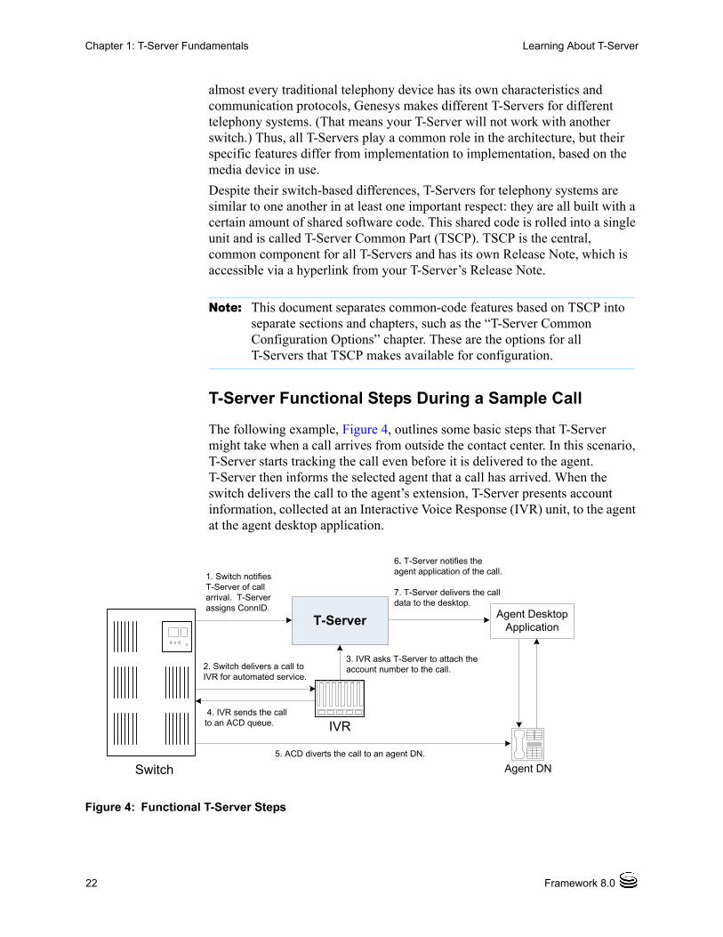
The following example, Figure 4, outlines some basic steps that T-Server might take when a call arrives from outside the contact center. In this scenario, T-Server starts tracking the call even before it is delivered to the agent. T-Server then informs the selected agent that a call has arrived. When the switch delivers the call to the agent’s extension, T-Server presents account information, collected at an Interactive Voice Response (IVR) unit, to the agent at the agent desktop application.
Figure 4: Functional T-Server Steps
Note: This document separates common-code features based on TSCP into separate sections and chapters, such as the “T-Server Common Configuration Options” chapter. These are the options for all T-Servers that TSCP makes available for configuration.
1. Switch notifiesT-Server of call arrival. T-Server assigns ConnID.
3. IVR asks T-Server to attach the account number to the call.2. Switch delivers a call to
IVR for automated service.
4. IVR sends the call to an ACD queue.
5. ACD diverts the call to an agent DN.
6. T-Server notifies the agent application of the call.
7. T-Server delivers the call data to the desktop.
Agent DNSwitch
T-Server Agent Desktop Application
IVR
Chapter 1: T-Server Fundamentals Advanced Disconnect Detection Protocol
T-Server—Deployment Guide 23
Step 1
When the call arrives at the switch, T-Server creates a call in its internal structure. T-Server assigns the call a unique identifier, connection ID.
Step 2
The switch delivers the call to an Interactive Voice Response (IVR) unit, which begins automated interactions with the caller.
Step 3
IVR acquires user information from the caller through prompts and requests T-Server to attach that information to the call. T-Server updates the call with the user information.
Step 4
IVR sends the call to an ACD (Automated Call Distribution) queue.
Step 5
The ACD unit distributes the call to an available agent logged in to a particular DN (directory number).
Step 6
T-Server notifies the agent desktop application that the call is ringing on the agent DN. The notification event contains call data including ANI, DNIS, and account information that the IVR has collected.
Step 7
The agent desktop application presents the account information, including the name of the person whose account this is, on the agent’s screen, so that the agent answering the call has all the relevant information.
These seven steps illustrate just a small part of T-Server’s bridging, messaging, and interaction-processing capabilities.
Advanced Disconnect Detection ProtocolSince the 6.0 release of T-Server, the Advanced Disconnect Detection Protocol (ADDP) has replaced the Keep-Alive Protocol (KPL) as the method to detect
24 Framework 8.0
Chapter 1: T-Server Fundamentals Redundant T-Servers
failures for certain T-Server connections, including connections between two T-Servers and between a T-Server and its clients.
With ADDP, protocol activation and initialization is made on the client’s side and you can change these parameters. No additional messages are sent when there is existing activity over the connection. T-Server client applications and the remote T-Server (if any) must be listening to the socket and respond promptly to the polling signal for the connection to be preserved.
If you are going to enable ADDP, you must do it using the protocol, addp-timeout, addp-remote-timeout, and addp-trace configuration options. When configuring a timeout, consider the following issues:
• The configured timeout must be at least twice as long as the maximum network latency.
• There may be an interval when T-Server does not check for network activity.
• If the link connection fails but the client is not notified (for example, because the host is turned off, or because a network cable is unplugged), the maximum reaction time to a link-connection failure is equal to double the configured timeout plus the established network latency.
Also keep in mind that the T-Server receiving the polling signal may not respond immediately, and that a delay occurs after the polling signal, while the response travels from one T-Server to another. If you do not account for these contingencies when configuring a timeout, the connection that ADDP is monitoring will be dropped periodically.
Redundant T-ServersT-Servers can operate in a high-availability (HA) configuration, providing you with redundant systems. The basics of each T-Server’s redundant capabilities differ from T-Server to T-Server. One basic principle of redundant T-Servers is the standby redundancy type, which dictates how quickly a backup T-Server steps in when the primary T-Server goes down.
The Framework Management Layer currently supports two types of redundant configurations: warm standby and hot standby. All T-Servers offer the warm standby redundancy type and, starting with release 7.1, the hot standby redundancy type is implemented in T-Servers for most types of switches. (See Table 1.)
Notes: Starting with release 7.5, the KPL backward-compatibility feature is no longer supported.
ADDP applies only to connections between Genesys software components.
Chapter 1: T-Server Fundamentals Redundant T-Servers
T-Server—Deployment Guide 25
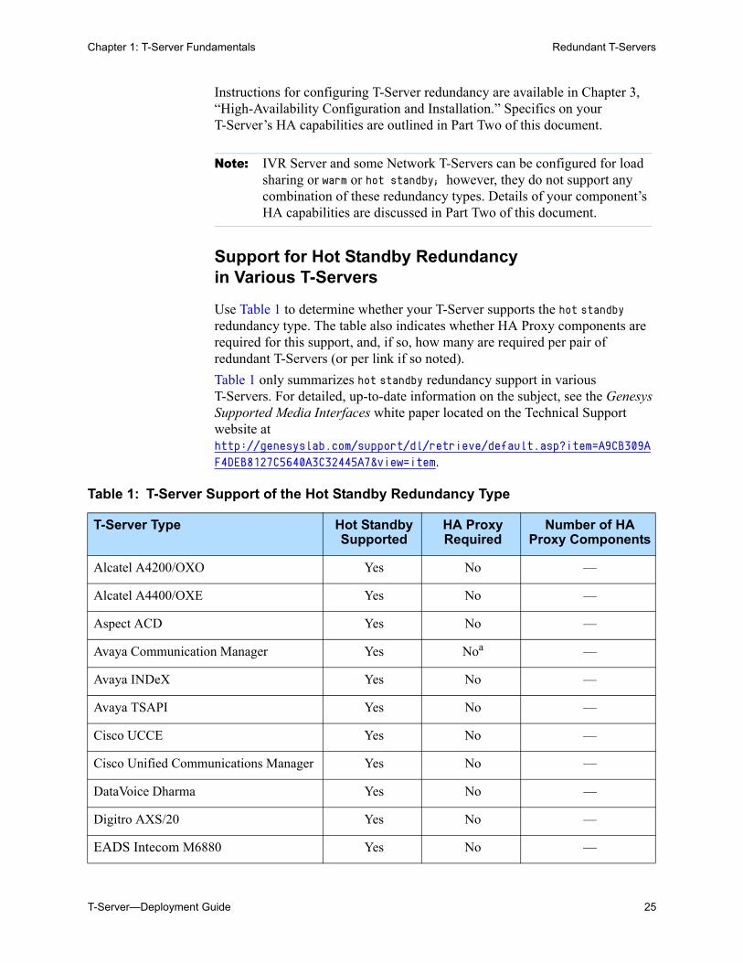
Instructions for configuring T-Server redundancy are available in Chapter 3, “High-Availability Configuration and Installation.” Specifics on your T-Server’s HA capabilities are outlined in Part Two of this document.
Support for Hot Standby Redundancy in Various T-Servers
Use Table 1 to determine whether your T-Server supports the hot standby redundancy type. The table also indicates whether HA Proxy components are required for this support, and, if so, how many are required per pair of redundant T-Servers (or per link if so noted).
Table 1 only summarizes hot standby redundancy support in various T-Servers. For detailed, up-to-date information on the subject, see the Genesys Supported Media Interfaces white paper located on the Technical Support website at http://genesyslab.com/support/dl/retrieve/default.asp?item=A9CB309AF4DEB8127C5640A3C32445A7&view=item.
Note: IVR Server and some Network T-Servers can be configured for load sharing or warm or hot standby; however, they do not support any combination of these redundancy types. Details of your component’s HA capabilities are discussed in Part Two of this document.
Table 1: T-Server Support of the Hot Standby Redundancy Type
T-Server Type Hot Standby Supported
HA Proxy Required
Number of HA Proxy Components
Alcatel A4200/OXO Yes No —
Alcatel A4400/OXE Yes No —
Aspect ACD Yes No —
Avaya Communication Manager Yes Noa —
Avaya INDeX Yes No —
Avaya TSAPI Yes No —
Cisco UCCE Yes No —
Cisco Unified Communications Manager Yes No —
DataVoice Dharma Yes No —
Digitro AXS/20 Yes No —
EADS Intecom M6880 Yes No —
26 Framework 8.0
Chapter 1: T-Server Fundamentals Redundant T-Servers
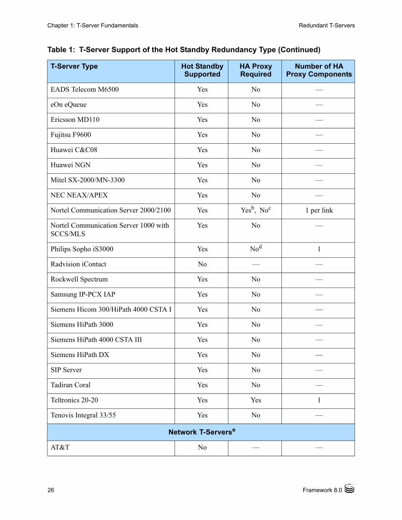
EADS Telecom M6500 Yes No —
eOn eQueue Yes No —
Ericsson MD110 Yes No —
Fujitsu F9600 Yes No —
Huawei C&C08 Yes No —
Huawei NGN Yes No —
Mitel SX-2000/MN-3300 Yes No —
NEC NEAX/APEX Yes No —
Nortel Communication Server 2000/2100 Yes Yesb, Noc 1 per link
Nortel Communication Server 1000 with SCCS/MLS
Yes No —
Philips Sopho iS3000 Yes Nod 1
Radvision iContact No — —
Rockwell Spectrum Yes No —
Samsung IP-PCX IAP Yes No —
Siemens Hicom 300/HiPath 4000 CSTA I Yes No —
Siemens HiPath 3000 Yes No —
Siemens HiPath 4000 CSTA III Yes No —
Siemens HiPath DX Yes No —
SIP Server Yes No —
Tadiran Coral Yes No —
Teltronics 20-20 Yes Yes 1
Tenovis Integral 33/55 Yes No —
Network T-Serverse
AT&T No — —
Table 1: T-Server Support of the Hot Standby Redundancy Type (Continued)
T-Server Type Hot Standby Supported
HA Proxy Required
Number of HA Proxy Components
Chapter 1: T-Server Fundamentals Redundant T-Servers
T-Server—Deployment Guide 27
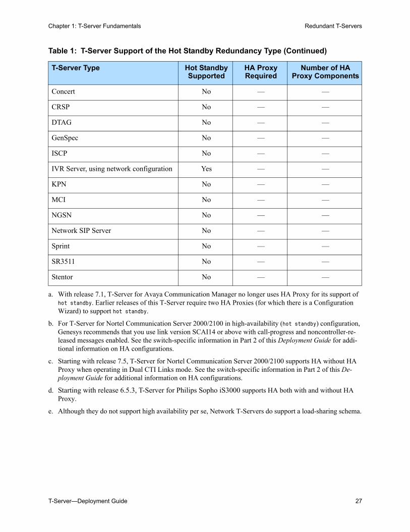
Concert No — —
CRSP No — —
DTAG No — —
GenSpec No — —
ISCP No — —
IVR Server, using network configuration Yes — —
KPN No — —
MCI No — —
NGSN No — —
Network SIP Server No — —
Sprint No — —
SR3511 No — —
Stentor No — —
a. With release 7.1, T-Server for Avaya Communication Manager no longer uses HA Proxy for its support of hot standby. Earlier releases of this T-Server require two HA Proxies (for which there is a Configuration Wizard) to support hot standby.
b. For T-Server for Nortel Communication Server 2000/2100 in high-availability (hot standby) configuration, Genesys recommends that you use link version SCAI14 or above with call-progress and noncontroller-re-leased messages enabled. See the switch-specific information in Part 2 of this Deployment Guide for addi-tional information on HA configurations.
c. Starting with release 7.5, T-Server for Nortel Communication Server 2000/2100 supports HA without HA Proxy when operating in Dual CTI Links mode. See the switch-specific information in Part 2 of this De-ployment Guide for additional information on HA configurations.
d. Starting with release 6.5.3, T-Server for Philips Sopho iS3000 supports HA both with and without HA Proxy.
e. Although they do not support high availability per se, Network T-Servers do support a load-sharing schema.
Table 1: T-Server Support of the Hot Standby Redundancy Type (Continued)
T-Server Type Hot Standby Supported
HA Proxy Required
Number of HA Proxy Components
28 Framework 8.0
Chapter 1: T-Server Fundamentals Multi-Site Support
Multi-Site SupportMulti-site configuration implies the existence of two or more switches that belong to the same enterprise or service provider, and that share the Genesys Configuration Database. (In some cases this may include isolated partitions on a given switch served by different T-Servers.) The main goal of T-Server support for multi-site operations is to maintain critical information about a call as it travels from one switch to another.
For instructions on installing and configuring a multi-site environment, including information on the Inter Server Call Control (ISCC) features, please see Chapter 4, “Multi-Site Support,” on page 61.
Agent ReservationT-Server provides support for clients to invoke the agent reservation function, TReserveAgent(). This function allows a server application that is a client of T-Server to reserve a DN along with an agent, a Place, or both, so that no other T-Server client can route calls to it during a specified reservation interval. Alternatively, when clients use the ISCC feature (see “ISCC Call Data Transfer Service” on page 63), they can use an agent reservation embedded in an ISCC request. (To do so, clients have to specify a certain Extensions attribute in an ISCC request when initiating an ISCC transaction. See page 70 for the list of ISCC requests.)
The reservation does not currently prevent the reserved objects from receiving direct calls or calls distributed from ACD Queues; agent reservation is intended as a way of synchronizing the operation of several clients. See RequestReserveAgent in the Voice Platform SDK 8.0 .NET (or Java) API Reference for more details on this function from the client’s point of view.
In addition to invoking the TReserveAgent function, you can customize the Agent Reservation feature by configuring options in the T-Server Application object. See“Agent-Reservation Section” on page 214 in the “T-Server Common Configuration Options” chapter in Part Two for more details.
Starting with version 8.0, T-Server supports Agent Reservation failure optimization, to ensure that only agent reservation requests of the highest priority are collected. T-Server responds immediately with the EventError message to existing or new reservation requests of a lower priority while collecting the agent reservation requests of the highest priority only. This functionality is controlled with the collect-lower-priority-requests configuration option (see page 214).
Chapter 1: T-Server Fundamentals Client Connections
T-Server—Deployment Guide 29
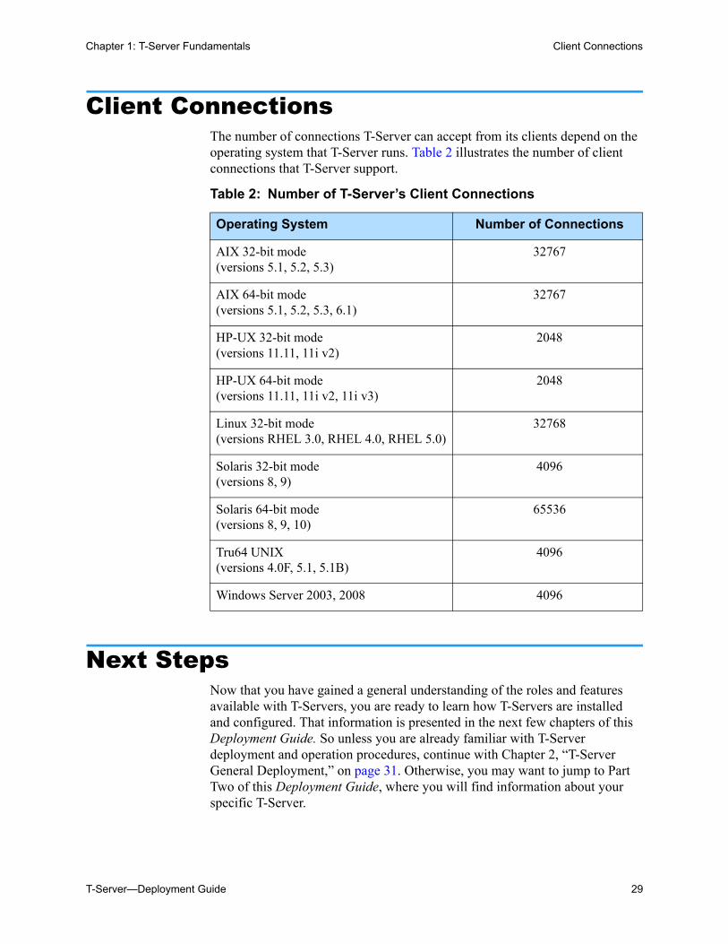
Client ConnectionsThe number of connections T-Server can accept from its clients depend on the operating system that T-Server runs. Table 2 illustrates the number of client connections that T-Server support.
Next StepsNow that you have gained a general understanding of the roles and features available with T-Servers, you are ready to learn how T-Servers are installed and configured. That information is presented in the next few chapters of this Deployment Guide. So unless you are already familiar with T-Server deployment and operation procedures, continue with Chapter 2, “T-Server General Deployment,” on page 31. Otherwise, you may want to jump to Part Two of this Deployment Guide, where you will find information about your specific T-Server.
Table 2: Number of T-Server’s Client Connections
Operating System Number of Connections
AIX 32-bit mode(versions 5.1, 5.2, 5.3)
32767
AIX 64-bit mode (versions 5.1, 5.2, 5.3, 6.1)
32767
HP-UX 32-bit mode (versions 11.11, 11i v2)
2048
HP-UX 64-bit mode (versions 11.11, 11i v2, 11i v3)
2048
Linux 32-bit mode (versions RHEL 3.0, RHEL 4.0, RHEL 5.0)
32768
Solaris 32-bit mode(versions 8, 9)
4096
Solaris 64-bit mode(versions 8, 9, 10)
65536
Tru64 UNIX (versions 4.0F, 5.1, 5.1B)
4096
Windows Server 2003, 2008 4096

30 Framework 8.0
Chapter 1: T-Server Fundamentals Next Steps
T-Server—Deployment Guide 31
Chapter
2 T-Server General DeploymentThis chapter contains general information for the deployment, configuration, and installation of your T-Server. You may have to complete additional configuration and installation steps specific to your T-Server and switch. You will find these steps in Part Two of this document.
This chapter contains these sections: Prerequisites, page 31 Deployment Sequence, page 36 Wizard Deployment of T-Server, page 36 Manual Deployment of T-Server, page 39 Next Steps, page 46
PrerequisitesT-Server has a number of prerequisites for deployment. Read through this section before deploying your T-Server.
Note: You must read the Framework 8.0 Deployment Guide before proceeding with this T-Server guide. That book contains information about the Genesys software you must deploy before deploying T-Server.
32 Framework 8.0
Chapter 2: T-Server General Deployment Prerequisites
Software Requirements
Framework Components
You can only configure T-Server after you have deployed the Configuration Layer of Genesys Framework. This layer contains DB Server, Configuration Server, Configuration Manager, and, at your option, Deployment Wizards. If you intend to monitor or control T-Server through the Management Layer, you must also install and configure components of this Framework layer, such as Local Control Agent (LCA), Message Server, Solution Control Server (SCS), and Solution Control Interface (SCI), before deploying T-Server.
Refer to the Framework 8.0 Deployment Guide for information about, and deployment instructions for, these Framework components.
Media Layer and LCA
To monitor the status of components in the Media Layer through the Management Layer, you must load an instance of LCA on every host running Media Layer components. Without LCA, Management Layer cannot monitor the status of any of these components. If you do not use the Management Layer, LCA is not required.
Supported Platforms
Refer to the Genesys Supported Operating Environment Reference Manual for the list of operating systems and database systems supported in Genesys releases 6.x, 7.x, and 8.x. You can find this document on the Genesys Technical Support website at http://genesyslab.com/support/dl/retrieve/default.asp?item=B6C52FB62DB42BB229B02755A3D92054&view=item.
For UNIX-based (UNIX) operating systems, also review the list of patches Genesys uses for software product builds, and upgrade your patch configuration if necessary. A description of patch configuration is linked to installation read_me.html files for the Genesys applications that operate on UNIX, and is available within the installation packages.
Security
Starting with release 7.5, T-Server supports the Genesys Transport Layer Security (TLS) and can be configured for secure data exchange with the other Genesys components that support this functionality.
The Genesys TLS is not supported on all operating systems that T-Server itself supports. For information about the supported operating systems, see the Genesys 8.0 Security Deployment Guide.
Chapter 2: T-Server General Deployment Prerequisites
T-Server—Deployment Guide 33
Hardware and Network Environment Requirements
Hosting
Genesys recommends that you or your IT specialist assign host computers to Genesys software before you start Genesys installation. Remember the following restrictions:
• Do not install all the Genesys server applications on the same host computer.
• When installing a few server applications on the same host computer, prevent them (except for Configuration Server) from using the swap area.
Installation Privileges
During deployment, be sure to log in with an account that will permit you to perform administrative functions—that is, one that has root privileges.
Server Locations
Refer to the “Network Locations for Framework Components” chapter of the Framework 8.0 Deployment Guide for recommendations on server locations.
Supported Platforms
Refer to the Genesys Supported Media Interfaces white paper for the list of supported switch and PABX versions. You can find this document on the Genesys Technical Support website at http://genesyslab.com/support/dl/retrieve/default.asp?item=A9CB309AF4DEB8127C5640A3C32445A7&view=item.
Licensing Requirements
All Genesys software is licensed—that is, it is not shareware. Genesys products are protected through legal license conditions as part of your purchase contract. However, the level of technical license-control enforcement varies across different solutions and components.
Before you begin to install T-Server, remember that, although you may not have had to use technical licenses for your software when you deployed the Configuration and Management Layers in their basic configurations, this is not the case with the Media Layer.
T-Server requires seat-related DN technical licenses to operate even in its most basic configuration. Without appropriate licenses, you cannot install and start T-Server. If you have not already done so, Genesys recommends that you install License Manager and configure a license file at this point. For complete
34 Framework 8.0
Chapter 2: T-Server General Deployment Prerequisites
information on which products require what types of licenses, and on the installation procedure for License Manager, refer to the Genesys Licensing Guide available on the Genesys Documentation Library DVD.
The sections that follow briefly describe the T-Server license types.
Note: Starting with release 7.2, the licensing requirements for T-Server have changed from previous releases. Please read this section carefully and refer to the Genesys Licensing Guide for complete licensing information.
Licensing Basic Implementations
A stand-alone T-Server serving a single site requires licenses to register all DNs it monitors. DNs that agents use in day-to-day contact center operations, such as Extensions and ACD Positions, have to be registered using licenses that control agent seats.
Note: Configure all seat DNs that agents use (Extensions and ACD Positions) in the Configuration Layer. This enables detailed call monitoring through Genesys reporting, and generally allows you to control access to individual DNs.
Licensing HA Implementations
T-Servers operating with the hot standby redundancy type require a special CTI HA technical license, which allows for high-availability implementations, in addition to regular T-Server licenses. Neither T-Server in a redundant pair configured for hot standby starts if this license is unavailable. Moreover, the primary and backup T-Servers must use the same licenses to control the same pool of DNs. If your T-Servers are configured with the hot standby redundancy type, order licenses for CTI HA support.
Licensing Multi-Site Implementations
T-Servers performing multi-site operations require licenses that allow for such operations, in addition to regular T-Server licenses. If some of your T-Servers are configured for multi-site routing while others are not, either order licenses for multi-site support for all T-Servers or install an additional License Manager to handle the T-Servers involved in multi-site routing.
Note: You do not need licenses for multi-site support if some T-Server clients include the local location as the location attribute value in their requests for routing within the same site.
Chapter 2: T-Server General Deployment Prerequisites
T-Server—Deployment Guide 35
Configuring License Files
You need a license to configure and install Media Layer components. Genesys recommends that, if you have not already done so, at this point you:
1. Install License Manager.
2. Configure license files.
Note: If you use the <port>@<server> format when entering the name of the license server during installation, remember that some operating systems use @ as a special character. In this case, the installation routine is unable to write license information for T-Server to the Configuration Layer or the run.sh file. Therefore, when you use the <port>@<server> format, you must manually modify the command-line license parameter after installing T-Server.
For information about which products require what types of licenses and for the installation procedure for License Manager, refer to the Genesys Licensing Guide available on the Genesys Documentation Library DVD.
About Configuration Options
Configuring T-Server is not a onetime operation. It is something you do at the time of installation and then in an ongoing way to ensure the continued optimal performance of your software. You must enter values for T-Server configuration options in the relevant Wizard screens or on the Options tab of your T-Server Application object in Configuration Manager. The instructions for configuring and installing T-Server that you see here are only the most rudimentary parts of the process. You must refer extensively to the configuration options chapters located in Part Two of this book. Pay particular attention to the configuration options specific to your own T-Server.
Configuration options common to all T-Servers, independent of switch type, are described in Chapter 9, “T-Server Common Configuration Options,” on page 205. Switch-specific configuration options are described in a separate chapter. T-Server also supports unified Genesys log options, as described in the “Common Configuration Options” chapter.
Options that configure values for the TSCP software in your T-Server are common to all T-Servers. Options based on the custom features of your switch apply to your T-Server only. Familiarize yourself with both types of options. You will want to adjust them to accommodate your production environment and the business rules that you want implemented there.
36 Framework 8.0
Chapter 2: T-Server General Deployment Deployment Sequence
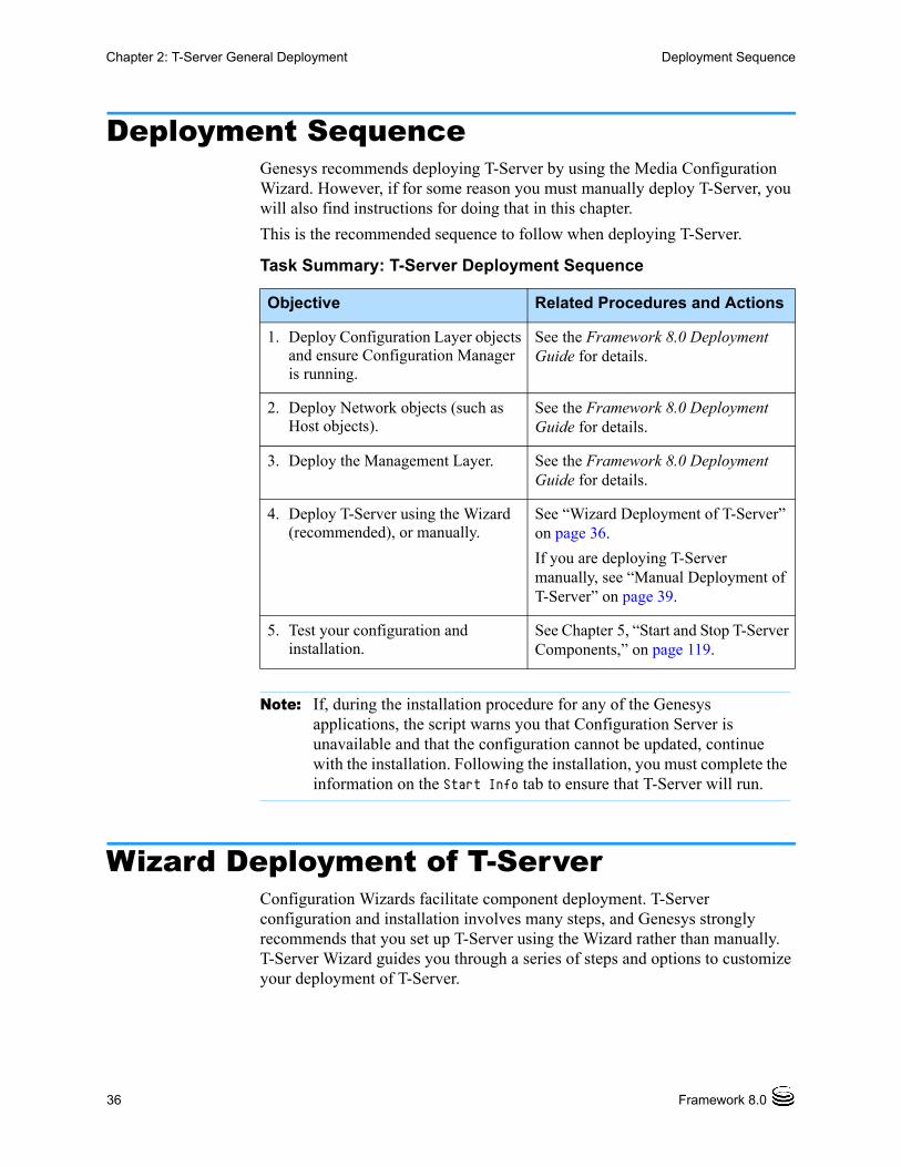
Deployment SequenceGenesys recommends deploying T-Server by using the Media Configuration Wizard. However, if for some reason you must manually deploy T-Server, you will also find instructions for doing that in this chapter.
This is the recommended sequence to follow when deploying T-Server.
Wizard Deployment of T-ServerConfiguration Wizards facilitate component deployment. T-Server configuration and installation involves many steps, and Genesys strongly recommends that you set up T-Server using the Wizard rather than manually. T-Server Wizard guides you through a series of steps and options to customize your deployment of T-Server.
Task Summary: T-Server Deployment Sequence
Objective Related Procedures and Actions
1. Deploy Configuration Layer objects and ensure Configuration Manager is running.
See the Framework 8.0 Deployment Guide for details.
2. Deploy Network objects (such as Host objects).
See the Framework 8.0 Deployment Guide for details.
3. Deploy the Management Layer. See the Framework 8.0 Deployment Guide for details.
4. Deploy T-Server using the Wizard (recommended), or manually.
See “Wizard Deployment of T-Server” on page 36.
If you are deploying T-Server manually, see “Manual Deployment of T-Server” on page 39.
5. Test your configuration and installation.
See Chapter 5, “Start and Stop T-Server Components,” on page 119.
Note: If, during the installation procedure for any of the Genesys applications, the script warns you that Configuration Server is unavailable and that the configuration cannot be updated, continue with the installation. Following the installation, you must complete the information on the Start Info tab to ensure that T-Server will run.
Chapter 2: T-Server General Deployment Wizard Deployment of T-Server
T-Server—Deployment Guide 37
Wizard Configuration of T-Server
The first step to take for a Wizard-based configuration is to install and launch Genesys Wizard Manager. (Refer to the Framework 8.0 Deployment Guide for instructions.) When you first launch Genesys Wizard Manager, it suggests that you set up the Management Layer and then the Framework. The Framework setup begins with configuring and creating the objects related to T-Server, starting with the Switch and Switching Office objects, and the T-Server’s Application object itself.
During creation of the Switch object, you also have an opportunity to run the Log Wizard to set up T-Server logging. Then, you can specify values for the most important T-Server options. Finally, you can create contact center objects related to T-Server, such as DNs, Agent Logins, and some others.
After you complete the Framework configuration, the Genesys Wizard Manager screen no longer prompts you to set up the Framework. Instead, it suggests that you set up your solutions or add various contact center objects to the Framework configuration, including the Switch, DNs and Places, Agent Logins, Agent Groups, Place Groups, and, in a multi-tenant environment, a Tenant. In each case, click the link for the object you wish to create. Again, you create a new T-Server Application object in the course of creating a new Switch object.
Wizard Installation of T-Server
After creating and configuring your T-Server and its related components with the Wizard, proceed to T-Server installation. That installation process is similar to that of previously installed components.
Note: With the Wizard, you create your T-Server Application object in the course of creating your Switch object.
Note: During configuration of a Switch object, the Wizard prompts you to copy a T-Server installation package to an assigned computer. After that package is copied to the destination directory on the T-Server host, complete the last steps of the T-Server configuration. Then, install T-Server on its host.
Note: Certain Wizard-related procedures are not described in this document. Refer to the Framework 8.0 Deployment Guide for general instructions.
38 Framework 8.0
Chapter 2: T-Server General Deployment Wizard Deployment of T-Server
Procedure:Installing T-Server on UNIX using Wizard
Start of procedure
1. In the directory to which the T-Server installation package was copied during Wizard configuration, locate a shell script called install.sh.
2. Run this script from the command prompt by typing sh and the file name. For example: sh install.sh.
3. When prompted, confirm the host name of the computer on which you are installing T-Server.
4. When prompted, confirm the application name of the T-Server that you are installing.
5. Specify the destination directory into which you are installing T-Server, with the full path to it.
6. If the target installation directory has files in it, do one of the following:• Type 1 to back up all the files in the directory (recommended).• Type 2 to overwrite only the files in this installation package. Use this
option only if the installation being upgraded operates properly. • Type 3 to erase all files in this directory before continuing with the
installation.
The list of file names will appear on the screen as the files are copied to the destination directory.
7. If asked which version of the product to install, the 32-bit or the 64-bit, choose the one appropriate to your environment.
8. If asked, specify the license information that T-Server is to use.
9. As soon as the installation process is finished, a message appears announcing that installation was successful. The process places T-Server in the directory with the name specified during the installation.
End of procedure
Next Steps
• To test your configuration and installation, go to Chapter 5, “Start and Stop T-Server Components,” on page 119, and try it out.
• To configure and install redundant T-Servers, see Chapter 3, “High-Availability Deployment,” on page 49.
Warning! Genesys does not recommend installation of its components using a Microsoft Remote Desktop connection. The installation should be performed locally
Chapter 2: T-Server General Deployment Manual Deployment of T-Server
T-Server—Deployment Guide 39
• To install T-Servers for a multi-site environment, proceed to Chapter 4, “Multi-Site Support,” on page 61.
Procedure:Installing T-Server on Windows using Wizard
Start of procedure
1. Open the directory to which the T-Server installation package was copied during Wizard configuration.
2. Locate and double-click Setup.exe to start the installation. The Welcome screen launches.
3. When prompted, specify the connection parameters to the Configuration Server associated with this T-Server.
4. Identify the T-Server Application object in the Configuration Layer to be used by this T-Server.
5. Specify the license information that T-Server is to use.
6. Specify the destination directory into which you are installing T-Server.
7. Click Install to begin the installation.
8. Click Finish to complete the installation.
By default, T-Server is installed as a Genesys service (Windows Services) with Automatic startup type.
End of procedure
Next Steps
• To test your configuration and installation, go to Chapter 5, “Start and Stop T-Server Components,” on page 119, and try it out.
• To configure and install redundant T-Servers, see Chapter 3, “High-Availability Deployment,” on page 49.
• To install T-Servers for a multi-site environment, proceed to Chapter 4, “Multi-Site Support,” on page 61.
Manual Deployment of T-ServerDeploying T-Server manually requires that you configure a number of different objects in the Configuration Layer prior to setting up your T-Server
40 Framework 8.0
Chapter 2: T-Server General Deployment Manual Deployment of T-Server
objects and then install T-Server. This section describes the manual deployment process.
Manual Configuration of Telephony Objects
This section describes how to manually configure T-Server Telephony objects if you are using Configuration Manager.
Recommendations
Genesys recommends registering (configuring) only those entities you plan to use in the current configuration. The more data there is in the Configuration Database, the longer it takes for the CTI setup to start, and the longer it will take to process configuration data. Remember that adding configuration objects to the Genesys Configuration Database does not cause any interruption in contact center operation.
Depending on how much work is required to manually configure all applications and objects, consider registering more Person objects first, with a set of privileges that lets them perform configuration tasks.
Switching Offices
Your telephony network may contain many switching offices, but you should only configure those that are involved with customer interactions.
Using Configuration Manager, be sure to register a Switching Office object that accommodates your Switch object under Environment. Until you have done this, you cannot register a Switch object under Resources (single-tenant environment) or a Tenant (multi-tenant environment).
Switches
1. Configure a Switch object for each switch on your telephony network. Assign each Switch object to the appropriate T-Server object.
2. If implementing the multi-site configuration, specify access codes for all switches on the network so that the call-processing applications can route and transfer calls between switches.
Two types of access codes exist in a Genesys configuration: Default access codes that specify how to reach this switch from any
other switch in the Genesys environment.
Note: The value for the switching office name must not have spaces in it.
Chapter 2: T-Server General Deployment Manual Deployment of T-Server
T-Server—Deployment Guide 41
Switch-to-switch access codes that specify how to reach a particular switch from any other switch. Use this type when either a nondefault dial number or routing type is required between any two locations. When a switch-to-switch access code is configured, its value has a higher priority than that of a default access code.
See Chapter 4, “Multi-Site Support,” on page 61, for step-by-step instructions.
DNs and Agent Logins
For each T-Server for which you are configuring DNs, you must configure all DNs that agents and their supervisors use in day-to-day contact center operation—so-called seat-related DNs—such as Extensions and ACD Positions. Otherwise, T-Server does not register such DNs.
1. To configure Telephony objects within each switch, consult the switch documentation. Information specific to your T-Server in Part Two of this document contains tables that indicate how to set DN types in the Genesys Configuration Database depending on the switch DN types and configuration.
2. Check the numbering plan for different types of DNs, to see if you can save time by registering Ranges of DNs. Usually, DNs of the same type have consecutive numbers, which will make an otherwise tedious configuration task easy. Agent Login objects almost always have consecutive numbers, which means you can register them through the Range of Agent Logins feature as well.
3. If you plan to use Virtual Queues and Virtual Routing Points in the contact center operation, Genesys recommends registering them after you have outlined the call-processing algorithms and identified your reporting needs.
Note: When the numbering plan uses unique directory number (DN) assignment across sites and multi-site routing is not used, you do not have to configure access codes.
Note: Starting with release 7.2, the requirements for configuring DNs in the Configuration Layer have changed. Refer to Part Two of this guide for information about the requirements on configuring specific DN types for your T-Server.
Note: Remember that CTI applications, not the switch, generate telephony events for DNs of these types.
42 Framework 8.0
Chapter 2: T-Server General Deployment Manual Deployment of T-Server
Multi-Site Operations
See the section, “Configuring Multi-Site Support” on page 104, for information on setting up DNs for multi-site operations.
Manual Configuration of T-Server
Use the Framework 8.0 Deployment Guide to prepare accurate configuration information. You may also want to consult Configuration Manager Help, which contains detailed information about configuring objects.
Recommendations
Genesys recommends using an Application Template when you are configuring your T-Server application. The Application Template for your particular T-Server contains the most important configuration options set to the values recommended for the majority of environments. When modifying configuration options for your T-Server application later in the process, you can change the values inherited from the template rather than create all the options by yourself.
Procedure:Configuring T-Server manually
Start of procedure
1. Follow the standard procedure for configuring all Application objects to begin configuring your T-Server Application object. Refer to the Framework 8.0 Deployment Guide for instructions.
2. In a Multi-Tenant environment, specify the Tenant to which this T-Server belongs on the General tab of the Properties dialog box.
Warning! When setting the Register flag for a DN, make sure you select the value according to your needs. The Register flag values are as follows: • False—T-Server processes this DN locally, and never registers
it on the switch. • True—T-Server always registers this DN on the switch during
T-Server startup or CTI link reconnect. • On Demand—T-Server registers this DN on the switch only if a
T-Server client requests that it be registered.
Chapter 2: T-Server General Deployment Manual Deployment of T-Server
T-Server—Deployment Guide 43
3. On the Connections tab: Add all Genesys applications to which T-Server must connect.
4. On the Options tab, specify values for configuration options as appropriate for your environment.
5. In a multi-site environment, you must complete additional T-Server configuration steps to support multi-site operations; see Chapter 4, “Multi-Site Support,” on page 61.
End of procedure
Next Steps
• See “Manual Installation of T-Server” on page 44.
Procedure:Configuring multiple ports
Purpose: To configure multiple ports in T-Server for its client connections.
Start of procedure
1. Open the T-Server Application Properties dialog box.
2. Click the Server Info tab.
3. In the Ports section, click Add Port.
4. In the Port Properties dialog box, on the Port Info tab:
a. In the Port ID text box, enter the port ID.
b. In the Communication Port text box, enter the number of the new port.
c. In the Connection Protocol box, select the connection protocol, if necessary.
d. Select the Listening Mode option.
Note: For multi-site deployments you should also specify T-Server connections on the Connections tab for any T-Servers that may transfer calls directly to each other.
Note: For T-Server option descriptions, see Part Two of this document.
Note: For more information on configuring secure connections between Framework components, see Genesys 8.0 Security Deployment Guide.
44 Framework 8.0
Chapter 2: T-Server General Deployment Manual Deployment of T-Server
e. Click OK.
5. Click OK to save the new configuration.
End of procedure
Manual Installation of T-Server
The following directories on the Genesys 8.0 Media product DVD contain T-Server installation packages:
• media_layer/<switch>/<platform> for UNIX installations, where <switch> is your switch name and <platform> is your operating system.
• media_layer\<switch>\windows for Windows installations, where <switch> is your switch name.
Procedure:Installing T-Server on UNIX manually
Start of procedure
1. In the directory to which the T-Server installation package was copied, locate a shell script called install.sh.
2. Run this script from the command prompt by typing sh and the file name. For example: sh install.sh.
3. When prompted, confirm the host name of the computer on which T-Server is to be installed.
4. When prompted, specify the host and port of Configuration Server.
5. When prompted, enter the user name and password to access Configuration Server.
6. When prompted, select the T-Server application you configured in “Configuring T-Server manually” on page 42 from the list of applications.
7. Specify the destination directory into which T-Server is to be installed, with the full path to it.
8. If the target installation directory has files in it, do one of the following:• Type 1 to back up all the files in the directory (recommended).• Type 2 to overwrite only the files in this installation package. Use this
option only if the installation being upgraded operates properly.
Note: During installation on UNIX, all files are copied into the directory you specify. No additional directories are created within this directory. Therefore, do not install different products into the same directory.
Chapter 2: T-Server General Deployment Manual Deployment of T-Server
T-Server—Deployment Guide 45
• Type 3 to erase all files in this directory before continuing with the installation.
The list of file names will appear on the screen as the files are copied to the destination directory.
9. If asked which version of the product to install, the 32-bit or the 64-bit, choose the one appropriate to your environment.
10. If asked about the license information that T-Server is to use: specify either the full path to, and the name of, the license file, or the license server parameters.
11. As soon as the installation process is finished, a message appears announcing that installation was successful. The process places T-Server in the directory with the name specified during the installation.
End of procedure
Next Steps
• To verify manual installation, go to “Verifying the manual installation of T-Server” on page 46.
• To test your configuration and installation, go to Chapter 5, “Start and Stop T-Server Components,” on page 119, and try it out.
• To configure and install redundant T-Servers, see Chapter 3, “High-Availability Deployment,” on page 49.
• To install T-Servers for a multi-site environment, proceed to Chapter 4, “Multi-Site Support,” on page 61.
Procedure:Installing T-Server on Windows manually
Start of procedure
1. In the directory to which the T-Server installation package was copied, locate and double-click Setup.exe to start the installation.
2. When prompted, specify the connection parameters to the Configuration Server associated with this T-Server.
3. When prompted, select the T-Server Application you configured in “Configuring T-Server manually” on page 42 from the list of applications.
4. Specify the license information that T-Server is to use: either the full path to, and the name of, the license file, or the license server parameters.
5. Specify the destination directory into which T-Server is to be installed.
6. Click Install to begin the installation.
7. Click Finish to complete the installation.
46 Framework 8.0
Chapter 2: T-Server General Deployment Next Steps
By default, T-Server is installed as a Genesys service (Windows Services) with Automatic startup type.
End of procedure
Next Steps
• To verify manual installation, go to “Verifying the manual installation of T-Server” on page 46.
• To test your configuration and installation, go to Chapter 5, “Start and Stop T-Server Components,” on page 119, and try it out.
• To configure and install redundant T-Servers, see Chapter 3, “High-Availability Deployment,” on page 49.
• To install T-Servers for a multi-site environment, proceed to Chapter 4, “Multi-Site Support,” on page 61.
Procedure:Verifying the manual installation of T-Server
Purpose: To verify the completeness of the manual installation of T-Server to ensure that T-Server will run.
Prerequisites
• Procedure: Installing T-Server on UNIX manually, on page 44
• Procedure: Installing T-Server on Windows manually, on page 45
Start of procedure
1. Open the Properties dialog box for a corresponding Application object in Configuration Manager.
2. Verify that the State Enabled check box on the General tab is selected.
3. Verify that the Working Directory, command-line, and Command-Line Arguments are specified correctly on the Start Info tab.
4. Click Apply and OK to save any configuration updates.
End of procedure
Next StepsAt this point, you have either used the Wizard to configure and install T-Server, or you have done it manually, using Configuration Manager. In either case, if you want to test your configuration and installation, go to Chapter 5,

Chapter 2: T-Server General Deployment Next Steps
T-Server—Deployment Guide 47
“Start and Stop T-Server Components,” on page 119, and try it out. Otherwise, if you want to configure and install redundant T-Servers, see Chapter 3, “High-Availability Deployment,” on page 49. If you want to install T-Servers for a multi-site environment, proceed to Chapter 4, “Multi-Site Support,” on page 61.

48 Framework 8.0
Chapter 2: T-Server General Deployment Next Steps
T-Server—Deployment Guide 49
Chapter
3 High-Availability DeploymentThis chapter describes the general steps for setting up a high-availability (HA) environment for your T-Server. The high-availability architecture implies the existence of redundant applications, a primary and a backup. These are monitored by a management application so that, if one application fails, the other can take over its operations without any significant loss of contact center data.
Every switch/T-Server combination offers different high-availability options. The Framework Management Layer currently supports two types of redundant configurations: warm standby and hot standby. All T-Servers offer the warm standby redundancy type and, starting with release 7.1, the hot standby redundancy type is implemented in T-Servers for most types of switches. Some T-Servers support a switch’s ability to provide two CTI links to two T-Servers or even one CTI link to two T-Servers. Other T-Servers require Genesys’s HA Proxy in order to support the hot standby redundancy type. See Table 1 on page 25 and the T-Server-specific information later in this document for details on your T-Server.
This chapter describes the redundant architecture and how to configure T-Server so that it operates with either type. Information in this chapter is divided into the following sections: Warm Standby Redundancy Type, page 50 Hot Standby Redundancy Type, page 51 Prerequisites, page 53 Warm Standby Deployment, page 54 Hot Standby Deployment, page 56 Next Steps, page 60
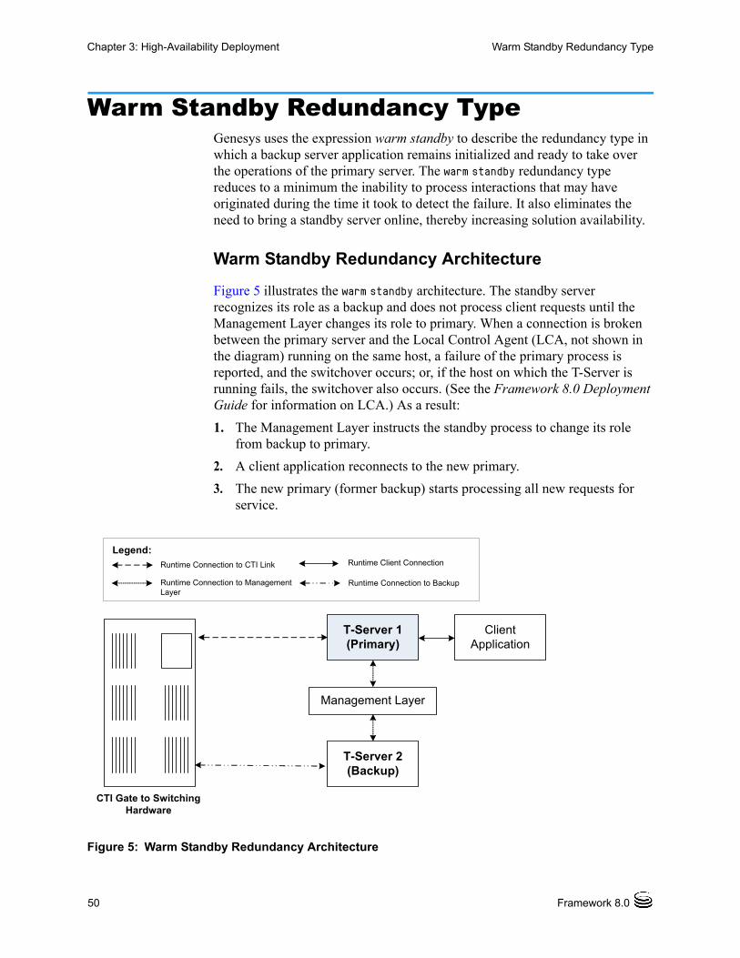
50 Framework 8.0
Chapter 3: High-Availability Deployment Warm Standby Redundancy Type
Warm Standby Redundancy TypeGenesys uses the expression warm standby to describe the redundancy type in which a backup server application remains initialized and ready to take over the operations of the primary server. The warm standby redundancy type reduces to a minimum the inability to process interactions that may have originated during the time it took to detect the failure. It also eliminates the need to bring a standby server online, thereby increasing solution availability.
Warm Standby Redundancy Architecture
Figure 5 illustrates the warm standby architecture. The standby server recognizes its role as a backup and does not process client requests until the Management Layer changes its role to primary. When a connection is broken between the primary server and the Local Control Agent (LCA, not shown in the diagram) running on the same host, a failure of the primary process is reported, and the switchover occurs; or, if the host on which the T-Server is running fails, the switchover also occurs. (See the Framework 8.0 Deployment Guide for information on LCA.) As a result:
1. The Management Layer instructs the standby process to change its role from backup to primary.
2. A client application reconnects to the new primary.
3. The new primary (former backup) starts processing all new requests for service.
Figure 5: Warm Standby Redundancy Architecture
CTI Gate to SwitchingHardware
T-Server 1 (Primary)
T-Server 2 (Backup)
Management Layer
Client Application
Legend:Runtime Client Connection
Runtime Connection to Management Layer
Runtime Connection to Backup
Runtime Connection to CTI Link
Chapter 3: High-Availability Deployment Hot Standby Redundancy Type
T-Server—Deployment Guide 51
Although normal operations are restored as soon as the backup process takes over, the fault management effort continues. That effort consists of repeated attempts to restart the process that failed. Once successfully restarted, the process is assigned the backup role.
Hot Standby Redundancy TypeGenesys uses the expression hot standby to describe the redundancy type in which a backup server application remains initialized, clients connect to both the primary and backup servers at startup, and the backup server data is synchronized from the primary server. Data synchronization and existing client connections to the backup guarantee higher availability of a component. (See Figure 6 on page 52.)
Starting with release 7.1, the hot standby redundancy type is implemented in T-Servers for most types of switches. However, for some switches, you must compensate for the lack of link redundancy by using an additional Genesys component called HA Proxy.
Hot Standby Redundancy Architecture
Figure 6 illustrates the switch-independent side of a hot standby implementation. Here, T-Servers start simultaneously and connect to the switch. At T-Server startup, the Management Layer assigns the role of the primary server to T-Server 1, and the role of backup to T-Server 2. T-Server clients register with both T-Servers, but only the primary T-Server handles client requests other than the registration requests. The internal T-Server information, such as a DN status, ConnID, UserData, and Call Type, is synchronized between the primary and backup T-Servers. Therefore, the backup T-Server has the same information as the primary T-Server.
If T-Server 1 fails, the Management Layer makes T-Server 2 the new primary server, and it starts processing client requests. The Management Layer attempts to restart T-Server 1, and if it is successful, it makes T-Server 1 the new backup server.
The details of hot standby redundancy implementation between T-Servers and their switches vary depending on switch support for multiple CTI links. If your T-Server supports hot standby (see Table 1 on page 25), refer to Part Two for detailed information on the available hot standby schema.
Note: You can find full details on the role of the Management Layer in redundant configurations in the Framework 8.0 Deployment Guide.
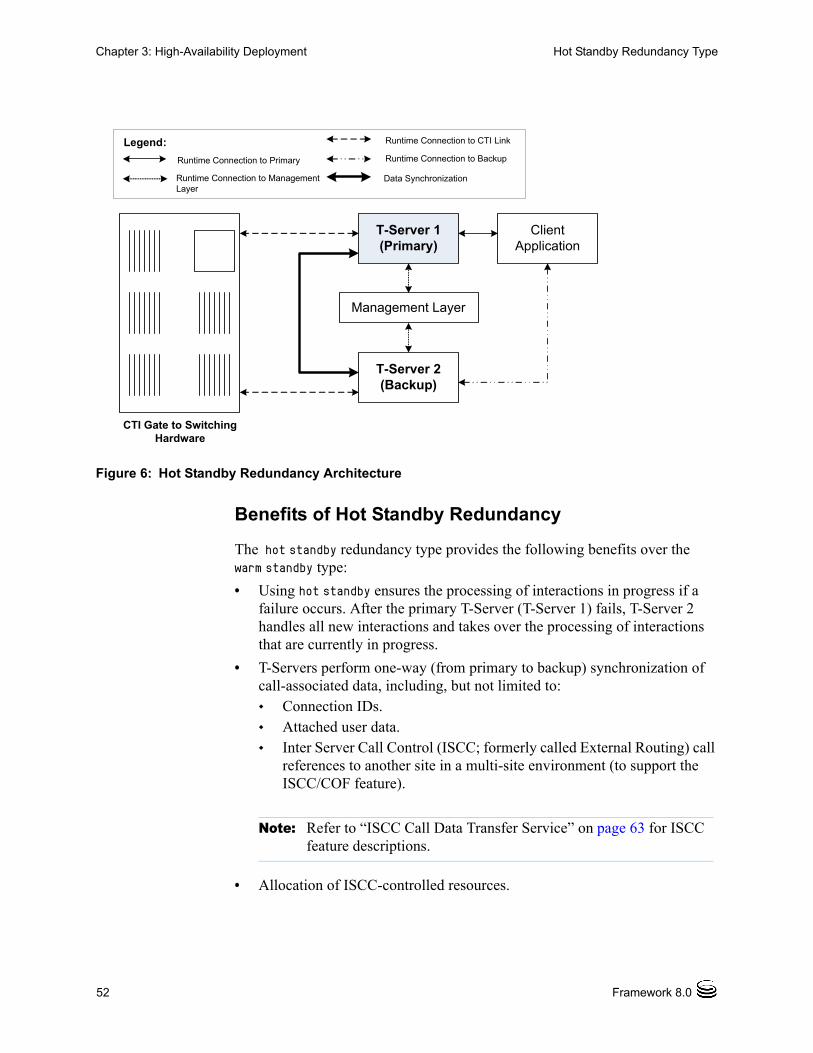
52 Framework 8.0
Chapter 3: High-Availability Deployment Hot Standby Redundancy Type
Figure 6: Hot Standby Redundancy Architecture
Benefits of Hot Standby Redundancy
The hot standby redundancy type provides the following benefits over the warm standby type:
• Using hot standby ensures the processing of interactions in progress if a failure occurs. After the primary T-Server (T-Server 1) fails, T-Server 2 handles all new interactions and takes over the processing of interactions that are currently in progress.
• T-Servers perform one-way (from primary to backup) synchronization of call-associated data, including, but not limited to: Connection IDs. Attached user data. Inter Server Call Control (ISCC; formerly called External Routing) call
references to another site in a multi-site environment (to support the ISCC/COF feature).
• Allocation of ISCC-controlled resources.
CTI Gate to SwitchingHardware
T-Server 1 (Primary)
T-Server 2 (Backup)
Management Layer
Client Application
Legend:
Runtime Connection to Primary
Runtime Connection to Management Layer
Runtime Connection to CTI Link
Runtime Connection to Backup
Data Synchronization
Note: Refer to “ISCC Call Data Transfer Service” on page 63 for ISCC feature descriptions.
Chapter 3: High-Availability Deployment Prerequisites
T-Server—Deployment Guide 53
• When mirrored links are not available, HA Proxy helps T-Server synchronize the current states of agents, calls, parties, and devices between the primary and backup T-Servers.
However, keep the following hot standby limitations in mind:
• Client requests sent during the failure and switchover may be lost.
• Routing requests sent by the switch during the failure and switchover may be lost.
• T-Server does not synchronize interactions that begin before it starts.
• Some T-Library events might be duplicated or lost.
• Reference IDs from client requests can be lost in events.
PrerequisitesThis section presents basic requirements and recommendations for configuring and using redundant T-Servers.
Requirements
You must install the Management Layer if you are installing redundant T-Server applications. In particular, install Local Control Agent (LCA) on each computer that runs T-Server.
Synchronization Between Redundant T-Servers
When T-Servers operate in a high-availability environment, the backup T-Server must be ready to take on the primary role when required. For this purpose, both T-Servers must be running and must have the same information. When you configure redundant T-Servers to operate with the hot standby type, the primary T-Server uses the connection to the backup to deliver synchronization updates. Genesys recommends that you enable the Advanced Disconnect Detection Protocol (ADDP), described in Chapter 1, for this connection. Do so using the configuration options in the “Backup-Synchronization Section” section. Refer to the “T-Server Common Configuration Options” chapter for option descriptions.
Configuration Warnings
When configuring T-Servers to support either the warm standby or hot standby redundancy type, remember:
Warning! Genesys strongly recommends that you install the backup and primary T-Servers on different host computers.
54 Framework 8.0
Chapter 3: High-Availability Deployment Warm Standby Deployment
1. When at least one of the two T-Servers that operate in a redundant mode is running, do not change a redundancy type, host, or port in either T-Server configuration.
2. When both the primary and backup T-Servers are running, do not remove the backup T-Server Application object from the configuration.
You are responsible for the option synchronization in the configuration of the primary and backup T-Servers; Configuration Server does not synchronize either options or their values in different T-Server Application objects. That is, you must configure both T-Servers to have the same options with the same values. If you change a value in one T-Server configuration, you must change it in the other T-Server configuration manually. The log options in the primary T-Server can differ from those in the backup T-Server configuration. The link configuration options in the primary T-Server can also differ from those in the backup T-Server configuration.
Warm Standby DeploymentThis section describes how to configure redundant T-Servers to work with the warm standby redundancy type, including details on their connections and settings.
General Order of Deployment
The general guidelines for T-Server warm standby configuration are:
WizardDeployment
• If you used wizards to configure T-Servers and selected the warm standby redundancy type, no additional configuration is required for your T-Servers.
ManualDeployment
• If you did not use wizards to configure T-Servers:
a. Manually configure two T-Server Application objects as described in “Manual Configuration of T-Server” on page 42.
b. Make sure the Switch object is configured for the switch these T-Servers should serve, as described in “Manual Configuration of T-Server” on page 42.
c. Modify the configuration of the primary and backup T-Servers as instructed in the following sections.
After completing the configuration steps, ensure that both T-Servers are installed (see page 56).
Chapter 3: High-Availability Deployment Warm Standby Deployment
T-Server—Deployment Guide 55
Manual Modification of T-Servers for Warm Standby
Modify the configuration of both the primary and backup T-Server Application objects as described in the following sections.
Procedure:Modifying the primary T-Server configuration for warm standby
Start of procedure
1. Stop both the primary and backup T-Servers if they are already running.
2. Open the Configuration Manager main window.
3. Open the Properties dialog box of the Application object for the T-Server that you want to configure as a primary server.
4. Click the Switches tab.
5. Ensure that it specifies the Switch that this T-Server Application should serve. If necessary, select the correct Switch using the Browse button.
6. Click Apply to save the configuration changes.
7. Click the Server Info tab.
8. Specify the T-Server Application you want to use as the backup server. Use the Browse button next to the Backup Server field to locate the backup T-Server Application object.
9. Select Warm Standby as the Redundancy Type.
10. Click Apply to save the configuration changes.
11. Click the Start Info tab.
12. Select Auto-Restart.
13. Click Apply and OK to save the configuration changes.
End of procedure
Next Steps
• Procedure: Modifying the backup T-Server configuration for warm standby, on page 56
Note: Starting with release 7.5, you can configure multiple ports for any application of type server. When multiple ports are configured for a server in a warm standby redundancy pair, the number of ports, their Port IDs, and the Listening Mode settings of the primary and backup servers must match respectively.
56 Framework 8.0
Chapter 3: High-Availability Deployment Hot Standby Deployment
Procedure:Modifying the backup T-Server configuration for warm standby
Start of procedure
1. Make sure the two T-Servers are not running.
2. Open the Configuration Manager main window.
3. Open the Properties dialog box of the Application object for the T-Server that you want to configure as a backup server.
4. Click the Switches tab.
5. Using the Browse button, select the same Switch object you associated with the primary T-Server Application object.
6. Click Apply to save the configuration changes.
7. Click the Start Info tab.
8. Select Auto-Restart.
9. Click Apply and OK to save the configuration changes.
End of procedure
Warm Standby Installation of Redundant T-Servers
The installation of a redundant T-Server is the same as that for the stand-alone T-Server. If you have not installed the primary and backup T-Servers yet, follow the instructions in “Manual Installation of T-Server” on page 44 for both installations.
Hot Standby DeploymentThis section describes how to configure redundant T-Servers to work with the hot standby redundancy type, including details on their connections and settings.
General Order of Deployment
The general guidelines for T-Server hot standby configuration are:
WizardDeployment
• If you used wizards to configure T-Servers and selected the hot standby redundancy type, no additional configuration is required for your T-Servers.
Chapter 3: High-Availability Deployment Hot Standby Deployment
T-Server—Deployment Guide 57
ManualDeployment
• If you did not use wizards to configure T-Servers:
a. Manually configure two T-Server Applications objects as described in “Configuring T-Server manually” on page 42.
b. Make sure the Switch object is configured for the switch these T-Servers should serve, as described in “Manual Configuration of Telephony Objects” on page 40.
c. Modify the configuration of the primary and backup T-Servers as instructed in the following sections.
After completing the configuration steps, ensure that both T-Servers are installed (see page 60).
Table 1 on page 25 summarizes hot standby redundancy support in various T-Servers. For detailed, up-to-date information on the subject, see the Genesys Supported Media Interfaces white paper located on the Technical Support website at http://genesyslab.com/support/dl/retrieve/default.asp?item=A9CB309AF4DEB8127C5640A3C32445A7&view=item.
Manual Modification of T-Servers for Hot Standby
Modify the configuration of both the primary and backup T-Server Application objects for hot standby redundancy as described in the following sections.
Procedure:Modifying the primary T-Server configuration for hot standby
Start of procedure
1. Stop both primary and backup T-Servers if they are already running.
2. Open the Configuration Manager main window.
3. Open the Properties dialog box of the Application object for the T-Server that you want to configure as a primary server.
4. Click the Switches tab.
5. Ensure that it specifies the Switch that this T-Server Application should serve. If necessary, select the correct Switch using the Browse button.
Note: Starting with release 7.5, you can configure multiple ports for any application of type server. When multiple ports are configured for a server in a hot standby redundancy pair, the number of ports, their Port IDs, and the Listening Mode settings of the primary and backup servers must match respectively.
58 Framework 8.0
Chapter 3: High-Availability Deployment Hot Standby Deployment
6. Click Apply to save the configuration changes.
7. Click the Server Info tab.
8. In the Ports section, select the port to which the backup server will connect for HA data synchronization and click Edit Port.
a. In the Port Properties dialog box, on the Port Info tab, select the HA sync check box.
b. Click OK.
9. Specify the T-Server Application you want to use as the backup server. Use the Browse button next to the Backup Server field to locate the backup T-Server Application object.
10. Select Hot Standby as the Redundancy Type.
11. Click Apply to save the configuration changes.
12. Click the Start Info tab.
13. Select Auto-Restart.
14. Click Apply to save the configuration changes.
15. To enable ADDP between the primary and backup T-Servers, click the Options tab. Open or create the backup-sync section and configure corresponding options.
16. Click Apply and OK to save the configuration changes.
End of procedure
Next Steps
• Procedure: Modifying the backup T-Server configuration for hot standby, on page 59
Note: For information on adding multiple ports, see “Configuring multiple ports” on page 43.
Note: If the HA sync check box is not selected, the backup T-Server will connect to the default port of the primary T-Server.
Note: For a list of options and valid values, see the “Backup-Synchronization Section” section of “T-Server Common Configuration Options” chapter in Part Two of this document.
Chapter 3: High-Availability Deployment Hot Standby Deployment
T-Server—Deployment Guide 59
Procedure:Modifying the backup T-Server configuration for hot standby
Start of procedure
1. Make sure the two T-Servers are not running.
2. Open the Configuration Manager main window.
3. Open the Properties dialog box of the Application object for the T-Server that you want to configure as a backup server.
4. Click the Switches tab.
5. Using the Browse button, select the same Switch object you associated with the primary T-Server Application.
6. Click the Server Info tab.
7. In the Ports section, select the port to which the primary server will connect for HA data synchronization and click Edit Port.
a. In the Port Properties dialog box, on the Port Info tab, select the HA sync check box.
b. Click OK.
8. Click Apply to save the configuration changes.
9. Click the Start Info tab.
10. Select Auto-Restart.
11. Click the Options tab.
12. Modify the values for all necessary configuration options. Genesys recommends that you set all configuration options for the backup T-Server to the same values as for the primary T-Server; the only exceptions are the log options and the server-id option.
13. Click Apply and OK to save the configuration changes.
End of procedure
Note: For information on adding multiple ports, see “Configuring multiple ports” on page 43.
Note: If the HA sync check box is not selected, the primary T-Server will connect to the default port of the backup T-Server.
60 Framework 8.0
Chapter 3: High-Availability Deployment Next Steps
Hot Standby Installation of Redundant T-Servers
The installation of a redundant T-Server is the same as that for the stand-alone T-Server. If you have not installed the primary and backup T-Servers yet, follow instructions in “Manual Installation of T-Server” on page 44 for both installations.
Next StepsAt this point, you have learned how to configure and install redundant T-Servers. Go to Chapter 5, “Start and Stop T-Server Components,” on page 119, to test your configuration and installation, or continue with Chapter 4, “Multi-Site Support,” on page 61, for more possibilities.
T-Server—Deployment Guide 61
Chapter
4 Multi-Site SupportThis chapter contains general information about multi-site environments, as well as information on deploying a multi-site environment for your T-Server.
This chapter is divided into the following sections: Multi-Site Fundamentals, page 62 ISCC Call Data Transfer Service, page 63 ISCC/Call Overflow Feature, page 83 Number Translation Feature, page 87 Network Attended Transfer/Conference Feature, page 95 Event Propagation Feature, page 97 ISCC Transaction Monitoring Feature, page 104 Configuring Multi-Site Support, page 104 Next Steps, page 118
The following instructions apply to both local and remote switches and T-Servers. Because different vendor switches can be installed at the local and remote locations, this chapter covers several, but not all, possible configurations. To help determine which sections of this chapter apply to your situation, refer to Table 3 on page 79 and Table 4 on page 84.
For more information on your specific switch/T-Server environment, refer to the multi-site topics in Part Two of this guide.
Note: Each switch/T-Server combination offers different multi-site options. For details describing your specific switch/T-Server environment, refer to Chapter 9, “T-Server Common Configuration Options,” on page 205.
62 Framework 8.0
Chapter 4: Multi-Site Support Multi-Site Fundamentals
Multi-Site FundamentalsA multi-site configuration has two or more switches that belong to the same enterprise or service provider and that share the Genesys Configuration Database. (In some cases, this may include isolated partitions on a given switch served by different T-Servers.) The main goal of T-Server support for multi-site operations is to maintain critical information about a call as it travels from one switch to another.
T-Server supports multi-site operations using its Inter Server Call Control (ISCC; formerly called External Routing), which supports the following functions:
• Call matching—To link instances of a call distributed across multiple sites and to re-attach essential data associated with the call (ConnID, UserData, CallType, and CallHistory). The following T-Server features support this capability: ISCC Call Data Transfer Service (active external routing)—when
requested by a T-Server client by specifying the desired destination in the location parameter, and also with various ISCC strategies performed by direct dial or by using the Transfer Connect Service. See “ISCC Transaction Types” on page 70 and “Transfer Connect Service Feature” on page 82.
Inter Server Call Control/Call Overflow (ISCC/COF) feature (passive external routing)—applicable when calls are overflowed to another site either directly or manually (see page 83).
Number Translation feature (see page 87). Network Attended Transfer/Conference (NAT/C) feature (see
page 95).
• Call data synchronization between associated call instances (ISCC Event Propagation)—To provide the most current data to call instances residing on remote T-Servers. The following T-Server features support this capability: User Data propagation (see page 98) Party Events propagation (see page 99)
Note: When ISCC detects call instance reappearance on a given site, the call is assigned a unique ConnID and the user data is synchronized with the previous call instances. This ensures that ConnIDs assigned to different instances of the same call on a given site are unique.
Note: ISCC automatically detects topology loops and prevents continuous updates.
Chapter 4: Multi-Site Support ISCC Call Data Transfer Service
T-Server—Deployment Guide 63
The T-Server configuration contains information about other T-Servers with which it will communicate. T-Server uses this information to connect with the other T-Servers. During this “handshake” process, T-Servers exchange information about the following parameters:
• Protocol type
• Switch type
• Server name
• Location name (switch name)
• T-Server role (primary or backup)
To complete the handshake process, T-Servers exchange messages about the current condition of the links to their switches. After the handshake process is complete, T-Server is ready to support a multi-site operation.
ISCC Call Data Transfer ServiceBecause ISCC supports active external routing, T-Servers that serve different switches (usually on different sites) can exchange call data when a call is passed from one switch to another. With this functionality, T-Server provides its clients with the following additional information about each call received from another switch:
• The connection identifier of the call (attribute ConnID).
• Updates to user data attached to the call at the previous site (attribute UserData).
• The call type of the call (attribute CallType)—In multi-site environments the CallType of the call may be different for each of its different legs. For example, one T-Server may report a call as an Outbound or Consult call, but on the receiving end this call may be reported as Inbound.
• The call history (attribute CallHistory)—Information about transferring/routing of the call through a multi-site contact center network.
Note: In distributed networks, Genesys recommends using call flows that prevent call topology loops and multiple reappearances of the same call instance. This approach ensures that all T-Servers involved with the call report the same ConnID, and also optimizes telephony trunk allocation by preventing trunk tromboning.
Note: Load-sharing IVR Servers and Network T-Servers cannot be designated as the destination location for ISCC, except when cast-type is set to dnis-pool. Consult the Universal Routing Deployment Guide for specific configuration details.
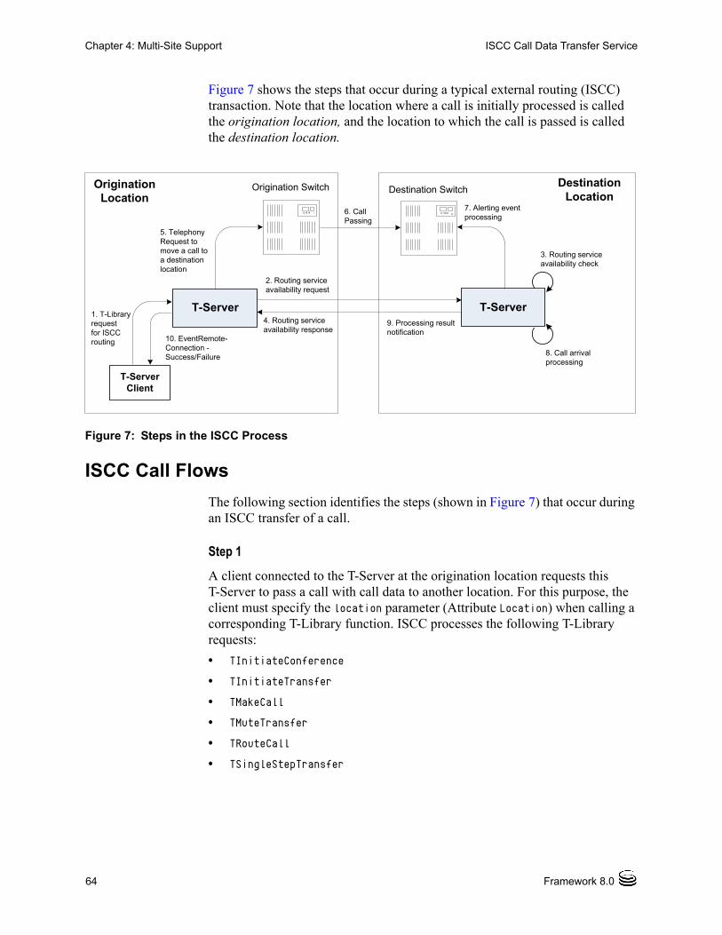
64 Framework 8.0
Chapter 4: Multi-Site Support ISCC Call Data Transfer Service
Figure 7 shows the steps that occur during a typical external routing (ISCC) transaction. Note that the location where a call is initially processed is called the origination location, and the location to which the call is passed is called the destination location.
Figure 7: Steps in the ISCC Process
ISCC Call Flows
The following section identifies the steps (shown in Figure 7) that occur during an ISCC transfer of a call.
Step 1
A client connected to the T-Server at the origination location requests this T-Server to pass a call with call data to another location. For this purpose, the client must specify the location parameter (Attribute Location) when calling a corresponding T-Library function. ISCC processes the following T-Library requests:
• TInitiateConference
• TInitiateTransfer
• TMakeCall
• TMuteTransfer
• TRouteCall
• TSingleStepTransfer
T-Server
3. Routing serviceavailability check
10. EventRemote-Connection -Success/Failure
5. Telephony Request to move a call to a destination location
6. Call Passing
7. Alerting eventprocessing
8. Call arrival processing
2. Routing serviceavailability request
1. T-Library request for ISCC routing
T-Server9. Processing result notification
4. Routing serviceavailability response
Origination Location
Destination Location
Origination Switch Destination Switch
T-Server Client
Chapter 4: Multi-Site Support ISCC Call Data Transfer Service
T-Server—Deployment Guide 65
Step 2
Upon receiving a client’s request, the origination T-Server checks that the:
1. Connection to the destination T-Server is configured in the origination T-Server Properties dialog box.
2. The connection to the destination T-Server is active.
3. The destination T-Server is connected to its link.
4. The origination T-Server is connected to its link.
If these four conditions are met, the origination T-Server determines the transaction type that will be used for passing call data to another location in this transaction. The following possibilities exist:
• The client can request what ISCC transaction type (or simply transaction type) to use by specifying an appropriate key-value pair in the Extensions attribute of the request. The key-value pair must have a key equal to iscc-xaction-type and either an integer value as specified in the TXRouteType enumeration (see the Voice Platform SDK 8.0 .NET (or Java) API Reference) or a string value equal to one of the following: default, route, direct (or direct-callid), direct-network-callid, direct-notoken, direct-ani, direct-uui, direct-digits, reroute,
dnis-pool, pullback, or route-uui.
• If the client does not specify the transaction type in the request or specifies the default transaction type, T-Server checks the Switch configuration for the transaction type configured in the Access Code (or Default Access Code) properties: If the Route Type property of the Access Code is set to any value other
than default, T-Server uses the specified value as the transaction type. If the Route Type property of the Access Code is set to the default
value, T-Server uses the first value from the list specified in the cast-type configuration option configured for the destination T-Server. If no value has been specified for the cast-type option, the default value of route is used as the transaction type.
After the origination T-Server determines the requested transaction type, it determines if the destination T-Server supports this transaction type.
You must list the transaction types T-Server supports in the cast-type configuration option.
The origination T-Server issues a request for routing service availability and sends it to the destination T-Server. The T-Server request contains data that should be passed along with the call to the destination location. This data includes the transaction type, ConnID, UserData, CallType, and CallHistory.
Note: For more information on Access Codes and Default Access Code, see “Switches and Access Codes” on page 106.
66 Framework 8.0
Chapter 4: Multi-Site Support ISCC Call Data Transfer Service
The timer specified by the request-tout configuration option is set when the origination T-Server sends the request. If either the specified timeout expires or the call is abandoned before the origination T-Server receives a response from the destination T-Server, the operation is considered failed. In this scenario, the origination T-Server:
1. Generates a request to the destination T-Server to cancel the request for routing service.
2. Sends EventError to the client that requested the service.
3. Deletes information about the request.
Step 3
The destination T-Server receives the request for routing service availability and checks the requested type of routing. Depending on the ISCC transaction type, it stores the request information and, when appropriate, allocates access resources for the coming call. For example, an External Routing Point is allocated when the transaction type is route, and an Access Resource of type dnis is allocated when the transaction type is dnis-pool.
If resources are unavailable, the request is queued at the destination location until a resource is free or the origination T-Server cancels the request. If the request is canceled, the destination T-Server deletes all information about the request.
If resources are unavailable because of incorrect configuration, the destination T-Server returns an error event to the origination T-Server.
Step 4
If resources are available, the destination T-Server generates a positive response and the timer is started for the interval specified by the timeout configuration option of the destination T-Server.
Step 5
If the origination T-Server receives a negative response, it sends an EventError message to the client and clears all data about the request.
If the origination T-Server receives the confirmation about routing service availability, it processes the client’s request and sends a corresponding message to the switch. The timer on the origination T-Server is also started for the interval specified by the timeout configuration option of the destination T-Server.
Note: The resource-allocation-mode and resource-load-maximum configuration options determine how resources are allocated. For option descriptions, refer to Chapter 9, “T-Server Common Configuration Options,” on page 205 for option descriptions.
Chapter 4: Multi-Site Support ISCC Call Data Transfer Service
T-Server—Deployment Guide 67
Step 6
The origination switch processes the T-Server request and passes the call to the destination switch.
Step 7
If the call arrives at the destination switch, the switch generates an alerting event.
The destination T-Server waits for the call no longer than the interval specified by the timeout configured on the destination T-Server. If the call is not received at the destination location within this interval, the destination T-Server issues a failure notification to the origination T-Server, deletes all data about the request, and, when appropriate, frees the resources previously allocated for the request.
If either the specified timeout expires or the call is abandoned before the origination T-Server receives a response from the destination T-Server, the operation is considered failed. In this case, the origination T-Server:
1. Generates a request to the destination T-Server to cancel the request for routing service.
2. Responds to the client that requested the service in one of the following ways: If the origination T-Server has already sent a response to the request
the client sent in Step 1, the origination T-Server supplements its response with EventRemoteConnectionFailed.
If the origination T-Server has not yet sent a response to the client, the origination T-Server sends EventError.
3. Deletes information about the request.
Step 8
If the destination T-Server matches the arrived call, it updates the ConnID, UserData, CallType, and CallHistory attributes with the data received in the request for routing service availability. The connection ID is updated as follows:
The arrived call is assigned the ConnID that is specified in the request for routing service availability, but only if this ConnID does not coincide with the ConnID of a call that has existed at the destination site. If two such ConnIDs are identical, the arrived call is assigned a new unique ConnID.
For direct-* transaction types (where the asterisk stands for a callid, uui, ani, or digits extension), the call reaches the destination DN directly.
For the transaction types route and route-uui, the call first arrives at an External Routing Point from which it is routed to the destination DN. The call info is updated when the call reaches the External Routing Point. An External
68 Framework 8.0
Chapter 4: Multi-Site Support ISCC Call Data Transfer Service
Routing Point is considered free when the first alerting event (EventQueued or EventRouteRequest) is distributed.
Please keep the following issues in mind when using the ISCC feature:
• If routing from a dedicated External Routing Point to the destination DN fails, T-Server considers the transaction failed. However, the ConnID, UserData, CallType, and CallHistory attributes are updated. Then, T-Server attempts to route the call to one of the Default DNs configured for this External Routing Point.
• If the destination T-Server did not receive a request for routing service availability, but a call arrives at an External Routing Point, T-Server considers the call to be unexpected and routes the call to the DN specified by the dn-for-unexpected-calls configuration option. When no alternative targets are defined, the call remains at the External Routing Point until diverted by the switch or abandoned by the caller.
For reroute and pullback transaction types, the call returns to the network location. For the dnis-pool transaction type, the call reaches the destination DN directly.
Step 9
If, in Step 8, the call does not arrive within the configured timeout, or the transaction fails, the destination T-Server sends a notification of failure to the origination T-Server.
Otherwise, the destination T-Server notifies the origination T-Server that the routing service was successful and deletes all information about the request.
Step 10
The origination T-Server notifies the client that the routing service was successful (or failed) and deletes all information about the request.
Client-Controlled ISCC Call Flow
The following section identifies the steps that occur during a client-controlled ISCC transfer of a call.
Step 1
A client, such as Universal Routing Server (URS), that is connected to the T-Server at the origination location detects a call to be delivered to another destination location.
Chapter 4: Multi-Site Support ISCC Call Data Transfer Service
T-Server—Deployment Guide 69
Step 2
The client chooses a destination location and the target DN for the call. Then, it sends the TGetAccessNumber request to the destination T-Server for routing service availability, indicating the target DN and other call context (ConnID, UserData, and CallHistory attributes).
Step 3
The destination T-Server receives the request for routing service availability. Depending on the ISCC transaction type, it stores the request information, including the call context. When appropriate, it allocates access resources for the coming call, such as External Routing Point.
If resources are unavailable, the request is queued at the destination T-Server until an appropriate ISCC resource is free or the client cancels the request. If the request is canceled, the destination T-Server deletes all information about the request.
If resources are unavailable because of incorrect configuration, the destination T-Server returns an EventError message to the client.
Step 4
The destination T-Server replies to the client with the EventAnswerAccessNumber message, which contains the allocated ISCC resource.
Step 5
The client requests that the origination T-Server delivers the call to the destination location using the allocated access resource.
Step 6
The origination T-Server receives and processes the client’s request, and then sends a corresponding message to the switch.
Step 7
The call arrives at the destination switch and is reported to the destination T-Server via CTI. The call is matched by means of ISCC, based on the specified cast-type setting and allocated resource, and then the call is assigned a requested call context (such as ConnID or call data). Upon successful transaction completion, the destination T-Server notifies the client by sending EventRemoteConnectionSuccess.
The destination T-Server waits for the call no longer than the interval specified by the timeout that is configured on the destination T-Server. If the call is not received at the destination location within this interval, the destination T-Server issues a failure notification to the client by sending
70 Framework 8.0
Chapter 4: Multi-Site Support ISCC Call Data Transfer Service
EventRemoteConnectionFailed, deletes all data about the request, and, when appropriate, frees the resources previously allocated for the request.
The destination T-Server notifies the client whether the routing service succeeded or failed by sending either the EventRemoteConnectionSuccess or EventRemoteConnectionFailure, respectively.
ISCC Transaction Types
As switches of different types provide calls with different sets of information parameters, a single mechanism for passing call data between the switches is not feasible in some cases. Therefore, the ISCC feature supports a number of mechanisms for passing call data along with calls between locations. This section describes ISCC transaction type principles, identifies which transaction types are supported for each T-Server, and defines each transaction type (beginning with “direct-ani” on page 71).
It is important to distinguish the two roles that T-Servers play in an external routing (ISCC) transaction—namely origination T-Server and destination T-Server.
• The origination T-Server initiates an ISCC transaction. It prepares to send the call to another T-Server and coordinates the process.
• The destination T-Server receives call data from an origination T-Server and matches this data to a call that will arrive at some time in the future.
The distinction between these roles is important because the range of telephony-hardware functionality often requires T-Servers to support two entirely different sets of ISCC transactions based on which of the two roles they play. For instance, it is very common for a particular T-Server to support many types of ISCC transactions when it takes on the origination role, but fewer when it takes on the role of a destination T-Server.
The ISCC transaction type reroute is a good example. Most T-Servers support Reroute as origination T-Servers, but very few support Reroute as destination T-Servers.
Determining and Configuring Transaction Type Support
You can find descriptions of these transaction types starting on page 71. Use Table 3 on page 79 to identify the transaction types your destination T-Server supports. A blank table cell indicates that T-Server does not support a certain transaction type.
You can configure the transaction types specific to your T-Server as values of the cast-type configuration option specified in the ISCC configuration section extrouter. Refer to Chapter 9, “T-Server Common Configuration Options,” on page 205 for the option description.
Chapter 4: Multi-Site Support ISCC Call Data Transfer Service
T-Server—Deployment Guide 71
ISCC Transaction Type General Principles
Generally, since most of the ISCC implementation is done at the T-Server Common Part (TSCP) code level, all T-Servers support certain ISCC transaction types. Any T-Server can act as the origination T-Server for the following transaction types:
• direct-ani, page 71
• direct-notoken, page 73
• dnis-pool, page 74
• pullback, page 75
• reroute, page 76
• route (aliased as route-notoken), the default transaction type, page 77
The following transaction types are unevenly supported for both the origination and destination T-Server roles:
• direct-callid (aliased as direct), page 72
• direct-digits (reserved for Genesys Engineering)
• direct-network-callid, page 72
• direct-uui, page 73
• route-uui, page 78
The reroute and pullback transaction types are supported only for selected T-Servers in the destination role. However, if you implement this support, other transaction types require additional configuration and testing—even those that would normally be supported by default.
direct-ani
With the transaction type direct-ani, the ANI call attribute is taken as the parameter for call matching. Properly configured switches and trunks can keep the ANI attribute when a call is transferred over the network. T-Server can use this network feature for call matching.
72 Framework 8.0
Chapter 4: Multi-Site Support ISCC Call Data Transfer Service
direct-callid
With the transaction type direct-callid, the call reaches the destination DN directly from another location, and the CallID of the call is taken as the attribute for call matching. When a call arrives at the final destination, the destination T-Server identifies its CallID, and updates the call info if the CallID matches.
Use this transaction type when the destination switch has the capability to assign to an incoming call the same network-wide unique CallID that the origination switch has already assigned to that call.
direct-network-callid
With the transaction type direct-network-callid, the call reaches the destination DN directly from another location, and the NetworkCallID of the call is taken as the attribute for call matching. When a call arrives at the final destination, the destination T-Server identifies its NetworkCallID, and updates the call info if the NetworkCallID matches.
Warning! Depending on the switch platform, it may be possible to inherit the ANI attribute after routing a call to a remote destination, and after performing a single-step transfer and other telephone actions. However, ISCC only works properly in scenarios where the ANI attribute on the destination T-Server is represented by exactly the same digit string as on the origination T-Server.
Typically, the ANI attribute represents the original call identifier (customer phone number), which guarantees that the attribute remains unique. However, you can use the non-unique-ani resource type to block ISCC from matching calls based on an ANI that is known to be non-unique. (See “Configuring access resources for non-unique ANI” on page 115 for details.)
Notes: The direct-callid transaction type is used only in conjunction with the TRouteCall and TSingleStepTransfer function calls. It is applied only to the call that is in progress, and does not apply to functions that involve in the creation of a new call, such as TMakeCall.
For T-Server for Nortel Communication Server 2000/2100, the direct-callid transaction type is also applied to the TMuteTransfer function.
Chapter 4: Multi-Site Support ISCC Call Data Transfer Service
T-Server—Deployment Guide 73
Use this transaction type when the destination switch has the capability to assign to an incoming call the same network-wide unique NetworkCallID that the origination switch has already assigned to that call.
direct-uui
With the transaction type direct-uui, so-called user-to-user information (UUI) is taken as the attribute for call matching. Some switches make it possible to send a small data packet along with a call. T-Server can use this data to recognize a call passed from one switch to another. The destination T-Server generates a local unique value for UUI, and then notifies the origination T-Server. The origination T-Server uses a provided value to mark the call coming from the origination location. The destination T-Server receives a call and checks whether it is marked with an exact UUI value. If so, the call is considered to be matched.
On the Avaya Communication Manager and the Aspect ACD, UUI is referred to as “user-to-user information.” On the Siemens Hicom 300 switch with CallBridge, UUI is referred to as “Private User Data.” On the Alcatel A4400/OXE switch, UUI is referred to as “correlator data.”
direct-notoken
With the transaction type direct-notoken, T-Server expects a call to arrive from another location to the destination DN specified in the request for routing service availability. When a call reaches the specified DN, T-Server processes the call as the expected externally-routed call.
Note: To support this transaction type, you must configure Target Type and ISCC Protocol Parameters fields of the corresponding Switch Access Code in the Configuration Layer. For information about settings that are specific for your T-Server type, refer to Part Two of this document.
Note: To support this transaction type, you must configure your switches to pass the UUI provided by your T-Server. You must also ensure that the trunks involved do not drop this data.
74 Framework 8.0
Chapter 4: Multi-Site Support ISCC Call Data Transfer Service
dnis-pool
With the dnis-pool transaction type, T-Server reserves one of its DNIS access resources and waits for the call that has the same DNIS attribute as the name of the reserved DNIS access resource.
If the arrived call is matched successfully, the destination T-Server may update the value of the DNIS attribute of the call (along with ConnID, UserData, CallType, and CallHistory) with the value of the DNIS attribute of the original call. This occurs when the value of the DNIS attribute of the original call is specified as a value of the key-value pair _ISCC_TRACKING_NUMBER_ in the Extensions attribute of the original client request.
The DNIS matching can be based on any number of digits out of all the digits that comprise the DNIS attribute. The number of digits that T-Server should use for DNIS matching is specified for the destination switch as the ISCC Protocol Parameters property of the Switch Access Code. The value syntax should be as follows:
dnis-tail=<number-of-digits>
For example, if this property is set to the dnis-tail=7 value, ISCC matches only the last seven digits of a DNIS.
You must configure DNIS access resources in the switch; otherwise, ISCC fails to use this transaction type and sends EventError in response to the client application request.
Notes: This matching criterion is weak because any call that reaches the specified DN is considered to be the expected call. Genesys recommends that you use this transaction type only in a contact center subdivision that can only be reached from within the contact center (such as the second line of support, which customers cannot contact directly).
When using direct transaction types, Network T-Servers and load-sharing IVR Servers are not meant to act as destination T-Servers for call routing. Using Network T-Server with these transaction types requires special architecture.
Note: The dnis-pool transaction type is typically used for networks that employ a “behind the SCP” architecture, such as network IVR. Network T-Server for GenSpec and IServer are two examples of this, but other Network T-Servers might also be used in this architecture.
Chapter 4: Multi-Site Support ISCC Call Data Transfer Service
T-Server—Deployment Guide 75
In Load-Balancing Mode
When T-Server uses load balancing for call routing with the dnis-pool transaction type, the following processes occur:
1. A client of the origination T-Server sends a request to pass a call to the location with a DNIS access resource specified in the key-value pair iscc-selected-dnis.
2. The origination T-Server distributes the request for a routing service to all destination T-Servers.
3. The destination T-Servers receive the request and check that the specified DNIS is not being used by another routing service request.
4. The origination T-Server expects to receive a positive response from each destination T-Server. If the origination T-Server receives a negative response from at least one T-Server, it sends an EventError to the client and clears all data about the request. If the origination T-Server receives the confirmation about routing service availability from all destination T-Servers, it processes the client’s request and sends a corresponding message to the switch.
5. The origination switch processes the T-Server request and passes the call to the destination switch.
6. The call arrives at the destination switch, which generates an alerting event to one of the corresponding load-balanced destination T-Servers.
7. That destination T-Server processes the call and notifies the origination T-Server that the routing service was successful and deletes all information about the request.
8. The origination T-Server sends a routing service request cancellation to all other destination T-Servers.
9. The origination T-Server notifies the client that the routing service has been successful and deletes all information about the request.
pullback
Pullback is used in the following scenario, for those T-Servers that support it:
1. A call arrives at Site A served by a Network T-Server.
2. At Site A, a Network T-Server client requests to pass the call by means of ISCC routing to Site B served by a premise T-Server. Any transaction type except reroute or pullback can be specified in this request.
3. The call arrives at Site B and is either answered by an agent or delivered to a routing point.
4. A client of the premise T-Server at Site B sends a TRouteCall or TSingleStepTransfer request to transfer the call to the network.
76 Framework 8.0
Chapter 4: Multi-Site Support ISCC Call Data Transfer Service
5. The Site B premise T-Server notifies the Network T-Server about this request.
6. The network T-Server receives the notification and issues an EventRouteRequest to obtain a new destination.
7. After receiving the new destination information, the Network T-Server disconnects the call from its current premise location at Site B and attempts to route the call to the new destination.
8. The Site B premise T-Server stops tracking the call, which has disconnected from the premise’s agent DN or routing point and is delivered to the network.
9. The network T-Server completes routing the call to its new destination.
reroute
Reroute is used in the following scenario, for those T-Servers that support it:
1. A call arrives at Site A served by a Network T-Server.
2. At Site A, a Network T-Server client requests to pass the call by means of ISCC to Site B served by a premise T-Server. Any transaction type except reroute or pullback can be specified in this request.
3. An agent at Site B answers the call.
4. A client of the premise T-Server at Site B sends a TSingleStepTransfer or TRouteCall request to transfer the call elsewhere (to a PSTN, to an agent, or to a routing point).
5. The Site B premise T-Server notifies the Network T-Server about this request and releases the call leg that resides at the agent’s phone (using TReleaseCall) or at the Routing Point (using TRouteCall with the parameter RouteTypeCallDisconnect).
6. The Network T-Server receives the notification and reroutes the call to the requested destination by sending EventRouteRequest and attaching the call’s user data.
Note: The transaction type pullback can only be used to return a call from a premise T-Server to the Network T-Server that serves the site from which the call was previously transferred.
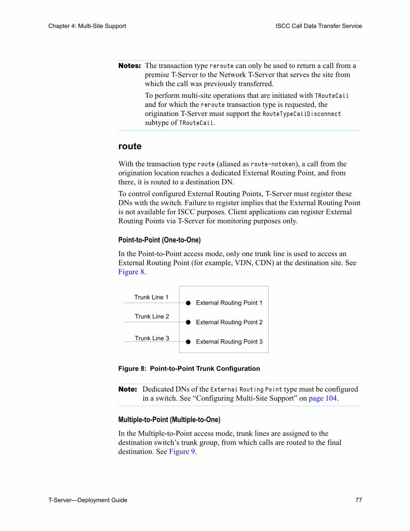
Chapter 4: Multi-Site Support ISCC Call Data Transfer Service
T-Server—Deployment Guide 77
route
With the transaction type route (aliased as route-notoken), a call from the origination location reaches a dedicated External Routing Point, and from there, it is routed to a destination DN.
To control configured External Routing Points, T-Server must register these DNs with the switch. Failure to register implies that the External Routing Point is not available for ISCC purposes. Client applications can register External Routing Points via T-Server for monitoring purposes only.
Point-to-Point (One-to-One)
In the Point-to-Point access mode, only one trunk line is used to access an External Routing Point (for example, VDN, CDN) at the destination site. See Figure 8.
Figure 8: Point-to-Point Trunk Configuration
Multiple-to-Point (Multiple-to-One)
In the Multiple-to-Point access mode, trunk lines are assigned to the destination switch’s trunk group, from which calls are routed to the final destination. See Figure 9.
Notes: The transaction type reroute can only be used to return a call from a premise T-Server to the Network T-Server that serves the site from which the call was previously transferred.
To perform multi-site operations that are initiated with TRouteCall and for which the reroute transaction type is requested, the origination T-Server must support the RouteTypeCallDisconnect subtype of TRouteCall.
Note: Dedicated DNs of the External Routing Point type must be configured in a switch. See “Configuring Multi-Site Support” on page 104.
Trunk Line 1
Trunk Line 2
Trunk Line 3
External Routing Point 1
External Routing Point 2
External Routing Point 3
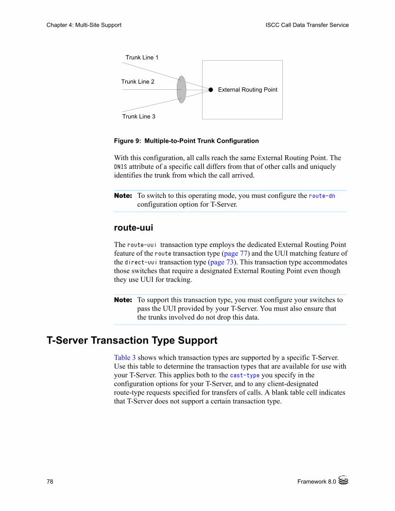
78 Framework 8.0
Chapter 4: Multi-Site Support ISCC Call Data Transfer Service
Figure 9: Multiple-to-Point Trunk Configuration
With this configuration, all calls reach the same External Routing Point. The DNIS attribute of a specific call differs from that of other calls and uniquely identifies the trunk from which the call arrived.
route-uui
The route-uui transaction type employs the dedicated External Routing Point feature of the route transaction type (page 77) and the UUI matching feature of the direct-uui transaction type (page 73). This transaction type accommodates those switches that require a designated External Routing Point even though they use UUI for tracking.
T-Server Transaction Type Support
Table 3 shows which transaction types are supported by a specific T-Server. Use this table to determine the transaction types that are available for use with your T-Server. This applies both to the cast-type you specify in the configuration options for your T-Server, and to any client-designated route-type requests specified for transfers of calls. A blank table cell indicates that T-Server does not support a certain transaction type.
Note: To switch to this operating mode, you must configure the route-dn configuration option for T-Server.
Note: To support this transaction type, you must configure your switches to pass the UUI provided by your T-Server. You must also ensure that the trunks involved do not drop this data.
Trunk Line 1
External Routing PointTrunk Line 2
Trunk Line 3
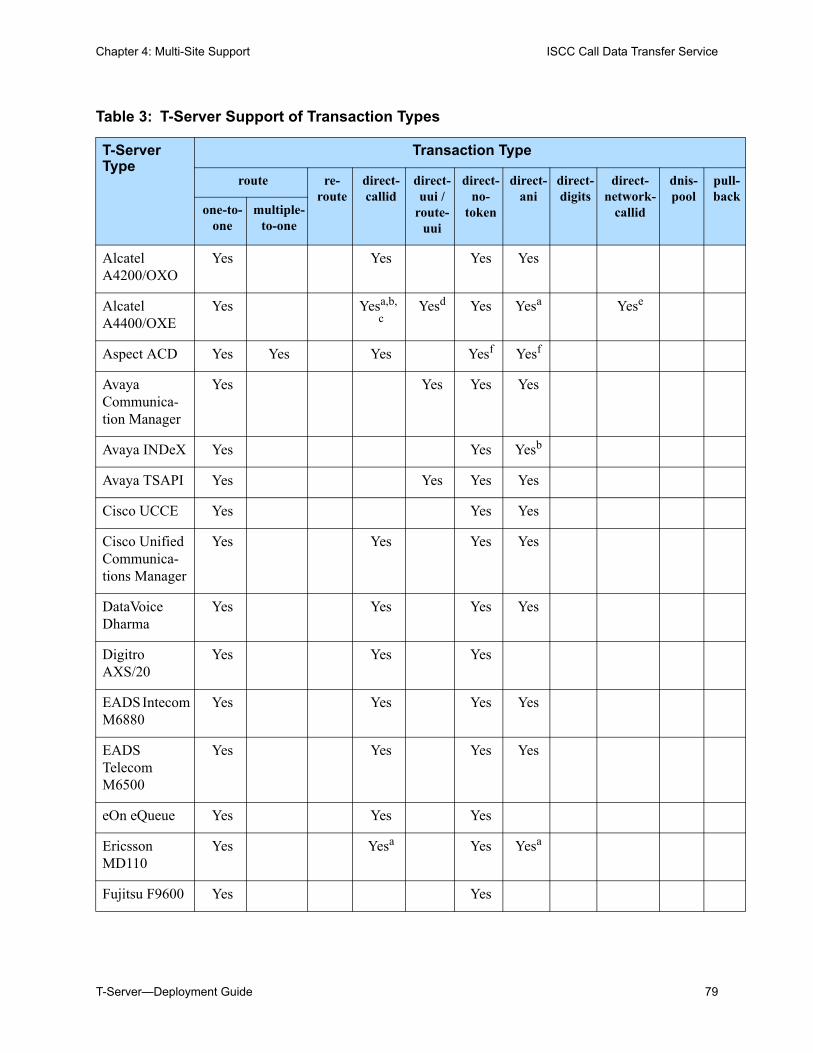
Chapter 4: Multi-Site Support ISCC Call Data Transfer Service
T-Server—Deployment Guide 79
Table 3: T-Server Support of Transaction Types
T-ServerType
Transaction Type
route re-route
direct-callid
direct-uui /
route-uui
direct-no-
token
direct-ani
direct-digits
direct-network-
callid
dnis-pool
pull-back
one-to-one
multiple-to-one
Alcatel A4200/OXO
Yes Yes Yes Yes
Alcatel A4400/OXE
Yes Yesa,b,
cYesd Yes Yesa Yese
Aspect ACD Yes Yes Yes Yesf Yesf
Avaya Communica- tion Manager
Yes Yes Yes Yes
Avaya INDeX Yes Yes Yesb
Avaya TSAPI Yes Yes Yes Yes
Cisco UCCE Yes Yes Yes
Cisco Unified Communica- tions Manager
Yes Yes Yes Yes
DataVoice Dharma
Yes Yes Yes Yes
Digitro AXS/20
Yes Yes Yes
EADS Intecom M6880
Yes Yes Yes Yes
EADS Telecom M6500
Yes Yes Yes Yes
eOn eQueue Yes Yes Yes
Ericsson MD110
Yes Yesa Yes Yesa
Fujitsu F9600 Yes Yes
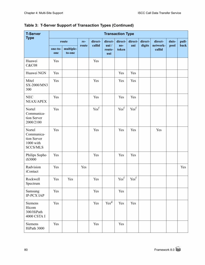
80 Framework 8.0
Chapter 4: Multi-Site Support ISCC Call Data Transfer Service
Huawei C&C08
Yes Yes
Huawei NGN Yes Yes Yes
Mitel SX-2000/MN3300
Yes Yes Yes Yes
NEC NEAX/APEX
Yes Yes Yes Yes
Nortel Communica- tion Server 2000/2100
Yes Yesf Yesf Yesf
Nortel Communica- tion Server 1000 with SCCS/MLS
Yes Yes Yes Yes Yes
Philips Sopho iS3000
Yes Yes Yes Yes
Radvision iContact
Yes Yes Yes
Rockwell Spectrum
Yes Yes Yes Yesf Yesf
Samsung IP-PCX IAP
Yes Yes Yes
Siemens Hicom 300/HiPath 4000 CSTA I
Yes Yes Yesd Yes Yes
Siemens HiPath 3000
Yes Yes Yes
Table 3: T-Server Support of Transaction Types (Continued)
T-ServerType
Transaction Type
route re-route
direct-callid
direct-uui /
route-uui
direct-no-
token
direct-ani
direct-digits
direct-network-
callid
dnis-pool
pull-back
one-to-one
multiple-to-one
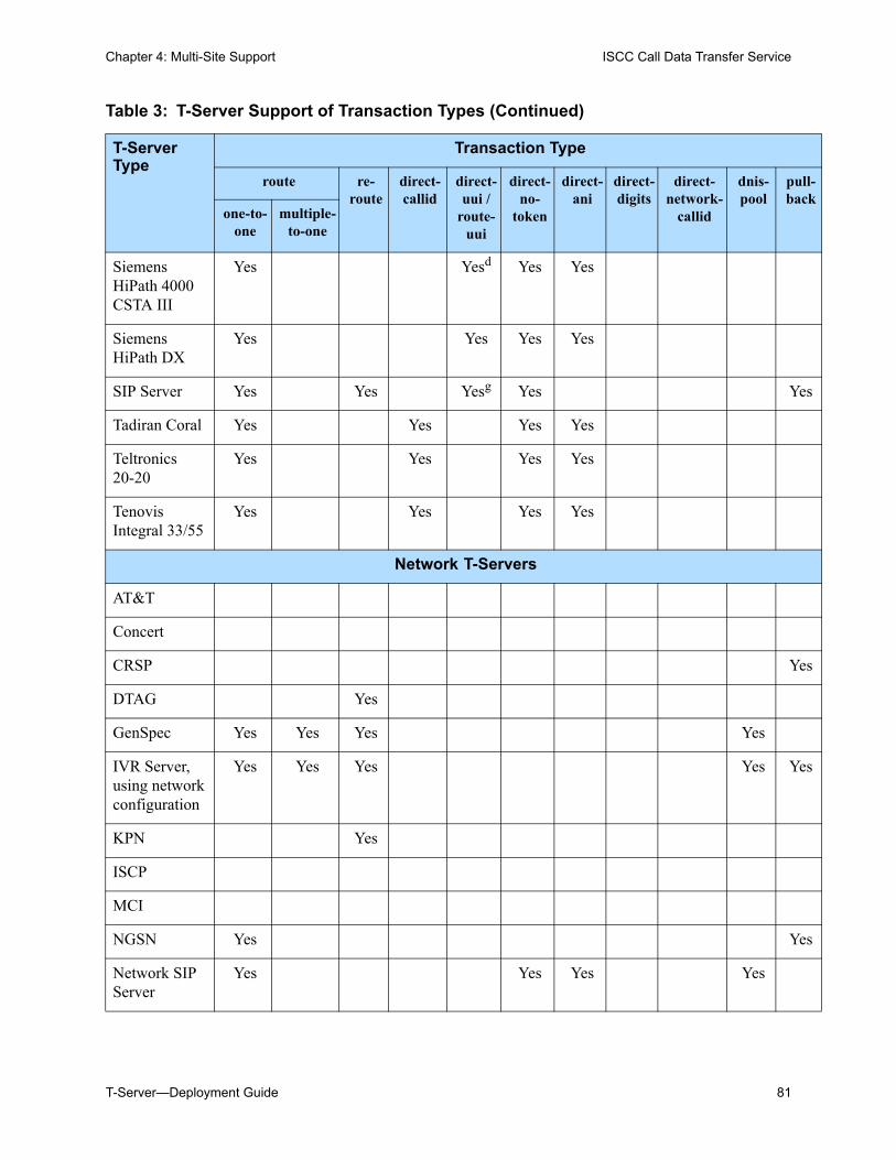
Chapter 4: Multi-Site Support ISCC Call Data Transfer Service
T-Server—Deployment Guide 81
Siemens HiPath 4000 CSTA III
Yes Yesd Yes Yes
Siemens HiPath DX
Yes Yes Yes Yes
SIP Server Yes Yes Yesg Yes Yes
Tadiran Coral Yes Yes Yes Yes
Teltronics 20-20
Yes Yes Yes Yes
Tenovis Integral 33/55
Yes Yes Yes Yes
Network T-Servers
AT&T
Concert
CRSP Yes
DTAG Yes
GenSpec Yes Yes Yes Yes
IVR Server, using network configuration
Yes Yes Yes Yes Yes
KPN Yes
ISCP
MCI
NGSN Yes Yes
Network SIP Server
Yes Yes Yes Yes
Table 3: T-Server Support of Transaction Types (Continued)
T-ServerType
Transaction Type
route re-route
direct-callid
direct-uui /
route-uui
direct-no-
token
direct-ani
direct-digits
direct-network-
callid
dnis-pool
pull-back
one-to-one
multiple-to-one
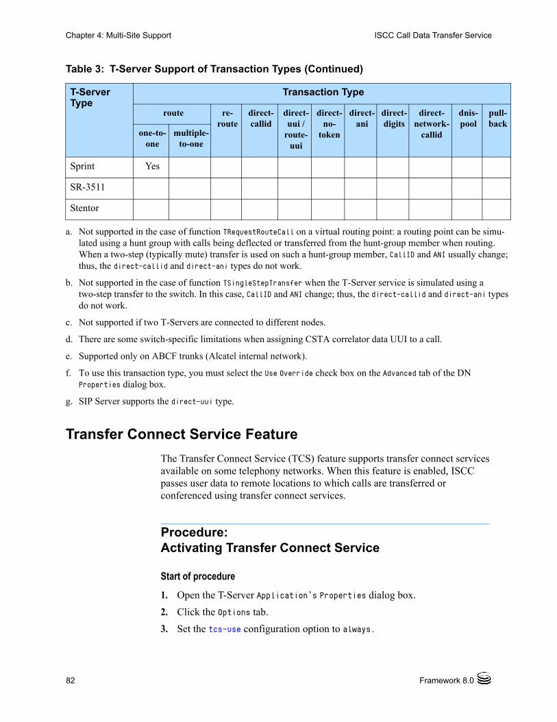
82 Framework 8.0
Chapter 4: Multi-Site Support ISCC Call Data Transfer Service
Transfer Connect Service Feature
The Transfer Connect Service (TCS) feature supports transfer connect services available on some telephony networks. When this feature is enabled, ISCC passes user data to remote locations to which calls are transferred or conferenced using transfer connect services.
Procedure:Activating Transfer Connect Service
Start of procedure
1. Open the T-Server Application’s Properties dialog box.
2. Click the Options tab.
3. Set the tcs-use configuration option to always.
Sprint Yes
SR-3511
Stentor
a. Not supported in the case of function TRequestRouteCall on a virtual routing point: a routing point can be simu-lated using a hunt group with calls being deflected or transferred from the hunt-group member when routing. When a two-step (typically mute) transfer is used on such a hunt-group member, CallID and ANI usually change; thus, the direct-callid and direct-ani types do not work.
b. Not supported in the case of function TSingleStepTransfer when the T-Server service is simulated using a two-step transfer to the switch. In this case, CallID and ANI change; thus, the direct-callid and direct-ani types do not work.
c. Not supported if two T-Servers are connected to different nodes.
d. There are some switch-specific limitations when assigning CSTA correlator data UUI to a call.
e. Supported only on ABCF trunks (Alcatel internal network).
f. To use this transaction type, you must select the Use Override check box on the Advanced tab of the DN Properties dialog box.
g. SIP Server supports the direct-uui type.
Table 3: T-Server Support of Transaction Types (Continued)
T-ServerType
Transaction Type
route re-route
direct-callid
direct-uui /
route-uui
direct-no-
token
direct-ani
direct-digits
direct-network-
callid
dnis-pool
pull-back
one-to-one
multiple-to-one
Chapter 4: Multi-Site Support ISCC/Call Overflow Feature
T-Server—Deployment Guide 83
4. Set the tcs-queue configuration option to the number of a DN on the origination switch.
ISCC uses this DN as an intermediate step when sending calls to the remote location. The DN that is configured as tcs-queue receives attached data indicating the Feature Access Code (FAC) needed to reach the remote site. After a call is directed to the DN with data, a monitoring application takes the data and generates the required DTMF (dual-tone multifrequency) tones to redirect the call through the network to the remote location.
5. When you are finished, click Apply.
6. Click OK to save your changes and exit the Properties dialog box.
End of procedure
ISCC/Call Overflow FeatureThe Inter Server Call Control/Call Overflow (ISCC/COF) feature of T-Server, that supports passive external routing, is specifically designed to handle calls delivered between sites by means other than ISCC. Such scenarios include contact center overflows and manual call transfers.
An overflow situation occurs when a call comes into a contact center where all agents are currently busy. In this situation, the switch can transfer (overflow) the incoming call to another site where there is an available agent.
T-Server uses two methods to handle call overflow and manual transfer scenarios. The first method is based on NetworkCallID matching and the second method is based on ANI/OtherDN matching.
When connected to each other via switch-specific networks, switches of some types can pass additional information along with transferred calls. This information may contain the NetworkCallID of a call, which is a networkwide unique identifier of the call.
When connected via a regular PSTN, switches of all types can send the ANI and/or OtherDN attributes to the destination switch during any call transfer operation.
Note: With T-Server for Avaya Communication Manager, you can use RequestRouteCall with RouteTypeOverwriteDNIS to initiate the playing of DTMF tones. This is done through the use of another intermediate DN (typically, an announcement port configured to give the silent treatment), to which the call is routed. When the call is established on this DN, T-Server requests that the digits sent in the DNIS field of the TRequestRouteCall be played by using the ASAI-send-DTMF-single procedure.
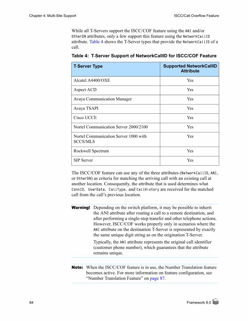
84 Framework 8.0
Chapter 4: Multi-Site Support ISCC/Call Overflow Feature
While all T-Servers support the ISCC/COF feature using the ANI and/or OtherDN attributes, only a few support this feature using the NetworkCallID attribute. Table 4 shows the T-Server types that provide the NetworkCallID of a call.
The ISCC/COF feature can use any of the three attributes (NetworkCallID, ANI, or OtherDN) as criteria for matching the arriving call with an existing call at another location. Consequently, the attribute that is used determines what ConnID, UserData, CallType, and CallHistory are received for the matched call from the call’s previous location.
Table 4: T-Server Support of NetworkCallID for ISCC/COF Feature
T-Server Type Supported NetworkCallID Attribute
Alcatel A4400/OXE Yes
Aspect ACD Yes
Avaya Communication Manager Yes
Avaya TSAPI Yes
Cisco UCCE Yes
Nortel Communication Server 2000/2100 Yes
Nortel Communication Server 1000 with SCCS/MLS
Yes
Rockwell Spectrum Yes
SIP Server Yes
Warning! Depending on the switch platform, it may be possible to inherit the ANI attribute after routing a call to a remote destination, and after performing a single-step transfer and other telephone actions. However, ISCC/COF works properly only in scenarios where the ANI attribute on the destination T-Server is represented by exactly the same unique digit string as on the origination T-Server.
Typically, the ANI attribute represents the original call identifier (customer phone number), which guarantees that the attribute remains unique.
Note: When the ISCC/COF feature is in use, the Number Translation feature becomes active. For more information on feature configuration, see “Number Translation Feature” on page 87.
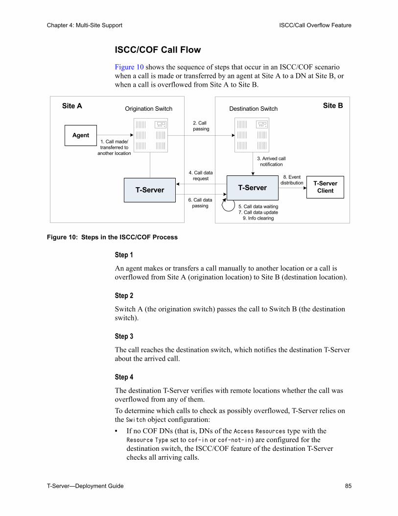
Chapter 4: Multi-Site Support ISCC/Call Overflow Feature
T-Server—Deployment Guide 85
ISCC/COF Call Flow
Figure 10 shows the sequence of steps that occur in an ISCC/COF scenario when a call is made or transferred by an agent at Site A to a DN at Site B, or when a call is overflowed from Site A to Site B.
Figure 10: Steps in the ISCC/COF Process
Step 1
An agent makes or transfers a call manually to another location or a call is overflowed from Site A (origination location) to Site B (destination location).
Step 2
Switch A (the origination switch) passes the call to Switch B (the destination switch).
Step 3
The call reaches the destination switch, which notifies the destination T-Server about the arrived call.
Step 4
The destination T-Server verifies with remote locations whether the call was overflowed from any of them.
To determine which calls to check as possibly overflowed, T-Server relies on the Switch object configuration:
• If no COF DNs (that is, DNs of the Access Resources type with the Resource Type set to cof-in or cof-not-in) are configured for the destination switch, the ISCC/COF feature of the destination T-Server checks all arriving calls.
2. Call passing
Site A Site B
Agent1. Call made/transferred to
another location3. Arrived call
notification
5. Call data waiting7. Call data update
9. Info clearing
T-Server Client
8. Event distribution
4. Call data request
6. Call data passing
T-Server T-Server
Origination Switch Destination Switch
86 Framework 8.0
Chapter 4: Multi-Site Support ISCC/Call Overflow Feature
• If a number of COF DNs are configured for the destination switch, one of three scenarios occurs: If the COF DNs with the cof-in setting for the Resource Type property
are configured, the ISCC/COF checks for overflow only those calls that arrive to those cof-in DNs that are Enabled.
If no DNs with the cof-in setting for the Resource Type property are configured, but some DNs have the cof-not-in setting for the Resource Type property, the ISCC/COF checks for overflow only those calls that arrive to those cof-not-in DNs that are Disabled.
If no DNs with the cof-in setting for the Resource Type property are configured, some DNs have the cof-not-in setting for the Resource Type property, and some other DNs do not have any setting for the Resource Type property, the ISCC/COF checks for overflow only those calls that arrive to the DNs without any setting for the Resource Type property.
• In all other cases, no calls are checked for overflow.
To determine which location the call arrived from, T-Server checks the call type and checks whether the call has the NetworkCallID, ANI, or OtherDN attribute:
• If the call is not an inbound call, the request for call data is sent to all remote locations except those whose Switch Access Code has the ISCC Call Overflow Parameters property set to inbound-only=true.
• If the call of any type has the NetworkCallID attribute, the destination T-Server sends a request for call data to the remote locations of the same switch type as the destination location if their Switch Access Codes have the ISCC Call Overflow Parameters property set to match-callid.
• If the call of any type has the ANI or OtherDN attribute, the request for call data is sent to remote locations whose Switch Access Code has the ISCC Call Overflow Parameters property set to match-ani.
Step 5
The destination T-Server waits (suspending events related to that call) for the call data from the remote T-Server for the time interval specified in the cof-ci-req-tout configuration option. Within this interval, T-Server holds any events related to the call. In addition, the cof-ci-defer-delete option on the origination T-Server establishes the time interval only after which that T-Server deletes the call information. And the cof-ci-wait-all, if set to true, forces the origination T-Server to wait for responses related to possible call overflow situations before updating call data.
Step 6
The T-Server at the location from which the call was transferred or overflowed sends call data to the requesting T-Server.
Chapter 4: Multi-Site Support Number Translation Feature
T-Server—Deployment Guide 87
Step 7
If a positive response to the call-data request is received, T-Server updates ConnID, UserData, CallType, and CallHistory, distributes all suspended events related to that call, and deletes all information regarding the transaction (Step 9).
Step 8
If the timeout set by cof-ci-req-tout expires, T-Server distributes all suspended events, and starts the timeout specified by the cof-rci-tout option. If a positive response is received within the timeout set by cof-rci-tout, T-Server updates the ConnID, UserData, CallType, and CallHistory, and notifies client applications by distributing EventPartyChanged.
Step 9
T-Server deletes all information regarding the transaction when one of these results occurs:
• The first positive response to the call-data request is received.
• Negative responses from all queried locations are received.
• The timeout specified by the cof-rci-tout option expires.
Number Translation FeatureThe Number Translation feature of T-Server extends the ISCC/COF and direct-ani transaction type functions to provide more flexibility for handling calls distributed across multiple sites. T-Server translates the input string (ANI string) into a number defined by the translation rules. This processing is called number translation. T-Servers participating in handling calls at multiple sites exchange the translated numbers in order to match the call instances.
The translation process involves two algorithms, one for rule selection and the other for the actual translation. Through the first algorithm, T-Server selects a rule that will be used for number translation. Through the second algorithm, T-Server translates the number according to the selected rule definition. See “Number Translation Rules” on page 88 for more information on configuring rules for your environment.
Number translation occurs as follows:
1. The switch reports a number, typically via AttributeANI.
2. T-Server evaluates all configured inbound rules to determine which one is the best fit for the received number. The best fit is determined by comparing the length of, and the specific digits in, the input number with the inbound pattern of each configured rule. See “Rule Examples” on page 93 for specific examples.
88 Framework 8.0
Chapter 4: Multi-Site Support Number Translation Feature
3. T-Server translates the number according to the selected rule.
To enable T-Server to translate numbers, you must perform specific configuration tasks that are associated with translation. See “Configuring Number Translation” on page 95.
Number Translation Rules
T-Server uses the number translation rules that you define in the T-Server configuration object in two ways:
• Rule selection—To determine which rule should be used for number translation
• Number translation—To transform the number according to the selected rule
Using ABNF for Rules
The number translation rules must conform to the following syntax, represented using Augmented Backus-Naur Form (ABNF) notation. For more information about ABNF, see RFC 2234, “Augmented BNF for Syntax Specifications: ABNF.”
Common Syntax Notations
Syntax notations common to many of these rules include:
• *—Indicates that 0 to an infinite number of the item following this symbol are acceptable.
• 1*—Indicates that one repetition is required. For T-Server, only one instance is acceptable.
• /—Indicates that any of the items mentioned, or a combination of those items, is acceptable.
Component Notations
Component notations include:
• dialing-plan = *dialing-plan-rule
where:
Note: The following notation explanations begin with the highest level notation. Each explanation includes the name of a component notation and a basic definition of each component that it contains. Some components require more detailed definitions, which are included later in this section.
Chapter 4: Multi-Site Support Number Translation Feature
T-Server—Deployment Guide 89
dialing-plan-rule represents the name of the rule. Each rule must have a unique name. There are no other naming restrictions, and you do not need to model your names according to the examples in this chapter.
The rules are represented as separate options in the configuration. Also, fields from a rule are represented as parameters in a single option string.
• rule = [name] in-pattern [out-pattern]
where: [name] is the name for the rule option, for example, rule-01. In ABNF
notation, the brackets [] indicate that 0 or 1 instance of the component is required. However, for T-Server, a name is required.
in-pattern is the part of the rule to which T-Server looks when attempting to match the input number.
[out-pattern] is the part of the rule that instructs T-Server on how to translate the input number into the required format. The brackets indicate that either 0 or 1 instance is required. You must create an out-pattern for number translation rules.
• name = *( ALPHA / DIGIT / "-")
where: ALPHA indicates that letters can be used in the name for the rule option. DIGIT indicates that numbers can be used in the name for the rule
option. “-” indicates that a dash (-) can also be used in the option name, for
example, rule-01.
• in-pattern = 1*(digit-part / abstract-group)
where: digit-part represents numbers. T-Server uses this when selecting the
most appropriate rule from the entire dialing plan. abstract-group represents one or more letters with each letter
representing one or more numbers. T-Server uses this when transforming a dial string.
For example, [1-9] is the digit-part (representing a range of numbers) and ABBB is the abstract-group for in-pattern=[1-9]ABBB.
• out-pattern = 1*(symbol-part / group-identifier) *param-part
where: symbol-part represents digits, symbols, or a combination. Symbols are
rarely used. They are not used in the United States. group-identifier are letters that represent groups of numbers. A letter
in the out-pattern represents one or more digits, based on the number of times the letter is used in the in-pattern.
90 Framework 8.0
Chapter 4: Multi-Site Support Number Translation Feature
*param-part represents an additional parameter, such as phone-context. Reminder: an asterisk means that 0 to an infinite number of these are acceptable.
For example, in rule-04; in-pattern=1AAABBBCCC;out-pattern=91ABC, 91 is the symbol-part; A, B, and C are group-identifiers in the out-pattern, each representing three digits, since there are three instances of each in the in-pattern.
• digit-part = digits / range / sequence
where: digits are numbers 0 through 9. range is a series of digits, for example, 1-3. sequence is a set of digits.
• symbol-part = digits / symbols
where: digits are numbers 0 through 9. symbols include such characters as +, -, and so on.
• range = "[" digits "-" digits "]" group-identifier
where: "[" digits "-" digits "]" represents the numeric range, for
example, [1-2]. group-identifier represents the group to which the number range is
applied.
For example, [1-2] applies to group identifier A for in-pattern=[1-2]ABBB. When T-Server evaluates the rule to determine if it matches the number, it examines whether the first digit of the number, identified as group-identifier A, is 1 or 2.
• sequence = "[" 1*(digits [","] ) "]" group-identifier
where: "[" 1*(digits [","] ) "]" represents a sequence of digits, separated
by commas, and bracketed. T-Server requires that each digit set have the same number of digits. For example, in [415,650] the sets have three digits.
group-identifier represents the group to which the number sequence is applied.
For example, in in-pattern=1[415,650]A*B, [415,650] applies to group-identifier A. When T-Server evaluates the rule to determine if it matches the number, it examines whether the three digits (group-identifier A) following the 1 in the number are 415 or 650.
Note: Prefix an out-pattern value with a plus sign (+) for the inbound rule when the output must be in a global form (E.164 format).
Chapter 4: Multi-Site Support Number Translation Feature
T-Server—Deployment Guide 91
• abstract-group = fixed-length-group / flexible-length-group / entity
where: fixed-length-group specifies a group composed of a specific number
of digits and determined by how many times the group identifier is included in the in-pattern. For example, for in-pattern=1AAABBBCCCC, there are three digits in group A and B but four in group C.
When you create an out-pattern, you include the group identifier only once because the in-pattern tells T-Server how many digits belong in that group. For example, rule-04 (see page 93) is in-pattern=1AAABBBCCCC; out-pattern=91ABC.
flexible-length-group specifies a group composed of 0 or more digits in the group represented by the group-identifier. For example, in in-pattern=1[415,650]A*B, *B represents the flexible length group containing the remaining digits in the number.
entity represents digits defined for a specific purpose, for example, country code.
The component abstract-group is used only for the in-pattern.
• fixed-length-group = 1*group-identifier
See the earlier explanation under abstract-group.
• flexible-length-group = "*" group-identifier
See the earlier explanation under abstract-group.
• entity = "#" entity-identifier group-identifier
where: “#” indicates the start of a Country Code entity-identifier. entity-identifier must be the letter C which represents Country Code
when preceded by a pound symbol (#). Any other letter following the # causes an error.
group-identifier represents the Country Code group when preceded by #C.
The entity component is a special group that assumes some kind of predefined processing, such as the Country Code detection.
• param-part = ";" param-name "=" param-value
where: “;” is a required separator element. param-name is the name of the parameter. “=” is the next required element.
• param-value represents the value for param-name.
• param-name = "ext" / "phone-context" / "dn"
where: “ext” refers to extension.
92 Framework 8.0
Chapter 4: Multi-Site Support Number Translation Feature
“phone-context” represents the value of the phone-context option configured on the switch.
“dn” represents the directory number.
• param-value = 1*ANYSYMBOL
where: ANYSYMBOL represents any number, letter, or symbol with no restrictions.
• group-identifier = ALPHA
• entity-identifier = ALPHA
• digits = 1*DIGIT
• symbols = 1*("-" / "+" / ")" / "(" / ".")
Recommendations for Rule Configuration
The configuration of rules for inbound numbers usually depends on the settings in the corresponding PBX. These settings often define the form in which the PBX notifies its client applications about the number from which an inbound call is coming.
As a general guideline, configure rules that define how to process calls from:
• Internal numbers.
• External numbers within the same local dialing area.
• External numbers within the same country.
• International numbers.
Rules for inbound numbers, typically for North American locations, might look like this:
1. Two rules to transform internal numbers (extensions): name=rule-01;in-pattern=[1-9]ABBB;out-pattern=AB
name=rule-02;in-pattern=[1-9]ABBBB;out-pattern=AB
2. A rule to transform local area code numbers (in 333-1234 format in this example):name=rule-03;in-pattern=[1-9]ABBBBBB;out-pattern=+1222AB
3. A rule to transform U.S. numbers (in +1(222)333-4444 format):name=rule-04;in-pattern=1AAAAAAAAAA;out-pattern=+1A
4. A rule to transform U.S. numbers without the +1 prefix (in (222)333-4444 format):name=rule-05;in-pattern=[2-9]ABBBBBBBBB;out-pattern=+1AB
5. A rule to transform U.S. numbers with an outside prefix (in 9 +1(222)333-4444 format):name=rule-06;in-pattern=91AAAAAAAAAA;out-pattern=+1A
Chapter 4: Multi-Site Support Number Translation Feature
T-Server—Deployment Guide 93
6. A rule to transform international numbers with an IDD (international dialing digits) prefix (in 011 +44(111)222-3333 format):name=rule-07;in-pattern=011*A;out-pattern=+A
7. A rule to transform international numbers without an IDD prefix (in +44(111)222-3333 format):name=rule-08;in-pattern=[2-9]A*B;out-pattern=+AB
Rule Examples
This section provides examples of six rules that are configured as options in the Genesys Configuration Database. It also provides examples of how T-Server applies rules to various input numbers.
Rules
rule-01 in-pattern=[1-8]ABBB;out-pattern=AB
rule-02 in-pattern=AAAA;out-pattern=A
rule-03 in-pattern=1[415,650]A*B;out-pattern=B
rule-04 in-pattern=1AAABBBCCCC;out-pattern=91ABC
rule-05 in-pattern=*A913BBBB;out-pattern=80407913B
rule-06 in-pattern=011#CA*B;out-pattern=9011AB
Examples
Here are examples of how T-Server applies configured above rules to various input numbers.
Example 1 T-Server receives input number 2326.
As a result of the rule selection process, T-Server determines that the matching rule is rule-01:
name=rule-01;in-pattern=[1-8]ABBB;out-pattern=AB
The matching count for this rule is 1, because Group A matches the digit 2.
As a result of the parsing process, T-Server detects two groups: Group A = 2 and Group B = 326.
T-Server formats the output string as 2326.
Example 2 T-Server receives input number 9122.
As a result of the rule selection process, T-Server determines that the matching rule is rule-02:
name=rule-02;in-pattern=AAAA;out-pattern=A
The matching count for this rule is 0; however, the overall length of the input number matches that of the in-pattern configuration.
94 Framework 8.0
Chapter 4: Multi-Site Support Number Translation Feature
As a result of the parsing process, T-Server detects one group: Group A = 9122.
T-Server formats the output string as 9122.
Example 3 T-Server receives input number 16503222332.
As a result of the rule selection process, T-Server determines that the matching rule is rule-03:
name=rule-03;in-pattern=1[415,650]A*B;out-pattern=B
The matching count for this rule is 4, because the first digit matches and all three digits in Group A match.
As a result of the parsing process, T-Server detects two groups: Group A = 650 and Group B = 3222332.
T-Server formats the output string as 3222332.
Example 4 T-Server receives input number 19253227676.
As a result of the rule selection process, T-Server determines that the matching rule is rule-04:
name=rule-04;in-pattern=1AAABBBCCCC;out-pattern=91ABC
The matching count for this rule is 1, because the first digit matches.
As a result of parsing process, T-Server detects three groups: Group A = 925, Group B = 322, and Group C = 7676.
T-Server formats the output string as 919253227676.
Example 5 T-Server receives input number 4089137676.
As a result of rule selection process, T-Server determines that the matching rule is rule-05:
name=rule-05;in-pattern=*A913BBBB;out-pattern=80407913B
The matching count for this rule is 3, because three digits match.
As a result of the parsing process, T-Server detects two groups: Group A = 408 and Group B = 7676.
T-Server formats the output string as 804079137676.
Example 6 T-Server receives input number 011441112223333.
As a result of the rule selection process, T-Server determines that the matching rule is rule-06:
name=rule-06;in-pattern=011#CA*B;out-pattern=9011AB
The matching count for this rule is 3, because three digits match.
As a result of the parsing process, T-Server detects two groups: Group A = 44 and Group B = 1112223333.
T-Server formats the output string as 9011441112223333.
Chapter 4: Multi-Site Support Network Attended Transfer/Conference Feature
T-Server—Deployment Guide 95
Procedure:Configuring Number Translation
Purpose: To configure the Number Translation feature in T-Server to provide more flexibility for handling calls distributed across multiple sites.
Overview
• The Number Translation feature becomes active when the ISCC/COF feature and/or the direct-ani transaction type are used.
• This configuration procedure must be completed within the T-Server Application object corresponding to your T-Server.
Start of procedure
1. Open the T-Server Application’s Properties dialog box.
2. Click the Options tab.
3. Create a new section called extrouter or open an existing section with this name.
4. Create a new option called inbound-translator-<n>. This option points to another section that describes the translation rules for inbound numbers.
5. In this section, create one configuration option for each rule. Specify the rule name as the option name. The values of these options are the rules for the number translation.
For the option description and its valid values, see Chapter 9, “T-Server Common Configuration Options,” on page 205.
6. When you are finished, click Apply.
7. Click OK to save your changes and exit the Properties dialog box.
End of procedure
Network Attended Transfer/Conference Feature
The Network Attended Transfer/Conference (NAT/C) feature is designed to enable agents working in multi-site contact centers to consult with each other before making call transfers or conferences, regardless of whether both agents work at the same or different sites. It also enables the agent who requests a consultation to maintain his or her conversation with the customer while the system is looking for an available agent and setting up the consultation call.
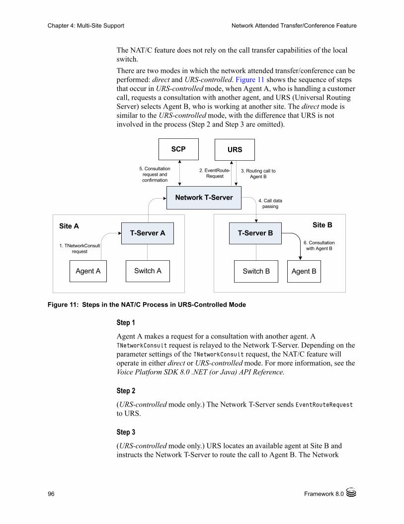
96 Framework 8.0
Chapter 4: Multi-Site Support Network Attended Transfer/Conference Feature
The NAT/C feature does not rely on the call transfer capabilities of the local switch.
There are two modes in which the network attended transfer/conference can be performed: direct and URS-controlled. Figure 11 shows the sequence of steps that occur in URS-controlled mode, when Agent A, who is handling a customer call, requests a consultation with another agent, and URS (Universal Routing Server) selects Agent B, who is working at another site. The direct mode is similar to the URS-controlled mode, with the difference that URS is not involved in the process (Step 2 and Step 3 are omitted).
Figure 11: Steps in the NAT/C Process in URS-Controlled Mode
Step 1
Agent A makes a request for a consultation with another agent. A TNetworkConsult request is relayed to the Network T-Server. Depending on the parameter settings of the TNetworkConsult request, the NAT/C feature will operate in either direct or URS-controlled mode. For more information, see the Voice Platform SDK 8.0 .NET (or Java) API Reference.
Step 2
(URS-controlled mode only.) The Network T-Server sends EventRouteRequest to URS.
Step 3
(URS-controlled mode only.) URS locates an available agent at Site B and instructs the Network T-Server to route the call to Agent B. The Network
Network T-Server
SCP
2. EventRoute-Request
5. Consultation request and confirmation
Site BT-Server B
3. Routing call to Agent B
Agent B
6. Consultation with Agent B
4. Call data passing
Site AT-Server A
Agent A
1. TNetworkConsultrequest
Switch A Switch B
URS
Chapter 4: Multi-Site Support Event Propagation Feature
T-Server—Deployment Guide 97
T-Server confirms the initiation of the network transfer by sending EventNetworkCallStatus to T-Server A, which then relays it to Agent A.
Step 4
The Network T-Server proceeds to obtain the access number from T-Server B, and passes the call data to T-Server B. (See “ISCC Call Data Transfer Service” on page 63 for details.)
Step 5
The Network T-Server instructs the Service Control Point (SCP) to initiate a new voice path with Agent B. Once the connection is confirmed, the Network T-Server distributes EventNetworkCallStatus to both T-Server A and T-Server B, which then relay it to Agent A and Agent B respectively, to indicate that the consultation call is being established.
The Network T-Server also distributes EventRouteUsed to URS to confirm successful routing of the call to the selected agent.
Step 6
At this point, the customer is on hold, and Agent A is consulting with Agent B. Agent A can do one of the following:
• End the consultation and retrieve the original customer call
• Alternate between Agent B and the customer
• Set up a conference call with Agent B and the customer
• Transfer the customer call to Agent B
Event Propagation FeatureThe Event Propagation feature complements the ISCC and ISCC/COF features by distributing updated user data and party-related events to remote T-Servers. This feature is used when a call is being made, transferred, or conferenced to another location, and when, as a result, one or more instances of the call reside at one location while other call instances reside at another location. In this scenario, when a client at one location makes changes to user data, updated user data is passed (propagated) to T-Servers at other locations.
Note: All T-Servers support NAT/C requests with AttributeHomeLocation provided that this attribute identifies a network location that is capable of processing such requests. Refer to the Network T-Server Deployment Guides to determine whether a specific Network T-Server can process these requests.
98 Framework 8.0
Chapter 4: Multi-Site Support Event Propagation Feature
The Event Propagation feature consists of User Data update propagation and Party Events propagation.
User Data Propagation
User data propagation takes place when a client at one location makes changes to user data associated with a call that was made, transferred, conferenced, or routed to other locations. The remote clients involved with the call are notified about the changes with EventAttachedDataChanged.
When T-Server receives a local update to user data (that is, when a client of this T-Server has changed the call’s user data), T-Server determines if parties at remote locations are involved with the call and, if so, sends (propagates) the updated user data to the T-Servers at remote locations.
When T-Server receives a remote update to user data (that is, when a client of a remote T-Server has changed the call’s user data and the remote T-Server has used the Event Propagation feature to send the updated user data), T-Server:
1. Updates the user data of the corresponding local call.
2. Determines if parties at other remote locations are involved with the call and, if so, propagates the updated user data to T-Servers at other remote locations.
The locations to which user data is propagated are selected based on a call distribution topology. That is, the updated user data is passed directly to the location to which a call was sent and to the location from which the call was received, excluding the location from which the update was received.
For example, consider a call made from location A to location B, and then conferenced from location B to location C. The three instances of the call reside at different locations: the first instance is at location A, the second instance is at location B, and the third instance is at location C. The Event Propagation feature is employed in the following scenarios:
• When T-Server at location A receives a local update to user data, it notifies T-Server at location B (to which it sent the call) about changes to the call’s user data. Thus, T-Server at location B receives a remote update to user data and, in turn, notifies T-Server at location C (to which it sent the call) about these changes.
Although T-Server at location C receives a remote update to user data, it does not pass the notification to any other T-Servers, because it did not send the call to any other locations. As mentioned earlier, T-Servers at locations B and C update the user data of the corresponding local calls and notify their clients about the changes with EventAttachedDataChanged.
• When T-Server at location B receives a local update to user data, it notifies T-Server at location C (to which it sent the call) and T-Server at location A (from which it received the call) about changes to the call’s user data. Thus, T-Servers at locations C and A receive a remote update to user data.
Chapter 4: Multi-Site Support Event Propagation Feature
T-Server—Deployment Guide 99
Because T-Server at location C did not send the call to any other locations, and T-Server at location A originated the call, neither of these T-Servers passes the notification to any other T-Servers. T-Servers at locations C and A update the user data of the corresponding local calls and notify their clients about the changes with EventAttachedDataChanged.
• When T-Server at location C receives a local update to user data, it notifies T-Server at location B (from which it received the call) about changes to the call’s user data. Thus, T-Server at location B receives a remote update to user data and, in turn, notifies T-Server at location A (from which it received the call) about these changes.
Although T-Server at location A receives a remote update to user data, it does not pass the notification to any other T-Servers, because it originated the call. T-Servers at locations B and A update the user data of the corresponding local calls and notify their clients about the changes with EventAttachedDataChanged.
When a call is distributed between location A and location C using location B, and is then deleted on location B, propagation between locations A and C still occurs through the transit node at location B.
Party Events Propagation
Party events propagation takes place when a transfer or a conference is completed for a call that was made to or from one or more remote locations, or when a conference party is removed from the conference.
In these cases, the Event Propagation feature distributes party events, such as EventPartyChanged, EventPartyAdded, and EventPartyDeleted, to remote locations involved with the call, according to appropriate call model scenarios.
For example, consider a call made from DN 1 to DN 2 on location A. A TInitiateConference request is then issued for DN 2 to transfer the call to external DN 3 on location B. That transfer is made by means of ISCC routing. When this conference is completed on location A, the Event Propagation feature sends EventPartyChanged to location B and distributes this event to involved client applications that are connected to location B and registered for DN 3. After that, if a party of the conference is removed from the conference (for example, a party on DN 2), the Event Propagation feature sends EventPartyDeleted to location B and distributes this event to client applications registered for DN 3.
If a call involved in the propagation has no local parties but has two or more remote parties, the party events propagation is processed in the same manner as the propagation of user data updates.
For a complete event flow in such scenarios, refer to the Genesys 7 Events and Models Reference Manual.
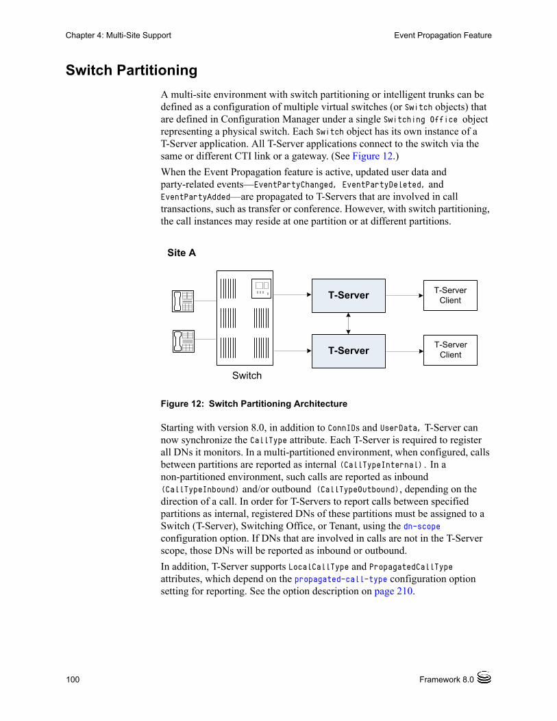
100 Framework 8.0
Chapter 4: Multi-Site Support Event Propagation Feature
Switch Partitioning
A multi-site environment with switch partitioning or intelligent trunks can be defined as a configuration of multiple virtual switches (or Switch objects) that are defined in Configuration Manager under a single Switching Office object representing a physical switch. Each Switch object has its own instance of a T-Server application. All T-Server applications connect to the switch via the same or different CTI link or a gateway. (See Figure 12.)
When the Event Propagation feature is active, updated user data and party-related events—EventPartyChanged, EventPartyDeleted, and EventPartyAdded—are propagated to T-Servers that are involved in call transactions, such as transfer or conference. However, with switch partitioning, the call instances may reside at one partition or at different partitions.
Figure 12: Switch Partitioning Architecture
Starting with version 8.0, in addition to ConnIDs and UserData, T-Server can now synchronize the CallType attribute. Each T-Server is required to register all DNs it monitors. In a multi-partitioned environment, when configured, calls between partitions are reported as internal (CallTypeInternal). In a non-partitioned environment, such calls are reported as inbound (CallTypeInbound) and/or outbound (CallTypeOutbound), depending on the direction of a call. In order for T-Servers to report calls between specified partitions as internal, registered DNs of these partitions must be assigned to a Switch (T-Server), Switching Office, or Tenant, using the dn-scope configuration option. If DNs that are involved in calls are not in the T-Server scope, those DNs will be reported as inbound or outbound.
In addition, T-Server supports LocalCallType and PropagatedCallType attributes, which depend on the propagated-call-type configuration option setting for reporting. See the option description on page 210.
Site A
T-Server ClientT-Server
T-Server
Switch
T-Server Client
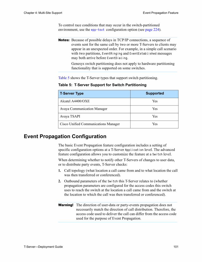
Chapter 4: Multi-Site Support Event Propagation Feature
T-Server—Deployment Guide 101
To control race conditions that may occur in the switch-partitioned environment, use the epp-tout configuration option (see page 224).
Table 5 shows the T-Server types that support switch partitioning.
Event Propagation Configuration
The basic Event Propagation feature configuration includes a setting of specific configuration options at a T-Server Application level. The advanced feature configuration allows you to customize the feature at a Switch level.
When determining whether to notify other T-Servers of changes to user data, or to distribute party events, T-Server checks:
1. Call topology (what location a call came from and to what location the call was then transferred or conferenced).
2. Outbound parameters of the Switch this T-Server relates to (whether propagation parameters are configured for the access codes this switch uses to reach the switch at the location a call came from and the switch at the location to which the call was then transferred or conferenced).
Notes: Because of possible delays in TCP/IP connections, a sequence of events sent for the same call by two or more T-Servers to clients may appear in an unexpected order. For example, in a simple call scenario with two partitions, EventRinging and EventEstablished messages may both arrive before EventDialing.
Genesys switch partitioning does not apply to hardware partitioning functionality that is supported on some switches.
Table 5: T-Server Support for Switch Partitioning
T-Server Type Supported
Alcatel A4400/OXE Yes
Avaya Communication Manager Yes
Avaya TSAPI Yes
Cisco Unified Communications Manager Yes
Warning! The direction of user-data or party-events propagation does not necessarily match the direction of call distribution. Therefore, the access code used to deliver the call can differ from the access code used for the purpose of Event Propagation.
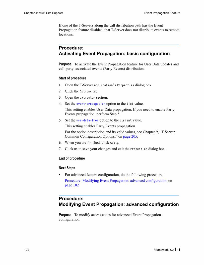
102 Framework 8.0
Chapter 4: Multi-Site Support Event Propagation Feature
If one of the T-Servers along the call distribution path has the Event Propagation feature disabled, that T-Server does not distribute events to remote locations.
Procedure:Activating Event Propagation: basic configuration
Purpose: To activate the Event Propagation feature for User Data updates and call-party–associated events (Party Events) distribution.
Start of procedure
1. Open the T-Server Application’s Properties dialog box.
2. Click the Options tab.
3. Open the extrouter section.
4. Set the event-propagation option to the list value.
This setting enables User Data propagation. If you need to enable Party Events propagation, perform Step 5.
5. Set the use-data-from option to the current value.
This setting enables Party Events propagation.
For the option description and its valid values, see Chapter 9, “T-Server Common Configuration Options,” on page 205.
6. When you are finished, click Apply.
7. Click OK to save your changes and exit the Properties dialog box.
End of procedure
Next Steps
• For advanced feature configuration, do the following procedure:
Procedure: Modifying Event Propagation: advanced configuration, on page 102
Procedure:Modifying Event Propagation: advanced configuration
Purpose: To modify access codes for advanced Event Propagation configuration.
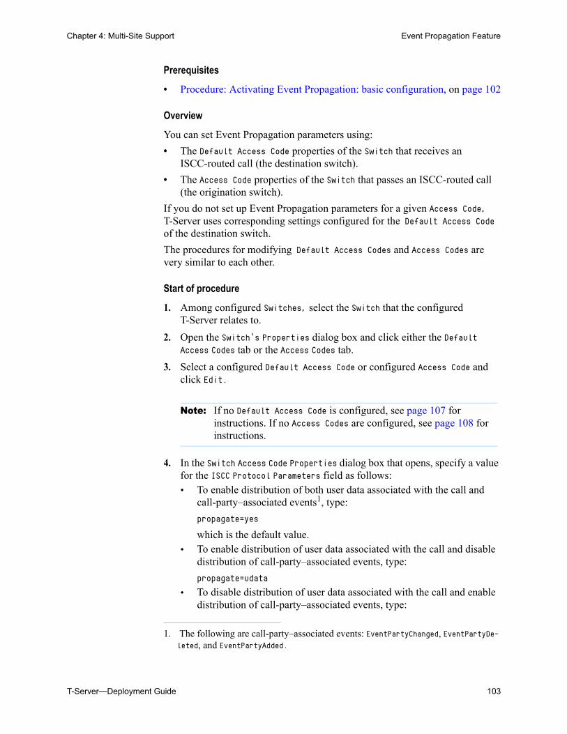
Chapter 4: Multi-Site Support Event Propagation Feature
T-Server—Deployment Guide 103
Prerequisites
• Procedure: Activating Event Propagation: basic configuration, on page 102
Overview
You can set Event Propagation parameters using:
• The Default Access Code properties of the Switch that receives an ISCC-routed call (the destination switch).
• The Access Code properties of the Switch that passes an ISCC-routed call (the origination switch).
If you do not set up Event Propagation parameters for a given Access Code, T-Server uses corresponding settings configured for the Default Access Code of the destination switch.
The procedures for modifying Default Access Codes and Access Codes are very similar to each other.
Start of procedure
1. Among configured Switches, select the Switch that the configured T-Server relates to.
2. Open the Switch’s Properties dialog box and click either the Default Access Codes tab or the Access Codes tab.
3. Select a configured Default Access Code or configured Access Code and click Edit.
4. In the Switch Access Code Properties dialog box that opens, specify a value for the ISCC Protocol Parameters field as follows: To enable distribution of both user data associated with the call and
call-party–associated events1, type:
propagate=yes
which is the default value. To enable distribution of user data associated with the call and disable
distribution of call-party–associated events, type:
propagate=udata
To disable distribution of user data associated with the call and enable distribution of call-party–associated events, type:
Note: If no Default Access Code is configured, see page 107 for instructions. If no Access Codes are configured, see page 108 for instructions.
1. The following are call-party–associated events: EventPartyChanged, EventPartyDe-leted, and EventPartyAdded.
104 Framework 8.0
Chapter 4: Multi-Site Support ISCC Transaction Monitoring Feature
propagate=party
To disable distribution of both user data associated with the call and call-party–associated events, type:propagate=no
5. Click OK to save configuration updates and close the Switch Access Code Properties dialog box.
6. Click Apply and OK to save configuration updates and close the Switch Properties dialog box.
End of procedure
ISCC Transaction Monitoring FeatureThis feature allows T-Server clients to monitor ISCC transactions that occur during the call data transfer between T-Servers in a multi-site environment.
In order to be able to monitor ISCC messaging, a T-Server client must subscribe to the ISCC Transaction Monitoring. Once a subscription request is confirmed, a client will receive updates about all multi-site operations of this T-Server.
The TTransactionMonitoring request is used to instruct T-Server to start, stop, or modify a client’s subscription to Transaction Monitoring feature notifications by setting the TSubscriptionOperationType parameter to SubscriptionStart, SubscriptionStop, or SubscriptionModify respectively. The transaction status is reported in EventTransactionStatus messages to the subscribed clients.
To determine whether the Transaction Monitoring feature is supported by a specific T-Server, a T-Server client may query T-Server’s capabilities. For more information about support of this feature, see Genesys 7 Events and Models Reference Manual and Voice Platform SDK 8.0 .NET (or Java) API Reference.
Configuring Multi-Site SupportPrior to configuring T-Server to support multi-site operation, you must read the “Licensing Requirements” on page 33, as well as previous sections of this chapter on multi-site deployment. In particular, Table 3 on page 79 shows which transaction types are supported by a specific T-Server, while Table 4 on page 84 shows whether your T-Server supports the NetworkCallID attribute for
Chapter 4: Multi-Site Support Configuring Multi-Site Support
T-Server—Deployment Guide 105
the ISCC/COF feature. Use this information as you follow the instructions in this chapter.
For T-Server to support multi-site operation, you must create and configure three types of objects in the Configuration Layer:
1. Applications
2. Switches, including Access Codes
3. DNs
You must configure these objects for origination and destination locations. Multi-site support features activate automatically at T-Server startup. See “DNs” on page 112 for details.
Applications
Ensure that T-Server Application objects, and their corresponding Host objects, exist and are configured for origination and destination locations.
Once you’ve done that, use Configuration Manager to add this configuration to a T-Server Application.
Procedure:Configuring T-Server Applications
Purpose: To configure T-Server Application objects for multi-site operation support.
Start of procedure
1. Open the T-Server Application’s Properties dialog box.
2. Click the Connections tab and click Add to add a connection to the appropriate T-Server. The Connection Info Properties dialog box displays.
3. Use the Browse button to search for the T-Server you want to connect to, and fill in the following values: Port ID
Note: Before attempting to configure a multi-site environment, Genesys recommends that you plan the changes you want to make to your existing contact centers. You should then gather the configuration information you will need (such as the name of each T-Server application, port assignments, and switch names), and use Configuration Manager to create and partially configure each T-Server object. Review multi-site option values in the “Multi-Site Support Section” on page 215 and determine what these values need to be, based on your network topology.
106 Framework 8.0
Chapter 4: Multi-Site Support Configuring Multi-Site Support
Connection Protocol Local Timeout Remote Timeout Trace Mode
4. Click the Options tab. Create a new section called extrouter or open an existing section with this name.
5. Open the extrouter section. Configure the options used for multi-site support.
6. When you are finished, click Apply.
7. Repeat this procedure for all T-Servers for origination and destination locations that are used for multi-site operations.
End of procedure
Next Steps
• See “Switches and Access Codes.”
Switches and Access Codes
Ensure that Switching Office and Switch objects are configured for both origination and destination locations.
You configure Access Codes to a destination switch in the origination Switch’s Properties dialog box. The only exception is the Default Access Code, which is configured at the destination Switch’s Properties dialog box.
You can configure two types of switch Access Codes in the Switch’s Properties dialog box:
• A Default Access Code (for inbound calls)—Specifies the access code that other switches can use to access this switch when they originate a multi-site transaction.
• An Access Code (for outbound calls)—Specifies the access code that this switch can use when it originates a multi-site transaction to access another switch.
Note: If you do not create the extrouter section, T-Server uses the default values of the corresponding configuration options.
Note: For a list of options and valid values, see “Multi-Site Support Section” on page 215, in the “T-Server Common Configuration Options” chapter in Part Two of this document.
Chapter 4: Multi-Site Support Configuring Multi-Site Support
T-Server—Deployment Guide 107
When the origination T-Server processes a multi-site transaction, it looks for an access code to the destination switch. First, T-Server checks the Access Code of the origination Switch:
• If an access code to the destination switch is configured with the target type Target ISCC and with any transaction type except Forbidden, T-Server uses this access code to dial the destination switch.
• If the access code to the destination switch is not configured on the Access Code tab of the origination switch, the origination T-Server checks the Default Access Code tab of the destination switch. If an access code is configured there with the target type Target ISCC and with any transaction type except Forbidden, T-Server uses this access code to dial the destination switch.
• If no access code with the required properties is found, T-Server rejects the transaction.
Procedure:Configuring Default Access Codes
Purpose: To configure the Default Access Codes (one per Switch object) to be used by other switches to access this switch when they originate a multi-site transaction.
Prerequisites
• Ensure that Switching Office and Switch objects are configured for both origination and destination locations.
Start of procedure
1. Among configured Switches, select the Switch that the configured T-Server relates to.
2. Open the Switch Properties dialog box and click the Default Access Codes tab.
3. Click Add to open the Access Code Properties dialog box.
Note: When migrating from previous releases of T-Servers to 8.0, or when using T-Servers of different releases (including 8.0) in the same environment, see “Compatibility Notes” on page 111.
108 Framework 8.0
Chapter 4: Multi-Site Support Configuring Multi-Site Support
4. In the Code field, specify the access code used by remote switches to reach a DN at this switch. An access code is used as a prefix to the remote switch numbers.
5. In the Target Type field, select Target ISCC.
6. In the Route Type field, select a value corresponding to the transaction type you want to use (given that it is supported for your switch type).
7. When you are finished, click Apply.
End of procedure
Next Steps
• See “Configuring Access Codes.”
Procedure:Configuring Access Codes
Purpose: To configure the Access Codes (one or more per Switch object) that this switch can use when it originates a multi-site transaction to access another switch.
Prerequisites
• Ensure that Switching Office and Switch objects are configured for both origination and destination locations.
Start of procedure
1. Among configured Switches, select the Switch that the configured T-Server relates to.
2. Open the Switch Properties dialog box and click the Access Codes tab.
3. Click Add to open the Access Code Properties dialog box.
4. In the Switch field, specify the switch that this switch can reach using this access code. Use the Browse button to locate the remote switch.
Note: If no prefix is needed to dial to the configured switch, you can leave the Code field blank.
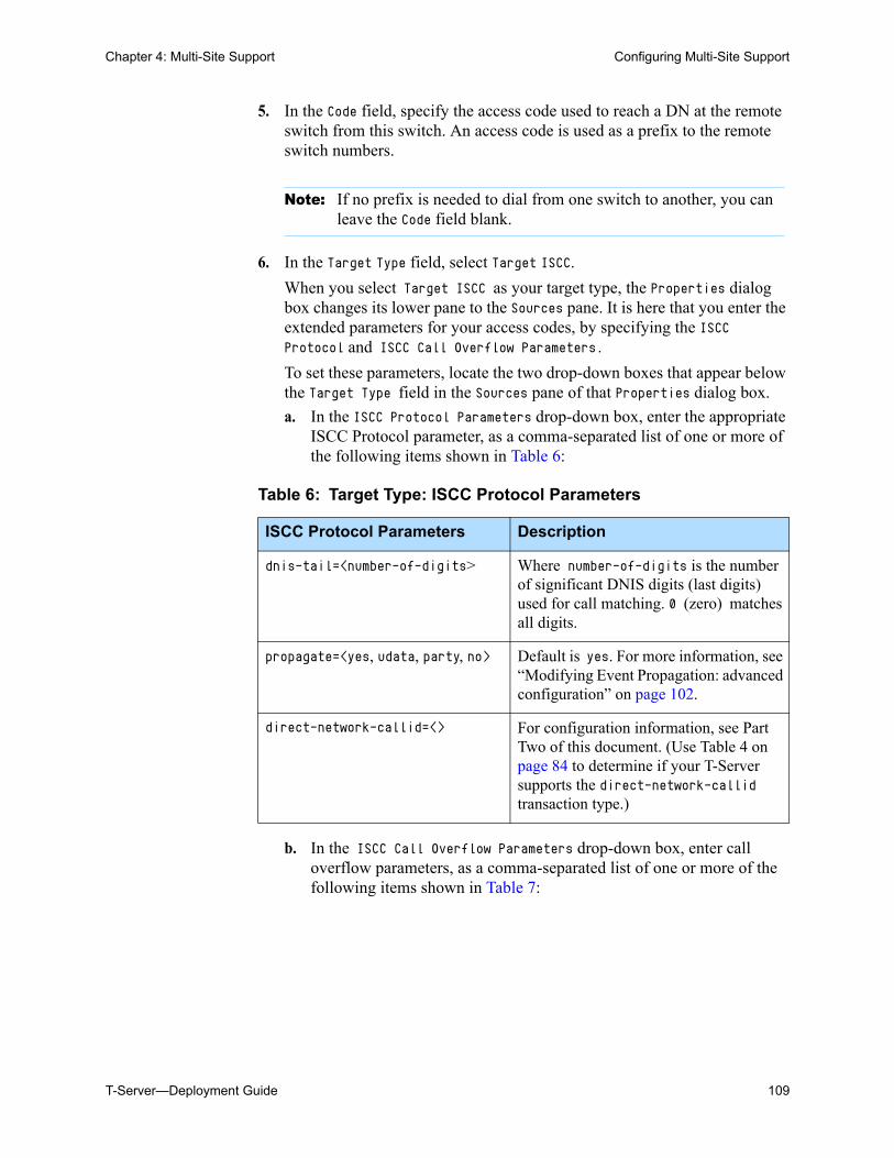
Chapter 4: Multi-Site Support Configuring Multi-Site Support
T-Server—Deployment Guide 109
5. In the Code field, specify the access code used to reach a DN at the remote switch from this switch. An access code is used as a prefix to the remote switch numbers.
6. In the Target Type field, select Target ISCC.
When you select Target ISCC as your target type, the Properties dialog box changes its lower pane to the Sources pane. It is here that you enter the extended parameters for your access codes, by specifying the ISCC Protocol and ISCC Call Overflow Parameters.
To set these parameters, locate the two drop-down boxes that appear below the Target Type field in the Sources pane of that Properties dialog box.
a. In the ISCC Protocol Parameters drop-down box, enter the appropriate ISCC Protocol parameter, as a comma-separated list of one or more of the following items shown in Table 6:
b. In the ISCC Call Overflow Parameters drop-down box, enter call overflow parameters, as a comma-separated list of one or more of the following items shown in Table 7:
Note: If no prefix is needed to dial from one switch to another, you can leave the Code field blank.
Table 6: Target Type: ISCC Protocol Parameters
ISCC Protocol Parameters Description
dnis-tail=<number-of-digits> Where number-of-digits is the number of significant DNIS digits (last digits) used for call matching. 0 (zero) matches all digits.
propagate=<yes, udata, party, no> Default is yes. For more information, see “Modifying Event Propagation: advanced configuration” on page 102.
direct-network-callid=<> For configuration information, see Part Two of this document. (Use Table 4 on page 84 to determine if your T-Server supports the direct-network-callid transaction type.)
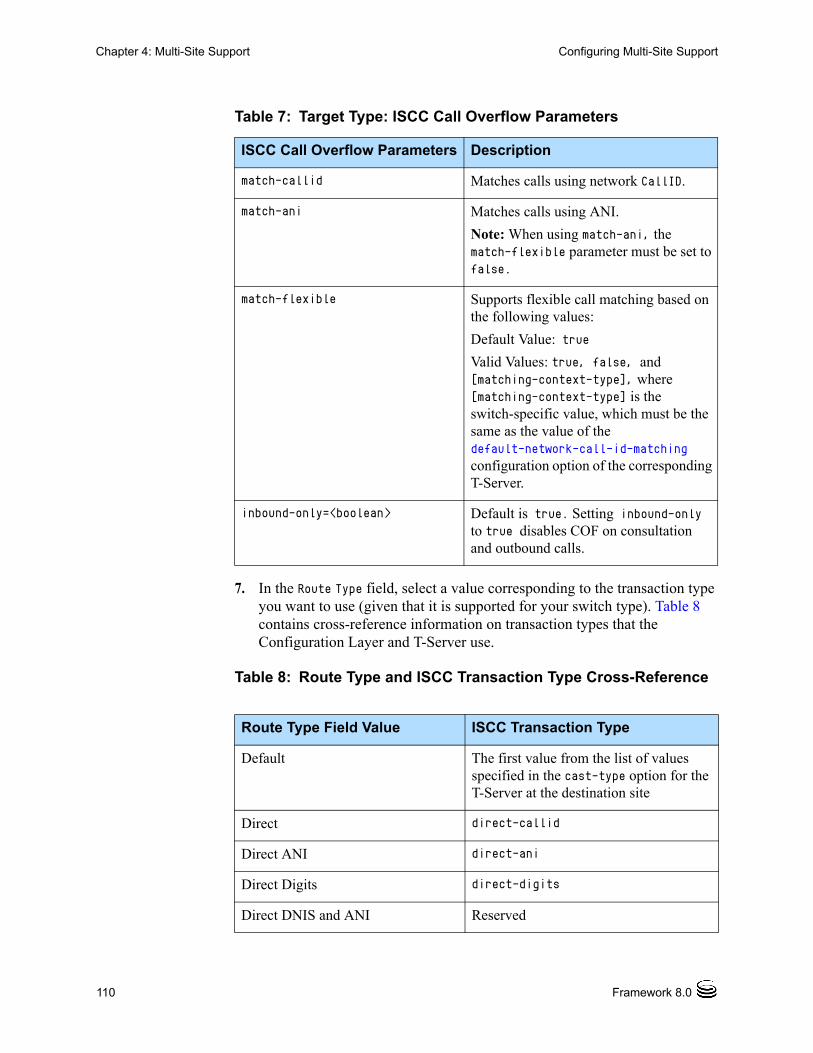
110 Framework 8.0
Chapter 4: Multi-Site Support Configuring Multi-Site Support
7. In the Route Type field, select a value corresponding to the transaction type you want to use (given that it is supported for your switch type). Table 8 contains cross-reference information on transaction types that the Configuration Layer and T-Server use.
Table 7: Target Type: ISCC Call Overflow Parameters
ISCC Call Overflow Parameters Description
match-callid Matches calls using network CallID.
match-ani Matches calls using ANI.
Note: When using match-ani, the match-flexible parameter must be set to false.
match-flexible Supports flexible call matching based on the following values:
Default Value: true
Valid Values: true, false, and [matching-context-type], where [matching-context-type] is the switch-specific value, which must be the same as the value of the default-network-call-id-matching configuration option of the corresponding T-Server.
inbound-only=<boolean> Default is true. Setting inbound-only to true disables COF on consultation and outbound calls.
Table 8: Route Type and ISCC Transaction Type Cross-Reference
Route Type Field Value ISCC Transaction Type
Default The first value from the list of values specified in the cast-type option for the T-Server at the destination site
Direct direct-callid
Direct ANI direct-ani
Direct Digits direct-digits
Direct DNIS and ANI Reserved
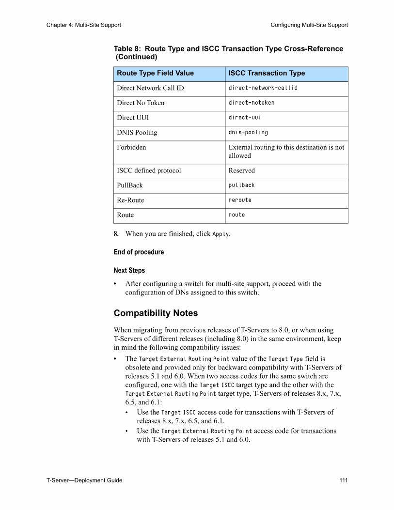
Chapter 4: Multi-Site Support Configuring Multi-Site Support
T-Server—Deployment Guide 111
8. When you are finished, click Apply.
End of procedure
Next Steps
• After configuring a switch for multi-site support, proceed with the configuration of DNs assigned to this switch.
Compatibility Notes
When migrating from previous releases of T-Servers to 8.0, or when using T-Servers of different releases (including 8.0) in the same environment, keep in mind the following compatibility issues:
• The Target External Routing Point value of the Target Type field is obsolete and provided only for backward compatibility with T-Servers of releases 5.1 and 6.0. When two access codes for the same switch are configured, one with the Target ISCC target type and the other with the Target External Routing Point target type, T-Servers of releases 8.x, 7.x, 6.5, and 6.1: Use the Target ISCC access code for transactions with T-Servers of
releases 8.x, 7.x, 6.5, and 6.1. Use the Target External Routing Point access code for transactions
with T-Servers of releases 5.1 and 6.0.
Direct Network Call ID direct-network-callid
Direct No Token direct-notoken
Direct UUI direct-uui
DNIS Pooling dnis-pooling
Forbidden External routing to this destination is not allowed
ISCC defined protocol Reserved
PullBack pullback
Re-Route reroute
Route route
Table 8: Route Type and ISCC Transaction Type Cross-Reference (Continued)
Route Type Field Value ISCC Transaction Type
112 Framework 8.0
Chapter 4: Multi-Site Support Configuring Multi-Site Support
When the only access code configured for a switch has the Target External Routing Point target type, T-Server uses this access code for all transactions.
• When the Target External Routing Point value of the Target Type field is configured, you must set the Route Type field to one of the following: Default to enable the route transaction type Label to enable the direct-ani transaction type Direct to enable the direct transaction type
UseExtProtocol to enable the direct-uui transaction type PostFeature to enable the reroute transaction type
These values are fully compatible with the transaction types supported in T-Server release 5.1.
• For successful multi-site operations between any two locations served by release 5.1 T-Servers, identical Route Type values must be set in the Switch’s Access Code Properties dialog boxes for both the origination and destination switches.
DNs
Use the procedures from this section to configure access resources for various transaction types.
Procedure:Configuring access resources for the route transaction type
Purpose: To configure dedicated DNs required for the route transaction type.
Prerequisites
• Ensure that Switching Office and Switch objects are configured for both origination and destination locations.
Note: The direct transaction type in releases 5.1 and 6.0 corresponds to the direct-callid transaction type in releases 6.1 and later.
Chapter 4: Multi-Site Support Configuring Multi-Site Support
T-Server—Deployment Guide 113
Start of procedure
1. Under a configured Switch, select the DNs folder. From the main menu, select File > New > DN to create a new DN object.
2. On the General tab of the DN’s Properties dialog box, specify the number of the configured DN as the value of the Number field. This value must correspond to the Routing Point number on the switch.
3. Select External Routing Point as the value of the Type field.
4. If a dialable number for that Routing Point is different from its DN name, specify the number in the Association field.
5. Click the Access Numbers tab. Click Add and specify these access number parameters: Origination switch. Access number that must be dialed to reach this DN from the
origination switch.
In determining an access number for the Routing Point, T-Server composes it of the values of the following properties (in the order listed):
a. Access number (if specified).
b. Switch access code from the switch of the origination party to the switch to which the Routing Point belongs, concatenated with its Association (if the Association value is specified).
c. Switch access code from the switch of the origination party to the switch to which the Routing Point belongs, concatenated with the number for the DN.
d. Default access code of the switch to which the Routing Point belongs, concatenated with its Association (if the Association value is specified).
e. Default access code of the switch to which the Routing Point belongs, concatenated with the number for the DN.
6. When you are finished, click Apply.
End of procedure
Note: If option use-implicit-access-numbers is set to true, the access number composed of switch access code and DN can be used for external transfers of calls originating at switches for which an access number is not specified.
114 Framework 8.0
Chapter 4: Multi-Site Support Configuring Multi-Site Support
Procedure:Configuring access resources for the dnis-pool transaction type
Purpose: To configure dedicated DNs required for the dnis-pool transaction type.
Start of procedure
1. Under a configured Switch, select the DNs folder. From the main menu, select File > New > DN to create a new DN object.
2. On the General tab of the DN’s Properties dialog box, specify the number of the configured DN as the value of the Number field. This value must be a dialable number on the switch.
3. Select Access Resource as the Type field and type dnis as the value of the Resource Type field on the Advanced tab.
4. Click the Access Numbers tab. Click Add and specify these Access Number parameters: Origination switch. Access number that must be dialed to reach this DN from the
origination switch.
An access number for the access resource is determined in the same manner as for the route access resource.
5. When you are finished, click Apply.
End of procedure
Procedure:Configuring access resources for direct-* transaction types
Overview
You can use any configured DN as an access resource for the direct-* transaction types. (The * symbol stands for any of the following: callid, uui, notoken, ani, or digits.)
You can select the Use Override check box on the Advanced tab to indicate whether the override value should be used instead of the number value to dial to the DN. You must specify this value if the DN has a different DN name and dialable number. In fact, this value is required for T-Servers for some switch types—such as Aspect ACD, Nortel Communication Server 2000/2100, and Spectrum.
Chapter 4: Multi-Site Support Configuring Multi-Site Support
T-Server—Deployment Guide 115
Procedure:Configuring access resources for ISCC/COF
Purpose: To configure dedicated DNs required for the ISCC/COF feature.
Start of procedure
1. Under a configured Switch, select the DNs folder. From the main menu, select File > New > DN to create a new DN object.
2. On the General tab of the DN Properties dialog box, specify the number of the configured DN as the value for the Number field.
3. Select Access Resource as the value for the Type field.
4. On the Advanced tab, type cof-in or cof-not-in as the value for the Resource Type field.
5. When you are finished, click Apply.
End of procedure
Procedure:Configuring access resources for non-unique ANI
Purpose: To configure dedicated DNs required for the non-unique-ani resource type.
The non-unique-ani resource type is used to block direct-ani and COF/ani from relaying on ANI when it matches configured/enabled resource digits. Using non-unique-ani, T-Server checks every ANI against a list of non-unique-ani resources.
Note: Use Table 4 on page 84 to determine if your T-Server supports the ISCC/COF feature.
Note: The number of the access resource must match the name of a DN configured on the switch (usually, an ACD Queue) so that T-Server can determine whether the calls arriving to this DN are overflowed calls.
Note: Calls coming to DNs with the cof-not-in value for the Resource Type are never considered to be overflowed.
116 Framework 8.0
Chapter 4: Multi-Site Support Configuring Multi-Site Support
Start of procedure
1. Under a configured Switch, select the DNs folder. From the main menu, select File > New > DN to create a new DN object.
2. On the General tab of the DN Properties dialog box, specify the ANI digits that need to be excluded from normal processing.
3. Select Access Resource as the value for the Type field.
4. On the Advanced tab, specify the Resource Type field as non-unique-ani.
5. When you are finished, click Apply.
End of procedure
Procedure:Modifying DNs for isolated switch partitioning
Purpose: To modify DNs that belong to a particular partition where switch partitioning is used.
This configuration instructs T-Server to select an External Routing Point that has the same partition as the requested destination DN.
Start of procedure
1. Under a Switch object, select the DNs folder.
2. Open the Properties dialog box of a particular DN.
3. Click the Annex tab.
4. Create a new section named TServer.
5. Within that section, create a new option named epn. Set the option value to the partition name to which the DN belongs.
6. Repeat Steps 1–5 for all DNs, including DNs of the External Routing Point type, that belong to the same switch partition.
7. When you are finished, click Apply.
End of procedure
Note: When a target DN is not configured or has no configured partition name, T-Server allocates a DN of the External Routing Point type that belongs to any partition.
Chapter 4: Multi-Site Support Configuring Multi-Site Support
T-Server—Deployment Guide 117
Configuration Examples
This section provides two configuration examples and describes how the configuration settings affect T-Server’s behavior.
Multiple Transaction Types
This example demonstrates the difference in how ISCC directs a call when you specify two different transaction types (route and direct-ani).
In this example, you configure an origination and a destination switch for as described in “Switches and Access Codes” on page 106.
1. Among configured Switches, select the origination Switch.
2. Open the Switch Properties dialog box and click the Default Access Codes tab.
3. Click Add to open the Access Code Properties dialog box.
4. Set the Access Code field to 9.
5. When you are finished, click Apply.
6. Among configured Switches, select the destination Switch.
7. Under the destination Switch, configure a DN as described in “Configuring access resources for the route transaction type” on page 112.
8. Set the DN Number field to 5001234567.
9. Click the Advanced tab of this DN’s Properties dialog box.
10. Select the Use Override check box and enter 1234567 in the Use Override field.
11. When you are finished, click Apply or Save.
12. Use a T-Server client application to register for this new DN with the destination T-Server and, therefore, with the switch.
13. Request to route a call from any DN at the origination switch to the destination DN you have just configured: If you are using the route ISCC transaction type, the client requests
that T-Server deliver a call to a destination location using the DN number 5001234567. ISCC requests that the switch dial one of the external routing points at the destination location, using the value either of the Access Number field or of the Access Code field, which is 9, concatenated with the external routing point at the destination location. The call is routed to the DN number 5001234567.
If you are using the direct-ani ISCC transaction type, the client requests that T-Server deliver a call to a destination location using the DN number 1234567, which is the Use Override value. ISCC requests
118 Framework 8.0
Chapter 4: Multi-Site Support Next Steps
that the switch dial 91234567, which is a combination of the Switch Access Code value and the Use Override value. The destination T-Server is waiting for the call to directly arrive at DN number 5001234567.
Call Overflow Methods
This section demonstrates how to indicate which overflow methods a switch supports.
In this example, for T-Server to use ANI/OtherDN matching in call overflow and manual transfer scenarios, set the ISCC Call Overflow Parameters to:
match-ani, inbound-only=true
when configuring Switch Access Codes as described on page 108.
With this setting, the switch’s location is queried for call data each time the destination T-Server receives an inbound call with the ANI or OtherDN attribute.
For T-Server to use NetworkCallID matching in call overflow and manual transfer scenarios, set the ISCC Call Overflow Parameters to (for example):
match-callid, inbound-only=false
when configuring Switch Access Codes as described on page 108.
With this setting, the switch’s location is queried for call data each time the destination T-Server receives a call of any type (including inbound) with the NetworkCallID attribute.
Next StepsContinue with Chapter 5, “Start and Stop T-Server Components,” on page 119 to test your configuration and installation.
T-Server—Deployment Guide 119
Chapter
5 Start and Stop T-Server ComponentsThis chapter describes methods for stopping and starting T-Server, focusing on manual startup for T-Server and HA Proxy for all switches. It includes these sections: Command-Line Parameters, page 119 Starting and Stopping with the Management Layer, page 121 Starting with Startup Files, page 122 Starting Manually, page 123 Verifying Successful Startup, page 129 Stopping Manually, page 129 Starting and Stopping with Windows Services Manager, page 130 Next Steps, page 130
Command-Line ParametersYou can start and stop Framework components using the Management Layer, a startup file, a manual procedure, or the Windows Services Manager.
With all these methods, command-line parameters are usually required for a server application in addition to an executable file name.
Common command-line parameters are as follows:
-host The name of the host on which Configuration Server is running.
-port The communication port that client applications must use to connect to Configuration Server.
-app The exact name of an Application object as configured in the Configuration Database.
120 Framework 8.0
Chapter 5: Start and Stop T-Server Components Command-Line Parameters
-l The license address. Use for the server applications that check out technical licenses. Can be either of the following:
• The full path to, and the exact name of, the license file used by an application. For example, -l /opt/mlink/license/license.dat.
• The host name and port of the license server, as specified in the SERVER line of the license file, in the port@host format. For example, -l 7260@ctiserver.
Note: Specifying the License Manager’s host and port parameter eliminates the need to store a copy of a license file on all computers running licensed applications.
-V The version of a Framework component. Note that specifying this parameter does not start an application, but returns its version number instead. You can use either uppercase or lowercase.
-nco X/Y The Nonstop Operation feature is activated; X exceptions occurring within Y seconds do not cause an application to exit. If the specified number of exceptions is exceeded within the specified number of seconds, the application exits or, if so configured, the Management Layer restarts the application. If the -nco parameter is not specified, the default value of 6 exceptions handled in 10 seconds applies. To disable the Nonstop Operation feature, specify -nco 0 when starting the application.
-lmspath The full path to log messages files (the common file named common.lms and the application-specific file with the extension *.lms) that an application uses to generate log events. This parameter is used when the common and application-specific log message files are located in a directory other than the application’s working directory, such as when the application’s working directory differs from the directory to which the application is originally installed.
Note that if the full path to the executable file is specified in the startup command-line (for instance, c:\gcti\multiserver.exe), the path specified for the executable file is used for locating the *.lms files, and the value of the lmspath parameter is ignored.
- transport-port <port number>
<port number> is the port number that a client will use for its TCP/IP connection to Configuration Server. See the Client-Side Port Definition section in the Genesys 8.0 Security Deployment Guide for more information.
- transport-address <IP address>
<IP address> is the IP address that a client will use for its TCP/IP connection to Configuration Server. See the Client-Side Port Definition section in the Genesys 8.0 Security Deployment Guide for more information.
Chapter 5: Start and Stop T-Server Components Starting and Stopping with the Management Layer
T-Server—Deployment Guide 121
Starting and Stopping with the Management Layer
Procedure:Configuring T-Server to start with the Management Layer
Start of procedure
1. Open the T-Server Application’s Properties dialog box.
2. Click the Start Info tab.
3. Specify the directory where the application is installed and/or is to run as the Working Directory.
4. Specify the name of the executable file as the command-line.
5. Specify command-line parameters as the Command–Line Arguments.
The command-line parameters common to Framework server components are described on page 119.
6. When you are finished, click Apply.
7. Click OK to save your changes and exit the Properties dialog box.
End of procedure
After its command-line parameters are correctly specified in the Properties dialog box, you can start and stop T-Server from Solution Control Interface (SCI), which is the graphical interface component of the Management Layer. (The starting procedure for SCI is described in the Framework 8.0 Deployment Guide.) Framework 8.0 Solution Control Interface Help provides complete instructions on starting and stopping applications.
You can also use the Management Layer to start a T-Server that has failed. To enable T-Server’s autorestart functionality, select the corresponding check box in the Application’s Properties dialog box.
Note: In the command-line examples in this document, angle brackets indicate variables that must be replaced with appropriate values.
Note: Before starting an application with the Management Layer, make sure the startup parameters of the application are correctly specified in the application’s Properties dialog box in Configuration Manager.
122 Framework 8.0
Chapter 5: Start and Stop T-Server Components Starting with Startup Files
Note that when you start (or restart) an application via the Management Layer, the application inherits environment variables from Local Control Agent (LCA), which executes the startup command. Therefore, you must also set the environment variables required by the application for the account that runs LCA.
Starting with Startup FilesStartup files are files with the extension run.sh (on UNIX) or startServer.bat (on Windows), which installation scripts create and place into the applications’ directories during the installations. These files are created for all Framework server applications except:
• Configuration Server (primary or backup) running on Windows.
• Backup Configuration Server running on UNIX.
• DB Server running on Windows.
• LCA running on either Windows or UNIX.
When using a startup file, verify that the startup parameters the installation script inserted in the startup file are correct. Use the following instructions for UNIX and Windows to start those application for which startup files are created. See the appropriate sections in “Starting Manually” on page 123 to identify which applications should be running for a particular application to start.
Procedure:Starting T-Server on UNIX with a startup file
Start of procedure
1. Go to the directory where an application is installed.
2. Type the following command line: sh run.sh
End of procedure
Warning! Stopping an application via the Management Layer is not considered an application failure. Therefore, the Management Layer does not restart applications that it has stopped unless an appropriate alarm condition and alarm reaction are configured for these applications.
Chapter 5: Start and Stop T-Server Components Starting Manually
T-Server—Deployment Guide 123
Procedure:Starting T-Server on Windows with a startup file
Start of procedure
To start T-Server on Windows with a startup file, use either of these methods:
• Go to the directory where an application is installed and double-click the startServer.bat icon.
Or
• From the MS-DOS window, go to the directory where the application is installed and type the following command-line:startServer.bat
End of procedure
Starting ManuallyWhen starting an application manually, you must specify the startup parameters at the command prompt, whether you are starting on UNIX or Windows. At the command prompt, command-line parameters must follow the name of the executable file. On the Shortcut tab of the Program Properties dialog box, command-line parameters must also follow the name of the executable file.
The command-line parameters common to Framework server components are described on page 119.
If an Application object name, as configured in the Configuration Database, contains spaces (for example, T-Server Nortel), the Application name must be surrounded by quotation marks in the command-line:-app “T-Server Nortel”
You must specify the rest of the command-line parameters as for any other application.
The following sections provide general instructions for starting HA Proxy and T-Server manually. Along with these instructions, refer to Table 9, which lists T-Servers and HA Proxy executable file names for supported switches for Windows and UNIX operating systems.
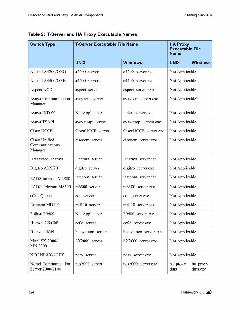
124 Framework 8.0
Chapter 5: Start and Stop T-Server Components Starting Manually
Table 9: T-Server and HA Proxy Executable Names
Switch Type T-Server Executable File Name HA Proxy Executable File Name
UNIX Windows UNIX Windows
Alcatel A4200/OXO a4200_server a4200_server.exe Not Applicable
Alcatel A4400/OXE a4400_server a4400_server.exe Not Applicable
Aspect ACD aspect_server aspect_server.exe Not Applicable
Avaya Communication Manager
avayacm_server avayacm_server.exe Not Applicablea
Avaya INDeX Not Applicable index_server.exe Not Applicable
Avaya TSAPI avayatsapi_server avayatsapi_server.exe Not Applicable
Cisco UCCE CiscoUCCE_server CiscoUCCE_server.exe Not Applicable
Cisco Unified Communications Manager
ciscocm_server ciscocm_server.exe Not Applicable
DataVoice Dharma Dharma_server Dharma_server.exe Not Applicable
Digitro AXS/20 digitro_server digitro_server.exe Not Applicable
EADS Intecom M6880 intecom_server intecom_server.exe Not Applicable
EADS Telecom M6500 m6500_server m6500_server.exe Not Applicable
eOn eQueue eon_server eon_server.exe Not Applicable
Ericsson MD110 md110_server md110_server.exe Not Applicable
Fujitsu F9600 Not Applicable F9600_server.exe Not Applicable
Huawei C&C08 cc08_server cc08_server.exe Not Applicable
Huawei NGN huaweingn_server huaweingn_server.exe Not Applicable
Mitel SX-2000/MN 3300
SX2000_server SX2000_server.exe Not Applicable
NEC NEAX/APEX neax_server neax_server.exe Not Applicable
Nortel Communication Server 2000/2100
ncs2000_server ncs2000_server.exe ha_proxy_dms
ha_proxy_dms.exe

Chapter 5: Start and Stop T-Server Components Starting Manually
T-Server—Deployment Guide 125
Nortel Communication Server 1000 with SCSS/MLS
succession_server succession_server.exe
Not Applicable
Philips Sopho iS3000 iS3000_server iS3000_server.exe ha_proxy_iS3000
ha_proxy_iS3000.exe
Radvision iContact nts_server nts_server.exe Not Applicable
Rockwell Spectrum spectrum_server spectrum_server.exe Not Applicable
Samsung IP-PCX IAP samsung_server samsung_server.exe Not Applicable
Siemens Hicom 300/HiPath 400 CSTA I
rolmcb4_server rolmcb4_server.exe Not Applicable
Siemens HiPath 3000 HiPath3000_server HiPath3000_server.exe Not Applicable
Siemens HiPath 4000 CSTA III
HiPath4000_server HiPath4000_server.exe Not Applicable
Siemens HiPath DX iCCL
HiPathDX_server HiPathDX_server.exe Not Applicable
SIP Server sip_server sip_server.exe Not Applicable
Tadiran Coral Coral_server Coral_server.exe Not Applicable
Teltronics 20-20 Teltronics2020_server Teltronics2020_server.exe
ha_proxy_teltronics2020
ha_proxy_teltronics2020.exe
Tenovis Integral 33/55 Tenovis_server Tenovis_server.exe Not Applicable
Network T-Servers
AT&T nts_server nts_server.exe Not Applicable
Concert nts_server nts_server.exe Not Applicable
CRSP nts_server nts_server.exe Not Applicable
DTAG dtag_server dtag_server.exe Not Applicable
GenSpec genspec_server genspec_server.exe Not Applicable
Table 9: T-Server and HA Proxy Executable Names (Continued)
Switch Type T-Server Executable File Name HA Proxy Executable File Name
UNIX Windows UNIX Windows
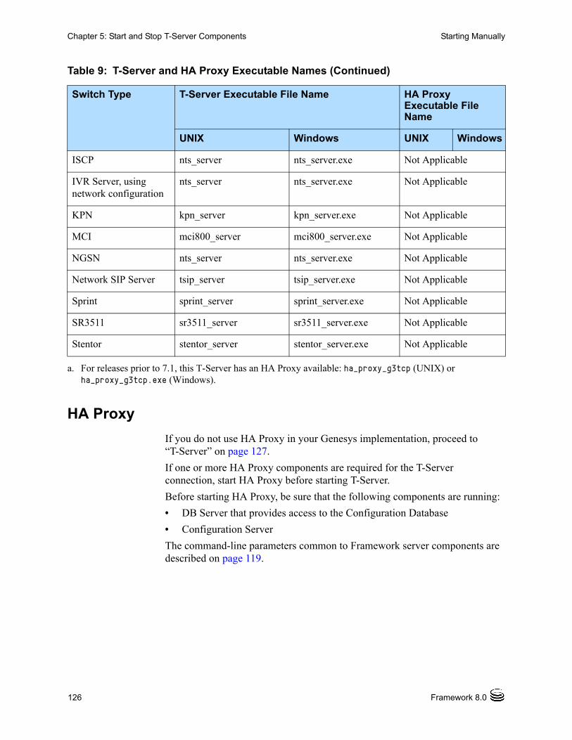
126 Framework 8.0
Chapter 5: Start and Stop T-Server Components Starting Manually
HA Proxy
If you do not use HA Proxy in your Genesys implementation, proceed to “T-Server” on page 127.
If one or more HA Proxy components are required for the T-Server connection, start HA Proxy before starting T-Server.
Before starting HA Proxy, be sure that the following components are running:
• DB Server that provides access to the Configuration Database
• Configuration Server
The command-line parameters common to Framework server components are described on page 119.
ISCP nts_server nts_server.exe Not Applicable
IVR Server, using network configuration
nts_server nts_server.exe Not Applicable
KPN kpn_server kpn_server.exe Not Applicable
MCI mci800_server mci800_server.exe Not Applicable
NGSN nts_server nts_server.exe Not Applicable
Network SIP Server tsip_server tsip_server.exe Not Applicable
Sprint sprint_server sprint_server.exe Not Applicable
SR3511 sr3511_server sr3511_server.exe Not Applicable
Stentor stentor_server stentor_server.exe Not Applicable
a. For releases prior to 7.1, this T-Server has an HA Proxy available: ha_proxy_g3tcp (UNIX) or ha_proxy_g3tcp.exe (Windows).
Table 9: T-Server and HA Proxy Executable Names (Continued)
Switch Type T-Server Executable File Name HA Proxy Executable File Name
UNIX Windows UNIX Windows
Chapter 5: Start and Stop T-Server Components Starting Manually
T-Server—Deployment Guide 127
Procedure:Starting HA Proxy on UNIX manually
Start of procedure
1. Go to the directory where HA Proxy is installed and type the following command-line: ha_proxy_<switch> -host <Configuration Server host> -port <Configuration Server port> -app <HA Proxy Application>
2. Replace ha_proxy_<switch> with the correct HA Proxy executable name, which depends on the type of the switch used.
Table 9 on page 124 lists HA Proxy executable names for supported switches.
End of procedure
Procedure:Starting HA Proxy on Windows manually
Start of procedure
1. Start HA Proxy from either the Start menu or the MS-DOS window. If using the MS-DOS window, go to the directory where HA Proxy is installed and type the following command-line:ha_proxy_<switch>.exe -host <Configuration Server host> -port <Configuration Server port> -app <HA Proxy Application>
2. Replace ha_proxy_<switch>.exe with the correct HA Proxy executable name, which depends on the type of the switch used.
Table 9 on page 124 lists HA Proxy executable names for supported switches.
End of procedure
T-Server
Before starting T-Server, be sure that the following components are running:
• DB Server that provides access to the Configuration Database
• Configuration Server
• License Manager
Note: If an HA Proxy component is required for the T-Server connection, HA Proxy must be started before T-Server.
128 Framework 8.0
Chapter 5: Start and Stop T-Server Components Starting Manually
The command-line parameters common to Framework server components are described on page 119.
Procedure:Starting T-Server on UNIX manually
Start of procedure
1. Go to the directory where T-Server is installed and type the following command-line:
<switch>_server -host <Configuration Server host>
-port <Configuration Server port> -app <T-Server Application>
-l <license address> -nco [X]/[Y]
2. Replace <switch>_server with the correct T-Server executable name, which depends on the type of the switch used.
Table 9 on page 124 lists T-Server executable names for supported switches.
End of procedure
Procedure:Starting T-Server on Windows manually
Start of procedure
1. Start T-Server from either the Start menu or the MS-DOS window. If using the MS-DOS window, go to the directory where T-Server is installed and type the following command-line:
<switch>_server.exe -host <Configuration Server host>
-port <Configuration Server port> -app <T-Server Application>
-l <license address> -nco [X]/[Y]
2. Replace <switch>_server.exe with the correct T-Server executable name, which depends on the type of the switch used.
Table 9 on page 124 lists T-Server executable names for supported switches.
End of procedure
Chapter 5: Start and Stop T-Server Components Verifying Successful Startup
T-Server—Deployment Guide 129
Verifying Successful StartupAfter executing the startup command, you might want to check whether it was successful.
If you used the Management Layer to start either T-Server or HA Proxy, check whether Solution Control Interface displays Started or Service Unavailable status for the corresponding application. Refer to the “Troubleshooting” section of the Framework 8.0 Management Layer User’s Guide if the startup command does not result in either Started or Service Unavailable status for some period of time.
If you start your T-Server or HA Proxy with startup files or manually, and if you have configured logging to console or a log file, check the log for messages similar to the following:
• T-Server log file: Link connected
• HA Proxy log file: Link connected
Stopping ManuallyThe following stopping procedures apply to Genesys server applications, such as DB Server, Configuration Server, Message Server, Local Control Agent, Solution Control Server, HA Proxy, T-Server, and Stat Server.
Procedure:Stopping T-Server on UNIX manually
Start of procedure
To stop a server application from its console window on UNIX, use either of these commands:
• Ctrl+C
• kill <process number>
End of procedure
Procedure:Stopping T-Server on Windows manually
Start of procedure
To stop a server application on Windows, use either of these commands:
130 Framework 8.0
Chapter 5: Start and Stop T-Server Components Starting and Stopping with Windows Services Manager
• To stop a server application from its console window on Windows, use the Ctrl+C command.
• To stop a server application on Windows, use the End Task button on the Windows Task Manager.
End of procedure
Starting and Stopping with Windows Services Manager
When starting an application installed as a Windows Service, make sure the startup parameters of the application are correctly specified in the ImagePath in the Application folder in the Registry Editor. The ImagePath must have the following value data:<full path>\<executable file name> -service <Application Name as Service> -host <Configuration Server host> -port <Configuration Server port> -app <Application Name> -l <license address>
where the command-line parameters common to Framework server components are described on page 119 and
-service The name of the Application running as a Windows Service; typically, it matches the Application name specified in the -app command-line parameter.
Framework components installed as Windows Services with the autostart capability are automatically started each time a computer on which they are installed is rebooted.
You can start Framework components installed as Windows Services with the manual start capability with the Start button in Services Manager.
Regardless of a component’s start capability, you can stop Framework components installed as Windows Services with the Stop button in Services Manager.
Next StepsThis chapter concludes Part One of this document—the set of general instructions for deploying any T-Server. Refer to subsequent chapters in this guide for detailed reference information and any special procedural instructions that pertain to your particular T-Server.
Note: Use the Windows Services window to change the startup mode from Automatic to Manual and vice versa.
T-Server—Deployment Guide 131
Part
2 Reference Information Part Two of this T-Server Deployment Guide contains reference information specific to your T-Server. However, it also contains information on all T-Server options—both those specific to your T-Server and those common to all T-Servers. The information is divided among these chapters:
• Chapter 6, “Switch-Specific Configuration,” on page 133, describes compatibility and configuration information specific to this T-Server, including instructions for setting the DN properties and recommendations for the switch configuration.
• Chapter 7, “Supported Functionality,” on page 139, describes the features that are supported by this T-Server, including T-Library functionality, and error messages.
• Chapter 8, “Common Configuration Options,” on page 185, describes the log configuration options common to all Genesys server applications.
• Chapter 9, “T-Server Common Configuration Options,” on page 205, describes the configuration options common to all T-Server types, including options for multi-site configuration.
• Chapter 10, “Configuration Options for T-Server for Cisco Unified Communications Manager,” on page 231, describes the configuration options specific to this T-Server, including the link-related options—those that address the interface between T-Server and the switch.
• Chapter 11, “Stream Manager Configuration,” on page 253,describes the configuration options that enable Stream Manager to work with T-Server for Cisco Unified Communications Manager.
• Chapter 12, “HA Configuration and Operation with CUCM JTAPI,” on page 257 describes how Cisco Unified Communications Manager operates in high-availability (HA) environment.
132 Framework 8.0
Part 2: Reference Information New in T-Server for Cisco Unified Communications Manager
New in T-Server for Cisco Unified Communications Manager
The following new features are now available in the 8.0.1 release of T-Server for Cisco Unified Communications Manager
• Support for specifying the partition with a DN is independent of its uniqueness. T-Server now supports the ability to independently specify a partition with a DN (number) whether it's unique or not. See “Single DN configuration” on page 175 for details.
• Support for multiple T-Servers per switch configuration. T-Server now supports a configuration of multiple T-Servers to a single Cisco Unified Communications Manager switch, allowing proper call type reporting for agents on different T-Servers. See “Switch Partitioning” on page 100 for details.
• Support Call Parking with 3PCC. T-Server now allows a Park request to be issued on a call. See “Call Parking with 3PCC” on page 184 for details.
• Support for new T-Server HA configuration option. The switchover-on-first-link-failure option has been added to force failover to the backup T-Server for all JTAPI links upon failure of one JTAPI link (or associated CTI Manager). See page 241 for details.
• Cisco JTAPI specific documentation for HA functionality. See “HA Configuration and Operation with CUCM JTAPI” on page 257 for details.
• Support for the Cisco UCM 7.1 feature Drop Any Party From Conference. This feature provides T-Server the capability to drop any participant of a conference call.
Note: Configuration option changes that apply to your T-Server are described in “Changes from 8.0 to 8.0.1” on page 251.
T-Server—Deployment Guide 133
Chapter
6 Switch-Specific Configuration This chapter presents switch-specific reference information for configuring T-Server for the Cisco Unified Communications Manager (CUCM) switch. This chapter has these sections: Known Limitations, page 133 Configuring the Java Virtual Machine on a T-Server Host, page 134 Configuring the Cisco Unified Communications Manager switch for
T-Server, page 135 JTAPI and Configuring JTAPI Options, page 136
Known LimitationsSeveral known limitations result from the current T-Server/Cisco Unified Communications Manager interface:
• T-Server does not add the value of Forwarded to the CallState message in the EventRinging event when a call is unconditionally forwarded.
• When digits collection is completed (because the MAX_DIGITS limit is reached or the ABORT/TERM_DIGITS is entered), the treatment PlayAnnouncementAndCollectDigits ends, causing the interruption of the announcement regardless of the setting of the INTERRUPTABLE flag for this announcement.
• In Call Pickup scenarios, T-Server distributes additional EventOnHook / EventOffHook when PickUp button is pressed on the phone set.
• CUCM establishes a voice path for inbound calls immediately upon their being placed in an ACD queue, or when you have configured a music treatment on a Routing Point. This behavior differs from other PBXs, which establish the voice path only when the call is delivered to the agent. This limitation does not affect the Genesys Call Model.
134 Framework 8.0
Chapter 6: Switch-Specific Configuration Configuring the Java Virtual Machine on a T-Server Host
• CTI ports were only supported on version 3.3 of the Cisco Unified Communications Manger switch. As of release 7.5, T-Server no longer supports version 3.3 CUCM or CTI ports.
Configuring the Java Virtual Machine on a T-Server Host
Starting with version 8.0, T-Server no longer uses dynamic JVM loading. For this reason, jvm_lib.so or DLL files are no longer needed for T-Sever to operate. As well, LD_LIBRARY_PATH is no longer needed for T-Server to operate.
T-Server for Cisco Unified Communications Manager requires that the Java 2 Standard Edition (J2SE) Runtime Environment (or J2SE SDK) version 1.4.2 or later be installed on the T-Server host. This can be downloaded freely from the Sun Microsystems website at http://java.sun.com. The following platforms are currently supported, and you must select the appropriate one based on the T-Server host operating system:
• Solaris 32 bit
• Solaris 64 bit
• AIX
• Linux
• Windows
After installing Java VM, set the following environment variable:JAVA_HOME
See the Java installation guide to configure this environment variable correctly. Java should run without errors before T-Server is started.
Warning! T-Server for Cisco Unified Communications Manager will not run if the JVM version is earlier than 1.4.2, see console output for errors.
T-Server—Deployment Guide 135
Chapter 6: Switch-Specific Configuration Configuring the Cisco Unified Communications Manager switch for T-Server
Configuring the Cisco Unified Communications Manager switch for T-Server
Note: For specific information about Cisco Unified Communications Manager configuration, please refer to the Cisco Unified Communications Manager System Guide and the Cisco Unified Communications Manager Administration Guide.
The following procedure enables all versions of the Cisco Unified Communications Manager switch to work with the T-Server application:
1. In both the Cisco Unified Communications Manager and the Genesys Configuration Management Environment, create or identify the following DN types to be controlled or monitored by Genesys: Agent IP-Phone DNs for standalone Cisco softphones. CTI Routing Points.
Warning! Cisco Unified Communications Manager T-Server does not support CTI Routing Point configurations where the same device is assigned to more than one line on the switch.
These Cisco Unified Communications Manager DN types have different names in Genesys; see “T-Server Device and Cisco Unified Communications Manager DN types” on page 136 for equivalent Genesys types. Use the Genesys terminology when configuring DNs with Configuration Manager. T-Server accepts other DNs, but they are not registered with the Cisco Unified Communications Manager.
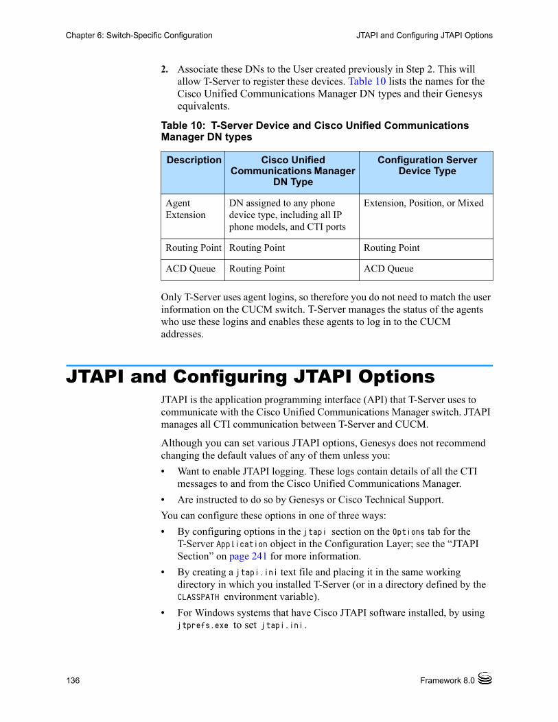
136 Framework 8.0
Chapter 6: Switch-Specific Configuration JTAPI and Configuring JTAPI Options
2. Associate these DNs to the User created previously in Step 2. This will allow T-Server to register these devices. Table 10 lists the names for the Cisco Unified Communications Manager DN types and their Genesys equivalents.
Only T-Server uses agent logins, so therefore you do not need to match the user information on the CUCM switch. T-Server manages the status of the agents who use these logins and enables these agents to log in to the CUCM addresses.
JTAPI and Configuring JTAPI OptionsJTAPI is the application programming interface (API) that T-Server uses to communicate with the Cisco Unified Communications Manager switch. JTAPI manages all CTI communication between T-Server and CUCM.
Although you can set various JTAPI options, Genesys does not recommend changing the default values of any of them unless you:
• Want to enable JTAPI logging. These logs contain details of all the CTI messages to and from the Cisco Unified Communications Manager.
• Are instructed to do so by Genesys or Cisco Technical Support.
You can configure these options in one of three ways:
• By configuring options in the jtapi section on the Options tab for the T-Server Application object in the Configuration Layer; see the “JTAPI Section” on page 241 for more information.
• By creating a jtapi.ini text file and placing it in the same working directory in which you installed T-Server (or in a directory defined by the CLASSPATH environment variable).
• For Windows systems that have Cisco JTAPI software installed, by using jtprefs.exe to set jtapi.ini.
Table 10: T-Server Device and Cisco Unified Communications Manager DN types
Description Cisco Unified Communications Manager
DN Type
Configuration Server Device Type
Agent Extension
DN assigned to any phone device type, including all IP phone models, and CTI ports
Extension, Position, or Mixed
Routing Point Routing Point Routing Point
ACD Queue Routing Point ACD Queue

T-Server—Deployment Guide 137
Chapter 6: Switch-Specific Configuration JTAPI and Configuring JTAPI Options
For more information about JTAPI, jtprefs.exe, and JTAPI options, see the Cisco Unified Communications Manager Administration Guide.

138 Framework 8.0
Chapter 6: Switch-Specific Configuration JTAPI and Configuring JTAPI Options
T-Server—Deployment Guide 139
Chapter
7 Supported Functionality This chapter describes the telephony functionality that T-Server for Cisco Unified Communications Manager supports. It contains the following sections: T-Library Functionality, page 140 Error Messages, page 150 Agent Login and Agent States, page 152 Agent After Call Work, page 153 Agent Ring Redirect Timeout, page 154 ACD Queues, page 154 Music and Announcements, page 154 Predictive Dialing, page 159 Dual-Tone Multi-Frequency, page 161 User-Data Display to IP Phones, page 161 User-Data Display to IP Phones Not on a Call, page 162 Voice Monitoring, page 163 Shared Lines, page 163 Extension Mobility, page 167 Call Pickup, page 170 Group Call Pickup, page 170 Call Parking, page 170 ACD-like Default Routing, page 171 Route Points with Multiple Partitions, page 171 Calling Search Space Feature, page 171 Socket Mode of Communication, page 172 Customer Matters Code and Forced Authorization Code, page 173 Cisco Unified Communications Manager Partition, page 174 Retrieval and Distribution of Modified CLID, page 175 Call Recording, page 176 Supervisor Monitoring, page 178
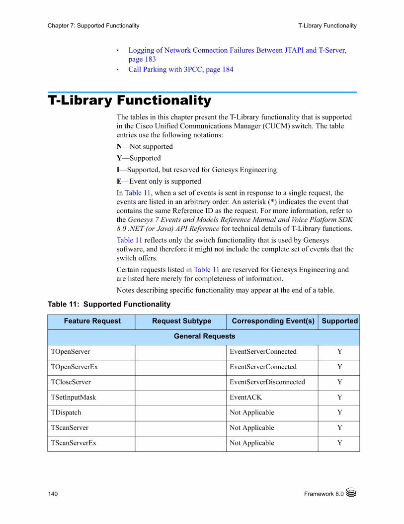
140 Framework 8.0
Chapter 7: Supported Functionality T-Library Functionality
Logging of Network Connection Failures Between JTAPI and T-Server, page 183
Call Parking with 3PCC, page 184
T-Library Functionality The tables in this chapter present the T-Library functionality that is supported in the Cisco Unified Communications Manager (CUCM) switch. The table entries use the following notations:
N—Not supported
Y—Supported
I—Supported, but reserved for Genesys Engineering
E—Event only is supported
In Table 11, when a set of events is sent in response to a single request, the events are listed in an arbitrary order. An asterisk (*) indicates the event that contains the same Reference ID as the request. For more information, refer to the Genesys 7 Events and Models Reference Manual and Voice Platform SDK 8.0 .NET (or Java) API Reference for technical details of T-Library functions.
Table 11 reflects only the switch functionality that is used by Genesys software, and therefore it might not include the complete set of events that the switch offers.
Certain requests listed in Table 11 are reserved for Genesys Engineering and are listed here merely for completeness of information.
Notes describing specific functionality may appear at the end of a table.
Table 11: Supported Functionality
Feature Request Request Subtype Corresponding Event(s) Supported
General Requests
TOpenServer EventServerConnected Y
TOpenServerEx EventServerConnected Y
TCloseServer EventServerDisconnected Y
TSetInputMask EventACK Y
TDispatch Not Applicable Y
TScanServer Not Applicable Y
TScanServerEx Not Applicable Y
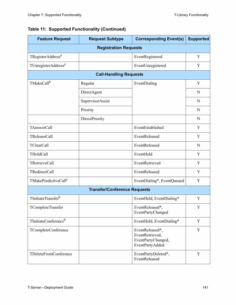
T-Server—Deployment Guide 141
Chapter 7: Supported Functionality T-Library Functionality
Registration Requests
TRegisterAddressa EventRegistered Y
TUnregisterAddressa EventUnregistered Y
Call-Handling Requests
TMakeCallb Regular EventDialing Y
DirectAgent N
SupervisorAssist N
Priority N
DirectPriority N
TAnswerCall EventEstablished Y
TReleaseCall EventReleased Y
TClearCall EventReleased N
THoldCall EventHeld Y
TRetrieveCall EventRetrieved Y
TRedirectCall EventReleased Y
TMakePredictiveCallc EventDialing*, EventQueued Y
Transfer/Conference Requests
TInitiateTransferb EventHeld, EventDialing* Y
TCompleteTransfer EventReleased*, EventPartyChanged
Y
TInitiateConferenceb EventHeld, EventDialing* Y
TCompleteConference EventReleased*, EventRetrieved, EventPartyChanged, EventPartyAdded
Y
TDeleteFromConference EventPartyDeleted*, EventReleased
Y
Table 11: Supported Functionality (Continued)
Feature Request Request Subtype Corresponding Event(s) Supported
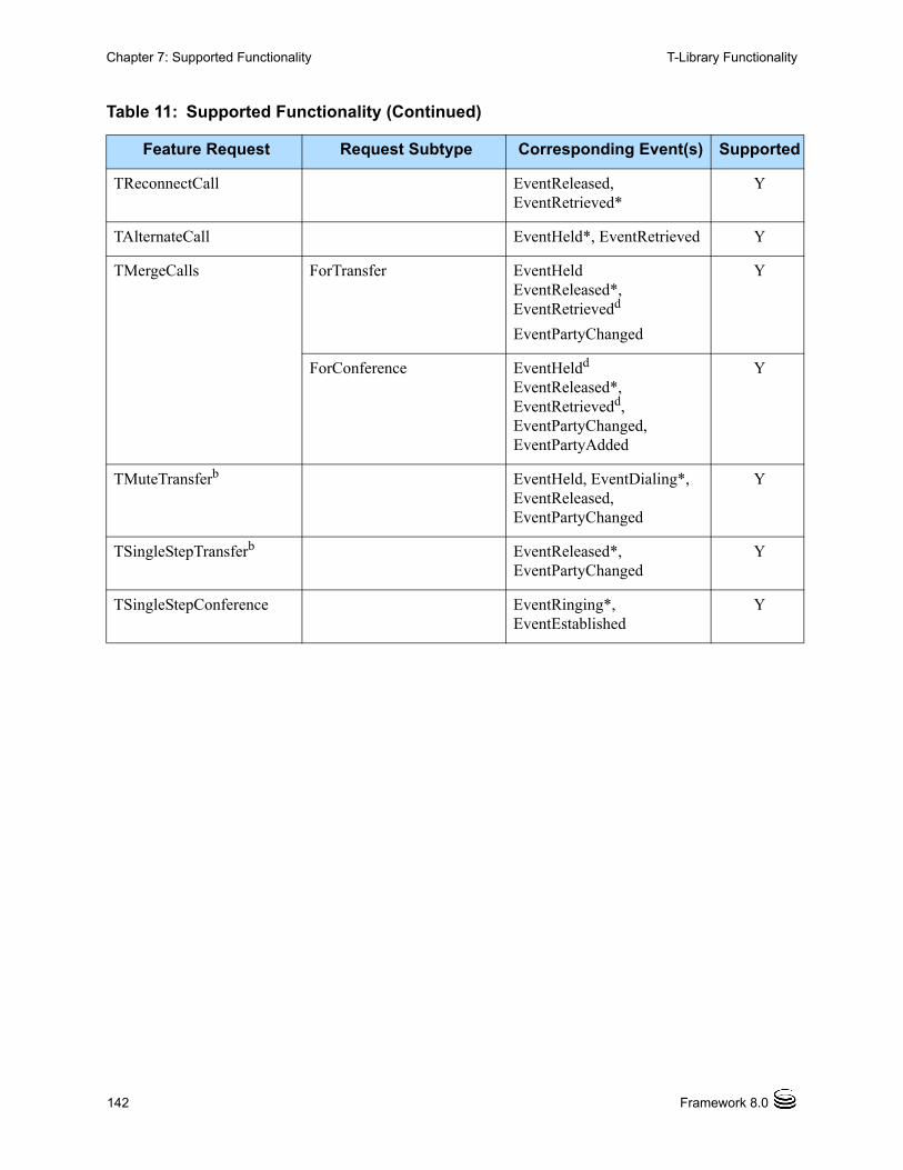
142 Framework 8.0
Chapter 7: Supported Functionality T-Library Functionality
TReconnectCall EventReleased, EventRetrieved*
Y
TAlternateCall EventHeld*, EventRetrieved Y
TMergeCalls ForTransfer EventHeldEventReleased*,EventRetrievedd
EventPartyChanged
Y
ForConference EventHeldd
EventReleased*, EventRetrievedd, EventPartyChanged, EventPartyAdded
Y
TMuteTransferb EventHeld, EventDialing*, EventReleased, EventPartyChanged
Y
TSingleStepTransferb EventReleased*, EventPartyChanged
Y
TSingleStepConference EventRinging*, EventEstablished
Y
Table 11: Supported Functionality (Continued)
Feature Request Request Subtype Corresponding Event(s) Supported
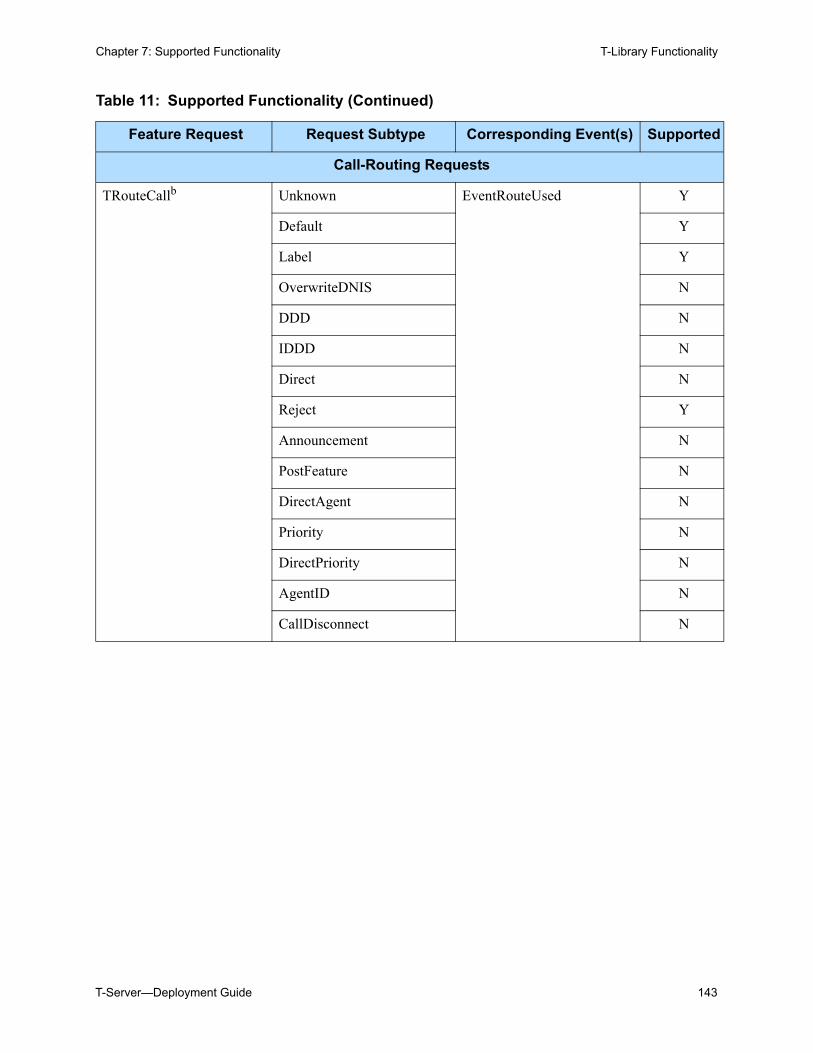
T-Server—Deployment Guide 143
Chapter 7: Supported Functionality T-Library Functionality
Call-Routing Requests
TRouteCallb Unknown EventRouteUsed Y
Default Y
Label Y
OverwriteDNIS N
DDD N
IDDD N
Direct N
Reject Y
Announcement N
PostFeature N
DirectAgent N
Priority N
DirectPriority N
AgentID N
CallDisconnect N
Table 11: Supported Functionality (Continued)
Feature Request Request Subtype Corresponding Event(s) Supported
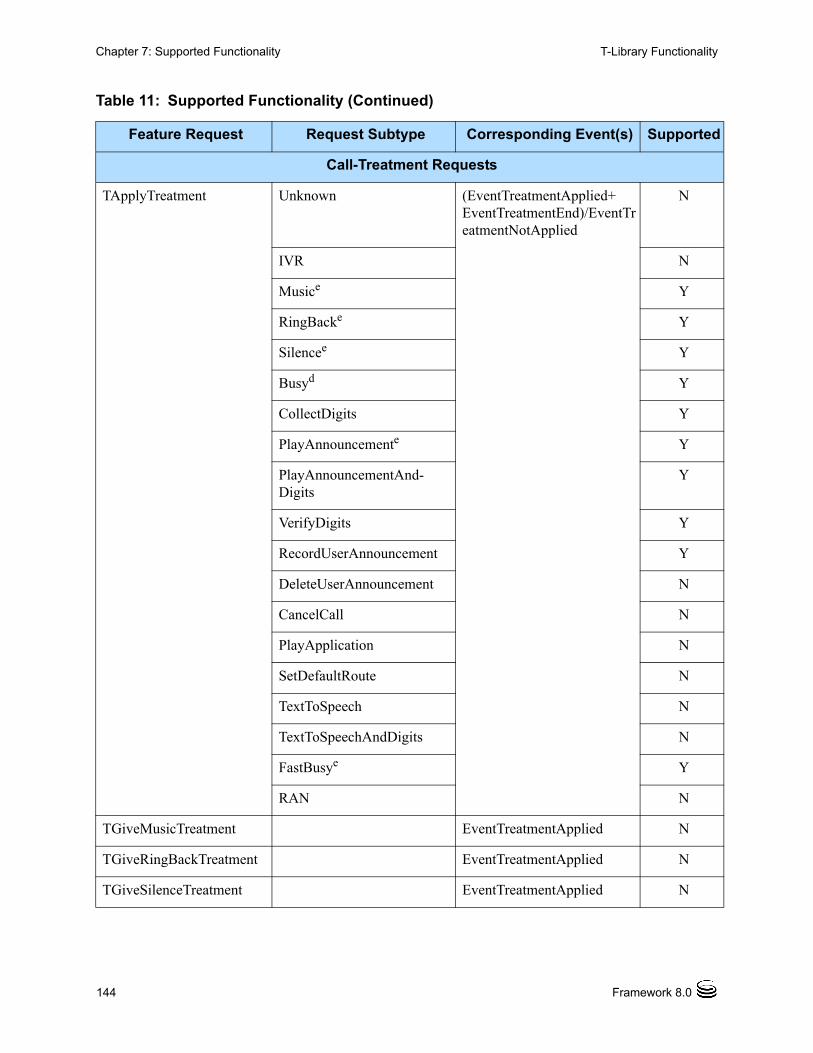
144 Framework 8.0
Chapter 7: Supported Functionality T-Library Functionality
Call-Treatment Requests
TApplyTreatment Unknown (EventTreatmentApplied+EventTreatmentEnd)/EventTreatmentNotApplied
N
IVR N
Musice Y
RingBacke Y
Silencee Y
Busyd Y
CollectDigits Y
PlayAnnouncemente Y
PlayAnnouncementAnd-Digits
Y
VerifyDigits Y
RecordUserAnnouncement Y
DeleteUserAnnouncement N
CancelCall N
PlayApplication N
SetDefaultRoute N
TextToSpeech N
TextToSpeechAndDigits N
FastBusye Y
RAN N
TGiveMusicTreatment EventTreatmentApplied N
TGiveRingBackTreatment EventTreatmentApplied N
TGiveSilenceTreatment EventTreatmentApplied N
Table 11: Supported Functionality (Continued)
Feature Request Request Subtype Corresponding Event(s) Supported
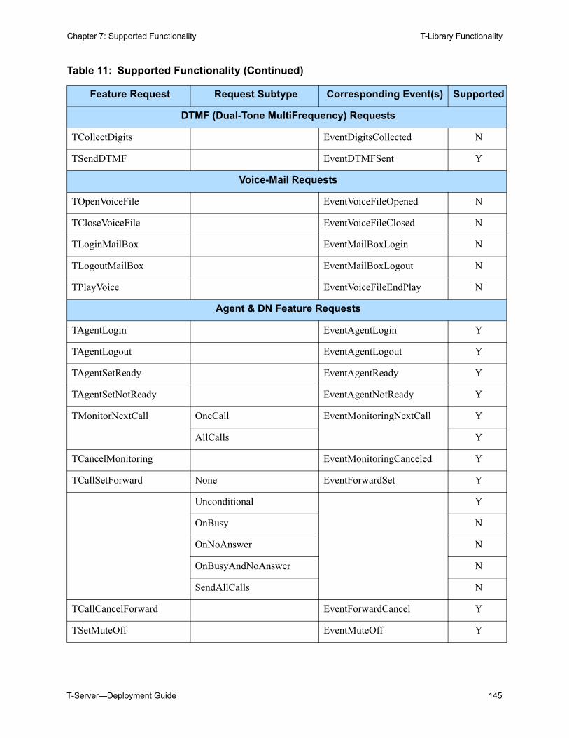
T-Server—Deployment Guide 145
Chapter 7: Supported Functionality T-Library Functionality
DTMF (Dual-Tone MultiFrequency) Requests
TCollectDigits EventDigitsCollected N
TSendDTMF EventDTMFSent Y
Voice-Mail Requests
TOpenVoiceFile EventVoiceFileOpened N
TCloseVoiceFile EventVoiceFileClosed N
TLoginMailBox EventMailBoxLogin N
TLogoutMailBox EventMailBoxLogout N
TPlayVoice EventVoiceFileEndPlay N
Agent & DN Feature Requests
TAgentLogin EventAgentLogin Y
TAgentLogout EventAgentLogout Y
TAgentSetReady EventAgentReady Y
TAgentSetNotReady EventAgentNotReady Y
TMonitorNextCall OneCall EventMonitoringNextCall Y
AllCalls Y
TCancelMonitoring EventMonitoringCanceled Y
TCallSetForward None EventForwardSet Y
Unconditional Y
OnBusy N
OnNoAnswer N
OnBusyAndNoAnswer N
SendAllCalls N
TCallCancelForward EventForwardCancel Y
TSetMuteOff EventMuteOff Y
Table 11: Supported Functionality (Continued)
Feature Request Request Subtype Corresponding Event(s) Supported
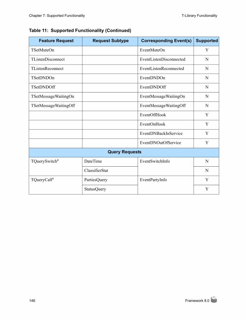
146 Framework 8.0
Chapter 7: Supported Functionality T-Library Functionality
TSetMuteOn EventMuteOn Y
TListenDisconnect EventListenDisconnected N
TListenReconnect EventListenReconnected N
TSetDNDOn EventDNDOn N
TSetDNDOff EventDNDOff N
TSetMessageWaitingOn EventMessageWaitingOn N
TSetMessageWaitingOff EventMessageWaitingOff N
EventOffHook Y
EventOnHook Y
EventDNBackInService Y
EventDNOutOfService Y
Query Requests
TQuerySwitcha DateTime EventSwitchInfo N
ClassifierStat N
TQueryCalla PartiesQuery EventPartyInfo Y
StatusQuery Y
Table 11: Supported Functionality (Continued)
Feature Request Request Subtype Corresponding Event(s) Supported
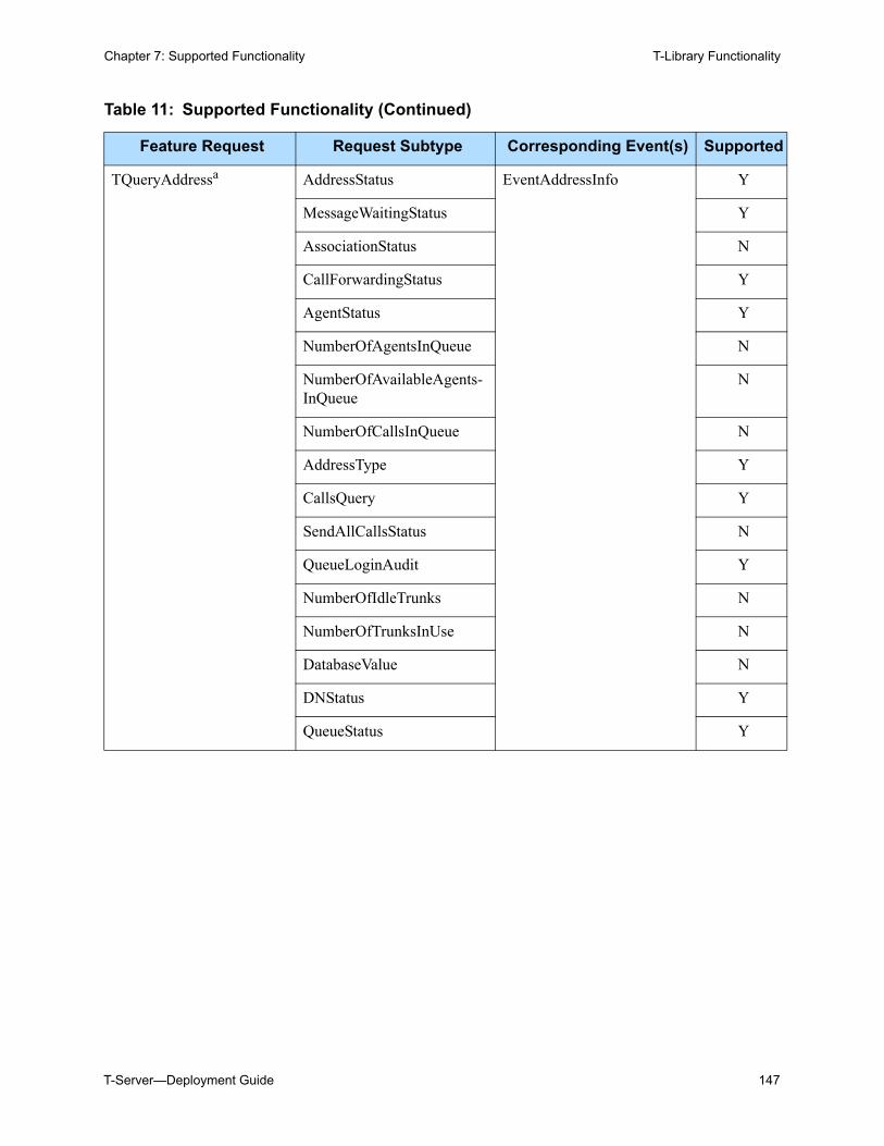
T-Server—Deployment Guide 147
Chapter 7: Supported Functionality T-Library Functionality
TQueryAddressa AddressStatus EventAddressInfo Y
MessageWaitingStatus Y
AssociationStatus N
CallForwardingStatus Y
AgentStatus Y
NumberOfAgentsInQueue N
NumberOfAvailableAgents-InQueue
N
NumberOfCallsInQueue N
AddressType Y
CallsQuery Y
SendAllCallsStatus N
QueueLoginAudit Y
NumberOfIdleTrunks N
NumberOfTrunksInUse N
DatabaseValue N
DNStatus Y
QueueStatus Y
Table 11: Supported Functionality (Continued)
Feature Request Request Subtype Corresponding Event(s) Supported
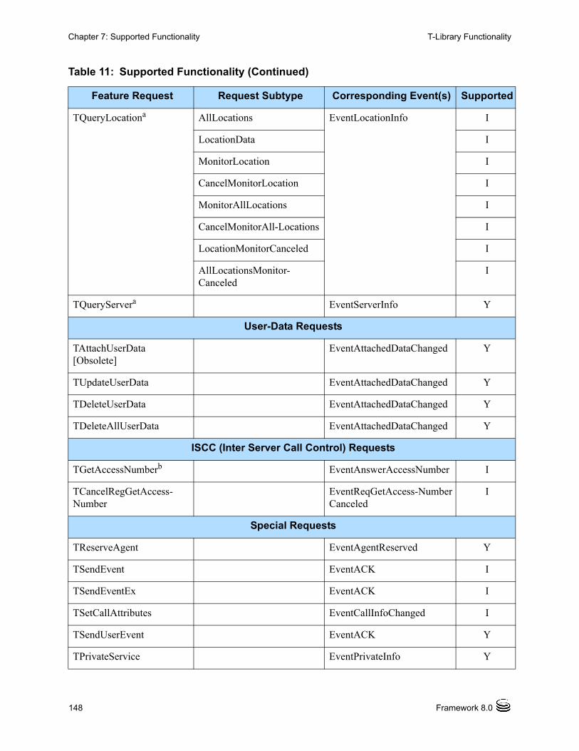
148 Framework 8.0
Chapter 7: Supported Functionality T-Library Functionality
TQueryLocationa AllLocations EventLocationInfo I
LocationData I
MonitorLocation I
CancelMonitorLocation I
MonitorAllLocations I
CancelMonitorAll-Locations I
LocationMonitorCanceled I
AllLocationsMonitor-Canceled
I
TQueryServera EventServerInfo Y
User-Data Requests
TAttachUserData [Obsolete]
EventAttachedDataChanged Y
TUpdateUserData EventAttachedDataChanged Y
TDeleteUserData EventAttachedDataChanged Y
TDeleteAllUserData EventAttachedDataChanged Y
ISCC (Inter Server Call Control) Requests
TGetAccessNumberb EventAnswerAccessNumber I
TCancelRegGetAccess-Number
EventReqGetAccess-NumberCanceled
I
Special Requests
TReserveAgent EventAgentReserved Y
TSendEvent EventACK I
TSendEventEx EventACK I
TSetCallAttributes EventCallInfoChanged I
TSendUserEvent EventACK Y
TPrivateService EventPrivateInfo Y
Table 11: Supported Functionality (Continued)
Feature Request Request Subtype Corresponding Event(s) Supported
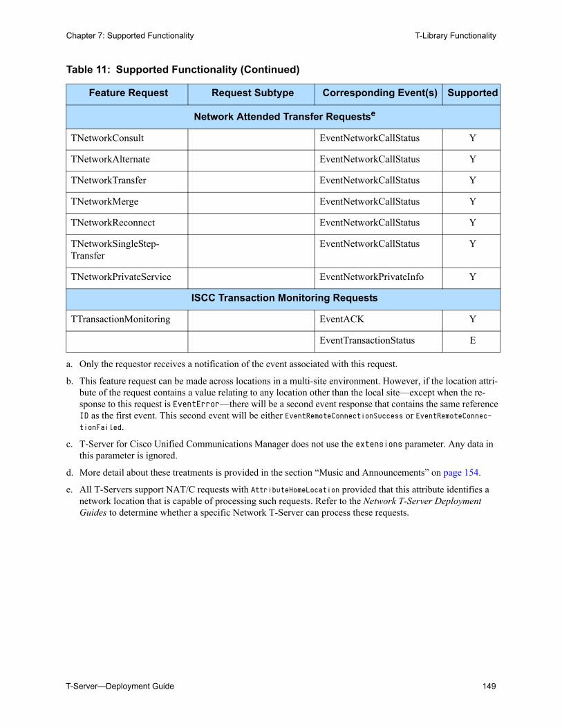
T-Server—Deployment Guide 149
Chapter 7: Supported Functionality T-Library Functionality
Network Attended Transfer Requestse
TNetworkConsult EventNetworkCallStatus Y
TNetworkAlternate EventNetworkCallStatus Y
TNetworkTransfer EventNetworkCallStatus Y
TNetworkMerge EventNetworkCallStatus Y
TNetworkReconnect EventNetworkCallStatus Y
TNetworkSingleStep-Transfer
EventNetworkCallStatus Y
TNetworkPrivateService EventNetworkPrivateInfo Y
ISCC Transaction Monitoring Requests
TTransactionMonitoring EventACK Y
EventTransactionStatus E
a. Only the requestor receives a notification of the event associated with this request.
b. This feature request can be made across locations in a multi-site environment. However, if the location attri-bute of the request contains a value relating to any location other than the local site—except when the re-sponse to this request is EventError—there will be a second event response that contains the same reference ID as the first event. This second event will be either EventRemoteConnectionSuccess or EventRemoteConnec-tionFailed.
c. T-Server for Cisco Unified Communications Manager does not use the extensions parameter. Any data in this parameter is ignored.
d. More detail about these treatments is provided in the section “Music and Announcements” on page 154.
e. All T-Servers support NAT/C requests with AttributeHomeLocation provided that this attribute identifies a network location that is capable of processing such requests. Refer to the Network T-Server Deployment Guides to determine whether a specific Network T-Server can process these requests.
Table 11: Supported Functionality (Continued)
Feature Request Request Subtype Corresponding Event(s) Supported
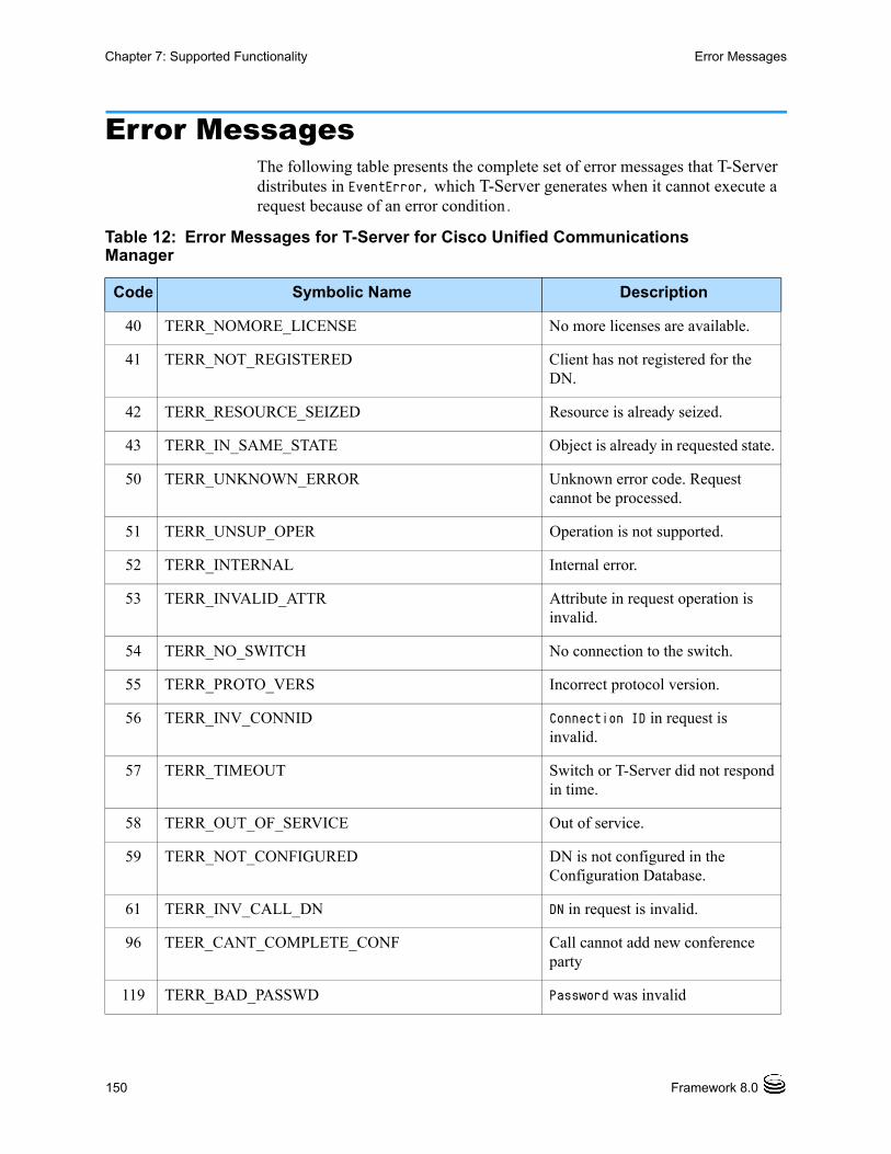
150 Framework 8.0
Chapter 7: Supported Functionality Error Messages
Error MessagesThe following table presents the complete set of error messages that T-Server distributes in EventError, which T-Server generates when it cannot execute a request because of an error condition.
Table 12: Error Messages for T-Server for Cisco Unified Communications Manager
Code Symbolic Name Description
40 TERR_NOMORE_LICENSE No more licenses are available.
41 TERR_NOT_REGISTERED Client has not registered for the DN.
42 TERR_RESOURCE_SEIZED Resource is already seized.
43 TERR_IN_SAME_STATE Object is already in requested state.
50 TERR_UNKNOWN_ERROR Unknown error code. Request cannot be processed.
51 TERR_UNSUP_OPER Operation is not supported.
52 TERR_INTERNAL Internal error.
53 TERR_INVALID_ATTR Attribute in request operation is invalid.
54 TERR_NO_SWITCH No connection to the switch.
55 TERR_PROTO_VERS Incorrect protocol version.
56 TERR_INV_CONNID Connection ID in request is invalid.
57 TERR_TIMEOUT Switch or T-Server did not respond in time.
58 TERR_OUT_OF_SERVICE Out of service.
59 TERR_NOT_CONFIGURED DN is not configured in the Configuration Database.
61 TERR_INV_CALL_DN DN in request is invalid.
96 TEER_CANT_COMPLETE_CONF Call cannot add new conference party
119 TERR_BAD_PASSWD Password was invalid
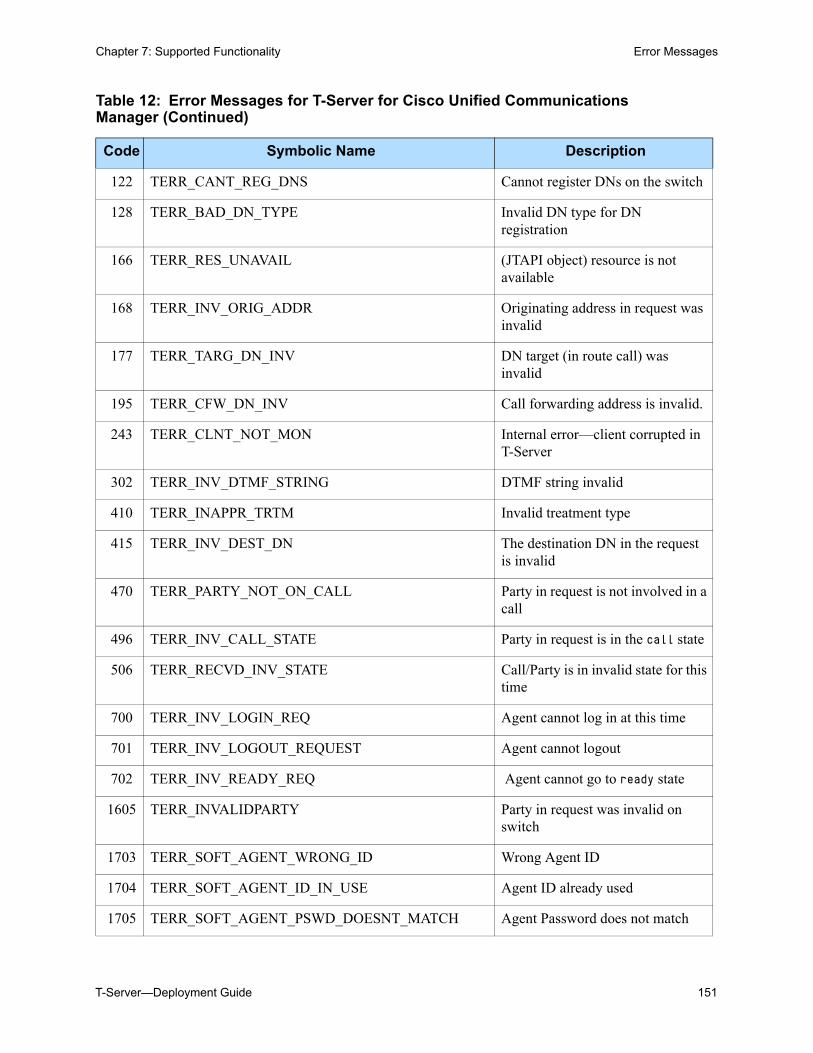
T-Server—Deployment Guide 151
Chapter 7: Supported Functionality Error Messages
122 TERR_CANT_REG_DNS Cannot register DNs on the switch
128 TERR_BAD_DN_TYPE Invalid DN type for DN registration
166 TERR_RES_UNAVAIL (JTAPI object) resource is not available
168 TERR_INV_ORIG_ADDR Originating address in request was invalid
177 TERR_TARG_DN_INV DN target (in route call) was invalid
195 TERR_CFW_DN_INV Call forwarding address is invalid.
243 TERR_CLNT_NOT_MON Internal error—client corrupted in T-Server
302 TERR_INV_DTMF_STRING DTMF string invalid
410 TERR_INAPPR_TRTM Invalid treatment type
415 TERR_INV_DEST_DN The destination DN in the request is invalid
470 TERR_PARTY_NOT_ON_CALL Party in request is not involved in a call
496 TERR_INV_CALL_STATE Party in request is in the call state
506 TERR_RECVD_INV_STATE Call/Party is in invalid state for this time
700 TERR_INV_LOGIN_REQ Agent cannot log in at this time
701 TERR_INV_LOGOUT_REQUEST Agent cannot logout
702 TERR_INV_READY_REQ Agent cannot go to ready state
1605 TERR_INVALIDPARTY Party in request was invalid on switch
1703 TERR_SOFT_AGENT_WRONG_ID Wrong Agent ID
1704 TERR_SOFT_AGENT_ID_IN_USE Agent ID already used
1705 TERR_SOFT_AGENT_PSWD_DOESNT_MATCH Agent Password does not match
Table 12: Error Messages for T-Server for Cisco Unified Communications Manager (Continued)
Code Symbolic Name Description
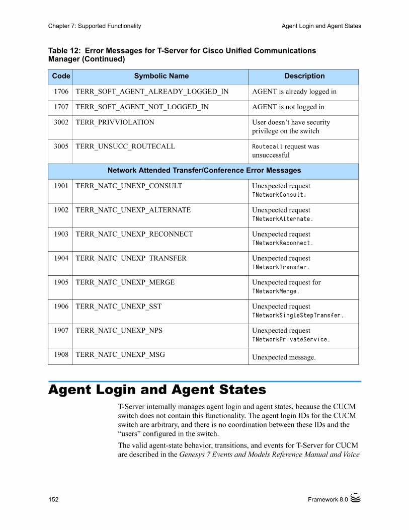
152 Framework 8.0
Chapter 7: Supported Functionality Agent Login and Agent States
Agent Login and Agent StatesT-Server internally manages agent login and agent states, because the CUCM switch does not contain this functionality. The agent login IDs for the CUCM switch are arbitrary, and there is no coordination between these IDs and the “users” configured in the switch.
The valid agent-state behavior, transitions, and events for T-Server for CUCM are described in the Genesys 7 Events and Models Reference Manual and Voice
1706 TERR_SOFT_AGENT_ALREADY_LOGGED_IN AGENT is already logged in
1707 TERR_SOFT_AGENT_NOT_LOGGED_IN AGENT is not logged in
3002 TERR_PRIVVIOLATION User doesn’t have security privilege on the switch
3005 TERR_UNSUCC_ROUTECALL Routecall request was unsuccessful
Network Attended Transfer/Conference Error Messages
1901 TERR_NATC_UNEXP_CONSULT Unexpected request TNetworkConsult.
1902 TERR_NATC_UNEXP_ALTERNATE Unexpected request TNetworkAlternate.
1903 TERR_NATC_UNEXP_RECONNECT Unexpected request TNetworkReconnect.
1904 TERR_NATC_UNEXP_TRANSFER Unexpected request TNetworkTransfer.
1905 TERR_NATC_UNEXP_MERGE Unexpected request for TNetworkMerge.
1906 TERR_NATC_UNEXP_SST Unexpected request TNetworkSingleStepTransfer.
1907 TERR_NATC_UNEXP_NPS Unexpected request TNetworkPrivateService.
1908 TERR_NATC_UNEXP_MSG Unexpected message.
Table 12: Error Messages for T-Server for Cisco Unified Communications Manager (Continued)
Code Symbolic Name Description
T-Server—Deployment Guide 153
Chapter 7: Supported Functionality Agent After Call Work
Platform SDK 8.0 .NET (or Java) API Reference for technical details of T-Library functions. Except for the following unique behavior:
• When an agent is set to the NotReady state, the switch can direct calls to this agent. Genesys Universal Routing Server (URS), however, does not direct calls to an agent in the NotReady state.
• After a T-Server restart, all agents are set to the Logged Out state.
• When an agent logs in with the TAgentLogin request, the agent state is determined by the workmode in the request, as follows: AgentAutoIn/AgentManualIn: Ready state (EventAgentReady is
sent.) AgentAfterCallWork: AfterCallWork state (EventAgentNotReady,
workmode = AgentAfterCallWork, is sent.) AgentWalkAway: WalkAway state (EventAgentNotReady, workmode =
AgentWalkAway, is sent.) All other workmodes: NotReady state (EventAgentNotReady,
workmode = AgentAuxWork, is sent.)
• T-Server automatically sets the agent to the AfterCallWork state after releasing a call if wrap-up-time is configured for that agent. See “Agent After Call Work” on page 153.
• T-Server automatically sets the agent to the WalkAway state if the agent does not answer a call within the ring timeout for that call. See “Agent Ring Redirect Timeout” on page 154.
• An agent cannot log in to multiple queues.
Agent After Call Work AfterCallWork (ACW) is an agent state that prevents Genesys-routed calls from being delivered to the agent.
ACW is configured in the Configuration Layer using the <wrap-up-time> variable, located in the Agent’s Properties section. The variable is defined in seconds, with the following behavior:
• Automatic: (if WrapUpTime > 0)
After releasing a call, an agent in Ready state automatically is placed into the ACW unless the call was released because it was redirected using TRedirectCall, or unless the agent has another call in progress. The agent remains in the ACW state for <wrap-up-time> seconds, or until the agent explicitly enters the Ready state through a TAgentReady request.
• Manual: (if WrapUpTime = 0)
After releasing a call, an agent remains in Ready state. In both automatic and manual ACW modes, T-Server can also set the agent to the ACW state if the client sends TAgentNotReady with Workmode=AfterCallWork. In this case, the agent remains in the ACW state until TAgentReady is sent.
154 Framework 8.0
Chapter 7: Supported Functionality Agent Ring Redirect Timeout
Agent Ring Redirect TimeoutThis feature is intended to prevent calls from ringing indefinitely at an agent desktop when that agent logged in, but then left his or her desk, without logging out. When this feature is invoked, T-Server allows a call to ring at an agent's phone for only a specified number of seconds before considering the agent as “walked away”. When this occurs, T-Server reroutes the call to another address (usually configured to be a Routing Point) and, if the agent is in Ready state, sets the agent to NotReady (WalkAway) state.
To invoke this feature, the following key-value pairs should be attached to the attribute Extensions of the RequestRouteCall request:
Key: NO_ANSWER_TIMEOUT
Value: A string representing the timeout.
Key: NO_ANSWER_ACTION
Value: A string representing what action T-Server performs for an agent. It can be either notready, walkaway, or logout.
Key: NO_ANSWER_OVERFLOW
Value: A string representing an overflow DN.
If you do not set a timeout value, the call is redirected to the value specified in the default-dn option on page 218; or if that option is not set, the phone continues to ring without redirection (but the agent is still placed in the NotReady state).
ACD QueuesDNs of the ACD Queue type are configured as the Routing Point type in the Cisco Unified Communications Manager. T-Server manages the ACD Queue call distribution and agentlogin functionality internally; however this is transparent to T-Server clients. An Agent DN may log into only one queue. Calls with the longest wait time on an ACD queue are distributed to agents with the longest idle time.
The music played to the caller in the ACD queue is configurable. For more information, please see “Music Treatment on ACD Queues” on page 156.
Music and AnnouncementsT-Server is able to control the playing of announcements and music on Routing Points and ACD Queues in Cisco Unified Communications Manager. Music and announcements can come from two sources:
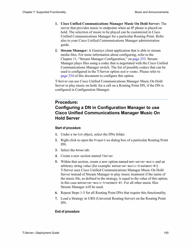
T-Server—Deployment Guide 155
Chapter 7: Supported Functionality Music and Announcements
1. Cisco Unified Communications Manager Music On Hold Server: The server that provides music to endpoints when an IP phone is placed on hold. The selection of music to be played can be customized in Cisco Unified Communications Manager for a particular Routing Point. Refer also to your Cisco Unified Communications Manager administration guide.
2. Stream Manager: A Genesys client application that is able to stream media files. For more information about configuring, refer to the Chapter 11, “Stream Manager Configuration,” on page 253. Stream Manager plays files using a codec that is negotiated with the Cisco Unified Communications Manager switch. The list of possible codecs that can be used is configured in the T-Server option audio-codec. Please refer to page 234 of this document to configure this option.
T-Server can use Cisco Unified Communications Manager Music On Hold Server to play music on hold, for a call on a Routing Point DN, if the DN is configured in Configuration Manager.
Procedure:Configuring a DN in Configuration Manager to use Cisco Unified Communications Manager Music On Hold Server
Start of procedure
1. Under a Switch object, select the DNs folder.
2. Right click to open the Properties dialog box of a particular Routing Point DN.
3. Select the Annex tab.
4. Create a new section named TServer.
5. Within that section, create a new option named moh-server-music and an arbitrary string value (for example: mohserver-music-treatment-01). T-Server uses Cisco Unified Communications Manager Music On Hold Server instead of Stream Manager to play music treatment if the name of the music file, as defined in the strategy, is equal to the value of this option, in this case mohserver-music-treatment-01. For all other music files Stream Manager will be used.
6. Repeat Steps 1-5 for all Routing Point DNs that require this functionality.
7. Load a Strategy in URS (Universal Routing Server) on the Routing Point DN.
End of procedure
156 Framework 8.0
Chapter 7: Supported Functionality Music and Announcements
Announcement Treatments on Routing Points
The two announcement treatments, PlayAnnouncement and PlayAnnouncementAndDigits, include the following parameters:
LANGUAGE: Ignored.
MSGID: Ignored.
MSGTXT: Ignored
PROMPT: Contains up to 10 sub-prompts. Each of these will contain a music file, and they are played in order:
INTERRUPTABLE: If set to true, the caller can interrupt the announcement with a DTMF keystroke.
ID: Contains an integer that refers to the file announcement/<integer>. For example, a value of ID 1 would refer to the file announcement/1_alaw.au, if the G.711 a-law codec is used.
DIGITS: Ignored.
USER_ID: Ignored.
USER_ANN_ID: Ignored.
TEXT: Ignored.
Cisco Unified Communications Manager Music on hold is not available for these treatment types. Only Stream Manager can be the source for the announcements.
If the treatment is terminated early because of a problem with Stream Manager or T-Server, T-Server sets the Extension data fields, ERR_CODE and ERR_TEXT. To determine whether these fields exist, and/or to determine their values, from a routing strategy, use the ExtensionData function. Place this function on a normal completion branch (not the error branch) after the treatment.
Refer to the Universal Routing 7.6 Reference Manual for more information about using and configuring strategies.
Note: Leave the Wait For Treatment End check box selected in order to enable these treatments to play until completion.
Music Treatment on ACD Queues
Each ACD queue can play a specific Stream Manager music file. The file is specified in the DN queue-music option (under the TServer section under the Annex tab in Configuration Manager). The file is specified as <directory/music file name>, where <directory> is a sub-directory off the Stream Manager root directory, and <music file name> refers to the name of the file, without the codec extension. If Stream Manager is not configured or if it has failed, then music-on-hold music is played. For example, music/in_queue
T-Server—Deployment Guide 157
Chapter 7: Supported Functionality Music and Announcements
would refer to the file music/in_queue_alaw.au if the G.711 a-law codec was to be used.
If an ACD queue does not have the queue-music option configured, T-Server plays the Stream Manager music file that is specified in the T-Server queue-music option.
Note: Leave the compatible mode checkbox unselected when configuring the music treatment on an ACD Queue.
Music Treatments on Routing Points (TreatmentMusic)
The music treatment includes the following parameters:
MUSIC_DN: Specifies the music file for Stream Manager to play. The format is <directory>/<music file name>, where <directory> is a sub-directory off the Stream Manager root directory, and <music file name> refers to the name of the file without the codec extension. If the music file name is prefixed with a plus sign +, the music file loops continuously, otherwise the file is played only once. However, if the MUSIC_DN field is blank, music-on-hold music is played by default. For example, music/in_queue would refer to the file music/in_queue_alaw.au if G.711 a-law codec is used.
DURATION: Specifies the duration, in seconds, that the music plays. Note that this parameter is ignored if MUSIC_DN is blank (that is, if music-on-hold is used).
This treatment terminates before the music file has finished playing. To continue playing music after the treatment terminates, consider one of the following strategies in Interaction Routing Designer:
• Execute the treatment inside a route-selection treatment block. In this case the treatment continues until a route target is selected.
• Follow the treatment with the SuspendForTreatmentEnd function. In this case, the treatment plays music until terminated after DURATION seconds.
• Follow the treatment with the delay function. In this case, the treatment plays music for delay seconds. If DURATION is less than delay, silence is played for the time difference.
Refer to the Universal Routing 7.6 Reference Manual for more information about using and configuring strategies.
Call Recording (RecordUserAnnouncement)
The call recording function is supported by the RecordUserAnnouncement treatment. By default, the recorded user’s announcement (an audio file) is saved into a single users folder for a single Stream Manager (SM), with a filename specified in the RecordUserAnnouncement treatment (which should coincide with the Configuration Manager’s Tenant’s name). The format of the recorded file depends on the audio-codec chosen during the terminal capability
158 Framework 8.0
Chapter 7: Supported Functionality Music and Announcements
negotiation procedure. Multiple Stream Managers can share a single storage for media files, even if they are executed on different hosts, under different operating systems. In this case, issues of file accessibility from the shared storage for all hosts should be resolved on an organizational/administrative level.
When a treatment of type TreatmentRecordUserAnnouncement is issued, it is passed to the Stream Manager. In cases where multiple Stream Managers are connected, the TreatmentRecordUserAnnouncement command is chosen among all available Stream Managers in a round-robin fashion.
The RecordUserAnnouncement announcement treatment includes the following parameters:
• USER_ID: Mandatory
• ABORT_DIGITS: Ignored
• TERM_DIGITS: Ignored
• RESET_DIGITS: Ignored
• START_TIMEOUT: Specifies the time during which a user should start talking. If the timeout expires, the treatment is terminated with an error code.
• TOTAL_TIMEOUT: Specifies the maximum time allocated to recording the announcement. In cases where the call recording start_timeout parameter affects the total_timeout parameter, Genesys recommends that the start_timeout parameter field be left empty.
• PROMPT: Specifies the prompt that is played before recording.
The user’s recorded announcement is saved in the SM “users” directory with the name <USER_ID>-<number>_<codec>.wav (where <number> is the sequence number of the file for USER_ID) The user who is executing the SM application must have “write” permission to this directory. The audio codec used in the recoding will be one of the codecs defined on page 256.
When recording calls, Stream Manager uses the following options:
• max-record-file-size: Specifies the maximum size, in KB, of the audio file used for recording.
• max-record-time: Specifies the maximum recording time, in seconds.
• max-record-silence: Specifies the maximum amount of time, in seconds, that silence can be detected during a recording.
Additional recording parameters should be specified in the RecordUserAnnouncement treatment. Refer to the Universal Routing 7.6 Reference Manual for more information.
File recording ceases when:
• An interruptible treatment is interrupted by DTMF entry.
• The max-record-time interval has expired.
• The max-record-silence or the max-record-file-size limit is reached.
• T-Server issues EventTreatmentEnd in these cases.
T-Server—Deployment Guide 159
Chapter 7: Supported Functionality Predictive Dialing
Busy, Fast Busy, Silence and RingBack Treatments on Routing Points
These treatments continuously loop a pre-defined audio file to a call. You must configure Stream Manager to use these treatments. Music-on-hold cannot be the source of the audio file. The treatment types are:
Busy: Plays a busy tone. To define the busy tone audio file, configure the T-Server busy-tone option.
Fast Busy: Plays a fast busy tone. To define the fast busy tone audio file, configure the T-Server fast-busy-tone option.
Silence: Plays no sound. To define the silence audio file, configure the T-Server silence-tone option.
Ringback: Plays a ringback tone. To define the ringback audio file, configure the T-Server ring-tone option.
T-Server is capable of applying a treatment with a RingBack type to a new call without a charge to the customer. This treatment uses the Cisco Unified Communications Manager native ringback feature rather than connecting a customer with Stream Manager to play a predefined audio file with a ringback sound. This treatment should be the first treatment in a strategy.
For more details about T-Server options, please see the “T-Server Section” on page 233.
Note: The DURATION parameter is not used for Cisco Unified Communications Manager.
Refer to the Universal Routing 7.6 Reference Manual for more information about using and configuring strategies.
Predictive DialingT-Server provides support for outbound campaigns in predictive/progressive dialing mode, either by using a Dialogic board in ASM (Active Switching Matrix) mode, or directly through the TMakePredictiveCall request.
It is recommended not to apply treatments on a Routing Point during predictive dialing to prevent excessive use of dialogic channels by the Call Progress Detection (CPD) server because of a premature CONNECTED ISDN message. Also, a call should be routed off a Routing Point within a four-second timeout as is configured on Cisco Unified Communications Manager.
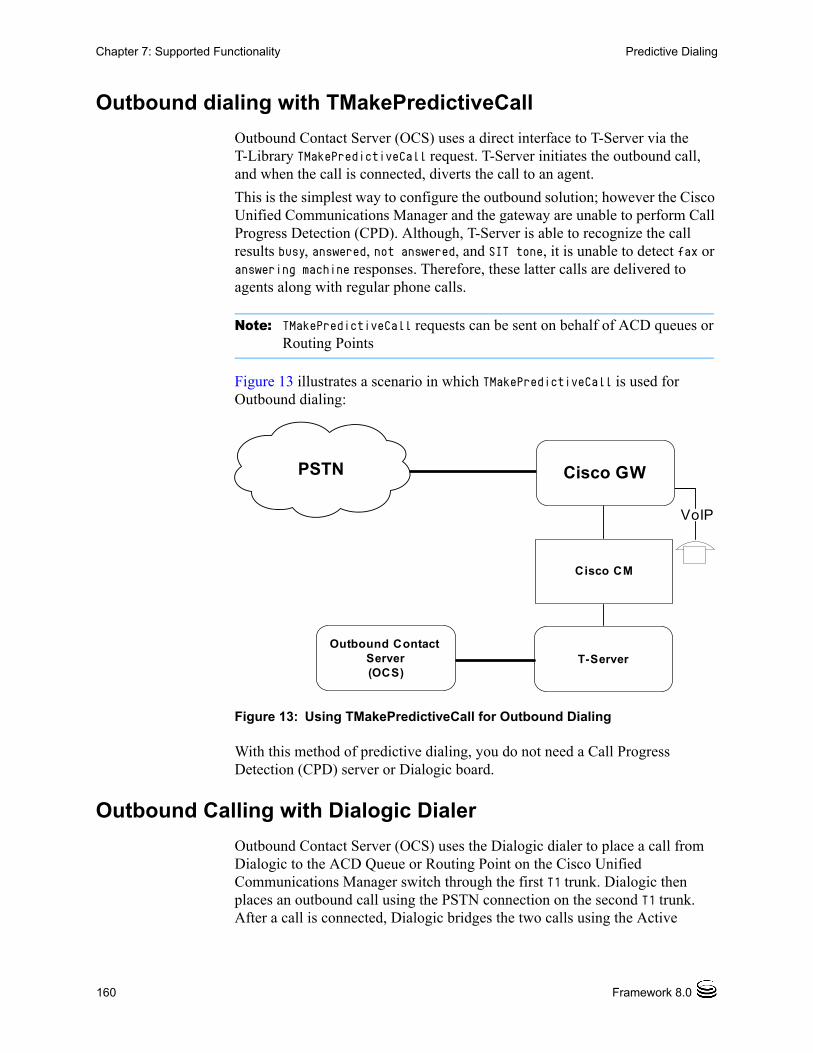
160 Framework 8.0
Chapter 7: Supported Functionality Predictive Dialing
Outbound dialing with TMakePredictiveCall
Outbound Contact Server (OCS) uses a direct interface to T-Server via the T-Library TMakePredictiveCall request. T-Server initiates the outbound call, and when the call is connected, diverts the call to an agent.
This is the simplest way to configure the outbound solution; however the Cisco Unified Communications Manager and the gateway are unable to perform Call Progress Detection (CPD). Although, T-Server is able to recognize the call results busy, answered, not answered, and SIT tone, it is unable to detect fax or answering machine responses. Therefore, these latter calls are delivered to agents along with regular phone calls.
Note: TMakePredictiveCall requests can be sent on behalf of ACD queues or Routing Points
Figure 13 illustrates a scenario in which TMakePredictiveCall is used for Outbound dialing:
Figure 13: Using TMakePredictiveCall for Outbound Dialing
With this method of predictive dialing, you do not need a Call Progress Detection (CPD) server or Dialogic board.
Outbound Calling with Dialogic Dialer
Outbound Contact Server (OCS) uses the Dialogic dialer to place a call from Dialogic to the ACD Queue or Routing Point on the Cisco Unified Communications Manager switch through the first T1 trunk. Dialogic then places an outbound call using the PSTN connection on the second T1 trunk. After a call is connected, Dialogic bridges the two calls using the Active
Cisco CM
T-Server
PSTN
VoIP
Outbound Contact Server (OCS)
Cisco GW
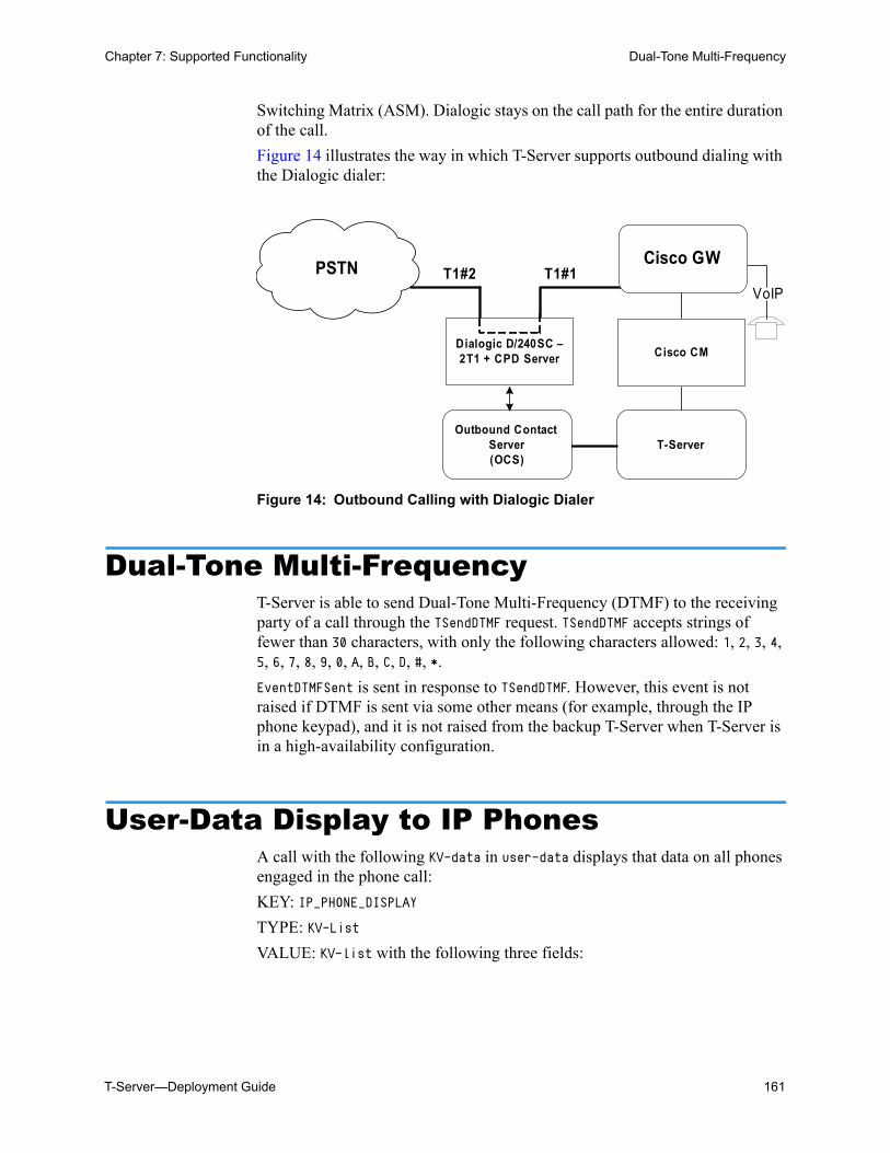
T-Server—Deployment Guide 161
Chapter 7: Supported Functionality Dual-Tone Multi-Frequency
Switching Matrix (ASM). Dialogic stays on the call path for the entire duration of the call.
Figure 14 illustrates the way in which T-Server supports outbound dialing with the Dialogic dialer:
Figure 14: Outbound Calling with Dialogic Dialer
Dual-Tone Multi-FrequencyT-Server is able to send Dual-Tone Multi-Frequency (DTMF) to the receiving party of a call through the TSendDTMF request. TSendDTMF accepts strings of fewer than 30 characters, with only the following characters allowed: 1, 2, 3, 4, 5, 6, 7, 8, 9, 0, A, B, C, D, #, *.
EventDTMFSent is sent in response to TSendDTMF. However, this event is not raised if DTMF is sent via some other means (for example, through the IP phone keypad), and it is not raised from the backup T-Server when T-Server is in a high-availability configuration.
User-Data Display to IP PhonesA call with the following KV-data in user-data displays that data on all phones engaged in the phone call:
KEY: IP_PHONE_DISPLAY
TYPE: KV-List
VALUE: KV-list with the following three fields:
Cisco CM
T-Server
PSTNVoIP
Outbound Contact Server (OCS)
Cisco GW
Dialogic D/240SC –2T1 + CPD Server
T1#2 T1#1
162 Framework 8.0
Chapter 7: Supported Functionality User-Data Display to IP Phones Not on a Call
1. KEY: TITLETYPE: STRINGVALUE: Any string, up to 24 characters. This is displayed at the top of the phone screen.
2. KEY: TEXTTYPE: STRINGVALUE: Any string of fewer than 1024 characters. This is displayed in the center of the phone screen.
3. KEY: PROMPTTYPE: STRINGVALUE: Any string, up to 28 characters. This is displayed at the bottom of the phone screen.
Note: If the data length is longer than the values specified above, T-Server silently “trims” the excess text. Note that the IP phone screen might not be large enough to hold all the text.
Phones on a call will no longer display user-data if the data is deleted.
For a conference call, all phones on the original call, and all phones that later join the call when the data is attached (for instance, those transferred to the call), displays KV-data. However, when a phone leaves the call, the data is no longer displayed on the departed phone.
If a user presses the Exit button (or any “soft” button) on the phone, KV data is no longer displayed.
The display of KV-data has the following limitations:
• If a remote T-Server updates the user-data (using the ISCC user-data propagation feature), the IP phones on the local T-Server do not display the updated data. However, if a local T-Server updates user-data, all the phones on the call displays the updated data.
• If a T-Server switches over to the backup T-Server, the backup T-Server displays user-data only for new calls, not existing calls.
• If the primary T-Server stops or is restarted, the phones on a call retains the KV data when the call terminates.
User data displayed on IP phones feature is applicable to shared lines DNs.
User-Data Display to IP Phones Not on a Call
To send a message to a phone that is not on call, the client should use the request TPrivateService with PrivateServiceID = 3 and the following KV-data in user-data:
T-Server—Deployment Guide 163
Chapter 7: Supported Functionality Voice Monitoring
KEY: IP_PHONE_DISPLAY
TYPE: KV-List
VALUE: KV-list with the following three fields:
1. KEY: TITLETYPE: STRINGVALUE: Any string, up to 24 characters. This is displayed at the top of the phone screen.
2. KEY: TEXTTYPE: STRINGVALUE: Any string, up to 1024 characters. This is displayed in the center of the phone screen.
3. KEY: PROMPTTYPE: STRINGVALUE: Any string, up to 28 characters. This is displayed at the bottom of the phone screen.
Note: If the data length is longer than the values specified above, T-Server truncates the excess text. Note that the IP phone screen might not be large enough to display all the text.
Voice MonitoringT-Server for Cisco Unified Communications Manager supports third party voice monitoring applications. For more details about voice monitoring, contact Genesys Technical Support at: http://genesyslab.com/support.
Shared LinesT-Server for Cisco Unified Communications Manager supports Shared Lines available with Cisco Unified Communications Manager. Incoming calls to Shared Lines are now able to arrive directly to the Shared Line DN.
Note: Statistics for Shared Lines DNs may differ from traditional Agent DNs (ACD or Extension DNs).
Configuration for Multiple Extensions within Shared Lines in Configuration Manager
DNs within Shared Lines in Configuration Manager can be configured differently:
164 Framework 8.0
Chapter 7: Supported Functionality Shared Lines
• Using MAC address suffixes as a part of the DN number.
• Using user-friendly suffixes on multi-line IP phones with a unique DN on a second line.
Shared Lines configuration may have, simultaneously, DNs configured with MAC addresses and DNs with user-friendly suffixes. If Shared Line DN is being used with an Extension Mobility (EM) profile, the user-friendly configuration method in Configuration Manager should be used for the EM Shared Line DN. Refer to the Extension Mobility section on page 167 for more details.
Procedure:Configuration using MAC address suffixes
Start of procedure
1. Under a Switch object, select and right click the DNs folder.
2. Select the New DN item from the menu.
3. Enter a number in the DN@MAC format, for example, 1889@SEP000F8F1BE25 as in Figure 15 on page 165. The MAC address can be found on the back of your IP phone.
Note: The uniqueDN option is not required with MAC address suffixes.
Notes: T-Server does not allow single DN configuration (without a suffix) if the DN number is configured as Shared Lines on Cisco Unified Communications Manager. In this case T-Server will generate the standard message 51114 Shared Line DN is not configured correctly in CME.
Agent operations (login, ready, not ready, logout) are not supported for Shared Lines.
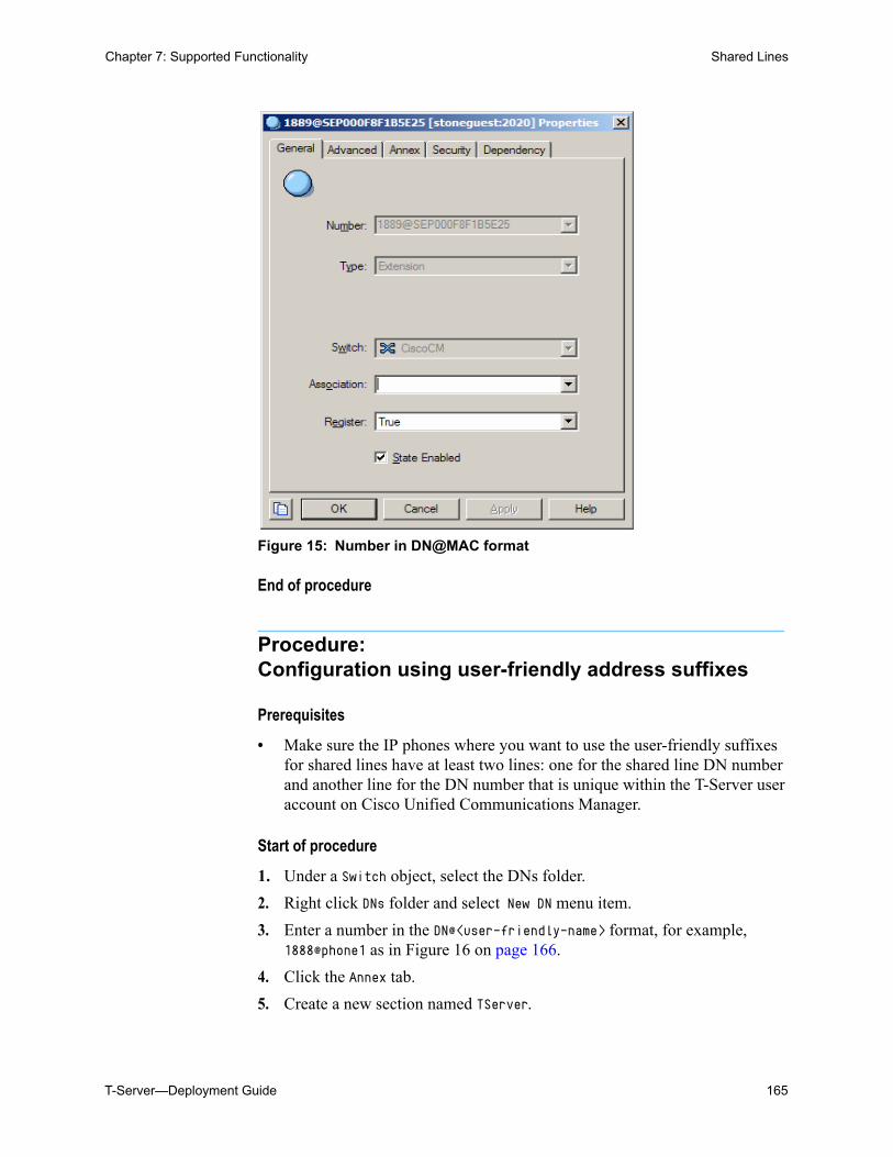
T-Server—Deployment Guide 165
Chapter 7: Supported Functionality Shared Lines
Figure 15: Number in DN@MAC format
End of procedure
Procedure:Configuration using user-friendly address suffixes
Prerequisites
• Make sure the IP phones where you want to use the user-friendly suffixes for shared lines have at least two lines: one for the shared line DN number and another line for the DN number that is unique within the T-Server user account on Cisco Unified Communications Manager.
Start of procedure
1. Under a Switch object, select the DNs folder.
2. Right click DNs folder and select New DN menu item.
3. Enter a number in the DN@<user-friendly-name> format, for example, 1888@phone1 as in Figure 16 on page 166.
4. Click the Annex tab.
5. Create a new section named TServer.
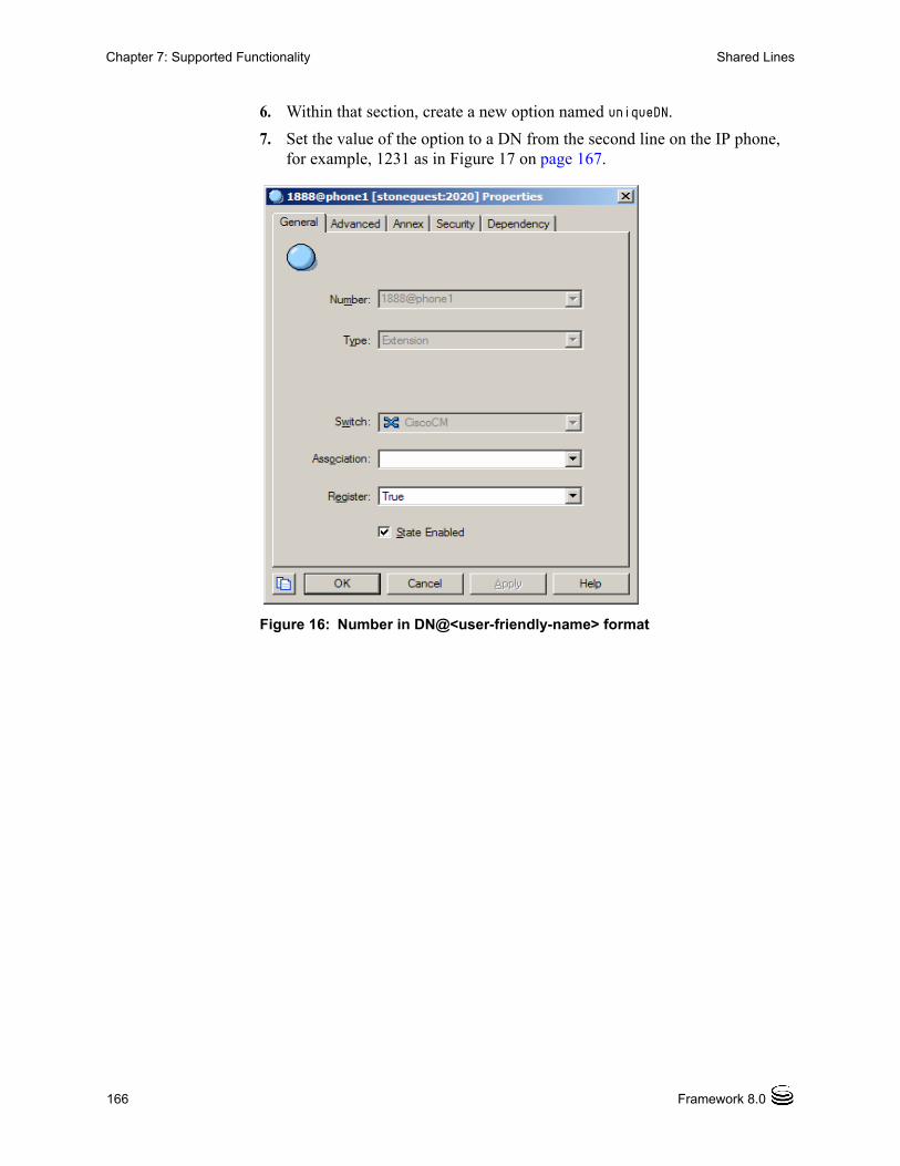
166 Framework 8.0
Chapter 7: Supported Functionality Shared Lines
6. Within that section, create a new option named uniqueDN.
7. Set the value of the option to a DN from the second line on the IP phone, for example, 1231 as in Figure 17 on page 167.
Figure 16: Number in DN@<user-friendly-name> format
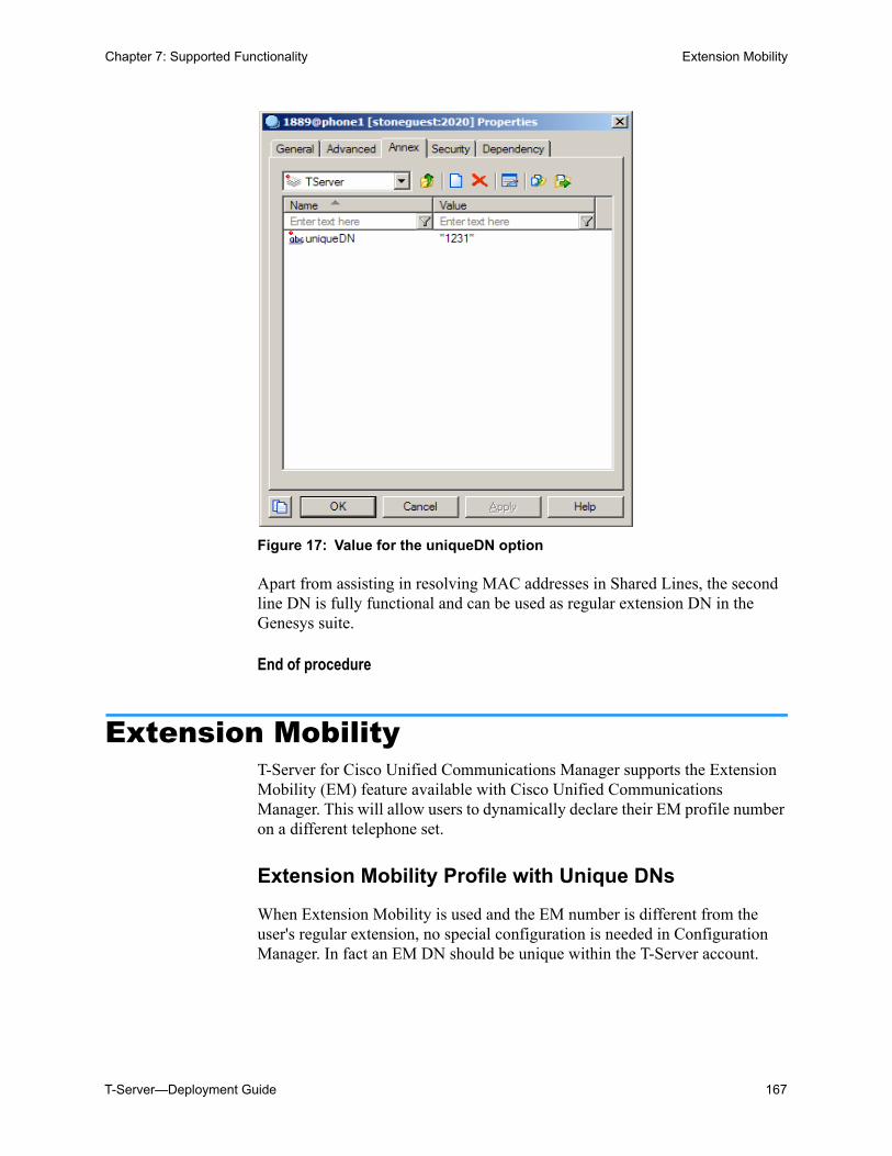
T-Server—Deployment Guide 167
Chapter 7: Supported Functionality Extension Mobility
Figure 17: Value for the uniqueDN option
Apart from assisting in resolving MAC addresses in Shared Lines, the second line DN is fully functional and can be used as regular extension DN in the Genesys suite.
End of procedure
Extension MobilityT-Server for Cisco Unified Communications Manager supports the Extension Mobility (EM) feature available with Cisco Unified Communications Manager. This will allow users to dynamically declare their EM profile number on a different telephone set.
Extension Mobility Profile with Unique DNs
When Extension Mobility is used and the EM number is different from the user's regular extension, no special configuration is needed in Configuration Manager. In fact an EM DN should be unique within the T-Server account.
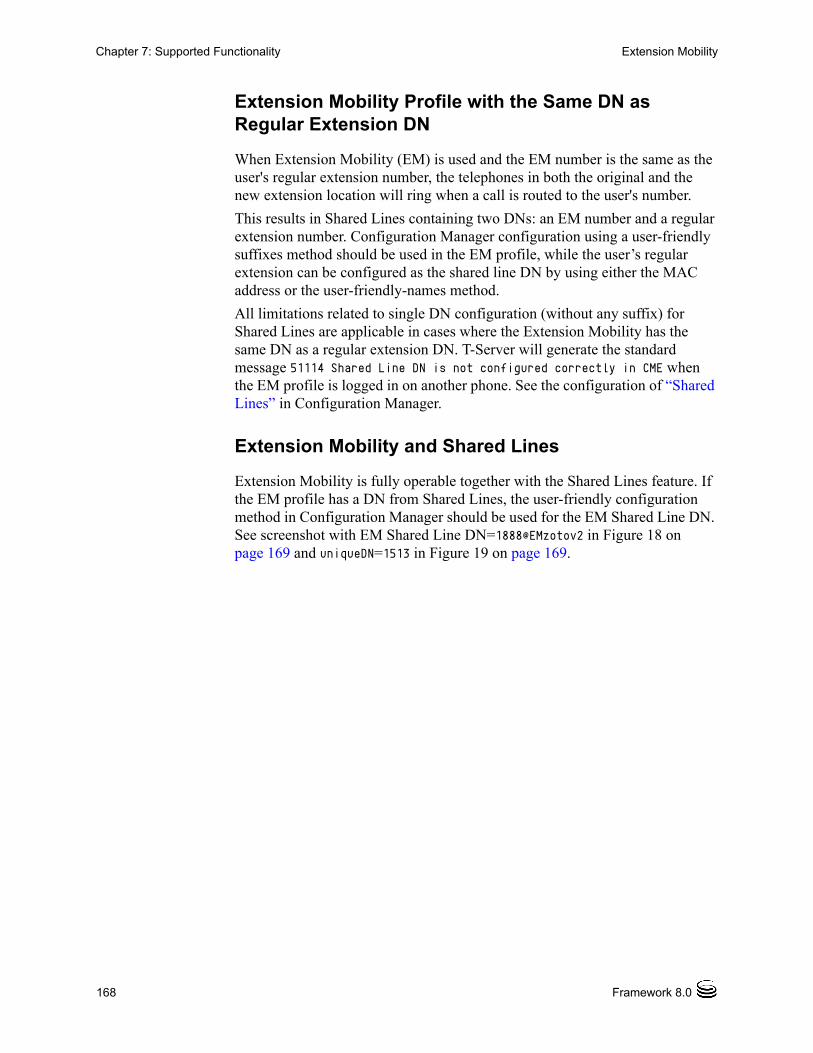
168 Framework 8.0
Chapter 7: Supported Functionality Extension Mobility
Extension Mobility Profile with the Same DN as Regular Extension DN
When Extension Mobility (EM) is used and the EM number is the same as the user's regular extension number, the telephones in both the original and the new extension location will ring when a call is routed to the user's number.
This results in Shared Lines containing two DNs: an EM number and a regular extension number. Configuration Manager configuration using a user-friendly suffixes method should be used in the EM profile, while the user’s regular extension can be configured as the shared line DN by using either the MAC address or the user-friendly-names method.
All limitations related to single DN configuration (without any suffix) for Shared Lines are applicable in cases where the Extension Mobility has the same DN as a regular extension DN. T-Server will generate the standard message 51114 Shared Line DN is not configured correctly in CME when the EM profile is logged in on another phone. See the configuration of “Shared Lines” in Configuration Manager.
Extension Mobility and Shared Lines
Extension Mobility is fully operable together with the Shared Lines feature. If the EM profile has a DN from Shared Lines, the user-friendly configuration method in Configuration Manager should be used for the EM Shared Line DN. See screenshot with EM Shared Line DN=1888@EMzotov2 in Figure 18 on page 169 and uniqueDN=1513 in Figure 19 on page 169.
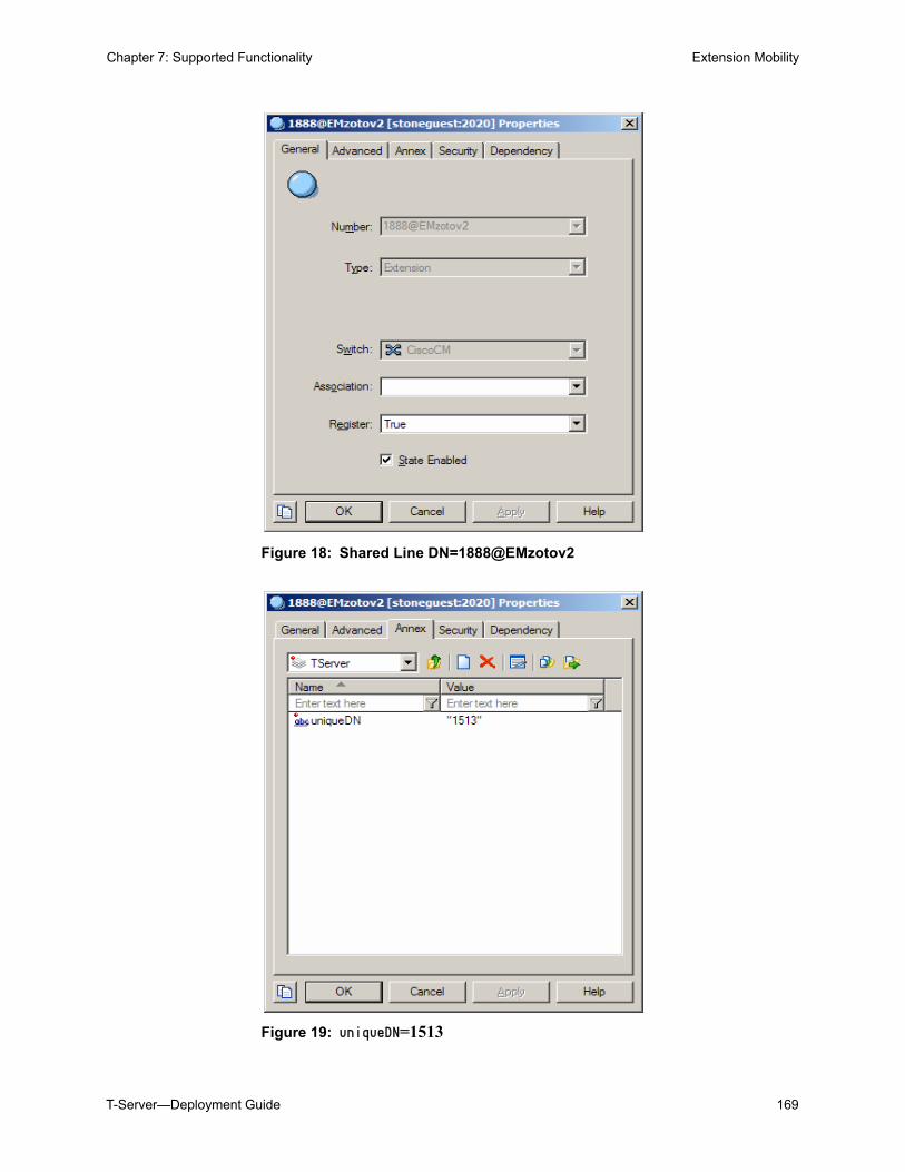
T-Server—Deployment Guide 169
Chapter 7: Supported Functionality Extension Mobility
Figure 18: Shared Line DN=1888@EMzotov2
Figure 19: uniqueDN=1513
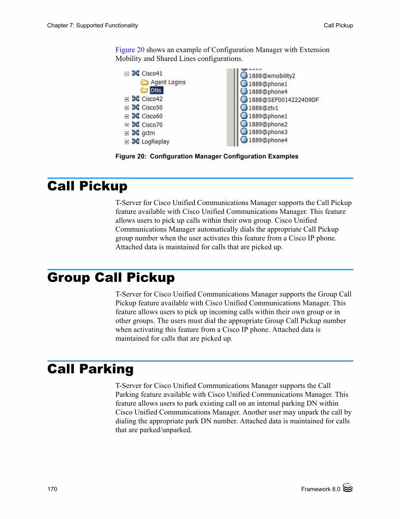
170 Framework 8.0
Chapter 7: Supported Functionality Call Pickup
Figure 20 shows an example of Configuration Manager with Extension Mobility and Shared Lines configurations.
Figure 20: Configuration Manager Configuration Examples
Call PickupT-Server for Cisco Unified Communications Manager supports the Call Pickup feature available with Cisco Unified Communications Manager. This feature allows users to pick up calls within their own group. Cisco Unified Communications Manager automatically dials the appropriate Call Pickup group number when the user activates this feature from a Cisco IP phone. Attached data is maintained for calls that are picked up.
Group Call PickupT-Server for Cisco Unified Communications Manager supports the Group Call Pickup feature available with Cisco Unified Communications Manager. This feature allows users to pick up incoming calls within their own group or in other groups. The users must dial the appropriate Group Call Pickup number when activating this feature from a Cisco IP phone. Attached data is maintained for calls that are picked up.
Call ParkingT-Server for Cisco Unified Communications Manager supports the Call Parking feature available with Cisco Unified Communications Manager. This feature allows users to park existing call on an internal parking DN within Cisco Unified Communications Manager. Another user may unpark the call by dialing the appropriate park DN number. Attached data is maintained for calls that are parked/unparked.
T-Server—Deployment Guide 171
Chapter 7: Supported Functionality ACD-like Default Routing
ACD-like Default Routing When a call arrives to a Route Point, and the URS server is disconnected, the call will be routed by T-Server to the ACD Queue configured in the default-dn option. The use of this feature is triggered with the value of the boolean use-default-route option. See Page 241 for more details.
Note: The following line will be displayed in the log when this feature is used: Router not present, will use default route to <DN number>.
Route Points with Multiple PartitionsWhen a Routing Point DN is registered on Cisco Unified Communications Manager, T-Server enumerates all the partitions for this Routing Point DN and registers all terminals associated with the partitions.
As JTAPI does not support Multiple Partitioning, Genesys recommends that the Routing Point be created as a single DN in the Configuration Layer without specifying a partition suffix. This DN will receive all Routing Point related events coming from any partition, but events will not have partition-specific information.
Calling Search Space FeatureCisco Unified Communications Manager can use the Calling Search Space feature when routing a call by adding the following key-value pair in AttributeExtensions in TRouteCall in the routing strategy:
Key: CALLING_SEARCH_SPACEType: StringValue: SEARCH_SPACE_CALLINGADDRESS or SEARCH_SPACE_ADDRESS
SEARCH_SPACE_CALLINGADDRESS indicates that the routing strategy is to use the Search Space of the Calling Address. This is the default value.
SEARCH_SPACE_ADDRESS indicates that the routing strategy is to use the Search Space of the Route Point Address.
Refer to the Cisco Unified Communications Manager System and Administration guides for more information about Partitions and Calling Search Spaces.
172 Framework 8.0
Chapter 7: Supported Functionality Socket Mode of Communication
Socket Mode of Communication
User Account configuration on a Cisco Unified Communications Manager cluster for T-Server
When configuring user accounts, the following must be taken into consideration:
1. For CallManager version 4.x, the option Enable CTI Application Use must be checked for every T-Server user configured in CallManager.
2. For CallManager versions 5.0 and later, the T-Server cucm-users must be created as an End User, then associated with all of the necessary devices, and finally (also new to release 5) placed into the Standard CTI Enabled Group.
3. To allow users to be authenticated locally, cucm-users must be created as an App User, while the End User must also be created on the LDAP where the authentication takes place.
Configuration Manager Configuration for T-Server in Socket Mode
Starting with 7.6, T-Server will use a standard link-n-name link configuration option set in Socket mode.
The TServer section will contain options link-1-name, link-2-name, ..., link-4-name while separate sections will contain link parameters.
See the following example: [TServer]
application=T-Server
packet-size=60
queue-music=music/in_queue
audio-codec=4
link-1-name=link-1
link-2-name=link-2
link-3-name=link-3
link-4-name=link-4
[link-1]
hostname=localhost
port=7888
protocol=tcp
ccm-host= CTIManager1.acme.com
T-Server—Deployment Guide 173
Chapter 7: Supported Functionality Customer Matters Code and Forced Authorization Code
password=*******
user-login=ccm-user-1
[link-2]
hostname= localhost
protocol=tcp
ccm-host= CTIManager2.acme.com
port=7890
password=*******
user-login=ccm-user-2
[link-3]
hostname= localhost
protocol=tcp
ccm-host= CTIManager3.acme.com
port=7892
password=*******
user-login=ccm-user-3
[link-4]
hostname= localhost
protocol=tcp
ccm-host= CTIManager4.acme.com
port=7894
password=*******
user-login=ccm-user-4
See Table 16 on page 232 for a more detailed explanation of the link options.
Make sure that the ccm-host, port and user-login options are different for all link sections. Also,make sure that the port values are different from T-Server listening ports from the Server Info tab in Configuration Manager and the sm-port option in the TServer section.
Customer Matters Code and Forced Authorization Code
Starting with release 8.0, T-Server extends the processing of the following T-Library requests to support Customer Matters Code (CMC) and Forced Authorization Code (FAC):TMakeCall, TMakePredictiveCall, TInitiateTransfer, TMuteTransfer, TInitiateConference, TRedirectCall, TRouteCall
T-Server will look for an AttributeExtension with the following data:
174 Framework 8.0
Chapter 7: Supported Functionality Cisco Unified Communications Manager Partition
Key: CMCType: StringValue: <cmc number>
Key: FACType: StringValue:<fac number>
Note: FAC and CMC numbers should not have the # symbol as a terminating sign. T-Server will append it automatically.
Call-Creating Requests
The following requests result in a new call or the creation of a consultation call when a call is created to a DN that requires an FAC, CMC, or both codes:
TMakeCall, TMakePredictiveCall, TInitiateTransfer, TMuteTransfer,
TInitiateConference, TRedirectCall or TRouteCall.
Cisco Unified Communications Manager Partition
Starting with release 5.0 of CUCM, JTAPI supports addresses that have the same DN but belong to different partitions and treats these DNs as different addresses.
Starting with release 8.0, the following configurations are supported by T-Server:
• Addresses with the same DN, in the same partition, and in different devices are treated as shared lines.
• Addresses with the same DN, in the same partition, and in the same device are not allowed.
• Addresses with the same DN, in different partitions, and in the same device are treated as different addresses.
• Addresses with the same DN, in different partitions, and in different devices are treated as different addresses.
DN Name Mangling
To distinguish between two addresses with the same digits but with different partitions, T-Server will use Cisco Unified Communications Manager partition information as a part of the DN name in Configuration Manager. This name mangling is also compatible with the existing T-Server Shared Lines feature.
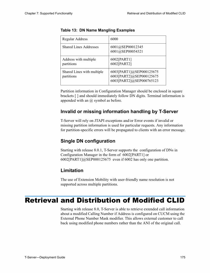
T-Server—Deployment Guide 175
Chapter 7: Supported Functionality Retrieval and Distribution of Modified CLID
Partition information in Configuration Manager should be enclosed in square brackets [ ] and should immediately follow DN digits. Terminal information is appended with an @ symbol as before.
Invalid or missing information handling by T-Server
T-Server will rely on JTAPI exceptions and/or Error events if invalid or missing partition information is used for particular requests. Any information for partition-specific errors will be propagated to clients with an error message.
Single DN configuration
Starting with release 8.0.1, T-Server supports the configuration of DNs in Configuration Manager in the form of 6002[PART1] or 6002[PART1]@SEP000125675 even if 6002 has only one partition.
Limitation
The use of Extension Mobility with user-friendly name resolution is not supported across multiple partitions.
Retrieval and Distribution of Modified CLIDStarting with release 8.0, T-Server is able to retrieve extended call information about a modified Calling Number if Address is configured on CUCM using the External Phone Number Mask modifier. This allows external customer to call back using modified phone numbers rather than the ANI of the original call.
Table 13: DN Name Mangling Examples
Regular Address 6000
Shared Lines Addresses 6001@SEP000123456001@SEP00054321
Address with multiple partitions
6002[PART1]6002[PART2]
Shared Lines with multiple partitions
6003[PART1]@SEP0001256756003[PART2]@SEP0001256756003[PART2]@SEP000765123
176 Framework 8.0
Chapter 7: Supported Functionality Call Recording
Distribution of Events
T-Server uses the ModifiedCallingAddress event to communicate new digits to T-Server clients.
CUCM modifies the CallingAddress only for outbound calls. For this reason, T-Server will use EventNetworkReached to communicate modified calling digits to T-Server clients. For internal calls, ModifiedCallingAddress is the same as the OriginalCallingAddress.
T-Server distributes a modified Calling Number only for the Network Reached event. Consequently, the following AttributeExtensions is used for extra information:
KEY: MODIFIED_CALLING_NUMBERType: StringVALUE: <modified number>
Call RecordingT-Server supports both regular call recording and emergency call recording.
Regular Call Recording
Call recording is performed by passing an RTP stream through Stream Manager. Stream Manager acts as a media stream proxy, recording all media packets into a file. Depending on the configuration, Stream Manager may perform media mixing, or it may save the RTP packets as is, thus improving call recording performance. (See the Framework 7.6 Stream Manager Deployment Guide for details.) Call recording is always enabled on a single call leg, such as a leg with a gateway or a leg with a Cisco phone.
Call recording starts after a call becomes established. It does not result in any changes to the call itself, to event processing, or to any other generated TEvents.
Call recording has the highest priority compared to other operations that can be performed on the call when it is established. That is, when the EventEstablished message is generated on the destination DN, the operations on the call are performed in the following order:
1. Call recording, if enabled.
2. Supervisor monitoring, if enabled.
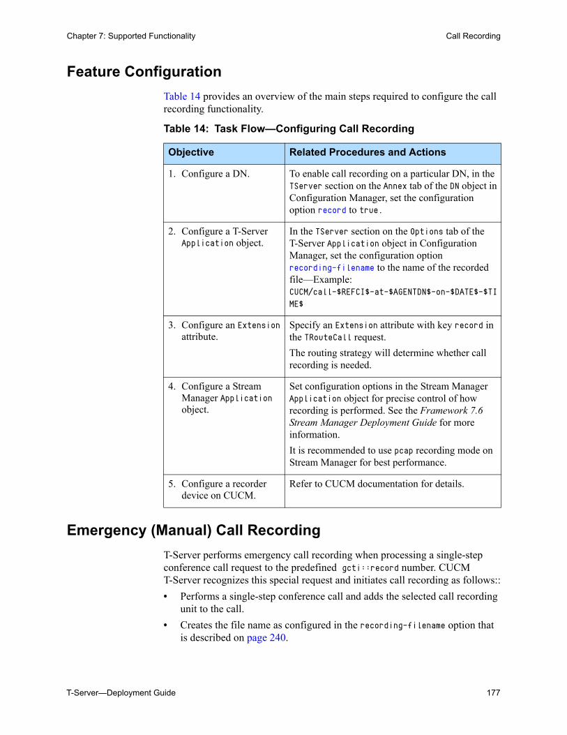
T-Server—Deployment Guide 177
Chapter 7: Supported Functionality Call Recording
Feature Configuration
Table 14 provides an overview of the main steps required to configure the call recording functionality.
Emergency (Manual) Call Recording
T-Server performs emergency call recording when processing a single-step conference call request to the predefined gcti::record number. CUCM T-Server recognizes this special request and initiates call recording as follows::
• Performs a single-step conference call and adds the selected call recording unit to the call.
• Creates the file name as configured in the recording-filename option that is described on page 240.
Table 14: Task Flow—Configuring Call Recording
Objective Related Procedures and Actions
1. Configure a DN. To enable call recording on a particular DN, in the TServer section on the Annex tab of the DN object in Configuration Manager, set the configuration option record to true.
2. Configure a T-Server Application object.
In the TServer section on the Options tab of the T-Server Application object in Configuration Manager, set the configuration option recording-filename to the name of the recorded file—Example: CUCM/call-$REFCI$-at-$AGENTDN$-on-$DATE$-$TIME$
3. Configure an Extension attribute.
Specify an Extension attribute with key record in the TRouteCall request.
The routing strategy will determine whether call recording is needed.
4. Configure a Stream Manager Application object.
Set configuration options in the Stream Manager Application object for precise control of how recording is performed. See the Framework 7.6 Stream Manager Deployment Guide for more information.
It is recommended to use pcap recording mode on Stream Manager for best performance.
5. Configure a recorder device on CUCM.
Refer to CUCM documentation for details.
178 Framework 8.0
Chapter 7: Supported Functionality Supervisor Monitoring
To stop emergency call recording, the agent must issue the TDeleteFromConference request using the gcti::record number.
Summary of Configurations for Call Recording
Call recording is enabled on DNs using the record option.
Call recording is enabled by specifying extension record in RequestRouteCall. The routing strategy may determine whether or not call recording is needed.
To invoke this feature, the following key-value pairs should be attached to the Attribute Extensions of the RequestRouteCall request:
Key: recordValue: destinationWhen the extension is set to destination, the recording will be initiated on the routing destination DN (agent) and will continue while the agent stays in the call.
AttributeUserData in EventAttachedDataChanged
Key: GSIP_REC_FNValue: <actual filename>The value of this key is equal to the recorded Stream Manager filename. CUCM T-Server 8.0 is generating this filename to match the Stream Manager filename.
Key: GSIP_REC_RECORDERValue: <recorder>This key has a value that is equal to the recorder address name that is configured on Cisco Unified Communications Manager.
Recorded filename matching
T-Server may not be able to construct exactly the same file name that Stream Manager used for recording.
• Stream Manager always adds the codec suffix and file extension (depending on the recording mode), so the exact file name is not available (as T-Server does not control codec selection in this case).
• The recorded file still can be matched by the prefix (directory/call-$REFCI$-at-$AGENTDN$-on) that is known.
• If recording-filename is set to call-$REFCI$-at-$AGENTDN$-on-$DATE$ then a 100% match can be achieved.
Supervisor MonitoringStarting with version 8.0, supervisor monitoring is supported by T-Server.
T-Server—Deployment Guide 179
Chapter 7: Supported Functionality Supervisor Monitoring
The call supervision functionality enables contact center managers to monitor agents.
Call supervision subscription
Call supervision functionality enables call center managers to monitor agents.
Subscription is designed for the supervisors. Supervisors can subscribe to monitor one agent. If a subscription is active, T-Server automatically invites the supervisor to all calls where the agent participates. T-Server stops working in this mode as soon as the subscription is cancelled.
Monitoring Session
A Monitoring Session is a period where a supervisor monitors and agent-customer conversation. Monitoring Sessions can be created as a result of an active subscription. A Monitoring Session starts when a supervisor joins the call and it ends when the supervisor disconnects.
Modes of Call Supervision
Call supervision can be carried out in different modes:
• Silent Monitoring: Hiding the supervisor presence from all call participants, including the monitored agent who is the target of the supervisor's attention in this case.
• Whisper Coaching: The supervisor’s presence is hidden from all call participants except the monitored agent. In this scenario, only the monitored agent can hear the supervisor.
Scope of Call Supervision
Call supervision scope defines the part of the call to be monitored by the supervisor. The only scope available in T-Server for this is agent. The supervisor follows the monitored agent in this mode. This means that the supervisor leaves the call as soon as agent is gone.
Types of Call Supervision
Call supervision type specifies the number of calls to be monitored. There are two options:
• One Call: Only one call is monitored.
• All Calls: All calls are monitored.
Supervision type plays an important role in the monitoring subscription. If the One Call option is chosen for the subscription, the subscription gets cancelled automatically when the supervisor finishes monitoring the first call on the monitored agent. In the case of All Calls, the supervisor should cancel the subscription manually to stop monitoring the agent's calls.
180 Framework 8.0
Chapter 7: Supported Functionality Supervisor Monitoring
Intrusion
Intrusion occurs if a Supervisor activates a new call supervision subscription to monitor the agent who is currently on the call. In this case T-Server creates the requested subscription and immediately invites the Supervisor to join the existing call.
Implementation Call Supervision Subscription
General approach
Call supervision subscription is implemented through the use of two T-Library requests:
• TMonitorNextCall: starts new subscription.
• TCancelMonitoring: deletes existing subscription.
Both of these requests use AttributeThisDN to point to the supervisor and AttributeOtherDN to define the monitored agent. Additionally, the TMonitorNextCall request carries the information to specify the mode, scope, and type of the monitoring subscription to be created. This information is transferred in the request as follows:
• AttributeMonitorNextCallType: Defines the type of call supervision. MonitorOneCall: A subscription is created to monitor one call only and
will be terminated automatically. MonitorAllCalls: A subscription is created to monitor all calls and is
terminated when the supervisor sends a TCancelMonitoring request.
• AttributeExtensions/MonitorMode: Defines the mode of call supervision.
• AttributeExtensions/MonitorScope: Defines the scope of call supervision.
Creating subscriptions
T-Server creates a new subscription based on the TMonitorNextCall request that is submitted by the supervisor. Based on certain circumstances, the request can be either accepted or rejected. Requests are rejected in the following cases:
• Either the supervisor or agent DN is not internal, and monitored by the switch.
• Either the supervisor or the agent DN is not configured in Configuration Manager.
• The agent DN is already monitored.
If a request is accepted, T-Server creates a new subscription and initializes it with the information that is passed in the AttributeMonitorNextCallType request attribute and in the AttributeExtensions key-value pairs: MonitorScope and MonitorMode.
If the monitor mode is missing, the value from the default-monitor-mode configuration option will be used.
T-Server—Deployment Guide 181
Chapter 7: Supported Functionality Supervisor Monitoring
The AttributeMonitorNextCallType is mandatory.
T-Server confirms the creation of a new subscription for both the supervisor and agent by sending EventMonitoringNextCall to both destinations. This event always contains AttributeExtensions with both monitoring extensions representing the monitoring configuration defined in T-Server for a new subscription.
Monitoring Parameters Used for Subscription Initialization
To specify MonitorMode for a subscription, the following key-value pairs should be attached to the attribute Extensions of the TMonitorNextCall request:
Key: MonitorModeType: StringValues:
The default-monitor-mode option is used when the MonitorMode extension in the TMonitorNextCall request is not specified or is specified incorrectly.
Key: MonitorScopeType: StringValues: agent (Only possible value)
Canceling Subscriptions
There are two scenarios used in T-Server to cancel active subscriptions:
• Incoming TCancelMonitoring request.
• Completion of a monitoring session created based on the Monitor One Call type of subscription.
T-Server generates EventMonitoringCancelled events for both supervisor and agent to inform them that a subscription is cancelled.
Implementing Call Intrusion
Call intrusion is a scenario when T-Server gets RequestMonitorNextCall from the supervisor at the time when an agent is to be monitored, but is already on the call. T-Server’s behavior in this scenario is controlled by the intrusion-enabled option. If this option is set to false, T-Server only creates a
normal Silent monitoring (mutes supervisor’s connection, possible warning beep).
mute Silent monitoring (mutes supervisor’s connection).coach Whisper coaching (only monitored agent can hear the
supervisor).connect Opens the supervisor’s presence (Not supported. Use a
two-step conference instead).
182 Framework 8.0
Chapter 7: Supported Functionality Supervisor Monitoring
new subscription. If intrusion-enabled is set to true, T-Server creates a new subscription and immediately invites the supervisor to join the existing call.
Mute Off/Mute On Support
T-Server is able to switch from silent monitoring to coach conferencing (barge- in functionality), and switch from coach conferencing to silent monitoring. This functionality is provided by implementation of two T-library requests:
• TSetMuteOff—Switch from silent monitoring to coach conferencing.
• TSetMuteOn—Switch from coach conferencing to silent monitoring.
Request TSetMuteOff will be performed only if the corresponding supervisor DN is in the process of silent monitoring. When the request has completed successfully, EventMuteOff is sent.
Request TSetMuteOn will be performed only if the corresponding DN is a regular conference member, or a supervisor in Whisper mode. When the request has completed successfully, EventMuteOn is sent.
Whisper Coaching and Extra Instance of Intercom Call
Whisper coaching in T-Server is performed using the CUCM Intercom feature.
The Intercom feature allows one user to call another user and have the call answered automatically, and with one-way media from the caller to the called party, regardless of whether the called party is busy or idle. The called user can press the talk back softkey (unmarked key) on their phone display to start talking to the caller. Only a specially configured Intercom address on the phone can initiate an Intercom call. JTAPI creates a new type of address object named CiscoIntercomAddress for Intercom addresses that are configured on the phone.
Only one Intercom DN can call another Intercom DN. For this reason, the Configuration Manager DN configuration option intercomDN must be configured on both the supervisor phone and the agent phone for the Whisper feature to work. See Figure 21, “Screen Shot of Intercom DN,” on page 183.
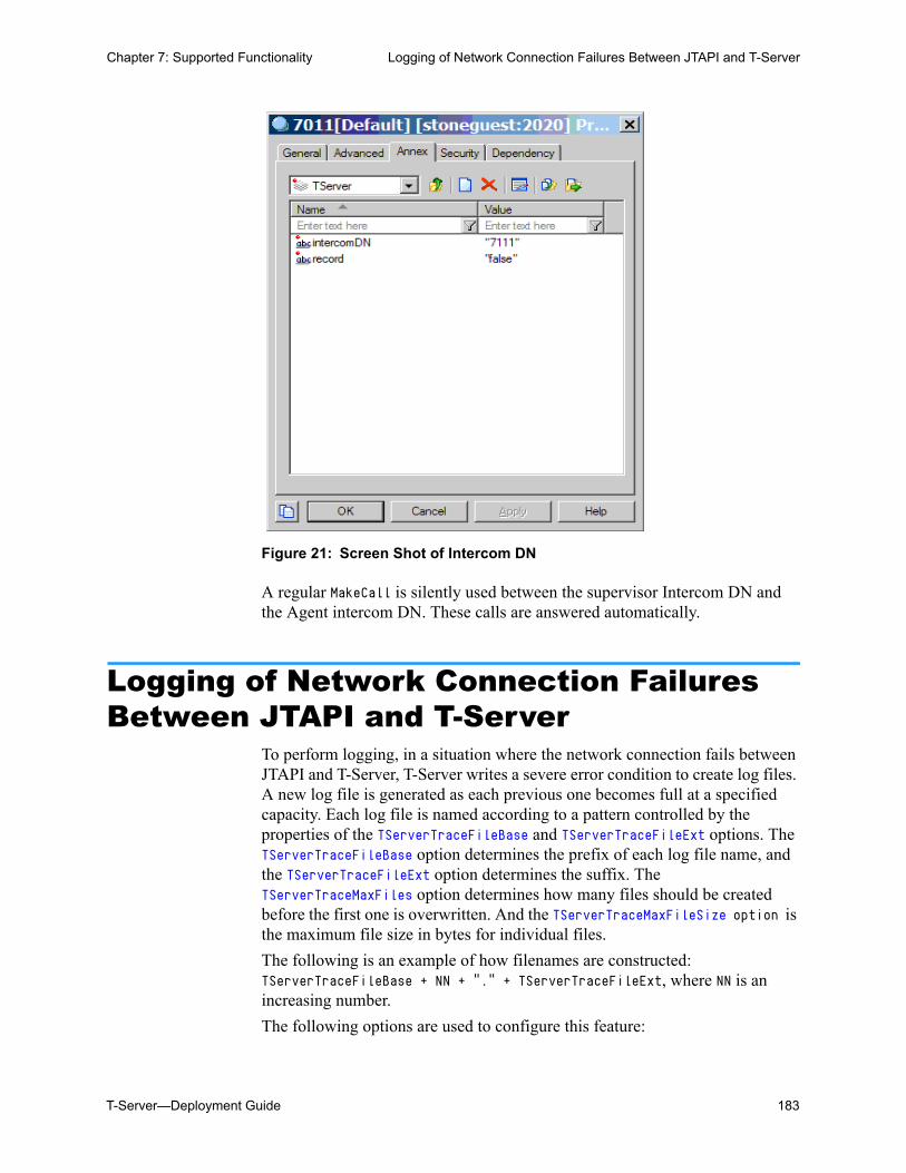
T-Server—Deployment Guide 183
Chapter 7: Supported Functionality Logging of Network Connection Failures Between JTAPI and T-Server
Figure 21: Screen Shot of Intercom DN
A regular MakeCall is silently used between the supervisor Intercom DN and the Agent intercom DN. These calls are answered automatically.
Logging of Network Connection Failures Between JTAPI and T-Server
To perform logging, in a situation where the network connection fails between JTAPI and T-Server, T-Server writes a severe error condition to create log files. A new log file is generated as each previous one becomes full at a specified capacity. Each log file is named according to a pattern controlled by the properties of the TServerTraceFileBase and TServerTraceFileExt options. The TServerTraceFileBase option determines the prefix of each log file name, and the TServerTraceFileExt option determines the suffix. The TServerTraceMaxFiles option determines how many files should be created before the first one is overwritten. And the TServerTraceMaxFileSize option is the maximum file size in bytes for individual files.
The following is an example of how filenames are constructed: TServerTraceFileBase + NN + "." + TServerTraceFileExt, where NN is an increasing number.
The following options are used to configure this feature:
184 Framework 8.0
Chapter 7: Supported Functionality Call Parking with 3PCC
• TServerTraceFileBase
• TServerTraceFileExt
• TServerTraceMaxFiles
• TServerTraceMaxFileSize
Configure these options in the jtapi section on the Options tab for the T-Server Application object in the Configuration Layer.
Call Parking with 3PCCWith release version 8.0.1, T-Server allows a softphone, while on a call, to issue a Park request. T-Server sends this request to Call Manager, which parks the call and returns the parked number in the released message. T-Server then passes this to the softphone which displays the location where the call is parked. The softphone issues a TSingleStepTransfer request to a special DN (gcti::park) to accomplish this action. If a physical phone is used to park a call, the DN where the call is parked is returned in EventReleased message using the key-value pairs in AttributeExtensions of PARK_DN = <DN number> (Example: PARK_DN = 7000). To unpark a call, a client must issue a TMakeCall request to the DN number.
T-Server—Deployment Guide 185
Chapter
8 Common Configuration OptionsUnless otherwise noted, the common configuration options that this chapter describes are common to all Genesys server applications and applicable to any Framework server component. This chapter includes the following sections: Setting Configuration Options, page 186 Mandatory Options, page 186 Log Section, page 186 Log-Extended Section, page 200 Log-Filter Section, page 202 Log-Filter-Data Section, page 203 SML Section, page 203 Common Section, page 203
Note: Some server applications also support log options that are unique to them. For descriptions of a particular application’s unique log options, refer to the chapter/document about that application.
186 Framework 8.0
Chapter 8: Common Configuration Options Setting Configuration Options
Setting Configuration OptionsUnless specified otherwise, set common configuration options in the Application object, using the following navigation path:
• In Configuration Manager—Application object > Properties dialog box > Options tab
Mandatory OptionsYou do not have to configure any common options to start Server applications.
Log SectionThis section must be called log.
verbose Default Value: allValid Values:
Changes Take Effect: Immediately
Determines whether a log output is created. If it is, specifies the minimum level of log events generated. The log events levels, starting with the highest
Warning! Configuration section names, configuration option names, and predefined option values are case-sensitive. Type them in Configuration Manager exactly as they are documented in this chapter.
all All log events (that is, log events of the Standard, Trace, Interaction, and Debug levels) are generated.
debug The same as all.trace Log events of the Trace level and higher (that is, log events of
the Standard, Interaction, and Trace levels) are generated, but log events of the Debug level are not generated.
interaction Log events of the Interaction level and higher (that is, log events of the Standard and Interaction levels) are generated, but log events of the Trace and Debug levels are not generated.
standard Log events of the Standard level are generated, but log events of the Interaction, Trace, and Debug levels are not generated.
none No output is produced.
T-Server—Deployment Guide 187
Chapter 8: Common Configuration Options Log Section
priority level, are Standard, Interaction, Trace, and Debug. See also “Log Output Options” on page 192.
bufferingDefault Value: trueValid Values:
Changes Take Effect: Immediately
Turns on/off operating system file buffering. The option is applicable only to the stderr and stdout output (see page 192). Setting this option to true increases the output performance.
segment Default Value: falseValid Values:
Changes Take Effect: Immediately
Specifies whether there is a segmentation limit for a log file. If there is, sets the mode of measurement, along with the maximum size. If the current log segment exceeds the size set by this option, the file is closed and a new one is created. This option is ignored if log output is not configured to be sent to a log file.
Note: For definitions of the Standard, Interaction, Trace, and Debug log levels, refer to the Framework 8.0 Management Layer User’s Guide or to Framework 8.0 Solution Control Interface Help.
true Enables buffering.false Disables buffering.
Note: When buffering is enabled, there might be a delay before log messages appear at the console.
false No segmentation is allowed.<number> KB or <number>
Sets the maximum segment size, in kilobytes. The minimum segment size is 100 KB.
<number> MB Sets the maximum segment size, in megabytes.<number> hr Sets the number of hours for the segment to stay open. The
minimum number is 1 hour.
188 Framework 8.0
Chapter 8: Common Configuration Options Log Section
expire Default Value: falseValid Values:
Changes Take Effect: Immediately
Determines whether log files expire. If they do, sets the measurement for determining when they expire, along with the maximum number of files (segments) or days before the files are removed. This option is ignored if log output is not configured to be sent to a log file.
keep-startup-fileDefault Value: falseValid Values:
Changes Take Effect: After restart
Specifies whether a startup segment of the log, containing the initial T-Server configuration, is to be kept. If it is, this option can be set to true or to a specific size. If set to true, the size of the initial segment will be equal to the size of the regular log segment defined by the segment option. The value of this option will be ignored if segmentation is turned off (that is, if the segment option set to false).
messagefile Default Value: As specified by a particular applicationValid Values: <string>.lms (message file name)Changes Take Effect: Immediately, if an application cannot find its *.lms file at startup
false No expiration; all generated segments are stored.<number> file or <number>
Sets the maximum number of log files to store. Specify a number from 1–100.
<number> day Sets the maximum number of days before log files are deleted. Specify a number from 1–100.
Note: If an option’s value is set incorrectly—out of the range of valid values— it will be automatically reset to 10.
false No startup segment of the log is kept.true A startup segment of the log is kept. The size of the segment
equals the value of the segment option.<number> KB Sets the maximum size, in kilobytes, for a startup segment of
the log.<number> MB Sets the maximum size, in megabytes, for a startup segment
of the log.
Note: This option applies only to T-Servers.
T-Server—Deployment Guide 189
Chapter 8: Common Configuration Options Log Section
Specifies the file name for application-specific log events. The name must be valid for the operating system on which the application is running. The option value can also contain the absolute path to the application-specific *.lms file. Otherwise, an application looks for the file in its working directory.
message_format Default Value: shortValid Values:
Changes Take Effect: Immediately
Specifies the format of log record headers that an application uses when writing logs in the log file. Using compressed log record headers improves application performance and reduces the log file’s size.
With the value set to short:
• A header of the log file or the log file segment contains information about the application (such as the application name, application type, host type, and time zone), whereas single log records within the file or segment omit this information.
• A log message priority is abbreviated to Std, Int, Trc, or Dbg, for Standard, Interaction, Trace, or Debug messages, respectively.
• The message ID does not contain the prefix GCTI or the application type ID.
A log record in the full format looks like this:2002-05-07T18:11:38.196 Standard localhost cfg_dbserver GCTI-00-05060 Application started
A log record in the short format looks like this:2002-05-07T18:15:33.952 Std 05060 Application started
Warning! An application that does not find its *.lms file at startup cannot generate application-specific log events and send them to Message Server.
short An application uses compressed headers when writing log records in its log file.
full An application uses complete headers when writing log records in its log file.
Note: Whether the full or short format is used, time is printed in the format specified by the time_format option.
190 Framework 8.0
Chapter 8: Common Configuration Options Log Section
time_convert Default Value: LocalValid Values:
Changes Take Effect: Immediately
Specifies the system in which an application calculates the log record time when generating a log file. The time is converted from the time in seconds since the Epoch (00:00:00 UTC, January 1, 1970).
time_format Default Value: timeValid Values:
Changes Take Effect: Immediately
Specifies how to represent, in a log file, the time when an application generates log records.
A log record’s time field in the ISO 8601 format looks like this:2001-07-24T04:58:10.123
print-attributes Default Value: falseValid Values:
Changes Take Effect: Immediately
Specifies whether the application attaches extended attributes, if any exist, to a log event that it sends to log output. Typically, log events of the Interaction log level and Audit-related log events contain extended attributes. Setting this option to true enables audit capabilities, but negatively affects performance. Genesys recommends enabling this option for Solution Control Server and Configuration Server when using audit tracking. For other applications, refer to Genesys 8.0 Combined Log Events Help to find out whether an application generates Interaction-level and Audit-related log events; if it does, enable the option only when testing new interaction scenarios.
local The time of log record generation is expressed as a local time, based on the time zone and any seasonal adjustments. Time zone information of the application’s host computer is used.
utc The time of log record generation is expressed as Coordinated Universal Time (UTC).
time The time string is formatted according to the HH:MM:SS.sss (hours, minutes, seconds, and milliseconds) format.
locale The time string is formatted according to the system’s locale.ISO8601 The date in the time string is formatted according to the ISO 8601
format. Fractional seconds are given in milliseconds.
true Attaches extended attributes, if any exist, to a log event sent to log output.
false Does not attach extended attributes to a log event sent to log output.
T-Server—Deployment Guide 191
Chapter 8: Common Configuration Options Log Section
check-point Default Value: 1Valid Values: 0–24Changes Take Effect: Immediately
Specifies, in hours, how often the application generates a check point log event, to divide the log into sections of equal time. By default, the application generates this log event every hour. Setting the option to 0 prevents the generation of check-point events.
memory Default Value: No default valueValid Values: <string> (memory file name)Changes Take Effect: Immediately
Specifies the name of the file to which the application regularly prints a snapshot of the memory output, if it is configured to do this (see “Log Output Options” on page 192). The new snapshot overwrites the previously written data. If the application terminates abnormally, this file will contain the latest log messages. Memory output is not recommended for processors with a CPU frequency lower than 600 MHz.
memory-storage-size Default Value: 2 MBValid Values:
Changes Take Effect: When memory output is created
Specifies the buffer size for log output to the memory, if configured. See also “Log Output Options” on page 192.
spool Default Value: The application’s working directoryValid Values: <path> (the folder, with the full path to it)Changes Take Effect: Immediately
Specifies the folder, including full path to it, in which an application creates temporary files related to network log output. If you change the option value while the application is running, the change does not affect the currently open network output.
Note: If the file specified as the memory file is located on a network drive, an application does not create a snapshot file (with the extension *.memory.log).
<number> KB or <number> The size of the memory output, in kilobytes. The minimum value is 128 KB.
<number> MB The size of the memory output, in megabytes. The maximum value is 64 MB.
192 Framework 8.0
Chapter 8: Common Configuration Options Log Section
compatible-output-priority Default Value: falseValid Values:
Changes Take Effect: Immediately
Specifies whether the application uses 6.x output logic. For example, you configure the following options in the log section for a 6.x application and for a 7.x application:[log]
verbose = all
debug = file1
standard = file2
The log file content of a 6.x application is as follows:
• file1 contains Debug messages only.
• file2 contains Standard messages only.
The log file content of a 7.x application is as follows:
• file1 contains Debug, Trace, Interaction, and Standard messages.
• file2 contains Standard messages only.
If you set compatible-output-priority to true in the 7.x application, its log file content will be the same as for the 6.x application.
Log Output Options
To configure log outputs, set log level options (all, alarm, standard, interaction, trace, and/or debug) to the desired types of log output (stdout, stderr, network, memory, and/or [filename], for log file output).
You can use:
• One log level option to specify different log outputs.
• One log output type for different log levels.
• Several log output types simultaneously, to log events of the same or different log levels.
true The log of the level specified by “Log Output Options” is sent to the specified output.
false The log of the level specified by “Log Output Options” and higher levels is sent to the specified output.
Warning! Genesys does not recommend changing the default value of the this option unless you have specific reasons to use the 6.x log output logic—that is, to mimic the output priority as implemented in releases 6.x. Setting this option to true affects log consistency.
T-Server—Deployment Guide 193
Chapter 8: Common Configuration Options Log Section
You must separate the log output types by a comma when you are configuring more than one output for the same log level. See “Examples” on page 197.
allDefault Value: No default valueValid Values (log output types):
Changes Take Effect: Immediately
Specifies the outputs to which an application sends all log events. The log output types must be separated by a comma when more than one output is configured. For example:all = stdout, logfile
Note: The log output options are activated according to the setting of the verbose configuration option.
Warnings! • If you direct log output to a file on the network drive, an application does not create a snapshot log file (with the extension *.snapshot.log) in case it terminates abnormally.
• Directing log output to the console (by using the stdout or stderr settings) can affect application performance. Avoid using these log output settings in a production environment.
stdout Log events are sent to the Standard output (stdout).stderr Log events are sent to the Standard error output (stderr).network Log events are sent to Message Server, which can reside
anywhere on the network. Message Server stores the log events in the Log Database.
Setting the all log level option to the network output enables an application to send log events of the Standard, Interaction, and Trace levels to Message Server. Debug-level log events are neither sent to Message Server nor stored in the Log Database.
memory Log events are sent to the memory output on the local disk. This is the safest output in terms of the application performance.
[filename] Log events are stored in a file with the specified name. If a path is not specified, the file is created in the application’s working directory.
Note: To ease the troubleshooting process, consider using unique names for log files that different applications generate.
194 Framework 8.0
Chapter 8: Common Configuration Options Log Section
alarmDefault Value: No default valueValid Values (log output types):
Changes Take Effect: Immediately
Specifies the outputs to which an application sends the log events of the Alarm level. The log output types must be separated by a comma when more than one output is configured. For example:standard = stderr, network
standardDefault Value: No default valueValid Values (log output types):
Changes Take Effect: Immediately
Specifies the outputs to which an application sends the log events of the Standard level. The log output types must be separated by a comma when more than one output is configured. For example:standard = stderr, network
interactionDefault Value: No default valueValid Values (log output types):
stdout Log events are sent to the Standard output (stdout).stderr Log events are sent to the Standard error output (stderr).network Log events are sent to Message Server, which resides anywhere
on the network, and Message Server stores the log events in the Log Database.
memory Log events are sent to the memory output on the local disk. This is the safest output in terms of the application performance.
[filename] Log events are stored in a file with the specified name. If a path is not specified, the file is created in the application’s working directory.
stdout Log events are sent to the Standard output (stdout).stderr Log events are sent to the Standard error output (stderr).network Log events are sent to Message Server, which can reside
anywhere on the network. Message Server stores the log events in the Log Database.
memory Log events are sent to the memory output on the local disk. This is the safest output in terms of the application performance.
[filename] Log events are stored in a file with the specified name. If a path is not specified, the file is created in the application’s working directory.
stdout Log events are sent to the Standard output (stdout).stderr Log events are sent to the Standard error output (stderr).
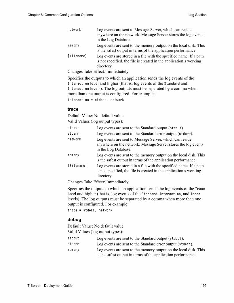
T-Server—Deployment Guide 195
Chapter 8: Common Configuration Options Log Section
Changes Take Effect: Immediately
Specifies the outputs to which an application sends the log events of the Interaction level and higher (that is, log events of the Standard and Interaction levels). The log outputs must be separated by a comma when more than one output is configured. For example:interaction = stderr, network
traceDefault Value: No default valueValid Values (log output types):
Changes Take Effect: Immediately
Specifies the outputs to which an application sends the log events of the Trace level and higher (that is, log events of the Standard, Interaction, and Trace levels). The log outputs must be separated by a comma when more than one output is configured. For example:trace = stderr, network
debugDefault Value: No default valueValid Values (log output types):
network Log events are sent to Message Server, which can reside anywhere on the network. Message Server stores the log events in the Log Database.
memory Log events are sent to the memory output on the local disk. This is the safest output in terms of the application performance.
[filename] Log events are stored in a file with the specified name. If a path is not specified, the file is created in the application’s working directory.
stdout Log events are sent to the Standard output (stdout).stderr Log events are sent to the Standard error output (stderr).network Log events are sent to Message Server, which can reside
anywhere on the network. Message Server stores the log events in the Log Database.
memory Log events are sent to the memory output on the local disk. This is the safest output in terms of the application performance.
[filename] Log events are stored in a file with the specified name. If a path is not specified, the file is created in the application’s working directory.
stdout Log events are sent to the Standard output (stdout).stderr Log events are sent to the Standard error output (stderr).memory Log events are sent to the memory output on the local disk. This
is the safest output in terms of the application performance.
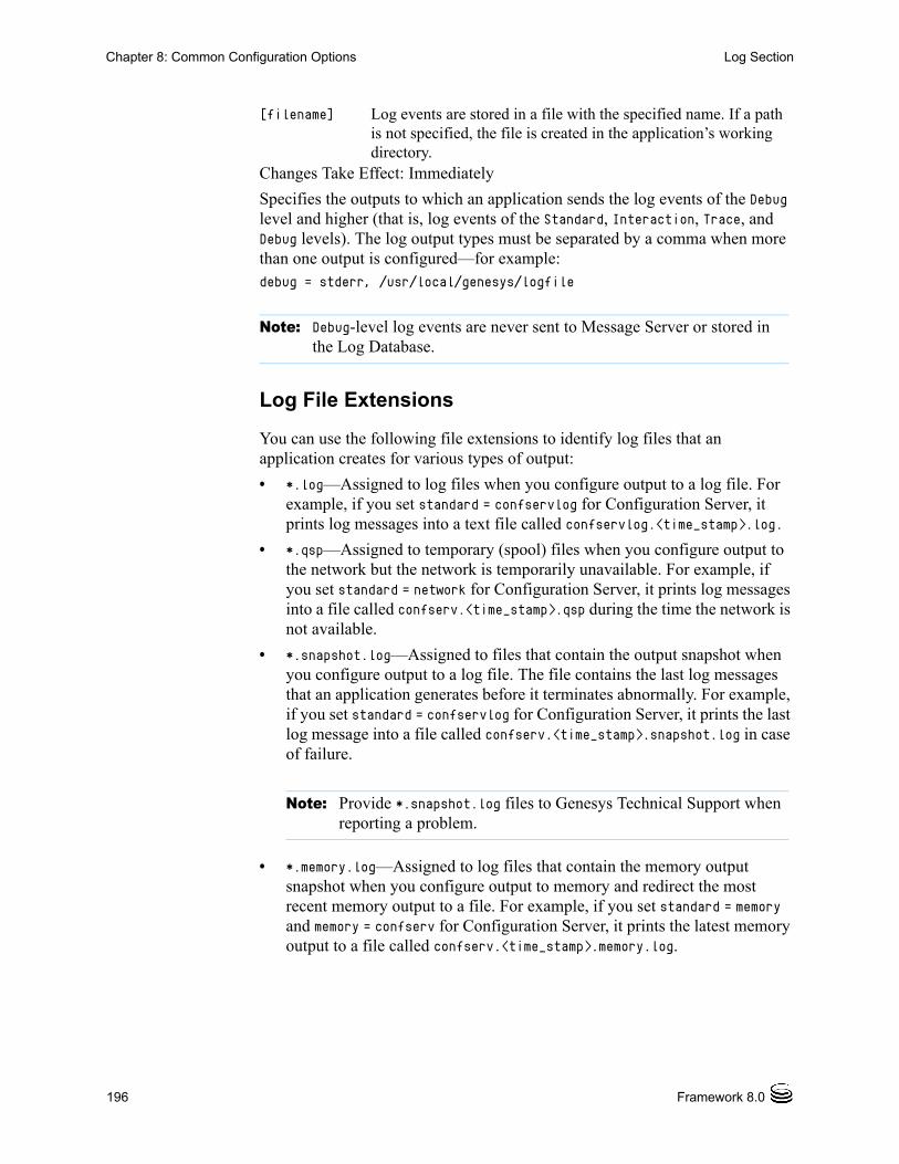
196 Framework 8.0
Chapter 8: Common Configuration Options Log Section
Changes Take Effect: Immediately
Specifies the outputs to which an application sends the log events of the Debug level and higher (that is, log events of the Standard, Interaction, Trace, and Debug levels). The log output types must be separated by a comma when more than one output is configured—for example:debug = stderr, /usr/local/genesys/logfile
Log File Extensions
You can use the following file extensions to identify log files that an application creates for various types of output:
• *.log—Assigned to log files when you configure output to a log file. For example, if you set standard = confservlog for Configuration Server, it prints log messages into a text file called confservlog.<time_stamp>.log.
• *.qsp—Assigned to temporary (spool) files when you configure output to the network but the network is temporarily unavailable. For example, if you set standard = network for Configuration Server, it prints log messages into a file called confserv.<time_stamp>.qsp during the time the network is not available.
• *.snapshot.log—Assigned to files that contain the output snapshot when you configure output to a log file. The file contains the last log messages that an application generates before it terminates abnormally. For example, if you set standard = confservlog for Configuration Server, it prints the last log message into a file called confserv.<time_stamp>.snapshot.log in case of failure.
• *.memory.log—Assigned to log files that contain the memory output snapshot when you configure output to memory and redirect the most recent memory output to a file. For example, if you set standard = memory and memory = confserv for Configuration Server, it prints the latest memory output to a file called confserv.<time_stamp>.memory.log.
[filename] Log events are stored in a file with the specified name. If a path is not specified, the file is created in the application’s working directory.
Note: Debug-level log events are never sent to Message Server or stored in the Log Database.
Note: Provide *.snapshot.log files to Genesys Technical Support when reporting a problem.
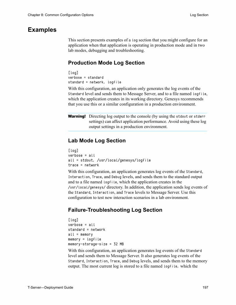
T-Server—Deployment Guide 197
Chapter 8: Common Configuration Options Log Section
Examples
This section presents examples of a log section that you might configure for an application when that application is operating in production mode and in two lab modes, debugging and troubleshooting.
Production Mode Log Section
[log]verbose = standardstandard = network, logfile
With this configuration, an application only generates the log events of the Standard level and sends them to Message Server, and to a file named logfile, which the application creates in its working directory. Genesys recommends that you use this or a similar configuration in a production environment.
Lab Mode Log Section
[log]verbose = allall = stdout, /usr/local/genesys/logfiletrace = network
With this configuration, an application generates log events of the Standard, Interaction, Trace, and Debug levels, and sends them to the standard output and to a file named logfile, which the application creates in the /usr/local/genesys/ directory. In addition, the application sends log events of the Standard, Interaction, and Trace levels to Message Server. Use this configuration to test new interaction scenarios in a lab environment.
Failure-Troubleshooting Log Section
[log]verbose = allstandard = networkall = memorymemory = logfilememory-storage-size = 32 MB
With this configuration, an application generates log events of the Standard level and sends them to Message Server. It also generates log events of the Standard, Interaction, Trace, and Debug levels, and sends them to the memory output. The most current log is stored to a file named logfile, which the
Warning! Directing log output to the console (by using the stdout or stderr settings) can affect application performance. Avoid using these log output settings in a production environment.
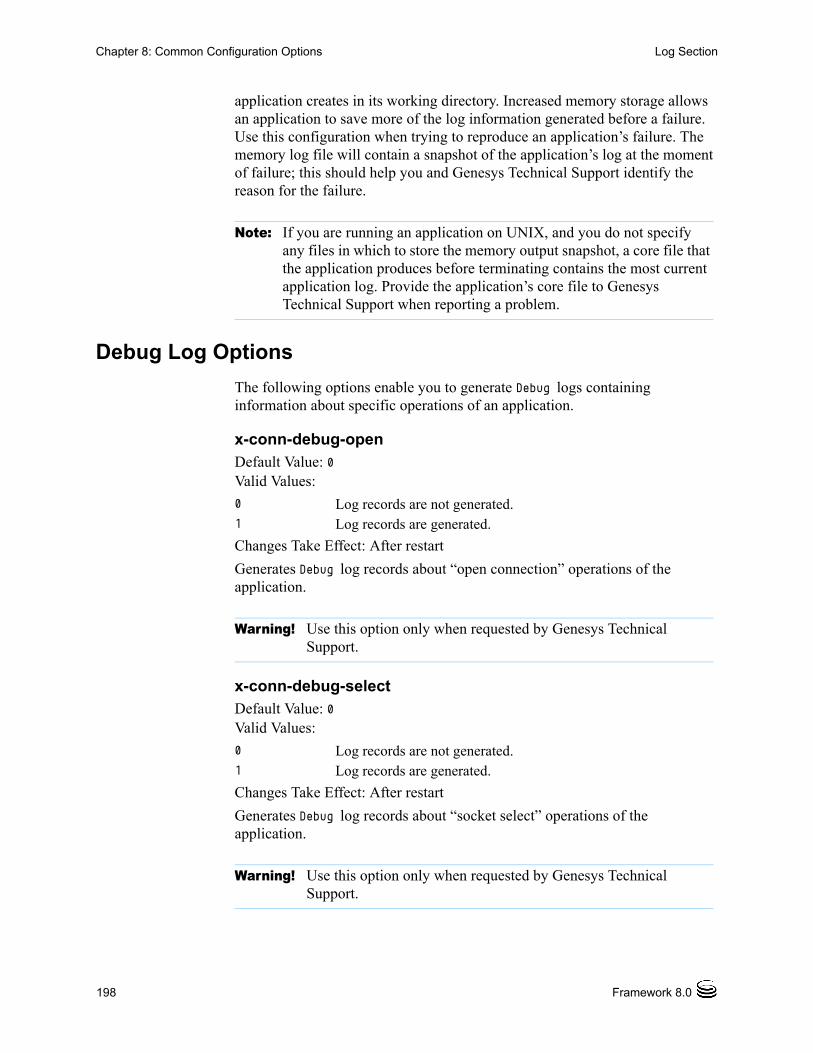
198 Framework 8.0
Chapter 8: Common Configuration Options Log Section
application creates in its working directory. Increased memory storage allows an application to save more of the log information generated before a failure. Use this configuration when trying to reproduce an application’s failure. The memory log file will contain a snapshot of the application’s log at the moment of failure; this should help you and Genesys Technical Support identify the reason for the failure.
Debug Log Options
The following options enable you to generate Debug logs containing information about specific operations of an application.
x-conn-debug-openDefault Value: 0Valid Values:
Changes Take Effect: After restart
Generates Debug log records about “open connection” operations of the application.
x-conn-debug-selectDefault Value: 0Valid Values:
Changes Take Effect: After restart
Generates Debug log records about “socket select” operations of the application.
Note: If you are running an application on UNIX, and you do not specify any files in which to store the memory output snapshot, a core file that the application produces before terminating contains the most current application log. Provide the application’s core file to Genesys Technical Support when reporting a problem.
0 Log records are not generated. 1 Log records are generated.
Warning! Use this option only when requested by Genesys Technical Support.
0 Log records are not generated. 1 Log records are generated.
Warning! Use this option only when requested by Genesys Technical Support.
T-Server—Deployment Guide 199
Chapter 8: Common Configuration Options Log Section
x-conn-debug-timersDefault Value: 0Valid Values:
Changes Take Effect: After restart
Generates Debug log records about the timer creation and deletion operations of the application.
x-conn-debug-writeDefault Value: 0Valid Values:
Changes Take Effect: After restart
Generates Debug log records about “write” operations of the application.
x-conn-debug-securityDefault Value: 0Valid Values:
Changes Take Effect: After restart
Generates Debug log records about security-related operations, such as Transport Layer Security and security certificates.
x-conn-debug-apiDefault Value: 0Valid Values:
Changes Take Effect: After restart
0 Log records are not generated. 1 Log records are generated.
Warning! Use this option only when requested by Genesys Technical Support.
0 Log records are not generated. 1 Log records are generated.
Warning! Use this option only when requested by Genesys Technical Support.
0 Log records are not generated. 1 Log records are generated.
Warning! Use this option only when requested by Genesys Technical Support.
0 Log records are not generated. 1 Log records are generated.
200 Framework 8.0
Chapter 8: Common Configuration Options Log-Extended Section
Generates Debug log records about connection library function calls.
x-conn-debug-dnsDefault Value: 0Valid Values:
Changes Take Effect: After restart
Generates Debug log records about DNS operations.
x-conn-debug-allDefault Value: 0Valid Values:
Changes Take Effect: After restart
Generates Debug log records about open connection, socket select, timer creation and deletion, write, security-related, and DNS operations, and connection library function calls. This option is the same as enabling or disabling all of the previous x-conn-debug-<op type> options.
Log-Extended SectionThis section must be called log-extended.
level-reassign-<eventID>Default Value: Default value of log event <eventID> Valid Values:
Warning! Use this option only when requested by Genesys Technical Support.
0 Log records are not generated. 1 Log records are generated.
Warning! Use this option only when requested by Genesys Technical Support.
0 Log records are not generated. 1 Log records are generated.
Warning! Use this option only when requested by Genesys Technical Support.
alarm The log level of log event <eventID> is set to Alarm. standard The log level of log event <eventID> is set to Standard.interaction The log level of log event <eventID> is set to Interaction.
T-Server—Deployment Guide 201
Chapter 8: Common Configuration Options Log-Extended Section
Changes Take Effect: Immediately
Specifies a log level for log event <eventID> that is different than its default level, or disables log event <eventID> completely. If no value is specified, the log event retains its default level. This option is useful when you want to customize the log level for selected log events.
These options can be deactivated with the option level-reassign-disable.
In addition to the preceding warning, take note of the following:
• Logs can be customized only by release 7.6 or later applications.
• When the log level of a log event is changed to any level except none, it is subject to the other settings in the [log] section at its new level. If set to none, it is not logged and is therefore not subject to any log configuration.
• Using this feature to change the log level of a log changes only its priority; it does not change how that log is treated by the system. For example, increasing the priority of a log to Alarm level does not mean that an alarm will be associated with it.
• Each application in a High Availability (HA) pair can define its own unique set of log customizations, but the two sets are not synchronized with each other. This can result in different log behavior depending on which application is currently in primary mode.
• This feature is not the same as a similar feature in Universal Routing Server (URS) release 7.2 or later. In this Framework feature, the priority of log events are customized. In the URS feature, the priority of debug messages only are customized. Refer to the Universal Routing Reference Manual for more information about the URS feature.
• You cannot customize any log event that is not in the unified log record format. Log events of the Alarm, Standard, Interaction, and Trace levels feature the same unified log record format.
trace The log level of log event <eventID> is set to Trace.debug The log level of log event <eventID> is set to Debug.none Log event <eventID> is not recorded in a log.
Warning! Use caution when making these changes in a production environment.
Depending on the log configuration, changing the log level to a higher priority may cause the log event to be logged more often or to a greater number of outputs. This could affect system performance.
Likewise, changing the log level to a lower priority may cause the log event to be not logged at all, or to be not logged to specific outputs, thereby losing important information. The same applies to any alarms associated with that log event.
202 Framework 8.0
Chapter 8: Common Configuration Options Log-Filter Section
Example
This is an example of using customized log level settings, subject to the following log configuration:
[log]verbose=interactionall=stderrinteraction=log_filestandard=network
Before the log levels of the log are changed:
• Log event 1020, with default level standard, is output to stderr and log_file, and sent to Message Server.
• Log event 2020, with default level standard, is output to stderr and log_file, and sent to Message Server.
• Log event 3020, with default level trace, is output to stderr.
• Log event 4020, with default level debug, is output to stderr.
Extended log configuration section:
[log-extended]level-reassign-1020=nonelevel-reassign-2020=interactionlevel-reassign-3020=interactionlevel-reassign-4020=standard
After the log levels are changed:
• Log event 1020 is disabled and not logged.
• Log event 2020 is output to stderr and log_file.
• Log event 3020 is output to stderr and log_file.
• Log event 4020 is output to stderr and log_file, and sent to Message Server.
level-reassign-disableDefault Value: falseValid Values: true, falseChanges Take Effect: Immediately
When this option is set to true, the original (default) log level of all log events in the [log-extended] section are restored. This option is useful when you want to use the default levels, but not delete the customization statements.
Log-Filter SectionThe log-filter section contains configuration options used to define the default treatment of filtering data in logs. This section contains one configuration option, default-filter-type. Refer to the chapter “Hide
T-Server—Deployment Guide 203
Chapter 8: Common Configuration Options Log-Filter-Data Section
Selected Data in Logs” in the Genesys 8.0 Security Deployment Guide for complete information about this option.
Log-Filter-Data SectionThe log-filter-data section contains configuration options used to define the treatment of filtering data in logs on a key-by-key basis. This section contains one configuration option in the form of <key name>. Refer to the chapter “Hide Selected Data in Logs” in the Genesys 8.0 Security Deployment Guide for complete information about this option.
SML SectionThis section must be called sml.
suspending-wait-timeoutDefault Value: 10Valid Values: 5-600Changes Take Effect: Immediately
Specifies a timeout (in seconds) after the Stop Graceful command is issued to an application during which the status of the application should change to Suspending if the application supports graceful shutdown. If the status of the application does not change to Suspending before the timeout expires, it is assumed that the application does not support graceful shutdown, and it is stopped ungracefully.
Use this option if you are unsure whether the Application supports graceful shutdown.
Common SectionThis section must be called common.
enable-async-dnsDefault Value: off
Note: This option is defined in the Application object, as follows:• in Configuration Manager— Application object > Properties
dialog box > Annex tab
204 Framework 8.0
Chapter 8: Common Configuration Options Common Section
Valid Values:
Changes Take Effect: Immediately
Enables the asynchronous processing of DNS requests such as, for example, host-name resolution.
rebind-delayDefault Value: 10Valid Values: 0–600Changes Take Effect: After restart
Specifies the delay, in seconds, between socket-bind operations that are being executed by the server. Use this option if the server has not been able to successfully occupy a configured port.
off Disables asynchronous processing of DNS requests.on Enables asynchronous processing of DNS requests.
Warnings! • Use this option only when requested by Genesys Technical Support.
• Use this option only with T-Servers.
Warning! Use this option only when requested by Genesys Technical Support.
T-Server—Deployment Guide 205
Chapter
9 T-Server Common Configuration OptionsThis chapter describes the configuration options that are generally common to all T-Server types, with some exceptions noted. It contains the following sections: Setting Configuration Options, page 205 Mandatory Options, page 206 T-Server Section, page 206 License Section, page 211 Agent-Reservation Section, page 214 Multi-Site Support Section, page 215 Translation Rules Section, page 225 Backup-Synchronization Section, page 226 Call-Cleanup Section, page 227 Security Section, page 229 Timeout Value Format, page 229
T-Server also supports common log options described in Chapter 8, “Common Configuration Options,” on page 185.
Setting Configuration OptionsUnless it is specified otherwise, you set configuration options in Configuration Manager in the corresponding sections on the Options tab for the T-Server Application object.
206 Framework 8.0
Chapter 9: T-Server Common Configuration Options Mandatory Options
Mandatory OptionsExcept as noted for certain environments, the configuration of common options is not required for basic T-Server operation.
T-Server SectionThe T-Server section contains the configuration options that are used to support the core features common to all T-Servers.
TServer This section must be called TServer.
ani-distributionDefault Value: inbound-calls-onlyValid Values: inbound-calls-only, all-calls, suppressedChanges Take Effect: Immediately
Controls the distribution of the ANI information in TEvent messages. When this option is set to all-calls, the ANI attribute will be reported for all calls for which it is available. When this option is set to suppressed, the ANI attribute will not be reported for any calls. When this option is set to inbound-calls-only, the ANI attribute will be reported for inbound calls only.
background-processingDefault Value: falseValid Values: true, falseChanges Take Effect: Immediately
When set to true, T-Server processes all client requests in the background, giving higher priority to the rest of the messages. This ensures that it processes these messages without any significant delay.
With Background Processing functionality enabled, T-Server processes all switch messages immediately and waits until there are no switch messages before processing the message queue associated with T-Server client requests. T-Server reads all connection sockets immediately and places client requests in the input buffer, which prevents T-Server clients from disconnecting because of configured timeouts.
When T-Server processes client requests from the message queue, requests are processed in the order in which T-Server received them.
When set to false, T-Server processes multiple requests from one T-Server client before proceeding to the requests from another T-Server client, and so on.
Note: Use of this option can negatively impact T-Server processing speed.
Chapter 9: T-Server Common Configuration Options T-Server Section
T-Server—Deployment Guide 207
background-timeoutDefault Value: 60 msecValid Values: See “Timeout Value Format” on page 229.Changes Take Effect: Immediately
Specifies the time interval that T-Server waits before processing client requests in background mode. You must set the background-processing option to true in order for this option to take effect.
check-tenant-profileDefault Value: falseValid Values: true, falseChanges Take Effect: For the next connected client
When set to true, T-Server checks whether a client provides the correct name and password of a tenant. If it does, T-Server allows that client to register DNs that are included in the switch configuration in the Configuration Database, but it does not allow the client to register DNs that are not included in the switch configuration.
consult-user-dataDefault Value: separateValid Values:
Changes Take Effect: For the next consultation call created
separate Stores user data for original and consultation calls in separate structures. The data attached to the original call is available for review or changes only to the parties of that call. The data attached to the consultation call is available only to the parties of the consultation call.
inherited Copies user data from an original call to a consultation call when the consultation call is created; thereafter, stores user data separately for the original and the consultation call. Changes to the original call’s user data are not available to the parties of the consultation call, and vice versa.
joint Stores user data for an original call and a consultation call in one structure. The user data structure is associated with the original call, but the parties of both the original and consultation calls can see and make changes to the common user data.
208 Framework 8.0
Chapter 9: T-Server Common Configuration Options T-Server Section
Specifies the method for handling user data in a consultation call.
customer-idDefault Value: No default value. (A value must be specified for a multi-tenant environment.)Valid Values: Any character stringChanges Take Effect: Immediately
Identifies the T-Server customer. You must set this option to the name of the tenant that is using this T-Server. You must specify a value for this option if you are working in a multi-tenant environment.
dn-scopeDefault Value: undefinedValid Values: undefined, switch, office, tenant
Specifies whether DNs associated with the Switch, Switching Office, or Tenant objects will be considered in the T-Server monitoring scope, enabling T-Server to report calls to or from those DNs as internal.
With a value of tenant, all DNs associated with the switches that are within the Tenant will be in the T-Server monitoring scope. With a value of office, all DNs associated with the switches that are within the Switching Office will be in the T-Server monitoring scope. With a value of switch, all DNs associated with the Switch will be in the T-Server monitoring scope.
With a value of undefined (the default), pre-8.0 T-Server behavior applies.
Note: A T-Server client can also specify the consult-user-data mode in the Extensions attribute ConsultUserData key for a conference or transfer request. If it is specified, the method of handling user data is based on the value of the ConsultUserData key-value pair of the request and takes precedence over the T-Server consult-user-data option. If it is not specified in the client request, the value specified in the consult-user-data option applies.
Note: Do not configure the customer-id option for single-tenant environments.
Note: Setting the option to a value of office or tenant, which requires T-Server to monitor a large set of configuration data, may negatively affect T-Server performance.
Chapter 9: T-Server Common Configuration Options T-Server Section
T-Server—Deployment Guide 209
log-trace-flagsDefault Value: +iscc, +cfg$dn, -cfgserv, +passwd, +udata, -devlink, -sw,
-req, -callops, -conn, -client
Valid Values (in any combination):
Changes Take Effect: Immediately
Specifies—using a space-, comma- or semicolon-separated list—the types of information that are written to the log files.
management-portDefault Value: 0Valid Values: 0 or any valid TCP/IP portChanges Take Effect: After T-Server is restarted
Specifies the TCP/IP port that management agents use to communicate with T-Server. If set to 0 (zero), this port is not used.
merged-user-dataDefault Value: main-onlyValid Values:
Changes Take Effect: Immediately
+/-iscc Turns on/off the writing of information about Inter Server Call Control (ISCC) transactions.
+/-cfg$dn Turns on/off the writing of information about DN configuration.
+/-cfgserv Turns on/off the writing of messages from Configuration Server.
+/-passwd Turns on/off the writing of AttributePassword in TEvents.+/-udata Turns on/off the writing of attached data.+/-devlink Turns on/off the writing of information about the link used to
send CTI messages to the switch (for multilink environments).+/-sw Reserved by Genesys Engineering.+/-req Reserved by Genesys Engineering.+/-callops Reserved by Genesys Engineering.+/-conn Reserved by Genesys Engineering.+/-client Turns on/off the writing of additional information about the
client’s connection.
main-only T-Server attaches user data from the remaining call only.merged-only T-Server attaches user data from the merging call. merged-over-main T-Server attaches user data from the remaining and the
merging call. In the event of equal keys, T-Server uses data from the merging call.
main-over-merged T-Server attaches data from the remaining and the merging call. In the event of equal keys, T-Server uses data from the remaining call.
210 Framework 8.0
Chapter 9: T-Server Common Configuration Options T-Server Section
Specifies the data that is attached to the resulting call after a call transfer, conference, or merge completion.
propagated-call-typeDefault Value: falseValid Values: true, falseChanges Take Effect: Immediately
When set to false, T-Server reports a value in the CallType attribute as it did in pre-8.0 releases and extends distribution of call-related TEvents that contain the PropagatedCallType attribute (if known). This provides backward compatibility with existing T-Server clients.
When set to true, T-Server extends distribution of call-related TEvents that contain a call type value in the LocalCallType attribute (as in a single-site T-Server deployment) and replaces the value of the regular CallType attribute with the PropagatedCallType value.
server-idDefault Value: An integer equal to the value ApplicationDBID as reported by Configuration ServerValid Values: Any integer from 0–16383Changes Take Effect: Immediately
Specifies the Server ID that T-Server uses to generate Connection IDs and other unique identifiers. In a multi-site environment, you must assign each T-Server a unique Server ID, in order to avoid confusion in reporting applications and T-Server behavior.
Configuration of this option is necessary for Framework environments in which there are two or more instances of the Configuration Database.
Note: The option setting does not affect the resulting data for merging calls if the consult-user-data option is set to joint. (See “consult-user-data” on page 207.)
Note: If you do not specify a value for this option, T-Server populates it with the ApplicationDBID as reported by Configuration Server. Each data object in the Configuration Database is assigned a separate DBID that maintains a unique Server ID for each T-Server configured in the database.
Warning! Genesys does not recommend using multiple instances of the Configuration Database.
Chapter 9: T-Server Common Configuration Options License Section
T-Server—Deployment Guide 211
user-data-limitDefault Value: 16000Valid Values: 0–65535 Changes Take Effect: Immediately
Specifies the maximum size (in bytes) of user data in a packed format.
License SectionThe License section contains the configuration options that are used to configure T-Server licenses. They set the upper limit of the seat-related DN licenses (tserver_sdn) that T-Server tries to check out from a license file. See “License Checkout” on page 212.
license This section must be called license.
If you use two or more T-Servers, and they share licenses, you must configure the following options in the license section of the T-Servers.
num-of-licensesDefault Value: 0 or max (all available licenses)Valid Values: 0 or string maxChanges Take Effect: Immediately
Specifies how many DN licenses T-Server checks out. T-Server treats a value of 0 (zero) the same as it treats max—that is, it checks out all available licenses.
The sum of all num-of-licenses values for all concurrently deployed T-Servers must not exceed the number of seat-related DN licenses (tserver_sdn) in the corresponding license file. The primary and backup T-Servers share the same licenses, and therefore they need to be counted only once. T-Server checks out the number of licenses indicated by the value for this option, regardless of the number actually in use.
Note: When T-Server works in mixed 8.x/7.x/6.x environment, the value of this option must not exceed the default value of 16000 bytes; otherwise, 6.x T-Server clients might fail.
Notes: T-Server also supports the license-file option described in the Genesys Licensing Guide.
The license section is not applicable to Network T-Server for DTAG.
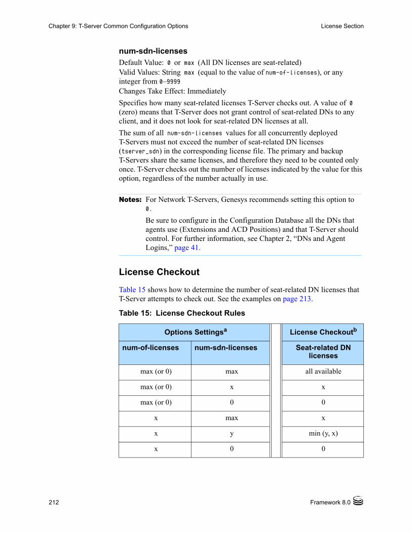
212 Framework 8.0
Chapter 9: T-Server Common Configuration Options License Section
num-sdn-licensesDefault Value: 0 or max (All DN licenses are seat-related)Valid Values: String max (equal to the value of num-of-licenses), or any integer from 0–9999Changes Take Effect: Immediately
Specifies how many seat-related licenses T-Server checks out. A value of 0 (zero) means that T-Server does not grant control of seat-related DNs to any client, and it does not look for seat-related DN licenses at all.
The sum of all num-sdn-licenses values for all concurrently deployed T-Servers must not exceed the number of seat-related DN licenses (tserver_sdn) in the corresponding license file. The primary and backup T-Servers share the same licenses, and therefore they need to be counted only once. T-Server checks out the number of licenses indicated by the value for this option, regardless of the number actually in use.
License Checkout
Table 15 shows how to determine the number of seat-related DN licenses that T-Server attempts to check out. See the examples on page 213.
Notes: For Network T-Servers, Genesys recommends setting this option to 0.
Be sure to configure in the Configuration Database all the DNs that agents use (Extensions and ACD Positions) and that T-Server should control. For further information, see Chapter 2, “DNs and Agent Logins,” page 41.
Table 15: License Checkout Rules
Options Settingsa License Checkoutb
num-of-licenses num-sdn-licenses Seat-related DN licenses
max (or 0) max all available
max (or 0) x x
max (or 0) 0 0
x max x
x y min (y, x)
x 0 0
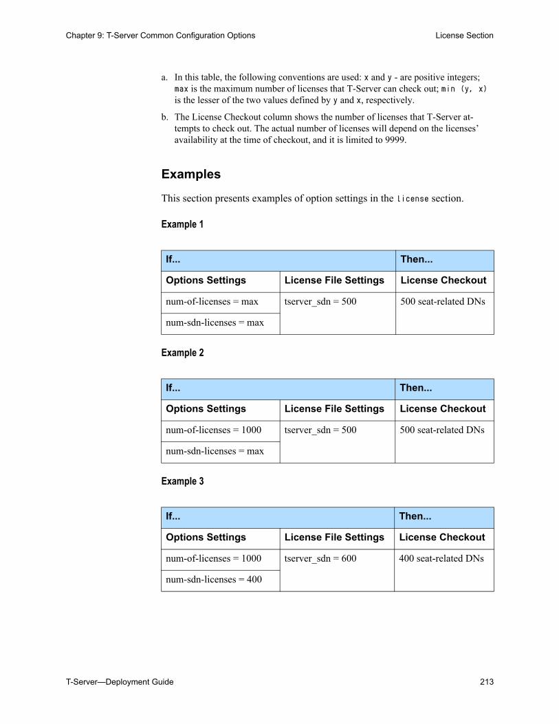
Chapter 9: T-Server Common Configuration Options License Section
T-Server—Deployment Guide 213
Examples
This section presents examples of option settings in the license section.
Example 1
Example 2
Example 3
a. In this table, the following conventions are used: x and y - are positive integers; max is the maximum number of licenses that T-Server can check out; min (y, x) is the lesser of the two values defined by y and x, respectively.
b. The License Checkout column shows the number of licenses that T-Server at-tempts to check out. The actual number of licenses will depend on the licenses’ availability at the time of checkout, and it is limited to 9999.
If... Then...
Options Settings License File Settings License Checkout
num-of-licenses = max tserver_sdn = 500 500 seat-related DNs
num-sdn-licenses = max
If... Then...
Options Settings License File Settings License Checkout
num-of-licenses = 1000 tserver_sdn = 500 500 seat-related DNs
num-sdn-licenses = max
If... Then...
Options Settings License File Settings License Checkout
num-of-licenses = 1000 tserver_sdn = 600 400 seat-related DNs
num-sdn-licenses = 400
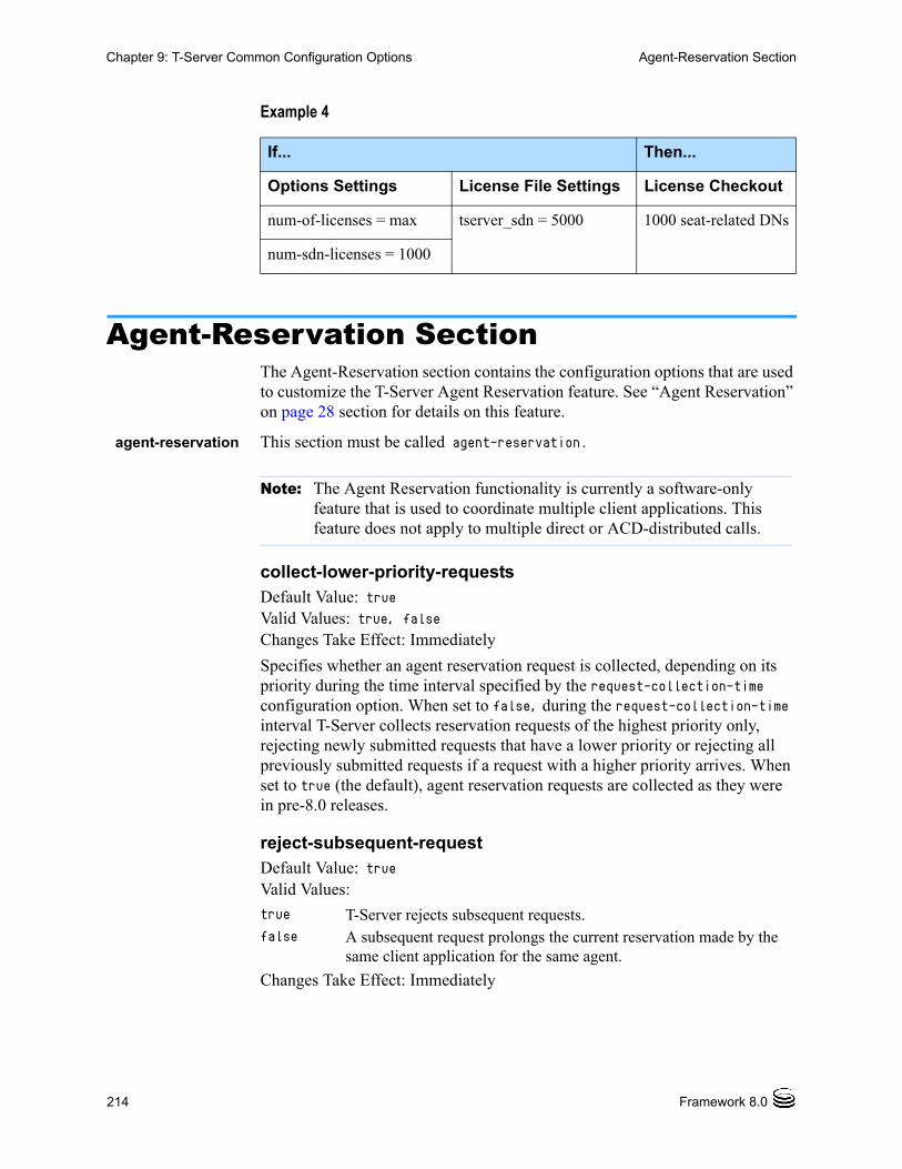
214 Framework 8.0
Chapter 9: T-Server Common Configuration Options Agent-Reservation Section
Example 4
Agent-Reservation SectionThe Agent-Reservation section contains the configuration options that are used to customize the T-Server Agent Reservation feature. See “Agent Reservation” on page 28 section for details on this feature.
agent-reservation This section must be called agent-reservation.
collect-lower-priority-requestsDefault Value: trueValid Values: true, falseChanges Take Effect: Immediately
Specifies whether an agent reservation request is collected, depending on its priority during the time interval specified by the request-collection-time configuration option. When set to false, during the request-collection-time interval T-Server collects reservation requests of the highest priority only, rejecting newly submitted requests that have a lower priority or rejecting all previously submitted requests if a request with a higher priority arrives. When set to true (the default), agent reservation requests are collected as they were in pre-8.0 releases.
reject-subsequent-requestDefault Value: trueValid Values:
Changes Take Effect: Immediately
If... Then...
Options Settings License File Settings License Checkout
num-of-licenses = max tserver_sdn = 5000 1000 seat-related DNs
num-sdn-licenses = 1000
Note: The Agent Reservation functionality is currently a software-only feature that is used to coordinate multiple client applications. This feature does not apply to multiple direct or ACD-distributed calls.
true T-Server rejects subsequent requests.false A subsequent request prolongs the current reservation made by the
same client application for the same agent.
Chapter 9: T-Server Common Configuration Options Multi-Site Support Section
T-Server—Deployment Guide 215
Specifies whether T-Server rejects subsequent requests from the same client application, for an agent reservation for the same Agent object that is currently reserved.
request-collection-timeDefault Value: 100 msecValid Values: See “Timeout Value Format” on page 229.Changes Take Effect: Immediately
Specifies the interval that agent reservation requests are collected before a reservation is granted. During this interval, agent reservation requests are delayed, in order to balance successful reservations between client applications (for example, Universal Routing Servers).
reservation-timeDefault Value: 10000 msecValid Values: See “Timeout Value Format” on page 229.Changes Take Effect: Immediately
Specifies the default interval for which a an Agent DN is reserved. During this interval, the agent cannot be reserved again.
Multi-Site Support SectionThe Multi-Site Support section contains the configuration options that are used to support multi-site environments with the Inter Server Call Control (ISCC) feature. The configuration options in this section of the document are grouped with related options that support the same functionality, as follows: ISCC Transaction Options, page 217 Transfer Connect Service Options, page 221 ISCC/COF Options, page 222 Event Propagation Options, page 224 Number Translation Option, page 225
extrouter This configuration section must be called extrouter.
Note: Genesys does not recommend setting this option to false in a multi-site environment in which remote locations use the Agent-Reservation feature.
216 Framework 8.0
Chapter 9: T-Server Common Configuration Options Multi-Site Support Section
For a description of the ways in which T-Server supports multi-site configurations and for an explanation of the configuration possibilities for a multi-site operation, see the “Multi-Site Support” chapter.
match-call-onceDefault Value: trueValid Values:
Changes Take Effect: Immediately
Specifies how many times ISCC processes an inbound call when it arrives at an ISCC resource. When set to false, ISCC processes (attempts to match) the call even if it has already been processed.
reconnect-toutDefault Value: 5 secValid Values: See “Timeout Value Format” on page 229.Changes Take Effect: At the next reconnection attempt
Specifies the time interval after which a remote T-Server attempts to connect to this T-Server after an unsuccessful attempt or a lost connection. The number of attempts is unlimited. At startup, T-Server immediately attempts the first connection, without this timeout.
report-connid-changesDefault Value: falseValid Values:
Changes Take Effect: Immediately
Note: In a multi-site environment, you must configure the timeout, cast-type, and default-dn options with the same value for both the primary and backup T-Servers. If you do not do this, the value specified for the backup T-Server overrides the value specified for the primary T-Server.
true ISCC does not process (match) an inbound call that has already been processed (matched).
false ISCC processes (attempts to match) a call as many times as it arrives at an ISCC resource or multi-site-transfer target.
Note: Genesys does not recommend changing the default value of the match-call-once option to false unless you have specific reasons. Setting this option to false may lead to excessive or inconsistent call data updates.
true EventPartyChanged is generated.false EventPartyChanged is not generated.
Chapter 9: T-Server Common Configuration Options Multi-Site Support Section
T-Server—Deployment Guide 217
Specifies whether the destination T-Server generates EventPartyChanged for the incoming call when the resulting ConnID attribute is different from the ConnID attribute of an instance of the same call at the origination location.
use-data-fromDefault Value: currentValid Values:
Changes Take Effect: Immediately
Specifies the call from which the values for the UserData and ConnID attributes are taken for a consultation call that is routed or transferred to a remote location.
ISCC Transaction Options
cast-typeDefault Value: route, route-uui, reroute, direct-callid, direct-uui,
direct-network-callid, direct-notoken, direct-digits,
direct-ani, dnis-pool, pullback
Valid Values: route, route-uui, reroute, direct-callid, direct-uui,
direct-network-callid, direct-notoken, direct-digits,
direct-ani, dnis-pool, pullback
Changes Take Effect: For the next request for the remote service
Specifies—using a space-, comma- or semicolon-separated list—the routing types that can be performed for this T-Server.
active The values of UserData and ConnID attributes are taken from the consultation call.
original The values of UserData and ConnID attributes are taken from the original call.
active-data-original-call
The value of the UserData attribute is taken from the consultation call and the value of ConnID attribute is taken from the original call.
current If the value of current is specified, the following occurs:
• Before the transfer or conference is completed, the UserData and ConnID attributes are taken from the consultation call.
• After the transfer or conference is completed, EventPartyChanged is generated, and the UserData and ConnID are taken from the original call.
Note: For compatibility with the previous T-Server releases, you can use the values consult, main, and consult-user-data for this option. These are aliases for active, original, and current, respectively.
218 Framework 8.0
Chapter 9: T-Server Common Configuration Options Multi-Site Support Section
The valid values provide for a range of mechanisms that the ISCC feature can support with various T-Servers, in order to pass call data along with calls between locations.
Because switches of different types provide calls with different sets of information parameters, some values might not work with your T-Server. See Table 3 on page 79 for information about supported transaction types by a specific T-Server. The “Multi-Site Support” chapter also provides detailed descriptions of all transaction types.
default-dnDefault Value: No default valueValid Values: Any DNChanges Take Effect: For the next request for the remote service
Specifies the DN to which a call is routed when a Destination DN (AttributeOtherDN) is not specified in the client’s request for routing. If neither this option nor the client’s request contains the destination DN, the client receives EventError.
direct-digits-keyDefault Value: CDT_Track_NumValid Values: Any valid key name of a key-value pair from the UserData attributeChanges Take Effect: For the next request for the remote service
Specifies the name of a key from the UserData attribute that contains a string of digits that are used as matching criteria for remote service requests with the direct-digits routing type.
dn-for-unexpected-callsDefault Value: No default valueValid Values: Any DNChanges Take Effect: Immediately
Notes: For compatibility with the previous T-Server releases, you can use the direct value for this option. This is an alias for direct-callid.
An alias, route-notoken, has been added to the route value.
Note: This option is used only for requests with route types route, route-uui, direct-callid, direct-network-callid, direct-uui,
direct-notoken, direct-digits, and direct-ani.
Note: For compatibility with the previous T-Server releases, this configuration option has an alias value of cdt-udata-key.
Chapter 9: T-Server Common Configuration Options Multi-Site Support Section
T-Server—Deployment Guide 219
Specifies a default DN for unexpected calls arriving on an External Routing Point.
network-request-timeoutDefault Value: 20 secValid Values: See “Timeout Value Format” on page 229.Changes Take Effect: For the next network request
For a premise T-Server, this option specifies the time interval that the premise T-Server waits for a response, after relaying a TNetwork<...> request to the Network T-Server. For a Network T-Server, this option specifies the time interval that the Network T-Server waits for a response from an SCP (Service Control Point), after initiating the processing of the request by the SCP.
When the allowed time expires, the T-Server cancels further processing of the request and generates EventError.
register-attemptsDefault Value: 5Valid Values: Any positive integerChanges Take Effect: For the next registration
Specifies the number of attempts that T-Server makes to register a dedicated External Routing Point.
register-toutDefault Value: 2 secValid Values: See “Timeout Value Format” on page 229.Changes Take Effect: For the next registration
Specifies the time interval after which T-Server attempts to register a dedicated External Routing Point. Counting starts when the attempt to register a Routing Point fails.
request-toutDefault Value: 20 secValid Values: See “Timeout Value Format” on page 229.Changes Take Effect: For the next request for remote service
Specifies the time interval that a T-Server at the origination location waits for a notification of routing service availability from the destination location. Counting starts when the T-Server sends a request for remote service to the destination site.
resource-allocation-modeDefault Value: circular
220 Framework 8.0
Chapter 9: T-Server Common Configuration Options Multi-Site Support Section
Valid Values:
Changes Take Effect: Immediately
Specifies the manner in which T-Server allocates resources (that is, DNs of the External Routing Point type and Access Resources with Resource Type dnis) for multi-site transaction requests.
resource-load-maximumDefault Value: 0Valid Values: Any positive integerChanges Take Effect: Immediately
Specifies the maximum number of ISCC routing transactions that can be concurrently processed at a single DN of the External Routing Point route type. After a number of outstanding transactions at a particular DN of the External Routing Point type reaches the specified number, T-Server considers the DN not available. Any subsequent request for this DN is queued until the number of outstanding transactions decreases. A value of 0 (zero) means that no limitation is set to the number of concurrent transactions at a single External Routing Point. In addition, the 0 value enables T-Server to perform load balancing of all incoming requests among all available External Routing Points, in order to minimize the load on each DN.
route-dnDefault Value: No default valueValid Values: Any DNChanges Take Effect: Immediately
Specifies the DN that serves as a Routing Point for the route transaction type in the multiple-to-one access mode.
timeoutDefault Value: 60 secValid Values: See “Timeout Value Format” on page 229.Changes Take Effect: For the next request for remote service
home T-Server takes an alphabetized (or numerically sequential) list of configured DNs and reserves the first available DN from the top of the list for each new request. For example, if the first DN is not available, the second DN is allocated for a new request. If the first DN is freed by the time the next request comes, the first DN is allocated for this next request.
circular T-Server takes the same list of configured DNs, but reserves a subsequent DN for each subsequent request. For example, when the first request comes, T-Server allocates the first DN; when the second request comes, T-Server allocates the second DN; and so on. T-Server does not reuse the first DN until reaching the end of the DN list.
Chapter 9: T-Server Common Configuration Options Multi-Site Support Section
T-Server—Deployment Guide 221
Specifies the time interval that the destination T-Server waits for a call routed from the origination location. Counting starts when this T-Server notifies the requesting T-Server about routing service availability. The timeout must be long enough to account for possible network delays in call arrival.
use-implicit-access-numbersDefault Value: falseValid Values: true, falseChanges Take Effect: After T-Server is restarted
Determines whether an External Routing Point in which at least one access number is specified is eligible for use as a resource for calls coming from switches for which an access number is not specified in the External Routing Point. If this option is set to false, the External Routing Point is not eligible for use as a resource for calls coming from such switches. If this option is set to true, an implicit access number for the External Routing Point, composed of the switch access code and the DN number of the External Routing Point, will be used.
Transfer Connect Service Options
tcs-queueDefault Value: No default valueValid Values: Any valid DN numberChanges Take Effect: For the next request for the remote service
Specifies the TCS DN number to which a call, processed by the TCS feature, is dialed after the originating external router obtains an access number. This option applies only if the tcs-use option is activated.
tcs-useDefault Value: neverValid Values:
Changes Take Effect: Immediately
Note: If an External Routing Point does not have an access number specified, this option will not affect its use.
never The TCS feature is not used.always The TCS feature is used for every call.app-defined In order to use the TCS feature for a multi-site call transfer
request, a client application must add a key-value pair with a TC-type key and a nonempty string value to the UserData attribute of the request.
222 Framework 8.0
Chapter 9: T-Server Common Configuration Options Multi-Site Support Section
Specifies whether the Transfer Connect Service (TCS) feature is used.
ISCC/COF Options
cof-ci-defer-createDefault Value: 0Valid Values: See “Timeout Value Format” on page 229.Changes Take Effect: Immediately
Specifies the time interval that T-Server waits for call data from the switch before generating a negative response for a call data request from a remote T-Server. If T-Server detects the matching call before this timeout expires, it sends the requested data. This option applies only if the cof-feature option is set to true.
cof-ci-defer-deleteDefault Value: 0Valid Values: See “Timeout Value Format” on page 229.Changes Take Effect: Immediately
Specifies the time interval that T-Server waits before deleting call data that might be overflowed. If set to 0, deletion deferring is disabled. This option applies only if the cof-feature option is set to true.
cof-ci-req-toutDefault Value: 500 msecValid Values: See “Timeout Value Format” on page 229.Changes Take Effect: For the next COF operation
Specifies the time interval during which T-Server will wait for call data requested with respect to a call originated at another site. After T-Server sends the call data request to remote T-Servers, all events related to this call will be suspended until either the requested call data is received or the specified timeout expires. This option applies only if the cof-feature option is set to true.
cof-ci-wait-allDefault Value: false
Note: For compatibility with the previous T-Server releases, you can use the value up-app-depended for this option. This is an alias for app-defined.
Chapter 9: T-Server Common Configuration Options Multi-Site Support Section
T-Server—Deployment Guide 223
Valid Values:
Changes Take Effect: Immediately
Specifies whether T-Server, after sending a request for matching call data, waits for responses from other T-Servers before updating the call data (such as CallHistory, ConnID, and UserData) for a potentially overflowed call. The waiting period is specified by the cof-ci-req-tout and cof-rci-tout options. This option applies only if the cof-feature option is set to true.
cof-featureDefault Value: falseValid Values: true, falseChanges Take Effect: Immediately
Enables or disables the Inter Server Call Control/Call Overflow (ISCC/COF) feature.
cof-rci-toutDefault Value: 10 secValid Values: See “Timeout Value Format” on page 229.Changes Take Effect: For the next COF operation
Specifies the time interval that T-Server waits for call data from other T-Servers’ transactions. Counting starts when cof-ci-req-tout expires. This option applies only if the cof-feature option is set to true.
local-node-idDefault Value: 0Valid Values: 0 or any positive integerChanges Take Effect: Immediately
This option, if enabled, checks all networked calls against the specified NetworkNodeID (the identity of the switch to which the call initially arrived). If the NetworkNodeID is the same as the value of this option, the request for call information is not sent. The default value of 0 disables the functionality of this option. To establish an appropriate NetworkNodeID, specify a value other than the default. This option applies only if the cof-feature option is set to true.
default-network-call-id-matchingDefault Value: No default value
true T-Server waits for responses from all T-Servers that might have the requested call data before updating the call data with the latest information.
false T-Server updates the call data with the information received from the first positive response.
Note: This option applies only to T-Server for Nortel Communication Server 2000/2100.
224 Framework 8.0
Chapter 9: T-Server Common Configuration Options Multi-Site Support Section
Valid Values: See the “T-Server-Specific Configuration Options” chapter for an option description for your T-ServerChanges Take Effect: Immediately
When a value for this option is specified, T-Server uses the NetworkCallID attribute for the ISCC/COF call matching.
To activate this feature, the cof-feature option must be set to true.
Event Propagation Options
compound-dn-representationDefault Value: trueValid Values: true, falseChanges Take Effect: Immediately
Specifies which format T-Server uses to represent a DN when reporting an OtherDN or ThirdPartyDN attribute in event propagation messages.
When set to true, the <switch>::DN (compound) format is used. This option value supports backward compatibility for pre-8.0 T-Server ISCC/EPP functionality and is provided for multi-site deployments where the same DNs are configured under several switches.
When set to false, the DN (non-compound) format is used. This option value ensures more transparent reporting of OtherDN or ThirdPartyDN attributes and is recommended for all single-site deployments, as well as for multi-site deployments that do not have the same DNs configured under several switches. This option applies only if the event-propagation option is set to list.
epp-toutDefault Value: 0 Valid Values: See “Timeout Value Format” on page 229.Changes Take Effect: Immediately
Specifies the time interval during which T-Server attempts to resolve race conditions that may occur in deployments that use switch partitioning or
Note: SIP Server and several T-Servers support the NetworkCallID attribute for the ISCC/COF call matching in a way that requires setting this option to a specific value. For information about the option value that is specific for your T-Server, see the “T-Server-Specific Configuration Options” chapter of your T-Server Deployment Guide.
Note: Local DNs are always represented in the non-compound (DN) form.
Chapter 9: T-Server Common Configuration Options Translation Rules Section
T-Server—Deployment Guide 225
intelligent trunks. This option applies only if the event-propagation option is set to list.
event-propagationDefault Value: listValid Values:
Changes Take Effect: Immediately
Specifies whether the Event Propagation feature is enabled.
Number Translation Option
inbound-translator-<n>Default Value: No default value.Valid Value: Any valid nameChanges Take Effect: Immediately
Specifies the name of another configuration section as the value for the inbound-translator option. For example, inbound-translator-1 = ani-translator
where ani-translator is the name of the configuration that describes the translation rules for inbound numbers.
Translation Rules SectionThe section name is specified by the inbound-translator-<n> option. It contains options that define translation rules for inbound numbers.
You can choose any name for this section, provided that it matches the value of the section. Every option in this section corresponds to a rule and must conform to the format described below. You can configure as many rules as necessary to accommodate your business needs.
rule-<n>Default Value: No default valueValid Value: Any valid string in the following format:in-pattern=<input pattern value>;out-pattern=<output pattern value>
Note: If the time interval is not long enough to account for possible network switching delays, T-Server may produce duplicated events, such as events that are propagated by the ISCC and generated locally.
list Changes in user data and party events are propagated to remote locations through call distribution topology.
off The feature is disabled. Changes in user data and party events are not propagated to remote locations.
226 Framework 8.0
Chapter 9: T-Server Common Configuration Options Backup-Synchronization Section
Changes Take Effect: Immediately
Defines a rule to be applied to an inbound number. The two parts of the option value describe the input and output patterns in the rule. When configuring the pattern values, follow the syntax defined in “Using ABNF for Rules” on page 88. See “Configuring Number Translation” on page 95 for examples of these rules as well as detailed instructions for creating rules for your installation. For example, a value for this configuration option might look like this:
rule-01 = in-pattern=0111#CABBB*ccD;out-pattern=ABD
Backup-Synchronization SectionThe Backup-Synchronization section contains the configuration options that are used to support a high-availability (hot standby redundancy type) configuration.
backup-sync This section must be called backup-sync.
addp-remote-timeoutDefault Value: 0Valid Values: Any integer from 0–3600Changes Take Effect: Immediately
Specifies the time interval that the redundant T-Server waits for a response from this T-Server after sending a polling signal. The default value of 0 (zero) disables the functionality of this option. To establish an appropriate timeout, specify a value other than the default. This option applies only if the protocol option is set to addp.
addp-timeoutDefault Value: 0Valid Values: Any integer from 0–3600Changes Take Effect: Immediately
Specifies the time interval that this T-Server waits for a response from another T-Server after sending a polling signal. The default value of 0 (zero) disables the functionality of this option. To establish an appropriate timeout, specify a value other than the default. This option applies only if the protocol option is set to addp.
addp-traceDefault Value: off
Note: These options apply only to T-Servers that support the hot standby redundancy type.
Chapter 9: T-Server Common Configuration Options Call-Cleanup Section
T-Server—Deployment Guide 227
Valid Values:
Changes Take Effect: Immediately
Specifies whether addp messages are traced in a log file, to what level the trace is performed, and in which direction. This option applies only if the protocol option is set to addp.
protocolDefault Value: defaultValid Values:
Changes Take Effect: When the next connection is established
Specifies the name of the method used to detect connection failures. If you specify the addp value, you must also specify a value for the addp-timeout, addp-remote-timeout, and addp-trace options.
sync-reconnect-toutDefault Value: 20 secValid Values: See “Timeout Value Format” on page 229.Changes Take Effect: Immediately
Specifies the time interval after which the backup T-Server attempts to reconnect to the primary server (for a synchronized link).
Call-Cleanup SectionThe Call-Cleanup section contains the configuration options that are used to control detection and cleanup of stuck calls in T-Server. For more information on stuck call handling, refer to the “Stuck Call Management” chapter in the Framework 8.0 Management Layer User’s Guide.
call-cleanup This section must be called call-cleanup.
cleanup-idle-toutDefault Value: 0Valid Values: See “Timeout Value Format” on page 229. Changes Take Effect: Immediately
Specifies the time interval that T-Server waits for a call to be updated from its last update. After this time elapses, if no new events about the call are received, T-Server clears this call as a stuck call, either by querying the switch
off, false, no No trace (default).local, on, true, yesTrace on this T-Server side only.remote Trace on the redundant T-Server side only.full, both Full trace (on both sides).
default The feature is not active.addp Activates the Advanced Disconnect Detection Protocol.
228 Framework 8.0
Chapter 9: T-Server Common Configuration Options Call-Cleanup Section
(if a CTI link provides such capabilities) or by deleting the call information from memory unconditionally. The default value of 0 disables the stuck calls cleanup.
notify-idle-toutDefault Value: 0Valid Values: See “Timeout Value Format” on page 229.Changes Take Effect: Immediately
Specifies the time interval that T-Server waits for a call to be updated from its last update. After this time elapses, if no new events about the call are received, T-Server reports this call as a stuck call. The default value of 0 disables the stuck calls notification.
periodic-check-toutDefault Value: 10 minValid Values: See “Timeout Value Format” on page 229.Changes Take Effect: Immediately
Specifies the time interval for periodic checks for stuck calls. These checks affect both notification and cleanup functionality, and are made by checking the T-Server’s own call information with call information available in the switch. For performance reasons, T-Server does not verify whether the notify-idle-tout or cleanup-idle-tout option has expired before performing this check.
Examples
This section presents examples of option settings in the call-cleanup section.
Example 1 cleanup-idle-tout = 0
notify-idle-tout = 0
periodic-check-tout = 10
With these settings, T-Server will not perform any checks for stuck calls.
Example 2 cleanup-idle-tout = 0
notify-idle-tout = 5 min
periodic-check-tout = 10 min
Note: If the call-cleanup functionality is enabled in T-Server for Avaya Communication Manager, the UCID (Universal Call ID) feature must be enabled on the switch as well. This allows the UCID to be generated and passed to T-Server.
Note: Setting this option to a value of less than a few seconds can affect T-Server performance.
Chapter 9: T-Server Common Configuration Options Security Section
T-Server—Deployment Guide 229
With these settings, T-Server performs checks every 10 minutes and sends notifications about all calls that have been idle for at least 5 minutes.
Example 3 cleanup-idle-tout = 20 min
notify-idle-tout = 5 min
periodic-check-tout = 10 min
With these settings, T-Server performs checks every 10 minutes, sends notifications about all calls that have been idle for at least 5 minutes, and attempts to clean up all calls that have been idle for more than 20 minutes.
Security SectionThe Security section contains the configuration options that are used to configure secure data exchange between T-Servers and other Genesys components. Refer to the Genesys 8.0 Security Deployment Guide for complete information on the security configuration.
Timeout Value FormatThis section of the document describes the values to use for those T-Server common options that set various timeouts. The current format allows you to use fractional values and various time units for timeout settings.
For timeout-related options, you can specify any value that represents a time interval, provided that it is specified in one of the following formats:
[[[hours:]minutes:]seconds][milliseconds]
or
[hours hr][minutes min][seconds sec][milliseconds msec]
Where a time unit name in italic (such as hours) is to be replaced by an integer value for this time unit.
Integer values with no measuring units are still supported, for compatibility with previous releases of T-Server. When you do not specify any measuring units, the units of the default value apply. For example, if the default value equals 60 sec, specifying the value of 30 sets the option to 30 seconds.
Example 1
The following settings result in a value of 1 second, 250 milliseconds:
sync-reconnect-tout = 1.25
sync-reconnect-tout = 1 sec 250 msec
Example 2
The following settings result in a value of 1 minute, 30 seconds:

230 Framework 8.0
Chapter 9: T-Server Common Configuration Options Timeout Value Format
timeout = 1:30
timeout = 1 min 30 sec
T-Server—Deployment Guide 231
Chapter
10 Configuration Options forT-Server for Cisco Unified Communications ManagerThis chapter describes the configuration options that are unique to T-Server for Cisco Unified Communications Manager. It includes the following sections:
• Application-Level Options, page 231
• DN-Specific Section, page 250
• Changes from 8.0 to 8.0.1, page 251
To establish a link connection, configure the link options that are applicable to the connection protocol used in your environment (TCP/IP).
Application-Level OptionsConfiguration options specific to T-Server functionality are set in Configuration Manager, in the corresponding sections on the Options tab of the T-Server Application object.
For ease of reference, the options have been arranged in alphabetical order within their corresponding sections:
• Mandatory Options, page 232
• T-Server Section, page 233
• JTAPI Section, page 241
• Global Group Section, page 248
• Link Section, page 249
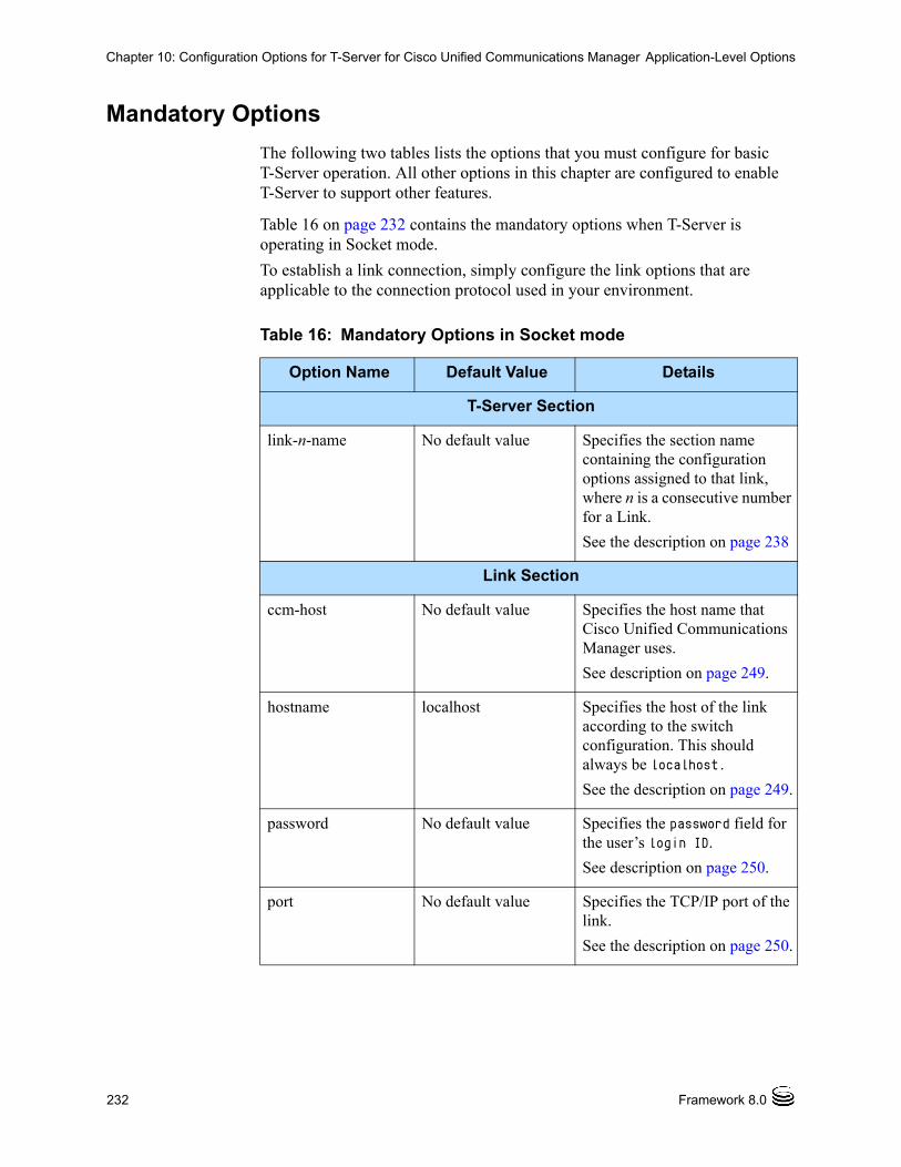
232 Framework 8.0
Chapter 10: Configuration Options for T-Server for Cisco Unified Communications Manager Application-Level Options
Mandatory Options
The following two tables lists the options that you must configure for basic T-Server operation. All other options in this chapter are configured to enable T-Server to support other features.
Table 16 on page 232 contains the mandatory options when T-Server is operating in Socket mode.
To establish a link connection, simply configure the link options that are applicable to the connection protocol used in your environment.
Table 16: Mandatory Options in Socket mode
Option Name Default Value Details
T-Server Section
link-n-name No default value Specifies the section name containing the configuration options assigned to that link, where n is a consecutive number for a Link.
See the description on page 238
Link Section
ccm-host No default value Specifies the host name that Cisco Unified Communications Manager uses.
See description on page 249.
hostname localhost Specifies the host of the link according to the switch configuration. This should always be localhost.
See the description on page 249.
password No default value Specifies the password field for the user’s login ID.
See description on page 250.
port No default value Specifies the TCP/IP port of the link.
See the description on page 250.
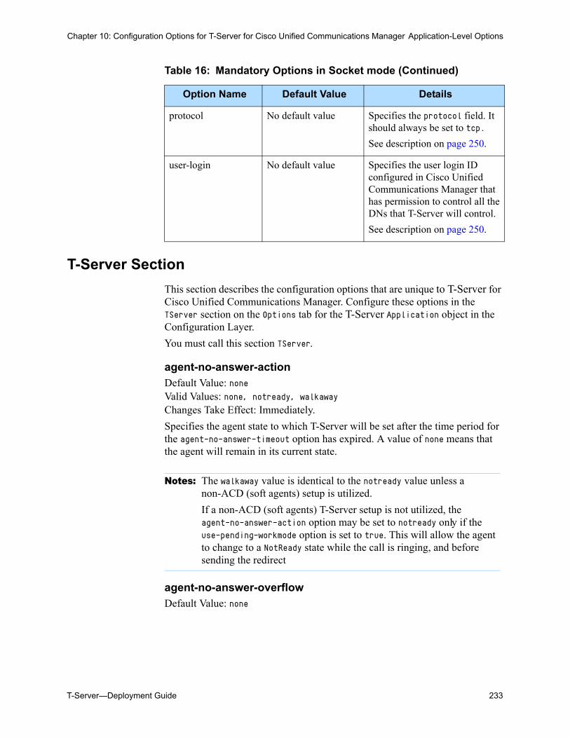
T-Server—Deployment Guide 233
Chapter 10: Configuration Options for T-Server for Cisco Unified Communications Manager Application-Level Options
T-Server Section
This section describes the configuration options that are unique to T-Server for Cisco Unified Communications Manager. Configure these options in the TServer section on the Options tab for the T-Server Application object in the Configuration Layer.
You must call this section TServer.
agent-no-answer-actionDefault Value: noneValid Values: none, notready, walkawayChanges Take Effect: Immediately.
Specifies the agent state to which T-Server will be set after the time period for the agent-no-answer-timeout option has expired. A value of none means that the agent will remain in its current state.
agent-no-answer-overflowDefault Value: none
protocol No default value Specifies the protocol field. It should always be set to tcp.
See description on page 250.
user-login No default value Specifies the user login ID configured in Cisco Unified Communications Manager that has permission to control all the DNs that T-Server will control.
See description on page 250.
Table 16: Mandatory Options in Socket mode (Continued)
Option Name Default Value Details
Notes: The walkaway value is identical to the notready value unless a non-ACD (soft agents) setup is utilized.
If a non-ACD (soft agents) T-Server setup is not utilized, the agent-no-answer-action option may be set to notready only if the use-pending-workmode option is set to true. This will allow the agent to change to a NotReady state while the call is ringing, and before sending the redirect
234 Framework 8.0
Chapter 10: Configuration Options for T-Server for Cisco Unified Communications Manager Application-Level Options
Valid Values:
Changes Take Effect: Immediately.
After the time period for the agent-no-answer-timeout option has expired, T-Server will redirect the ringing call to the destination described by this option.
agent-no-answer-timeoutDefault Value: 0Valid Values: 0 to 600Changes Take Effect: Immediately.
Calls ringing on an agent's phone that were distributed from an ACD Queue or a Routing Point will wait for the telephone to ring for this timeout period (in seconds) before performing the actions described by the agent-no-answer-action option and redirect the call to the destination described in the agent-no-answer-overflow option. The default value of 0 (zero) disables the functionality of this option.
applicationDefault Value: T-ServerValid Values: Any character stringChanges Take Effect: After T-Server is restarted
Specifies the name of the T-Server application shown in the Cisco Unified Communications Manager switch. It is used to identify an application to the Cisco switch.
audio-codecDefault Value: 1,3Valid Values: Comma-separated list of any of the following:
Changes Take Effect: After T-Server is restarted
Specifies the audio codec(s) to be used by this T-Server. G.711 operates at a higher bit rate than G.723 and G.729A, providing good quality but consuming more network resources. MS-GSM is intermediate, providing moderate quality and low network resource consumption. For G.711, mu-Law is used in North
none The call will remain ringing on the agent phone.recall The call will be redirected back to the Routing Point or the
ACD Queue that delivered the call to the agent.Any destinationdigits
A valid destination DN must be provided (a Queue or Routing Point on the local switch is recommended).
1 G.711 mu-Law
2 G.711 a-Law
3 G.723
4 G.729A
8 MS-GSM and GSM Full Rate
T-Server—Deployment Guide 235
Chapter 10: Configuration Options for T-Server for Cisco Unified Communications Manager Application-Level Options
America and Japan and a-Law is used elsewhere, including international routes.
busy-toneDefault Value: music/busy_5secValid Values: Name and path of any valid audio fileChanges Take Effect: Immediately for all new calls
Specifies an audio file to be played for the Busy treatment.
collect-toneDefault Value: music/collectValid Values: Name and path of any valid audio fileChanges Take Effect: Immediately for all new calls
Specifies that T-Server uses this non-completion tone to produce the sound played during DTMF digit collection. Basically, this option is a duplicate of the silence-tone option.
debugDefault Value: +allValid Values: +/-all, +/-jtapi, +/-toop, +/-smChanges Take Effect: Immediately
Specifies which submodules in Cisco Unified Communications Manager produce debug output. This output is ultimately controlled by the Log section. The format of the string is +module1 -module2, which means that module1 produces debug output and module2 does not. The module name all represents all modules. Current modules are all, toop (internal call object manipulation), sm (Stream Manager), and jtapi (JTAPI events and requests). All T-Server debug output that is a part of a debug module is prefixed with (module name)*>>.
default-dnDefault Value: No default valueValid Values: Any character string. Do not use the period (.) character or the commercial “at” (@) sign in this string.Changes Take Effect: Immediately
This option has the following functionality:
• Provides the default DN that calls are routed to if Universal Routing Server (URS) requests T-Server to route to a default target. If no default is provided, T-Server rejects the call if URS sends a default target.
• If the Agent Ring Redirect Timeout expires but there is no value in the user-data RING_REDIRECT_DN key, the call is redirected to the address specified in default-dn option. If the default-dn option is not set, the call is not redirected (it still rings) but the agent is still placed into the NotReady state.
236 Framework 8.0
Chapter 10: Configuration Options for T-Server for Cisco Unified Communications Manager Application-Level Options
• Provides the destination for calls that could not be queued on an ACD queue. (for example, if the ACD queue ran out of music ports).
default-monitor-modeDefault Value: normalValid Values: normal,mute,coachChanges take effect: With the next received TMonitorNextCall request.
Specifies the monitor mode for subscription:
This option is used when MonitorMode extension in the request TMonitorNextCall is not specified or specified incorrectly.
default-monitor-toneDefault Value: localValid Values:
Changes take effect: With the next recorded call.
This option is set to generate a periodic tone to let people know that they are monitored.
default-record-toneDefault Value: noneValid Values:
Changes take effect: With the next recorded call.
This option is set to generate a periodic tone to let people know that they are being recorded.
normal Silent monitoring (mute supervisor connection, possible warning beep).
mute Silent monitoring (mute supervisor connection).coach Whisper coaching (only monitored agent can hear Supervisor).connect Open supervisor presence (Not supported).
none No tone is generated on both legs of the call.local A periodic tone is generated on the agent’s phone.remote A periodic tone is generated on the customer’s phone.both A periodic tone is generated on both the customer’s and the
agent’s phone.
none No tone is generated on both legs of the call.local A periodic tone is generated on the agent’s phone.remote A periodic tone is generated on the customer’s phone.both A periodic tone is generated on both the customer’s and the
agent’s phone.
T-Server—Deployment Guide 237
Chapter 10: Configuration Options for T-Server for Cisco Unified Communications Manager Application-Level Options
enable-data-on-bridgedDefault Value: trueValid Values: true, falseChanges Take Effect: Immediately
When the value of this option is set to true, the data on IP Phones will not be displayed if the phone is in a bridged state.
fast-busy-toneDefault Value: music/atb_5secValid Values: Name and path of any valid audio fileChanges Take Effect: Immediately for all new calls
Specifies an audio file to be played for the FastBusy treatment.
intrusion-enabledDefault Value: trueValid Values: true, falseChanges take effect: At the next request TMonitorNextCall
Controls whether intrusion is enabled. For example, request TMonitorNextCall will result in immediate Single Step Conference with Supervisor DN if there is an active call on Agent DN at the moment when TMonitorNextCall is processed.
jtapi-update-modeDefault Value: startupValid Values: never, install, startupChanges Take Effect: After T-Server is restarted
Specifies when the jtapi.jar library is synchronized with the CTIManager host. T-Server needs jtapi.jar in order to communicate with Cisco CTIManager.
When this option is set to never, no synchronization takes place. In this case, the jtapi.jar must be manually copied from the CTI-Manager host to the T-Server working directory.
When this option is set to install, the jtapi.jar file is downloaded from the CTIManager host only when no existing jtapi.jar is available. The updated jtapi.jar file will be used upon the next T-Server restart.
When this option is set to startup, T-Server synchronizes jtapi.jar before startup. This adds several seconds to the startup time, during which T-Server verifies the CTIManager jtapi.jar version. If the version is the same as the one currently in use, no action is taken; otherwise the currently used version of jtapi.jar is replaced with the one downloaded from CTIManager and used for startup.
false Intrusion is disabled.true Intrusion is enabled.
238 Framework 8.0
Chapter 10: Configuration Options for T-Server for Cisco Unified Communications Manager Application-Level Options
Unless the option is set to never, the user who started this T-Server must have "write" permission for the T-Server working directory in order for this feature to operate.
link-n-nameDefault Value: Mandatory field. No default value.Valid Values: Any valid nameChanges Take Effect: Immediately
Specifies the section name containing the configuration options assigned to that link, where n is a nonzero consecutive number for a link. You must specify a value for this option.
Warning! Do not update the link configuration while T-Server is running.
logout-on-agent-disconnectDefault Value: falseValid Values: false, trueChanges Take Effect: Immediately
With value true, T-Server sends an AgentLogout message if an agent application disconnects.
logout-on-fwdDefault Value: falseValid Values: false, trueChanges Take Effect: Immediately
With value true, T-Server send an AgentLogout message if a DN becomes forwarded to otherDN.
logout-on-out-of-serviceDefault Value: falseValid Values: true, falseChanges Take Effect: Immediately
Specifies whether agents can log in to DNs that are in the out-of-service state. If the value is set to true, agents cannot log in.
DNs can enter the out-of-service state if their IP phone is unplugged or if the IP network associated with the phone is unreachable. T-Server raises EventDnOutOfService when a DN enters the out-of-service state, and EventDnBackInService when the DN returns to the in-service state. At
Notes: The link-n-name option name refers to the link number and the section name (for example, link-1-name).
See “Socket Mode of Communication” on page 172 for more details.
T-Server—Deployment Guide 239
Chapter 10: Configuration Options for T-Server for Cisco Unified Communications Manager Application-Level Options
T-Server startup all DNs are considered to be in the out-of-service state until their true state is known otherwise.
If the value is set to true, when a DN enters the out-of-service state while an agent is logged in there, T-Server logs out the agent and sends EventAgentLogout, and if an agent attempts to log in to the out-of-service DN, the T-Server responds with EventError.
If the value is set to false, agents can log in at any time, regardless of the DN state.
packet-sizeDefault value: 20Valid values: Comma-separated list of any of: 1,2,3,4,20,30 (see Table 17) Changes Take Effect: After T-Server is restarted
Specifies the maximum packet size, as follows:
If more than one audio-codec is specified, the values of packet-size correspond one-to-one, in the same order. For example, suppose that audio-codec has the values 1, 2, 4 and that packet-size has the values 20, 30, 2. This means that this T-Server uses codecs G.711 mu-Law at 20 msec per packet, G.711 a-Law at 30 msec per packet, and G.729A at 2 frames per packet. You do not have to list the audio-codec values in ascending order (therefore audio-codec = 4, 2, 1 and packet-size = 2, 30, 20 would have the same effect as the example just described), although it is probably easier to do so. If a packet-size value is invalid for the codec it corresponds to, it is ignored, and that codec receives the default packet size.
queue-musicDefault Value: music/in_queueValid Value: Name and path of any valid audio fileChanges Take Effect: Immediately for all new callsSpecifies the name of the file for music treatment of ACD Queues, when the ACD queue DN has no specific music file configured.
Table 17: Values of Packet-Size Option
Codec Default Value Valid Values Unit
G.711 mu-Law or a-Law
20 20, 30 msec per packet
G.723, G.729A 1 1, 2, 3, 4 frames per packet
MS-GSM Not applicable
GSM Full Rate Not applicable
240 Framework 8.0
Chapter 10: Configuration Options for T-Server for Cisco Unified Communications Manager Application-Level Options
record-only-business-callsDefault Value: false Valid Values: false, trueChanges Take Effect: Immediately
If set to true, only calls coming from a Routing Point or an ACD Queue to the target DN will be recorded.
recording-filenameDefault Value: NULLValid Values: Any valid file name using the variables specified belowChanges Take Effect: When the next call recording is initiated
Specifies the file name for call recording when call recording is initiated automatically, according to T-Server configuration. When this option contains a value, the generated file name is added as UserData to the call with the GSIP_REC_FN key. When this option does not contain a value, the file name is the UUID of the call.
The following variables are used when creating the file:
$AGENTDN$—The DN where the call recording is initiated.$REFCI$—The CUCM callId of the call.$DATE$—The current date (GMT) in the Y-M-D format.$TIME$—The current time (GMT) in the H-M-S format.
recording-filename-suffixDefault Value: NULLValid Values: String, representing part of filename.Changes Take Effect: Immediately
If specified, the value is appended to the generated filename. Can be set, for example, to _pcma.wav on Windows to achieve a constant filename match with Stream Manager.
ring-toneDefault Value: music/ring_backValid Values: Name and path of any valid audio fileChanges Take Effect: Immediately for all new calls
Specifies an audio file to be played for the RingBack treatment.
rtp-info-passwordDefault Value: Empty stringValid Values: Any stringChanges Take Effect: Immediately
Specifies the password to allow voice-monitoring applications to monitor any call. If password is not provided, no applications will be able to perform monitoring.
T-Server—Deployment Guide 241
Chapter 10: Configuration Options for T-Server for Cisco Unified Communications Manager Application-Level Options
Warning! This password is not secure. It is passed as text to the voice-monitoring application.
silence-toneDefault Value: music/silenceValid Values: Name and path of any valid audio fileChanges Take Place: Immediately for all new calls
Specifies an audio file to be played for the Silence treatment.
sm-portDefault Value: 0Valid Values: 0–65535Changes Take Effect: After restart
Specifies the listening port for VoIP Stream Manager connection. If this option is set to 0, T-Server does not allow Stream Manager connections and ignores all Stream Manager treatments options.
switchover-on-first-link-failureDefault Value: trueValid Values: true, falseChanges Take Effect: Immediately
When set to false, T-Server sets DNs from the failed link to out-of-service, and will not trigger switchover if at least one JTAPI link remains active. When set to true, T-Server immediately reports LinkDisconnected to SCI after the first JTAPI link fails, SCS then triggers the switchover.
use-default-routeDefault Value: falseValid Values: false, trueChanges Take Effect: With the next route request
Specifies whether to use the default DN (see “default-dn”) as a default route destination if URS (Universal Routing Server) is not connected.
JTAPI Section
This section describes configuration options unique to T-Server for CMM. Configure these options in the jtapi section on the Options tab for the T-Server Application object in the Configuration Layer.
You must call this section jtapi.
242 Framework 8.0
Chapter 10: Configuration Options for T-Server for Cisco Unified Communications Manager Application-Level Options
Note: Any option defined in this section overrides the equivalent option in jtapi.ini. See “JTAPI and Configuring JTAPI Options” on page 136. Any option not defined in this section takes its value from jtapi.ini; or, if the option is also not defined in jtapi.ini, the value is taken from the predefined JTAPI library default value for the option.
AlarmServiceHostnameDefault Value: No default value. See Note on page 241.Valid Values: Any stringChanges Take Effect: After T-Server is restarted
Specifies the host name for the JTAPI alarm service.
AlarmServicePortDefault Value: None. See Note on page 241.Valid Value: Any integerChanges Take Effect: After T-Server is restarted
Specifies the port for the JTAPI alarm service.
CTI_DEBUGGINGDefault Value: No default value. See Note on page 241. Valid Values: true, falseChanges Take Effect: After T-Server is restarted
When set to true, Cisco Unified Communications Manager CTI events are written to the JTAPI log (if logging is enabled).
CTIIMPL_DEBUGGINGDefault Value: No default value. See Note on page 241. Valid Values: true, falseChanges Take Effect: After T-Server is restarted
When set to true, internal CTI implementation is written to the JTAPI log (if logging is enabled).
CtiManagersDefault Value: No default value. See Note on page 241. Valid Value: Any stringChanges Take Effect: After T-Server is restarted
Not used by T-Server.
CtiRequestTimeoutDefault Value: None. See Note on page 241. Valid Value: Any integerChanges Take Effect: After T-Server is restarted
T-Server—Deployment Guide 243
Chapter 10: Configuration Options for T-Server for Cisco Unified Communications Manager Application-Level Options
Specified the time, in seconds, during which T-Server waits for a response to a CTI request.
DEBUG Default Value: No default value. See Note on page 241. Valid Values: true, falseChanges Take Effect: After T-Server is restarted
When set to true, debugging information is written to the JTAPI log (if logging is enabled).
Note: For detailed descriptions of all JTAPI options, see the Cisco Unified Communications Manager Administration Guide.
DesiredServerHeartbeatIntervalDefault Value: No default value. See Note on page 241.Valid Value: Any integerChanges Take Effect: After T-Server is restarted
Specifies the time, in seconds, between verification heartbeat messages between T-Server and the Cisco Unified Communications Manager cluster. If T-Server fails to receive heartbeats, it attempts to connect to the backup CTIManager.
DirectoryDefault Value: No default value. See Note on page 241. Valid Value: Any stringChanges Take Effect: After T-Server is restarted
Specifies the directory used to store JTAPI log files.
FileNameBaseDefault Value: No default value. See Note on page 241. Valid Value: Any stringChanges Take Effect: After T-Server is restarted
Species the file name prefix to store JTAPI logs.
FileNameExtensionDefault Value: No default value. See Note on page 241.Valid Value: Any stringChanges Take Effect: After T-Server is restarted
Specifies the filename extension to store JTAPI logs.
INFORMATIONALDefault Value: No default value. See Note on page 241. Valid Values: true, false
244 Framework 8.0
Chapter 10: Configuration Options for T-Server for Cisco Unified Communications Manager Application-Level Options
Changes Take Effect: After T-Server is restarted
When set to true, status events are written to the JTAPI log (if logging is enabled).
JTAPI_DEBUGGINGDefault Value: No default value. See Note on page 241. Valid Values: true, falseChanges Take Effect: After T-Server is restarted
When set to true, JTAPI methods and events are written to the JTAPI log (if logging is enabled).
JTAPIIMPL_DEBUGGINGDefault Value: No default value. See Note on page 241. Valid Values: true, falseChanges Take Effect: After T-Server is restarted
When set to true, JTAPI internal implementation is written to the JTAPI log (if logging is enabled).
MISC_DEBUGGINGDefault Value: No default value. See Note on page 241. Valid Values: true, falseChanges Take Effect: After T-Server is restarted
When set to true, miscellaneous tracing is written to the JTAPI log (if logging is enabled).
NumTraceFilesDefault Value: No default value. See Note on page 241.Valid Value: Any integerChanges Take Effect: After T-Server is restarted
Specifies the number of JTAPI logs to produce before overwriting old logs.
PeriodicWakeupEnabledDefault Value: No default value. See Note on page 241. Valid Values: true, falseChanges Take Effect: After T-Server is restarted
When set to true, each JTAPI thread is woken up after a specified sleep interval in order to write a debug message to the JTAPI log (if logging is enabled).
PeriodicWakeupIntervalDefault Value: No default value. See Note on page 241. Valid Value: Any integerChanges Take Effect: After T-Server is restarted
T-Server—Deployment Guide 245
Chapter 10: Configuration Options for T-Server for Cisco Unified Communications Manager Application-Level Options
Specifies the interval, in seconds, between debug thread wakeup.
PROTOCOL_DEBUGGING Default Value: No default value. See Note on page 241. Valid Values: true, falseChanges Take Effect: After T-Server is restarted
When set to true, full CTI protocol trace is written to the JTAPI log (if logging is enabled).
ProviderOpenRequestTimeoutDefault Value: No default value. See Note on page 241. Valid Value: Any integerChanges Take Effect: After T-Server is restarted
Specifies the amount of time, in seconds, that T-Server waits for a response to a ProviderOpen message.
ProviderRetryInterval Default Value: No default value. See Note on page 241. Valid Value: Any integerChanges Take Effect: After T-Server is restarted
Specifies the amount of time, in seconds, that T-Server tries to reopen a connection to a Cisco Unified Communications Manager cluster after a failure.
QueueSizeThresholdDefault Value: No default value. See Note on page 241. Valid Value: Any integer.Changes Take Effect: After T-Server is restarted
Specifies the size of the internal JTAPI Queue which, when exceeded, causes a debug message to be written to the JTAPI log (when logging is enabled).
QueueStatsEnabledDefault Value: No default value. See Note on page 241. Valid Values: true, falseChanges Take Effect: After T-Server is restarted
When set to true, if the internal JTAPI is greater than the threshold, a debug message is written to the JTAPI log (when JTAPI logging enabled).
RouteSelectTimeoutDefault Value: No default value. See Note on page 241. Valid Value: Any integerChanges Take Effect: After T-Server is restarted
246 Framework 8.0
Chapter 10: Configuration Options for T-Server for Cisco Unified Communications Manager Application-Level Options
Specifies the amount of time, in milliseconds, that T-Server waits for URS to respond to a route request. This setting is also affected by other Cisco Unified Communications Manager switch settings.
SyslogCollectorDefault Value: No default value. See Note on page 241. Valid Value: Any stringChanges Take Effect: After T-Server is restarted
Specifies the host name for a syslog collector.
SyslogCollectorUDPPortDefault Value: No default value. See Note on page 241. Valid Value: Any integerChanges Take Effect: After T-Server is restarted
Specifies a UDP port for the syslog collector.
TraceFileSizeDefault Value: No default value. See Note on page 241.Valid Value: Any integerChanges Take Effect: After T-Server is restartedSpecifies the maximum size of each JTAPI log file.
TracePathDefault Value: No default value. See Note on page 241. Valid Value: Any character stringChanges Take Effect: After T-Server is restarted
Specifies the root directory used to store JTAPI log files.
TServerTraceFileBaseDefault Value: ts_traceValid Values: Any character stringChanges Take Effect: After T-Server is restarted
Determines the prefix of the log file name in a situation where the network connection fails between JTAPI and T-Server. See page 183 for more details.
TServerTraceFileExtDefault Value: logValid Values: Any character stringChanges Take Effect: After T-Server is restarted
Determines the suffix of the log file name in a situation where the network connection fails between JTAPI and T-Server. See page 183 for more details.
T-Server—Deployment Guide 247
Chapter 10: Configuration Options for T-Server for Cisco Unified Communications Manager Application-Level Options
TServerTraceMaxFilesDefault Value: 10Valid Values: 0-Maximum IntegerChanges Take Effect: After T-Server is restarted
Determines how many files should be in a created before the first one is overwritten for the files created with the TServerTraceFileBase, and TServerTraceFileExt options. See page 183 for more details.
TServerTraceMaxFileSizeDefault Value: 100Valid Values: 0 - Maximum IntegerChanges Take Effect: After T-Server is restarted
Determines the maximum file size in bytes for individual files created with the TServerTraceFileBase, and TServerTraceFileExt options. See page 183 for more details.
UseAlarmServiceDefault Value: No default value. See Note on page 241. Valid Values: true, falseChanges Take Effect: After T-Server is restarted
When set to true, JTAPI alarms go to an alarm service on the specified host and port.
UseTraceFileDefault Value: No default value. See Note on page 241. Valid Values: true, falseChanges Take Effect: After T-Server is restarted
When set to true, JTAPI log files are written.
UseJavaConsoleTraceDefault Value: No default value. See Note on page 241. Valid Values: true, falseChanges Take Effect: After T-Server is restarted
When set to true, JTAPI log messages are sent to the console (stdout).
UseSameDirectoryDefault Value: No default value. See Note on page 241. Valid Values: true, falseChanges Take Effect: After T-Server is restarted
When set to true, all instances of the same application write JTAPI logs to the same directory.
248 Framework 8.0
Chapter 10: Configuration Options for T-Server for Cisco Unified Communications Manager Application-Level Options
UseSyslogDefault Value: No default value. See Note on page 241. Valid Values: true, falseChanges Take Effect: After T-Server is restarted
When set to true, JTAPI log traces go to the syslog collector service at the specified UDP port and host.
WARNINGDefault Value: No default value. See Note on page 241. Valid Values: true, falseChanges Take Effect: After T-Server is restarted
When set to true, low-level warning events are written to the JTAPI log (if logging is enabled).
Global Group Section
This section describes the configuration options that are unique to T-Server for Cisco Unified Communications Manager. Configure these options in the globalgroup section on the Options tab for the T-Server Application object in the Configuration Layer. You must call this section globalgroup.
callmgr-autopickup-onDefault Value: falseValid Values: false, trueChanges Take Effect: Immediately
This option should be set to match the Cisco Unified Communications Manager Pickup mode: Auto Pickup (true) or Regular Pickup (false).
enable-jtapi-keep-aliveDefault Value: falseValid Values: false, trueChanges Take Effect: Immediately
This option enables a heartbeat between T-Sever and JTAPI as a keep alive functionality to detect possible conditions when JTAPI becomes unstable, and the JTAPI event sequence is no longer reliable.
enable-pickup-jtapi-workaroundDefault Value: falseValid Values: false, trueChanges Take Effect: Immediately
This option controls whether T-Server detects the inbound pickup scenario. It is applicable only to CallManager version 4.x. For CallManager version 5.x, this option should be set to false.
T-Server—Deployment Guide 249
Chapter 10: Configuration Options for T-Server for Cisco Unified Communications Manager Application-Level Options
CallManager version 4.x has a known issue for inbound pickup scenario where the external party is released by CallManager JTAPI during pickup, when it is still on a call. T-Server detects this scenario and ignores the incorrect EventReleased message which is sent by JTAPI. This issue is not present with CallManager 5.x.
Note: Java machine runs as a separate 64-bit process called Java.exe and T-Server is running as 32-bit process called ciscocm_server.exe.
jtapi-keep-alive-retriesDefault Value: 10Valid Values: Any positive integer from 1 to 999Changes Take Effect: Immediately
Specifies how many skipped heartbeat attempts are permitted before T-Server will shut itself down. T-Server sends the STANDARD message JTAPI keepalive timer exceeded %d allowed retries. Exiting now. before exiting.
jtapi-keep-alive-timeoutDefault Value: 60000Valid Values: Any positive integer from 1000 to 3600000Changes Take Effect: Immediately
Specifies the time (in milliseconds) between keep alive attempts. Any event from JTAPI is also considered as a keep alive message. T-Server will send the STANDARD message JTAPI keepalive timer expired. Retry %d of %d. when there are no messages within the timeout interval.
Link Section
Configure these options in the link section on the Options tab for the T-Server Application object in the Configuration Layer.
Starting with release 7.6, T-Server operating in Socket mode uses a standard link-n-name link configuration option. The TServer section will contain options link-1-name, link-2-name, ... while separate sections with names equal to the link-n-name values will contain link parameters.
ccm-hostDefault Value: Mandatory field. No default value.Valid Values: Any valid IP address.Changes Take Effect: Immediately
IP address for the CTI manager for this account.
hostnameDefault Value: localhostValid Values: Any valid host name
250 Framework 8.0
Chapter 10: Configuration Options for T-Server for Cisco Unified Communications Manager DN-Specific Section
Changes Take Effect: Read-only value. Do not change
Specifies the host of the link according to the switch configuration. This should always be localhost.
passwordDefault Value: Mandatory field. No default value.Valid Values: Any valid password.Changes Take Effect: Immediately
The CUCM password for this link.
portDefault Value: Mandatory field. No default value.Valid Values: Any valid port addressChanges Take Effect: Immediately
Specifies the TCP/IP port on the localhost that the Java link is opening to listen to.
protocolDefault Value: tcpValid Values: tcpChanges Take Effect: Immediately
Specifies the connection protocol T-Server uses in communicating with the switch.
user-loginDefault Value: Mandatory field. No default value.Valid Values: Any valid user login.Changes Take Effect: Immediately
The CUCM user for this link.
DN-Specific SectionYou set configuration options described in this section in the TServer section on the Annex tab of the relevant DN object in Configuration Manager. You cannot define them in the T-Server Application object.
recordDefault Value: falseValid Values: true, falseChanges Take Effect: Immediately
T-Server—Deployment Guide 251
Chapter 10: Configuration Options for T-Server for Cisco Unified Communications Manager Changes from 8.0 to 8.0.1
When this option is set to true, recording will be started automatically when the call is established on the corresponding DN. Call recording will be stopped when this DN leaves the call.
Changes from 8.0 to 8.0.1Table 18 provides all configuration option changes for this T-Server between release 8.0 and the latest 8.0.1 release.
Table 18: T-Server Option Changes from 8.0 to 8.0.1
Option Name Type of Change
Details
T-Server Section
default-monitor-tone New See page 236 for details.
default-record-tone New See page 236 for details.
switchover-on-first-link-failure New See page 241 for details.

252 Framework 8.0
Chapter 10: Configuration Options for T-Server for Cisco Unified Communications Manager Changes from 8.0 to 8.0.1
T-Server—Deployment Guide 253
Chapter
11 Stream Manager ConfigurationThis chapter describes the configuration options that are used for configuring Stream Manager to work with T-Server for Cisco Unified Communications Manager. It contains the following section: Stream Manager Configuration Options with T-Server, page 253 Stream Manager Configuration Options, page 256
Options that are common to all T-Servers are described in Chapter 8, “Common Configuration Options,” on page 185 and in Chapter 9, “T-Server Common Configuration Options,” on page 205.
Stream Manager Configuration Options with T-Server
Stream Manager is a Genesys client application that streams media files in order to provide announcements and music to callers queued on Routing Points and ACD Queues (please refer to “Music and Announcements” on page 154 of this document).
In order to enable the connections, configure the T-Server option sm-port in the T-Server application (refer to Page 241 for more information).
To configure Stream Manager to work with T-Server for Cisco Unified Communications Manager, select the Stream Manager application object in the Configuration Manager and then add a connection to the T-Server application.
Multiple Stream Managers can connect to one T-Server. In this scenario, T-Server distributes calls to all connected Stream Managers in a load-balanced arrangement.
Multiple Stream Managers can be deployed in a load-balancing configuration, (though not in a primary/backup configuration). This configuration provides
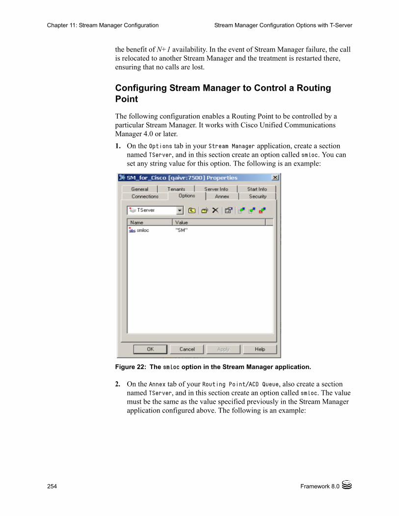
254 Framework 8.0
Chapter 11: Stream Manager Configuration Stream Manager Configuration Options with T-Server
the benefit of N+1 availability. In the event of Stream Manager failure, the call is relocated to another Stream Manager and the treatment is restarted there, ensuring that no calls are lost.
Configuring Stream Manager to Control a Routing Point
The following configuration enables a Routing Point to be controlled by a particular Stream Manager. It works with Cisco Unified Communications Manager 4.0 or later.
1. On the Options tab in your Stream Manager application, create a section named TServer, and in this section create an option called smloc. You can set any string value for this option. The following is an example:
Figure 22: The smloc option in the Stream Manager application.
2. On the Annex tab of your Routing Point/ACD Queue, also create a section named TServer, and in this section create an option called smloc. The value must be the same as the value specified previously in the Stream Manager application configured above. The following is an example:
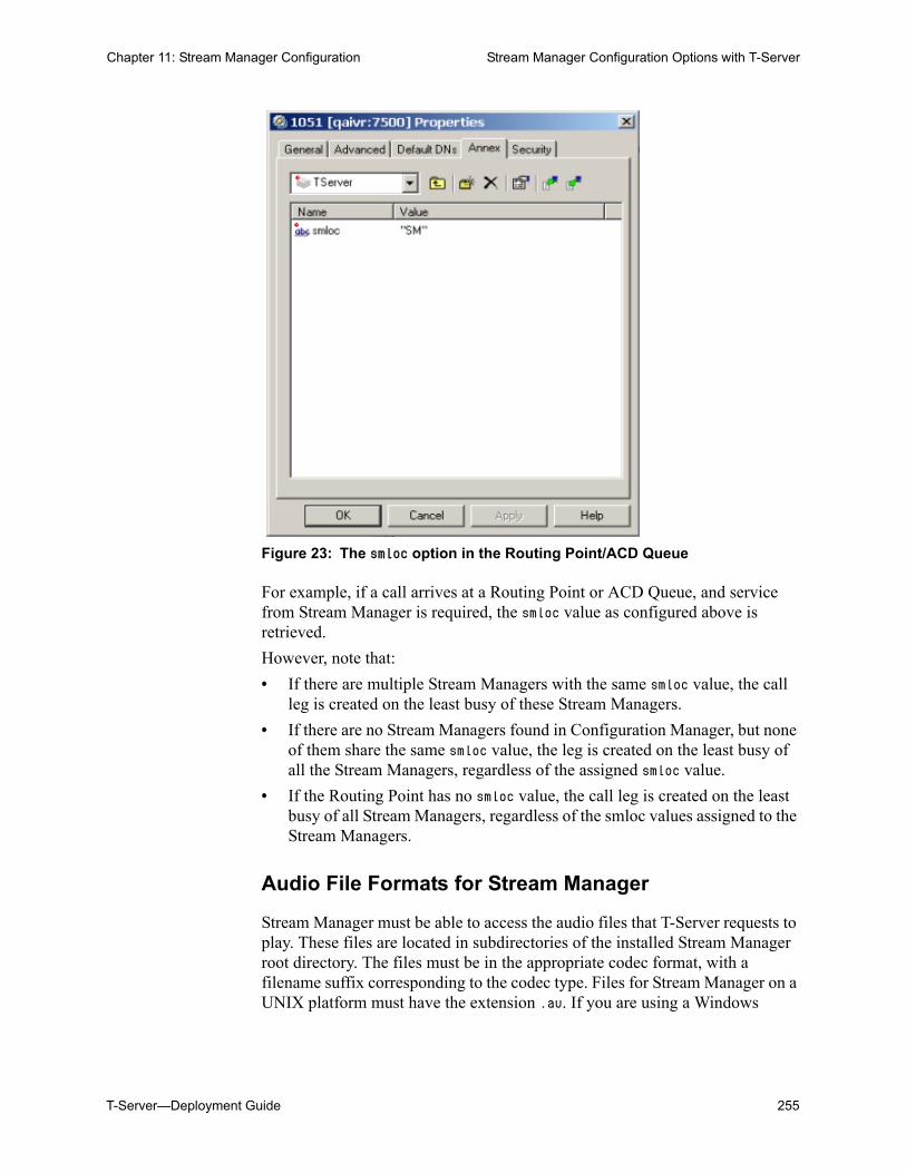
T-Server—Deployment Guide 255
Chapter 11: Stream Manager Configuration Stream Manager Configuration Options with T-Server
Figure 23: The smloc option in the Routing Point/ACD Queue
For example, if a call arrives at a Routing Point or ACD Queue, and service from Stream Manager is required, the smloc value as configured above is retrieved.
However, note that:
• If there are multiple Stream Managers with the same smloc value, the call leg is created on the least busy of these Stream Managers.
• If there are no Stream Managers found in Configuration Manager, but none of them share the same smloc value, the leg is created on the least busy of all the Stream Managers, regardless of the assigned smloc value.
• If the Routing Point has no smloc value, the call leg is created on the least busy of all Stream Managers, regardless of the smloc values assigned to the Stream Managers.
Audio File Formats for Stream Manager
Stream Manager must be able to access the audio files that T-Server requests to play. These files are located in subdirectories of the installed Stream Manager root directory. The files must be in the appropriate codec format, with a filename suffix corresponding to the codec type. Files for Stream Manager on a UNIX platform must have the extension .au. If you are using a Windows
256 Framework 8.0
Chapter 11: Stream Manager Configuration Stream Manager Configuration Options
platform, files for Stream Manager must have the extension .wav. The supported formats and file suffixes are:
• G.711 mu-law: mulaw.au, mulaw.wav
• G.711 a-law: alaw.au, alaw.wav
• G.723: _g7231.au, _g7231.wav
• G.729A: _g729a.au, _g729a.wav
• GSM: _gsm.au, _gsm.wav
To facilitate the use of the full range of supported codecs, Genesys has made Audio Transcoding Utility (ATU) available through Genesys Technical Support (http://genesyslab.com/support). ATU takes as input an audio file in any format supported by Stream Manager and produces versions of the file in all supported formats.
When these files are produced, ensure that all Stream Managers connected to a T-Server contains the same announcement/music files in the same directory structure. T-Server will instruct the Stream Manager to play a file, but if the file does not exist in the specified directory, the treatment will fail.
Stream Manager Configuration OptionsStarting with T-Server 7.6, Stream Manager options are now grouped into the following Sections: codecs, contact, limits, log, and x-config. The updated options descriptions for these Sections are located in the Framework 7.6 Stream Manager Deployment Guide.
None of the options for Stream Manager configuration are mandatory.
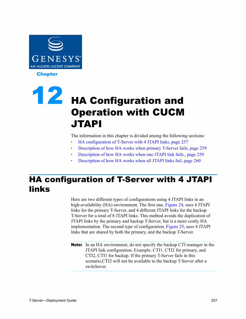
T-Server—Deployment Guide 257
Chapter
12 HA Configuration and Operation with CUCM JTAPIThe information in this chapter is divided among the following sections: HA configuration of T-Server with 4 JTAPI links, page 257 Description of how HA works when primary T-Server fails, page 259 Description of how HA works when one JTAPI link fails., page 259 Description of how HA works when all JTAPI links fail, page 260
HA configuration of T-Server with 4 JTAPI links
Here are two different types of configurations using 4 JTAPI links in an high-availability (HA) environment. The first one, Figure 24, uses 4 JTAPI links for the primary T-Server, and 4 different JTAPI links for the backup T-Server for a total of 8 JTAPI links. This method avoids the duplication of JTAPI links by the primary and backup T-Server, but is a more costly HA implementation. The second type of configuration, Figure 25, uses 4 JTAPI links that are shared by both the primary, and the backup T-Server.
Note: In an HA environment, do not specify the backup CTI manager in the JTAPI link configuration. Example: CTI1, CTI2 for primary, and CTI2, CTI1 for backup. If the primary T-Server fails in this scenario,CTI2 will not be available to the backup T-Server after a switchover.
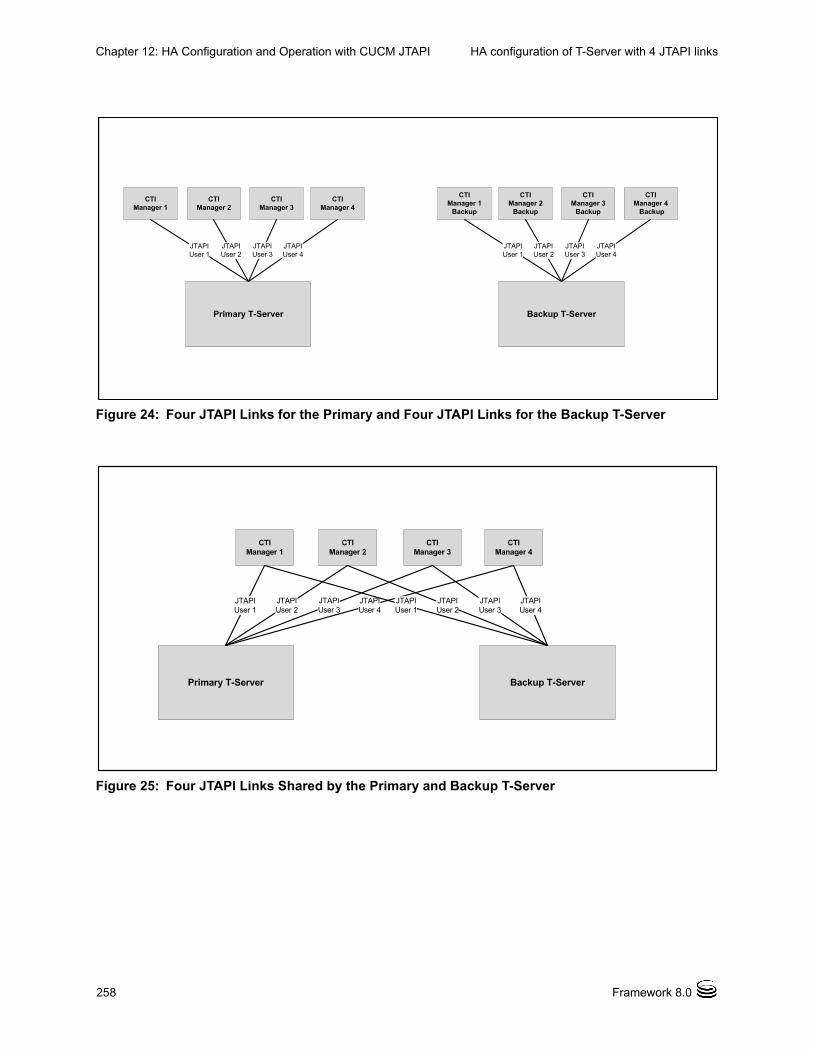
258 Framework 8.0
Chapter 12: HA Configuration and Operation with CUCM JTAPI HA configuration of T-Server with 4 JTAPI links
Figure 24: Four JTAPI Links for the Primary and Four JTAPI Links for the Backup T-Server
Figure 25: Four JTAPI Links Shared by the Primary and Backup T-Server
CTIManager 1
CTIManager 2
CTIManager 3
CTIManager 4
CTIManager 2
Backup
CTI Manager 1
Backup
CTIManager 3
Backup
CTIManager 4 Backup
Primary T-Server Backup T-Server
JTAPIUser 1
JTAPIUser 2
JTAPIUser 3
JTAPI User 4
JTAPIUser 4
JTAPIUser 3
JTAPIUser 2
JTAPIUser 1
CTI Manager 1
CTIManager 2
CTI Manager 3
CTIManager 4
Primary T-Server Backup T-Server
JTAPIUser 1
JTAPIUser 2
JTAPIUser 3
JTAPI User 4
JTAPIUser 4
JTAPIUser 3
JTAPIUser 2
JTAPIUser 1
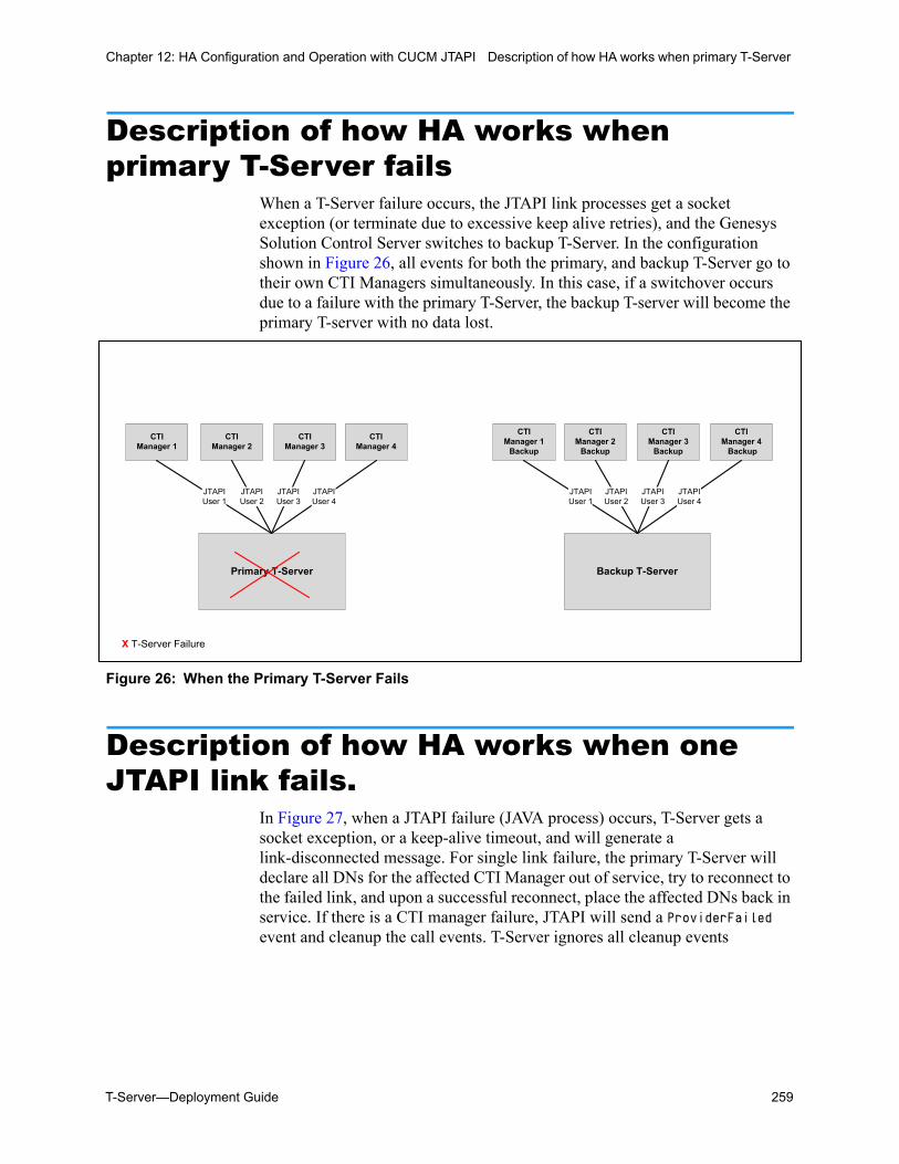
T-Server—Deployment Guide 259
Chapter 12: HA Configuration and Operation with CUCM JTAPI Description of how HA works when primary T-Server
Description of how HA works when primary T-Server fails
When a T-Server failure occurs, the JTAPI link processes get a socket exception (or terminate due to excessive keep alive retries), and the Genesys Solution Control Server switches to backup T-Server. In the configuration shown in Figure 26, all events for both the primary, and backup T-Server go to their own CTI Managers simultaneously. In this case, if a switchover occurs due to a failure with the primary T-Server, the backup T-server will become the primary T-server with no data lost.
Figure 26: When the Primary T-Server Fails
Description of how HA works when one JTAPI link fails.
In Figure 27, when a JTAPI failure (JAVA process) occurs, T-Server gets a socket exception, or a keep-alive timeout, and will generate a link-disconnected message. For single link failure, the primary T-Server will declare all DNs for the affected CTI Manager out of service, try to reconnect to the failed link, and upon a successful reconnect, place the affected DNs back in service. If there is a CTI manager failure, JTAPI will send a ProviderFailed event and cleanup the call events. T-Server ignores all cleanup events
CTIManager 1
CTIManager 2
CTI Manager 3
CTI Manager 4
CTI Manager 2
Backup
CTI Manager 1
Backup
CTIManager 3
Backup
CTI Manager 4 Backup
Primary T-Server Backup T-Server
JTAPIUser 1
JTAPIUser 2
JTAPIUser 3
JTAPI User 4
JTAPIUser 4
JTAPIUser 3
JTAPIUser 2
JTAPIUser 1
X T-Server Failure
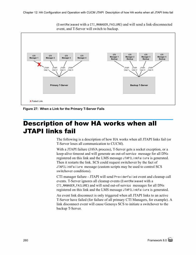
260 Framework 8.0
Chapter 12: HA Configuration and Operation with CUCM JTAPI Description of how HA works when all JTAPI links fail
(EventReleased with a CTI_MANAGER_FAILURE) and will send a link-disconnected event, and T-Server will switch to backup.
Figure 27: When a Link for the Primary T-Server Fails
Description of how HA works when all JTAPI links fail
The following is a description of how HA works when all JTAPI links fail (or T-Server loses all communication to CUCM).
With a JTAPI failure (JAVA process), T-Server gets a socket exception, or a keep-alive timeout and will generate an out-of-service message for all DNs registered on this link and the LMS message JTAPILinkFailure is generated. Then it restarts the link. SCS could request switchover by the fact of JTAPILinkFailure message (custom scripts may be used to control SCS switchover conditions).
CTI manager failure - JTAPI will send ProviderFailed event and cleanup call events. T-Server ignores all cleanup events (EventReleased with a CTI_MANAGER_FAILURE) and will send out-of-service messages for all DNs registered on this link and the LMS message JTAPILinkFailure is generated.
An event link disconnect is only triggered when all JTAPI links to an active T-Server have failed (for failure of all primary CTI Managers, for example). A link disconnect event will cause Genesys SCS to initiate a switchover to the backup T-Server.
CTI Manager 1
CTI Manager 2
CTI Manager 3
CTI Manager 4
CTI Manager 2
Backup
CTI Manager 1
Backup
CTI Manager 3
Backup
CTI Manager 4 Backup
Primary T-Server Backup T-Server
JTAPIUser 1
JTAPIUser 2
JTAPIUser 3
JTAPI User 4
JTAPIUser 4
JTAPIUser 3
JTAPIUser 2
JTAPIUser 1
X Failed Link
X
T-Server—Deployment Guide 261
Supplements
Related Documentation ResourcesThe following resources provide additional information that is relevant to this software. Consult these additional resources as necessary.
T-Server for T-Server for Cisco Unified Communications Manager
Consult these additional resources as necessary:
• The Framework 8.0 Deployment Guide, which will help you configure, install, start, and stop Framework components.
• The Framework 8.0 Configuration Options Reference Manual, which will provide you with descriptions of configuration options for other Framework components.
• The Framework 8.0 Configuration Manager Help, which will help you use Configuration Manager.
• The Genesys Migration Guide, also on the Genesys Documentation Library DVD, which contains a documented migration strategy from Genesys product releases 5.x and later to all Genesys 7.x releases. Contact Genesys Technical Support for additional information.
• The Genesys 7 Events and Models Reference Manual and Voice Platform SDK 8.0 .NET (or Java) API Reference for technical details of T-Library functions which contains the T-Library API, information on TEvents, and an extensive collection of call models.
• The Genesys Technical Publications Glossary, which ships on the Genesys Documentation Library DVD and which provides a comprehensive list of the Genesys and CTI terminology and acronyms used in this document.
• The Release Notes and Product Advisories for this product, which are available on the Genesys Technical Support website at http://genesyslab.com/support.
262 Framework 8.0
Related Documentation Resources
Genesys
• Genesys Technical Publications Glossary, which ships on the Genesys Documentation Library DVD and which provides a comprehensive list of the Genesys and computer-telephony integration (CTI) terminology and acronyms used in this document.
• Genesys Migration Guide, which ships on the Genesys Documentation Library DVD, and which provides documented migration strategies for Genesys product releases. Contact Genesys Technical Support for more information.
Information about supported hardware and third-party software is available on the Genesys Technical Support website in the following documents:
• Genesys Supported Operating Environment Reference Manual
• Genesys Supported Media Interfaces Reference Manual
Consult these additional resources as necessary:
• Genesys Hardware Sizing Guide, which provides information about Genesys hardware sizing guidelines for the Genesys releases.
• Genesys 7 Interoperability Guide, which provides information on the compatibility of Genesys products with various Configuration Layer Environments; Interoperability of Reporting Templates and Solutions; and Gplus Adapters Interoperability.
• Genesys Licensing Guide, which introduces you to the concepts, terminology, and procedures relevant to the Genesys licensing system.
• Genesys Database Sizing Estimator 7.6 Worksheets, which provides a range of expected database sizes for various Genesys products.
For additional system-wide planning tools and information, see the release-specific listings of System Level Documents on the Genesys Technical Support website, accessible from the system level documents by release tab in the Knowledge Base Browse Documents Section.
Genesys product documentation is available on the:
• Genesys Technical Support website at http://genesyslab.com/support.
• Genesys Documentation Library DVD, which you can order by e-mail from Genesys Order Management at [email protected].
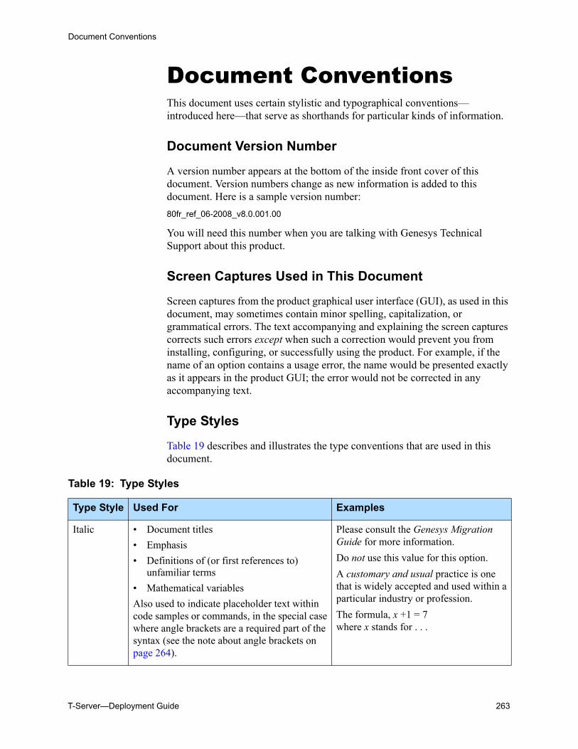
T-Server—Deployment Guide 263
Document Conventions
Document ConventionsThis document uses certain stylistic and typographical conventions—introduced here—that serve as shorthands for particular kinds of information.
Document Version Number
A version number appears at the bottom of the inside front cover of this document. Version numbers change as new information is added to this document. Here is a sample version number:
80fr_ref_06-2008_v8.0.001.00
You will need this number when you are talking with Genesys Technical Support about this product.
Screen Captures Used in This Document
Screen captures from the product graphical user interface (GUI), as used in this document, may sometimes contain minor spelling, capitalization, or grammatical errors. The text accompanying and explaining the screen captures corrects such errors except when such a correction would prevent you from installing, configuring, or successfully using the product. For example, if the name of an option contains a usage error, the name would be presented exactly as it appears in the product GUI; the error would not be corrected in any accompanying text.
Type Styles
Table 19 describes and illustrates the type conventions that are used in this document.
Table 19: Type Styles
Type Style Used For Examples
Italic • Document titles
• Emphasis
• Definitions of (or first references to) unfamiliar terms
• Mathematical variables
Also used to indicate placeholder text within code samples or commands, in the special case where angle brackets are a required part of the syntax (see the note about angle brackets on page 264).
Please consult the Genesys Migration Guide for more information.
Do not use this value for this option.
A customary and usual practice is one that is widely accepted and used within a particular industry or profession.
The formula, x +1 = 7 where x stands for . . .
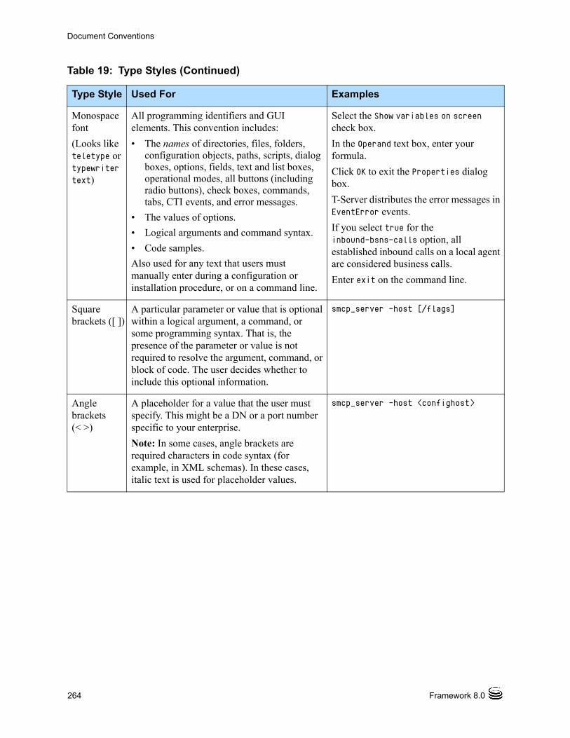
264 Framework 8.0
Document Conventions
Monospace font
(Looks like teletype or typewriter text)
All programming identifiers and GUI elements. This convention includes:
• The names of directories, files, folders, configuration objects, paths, scripts, dialog boxes, options, fields, text and list boxes, operational modes, all buttons (including radio buttons), check boxes, commands, tabs, CTI events, and error messages.
• The values of options.
• Logical arguments and command syntax.
• Code samples.
Also used for any text that users must manually enter during a configuration or installation procedure, or on a command line.
Select the Show variables on screen check box.
In the Operand text box, enter your formula.
Click OK to exit the Properties dialog box.
T-Server distributes the error messages in EventError events.
If you select true for the inbound-bsns-calls option, all established inbound calls on a local agent are considered business calls.
Enter exit on the command line.
Square brackets ([ ])
A particular parameter or value that is optional within a logical argument, a command, or some programming syntax. That is, the presence of the parameter or value is not required to resolve the argument, command, or block of code. The user decides whether to include this optional information.
smcp_server -host [/flags]
Angle brackets (< >)
A placeholder for a value that the user must specify. This might be a DN or a port number specific to your enterprise.
Note: In some cases, angle brackets are required characters in code syntax (for example, in XML schemas). In these cases, italic text is used for placeholder values.
smcp_server -host <confighost>
Table 19: Type Styles (Continued)
Type Style Used For Examples
T-Server—Deployment Guide 265
Index
Symbols[] (square brackets). . . . . . . . . . . . . . 264< > (angle brackets) . . . . . . . . . . . . . 264<key name>
common log option . . . . . . . . . . . . 203
AAccess Code
configuration. . . . . . . . . . . . . . . . 108defined. . . . . . . . . . . . . . . . . 40, 106
ADDP. . . . . . . . . . . . . . . . . . . . . 58addp-remote-timeout
configuration option . . . . . . . . . . . . 226addp-timeout
configuration option . . . . . . . . . . . . 226addp-trace
configuration option . . . . . . . . . . . . 226Advanced Disconnect Detection Protocol . . 23Agent Login objects . . . . . . . . . . . . . 41agent reservation
defined. . . . . . . . . . . . . . . . . . . . 28Agent Ring Timeout
Supported Functionality . . . . . . . . . . 154AgentAfterCallWork
Supported Functionality . . . . . . . . . . 153agent-no-answer-action
configuration options . . . . . . . . . . . 233agent-no-answer-overflow
configuration options . . . . . . . . . . . 233agent-no-answer-timeout
configuration options . . . . . . . . . . . 234Agent-Reservation section
configuration options . . . . . . . . .214–215alarm
common log option . . . . . . . . . . . . 194AlarmServiceHostname
JTAPI configuration options . . . . . . . . 242AlarmServicePort
JTAPI configuration options . . . . . . . . 242
common log option . . . . . . . . . . . . 193angle brackets . . . . . . . . . . . . . . . . 264ANI . . . . . . . . . . . . . . . . . . . . . . .71ani-distribution
configuration option . . . . . . . . . . . . 206app
command line parameter . . . . . . . . . 119application
configuration options . . . . . . . . . . . 234Application objects
multi-site operation . . . . . . . . . . . . 105audience, for document . . . . . . . . . . . .12audio-codec
configuration options . . . . . . . . . . . 234
Bbackground-processing
configuration option . . . . . . . . . . . . 206background-timeout
configuration option . . . . . . . . . . . . 207backup servers. . . . . . . . . . . . . . . . .49backup-sync
configuration section . . . . . . . . . . . . 58Backup-Synchronization section
configuration option . . . . . . . . . . 226–227brackets
angle . . . . . . . . . . . . . . . . . . . 264square. . . . . . . . . . . . . . . . . . . 264
bufferingcommon log option . . . . . . . . . . . . 187
busy-toneconfiguration options . . . . . . . . . . . 235
CCall Recording . . . . . . . . . . . . . . . . 157
emergency . . . . . . . . . . . . . . . . 177feature configuration . . . . . . . . . . . 177
Index
266 Framework 8.0
Call-Cleanup sectionconfiguration option . . . . . . . . . .227–229
callmgr-autopickup-onconfiguration options . . . . . . . . . . . 248
cast-typeconfiguration option . . . . . . . . . . 70, 217
ccm-hostconfiguration options . . . . . . . . . . . 249
CDN . . . . . . . . . . . . . . . . . . . . . 77changes from 8.0 to 8.0.1
T-Server options . . . . . . . . . . . . . . 251check-point
common log option . . . . . . . . . . . . 191check-tenant-profile
configuration option . . . . . . . . . . . . 207cleanup-idle-tout
configuration option . . . . . . . . . . . . 227Code property . . . . . . . . . . . . . 108, 109cof-ci-defer-create
configuration option . . . . . . . . . . . . 222cof-ci-defer-delete
configuration option . . . . . . . . . . . . 222cof-ci-req-tout
configuration option . . . . . . . . . . 86, 222cof-ci-wait-all
configuration option . . . . . . . . . . . . 222cof-feature
configuration option . . . . . . . . . . . . 223cof-rci-tout
configuration option . . . . . . . . . . . . 223collect-lower-priority-requests
configuration option . . . . . . . . . . . . 214collect-tone
configuration options . . . . . . . . . . . 235command line parameters . . . . . . . . . . 119
app . . . . . . . . . . . . . . . . . . . . 119host . . . . . . . . . . . . . . . . . . . . 119l . . . . . . . . . . . . . . . . . . . . . . 120lmspath . . . . . . . . . . . . . . . . . . 120nco X/Y . . . . . . . . . . . . . . . . . . 120port . . . . . . . . . . . . . . . . . . . . 119V. . . . . . . . . . . . . . . . . . . . . . 120
commenting on this document . . . . . . . . 13common configuration options . . . . . 186–204
common section . . . . . . . . . . . .203–204enable-async-dns . . . . . . . . . . . . . 203log section . . . . . . . . . . . . . . .186–200log-extended section . . . . . . . . .200–202log-filter section . . . . . . . . . . . .202–203log-filter-data section . . . . . . . . . . . 203mandatory . . . . . . . . . . . . . . . . . 186rebind-delay . . . . . . . . . . . . . . . . 204setting . . . . . . . . . . . . . . . . . . . 186sml section . . . . . . . . . . . . . . . . 203suspending-wait-timeout . . . . . . . . . 203
common log options . . . . . . . . . . 186–203
<key name>. . . . . . . . . . . . . . . . 203alarm . . . . . . . . . . . . . . . . . . . 194all . . . . . . . . . . . . . . . . . . . . . 193buffering. . . . . . . . . . . . . . . . . . 187check-point . . . . . . . . . . . . . . . . 191compatible-output-priority . . . . . . . . . 192debug . . . . . . . . . . . . . . . . . . . 195default-filter-type . . . . . . . . . . . . . 202expire . . . . . . . . . . . . . . . . . . . 188interaction . . . . . . . . . . . . . . . . . 194keep-startup-file . . . . . . . . . . . . . . 188level-reassign-<eventID> . . . . . . . . . 200level-reassign-disable. . . . . . . . . . . 202log section . . . . . . . . . . . . . . 186–200log-extended section . . . . . . . . . 200–202log-filter section . . . . . . . . . . . . 202–203log-filter-data section . . . . . . . . . . . 203mandatory options . . . . . . . . . . . . 186memory . . . . . . . . . . . . . . . . . . 191memory-storage-size . . . . . . . . . . . 191message_format . . . . . . . . . . . . . 189messagefile . . . . . . . . . . . . . . . . 188print-attributes. . . . . . . . . . . . . . . 190segment. . . . . . . . . . . . . . . . . . 187setting . . . . . . . . . . . . . . . . . . . 186spool . . . . . . . . . . . . . . . . . . . 191standard. . . . . . . . . . . . . . . . . . 194time_convert . . . . . . . . . . . . . . . 190time_format . . . . . . . . . . . . . . . . 190trace. . . . . . . . . . . . . . . . . . . . 195verbose . . . . . . . . . . . . . . . . . . 186x-conn-debug-all . . . . . . . . . . . . . 200x-conn-debug-api . . . . . . . . . . . . . 199x-conn-debug-dns. . . . . . . . . . . . . 200x-conn-debug-open . . . . . . . . . . . . 198x-conn-debug-security . . . . . . . . . . 199x-conn-debug-select . . . . . . . . . . . 198x-conn-debug-timers . . . . . . . . . . . 199x-conn-debug-write . . . . . . . . . . . . 199
common optionscommon log options . . . . . . . . . 186–203common section . . . . . . . . . . . 203–204mandatory options . . . . . . . . . . . . 186sml section . . . . . . . . . . . . . . . . 203
common sectioncommon options . . . . . . . . . . . 203–204
compatible-output-prioritycommon log option . . . . . . . . . . . . 192
compound-dn-representationconfiguration option . . . . . . . . . . . . 224
Configuration Managerconfiguring T-Server . . . . . . . . . . . . 42
multiple ports . . . . . . . . . . . . . .43configuration options. . . . . . . . . . 231, 253
addp-remote-timeout . . . . . . . . . . . 226addp-timeout . . . . . . . . . . . . . . . 226
Index
T-Server—Deployment Guide 267
addp-trace . . . . . . . . . . . . . . . . . 226agent-no-answer-action . . . . . . . . . . 233agent-no-answer-overflow. . . . . . . . . 233agent-no-answer-timeout . . . . . . . . . 234Agent-Reservation section . . . . . .214–215ani-distribution . . . . . . . . . . . . . . . 206application . . . . . . . . . . . . . . . . . 234audio-codec . . . . . . . . . . . . . . . . 234background-processing . . . . . . . . . . 206background-timeout . . . . . . . . . . . . 207Backup-Synchronization section . . .226–227busy-tone . . . . . . . . . . . . . . . . . 235Call-Cleanup section . . . . . . . . .227–229callmgr-autopickup-on . . . . . . . . . . . 248cast-type. . . . . . . . . . . . . . . . . . 217ccm-host. . . . . . . . . . . . . . . . . . 249changes from 8.0 to 8.0.1 . . . . . . . . . 251check-tenant-profile . . . . . . . . . . . . 207cleanup-idle-tout. . . . . . . . . . . . . . 227cof-ci-defer-create . . . . . . . . . . . . . 222cof-ci-defer-delete . . . . . . . . . . . . . 222cof-ci-req-tout . . . . . . . . . . . . . . . 222cof-ci-wait-all . . . . . . . . . . . . . . . 222cof-feature . . . . . . . . . . . . . . . . . 223cof-rci-tout . . . . . . . . . . . . . . . . . 223collect-lower-priority-requests . . . . . . . 214collect-tone . . . . . . . . . . . . . . . . 235common log options . . . . . . . . . .186–203common options . . . . . . . . . . . .186–204compound-dn-representation . . . . . . . 224consult-user-data . . . . . . . . . . . . . 207customer-id . . . . . . . . . . . . . . . . 208debug . . . . . . . . . . . . . . . . . . . 235default-dn . . . . . . . . . . . . . . .218, 235default-monitor-tone . . . . . . . . . . . . 236default-network-call-id-matching . . . . . 223default-record-tone . . . . . . . . . . . . 236direct-digits-key . . . . . . . . . . . . . . 218dn-for-unexpected-calls . . . . . . . . . . 218dn-scope. . . . . . . . . . . . . . . .100, 208enable-data-on-bridged . . . . . . . . . . 237enable-jtapi-keep-alive . . . . . . . . . . 248enable-pickup-jtapi-workaround . . . . . . 248epp-tout . . . . . . . . . . . . . . . .101, 224event-propagation . . . . . . . . . . . . . 225fast-busy-tone . . . . . . . . . . . . . . . 237hostname . . . . . . . . . . . . . . . . . 249inbound-translator-<n> . . . . . . . . . . 225jtapi-keep-alive-retries . . . . . . . . . . . 249jtapi-keep-alive-timeout . . . . . . . . . . 249jtapi-update-mode . . . . . . . . . . . . . 237License section . . . . . . . . . . . .211–214link-n-name . . . . . . . . . . . . . . . . 238local-node-id. . . . . . . . . . . . . . . . 223logout-on-agent-disconnect . . . . . . . . 238logout-on-fwd . . . . . . . . . . . . . . . 238
log-trace-flags. . . . . . . . . . . . . . . 209management-port . . . . . . . . . . . . . 209mandatory options . . . . . . . . . . . . 186match-call-once . . . . . . . . . . . . . . 216merged-user-data . . . . . . . . . . . . . 209Multi-Site Support section. . . . . . . 215–225network-request-timeout . . . . . . . . . 219notify-idle-tout . . . . . . . . . . . . . . . 228num-of-licenses . . . . . . . . . . . . . . 211num-sdn-licenses . . . . . . . . . . . . . 212packet-size . . . . . . . . . . . . . . . . 239password . . . . . . . . . . . . . . . . . 250periodic-check-tout . . . . . . . . . . . . 228port . . . . . . . . . . . . . . . . . . . . 250propagated-call-type . . . . . . . . . 100, 210protocol . . . . . . . . . . . . . . . . 227, 250queue-music . . . . . . . . . . . . . . . 239reconnect-tout. . . . . . . . . . . . . . . 216register-attempts . . . . . . . . . . . . . 219register-tout . . . . . . . . . . . . . . . . 219reject-subsequent-request . . . . . . . . 214report-connid-changes . . . . . . . . . . 216request-collection-time . . . . . . . . . . 215request-tout . . . . . . . . . . . . . . . . 219reservation-time. . . . . . . . . . . . . . 215resource-allocation-mode . . . . . . . . . 219resource-load-maximum . . . . . . . . . 220ring-tone . . . . . . . . . . . . . . . . . 240route-dn . . . . . . . . . . . . . . . . . . 220rule-<n> . . . . . . . . . . . . . . . . . . 225Security section . . . . . . . . . . . . . . 229server-id. . . . . . . . . . . . . . . . . . 210setting . . . . . . . . . . . . . . . . . . . 205
common . . . . . . . . . . . . . . . . 186silence-tone . . . . . . . . . . . . . . . . 241sm-port . . . . . . . . . . . . . . . . . . 241switchover-on-first-link-failure . . . . . . . 241sync-reconnect-tout . . . . . . . . . . . . 227tcs-queue . . . . . . . . . . . . . . . . . 221tcs-use . . . . . . . . . . . . . . . . . . 221timeout . . . . . . . . . . . . . . . . . . 220timeout value format . . . . . . . . . 229–230Translation Rules section . . . . . . . . . 225T-Server section . . . . . . . . . . . 206–211TServerTraceFileBase . . . . . . . . . . 246TServerTraceFileExt . . . . . . . . . . . 246TServerTraceMaxFiles . . . . . . . . . . 246TServerTraceMaxFileSize . . . . . . . . 247use-data-from . . . . . . . . . . . . . . . 217use-default-route . . . . . . . . . . . . . 241use-implicit-access-numbers . . . . . . . 221user-data-limit . . . . . . . . . . . . . . . 211user-login . . . . . . . . . . . . . . . . . 250
configuringDN options . . . . . . . . . . . . . . . . 250
Index
268 Framework 8.0
high availabilityT-Server . . . . . . . . . . . . . . .57–59
multi-site operation . . . . . . . . . .105–118steps . . . . . . . . . . . . . . . . . . 105
T-Server . . . . . . . . . . . . . . . . . . . 42multiple ports. . . . . . . . . . . . . . 43
consult-user-dataconfiguration option . . . . . . . . . . . . 207
conventionsin document . . . . . . . . . . . . . . . . 263type styles . . . . . . . . . . . . . . . . . 263
CtiManagersJTAPI configuration options . . . . . . . . 242
CtiRequestTimeoutJTAPI configuration options . . . . . . . . 242
customer-idconfiguration option . . . . . . . . . . . . 208
DDEBUG
JTAPI configuration options . . . . . . . . 243debug
common log option . . . . . . . . . . . . 195configuration options . . . . . . . . . . . 235
Default Access Codeconfiguration. . . . . . . . . . . . . . . . 107defined. . . . . . . . . . . . . . . . . . . 106
default-dnconfiguration option . . . . . . . . . . . . 218configuration options . . . . . . . . . . . 235
default-filter-typecommon log option . . . . . . . . . . . . 202
default-monitor-toneconfiguration options . . . . . . . . . . . 236
default-network-call-id-matchingconfiguration option . . . . . . . . . . . . 223
default-record-toneconfiguration options . . . . . . . . . . . 236
DesiredServerHeatbeatIntervalJTAPI configuration options . . . . . . . . 243
destination location. . . . . . . . . . . . . . 64destination T-Server . . . . . . . . . . . . . 70Dialogic Dialer . . . . . . . . . . . . . . . . 160direct-ani
ISCC transaction type . . . . . . . . . . 71, 79direct-callid
ISCC transaction type . . . . . . . . . . 72, 79direct-digits
transaction type . . . . . . . . . . . . . . . 79direct-digits-key
configuration option . . . . . . . . . . . . 218direct-network-callid
ISCC transaction type . . . . . . . . . . 72, 79
direct-notokenISCC transaction type. . . . . . . . . . 73, 79
DirectoryJTAPI configuration options . . . . . . . . 243
direct-uuiISCC transaction type. . . . . . . . . . 73, 79
DN objects . . . . . . . . . . . . . . . . . . .41dn-for-unexpected-calls
configuration option . . . . . . . . . . . . 218dnis-pool
in load-balancing mode . . . . . . . . . . . 75ISCC transaction type. . . . . . . . 66, 74, 79
DNsconfiguring for multi-sites . . . . . . . . . 112
dn-scopeconfiguration option . . . . . . . . . . 100, 208
documentaudience . . . . . . . . . . . . . . . . . . 12change history . . . . . . . . . . . . . . . 14conventions . . . . . . . . . . . . . . . . 263errors, commenting on . . . . . . . . . . . 13version number . . . . . . . . . . . . . . 263
Eenable-async-dns
common configuration option . . . . . . . 203enable-data-on-bridged
configuration options . . . . . . . . . . . 237enable-jtapi-keep-alive
configuration options . . . . . . . . . . . 248enable-pickup-jtapi-workaround
configuration options . . . . . . . . . . . 248epp-tout
configuration option . . . . . . . . . . 101, 224Error Messages
Supported Functionality. . . . . . . . . . 150Event Propagation
defined . . . . . . . . . . . . . . . . . . . 97EventAttachedDataChanged . . . . . . . . .98event-propagation
configuration option . . . . . . . . . . . . 225expire
common log option . . . . . . . . . . . . 188extrouter
configuration section . . . . . . . 95, 102, 106
Ffast-busy-tone
configuration options . . . . . . . . . . . 237figures
hot standby redundancy . . . . . . . . . . 52Multiple-to-Point mode . . . . . . . . . . . 78Point-to-Point mode. . . . . . . . . . . . . 77
Index
T-Server—Deployment Guide 269
steps in ISCC/Call Overflow . . . . . . . . . 85FileNameBase
JTAPI configuration options . . . . . . . . 243FileNameExtension
JTAPI configuration options . . . . . . . . 243font styles
italic . . . . . . . . . . . . . . . . . . . . 263monospace . . . . . . . . . . . . . . . . 264
HHA
See also high availabilitySee hot standby
HA configuration . . . . . . . . . . . . . .49–59HA Proxy
starting. . . . . . . . . . . . . . . . .126, 127high-availability configuration . . . . . . .49–59host
command line parameter . . . . . . . . . 119hostname
configuration options . . . . . . . . . . . 249hot standby . . . . . . . . . . . . . . . . .24, 49
defined. . . . . . . . . . . . . . . . . . . . 25figure . . . . . . . . . . . . . . . . . . . . 52T-Server configuration . . . . . . . . . . . . 56
Iinbound-translator-<n>
configuration option . . . . . . . . . . . . 225INFORMATIONAL
JTAPI configuration options . . . . . . . . 243intended audience . . . . . . . . . . . . . . 12Inter Server Call Control . . . . . . . . . .64–83Inter Server Call Control/Call Overflow. . .83–87interaction
common log option . . . . . . . . . . . . 194ISCC
destination T-Server . . . . . . . . . . . . . 70origination T-Server . . . . . . . . . . . . . 70
ISCC transaction types. . . . . . . . . . .65, 70direct-ani. . . . . . . . . . . . . . . . . 71, 79direct-callid . . . . . . . . . . . . . . . 72, 79direct-digits . . . . . . . . . . . . . . . . . 79direct-network-callid . . . . . . . . . . . 72, 79direct-notoken . . . . . . . . . . . . . . 73, 79direct-uui. . . . . . . . . . . . . . . . . 73, 79dnis-pool. . . . . . . . . . . . . . . . . 74, 79
in load-balancing mode . . . . . . . . 75pullback . . . . . . . . . . . . . . . . . 75, 79reroute . . . . . . . . . . . . . . . . . . 76, 79route . . . . . . . . . . . . . . . . . . . 77, 79route-uui . . . . . . . . . . . . . . . . . . . 78supported . . . . . . . . . . . . . . . . . . 79
ISCC/COFsupported . . . . . . . . . . . . . . . . . . 84
iscc-xaction-type . . . . . . . . . . . . . . . .65italics . . . . . . . . . . . . . . . . . . . . . 263
JJTAPI configuration options
. . . . . . . . . . . . . . . . . . . . . . 247AlarmServiceHostname. . . . . . . . . . 242AlarmServicePort . . . . . . . . . . . . . 242CtiManagers . . . . . . . . . . . . . . . 242CtiRequestTimeout . . . . . . . . . . . . 242DEBUG . . . . . . . . . . . . . . . . . . 243DesiredServerHeatbeatInterval . . . . . . 243Directory . . . . . . . . . . . . . . . . . 243FileNameBase . . . . . . . . . . . . . . 243FileNameExtension . . . . . . . . . . . . 243INFORMATIONAL . . . . . . . . . . . . 243JTAPI_DEBUGGING . . . . . . . . . . . 244JTAPIIMPL_DEBUGGING . . . . . . . . 244MISC_DEBUGGING . . . . . . . . . . . 244NumTraceFiles . . . . . . . . . . . . . . 244PeriodicWakeupEnabled . . . . . . . . . 244PeriodicWakeupInterval. . . . . . . . . . 244PROTOCOL_DEBUGGING. . . . . . . . 244ProviderOpenRequestTimeout . . . . . . 245ProviderOpenRetryInterval . . . . . . . . 245QueueSizeThreshold . . . . . . . . . 237, 245RouteSelectTimeout . . . . . . . . . . . 245SyslogCollector . . . . . . . . . . . . . . 245SyslogCollectorUDPPort . . . . . . . . . 246TraceFileSize . . . . . . . . . . . . . . . 246TracePath . . . . . . . . . . . . . . . . . 246UseJavaConsoleTrace . . . . . . . . . . 247UseSameDirectory . . . . . . . . . . . . 247UseSyslog . . . . . . . . . . . . . . . . 247UseTraceFile . . . . . . . . . . . . . . . 247WARNING . . . . . . . . . . . . . . . . 248
JTAPI_DEBUGGINGJTAPI configuration options . . . . . . . . 244
JTAPIIMPL_DEBUGGINGJTAPI configuration options . . . . . . . . 244
jtapi-keep-alive-retriesconfiguration options . . . . . . . . . . . 249
jtapi-keep-alive-timeoutconfiguration options . . . . . . . . . . . 249
jtapi-update-modeconfiguration options . . . . . . . . . . . 237
Kkeep-startup-file
common log option . . . . . . . . . . . . 188
Index
270 Framework 8.0
Known LimitationsSwitch Configuration . . . . . . . . . . . 133
Ll
command line parameter . . . . . . . . . 120level-reassign-<eventID>
common log option . . . . . . . . . . . . 200level-reassign-disable
common log option . . . . . . . . . . . . 202License section
configuration options . . . . . . . . .211–214link-n-name
configuration options . . . . . . . . . . . 238lmspath
command line parameter . . . . . . . . . 120local-node-id
configuration option . . . . . . . . . . . . 223location parameter . . . . . . . . . . . . . . 64log configuration options . . . . . . . . 186–192log section
common log options . . . . . . . . . .186–200log-extended section
common log options . . . . . . . . . .200–202log-filter section
common log options . . . . . . . . . .202–203log-filter-data section
common log options . . . . . . . . . . . . 203logout-on-agent-disconnect
configuration options . . . . . . . . . . . 238logout-on-fwd
configuration options . . . . . . . . . . . 238logout-on-out-of-service
T-Server configuration options . . . . . . 238log-trace-flags
configuration option . . . . . . . . . . . . 209
MManagement Layer. . . . . . . . . . . . . . 36management-port
configuration option . . . . . . . . . . . . 209Mandatory Options
configuration options . . . . . . . . . . . 232mandatory options
configuration options . . . . . . . . . . . 206match-call-once
configuration option . . . . . . . . . . . . 216memory
common log option . . . . . . . . . . . . 191memory-storage-size
common log option . . . . . . . . . . . . 191merged-user-data
configuration option . . . . . . . . . . . . 209message_format
common log option . . . . . . . . . . . . 189messagefile
common log option . . . . . . . . . . . . 188MISC_DEBUGGING
JTAPI configuration options . . . . . . . . 244monospace font . . . . . . . . . . . . . . . 264Multiple-to-One mode . . . . . . . . . . . . .77Multiple-to-Point mode. . . . . . . . . . . 77, 78Multi-Site Support section
configuration options . . . . . . . . . 215–225Music Treatment on Route-Points .156, 157, 159,
160
NNAT/C feature . . . . . . . . . . . . . . . . .95nco X/Y
command line parameter . . . . . . . . . 120network attended transfer/conference . . . . .95network objects . . . . . . . . . . . . . . . .36network-request-timeout
configuration option . . . . . . . . . . . . 219notify-idle-tout
configuration option . . . . . . . . . . . . 228Number Translation feature . . . . . . . . 87–95number translation rules . . . . . . . . . . . .88num-of-licenses
configuration option . . . . . . . . . . . . 211num-sdn-licenses
configuration option . . . . . . . . . . . . 212NumTraceFiles
JTAPI configuration options . . . . . . . . 244
Oobjects
Agent Logins . . . . . . . . . . . . . . . . 41DNs . . . . . . . . . . . . . . . . . . . . . 41network . . . . . . . . . . . . . . . . . . . 36Switches . . . . . . . . . . . . . . . . . . 40Switching Offices . . . . . . . . . . . . . . 40
One-to-One mode . . . . . . . . . . . . . . .77origination location . . . . . . . . . . . . . . .64origination T-Server . . . . . . . . . . . . . .70Outbound Calling . . . . . . . . . . . . . . 160Outbound Calling with Dialogic Dialer . . . . 160
Ppacket-size
configuration options . . . . . . . . . . . 239
Index
T-Server—Deployment Guide 271
passwordconfiguration options . . . . . . . . . . . 250
periodic-check-toutconfiguration option . . . . . . . . . . . . 228
PeriodicWakeupEnabledJTAPI configuration options . . . . . . . . 244
PeriodicWakeupIntervalJTAPI configuration options . . . . . . . . 244
Point-to-Point mode . . . . . . . . . . . . . 77port
command line parameter . . . . . . . . . 119configuration options . . . . . . . . . . . 250
primary servers. . . . . . . . . . . . . . . . 49print-attributes
common log option . . . . . . . . . . . . 190propagated-call-type
configuration option . . . . . . . . . .100, 210protocol
configuration option . . . . . . . . . . . . 227configuration options . . . . . . . . . . . 250
PROTOCOL_DEBUGGINGJTAPI configuration options . . . . . . . . 244
ProviderOpenRequestTimeoutJTAPI configuration options . . . . . . . . 245
ProviderRetryIntervalJTAPI configuration options . . . . . . . . 245
pullbackISCC transaction type . . . . . . . . . . 75, 79
Qqueue-music
configuration options . . . . . . . . . . . 239QueueSizeThreshold
JTAPI configuration options . . . . . .237, 245
Rrebind-delay
common configuration option . . . . . . . 204reconnect-tout
configuration option . . . . . . . . . . . . 216RecordUserAnnouncement . . . . . . . . . 157redundancy
hot standby . . . . . . . . . . . . . . . 24, 49warm standby . . . . . . . . . . . . . . 24, 49
redundancy types . . . . . . . . . . .53, 54, 56hot standby . . . . . . . . . . . . . . . . . 25
register-attemptsconfiguration option . . . . . . . . . . . . 219
register-toutconfiguration option . . . . . . . . . . . . 219
reject-subsequent-requestconfiguration option . . . . . . . . . . . . 214
report-connid-changesconfiguration option . . . . . . . . . . . . 216
request-collection-timeconfiguration option . . . . . . . . . . . . 215
request-toutconfiguration option . . . . . . . . . . 66, 219
rerouteISCC transaction type. . . . . . . . . . 76, 79
reservation-timeconfiguration option . . . . . . . . . . . . 215
resource-allocation-modeconfiguration option . . . . . . . . . . . . 219
resource-load-maximumconfiguration option . . . . . . . . . . . . 220
ring-toneconfiguration options . . . . . . . . . . . 240
routeISCC transaction type. . . . . . 66, 77, 79, 112
route-dnconfiguration option . . . . . . . . . . . . 220
RouteSelectTimeoutJTAPI configuration options . . . . . . . . 245
route-uuiISCC transaction type. . . . . . . . . . . . 78
routingInter Server Call Control . . . . . . . . 70–83
rule-<n>configuration option . . . . . . . . . . . . 225
run.bat . . . . . . . . . . . . . . . . . . . . 123run.sh . . . . . . . . . . . . . . . . . . . . 122
SSecurity section
configuration option . . . . . . . . . . . . 229segment
common log option . . . . . . . . . . . . 187server-id
configuration option . . . . . . . . . . . . 210setting
configuration options . . . . . . . . . . . 205setting configuration options
common. . . . . . . . . . . . . . . . . . 186silence-tone
configuration options . . . . . . . . . . . 241sml section
common options . . . . . . . . . . . . . 203smloc . . . . . . . . . . . . . . . . . . . . 254sm-port
configuration options . . . . . . . . . . . 241spool
common log option . . . . . . . . . . . . 191square brackets . . . . . . . . . . . . . . . 264standard
common log option . . . . . . . . . . . . 194
Index
272 Framework 8.0
startingHA Proxy . . . . . . . . . . . . . . . . . 126T-Server . . . . . . . . . . . . . . . . . . 127
StreamManager . . . . . . . . . . . . . . . 157Supported Functionality . . . . . . . . . . . 139
Agent Ring Timeout . . . . . . . . . . . . 154AgentAfterCallWork . . . . . . . . . . . . 153Error Messages . . . . . . . . . . . . . . 150
supported functionalityHigh-Availability configurations . . . . . . 257
Supported Functionality table . . . . . 140–149suspending-wait-timeout
common configuration option . . . . . . . 203Switch Configuration
Known Limitations . . . . . . . . . . . . . 133Switch objects . . . . . . . . . . . . . . . . 40
multi-site operation . . . . . . . . . . . . 105switch partitioning
defined. . . . . . . . . . . . . . . . . . . 100T-Server support. . . . . . . . . . . . . . 101
Switching Office objects . . . . . . . . . . . 40multi-site operation . . . . .106, 107, 108, 112
switchover-on-first-link-failureconfiguration options . . . . . . . . . . . 241
Switch-Specific Configuration . . . . . . . . 133sync-reconnect-tout
configuration option . . . . . . . . . . . . 227SyslogCollector
JTAPI configuration options . . . . . . . . 245SyslogCollectorUDPPort
JTAPI configuration options . . . . . . . . 246
TTarget ISCC
Access Code configuration . . . . . . . . 109Default Access Code configuration . . . . 108
tcs-queueconfiguration option . . . . . . . . . . . . 221
tcs-useconfiguration option . . . . . . . . . . . . 221
time_convertcommon log option . . . . . . . . . . . . 190
time_formatcommon log option . . . . . . . . . . . . 190
timeoutconfiguration option . . . . . . . . . . 66, 220
timeout value formatconfiguration option . . . . . . . . . .229–230
TInitiateConference . . . . . . . . . . . . . 64TInitiateTransfer . . . . . . . . . . . . . . . 64T-Library Functionality . . . . . . . . . . . . 140TMakeCall . . . . . . . . . . . . . . . . . . 64TMakePredictiveCall . . . . . . . . . . . . . 160TMuteTransfer . . . . . . . . . . . . . . . . 64trace
common log option . . . . . . . . . . . . 195TraceFileSize
JTAPI configuration options . . . . . . . . 246TracePath
JTAPI configuration options . . . . . . . . 246transaction types (ISCC). . . . . . . . . . 65, 70
supported . . . . . . . . . . . . . . . . . . 79transfer connect service . . . . . . . . . . . .82Translation Rules section
configuration option . . . . . . . . . . . . 225TreatmentMusic . . . . . . . . . . . . 157, 159TRouteCall . . . . . . . . . . . . . . . . . . .64trunk lines . . . . . . . . . . . . . . . . . . .77T-Server
configuring Application objects . . . . . . . 42for multi-sites . . . . . . . . . . . . . 105
configuring redundancy . . . . . . . . . . . 54HA. . . . . . . . . . . . . . . . . . . . . . 56high availability . . . . . . . . . . . . . . . 56hot standby . . . . . . . . . . . . . . . . . 56multi-site operation . . . . . . . . . . 105–118redundancy . . . . . . . . . . . . . 53, 54, 56starting . . . . . . . . . . . . . . . . 127, 128using Configuration Manager . . . . . . . . 42
multiple ports . . . . . . . . . . . . . .43warm standby . . . . . . . . . . . . . . . . 54
T-Server configuration optionslogout-on-out-of-service. . . . . . . . . . 238
T-Server Sectionconfiguration options . . . . . . . . . . . 233
T-Server sectionconfiguration options . . . . . . . . . 206–211
TServerTraceFileBase options . . . . . . . 246TServerTraceFileExt options . . . . . . . . 246TServerTraceMaxFiles options . . . . . . . 246TServerTraceMaxFileSize options. . . . . . 247TSingleStepTransfer . . . . . . . . . . . . . .64TXRouteType . . . . . . . . . . . . . . . . .65type styles
conventions . . . . . . . . . . . . . . . . 263italic . . . . . . . . . . . . . . . . . . . . 263monospace . . . . . . . . . . . . . . . . 264
typographical styles . . . . . . . . . . . . . 263
Uudio . . . . . . . . . . . . . . . . . . . . . 234umTraceFiles . . . . . . . . . . . . . . . . 244UNIX
installing T-Server . . . . . . . . . . . . 38, 44starting applications . . . . . . . . . . . . 123starting HA Proxy . . . . . . . . . . . . . 127starting T-Server . . . . . . . . . . . . . 128starting with run.sh . . . . . . . . . . . . 122
Index
T-Server—Deployment Guide 273
UseAlarmServiceJTAPI configuration options . . . . . . . . 247
use-data-fromconfiguration option . . . . . . . . . . . . 217
use-default-routeconfiguration options . . . . . . . . . . . 241
use-implicit-access-numbersconfiguration option . . . . . . . . . . . . 221
UseJavaConsoleTraceJTAPI configuration options . . . . . . . . 247
user data propagation . . . . . . . . . . . . 98user-data-limit
configuration option . . . . . . . . . . . . 211user-login
configuration options . . . . . . . . . . . 250UseSameDirectory
JTAPI configuration options . . . . . . . . 247UseSyslog
JTAPI configuration options . . . . . . . . 247UseTraceFile
JTAPI configuration options . . . . . . . . 247
VV
command line parameters. . . . . . . . . 120VDN . . . . . . . . . . . . . . . . . . . . . 77verbose
common log option . . . . . . . . . . . . 186version numbering, document . . . . . . . . 263
Wwarm standby . . . . . . . . . . . . . . .24, 49
figure . . . . . . . . . . . . . . . . . . . . 50T-Server configuration . . . . . . . . . . . . 54
WARNINGJTAPI configuration options . . . . . . . . 248
Windowsinstalling T-Server . . . . . . . . . . . . 39, 45starting applications . . . . . . . . . . . . 123starting HA Proxy . . . . . . . . . . . . . 127starting T-Server. . . . . . . . . . . . . . 128starting with run.bat . . . . . . . . . . . . 123
Xx-conn-debug-all
common log option . . . . . . . . . . . . 200x-conn-debug-api
common log option . . . . . . . . . . . . 199x-conn-debug-dns
common log option . . . . . . . . . . . . 200x-conn-debug-open
common log option . . . . . . . . . . . . 198x-conn-debug-security
common log option . . . . . . . . . . . . 199x-conn-debug-select
common log option . . . . . . . . . . . . 198x-conn-debug-timers
common log option . . . . . . . . . . . . 199x-conn-debug-write
common log option . . . . . . . . . . . . 199

Index
274 Framework 8.0