forwards rev 24 to "sses emergency plan," incorporating
TRANSCRIPT
1e
CATEGORY'REGULATORY INFORMATION DZSTRlBUTION STEM (RIDE)
ACCESSION NBR:9607050280 DOC.DATE: 96/06/28 NOTARIZED: NO DOCKET IFACIL:50-387 Susquehanna Steam Electric Station, Unit 1, Pennsylva 05000387
50-388 Susquehanna Steam Electric Station, Unit 2, Pennsylva 05000388AUTH.NAME AUTHOR AFFILIATION
BYRAM,R.G. pennsylvania Power S Light Co. /7g"Q. [email protected] RECIPIENT AFFILIATIONDocument Control Branch (Document Control Desk)
SUBJECT: Forwards Rev 24 to "SSES Emergency Plan," incorporatingchanges associated w/EOF move (approved by NRC staff),organizational a administrative changes. A
DISTRIBUTION CODE: A045D COPIES RECEIVED:LTR f ENCL 2 SIZE: AI(8 TTITLE: OR Submittal: Emergency Preparedness Plans, Implement'g Procedures, C
ENOTES: 05000387
G
RECIPIENTID CODE/NAME
PD1-2 PD
INTERNAL~CFILE CE TER UENUDOCS-ABSTRACT
COPIESLTTR ENCL
1 1'
21 1
RECIPIENTID CODE/NAME
POSLUSNY,C
NRR/DRPM/PERB
COPIESLTTR ENCL
1 1
1 1
EXTERNAL: NOAC
NOTES:
1 1
1 1
NRC PDR 1 1
D
0
E
N
NOTE TO ALL "RIDS" RECIPIENTS:PLEASE HELP US TO REDUCE WASTEI CONTACT THE DOCUMENT CONTROL DESK,ROOM OWFN SD-5 (EXTi 415-2085) TO ELIMINATE YOUR NAME FROMDISTRIBUTION L1STS FOR DOCUMENTS YOU DON'T NEEDt
TOTAL NUMBER OF COPIES REQUIRED: LTTR .9' ENCL 9

~-''""' l
~F j
'E
Pennsylvania Power 8 Light CompanyTwo North Ninth Street ~ Allentown, PA 18101-1179 ~ 610/774-5151
Robert G. ByramSen/or Vlcc President-Nuclear610/774-7502Fax: 610/774-5019
JUN 20 1996
U.S. Nuclear Regulatory CommissionAttn: Document Control DeskMail Station P1-137Washington, DC 20555
SUSQUEHANNA STEAM ELECTRIC STATIONNOTIFICATIONOF TRANSFER OF EMERGENCYFUNCTIONS TO THE NEW EMERGENCYOP~TIONS FACILITYINWILKES-BARRE Docket Nos. 50-387
and 50-388
Pennsylvania Power 2, Light Company will be implementing the move of its EmergencyOperations Facility (EOF) from directly west of the plant on Confers Lane to the East MountainBusiness, Center offExit 47A of Interstate 81 near Wilkes-Barre. The implementation will takeplace on July 1, 1996. Attached is Revision No. 24 to the Emergency Plan for SusquehannaSES Units 1 and 2 which incorporates the changes associated with the EOF move (approved bythe NRC staff) and other organizational and administrative changes that do not decrease theeffectiveness of the Emergency Plan.
The only noticeable effect will be to those offsite agencies who would report to the new EOFlocation during an emergency. For all others the change willbe unnoticeable. Phone numberswillbe transferred and remain the same.
Ifyou have any comments or questions, please contact Ms. Cynthia A. Smith at (717) 542-3233.
Very truly yours,
R. G yr
Attachment
g0
9607050280 960628PDR ADOCK 05000387F PDR

4
C <~k
-2- FILE R41-2 PLA-4474Document Control Desk
copy:NRC Region IMs. M. BanerjeeMr. R. KeimigMr. C. Poslusny, Jr.
Mr. J. SyracuseMs. I. MillerMr. C. Wynne
NRC Sr. Resident Inspector-SSESSection Chief-Region INRC Sr. Project Manager-OWFNLuzerne County Emergency ManagementColumbia County Department ofEmergency ServicesPEMA
II
PENNSYLVANIAPOWER 8 LIGHT COMPANY
SUSQUEHANNA STEAM ELEC")'RIC STATIO
ERGENCY PLA
C
Ch,
REVISI
AP IL 199
PORC MEET(NG 5-096

r
/
.4l
4
PENNSYLVANIAPOWER & LIGHTCOMPANY
SUSQUEHANNA STEAM ELECTRIC STATION
~PZ41Vg
gag piOare s~
0 0 0
'* P '.c'A * ~ C
THIS DOCUMENTHAS BEEN UPDATED TO
INCLUDEREVISIONS THROUGH 22 DATED
04/95 .

I
SUSQUEHANNA STEAM ELECTRIC STATION'"- EMERGENCY PLAN'.C I-
"..";,;:," 'LlST. OF 'EFFECTIVE"PA'GES:;-::,--- ' .'
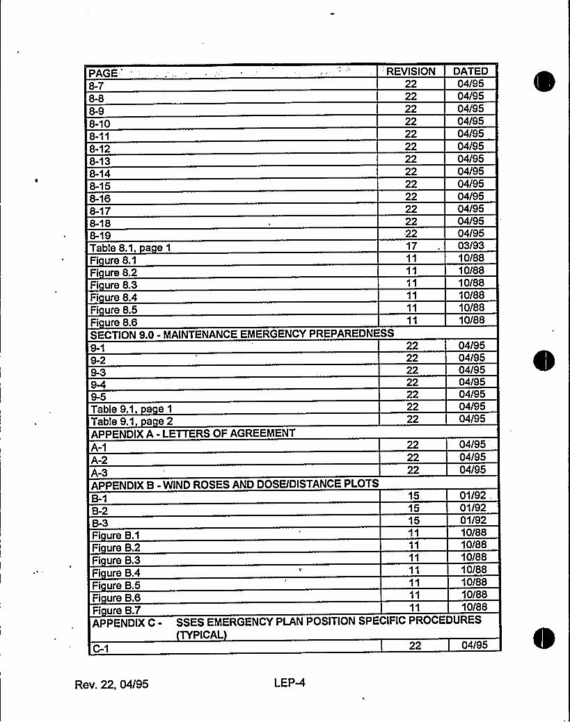
This': list';of 'effective::pa'ges:,'is':: provided for'he convenien'ce.'f rthe'-'end users'f..'th'Susqueharina: SES Emergency Plan';-'" It'is'eprinted: in'.Its:entirety';and', distiibuted"witheach',revision;-.:.,';.....,-'.: ..:.,
'.:,'-..:-::.'.:-:::.",'AGE'."i:::.":::
-; ',:,;;~7::-i'::i'. ".'."':."„-',:<.':..:',;..'; ",: . i::,'.' REVISION 'ATEDTitleTable of Contents i
SECTION 1.0 - DEFINITIONS
1-21-3
1-5SECTION 2.0 - ACRONYMS2-12-2SECTION 3.0- REFERENCES
SECTION 4.0 - SCOPE AND CONTENTS4-14-2Fi ure4.1Fi ure4.2SECTION 5.0 - EMERGENCY CONDITIONS
Table5.1 a e1Table5.1 a e2Table5.1 a e3Table5.1 a e4Table 5.1, a e5Table5.1 a e6Table 5.1 a e7Table 5.1 a e 8Table 5.1 a e 9
22222222
2222222222
2222
22
2222
212121212121222222222222222222
04/9504/9504/9504/95
04/9504/9504/9504/9504/95
04/9504/95
04/95
04/9504/9510/8810/88
04/9404/9404/9404/9404/9404/9404/9504/9504/9504/9504/9504/9504/9504/9504/95
Rev. 22, 04/95 LEP-1
PAGE REVISION DATEDTable 5.1,Table 5.1,Table 5.1,Table 5.1Table 5.1Table 5.1,Table 5.1Table 5.1Table 5.1Table 5.1,Table 5.1Table 5.1,Table 5.1Table 5.1Table 5.1Table 5.1Table 5.1,Table 5.1Table 5.1Table 5.1Table 5.1,Table 5.1Table 5.1Table 5.1,Table 5.2,Table 5.2,Table 5.2,Table 5.2Table 5.2Table 5.2Table 5.2
a e10a e11a e128 B13a e14a e15
e16a e17a e18a e19
e20a e218 B22
B 23a e24a e25
e268 B27a e28a e29a e308 B318 B328 B33
B1ae2
B3e4e5e6
a e7
22222222222222222222222222222222222222222222222222222222222222
04/9504/9504/9504/9504/9504/9504/9504/9504/9504/9504/9504/9504/9504/9504/9504/9504/9504/9504/9504/9504/9504/9504/9504/9504/9504/9504/9504/9504/9504/9504/95
SECTION 6.0 - ORGANIZATIONALCONTROL OF EMERGEN
6-106-116-12
CIES222222222222222222222222
04/9504/9504/9504/9504/9504/9504/9504/9504/9504/9504/9504/95
Rev. 22, 04/95l
LEP-2
PAGE'-., , . REVISION DATED6-136-146-156-166-176-186-19Table 6.1 a e 1
Table6.1, a e2Table6.2, a e1Table6.2, a e2Table6.2, a e3Table6.2 a e4Table B.3, a e 1
Fi ure 6.1Fi ure 6.2aFi ure 6.2bFi ure 6.3Fi ure6.4Fi ure 6.5Fi ure 6.6Fi ure 6.7SECTION 7.0 - EMERGENCY MEASURES7-17-27-37-47-5
7-7Table 7.1 a e1Table7.1 a e2Table7.2 a e1Table 7.2 a e2Table 7.2 a e3Table 7.3 a e1Table7.3 a e2Table 7.3, a e3Table 7.3, a e4SECTION 8.0- EMERGENCY FACILITIESAND EQUIPMENT
222222222222222222222222221522181B221921
15
22222222222222181822222220202020
222222222222
04/9504/9504/9504/9504/9504/9504/9504/9504/9504/9504/9504/9504/9501/9204/9505/9301/9304/9511/9304/9410/8801/92
04/9504/9504/9504/9504/9504/9504/9505/9305/9304/9504/9504/9512/9312/9312/9312/93
04/9504/9504/9504/9504/9504/95
Rev. 22, 04/95 LEP-3
PAGE"
8-78-88-98-108-118-128-138-148-158-168-178-188-19Table 8.1, a e1Fi ure 8.1Fi ure 8.2Fi ure 8.3Fi ure 8.4Fi ure 8.5Fi ure 8.6
'REVISION222222222222222222222222-22
17
DATED04/9504/9504/9504/9504/9504/9504/9504/9504/9504/9504/9504/9504/9503/9310/8810/8810/8810/8810/8810/88
SECTION 9.0 - MAINTENANCEEMERGENCY PREPAREDNE SS
Table9.1, a e1Table9.1 a e2APPENDIX A - LETTERS OF AGREEMENTA-1A-2A-3APPENDIX B - WIND ROSES AND DOSE/DISTANCE PLOTS
B-2
Fi ure B.1Fi ure B.2Fi ure B.3Fi ure B.4Fi ure B.5Fi ure B.6Fi ure B.7
22222222222222
222222
151515
04/9504/9504/9504/9504/9504/9504/95
04/9504/9504/95
01/9201/9201/9210/8810/8810/8810/8810/8810/8810/88
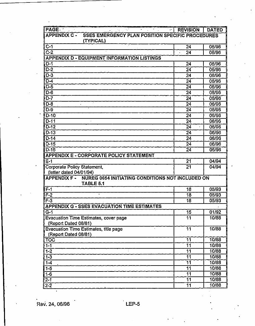
APPENDIX C - SSES EMERGENCY PLAN POSITION SPECIFIC PROCEDURESTYPICAL
22 04/95
Rev. 22, 04/95 LEP-4
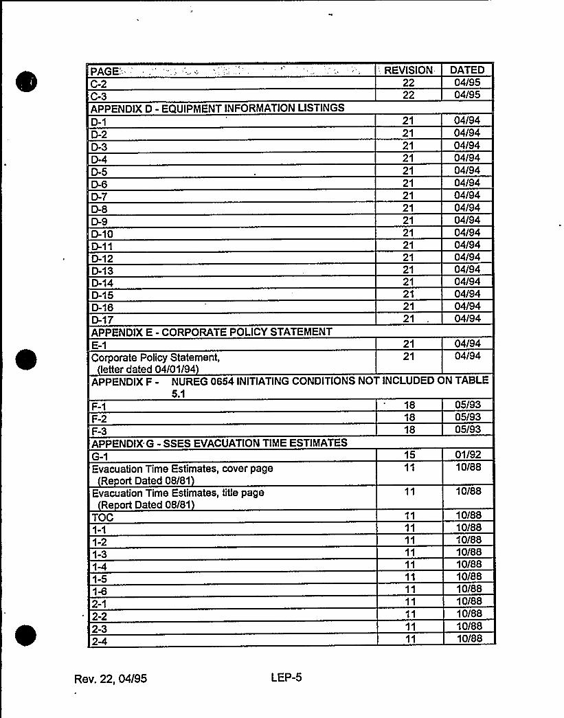
PAGE.'-''C-2C-3APPENDIX D - EQUIPMENT INFORMATIONLISTINGSD-1
D-10D-11D-12D-13D-14D-15D-1BD-17APPENDIX E - CORPORATE POLICY STATEMENTE-1
Corporate Policy Statement,letter dated 04/01/94
-. REVISION-.2222
2121212121212121212121212121212121
2121
DATED04/9504/95
04/9404/9404/9404/9404/9404/9404/9404/9404/9404/9404/9404/9404/9404/9404/9404/9404/94
04/9404/94
APPENDIX F - NUREG 0654 INITIATINGCONDITIONS NOT INCLUDEDON TABLE5.1
F-1F-2F-3APPENDIX G - SSES EVACUATIONTIME ESTIMATESG-1Evacuation Time Estimates, cover page
Re ort Dated 08/81Evacuation Time Estimates, title page
Re ort Dated 08/81TOC
1-21-3
1-5
2-12-22-3
181818
15
05/9305/9305/93
01/9210/88
10/88
10/8810/8810/8810/8810/8810/8810/8810/8810/8810/8810/88
Rev. 22, 04/95 LEP-5
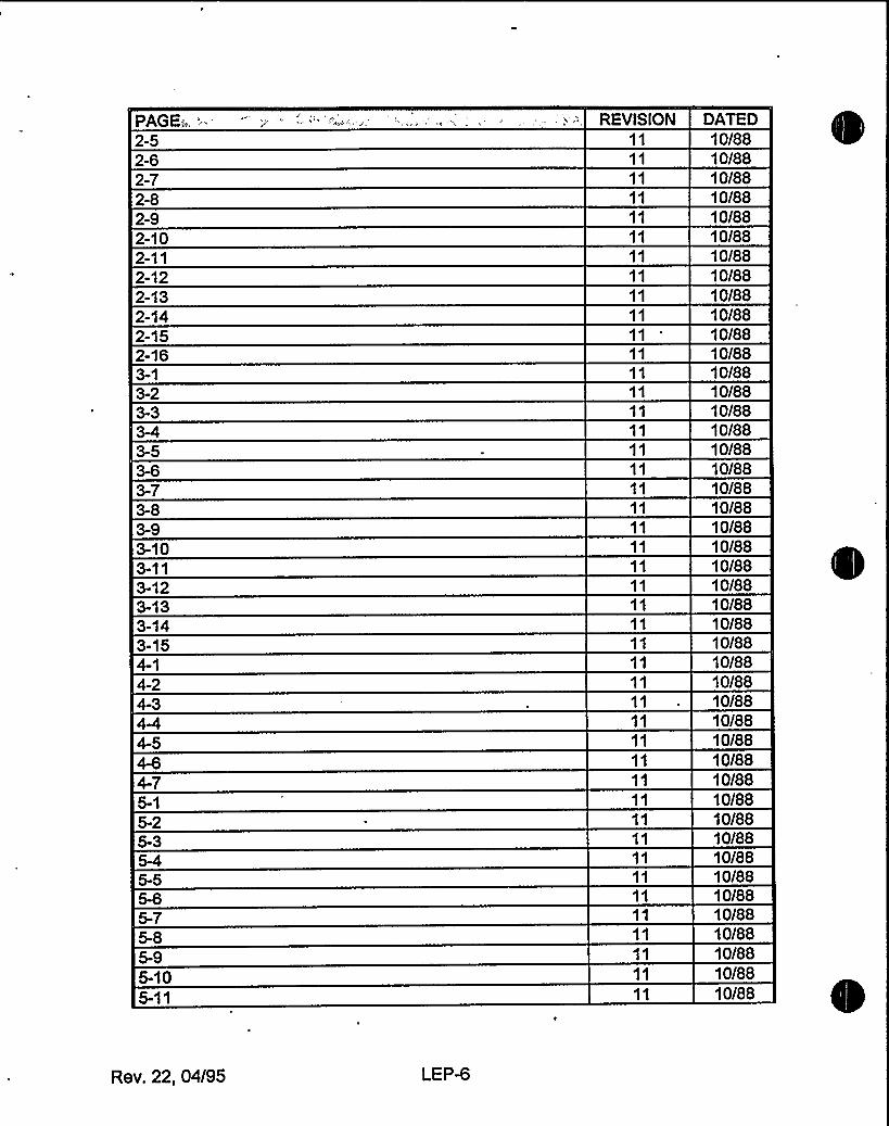
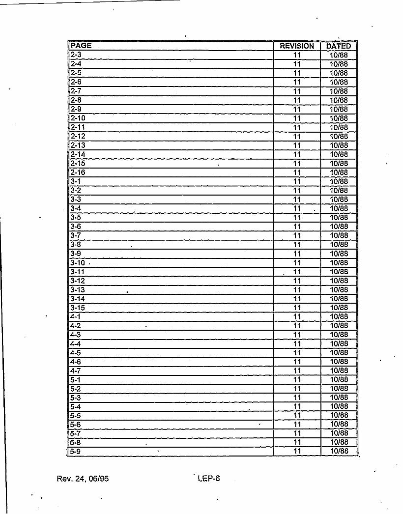
PAGE:„,.'-5
2-72-82-92-102-112-122-132-142-152-16
3-93-103-113-123-13
3-154-14-2
5-105-11
REVtSION DATED10/8810/8810/8810/8810/8810/8810/8810/8810/8810/8810/8810/8810/8810/8810/8810/8810/8810/8810/8810/8810/8810/8810/8810/8810/8810/8810/8810/8810/8810/8810/8810/8810/8810/8810/8810/8810/8810/8810/8810/8810/8810/8810/8810/8810/88
Rev. 22, 04/95 LEP-6
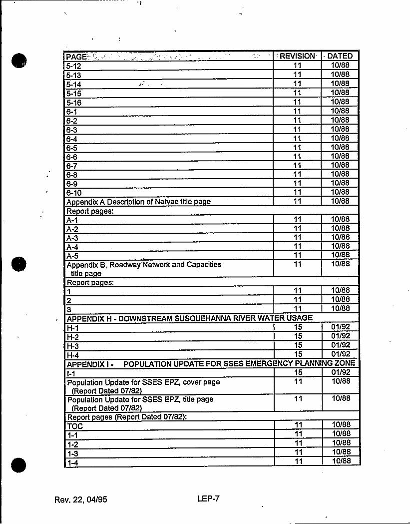
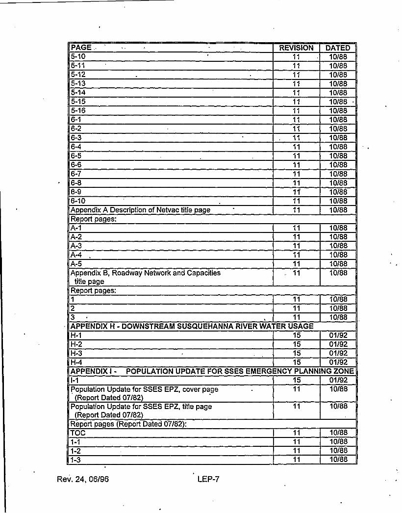
PAGE'."'::.'-12
5-135-145-155-16
6-26-3
6-10A endixA Descri tion of Netvac title a eRe ort a es:
A-2A-3
A-5Appendix B, Roadway'Network and Capacities
title a eRe ort a es:
::. REVISION = DATED10/8810/8810/8810/8810/8810/8810/8810/8810/8810/8810/8810/8810/8810/8810/8810/88
10/8810/8810/8810/8810/8810/88
10/8810/8810/88
APPENDIX H - DOWNSTREAM SUSQUEHANNA RIVER WATER USAGEH-1H-2H-3H-4
15151515
01/9201/9201/9201/92
APPENDIX I - POPULATION UPDATE FOR SSES EMERGENCY PLANNINGZONE
Population Update for SSES EPZ, cover pageRe ort Dated 07/82
Population Update for SSES EPZ, title pageRe ort Dated 07/82
Re ort a es Re ort Dated 07/82:TOC
1-21-3
15 01/9210/88
10/88
10/8810/8810/8810/8810/88
Rev. 22, 04/95 LEP-7
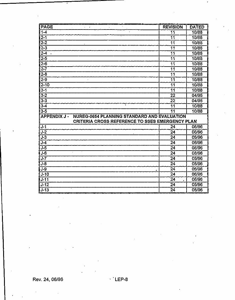
PAGE::-2-12-22-3
2-5
2-72-82-92-10
,:, REVISION
2222
DATED10/8810/8810/8810/8810/8810/8810/8810/8810/8810/8810/8804/9504/9510/8810/88
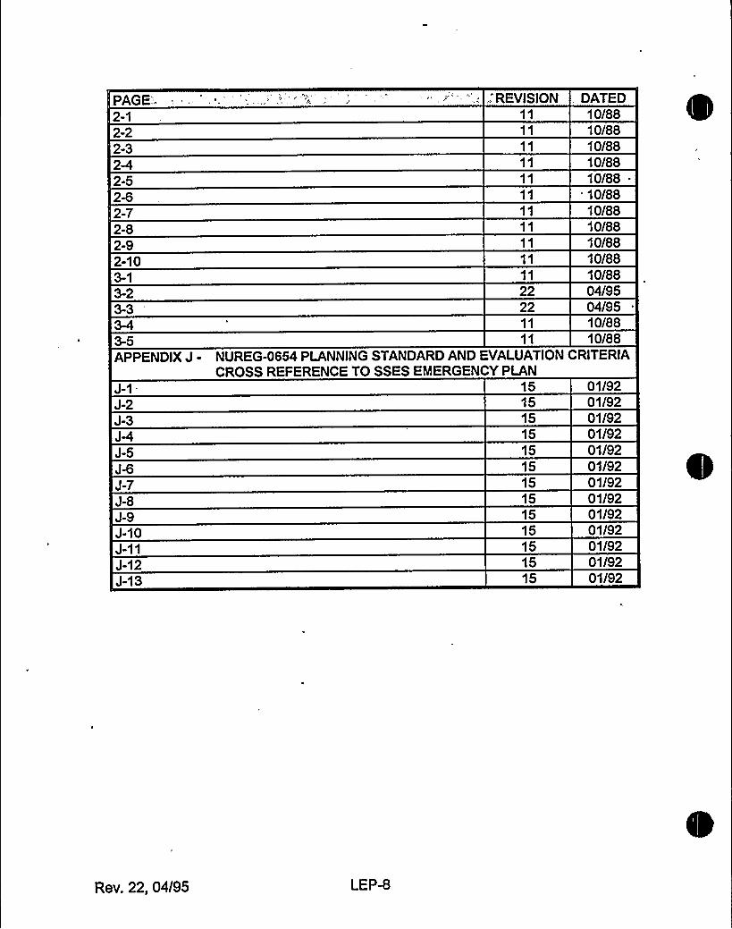
APPENDIX J - NUREG-0654 PLANNING STANDARDAND EVALUATIONCRITERIACROSS REFERENCE TO SSES EMERGENCY PLAN
J-2J-3
J-5
J-7J-8J-9J-10
J-12J-13
15151515151515151515151515
01/9201/9201/9201/9201/9201/9201/9201/9201/9201/9201/9201/9201/92
Rev. 22, 04/95 LEP-8
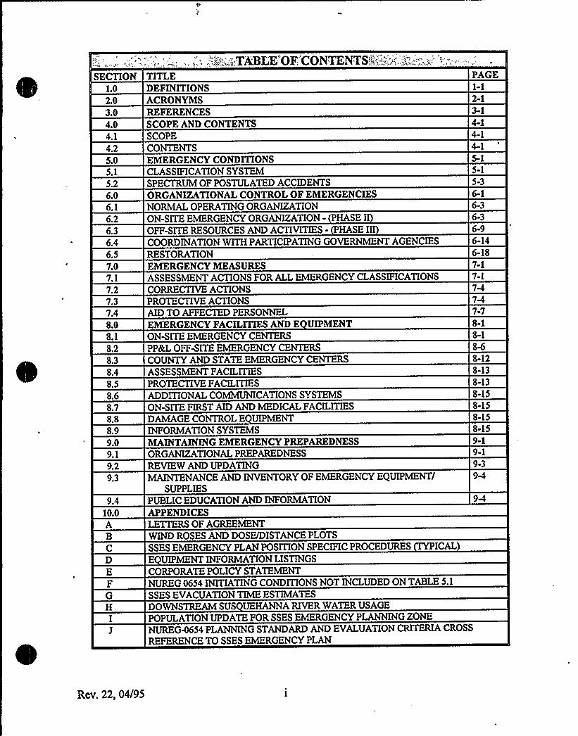
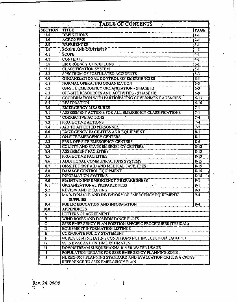
SECTION TITLE, .;.'. -.,""..'';:.„,'„,TA'BLE'OF'CONTENTS,".:''.,:::.,-'::;=:-.'.'~'.::,„...;...„,
PAGE
1.0
2.03.04.04.1
4.25.05.1
5.26.06.1
6.26.3
6.46.57.07.17.27.37.48.08.1
8.28.3
8.48.58.68.78.88.99.09.1
9.29.3
9.410.0A
DEFINITIONSACRONYMSREFERENCESSCOPE AND CONTENTSSCOPECONTENTSEMERGENCY CONDITIONSCLASSIFICATIONSYSTEMSPECTRUM OF POSTULATED ACCIDENTSORGANIZATIONALCONTROL OF EMERGENCIESNORMALOPERATING ORGANIZATIONON-SITE EMERGENCY ORGANIZATION- HASE IOFF-SITE RESOURCES AND ACTIVITIES- HASE IICOORDINATIONWITHPARTICIPATINGGOVERNMENT AGENCIESRESTORATIONEMERGENCY MEASURESASSESSMENT ACTIONS FOR ALLEMERGENCY CLASSIFICATIONSCORRECTIVE ACTIONSPROTECTIVE ACTIONSAIDTO AFFECTED PERSONNELEMERGENCY FACILITIESAND E UIPMENTON-SITE EMERGENCY CENTERSPP8tL OFF-SITE EMERGENCY CENTERSCOUNTYAND STATE EMERGENCY CENTERS
ASSESSMENT FACILITIESPROTECTIVE FACILITIESADDITIONALCOMMUNICATIONSSYSTEMSON-SITE FIRST AIDAND MEDICALFACILITIESDAMAGECONTROL E UIPMENTINFORMATIONSYSTEMSMAINTAININGEMERGENCY PREPAREDNESSORGANIZATIONALPREPAREDNESSREVIEW ANDUPDATINGMAINTENANCEAND INVENTORYOF EMERGENCY EQUIPMENT/
SUPPLIESPUBLIC EDUCATIONAND INFORMATIONAPPENDICESLETTERS OF AGREEMENT
2-1
4-14-1
5-1
5-3
6-36-36-96-146-187-17-1
7-7
8-1
8-128-138-138-158-158-158-159-19-19-3
B WINDROSES ANDDOSE/DISTANCE PLOTS
SSES EMERGENCY PLAN POSITION SPECIFIC PROCEDURES ICALD E UIPMENT INFORMATIONLISTINGSE CORPORATE POLICY STATEMENTF NUREG 0654 INITIATINGCONDITIONS NOT INCLUDEDON TABLE5.1
G SSES EVACUATIONTIMEESTIMATESH DOWNSTREAM SUS UEHANNARIVER WATERUSAGE
I POPULATION UPDATE FOR SSES EMERGENCY PLANNINGZONE
J NUREG4654 PLANNINGSTANDARDAND EVALUATIONCRITERIA CROSS
REFERENCE TO SSES EMERGENCY PLAN
Rev. 22, 04/95
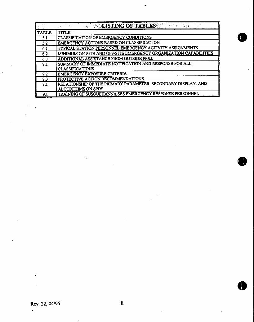
TABLE TITLE".'."'::i.'LISTING'OF'TA'BLES''''.'.1
CLASSIFICATIONOF EMERGENCY CONDITIONS
5.2 EMERGENCY ACTIONS BASED ON CLASSIFICATION6.1 TYPICALSTATION PERSONNEL EMERGENCY ACTIVITYASSIGNMENTS
6.2 MINIMUMON-SITE AND OFF-SITE EMERGENCY ORGANIZATIONCAPABILITIES6.3 ADDITIONALASSISTANCE FROM OUTSIDE PP8Q
7.1 SUMMARYOF IMMEDIATENOTIFICATIONAND RESPONSE FOR ALLCLASSIFICATIONS
7.2 EMERGENCY EXPOSURE CRITERIA7.38.1
PROTECTIVE ACTIONRECOMMENDATIONSRELATIONSHIP OF THE PRIMARYPARAMETER, SECONDARY DISPLAY, ANDALGORITHMSON SPDS
9.1 TRAININGOF SUS UEHANNASES EMERGENCY RESPONSE PERSONNEL
Rev. 22, 04/95
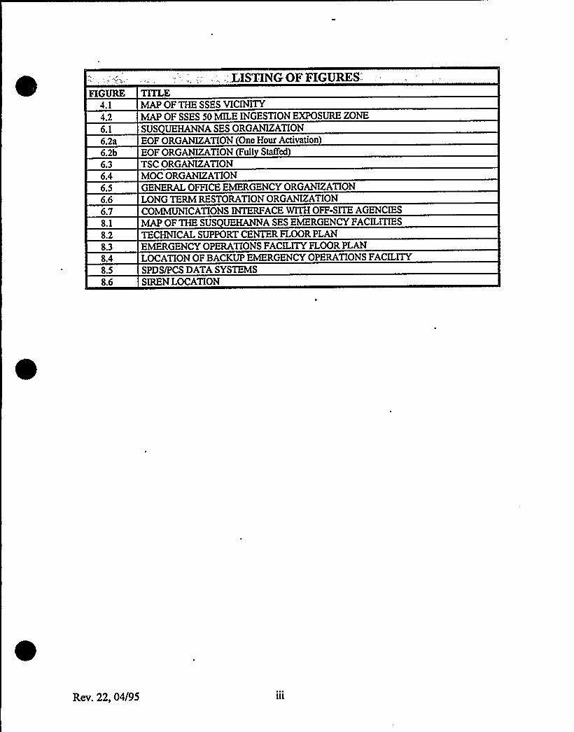
FIGURE TITLE;,;,LISTINGOF
FIGURES:.'.1
4.26.1
MAP OF THE SSES VICINITYMAP OF SSES 50 MLE INGESTION EXPOSURE ZONE
SUS UEHANNASES ORGANIZATION6.2a EOF ORGANIZATION One Hour Activation6.2b EOF ORGANIZATION ull Staffed
6.36.46.56.66.78.1
8.28.38.48.58.6
TSC ORGANIZATIONMOC ORGANIZATIONGENERAL OFFICE EMERGENCY ORGANIZATIONLONG TERM RESTORATION ORGANIZATIONCOMMUNICATIONSINTERFACE WITHOFF-SITE AGENCIES
MAP OF THE SUS UEHANNASES EMERGENCY FACILITIESTECHNICALSUPPORT CENTER FLOOR PLANEMERGENCY OPERATIONS FACILITYFLOOR PLANLOCATIONOF BACKUP EMERGENCY OPERATIONS FACILITYSPDS/PCS DATASYSTEMSSIREN LOCATION
Rev. 22, 04/95
SUSQUEHANNA STEAM ELECTRlC STATlONEMERGENCY PLAN
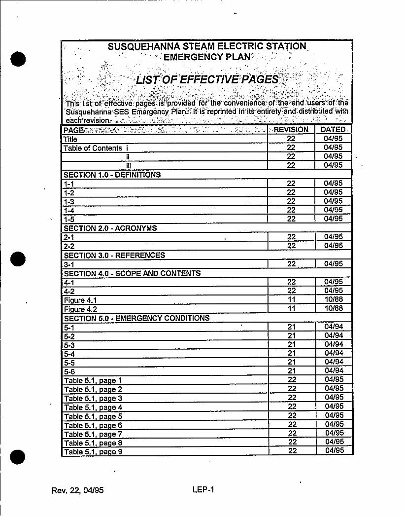
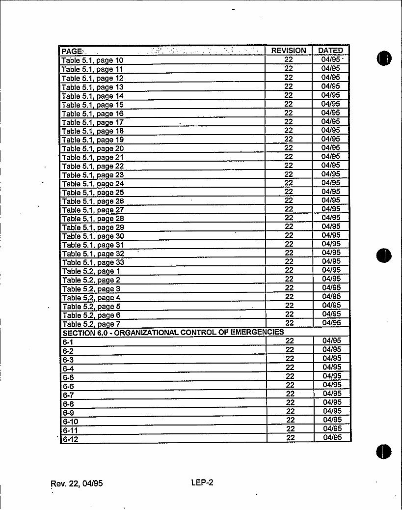
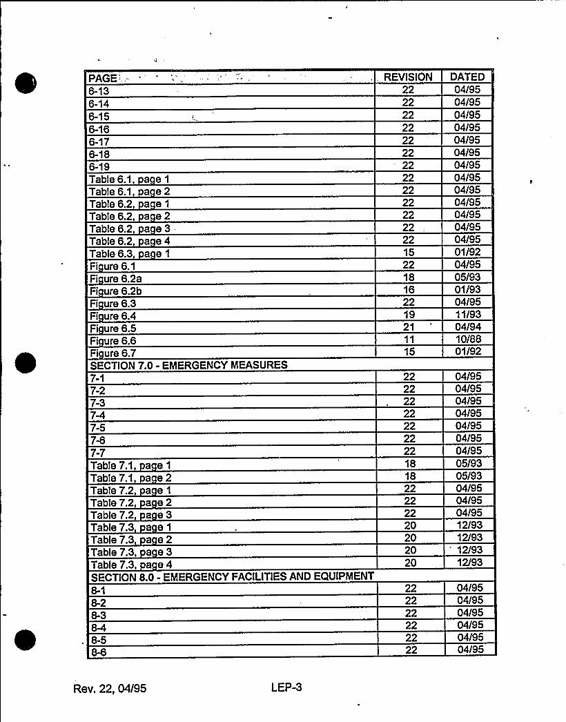
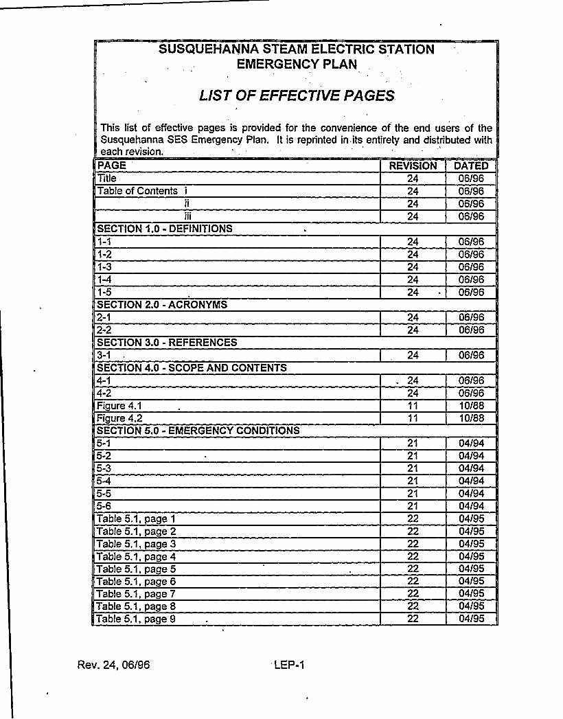
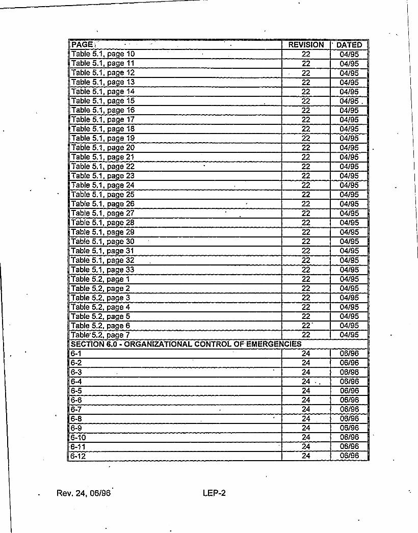
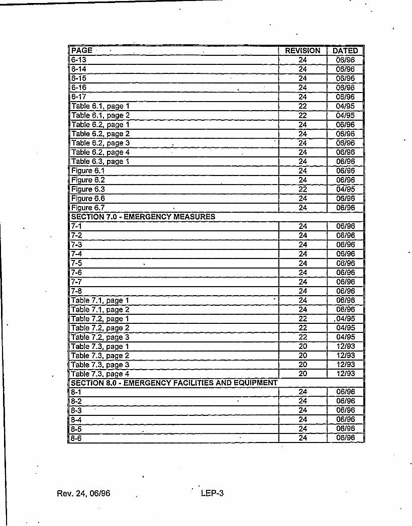
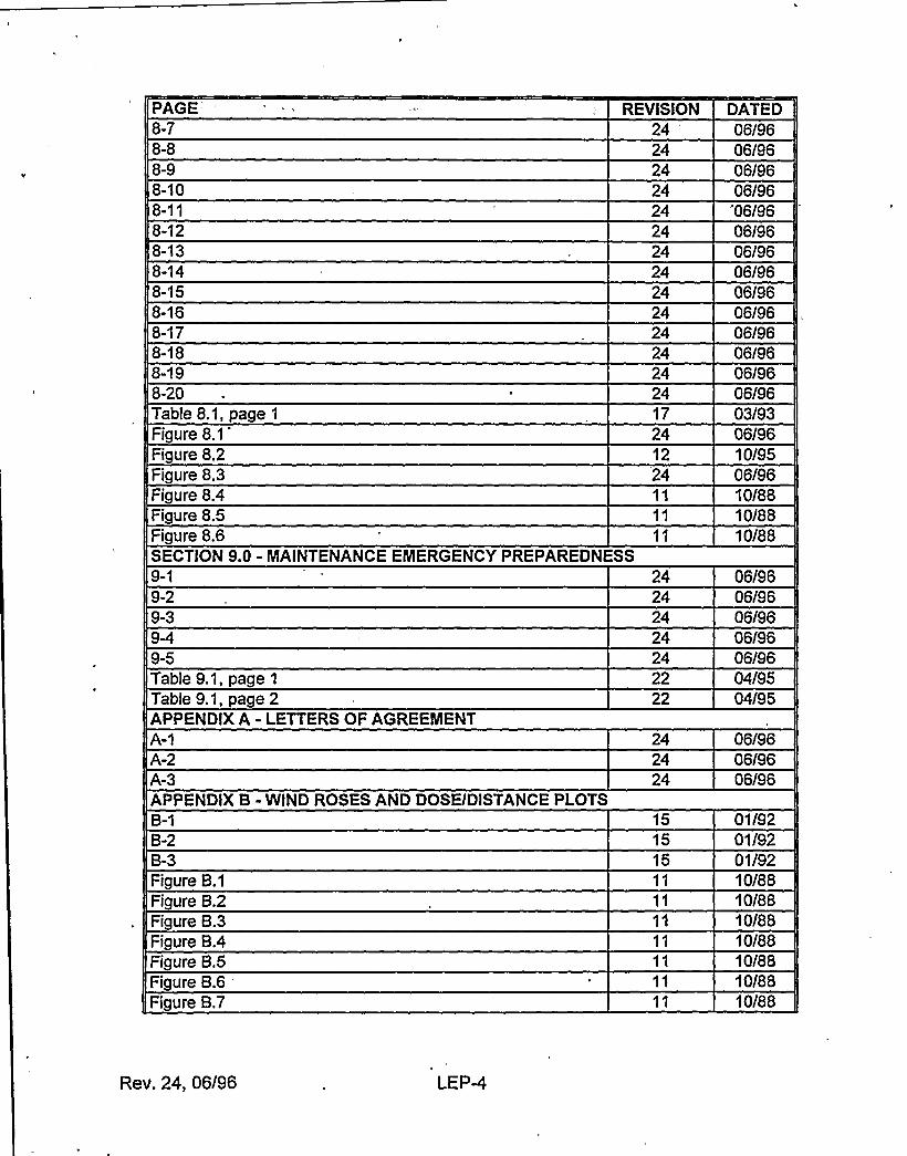
LlST OF EFFECTlVE PAGES
This list of effective pages is provided for the convenience of the end users of theSusquehanna SES Emergency Plan. It is reprinted in.its entirety and distributed witheach revision.
PAGETitleTable of Contents i
SECTION 1.0 - DEFINITIONS
1-21-3
1-5SECTION 2.0 - ACRONYIIS2-12-2SECTION 3.0 - REFERENCES3-1
SECTION 4.0 - SCOPE AND CONTENTS4-14-2Figure 4.1Figure 4.2SECTION 5,0 - EIIERGENCY CONDITIONS5-15-25-3
5-55-6Table 5.1, page 1
Table 5.1, page 2Table 5.1, page 3Table 5.1, page 4Table 5.1, page 5Table 5.1, page 6Table 5.1, page 7Table 5.1, page 8Table 5.1, page 9
- REVISION24242424
2424242424
24
24
2424
21
21
2121
2121
222222222222222222
DATED06/9606/9606/9606/96
06/9606/9606I9606/9606/96
06/9606/96
06/96
06/9606/9610/8810/88
04/9404/9404/9404/9404/9404/9404/9504/9504/9504/9504/9504/9504/9504/9504/95
Rev. 24, 06/96 'EP-1
PAGE'able5.1, page 10
Table 5.1, page 11
Table 5.1; page 12Table 5.1, page 13Table 5.1, page 14Table 5.1, page 15Table 5.1, page 16Table 5.1, page 17Table 5.1, page 18Table 5.1, page 19Table 5.1, page 20Table 5.1, page 21Table 5.1, page 22Table 5.1, page 23Table 5.1, page 24Table 5.1, page 25Table 5.1, page 26Table 5.1, page 2?Table 5.1, page 28Table 5.1, page 29Table 5.1, page 30Table 5.1, page 31
Table 5.1, page 32Table 5.1, page 33Table 5.2, page 1
Table 5.2, page 2Table 5.2, page 3Table 5.2, page 4Table 5.2, page 5Table 5.2, page 6
REVISION22222222222222
22'222222222222
2222222222222222222222
2222
'ATED04/9504/9504/9504/9504/9504/9504/9504/9504/9504/9504/9504/9504/9504/9504/9504/9504/9504/9504/9504/9504/9504/9504/9504/9504/9504/9504/9504/9504/9504/95
Table'5.2, page 7SECTION 6.0 - ORGANIZATIONALCONTROL OF ENIERGENCIES
22 04/95
6-16-26-3
6-56-66-76-86-96-106-116-12
2424
242424
2424242424
06/9606/9606/9606/9606/9606/9606/9606/9606/9606/9606/9606/96
Rev. 24, 06/96 LEP-2

I
PAGE REVISION DATED6-136-146-156-166-17Table 6.1, page 1
Table 6.1, page 2Table 6.2, page 1
Table 6.2, page 2Table 6.2, page 3Table 6.2, page 4Table 6.3, page 1
Figure 6.1Figure 6.2Figure 6.3Figure 6.6Figure 6.7SECTION 7.0 - EMERGENCY MEASURES7-17-27-3
7-57-67-77-8Table 7.1, page 1
Table 7.1, page 2Table 7.2, page 1
Table 7.2, page 2Table?.2, page 3Table 7.3, page 1
Table 7.3, page 2Table 7.3, page 3Table 7.3, page 4SECTION 8.0 - EMERGENCY FACILITIESAND EQUIPMENT8-18-28-3
8-58-6
2424
2424
222424242424242422
2424242424242424242422222220
2020
2424242424
06/9606/9606/9606/9606/9604/9504/9506/9606/9606/9606/9606/9606/9606/9604/9506/9606/96
06/9606/9606/9606/9606/9606/9606/9606/9606/9606/9604/9504/9504/9512/9312/9312/9312/93
06/9606/9606/9606/9606/9606/96
Rev. 24, 06/96 LEP-3
PAGE-'EVISION DATED8-78-88-98-108-118-128-138-148-158-168-178-188-198-20Table 8.1, page 1
Figure 8.1Figure 8.2Figure 8.3Figure 8.4Figure 8.5Figure 8.6SECTION 9.0 - MAINTENANCEEMERGENCY PREPAREDNESS9-19-29-3
9-5Table 9.1, page 1
Table 9.1, page 2APPENDIX A - LETTERS OF AGREEMENT
A-2A-3APPENDIX 8 - WIND ROSES AND DOSE/DISTANCE PLOTS8-18-28-3Figure 8.1Figure 8.2Figure 8.3Figure 8.4Figure 8.5Figure 8.6Figure 8.7
2424
2424242424242424
242417241224
242424242222
242424
151515
06/9606I9606/9606/96
'06/9606/9606/9606/9606/9606/9606/9606/9606/9606/9603/9306/9610/9506/9610/8810/8810/88
06/9606/9606I9606/9606/9604/9504/95
06/9606/9606/96
01I9201/9201/9210/8810/8810/8810/8810/8810/8810/88
Rev. 24, 06/96 LEP-4
PAGE REVISION DATEDAPPENDIX C - SSES EMERGENCY PLAN POSITION SPECIFIC PROCEDURES
(TYPICAL)C-1C-2APPENDIX D - EQUIPMENT INFORMATIONLISTINGSD-1D-2D-3DAD-5D-6D-7D-8D-9D-10D-11D-12D-13D-14D-15D-16APPENDIX E - CORPORATE POLICY STATEMENTE-1
Corporate Policy Statement,(letter dated 04/01/94)
2424
242424
242424242424242424242424
21
21
06/9606/96
06/9606/9606I9606/9606I9606/9606/9606/9606/9606/9606/9606/9606/9606/9606/9606/96
04/9404/94
APPENDIX F - NUREG 0654 INITIATINGCONDITIONS NOT INCLUDEDONTABLE 5.1
F-1F-2F-3APPENDIX G - SSES EVACUATIONTIME ESTIMATESG-1
Evacuation Time Estimates, cover page(Report Dated 08/81)
Evacuation Time Estimates, title page(Report Dated 08/81)
TOC
1-21-3
1-51-62-12-2
181818
15
05/9305/9305/93
01/9210/88
10/88
10/8810I8810/8810/8810/8810/8810/8810/8810/88
Rev. 24, 06/96 LEP-5
PAGE2-3
2-52-62-72-82-92-102-112-122-132-142-152-163-13-23-33-43-53-63-73-83-93-103-113-123-133-143-154-14-24-3
4-54-64-75-15-25-3
5-55-65-75-85-9
REVlSlON DATED1018810/8810/8810/8810/8810/8810/8810/8810/8810/8810/8810/8810/881018810/8810/8810/8810/8810/8810/8810/8810/8810/8810/881018810/8810/8810/8810/8810/8810/8810/8810/8810/881018810/8810/8810/8810/8810/8810/8810/8810/8810/8810/88
Reu. 24, 06/96 LEP-6
PAGE,5-105-115-125-135-145-155-166-16-26-3
6-56-66-76-86-96-10Appendix A Description of Netvac title pageReport pages:A-1A-2A-3
A-5Appendix B, Roadway Network and Capacities
title pageReport pages:
REVISION DATED10I8810/8810/8810/8810/8810/8810/8810/8810/8810/8810/8810/8810/8810/8810/8810/8810/8810/88
10/8810/8810/8810/8810/8810/88
10/8810/8810/88
APPENDIX H - DOWNSTREAM SUSQUEHANNA RIVER WATER USAGEH-1H-2H-3HQ
15151515
01/9201I9201/9201/92
APPENDIX I - POPULATION UPDATE FOR SSES EMERGENCY PLANNING2ONE01/92
Population Update for SSES EPZ, cover page(Report Dated 07/82)
Population Update for SSES EPZ, title page(Report Dated 07/82)
Report pages (Report Dated 07/82):TOC
1-21-3
10/88
10I88
10/8810/8810/8810/88
Rev. 24, 06/96 LEP-7
PAGE
2-12-22-32-42-52-62-72-82-92-103-13-23-3
3-5
'EVISION
2222
DATED10/8810/8810/8810/8810/8810/8810/8810I8810/8810/8810/8810/8804/9504/9510/8810/88
APPENDIX J - NUREG-0654 PLANNING STANDARD AND EVALUATIONCRITERIA CROSS REFERENCE TO SSES EMERGENCY PLAN
J-2J-3J-4J-5J-6J-7J-8J-9J-10
24242424242424242424
06/9606/9606/9606/9606I9606/9606/9606/9606/9606/96
24 . 06/96J-12J-13
2424
06/9606/96
Rev. 24, 06/96 'EP-8
SECTION"1.0
TITLEDEFINITIONS
-, TABLEOF CONTENTSPAGE
2.03.04.04.1
4.25.05.1
5.26.06.1
6.2
6.46.5
7.0
7.1
7.37.4
8.08.1
8.2
8.3
8.5
8.6
8.88.99.09.1
9.3
9.410.0
ACRONYMSREFERENCESSCOPE AND CONTENTSSCOPECONTENTSEMERGENCY CONDITIONSCLASSIFICATIONSYSTEMSPECTRUM OF POSTULATED ACCIDENTSORGANIZATIONALCONTROL OF EMERGENCIESNORMALOPERATING ORGANIZATIONON-SITE EMERGENCY ORGANIZATION- (PHASE II)OFF-SITE RESOURCES AND ACTIVITIES- (PHASE III)COORDINATIONWITH PARTICIPATING GOVERNMENTAGENCIESRESTORATIONEMERGENCY MEASURESASSESSMENT ACTIONS FOR ALLEMERGENCY CLASSIFICATIONSCORRECTIVE ACTIONSPROTECTIVE ACTIONSAIDTO AFFECTED PERSONNELEMERGENCY FACILITIESAND EQUIPMENTON-SITE EMERGENCY CENTERSPP&L OFF-SITE EMERGENCY CENTERSCOUNTY AND STATE EMERGENCY CENTERSASSESSMENT FACILITIESPROTECTIVE FACILITIESADDITIONALCOMMUNICATIONSSYSTEMSON-SITE FIRST AIDAND MEDICALFACILITIESDAMAGECONTROL EQUIPMENTINFORMATIONSYSTEMSMAINTAININGEMERGENCY PREPAREDNESSORGANIZATIONALPREPAREDNESSREVIEW AND UPDATINGMAINTENANCEAND INVENTORYOF EMERGENCY EQUIPMENT/
SUPPLIESPUBLIC EDUCATION AND INFORMATIONAPPENDICES
2-1
3-14-14-1
4-1
5-1
5-1
5-36-1
6-36-36-96-136-167-1
7-1
7-47-4
8-1
8-1
8-68-12
8-138-138-158-158-158-159-1
9-1
9-39-4
9-4
A LETTERS OF AGREEMENTB WINDROSES AND DOSE/DISTANCE PLOTS
SSES EMERGENCY PLAN POSITION SPECIFIC PROCEDURES (TYPICAL)D EQUIPMENT INFORMATIONLISTINGS
CORPORATE POLICY STATEMENTNUREG 0654 INITIATINGCONDITIONS NOT INCLUDEDON TABLE5.1
SSES EVACUATIONTIMEESTIMATESDOWNSTREAM SUSQUEHANNA RIVER WATER USAGE
I POPULATION UPDATE FOR SSES EMERGENCY PLANNINGZONENUREG-0654 PLANNINGSTANDARD AND EVALUATIONCRITERIA CROSSREFERENCE TO SSES EMERGENCY PLAN
Rev. 24, 06/96

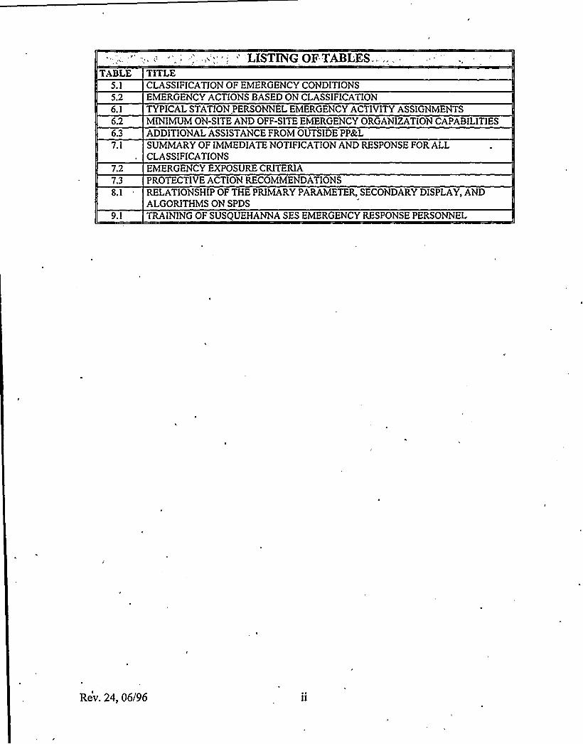
TABLE5.1
5.2
6.26.3
7.1
7.2
8.1
9.1
LISTINGOF TABLES..TITLECLASSIFICATION„OFEMERGENCY CONDITIONSEMERGENCY ACTIONS BASED ON CLASSIFICATIONTYPICALSTATION PERSONNEL EMERGENCY ACTIVITYASSIGNMENTSMINIMUMON-SITE AND OFF-SITE EMERGENCY ORGANIZATIONCAPABILITIESADDITIONALASSISTANCE FROM OUTSIDE PP&LSUMMARYOF IMMEDIATENOTIFICATIONAND RESPONSE FOR ALLCLASSIFICATIONSEMERGENCY EXPOSURE CRITERIAPROTECTIVE ACTION RECOMMENDATIONSRELATIONSHIP OF THE PRIMARYPARAMETER, SECONDARY DISPLAY, ANDALGORITHMSON SPDS
TRAININGOF SUSQUEHANNA SES EMERGENCY RESPONSE PERSONNEL
Rev. 24, 06/96
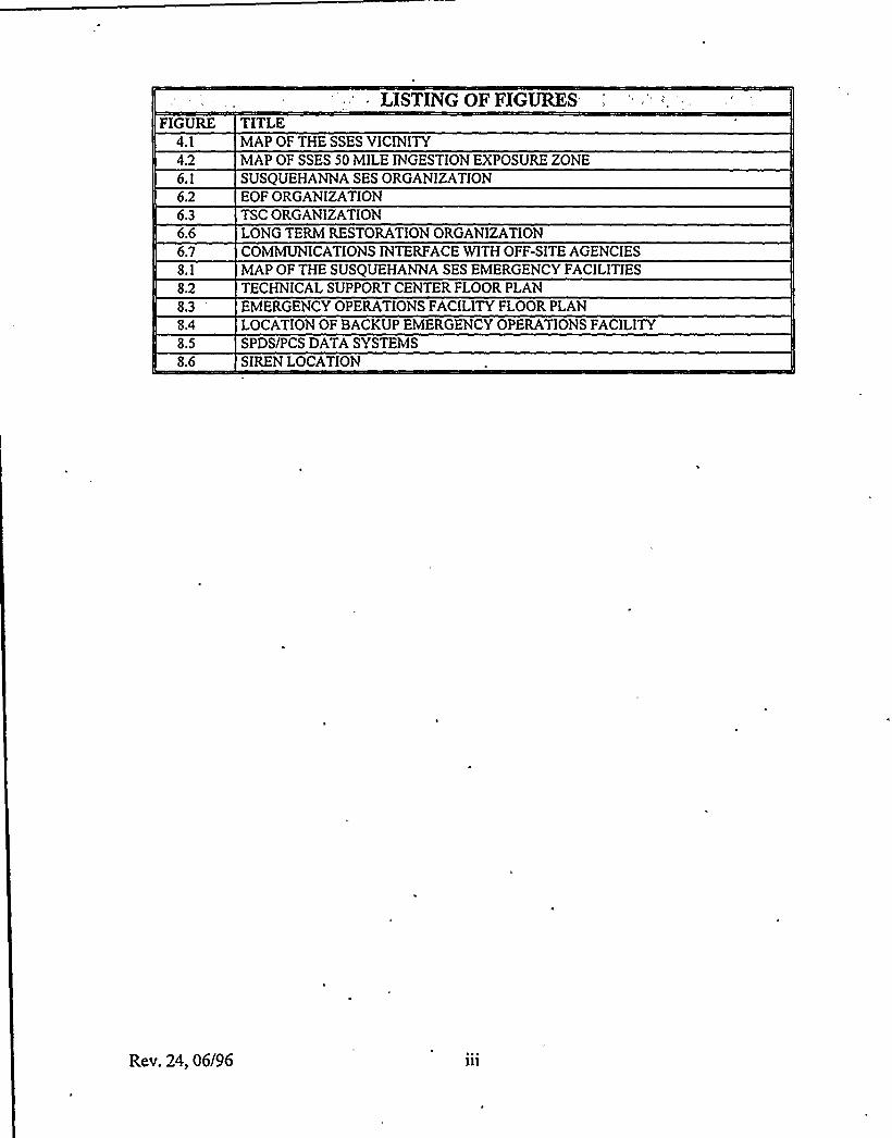
FIGURE TITLELISTING OF FIGURES
4.1
4.2
6.1
6.2
6.6
8.1
8.2
8.3
8.4
8.5
8.6
MAP OF THE SSES VICINITYMAP OF SSES 50 MILEINGESTION EXPOSURE ZONESUSQUEHANNA SES ORGANIZATIONEOF ORGANIZATIONTSC ORGANIZATIONLONG TERM RESTORATION ORGANIZATIONCOMMUNICATIONSINTERFACE WITHOFF-SITE AGENCIESMAP OF THE SUSQUEHANNA SES EMERGENCY FACILITIESTECHNICALSUPPORT CENTER FLOOR PLANEMERGENCY OPERATIONS FACILITYFLOOR PLANLOCATIONOF BACKUP EMERGENCY OPERATIONS FACILITYSPDS/PCS DATASYSTEMSSIREN LOCATION
Rev. 24, 06/96
1:.'0: DEFINITIONS!'.".,:,' ' =
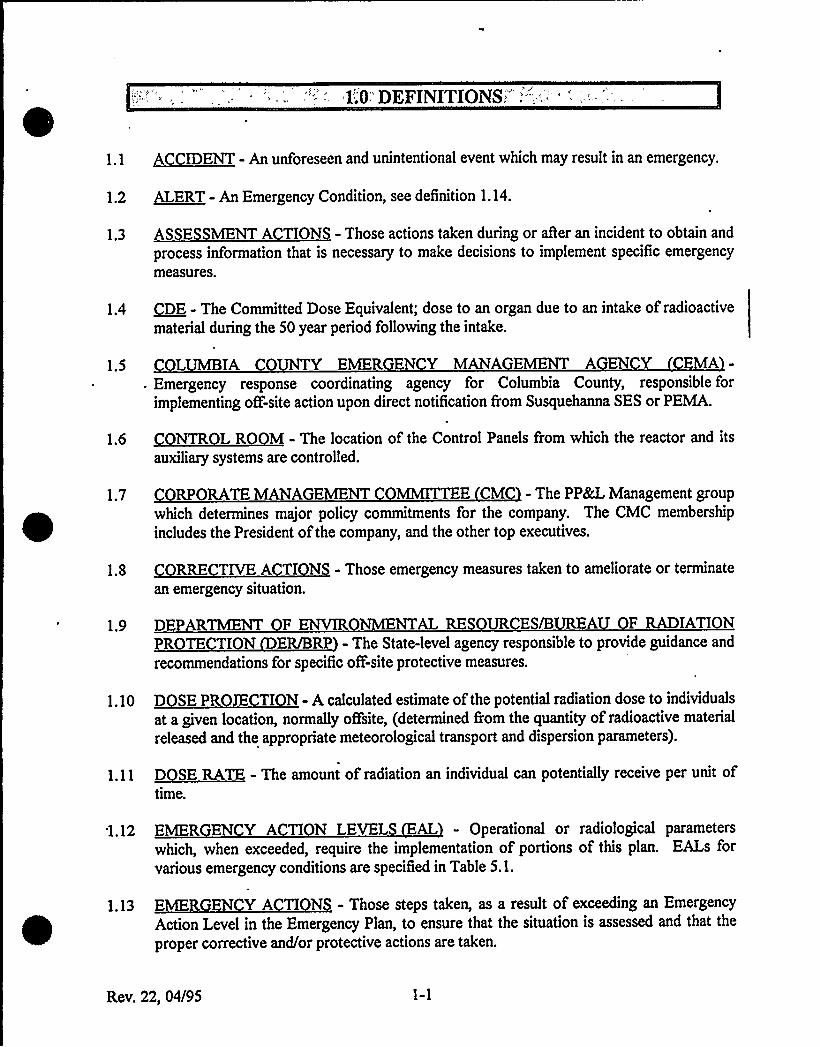
1.1 ACCIDENT - An unforeseen and unintentional event which may result in an emergency.
1.2 ALERT - An Emergency Condition, see definition 1.14.
1.3 ASSE SMENT ACTIONS - Those actions taken during or after an incident to obtain and
process information that is necessary to make decisions to implement specific emergencymeasures.
1.4 /DE - The Committed Dose Equivalent; dose to an organ due to an intake of radioactivematerial during the 50 year period following the intake.
1.5 COLUMBIA C Y EMER EN Y MANA EMENT A EN Y EMA-Emergency response coordinating agency for Columbia County, responsible forimplementing ofF-site action upon direct notification from Susquehanna SES or PEMA.
1.6 Myh I I fh C IP I II I'hl dlauxiliary systems are controlled.
1.7 RPORATE MANAGEMENT OMMITTEE CM - The PP&L Management groupwhich determines major policy commitments for the company. The CMC membership
includes the President of the company, and the other top executives.
1.8 RRE TIVE A TI NS - Those emergency measures taken to ameliorate or terminate
an emergency situation.
1.9 DEPARTMENT F ENVIRONMENTALRE UR ES/8 A F RADIATIONPROTE TION ER/BRP - The State-level agency responsible to provide guidance and
recommendations for specific o6-'site protective measures.
I.I~ D~SEPROIH ION.A d I d I f h p «Id dl I d I dl 'd dat a given location, normally offsite, (determined from the quantity of radioactive material
released and the appropriate meteorological transport and dispersion parameters).
P yll.yh I dl I Idl'dd p«MIP I p I ftime.
'1.12 EMER EN Y A TI N LEVELS AL - Operational or radiological parameters
which, when exceeded, require the implementation of portions of this plan. EALs forvarious emergency conditions are specified in Table 5.1.
1.13 EMERGEN Y ACTI N - Those steps taken, as a result of exceeding an Emergency
Action Level in the Emergency Plan, to ensure that the situation is assessed and that the
proper corrective and/or protective actions are taken.
Rev. 22, 04/95
1.14 EMER EN Y ONDITION - The characterization of several classes of emergencysituations consisting of exclusive groupings including the entire spectrum of possibleradiological emergency situations. The four classes of emergencies, listed in increasingseverity, which PP&L has incorporated into this Emergency Plan are outlined in Section5.0 of this plan.
1.15 EMER EN Y RDINAT R - Designated Susquehanna SES staff membersresponsible for coordinating specific emergency organization functions.
1.16 EMER EN Y DIRE T R - The PP&L individual responsible for direction of onsiteactivities during an emergency at the Susquehanna SES.
1.17 EMER EN Y MANAGER - Designated Susquehanna SES and General OfficePersonnel who are responsible for managing specific emergency organization functions.
1.18 EMER EN Y OPERATI NS ENTERS - Designated State and county emergencymanagement agency headquarters facilities, designed and equipped for the purpose ofexercising effective coordination and control over disaster operations carried out withintheir jurisdiction.
1.19 = EMER EN Y OPERATIONS FACILITY- PP&L Emergency Response Facility locatednear the reactor site to provide continuous coordination and evaluation ofPP&L activitiesduring an emergency having or potentially having environmental consequences.
1.20 EMER EN YPLAN B ARY- Same as the legal site boundary with the exceptionof those sectors which border on U.S. Route 11, where Route 11 forms the boundary;used to calculate offsite dose rates, project dose to the public and to determine necessary
protective actions.
1.21 EMER EN Y PLAN IMPLEMENTINGPROCEDURES - Specific procedures definingin detail the action to be taken in the event of an emergency condition. The EmergencyPlan Implementing Procedures will be separate from, but may incorporate and refer to,normal plant operating procedures and instructions and Emergency Plan Position SpecificProcedures.
1.22 EMER EN Y PLAIN Z NE - There are two Emergency Planning Zones. The
first is an area, approximately ten (10) miles in radius around the Susquehanna SES, forwhich emergency planning consideration of the plume exposure pathway has been given in
order to ensure that prompt and effective actions can be taken to protect the public in the
event of an accident. The second is an area approximately 50 miles in radius around the
Susquehanna SES, for which emergency planning consideration of the ingestion exposure
pathway has been given.
Rev. 22, 04/95 1-2
1.23 EMERGENCY PLAN POSITION SPECIFIC PROCEDURES - Procedures describinghow to perform tasks assigned to emergency positions. Each procedure includes an
overview of the position's tasks, detailed instructions, and relevant material. Used
together, these procedures are designed to implement the Emergency Plan during a
declared emergency.
1.24 ~EXCL I NANNA- Th SS N h SES 'I'I ffhdd'f(see Figure 8.1) determined in accordance with 10CFR100.11.
1.25 FEDERAL EMER ENCY MANA EMENT AGEN Y MA - Within the contextof this plan, serves as the primary contact for, requests for Federal assistance; lead
coordinator all non-technical federal response.
1.26 ENERALEMER EN Y-AnEmergencyClassification. Seedefinition1.14.
1.27 ENERAL OFFI E ENGINEERlN SUPPORT CENTER - The general office area
activated for Nuclear Plant Engineering resources in support of technical problemresolution.
1.28 LDE - Lens Dose Equivalent; the external exposure to the lens ofthe eye.
1.29 L ZERNEC YEMER EN YMANA EMEN'I'A EN Y EMA - The
host county emergency response coordinating agency, responsible for implementing off-site action upon either direct notification from the Susquehanna SES or from PEMA.
1.30 MEDIA PERATI N ENTER - The designated location &om which news releases,
press conferences and other media interfacing can be provided.
1.31 NUCLEARREG ATORY OMMISSION C - Within the context of this plan, the
Federal agency responsible for verifying that appropriate emergency plans have been
implemented and for conducting investigative activities associated with a radiological
emergency.
1.32 QFFSITE - Any area outside the PP&L site boundary surrounding the Susquehanna SES.
1.33 FFSITE RADI L I AL IN IDENT - Any radiation incident affecting areas beyond
the site boundary and posing a significant threat to public health and safety.
1.34 QNSITE - The area viithin the PP&L site boundary surrounding Susquehanna SES.
1.35 PERATI NAL PORT ENTER OS - The primary on-site assembly area foroperations support team personnel during the initial phase ofan emergency.
1.36 PENN YLVANIAEMER EN YMANAGEMENTA EN Y EMA - Within the
context of this plan, the lead state-agency for radiological emergency planning, response
and recovery and for providing guidance to local government for development ofradiological emergency plans and programs.
Rev. 22, 04/95 1-3
1.37 PLANT PROCED S - Those procedures utilized by the plant operations staff tocontrol and manipulate the plant under both normal and abnormal circumstances.
1.38 POWER DISPAT HER - Individual manning the PPkL Power Control Center in the
corporate headquarters in Allentown.
1.39 ~0TH ~ AIIHA-Th 'I' «I I 'b'f ty «dA*Barrier) designated to implement the requirements of 10CFR73.
1.40 PROTE TIVEACTIONGUIDE A - The projected dose to reference personnel, orother defined individual, from an unplanned release of radioactive material at which a
specific protective action to reduce or avoid that dose is recommended.
1.41 PR TE TIVE A TION - Those emergency measures taken for the purpose ofpreventing or minimizing radiological exposures.
1.42 I~IDA I ND H-Th h IH f df I b bNby h bdy yhthe body. A rem is a unit ofdose measurement.
1.43 RADI A TIVE MATERIAL - Any solid, liquid, or gas which emits radiationspontaneously.
1.44 RADI L I AL EMERGEN Y RESP N E TEAM RT - The response team
from the Division ofRadiological Health, State Board ofHealth, Pennsylvania EmergencyManagement Agency, and other State agencies, which willbe dispatched to the scene ofradiological emergencies. The team provides technical guidance and other services tolocal governments or an affected nuclear facility.
1.45 RADIOLOGICALLYC NTROLLED AREA CA - The area enclosed by the outerperimeter of the Turbine, Reactor, Radwaste Buildings for the operating Units, portions ofthe Low'Level Rad Waste Handling Facility and other areas designated by Health Physics.
1.46 RADIOL I ALLY NTR LLED'REA EVA ATI N - Evacuation ofnonessential individuals &om some or all ofthe Radiologically Controlled Area.
1.47 RE VERY A TI N - Those actions taken after the emergency to restore the plant as
nearly as possible to its pre-emergency condition.
1.48
1.49
RE VERY MANAGER -'he PP&L individual responsible for the management ofemergency response activities during an emergency at Susquehanna SES.
R~E (Acronym for roentgen equivalent man) - A unit of measure of radiation dose in
biological tissue.
1.50 REM TE ASSEMBLY AREA - A designated area, outside the exclusion area, for the
assembly ofevacuated plant personnel, ifnecessary, during a Site Evacuation.
Rev. 22, 04/95 1-4
1.51 SDE - Shallow Dose Equivalent; external exposure of the skin or extremity which is
measured at 0.007 cm in tissue.
1.52 SITE AREA EMER ENCY - An Emergency Condition. See definition 1.14.
1.55 ~SITE EVACUA I N-E I IEI Idp I II' 81
(the fenced in area ofSusquehanna SES).
'.54 /TATE - The Commonwealth ofPennsylvania.
1.55 STATI N ASSEMBLY AREA - An area designated for the assembly of specific groupsof individuals for the purpose ofpersonnel accountability.
1.56 TE HNICAL PORT CENTER - A designated on-site location where the conditions
during and after an accident can be analyzed to provide technical and radiologicalassessments ofthe accident to the Emergency Director.
1.57 TEDE - Total Effective Dose Equivalent; integrated doses consisting of the sum ofexternal doses from plume shine, 50 year committed effective dose equivalent frominhalation (CEDE), and 4 day ground shine doses.
1.58 T~RYlt IO OUSE-R 41 I 8 «h hy Id I gbiOE I I gradioactive materials.
1.59 !ESUEUAC NT-A E g yC 411 . 5* d II' 114
1.60 WHOLE BODYEXPOsources.
- Direct radiation exposure to the body from external
Rev. 22, 04/95 1-5

1.0 DEFIMTIONS'
An unforeseen and unintentional event which may result in an emergency.
1.2 ~~ - An Emergency Condition, see definition 1.14.
1.3 - Those actions taken during or aAer an incident to obtain.andprocess information that is necessary to make decisions to implement specific emergencymeasures.
1.4 QQQ - The Committed Dose Equivalent; dose to an organ due to an intake of radioactivematerial during the 50 year period following the intake.
1.5
Emergency response coordinating agency for Columbia County, responsible forimplementing off-site action upon direct notification from Susquehanna SES or PEMA.
1.6 ~.TI i i fhC IP If hilUd'iauxiliary systems are controlled.
1.7 - The PP&L Management group whichdetermines major policy commitments for the company. The CLC membership includesthe President of the company, and-the other top executives.
1.8
an emergency situation.
- Those emergency measures taken to ameliorate or terminate
1.9- The State-level agency responsible to provide guidance and
recommendations for specific off-site protective measures.
1 ~ 10 - A calculated estimate of the potential radiation dose toindividuals at a given location, normally off-site, (determined from the quantity ofradioactive material released and the appropriate meteorological transport and dispersionparameters).
time.
- The amount of radiation an individual can potentially receive per unit of
1.12 - Operational or radiological parameterswhich, when exceeded, require the implementation of portions of this plan. EALs forvarious emergency conditions are specified in Table 5.1.
1.13 - Those steps taken, as a result of exceeding an EmergencyAction Level in the Emergency Plan, to ensure that the situation is assessed and that the
proper corrective and/or protective actions are taken.
Rev. 24, 06/96

1.14 - The characterization of several classes of emergency-situations consisting of exclusive groupings including the entire spectrum of possibleradiological emergency situations. The four classes of emergencies, listed in increasingseverity, which PPEcL has incorporated into this Emergency Plan are outlined in Section5.0 ofthis plan.
1.15 - Designated Susquehanna SES staff membersresponsible for coordinating specific emergency organization functions.
1.16 - The PPckL individual responsible for direction of on-siteactivities during an emergency at the Susquehanna SES.
1.17 - Designated Susquehanna SES and General OKcePersonnel who are responsible for managing specific emergency organization functions.
1.18 - Designated State and county emergencymanagement agency headquarters facilities, designed and equipped for the purpose ofexercising effective coordination and control over disaster operations carried out withintheir jurisdiction.
1.19 - PPAL Emergency Response Facility co-located with the Media Operation Center in Plains Township, Pennsylvania, to providecontinuous coordination and evaluation of PPkL activities during an emergency havingor potentially having environmental consequences (Reference REFERENCES, Section3.19).
1.20 - Same as the legal site boundary with theexception of those sectors which border on U.S. Route 11, where Route 11 forms theboundary; used to calculate off-site dose rates, project dose to the public, and todetermine necessary protective actions.
1.21 - Specific procedures definingin detail the action to be taken in the event of an emergency condition. The EmergencyPlan Implementing Procedures will be separate from, but may incorporate and refer to,normal plant operating procedures and instructions and Emergency Plan Position SpecificProcedures.
1.22 - There are two Emergency Planning Zones. Thefirst is an area, approximately ten (10) miles in radius around the Susquehanna SES, forwhich emergency planning consideration of the plume exposure pathway has been givenin order to ensure that prompt and effective actions can be taken to protect the public inthe event of an accident. The second is an area approximately 50 miles in radius aroundthe Susquehanna SES, for which emergency planning consideration of the ingestionexposure pathway has been given.
Rev. 24, 06/96 1-2
1.23 - Instructions describinghow to perform tasks assigned to emergency positions. Each instruction includes anoverview of the position's tasks, detailed instructions, and relevant material. Usedtogether, these instructions are designed to implement the Emergency Plan during adeclared emergency.
1.24 ~- Th * dd q h SES lhl~ dl flddtlf(see Figure 8.1) determined in accordance with 10CFR100.11.
1.25 - Within the contextof this plan, serves as the primary contact for requests for Federal assistance; leadcoordinator all non-technical federal response.
1.26 - An Emergency Classification. See definition 1.14.
1.27 LQE.- Lens Dose Equivalent; the external exposure to the lens of the eye.
-1.28 Thehost county emergency response coordinating agency, responsible for implementing off-site action upon either direct notification from the Susquehanna SES or from PEMA.
1.29 - The designated location from which news releases,
press conferences and other media interfacing can be provided.
1.30 - Within the context of this plan,the Federal agency responsible for verifying that appropriate emergency plans have beenimplemented and for conducting investigative activities associated with a radiologicalemergency.
1.31 Q+5I1E - Any area outside the PP8eL site boundary surrounding the SusquehannaSES.
1.32 - Any radiation incident affecting areas
beyond the site boundary and posing a significant threat to public health and safety.
1.33 Q~Q - The area within the PPkL site boundary surrounding Susquehanna SES.
1.34 - The primary on-site assembly area foroperations support team personnel during the initial phase ofan emergency.
1.35
1.36
- Within thecontext of'this plan, the lead state-agency for radiological emergency planning, responseand recovery and for providing guidance to local government for development ofradiological emergency plans and programs.
- Those procedures utilized by the plant operations staff tocontrol and manipulate the plant under both normal and abnormal circumstances.
Rev. 24, 06/96 1-3
1.37
1.38
- Individual manning the PPkL Power Control Center in thecorporate headquarters in Allentown.~-Th'll h i i lyl* (P «dABarrier) designated to implement the requirements of 10CFR73.
1.39 V - The projected dose to reference personnel, orother defined individual, from an unplanned release of radioactive material at which a
specific protective action to reduce or avoid that dose is recommended.
1.40 - Those emergency measures taken for the purpose ofpreventing or minimizing radiological exposures.
L41~-Thq lyf dpi t bdbU*tdyyp i fthe body. A rem is a unit ofdose measurement.
1.42
spontaneously.
- Any solid, liquid, or gas which emits radiation
1.43 - The response teamfrom the Division of Radiological Health, State Board of Health, PennsylvaniaEmergency Management Agency, and other State agencies, which willbe dispatched tothe scene of radiological emergencies. The team provides technical guidance and otherservices to local governments or an affected nuclear facility.
1.44 - The area enclosed by the outerperimeter of the Turbine„Reactor,'Radwaste Buildings for the operating Units, portionsof the Low Level Rad Waste Handling Facility and other areas designated by HealthPhysics.
1.45 Evacuation ofnonessential individuals from some or all of the Radiologically Controlled Area.
1.46 - Those actions taken after the emergency to restore the plant as
nearly as possible to its pre-emergency condition.
1.47 - The PP&L individual responsible for the management ofemergency response activities during an emergency at Susquehanna SES.
1.48 RQh[ (Acronym for roentgen equivalent man) - A unit of measure of radiation dose inbiological tissue.
1.49 - A designated area, outside the exclusion area, for the
assembly ofevacuated plant personnel, ifnecessary, during a Site Evacuation.
Rev. 24, 06/96 1-4

1.50 QQP - Shallow Dose Equivalent; external exposure of the skin or extremity which ismeasured at 0.007 cm in tissue.
1.51 - An Emergency Condition. See definition 1.14.
1.52 - Evacuation ofall nonessential personnel within the plant site area
(the fenced in area of Susquehanna SES).
1.53 51~ - The Commonwealth ofPennsylvania.
1.54 - An area designated for the assembly of specific groupsof individuals for the purpose ofpersonnel accountability:
1.55 - A designated on-site location where the co'nditionsduring and after an accident can be analyzed to provide technical and radiologicalassessments of the accident to the Emergency Director.
II
1.56 I~ - Total Effective Dose Equivalent; integrated doses consisting of the sum ofexternal doses from plume shine, 50 year committed effective dose equivalent frominhalation (CEDE), and 4 day ground shine doses.
1.57 ~-Rdi i p «h*hy idl Ihdl i kg*i 8
radioactive materials.
1.58 - An Emergency Condition. See definition 1.14.
1.59sources.
- Direct radiation exposure to'the body from external
Rev. 24, 06/96 1-5
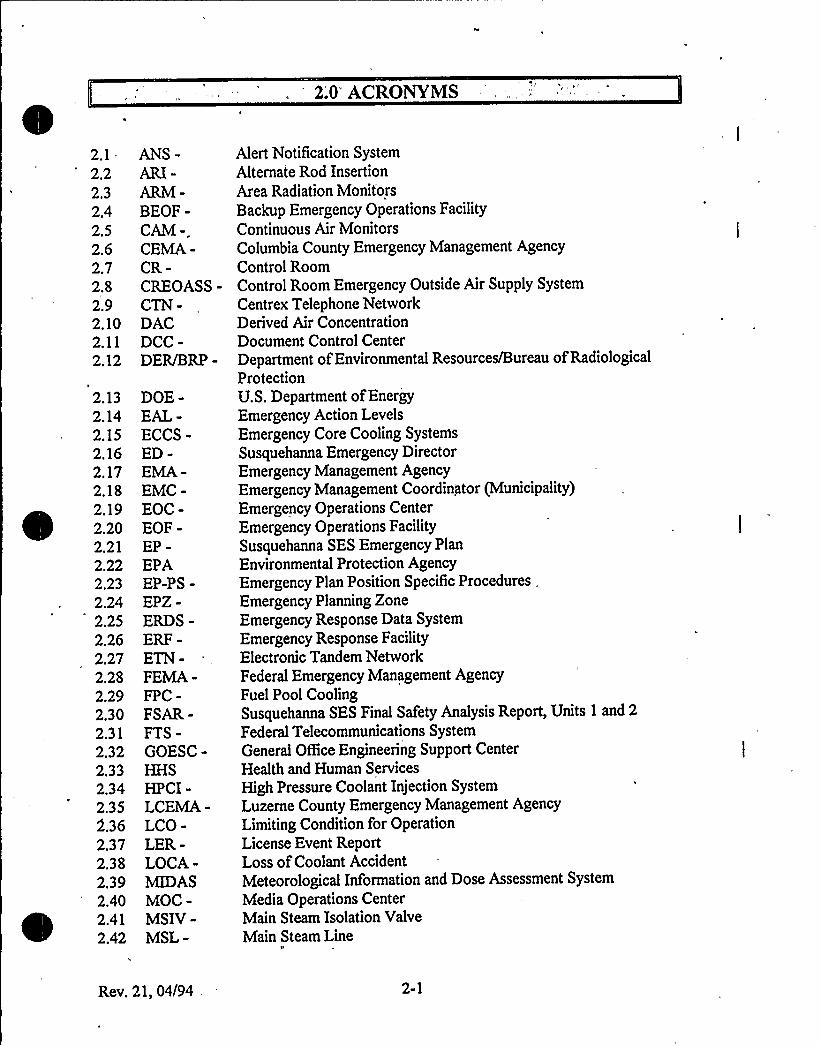
2.0'ACRONVMS
2.1-2.22.32.42.52.62.72.82.92.102.112.12
2.132.142.152.162.172.182.192.202.212.222.232.242.252.26
. 2272.282.292.302.312.322.332.342.352.362.372.382.392.402.412.42
ANS-ARI-ARM-BEOF-CAM -.CEMA-CR-CREOASS-CTN-DACDCC-DER/BRP-
DOE-EAL-ECCS-ED-EMA-EMC-EOC-EOF-EP-EPAEP-PS-EPZ-ERDS-ERF-ETN-FEMA-FPC-FSAR-FTS-GOESC-HHSHPCI-LCEMA-LCO-LER-LOCA-MIDASMOC-MSIV-MSL-
Alert Notification SystemAlternate Rod InsertionArea Radiation MonitorsBackup Emergency Operations FacilityContinuous AirMonitorsColumbia County Emergency Management AgencyControl RoomControl Room Emergency Outside AirSupply System
Centrex Telephone NetworkDerived AirConcentrationDocument Control CenterDepartment ofEnvironmental Resources/Bureau ofRadiologicalProtectionU.S. Department ofEnergyEmergency Action LevelsEmergency Core Cooling SystemsSusquehanna Emergency DirectorEmergency Management AgencyEmergency Management Coordinator (Municipality)Emergency Operations CenterEmergency Operations FacilitySusquehanna SES Emergency PlanEnvironmental Protection AgencyEmergency Plan Position Specific Procedures,Emergency Planning ZoneEmergency Response Data System
Emergency Response FacilityElectronic Tandem NetworkFederal Emergency Management AgencyFuel Pool CoolingSusquehanna SES Final Safety Analysis Report, Units 1 and 2
Federal Telecommunications SystemGeneral Of6ce Engineering Support CenterHealth and Human Services
High Pressure Coolant Injection SystemLuzerne County Emergency Management AgencyLimitingCondition for OperationLicense Event ReportLoss ofCoolant AccidentMeteorological Information and Dose Assessment System
Media Operations CenterMain Steam Isolation ValveMain Steam Line
II
Rev. 21, 04/94, 2-1
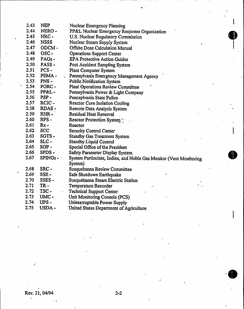
2.432.442.452.462.472.482.492.502.512.522.532.542.552.562.572.582.592.602.612.622.632.642.652.662.67
2.682.692.702.712.722.732.742.75
NEPNERO-NRC-NSSSODCM-OSC-PAGs-PASS-PCS-PEMA-PNS-PORC-PP&L-PSP-RCIC-RDAS-RHR-RPS-Rx-SCCSGTS-SLC-SOP-SPDS»SPINGs - .
SRC-SSE-SSES-TR-TSC-UMC-UPS-USDA-
Nuclear Emergency PlanningPP&L Nuclear Emergency Response OrganizationU.S. Nuclear Regulatory CommissionNuclear Steam Supply SystemQuite Dose Calculation ManualOperations Support CenterEPA Protective Action GuidesPost Accident Sampling SystemPlant Computer SystemPennsylvania Emergency Management AgencyPublic Notification SystemPlant Operations Review CommitteePennsylvania Power &Light CompanyPennsylvania State PoliceReactor Core Isolation CoolingRemote Data Analysis SystemResidual Heat RemovalReactor Protection System ''-ReactorSecurity Control CenterStandby Gas Treatment SystemStandby Liquid ControlSpecial OfBce ofthe PresidentSafety Parameter Display SystemSystem Particulate, Iodine, and Noble Gas Monitor (VeSystem)Susquehanna Review CommitteeSafe Shutdown EarthquakeSusquehanna Steam Electric StationTemperature RecorderTechnical Support CenterUnit Monitoring Console (PCS)Uninterruptable Power SupplyUnited States Department ofAgriculture
nt Monitoring
Rev. 21, 04/94 2-2
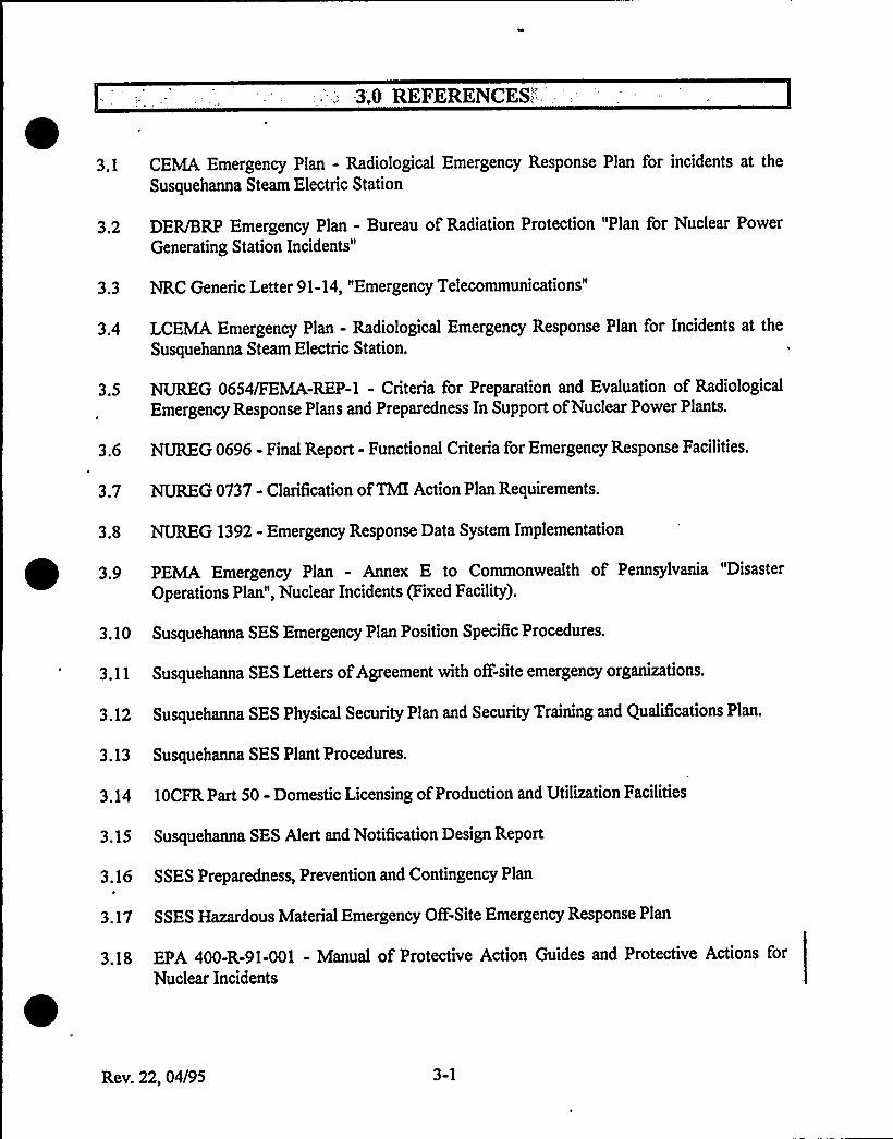
3;0REFERENCES;'.1
CEMA Emergency Plan - Radiological Emergency Response Plan for incidents at the
Susquehanna Steam Electric Station
3.2 DER/BRP Emergency Plan - Bureau of Radiation Protection "Plan for Nuclear Power
Generating Station Incidents"
3.3 NRC Generic Letter 91-14, "Emergency Telecommunications"
3.4 LCEMA Emergency Plan - Radiological Emergency Response Plan for Incidents at the
Susquehanna Steam Electric Station.
3.5 NUTMEG 0654/FEMA-REP-1 - Criteria for Preparation and Evaluation of Radiological
Emergency Response Plans and Preparedness In Support ofNuclear Power Plants.
3.6 NUREG 0696 - Final Report - Functional Criteria for Emergency Response Facilities.
3.7 NUIKG0737 - Clarification ofTMIAction Plan Requirements.
3.8 NUREG 1392 - Emergency Response Data System Implementationt 3.9 PEMA Emergency Plan - Annex E to Commonwealth of Pennsylvania "Disaster
Operations Plan", Nuclear Incidents (Fixed Facility).
3 ~ 10 Susquehanna SES Emergency Plan Position Specific Procedures.
3.11 Susquehanna SES Letters ofAgreement with oF-site emergency organizations.
3.12 Susquehanna SES Physical Security Plan and Security Training and Qualifications Plan.
3.13 Susquehanna SES Plant Procedures.
3.14 10CFR Part 50 - Domestic Licensing ofProduction and Utilization Facilities
3.15 Susquehanna SES Alert and Notification Design Report
3.16 SSES Preparedness, Prevention and Contingency Plan
3.17 SSES Hazardous Material Emergency OfF-Site Emergency Response Plan
3.18 EPA 400-R-91-001 - Manual of Protective Action Guides and Protective Actions for
Nuclear Incidents
Rev. 22, 04/95 3-1
4.0: SCOPE"AND CONTENTS";.
SSES includes two boiling water reactor electrical generating units. The station is located inSalem Township, Luzerne County, in east central Pennsylvania, about five miles northeast ofBerwick, Pennsylvania (See Figure 4.1), This Emergency Plan applies to the operation of Unit 1
and Unit 2.
4,1 COPE
This Plan provides guidance for both on-site and oft'-site emergency situations. It ranges in scopefrom relatively minor events and occurrences involving small releases of radioactive material, upto and including a major nuclear emergency having significant offsite radiological consequences.This Plan, together with the state, county, and municipal radiological emergency response plans,provides detailed guidance and direction for taking emergency measures by the NERO to ensurethe health and safety of the public living within the 10-mile EPZ of SSES. Additional guidance is
provided in state and county plans for ingestion pathway preventive measures out to 50 miles (SeeFigure 4.2).
Additional guidance on specific emergency actions for non-radiological releases of hazardousmaterials can be found in two other emergency plans: the SSES Preparedness, Prevention, and
Contingency Plan and the SSES Hazardous Material Emergency OF-Site Response Plan.
4~CONTENT
4 2.1 l ificati n
This Plan provides for a graded response for distinct classifications of emergency conditions,action within those classifications, and criteria for escalation to another classification. Thisclassification system is also used by PEMA, DER/BRP, LCEMAAND CEMA. This system is
covered in Section 5.0.
4.2.2 r anization Control
The PP&L organization for control of emergencies begins with the on-shift station personnel and
contains provisions for augmentation and extension to include other station personnel, PP&Lcorporate personnel, and outside emergency response organizations.
The total emergency program includes the support of state, federal and local emergencyorganizations. Detailed provisions are made for implementing protective measures against directradiation exposure for the public within a radius of at least ten miles aom the SSES. Additionalpreventive measures may be taken beyond that distance to preclude ingestion pathway exposures.
Specific agreements are also made with local ofF-site support organizations to provide fire
fighting, medical, law enforcement, and trafBc control services.
Rev. 22, 04/95 4-1
State, County and Federal agencies have lead responsibilities specifically related to this Plan.
Organizational control is covered in Section 6.0.
4.2.3 Emer enc Measures
The mechanisms through which this Plan provides for the proper response to emergencyconditions at SSES include identification of the event, initial and ongoing assessment, and initialand ongoing emergency actions. Emergency actions include classification ofevent, completion ofnotifications, activation of onsite and offsite NERO, requests for offsite assistance, implementingonsite protective actions, recommending offsite protective actions, and activation of the
restoration organization. These mechanisms are discussed in Section 7.0.
4 2 4 Emer en Facilities
Emergency facilities and equipment are provided to ensure the capabilities for prompt, efficientassessment and control of situations over the entire spectrum of probable and postulated
emergency conditions. The facilities and associated equipment and their emergency functions are
described in Section 8.0.
425Em r en Trainin
A concept of in-depth preparedness is employed regarding the SSES emergency program. This
concept is emphasized in the training program and in preparedness drills and exercises. Personnel
are trained to provide an in-depth response capability for required actions in an emergency
situation. Section 9.0 includes the means to achieve and maintain preparedness and to ensure
maintenance ofan effective emergency program.
Rev. 22, 04/95 4-2
'.- ..6.0'RGANIZATIONALCONTROL-'OF EMERGENCIES
PP&L's Emergency Plan is based upon a four phase approach to accident response and mitigation.
Phase I - Immediate Res on (Reference Figure 6.3 and Table 6.1). Phase I consists ofidentification of the emergency condition, initiation of prompt corrective action and initiation ofprompt notification to local, state and federal agencies as well as appropriate members ofPP&L's
NERO. This initial phase is implemented by the on-shift organization. The on-shift organizationhas been staffed and trained to be capable of both safely operating the unit and quickly and
effectively responding to an emergency condition. Initially, the Shift Supervisor, the highest
ranking management individual on-shift, willassume the role ofED.
The Shift Supervisor, as ED:
a) Classifies the condition.
b) Initiates corrective actions and coordinates emergency management activities.
c) Designates a communications coordinator to notify off-site agencies and initiate call-in ofselected personnel.
d) Notifies plant personnel over the PA system for accountability and/or evacuation.
e) Designates an OSC Coordinator who organizes and directs in-plant emergency team
functions.
f) Notifies the Vice President-Nuclear Operations or his designated alternate, informs him ofthe situation, and requests relief ifappropriate. For conditions under an Unusual Event
the Shift Supervisor is likely to remain as ED through termination of the condition, due toprobable short duration or low severity of the event:
g) Ensures that on-site emergency response individuals and groups are notified, using the PAsystem or direct communications. Depending on the nature and severity of the condition,TSC staf6ng may be called out.
h) Ensures that initial dose projections are done and makes resulting recommendations
regarding oF-site protective actions.
i) Ensures that off-duty station personnel are notified to assist as necessary with emergency
activities. These notifications are made, via the radio paging system or by telephone
backup, to individuals designated for
off
dut availability status to fill key emergency
response positions. Those key positions are identified in Sections 6.2 and 6.3. Other off-
duty personnel are called in as required.
Rev. 22, 04/95 6-1
Upon activation of Phase II, additional personnel are available, and control and dissemination ofin-plant teams shifts from the OSC to the TSC.
Phase II - Activation ofOn-Site NERO - (Reference Figure 6.3 and Table 6.2) Upon notification
by the on-shift organization, the VP-Nuclear Operations or his designated alternate, reports to the
site to assume the role of ED. Support coordinators and staffs in areas of technical assessment,
radiological assessment and operational coordination also report to the site. These individualsform the nucleus of the ED's Team and activate the TSC. The TSC is fullyfunctional within 30 to60 minutes of initial notification. As the Vice President-Nuclear Operations and his supportcoordinators arrive, they are briefed by the Shift Supervisor and then, in turn, assume
responsibility from the Shift Supervisor for their particular areas of expertise. Emergencymanagement activities, including communications, are under the control of the Plant
Superintendent or his designated alternate; dose projection and assessment activities are directed
by the Radiation Protection Coordinator; technical expertise is directed by the Tech SupportCoordinator, the Operations Coordinator oversees Operations activities and the Damage Control
. Team Coordinator oversees in-plant damage control actions. The TSC takes over all emergencymanagement and support activities from the on-shift organization, freeing them to devote theirefforts towards establishing and maintaining the plant in a safe, stable condition.
Pha III-A iv i n of ff-sit NER - (Reference Figures 6.2a, 6.2b, 6.4, 6.5 and Table 6.2).This organization staffs the Emergency Operations Facility, General Office Engineering SupportCenter, and Media Operations Facility to provide in-depth technical and off-site radiologicalassessment.
The Emergency Operations Facility is activated automatically at a Site Area Emergency, but can
be activated earlier at the discretion of the Emergency Director or Recovery Manager. Uponactivation of the Emergency Operations Facility, personnel shall report to the EOF and be
prepared for full functional operation within one hour.
Functional operation willinclude:
~ Management ofoverall emergency response
~ Coordination ofradiological and environmental assessment
~ Determination of recommended protective actions
~ Coordination of emergency response activities with Federal, State, local county and
municipal agencies
Site based EOF personnel willbe notified and report to the EOF at an ALERT classification to
prepare the facility should activation become necessary. The EOF is initially staffed by Site
personnel at an Alert classification. Upon activation, General Of5ce personnel willbe notified and
report to the EOF as soon as reasonably possible.
NOTE: Site based personnel are capable of fullyactivating the Emergency Operations Facility.
Rev. 22, 04/95 6-2
The General Office Engineering Support Center is also staffed by personnel from the General
OfBce. It is activated within one hour of notification, directed by the Engineering SupportManager, interfacing with the TSC and EOF. The EOF and GOESC, upon activation, will relieve
the Emergency Director and the on-site organization ofexternal responsibilities, allowing them to,«devote their entire efforts to in-plant activities.
Pha e IV- Restoration - This phase leads ultimately to the return to service of the unit. The
organizational and philosophical concepts that are utilized during this phase are highly dependent
upon the nature of the emergency. The restoration phase does not begin until there is completeassurance that the plant is in a stable shutdown condition and that there are no inadvertent orunplanned significant release ofradioactivity to the environment.
6.1 N RMALOPERATIN R ANIZATION
, The normal Operating Organization during working hours is illustrated in Figure 6.1. Minimum
. shift response during oF-hours is as follows:
1
1
1
2»
1
3»I»1
1
1
10
Shift Supervisor (SRO)Unit Supervisor (SRO)
'ssistantUnit Supervisor (RO)Licensed Operators (RO)Shift Technical AdvisorNon-Licensed OperatorsHealth Physics TechnicianChemistry TechnicianSecurity Shift SupervisorAssistant Security Shift SupervisorSecurity Officers
per unit
62 ON- ITEEMER EN Y R ANIZATI N- HA EI
621 Emer en Dir r
The Shift Supervisor assumes the role ofED until he is relieved by the VP-Nuclear Operations, orhis designated alternate. Typical alternates are the Manager - Nuclear Maintenance and the
Manager - Nuclear Plant Services. When the TSC is activated, and the Shift Supervisor is
relieved, the Shift Supervisor reassumes responsibility for plant operating functions in the controlroom.-
The Shift Supervisor ensures that the VP-Nuclear Operations, or designated alternate, is promptlynotified ofan emergency condition.
The ED assumes full responsibility for the implementation and administration of the Emergency
Plan and is responsible for assuring continuity of resources until he relinquishes thoseC
Rev. 22, 04/95 6-3
responsibilities to the Recovery Manager. The responsibility and authority of the ED are set forthin Appendix E.
'
The ED cannot relinquish any of the above responsibilities until the anival of and assumption ofresponsibilities by the Recovery Manager at the EOF. At that time, he may relinquish any of theabove responsibilities ~exce those related to maintaining the Unit in a safe shutdown conditionwith adequate core cooling and no uncontrolled radioactive material releases.
If the ED cannot perform this function during the emergency, he will be succeeded by theOperations Coordinator until another qualified Emergency Director arrives to assume thisresponsibility.
Functional responsibilities ofthe ED include:
a) Immediately upon notification of an existing or potential emergency, report to theControl Room and initiate assessment activities, including classification of the
emergency and dose projections ifappropriate.
b) Unilaterally implement the immediate on-site corrective and protective actions to bringthe incident under control and mitigate its effects.
c) Assure that appropriate notifications and recommendations to off-site organizations aremade within 15 minutes.
d) Appoint Emergency Coordinators for assistance with current and continuing emergencycontrol, but assume those responsibilities until the positions are filled.
e) Augment the on-site NERO with duty roster personnel and other available station staffmembers as dictated by the emergency condition.
x
f) Continue reassessment of emergency status and make appropriate recommendationsincluding protective actions to off-site organizations.
g) Ensure that information released is accurate and released through the proper channels.
h) Activate Emergency Facilities described in Section 8.0.
i) Assign technical liaison to EOCs ifrequested.
j) Communicate with and provide information to the Recovery Manager, EOF Support
Manager, Public Information Manager, and Engineering Support Manager.
k) Issuance ofRadioprotective Drugs in accordance with prescribed procedures and should
include consultation with the Radiation Protection Coordinator and medical consultants.
t) Taking essential corrective action which may involve the risk of emergency radiation Oexposure to NERO personnel. Table 7.2 provides the basic criteria for this decision.
Rev. 22, 04/95 6-4
m) Request Federal assistance to augment NERO capabilities as necessary. Such requests
should be coordinated with PEMA and/or DER/BRP.
6.2.2 0 erati n oordinaor-,,
This position is filled by the Manager of Nuclear Operations or a designated alternate. Typicalalternates are the Shift Supervisor or the Plant Scheduling Supervisor.
Responsibilities:
a) Direct Control Room and in-plant operational activities through the Shift Supervisor.
b) Advise the ED on plant operations.
62.3 TSCC mm nicator
This position is initially filled by a Plant Control Operator. When the TSC is activated this
position is typically filled by simulator instructors from the Susquehanna Training Center.
Responsibilities:
a) Make proper notification to oF-site organizations.
b) Initiate call-in procedures as requested by the ED.
c) Function as liaison for emergency-related communications between the ED and on-site
and off-site emergency groups.
d) Maintain communications with the NRC.
e) Maintain records concerning the emergency.
6.2.4 Health Ph sics Netw rk ommunicator
This position is filledby qualified Health Physics personnel when the TSC is activated.
Responsibilities:
~ a) Communicate radiological data to the NRC via the Health Physics Network.
625 Radiation Pr tecti n ordin t r
This position is filledby the Health Physics Supervisor. Typical alternates for this position are the
qualified Health Physics personnel.
Rev. 22, 04/95 6-5
Responsibilities
a) Perform initial dose projection and off-site environmental assessment until relieved bythe Interim Radiation Support Manager or Radiation Support Manager.
b) Provide radiological advice to the ED concerning on-site emergency activities.
c) Provide protective action recommendations to the ED.
d) Maintain communication with and provide information to the Interim Radiation Support"Manager and the Radiation Support Manager.
e) Maintain communication with and provide radiological information to DEWBRP untilrelieved by the Interim Radiation Support Manager or Radiation Support Manager.
f) Provide on-site radiation monitoring personnel for efHuent release assessment.
g) Provide radiation monitoring personnel for emergency team efForts.
h) Direct personnel and area contamination control and decontamination activities.
6.26 T hni u rt o rdinat r
This position is filled by the Engineering and Installation Planning Supervisor. Typical alternates
for this position are System Engineering management personnel.
Responsibilities:
a) Analyze mechanical, electrical, and instrument and control problems; determine alternate
solutions, design and coordinate the installation ofshort-term modifications.
b) Analyze thermohydraulic and thermodynamic problems and develop solutions.
c) Assist in the development 'of procedures necessary for conducting emergency
operations.
d) Analyze conditions and develop guidance for the ED and operations personnel.
e) Resolve questions concerning Operating License requirements with NRCrepresentatives.
f) Maintain lead technical responsibility, coordinating dissemination of technical workassignments to EOF and GOESC.
g) Maintain communication with and provide technical information to DER/BRP until
Orelieved by the Lead Technical Support Stair or Site Support Manager.
Rev. 22, 04/95 6-6
6.2.7 Administrative Coordinator
This position is filled by the Supervisor - Site Support. Typical alternates are Site Support
management personnel.
Responsibilities:
a) Coordinate provisions for transportation, food and other logistical support foremergency personnel.
b) Provide personnel and work schedules for relieving emergency personnel.
c) Act as liaison with outside groups in providing additional resources such as manpower,
equipment, supplies and transportation.
6.2.8 Securi Co rdinator
This position is filled by the Manager - Nuclear Security. The typical alternate for this position is
a Security Supervisor.
Responsibilities:
a) Maintain plant security and institute appropriate contingency measures.
b) Account for personnel in accordance with EP-PS's.
c) Provide access and trafBc control for off-site PP&L locations such as the EOF.
6.2.9 OSC Coordinator
This position is filled by the Assistant Unit Supervisor. If the AUS is unavailable the Shift
Supervisor willdesignate a replacement.
Responsibilities:
a) Direct the activities of the in-plant Emergency Teams such as damage control, fire
brigade and first aid and rescue until relieved by the TSC.
NOTE
The fire brigade leader is the Assistant Unit Supervisor. However, the coordination of various
team activities is the responsibility of the OSC Coordinator.,
b) Coordinating the availability and assignment of personnel supporting activities for the
ED and other NERO managers until relieved by the TSC.
Rev. 22, 04/95 6-7
6.2.10 Dama e Control Team Coordinator
The Damage Control Team Coordinator position is filled by Maintenance Functional Team
Managers.
Responsibilities:
a) Ensure damage control resources are allocated on the right priorities by assigning tasks
to available resources.
b) Dispatch in-plant teams.
c) Communicate with Operations and the Technical Support Coordinator.
6.2 11 T Radio Communicator
This position is filled by a Maintenance or I&CEngineer.
Responsibilities:
a) Maintain radio communications with all in-plant teams.
b) Maintain an up-to-date status of in-plant radiological conditions.
c) Track dose levels of in-plant team members.
6.212 Maintenan & or in t r
The Maintenance Coordinator position is filled by Maintenance Management personnel. The I&CCoordinator position is filledby I&CManagement personnel.
Responsibilities:
a) Organizing, briefing, dispatching, and directing, as necessary, the on-site damage controlteams.
b) Providing personnel assistance and support to in-plant teams as necessary.
c) Supporting technical group activities and operations as necessary.
6.2 13 Chemist rdinator
The Chemistry Coordinator position is filled by an ANSI qualified chemist. A typical alternate forthis position would be a Senior Chemist.
Rev. 22, 04/95 6-8
Responsibilities:
a) Assemble and direct the activities of chemistry personnel to assure information on plant
status is accurate and available.
6.3 OFF-SITE RE OUR ES AND ACTIVITIES HA E III
Notification of the Recovery Manager is made for all levels of emergencies by the
Communications Coordinator in the Control Room or TSC. An on-call duty roster is kept in the
CR and TSC.
For an Unusual Event or Alert, ifthe Recovery Manager decides to activate the off-'site NERO,
the Communications Coordinator directs the Security Controller to notify all required personnel
by contacting Security to activate the paging system or by direct telephone contact from the SCC
Controller.
For a Site Area or General Emergency, EOF activation is automatic. EOF staff is notified via a
paging signal generated by SSES Security or direct telephone from the SCC Controller. Field
team call-in is initiated by the NEP Duty Planner.
631 E F r anizati n
6.3.1.1 Interim Radiation Su ort Mana er
This position is filled by management personnel from the site having a health physics background.
Typical alternates would be the Supervisor-Modification Installation or the Supervisor-Nuclear
General Training.
Responsibilities
a) Until arrival of the Radiation Support Manager, m'anage interim radiological functions in
the EOF.
~ Offsite dose calculations, projections, and assessment.
~ Make protective'action recommendations to the Recovery Manager.
~ Communicate with DER/BRP Radiological.
~ Control field monitoring teams.
6.3.1.2 Interim Recove Mana r
This position is filled by site supervision having a technical background. Typical alternates would
be the Supervisor-Chemistry or the Manager-Nuclear Information Services.
Rev. 22, 04/95 6-9
Responsibilities
a) Until arrival of the Recovery Manager, act as the company representative, contributing a
prognosis, knowledge, and data to federal and state agencies, and assume responsibilityfor:
~ PP&L's emergency response effort to assure priority issues are being addressed and
a common understanding of the situation exists.
~ Represent the company in discussions with state and federal agencies.
~ Reclassify the emergency based on continuing assessment of the situation.
~ Make protective action recommendations.
6.3.1.3 Recove Mana er
This position is filled by the Vice President-Nuclear Engineering. The typical alternate is theManager-Independent Evaluation Services.
Ifthe Recovery Manager cannot perform this function during the emergency, he willbe succeeded
by the Interim Recovery Manager or the Assistant Recovery Manager.
Responsibilities:
a) Providing continuous coordination and evaluation of PP&L activities during an
emergency having or potentially having environmental consequences.
b) .Managing overall PP&L emergency response and as'suring continuity ofresources.
c) Acting as lead interface with off-'site government agency officials.
d) Assure appropriate notifications and recommendations to offsite organizations are
timely.
e) Continue reassessment of emergency status and make appropriate recommendations
including protective actions to oF-site organizations.
f) Ensure that information released is accurate and made through proper channels.
g) Directing the activities ofall other EOF managers'.
h) Request Federal assistance to augment NERO capabilities as necessary. Such requests
should be coordinated with PEMA and/or DER/BRP.
i) NotifyPEMA Emergency Operations Center ofProtective Action Recommendations.
Rev. 22, 04/95 6-10
j) Send a representative to the State and risk counties. If conditions result inimplementation of the Federal Radiological Emergency Response Plan, assign a
representative to the Federal Response Center, to the Federal Radiological Monitoringand Assessment Center, and to the Joint Information Center (most likely the PIM).
6.3.1.4 Lead Technical u taffer
This position is typically filled by qualified engineers.
Responsibilities:
a) Analyze technical and radiological data, identifying inconsistencies.
b) Further the response organization's understanding ofthe accident.
c) Provide technical information to the Recovery Manager and offsite agencies.
6315 i u ortMana er
This position is filled by the Manager-Nuclear Training. A typical alternate for this position is the
Senior Project Engineer-Nuclear Training.
Responsibilities:
a) Access in-plant technical and radiological information.
b) Provide analysis of in-plant data to the Recovery Manager.
c) Provide analysis of in-plant data and support the needs of Federal and State Agencypersonnel located in the EOF.
d) Oversee formal communications leaving the EOF.
6.3.1.6 Admini ra ive u ort Mana er
This position is filled by the Safety and Health Consultant-Nuclear. A typical alternate is the
Planning and Scheduling Foreman.
Responsibilities:
a) Providing personnel and work schedules for relieving emergency personnel.
b) Providing housing, food, office equipment, etc., for off-site support personnel.
c) Making necessary contractual arrangements for the emergency response efforts.
Rev. 22, 04/95 6-11
d) Procuring equipment, supplies, and additional personnel needed to support theemergency response eForts.
e) Providing additional manpower for scheduling activities deemed appropriate by theRecovery Manager.
6.3 1.7 Radia i n Su ort Mana er
This position is filled by the Supervisor-Operations Technology. A typical alternate is theSupervisor - Environmental Services-Nuclear.
Responsibilities:
a) Evaluating the magnitude'and eFects ofactual or potential radioactive releases from theplant.
b) Recommending appropriate o6site protective measures to the Recovery Manager.
c) Recommending appropriate emergency classifications to the Recovery Manager.
d) Communicating with the Radiation Protection Coordinator in the TSC and withDER/BRP radiological personnel.
e) Controlling field monitoring teams.
6.3.1 8 EOF C mmunicator
This position is typically filledby personnel assigned to the Nuclear Training Center.
Responsibilities:
a) Assume responsibility fiom the TSC for offsite notifications.
b) Transmit information about the emergency to oFsite organizations.
c) Function as liaison for questions received from other organizations.
d) Maintain a record ofemergency notifications.
~ 6.3 2 Media erations Center
The ED ensures that the MOC (Figure 6.4) is promptly notified and provided with available
details of the emergency. The MOC stafF transmits information regarding the emergency and
items ofpotential interest to municipal groups, initiates appropriate news-releases and responds to
questions from public information representative. After the Recovery Manager assumes control
of the EOF, he updates the Public Information Manager.
Rev. 22, 04/95 6-12
6.3.2.1 Public Information Mana er
This position is filled by the Special Assistant to the President - Susquehanna. Typical alternate is
the Senior Public Information Specialist.
Responsibilities:
a) Serving as official company spokesman.
b) Preparing and disseminating SSES information to the public via the news media.
c) Interpreting plant status information for the news media and other agencies.
d) Arranging for news media conferences.
e) Rumor control.
f) Establishes interfaces and coordinates news. releases with the federal and state agencies
in the MOC.
6.3.3 General ffice Su o Facilities
Emergency Support from the General Office is provided from the General Office Engineering
Support Center (GOESC).
The GOESC is located in the Corporate Offices in Allentown. Activation of the GOESC is
automatic during a SITE AREA or GENERAL EMERGENCY, and may also occur in. an
UNUSUALEVENT or ALERT ifthe Recovery Manager deems such action appropriate.
6.3.3 1 En 'neerin u rt Mana er
This position is filled by the Manager-Nuclear Technology. A typical alternate is the Supervisor-
Nuclear Fuels Engineering.
Responsibilities:
a) Provide technical information and management support to the Emergency Director and
Recovery Manager.
b) Provide priority guidance to the Engineering Support Leader and staff
c) Support technical needs ofthe Site Support Manager.
634 L c ff- iteSu ervice
The ED ensures that appropriate ofF-site emergency support groups are contacted to provide the
type and level of assistance which may be necessary to deal with the existing emergency
Rev. 22, 04/95 6-13
condition. The organizations listed below may be contacted for assistance. Methods available forcontacting these support groups include direct telephone communications with individualorganizations, use of the 911 telephone system for emergency services, and message relay throughLCEMAor CEMA.
~ Salem Township Fire Company No. 1 (fire and rescue)
~ East Berwick Hose Company No. 2 (fire and rescue)
~ Shickshinny Area Volunteer Ambulance Association (ambulance service)
~ Shickshinny Fire Department (fire)
~ Nescopeck Ambulance Association (ambulance service)
~ Hobbie Volunteer Fire Company (ambulance service)
~ Pond Hill-LillyLake Fire Company (ambulance service)
~ Hunlock Creek Ambulance Association (ambulance service)
~ Berwick Ambulance Association (ambulance service)
~ Berwick Hospital Paramedic Unit (ambulance service)
~ Berwick Hospital (medical treatment)
~ Geisinger Medical Center (backup medical treatment and LifeFlight helicopter service)
~ Pennsylvania State Police (traffic control and other assistance)
~ Reliance Fire Co. (fire)
6.35 Off- it Su ortServi s
An emergency at SSES may require additional technical services and equipment. This type ofassistance may be obtained from the organizations listed in Table 6.3. /
64 OORDINATI NWITHPARTI IPATING VERNMENTA ENCIE
The ED, and upon EOF activation, the RM, ensures that off-site authorities are notified and
apprised ofemergency events at SSES.
Notification of an Unusual Event is primarily to ensure that the authorities are cognizant of the
details of events which may arouse public concern and initiate inquiries by news media or
members ofthe public.
Rev. 22, 04/95 6-14
6.4,1 Count A encies
LCEMAand CEMAprovide for:
~ Planning and coordination with municipal, State and Federal authorities.
~ Initial response to noti6cation by SSES.
~ Alert and warning of local populations within the 10 mile EPZ.
~ Evacuation and other protective measures for local populations within the 10 mile EPZ.
~ Emergency services.
~ Situation analysis.
~ Operation ofcounty EOC.
LCEMAand CEMA also provide direction for the local organizations which are assigned action
or support responsibilities under their plans.
The primary method ofnotification to LCEMAand CEMA is via the Centrex Telephone Network(CTN). Secondary methods are radio and regular telephone.
6.4.2 State A encies
PEMA provides for:
~ Issuance ofplanning guidance.
~ Coordination ofState response to nuclear incidents.
~ Coordination ofmulti-county Emergency Response Planning.
~ Operation ofPEMA EOC.
~ Provision for emergency public information.
~ Coordination ofState agencies and departments.
DER/BRP provides for:
~ Technical consultation on Radiological and Plant conditions.
~ Accident assessment.
~ Recommendations for protective actions.
Rev. 22, 04/95 6-15
~ Recommendations for protection ofpotable water and food.
~ Recommendations for recovery and re-entry (off-site).
~ Operation ofDER/BRP EOC.
Initially, SSES notifies PEMA, who, in turn, notifies DER/BRP. DER/BRP calls back to SSES toobtain radiological and plant condition information and establishes a communication link withSSES via CTN. Ifthe emergency warrants, DER/BRP responds to the EOF.
The primary method of notification to PEMA is via the Centrex Telephone Network (CTN).CTN communications between SSES and DER/BRP are used for transmitting radiological and
technical information/recommendations.
643 Federal A encies
As detailed in the Federal Radiological Emergency, Response Plan (FRERP), the Federal
government maintains extensive capabilities to assist states and licensees in responding toradiological emergencies. The ED, and upon EOF activation, the RM are authorized to requestFederal assistance. Such requests should be coordinated with PEMA and/or DER/BRP.
N~R - designated Lead Federal Agency (LFA)under the FRERP.
The primary method ofnotification to the NRC is via the Emergency Notification System (ENS).Upon notification of an emergency classification, the NRC will enter one of several response
modes based on the severity of the event. Response modes include:
Normal (Increased Regional Monitoring)StandbyInitialActivationExpanded Activation
In the Normal and Standby modes, NRC site presence is provided by the Resident Inspectors who
typically observe activity in the Control Room and TSC. On Initial Activation, a site team willbe
dispatched with 15-25 individuals that can arrive at the site within several hours. Response
assignments are primarily at the EOF, with a few individuals located at the MOC, TSC, Control
Room and OSC. Ifconditions warrant, the NRC can go to Expanded Activation, where the NRCLead for the response is shHted from NRC Headquarters Operations Center to the NRC Leader ofthe Site Response Team. Assigned locations are similar to the initial site team.
~DE - provides radiological monitoring and assessmentassistance.'he
primary method of notification to DOE is by telephone, although assistance is typicallyrequested through the Lead Federal Agency (NRC) or through the State (DER/BRP). Initial
DOE response is by a Radiological Assistance Program (RAP) team dispatched from the DOE
Rev. 22, 04/95 6-16
Brookhaven Area OKce. This team of 4-6 people can arrive within eight hours and would
operate primarily out of the EOF.
Ifthe situation necessitates additional technical assistance, DOE can set up and staff a Federal
Radiological Monitoring and Assessment Center (FIMAC) in the vicinity of SSES. A FRMAC,which draws DOE resources and personnel from its Nevada Operations OfBce, can be operational
within about 24 hours. The location of such a center would be selected based on actual
radiological deposition patterns. The Federal FRMAC team is initially managed by DOE, withpersonnel also provided by NRC, EPA, USDA, HHS, and other agencies. The State and PP&Lwould assign personnel to the FRMAC to coordinate monitoring activity. As many as 200 people
could be assigned to a fullyfunctioning FRMAC.
FEMA - responsible for coordinating all Non-technical Federal response.
Ifthe emergency situation has warranted implementation of the Federal Plan (FRERP), FEMAwill set up and staff a Federal Response Center (FRC) in the vicinity of SSES. The location ofsuch a center. would be selected based on current needs and conditions. Access to all Federal
non-technical assistance is through the FRC where representatives of participating agencies are
based. As many as 100 people could be assigned to a fullyfunctioning FRC.
her Federal A ncie
In addition to NRC, DOE and FEMA, 14 other Federal agencies are available to provideassistance under the Federal Plan (FRERP). The extent of participation depends on the nature
and magnitude of the event. A full listing of these agencies and description of their missions is
found in the Federal Plan (FRERP).
Additional information on available resources can be found in NUREG-1442/ FEMA-REP-17,
"Post-Emergency Response Resources Guide."
in Inf rma i n enter
The Federal Plan (FRERP) provides for each participating agency to be represented at a Joint
Information Center, along with the State and the facility licensee. For Susquehanna, it is
expected that these parties will agree to utilize PP&L's MOC to fulfill this on-scene Joint
Information Center role.
R ore Av' F dr Re one
A. Lodging and Food Service - Lodging and food service for personnel operating from the
FRlVfAC, FRC and JIC are available from local commercial resources in the Wilkes-Barre,
Hazleton, and Bloomsburg areas.
B. Communications - Capability provided by DOE and FEMA, supplemented by standard
telephone service to be established when facilities are selected, are adequate for the FRMAC
and FRC.
Rev. 22, 04/95 6-17
C. Security - Security arrangements for the FRMAC and FRC can be made by the DOE and
FEMA, respectively, with local resources.
D. Transportation - Federal response personnel willprovide their own transportation by renting
commercially available vehicles.
E. Airport - Wilkes-Barre/Scranton International Airport, Avoca, Pennsylvania.
6~6T QN
The PP&L NERO continues to provide appropriate emergency response functions until such time
as the emergency has been terminated or the PP&L Corporate Management Committee (CMC)has approved the implementation of a long-range restoration organization. Termination from an
emergency condition is through joint evaluation by the organizations involved. In the case of a
severe emergency involving o6-'site consequences, this would include the Recovery Manager,
. DER/BRP, and NRC. The Sr. Vice President-Nuclear requests that the CMC establish a
restoration organization when the following guidelines have been met:
~ In-plant systems are stable, adequate core cooling established and contingency systems
and plans available.
~ In-plant radiation levels are stable or are decreasing with time.
~ Releases of radioactive material to the environment are under control or have ceased.
~ Any fire, flooding or similar emergency conditions are under control or have ceased.
Although planning for restoration varies according to the emergency, a long-term restoration
organization that is general in nature has been defined. The restoration organization is a project-
type organization with their major activities conducted from the EOF. This organization is
'depicted in Figure 6.6 and major responsibilities are defined below.
~ Rest ra ion Mana r - A designated officer or senior manager from PP&L qualified to
manage SSES restoration operations.
~ Plant rati ns M a er - A designated manager from PP&L qualified to control plant
operations including security.
~ Technical Su ort Mana er - A designated manager from PP&L qualified to manage a
technical group.
~ Mana er fRadiolo 'cal ontrol and Waste Mana ement - A designated manager
qualified to manage the radioactive waste and radiological control aspects.
~ n ructi n Mana r - A designated manager qualified to coordinate the activities ofPP&L, NSSS supplier and construction forces on proposed plant modifications or other
construction support.
Rev. 22, 04/95 6-18
~ Adviso u ort Function - Advisory support consists of senior representatives of theNSSS supplier, the NRC, and special consultants.
~ Schedulin lannin Mana er - A designated manager to coordinate plans and schedulesfor the Restoration Manager.
~ Administration and Lo istics Mana er - A designated manager who is responsible forproviding administrative, logistic, communications and personnel support.
~ Pu lic Information Mana er - A designated manager qualified to manage public relationsactivities.
During restoration operations, the radiation exposure limits of 10CFR20 apply. Compliance withthose limits are the responsibility of the Restoration Manager via the applicable Health Physicsorganization.
At the time of declaring that an emergency has entered the restoration phase, the RestorationManager is responsible for providing notification to all applicable agencies.
Restoration actions that plan for, or may result in, radioactive release are evaluated by theRestoration Manager as far in advance of the event as is possible. Such events and data arereported to the appropriate off-site emergency response organizations and agencies prior toinitiating release.
.Rev. 22, 04/95 6-19
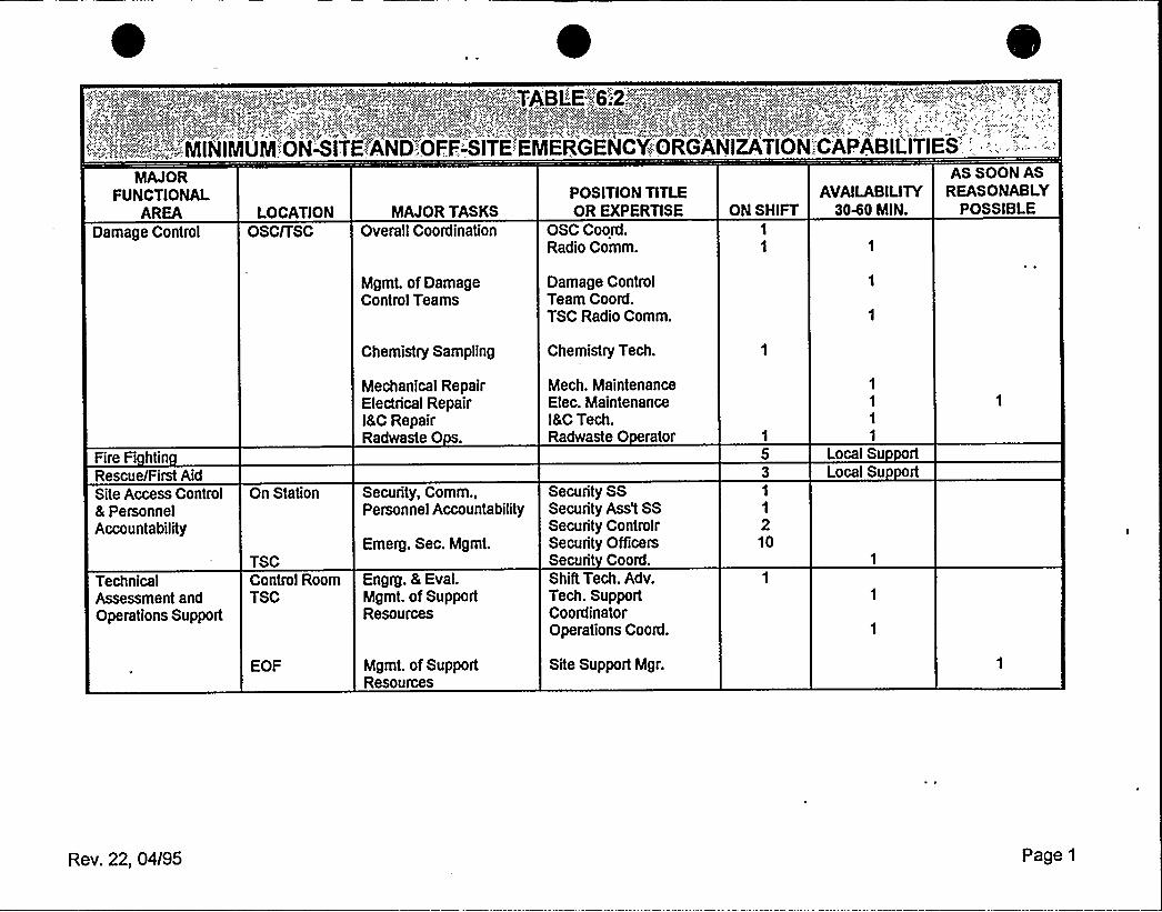
='-'."';=,;,:;:"':;-.':,;."-'.;;:--':MINIMUM:::ONITE"'AND'OFF-.-'SITE:EMERGENCY:.'':ORGANIZATION';:CAPABIL'ITIES':',,:: -'
'AJOR
FUNCTIONALAREA
Damage ControlLOCATION
OSCnSCMAJOR TASKS
Overall Coordination
POSITION TITLEOR EXPERTISE
OSC Coord.Radio Comm.
ON SHIFTAVAILABILITY
3040 MIN.
AS SOON ASREASONABLY
POSSIBLE
Fire Fi htinRescue/First AidSite Access Control& PersonnelAccountability
TechnicalAssessment andOperations Support
On Station
TSCControl RoomTSC
EOF
Mgmt. of DamageControl Teams
Chemistry Sampling
Mechanical RepairElectrical Repairl&C RepairRadwaste 0 s.
Security, Comm.,Personnel Accountability
Emerg. Sec. Mgmt.
Engig. & Eval.Mgmt. of SupportResources
Mgmt. of SupportResources
Damage ControlTeam Cooid.TSC Radio Comm.
Chemistry Tech
Mech. MaintenanceElec. Maintenancel&CTech.Radwaste 0 rator
Security SSSecurity Ass't SSSecunty ControlrSecurity OfficersSecurit Coord.Shift Tech. Adv.Tech. SupportCoordinatorOperations Coord.
Site Support Mgr.
1
1
210
1
1
1
1
Local Su rtLocal Su rt
Rev. 22, 04/95 Page 1
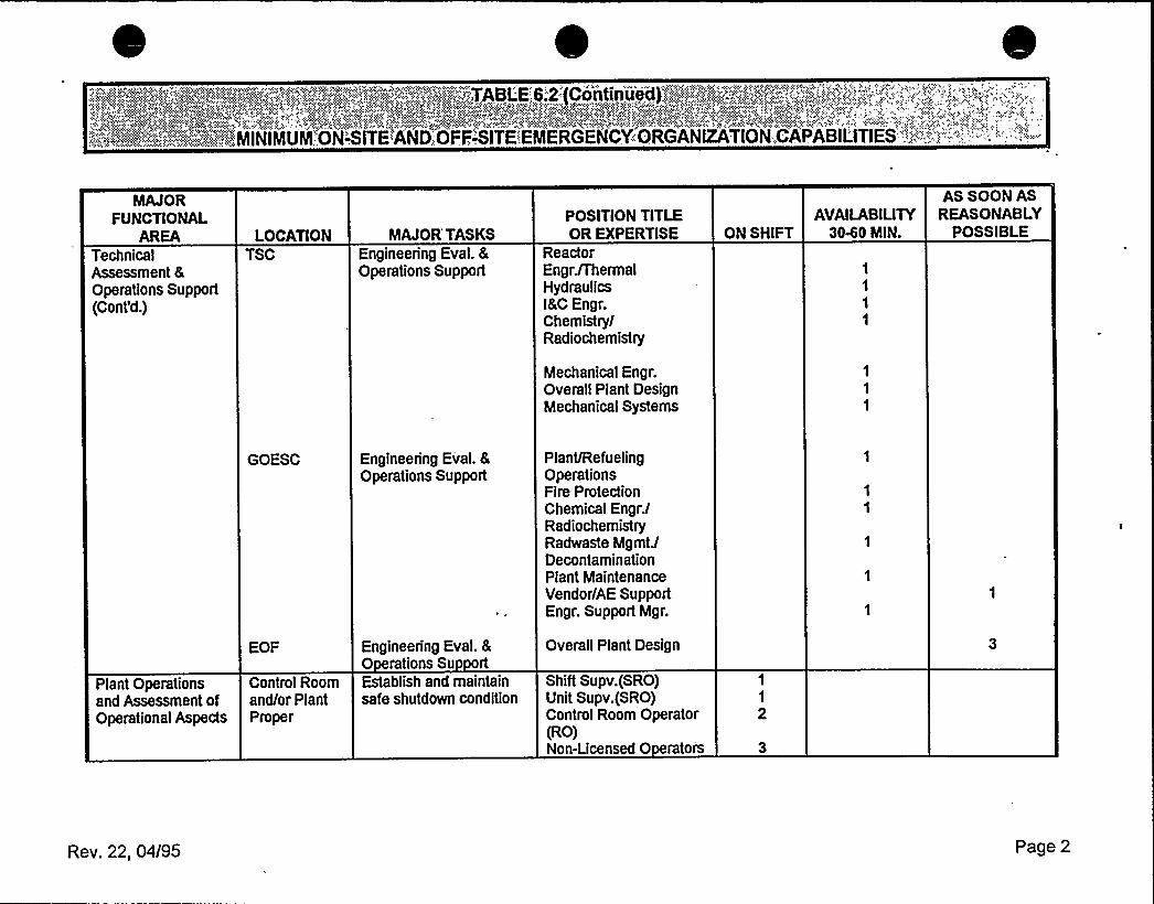
.'! i.'-;:;":ll:i':-.".-."..=.".!: '-':.':.';:",';"';:-".;MINIMVNl.':ONITE "AND.:.OFF,-',SITE:EINERGENCY:-'ORGANIZATION::.C
MAJORFUNCTIONAL
AREATechnicalAssessment 8Operations Support(Cont'd.)
LOCATIONTSC
MAJOR'ASKSEngineering Eval. &Operations Support
POSITION TITLEOR EXPERTISE
ReactorEngr. /ThermalHydraulicsl&C Engr.ChemistrylRadiochemistry
Mechanical Engr.Overall Plant DesignMechanical Systems
AVAILABILITYON SHIFT 3040 MIN.
1
1
1
1
AS SOON ASREASONABLY
POSSIBLE
Plant Operationsand Assessment ofOperational Aspects
GOESC
EOF
Control Roomand/or PlantProper
Engineering Eval. &Operations Support
Engineering Eval. 80 rations Su rtEstablish and maintainsafe shutdown condition
Plant/RefuelingOperationsFire ProtectionChemical Engr.lRadiochemistryRadwaste MgmtlDecontaminationPlant MaintenanceVendor/AE SupportEngr. Support Mgr.
Overall Plant Design
Shift Supv.(SRO)Unit Supv.(SRO)Control Room Operator(RO)Non-Licensed 0 rators
1
1
2
Rev. 22, 04/95 Page 2
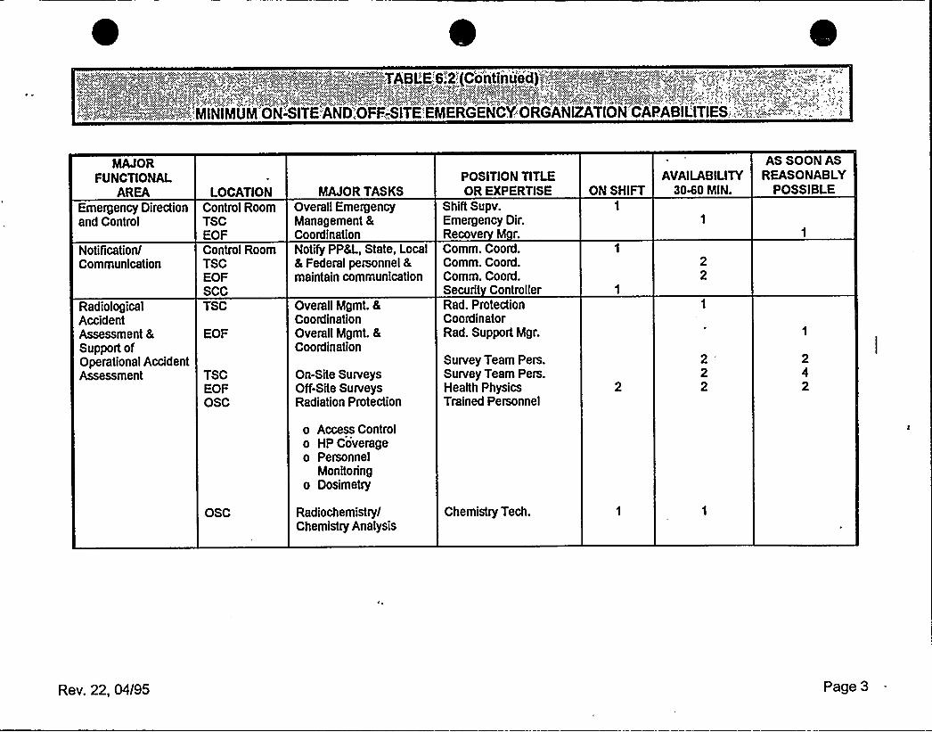
MAJORFUNCTIONAL
AREAEmergency Directionand Control
Notification/Communication
RadiologicalAccidentAssessment &Support ofOperational AccidentAssessment
LOCATIONControl RoomTSCEOFControl RoomTSCEOFSCCTSC
EOF
TSCEOFOSC
OSC
MAJOR TASKSOverall EmergencyManagement 8CootdinationNotify PP&L, State, Local8 Federal personnel &maintain communication
Overall Mgmt. &CoordinationOverall Mgmt. &Coordination
On-Site SurveysOff-Site SurveysRadiation Protection
o Access Controlo HP Coverageo Personnel
Monitoringo Dosimetry
RadiochemistrylChemistry Analysis
POSITION TITLEOR EXPERTISE
Shift Supv.Emergency Dir.Recove M r.Comm. Coord.Comm. Coord.Comm. Coord.Securit ControllerRad. ProtectionCoordinatorRad. Support Mgr.
Survey Team Pers.Survey Team Pers.Health PhysicsTrained Personnel
Chemistry Tech.
AVAILABILITYON SHIFT 3040 MIN.
22
222
AS SOON ASREASONABLY
POSSIBLE
242
Rev. 22, 04/95 Page 3
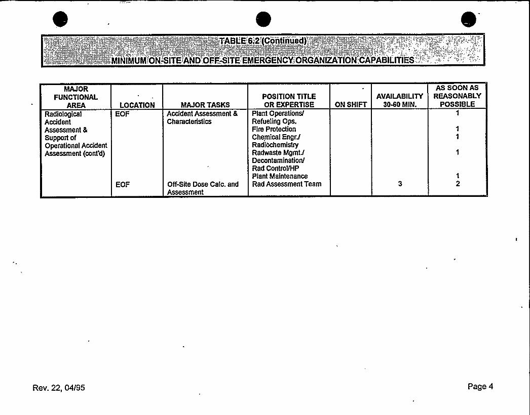
MAJORFUNCTIONAL
AREARadiologicalAccidentAssessment 8Support ofOperational AccidentAssessment (cont'd)
LOCATIONEOF
EOF
MAJOR TASKSAccident Assessment 8Characteristics
Offite Dose Gale. andAssessment
POSITION TITLEOR EXPERTISE
Plant OperationslRefueling Ops.Fire ProtectionChemical
Engr'adiochemistry
Radwaste MgmtJDeconta minationlRad Control/HPPlant MaintenanceRad Assessment Team
AVAILABILITYON SHIFT 3040 MIN.
AS SOON ASREASONABLY
POSSIBLE
1
2
Rev. 22, 04/95 Page 4
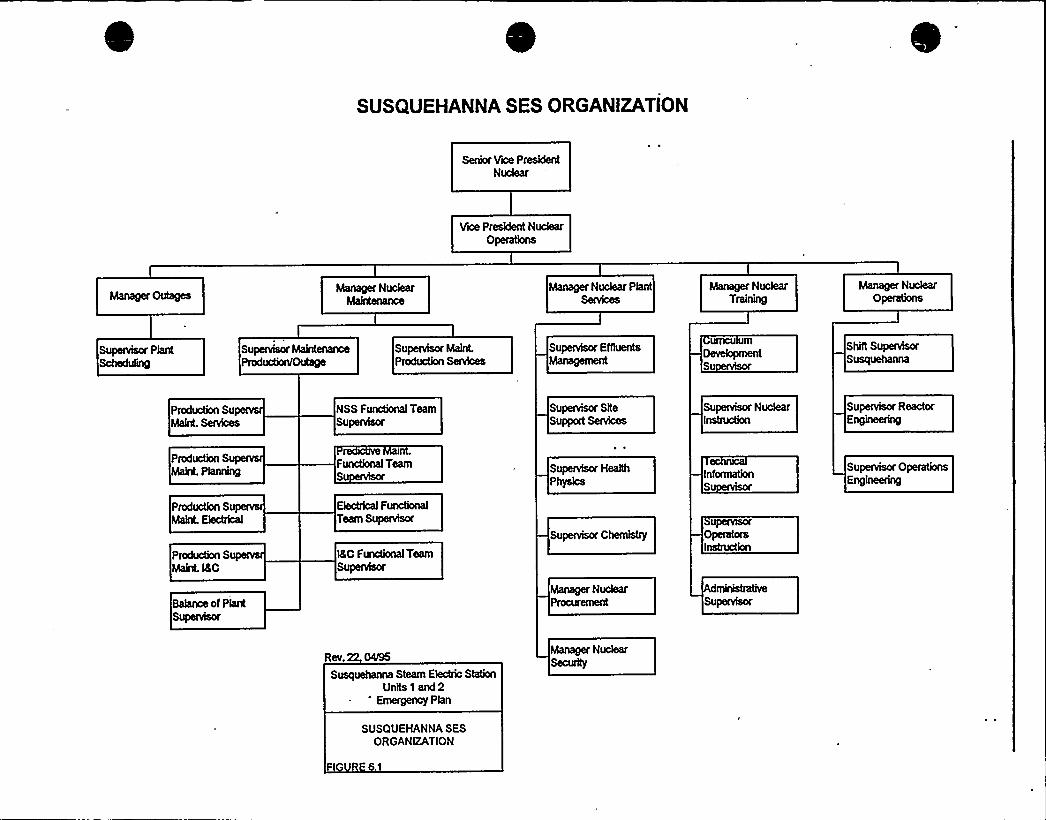
SUSQUEHANNA SES ORGANIZATION
Senior Vice PresidentNudear
Vice President NudearOperations
Manager Nudear Phnt Manager NudearTraining
Manager NudearOperations
Supenrisor PlantScheduhng
SupeNhor MaintenanceProduction/Outage
Supenrisor Malnt.Producthn Senrices
Supervisor ENuentsManagement
UfncU UlllDevelopmentS
Shift SupervhorSusquehanna
Production SuMaint. Senrices
NSS F nctional TeamSupervhor
Supervisor SiteSupport Services
Supenrisor NudearInstruction
Supenrisor ReactorEngineering
Production SuMaint. Phnning
Production SuMalnt. Electrical
Production SMainL l&G
Bahnce of PhntSuiienrisor
r inFuncional TeamSu
Hect'unctionalTeam Supenrisor
l&G Fncttcnaal TeamSupervhor
Supervisor Health
Phys@a
Supenrisor Ghemhtry
Manager NudearProcurement
InformationS
UpeivisorOperatorsInstruction
Supevisor OperationsEngineering
Susquehanna Steam Ehctric StationUnits 1 and 2
'mergency Phn
SUSQUEHANNA SESORGANIZATION

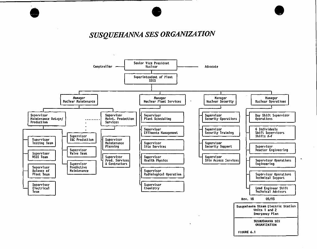
SUSQUEHANNA SES ORGANIZATION
ComptrollerSenior Vice President
Nuclear Advocate
Superintendent of PlantSSES
ManagerNuclear Haintenance
HanagerNuclear Plant Services
HanagerNuclear Security
ManagerNuclear Operations
SupervisorMaintenance Outage/Production
SupervisorMaint. ProductionServices
SupervisorPlant Scheduling
SupervisorSecurity Operations
Oay Shift SupervisorOperations
SupervisorTesting Team
SupervisorNSSS Team
SupervisorBalance ofPlant Team
SupervisorElectricalTeam
SupervisorIKC Production
SupervisorValve Team
SupervisorPredictiveHaintenance
SupervisorHaintenancePlanning
SupervisorProd. ServicesS Contractors
SupervisorEffluents Management
SupervisorSite Services
SupervisorHealth Physics
SupervisorRadiological Operation
SupervisorChemistry
SupervisorSecurity Training
SupervisorSecurity Support
SupervisorSite Access Services
6 IndividualsShift SupervisorsShifts A-F
SupervisorReactor Engineering
Supervisor OperationsEngineering
Supervisor OperationsTechnical Support
Lead Engineer ShiftTechnica'I Advisors
Rev. 18 05I93
Susquehanna Steam Electric StationUnits 1 end 2Emergency Plan
SUSQUEHANNA SESORGANIZAT ION
FIGURE 6.1
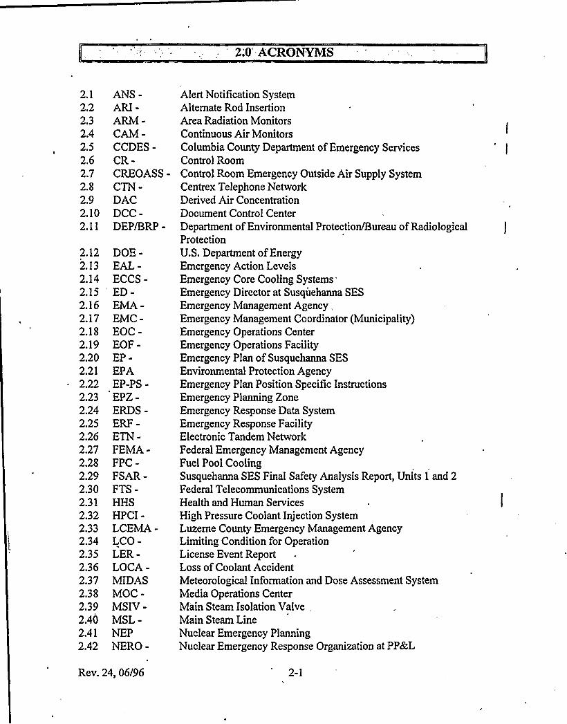
2;O'CRONVMS
2.1
2.22.32.42.52.62.72.82.92.102.11
2.122.132.142.152.162.172.182.192.202.212.222.232.242.252.262.272.282.292.302.312.322.332.342.352.362.372.382.392.402.412.42
ANS-'RI-
ARM-CAM-CCDES-CR-CREOASS-CTN-DACDCC-DEP/BRP-
DOE-EAL-ECCS-'D-EMA-EMC-EOC-EOF-EP-EPAEP-PS-EPZ-ERDS-ERF-ETN-FEMA-FPC-FSAR-FTS-HHSHPCI-LCEMA-LCO-LER-LOCA-MIDASMOC-MSIV-MSL-NEPNERO-
Alert Notification SystemAlternate Rod InsertionArea Radiation MonitorsContinuous AirMonitorsColumbia County Department ofEmergency ServicesControl RoomControl Room Emergency Outside AirSupply SystemCentrex Telephone NetworkDerived AirConcentrationDocument Control CenterDepartment ofEnvironmental Protection/Bureau ofRadiologicalProtectionU.S. Department ofEnergyEmergency Action LevelsEmergency Core Cooling Systems
'mergencyDirector at Susquehanna SES
Emergency Management Agency,Emergency Management Coordinator (Municipality)Emergency Operations CenterEmergency Operations FacilityEmergency Plan ofSusquehanna SESEnvironmental Protection AgencyEmergency Plan Position Specific InstructionsEmergency Planning ZoneEmergency Response Data SystemEmergency Response FacilityElectronic Tandem NetworkFederal Emergency Management AgencyFuel Pool CoolingSusquehanna SES Final Safety Analysis Report, Units 1 and 2Federal Telecommunications SystemHealth and Human ServicesHigh Pressure Coolant Injection SystemLuzerne County Emergency Management AgencyLimitingCondition for OperationLicense Event ReportLoss ofCoolant AccidentMeteorological Information and Dose Assessment SystemMedia Operations CenterMain Steam Isolation Valve,Main Steam LineNuclear Emergency PlanningNuclear Emergency Response Organization at PP&L
Rev. 24, 06/96 2-1

2.432.442.452.462.472.482.492.502.512.522.532.542.552.562.572.582.592.602.612.622.632.642.652.662.67
2.682.692.702.712.722.732.742.75
NRC -,NSSSODCM-OSC-PAGs-PASS-PCS-PEMA-PICSY-PNS-PORC-PP8cL-PSP-RCIC-RDAS-RHR-RPS-Rx-SCC-SDS-SGTS-SLC-SOP-SPDS-SPINGs-
SRC-SSE-SSES-TR-TSC-UMC-UPS-USDA-
gency
Monitor (Vent Monitoring
Nuclear Regulatory CommissionNuclear Steam Supply SystemOffsite Dose Calculation ManualOperations Support CenterProtective Action Guides from EPAPost Accident Sampling SystemPlant Computer SystemPennsylvania Emergency Management APlant Integrated Computer SystemPublic Notification SystemPlant Operations Review CommitteePennsylvania Power k, Light CompanyPennsylvania State PoliceReactor Core Isolation CoolingRemote Data Analysis SystemResidual Heat RemovalReactor Protection SystemReactorSecurity Control CenterSatellite Display SystemStandby'as Treatment SystemStandby Liquid ControlSpecial Office of the PresidentSafety Parameter Display SystemSystem Particulate, Iodine, and Noble Gas
System)Susquehanna Review CommitteeSafe Shutdown EarthquakeSusquehanna Steam Electric StationTemperature RecorderTechnical Support CenterUnit Monitoring Console (PCS)Uninterruptable Power SupplyUnited States Department ofAgriculture
Rev. 24, 06/96 2-2

3'O'EFERENCES
3.1 CCDES Emergency Plan - Radiological Emergency Response Plan for incidents at theSusquehanna Steam Electric Station
3.2 DEP/BRP Emergency Plan - Bureau of Radiation Protection "Plan for Nuclear PowerGenerating Station Incidents"
3.3 NRC Generic Letter 91-14, "Emergency Telecommunications"
3.4 LCEMA Emergency Plan - Radiological Emergency Response Plan for Incidents at theSusquehanna Steam Electric Station.
3.5 NUREG 0654/FEMA-REP-1 - Criteria for Preparation and Evaluation of RadiologicalEmergency Response Plans and Preparedness In Support ofNuclear Power Plants.
3.6 NUREG 0696 - Final Report - Functional Criteria for Emergency Response Facilities.1
3.7 NUREG 0737 - Clarification ofTMIAction Plan Requirements.
3.8 NUREG 1392 - Emergency Response Data System Implementation
3.9 PEMA Emergency Plan - Annex E to Commonwealth of Pennsylvania "Disaster OperationsPlan", Nuclear Incidents (Fixed Facility).
3.10 . Susquehanna SES Emergency Plan Position Specific Procedures.
3.11 Susquehanna SES Letters ofAgreement with off-site emergency organizations.
3.12 Susquehanna SES Physical Security Plan and Security Training and Qualifications Plan.
3.13 Susquehanna SES Plant Procedures.
3.14 10CFR Part 50 - Domestic Licensing ofProduction and Utilization Facilities
3.15 Susquehanna SES Alert and Notification Design Report
3.16 SSES Preparedness, Prevention and Contingency Plan
3.17 SSES Hazardous Material Emergency Off-Site Emergency Response Plan
3.18 EPA 400-R-91-001 - Manual of Protective Action Guides and Protective Actions forNuclear Incidents
3.19 NRC Letter dated April 17, 1996, MOVING THE EOF TO THE NORTHEAST DIVISIONHEADQUARTERS (TAC NOS. M91377 AND M91378), Docket Nos. 50-387/50-412
Rev. 24, 06/96 3-1
4.0 SCOPE AND-CONTENTS
SSES includes two boiling water reactor electrical generating units. The station is located inSalem Township, Luzerne County, in east central Pennsylvania, about five miles northeast ofBerwick, Pennsylvania (See Figure 4.1). This Emergency Plan applies to the operation ofUnit 1
and Unit 2.
This Plan provides guidance for both on-site and off-site emergency situations. It ranges inscope from relatively minor events and occurrences involving small releases of radioactivematerial, up to and including a major. nuclear emergency having significant off-site radiologicalconsequences. This Plan, together with the state, county, and municipal radiological emergencyresponse plans, provides detailed guidance and direction for taking emergency measures by theNERO to ensure the health and safety of the public living within the 10-mile EPZ of SSES.Additional guidance is provided in state and county plans for ingestion pathway preventivemeasures out to 50 miles (See Figure 4.2).
Additional guidance on specific emergency actions for non-radiological releases of hazardousmaterials can be found in two other emergency plans: the SSES Preparedness, Prevention, and
Contingency Plan and the SSES Hazardous Material Emergency Off-Site Response Plan.
This Plan provides for a graded response for distinct classifications of emergency conditions,action within those classifications, and criteria for escalation to another classification. Thisclassification system is also used by PEMA, DEP/BRP, LCEMAAND CCDES. This system iscovered in Section 5.0.
The PP&L organization for control of emergencies begins with the on-shift station personnel and
contains provisions for augmentation and extension to include other station personnel, PP&Lcorporate personnel, and outside emergency response organizations.
The total emergency program includes the support of state, federal and local emergencyorganizations. Detailed provisions are made for implementing protective measures against directradiation exposure for the public within a radius of at least ten miles from the SSES. Additiorialpreventive measures may be taken beyond that distance to preclude ingestion pathway exposures.
Specific agreements are also made with local off-site support organizations to provide firefighting, medical, law enforcement, and traffic control services.
Rev. 24, 06/96 4-1
State, County and Federal agencies have lead responsibilities specifically related to this Plan.
Organizational control is covered in Section 6.0.
The mechanisms through which this Plan provides for the proper response to emergencyconditions at SSES include identification of the event, initial and ongoing assessment, and initialand ongoing emergency actions. Emergency actions include classification of event, completionof notifications, activation of onsite and offsite NERO, requests for offsite assistance,
implementing onsite protective actions, recommending offsite protective actions, and activationof the restoration organization. These mechanisms are discussed in Section 7.0.
Emergency facilities and equipment are provided to ensure the capabilities for prompt, efficientassessment and control of situations over the entire spectrum of probable and postulated
emergency conditions. The facilities and associated equipment and their emergency functionsare described in Section 8.0.
A concept of in-depth preparedness is employed regarding the SSES emergency program. This
concept is emphasized in the training program and in preparedness drills and exercises.
Personnel are trained to provide an in-depth response capability for required actions in an
emergency situation. Section 9.0 includes the means to achieve and maintain preparedness and
to ensure maintenance ofan effective emergency program.
Rev. 24, 06/96 4-2
6.0 ORGANIZATIONALCONTROI OF EMERGENCIES
PP&L's Emergency Plan is based upon a four phase approach to accident response andmitigation.
(Reference Figure 6.3 and Table 6.1).,: Phase I consists ofidentification of. the emergency condition, initiation ofprompt corrective action and initiation ofprompt notification to local, state and federal agencies as well as appropriate members ofPP&L'sNERO. This initial phase is implemented by the on-shift organization. The on-shift organizationhas been staffed and trained to be capable of both safely operating the unit and quickly andeffectively responding to an emergency condition. Initially, the Shift Supervisor, the highestranking management individual on-shift, willassume the role ofED.
The Shift Supervisor, as ED:
a) Classifies the condition.
b) Initiates corrective'actions and coordinates emergency management activities.
c) Designates a communications coordinator to notify off-site agencies and initiate call-in ofselected personnel.
d) Notifies plant personnel over the PA system for accountability and/or evacuation.
e) Designates an OSC Coordinator who organizes and directs in-plant emergency teamfunctions.
Notifies the Plant Manager-Susquehanna SES or his designated alternate, informs him ofthe situation, and requests relief ifappropriate. For conditions under an Unusual Eventthe Shift Supervisor is likely to remain as ED through termination of the condition, due to
robable short duration or low severit of the event.P y
g) Ensures that on-site emergency response individuals and groups are notified, using thePA system or direct communications. Depending on the nature and severity of thecondition, TSC staffing may be called out.
h) Ensures that initial dose projections are done and makes resulting recommendationsregarding off-site protective actions.
(
i) Ensures that off-duty station personnel are notified to assist as necessary with emergencyactivities. These notifications are made, via the radio paging system or by telephonebackup, to individuals designated for off-duty availability status to fill key emergencyresponse positions. Those key positions are identified in Sections 6.2 and 6.3. Other off-duty personnel are called in as required.
Rev. 24, 06/96 6-1
Upon activation ofPhase II, additional personnel are available, and control and dissemination ofin-plant teams shifts from the OSC to the TSC.
- (Reference Figure 6.3 and Table 6.2) Upon notificationby the on-shift organization, the Plant Manager-Susquehanna SES or his designated alternate,reports to the site to assume the role ofED. Support coordinators and staffs in areas of technicalassessment, radiological assessment and operational coordination also report to the site. Theseindividuals form the nucleus of the ED's Team and activate the TSC. The TSC is fullyfunctionalwithin 30 to 60 minutes of initial notification. As the Plant Manager-Susquehanna SES and hissupport coordinators arrive, they are briefed by the Shift Supervisor and then, in turn, assumeresponsibility from the, Shift Supervisor for their particular areas of expertise. Emergencymanagement activities, including communications, are under the control of the EmergencyDirector or his designated alternate; dose projection and assessment activities are directed by theRadiation Protection Coordinator; technical expertise is directed by the Tech SupportCoordinator, the Operations Coordinator oversees Operations activities and the Damage ControlTeam Coordinator oversees in-plant damage control actions. The TSC takes over all emergencymanagement and support activities from the on-shift organization, freeing tom to devote theirefforts towards establishing and maintaining the plant in a safe, stable condition.
V - (Reference Figures 6.2, 6.4, and Table 6.2). Thisorganization staffs the Emergency Operations Facility to provide in-depth technical and off-siteradiological assessment.
The Emergency Operations Facility is" activated automatically at an Alert or higher emergencyclassification., Upon activation of the Emergency Operations Facility, personnel shall report tothe EOF and be prepared to take over management of the emergency from the TSC at a Site AreaEmergency or higher classification. When the initial emergency classification is a Site AreaEmergency or higher, the EOF will take over the management of the emergency within 90minutes of the declaration of a Site Area Emergency. At the discr'etion of the EmergencyDirector or Recovery Manager, the EOF can be activated and take over management of theemergency earlier.
Functional operation willinclude:
~ Management ofoverall emergency response
~ Coordination of radiological and environmental assessment
~ Determination of recommended protective actions
~ Coordination of emergency response activities with Federal, State, local county and
municipal agencies
- This phase leads ultimately to the return to service of the unit. Theorganizational and philosophical concepts that are utilized during this phase are highly dependentupon the nature of the emergency. The restoration phase does not begin until there is complete
t
Rev. 24, 06/96 6-2
assurance that the plant is in a stable shutdown condition and that there are no inadvertent orunplanned significant release of radioactivity to the environment.
... The normal Operating Organization during working hours is illustrated in Figure 6.1. Minimumshift response during off-hours is as follows:
1 Shift Supervisor (SRO)1 Unit Supervisor (SRO)1 Assistant Unit Supervisor (RO)
. 2* Licensed Operators (RO)I Shift Technical Advisor3* Non-Licensed Ope'rators1* Health Physics Technician1 Chemistry Technician1 Security Shift Supervisor1 Assistant Security Shift Supervisor
10 Security Officers
per unit
The Shift Supervisor assumes the role of ED until he is relieved by the Plant Manager-Susquehanna SES, or his designated alternate. Typical alternate is the Manager - NuclearMaintenance. When the TSC is activated, and the Shift Supervisor is relieved, the ShiftSupervisor reassumes responsibility for plant operating functions in the control room.
The Shift Supervisor ensures that the Plant Manager-Susquehanna SES, or designated alternate,is promptly notified of an emergency condition.
The ED assumes full responsibility for the implementation and administration of the EmergencyPlan and is responsible for assuring continuity of resources until he relinquishes thoseresponsibilities to the Recovery Manager. The responsibility and authority of the ED are setforth in Appendix E.
The ED cannot relinquish any of the above responsibilities until the arrival of and assumption ofresponsibilities by the Recovery Manager at the EOF. At that time, he may relinquish any of theabove responsibilities gzggg those related to maintaining the Unit in a safe shutdown conditionwith adequate core cooling and no uncontrolled radioactive material releases.
Rev. 24, 06/96 6-3
If the ED cannot perform this function during the emergency, he will be succeeded by the
Operations Coordinator until another qualified Emergency Director arrives to assume this
responsibility.
Functional responsibilities of the ED include:
a) Immediately upon notification of an existing or potential emergency, report to the
Control Room and initiate assessment activities, including classification of the
emergency and dose projections ifappropriate.
b) Unilaterally implement the immediate on-site corrective and protective actions to bringthe incident under control and mitigate its effects.
c) Assure that appropriate notifications and recommendations to off-site organizations are
made within 15, minutes.
d) Appoint Emergency Coordinators for assistance with current and continuing emergency
control, but assume those responsibilities until the positions are filled.
e) Augment the on-site NERO with duty roster personnel and other available station staffmembers as dictated by the emergency condition.
')
Continue reassessment of emergency status and make appropriate recommendations
including protective actions to off-site organizations.
g) Ensure that information released is accurate and released through the proper channels.
h) Activate Emergency Facilities described in Section 8.0.
i) Assign technical liaison to EOCs ifrequested.
j) Communicate with and provide information to the Recovery Manager and the Public
Information Manager.
- k) Issuance ofRadioprotective Drugs in accordance with prescribed procedures and should
include consultation with the Radiation Protection Coordinator and medical
consultants.
l) Taking essential corrective action which may involve the risk of emergency radiation
exposure to NERO personnel. Table 7.2 provides the basic criteria for this decision.
m) Request Federal assistance to augment NERO capabilities as necessary. Such requests[
should be coordinated with PEMA and/or DEP/BRP.
Rev. 24, 06/96 6-4

This position is filled by the Day Shift Supervisor or a designated alternate. Typical alternatesare SRO qualified personnel.
Responsibilities:
a) Direct Control Room and in-plant operational activities through the Shift Supervisor.
b) Advise the ED on plant operations.
This position is initially filled by a Plant Control Operator. When the TSC is activated thisposition is typically filled by simulator instructors from the Susquehanna Training Center.
Responsibilities:
a) Make proper notification to off-site organizations.
b) Initiate call-in procedures as requested by the ED.
c) Function as liaison for emergency-related communications between the ED and on-siteand off-site emergency groups.
d) Maintain communications with the NRC.
e) Maintain records concerning the emergency.
This position is filled by qualified Health Physics personnel when the TSC is activated.
Responsibilities:
a) Communicate radiological data to the NRC via the Health Physics Network.
This position is filled by the Health Physics Supervisor. Typical alternates for this position are
the qualified Health Physics personnel.
Responsibilities:
a) Perform dose projections.
Rev. 24, 06/96 6-5
b) Provide radiological advice to the ED concerning on-site emergency activities.
c) Provide protective action recommendations to the ED.
d) Maintain communication with and provide information to the Dose Assessment [Supervisor.
e). Maintain communication with and provide radiological information to DEP/BRP untilrelieved by the Dose Assessment Supervisor.
f) Provide on-site radiation monitoring personnel for eAluent release assessment.
g) Provide radiation monitoring personnel for emergency team efforts.
h) Direct personnel and area contamination control and decontamination activities.
i) Provide dose projections to the Dose Assessment Supervisor.
j) Perform initial off-site environmental assessment until relieved by the Dose Assessment
Supervisor.
This position is filledby System Engineering supervisory personnel.
Responsibilities:
a) Analyze mechanical, electrical, and instrument and control problems; determine
alternate solutions, design and coordinate the installation ofshort-term modifications.
b) Analyze thermohydraulic and thermodynamic problems and develop solutions.
c) Assist in the development of procedures necessary for conducting emergency
operations.
d) Analyze conditions and'develop guidance for the ED and operations personnel.
e) Resolve questions concerning Operating License requirements with NRCrepresentatives.
f) Maintain lead technical responsibility, coordinating dissemination of technical work
assignments to EOF.
g) Maintain communication with and provide technical information to DEP/BRP lTechnical.
Rev. 24, 06/96 6-6
This position is filled by the Supervisor - Site Support. Typical alternates are Site Supportmanagement personnel.
Responsibilities:
a) Coordinate provisions for transportation, food, and other logistical support foremergency personnel.
b) Provide personnel and work schedules for relieving emergency personnel.
c) Act as liaison with outside groups in providing additional resources such as manpower,equipment, supplies, and transportation.
This position is filled by the Manager - Nuclear Security. The typical alternate for this positionis a Security Supervisor.
Responsibilities:
a) Maintain plant security 'and institute appropriate contingency measures.
b) Account for personnel in accordance with EP-PS's.
This position is filled by the Assistant Unit Supervisor. If the AUS is unavailable the ShiftSupervisor willdesignate a replacement.
Responsibilities:
a) Direct the activities of the in-plant Emergency Teams such as damage control, firebrigade and first aid and rescue until relieved by the TSC.
The fire brigade leader is the Assistant Unit Supervisor. However, the coordination of variousteam activities is the responsibility of the OSC Coordinator.
b) Coordinating the availability and assignment of personnel supporting activities for theED and other NERO managers until relieved by the TSC.
Rev. 24, 06/96 6-7
The Damage Control Team Coordinator position is filled by Maintenance supervisory personnel.
A typical alternate would be the Maintenance Production Services Supervisor.
Responsibilities:
a) Ensure damage control resources are allocated on the right priorities by assigning tasks
~ to available resources.
b) Dispatch in-plant teams.
c) Communicate with Operations and the Technical Support Coordinator.
This position is filled by a Maintenance Engineer.
Responsibilities:
a) Maintain radio communications with all in-plant teams.
b) Maintain an up-to-date status of in-plant radiological conditions.
c) Track dose levels of in-plant team members.
The Maintenance Coordinator position is filled by Maintenance Management personnel. The
I&CCoordinator position is filled by I&CManagement personnel.
Responsibilities:
a) Organizing, briefing, dispatching, and directing, as necessary, the on-site damage
control teams.
b) Providing personnel assistance and support to in-plant teams as necessary.
c) Supporting technical group activities'and operations as necessary.
The Chemistry Coordinator position is filled by an ANSI qualified chemist. A typical alternate
for.this position would be a'Senior Chemist.
Rev. 24, 06/96 6-8
Responsibilities:
a) Assemble and direct the activities ofchemistry personnel to assure information on plantstatus is accurate and available.
F
Notification of the Recovery Manager is made for all levels of e'mergencies by theCommunicators in the Control Room or TSC. An on-call duty roster is kept in the CR and TSC.
At the discretion of the Recovery Manager, the EOF can be activated at an Unusual Event.
Activation of the .EOF is automatic at an Alert, Site Area Emergency, or:.General Emergencyclassification. NERO is notified of the facility activation by the Alternate Security 'ControlCenter using the Telenotification System.
This position is filled by the Vice President-Nuclear Operations. The typical alternate is theManager-Independent Evaluation Services.
If the Recovery Manager cannot perform this function during the emergency, he will besucceeded by the Assistant Recovery Manager.
Responsibilities:
a) Providing continuous coordination and evaluation of PP&L activities during an
emergency having or potentially having environmental consequences.
b) Managing overall PP&L emergency response and assuring continuity ofresources.
c) Acting as lead interface with off-site government agency officials.,'.
d) Assure appropriate notifications and recommendations to offsite organizations are
timely.
e) Continue reassessment of emergency status and make appropriate recommendationsincluding protective actions to off-site organizations.
f) Ensure that information released is accurate and made through proper channels.
g) Directing the activities ofall other EOF managers.
Rev. 24, 06/96 6-9
h) Request Federal assistance to augment NERO capabilities as necessary. Such requests
should be coordinated with PEMA and/or DEP/BRP.
r
i) NotifyPEMA Emergency Operations Center ofProtective Action Recommendations.
j) Send a representative to the State and risk counties. If conditions result inimplementation of the Federal Radiological Emergency Response Plan, assign a
representative to the Federal Response Center, to the Federal Radiological Monitoringand Assessment Center, and to the Joint Information Center (most likely the PIM).
This position is filled by personnel qualified for the position ofRecovery Manager.'I
Responsibilities:
a) Provide assistance as requested by the Recovery Manager.
b) Take over the position of Recovery Manager should the Recovery Manager be unable
to perform his duties during an emergency.
This position is typically filled by Nuclear Engineering supervisory personnel.
Responsibilities:
a) Manage engineering support resources in the EOF.
b) Provide technical support to aid in decision making process.
This position is filled by the Manager-Nuclear Training. A typical alternate for this position is
the Senior Project Engineer-Nuclear Training.
Responsibilities:
a) Provide analysis of in-plant data to the Recovery Manager.
b) Oversee formal communications leaving the EOF.
c) Oversee proper facility set up.
d) Provide administrative support.
Rev. 24, 06/96 6-10
e) Oversee security.
This position is filled by the Supervisor-Operations Technology. A typical alternate is theSupervisor - Environmental Services-Nuclear.
Responsibilities:
a) Evaluating the magnitude and effects ofactual or potential radioactive releases from theplant.
b) Recommending appropriate off-site protective measures to the Recovery Manager.
c) Recommending appropriate emergency classifications to the Recovery Manager.
d) Communicating with the Radiation Protection Coordinator in the TSC and withDEP/BRP radiological personnel.
e) Controlling field monitoring teams.
This position is typically filledby engineering disciplines.
Responsibilities:
a) Assume responsibility from the TSC for off-site notifications.
b) Transmit information about the emergency to off-site organizations.
c) Function as liaison for questions received from other organizations.
d) Maintain a record ofemergency notifications.
This position is filled by personnel from the Nuclear Licensing Group.r
a) Support the Recovery Manager with the off-site agency interface.
b) Provide technical assistance to the off-site agencies.
Rev. 24, 06/96 6-11
The ED ensures that the MOC (Figure 6.2) is promptly notified and provided with availabledetails of the emergency. The MOC staff transmits information regarding the emergency anditems of potential interest to municipal groups, initiates appropriate news releases and respondsto questions 'from public information representative. AAer the Recovery Manager assumescontrol of the EOF, the Public Information Manager reports to the Recovery Manager.
This position is filled by the Special Assistant to the President - Susquehanna. Typical alternateis the Senior Public Information Specialist.
Responsibilities:
a) Serving as official company spokesperson.')
Preparing and disseminating SSES information to the public via the news media.
c) Interpreting plant status information for the news media and other agencies.
d) Arranging for news media conferences.
e) Rumor control.
f) Establishes interfaces and coordinates news releases with the federal and state agenciesin the MOC.
The ED ensures that appropriate off-site emergency support groups are contacted to provide the
type and level of assistance which may be necessary to deal with the existing emergencycondition. Organizations that may be contacted for assistance during an emergency condition atSSES are listed in Attachment A, Letters of Agreement. Methods available for contacting these
, support groups include direct telephone communications with individual organizations, use ofthe 911 telephone system for emergency services, and message relay through LCEMA or
tCCDES.
An emergency at SSES may require additional technical services and equipment. This type ofassistance may be obtained from the organizations listed in Table 6.3.
Rev. 24, 06/96 6-12
The ED, and upon EOF activation, the RM, ensures that off-site authorities are notified andapprised ofemergency events at SSES.
Notification of an Unusual Ev'en/ is primarily to ensure that the authorities are cognizant of thedetails of events which may arouse public concern and initiate inquiries by news media ormembers of the public.
LCEMAand CCDES provide for:
~ Planning and coordination with municipal, State, and Federal authorities.
~ Initial response to notification by SSES.
~ Alert and warning of local populations within the 10 mile EPZ.
~ Evacuation and other protective measures for local populations within the 10 mile EPZ.
~ Emergency services.
~ Situation analysis.
~ Operation ofcounty EOC.
LCEMAand CCDES also provide direction for the local organizations which are assigned actionor support responsibilities under their plans.
The primary method of notification to LCEMA and CCDES is via the Centrex TelephoneNetwork (CTN). Secondary methods are radio and regular telephone.
PEMA provides for:
Issuance ofplanning guidance.
~ Coordination ofState response to nuclear incidents.
~ Coordination ofmulti-county Emergency Response Planning.
~ Operation ofPEMA EOC.
~ Provision for emergency public information.
Rev. 24, 06/96 6-13
~ Coordination of State agencies and departments.
DEP/BRP provides for:
~ Technical consultation on Radiological and Plant conditions.
~ . Accident assessment.
~ Recommendations for protective actions.
~ Recommendations for protection ofpotable water and food.
~ Recommendations for recovery and re-entry (off-site).
~ Operation ofDEP/BRP EOC.
Initially, SSES notifies PEMA, who, in turn, notifies DEP/BRP. DEP/BRP calls back to SSES
to obtain radiological and plant condition information and establishes a communication linkwithSSES via CTN. Ifthe emergency warrants, DEP/BRP responds to the EOF.
The primary method of notification to PEMA is via the Centrex Telephone Network (CTN).CTN communications between SSES and DEP/BRP are used for transmitting radiological and
technical information/recommendations.
As detailed in the Federal Radiological Emergency Response Plan (FRERP), the Federal
government maintains extensive capabilities to assist states and licensees in responding to
radiological emergencies. The ED, and upon EOF activation, the RM are authorized to request
Federal assistance. Such requests should be coordinated with PEMA and/or DEP/BRP.
5EQ - designated Lead Federal Agency (LFA)under the FRERP.
The primary method ofnotification to the NRC is via the Emergency Notification System (ENS).
Upon notification of an emergency classification, the NRC will enter one of several response
modes based on the severity of the event. Response modes include:
Normal (Increased Regional Monitoring)StandbyInitial ActivationExpanded Activation
In the Normal and Standby modes, NRC site presence is provided by the Resident Inspectors
who typically observe activity in the Control Room and TSC. On Initial Activation, a site team
will be dispatched with 15-25 individuals that can arrive at the site within several hours.
Rev. 24, 06/96 6-14
Response assignments are primarily at the EOF, with a few individuals located at the MOC,TSC,'Control Room and OSC. Ifconditions warrant, the NRC can go to Expanded Activation,where the NRC Lead for the response is shifted from NRC Headquarters Operations Center tothe NRC Leader of the Site Response Team. Assigned locations are similar to the initial siteteam.
DQE - provides radiological monitoring and assessment assistance., ~
The primary method of notification to DOE is by telephone, although assistance is typicallyrequested through the Lead Federal Agency (NRC) or through the State (DEP/BRP). InitialDOE response is by a Radiological Assistance Program (RAP) team dispatched from the DOEBrookhaven Area Office. This team of 4-6 people can arrive within eight hours and wouldoperate primarily out of the EOF.
1
Ifthe situation necessitates additional technical assistance, DOE can set up and staff a FederalRadiological Monitoring and Assessment Center (FRMAC) in the vicinityof SSES. A FRMAC,which draws DOE resources and personnel from its Nevada Operations Office, can beoperational within about 24 hours. The location of such a center would be selected based onactual radiological deposition patterns. The Federal FRMAC team is initiallymanaged by DOE,with personnel also provided by NRC, EPA, USDA, HHS, and other agencies. The State andPP8cL would assign personnel to the FRMAC to coordinate monitoring activity. As many as 200people could be assigned to a fullyfunctiorripg FRMAC.
EEhf5 - responsible for coordinating all Non-technical Federal response,
Ifthe emergency situation has warranted implementation of the Federal Plan (FRERP), FEMAwillset up and staff a Federal Response Center (FRC) in the vicinity of SSES. The location ofsuch a center would be selected based on current needs and conditions. Access to all Federal
~non-technical assistance is through the FRC where representatives of participating agencies arebased. As many as 100 people could be assigned to a fully functioning FRC.
yP
"pg
In addition to NRC, DOE, and FEMA, l4 other Federal agencies are available to provideassistance under the Federal Plan (FRERP). The extent of participation depends on the natureand magnitude of the event. A full listing of these agencies and description of their missions isfound in the Federal Plan (FRERP).
Additional information on available resources can be found in NUREG-1442/ FEMA-REP-17,"Post-Emergency Response Resources Guide."
The Federal Plan (FRERP) provides for each participating agency to be represented at a JointInformation Center, along with the State and the facility licensee. For Susquehanna, it is
Rev. 24, 06/96 6-15
expected that these parties will agree to utilize PP&L's MOC to fulfill this on-scene JointInformation Center role.
A. Lodging and Food Service - Lodging and food service for personnel operating from theFRMAC, FRC, and JIC are available from local commercial resources in the Wilkes-Barre,Hazleton, and Bloomsburg areas.
B. Communications - Capability provided by. DOE and FEMA, supplemented by standardtelephone service to be established when facilities are selected, are adequate for theFRMAC and FRC.
C. Security - Security arrangements for the FRMAC and FRC can be made by the DOE and~ FEMA, respectively, with local resources.
D. Transportation - Federal response personnel will provide their own transportation byrenting commercially available vehicles.
E. Airport- Wilkes-Barre/Scranton International Airport, Avoca, Pennsylvania.
The PP&L NERO continues to provide appropriate emergency response functions until suchtime as the emergency has been terminated or the PP&L Corporate Leadership Council (CLC)has approved the implementation of a long-range restoration organization. Termination from anemergency condition is through joint evaluation by the organizations involved. In the case of asevere emergency involving off-site consequences, this would include the Recovery Manager,DEP/BRP, and NRC. The Sr. Vice President-Nuclear requests that the PP&L CorporateLeadership Council establish a restoration organization when the following guidelines have beenmet:
~ In-plant systems are stable, adequate core cooling established and contingency systemsand plans available.
~ In-plant radiation levels are stable or are decreasing with time.
~ Releases of radioactive material to the environment are under control or have ceased.
~ Any fire, flooding or similar emergency conditions are under control or have ceased.
Although planning for restoration varies according to the emergency, a long-term restorationorganization that is general in nature has been defined. The restoration organization is a project-type organization with their major activities conducted from the EOF. This organization is
depicted in Figure 6.6 and major responsibilities are defined below.
Rev. 24, 06/96 6-16
d I d ff » I g f PPALq IIII dmanage SSES restoration operations.
- A designated manager from PP&L qualified to controlplant operations including security.
- A designated manager from PP&L qualified to manage a
technical group.
-Ad*lg d g* q llf d g* d dl
waste and radiological control aspects.
-Ad lg *d g* I llfld dl «d III fPP&L, NSSS supplier, and construction forces on proposed plant modifications or otherconstruction support.
- Advisory support consists of senior representatives of theNSSS supplier, the NRC, and special consultants.
- A designated, manager to coordinate plans andschedules for the Restoration Manager.
- A designated manager who is responsible forproviding administrative, logistic, communications and personnel support.
relations activities.
- A designated manager qualified to manage public
During restoration operations, the radiation exposure limits of 10CFR20 apply. Compliance withthose limits are the responsibility of the Restoration Manager via the applicable Health Physicsorganization.
At the time of declaring that an emergency has entered the restoration phase, the RestorationManager is responsible for providing notification to all applicable agencies.
Restoration actions that plan for, or may result in, radioactive release are evaluated by theRestoration Manager as far in advance of the event as is possible. Such events and data are
reported to the appropriate off-site emergency response organizations and agencies prior toinitiating release.
Rev. 24, 06/96 6-17

I
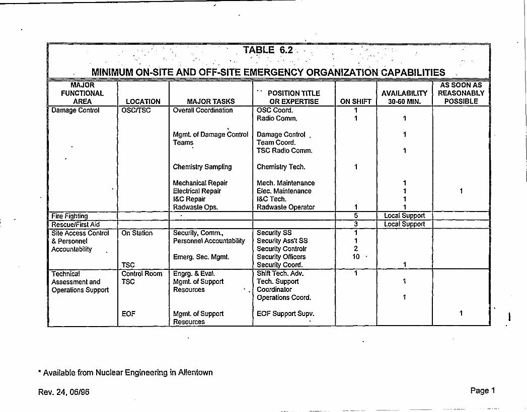
TABLE 6.2I
MINIMUMON-SITE AND OFF-SITE EMERGENCY ORGANIZATIONCAPABILITIESMAJOR
FUNCTIONALAREA
Damage ControlLOCATION
OSCITSCMAJOR TASKS
Overall Coordination
POSITION TITLEOR EXPERTISE
OSC Coord.Radio Comm.
ON SHIFTAVAILABILITY
3040 MIN.
AS SOON ASREASONABLY
POSSIBLE
Mgmt. of Damage ControlTeams
Damage Control .
Team Coord.TSC Radio Comm.
Fire FightingRescue/First AidSite Access Control& PersonnelAccountability
TechnicalAssessment andOperations Support
On Station
TSCControl RoomTSC
EOF
Chemistry Sampling
Mechanical RepairElectrical Repairl8C RepairRadwaste Ops.
Security, Comm.,Personnel Accountability
Emerg. Sec. Mgmt.
Engrg. & Eval.Mgmt. of SupportResources
Mgmt. of SupportResources
Chemistry Tech.
Mech. MaintenanceElec. MaintenanceI&CTech.Radwaste Operator
Security SSSecurity Ass't SSSecurity ControlrSecurity OfficersSecurity Coord.Shift Tech. Adv.Tech. SupportCoordinatorOperations Coord.
EOF Support Supv.
1
1
210
Local SupportLocal Support
* Available from Nuctear Engineering in Allentown
Rev. 24, 06/96 Page 1

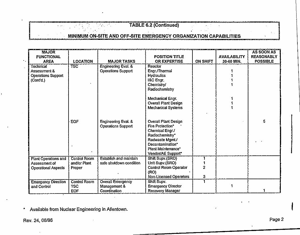
TABLE6.2 (Continued )
NIINIMUMON-SITE AND OFFNITE E!NERGENCY ORGANIZATIONCAPABILITIES
MAJORFUNCTIONAL
AREATechnicalAssessment 8
Operations Support(Cont'd.)
LOCATIONTSC
MAJOR TASKSEngineering Eval. 8Operations Support
POSITION TITLEOR EXPERTISE
ReactorEngr. /ThermalHydraulicsMC Engr.Chemistry/Radiochemistry
ON SHIFTAVAILABILITY
3040 MIN.
AS SOON ASREASONABLY
POSSIBLE
Mechanical Engr.Overall Plant DesignMechanical Systems
EOF
Plant Operations and Control RoomAssessment of and/or PlantOperational Aspects Proper
Engineering Eval. 8
Operations Support
Establish and maintainsafe shutdown condition
Overall Plant DesignFire ProtectionChemical Engr./Radiochemistry*Radwaste Mgmt./DecontaminationPlant Maintenance"Vendor/AE
Support'hift
Supv. (SRO)Unit Supv. (SRO)Control Room Operator(RO)Non-Licensed Operators
Emergency Directionand Control
Control RoomTSCEOF
Overall EmergencyManagement 8Coordination
Shift Supv.Emergency DirectorRecovery Manager
* Available from Nuclear Engineering in Allentown.
Rev. 24, 06/96 Page 2

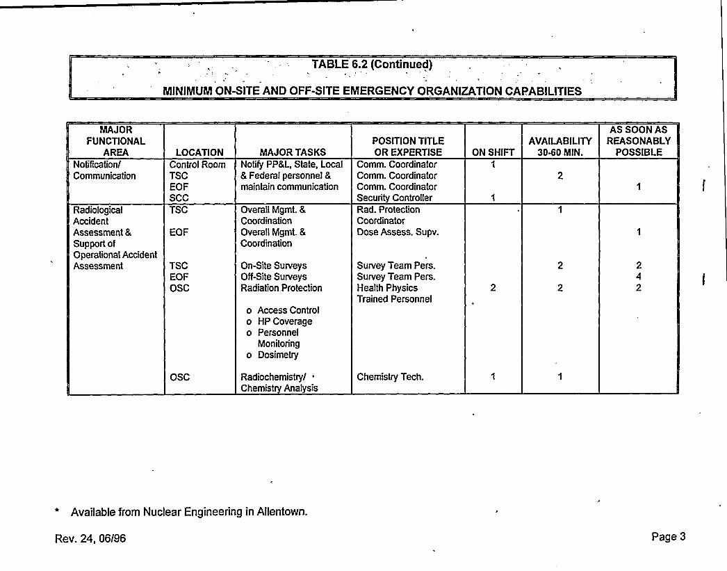
TABLE6.2 (Continued)
MINIMUMON-SITE AND OFF-SITE EMERGENCY ORGANIZATIONCAPABILITIES
MAJORFONCTIONAL
AREANotification/Communication
RadiologicalAccidentAssessment 8Support ofOperational AccidentAssessment
LOCATIONControl RoomTSCEOFSCCTSC
EOF
TSCEOFOSC
OSC
MAJOR TASKSNotil'y PP8L, State, Local8 Federal personnel 8maintain communication
Overall Mgmt. 8CoordinationOverall Mgmt. 8
Coordination
On-Site SurveysOff-Site SurveysRadiation Protection
o Access Controlo HP Coverageo Personnel
Monitoringo Dosimetry
Radiochemistry/ ~
Chemistry Analysis
POSITION TITLEOR EXPERTISE
Comm. CoordinatorComm. CoordinatorComm. CoordinatorSecurity ControllerRad. ProtectionCoordinatorDose Assess. Supv.
Survey Team Pers.Survey Team Pers.Health PhysicsTrained Personnel
Chemistry Tech.
ON SHIFTAVAILABILITY
30-60 MIN.
AS SOON ASREASONABLY
POSSIBLE
* Available from Nuclear Engineering in Allentown.
Rev. 24, 06196 Page 3
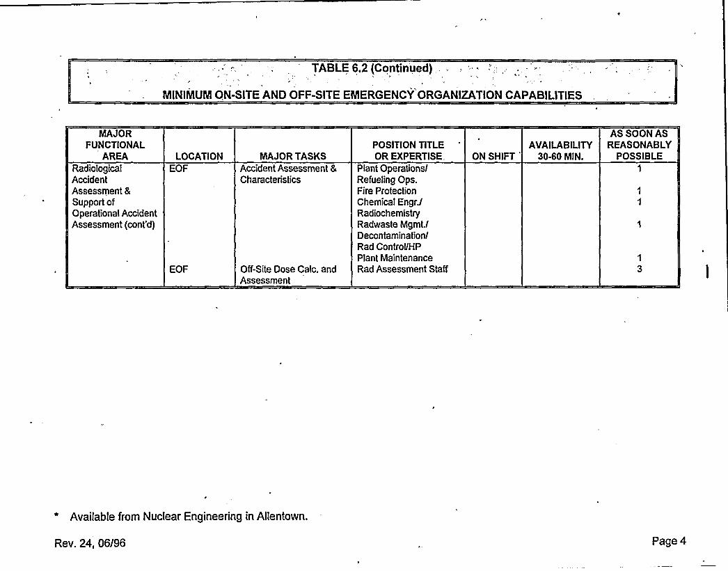
TABLE6.2 (Continued)
MINIMUMQN-SITE ANO OFF-SITE EMERGENCY ORGANIZATIONCAPABILITIES
MAJORFUNCTIONAL
AREARadiologicalAccidentAssessment 8
Support ofOperational AccidentAssessment (cont'd}
LOCATIONEOF
EOF
MAJOR TASKSAccident Assessment 8
Characteristics
Off-Site Dose Gale. andAssessment
POSITION TITLEOR EXPERTISE
Plant OperationslRefueling Ops.Fire ProtectionChemical Engr.lRadiochemistryRadeaste Mgmt.lDecontaminationlRad Control/HPPlant MaintenanceRad Assessment Staff
ON SHIFT'VAILABILITY
30-60 MIN.
AS SOON ASREASONABLY
POSSIBLE
1
3
* Available from Nuclear Engineering in Allentown.
Rev. 24, 06/96 Page 4

v
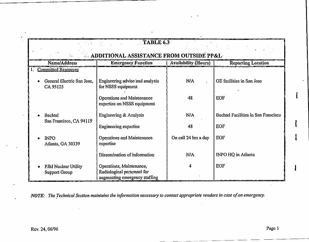
- TABLE6.3
''-: ADDITIONALASSISTANCE PROM OUTSIDE PP8rLName/Address Emergency Function Availability(Hours) Reporting Location
~ General Electric San Jose,CA 95125
Engineering advise 'and analysisfor NSSS equipment
N/A GE facilities in San Jose
Operations and Maintenanceexpertise on NSSS equipment
EOF
~ BechtelSan Francisco, CA 94119
Engineering &, Analysis
Engineering expertise
N/A
48
Bechtel Facilities in San Francisco
EOF
~ INPOAtlanta, GA 30339
Operations and Maintenanceexpertise
On call 24 hrs a day EOF
Dissemination of information N/A INPO HQ in Atlanta
~ PJM Nuclear UtilitySupport Group
Operations, Maintenance,Radiological personnel foraugmenting emergency staffing
EOF
iVOTFt The Technicaf Section maintains the information necessary to contact appropriate vendorsin case ofan emergency.
Rev. 24, 06/96 Page 1

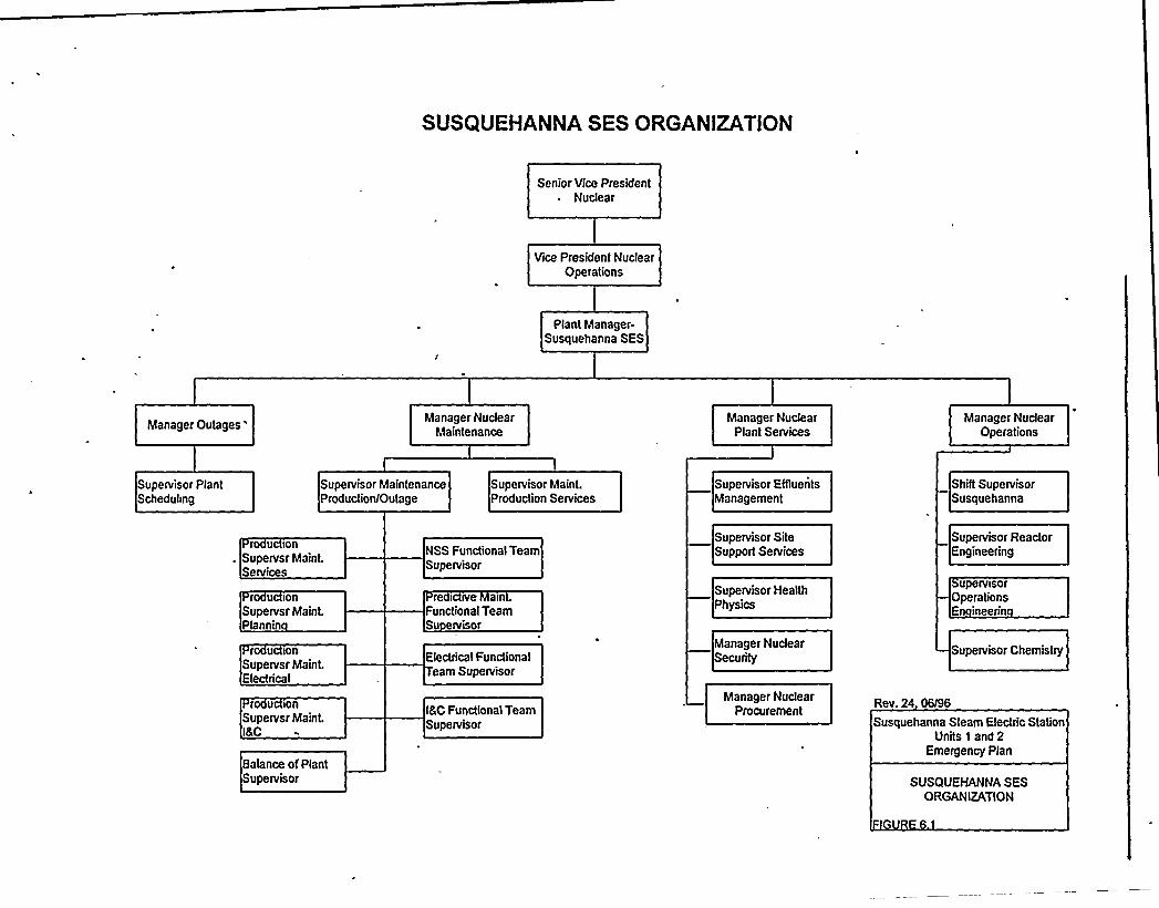
SUSQUEHANNA SES ORGANIZATJON
Senior Vice President~ Nudear
Vice President NuclearOperations
Plant Manager-Susquehanna SES
Manager Outages'anager Nudear
MaintenanceManager Nudear
Plant ServicesManager Nuclear
Operations
Supervisor PlantScheduhng
Supervisor MaintenanceProductionlOutage
Supervisor Maint.Production Services
Supervisor ENuentsManagement
Shift SupervisorSusquehanna
r U ionSupervsr Maint.Services
r u lonSupervsr Maint.Plannin
r u ionSupervsr Maint.Electrical
r u ionSupervsr Maint.I&C
Balance of PlantSupervisor
NSS Functional TeamSupervisor
re i rve a>n .
Functional TeamSu ervisor
Electrical Functionalearn Supervisor
l&CFunctional TeamSupervisor
Supervisor SiteSupport Services
Supervisor HealthPhysics
Manager NudearSecurity
Manager NudearProcurement
Supenrisor ReactorEngineering
UpelvlsofOperationsEn ineerin
Supervisor Chemistry
Rev. 24 06/96
Susquehanna Steam Electric StationUnits 1 and 2
Emergency Plan
SUSQUEHANNA SESORGANIZATION

A
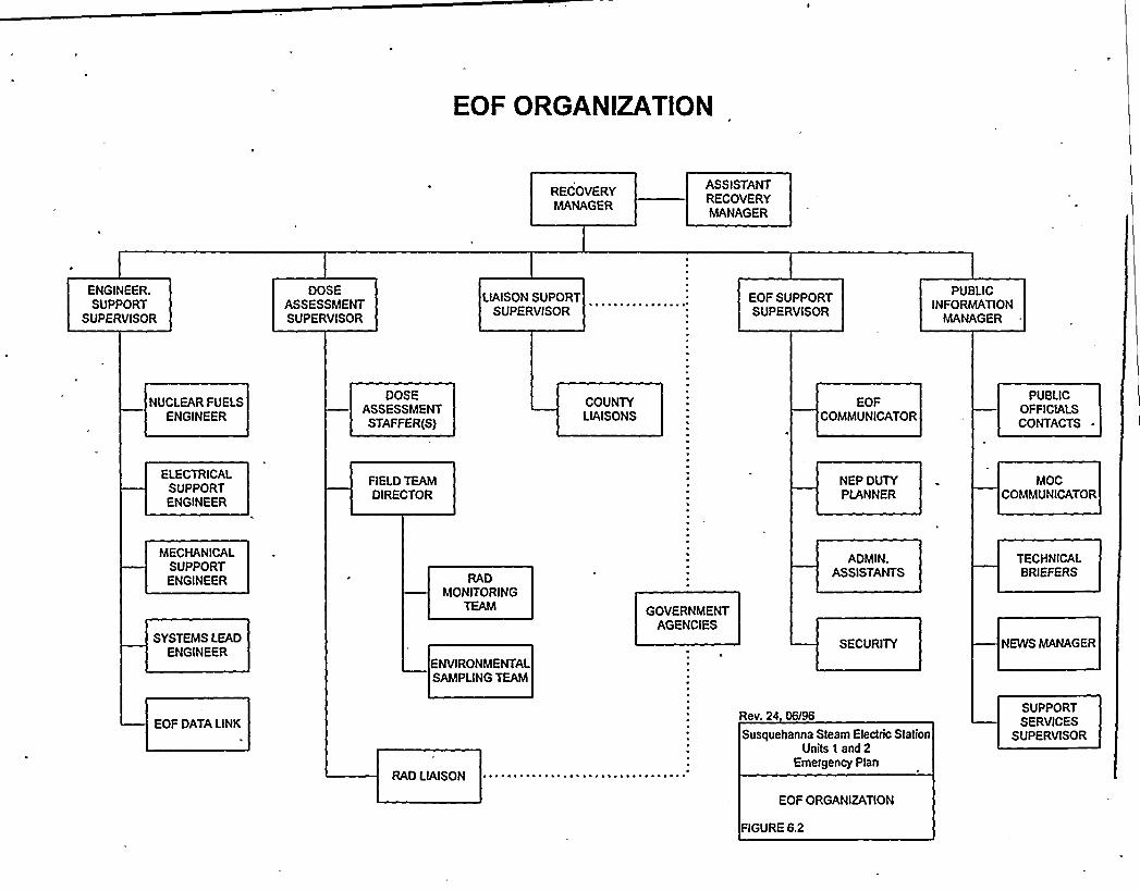
EOF ORGANIZATION
RECOVERYMANAGER
ASSISTANTRECOVERYMANAGER
ENGINEER.SUPPORT
SUPERVISOR
DOSEASSESSMENTSUPERVISOR
LIAISONSUPORTSUPERVISOR
EOF SUPPORTSUPERVISOR
PUBLICINFORMATION
MANAGER *
NUClEAR FUELSENGINEER
DOSEASSESSMENTSTAFFER(S)
COUNTYLIAISONS
EOFCOMMUNICATOR
PUBLICOFFICIALSCONTACTS
ELECTRICALSUPPORTENGINEER
FIELDTEAMDIRECTOR
NEP DUTYPLANNER
MOCCOMMUNICATOR
MECHANICALSUPPORTENGINEER
SYSTEMS LEADENGINEER
RADMONITORING
TEAM
ENVIRONMENTAlSAMPLINGTEAM
GOVERNMENTAGENCIES
ADMIN.ASSISTANTS
SECURITY
TECHNICAlBRIEFERS
NEWS MANAGER
EOF DATALINK
RAD LIAISON
Rev. 24 06/96
Susquehanna Steam Electric StationUnits 1 and 2
Emergency Plan
EOF ORGANIZATION
FIGURE 6.2
SUPPORTSERVICES
SUPERVISOR
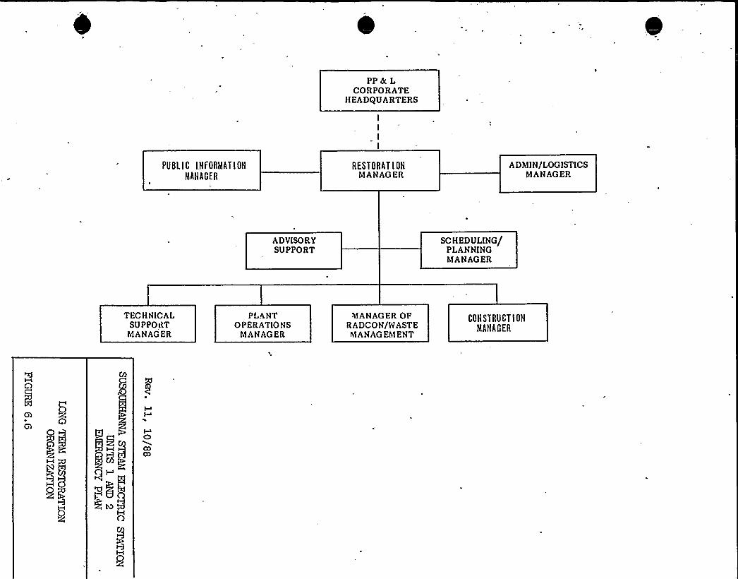
PP8(LCORPORATE
HEADQUARTERS
PUSLIC IHFORMATIOH
MANAGER
RESTORATIOHMANAGER
ADMIN/LOGISTICSMANAGER
ADVISORYSUPPORT
SCHEDULING/PLANNINGMANAGER
TEC H N ICALSUPPORTMANAGER
PLANTOPERATIONS
MANAGER
MANAGER OFRADCON/WASTEMANAGEMENT
COHSTRUCT IONMAHAGER
gHIqv
555O
M~9
COCO
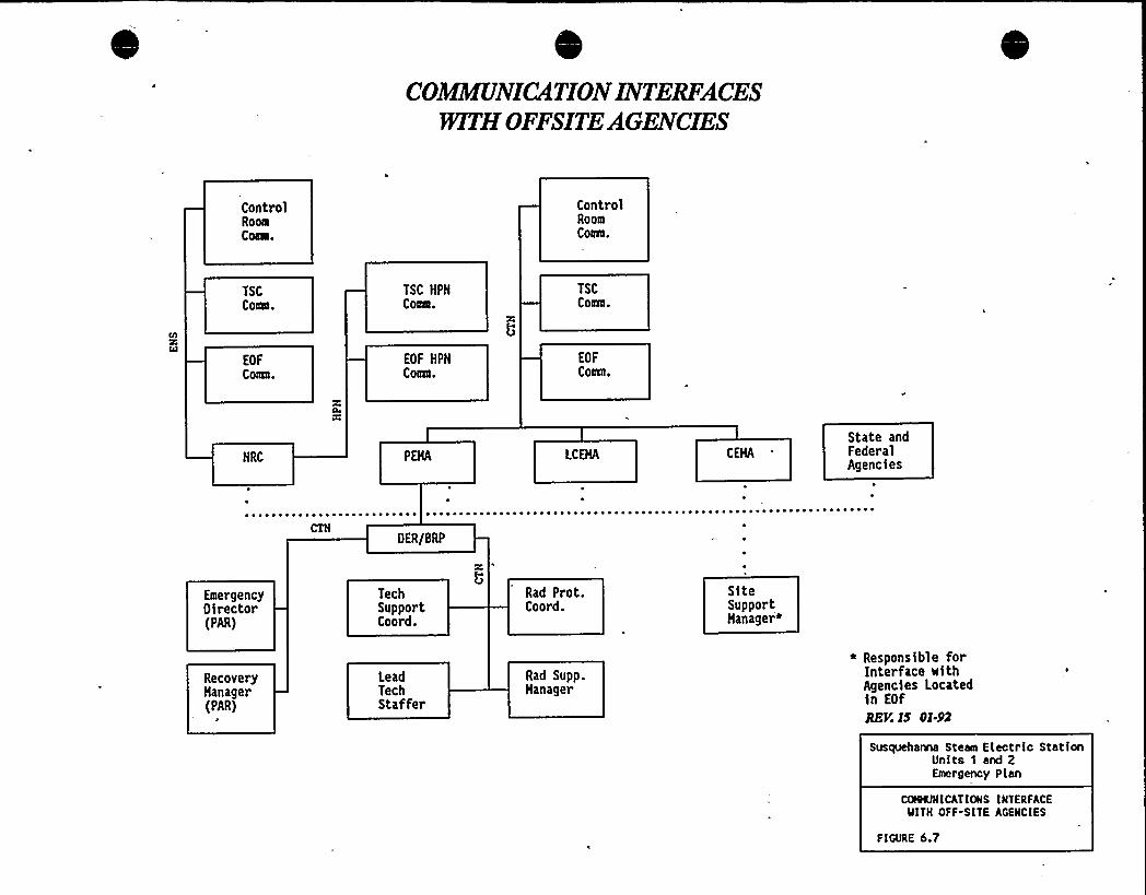
COjMIEUNICATIONINTERFACESmTHOFFSITE AGENCIES
ControlRoomCoaa.
ControlRoomComa.
TSCCoaNI.
TSC HPHCoae.
TSCCoats.
EOFCoats.
EOF HPHCmta.
EOF
Coats,
HRC LCEHA CEHA
State andFederalAgencies
OER/BRP
EmergencyOirector(PAR)
TechSupportCoord.
Rad Prot.Coord.
SiteSupportHanagere
RecoveryHanager(PAR)
P
LeadTechStaffer
Rad Supp.Hanager
* Responsible forInterface withAgencies Locatedin EOf
REV. IS OI-92
Susqueha~ Stean Electric StationUnits 1 and 2Emergency Plan
COHNJNI CAT IONS INTERFACEWITH OFF-SITE AGENCIES
FIGURE 6.7
I;.";::;.".;" ';.:, ', ."',, ':'„. „',7,0.;:-:.'MERGENCY'MEA'SURES::;;:;;:,,':,"-'„'.1
ASSESSMENT ACTIONS FOR ALLEMERGENCY CLA IFICATIONS
Provisions are made for assessment through the course of an emergency to ensure effective
coordination, direction and upgrading ofemergency activities in a timely manner. The assessment
actions are described in detail in EP-PSs.
Continuous assessment of the status of plant systems and radiological conditions is provided byplant instrumentation and is supplemented by routine surveillance functions. The occurrence ofan
Unusual Event is recognized by instrument alarms or indications, surveillance results or other
observation ofan off-normal condition by an individual at the station.
Assessment actions are described below. For an Unusual Event, one or more of the actions listed
below willbe initiated; for higher emergency classifications, actions are continued, intensified, and
increased in frequency.
~ Perform surveillance of in-plant instrumentation.
~ Initial and continued observation ofoff-normal conditions.
~ Obtain assistance from off-duty personnel and/or off-site support groups.
~ Perform dose calculation activities. Correlate with field team data.
~ Deploy field radiological monitoring teams to perform direct radiation measurements
and air sampling.
~ Perform sampling and analysis ofenvironmental media.
~ Deploy on-site damage control teams.
~ Perform reactor coolant sampling and analysis.
7.1.1 Off-Sit Dose alculati ns
The ED is responsible for initiating off-site dose calculation and assessment activities. These
activities are performed"by health physics technicians who report to the control room. Data from
the vent effluent monitors and the meteorological towers serve as inputs for the off-site dose
calculation methods.
The ED is responsible for calling in personnel to the TSC to perform off-site dose assessment
activities, The Radiation Protection Coordinator reports to the TSC within 30-60 minutes ofnotification. Subsequently, the off-site dose assessment activities at the TSC are turned over to
the Interim Radiation Support Manager at the EOF. The Interim Radiation Support Manager
Rev. 22, 04/95 7-1
reports to the EOF within one hour of notification. Upon arrival at the EOF the Radiation
Support Manager relieves the Interim Radiation, Support Manager of ofF-site radiological
responsibilities.
Field monitoring teams are directed to selected monitoring location(s) by the Radiation ProtectionCoordinator, Interim Radiation Support Manager, or Radiation Support Manager via radio
communication. The results of the teams'urveys are used to update projected doses and dose
calculational assumptions. This process is reiterated through the duration of the release in orderto maintain an updated status of dose rates and accumulated dose within the pathway of the
plume.
The initial field monitoring team(s) are staFed as required within 30-60 minutes. Additional
team(s) are dispatched within one to four hours.-
Each on-site and near site monitoring team is supplied with a survey meter and low volume air
sampler. TLDs are located at 19 sites around the station to provide early information on
accumulated ofF-site doses. Two sets of TLDs are provided at each of these sites; one set forvery early collection/exchange and readout and one set for dose accumulation during the period ofrelease.
The ED and Recovery Manager recommend appropriate protective actions to PEMA Operations
Center, Harrisburg, base'd upon the results ofthe oF-site dose assessment activities.
7.1.1.1 Meteor lo
The SSES on-site meteorological measurement system is based upon an on-site 300'rimarymeteorological tower located to the southeast of the station. The primary tower provides
measurements of wind speed, wind direction, and wind variability at its 10 and 60-meter levels,
temperature di6erential between the 10 and 60-meter levels, and ambient temperature and dew
point at the 10-meter level. Precipitation is measured at ground level. In case of primary tower
failure, a 10-meter on-site backup meteorological tower will provide measurements of wind
speed, wind direction, and wind variability.
The meteorological systems are instrumented to provide continuous data to the control room and
to the PCS for utilization in the TSC and EOF. Data which enter the PCS are viewable through
various display formats and are also transmitted to the NRC via ERDS. Digital dataloggers are
present at each of the two SSES meteorological towers. All data are stored locally and are
available for acquisition by interrogation across telephone lines. Primary and backup tower strip
chart recorders are located in the control room.
Additional meteorological information for emergency dose assessment purposes is available as
needed from the National Weather Service Station at the Wilkes-Barre Scranton Airport at
Avoca, about 30 miles northeast of the Susquehanna site, and the Philadelphia Forecast office ofthe National Weather Service.
Rev. 22, 04/95 7-2
7.1.1.2 Health Ph sics Considerations
In the event of an unplanned radioactive release from either the reactor building vents, the turbinebuilding vents or the standby gas treatment vent; gross noble gas, I-131, and gross particulatereadings are available from the System Particulate Iodine Noble Gas (SPING) vent monitors.
The following Health Physics considerations are taken into account: selection of the accident
type to closely approximate the isotopic mix and average gamma energies of the release
occurring, radioactive decay from time of reactor shutdown, plume decay-in-transit and iodineand particulate depletion due to precipitation.
7.1.13 D s Cal ulati nsF rAi rneRelease
A dose calculation model is used to make current, site specific estimates and predictions ofatmospheric e6luent transport "and diffusion during and immediately following an accidental
airborne radioactivity release. The purpose of the prediction is to provide an input to the
assessment of the consequences ofaccidental radioactive releases to the atmosphere and to aid inthe implementation ofemergency response decisions.
The dose calculation model used is a fast running, time-dependent, variable trajectory plumesegment "B" model with the following capabilities:
~ NOTE: A class "B" model is a numerical model which represents the actual spatial and temporalvariations ofplume distribution.
~ Computes atmospheric dispersion at the site based on atmospheric stability as a
function of site specific terrain conditions with 15-minute upgrades of source term and
meteorological conditions.
~ Provides estimates of deposition and relative concentration of radioactivity within the
plume exposure and ingestion EPZs for the duration ofthe release.
~ Incorporated in the calculations is wet and dry deposition which enables dose
estimates from three pathways - plume, ground shine, and inhalation.
The dose program complies with the "Manual ofProtective Action Guides and Protective Actionsfor Nuclear Incidents," (EPA-400), 'adopting the dose calculation methodology in ICRP 426/30.
The followingcalculational options are available:
~ TEDE (Total Effective Dose Equivalent) integrated doses consisting of the sum ofexternal doses from plume shine, 50 year committed effective dose equivalent frominhalation (CEDE), and 4 day ground shine doses.
~ TEDE dose rates for field team management.
~ Fiftyyear thyroid committed dose (CDE), from inhalation ofradioactive materials.
Rev. 22, 04/95 7-3
~ Population dose (person rem) out to 50 miles.
~ Summary print ofprojected doses for each offour projection times.
~ Integrated ground dose for projected times specified by the user.
The dose calculation program is a stand alone program running on PCs located in the TSC and
EOF.
7114 I.i i R l ase al 1 ti n
Estimates of downstream river water concentrations are made by employing efHuent sample
analysis or discharge monitor data, discharge flow rates and river elevation readings. The riverelevation is used to estimate the travel time to the point of interest. The calculated degree of
,. mixing, together with the discharge monitor data and the discharge flow rates are used tocalculate downstream concentrations.
7.2 ORRE TIVEA TI N
Detailed operating procedures and plant procedures are utilized by the plant operating personnel
to assist them in recognizing emergency events and taking the corrective actions necessary toplace the plant in a safe condition. Table 7.1 shows personnel available to respond to an
emergency. Additionally, EP-PSs describe subsequent and supplemental corrective actions for the
scope of potential situations within each of the emergency classifications. These procedures are
designed to guide the actions of the personnel to correct or mitigate the condition as early and as
near to the source of the problem as feasible.
Some essential corrective actions may involve the risk of emergency exposure to NERO
personnel. Such actions could involve preventing the release of large quantities of radioactive
material, reducing damage to major equipment or life saving actions. Table 7.2 specifies the limits
for emergency exposure and other relevant criteria to be considered. The ED is responsible for all
corrective actions taken to mitigate the consequences ofthe accident on-site.
73 PR TE TIVEA TI N
Protective actions are implemented to prevent or mitigate consequences to individuals during orafter a radiological incident. Protective actions within the SSES site boundary are the
responsibility of the ED, but may include assistance by oF-site organizations. Protective actions
outside the SSES site boundary are primarily the responsibility of State and local emergency
organizations, but may include coordination of activities, dissemination of appropriate data, and
recommendations by the ED or Recovery Manager. Protective action recommendations are
outlined in Table 7.3.
Rev. 22, 04/95 7-4
7,3.1'n-Site Protective Actions
Th'e primary protective measure for on-site personnel in an emergency is prompt evacuation fromareas which may be affected by significant radiation, contamination or airborne radioactivity.
Respiratory protective equipment and clothing are provided at the plant and in the various
emergency equipment kits for personnel who may be required to perform emergency activities.
Control of in-plant contamination is in accordance with SSES Health Physics procedures. In the
event of radioactive contamination outside fenced security areas, but within the exclusion area,
access to such areas is controlled by PPEcL with assistance from the PSP.
7.3,1.1 Local Ar Evacuati n
This category refers to evacuation &om one area to another area within the same building. Theinitiation of a Local Area Evacuation results from ARM or CAM alarm(s) sounding in the same
area within a building or &om observed conditions such as smoke or toxic gas, which mayindicate a possible habitability problem. The initial response for individuals is to evacuate to
an'naffectedarea ofthe building, notify the plant Control Room of the conditions, and await furtherinstruction. The ED assesses the situation, activates appropriate procedures to rectify thecondition and informs the personnel when to return to their respective work area via the PAsystem.
7.3.1.2 Radi lo 'call ntrolled Area Evacuation
The initiation of a Radiologically Controlled Area Evacuation results from ARM, CAM, or other
applicable monitor alarms, (i.e., fire alarms). Notification for personnel to proceed with a
Radiologically Controlled Area Evacuation is announced over the plant PA system. The initialmandatory response by individuals is evacuation to an unaffected area. In this case, however, the
nearest such area may not be in the same building, and multiple ARM, CAM, or fire alarms are
probable.
The decision to implement a Radiologically Controlled Area Evacuation is the responsibility of the
ED. Factors to be considered include the apparent levels of radiation and/or airborne
radioactivity involved and the exposure to personnel that would result &om evacuating toAssembly Areas. In the event of multiple fire alarms within the Radiologically Controlled Area,
with no potentiai hazard to personnel, such as workers in unaffected areas, the ED may deem it
prudent not to evacuate such personnel and allow work to continue.
~ 7 3 1 3 Securi and Accountabili
Accountability of on-site personnel during an emergency is accomplished through the use of the
physical security system and procedures. The physical security system clearly establishes who is
within the protected area. Personnel are summoned to accountability areas during an emergency
via an alert signal transmitted over the PA system. The names of the personnel reporting in are
compared to those logged through the security system in order to ensure total accountability.
Rev. 22, 04/95 7-5
7.3.1.4 Site Evacuation
Site Evacuation requires that all individuals within the SSES site, except for Control Room,operations personnel and others with specific emergency assignments, leave the site. Ifoff-siteassembly is required by the ED, personnel will go to the Remote Assembly Area. The PrimaryRemote Assembly Area is the Susquehanna Energy Information Center (NE Sector), as shown in
Figure 8.1. The alternate Remote Assembly Area is the EOF (WSW Sector). Security personneland assembly area leaders willcoordinate assembly and accountability at Remote Assembly Areas.
Implementation ofa Site Evacuation is the responsibility of the ED. That decision is based on the
severity of the incident, the likelihood of escalation, and the radiation and airborne radioactivitylevels throughout the station. Notification is made via the PA system.
Accountability is accomplished in passage through the security gate and supervisory checks at the
assembly area. Personnel and vehicle contamination surveys are performed at the RemoteAssembly Area, using portable survey instruments.
732 ff i Pr iv A in
The responsibility for actions to protect off-site individuals rests with the Commonwealth ofPennsylvania.
DER/BRP is responsible for evaluating information obtained from SSES and other sources and
recommending appropriate off-site protective actions to PEMA. Such recommendations include:
~ Shelter for affected populations~ Evacuation ofaffected populations~ Administration ofthyroid prophylaxis~ Control ofcontaminated agricultural products
The principal off-site local coordinating agency is LCEMA. Since the area and population inside
the ten-mile EPZ are partially within Columbia County, parallel emergency response functions are
provided by CEMA. Upon notification by PEMA of a situation which may require protectiveactions for off-site populations, LCEMAand CEMA initiate appropriate actions. IfPEMA has
lost communication or is otherwise unavailable, it is possible that the ED or Recovery Manager
may contact LCEMA and CEMA directly with protective action recommendations, If time
permits, LCEMA and CEMA obtain a review and verification by PEMA of recommendations
made by the ED or Recovery Manager.
'LCEMAand CEMAprotective actions include:
~ Prompt alerting of the population within ten miles of the SSES through the 'use of the
Public Notification System described in Section 8.0.~ Transmission of specific instructions to potentially affected populations via the
Emergency Broadcast System.~ Assistance for evacuation of the population within the ten-mile EPZ.
Rev. 22, 04/95 7-6
Reception and mass care centers for evacuated individuals.
Appendix G includes the estimated times to evacuate all or segments of the population from the
10-mile EPZ, identifies potential problem areas and provides contingencies for dealing withadverse conditions. It was utilized in the development of detailed evacuation plans by PEMA,LCEMAand CEMA.
7 4 AIDTO AFFECTED PER ONNEL
7.4.1 Emer enc Ex osure
Allreasonable measures are taken to maintain the radiation exposure ofemergency personnel who
provide rescue, first aid, decontamination, ambulance, or medical treatment services within
applicable limits specified in 10CFR20. Table 7.2 summarizes the emergency exposure criteria forentry or re-entry into areas for purposes ofundertaking protective or corrective actions. Methods
. and conditions for permitting volunteers to receive emergency radiation exposures are described
in EP-PSs, and provide for expeditious decisions with consideration to known and reasonable
balance ofassociated risks.
7.4 2 Dec ntamina i n an First Aid
Personnel contamination in emergency situations is controlled to the extent feasible by the normal
methods of using protective clothing and surveying for contamination following the removal ofsuch clothing. Personnel decontamination areas are available in-plant and at the EOF foremergency use. Decontamination efforts involving significant amounts of contamination are
performed under the direction ofHealth Physics personnel.
In the'vent of Site Evacuation, Health Physics personnel conduct personnel surveys ofindividuals as they are evacuated. Ifpersonnel decontamination is required, EOF facilities are
available to support the decontamination efforts ofHealth Physics personnel.\
At least two persons who are qualified in first aid methods are on-site at all times. First aid to
injured personnel can be performed in conjunction with any necessary decontamination methods.
However, if immediate treatment of the injury is vital, that treatment takes precedence over
decontamination.'his philosophy also extends to oF-site emergency assistance involving
radioactive contamination. For that purpose, measures are established to ensure timely off-site
medical treatment.
7.4.3 Medical Trans ortati n and Treatment
Arrangements and agreements have been made for the transportation and treatment of patients
from SSES, who may have injuries complicated with radioactive contamination or who may have
been involved in a radiation incident.
Rev. 22, 04/95 7-7

Cl
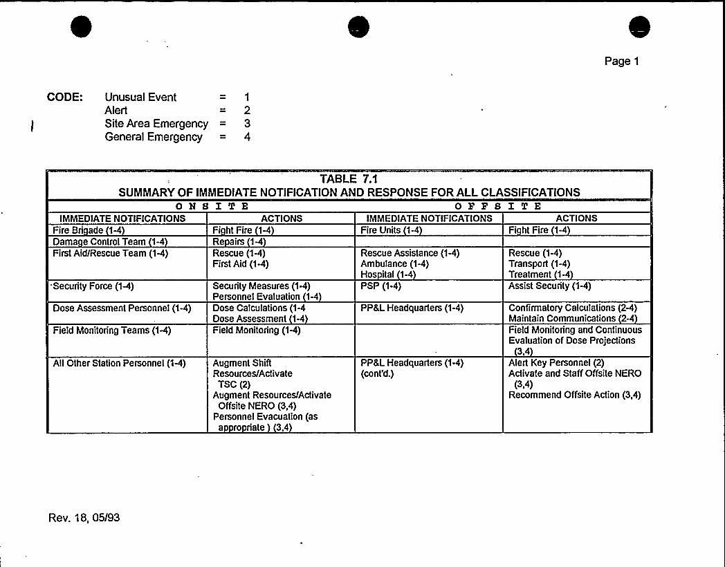
Page 1
CODE: Unusual EventAlertSite Area EmergencyGeneral Emergency
TABLE 7.1SUMMARYOF IMMEDIATENOTIFICATIONAND RESPONSE FOR ALLCLASSIFICATIONS
ONS I TEIMMEDIATENOTIFICATIONS ACTIONS
OFFS ITEIMMEDIATENOTIFICATIONS ACTIONS
Fire Bri ade 14Dama e Control Team 1-4First Aid/Rescue Team (1-4)
Security Force (1-4)
Dose Assessment Personnel (1-4)
Field Monitoring Teams (1-4)
AIIOther Station Personnel (1-4)
Fi htFire 1ARe airs 1-4Rescue (1-4)First Aid (1-4)
Security Measures (1A)Personnel Evaluation 1-4Dose Calculations (1-4Dose Assessment 1-4
Field Monitoring (1-4)
Augment ShiftResources/Activate
TSC (2)Augment Resources/Activate
Offsite NERO (3,4)Personnel Evacuation (as
a ro riate 3,4
Fire Units 1-4
Rescue Assistance (1-4)Ambulance (1-4)Hos ital 1-4PSP (1-4)
PP&L Headquarters (1-4)
PP &LHeadquarters (1-4)(cont'd.)
Fi ht Fire 1-4
Rescue (1-4)Transport (1-4)Treatment 1-4Assist Security (1-4)
Confirmatory Calculations (2-4)Maintain Communications 2-4Field Monitoring and ContinuousEvaluation of Dose Projections
3,4Alert Key Personnel (2)Activate and Staff Offsite NERO
(3 4)Recommend Offsite Action (3,4)
Rev. 18, 05/93

0
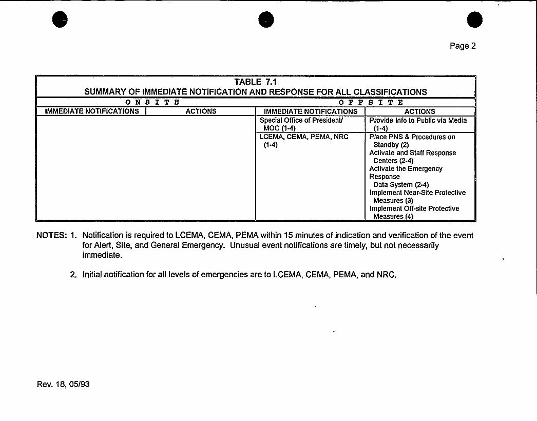
Page 2
TABLE 7.1SUMMARYOF IMMEDIATENOTIFICATIONAND RESPONSE FOR ALLCLASSIFICATIONS
ON8ITE ORR8 ITEIMMEDIATENOTIFICATIONS ACTIONS IMMEDIATENOTIFICATIONS
Special Office of President/MOC 1-4
LCEMA, CEMA, PEMA, NRC(1-4)
ACTIONSProvide Info to Public via Media
1-4Place PNS & Procedures on
Standby (2)Activate and Staff Response
Centers (2-4)Activate the EmergencyResponse
Data System (2-4)Implement Near-Site Protective
Measures (3)Implement Off-site Protective
Measures 4
NOTES: 1. Notification is required to LCEMA, CEMA, PEMA within 15 minutes of indication and verification of the eventfor Alert, Site, and General Emergency. Unusual event notifications are timely, but not necessarilyimmediate.
2. Initial notification for all levels of emergencies are to LCEMA, CEMA, PEMA, and NRC.
Rev. 18, 05/93
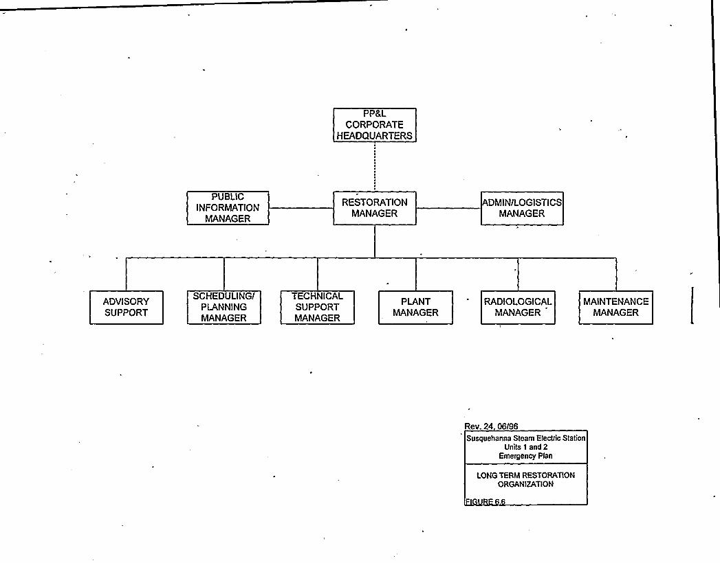
PP&LCORPORATE
HEADQUARTERS
PUBLICINFORMATION
MANAGER
RESTORATIONMANAGER
DMIN/LOGISTICSMANAGER
ADVISORYSUPPORT
SCHEDULINGIPLANNINGMANAGER
TECHNICALSUPPORTMANAGER
PLANTMANAGER
RADIOLOGICALMANAGER
MAINTENANCEMANAGER
Rev. 24 Q6I96
Susquehanna Steam Electric StationUnits 1 and 2
Emergency Plan
LONG TERM RESTORATIONORGANIZATION

I
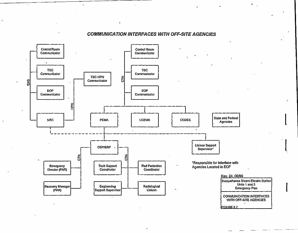
COMMUNICATIONINTERFACES WlTH OFF-SITE AGENCIES
Control RoomCommunicator
Control RoomCommunicator
TSCCommunicator
TSC HPNCommunicator
TSCCommunicator
EOFCommunicator
EOFCommunicator
zn.x
NRC PEMA LCEMA CCDESState and Federal
Agencies
EmergencyDirector (PAR)
Recovery Manager(PAR)
XIO
DEPlBRP
Tech SupportCoordinator
EngineeringSupport Supervisor
Rad ProtectionCoordinator
RadiologicalLiaison
Liaison SupportSupervisor
'Responsible for Interface withAgencies Located in EOF
Rev. 24 06I96
Susquehanna Steam Electric StationUnits 1 and 2
Emergency Plan
COMMUNICATIONINTERFACESWITH OFF-SITE AGENCIES
- 7.0- EMERGENCY MEASURES
Provisions are made for assessment through the course of an emergency to ensure effectivecoordination, direction and upgrading of emergency activities in a timely manner. 'Theassessment actions are described in detail in EP-PSs.
Continuous assessment of the status of plant systems and radiological conditions is provided byplant instrumentation and is supplemented by routine surveillance functions. The occurrence ofan Unusual Event is recognized by instrument alarms or indications, surveillance results, or otherobservation ofan off-normal condition by an individual at the station.
Assessment actions are described below. For an Unusual Event, one or more of the actions listedbelow will be initiated; for higher emergency classifications, actions are continued, intensified,and increased in frequency.
~ Perform surveillance, of in-plant instrumentation.
~ Initial and continued observation ofoff-normal conditions.
~ Obtain assistance from off-duty personnel and/or off-site support groups.
~ Perform dose calculation activities. Correlate with field team data.
~ Deploy field radiological monitoring teams to perform direct radiation measurementsand air sampling.
~ Perform sampling and analysis ofenvironmental media.
~ Deploy on-site damage control teams.
~ .Perform reactor coolant sampling and analysis.
The ED is responsible for initiating off-site dose calculation and assessment activities. Theseactivities are performed by health physics technicians who report to the control room. Data fromthe vent eQluent monitors and the meteorological towers serve as inputs for the off-site dosecalculation methods.
The ED is responsible for calling in personnel to the TSC to perform off-site dose assessmentactivities. The Radiation Protection Coordinator reports to the TSC within 30-60 minutes of
tnotification.
Rev. 24, 06/96 7-1
Field monitoring teams are directed to selected monitoring location(s) by the Radiation
Protection Coordinator, Dose Assessment Supervisor, Dose Assessment Staffer, or Field Team
Director via radio communication. The results of the teams'urveys are used to update projecteddoses and dose calculational assumptions. This process is reiterated through the duration of the
release in order to maintain an updated status of dose rates and accumulated dose within the
pathway of the plume.
The initial field monitoring team(s) are staffed as required within 30-60 minutes. Additional
team(s) are dispatched within one to four hours.
Each radiological monitoring team is supplied with a survey meter and low volume air sampler.
TLDs are located at 19 sites around the station to provide early information on accumulated off-site doses. Two sets of TLDs are provided at each of these sites; one set for very early
collection/exchange and readout and one set for dose accumulation during the period of release.
The ED and Recovery Manager recommend appropriate protective actions to PEMA Operations
Center, Harrisburg, based upon the results of the off-site dose assessment activities.
The SSES on-site meteorological measurement system is based upon an 'on-site 300'rimarymeteorological tower located to the east southeast of the station. The primary tower provides
measurements of wind speed, wind direction, and wind variability at its 10 and 60-meter levels,
temperature differential between the 10 and 60-meter levels, and ambient temperature and dew
point at the 10-meter level. Precipitation is measured at ground level. In case of primary tower
failure, a 10-meter on-site backup meteorological tower will provide measurements of wind
speed, wind direction, and wind variability.
The meteorological systems are instrumented to provide continuous data to the control room and
to the Unit One PCS and Unit Two PICSY for utilization in the TSC and EOF. Data which enter
the Unit One PCS and Unit Two PICSY are viewable through various display formats and are
also transmitted to the NRC via ERDS. Digital dataloggers are present at all of the SSES
meteorological towers. Alldata is stored locally and is available for acquisition by interrogation
across telephone lines. Primary and backup tower strip chart recorders are located in the control
room.
Site specific, meteorological information for emergency dose assessment purposes can be
obtained by contacting either the SSES Contract Meteorologist or the National Weather Service
Station using the phone numbers provided in the SSES Emergency Telephone Directory.
In the event of'an unplanned radioactive release from either the reactor building vents, the
turbine building vents or the standby gas treatment vent; gross noble gas, I-131, and gross
Rev. 24, 06/96 7-2
particulate readings are available from the System Particulate Iodine Noble Gas (SPING) ventmonitors.
The following Health Physics considerations are taken into account: selection of the accidenttype to closely approximate the isotopic mix and average gamma energies of the releaseoccurring, radioactive decay from time of reactor shutdown, plume decay-in-transit and iodineand particulate depletion due to precipitation.
A dose calculation model is used to make current, site specific estimates and predictions ofatmospheric effiuent transport and diffusion during and immediately following an accidentalairborne radioactivity release. The purpose of the prediction is to provide an input to theassessment of the consequences of accidental radioactive releases to the atmosphere and to aid inthe implementation ofemergency response decisions.
The dose calculation model used is a fast running, time-dependent, variable trajectory plumesegment "B" model with the followingcapabilities:
NOTE: A class "B" model is a numerical model which represents the actual spatial and
temporal variations ofplume distribution.
~ Computes atmospheric dispersion at the site based on atmospheric stability as a
function of site specific terrain conditions with 15-minute upgrades of source termand meteorological conditions.
~ Provides estimates ofdeposition and relative concentration of radioactivity within theplume exposure and ingestion EPZs for the duration of the release.
~ Incorporated in the calculations is wet and dry deposition which enables dose
estimates from three pathways - plume, ground shine, and'inhalation.
The dose program complies with the "Manual of Protective Action Guides and ProtectiveActions for Nuclear Incidents," (EPA-400), adopting the dose calculation methodology in ICRP026/30. The following calculational options are available:
~ TEDE (Total Effective Dose Equivalent) integrated doses consisting of the sum ofexternal doses from plume shine, 50 year committed effective dose equivalent frominhalation (CEDE), and 4 day ground shine doses.
~ TEDE dose rates for field team management.
~ Fiftyyear thyroid committed dose (CDE), from inhalation ofradioactive materials.I
~ Population dose (person rem) out to 50 miles.
Rev. 24, 06/96 7-3
~ Summary print ofprojected doses for each of four projection times.
~ Integrated ground dose for projected times specified by the user.
The dose calculation program is a stand alone program running on PCs located in the TSC andEOF.
Estimates of downstream river water concentrations are made by employing effluent sampleanalysis or discharge monitor data, discharge flow rates and river elevation readings. The riverelevation is used to estimate the travel time to the point of interest. The calculated degree ofmixing, together with the discharge monitor data and the discharge flow rates are used tocalculate downstream concentrations.
Detailed operating procedures and plant procedures are utilized by the plant operating personnelto assist them in recognizing emergency events and taking the corrective actions necessary toplace the plant'n a safe condition. Table 7.1 shows personnel available to respond to anemergency. Additionally, EP-PSs describe subsequent and supplemental corrective actions forthe scope of potential situations within each of the emergency classifications. These proceduresare designed to guide the actions ofthe personnel to correct or mitigate the condition as early andas near to the source of the problem as feasible.
Some essential corrective actions may involve the risk of emergency exposure to NEROpersonnel. Such actions could involve preventing the release of large quantities of radioactivematerial, reducing damage to major equipment or life saving actions. Table 7.2 specifies thelimits for emergency exposure and other relevant criteria to be considered. The ED isresponsible for all corrective actions taken to mitigate the consequences of the accident on-site.
Protective actions are implemented to prevent or mitigate consequences to individuals during orafter a radiological incident. Protective actions within the SSES site boundary are theresponsibility of the ED, but may include assistance by off-site organizations. Protective actionsoutside the SSES site boundary are primarily the responsibility of State and local, emergencyorganizations, but may include coordination of activities, dissemination of appropriate data, andrecommendations by the ED or Recovery Manager. Protective action recommendations are
outlined in Table 7.3.
Rev. 24, 06/96 7-4
The primary protective measure for on-site personnel in an emergency is prompt evacuation fromareas which may be affected by significant radiation, contamination, or airborne radioactivity.
Respiratory protective equipment and clothing are provided at the-plant and in the variousemergency equipment kits for peisonnel who may be required to perform emergency activities.
Control of in-plant contamination is in accordance with SSES Health Physics procedures. In theevent of radioactive contamination outside fenced security areas, but within the exclusion area,access to such areas is controlled by PP &Lwith assistance from the PSP.
This category refers to evacuation from one area to another area within the same building. Theinitiation of a Local Area Evacuation results from ARM or CAM alarm(s) sounding in the samearea within a building or from observed conditions such as smoke or toxic gas, which mayindicate a possible habitability problem. The initial response for individuals is to evacuate to anunaffected area of the building, notify the plant Control Room of the conditions, and awaitfurther instruction. The ED assesses the situation, activates appropriate procedures to rectify thecondition and informs the personnel when to return to their respective work area via the PAsystem.
The initiation of a Radiologically Controlled Area Evacuation results from ARM, CAM, or otherapplicable monitor alarms, (i.e., fire alarms). Notification for personnel to proceed with a
Radiologically Controlled Area Evacuation is announced over the plant PA system. The initialmandatory response by individuals is evacuation to an unaffected area. In this case, however, thenearest such area may not be in the same building, and multiple ARM, CAM, or fire alarms are
probable.
'he
decision to implement a Radiologically Controlled Area Evacuation is the responsibility ofthe ED. Factors to be considered include the apparent levels of radiation and/or airborneradioactivity involved and the exposure to personnel that would result from evacuating toAssembly Areas. In the event ofmultiple fire alarms within the Radiologically Controlled Area,with no potential hazard to personnel, such as workers in unaffected areas, the ED may deem itprudent not to evacuate such personnel and allow work to continue.
Accountability of on-site personnel during an emergency is accomplished through the use of thephysical security system and procedures. The physical security system clearly establishes who iswithin the protected area. Personnel are summoned to accountability areas during an emergency
Rev. 24, 06/96 7-5
via an alert signal transmitted over the PA system. The names of the personnel reporting in arecompared to those logged through the security system in order to ensure total accountability.
Site Evacuation requires that all individuals within the SSES site, except for Control Roomoperations personnel and others with specific emergency assignments, leave, the site. Ifoff-siteassembly is required by the ED, personnel will go to the Remote Assembly Area. The PrimaryRemote Assembly Area is the Susquehannaknergy Information Center (NE Sector), as shown inFigure 8.1. The alternate Remote Assembly Area is the old EOF (WSW Sector). Securitypersonnel and assembly area leaders will coordinate assembly and, accountability at RemoteAssembly Areas.
Implementation of a Site Evacuation is the responsibility of the ED. That decision is based onthe severity of the incident, the likelihood of escalation, and the radiation and airborneradioactivity levels throughout the station. Notification is made via the PA system..
Accountability is accomplished in passage through the security gate and supervisory checks atthe assembly area. Personnel and vehicle contamination surveys are performed at the RemoteAssembly Area, using portable survey instruments.
The responsibility for actions to protect off-site individuals rests with the Commonwealth ofPennsylvania.
DEP/BRP is responsible for evaluating information obtained from SSES and other sources andrecommending appropriate off-site protective actions to PEMA. Such recommendations include:
~ Shelter for affected populations~ Evacuation ofaffected populations~ Administration of thyroid prophylaxis
~ ~ Control ofcontaminated agricultural products
, The principal off-site local coordinating agency is LCEMA. Since the area and population insidethe ten-mile EPZ are partially within Columbia County, parallel emergency response functionsare provided by CCDES. Upon notification by PEMA of a situation which may requireprotective actions for off-site populations, LCEMA and CCDES initiate appropriate actions. IfPEMA has lost communication or is otherwise unavailable, it is possible that the ED or RecoveryManager may contact LCEMAand CCDES directly with protective action recommendations. Iftime permits, LCEMA and CCDES obtain a review and verification by PEMA ofrecommendations made by the ED or Recovery Manager.
Rev. 24, 06/96 7-6
LCEMAand CCDES protective actions include:
~ Prompt alerting of the population within ten miles of the SSES through the use of thePublic Notification System described in Section 8.0.
~ Transmission of specific instructions to potentially affected populations via theEmergency Alert'ystem.
~ A'ssistance for evacuation of the population within the ten-mile EPZ.~ Reception and mass care centers for evacuated individuals.
'ppendix G includes the estimated times to evacuate all or segments of the population from the10-mile EPZ, identifies potential problem areas and provides contingencies for dealing withadverse conditions. It was utilized in the development of detailed evacuation plans by PEMA,LCEMA,and CCDES.
All reasonable measures are taken to maintain the radiation exposure of emergency personnelwho provide rescue, first aid, decontamination, ambulance, or medical treatment services withinapplicable limits specified in 10CFR20. Table 7.2 summarizes the emergency exposure criteriafor entry or re-entry into areas for purposes of undertaking protective or corrective actions.Methods and conditions for permitting volunteers to receive emergency radiation exposures aredescribed in EP-PSs, and provide for 'expeditious decisions with consideration to known andreasonable balance ofassociated risks.
Personnel contamination in emergency situations is controlled to the extent feasible by thenormal methods of using protective clothing and surveying for contamination following theremoval of such clothing. Personnel decontamination areas are available in-plant anddecontamination efforts involving significant amounts of contamination are performed under thedirection ofHealth Physics personnel.
At least two persons who are qualified in first aid methods are on-site at all times. First aid toinjured personnel can be performed in conjunction with any necessary decontamination methods.However, if immediate treatment of the injury is vital, that treatment takes precedence overdecontamination. This philosophy also extends to off-site emergency assistance involvingradioactive contamination. For that purpose, measures are established to ensure timely off-sitemedical treatment.
Rev. 24, 06/96 7-7
Arrangements and agreements have been made for the transportation and treatment of patients
from SSES, who may have injuries complicated with radioactive contamination or who may
have been involved in a radiation incident.
Rev. 24, 06/96 7-8
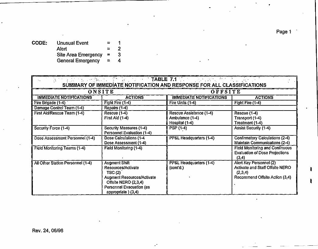
Page)
CODE: Unusual EventAlert-Site Area EmergencyGeneral Emergency
1
234
'ABLE 7.1SUMMARYOF IMMEDIATENOTIFICATIONAND RESPONSE FOR ALLCLASSIFICATIONS
ON SITEIMMEDIATENOTIFICATIONS ACTIONS
OFFSITEIMMEDIATENOTIFICATIONS ACTIONS
Fire Brigade (1-4)*
Damage Control Team (1-4)First Aid/Rescue Team (1-4)
Security Force (1A)
Dose Assessment Personnel (1-4)
Field Monitoring Teams (1-4)
AllOther Station Personnel (14)
Fight Fire (1R)Repairs (1-4)Rescue (1-4)First Aid (1-4)
Security Measures (1-4)Personnel Evaluation (1-4)Dose Calculations (1-4Dose Assessment (1-4)Field Monitoring (1-4)
Augment ShiftResources/ActivateTSC (2)
Augment Resources/ActivateOffsite NERO (2,3,4)
Personnel Evacuation (asappropriate } (3,4)
Fire Units (1-4)
Rescue Assistance (1P)Ambulance (1-4)Hospital (1-4)PSP (1R)
PP&L Headquarters (1A)
PP&L Headquarters (1C)(cont'd.)
Fight Fire (1-4)
Rescue (1-4)Transport (14)Treatment (1-4)Assist Security (1-4)
Confirmatory Calculations (2-4)Maintain Communications (2-4)Field Monitoring and ContinuousEvaluation of Dose Projections
(3,4)Alert Key Personnel (2}Activate and Staff Offsite NERO
(2,3,4)Recommend Offsite Action (3,4)
Rev. 24, 06/S6

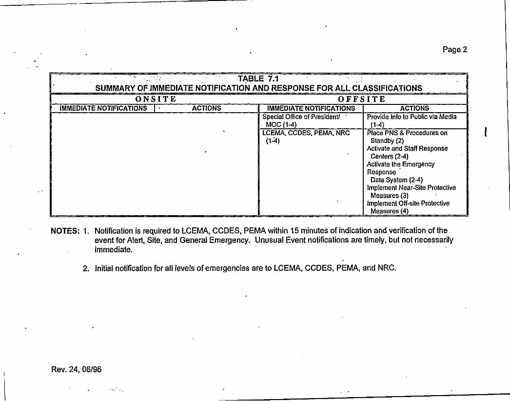
Page 2
TABLE 7.1SUMMARYOF IMMEDIATENOTIFICATIONAND RESPONSE FOR ALLCLASSIFICATIONS
ONSITKIMMEDIATENOTIFICATIONS ACTIONS
OFFSITEIMMEDIATENOTIFICATIONS ACTIONS
Special Office of President/MOC (1P)
LCEMA, CCDES, PEMA, NRC(1-4)
Provide Info to Public via Media(1-4)
Place PNS 8 Procedures onStandby (2)
Activate and Staff ResponseCenters (2-4)
Activate the EmergencyResponse
Data System (2-4)Implement Near-Site Protective
Measures (3)implement Off-site Protective
Measures (4)
NOTES: 1. Notification is required to LCEMA, CCDES, PEMA within 15 minutes of indication and verification of theevent for Alert, Site, and General Emergency. Unusual Event notifications are timely, but not necessarilyimmediate.
2. Initial notification for all levels of emergencies are to LGEMA, GCDES, PEMA, and NRC.
Rev. 24, 06/96
S.O'. EMERGENCY FACILITIKSAND EQUIPMENT .
8,1 ON-SITE EMERGENCY CENTERS
8.1 I Station Control Room
The Station Control Room is the primary location for the initial assessment and coordination ofcorrective actions for all emergency conditions. The Control Room is equipped with the displayand controls for all critical plant systems, radiological and meteorological monitoring systems,, and
all station communication systems. Reference Appendix D.
OfF-site emergency functions initially served by the Control Room are transferred to the TSC orEOF for a Site Area or a General Emergency as deemed appropriate by the ED. The primaryconsideration is to ensure that the number of personnel involved with the emergency in the
Control Room shall not impair the safe and orderly shutdown of the reactor or the operation ofplant safety systems.
8,1,2 0 erations Su ort Center
The OSC is the primary on-site assembly area for operations support team personnel during an
emergency. It occupies 340 square feet adjacent to the Control Room on El. 729'-1" of the
control structure.
The OSC is utilized initially as the central location for the assembly, accountability, and
dispatching of on-shift emergency team personnel required to perform such functions as: fire
fighting, first aid, search and rescue, damage control, and on-site radiation monitoring. Ifand
when the TSC is activated, all non-operations support team personnel assemble and are accounted
for at their individual assembly areas. TSC personnel assess the need for emergency team
personnel and based on this assessment, dispatch team personnel from their assembly area or viacall-in to perform TSC team functions. Long term retention ofadditional personnel to support in-
plant team functions will be in the Maintenance and I&C assembly areas. These areas will be
monitored continuously for habitability. Ifthese areas become uninhabitable, retained personnel
will be directed to alternate holding areas. Control and dispatch of these teams is the
responsibility of the TSC Radioman. The OSC continues to manage operations support
personnel, even after the TSC is activated.
Equipment required for these teams to perform their functions, as outlined in Appendix D is
stored and maintained in the Control Room, Technical Support Center and Health Physics access
control points.
During normal plant operations, this area serves as an operations stafF work area for shift
changeover purposes as well as shift work assignment area. The Non-Emergency use of the OSC
does not degrade its primary purpose.
Rev. 22, 04/95 8-1
8 1.2.1 Habitabilit
8.1.2.1.1 Allowable Post-Accident Radiation Doses
OSC personnel are protected from radiological hazards, including direct shine and airborneactivities for postulated accident conditions to the same degree as Control Room personnel.
Applicable criteria are specified in General Design Criterion 19, Standard Review Plan 6.4, and
NUREG-0737, Item II.B.2.
8.1.2.1 2 Postulated Post Accident Radiation Doses
The radiation dose to personnel occupying the OSC is the same as the Control Room personnel.The doses from controlling accidents are summarized in Chapter 15.0 of the FSAR.
8 1 2 1.3 Radiation M nitorin
To ensure adequate radiological protection of the OSC personnel, a commercial grade monitoralarms on high gross gamma radiation dose rates.
8.1.2.2 HVA
The OSC HVAC system is a part of the Control Room HVAC system which is described in FSARSection 9.4.1.
8.1 2 3 Shieldin
Shielding requirement for the OSC is the same as for the Control Room for total dose tooccupants from direct shine and airborne. Exposure does not exceed 5 Rem whole body for the
duration of the accident. This is in accordance with General Design Criterion 19, USNRCStandard Review Plan 6.4, and NUREG-0737, Item II.B.2. Duration of occupancy and methodofanalysis is the same as that used for the Control Room.
8124 Occu ant Accomm d ion
No toilet facilities are provided in the OSC. Facilities are available in the Control Room and at
grade level ofthe control structure for washing and toilet accommodations.
8125 Comm nic ti n
The OSC communication system includes priority access voice links-hotlines, the plant PA system
and telephone lines tied through the plant switchboard.
8.1 2 5.1 Tel h n
The normal telephone service for the OSC uses the plant ETN and CTN systems. Both systems
have the capability to reach on- and off-site locations.
Rev. 22, 04/95 8-2
8.1.2.5.2 Hotlines
Priority access voice communication links with automatic signaling is provided in the OSC. The
OSC hotline connects with the TSC or the Control Room.
8.1.2.5.3 Public Address S stem"
The PA system is part of the plant PA system. The system provides two-way communications at
handset stations. Each station may originate and receive communications by switching to either a
page channel or to one of five non-interfering party line channels.
8 1 3 Technical u rt enter
The TSC is a controlled access area which provides working space and facilities for 25 NERO
personnel. These personnel provide guidance to plant operations personnel for management ofemergency conditions and accident mitigation.
The TSC is located in the existing Control Room mezzanine above the Control Room at elevation741'-1" of the control structure and occupies approximately 2500 square feet. The TSC is within
approximately two minutes travel time ofthe Control Room by elevator or stairs.
The TSC facilities may be used for normal daily activities which do not degrade TSC emergency
preparedness. The TSC provides ofBce space for Operations and Technical personnel. The
facilities may also be used as a research or reference area by other station personnel.
8.1 3.1 atial La out Descri tion
The TSC includes areas for work, conferencing (NRC & PP&L), document control, and
computer monitoring. Housed components are SPDS, UMC, video copier, RDAS
(printer/terminal), and SPING monitor panel. (Reference Figure 8.2).e
8.1 3.2 Fire Protection
Automatic wet pipe sprinklers on an ordinary hazard pipe schedule are provided.
8 1 3.3 tru ral Desi Crit ri
The TSC is part of the control structure which is a Seismic Category I structure, as defined in
NRC Regulatory Guide 1.29. It is designed in accordance with Chapter 3.0 of the FSAR.
Rev. 22, 04/95 8-3
8.1.3 4 Habitabilit
8 1.3.4.1 Post-A cident Radiation Dose
8.1.3.4.1.1 Allowable
TSC personnel are protected from radiological hazards, including direct shine and airborne
activities for postulated accident conditions to the same degree as control room personnel.
Applicable criteria are specified in General Design Criterion 19, Standard Review Plan 6.4, and
NUREG-0737, Item II.B.2.
8 1.3 4 1.2 Postulated
The radiation dose to personnel is the same as the Control Room personnel. The doses fromcontrolling accidents are summarized in Chapter 15.0 ofthe FSAR.,
81.3413 Radiai nMoni orin
Commercial grade monitors are provided to alarm on high gross gamma radiation dose rates. Inaddition, airborne radioactivity concentrations are monitored by portable monitors. Iodinedetection capability is provided.
8 1 3 4.2 HVA
The TSC HVAC system is a part ofthe Control Room HVAC system which is described in FSAR
Section 9.4.1.
8 1.3 4.3 Shi ldin
Shielding is the same as for the Control Room for total dose to occupants from direct shine and
airborne. Exposure willnot exceed 5 Rem whole body for the duration of the accident. This is in
accordance with General Design Criterion 19, USNRC Standard Review Plan 6.4, and NUREG-
0737, Item II.B.2. Duration of occupancy and method of analysis is the same as for the control
room.
81,34.4 Occu tAcc mm dation
No sleeping accommodations or toilet facilities are provided. Use of the plant's existing facilities
at grade level of the control structure for washing and toilet accommodations is available. There
is a unit kitchen with appliances and sink. Self-contained breathing apparatus are available.
8 1 3 5 mmunication Link
The TSC communications system is comprised of three telephone networks (ETN, CTN, and
FTS), VHF and UHF radios, and the plant PA system, They provide reliable primary and back-np
communication links to emergency response facilities on- and off-site.
Rev. 22, 04/95 84
8,1,3 5.1 Tele hones
The TSC uses the CTN system as primary communications with the ETN system available at
various locations and the FTS 2000 reserved for federal government agencies.
8.1,3.5.2 Radio
The TSC has a four-channel 450 MHz UHF and a two-channel 150 MHz VHF radio system withdigital voice privacy capability. The VHF radio is an emergency backup for communication withLCEMA, CEMA, and GOESC, and to communicate with the field monitoring teams. The UHFradio provides primary and backup security, emergency, operational and maintenance
communication links.
81353 P li Addre tern
The system provides two-way communications at handset stations. Each station may originateand receive communication by switching to either a pager channel or to one of five non-
interfacing party-line channels.
8.1.3.6 Power Su 1
The TSC is part of the existing power block as described in Chapter 8.0 ofthe FSAR.
8.1.3.7 Instrumentati n
The TSC utilizes the same field sensors and signal conditioning equipment which is provided tomonitor plant systems. TSC instrumentation is identical to the field instrumentation used to
operate the plant. A detailed description of this instrumentation is provided in Chapter 7.0 of the
FSAR.
813.8 T DataPresen a ion
The TSC includes human factors engineered man-machine capabilities to allow personnel to
determine:
~ plant conditions during normal operation~ plant steady-state conditions prior to an accident~ transient conditions producing an initiating event~ plant system dynamic behavior during an accident~ projected behavior and effects ofoffsite airborne radioactivity releases.
The man-machine interface is provided by devices tied to the SPDS, PCS, and RDAS in the TSC
monitoring area: (Reference Figure 8.2).
a) Two CRTs housed in the SPDS console.
Rev. 22, 04/95 8-5
b) Two PCS UMCs which have graphic and parameter displays depicting the conditions ofthe plant systems.
c) Video copiers for hard copy output ofSPDS and PCS data.
d) RDAS printer/terminal for display ofmeteorological and vent data.
8.1,3.9 Records and Documents
The TSC contains up-to-date records and references for use during emergency conditions.(Reference Appendix D). Records are updated and managed by the DCS utilizing Plant
Administrative Procedures.
3~1.3. 0 II
The TSC is located within a plant vital area and is subject to the vital area access controls as
identi6ed in FSAR Section 13.6.
82 PP&L FF- ITEEMER EN YCENTER
8.2 1 Medi ration en r
Initially, the Susquehanna Energy Information Center, located on U.S. Route 11, is utilized as the
Media Operations Center. When the number of reporters anticipated is greater then the
comfortable limits of the Information Center, or ifa General Emergency is likely, the NortheastDivision Headquarters, located near Wilkes-Barre, will be activated as the Media Operations
Center.
8.22 Emer en erati n Facili
The EOF is an emergency response facility located near the site. The EOF provides continuous
management ofPP&L activities during radiological emergencies which may have oQsite impact.
The site location ofthe EOF is in North Central Pennsylvania in Luzerne County approximately 5-
V4 miles north of the Borough of Berwick in Salem Township, approximately 2,500 feet
southwest of the control structure (Reference Figure 8.1). The site fronts on County Road T-
438. Direct access to the site is maintained over a 12'ide stoned roadway from Rt. T-438 to the
500kV Switchyard.
The non-emergency activities of the EOF are such that its main'function is not degraded. The
EOF provides office space for the Nuclear Emergency Plannirig Group and computer maintenance
personnel. Also, space is provided for training and operational support functions.
8.2.2 1 Architectur
The 16,500 square feet, one-story building is a rectangular structure, 167'ong by 99'ide. The
exterior walls are 12" reinforced concrete with a brick facing. The shed roof is a 9-1/2"
Rev. 22, 04/95 8-6
reinforced concrete slab. The concrete was utilized to provide the required radiologicalprotection.
Fifty parking stalls are provided at the EOF. In addition, parking space for five emergency
response monitoring vans is provided at the side and rear of the building. Communication and
power hookups are available for each van.
8.2.2.1.1 S atialLa outDescri tion
The EOF is divided into three areas (Reference Figure 8.3):
'A. EMERGENCY OPERATI N RESPONSE
This area is composed ofoffices for a receptionist, PP&;L emergency managers and support,NRC, and conferencing. There is also a central work area for 35 people.
B. PORT AREA FOR EMERGENCY RESPON E
The areas provided are mechanical and electrical equipment, toilets, kitchen and eatingfacilities, storage areas and conference rooms.
C. COO MPR R hl
A computer room supports SPDS and RDAS and ERDS. Also, an adjoining computer workroom is used to operate and maintain the computer equipment.
8 2,2 1.2 Fire Prot ti n
a) Automatic wet pipe sprinklers on an ordinary hazard pipe schedule are providedthroughout the building except below the computer room floor and above ceilings where
no combustible materials are present.
b) Computer Area
A total flooding, automatic Halon 1301 system protects the room volumes and the
volume of the spaces beneath the floors of the computer room and computer work room
with a 5% concentration.
c) The Halon system is actuated by a cross-zoned product ofcombustion detection system.
8.222 ru ural las ificatin'he
EOF is classified as a structure, the failure ofwhich would not result in release of significant
radioactivity, and is not required for reactor shutdown. This structure is classified as Non-
Category I.
Rev. 22, 04/95 8-7
8.2.2.3 Habitabilit
8.2.2.3.1 Post Accident Radiation Shieldin
'he EOF is designed to provide sufficient shielding to reduce by a factor of more than 5 the
gamma radiation shine from external post accident sources, including both direct shine from thereactor building and from airborne radioactivity outside the EOF which is released from the
: reactor building. The walls and ceilings are designed to provide a minimum thickness of nineinches ofconcrete. Based on the attenuation of0.7 MeV gamma radiation, this concrete providesa protection factor of greater than 5. In addition, all entrances, exits and penetrations have a
labyrinth design which prevents direct shine from outside sources into any part of the buildingwhich is normally occupied without passing through at least nine inches ofconcrete.
8.2.2.3.2 HVAC
8.2.2.3.2 1 Desi n Basis
This system provides for control of environmental conditions in the EOF. It is designed toaccomplish the following objectives:
a) Maintain a slightly positive pressure above atmosphere inside the EOF, in order toinhibit air leakage into the building. This is not applicable for operation during isolationmode.
b) Provide radiation protection from airborne fission products. The system may be
manually transferred to one of two emergency modes. One mode provides for aircirculation through HEPA Filters with intake from the outside; the other routes airthrough HEPA Filters with 100% recirculation.
c) Maintain airflow from areas of lesser to areas of greater potential radioactivecontamination.
The equipment and the system components are not designed to meet seismic category Irequirements or qualified as Engineered Safety Features. All HVAC equipment except HEPAfilters are commercial grade quality. HEPA filters are suitable for nuclear application.
8.2.2.3.2 2 afe Evalua i n
The system, as designed, meets the EOF functional requirements as stated in NUREG-0696. The
system includes a tie connection between the two supply air system ducts so that partial cooling
can be provided in the event one ofthe units is not functioning.
Rev. 22, 04/95 8-8
8.2.2.3.3 Radiation Monitorin
a) Outside Air Intake Radiation Monitoring System.
This system consists of a radiation detector installed in the outside air intake duct and
connected to electronic circuits which activate both audible and visual alarms whenradiation levels of outside air exceed a preset trip point. The alarms can be heard innormally occupied areas of the EOF. When the alarm sounds, previously designated
personnel will assess the need to place the HVAC System in an alternate mode ofoperation.
b) Iodine Sampling
The concentration ofairborne radioiodine is determined by use of a portable low volumeair sampler with silver zeolite cartridges.
8.2.2.4'mmunications
The EOF communications system is comprised of three telephone networks (ETN, CTN, and
FTS), VHF and UHF radios, and a PA system. They provide a reliable primary and back-upcommunications network.
8.2241 T 1 h ne
The EOF uses a combination of the CTN and ETN systems with the FTS system available forfederal governmental agencies.
8.2.2.4.2 Radio
The EOF has both a four-channel 450 MHz UHF and a two-channel 150 MHz VHF radio system.
The VHF system is used as an emergency backup to the telephone system and to communicate
with the field monitoring teams. The UHF radio allows EOF personnel to monitor security,
emergency, operational, and maintenance communication links.
8225 PowerR liabili
8.2 2.5.1 Emer en nerat r
The standby diesel generator is sized for complete operation of the facility. On loss of utilitypower, automatic transfer is made to the standby diesel generator which will accept load withinten seconds.
Rev. 22,,04/95 8-9
8.2 2.5.2 ninterru table Power Su I S
The UPS system is completely static design with rectifier, batteries and inverter being the main
components. The system is sized to carry all critical loads, which include computer equipment,
security, emergency lighting, telephone and radio systems.
8,2.2,6 E F Data Presentation
The EOF includes human factors engineered man-machine interface capabilities to allowpersonnel to:
~ access environmental conditions~ coordinate radiological monitoring activities~ recommend implementation ofoF-site emergency plans~ monitor Emergency Response Data System
The system is designed to provide the interface to the following devices:
a) Separate CRTs for display ofSPDS, PCS, and ERDS Data Link status.
b) Separate printers for hard copy output ofPCS, SPDS and meteorological and vent data.
c) A color copier for hard copy output ofSPDS.
8.2.2.7 Record and Document
The EOF contains up-to-date references and records. Documents are managed by DCS using
plant administrative procedures.
8 2.2.8 Securit
EOF access during an emergency is limited to authorized personnel. Intrusion detection devices
monitor the EOF during unoccupied periods.
82.3 Ba ku Emer en er i n F cili
8.2 3 1 Function
The BEOF provides space and facilities for maintaining the continuity of primary EOF functions,
dose projection and senior management decision making capability, during emergency conditions
that require EOF personnel to evacuate the primary EOF or ifthe primary EOF is inaccessible.
8.2.3 2 Location
The location for the Backup EOF is 13 air miles from SSES, at the PP&L Hazleton Service
Center auditorium on 344 South Poplar Street, Hazleton, PA. (Reference Figure 8.4)
Rev. 22, 04/95 8-10
8.2.3.3 EOF Evacuation/Backu EOF Activation
8,2.3,3,1 Evacuati n riteria
The Interim Radiation Support Manager or the Radiation Support Manager recommends
evacuation of the EOF ifone or more of the following radiological conditions is realized and
verified:
a) Rad survey in EOF indicates whole body dose rate greater than 500 mrem/hr.
'b) Personnel frisk and smears indicate widespread unmanageable contamination in and near
the EOF.
c) Airsample readings in the EOF read greater than 75 DAC.
823 3.2 Fun i n n inui Durin Evaluati n
The Recovery Manager ensures a transfer of the following functions to the TSC until the BackupEOF is activated and operational:
a) Dose calculationsb) Field monitoring team directionc) Communications, (except DER-Technical)d) Dose assessment and protective actions.
The Recovery Manager also ensures that technical assessment capability and communications
with DER-Technical are transferred to the GOESC.
8.2 3.4 Staffin
In order to perform the functional requirements mentioned above, the minimum staf6ng consists
of the Recovery Manager, the Radiation Support Manager, the Site Support Manager, the
Administrative Support Manager and their staffs.
The task functions of the minimum staff'personnel required to ensure continuity of functions at
the Backup EOF are the same as the normal EOF minimum stafBng described in Section 6.0.
8.23.5 S atialLa outDescri tion
The available space at the Backup EOF can be set up in a configuration allowing access and
coordination of information necessary to carry on the function of the EOF. Being located in a
main PP&L Service Center provides for access to support facilities that may be needed in an
emergency situation.-
Rev. 22, 04/95 8-11
8.2.3.6 Communication
The BEOF communication system consists of normal telephone lines capable of reaching outsidenumbers and PP&L system extensions via the ETN.
Radio communication with the field monitoring teams is maintained with portable two-channel150 mhz VHF radio units. These portable units also provide a backup means of communicationwith the TSC, GOESC, LCEMAand CEMA.
8.2.3.7 Data Evaluation
Allpertinent data and evaluations willbe transmitted to the BEOF and GOESC via telecopy and
telephone.
8.2.3.8 Rec rds and Do m nt
The following records are transported from the primary EOF to the Backup EOF upon activation:
~ Emergency Plan Position Specific Procedures~ SSES Preparedness, Prevention and Contingency Plan~ SSES Hazardous Material Off-site Response Plan~ Radiological Records~ Plant Technical Specifications~ Current Emergency Plans for PP&L.
8.2.4 General ffice En ineerin Su ort enter GOESC
Located in Allentown, activated at the discretion of the Emergency Director/Recovery Manager
or automatically at a Site Area Emergency. Upon activation, provides Nuclear Plant Engineeringresources in support of technical problem resolution.
8'3 YAND TATEEMER EN Y ENTER
83 1 oun Emer en nter
Both LCEMA and CEMA have EOCs which meet or exceed the minimum Federal criteria for
sufhcient
space, communications, warning systems, self-sufficiency in supplies and
accommodations and radiological protection factor. Both counties maintain full-time employees,
providing 24-hour per day coverage at their EOC, to coordinate emergency planning and
evaluation. "CTN" telephone connections exist between SSES and each County EOC.
Location ofthe county EOCs:
~ Luzerne CountyWilkes-Barre, Pennsylvania
~ Columbia County Court HouseBloomsburg, Pennsylvania-
Rev. 22, 04/95 8-12
8.3.2 State Emer enc enter
The State.EOC is located at the PEMA headquarters, in the Transportation Building, in
Harrisburg. This center is equipped with a reliable communications system which includes "CTN"
telephone connections between the EOC and SSES, and ties to all area and county EOCs. Duringan emergency, representatives from appropriate State agencies will assemble at the State EOC to
manage and support the emergency response activities. Facilities are also available at the EOF forPEMA personnel.
8 4 AS ESSMENT CAPABILITIES
8.4.1 Radiation Monitorin S stem
. This on-site system, consisting of ARMs, CAMs, and process monitors, contributes to personnel
'rotection, equipment monitoring and accident assessment by measuring and recording radiation
. levels and concentrations at selected locations throughout the station. Reference Appendix D..
=;, —.,84 2 Fire Dete i n
Fire protection at SSES is provided by a complete network of fire suppression and extinguishing
systems. These systems and associated fire alarms are activated by a variety of fire and smoke
detection devices throughout the plant. Types of detectors include combustion product, smoke,
thermal, and flame. For more detail, reference the SSES FSAR and Fire Protection Review
Report.
8.4.3 'atural Phenomena Monitors
Monitors are provided for detecting and recording natural phenomena events that could result in
plant damage due to ground motion or structural vibration. Reference Appendix D.
8.44 Environmental M nitorin
This program establishes the pre-operational background levels, detects any gradual buildup oflong-lived radionuclides, and verifies that operation of the plant has no detrimental e6ect on the
health and safety ofthe public or the environment. Reference Appendix D.
8.4.5 Emer n Moni rin Team E ui men
Reference Appendix D.
8,5 PROTE TIVEFA ILITIE
8.5.1 Contr 1R m
Protective features (Reference the SSES FSAR):
a) Adequate shielding by concrete walls.
Rev. 22, 04/95 8-13
b) CREOASS..
c) ARM system indications.
d) Emergency and essential lighting and power..
e) Basic protection equipment for emergency teams (Appendix D), and listings/locations ofadditional emergency supplies/equipment.
f) Communications systems.
852 Stai nA em I Area
Specific locations are designated for assembly and accountability of all station personnel. Theyare located on the basis of logical access routes and physical separation from likely areas ofradiation and/or airborne radioactivity. Reference the EP-PSs.
8.53 Remote A sem l Areas
Upon declaration of a Site Evacuation, the ED may send personnel to their homes or to Remote
Assembly Areas. These areas are designated for assembly of personnel which can be used to
augment the plant staff Locations were selected on the basis of:
a) Space availability for all personnel who may be within the exclusion area at the time ofan evacuation.
b) Assurance of a controlled area for contamination surveys and for possible establishment
ofdecontamination stations.
8.5.4 Public Notification stem
A PNS consisting of sirens with ratings ranging from 107 db to 125 db exists within the ten-mile
EPZ around SSES. Siren location was determined by a detailed study including field surveys,
actual determination of average background noise level, and consideration of population
distribution within the 10-mile EPZ.
Activation of the PNS is via radio control from either the LCEMAEmergency Operations Center
or the PP&L Emergency Operations Facility and by telephone from the CEMA Emergency
Operations Center. The Nuclear Emergency Alert signal is a steady 3-5 minute wail. Public
response to this signal is to proceed indoors and tune their radio or television to the Emergency
Broadcast System Network serving their local area for additional information.
Testing of the system takes place annually and includes verification of the system's ability to alert
the general public. Reference Figure 8.6.
Rev. 22, 04/95 8-14
8.6 ADDITIONALCO CATIONS SYSTEMS
8.6.1 ommonwealth/Bell Tele hone S stem
Two independent telecommunications networks exist to provide primary and backup telephone
communications between ERFs and offsite agencies. These systems are the Centrex Telephone
Network (CTN) and Electronic Tandem Network (ETN).
CTN extension locations include: Control Room, TSC, EOF, MOC, SOP, DER/BRP, GOESC,
PEMA, LCEMA, and CEMA. This is the primary system for emergency communications.
8.6,2 Plant Emer en Alarm S stem
A plant emergency alarm system provides audible warning of emergency conditions to plant
personnel. The system consists of a multi-tone generator, tone selector switch, area selector
switch, and message tape recorder. The Emergency Alarm System is integral to the PA System
and is powered via the Vital AC UPS. The Plant Emergency Alarm System is tested at least
weekly.
8.7 ON- ITE FIR T AIDAND MEDICALFACILITIES
A first aid treatment facility, equipped with normal industrial first aid supplies, is located on the
first floor of the S&ABuilding. Standard first aid kits are at designated locations throughout the
station. Inventories are performed regularly.
8 8 DAMA E NTROL E MENT
Damage control equipment consists of normal and special purpose tools and devices used formaintenance functions throughout the station. The ED has access to keys for maintenance tool
cribs, shops and other locations where damage control equipment is stored. Inventories are
performed regularly.
89 INF RMATI N Y TEM
8.9.1 Saf P et r Dis la em
The purpose of the SPDS is to provide a continuous indication of the safety status of the plant.
SPDS data aids the control room, and TSC staff in rapidly detecting abnormal operating
.conditions, by enabling the staff to achieve a timely status assessment without surveying the entire
Control Room.
SPDS includes sensors and signals, data acquisition equipment, data preparation equipment, and a
data display device. SPDS consists of three separate sofbvare/hardware systems: separate
systems serving the control room and the TSC for each unit, and a third serving the EOF. Data
for Unit 1 and Unit 2 is collected separately by dedicated Data Acquisition Systems.
Rev. 22, 04/95 8-15
8.9.1.1 Data In The SPDSI
The SSES emergency procedures were developed from the BWR Emergency ProcedureGuidelines (EPGs). The EPGs were developed by GE and BWR Owner's Group to comply withTask Action Plan Item I.C.1 item 3 as clarified by NUTMEG-0737. The Owner's Group performeda comprehensive study to identify a minimum set ofEPGs which provide'coverage of plant safetyfunctions and FSAR Chapter 15 events. Table 8-1 presents a list of parameters which have been
derived from the plant emergency procedures and form the safety parameter set for the SPDS.
Where available, inputs are taken from redundant sensors. This allows SPDS to validate criticalparameters on a real-time basis. The accuracy of the data acquired is consistent with accuracyneeded to perform the various emergency functions. The time resolution of each sensor signal
depends on the potential transient behavior of the variable being measured, and the scan rate foreach variable is determined accordingly. One sample per second is the fastest that any givenvariable is scanned.
Allsignal interfaces to safety systems utilize isolation devices to prevent interference, degradation,or damage to any element of those safety systems as specified in 10 CFR 50 General DesignCriteria 22, 23 and 24, and in IEEE Standard 279-1971 Sec. 4.7.
8912 D Ac ui iti n
Because the SPDS contains a small computer dedicated to performing data acquisition, data
processing, and data display functions solely for the SPDS, data scan and monitoring of the safety
parameters is independently achieved.
Data acquisition hardware is designed to achieve maximum scanning communication availability.Expandability criteria is also factored into the data acquisition design.
8.9.1 3 Da a Pre aration
Once the data has been acquired, it is prepared and then output to the SPDS display. Data fromthe data acquisition system is stored in memory and processed before it is presented to personnel.
Sofbvare provides for data acquisition, preparation, and presentation. The data base includes raw
data converted to engineering units, validated data, and calculated data, which is used for trends
or time derivatives.
8 9 1 4 Data Presentati n
The SPDS display is responsive to transient conditions and is sufBcient to indicate the plant
status. A simple primary display, using human factors engineering criteria, gives an overall system
status, and includes as a minimum „the following parameters: Reactivity control, reactor core
cooling and heat removal from primary system, reactor coolant system integrity, radioactivity
control and containment integrity. The display is easily accessible and visible. An audible
notification is included in the Control Room to alert personnel ofan unsafe operating condition.
Rev. 22, 04/95 8-16
8.9 1 5. Availabilit
This system has an availability in the 99% area above cold shutdown, and 80% area during coldshutdown. Availabilitycalculations are performed on a regular basis.
The availability of the system is enhanced by a comprehensive maintenance program and withbuilt-in facilities. Power supplies for SPDS are shown on Figure 8.5.
8,9.2 Plant om ut r s em
The PCS is used for emergency data configuration for the following reasons:
~ It contains CRT graphic and trending capabilities.~ It provides for historical data recording and retrieval.~ It has flexibilityto permit interfacing to additional IJO equipment.~ It has a proven high degree of reliability.~ It is capable of scanning and processing all of the data needed in the EOF and TSC that
is not provided in SPDS.~ It is located in a secure area within the control structure.
8 9 2 1 Data Ac uisition
The data acquisition employed by the PCS contains most parameters required by the ERF. TheERF data acquired by the PCS undergoes the normal validity and error checking applied to all
PCS inputs. Isolation is applied to all safety-related signals.
8.9.22 D aPre aration
Display formats needed by the ERF are generated and stored within the PCS using the existingformat generators. The system to manage the data is designed such that input/output processingoverhead is minimized.
Proven system and application software has been developed which performs data display and
system security. The data base includes raw data, data converted to engineering units, data
checked on a real-time basis, and various types of calculated data. The system determines the
data that is displayed and the available output format.User interaction with the system is also determined by the sofbvare. Although identical, the VO
processes for data display in the TSC function independently ofthose for EOF.
8.9 2 3 Data Presentati n
Two CRTs tied to the PCS provide for display functions in the TSC. Procedures and methods forkeyboard call-up and error indication ofTSC functions are identical to those in use in the control
room. There are also two CRT's in the EOF which are functionally identical to those in the TSC.
Rev. 22, 04/95 8-17
Data is presented in formats which are easy to understand and interpret. Variables not in a normalcondition are presented with an indication of that condition. Alarms are represented by using the
same color coding techniques as the control room computer. Output formats are designed
according to human factors engineering criteria, and include pattern and coding techniques.
8 9.2.4 Availabilit
A minimum system availability of97% can be guaranteed, based upon analytical calculations.
89.3 Rem te Data Anal sis S tern
The RDAS is used to provide meteorological and vent data for the following reasons:
~ Flexible architecture to allow efficient interfacing to other data sources~ Proven high degree ofreliability~ Located in EOF computer area~ Redundant computer system design~ Duplicate system console and controls reside in PCS room in plant.
8 9.3 1 D a A uisition
I
Data is acquired over a fiber optic data link from the PCS. This includes the meteorological,mode switch parameters, and radiological release data. Alldata inputs and outputs are retained in
historical files for archive or later recall and analysis.
8.9,3,2 Da a Presentati n
The data can be printed in the EOF and TSC.
8.9.3 3 Availabili
Based on previous system experience and two years ofRDAS operational data, it is expected that
the system should be able to achieve an availability of98% or higher.
89.4 Emer en Res nseData m
The purpose ofERDS is to transmit a limited set ofplant performance parameters from the site to
the Nuclear Regulatory Commission during an Alert or higher emergency classification.
8.9.4.1 Data Ac ui iti n
Data required to support ERDS is acquired &om plant process computer system data bases which
include SPDS, PCS and vent monitor systems.
Rev. 22, 04/95 8-18
8.9.4.2 Data Presentation
ERDS does not have any capability for local data presentation of the parameters being transmitted
to the NRC beyond what already exists for the SPDS, PCS and RDAS computers.
8.9.4.3 Avail ilit
Based on previous system experience, it is expected that the system should be able to achieve an
availability of98% or higher.
Rev. 22, 04/95 8-19
8.0 EMERGENCY FACILITIESAND EQUIPMENT
The Station Control Room is the primary location for the initial assessment and coordination ofcorrective actions for all emergency conditions. The Control Room is equipped with the displayand controls for all critical plant systems, radiological and meteorological monitoring systems,and all station communication systems. Reference Appendix D.
Off-site emergency functions initiallyserved by the Control Room are transferred to the. TSC orEOF for a Site Area or a General Emergency as deemed appropriate by the ED. The primaryconsideration is to ensure that the number of personnel involved with the emergency in theControl Room shall not impair the safe and orderly shutdown of the reactor or the operation ofplant safety systems.
The OSC is the primary on-site assembly area for operations support team personnel during anemergency. It occupies 340 square feet adjacent to the Control Room on El. 729'-1" of thecontrol structure.
The OSC is utilized initially as the central location for the assembly, accountability, anddispatching of on-shift emergency team personnel required to perform such functions as: firefighting, first aid, search and rescue, damage control, and on-site radiation monitoring. Ifandwhen the TSC is activated, all non-operations support team personnel assemble and areaccounted for at their individual assembly areas. TSC personnel assess the need for emergencyteam personnel and based on this assessment, dispatch team personnel from their assembly areaor via call-in to perform TSC team functions. Long term retention of additional personnel tosupport in-plant team functions willbe in the Maintenance and IAC assembly areas. These areaswill be monitored continuously for habitability. If these areas become uninhabitable, retainedpersonnel willbe directed to alternate holding areas. Control and dispatch of these teams is theresponsibility of the TSC Radioman. The OSC continues to manage operations supportpersonnel, even after the TSC is activated.
Equipment required for these teams to perform their functions, as outlined in Appendix D isstored and maintained in the Control Room, Technical Support Center and Health Physics accesscontrol points.
During normal plant operations, this area serves as an operations staff work area for shiftchangeover purposes as well as shift work assignment area. The Non-Emergency use of the OSCdoes not degrade its primary purpose.
Rev. 24, 06/96 8-1
OSC personnel are protected from radiological hazards, including direct shine and airborneactivities for postulated accident conditions to the same degree as Control Room personnel.Applicable criteria are specified in General Design Criterion 19, Standard Review Plan 6.4, andNUREG-0737, Item II.B.2.
The radiation dose to personnel occupying the OSC is the same as the Control Room personnel.The doses from controlling accidents are summarized in Chapter 15.0 of the FSAR.
To ensure adequate radiological protection of the OSC personnel, a commercial grade monitoralarms on high gross gamma radiation dose rates.
The OSC HVAC system is a part of the Control Room HVAC system which is described inFSAR Section 9.4.1.
Shielding requirement for the OSC is the same as for the Control Room for total dose tooccupants from direct shine and airborne. Exposure does not exceed 5 Rem whole body for theduration of the accident. This is in accordance with General Design Criterion 19, USNRCStandard Review Plan 6.4, and NUREG-0737, Item II.B.2. Duration of occupancy and methodofanalysis is the same as that used for the Control Room.
No toilet facilities are provided in the OSC. Facilities are available in the Control Room and at
grade level of the control structure for washing and toilet accommodations.
The OSC communication system includes priority access voice links-hotlines, the plant PAsystem and telephone lines tied through the plant switchboard.
The normal telephone service for the OSC uses the plant ETN and CTN systems. Both systemshave the capability to reach on- and off-site locations.
Rev. 24, 06/96 8-2
Priority access voice communication links with automatic signaling is provided in the OSC. TheOSC hotline connects with the TSC or the Control Room.
The PA system is part of the plant PA system. The system provides two-way communications athandset stations. Each station may originate and receive communications by switching to eithera page channel or to one of five non-interfering party line channels.
The TSC is a controlled access area which provides working space and facilities for 25 NEROpersonnel. These personnel provide guidance to plant operations personnel for management ofemergency conditions and accident mitigation.
The TSC is located in the existing Control Room mezzanine above the Control Room atelevation 741'-I" of the control structure and occupies approximately 2500 square feet. The TSCis within approximately two minutes travel time of the Control Room by elevator or stairs.
The TSC facilities may be used for normal daily activities which do not degrade TSC emergencypreparedness. The TSC provides office space for Operations and Technical personnel. Thefacilities may also be used as a research or reference area by other station personnel.
The TSC includes areas for work, conferencing (NRC Ec PP8cL), document control, andcomputer monitoring. Housed components are SPDS, UMC, PICSY SDS, video copier, RDAS(printer/terminal), and SPING monitor panel. (Reference Figure 8.2).
Automatic wet pipe sprinklers on an ordinary hazard pipe schedule are provided.
The TSC is part of the control structure which is a Seismic Category I structure, as defined inNRC Regulatory Guide 1.29. It is designed in accordance with Chapter 3.0 of the FSAR.
Rev. 24, 06/96 8-3
TSC personnel are protected from radiological hazards, including direct shine and airborne
activities for postulated accident conditions to the same degree as control room personnel.
Applicable criteria are specified in General Design Criterion 19, Standard Review Plan 6.4, and
NUREG-0737, Item II.B.2.
The radiation dose to personnel is the same as the Control Room personnel. The doses from
controlling accidents are summarized in Chapter 15.0 of the FSAR.
Commercial grade monitors are provided to alarm on high gross gamma radiation dose rates. Inaddition, airborne radioactivity concentrations are monitored by portable monitors. Iodine
detection capability is provided.
The TSC HVAC system is a part of the Control Room HVAC system which is described in
FSAR Section 9.4.1.
Shielding is the same as for the Control Room for total dose to occupants from direct shine and
airborne. Exposure willnot exceed 5 Rem whole body for the duration of the accident. This is
in accordance with General Design Criterion 19, USNRC Standard Review Plan 6.4, and
NUREG-0737, Item II.B.2. Duration ofoccupancy and method of analysis is the same as for the
control room.
No sleeping accommodations or toilet facilities are provided. Use of the plant's existing facilities
at grade level of the control structure for washing and toilet accommodations is available. There
is a unit kitchen with appliances and sink. Self-contained breathing apparatus are available.
The TSC communications system is comprised of three telephone networks (ETN, CTN, and
FTS), VHF and UHF radios, and the plant PA system. They provide reliable primary and back-
up communication links to emergency response facilities on- and off-site.
Rev. 24, 06/96 8-4
The TSC uses the CTN system as primary communications with the ETN system available atvarious locations and the FTS 2000 reserved for federal government agencies.
The TSC has a four-channel 450 MHz UHF and a two-channel 150 MHz VHF radio system withdigital voice privacy capability. The VHF radio is an emergency backup for communicationwith LCEMA and CCDES, and to communicate with the field monitoring teams. The UHFradio provides primary and backup security, emergency, operational and maintenancecommunication links.
The system provides two-way communications at handset stations. Each station may originateand receive communication by switching to either a pager channel or to one of five non-interfacing party-line channels.
The TSC is part of the existing power block as described in Chapter 8.0 of the FSAR.
The TSC utilizes the same field sensors and signal conditioning equipment which is provided tomonitor plant systems. TSC instrumentation is identical to the 'field instrumentation used tooperate the plant. A detailed description of this instrumentation is provided in Chapter 7.0 of theFSAR.
The TSC includes human factors engineered man-machine capabilities to allow personnel todetermine:
~ plant conditions during normal operation~ plant steady-state conditions prior to an accident~ transient conditions producing an initiating event~ plant system dynamic behavior during an accident~ projected behavior and effects ofoffsite airborne radioactivity releases.
The man-machine interface is provided by devices tied to the SPDS, PCS, PICSY, and RDAS inthe TSC monitoring area: (Reference Figure 8.2).
a) Two CRTs housed in the SPDS console.
Rev. 24, 06I96 8-5
b) Two PCS UMCs which have graphic and parameter displays depicting the conditions ofthe plant systems.
c) Video copiers for hard copy output ofSPDS, PICSY, and PCS data
d) RDAS printer/terminal for display ofmeteorological and vent data.
The TSC contains up-to-date records and references for use during emergency conditions.(Reference Appendix D). Records are updated and managed by the Susquehanna RecordsManagement System (SRMS) utilizing Plant Administrative Procedures.
The TSC is located within a plant vital area and is subject to the vital area access controls as
identified in FSAR Section 13.6.
For an Unusual Event, the Susquehanna Energy Information Center, located on U.S. Route 11, isutilized as the Media Operations Center. For other event classifications, the East MountainBusiness Center, Plains Township, willbe activated as the Media Operations Center.
The EOF is an emergency response facility which provides continuous management of PP&Lactivities during radiological emergencies which may have offsite impact.
The EOF is located on East Mountain Road in Plains Township, offPA Route 115 (five milesnorth of exit 36 of the Northeast Extension of the Pennsylvania Turnpike and one mile south ofexit 47A of Interstate 81). As the EOF is located beyond 10 miles from the site, the NRCCommission approval was required prior to the relocation. This was granted April 17, 1996 (see
REFERENCES, Section 3.19).
The non-emergency activities of the EOF are such that its main function is not degraded. TheEOF provides office space for PP&L Marketing Department.
The EOF is a one-story, rectangular structure. The building was constructed using standard
building codes.
Rev. 24, 06/96 8-6

Reference Figure 8.3.
a) Automatic wet pipe sprinklers on an ordinary hazard pipe schedule are providedthroughout the building.
The EOF is classified as a structure, the failure ofwhich would not result in release of significantradioactivity, and is not required for reactor shutdown. This structure is classified as Non-Category I.
The EOF is located outside the EPZ, therefore, no special habitability needs are required.
The EOF communications system is comprised of three telephone networks (ETN, CTN, and
FTS), VHF and UHF radios, and a PA system. They provide a reliable primary and back-upcommunications network.
The EOF uses a combination of the CTN and ETN.systems with the FTS system available forfederal governmental agencies.
The EOF has both a four-channel 450 MHz UHF and a two-channel 150 MHz VHF radiosystem.
The VHF system is used as an emergency backup to the telephone system and to communicatewith the field monitoring teams. The UHF radio allows EOF personnel to monitor security,emergency, operational, and maintenance communication links.
Power is supplied to the EOF via two independent underground power lines which supply theindustrial park complex.
Rev. 24, 06/96 8-7
The EOF includes human factors'engineered man-machine interface capabilities to allowpersonnel to:
~ access environmental conditions~ coordinate radiological monitoring activities~ recoinmend implementation ofoff-site emergency plans~ monitor Emergency Re'sponse Data System
The EOF contains up-to-date references and records. Documents are managed by DCS using
plant administrative procedures.
EOF access during an emergency is limited to authorized personnel. Intrusion detection devices
monitor the EOF during unoccupied periods.
Both LCEMA and CCDES have EOCs which meet or exceed the minimum Federal criteria forsufficient space, communications, warning systems, self-suFiciency in supplies and
accommodations and radiological protection factor. Both counties maintain full-time employees,
providing 24-hour per day coverage at their EOC, to coordinate emergency planning and
evaluation. "CTN" telephone connections exist between SSES and each County EOC.
Location of the county EOCs:
~ Luzerne CountyWilkes-'Barre, Pennsylvania
~ Columbia County Court HouseBloomsburg, Pennsylvania
The State EOC is located at the PEMA headquarters, in the Transportation Building, in
Harrisbur'g. This center is equipped with a reliable communications system which includes
"CTN" telephone connections between the EOC and SSES, and ties to all area and county EOCs.
During an emergency, representatives from appropriate State agencies willassemble at the State
EOC to manage and support the emergency response activities. Facilities are also'vailable at
the EOF.for PEMA personnel.
Rev. 24, 06/96 S-3
This on-site system, consisting of ARMs, CAMs, and process monitors, contributes to personnelprotection, equipment monitoring and accident assessment by measuring and recording radiationlevels and concentrations at selected locations throughout the station. Reference Appendix D.
Fire protection at SSES is provided by a complete network of fire suppression and extinguishingsystems. These systems and associated fire alarms are activated by a variety of fire and smokedetection devices throughout the plant. Types of detectors include combustion product, smoke,thermal, and flame. For more detail, reference the SSES FSAR and Fire Protection ReviewReport.
Monitors are provided for detecting and recording natural phenomena events that could result inplant damage due to ground motion or structural vibration. Reference Appendix D.
This program establishes the pre-operational background levels, detects any gradual buildup oflong-lived radionuclides, and verifies that operation of the plant has no detrimental eQect on thehealth and safety of the public or the environment. Reference Appendix D.
Reference Appendix D.
Protective features (Reference the SSES FSAR):
a) Adequate shielding by concrete walls.
b) CREOASS.
c) ARM system indications.
d) Emergency and essential lighting and power.
Rev. 24, 06/96 8-9
e) Basic protection equipment for emergency teams (Appendix D), and listings/locationsofadditional emergency supplies/equipment.
f) Communications systems.
Specific locations are designated for assembly and accountability of all station personnel. Theyare located on the basis of logical access routes and physical separation from likely areas ofradiation and/or airborne radioactivity. Reference the EP-PSs.
Upon declaration of a Site Evacuation, the ED may send personnel to their homes or to RemoteAssembly Areas. These areas are designated for assembly of personnel which can be used toaugment the plant staff. Locations were selected on the basis of:
a) Space availability for all personnel who may be within the exclusion area at the time ofan evacuation.
b) Assurance of a controlled area for contamination surveys and for possible establishmentofdecontamination stations.
A PNS consisting of sirens with ratings ranging from 107 dB to 125 dB exists within the ten-mile EPZ around SSES. Siren location was determined by a detailed study including fieldsurveys, actual determination ofaverage background noise level, and consideration ofpopulationdistribution within the 10-mile EPZ.
Activation of the PNS is via radio control from either the LCEMAEmergency Operations Centeror the PP&L Emergency Operations Facility and by telephone from the CCDES EmergencyOperations Center. The Nuclear Emergency Alert signal is a steady 3-5 minute wail. Publicresponse to this signal is to proceed indoors and tune their radio or television to the EmergencyAlert System Network serving their local area for additional information.
Testing of the system takes place annually and includes verification of the system's ability toalert the general public. Reference Figure 8.6.
Two independent telecommunications networks exist to provide primary and backup telephonecommunications between ERFs and offsite agencies. These systems are the Centrex TelephoneNetwork (CTN) and Electronic Tandem Network (ETN).
Rev. 24, 06/96 8-10
CTN extension locations include: Control Room, TSC, EOF, MOC, SOP, DEP/BRP, PEMA, (LCEMA, and CCDES. This is the primary system for emergency communications.
A plant erne'rgency alarm system provides audible warning of emergency conditions to plantpersonnel. The system consists of a multi-tone generator, tone selector switch, area selectorswitch, and message tape recorder. The Emergency Alarm System is integral to the PA Systemand is powered via the Vital AC UPS. The Plant Emergency Alarm System is tested at leastweekly.
A first aid treatment facility, equipped with normal industrial first aid supplies, is located on thefirst floor of the S&A Building. Standard first aid kits are at designated locations throughout thestation. Inventories are performed regularly.
Damage control equipment consists of normal and special purpose tools and devices used formaintenance functions throughout the station. The ED has access to keys for maintenance toolcribs, shops and other locations where damage control equipment is stored. Inventories areperformed regularly.
The purpose of the SPDS is to provide a continuous indication of the safety status of the plant.SPDS data aids the control room, and TSC staff in rapidly detecting abnormal operatingconditions, by enabling the. staff to achieve a timely status assessment without surveying theentire Control Room.
SPDS includes sensors, signals, data acquisition equipment, data preparation equipment, and datadisplay devices. Data for Unit 1 and Unit 2 is collected separately by dedicated Data AcquisitionSystems. Unit 1 data is available in the Control Room and TSC via SPDS. Unit 2 data istransmitted to the Unit 2 PICSY and is available on any PICSY SDS'located in the ControlRoom, TSC, EOF, MOC, General OQice, or Simulator. Unit 1 SPDS data willbe installed onthe PICSY SDS during the second quarter of 1998., This section will be revised after theinstallation ofPICSY on Unit 1.
The SSES emergency procedures were developed from the BWR Emergency ProcedureGuidelines (EPGs). The EPGs were developed by GE and BWR Owner's Group to comply withTask Action Plan Item I.C.1 item 3 as clarified by NUREG-0737. The Owner's Group performed
Rev. 24, 06/96 8-11
a comprehensive study to identify a minimum set of EPGs which provide coverage of plant
safety functions and FSAR Chapter 15 events. Table 8-1 presents a list of parameters whichhave been derived from the plant emergency procedures and form the safety parameter set for the
SPDS.
Where available, inputs are taken from redundant sensors. This allows SPDS to validate critical
parameters on a real-time basis. The accuracy of the data acquired is consistent with accuracy
needed to perform the various emergency functions. The time resolution of each sensor signal
depends on the potential transient behavior of the variable being measured, and the scan rate for
each variable is determined accordingly. One sample per second is the fastest that any given
variable is scanned.
All signal interfaces to safety systems utilize isolation devices to prevent interference,
degradation, or damage to any element of those safety systems as specified in 10 CFR 50
General Design Criteria 22, 23 and 24, and in IEEE Standard 279-1971 Sec. 4.7.
Once the data has been acquired, it is prepared and then output to the SPDS display. Data from
the data acquisition system is stored in memory and processed before it is presented to personnel.
Sofbvare provides for data acquisition, preparation, and presentation. The data base includes raw
data converted to engineering units, validated data, and calculated data, which is used for trends
or time derivatives.
The SPDS display is responsive to transient conditions and is sufficient to indicate the plant
status. A simple primary display, using human factors engineering criteria, gives an overall
system status, and includes as a minimum the following parameters: Reactivity control, reactor
core cooling and heat removal &om primary system, reactor coolant system integrity,
radioactivity control and containment integrity. The display is easily accessible and visible. An
audible notification is included in the Control Room to alert personnel of an unsafe operating
condition.
This system has an availability in the 99% area, above cold shutdown, and 80% area during cold
shutdown. Availabilitycalculations are performed on a regular basis.
The availability of the system is enhanced by a comprehensive maintenance program and with
built-in facilities. Power supplies for SPDS are shown on Figure 8.5.
The PCS is used for Unit 1 emergency data configuration for the following reasons:
Rev. 24, 06/96 8-12
~ It contains CRT graphic and trending capabilities.~ It provides for historical data recording and retrieval.~ It has fiexibilityto permit interfacing to additional I/O equipment.~ It has a proven high degree of reliability.~ It is capable of scanning and processing all of the data needed in the EOF and TSC that
is not provided in SPDS.~ It is located in a secure area within the control structure.
The data acquisition employed by the Unit 1 PCS contains most parameters required by the ERF.The ERF data acquired by the Unit 1 PCS undergoes the normal validity and error checkingapplied to all PCS inputs. Isolation is applied to all safety-related signals.
Display formats needed by the ERF are generated and stored within the PCS using the existingformat generators. The system to manage the data is designed such that input/output processingoverhead is minimized.
Proven system and application software has been developed which performs data display andsystem security. The data base includes raw data, data converted to engineering units, datachecked on a real-time basis, and various types of calculated data. The system determines thedata that is displayed and the available output format.
Two CRTs tied to the Unit 1 PCS provide for display functions in the TSC. Procedures andmethods for keyboard call-up and error indication of TSC functions are identical to those in use
in the control room.
Data is presented in formats which are easy to understand and interpret. Variables not in a normalcondition are presented with an indication of that condition. Alarms are represented by using thesame color coding techniques as the control room computer. Output formats are designedaccording to human factors engineering criteria, and include pattern and coding techniques.
A minimum system availability of97% can be guaranteed, based upon analytical calculations.
The RDAS is used to provide Unit 1 meteorological and vent data for the following reasons:
~ Flexible architecture to allow efficient interfacing to other data sources
Rev. 24, 06/96 8-13
~ Proven high degree ofreliability~ 'edundant computer system design~ Duplicate system console and controls reside in PCS room in plant.
Unit 1 data is acquired over a fiber optic data link from the PCS. This includes the
meteorological, mode switch parameters, and radiological release data. All data inputs and
outputs are retained in historical files for archive or later recall and analysis.
The data can be printed in the TSC.
Based on previous system experience and two years ofRDAS operational data, it is expected that
the system should be able to achieve an availability of98% or higher.
The purpose of ERDS is to transmit a limited set of Unit 1 plant performance parameters from
the site to the Nuclear Regulatory Commission during an Alert or higher emergency
classification.
Data required to support ERDS is acquired from Unit 1 plant process computer system data bases
which include SPDS, PCS and vent monitor systems.
ERDS does not have any capability for local data presentation of the parameters being
transmitted to the NRC beyond what already exists for the SPDS, PCS and RDAS computers.
Based on previous system experience, it is expected that the system should be able to achieve an
availability of98% or higher.
The PICSY is used for emergency data configuration for the following reasons:
~ It contains CRT graphic and trending capabilities.~ It provides for historical data recording and retrieval.
Rev. 24, 06/96 8-14
~ It has fiexibilityto permit interfacing to additional I/O equipment and other sources ofdata.~ Its design provides for a high degree ofreliability.~ It is capable ofscanning and processing all ofthe data needed in the EOF'and TSC.~ It is located in a secure area within the control structure.~ It has a redundant system design.~ The ERDS and SPDS functions are integrated into its design.~ All of the PICSY data and functions are easily made available at locations remote from
SSES.
Data is acquired from I/O hardware in the plant as well as over data interfaces to various otherplant equipment. All data is checked for validity and errors before being displayed to the user.Isolation is applied to all safety-related inputs. All data is archived. Both short term and longterm data are available for retrieval at any PICSY SDS. Long term data is available for at leastthe previous fuel cycle.
Display formats needed by the ERF are generated and stored within the PCS using standardproven PICSY software. A configuration management software system is employed to trackchanges to all formats and the data base itself.
Proven system and application software has been developed which performs data display andsystem security. The data base includes raw data, data converted to engineering units, datachecked on a real-time basis, and various types ofcalculated data.
User interaction from the PICSY SDS is independent from each station and controlled bymultiple copies of the identical software.
Three SDSs willbe available in the TSC for display ofUnit 2 data. Procedures and methods forcall-up and error indications ofTSC function are identical to those used in the control room withone exception. Control Room CRTs are usually fitted with touch screens in lieu of track balls
'nd keyboards.
Data is presented in formats which are easy to understand and interpret. Variables not in a
normal condition are presented with an indication of that condition. Alarms are represented byusing the same color coding techniques as in the control room. Output formats are designedaccording to human factors engineering criteria, and include, pattern and coding techniques.
A minimum system availability of 99% or greater can be guaranteed, based on analyticalcalculations.
Rev. 24, 06/96 8-15
CATEGORY 1REGULATORY INFORMATION DISTRIBUTION SYSTEM (RIDS)
ACCESSION NBR:9607050280 DOC.DATE: 96/06/28 NOTARIZED:,NO DOCKET IFACIL:50-387 Susquehanna Steam Electric Station, Unit 1, Pennsylva 05000387
50-388 Susquehanna Steam Electric Station, Unit 2, Pennsylva 05000388AUTH.NAME AUTHOR AFFILIATION
BYRAM,R.G. Pennsylvania Power & Light Co.RECIP.NAME RECIPIENT AFFILIATION
Document Control Branch (Document Control Desk)
NOTES:
SUBJECT: Forwards Rev 24 to "SSES Emergency Plan," incorporating C
changes associated w/EOF move (approved by NRC staff),organizational & administrative changes.
DISTRISUTION CODE: R045D COPIES RECEIVED:LTR g ENCL g SIZE: AII8 TTITLE: OR Submittal: Emergency Preparedness Plans, Implement'g Procedures, C
E05000387
G
RECIPIENTID CODE/NAME
PD1-2 PD
INTERNAL FILE CENTER.lS-A'BSTRACT
EXTERNAL: NOAC
NOTES:
COPIESLTTR ENCL
1 1
2 21 1
1 1
1 1
RECIPIENTID CODE/NAME
POSLUSNYPC
NRR/DRPM/PERB
NRC PDR
COPIESLTTR ENCL
1 1
1 1
1 1
0
D
N
NOTE TO ALL "RIDS" RECIPIENTS:PLEASE HELP US TO REDUCE WASTETH CONTACT THE DOCUMENT CONTROL DESK,
ROOM OWFN SD-5(EXT. 415-2083) TO ELIMINATE YOUR NAME FROM
DISTRIBUTION LISTS FOR DOCUMENTS YOU DON'T NEED!
TOTAL NUMBER OF COPIES REQUIRED: LTTR 9 ENCL 9
Pennsylvania Power 8 Light CompanyTwo North. Ninth Street ~ Allentown, PA 18101-1179 ~ 610/774-5151
Robert G. ByramSenior Vice President-iVuclear610/774-7502Fax: 610/774-5019
J l."28 896U.S. Nuclear Regulatory CommissionAttn: Document Control DeskMail Station P 1-137
'Washington, DC 20555-
SUSQUEHANNA STEAM ELECTRIC STATIONNOTIFICATIONOF TRANSFER OF EMERGENCYFUNCTIONS TO THE NEW EMERGENCYOPERATIONS FACILITYIN WILKES-BARRE Docket Nos. 50-387
and 50-388
Pennsylvania Power & Light Company will be implementing the move of its Emergency
Operations Facility (EOF) from directly west of the plant on Confers Lane to the East MountainBusiness Center offExit 47A of Interstate 81 near Wilkes-Barre. The implementation will take
place on July 1, 1996. Attached is Revision No. 24 to the Emergency Plan for Susquehanna
SES Units 1 and 2 which incorporates the changes associated with the EOF move (approved bythe NRC staff) and other organizational and administrative changes that do not decrease the
effectiveness of the Emergency Plan.
The only noticeable effect will be to those offsite agencies who would report to the new EOF
location during an emergency. For all others the change will be unnoticeable. Phone numbers
willbe transferred and remain the same.
Ifyou have any comments or questions, please contact Ms. Cynthia A. Smith at (717) 542-3233.
Very truly yours,
R. G yra
Attachment
.. ~,(~-t -'
C'607050280960628PDR ADOCK 05000387F PDR
-2- FILE R41-2 PLA-4474Document Control Desk
copy:NRC Region IMs. M. BanerjeeMr. R. KeimigMr. C. Poslusny, Jr.
Mr. J. SyracuseMs. I. MillerMr. C. Wynne
NRC Sr. Resident Inspector-SSESSection Chief-Region INRC Sr. Project Manager-OWFNLuzerne County Emergency ManagementColumbia County Department ofEmergency ServicesPEMA
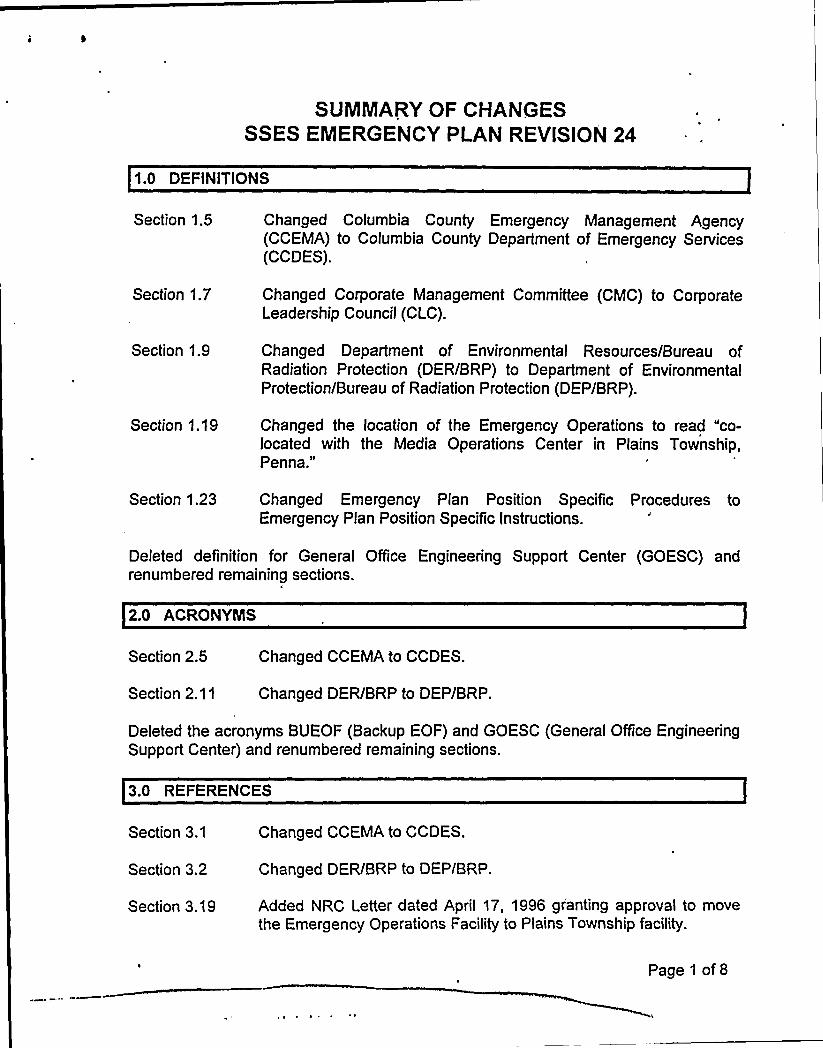
SUMMARYOF CHANGESSSES EMERGENCY PLAN REYlSlON 24
1.0 DEFINITlONS
Section 1.5
Section 1.7
Section 1.9
Section 1.19
Changed Columbia County Emergency Management Agency(CCEMA) to Columbia County Department of Emergency Services(CCDES).
Changed Corporate Management Committee (CMC) to CorporateLeadership Council (CLC).
Changed Department of Environmental Resources/Bureau ofRadiation Protection (DER/BRP) to Department of EnvironmentalProtection/Bureau of Radiation Protection (DEP/BRP).
Changed the location of the Emergency Operations to read "co-located with the Media Operations Center in Plains Township,Penna."
Section 1.23 Changed Emergency Plan Position Specific Procedures toEmergency Plan Position Specific instructions.
Deleted definition for General Office Engineering Support Center (GOESC) andrenumbered remaining sections.
2.0 ACRONYlNS
Section 2.5
Section 2.11
Changed CCEMA to CCDES.
Changed DER/BRP to DEP/BRP.
Deleted the acronyms BUEOF (Backup EOF) and GOESC (General Office EngineeringSupport Center) and renumbered remaining sections.
3.0 REFERENCES
Section 3.1
Section 3.2
Changed CCEMA to CCDES.
Changed DER/BRP to DEP/BRP.
Section 3.19 Added NRC Letter dated April 17, 1996 granting approval to movethe Emergency Operations Facility to Plains Township facility.
Page 1 of 8
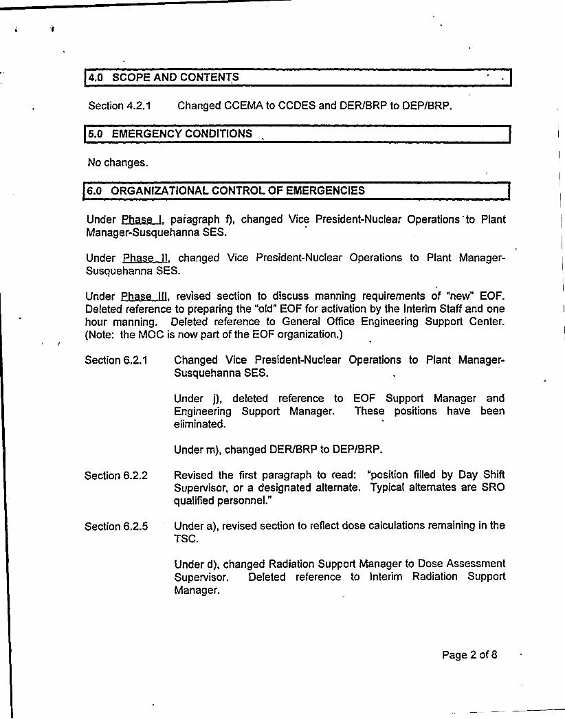
4,0 SCOPE AND CONTENTS
Section 4.2.1 Changed CCEMA to CCDES and DER/BRP to DEP/BRP.
5.0 EMERGENCY CONDITIONS
No changes.
6.0 ORGANIZATIONALCONTROL OF EMERGENCIES
Under ~age, paragraph f), changed Vice President-Nuclear Operations'to PlantManager-Susquehanna SES.
Under ~~, changed Vice President-Nuclear Operations to Plant Manager-Susquehanna SES.
Under ~~gJQ, revised section to discuss manning requirements of "new" EOF.Deleted reference to preparing the "otd" EOF for activation by the Interim Staff and onehour manning. Deleted reference to General Office Engineering Support Center.(Note: the MOC is now part of the EOF organization.)
Section 6.2.1 Changed Vice President-Nuclear Operations to Plant Manager-Susquehanna SES.
Under j), deleted reference to EOF Support Manager andEngineering Support Manager. These positions have beeneliminated.
Under m), changed DER/BRP to DEP/BRP.
Section 6.2.2 Revised the first paragraph to read: "position filled by Day ShiftSupervisor, or a designated alternate. Typical alternates are SROqualified personnel."
Section 6.2.5 Under a), revised section to reflect dose calculations remaining in theTSC.
Under d), changed Radiation Support Manager to Dose AssessmentSupervisor. Deleted reference to Interim Radiation SupportManager.
Page 2 of 8
V
Section 6.2.5 Under e), changed DER/BRP to DEP/BRP anr'adiation SupportManager to Dose Assessment Supervisor.
Under i) and j), added information to reflect new philosophy of dosecalculations remaining in the TSC. Changed Radiation SupportManager to Dose Assessment Supervisor.
Section 6.2.6 Changed paragraph to read position is filled by "SystemsEngineering supervisory personnel."
Under f), deleted reference to GOESC.
Under g), changed DER/BRP to DEP/BRP. Deleted reference toLead Technical Support Staffer and Site Support Manager (positionseliminated).
Section 6.2.8
Section 6.2.10
Deleted c), providing traffic control for the "old" EOF,
Changed first paragraph to read "position filled by MaintenanceSupervisor personnel."
Section 6.3 Changed paragraphs 2 and 3 to address revised EOF activation,which is now automatic at the Alert classification. Deleted referenceto the Interim Radiation Support Manager and Interim RecoveryManager.
Section 6.3.1.1 Under h), changed DER/BRP to DEP/BRP. Deleted reference toInterim Recovery Manager.
Section $ .3.1.2 Added Assistant Recovery Manager responsibilities. This position isappointed "as necessary."
Section 6.3.1.3 Defined the responsibilities for the new position of EngineeringSupport Supervisor, which combines the responsibilities of the LeadTech Support Staffer from the "old" EOF organization, and theEngineering Support Manager from the GOESC.
Section 6.3.1.4 Added responsibilities for the position of EOF Support Supervisor,which replaces the Site Support Manager position in the "old" EOForganization.
Section 6.3.1.5 Added responsibilities for the position of Dose AssessmentSupervisor, which replaces the Radiation Support Manager. Underd), changed DER/BRP to DEP/BRP.
Page 3 of 8
Section 6.3.1.6 Revised section to read "position is normally filled by engineeringdisciplines.".
Section 6.3.1.7
Section 6.3.2
Added responsibilities for the position of Liaison Support Supervisor.
Changed to reflect the Public Information Manager reporting to theRecovery Manager.
Section 6.3.3. Revised to reflect "Letters of Agreement" located in Attachment A.Changed CCEMA to CCDES.
Section 6.4.1 Changed CCEMA to CCDES.
Section 6.4.2 Changed DER/BRP to DEP/BRP.
Section 6.4.3
Section 6.5
Changed DER/BRP to DEP/BRP.
Changed Corporate Management Committee to CorporateLeadership Council; changed DER/BRP to DEP/BRP; changedManager Radiological Control to Radiological Manager; cha'ngedConstruction Manager to Maintenance Manager.
Deleted section on Administrative Support Manager in the EOF.
Deleted references to General Office Engineering Support Center.
Table 6.2 Under Technical Assessment, changed Site Support Manager toEOF Support Manager.
Deleted support for assessment from the GOESC. (GOESCeliminated, support supplied by EOF with assessment available fromNuclear Engineering located in Allentown) and address availability.
Under Rad/Accident Assessment at the EOF, changed Rad SupportManager to Dose Assessment Supervisor, changed RadAssessment Team to Rad Assessment Staff, and addressavailability.
Table 6.3
Figure 6.1
Figure 6.2
Figure 6.2a
Clarified reporting location.
Revised to reflect current organization.
Revised to reflect new EOF organization.
Deleted figure (staff no longer utilized).
Page 4 of 8
Figure 6.2b
Figure 6.4
Figure 6.5
Figure 6.6
Figure 6.7
Deleted figure (staff no longer utilized).
Deleted figure (MOC staff moved to EOF organization).
Deleted figure (facility eliminated, function transferred to EOF).
Changed Plant Operations Manager to Plant Manager; changedManager of Rad Assessment to Radiological Manager; changedConstruction Manager to Maintenance Manager, all due toreorganization of EOF.
Changed Lead Tech Staffer to Engineering Support Supervisor;changed Rad Support Manager to Radiological Liaison; changedSite Support Manager to Liaison Support Supervisor, all due torelocation/reorganization of EOF.
7.0 EMERGENCY MEASURES
Section 7.1.1 Deleted reference to Interim Radiation Support Manager (positioneliminated).
Section 7.1.1.1 Changed southeast to east southeast. Added new weatherinformation contacts.
Section 7.3.1.4 Added old to EOF to distinguish from "new" EOF.
Section 7.3.2 Changed CCEMA to CCDES, changed DER/BRP to DEP/BRP,changed EBS to EAS.
Section 7.4.2 Deleted reference to using EOF for decontamination facility. Due torelocation of facility, this is no longer appropriate.
Table 7.1 Added code 2 to "augment resources/activate offsite NERO."Changed CCEMA to CCDES.
8.0 EMERGENCY FACILITIESAND EQUIPMENT
Section 8.1.3.5.2 Changed CCEMA to CCDES.
Section 8.1.3.9 Changed DCS to Susquehanna Records Management System(SRMS).
Page 5 of 8
Section 8.2.1 Changed Northeast Division Headquarters to East MountainBusiness Center, Plains Township.
Section 8.2.2 Revised description of EOF location and added reference to NRCapproval to relocate. Revised third paragraph to reference otherinhabitants of the facility.
Section 8.2.2.1 Revised building description.
Section 8.2.2.1.1 Revised to reflect new facility,
Section 8.2.2.1.2 Revised to reflect new facility.
Section 8.2.2.3 Revised to reflect the deletion of special environmental needs withthe location of the EOF outside the EPZ.
Section 8.2.2.5 Revised. New facility is located in an "ultra service Business Park"and is supplied by two independent power sources.
Section 8.2.2.5.2 Deleted section.
Section 8.2.2.6 Deleted paragraph addressing PCS, SPDS, ERDS Data Link, andGulton color copiers.
Section 8.2.3 Deleted section. New facility is located outside the EPZ.
Section 8.2.4 Deleted section. Facility has been eliminated.
Section 8.3.1 Changed.CCEMA to CCDES.
Section 8.5.4 Changed CCEMA to CCDES and Emergency Broadcast System toEmergency Alert System.
Section 8.6.1 Changed CCEMA to CCDES, changed DERIBRP to DEP/BRP, anddeleted reference to GOESC.
Section 8.9.1 Revised second paragraph to reflect current status of PICSY project.
Section 8.9.2.2 Deleted third paragraph explaining IIO process.
Section 8.9.2.3 Deleted reference to identical CRTs in the TSC and EOF.
Section 8.9.3 Deleted reference to EOF location.
Section 8.9.3.2 Deleted reference to RDAS printer located in the EOF.
Page 6 of 8

I
Figure 8.1
Figure 8.3
Figure 8.4
Revised to reflect deletion of old EOF.
Pevised to reflect new EOF floor layout.
Intentionally blank (deleted Backup EOF).
Sections 8.2.2.3.1, 8.2.2.3.2, 8.2.2.3.2.2, and 8.2.2.3.3 were deleted.
9.0 MAINTAININGEMERGENCY PREPAREDNESS
Section 9.1.1 Changed DER/BRP to DEP/BRP.
Section 9.1.2
Section 9.1.3
Eliminated annual radio drills (radio drills are performed as part ofour two full scale drills conducted annually).
Deleted reference to Manager-Nuclear Department Support forassuring operational readiness of GOESC. Deleted BUEOF. Thesetwo facilities have been eliminated. Added reference to PlantManager-Susquehanna SES.
Section 9.4.1 Changed CCEMA to CCDES.
APPENDIX A - LETTERS OF AGREEMENT
Added letters of agreement for the following:
Department of Environmental Protection/Bureau of Radiation ProtectionU.S. Department of CommerceNational Oceanic and Atmospheric AdministrationNational Weather Service
Deleted letter of agreement for Helgeson Scientific.Changed DCS to Nuclear Records-SSES.
APPENDIX C - SSES EMERGENCY PLAN POS)TION SPECIFIC PROCEDURES
Deleted thirty-eight procedures and added eight procedures.
APPENDIX D - EQUIPMENT INFORMATIONLISTINGS
Enclosure 5 Deleted source check under Typical Field Monitoring Team Equipment.
Page 7 of 8
Enclosure 9
Enclosure 9
Deleted microfilm and reader under Typical Emergency OperationsFacility Equipment.
Deleted section titled EOF HP Decontamination Equipment andSupplies (not utilized in new facility).
Deleted section titled GOESC. The facility has been eliminated.
Changed CCEMA to CCDES.
APPENDIX'J - NUREG4654 PLANNlNG STANDARD CROSS REFERENCE
Section E, 1., defeted partial list of procedures.
Deleted titfes of old positions and added titles new positions throughout the document.
Page 8 of 8
PENNSYLVANIAPOWER & LIGHTCOMPANY
SUSQUEHANNA STEAN ELECTRIC STATION
Q7g~O
~wsc s~"
EMERGENCY PLAN
THIS DOCUMENTHAS BEEN UPDATED TO
INCI UDE REVISIONS THROUGH ~4 DATED
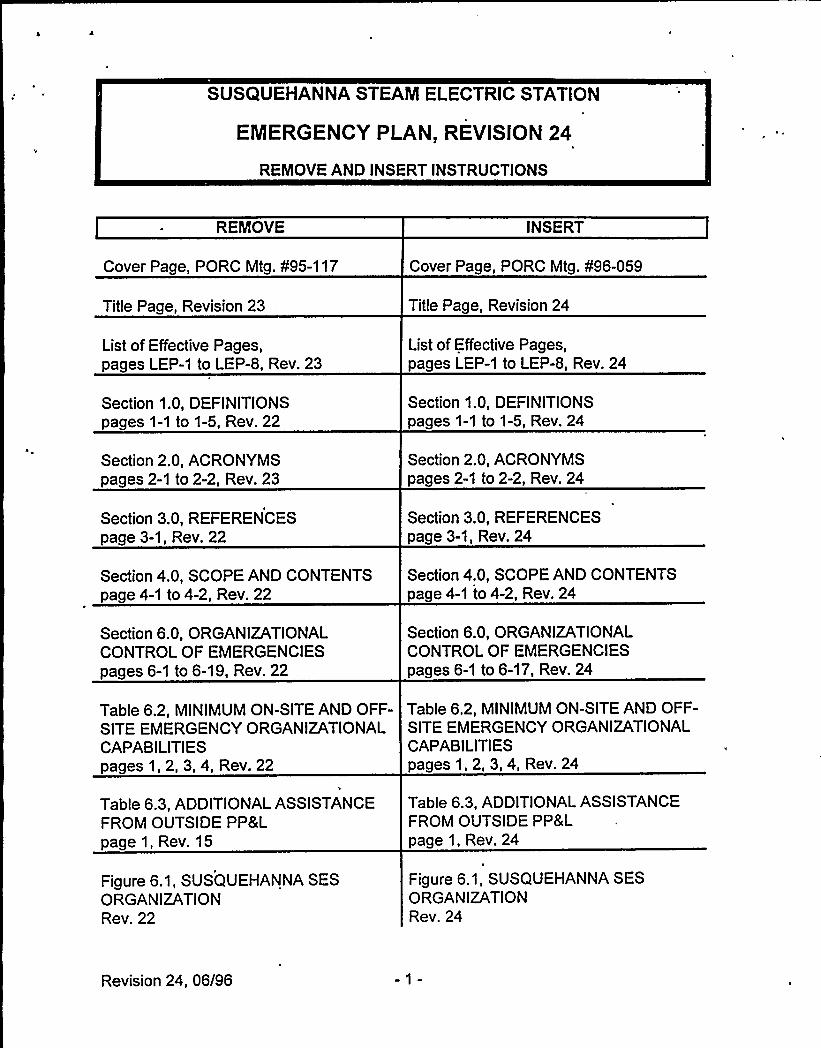
SUSQUEHANNA STEAM ELECTRIC STATION
EMERGENCY PLAN, REVISION 24
REMOVE AND INSERT INSTRUCTIONS
REMOVE INSERT
Cover Page, PORC Mtg. ¹95-117
Title Page, Revision 23,
List of Effective Pages,pages LEP-1 to LEP-8, Rev. 23
Section 1.0, DEFINITIONSpages 1-1 to 1-5, Rev. 22
Section 2.0, ACRONYMSpages 2-1 to 2-2, Rev. 23
Cover Page, PORC Mtg. ¹96-059
Title Page, Revision 24
List of Effective Pages,pages LEP-1 to LEP-8, Rev. 24
Section 1.0, DEFINITIONSpages 1-1 to 1-5, Rev. 24
Section 2.0, ACRONYMSpages 2-1 to 2-2, Rev. 24
Section 3.0, REFERENCESpage 3-1, Rev. 22
Section 3.0, REFERENCESpage 3-1, Rev. 24
Section 4.0, SCOPE AND CONTENTSpage 4-1 to 4-2, Rev. 22
Section 6.0, ORGANIZATIONALCONTROL OF EMERGENCIESpages 6-1 to 6-19, Rev. 22
Section 4.0, SCOPE AND CONTENTSpage 4-1 to 4-2, Rev. 24
Section 6.0, ORGANIZATIONALCONTROL OF EMERGENCIESpages 6-1 to 6-17, Rev. 24
Table 6.2, MINIMUMON-SITE AND OFF- Table 6.2, MINIMUMON-SITE AND OFF-SITE EMERGENCY ORGANIZATIONAL SITE EMERGENCY ORGANIZATIONALCAPABILITIES CAPABILITIESpages 1, 2, 3, 4, Rev. 22 pages1,2,3,4, Rev. 24
Table 6.3, ADDITIONALASSISTANCEFROM OUTSIDE PP8Lpage 1, Rev. 15
Table 6.3, ADDITIONALASSISTANCEFROM OUTSIDE PP&Lpage 1, Rev. 24
Figure 6.1, SUSQUEHANNA SESORGANIZATIONRev. 22
Figure 6.1, SUSQUEHANNA SESORGANIZATIONRev. 24
Revision 24, 06/96
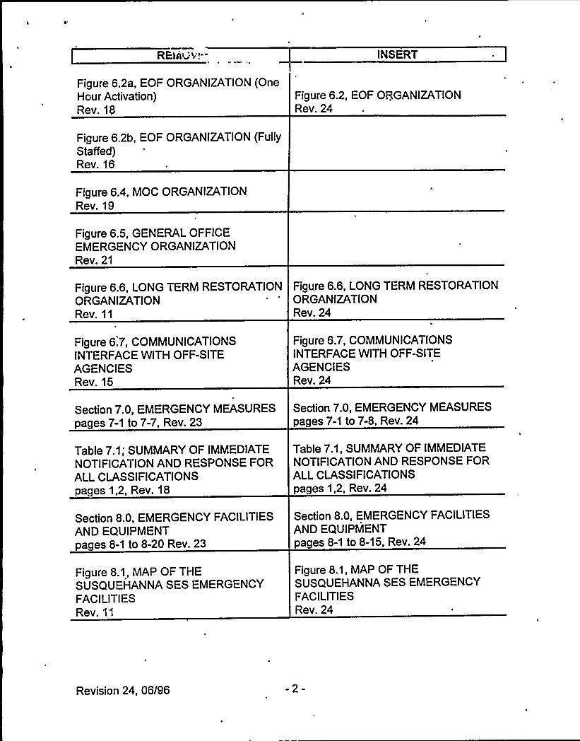
REliU<'!- INSERT
Figure 6.2a, EOF ORGANIZATION(OneHour Activation)Rev. 19
Figure 6.2, EOF ORGANIZATIONRev. 24
Figure 6.2b, EOF ORGANIZATION(FullyStaffed)Rev. 16
Figure 6.4, MOC ORGANIZATIONRev. 19
Figure 6.5, GENERAL OFFICEEMERGENCY ORGANIZATIONRev. 21
Figure 6.6, LONG TERM RESTORATION Figure 6.6, LONG TERM RESTORATIONORGANIZATION ORGAhtlZATIONRev. 11 Rev. 24
Figure 6.7, COMMUNICATIONSINTERFACE WITH OFF-SITEAGENCIESRev. 15
Figure 6.7, COMMUNICATIONSINTERFACE WITH OFF-SITEAGENCIESRev. 24
Section 7.0, EMERGENCY MEASURESpages 7-1 to 7-7, Rev. 23
Table 7.1; SUMMARYOF IMMEDIATENOTIFICATIONAND RESPONSE FORALLCLASSIFICATIONSpages 1,2, Rev. 18
Section 8.0, EMERGENCY FACILITIESAND EQUIPMENTpages 8-1 to 8-20 Rev. 23
Figure 8.1, MAP OF THESUSQUEHANNA SES EMERGENCYFACILITIESRev. 11
Section 7.0, EMERGENCY MEASURESpages 7-1 to 7-8, Rev. 24
Table 7.1, SUMMARYOF IMMEDIATENOTIFICATIONAND RESPONSE FORALLCLASSIFICATIONSpages 1,2, Rev. 24
Section 8.0, EMERGENCY FACILITIESAND EQUIPMENTpages 8-1 to 8-15, Rev. 24
Figure 8.1, MAP OF THESUSQUEHANNA SES EMERGENCYFACILITIESRev. 24
Revision 24, 06/96 -2-
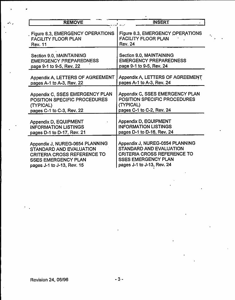
REMOVE INSERT
. Figure 8.3, EMERGENCY OPERATIONS Figure 8.3, EMERGENCY OPERATIONSFACILITYFLOOR PLAN FACILITYFLOOR PLANRev. 11 Rev. 24
Section 9.0, MAINTAININGEMERGENCY PREPAREDNESSpage 9-1 to 9-5, Rev. 22
Section 9.0, MAINTAININGEMERGENCY PREPAREDNESSpage 9-1 to 9-5, Rev. 24
Appendix A, LETTERS OF AGREEMENT Appendix A, LETTERS OF AGREEMENTpages A-1 to A-3, Rev. 22 pages A-1 to A-3, Rev. 24
Appendix C, SSES EMERGENCY PLANPOSITION SPECIFIC PROCEDURES(TYPICAL)pages C-1 to C-3, Rev. 22
Appendix D, EQUIPMENTINFORMATIONLISTINGSpages D-1 to D-17, Rev. 21
Appendix J, NUREG-0654 PLANNINGSTANDARD AND EVALUATIONCRITERIA CROSS REFERENCE TOSSES EMERGENCY PLANpages J-1 to J-13, Rev. 15
Appendix C, SSES EMERGENCY PLANPOSITION SPECIFIC PROCEDURES(TYPICAL)pages C-1 to C-2, Rev. 24
Appendix D, EQUIPMENTINFORMATIONLISTINGSpages D-1 to D-16, Rev. 24
Appendix J, NUREG-0654 PLANNINGSTANDARDAND EVALUATIONCRITERIA CROSS REFERENCE TOSSES EMERGENCY PLANpages J-1 to J-13, Rev. 24
Revision 24, 06/96 -3-