formal methods into practice: case studies in the application of the b method
TRANSCRIPT
Formal methods into practice: case studies in the application of the B method
J.C.Bicarregui D.L. Clutterbuck G.Finnie H.Haughton K. Lano H. Lesan D.W.R.M. Marsh B.M. Matthews M.R. Moulding A.R. Newton B. Ritchie T.G.A. Rushton P. N, Scha rbach
Indexing terms: Formal methodr, Software development
Abstract: The paper reports on an investigation into the application of the B method of formal software development. Six case studies are described, each exploring a different aspect of the use of the B methodology and toolkit. The case studies are drawn from a diverse range of applications and address different aspects of the software development lifecycle. The notation, method and tool support are assessed and conclusions are drawn concerning the use of B and formal methods generally.
1 Introduction
Formal methods have long been advocated as a way to make the development of software into a scientifically based engineering discipline. Nevertheless, in practice, very little software is produced using the formal approach. To some extent, the introduction of formal methods has been hampered by the lack of quality sup- port tools. However, there are now commercial prod- ucts claiming to provide for the use of formality in the context of the software development task as a whole.
This paper reports on the work of the B user trials project [Note 11, which investigated the application of formal methods in software development. A number of case studies are discussed that apply formal techniques to different tasks in the software development lifecycle within a particular development environment, which is a commercial product supporting formal methods. Although no quantitative analysis is undertaken, we discuss our experiences with the method, notation and 0 IEE, 1997 IEE Proceedings online no. 19970974 Paper first received 4th October 1995 and in final revised form 24th June
The authors are with CLRC, Rutherford Appleton Laboratory, Computing and Information Systems Department, Chilton, Didcot, Oxfordshire OX1 1 OQX, UK
1996
tools and assess the extent to which the formal approach yields a viable means to establish a sound engineering practice.
1. I The B method [Note 2][1-31 is a ‘model-oriented’ for- mal method, providing a unified notation and support tool for many of the activities in the software develop- ment lifecycle. It is currently being used in several industrial organisations [4-6]. Modularity is central to the B method, and this is achieved by structuring spec- ifications and developments into ‘abstract machines’.
Machines are essentially abstract data types with state. The state is defined by the construction of a set theoretic model. Similar constructors to those of other model-oriented notations are available, although, in practice, we tend to use a number of variables each of simple type, rather than building more complex, user- defined, types as encouraged by VDM [7] or Z [SI. State initialisation and invariant conditions are given explicitly.
The invariant and other predicates are given in first- order predicate calculus and set theory. The underlying logic is untyped, and typing constraints appear as set memberships in the invariant, along with the usual relationships between variables. The foundations are based on Zermelo set theory, with an axiom of choice, an axiom of infinity and an axiomatic definition of Cartesian product.
B method, notation and toolkit
Note 1: The B user trials project was a UK collaborative project between Lloyd’s Register of Shipping, Program Validation Limited, the Royal Military College of Science and the Rutherford Appleton Laboratory. It was jointly funded by the Department of Trade & Industry and the Engi- neering & Physical Science Research Council. Note 2: Support for the B method is currently being developed by several organisations: our study was based upon the B toolkit developed oria- nally at British Petroleum PLC and subsequently by B-Core (UK) Ltd. This study was undertaken primarily with the Beta release of this tookit (Version 2.0) during the period from January 1993 to December 1994, and a number of the detailed issues concerning the functionality and per- formance of the B toolkit that arose during the course of the project have been taken into account in later versions of the product. It is intended that the experiences reported here also be used to guide its future evolu- tion
IEE Proc.-Softw. Eng, Vol. 144, No. 2, April 1997 119
Operations are defined as ‘generalised substitutions’. rhis departure from the before-after predicates of VDM and Z yields the same expressive power, while giving the language a more programmatic feel and thus making it more accessible to those with programming, rather than mathematical, experience. For example, a number of constructs are available that mimic the usual notation for assignment, x := y for x becomes equal to y , to give loose specifications such as x :E S for x becomes any member of S. As in Morgan’s refinement calculus [9], the semantics of operations are given via the weakest preconditions.
The overall specification is structured using machine composition. Specifications can be built incrementally using the ‘sees’ and ‘includes’ mechanisms that, respec- tively, allow read-only and read-write extensions of a machine by new variables and operations. Data reifica- tion is provided by ‘refinements’, and compositional development is provided by ‘imports’. Low-level machines, ‘implementations’, can be written in an exe- cutable subset of the language, and a library of ‘base’ machines can be automatically translated into C code.
Validation is supported by an animation facility that allows the developer interactively to ‘execute’ a specifi- cation by providing input to simplify non-executable constructs or to resolve non-determinism. Verification is supported through the generation and discharge of proof obligations, which ensure the consistency of spec- ifications and the correctness of refinements.
The emphasis on modularity is also applied to proof. The motivation here is that the overall proof task should, as far as possible, be decomposed into proofs concerning individual machines. Once a machine has been proven consistent and correct, those proofs should be valid in any context in which this machine is used as part of a more complex specification. Indeed, it is this aim that has determined the structuring mecha- nisms availabe for machines. Thus, a highly composi- tional method is provided for proof so that, although numerous, proof obligations are mostly simple and the majority can be discharged automatically.
Two proof tools are provided: the ‘autoprover’ is used to discharge automatically the majority of proof obligations using a ‘rulebase’ of built-in rules and tactics; and the ‘interprover’ is used to explore interac- tively the failed proof attempt and extend the rulebase with user-defined ‘theories’ that provide problem- specific rules and tactics.
1.2 Overview of paper This paper reports on six case studies that explore the use of the B method and toolkit for different aspects of the software design lifecycle. The first three case studies address the early phases of development, considering requirements, validation and prototyping. The next two case studies address high-level design and data refine- ment, comparing the B abstract machine notation with two other model-oriented specification notations, VDM and Z. The last case study addresses algorithm development, code generation and verification.
2 Expressing requirements in B
The first case study was concerned with expressing requirements in the B method. A requirements model of a short-term conflict alert (STCA) air traffic control application, previously defined using controlled requirements expression (CORE), was developed to
120
investigate how effective the B method is for expressing a requirements model of this type and complexity, and to evaluate the role of the B toolkit in animating and proving relevant properties of that model.
CORE is an established structured requirements analysis method that employs diagrams and supporting text to construct a functional model of the required system and its operational environment, using a combi- nation of hierarchical decomposition, data flow and data structuring techniques depicting the interaction of the target system with its environment at various levels of abstraction. CORE has been the subject of a number of research projects within the Software Engineering Group at RMCS since 1986, using the SD variant of CORE [lo] and its associated Analyst support tool.
This overview presents the experiment that was per- formed with B and CORE and outlines the resultant evaluation of the B toolkit.
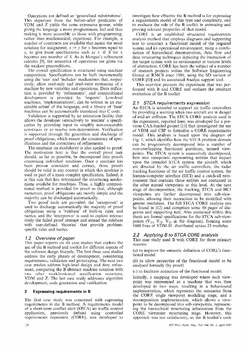
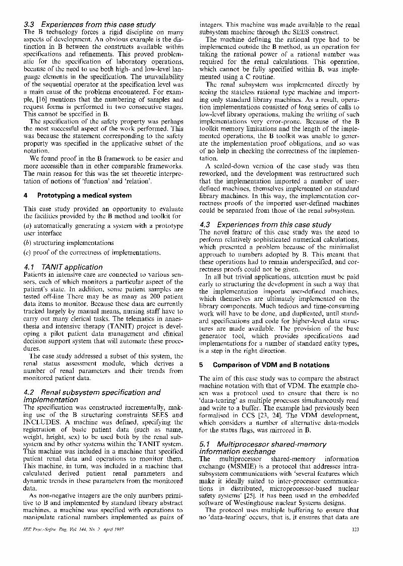
2. I STCA requirements expression An STCA is intended to support air traffic controllers by providing a warning when two aircraft are in danger of mid-air collision. The STCA CORE analysis used in the experiment, reported here, was developed for a pre- vious CAA-funded project [ 1 11 that investigated the use of VDM and CSP to formalise a CORE requirements model. This analysis is based upon the diagram of Fig. 1, which identifies how the STCA problem domain can be progressively decomposed into a number of non-overlapping functional partitions, termed view- points. The STCA system is successively decomposed, first into viewpoints representing entities that impact upon the intended STCA system: the aircraft, which are directed by the air traffic controllers, the radar tracking functions of the air traffic control system, the human-computer interface (HCI) and a catch-all envi- ronment that contains those entities not contained in the other named viewpoints at this level. At the next stage of decomposition, the tracking, STCA and HCI viewpoints are further decomposed into sub-view- points, allowing their interaction to be modelled with greater resolution. The full STCA CORE analysis can be found in [12] and comprises some 40 pages of dia- grams and supporting text. Also contained within this thesis are formal specifications for the STCA sub-view- points (V31, V32, V33 in the diagram), forming some 1600 lines of VDM-SL distributed across 23 modules.
2.2 Applying B to STCA CORE analysis This case study used B with CORE for three primary re as o n s : (a) to improve the semantic definition of CORE’S func- tional model (b) to allow properties of the functional model to be analysed formally (by proof) (c) to facilitate animation of the functional model Initially, a mapping was developed where each view- point was represented as a machine that was then developed in two ways, resulting in a behavioural implementation, which represents the semantics from the CORE single viewpoint modelling stage, and a decomposition implementation, which allows a view- point to be decomposed into sub-viewpoints, represent- ing the hierarchical structuring information from the CORE viewpoint structuring stage. However, this approach was not satisfactory, as the B toolkit’s code
IEE ProcSof tw Eng., Vol. 144, No. 2, April 1997
v o
STCA problem
Fig. 1 STCA CORE viewpoint structure diugrum
generation facilities do not support the passing of structured data, such as sets and sequences, between B operations (although B imposes no such restriction). This means that an object-oriented programming style has to be adopted, where each structured data type that is passed between B operations is managed by an explicit abstract machine, used to create scalar tokens to identify objects of that type, which are then passed between operations and de-referenced via the data type manager. In the case of the STCA model, the very large number ot structured data types that would have been needed to be handled rendered the approach infeasible.
In view of this, an alternative strategy was adopted that involved the construction of three separate B mod- els to address different aspects of the CORE model: (i) a conceptual model, which uses the full features of B machines and implementations to capture the complete semantics of the CORE functional model and which is used to analyse formally the properties of that model (ii) a viewpoint semantic model, which expresses the data-processing actions of a single CORE viewpoint using solely B machines and which can therefore be animated using the symbolic animation facilities of the B toolkit. (iii) a connectivity model, which provides an executable program for the entire CORE functional model, but which only captures the data-flow connectivity of actions; the actions pass data-flow markers around the model, each tagged with the history of actions that have processed that marker. This strategy yielded a conceptual model about one third of the size of the initial model (6800 lines of B instead of 20 000). The number of proof obligations was also reduced from some 2000 in the initial model to about 200. Of these, about 90% were discharged The viewpoint semantic model for the configuration view- point was constructed and animated. The B specifica- tions for this viewpoint were derived from the VDM specifications of [12]. The connectivity model was partly constructed, but was not completed, owing to problems in building a data type manager for the data- flow markers.
A full account of the two approaches for using B with CORE can be found in [13], and details of the application of these approaches to the STCA CORE analysis are contained in [14].
IEE Proc.-Softw. Eng, Vol. 144, No. 2, April 1997
2.3 Experiences of this case study When trying to specify the CORE functional nindt‘l using B, a number of limitations particular to the B- language were identified. First, the language does n o t allow sequencing at the abstract ‘machine’ level; ‘im plc- mentations’ had to be used resulting in a far moic detailed specification than desirable for a requirement:; model. Secondly. the data typing facilities within €3 were found to be limited, and the implicit typing style was found to lack the clarity of more explicit approaches, such as that employed in VDM. A serious omission is the absence of record types, which was overcome using an algebraic definition style (see Sec tion 6). Thirdly, the machine structuring facilities of B prevented two, or more, machines from sharing write access to the state of a third machine. Although this restriction is mdde to simplify the proof process, it is a severe constraint when modelling certain real-world problems and can lead to very inelegant and unnatural specifications.
With regard to the methodology, the restriction of the arguments and returns associated with operations to scalar types led to our proposal for an enhanced B method [13], which attempts to separate out the con- cern of specifying the problem in a ‘conceptual model’, from the concern of providing an executable program to address that problem in a ‘constructional model’. Where applications require little structured data pass- ing, the distinction between conceptual and construc- tional models is small. However, for structured analysis and design approaches applied to data-rich informa- tion-processing systems, the difference in complexity is considerable. In fact, such was the predicted complexity of the constructioiial model for the STCA CORE anal- ysis, that alternative approaches were devised to pro- vide animation of the CORE model, in the form of viewpoint semantic and connectivity models.
With regard to the specific tools available, this study provided an opportunity to evaluate the B toolkit (ver- sion 2.0) for a large-scale development. and a number of areas for improvement were identified. The response speed of the tool was very slow for a large develop- ment, and animating a large specification was also slow, especially when compared with equivalent Prolog systems. For very large developments, the proof tools failed to construct proof obligations and carry out proofs. The animator provides the basis of a very use- ful tool, but should be enhanced to evaluate nested LET and ANY clauses, animate refinements and imple-
121
mentations, and provide an improved developer inter- face, such as the inclusion of batch-testing and roll- back features.
In summary, this case study showed that the B method offers potential benefits over other model- based approaches, such as VDM and Z, in that it pro- vides a semantically strong object-oriented modularisa- tion scheme that allows proof to be partitioned, supports the progressive refinement of specifications and encourages specification reuse. The inclusion of animation, proof and code-generation facilities within the B toolkit also represents a significant enhancement over the functionality of existing tools for VDM and Z. However, when using the B method and the B toolkit for our STCA case study, we encountered a number of limitations described above, which we feel should be addressed if this new and advanced technology is to be used successfully in requirement modelling of complex information systems.
3
This case study was in the domain of clinical biochem- istry, which is a branch of pathology. concerned with the analysis of body fluids to aid diagnosis, prognosis and monitoring of treatment. Automatic analysers capable of performing thousands of tests daily are used widely. Such systems are clearly safety-critical, as send- ing the wrong test result can result in incorrect treat- ment.
The B method and B toolkit were used to analyse the hazards in the laboratory information management sys- tem employed in the Clinical Biochemistry Department of the West Middlesex University Hospital (see, for example, [ 151 or [ 161). The hazard analysis technique used involved the development of a formal specifica- tion of the system, the identification and formalisation of system safety properties, and an attempt to prove the safety properties from the formal specification. This technique, first discussed in [17] can be regarded as an extension of the fault tree analysis (FTA) technique [18] and its extensions to software [19, 201. FTA is a diagrammatic technique where a potential failure of the system is traced back and decomposed into a combina- tion of failures of atomic events. Such an analysis can be regarded as an informal, backwards proof attempt. The main differences between FTA and the technique used here are the use of formality and the proving of safety, as opposed to showing freedom from failure. The formal methodology, where formal models arc compared with the actual system operations is also reminiscent of the hazard and operability studies (HAZOP) [21], where guidewords arc used to find pos- sible deviations of a design from its ‘intended’ use.
We believe that the main contributions of this approach to hazard analysis are its systematic nature and its explication of all relevant assumptions about the system. The formalisation and proof activities also result in the identification of constraints on various aspects of the system analysed.
Validation of clinical system safety property
3. I Safety property The property that largely encapsulates the safety requirement under investigation can be stated infor- mally as
the right results will be associated with the right patient at the right time
The case study considered a slightly simpler problem by removing the temporal considerations from the safety property. The main aims of the case study were to use B to (a) formalise the safety property (b) model the operations of the laboratory (c) prove the safety property from the specification of the laboratory. The clarification of the safety property was a major contribution of this case study. The basic idea behind this was the separation of the notion of core-analyser, modelling the component of the automatic analyser that performs the actual tests, from other functionali- tics of the automatic analyser, which, for example, is able to read the laboratory number that is bar-coded on the sample.
The machinery corresponding to the core-analyser was not considered in the hazard analysis. The safety property could then be reformulated as
the result of a test produced by the laboratory proce- dures is identical to the result of the application of the core-analyser to the contents of the sample and test requested
In other words, the laboratory provides a collective core-analyser service to the requesting clinicians. The extension of this simple idea to the actual boundaries of the laboratory requires identification of all appropri- ate requests from various containers delivered to the laboratory. Each such request contains a sample, tests required on the sample and the patient identity. It also requires the explication and specification of a number of constraints that are expressed as properties of the relevant abstract machines.
The laboratory is described in [16]. A full account of this case study appears in [22].
3.2 Specification and proof The laboratory system is formalised by a number of abstract machines declaring data structures and the constraints upon them, which are seen by an abstract machine Lab, formalising the safety property. This machine possesses one operation, labtest, which, for an input set of samples and test requests, specifies the effect of the automatic analyser and checks performed on the test results. Machines at this level arc all appli- cative; they do not have any state variables.
A B implementation of Lab, Lab-imp was defined that corresponds to one operation cycle of the Labora- tory. Lab-imp has one operation labtest, which is a sequence of operations of imported machines specifying the individual laboratory procedures, from validation and numbering of request forms and samples on recep- tion, to performing the analyses and collecting the results of tests from analysers. Proof of the safety prop- erty is then a proof that Lub-amp correctly implements Lab. The B toolkit was used to generate this implemen- tation proof obligation.
Although the toolkit was used to discharge some other proof obligations associated with the internal consistency of a number of specifications, the above safety property could not be discharged automatically, and user-assisted proof of the safety property could not be completed in the time allocated. A semi-formal proof of the safety property was, however, completed by hand.
IEE Proc -Softw Eng , Vol 144, No 2, April 1997
3.3 Experiences from this case study The B technology forces a rigid discipline on many aspects of development. An obvious example is the dis- tinction in B between the constructs available within specifications and refinements. This proved problem- atic for the specification of laboratory operations, because of the need to use both high- and low-level lan- guage elements in the specification. The unavailability of the sequential operator at the specification level was a main cause of the problems encountered. For exam- ple, [16] mentions that the numbering of samples and request forms is performed in two consecutive stages. This cannot be specified in B.
The specification of the safety property was perhaps the most successful aspect of the work performed. This was because the statement corresponding to the safety property was specified in the applicative subset of the notation.
We found proof in the B framework to be easier and more accessible than in other comparable frameworks. The main reason for this was the set theoretic interpre- tation of notions of ‘function’ and ‘relation’.
4 Prototyping a medical system
This case study provided an opportunity to evaluate the facilities provided by the B method and toolkit for (a) automatically generating a system with a prototype user interface (b) structuring implementations (c) proof of the correctness of implementations.
4. I TANIT application Patients in intensive care are connected to various sen- sors, each of which monitors a particular aspect of the patient’s state. In addition, some patient samples are tested off-line There may be as many as 200 patient data items to monitor. Because these data are currently tracked largely by manual means, nursing staff have to carry out many clerical tasks. The telematics in anaes- thesia and intensive therapy (TANIT) project is devel- oping a pilot patient data management and clinical decision support system that will automate these proce- dures.
The case study addressed a subset of this system, the renal status assessment module, which derives a number of renal parameters and their trends from monitored patient data.
4.2 Renal subsystem specification and implementation The specification was constructed incrementally, mak- ing use of the B structuring constraints SEES and INCLUDES. A machine was defined, specifying the registration of basic patient data (such as name, weight, height, sex) to be used both by the renal sub- system and by other systems within the TANIT system. This machine was included in a machine that specified patient renal data and operations to monitor them. This machine, in turn, was included in a machine that calculated derived patient renal parameters and dynamic trends in these parameters from the monitored data.
As non-negative integers are the only numbers primi- tive to B and implemented by standard library abstract machines, a machine was specified with operations to manipulate rational numbers implemented as pairs of
IEE Proc.-Softw Eng, Vol 144, No 2, April 1997
integers. This machine was made available to the renal subsystem machine through the SEES construct.
The machine defining the rational type had to be implemented outside the B method, as an operation for taking the rational power of a rational number was required for the renal calculations. This operation, which cannot be fully specified within B, was imple- mented using a C routine.
The renal subsystem was implemented directly by seeing the stateless rational type machine and import- ing only standard library machines. As a result, opera- tion implementations consisted of long series of calls to low-level library operations, making the writing of such implementations very error-prone. Because of the B toolkit memory limitations and the length of the imple- mented operations, the B toolkit was unable to gener- ate the implementation proof obligations, and so was of no help in checking the correctness of the implemen- tation.
A scaled-down version of the case study was then reworked, and the development was restructured such that the implementation imported a number of user- defined machines, themselves implemented on standard library machines. In this way, the implementation cor- rectness proofs of the imported user-defined machines could be separated from those of the renal subsystem.
4.3 Experiences from this case study The novel feature of this case study was the need to perform relatively sophisticated numerical calculations, which presented a problem because of the minimalist approach to numbers adopted by B. This meant that these operations had to remain underspecified, and cor- rectness proofs could not be given.
In all but trivial applications, attention must be paid early to structuring the development in such a way that the implementation imports user-defined machines, which themselves are ultimately implemented on the library components. Much tedious and time-consuming work will have to be done, and duplicated, until stand- ard specifications and code for higher-level data struc- tures are made available. The provision of the base generator tool, which provides specifications and implementations for a number of standard entity types, is a step in the right direction.
5
The aim of this case study was to compare the abstract machine notation with that of VDM. The example cho- sen was a protocol used to ensure that there is no ‘data-tearing’ as multiple processes simultaneously read and write to a buffer. The example had previously been formalised in CCS [23, 241. The VDM development, which considers a number of alternative data-models for the status flags, was mirrored in B.
5. I Multiprocessor shared-memory information exchange The multiprocessor shared-memory information exchange (MSMIE) is a protocol that addresses intra- subsystem communications with ‘several features which make it ideally suited to inter-processor communica- tions in distributed, microprocessor-based nuclear safety systems’ [25]. It has been used in the embedded software of Westinghouse nuclear Systems designs.
The protocol uses multiple buffering to ensure that no ‘data-tearing’ occurs, that is, it ensures that data are
Comparison of VDM and B notations
123
never overwritten by onc process while being read by another. One important requirement is that neither writing nor reading processes should have to wait for a buffer lo become available; another is that ‘recent’ information should be passed, via the buffers, from writers to readers. In the simplification considered, it is assumed that information is being passed from a single writing ‘slave’ process, to several reading ‘master’ proc- esses.
The information exchange is realised by a system with three buffers. Roughly speaking, at any time, one buffer is available for writing, one is available for read- ing, and the third is either in between a write and a read and, hence, contains the most recently written information, or is between a read and a write and so is idle.
The status of each buffer is recorded by a flag that can take one of four values (i) s: ‘assigned to slave’. This buffer is reserved for writ- ing; it may actually be being written at the moment or just marked as available for writing. (ii) m: ‘assigned to master’. This buffer is being read by one or more processes. (iii) n: ‘newest’. This buffer has just been written and contains the latest information. It is not being read at the moment. (iv) i: ‘idle’. ‘This buffer is idle, not being read or writ- ten and not containing the latest data. The names of the master processes that are currently reading are also stored in the state.
The slave and master processes that access the buff- ers in parallel are not modelled; rather, the analysis concerns only the operations that modify the buffer status flags. These operations are protected by a system of semaphores that allows each operation uninter- rupted access to the state, and thus their behaviour is purely sequential.
f a ) s h e : this operation is executed when a write fin- ishes. slave sets the status of the buffer that is being written to ‘newest’, thus replacing any other buffer with this status. (6) acquire: this is executed when a read begins. The new reader name (passed as a parameter) is added to the set of readers, and status flags are updated as appropriate. (c) release: executed when a read ends, this removes a reader from the set and updates flags as appropriate. The precise behaviour of the operations is rather intri- cate and space does not permit us to describe them fur- ther here. The reader is referred to [26] for a detailed description of this case study; however, a summary of conclusions drawn from the comparison are given below.
There are three of these operations
5.2 The system was described at several levels of abstrac- tion in both VDM and B, and formal data refinements were defined between levels, although there was no algorithm development. In this small example, there was little scope for the effective use of structuring of specifications that is one of the major features of the B method, neither was the use of proof explored to any great extent. Comparison of these two formal develop- ments highlighted three areas where the notations dif- fered.
Experiences from this case study
5.2, I Invariants: The definition of the state was cen- tral in this example. In both notations, the pivotal specification was the one where multiple buffering was introduced, and, at this level, the state invariant played a key role in conveying an understanding of the system by defining reachable values of the state and, hence, liberating the designer from having to consider other cases.
However, the role of state invariants in operation definitions differs in VDM and B. In B, post-conditions (in the form of generalised substitutions) have to be written so as explicitly to ensure the maintenance of the invariant. In VDM, the state invariant is effectively part of the state typing information and, as such, is implicitly assumed to be maintained by the operation.
VDM’s implicit maintenance of the invariant leads to a choice as to how much of the information that can be deduced from the invariant is repeated in a post-condi- tion. The example showed that there is often some ten- sion between the most concise form that relies on properties of the invariant for its correctness, and a longer, but more explicit, form that includes some redundant information. This choice can be seen as an opportunity to prove the stronger forms from the weaker. Which form is chosen may make a significant difference to the complexity of the proofs: the form that most clearly conveys the information may not be the form that will be most usable in proofs. Indeed, the stronger form is more likely to be helpful when the specification is being proved to be a reification of another, and the weaker form may be more helpful when it is itself being reified.
In the B notation, on the other hand, operations are written so as to imply the preservation of the invariant. This style provides the opportunity to prove that the operation does indeed do this; however, it can encour- age a tendency to describe how the invariant is main- tained, which may lead to less abstract specifications.
5.2.2 Operation definitions: The greater program- matic feel of the B notation is reinforced by the use of generaliseci substitutions, as opposed to VDM’s rela- tional post-conditions. Although the two forms have the same expressive power, in some cases, we found it convenient to give greater algorithmic detail in the B version. This would appear to imply that the B nota- tion is more useful for the development of algorithms. Indeed, the process of operation decomposition has been given greater attention in the B method than for VDM. In contrast, VDM’s relational post-conditions perhaps give a greater facility for non-algorithmic spec- ifications of complex operations.
5.2.3 Framing: Both notations give syntactic devices for specifying the frame of reference for operations. In VDM, the read and write frames are given explicitly in an operation definition, whereas, in B, the variable accesses are implicit in the form of the generalised sub- stitution, but are made explicit at the machine level through the semi-hiding and full-hiding involved in the various forms of machine structuring.
In VDM operations, the semantic role of the read frame is often underplayed. Typically, it is interpreted as merely providing syntactic scoping for variables appearing in the pre-condition or post-condition. Alter- natively, it can be interpreted as a constraint on imple- mentations, restricting which state components can be
IEE Proc -Softw Eng , Vol 144, No 2, April 1997 I24
read. Thus, rather than think of the externals clauses as giving information about the variables mentioned in the specification, we see them as giving details of what access to state variables an implementation of that oper- ation can be allowed to make. (See [27-291 for further discussion of his point.)
In B, similar restrictions can be given through the hiding principles inherent in the different forms of machine structuring. For instance, where, in the more concrete VDM specifications, we are able to narrow the read frames, in their B counterparts, there is a potential to structure the overall machine.
The above three areas are where our experiment sug- gested that the notations of VDM and B encourage dif- ferent specification styles. Each style has its own advantages at different stages of the development proc- ess. In this example, we found that the process of developing implementation code was better addressed in abstract machine notation. However, we also found VDM’s relational post-conditions more convenient for expressing wholly implicit specifications of operations, particularly when the data model involved complex interdependencies.
6 system
This case study was motivated by a desire to relate for- mally (part of) a Z specification of generic graphical kernel system (GKS) [20] operations to a set of C lan- guage bindings for those operations. The approach chosen was to ‘transliterate’ the Z specification into abstract machine notation, with the aim of subse- quently refining the top-level abstract machines to the stage where the data structures and algorithms could be mapped directly onto C.
In the first phase, that of translating Z to B, it was considered important that the B should bear a strong resemblance to the original Z specification, even where this went against the style guidelines emerging from other areas of the B user trials project. This iconoclas- tic approach raised many problems, both anticipated and unexpected. In the subsequent refinement, another attempt to break with ‘B tradition’ led to further prob- lems.
Specifying and refining the GKS attribute
6. ’I GKS specification In the GNS standard (and draft revision), GNS func- tions are defined using Z in abstract terms on abstract data types. Language bindings are defined for these functions for C and FORTRAN.
Though many of the language bindings are 1-1 (each abstract function has a direct binding counterpart), for practical reasons there are often additional bindings, where a single abstract function is implemented by a set of concrete functions.
The GKS primitive attributes are state parameters that affect the behaviour of graphics output operations. For example they govern the style of line-drawing to be used, or the current text font. Primitive attribute values are drawn from a type PrimAttr Value, which is defined, like a Z free type definition, as a disjoint union of all the possible attribute value types
Prim,AttrValue :: = m a r k e r t y p e ~ ~ ~ a r L e r T y p e ) )
I markerind(( Marker Ind)) I . . .
The state of the attributes is then modelled as a map from attribute names to this union type, such that each attribute name is associated with a unique (injected) type. The use of a single large union type is a specifica- tion artefact that makes it possible to define a single schema SetPrimAttribute, specifying the operation of updating any attribute value, as opposed to a family of operations, one per attribute. The schema takes a single input, the new value; there is no need to supply the attribute name as this can be inferred from the type injector of the argument.
This specification has a fairly direct counterpart in C using unions and structures; however, for practical reasons, it is more convenient to define the language bindings as a family of C functions, with separate update functions for each primitive attribute.
The intention in this case study was to develop an analogue of the Z specification in B, then refine this using a set of single-attribute machines and develop these machines to the stage where it would be feasible to produce C code conforming to the GKS language bindings. In practice, the problems encountered in achieving the first step took up the majority of the available time, so that the subsequent stages were less well developed, and a separate intention of extending the specification to cover more of the original GKS specification was never realised.
6.2 Specifying ’really abstract’ machines The greatest difficulty in ‘transliterating’ the Z specifi- cation into B arose in handling free-type definitions. A Z free-type definition corresponds most closely to a property-specified set definition in B.
The first problem is that, whereas Z uses a special notation for free-type definitions, in B we are forced to ‘unfold’ the notation and expose the underlying struc- ture, including, for example, the predicate describing the induction property for the specified set. This means that the resultant machine looks less elegant than the original Z.
The second, more serious, problem encountered is that much of the automated technology of the B toolkit is not suited to dealing with property-oriented specifi- cations. Consequently, the designer of a machine based on free types must also expend some effort in develop- ing a new theory to assist in the discharging of proof obligations and a separate theory to support simplifica- tion of free-type-valued expressions during animation. Without this extra work, neither autoproof nor anima- tion yields useful results.
On the positive side, it was possible to use B structur- ing to develop separate ‘stateless’ machines for each type definition and to use subsequently these machines in the final state-based machine. B structuring rules are stricter than those for Z’s schema calculus, and so it is no surprise that not all of the structure of the Z specifi- cation could be reflected in the B structure. In this case study at least, this was not considered a drawback.
The top-level machine includes the stateless machine defining the free type PrimAttrValue (as well as the set of PrimAttriVumes) and, following the Z specification, has a map from names to values as the single state var- iable. The use of such a ‘monolithic’ state variable forced us to use qome inelegant syntax for state initiali- sation. At first sight, it would seem natural to define the initial value for this map using a parallel combina- tion of nondeterministic substitutions, e.g.
125 IEE Pvoc.-Softw Eng, Vol. 144, No. 2, April 1997
attrs ( M A R K E R T Y P E ) : E ran markertype 1 1 a t t r s ( M A R K E R I N D ) :E ran marlcerind 1 1
(this would be the weakest initialisation ensuring the invariant that the value associated with each attribute name is drawn from the appropriate type). However, this breaks a syntactic well-formedness condition in B that the written variables of a parallel substitution must be disjoint, as the single state variable attrs is being modified in each clause. Consequently, it is necessary to resort to a considerably less elegant form involving a nondeterministic choice using the ‘ANY ... WHERE ...’ construct
ANY mkty, mkind, ... WHERE
...
mkty E ran markertype A mkind E ran markerind A ... THEN
attrs := {MARKERTYPE mkty, MARKERIND H
mkind, ...} END
This circumlocution stems from the over-strictness of a purely static syntactic condition on independence of parallel substitutions. This is perhaps surprising given that the use of map-valued states occurs in many ‘standard’ B examples. In this particular case, as the constants MARKERTYPE, ... are distinct, it should have been possible to determine that the first construc- tion is non-interfering parallelism by purely static anal- ysis. Alternatively, a more general approach would defer determination of independence by generating an appropriate proof obligation.
We note that much of the work done in ‘transliterat- ing’ the Z free-type definition to a B property-specified set could have been automated, as could the generation of the proof and animation theories. This could be automated in the same manner as the BASE constructs already present in the notation, although to do this would require access to the internal structure of the B toolkit and would be a task for the toolkit developers rather than its users.
6.3 Interface refinement The next phase of the case study was to develop a family of abstract machines, each managing a single attribute. The ability to use both value and type (set) parameters in abstract machines made this stage simple: a single generic machine was defined, analysed and proved self-consistent.
We wanted to use these machines to construct another machine, presenting the same interface and behaviour as the machine using a single map-valued state, and then, ‘VDM fashion’, to construct a refine- ment that effectively linked this machine to the ‘Z-level’ machine. However, it was not possible to construct such a machine in its own right.
The arguments and results of the original Z specifica- tion’s operations, and therefore in the top-level abstract machine, are expressed in terms of the free-type defini- tion PrimAttr Value, whereas the arguments and results in the individual machines are in terms of the type of each individual attribute. In constructing the second- level machine from these machines, it is necessary to extract the specific argument type based on the injec- tion function used for the PrimAttr Value, then supply this value to the appropriate attribute machine opera- tion, obtain its result and apply the same injection
126
function to that. For example, the getPrimAttr opera- tion in the second-level machine would have the form
vu1 - getPrimAttribute(name) = PRE name E PrimAttvName THEN
IF name = MARKERTYPE THEN
vv - markertype-attr.enq; vu1 := markertype(vv)
VAR vv IN
END
VAR vv IN ELSIF name = MARKERIND THEN
vv - markerind-attr.enq; vu1 := markerind(vv)
END ELSIF ...
The need to obtain a value from an operation invoca- tion and to ‘wrap’ subsequently an injection function around that value meant that it was necessary to use sequential substitutions. However, sequential substitu- tions cannot be used in machines, only in refinements and implementations. Consequently, it was not possible to separate the second level of the design into a machine in its own right and a separate refinement relating it to the first-level machine.
6.4 Experiences from this case study The outcome of this case study is mixed. On the one hand, the B toolkit provides a level of integration of formal development support that is very significant. It is possible to develop reasonably abstract specifications of a system in a structured manner, to derive and attempt to discharge self-consistency obligations, and to animate the specification to determine its fitness for purpose. It is also possible to construct and justify refinements of specifications and to develop them to the stage where code can be generated automatically although this was not realised in this case study. This is an impressive achievement, well worthy of credit and attention.
On the other hand, this case study also revealed a number of areas in which we found that either the notation or the tool support was unsatisfactory [31] and, hence, consumed much of the available time. In particular, the poor support for free types and non- interfering concurrency caused problems. In many ways, much of our dissatisfaction is, in a way, our own fault, for we have knowingly strayed outside the ‘accepted envelope’ of B style. Nonetheless, it should have been easier to make the transition from Z to B.
7
The B method advocates that specifications are refined until they are sufficiently concrete to support the auto- matic generation of code in the desired programming language. The resulting code is regarded as an interme- diate representation, in itself of limited value to the overall process. Correctness is dependent upon the con- struction of mathematical proofs of the refinement steps. In another study within the B user trials, we investigated the refinement of programs to a machine- level language [32] and the support for the process of proof of the verification of the refinement steps.
From B to SPARK: a case study
IEE Proc-Softw. Eng., Vol. 144, No. 2, April 1997
A further concern in the construction of high-integ- rity software using the B method centres on the implicit trust in the automatic code generator. No provision is made for the verification of the transformation from the lowest-level B design to the program code. In prac- tice, the correctness of this transformation is estab- lished by generating object code with a compiler and testing it against the system requirements. Current standards for the development of safety-critical soft- ware require additional verification effort beyond requirements-based testing. For this reason, to verify a product to the required standard, it is necessary to work directly with the program code to identify the additional test cases required to ensure an acceptable test coverage; to ensure data flow properties are sound; to demonstrate the absence of run-time errors in each subprogram; and even simply to review the code by reading it. Such activities clearly require the code to be constructed in a manner that makes it readily under- stood and analysed. This is difficult to achieve with an automatic code generator.
For this study, we investigated the manual transfor- mation of a low-level B design into a subset of the Ada language, such that the resulting Ada program would support dynamic test, review and static analysis. The study centred on a simplified autopilot specification, and the SPARK subset of Ada was used for the imple- mentation. SPARK [33] is designed specifically for use in high-integrity applications. It is supported by a formal definition and meets the requirements of current standards for safety-related software. The study is reported in full in [34].
7.1 Autopilot specification The autopilot has two functions: altitude hold and heading hold. When altitude hold is selected, the auto- pilot ensures that the aircraft maintains the present alti- tude. When heading hold is selected, the autopilot turns the aircraft onto the heading selected by the pilot and then maintains that heading. These two functions
can be selected independently. The autopilot is control- led via a control panel that allows the pilot to select the various functions of the autopilot, as well as to switch it on and off. The autopilot ‘reads’ the flight instru- ments (the altimeter, airspeed indicator, etc.) and ‘moves’ the control surfaces (the ailerons, elevators and rudder) to ‘fly’ the aircraft.
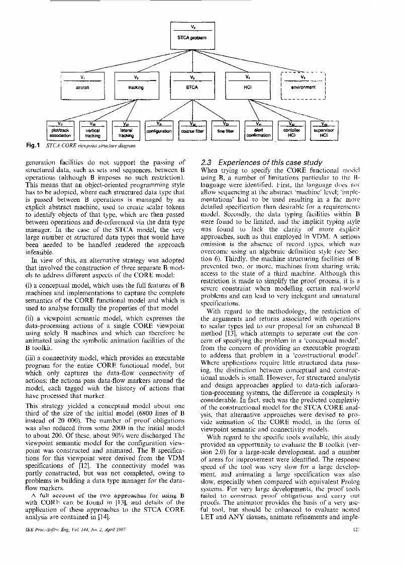
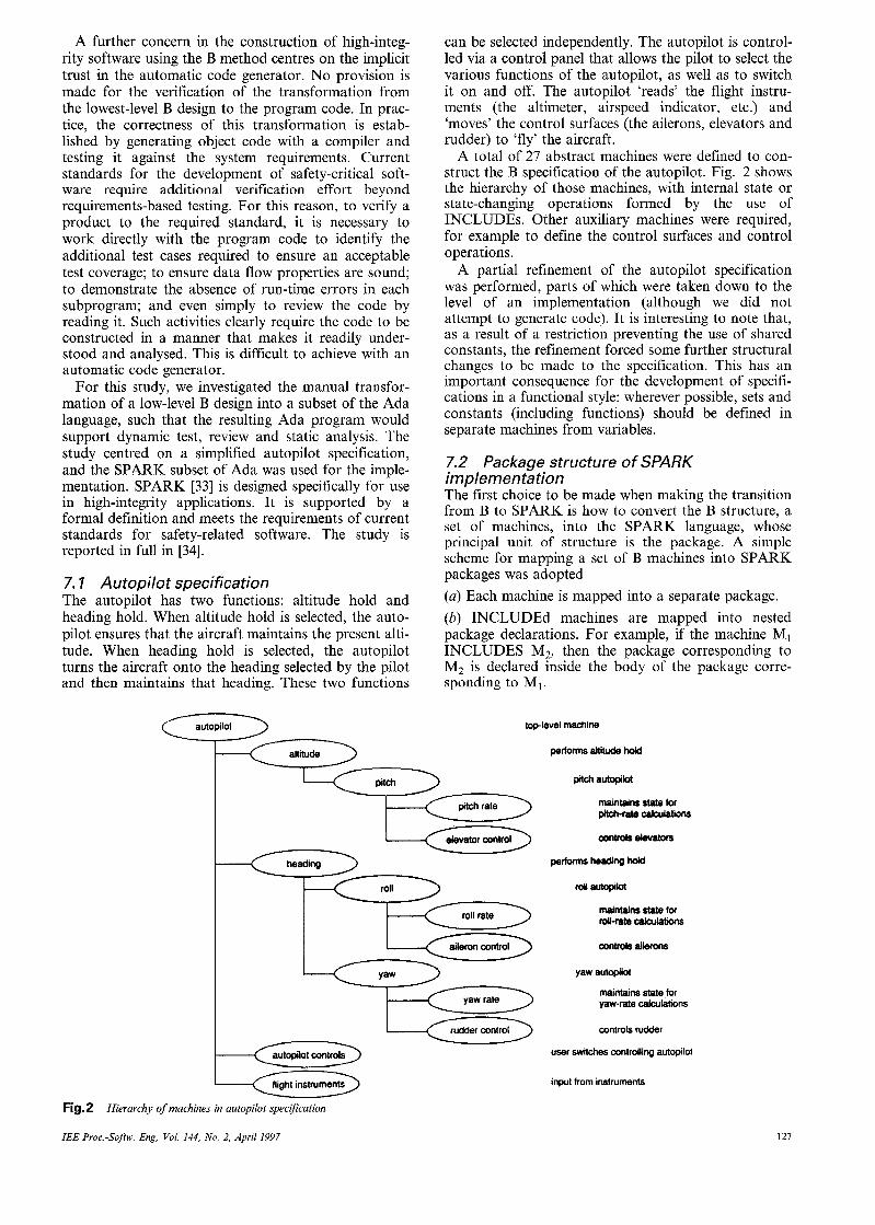
A total of 27 abstract machines were defined to con- struct the B specification of the autopilot. Fig. 2 shows the hierarchy of those machines, with internal state or state-changing operations formed by the use of INCLUDES. Other auxiliary machines were required, for example to define the control surfaces and control operations.
A partial refinement of the autopilot specification was performed, parts of which were taken down to the level of an implementation (although we did not attempt to generate code). It is interesting to note that, as a result of a restriction preventing the use of shared constants, the refinement forced some further structural changes to be made to the specification. This has an important consequence for the development of specifi- cations in a functional style: wherever possible, sets and constants (including functions) should be defined in separate machines from variables.
7.2 Package structure of SPARK implementation The first choice to be made when making the transition from B to SPARK is how to convert the B structure, a set of machines, into the SPARK language, whose principal unit of structure is the package. A simple scheme for mapping a set of B machines into SPARK packages was adopted (a) Each machine is mapped into a separate package. (b) INCLUDEd machines are mapped into nested package declarations. For example, if the machine MI INCLUDES M2, then the package corresponding to M2 is declared inside the body of the package corre- sponding to MI.
top-level machine
performs altitude hold
pitch autopikt
maintains state for m-r* - elevators
p e r f m heading hold
roll autopilot
maintains state for roll-ratecalculations
controls ailerons
yaw autopilot
maintains state for yaw-rate calculations
controls rudder
user switches controlling autopilot
input from instruments
Fig. 2
IEE Proc-Softw. Eng, Vol. 144, No. 2, April 1997
Hierarchy of machines in autopilot specijkation
127
(e) Packages corresponding to SEEn machines are declared inside the body of the highest-level package that provides the required access. Commonly, this is the package corresponding to the highest-level SEEing machine, but, where there is more than one such machine, a common ancestor may need to be used. Nested packages in Ada allow a package to be visible only where it is required. In SPARK, they may also be used in conjunction with state refinement (using the ‘own variable clause’) to ensure that information flow between operations is described at the appropriate level of abstraction. It is usually good practice to define, at the outermost level (the library-level), any packages that represent external system interfaces, even if their visibility is only required in one part of the code. In B, we generally find that an abstract machine describing an external interface ends up at the ‘bottom’ of an INCLUDES chain, because it has its own internal state but its operations do not change the state of any other machine. Therefore we extended the B-SPARK map- ping scheme by adding a further rule (d) machines representing external system interfaces are mapped into library-level SPARK packages. In SPARK, it is also necessary to consider the annota- tions (formal comments) used by the examiner to check conformance to the static-semantic rules of SPARK. At a package level, SPARK requires an own-variable clause to identify package state variables, where present. The own variable of a package enclosing one or more embedded packages must represent the overall state of the outer package, including the embedded states. This is done in SPARK using own-variable ‘refinement’. To support flow analysis of state varia- bles, SPARK also requires an initialisation clause to identify any package whose body initialises its state variable(s). These may be identified from the INITIAL- ISATION part of the associated B machine.
In the autopilot implementation, this approach resulted in the top-level autopilot state being refined in terms of the states of autopilotcontrols, altitude and heading. In turn, heading’s internal state was refined in terms of those of roll and yaw, and so on. It is interest- ing to note that we had to make use of our insight into the system requirements to arrive at the final package structure for the autopilot, in particular to extract external interfaces and collect together ‘related’ machines. It is likely that an automatic code generator would have to adopt a more ‘naive’ approach, resulting in a less understandable SPARK program.
7.3 Operation refinement into SPARK Once the most appropriate SPARK package structure had been determined, the outline of these packages was coded, with B operations mapped into SPARK proce- dures (or functions if they return a simple result and are free of side-effects). Functions in B that have not been refined into operations would also be mapped into SPARK function definitions. At this stage, appro- priate SPARK annotations would be added to each procedure or function specification, enabling the SPARK examiner to carry out the static semantic checks to ensure conformance to SPARK. Annotations for information-flow relationships, which would be derived from an understanding of the B description of the system, would be checked for consistency by the examiner.
128
With this manual approach to transition from B to SPARK, there remains the possibility of additional design work being carried out in SPARK. Specification information can then be entered as SRARK proof con- texts, and the SPARK examiner can be used to gener- ate proof obligations. In particular, a restricted form of verification, not directly addressed by the B toolkit but of key concern for high-integrity program development, is the proof of the absence of run-time errors, such as subrange violation. With the SPARK toolset, proof obligations associated with the relevant statement and expression for forms are generated automatically.
7.4 Experiences from this case study The autopilot system is a reactive system, with rela- tively few state data and no complex invariants. Its main purpose is continuously to adjust the system out- puts according to its current inputs. For this a func- tional style of specification was fairly natural, and it made the transition to SPARK relatively straightfor- ward. However, many safety-critical systems have these characteristics, and a similar approach is likely to be appropriate again.
In this study, we demonstrated that it is possible to produce a well-designed and easily understood SPARK implementation from a well-presented B specification, in a manner that allows relatively straightforward com- parison between the two. A number of proposals were made to guide the transition from B machines and operations to SPARK packages and subprograms and the use of B invariant and initialises clauses in deter- mining SPARK own-variable annotations. We also investigated how pre- and post-conditions can be entered as SPARK proof contexts allowing verification of any further design changes, and how it is possible to support a proof of the absence of run-time errors through the use of B invariants.
A significant issue in making the transition from B to SPARK is determining how far we should first refine the B specification. Our experience suggests that to per- form some refinement of the specification into a design makes the eventual transition easier. In particular, the following activities should be carried out: (a) algorithmic refinement of the specification to remove parallelism and any non-determinism (b) data refinement to a point where the B data types have an obvious SPARK counterpart; for example, to replace sets by sequences, which can be implemented as arrays. However, we found that it was not useful to refine the entire specification down to the level of a B implemen- tation before making the transition to SPARK. Doing this would require all explicit state variables to be replaced by B toolkit library machines; as these are very low-level building blocks, this approach tends to result in a more fragmented code and data structure than would naturally be written in SPARK.
The overall aim should be to reduce the gap between the refined B and the SPARK code, such that the gen- eration of SPARK code becomes a transcription exer- cise that can be verified by inspection. The SPARK code should be readily understandable in its own right, for the benefit of subsequent activities such as review, test-case generation, maintenance etc.
It is significant that we had to make use of our insight into the system requirements to arrive at a suit- able program structure (in particular to extract external
IEE Proc.-Sojtw. Eng., Vol. 144, No. 2, April 1997
interfaces and collect together ‘related’ machines). Such improvements to the design would be difficult for an automatic code generator to perform.
8 Proof using B toolkit
This strand of work in the B user trials project investi- gated the facilities for proof provided by the B toolkit.
8. I Proof support in B toolkit A guiding principle in the design of the B method has been to make practical the proof of internal consistency of specifications and the correctness of their refine- ments. Thus the structuring mechanisms in the B method decompose the overall proof task into smaller proof tasks in a compositional fashion. The verification of a development is based on the generation and dis- charge of a number of proof obligations that together ensure consistency and correctness of design.
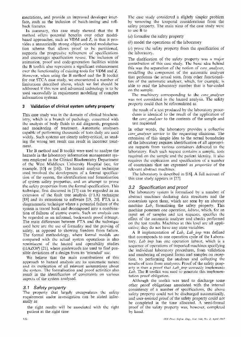
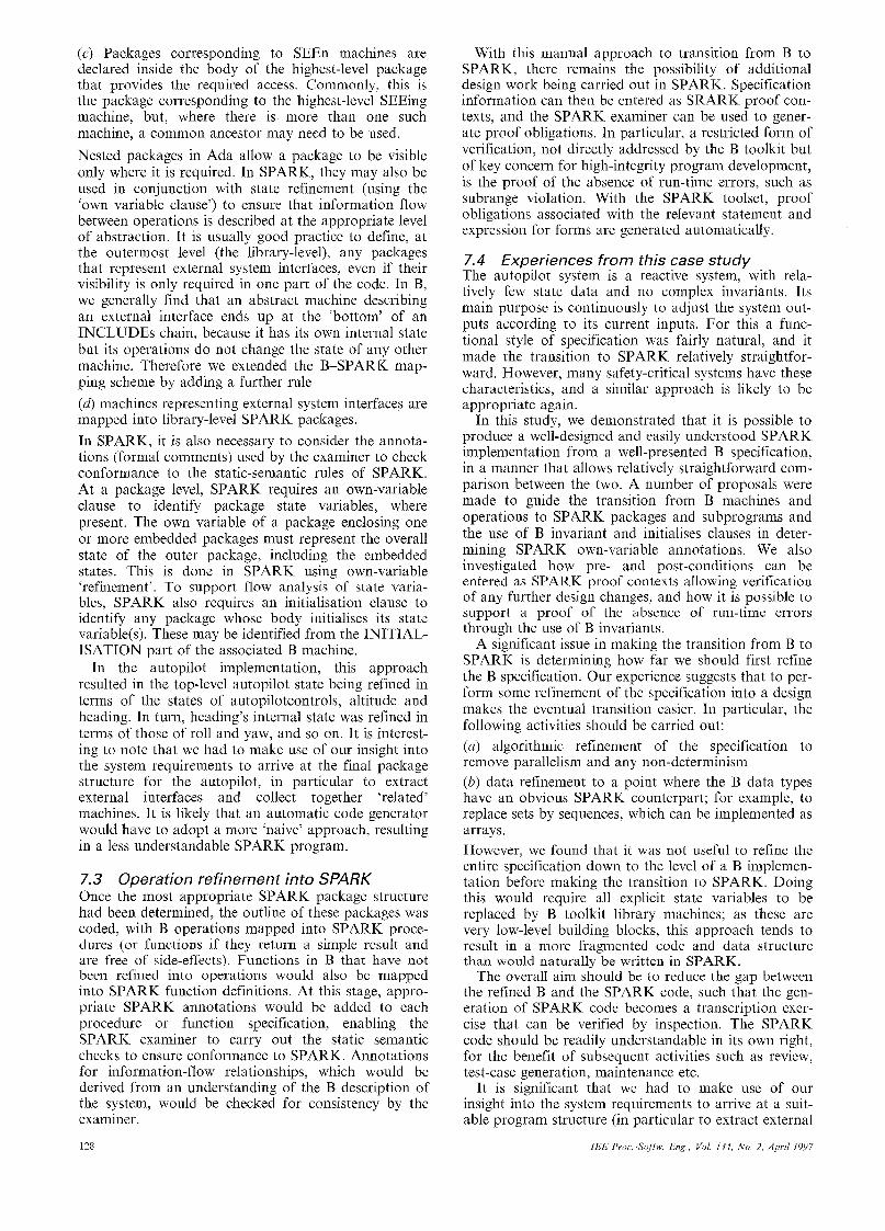
Within the B toolkit, proof is performed in a cycle of automation and interaction, given diagrammatically in Fig. 3. First, the autoprover is used to discharge obliga- tions using the built-in rulebase. Then the user browses the remaining un proven obligations and selects one to analyse. The leaves of its failed proof search tree are examined, and the user selects a leaf that is believed to be valid. This is asserted as a lemma that proves the selected proof obligation. Lemmas thus generated are then proved interactively, using the interprover, by adding rules to the user’s rule set. This cycle is repeated on other obligations as desired. The proof obligations are then discharged when the autoprover is run again. This cycle is repeated until all the proof obligations are discharged. Each iteration of this cycle introduces a new ‘level’ of user theory, thus allowing the addition of only those rules that are necessary to prove the current obligations.
Automated proof is based upon a large rulebase of built-in rules and associated control tactics. This rule- base is not normally visible to the user, but rather pro- vides a number of ‘hooks’, whereby user rules for forwards and backwards proof are called from the
automatic process. For the purposes of this project, the internal structure of the built-in rulebase was investi- gated in greater detail than is normally required [Note 31. Within the rulebase, rules are organised into ‘theories’, linear collections of rules that are searched in sequence. Each rule can include a tactic call that directs the prover in the proof search, including tactics that encode the dependencies between rule sets. Thus the theories are not logical theories in the usual sense, as they are characterised by their use in proofs rather than logical form and provide a control strategy for guiding the automatic proof.
8.2 Investigations into proof process We compared proof facilities in the B toolkit with the Mural system [35] in its instantiation for VDM [37] on a small but non-trivial refinement and proof. The sys- tems are comparable as both support fully formal development in the model-oriented style, including specification, refinement and proof; both support the ‘posit and prove’ approach, separating out the develop- ment of specifications, proof obligations and proofs; and both make use of extensive ’base theories’ of proof rules supplied with the system and allow for the devel- opment of ‘user theories’. However, the two systems differ markedly in their mechanisms for constructing proofs and maintaining the theory store. A fuller dis- cussion of this work can be found in [38].
8.2. I Automated search: Although both systems automatically generate proof obligations, their approaches to discharging them differ radically. The B toolkit aims for a highly automated approach with user intervention when necessary: the autoprover discharges a percentage of the proof obligations immediately, using an optimised search strategy based on the arrangement of the rulebase as discussed above. This is highly effective, especially on the more trivial and unin- teresting obligations, typically involving the proof of
Note 3: The source of the rule base was made available courtesy of B- Core (UK) Ltd
--c 4 proof obligations add user rules
fail
fail
proven obligations
u Fig.3 Proof cycle in B toolkit
IEE P?oc.-Sojtw. Eng, Vol. 144, No. 2, April 1997 129
type assertions. However, when it fails, user interven- tion is not well supported.
In contrast, in Mural, the basic mode of proof is highly user-driven, with only minimal automation available. The search is user guided; machine search for applicable rules is available and effective, but the user controls how much of the current context is considered in the search. The user gains insight into the proof, but this step-by-step proof process is time consuming.
8.2.2 Reuse of user theories: In the B toolkit, when the autoprover fails to prove obligations, the user is invited to intervene to prove the remaining obliga- tions. This is carried out by adding new rules into a user theory file. The rules that the user defines fall broadly into three categories: rules that are specific to the current machine; generic rules that define user- defined functions; and rules that give additional prop- erties of the built-in operators. The first are useful only in the current machine, the second are likely to be gen- erally applicable to the application domain in hand, and the third are likely to be re-usable in all domains.
However, the B toolkit does not encourage the easy re-use of user defined rules, as user theories are specific to the lemma currently being proved and so cannot be re-used for other proofs. The rulebase is opaque so the user cannot see what rules have already been defined and avoid duplication, or insert rules into the rulebase in their ‘logical place’, grouped with similar rules. The #include facility of the B toolkit can be used to enable re-use, whereby libraries of rules are constructed inde- pendently in files and imported into user theories as required. However, this is a rather ad hoc method that is awkward to use and poorly documented.
This contrasts with the transparency of the Mural system. The user can browse existing theories, adding rules to them to cover perceived deficiencies. Further, for application-specific functions, user libraries can be added into the hierarchy of theories, inheriting base theories as appropriate. Thus users can build up a re- usable library to support their own application domains. However, as proof is performed by hand, typ- ically tactics are not introduced to integrate new rules into the search procedure.
8.2.3 Proving lemmas: In the B method, it would be desirable to add user defined rules as lemmas and give separate proofs to verify them. However, only those lemmas that are conjectured by the toolkit can be proven. User rules are assumed to be valid and are not verified. This is potentially a dangerous facility as inconsistent rules can easily be added.
To synthesise the proof of lemmas, it is possible to fabricate a rule similar to the desired lemma in such a way that it will be proved each time it is applied. This requires building a statement of the rule as a premise of the rule itself. Then, when the rule is applied in a back- wards proof, the rule becomes a sub-goal and is then proven by the system. This method is valid, since the B method uses classical logic, and the deduction theorem holds, but it is clearly unsatisfactory.
Again, we contrast with the Mural system, where new rules are either marked as being axioms or derived rules. Clearly axioms need no proof, and the user risks inconsistency. The use of derived rules is preferred, and they are marked as unjustified until a separate proof is given for them. These derived rules can be used in
130
proofs before they are proven, and the system main- tains a record of dependencies between proofs.
8.3 Experiences from this case study Although formal specifications are increasingly being used in industrial systems development, few are using formal proof to any great extent. Proof is perceived as an expensive and highly specialised task that is justifia- ble only in the most safety-critical applications. The B toolkit does, however, support an approach to deriving proof that is reasonably effective. The autoprover often works well to discharge automatically a significant per- centage of proof obligations. However, large-scale development may generate several hundreds of proof obligations, and, even if the autoprover discharges, say, 80% of them, this still leaves very many remaining to be considered by user intervention. For interactive proof, the B toolkit was found to be in need of improvement and the example of the Mural system was instructive.
We propose the following suggestions for improving the B toolkit’s approach to the development of proof in the software development cycle. (a) User viewing: clarity and openness of the rulebase are essential in a user-directed proof in order for the user to guide the system in the use of existing rules and to allow inspection and analysis of the rulebase to establish confidence in its consistency. (b) Aiding the autoprover: as the proof cycle alternates between automated and interactive proof, inevitably, it is necessary for the user to help the autoprover by sup- plying appropriate rules and tactics. These are cur- rently added though a number of predefined ’hooks’, whereby user defined tactics or rules can be called. It would often be more convenient to be able to modify the existing rules and tactics in situ. (c) Re-use of rules: to ease the discharge of large num- bers of obligations, it is necessary to be able to build libraries of user-defined rules that can be re-used, rather than regenerated, as needed. These rules also need to be to be proven themselves to ensure that inconsistency is not introduced. (d) Efficient search: the B toolkit already provides an efficient search for its autoprover using its base rules. It would be helpful, in addition, to provide a search facil- ity to help the user browse the proof space in the inter- prover. (e) Managing change: the machine needs to recognise dependencies between the formal objects to maintain the integrity of the system. In a development environ- ment specifications are continually evolving. When a modification occurs, the system should, to a large extent, be able to re-establish the consistency of proofs without intensive user involvement. (f> Graceful failure: when a machine proof fails and control is returned to the user, it is worthwhile making an effort to ‘fail gracefully’ and present the current state of the proof in a form that will aid understanding of why the failure has occurred and how best the user can intervene to proceed with the proof.
9 Overall conclusions
9. I Methodology The B abstract machine notation provides a semanti- cally strong, formally based development methodology
IEE Proc.-Softw. Eng., Vol. 144, No. 2, April 1997
supporting stepwise refinement with a rich modularisa- tion mechanism. The structuring mechanisms provided yield a highly compositional approach to development and proof construction, such that the validity of imple- mentations and proofs is maintained when specification components are used in larger structures. However, this underlying quest for compositionality does lead to some constraints that can be restricting in software development:
9. I. 1 Machine structuring: The structuring mecha- nisms provided impose a rigid discipline that may cause problems for developers accustomed to other method- ologies, such as VDM or Z. In particular, an object- based style of architecture is prescribed for implemen- tations in which only scalar values (object identifiers) are passed between operations. A less prescriptive method is likely to be more effective for data-rich structured analysis and design.
The static nature of the machine structuring required to enable proof decomposition imposes constraints on the possibilities for system decomposition. For examo- ple, a multiple-read, single-write discipline is required for machine inclusion.
9.1.2 Language: Some useful constructs are not available; for example, record types had to be imple- mented algebraically and there is little support for numerical calculations. Furthermore, there are addi- tional restrictions on the use of certain constructs, such as sequencing in abstract specifications.
The untyped logic leads to a uniform treatment of proofs of typing and other obligations; however, this merges different aspects of verification that could well be better separated. In particular, many proofs are required that would be part of the type checking in a typed language and would thus never arise as proof obligations in that setting.
The requirement for operations to maintain the invariant explicitly, while providing an opportunity to prove the internal consistency of a machine, does tend to encourage a less abstract definition of operations. Furthermore, the use of generalised substitutions and, in particular, the programmatic syntactic sugars, focuses attention on algorithm development.
9.1.3 Refinement and implementation: Although we were able to conduct refinements success- fully, it was not considered the best use of resources blindly to attempt to refine to code and prove a whole specification. Rather, some enlightened focusing of resources on areas where greatest attention is merited is beneficial.
The standard library machines to which implementa- tions must ultimately be targeted are rather low level, and so the use of the code generation facilities incurs the overhead of adjusting specifications and develop- ments towards implementations on target machines manipulating simple data structures. These machines and their implementations should also be proved cor- rect, once and for all, by the developers of the B method and tools.
In code generation, it was not always the case that the desired program structure was that that arose from the code generation. However, this may well always be a problem with automatic code generation.
IEE Proc.-Softw. Eng, Vol. 144, No 2, April 1997
9.2 Tools The B toolkit provides a rare breadth of support for formal development. It combines facilities for the con- struction of structured abstract specifications, their ani- mation and the proof of their internal consistency, with support for verifiable data refinement and operation decomposition through a combination of interactive and automatic proof and the ability automatically to generate code from low-level specifications.
At the time of this evaluation, however, there were some shortcomings in the toolkit that caused us prob- lems:
9.2. I Specifications: The tool support was at best slow for large specifications and, for our largest specifi- cations, the proof obligation generation and autoproof tools appeared not to terminate. Naturally, this might also be attributed to a failure on the user’s part to structure the specification sufficiently. The facilities for multi-person development were also rather restrictive.
9.2.2 Animation: The animation support was an extremely useful and successful means of validating and debugging our specifications. However, it could be improved by the provision of a greater library of sim- plification rules as, presently, the user has to provide many rules to aid the simplifier. It would also be help- ful if the support for animation were extended to refinements and implementations. Another useful facil- ity would be support for a ‘batch’ style of animation to enable the running of test suites.
9.2.3 Proof: Compared with some other proof tools, the proof support provided by the B toolkit is relatively accessible, and it was quickly possible to begin success- ful proving. However, in the long term, the approach is limited by its prescriptive style and opacity. For exam- ple, the built-in rules that are provided for the basic constructs of the language are not available for inspec- tion. Thus, when the proof fails, it is unknown whether this is because of a shortcoming in the logic of the rules or the tactic for constructing the proof.
There is no direct support for building a structured collection of user rules, and thus a naive user would be required to add the same rule to many user theories. Neither is it possible to build a multi-level justification of a rule. Rules added by the user are treated as axioms and are not subject to proof themselves. There is also a lack of integration of rules between different aspects of the toolkit. Sometimes, the same definition had to be entered three times, as a definition in the specification, as a rule in the animation theory and as another rule in the proof theory.
For these and other reasons, many proof obligations remained unproven, and it is likely that B will be used primarily for its ability to provide tool-supported for- mal specification, development and code generation facilities, while proofs are either left unattempted, per- formed only at the most abstract specification level, or only for small critical system subcomponents.
Further discussion of the B method and toolkit can be found in [39].
9.3 Applicability Overall, the case studies have shown the feasibility of the formal approach to software development for a variety of development tasks and in a variety of types
131
of system. Our experience of the B method and toolkit was mixed: it does provide a range of support for many parts of the development lifecycle; however, our success in different tasks varied.
In the requirements phase, where system descriptions are wanted that are as close as possible to ‘the real world’, B did not perform so well. This is not so much a failing of the formal approach generally, but specific to the B method, which adopts a minimalist approach to specification to facilitate the subsequent develop- ment task.
The B method’s major strength, in common with other model-oriented formal methods, was shown to be in the high-level - low-level design stages. The B toolkit provides support for the development of structured abstract specifications, for the animation of those spec- ifications and for the generation and discharge of con- sistency proof obligations. It is also possible to construct and justify data and algorithm refinements and to develop them to the stage where code can be generated automatically from them. For these design activities, compared with other model-oriented formal methods, B favours the latter stages of development, the decomposition of system into modules and the development of each module towards code. This focus does, however, tend to discourage abstraction in high- level designs.
The support for low-level design is geared towards the automatic generation of code, a feature that worked well provided a prescribed architectural approach was adopted. However, to conform to certain standards for safety-critical software, it was not appro- priate to rely on the integrity of an automatic code gen- erator, and manual translation from an intermediate design into the target language was preferred. TI-‘ 11s was found to be a viable alternative and led to a satisfac- tory design. B’s philosophy regarding proof is towards a high degree of automation. The automatic proof facilities were certainly useful to filter out the simplest proof obligations. However, with the state of current theorem-proving technology, it seems that some degree of user intervention in the proof process is inevitable, and therefore attention must be paid to providing industrial-strength support for interactive proof.
10 Acknowledgments
We are indebted to Dr Richard Fink and Susan Oppert, of the West Middlesex University Hospital, and Dr Paul Collinson, of the Mayday Hospital, for their help in the formulation of the medical informa- tion management case studies. Clive Lee and Andrew Storey collaborated in the evaluation of the B method and toolkit and in the development of training courses and a B method manual [36]. Finally, we thank B-Core UK for their interest in the project, for their support and their professional approach towards collecting and addressing our problems.
11 References
1 ABRIAL, J.-R.: ‘The B-book’ (Cambridge Unicersity Press, 1996) 2 LANO, K.: ‘The B language and method: a guide to practical for-
mal development’ (Springer-Verlag, 1996), FACIT series 3 WORDSWORTH, J.: ‘Software engineering with B’ (Addison-
Wesley Longman, 1996)
BICARREGUI, J.C., DICK, J., and WOODS, E.: ‘Quantitative analysis of an application of formal methods’, Proceeding of FME’96. third international svmDosium of Formal methods Europe, ’(Springer-Verlag, March 1’996), pp. 60-73 (LNCS 1051, ISBN: 3-540-60973-3) HOARE, J., DICK, J., NEILSEN, D., and SORENSEN, 1.: ‘ADolving the B technologies to CICS’. Proceeding of FME’96. thcra inikrnational symGsium of Formal metKods Europe, (Springer-Verlag, March 1996), pp. 74-84 (LNCS 1051, ISBN: 3- 540-60973-3) DEHBONEI, B., and MEJIOA, F.: ‘Formal methods in the rail- ways signaling industry’ in NAFTALIN, M., and DENVIR, T. (Eds.): ‘Proceedings of Formal methods Europe ’94’. Lecture notes in computer science, (Springer-Verlag, 1994), pp. 26-34 JONES. C.B.: ‘Svstematic software develonment using VDM’ (Prentice-Hall, 1990- SPIVEY, J.M.: ‘The Z notation: a reference manual’ (Prentice-
- Hall, 1989) MORGAN, C.: ‘Programming from specifications’ (Prentice- Hall, 1990)
10 ‘CORE - the method’. SD CORE manual, SD Software Technol- ogy Centre, April 1989
11 MOULDING, M.R., and SMITH, L.C.: ‘Combining formal specification and CORE: an experimental investigation’, Softw. Eng. J., 1995, 10, pp. 3142
12 SMITH, L.C.: ‘Formalising CORE requirements’. PhD thesis, Cranfield Institute of Technoloev. 1993
13 MOULDING, M R ‘Using XMN with CORE’. RMCS ref
14 MOULDING, M R , NEWTON, A R , and RUSHTON, BUT/RMCS/MRM/I EXT/vl, January 1995
T.G.A.: ‘A practical evaluation of AMN and the B toolkit for use with CORE’. RMCS ref: BUTIRMCSIMNRI2.EXTIv. 1, May 1995
15 FINK, R. et al.: ‘Data management in clinical laboratory infor- mation systems’ in REDMIL, F., and ANDERSEN, T. (Eds.): Directions in safety-critical systems’ (Springer-Verlag, 199 3)
16 OPPERT, S.: ‘WMH case study, system definition’. MORSE/ WHMISOI 1 /V 1
17 HESAN, H. et al: ‘Safety properties’. Lloyds register of shipping, MORSEILLOYDSIHALI44N2
18 ROBERTS, N.H. et al.: ‘Fault tree handbook’. U.S. Nuclear Regulatory Commission, NUREF-0492, January 1986
19 LEVESON, N.G., and HARVEY, P.R.: ‘Analysing software safety’, ZEEE Trans. Softw. Eng., 1983, SE-9, (5), pp. 569-579
20 CLARKE, S.J., and MCDERMID, J.A.: ‘Software fault trees and weakest preconditions: a comparison and analysis’, ZEE Softw. Eng. J., 1993, 8, pp. 225-236
21 ‘A guide to hazard and operability studies’. Chemical Industries Association, CIA/CISHEC/9006/1000/9.5C, 1991
22 LESAN, H.: ‘Final report on the use of B for hazard analysis’. B User Trials External Deliverable Dll(3.1/3), 1995
23 BRUNS, G., and ANDERSON, S.: ‘The formalization and anal- ysis of a communications protocol’, Form. Asp. Comput., 1994, 6,
24 BICARREGUI, J.C.: ‘A model-oriented analysis of a communi- cations protocol’. Rutherford Appleton Laboratory Technical report RAL-93-099
LUND, C.J., and GRIST, W.D.: ‘Multiprocessor shared-memory information exchange’, IEEE Tvans. Nucl. Sci., 1989, 36, (l), pp. 626-633
26 BICARREGUI, J.C., and RITCHIE, B.: ‘Invariants, frames and postconditions: a comparison of the VDM and B notations’ in WOODCOCK, J.C.P., and LARSEN, P.G., (Eds.): “Proceedings of Formal methods Europe ’93’. Lecture notes in computer sci- ence, vol. 670, (Springer-Verlag, 1993), reprinted in IEEE Trans. Softw. Eng., 1995, 21, (2)
27 BICARREGUI, J.C.: ‘Algorithm refinement with read and write !rames’ in WOODCOCK, J.C.P., and LARSEN, P.G. (Eds.): Proceedings of Formal Methods Europe ’93’. Lecture notes in
computer science, vol. 670, (Springer-Verlag, 1993) 28 BICARREGUI, J.C.: ‘Operation semantics with read and write
frames’ (Springer-Verlag, 1994 (Sixth refinement workshop, Workshops in computer science))
29 BICARREGUI, J.C.: ‘Intra-modular structuring in model-ori- ented specification: expressing non-interference with read and write frames’. PhD thesis, University of Manchester (UMCS-95- 10-1)
30 ‘Information technology-Computer graphics and image process- ing-Graphical KErnel System (GKS) Part 1 : functional descrip- tion’. International Organisation for Standardization, (Draft Internation Standard), 1993
31 BICARREGUI, J.C., RITCHIE, B., and HAUGHTON, H.: ‘Experiences in using the abstract machine notation in a GKS case study’ in NAFTALIN, M., and DENVIR, T. (Eds.): ‘Pro- ceedings of Formal methods Europe ’94’. Lecture notes in com- nuter science. (Snringer-Veralg. 1994)
(l), pp. 92-112
25 SANTOLINE, L.L., BOWERS, M.D., CREW, A.W., ROS-
32 ‘CLUTTERBUdK, 6.L.: ‘Thekification of low-level code using the R-toolkit’. B User Trials Deliverable 3.2/2, BUTIPVLI
1 ~~~ ~ . . ....
PRFREPIl .L 33 CARRE, et al.: ‘SPARK - the SPADE Ada Kernel edition 3.1’.
Program’ Validation Ltd, 26 Queen’s Terrace, Southampton
IEE Pvoc.-Softw. Eng., Vol. 144, No. 2, Apvil 1997 15L
34 FINNIE. G.J.. and CLUTTERBUCK. D.L.: ‘AMN to SPARK implementation case study’. B User ’ Trials Deliverable 3.213, BUTIPVLISPKREPIvl , 1
35 JONES, C.B., JONES, K.D., LINDSAY, P.A., and MOORE, R.: ‘Mural: a formal development support system’ (Springer- Verlag, 199 1)
36 SCHARBACH, P.N., and STOREY, A,: ‘B method manual’. B User Trials Exteranl Deliverable, D 9 (2.216)
37 BICARREGUI, J.C., FITZGERALD, J.S., LINDSAY, P.A., MOORE, R., and RITCHIE, B.: ‘Proof in VDM: a practitioners guide’ (Springer-Verlag, 1994)
38 BICARREGUI, J.C., and MATTHEWS, B.M.: ‘Formal methods in practice: a comparison of two support systems for prooP in BARTOSEK et al. (Eds.): ‘Proceedings of SOFSEM ’95: Theory and practice of informatics’ (Springer-Verlag, November 1995), pp. 184205
39 CLUTTERBUCK, D.c., LESAN, H.A., NEWTON, A.R., RUSHTON. T.G.A.R.. SCHARBACH. P.N., and STOREY. A.C.: ‘Report on the use of the B method and toolkit’. B User Trials External Deliverable D6(2.113), 1994
40 “B-toolkit user’s manual, release version 2.0’. B-Core (UK) Ltd, 1994
IEE Proc -Softw. Eng, Vol. 144, No. 2, Apvil 1997 133