for oled full report
TRANSCRIPT
“OLED TECHNOLOGY”
A Seminar Report
Submitted in partial fulfillment of The requirements for the award of the Degree of
BACHELOR OF TECHNOLOGY
IN
Electronics and Communication Engineering
By
DEEPAK KUMAR
1101292167
DEPARTMENT OF
Electronics and Communication Engineering
GANDHI ENGINEERING COLLEGE BHUBANESWAR-752054
2014-15
2 | P a g e
DEPARTMENT OF ELECTRONICS & COMMUNICATION
ENGINEERING
CERTIFICATE
This is to certify that the seminar report entitled “OLED
TECHNOLOGY” is presented by DEEPAK KUMAR (1101292167) in
partial fulfillment of the requirements for the award of the degree of
Bachelor of Technology in Electronics and Communication Engineering
during the academic year 2013-14. This seminar report is submitted to the
department as a part of evaluation of 7th Semester Seminar Presentation.
MANORANJAN SATAPATHY
H O D
Dept. of Electronics and Communication Engineering
Gandhi Engineering College, Bhubaneswar
3 | P a g e
ACKNOWLEDGEMENT
My sincere thanks to Prof. Manoranjan Satapathy, Head of the
Department of ECE, Gandhi Engineering College, Bhubaneswar for his
encouragement and valuable suggestions during period of my seminar
presentation and report preparation.
No words would suffice to express my regard and gratitude to
Madhusmita Mohanty and Satyanarayan Pradhan, Department of
ECE for his inspiring guidance, and also I am gratitude to Prof.
Himansu Bh Mohapatra , Asst head of Department of ECE, Gandhi
Engineering College, Bhubaneswar for constant encouragement, immense
support and help during the seminar presentation and report preparation.
I express my heartfelt gratitude to all my teachers for his valuable
suggestion and guidance, without their cooperation this report is incomplete.
I express my thanks to all my friends for his valuable suggestion and
comments during my seminar preparation.
DEEPAK KUMAR 1101292167
0 | P a g e
CONTENTS
Sl.No Topic Name Page No.
1. Abstract 2
2. Introduction 3
3. History 4-5
4. OLEDs structure 6
5. OLEDs working principle
5.1.Working
5.2Colour creations
7-8
6. Types of OLEDs
6.1 Passive-matrix OLED
6.2 Active-matrix OLED
6.3 Transparent OLED
6.4 Top-emitting OLED
6.5 Foldable OLED
6.6 White OLED
9-12
7. comparison with existing forms of illumination 13
8. Advantages and Disadvantages of OLEDs 14
9. Applications of OLEDs 15
10. Current research on OLEDs 15
11. The organic future of OLEDs 16
12. Conclusion
17
13. References 18
1 | P a g e
LIST OF FIGURE
Sl.No Figure Name Fig
No.
Page
No.
1. Generation of OLED 0 4
2. Slight emitting diode 1 4
3. Multi layered OLED 2 5
4. POLED (polymer based OLED) 3 5
5. PMOLED (passive matrix OLED) 4 5
6. PHOLED (phosphorescenterent OLED) 5 5
7. Structure of OLED 6 6
8. Working of OLED 7 7
9. Colour creation 8 8
10. Passive OLED 9 9
11. Active OLED 10 10
12. Transparent OLED 11 10
13. Top emitting OLED 12 11
14. Foldable OLED 13 12
15. White OLED 14 12
16. Future of OLED 15 16
2 | P a g e
1. ABSTRACT
OLED (Organic Light Emitting Diode) TECHNOLOGY
OLED is flat light emitting technology, composed of thin films of organic molecules that create light with the application of electricity. OLED can provide displays on electronic devices and use less power than conventional light emitting diodes i.e. (LED) used today. Like an LED, an OLED is a solid state semiconductor device that is 100 to 500 nanometers thick and 200 times smaller than the human hair. OLED can have two layers or three layers of organic material. It emits light through a process called electrophosphorescene. An OLED consists of the following parts:
Anode
Organic layers
Cathode
There are Different Types of an OLED are available:
Active matrix OLED
Passive matrix OLED
Transparent OLED
Foldable OLED
Top emitting OLED
White OLED
Currently OLED are used in many devices such as:
Display
Keyboard
Light
Portable devices screen
Research and Development in the field of OLED is proceeding rapidly now,
and may lead to future application in heads-up display and lighting.
SUBMITTED BY: - DEEPAK KUMAR REG.NO:- 1101292167
DEPARTMENT OF “ECE” GANDHI ENGINEERING COLLEGE
3 | P a g e
2. INTRODUCTION
An organic light emitting diode (OLED) is simply a light emitting diode (LED)
whose emissive electro luminescent layer is composed of a film of organic
compounds. The layers are made up of small organic molecules or macro
polymers that conduct electricity. They have conductivity levels ranging from
insulators to conductors, so OLEDs are considered as organic
semiconductors. The layer of organic semiconductor material is formed
between two electrodes, where at least one of the layers is transparent.
An organic light emitting diode (OLED), also organic electro
luminescent device (OELD), is a light-emitting diode (LED) whose emissive
electroluminescent layer is composed of a film of organic compounds. This
layer of organic semiconductor material is formed between two electrodes,
where at least one of the electrodes is transparent.
Such devices can be used in television screens, computer monitors,
small, portable system screens such as cell phones and PDAs, watches,
advertising, information and indication. OLEDs can also be used in light
sources for general space illumination, and large-area light-emitting elements.
Due to the younger stage of development, OLEDs typically emit less light per
unit area than inorganic solid-state based LEDs which are usually designed
for use as point-light sources.
In the context of displays, OLEDs have certain advantages over
traditional liquid crystal displays (LCDs). OLED displays do not require a
backlight to function. Thus, they can display deep black levels and can be
thinner and lighter than LCD panels. OLED displays also naturally achieve
higher contrast ratios than either LCD screens using cold cathode fluorescent
lamps (CCFLs) or the more recently developed LED backlights in conditions
of low ambient light such as dark rooms.
4 | P a g e
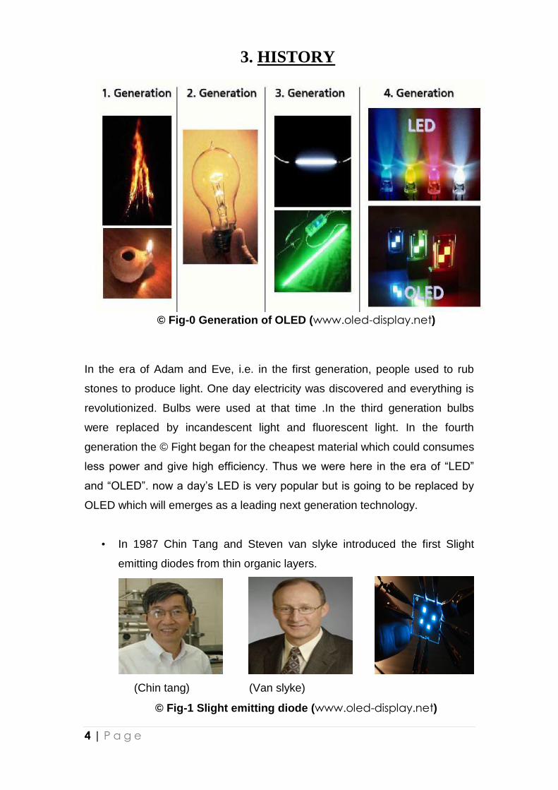
3. HISTORY
© Fig-0 Generation of OLED (www.oled-display.net)
In the era of Adam and Eve, i.e. in the first generation, people used to rub
stones to produce light. One day electricity was discovered and everything is
revolutionized. Bulbs were used at that time .In the third generation bulbs
were replaced by incandescent light and fluorescent light. In the fourth
generation the © Fight began for the cheapest material which could consumes
less power and give high efficiency. Thus we were here in the era of “LED”
and “OLED”. now a day’s LED is very popular but is going to be replaced by
OLED which will emerges as a leading next generation technology.
• In 1987 Chin Tang and Steven van slyke introduced the first Slight
emitting diodes from thin organic layers.
(Chin tang) (Van slyke)
© Fig-1 Slight emitting diode (www.oled-display.net)
5 | P a g e
• In 1988 Chihaya Adachi and Tetsuo Tsutsui developed first multi
layered OLED .
(Chihaya Adachi) (Tetsuo Tsutsui)
© Fig-2 Multi layered OLED (www.oled-display.net)
• In 1990 Germy Burroughes and Richard Friend and Donal Bradely
developed first polymer based OLED(PLED).
(Germy Burroughes) ( Richard Friend) ( Donal Bradely)
© Fig-3 POLED (www.oled-display.net)
• In 1997 Teruo Tohma developed first passive matrix organic light
emitting diode (PMOLED) .
(Teruo Tohma)
© Fig-4 PMOLED (www.oled-display.net)
• In 1998 Mark Thompson and Stephen Forrest developed first
phosphorescent OLED (PHOLED) .
(Mark Thompson) (Stephen Forrest)
© Fig-5 PHOLED (www.oled-display.net)
6 | P a g e
4. OLED STRUCTURE
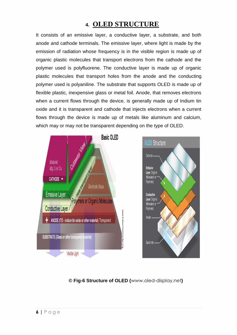
It consists of an emissive layer, a conductive layer, a substrate, and both
anode and cathode terminals. The emissive layer, where light is made by the
emission of radiation whose frequency is in the visible region is made up of
organic plastic molecules that transport electrons from the cathode and the
polymer used is polyfluorene. The conductive layer is made up of organic
plastic molecules that transport holes from the anode and the conducting
polymer used is polyaniline. The substrate that supports OLED is made up of
flexible plastic, inexpensive glass or metal foil. Anode, that removes electrons
when a current flows through the device, is generally made up of Indium tin
oxide and it is transparent and cathode that injects electrons when a current
flows through the device is made up of metals like aluminum and calcium,
which may or may not be transparent depending on the type of OLED.
© Fig-6 Structure of OLED (www.oled-display.net)
7 | P a g e
5. OLED WORKING PRINCIPLE
5.1 Working:
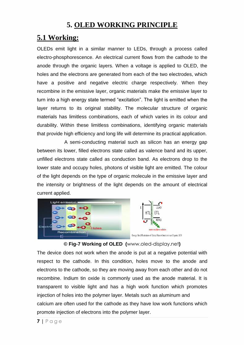
OLEDs emit light in a similar manner to LEDs, through a process called
electro-phosphorescence. An electrical current flows from the cathode to the
anode through the organic layers. When a voltage is applied to OLED, the
holes and the electrons are generated from each of the two electrodes, which
have a positive and negative electric charge respectively. When they
recombine in the emissive layer, organic materials make the emissive layer to
turn into a high energy state termed “excitation”. The light is emitted when the
layer returns to its original stability. The molecular structure of organic
materials has limitless combinations, each of which varies in its colour and
durability. Within these limitless combinations, identifying organic materials
that provide high efficiency and long life will determine its practical application.
A semi-conducting material such as silicon has an energy gap
between its lower, filled electrons state called as valence band and its upper,
unfilled electrons state called as conduction band. As electrons drop to the
lower state and occupy holes, photons of visible light are emitted. The colour
of the light depends on the type of organic molecule in the emissive layer and
the intensity or brightness of the light depends on the amount of electrical
current applied.
© Fig-7 Working of OLED (www.oled-display.net)
The device does not work when the anode is put at a negative potential with
respect to the cathode. In this condition, holes move to the anode and
electrons to the cathode, so they are moving away from each other and do not
recombine. Indium tin oxide is commonly used as the anode material. It is
transparent to visible light and has a high work function which promotes
injection of holes into the polymer layer. Metals such as aluminum and
calcium are often used for the cathode as they have low work functions which
promote injection of electrons into the polymer layer.
8 | P a g e
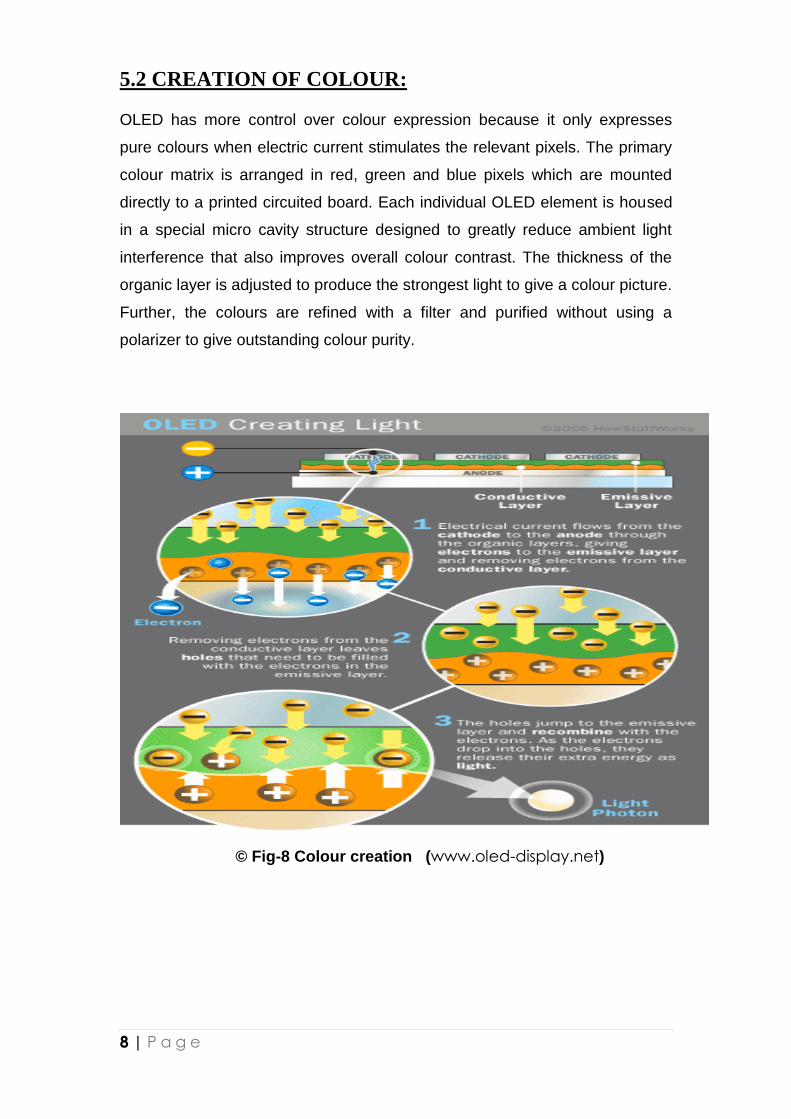
5.2 CREATION OF COLOUR: OLED has more control over colour expression because it only expresses
pure colours when electric current stimulates the relevant pixels. The primary
colour matrix is arranged in red, green and blue pixels which are mounted
directly to a printed circuited board. Each individual OLED element is housed
in a special micro cavity structure designed to greatly reduce ambient light
interference that also improves overall colour contrast. The thickness of the
organic layer is adjusted to produce the strongest light to give a colour picture.
Further, the colours are refined with a filter and purified without using a
polarizer to give outstanding colour purity.
© Fig-8 Colour creation (www.oled-display.net)
9 | P a g e
6. TYPES OF OLEDs
Passive-matrix OLED
Active-matrix OLED
Transparent OLED
Top-emitting OLED
Foldable OLED
White OLED
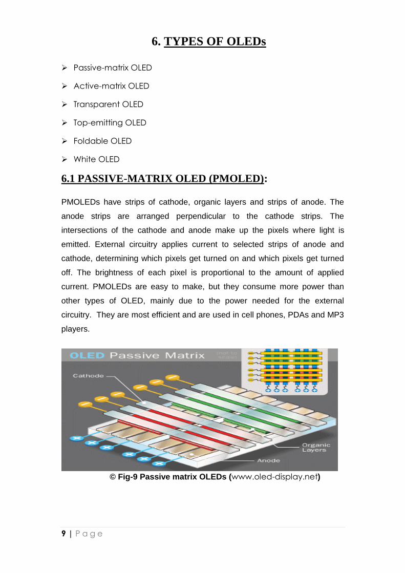
6.1 PASSIVE-MATRIX OLED (PMOLED):
PMOLEDs have strips of cathode, organic layers and strips of anode. The
anode strips are arranged perpendicular to the cathode strips. The
intersections of the cathode and anode make up the pixels where light is
emitted. External circuitry applies current to selected strips of anode and
cathode, determining which pixels get turned on and which pixels get turned
off. The brightness of each pixel is proportional to the amount of applied
current. PMOLEDs are easy to make, but they consume more power than
other types of OLED, mainly due to the power needed for the external
circuitry. They are most efficient and are used in cell phones, PDAs and MP3
players.
© Fig-9 Passive matrix OLEDs (www.oled-display.net)
10 | P a g e
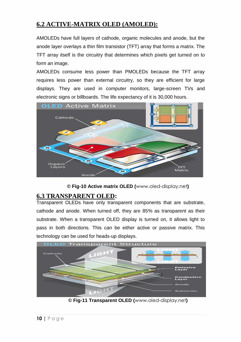
6.2 ACTIVE-MATRIX OLED (AMOLED):
AMOLEDs have full layers of cathode, organic molecules and anode, but the
anode layer overlays a thin film transistor (TFT) array that forms a matrix. The
TFT array itself is the circuitry that determines which pixels get turned on to
form an image.
AMOLEDs consume less power than PMOLEDs because the TFT array
requires less power than external circuitry, so they are efficient for large
displays. They are used in computer monitors, large-screen TVs and
electronic signs or billboards. The life expectancy of it is 30,000 hours.
© Fig-10 Active matrix OLED (www.oled-display.net)
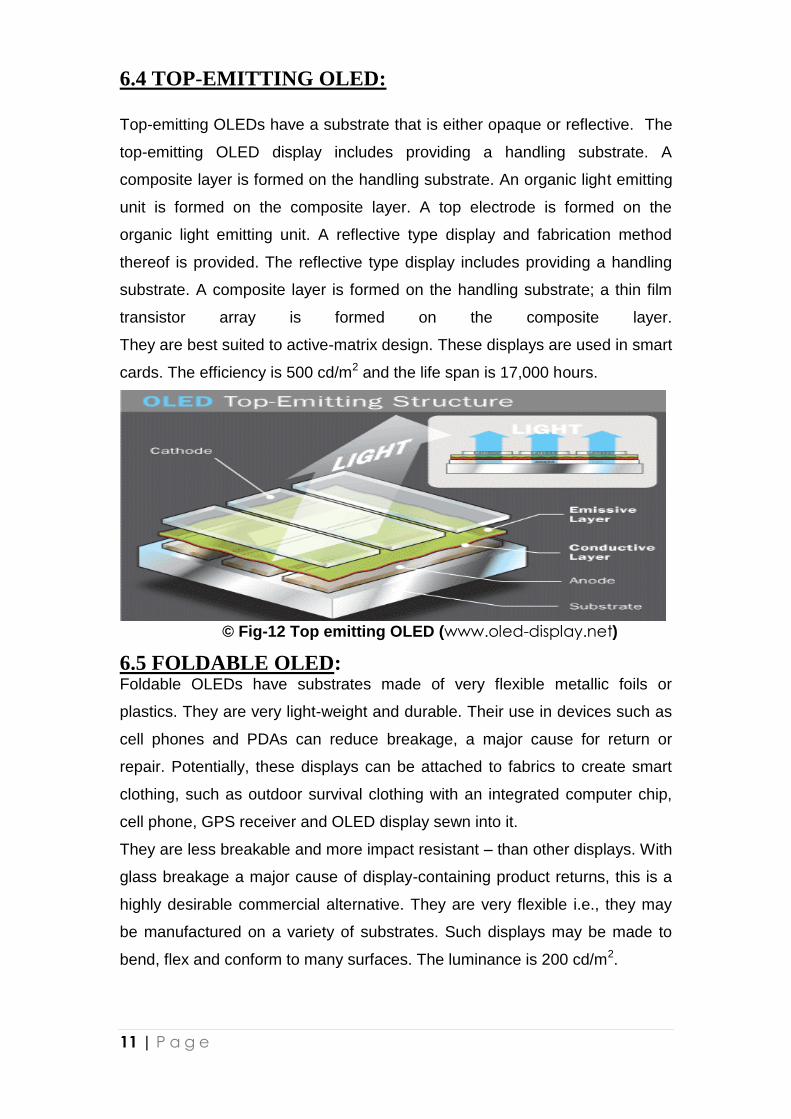
6.3 TRANSPARENT OLED: Transparent OLEDs have only transparent components that are substrate,
cathode and anode. When turned off, they are 85% as transparent as their
substrate. When a transparent OLED display is turned on, it allows light to
pass in both directions. This can be either active or passive matrix. This
technology can be used for heads-up displays.
© Fig-11 Transparent OLED (www.oled-display.net)
11 | P a g e
6.4 TOP-EMITTING OLED:
Top-emitting OLEDs have a substrate that is either opaque or reflective. The
top-emitting OLED display includes providing a handling substrate. A
composite layer is formed on the handling substrate. An organic light emitting
unit is formed on the composite layer. A top electrode is formed on the
organic light emitting unit. A reflective type display and fabrication method
thereof is provided. The reflective type display includes providing a handling
substrate. A composite layer is formed on the handling substrate; a thin film
transistor array is formed on the composite layer.
They are best suited to active-matrix design. These displays are used in smart
cards. The efficiency is 500 cd/m2 and the life span is 17,000 hours.
© Fig-12 Top emitting OLED (www.oled-display.net)
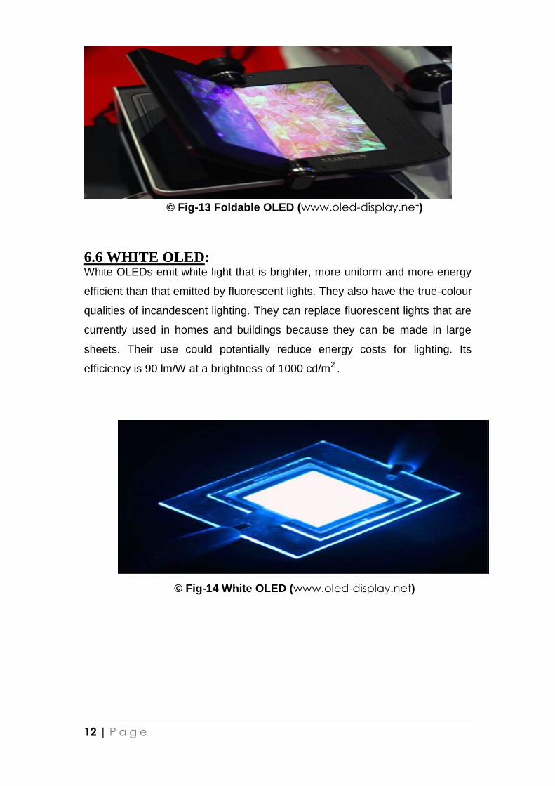
6.5 FOLDABLE OLED: Foldable OLEDs have substrates made of very flexible metallic foils or
plastics. They are very light-weight and durable. Their use in devices such as
cell phones and PDAs can reduce breakage, a major cause for return or
repair. Potentially, these displays can be attached to fabrics to create smart
clothing, such as outdoor survival clothing with an integrated computer chip,
cell phone, GPS receiver and OLED display sewn into it.
They are less breakable and more impact resistant – than other displays. With
glass breakage a major cause of display-containing product returns, this is a
highly desirable commercial alternative. They are very flexible i.e., they may
be manufactured on a variety of substrates. Such displays may be made to
bend, flex and conform to many surfaces. The luminance is 200 cd/m2.
12 | P a g e
© Fig-13 Foldable OLED (www.oled-display.net)
6.6 WHITE OLED: White OLEDs emit white light that is brighter, more uniform and more energy
efficient than that emitted by fluorescent lights. They also have the true-colour
qualities of incandescent lighting. They can replace fluorescent lights that are
currently used in homes and buildings because they can be made in large
sheets. Their use could potentially reduce energy costs for lighting. Its
efficiency is 90 lm/W at a brightness of 1000 cd/m2 .
© Fig-14 White OLED (www.oled-display.net)
13 | P a g e
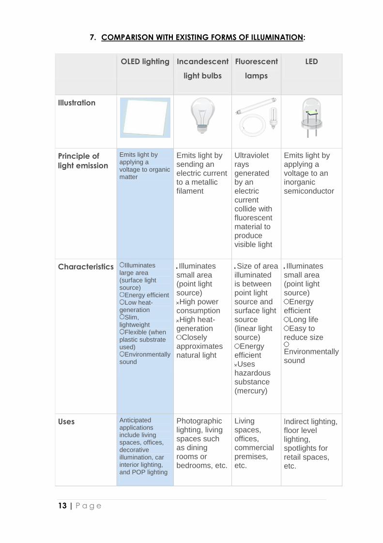
7. COMPARISON WITH EXISTING FORMS OF ILLUMINATION:
OLED lighting Incandescent
light bulbs
Fluorescent
lamps
LED
Illustration
Principle of
light emission
Emits light by applying a voltage to organic matter
Emits light by sending an electric current to a metallic filament
Ultraviolet rays generated by an electric current collide with fluorescent material to produce visible light
Emits light by applying a voltage to an inorganic semiconductor
Characteristics Illuminates large area (surface light source)
Energy efficient Low heat-
generation Slim,
lightweight Flexible (when
plastic substrate used)
Environmentally sound
Illuminates small area (point light source) High power
consumption High heat-
generation Closely
approximates natural light
Size of area illuminated is between point light source and surface light source (linear light source)
Energy efficient Uses
hazardous substance (mercury)
Illuminates small area (point light source)
Energy efficient
Long life Easy to
reduce size
Environmentally sound
Uses Anticipated applications include living spaces, offices, decorative illumination, car interior lighting, and POP lighting
Photographic lighting, living spaces such as dining rooms or bedrooms, etc.
Living spaces, offices, commercial premises, etc.
Indirect lighting, floor level lighting, spotlights for retail spaces, etc.
14 | P a g e
8. ADVANTAGES:
OLEDs are thinner, lighter and more flexible than the crystalline layers in
an LED or LCD. The plastic, organic layers of an OLED are 100 to 500
nanometers thick or about 200 times smaller than a human hair.
They are brighter than LEDs because the organic layers of an OLED are
much thinner than the corresponding inorganic crystal layers of an LED.
Also they do not require glass for support which absorbs some light.
It has ability to emit light from a surface, low heat generation, and
environmentally sound compared to fluorescent lamps.
They do not require backlighting like LCDs as they generate light
themselves, so they consume much less power than LCDs.
They are easier to produce and can be made to large sizes because they
are essentially plastics, which can be made into large, thin sheets.
They can enable a greater artificial contrast ratio that is measured in
purely dark conditions and have better viewing angle compared to LCDs
because OLED pixels directly emit light.
They have a faster time response than standard LCD screens.
DISADVANTAGES: Limited lifetime of the organic materials. While red and green OLED
films have longer lifetimes, blue organics currently have much
shorter lifetimes. However, the lifespan of OLED displays can be
increased by improving light out coupling.
The intrusion of water into displays can damage the organic
materials and limit the longevity of more flexible displays. Therefore,
improved sealing processes are important for practical
manufacturing.
The fabrication of the substrate is complex and expensive process in
the production of TFT LCD, so flexible substrates such as roll-up
displays and displays embedded in fabrics or clothing can be used.
15 | P a g e
9. APPLICATIONS:
Light sources made from organic materials are of immense potential value for
a range of applications. Large area, flat light sources with surface brightness
have potential applications such as space lighting, back lighting or advertising
displays. Organic light emitting devices(OLEDs) offer the potential for such a
source. OLEDs promise a cheap, light weight source which potentially can be
made any size and on to a range of substrates (including flexible plastic).
Due to its light-weight, they can be used in cellular phones, PDAs,
notebooks, digital cameras, DVD players, car stereos, televisions, etc.,
They can be used as solid-state light sources.
In heads-up displays, automotive dashboards, billboard-type displays,
home and office lighting and flexible displays.
Due to its faster response than LCDs almost 1000 times faster, a device
with an OLED display could change information almost in real time.
In video images for more realistic and constant updates.
10. CURRENT RESEARCH ON OLEDs
Manufacturers focusing on finding a cheap way to produce OLEDs.
"Roll-to-Roll" Manufacturing Increase the efficiency of blue luminance.
Focusing to increase overall lifespan of OLEDs.
16 | P a g e
11. THE ORGANIC FUTURE
The first products using organic displays are already being introduced into
the market place. And while it is always difficult to predict when and what
future products will be introduced, many manufacturers are now working to
introduce cell phones and personal digital assistants with OLED displays
within the next one or two years. The ultimate goal of using high-efficiency,
phosphorescenct, flexible OLED displays in lap top computers and even for
home video applications may be no more than a few years into future.
However, there remains much to be done if organics are to establish a
foothold in the display market. Achieving higher efficiencies, lower operating
voltages, and lower device life times are all challenges still to be met. But,
given the aggressive worldwide efforts in this area, emissive organic thin
films have an excellent chance of becoming the technology of choice for the
next generation of high-resolution, high-efficiency flat panel displays.
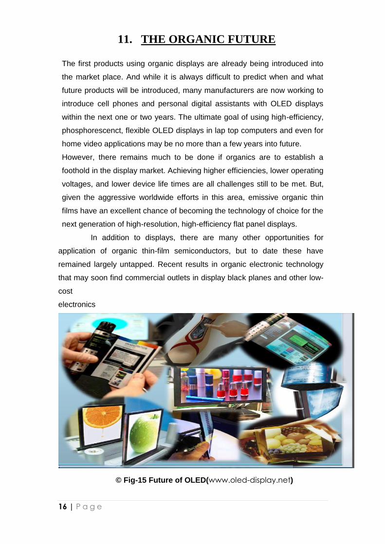
In addition to displays, there are many other opportunities for
application of organic thin-film semiconductors, but to date these have
remained largely untapped. Recent results in organic electronic technology
that may soon find commercial outlets in display black planes and other low-
cost
electronics
© Fig-15 Future of OLED(www.oled-display.net)
17 | P a g e
12. CONCLUSION
Organic light emitting diodes promise to make electronic viewing more
convenient and ubiquitous as they are more energy efficient. OLED is so
revolutionary that in the field of illumination it is being hailed as “the first
discovery since Edison”. Today, OLED technology is widely seen as a next
generation component for flat panel displays and is expected to become a key
technology in the development of flexible displays.
Performance of organic LEDs depend upon many parameters such as
electron and hole mobility, magnitude of applied field, nature of hole and
electron transport layers and excited life-times. Organic materials are poised
as never before to transform the world IF circuit and display technology.
Major electronics firms are betting that the future holds tremendous
opportunity for the low cost and sometimes surprisingly high performance
offered by organic electronic and optoelectronic devices.
Organic Light Emitting Diodes are evolving as the next generation of
light sources. Presently researchers have been gong on to develop a 1.5
emitting device. This wavelength is of special interest for telecommunications
as it is the low-loss wavelength for optical fibre communications. Organic full-
colour displays may eventually replace liquid crystal displays for use with lap
top and even desktop computers. Researches are going on this subject and it
is sure that OLED will emerge as future solid state light source.
18 | P a g e
13. REFERENCE
1. Electronics for You ; Volume 35
2. www.universaldisplay.com
3. www.edtn.com
4. www.emagin.com
5. www.pearsonptg.com
6. http://www.edisontechcenter.org/LED.html
7. www.google.com/oled-technology
8. www.wikipedia.com/oled
9. www.electronics.howstuffworks.com/oled
10. www.oled-info.com
11. www.oled-display.net