fluorescent ballast basics advance transformer co
TRANSCRIPT

Fluorescent Ballast Basics Advance Transformer Co.
Advance Transformer Co. Page 2 2/25/2003
Purpose of a Ballast ........................................................................................................................................................................3
Incandescent vs. Fluorescent Lamps ..........................................................................................................................................3 Ballast Function..........................................................................................................................................................................3
Construction of a Ballast ................................................................................................................................................................4 Electromagnetic Ballasts ............................................................................................................................................................4 Hybrid Ballasts ...........................................................................................................................................................................4 Electronic Ballasts ......................................................................................................................................................................5
Operation of a Ballast (Operating Frequency)................................................................................................................................5 Input Frequency (Power Line Frequency) ..................................................................................................................................5 Output Frequency (Lamp Operating Frequency)........................................................................................................................5
Wiring of a Ballast..........................................................................................................................................................................6 Series or Parallel.........................................................................................................................................................................6 Wiring Diagrams ........................................................................................................................................................................6
Ballast Circuit Types ......................................................................................................................................................................6 Preheat Circuit (Electromagnetic Ballast) ..................................................................................................................................6 Slimline Instant Start (Electromagnetic or Electronic Ballast) ...................................................................................................7 Rapid Start Circuit (Electromagnetic or Electronic Ballast).......................................................................................................9 Modified Rapid Start Circuit (Hybrid Ballast) ...........................................................................................................................9 Instant Start of Rapid Start Lamps (Electronic Ballast)............................................................................................................10
Specifications / Terms ..................................................................................................................................................................10 Certification..............................................................................................................................................................................10 Basic Information .....................................................................................................................................................................11 Input Watts ...............................................................................................................................................................................11 Input Voltage ............................................................................................................................................................................12 Input Current ............................................................................................................................................................................12 Power Factor.............................................................................................................................................................................13 Ballast Factor............................................................................................................................................................................14 Ballast Efficacy Factor .............................................................................................................................................................14 Crest Factor ..............................................................................................................................................................................15 Class P Thermal Protection ......................................................................................................................................................15 EMI/RFI (Electromagnetic Interference/Radio Frequency Interference) .................................................................................16 Ballast Sound............................................................................................................................................................................16 SOUND RATINGS ..................................................................................................................................................................17
Specialty Ballasts..........................................................................................................................................................................17 Dimming Ballasts .....................................................................................................................................................................17 Cold Weather Ballasts (800mA HO and 1500mA VHO Lamps) .............................................................................................17 Sign Ballasts .............................................................................................................................................................................18 Weatherproof Ballasts ..............................................................................................................................................................18
Specialty Applications..................................................................................................................................................................19 High Ambient Temperature......................................................................................................................................................19 Dual Switching .........................................................................................................................................................................21
Ballast Life ...................................................................................................................................................................................21 Ventilation ................................................................................................................................................................................21 Effect of Voltage ......................................................................................................................................................................22 Fixture Design ..........................................................................................................................................................................22 Effects of Light Output and Other Factors ...............................................................................................................................22
Troubleshooting............................................................................................................................................................................23 Troubleshooting Fluorescent Applications ...............................................................................................................................23 Inoperative Fixture ...................................................................................................................................................................23 Lamps Not Starting...................................................................................................................................................................24 Lamp Cycling ...........................................................................................................................................................................24 Lamp Cycling ...........................................................................................................................................................................25 Lamp "SWIRLING" .................................................................................................................................................................26 Preheat Ballasts ........................................................................................................................................................................26 Slimline Instant Start Ballasts...................................................................................................................................................28 Rapid Start Ballasts ..................................................................................................................................................................30 Hybrid Ballast (Modified Rapid Start) .....................................................................................................................................32 Electronic Instant Start Ballasts (Instant Start of R. S. Lamps) ................................................................................................32
Advance Transformer Co. Page 3 2/25/2003
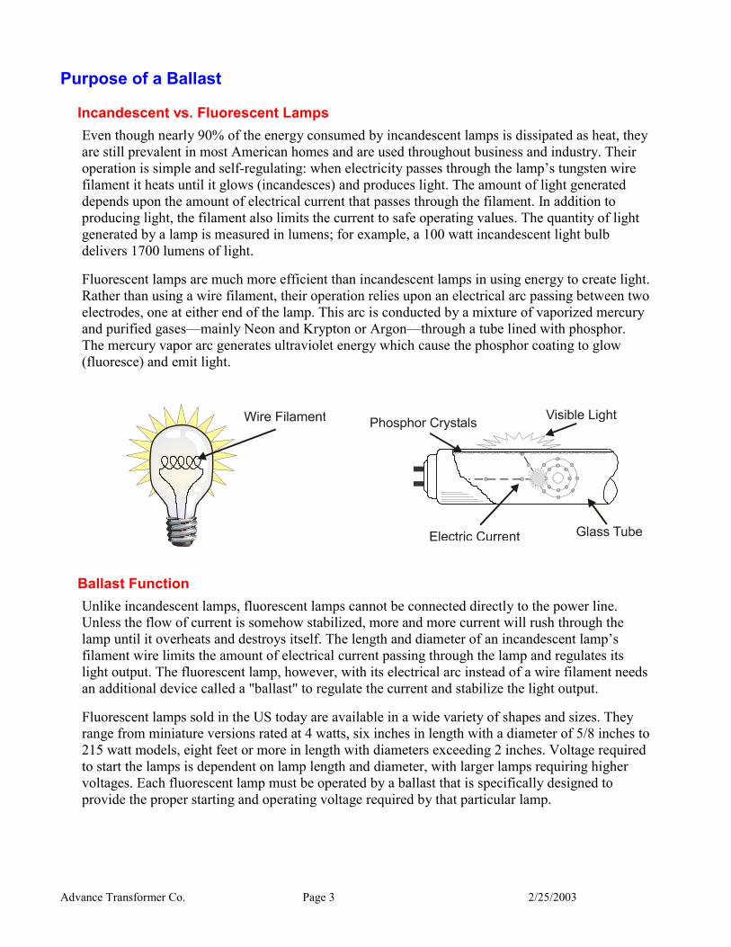
Purpose of a Ballast Incandescent vs. Fluorescent Lamps Even though nearly 90% of the energy consumed by incandescent lamps is dissipated as heat, they are still prevalent in most American homes and are used throughout business and industry. Their operation is simple and self-regulating: when electricity passes through the lamp’s tungsten wire filament it heats until it glows (incandesces) and produces light. The amount of light generated depends upon the amount of electrical current that passes through the filament. In addition to producing light, the filament also limits the current to safe operating values. The quantity of light generated by a lamp is measured in lumens; for example, a 100 watt incandescent light bulb delivers 1700 lumens of light.
Fluorescent lamps are much more efficient than incandescent lamps in using energy to create light. Rather than using a wire filament, their operation relies upon an electrical arc passing between two electrodes, one at either end of the lamp. This arc is conducted by a mixture of vaporized mercury and purified gases—mainly Neon and Krypton or Argon—through a tube lined with phosphor. The mercury vapor arc generates ultraviolet energy which cause the phosphor coating to glow (fluoresce) and emit light.
Ballast Function Unlike incandescent lamps, fluorescent lamps cannot be connected directly to the power line. Unless the flow of current is somehow stabilized, more and more current will rush through the lamp until it overheats and destroys itself. The length and diameter of an incandescent lamp’s filament wire limits the amount of electrical current passing through the lamp and regulates its light output. The fluorescent lamp, however, with its electrical arc instead of a wire filament needs an additional device called a "ballast" to regulate the current and stabilize the light output.
Fluorescent lamps sold in the US today are available in a wide variety of shapes and sizes. They range from miniature versions rated at 4 watts, six inches in length with a diameter of 5/8 inches to 215 watt models, eight feet or more in length with diameters exceeding 2 inches. Voltage required to start the lamps is dependent on lamp length and diameter, with larger lamps requiring higher voltages. Each fluorescent lamp must be operated by a ballast that is specifically designed to provide the proper starting and operating voltage required by that particular lamp.
Advance Transformer Co. Page 4 2/25/2003
In all fluorescent lighting systems, the ballast performs two basic tasks:
1. Provides the proper voltage to establish an arc between the two electrodes.
2. Regulates the electric current flowing through the lamp to stabilize light output.
In many fluorescent lighting systems the ballast also provides a controlled amount of electrical energy to heat lamp electrodes.
To receive peak performance from fluorescent lighting it is essential that the fluorescent lamp ballast match precisely the requirements of the lamp it is designed to operate.
Construction of a Ballast
There are three types of ballasts available for use with fluorescent lamps. These are called Electromagnetic, Hybrid or electronic ballasts.
Electromagnetic Ballasts Because ballasts are essential to fluorescent lamp operation, they have been available for as long as the lamps they start and operate. Throughout most of their history, fluorescent ballasts have been electromagnetic. As a result of their design, these ballasts are also called "core & coil" ballasts.
The primary component of an electromagnetic ballast is a core of stacked steel laminations surrounded by wound coils of insulated copper or aluminum wire. This core & coil design functions both as a voltage transformer and a current limiter (or choke). As heat produced by the ballast’s operation can eventually break down the insulation around the coils and cause failure, the core & coil is "potted" in insulating material such as asphalt to conduct the heat away from the coils. This assembly is usually housed in a steel case.
Another component used in many electromagnetic ballasts is the capacitor. The capacitor allows the ballast to utilize energy from the power line more efficiently. An electromagnetic ballast that is equipped with a capacitor is generally known as a "high power factor" or "power factor corrected" ballast (see section F-6).
Hybrid Ballasts The "hybrid" ballast design combines the starting and operating characteristics of the electromagnetic ballast with the energy efficiencies of electronic circuitry to provide an alternative means of operating rapid start lamps.
The construction of a hybrid ballast is basically the same as an electromagnetic ballast - both have a core & coil , a capacitor and potting. But a hybrid ballast also incorporates electronic circuitry to disconnect the cathode heater windings after the lamp ignites.
The starting method for a hybrid ballast is identical to that of an electromagnetic rapid start ballast. The difference occurs during normal operation when the cathode heaters are disconnected and the energy consumption is reduced by about 3 watts per lamp.
Advance Transformer Co. Page 5 2/25/2003
Electronic Ballasts Like electromagnetic ballasts, electronic ballasts provide the necessary voltage to start lamps and regulate the current through the lamps after ignition. The electronic ballast, however, operates the lamp at a frequency of 20,000 Hz or greater, rather than the 60 Hz operation of electromagnetic and hybrid types. This allows users to take advantage of increased fluorescent lamp efficiencies obtainable at these higher frequencies. This high frequency operation is accomplished through the use of electronic circuitry, which generally results in a more efficient, smaller, lighter and quieter ballast design than the standard electromagnetic ballast.
Operation of a Ballast (Operating Frequency)
The operating frequency of a ballast can be separated into two distinct frequencies: Input and Output Frequency. Input Frequency refers to the power line frequency the ballast is connected to. Output Frequency refers to the frequency at which the ballast operates the lamp.
Input Frequency (Power Line Frequency) Ballasts are usually connected to an AC (alternating current) power line operating at 50 Hz or 60 Hz (Hertz or cycles per second) depending on the local power company (50 Hz in Europe and 60 Hz in North America). Most ballasts are designed for one of these frequencies but not both. Some electronic ballasts, however, can operate on both frequencies. Also, some ballasts are designed to operate on DC (direct current) power, but these would be considered specialty ballasts for applications like bus lighting.
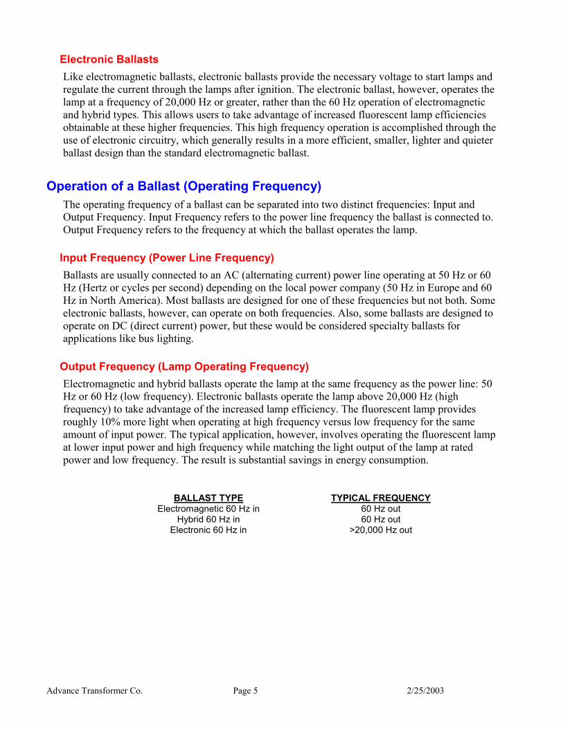
Output Frequency (Lamp Operating Frequency) Electromagnetic and hybrid ballasts operate the lamp at the same frequency as the power line: 50 Hz or 60 Hz (low frequency). Electronic ballasts operate the lamp above 20,000 Hz (high frequency) to take advantage of the increased lamp efficiency. The fluorescent lamp provides roughly 10% more light when operating at high frequency versus low frequency for the same amount of input power. The typical application, however, involves operating the fluorescent lamp at lower input power and high frequency while matching the light output of the lamp at rated power and low frequency. The result is substantial savings in energy consumption.
BALLAST TYPE TYPICAL FREQUENCY
Electromagnetic 60 Hz in 60 Hz out Hybrid 60 Hz in 60 Hz out
Electronic 60 Hz in >20,000 Hz out
Advance Transformer Co. Page 6 2/25/2003
Wiring of a Ballast Ballasts can be connected, or wired, between the input power line and the lamp in a number of configurations. Usually this is determined by the type of lamp that the ballast will operate, as discussed in section E, but there are some exceptions. Multiple lamp ballasts for rapid start or instant start lamps can operate lamps connected in series or parallel depending on the ballast design.
Series or Parallel When lamps are connected in series to a ballast and one lamp fails, or is removed from the fixture, the other lamp(s) connected to that ballast will also not light. When lamps are connected in parallel to a ballast and one lamp fails, or is removed, the other lamp(s) will continue to light.
BALLAST TYPE LAMP TYPE LAMP CONNECTION
Electromagnetic Rapid Start Instant Start Instant Start
Series Series Parallel
Hybrid Rapid Start Series Electronic Rapid Start
Rapid Start Instant Start
Series Parallel Parallel
Wiring Diagrams Ballast wiring diagrams are listed on the ballast label and designate the proper connections between the lamp, ballast and input power to correctly start and operate the lamp. Failure to follow this wiring diagram could result in damage to the lamp, the ballast or both. The integral leads of the ballast are color coded to industry standards for ease of installation and replacement.
Ballast Circuit Types
Three major types of lighting system circuits are in use today for electromagnetic ballasts: Preheat, Slimline Instant Start and Rapid Start. With the introduction of hybrid and electronic ballasts, two new circuits were introduced: Modified Rapid Start and Instant Start of Rapid Start Lamps.
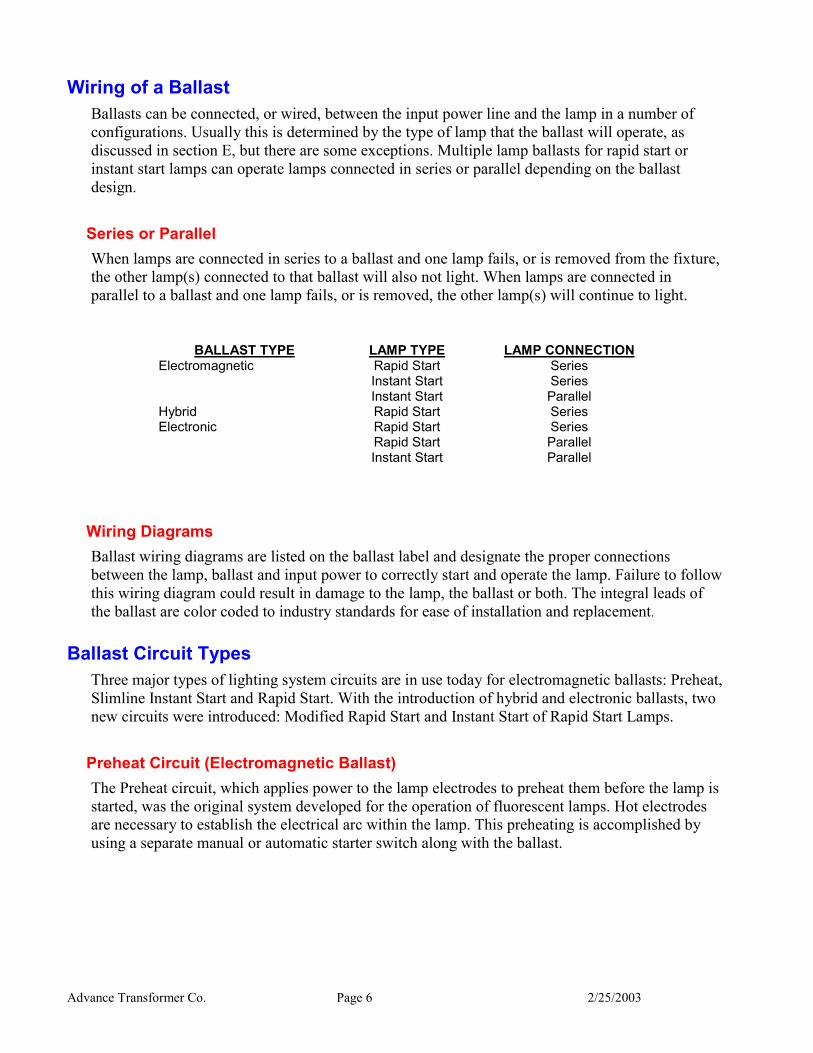
Preheat Circuit (Electromagnetic Ballast) The Preheat circuit, which applies power to the lamp electrodes to preheat them before the lamp is started, was the original system developed for the operation of fluorescent lamps. Hot electrodes are necessary to establish the electrical arc within the lamp. This preheating is accomplished by using a separate manual or automatic starter switch along with the ballast.
Advance Transformer Co. Page 7 2/25/2003
When power is applied, the starter switch is closed and the ballast delivers a controlled amount of current through the electrodes to preheat them. In a few seconds the electrodes attain the proper temperature and the starting switch automatically opens. The opening of the starting switch, which acted as a short circuit across the lamp, leaves the gas in the lamp as the only other path for the current to travel. Because the filaments are hot and the arc is established, the lamp emits light. The Preheat circuit is generally used for low wattage linear and compact lamps (4 to 30 watts). Linear lamps require an external starter while compact lamps have the starter built into the lamp base.
Linear preheat lamps can also be operated on a Trigger Start ballast which heats the electrodes by means of heater windings built into the ballast before the lamps ignite. No external starter is required with this type ballast. The Trigger Start ballast was developed later when the Rapid Start circuit was developed. The wiring of the Trigger Start is the same as the Rapid Start (see section E-3).
Slimline Instant Start (Electromagnetic or Electronic Ballast) The Slimline Instant Start system produces light instantly without the assistance of a starter. To achieve this quick response with no preheating of lamp filaments, the ballast must provide an open circuit voltage to the lamp electrodes about three times the normal lamp operating voltage, to initiate the arc. This high initial voltage requires a larger autotransformer as an integral part of the ballast. A larger current limiting "choke coil" or "reactor" must also be included because of this large difference between the starting and operating voltage of the lamp. This starting method makes the slimline ballast much larger then the preheat ballast.
Two-lamp electromagnetic slimline ballasts are available in two circuit types: Lead Lag and Series Sequence. Two-lamp electronic slimline ballasts are available as Electronic Instant Start.
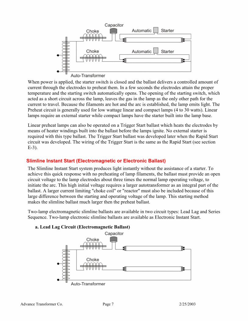
a. Lead Lag Circuit (Electromagnetic Ballast)
Advance Transformer Co. Page 8 2/25/2003
The Lead Lag Slimline Instant Start circuit differs from the Preheat circuit only in the higher starting voltage produced and absence of lamp starters. This ballast, which was the original circuit design for Slimline lamps, also provides the necessary starting voltage to ignite each lamp independently of the other with the lamps wired in parallel. This instant starting and independent lamp operation is what makes the size of the ballast rather large.
A capacitor is added to the ballast circuit in series with one of the lamps in order to improve power factor (see section F-6). Circuits with only a choke in series with the lamp are designated as "Lag" circuits while circuits with a capacitor in series with the lamp are designated as "Lead" circuits. The name "Lead Lag" was developed since there is a capacitor in series with only one of the lamps.
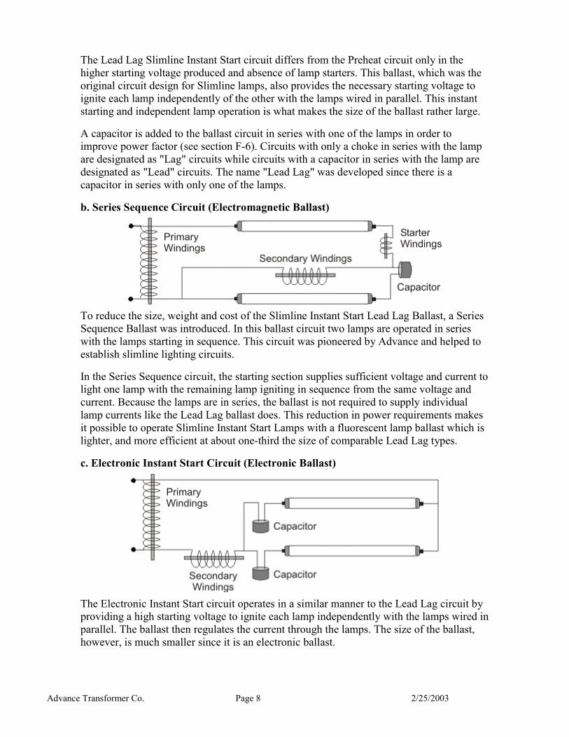
b. Series Sequence Circuit (Electromagnetic Ballast)
To reduce the size, weight and cost of the Slimline Instant Start Lead Lag Ballast, a Series Sequence Ballast was introduced. In this ballast circuit two lamps are operated in series with the lamps starting in sequence. This circuit was pioneered by Advance and helped to establish slimline lighting circuits.
In the Series Sequence circuit, the starting section supplies sufficient voltage and current to light one lamp with the remaining lamp igniting in sequence from the same voltage and current. Because the lamps are in series, the ballast is not required to supply individual lamp currents like the Lead Lag ballast does. This reduction in power requirements makes it possible to operate Slimline Instant Start Lamps with a fluorescent lamp ballast which is lighter, and more efficient at about one-third the size of comparable Lead Lag types.
c. Electronic Instant Start Circuit (Electronic Ballast)
The Electronic Instant Start circuit operates in a similar manner to the Lead Lag circuit by providing a high starting voltage to ignite each lamp independently with the lamps wired in parallel. The ballast then regulates the current through the lamps. The size of the ballast, however, is much smaller since it is an electronic ballast.

Advance Transformer Co. Page 9 2/25/2003
Rapid Start Circuit (Electromagnetic or Electronic Ballast)
Rapid Start lighting system circuits are today’s most popular design and are used for virtually all 4 foot lamps as well as 800 mA HO & 1500mA VHO lamps. The lamp electrodes, or "cathodes," are automatically preheated by means of heater windings built into the fluorescent lamp ballast. This eliminates the need for a separate starting switch, but the fixture must be properly grounded to ensure good starting of the lamps. The lamps must also be positioned within ½ inch (F40T12), ¾ inch (F32T8) or one inch (800 mA HO and 1500 mA VHO) of the fixture for proper starting. Continuous lamp filament heating is provided by the ballast after the lamps are started.
Because of the continuously heated electrodes, less voltage is required for the initial surge to start the lamp than with Slimline Instant Start which allows for a smaller size ballast. Rapid Start Lamps light immediately at low brightness and are fully lighted in about two seconds. The lamps are mostly wired in series, but some parallel electronic ballasts are available.
Modified Rapid Start Circuit (Hybrid Ballast)
Modified Rapid Start circuits start the lamps in the same manner as Rapid Start circuits do, but automatically switch off filament heating after the lamps ignite. Once the fluorescent arc is established, it is no longer necessary to maintain filament heat to sustain the arc. The lamp filament heating is eliminated to save energy. Approximately 3 watts per lamp can be saved by switching off the filament heating.
Advance Transformer Co. Page 10 2/25/2003
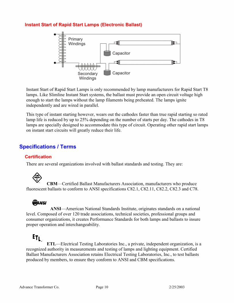
Instant Start of Rapid Start Lamps (Electronic Ballast)
Instant Start of Rapid Start Lamps is only recommended by lamp manufacturers for Rapid Start T8 lamps. Like Slimline Instant Start systems, the ballast must provide an open circuit voltage high enough to start the lamps without the lamp filaments being preheated. The lamps ignite independently and are wired in parallel.
This type of instant starting however, wears out the cathodes faster than true rapid starting so rated lamp life is reduced by up to 25% depending on the number of starts per day. The cathodes in T8 lamps are specially designed to accommodate this type of circuit. Operating other rapid start lamps on instant start circuits will greatly reduce their life.
Specifications / Terms
Certification There are several organizations involved with ballast standards and testing. They are:
CBM—Certified Ballast Manufacturers Association, manufacturers who produce fluorescent ballasts to conform to ANSI specifications C82.1, C82.11, C82.2, C82.3 and C78.
ANSI—American National Standards Institute, originates standards on a national level. Composed of over 120 trade associations, technical societies, professional groups and consumer organizations, it creates Performance Standards for both lamps and ballasts to insure proper operation and interchangeability.
ETL—Electrical Testing Laboratories Inc., a private, independent organization, is a recognized authority in measurements and testing of lamps and lighting equipment. Certified Ballast Manufacturers Association retains Electrical Testing Laboratories, Inc., to test ballasts produced by members, to ensure they conform to ANSI and CBM specifications.
Advance Transformer Co. Page 11 2/25/2003
UL—Underwriters’ Laboratories, Inc., is an independent, not-for-profit organization testing for public safety. Its function is, through study, experiment and tests, to prevent the loss of life and property from the hazards of fire or casualty.
CSA—Canadian Standards Association, is the safety testing authority for ballasts used in Canada.
E—Energy Efficient Ballast, indicates ballast complies with National Energy Conservation Amendments (NAECA) of 1988 to Energy Policy and Conservation Act (EPCA) of 1987. Applies to most popular 4’ and 8’ linear lamps.
CSA-E—Canadian Standards Association Energy Efficient Ballast, indicates ballast complies with Canadian Energy Standards. Applies to most popular 4’ and 8’ linear lamps.
Basic Information In order to choose a ballast for a particular application, there are three pieces of information that must be supplied. These are lamp type, number of lamps the ballast must operate, and input voltage to the lighting system. Once these three criteria are identified, a ballast can be chosen based on the performance characteristics that follow.
Input Watts Input Watts refers to the total watts required to operate both the ballast and lamp together as a system. Ballast watts and lamp watts cannot be added together to provide an input watts figure because most ballasts do not operate the lamps at full wattage. Input watts is the more accurate measurement of system watts since it includes the actual lamp operating wattage.
Different ballast manufacturers, however, may express input watts in different ways, such as ANSI Watts, Open Fixture or Enclosed Fixture. The only repeatable measurement is ANSI Watts, since the test method is standardized for the lighting industry.
Ballast Losses refers to the wattage used by the ballast alone. If only ballast losses are specified, the total input watts equals ballast losses plus lamp wattage. However, this calculation can be misleading as it assumes that the lamps are operated at full wattage.
Advance Transformer Co. Page 12 2/25/2003
Input Voltage Each ballast is designed to operate at the nominal voltage shown on the ballast label. Abnormal deviation from these values will result in damage to either the ballast or lamp or both. It is therefore recommended that the voltage applied to ballasts bearing the following nominal rating be maintained within the respective limits shown:
NOMINAL VOLTAGE APPLIED VOLTAGE LIMIT 120 208 220 240 250 277 347 480
112 - 127 199 - 216 210 - 230 225 - 250 235 - 260 255 - 290 322 - 365 450 - 500
Electronic ballasts may operate over a wider voltage limit of ±10%.
Input Current Input Current is the current drawn by the ballast and lamps and is generally listed for normal operation. For most ballasts, it is the only current that should be specified since it is also the maximum current. Some ballasts, like electromagnetic compact ballasts, specify operating current, starting current, and open circuit current because normal operating current is not the highest current. It is possible that either starting or open circuit current could be higher than operating current. The highest current must be listed because it is critical to the proper sizing of the lighting system circuit, circuit breakers, fuses, etc. Otherwise, nuisance outages could occur.
a. Inrush Current
Ballasts have an input current during initial start-up several times greater than their normal operating current. This current during start-up is referred to as Inrush Current. This current during start-up typically lasts for a very short duration, about ¼ of the 60 Hz cycle. Electronic ballasts generally have higher inrush current than electromagnetic or hybrid ballasts. Nuisance tripping of circuit breakers or fuses could occur if they are not sized to handle the inrush current from the ballast.
b. Fuse Protection
Individual fusing is sometimes considered when many fixtures operate on a single circuit and where it is desirable to isolate an inoperative fixture quickly. This helps in troubleshooting a fixture and avoids a complete circuit outage if a ballast fails shorted. If used, fuses should be of the slow-blow type and should accommodate the inrush current of the ballast. Electronic ballasts generally have higher inrush current then electromagnetic ballasts. This will not be a problem if the correct fuse is specified.
c. Total Harmonic Distortion
Harmonics are currents or voltages which have frequencies that are integer multiples of the fundamental power frequency. Each has a name associated with the multiplying number, i.e., if the fundamental frequency is 60 Hz, then the second harmonic is 120 Hz, the third is 180 Hz, etc.
Advance Transformer Co. Page 13 2/25/2003
Harmonics occur whenever the current or voltage wave shape is distorted, i.e., when the wave shape varies from a pure sine wave. Electric Utilities typically generate a voltage which is very nearly a sine wave. If an end user connects a linear load such as a resistive heater, the resulting current will be a sine wave and no harmonics will be present. If, however, the load is non-linear, drawing short pulses of current within each cycle, the current wave shape will be distorted (non-sinusoidal) and harmonic currents will flow. The total current will be a combination of the fundamental plus each of the harmonics. Total Harmonic Distortion (THD) is the measurement of the magnitude of the input current harmonics compared with the amplitude of the fundamental frequency current.
TYPICAL ELECTRICAL SUPPLY SYSTEM FOR COMMERCIAL BUILDINGS
(4 WIRE, 3 PHASE WYE CONFIGURATION)
NEUTRAL CURRENT = CURRENT ON PHASE A + PHASEB + PHASE C EACH PHASE IS 120 DEGREES OUT OF PHASE WITH RESPECT TO THE OTHERS
Harmonics are important because in three-phase systems, certain harmonic currents can overload neutral conductors. The troublesome harmonics, called "triplens," consist of the 3rd and odd multiples of the 3rd (i.e., 3rd, 9th, 15th, etc.). These harmonics will add rather than cancel in the neutral of a three-phase 4-wire system. Therefore, if the triplen harmonics exceed 33 1/3, more current will flow in the neutral wire than in any of the phase wires, even if the phase currents are perfectly balanced.
Power Factor The Power Factor of a ballast is the measurement of how efficiently it converts the voltage and current supplied from the power source into watts of usable power consumed by the ballast and lamps. Perfect utilization of electrical current would result in a power factor of 100%. Power factor is not an indication of the ballast’s ability to supply light through the lamps.
Power Factor = Input Watts Line Volts x Line Amps
Fluorescent ballasts are designated high power factor, normal (low) power factor, or power factor corrected. High power factor ballasts, which are specified for all commercial lighting applications, are those having a ratio of input watts delivered to the ballast and lamps, compared to the volt-
Advance Transformer Co. Page 14 2/25/2003
amperes supplied, of greater than 90% (.9). High power factor ballasts employ a lower operating current than low power factor ballasts so more fixtures can be installed per branch circuit. Low power factor ballasts require about twice the current needed by high power factor ballasts. Low power factor ballasts create added wiring costs because fewer fixtures are permitted per circuit, and can load branch circuits as well as the circuits of the utility, potentially resulting in penalty charges.
Advantages of High Power Factor Ballasts
3. Avoid possible penalty charges from electric utility.
4. Wiring costs are less because normal power factor ballasts take about twice the line current of high power factor ballasts and may require heavier wire to carry the load.
5. With high power factor ballasts, more fixtures can be installed on each branch circuit.
Ballast Factor Ballast Factor is the measurement of a ballast’s ability to produce light from fluorescent lamps. It is the ratio of light output produced by lamps operating on a commercial ballast versus the light output of the same lamps operating on a 60 Hz laboratory reference ballast specified to ANSI standards for a given lamp type.
Ballast Factor = Commercial ballast light output Laboratory reference ballast (100% light output)
Ballast factor is multiplied by the lumen rating of the lamp, times the number of lamps, to determine the delivered lumens (actual amount of light) from this ballast and lamp system. A ballast may have different ballast factors for different lamps, e.g., an electromagnetic ballast with standard lamps has a B.F. of 95% while the same ballast with energy saving lamps has a B.F. of 88%.
Ballast Efficacy Factor The Ballast Efficacy Factor is a ratio of the ballast factor (the ballast’s ability to produce light) versus the watts input to the ballast. This measurement is generally used to compare the efficiencies of various ballasts with the same lamp.
Ballast Efficacy Factor = Ballast Factor Ballast Watt Input
The higher the ballast efficacy factor, the more efficient the ballast. When ballast efficacy factor is multiplied by the lumen rating of the lamp and the number of lamps, a ratio of lumens per watt is created.
Lumens Per Watt = B.E.F. x (Rated Lamp Lumens) x (Number of Lamps) The higher the lumens per watt, the more efficient the ballast and lamp system. This measurement can be used to compare different types of ballast and lamp systems; for example, F32T8 vs. F40T12 systems.
Advance Transformer Co. Page 15 2/25/2003
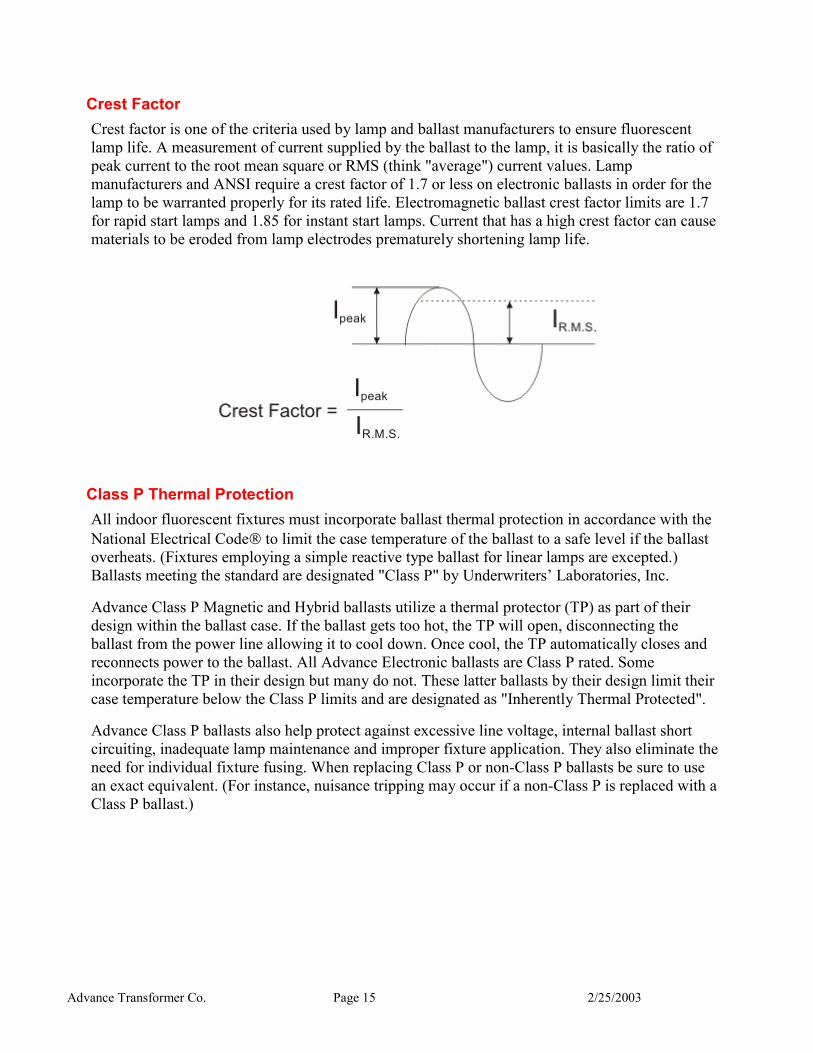
Crest Factor Crest factor is one of the criteria used by lamp and ballast manufacturers to ensure fluorescent lamp life. A measurement of current supplied by the ballast to the lamp, it is basically the ratio of peak current to the root mean square or RMS (think "average") current values. Lamp manufacturers and ANSI require a crest factor of 1.7 or less on electronic ballasts in order for the lamp to be warranted properly for its rated life. Electromagnetic ballast crest factor limits are 1.7 for rapid start lamps and 1.85 for instant start lamps. Current that has a high crest factor can cause materials to be eroded from lamp electrodes prematurely shortening lamp life.
Class P Thermal Protection All indoor fluorescent fixtures must incorporate ballast thermal protection in accordance with the National Electrical Code to limit the case temperature of the ballast to a safe level if the ballast overheats. (Fixtures employing a simple reactive type ballast for linear lamps are excepted.) Ballasts meeting the standard are designated "Class P" by Underwriters’ Laboratories, Inc.
Advance Class P Magnetic and Hybrid ballasts utilize a thermal protector (TP) as part of their design within the ballast case. If the ballast gets too hot, the TP will open, disconnecting the ballast from the power line allowing it to cool down. Once cool, the TP automatically closes and reconnects power to the ballast. All Advance Electronic ballasts are Class P rated. Some incorporate the TP in their design but many do not. These latter ballasts by their design limit their case temperature below the Class P limits and are designated as "Inherently Thermal Protected".
Advance Class P ballasts also help protect against excessive line voltage, internal ballast short circuiting, inadequate lamp maintenance and improper fixture application. They also eliminate the need for individual fixture fusing. When replacing Class P or non-Class P ballasts be sure to use an exact equivalent. (For instance, nuisance tripping may occur if a non-Class P is replaced with a Class P ballast.)
Advance Transformer Co. Page 16 2/25/2003
EMI/RFI (Electromagnetic Interference/Radio Frequency Interference) Radio and TV interference, or static, is caused by the action of the arc at the lamp electrodes which creates a series of radio waves. This energy may interfere with radio reception and the operation of other communications equipment.
Types of interference:
1. Direct radiation from the fluorescent lamp to the antenna circuit.
2. Line feedback from the lamp/ballast through the power line to the radio.
3. Direct radiation from the electric supply line to the antenna circuit.
To correct the first cause, it is recommended that the radio and its antenna circuit be separated at least 10 feet from the fluorescent lamp and the radio provided with a positive ground.
The second and third causes can be corrected in lighting systems that generate objectionable radio interference by additional filtering. Generally this can be accomplished by the addition of an external capacitor-reactor filter. It is also desirable for the radio and fluorescent lamp fixture to be provided with a supply voltage from separate branch circuits.
Electronic ballasts which operate the lamp at high frequency may also affect the operation of infrared, power line carrier and communications equipment. There may be no correction possible for some of these interference problems, short of changing the ballasts to a low frequency type, so care must be taken when specifying a lighting installation.
Ballast Sound The slight hum present in fluorescent lighting installation originates from vibration caused by the inherent magnetic action in the core & coil assembly of the ballasts. There are three possible ways this sound may be amplified:
1. Method of mounting the ballast in the fixture.
2. Loose parts in the fixture.
3. Ceilings, walls, floors and furniture.
The choice of fluorescent lamp ballasts should be made on the basis of selecting the one rated quietest for a specific location. Ballasts are assigned a sound rating, Class A through F, based on the amount of noise produced. Because electronic ballasts lack vibrating parts, and have higher operating frequencies, they generally produce less noise and achieve a lower sound rating.
To make the best selection, the application needs must be considered. It is obvious that consideration of ballast sound is more important in a private office than in a busy store. See chart for assistance in selecting the proper sound rated ballast.

Advance Transformer Co. Page 17 2/25/2003
SOUND RATINGS
FOR INSTALLATION IN: AVERAGE
AMBIENT NOISE LEVEL
SOUND LEVEL RATING*
TV or Radio Station, Library, Reception or Reading Room, Church, School Study Hall 20 - 24 Decibels A
Residence, Quiet Office, Night School Classroom 25 - 30 Decibels B
General Office Area, Commercial Building, Storeroom 31 - 36 Decibels C
Manufacturing Facility, Retail Store, Noisy Office 37 - 42 Decibels D
*These sound ratings are based on measurements of Average Ambient noise levels during conditions of normal occupancy. Audible ballast hum may appear amplified during exceptionally quiet periods and at times when area is unoccupied.
NOTE: In planning a lighting installation, careful consideration must be given to the selection of the ballast, the lighting fixture and the room components in the early planning stages to ensure the quietest lighting installation possible.
Specialty Ballasts
Dimming Ballasts A ballast that can continuously vary the light output of a lamp is called a dimming ballast. A dimming ballast must be connected to a compatible dimmer or controller in order to actually dim the lamp. Some controls are separately wired to the dimming ballast using low voltage leads while others are connected in series with the power leads to the ballast.
Only standard rapid start lamps are recommended for dimming, provided that cathode heating be maintained throughout the dimming range. Energy saving lamps, because of their construction, do not operate correctly at low temperature or low current and therefore will not operate correctly at low light output.
Dimming ballasts can reduce the light output to various levels depending on their design and are used for aesthetic or energy saving reasons. Reducing the light output to create atmosphere would be aesthetic while reducing the light output to use the sunlight shining through the windows would be energy saving. Dimming ballasts are available as electromagnetic or electronic ballasts which are not interchangeable.
Cold Weather Ballasts (800mA HO and 1500mA VHO Lamps) Low temperatures in cold weather applications such as outdoors and walk-in freezers can affect lamp starting and operation. Lumen ratings of fluorescent lamps apply for operation in still air that has a temperature of 25°C (77°F). While many fluorescent lamps and ballasts are designed to give their best performance at 25°C (77°F), they will provide reasonably good light output down to 10°C (50°F) for standard lamps and 16°C (60°F) for energy saving lamps. Further decreases in ambient temperature will result in a measurable reduction of light output.
Such variables as humidity, line voltage, fixture design and variations within the particular design of the lamp and the ballast play an important part in determining the low temperature starting limit. Starting temperature applies to both the ballast and lamp as a system.
Advance Transformer Co. Page 18 2/25/2003
Some standard rapid start and slimline lamps are also rated for -18°C (0°F) when operated on a ballast which provides a higher starting voltage to the lamps. These ballast and lamp combinations are generally used in unheated locations where the ambient temperature remains above -18°C (0°F).
The 800mA HO and 1500mA VHO lamps with their higher bulb wall temperatures are recommended for most efficient cold weather operation at -29°C (-20°F). Even with high output fluorescent lamps, however, satisfactory operation of the lamps depends upon adequate sleeving, jacketing or enclosing of the lamps to permit them to reach recommended operating temperatures. Care must also be exercised in fixture designs for the prevention of overheating of the ballast in summertime operation.
There are Energy Saving versions of the 800mA HO and 1500mA VHO lamps which are only rated for 16°C (60°F). These lamps cannot be used for low temperature applications. Standard lamps must be specified.
Sign Ballasts Sign ballasts are designed for mounting in outdoor signs which provide an enclosure for mounting the ballast. The ballast case, potting material and internal insulation are specifically designed to provide rated life in this type environment. These ballasts will operate in high humidity but cannot be directly exposed to standing water, spray, or drips. Sign ballasts usually operate a multiple number of 800mA HO lamps and list the minimum to maximum amount of total lamp footage that they will operate on their label. Some ballasts are also available for Slimline lamps.
Weatherproof Ballasts Weatherproof ballasts are designed for mounting in outdoor applications exposed to the weather without an additional enclosure. While these ballasts "shed" water, they are not waterproof or "submersible" and cannot be allowed to sit in water. Weatherproof ballasts are available for 800mA HO or 1500mA VHO lamps as one or two lamp ballasts.
Advance Transformer Co. Page 19 2/25/2003
Specialty Applications
High Ambient Temperature All fluorescent light fixtures are tested in an ambient temperature of 25°C (77°F), which theoretically duplicates the temperature in a normal lighting installation. Significantly higher ambient temperatures, however, are sometimes encountered. For instance, in new construction before the air conditioning is turned on, or in industrial plants that are not air conditioned, it is not uncommon to find ambient temperatures as high as 40°C (104°F) to 50°C (122°F) at the light fixture location.
This higher ambient temperature will, of course, greatly affect ballast operating temperatures. How much? In a sample fixture ballast combination a 1°C ambient temperature rise causes a 0.9°C rise in ballast case temperature. Thus, in a 30°C ambient temperature, the ballast case temperature will rise 4.5°C. In a 40°C ambient temperature, the case temperature will rise 13.5°C.
High ambient temperature conditions at the light fixture will affect ballast life and possibly cause the ballast to cycle due to the thermal protector (see sections F-10). Reducing the ballast’s operating temperature is the only option for proper operation (see section J-4). For every 10°C rise in ballast operating temperature, its life is cut in half while every 10°C decrease in operating temperature will double the ballast’s life.
a. Effect of Ceiling Material
Underwriters’ Laboratories, Inc. specifies a pine board material be used to test surface-mounted light fixtures, except in the cases of low density ceiling (acoustical tile) mounting. The majority of ceilings used in construction today are some variation of acoustical tile, all of which has a different rate of heat dissipation. Extensive tests prove that there can be a 10°C variation between a pine board ceiling and various commonly used acoustical ceilings.
UL also calls for a recessed light fixture to be heat tested in a wooden enclosure which represents the wall or ceiling cavity in which the unit is to be installed. Normally, this should present no problem. However, there have been numerous occasions where fiberglass insulation material is placed over the recessed light fixture in a suspended ceiling. Tests indicate there is a minimum of a 10°C rise of the fixture components, including the ballast, when this happens. This temperature rise may cause the ballast to cycle due to the thermal protector (see section F-10).
If fiberglass insulation is used above the light fixture, its removal will greatly reduce the operating temperature of the ballast thereby enhancing its life.
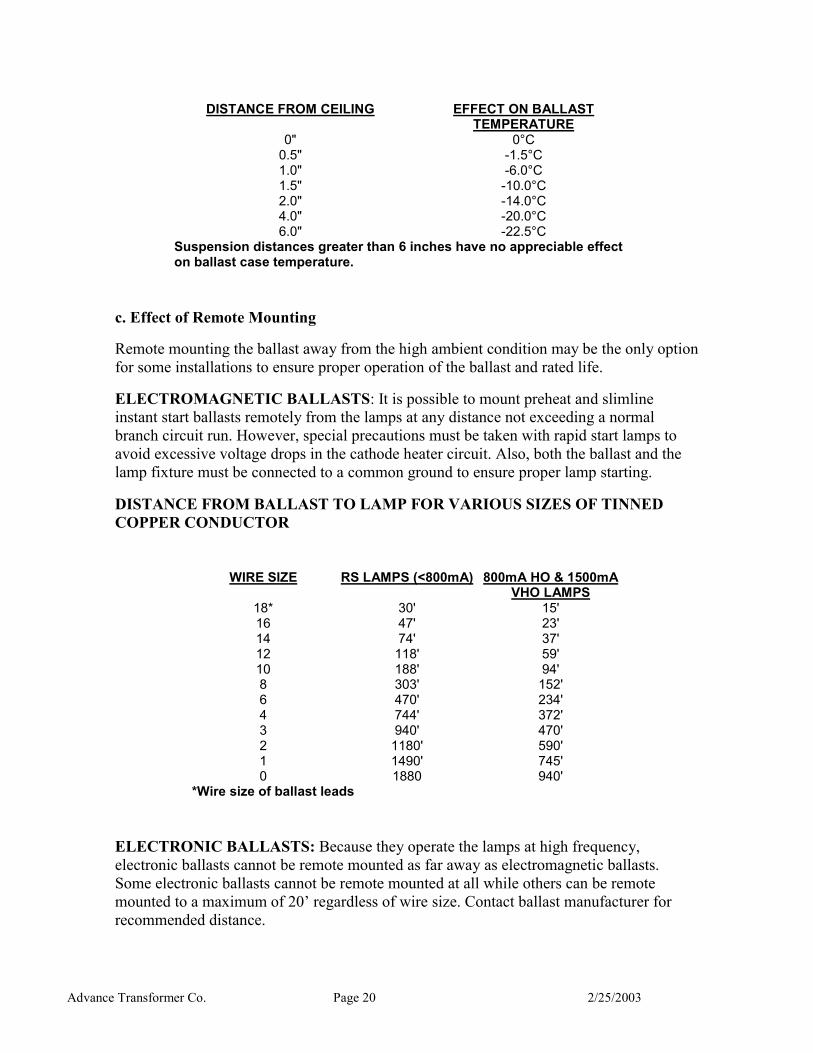
b. Effect of Mounting Distance From Ceiling
Many light fixtures are designed so they can be either surface mounted on the ceiling or suspended. The distance the light fixture is suspended below the ceiling greatly affects the ballast operating temperature. Tests indicate a ballast case temperature variation of 22.5°C between a close-ceiling mounted fixture and one suspended 6 inches from the ceiling (see chart).
Advance Transformer Co. Page 20 2/25/2003
DISTANCE FROM CEILING EFFECT ON BALLAST
TEMPERATURE 0"
0.5" 1.0" 1.5" 2.0" 4.0" 6.0"
0°C -1.5°C -6.0°C -10.0°C -14.0°C -20.0°C -22.5°C
Suspension distances greater than 6 inches have no appreciable effect on ballast case temperature.
c. Effect of Remote Mounting
Remote mounting the ballast away from the high ambient condition may be the only option for some installations to ensure proper operation of the ballast and rated life.
ELECTROMAGNETIC BALLASTS: It is possible to mount preheat and slimline instant start ballasts remotely from the lamps at any distance not exceeding a normal branch circuit run. However, special precautions must be taken with rapid start lamps to avoid excessive voltage drops in the cathode heater circuit. Also, both the ballast and the lamp fixture must be connected to a common ground to ensure proper lamp starting.
DISTANCE FROM BALLAST TO LAMP FOR VARIOUS SIZES OF TINNED COPPER CONDUCTOR
WIRE SIZE RS LAMPS (<800mA) 800mA HO & 1500mA
VHO LAMPS 18* 16 14 12 10 8 6 4 3 2 1 0
30' 47' 74' 118' 188' 303' 470' 744' 940' 1180' 1490' 1880
15' 23' 37' 59' 94' 152' 234' 372' 470' 590' 745' 940'
*Wire size of ballast leads
ELECTRONIC BALLASTS: Because they operate the lamps at high frequency, electronic ballasts cannot be remote mounted as far away as electromagnetic ballasts. Some electronic ballasts cannot be remote mounted at all while others can be remote mounted to a maximum of 20’ regardless of wire size. Contact ballast manufacturer for recommended distance.

Advance Transformer Co. Page 21 2/25/2003
Dual Switching Dual switching refers to producing two different light levels from the same fixture. This is normally accomplished by supplying two ballasts per fixture and two separate light switches to control the light level. There are some electronic ballasts available that can accomplish this with one switch.
a. Tandem Wiring
The number of ballasts required for an installation can be reduced if some of the ballasts are tandem wired between fixtures. Tandem wiring occurs when one ballast operates lamps located in different fixtures. Most electromagnetic ballasts can also be tandem wired per the above table on remote mounting. On these ballasts there is also the requirement to remote a particular lamp; such as, remote the lamp connected to the Red & Yellow leads on a two lamp rapid start ballast. Some electronic ballasts cannot be tandem wired at all while others can be tandem wired to a maximum of 20’. Similar restrictions on which lamp to remote also apply to rapid start electronic ballasts. Consult ballast manufacturer for recommended distance.
Ballast Life
A fluorescent lamp ballast, like other electrical equipment, generates heat during normal operation. Underwriters’ Laboratories, Inc. stipulates that the temperature limitation of a ballast using Class A insulation in normal operation should have a maximum ballast coil temperature of 105°C (221°F) and a maximum ballast case temperature of 90°C (194°F) at its hottest spot. Electromagnetic ballast life will be reduced if it is operated at temperatures above these limits. Electronic ballast life will be reduced if the case temperature exceeds 75°C (167°F). Possible causes for an increase in ballast temperature include ambient temperature, ceiling material, distance of fixture from ceiling as described above. Ballast temperature can also be affected by ventilation, supply voltage, fixture design, light output and other factors.
Ventilation Where more than one ballast is installed in an enclosure, the ballasts should be positioned far enough apart to allow for the combined heating effects of the ballasts under normal operation. To assist in limiting the temperature rise of ballasts, the following procedures are recommended:
1. Mount ballast with maximum number of sides in direct contact with metal channel of fixture. Radiators are an excellent means of dissipating heat.
2. Provide fixture ventilation.
3. Paint the unpainted fixture channels with a nonmetallic finish to increase radiation.
4. Place the ballast in a cooler location outside the fixture (remote mounting).
5. Place fixture to attain maximum dissipation of heat by conduction, convection or radiation.
Advance Transformer Co. Page 22 2/25/2003
Effect of Voltage A ballast is tested in a light fixture at rated voltages, e.g., 120 V or 277 V. However, voltage variations can exist in any installation. Voltages as high as 127 V to 130 V operating a ballast rated at 120 V are possible. In new construction, the voltage can become excessive until the electrical system is fully loaded. Lighting is usually installed before the other heavy electrical equipment whose increased load will reduce the voltage.
The ballast industry rates ballasts for + 5% / - 7.5% voltage variation for electromagnetic ballasts and ±10% for electronic ballasts. This, however, pertains only to the electrical characteristics of the ballast and not its thermal characteristics. As voltage above nominal is applied, the ballast operating temperature increases. Test results for a 120 V ballast fixture combination shows for every one volt increase, the ballast case temperature increases approximately 0.8°C. Considering that for every 10°C temperature increase ballast life will be cut in half, excessive voltage increase will significantly decrease the life of a ballast.
Fixture Design Today, lighting fixture designs allow a fixture to be installed as a bare lamp (without shielding) or totally enclosed (100% shielding). The methods of shielding the lamps in a light fixture are many, varied and too numerous to evaluate here. Tests taken at the extremes, e.g., the difference in ballast operating temperatures in a surface mount bare lamp fixture and a surface mount wrap-around fixture can run as high as 14.5°C. In a louvered light fixture, the ballast case temperature runs between these two extremes. As a result one can expect shorter ballast life in 100% shielded fixtures versus those that are more open.
Effects of Light Output and Other Factors Ballast tests indicate there can be a 4°C variation in the case temperature of a Certified Ballast (CBM) which provides 95% light output versus a CBM ballast which provides 100% light output. Ballast material variations can also result in slight ballast temperature variations no matter how rigidly they are controlled. Other uncontrollable variations which can affect ballast temperatures include lamp tolerances, ballast case contact with the light fixture, and thickness of the fixture metal.
Advance Transformer Co. Page 23 2/25/2003
Troubleshooting
Troubleshooting Fluorescent Applications The following equipment is recommended for testing fluorescent fixtures:
1. True RMS Voltmeter with 0-300-1000 Volts AC ranges
2. Ammeter (Clamp-on type acceptable) with 0-10 Amperes AC ranges
3. or Multi-meter (with voltage and current ratings as shown above)
4. Frequency: 60Hz for Electromagnetic, Above 20KHz for Electronic
Note: Voltage and current measurements present the possibility of exposure to hazardous voltages and should be performed only by qualified personnel. Ballasts, starters, capacitors and fixtures must be grounded in accordance with the National Electric Code (NEC®). In the case of fluorescent ballasts, the case must be grounded either to the fluorescent fixture or, if remote mounted, by other means such as a wire from ballast case to ground. Without proper fixture and ballast grounding, a shock hazard may exist due to the fluorescent fixture becoming energized by an internal ballast failure. In addition, all ballasts have normal current leakage. When the ballast is properly grounded, this leakage current is not a hazard. Any work performed on the lighting system including inspection, troubleshooting and maintenance, should be done with the fixture properly de-energized and the circuit locked and tagged according to Occupational Safety and Health Act (OSHA) requirements.
Inoperative Fixture Often when a fixture becomes inoperative, the cause is not attributable to the ballast. It is therefore important to examine all components of the fixture before removing the ballast for replacement. The following procedure is recommended:
1. Change or check all lamps to ensure satisfactory operation.
2. As lamps are removed, examine all sockets to ensure proper and positive contact with lamp pins.
3. If starters are used, each starter should be checked and replaced wherever necessary.
4. Examine all connections within the fixture to ensure their conformance with the wiring instructions appearing on the ballast.
5. Examine and test ballast.
Advance Transformer Co. Page 24 2/25/2003
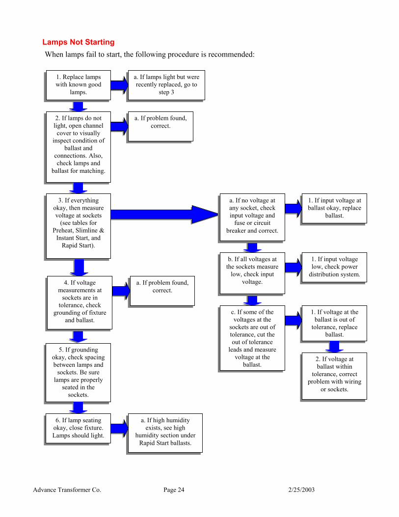
Lamps Not Starting When lamps fail to start, the following procedure is recommended:
a. If lamps light but were recently replaced, go to
step 3
a. If problem found, correct.
1. Replace lamps with known good
lamps.
2. If lamps do not light, open channel cover to visually
inspect condition of ballast and
connections. Also, check lamps and
ballast for matching.
1. If input voltage at ballast okay, replace
ballast.
1. If input voltage low, check power
distribution system.
1. If voltage at the ballast is out of
tolerance, replace ballast.
3. If everything okay, then measure voltage at sockets
(see tables for Preheat, Slimline &
Instant Start, and Rapid Start).
b. If all voltages at
the sockets measure low, check input
voltage.
c. If some of the voltages at the
sockets are out of tolerance, cut the out of tolerance
leads and measure voltage at the
ballast.2. If voltage at ballast within
tolerance, correct problem with wiring
or sockets.
a. If problem found, correct.
a. If no voltage at any socket, check input voltage and
fuse or circuit breaker and correct.
5. If grounding okay, check spacing between lamps and
sockets. Be sure lamps are properly
seated in the sockets.
a. If high humidity exists, see high
humidity section under Rapid Start ballasts.
6. If lamp seating okay, close fixture. Lamps should light.
4. If voltage measurements at
sockets are in tolerance, check
grounding of fixture and ballast.
Advance Transformer Co. Page 25 2/25/2003
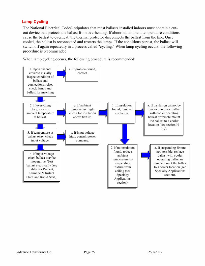
Lamp Cycling The National Electrical Code® stipulates that most ballasts installed indoors must contain a cut-out device that protects the ballast from overheating. If abnormal ambient temperature conditions cause the ballast to overheat, the thermal protector disconnects the ballast from the line. Once cooled, the ballast is reconnected and restarts the lamps. If the conditions persist, the ballast will switch off again repeatedly in a process called "cycling." When lamp cycling occurs, the following procedure is recommended
When lamp cycling occurs, the following procedure is recommended:
a. If problem found, correct.
1. Open channel cover to visually
inspect condition of ballast and
connections. Also, check lamps and
ballast for matching
a. If ambient temperature high,
check for insulation above fixture.
a. If insulation cannot be removed, replace ballast
with cooler operating ballast or remote mount the ballast to a cooler
location (see section H-1-c).
a. If suspending fixture not possible, replace ballast with cooler operating ballast or
remote mount the ballast to a cooler location (see Specialty Applications
section).
a. If input voltage high, consult power
company.
2. If everything okay, measure
ambient temperature at ballast.
3. If temperature at ballast okay, check
input voltage.
4. If input voltage okay, ballast may be
inoperative. Test ballast electrically (see
tables for Preheat, Slimline & Instant
Start, and Rapid Start).
1. If insulation found, remove
insulation.
2. If no insulation found, reduce
ambient temperature by
suspending fixture from ceiling (see Specialty
Applications section).
Advance Transformer Co. Page 26 2/25/2003
Lamp "SWIRLING" Another problem that may occur is a process known as swirling or spiraling, where light does indeed appear to swirl or spiral inside the tube. This is normal for some lamps when first lighted and in these cases, the problem will correct itself after a few hours of operation.
1. This problem may also be caused, by cold temperatures. In this case, the lamps may need to be jacketed or otherwise shielded from the cold drafts. Also, check that the lamps are rated for the actual temperature measured.
2. This problem may also be caused by low input voltage, check and correct.
3. Next, check for ballast and lamp compatibility and replace the wrong component.
4. Replace lamp with known good lamp. If condition still exists, change ballast.
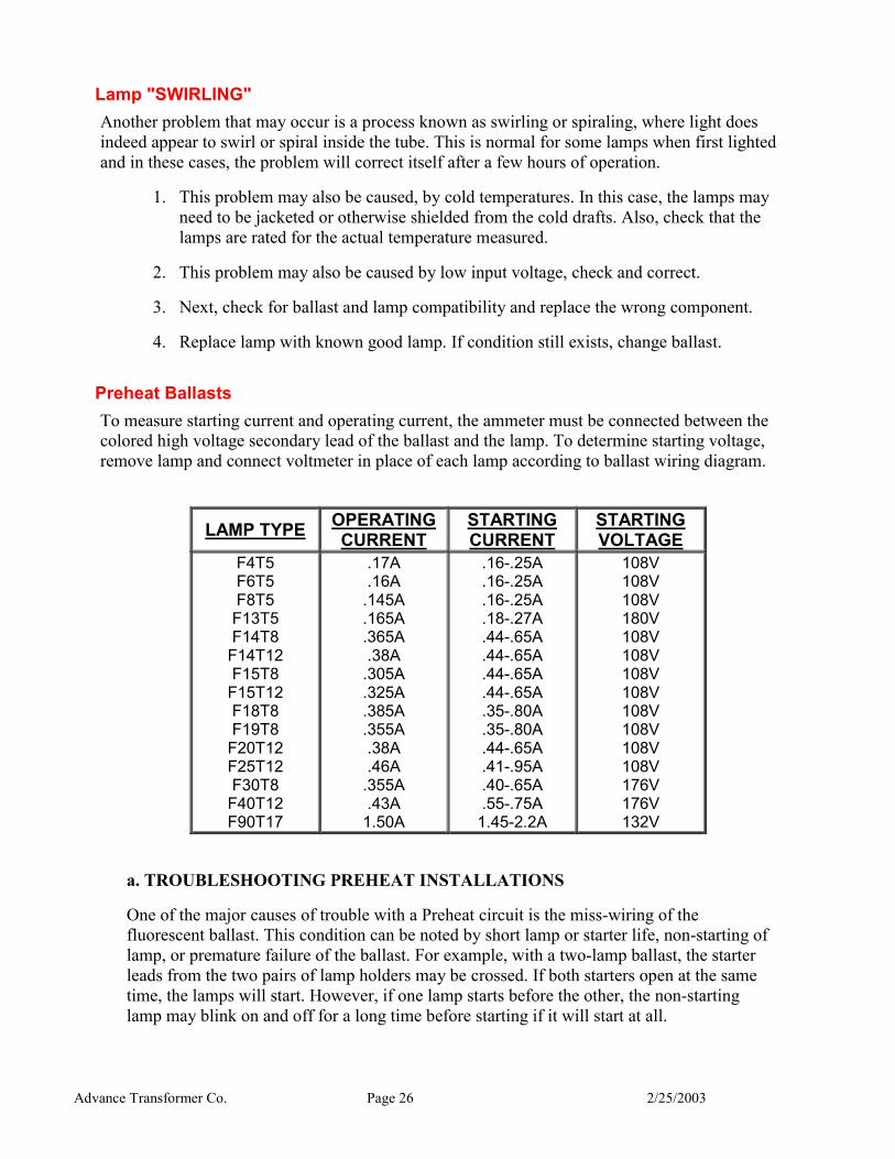
Preheat Ballasts To measure starting current and operating current, the ammeter must be connected between the colored high voltage secondary lead of the ballast and the lamp. To determine starting voltage, remove lamp and connect voltmeter in place of each lamp according to ballast wiring diagram.
LAMP TYPE OPERATING CURRENT
STARTING CURRENT
STARTING VOLTAGE
F4T5 F6T5 F8T5 F13T5 F14T8
F14T12 F15T8
F15T12 F18T8 F19T8
F20T12 F25T12 F30T8
F40T12 F90T17
.17A
.16A .145A .165A .365A .38A
.305A
.325A
.385A
.355A .38A .46A
.355A .43A
1.50A
.16-.25A
.16-.25A
.16-.25A
.18-.27A
.44-.65A
.44-.65A
.44-.65A
.44-.65A
.35-.80A
.35-.80A
.44-.65A
.41-.95A
.40-.65A
.55-.75A 1.45-2.2A
108V 108V 108V 180V 108V 108V 108V 108V 108V 108V 108V 108V 176V 176V 132V
a. TROUBLESHOOTING PREHEAT INSTALLATIONS
One of the major causes of trouble with a Preheat circuit is the miss-wiring of the fluorescent ballast. This condition can be noted by short lamp or starter life, non-starting of lamp, or premature failure of the ballast. For example, with a two-lamp ballast, the starter leads from the two pairs of lamp holders may be crossed. If both starters open at the same time, the lamps will start. However, if one lamp starts before the other, the non-starting lamp may blink on and off for a long time before starting if it will start at all.
Advance Transformer Co. Page 27 2/25/2003
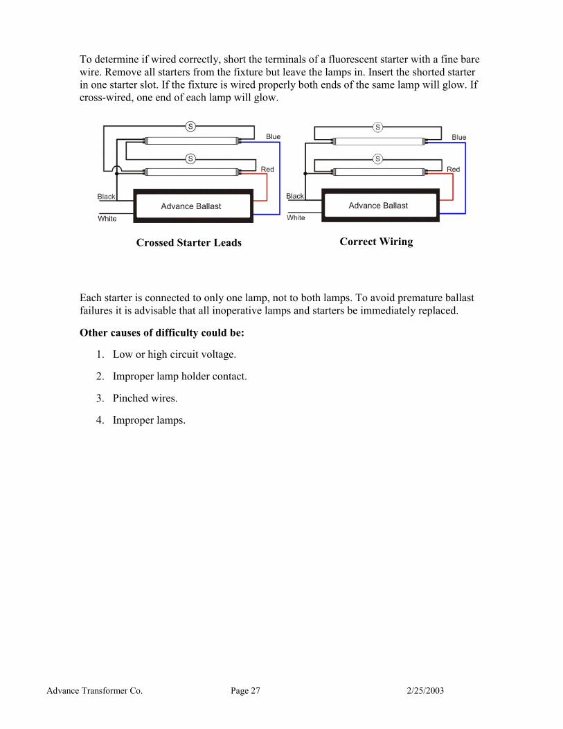
To determine if wired correctly, short the terminals of a fluorescent starter with a fine bare wire. Remove all starters from the fixture but leave the lamps in. Insert the shorted starter in one starter slot. If the fixture is wired properly both ends of the same lamp will glow. If cross-wired, one end of each lamp will glow.
Crossed Starter Leads
Correct Wiring
Each starter is connected to only one lamp, not to both lamps. To avoid premature ballast failures it is advisable that all inoperative lamps and starters be immediately replaced.
Other causes of difficulty could be:
1. Low or high circuit voltage.
2. Improper lamp holder contact.
3. Pinched wires.
4. Improper lamps.
Advance Transformer Co. Page 28 2/25/2003
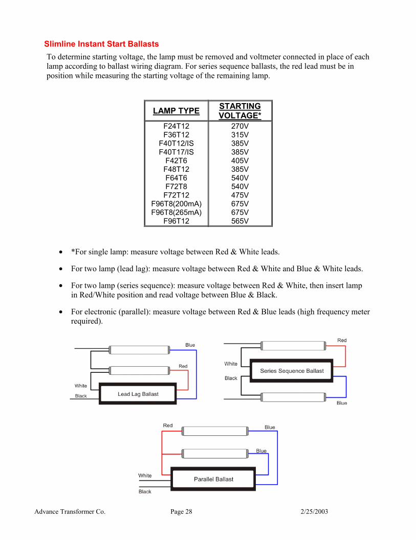
Slimline Instant Start Ballasts To determine starting voltage, the lamp must be removed and voltmeter connected in place of each lamp according to ballast wiring diagram. For series sequence ballasts, the red lead must be in position while measuring the starting voltage of the remaining lamp.
LAMP TYPE STARTING VOLTAGE*
F24T12 F36T12
F40T12/IS F40T17/IS
F42T6 F48T12 F64T6 F72T8 F72T12
F96T8(200mA)F96T8(265mA)
F96T12
270V 315V 385V 385V 405V 385V 540V 540V 475V 675V 675V 565V
• *For single lamp: measure voltage between Red & White leads.
• For two lamp (lead lag): measure voltage between Red & White and Blue & White leads.
• For two lamp (series sequence): measure voltage between Red & White, then insert lamp in Red/White position and read voltage between Blue & Black.
• For electronic (parallel): measure voltage between Red & Blue leads (high frequency meter required).
Advance Transformer Co. Page 29 2/25/2003
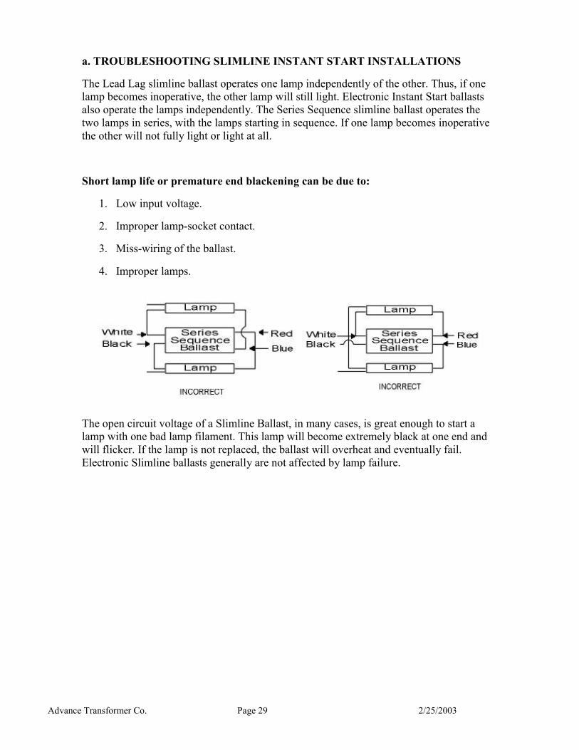
a. TROUBLESHOOTING SLIMLINE INSTANT START INSTALLATIONS
The Lead Lag slimline ballast operates one lamp independently of the other. Thus, if one lamp becomes inoperative, the other lamp will still light. Electronic Instant Start ballasts also operate the lamps independently. The Series Sequence slimline ballast operates the two lamps in series, with the lamps starting in sequence. If one lamp becomes inoperative the other will not fully light or light at all.
Short lamp life or premature end blackening can be due to:
1. Low input voltage.
2. Improper lamp-socket contact.
3. Miss-wiring of the ballast.
4. Improper lamps.
The open circuit voltage of a Slimline Ballast, in many cases, is great enough to start a lamp with one bad lamp filament. This lamp will become extremely black at one end and will flicker. If the lamp is not replaced, the ballast will overheat and eventually fail. Electronic Slimline ballasts generally are not affected by lamp failure.
Advance Transformer Co. Page 30 2/25/2003
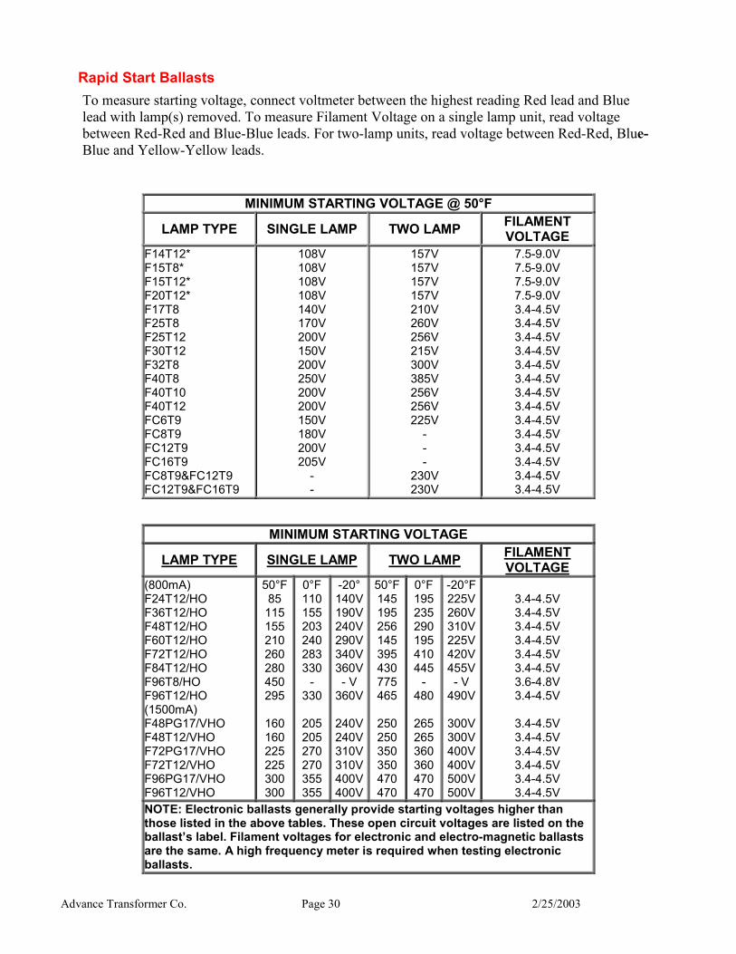
Rapid Start Ballasts To measure starting voltage, connect voltmeter between the highest reading Red lead and Blue lead with lamp(s) removed. To measure Filament Voltage on a single lamp unit, read voltage between Red-Red and Blue-Blue leads. For two-lamp units, read voltage between Red-Red, Blue-Blue and Yellow-Yellow leads.
MINIMUM STARTING VOLTAGE @ 50°F
LAMP TYPE SINGLE LAMP TWO LAMP FILAMENT VOLTAGE
F14T12* F15T8* F15T12* F20T12* F17T8 F25T8 F25T12 F30T12 F32T8 F40T8 F40T10 F40T12 FC6T9 FC8T9 FC12T9 FC16T9 FC8T9&FC12T9 FC12T9&FC16T9
108V 108V 108V 108V 140V 170V 200V 150V 200V 250V 200V 200V 150V 180V 200V 205V
- -
157V 157V 157V 157V 210V 260V 256V 215V 300V 385V 256V 256V 225V
- - -
230V 230V
7.5-9.0V 7.5-9.0V 7.5-9.0V 7.5-9.0V 3.4-4.5V 3.4-4.5V 3.4-4.5V 3.4-4.5V 3.4-4.5V 3.4-4.5V 3.4-4.5V 3.4-4.5V 3.4-4.5V 3.4-4.5V 3.4-4.5V 3.4-4.5V 3.4-4.5V 3.4-4.5V
MINIMUM STARTING VOLTAGE
LAMP TYPE SINGLE LAMP TWO LAMP FILAMENT VOLTAGE
(800mA) F24T12/HO F36T12/HO F48T12/HO F60T12/HO F72T12/HO F84T12/HO F96T8/HO F96T12/HO (1500mA) F48PG17/VHO F48T12/VHO F72PG17/VHO F72T12/VHO F96PG17/VHO F96T12/VHO
50°F 85 115 155 210 260 280 450 295
160 160 225 225 300 300
0°F110155203240283330
- 330
205205270270355355
-20°140V190V240V290V340V360V- V
360V
240V240V310V310V400V400V
50°F145195256145395430775465
250250350350470470
0°F195235290195410445
- 480
265265360360470470
-20°F225V260V310V225V420V455V- V
490V
300V300V400V400V500V500V
3.4-4.5V 3.4-4.5V 3.4-4.5V 3.4-4.5V 3.4-4.5V 3.4-4.5V 3.6-4.8V 3.4-4.5V
3.4-4.5V 3.4-4.5V 3.4-4.5V 3.4-4.5V 3.4-4.5V 3.4-4.5V
NOTE: Electronic ballasts generally provide starting voltages higher than those listed in the above tables. These open circuit voltages are listed on the ballast’s label. Filament voltages for electronic and electro-magnetic ballasts are the same. A high frequency meter is required when testing electronic ballasts.
Advance Transformer Co. Page 31 2/25/2003
a. TROUBLESHOOTING RAPID START INSTALLATIONS
The Rapid Start lamp operates on the principle of utilizing a starting voltage which is insufficient to start the lamps while the cathodes are cold but is sufficient to start the lamps when the cathodes are properly heated. This voltage range between starting cold and starting hot is a very narrow band of voltage which must be closely controlled by the ballast in order to prevent either failure of the lamps to start or instant starting of the lamps with cold cathodes which is detrimental to the lamps. In order to stay within this range of voltage, it is necessary to excite the gas within the lamps by means of an external voltage applied between the lamp and the reflector or channel (the starting aid). In order to act effectively, the fixture must be connected to ground and the white lead of ballast connected to ground lead (neutral) of the power line. Thus it is stated on the label of Rapid Start ballasts "Mount lamps within ½ inch (3/4 inch or 1 inch) of grounded metal reflector." Fluorescent fixtures are designed to provide the proper lamp-to-reflector distance.
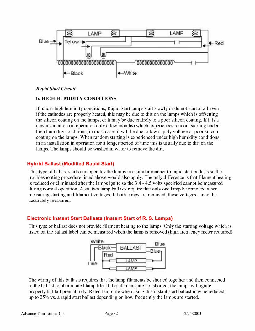
The majority of new fluorescent installations today use ballasts of the Rapid Start design. Refer to the rapid start circuit below: Blue-Blue, Yellow-Yellow and Red-Red leads are the built-in filament windings which supply a voltage of 3.4 to 4.5 volts to the lamp cathodes. If the cathodes are not properly heated, premature lamp end blackening will result. The lack of heating could be due to:
1. Improper seating of the lamp within the socket.
2. Broken sockets.
3. Broken lamp pins.
4. Too great of socket spacing.
5. Damaged lamp cathode(s).
6. Ballast lead wire not properly connected to socket.
7. Low input voltage.
8. Inadequate ballast filament voltage.
9. Improper wiring.
To determine if there is adequate voltage at the lamp cathodes, measure the voltage at the socket terminals. The voltage at the sockets should read between 3.4 - 4.5 volts. If there is adequate voltage, the lamp end blackening can be due to conditions 1, 2, 3, 4 or 5. If the voltage is not adequate it can be due to one or more of conditions 6, 7, 8 or 9.
If random starting of Rapid Start lamps is experienced, be sure the fixture is properly grounded. As previously stated, for completely reliable starting in Rapid Start circuits it is necessary to have a starting aid. The starting aid should be an electrically grounded metal strip at least 1 inch wide and extending the full length of the lamp (usually the fixture). The lamp should be within ½ inch of the grounded strip for 40 watt lamps and smaller, (3/4 inch for T8 lamps) and 1 inch for higher output lamps.
Advance Transformer Co. Page 32 2/25/2003
Rapid Start Circuit
b. HIGH HUMIDITY CONDITIONS
If, under high humidity conditions, Rapid Start lamps start slowly or do not start at all even if the cathodes are properly heated, this may be due to dirt on the lamps which is offsetting the silicon coating on the lamps, or it may be due entirely to a poor silicon coating. If it is a new installation (in operation only a few months) which experiences random starting under high humidity conditions, in most cases it will be due to low supply voltage or poor silicon coating on the lamps. When random starting is experienced under high humidity conditions in an installation in operation for a longer period of time this is usually due to dirt on the lamps. The lamps should be washed in water to remove the dirt.
Hybrid Ballast (Modified Rapid Start) This type of ballast starts and operates the lamps in a similar manner to rapid start ballasts so the troubleshooting procedure listed above would also apply. The only difference is that filament heating is reduced or eliminated after the lamps ignite so the 3.4 - 4.5 volts specified cannot be measured during normal operation. Also, two lamp ballasts require that only one lamp be removed when measuring starting and filament voltages. If both lamps are removed, these voltages cannot be accurately measured.
Electronic Instant Start Ballasts (Instant Start of R. S. Lamps) This type of ballast does not provide filament heating to the lamps. Only the starting voltage which is listed on the ballast label can be measured when the lamp is removed (high frequency meter required).
The wiring of this ballasts requires that the lamp filaments be shorted together and then connected to the ballast to obtain rated lamp life. If the filaments are not shorted, the lamps will ignite properly but fail prematurely. Rated lamp life when using this instant start ballast may be reduced up to 25% vs. a rapid start ballast depending on how frequently the lamps are started.