flir boson® ffc/nuc control application doc - netx
TRANSCRIPT
FLIR Boson® FFC/NUC Control Appl icat ion Doc
EAR99 - The information contained herein does not contain technology as defined by EAR,
15 CFR 772, is publicly available and therefore not subject to EAR
Official Publication Date: 9/21/18 Official Expiration Date: Until next release
FLIR Boson® FFC/NUC Control Appl icat ion Doc
EAR99 - The information contained herein does not contain technology as defined by EAR,
15 CFR 772, is publicly available and therefore not subject to EAR
1 Document 1.1 Revision History
Version Date Comments
100 1/22/2018 Initial Release
110 6/26/2018 -Clarified section 2.2, Serial Query -Renamed App note -Removed section numbers from SDK commands in section 2
120 9/21/2018 -Added information about how to operate the camera in manual FFC mode -Clarified wording in some sections -Changed “Scope” section into an “Intro” section, and added more background information -Updated proprietary statement/export control footer
1.2 Reference Documents Ref Number Document Number Description
1 102-2013-43 Boson datasheet
2 102-2013-44 Boson Software IDD
1.3 Intro
This application note describes the appropriate way to control the FLIR Boson® LWIR
camera while in External or Manual Flat Field Correction (“FFC) mode. The information contained within this document also applies to the Automotive Development Kit (ADK). The FFC is one of multiple correction maps that helps to optimize image quality for all LWIR thermal cameras. Changing the FFC mode from Auto-mode will allow a user to control when the FFC occurs and whether to use the internal shutter or a customer-furnished, external shutter source. Please Note: Boson does have signal processing algorithms to help improve image quality between FFC events (known as SSN), however this should not be relied upon as a method to replace the Shutter/FFC. Regular FFCs are required for Boson to meet its sensitivity specifications. Often customers operate the Boson in ‘Auto FFC’ mode, however this may not be acceptable for some applications. During FFC, the video output will be frozen for approximately 0.5 seconds and this process may occur at any time depending on the temperature and elapsed operating time of the camera. Therefore, when analytics are involved in a system, it is generally recommended to operate the camera in manual mode. This allows the analytics software to accommodate for an FFC at known time rather than become interrupted unexpectedly. One such application that may use Manual mode is the automotive
FLIR Boson® FFC/NUC Control Appl icat ion Doc
EAR99 - The information contained herein does not contain technology as defined by EAR,
15 CFR 772, is publicly available and therefore not subject to EAR
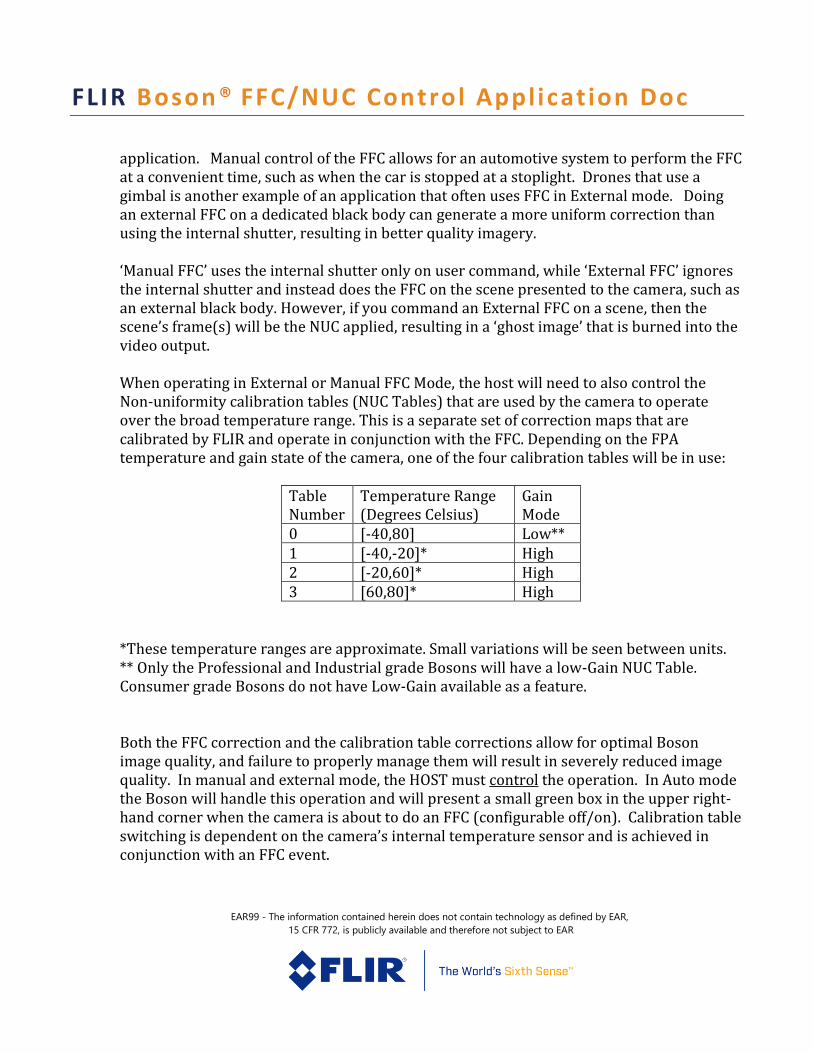
application. Manual control of the FFC allows for an automotive system to perform the FFC at a convenient time, such as when the car is stopped at a stoplight. Drones that use a gimbal is another example of an application that often uses FFC in External mode. Doing an external FFC on a dedicated black body can generate a more uniform correction than using the internal shutter, resulting in better quality imagery. ‘Manual FFC’ uses the internal shutter only on user command, while ‘External FFC’ ignores the internal shutter and instead does the FFC on the scene presented to the camera, such as an external black body. However, if you command an External FFC on a scene, then the scene’s frame(s) will be the NUC applied, resulting in a ‘ghost image’ that is burned into the video output. When operating in External or Manual FFC Mode, the host will need to also control the Non-uniformity calibration tables (NUC Tables) that are used by the camera to operate over the broad temperature range. This is a separate set of correction maps that are calibrated by FLIR and operate in conjunction with the FFC. Depending on the FPA temperature and gain state of the camera, one of the four calibration tables will be in use:
Table Number
Temperature Range (Degrees Celsius)
Gain Mode
0 [-40,80] Low** 1 [-40,-20]* High 2 [-20,60]* High 3 [60,80]* High
*These temperature ranges are approximate. Small variations will be seen between units. ** Only the Professional and Industrial grade Bosons will have a low-Gain NUC Table. Consumer grade Bosons do not have Low-Gain available as a feature. Both the FFC correction and the calibration table corrections allow for optimal Boson image quality, and failure to properly manage them will result in severely reduced image quality. In manual and external mode, the HOST must control the operation. In Auto mode the Boson will handle this operation and will present a small green box in the upper right-hand corner when the camera is about to do an FFC (configurable off/on). Calibration table switching is dependent on the camera’s internal temperature sensor and is achieved in conjunction with an FFC event.
FLIR Boson® FFC/NUC Control Appl icat ion Doc
EAR99 - The information contained herein does not contain technology as defined by EAR,
15 CFR 772, is publicly available and therefore not subject to EAR
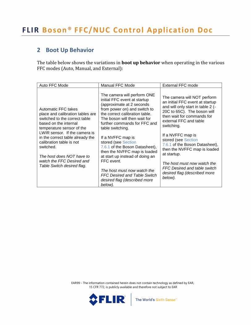
2 Boot Up Behavior The table below shows the variations in boot up behavior when operating in the various FFC modes (Auto, Manual, and External):
Auto FFC Mode Manual FFC Mode External FFC mode
Automatic FFC takes place and calibration tables are switched to the correct table based on the internal temperature sensor of the LWIR sensor. If the camera is in the correct table already the calibration table is not switched. The host does NOT have to watch the FFC Desired and Table Switch desired flag.
The camera will perform ONE initial FFC event at startup (approximate at 2 seconds from power on) and switch to the correct calibration table. The boson will then wait for further commands for FFC and table switching. If a NVFFC map is stored (see Section 7.6.1 of the Boson Datasheet), then the NVFFC map is loaded at start up instead of doing an FFC event. The host must now watch the FFC Desired and Table Switch desired flag (described more below).
The camera will NOT perform an initial FFC event at startup and will only start in table 2 (-20C to 65C). The boson will then wait for commands for external FFC and table switching. If a NVFFC map is stored (see Section 7.6.1 of the Boson Datasheet), then the NVFFC map is loaded at startup. The host must now watch the FFC Desired and table switch desired flag (described more below).
FLIR Boson® FFC/NUC Control Appl icat ion Doc
EAR99 - The information contained herein does not contain technology as defined by EAR,
15 CFR 772, is publicly available and therefore not subject to EAR
3 Status Bits for FFC and Calibration Table Switching Boson has a set of status bits (or flags) that can be monitored via the Telemetry line or using the serial commands. These status bits allow a host system to determine if an FFC or Table switch is required and when those operations have completed. Each of the commands listed in blue italics are taken from the Boson software IDD (Ref 2) (more information on each command can be found in the appropriate section of that document). For a full description of all the status bits and what conditions cause them to be set, see section 6.12.3 of the Boson Datasheet (Ref 1). Section 7.6 of the Boson datasheet describes the FFC modes in detail. In general, the logic is as follows for manual or external FFC mode:
1. Monitor the FFC Desired Flag and Table Switch Desired Flag
2. If the flag indicates that and FFC or Table switch is desired, then
perform the correction using the appropriate SDK commands (see below).
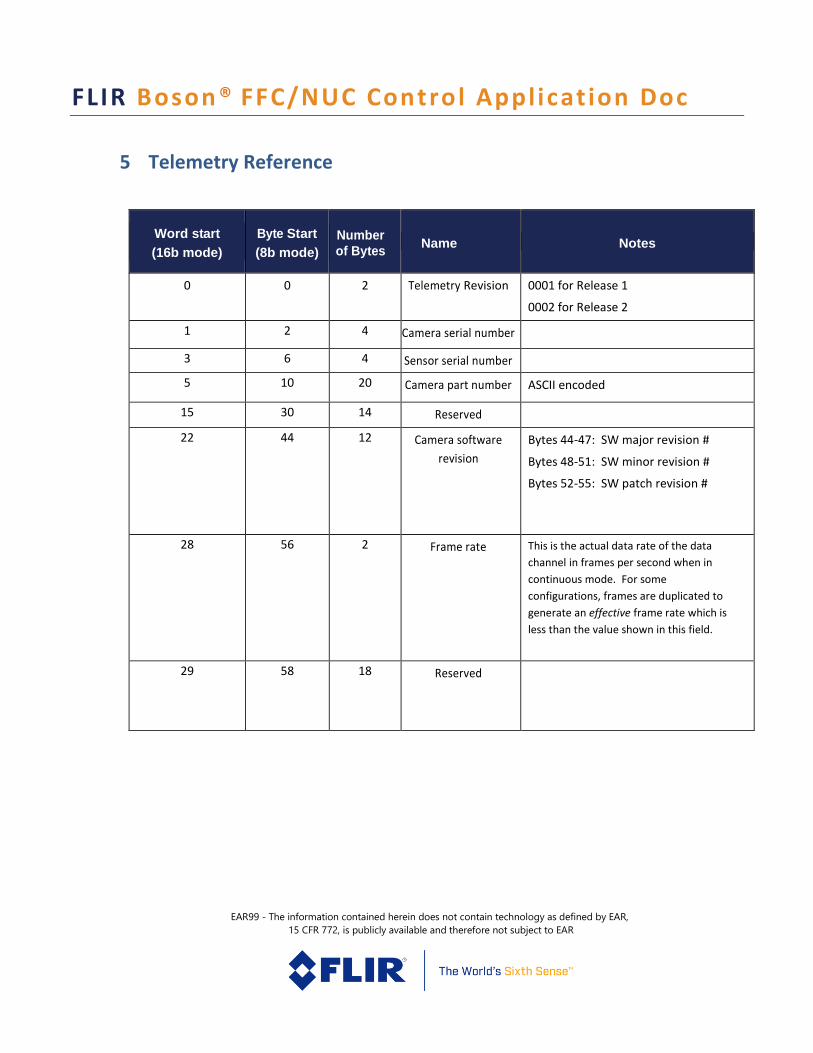
3.1 Telemetry Boson provides telemetry information on the parallel video output provided on the 80 pin connector. The entire telemetry line reference is printed at the end of this document for reference. This telemetry line can be used to watch for FFC, Table Switched desired, and NUC Table desired status. If the Boson camera is connected to the USB accessory, then telemetry is not provided. For some application it may be desired to get telemetry over USB video (ie the ADK). Contact [email protected] for more information about getting telemetry in the ADK with USB.
FLIR Boson® FFC/NUC Control Appl icat ion Doc
EAR99 - The information contained herein does not contain technology as defined by EAR,
15 CFR 772, is publicly available and therefore not subject to EAR
To keep the Boson in the appropriate NUC table, the following procedure is recommended:
1.) Once per second, read the Telemetry Status bits for the “Table Switch Desired” bit
2.) If Table Switch Desired is set, stop all other serial communications to Boson
3.) Use command bosonCheckForTableSwitch(): this will start the NUC Table switch (will
take around 2 seconds).
a. If using Manual FFC Mode, then the Boson may perform an FFC as described
by Note 1 below.
b. If using External FFC Mode, then the Boson will set the FFC Desired flag as
described by Note 1 below.
4.) Read the telemetry data to ensure that “Current NUC Table” is set the same as
“Desired NUC Table”. This indicates that the table switch has completed
5.) Once the NUC Table switch is complete, other serial communications may be
resumed
To determine if the Boson needs an FFC:
1.) Once per second, read the Telemetry Status bits for “FFC Desired”
2.) Stop all other serial communications to Boson
3.) Use command bosonRunFFC()
4.) Read the Telemetry Status bits to check for when the FFC state returns “complete”
5.) Once the FFC is complete, other serial communications may be resumed
FLIR Boson® FFC/NUC Control Appl icat ion Doc
EAR99 - The information contained herein does not contain technology as defined by EAR,
15 CFR 772, is publicly available and therefore not subject to EAR
3.2 Serial Query If an application is unable to monitor the telemetry line, a good alternative would be to use serial commands to query the same status bits. To keep the Boson in the appropriate NUC table, the following procedure is recommended:
1.) Once per second, read bosonGetTableSwitchDesired() to determine if a Table Switch is
needed
2.) If Table Switch Desired is set, stop all other serial communications to Boson
3.) Use command bosonCheckForTableSwitch(): this will start the NUC Table switch (will take
around 2 seconds). See Boson SWIDD for more information on the command.
a. If using Manual FFC Mode, then the Boson may perform an FFC as described by
Note 1 below.
b. If using External FFC Mode, then the Boson May set the FFC Desired flag as
described by Note 1 below.
4.) Read bosonGetDesiredTableNumber() and bosonGetTableNumber() to ensure that “Current
NUC Table” is set the same as “Desired NUC Table”. This indicates that the Table Switch has
completed.
5.) Once the NUC Table switch is complete, other serial communications may be resumed
To determine if the Boson needs an FFC:
1.) Once per second, read bosonGetFfcDesired()
2.) Stop all other serial communications to Boson
3.) Use command bosonRunFFC()
4.) Read bosonGetFfcStatus() to check for when the FFC status returns “complete”
5.) Once the FFC is complete, other serial communications may be resumed
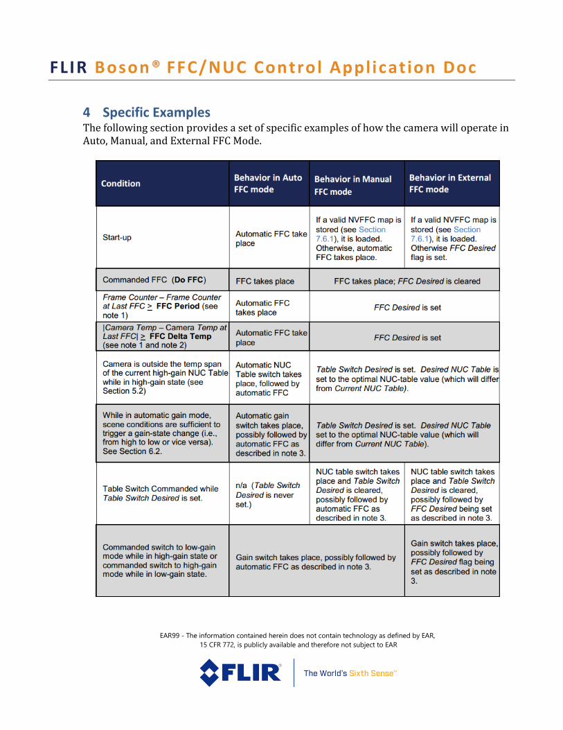
Note 1: Switching Gain state (HIGH GAIN and LOW GAIN) will require a table switch, and Boson is capable of transitioning between high-gain and low-gain state without an intervening FFC operation. Separate FFC maps are maintained for high-gain and low-gain states, as well as separate values of Frame Counter at Last FFC and Camera Temp at Last FFC. When transitioning between gain states—whether the result of an automatic switch, commanded switch, automatic FFC, or a set of the FFC Desired flag—an FFC only occurs if elapsed time since FFC in that state and/or temperature change since the last FFC in that state dictate that an FFC take place. See the examples below.
FLIR Boson® FFC/NUC Control Appl icat ion Doc
EAR99 - The information contained herein does not contain technology as defined by EAR,
15 CFR 772, is publicly available and therefore not subject to EAR
Examples of FFC behavior when transitioning between gain states or NUC Tables: • With the camera in automatic FFC mode and high-gain mode, FFC is commanded while Camera Temperature has a value of 3000 (300.0K). Following FFC, Camera Temperature at Last FFC = 3000 (300.0K). FFC Temp Delta is at its factory-default value, 30 (3.0C). • When Camera Temperature = 301.0K, the camera is commanded into low-gain mode for the first time. Gain switch takes place, and now Camera Temperature at Last FFC = 0 since FFC has never been performed in low-gain state. Consequently, automatic FFC takes place, and now Camera Temperature at Last FFC = 3010 (301.0K). • When the camera is at 302.0K, the camera is commanded into high-gain mode. Camera Temperature at Last FFC = 3000 again. No FFC takes place and FFC Desired is not set since |Camera Temperature - Camera Temperature at Last FFC| < FFC Temp Delta. • When the camera is at 303.0K, it is commanded back to low-gain state. Gain switch takes place, and Camera Temperature at Last FFC = 3010 again. No FFC takes place and FFC Desired is not set since |Camera Temperature - Camera Temperature at Last FFC| < FFC Temp Delta. • The camera continues to heat while in low-gain state until it reaches 304.0K. Now an automatic FFC takes place because |Camera Temperature - Camera Temperature at Last FFC| > FFC Temp Delta. Following FFC, Camera Temperature at Last FFC = 3040 (304.0K) and FFC Desired is cleared. • With temperature still at 304.0K, the camera is commanded to high-gain mode. Now Camera Temperature at Last FFC = 3000, and another automatic FFC takes place because |Camera Temperature - Camera Temperature at Last FFC| > FFC Temp Delta.
FLIR Boson® FFC/NUC Control Appl icat ion Doc
EAR99 - The information contained herein does not contain technology as defined by EAR,
15 CFR 772, is publicly available and therefore not subject to EAR
4 Specific Examples The following section provides a set of specific examples of how the camera will operate in Auto, Manual, and External FFC Mode.
FLIR Boson® FFC/NUC Control Appl icat ion Doc
EAR99 - The information contained herein does not contain technology as defined by EAR,
15 CFR 772, is publicly available and therefore not subject to EAR
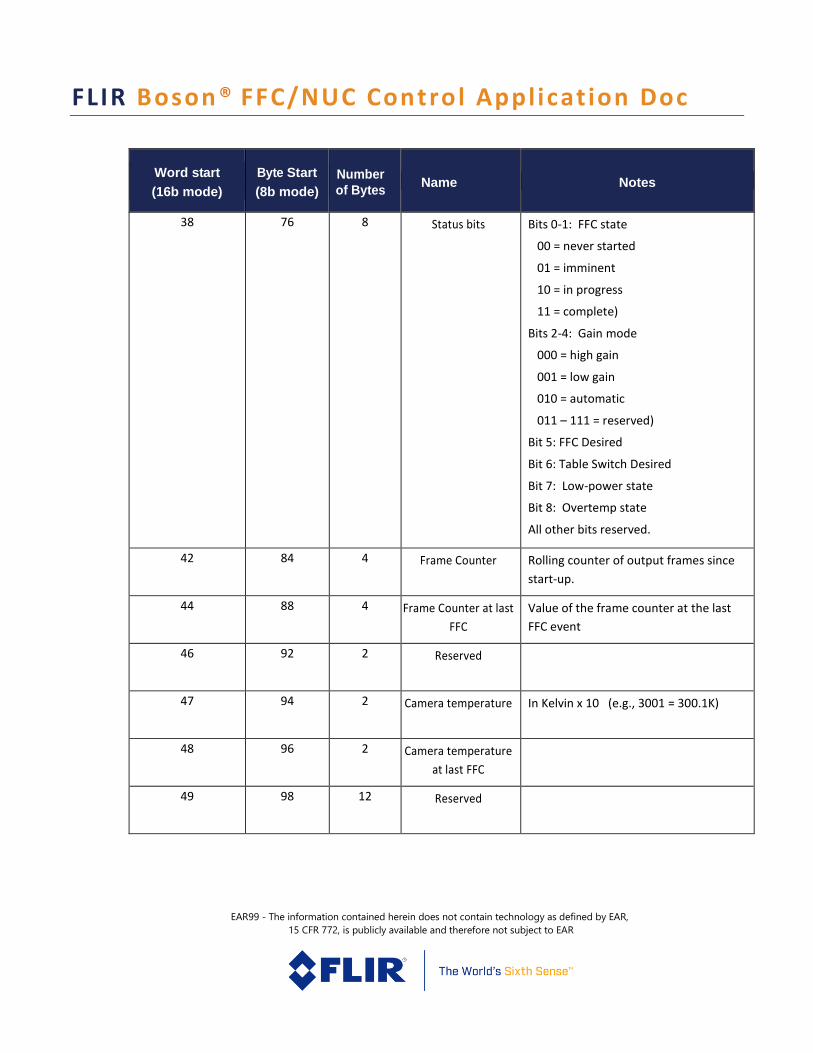
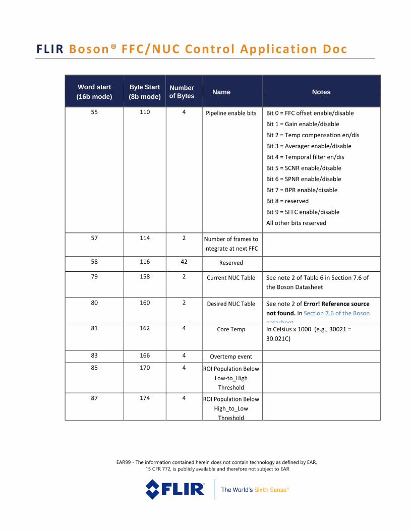
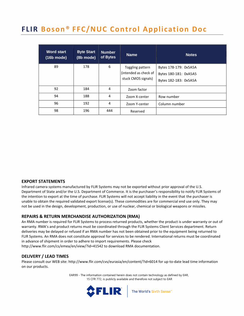
5 Telemetry Reference
Word start
(16b mode)
Byte Start
(8b mode)
Number
of Bytes Name Notes
0 0 2 Telemetry Revision 0001 for Release 1
0002 for Release 2
1 2 4 Camera serial number
3 6 4 Sensor serial number
5 10 20 Camera part number ASCII encoded
15 30 14 Reserved
22 44 12 Camera software
revision
Bytes 44-47: SW major revision #
Bytes 48-51: SW minor revision #
Bytes 52-55: SW patch revision #
28 56 2 Frame rate This is the actual data rate of the data
channel in frames per second when in
continuous mode. For some
configurations, frames are duplicated to
generate an effective frame rate which is
less than the value shown in this field.
29 58 18 Reserved
FLIR Boson® FFC/NUC Control Appl icat ion Doc
EAR99 - The information contained herein does not contain technology as defined by EAR,
15 CFR 772, is publicly available and therefore not subject to EAR
Word start
(16b mode)
Byte Start
(8b mode)
Number
of Bytes Name Notes
38 76 8 Status bits Bits 0-1: FFC state
00 = never started
01 = imminent
10 = in progress
11 = complete)
Bits 2-4: Gain mode
000 = high gain
001 = low gain
010 = automatic
011 – 111 = reserved)
Bit 5: FFC Desired
Bit 6: Table Switch Desired
Bit 7: Low-power state
Bit 8: Overtemp state
All other bits reserved.
42 84 4 Frame Counter Rolling counter of output frames since
start-up.
44 88 4 Frame Counter at last
FFC
Value of the frame counter at the last
FFC event
46 92 2 Reserved
47 94 2 Camera temperature In Kelvin x 10 (e.g., 3001 = 300.1K)
48 96 2 Camera temperature
at last FFC
49 98 12 Reserved
FLIR Boson® FFC/NUC Control Appl icat ion Doc
EAR99 - The information contained herein does not contain technology as defined by EAR,
15 CFR 772, is publicly available and therefore not subject to EAR
Word start
(16b mode)
Byte Start
(8b mode)
Number
of Bytes Name Notes
55 110 4 Pipeline enable bits Bit 0 = FFC offset enable/disable
Bit 1 = Gain enable/disable
Bit 2 = Temp compensation en/dis
Bit 3 = Averager enable/disable
Bit 4 = Temporal filter en/dis
Bit 5 = SCNR enable/disable
Bit 6 = SPNR enable/disable
Bit 7 = BPR enable/disable
Bit 8 = reserved
Bit 9 = SFFC enable/disable
All other bits reserved
57 114 2 Number of frames to
integrate at next FFC
58 116 42 Reserved
79 158 2 Current NUC Table See note 2 of Table 6 in Section 7.6 of
the Boson Datasheet
80 160 2 Desired NUC Table See note 2 of Error! Reference source
not found. in Section 7.6 of the Boson
datasheet 81 162 4 Core Temp In Celsius x 1000 (e.g., 30021 =
30.021C)
83 166 4 Overtemp event
counter
85 170 4 ROI Population Below
Low-to_High
Threshold
87 174 4 ROI Population Below
High_to_Low
Threshold
FLIR Boson® FFC/NUC Control Appl icat ion Doc
EAR99 - The information contained herein does not contain technology as defined by EAR,
15 CFR 772, is publicly available and therefore not subject to EAR
Word start
(16b mode)
Byte Start
(8b mode)
Number
of Bytes Name Notes
89 178 6 Toggling pattern
(intended as check of
stuck CMOS signals)
Bytes 178-179: 0x5A5A
Bytes 180-181: 0xA5A5
Bytes 182-183: 0x5A5A
92 184 4 Zoom factor
94 188 4 Zoom X-center Row number
96 192 4 Zoom Y-center Column number
98 196 444 Reserved
EXPORT STATEMENTS
Infrared camera systems manufactured by FLIR Systems may not be exported without prior approval of the U.S. Department of State and/or the U.S. Department of Commerce. It is the purchaser’s responsibility to notify FLIR Systems of the intention to export at the time of purchase. FLIR Systems will not accept liability in the event that the purchaser is unable to obtain the required validated export license(s). These commodities are for commercial end use only. They may not be used in the design, development, production, or use of nuclear, chemical or biological weapons or missiles.
REPAIRS & RETURN MERCHANDISE AUTHORIZATION (RMA) An RMA number is required for FLIR Systems to process returned products, whether the product is under warranty or out of warranty. RMA’s and product returns must be coordinated through the FLIR Systems Client Services department. Return deliveries may be delayed or refused if an RMA number has not been obtained prior to the equipment being returned to FLIR Systems. An RMA does not constitute approval for services to be rendered. International returns must be coordinated in advance of shipment in order to adhere to import requirements. Please check http://www.flir.com/cs/emea/en/view/?id=41542 to download RMA documentation.
DELIVERY / LEAD TIMES Please consult our WEB site: http://www.flir.com/cvs/eurasia/en/content/?id=6014 for up-to-date lead time information on our products.