flight management systems - part 2
TRANSCRIPT
EE6900 Flight Management Systems
“Flight Management System – Part 2”
Dr. Maarten Uijt de Haag
Ohio University
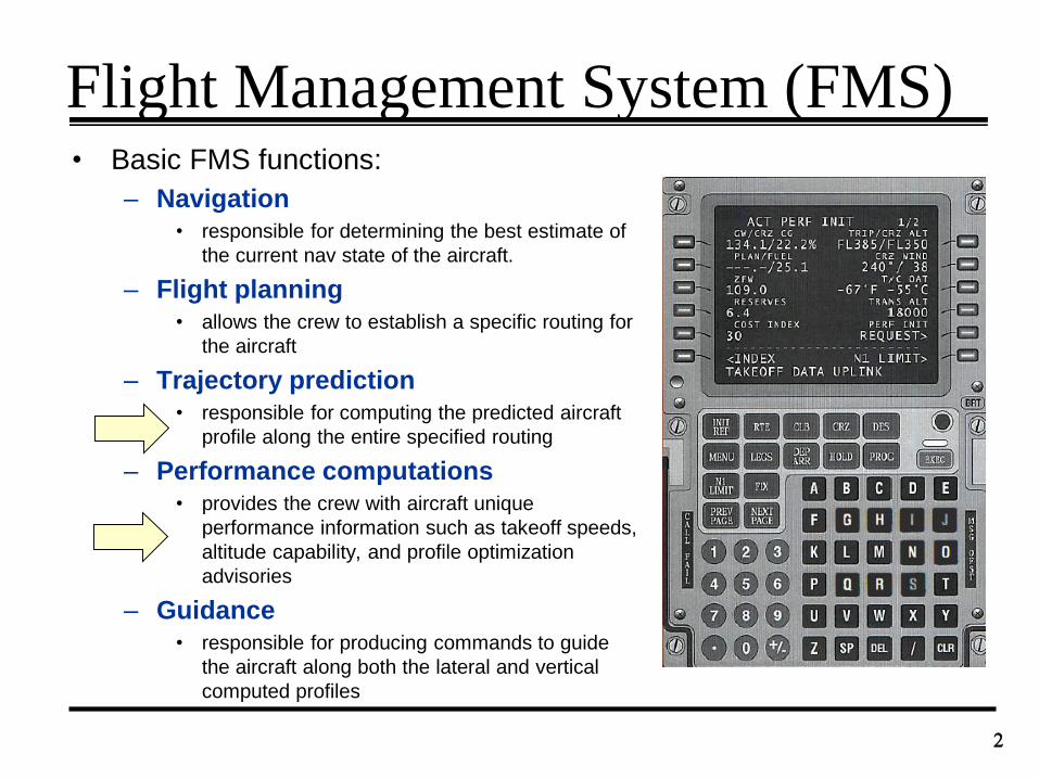
Flight Management System (FMS)• Basic FMS functions:
– Navigation
• responsible for determining the best estimate of
the current nav state of the aircraft.
– Flight planning
• allows the crew to establish a specific routing for
the aircraft
– Trajectory prediction
• responsible for computing the predicted aircraft
profile along the entire specified routing
– Performance computations
• provides the crew with aircraft unique
performance information such as takeoff speeds,
altitude capability, and profile optimization
advisories
– Guidance
• responsible for producing commands to guide
the aircraft along both the lateral and vertical
computed profiles
2
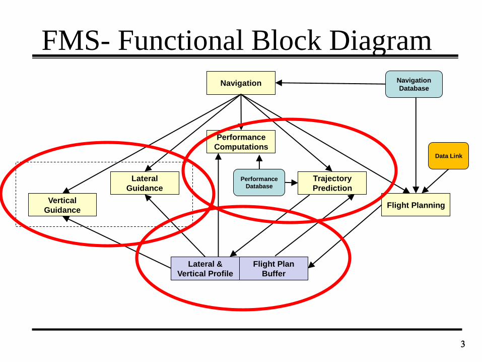
FMS- Functional Block Diagram
3
Navigation
Flight PlanningVertical
Guidance
Lateral
Guidance
Performance
Computations
Trajectory
Prediction
Navigation
Database
Performance
Database
Lateral &
Vertical Profile
Data Link
Flight Plan
Buffer
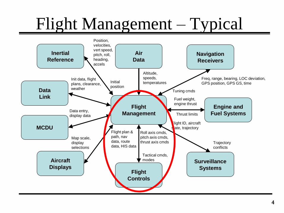
Flight Management – Typical
4
Flight
Management
Inertial
Reference
Air
DataNavigation
Receivers
Aircraft
DisplaysFlight
Controls
Surveillance
Systems
Engine and
Fuel Systems
Data
Link
MCDU
Altitude,
speeds,
temperaturesInitial
position
Position,
velocities,
vert speed,
pitch, roll,
heading,
accels
Init data, flight
plans, clearance,
weather
Data entry,
display data
Map scale,
display
selections
Trajectory
conflicts
Flight plan &
path, nav
data, route
data, HIS data
Roll axis cmds,
pitch axis cmds,
thrust axis cmds
Tactical cmds,
modes
Flight ID, aircraft
state, trajectory
Fuel weight,
engine thrust
Thrust limits
Tuning cmds
Freq, range, bearing, LOC deviation,
GPS position, GPS GS, time
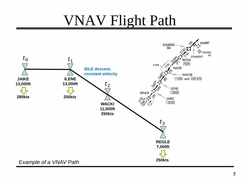
VNAV Flight Path
5
JAIKE
13,000ft
ILENE
13,000ft
WACKI
11,000ft
250kts
REGLE
7,000ft
Example of a VNAV Path
280kts 250kts
250kts
𝑡0 𝑡1
𝑡2
𝑡3
IDLE descent,
constant velocity
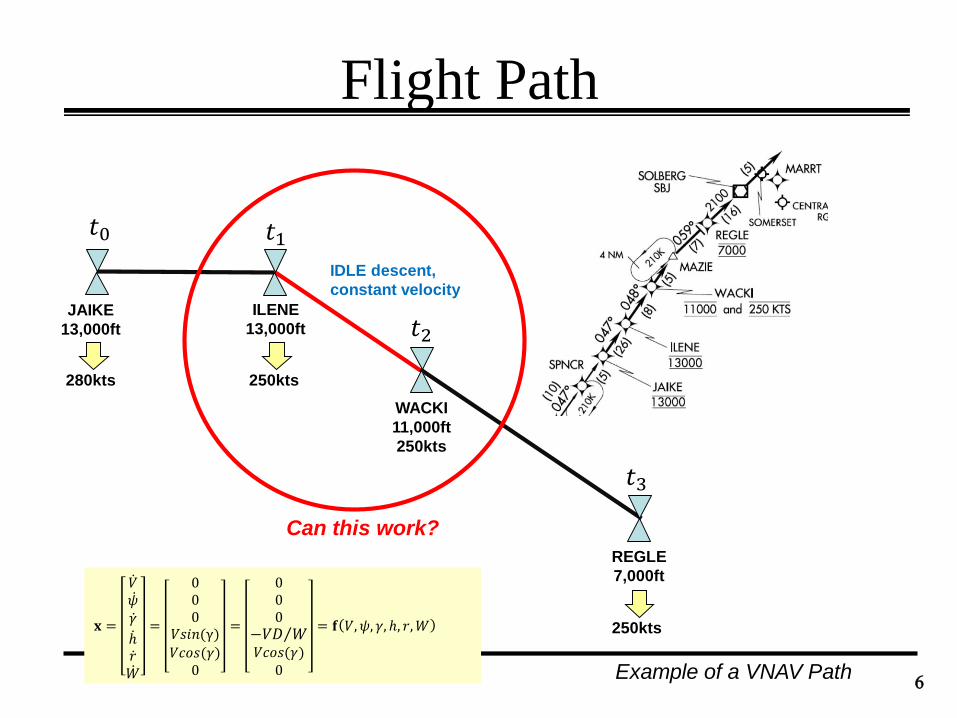
Flight Path
6
JAIKE
13,000ft
ILENE
13,000ft
WACKI
11,000ft
250kts
REGLE
7,000ft
Example of a VNAV Path
280kts 250kts
250kts
𝑡0 𝑡1
𝑡2
𝑡3
IDLE descent,
constant velocity
Can this work?
𝐱 =
𝑉 𝜓 𝛾 ℎ 𝑟 𝑊
=
000
𝑉𝑠𝑖𝑛(γ)
𝑉𝑐𝑜𝑠(𝛾)0
=
000 −𝑉𝐷 𝑊
𝑉𝑐𝑜𝑠(𝛾)0
= 𝐟 𝑉, 𝜓, 𝛾, ℎ, 𝑟,𝑊
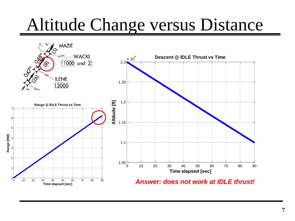
0 10 20 30 40 50 60 70 80 900
1
2
3
4
5
6
7
Time elapsed [sec]
Ra
ng
e [
NM
]
Range @ IDLE Thrust vs Time
Altitude Change versus Distance
7
Answer: does not work at IDLE thrust!
0 10 20 30 40 50 60 70 80 901.05
1.1
1.15
1.2
1.25
1.3x 10
4
Time elapsed [sec]
Alt
itu
de
[ft
]
Descent @ IDLE Thrust vs Time
Adjust the Thrust?
8
ILENE
13,000ft
WACKI
11,000ft
Δ𝑟𝑑𝑒𝑠
Δℎ𝑑𝑒𝑠
(e.g. 8NM)
(e.g. 13000ft)
𝛾
𝛾 = 𝑎𝑡𝑎𝑛Δℎ𝑑𝑒𝑠Δ𝑟𝑑𝑒𝑠
6NM
𝐱 =
𝑉 𝜓 𝛾 ℎ 𝑟 𝑊
=
𝑔𝑊
𝑇 − 𝐷 −𝑊𝑠𝑖𝑛(𝛾)
00
𝑉𝑠𝑖𝑛(γ)𝑉𝑐𝑜𝑠(𝛾)
0
=
000
𝑉(𝑇 − 𝐷) 𝑊𝑉𝑐𝑜𝑠(𝛾)
0
= 𝐟 𝑉,𝜓, 𝛾, ℎ, 𝑟,𝑊
ℎ =𝑇 − 𝐷 𝑉
𝑊= 𝑉𝑠𝑖𝑛 𝛾
sin 𝛾 =𝑇 − 𝐷
𝑊
𝑇 = 𝐷 +𝑊𝑠𝑖𝑛(𝛾)
Not IDLE thrust
0 20 40 60 80 100 1200
1
2
3
4
5
6
7
8
9
Time elapsed [sec]
Ra
ng
e [
NM
]
Range @ IDLE Thrust vs Time
𝛾𝑔𝑙𝑖𝑑𝑒
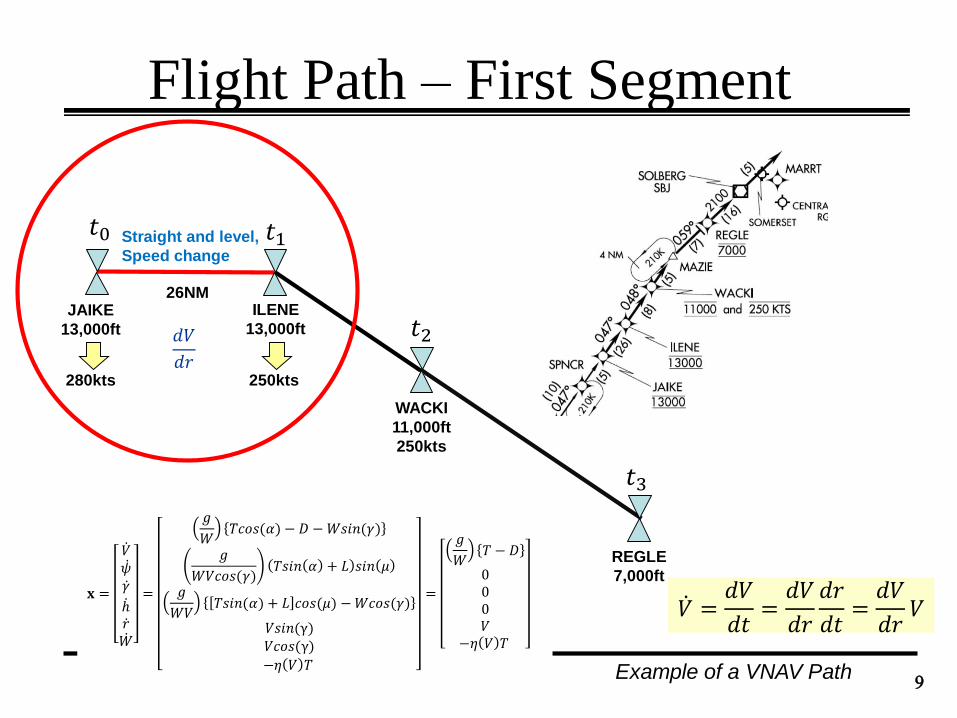
Flight Path – First Segment
9
JAIKE
13,000ft
ILENE
13,000ft
WACKI
11,000ft
250kts
REGLE
7,000ft
Example of a VNAV Path
280kts 250kts
𝑡0 𝑡1
𝑡2
𝑡3
Straight and level,
Speed change
𝐱 =
𝑉 𝜓 𝛾 ℎ 𝑟 𝑊
=
𝑔
𝑊𝑇𝑐𝑜𝑠(𝛼) − 𝐷 −𝑊𝑠𝑖𝑛(𝛾)
𝑔
𝑊𝑉𝑐𝑜𝑠(𝛾)𝑇𝑠𝑖𝑛 𝛼 + 𝐿 𝑠𝑖𝑛 𝜇
𝑔
𝑊𝑉𝑇𝑠𝑖𝑛(𝛼) + 𝐿 𝑐𝑜𝑠(𝜇) −𝑊𝑐𝑜𝑠(𝛾)
𝑉𝑠𝑖𝑛(γ)𝑉𝑐𝑜𝑠(γ)
−𝜂 𝑉 𝑇
=
𝑔
𝑊𝑇 − 𝐷
000𝑉
−𝜂 𝑉 𝑇
𝑉 =𝑑𝑉
𝑑𝑡=𝑑𝑉
𝑑𝑟
𝑑𝑟
𝑑𝑡=𝑑𝑉
𝑑𝑟𝑉
26NM
𝑑𝑉
𝑑𝑟
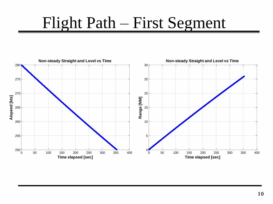
Flight Path – First Segment
10
0 50 100 150 200 250 300 350 400250
255
260
265
270
275
280
Time elapsed [sec]
Ais
pe
ed
[k
ts]
Non-steady Straight and Level vs Time
0 50 100 150 200 250 300 350 4000
5
10
15
20
25
30
Time elapsed [sec]
Ra
ng
e [
NM
]
Non-steady Straight and Level vs Time
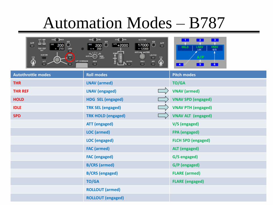
Automation Modes – B787
1111
Autothrottle modes Roll modes Pitch modes
THR LNAV (armed) TO/GA
THR REF LNAV (engaged) VNAV (armed)
HOLD HDG SEL (engaged) VNAV SPD (engaged)
IDLE TRK SEL (engaged) VNAV PTH (engaged)
SPD TRK HOLD (engaged) VNAV ALT (engaged)
ATT (engaged) V/S (engaged)
LOC (armed) FPA (engaged)
LOC (engaged) FLCH SPD (engaged)
FAC (armed) ALT (engaged)
FAC (engaged) G/S engaged)
B/CRS (armed) G/P (engaged)
B/CRS (engaged) FLARE (armed)
TO/GA FLARE (engaged)
ROLLOUT (armed)
ROLLOUT (engaged)
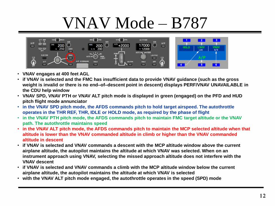
VNAV Mode – B787
12
• VNAV engages at 400 feet AGL
• if VNAV is selected and the FMC has insufficient data to provide VNAV guidance (such as the gross
weight is invalid or there is no end–of–descent point in descent) displays PERF/VNAV UNAVAILABLE in
the CDU help window
• VNAV SPD, VNAV PTH or VNAV ALT pitch mode is displayed in green (engaged) on the PFD and HUD
pitch flight mode annunciator
• in the VNAV SPD pitch mode, the AFDS commands pitch to hold target airspeed. The autothrottle
operates in the THR REF, THR, IDLE or HOLD mode, as required by the phase of flight
• in the VNAV PTH pitch mode, the AFDS commands pitch to maintain FMC target altitude or the VNAV
path. The autothrottle maintains speed
• in the VNAV ALT pitch mode, the AFDS commands pitch to maintain the MCP selected altitude when that
altitude is lower than the VNAV commanded altitude in climb or higher than the VNAV commanded
altitude in descent
• if VNAV is selected and VNAV commands a descent with the MCP altitude window above the current
airplane altitude, the autopilot maintains the altitude at which VNAV was selected. When on an
instrument approach using VNAV, selecting the missed approach altitude does not interfere with the
VNAV descent
• if VNAV is selected and VNAV commands a climb with the MCP altitude window below the current
airplane altitude, the autopilot maintains the altitude at which VNAV is selected
• with the VNAV ALT pitch mode engaged, the autothrottle operates in the speed (SPD) mode
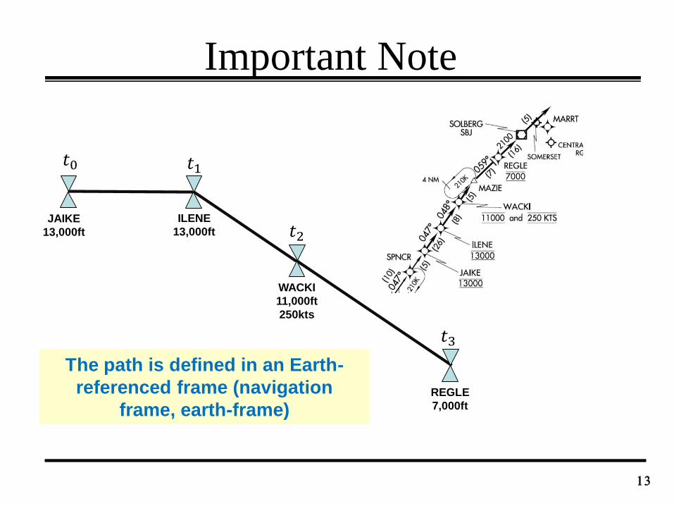
Important Note
13
JAIKE
13,000ft
ILENE
13,000ft
WACKI
11,000ft
250kts
REGLE
7,000ft
𝑡0 𝑡1
𝑡2
𝑡3
The path is defined in an Earth-
referenced frame (navigation
frame, earth-frame)
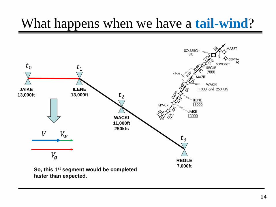
What happens when we have a tail-wind?
14
JAIKE
13,000ft
ILENE
13,000ft
WACKI
11,000ft
250kts
REGLE
7,000ft
𝑡0 𝑡1
𝑡2
𝑡3𝑉 𝑉𝑤
𝑉𝑔
So, this 1st segment would be completed
faster than expected.
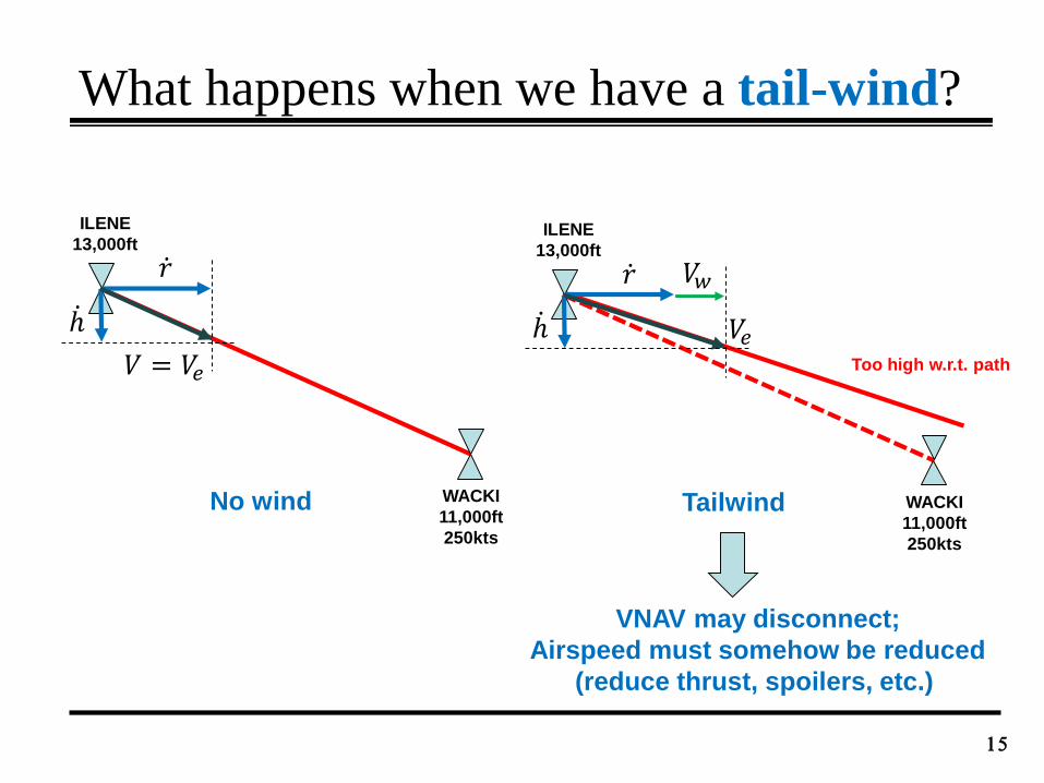
What happens when we have a tail-wind?
15
ILENE
13,000ft
WACKI
11,000ft
250kts
ℎ
𝑟
No wind
ILENE
13,000ft
WACKI
11,000ft
250kts
ℎ
Tailwind
𝑉𝑤
𝑉 = 𝑉𝑒
𝑉𝑒Too high w.r.t. path
VNAV may disconnect;
Airspeed must somehow be reduced
(reduce thrust, spoilers, etc.)
𝑟
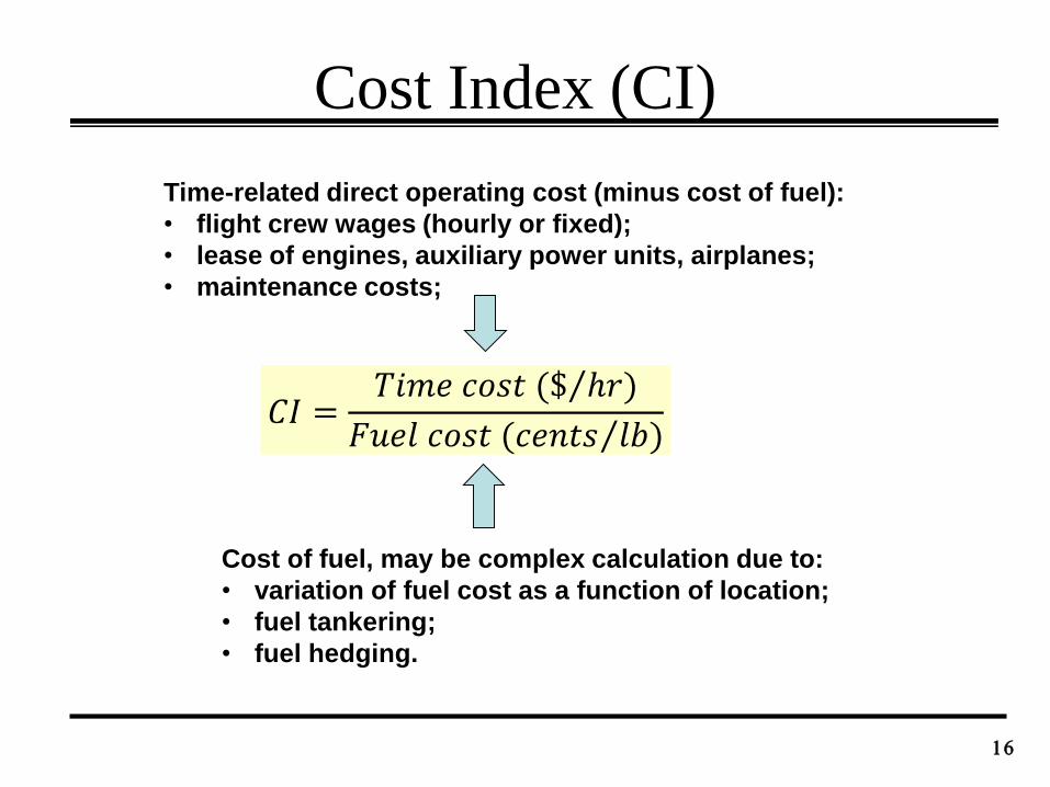
Cost Index (CI)
16
𝐶𝐼 =𝑇𝑖𝑚𝑒 𝑐𝑜𝑠𝑡 ( $ ℎ𝑟)
𝐹𝑢𝑒𝑙 𝑐𝑜𝑠𝑡 ( 𝑐𝑒𝑛𝑡𝑠 𝑙𝑏)
Time-related direct operating cost (minus cost of fuel):
• flight crew wages (hourly or fixed);
• lease of engines, auxiliary power units, airplanes;
• maintenance costs;
Cost of fuel, may be complex calculation due to:
• variation of fuel cost as a function of location;
• fuel tankering;
• fuel hedging.
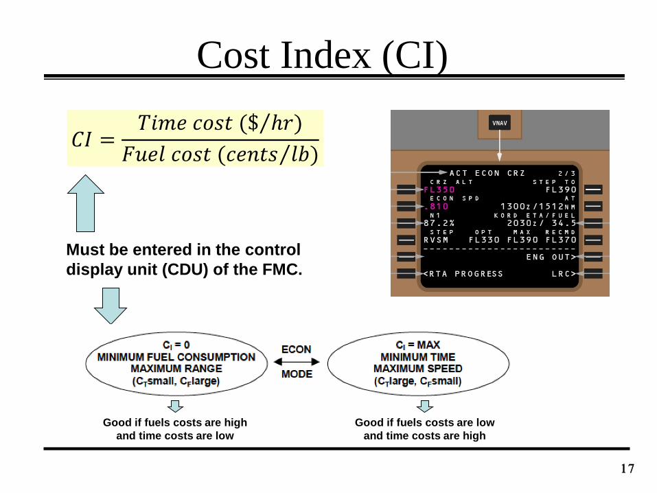
Cost Index (CI)
17
𝐶𝐼 =𝑇𝑖𝑚𝑒 𝑐𝑜𝑠𝑡 ( $ ℎ𝑟)
𝐹𝑢𝑒𝑙 𝑐𝑜𝑠𝑡 ( 𝑐𝑒𝑛𝑡𝑠 𝑙𝑏)
Must be entered in the control
display unit (CDU) of the FMC.
Good if fuels costs are high
and time costs are low
Good if fuels costs are low
and time costs are high
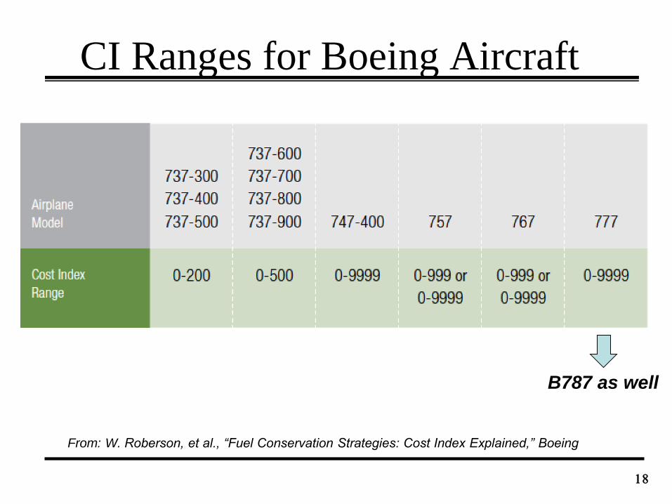
CI Ranges for Boeing Aircraft
18
From: W. Roberson, et al., “Fuel Conservation Strategies: Cost Index Explained,” Boeing
B787 as well
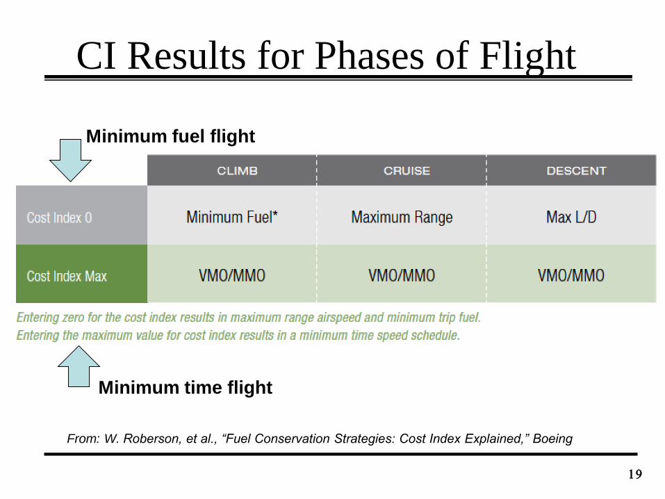
CI Results for Phases of Flight
19
From: W. Roberson, et al., “Fuel Conservation Strategies: Cost Index Explained,” Boeing
Minimum fuel flight
Minimum time flight
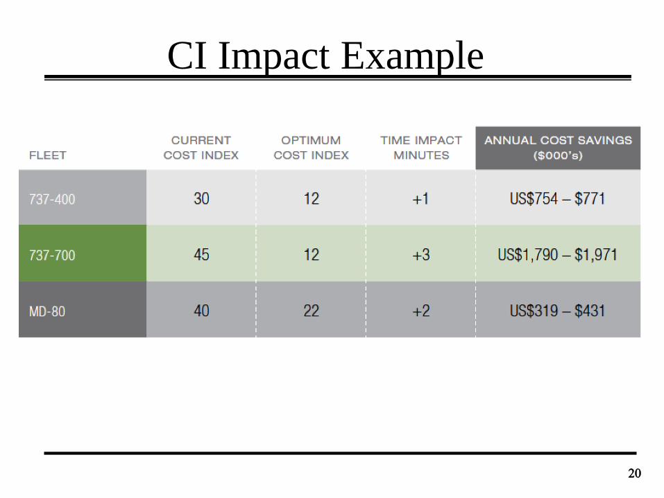
CI Impact Example
20
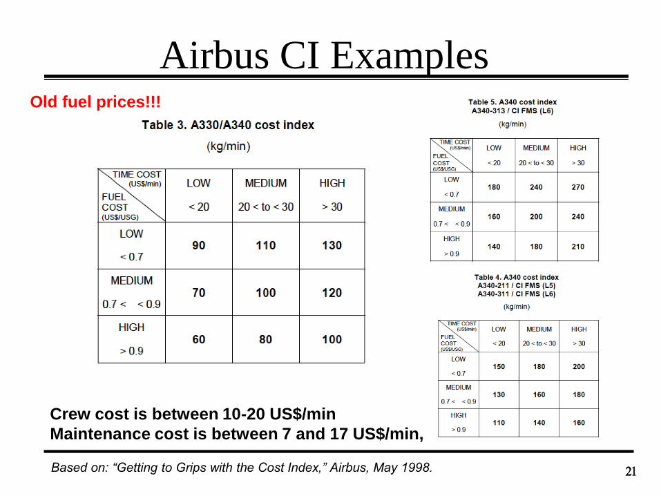
Airbus CI Examples
21
Old fuel prices!!!
Based on: “Getting to Grips with the Cost Index,” Airbus, May 1998.
Crew cost is between 10-20 US$/min
Maintenance cost is between 7 and 17 US$/min,
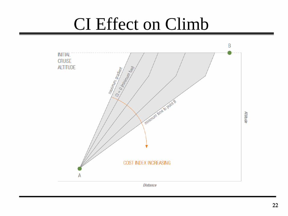
CI Effect on Climb
22
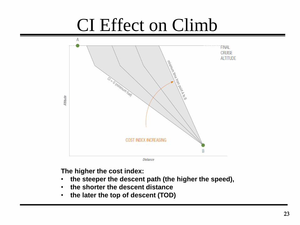
CI Effect on Climb
23
The higher the cost index:
• the steeper the descent path (the higher the speed),
• the shorter the descent distance
• the later the top of descent (TOD)
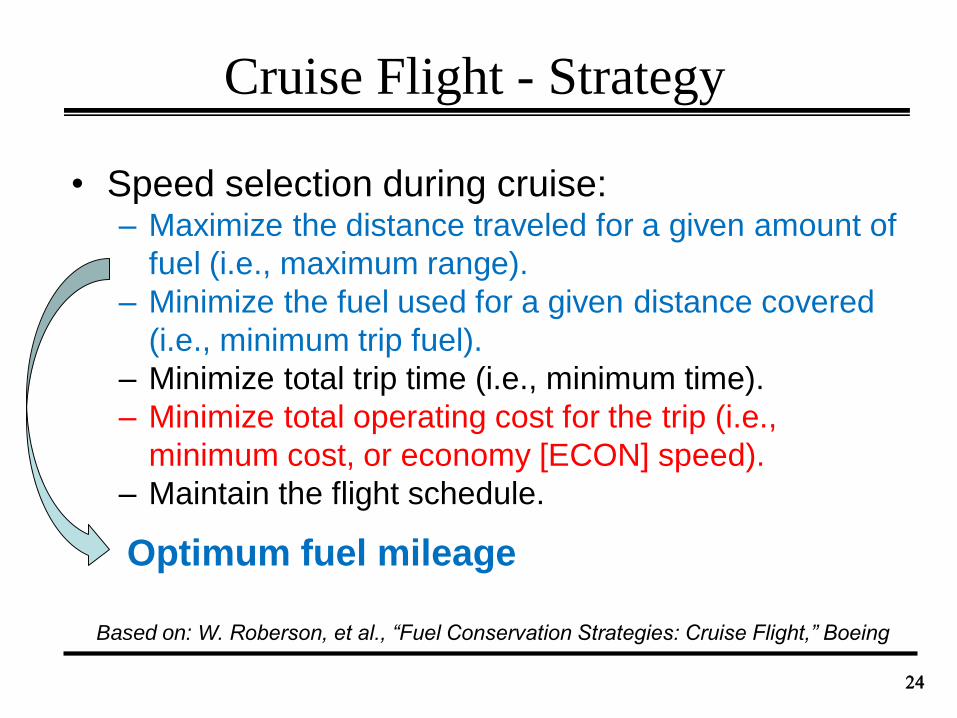
Cruise Flight - Strategy
• Speed selection during cruise:– Maximize the distance traveled for a given amount of
fuel (i.e., maximum range).
– Minimize the fuel used for a given distance covered
(i.e., minimum trip fuel).
– Minimize total trip time (i.e., minimum time).
– Minimize total operating cost for the trip (i.e.,
minimum cost, or economy [ECON] speed).
– Maintain the flight schedule.
24
Optimum fuel mileage
Based on: W. Roberson, et al., “Fuel Conservation Strategies: Cruise Flight,” Boeing
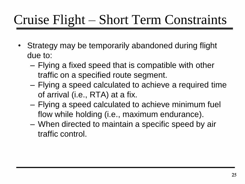
Cruise Flight – Short Term Constraints
• Strategy may be temporarily abandoned during flight
due to:
– Flying a fixed speed that is compatible with other
traffic on a specified route segment.
– Flying a speed calculated to achieve a required time
of arrival (i.e., RTA) at a fix.
– Flying a speed calculated to achieve minimum fuel
flow while holding (i.e., maximum endurance).
– When directed to maintain a specific speed by air
traffic control.
25
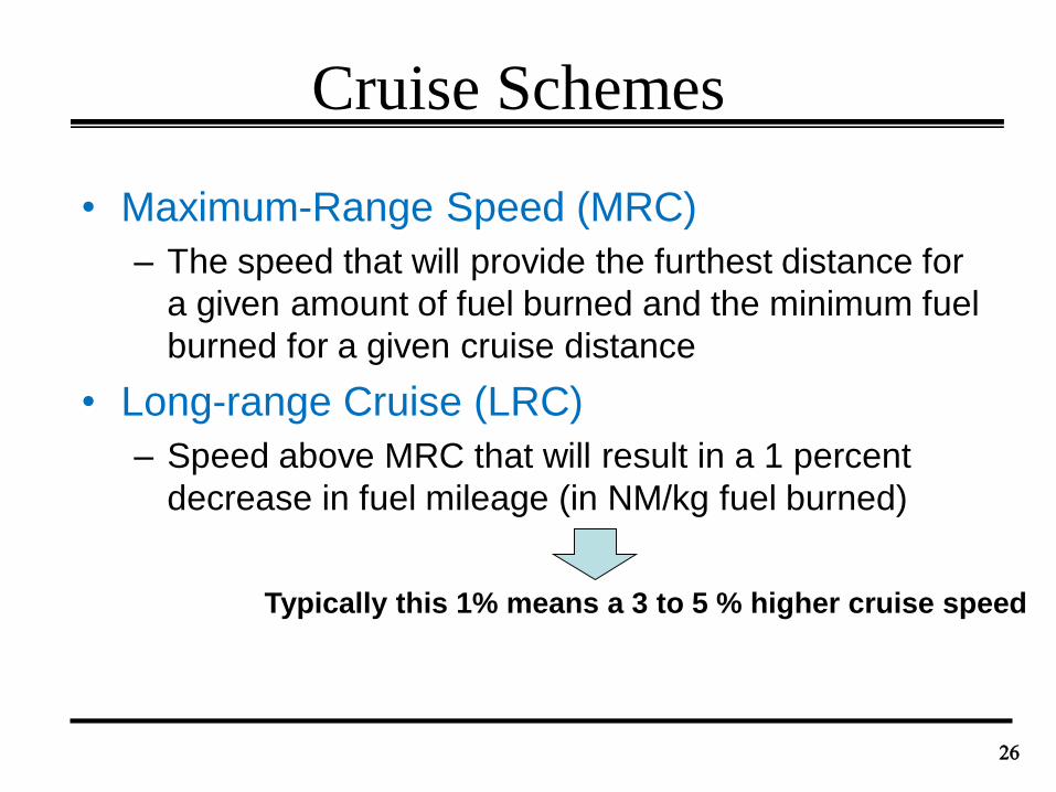
Cruise Schemes
• Maximum-Range Speed (MRC)
– The speed that will provide the furthest distance for
a given amount of fuel burned and the minimum fuel
burned for a given cruise distance
• Long-range Cruise (LRC)
– Speed above MRC that will result in a 1 percent
decrease in fuel mileage (in NM/kg fuel burned)
26
Typically this 1% means a 3 to 5 % higher cruise speed
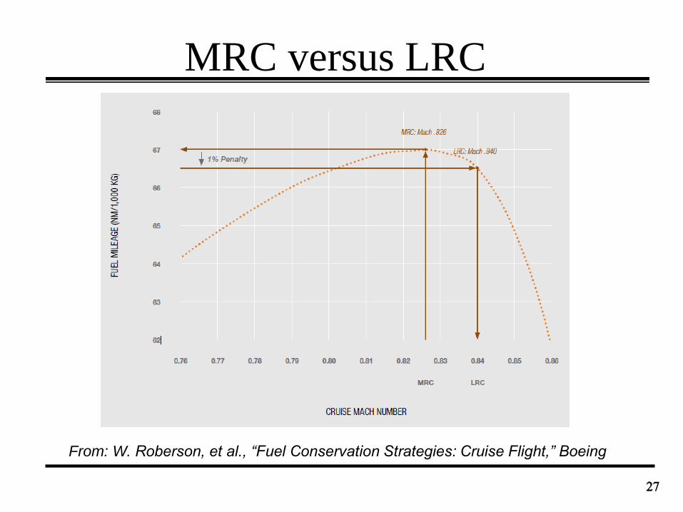
MRC versus LRC
27
From: W. Roberson, et al., “Fuel Conservation Strategies: Cruise Flight,” Boeing
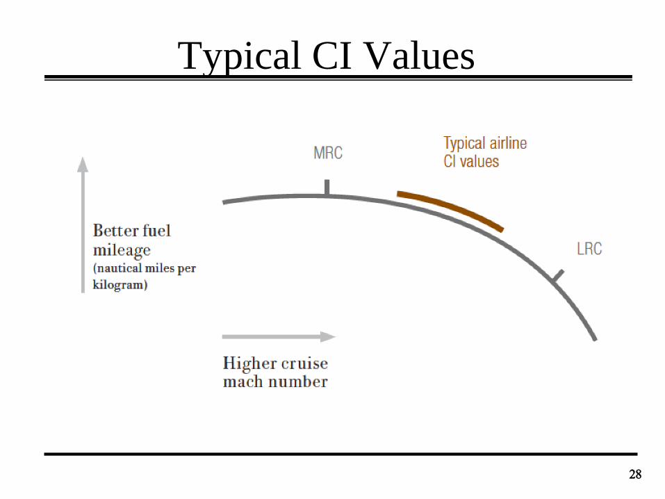
Typical CI Values
28

Cost Simulations
• Price fuel: $2.94/gallon
• Crew and maintenance: $45/minute
• Altitude: 20,000ft
• Cruise for 200NM
• Cruise: steady straight and level flight
• Change from Vmo down to 0.65Vmo
29
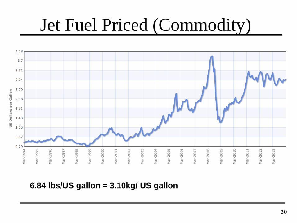
Jet Fuel Priced (Commodity)
30
6.84 lbs/US gallon = 3.10kg/ US gallon
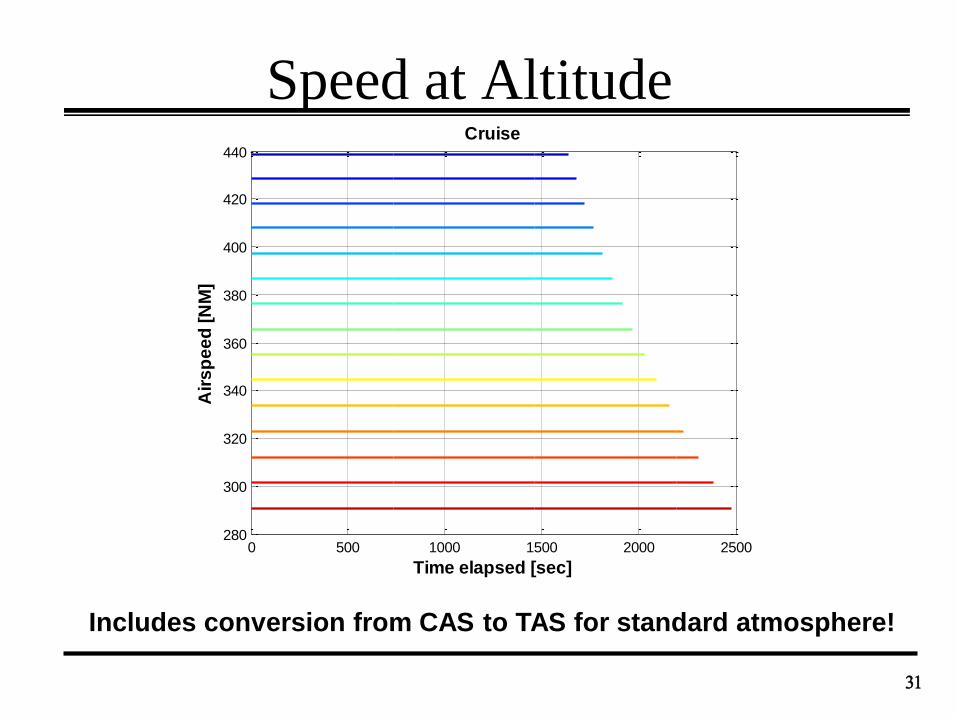
Speed at Altitude
31
0 500 1000 1500 2000 2500280
300
320
340
360
380
400
420
440
Time elapsed [sec]
Air
sp
ee
d [
NM
]
Cruise
Includes conversion from CAS to TAS for standard atmosphere!

Range and Speed
32
0 500 1000 1500 2000 25000
50
100
150
200
250
Time elapsed [sec]
Ra
ng
e [
NM
]
Cruise
0 500 1000 1500 2000 2500232
233
234
235
236
237
238
Time elapsed [sec]
Ma
ss
[to
nn
es
]
Cruise
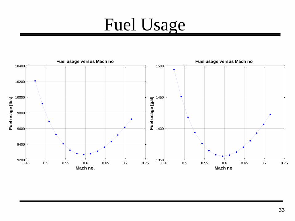
Fuel Usage
33
0.45 0.5 0.55 0.6 0.65 0.7 0.751350
1400
1450
1500
Mach no.
Fu
el u
sa
ge
[g
al]
Fuel usage versus Mach no
0.45 0.5 0.55 0.6 0.65 0.7 0.759200
9400
9600
9800
10000
10200
10400
Mach no.
Fu
el u
sa
ge
[lb
s]
Fuel usage versus Mach no
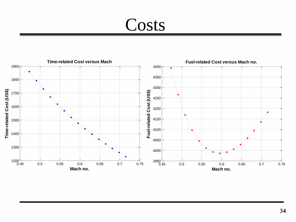
Costs
34
0.45 0.5 0.55 0.6 0.65 0.7 0.751200
1300
1400
1500
1600
1700
1800
1900
Mach no.
Tim
e-r
ela
ted
Co
st
(US
$)
Time-related Cost versus Mach
0.45 0.5 0.55 0.6 0.65 0.7 0.753950
4000
4050
4100
4150
4200
4250
4300
4350
4400
Mach no.
Fu
el-
rela
ted
Co
st
(US
$)
Fuel-related Cost versus Mach no.
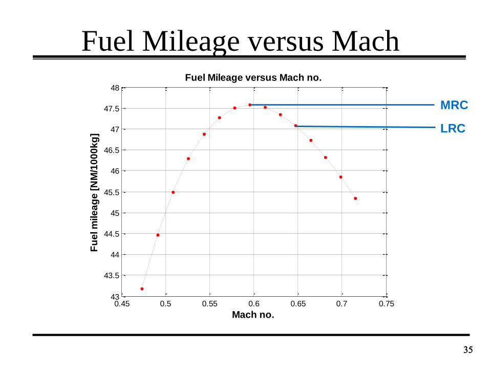
Fuel Mileage versus Mach
35
0.45 0.5 0.55 0.6 0.65 0.7 0.7543
43.5
44
44.5
45
45.5
46
46.5
47
47.5
48
Mach no.
Fu
el m
ile
ag
e [
NM
/10
00
kg
]
Fuel Mileage versus Mach no.
MRC
LRC
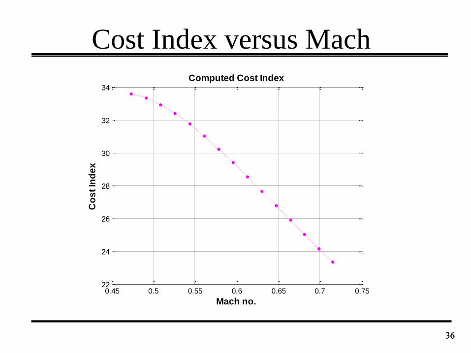
Cost Index versus Mach
36
0.45 0.5 0.55 0.6 0.65 0.7 0.7522
24
26
28
30
32
34
Mach no.
Co
st
Ind
ex
Computed Cost Index
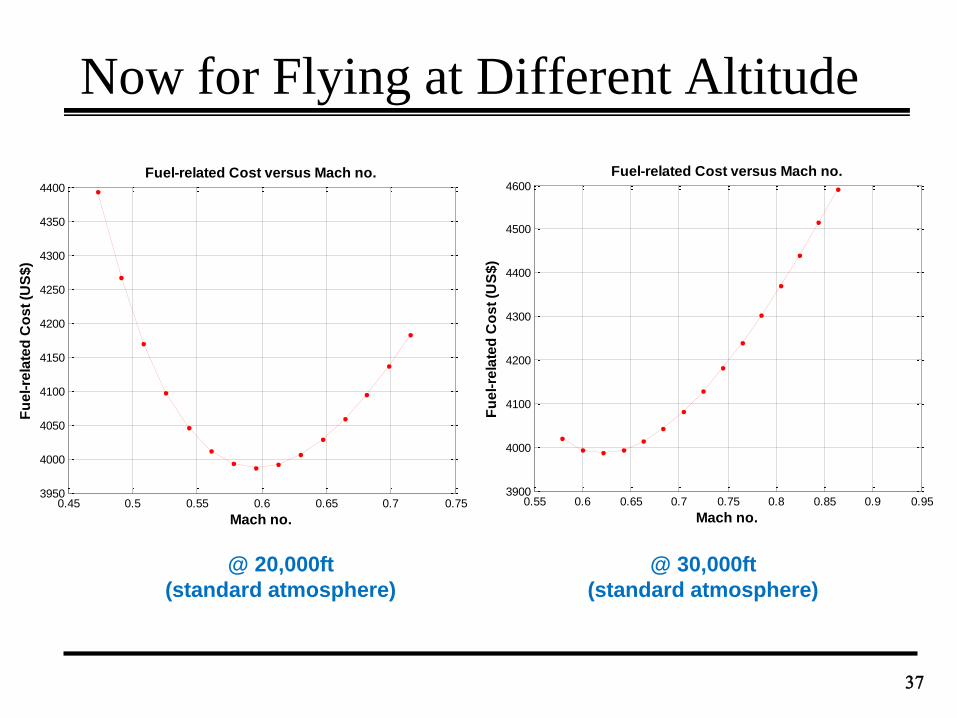
Now for Flying at Different Altitude
37
@ 20,000ft
(standard atmosphere)
@ 30,000ft
(standard atmosphere)
0.45 0.5 0.55 0.6 0.65 0.7 0.753950
4000
4050
4100
4150
4200
4250
4300
4350
4400
Mach no.
Fu
el-
rela
ted
Co
st
(US
$)
Fuel-related Cost versus Mach no.
0.55 0.6 0.65 0.7 0.75 0.8 0.85 0.9 0.953900
4000
4100
4200
4300
4400
4500
4600
Mach no.
Fu
el-
rela
ted
Co
st
(US
$)
Fuel-related Cost versus Mach no.
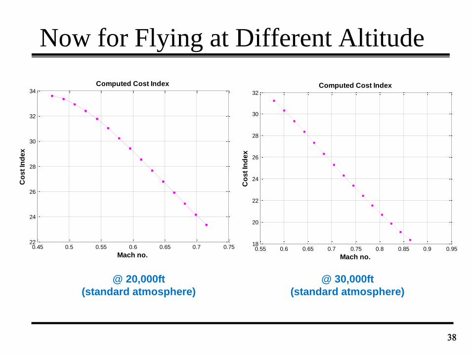
Now for Flying at Different Altitude
38
0.55 0.6 0.65 0.7 0.75 0.8 0.85 0.9 0.9518
20
22
24
26
28
30
32
Mach no.
Co
st
Ind
ex
Computed Cost Index
0.45 0.5 0.55 0.6 0.65 0.7 0.7522
24
26
28
30
32
34
Mach no.
Co
st
Ind
ex
Computed Cost Index
@ 20,000ft
(standard atmosphere)
@ 30,000ft
(standard atmosphere)
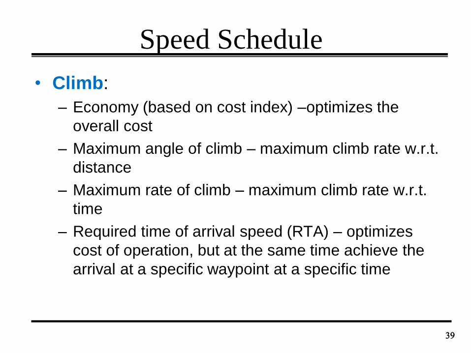
Speed Schedule
• Climb:
– Economy (based on cost index) –optimizes the
overall cost
– Maximum angle of climb – maximum climb rate w.r.t.
distance
– Maximum rate of climb – maximum climb rate w.r.t.
time
– Required time of arrival speed (RTA) – optimizes
cost of operation, but at the same time achieve the
arrival at a specific waypoint at a specific time
39
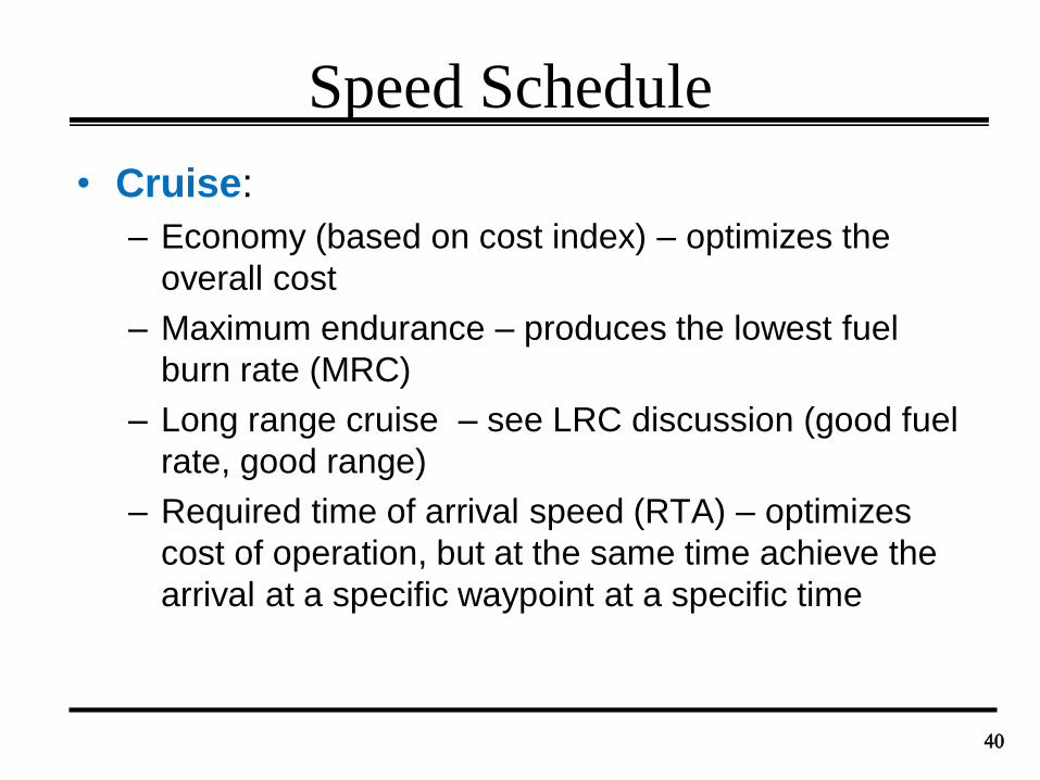
Speed Schedule
• Cruise:
– Economy (based on cost index) – optimizes the
overall cost
– Maximum endurance – produces the lowest fuel
burn rate (MRC)
– Long range cruise – see LRC discussion (good fuel
rate, good range)
– Required time of arrival speed (RTA) – optimizes
cost of operation, but at the same time achieve the
arrival at a specific waypoint at a specific time
40
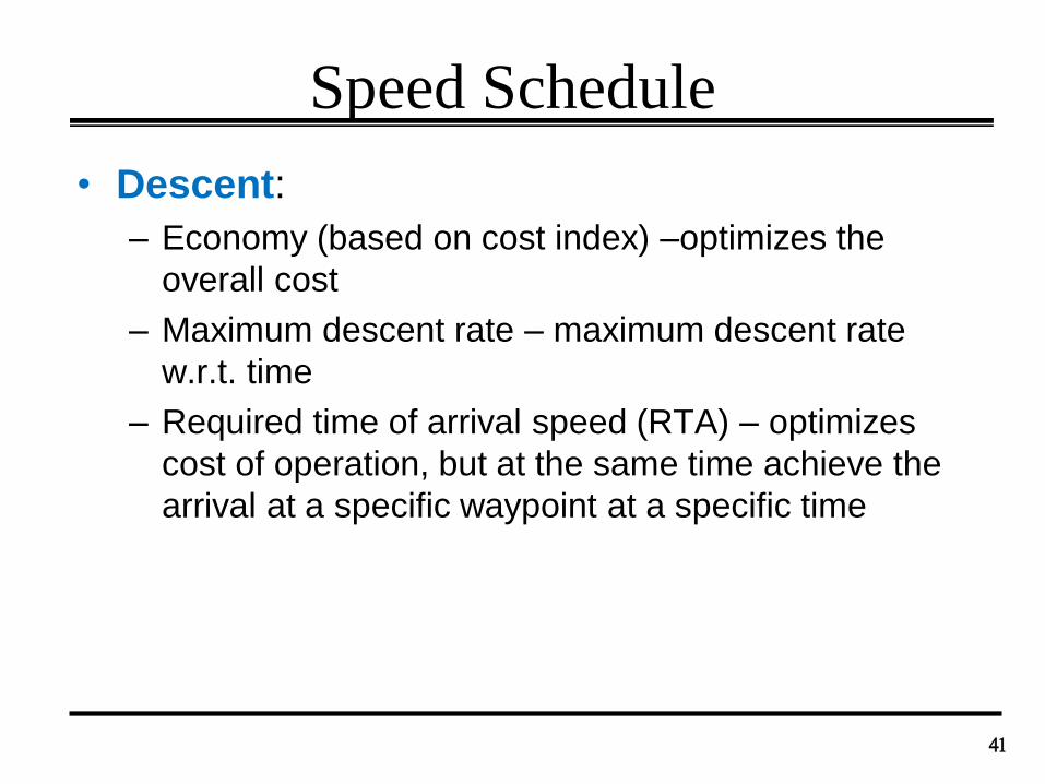
Speed Schedule
• Descent:
– Economy (based on cost index) –optimizes the
overall cost
– Maximum descent rate – maximum descent rate
w.r.t. time
– Required time of arrival speed (RTA) – optimizes
cost of operation, but at the same time achieve the
arrival at a specific waypoint at a specific time
41
Crossover Altitude
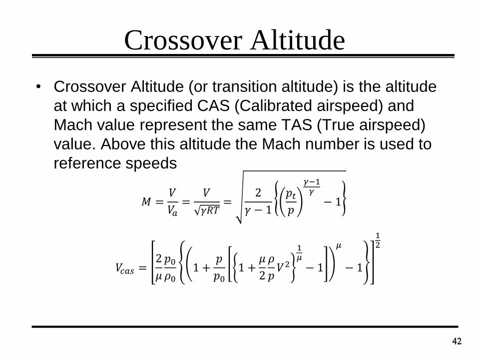
• Crossover Altitude (or transition altitude) is the altitude
at which a specified CAS (Calibrated airspeed) and
Mach value represent the same TAS (True airspeed)
value. Above this altitude the Mach number is used to
reference speeds
42
𝑀 =𝑉
𝑉𝑎=
𝑉
𝛾𝑅𝑇=
2
𝛾 − 1
𝑝𝑡𝑝
𝛾−1𝛾
− 1
𝑉𝑐𝑎𝑠 =2
𝜇
𝑝0𝜌0
1 +𝑝
𝑝01 +
𝜇
2
𝜌
𝑝𝑉2
1𝜇
− 1
𝜇
− 1
12
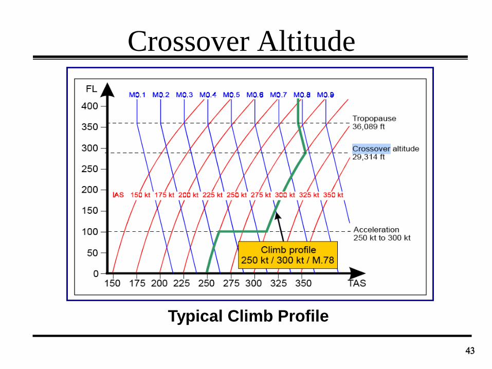
Crossover Altitude
43
Typical Climb Profile
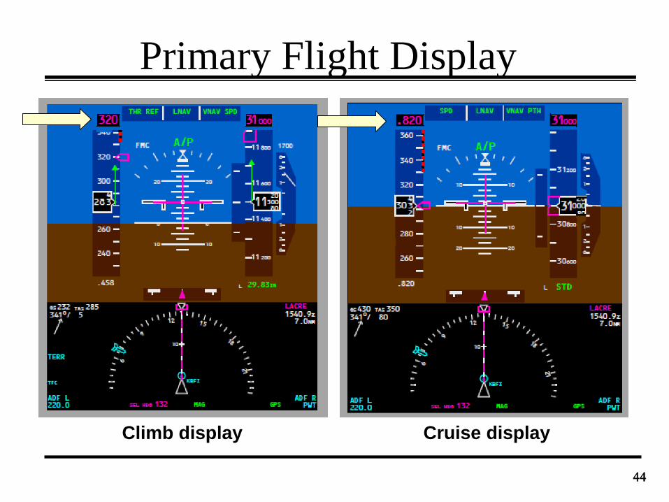
Primary Flight Display
44
Climb display Cruise display
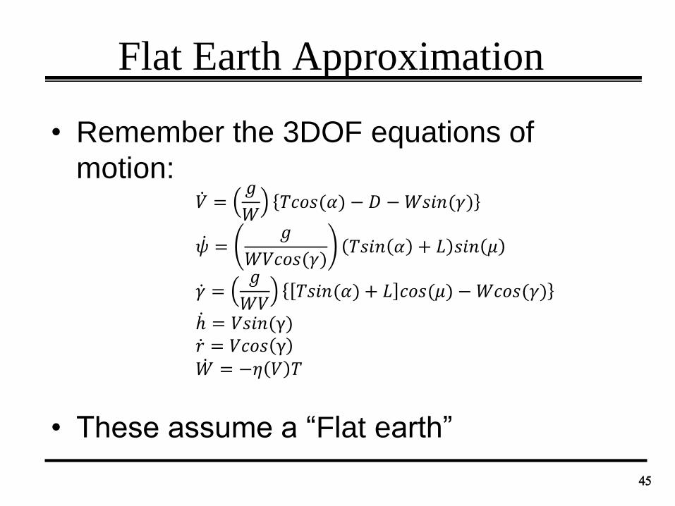
Flat Earth Approximation
• Remember the 3DOF equations of
motion:
• These assume a “Flat earth”
45
𝑉 =𝑔
𝑊𝑇𝑐𝑜𝑠(𝛼) − 𝐷 −𝑊𝑠𝑖𝑛(𝛾)
𝜓 =𝑔
𝑊𝑉𝑐𝑜𝑠(𝛾)𝑇𝑠𝑖𝑛 𝛼 + 𝐿 𝑠𝑖𝑛 𝜇
𝛾 =𝑔
𝑊𝑉𝑇𝑠𝑖𝑛(𝛼) + 𝐿 𝑐𝑜𝑠(𝜇) −𝑊𝑐𝑜𝑠(𝛾)
ℎ = 𝑉𝑠𝑖𝑛(γ) 𝑟 = 𝑉𝑐𝑜𝑠 γ 𝑊 = −𝜂 𝑉 𝑇
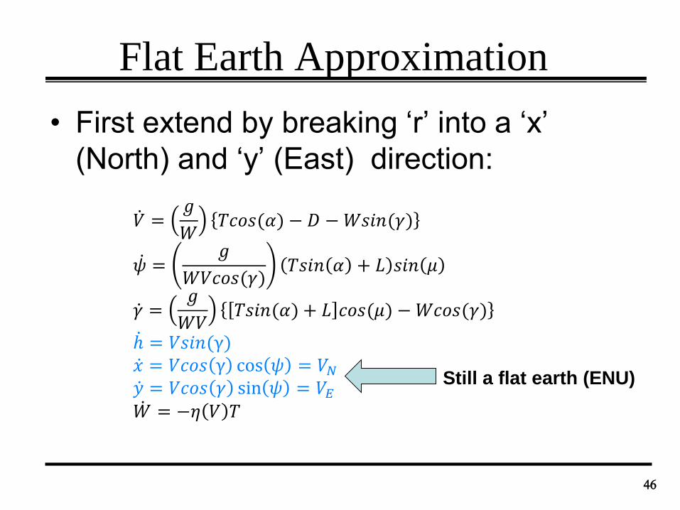
Flat Earth Approximation
• First extend by breaking ‘r’ into a ‘x’
(North) and ‘y’ (East) direction:
46
𝑉 =𝑔
𝑊𝑇𝑐𝑜𝑠(𝛼) − 𝐷 −𝑊𝑠𝑖𝑛(𝛾)
𝜓 =𝑔
𝑊𝑉𝑐𝑜𝑠(𝛾)𝑇𝑠𝑖𝑛 𝛼 + 𝐿 𝑠𝑖𝑛 𝜇
𝛾 =𝑔
𝑊𝑉𝑇𝑠𝑖𝑛(𝛼) + 𝐿 𝑐𝑜𝑠(𝜇) −𝑊𝑐𝑜𝑠(𝛾)
ℎ = 𝑉𝑠𝑖𝑛(γ) 𝑥 = 𝑉𝑐𝑜𝑠 γ cos 𝜓 = 𝑉𝑁 𝑦 = 𝑉𝑐𝑜𝑠 𝛾 sin 𝜓 = 𝑉𝐸 𝑊 = −𝜂 𝑉 𝑇
Still a flat earth (ENU)
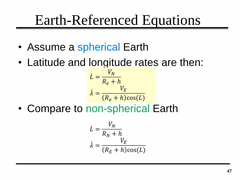
Earth-Referenced Equations
• Assume a spherical Earth
• Latitude and longitude rates are then:
• Compare to non-spherical Earth
47
𝐿 =𝑉𝑁
𝑅𝑒 + ℎ
𝜆 =𝑉𝐸
𝑅𝑒 + ℎ cos(𝐿)
𝐿 =𝑉𝑁
𝑅𝑁 + ℎ
𝜆 =𝑉𝐸
𝑅𝐸 + ℎ cos(𝐿)
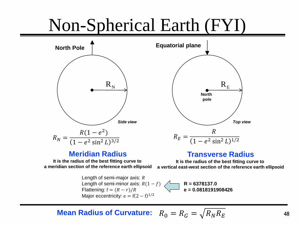
Non-Spherical Earth (FYI)
48
North Pole
RN
Meridian RadiusIt is the radius of the best fitting curve to
a meridian section of the reference earth ellipsoid
Equatorial plane
RE
North
pole
Top viewSide view
Transverse RadiusIt is the radius of the best fitting curve to
a vertical east-west section of the reference earth ellipsoid
Mean Radius of Curvature:
𝑅𝑁 =𝑅(1 − 𝑒2)
1 − 𝑒2 sin2 𝐿 3/2𝑅𝐸 =
𝑅
1 − 𝑒2 sin2 𝐿 1/2
𝑅0 = 𝑅𝐺 = 𝑅𝑁𝑅𝐸
Length of semi-major axis: 𝑅Length of semi-minor axis: 𝑅(1 − 𝑓)Flattening: f = (𝑅 − 𝑟)/𝑅Major eccentricity: e = f 2 − f 1/2
R = 6378137.0
e = 0.0818191908426
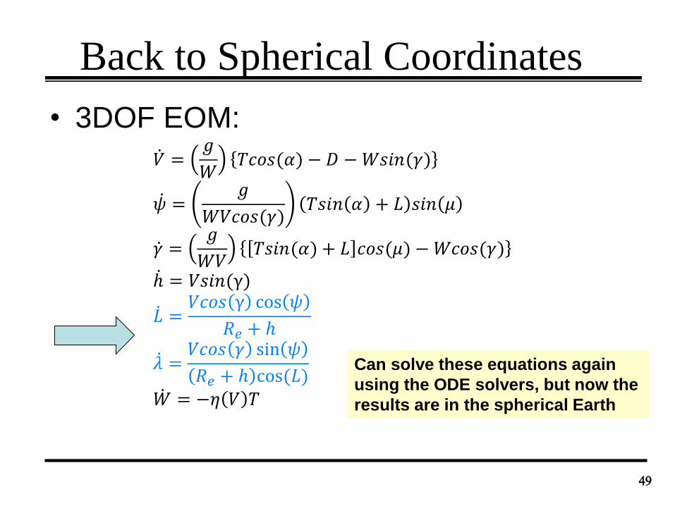
Back to Spherical Coordinates
• 3DOF EOM:
49
𝑉 =𝑔
𝑊𝑇𝑐𝑜𝑠(𝛼) − 𝐷 −𝑊𝑠𝑖𝑛(𝛾)
𝜓 =𝑔
𝑊𝑉𝑐𝑜𝑠(𝛾)𝑇𝑠𝑖𝑛 𝛼 + 𝐿 𝑠𝑖𝑛 𝜇
𝛾 =𝑔
𝑊𝑉𝑇𝑠𝑖𝑛(𝛼) + 𝐿 𝑐𝑜𝑠(𝜇) −𝑊𝑐𝑜𝑠(𝛾)
ℎ = 𝑉𝑠𝑖𝑛(γ)
𝐿 =𝑉𝑐𝑜𝑠 γ cos 𝜓
𝑅𝑒 + ℎ
𝜆 =𝑉𝑐𝑜𝑠 𝛾 sin 𝜓
𝑅𝑒 + ℎ cos(𝐿) 𝑊 = −𝜂 𝑉 𝑇
Can solve these equations again
using the ODE solvers, but now the
results are in the spherical Earth
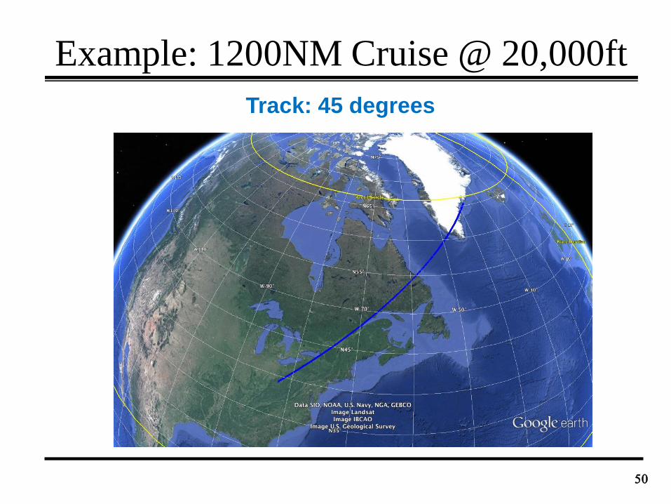
Example: 1200NM Cruise @ 20,000ft
50
Track: 45 degrees
Remember from earlier notes …
51
E
WAYPOINT ‘i’ 𝐫𝑖 = 𝑅𝑒
𝑐𝑜𝑠𝜆𝑖𝑐𝑜𝑠𝐿𝑖𝑠𝑖𝑛𝜆𝑖𝑐𝑜𝑠𝐿𝑖
𝑠𝑖𝑛𝐿𝑖
= 𝑅𝑒𝐞𝑖
𝐿𝑖
𝜆𝑖𝐿𝑖 = waypoint latitude
𝜆𝑖 = waypoint longitude
Radius of a sphere
(approximate Earth by a sphere)
Lateral Guidance
52
Great-circle route:
𝐞𝑔𝑡
𝐞𝑠𝑡
𝐞𝑎𝑝
st: start point
gt: go to
ap: along path𝐨
Normal vector to 𝐞𝑠𝑡𝐨𝐞𝑔𝑡 plane:
𝐧 = 𝐞𝑠𝑡 × 𝐞𝑔𝑡𝑅𝑒
𝑅𝑒
Δ𝑟𝑎𝑝−𝑔𝑡= 𝑅𝑒𝑎𝑐𝑜𝑠 𝐞𝑎𝑝 ∙ 𝐞𝑔𝑡
Δ𝑟𝑠𝑡−𝑔𝑡= 𝑅𝑒 cos
−1 𝐞𝒔𝒕 ∙ 𝐞𝑔𝑡
𝐞𝐸,𝑠𝑡 = 𝐞𝑍 × 𝐞𝑠𝑡𝐞𝑁,𝑠𝑡 = 𝐞𝑠𝑡 × 𝐞𝐸,𝑠𝑡
North-pointing local
level unit vector
𝐞𝑁,𝑠𝑡
East-pointing local
level unit vector
𝐞𝐸,𝑠𝑡
𝐞𝑧 = 0 0 1 𝑇
Lateral Guidance
53
Top-view
𝐞𝑔𝑡
𝐞𝑠𝑡
𝐞𝑎𝑝
𝐞𝑝𝑜𝑠
Cross-track error:
𝑋𝑇𝑅𝐾 = −𝑅𝑒 cos−1 𝐞𝑎𝑝 ∙ 𝐞𝑝𝑜𝑠
𝑋𝑇𝑅𝐾 = −𝑅𝑒𝐧 ∙ 𝐞𝑝𝑜𝑠
Desired track:
𝐷𝑇𝑅𝐾 = 𝑎𝑡𝑎𝑛−𝐧 ∙ 𝐞𝑁,𝑎𝑝
−𝐧 ∙ 𝐞𝐸,𝑎𝑝
𝐷𝑇𝑅𝐾
𝐶𝑇𝑅𝐾𝑋𝑇𝑅𝐾
Track error:
𝑇𝑅𝐾𝐸𝑅𝑅 = 𝐷𝑇𝑅𝐾 − 𝐶𝑇𝑅𝐾
Lateral Guidance
• LNAV is a so-called roll mode: a roll must
be commanded so the XTRK error and
the TRKERR can be reduced to zero
• Over-simplified control strategy:
54
𝜑𝑐𝑜𝑚𝑚𝑎𝑛𝑑𝑒𝑑 = 𝐺𝑋𝑇𝑅𝐾 ∙ 𝑋𝑇𝑅𝐾 + 𝐺𝑇𝑅𝐾𝐸𝑅𝑅 ∙ 𝑇𝑅𝐾𝐸𝑅𝑅 + 𝜑𝑛𝑜𝑚𝑖𝑛𝑎𝑙
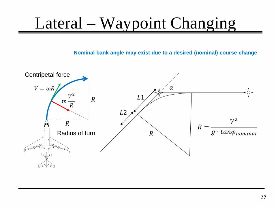
Lateral – Waypoint Changing
55
𝑅
𝑅
Radius of turn
Centripetal force
𝑚𝑉2
𝑅
𝑉 = 𝜔𝑅 𝛼
𝐿1
𝑅 =𝑉2
𝑔 ∙ 𝑡𝑎𝑛𝜑𝑛𝑜𝑚𝑖𝑛𝑎𝑙
𝐿2
𝑅
Nominal bank angle may exist due to a desired (nominal) course change
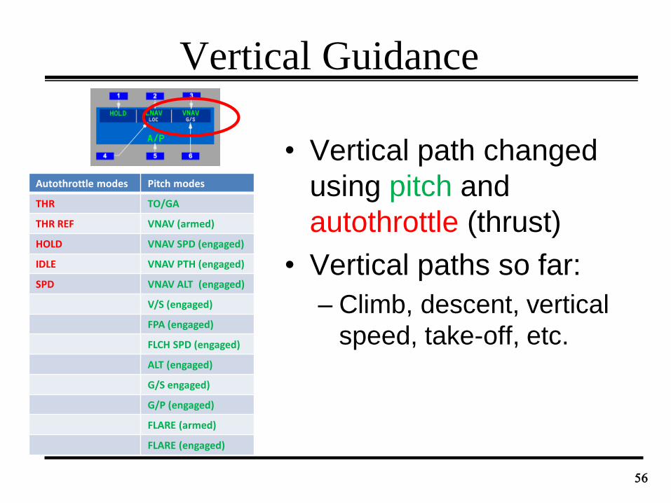
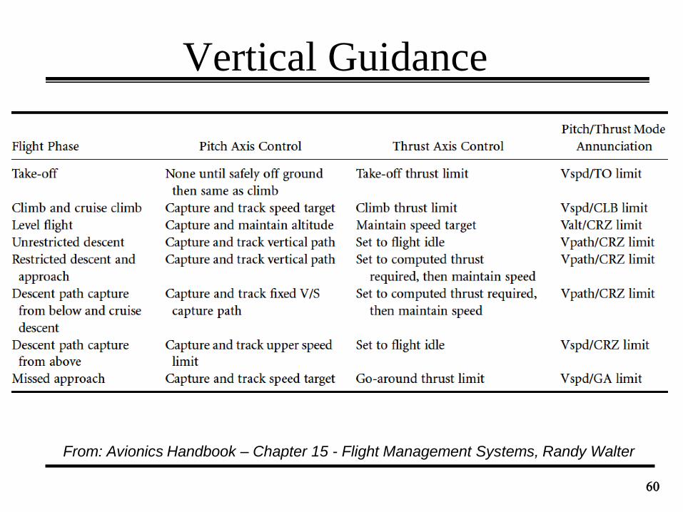
Vertical Guidance
• Vertical path changed
using pitch and
autothrottle (thrust)
• Vertical paths so far:
– Climb, descent, vertical
speed, take-off, etc.
56
Autothrottle modes Pitch modes
THR TO/GA
THR REF VNAV (armed)
HOLD VNAV SPD (engaged)
IDLE VNAV PTH (engaged)
SPD VNAV ALT (engaged)
V/S (engaged)
FPA (engaged)
FLCH SPD (engaged)
ALT (engaged)
G/S engaged)
G/P (engaged)
FLARE (armed)
FLARE (engaged)
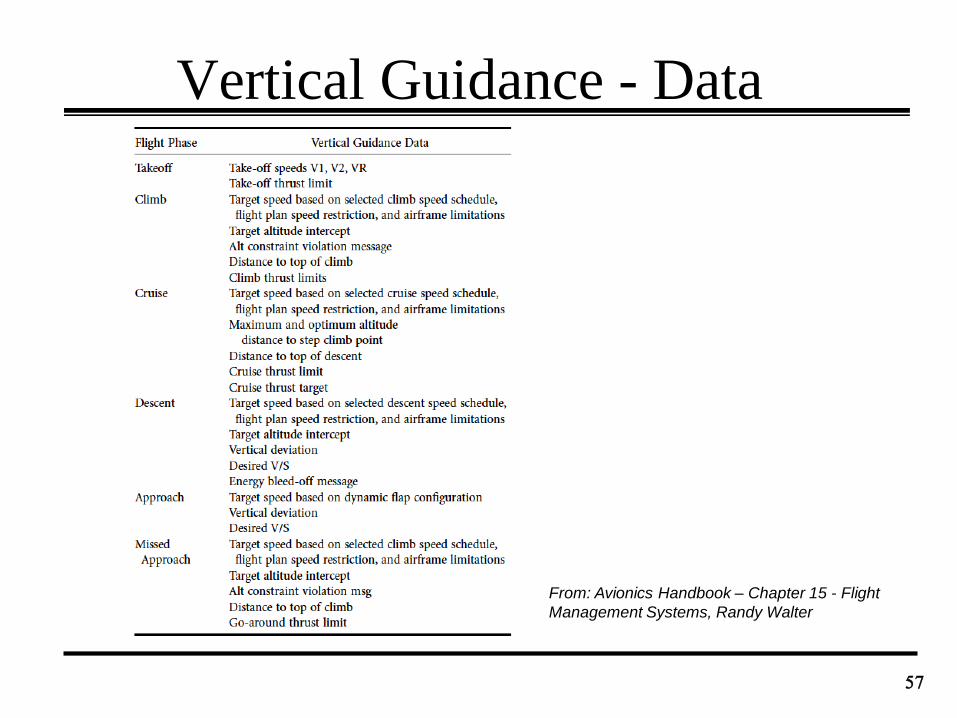
Vertical Guidance - Data
57
From: Avionics Handbook – Chapter 15 - Flight
Management Systems, Randy Walter
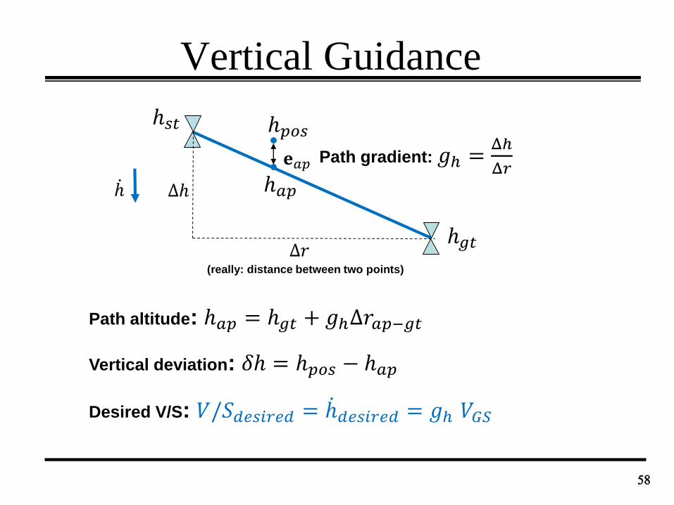
Vertical Guidance
58
Δℎ
(really: distance between two points)
ℎ
Δ𝑟
Path gradient: 𝑔ℎ =Δℎ
Δ𝑟
Path altitude: ℎ𝑎𝑝 = ℎ𝑔𝑡 + 𝑔ℎΔ𝑟𝑎𝑝−𝑔𝑡
𝐞𝑎𝑝
Vertical deviation: 𝛿ℎ = ℎ𝑝𝑜𝑠 − ℎ𝑎𝑝
ℎ𝑝𝑜𝑠
ℎ𝑎𝑝
ℎ𝑔𝑡
ℎ𝑠𝑡
Desired V/S: 𝑉/𝑆𝑑𝑒𝑠𝑖𝑟𝑒𝑑 = ℎ𝑑𝑒𝑠𝑖𝑟𝑒𝑑 = 𝑔ℎ 𝑉𝐺𝑆
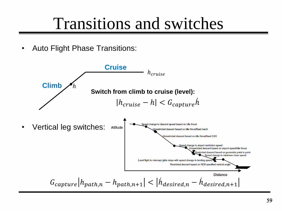
Transitions and switches
• Auto Flight Phase Transitions:
• Vertical leg switches:
59
Climb
Cruise
ℎ𝑐𝑟𝑢𝑖𝑠𝑒 − ℎ < 𝐺𝑐𝑎𝑝𝑡𝑢𝑟𝑒 ℎ
ℎ𝑐𝑟𝑢𝑖𝑠𝑒
ℎSwitch from climb to cruise (level):
𝐺𝑐𝑎𝑝𝑡𝑢𝑟𝑒 ℎ𝑝𝑎𝑡ℎ,𝑛 − ℎ𝑝𝑎𝑡ℎ,𝑛+1 < ℎ𝑑𝑒𝑠𝑖𝑟𝑒𝑑,𝑛 − ℎ𝑑𝑒𝑠𝑖𝑟𝑒𝑑,𝑛+1
Vertical Guidance
60
From: Avionics Handbook – Chapter 15 - Flight Management Systems, Randy Walter
Vertical Guidance
61
Vpath:
Capture: Δ𝜃 = 𝐺𝑝𝑎𝑡ℎ−𝑐𝑎𝑝𝑡𝑢𝑟𝑒 sin−1
ℎ𝑓𝑖𝑥𝑒𝑑−𝑐𝑎𝑝𝑡𝑢𝑟𝑒− ℎ
𝑉𝑡𝑟𝑢𝑒
Track: Δ𝜃 = 𝐺𝑎𝑙𝑡𝑖𝑡𝑢𝑑𝑒𝛿ℎ + 𝐺𝑉𝑆 ℎ𝑓𝑖𝑥𝑒𝑑−𝑐𝑎𝑝𝑡𝑢𝑟𝑒 − ℎ /𝑉𝑡𝑟𝑢𝑒
Altitude error V/S error
ℎ = 𝑉 𝑆 =vertical speed
For example VNAV PATH (B787 FCOM):
in the VNAV PTH pitch mode, the AFDS commands pitch to maintain FMC target altitude or the
VNAV path. The autothrottle maintains speed
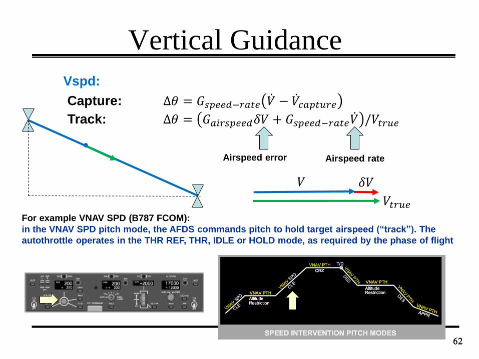
Vertical Guidance
62
Vspd:
Capture: Δ𝜃 = 𝐺𝑠𝑝𝑒𝑒𝑑−𝑟𝑎𝑡𝑒 𝑉 − 𝑉𝑐𝑎𝑝𝑡𝑢𝑟𝑒Track: Δ𝜃 = 𝐺𝑎𝑖𝑟𝑠𝑝𝑒𝑒𝑑𝛿𝑉 + 𝐺𝑠𝑝𝑒𝑒𝑑−𝑟𝑎𝑡𝑒 𝑉 /𝑉𝑡𝑟𝑢𝑒
𝑉𝑡𝑟𝑢𝑒
𝛿𝑉𝑉
Airspeed error Airspeed rate
For example VNAV SPD (B787 FCOM):
in the VNAV SPD pitch mode, the AFDS commands pitch to hold target airspeed (“track”). The
autothrottle operates in the THR REF, THR, IDLE or HOLD mode, as required by the phase of flight
Vertical Guidance
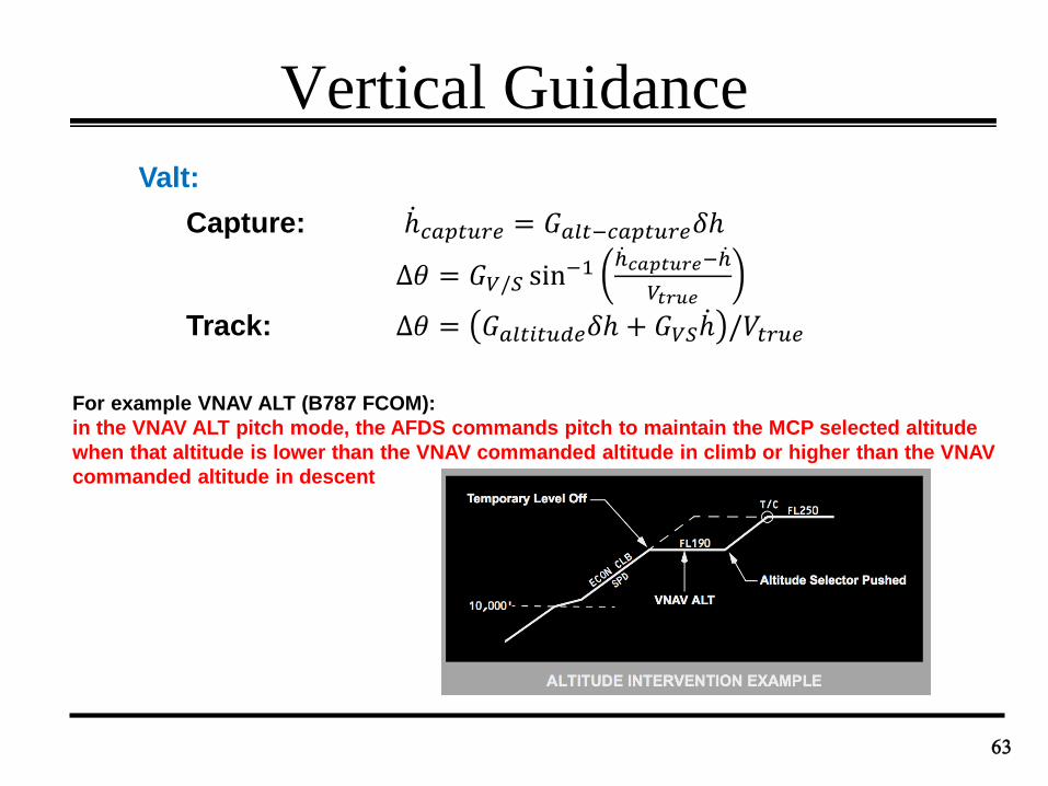
63
Valt:
Capture: ℎ𝑐𝑎𝑝𝑡𝑢𝑟𝑒 = 𝐺𝑎𝑙𝑡−𝑐𝑎𝑝𝑡𝑢𝑟𝑒𝛿ℎ
Δ𝜃 = 𝐺𝑉/𝑆 sin−1
ℎ𝑐𝑎𝑝𝑡𝑢𝑟𝑒− ℎ
𝑉𝑡𝑟𝑢𝑒
Track: Δ𝜃 = 𝐺𝑎𝑙𝑡𝑖𝑡𝑢𝑑𝑒𝛿ℎ + 𝐺𝑉𝑆 ℎ /𝑉𝑡𝑟𝑢𝑒
For example VNAV ALT (B787 FCOM):
in the VNAV ALT pitch mode, the AFDS commands pitch to maintain the MCP selected altitude
when that altitude is lower than the VNAV commanded altitude in climb or higher than the VNAV
commanded altitude in descent
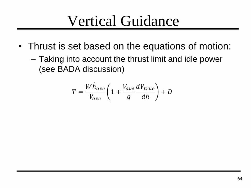
Vertical Guidance
• Thrust is set based on the equations of motion:
– Taking into account the thrust limit and idle power
(see BADA discussion)
64
𝑇 =𝑊 ℎ𝑎𝑣𝑒𝑉𝑎𝑣𝑒
1 +𝑉𝑎𝑣𝑒𝑔
𝑑𝑉𝑡𝑟𝑢𝑒𝑑ℎ
+ 𝐷
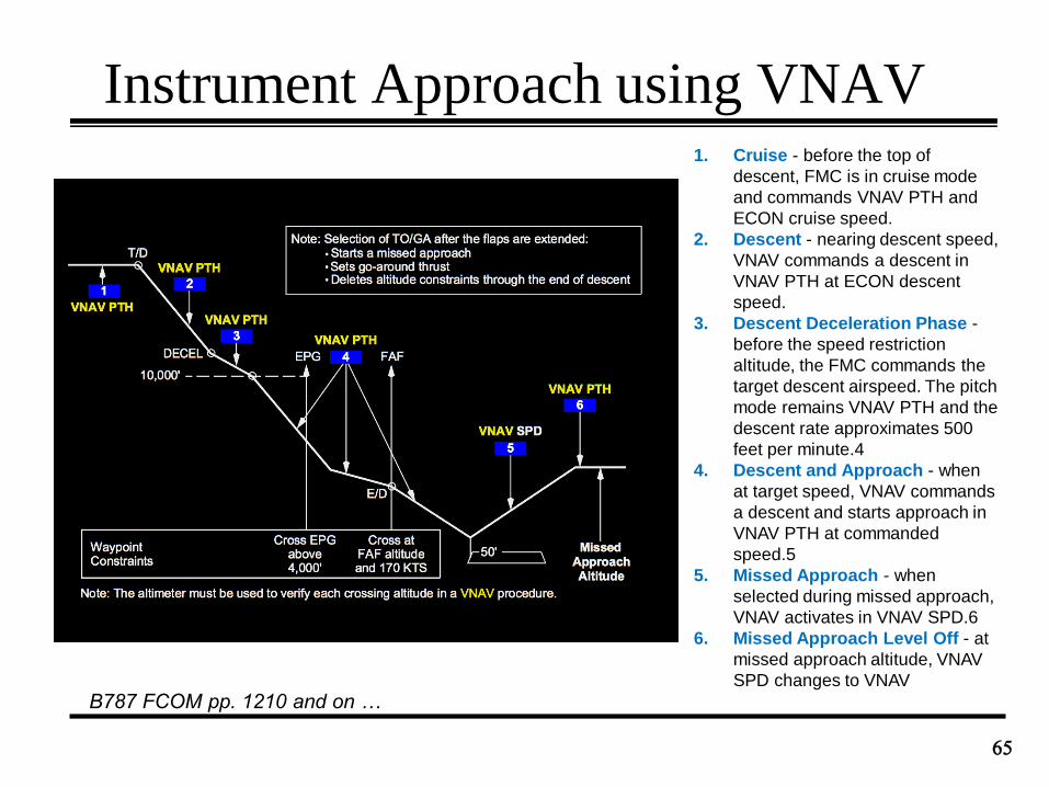
Instrument Approach using VNAV
65
B787 FCOM pp. 1210 and on …
1. Cruise - before the top of
descent, FMC is in cruise mode
and commands VNAV PTH and
ECON cruise speed.
2. Descent - nearing descent speed,
VNAV commands a descent in
VNAV PTH at ECON descent
speed.
3. Descent Deceleration Phase -
before the speed restriction
altitude, the FMC commands the
target descent airspeed. The pitch
mode remains VNAV PTH and the
descent rate approximates 500
feet per minute.4
4. Descent and Approach - when
at target speed, VNAV commands
a descent and starts approach in
VNAV PTH at commanded
speed.5
5. Missed Approach - when
selected during missed approach,
VNAV activates in VNAV SPD.6
6. Missed Approach Level Off - at
missed approach altitude, VNAV
SPD changes to VNAV
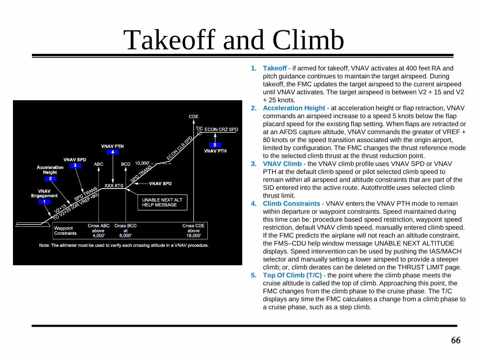
Takeoff and Climb
66
1. Takeoff - if armed for takeoff, VNAV activates at 400 feet RA and
pitch guidance continues to maintain the target airspeed. During
takeoff, the FMC updates the target airspeed to the current airspeed
until VNAV activates. The target airspeed is between V2 + 15 and V2
+ 25 knots.
2. Acceleration Height - at acceleration height or flap retraction, VNAV
commands an airspeed increase to a speed 5 knots below the flap
placard speed for the existing flap setting. When flaps are retracted or
at an AFDS capture altitude, VNAV commands the greater of VREF +
80 knots or the speed transition associated with the origin airport,
limited by configuration. The FMC changes the thrust reference mode
to the selected climb thrust at the thrust reduction point.
3. VNAV Climb - the VNAV climb profile uses VNAV SPD or VNAV
PTH at the default climb speed or pilot selected climb speed to
remain within all airspeed and altitude constraints that are part of the
SID entered into the active route. Autothrottle uses selected climb
thrust limit.
4. Climb Constraints - VNAV enters the VNAV PTH mode to remain
within departure or waypoint constraints. Speed maintained during
this time can be: procedure based speed restriction, waypoint speed
restriction, default VNAV climb speed, manually entered climb speed.
If the FMC predicts the airplane will not reach an altitude constraint,
the FMS–CDU help window message UNABLE NEXT ALTITUDE
displays. Speed intervention can be used by pushing the IAS/MACH
selector and manually setting a lower airspeed to provide a steeper
climb; or, climb derates can be deleted on the THRUST LIMIT page.
5. Top Of Climb (T/C) - the point where the climb phase meets the
cruise altitude is called the top of climb. Approaching this point, the
FMC changes from the climb phase to the cruise phase. The T/C
displays any time the FMC calculates a change from a climb phase to
a cruise phase, such as a step climb.
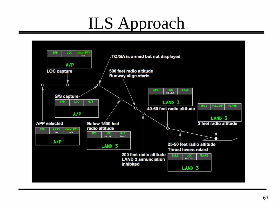
ILS Approach
67