flexibly-configurable and computation-efficient digital cash with polynomial-thresholded coinage
TRANSCRIPT


Lecture Notes in Computer Science 2828Edited by G. Goos, J. Hartmanis, and J. van Leeuwen

3BerlinHeidelbergNew YorkHong KongLondonMilanParisTokyo

Antonio Lioy Daniele Mazzocchi (Eds.)
Communications andMultimedia Security
AdvancedTechniques for Network and Data Protection
7th IFIP-TC6 TC11 International Conference, CMS 2003Torino, Italy, October 2-3, 2003Proceedings
1 3

Series Editors
Gerhard Goos, Karlsruhe University, GermanyJuris Hartmanis, Cornell University, NY, USAJan van Leeuwen, Utrecht University, The Netherlands
Volume Editors
Antonio LioyPolitecnico di TorinoDip. di Automatica e Informaticacorso Duca degli Abruzzi, 24, 10129 Torino, ItalyE-mail: [email protected]
Daniele MazzocchiIstituto Superiore Mario Boellacorso Trento, 21, 10129 Torino, ItalyE-mail: [email protected]
Cataloging-in-Publication Data applied for
A catalog record for this book is available from the Library of Congress.
Bibliographic information published by Die Deutsche BibliothekDie Deutsche Bibliothek lists this publication in the Deutsche Nationalbibliografie;detailed bibliographic data is available in the Internet at <http://dnb.ddb.de>.
CR Subject Classification (1998): C.2, E.3, D.4.6, H.5.1, K.4.1, K.6.5, H.4
ISSN 0302-9743ISBN 3-540-20185-8 Springer-Verlag Berlin Heidelberg New York
This work is subject to copyright. All rights are reserved, whether the whole or part of the material isconcerned, specifically the rights of translation, reprinting, re-use of illustrations, recitation, broadcasting,reproduction on microfilms or in any other way, and storage in data banks. Duplication of this publicationor parts thereof is permitted only under the provisions of the German Copyright Law of September 9, 1965,in its current version, and permission for use must always be obtained from Springer-Verlag. Violations areliable for prosecution under the German Copyright Law.
Springer-Verlag Berlin Heidelberg New Yorka member of BertelsmannSpringer Science+Business Media GmbH
http://www.springer.de
©IFIP International Federation for Information Processing, Hofstraße 3, A-2361 Laxenburg, Austria 2003Printed in Germany
Typesetting: Camera-ready by author, data conversion by PTP-Berlin GmbHPrinted on acid-free paper SPIN: 10959107 06/3142 5 4 3 2 1 0

Preface
The Communications and Multimedia Security conference (CMS 2003) was or-ganized in Torino, Italy, on October 2-3, 2003. CMS 2003 was the seventh IFIPworking conference on communications and multimedia security since 1995. Re-search issues and practical experiences were the topics of interest, with a specialfocus on the security of advanced technologies, such as wireless and multimediacommunications.
The book “Advanced Communications and Multimedia Security” containsthe 21 articles that were selected by the conference program committee for pre-sentation at CMS 2003. The articles address new ideas and experimental evalua-tion in several fields related to communications and multimedia security, suchas cryptography, network security, multimedia data protection, application secu-rity, trust management and user privacy. We think that they will be of interestnot only to the conference attendees but also to the general public of researchersin the security field.
We wish to thank all the participants, organizers, and contributors of theCMS 2003 conference for having made it a success.
October 2003 Antonio LioyGeneral Chair of CMS 2003
Daniele MazzocchiProgram Chair of CMS 2003

VI
Organization
CMS 2003 was organized by the TORSEC Computer and Network SecurityGroup of the Dipartimento di Automatica ed Informatica at the Politecnico diTorino, in cooperation with the Istituto Superiore Mario Boella.
Conference Committee
General Chair: Antonio Lioy (Politecnico di Torino, Italy)Program Chair: Daniele Mazzocchi (Istituto Superiore Mario Boella, Italy)Organizing Chair: Andrea S. Atzeni (Politecnico di Torino, Italy)
Program Committee
F. Bergadano, Universita di TorinoE. Bertino, Universita di MilanoL. Breveglieri, Politecnico di MilanoA. Casaca, INESC, chairman IFIP TC6M. Cremonini, Universita di MilanoY. Deswarte, LAAS-CNRSM. G. Fugini, Politecnico di MilanoS. Furnell, University of PlymouthR. Grimm, Technische Universitat IlmenauB. Jerman-Blazic, Institut Jozef StefanS. Kent, BBNT. Klobucar, Institut Jozef StefanA. Lioy, Politecnico di TorinoP. Lipp, IAIKJ. Lopez, Universidad de MalagaF. Maino, CISCOD. Mazzocchi, ISMBS. Muftic, KTHF. Piessens, Katholieke Universiteit LeuvenP. A. Samarati, Universita di MilanoA. F. G. Skarmeta, Universidad de MurciaL. Strous, De Nederlandsche Bank, chairman IFIP TC11G. Tsudik, University of California at Irvine

Table of Contents
Cryptography
Computation of Cryptographic Keys from Face Biometrics . . . . . . . . . . . . . 1Alwyn Goh, David C.L. Ngo
AUTHMAC DH: A New Protocol for Authentication andKey Distribution . . . . . . . . . . . . . . . . . . . . . . . . . . . . . . . . . . . . . . . . . . . . . . . . . . 14
Heba K. Aslan
Multipoint-to-Multipoint Secure-Messaging with Threshold-RegulatedAuthorisation and Sabotage Detection . . . . . . . . . . . . . . . . . . . . . . . . . . . . . . . 27
Alwyn Goh, David C.L. Ngo
Network Security
Securing the Border Gateway Protocol: A Status Update . . . . . . . . . . . . . . . 40Stephen T. Kent
Towards an IPv6-Based Security Framework for Distributed StorageResources . . . . . . . . . . . . . . . . . . . . . . . . . . . . . . . . . . . . . . . . . . . . . . . . . . . . . . . . 54
Alessandro Bassi, Julien Laganier
Operational Characteristics of an Automated Intrusion ResponseSystem . . . . . . . . . . . . . . . . . . . . . . . . . . . . . . . . . . . . . . . . . . . . . . . . . . . . . . . . . . 65
Maria Papadaki, Steven Furnell, Benn Lines, Paul Reynolds
Mobile and Wireless Network Security
A Secure Multimedia System in Emerging Wireless Home Networks . . . . . 76Nut Taesombut, Richard Huang, Venkat P. Rangan
Java Obfuscation with a Theoretical Basis for Building SecureMobile Agents . . . . . . . . . . . . . . . . . . . . . . . . . . . . . . . . . . . . . . . . . . . . . . . . . . . . 89
Yusuke Sakabe, Masakazu Soshi, Atsuko Miyaji
A Security Scheme for Mobile Agent Platforms in Large-ScaleSystems . . . . . . . . . . . . . . . . . . . . . . . . . . . . . . . . . . . . . . . . . . . . . . . . . . . . . . . . . 104
Michelle S. Wangham, Joni da Silva Fraga, Rafael R. Obelheiro
Trust and Privacy
Privacy and Trust in Distributed Networks . . . . . . . . . . . . . . . . . . . . . . . . . . . 117Thomas Rossler, Arno Hollosi

VIII Table of Contents
Extending the SDSI / SPKI Model through Federation Webs . . . . . . . . . . . 132Altair Olivo Santin, Joni da Silva Fraga, Carlos Maziero
Trust-X : An XML Framework for Trust Negotiations . . . . . . . . . . . . . . . . . . 146Elisa Bertino, Elena Ferrari, Anna C. Squicciarini
Application Security
How to Specify Security Services: A Practical Approach . . . . . . . . . . . . . . . 158Javier Lopez, Juan J. Ortega, Jose Vivas, Jose M. Troya
Application Level Smart Card Support through Networked MobileDevices . . . . . . . . . . . . . . . . . . . . . . . . . . . . . . . . . . . . . . . . . . . . . . . . . . . . . . . . . . 172
Pierpaolo Baglietto, Francesco Moggia, Nicola Zingirian,Massimo Maresca
Flexibly-Configurable and Computation-Efficient Digital Cash withPolynomial-Thresholded Coinage . . . . . . . . . . . . . . . . . . . . . . . . . . . . . . . . . . . . 181
Alwyn Goh, Kuan W. Yip, David C.L. Ngo
Multimedia Security
Selective Encryption of the JPEG2000 Bitstream . . . . . . . . . . . . . . . . . . . . . 194Roland Norcen, Andreas Uhl
Robust Spatial Data Hiding for Color Images . . . . . . . . . . . . . . . . . . . . . . . . . 205Xiaoqiang Li, Xiangyang Xue, Wei Li
Watermark Security via Secret Wavelet Packet Subband Structures . . . . . 214Werner Dietl, Andreas Uhl
A Robust Audio Watermarking Scheme Based on MPEG 1 Layer 3Compression . . . . . . . . . . . . . . . . . . . . . . . . . . . . . . . . . . . . . . . . . . . . . . . . . . . . . 226
David Megıas, Jordi Herrera-Joancomartı, Julia Minguillon
Loss-Tolerant Stream Authentication via Configurable Integrationof One-Time Signatures and Hash-Graphs . . . . . . . . . . . . . . . . . . . . . . . . . . . 239
Alwyn Goh, G.S. Poh, David C.L. Ngo
Confidential Transmission of Lossless Visual Data: ExperimentalModelling and Optimization . . . . . . . . . . . . . . . . . . . . . . . . . . . . . . . . . . . . . . . . 252
Bubi G. Flepp-Stars, Herbert Stogner, Andreas Uhl
Author Index . . . . . . . . . . . . . . . . . . . . . . . . . . . . . . . . . . . . . . . . . . . . . . . . 265

A. Lioy and D. Mazzocchi (Eds.): CMS 2003, LNCS 2828, pp. 1–13, 2003.© IFIP International Federation for Information Processing 2003
Computation of Cryptographic Keys from FaceBiometrics
Alwyn Goh1 and David C.L. Ngo2
1 Corentix Laboratories, B–19–02 Cameron Towers, Jln 5/58B,46000 Petaling Jaya, [email protected]
2 Faculty of Information Science & Technology, Multimedia University,75450 Melaka, Malaysia
Abstract. We outline cryptographic key–computation from biometric databased on error-tolerant transformation of continuous-valued face eigenprojec-tions to zero-error bitstrings suitable for cryptographic applicability. Bio-hashing is based on iterated inner-products between pseudorandom and user-specific eigenprojections, each of which extracts a single-bit from the face data.This discretisation is highly tolerant of data capture offsets, with same-user facedata resulting in highly correlated bitstrings. The resultant user identification interms of a small bitstring-set is then securely reduced to a single cryptographickey via Shamir secret-sharing. Generation of the pseudorandom eigenprojectionsequence can be securely parameterised via incorporation of physical tokens.Tokenised bio-hashing is rigorously protective of the face data, with securitycomparable to cryptographic hashing of token and knowledge key-factors. Ourmethodology has several major advantages over conventional biometric analy-sis ie elimination of false accepts (FA) without unacceptable compromise interms of more probable false rejects (FR), straightforward key-management,and cryptographically rigorous commitment of biometric data in conjunctionwith verification thereof.
1 Introduction
Biometric ergonomics and cryptographic security are highly complementary attrib-utes, hence the motivation for the presented research. Computation of cryptographickeys from biometric data was first proposed in the Bodo patent [1], and is technicallychallenging from both signal processing and information security viewpoints. Therepresentation problem is that biometric data (ie linear time-series or planar bitmaps)is continuous and high-uncertainty, while cryptographic parameters are discrete andzero-uncertainty. Biometric consistency—ie the difference between reference and testdata, which are (at best) similar but never equal—is hence inadequate for crypto-graphic purposes which require exact reproduction. This motivates the formulation ofoffset-tolerant discretisation methodologies, the end result of which is also required tobe protect against adversarial recovery of user-specific biometrics.

2 A. Goh and D.C.L. Ngo
2 Review of Previous Work
The earliest publications in this domain are by Soutar et al [2, 3], whose researchoutlines cryptographic key-recovery from the integral correlation of freshly capturedfingerprint data and previously registered bioscrypts. Bioscrypts result from themixing of random and user-specific data—thereby preventing recovery of the originalfingerprint data—with data capture uncertainties addressed via multiply-redundantmajority-result table lookups. This ensures representation tolerance against offsets insame-user test fingerprints, but does not satisfactorily handle the issue of discrimina-tion against different-user data..
The Davida et al [4, 5] formulation outlines cryptographic signature verificationof iris data without stored references. This is accomplished via open token-basedstorage of user-specific Hamming codes necessary to rectify offsets in the test data,thereby allowing verification of the corrected biometrics. Such self-correctingbiometric representations are applicable towards key-computation, with recovery ofiris data prevented by complexity theory. Resolution of biometric uncertainty viaHamming error correction is rigorous from the security viewpoint, and improves onthe somewhat heuristic Soutar et al lookups.
Monrose et al key-computation from user-specific keystroke [6] and voice [7]data is based on the deterministic concatenation of single-bit outputs based on logicalcharacterisations of the biometric data, in particular whether user-specific features arebelow (0) or above (1) some population-generic threshold. These feature-derivedbitstrings are used in conjunction with randomised lookup tables formulated viaShamir [8] secret-sharing. Error correction in this case is also rigorous, with Shamirpolynomial thresholding and Hamming error correction considered to be equivalentmechanisms [5]. The inherent scalability of the bitstrings is another major advantageover the Soutar et al methodology.
Direct mixing of random and biometric data (as in Soutar er al) allows incorpora-tion of serialised physical tokens, thereby resulting in token+biometric cryptographickeys. There are also advantages from the operations security viewpoint, arising fromthe permanent association of biometrics with their owners. Tokenised randomisationprotects against biometric fabrication—as demonstrated by Matsumoto et al [9] forfingerprints, which is considered one of the more secure form factors—without adver-sarial knowledge of the randomisation, or equivalently possession of the correspond-ing token.
3 Bio–Hash Methodology
This paper outlines cryptographic key-computation from face bitmaps, or specificallyfrom Sirovich-Kirby [10, 11] eigenprojections thereof. The proposed bio-hashing isbased on: (1) biometric eigenanalysis: resulting in user-specific eigenprojections witha moderate degree of offset tolerance, (2) biometric discretisation: via iterated inner-product mixing of tokenised and biometric data, with enhanced offset tolerance, and(3) cryptographic interpolation: of Shamir secret-shares corresponding to token andbiometric data, culminating in a zero-error key. Bio-hashing has the following ad-

Computation of Cryptographic Keys from Face Biometrics 3
vantages: (1) tokenised random mixing: in common with Soutar et al, (2) discretisa-tion scalability: in common with Monrose et al, and (3) rigorous error correction: incommon with Davida et al and Monrose et al. The proposed formulation is further-more highly generic arising from the proposed discretisation in terms of inner-
products ie s = a⋅b for a,b∈ IRn
We believe our work to be the first demonstration of key-computation from face data,which seems difficult to handle (in common with other planar representations) usingthe Monrose et at procedure. Bio-hashing is essentially a transformation from repre-sentations which are high-dimension and high-uncertainty (the face bitmaps) to thosewhich are low-dimension and zero-uncertainty (the derived keys). The successive
representations are: (1) raw bitmap: x ∈ S in domain IRN
, with N the pixelisation
dimension, (2) eigenprojection: a ∈ S′ in domain IRn, with n << N the eigenbasis
dimension, (3) discretisation: x ∈ S″ in domain m2 , with m the bitstring length, and
(4) interpolation: a in domain m2 ; as illustrated below:
IR IR
Fig. 1. Bio-hash representations and transformations
with enhanced stability at each step. Note this abstracted outlook does not take intoaccount bitmap pre-processing prior to step (2), which is in actual fact extremelyimportant due to the obvious correlation between the offset tolerances of (2) and (3).Enhancements in the former can be effected via application of Hambridge featurelocation [12] and eigenanalysis as reported in Ngo-Goh [13]. Our methodology is stillstraightforwardly applicable, with a and x in this case a concatenation of feature-specific contributions.The primary concern from the security viewpoint centres on protection of informationduring the representational transformations, and in particular whether these transfor-mations can be inverted to recover the input information. The above-listed parame-ters are said to be zero knowledge (ZK) representations of their inputs if thetransformations are non-invertible, as in the case of cryptographic hash
m m mh(i, j) : 2 2 2m
′× ∀ →′
for token serialisation i and secret knowledge j. This
motivates an equivalent level of protection for biometric a; which is accomplished viatoken-specification of the (3) and (4) representations, such that bio-hash
H (i, a) : 2m
× IRn → 2
m does not jeopardise ⟨i, a⟩. ZK representation a = H(i, a) is

4 A. Goh and D.C.L. Ngo
subsequently useful for standard cryptographic operations ie signature generation andmessage decryption. Note H has an important (and challenging) additional require-ment over h, namely offset tolerance so that H(i, a) is stable for ∀a ∈ S′. This re-quirement essentially addresses the fundamental gap between biometric similarity andcryptographic equality.
Our methodology is outlined in the above-discussed stages, as follows:-
3.1 Biometric Eigenanalysis
Sirovich-Kirby principal components analysis (PCA) presumes that IRN
face bitmaps
are more effectively represented as IRn eigenprojections, with interim dimensionality
M << N corresponding to the number of distinct users in the bitmap database. Ei-genface characterisation requires computation of eigenbasis ke (ranked by eigen-
value ck significance) for k = 1… M. The n << M principal eigenfaces enables
descriptive accuracy up to an externally specified accuracy, with user-specific data
represented as are then computed as †ak k= ⋅ αe d .
Conventional biometrics requires storage of user-specific a so as to provide a ref-erence against freshly captured test data. This is not satisfactory from the securityviewpoint, as an intercepted a opens up the possibility of transaction fraud. Revoca-tion of a (analogous to password refreshment or token replacement) is also highlyproblematic for all biometric forms, and impossible for face data. This dilemma is amajor motivation for our work, particularly in its emphasis that stored references arefundamentally insecure and that bio-hashing should operate in a one-way manner onfresh data, analogous to password hashing.
3.2 Biometric Discretisation
The most offset tolerant transformation on face data a ∈ IRn is reduction down to a
single-bit. This is accomplished via:-
1. Compute ( )s( , ) c a bk k kk
= ⋅ = ∑a b a b with random normalised b ∈ IRn
2. Assign
0 : s
b(s) 1: s
: s [ , ]
< µ−σ= > µ+σ∅ ∈ µ−σ µ+σ
for empirical µ and σ, the former of which should theoretically vanish due to abovespecification of a relative to the population average. Extracted b(a⋅b) is a broadmeasure of whether ⟨a, b⟩ are inline or opposed, with σ applied to exclude the per-pendicular case. This exclusion mitigates against data capture uncertainties in a,which might otherwise result in bit-inversion for numerically small s.
Repetition of this procedure to obtain multiple bits raises the issue of inter-bitcorrelations, which is addressed via orthonormal set : k 1kβ = = νb with ν < n.

Computation of Cryptographic Keys from Face Biometrics 5
Each bit ( )bxk k= ⋅a b is hence rendered independant of all others, so that legitimate
(and unavoidable) variations in ∀a ∈ S′ that invert xk would not necessarily have
the same effect on xk′ .
Inter-bit correlations and observations thereof are also important from the secu-rity viewpoint, the latter of which is prevented via cryptographic hashing of the con-catenated bits. Indeterminate bits xk = ∅ are handled via replacement of near-
perpendicular kb with alternative k′b , the net effect of which is bit-extraction via
adjusted set k kk k
β − ∀ + ∀ ′∈⊥ ∈⊥
b b . This reformulation is facilitated by the original
stipulation on ν, which allows up to n–ν replacements for unsuitable kb .
The proposed discretisation via repeated inner-products then proceeds as follows:1. Generate random β + ∀b′ for k = 1…ν…n2. Orthonormalise β + ∀b′ via Gram-Schmidt procedure3. For each k = 1…ν:
1. Compute sk k= ⋅a b2. While [ , ]sk ∈ µ−σ µ+σ :-
1. Get next unused b′2. Reassign k ′= bb in β3. Recompute sk
3. Assign ( )b sxk k=4. Concatenate xk
kα = ∀
5. Compute x = h(α)Note the easy adaptability to the previously discussed multi-feature biometrics, and
also the inherent scalability (with respect the 2να∈ bitlength) equivalent to theMonrose et al methodology. The experimental data in the next section is designed toaddress signal processing issues, hence the omission of step (5) there. Step (3.2) iscritical for representational stability ie the confinement of x(a) for ∀a ∈ S′ to a smallset S″, so as to facilitate mapping down to a single cryptographic key. This requires
the generic stability of random ( )x k⋅a b ; and is a fundamental motivation for the
presented error correction at two stages, the first of which uses σ valuation to mitigateagainst continuous-valued uncertainties in a. The second-stage addresses the discreti-
sation of these uncertainties in mx( ) 2∈a .
Recall the stipulation that a be protected equivalent to other cryptographic key-factors, which is accomplished via the use of tokenised cryptographic mechanisms—ie X9.17 pseudorandom generators [14] constructed from ciphers or hashes—in step(1). Resultant sequence β(i) and output x(i, a) are hence ZK representations of i, andconsequently protective of a as subsequently outlined; which is reminiscent of theSoutar et al methodology. Note the effect of different token i′ on the β sequence,resulting in x(i, a) ≠ x(i′, a) to a high degree of certainty. The proposed tokenised

6 A. Goh and D.C.L. Ngo
discretisation can therefore be said to combine the best attributes of the Soutar et aland Monrose et al approaches.
3.3 Cryptographic Interpolation
The limited uncertainty of x ∈ S″ is addressed via Shamir secret-sharing; which usesmodular polynomial f (x) : ZZ q → ZZ q for secret encoding f (0) = a, which is the
2m ZZ q cryptographic key in our context. In the simplest linear case, this allows
secret recovery via x f (x ) x f (x)
a (modq)x x x x
′ ′⋅ ⋅= +′ ′− − with x = x(i, a) and x′ = h(i). Coor-
dinate pair ⟨x, f(x)⟩ constitutes a secret-share, any two of which can be combined torecover a. The operational concept is to match one of the biometric-associated shareswith the token-associated one, so as to be consistent with the above-outlined discus-sion on token-specific discretisations. This is a rigorous 2-of-µ threshold system,with µ = |S″| the number of possible discretisation outcomes corresponding to a par-ticular user.
The still approximate nature of the above-presented discretisation is addressedvia prior specification and token-side insertion of X = ⟨∀⟨χ, y⟩, c⟩, with: (1) χ = h(x)
and x f (x)
y modqx x′⋅= ′ − for ∀a ∈ S′, and (2) c = f(x′) mod q; corresponding to some
random key-encoding polynomial f. Key-computation then commences as follows:-1. Retrieve X from token2. Compute x = x(i, a) as previously outlined3. Select y such that χ = h(x) else stop
4. Compute c x
a y (modq)x h(i)
⋅= +−provided ∀x ∈ S″ have been properly identified. Note that a(i, a) in step (4) cannotbe computed without one of the correct discretisations x or token i, and that neither ofthese can be recovered from the ZK representations in X. The latter can in fact bestored completely in the open, which is illustrative of the protocol-level security com-parable to the Davida et al and Monrose et al formulations. This is in complete con-trast to the highly sensitive handling of biometric references, and the seriousconsequences arising from failure thereof. It is furthermore possible to encode a
password-associated key-share via prior specification in X of x f (x )
y modqx x′ ′′⋅′′ = ′ ′′−
with x″ = h(j) from password j. This enables subsequent token+knowledge computa-
tion c x
a y (modq)x h(i)
′′⋅ ′′= +′′− via y″ from token-side X as a backup option when the
usual token+biometric computation is inapplicable ie in low-light conditions.Polynomial thresholding is rigorous and versatile, but is on the other hand re-
strictive in that (small) µ has to known a priori. This requires a high degree of errortolerance in the above-discussed discretisation x(i, a), as would result from suitable ad-

Computation of Cryptographic Keys from Face Biometrics 7
justment of σ. Key-interpolation is interpreted as a final error-correcting step in thiscontext, supplementing the basic robustness of random bit-extraction and the re-placement of bits over-sensitive to legitimate variations in a. End result a = H(i, a) ishence: (1) sensitively dependant on i: so that exact correctness is required for β(i) andx′(i), the former of which contributes sensitively towards x(i, a) ∈ S″, (2) robustlydependant on a; commensurate with the discrete i and continuous a key-factors.
4 Experimental Data
The proposed methodology is tested on Spacek’s Faces94 dataset [15] posted onthe University of Essex Website. This dataset contains frontal face photos takenfrom a fixed camera distance, with the subjects asked to speak throughout theprocess; resulting in biometric data with the following characteristics: (1) data-base size: 153 individuals, 3060 images, (2) bitmap dimension: 180×200 pixels,256-level grayscale, (3) photo illumination: relatively uniform, with dark back-ground, (4) face scale in image: relatively uniform, (5) face position in image:minor variations, (6) face aspect: very minor variations in turn, tilt and slant, and(7) face expression: significant variation due to speech. Faces94 is considered tobe somewhat less challenging in comparison to other widely analysed datasets (ieFaces95 and Faces96) from the viewpoint of scale, aspect and illumination off-sets; but is excellent for our purposes as it simulates our anticipated operationalscenario ie individual users in desktop or kiosk environments. There scenariosallow biometric capture under relatively controlled conditions, with users safelypresumed to be facing forward in adequately illuminated surroundings. Recall thefocus of this paper on the effects of post-eigenanalytic discretisation and errorcorrection; hence our omission of image-preprocessing, which is acceptable forFaces94 but far less so for the other datasets. We look forward to presenting amore comprehensive analysis—with more challenging data, and incorporatingimage-preprocessing—in a subsequent publication. Faces94 is furthermore quitelarge with 20 distinct images per person; so that half can be used for establish-ment of the population eigenbasis, and the rest for testing.
The featured experimental configurations are as follows: (1) pca-n: denoting
IRn
eigenanalysis, (2) pca+d-n: denoting n2 σ = 0 discretisation without exclu-
sion of weak inner-products, and (3) pca+de-n: denoting n2 discretisation with σerror-correction based on analysis of inner-products computed from random anduser-specific eigenprojections. The last configuration amounts to exclusion pa-rameter σ amounting to selection of the n most significant inner-products from a
random sample of size n′ > n. This necessitates a IRn’
eigenbasis, with n′–n corre-sponding to the Hamming distances between same user discretisations. Ourmethodology requires relatively small Hamming distances in the pca+d-n con-figurations, which are then further reduced via error-correction for pca+de-n. Weacquired experimental data for n = 20, 30, 40, 50, 60, 70 and 80 in all cases.
8 A. Goh and D.C.L. Ngo
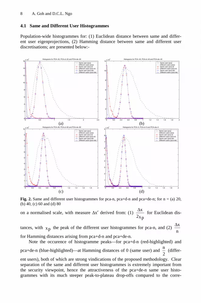
4.1 Same and Different User Histogrammes
Population-wide histogrammes for: (1) Euclidean distance between same and differ-ent user eigenprojections, (2) Hamming distance between same and different userdiscretisations; are presented below:-
0 0.5 1 1.5 2 2.50
2
4
6
8
10
12
14
16x 10
4 Histograms for PCA−20, PCA+d−20 and PCA+de−20
Same user (pca)Different users (pca)Same user (pca+d)Different users (pca+d)Same user (pca+de)Different users (pca+de)
(a)0 0.2 0.4 0.6 0.8 1 1.2 1.4 1.6 1.8 2
0
2
4
6
8
10
12x 10
4 Histograms for PCA−40, PCA+d−40 and PCA+de−40
Same user (pca)Different users (pca)Same user (pca+d)Different users (pca+d)Same user (pca+de)Different users (pca+de)
(b)
0 0.2 0.4 0.6 0.8 1 1.2 1.4 1.6 1.8 20
1
2
3
4
5
6
7
8
9
10x 10
4 Histograms for PCA−60, PCA+d−60 and PCA+de−60
Same user (pca)Different users (pca)Same user (pca+d)Different users (pca+d)Same user (pca+de)Different users (pca+de)
(c)0 0.2 0.4 0.6 0.8 1 1.2 1.4 1.6 1.8 2
0
1
2
3
4
5
6
7
8
9x 10
4 Histograms for PCA−80, PCA+d−80 and PCA+de−80
Same user (pca)Different users (pca)Same user (pca+d)Different users (pca+d)Same user (pca+de)Different users (pca+de)
(d)
Fig. 2. Same and different user histogrammes for pca-n, pca+d-n and pca+de-n; for n = (a) 20,(b) 40, (c) 60 and (d) 80
on a normalised scale, with measure ∆x′ derived from: (1) x
2xp
∆ for Euclidean dis-
tances, with xp the peak of the different user histogrammes for pca-n, and (2) x
n
∆
for Hamming distances arising from pca+d-n and pca+de-n.Note the occurence of histogramme peaks—for pca+d-n (red-highlighted) and
pca+de-n (blue-highlighted)—at Hamming distances of 0 (same user) and n
2 (differ-
ent users), both of which are strong vindications of the proposed methodology. Clearseparation of the same and different user histogrammes is extremely important fromthe security viewpoint, hence the attractiveness of the pca+de-n same user histo-grammes with its much steeper peak-to-plateau drop-offs compared to the corre-

Computation of Cryptographic Keys from Face Biometrics 9
sponding pca+d-n profiles. The above-outlined Euclidean normalisation allows forqualitative comparison of pca-n characteristics, which also emphasises the advantagesof the pca+de-n configurations.
These sharp drop-offs are clearly apparent in the n = 40 and 60 cases, but less sofor n = 20 and 80. This can be attributed to the descriptive insufficiency for low n,and over-sensitivity to noise for high n configurations; not just for the proposed
n2α∈ bitstrings but also for the basic. a ∈ IRn The form of the pca+de-n = 40 and
60 histogrammes allows for specification of zero FAs without overly jeopardising theFR performance. FR (FA = 0) is, in fact, an important merit criteria in the proposedframework, which anticipates H(i, a) parameterised cryptographic functionality. It isimportant to be able to preclude the occurence of FAs in this context.
4.2 FA and FR Characteristics
Establishment of FR (FA = 0) and the more commonly cited crossover error (CE) rate(at which point FA = FR) for a particular configuration requires analysis of the FA-FR operational characteristics ie:
(a)0 0.5 1 1.5 2 2.5 3 3.5 4 4.5 5
0
0.5
1
1.5
2
2.5
3
3.5
4
4.5
5 CE % for Pca−40, Pca+d−40 and Pca+de−40
FR %
FA
%
Pca−40, Pca+d−40Pca+de−40
(b)
0 0.5 1 1.5 2 2.5 3 3.5 4 4.5 50
0.5
1
1.5
2
2.5
3
3.5
4
4.5
5 CE % for Pca−60, Pca+d−60 and Pca+de−60
FR %
FA
%
Pca−60, Pca+d−60Pca+de−60
(c)0 0.5 1 1.5 2 2.5 3 3.5 4 4.5 5
0
0.5
1
1.5
2
2.5
3
3.5
4
4.5
5 CE % for Pca−80, Pca+d−80 and Pca+de−80
FR %
FA
%
Pca−80, Pca+d−80Pca+de−80
(d)
Fig. 3. Operational characteristics for for pca-n, pca+d-n and pca+de-n; for n = (a) 20, (b) 40,(c) 60 and (d) 80

10 A. Goh and D.C.L. Ngo
Note the higher CE rates of pca+d-n (red-highlighted) compared to the corre-sponding pca-n configuration; the former of which eventually drops under the latter,corresponding to lower FR (FA = 0) rates. The pca+d-n configuration is hence moresecure than the corresponding pca-n, but on the other hand somewhat less robust interms of recognition. Error-correction can certainly be expected to improve recogni-tion, as can be seen from the consistent location of pca+de-n (blue-highlighted) insidethe corresponding pca+d-n profile. This reduces the CE point dramatically for the n =20, 40 and 60 cases; but (in common with the Fig 3 histogrammes) less so for n = 80.The CE points for pca+de-n are in fact a significant improvement over the corre-sponding pca-n, again with the notable exception of the n = 80 case.
4.3 General Characteristics
The general characteristics of pca-n, pca+d-n and pca+de-n are as follows:
Table 1. Characteristics of (a) pca-n, (b) pca+d-n and pca+de-n
a eigenbasis Same user diff(Euclidean)
FR %(FA = 0)
CE %
20 0.030 4.47 0.5630 0.035 2.80 0.5740 0.041 2.49 0.4950 0.046 2.37 0.4960 0.049 2.26 0.4170 0.053 1.69 0.5580 0.055 1.60 0.37
Same user diff(Hamming)
FR %(FA = 0)
CE %α bitlength
pca+d pca+de pca+d pca+de pca+d pca+de20 1.15 0.03 29.70 3.37 2.07 0.0230 1.72 0.09 8.42 0.01 1.02 0.0140 2.18 0.15 4.04 0.01 0.77 0.0150 2.85 0.47 1.98 0.27 0.57 0.0760 3.53 0.86 1.57 0.22 0.49 0.1070 4.17 1.79 1.17 0.35 0.55 0.1580 4.48 4.51 1.31 0.93 0.37 0.34
and clearly illustrate the functional shortcomings of under and over-sized n represen-tations. Choice of operational n in the (30, 45) range appears most suitable, so as tosimultaneously avoid degraded recognition and frequent occurence of bit-errors.
Note the relatively small Hamming distances between same user pca+d-n bit-strings, which vindicates the Section 3.2 discretisation and error-correction. Thisimplies the sufficiency of relatively small n′–n margins. The even smaller Hammingdifferences—less than a single-bit for most of the above-tabulated operationalrange—in the augmented pca+de-n case is also encouraging as it suggests a relativelysmall number of x(i, a) outcomes per user, which is important for the Section 3.3interpolation.

Computation of Cryptographic Keys from Face Biometrics 11
5 Security Analysis
The security of H should be evaluated in terms of key-factor: (1) independence: ieevaluation of a = H(i, a) in the absence of i or a, and (2) non-recovery: of i or a givenspecific value of a(i, a) and the other factor; with the benchmark being cryptographichashing of i and secret knowledge j. Recall that a = h(i, j) cannot be computed with-out both ⟨i, j⟩ factors, so that adversarial deduction is no more more probable than
random guessing of order m2− . Factorisation ⟨i, j⟩ is also protected by the target-collision resistance of h, so that deduction of i or j—from output a(i, j) and one of thefactors—is equally improbable.
5.1 Key–Factor Independence
Non-possession of i means that tokenised β(i) is unavailable to an adversary, so thatpreviously intercepted (or fabricated) a is simply not useful. This prevents meaning-
ful deduction of a(i, a), with random guessing being of probability 1q− in this case.
Possession of i is more useful as it divulges ∀χ = h(x) from the token-inserted X(i, a),
which suggests an analytic strategy whereby random 2να∈ bitstrings are tested for
suitability with respect condition h(h(α)) = χ. The collision probability is 2−νµ in
this case, hence the motivation to minimise µ and to maximise ν. This is accom-plished via suitable choice for inner-product exclusion parameter σ (which serves nouseful purpose if over-large); and also by adoption of the previously discussed multi-feature eigenanalysis [13], so that lengthier α can be concatenated from feature-specific bitstrings. Note α with arbitrarily large ν are straightforwardly obtained fromintegral transform representations, which do not restrict the length of the β(i) se-quence. Recall this issue of discretisation scalability also arises in the Monrose et alformulation.
The operational security of our scheme is enhanced via token-side access controland encryption of X, with respective parameterisation ⟨k, k′⟩ = h(i′, i) for domain orplatform serialisation i′. This necessitates prior token-side insertion of (X)EkΨ = ′ ,
with the following operational sequence:1. Compute ⟨k, k′⟩ from token i2. Transmit k to retrive Ψ from token3. Recover X ( )Dk= Ψ′prior to the computations of Section 3, successful completion of which is restricted todomain/platform i′.
5.2 Key-Factor Non–recovery
Knowledge of a(i, a) and a does not in any way jeopardise i, due to non-recovery of:(1) any x ∈ S″ from a, (2) any (i)k ∈βb from x and a, and (3) i from β(i) or any

12 A. Goh and D.C.L. Ngo
subset thereof; thereby resulting in i deduction being no less probable than the m2−of random guessing. The other scenario of a and i compromise allows testing of ran-
dom a ∈ IRn eigenprojections for suitability with respect condition h(x(i, a)) = χ.
Probability of a recovery in this case is pνµ , with 1p 2−< due to exclusion of nu-
merically small inner-products.
Key-factor protection is enhanced via reasonable operational measures: (1)minimisation of µ and maximisation of ν, and (2) access control and encryption of X;in addition to incorporation of i′ dependence in the β sequence. This β(i, i′) specifi-cation is straightforwardly accomplished ie via initialisation (i )0 ′b for the proposed
X9.17 pseudorandom generator.
5.3 Cryptographic Applicability
The above-outlined a = H(i, a) computation facilitates the application of asymmetriccryptogaphic protocols, ie for (1) online verification over a priori insecure environ-ments, or (2) offline commitment and subsequent verification in relation to specificdata; without presumptions that might be operationally inconvenient or unrealistic iethe establishment of communications security prior to biometric verification. Securechannel establishment in any case requires cryptographic support—ie the Diffie-Hellman (DH) [14] protocol—hence the motivation for the integrated handling ofbiometric and communications security, as subsequently outlined. Bio-hash H allowsfor cryptography predicated on ⟨i, a⟩ possession, which is more secure (due to sim-plicity of the key-computation conditions) and furthermore supportive of greaterfunctional sophistication.
Cryptographic operations are straightforwardly parameterised via discrete loga-rithmic (DL) [14] or elliptic curve (EC) [16] key-pair of form ⟨a(i, a), A(a)⟩ withpublic-key A = a⋅g for basepoint g in some scalar-multiplicative subgroup EGq ⊆ of
the specified curve. User-specific key-pair ⟨a, A⟩ is hence a ZK representation of ⟨i,a⟩ via the H and g (a) : ZZ q → G q transformations, with remote identification in
terms of (i, ) Gq∈A a . This is qualitatively superior compared to the insecure and
functionally limited a ∈ IRn of conventional biometrics.
6 Concluding Remarks
This paper outlines error-tolerant discretisation and cryptographic key-computationfrom user-specific face images and uniquely serialised tokens. Our bio-hash method-ology has significant functional advantages over conventional biometrics ie extremelyclean separation of the same and different user histogrammes and near-zero CE point,thereby allowing elimination of FAs without suffering from increased occurence ofFRs. H(i, a) is furthermore highly secure with respect independence and non-

Computation of Cryptographic Keys from Face Biometrics 13
recovery of the ⟨i, a⟩ key-factorisation, with tokenised immunity against biometricinterception or fabrication. Use of token+biometric key a(i, a) within the context ofasymmetric cryptography is also attractive in that it enables secure and versatile func-tionality.
References
1. A Bodo (1994). Method for Producing a Digital Signature with Aid of a Biometric Fea-ture. German Patent DE 42–43–908–A1
2. C Soutar & GJ Tomko (1996). Secure Private Key Generation Using a Fingerprint.Cardtech/Securetech Conf 1: pp 245–252
3. C Soutar, D Roberge, A Stoianov, R Gilroy & BVK Vijaya Kumar (1998). BiometricEncryption Using Image Processing. SPIE 3314: pp 178–188
4. GI Davida, Y Frankel & BJ Matt (1998). On Enabling Secure Applications Through Off–Line Biometric Identification. IEEE Symp on Security & Privacy: pp 148–157
5. GI Davida, Y Frankel, BJ Matt, & R Peralta (1999). On the Relation of Error Correctionand Cryptography to an Off–Line Biometric–Based Identification Scheme. Wkshop Cod-ing & Cryptography: Paris France
6. F Monrose, MK Reiter & S Wetzel (1999). Password Hardening Based on KeystrokeDynamics. 6–th ACM Conf on Comp & Comms Security: pp 73–82
7. F Monrose, MK Reiter, Q Li & S Wetzel (2001). Cryptographic Key Generation fromVoice. IEEE Symp on Security & Privacy: pp 202–213
8. A Shamir (1979). How to Share a Secret. ACM Comms 22 (11): pp 612–6139. T Matsumoto, H Matsumoto, K Yamada & H Hoshino (2002). Impact of Artificial
“Gummy” Fingers on Fingerprint Systems. SPIE 4677: ??10. L Sirovich & M Kirby (1987). A Low–Dimensional Procedure for Characterisation of
Human Faces. J Optical Soc 4 (3): pp 519–52411. M Turk & A Pentland (1991). Face Recognition Using Eigenfaces. IEEE Conf Comp
Vision & Pattern Recognition: pp 586–59112. J Hambridge (1926). The Elements of Dynamic Symmetry. Yale Univ Press, New Haven
USA13. DCL Ngo & A Goh (2003). Facial Feature Extraction via Dynamic Symmetry Modelling
for User Identification. Pattern Pattern Recognition Letters.14. AJ Menezes, P van Oorschot & S Vanstone (1996). Handbook of Applied Cryptography.
CRC Press, Boca Raton USA.15. L Spacek (2000). Face Recognition Data. http://cswww.essex.ac.uk/allfaces/index.html16. AJ Menezes (1993). Elliptic–Curve Public–Key Cryptosystems. Kluwer Academic Press,
Boston USA.

A. Lioy and D. Mazzocchi (Eds.): CMS 2003, LNCS 2828, pp. 14–26, 2003.© IFIP International Federation for Information Processing 2003
AUTHMAC_DH: A New Protocol for Authentication andKey Distribution
Heba K. Aslan
The Electronics Research Institute, El-Tahrir St., Dokki, Cairo, Egypt
Abstract. In the present paper, a new protocol for authentication and key dis-tribution is proposed. The new protocol has the aim to achieve a comparableperformance with the Kerberos protocol and overcome its drawbacks. Forauthentication of the exchanged messages during authentication and key distri-bution, the new protocol uses the Message Authentication Codes (MAC) to ex-change the Diffie-Hellman components. On the other hand, the new protocoluses nonces to ensure the freshness of the exchanged messages. Subsequently,there is no need for clock synchronization which will simplify the system re-quirements. The new protocol is analyzed using queuing model, the perform-ance analysis of the new protocol shows that the new protocol has acomparable performance with the Kerberos protocol for short messages andoutperforms it for large messages.
1 Introduction
In recent years, many applications that require the exchange of sensitive informationover public networks increase considerably. This introduces the need of two require-ments: firstly, the need for providing authenticity of the communicating parties and toensure the freshness of the exchanged messages. Secondly, the need to ensure thesecurity of exchanged information. In literature, many protocols for authenticationand key distribution were given. While some of them use symmetric key techniques,the others use public key techniques to distribute a symmetric key. Examples of thefirst method are: the Kerberos protocol [1, 2], and the Kryptoknight protocol [3]. Onthe other hand, examples of the second method are: the SPX protocol [4, 5], and theauthenticated Diffie-Hellman protocol [6]. Among the above protocols, the Kerberosprotocol achieves a widespread use especially for UNIX environment. This is due tothe fact that it uses symmetric techniques; therefore, it leads to a better performanceover the other protocols. In the present paper, a new protocol for authentication and key distribution is pro-posed. The new protocol, which is named AUTHMAC_DH, is based on work done in[7, 8] and has the aim to achieve a comparable performance with the Kerberos proto-col and overcome its drawbacks [9]. The paper is organized as follows: in Section 2, adescription of the new protocol is detailed. In Section 3, expressions for the perform-ance analysis of both the Kerberos protocol and the new protocol were derived. InSection 4, numerical results of the new protocol are discussed. Finally, the paperconcludes in Section 5.

AUTHMAC_DH: A New Protocol for Authentication and Key Distribution 15
2 AUTHMAC_DH: A New Protocol for Authentication and KeyDistribution
The Kerberos protocol is based on the exchange of symmetric key between the com-municating parties using symmetric key encryption. Therefore, in case of compromiseof messages exchanged during authentication and key distribution, all subsequentcommunication will be susceptible to disclosure. Besides the above feature, to ensurethe freshness of the exchanged messages, timestamps are used. Consequently, theneed for synchronizing all clocks of the system, which is a difficult problem, becomesa vital requirement. To overcome the abovementioned drawbacks, the new protocoluses the Message Authentication Codes (MAC) as in KryptoKnight protocol to ex-change the Diffie-Hellman components as in the authenticated Diffie-Hellman proto-col. Since, the compromise of messages exchanged during authentication and keydistribution will lead to the disclosure of the Diffie-Hellman components. Therefore,the attacker cannot calculate the symmetric key used between the communicatingparties (the difficulty of computing discrete logarithm for a large modulo number is awell-known problem in number theory). The use of MAC will fasten the proposedprotocol. On the other hand, the new protocol uses nonces to ensure the freshness ofthe exchanged messages. Subsequently, there is no need for clock synchronizationwhich will simplify the system requirements. In order to achieve the goals of authentication and key distribution, a third-partycalled the Security Manager (SM) is incorporated into the system. The SM stores allthe Diffie-Hellman components of all registered users and it shares a symmetric keywith all users. Each station needs to store its Diffie-Hellman secret and the symmetrickey shared between it and the SM. Fig. 1 shows the steps required to perform authen-tication and key distribution. The steps of the protocol are described in the followingparagraphs.Step 1: When client A wants to communicate with server B, it sends to the SM a mes-sage consisting of: A’s identity ‘A’, B’s identity ‘B’, and a nonce Na.Step 2: After receiving A’s request, the SM calculates the MAC of the followingmessages: - The symmetric key shared between SM and A ‘KSM,A’, A, B, Na, the Diffie-Hellman component of A ‘axmodp’, and the Diffie-Hellman component of B ‘ay-
modp’.- The symmetric key shared between SM and B ‘KSM,B’, A, B, Na, a
xmodp, and ay-
modp. Then, it sends to both A and B a message consisting of: A, B, Na, axmodp,
aymodp, MAC(KSM,A, A, B, Na, axmodp, aymodp), and MAC(KSM,b, A, B, Na, a
xmodp,aymodp).Step 3: Upon receiving the reply of the SM, both A and B authenticate the receivingmessage using the MAC appended in the reply. A ensures the freshness of the re-ceived message using Na. Then, A and B calculate the symmetric key axymodp whichwill be used to encrypt subsequent communication between them. Next, B generates anonce Nb and sends to A a message consisting of Na and Nb both encrypted usingaxymodp. After receiving B’s reply, A decrypts the message of B, and compares be-tween the nonce included in the message and the nonce generated by it ‘Na’. If theyare equal, this implies that B can calculate axymodp. Therefore, A authenticates B.

16 H.K. Aslan
Step 4: A sends to B a message consisting of Nb encrypted using axymodp. Upon re-ceiving the reply of A, B authenticates A by decrypting the reply and comparing be-tween the nonce included in the message and the nonce generated by it ‘Nb’. Aftercompletion of the abovementioned steps, both A and B authenticate each other, andshare a symmetric key axymodp. The proposed protocol has the following advantagesover the Kerberos protocol:
- It does not rely on timestamps which simplify the system requirements.- Since, the Diffie-Hellman components are exchanged during authentica-
tion and key distribution and not the symmetric key itself as in the Ker-beros protocol. Therefore, the compromise of messages exchanged duringauthentication and key distribution does not lead to the disclosure of thesymmetric key used between A and B.
In the next section, expressions for the performance analysis of both theAUTHMAC_DH and the Kerberos protocols will be derived.
Step 1: A sends to the SM a request to communicate with BTransmitted message of Step1: [A, B, Na]
Step 2: The SM broadcasts its reply to both A and BTransmitted message of Step2: [A, B, Na, a
xmodp, aymodp, MAC(KSM,A, A, B, Na, a
xmodp, aymodp), MAC(KSM,B, A, B, Na, a
xmodp, aymodp)]x : Diffie-Hellman secret of Ay : Diffie-Hellman secret of Ba, p : Diffie-Hellman parameters
Step 3: A authenticates BTransmitted message of Step3: [Na, Nb]a
xymodpStep 4: B authenticates A
Transmitted message of Step4: [Nb]axymodp
Fig. 1. Steps required during authentication and key distribution for the AUTHMAC_DH pro-tocol
3 Performance Analysis of the AUTHMAC_DH and the KerberosProtocol
In order to derive the performance expressions, the following assumptions are made:number of clients = m and the number of servers = n. All clients are identical and

AUTHMAC_DH: A New Protocol for Authentication and Key Distribution 17
have the same statistics. The same is true for the servers. The client requests a servicefrom the server at rate requests/sec. The rate of messages exchange between theclient and the server is v messages/sec. Messages exchanged between clients andservers are of exponential distribution with mean length equals to L bits. Symmetricencryption is done using the Advanced Encryption Standard (AES) [10] with rateTAES bits/sec. Calculation of the Diffie-Hellman components is done using the Chi-nese remainder theorem [11] with rate TDH bits/sec. Message authentication codesare calculated using the UMAC algorithm [12] with rate TMAC bits/sec. The net-work capacity = C bits/sec. In the following subsections, expressions for the perform-ance analysis of the AUTHMAC_DH and the Kerbros protocols will be derived.
3.1 Performance Analysis of the AUTHMAC_DH Protocol
Fig. 2 illustrates the time sequence diagram of the AUTHMAC_DH protocol. Thesteps of the protocol are given in Section 2. According to Fig. 2, the mean messagetime Tmes for transmitting a message from a client to a server is given by:
Tmes=r
1E[Wc1]+Sc1+Wn1+tn1+E[Wsm]+Ssm+Wn2+tn2+E[Ws1]+Ss1+Wn3+
tn3+E[Wc3]+Sc3+Wn4+tn4+E[Ws2] +Ss2+ E[Wc4]+Sc4+ Wn5+tn5+ E[Ws3]+Ss3 (1)where,
r is the number of transmitted messages between the client and the server using thekey calculated in the key distribution phase, Wc1 is the waiting time in the client queue(A) before processing the request for the communication with the server (B), Sc1 is thetime required for processing the request of A to communicate with B, Wn1 is thewaiting time in the network queue, tn1 is the time required for transmitting the requestof A to the SM, Wsm is the waiting time in the Security Manager (SM) queue beforeprocessing the request of A, Ssm is the time required to calculate the UMAC of (KSM,A,A, B, Na, a
xmodp, aymodp), and the UMAC of (KSM,B, A, B, Na, axmodp, aymodp)],
Wn2 is the waiting time in the network queue, tn2 is the time required for transmittingthe SM reply to both A and B, Ws1 is the waiting time in the server’s queue beforeprocessing the reply of the SM, Ss1 is the time required to calculate the UMAC of(KSM,B, A, B, Na, axmodp, aymodp), to calculate axymodp, and to encrypt (Na, Nb)using the AES cipher, Wn3 is the waiting time in the network queue, tn3 is the timerequired for transmitting the server’s reply to A, Wc3 is the waiting time in the clientqueue before processing B’s reply, Sc3 is the time required to decrypt(Na, Nb), and toencrypt (Nb) using the AES cipher, Wn4 is the waiting time in the network queue, tn4 isthe time required for transmitting A’s reply to B, Ws2 is the waiting time in theserver’s queue before processing the reply of A, Ss2 is the time required to decrypt(Nb), Wc4 is the waiting time in the client queue before encryption of the messagetransmitted to B, Sc4 is the time required to encrypt a message of length L using theAES cipher, Wn5 is the waiting time in the network queue, tn5 is the time required fortransmitting the message from A to B, Ws3 is the waiting time in the server’s queuebefore processing the message of A, and Ss3 is the time required to decrypt A’s mes-sage.

18 H.K. Aslan
In order to calculate the mean message time, the following assumptions are made:A’s identity = B’s identity = 8 bits, Na = Nb = 16 bits, axmodp = aymodp = axymodp =512 bits, KSM,A = KSM,B = 128 bits, the encryption block of the AES = 128 bits, theoutput block of UMAC algorithm = 32 bits, and TAES = 20TDH = TMAC/5. Ac-cording to the previous assumptions, the following parameters are calculated: Sc1 = 0(since it involves no encryption), Ssm = 476/TAES, Sc2 = 10478/TAES, Ss1 =10510/TAES, Sc3 = 48/TAES, Ss2 = 16/TAES, and Sc4 = Ss3 = L/TAES.For Simplicitythe following assumptions are made: Wc1= Wc2 = Wc3 = Wc4 =E[Wc], Ws1= Ws2 = Ws3
= E[Ws], and Wn1= Wn2 = Wn3 = Wn4 = Wn5 =E[Wn]
Fig. 2. The time sequence diagram for the AUTHMAC_DH protocol
For the client queue: The client is modeled as an M/G/1 queue. It has to be noted thatthe key calculated in the authentication and key distribution phase ‘axymodp’ has alength of 512 bits. Therefore, four keys each of 128 bits could be extracted from these512 bits. Each key could be used r’ times between the client and the server (i.e. r =4r’). The client queue has the following parameters: the arrival rate client
= (number of arrivals per ticket/lifetime of the ticket)*number of servers = λ)n4r’(3 +
= 4r’
)nv4r’(3 + , the mean service time Tclient = c4S34r’
4r’)c3Sc2Sc1(S
34r’
1
++++
+=
3)TAES(4r’
L4r’10497
++ , and the traffic intensity client =
TAESr’
L)r’nv(2624 + . For M/G/1 queues, the
waiting time is given by [13, Eq. (2.65)]:
E[W] = )-2(1
]2E[
ρτλ (2)
where is the traffic intensity, is the mean arrival rate, and E[ 2] is the secondmoment of the service time and is equal to:
E[ 2] = 23)TAES(4r’
2Lr’8109790788
+
+

AUTHMAC_DH: A New Protocol for Authentication and Key Distribution 19
Substituting into Eq. (2), the average waiting time E[Wc] is equal to:
E[Wc] = )
TAESr’
L)r’nv(2624(12TAESr’
)2Lr’9nv(1372384+−
+ (3)
For the server queue: The server queue is modeled as an M/G/1 queue with the fol-lowing parameters:
server = 2r’
)r’2mv(1 + , Tserver = s3S24r’
4r’)s2Ss1(S
24r’
1
+++
+ =
)TAES1(2r’
Lr’25263
++ , server =
TAESr’
L)r’mv(2632 +, and E[ 2]=
2)TAES1(2r’
2Lr’255230178
+
+ . Substituting into Eq. (2), the average
waiting time E[Ws] is equal to:
E[Ws] = )
TAESr’
L)r’mv(2632(12TAES2r’
)2Lr’9mv(2761508+−
+ (4)
For the Security Manager queue: The SM queue is modeled as an M/D/1 queue with
the following parameters: sm = 4r’
mnv , Tsm = TAES
476 , and sm= TAESr’
120mnv. For M/D/1
queue the average waiting and service time is given by [13, Eq. (2.63)]:
E[w+s] = )1(
/2-1
ρµρ−
(5)
where is the traffic intensity to the queue, and is its service rate. Substituting intoEq. (5), the average waiting and service time E[WSM+ SSM] is equal to:
E[Wsm+ Ssm] =
TAESr’
120mnv1
)TAESr’
60mnv-(1
TAES
476
− (6)
For the network queue: The network queue is modeled as an M/G/1 queue with the
following parameters: network = r’
1)mnv(r’+ , the mean packet length = 1r’
Lr’300
++ ,
Tnetwork = 1)C(r’
Lr’300
++ , network =
Cr’
L)r’mnv(300 + , and E[ 2]= 2)C1(r’
2Lr’2314176
+
+ . Substi-
tuting into Eq. (2), the average waiting time E[Wn] is equal to:
E[Wn] = )
Cr’
L)r’mnv(300(12Cr’
)2Lr’mnv(157088+−
+ (7)

20 H.K. Aslan
The mean message time Tmes given in Eq. (1) can be now calculated using Eqs. (3,4, 6, and 7):
Tmes = TAESr’
Lr’22644 + + Cr’
Lr’300 + +
TAESr’
120mnv1
)TAESr’
60mnv-(1
TAESr’
120
−
+
)TAESr’
L)r’mv(2632(12TAES24r’
)2Lr’91)(2761508mv(2r’+−
++ +)
TAESr’
L)r’nv(2624(12TAES22r’
)2Lr’91)(1372384nv(2r’+−
++
+ )
Cr’
L)r’mnv(300(12C2r’
)2Lr’1)(157088mnv(r’+−
++ (8)
3.2 Performance Analysis of the Kerberos Protocol
Fig. 3 shows the time sequence diagram of the Kerberos protocol. For more informa-tion about the Kerberos protocol, the reader could refer to [1]. The steps of the proto-col are summarized below:
Step 1: A sends to the AS a request to communicate with BTransmitted message of Step1: [A, B]
A : A’s identity B : B’s identityStep 2: The AS sends its reply to ATransmitted message of Step2: [Tas, L1, Ka,b, B]Ka,as, [Tas, L1, Ka,b, A]Kb,as]
Tas : timestamp generated by ASKa,b : symmetric key between A and BL1 : lifetime of Ka,b
Ka,as : the symmetric key between A and AS Kb,as : the symmetric key between B and ASStep 3: A sends to B the AS’s reply
Transmitted message of Step3: [A, [Tas, L1, Ka,b, A]Kb,as, [A, Ta] Ka,b
Ta : timestamp generated by AStep 4: A authenticates B
Transmitted message of Step4: [A, Ta+1] Ka,b
According to Fig. 3, the mean message time Tmes for transmitting a message from aclient to a server is given by:
Tmes = r’
1E[Wc1]+Sc1+ Wn1+tn1+ E[Was]+Sas+ Wn2+tn2+ E[Wc2]+Sc2 +
Wn3 + tn3 + E[Ws1] + Ss1 + Wn4 + tn4 + E[Wc3] + Sc3 +E[Wc4]+Sc4+ Wn5+tn5+ E[Ws2]+Ss2 (9)
where, r’ is the number of transmitted messages between the client and the server using thekey transmitted in the key distribution phase, Wc1 is the waiting time in the clientqueue (A) before processing the request for the communication with the server (B),

AUTHMAC_DH: A New Protocol for Authentication and Key Distribution 21
Sc1 is the time required for processing the request of A to communicate with B, Wn1 isthe waiting time in the network queue, tn1 is the time required for transmitting therequest of A to the AS, Was is the waiting time in the Authentication Server (AS)queue before processing the request of A, Sas is the time required to encrypt (Tas, L1,Ka,b, A), and (Tas, L1, Ka,b, B) using the AES cipher, Wn2 is the waiting time in thenetwork queue, tn2 is the time required for transmitting the AS reply to A, Wc2 is thewaiting time in A’s queue before processing the reply from the AS, Sc1 is the timerequired to decrypt (Tas, L1, Ka,b, B), and to encrypt (A, Ta) using the AES cipher, Wn3
is the waiting time in the network queue, tn3 is the time required for transmitting A’sreply to B, Ws1 is the waiting time in the server’s queue before processing the reply ofA, Ss1is the time required to decrypt (Tas, L1, Ka,b, A), to decrypt (A, Ta), and to en-crypt (B, Ta+1) using the AES cipher, Wn4 is the waiting time in the network queue,tn4 is the time required for transmitting B’s reply to A, Wc3 is the waiting time in theclient queue before processing B’s reply, Sc3 is the time required to decrypt(B, Ta+1)using the AES cipher, Wc4 is the waiting time in the client queue before encryption ofthe message transmitted to B, Sc4 is the time required to encrypt a message of length Lusing the AES cipher, Wn5 is the waiting time in the network queue, tn5 is the timerequired for transmitting the message from A to B, Ws2 is the waiting time in theserver’s queue before processing the message of A, and Ss2 is the time required todecrypt A’s message.
Fig. 3. The time sequence diagram for the Kerberos protocol
In order to calculate the mean message time, the following assumptions are made:A’s identity = B’s identity = 8 bits, Tas = 24 bits, L1 = 8 bits, Ka,b = 128 bits, and theencryption block of the AES = 128 bits. According to the previous assumptions, thefollowing parameters are calculated: Sc1 = 0 (since it involves no encryption), Sas =336/TAES, Sc2 = 200/TAES, Ss1 = 232/TAES, Sc3 = 32/TAES, and Sc4 = Ss2 =L/TAES. For Simplicity the following assumptions are made: Wc1= Wc2 = Wc3 = Wc4
=E[Wc], Ws1= Ws2 = E[Ws], and Wn1= Wn2 = Wn3 = Wn4 = Wn5 =E[Wn].

22 H.K. Aslan
For the client queue: The client queue is modeled as an M/G/1 queue with the fol-
lowing parameters: client = r’
)nvr’(3 +, Tclient =
3)TAES(r’
Lr’232
++ , client =
TAESr’
L)r’nv(232 + ,
and E[ 2] = 23)TAES(r’
2Lr’241024
+
+ .Substituting into Eq. (2), the average waiting time E[Wc] is
equal to:
E[Wc] = )
TAESr’
L)r’nv(232(12TAESr’
)2Lr’nv(20512+−
+ (10)
For the server queue: The server queue is modeled as an M/G/1 queue with the fol-
lowing parameters: server = r’
)r’mv(1+ , Tserver = )TAES1(r’
Lr’232
++ , server =
TAESr’
L)r’mv(232 + ,
and E[ 2] = 2)TAES1(r’
2Lr’253824
+
+ . Substituting into Eq. (2), the average waiting time E[Ws]
is equal to:
E[Ws] = )
TAESr’
L)r’mv(232(12TAESr’
)2Lr’mv(26912+−
+ (11)
For the Authentication Server queue: The AS queue is modeled as an M/D/1 queue
with the following parameters: as = r’
mnv , Tas = TAES
336 , and as = TAESr’
336mnv . Substi-
tuting into Eq. (5), the average waiting and service time E[WSM+ SSM] is equal to:
E[Was+ Sas] =
TAESr’
336mnv1
)TAESr’
168mnv-(1
TAES
336
− (12)
For the network queue: The network queue is modeled as an M/G/1 queue with the
following parameters: network= r’
)4mnv(r’+ , the mean packet length = 4r’
Lr’584
++ ,
Tnetwork = )4C(r’
Lr’584
++ , network=
Cr’
L)r’mnv(584 + , and E[ 2] = 2)C4(r’
2Lr’2154176
+
+ . Substi-
tuting into Eq. (2), the average waiting time E[Wn] is equal to:
E[Wn] =
)Cr’
L)r’mnv(584(1Cr’
)Lr’mnv(77088
2
2
+−
+ (13)

AUTHMAC_DH: A New Protocol for Authentication and Key Distribution 23
The mean message time Tmes given in Eq. (9) can be now calculated using Eqs. (10–13):
Tmes = TAESr’
Lr’2464 + + Cr’
Lr’584 + +
TAESr’
336mnv1
)TAESr’
168mnv-(1
TAESr’
336
−
+)
TAESr’
L)r’nv(232(12TAES2r’
)2Lr’3)(20512nv(r’+−
++ +)
TAESr’
L)r’mv(232(12TAES2r’
)2Lr’1)(26912mv(r’+−
++
+
)Cr’
L)r’mnv(584(1Cr’
)Lr’4)(77088mnv(r’
22
2
+−
++ (14)
4 Numerical Results and Discussions
In the previous section, formulas for the mean message time for both theAUTHMAC_DH and the Kerberos protocols were derived. In order to obtain per-formance curves, the following assumptions are made: the number of clients m = 150,the number of servers n = 15, and the number of transmitted messages between theclient and the server r’ = 10. In the present paper, the performance is analyzed for thefollowing case:
- Two message lengths are assumed: one for short messages where L = 1000bits and the latter for large messages where L = 1 Mbits.
- Two encryption speeds are assumed: one for low encryption speed whereTAES = 1 Mbps and the latter for high encryption speed where TAES = 1Gbps.
- Two network rates are assumed: one for low network rate where C = 1 Gbpsand the latter for high network rate where C = 10 Gbps.
In the following paragraphs, performance comparison between the proposed proto-col and the Kerberos protocol will be given. Figs 4–7 depict Tmes versus v for Kerberos, and the proposed protocol. Figs 4 and 5are plotted for L = 1000 bits. Figs. 4.a and 4.b are plotted for TAES = 1 Gbps, whileFig. 5 is plotted for TAES = 1 Mbps. Figs 6 and 7 are plotted for L = 1 Mbits. Fig. 6is plotted for TAES = 1 Gbps, while Fig. 7 is plotted for TAES = 1 Mbps. All (a)figures are plotted for C = 10 Gbps, while all (b) figures are plotted for C = 1 Gbps.From the figures, the following remarks can be deduced.:1. For short messages(L = 1000 bits) and high encryption speed (TAES = 1 Gbps),
two cases are examined: one for a transmission rate C = 10 Gbps and the latter forC = 1 Gbps. The following remarks could be deduced:
- For C = 10 Gbps, the Kerberos protocol has a better performance than thenew protocol. This is shown in Fig. 4.a. For short messages and high en-cryption speed, it could be concluded from all the queues of both the Ker-beros protocol and the new protocol that the Kerberos protocol has a betterperformance over the new protocol.

24 H.K. Aslan
- For C = 1 Gbps, the new protocol outperforms the Kerberos protocol asillustrated in Fig. 4.b. This is due to the fact that, as the network speed de-creases, the performance becomes network dependent. Moreover, it couldbe concluded from the network queues (Eqs. 7 and 13) that the networktime of the new protocol is less than that of the Kerberos protocol.
2. For short messages and low encryption speed (TAES = 1 Mbps), the Kerberosprotocol has a better performance than the new protocol as illustrated in Fig. 5.This results from the fact that for low encryption rates, the performance becomesdependent on the server’s queue. From the server queues (Eqs. 4 and 11), it isclear that for short messages, the server’s waiting time in the Kerberos protocol isless than that of the new protocol.
3. For large messages (L = 1 Mbits), the new protocol outperforms the Kerberosprotocol (Figs 6–7). This results since, for large messages, both the network andthe server queues of the new protocol have a better performance over the Ker-beros protocol for both low encryption speed and high encryption speed. Thesame conclusion could be applied for both high network speed and low networkspeed.
v messages/sec
Tm
es in
mic
rose
cond
s
AUTHMAC_DHprotocol
Kerberos protocol
2
12
22
32
0 100 200 300 400
v messages/sec
Tm
es in
mic
rose
cond
s
AUTHMAC_DHprotocol
Kerberos protocol
a. b.
Fig. 4. Tmes versus v for L = 1000 bits and TAES = 1 Gbps: a. C = 10 Gbps b. C = 1 Gbps
v messages/sec
Tm
es in
mic
rose
cond
s
AUTHMAC_DHprotocol
Kerberos protocol
v messages/sec
Tm
es in
mic
rose
cond
s
AUTHMAC_DHprotocol
Kerberos protocol
a. b.
Fig. 5. Tmes versus v for L=1000 bits and TAES=1 Mbps: a. C = 10 Gbps b. C = 1 Gbps

AUTHMAC_DH: A New Protocol for Authentication and Key Distribution 25
v messages/sec
Tm
es in
mic
rose
cond
s
AUTHMAC_DHprotocol
Kerberos protocol
. . . .
v messages/sec
Tm
es in
mic
rose
cond
s
AUTHMAC_DHprotocol
Kerberos protoco
a. b.
Fig. 6. Tmes versus v for L = 1 Mbits and TAES = 1 Gbps:a. C = 10 Gbps b. C = 1 Gbps
.
.
. . . .
v messages/sec
Tm
es in
sec
onds
AUTHMAC_DHprotocol
Kerberos protocol
.
.
. . . .
v messages/sec
Tm
es in
sec
onds
AUTHMAC_DHprotocol
Kerberos protocol
a. b.
Fig. 7. Tmes versus v for L = 1 Mbits and TAES = 1 Mbps: a. C = 10 Gbps b. C = 1 Gbps
5 Conclusions
In the present paper, a new protocol for authentication and key distribution called theAUTHMAC_DH is proposed. In order to provide authentication of the exchangedmessages during authentication and key distribution, the AUTHMAC_DH protocoluses the Message Authentication Codes (MAC) to exchange the Diffie-Hellmancomponents. Since, the compromise of messages exchanged during authentication andkey distribution will lead to the disclosure of the Diffie-Hellman components and notthe symmetric key itself. Therefore, the attacker cannot calculate the symmetric keyused between the communicating parties. This feature is considered as an advantageover the Kerberos protocol in which the disclosure of messages exchanged duringauthentication and key distribution will lead to the disclosure of the symmetric keyused between the communicating parties. It has to be noted that the use of MAC willfasten the proposed protocol. On the other hand, the AUTHMAC_DH protocol usesnonces to ensure the freshness of the exchanged messages. Subsequently, there is noneed for clock synchronization which will simplify the system requirements which isconsidered as a second advantage over the Kerberos protocol. Performance expres-

26 H.K. Aslan
sions for both the AUTHMAC_DH and the Kerberos protocols are derived usingqueuing model analysis. The performance is evaluated for several conditions: bothshort and large messages are examined, also the evaluation is considered for high andlow encryption speeds, finally the analysis is undertaken for low and high networkspeeds. The performance analysis shows that the AUTHMAC_DH protocol has acomparable performance with the Kerberos protocol for short messages and outper-forms it for large messages. In conclusion, besides that the AUTHMAC_DH protocolhas a comparable performance with the Kerberos protocol, it overcomes its draw-backs.
References
1. Kohl, J. T., and Neuman, B. C.: The Kerberos Network Authentication Service (V5), RFC1510, September 1993, (1993).
2. Kohl, J. T., Neuman, B. C., and Ts’o., T. Y.: The Evolution of the Kerberos Authentica-tion Service, IEEE Computer Society Press Book (1994).
3. Molva, R., Tsudik, G., Herreweghen, E. V., and Zatti, S.: KryptoKnight Authenticationand Key Distribution System, Proceedings of ESORICS 92, October 1992, (1992).
4. Tardo, J. J., and Alagappan, K.: SPX: Global Authentication Using Public Key Certifi-cates, IEEE Privacy and Security Conference (1991).
5. Tardo, J. J., and Alagappan, K.: SPX Guide: A Prototype Public Key AuthenticationService, Digital Equipment Corporation, May 1991, (1991).
6. Ford, W.: Computer Communications Security: Principles, Standard Protocols and Tech-niques, Prentice Hall (1994).
7. Aslan, H. K.: Logic-Based Analysis and Performance Evaluation of a New Protocol forAuthentication and Key Distribution in Distributed Environments, Ph. D. Thesis, Elec-tronics and Communications Dept., Faculty of Engineering, Cairo University, July 1998,(1998).
8. El-Hadidi, M. T., Hegazi, N. H., and Aslan, H. K.: Logic-Based Analysis of a New HybridEncryption Protocol for Authentication and Key Distribution, IFIP SEC98 conference(1998).
9. Bellovin, S. M., and Merrit, M.: Limitations of the Kerberos Authentication System,Computer Communication Review, October 1990, (1990).
10. Daemen J., and Rijmen, V.: AES Proposal: Rijndael, available at http://www.nist.gov/aes.11. http://www.iaik.tugraz.at/aboutus/people/groszschaedl/papers/acsac2000.pdf12. Black, J., Halevi, S., Krawczyk, H., Krovetz, T., and Rogaway, P.: UMAC: Fast and Se-
cure Message Authentication, Advances in Cryptology, Crypto’99, Lecture Notes in Com-puter Science, Vol. 1666, Springer-Verlag (1999).
13. Schwartz, M.: Telecommunication Networks: Protocols, Modeling and Analysis,Addison–Wesley (1987).

A. Lioy and D. Mazzocchi (Eds.): CMS 2003, LNCS 2828, pp. 27–39, 2003.© IFIP International Federation for Information Processing 2003
Multipoint-to-Multipoint Secure-Messaging withThreshold-Regulated Authorisation and Sabotage
Detection
Alwyn Goh1 and David C.L. Ngo2
1 Corentix Laboratories, B-19-02 Cameron Towers, Jln 5/58B,46000 Petaling Jaya, [email protected]
2 Faculty of Information Science & Technology, Multimedia University,75450 Melaka, Malaysia
Abstract. This paper presents multi-user protocol-extensions forSchnorr/Nyberg-Ruepple (NR) signatures and Zheng signcryption, both ofwhich are elliptic curve (EC)/discrete logarithmic (DL) formulations. Our ex-tension methodology is based on k-of-n threshold cryptography—with Shamirpolynomial parameterisation and Feldman-Pedersen verification—resulting inmulti-sender Schnorr-NR (SNR) and multi-sender/receiver Zheng-NR (ZNR)protocols, all of which are interoperable with their single-user base formula-tions. The ZNR protocol-extensions are compared with the earlier Takaragi etal multi-user sign-encryption, which is extended from a base-protocol with tworandom key-pairs following the usual specification of one each of signing andencryption. Both single and double-pair formulations are analysed from theviewpoint of EC equivalence (EQ) establishment, which is required for rigor-ous multi-sender functionality. We outline a rectification to the original Ta-karagi et al formulation; thereby enabling parameter-share verification, but atsignificantly increased overheads. This enables comprehensive equivalent-functionality comparisons with the various multi-user ZNR protocol-extensions. The single-pair ZNR approach is shown to be significantly moreefficient, in some cases demonstrating a two/three-fold advantage.
1 Introduction
The emergence of various technologies ie peer-to-peer computing and ad hoc com-munications motivates the development of transactional models beyond the presentlydominant presumption of single-user functionality and point-to-point connectivity.This in turn motivates the development of cryptographic protocols to support net-work-mediated collaboration and workgroup transactions, the multi-user nature ofwhich is not accommodated naturally by the conventional presumption of user-specific key-parameterisation. External transaction-to-workgroup association is a farbetter solution—from the viewpoint of transactional logic and liability—which alsoreduces the receiver-side storage overhead to a single public-key.
The cryptographic specification is therefore to rigorously associate multiple user-specific key-shares with a common workgroup public-key, so that a configurableuser-subset is able to exercise workgroup-representative authority. This can be ele-

28 A. Goh and D.C.L. Ngo
gantly implemented via the polynomial-based k-of-n threshold methodology ofShamir [1] and Feldman-Pedersen [2-4], which is applicable to EC [5, 6]/DL proto-cols. k-of-n thresholding is therefore a useful multi-user specification methodology;as respectively demonstrated by Park-Kurosawa [7] and Takaragi et al [8] extensionson ElGamal [9] and NR [10] signatures respectively, the latter of which was presentedto the Institute of Electrical and Electronics Engineers (IEEE) study-group for public-key cryptography standards. Takaragi et al also specifies a sign-encryption protocolable to incorporate multiple senders and receivers. This paper departs from earlierwork in its emphasis on secure-messaging rather than signatures; with its focus onintegration of message authentication/encryption and multi-user functionality.
We outline k-of-n threshold extensions for Schnorr [11], Zheng [12] and NR con-structions, with the characteristic property of message-level parameterisation based ona single EC/DL key-pair of the initial sender-determined randomisation. This ap-proach was motivated by the use of the single-pair in Zheng signcryption for bothauthentication and encryption; which is a departure from the more frequently en-countered specification of distinct key-pairs for each message-related functionality, asexemplified by the Takaragi et al NR-derived (TNR) sign-encryption. Single (ratherthan double) key-pair secure-messaging is significantly more compute-efficient on apoint-to-point basis, and is shown in this paper to be similarly advantageous for multi-user extensions. This applies to both fast and rigorous multi-sender modes, the latterof which necessitates detection of malformed parameter-shares via ECEQ establish-ment. The original multi-sender TNR sign-encryption is, in fact, not rigorous due tonon-establishment of ECEQ, which can be rectified via application of the Chaum-Pedersen [13] and Fiat-Shamir[14] protocols.
2 Review of Base Protocols and Mechanisms
2.1 Schnorr-Zheng, NR and Takaragi et al Cryptography
All signature and secure-messaging protocols in this section presume prior specifica-tion of a EC/DL finite-field. We adopt the former description, denoted F with base-
point g ∈ F and multiplicative-group G k : k FZq= ∈ ⊂g . Schnorr signatures are
inherently bandwidth-efficient, with signature bit-length of |h| + |q| (for h some cryp-tographic hash) independent of the underlying finite-field. Zheng secure-messagingextends the Schnorr formulation to enable receiver-designation, so that the sender-side signcryption and receiver-side unsigncryption operations respectively incorporatesymmetric cipher operations ⟨E, D⟩. Both protocols require prior specification ofsender (A) key-pair ⟨a, A (= a g)⟩, with Zheng additionally necessitating receiver (B)key-pair ⟨b, B (= b g)⟩. Sender and receiver-side computations then proceed as fol-lows: with F some key-formatting function, most conveniently implemented withhash h. Note the use of basepoint g and receiver public-key B as the expansion pointfor initial randomisation k, resulting in random message-specific public-keys k and .This prescription is entirely consistent with NR cryptography, with the only differencebeing specification of r = ν – h(m) instead of the above-outlined r (m)h= ν .
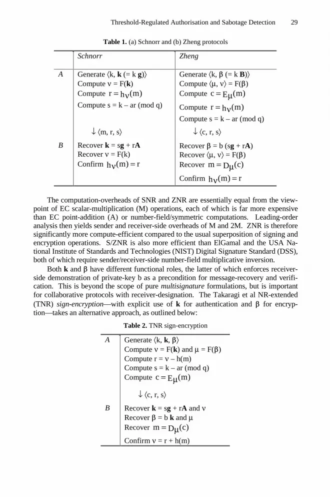
Threshold-Regulated Authorisation and Sabotage Detection 29
Table 1. (a) Schnorr and (b) Zheng protocols
Schnorr Zheng
A Generate ⟨k, k (= k g)⟩Compute ν = F(k)Compute r (m)h= νCompute s = k – ar (mod q)
Generate ⟨k, (= k B)⟩Compute ⟨µ, ν⟩ = F()Compute c (m)E= µCompute r (m)h= νCompute s = k – ar (mod q)
↓ ⟨m, r, s⟩ ↓ ⟨c, r, s⟩
B Recover k = sg + rARecover ν = F(k)Confirm (m) rh =ν
Recover = b (sg + rA)Recover ⟨µ, ν⟩ = F()Recover m (c)D= µConfirm (m) rh =ν
The computation-overheads of SNR and ZNR are essentially equal from the view-point of EC scalar-multiplication (M) operations, each of which is far more expensivethan EC point-addition (A) or number-field/symmetric computations. Leading-orderanalysis then yields sender and receiver-side overheads of M and 2M. ZNR is thereforesignificantly more compute-efficient compared to the usual superposition of signing andencryption operations. S/ZNR is also more efficient than ElGamal and the USA Na-tional Institute of Standards and Technologies (NIST) Digital Signature Standard (DSS),both of which require sender/receiver-side number-field multiplicative inversion.
Both k and have different functional roles, the latter of which enforces receiver-side demonstration of private-key b as a precondition for message-recovery and verifi-cation. This is beyond the scope of pure multisignature formulations, but is importantfor collaborative protocols with receiver-designation. The Takaragi et al NR-extended(TNR) sign-encryption—with explicit use of k for authentication and for encryp-tion—takes an alternative approach, as outlined below:
Table 2. TNR sign-encryption
A Generate ⟨k, k, ⟩Compute ν = F(k) and µ = F()Compute r = ν – h(m)Compute s = k – ar (mod q)Compute c (m)E= µ
↓ ⟨c, r, s⟩
B Recover k = sg + rA and νRecover = b k and µRecover m (c)D= µConfirm ν = r + h(m)

30 A. Goh and D.C.L. Ngo
This formulation costs 2M on the sender-side and 3M on the receiver-side, the latterof which arises from the necessity to sequentially compute k and then . Both aremore significantly more compute-intensive than the corresponding ZNR operations.
2.2 k-of-n Polynomial Thresholding
k-of-n threshold cryptography as formulated by Shamir allows workgroup (set of allusers U) key-parameterisation via (k–1)-degree polynomial
k 1e(x) (mod q)e x
0
− µ= ∑ µµ =
, with a = e(0) mod q interpreted as the workgroup private-
key. Individual users—of which there are n, indexed i ∈ U—would then be assignedpolynomial-associated private key-shares e(i) mod qai = , which are essentially a k-th
share of a if e is secret. This arises from the necessity of at least k datapoints of form ⟨i,e(i)⟩ for finite-field Lagrange interpolation ie
x je(x) e(i) (mod q)
i ji S j S i
− = ∑ ∏ −∈ ∈ −
. Evaluation of this expression results in
e(0) a (mod q)ai ii S
= = ∑ ε∈
with index-coefficient j
(mod q)i j ij S i= ∏ε
−∈ − for
any k-sized subset S ⊂ U. Knowledge of e should be restricted to a trusted key-generator (T), whose role will be subsequently outlined.
Pedersen verification allows individual key-shares ai to be verified as a k-th por-
tion of workgroup private-key a without divulging polynomial e. This operation can beexecuted with [3] or without [4] a centralised T. Presumption of T allows an efficient
non-interactive implementation; with individual EC key-pairs ( ),a aii i= gA and
polynomial parameterisation ( ),e e=µ µ µge , the latter of which includes work-
group key-pair ⟨a, A (= a g)⟩. Key-share generation, distribution and verification be-tween T and all users i ∈ U then proceeds as follows:-
Table 3. Key-share generation, distribution and verification
T Generate polynomial ,eµ µe
Generate key-share ,a ii A for ∀i
Authenticated ch:
, i, i⇓ µe ASecure ch:
ai↓
i ∈ UConfirm ( )k 1
mod q ai ii0
− µ = =∑ µµ =
ge A

Threshold-Regulated Authorisation and Sabotage Detection 31
the last step of which is a zero knowledge (ZK) verification of key-share possessionby user i, thereby enabling engagement in the subsequently outlined protocols. Notethe non-interactive nature of the above-described one-time procedure, with authenti-cated communication essentially equivalent to signed postings on a bulletin-board.
3 Basic Multi-sender Protocol-Extensions
3.1 Individual and Workgroup Parameterisations
The most straightforward extension methodology would be via SNR k and ZNR public-keys as the starting point. The protocol parameters are outlined below:
Table 4. Sender-specific and workgroup-combined parameters
SNR ZNR
kii∈ S
ki i= gk kii = B
ii S
= ∑∈
k k ii S
= ∑∈
S ⊂ U
ν, r ⟨µ, ν⟩, ⟨c, r⟩i r (mod q)s akii i i= − εS s (mod q)si
i S= ∑
∈
with Schnorr-Zheng/NR differentiation via specification for r. The end result wouldbe SNR signature ⟨r, s⟩ or ZNR signcryption ⟨c, r, s⟩, as would be computed by an
entity with private-key a (mod q)ai ii S
= ∑ ε∈
. This approach has been demonstrated
by Takaragi et al to be advantageous compared to the earlier Park-Kurosawa formula-tion with individual random polynomials.
The Takaragi et al description of multisignature formation specifies broadcast of
all individual ,si ik and repeated computation of the common k and ⟨r, s⟩ by each i
∈ S. We outline an alternative presentation with a centralised combiner (C) of work-group parameters—the details of which can logged and straightforwardly verified—which is also applicable towards TNR multisignatures, as demonstrated below: (SeeTable 5) resulting in NR signature ⟨r, s⟩. Such an implementation clearly and effi-ciently separates security-critical sender-specific and verifiable workgroup-aggregatedoperations, the latter of which does not result in an externally (to the workgroup)visible contribution.

32 A. Goh and D.C.L. Ngo
Table 5. TNR multisignature formation
i ∈ S C
1 Generate ,ki ik i →k2 ⇐ ⟨∀i, r⟩ Compute k, ν and r3 Compute iε and si is → Compute i∀ε4 Confirm rs ii i i+ =εg A k
Compute s
3.2 Multi-sender Extended Cryptography
Recall that TNR multisignatures are an extension of the NR base-formulation, hencethe applicability of Table 5 to Schnorr multisignatures via definition r (m)h= ν . The
equivalent ZNR extension is as follows:-
Table 6. ZNR multi-signcryption
i ∈ S C
1 Generate ,ki i i →2 ⇐ ⟨∀i, r⟩ Compute , ⟨µ, ν⟩ and ⟨c, r⟩3 Compute iε and si si → Compute i∀ε4 Compute s
Both T/SNR and ZNR formulations have sender-side overheads of M (computations)and |p| + |q| (communications), which is slightly higher (with respect bandwidth)compared with the single-sender base-protocols in Table 1. The 2kM computationrequired for T/SNR signature-share verification in step (4) of Tables 5 is noteworthy,
as is the modest k
1 |h|2
+ broadcast overhead after step (2) in both protocol-
extensions.Note that submission of k after step (1) and its subsequent verification in step (4)
as in Table 5, does not preclude protocol-sabotage by individual users. This is exe-cuted via submission of = k B and s′ = k′ – εar (mod q) with different initial ran-domisations, resulting in receiver-side inability to recover the signcrypted message.Detection and mitigation of malformed parameter-shares motivates our subsequentanalysis of TNR sign-encryption, and formulation of a ZNR extension with verifiedcombination.

Threshold-Regulated Authorisation and Sabotage Detection 33
4 Multi-sender Protocol-Extension with Verified Combination
4.1 Analysis of Randomised Key-Pairs
Verification of the ZNR-shares in Table 6 essentially requires establishment that thepublic-keys ⟨k, ⟩ are ECEQ . This is not demonstrated in TNR multi-sender sign-encryption—which simply uses one key-pair each for parameter-share authenticationand encryption—as outlined below:-
Table 7. TNR multi-sender sign-encryption
i ∈ S C
1 Generate , ,ki i ik ,i i →k
2 ⇐ ⟨∀i, r⟩ Compute k, ν and r3 Compute iε and si si → Compute i∀ε4 Confirm rsi i i i+ =εg A k
Compute sCompute , µ and c
Note the pair-related computations are essentially independent signing and encryptionoperations—with increased sender-side overheads of 2M and 2|p| + |q|—which isproblematic due to individual senders being able to sabotage the protocol throughsubmission of non-ECEQ pair ⟨k, ′⟩. Such an malformed submission enables suc-cessful verification (internal to the workgroup), but prevents proper receiver-siderecovery (typically outside the workgroup). Saboteurs can therefore remain unde-tected in TNR multi-sender sign-encryption.
This inability to detect non-ECEQ pairs prior to combination is unfortunate, sincetypical operations might result in submission of more than k parameter-shares. Com-biner-side detection of sabotaged parameter-shares under such circumstances wouldtherefore allow for their straightforward replacement with well-formed ones, so thatthe resultant ⟨c, r, s⟩ is also well-formed. Lack of such a capability, on the other hand,is problematic in any number of realistic operational scenarios.
4.2 Rectification via ECEQ Establishment
A pair P = ⟨k, ⟩ can be proven ECEQ with respect basepoint pair ⟨g, B⟩ via theChaum-Pedersen [13] protocol, which can be made non-interactive via Fiat-Shamir[14] heuristics. Prover (P) knowledge of common randomisation k allows Verifier(V) side confirmation of ZK proof ⟨e, z⟩ as follows:-

34 A. Goh and D.C.L. Ngo
Table 8. ECEQ of P with respect ⟨g, B⟩
P Generate random rCompute P′ = ⟨r g, r B⟩Compute e = h(g, B, P, P′)Compute z = r – ek (mod q)
↓ ⟨e, z⟩
V Compute k′ = ek + zgCompute ′ = e + zBConfirm e = h(g, B, P, P′)
which requires prover and verifier-side computation overheads of 2M and 4M respec-tively, in addition to bandwidth |h| + |q|. ECEQ establishment allows rectification ofthe TNR formulation in Table 7 as follows:-
Table 9. TNR multi-sender sign-encryption with ECEQ
i ∈ S C
1 Generate , ,ki i ik ,i i →k
2 ⇐ ⟨∀i, r⟩ Compute k, ν and r3 Compute ,e zii
Compute iε and si , ,e szii i →
Compute i∀ε
4 Establish ECEQ ,i ik
Confirm rsi i i i+ =εg A k
Compute sCompute , µ and c
resulting in a well-formed ⟨c, r, s⟩; but at significantly higher overheads, particularlycombiner-side for large k.
4.3 Homomorphic ECEQ Establishment
ECEQ establishment for multi-sender signcryption is far more straightforward viareexpression of the EC verification condition (V): sg + rA = k (ref Table 1), specifi-cally its RHS(V): k = + with = k d and d = g – B. Individual senders wouldtherefore need to compute and transmit ECEQ pair ⟨, ⟩, the latter of which essen-tially constitutes a homomorphic commitment on the former. This results in the fol-lowing ZNR extension:

Threshold-Regulated Authorisation and Sabotage Detection 35
Table 10. ZNR multi-signcryption with verified combination
i ∈ S C
1 Generate , ,ki ii , ii → 2 ⇐ ⟨∀i, r⟩ Compute , ⟨µ, ν⟩ and ⟨c, r⟩3 Compute iε and si
si →
Compute i∀εRecover ii i= +k
4 Confirm rsi i i i+ =εg A k
Compute s
with parameter-share verification in step(4) prior to computation of the workgroup s.The single key-pair computation results in sender-side overheads essentially equal toweak TNR sign-encryption without ECEQ (Table 7), but is only half that of the rigor-ous variant with ECEQ (Table 9). The combiner-side overhead is essentially equal tothat of the T/SNR multisignature scheme in Table 5, and also only a third of TNRsign-encryption with ECEQ.
Note the differences in the ECEQ establishment mechanisms, with independentuse of ⟨k, ⟩ resulting in the necessity for specification of another pair ⟨k′, ′⟩. ZNRpredication on single public-key , on the other hand, allows for a much simpler ho-momorphic establishment of ECEQ which leverages EC verification (in any caserequired) of individually submitted s. This illustrates the efficacy of the ZNR sign-cryption approach which integrates signature and encryption operations.
5 Multi-receiver Protocol-Extension
5.1 Individual and Workgroup Parameterisations
ZNR multi-receiver extensibility is predicated on receiver-specific (i ∈ R) knowledge
of key-share bi applied to compute parameter-share (s r )bii = +g A . Sufficient
quantities of the latter can be summed to obtain workgroup-common (R ⊂ U)
i ii R
= ∑ ε∈
. This parameterisation also applies to the TNR decrypt-verify proto-
col, but is beyond the functional scope of the TNR and SNR multisignature formula-tions.
Following the sender-side analysis, we adopt a presentation with centralised C soas to separate security-critical receiver-specific (predicated on key-share knowledge)and verifiable workgroup-aggregated operations. This is straightforward for ZNRrecovery of , but more complicated for the equivalent TNR operation predicated onboth k and . The most efficient approach is to independantly compute receiver-

36 A. Goh and D.C.L. Ngo
specific i —departing from single-receiver case in Table 2—and workgroup-
common k = sg + rA as illustrated below:
Table 11. TNR multi-receiver decrypt-verification
i ∈ R Compute i
i↓C Compute i∀ε , and µ
Recover m (c)D= µCompute k = sg + rA and νConfirm ν = r + h(m)
with an overhead of 2M per receiver (ref Section 2.1), and an additional 2M at C.This is less efficient than multi-receiver ZNR, as will be subsequently demonstrated.Successful message recovery/verification presumes proper sender-side formation of⟨c, r, s⟩, which places a premium on parameter-share verification.
5.2 Multi-receiver Extended Cryptography
ZNR unsigncryption as outlined in Section 2.1 can be extended to incorporate multi-ple receivers, as follows:-
Table 12. ZNR multi-unsigncryption
i ∈ R Compute i
i↓C Compute i∀ε and
Recover ⟨µ, ν⟩ = F()Recover m (c)D= µUse ν to confirm r
with Schnorr-Zheng/NR differentiation only in the final confirmation ie (m) rh =νand ν = r + h(m) respectively. This formulation can be used in conjunction with sin-gle/multi-sender signcryption protocols of Tables 1(b), 6 and 10; the last of whichprevents protocol-sabotage via malformed signcryption-shares. This ZNR extensionis also more compute-efficient on the combiner-side—by 2M, due to non-computationof k—compared with the equivalent TNR operation.

Threshold-Regulated Authorisation and Sabotage Detection 37
6 Comparison with TNR Protocols
The computation and communications overheads of the featured multi-user extensionsare as follows:-
Table 13. Comparison of (a) single/multi-sender signature/signcryption protocols, and (b)single/multi-receiver verification/unsigncryption protocols.#, * and + denote receiver–designation, parameter–share verification and receiver–confirmation
Protocol Table Senderoverhead
Combineroverhead
SNR sgn 1(a)ZNR sgncpt # 1(b)
M, |h|+|q|
TNR sgn/enc #2 2M, |h|+|q|
n/a
T/SNR multisgn * 5 M, |p|+|q|TNR multi-sgn/enc #
7 2M, 2|p|+|q|2kM,
k1 |h|
2 +
TNR multi-sgn/enc ECEQ #* 9 4M, 2|p|+2|q|+|h| 6kM,
k1 |h|
2 +
ZNR unverifmulti-sgncpt #* 6 M, |p|+|q| kA ,
k1 |h|
2 +
ZNR verifmulti-sgncpt #* 10 2M 2|p|+|q| 2kM,
k1 |h|
2 +
Protocol Table Receiveroverhead
Combineroverhead
Receiver-confirmation
T/SNR verif 1(a) noZNR unsgncpt + 1(b)
2M
TNR dec/verif + 2 3Mn/a
TNR multi-dec/verif +
11 2M+kA
ZNR multi-unsgncpt +
122M, |p|
kA
yes
Note the presentation of two ZNR multi-sender extensions, the more rigorous (Table10) of which facilitates parameter-share verification in addition to receiver-designation. This is achieved efficiently via homomorphic ECEQ, resulting in over-heads only marginally greater than T/SNR multisignature formation (Table 5). Rig-orous multi-sender TNR (Table 9) sign-encryption requires significantly higher(doubled/tripled) overheads due to the necessity to establish ECEQ of the ⟨k, ⟩ pub-lic-keys with respect a challenge (r-dependent) pair ⟨k′, ′⟩. Both ZNR and TNR
38 A. Goh and D.C.L. Ngo
multi-sender extensions can be operated in unverified modes ie Tables 6 and 7 re-spectively, with dispensation of the combiner-side overhead for the latter. ZNRmulti-signcryption is also significantly more efficient sender-side when operated infast mode.
The multi-receiver ZNR (Table 12) and TNR (Table 11) formulations differthrough their respective use of single and double ⟨k, ⟩, the former of which is moreefficient. Both protocol-extensions are vulnerable to sender-side sabotage resulting inmalformed secure-messages, which emphasises the importance of parameter-shareverification. Multi-receiver ZNR in conjunction with the verifying multi-sender andsingle-sender ZNR variants, can therefore be characterised as rigorous and efficientmultipoint-to-multipoint secure-messaging.
7 Concluding Remarks
The outlined multi-user S/ZNR protocols are functionally comprehensive, com-pute/bandwidth-efficient and transparently interoperable with respect their single-userbase-formulations. This allows for straightforward implementation of both withintypical workgroup environments; with verified combination by designated users orcentralised servers, and externally-visible S/ZNR parameters structurally identical totheir single-user base-formulations. Combiners can therefore be regarded as work-group gateways, the efficiency of which is enhanced by the near-similarity of theS/ZNR formulations. Note the receiver-side operation can be concluded after a singlecryptographic computation, and is therefore inherently efficient independant of k.Sender-side collaboration can also be simplified to a single pass for the (k = 2) case,with only initiating (i ∈ S) and responding (j ∈ S) users.
This versatility and efficiency stems from the featured multi-user extensionmethodology on single key-pair base-protocols, which in the case of ZNR departsfrom the usual prescription (adopted for TNR sign-encryption) of distinct pairs formessage-authentication and encryption. The proposed formulation integrates authen-tication and encryption functionalities, and enables efficient detection of sabotagedparameter-shares in multi-sender ZNR. This capacity for sabotage-detection is alsopresent in the T/SNR multisignature protocol, which is a single-pair authentication-only formulation. Sabotage-detection can also be incorporated into the double-pairmulti-sender TNR sign-encryption, but only at the cost of significantly higher over-heads compared to multi-sender ZNR signcryption. It is interesting to speculatewhether other double-pair secure-messaging formulations can be efficiently extendedto incorporate this attribute.
Parameter-share verification is a significant functional advantage, the lack ofwhich jeopardises multi-receiver message-recovery/verification. This can be seenfrom transaction scenarios featuring long-term—so that existence of the original mes-sage, sender-side key-shares or even the sending-workgroup cannot be presumed—escrow of inadvertently malformed secure-messages, resulting in permanent informa-tion loss. Efficiency with respect sabotage-detection is also important, especially inconsideration of the two/three-fold differences in the ZNR and TNR overheads. Thepresented ZNR extension can therefore be safely characterised as rigorous yet effi-cient multipoint-to-multipoint secure-messaging.

Threshold-Regulated Authorisation and Sabotage Detection 39
References
1. A Shamir (1979). How to Share a Secret. Assoc Comp Machinery (ACM) Comms vol22, no 11: pp 612–613
2. P Feldman (1987). A Practical Scheme for Non-Interactive Verifiable Secret-Sharing. 28-th IEEE Symp on the Foundations of Comp Sc: pp 427–437
3. TP Pedersen (1991). Distributed Provers with Applications to Undeniable Signatures.Eurocrypt-91, Springer-Verlag Lecture Notes in Computer Science (LNCS) 547: pp 221–238
4. TP Pedersen (1991). A Threshold Cryptosystem without a Trusted Party. Eurocrypt-91,Springer-Verlag LNCS 547: pp 522–526
5. AJ Menezes (1993). Elliptic Curve Public-Key Cryptosystems. Kluwer Acad Press.6. IF Blake, G Seroussi & NP Smart (1999). Elliptic Curves in Cryptography. Cambridge
Univ Press7. C Park & K Kurosawa (1996). New ElGamal-Type Threshold Digital Signature Scheme.
Inst Electrical, Info & Comms Engineers (IEICE) Trans, Vol E79-A, no 1: pp 86–938. K Takaragi, K Miyazaki & M Takahashi (1998). A Threshold Digital Signature Issuing
Scheme without Secret Communication. Presentation IEEE P1363 Study Group for Pub-lic-key Crypto Stds
9. T ElGamal (1985). A Public-Key Cryptosystem and Signature Scheme Based on DiscreteLogarithms. IEEE Trans Info Theory
10. K Nyberg & R Ruepple (1993). A New Signature Scheme Based on DSA Giving MessageRecovery. 1-st ACM Conf on Comp & Comms Security, ACM Press: pp 58–61
11. CP Schnorr (1989). Efficient Identification and Signatures for Smartcards. Crypto-89,Springer-Verlag LNCS 435: pp 239–252
12. Y Zheng (1997). Digital Signcryption or how to Achieve Cost(Signature & Encryption)<< Cost(Signature) + Cost(Encryption). Crypto-97, Springer Verlag LNCS 1396: pp291–312
13. DL Chaum & TP Pedersen. Wallet Databases with Observers. Crypto-92, Springer Ver-lag LNCS 740: 89–105
14. A Fiat & A Shamir. How to Prove Yourself: Practical Solutions to Identification andSignature Problems. Crypto-86, Springer Verlag LNCS 263: 186–194

Securing the Border Gateway Protocol: A Status Update
Stephen T. Kent
BBN Technologies, 10 Moulton Street, Cambridge, MA, U.S. [email protected]
Abstract. The Border Gateway Protocol (BGP) is a critical component of theInternet routing infrastructure, used to distribute routing information betweenautonomous systems (ASes). It is highly vulnerable to a variety of maliciousattacks and benign operator errors. Under DARPA sponsorship, BBN has de-veloped a secure version of BGP (S-BGP) that addresses most of BGP’s archi-tectural security problems. This paper reviews BGP vulnerabilities and their im-plications, derives security requirements based on the semantics of the protocol,and describes the S-BGP architecture. Refinements to the original S-BGP de-sign, based on interactions with ISP operations personnel and further experiencewith a prototype implementation are presented, including a heuristic for signifi-cantly improving performance. The paper concludes with a comparison ofS-BGP to other proposed approaches.
1 Problem Description
Routing in the public Internet is based on a distributed system composed of manyrouters, grouped into management domains called Autonomous Systems (ASes).Routing information is exchanged between ASes using the Border Gateway Protocol(BGP) [1], via UPDATE messages. BGP is highly vulnerable to a variety of attacks[2], due to the lack of a secure means of verifying the authorization of BGP controltraffic. In April 1997, we began work on the security architecture described in this pa-per. We begin by reviewing the problem—a model for correct operation of BGP, BGPvulnerabilities and a threat model, and the goals, constraints and assumptions that un-derlie S-BGP. The reader is assumed to be familiar with the fundaments of BGP.
BGP is used in two different contexts. External use of BGP (eBGP) propagatesroutes between ISPs, or between ISPs and subscriber networks that are connected tomore than one ISP, i.e., multi-homed subscribers. BGP also is used internally, withinan AS, to propagate routes acquired from other ASes. This use is referred to as inter-nal BGP (iBGP). eBGP is the primary focus of this work, because failures of eBGPadversely affect subscribers outside the administrative boundary of the source of thefailure. Nonetheless, some ISPs have expressed interest in using S-BGP to protect thedistribution of routes within an ISP. If route servers are employed for iBGP (see sec-
Lioy and Mazzocchi (Eds.): CMS 2003, LNCS 2828, pp 40–53, 2003.© IFIP International Federation for Information Processing 2003

Securing the Border Gateway Protocol: A Status Update 41
tion 5.5), or if the number of iBGP peers is small, S-BGP may be a viable approachfor iBGP security. We use „BGP“ to refer to eBGP, unless otherwise noted.
A route is defined as an address prefix and a set of path attributes, one of which isan AS path. The AS path specifies the sequence of ASes that subscriber traffic willtraverse if forwarded via this route. When propagating an UPDATE to a neighboringAS, the BGP router prepends its AS number to the sequence, and may update certainother path attributes.
Each BGP router maintains a full routing table, and sends its best route for eachprefix to each neighbor. In BGP, „best“ is very locally defined. The BGP route selec-tion algorithm has few criteria that are universal, which limits the extent to which anysecurity mechanism can detect and reject „bad“ routes emitted by a neighbor. EachISP makes use of local policies that it need not disclose, and this gives BGP route se-lection a „black box“ flavor, which has significant adverse implications for security.
1.1 Correct Operation of BGP
As we noted in [2], security for BGP is defined as the correct operation of BGProuters. This definition is based on the observation that any successful attack againstBGP will result in other than correct operation, presumably yielding degraded routing.Correct operation of BGP depends upon the integrity, authenticity, and timeliness ofthe routing information it distributes, as well as each BGP router’s processing, storing,and distribution of this information in accordance with both the BGP specification andwith the local routing policies. Many statements could be made in an effort to charac-terize correct operation, but they rest on two simple assumptions:• Communications between peer BGP routers is authenticity & integrity secure• BGP routers execute the route selection algorithm correctly and communicate the
resultsThe first assumption is easily realized through the use of a suitable, point-to-point se-curity protocol, e.g., IPsec. The second assumption is divisible into two cases: proc-essing received UPDATEs, and generation and transmission of UPDATEs. From theperspective of an AS trying to protect itself against external attacks, correct operationof its own BGP routers is an implementation, not an architectural, security issue.However, an AS ought not rely on other ASes to operate properly, since such relianceleads to cascade failures. It is desirable for a BGP router to be able to verify that eachUPDATE it receives from a peer is valid and timely. Validity of an UPDATE encom-passes four primary criteria.1. The router that sent the UPDATE was authorized to act on behalf of the AS it
claims to represent (by virtue of placing that AS number in the AS path).2. The AS from which the UPDATE emanates was authorized by the preceding AS in
the AS path to advertise the prefixes contained within the UPDATE.3. The first AS in the AS path was authorized, by the „owner“ of the set of prefixes
(NLRI), to advertise those prefixes.4. If the UPDATE withdraws one or more routes, then the sender must have adver-
tised the route(s) prior to withdrawing it (them).

42 S.T. Kent
There are limitations to the ability of any security mechanism to detect attacks. Thelocal policy feature of BGP allows considerable latitude in UPDATE processing,, soS-BGP cannot detect erroneous behavior that could be attributed to local policies notvisible outside an AS. To address such attacks, the semantics of BGP itself wouldhave to change. Moreover, because UPDATEs do not carry sequence numbers, a BGProuter can generate an UPDATE based on authentic, but old, information, e.g., with-drawing or reasserting a route based on outdated information. Thus the temporal accu-racy of UPDATEs, in the face of Byzantine failures, is enforced only very coarsely bythese countermeasures.
1.2 Threat Model and BGP Vulnerabilities
BGP has many vulnerabilities that can be exploited to cause improper routing or non-delivery of subscriber traffic, network congestion, and traffic delays. Misrouting at-tacks facilitate passive and active wiretapping of subscriber traffic, and thus an attackagainst BGP may be part of a larger attack against subscriber computers.
Routers are vulnerable in both the architectural and implementation domains. Im-plementation vulnerabilities may allow an attacker to assume control of a router, tocause it to operate maliciously, or to cause the router to crash, and thus deny service.Architectural vulnerabilities permit various forms of attack, independent of imple-mentation details, and thus are potentially more damaging, as they persist across allimplementations. To make Internet routing robust, both forms of vulnerabilities mustbe addressed. S-BGP does not directly address implementation vulnerabilities, but itdoes limit the impact of such vulnerabilities. Use of S-BGP by an AS protects that ASagainst many attacks that result from security failures suffered by other ASes.
BGP can be attacked in many ways. Communication between BGP peers can besubjected to active and passive wiretapping. A router’s BGP software, configurationinformation, or routing databases may be modified or replaced illicitly via unauthor-ized access to a router, or to a server from which router software is downloaded, or viaan attacked distribution channel. Most of these attacks transform routers into hostileinsiders. Effective security measures must address such Byzantine failures.
Many countermeasure could be employed in an attempt to addresses these vulner-abilities. Better physical and procedural security for network management facilities,and routers would help. Cryptographic protection of BGP traffic between routers andfor network management traffic would also reduce some of these vulnerabilities.However, improved physical and procedural security is expensive and imperfect andthese countermeasures would not protect the Internet against accidental or maliciousmisconfiguration by operators, nor against attacks that mimic such errors. Misconfigu-ration of this sort has proved to be a source of several significant Internet outages inthe past and seems likely to persist. Any security approach that relies on ISPs to actproperly, that relies on „trust“ among ISPs, violates the "principle of least privilege"and leaves the Internet routing system vulnerable at its weakest link. In contrast, thesecurity approach described here satisfies this principle, so that any attack on anycomponent of the routing system is limited in its impact on the Internet as a whole.

Securing the Border Gateway Protocol: A Status Update 43
1.3 Goals, Constraints, and Assumptions
In order to create countermeasures that are both effective and practical, the S-BGP ar-chitecture is based on the following goals, constraints, and assumptions.
Any proposed security architecture must exhibit dynamics consistent with the ex-isting system, e.g., responding automatically to topology changes, including the addi-tion of new networks, routers and ASes. Solutions also must scale in a manner con-sistent with the growth of the Internet.
The countermeasures must be consistent with the BGP protocol standards and withthe likely evolution of these standards. This includes packet size limits and featuressuch as path aggregation, communities, and multi-protocol support (e.g., MPLS).
The S-BGP architecture must be incrementally deployable; there cannot be a „flagday“ when all BGP routers suddenly begin executing S-BGP.
It is desirable to not create new organizational entities that must be accepted asauthorities by ISPs and subscribers, in order to make routing secure.
2 S-BGP Architecture
S-BGP consists of four major elements:• a Public Key Infrastructure (PKI) that represents the ownership and delegation of
address prefixes and AS numbers• „address attestations“ that the owner of a prefix uses to authorize an AS to originate
routes to the prefix• „route attestations“ that an AS creates to authorize a neighbor to advertise prefixes• IPsec for point-to-point security of BGP traffic transmitted between routersThese elements are used by an S-BGP router to secure communication with neighbors,and to generate and validate UPDATE messages relative to the authorization modelrepresented by the PKI and address attestations. Together, the combination of thesesecurity mechanisms provide a „firebreak“ that prevents a compromised AS frompropagating erroneous routing data to other (secured) ASes.
2.1 S-BGP Public Key Infrastructure (PKI)
S-BGP uses a PKI based on X.509 (v3) certificates to enable BGP routers to validatethe authorization of BGP routers to represent ASes and prefixes. This PKI was de-scribed in [24] and the reader is referred to that paper for additional details. TheS-BGP PKI parallels the existing IP address and AS number assignment delegationsystem and takes advantage of this infrastructure. Because the PKI mirrors existing in-frastructure, it avoids many of the "trust" issues that often complicate the creation of aPKI. This PKI is unusual in that it focuses on authorization, not authentication; thenames used in most of the certificates in this PKI are not meaningful outside ofS-BGP.

44 S.T. Kent
S-BGP calls for a certificate to be issued to each organization that is granted "rightto use" of a portion of the IP address space. This certificate is issued through the samechain of entities that today is responsible for address allocation starting with theIANA1. If an ISP or subscriber owns multiple prefixes, we issue a single certificatecontaining a list of prefixes, to minimize the number of certificates needed to validatean UPDATE.
This PKI represents the assignment of prefixes by binding prefixes to a public keybelonging to the organization to which the prefixes have been assigned. These certifi-cates are used to prove „ownership“ of one or more prefixes2. Each certificate in thisPKI contains a private extension that specifies the set of prefixes that has been allo-cated to the organization. We use the Domain Component (RFC 2247) construct in thesubject name in each certificate to represent a DNS-style name for an organization.
Certificates issued under this PKI also represent the binding between an organiza-tion and the AS numbers allocated to it. The PKI allows an organization to certify thata router represents the organization’s AS(es). Here too, the PKI parallels existing"trust relationships," i.e., the IANA assigns AS numbers to RIRs, which in turn assignAS numbers to ISPs or subscribers that run BGP, and they certify their routers.
2.2 Attestations
An attestation is a digitally signed datum asserting that its target (an AS) is authorizedby the signer (an organization) to advertise a path to the specified prefix(es). There aretwo types of attestations, address and route. They share a single format.
• Address attestation (AA)— the signer of an AA is the organization that „owns“ theprefix(es) in the AA, and the target is a set of ASes that the organization authorizesto originate a route to the prefix(es), i.e., the ISPs with which the issuer has a trafficcarriage arrangement. AAs are relatively static data items, since relationships be-tween address space owners and ISPs change relatively slowly.
• Route attestation (RA)— the signer of an RA is an S-BGP router in an ISP. Thetarget is a set of ASes, representing the neighbors to which UPDATEs containingthe RA will be sent. Note that the router signing an RA might sign a separate RAfor each neighbor, or it may sign a single RA directed to all of its neighbors. Thelatter option permits a router to reduce its digital signature burden, so long as thesame parameters appear in the UPDATEs sent to each neighbor. RAs, unlike AAs,are very dynamic, possibly changing for each transmitted UPDATE.
2 One could use X.509 attribute certificates to represent this authorization, but they offer little
benefit in this context and would increase the certificate processing burden.
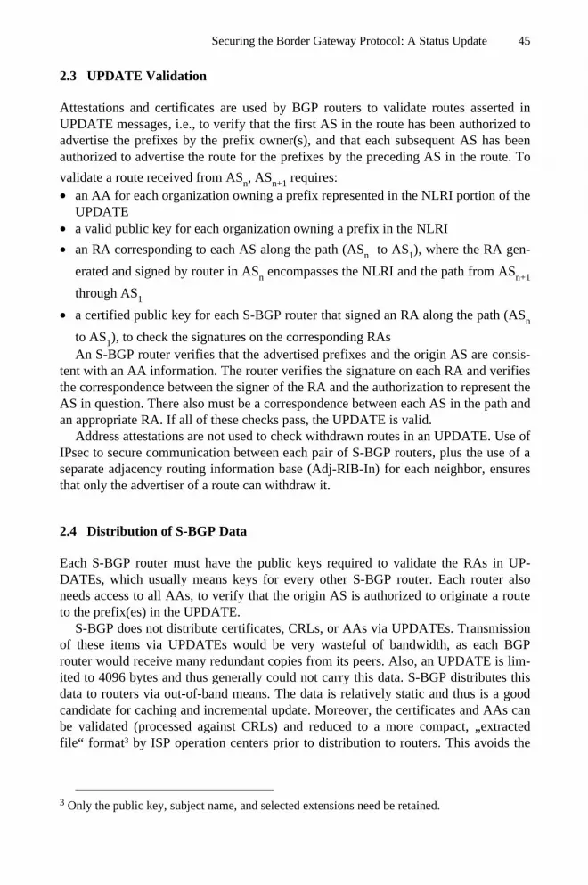
Securing the Border Gateway Protocol: A Status Update 45
2.3 UPDATE Validation
Attestations and certificates are used by BGP routers to validate routes asserted inUPDATE messages, i.e., to verify that the first AS in the route has been authorized toadvertise the prefixes by the prefix owner(s), and that each subsequent AS has beenauthorized to advertise the route for the prefixes by the preceding AS in the route. To
validate a route received from ASn, ASn+1 requires:• an AA for each organization owning a prefix represented in the NLRI portion of the
UPDATE• a valid public key for each organization owning a prefix in the NLRI
• an RA corresponding to each AS along the path (ASn to AS1), where the RA gen-
erated and signed by router in ASn encompasses the NLRI and the path from ASn+1
through AS1
• a certified public key for each S-BGP router that signed an RA along the path (ASn
to AS1), to check the signatures on the corresponding RAsAn S-BGP router verifies that the advertised prefixes and the origin AS are consis-
tent with an AA information. The router verifies the signature on each RA and verifiesthe correspondence between the signer of the RA and the authorization to represent theAS in question. There also must be a correspondence between each AS in the path andan appropriate RA. If all of these checks pass, the UPDATE is valid.
Address attestations are not used to check withdrawn routes in an UPDATE. Use ofIPsec to secure communication between each pair of S-BGP routers, plus the use of aseparate adjacency routing information base (Adj-RIB-In) for each neighbor, ensuresthat only the advertiser of a route can withdraw it.
2.4 Distribution of S-BGP Data
Each S-BGP router must have the public keys required to validate the RAs in UP-DATEs, which usually means keys for every other S-BGP router. Each router alsoneeds access to all AAs, to verify that the origin AS is authorized to originate a routeto the prefix(es) in the UPDATE.
S-BGP does not distribute certificates, CRLs, or AAs via UPDATEs. Transmissionof these items via UPDATEs would be very wasteful of bandwidth, as each BGProuter would receive many redundant copies from its peers. Also, an UPDATE is lim-ited to 4096 bytes and thus generally could not carry this data. S-BGP distributes thisdata to routers via out-of-band means. The data is relatively static and thus is a goodcandidate for caching and incremental update. Moreover, the certificates and AAs canbe validated (processed against CRLs) and reduced to a more compact, „extractedfile“ format3 by ISP operation centers prior to distribution to routers. This avoids the
3 Only the public key, subject name, and selected extensions need be retained.

46 S.T. Kent
need for each router to perform this processing, saving both bandwidth and storagespace.
S-BGP uses repositories for distribution of this data. We initially described a modelin which a few replicated, loosely synchronized repositories were operated by theRIRs. Discussions with ISPs suggest a model in which major ISPs and Internet ex-changes operate repositories, and smaller ISPs and subscribers make use of these re-positories. In either model, ISPs periodically (e.g., daily), upload and downloadnew/changed certificates, CRLs, and AAs. The repositories periodically transfer newdata to one another to maintain loose synchronization. ISPs process the repository in-formation to create „extracted files“ and transfer them to their routers.
Since certificates, AAs, and CRLs are signed and carry validity interval informa-tion, they require minimal additional security. Nonetheless, S-BGP employs SSL, withboth client and server certificates, to protect access to the repositories, as a counter-measure to denial of service attacks. The simple, hierarchic structure of the PKI al-lows repositories to automatically effect access control checks on the uploaded data.
2.5 Distribution of Route Attestations
Route attestations (RAs) are distributed with BGP UPDATEs in a newly defined, op-tional, transitive path attribute. Because RAs may change quickly, it is important thatthey accompany the UPDATEs that are validated using the RAs. When an S-BGProuter opens a BGP session with a peer, transmitting a portion of its routing informa-tion database via UPDATEs, relevant RAs are sent with each UPDATE, and with sub-sequent UPDATEs sent in response to route changes. These attestations employ acompact encoding scheme to help ensure that they fit within the BGP packet size lim-its, even when route or address aggregation is employed. (S-BGP accommodates ag-gregation by explicitly including signed attribute data that otherwise would be lostwhen aggregation occurs.) An S-BGP router receiving an UPDATE from a peercaches the RAs with the route in the Adj-RIB for the peer, and in the Loc-RIB (if theroute is selected). As noted below in Section 4, the bandwidth required to support in-band distribution of route attestations is negligible (compared to user traffic).
Although the RA mechanism was designed to protect AS path data, it can also ac-commodate other new path attributes, e.g., communities [13] and confederations [14].Specifically, there is a provision to indicate what data, in addition to the AS path, iscovered by the digital signature that is part of the RA.
2.6 IPsec and Router Authentication
S-BGP uses IPsec [8,9,10], specifically the Encapsulating Security Payload (ESP)protocol, to provide authentication, data integrity, and anti-replay for all BGP trafficbetween neighboring routers. The Internet Key Exchange protocol (IKE) [11,12] isused for key management services in support of ESP. The PKI established for S-BGPincludes certificates for IKE, separate from those used for RA processing.
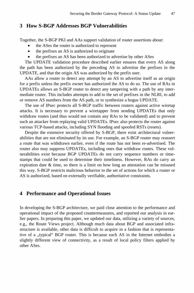
Securing the Border Gateway Protocol: A Status Update 47
3 How S-BGP Addresses BGP Vulnerabilities
Together, the S-BGP PKI and AAs support validation of router assertions about:• the ASes the router is authorized to represent• the prefixes an AS is authorized to originate• the prefixes an AS has been authorized to advertise by other ASes
The UPDATE validation procedure described earlier ensures that every AS alongthe path has been authorized by the preceding AS to advertise the prefixes in theUPDATE, and that the origin AS was authorized by the prefix user.
AAs allow a router to detect any attempt by an AS to advertise itself as an originfor a prefix unless the prefix owner has authorized the AS to do so. The use of RAs inUPDATEs allows an S-BGP router to detect any tampering with a path by any inter-mediate router. This includes attempts to add to the set of prefixes in the NLRI, to addor remove AS numbers from the AS path, or to synthesize a bogus UPDATE.
The use of IPsec protects all S-BGP traffic between routers against active wiretapattacks. It is necessary to prevent a wiretapper from sending UPDATEs that onlywithdraw routes (and thus would not contain any RAs to be validated) and to preventsuch an attacker from replaying valid UPDATEs. IPsec also protects the router againstvarious TCP-based attacks, including SYN flooding and spoofed RSTs (resets).
Despite the extensive security offered by S-BGP, there exist architectural vulner-abilities that are not eliminated by its use. For example, an S-BGP router may reasserta route that was withdrawn earlier, even if the route has not been re-advertised. Therouter also may suppress UPDATEs, including ones that withdraw routes. These vul-nerabilities exist because BGP UPDATEs do not carry sequence numbers or time-stamps that could be used to determine their timeliness. However, RAs do carry anexpiration date & time, so there is a limit on how long an attestation can be misusedthis way. S-BGP restricts malicious behavior to the set of actions for which a router orAS is authorized, based on externally verifiable, authoritative constraints.
4 Performance and Operational Issues
In developing the S-BGP architecture, we paid close attention to the performance andoperational impact of the proposed countermeasures, and reported our analysis in ear-lier papers. In preparing this paper, we updated our data, utilizing a variety of sources,e.g., the Route Views project. Although much data about BGP and associated infra-structure is available, other data is difficult to acquire in a fashion that is representa-tive of a „typical“ BGP router. This is because each AS in the Internet embodies aslightly different view of connectivity, as a result of local policy filters applied byother ASes.

48 S.T. Kent
4.1 Some BGP and S-BGP Parameters
The backbone routers of the major ISPs have a route to every reachable IP address. Asof 2003, the routing information databases (Loc-RIBs) in these routers contain about125,000 IPv4 address prefixes. Each route contains an average of about 3.7 ASes, andtypically there would be one route attestation per AS, which provides a basis for cal-culating how much space is devoted to RAs in UPDATE messages and in RIBs.
Over a 24 hour period, a typical BGP router receives an average of about oneUPDATE per minute per peer. Thus a router at an Internet exchange with 30 peers,receives about .5 UPDATEs per second, on average. This rate is affected somewhat byInternet growth, but it is primarily a function of link, component, or congestion fail-ures and recoveries.
We originally estimated the peak, per-minute rate for UPDATEs at about 10 timesthe average. However, more recent data suggests that, in times of extreme stress, thepeak UPDATE rate might be as much as 200 times the average. Analysis shows thatabout 50% of all UPDATEs are sent as a result of route "flaps," i.e., transient commu-nication failures that, when remedied, result in a return to the former route. This sortof routing behavior has long been characteristic of the Internet4 [3].
The X.509 certificates used in S-BGP are about 600 bytes long. The certificate da-tabase will grow each year as more prefixes, ASes, and S-BGP routers are added. Weestimate the current database size at about 75-85 Mbytes. The CRL database associ-ated with these certificates adds to this total, but since most of these certificates are is-sued to organizations and devices (vs. people) and the expected revocation rate shouldbe relatively low and thus CRLs ought not grow large.
4.2 S-BGP Processing
The computation burden for signature generation and validation in S-BGP has at-tracted considerable attention, as well it should. After all, routers today do not processdigital signatures and this new burden must be considered carefully. Under normalconditions, UPDATEs processing represents a minimal burden for most BGP routers5.However, when routes are changing rapidly, the BGP processing load can rise dra-matically, and when a BGP router reboots, it receives complete routing tables (viaUPDATEs) from each of its neighbors. The time required by BGP to process all ofthese UPDATEs represents a significant processing burden. Better algorithms andheuristics are needed to allow routers to better cope with UPDATE surges. Such algo-rithms should be developed irrespective of the use of S-BGP, but S-BGP would allowthese algorithms to operate with confidence about the source and integrity of UP-DATEs.
4 In a discussion with David Mills, an architect of the NSFNET, he confirmed that route flap-
ping has been a characteristic of the Internet since the mid-80’s.5 Most subscriber traffic traverses a router via a „fast path“ which often uses hardware for path
selection. Management traffic, such as BGP, is directed to a general purpose processor andassociated memory, which processes the traffic and executes routing algorithms.

Securing the Border Gateway Protocol: A Status Update 49
In previous analysis, we assumed that each received UPDATE would contain about3.6 RAs (now updated to 3.7), and would result in transmission of an UPDATE withone new signature. This was an over simplification; a router generates and transmitsan UPDATE only if the newly received route is „better“ than the current best route, orif that route is withdrawn by the UPDATE. When a router has many peers, most of theUPDATEs it receives will not trigger a change in its view of the best route.
On the other hand, when a router does select a new route, an UPDATE may be con-structed and sent to each neighbor, requiring a one signature per neighbor. This is be-cause an RA specifies the AS number of the neighbor to which it is directed. It is pos-sible to construct an RA that identifies the next hop as a set of AS numbers,corresponding to all the neighbors to which an UPDATE is authorized to be sent. Thedownside of this strategy is that it makes the RAs, and thus UPDATEs, larger.
This observation suggests a heuristic for UPDATE processing to mitigate signaturevalidation costs. A router can defer validation of the RAs in any UPDATE that it re-ceives, if the UPDATE would not represent a new best route. This optimization couldbe especially helpful for routers that receive the greatest number of UPDATEs, i.e.,routers with many neighbors. One might worry that this strategy allows an attacker toforce processing, by sending what would be considered „very good“ routes, but anS-BGP router will detect such fraudulent UPDATEs and could choose to drop its con-nection to a peer that behaved this way.
Out initial analysis yielded a peak signature verification rate of about 9/second, fora router with 30 peers, and taking advantage of a depth 1 cache. Given the morethoughtful analysis above, and the more realistic surge UPDATE rates, it is no longerclear what constitutes a good estimate for typical & surge signature valida-tion/generation rates. One could argue for use of a crypto processor to accommodateworst case (200-fold surge) UPDATE rates at a router with many peers. One alsocould argue that deferring validation unless a received UPDATE would trigger trans-mission of an UPDATE would reduce the crypto burden to a level that is well withinthe capabilities of modern, general purpose CPUs. We have not constructed a newanalytic model or simulation to evaluate the heuristic.
Initialization/reboot of a BGP router also results a surge in UPDATE processing,and the deferred processing heuristic is applicable here too, even though reboots arerelatively infrequent. Saving RIBs in non-volatile storage also addresses this problem.
4.3 Transmission Bandwidth
Transmission of RAs in UPDATEs increases the average size of these messages toabout 600 bytes. This is a significant percentage increase (over 800%), but UPDATEsrepresent a very, very small amount of data vs. subscriber traffic. Downloading thecertificate, CRL, and AA databases contributes an insignificant increment to thisoverhead. Full database download, from a repository to an ISP might entail a 75-85Mbyte file transfer by each ISP. Even if performed more than once a day, these trans-fers would be swamped by subscriber traffic. Thus the impact on utilization of Internetbandwidth due to transmission of all of the countermeasures data is minimal.

50 S.T. Kent
4.4 RIB Size
UPDATEs received from neighbors are held in Adj-RIBs and in the Loc-RIB. Thespace required for RAs is estimated at about 30-35 Mbytes per peer today. This is amodest amount of memory for a typical router with a few peers, but a significantamount of storage for routers at Internet exchanges, where a router may have tens ofpeers. Thus the management CPU in a router might need up a gigabyte of RAM undersome conditions, a modest amount by current workstation standards.
Unfortunately, most currently deployed BGP routers cannot be configured withmore than 128M or 256M of RAM; additional RAM would be needed in these routersto support full deployment of S-BGP. Over time it is reasonable to assume that routerscould be configured with enough RAM, but this analysis shows that full deployment isnot feasible with the currently deployed router base. To add RAM, and possibly to addnon-volatile storage, router vendors will have to upgrade the processor boards wherenet management processing takes place. That suggests that addition of a crypto accel-erator chip would be prudent as part of the board redesign process.
4.5 Deployment and Transition Issues
Adoption of S-BGP requires cooperation among several groups. ISPs and subscribersrunning BGP must cooperate to generate and distribute AAs. Major ISPs must imple-ment the S-BGP security mechanisms in order to offer significant benefit to the Inter-net community. IANA and RIRs must expand operational procedures to support gen-eration of prefix and AS number allocation certificates. Router vendors need to offeradditional storage in next generation products, or offer ancillary devices for use withexisting router products, and revise BGP software to support S-BGP.
There is some good news; S-BGP can be deployed incrementally, subject to theconstraint that only neighboring ASes will benefit directly from such deployment.Although we chose a transitive path attribute syntax to carry RAs, and thus it might bepossible for non-neighbor ASes to exchange RAs, it seems likely that interveningASes would not have sufficient storage for the RAs in their RIBs. Also, the controlsneeded in routers to take advantage of non-contiguous deployment of S-BGP are quitecomplex, hence our comment that only contiguous deployment is a viable strategy.
External routes received from S-BGP peers need to be redistributed within the AS,both to interior routers and to other border routers, in order to maintain a consistentand stable view of the exterior routes across the AS. Thus an AS must switch to usingS-BGP for all its border routers, to avoid route loops within the AS.
5 Related Work
Any discussion of routing security must include a reference to the first significanttreatment of the topic, Radia Perlman’s thesis [21].
Several papers on routing security have been published over the last decade, butmost deal with „toy“ protocols, not with BGP specifically. A number of these papers

Securing the Border Gateway Protocol: A Status Update 51
made suggestions that the techniques they developed would be applicable to BGP, butthe assertions proved to be incorrect. Fast signatures based on hash chains have beenproposed for this purpose, most recently in [20], but these proposals also have failed tomake a solid case for their applicability to BGP.
Some ISPs do make use of a keyed, MD5 integrity check with TCP for BGP trans-port [16]. This mechanism is less desirable than the use of IPsec in S-BGP, due to itslack of automated key management and operation above the IP layer.
It has been suggested [17] that one could use the DNS and DNSSEC [18] to dis-tribute the information contained in AAs. This mechanism does not address routeauthorization, nor does the proposal describe in detail how this data would be distrib-uted to BGP routers, and thus it is at best a part of a solution.
Several papers have proposed using Internet Routing Registries [19] or servers op-erated by ISPs [22] as a basis for distributing data for use in detecting unauthorizedroute advertisements. The proposals do not address how the accuracy of the informa-tion placed in these registries would be verified. The latter proposal suggests that serv-ers operated by ISPs would communicate to verify routes, when routers detect suspi-cious UPDATEs, but this merely creates another path for propagating erroneous data.
Any approach that relies on repositories to propagate routing (vs. origin ASauthorization) data will be less dynamic than routing changes, creating problems whenroute authorizations change quickly, a not uncommon occurrence in response to majoroutages. Finally, the Internet routing registries (as opposed to RIRs) are „artificial“entities from an authorization perspective, which creates additional concerns.
The most recent proposal in the BGP security arena is soBGP, described in a set ofindividual Internet Drafts submitted by a team of engineers from Cisco. The namesuggests that soBGP focuses on securing origin AS data, but the proposal has evolvedto encompass security for AS paths (routes). At this stage, soBGP is not a security ar-chitecture for BGP. It is a „Chinese menu“ set of components that cannot be analyzedas a system, because it allows a variety of options for various aspects of the protocol,and mandates no choices among these options. Absent such choices, interoperabilitycannot be assured among ASes, nor can the impact of the system be evaluated. For ex-ample, soBGP allows distribution of signed route data via repositories, or inband (vianew BGP protocol extensions). It allows the computation of authorized routes byrouters, or by a NOC that distributes the results to the routers in its AS at some un-specified interval. One cannot meaningfully compare soBGP to S-BGP at this time,because the former does not yet reflect choices that permit such comparisons.
6 Status
As of early 2003, an implementation of S-BGP has been developed and demonstratedon small numbers of workstations representing small numbers of ASes. We also de-veloped software for a simple repository, and for NOC tools that support secure up-load and download of certificates, CRLs, and AAs to and from repositories, and forcertificate management for NOC personnel and routers. This suite of software, plus

52 S.T. Kent
CA software from another DARPA program, provide all of the elements needed torepresent a full S-BGP system. All of this software is available in open source form.
7 Summary
S-BGP represents a comprehensive approach to addressing a wide range of securityconcerns associated with BGP. It is currently the only complete proposal for address-ing BGP security problems. It detects and rejects unauthorized UPDATE messages, ir-respective of the means by which they arise, e.g., misconfiguration, active wiretap-ping, compromise of routers or management systems, etc. S-BGP addresses thetimeliness of UPDATE messages only in a limited fashion. S-BGP also does not ad-dress an existing, significant problem for BGP routers, i.e., rapid demuxing of man-agement traffic to avoid processor overload. The former problem is a side effect of thelack of such capabilities in BGP itself; the latter is a problem not unique to BGP.
The S-BGP design is based on a top-down security analysis, starting with the se-mantics of BGP and factoring in the wide range of attacks that have or could belaunched against the existing infrastructure.
Acknowledgements. Many individuals contributed to the design and development ofS-BGP. Initial funding was provided by NSA, in April of 1997, yielding a first cutdesign. DARPA provided continued funding, under Dr. Hilarie Orman and Dr.Douglas Maughan, that enabled us to refine, implement and test the design, and tocreate the current prototype. The author would also like to thank Christine Jones,Charlie Lynn, Joanne Mikkelson, and Karen Seo for their efforts on this project.
References
1. Y. Rekhter, T. Li, "A Border Gateway Protocol 4 (BGP-4)," RFC 1771, March 1995.2. S. Kent, C. Lynn, and K. Seo, „Secure Boarder Gateway Protocol (S-BGP),“ IEEE Journal
on Selected Areas in Communications, vol. 18, no. 4, April 2000.3. C. Villamizar, R. Chandra, R. Govindan., "BGP Route Flap Damping," RFC 2439, No-
vember 1998.4. Smith, B.R. and Garcia-Luna-Aceves, J.J., "Securing the Border Gateway Routing Proto-
col," Proceedings of Global Internet ‘96, November 1996.5. Smith, B.R, Murphy, S., and Garcia-Luna-Aceves, J.J., "Securing Distance-Vector Rout-
ing Protocols," Symposium on Network and Distributed System Security, February 1997.6. Kumar, B., "Integration of Security in Network Routing Protocols," ACM SIGSAC Re-
view, vol.11, no.2, Spring 1993.7. Murphy, S., panel presentation on "Security Architecture for the Internet Infrastructure,"
Symposium on Network and Distributed System Security, April 1995.8. S. Kent, R. Atkinson, "Security Architecture for the Internet Protocol", RFC 2401, No-
vember 1998.

Securing the Border Gateway Protocol: A Status Update 53
9. R. Glenn & S. Kent, "The NULL Encryption Algorithm and its Use with IPsec," RFC2410, November 1998.
10. S. Kent, R. Atkinson, "IP Encapsulating Security Payload (ESP)," RFC 2406, November1998.
11. D. Maughan, M. Schertler, M. Schneider, J. Turner, "Internet Security Association andKey Management Protocol (ISAKMP)," RFC 2408, November 1998..
12. D. Harkins, D. Carrel, "The Internet Key Exchange (IKE)," RFC 2406, November 1998.13. R. Chandra, P. Traina, T. Li, "BGP Communities Attribute", RFC 1997, August 1996.14. P. Traina, "Autonomous System Confederations for BGP," RFC 1965, June 1996.15. T. Bates, R. Chandra, D. Katz, Y. Rekhter, "Multiprotocol Extensions for BGP-4," RFC
2283, February 1998.16. A. Heffernan, "Protection of BGP Sessions via the TCP MD5 Signature Option," RFC
2385, August 1998.17. T. Bates, R. Bush, T. Li, Y. Rekhter, "DNS-based NLRI origin AS verification in BGP,"
presentation at NANOG 12, February 1998, http://www.nanog.org/mtg-9802.18. D. Eastlake, 3rd, C. Kaufman, "Domain Name System Security Extensions," RFC 2065,
January 1997.19. C. Alaettinoglu, T. Bates, E. Gerich, D. Karrenberg, D. Meyer, M. Terpstra, C. Villamizar,
"Routing Policy Specification Language (RPSL)," RFC 2280, January 1998.20. Yih-Chun Hu, A. Perrig, and D. Johnson, „Efficient Security Mechanisms for Routing
Protocols,“ Network and Distributed System Security Symposium, February, 2003.21. R. Perlman, "Network Layer Protocols With Byzantine Robustness," MIT/LCS/TR-429,
October, 1988.22. G. Goodell, W. Aiello, T. Griffin, J. Ioannidis, P. McDaniel, and A. Rubin, „Working
Around BGP: An Incremental Approach to Improving Security and Accuracy for Interdo-main Routing,“ Network and Distributed System Security Symposium, February, 2003.
23. J. Ng, „Extensions to BGP to Support Secure Origin BGP (soBGP), "www.ietf.org/internet-drafts/draft-ng-sobgp-bgp-extensions-00.txt.
24. Seo, K., Lynn, C., Kent, S., „Public-Key Infrastructure for the Secure Border GatewayProtocol (S-BGP),“ DARPA Information Survivability Conference and Exposition, June2001.

Towards an IPv6-Based Security Framework forDistributed Storage Resources
Alessandro Bassi1 and Julien Laganier2,3
1 LoCI Laboratory – University of Tennessee203 Claxton Building – 37996–3450 Knoxville, TN, USA
[email protected] SUN Microsystems Laboratories Europe
180, avenue de l’Europe 38334 Saint-Ismier [email protected]
3 INRIA Action RESO / Laboratoire de l’Informatique du ParallelismeEcole Normale Superieure de Lyon - 46, allee d’Italie 69364 LYON Cedex 07 - France
Abstract. Some security problems can be often solved throughauthorization rather than authentication. Furthermore, certificate-basedauthorization approach can alleviate usual drawbacks of centralizedsystems such as bottlenecks or single point of failure. In this paper, wepropose a solution that could bring an appropriate security architectureto the Internet Backplane Protocol (IBP), a distributed shared storageprotocol. The three basic building blocks are IPsec, Simple Public KeyInfrastructure (SPKI) certificates and Crypto-Based Identifiers (CBID).CBID allows entities to prove ownership of their identifiers, SPKI allowsentities to prove that they have been authorized to performs specific ac-tions while IPsec provides data origin authentication and confidentiality.We propose to use them to bring some level of ’opportunistic’ securityin the absence of any trusted central authority. This is particularlytailored to ad-hoc environments where collaborations might be veryshort-termed.
Keywords: IBP, IPv6, IPsec, authorization certificates, SPKI,CBID, CGA
1 Introduction
In many security approaches the issue of authorization is often overlooked, asthe main research focus lies on authentication issues. This is unfortunate, be-cause many security problems have stringent authorization issues rather than This work is supported by the National Science Foundation Next Generation Soft-
ware Program under grant # 0204007, the Department of Energy Scientific Disco-very through Advanced Computing Program under grant # DE-FC02-01ER25465,and by the National Science Foundation Internet Technologies Program under grant# ANI-9980203.
A. Lioy and D. Mazzocchi (Eds.): CMS 2003, LNCS 2828, pp. 54–64, 2003.c© IFIP International Federation for Information Processing 2003

Towards an IPv6-Based Security Framework 55
authentication problems. Furthermore, an authorization approach avoids usualdrawbacks of centralised systems such as bottlenecks or single point of failure,and it’s much more suited for high-performance distributed systems.
In this paper, we would like to introduce a solution that could bring an ap-propriate security architecture to the Internet Backplane Protocol (IBP), a pro-tocol for managing distributed shared storage. The three basic building blockswe are using to provide an acceptable level of security are IPsec, Simple Pub-lic Key Infrastructure (SPKI) certificates and Crypto-Based Identifiers (CBID).At present, IBP provides a certain level of security, using an interesting autho-rization scheme based on cryptographically secure URLs for loading and storingdata on a server, but unfortunately not on the most sensitive call of the protocol,the one that allows remote space to be reserved by an end user.
Of those three basic blocks, CBID allows entities to prove ownership of theiridentifiers, SPKI allows entities to prove that they have been authorized to per-form specific actions while IPsec provides data origin authentication and possiblyconfidentiality. We propose to use them to bring some level of ’opportunistic’ se-curity in the absence of any trusted central authority, as the IBP architecture isdesigned around the concept of using untrusted data depots for holding data fora limited amount of time . As IBP itself does not provide any system to guar-antee the integrity and confidentiality of data, these matters have to be takencare by the applications willing to use the IBP infrastructure, and therefore areoutside of the scope of this work. We are concentrating especially of potentialDenial-of-Service attacks that might occur if an attacker tries to reserve all theavailable space.
The approach we are following is also particularly tailored to ad-hoc envi-ronments where collaborations might be very short-termed.
The paper is organized as follows: in section 2 we will describe the InternetBackplane Protocol. Then, in section 3, we will analyse its security features,and in section 4 we will talk about the basic security building blocks we willuse. Section 5 will focus on how those blocks will work together, and, afterdiscussing about the related topics in section 6, we will illustrate the directionof our research in section 7.
2 The Internet Backplane Protocol
The Internet Backplane Protocol [9] (IBP) is a protocol developed by the Logisti-cal Computing and Internetworking (LoCI) Lab from the University of Tennesseeto allow an easy sharing of distributed storage resources. The singularity of thisprotocol is the way of considering those resources completely exposed: any ap-plication can allocate some amount of space for a limited amount of time onany server. This key aspect of the IBP storage model, the capacity of allocatingspace on a shared network resource, can be seen as doing a C-like malloc on anInternet resource, with some outstanding differences, such, for instance, time-limitation. IBP servers, also called depots to underline the similarity with theindustrial and military logistics, are therefore equipment that allow the sharing

56 A. Bassi and J. Laganier
of space, either disk or RAM, giving any application the possibility to managea certain amount of space for a limited time, and therefore allowing end usersand applications to explicitly schedule the movement and the position of data.
IBP allocations have to be considered ”best-effort”, as the server does notguarantee the presence of stored data. Therefore, if reliability of the storage isrequested, data replication is necessary, and it must be carried out either throughthe LoRS tools provided by the same LoCI lab, or directly by the applicationitself. Because of this particular characteristic, an analogy can be seen betweenIBP and the Internet Protocol: as IP is a more abstract service based on link-layerdatagram delivery, and provides an unreliable, connectionless network service,IBP is a more abstract service based on blocks of data, managed as “byte arrays”,providing an unreliable and stateless storage service.
The IBP protocol has not been standardized yet, but efforts in this sensehave been made in the realm of the Global Grid Forum, and a final protocolspecification is likely to appear towards the end of this year.
IBP Servers have been deployed in around 160 sites, mainly in the UnitedStates, providing a publicly available total storage of more than 10 Terabytes.Because of their general-purpose nature, they are well adapted to many differentapplications, from data staging for scientific calculation, to overlay routing, tomultimedia stream caching. In this last field we can notice several initiatives, thelatest one being IBPvo, a mechanism similar to TiVo, a set-up box for recordingTV shows on a hard disk support, but based on the IBP infrastructure.
Therefore, we can forecast that this protocol will be broadly used in thefuture, as its peer-to-peer nature makes it the perfect candidate for the nextgeneration of multimedia sharing software.
3 Security Analysis for IBP
3.1 Threat on Allocate Method
The only mechanism currently implemented to protect depots from Denial-of-Service (DoS) attacks on allocation is Access Control List (ACL). The owner ofa depot may choose to define ACL listing IP address list of clients authorized toperform an allocation. Since this verification is based on a longest prefix matchof an identifier that has been obtained in an untrusted manner versus someACL entries, it does not provide a very high level of security, and is particularlyvulnerable to IP spoofing and hijacking attacks. An attacker that can snoop alink that carries legitimate and authorized IBP traffic towards a given depotcan easily attack this depot by generating either fake read/write/free querieswith valid capabilities to destroy other users’ data, or fake alloc queries withan authorized source IP address to mount a DoS attack on the exhaustion ofthe available storage, although, allowing application to retain storage only for acertain amount of time, the risk of having a resource completely taken over fora long amount of time is practically non-existent.
Our belief is that this call (i.e. allocate) is the most important, as it allowsapplications to commit part of a public resource for their private use, and at the

Towards an IPv6-Based Security Framework 57
same time the more vulnerable one, as apart from the ACL no other mechanismis implemented to protect the unauthorized use of the resource. This work isfocused on how to secure this vital phase of the protocol in a manner that bothdemonstrates scalability and retains a fine-grained resource control.
3.2 Threat on get and put Method
IBP has been designed around the concept of capability, an opaque string re-turned to a client by a server after a successful allocation, which is the functionalequivalent of both a plain-text password and a handler. By providing this capa-bility to his subsequent queries (to put or get data on a depot), the client canprove that either he is the allocator of the storage area, or that the original allo-cator has authorized him to use this resource by unveiling to him the associatedcapability. Semantically, those two situations are the same for an IBP server, asthe focus is on authorization rather than authentication. This a very practicalmeans of delegating rights to share resources; however, since with the currentlevel of the code no strong cryptographic mechanism (namely authentication andencryption) protect theses exchanges, they could be subject to a wide range ofattacks originating from the network layer to the application layer.
As the simple adoption of a publicly available SSL library for any exchangewhere capabilities have to be passed would provide a sufficient level of security,it would require to modify legacy IBP applications to benefit from. This implythat when each IBP-based application establish a new communication channelintended to carry IBP capabilities, it also needs to perform a SSL/TLS hand-shake, independently of the fact it may have already perform such an handshakebefore for protecting a different socket instance. So we decided not to concen-trate our attention on this aspect in this paper. Since our scheme use IPsec (IPpacket level), it is almost transparent to applications and allows to factorize thesecurity context establishemnt between two peers for protecting multiple socketinstances.
4 Secure Building Blocks: IPsec, SPKI, and CBID
4.1 IPsec
IPsec [2] is the security architecture for IP. It can provides data-origin authen-tication, replay protection, non-repudiation and confidentiality to IP datagramdelivery.
IPsec processing takes place at the bottom of the IP stack. Each outgoingor incoming packet is matched against the Security Policy Database (SPD) tosee which policy must be applied. The selection of the policy is based on theinbound or outbound network interfaces used, source and destination IP ad-dresses, IP protocol carried (e.g. TCP, UDP). The policy specifies if a packetshould be dropped, bypass IPsec processing, or secured by an appropriate Se-curity Association. When the appropriate Security Policy has been selected, the

58 A. Bassi and J. Laganier
kernel look at the Security Association Database (SAD) to find which algorithmsand parameters should be applied to the packet (a two-peers agreement on suchparameters is called a Security Association). After the algorithms are applied,the packet continues to flow within the stack.
SAs can be established through manual keying or automatic key exchangewith Internet Key Exchange (IKE). The main issue with automatic key exchangeis the authentication of so-called ”IKE peers”. IKE specifies three means ofauthentication:
– Pre-Shared Keys– Digital Signatures– Public Key Encryption
The problem here is that in the absence of a trusted infrastructure, these meth-ods don’t allow two previously unknown nodes to successfully authenticate eachother: Pre-Shared Keys require prior agreement between the peers, Digital Sig-natures and Public Key requires both peers to know each other’s public key.This knowledge could be achieved either by prior agreement, or by relying on atrusted infrastructure like a Public Key Infrastructure (PKI), a Trusted ThirdParty (TTP), or a Key Distribution Center (KDC). The approach described inthis paper supersedes current limitations on IKE by allowing any two previouslyunknown nodes to exchange keys.
4.2 SPKI
SPKI [6] stands for Simple Public Key Infrastructure. The vast majority oftoday’s security mechanism relied on ACLs and PKIs. ACLs define who (orwhich entity) is authorized to perform a given action (like having read accessto a file), while PKIs allows any subject of a common trust domain to bind hisname (so called Distinguished Names or DN in X509 nomenclature) to a givenpublic/private key pair.
SPKI specifies a framework which includes the definition of authorizationcertificates allowing a given public-private key pair to authorize another entity(subject) to perform some actions through the delegation of rights. SPKI au-thorization certificates differs from standard X509 attributes certificates by thefact that both the issuer (or Certificate Authority or CA in X509 terms) andthe subject are identified by either their public key or a hash of their public key(Whereas with X509, the issuer must be identified by its DN).
A subject may be authorized to do something by an issuer through a chainof several delegatable SPKI authorization certificates, each of them having asubject field corresponding to the issuer of the next certificate in the chain. Thefinal subject gains the intersection of the rights granted by each certificate ofthe chain.
SPKI authorization certificates are very useful objects in a distributed andopen system threatened by possible malicious attacks. They can be seen as anACL entry packed with an in-line PKI certificate. They allow an entity to prove

Towards an IPv6-Based Security Framework 59
to the controller of a remote resource that he has the right to perform someactions on it, without the intervention of any trusted third party, and possi-bly without direct contact between the requester and the controller. The del-egation feature reduces the management overhead in many different manners,from standard PKI-oriented hierarchical delegation, through small flat groups,to Web-of-Trust Peer-to-Peer communities.
This delegation property is particularly convenient for securing distributedsystems because it does not require a centralized management of credentials,thus alleviating some of the potential scalability issues encountered on suchlarge-scale systems (e.g. bottlenecks, single point of failure)
A SPKI authorization certificate has the following general structure:
(sequence(public-key object)(cert object)(signature object)
)
public-key, signature and cert are objects defined by the SPKI framework.In our experiences, we only uses SPKI authorization certificates in which thecert object contains an application-dependent tag specifying the attributes ofthe granted authorization.
4.3 Crypto-Based Identifiers (CBID)
CBID were used by Montenegro et Castellucia ([7]) to help solve the identifierownership problem in MobileIPv6. Since then, it was also proposed to securethe group management problem for IPv6 multicast/anycast with the help ofauthorization certificates ([8]), to secure IPv6 Neighbor Discovery, to secure theJXTA peer-to-peer infrastructure ([10]), etc.
The concept of Crypto-Based IDentifiers is quite simple: Starting froma public/private key pair, one could use its public key as one of the inputparameters of a secure hash function. The truncated output of the hash is theCBID itself.
CBID = h128(PK|Imprint) (1)
Where PK is the Public Key of the owner of the CBID and Imprint an inputparameter to the secure hash function that allows to restrict the scope of a givenCBID. Imprint is usually the 64 bits of the node’s IPv6 NetworkPrefix. h128denotes the truncated output (128 leftmost bits) of the secure hash function hBy doing so, one is able to prove ownership of its CBID by computing the digitalsignature (using its private key) of the message carrying it:
msg = CBID|text|PK|SIGSKCBID|text|PK (2)

60 A. Bassi and J. Laganier
Where SK is the Private Key associated with PK, text is some data that theowner wants to protect and SIGSK is the digital signature function (usuallyRSA).In this scheme, we choose to use IPv6 addresses that are CBIDs, sometimes alsocalled Cryptographically Generated Addresses (CGAs) or Statistically Uniqueand Cryptographically Verifiable Addresses (SUCV-Address). We constructthem by concatenating the IPv6 Network Prefix NP with the 64 leftmost bitsof the secure hash output used as an Interface IDentifier (IID):
CGIID = h64(PK|Imprint) (3)CGA = NP |h64(PK|Imprint) (4)
Thus, one would loose half the bits of entropy, but gain a routable CBID (i.e.CGA, SUCVAddr) that can be embedded in existent IP protocols like NeighborDiscovery, or, in our case, Internet Key Exchange and Internet Backplane Pro-tocol.Two peers previously unknown nodes using CGA are now able to authenticatethemselves and exchange keys to negotiate some IPsec Security Associations thatcould be subsequently used by any Upper Layer Protocol (ULP) like IBP.
5 Putting Together the Building Blocks
In this paper we propose the use of existing IPsec security mechanism in con-junction with SPKI certificates and CBID at the network layer to secure thewhole stack from the IP network layer, to IBP, used as an ULP for distributedshared storage systems for the Grid.
We assume that the network is no more than a collection of untrusted nodes,and that no trusted infrastructure (e.g. PKI, TTP, KDC) is available. The ownerof an IBP depot wants to control who is authorized to allocate storage in hisdepot, and moreover, doesn’t want to be involved in each authorization processbecause it does not scale with the number of users.
We combine together CBIDs, used as IPv6 addresses (i.e. CGA), with SPKIauthorization certificates and IPsec to allow us to verify address ownership,bootstrap a subsequent IPsec Security Association, and verify that a given end-point is indeed authorized to request a given service (like a long term IBP storageallocation).
We propose to authorize the subsequent IBP allocation only if the requestingend-point has transmitted in-line an appropriate SPKI certificates chain. Such achain must begin by a SPKI certificate signed with the private key of the storagedepot, whose issuer is CBID of the depot. If this certificate is not delegatable(propagate), then the subject must be the entity trying to allocate space. If thecertificate can be delegated, then it can be followed by other certificates whichhave to be delegatable as well (except the latest). Each certificate subject field ofthe chain must be the issuer of the next certificate of the chain. These certificatechains allow the maximum flexibility in the representation of the effective trustrelationship among a large number of individuals and others entities.

Towards an IPv6-Based Security Framework 61
(cert(issuer (cbid <cbid>) )(subject (cbid <cbid>) )(tag
(ibp-alloc <size> <duration>))(propagate)(online-test <uri>)(not-before <date1>)(not-after <date2>)
)
(cert(issuer (cbid <3ffe:b89a:10c0:a120:2c48:54ff:fec0:de93>)(subject (cbid <2c48:54ff:1ae3:01bb:0ab4:b89a:4f0e:389a>)(tag
(ibp-alloc <5GB> <*>))(propagate)(not-before <10/1/2002>)(not-after <10/31/2002>)(online-test
<http://3ffe:b89a:10c0:a120:2c48:54ff:fec0:de93/crl/latest.der>))
Fig. 1. IBP SPKI Authorization Certificate
The IBP SPKI authorization certificate (figure 1) includes a tag which definesthe maximum space and duration of an allocation on a given depot. The signercan also include an Uniform Resource Identifier (URI) indicating a location in or-der to perform online revocation check of the certificate. Those revocation checkcan be conveniently performed toward the issuer of an authorization certificate,as it is probably the most capable entity for doing that. Thus revocation can beperformed at the point of authorization, and not on a centralized CRL server.Another solution to avoid the need for a centralized CRL server may be that theissuer only issues short-lived certificates, thus requiring certificate re-validationfrom time to time.
Each time an entity wants to perform an action toward a depot, it opensa connection, and packets begin to flow. While the IPsec security policy hasbeen appropriately defined, it should specify that IP packets from protocol TCPand port number IBP PORT NUMBER MUST be authenticated and encryptedusing ESP transport mode. When the first packet is sent, it match an SPD entry,so the stack will search an appropriate SA to apply it to the packet. If such aSA is not yet in place, IKE would be requested to perform the appropriate key-exchange and SA negotiation using CBID as IPv6 addresses. IKE will then proveaddress-ownership and bootstrap an ESP transport mode Security Association

62 A. Bassi and J. Laganier
with the generated Diffie-Hellman shared-secret. This brings both data-originintegrity and confidentiality to the ULP, thus avoiding compromising the IBPcapability.
If the security policy is appropriate, the underlying verifiable identifier wasalready verified when the TCP connection complete three-way handshake. How-ever, it could be safer to verify a second time in the ULP that the host public-keymatch its CBID or CGA (this can be done through a single call to the CBIDlibrary).
In the case of an allocation request, the depot verifies that the provided SPKIauthorization certificates chains indeed authorizes the requester to allocate thedesired space. In the case of get and put, the depot does not need to verifycertificates because the capability proves that the authorization has been givenby the owner of the resource (indeed, the owner had given authorization bydisclosing a capability).
Since the TCP connection is protected by IPsec encapsulation from IP spoof-ing, hijacking and snooping, an attacker cannot claim to be someone that isauthorized to allocate nor can he learn some capabilities that would authorizehim to read/write/manage associated data buffers.
6 Related Work
The approach presented here differs from classical other security approachestargeted at large scale distributed systems by the fact that it does not rely onthe existence of a global trusted infrastructure to authenticate users and othersentities.
Some of these frameworks try to federate multiple security framework (suchas Kerberos, DCE, PKI) under a global PKI, like in Globus Security Infrastruc-ture [11]. Others propose to lay on top of existant remote untrusted storage (e.g.NFS, CIFS, P2P, HTTP) a layer that bring security like in SiRIUS [12]. Bothrequires an always on-line PKI top work.
Theses approaches have a lot of advantages in terms of re-usability of existingcomponents, but they don’t address the major problem in distributed systemswhich is scalability. Actually, there is no Internet-wide deployed PKI, and somepeoples thinks that the nearest thing we could achieve is DNS-SEC. Assumingthat this is the case, it severely limits the real scalability of such solutions. Scal-ability concerns may push users to use their own trusted Certificate Authority,thus fragmenting the unified grid environment.
From another point of view, the fact that these architectures allows local ad-ministrator to enforce their locally implemented security policy while joining anexistent grid computing domain is extremely valuable in terms of scalability be-cause it gives much more flexibility in deployment (no modification of locally im-plemented security mechanisms is required). Apparently the scalability of a gridsecurity architecture seems to be a tradeoff between agregation-centralization(reducing management and heterogeneity) and distribution (avoiding possiblesbottlenecks, single-point of failures, etc.). We choose to address the second point.

Towards an IPv6-Based Security Framework 63
Meanwhile, some researchers have already build completely distributed secu-rity systems using SPKI or Keynotes authorization certificates. The most relatedsolutions have been described to implement distributed firewalls [14] and TrustManagement in IPsec [13].
Our contribution bring to the existent approaches some interesting way toverify the identifier used within network protocols because we use the publickey (in fact, the hash of the public key) as an identifier in both the architectureand the protocols we want to secure. This is particularly convenient for securingexistent protocols because as long as protocol’s identifiers are as long as needed(about 128 bits), you can replace them by CBIDs and gain a means of verifyingidentifiers embedded in the protocol itself (without requiring to modify it). Thisis also convenient by the fact that protocols identifiers are usually generatedwith the address as an input parameter, and that the address is a CBID in oursolution, so in addition to being able to verify the identities of your correspondentin the ULP (using CBIDs and SPKI) and at the network layer (using IPsecand CGA), you can benefit from a Cryptographic Layering Enforcement of thecomplete protocol stack. The ULP is then securely layered on top of TCP/IP.Hence, an attacker cannot succeed while launching an attack towards the lonelyULP because IPsec prevents IP spoofing and hijacking, and the ULP’s identifiersare equivalently tight to both the public key and the IPv6 CryptographicallyGenerated Address.
7 Future Works
In this paper, we have presented new solutions to secure the most sensitive partof a distributed and shared storage infrastructure, the resource allocation phase.
The Internet Backplane Protocol provides a complete storage infrastructureinside the network in the form of distributed data depots which allow usersto deploy and temporarily store their data. Currently more than 160 depotsare available worldwide (mainly at Internet2 and PlanetLab nodes, but also atmany independent locations), with an aggregate storage capacity of around 10Terabytes. Depots must rely on replicated authorization mechanisms to movedata between them in a secure way.
We showed how to combine together security protocols (IPsec, SPKI andIPsec) for allocation authorization in IBP depots. We are currently implement-ing this model inside the Internet Backplane Protocol software suite. This im-plementation will be completely transparent to the protocol itself, and it will beeasily usable by IBP servers and clients.
A further step will be to rethink through the capability mechanism thatIBP uses for read/write authorization rights and see if out framework could beapplicable, and at what price in terms of structural modification to the currentscheme.
Because of its elegant architecture, this security model can easily be extendedto other Peer to Peer or Content Delivery infrastructure which need fully dis-tributed authorization solutions.

64 A. Bassi and J. Laganier
References
1. S. Deeringr, B. Hinden, “Internet Protocol version 6 (IPv6) Specification”, RFC2460, December 1995.
2. S. Kent, R. Atkinson, “Security Architecture for the Internet Protocol”, RFC 2401,November 1998.
3. S. Kent, R. Atkinson, “IP Authentication Header”, RFC 2402, November 1998.4. S. Kent, R. Atkinson, “Encapsulating Security Payload”, RFC 2403, November
1998.5. T. Dierks, C. Allen, “The Tranport Layer Security (TLS) Protocol”, RFC 2246,
January 1999.6. C. Ellison et al., ”SPKI Certificate Theory”, RFC 2693, September 1999.7. G. Montenegro & C. Castellucia, “Stastically Unique and Cryptographically Ver-
ifiable (SUCV) Identifiers and Addresses”, 9th Network and Distributed SystemSecurity Symposium (NDSS), February 2002.
8. G. Montenegro & C. Castellucia, “Securing Group Management”, ACM Transac-tions on Security (T-SEC) 2002, February 2001.
9. J. Plank, A. Bassi, M. Beck & al., Managing Data Storage in the Network, IEEEInternet Computing, September-October 2001.
10. G. Montenegro & D. Bailly The Crypto-ID JXTA project web site, http://crypto-id.jxta.org
11. The Globus project web site, http://www.globus.org12. E. Goh, H. Shacham, N. Modadugu, D. Boneh, “SiRIUS: Securing Remote Un-
trusted Storage”, Proc. Network and Distributed System Security Symposium(NDSS), February 2003.
13. J. Ioannidis, A. Keromytis & al., “Trust Management for IPsec”, Proc. Networkand Distributed System Security Symposium (NDSS), February 2001.
14. J. Ioannidis, A. Keromytis et al., “Implementing a Distributed Firewall”, Proc.ACM Conference on Computer and Communications Security 2000.

A. Lioy and D. Mazzocchi (Eds.): CMS 2003, LNCS 2828, pp. 65–75, 2003.© IFIP International Federation for Information Processing 2003
Operational Characteristics of an Automated IntrusionResponse System
Maria Papadaki1, Steven Furnell1, Benn Lines1, and Paul Reynolds2
1 Network Research Group, University of Plymouth,Drake Circus, Plymouth, United Kingdom
[email protected] Orange Personal Communications Services Ltd,St James Court, Great Park Road, Bradley Stoke,
Bristol, United Kingdom.
Abstract. Continuing organisational dependence upon computing andnetworked systems, in conjunction with the mounting problems of securitybreaches and attacks, has served to make intrusion detection systems anincreasingly common, and even essential, security countermeasure. However,whereas detection technologies have received extensive research focus for overfifteen years, the issue of intrusion response has received relatively littleattention - particularly in the context of automated and active response systems.This paper considers the importance of intrusion response, and discusses theoperational characteristics required of a flexible, automated responder agentwithin an intrusion monitoring architecture. This discussion is supported bydetails of a prototype implementation, based on the architecture described,which demonstrates how response policies and alerts can be managed in apractical context.
1 Introduction
Ever since the commercialisation of the Internet, there has been a substantial growthin the problem of intrusions, such as Denial of Service attacks, website defacementsand virus infections [1]. Such intrusions cost organisations significant amounts ofmoney each year; for example, the 2003 CSI/FBI Computer Crime and SecuritySurvey [2] reported annual losses of $201,797,340 from 530 companies questioned.Although these results suggest that the cost of attacks has decreased for the first timesince 1999, it is still significant amount, representing a 101.55% increase compared to1997 [3].
As a defence against such attacks, intrusion detection technologies have beenemployed to monitor events occurring in computer systems and networks. Intrusiondetection has been an active research area for more than 15 years [4,5], and merits awide acceptance within the IT community [6;3]. However, detecting intrusions is onlythe first step in combating computer attacks. The next step involves the counteractionof an incident and has so far been largely overlooked [7;8]. The CSI/FBI surveysuggests a declining trend amongst organisations to address vulnerabilities, or reportincidents to law enforcement since 1999 [2]. Although the percentage of respondents,

66 M. Papadaki et al.
who patched vulnerabilities after an incident, was reasonably high, it was stilldecreased by 2% when compared to the respective figure of 1999, while about 50% ofthe respondents chose not to report the incident at all. Even if vulnerability patchingand incident reporting are only two aspects of responding to intrusions, the lowerpercentages suggest a lack of effective response policies and mechanisms withinorganisations.
A principal reason for this problem is likely to be the administrative overheadposed by response procedures. At the moment, the detection of a suspected intrusiontypically triggers a manual intervention by a system administrator, after havingreceived an alert message from the intrusion detection system. The IDS canadditionally assist the incident response process, by providing the details of the attack,saved in a log file [9]. However, responding manually to intrusions is not necessarilyan easy task, as it may involve dealing with a high number of alerts and notificationsfrom the IDS [10], ensuring awareness of security bulletins and advisories fromincident response teams, and taking appropriate actions to resolve each of the alertsreported. From the system administrator’s perspective, the main requirement is toensure that the system remains operational and available. Thus, unless resolving adetected incident is explicitly required to ensure that this is the case, the task ofresponding is likely to be given a lower priority.
The importance of timely response has been demonstrated by Cohen [11] in hissimulation of attacks, defences and their consequences in complex ‘cyber’ systems.These showed that, if skilled attackers are given 10 hours between being detected, andgenerating a response, then they have an 80% chance of a successful attack. Whenthat time interval increases to 20 hours, the rate of success rises to 95%. After 30hours the skill of the system administrator makes no difference, as the attacker willalways succeed. However, if the response is instant, the probability of a successfulattack against a skilled system administrator becomes almost zero. This shows notonly the importance of response, but also the relationship between its effectivenessand the time it is initiated.
At the time of writing, the degree of automation in current IDS is very low,offering mostly passive responses (i.e. actions that aim to notify other parties aboutthe occurrence of an incident and relying on them to take further action). In contrast,active responses (actions taken to counter the incident that has occurred) either haveto be initiated manually or may not be offered at all. Lee [12] found that even if IDSproducts offer active responses, they are not trusted by administrators, mainly due tothe likely adverse effects in the event of them being falsely initiated. In spite of thepotential problems, practical factors suggest that automated response methods willbecome increasingly important. For example, the widespread use of automated scriptsto generate distributed attacks [13] can offer very limited opportunity to respond, andfurther diminishes the feasibility of doing so manually. Thus, there is a need for theadoption of automated response mechanisms, which will be able to protect systemresources in real time and, if possible, without requiring explicit administratorinvolvement at the time.
As an effort to enhance the effectiveness of automated response and reduce itsadverse effects in false rejection scenarios, an automated response framework hasbeen devised. The aim is to enable accurate response decisions to be madeautonomously, based on the nature of the attack and the context in which it isoccurring (e.g. what applications are running, what account is being used, etc.). The

Operational Characteristics of an Automated Intrusion Response System 67
remainder of this paper describes the concept of the Responder, followed by details ofa prototype implementation that demonstrates the approach in practice.
2 The Intrusion Monitoring System (IMS)
IMS has been the focus of research within the authors’ research group for severalyears and is a conceptual architecture for intrusion monitoring and activitysupervision, based around the concept of a centralised host handling the monitoring ofa number of networked client systems. Intrusion detection is based upon thecomparison of current user activity against both historical profiles of normalbehaviour for legitimate users and intrusion specifications of recognised attackpatterns. The architecture addresses data collection and response on the client side,and data analysis and recording at the host. The elements of the architecture that arerelevant to the discussion presented in this paper are illustrated in Figure 1. The mainmodules of IMS have already been defined in earlier publications [14], and interestedreaders are referred to these for associated details. In this paper, specific focus will begiven to the modules related to intrusion response.
The Responder is responsible for monitoring the Alerts sent from the DetectionEngine (note: this module was referred to as the Anomaly Detector in previouspapers) and, after considering them, in conjunction with other contextual factors,taking appropriate actions where necessary. If the actions selected by the Responderneed to be performed on the client side, a local Responder Agent is responsible forinitiating and managing the process. Without providing an exhaustive list, examplesof actions that could be performed at the client side include correcting vulnerabilities,updating software, issuing authentication challenges, limiting access rights andincreasing the monitoring level.
The Responder utilises a variety of information in order to make an appropriatedecision. This is acquired from several other elements of IMS, including theDetection Engine, the Collector, the Profiles, and the Intrusion Specifications. Thepossible contributions from each of these sources are described below.
As well as indicating the type of suspected incident, the Detection Engine is alsoable to directly inform the Responder about the intrusion confidence, the current alertstatus of the IDS, the source of the alert that triggered the detection, information aboutthe perceived perpetrator(s) and the target involved.
The Collector is able to provide information about current activity on the targetsystem (e.g. applications currently running, network connections currently active,applications installed etc.). This information can be used to minimise the disruption oflegitimate activity, by making sure that no important work at the target gets lost, or noimportant applications are ended unnecessarily, as a result of selected responseactions. It can also be used for cases of compromised targets when information aboutthem needs to be reassessed. For example, the determination of whether unauthorisedsoftware (sniffing software / malware) has been installed will be vital information forthe response decision process. In that way the negative impacts of responses can beminimised and the response capability enhanced as much as possible.

68 M. Papadaki et al.
Fig. 1. The Intrusion Monitoring System (IMS)
The Profiles contain information about users and systems, both of which can providesome information in the context of response decisions:
− User profiles: If the incident involves the utilisation of a user account, then thecorresponding user profile can indicate aspects such as the privileges and accessrights associated with it.
− System profiles: These relate to system characteristics, such as versions ofoperating systems and installed services, the expected load at given hours/periods,the importance of the system within the organisation (e.g. whether it holdssensitive information or offers critical services), its location on the network etc.
Finally, Intrusion Specifications contain information about specific types of intrusionsand their characteristics - such as incident severity rating, ratings of likely impacts(e.g. in terms of confidentiality, integrity and availability), and the speed with whichthe attack is likely to evolve [15]. Once the Detection Engine has indicated the type ofincident that it believes to have occurred, additional information can be retrieved fromthe specifications to obtain a comprehensive view of the incident (all of which wouldagain influence the response selection).
Having gathered all of the available information, the actions that should beinitiated in different contexts are then specified in the Response Policy. In the firstinstance, the Response Policy would need to be explicitly defined by the systemadministrator; however, it could also be refined over time to reflect practicalexperience. For example, if a particular response is found to be ineffective against aparticular situation, then the policy could be updated to account for this. It isenvisaged that this refinement could be initiated manually by the systemadministrator, as well as automatically by the system itself. Further information aboutthis process is given in the next section.
Alert
Host
ClientRESPONSEPOLICY
† User and System Profiles
COMMUNICATOR
COMMUNICATOR
ChallengeData
UserResponse
ActivityData
AlertStatus
Response
ActivityData
DETECTIONENGINE
PROFILES†
Challenge Data
INTRUSIONSPECIFICATIONS
RESPONDER
BehaviourData
Policy Refinements
RESPONSEACTIONS
RESPONDERAGENT
Response
Challenge/Response
COLLECTOR
ActivityData
SENSORS

Operational Characteristics of an Automated Intrusion Response System 69
3 Operational Characteristics of the Responder
In order to enable increasingly automated responses, and reduce the risks associatedwith using active response methods, the architecture incorporates techniques toimprove the flexibility of the response process when compared to approaches incurrent IDS. Specifically, the proposed Responder includes the ability to:
− adapt decisions according to the current context; and− assess the appropriateness of response actions before and after initiating them.
The concept of adaptive decision-making relates to the requirement for flexibility inthe response process. A fundamental principle of the proposed approach is thatresponse decisions should vary depending upon the context in which an incident hasoccurred (i.e. a response that is appropriate to a particular type of incident on oneoccasion will not necessarily be appropriate if the same incident was to occur againunder different circumstances). The previous section described how the Responderdraws upon information from a number of other sources within the IMS framework.This enables the system to determine the overall context in which an incident hasoccurred, including considerations such as:
− the overall alert status of the IDS at the time of the new incident;− whether the incident is part of an ongoing series of attacks (e.g. how many targets
have already been affected? Which responses have already been issued?);− the perpetrator of the attack (is there enough information to suggest a specific
attacker? Is he/she an insider/outsider? Has he/she initiated an attack before? Howdangerous is he/she? What attacks is he likely to attempt?);
− the current status of the target (e.g. is it a business critical system? What is its loadat the moment? Is there any information or service that needs to be protected?What software/hardware can be used for response?);
− the privileges of the user account involved (e.g. what is the risk of damage to thesystem?);
− the probability of a false alarm (how reliable has the sensor/source that detected theincident been in the past? What is the level of confidence indicated by theDetection Engine about the occurrence of an intrusion?);
− the probability of a wrong decision (how effective has the Responder been so far?Have these responses been applied before in similar circumstances?).
Having assessed the above factors, response decisions must then be adapted to thecontext accordingly. For example, if the incident has been detected on a businesscritical system, and the Detection Engine has indicated a low confidence, then theselection of a response with minimal impact upon the system would represent themost sensible course of action. That decision minimises the chance of criticaloperations being disrupted in the case of an error alert. However, if the same scenariooccurred in conjunction with previous alerts having already been raised (i.e.indicating that the current incident was part of a series of attacks), or if the overallalert status of the IDS was already high, then a more severe response would be

70 M. Papadaki et al.
warranted. More comprehensive information about this decision process, and theinformation that would be assessed, is presented in earlier publications [15; 16].
The other novel feature of the Responder is its ability to assess the appropriatenessof response actions. This can be achieved in two ways; firstly by considering thepotential side effects of a response action, and secondly by determining its practicaleffectiveness in containing or combating attacks.
As previously identified in the introduction, the problem of side effects is aparticular concern in the context of using active responses, because they have thepotential to adversely affect legitimate users of the system. As a result, this needs tobe considered before the Responder chooses to initiate a given action. There are anumber of characteristics that would be relevant in this context:
− the transparency of the response action. In some cases it might be preferable toissue responses that do not alert the attacker to the fact that he/she has beennoticed, whereas in others it could be preferable to issue a response that is veryexplicit.
− the degree to which the action would disrupt the user to whom it is issued. This isespecially relevant in the context of a response action having been mistakenlyissued against a legitimate user instead of an attacker. In situations where theDetection Engine has flagged an incident but expressed low confidence, it wouldbe desirable to begin by issuing responses that a legitimate user would be able toovercome easily.
− the degree to which the action would disrupt other users, or the operation of thesystem in general. Certain types of response (e.g. termination of a process,restriction of network connectivity) would have the potential to affect more thanjust the perceived attacker, and could cause reduced availability to other people aswell. As such, the Response Policy may wish to reserve such responses only for themost extreme conditions.
Each of these factors would need to be rated independently, and the informationwould be held in the database of available response actions (previously illustrated inFigure 1). The consideration of the ratings could then be incorporated into theresponse selection process as appropriate, and indeed during the formulation of theResponse Policy by the system administrator. In addition to assessing the side effects,each response could also usefully be given an associated rating to indicate itsperceived strength (which could inform the Responder and the administrator about itslikely ‘stopping power’ in relation to an attacker).
The second factor that would influence the appropriateness of a response in aparticular context would be whether it had been used in the same context before. Ifthe Responder keeps track of its previous response decisions, then they cansubsequently be used as the basis for assessing whether the response actions wereactually effective or not. This requires some form of feedback mechanism, which canthen be used to refine the Response Policy. It is envisaged that feedback could beprovided in two ways: explicitly by a system administrator, and implicitly by theResponder itself. In the former case, the administrator would inspect the alert historyand manually provide feedback in relation to the responses that had been selected toindicate whether or not they had been effective or appropriate to the incident. Bycontrast, the latter case would require the Responder itself to infer whether previous

Operational Characteristics of an Automated Intrusion Response System 71
responses had been effective. A simplified example of how it might do this would beto determine whether it had been required to issue repeated responses in relation tothe same detected incident. If this was the case, then it could potentially infer that (a)the initial response actions were not effective against that type of incident, and (b) thelast response action issued might form a better starting point on future occasions (i.e.upgrading and downgrading the perceived effectiveness of the responses when used inthat context).
Having obtained such feedback, it would be desirable for the system toautomatically incorporate it into a refined version of the Response Policy. This,however, would be a non-trivial undertaking, and it is anticipated that a fullimplementation of the system would need to incorporate machine-learningmechanisms to facilitate a fully automated process. An alternative would be to collatethe feedback, and present it to the system administrator for later consideration whenperforming a manual overhaul of the Response Policy.
4 A Prototype Responder System
As an initial step towards the development of the Responder, a prototype system hasbeen implemented that demonstrates the main response features of IMS, including theability to make decisions based on the information from IDS alerts and othercontextual factors.
The first element of the prototype is a console used to simulate intrusionconditions. In the absence of a full Detection Engine, or indeed genuine incidents, thisis necessary to enable incident conditions to be configured before generating an alertto trigger the Responder’s involvement. The parameters that can be adjusted from theconsole interface include the ones that are meant to be provided by the DetectionEngine in the alert message, and are illustrated in Figure 2. The Responder can forma decision by monitoring (or determining) an additional set of contextual parameters,and then using these in conjunction with the ones included in the alert message.
The second component of the prototype is the Responder itself, which isresponsible for receiving the alerts and making response decisions according to thegiven context. The Responder largely bases its decision upon the Response Policy,which can be accessed from the Responder module, by selecting the Response PolicyManager tool. A user-friendly interface is provided for the review of Policy rules,which are represented via a hierarchical tree, where the incidents are at the highestlevel and the response actions lie at the lowest levels. At the most basic level, therewill be a one to one correspondence between a type of incident and an associated typeof response. However, a more likely situation is that the desired response(s) to anincident will vary, depending upon other contextual factors, and the Policy Managerallows these alternative paths to be specified via intermediate branches in the tree.Between them, these intermediate branches comprise the conditions, under whichspecific response actions are initiated for particular incidents.

72 M. Papadaki et al.
Fig. 2. Prototype Console Interface
The IMS Response Policy Manager is illustrated in Figure 3, with an example ofresponse rules that could be specified in relation to an ‘authentication failure’incident. In this case, had there been an alarm from the Detection Engine describingthe successful login of a suspected masquerador, the Responder would check for themost recent update of related software to ensure that it is not vulnerable, and initiatekeystroke analysis and facial recognition (if available) to authenticate the user in anon-intrusive manner. Of course, the conditions for the latter to happen would not bejust the occurrence of the incident. Only the addition of the alarm to a log file wouldhappen in that case. For the previously mentioned responses to be issued, the intrusionconfidence would need to be low (hence the responder would need to collect moreinformation about the incident), the overall threat and the importance of the targetwould need to be at low levels as well, not justifying the issue of more severeresponses. Also, the account involved would need to be not privileged, with logintime outside the normal pattern, in order to issue non-intrusive authentication.
Had there been a privileged account logged in at an abnormal time, then theurgency to collect more information about the incident would be greater and thusmore intrusive countermeasures could be allowed. More authentication challengeslike continuous keystroke analysis [17], the use of cognitive questions [18], andfingerprint recognition could also be used. Other methods that could be utilisedinclude session logging (for further future reference or forensic purposes), alerting theuser himself/herself about the occurrence of this suspicious behaviour (aiming toprovoke a reaction from him/her and possible discourage him/her from any furtherunauthorised activity). Finally another option would be the redirection to a decoysystem, in order to protect the integrity of the original target. Although this optionwould be more suited in the case of a server being compromised, it could still be anoption for very sensitive environments, where a maximum level of security is requiredand minimum levels of risk are allowed. In any case, Figure 3 depicts an example of asecurity policy, which may or may not be optimal.

Operational Characteristics of an Automated Intrusion Response System 73
Fig. 3. IMS Response Policy Manager
Having determined the Response Policy, the Responder can make decisions about thealerts it receives. During normal operation, the Responder logs the details ofresponses that have been issued so that they can be tracked and reviewed by a systemadministrator. This is achieved via the Alert Manager interface (see Figure 4), whichcontains a list of suspected incidents, allowing them to be selected and reveal theresponse action(s) initiated for them. Each alert contains information about theincident itself, and the reasoning for the associated response decision. When viewingthe alerts, it is also possible for the administrator to review the response decision thatwas made by the system, and provide feedback about the effectiveness of the actionsselected. A full implementation of the Responder would use this feedback as the basisfor automatic refinement of the response policy over time.
Fig. 4. IMS Responder: Alert Manager

74 M. Papadaki et al.
5 Conclusions and Future Work
This paper has presented the requirements for enhanced intrusion response and theoperational characteristics of an automated response architecture that enables flexible,escalating response strategies. The prototype system developed provides a proof-of-concept, and demonstrates the process of creating and managing a flexible responsepolicy, as well as allowing intrusion scenarios to be simulated in order to test theresponse actions that would be initiated. Although the IMS approach as a wholewould not necessarily be suited to all computing environments it is considered that theautomated response concept could still be more generally applicable.
Future work could usefully include the integration of machine learning algorithmsinto the Responder implementation, in order to enable it to learn from theeffectiveness (or otherwise) of previous response decisions and automatically refinethe response policy accordingly. Based on the feedback from experience, the ability tolearn and to assess its decision-making capability, the Responder could eventuallyattain a sufficient level of confidence to operate autonomously.
Acknowledgments. The research presented in this paper has been supported byfunding from the State Scholarships Foundation (SSF) of Greece.
References
1. CERT Coordination Center: Security of the Internet, Vol. 15, The Froehlich/KentEncyclopedia of Telecommunications, Marcel Dekker, New York (1997) 231–255
2. Richardson, R.: 2003 CSI/FBI Computer Crime and Security Survey (2003)http://www.gocsi.com/
3. Power, R.: 2002 CSI/FBI Computer Crime and Security Survey, Vol. VIII, No. 1,Computer Security Issues and Trends (2002) 10–11, 20–21
4. Denning, D.E.: An Intrusion-Detection Model, Vol. SE-13, No. 2, IEEE Transactions onSoftware Engineering (1987) 222–232
5. Allen, J., Christie, A., et al.: State of the Practice of Intrusion Detection Technologies,Technical Report CMU/SEI-99-TR-028, Carnegie Mellon University (2000)http://www.sei.cmu.edu/publications/documents/99.reports/99tr028/99tr028abstract.html
6. Mukherjee, B., Heberlein, L.T.; Levitt, K.N.: Network Intrusion Detection, IEEENetworks 8, no.3 (1994) 26–41
7. Schneier, B.: Secrets and Lies: Digital Security in a Networked World, John Wiley & Sons(2000)
8. Amoroso, E.: Intrusion Detection: An Introduction to Internet Surveillance, Correlation,Traps, Trace Back, and Response, Second Printing, Intrusion.Net Books, New Jersey(1999)
9. Bace, R., and Mell, P.: NIST Special Publication on Intrusion Detection Systems, NationalInstitute of Standards and Technology (NIST),http://csrc.nist.gov/publications/drafts/idsdraft.pdf (2001)

Operational Characteristics of an Automated Intrusion Response System 75
10. Newman, D., Snyder, J., and Thayer, R.: Crying Wolf: False Alarms hide attacks, NetworkWorld Fusion Magazine, http://www.nwfusion.com/techinsider/2002/0624security1.html/(2002)
11. Cohen, F.B.: Simulating Cyber Attacks, Defences, and Consequences, The InfosecTechnical Baseline studies, http://all.net/journal/ntb/simulate/simulate.html (1999)
12. Lee, S.Y.J.: Methods of response to IT system intrusions, MSc thesis, University ofPlymouth, Plymouth (2001)
13. Cheung, S., and Levitt, K.N.: Protecting Routing Infrastructures from Denial of ServiceUsing Cooperative Intrusion Detection, Proceedings of the New Security ParadigmsWorkshop, Langdale,Cumbria UK (1997) http://riss.keris.or.kr:8080/pubs/contents/proceedings/commsec/283699/
14. Furnell, S.M., and Dowland, P.S.: A conceptual architecture for real-time intrusionmonitoring, Vol. 8, No. 2, Information Management & Computer Security (2000) 65-74
15. Papadaki, M., Furnell, S.M., Lines, B.M., and Reynolds, P.L.: A Response-OrientedTaxonomy of IT System Intrusions, Proceedings of Euromedia 2002, Modena, Italy (2002)87–95
16. Papadaki, M., Furnell, S.M., Lee, S.J, Lines, B.M., and Reynolds, P.L.: Enhancingresponse in intrusion detection systems, Vol. 2, No. 1, Journal of Information Warfare(2002) 90–102
17. Dowland, P., Furnell, S., and Papadaki, M.: Keystroke Analysis as a Method of AdvancedUser Authentication and Response, Proceedings of IFIP/SEC 2002 - 17th InternationalConference on Information Security, Cairo, Egypt (2002) 215–226
18. Irakleous, I., Furnell, S., Dowland, P., and Papadaki, M.: An experimental comparison ofsecret-based user authentication technologies, Vol. 10, No. 3, Journal of InformationManagement & Computer Security (2002) 100–108

A Secure Multimedia System in EmergingWireless Home Networks
Nut Taesombut, Richard Huang, and Venkat P. Rangan
Department of Computer Science and EngineeringUniversity of California, San Diego
La Jolla, CA 92093-0114, USAntaesomb,ryhuang,[email protected]
Abstract.With their availability of high-bandwidth and extensive trans-mission range, Wireless Local Area Networks (WLANs) become a com-pelling technology for developing next-generation home entertainmentsystems. In the near future, home multimedia systems will rely on wire-less networks in lieu of typical wired networks in interconnecting mediaappliances. Wireless connectivity will enable many novel and advancedfeatures to entertain and comfort a home user. However, before systemsare viable and widely acceptable, there are security and copyright pro-tection problems that need to be addressed. Since the system relies onwireless communication, privacy of streaming media content becomes agreat concern among media content owners and legitimate consumerswho wish to protect their intellectual property against illegal use. Inthis paper, we present a gateway-based architecture for secure wirelesshome multimedia systems. We have developed a protocol to ensure securebootstrap registration of new media devices and protect communicationwithin a wireless home network. We have built the system prototypeto evaluate the timing overhead of the device registration process andidentify the bottleneck.
1 Introduction
In the past, the lack of high speed and broad transmission range was a mainobstacle that hindered the widespread deployment of wireless communicationtechnologies. With an advanced “third generation” (3G) mobile phone, a usercan exchange only non-bursty-traffic information, such as a voice, a small imageand a short video clip. Nonetheless, the recent advancements in the IEEE 802.11standard [1] yield a new paradigm for considerably higher bandwidth communi-cation over a wireless medium. As a consequence, multimedia streaming whichgenerally requires a bandwidth up to several megabits per second becomes fea-sible in a wireless network. Such advanced wireless technology has catalyzedthe development of digital multimedia systems for homes and small enterprisestoday. It allows media appliances and conventional computers to communicatewith each other using a radio signal rather than through a wired cable. Onekey advantage of adopting WLAN in implementing multimedia systems over
A. Lioy and D. Mazzocchi (Eds.): CMS 2003, LNCS 2828, pp. 76–88, 2003.c© IFIP International Federation for Information Processing 2003

A Secure Multimedia System in Emerging Wireless Home Networks 77
its wired counterpart is that all wiring difficulty during system installation andadjustment can be eliminated. Furthermore, a device can be relocated unre-strictedly and seamlessly within the wireless network, thus allowing more flexi-bility and convenience for a user to use the system. In the near future, WLANsare expected to increasingly replace wired networks in interconnecting mediaappliances in homes and small workplaces. We envision next-generation homeentertainment systems built from off-the-shelf media devices that can be auto-matically recognized by the system (plug and play) and communicate with eachother wirelessly.
The Internet has revolutionized the way digital media content is produced,distributed and consumed. Varying kinds of media content, such as movies andsongs, are now available online and can be delivered to home users at low cost.Nevertheless, not all media content are available for public consumption; someare for sale or controlled by other restriction rules. In a wireless network, whichrelies on a broadcast medium, one can easily intercept streaming media contentfrom a network neighborhood and illegally forward it to his display device. Dueto the digital nature of today’s media content, once compromised, unlimitednumber of copies can be made and redistributed. This has posed a great concernto media content owners who wish to protect their intellectual property againstonline piracy. Therefore, to make such wireless home multimedia systems viable,there are significant digital media content protection and security challenges thatneed to be addressed.
It has been shown that a wireless network based on the IEEE 802.11 stan-dard is untrustworthy. Even though there are a few techniques that provideauthentication, privacy and access control in wireless LANs [1,2], in practicethese security mechanisms are ineffective and usually not enabled by default.In addition, several flaws have been found in the design and implementation ofWLAN [3,4,5]. A smart attacker can eavesdrop an on-going communication in,obtain an unauthorized access from, and inject a bogus message into the wire-less network. For this reason, the existing security mechanisms should not becounted on to provide a reliable communication in WLAN.
In this paper, we present a gateway-based architecture of the wireless homemedia network and develop a secure registration protocol for it. The primarygoal of our proposed architecture is to secure a wireless home network as well asfacilitate digital rights management (DRM) for media content protection. Theprotocol aims to ensure secure bootstrap registration of new media appliances.It provides mechanisms for mutual authentication and trust establishment be-tween media appliances and a home gateway. At the end of the protocol, sessionkeys will be generated and distributed to the participating gateway and me-dia appliance. We demonstrate an application of these keys with a lightweightvideo encryption algorithm to encrypt video streams. The major challenge inthe design and implementation of the system is the resource constraints of alightweight media appliance. A media appliance, such as TV and DVD player,generally has limited processing capabilities and memory resources. We over-come such limitations by avoiding computationally expensive operations at a

78 N. Taesombut, R. Huang, and V.P. Rangan
media appliance. We expect our full-fledged system to provide a strong securityand content protection guarantee for wireless home multimedia networks.
The remainder of this paper is organized as follows: In Section 2, we describethe gateway-based architecture of the wireless multimedia system followed byits components and advantages. In Section 3, we present the secure registrationprotocol and its security analysis. In Section 4, we illustrate an application ofthe generated session keys to protect the privacy of digital video. In Section 5,we present the system prototype built to evaluate the performance of the deviceregistration process. In Section 6, we discuss the future work and conclude thepaper.
2 Wireless Home Multimedia System
This section presents a gateway-based architecture of the wireless home medianetwork. The proposed architecture is illustrated in Figure 1. The secure mul-timedia system can be viewed as two connected networks: (1) a wireless homenetwork and (2) a wired global network. All communication across these twonetworks is managed through a master gateway. The wireless home networkis based on the WLAN technology. It provides a hosting environment to me-dia appliances (e.g. TVs, DVD players and speakers). As communication withinWLAN is untrustworthy, when a media appliance first emerges in the networkit does not trust any other device. On the other hand, the wired global networkis the well-known Internet in which an authentication server and media contentproviders reside. In contrast to that in WLAN, any communication between twoparties in the Internet is assumed to be trusted using SSL. The rest of this sectionwill describe the system components and the advantages of the gateway-basedapproach.
Fig. 1. Architecture of Wireless Home Multimedia System

A Secure Multimedia System in Emerging Wireless Home Networks 79
2.1 System Components
The wireless home multimedia system comprises of four main components:namely (1) media device; (2) active gateway; (3) media content provider; and(4) authentication server. The detail of each component is given in this section.
Media Device. Each media appliance connects to the home WLAN through alightweight interface called Buddy [6]. The buddy is equipped with an encoderand/or decoder that corresponds to the media types that the device is capableof playing. However, as the buddy is designed to be a simple and inexpensiveattachment, it does not include any user interface and cannot perform processing-intensive cryptographic operations. For convenience, a media appliance togetherwith its buddy will be referred to as a media device.
Active Gateway. A master gateway called Actiway (Active gateway) is a re-sourceful gateway located between the wireless home network and the Internet.Connectivity to the Internet via the gateway allows media content providers todeliver media content to remote devices. The gateway maintains a record of allthe devices owned by the user, enforces access control and copyrights policy aswell as mediates communication among media devices. Since the system aims tosupport varying kinds of media devices, many of which may have their specificdata formats, the gateway also functions as a media switch, capable of perform-ing necessary media type conversion and streaming media content from multiplesources to multiple playback devices.
Media Content Provider. A media content provider is a storage server thatcontains multimedia presentations, such as movies, songs, etc. These documentscan be accessed from a media device in the wireless home network. If the me-dia content is available for public consumption, a home user can download thecontent via the gateway to his display device and replay it many times. On theother hand, a user may be required to pay for the content before he can getaccess to it.
Authentication Server. An authentication server (or AS) is a trusted serverand may be specific to device manufacturer. It maintains a secured databasethat contains a unique ID, embedded keys and an access key of each genuinelymanufactured device. When the device first emerges in the network, the deviceand gateway do not trust each other. The AS mediates the establishment of trustand a secure channel between them.
2.2 System Advantages
We have chosen to use the gateway-based architecture for the wireless homemultimedia system. In this architecture, the gateway is a master controller overall media devices in the wireless home network. This section summarizes thebenefits resulting from using the gateway-based approach.

80 N. Taesombut, R. Huang, and V.P. Rangan
Media Switching. In a multimedia-based network, communicating informa-tion is inherently media content. Multiple media sources can simultaneouslydeliver media content to multiple media sinks. With the gateway as a centralmedia switch, media content can be appropriately forwarded to media sinks andconversion between different types of media format can be efficiently managed.
Media Synchronization. When a media source streams media content to morethan one media sink, the emergence of asynchrony among the different mediasinks is imminent due to an unreliable nature of a wireless network. The gate-way can perform as a conductor to ensure synchrony over all media sinks. Usingadaptive feedback techniques for media synchronization and continuity as de-scribed in [7], the media sinks can periodically send synchronization informationback to the gateway and the gateway can use this information to dynamicallyadapt media streaming rate appropriate for individual media sink.
Centralized Access Control. As an access controller, the gateway controlswhich media devices can enter the wireless network and participate in the homemultimedia system. All communication between media devices and other ma-chines in the Internet and among the devices themselves in the home networkmust be through the gateway. A device will not be allowed to communicate withany other device in the system unless it can properly identify and prove itself astrusted (authentic) one.
Digital Rights Management. The gateway-based architecture of the wire-less home multimedia system facilitates the concept of Digital Rights Manage-ment (DRM). Instead of streaming media content to (possibly dishonest) mediadevices directly, the media content provider delivers the content through thegateway. The gateway can enforce media rights policies provided by a mediacontent provider. The protected media content are buffered at the gateway andthen forwarded to the media device in a manner corresponding to the restrictionrule. The gateway ensures that the content will never be copied or distributedillegally.
3 Secure Registration Protocol
In this section, we present the Secure Registration Protocol (SRP) for the wire-less home multimedia system. Here, we provide only an overview of the protocol.The detailed description can be found in our previous paper [8]. The primarygoals of the protocol are to provide a secure bootstrap registration for a new me-dia device and to establish a secure communication channel between the deviceand the home gateway.

A Secure Multimedia System in Emerging Wireless Home Networks 81
3.1 Protocol Overview
We now present a high-level description of the protocol. Figure 2 illustrates allmessages exchanged in the protocol1. There are three main stages in the protocolas summarily described below.
DevReq
DevAut
DevKeyVer
DevFin
DevReqRes
GatAutRes
GatAut
DevAutRes
GatKeyVer
ASGatewayDevice
Fig. 2. Secure Registration Protocol
Authentication of Media Device to Authentication Server. The deviceneeds to identify and authenticate itself to the authentication server in orderto show that it is genuine. When manufactured, the device is associated with aglobally unique ID (DeviceID) and embedded with two secret keys (KE,KMAC )– the former is used as a key for encryption functions and the later is used akey for message authentication code (MAC) generation functions. These keysare known only to the device itself and the authentication server. Therefore,to authenticate, the device creates a new request message, called DevReq, withHMAC record signed by KMAC and broadcasts it over the WLAN to the gate-way. The gateway then copies all information in the received message togetherwith its GatewayID into a new message, called DevAut, and forwards it to theauthentication server via a secure channel. Since the authentication server alsoknows KMAC, it can check whether the device is authentic by re-computing theHMAC record. If both HMACs match, the authentication server accepts andtrusts the device. The server then notifies the gateway with DevAutRes that thedevice can be trusted.
1 See Appendix for the detailed message format and the notations we use.

82 N. Taesombut, R. Huang, and V.P. Rangan
Authentication of Gateway to Authentication Server. The gateway alsohas to prove itself to the authentication server that it is authorized to control thedevice. At the time of purchase, the user will be given a device together with itsaccess key2. The user can delegate his access rights to the device to the gatewayby entering the access key into the gateway. The gateway sends the hashed valueof the access key as a certificate in GatAut to the authentication server.
Session Key Distribution. If the access key is valid and the correspondingdevice has never been associated with any other gateway, the authenticationserver associates the device with the requesting gateway. The server then grants aticket3 to the gateway in the GatAutRes message. Next, the authentication servergenerates a master key and securely distributes it to the device and gateway(via GatAutRes and DevReqRes messages). At this point, both the device andgateway use the master key to generate two session keys (SKE,SKMAC ) withwhich they will use to establish a secure communication channel. However, beforethey start the secure session, they need to verify that their derived keys arematched (with DevKeyVer, GatKeyVer and DevFin messages).
3.2 Protocol Analysis and Security Considerations
The goals of the protocol and the secure system are security of a wireless networkand copyright protection of communicating media content. This section showshow these security properties can be achieved.
Preventing Unauthorized Devices from Entering a Home Network.If an unauthorized device attempts to connect to a home network, it needs tosupply the authentication server with its private KMAC key that has not beenpreviously associated with any other gateway. Since this key is securely embed-ded with the device and has never been exposed, it could not be compromised.In addition, the user needs to supply a device’s access key in the authenticationprocess. If an unauthorized device requests to join the network, the user canobserve the emergence of this device from the gateway’s user interface. Either ofthese processes will fail for an unauthorized device.
Preventing Eavesdropping and Message Forgery over Device-GatewayCommunication. Following a successful registration, all communication be-tween device and gateway is either encrypted or noise-modulated with SKEthat is generated from the confidential master key known only to the gateway,the participating device and the authentication server. Without knowledge ofthis key, an attacker cannot derive any intelligible information from an obscured2 The access key is a credential that its possessor can claim as a rightful controller of
the device.3 Possession of the ticket proves to the device that the gateway is authorized to control
the device. See M2 in Table 4 for the detail of the ticket.
A Secure Multimedia System in Emerging Wireless Home Networks 83
communication in the wireless home network. To verify the integrity of mes-sages transmitted over the wireless home network and the identity of its sender,every message is attached with HMAC digest generated using the secret keySKMAC. Unless this digest is valid, the received message is rejected and dis-carded. Therefore, an attacker cannot impersonate a trusted entity or inject acounterfeit message into the home network.
4 Lightweight Video Encryption
At the end of the SRP protocol, session keys (SKE, SKMAC ) are generated anddistributed to the device and the gateway. These session keys will be used toestablish a secure communication path between the two parties, which guaranteescommunication privacy and message authentication. This section presents anapplication of the session keys, a lightweight video encryption which appropriatefor resource-constrained devices.
4.1 Background
MPEG (Moving Picture Experts Group) standards, including MPEG-1, MPEG-2, MPEG-4, and MPEG-7, are widely used in multimedia applications. MPEGstandards consist of three parts: audio, video, and the interleaving of the twostreams. In this paper, we consider MPEG-1 video, although similar operationscan be applied to the other MPEG models.
An MPEG sequence consists of units called Group Of Pictures (GOPs). EachGOP contains I (intracoded) frames, P (predicted) frames, andB(bidirectionally-predicted) frames. Motion estimation in MPEG operates on Macroblocks. We’reinterested in the intracoded macroblocks. They can occur in P and B frames inaddition to I frames. This is important because some selective methods encryptonly the I frames, but leaves I blocks in P and B frames unencrypted. This is notsufficiently effective because I blocks usually contain the most important aspectof a frame.
4.2 Lightweight Video Encryption
By making the observation that P and B frames are interpolated from I frames,we decided to encrypt only I frames with the 128 bit session keys. We experi-mented with encrypting a combination of Y, U, and V blocks. Encrypting anyof Y, U, or V blocks by itself does not fully make the frames unrecognizable. En-crypting Y and one of U or V is sufficient to result in an unrecognizable picture.Our lightweight video encryption works by applying DES to the AC componentsof the Y and V blocks of the I frames. However, to provide a higher level secu-rity, we can optionally encrypt the I blocks within the P and B frames. Anotherpossibility would be to encrypt only I blocks in all frames. Figure 3 shows theresult of encrypting.

84 N. Taesombut, R. Huang, and V.P. Rangan
Fig. 3. From upper-left to bottom right, unencrypted I frame, encrypted I frame, Pframe from encrypted I frame and unencrypted I blocks, and P frame from encryptedI frame and encrypted I bocks
5 System Prototype
This section focuses on the system prototype we have built to demonstrate thepotential of the proposed architecture. We give an overview of the prototype andpresent its implementation. Here, we also describe the experiment we performedto evaluate the performance of the device registration process.
5.1 Implementation
The main objective of implementing the prototype is to illustrate and evaluatethe secure device registration process of the system. Figure 4 shows the physicalstructure of the prototype.
As can be seen, the prototype consists of a media device, a gateway, anauthentication server and a wireless access point. The gateway, the authentica-tion server and the access point are connected through a 10 Mbits/sec speedLAN, while the media device connects to the access point via a 11 Mbits/secspeed WLAN. The system specification is as follows: the media device is a 500MHz Pentium III Dell Inspiron 7500 with 192 MB RAM and a Lucent WaveLan10/100 PC card; the gateway is a 1.8 GHz Pentium 4 Sony PCG-GRS100P with512 MB RAM and a Inter(R) PRO/100 VE Network Connector card; and theauthentication server is a 800 MHz Celeron HP desktop with 128 RAM and aLinksys NC100 Fast Ethernet adapter. All machines operated on RedHat 8.0with kernel version 2.4.18-14 and all processes were written in GNU C. Theauthentication server had a database management system (DBMS) running onit. The DBMS we used is MySQL version 3.23 (www.mysql.com). The databasestored records of each genuinely manufactured device comprising of DeviceID,embedded secret keys and the current value of device counter. The SSL and cryp-tographic library is the OpenSSL library version 0.9.7 (www.openssl.org). The

A Secure Multimedia System in Emerging Wireless Home Networks 85
Fig. 4. System Prototype
key-hashing function and the symmetric key encryptions we used are HMAC [9]and AES [10] respectively.
5.2 Performance of Secure Registration Process
We used the setup as described above to perform an experiment. The main goalof the experiment is to measure the timing overhead of the secure registrationprocess of the system and to identify the bottleneck. The overhead includes theprocessing time of the process at each device and the communication time amongthem.
The experiment we performed is as described below: Initially, the gatewayhad established a secure communication with the authentication server usingSSL and it was listening for a new request from the device. We then startedrunning the device process. We measured the total elapsed time in the secureregistration process starting from the time the device sent the DevReq messageuntil when the gateway received the DevFin message. Note that during the timethe experiment was performed no other nodes were active. Therefore, we assumethat there is no interference with our experimental results.
Table 1 shows the average elapsed time for the secure registration process tocomplete. The total elapsed time for the entire process is approximately 303.6msec. As can be seen, the communication time dominates the processing time,accounting for 96.5 percent of the total elapsed time. Specifically, most of thecommunication time was spent in the conversation between the gateway and theauthentication server (230.6 msec), as compared to that between the device andthe gateway (62.5 msec).
Next we consider the processing-time overhead of the secure registrationprocess. Unfortunately, due to our resource limitations, the machines we usedto perform the experiment had different processing capabilities. The gateway

86 N. Taesombut, R. Huang, and V.P. Rangan
Table 1. Average elapsed time for SRP protocol
Time(msec)Total elapsed time 303.6Processing time 10.5- at device 1.0- at gateway 2.0- at auth server 7.5Communication time 293.1- between device and gateway 62.5- between gateway and auth server 230.6
Table 2. Processing time for each category of operations at the device
Time(msec)Key-hashing function (HMAC) 0.5Encryption function 0.1Other operations 0.4
process, which was run on the fastest machine (1.8 GHz), would take longer timeto finish when it was run on the other machines in the experiment. Nonetheless,as can be observed in Table 1, the process at the authentication server incursthe highest overhead. From our detailed analysis, this was a consequence of thetime for the AS process to make a query to the database system.
In our experiment, we were specifically interested in the processing-time over-head at the media device since in practice only the device would have limitedprocessing resources. Table 2 shows the processing time of each category of op-erations executed at the device. As we expected, the types of operations thatdominated the others were cryptographic operations, including keyed-hashingfunctions and symmetric key encryptions. Although such operations are compu-tationally expensive, they are required for our system to meet its security goals.In fact, the processing-time overhead would have been much higher, if we insteadused public key encryptions and digital signatures.
Since the communication time results in the largest portion of the totalelapsed time, minimizing the number of exchanged messages would greatly re-duce the timing overhead. It is possible to combine the device authenticationprocess and the gateway authentication process by merging the DevAut andGatAut and sending them together. Another possibility of optimization is tostart performing session key verification process at the gateway rather than atthe device. The gateway can generate a random number, encrypt it and sendthe outcome with the DevReqRes message to challenge the device. Only twoadditional messages (DevKeyVer and GatKeyVer) are required to complete theentire verification process and the protocol. As a result, one roundtrip time be-

A Secure Multimedia System in Emerging Wireless Home Networks 87
tween the gateway and the authentication server and one-trip time between thedevice and the gateway can be eliminated.
6 Conclusion and Future Work
We have presented the design and implementation of our gateway-based architec-ture that aims to secure a communication in wireless home networks and protectdigital media content from online piracy. A major service provided by the systemis a secure registration where new media devices can be securely registered atthe master gateway. In addition, we have developed the system prototype andperformed the experiment to investigate the timing overhead of the registrationprocess. The results we got are promising; it takes approximately 0.3 second tocomplete the entire registration process and the processing resource used at thedevice is minimized.
The next step of our project is to design and implement a lightweight com-munication protocol suitable for other multimedia-based applications and applythe Digital Rights Management (DRM) technology to our prototype.
References
1. L.M.S.C. of the IEEE Computer Society: Wireless LAN Medium Access Control.IEEE Standard 802.11, 1999.
2. Lucent Orinoco: User’s Guide for the ORiNOCO Manager’s Suite, November 2000.3. W. A. Arbaugh, N. Shankar, and Y. J. Wan: Your 802.11 Wireless Network Has
No Clothes, http://www.cs.umd.edu/waa/wireless.pdf.4. J. Walker: Unsafe at Any Key Size: Analysis of the WEP Encapsulation. Technical
Report 03628E, 802.11 Committee, March 2002.5. Intercepting Mobile Communications: The Insecurity of 802.11. in Proceedings of
the 7th Conference on Mobile Computing and Networking, March 2002.6. I. Ramani, R. Bharadwaja, and P. V. Rangan: Location Tracking for Media Ap-
pliances in Wireless Home Networks. in Proceedings of the IEEE InternationalConference on Multimedia and Expo (ICME’03), July 2003.
7. S. Ramanthan and P. V. Rangan: Adaptive Feedback Techniques for SyschronizedMultimedia Retrieval over Integrated Networks. in IEEE/ACM Transaction onNetworking, 1993.
8. N. Taesombut, V. Kumar, R. Dubey, and P. V. Rangan: A Secure RegistrationProtocol for Media Appliances in Wireless Home Networks: in Proceedings of theIEEE International Conference on Multimedia and Expo (ICME’03), July 2003.
9. M. Bellare, R. Canetti, and H. Krawczyk: Message Authentication Code UsingHash Functions: The HMAC Construction. in Proceedings of the 23rd InternationalCryptology Conference (CRYPTO’96), March 1996.
10. J. Daemen and V. Rijmen: AES Proposal: Rijindael. in Proceedings of the 1st AESConference, August 1998.
Appendix
Table 3 shows all notations and terms used in the paper and Table 4 illustratesthe detailed format of the messages involved in the secure registration protocol.

88 N. Taesombut, R. Huang, and V.P. Rangan
Table 3. Notations and terms used in the paper.
M1, M2 Concatenation of two messages M1 and M2
DeviceID Device’s identificationGatewayID Gateway’s identificationN Random number for key verificationDcount Counter maintained by deviceScount1, Two separate counters maintained by authentication serverScount2AccKey Device’s access keyMasterKey Master keyKE Embedded key for encryption function shared between device and
authentication serverKMAC Embedded key for HMAC function shared between device and
authentication serverSKE Session key for encryption function shared between device and gatewaySKMAC Session key for HMAC function shared between device and gatewayHMACk() Keyed-hashing function for message authentication code using key k
H() One way hashing functionEk() Encryption function using key k
DevAcc Pre-determined number indicating that the device authenticationis successful
GateAcc Pre-determined number indicating that the gateway authenticationis successful
Finish Pre-determined number indicating that the protocol is complete
Table 4. Detail of messages exchanged in the SRP protocol.
DevReq M1, HMACKMAC(M1)(Device → Gateway) where M1 = DeviceID, Dcount
DevAut GatewayID, M1, HMACKMAC(M1)(Gateway → AS)DevAutRes DevAcc, GatewayID, DeviceID, Scount1(AS → Gateway)GatAut GatewayID, DeviceID, Scount1, h(AccKey, Scount1)(Gateway → AS)GatAutRes GateAcc, M2, MasterKey, HMACKMAC(M2)(AS → Gateway) where M2 = GatewayID, DeviceID, EKE(MasterKey),
Scount2, Dcount
DevReqRes M2, HMACKMAC(M2)(Gateway → Device)DevKeyV er M3, HMACSKMAC(M3)(Device → Gateway) where M3 = GatewayID, DeviceID, ESKE(N)GatKeyV er M4, HMACSKMAC(M4)(Gateway → Device) where M4 = GatewayID, DeviceID, ESKE(N − 1)DevFin M5, HMACSKMAC(M5)(Device → Gateway) where M5 = Finish, DeviceID, GatewayID

Java Obfuscation with a Theoretical Basis forBuilding Secure Mobile Agents
Yusuke Sakabe, Masakazu Soshi, and Atsuko Miyaji
School of Information Science, Japan Advanced Institute of Science and Technology1-1 Asahidai, Tatsunokuchi, Nomi, Ishikawa 923-1292, JAPAN
y-sakabe,soshi,[email protected]
Abstract. In this paper we propose novel techniques to obfuscate Javaprograms for developing secure mobile agent systems. Our obfuscationtechniques take advantage of polymorphism and exception mechanismof object-oriented languages and can drastically reduce the precision ofpoints-to analysis of the programs. We show that determining precisepoints-to analysis in obfuscated programs is NP-hard and the factprovides a theoretical basis for our obfuscation techniques. Furthermore,in this paper we present some empirical experiments, whereby wedemonstrate the effectiveness of our approaches.
Keywords: mobile agents, security, obfuscation, static analysis,computational complexity
1 Introduction
In recent years mobile agent systems have been paid much attention to as a newcomputing paradigm. Here a mobile agent is a program that migrates throughseveral hosts and performs a specific job on behalf of users. They can not onlymove to other hosts, but can also offer advanced computing services such asinformation retrieval and cooperative computation with other agents. In addi-tion because a mobile agent is self-contained, i.e., it is accompanied by resourcesnecessary for execution, it can run on a host offline. Consequently, mobile agentsystems can realize a promising computing environment for next generations,in particular an infrastructure suitable for electronic commerce. In such an ap-plication area, security is of critical importance since the mobile agents processsensitive data of users on behalf of them.
In order to attain security for mobile agent systems, we must provide pro-tection against the two kinds of attacks: (i) attacks by malicious agents and (ii)attacks by malicious hosts. The problem of the former attacks has been well un-derstood and thus various countermeasures are available, e.g., sandbox securitytechnologies, cryptographic techniques such as encryption, digital signatures, orauthentication protocols. On the other hand, few attempts have been made so The author is currently with Sony Corporation, Network Application & Content
Service Sector.
A. Lioy and D. Mazzocchi (Eds.): CMS 2003, LNCS 2828, pp. 89–103, 2003.c© IFIP International Federation for Information Processing 2003

90 Y. Sakabe, M. Soshi, and A. Miyaji
far on solutions to the latter problem. Hence we can hardly find any establishedtechniques to solve the problem, except for those with some dedicated hardware.For instance, encryption cannot be used to solve the problem since encryptedmobile agents must be eventually decrypted into executable forms and then be-come vulnerable against the attacks mounted by malicious hosts1.
In order to solve the problem, obfuscation of agent programs is very promis-ing [2,1]. Therefore in this paper we propose novel methods to protect mobileagents via software obfuscation. The proposed methods are to obfuscate Javasince Java is one of the most excellent object-oriented languages for developingmobile agents. We believe that our obfuscation techniques are easily applicableto other object-oriented languages such as C++.
Software obfuscation has been vigorously studied so far [3,2,1,4,5,6]. Unfor-tunately previous software obfuscation techniques share a major drawback thatthey do not have a theoretical basis and thus it is unclear how effective they are.
In order to mitigate such a situation, Wang et al. proposed a software obfus-cation technique based on the fact that aliases in a program drastically reducethe precision of static analysis of the program [6]. However, their approach islimited to the intraprocedural analysis. Since a program consists of many proce-dures in general, we must conduct interprocedural analysis whether or not it isobfuscated. Hence Ogiso et al. proposed obfuscation techniques with the use offunction pointers and arrays, which greatly hinder interprocedural analysis [5].Their work is very promising since it succeeds in providing theoretical basisesfor the effect of obfuscation techniques. However, unfortunately, the techniquesin [5,6] cannot straightforwardly apply to object-oriented languages, especially,to Java.
Our obfuscation techniques take advantage of polymorphism and exceptionhandling mechanism of Java, which can drastically reduce the precision of staticanalysis of the obfuscated programs and thus make them significantly harder tounderstand and to modify. Hence in mobile agent systems developed in Java,the techniques can provide protection against attacks by malicious hosts.
More technically, our obfuscation techniques are based on the difficulty ofpoints-to analysis2, which can be proved to be NP-hard [8]. Therefore, we canalso provide a theoretical basis to the techniques. This is one of the great ad-vantages of our approaches over other related work.
We plan to build secure mobile agent systems with our proposed methods andare now conducting various experiments and implementations. In this paper wepresent some of empirical evaluation, whereby we demonstrate the effectivenessof our approaches.
The rest of the paper is structured as follows. In Sect. 2, we introduce poly-morphism and exception in Java to describe our approaches. Next in Sect. 3,we discuss related work to ours and point out their drawbacks. In order to solve
1 In this paper, due to space limitation, we cannot go into the details of the problemof attacks by malicious hosts. Refer to [1] for further details.
2 See also [7] for the difficulty of conducting static analysis in Java in cases other thanours.

Java Obfuscation with a Theoretical Basis for Building Secure Mobile Agents 91
them, we propose new obfuscation techniques in Sect. 4, and we theoreticallyevaluate our techniques in Sect. 5. In Sect. 6 we show empirical experiments ofthe techniques. Finally we conclude this paper in Sect. 7.
2 Java
Our obfuscation techniques take advantage of functions of Java as an object-oriented language such as polymorphism, exceptions, and so on. Therefore, beforegoing into details of the techniques, in this section we explain about the functionsthat we use.
2.1 Object-Oriented Languages
Object-orientation is the framework to describe a program with objects andmessages. Object-oriented language have advantages over traditional languagessuch as C from the viewpoint of the cost for reuse or maintenance of programs.
Object-oriented languages mainly consist of the following three foundations:
1. encapsulation: integrates data and routines,2. inheritance: defines a hierarchical relationships among objects, and3. polymorphism: handles different functions by a unique name.
While these functions often make it easier to implement programs for largescale or advanced application, the behavior of the program is likely to be morecomplex. As a result, the analysis of object-oriented programs often becomesmore difficult. Our proposed obfuscation techniques exploit this fact.
In the rest of this section, we describe about Polymorphism on Java andException with subtyping, which are ingeniously used in our proposed obfuscationtechniques.
2.2 Polymorphism on Java
Polymorphism is one of the fundamental mechanisms of object-oriented lan-guages, which can “handle different functions by a unique name.” Especially inJava, we can implement polymorphism by the following features;
1. method override with class subtyping,2. interface, or3. method overload.
We explain how to implement polymorphism with interface and method over-load, which are used for our obfuscation techniques.

92 Y. Sakabe, M. Soshi, and A. Miyaji
interface F public void m();
class A implements F
public void m() System.out.println("I’m A"); class B implements F
public void m() System.out.println("I’m B");
F obj;obj = new A();c1: obj.m();obj = new B();c2: obj.m();
Fig. 1. Example of Interface
Interface. Fig. 1 is an example of the use of interface. The variable obj isdefined as the type of interface F, therefore obj can be an instance of a classthat implements interface F. When this code is executed, the string “I’m A” isprinted at the program site c1, because obj is an instance of class A. And at thesite c2, the program prints “I’m B” because obj is an instance of class B there.
Here notice that the code obj.m() at c1 is identical to the one at c2, al-though, different methods are called according to the class types of obj. Thatbehavior is not decided at the time that the program is compiled, but is dynam-ically decided when it is executed.
static void m(int arg) System.out.println("int"); static void m(char arg) System.out.println("char");
int i=0; char c=0;c1: m(i);c2: m(c);
Fig. 2. Example of Overloading
Method Overloading. Next in Fig. 2, we show a Java code that performsmethod overloading. At the site c1 and c2, methods of the same name m arecalled. The difference between them is the type of the arguments, which is intat site c1 and char at c2. Consequently the string printed on the terminal is

Java Obfuscation with a Theoretical Basis for Building Secure Mobile Agents 93
“int” and “char”, respectively. If there are some methods with the same name,the type or the number of the arguments determine which method is called.
class E1 extends Exception class E2 extends Exception
int d, u;1: d=1;try
2: method();// may throw an exception E1 or E2
catch (E1 e1) 3: d=4; catch (E2 e2) 4: d=3; 5: u = d;
Fig. 3. Example of Exception
2.3 Exception
Java uses exceptions to provide error-handling capabilities. An exception is anevent that occurs during program execution, which disrupts the normal flow ofinstructions. In Java programs, throw and catch (and finally) statements are usedto handle exceptions. In order to utilize exceptions, at first we define a class foreach error type, then throw/catch the instance of the class.
Fig. 3 is a simple example of how to use exceptions in Java codes. If themethod() called at the site 2 may throw an exception E1 or E2, the value ofd substituted for u at the site 5 changes dependently on which exception wasthrown, or whether the exception was thrown or not. Thus, operation of theprogram containing exception exhibits non-deterministic property.
3 Related Work
In this section, we discuss some of existing approaches to solve the problem ofattacks by malicious hosts.
Sander and Tshudin proposed mobile cryptography for the problem [9]. Inmobile cryptography, we can develop programs that perform operation on en-crypted data. It has an advantage that the security is provable, although, itcannot be applicable to general agent programs but only to those of a ratherspecific form. Hence it is of very limited use for practical situations. For othercryptographic approaches, see also [10].
Now protection of mobile agents with software obfuscation is being paid muchattention to. Therefore below we present obfuscation techniques proposed so far,some of which are not limited to security for mobile agent systems.

94 Y. Sakabe, M. Soshi, and A. Miyaji
Hohl proposed the concept of ‘time-limited blackbox security’, which pro-vides tamper-resistance for mobile agents by software obfuscation techniquesuntil a prescribed time limit [1]. For other obfuscation approaches, Mambo pro-posed obfuscation techniques in which frequency distributions of instructionsin obfuscated programs are made as uniformly as possible by limiting availableinstructions for obfuscation [4].
Unfortunately previous software obfuscation techniques share a major draw-back that they do not have a theoretical basis and thus it is unclear how effectivethey are.
In order to mitigate such a situation, Wang et al. proposed a software obfusca-tion technique based on the fact that aliases in a program drastically reduce theprecision of static analysis of the program [6]. However, their approach is limitedto the intraprocedural analysis. Since a program consists of many procedures ingeneral, whether or not it is obfuscated, we must conduct interprocedural analy-sis. Hence Ogiso et al. proposed obfuscation techniques with the use of functionpointers and arrays, which greatly hinder interprocedural analysis [5]. Their workis very promising since they are successful in providing the theoretical basis forthe effect of obfuscation techniques.
Unfortunately the techniques in [5,6] cannot straightforwardly apply toobject-oriented languages, especially, to Java, because they require the use ofpointers or goto statements, which are not supported in Java3. Therefore weneed new obfuscation techniques that can be applicable to Java.
4 Proposed Obfuscation Techniques
From the discussions so far, in this section we shall propose new software obfus-cation techniques using object-oriented features of Java.
4.1 Use of Polymorphism
As described in Sect. 2.2, polymorphism is one of the fundamental mechanismsof object-oriented languages, which can handle different functions by a uniquename. While polymorpihsm makes it easy to implement complicated algorithms,it also makes the behavior of the created programs more complicated. Conse-quently it is difficult to analyze those program. We apply such a feature to ourobfuscation techniques.
Our obfuscation procedures with respect to polymorphism on Java are givenbelow. They consist of three phases: (1) Introduction of method overloading, (2)Introduction of interfaces and dummy classes, and (3) Change types and newsentences. Below, the procedures are concisely described because of space limi-tation. Also notice that although the example programs below that result from3 Collberg et al. proposed some obfuscation techniques using object-oriented fea-
tures [2], however their techniques are limited to rather simple ones, e.g., disturbanceof class hierarchies. Furthermore they do not provide any theoretical basis about howeffective their techniques are.
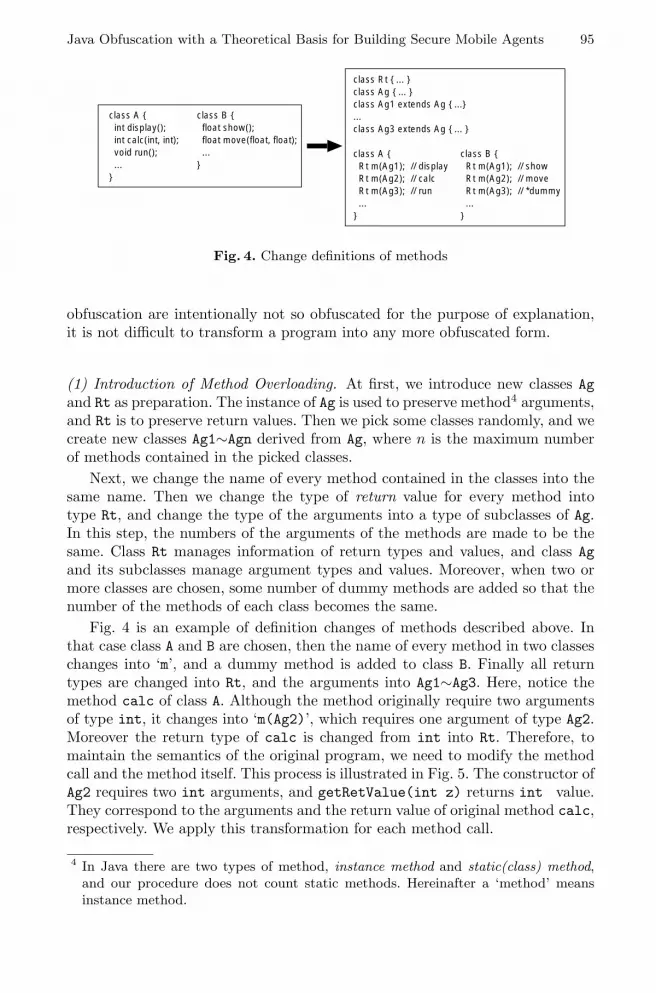
Java Obfuscation with a Theoretical Basis for Building Secure Mobile Agents 95
class A int display(); int calc(int, int); void run(); ...
class B float show(); float move(float, float); ...
class A Rt m(Ag1); // display Rt m(Ag2); // calc Rt m(Ag3); // run ...
class B Rt m(Ag1); // show Rt m(Ag2); // move Rt m(Ag3); // *dummy ...
class Rt ... class Ag ... class Ag1 extends Ag ......class Ag3 extends Ag ...
Fig. 4. Change definitions of methods
obfuscation are intentionally not so obfuscated for the purpose of explanation,it is not difficult to transform a program into any more obfuscated form.
(1) Introduction of Method Overloading. At first, we introduce new classes Agand Rt as preparation. The instance of Ag is used to preserve method4 arguments,and Rt is to preserve return values. Then we pick some classes randomly, and wecreate new classes Ag1∼Agn derived from Ag, where n is the maximum numberof methods contained in the picked classes.
Next, we change the name of every method contained in the classes into thesame name. Then we change the type of return value for every method intotype Rt, and change the type of the arguments into a type of subclasses of Ag.In this step, the numbers of the arguments of the methods are made to be thesame. Class Rt manages information of return types and values, and class Agand its subclasses manage argument types and values. Moreover, when two ormore classes are chosen, some number of dummy methods are added so that thenumber of the methods of each class becomes the same.
Fig. 4 is an example of definition changes of methods described above. Inthat case class A and B are chosen, then the name of every method in two classeschanges into ‘m’, and a dummy method is added to class B. Finally all returntypes are changed into Rt, and the arguments into Ag1∼Ag3. Here, notice themethod calc of class A. Although the method originally require two argumentsof type int, it changes into ‘m(Ag2)’, which requires one argument of type Ag2.Moreover the return type of calc is changed from int into Rt. Therefore, tomaintain the semantics of the original program, we need to modify the methodcall and the method itself. This process is illustrated in Fig. 5. The constructor ofAg2 requires two int arguments, and getRetValue(int z) returns int value.They correspond to the arguments and the return value of original method calc,respectively. We apply this transformation for each method call.
4 In Java there are two types of method, instance method and static(class) method,and our procedure does not count static methods. Hereinafter a ‘method’ meansinstance method.

96 Y. Sakabe, M. Soshi, and A. Miyaji
// in class Apublic int calc(int x, int y) int z; ... return z;
int x, y, z; A the_a = new A(); ... z = the_a.calc(x, y); ...
// in class Apublic Rt m(Ag2 p) // calc int x, y, z; x=p.getArg(0); y=p.getArg(1); ... Rt p = new Rt(z); return r;
int x, y, z; A the_a = new A(); Rt r; Ag2 p; ... p = new Ag2(x, y); r = the_a.m(p); z = r.getRetValue(z); ...
Fig. 5. Modify method and method call
class A implements I Rt m(Ag1); Rt m(Ag2); Rt m(Ag3); ...
class B implements I Rt m(Ag1); Rt m(Ag2); Rt m(Ag3); ...
// *dummyclass C implements I Rt m(Ag1); Rt m(Ag2); Rt m(Ag3); ...
interface I Rt m(Ag1); Rt m(Ag2); Rt m(Ag3);
Fig. 6. Definition of new Interfaces and Classes
(2) Introduction of Interfaces and Dummy Classes. In this step we newly in-troduce interface, and dummy classes if needed. The interface defines methodstransformed in step (1), and we make targeted classes to ‘implements’ thisinterface. Moreover, we newly create classes that play no role (i.e., dummy).These dummy classes also need to implement the interface defined immediatelybefore. If dummy classes are not needed for some reasons (for example, due toperformance the program requires), we can cancel to introduce dummy classes.
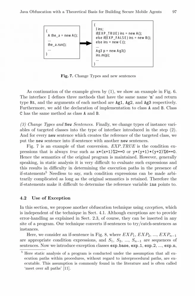
Java Obfuscation with a Theoretical Basis for Building Secure Mobile Agents 97
A the_a = new A(); ... the_a.run(); ...
I ins; if(EXP_TRUE) ins = new A(); else if(EXP_FALSE) ins = new B(); else ins = new C(); ... Ag3 p = new Ag3() ins.m(p); ...
Fig. 7. Change Types and new sentences
As continuation of the example given by (1), we show an example in Fig. 6.The interface I defines three methods that have the same name ‘m’ and returntype Rt, and the arguments of each method are Ag1, Ag2, and Ag3 respectively.Furthermore, we add the declaration of implementation to class A and B. ClassC has the same method as class A and B.
(3) Change Types and New Sentences. Finally, we change types of instance vari-ables of targeted classes into the type of interface introduced in the step (2).And for every new sentence which creates the reference of the targeted class, weput the new sentence into if-sentence with another new sentences.
Fig. 7 is an example of that conversion. EXP TRUE is the condition ex-pressions that is always true such as x*(x+1)%2==0 or y*(y+1)*(y+2)%6==0.Hence the semantics of the original program is maintained. However, generallyspeaking, in static analysis it is very difficult to evaluate such expressions andthis results in difficulty in determining the execution paths in the presence ofif-statements5 Needless to say, such condition expressions can be made arbi-trarily complicated as long as the original semantics is retained. Therefore theif-statements make it difficult to determine the reference variable ins points to.
4.2 Use of Exception
In this section, we propose another obfuscation technique using exception, whichis independent of the technique in Sect. 4.1. Although exceptions are to provideerror-handling as explained in Sect. 2.3, of course, they can be inserted in anysite of a program. Our technique converts if-sentences to try/catch-sentences asinstances.
Here, we consider an if-sentence in Fig. 8, where EXP1, EXP2, ..., EXPn−1are appropriate condition expressions, and S1, S2, ..., Sn−1 are sequences ofsentences. Now we introduce exception classes exp base, exp 1, exp 2, ..., exp n,5 Here static analysis of a program is conducted under the assumption that all ex-
ecution paths within procedures, without regard to interprocedural paths, are ex-ecutable. This assumption is commonly found in the literature and is often called‘meet over all paths’ [11].

98 Y. Sakabe, M. Soshi, and A. Miyaji
... if( EXP1 ) S1 else if( EXP2) S2 ... else if( EXPn-1) Sn-1 else Sn ...
class exp_base extends Exception class exp_1 extends exp_base ...class exp_n extends exp_base
exp_base e; ... try throw e catch ( exp_1 e1 ) S1 catch ( exp_2 e2 ) S2 ... catch ( En en ) Sn ...
Fig. 8. Use of Exceptions
where exp 1∼exp n are subclasses of exp base. Then we convert the if-sentenceto the try/catch-sentence as shown in the right side in Fig. 8. The variablee should be an instance of an appropriate exception class so that obfuscatedsentences execute equivalently to the original if-sentence.
4.3 Example of Obfuscation
At the end of Sect. 4, for completeness of the description of this section, we showin Fig. 9 an example of obfuscation to which all obfuscation techniques apply.
5 Complexity Evaluation
Our obfuscation techniques described in Sect. 4 substantially impede precisepoints-to analysis. In this section, we support this claim by presenting a proofin which we show that statically determining precise points-to is NP-hard.
Theorem 1: In the presence of classes which implement interfaces, method callsby the instances of the classes, and at the same time in the presence of method-overloadings, the problem of precisely determining if there exists an executionpath in a program on which a given instance points to a given method at a pointof the program is NP-hard 6.
Proof: The proof of Theorem 1 is by reduction from the 3-SAT problem [8]for ∧n
i=1(li,1 ∨ li,2 ∨ li,3) with propositional variables v1, v2, ..., vm, where lijis a literal and is either vk or vk for some k (1 ≤ k ≤ m). The reduction isspecified by the program in Fig. 10, which is polynomial in the size of the 3-SAT6 For further backgrounds behind the way of this proof, see [11].

Java Obfuscation with a Theoretical Basis for Building Secure Mobile Agents 99
int x, y, z; float s, t; I ins1, ins2; Ag p; ex_base e; ... if(x*(x+1)%2==0) e = new ex_1(); else if(x/y==z) e = new ex_2(); else e = new ex_3(); ... try throw e catch(ex_1 e1) ins1 = new A(); catch(ex_2 e2) ins1 = new B(); catch(ex_3 e3) ins1 = new C(); ... p = new Ag2(x, y); r = ins1.m(p); z = r.getRetValue(z); ... if(x*x<0) e = new ex_1(); else if(y*(y+1)*(y+2)&6==0) e = new ex_2(); else e = new ex_3(); ... try throw e catch(ex_1 e1) ins2 = new A(); catch(ex_2 e2) ins2 = new B(); catch(ex_3 e3) ins2 = new C(); p = new Ag2(t); r = ins2.m(p); s = r.getRetValue(s); ...
class A int display(); int calc(int, int); void run();class B float show(); float move(float, float);
int x, y, z; float s, t; ... A the_a = new A(); ... z = the_a.calc(x, y); ... B the_b = new B(); s = the_b.move(t); ...
class Rt ... class Ag ... class Ag1 extends Ag ... class Ag2 extends Ag ... class Ag3 extends Ag ...
interface I Rt m(Ag1); Rtm(Ag2); Rt m(Ag3);
class A implements I Rt m(Ag1); Rt m(Ag2); Rt m(Ag3);
class B implements I Rt m(Ag1); Rt m(Ag2); Rt m(Ag3);
class C implements I Rt m(Ag1); Rt m(Ag2); Rt m(Ag3);
Fig. 9. Example of Obfuscation
problem. The conditionals are not specified in the program since we assume thatall paths are executable. As will be seen later, paths through the code betweenL1 and L2 represent truth assignments for the propositional variables. The truthassignment on a particular path is encoded in the points-to relationship of certainvariables in the program. Paths between L2 and L3 then encode in the points-torelationship whether or not the truth assignment resultant from the path to L2satisfies ∧n
i=1(li,1 ∨ li,2 ∨ li,3).If we interpret vi pointing to b true as the propositional variable vi being
true, then any path from L1 to L2 uniquely determines one truth assignment.Furthermore, the converse is also true, namely, every truth assignment corre-sponds to exactly one execution path as just mentioned.
Now consider the path from L2 to L3. If the truth assignment for a path fromL1 to L2 satisfies the formula then every clause has at least one literal which istrue. Pick the path from L2 on which each clause assigns b ture to c. Theneach assignment corresponds to c = b true.and(b true) and c must point tob true at L3. However if the formula is unsatisfiable then every truth assignmenthas a clause, say (li,1 ∨ li,2 ∨ li,3), where all these three literals are false. Thisimplies li,1, li,2, and li,3 all point to b false. Because every path from L2 to L3must go through the statement

100 Y. Sakabe, M. Soshi, and A. Miyaji
if(-) c = c.and(li,1) else if(-) c = c.and(li,2) elsec = c.and(li,3);c must point to b false on all paths to L3 and thus c never points to b true.Therefore 3-SAT is polynomial reducible to the problem of Theorem 1 and thiscompletes the proof.
6 Empirical Evaluation
In this section we present application of our obfuscation procedures to fourprograms, RC6, compress, MD5 and FFT. Table 1 shows the difference betweenthe hierarchy/call graphs of the original programs and those of the obfuscatedprograms. In the rows for a hierarchy graph, ‘#nodes’ represents the sum of theclasses and the interfaces, and ‘#edges’ represents the sum of subclassing andimplements edges. Furthermore, in the rows of a call graph, ‘#nodes’ representsthe number of call sites, and ‘#edges’ represents the number of ‘to methodnodes’. Here, we can readily see from the table that the increase of the numbers ofedges is greater than those of nodes, while the number of edges usually increasesin proportion to the number of nodes. In the original call graphs, the numbersof nodes and edges are almost the same, which means that all the call sites andtarget methods correspond one to one. On the other hand, in the call graphs ofthe obfuscated programs, the number of edges is 3.4 times the number of nodeson average. Therefore, some call sites have two or more candidates of methods,and these result give a good evidence that precision of analysis is much reducedby our obfuscation techniques.
We have evaluated performance degradation due to the obfuscation, asindicated in Table 2. The experiments were conducted on a Sun Ultra5(UltraSPARC-II 400Mhz) with Solaris 8 (SunOS 5.8). Programs were compiledand executed by Java version 1.3.1. Each execution time was the average of 1000times execution. The average rate of execution times of obfuscated programsover the original programs is 1.3, which is not so great as the rise in source codesor class files. Therefore, our obfuscation techniques do not degrade performanceso much.
Note that these are results of applying our obfuscation procedures just once.If needed we can apply the procedures two or more times, then it will providefurther obfuscated programs.
7 Conclusion
In recent years mobile agent systems have been paid much attention to as anew computing paradigm. However, for advanced application such as electroniccommerce, the agent systems are of little value unless their security is ensured.Especially it is significantly important to provide protection for mobile agentsagainst attacks by malicious hosts.

Java Obfuscation with a Theoretical Basis for Building Secure Mobile Agents 101
interface Bool public Bool and(Bool arg);
class True implements Bool
public Bool and(Bool arg) return arg; class False implements Bool
public Bool and(Bool arg) return this;
class theorem Bool b true, b false;Bool c;
void var(Bool v1, Bool v1) if(-) var(v1, v1, b true, b false);else var(v1, v1, b false, b true);
void var(Bool v1, Bool v1, Bool v2, Bool v2)
if(-) var(v1, v1, v2, v2, b true, b false);else var(v1, v1, v2, v2, b false, b true);
. . .
void var(Bool v1, Bool v1, Bool v2, Bool v2, ... Bool vm,Bool vm)
L2:if(-) c = l1,1 else
if(-) c = l1,2 else c = l1,3;if(-) c = c.and(l2,1) else
if(-) c = c.and(l2,2) else c = c.and(l2,3);. . .
if(-) c = c.and(ln,1) elseif(-) c = c.and(ln,2) else c = c.and(ln,3);
L3:
public theorem() b true = new True();b false = new False();
L1: if(-) var(b true, b false); else var(b false, b true);public static void main(String[] args)
new theorem();
Fig. 10. 3-SAT solution iff 〈c, b true〉 in Interprocedural Points-to Analysis

102 Y. Sakabe, M. Soshi, and A. Miyaji
Table 1. Change of hierarchy and call graphs
program Before Obfuscation After Obfuscation ratioHierarchy #nodes 3 21 7.0
compress Graph #edges 2 30 15.0Call Graph #nodes 30 74 2.5
#edges 30 274 9.1Hierarchy #nodes 5 23 4.6
RC6 Graph #edges 4 33 8.3Call Graph #nodes 18 77 4.3
#edges 18 297 16.5Hierarchy #nodes 10 33 3.3
MD5 Graph #edges 9 42 4.7Call Graph #nodes 194 667 3.4
#edges 202 1775 8.8Hierarchy #nodes 7 25 3.6
FFT Graph #edges 6 41 6.8Call Graph #nodes 86 318 3.7
#edges 86 1057 12.3
Table 2. Change of program size and execution time
program Before Obfuscation After Obfuscation ratioprogram source[#lines] 126 332 2.6
compress size class file[byte] 2906 12056 4.2execution time[sec] 0.57 0.69 1.2
program source[#lines] 561 853 1.5RC6 size class file[byte] 6039 18414 2.0
execution time[sec] 0.70 0.78 1.1program source[#lines] 762 2142 2.8
MD5 size class file[byte] 11257 43462 3.9execution time[sec] 0.61 0.92 1.5
program source[#lines] 874 2185 2.5FFT size class file[byte] 11260 37158 3.3
execution time[sec] 0.66 0.99 1.5
In order to solve the problem, obfuscation of agent programs is very promis-ing. Unfortunately previous software obfuscation techniques share a major draw-back that they do not have a theoretical basis and thus it is unclear how effectivethey are. Therefore, in this paper we propose novel obfuscation techniques forJava. We believe it is fairly easy to apply the techniques to other object-orientedlanguages such as C++.
Our obfuscation techniques take advantage of polymorphism and exceptionmechanism and can drastically reduce the precision of points-to analysis of theprograms. We have shown that determining precise points-to analysis in obfus-

Java Obfuscation with a Theoretical Basis for Building Secure Mobile Agents 103
cated programs is NP-hard and the fact provides a theoretical basis for our obfus-cation techniques. Furthermore, in this paper we have presented some empiricalexperiments. The results show the effectiveness of our obfuscation approaches.
References
1. Hohl, F.: Time limited blackbox security: Protecting mobile agents from malicioushosts. In Vigna, G., ed.: Mobile Agents Security. Volume 1419 of Lecture Notes inComputer Science. Springer-Verlag (1998) 92–113
2. Collberg, C., Thomborson, C., Low, D.: A taxonomy of obfuscating transforma-tions. Technical Report 148, Department of Computer Science, the University ofAuckland, Auckland, New Zealand (1997)
3. Aucsmith, D.: Tamper resistant software: An implementation. In Anderson, R.J.,ed.: Information Hiding: First International Workshop. Volume 1174 of LectureNotes in Computer Science., Springer-Verlag (1996) 317–333
4. Mambo, M., Murayama, T., Okamoto, E.: A tentative approach to constructingtamper-resistant software. In: New Security Paradigm Workshop. (1997) 23–33
5. Ogiso, T., Sakabe, Y., Soshi, M., Miyaji, A.: Software obfuscation on a theoreticalbasis and its implementation. IEICE Transactions on Fundamentals E86-A (2003)176–186
6. Wang, C., Hill, J., Knight, J., Davidson, J.: Software tamper resistance: Ob-structing static analysis of programs. Technical Report CS-2000-12, Departmentof Computer Science, University of Virginia (2000)
7. Chatterjee, R., Ryder, B.G., Landi, W.: Complexity of points-to analysis of Java inthe presence of exceptions. IEEE Transactions on Software Engineering 27 (2001)481–512
8. Garey, M.R., Johnson, D.S.: Computers and Intractability – A Guide to the Theoryof NP-completeness. W. H. Freeman and Co. (1979)
9. Sander, T., Tschudin, C.F.: Protecting mobile agents against malicious hosts.In Vign, G., ed.: Mobile Agents and Security. Volume 1419 of Lecture Notes inComputer Science. Springer-Verlag (1998) 44–60
10. Kotzanikolaou, P., Burmester, M., Chrissikopoulos, V.: Secure transactions withmobile agents in hostile environments. In: Information Security and Privacy: FifthAustralasian Conference on Information Security and Privacy, ACISP 2000. Vol-ume 1841 of Lecture Notes in Computer Science., Springer-Verlag (2000) 289–297
11. Myers, E.W.: A precise inter-procedural data flow algorithm. In: Conference recordof the 8th ACM Symposium on Principles of Programming Languages (POPL).(1981) 219–230

A Security Scheme for Mobile Agent Platformsin Large-Scale Systems
Michelle S. Wangham, Joni da Silva Fraga, and Rafael R. Obelheiro
Department of Automation and SystemsFederal University of Santa Catarina
C. P. 476 – 88040-900 – Florianopolis – SC – Brazilwangham,fraga,[email protected]
Abstract. Mobile agents have recently started being deployed in large-scale distributed systems. However, this new technology brings some se-curity concerns of its own. In this work, we propose a security schemefor protecting mobile agent platforms in large-scale systems. This schemecomprises a mutual authentication protocol for the platforms involved,a mobile agent authenticator, and a method for generation of protectiondomains. It is based on SPKI/SDSI chains of trust, and takes advantageof the flexibility of the SPKI/SDSI certificate delegation infrastructureto provide decentralized authorization and authentication control.
1 Introduction
A mobile agent in a large-scale network can be defined as a software agentthat is able to autonomously migrate from one host to another in a heteroge-neous network, crossing various security domains. In order for these agents toexist within a system or to form themselves a system, they require a computingenvironment—an agent platform—for deployment and execution.
The ability to move agents (code + state) allows deployment of services andapplications in a more flexible, dynamic, and customizable way with respectto the client-server paradigm [1]. Despite its many benefits, the mobile agentparadigm introduces new security threats from malicious agents and platforms[2]. Due to these threats, security mechanisms should be designed to protect thecommunications infrastructure, agent platforms and agents themselves. This pa-per concentrates on mechanisms for protecting agent platforms against maliciousagents, considering large-scale distributed systems.
One of the main concerns with an agent platform implementation is ensuringthat agents are not able to interfere with one another or with the underlyingagent platform [3]. A common approach for accomplishing it is to establish iso-lated execution domains (protection domains) for each incoming mobile agentand platform, and to control all inter-domain access. Protection against mali-cious agents is not restricted to confining their execution to their own executiondomains in agent platforms; other issues need to be considered when distributedlarge-scale systems are the focus. For instance, generation of these protection
A. Lioy and D. Mazzocchi (Eds.): CMS 2003, LNCS 2828, pp. 104–116, 2003.c© IFIP International Federation for Information Processing 2003
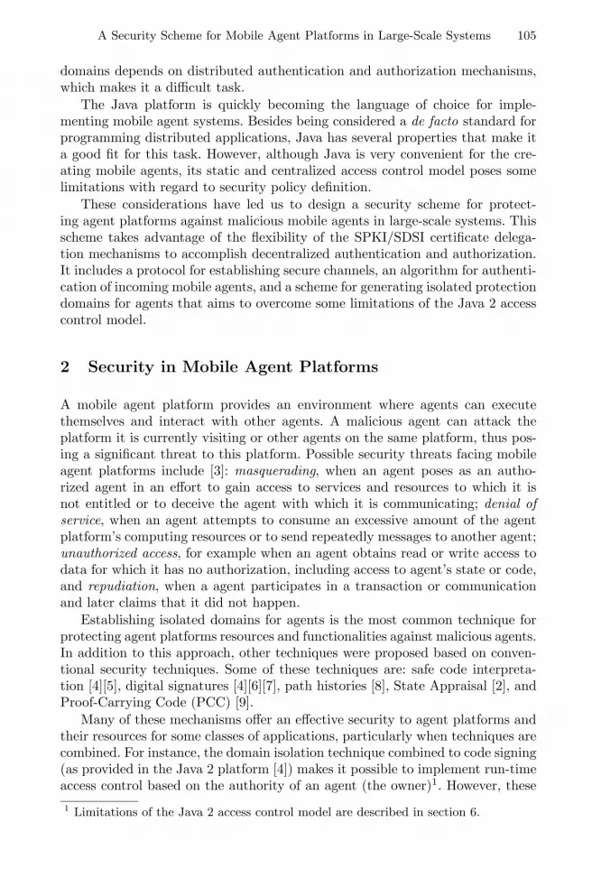
A Security Scheme for Mobile Agent Platforms in Large-Scale Systems 105
domains depends on distributed authentication and authorization mechanisms,which makes it a difficult task.
The Java platform is quickly becoming the language of choice for imple-menting mobile agent systems. Besides being considered a de facto standard forprogramming distributed applications, Java has several properties that make ita good fit for this task. However, although Java is very convenient for the cre-ating mobile agents, its static and centralized access control model poses somelimitations with regard to security policy definition.
These considerations have led us to design a security scheme for protect-ing agent platforms against malicious mobile agents in large-scale systems. Thisscheme takes advantage of the flexibility of the SPKI/SDSI certificate delega-tion mechanisms to accomplish decentralized authentication and authorization.It includes a protocol for establishing secure channels, an algorithm for authenti-cation of incoming mobile agents, and a scheme for generating isolated protectiondomains for agents that aims to overcome some limitations of the Java 2 accesscontrol model.
2 Security in Mobile Agent Platforms
A mobile agent platform provides an environment where agents can executethemselves and interact with other agents. A malicious agent can attack theplatform it is currently visiting or other agents on the same platform, thus pos-ing a significant threat to this platform. Possible security threats facing mobileagent platforms include [3]: masquerading, when an agent poses as an autho-rized agent in an effort to gain access to services and resources to which it isnot entitled or to deceive the agent with which it is communicating; denial ofservice, when an agent attempts to consume an excessive amount of the agentplatform’s computing resources or to send repeatedly messages to another agent;unauthorized access, for example when an agent obtains read or write access todata for which it has no authorization, including access to agent’s state or code,and repudiation, when a agent participates in a transaction or communicationand later claims that it did not happen.
Establishing isolated domains for agents is the most common technique forprotecting agent platforms resources and functionalities against malicious agents.In addition to this approach, other techniques were proposed based on conven-tional security techniques. Some of these techniques are: safe code interpreta-tion [4][5], digital signatures [4][6][7], path histories [8], State Appraisal [2], andProof-Carrying Code (PCC) [9].
Many of these mechanisms offer an effective security to agent platforms andtheir resources for some classes of applications, particularly when techniques arecombined. For instance, the domain isolation technique combined to code signing(as provided in the Java 2 platform [4]) makes it possible to implement run-timeaccess control based on the authority of an agent (the owner)1. However, these1 Limitations of the Java 2 access control model are described in section 6.

106 M.S. Wangham, J. da Silva Fraga, and R.R. Obelheiro
techniques are not really suitable to large-scale applications. Moreover, accesscontrol based solely on owner of the agent does not seem to be appropriate whenmulti-hop agents with free destinations are taken into consideration, since thetrust in an agent depends not only on the owner and the forwarding platformbut also on all platforms visited by the agent [8]. Therefore, an effective authen-tication and authorization scheme for large-scale mobile agent systems shouldbe based on agent credentials, on the identities of agent owners and on the listsof platforms visited by agents. Identities and credentials are usually representedby, and stored in, digital certificates, such as those used in SPKI/SDSI.
3 SPKI/SDSI Infrastructure
The Simple Public Key Infrastructure/Simple Distributed Security Infrastruc-ture(SPKI/SDSI) specification defines a simple and flexible distributed authen-tication and authorization infrastructure based on digital certificates and localname spaces [10].
SPKI/SDSI uses an egalitarian model of trust. The subjects (or principals)are public keys and each public key is a certificate authority [11]. There is no hi-erarchical global infrastructure as in X.509. Two types of certificates are definedby SPKI/SDSI: name and authorization certificates. An authorization certificategrants specific authorizations from the issuer to the subject of the certificate;these authorizations are bound to a name, a group of names or a key. The issuerof the certificate can also allow a principal to delegate the received permissionsto other principals.
The SPKI/SDSI delegation model allows the construction of chains of trustthat begin with a service guardian and arrive in principals’ keys. When a givensubject desires to obtain access to some resource, it must present a signed requestand a chain of authorization certificates for checking the needed permissions [11].
Since SPKI/SDSI follows a decentralized approach to authentication and au-thorization, it is suitable for large-scale systems. Access rights can be delegatedto form a chain of certificates (controlled distribution of authorization). Au-thorizations and permissions can be freely defined and are not restricted to anypredefined set [10]. The issuer of a certificate can specify certain conditions underwhich the certificate is valid; this provides for finer-grained control of delegation.Since certificates are bound to keys instead of names, they eliminate the need forfinding the public key corresponding to a given name [12], and can be also usedin situations where anonymity is desired. Due to these advantages, SPKI/SDSIcertificates were chosen to represent agent credentials in our security scheme.
4 A Proposal for Authentication and AuthorizationBased on Chains of Trust
We now present an authentication and authorization scheme for large-scale mo-bile agent systems. We assume that agents have free itineraries and are multi-hop, that is, the number of platforms they traverse in a given itinerary is not

A Security Scheme for Mobile Agent Platforms in Large-Scale Systems 107
fixed. SPKI/SDSI chains of trust and the concept of federations provide scala-bility and flexibility to this scheme.
4.1 Platform Federations
In this scheme, we use the concept of federation introduced in [13], which em-phasizes the grouping of principals with common interests. With that, mobileagent platforms can group according to their service classes, constituting ser-vice federations. For example, the Mold Enterprise Federation may group themobile agent platforms from enterprises that manufacture molds and matrices.The purpose of a federation is to assist its members on reducing principal namesand on building new chains of trust through its Certificate Manager (CM) [13].These chains of trust between client and service are quickly and efficiently es-tablished from name and authorization certificates available at the certificaterepository of the service federation. By storing name and authorization certifi-cates in these repositories, the services available in the associated platforms canbe announced. The inclusion of a platform in one of these federations shouldbe negotiated with the association that controls this certificate storage service.The CM offers a certificate search alternative, either for name reduction or forcreating new authorization chains.
Besides, a member of a federation can join other federations and differentfederations can establish trust relationships. The certificate managers can beassociated to each other, linking those who, for affinity, can better representthe needs of their members, creating webs of federations with global scope. Themain function of a web of federations is to help a client, through its agents, inthe search for access privileges that link it to the guardian of a service (anotherplatform). Further details on the concept of federations can be found in [13].
4.2 Authentication and Authorization Scheme
Fig. 1 shows the procedures defined in the security scheme, composed by preven-tion and detection techniques that emphasize the protection of agent platformsand their resources. In this scheme, after the mobile agent creation process, thesource and destination platforms (the ones which send and receive agents, re-spectively) first go through a mutual authentication protocol so that a securechannel between them can be established. After that, the agent will be sentwith its credentials to be authenticated by the destination platform and thenits domain of execution can be created. In other words, when an agent arrivesin a platform it presents its public key and a chain of SPKI/SDSI certificatesto a verifier that performs the authorization checks. From these information,this verifier must generate the permissions required for the agent to be run in aprotection domain on its destination platform. This dynamic generation of per-missions provides flexibility and follows the principle of least privilege. Chainsof trust also help to achieve the necessary scalability for Internet-based applica-tions. The following section analyzes some aspects referring to the mechanismsin the proposed scheme.

108 M.S. Wangham, J. da Silva Fraga, and R.R. Obelheiro
Fig. 1. Security Scheme for Agent Platform Protection
Creation of Mobile Agents. During the mobile agent creation process (seeFig. 1, procedure 1), the owner, being the authority that an agent represents,provides a set of SPKI/SDSI authorization certificates defining the agent’s cre-dentials. It should be noted that this initial set of authorization certificates maynot be sufficient to grant access to certain resources in a given platform. So,new certificates can be provided to the agent during its visits to other agentplatforms. For example, suppose that an agent needs to visit a transport enter-prise associated to a mold enterprise. The agent may not have the certificatesneeded to be received in this platform. Thus, the platform that represents themold enterprise can delegate certificates to this agent enabling it to access theassociated enterprise. The trust model proposed in SPKI/SDSI determines thata client is responsible for finding certificates that enable it to access a givenservice. Therefore, an agent can search for certificates on the webs of federationsand negotiate them when they are found.
The owner of the agent has to put in an object that will contain the listof previously visited platforms (called the path register) a signature indicatingits identity and the identity of the first platform to be visited. This object isattached to the agent. A list that indicates service federations whose memberplatforms are authorized to execute the agent can be (optionally) defined andattached to the agent. The path register and the list of federations are used toanalyze the history of the agent’s travels in the agent authentication process.
Finally, the agent’s owner must sign the code of the agent and its read-onlydata, and then create the agent in its home platform to send it through thenetwork.
Secure Channel Establishment. In the proposed scheme, mutual authenti-cation between the platforms involved must be established before agents can betransferred. This authentication creates a secure channel in the communicationsinfrastructure between the authenticated parties that is used for agent transfers.
In accordance to the SPKI/SDSI model, identification is not done withnames, but with public keys, with digital signatures as the authentication mech-

A Security Scheme for Mobile Agent Platforms in Large-Scale Systems 109
anism. Thus, in platform authentication, for a digital signature to be verified, apublic key and a signed request must be present at the receiver.
Mutual authentication is performed during the secure channel establishmentbetween agents platforms. Fig. 2 shows the mutual authentication performedwith a challenge-response protocol, based on SPKI/SDSI certificates of the own-ers (managers) of the platforms. The basis for authentication in SPKI/SDSI arechains of authorization certificates [10].
In step 1, Fig. 2, the source platform sends a signed message containing arequest (establish trust) and a nonce (nonceSP), without any certificates. Fromthis request, the destination platform builds a signed challenge and sends it tothe source platform so that it can prove it has the required permissions (step 2).The challenge is composed by information from the resource’s ACL, by nonceSPand by a nonce generated by the destination platform (nonceDP). In step 3,the source platform verifies the signature of the challenge to confirm the au-thenticity of the destination platform. Then, it sends a signed response with therequest, nonceDP, and the authorization certificates for the desired operation.From the chain of authorization certificates, the destination platform can checkthe requester’s signature, finishing the authentication process (step 4).
Fig. 2. Protocol for Mutual Authentication of Platforms
It is important to note that the process of mutual authentication of platformsis concluded with the establishment of a secure channel. This channel will beused for all agents that are transferred between the two platforms, without needfor subsequent platform authentication.
For secure channel establishment, an underlying security technology—SecureSockets Layer (SSL)—is used to ensure confidentiality and integrity of commu-nications between agent platforms. When a secure channel is established, thesource platform sends the agent to the destination platform along with its itscredentials for building an execution domain that is appropriate for the agent.
Mobile Agents Authentication. Before instantiating a thread to an agent,the destination platform must authenticate the received agent. In order to pro-tect against an agent, a platform depends not only on the verification of theagent’s owner authenticity, but also on the degree of trust in the platforms al-ready visited by the agent, since a mobile agent can become malicious by virtueof its state having been corrupted by previously visited platforms [2]. One of the

110 M.S. Wangham, J. da Silva Fraga, and R.R. Obelheiro
contributions of this paper is the definition of a multi-hop authenticator that es-tablishes trust on an agent, based on the authenticity of the owner of the agent,on the authenticity of the platforms visited by the agent and on the federationsdefined by the owner of the agent.
Consider the authenticator shown in Fig. 3; upon receiving a mobile agent,a platform must first check, through verification of the agent’s signature (codeand read-only data), that this agent has not been corrupted and confirm itsassociation to a principal, its owner (step 1). Thus, modifications introduced bymalicious platforms can be easily detected by any platform visited by the agent.
Fig. 3. Multi-hop Agents Authenticator
For one-hop agents, the technique proposed in step 1 ensures the integrityof an agent, but for multi-hop agents this technique is insufficient. For detectingpossible modifications and checking the agent’s traveling history, the destinationagent platform must analyze the agent’s path register (step 2). For that purpose,each platform visited by the agent should add to the agent’s path register asigned entry containing its identity (public key) and the identity (public key) ofthe next platform to be visited, forming a history of the path followed by theagent. In step 2, Fig. 3, the platform administrator has to define how the agent’spath register is analyzed and how the trust level is established. The possibilitiesshown in Fig 3 include only step 2.1, only step 2.2, or both steps2.
Moreover, we suggest that platform-generated sensitive data (write-oncedata) should be stored in a container to be carried by the agents (as proposed byKarnik in [7]). These sensitive data should be signed by the generating platformso that possible modifications can be detected. This approach is vulnerable tosome attacks, however [14][15][16]. For instance, Roth [16] describes an attackwhere a malicious platform, which is visited a second time by an agent or whichcolludes with another platform, deletes all items that were added to the agent’scontainer since one of its previous visits or since the agent’s departure from thefirst platform. In this paper, we focus on protecting agent platforms, but it isour intention to address the protection of agents in future work.
Generation of Protection Domains. Protection domains and the permis-sions assigned to them are defined after trust in an agent has been established2 An inconvenient is that analyzing an agent’s path becomes costlier as the path
register grows.

A Security Scheme for Mobile Agent Platforms in Large-Scale Systems 111
(a result from previous procedures). They are based on the agent’s SPKI/SDSIauthorization certificates and on trust and risk levels. The platform guardianverifies the agent’s certificates in order to define the set of permissions. Thisdecouples the privileges granted to agents (their credentials) from the privilegesrequired to access resources (the access control policy), which provides flexibilityand scalability to the security scheme.
Some extensions to the Java 2 security model are needed for generating theprotection domain where an agent will be run. These extensions, representedby grey boxes in Fig. 4, are: SPKISecureClassLoader, required for extractingcertificates from the incoming agent and for creating a protection domain of athread; SPKIPolicy, an object that represents a policy that defines, from thecertificates carried by an agent, which Java permissions will be associated to theapplication domain; and SPKIVerifier, required for verifying the authenticity ofSPKI certificates.
Following the dynamics depicted in Fig. 4, the platform administrator de-scribes the security policy of the agent platform by mapping the authorizationgranted from SPKI/SDSI certificates to Java permissions, defining for that pur-pose a policy file. When an agent is received in a platform, its credentials areforwarded by SPKISecureClassLoader to the SPKIPolicy object which interpretsthem. When SPKI permissions are mapped to Java permissions, the Java sup-port generates the corresponding protection domain for the thread that runs theagent; the Java permissions are made available through PermissionCollection.
Fig. 4. Dynamics for Protection Domain Generation
If a thread (agent) makes an access request to a resource outside of its ap-plication domain, that is, in a system domain, AccessController is activated tocheck whether the access must be allowed. It must verify, in the created protec-tion domain, whether the principal has a corresponding Permission object in itscollection of permissions. If it does, the thread can exchange domains, enteringin the system domain.
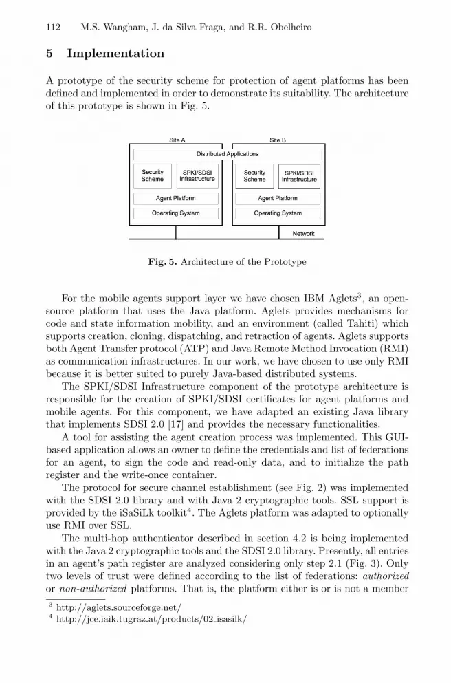
112 M.S. Wangham, J. da Silva Fraga, and R.R. Obelheiro
5 Implementation
A prototype of the security scheme for protection of agent platforms has beendefined and implemented in order to demonstrate its suitability. The architectureof this prototype is shown in Fig. 5.
Fig. 5. Architecture of the Prototype
For the mobile agents support layer we have chosen IBM Aglets3, an open-source platform that uses the Java platform. Aglets provides mechanisms forcode and state information mobility, and an environment (called Tahiti) whichsupports creation, cloning, dispatching, and retraction of agents. Aglets supportsboth Agent Transfer protocol (ATP) and Java Remote Method Invocation (RMI)as communication infrastructures. In our work, we have chosen to use only RMIbecause it is better suited to purely Java-based distributed systems.
The SPKI/SDSI Infrastructure component of the prototype architecture isresponsible for the creation of SPKI/SDSI certificates for agent platforms andmobile agents. For this component, we have adapted an existing Java librarythat implements SDSI 2.0 [17] and provides the necessary functionalities.
A tool for assisting the agent creation process was implemented. This GUI-based application allows an owner to define the credentials and list of federationsfor an agent, to sign the code and read-only data, and to initialize the pathregister and the write-once container.
The protocol for secure channel establishment (see Fig. 2) was implementedwith the SDSI 2.0 library and with Java 2 cryptographic tools. SSL support isprovided by the iSaSiLk toolkit4. The Aglets platform was adapted to optionallyuse RMI over SSL.
The multi-hop authenticator described in section 4.2 is being implementedwith the Java 2 cryptographic tools and the SDSI 2.0 library. Presently, all entriesin an agent’s path register are analyzed considering only step 2.1 (Fig. 3). Onlytwo levels of trust were defined according to the list of federations: authorizedor non-authorized platforms. That is, the platform either is or is not a member3 http://aglets.sourceforge.net/4 http://jce.iaik.tugraz.at/products/02 isasilk/

A Security Scheme for Mobile Agent Platforms in Large-Scale Systems 113
of a federation present in the list of federations previously defined for the agentmission. The multi-hop algorithm as currently defined is shown in Fig. 6.
Fig. 6. Multi-hop Authenticator
The scheme for generation of protection domains (see Fig. 4) has been fullydesigned but only partially implemented in the Aglets Platform. When a agentis dispatched, the Aglets Platform attaches the certificates defined in the agentcreation to the serialized agent through SPKIAgletWriter. When the agent isreceived in the destination platform, SPKISecureClassLoader calls SPKIAgle-tReader to extract these certificates.
6 Related Work
Most Java-based agent platforms take advantage of the Java security models(especially the Java 2 version) to implement part of their security mechanisms.Among these platforms, there are commercial ones, such as IBM Aglets andGMDFokus Grasshopper, and academic ones, such as SOMA (University ofBologna) and Ajanta (University of Minnesota).
These mobile agent platforms extend the Java Security Manager to providea more flexible and adequate solution to agent platforms and to implementprotection domains that isolate mobile agents, preventing malicious attacks fromthem. The difference between authorization schemes in these platforms lies inthe information used to determine the set of access rights for an incoming agent.Aglets and Ajanta use only the agent’s owner identity. Grasshopper uses accesscontrol policies based on the owner’s identity or on the name of its group (groupmembership). In SOMA the principals are associated to roles that identify theoperations allowed on the resources of the system. All these approaches are notreally suitable to large-scale systems.
Besides, it is important to note that the Java 2 access control model hassome limitations that need to be analyzed. Instead of following the distributed

114 M.S. Wangham, J. da Silva Fraga, and R.R. Obelheiro
nature of its execution model, the Java 2 security model uses a centralized au-thorization scheme5. When running, each code is labeled as belonging to one ormore protection domains. Each domain has a set of permissions associated froma policy configuration file. Therefore, this file defines a static mapping betweeneach mobile component and the permissions granted to it for execution in a lo-cal environment. In addition to a number of difficulties related to programming,development of a distributed and dynamic environment is constrained by limi-tations that stem from the concentration of trust on a single configuration file,which demands an up-front static definition of all distributed components in thesystem and their corresponding security attributes.
Agent authentication is essential for implementing an effective authorizationscheme in mobile agent systems. The Aglets and Grasshopper platforms do nothave mechanisms for mobile agent authentication. SOMA authenticates agentsbased on several data contained in its credentials: domain and place of origin,class which implements the agent and user responsible for the agent. Beforemigration, these information, the initial state of agent and its code are digitallysigned by the user that creates the agent. When an agent arrives at a remote site,its credentials are verified with regard to authenticity by checking the signature ofthe agent’s owner. The Ajanta platform uses a challenge-response authenticationprotocol with random nonce generation to prevent replay attacks, based on thesignature of the agent’s owner.
In comparison to the static model in Java 2 and to the platforms discussedabove, our scheme has the advantage of decoupling privilege attributes (cre-dentials) from control attributes (policies), its use of some Java security featuresnotwithstanding. This means that, although a policy configuration file still needsto be statically defined, the proposed mechanisms add the flexibility offered bySPKI certificates to domain generation. That is, domains are dynamically definedwhen an agent aggregates to its credentials the delegated certificates receivedduring its itinerary.
Besides, in the agent authentication process described in section 5, the infor-mation used to determine an agent’s set of access rights is based not only on theidentity of the agent’s owner, but also on the public keys of the owner and of thevisited platforms, which avoids global name resolutions in large-scale systems.
Two related proposals use SPKI/SDSI certificates to improve access controlin Java 2. The first, developed by Nikander and Partnen [12], uses SPKI autho-rization certificates to delegate Java permissions that directly describe possiblepermissions associated to a protection domain. In this work, the authorizationtag of the SPKI certificate was extended to express Java permissions. This solu-tion has the disadvantage of using modified SPKI certificates. The second work[18] proposes two improvements to access control in Java 2: association of accesscontrol information to each mobile code segment (applet) as attributes, and theintroduction of intermediate elements in the access control scheme for assisting
5 This centralization refers to the fact that all access control is done from a singleconfiguration file that defines the whole security policy of a machine. Thus, there isonly one ACL relating all subjects and objects in the machine.

A Security Scheme for Mobile Agent Platforms in Large-Scale Systems 115
the configuration of access control attributes of incoming mobile programs and ofaccess control information located in the runtime environments. The SPKI/SDSIgroup mechanism is implemented through name certificates and makes these im-provements possible. Molva and Roudier’s work [18] does not provide details onhow their proposal can be implemented nor on how to combine it to current Java2 security model.
Both works discussed above do not deal with mutual authentication betweensource and destination platforms nor analyze the history of the visited platformsto establish trust on mobile code. Only the first proposal has flexibility charac-teristics similar to the ones proposed in the present work, in which the domainsare formed according to the certificates delegated to an agent in its creationand throughout its itinerary. Nikander and Partanen propose that the search forforming new chains should be responsibility of the server. However, as mentionedbefore, this is not in accordance to the SPKI/SDSI model.
7 Concluding Remarks
Security issues still hamper the development of applications with mobile systems.Current security mechanisms do not present satisfactory results for protectingmobile agent platforms. There are even more limitations when we consider large-scale systems, which impose stronger requirements with regard to flexibility andscalability.
Our security scheme was motivated by perception of these limitations and aconcern with aspects of security specific to large-scale applications. Its purposeis to prevent mobile agent attacks against platforms, defining a procedure thatemploys a combination of prevention and detection techniques. This scheme isbased on decentralized authorization and authentication control that is suitablefor large-scale systems due to its use of SPKI/SDSI authorization certificates.The mechanism of authorization certificate delegation allows a separation be-tween agent credentials and security policy definition. The scheme for generationof protection domains is more flexible than those of the related works.
The work described in this paper, although not fully implemented yet, al-ready presents satisfactory results. As soon as it is concluded, its performancewill be properly evaluated. This prototype is currently being integrated to a dis-tributed Internet-based application in order to demonstrate its usefulness [19].Considering the protection of platforms from agents and of the communicationchannel, the proposed security scheme effectively mitigates the perceived securitythreats, albeit further work is still needed to define mechanisms for protectionof mobile agents against malicious agent platforms.
Acknowledgments. The authors thank the “IFM (Instituto Fabrica doMilenio)” and “Chains of Trust” project (CNPq 552175/01-3) members for theircontributions, especially Elizabeth Fernandes, Galeno Jung, Ricardo Schmidt,and Rafael Deitos. We also thank the anonymous reviewers for their helpful

116 M.S. Wangham, J. da Silva Fraga, and R.R. Obelheiro
comments. The first and second authors are supported by CNPq (Brazil). Thethird author is supported by CAPES (Brazil).
References
1. Vigna, G., ed.: Mobile Agents and Security. LNCS 1419. Springer-Verlag (1998)2. Farmer, W., Guttman, J., Swarup, V.: Security for mobile agents: Issues and
requirements. In: Proc. 19th National Information System Security Conference.(1996)
3. Jansen, W., Karygiannis, T.: Mobile agent security. Technical Report NIST SpecialPublication 800-19, National Institute of Standards and Technology (1999)
4. Sun: Java 2 SDK security documentation. (2003)http://java.sun.com/security/.
5. Levy, J., Ousterhout, J., Welch, B.: The Safe-Tcl security model. Technical ReportSMLI TR-97-60, Sun Microsystems (1997)
6. Gray, R., Kotz, D., Cybenko, G., Rus, D.: D’Agents: Security in a multiple-language, mobile agent systems. In Vigna, G., ed.: Mobile Agents and Security.LNCS 1419. Springer-Verlag (1998) 154–187
7. Karnik, N.: Security in Mobile Agent Systems. PhD thesis, University of Minnesota(1998)
8. Ordille, J.: When agents roam, who can you trust? In: 1st Conference on EmergingTechnologies and Applications in Communications. (1996)
9. Necula, G., Lee, P.: Safe, untrusted agents using proof-carrying code. In Vigna,G., ed.: Mobile Agents and Security. LNCS 1419. Springer-Verlag (1998) 61–91
10. Ellison, C.M., Frantz, B., Lampson, B., Rivest, R., Thomas, B., Ylonen, T.: SPKIrequirements. RFC 2693, Internet Engineering Task Force (1999)
11. Clarke, D.E.: SPKI/SDSI HTTP server/certificate chain discovery in SPKI/SDSI.Master’s thesis, Massachusetts Institute of Technology (MIT) (2001)
12. Nikander, P., Partanen, J.: Distributed policy management for JDK 1.2. In: Proc.1999 Network and Distributed Systems Security Symposium. (1999)
13. Santin, A., Fraga, J., Mello, E., Siqueira, F.: Extending the SPKI/SDSI modelthrough federation webs. In: Proc. 7th IFIP Conference on Communications andMultimedia Security. (2003)
14. Yee, B.: A sanctuary for mobile agents. In: Secure Internet Programming. LNCS1603. Springer-Verlag (1997) 261–273
15. Karjoth, G., Asokan, N., Gulcu, C.: Protecting the computing results of free-roaming agents. In: Proc. 2nd International Workshop on Mobile Agents. (1998)
16. Roth, V.: On the robustness of some cryptographic protocols for mobile agentprotection. In Picco, G.P., ed.: Mobile Agents. LNCS 2240. Springer-Verlag (2001)1–14
17. Morcos, A.: A Java implementation of Simple Distributed Security Infrastructure.Master’s thesis, Massachusetts Institute of Technology (1998)
18. Molva, R., Roudier, Y.: A distributed access control model for Java. In: EuropeanSymposium on Research in Computer Security (ESORICS). (2000)
19. Rabelo, R., Wangham, M., Schmidt, R., Fraga, J.: Trust building in the creationof virtual enterprises in mobile agent-based architectures. In: 4th IFIP WorkingConference on Virtual Enterprises. (2003)

Privacy and Trust in Distributed Networks
Thomas Rossler and Arno Hollosi
Institute for Applied Information Processing and Communications (IAIK),Graz University of Technology, Inffeldgasse 16a, 8010 Graz, Austria
thomas.roessler,[email protected]
Abstract. Today distributed service frameworks play an ever more im-portant role. Transitive trust is of great importance in such frameworksand is well researched. Although there are many solutions for buildingand transmitting trust in distributed networks, impacts on privacy areoften neglected. Based on a trust metric it will be shown why insuffi-cient trust is eventually inevitable if a request or message pass througha chain of services. Depending on the reaction of the service, privacycritical information may leak to other entities in the chain. It is shownthat even simple error messages pose a privacy threat and that properre-authentication methods should be used instead. Several methods ofre-authentication and their impacts on privacy are discussed.
1 Introductional Example
The following example shall illustrate the problems concerning privacy and trustrelationships in a distributed network of services. Here, in order to process aspecial task, the cooperation of several autonomous services is needed.
Assume the Following Situation. A client would like to buy something which isoffered by an online shop where the client is registered in the customer data base.Therefore, the buyer signs a purchase order through the shop’s online portal. Theprocess involves several services of other instances such as a service for checkingthe inventory of the chosen product or a service for doing the payment. Figure1 depicts the constellation of services used in this example.
After the user has been authenticated to the portal of the online shop (serviceA), he has to fill in some forms and enter some personal data. When this firststep is completed, service A contacts the service which processes a new order(service B). This service validates and verifies the content of the order. First,it checks if the desired product is still available for sale. This will be done bysending a request to the inventory service (service F ). Next, service B initiatesthe payment service (service C ) to process the payment of the product. Thepayment is preferably done by the client’s customer account which allows theclient to buy products within a certain credit line. Thus, service C contactsa service of the internal account system (service D). Assuming, that the userhas not enough money on his account, the payment service tries to make thepayment by a direct debit to the client’s credit card institution by requesting
A. Lioy and D. Mazzocchi (Eds.): CMS 2003, LNCS 2828, pp. 117–131, 2003.c© IFIP International Federation for Information Processing 2003

118 T. Rossler and A. Hollosi
the corresponding service E. At this point, some problems concerning privacyand transitive trust will arise:
– Because of too low security restrictions in the chain of services, it might bepossible that service E does not accept the request.
– Depending on how service E reacts to this situation, private data about theclient may be disclosed to other services and the client’s privacy may beharmed.
A B C
D
F
E
X
X
public service (request needs not tobe personalized with the client’s data)
non-public service (request must bepersonalized with the client’s data)
optional path (service used in specialcases)
Fig. 1. Example of distributed services
If service E does not trust the request from service C, it is likely that an errormessage is sent back to the client. Passing this message back to the user throughthe service chain harms the user’s privacy because each service learns about theerror. In the worst case, the error message contains the information of its origin,service E. Thus, every service in the chain gains knowledge that the client hasnot enough money and needs to use his credit card. Otherwise it would not havebeen necessary to involve service E into the process. Moreover, by recording aclient’s habit it would be possible for instance to recognize that his customeraccount is overdrawn every end of month. Instead of sending an error messagein response to insufficient trust into the authentication, service E can request are-authentication of the client. Again, similar problems and privacy threats arisein this case. In the next section a trust model and applicable trust algebra isdescribed, which is based on the work of Audun Jøsang ([7],[8],[9],[10]). Basedon this a metric for determining the trustworthiness of a request inside a chainof services is discussed. By introducing and adapting trust values ([1],[2]) basedon established criteria ([6],[4]) it is possible to decide either to trust or distrustan incoming request. This will lead to the necessity of re-authenticating requestsif a service does not trust the incoming request. In the last section, privacy andthreats on privacy are described. Error messages and re-authentication requestsare considered critical to privacy and so they are discussed in detail at the endof this paper.

Privacy and Trust in Distributed Networks 119
A B C D
A
(t)
A
(t)
B
(t)
C
Fig. 2. An example of chained trust
2 The Opinion Triangle
2.1 Definitions
Initially, the trustworthiness of each service has to be determined. Therefore, ev-ery entity can be divided in two parts. On the one hand, the connection betweentwo services has to be evaluated under the aspect of security. For example, anormal TCP/IP connection will result in a lower level of security than an SSL-connection with client certificates. On the other hand, the service itself has tobe evaluated. For this purpose, some established criteria already exist, e.g. theCommon Criteria [6]. Such criteria not only consider the technical infrastructureand the system itself. They also take the technical and nontechnical environmentinto account. After evaluating each service, the level of trust must be expressedin an applicable metric. Therefore, in [10] and [9] the term opinion (ω) wasdefined as:
t + d + u = 1, t, d, u ∈ [0, 1]3 (1)
Definition Opinion: Let ω = t, d, u be a triplet satisfying (1) wherethe first, second and third component correspond to trust, distrust anduncertainty respectively. Then ω is called an opinion.
Corresponding to this definition, several levels of trustworthiness are mappedaccordingly to different opinions. Equation 1 defines a triangle which is depictedin figure 3. Every opinion ω can be described as a point t, d, u in the triangle.For example, there are five trust levels to distinguish (according to table 1) andeach trust level can be found in the opinion triangle (fig. 3).
Table 1. Example of mapping between trust levels and opinions ω = t, d, u
t d u trust level0.00 0.95 0.05 distrust (-1)0.10 0.10 0.80 ignorance (0)0.40 0.10 0.50 minimum trust (1)0.70 0.15 0.15 medium trust (2)0.95 0.00 0.05 maximum trust (3)

120 T. Rossler and A. Hollosi
01 1
0 0
1
1
0
2-1
trustdistrust
uncertainty
3
Fig. 3. Trust levels inserted into the opinion triangle
The advantage of using the opinion based trust model instead of a simpletrust level based model is that there are three parameters expressing trust insteadof only one value. As it will turn out in the next section, these three separatevalues are not treated equally when different opinions have to be combined. Thiswill result in a real world adequate model for distributed trust relationships.
3 Subjective Logic
The algebra for determining trust will be based on a framework for artificialreasoning called Subjective Logic, which has been described in Audun Jøsang’spapers [8] and [9]. It defines various logical operators for combining opinions.In this section, only the most important definitions will be quoted, e.g. theRecommendation and Consensus operator. Finally, the subjective logic allowsto examine joined entities under the aspect of trust.
3.1 Definition: Conjunction
If some entity has two different opinions about another entity, then theconjunction (∧) of these opinions may be useful.
Let ωAp = tAp , dA
p , uAp and ωA
q = tAq , dAq , uA
q be entity A’s opinionsabout two distinct binary statements p and q. Then the conjunction ofωA
p and ωAq , representing A’s opinion about both p and q being true is
defined by [9]:
ωAp∧q = ωA
p ∧ ωAq
= tAp∧q, dAp∧q, u
Ap∧q (2)
wheretAp∧q = tAp tAq ,dA
p∧q = dAp + dA
q − dAp dA
q ,uA
p∧q = tAp uAq + uA
p tAq + uAp uA
q .(3)

Privacy and Trust in Distributed Networks 121
3.2 Definition: Recommendation
Recommendation (⊗) is needed if an entity A decides about the trustworthinessof something (p) based on trust-recommendations given by a third party B. Moreformally:
Let A and B two entities where ωAB = tAB , dA
B , uAB is A’s opinion
about B’s recommendation, and let p be a binary statement where ωBp =
tBp , dBp , uB
p is B’s opinion about p expressed in a recommendation toA. Then A’s opinion about p as a result of the recommendation from Bis defined by [9]:
ωABp = ωA
B ⊗ ωBp
= tABp , dAB
p , uABp (4)
where
tABp = tABtBp ,
dABp = tABdB
p ,uAB
p = dAB + uA
B + tABuBp .
(5)
It must be mentioned that ωBp is actually only the opinion that B recommends
to A and it is not necessarily B’s real opinion. The opinion about an entity’srecommendation, e.g. ωA
B , results of the conjunction of two separate opinions.On the one hand, there is entity A’s opinion about the trustworthiness of entityB by itself, called ωA
KA(B). On the other hand, entity A’s opinion about thetrustworthiness of the recommendations (recommendation trust) made by entityB has to be considered, given as ωA
RT (B). Applying the conjunction operator asdefined above results in:
ωAB = (ωA
KA(B) ∧ ωART (B)) (6)
This term is also known as the conjunctive recommendation term [9].
3.3 Definition: Consensus
The consensus (⊕) operator is used to combine several independent opinionsabout the same statement. As a result the certainty should increase.
Let ωAp = tAp , dA
p , uAp and ωB
p = tBp , dBp , uB
p be opinions respectivelyheld by entities A and B about the same statement p. Then the consensusopinion held by an imaginary entity [A,B] representing both A and B isdefined by [9]:

122 T. Rossler and A. Hollosi
ωA,Bp = ωA
p ⊕ ωBp
= tA,Bp , dA,B
p , uA,Bp (7)
where
tA,Bp = (tAp uB
p + tBp uAp )/(uA
p + uBp − uA
p uBp ),
dA,Bp = (dA
p uBp + dB
p uAp )/(uA
p + uBp − uA
p uBp ),
uA,Bp = (uA
p uBp )/(uA
p + uBp − uA
p uBp ).
(8)
The effect of the consensus operator is to reduce the uncertainty. Opinionscontaining zero uncertainty can not be combined.
Equipped with these three basic operation, it is possible to form a model fordetermining distributed trust in the web service scenario.
4 Chained Trust
As a basis for any calculation, each service must already have assigned an opinionω about its security level—preferable by an independent authority. This opinionwill be determined initially, during setting up the service, and has to be keptup-to-date. With some precautions, for example wrapping the opinion value intoa signed certificate, the trust value could be sent within the requests. Anyway,trust values, opinions about the trustworthiness of an entity, respectively, haveto be propagated in the network.
A B C D
request request request
?
(t)
A
(t)
B
(t)
C
Fig. 4. The problem of chained trust
Figure 4 depicts the stated problem: a request originating from service A willbe propagated through service B, C to D. Because of the security requirements ofservice D, there must be a mechanism to decide whether the request is trustwor-thy or not. This question is similar to determining service D’s opinion about thetrustworthiness of service A. Because of the indirect relationship between serviceA and D, the principle of recommendation is used. Let us consider the chainedsituation step by step. At first, service B has to decide about the trustworthinessof service A. This can easily be done by evaluating the opinion of service A’strustworthiness ωA
t , which preferable was attached to the request. Because ofthe direct trust relationship between A and B, ωA
t is the value which enables

Privacy and Trust in Distributed Networks 123
a decision. In the next step, assuming that service B considers A’s request astrustworthy, service B sends a request to service C. At this point, service C hasto decide whether to trust or distrust the whole chain. Therefore, the subjec-tive logic is needed. A direct trust relationship exists between B and C and theopinion ωB
t is received by service C through the request. However, between ser-vice A and C there is no such direct relationship. In order to decide about thetrustworthiness of the chain, respectively about the trustability of service A, therecommendation operator is applied. In this case, the opinion ωA
t about serviceA’s trustworthiness is recommended to service C by the preceding service B.
In the definitions stated by Audon Jøsang [9] there is a difference between theopinion ωA
t about the trustability of an entity A and the opinion about recom-mendations of an entity. Therefore, the recommendation operator as introducedin section 3.2 requires the so called conjunctive recommendation term (equation6), e.g. ωA
B , which combines the opinion of the trustworthiness about a serviceitself and the opinion about its recommendation by applying the conjunctionoperator (as stated in 3.2). In this work, these two opinions are considered asequal. This assumption is legitimate in this context because in this scenario,if a service is not trustworthy and its trust value is respectively low, then therecommendations of this service should also be considered as not trustworthyand vice versa. Thus, the conjunctive recommendation term is built by the useof only one opinion and the term can be reduced to (equ. 9):
ωAB = (ωA
KA(B) ∧ ωAKA(B)) = (ωB
t ∧ ωBt ) = ωB
t∧t (9)Therefore, it is not necessary to define a separate opinion for recommenda-
tions which simplifies the application of the recommendation operator. With thisassumption, the trust relationship at service C can be calculated as follows:
ωCBt(A) = ωC
B ⊗ ωAt
= (ωBt ∧ ωB
t )⊗ ωAt
= ωBt∧t ⊗ ωA
t
(10)
In (10), C’s opinion about the trustworthiness of service A consists of:– the conjunction (∧) of C’s opinion about B’s recommendations and B’s au-
thenticity. In this matter, they are the same, namely ωBt .
– B’s opinion about the trustworthiness of service A (ωAt )
With this result, service C is able to decide about the trustability of thechain. The same problem arises in the next step. Then, service D receives therequest from the preceding service and it has to decide whether to trust or todistrust the chain of services. Based on recommendations as mentioned above,service D will calculate the opinion ωDCB
t(A) in order to determine the trustabilityof service A through the chain of recommendations.
ωDCBt(A) = ωD
C ⊗ ωCB ⊗ ωA
t
= (ωCt ∧ ωC
t )⊗ (ωBt ∧ ωB
t )⊗ ωAt
= (ωCt ∧ ωC
t )⊗ ωCBt(A)
= ωCt∧t ⊗ ωCB
t(A)
(11)

124 T. Rossler and A. Hollosi
The pattern of calculation is always the same. Moreover, it can be shownthat this determination is recursive. With the opinion about the trustabilityof the chain so far, which was determined at the preceding service, and withthe opinion about the trust relationship between the actual and the previousservice, the chain can be evaluated. We will summarize this recursive approachto the calculation in the following lemma (12):
Lemma: Recursive Trust Let A1 . . .An be a chain of services, whereservice An−1 makes some request to service An. An−1’s opinion about the trust-worthiness of the chain so far is given by ω
An−1...A2
t(A1)and it is attached to the
request. An’s opinion about the trustworthiness of the whole chain is:
ωAn...A2t(A1)
= ωAn
An−1⊗ ω
An−1...A2
t(A1)
= ωAn−1t∧t ⊗ ω
An−1...A2
t(A1)
(12)
In consequence of this recursive calculation it is possible to evaluate thetrustworthiness of the whole chain of services without having a particular listof all involved services. Such a list would be a threat for privacy as well. Trac-ing the components of the opinion about the trustworthiness of the whole chainduring its propagation (based on recommendation) leads to the conclusion thatthe trust-component will never increase and the uncertainty generally becomeshigher. Furthermore, at the end of the chain, depending on the particular opin-ions during the propagation, the uncertainty about a request may be too high fora service with sophisticated security restrictions. This is the reason why serviceseither decline to act on the request and return an error message, or need thepossibility to re-authenticate the client. In the next section we are going to lookat the privacy threats that arise from this situation.
5 Privacy and Re-authentication
Insufficient trust leads to either declining a request or forcing a re-authentication.Webster’s dictionary defines privacy as “freedom from unauthorized intrusion”which is also an adequate definition for this situation. Here, privacy means thatthe involved services should not gain more knowledge than it is necessary.
A B C
D
F
Eerror
re-auth.
Fig. 5. Errors in distributed services
In the example given in the introduction, the error message disclosed enoughinformation to conclude about the customer’s financial situation. Therefore, er-

Privacy and Trust in Distributed Networks 125
ror messages can act as side-channels. By analyzing similar processes initiatedby different people it is possible to establish the standard workflow. But someclient’s request causes an error message or a re-authentication request due to atoo low security level in the chain of services (service E in our example). Withthis information and with enough knowledge about the process it is possible toconclude about the involved services. In addition it is possible to gain informa-tion about user’s request and about the user himself. This is why it is crucial toreact carefully in such a situation. There are two possible reactions:
– replying with an error message– starting a re-authentication procedure
Chain History. The question arises how and when information is propagated inorder to reach previous services or the original client directly. One possibilityis adding a chain history of preceding services to every request. The benefits ofthis approach are obvious: the original client is known to every service and eachservice can decide to trust the request based on the history of the request insteadof calculating a level of trust. But adding a history of all involved services toevery message not only increases the header of such messages, it also harms theuser’s privacy. Every involved service learns about all preceding services. In ourexample, service E (credit card institute) would learn about the user’s contactto the online shop portal represented by service A, and that the user is goingto buy something but does not have enough money (service B and service Crespectively.) It seems that harming privacy is a too high price for the benefitsof a chain history. Thus, a request or message should contain information of thesending and the receiving service only. No service should get more informationabout the process automatically, or more generally: a service should get as muchinformation as needed but not more than absolutely necessary.
5.1 Error Messages
The minimum reaction is to return an error message to the preceding service. Inthe situation depicted in fig. 5, service E rejects the request from service C due tosecurity considerations. Therefore, service C will receive an according message.Depending on how detailed the error message is, the receiving service will react.In the worst case, the error will be reported backwards through the whole chainto the original client. On the one hand, in order to give the user as much help aspossible, the error message should be very detailed. On the other hand, a detailederror message, which in the worst case passes through every entity in the chain,gives all desirable information about the whole process and the user himself.For this reason, such messages should be encrypted with the client’s public key.This prevents disclosing detailed information to any third party. But already theoccurrence of an error message brings enough information. Nevertheless, theremust be at least a message about the unsuccessfully terminated process that hasto be sent to every involved service in order to stop the process. It is preferableto use a solution where services try to fulfill the request without rejecting an

126 T. Rossler and A. Hollosi
error message. The usage of re-authentication is an attempt to do so. In samecases it may be the only practical way in a distributed service framework.
5.2 Re-authentication Requests
A re-authentication request is sent to the user in order to authenticate the requestfor a dedicated service. It is also possible that instead of the user himself atrusted third party is allowed to sign the request on behalf of the user. A re-authentication request has to contain at least the following data:
– a pseudo-random stream or a digital finger-print of the sending service (hash-value)
– a time-stamp or nonce to prevent replay-attacks– an explanation of the receiving service and the purpose of this service in
plain text (readable for the user who has to sign it)– a signature over the request with the private key of the sending service in
order to prove the origin of this request
The time-stamp or nonce is needed to prevent manipulation of a service witha replayed re-authentication request in order to gain confidential informationabout a client. This component is essential for security and is common practicein security technologies. The additional text of the request has to contain detailedinformation about the service which wants the user to re-authenticate himself.The user must be able to recognize the circumstances of this request in orderto decide correctly. Furthermore, the explanation in the request must point outthe consequences and results of signing and executing the request. At last, thewhole re-authentication request has to be signed by the sending service in orderto prove the origin of the message. With such a detailed request, the client willbe well informed and will be able to decide whether to grant the permission byre-authenticating or not to grant permission.
Re-authentication requests can be split up into synchronous and asyn-chronous requests. In a synchronous request, the re-authentication request hasto be fulfilled in time. That means that the requesting service is waiting until therequest is sent back. This is a viable option only if it can be assumed that this willhappen within a certain time frame. Contrarily, the asynchronous request leadsto a temporary interruption of the process, because it is not predictable whenthe re-authentication request will be sent back. If too much time elapsed be-tween starting the process and answering to the re-authentication request, someproblems may arise concerning time restrictions for some outstanding requestsin the chain. Therefore, a re-authentication through a synchronous way shouldbe the first choice. The re-authentication can be carried out by four means, asfollows.
Out-of-Band Re-authentication. When using this method, every servicecontacts the user directly. It implies the requirement that every service has toget information about how to reach the user in an out-of-band way. Therefore,

Privacy and Trust in Distributed Networks 127
it is necessary to add some information like the client’s e-mail address to therequest.
A B C D
request request request
Fig. 6. An example of an out-of-band re-authentication
From the point of view of privacy this is the best solution, as services do notgain any more information by adding (possibly temporary) contact informationto the requests. And in case of errors or re-authentication no information isdisclosed to other services in the chain (see figure 6.) Assuming that the clientsigns the request immediately, no other service in the chain will recognize there-authentication. The drawback is that a re-authentication in this way will mostlikely be asynchronous (for example using e-mail). It is not very likely for all usersto have their own server running which services can contact for re-authentication.
Roll-Back Re-authentication. Using this method the re-authentication re-quest is passed step by step back to the client. Beginning from the last service,e.g. service D, a re-authentication request will go through the whole chain back-wards until a trustworthy service or the user itself is reached. The request is thensigned and sent back. (fig.7). Each entity in the chain will learn that somethingis going on, and depending on the content of the request private informationmay be disclosed.
A B C D
request request request
re-authre-authre-authre-auth
Fig. 7. Roll-back re-authentication
Using this method it is very important to encrypt the content of there-authentication request. Otherwise, every involved service which transmits therequest will gain additional information about the process. But even if the con-tent of the request is encrypted and the identity of the requesting service ismasked through some session-id privacy is threatened. In our introductory ex-ample, when service E issues service A an encrypted re-authentication request,service A can reason that the request originated from service E, as no other

128 T. Rossler and A. Hollosi
service in the workflow would issue such a request. Thus, service A learns thatthe user has to have some problems in context with his financial situation. Fromthe aspect of privacy roll-back re-authentication is not the best solution.
Contrarily to the out-of-band mechanism, this re-authentication is a syn-chronous possibility to get in contact with the user. This is because, the clientis already logged in to service A and the re-authentication request is eventuallypresented to the user through service A.
Ticket-Server Solution. Similar to MS-Passport or the Kerberos authenti-cation system ([12],[11]), this solution uses an additional ticket server (TS). Asdepicted in figure 8, in parallel to accessing the agent’s portal (service A) the usersigns in at the ticket server. Whenever an authentication is needed the servicein question contacts the ticket server.
A B C D
request request request
TS
Fig. 8. Re-authentication by using a ticket server
After the user is successfully signed in at the ticket server, the ticket serveris allowed to perform re-authentication requests by signing these requests onbehalf of the user. Therefore, the server replies with tickets to the requestingservices. The ticket itself is signed by the ticket server using its private key.In order to prevent unrelated services requesting an authentication ticket fromthe server, the server has to generate a session-id which the user will tie to hisrequest to service A by using cryptographic techniques. Otherwise the ticketserver would have to make plausibility checks on the re-authentication requestswhich is impractical in most but the trivial cases. Furthermore, the ticket serverwould need more information than a session-id. This in turn may create newprivacy problems.
The main advantage of this solution is that in the case of a requiredre-authentication no other service will learn about it. Also, the ticket serveritself has no idea about the other involved services which do not require re-authentication or the whole process as such. Moreover, this solution is verycomfortable for the user because he is not burdened with the re-authentication.This is why there will be no additional time-delay caused by the client whileanswering the request. And so, this re-authentication can be made synchronous.The drawback is that the user has to have absolute trust in the ticket serveritself. After all, the ticket server acts on his behalf. Therefore this server mustbe maintained by a trustworthy independent party. Of course, such a server willbe a prime target for attacks.

Privacy and Trust in Distributed Networks 129
Communication Server Solution. This solution is similar to the ticket serversolution. However, here the so-called communication server (CS) does not act onbehalf of the user but is only used as contact and communication point (fig.9).This scenario does not suffer the drawbacks of the previous solution.
A B C D
request request request
CS
Fig. 9. Re-authentication through a web-server
The user contacts the CS and is reachable through the CS during the time ofthe process. For example, if the services have web-interfaces the communicationserver can be a special website. If a service wants to communicate with theclient, e.g. because a re-authentication request is needed, it sends a request tothe communication server. This implies that the services need to be aware ofthe IP-address of this web server. Thus, its address has to be propagated withinthe requests. Beside the IP-address, the requests may also contain some session-id in order to make it easier for the communication server to classify incomingrequests. Both information do not provide additional private information aboutthe user and are thus not privacy critical. The communication server passes onthe request to the user who then signs the re-authentication request. The signedresponse is sent back directly to the requesting service.
This solution is similar to the out-of-band re-authentication. Here, the requestis sent to a communication server instead of the client’s mailbox. The requestwill be displayed directly through for example a web-page and the client cansign the request immediately. Therefore, the re-authentication is synchronouswhich is the difference to a common out-of-band solution. Apart from this dif-ference, the content of the re-authentication request itself will be quite similar tothe other solutions. The communication server could also be used to inform theclient about the actual status of the process or to send him error messages. Gen-erally, the communication server allows to communicate with the client withoutharming his privacy. The only precondition is that the communication server istrustworthy and is run by some reliable party.
5.3 Practical Aspects
The models and problems described in this section are crucial for applicationsin an e-governmental environment. Here too, distributed services are used toprocess transactions initiated by a client. Furthermore, because of the sensitivedata involved with governmental transactions, protecting the client’s privacy isof paramount importance.

130 T. Rossler and A. Hollosi
From the discussed solutions in the previous section, out-of-bandre-authentication cannot be used as some services require a synchronous re-authentication possibility. Roll-back re-authentication discloses too much infor-mation and should not be used in a privacy sensitive environment. That leavesthe ticket server and communication server methods as options. However, such aserver acts as central authentication authority for whichever governmental ser-vice the user accesses. Thus, such a server could be used to profile the user’sactions. In addition, data protection laws may forbid running such a servicein the context of governmental processes. How can this situation be resolved?Depending on the circumstances three solutions exist:
1. using a private communication server2. using different authentication authorities3. minimize the need for re-authentication
Ad. 1). If it can be assumed that the user has access to a private communicationserver (possibly run by a third party), this server can be used to solve theproblem. Again, this is a central approach, but the point is that this server isunrelated to the accessed services and it is a conscious decision on the user’spart to use and trust that server.
Ad. 2). The second solution is using many different authentication authorities,instead of only one. For example, the first service in a process could act as anauthority. Furthermore, the user might choose different authorities for accessingdifferent services as it is intended by the Liberty Alliance specifications [5] andthe federated Single Sign-On approach [3]. This stands out against a centralapproach clearly, but has the drawback of possible privacy violations mentionedearlier.
Ad. 3). The third solution is to minimize the need for re-authentication. This canbe achieved by digitally signing the request and binding it to the current session.The signature can be verified by every service in the chain and thus the usercan reliably be authenticated at each service. To prevent sending the completerequest and disclosing too much information to each service the request couldbe split into separate signed parts. Alternatively, the parts could be partiallyencrypted with the targeted service’s public key. However, signing and splittingthe request is not possible in all cases.
To sum up, every solution has its benefits and drawbacks and should beapplied according to the situation at hand. Based on our experience, a sensiblecombination of the proposed solutions may solve most problems.
6 Conclusion
In this paper, we analyzed privacy threats in distributed service frameworks.First, we introduced a metric to calculate security in such frameworks. Theterm opinion was defined and an algebra which is based on recommendation

Privacy and Trust in Distributed Networks 131
relationships was given. With this it is possible to determine the trustworthinessof a request without having information of all involved services. Determiningtrust stepwise through a chain of services led to the conclusion, that the trust-worthiness of a request will decrease while the value of uncertainty will becomehigher. Thus, eventually a request may be considered as not trustworthy. In or-der to complete the request successfully, the necessity for some re-authenticationmechanism arises. Furthermore, we have shown how the client’s privacy can beharmed by simple error messages. The mere fact of the existence of error mes-sages combined with a knowledge of the workflow may disclose private infor-mation to others. Next, several methods of re-authentication and their impacton privacy have been discussed. A consequence of this analysis is that messagesshould contain only the absolute minimum information necessary for the servicesto function correctly. Any more data may harm the client’s privacy. Furthermore,encryption should be used wherever sensible, so that information can be passedto services further down the chain without disclosing it to intermediate nodes. Ithas also been shown that introducing a trusted third party may have substan-tial benefits from the point of view of privacy. We hope, that other researchersfollow suit and consider privacy when designing methods for distributed servicenetworks.
References
1. A. Abdul-Rahman and S. Hailes: A distributed trust model. In Proceedings of theNew Security Paradigms 97, 1997.
2. A. Abdul-Rahman and S. Hailes: Supporting trust in virtual communities. In Pro-ceedings of the Hawaii Int. Conference on System Sciences 33 , Maui, Hawaii,2000.
3. J.D. Beatty et al: Liberty Protocols and Schemas Specification 1.0. Liberty Al-liance, 2002.
4. ECSC-EEC-EAEC: Information Technology Security Evaluation Criteria (IT-SEC), 1991.
5. J. Hodges et al: Liberty Architecture Overview 1.0. Liberty Alliance, 2002.6. International Standardization Organisation (ISO): Evaluation criteria for IT secu-
rity (ISO/IEC 15408:1999), 1999.7. A. Jøsang: The right type of trust for distributed systems. In C. Meadows, editor,
Proceedings of the 1996 New Security Paradigms Workshop, 1996.8. A. Jøsang: Artificial reasioning with subjective logic. In Abhaya Nayak, editor,
Proceedings of the Second Australian Workshop on Commonsense Reasoning, 1997.9. A. Jøsang: An algebra for assessing trust in certification chains. In J.Kochmar,
editor, Proceedings of the Network and Distributed Systems Security (NDSS’99)Symposium, 1999.
10. A. Jøsang: Trust-based decision making for electronic transactions. In L.Yngstrmand T.Svensson, editors, Proceedings of the Fourth Nordic Workshop on SecureIT Systems (NORDSEC’99), Stockholm, Sweden, 1999.
11. J. Kohl and C. Neuman: The Kerberos Network Authentication Service (V5). RFC1510, 1993.
12. Microsoft Corporation: Microsoft .NET Passport – Technical Overview, 2001.

A. Lioy and D. Mazzocchi (Eds.): CMS 2003, LNCS 2828, pp. 132–145, 2003.© IFIP International Federation for Information Processing 2003
Extending the SDSI / SPKI Model through FederationWebs*
Altair Olivo Santin1,2, Joni da Silva Fraga1, and Carlos Maziero2
1 Federal University of Santa Catarina – DAS/CTC/UFSCC.P. 476, CEP 88040-900 – Florianópolis – Brazil
santin,[email protected] Pontifical Catholic University of Paraná – PPGIA/CCET/PUCPRR. Imaculada Conceição 1155, CEP 80215-901 – Curitiba – Brazil
santin,[email protected]
Abstract. Classic security systems use a trust model centered in theauthentication procedure, which depends on a naming service. Even when usinga Public Key Infrastructure as X.509, such systems are not easily scalable andcan become single failure points or performance bottlenecks. Newer systems,with trust paradigm focused on the client and based on authorization chains, asSDSI/SPKI, are much more scalable. However, they offer some difficulty onlocating the chain linking the client to a given server. This paper definesextensions to the SDSI/SPKI authorization and authentication model, whichallow the client to build new chains in order to link it to a server when thecorresponding path does not exist.
1 Introduction
In the classic view of authentication and authorization in distributed systems, thenaming service centralizes the authentication procedure, restricting its action to thelocal naming domain. On the other hand, authorization mechanisms are generallyimplemented in a distributed way. This model, usually adopted in corporate networks,grows in complexity when applied to the whole Internet. In order to overcome thescalability limitations, it is necessary to define inter-domains trust relationships,allowing the coverage of a global naming space. Under such circumstances, themanagement of these relationships may become a difficult task.
Public Key Infrastructures (PKI) offer means to carry out authentication on a globalcontext. The X.509 PKI, for example, adopts a global naming system (X.500), whichis based on a hierarchical trust model formed by Certification Authorities (CA). In thismodel, the authentication chains start from a root CA and lead to a principal (a user,for example). Although the X.509 PKI is widely used, its global model faces
* This project has been partially supported by the Brazilian Research Council – CNPq, under the
grant 552175/2001-3.

Extending the SDSI / SPKI Model through Federation Webs 133
difficulties on adjusting to each country’s legislation, and can also be difficult to usedue to its complex and inflexible scheme. In other words, trust models based on acentralized entity (names/authentication service), besides representing critical pointsregarding faults and vulnerability, may impose restrictions to performance andsystem’s scalability on large-scale environments [1].
Internet applications must be developed taking into account authentication andauthorization models in which the trust relationships can be established on a flexible,scalable, and distributed way. The Pretty Good Privacy (PGP) mechanism, employedto cipher and authenticate computer files and e-mail [2], adopts a structure for key andcertificate management based on a web of trust. When compared to the X.509hierarchies, the PGP web of trust – built up on an arbitrary way – is quite flexible andvery well adapted to the World Wide Web features. However, choosing such ponderedbased models leads to difficulties for making trust decisions, as multiple signaturescan be demanded in a single certificate for assuring credibility.
On egalitarian trust models – which have the main purpose of adaptingauthentication and authorization models to the distributed worldwide networkenvironment – i.e. the Internet – the trust management concept has been proposedmainly as a focused paradigm for authorization [3]. The trust management unifies theconcepts of security policies, identification, access controls, and authorization.
Two different approaches are found in the technical literature that can follow thisconcept. In the first one, the trust management is set using a language for authorizationand credentials description, and an engine that defines the compliance checkermodule. PolicyMaker and KeyNote [4] are systems that use this approach. The conceptof trust management can also be implemented using a standardized informationstructure that allows the description of both credentials stating authorization andsecurity policies; the Simple Distributed Security Infrastructure / Simple Public KeyInfrastructure (SDSI/SPKI) is a good example of this approach.
The SDSI/SPKI infrastructure has been motivated by the complexity of the X.509global naming scheme. SDSI [5] is a security infrastructure which main purpose is tomake the building of secure distributed systems easier. SPKI [6] is the final result ofconcentrated efforts on a project of a simple and well-defined authorization model. Asthey have complementary purposes, SPKI and SDSI proposals are combined together,resulting in a unique base for authentication and authorization in distributedapplications.
The main difficulty in SDSI/SPKI is to find an authorization chain that certifies agiven principal (client) is granted permission to access an object or a service in thedistributed system. Several architectures and algorithms have been proposed to help aclient to search a certificate chain. However, none of these proposals offersalternatives to the client when a search for a certificate chain is unsuccessful (i.e. nocertificate chain is found between the client and the server).
This work presents a new approach for using trust chains for authentication andauthorization in large scale distributed systems. The SDSI/SPKI trust model isextended through the federations notion, in order to simplify certificate management,as well as to establish new trust relationships in large scale systems. Federationsdefine domains in which there exist trust relationships among principals, providing

134 A.O. Santin, J. da Silva Fraga, and C. Maziero
mechanisms that allow principals to compose global trust relationships. Therefore, inthe absence of a given authorization chain, principals can locate certificates in thefederation web and then negotiate the concession of privileges in order to establish anew authorization chain.
This paper is structured as follows: section 2 shortly summarizes SDSI/SPKI;section 3 introduces the proposed extensions to the SDSI/SPKI model; section 4explains how new authorization chains can be established; section 5 details theprototype implementation; section 6 summarizes related works, and finally section 7outlines some conclusions.
2 Overview of SDSI/SPKI
The SDSI/SPKI defines an egalitarian trust model: principals are public keys that cansign and issue certificates – similarly to a Certification Authority (CA) on an X.509PKI environment. In the current version of SDSI/SPKI, two different types ofcertificates are defined: one for names and the other for authorization.
A name certificate links names to public keys, or even to other names. The namesdescribed on a name certificate are meaningful only within the naming space of thecertificate issuer. The concatenation of the public key of the certificate issuer with alocal name represents a SDSI/SPKI unique global identifier. A certificate is alwayssigned with the private key of the issuer. The SDSI/SPKI names and naming chainsare used only to ease searching the real principal identifiers: the public keys. Whennames need to be resolved, the naming chain must be examined in order to reach thecorresponding public key. The procedure of resolving the naming chain to reach thereal certificate name is called “naming chain reduction”.
The SDSI/SPKI authorization certificates link authorizations to a name, to a specialgroup of principals – called threshold subjects – or to a public key. Through thesecertificates, the issuer can delegate access permissions to other principals (other publickeys) in the system.
The SDSI/SPKI authorization certificates can be used for two different purposes. Ifthe delegation bit is off (delegation not allowed), the received privileges cannot bedelegated (forwarded). In such case, the subject (principal) should keep theauthorization certificate considering it as “private”, i.e. only that principal can use it. Ifthe delegation bit is on (delegation allowed), the subject is holding a “public”authorization certificate, enabling it to delegate (grant) access privileges, whichmeans, keeping them for private use, passing them on to a third party – either as awhole or partially – or both [7].
For the access control procedures, the granted rights through consecutivedelegations (authorization chains) must be “reduced / summarized” to only onecertificate containing the intersection of all the privileges granted to that subject, in aprocedure called “authorization chain reduction”.
Fig. 1 shows the authorization flow on the SDSI/SPKI trust model. Through thedelegation of privileges from the application server, authorization chains are built,ensuring trust paths between the server and the clients. In the Fig. 1, clients A and B,

Extending the SDSI / SPKI Model through Federation Webs 135
after receiving the certificates, will have authorization chains allowing them to accessthe server. The authorization chains are usually built arbitrarily. The privilege ownermust keep the corresponding certificate and present it to the server when accessing theprotected resource. Based on this, one can state that the trust model adopted bySDSI/SPKI is focused on the client.
Caption: SELF: Reserved word, used only in ACLs issued by the authorization chain checker PK x : x public key identification
Application Server
Server S
ACL´s repository
(PKB_CLIENT , PKA_CLIENT , “delegation not allowed”
, “authorization” , “time restrictions”)
(PKS_SERVER , PKB_CLIENT , “delegation allowed” ,
“authorization” , “time restrictions”)
(“SELF” , PKB_CLIENT , “delegation allowed” ,
“authorization” , “time restrictions”)
signed request + authorization certificate chain
subject
issuer
Client A
Local certificate repository
Client B
Local certificate repository
Fig. 1. SDSI/SPKI authorization flow (trust model focused on the client)
3 A Trust Model Proposal Based on SDSI/SPKI Extensions
This section presents the proposal of an extension to the SDSI/SPKI trust model,which allows building new authorization chains. The proposed trust model is based onthe concept of a federation, which emphasizes the grouping of principals withcommon interests. The purpose of a federation is to assist its members on reducingprincipal names and on building new authorization chains, through the federation’sCertificate Manager (CM).
By joining a federation, principals get access to the federation facilities and newtrust relationships among these principals can be established. In this sense, theSDSI/SPKI trust model is extended by adding a Certificate Manager. The CM offers acertificate search alternative, either for name reduction or for creating newauthorization chains.
Federation X CM
Public certificate repository Public certificate
storage
Public certificate autorization
searching Delegation request
Application Server
Server S
ACL´s repository
Client A
Local certificate repository
signed request + authorization certificate chain
Client B
Local certificate repository
Fig. 2. SDSI/SPKI extended trust model
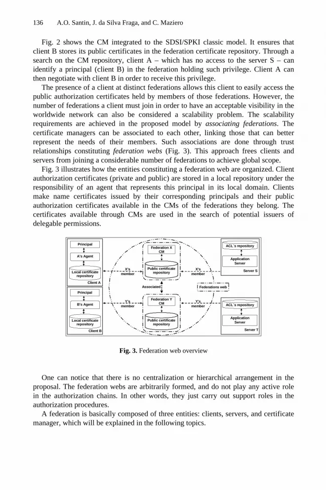
136 A.O. Santin, J. da Silva Fraga, and C. Maziero
Fig. 2 shows the CM integrated to the SDSI/SPKI classic model. It ensures thatclient B stores its public certificates in the federation certificate repository. Through asearch on the CM repository, client A – which has no access to the server S – canidentify a principal (client B) in the federation holding such privilege. Client A canthen negotiate with client B in order to receive this privilege.
The presence of a client at distinct federations allows this client to easily access thepublic authorization certificates held by members of those federations. However, thenumber of federations a client must join in order to have an acceptable visibility in theworldwide network can also be considered a scalability problem. The scalabilityrequirements are achieved in the proposed model by associating federations. Thecertificate managers can be associated to each other, linking those that can betterrepresent the needs of their members. Such associations are done through trustrelationships constituting federation webs (Fig. 3). This approach frees clients andservers from joining a considerable number of federations to achieve global scope.
Fig. 3 illustrates how the entities constituting a federation web are organized. Clientauthorization certificates (private and public) are stored in a local repository under theresponsibility of an agent that represents this principal in its local domain. Clientsmake name certificates issued by their corresponding principals and their publicauthorization certificates available in the CMs of the federations they belong. Thecertificates available through CMs are used in the search of potential issuers ofdelegable permissions.
X’s member
Y’s member
Server S
Application Server
ACL´s repository
Y’s member
X’s member
Client B
B’s Agent
Local certificate repository
Principal
Federations web Associated
Server T
Application Server
ACL´s repository
Federation X CM
Public certificate repository
Client A
A’s Agent
Local certificate repository
Principal
Federation Y CM
Public certificate repository
Fig. 3. Federation web overview
One can notice that there is no centralization or hierarchical arrangement in theproposal. The federation webs are arbitrarily formed, and do not play any active rolein the authorization chains. In other words, they just carry out support roles in theauthorization procedures.
A federation is basically composed of three entities: clients, servers, and certificatemanager, which will be explained in the following topics.

Extending the SDSI / SPKI Model through Federation Webs 137
3.1 Certificate Manager
The main purpose of the certificate manager is to facilitate the interaction betweenclients and servers. A certificate manager only serves the principals that belong to itsown federation. The public keys of its members constitute a SDSI group. As the CMdoes not actively participate on any authorization chain, therefore it is not seen as aprincipal – it is basically a repository of public certificates.
In order to any ordinary principal participate in a federation, an endorsement in theform of a threshold certificate is demanded from it [8]. The threshold certificatesignature depends on “k–out of–n” federation members. Each federation defines thenumber of members (k) that must sign the endorsement request. When joining afederation, the principal’s name certificate is included in the federation repository. Thefederation’s certificate manager will store name certificates in order to make easeprincipal identification (section 3.3). To every new member joining the federation, aname certificate stating SDSI group inclusion is issued, for membership provingpurposes.
The creation of associations among federations (federation webs) is also interpretedas membership inclusion in the SDSI groups of each federation involved. In this case,the new member (the other federation) is recognized as a group defined andadministered within another naming space, according to the definition of SDSI groups[5].
Therefore, the certificate manager should manage the information related to themembers and associations of its own federation. This manager has the ability toinclude or exclude members and associations to other federations, observing anyinterest conflicts. Procedures for storing and retrieving name and authorizationcertificates are made available to federation members through standard interfacesoffered by the federation’s CM.
3.2 Clients and Application Servers
The client represents the principal who creates name certificates, propagates theauthorization certificates by delegation, takes part in threshold certificates, requestsaccess, and composes new chains.
The storage and retrieval of certificates in the client naming space is responsibilityof the client’s agent (Fig. 3). This agent is a program that manages the certificatesavailable at the local repository. These tasks include checking and effecting signatures,searching for certificate chains, negotiating permission grants, issuing newauthorization certificates, and maintaining local names consistency. The agent must beinstantiated during the client’s lifetime; it interacts with the client through a binding toits operational interface.
The application server implements the service objects, which are protected by SPKIACLs kept by a guardian. In order to perform delegations and negotiations topropagate permissions, the server can also make use of an agent. In the certificatesreduction procedure, the server can issue authorization certificates to clients that

138 A.O. Santin, J. da Silva Fraga, and C. Maziero
present new delegation chains and/or include the public keys of these clients in theguardian’s ACLs.
3.3 Authentication, Authorization, and Auditing in the Model
In the SDSI/SPKI principals’ authentication, the identification is not performed usingnames, but public keys, and the authentication is done through digital signatures. Inorder to check the digital signature on the destination, the principal’s public key mustarrive there securely. As there is no public key distribution entity in the SDSI/SPKIinfrastructure, the public keys demanded by an authentication procedure are availablethrough authorization certificate chains.
Mutual authentication is achieved with SDSI/SPKI on an authorization chain basis.The client making a request to a server must sign it and send it along with theauthorization chain that grants the required access privileges. The authorization chainsequence associated to a request is checked by the resource guardian upon its arrival.When this verification is successful, the guardian uses the last key in the authorizationchain (the client’s key) to check the digital signature on the request. Having this checkbeen successful, then client’s authenticity is verified.
Every authorization certificate carries the public key of the principal signing thatcertificate in the issuer field. Therefore, to authenticate a server (always expressed as apublic key starting an authorization chain), the client should require the server’s namecertificate, retrieved from a federation web. After that, the client uses the certificate’spublic key for validating the server’s signature in the authorization chain. When all thementioned procedures are successfully done, the server identity can be assured.
All accesses by public keys to the server are locally logged, and these log recordscan be used for auditing purposes. If needed, the search of the corresponding namecertificate can be performed on the federation web to identify the principalcorresponding to the public key that performed a given access.
The entire mentioned authentication and authorization scheme described in thissection is in compliance with the SDSI/SPKI specifications.
4 Creation of New Authorization Chains on the Proposed Model
There are several related experiences regarding procedures for searching SDSI/SPKIcertificates [9,10,11,12]. However, in all these approaches, if a certificate chain is notfound, the search is finished reporting an exception (fault), and the client is unable toperform the desired access. This work, through the federation notion, proposes aschema that enables a client to locate a certificate holding the needed authorization ina federation web. Later on, the client can negotiate with the privilege holder such grantto build an authorization chain that makes possible the desired access.
The scenario detailed bellow will consider the situation depicted in Figure 3. Atfirst, an authorization certificate is stored in the CM of federation X, after beenpropagated from the server S to the client A (A is a member of the federation X). In

Extending the SDSI / SPKI Model through Federation Webs 139
Figure 4, the messages exchanges are depicted for the case in which the chain betweenthe client B and the server S does not exist.
The client B, member of federation Y, starts by requesting an access to server S(message m1 in Fig. 4). Server S replies by sending a challenge message back to B. Inthis message (m2), server S informs the ACL protecting the requested object and asksfrom client B to prove its authorization for the requested access. In this case,SDSI/SPKI ACL data is effective to accelerate the searching process.
Client A
Federation X CM
S E R V E R
S
C L I E N T
B
m3: search (“ certificate chain ”)
m4: return (“ search.null, certificate associated”)
m5: search (“ certificate chain ”)
m6: return (“ certificate chain ”)
m7: negotiation (“ start ”)
m8: negotiation (“ requirements ”)
m9: negotiation (“ attributes ”)
m10: granting (“ privilegies ”)
m1: request (“ w/chain ”)
m2: challenge (“ object.ACL ”)
m11: response (“ request, certificate chain
Federation Y CM
Fig. 4. Messages exchanges in the authorization chain compounding
Having the ACL, B’s agent performs a local search for an authorization chainallowing the requested access that links client B to server S. This search must retrieveall the authorization chains that include the required permission, and have therequested server as the issuer. Supposing that the local search turns to be unsuccessful,B’s agent asks the CM of the federation it belongs (Y) to search for authorizationcertificates holding the required rights for accessing server S (m3).
The attributes considered in the search are the required permissions and the publickey of server S. In the case considered in Fig. 4, the search does not result in anyauthorization chain. In this situation, the CM of federation Y returns to client B, as aresult of the search, the certificates belonging to members of the associated federations(Federation X, in Fig. 3), so that it can keep on searching (m4 message). Having theassociated certificates, the client extends its search on the other federation’s CMs(belonging to the federations web). Message m5 corresponds to the queries onfederation X in the considered example. In the message m6, client B receives as returnfrom the X’s CM a chain – the authorization certificate with the access permissionbetween client A and server S. Then client B sends to the rights holder (A) thedelegation right request (message m7). The delegation of permissions can be carriedout in a simple way – because both the client and the rights holder are sharing thesame federation, for example. However, depending on the application semantics, morecomplex negotiations may be demanded. The Fig. 4 represents this situation: therequested rights holder notifies client B about a set of requirements for the permissionconcession (message m8). The client gathers the demanded requirements and sendsthem to client A (message m9). Once the application requirements are satisfied, therights holder issues a certificate granting permissions to client B and sends it on

140 A.O. Santin, J. da Silva Fraga, and C. Maziero
message m10. By this last message, the chain compounding process is concluded andclient B can answer the challenge proposed by server S in the response message m11.
4.1 Example: Internet Commerce Application
In this section is depicted an example scenario to overview the usage of federation webs,which synthesizes the proposed schema. This scenario is built upon a Web-basede-commerce application, and involves access privileges location and negotiation. Oneshould notice that the proposed schema is quite general and can be applied to distinctsituations.
In order to simplify the presentation, let’s consider a credit card institution (CC) and abanking institution (BK), having some business agreement allowing each other easyfinancial transactions. Based on this agreement, the CC representative grants to the BKrepresentative the right to “allow purchase” – in this case, the bank representative canallow purchases if payments are to be charged to credit cards issued by the credit cardinstitution. The BK representative, whenever receives an authorization certificate withthe delegation flag on, stores it on the CM of the federation FB.
FB’s member FCC’s associated
3
1 2
FCCs’ member FB’s associated
Server S
Internet Commerce site server
ACL´s repository
9
Request
Challenge
FB’s member FCC’s associated
Public certificate storage
FCC’s member FB’s associated
Public certificate storage
Response
Representative CC
CC’s Agent
Principal
Local certificate repository
5
6
7 8
Representative BK
BK’s Agent
Principal
Local certificate repository
Client B
B’s Agent
Principal
Local certificate repository
Associated
Federation FCC CM
Public certificate repository
Federation FB CM
Public certificate repository
4
Federat ions web
signed request + auhorization certificate chain
Fig. 5. Scenario for purchases in the Internet using of the federation web
Table 1 describes the messages (numbered in Fig. 5) exchanged between entities inorder to implement the purchase transactions in the e-commerce site.

Extending the SDSI / SPKI Model through Federation Webs 141
Table 1. Messages exchanged in Fig. 5 scenario
Step Actions1 Client B navigates through the web pages offered by the e-commerce server S. After
selecting some items to purchase, client B proceeds to checkout.2 Server S sends back to the client a message containing the purchase bill and a
challenge: the “allow purchase” privilege holder is the CC representative.Step Actions
3 Client B queries its local repository and finds no chains linking it to the CCrepresentative. Then, client B sends the chain query to the CM of federation FB.
4 CM of federation FB makes a search in their repository and finds the required chain.It sends back to client B the chain between the server S and the BK representative.
5 Client B requests to BK representative the delegation of privilege “allow purchase”.6 BK representative notifies client B that delegating the requested privilege requires
paying the bill using one of the payment options offered by BK.7 B client pays the bill using one of the options offered by BK.8 BK representative delegates the “allow purchase” privilege to client B.9 Client B sends the authorization chain to server S, along with the request (in a
response message) and the server concludes the purchase transaction.
In order to monitor the “allow purchase” privilege delegations, the CC repre-sentative receives a copy of all paid purchase bills from the e-commerce site.
In the scenario described here, no authorization chains existed linking the CCrepresentative to client B. However, the mechanisms proposed by the federation webmodel allowed to dynamically and automatically creating the requested authorizationchain, in order to complete the purchase operation on the e-commerce site. Of course,if the chain holding the requested authorization was not found in the CM of federationFB, the search would continue on the associated federations until an appropriate chainwas found.
For the scenario described in Fig. 5, it should be noticed that the ACL of the serverdoes not have an entry for client B allowing it to access the services. Therefore, it isno longer required to register the clients on the server ACL to allow their access to theservices. Consequently, all clients’ private information is stored only in thoseinstitutions with which they have strict relationships. In the example above, the clientcan pay for the purchase not only if it is a credit card customer – but also being onlyan ordinary bank customer. By doing so, no credit card numbers or other client-relatedinformation is transmitted through the network. Also, client information is stored onlyby its banking institution.
5 Architecture Implementation Aspects
The SDSI/SPKI infrastructure and the policies applied in the model (previouslydescribed in sections 3 and 4) are totally independent from the adopted technology. Inthis sense, the tools used in the prototype (Fig. 6) have been highly influenced by themodel usage in the Internet – environment assumed as the context of this work.

142 A.O. Santin, J. da Silva Fraga, and C. Maziero
The motivation on adopting CORBA as middleware is to take advantage of theservices provided by that platform, mainly in aspects related to object lookup (nameresolution) and secure remote access invocation. SSL (Secure Socket Layer) wasadopted for remote communications. In order to establish a secure communicationchannel between a client and a server (holding SSL integrity and confidentiallyproperties), mutual authentication for the principals (client and server) is required.However, SPKI uses keys as principals, instead of names. To solve this, a functionwas developed to translate SDSI/SPKI into SSL name certificates.
The SDSI/SPKI integration with the distributed object middleware (shown in Fig.7) was done using CORBASec at application level (CORBASec Level 2) [13].
Client JVM
TCP / IP
TLS / SSL
ORB / CORBASec Server JVM
SDSI / SPKI Infrastructure Authorization / Authentication Policies
HTTP, FTP, ...
Fig. 6. Prototype model architecture
Security Level 2 is not helpful in structuring security functions at application level.However, in order to make use of the CORBA security model, a minimum set ofobjects at the ORB level has been kept. The following session objects weremaintained: PrincipalAuthenticator, SecurityManager and Credentials (Fig. 7).
Localcertificaterepository
ORB Core
ServerClient
S S LS S L
ACL’s repository
ACL
PrincipalAuthenticator
SecurityManager
credentialsPrincipal
Authenticator
SDSI / SPKI (Access Decision)
SDSI / SPKIResolver
SecurityManager
credentials
<XML> <XML>
ORB Services
ORB Services
Federationsweb
Public certificate repository
Federation FCM
Public certificate repository
Federation F
CM
Public certificate repository
Federation FCM
Public certificate repository
Federation FCM
Fig. 7. CORBA-SPKI integration prototype overview
Fig. 7 shows other implementation details. The CM public certificate repository isimplemented using Apache Xindice (which stores XML native data) [14]. The CM is

Extending the SDSI / SPKI Model through Federation Webs 143
implemented as an extension module of the Apache server [15]. All messagesexchanged between members and CM is written in XML. The SDSI/SPKI certificates,originally coded as S-expressions, are translated into XML in our prototype forportability and standardization reasons [16]. The SDSI/SPKI resolver object shown inFig. 7 is a partial implementation of the client’s agent, covering chain searching anddigital signature management. Finally, the reference monitor (guardian) isimplemented by the SDSI/SPKI Access Decision object. The client and serverintegration onto the prototype environment was greatly facilitated by using plug-insand applets in the application deployment.
6 Related Work
In [9], the DNS service was used for storing and retrieving SDSI/SPKI certificates. Inthat proposal, DNS extensions added by RFC 2065 have been used to allow thestorage of certificate records by using entities that store identification andauthorization certificates in DNS databases. In addition, the search algorithms includesome filtering of the certificates being retrieved.
The work [10] views the network built by the propagation of SDSI/SPKIauthorization certificates as an oriented graph. It also assumes that, in typicalcorporate environments, such graph is hourglass-shaped. This is due to the fact thatthere is much more client and server keys than intermediary keys. Therefore, startingfrom these premises, the author uses the DFS forward and DFS backward algorithms,and their combination, to perform fast searches in a database having only oneintermediary. Experiments using the distributed search algorithms proposed in [10] arereported in [11]. This work also analyses some improvements in the DFS forwardalgorithm.
One can notice that the previously described works have been conceived forpreliminary versions of SDSI/SPKI, in which some aspects of the model still had notbeen solved. Some premises assumed at that time are now considered obsolete, nolonger complying with the RFC 2693 specifications. However, these papers havevaluable contributions in terms of system architecture.
According to [17], SDSI/SPKI local names can be viewed as distributed groups ofprincipals for name resolution. Based on this assumption, the author proposesalgorithms based on logic programming, supposed to be more efficient in chain searchwhen compared to conventional implementations. As the main purpose of the paperwas to define search algorithms based on logic programming, a new architecture hasnot been proposed. Nevertheless, the interpretation of local names as distributedgroups can be considered a significant contribution.
The chain search algorithms suggested by [12] and aspects considered there aredeeper refinements of RFC 2693 recommendations. It also presents an implementationof the SPKI current version, quite rich in content, although no architecturalpropositions for distributed systems have been developed.

144 A.O. Santin, J. da Silva Fraga, and C. Maziero
7 Conclusion
This paper proposed architectural extensions to the SDSI/SPKI authorization andauthentication model, allowing the client to build new chains to link it to a server,when the corresponding path does not exist. The proposal is centered on the notion offederations and on entities called Certificate Managers. The role of certificatemanagers is to help in the construction of authorization chains, through a repositorysearching facility, for locating privileges needed by access. As the certificate managerdoes not participate in the authorization chains, the proposed model can be consideredfully decentralized. Thus, the manager does not centralize nor turns hierarchical therelationship between clients and servers, neither it constitutes a critical point regardingto faults, vulnerability or performance.
Adopting the federation web model frees the server from user accountmanagement. It also frees the client from the traditional account creation procedures inorder to have access to a server – even in a global context.
The proposed model presents a support to certificate management that allows thecreation of new authorization chains. This facility is not observed in any otherproposal presented in the technical literature. The proposed scheme is quite flexibleand dynamic, even considering that in some cases the number of messages exchangedto create a new chain can be expressive.
References
1. Horst, F. W., Lischka, M.: Modular Authorization. Proceedings of ACM SACMAT(2001)
2. Garfinkel, S.: PGP:Pretty Good Privacy. O’Reilly & Associates, Inc (1995)3. Blaze, M., Feigenbaum, J., Lacy, J.: Decentralized Trust Management. Proceedings of the
17th IEEE Symposium on Security and Privacy (1996)4. Blaze, M., Feigenbaum, J., Lacy, J.: The KeyNote Trust Management System, Version 2.
IETF-RFC2704 (1999)5. Lampson, B., Rivest, R. L.: A Simple Distributed Security Infrastructure (1996). URL
http://theory.lcs.mit.edu/~cis/sdsi.html, Last access on Jun, 2003.6. Ellison, C., Frantz, B., Lampson, B., Rivest, R., Thomas, B., Ylonen, T.: SPKI Certificate
Theory. IETF-RFC2693 (1999)7. Gasser, M., Mcdermott, E.: An Architecture for Practical Delegation in a Distributed
System. Proceedings of the IEEE Symposium on Security and Privacy (1990)8. Aura, T.: On the Structure of Delegation Networks. Proceedings of IEEE CSFW (1998)9. Nikander, P., Viljanen, L.: Storing and Retrieving Internet Certificates. Proceedings of 3th
Nordic Workshop on Secure IT Systems (1998)10. Aura, T.: Fast Access Control Decisions from Delegation Certificate Databases.
Proceedings of 3th Australian Conference on Information Security and Privacy (1998)11. Ajmani, S.: A trusted Execution Platform for Multiparty Computation. Master thesis, Dep.
of Electrical Engineering and Computer Science, MIT (2000)12. Clarke, D. E.: SPKI/SDSI HTTP Server Certificate Chain Discovery in SPKI/SDSI.
Master dissertation, Dep. Electrical Engineering and Computer Science of MIT (2001)

Extending the SDSI / SPKI Model through Federation Webs 145
13. OMG – Object Management Group: Security Service Specification, v1.8 (2002). URLhttp://www.omg.org/cgi-bin/doc?formal/02-03-11.pdf. Last access on Jun, 2003.
14. Staken, K.: Xindice Developers Guide 0.7.1 (2002). URLhttp://xml.apache.org/xindice/guide-developer.html. Last access on Jun, 2003.
15. Thau, R.: Design Considerations for the Apache API (2002). URLhttp://modules.apache.org/reference. Last access on Jun, 2003.
16. Terreros, X. S. L., Ribes, J-M. M.: SPKI-XML Certificate Structure (2002). URLhttp://www.oasis-open.org/cover/xml-spki.html. Last access on Jun, 2003.
17. Li, N.: Local Names in SPKI/SDSI. Proceedings of the IEEE CSFW (2000).

Trust-X : An XML Framework for TrustNegotiations
Elisa Bertino1, Elena Ferrari2, and Anna Cinzia Squicciarini1
1 Dipartimento di Informatica e ComunicazioneUniversita degli Studi di Milano
Via Comelico, 39/4120135 Milano, ItalyFax +39-0250316253
bertino,[email protected] Dipartimento di Scienze Chimiche, Fisiche e Matematiche
Universita dell’Insubria ComoVia Valleggio, 1122100 Como, Italy
Abstract. In this paper we present Trust-X , a comprehensive XML-based [9] framework for trust negotiations. The framework we proposetakes into account all aspects related to negotiations, from the specifi-cation of the profiles and policies of the involved parties to the deter-mination of the strategy to succeed in the negotiation. In the paper wepresent the system architecture, and describe the phases according towhich negotiations can take place.
1 Introduction
The extensive use of the web for exchanging information and requiring or offeringservices requires to deeply redesign the way access control is usually performed.In a conventional system, the identity of subjects is known in advance and can beused for performing access control. This simple paradigm is not suitable for anenvironment like the web, where the involved parties need to establish mutualtrust on first contact, even if they are total strangers. A promising approachis represented by trust negotiation [7], according to which mutual trust is es-tablished through an exchange of digital credentials. Disclosure of credentials, inturn, must be protected through the use of policies that specify which credentialsmust be received before the requested credential can be disclosed.
A number of approaches to trust negotiation have been recently proposed [1],[5], [8], [6], [4]. However, all these proposals mainly focus on one of the aspects oftrust negotiation, such as for instance policy and credential specification [1], orthe selection of the negotiation strategy, but none of them provide a comprehen-sive solution to trust negotiation, able to take into account all the phases of thenegotiation process. For this reason, we propose Trust-X . Trust-X provides an
A. Lioy and D. Mazzocchi (Eds.): CMS 2003, LNCS 2828, pp. 146–157, 2003.c© IFIP International Federation for Information Processing 2003

Trust-X : An XML Framework for Trust Negotiations 147
XML-based language, named X -TNL, for specifying Trust-X certificates. Trust-X certificates convey information about the profile of the parties involved in thenegotiation. The formalism we propose allows the specification of both creden-tials and declarations, where a credential is a set of properties of a party certifiedby a Certification Authority, whereas declarations contain information that mayhelp the negotiation process (such as for instance specific preferences of one ofthe party) but do not need to be certified. All the certificates associated witha party are collected into its X -Profile. In addition, to better structure cre-dentials and declarations into an X -Profile, each X -Profile is organized intoData sets. Each data set collects a class of credentials and declarations referringto a particular aspect of the life of their owner, and can be used to facilitate cer-tificate exchange. We provide the definition of disclosure policies, encoded usingXML. With the notion of disclosure policy we mean requirement needs for therelease of a resource expressed by rules. Such rules regulate the disclosure of aresource by imposing conditions on the certificates the requesting party shouldpossess and can be organized into groups of policies, ordered by a sensitivitylevel, to better protect flow of sensitive information that policies contain. A re-source can be either a service, a credential, or any kind of data that need to beprotected. In this paper we focus on the approach used in Trust-X for policydisclosures during negotiation and we present the negotiation system architec-ture. The paper is structured as follows. In Section 2 we present an overview ofthe Trust Negotiation language we have developed. We refer the readers to [2]for details on the X -TNL language.In Section 3 we introduce Trust-X negotiation, whereas Section 4 discusses someadditional features of the Trust-X system. Finally, Section 5 concludes the paper.
2 Overview of X -TNL, Trust Negotiation Language
In this section, we summarize the key elements of X -TNL, the XML [9] languagewe have developed for specifying Trust-X certificates and policies. Then, wepresent X -TNL disclosure policies, that is, policies regulating the disclosure ofresources by imposing conditions on the certificates the requesting party shouldpossess. A detailed presentation of X -TNL can be found in [2].
2.1 X -TNL Certificates
Constructs of X -TNL include the notion of certificate, which are the means toconvey information about the profile of the parties involved in the negotiation.A certificate can be either a credential or a declaration.
Credential. A credential is a set of properties of a party certified by a Certifi-cation Authority. X -TNL simplifies the task of credential specification becauseit provides a set of templates called credential types, for the specification of cre-dentials with similar structure. In X -TNL, a credential type is modeled as a

148 E. Bertino, E. Ferrari, and A.C. Squicciarini
<Library Badge credID=’12ab’, SENS= ’NORMAL’ ><Issuer HREF=’http://www.DigitaLibrary.com’Title=DigitaLibrary Repository/><name>
<Fname> Olivia </Fname><lname > White </lname>
</name><address> Grange Wood 69 Dublin </address><badge number code=34ABN/><e mail> [email protected] </e mail><position> Student </position>
</Library Badge>
Fig. 1. Example of Trust-X credential
DTD and a credential as a valid document with respect to the correspondingcredential type. Each credential is digitally signed by the issuer Credential Au-thority, according to the standard defined by W3C for XML Signatures [9]. Acredential is an instance of a credential type, and specifies the list of propertyvalues characterizing a given subject. A Trust-X credential is thus a valid XMLdocument conforming to the DTD modeling the corresponding credential type.Figure 1 shows an example of credential, containing the basic information abouta library badge issued by the digital library Library Badge.
Declaration. Declarations are sets of data without any certification, thereforethey are stated by their owner. Declarations can be considered as structuredobjects like credentials, collecting personal information about the owner. Thiskind of certificates provide thus auxiliary information that can help the negotia-tion process. For instance, a declaration named book preferences describes theliterary preferences of a given subject. In X -TNL, we simply define a declara-tion as a valid XML document. Like credentials, also declarations are structuredinto declaration types, that are DTDs to which the corresponding declarationsconform. Figure 2 shows the Trust-X representation of the book preferencesdeclaration. The declaration describes the genre of books Olivia prefers to readand lists some her favourite authors. This declaration can be used to communi-cate Olivia’s personal preferences during negotiation with an online library.
2.2 Data Sets and X -Profiles
All certificates associated with a party are collected into its X -Profile. To bet-ter structure credentials and declarations into an X -Profile, each X -Profile isorganized into Data sets. Each data set collects a class of credentials and dec-larations referring to a particular aspect of the life of their owner. For instance,Demographic Data, Education, Working Experience are examples of possi-

Trust-X : An XML Framework for Trust Negotiations 149
<book preferences ><name>
<Fname> Olivia </Fname><lname > White </lname>
</name><book genre> horror </book genre>
< author><name> Stephen King </name><name> John Smith </name>
</author><interests >Cinema tab </interests >
</book preferences>
Fig. 2. Example of an X -TNL declaration
ble data sets.1 For example, Alice’s certificates concerning working experiencescan be collected in the Working Experience data set. In this group of digitaldocuments we can find Alice’s work license number, a digital copy of her last jobcontract and some uncertified information about her precedent job experiences.Organizing certificates into data sets facilitates their retrieval during negotiation.Indeed, all the certificates collected in the same data set are logically related.Data sets can then be used to refer to a set of homogeneous declarations or cre-dentials as a whole, and this can facilitate their evaluation and exchange duringnegotiation.
2.3 Disclosure Policies
Trust-X disclosure policies are specified by each party involved in a negotiation,and state the conditions under which a resource can be released during a negotia-tion. Conditions are expressed as constraints against the certificates possessed bythe involved parties and on the certificate attributes. Each party adopts its ownpolicies to regulate release of local information and access to services. Similar tocertificates, disclosure policies are encoded using XML[2].
Trust-X policies are thus defined for protecting any kind of sensitive re-sources. Additionally, a resource can be characterized by a set of attributes,specifying relevant characteristics of the resource that can be used when spec-ifying disclosure policies. To make easier resource management and protection,resources can be further classified into simple and composite resources. Trust-Xlanguage includes specific formalism to define resources relationship.2 Intuitively,a simple resource is an atomic service or information whereas a composite re-source R can be thought as the composition of several resources R1, R2, ..Rk.Resources R1, R2, ..Rk in turn, can be either simple or composite and therefore1 Like for credentials we assume that data set names are unique and are registered
through some central organization.2 We omit the complete specification for lack of space.

150 E. Bertino, E. Ferrari, and A.C. Squicciarini
<!DOCTYPE policyBase[<!ELEMENT policyBase(policySpec)+><!ELEMENT policySpec (properties, resource, type)><!ELEMENT properties (DELIV |certificate+) ><!ELEMENT resource EMPTY><!ELEMENT type EMPTY ><!ELEMENT certificate (certCond*) ><!ELEMENT DELIV EMPTY ><!ELEMENT certCond (#PCDATA) ><!ATTLIST certificate targetCertType CDATA #REQUIRED><!ATTLIST DELIV value CDATA #FIXED ’DELIV’ ><!ATTLIST resource target CDATA #REQUIRED ><!ATTLIST type value (CERT|SERVICE) ’SERVICE’ >] >[]
Fig. 3. Trust-X policy base template
may be released singularly or all together as R. Each resource Ri i ∈ [1, k] canhave its own disclosure policies. Resource R itself can also have its own disclo-sure policies. When R is requested, the related disclosure policy is obtained byprocessing all policies for R, if any, and of R1R2, .., Rk. An example of compositeresource may be a theatre package, including a theatre ticket for a performance,the corresponding script, and a dinner at the restaurant of the theatre. The re-source may be likely also characterized by a set of attributes giving informationrelated to the performance, that is, the name of the show and the exact locationand time where it is performed.
Different policies for the same sensitive resource denote alternative policiesequally valid to obtain it. Each resource R can be disclosed if and only if one ofthe corresponding policies is satisfied. In addition, the disclosure policy languagecan be used to specify prerequisite information. Such policies denote conditionsthat must be satisfied for a resource request to be taken into consideration, andare therefore used at the beginning of the negotiation process, how explained inSection 3. Figure 3 shows the template of X -TNL policy base. According withour XML compliant formalism, the template correspond to a DTD, whereas apolicy base is the corresponding valid XML document.
3 Trust-X Negotiation
The reference scenario for Trust-X negotiations is a network composed of dif-ferent entities that interact with each other by exchanging sensitive resourcescontrolled by the entities themselves. The notion of resource comprises bothsensitive information and services, whereas the notion of entity includes users,

Trust-X : An XML Framework for Trust Negotiations 151
CONTROLLERREQUESTER
X-PROFILE
COMPLIANCE CHECKER
POLICYBASE
X-PROFILE
COMPLIANCE CHECKER
TREEMANAGER
TREEMANAGER
POLICY EXCHANGE
POLICY EXCHANGE
SEQUENCEPREDICTION
MODULE
POLICYBASE
SEQUENCEPREDICTION
MODULE
SEQ .CACHESEQ .CACHE
Fig. 4. Architecture for TrustX negotiation
processes, servers. Entities are characterized by a set of credentials, issued byCAs. Each credential describes attributes characterizing the owner, and theyare used as a means to certify properties of the parties. A negotiation involvestwo entities (also named parties); each of them has a Trust-X profile of certifi-cates, conforming to the syntax introduced in the previous section. During anegotiation mutual trust might be established between the controller and therequester: the requester has to show its certificates to obtain the resource, andthe controller, whose honesty is not always assured, submits certificates to thecounterpart in order to establish trust before receiving sensitive information.Release of information is regulated by disclosure policies, introduced in section2.3, and by appropriate policies that govern access to protected resources byspecifying credential combinations that must be submitted to obtain authoriza-tion. Disclosure policies are exchanged to inform the other party of the trustrequirements that need to be satisfied to advance the state of the negotiation.
The main components of the Trust-X architecture are shown in Figure 4.Note that the architecture is peer-to-peer. The goals of the system componentsare essentially the following: supporting policy exchange, testing whether a policymight be satisfied, supporting certificate and trust ticket exchange, and cachingof sequences. Each of these functions is executed by a specific module of theTrust-X system. Facets modules may be also added to make the negotiationeasier and faster, but we omit them to focus on the most relevant components.The system is composed by a Policy Base, storing disclosure policies, the X -Profile associated with the party, a Tree Manager, storing the state of thenegotiation, and a Compliance Checker, to test policy satisfaction and deter-mine request replies. In the following, we assume that both parties are Trust-Xcompliant but it is possible to enforce negotiations even between parties that donot adopt the same negotiation language, simply by adding a translation mech-

152 E. Bertino, E. Ferrari, and A.C. Squicciarini
anism to guarantee semantic conversion of possibly heterogeneous certificates.In the following we illustrate in more details the negotiation phases.
3.1 Negotiation Phases
A Trust-X negotiation is structured according to the following phases: introduc-tory phase, the policy evaluation phase, certificate exchange phase. The policyevaluation phase is the core of the negotiation process. Certificates and ser-vices are disclosed only after a complete counterpart policies evaluation, thatis, only when the parties have found a trust sequence of certificate disclosuresthat makes it possible the release of the requested resource, according to thedisclosure policies of both parties. Even disclosure of sensitive policies may beprotected, by disclosing sensitive policies gradually according to the degree oftrust established. The concluding step of a Trust-X successful negotiation is ananalysis of the certificates and information exchanged and may result in cachingthe generated sequence, as illustrated in section 4.2. In what follows we illustrateeach one of the above-mentioned phases in more detail. Note that articulatingthe negotiation into different distinct phases results in a multilevel protectionmechanism, that avoids the release of unnecessary or unwanted information.Each phase is executed only if the previous ones succeed and sensitivity of theexchanged information increases during negotiation. Indeed, the disclosure ofcertificates, that can be regarded as more sensitive with respect to policies, ispostponed at the end of policy evaluation: only if there is any possibility tosucceed in the negotiation, certificates are effectively disclosed.
Introductory Phase. The introductory phase begins when a requester con-tacts a controller asking for a resource R. The initial phase of a negotiation iscarried out to exchange preliminary information that must be satisfied in orderto start the actual processing of the resource request. Such exchange of infor-mation is regulated by the introductory policies of both parties. Introductorypolicies are used to verify properties of the counterpart that are mandatory tocontinue in the negotiation. For instance, a server providing services only toregistered clients, before evaluating the requirements for the requested servicecan first ask the counterpart for the login name. If the requester is not regis-tered there is no reason to further proceed. Prerequisite policies are thereforeessentially used to establish whether to enter into the core of the negotiationprocess or not, but they also can also help in driving the following phases ofthe process. Introductory policies may also be used to collect information aboutthe requester preferences and/or needs. For instance, in a purchasing of booksonline, a book store may ask the requester to submit the book preferencesdeclaration, if any, in order to satisfy customer preferences. If the requester doesnot assume honesty of the controller it can, in turn, send its own introductorypolicies. Such phase is therefore composed by a short number of simple messagesexchanged between the two parties.

Trust-X : An XML Framework for Trust Negotiations 153
Example 1. Consider a Rental Car Service. When Alice asks to rent a car thenegotiation starts. Possible prerequisites that the agency may require duringintroductory phase are modeled by the following introductory policies3:• Car Rentalp ← Preferred customer()• Car Rentalp ← Car Preferences().The first policy checks whether the client has the preferred customer credentialdenoting previous business relationship between the parties, whereas with thesecond policy the Agency asks the requester to submit the car preferencesdeclaration, if any, in order to satisfy requester preferences.
Policy Evaluation Phase. During this phase, both client and server com-municate disclosure policies adopted for the involved resources. The goal is todetermine a sequence of client and server certificates that when disclosed enablethe release of the requested resource, in accordance to the disclosure policies ofboth parties. This phase is carried out as an interplay between the client and theserver. During each interaction one of the two parties sends a set of disclosurepolicies to the other. The receiver party verifies whether its X -Profile satisfiesthe conditions stated by the policies, and determines a policy counter requestregulating the disclosure of the certificates requested. If the X -Profile of the re-ceiver party satisfies the conditions stated by at least one of the received policies,the receiver can adopt one of two alternative strategies. It can choose to maxi-mize the protection of its local resources replying only for one policy at a time,hiding the real availability of the other requested resources, or, alternatively, itcan reply for all the policies to maximize the number of potential solutions fornegotiation. Additionally, when selecting a policy each party determines whetherits preconditions are verified by the policies disclosed until that point, and, onlyin this case, the policy is selected. By contrast, if the X -Profile of the receiverparty does not satisfy the conditions stated by the received policies, the receiverinforms the other party that it does not possess the requested certificates. Thecounterpart then sends an alternative policy, if any, or it halts the process, if noother policies can be found. The interplay goes on until one or more potentialsolutions are determined, that is, whenever both the parties determine one ormore set of policies that can be satisfied for all the involved resources. The policyevaluation phase is mostly executed by the Compliance Checker, whose goal isthe evaluation of remote policies with respect to local policies and certificates(certificates can be locally available in the X -Profile or can be retrieved throughcertificate chains), and the selection of the strategy for carrying out the remain-der of the negotiation. To simplify the process a tree structure is used which ismanaged and updated by the Tree Manager.
Note that no certificates are disclosed during the policy evaluation phase.The satisfaction of the policies is only checked to communicate to the otherparty the possibility of going on with the process and how this can be done. A
3 Policies are expressed in terms of logical expressions to simplify the comprehensionof the corresponding semantic

154 E. Bertino, E. Ferrari, and A.C. Squicciarini
detailed description of the Trust-X negotiation, with the associated algorithmsfor all the negotiation strategies can be found in [3].
Certificate Exchange. This phase begins when the previous phase ends suc-cessfully, determining one or more trust sequences. Several sequences of creden-tials can be determined to succeed in the same negotiation. Once the partieschoose the sequence of certificates to disclose, the certificate exchange starts.Each party discloses its certificates, observing the order defined in the sequence.Upon receiving a certificate, the counterpart verifies the satisfaction of the as-sociated policies, checks for revocation, checks validity dates and authenticatesthe ownership (for credentials). Eventually, if further information is needed forestablishing trust, it is the receiver responsibility to check for new certificatesusing credential chains. For example, if a medical certificate was requested andthe issuer is an unknown hospital, the receiver party has to check the valid-ity of issuer certificate by collecting new certificates from issuer repository. Thereceiver then replies with an acknowledgment expressed with an ack message,and asks for the following certificate in the sequence, or if it has received allthe certificates of the set, it sends a certificate belonging to the subsequent setof certificates in the trust sequence. If no unforeseen event happens, the ex-change ends with the disclosure of the requested resource. Figure 5 shows anexample of the messages exchanged by two parties performing a car rental ne-gotiation. Suppose that parties have successfully completed policy evaluationphase and have determined the subsequent sequence (each name denotes a cer-tificate): [Corrier Affiliation, Corrier Employee, Rental Car]. The disclo-sure of certificates begins with submission of Corrier Affiliation credential,which should satisfy the conditions specified during policy evaluation phase. Thesubsequent certificate (Corrier Employee) is disclosed from the counterpart af-ter checking the remote certificate received. Rental Service is finally providedand the negotiation succeeds.
4 Additional Features of Trust-XIn this section we discuss two additional aspects of Trust-X system, that is, thenegotiation of multiple resources and the possibility of caching the sequence ofcertificates as a mechanism to speed up negotiation processes.
4.1 Negotiation of Composite Resources
As previously introduced, Trust-X resources can be either simple or composite,that is, obtained as the composition of several resources. The negotiation of com-posite resources can be considered as an extension of negotiation of simple onesand it is supported as follows. Each component of the main resource is sequen-tially negotiated. When a party asks for a composite resource, the negotiation is

Trust-X : An XML Framework for Trust Negotiations 155
Acceptsequence
SendCorrier_Affiliation
check:Corrier_Employee
SendRental Service
check:Corrier- Affilation
SendCorrier_employee
Sequences:
2. ( Corrier_Affiliation),( Corrier_Employee), (Rental)
Corrier_Affiliation Corrier_Employee R
SERVER CLIENT
sequencemessagge
ack
Co rrier_Employee R
Car Reservationconfirmed
Fig. 5. An example of certificate exchange phase
executed evaluating first the policies for the root resource4 and then negotiatingeach component at the time. Each time the policy evaluation phase of a resourcecomponent succeeds, the corresponding trust sequence is determined. Note that,although it is possible to determine more than a sequence for the same resource,we now refer to the sequence on which parties agree. Instead of immediately exe-cuting it, both parties store it and start evaluating requirements for negotiatingthe next component resource. Intuitively, the information obtained from the pre-vious process can be used to make this phase simpler and faster, by avoiding toask for the same certificates or properties again. This simplification consists innot asking again the satisfaction of disclosure policies that were already satisfiedin previous policy exchange. This simple strategy reduces the number of partyrequests and optimizes the number of exchanges. In addition, the controller canchoose whether allow partial disclosure of some of the components or not. In-deed, suppose that during a negotiation of a composite resource (composed bythree atomic resources, say), a party results to be in order to obtain only two ofthe three resource components of the resource originally requested. What shouldthe controller do? It can choose to disclose the two resources anyway or deny theentire access. Intuitively, this decision strongly depends from the context andfrom the kind of the resources parties are negotiating. If parties are part of acollaborative environment and resources are not logically dependent from eachother, the disclosure can be granted, otherwise, it is denied.
4.2 Sequence Caching
It is really likely that some negotiations will be performed by an entity withdifferent counterparts having a similar profile. In such cases it might be usefulto keep track of the sequences of certificates most frequently exchanged, instead4 Policies may be specified for both the main resource and for resource components
too.

156 E. Bertino, E. Ferrari, and A.C. Squicciarini
of recalculating them for each negotiation. For instance, some books of a digitallibrary might be often asked during exam sessions. The trust negotiation processwill be very similar for different students. Or, better, the asked information willbe exactly the same and the only differences will concern the type of certificatesdisclosed. As an example, consider a student attending a certain University Y.Students might have a card issued by the main secretary office of the university,whereas students of a branch department might have only a badge issued by thedepartmental secretary office. Suppose that the properties required to obtain theauthorization to access the library can be proved by presenting either the cardissued by the main secretary office or by presenting both the badge issued by thedepartmental secretary office and the student library badge. Suppose moreoverthat students usually require privacy guarantees before disclosing certificates,and that the library proves its honesty by a set of proper certificates. Alternativesequences can therefore be generated to disclose the same resource, but all ofthem are quite intuitive and easy to determine. The controller can cache andsuggest them upon receiving a request from a student. The student can cachethe most widely used sequences for negotiating access to digital libraries as wellas the library, and suggest them upon sending a request to a library.
Intuitively, this approach does not ensure a complete protection of policies.However, in many contexts, protection of policies and associated certificatesis not the main goal for parties. Moreover, we expect that in many scenariosthere will be standard, off-the-shelf policies available for widely used resources(e.g., VISA cards, passports). In case of negotiations involving such commonresources the sequences of certificates to be disclosed will be only regulated bysuch standard and predictable policies. In this case, certificates represent onlya means to easily prove parties properties, and it is not unsafe to suggest thesequences at the beginning of the process. If the counterpart can not satisfythe proposed sequence, the negotiation can continue by executing the policyevaluation phase or by suggesting the another sequence. The module of Trust-X in charge of caching and suggesting the sequences is the sequence predictionmodule.
5 Conclusion
In this paper we have introduced Trust-X , a comprehensive XML-based frame-work for trust negotiations. We have focused on the various phases in whicha Trust-X negotiation is articulated. Future work includes the extension of X -TNL among several directions, such as for instance the possibility of specifyingthe credential submitter. Another extension we are currently working on is thepossibility of disclosing only portions of a credential during the negotiation pro-cess. This will allows us to protect the elements of a credential in a selectiveand differentiated way. Finally, we are developing techniques and algorithms forcredential chains discovery and for recovering from a negotiation failure and weare optimizing caching strategy to increase the efficiency of negotiation.

Trust-X : An XML Framework for Trust Negotiations 157
References
1. E. Bertino, S. Castano, E. Ferrari. ”On Specifying Security Policies for Web Docu-ments with an XML-based Language”. Proc. of SACMAT 2001, ACM Symposiumon Access Control Models and Technologies, Fairfax, VA, May 2001.
2. E. Bertino, E. Ferrari, A. Squicciarini, ”X -TNL - An XML Based language forTrust Negotiations”. Proceedings of Fourth International Workshop on Policies forDistributed Systems and Networks, Como, Italy, June 2003.
3. E. Bertino, E. Ferrari, A. Squicciarini, ”Trust-X A Peer to Peer framework forTrust Establishment”. Submitted for Publication.
4. M. Blaze, J. Feigenbaum, J. Ioannidis, and A. Keromytis, The KeyNote Trust-Management System RFC 2704, September 1999.
5. T. Yu, M. Winslett, K. Seamons, ”Supporting Structured Credentials and SensitivePolicies through Interoperable Strategies for Automated Trust Negotiation” ACMTransactions on Information and System Security, volume 6, number 1, February2003.
6. P. Bonatti, P. Samarati, ”Regulating Access Services and Information Releaseon the Web” 7th ACM Conference on Computer and Communications Security,Athens, Greece, November 2000.
7. K. E. Seamons, M. Winslett, T. Yu, B. Smith, E. Child, J. Jacobson, H. Mills,and L. Yu. ”Requirements for Policy Languages for Trust Negotiation”. Inter-national Workshop on Policies for Distributed Systems and Networks (POLICY2002), Monterey, CA, June 2002.
8. A. Herzberg, Mihaeli, Y. Mass, D. Naor, and Y. Ravid, ”Access Control SystemMeets Public Infrastructure, Or: Assigning roles to Strangers” IEEE Symposiumon Security and Privacy, Oakland, CA, May 2000.
9. World Wide Web Consortium. Available at http://www.w3.org/

A. Lioy and D. Mazzocchi (Eds.): CMS 2003, LNCS 2828, pp. 158–171, 2003.© IFIP International Federation for Information Processing 2003
How to Specify Security Services: A Practical Approach
Javier Lopez1, Juan J. Ortega1, Jose Vivas2, and Jose M. Troya1
1Computer Science Department, E.T.S. Ingeniería InformáticaUniversity of Malaga, SPAIN
jlm,juanjose,[email protected]
2Hewlett-Packard Labs.Bristol, UK
Abstract. Security services are essential for ensuring secure communications.Typically no consideration is given to security requirements during the initialstages of system development. Security is only added latter as an afterthought infunction of other factors such as the environment into which the system is to beinserted, legal requirements, and other kinds of constraints. In this work we in-troduce a methodology for the specification of security requirements intended toassist developers in the design, analysis, and implementation phases of protocoldevelopment. The methodology consists of an extension of the ITU-T standardrequirements language MSC and HMSC, called SRSL, defined as a high levellanguage for the specification of security protocols. In order to illustrate it andevaluate its power, we apply the new methodology to a real world example, theintegration of an electronic notary system into a web-based multi-users serviceplatform.
1 Introduction
Many problems with security critical systems arise from the fact that developers sel-dom have a strong background in computer security. However, nowadays it is widelyaccepted that an adequate specification of a system is required in order to obtain arobust implementation. There is currently an increased need to consider security as-pects at the early stages of system development. This need is not always met by ade-quate knowledge on the part of the developer. This is problematic since security ismost often compromised not by breaking the dedicated mechanisms, but by exploitingweaknesses in the way those mechanisms are used. Therefore security mechanismscannot simply be inserted into the system as an afterthought. In consequence, securityaspects should be considered already at an early stage of the software development lifecycle.
Results obtained using formal specification techniques are not readily applicable inthe context of a real world development environment. First of all there is a require-ments engineering problem: how to capture the intended security requirements. Then

How to Specify Security Services: A Practical Approach 159
we have an implementation problem. Thus, it is not obvious how to reconcile themathematical notion of a perfect public key with the fact of a stored file representing acouple of numbers n and e encoded according to the Basic Encoded Rules (BER).Also, although we often talk about secure channels, in reality what we have are thingssuch as https connections.
Security requirements are commonly expressed as system constrains, but often theyare in fact a kind of service that must be provided by a variety of mechanisms. In thissense, security requirements are not different from e.g. real-time requirements, andshould be treated in an analogous way. Accordingly, we refer to these services assecurity services.
The rest of this paper is organized as follows. In Sect. 2 we present some commonsecurity concepts. In Sect. 3 we give an overview of a couple of representative specifi-cation languages. Sect. 4 is dedicated to a brief introduction of the communicationrequirements language Message Sequence Charts (MSC), and the High-Level MSC(HMSC). In Sect. 5 we describe a new specification language, SRSL, which is anextension of MSC and HMSC. Sect. 6 is dedicated to the description of an applicationof SRSL to a real world example, and in Sect. 7 we present some conclusions.
2 Specification of Security Properties Paradigm
A security protocol [7] is a general template describing a sequence of communicationsand making use of cryptographic techniques to meet one or more particular securityrelated goals. The basic security services [11] provided by security mechanisms(cryptographic algorithms and secure protocols) are authentication, access control,data confidentiality, data integrity, and non-repudiation.
The notion of authentication includes authentication of origin and entity authentica-tion. Authentication of origin can be defined as the certainty that a message that isclaimed to proceed from a certain party actually originated from it. As an illustration,if during the execution of a protocol Bob receives a message, supposed to come fromAnne, then the protocol is said to guarantee authentication of origin for Bob if it isalways the case that, if Bob’s node accepts the message as being from Anne, then itmust indeed be the case that Anne sent exactly this message earlier. Thus, authentica-tion of origin must be established for the whole message. Moreover, it is often the casethat certain time constraints concerning the freshness of the message received mustalso be met. Entity authentication protocols, by its turn, guarantees that the claimedidentity of an agent participating in the protocol is identical to the real one.
Access control service ensures that only authorized principals can gain access toprotected resources. Usually the identity of the principal must be established; henceentity authentication of origin is also required here.
Confidentiality may be defined as prevention of unauthorized disclosure of infor-mation.
Data integrity means that data cannot be corrupted, or at least that corruption willnot remain undetected. If it were possible for a corrupted message to be accepted, then

160 J. Lopez et al.
this would show up as a violation of integrity and the protocol must be regarded asflawed.
Non-repudiation provides evidence to the parties involved in a communication thatcertain determined steps of the protocol have occurred. This property appears to bevery similar to authentication, but here the participants are given capabilities to fakemessages up to the usual cryptographic constrains. It uses signature mechanisms and atrusted notary.
These services are enforced using cryptographic protocols or similar mechanisms,and it is essential to determine which ones are needed. In order to specify a securitysystem it is not necessary to know how the analysis of the system will be carried;however, it is absolutely indispensable to identify the security services required.
3 Overview of Security Specification Languages
We focus here on two kinds of specification languages applied to security systems:languages for software engineering and languages for the design and analysis of cryp-tographic protocols [6].
A representative example of the first kind of language is UML - Unified ModelingLanguage [10]. UML is a language for the specification, visualisation, development,and maintenance of software systems. The notation consists basically of graphicalsymbols, including a set of diagrams giving different views of a system.
J. Jurjens [3] has defined an extension of UML, UMLsec, to specify standard secu-rity requirements on security-critical systems. The aim of this work is to use UML toencapsulate knowledge on prudent security engineering and to make it available todevelopers not specialised in security. It is based on the most important kinds of dia-grams for describing object-oriented software, class diagrams, state-chart diagrams,and interaction diagrams, and uses the basic elements offered by UML to extend thelanguage, i.e. stereotypes, tagged values, and constraints.
An example of the second kind of language is CAPSL [8]. This is a high-level for-mal language intended to support security analysis of cryptographic authentication andkey distribution protocols. A protocol specification in CAPSL can be translated into amultiset rewriting (MSR) rule intermediate language like CIL, and the result can beused as input to different security analysis tools.
A CAPSL specification has tree sections: protocol specification, type specification,and environment specification. The type and environment specifications are optional.A protocol specification is a description of behaviour and consists of three parts: dec-larations, messages, and goals. A type specification defines cryptographic operators,whereas an environment specification provides scenarios used by model-checkingtools to verify the protocol. A CAPSL extension called MuCAPSL is also under de-velopment [9], intended to support the specification of protocols for secure multicast.
We believe it is important to develop a specification language integrating bothkinds of languages. As a first approach to achieve this aim we propose here a newlanguage, the Security Requirements Specification Language (SRSL), based on Mes-

How to Specify Security Services: A Practical Approach 161
sage Sequence Charts. In the next section we give an overview of the latter, and in thesubsequent one we introduce the SRSL.
4 A Requirements Language for Communication Protocols: MSC
The ITU-T’s Standardization Sector specifies Message Sequence Charts [2] (ITU-TZ.120) as the requirements language for the visualization of system runs or traceswithin communication systems. MSCs can be defined as a trace language for describ-ing message interchanges among communicating entities. It is endowed with a graphi-cal layout that gives a description of system behaviour in terms of message flow dia-grams that is both clear and perspicuous. MSCs focus on the communication behav-iour of system components and their environments, and are widely used as follows: forrequirements definition; for specification of process communication and interface; as abasis for automatic generation of Specification Description Language (SDL) [1]skeletons; for selection and specification of test cases; and for documentation. It isused most frequently together with SDL.
The basic language constructs of MSCs are instances and messages. Instances aregraphically represented by an axis, i.e. a vertical line or a column. An entity name andan instance name can be specified within an instance heading in the graph. A totalordering of the communication events is specified along each instance axis. Actionsdescribing an internal activity of an instance, in addition to message exchange, mayalso be specified. The system environment is also represented by a frame symbolforming the boundary of the diagram.
Instances may also be created from a parent instance. Instance creation is describedby a special symbol in the shape of a dashed arrow that can be associated with textualparameters. Termination of instances is also possible, and is represented by a stopsymbol in form of a cross at the end of an instance axis.
It is also possible to specify conditions describing a state associated with a non-empty set of instances. Conditions can be also used for sequential composition ofMSCs. MSCs can be used to describe the behavior of a subsystem or component in-tended to be combined in different ways into a more complex system.
In addition, MSCs may also be combined with the help of expressions consisting ofcomposition operators and references to the MSCs. MSC references can be used eitherto reference a single MSC or a number of MSCs using a textual MSC expression. TheMSC expressions are constructed from the operators alt, par, loop, opt and exc, de-scribed below.
The keyword alt denotes alternative executions of several MSCs. Only one of thealternatives is applicable in an instantiation of the actual sequence.
The par operator denotes parallel executions of several MSCs. All events within theMSCs involved are executed, with the sole restriction that the event order within eachMSC is preserved.
An MSC reference with a loop construct is used for iterations and can have severalforms. The most general construct, loop<n,m>, where “n” and “m” are natural num-bers, denotes iteration at least n and most m times.

162 J. Lopez et al.
The opt construct denotes a unary operator. It is interpreted in the same way as analt operation where the second operand is an empty MSC.
An MSC reference where the text starts with exc followed by the name of an MSCindicates that the MSC can be aborted at the position of the MSC reference symboland instead continued with the referenced MSC. MSC references with exceptions areused frequently.
High-level MSCs [2] provide a means to graphically define how a set of MSCs canbe combined. An HMSC is a directed graph where each node is a start symbol, an endsymbol, an MSC reference, a condition, a connection point, or a parallel frame. Theflow lines are used to connect the nodes in the HMSC and indicate the sequencing thatis possible among the nodes. The incoming flow lines are always connected to the topedge of the node symbols, whereas the outgoing flow lines are connected to the bot-tom edge. If there is more than one outgoing flow line from a node this indicates analternative. The conditions in HMSCs can be used to indicate global system states orguards and impose restrictions on the MSCs that are referenced in the HMSC. Theparallel frames contain one or more small HMSCs and indicate that the small HMSCsare the operands of a parallel operator, i.e. the events in the different small HMSCscan be interleaved.
The connection points are introduced to simplify the layout of the HMSCs and haveno semantic meaning. High-level MSCs can be constrained and measured with timeintervals for MSC expressions. In addition, the execution time of a parallel frame ofan HMSC can be constrained or measured. The interpretation is similar to the inter-pretation of Timed MSC expressions.
5 The SRSL Language
The specification language proposed here is an extension of ITU standard require-ments language MSC and HMSC. SRSL [4] is a high level language intended to spec-ify cryptographic protocols and secure systems. Such a language must be modular,easy to learn, and able to express security notions.
The main design criteria we have used during development of the SRSL languageare the following:
• The language should provide visualization capabilities. A graphic representa-tion offers perspicuous views of a system and clarifies the communicationamong customers, users and developers.
• It should be possible to produce specifications of a system at several levels ofabstraction. Different stakeholders may have different views, and accordinglyso we require that it be possible to describe a system at several levels of ab-straction.
• The language should make available mechanisms for modularisation. Standardimplementations of a part of the system are often used as components of thewhole system. Standard modules may be defined, implemented and reused.For instance, it is common to implement a new system using well-definedstandards protocols. Thus, if we need a server authenticated and encrypted

How to Specify Security Services: A Practical Approach 163
connection, we can make use of a standard TSL protocol. In this way it be-comes also easier to use a formerly implemented library in any program lan-guage.
• Standard languages should be reused as much as possible. Using standard lan-guages have a lot of benefits. Usually it is difficult to learn a new language ormethodology. In the beginning there may be not enough tools to support it, orthey may be too inefficient. Standard languages typically have tools that sup-port them, and many users may have previous experience with them.
• The language should be suitable for validation purposes. When specifying asystem we usually describe what the system is supposed to do. However, weneed also be able to validate the system, i.e. to show that it is defined accord-ing to the specification.
• It should be possible to express security requirements in the language. Unfor-tunately, there is currently no standard notation to represent those require-ments.
The SRSL has two levels of representation: multi-layer module scheme and secu-rity scenario description.
The multi-layer module scheme describes security systems in terms of a multi-layered structure. The first layer is the communication medium, also used to studyattack strategies in the security analysis phase, i.e. the intruders’ behaviour. The otherlayers depend on the security mechanisms defined during system development. Thisdescription is translated into a security scenario representation using standard packagedefinitions.
As an example, we consider a system that uses SSL security mechanisms in orderto achieve server authentication and confidential communication. Its design mustensure that an application server (the responder) is given evidence of the fact that asender (the initiator) has previously sent some message, i.e. the protocol must be ableto ensure non-repudiation of the origin of messages sent to the server. The modulespecification is depicted in figure 1.
Fig. 1. SRSL Module Specification
INITIATOR
SSL layer(client)
MEDIUM LAYER
RESPONDER
SSL layer(server)
User Protocol
SSL Protocol

164 J. Lopez et al.
The SSL layer is described in a standard security communications package. There-fore, part of medium layer is generated automatically. Consequently, we only have tospecify the Initiator-Responder protocol. It is composed of simple scenarios describedin MSC. The SRSL security scenario description is divided into three parts; the speci-fication of protocol elements, the message exchange flow, and the security servicesrequirements.
The extensions proposed concern the definition of entities, the definition of datatypes related to security aspects, and the security services that are going to be used oranalysed. These are described in comment text boxes, and are intended to be exam-ined during the security analysis phase. These elements required to define a securityprotocol can be divided into several categories. These are explained as follows (key-words are in cursive):• Entities: Agent (Initiator/Responder), the principal’s identification; Key_Server,
which provides cryptographic keys; Time_Server, which provides time tokens; No-tary, which registers the transaction; Server Certification Authority (SCA), whichvalidates a certificate.
• Messages: Text, of type clear text; Random_Number, an integer; Timestamp, givingthe actual time; Sequence, the count number.
• Keys: Public_key, e.g. in PKCS#12 format (aprostrophe symbol (‘) reference toprivate key); Certificate, a public key signed by CA; Private_key, used to signdocuments; Shared_key, a secret key shared by more than one entity; Session_key, asecret key used to encrypt transmitted data.In addition, SRSL may operate with previously defined data types. These
operations are: Concatenate, composition of complex data (operator ’,’); Cipher(operator ““ ””), which provides cipher data resp. cleartext data (e.g.RSAcipher/RSADecipher PKCS#1 format); Hash, the result of a one-way algorithm;Sign (operator “[“ “]”), a message hash encrypted with signer’s private key (e.g.RSAsign PKCS#7). Furthermore, user-defined functions are also considerated.
The message exchange is defined in MSC, the requirements language most widelyutilized in telecommunications, and its extension HMSC, explained in section 4. Theis known for its high degree of flexibility and is universally accepted in protocol engi-neering.
The security services requirements section are also described in comment textboxes. We use three different security statements: Authenticated(A,B), stating that B iscertain of the identity of A; conf(X), stating that the data X cannot be deduced (alsocalled confidentiality); NRO(A,X) ( non-repudiation of origin ), stating that that data X(the evidence) must have originated in A. These statements have been formally de-fined in [5].
Furthermore, an automatic translator program [7] is used to produce the SDL ver-sion of the system from SRSL. The SDL system produced is subsequently used toanalyse security requirements of the system during the analysis phase.
In the specification stage we must consider two different kinds of tasks. The firstone concerns the specification of a system yet to be developed, in which case we havemore freedom to choose what security mechanisms to use. The second one concernsthe specification of an already implemented system.
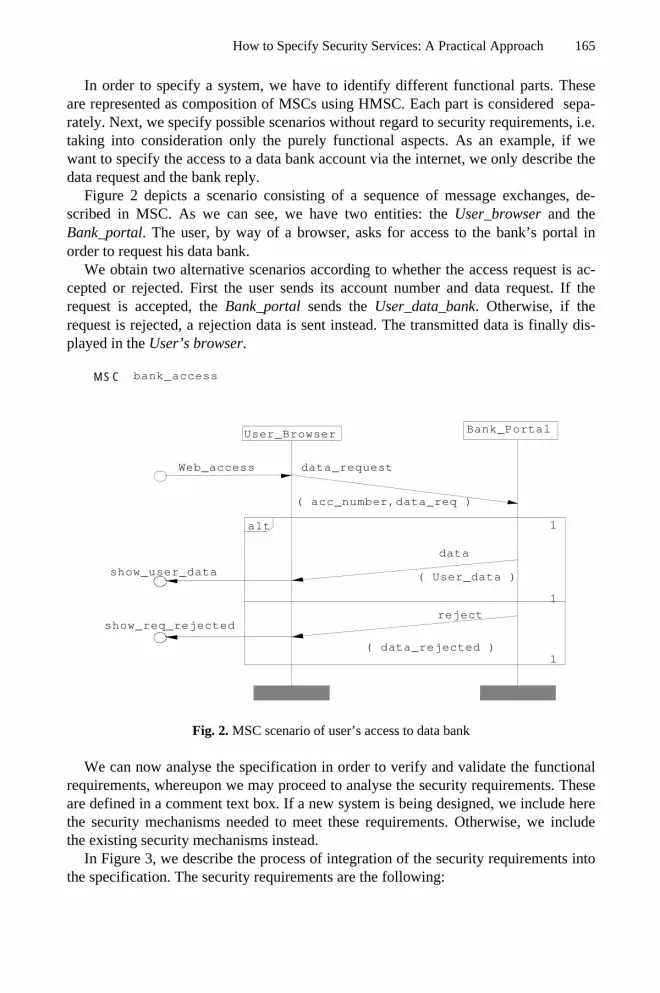
How to Specify Security Services: A Practical Approach 165
In order to specify a system, we have to identify different functional parts. Theseare represented as composition of MSCs using HMSC. Each part is considered sepa-rately. Next, we specify possible scenarios without regard to security requirements, i.e.taking into consideration only the purely functional aspects. As an example, if wewant to specify the access to a data bank account via the internet, we only describe thedata request and the bank reply.
Figure 2 depicts a scenario consisting of a sequence of message exchanges, de-scribed in MSC. As we can see, we have two entities: the User_browser and theBank_portal. The user, by way of a browser, asks for access to the bank’s portal inorder to request his data bank.
We obtain two alternative scenarios according to whether the access request is ac-cepted or rejected. First the user sends its account number and data request. If therequest is accepted, the Bank_portal sends the User_data_bank. Otherwise, if therequest is rejected, a rejection data is sent instead. The transmitted data is finally dis-played in the User’s browser.
Bank_Portal User_Browser
1
1 alt
1
MSC bank_access
show_req_rejected reject
( data_rejected )
show_user_data
data
( User_data )
data_request
( acc_number,data_req )
Web_access
Fig. 2. MSC scenario of user’s access to data bank
We can now analyse the specification in order to verify and validate the functionalrequirements, whereupon we may proceed to analyse the security requirements. Theseare defined in a comment text box. If a new system is being designed, we include herethe security mechanisms needed to meet these requirements. Otherwise, we includethe existing security mechanisms instead.
In Figure 3, we describe the process of integration of the security requirements intothe specification. The security requirements are the following:

166 J. Lopez et al.
1- Authenticated(Bank_Portal,User_Browser);2- Authenticated(User,Bank_Portal);3- conf(account_number);4- conf(data_req);5- conf(user_data);
The first requirement means that user’s browser must authenticate itself to bank’sportal. This is achieved with the help of an HTTPS-connection.
The second requirement means that the user must authenticate itself to the bank’sportal. This is accomplished by a mechanism that asks for the user’s identification andpassword, and subsequently validates it.
The three last requirements mean that the data transmitted is confidential. This goalis accomplished by making use of the session key established during the https connec-tion.
definitionsUser_Browser, Bank_Portal: Agent;account_number, data_req: Text;data_user_bank: Text;web_form_login: Text;login,password: Text;wellcome_page: Text;session_ID: Text;data_rejected: Text;httpskey: session_key;
Security ServiceAuthenticated(Bank_Portal,User_Browser);Authenticated(User,Bank_Portal);conf(account_number);conf(data_req);conf(data_user_bank);
User_Browser Bank_Portal
1
1
1
1alt
1
1alt
https_connection_server_authen
init_state
init_state
init_state
MSC bank_security_access
gainned_access
( wellcome_page,session_IDhttpskey)
data_request
( account_number,data_req,session_ID )
login_password
(login,passwordhttpskey )
login_password
( web_form_loginhttpskey)
rejected
( data_rejected,session_IDhttpskey)
data_bank
( user_data_bank,session_IDhttpskey)
invalid_login_password
Web_access
show_web_login_page
fill_web_login_page
show_invalid_authentication
show_wellcome_page
select_data_request
show_user_data_bank
show_request_rejected
Fig. 3. SRSL security scenario of user’s access to data bank
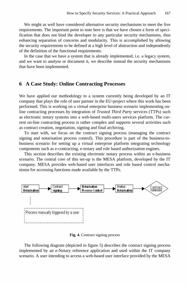
How to Specify Security Services: A Practical Approach 167
We might as well have considered alternative security mechanisms to meet the fiverequirements. The important point to note here is that we have chosen a form of speci-fication that does not bind the developer to any particular security mechanisms, thusenhancing separation of concerns and modularity. This is accomplished by allowingthe security requirements to be defined at a high level of abstraction and independentlyof the definition of the functional requirements.
In the case that we have a system that is already implemented, i.e. a legacy system,and we want to analyse or document it, we describe instead the security mechanismsthat have been implemented.
6 A Case Study: Online Contracting Processes
We have applied our methodology to a system currently being developed by an ITcompany that plays the role of user partner in the EU-project where this work has beenperformed. This is working on a virtual enterprise business scenario implementing on-line contracting processes by integration of Trusted Third Party services (TTPs) suchas electronic notary systems into a web-based multi-users services platform. The cur-rent on-line contracting process is rather complex and supports several activities suchas contract creation, negotiation, signing and final archiving.
To start with, we focus on the contract signing process (managing the contractsigning and notarisation process control). This procedure is part of the business-to-business scenario for setting up a virtual enterprise platform integrating technologycomponents such as e-contracting, e-notary and role based authorization engines.
This section describes the existing electronic notary process within an e-businessscenario. The central core of this set-up is the MESA platform, developed by the ITcompany. MESA provides web-based user interfaces and role based control mecha-nisms for accessing functions made available by the TTPs.
Fig. 4. Contract signing process
The following diagram (depicted in figure 5) describes the contract signing processimplemented by an e-Notary reference application and used within the IT companyscenario. A user intending to access a web-based user interface provided by the MESA

168 J. Lopez et al.
platform triggers manually the contract signing process within the following businessscenario:
In the sequel we describe the contract signing process, including the security re-quirements and the relationships among the users, the MESA platform, and the e-notary service.
Our methodology has been used to examine this process in terms of communicationsecurity issues. The intended goals have been to validate the model and evaluate boththe current reference implementation and a proposed extension to an agent-basedscenario for the reference implementation.
MESA
Fig. 5. Application structure in SRSL module description
This implementation is being used within the current business scenario. However,the current client/server implementation, based on traditional PKC technology, hasinherent problems in terms of flexibility and scalability. While the reference scenariorequires a certain infrastructure, compliance to the European directives concerningdigital signatures, to alternative PKC technologies and to certificate infrastructuresmight be more suitable when adopting the e-notary process within other business sce-narios (with different context of actors, contents, legal requirements and liability is-sues). In fact, changing the context of a recent e-Notary deployment scenario andidentification of implications in terms of security are the most interesting challengeswe face.
We have to pay attention to the fact that what we have specified here is a newlyimplemented system. Therefore the task has been to describe the behavior of currentapplication in order analyze and improve the current implementation. We started byemphasizing for the developers the usefulness of elaborating a system specificationintended to clarify the different scenarios in order to increase our understanding ofthem and to avoid certain ambiguities. We show now the definition of the systemmodule description representing the different layers structured according to the secu-rity services.

How to Specify Security Services: A Practical Approach 169
The protocols described in each layer are specified in terms of MSC/HMSC dia-grams. Many are standard protocols and so they are instances of generic specifica-tions.
The system (see Figure 6) is divided into three parts: the contract creation process,the signing process, and the notarization process. A diagram in a lower abstractionlevel describes each MSC reference.
M S C N e t u n io n
s ig n in g _ p r o c e s s
n o t a r isa t io n _ c o n tr o l
c o n t r a c t _ c r e a t io n
Fig. 6. HMSC application description
A representative part of the specification is the create_contract scenario (Figure 7).
CL MESA
Definition
CL,MESA: Agent; contract, teplate_ID : T ext; session_ID : T ext; list_of_signers: Text; httpskey : SESSIO N_KEY; Security service conf(contract); conf(session_ID); conf(template_ID); conf(template); conf(list_of_signers);
negotiation
1
1
1
1
1
1 alt
created_contrac t
Created_contract
client_authenticated
MSC create_contract
choose_s igners
s tore_template_localy
choose_template
show_lis t_of_tem plates
confirm Confirm_data
lis t_of_s igners ( session_ID ,list_of_signershttpskey )
show_list_of_s igners list_of_signers ( list_of_s igners ]httpskey )
contract ( sesion_ID ,contrac thttpskey )
upload_contract
tem plate ( templatehttpskey )
template_ID ( sess ion_ID ,template_IDhttpskey )
create_contract_from _template
lis t_of_tem plates ( listtemplateshttpskey )
ask_for_list_of_templates
( sess ion_IDhttpskey )
confirm _datahttpskey
confirm_data: Text;
Fig. 7. SRSL create_contract security scenario

170 J. Lopez et al.
The contract leader (CL) triggers the contract creation process. Previously, the con-tract leader and the MESA platform had to be authenticated, and a HTTPS session keyexchanged. This is represented by the initial state client_authenticated. The scenario isdivided into four independent alternatives (alt-operator). In the third sub-scenario weuse the task MSC operator to specify the possibility of an external negotiation agree-ment that is not part of our system. The fourth sub-scenario ends the process by ac-cepting the uploaded contract and starting the next scenario in the state cre-ated_contract.
Developers considered this methodology very useful for their purposes, especiallywith regard to the specification of the contract signing process (Figure 8). The notifi-cation was initially implemented by letting the E-notary service send an e-mail to eachsigner. However, this procedure is unreliable since it lacks any kind of security guar-antees. When this fact was drawn to attention of the developers, they decided to mod-ify the system in order to provide for security services, such as the signing of the e-mail by the e-notary service to ensure non-repudiation of origin (NRO). This has beenappended to security services section, and a signing mechanism has been included inthe definition of the e-notary. This mechanism is checked later in analysis phase.
Fig. 8. SRSL contract_signing security scenario & non-repudiation improvement
The developers deemed this methodology easy to learn and to apply in real envi-ronments. They believed that it has been of great help for understanding the imple-mentation and that it provided a method to improve the application with regard to therequired security services and mechanisms. Furthermore, the methodology madeavailable a formal method of analysis that increased the developers and users relianceon the system.
e_notary Signer
Definitions
contract_ID: text;
Security service
1
1 loop
wait_for_contract_signing
signing
MSC contract_signing
uest_for_contract_signing contract_ID
Signer : Agent; e_notary : Agent;
e_notary Signer
Definitions
Signer,e_notary : Agent; contract_ID: text;
Security service
1
1 loop
wait_for_contract_signing
signing
MSC contract_sign_NRO
contract_ID_signed contract_ID
NRO(e-notary,contract_ID
( contract_IDPken)
PKen: Public_key;;
Integrity(contract_ID)

How to Specify Security Services: A Practical Approach 171
7 Conclusions
We have studied different methods for designing and analyzing a system containingcommunication protocols. We observed that in order to define a secure system, thedevelopers need a unified framework that allows them to integrate the security aspectsinto both the software system itself, or at least relevant parts of it, and the communi-cation protocols that constitute a part of the total system. The methodology consistedof an extension of the ITU standard requirements language MCS, called SRSL, a highlevel language for the specification of cryptographic protocols.
In order to illustrate the methodology, we have shown an application consisting ofan electronic notary process scenario that the developers wanted to validate and im-prove. Moreover, we have described how this electronic Notary process can be in-serted into a different scenario, given different input parameters. In this way, we wereable to offer a framework within which it became possible to define and to evaluatedifferent deployment options for rolling out the security services. We concluded bynoting that the solutions proposed were very well received by the developers, whoconsidered them easy to learn and to apply.
Acknowledgements. The work described in this paper has been supported by theEuropean Commission through the IST Programme under Contract IST-2001-32446(CASENET).
References
1. ITU-T Recommendation Z.100 (11/99), Specification and Description Language (SDL),Geneva, 1999.
2. ITU-T Recommendation Z.120 (11/99), Message Sequence Charts (MSC-2000), Ge-neva,1999.
3. Jurjëns, J., Towards development of secure systems using UMLsec, Lecture notes in Com-puter Science 2029, 2001.
4. Lopez, J., Ortega, J.J. and Troya, J.M., Protocol Engineering Applied to Formal Analysisof Security Systems, Infrasec'02, LNCS 2437, Bristol, UK, October 2002.
5. Lopez ,J., Ortega, J.J. and Troya, J.M., Verification of authentication protocols usingSDL-Method, Workshop of Information Security, Ciudad-Real- SPAIN, April 2002.
6. Meadows, C., Open issues in formal methods for cryptographic protocol analysis, Pro-ceedings of DISCEX 2000,pages 237–250. IEEE Comp. Society Press, 2000.
7. Menezes, A., Van Oorschot, P.C., Vanstone, S., Handbook of Applied Cryptography, CRCPress, 1996.
8. Millen, J. and Denker, G., CAPSL integrated protocol environment, In DARPA Informa-tion Survivability Conference (DISCEX 2000), IEEE Computer Society, 2000.
9. Millen. J. Denker, G. CAPSL and MuCAPSL, J. Telecommunications and InformationTechnology, 2002
10. Object Management Group. http://www.omg.org/11. Ryan, P. and Schneider, S., The Modelling and Analysis of Security Protocols: the CSP
Approach, Addison-Wesley, 2001.

A. Lioy and D. Mazzocchi (Eds.): CMS 2003, LNCS 2828, pp. 172–180, 2003.© IFIP International Federation for Information Processing 2003
Application Level Smart Card Support throughNetworked Mobile Devices
Pierpaolo Baglietto1, Francesco Moggia1, Nicola Zingirian2, and Massimo Maresca2
1 DIST University of Genoa, via Opera Pia 13,16145 Genova, Italy
p.baglietto, [email protected] DEI, University of Padua, via Gradenigo, 16145 Padova, Italy
Abstract. This paper addresses the problem of using networked mobile devicesas providers of cryptographic functions. More specifically the paper describes asystem developed to allow the usage of portable devices, such as PDAs and mo-bile phones, as remote smart card readers when connected into a TCP/IP net-work. This system is completely transparent to desktop applications. The digitalsignature technology, at its highest level of security, requires the use of smartcards and smart card readers not yet widely deployed. This requirement limitsthe mobility and may turn out to be an obstacle to the wide adoption of thedigital signature technology. Our work aims precisely at facilitating the adoptionof the smart card technology by means of PDAs and mobile phones.
1 Introduction
The main challenge for a successful and wide deployment of a new technology is theimplementation of new user friendly services possibly characterized by a minimalimpact on the an existing infrastructure.
The use of smart cards to execute cryptographic operations, such as the electronicsignature, is presently possible only by means of smart card readers directly connectedto the PC. The goal of our work has been to allow accessing the services of a micro-processor card located on a remote device without the introduction of a new API. Onthe contrary, at the application level we adopt standard interfaces that are alreadywidely adopted.
In past projects, such as the CASTING project [1], a GSM phone has been pro-posed as a tool for authentication and for the storage of confidential information. Inthat case, private keys were securely stored on a SIM card that was able to communi-cate with a desktop PC using the SECTUS protocol, an ad hoc wireless protocol. Inother works [2][3][4] has been proposed to make smart card accessible in a more gen-eral distributed environment.
On the contrary, the work described in this paper is focused on the development ofa system which simply allows to remotely access the services provided by smart cards
Application Level Smart Card Support through Networked Mobile Devices 173
through the standard PKCS#11 [5] or CSP (Cryptographic Service Provider) [6] appli-cation interfaces in TCP/IP networks. More specifically the architecture presented inthis paper is based on a client-server model and it consists of two components. Thesecomponents are both compliant with either the PKCS#11 or the CryptoAPI specifica-tions. The client module establishes a secure TLS [7] channel with its correspondingserver application and it sends calls to the PKCS#11 or CSP module to the servermodule. The server module receives the information about the requested cryptographicoperations and executes them on the smart card inserted on a local smart card readerby means of usual PKCS#11 or CSP modules. The whole process is transparent to theuser.
In section 2 and 3 we briefly present application level cryptographic standards wehave used in the implementation of the system and the related work in the remotesmart card application field. In section 4 we describe the usage scenario we consideredduring both the specification of the system architecture, described in section 5, and thedevelopment of a prototype system described in section 6. Finally, we give some con-cluding remarks in section 7.
2 Smart Card Application Programming Interfaces
The digital signature devices are used in the application by means of two standardcalled respectively CryptoAPI and PKCS#11, that define a high level application pro-gramming interface (API) layer. This API isolates an application from the details ofthe cryptographic device. The application does not have to change the interface for adifferent type of device or to run in a different environment; thus, the application isportable.
2.1 Cryptographic APIs
Cryptographic APIs (CryptoAPIs) are set of functions that allow applications to en-crypt and digitally sign data in a flexible manner, granting privacy, secrecy and pro-tection for the user’s sensitive private-key data.
CryptoAPIs provide services that enable developers to add cryptography and cer-tificate management functionality to their applications. Applications can use Cryp-toAPI functions ignoring the underlying implementation, in the same way that anapplication can use a graphic library putting no attention about the particular graphichardware configuration.
All cryptographic operations, furthermore, are performed by independent modulesknown as cryptographic service providers (CSPs). Each CSP provides a differentimplementation of the CryptoAPI. Some CSPs interact directly with hardware compo-nents such as smartcards.

174 P. Baglietto et al.
2.2 PKCS#11
This standard specifies an application programming interface (API), called “Cryp-toki,” for devices which hold cryptographic information and perform cryptographicfunctions. Cryptoki addresses the goals of technology independence (any kind ofdevice) and resource sharing (multiple applications accessing multiple devices), pre-senting to applications a common, logical view of the device called “cryptographictoken”.
3 Scenario
The basic usage scenario is the signature of an e-mail, a document, or everything thathave to be signed for authentication, integrity and non-repudiation purposes, withoutusing a local smart card reader. In particular, let’s consider the signature task of adocument. If a user wants to digitally sign a document in a traditional way he has touse a smart card reader attached to his personal computer and the relative software.This is a restriction to spreading and utilization of digital signature, making it feasibleonly with full-configured and full-equipped PC. On the contrary, our system allowsthe user to perform a digital signature operation everywhere, by means of a mobiledevice. In everyday life few people take with them a PC smart card reader but every-one possesses a cellular phone or, surely in the next future, a more intelligent devicesuch a PDA or a SmartPhone. Our idea is to use these mobile devices as remote smartcard readers.
Fig. 1. The system basic elements
Another usage scenario may be the following. Let’s consider the trust relationshipusually existing between a company secretary and her sales manager in case of normalbusiness transactions. The company secretary needs that some documents, not par-ticularly significant for the enterprise, to be signed by the sales manager. The manager

Application Level Smart Card Support through Networked Mobile Devices 175
trusts the secretary and puts his signature without spending time to read them accu-rately.
This is a widespread interaction-model and we want to reproduce it using digitalsignature through networked mobile devices.
The proposed schema is based on a client-server model that involves three maincomponents: a client application on a desktop computer, a server application on amobile device, and a secure channel between them. The mobile device is equippedwith a smart card that contains the secret keys of the signer. We suppose that the mo-bile device has a PC/SC compliant smart card reader. The environment is a TCP/IPnetwork, so that our device can be identified by an unique IP address. So this approachis valid both in a wireless LAN or in a WAN through the Internet.
4 Related Work in Remote Smart Card Applications
The problem of making the services offered by a smart card accessible from the Inter-net has been addressed in literature. In the WebSIM approach [5] a GSM SIM istransparently visible from the Internet via HTTP. This is possible by means of a smallWeb server placed on the SIM, whose unique function is to provide a Web-like inter-face to the SIM. All the services are implemented as server side scripts on the cardand, so, they can be accessed via HTTP requests. The Web server is an applet on thetop of a GSM SIM Toolkit platform that allows interacting with the SIM and providesa set of API for I/O operations. The problem of connecting the Web server to theInternet is solved by introducing a proxy server into the WebSIM architecture. Theproxy has a public IP address which an Internet host can send its HTTP request to. Theproxy encapsulates the HTTP request into a specially tagged SMS and sends it to theuser’s mobile phone. Once de-capsulated, the HTTP request is processed by the Webserver and the response is sent back to the proxy using the same SMS tunnelingmechanism. Finally, the proxy extracts HTTP response from the SMS and sends it tothe Internet host. The WebSIM main purpose is to univocally authenticate and identifya user in the Web.
In the CASTING project [4] a mobile phone, containing the user certificate and thecorresponding private key, is used for authentication purposes, allowing each user tosecurely access to his personal data, placed on a Web sever, from a pool of fixed PCs(terminals). The link between the mobile phone and the user terminal is secured by awireless ad hoc protocol named SECTUS, while the long distance Internet connectionis protected with SSL/TLS. The idea behind this work is to install a custom PKCS#11Netscape token on the user terminal, that asks the mobile phone to execute on the cardall necessary cryptographic functions involving the user private key in the SSL hand-shake with the Web server, and leaves to the terminal the task to perform the remain-ing operations. The goal of the SECTUS protocol is to establish an authentic channelbetween the terminal and the mobile phone by sharing a secret between them. Thesecret is necessary to compute the MAC of all messages that are sent across the wire-less link, assuring that they are not been altered. The SECTUS protocol consists of thefollowing steps: the mobile phone generates a temporary secret, called r, that is in-

176 P. Baglietto et al.
serted by the user into the terminal. The mobile phone sends its certificate to the ter-minal that generates an authentication key, called s. This is encrypted with the userpublic key and sent back to the mobile phone together with a MAC calculated with r.The mobile phone verifies the MAC, decrypts s and, finally, sends the MAC of itscertificate calculated with s to the terminal that, so, can verify it. In the TLS hand-shake with the Web server the client proves its identity by signing an hash value. Theauthenticity of the transmission of the hash and the signature is assured by MAC com-puted with the authentication key s.
A different approach, based on a distributed object model, is adopted by Chan andTse [6], whose aim is to give a Corba interface to java card applications. The proposedarchitecture defines an OrbCard adaptor that works as a proxy gateway, translating theclient Corba-specific requests into their APDU representations and sending them tothe on-card applet. This applet generates the responses in the APDU format, which theadaptor maps into Corba responses and sends back to the client. The OrbCard adaptorgives a Corba interface to the on-card services, so that they appear as typical Corbaobjects.
5 Architecture
Our starting point is that the system must be transparent to the user, who can use stan-dard application to perform a sign task. The digital signature devices are accessed inour application by means of two standard called respectively Crypto Service Provider(CSP) and PKCS#11. Both of them define a high level API layer that is independentfrom the specific cryptographic device.
For example Internet Explorer and Outlook Express uses CSPs (through CryptoAPIinterface) to sign a document or an e-mail, while Netscape Navigator uses a PKCS#11module. Our system relies on these standard interfaces, assuring a good level of port-ability. We have developed both PKCS#11 and CSP modules that expose all the es-sential functions for digital signature, that are a subset of whole CryptoAPI /PKCS#11 functions.
The idea is to transmit through a socket channel the necessary data to perform asign task on the mobile device. The use of TCP/IP and Internet as, respectively, com-munication protocol and communication channel between the application and thesmart card in place of RS232 and a serial cable entails the use of some technique tomake the channel secure as if we had a local smart card reader. We must be sure aboutthe identity of the mobile device which we are sending information to, we have to besure about the identity of the person that executes the sign request and we want toassure the communication secrecy.
5.1 Smart Card Reader Authentication
Our solution for smart card reader authentication and communication secrecy is to usean SSL channel between the client and the server application, so that the PDA canauthenticate itself presenting its certificate to the client and the communication chan-

Application Level Smart Card Support through Networked Mobile Devices 177
nel between client and server can be encrypted for information hiding purposes. Smartcard authentication is necessary to avoid that someone could impersonate the mobiledevice. In that case, the ill-intentioned could easily put himself between the user andthe mobile device, read the whole communication and modify it in order to sign hisdocument instead of the user.
Fig. 2. The modules we have developed
5.2 User Authentication
For the user authentication, instead, we use an ad hoc solution. When the user wants tosign a document or e-mail, in fact, the application that performs the operation asks tothe user to insert a PIN. The PIN, generally, protects sensible data on the card andallows only an authenticated access to the on board functions. In our application, thePIN takes the meaning of a user identification code. The user identification code,serves exclusively to allow the user to be sure that the signature request, appearing onhis PDA, is the request started on the personal computer. Once the user has verifiedthat the request is correct by means of the user identification code on the PDA, hemust enter the PIN code to perform the signature. Inserting PIN code on PDA is moresecure than inserting PIN code on a personal computer. Altering a software or theoperative system on a PDA, in fact, is more difficult than modify them on a PC, sim-ply because the PDA is less accessible than a personal computer. On the personal

178 P. Baglietto et al.
computer, in fact, a ill-intentioned could install a software that, while the user inserts aPIN, captures the keys pressed on the keyboard and rescues the PIN.
The user identification code, for example, is necessary to avoid the man in the mid-dle attack. If we send a request to the mobile device to sign a document without theuser identification code, an hacker could block our request and take our place and wewouldn’t have the necessary means to reveal this attack. So the user, interpreting therequest on his PDA as trusted, would insert the PIN code to finalize the signature task,but the signed document owner would be the ill-intentioned and not the user.
Fig. 3. System architecture
Fig. 4. A possible attack to the system

Application Level Smart Card Support through Networked Mobile Devices 179
6 Implementation
At the implementation level, we have developed a system based on a client-serverparadigm. The client side application includes a PKCS#11 module, while the serverside application a SSL server. Moreover, the client side application communicateswith the server side application by means of an ad hoc communication protocol.
6.1 Ad hoc Communication Protocol
Our ad hoc communication protocol consists of a simple mechanism of serialization.In particular, we have implemented a common base class that holds a function identi-fier and a member variable containing the server side error code generated by theinvoked function. Each PKCS#11/CSP function is mapped in a class, derived from thebase, that contains specific parameters.
The necessary steps to invoke a function are the following:- Instantiate the right class corresponding to the function (Function id is automati-
cally assigned in the constructor of the class)- Insert the values of the function parameters in the instantiated class- Send the class instance to the server- Receive the server response- Parse the response and return to the client application the right values
6.2 Client Side Application
A PKCS #11 module is the main part of the client side application. For simplicity, wehave not implemented all the functions defined by the standard but only those neces-sary for being able to perform digital signature operations, and only some of them areexecuted remotely. The functions locally performed refer to information about thePKCS#11 module, to functionalities supported by the module and to all that is notused directly by the smart card. The client module opens an SSL channel with themobile device when the application requests the execution of the first remote function.
For being able to verify if the mobile device to which we are sending confidentialinformation is trusted device, the PC screen visualizes the certificate sent by mobiledevice in the SSL handshake and asks to the user if the content is correct. At thispoint, the SSL channel is established and all remote functions can be correctly invokedby means of the ad hoc protocol above-mentioned. At the end, the client closes theSSL session when the digital signature task is finished or when a timeout expires.
6.3 Server Side Application
The server side application waits for the incoming client request and try to establish asecure SSL channel with it. The server identity is granted by the SSL certificate andby the corresponding private key generated with OpenSSL.

180 P. Baglietto et al.
If the SSL handshake has succeeded, the server is ready to execute the function re-quested by the client. The server performs all operations, parsing the client request andidentifying the function called. This is accomplished by checking the first byte re-ceived that specifies the function identifier invoked by the client application. Thisprocess continues until the client requests to execute the C_Login function. At thispoint the server shows on the display of the PDA the one-time user identification code,so that the user can verify it and, if it’s correct, insert the PIN code to perform digitalsignature.
For the management of the SSL channel we have used the OpenSSL libraries com-piled for Windows CE.
7 Conclusions and Future Works
We have presented an architecture model based on well-defined standards that allowssigning of a document remotely and in a transparent way.
We have made a prototype that uses a handheld PC with a wireless LAN card, andwe are working to extend this work to cellular phones. SIM Application Toolkit pro-vides the SIM card with an embedded java virtual machine on which it is possible torun applets. Our idea is to use a proxy that terminates the SSL connection of the clientand works as a SMS gateway for the mobile device.
Moreover, a direct porting of our application on mobile phones that adopt WindowsCE as operating environment is straightforward.
References
1. Michael Rohs, Harald Vogt., Smart Card Applications and Mobility in a World of ShortDistance Communication, CASTING Project Tech Report., ETH Zurich, January 2001.
2. Roger Kehr, Michael Rohs, Harald Vogt, Mobile Code as an Enabling Technology forService-oriented Smartcard Middleware, Proc. 2nd Int. Symposium on Distributed Objectsand Applications DOA'2000, Antwerp, Belgium, IEEE Computer Society, pp. 119–130,September 2000.
3. Scott Guthery, Roger Kehr, Joachim Posegga, and Harald Vogt. GSM SIMs as Web Serv-ers. In 7th International Conference on Intelligence in Services and Networks IS&N, Ath-ens, Greece, Feb. 2000
4. A. Chan, F. Tse, J. Cao and H. Leong, Enabling distributed Corba Access to smart cardapplications, Ieee Internet Computing, pp. 27–36, Vol. 6 N. 3, May 2002.
5. RSA Laboratories. PKCS#11 v2.11: Cryptographic Token Interface Standard, November2001.
6. Robert Coleridge, The Cryptography API, or How to Keep a Secret, Microsoft DeveloperNetwork Technology Group., August 1996.
7. C. Allen and T. Dierks. The TLS Protocol, Version 1.0. Internet RFC 2246, January 1999.

A. Lioy and D. Mazzocchi (Eds.): CMS 2003, LNCS 2828, pp. 181–193, 2003.© IFIP International Federation for Information Processing 2003
Flexibly-Configurable and Computation-Efficient DigitalCash with Polynomial-Thresholded Coinage
Alwyn Goh1, Kuan W. Yip2, and David C.L. Ngo3
1 Corentix Laboratories, B-19-02 Cameron Towers, Jln 5/58B,46000 Petaling Jaya, Malaysia. [email protected]
2 Help Institute, BZ-2 Pusat Bandar Damansara,50490 Kuala Lumpur, Malaysia
3 Faculty of Information Science & Technology, Multimedia University,75450 Melaka, Malaysia
Abstract. This paper describes an extension of the Brands protocol to incorpo-rate flexibly-divisble k-term Coins via application of Shamir polynomial pa-rameterisation and Feldman-Pedersen zero knowledge (ZK) verification. Useranonymity is preserved for up to k sub-Coin Payments per k-term Coin, but re-voked for over-Payments with (k+1) or more sub-Coins. Poly-cash construc-tion using only discrete logarithm (DL) or elliptic curve (EC) operationsenables efficient implementation in terms of the latter; which constitutes an ad-vantage over previous divisble Coin formulations based on quadratic residue(QR) binary-trees, integer factorisation (IF) cryptography or hybrid DL/IF.Comparative analysis of Poly-cash and previous protocols illustrates the ad-vantages of the former for operationally realistic Coin sub-denominations. Theadvantage of Poly-cash in terms computational overhead is particularly signifi-cant, and facilitates implementation on lightweight User Purses and MerchantPayment-terminals. Configurable k-divisibility is also an important considera-tion for real-world applicability with decimal currency denominations, which isnot well addressed by the binarised values of QR-tree divisible Coins.
1 Introduction
Digital cash protocols—specifying interactions between distinct User, Bank and Mer-chant entities—typically emphasise anonymous Payment transactions and featureCoin data-structures which can be recognised as authentic. These attributes are char-acteristic of physical currency, the goodness of which can be established without Useridentity being an operational issue. The notion of User anonymity in a digital cashcontext is usually modified to result in preservation only in the event of legitimateCoin usage. Conditional anonymity allows for offline Coin verification—with respecthaving been issued by a particular Bank, without compromising User identity andwithout the necessity for Merchant-to-Bank connectivity—during a User-to-MerchantPayment. Merchants and Banks are, however, protected via detection of User fraudduring subsequent Merchant-to-Bank Deposits. The conceptual framework for digitalcash protocols was defined by the groundbreaking research of Chaum [1] and Brands[2, 3], the latter of which constitutes the base-formulation (with single-term non-divisible Coins) for featured protocol.
The concept of Coin-divisibility (with multiple sub-Coins per Coin) was firstformulated by Okamoto-Ohta [4, 5], and is motivated by the reduced overheads aris-ing from amortisation of computationally-expensive Withdrawals. Okamoto divisi

182 A. Goh, K.W. Yip, and D.C.L. Ngo
bility is based on QR/IF cryptography, with the Coin a binary-tree of successivelycomputed QRs. Such a data-structure—subsequently also used in the Chan-Frankel-
Tsiounnis [6] protocol—has k2 leaf-nodes for a tree of height k, allowing sub-Coins
of binarised fractional value k1
2
for k ∈ [1, n]. QR-tree Coinage is extremely effi-
cient for large k values, but would result in relatively high overheads for smaller de-nominations due to the necessity for long QR parameter-lengths. The Fergusonprotocol [7] also features Coin divisibility based on the Rivest-Shamir-Adleman(RSA) formulation, and would therefore require similarly high overheads.
We outline a divisible cash protocol with flexibly configurable k-term Coins—
with sub-Coins of relative fractional value 1
k—specified via Shamir [8] polynomials
and Feldman-Pedersen [9, 10] verification. The proposed divisibility mechanism canbe expressed in terms of DL or EC finite-field operations, the latter of which results insignificantly reduced overheads. This is a major advantage over the QR/IF basis ofprevious divisible cash protocols. The resultant k-term Coins and extended Brandsoperational framework is both efficient and versatile, for instance being straightfor-wardly supportive of practical (k = 10) dime or (k = 20) nickel denominations.
2 Review of Single-Term Brands Protocol
2.1 Bank/User Setup
The Brands protocol can be described in terms of the following processes:-(1) Bank Setup: establishment of common computational environment(2) User Setup: account establishment and individual licensing for Coin-generation(3) Withdrawal: generation of anonymised Coin, resulting in User account-debit(4) Payment: transfer of transaction-committed Coin from User to Merchant(5) Deposit: submission of Coin to Bank, resulting in Merchant account-creditas illustrated below:
Payment BlindedSignedCoin
BankMerchant
User
WithdrawalTransactionParameters
SignedCommittedSub-Coin
Deposit
SignedCommittedSub-Coin
BlindedUnsigned
Coin
Fig. 1. Digital Cash Withdraw-Pay-Deposit Cycle
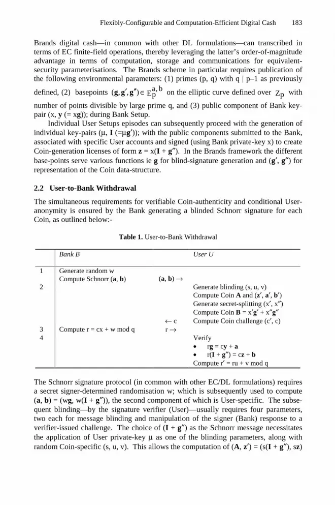
Flexibly-Configurable and Computation-Efficient Digital Cash 183
Brands digital cash—in common with other DL formulations—can transcribed interms of EC finite-field operations, thereby leveraging the latter’s order-of-magnitudeadvantage in terms of computation, storage and communications for equivalent-security parameterisations. The Brands scheme in particular requires publication ofthe following environmental parameters: (1) primes (p, q) with q | p–1 as previously
defined, (2) basepoints a, b( , , ) Ep′ ′′ ∈g g g on the elliptic curve defined over Zp with
number of points divisible by large prime q, and (3) public component of Bank key-pair (x, y (= xg)); during Bank Setup.
Individual User Setups episodes can subsequently proceed with the generation ofindividual key-pairs (µ, I (=µg′)); with the public components submitted to the Bank,associated with specific User accounts and signed (using Bank private-key x) to createCoin-generation licenses of form z = x(I + g″). In the Brands framework the differentbase-points serve various functions ie g for blind-signature generation and (g′, g″) forrepresentation of the Coin data-structure.
2.2 User-to-Bank Withdrawal
The simultaneous requirements for verifiable Coin-authenticity and conditional User-anonymity is ensured by the Bank generating a blinded Schnorr signature for eachCoin, as outlined below:-
Table 1. User-to-Bank Withdrawal
Bank B User U
1 Generate random wCompute Schnorr (a, b) (a, b) →
2
← c
Generate blinding (s, u, v)Compute Coin A and (z′, a′, b′)Generate secret-splitting (x′, x″)Compute Coin B = x′g′ + x″g″Compute Coin challenge (c′, c)
3 Compute r = cx + w mod q r →4 Verify
• rg = cy + a• r(I + g″) = cz + bCompute r′ = ru + v mod q
The Schnorr signature protocol (in common with other EC/DL formulations) requiresa secret signer-determined randomisation w; which is subsequently used to compute(a, b) = (wg, w(I + g″)), the second component of which is User-specific. The subse-quent blinding—by the signature verifier (User)—usually requires four parameters,two each for message blinding and manipulation of the signer (Bank) response to averifier-issued challenge. The choice of (I + g″) as the Schnorr message necessitatesthe application of User private-key µ as one of the blinding parameters, along withrandom Coin-specific (s, u, v). This allows the computation of (A, z′) = (s(I + g″), sz)

184 A. Goh, K.W. Yip, and D.C.L. Ngo
and (a′, b′) = (ua + vg, sub + vA). Parameter A can be regarded as the User-specificpart of the Coin, while (z′, a′, b′) are components of the (as yet incomplete) signature.
Encoding of the User secret into the Coin is established randomly generated fac-tors (x′, x″) and B. The latter constitutes a User-to-Bank commitment on the specificCoin, and is later used for the verification of the challenge-response pair during Pay-ment. This is followed by computation of unblinded c′ = h(A, B, z′, a′, b′) and
blinded 1c c mod qu−′= challenge parameters, both of which are Coin-specific and
the latter of which is then presented to the Bank for blind-signature affixation. All ofcomputations thus far constitute pre-transaction operations which can, in fact, beexecuted (and the generated parameters stored) prior to an actual Withdrawal episoderesulting in User account-debit. This speeds up Coin-generation to a significant ex-tent, which consequently only requires the User-to-Bank challenge-response sequencein the last two steps of Table 1 for satisfactory conclusion.
A proper response r to blinded challenge c would require knowledge—presumedas restricted to the Bank—of private-key x and transaction parameter w. Such a re-sponse for blinded message (z, a, b, c) can be verified using Bank public-key y andenables construction of unblinded signature σ(A, B) = (z′, a′, b′, r′), following whichthe Bank can be safely authorised to execute the account-debit. The interpretation forσ(A, B) as a blind-signature can be seen from the Bank not knowing (A, B), in con-junction with the dependence of third-party (Merchant) verification condition (r′g,r′A) = (c′y + a′, c′z′ + b′) on Bank public-key y. Coin χ = (A, B, σ(A, B)) is henceverifiably authentic, while also entirely protective of User anonymity.
2.3 User-to-Merchant Payment
Coin χ can subsequently be used for Payment as follows:-
Table 2. User-to-Merchant Payment
U Compute challenge ( )c h , , ,Tm= A B ICompute response (r′, r″) for c
↓ χ(A, B), T, (r′, r″)
MerchantM
Verify Bank signature σ(A, B)Compute challenge cVerify response r′g′ + r″g″ = cA + B
Note the Payment-specific non-interactive challenge c—which incorporates MerchantID mI and external specifier (ie timestamp) T—the correct response for which is (r′,r″) = (c(µs) + x′, cs + x″). The response: (1) encodes µ and Coin-specific blindingfactor s, while (2) concealing s; thereby facilitating recovery of the User secret (andconsequently identity I) with two or more of the challenge-response pairs submittedduring the subseqeuntly described Deposit. User anonymity is therefore conditionalon proper use ie not more than one Payment per Coin.

Flexibly-Configurable and Computation-Efficient Digital Cash 185
2.4 Merchant-to-Bank Deposit
Deposit is simply Merchant-to-Bank submission of the Coin and Payment-specificcommitment χ′(A, B) = (χ(A, B), (c, r′, r″)), as outlined below:
Table 3. Merchant-to-Bank Deposit
M ↓ χ′ (A, B)B Verify own signature σ(A, B)
Verify response r′g′ + r″g″ = cA + BCheck for over-use of σ(A, B)If detected, then:-
• Compute r
r
′ ′− ρµ =′′ ′′− ρ
• Compute I = µg′ for identification
with (ρ′, ρ″) some previously catalogued response in the Bank database, threby ena-bling detection of double spending. There are three types of fraud which can be at-tempted on a particular Coin, with multiple responses that are: (1) identical, (2) non-identical but non-verifiable, and (3) non-identical and verifiable. The first two casescan probably be attributed to Merchant error or fraud, with User non-liability in (2)due to malformation of the commitments. Case (3) is User double-spending sincevalid commitments can only be computed by the User, whose anonymity is the re-voked via recovery of key-pair (µ, I) from multiple Payment-specific responses.
3 Review of Polynomial Secret-Sharing
Our scheme is based on the division of the Brands’ Coin to multiple sub-Coins viapolynomial secret-sharing (SS). Initial setup requires selection of a configurablethreshold (k) so that the secret—in our particular case the User-identity—can be besplit into an arbitrary (n) number of shares, with secret-reconstruction necessitatingpossession of k+1 (or more) shares. On the other hand, possession of k (or less)shares is cryptographically equivalent to knowing nothing about the divided secret,hence preserving User anonymity.
There are various encoding schemes for such divided secrets, with the moststraightforward (due to Shamir) based on polynomial interpolation over a finite field.
In such a scheme a k-th degree polynomial k
if (x) mod qb xii 0
= ∑=
is used to encode
secret f (0) b0= , with the remaining k coefficients b Zqi ∈ (for i ≠ 0 and q prime)
randomly generated and kept secret by the User. The Coin-specific polynomial isthen recoverable via Lagrange interpolation given k+1 distinct (x, f(x)) coordinatepairs on the polynomial-defined curve, enabling polynomial reconstruction
( )kk x x j
f (x) f mod qxix xi ji 0 j 0, i
− = ∑ ∏
− = = ≠ and subsequent recovery of secret f(0).

186 A. Goh, K.W. Yip, and D.C.L. Ngo
Polynomial-based SS is attractive due to the inherent threshold property preventingthe manipulation of k (or less) (x, f(x)) shares for any useful information on the en-coding polynomial.
Shamir SS does, however, assume honest share allocation by the User, which isoperationally unrealistic. The disclosed shares must therefore be verifiable, therebyallowing receivers to validate share association with the secret polynomial. This canbe established via Pedersen verified SS (VSS) which represents both the secret and itsshares in terms of EC/DL images, thereby resulting in ZK share-verification. The
Pedersen formalism—expressed in terms of EC operations with respect a, bEp∈g —
requires prior disclosure of polynomial commitments bii = g , thereby allowing ZK
polynomial evaluation via k k
i if (x) bx xiii 0 i 0
⋅ = = ⋅∑ ∑= =
g g . This enables a Merchant
to verify the legitimacy of an individual share (sub-Coin) with respect a Coin-specificsecret, without acquiring cryptographically useful information on the Coin and conse-quently the User. This results in User anonymity preservation unless there are if k+1(or more) distinct sub-Coins (Payments) corresponding to a k-term Coin.
Polynomial SS is an elegant mechanism with which to implement Coin divisibil-ity into the Brands digital cash protocol. Note this results in both divisibility andconditional-anonymity mechanisms being based on EC operations, in contrast to pre-vious formulations with Coin divisibility based on QR/IF cryptography. Our ap-proach also enables interpretation of Brands conditional-anonymity—which isrevoked from two distinct challenge-response pairs—as a special case with linear(k=1) polynomials.
4 Poly-Cash: k-Divisible Polynomial-Based Coins
Incorporation of polynomial divisibility requires requires extending the above-outlined Withdrawal, Payment and Deposit operations—for single-term BrandsCoins—as follows:
4.1 Coin Withdrawal
Coin-specific polynomials f(x) (of degree k) can be used to encode User identity ieb0 = µ , with the remaining coefficients randomly generated and kept secret by the
User. k-term Coin-generation therefore entails generation of polynomial coefficients
and their EC images ie ( )( ),b bi ii ′′= g for i = 0…k., with integration into the Brands
formulation via specification of Coin-parameter h ii
= ∏ ∀
B . This constitutes a
User-to-Bank commitment on the Coin-specific polynomial which (if over-spent) cansubsequently be used for secret-recovery.
Withdrawal and Coin-generation then proceeds as follows:

Flexibly-Configurable and Computation-Efficient Digital Cash 187
Table 4. Coin Withdrawal
B U
1 Generate random wCompute Schnorr (a, b) (a, b) →
2
← c
Generate blinding (s, u, v)Compute Coin A and (z′, a′, b′)Generate secret-splitting (x′, x″)
Compute Coin B from iCompute Coin challenge (c′, c)
3 Compute r = cx + w mod qr →
4Verify• rg = cy + a• r(I + g″) = cz + bCompute r′ = ru + v mod q
with a heavier computation overhead (by a factor of k
2) for the computation of B.
The first two steps are—in common with the base-formulation of Table 1—precom-putable, the result of which is improved efficiency compared to Withdrawal of k dis-tinct single-term Coins.
4.2 Sub-coin(s) Payment
Note the essential similarity of Tables 1 and 4, which differ only in the construction ofthe B component of Coin χ. The subsequently outlined Payment and Deposit, on the
other hand, must now deal with sub-Coins—of value 1
k in relation to k-term Coin
χ—as the fundamental transactional unit. The basic concept is to commit each sub-Coin Payment via disclosure of a Shamir polynomial share, which can then be ZK-verified (by the Merchant) using the Pedersen formalism. This necessitates Userdisclosure of Coin χ and polynomial-commitments , both of which are verifiable viaσ(A, B). A single share of the encoded secret is hence (c, r (= f(c))), which is verifi-
able via k
r ci ii 0
′′ = ∑=
g . Note that knowledge of polynomial-coefficients b is re-
quired for proper construction of verifiable responses, thereby restricting Payment tothe legitimate User.
Payment then proceeds as follows:

188 A. Goh, K.W. Yip, and D.C.L. Ngo
Table 5. Sub-Coin Payment
U Compute sub-Coins (c, r) j
, , (T, r)i j↓ χ
M Verify Bank signature σ(A, B)
Verify Coin polynomial i
Verify sub-Coin shares (c, r) j
and can be repeated to transfer n sub-Coins—for n = 1…k and with a relative value ofn
k—via computation of n challenge-response pairs of form (c, r) j for j = 1…n. Note
the incorporation of non-interactive challenges ( )h , , ,c Tm jj = A B I —with mI and
T j as previously specified—resulting in a simplified transactional framework. Pay-
ment using multiple sub-Coins divided from a k-term Coin (with reuse of all stepsinvolving χ and ) is also more efficient than the alternative of several equally-denominated single-term Coins. Successful Payment results in Merchant possession
of User-commitment on n sub-Coins of form ( )( , ) , , (c, r)i j′χ = χA B , the Deposit of
which is subsequently described. The computation complexity for a single sub-Coin
only involves generation of the challenge-response pair, which requires k(k 1)
2
+
modular multiplications with k a small (by cryptographic standards) integer. An aver-
age case of k
2 sub-Coins per Payment would therefore result in an overhead of
2(k 1)k4
+ modular multiplications.
4.3 Sub-coin(s) Deposit
Digital cash protocols are specifically designed to preserve User-anonymity in theevent of legitimate Coin usage, which in our formulation is specified by the Bank not
having a priori knowledge of Coin details ( ), , iA B and additionally by the number
of sub-Coins being below the recovery threshold. Over-Payment associated with a k-term Coin (by a particular User) is detectable by the Bank via scrutiny of χ′(A, B)Deposit data for possible accumulation of k+1 (or more) distinct and verifiable shares.These (c, r) j shares can then be combined (using Lagrange interpolation) by the
Bank, resulting in knowledge of the Coin-specific f(x) and subsequently identificationof the overspending User via (µ, I) computation.
The following Deposit process:-

Flexibly-Configurable and Computation-Efficient Digital Cash 189
Table 6. Sub-Coin Deposit
M ↓ χ′ (A, B)
B Verify own signature σ(A, B)
Verify Coin commitments i
Verify sub-Coins (c, r) jCheck for over-use of (A, B)If detected, then:-• Recover Coin f(x)• Compute (µ, I) for identification
leads (barring detection of fraud) to Merchant account-credit by n
k the value of Coin
χ. Note the emphasis on a posteriori detection of User fraud; which contrasts with thein situ prevention of Merchant or third-party fraud, both of which are effectively ruledout by the necessity for verifiable sub-Coin commitment. The Brands protocol canactually be extended to include User-side Observer modules for User fraud prevention(as opposed detection) at the expense of additional computation. The incorporation ofVSS-based divisibility as outlined in this document is designed to ensure Coin-structural compatibility with respect the Brands framework, thereby allowing forObserver-based fraud preventive measures.
The featured protocol does, however, allow the Bank to establish a posteriori sub-Coin (same Withdrawal, different Payments) level linkages; even when User ano-nymity is not revoked. This trait is also present in the Brands and Okamoto formula-tions, but not in the Chan et al protocol due to its elimination and downward-movement of the User Setup procedure into the Withdrawal operation. Such a strat-egy is somewhat at odds with one of the important motivations for divisible cash ie toreduce per-Payment overheads related to Withdrawal, which is particularly heavy dueto the complexity of conditional anonymity enablement and User identity encodinginto individual Coin. Note that our scheme can also be rendered unlinked via use ofCoin-specific identities, as in the Chan et al formulation. The most practical resolu-tion of this issue is, however, operational in nature via periodic refreshment (via UserSetup repetition) of identity vector (µ, I, z).
5 Comparative Analysis
We compare the performance of the above-outlined EC-based k-term scheme withequivalent-security [11] parameterisations of previously published protocols. Thisamounts to 160-bit moduli-lengths for our EC formulation being equivalent (at cur-rently accepted equivalent security levels) to 1024-bit moduli-lengths for DL-basedschemes ie Brands, Okamoto and Chan et al. Equivalent-security considerations alsorequires parameter-length adjustments ie standardisation of Okamoto’s (P, Q, N, n, b)to (512, 512, 1024, 1024, 128) and an upgrade of Chan-Frankel-Tsiounnis’ (P, Q, N,p, q) to (512, 512, 1024, 1024, 512).

190 A. Goh, K.W. Yip, and D.C.L. Ngo
Comparison of DL and EC overheads requires cross-calibration of the two mostsignificant operations for each formalism ie DL multiplication (Mult) vs EC pointaddition (PA) and DL exponentiation (Exp) vs EC scalar multiplication (SM). Thecomputational costs of these operations is analysed in [11, 12] and can be summarisedas follows:-
• Mult: 2plg
• Exp (via Repeated Squaring): 2lg q plg⋅
• PA: 3.5 Mults and one modular-inversion, which costs 2plg
• SM (via Addition-Subtraction): lg p doublings/PAs and plg
2 PAs
Note the EC operations presume a shorter moduli-length. This leads to evaluation ofthe relative Mult-to-PA overheads [12] as approximately 9 at the equivalent setting of(DL, EC) = (1024, 160)-bit, with an increase to 23 for the more rigorous (2048, 200)-bit [11] setting. Similar analysis establishes a Exp-to-SM ratios [12] of approximately6 at the regular-security setting, with an increase to 15 at the high-security setting.The relatively small increase in the EC moduli-lengths can be attributed to its expo-nential effect on computational security, as opposed increases in DL/IF moduli-lengths resulting in much less dramatic sub-exponential enhancements.
Our analysis examines the computation, storage and communications overheadsin terms of the leading-order significant operations (mostly Exp and SM); and pre-sumes pre-computation whenever allowed by the respective protocols. We also adjustfor the continuous divisibility of QR-tree based Coins via assignment of an averageheight h (=lg k). The real-time overheads of the (1) Okamoto, (2) Chan et al, (3)Brands and (4) Poly-cash schemes are summarised as follows:-
Table 7. Computation, Storage and Bandwidth Overheads of Various Schemes
Computation Storage Communications
1, 2 4lg P P Exp(P)⋅ ⋅ 2|N|+|P|+|Q| 4lg P P⋅3 2 Exp (p) |p| |p|
User Setup
4 2 SM (p) |p| |p|
1 2 Exp (N) 2|N|+|P|+|Q| 2|N|
2 12 Exp (N) 2|p|+|q|+2|P| 3|p|+2|q|
3 6 Exp (p) 5|p|+|q| 2|p|+2|q|
Withdrawal
4 6 SM (p) 6|p| 4|p|
1 (h+1) exp (N) |N|*(h+1) |N|*(h+1)
2 (h+1) exp (N) |N|*(h+1) |N|*(h+1)3 2 Mult (q) 3|q| 3|q|
Payment
4 k(k+1) Mul (p) k|p| 2k|p|

Flexibly-Configurable and Computation-Efficient Digital Cash 191
with respective Coin bit-lengths of:
1. 3|N|+|b|+|P|+|Q| (=424)2. 2|p|+|q|+2|P| (=4636)3. 5|p|+|q| (=960)4. 6|p| (=960) for decimal (k=10) divisibility
Poly-cash can be seen to have the most efficient Setup and Withdrawal processes,with the most striking comparison in case being with respect Okamoto and Chan et al.This illustrates the usefulness of an EC-compatible divisibility mechanisms, as op-posed the alternative of tree-node sub-Coins based on QR/IF cryptography. TheSetup and Withdrawal processes are, in fact, essentially as efficient as an EC tran-scription of the Brands protocol, with negligible additional overheads arising fromCoin divisibility. Note also the relatively modest sub-kbit size of the k-term Coin,thereby facilitating implementation of Coin-carrying Purses on lightweight handheldplatforms.
Divisible Coins are specifically intended to amortise a particular Withdrawaloverhead over multiple Payments, hence the most interesting analysis being from thatviewpoint. Such schemes are predicated on the efficiency of Sub-Coin verification,which was the motivation for divisibility based on QR-trees. The intrinsic logarith-mic efficiency and continuous divisibility of formulations based on QR-trees willeventually prevail for large divisibility (k) configurations. EC-based Poly-cash islinearly efficient with respect k; and is therefore expected to be advantageous forsmall values of k due to the previously discussed DL-to-EC operational ratios.
We found that our formulation to result in more efficient Payments—at least forpractical divisibilities ie k~10—at the moderate (DL, EC) = (1024, 160)-bit equiva-lency setting. The computation and communications overheads for increasing k isillustrated below:
Computation Overhead vs Number of Sub-Coins for EC Keysize = 104 and DL Keysize
(p,q)=(512,160) During Payment
0.E+00
1.E+08
2.E+08
3.E+08
4.E+08
5.E+08
6.E+08
7.E+08
8.E+08
1 6 11 16 21 26 31
Number of Sub-Coins, k
Co
mp
uta
tio
n
poly-cash Okamoto/Chan-et-al
Communication/Storage Overhead vs Number of Sub-Coins for EC Keysize=160 and DL
Keysize (p,q)=(1024, 180) During Payment
0.E+00
2.E+03
4.E+03
6.E+03
8.E+03
1.E+04
1 6 11 16 21 26 31
Number of Sub-Coins, n
Bit
Usa
ge
poly-cash Okamoto/Chan-et-al Brands
Fig. 2. (a) Computation and (b) communications overheads at moderate equivalent-securityconfigurations

192 A. Goh, K.W. Yip, and D.C.L. Ngo
Note from Fig 2(a) that the equal-efficiency (crossover) point is not even on thegraph, hence the lower computational overheads of Poly-cash even for fairly extremedivisibility settings. The crossover point in Fig 2(b), on the other hand, occurs around
k~16, which is still desirable as it exceeds the practical k=10 configuration with dime-sized sub-Coins. Comparison of communications overheads at the (2048, 200)-bithigh-security equivalency setting, as follows:-
Communication/Storage Overhead vs Number of Sub-Coins for EC Keysize=200 and DL Keysize (p,q)=(2048,200) During
Payment
0.E+00
4.E+03
8.E+03
1.E+04
1 6 11 16 21 26 31
Number of Sub-Coins, n
Bit
Usa
ge
poly-cash Okamoto/Chan-et-al Brands
Fig. 3. Communications Overheads at High Equivalent-Security Settings
right-shifts the cross-over point to k~31, thereby demonstrating the relative efficiencyof k=20 divisibility with nickel-sized sub-Coins.
6 Concluding Remarks
Polynomial thresholding is an elegant Coin-divisibility mechanism, and enables anefficient EC realisation impossible with the earlier QR-tree methodology. The com-bination of polynomial divisibility, an extended Brands operational framework and anEC implementation results in significant performance advantages (at equivalent-security parameterisations) compared to previous protocols. The flexible k-term di-visibility is also preferable to the more rigid binarised denominations of the QR-treeformalism, especially with respect straightforward integration into existing tradingand financial frameworks.
This and other digital cash protocols constitute viable alternatives to existingelectronic payment systems, which typically require expensive Merchant-Bank con-nectivity during Payment. Offline Coin verifiability also lowers the operational over-head of Bank- side account management. User conditional anonymity also facilitatesconsumer privacy (without jeopardising fraud detectability) to an extent impossiblewith typical payment solutions.

Flexibly-Configurable and Computation-Efficient Digital Cash 193
References
1. D Chaum, A Fiat & M Noar. “Untraceable Electronic Cash”. Crypto 88, Springer-VerlagLecture Notes in Comp Sc (LNCS) (1988).
2. S Brands. “Untraceable Off-Line Cash in Wallets with Observers”. Crypto 93, Springer-Verlag LNCS (1993).
3. S Brands. “An Efficient Off-line Electronic Cash System based on the RepresentationProblem”. Tech Rep CS-R9323, CWI (1993)
4. T Okamoto & K Ohta. “Universal Electronic Cash”. Crypto 91, Springer-Verlag LNCS(1991)
5. T Okamoto. “An Efficient Divisible Electronic Cash Scheme”. Crypto 95, Springer-Verlag LNCS (1995)
6. Chan, A., Frankel, Y. & Tsiounnis, Y., “Easy come- easy go divisible cash”, EuroCrypt98, Springer-Verlag LNCS (1998)
7. N Ferguson. “Extensions of Single-Term Coins”. Crypto 93, Springer-Verlag LNCS 773,pp 292-301(1993)
8. A Shamir. “How to Share a Secret”. ACM Comms (1979)9. P Feldman. “A Practical Scheme for Non-Interactive VSS”. IEEE Symp Foundations
Comp Sc (1987)10. TP Pedersen. “Non-Interactive and Information-Theoretic Secure VSS”. Crypto 91,
Springer-Verlag LNCS (1991)11. Menezes, A., “Comparing the security of ECC and RSA”, at www.certicom.com, 11 Jan
(2000)12. P1363/D13, Draft Version 13, Standard Specification for PKC (1999)13. WK Yip, “Divisible Digital Cash via Secret Sharing Schemes”, Masters in Comp Sc The-
sis, Universiti Sains Malaysia (2001)

Selective Encryption of the JPEG2000 Bitstream
Roland Norcen and Andreas Uhl
Department of Scientific Computing, Salzburg University,Jakob-Haringer-Str. 2, A-5020 Salzburg, Austria
Abstract. In this paper, we propose partial encryption of JPEG2000coded image data using an AES symmetric block cipher. We find thatencrypting 20% of the visual data is sufficient to provide a high levelof confidentiality. This percentage of encryption also provides securityagainst replacement attacks, which is discussed at length.
Introduction
Images and videos (often denoted as visual data) are data types which requireenormous storage capacity or transmission bandwidth due to the large amountof data involved. In order to provide reasonable execution performance for en-crypting such large amounts of data, only symmetric encryption (as opposedto public key cryptography) can be used. The Advanced Encryption StandardAES [3] is a recent symmetric block cipher potentially used in such applications.Nevertheless, real-time encryption of an entire video stream using such symmet-ric ciphers requires much computation time due to the large amounts of datainvolved.
Since many multimedia applications require security on a low level (e.g. TVbroadcasting [6]) or should protect their data just for a short period of time (e.g.news broadcast), faster encryption procedures specifically tailored to the targetenvironment should be designed for such multimedia security applications.
A good step in this direction is the introduction of a “soft“ encryption scheme.Such a scheme does not strive for maximum security and trades off security forcomputational complexity.
Selective or partial encryption (SE) of visual data is an example for such anapproach. Here, application specific data structures are exploited to create moreefficient encryption systems (see e.g. SE of MPEG video streams [1,5,10,11,13,19], of wavelet-based encoded imagery [2,4,8,9,18,19], and of quadtree decom-posed images [2]). Consequently, SE only protects (i.e. encrypts) the visuallymost important parts of an image or video representation relying on a securebut slow “classical” cipher.
In this work we discuss the selective encryption of JPEG2000 coded imagedata using an symmetric AES cipher. Section 1 introduces the JPEG2000 algo-rithm with a special focus on the bitstream assembling part, since this is thestarting point for our selective encryption approach. Then, in section 2, our par-tial encryption scheme of the JPEG2000 bitstream is presented and the obtainedresults are discussed in detail with emphasis on the achieved security.
A. Lioy and D. Mazzocchi (Eds.): CMS 2003, LNCS 2828, pp. 194–204, 2003.c© IFIP International Federation for Information Processing 2003

Selective Encryption of the JPEG2000 Bitstream 195
(a) Lena (256 × 256 and 512 × 512pixels)
(b) Angiogram (512 × 512 pixels)
Fig. 1. Testimages used in the experiments
In Fig. 1 we display the testimages which we use in our experiments. We havedecided to discuss the encryption efficiency of our proposed partial encryptionscheme with respect to two different classes of visual image data. The first classof visual data discussed is typical still image data and the testimage representingthis class is the lena image (see Fig. 1.a) at different resolutions including 256×256 and 512×512 pixels. Since this special type of visual data is usually encodedin lossy mode, the lena image is lossy coded in our experiments (at a fixed rateof 2 bpp). The second type of digital visual data should represent an applicationclass where lossless coding is important. We have therefore decided to use anangiogram as testimage in this case (see figure 1.b), since angiograms representan important class of medical image data where lossless coding is usually amandatory requirement.
In order to make the explanations and experiments of the proposed tech-niques simpler, we assume the testimages to be given in 8bit/pixel (bpp) preci-sion and in a squared format. Extensions to images of different acquisition types(e.g. [17]), higher bitdepth or non-squared format are straightforward.
1 JPEG2000
Image compression methods that use wavelet transforms [16] (which are based onmultiresolution analysis – MRA) have been successful in providing high compres-sion ratios while maintaining good image quality. Therefore, they have replaced

196 R. Norcen and A. Uhl
DCT based techniques in recent standards for still image coding: JPEG2000 [15]and VTC (visual texture coding in MPEG-4 [12]).
The JPEG2000 image coding standard is based on a scheme originally pro-posed by Taubman and known as EBCOT (“Embedded Block Coding with Op-timized Truncation” [14]). The major difference between previously proposedwavelet-based image compression algorithms such as EZW or SPIHT (see [16]) isthat, after performing a global wavelet transform, EBCOT as well as JPEG2000operate on independent, non-overlapping blocks of transform coefficients whichare coded in several bit layers to create an embedded, scalable bitstream. Insteadof zerotrees, the JPEG2000 scheme depends on a per-block quad-tree structuresince the strictly independent block coding strategy precludes structures acrosssubbands or even code-blocks. These independent code-blocks are passed downthe “coding pipeline” shown in Fig. 2 and generate separate bitstreams. Thewavelet coefficients inside a code-block are processed from the most significantbitplane towards the least significant. Furthermore, in each bitplane the bits arescanned in a maximum of three passes called coding passes. Finally, during eachcoding pass, the scanned bits with their context value are sent to a context-based adaptive arithmetic encoder that generates the code-block’s bitstream.This procedure is called Tier-1 encoding.
RateAllocation
codedimage
inherently parallel onindep. code blocks
TransformWavelet
SetupI/O,
sourceimage
Entropy coding pipelinein several stages (Quantization, ROI Scaling, Arithmetic Coding, ...)
Fig. 2. JPEG2000 coding pipeline
The rate-distortion optimal merging of these bitstreams into the final oneis based on a sophisticated optimization strategy and is called Tier-2 encoding.This last procedure carries out the creation of the so-called layers which roughlystand for successive qualities at which a compressed image can be optimallyreconstructed. These layers are built in a rate-allocation process that collects,in each code block, a certain number of coding-passes codewords. Hence, in acode-block, the bitstream is distributed into a certain number of layers.
The final JPEG2000 bitstream is organized as follows: A set of differentmain headers (including a main header (SIZ), a coding style header (COD), aquantization header (QCD), a comments header (COM), a start of a tile partsheader (SOT)) is followed by packets of data which are all preceded by a packetheader. In each packet appear the codewords of the code-blocks that belong tothe same image resolution and layer, the header identifies the data. Dependingon the arrangement of the packets, different progression orders may be specified.Among others, resolution and layer progressive are most important for grayscale

Selective Encryption of the JPEG2000 Bitstream 197
images. In layer progression order, the packets corresponding to the first layerare arranged first and cover data contained in all resolutions, followed by packetscorresponding to the second layer and so on. Vice versa, in resolution progressionorder the packets corresponding to the first resolution level are arranged first(these contain data of all layers).
2 Selective Encryption of JPEG2000 Coded Data
For selectively encrypting the JPEG2000 bitstream we have two general options.First, we do not care about the structure of the bitstream and simply encrypt apart, e.g. the first 10% of the bitstream. In this case, the main header and a coupleof packets including packet header and packet data are encrypted. Since basicinformation necessary for reconstruction usually located in the main header isnot available at the decoder, encrypted data of this type can not be reconstructedusing a JPEG2000 decoder. Although this seems to be desirable at first sight, anattacker could reconstruct the missing header data using the unencrypted parts,and, additionally, no control over the quality of the remaining unencrypted datais possible. Therefore, the second option is to design a JPEG2000 bitstreamformat compliant encryption scheme which does not encrypt main and packetheader but only packet data. This is what we propose in the following.
In order to achieve format compliance, we need to access and encrypt dataof single packets. Since the aim is to operate directly on the bitstream with-out any decoding we need to discriminate packet data from packet headers inthe bitstream. This can be achieved by using two special JPEG2000 optionalmarkers which were originally defined to achieve transcoding capability, i.e. ma-nipulation of the bitstream to a certain extent without the need to decode data.Additionally, these markers of course increase error resilience of the bitstream.These markers are “start of packet marker” (SOP - 0xFF91) and “end of packetmarker” (EPH - 0xFF92). The packet header is located between SOP and EPH,packet data finally may be found between EPH and the subsequent SOP. Forexample, using the official JAVA JPEG2000 reference implementation (JJ2000 -available at http://jj2000.epfl.ch) the usage of these markers may be easilyinvoked by the options -Peph on -Psop on.
Having identified the bitstream segments which should be subjected to en-cryption we note that packet data is of variable size and does not at all adhereto multiples of a block ciphers block-size. We have to employ AES in CFB modefor encryption, since in this mode, an arbitrary number of data bits can beencrypted, which is not offered by the ECB and CBC encryption modes. Infor-mation about the exact specification of the cryptographic techniques used (e.g.key exchange) may be inserted into the JPEG2000 bitstream taking advantageof so-called termination markers. Parts of the bitstream bounded by termina-tion markers are automatically ignored during bitstream processing and do notinterfere with the decoding process. Note that a JPEG2000 bitstream which isselectively encrypted in the described way is fully compliant to the standard

198 R. Norcen and A. Uhl
and can therefore be decoded by any codec which adheres to the JPEG2000specification.
We want to investigate whether resolution progressive order or layer progres-sive order is more appropriate for selective JPEG2000 bitstream encryption. Wetherefore arrange the packet data in either of the two progression orders, encryptan increasing number of packet data bytes, reconstruct the images and measurethe corresponding quality.
7
7.5
8
8.5
9
9.5
10
10.5
11
0 500 1000 1500 2000 2500 3000 3500 4000 4500 5000
PS
NR
no. first bytes coded
reslayer
Fig. 3. Angiogram: Comparison of selective encryption (PSNR of reconstructed im-ages) using resolution or layer progressive encoding - part 1.
9
10
11
12
13
14
15
16
17
18
19
0 500 1000 1500 2000 2500 3000 3500 4000 4500 5000
PS
NR
first bytes replaced
reslayer
(a) Lena 256 × 256 pixels
8
9
10
11
12
13
14
0 500 1000 1500 2000 2500 3000 3500 4000 4500 5000
PS
NR
first bytes replaced
reslayer
(b) Lena 512 × 512 pixels
Fig. 4. Comparison of selective encryption (PSNR of reconstructed images) using res-olution or layer progressive encoding - part 2.
Resolution progression is more suited for selectively encrypting the angiogramimage at higher rates of encrypted data (see Fig. 3, where a lower PSNR means

Selective Encryption of the JPEG2000 Bitstream 199
that it is more suited for selective encryption). In order to relate the obtainednumerical values to visual appearance, two reconstructed versions of the an-giogram, corresponding to the two progression orders, are displayed in Fig. 5. Inboth cases, 1% of the entire packet data has been encrypted.
Whereas no details are visible using layer progression (Fig. 5.a at 8.79 dB),only very high frequency visual information (right lower corner) is visible usingresolution progression (Fig. 5.b at 7.45 dB).
When considering the Lena image in Fig. 4, we observe that resolution pro-gression shows superior PSNR results for both tested image dimensions as com-pared to layer progression. Two reconstructed versions of the Lena image with512 × 512 pixels, corresponding to the two progression orders, are displayed inFig. 6. In each case, 1% of the entire packet data has been encrypted. Whereasonly very high frequency information is visible in the reconstructed image usinglayer progression (Fig. 6.a at 8.51 dB), important visual features are visible us-ing resolution progression (Fig. 6.b at 10.11 dB). In this case, the visible highfrequency information is enough to reveal sensible data. At 2 percent encryptedpacket data, this information is destroyed fully in the resolution progressive case.
The lena image at lower resolution (256× 256 pixels) performs equally, andthe results are therefore only given for the 5122 pixels version.
(a) layer progressive, 8.79 dB (b) resolution progressive, 7.45 dB
Fig. 5. Comparison of selective encryption (visual quality of reconstructed Angiogramwhere 1% of the bitstream data have been encrypted) using resolution or layer pro-gressive encoding.
Please note also the difference in coarseness of the noise pattern resultingfrom encryption between resolution and layer progression. Since in resolution
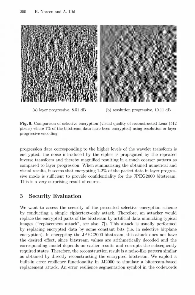
200 R. Norcen and A. Uhl
(a) layer progressive, 8.51 dB (b) resolution progressive, 10.11 dB
Fig. 6. Comparison of selective encryption (visual quality of reconstructed Lena (512pixels) where 1% of the bitstream data have been encrypted) using resolution or layerprogressive encoding.
progression data corresponding to the higher levels of the wavelet transform isencrypted, the noise introduced by the cipher is propagated by the repeatedinverse transform and thereby magnified resulting in a much coarser pattern ascompared to layer progression. When summarizing the obtained numerical andvisual results, it seems that encrypting 1-2% of the packet data in layer progres-sive mode is sufficient to provide confidentiality for the JPEG2000 bitstream.This is a very surprising result of course.
3 Security Evaluation
We want to assess the security of the presented selective encryption schemeby conducting a simple ciphertext-only attack. Therefore, an attacker wouldreplace the encrypted parts of the bitstream by artificial data mimicking typicalimages (“replacement attack”, see also [7]). This attack is usually performedby replacing encrypted data by some constant bits (i.e. in selective bitplaneencryption). In encrypting the JPEG2000-bitstream, this attack does not havethe desired effect, since bitstream values are arithmetically decoded and thecorresponding model depends on earlier results and corrupts the subsequentlyrequired states. Therefore, the reconstruction result is a noise-like pattern similaras obtained by directly reconstructing the encrypted bitstream. We exploit abuilt-in error resilience functionality in JJ2000 to simulate a bitstream-basedreplacement attack. An error resilience segmentation symbol in the codewords

Selective Encryption of the JPEG2000 Bitstream 201
at the end of each bit-plane can be inserted. Decoders can use this informationto detect and conceal errors. This method is invoked in JJ2000 encoding usingthe option -Cseg_symbol on.
If an error is detected during decoding (which is of course the case if data isencrypted) it means that the bit stream contains some erroneous bits that haveled to the decoding of incorrect data. This data affects the whole last decodedbit-plane. Subsequently, the affected data is concealed and no more passes shouldbe decoded for this code-block’s bit stream. The concealment resets the state ofthe decoded data to what it was before the decoding of the affected bit-planestarted. Therefore, the encrypted packets are simply ignored during decoding.
Using this technique, we again compare selective JPEG2000 encryption usingresolution and layer progressive mode by reconstructing images with a differentamount of encrypted packets. Decoding is done using error concealment. In Fig. 7and 8 we immediately recognize that the PSNR values are significantly higher ascompared to directly reconstructed images (see Fig. 3 and 4). Layer progressionis more suited for selectively encrypting the angiogram image. For the lena testimages, the situation differs slightly: When encrypting only minor parts of theoverall bitstream, layer progression is superior, at higher rates of encryption, theresolution progression scheme shows superior results.
9
9.2
9.4
9.6
9.8
10
10.2
10.4
10.6
10.8
11
11.2
0 2000 4000 6000 8000 10000
PS
NR
first bytes replaced
reslayer
Fig. 7. Angiogram: PSNR of reconstructed images after replacement attack using res-olution or layer progressive encoding - part 1.
Again, the numerical values have to be related to visual inspection. Fig. 9.ashows a reconstruction of the selectively compressed angiogram image, wherethe first 1% of the packets in resolution progressive mode have been encryptedand the reconstruction is done using the error concealment technique. In thiscase, this leads to a PSNR value of 10.51 dB, whereas the directly reconstructedimage has a value of 7.45 dB (see Fig. 5.b). The text in the right corner isclearly readable and even the structure of the blood vessels is exhibited. The lenaperforms similarly (see Fig. 10.a), all important visual features are reconstructed

202 R. Norcen and A. Uhl
at 1% encrypted. Here, we have a resulting PSNR of about 11.31 db, whereasthe directly reconstructed image has a value of 10.11 dB (see Fig. 6.b).
When increasing the percentage of encrypted packet data steadily, we finallyresult in 20% percent of the packet data encrypted where neither useful visualnor textual information remains in the image (see Fig. 9.b and 10.b). This resultis confirmed also with other images including other angiograms and other still
9
10
11
12
13
14
15
16
17
18
19
0 5000 10000 15000 20000
PS
NR
first bytes replaced
reslayer
(a) Lena 256 × 256 pixels
9.5
10
10.5
11
11.5
12
12.5
13
13.5
14
14.5
0 5000 10000 15000 20000
PS
NR
first bytes replaced
reslayer
(b) Lena 512 × 512 pixels
Fig. 8. PSNR of reconstructed images after replacement attack using resolution orlayer progressive encoding - part 2.
(a) 1% encrypted, 10.51 dB (b) 20% encrypted, 9.90 dB
Fig. 9. Visual quality of reconstructed Angiogram after replacement attack using res-olution encoding.

Selective Encryption of the JPEG2000 Bitstream 203
(a) 1% encrypted, 11.31 dB (b) 20% encrypted, 9.77 dB
Fig. 10. Visual quality of reconstructed Lena (512 pixels) after replacement attackusing resolution encoding.
images and can be used as a rule of thumb for a secure use of selective encryptionof the JPEG2000 bitstream.
4 Conclusion
A computationally efficient technique for the confidential storage and transmis-sion of digital image data has been discussed. In detail, we propose a partialencryption technique based on AES where parts of the JPEG2000 bitstream areencrypted. The percentage of data subjected to encryption while maintaininghigh confidentiality is significantly reduced as compared to full encryption, theencryption of 20% data already delivers a satisfying secure result. This is dueto the fact that important visual features are concentrated at the begin of theembedded JPEG2000 bitstream and may therefore be protected effectively.
References
1. A. M. Alattar, G. I. Al-Regib, and S. A. Al-Semari. Improved selective encryptiontechniques for secure transmission of MPEG video bit-streams. In Proceedings ofthe 1999 IEEE International Conference on Image Processing (ICIP’99). IEEESignal Processing Society, 1999.
2. H. Cheng and X. Li. Partial encryption of compressed images and videos. IEEETransactions on Signal Processing, 48(8):2439–2451, 2000.

204 R. Norcen and A. Uhl
3. J. Daemen and V. Rijmen. The Design of Rijndael: AES - the advanced encryptionstandard. Springer Verlag, 2002.
4. Raphael Grosbois, Pierre Gerbelot, and Touradj Ebrahimi. Authentication andaccess control in the JPEG 2000 compressed domain. In A.G. Tescher, editor,Applications of Digital Image Processing XXIV, volume 4472 of Proceedings ofSPIE, San Diego, CA, USA, July 2001.
5. Thomas Kunkelmann. Applying encryption to video communication. In Proceed-ings of the Multimedia and Security Workshop at ACM Multimedia ’98, pages41–47, Bristol, England, September 1998.
6. Benoit M. Macq and Jean-Jacques Quisquater. Cryptology for digital TV broad-casting. Proceedings of the IEEE, 83(6):944–957, June 1995.
7. M. Podesser, H.-P. Schmidt, and A. Uhl. Selective bitplane encryption for se-cure transmission of image data in mobile environments. In CD-ROM Proceedingsof the 5th IEEE Nordic Signal Processing Symposium (NORSIG 2002), Tromso-Trondheim, Norway, October 2002. IEEE Norway Section. file cr1037.pdf.
8. A. Pommer and A. Uhl. Wavelet packet methods for multimedia compressionand encryption. In Proceedings of the 2001 IEEE Pacific Rim Conference onCommunications, Computers and Signal Processing, pages 1–4, Victoria, Canada,August 2001. IEEE Signal Processing Society.
9. A. Pommer and A. Uhl. Selective encryption of wavelet packet subband structuresfor obscured transmission of visual data. In Proceedings of the 3rd IEEE BeneluxSignal Processing Symposium (SPS 2002), pages 25–28, Leuven, Belgium, March2002. IEEE Benelux Signal Processing Chapter.
10. Lintian Qiao and Klara Nahrstedt. Comparison of MPEG encryption algorithms.International Journal on Computers and Graphics (Special Issue on Data Securityin Image Communication and Networks), 22(3):437–444, 1998.
11. C. Shi and B. Bhargava. A fast MPEG video encryption algorithm. In Proceedingsof the ACM Multimedia 1998, pages 81–88, Boston, USA, 1998.
12. Iraj Sodagar, H. J. Lee, P. Hatrack, and Ya-Qin Zhang. Scalable wavelet codingfor synthetic/natural hybrid coding. IEEE Transactions on Circuits and Systemsfor Video Technology, 9(2):244–254, 1999.
13. L. Tang. Methods for encrypting and decrypting MPEG video data efficiently. InProceedings of the ACM Multimedia 1996, pages 219–229, Boston, USA, November1996.
14. D. Taubman. High performance scalable image compression with EBCOT. IEEETransactions on Image Processing, 9(7):1158 – 1170, 2000.
15. D. Taubman and M.W. Marcellin. JPEG2000 — Image Compression Fundamen-tals, Standards and Practice. Kluwer Academic Publishers, 2002.
16. P.N. Topiwala, editor. Wavelet Image and Video Compression. Kluwer AcademicPublishers Group, Boston, 1998.
17. P. Trunk, B. Gersak, and R. Trobec. Topical cardiac cooling - computer simulationof myocardial temperature changes. Computers in Biology and Medicine, 2003. Toappear in this issue.
18. T. Uehara, R. Safavi-Naini, and P. Ogunbona. Securing wavelet compression withrandom permutations. In Proceedings of the 2000 IEEE Pacific Rim Conferenceon Multimedia, pages 332–335, Sydney, December 2000. IEEE Signal ProcessingSociety.
19. Wenjun Zeng and Shawmin Lei. Efficient frequency domain video scrambling forcontent access control. In Proceedings of ACM Multimedia 1999, pages 285–293,Orlando, FL, USA, November 1999.

A. Lioy and D. Mazzocchi (Eds.): CMS 2003, LNCS 2828, pp. 205–213, 2003.© IFIP International Federation for Information Processing 2003
Robust Spatial Data Hiding for Color Images*
Xiaoqiang Li, Xiangyang Xue, and Wei Li
Department of Computer Science and Engineering,Fudan University, Shanghai 200433, China
Abstract. In paper [1], we present a new watermarking technique in spatialdomain expressly devised for color images, which is based on transmit diversitytechniques. We also show that the robustness of our new algorithm is better thansingle color channel. However, we don’t compare the robustness of ouralgorithm with luminance channel. In this paper, we describe the revisedscheme of algorithm [1] in detail, and give experimental results thatdemonstrate the unmistakable advantage of our new approach over algorithmsoperating on not only single color channel, but also luminance channel. Allexperimental results prove that our scheme is more robust than any other singlechannel scheme in spatial for color images.
1 Introduction
The Internet and the World Wide Web have revolutionalized the way in which digitaldata is distributed. The wide spread and easy access to multimedia content hasmotivated development of technologies for data hiding, with emphasis on accesscontrol, authentication, and copyright protection. Much of the recent work in datahiding is about copyright protection of multimedia data. This is also referred to asdigital watermarking. In the field of image watermarking, a great deal of research hasbeen carried out for mainly two targets. The first is to enlarge the maximum numberof information bits that can be hidden in a host image invisibly. The second is toimprove the robustness of watermark. However, there is a trade-off between thecapacity of the information embedded to a given image and the robustness of thewatermarking system. Previous researches were mostly focused on grayscale imagewatermarking. For color images, researchers usually embed information in luminancechannel [2,3], or in a single color channel [4,5]. Alternative approaches to color imagewatermarking have been advanced by Fleet and Heeger [6], who suggest embeddingthe watermark into the yellow-blue channel of the opponent-color representation ofcolor images. The aim of their scheme is resisting printing and rescanning. Kutter etal in [7,8] embed the watermark by modifying a selected set of pixel values in theblue channel, since human eye is less sensitive to changes in this band. However, the____________________*This work was supported in part by NSF of China under contract number 60003017, China 863 Projects under contract numbers 2001AA114120 and 2002AA103065.

206 X. Li, X. Xue, and W. Li
They didn’t take this phenomenon into consideration. Barni et al [9] proposed arobust watermarking scheme for color images, its detection is based on a globalcorrelation measure which is computed by taking into account the informationconveyed by the three color channels as well as their interdependency, but it is onlyused to decide whether the watermark is exist or not. Multi-bits robust watermarkingfor image remains a topic of research. In [1], we developed a new multi-bitswatermarking algorithm for color images based on transmit diversity techniques. Inthat scheme, color image is considered as three independent communication channelsto meet the assumption of transmit diversity technique. We detect the transmittedinformation from combination of three channels. A single color channel may suffersevere fading in many cases. However, by using transmit diversity we can provideredundant replica of information to the extractor. Compared with the single channelsystems, our scheme has better performance on capacity and on robustness tounintentional attacks, such as the JPEG lossy compression.
In this paper, we revise watermarking algorithm [1] in two aspects. Interleaver isreplaced by shuffling in embedding algorithm. In extraction algorithm a simplemethod accumulating the energy of three channels is used. By this method, we canachieve the capacity much higher than that of scheme in [5]. Lots of experimentsshow that the watermarking scheme we present excel not only single color algorithm,but also luminance channel algorithm.
This paper is organized as follows. In the next section we give a representation ofthe transmit diversity technique. We combine this technique with watermarking.Embedding and extraction algorithm is described in section 3. In section 4, we proveby plentiful experiments that transmit diversity techniques in our scheme can makenotable gains in both capacity and robustness. In section 5, we conclude that all theseproperties indicate that our scheme can be employed in the video watermarking andcovert communication [11].
2 Transmit Diversity and Watermarking
Any single communication channel suffers fading aroused by various channel noises.As a result, the receiver must have a redundant replica of the transmitted signal forreliable communication. In wireless communications, transmit diversity techniqueshave been proposed for providing diversity gain for higher voice and data rates. Byjointly designing the forward error correction coding, modulation, transmit diversity,and optional receiver diversity scheme, one can boost the throughput of band-limitedwireless channels [12,13].
In spatial spread spectrum watermarking scheme, a narrow-band signal (thewatermark) has to be transmitted in a wide-band channel with noise (the image orvideo signal). Conventional algorithms just embed information into a single channel:one of the three color channels (always the blue one) or the luminance channel.According to the assumption in transmit diversity techniques, the RGB tones of colorimages should be considered as independent and slowly fading channels. Modulatedby different pseudo-random sequences and shuffling respectively, the samewatermarking in different forms is embedded into the three channels. We employ

Robust Spatial Data Hiding for Color Images 207
three receivers that can receive replicas of the same transmitted information throughindependent fading paths. Even if a particular path is severely faded, we are still ableto recover a reliable estimate of the transmitted symbols through other propagationpaths.
Fig. 1. Watermarking scheme based on the theory of transmit diversity techniques
Transmit diversity techniques fall into three main categories: informationfeedback-assisted schemes, feedforward or training assisted arrangements, and blindschemes [13]. As image is non-stationary pseudo signal, it is hard to find anappropriate channel model to describe its characteristics. We also find that theperformance of the blue channel is not always better than the other two for all thecolor images. So we consider the images as unknown channel with unstructuredinterference. After demodulating the watermark from the three paths respectively, wedecide the information bits by simply accumulating the energy of three channels.Figure 1 shows the spatial watermarking in conjunction with three propagation paths.
3 Data Hiding in Spatial Domain
Based on transmit diversity principle, new color image watermarking schemeembedding the same watermark in three color channels improves the decodingperformance. To better hide the watermark to human observer, we use human visualsystem (HVS) model in spatial to ensure watermark invisible.
modulate
w
hard dicision
hBhG
hR
WR WG WB
nR nG nB
sR sG sB
sK
wK
modulate modulate
demodulate demodulate demodulate

208 X. Li, X. Xue, and W. Li
Fig. 2. Watermark embedding algorithm illustration
3.1 Watermark Embedding Algorithm
The embedding algorithm is shown in Figure 2. Given a color image I, the R, G, Bchannel are separated and denoted as IR, IG, IB. Hilbert scan is adopted and the two-dimensional pixel sequence is reordered into a one-dimension sequence for eachchannel. Watermark w is represented by the binary antipodal vector b. It is shuffled indifferent ways to be disordered into two new antipodal vectors which are denoted bycR, cG respectively. Including the unshuffled information sequence itself, we get threeantipodal vectors: cR, cG, cB. And these vectors should be expanded into three newvectors: c’R, c’G, c’B. Then c’R, c’G, c’B are modulated into vectors: pRc’R, pGc’G,pBc’B by three different pseudo-random antipodal sequences pR, pG, pB produced bypseudo-random-sequence (PRS) generator, which are controlled by three secrete keys:KR, KG, KB for security purpose. Considering the invisibility character, we use ahuman visual system (HVS) analyzer to control the watermark strength. It calculatesthe Just Noticeable Distortion (JND) mask: JR, JG, JB, for each color channel of thehost image respectively. Multiplied by the JND, each modulated vector is embeddedinto corresponding color channel according to the following rule:
I’i=Ii+Ji pi c’ i (1)
where ∈ B G, R,i . The watermarked color image I’ is obtained by reassembling I’R,
I’G, I’B.To maximize the admissible amplitude of the unperceivable information
embedded, we use the HVS model in [5] and calculate the JND mask of each colorchannel directly in the spatial domain. This algorithm contains 3 aspects: texture andedge analysis, edge separation and reclassification, luminance sensitivity analysis.Firstly, each channel of the original image is divided in blocks of 88 pixels. Then tocompute JND matrix for each 88 pixels block as follow:
),(),(),( yxdifyxlyxJ iii +=where ∈ B G, R,i . For each channel, ),( yxli
represents the additional noise threshold
and ),( yxdifi represents the basic noise threshold of the block it belongs to. Each
JND mask has the same size with the original image, denoted as JR, JG, JB.
Interleaver
HVS analysis
Expand
Embed
PRS generatorSecret key
Ki
Informationb
Original
channelIR,IG,IB
Watermarkedchannel
I’R,I’G,I’B
ci c’i
pi
pic’i
JR,JG,JB

Robust Spatial Data Hiding for Color Images 209
Fig. 3. Watermark extraction algorithm illustration
3.2 Shuffling Algorithm
There are three advantages we use shuffling in our scheme. First, the watermark isshuffled in different ways can better meet the assumption of transmit diversitytechnique than original scheme [1]. Second, after shuffling, information bit isscattered in different area of different color channel. So the same information bit ispossibly embedded in flat region and texture region, and we can make use of textureregion to recover more bit correctly in extract process. Third, shuffling also enhancessecurity since the shuffling table or a key for generating the table is needed tocorrectly extract the hidden data.
A key k=(k0, k1) is chosen by the copyright owner, where k0 is an arbitrary integer,and k1 is an integer within the interval [N/3, 2N/3] and is prime to N. Define
f (i) = ( k0 k1 ) mod N, i = 0,1,…,N (2)
Clearly, a one-to-one mapping between i and f(i) exists. In extraction procedure,we can derive i from f(i) by using above algorithm on f(i). Define
i = ( f (i) k0 ) k2 mod N (3)
where k2 satisfies the equation (4)
k2k1 = 1 mod N (4)
3.3 Watermark Extraction Algorithm
The extraction algorithm is shown in Figure 3. For a given watermarked color imageI’, the channel I’R, I’G, I’B are first separated. Hilbert scan is used again to transfertwo-dimensional sequences into one-dimensional sequences. Then we calculate thewindow energy s’i,k [1] for each channel. Before deciding the extracted informationbit, we synchronize the three channels by deshuffling s’R, s’G, s’B into sR, sG, sB. Forcomputational simplicity, we use simple following methods to decide the informationbits:
Meth--accumulating the value of sR,k, sG,k, sB,k for each bit, the sum is denoted bysk .
After getting sk, we use hard-decision to estimate the message according the signof sk, namely:
If the sign of sk is positive, the extracted information bit is 1; If the sign of sk is negative, the extracted information bit is 0.
Watermarkedchannel
I’R,I’G,I’B
Window
accumulateDeinterleave
s’R,s’G,s’B sR,sG,sBDecoder
Extractinformation
b’

210 X. Li, X. Xue, and W. Li
4 Experimental Results
Here we just give some experiment results for brevity. Please note that watermarks infive schemes are the same in all aspects except the channels in which they areembedded. We have tested the proposed algorithm on images with various contentcomplexity, e.g., “Lena,” “Pepper,” “Baboon,” and “F16.” All these images are51251224 color image. The image editing and attacking tools adopted inexperiment are StirMark 4.0 and Photoshop 6.0.
4.1 Capacity Analysis
Watermarking based on direct-sequence spread spectrum in spatial domain is a high-payload technique. But we have to trade off bandwidth and capacity in reality. Astransmit diversity can improve the throughput of band-limited wireless channel, itmay operates on watermark-channel. Experiments show that a certain color channeldoesn’t perform congruously. So referring to the transmit diversity principle, wemodel the three color tones of RGB image as three independent fading channels andembed the watermark in three channels simultaneously. Extensive experiments provethat this method can furthest integrate the merit of each channel. When embedding thesame capacity of information, the BER of new algorithm is always lower than that ofsingle channel scheme (See Figure 4) for all the four images.
In Huan’s [10] experiment, 192 information bits are embedded and watermarkextraction need original unwatermarked image. Lots of experiment result proves thatpropose blind watermarking algorithm in the paper is able to hide 512 bits withouterror. Du [5] mainly studied four kinds of convolutional code with different constraintlengths by comparing their performance on BER with that of the uncoded scheme insingle channel. Combined convulutional code with proposed algorithm, the capacitycan be improved again.
4.2 Robustness Test
To test the robustness against noise attack, we distorted the watermarked“Peppers” by Gaussian noise with different amount, and the peak signal-to-noise(PSNR) correspond to different amount noise is listed in Table 1. If the noiseamount is 2%, the BER when using red, green, blue and luminance channelseparately is 2.53%, 4.88% and 1.17%. From Figure 5, we can see that the BERof our algorithm is only 2% when the noise amount is equal 20%, but it’s morethan 7% for any single channel. Especially when the noise amount is below 10%,our scheme can keep the BER almost zero. Experiment results prove that ouralgorithm is considerably more robust than single channel.

Robust Spatial Data Hiding for Color Images 211
Table 1. The amount of Gaussian noise (in percentage) vs. PSNR in each channel
The amount of Gaussian noise (%) for watermarked image “Peppers”PSNR(db) 2 4 6 8 10 12 14 16 18 20
R 38.73 32.77 29.13 26.87 24.52 22.76 21.78 20.88 19.97 19.05
G 38.69 32.74 29.16 26.96 24.66 22.94 22.06 21.13 20.25 19.30
B 38.68 32.79 29.21 27.03 24.72 22.98 22.07 21.16 20.15 19.23
Using transmit diversity techniques, we greatly improve the robustness to theunintentional distortion as JPEG compression. In our experiments, we fix the hidingrate at 1 bit per 1024 pixels. It can be seen in Figure 6 that our scheme is more robustto JPEG compression than single channel schemes.
We test the performance on resistance to cropping by cutting off the borders of thewatermarked images and experiment results in Table 2 shows that new schemeperforms much better than the single channel schemes. When the watermark istransmitted through a single channel, information bits in the regions that are cut offcan’t be extracted correctly. But we can recover these bits by replica transmitted inother channels. In addition, due to shuffling, the information bits in a certain channelof the cropped region are undestroyed in other channels because they are embedded inother regions that in most cases are not cropped.
Our scheme can also resist low-pass filtering at certain degree. We have tested therobustness against median filter with 33 window size. We find that our schemeshows great advantage on the robustness to low-pass filtering when only one colorchannel is filtered. Experiment results are shown in Table 3, where Bf means to filterthe blue channel.
Table 2. BER (%) of five schemes for cropped watermarked image “Peppers” with 512information bits
Cut off borders to image “Peppers”(% of image cropped)Embedded
Channel 5% 10% 15% 20% 25%R 5.85 9.76 13.47 13.86 21.87G 6.05 9.17 13.67 13.47 24.20B 2.14 5.27 9.17 9.17 16.70
Lum 5.85 8.65 11.58 14.04 16.79Meth 0 0.19 0.39 0.58 0.97
5 Conclusion
In this paper, we describe the revised scheme of watermarking algorithm [1] in detail,and give experimental results that demonstrate the unmistakable advantage of our newapproach over algorithms operating on not only single color channel, but also

212 X. Li, X. Xue, and W. Li
luminance channel. Experimental result also prove that our scheme is more robustthan any other single channel scheme in spatial for color images. This algorithm costlittle time on extraction so that it can be applied to video watermark. Its robustness tokinds of attacks also makes it suitable for broadcast monitoring and covertcommunication.
Proposed algorithm is blind data hiding scheme, information bits can be extractedwithout original image, but it is fragile to geometric-based attack. So our further workfocuses on designing a method to successfully resist geometric-based attack.
(a) (b)
(c) (d)
Fig. 4. Capacity test for image “Baboon”, “F16”, “Lena” and “Peppers”. Detection BER (%)for watermarked image with different amount of information bits.
Fig. 5. Empirical BER with respect to thenoise (in percentage) with PSNR listed inTable 1 for “Pepper”
Fig. 6. Empirical BER with respect tothe JPEG compression with differentquality factor for “Pepper”

Robust Spatial Data Hiding for Color Images 213
Table 3. BER (%) of five schemes after 33 median filtering for “Peppers”
Meth Lum R G BWatermark(bit) Bf Bf Rf Gf Bf
256 0 0.21 5.85 3.15 3.52
512 0.39 3.13 23.04 22.41 16.99
1024 0.66 4.63 22.55 22.41 22.24
References
1. X.Q. Li, Z.Y. Du, et al. “Multi-channel Data Hiding Scheme for Color Images”, inProceeding of International Conference on Information Technology: Coding andComputing, ITCC2003, Apr 28, 2003.
2. W. Bender, D. Gruhl, and et al, “Technique for Data Hiding”, IBM Systems Journal, vol.35, no.3&4, pp.313–336, 1996
3. G. C. Langelaar, J. C. A. Van der Lubbe, and R. L. Lagendijk, “Robust Labeling Methodsfor Copy Protection of Images”, in Storage and Retrieval for Image and Video DatabasesV, I. K. Sethin and R. C. Jain, Eds. San Jose, CA: IST and SPIE, Feb. 1997, vol. 3022,pp.298–309
4. N. Nikolaidis and I. Pitas, “Robust Image Watermarking in the Spatial Domain”, SignalProcessing, vol. 66, no. 3, pp. 385–403, May 1998.
5. Z.Y. Du, Y. Zhou, and P.Z. Lu, “An Optimized Spatial Data Hiding Scheme Combinedwith Convolutional Codes and Hilbert Scan”, PCM2002.
6. D. Fleet and D.Heeger, “Embedding Invisible Information in Color Images”, in Proc.IEEE Inter. Conf. Image processing’97, Santa Barbara, CA, October 26-29 1997, vol.1,pp.532–535.
7. M. Kutter, F. Jordan, and F. Bossen, “Digital signature of Color Images Using AmplitudeModulation” in Storage and Retrieval for Image and Video Database V, SPIE vol. 3022,San Jose, CA, February 8-14 1997, pp. 518–526
8. M. Kutter, S. Winkler, “A Vision-based Masking Model for Spread-spectrum ImageWatermarking”, IEEE Tran. on Image Processing, vol.11, no.1, Jan. 2002
9. M. Barni, F. Bartolini and A. Piva, “Multichannel watermarking of color images”, IEEETransactions on circuits and systems for video technology, vol. 12, no. 3, pp.142–156,Mar. 2002.
10. J. Huang and Y.Q. Shi, “Reliable Information bit hiding”, IEEE Transactions on circuitsand systems for video technology, vol. 12, no. 10, pp. 916–920, Oct. 2002.
11. Ingemar J.Cox, Matt L. Miller and Jeffrey A. Bloom, “Watermarking Applications andTheir Properties”, in Proceeding of Int. Conf. On Information Technology’2000, LasVegas, 2000.
12. V. Tarokh, N. Seshadri and A.R. Calderbank, “Space-time codes for high data rate wirelesscommunication: performance criterion and code construction”, IEEE Transactions onInformation Therory, vol. 44, no. 2, Mar. 1998.
13. T. H. Liew and L. Hanzo, “Space-time Black Codes and Concatenated Channel Codes forWireless Communications”, in Proceedings of the IEEE, vol.96, no.2, pp. 744–765, Feb.2002.

Watermark Security via Secret Wavelet PacketSubband Structures
Werner Dietl and Andreas Uhl
Dept. of Scientific Computing, University of Salzburg,Jakob-Haringer-Str. 2, A-5020 Salzburg, Austria
wdietl,[email protected]
Abstract. Wavelet packet decompositions generalize the classical pyra-midal wavelet structure. We use the vast amount of possible waveletpacket decomposition structures to create a secret wavelet domain anddiscuss how this idea can be used to improve the security of watermark-ing schemes. Two methods to create random wavelet packet trees arediscussed and analyzed. The security against unauthorized detection isinvestigated. Using JPEG and JPEG2000 compression we assess the nor-malized correlation and Peak Signal to Noise Ratio (PSNR) behavior ofthe watermarks. We conclude that the proposed systems show improvedrobustness against compression and provide around 21046 possible keys.The security against unauthorized detection is greatly improved.
1 Introduction
Fast and easy distribution of content over the Internet is a serious threat to therevenue stream of content owners. Watermarking has gained high popularity as amethod to protect intellectual property rights on the Internet. For introductionsto this topic see [1,2,3,4,5].
Over the last several years wavelet analysis was developed as a new methodto analyze signals [6,7,8]. Wavelet analysis is also used in image compression,where better energy compaction, the multi-resolution analysis and many otherfeatures make it superior to the existing discrete-cosine based systems like JPEG.The new JPEG2000 compression standard [9,10] uses the wavelet transformationand achieves higher compression rates with less perceptible artifacts and otheradvanced features.
With the rising interest in wavelets also the watermarking community startedto use them. Many watermarking algorithms have been developed that embedthe watermark in the wavelet transform domain — Meerwald [11] compiled anoverview.
The pyramidal wavelet decomposition recursively decomposes only the ap-proximation subband. The wavelet packet decomposition does not have this lim-itation and allows further decomposition of all subbands. There are special algo-rithms to select the best decomposition for a specific input. For an introductionto wavelet packets and the best basis algorithm see [7].
A. Lioy and D. Mazzocchi (Eds.): CMS 2003, LNCS 2828, pp. 214–225, 2003.c© IFIP International Federation for Information Processing 2003

Watermark Security via Secret Wavelet Packet Subband Structures 215
Wavelet packets have not found too much attention in the watermarkingcommunity yet. Wang [12] uses one non-standard decomposition to embed awatermark sequence in the middle frequencies of an image. The algorithm by Tsai[13] uses wavelet packets, but the selection is not specified and no experimentalresults are provided. One interesting approach is used by Vehel in [14]. Thewavelet decomposition structure itself is used as the watermark sequence.
In previous work the following techniques to enhance the security of water-marks have been proposed. Pseudo-random skipping of coefficients has beenproposed by Wang [15] or Kundur [16], but skipping significant coefficientsreduces the capacity of the systems. Fridrich [17] introduced the concept ofkey-dependent basis functions in order to protect a watermark from hostile at-tacks. By embedding the watermark information in a secret transform domain,Fridrich’s algorithm can better withstand attacks such as those described byKalker [18] employing a public watermark detector device. However, Fridrich’sapproach suffers from the computational complexity and the storage require-ments for generating numerous orthogonal patterns of the size of the host image.In a later paper Fridrich reduced the computational complexity of the system[19]. Parametrized wavelet filters were proposed in [20,21] to improve the securityof wavelet based watermarking systems.
In this paper we propose to embed the watermark sequence using a secretwavelet decomposition and to use the decomposition structure as embedding key.This protects wavelet-based watermarks against unauthorized detection — thewatermark should only be detectable using the specific wavelet decompositionthat was used for embedding. Section 2 describes the details of our proposedsystem. Then in sections 3 and 4 we assess the security against unauthorizeddetection and the behavior under JPEG and JPEG2000 compression. We finishthe paper with the conclusions in section 5.
2 Proposed Method
Our system is based on the Wang algorithm proposed in [15]. In the paper theauthors already suggest to keep the wavelet decomposition structure secret, butno further details or experimental results are provided.
The basic system design is shown in Fig. 1. For the forward wavelet trans-formation we use a secret wavelet packet tree and then embed the watermarkin the generated wavelet coefficients. After embedding the watermark we applythe inverse transformation using the same wavelet packet tree to generate thewatermarked image.
The Wang algorithm embeds the watermark sequence based on SuccessiveSubband Quantization (SSQ), which has been developed by the same authors[22,23], and is used in the Multi-Threshold Wavelet Codec (MTWC). Withina selected subband all unselected coefficients Cs(x, y) that are larger than athreshold Ts are used to embed a watermark element Wk according to
C ′s,k(x, y) = Cs(x, y) + αsβsTsWk . (1)

216 W. Dietl and A. Uhl
WatermarkEmbedding
Forward DWT Inverse DWT
Wavelet Packet Tree1001101110
Host Image Watermarked ImageWavelet Decomposition
Wavelet Packet Tree
Fig. 1. Basic system design
The two factors αs and βs are used to determine the embedding strength of thealgorithm.
The wavelet packet tree is generated by a random process that depends ona secret seed number. In the following we will also call this seed number eithersimply key or tree number. Two tree numbers that are close together do notnecessarily generate similar trees.
We select a tree number and create a random wavelet packet tree using thatnumber. This tree number is kept secret and is later needed to extract the wa-termark. When it is time to detect the watermark we use the secret tree numberto generate the same wavelet packet tree again and extract the watermark se-quence. Then we apply a normalized correlation calculation to the embeddedand the extracted sequences and determine the likeliness that a watermark wasembedded.
There is a vast number of possible wavelet packet trees. According to [24],for a decomposition with n+1 levels there are
f(n) =4∑
i=0
(4i
)· (f(n− 1))i (2)
possible trees ( f(0) = 1 ). For 4 decomposition levels this results in around 265
trees and for 7 levels around 24185 trees are possible.For all decompositions we use the standard Biorthogonal 7/9 filter.
2.1 Generation of Tree Decompositions
We have three parameters that influence the tree decomposition: the tree num-ber, the number of decomposition levels and the decomposition method. We im-plemented two methods to randomly construct a tree. The first method randomlydecomposes the subbands and the second one puts more focus on decomposingmiddle frequencies.

Watermark Security via Secret Wavelet Packet Subband Structures 217
Random Tree Decomposition 1. For this method we initialise a randomnumber generator with the tree number as seed and then use a 50% probabilityfor each subband to decide whether it should be further decomposed or not.
This decomposition strategy gives us the full range of possible decompositiontrees, but could also result in trees that are generally not good for watermarkembedding. For example, if the generated tree only applies decompositions tothe detail subbands on all levels, then we are likely to embed the watermark ina high frequency domain which is more sensitive to image compression.
Random Tree Decomposition 2. We developed this decomposition specifi-cally for our watermarking system. The focus is on building a wavelet tree thathas a good resolution of the middle and low frequencies, which are best suitedfor watermark embedding. No decomposition of the three detail subbands on thefirst level (HL1, LH1 and HH1) is performed, only the first approximation sub-band is further decomposed. Therefore, more emphasis is put on decomposingin the middle frequencies.
Using this decomposition strategy we basically loose all the trees that arebelow the three top-level detail subbands. Therefore we have only around 83521trees for 4 levels, but still around 21046 trees for 7 levels.
2.2 Embedding Variations
From the security analysis we learn that common subtrees can happen and canresult in high correlation even for wrong tree numbers (see section 3, Figs. 2 and3). To protect against this problem we implemented two embedding variationsthat add another dependency on the tree number. Then two trees can have acommon subtree, but through the embedding variation there are still enoughdifferences between the two watermarks to make the system secure.
Both embedding variations can also be used with the standard watermark-ing system. Instead of using the tree number again as seed for the embeddingvariation we could use another number and use it as additional key element. Butto limit the complexity of our analysis we simply reuse the tree number for theembedding variations.
Variation 1 — Tree-Dependent Coefficient Skipping. This first variationskips a part of the selected significant coefficients, as proposed by Wang [15].We use 95% of the coefficients that are selected. The disadvantage of coefficientskipping could be reduced robustness to compression and reduced capacity. Weexpect that using 95 percent of the coefficient results in very good robustnessresults and does not limit the capacity too severely.
Variation 2 — Tree-Dependent Watermark Shuffling. The second vari-ation creates a permutation of the watermark sequence before we embed it intothe wavelet coefficients. Depending on the tree number we shuffle the elements

218 W. Dietl and A. Uhl
of the watermark and then embed them into the selected wavelet coefficients.This variation should not have an influence on the robustness or capacity of thewatermark, because we select the same coefficients for embedding.
3 Security Assessment
For the security assessment we embed a 1000 element watermark with 40dBPSNR into the Lena image. We use the tree that is generated by the tree number150000 for embedding and then use a set of keys with which we try to detectthe watermark. The set starts at 100000 and goes up to 200000 in incrementsof 50 — giving 2001 measurements. We also compare the behavior for 4 and 7decomposition levels.
Besides showing the effect of using the wrong key to extract the watermarkwe also look at the effect of using the wrong variation. When we embed thewatermark with one of the variations we only want to be able to successfullyextract the watermark with that variation.
-0.2
0
0.2
0.4
0.6
0.8
1
100000 120000 140000 160000 180000 200000
Cor
rela
tion
Tree #
Decomposition 1, Emb-Variation , Ext-Variation
(a) Decomposition 1
-0.2
0
0.2
0.4
0.6
0.8
1
100000 120000 140000 160000 180000 200000
Cor
rela
tion
Tree #
Decomposition 2, Emb-Variation , Ext-Variation
(b) Decomposition 2
Fig. 2. Security assessment with 7 levels and without embedding variation
Fig. 2 compares the response for decomposition 1 and 2 with 7 decompositionlevels without an embedding variation. For decomposition 1 there is one clearpeak at 150000 and low correlation for all other tree numbers. But for decom-position 2 there is one peak at 150000 and also three other tree numbers withmore than 60 percent correlation. There are also many other tree numbers witha correlation of around 0.20.
Because for decomposition 2 we do not allow decompositions at the top leveland also have a different probability distribution at the lower levels we havemore common subtrees than in decomposition 1. This leads to more commonsequences in different trees and therefore to higher correlation for the wrong
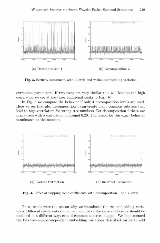
Watermark Security via Secret Wavelet Packet Subband Structures 219
-0.2
0
0.2
0.4
0.6
0.8
1
100000 120000 140000 160000 180000 200000
Cor
rela
tion
Tree #
Decomposition 1, Emb-Variation , Ext-Variation
(a) Decomposition 1
-0.2
0
0.2
0.4
0.6
0.8
1
100000 120000 140000 160000 180000 200000
Cor
rela
tion
Tree #
Decomposition 2, Emb-Variation , Ext-Variation
(b) Decomposition 2
Fig. 3. Security assessment with 4 levels and without embedding variation
extraction parameters. If two trees are very similar this will lead to the highcorrelation we see at the three additional peaks in Fig. (b).
In Fig. 3 we compare the behavior if only 4 decomposition levels are used.Here we see that also decomposition 1 can create many common subtrees thatlead to high correlation for wrong tree numbers. For decomposition 2 there aremany trees with a correlation of around 0.20. The reason for this exact behavioris unknown at the moment.
-0.2
0
0.2
0.4
0.6
0.8
1
100000 120000 140000 160000 180000 200000
Cor
rela
tion
Tree #
Decomposition 1, Emb-Variation -1, Ext-Variation -1
(a) Correct Extraction
-0.2
0
0.2
0.4
0.6
0.8
1
100000 120000 140000 160000 180000 200000
Cor
rela
tion
Tree #
Decomposition 1, Emb-Variation -1, Ext-Variation
(b) Incorrect Extraction
Fig. 4. Effect of skipping some coefficients with decomposition 1 and 7 levels
These result were the reason why we introduced the two embedding varia-tions. Different coefficients should be modified or the same coefficients should bemodified in a different way, even if common subtrees happen. We implementedthe two tree-number-dependent embedding variations described earlier to add

220 W. Dietl and A. Uhl
this feature. Decomposition 1 with a 7 level decomposition has a lower likelinessof common subtrees and can be used without a variation. But decomposition 2with 7 levels and both decompositions with only 4 decompositions need one orboth of the variations to protect against common subtrees.
In Fig. 4 we see the effect of embedding variation one — skipping somecoefficients — in combination with decomposition 1 with 7 levels. There is againone clear peak and the correlation of wrong tree numbers was further decreased.
In Fig. (b) we see what happens when we do not use variation 1 for watermarkextraction. There is low correlation for all tree numbers and the watermark isnot found.
-0.2
0
0.2
0.4
0.6
0.8
1
100000 120000 140000 160000 180000 200000
Cor
rela
tion
Tree #
Decomposition 2, Emb-Variation -1, Ext-Variation -1
(a) Correct Extraction
-0.2
0
0.2
0.4
0.6
0.8
1
100000 120000 140000 160000 180000 200000
Cor
rela
tion
Tree #
Decomposition 2, Emb-Variation -1, Ext-Variation
(b) Incorrect Extraction
Fig. 5. Effect of variation 1 on decomposition 2 with 7 levels
In Fig. 5 we see the effect of variation 1 on decomposition strategy 2 with 7levels. There is only one peak for the correct tree number and the correlation forthe wrong trees is reduced. The introduction of the embedding variations makesdecomposition 2 a useable system.
Fig. (b) shows the result when the wrong extraction variation is used. Againthere is very low correlation for all tree numbers and the correct tree numbercan not be found. This shows that the embedding variations can also be used tofurther increase the security of the watermark.
4 Quality Assessment
For the quality assessment we embed a watermark with 40dB PSNR and com-press the watermarked image with JPEG and JPEG2000. We then try to detectthe watermark in the compressed image and measure the correlation. As a mea-sure of the distortion we use the PSNR of the compressed image.

Watermark Security via Secret Wavelet Packet Subband Structures 221
To get a good variation of different trees we use tree numbers from 100000 to200000 with increments of 400. From all those 251 measurements we calculatethe average, maximum and minimum correlation and PSNR.
0
0.2
0.4
0.6
0.8
1
0 0.05 0.1 0.15 0.2 0.25
Cor
rela
tion
JPEG2000 Rate
Decomposition 1Decomposition 2
Pyramidal Biorthogonal 7/9Pyramidal Daubechies 6
(a) Correlation
20
22
24
26
28
30
32
34
36
38
40
0 0.05 0.1 0.15 0.2 0.25
PS
NR
JPEG2000 Rate
Decomposition 1Decomposition 2
Pyramidal Biorthogonal 7/9Pyramidal Daubechies 6
(b) PSNR
Fig. 6. Comparison of the proposed systems with the standard systems underJPEG2000 compression
0
0.2
0.4
0.6
0.8
1
10 20 30 40 50 60 70 80 90
Cor
rela
tion
JPEG Quality
Decomposition 1Decomposition 2
Pyramidal Biorthogonal 7/9Pyramidal Daubechies 6
(a) Correlation
26
28
30
32
34
36
38
40
10 20 30 40 50 60 70 80 90
PS
NR
JPEG Quality
Decomposition 1Decomposition 2
Pyramidal Biorthogonal 7/9Pyramidal Daubechies 6
(b) PSNR
Fig. 7. Comparison of the proposed systems with the standard systems under JPEGcompression
We compare tree decomposition 1 and 2 and expect that tree decomposition 2will have better results for higher compression rates. The results of the waveletpacket methods are compared with the standard Wang watermarking systemusing the Daubechies 6 and the Biorthogonal 7/9 filters.

222 W. Dietl and A. Uhl
With more subband decompositions we expect that it will be possible toembed longer watermark sequences compared to the pyramidal decomposition.To see whether this is true we analyze the image quality with watermark lengths1000, 5000 and 20000.
Figs. 6 and 7 show the compression behavior of the two different waveletpacket decompositions in comparison with the standard system with the Bi-orthogonal 7/9 and the Daubechies 6 filters.
In Fig. 6(a) we see the correlation behavior under JPEG2000 compression.The performance of decomposition 2 is superior to all other systems and thewavelet packet system with decomposition 1 is also better than the two standardsystems.
0
0.2
0.4
0.6
0.8
1
00.050.10.150.20.25
Cor
rela
tion
JPEG2000 Rate
Average CorrelationMinimum Correlation
Maximum Correlation
(a) JPEG2000 Correlation
0
0.2
0.4
0.6
0.8
1
102030405060708090
Cor
rela
tion
JPEG Quality
Average CorrelationMinimum Correlation
Maximum Correlation
(b) JPEG Correlation
Fig. 8. Details for tree decomposition 2
Fig. 7(a) shows the JPEG compression results. In this case the difference issmaller than under JPEG2000 compression. The decomposition 1 system per-forms slightly better than decomposition 2 and both wavelet packet systems areabove the standard decompositions.
The results for the PSNR performance are shown in Figs. 6(b) and 7(b). Allsystems behave very similarly without a significant difference. Therefore we willnot show further PSNR results.
Fig. 8 gives a close look at the results for decomposition 2. This diagramshows the average, minimum and maximum correlation behavior under com-pression. The minimum correlation behavior is still very good and the averageis closer to the maximum.
Figs. 9 and 10 compare the performance of decompositions 1 and 2 with 7decomposition levels for watermarks of length 1000, 5000 and 20000. We seethat under JPEG2000 compression decomposition 2 is the better system for allwatermark lengths. The advantage of decomposition 2 gets bigger for longer wa-termarks. Fig. 10 shows the results under JPEG compression. For a watermark

Watermark Security via Secret Wavelet Packet Subband Structures 223
of length 1000 decomposition 1 has a slight advantage, but for lengths 5000 and20000 decomposition 2 is clearly the better system. In comparison to the pyra-midal decomposition the wavelet packet systems clearly have a higher robustnessto compression.
-0.2
0
0.2
0.4
0.6
0.8
1
0 0.05 0.1 0.15 0.2 0.25
Cor
rela
tion
JPEG2000 Rate
Decomposition 1; Length 1000Decomposition 1; Length 5000
Decomposition 1; Length 20000Decomposition 2; Length 1000Decomposition 2; Length 5000
Decomposition 2; Length 20000Pyramidal Biorthogonal 7/9; Length 1000Pyramidal Biorthogonal 7/9; Length 5000
Pyramidal Biorthogonal 7/9; Length 20000
Fig. 9. Correlation comparison under JPEG2000 compression
-0.4
-0.2
0
0.2
0.4
0.6
0.8
1
10 20 30 40 50 60 70 80 90
Cor
rela
tion
JPEG Quality
Decomposition 1; Length 1000Decomposition 1; Length 5000
Decomposition 1; Length 20000Decomposition 2; Length 1000Decomposition 2; Length 5000
Decomposition 2; Length 20000Pyramidal Biorthogonal 7/9; Length 1000Pyramidal Biorthogonal 7/9; Length 5000
Pyramidal Biorthogonal 7/9; Length 20000
Fig. 10. Correlation comparison under JPEG compression
Decomposition 1 with 7 levels shows good security properties even withoutembedding variation and good robustness for a 1000 element watermark. Forlonger watermark lengths decomposition 2 has significantly better robustnessresults, but one of the embedding variations should be used to guard againstcommon subtrees.

224 W. Dietl and A. Uhl
5 Conclusions
In this paper we described how the wavelet packet decomposition can be used toenhance the security of wavelet-based watermarking systems. We use the Wangcoefficient selection method and propose two methods for generating randomtrees. The first method uses a 50% probability of decomposition for all subbands.The second method does not decompose the detail subbands on the first leveland puts more emphasis on decomposing in the low and middle frequency range.The seed for the random number generator is used as key and is kept secret. For7 decomposition levels we have 24185 or 21046 possible tree decompositions for thefirst and the second decomposition method, respectively. We also introduced twomethods to protect against common subtrees that can result in higher correlationeven for the wrong tree number.
Both the security and the quality assessment show that the wavelet packetsystems show better performance than the standard pyramidal system. Decom-position 1 can be used without embedding variation for 1000 element water-marks. Decomposition 2 has higher robustness for long watermarks and clearlyoutperforms the pyramidal decomposition.
Overall we conclude that a random tree decomposition that focuses on thelow and middle frequency range and uses either coefficient skipping or watermarkshuffling results in a robust and secure watermarking system.
Acknowledgments. Parts of this work were funded by the Austrian ScienceFund FWF projects P15170 “Sicherheit fur Bilddaten in Waveletdarstellung”and P13732 “Objekt-basierte Bild- und Videokompression mit Wavelets”.
References
1. Katzenbeisser, S., Petitcolas, F.A.P.: Information Hiding Techniques for Steganog-raphy and Digital Watermarking. Artech House (1999)
2. Dittmann, J., ed.: Digitale Wasserzeichen: Grundlagen, Verfahren, Anwendungs-gebiete. Springer Verlag (2000)
3. Johnson, N.F., Duric, Z., Jajodia, S.: Information Hiding: Steganography and Wa-termarking - Attacks and Countermeasures. Kluwer Academic Publishers (2000)
4. Cox, I.J., Miller, M.L., Bloom, J.A.: Digital Watermarking. Morgan Kaufmann(2002)
5. Eggers, J.J., Girod, B.: Informed Watermarking. Kluwer Academic Publishers(2002)
6. Daubechies, I.: Ten Lectures on Wavelets. Number 61 in CBMS-NSF Series inApplied Mathematics. SIAM Press, Philadelphia, PA, USA (1992)
7. Wickerhauser, M.: Adapted wavelet analysis from theory to software. A.K. Peters,Wellesley, Mass. (1994)
8. Mallat, S.: A wavelet tour of signal processing. Academic Press (1997)9. ISO/IEC JPEG committee: JPEG 2000 image coding system — ISO/IEC 15444-
1:2000 (2000)10. Taubman, D., Marcellin, M.: JPEG2000 — Image Compression Fundamentals,
Standards and Practice. Kluwer Academic Publishers (2002)

Watermark Security via Secret Wavelet Packet Subband Structures 225
11. Meerwald, P., Uhl, A.: A survey of wavelet-domain watermarking algorithms. InWong, P.W., Delp, E.J., eds.: Proceedings of SPIE, Electronic Imaging, Securityand Watermarking of Multimedia Contents III. Volume 4314., San Jose, CA, USA,SPIE (2001)
12. Wang, Y., Doherty, J.F., Dyck, R.E.V.: A wavelet-based watermarking algorithmfor copyright protection of digital images. IEEE Transactions on Image Processing11 (2002) 77–88
13. Tsai, M.J., Yu, K.Y., Chen, Y.Z.: Wavelet packet and adaptive spatial transfor-mation of watemark for digital image authentication. In: Proceedings of the IEEEInternational Conference on Image Processing, ICIP ’00, Vancouver, Canada (2000)
14. Levy-Vehel, J., Manoury, A.: Wavelet packet based digital watermarking. In: Pro-ceedings of the 15th International Conference on Pattern Recognition, Barcelona,Spain (2000)
15. Wang, H.J., Kuo, C.C.J.: Watermark design for embedded wavelet image codec.In: Proceedings of the SPIE’s 43rd Annual Meeting, Applications of Digital ImageProcessing. Volume 3460., San Diego, CA, USA (1998) 388–398
16. Kundur, D.: Improved digital watermarking through diversity and attack char-acterization. In: Proceedings of the ACM Workshop on Multimedia Security ’99,Orlando, FL, USA (1999) 53–58
17. Fridrich, J., Baldoza, A.C., Simard, R.J.: Robust digital watermarking based onkey-dependent basis functions. In Aucsmith, D., ed.: Information hiding: secondinternational workshop. Volume 1525 of Lecture notes in computer science., Port-land, OR, USA, Springer Verlag, Berlin, Germany (1998) 143–157
18. Kalker, T., Linnartz, J.P., Depovere, G., Maes, M.: On the reliability of detectingelectronic watermarks in digital images. In: Proceedings of the 9th European SignalProcessing Conference, EUSIPCO ’98, Island of Rhodes, Greece (1998) 13–16
19. Fridrich, J.: Key-dependent random image transforms and their applications inimage watermarking. In: Proceedings of the 1999 International Conference onImaging Science, Systems, and Technology, CISST ’99, Las Vegas, NV, USA (1999)237–243
20. Meerwald, P., Uhl, A.: Watermark security via wavelet filter parametrization. In:Proceedings of the IEEE International Conference on Image Processing (ICIP’01).Volume 3., Thessaloniki, Greece, IEEE Signal Processing Society (2001) 1027–1030
21. Dietl, W., Meerwald, P., Uhl, A.: Key-dependent pyramidal wavelet domains forsecure watermark embedding. In Delp, E.J., Wong, P.W., eds.: Proceedings ofSPIE, Electronic Imaging, Security and Watermarking of Multimedia Contents V.Volume 5020., Santa Clara, CA, USA, SPIE (2003)
22. Wang, H.J., Bao, Y.L., Kuo, C.C.J., Chen, H.: Multi-threshold wavelet codec(MTWC). Technical report, Derpartment of Electrical Engineering, University ofSouthern California, Los Angeles, CA, USA, Geneva, Switzerland (1998)
23. Wang, H.J., Kuo, C.C.J.: High fidelity image compression with multithresholdwavelet coding (MTWC). In: SPIE’s Annual meeting - Application of DigitalImage Processing XX, San Diego, CA, USA (1997)
24. Pommer, A., Uhl, A.: Selective encryption of wavelet packet subband structures forsecure transmission of visual data. In Dittmann, J., Fridrich, J., Wohlmacher, P.,eds.: Multimedia and Security Workshop, ACM Multimedia, Juan-les-Pins, France(2002) 67–70

A Robust Audio Watermarking Scheme Based on MPEG1 Layer 3 Compression
David Megıas, Jordi Herrera-Joancomartı, and Julia Minguillon
Estudis d’Informatica i MultimediaUniversitat Oberta de Catalunya
Av. Tibidabo 39–43, 08035 BarcelonaTel. (+34) 93 253 7523,Fax (+34) 93 417 6495
dmegias,jordiherrera,[email protected]
Abstract. This paper describes an audio watermarking scheme based on lossycompression. The main idea is taken from an image watermarking approach wherethe JPEG compression algorithm is used to determine where and how the markshould be placed. Similarly, in the audio scheme suggested in this paper, an MPEG1 Layer 3 algorithm is chosen for compression to determine the position of the markbits and, thus, the psychoacoustic masking of the MPEG 1 Layer 3 compression isimplicitly used. This methodology provides with a high robustness degree againstcompression attacks. The suggested scheme is also shown to succeed against mostof the StirMark benchmark attacks for audio.
Keywords: Copyright protection, Audio watermarking, Frequency domain meth-ods.
1 Introduction
Electronic copyright protection schemes based on the principle of copy prevention haveproven ineffective or insufficient in the last few years (see [1,2], for example). Pragmaticapproaches, like the one adopted for protecting DVDs [3], combine copy prevention withcopy detection.
Watermarking is a well-known technique for copy detection, whereby the merchantselling the piece of information (e.g. an audio file) embeds a mark in the copy sold.From a construction point of view, a watermarking scheme can be described in twostages: mark embedding and mark reconstruction. Since the former determines the markreconstruction process, the real problem is where and how the marks should be placedinto the product.
Watermarking schemes should provide some basic properties depending on specificapplications. Different properties are pointed out in the literature [4,2,5,6] but the mostrelevant are imperceptibility, capacity and robustness. Imperceptibility, sometimes re-ferred as perceptual quality, guarantees that the mark introduced is imperceptible andthen the marked version of the product is not distinguishable from the original one.Capacity measures the amount of information that can be embedded. Such a propertyis also known as bit rate. Robustness determines the resistance to accidental removal
A. Lioy and D. Mazzocchi (Eds.): CMS 2003, LNCS 2828, pp. 226–238, 2003.c© IFIP International Federation for Information Processing 2003

A Robust Audio Watermarking Scheme Based on MPEG 1 Layer 3 Compression 227
of the embedded mark. All those properties intersect in the sense that an increase incapacity usually improves robustness but reduces imperceptibility and, reciprocally, anincrease in imperceptibility reduces robustness. Hence a trade-off between them mustbe achieved.
In audio watermarking schemes, the mark embedding process can be performed indifferent ways, since audio allows multiple manipulations without affecting the percep-tual quality. But, since robustness is the most important watermarking property, questionslike where and how to place the mark are important issues. In order to maximise im-perceptibility, some proposals [7,8,9] exploit the frequency characteristics of the audiosignal to determine the place where the mark should be embedded. Other proposals [10]use echo coding techniques where the mark is encoded by using different delays be-tween the original signal and the echo. Such a technique increases robustness againstMPEG 1 Layer 3 audio compression and D/A conversion, but is not suitable for speechsignals with frequent silence intervals. Robustness against various signal processing op-erations is also increased in [11] by dividing the set of the original samples in embeddingsegments. A more detailed state of the art in audio watermarking can be found in [5].
In this paper we present a novel watermarking scheme for audio. The scheme isbased in some sense on the ideas of [12], where a lossy compression algorithm determineswhere the mark bits are placed. This paper is organised as follows. Section 2 presents themethod that describes the new watermarking scheme. Section 3 analyses the propertiesof the resulting watermarking scheme: imperceptibility, capacity and robustness. Finally,in Section 4, conclusions and some guidelines for further research are outlined.
2 Audio Watermarking Scheme
The audio watermarking scheme suggested in this paper is inspired in the image water-marking algorithm depicted in [12] in the sense that lossy compression is used in themark embedding process in order to identify which samples are suitable for marking.
Let the signal S to be watermarked be a collection of Pulse Code Modulation (PCM)samples (for example a RIFF-WAVE1 file). The aim of the watermarking scheme is toembed a mark into this file in such a way that imperceptibility and robustness of themark is preserved.
2.1 Mark Embedding
Without loss of generality, let S be codified in RIFF-WAVE format. It is well-known thatthe Human Auditory System (HAS) is sensitive to information in the frequency ratherthan the time domain. Because of this, the first step of this method is to obtain SF , thespectrum of S, by applying a Fast Fourier Transform (FFT) algorithm.
In order to determine where the mark bits should be placed, the signal S is com-pressed using a MPEG 1 Layer 3 algorithm with a rate of R Kbps (tuning parameter)and, then, decompressed again to RIFF-WAVE format. The modified signal, after thiscompression/decompression operation, is called S′, and its spectrum S′
F is obtained.
1 RIFF-WAVE stands for Resource Interchange File Format-WAVEform audio file format.

228 D. Megıas, J. Herrera-Joancomartı, and J. Minguillon
Throughout this paper, the Blade codec (compressor/decompressor) for the MPEG 1Layer 3 algorithm has been chosen and, thus, the psychoacoustic model of this codecis implicitly used. Note that audio quality is not an objective of the codec used for thisstep, since we only need the compression/decompression operation to produce a signalS′ which is slightly different from the original S. Hence, any other codec might havebeen used.
Now, the set of frequencies Fmark = fmark suitable for marking are chosenaccording to the following criteria:
1. All fmark ∈ Fmark must belong to the relevant frequencies Frel of the original signalSF . This means that the magnitude (or modulus) |SF (fmark)| must be not lowerthan a given percentage (for example a 2%) of the maximum magnitude of SF .Therefore, a first set of frequencies Frel = frel is chosen as:
Frel =
f ∈[0,
fmax
2
]: |SF (f)| ≥ p
100|SF |max
,
where fmax is the maximum frequency of the spectrum, which depends on thesampling rate and the sampling theorem2, p ∈ [0, 100] is a percentage and |SF |maxis the maximum magnitude of the spectrum SF . Note that the spectrum values inthe interval [fmax/2, fmax] are the complex-conjugate of those in [0, fmax/2]. Themarking frequencies are a subset of these relevant frequencies, i.e. Fmark ⊆ Frel.
2. Now, the frequencies to be marked are those which remain “unchanged" after thecompression/decompression phase, where “unchanged" means a relative error belowa given threshold ε (for example ε = 0.05):
Fmark = f1, f2, . . . , fn =
f ∈ Frel :∣∣∣∣SF (f)− S′
F (f)SF (f)
∣∣∣∣ < ε
.
Similarly, as done in the image watermarking scheme of [12], a 70-bit stream mark,W (|W | = 70), is firstly extended to a 434-bit stream WECC (|WECC| = 434) using adual Hamming Error Correcting Code (ECC). Using dual Hamming binary codes allowsus to apply the watermarking scheme as a fingerprinting scheme robust against collusionof two buyers [13]. Finally, a pseudo-random binary stream (PRBS), generated with acryptographic key k, is added to the extended mark as it is embedded into the originalsignal.
Once the frequencies in Fmark have been chosen, the mark embedding method con-sists of increasing or decreasing the magnitude of SF (fmark) in order to embed a ‘1’or a‘0’, respectively. The increase or decrease in the magnitude of SF must be small enoughnot to be perceptible, but large enough such that the mark can be reconstructed froman attacked signal. The approach of the suggested scheme is to increase or decrease thesignal amplitude d dB to embed a ‘1’ or a ‘0’, i.e., if fmark is the frequency at which abit must be marked, the watermarked signal spectrum will be:
SF (fmark) =
SF (fmark) · 10d/20 to embed ‘1’,SF (fmark) · 10−d/20 to embed ‘0’.
2 fmax = 1Ts
, where Ts is the sampling time.

A Robust Audio Watermarking Scheme Based on MPEG 1 Layer 3 Compression 229
where the parameter d dB can be tuned. This process is performed for all the frequenciesfmark ∈ Fmark. Note, also, that it is required that n (the number of elements in Fmark)should be greater than or equal to the length |WECC| of the extended mark (434 in ourexample). In a typical situation, the mark is embedded tens or hundreds of times all overthe spectrum SF . In addition, it must be taken into account that the spectrum componentsin SF are paired (pairs of complex-conjugate values) and thus the same transformation(adding or subtracting d dB) must be performed to the magnitude SF (fmark) and to themagnitude of its conjugate. For f ∈ Fmark the spectrum of SF is the same as that of S:
SF (f) =
SF (f), if f ∈ Fmark,SF (f)± d dB, if f ∈ Fmark.
Original signal
Watermarked signal
decompressorcompressor
S SF SF , Frel
70-bit stream 434-bit stream
FFTRelevant
frequencies
Relativeerror
IFFT
Magnitude
modification
FFTS′
F
SF , Fmark
SF
S
S′MPEG 1 Layer 3 MPEG 1 Layer 3
WECCWECC PRBS
k
Fig. 1. Mark embedding process
Finally, the marked audio signal is converted to the time domain S applying aninverse FFT (IFFT) algorithm. The whole mark embedding process is depicted in theblock diagram of Fig. 1. Note that this scheme has been designed to provide with “nat-ural" robustness against compression attacks, since only the frequencies for which themagnitude remains unaltered after compression/decompression, within some specifiedtolerance (the parameter ε), are chosen for marking. The mark embedding algorithm canbe denoted in terms of the following expression:
Embed (S, W, parameters = R, p, ε, d, k)→
S, Fmark

230 D. Megıas, J. Herrera-Joancomartı, and J. Minguillon
2.2 Mark Reconstruction
The objective of the mark reconstruction algorithm is to detect whether an audio testsignal T is a (possibly attacked) version of the marked signal S. It is assumed that T isin RIFF-WAVE format. If it were not the case, a format conversion step (for exampleMPEG 1 Layer 3 decompression) should be performed prior to the application of thereconstruction process.
First of all, the spectrum TF is obtained applying the FFT algorithm and, then, themagnitude at the potentially marked frequencies |TF (fmark)|, for all fmark ∈ Fmark, iscomputed. Note that this method is strictly positional and, because of this, it is requiredthat the number of samples in S and T is the same. If there is only a little difference inthe number of samples, it is possible to complete the sequences with zeroes. Thus, thismethodology cannot be directly applied when resampling attacks occur. In such a case,sampling rate conversion must be performed before the mark reconstruction algorithmcan be applied.
When |TF (fmark)| are available, a scaling step is undertaken in order to minimise
the distance of the sequences |TF (fmark)| and∣∣∣SF (fmark)
∣∣∣. This scaling is performed
to suppress the effect of attacks which modify only a range of frequencies or which scalethe PCM signal S. The following least squares problem is solved:
minλ
∑
f∈Fmark
(∣∣∣SF (f)∣∣∣− λ |TF (f)|
)2.
This problem can be solved analytically as follows. Given the vectors
s =[ |SF (f1)| |SF (f2)| . . . |SF (fn)| ]T ,
s =[ ∣∣∣SF (f1)
∣∣∣∣∣∣SF (f2)
∣∣∣ . . .∣∣∣SF (fn)
∣∣∣]T
,
t =[ |T (f1)| |T (f2)| . . . |T (fn)| ]T ,
where T stands for the transposition operator, it is possible to write the least squaresproblem in vector form as
minλ
(s− λt)T (s− λt) ,
which yields the minimum for:
λ =sTt
tTt.
Now, each component of λt is divided by the corresponding component of s and the valueobtained is compared with 10d/20 to decide wether a ‘0’, a ‘1’ or a ‘*’ (not identified)might be embedded in this component of λt. Let ri = λti
si:
ri ∈[10
d20
(100− q
100
), 10
d20
(100 + q
100
)]⇒ bi := ‘1’,
1ri∈
[10
d20
(100− q
100
), 10
d20
(100 + q
100
)]⇒ bi := ‘0’.

A Robust Audio Watermarking Scheme Based on MPEG 1 Layer 3 Compression 231
If none of these two conditions are satisfied, then bi := ‘*’. Here q ∈ [0, 100] is apercentage (e.g. q = 10) and bi is the i-th component of the vector b which containsa sequence of “detected bits". Finally, the PRBS signal is subtracted from the bits b torecover the true embedded bits b. This operation must preserve unaltered the ‘*’ marks.
Once b has been obtained, it must be taken into account that its length n is (much)greater than the length of the extended mark. Hence, each bit of the mark appears atdifferent positions in b. For example, if the length of the extended mark is 434, the firstbit should appear at
b1, b435, b869, . . . , b1+434j , . . .
Some of these bits will be identified as ‘1’, others as ‘0’ and the rest as ‘*’.Now a voting scheme is applied to decide wether the i-th bit of the mark is ‘1’, ‘0’ or
unidentified (‘*’). Let n0, n1 and n∗, be the number of ‘0’s, ‘1’s and ‘*’s identified forthe same mark bit. The simplest approach is to assign to each bit the sign which appearsmost. For example, if a given mark bit had been identified 100 times with n0 = 2,n1 = 47 and n∗ = 51, this simple approach would assign a ‘*’ mark to this bit. But,taking into account that any value outside the interval defined above is identified as ‘*’, itis clear that near ‘1’s are identified as ‘*’ although they are much closer to ‘1’ than to ‘0’.In the reported example, the big difference between the number of ‘1’s and ‘0’s (47 2)can reasonably lead to the conclusion that the corresponding bit can be assigned a ‘1’with very little probability error, since most of the ‘*’ will probably be near ‘1’s. As aresult of this consideration, the voting scheme used in this method ignores the ‘*’ if n∗is not more than twice the difference |n1 − n0|:
bit :=
‘*’ if n∗ > 2 |n1 − n0| ,‘1’ if n∗ ≤ 2 |n1 − n0| and n1 > n0,‘0’ if n∗ ≤ 2 |n1 − n0| and n0 > n1,
A more sophisticated method using statistics might be applied instead of this votingscheme. For instance, an analysis of the distribution of ri for each bit might be performed.However, the voting procedure described here is simple to implement and fast to execute,which makes it very convenient for real applications.
TFFT
ECCVoting
scheme
TF Leastsquares
Bit
identification
434-bit streamPRBS
70-bit stream
b
λTF
SF , Fmark SF , Fmark
W ′W ′
ECC
Test signal
k
b
Fig. 2. Mark reconstruction process
As a result of this voting scheme an identified extended mark W ′ECC will be avail-
able. Finally, W ′ECC and the error correcting algorithm are used to recover an identified

232 D. Megıas, J. Herrera-Joancomartı, and J. Minguillon
70-bit stream mark, W ′, which will be compared with the true mark W . The wholereconstruction process is depicted in Fig. 2. The mark reconstruction algorithm can bedescribed in terms of the following expression:
Reconstruct(T, S, S, Fmark, parameters = q, d, k
)→ W ′, b
where b is a byproduct of the algorithm which might be used to perform statistical tests.The proposed scheme is not blind, in the sense that the original signal is needed by
the mark reconstruction process. On the other hand, the bit sequence which forms theembedded mark is not needed for reconstruction, which makes this method suitable alsofor fingerprinting once the mark is properly coded [14].
3 Performance Evaluation
As pointed out in Section 1, three main measures are commonly used to assess theperformance of watermarking schemes:
Imperceptibility: the extent to which the embedding process leaves undamaged theperceptual quality of the marked object.
Capacity: the amount of information that may be embedded and recovered.Robustness: the resistance to accidental removal of the embedded bits.
In this section, we test the properties of the proposed scheme presented in Section2. The scheme described in Section 2 was implemented using a dual binary Hammingcode DH(31, 5) as ECC and the pseudo-random generator is a DES cryptosystem im-plemented in a OFB mode. A 70-bit mark W (resulting in an encoded WECC with|WECC| = 434) was included. In order to test the watermarking scheme we have chosenthe following parameters for embedding and reconstruction:
– R = 128 Kbps, which is the most widely used bit rate in MPEG 1 Layer 3 files.– p = 2, meaning that we only consider relevant those frequencies for which the
magnitude of SF is, at least, a 2% of the maximum magnitude.– ε = 0.05, which implies that a frequency is considered unchanged after compres-
sion/decompression if the magnitude varies less than a 5% (relative error).– d = 1 dB, if lower imperceptibility is required, a lower value can be chosen.– q = 10, i.e. a ±10% band is defined about d in order to reconstruct ‘1’s and ‘0’s.
This choice is quite conservative, since the ‘0’ and the ‘1’ bands are quite far fromeach other.
It is worth pointing out that these parameters have been chosen without performinga deep analysis on tuning. Basically, R, p and ε affect the place where the mark bitsare embedded; d is related to the imperceptibility of the hidden mark, since it describeshow much the spectrum of each marked frequency is disturbed; and, finally, q affectsthe robustness of the method, since it avoids misidentification of the embedded bits.
To test the performance of the suggested audio watermarking scheme, some of theaudio files provided in the Sound Quality Assessment Material (SQAM) page [15] have

A Robust Audio Watermarking Scheme Based on MPEG 1 Layer 3 Compression 233
been used. The following files have been tested: violoncello (m.p.3), trumpet (m.p.), horn(m.p.), glockenspiel (m.p.), harpsichord (arp.4), soprano (voice), bass (voice), quartet(voice), English female speech (voice) and English male speech (voice). We have takenonly the first ten seconds of each of these files, i.e., 441000 samples, and the mark hasbeen embedded in the left channel only. The glockenspiel file is an especial case, sinceit has about 5 blank seconds out of 10.
3.1 Imperceptibility
The imperceptibility property determines how much the marked signal S differs fromthe original one S. That is, imperceptibility is concerned with the distortion added withthe inclusion of the mark or, in other words, with the audio quality of the marked signalS with respect to S. There are several ways to measure audio quality. Here, the signal-to-noise ratio (SNR) and an average SNR (ASNR) are used. The SNR measure determinesthe power of the noise added by the watermark relative to the original signal, and isdefined by
SNR =
N∑
i=1
S2i
N∑
i=1
(Si − Si
)2
where N is the number of samples and Si (Si) denotes the i-th sample of S (S). Usually,this value is given in dB by performing the operation 10 log10(SNR). Another measureusual in audio quality assessment is an average of the SNR computed taking sampleblocks of some length. A typical choice is to consider pieces of 4 ms, which, with asampling rate of 44100 Hz, means 176 samples. The SNR of all these pieces is computed,and the average for all the sample blocks is obtained. The ASNR measure is often givenin dB. The measure used in this paper does not take into account the Human AuditorySystem (HAS) and, thus, all frequencies are equally weighted.
In Table 1, the SNR and ASNR measures obtained for the ten benchmark files areshown. The SNR measures are about 19 dB whereas the ASNR measures are about 20dB. This means that power of the noise introduced by watermarking is roughly 0.01 timesthe power of the original signal, which is quite satisfying and might even be improved(reduced) by choosing proper tuning parameters.
Obviously, the parameter d only affects the imperceptibility of the watermark, since itdetermines to which extent the spectrum of the marked signal S is modified with respectto the original signal S. Hence, by reducing d, to say 0.5 dB, the imperceptibility of themark would increase, though it will be more easily removed. The parameters R, p and εdetermine how many frequencies are chosen for watermarking and, thus, they also affectthe imperceptibility of the mark. The larger the number of marked frequencies is, themore perceptible the mark becomes. This establishes a link between the imperceptibility
3 “m.p." stands for “melodious phase".4 “arp." stands for “arpegio".

234 D. Megıas, J. Herrera-Joancomartı, and J. Minguillon
Table 1. Capacity and imperceptibility
SQAM file Marked bits Capacity (bits) SNR (dB) ASNR (dB)
violoncello 4477 722 18.92 20.91trumpet 3829 617 18.83 19.84horn 1573 253 18.96 21.10glockenspiel 1258 202 25.78 29.75harpsichord 3874 624 21.25 22.84soprano 5042 813 19.47 21.59bass 15763 2542 19.02 20.08quartet 13548 2185 19.22 20.36female speech 10677 1722 19.57 21.84male speech 9359 1509 19.44 21.49
and the capacity of the watermarking system. Hence a tradeoff between imperceptibilityand capacity must be achieved. Note, also, that capacity is related to robustness, since anincrease in the number of times the mark is embedded into the signal results in decreasingthe probability of losing the mark.
3.2 Capacity
The capacity of the watermarking scheme is determined by the parameters R, p and εused in the embedding process. Since the marked frequencies are chosen according tothe difference of S and S′ (the compressed/decompressed signal), it is obvious that therate R is a key parameter in this process. The percentage p determines which frequenciesare significant enough to be taken into account and, thus, this is a relevant parameter ascapacity is concerned. Finally, the relative error ε are used to measure wether two spectralvalues of S and S′ are equal, which also affects the number of marked frequencies.
In Table 1, the capacity of the suggested scheme for the ten benchmark files isdisplayed. We have considered that the true capacity is not the number of marked bits(the second column), since the extended watermark is highly redundant: 70 bits ofinformation plus 364 bits of redundancy. Hence only 70/434 of the marked bits are thetrue capacity (third column). However, this redundancy is relevant to the robustness ofthe method, as it allows to correct errors once the extended mark W ′
ECC is recovered.Note, also, that 10 seconds of music are enough to allow for, at least, 3 times the mark. If3-minute files were marked using this method, the capacity of method would be between3652 bits (or 52 times a 70-bit mark) plus the redundancy for the glockenspiel file and45763 bits (or 653 times a 70-bit mark) plus the redundancy for the quartet file. It mustbe taken into account that the glockenspiel file is an especial case, since it only contains5 seconds of music.
3.3 Robustness Assessment
The robustness of the resulting scheme has been tested using the StirMark benchmarkfor audio [16], version 0.2. Some of the attacks in this benchmark can not be evaluated

A Robust Audio Watermarking Scheme Based on MPEG 1 Layer 3 Compression 235
for the watermarking scheme presented in this paper, since the current version of ourwatermarking scheme does not allow for a large difference between the number ofsamples of the marked (S) and the attacked (T ) signals. In addition, only the left channelhas been marked in the experiments, thus stereo attacks do not apply here either. Theattacks considered for this test are summarised in Table 2.
Table 2. Attacks described in the StirMark benchmark for audio
Name Number Name Number Name Number
AddBrumm 1—11 AddDynnnoise 12 Addnoise 13—17AddSinus 18 Amplify 19 Compressor 20
Echo 21 Exchange 22 FFT HLPass 23FFT Invert 24 FFT RealReverse 25 FFT Stat1 26FFT Test 27 FlippSample 28 Invert 29LSBZero 30 Normalise 31 RC-HighPass 32
RC-LowPass 33 Smooth 34 Smooth2 35Stat1 36 Stat2 37 ZeroCross 38
According to this table, thirty-eight different attacks are performed. The attackAddFFTNoise with default parameters destroys the audio file (it produces no sound)and, thus, no results are available for this attack. Future versions of the watermark-ing scheme should cope with stereo attacks (ExtraStereo and VoiceRemove) and attackswhich modify the number of samples in a significant way (CutSamples, ZeroLength, Ze-roRemove, CopySample and Resampling), but the current version of the watermarkingscheme proposed here cannot cope with them.
In order to test the robustness of the suggested watermarking scheme against these38 attacks, a correlation measure between the embedded mark W and the identified markW ′ is used. Let Wi and W ′
i be, respectively, the i-th bit of W and W ′, hence
βi =
1, if Wi = W ′i
−1, if Wi = W ′i
is defined. Now, the correlation is computed, taking into account the βi for all the |W |bits (70 in our case) of the mark, as follows:
Correlation =1|W |
|W |∑
i=1
βi.
This measure is 1 when all the |W | bits are correctly recovered (W = W ′) and it is−1 when all the |W | bits are misidentified. A value of about 0 is expected when 50%of the bits are correctly recovered, as it would occur if the mark bits were reconstructedrandomly. In the StirMark benchmark test, we have considered that the watermarkingscheme survives an attack only if the correlation is exactly 1, i.e. only if all the 70 bitsof the mark are correctly recovered.

236 D. Megıas, J. Herrera-Joancomartı, and J. Minguillon
Table 3. Survival of the mark to the StirMark test
Number Survival ratio Number Survival ratio Number Survival ratio
1 10/10 2 10/10 3 10/10
4 10/10 5 10/10 6 10/10
7 10/10 8 10/10 9 10/10
10 10/10 11 10/10 12 6/10
13 10/10 14 10/10 15 10/10
16 10/10 17 8/10 18 6/10
19 10/10 20 10/10 21 0/10
22 10/10 23 3/10 24 10/10
25 10/10 26 0/10 27 0/10
28 0/10 29 10/10 30 10/10
31 10/10 32 1/10 33 10/10
34 9/10 35 9/10 36 10/10
37 10/10 38 1/10
In Table 3 the survival of the mark against the StirMark benchmark attacks is dis-played. The relation between the attack number and the name given in the StirMarkbenchmark is given in Table 2. Each attack has been performed to the ten files of theSQAM corpus reported above. Hence, the results are shown in a x/10 ratio since thetotal number of files is 10. As remarked above, the mark is considered to be recoveredonly if all the 70 bits are correctly reconstructed.
The results of Table 3 show that only 7 of the 38 attacks of the StirMark benchmarkperformed in this paper cause serious damage to the embedded mark. The attacks withsurvival ratios of 6/10 or above produce good correlation values in the non-survivedcases, which suggests that better results might arise with an appropriate tuning of thewatermarking scheme. The non-survived attacks are the following: 21 (Exchange), 23(FFT HLPass), 26 (FFT Stat1), 27 (FFT Test), 28 (Flipp Sample), 32 (RC Highpass)and 38 (ZeroCross). It must be remarked that most of these attacks produce significantaudible damage to the signal and would not be considered acceptable under the mostusual situations, especially for music files.
Finally, a set of MPEG 1 Layer 3 compression attacks (using the Blade codec)have been carried out to the marked soprano SQAM file in order to test the robustnessof the suggested watermarking scheme against compression. Since the rate used forwatermarking is R = 128 Kpbs, it was expected that the scheme is able to overcomecompression attacks with bit rates of 128 Kbps and higher.
Table 4 displays the correlation values obtained for the MPEG 1 Layer 3 compressionattacks for several bit rates, from 320 Kbps to 32 Kbps. This table shows that the water-marking scheme suggested here is not only robust for all bit rates greater than or equalto 128 Kpbs, as expected, but also to rates 112 and 96 Kbps, which are more compressed

A Robust Audio Watermarking Scheme Based on MPEG 1 Layer 3 Compression 237
Table 4. MPEG 1 Layer 3 compression attacks
Bit rate (Kbps) 320 256 224 192 160 128 112Compression ratio 4.41:1 5.51:1 6.30:1 7.35:1 8.82:1 11.03:1 12.60:1
Correlation 1 1 1 1 1 1 1
Bit rate (Kbps) 96 80 64 56 48 40 32Compression ratio 14.70:1 17.64:1 22.05:1 25.20:1 29.30:1 35.28:1 44.10:1
Correlation 1 0.97 0.97 0.94 0.83 0.80 0.49
than the rate used for watermarking (128 Kbps). In addition, the correlation value isvery close to 1 even for rates 80, 64 and 56 Kbps. Of course, better robustness againstcompression attacks might be achieved by choosing a different rate for watermarking,for example R = 64 Kbps.
4 Conclusions and Further Research
This paper presents a watermarking method which uses MPEG 1 Layer 3 compressionto determine the position of the embedded mark. The main idea of the method, borrowedfrom the image watermarking scheme of [12], is to find the frequencies for which thespectrum of the original signal is not modified after compression. These frequenciesare used to embed the mark bits by adding or subtracting a given parameter to themagnitude of the spectrum. The method is complemented with an error correcting codeand a pseudo-random binary signal to increase robustness and to avoid collusion of twobuyers. Thus, this watermarking approach is also suitable for fingerprinting.
The performance of the suggested schemes has been evaluated for the SQAM filecorpus using three measures: imperceptibility, capacity and robustness. We have shownthat (without tuning) the power of the embedded watermark is about 0.01 times that ofthe original signal. As capacity is concerned, for typical 3-minute music files, the markcan be repeated hundreds of times within the marked signal. Finally, robustness has beentested by performing the applicable attacks in the StirMark benchmark and also MPEG1 Layer 3 attacks. The suggested scheme has been shown to be robust against most ofthe StirMark attacks and to compression attacks with compression ratios larger than thatused for watermarking.
There are several directions to further the research presented in this paper. Part of thefuture research will be focused on the parameters of the scheme, since some guidelinesto tune these parameters must be suggested. In addition, the watermarking scheme mustbe adapted to stereo files by marking both the left and the right channels appropriately. Itis also required that the watermarking scheme is able to cope with attacks which modifythe number of samples in the attacked signal in a significant way. The use of filterswhich model the HAS to measure imperceptibility is another research topic. Finally,the possibility to work with blocks of samples instead of using the whole file should beaddressed.

238 D. Megıas, J. Herrera-Joancomartı, and J. Minguillon
Acknowledgements. This work is partially supported by the Spanish MCYT and theFEDER funds under grant no. TIC2001-0633-C03-03 STREAMOBILE.
References
1. Petitcolas, F., Anderson, R., Kuhn, M.: Attacks on copyright marking systems. In: 2ndWorkshop on Information Hiding. LNCS 1525, Springer-Verlag (1998) 219–239
2. Petitcolas, F., Anderson, R.: Evaluation of copyright marking systems. In: Proceedings ofIEEE Multimedia Systems’99. (1999) 574–579
3. Bell, A.: The dynamic digital disk. IEEE Spectrum 36 (1999) 28–354. Swanson, M., Kobayashi, M., Tewfik, A.: Multimedia data-embedding and watermarking
technologies. In: Proceedings of the IEEE. Volume 86(6)., IEEE Computer Society (1998)1064–1087
5. Swanson, M.D.; Bin Zhu; Tewfik, A.: Current state of the art, challenges and future directionsfor audio watermarking. In: Proceedings of IEEE International Conference on MultimediaComputing and Systems. Volume 1., IEEE Computer Society (1999) 19–24
6. Voyatzis, G.; Pitas, I.: Protecting digital image copyrights: a framework. IEEE ComputerGraphics and Applications 19 (1999) 18–24
7. Cox, I.J., Kilian, J., Leighton, T., Shamoon, T.: Secure spread spectrum watermarking formultimedia. IEEE Transactions on Image Processing 6 (1997) 1673–1687
8. M.D. Swanson, B. Zhu, A.T., Boney, L.: Robust audio watermarking using perceptual mask-ing. Elsevier Signal Processing, Special Issue on Copyright Protection And Access Control66 (1998) 337–335
9. W. Kim, J.L., Lee, W.: An audio watermarking scheme robust to mpeg audio compression.In: Proc. NSIP. Volume 1., Antalya, Turkey (1999) 326–330
10. D. Gruhl, A.L., Bender, W.: Echo hiding. In: Proceedings of the 1st Workshop on InformationHiding. Number 1174 in Lecture Notes in Computer Science, Cambridge, England, SpringerVerlag (1996) 295–316
11. Bassia, P., Pitas, I., Nikolaidis, N.: Robust audio watermarking in the time domain. IEEETransactions on Multimedia 3 (2001) 232–241
12. Domingo-Ferrer, J., Herrera-Joancomartı, J.: Simple collusion-secure fingerprinting schemesfor images. In: Proceedings of the Information Technology: Coding and ComputingITCC’2000, IEEE Computer Society (2000) 128–132
13. Domingo-Ferrer, J., Herrera-Joancomartı, J.: Short collusion-secure fingerprinting based ondual binary hamming codes. Electronics Letters 36 (2000) 1697–1699
14. Boneh, D., Shaw, J.: Collusion-secure fingerprinting for digital data. In: Advances inCryptology-CRYPTO’95. LNCS 963, Springer-Verlag (1995) 452–465
15. Purnhagen, H.: SQAM - Sound Quality Assessment Material (2001)http://www.tnt.uni-hannover.de/project/mpeg/audio/sqam/.
16. Steinebach, M., Petitcolas, F., Raynal, F., Dittmann, J., Fontaine, C., Seibel, S., Fates, N., Ferri,L.: Stirmark benchmark: audio watermarking attacks. In: Proceedings of the InformationTechnology: Coding and Computing ITCC’2001, IEEE Computer Society (2001) 49–54
A . Lioy and D. Mazzocchi (Eds.): CMS 2003, LNCS 2828, pp. 239–251, 2003.© IFIP International Federation for Information Processing 2003
Loss-Tolerant Stream Authentication via ConfigurableIntegration of One-Time Signatures and Hash-Graphs
Alwyn Goh1, G.S. Poh2, and David C.L. Ngo3
1 Corentix Laboratories, B-19-02 Cameron Towers, Jln 5/58B,
46000 Petaling Jaya, [email protected]
2 Mimos, Technology Park Malaysia,
57000 Kuala Lumpur, Malaysia3 Faculty of Information Science & Technology, Multimedia University,
75450 Melaka, Malaysia
Abstract. We present a stream authentication framework featuring preemptiveone-time signatures and reactive hash-graphs, thereby enabling simultaneousrealisation of near-online performance and packet-loss tolerance. Streamauthentication is executed on packet aggregations at three levels ie: (1) GMchaining of packets within groups, (2) WL star connectivity of GMauthenticator nodes within meta-groups, and (3) signature m-chaining betweenmeta-groups. The proposed framework leverages the most attractive functionalattributes of the constituent mechanisms ie: (1) immediate verifiability of one-time signatures and WL star nodes, (2) robust loss-tolerance of WL stars, and(3) efficient loss-tolerance of GM chains; while compensating for variousstructural characteristics ie: (1) high overhead of one-time signatures and WLstars, and (2) loss-intolerance of the GM chain authenticators. The resultantscheme can be operated in various configurations based on: (1) ratio of GMchain to WL star occurence, (2) frequency of one-time signature affixation, and(3) redundancy and spacing of signature-chain.
1 Introduction
Lossy streaming results in the received stream being a subset of the transmitted one;which is problematic from the data authentication viewpoint, especially in comparisonto the well-established authentication and verification of block-oriented data. Suchsignature protocols allow receiver-side establishment of: (1) absolute data integrityduring transit, and (2) association with specified sender; thereby regarding data loss(even a single bit) in transit as equivalent to fraudulent manipulation. Block-orientedsignature protocols are therefore essentially inapplicable on lossy datastreams.
1.1 Overview of Previous Research
Previous research in stream authentication [1-7] has focussed on the integrated use ofsignatures and hash-chaining, with the latter essentially an amortisation mechanism tocompensate for the heavy overheads of the former. This basic concept is established

240 A. Goh, G.S. Poh, and D.C.L. Ngo
in the seminal work of Gennaro-Rohatgi (GR) [1], who also introduced the notion ofreactive and preemptive mechanisms. The former is applicable when the entiredatastream is available a priori to the sender, thereby enabling attachment to everypacket of the hash-value of the preceeding packet. Earlier sections of the datastreamare hence reactively verified by subsequently recovered packets. This contrasts withthe preemptive one-time signatures applicable when the datastream is not entirelyavailable a priori. In this case previously recovered one-time public-keys are used toverify subsequent one-time signatures. Note that both formulations as originallypresented are intolerant of packet-loss.
Reactive authentication was extended by the hash-trees of Wong-Lam (WL) [2],in which the hash-values of child-nodes are aggregated and used for parent-nodecomputation. WL hash-trees require: (1) sender-side buffering of leaf andintermediate hashes, and (2) affixation of highly redundant authenticative informationto the data packets; both of which can constitute significant overheads. Thisformulation does nevertheless enable immediate receiver-side verification and is alsomaximally loss-tolerant. This tolerance against worst-case packet-loss contrasts withthe more economical presumption of random-bursty loss adopted by Golle-Modadugu(GM) [3]. GM augmented chains are far more efficient to compute than WL trees,but are not loss-tolerant to the same extreme degree.
1.2 Proposed Solution
The major issue in stream authentication is the difficulty of simultaneously enabling:(1) online (ie immediate or with minimal delay) functionality, and (2) packet-lossrobustness. The GR formulation satisfies (1) but not (2), with subsequent research [2-6] has focussed on incorporation of loss-tolerance via hash-graph topology. Over-emphasis on either of (1) or (2)—as respectively exemplified by the GR and WL/GMapproaches—results in stream authentication with a narrow functional emphasis, andtherefore limited usefulness.
This paper describes stream authentication in a broad functional context, whereonline (or near-online) performance and packet-loss tolerance are both important. Weoutline a composite solution featuring both preemptive and reactive mechanisms, withauthentication operations executed at three packet-aggregation layers ie: (1) packetlevel GM chaining thereby ensuring efficient authentication on the bulk of thedatastream, (2) group level WL star connectivity to protect the functionally importantchain authenticators, and (3) meta-group level one-time signature [10-12] chaining toestablish data-to-sender association.
2 Basic Mechanisms
A digital stream D differs significantly from conventional block-oriented data inseveral important respects ie: (1) a priori undefined (ie infinite) length, (2) online
generation in terms of finite L-packet substreams k 1 L, , Dd dD = ⊂ , (3) online
consumption upon receipt of one or more substreams kD′ , and (4) probable loss of

Loss-Tolerant Stream Authentication via Configurable Integration 241
packets during transit so that k kD D⊆′ and kk
DD∀
⊆′ . Attributes (2, 3)
necessitate high-throughputs for sender-side authentication and receiver-sideverification, thereby motivating the use of collision-resistant hash functions H ratherthan the (significantly slower) number-theoretic constructions. These hashes are usedas the fundamental building blocks for the subsequently described H-graphs andsender-irrefutable signatures, the latter of which are functionally equivalent to block-oriented signatures. Such schemes are denoted x,y x y: , ,G S Vσ [13] with key-
(G)eneration, (S)igning and (V)erification parameterised by key-pair (x, y) of privateand public portions; as would be familiar from number-theoretic cryptography.
H-graphs and one-time signatures are respectively reactive and preemptiveauthentication mechanisms, with computations in the former case necessitatingforward-buffering of data. Reactive authentication enables receiver-side verificationto be loss-tolerant to a certain degree, but is not genuinely online ie only nearly so ifthe buffer-size is relatively small compared to characteristic stream-lengths.Proactive authentication, in contrast, enables online performance, but requires losslessrecovery of the transmitted stream. The inherently dichotomous requirements ofonline signing/verification (2, 3) and loss-tolerance (4) is an important motivation forthe featured research, and will be subsequently discussed in more detail.
2.1 H-Chains
H-graphs result from the conceptualisation of authenticated message packets asvertices and H-based computation as directed edges, the latter of which establishesone-way connectivity among the former. Multi-packet authentication via H-graphscan be (depending on the topology) highly efficient due to overhead amortisation overthe multiple packets in a particular graph. This is achieved through appending aparticular packet hash (immediately or otherwise) ahead or astern of its location in thepacket-graph.
H-graph authentication can also be robust—to some degree, depending again onthe topology—against packet-loss, usually at the expense of signing/verificationdelays arising from the necessity for packet buffering during graph construction.Various buffered H-graph schemes [2-7] are therefore loss-tolerant, while others [1]are genuinely online-computable but loss-intolerant. The simplest H-graphconstruction is a linear chain on finite-stream D ie:
( ) ( )( )0 1 1H ,S Hd d=π and ( )( )i i i i 1,H ,Hd d d +=π (1)
for i ∈ [1, L–1]. The number-theoretic signature on initial packet 0π is required to
establish sender-association, which bootstraps the authentication process. There isthen the necessity for i 1d + prior to computation of iπ , which is characteristic of
reactive schemes.

242 A. Goh, G.S. Poh, and D.C.L. Ngo
2.2 One-Time Signatures
H- based signatures [10-12] are significantly faster than the corresponding number-theoretic operations, but functionally limited in that a key-pair can only be used tosign and verify a single-message. This results in a linear key-to-data overhead, asopposed the constant overhead of number-theoretic formulations with long-termreusable key-pairs. The signatures themselves also tend to be quite large—ie in thekbit-range for Even-Goldreich-Micali (EGM) [10] formulation—thereby renderingimpractical signature affixation on every stream packet.
One-time signatures do not (in contrast to H-graphs) require packet-buffering andcan therefore be operated online. The basic operational concept is for the i-th signing
iS and verification iV components (as parameterised by the i-th key-pair) to be
applied on packet i Dd ∈ . Note that one-time schemes also require bootstrapping
with a number-theoretic signature on the initial one-time public-key 0y . This
certified public-key can subsequently be used for receiver-side verification of asubsequent packet, the logic of which extends down the one-time signature chain asfollows:
( )0 0 0,Sy y=π and ( )( )i i i 1 ii i, , H ,y yd S d−=π (2)
This specific formulation is not loss-tolerant, and cannot recover from droppedpackets. It can, however, be extended via association of multiple public-keys to aparticular packet iπ . Such a m-time scheme would be able to tolerate lost packets,
but at an increased key-to-data overhead.Note that the signature in the i-th packet (on data and public-keys in iπ ) is
computed sender-side using the (i–1)-th public-key transmitted in i 1−π , which is
characteristic of preemptive authentication formulations. This constrasts with thereactive authenticative logic of Eqn 1, where sender-side computation of H-chainnode iπ presumes prior availabity of (buffered) i 1+π .
2.3 Wong-Lam H-Star
The H-star is the simplest case of the WL hierarchical authentication scheme [2], thebasic idea of which is to bind consecutive packets into groups defined by a commonsignature (number-theoretic or hash-based) on the packet-group. Each packet issubsequently appended with the authenticative information (including the packet-group signature) necessary to confirm membership in the arbitrary n-sized group.This is explicitly designed to enable verification of single packets independent of anyother within the same group. The result is an extremely high degree of loss-tolerance,allowing for group-level authentication even if n–1 (out of n) packets are lost duringtransmission. Formation of WL H-graphs, on the other hand, requires high bufferingand communications overheads.
The attributes of packet-loss robustness and high authenticative overhead can beseen from the packet structure ie:

Loss-Tolerant Stream Authentication via Configurable Integration 243
( ) ( )i i j jj i j
, H ,S H Hd d d∀ ≠ ∀
= π
(3)
with the root-node S corresponding to the common packet-group signature. Note S inthis case denotes the signature-based binding together of all packets within aparticular group, rather than a distinct node.
Eqn 3 facilitates packet-group verification via any packet i ∈Ππ within an star-
authenticated sub-stream, but at the expense of O(n) hashes and one signature perpacket-group. This constitutes an extremely high authenticative overhead per packet,and is also manifestly reactive ie necessitating buffering of i Dd∀ ∈ prior to
computation of any iπ . Packet-group size n is therefore indicative of both packet-
loss robustness and authenticative overheads, with small (large) values appropriate forrelatively low (high) loss communications environments.
2.4 Golle-Moldagu Augmented H-Chain
GM H-chaining [3] (in common with the WL constructions) is designed to facilitateverification within the context of lossy transmissions, but with a substantivelydifferent presumption of packet-loss. Note the packet-level self-similarity in Eqn 3,which renders WL stars robust against worst-case packet-loss, but at the expense of anextremely high authenticative overhead per packet. The GM approach adopts the lessstrenuous presumption that packets are loss in random-bursts, so that some packets ina n-sized packet-group would be successfully retrieved. There is some evidence [8, 9]that the latter presumption is more realistic, which is fortunate because mitigation ofworst-case loss (as addressed by WL stars) should intuitively require heavieroverheads than alternative packet-loss models. GM chains in fact enable a significantreduction in the per-packet authenticative overhead, via adoption of: (1) basic chainstructure, with far less H-connections compared to the above-discussed WLconfiguration; and (2) non-uniform distribution of authenticative overheads over thepacket-group.
Attribute (2) results in a more complex definition ie:-
( )
( )( )
i i
i n
,H i [ , n 1]
i nd
,S H iβ β
∈ α −ψ ψ
= =π = βψ ψ
with
( )( ) ( )( ) ( ) ( )
i i 1
i i 1 i 2i
1 2
,H i ,n 1d d,H ,H i [1,n 2]d d d,H ,H ,H id d d d
+
+ +
β α
= α −= ∈ −ψ = β
(4)
for i ∈ α, 1, …, n, β, with head node α and tail β. This is justified by the resultantconstant communications overhead per packet, as opposed O(n) (ie scaling withgroup-size) for WL stars. The group-level communications overheads are therefore of

244 A. Goh, G.S. Poh, and D.C.L. Ngo
O(n), rather then ( )2O n for WL stars. Such a reduction is of major practical
significance, particularly for operational scenarios with high-volume datatransmission and bandwidth-constrained environments.
GM augmented chaining allows for any packet i ∈Ππ to the verified so long as
there is a path to the signed βπ , which must be retrieved. This position-dependant
authenticative prioritisation is diametrically opposed to the node-level uniformity ofWL stars, the latter of which results in loss-tolerance irrespective of position. Notealso that GM chain formation at both sending and receiving endpoints requires O(n)packet-buffering, with verification predicated on recovery of the β node. Thiscontrasts with the online verifiability of WL star-connected packets, any of which canbe verified independently of all others in the packet-group.
3 Proposed Composite Solution
The above-outlined mechanisms have various attractive attributes ie: (1) structuralsimplicity of H-chains with single/multiple connections, (2) online performance of m-time signature chaining, (3) maximal packet-loss robustness of WL stars, and (4)efficient packet-loss robustness of GM augmented chains; as illustrated below:
1 i i+1i-1 L-1
i 1h +
0
ihi 1h −1h
(a)
1 i i+1i-10
0y 1y i 1y − iy i 1y +
(b)
1h i 1h − i 1h + nh
n1 i-1 i+1i
S
ih
(c)
α1 i
1hi+2
ih i 2h +n-1 n i-1 2i+1n-2
n 1h −
nhn 2h − i 1h + i 1h − 2hi 3h +
n-3i-2
3h
hα
(d)
Fig 1. (a) Linear H-chain, (b) linear one-time signature chain,(c) WL H-star, and (d) GM augmented H-chain
with the arrows indicative of the authentication direction. This section describes sucha framework featuring: (1) GM chain connectivity of individual packets in thedatastream, (2) WL star connectivity of the GM β nodes, and (3) m-time signatureaffixation on the WL groups.
The basic idea is to use GM chaining—with its simultaneous realisation of losstolerance and structural efficiency—for the bulk of the datastream. This stillnecessitates recovery of the β nodes, which are then protected strongly via WL starconnectivity. What remains is therefore to establish an association between any givenWL star-group and the sender identity, which is efficiently done via a chainedsequence of H-based signatures. Note this results in a tiered authenticationframework addressing (1) packet, (2) packet-group and (3) stream-level data-structures.

Loss-Tolerant Stream Authentication via Configurable Integration 245
3.1 Packet-Level GM Chain-Connectivity
Packets within groups can be characterised as kkid D∈ , with (k, i) the respective
group and packet indices. GM chain-authenticated packets kiπ are straightforwardly
obtained via Eqn 4, with the only difference being the handling of the β nodes ie:-
( )k kk ,Hβ β=β ψ ψ with ( ) ( ) ( )k k k k k
1 2,H ,H ,Hd d d dαββ =ψ (5)
Note these group-wise anchor nodes are not signed as in Eqn 4, but rather used (assubsequently outlined) as leaf nodes within a larger-scale WL star encompassingmultiple GM chains. This is denoted by i ∈ α, 1, …, n, β and k ∈ 1, …, Napplicable in Eqns 4 and 5. Each data packet in the GM chain then requires acommunications overhead of 3 H-words—less for the i ∈ α, n–1, n packets—resulting in a total of 3n H-words per packet-group. This is comparable to theoverhead of a single WL node, hence obvious attraction of GM chains. Computation
of H-chain is also relatively efficient if the ( )kiH d values in Eqn 4 are buffered,
resulting in a total requirement of 2n H-computations per group.
3.2 Group-Level WL Star-Connectivity
Node kβ of Eqn 5 allows verification of the k-th packet-group even if some packets
kid (for i ≠ β) are dropped, but can itself be loss in transit. Loss of a particular β
packet must therefore be mitigated against, so that the consequences do not extendbeyond the relatively small n-sized packet-group. This is addressed in our frameworkvia inter-β WL star-connectivity, with one-time signatures on the root-nodes. Theresultant structural form is modified from Eqn 3 ie:
( ) 1k k kk kk k
, , , H ,y yBµ µ µ
µ−+σ′∀ ≠
= β β Σ with
( )1 1 kk
H H H , ,y ySµ
µ− µ− µ µ+σ∀
= βΣ (6)
for k ∈ 1, …, N, with µ the meta-group index and σ the inter-group spacingbetween the affixed one-time public-keys. These star-connected β nodes encompassN packet-groups, and are representative of a meta-group containing Nn data-packets.
The WL star configuration ensures maximal robustness against loss of the group-
specific kµβ , so that each node can be verified independently of all others. One β
node out of the N is therefore sufficient to establish associativity within the larger-scale meta-group context, so long as public-key 1yµ− (necessary for verification of
signature 1µ−Σ ) is previously recovered and verified. Note the inclusion of two
public-keys per WL leaf in Eqn 6, thereby mitigating against discontinuities in thesequence of one-time public-keys and signatures.
Note the communications overhead of NH + mY + S per packet-group, withkey/signature-lengths Y and S further expressible in terms of H-words. The featured
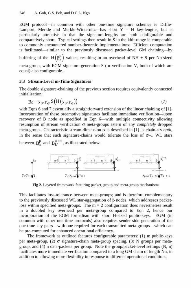
246 A. Goh, G.S. Poh, and D.C.L. Ngo
EGM protocol—in common with other one-time signature schemes ie Diffie-Lamport, Merkle and Merkle-Winternitz—has short Y = H key-lengths, but isparticularly attractive in that the signature-lengths are both configurable andcomparatively short. Typical settings then result in S in the kbit-range ie comparableto commonly encountered number-theoretic implementations. Efficient computationis facilitated—similar to the previously discussed packet-level GM chaining—by
buffering of the ( )kH µβ values; resulting in an overhead of NH + S per Nn-sized
meta-group, with EGM signature-generation S (or verification V, both of which areequal) also configurable.
3.3 Stream-Level m-Time Signatures
The double signature-chaining of the previous section requires equivalently connectedinitialisation:
( )( )0 0 0, ,S H ,y y y yB σ σ= (7)
with Eqns 6 and 7 essentially a straightforward extension of the linear chaining of [1].Incorporation of these preemptive signatures facilitate immediate verification—uponrecovery of B node as specified in Eqn 6—with multiple connectivity allowingresumption of stream verification σ meta-groups astern of any completely droppedmeta-group. Characteristic stream-dimension σ is described in [1] as chain-strength,in the sense that such signature-chains would tolerate the loss of σ–1 WL stars
between kBµ and kB
µ+σ′ , as illustrated below:
0B n βn-1 k 1Bµ
+n kBµ
βn-1
1µ−Σ 1µ+σ−ΣS
n βn-1 kBµ+σ
,y yµ µ+σ0,y yσ 2,y yµ+σ µ+ σ
Fig 2. Layered framework featuring packet, group and meta-group mechanisms
This facilitates loss-tolerance between meta-groups; and is therefore complementaryto the previously discussed WL star-aggregation of β nodes, which addresses packet-loss within specified meta-groups. The m = 2 configuration does nevertheless resultin a doubled key overhead per meta-group compared to Eqn 2, hence ourincorporation of the EGM formalism with short H-sized public-keys. EGM (incommon with other one-time protocols) also requires sender-side generation of theone-time key-pairs—with one required for each transmitted meta-groups—which canbe pre-computed for enhanced operational efficiency.
The framework as outlined features configurable parameters: (1) m public-keysper meta-group, (2) σ signature-chain meta-group spacing, (3) N groups per meta-group, and (4) n data-packets per group. Note the group/packet-level settings (N, n)facilitates more immediate verification compared to a long GM chain of length Nn, inaddition to allowing more flexibility in response to different operational conditions.

Loss-Tolerant Stream Authentication via Configurable Integration 247
4 Analysis of Framework
The proposed scheme can be implemented with any number-theoretic and one-timeprotocol. Our choice of the Rabin [14] and EGM formalisms is based primarily onperformance considerations. Rabin verification (necessitating only a single modular-squaring) is, for instance, significantly more computation-efficient compared withother number-theoretic and even H-based formulations [15]. EGM, on the other hand,is significantly more communications-efficient compared with other one-timeschemes, but in fact necessitates a higher computation-overhead. We thereforepresume the relative preeminence of bandwidth and latency constraints over thoserelated to endpoint computations. EGM signature generation and verification is alsomore computation-efficient (by up to two orders of magnitude) compared withnumber-theoretic protocols [15]. The constituent H-operations in EGM can beexecuted using block ciphers—ie the Data Encryption Standard (DES) as originallysuggested—or one-way collision-resistent compressions ie Message Digest (MD) 5 orthe Secure Hash Algorithm (SHA). Use of MD5 or SHA hashing results in superiorcomputation-efficiency, and is therefore adopted in our implementation. Thesehashes are also used to construct the above-discussed WL stars and GM augmentedchains.
Practical stream authentication must be both effective and efficient, withevaluation of both dependant on the manner in which packets are dropped in transit.Mechanisms designed to tolerate packet-loss in random-bursts (ie GM chains) cantherefore be expected to be significantly more efficient that those designed for worst-case loss (ie WL stars). Our incorporation of both WL stars and GM chains addressesthe fact that the β packets of the latter cannot be lost without major functionalconsequence. The objective is therefore to demonstrate that the featured specificationof loss-tolerance effectiveness does not significantly degrade computation andcommunications efficiency.
Our analysis is presented as follows:
4.1 Correctness
The above-outlined layered scheme can be demonstrated to be correct by consideringsystem-wide compromise to be equivalent to compromise of the underlyingcryptography protocols ie the signatures and H-graphs. We follow the GRmethodology [1], in which presumption of secure signatures—thereby establishing theinitial signed packet—is subsequently extended down a linear H-chains. Thisestablished security of linear H-chaining is based on random oracles, and is thereforeitself extensible to non-linear constructions (ie the proposed layer framework) viademonstration that node-level compromise is as difficult as the equivalent effort onthe underlying one-time signature and H-function. The proposed framework istherefore as secure as the underlying mechanisms ie: (1) number-theoretic signature,(2) one-time signature, (3) H-graphs and (4) H-function.
4.2 Signing and Verification Delay
Delay Ω is defined as the number of packets which must be buffered prior to signingor verification operations. These operations should ideally be executed on a particular

248 A. Goh, G.S. Poh, and D.C.L. Ngo
packet without delay ie Ω = 0, which denotes genuine online transmission andconsumption. Recall that delay-free operations are rendered impossible by our use ofH-graphs as an amortisation mechanism against the high overhead of signatureoperations. Our scheme results in: (1) Ω(send) = Nn from meta-group level bufferingprior to signature generation on WL root-node, and (2) Ω(recv) = n from group-levelbuffering prior to verification with respect signed β node; the latter of whichpresumes recovery of the required one-time public-keys.
4.3 Communications Overhead
The communications overhead per packet:-
i
S mH i 0
2H i ,n 1
3H i [1,n 2]
0 i n
S (m N 3)H i
′ + = = α −= ∈ −Ω =
+ + + = β
(8)
can be surmised from Eqns 4-7, with: (1) S′ the number-theoretic signature-length, (2)S the one-time signature-length, and (3) H the hash-length. We compare the proposedscheme—in three (N, n) configurations, with m = 2 signature-chaining—against otherstream authentication protocols over a 20-packet stream. Table 1 presents the delayand communication overheads associated with the various protocols:
Table 1. Buffering delays and communications overheads for 20-packet stream
Scheme (send, recv)
(i) i Loss
GR 0, 0 (0) 128, (i) 10 None
GR(one-time)
0, 0 (0) 128, (i) 146 None
WL star 20, 0 (i) 318 Worst-case
GM chain 20, 20 (α, n–1) 20, (i) 30,(n) 0, () 158
Random
Proposed scheme(4, 5)
20, 5 (0) 148, (α, n–1) 20,(i) 30, (n) 0, () 226
Random
Proposed scheme(2, 10)
20, 10 (0) 148, (α, n–1) 20,(i) 30, (n) 0, () 206
Random
Proposed scheme(1, 20)
20, 20 (0) 148, (α, n–1) 20,(i) 30, (n) 0, () 196
Random
given 10-byte H-words, 128-byte number-theoretc signatures and 136-byte one-timesignatures. These hashes are relatively short compared to those used on blocked data,but are sufficient in the context of interest ie to ensure target collision-resistance withrespect a fixed message, rather than a more generalised anti collision-resistance.

Loss-Tolerant Stream Authentication via Configurable Integration 249
Note the lessened verification delay compared to unassisted GM chaining, whileretaining the general efficiency of the augmented chain structure. This configurablereduction of the receiver-side delay is attained while simultaneously incorporating(random) loss-tolerance, the latter of which cannot be addressed by the GR and GRone-time formulations. The trade-off between Ω(recv) and βΩ is also interesting, as
is the significantly lessened communications overhead compared with the unassistedWL star configuration. Our scheme can therefore be said to possess functionaladvantages compared with previously reported formulations.
4.4 Computation Overhead
The signing overhead can also expressed in terms of the constituent operations ie: (1)S′ computations on a stream basis, (2) S computations on a meta-group basis, and (3)H computations on a group/packet basis. We presume the necessity of only a singleS′ per streaming session—thereafter represented as [S′] to denote amortisation overmultiple meta-groups—and also prior generation of the one-time key-pair sequence.Each meta-group then requires N(n+2) H-computations to account for all the datapackets, with N(n+1) required for GM chain construction; as can be seen from Eqns 4and 5. Meta-group formation also requires Ω(WL) = S + (N+2)H association with WLstar computation from Eqn 6. Buffering of packet-level hashes as previouslydiscussed allows for significant efficiency gains, thereby allowing analysis in terms ofincremental overheads during GM chaining ie i H=∆Ω (for i ≠ n) and n 0=∆Ω .
This results in a total meta-group overhead of:
( )k [S ] S N(n 2) 2 H′= + + + +Ω (9)
associated with sender-side signature generation.The verification overhead is likewise expressible in terms of: (1) V′ computations
on a stream basis, (2) V computations on a meta-group basis, and (3) H computationson a group/packet basis; with [V′] to denote amortisation over multiple meta-groups.Presumption of packet-level hash-buffering then allows for incremental overheads
i H=∆Ψ (for i ≠ n), n 0=∆Ψ and ∆Ψ(WL) = V + 3H. This results in:
( )k [V ] V N(n 1) 3 H′= + + + +Ψ (10)
associated with receiver-side signature verification. It should be emphasised that Hretrieval rather than recomputation is especially significant for (N, n) configurationswith relatively sparse WL star connections of long GM chains.
Our framework—once again in three (N, n) configurations—is compared withpreviously published protocols over multiple µ repetitions of a 20-packet meta-group,resulting in Table 2 ie:

250 A. Goh, G.S. Poh, and D.C.L. Ngo
Table 2. Signing and verification overheads for µ repetitions of 20-packet meta-group
Scheme (sign) (verify) Loss
GR S′ + 20µH V′ + 20µH None
GR(one-time)
S′ + 20µS V′ + 20µV None
WL star µ⋅(S′ + 21H)S′ + µ⋅(S + 21H)
µ⋅(V′ + 40H)V′ + µ⋅(V + 40H)
Worst-case
GM chain µ⋅(S′ + 24H)S′ + µ⋅(S + 24H)
µ⋅(V′ + 19H)V′ + µ⋅(V + 19H)
Random
Proposed scheme(4, 5)
S′ + µ⋅(S + 30H) V′ + µ⋅(V + 27H) Random
Proposed scheme(2, 10)
S′ + µ⋅(S + 26H) V′ + µ⋅(V + 25H) Random
Proposed scheme(1, 20)
S′ + µ⋅(S + 24H) V′ + µ⋅(V + 24H) Random
We present the WL star and GM chain overheads in terms of: (1) originally reportedtwo-layer (number-theoretic signatures and H-graphs) frameworks, and (2) modifiedtwo-layer framework incorporating one-time signatures; the latter of which is clearlymore efficient. Note the progressively higher overheads corresponding to morefrequent WL star computations. This nevertheless still results in receiver-sideverification significantly more efficient than the unassisted WL star configuration.Comparison with unassisted GM chaining is obviously unfavourable, with theoverhead difference interpretable as the cost of ensuring that β node verification isloss-tolerant. As with Table 1, the GR and GR one-time (both of which are loss-intolerant) formulations are the most computation-efficient. The presented frameworkis by contrast robustly loss-tolerant, while featuring configurable overheads notsignificantly greater than the optimal GM chain configuration.
5 Conclusions
The presented multi-layer stream authentication framework effectively leverages thedesirable characteristics of the underlying mechanisms ie: (1) preemptive one-timesignature-chains, (2) robustly loss-tolerant WL stars, and (3) efficiently loss-tolerantGM chains. This enables flexible configurability ie emphasising: (1) buffering orcommunications efficiency (ref Table 1), and (2) packet-loss tolerance or computationefficiency (ref Table 2); the relative importance of which is variably dependant on theoperational scenario. Our integrated framework also compensates for the functionalshortcomings of the constituent mechanisms ie: (1) high overhead of WL stars, and(2) inherent loss-sensitivity of the GM β nodes.
Note the relatively heavy authenticative overhead of the β nodes—resulting fromsignature and WL star related parameter affixation—compared to the bulk datapackets. This authenticative non-uniformity is a consequence of the GM chainstructure, and is entirely appropriate for various real-life datastreams ie as specified

Loss-Tolerant Stream Authentication via Configurable Integration 251
by the Motion Picture Experts Group (MPEG) standard. MPEG streams are, in fact,constituted from functionally distinct data constructs ie: (1) (I)ntra frames which areessentially static Joint Picture Experts Group (JPEG) images, (2) (P)redictive framesderived from previous reference data, and (3) (B)idirectional frames derived fromprevious/subseqeunt reference data; the first of which is by far the largest. Thefunctional importance and large size of the I-frames allows them to carry the βauthenticative overhead without resulting in unreasonably low data-to-(data+authenticator) ratios. We look forward to exploring the applicability of theproposed formulation in an upcoming publication.
References
1. R Gennaro & P Rohatgi, “How to Sign Digital Streams”, Adv in Cryptology – CRYPTO’97, Springer-Verlag, Berlin, pp 180–197, 1997.
2. CK Wong & SS Lam, “Digital Signatures for Flows and Multicasts”, Comp Sc Tech RepTR-98-15, U Texas at Austin. Also, in IEEE ICNP ’98, 1998.
3. P Golle & N Modadugu, “Authenticating Streamed Data in the Presence of RandomPacket Loss”, ISOC Network and Distributed System Security Symp, pp 13–22, 2001.
4. P Rohatgi. “A Compact and Fast Hybrid Signature Scheme for Multicast PacketAuthentication and Others Protocols”, 6th ACM Conf on Comp and Comms Security, pp93-100, 1999.
5. A Perrig, R Canetti, JD Tygar & D Song, “Efficient Authentication and Signing ofMulticast Streams over Lossy Channels”, IEEE Symp on Security and Privacy, pp 56–73,2000.
6. S Miner & J Staddon, “Graph-based Authentication of Digital Streams”, IEEE Symp onSecurity and Privacy, 2001.
7. A Perrig, “The BiBa One-Time Signature and Broadcast Authentication Protocol”, 8th
ACM Conf on Comp and Comms Security, pp 28–37, 2001.8. V Paxson. “End-to-end Internet Packet Dynamics”, IEEE/ACM Trans on Networking, 7,
pp 277–292, 1999.9. M Borella, D Swider, S Uludag & G Brewster, “Internet Packet Loss: Measurement and
Implications for End-to-end QoS”, Intl Conf Parallel Processing, 1998.10. S Even, O Goldreich & S Micali, “On-line/Off-line Digital Signatures”, J Cryptology,
9(1), pp 35–67, 1996.11. RC Merkle, “A Digital Signature based on a Conventional Encryption Function”, Adv in
Cryptology—Crypto ’87, LNCS 293, pp 369–378, 1987.12. RC Merkle, “A Certified Digital Signature”’ Adv in Cryptology—Crypto ’89, LNCS 435,
pp 218–238, 1989.13. S Goldwasser, S Micali & R Rivest, “A Digital Signature Scheme Secure Against
Adaptive Chosen Message Attack”, Siam J. Comp., 17(2), 281–308, 1988.14. MO Rabin, “Digital Signatures and Public-Key Functions as Intractable as Factorization”,
Comp Sc Tech Rep MIT/LCS/TR-212, MIT, 1979.15. GS Poh. “Loss-Tolerant Stream Authentication Based on One-Time Signatures and Hash-
Graphs”, Comp Sc Masters Thesis, University Sains Malaysia.

Confidential Transmission of Lossless VisualData: Experimental Modelling and Optimization
Bubi G. Flepp-Stars1, Herbert Stogner1, and Andreas Uhl1,2
1 Carinthia Tech Institute, School of Telematics & Network EngineeringPrimoschgasse 8, A-9020 Klagenfurt, Austria
2 Salzburg University, Department of Scientific ComputingJakob-Haringerstr.2, A-5020 Salzburg, Austria
Abstract. We discuss confidential transmission of visual data in loss-less format. Based on exemplary experimental data, we model the costsof the three main steps of such a scheme, i.e. compression, encryption,and transmission. Subsequently, we derive a cost optimal strategy foremployment of confidential visual data transmission. Our approach maybe applied to any environment provided that the costs of the single mainsteps in the target environment are known.
1 Introduction
The organization of large amounts of visual content in database infrastructureswhich are distributed worldwide shows very clearly that there is urgent needto provide and protect the confidentiality of sensitive visual data (e.g. patientrelated medical image data) when transmitted over networks of any kind.
The storage and transmission of visual image data in lossless formats differssignificantly from storage and transmission of common visual data for multime-dia applications. It is constrained by the fact that in lossless environments theamount of compression is typically limited to a factor of about 2-3 in contrastto factors of 100 or more achievable in lossy schemes [4].
There exist several reasons why a lossy representation may not be acceptableor a lossless one may be preferable:
– Due to requirements of the application a loss of image data is not acceptable(e.g., in medical applications because of reasons related to legal aspects anddiagnosis accuracy [17], in geographical information systems (GIS) due tothe required integrity of the data).
– Due to the low processing power or limited energy resources of the involvedhardware, compression and decompression of visual data may not be pos-sible or desired at all (e.g. mobile and wireless clients in the context ofpervasive/ubiquitous computing).
This artificial name represents the following group of students working on this projectin the framework of the multimedia 1 laboratory (winterterm 2003/2004): G. Biebl,J. Burger, T. Freidl, J. Gruber, P. Leidner, R. Pfarrhofer, J. Podritschig, S. Rebernig,T. Salbrechter, and G. Stanossek
A. Lioy and D. Mazzocchi (Eds.): CMS 2003, LNCS 2828, pp. 252–263, 2003.c© IFIP International Federation for Information Processing 2003

Confidential Transmission of Lossless Visual Data 253
– Due to the high bandwidth available at the communication channel lossycompression is not necessary and lossless formats are therefore preferred.
A possible solution to the first issue is to use selective compression where partsof the image that contain crucial information (e.g. microcalcifications in mammo-grams) are compressed in a lossless way whereas regions containing unimportantinformation are compressed in a lossy manner [2]. However, legal questions andproblems related to the usability of such a scheme remain unsolved. Therefore,we restrict the discussion to lossless data formats.
In the context of applications involving visual data transmission, we maydistinguish whether the image data is given as plain image data (e.g. after beingcaptured by a digitizer or CCD array) or in form of a bitstream resulting fromprior compression. The first application scenario has been denoted as “on-line”(e.g. video conferencing, surveillance applications) and the latter “off-line” (sincethe respective applications like video on demand or photo CD-ROM are purelyretrieval based) [9,14]. Note that the involvement of compression technologymight be not mandatory in the on-line scenario, especially when focusing ontolossless techniques due to the limited compression gain in this case.
In this work we focus on computationally efficient schemes to provide con-fidentiality for the transmission of visual data in a lossless on-line scenario. Inparticular, we seek to optimize the interplay of the three main steps of such ascheme, i.e. compression, encryption, and transmission in the sense of minimalcomputational effort and energy consumption. Based on exemplary experimentaldata, we model the costs of the three involved processing steps and subsequentlyderive a cost optimal strategy for employment of confidential visual data trans-mission in the target environment. Specifically, we aim at the question whetherthe compression stage is required in any case to result in an overall cost optimalscheme or not.
Additionally, we consider “selective encryption” (SE) for trading off compu-tational complexity for security, where application specific data structures areexploited to create more efficient encryption systems (see e.g. SE of MPEG videostreams [1,6,11,13,15,18], of wavelet-based encoded imagery [3,7,10,18], and ofquadtree decomposed images [3]). The basic idea of SE is to protect (i.e. en-crypt) the visually most important parts of an image or video representationonly, relying on a secure but slow “classical” cipher.
Section 2 provides an introduction to principles of confidential transmissionof visual data. In section 3 we present the building blocks of our target envi-ronment and model the respective computational costs based on experimentaldata. Cost optimal employment of several different configurations of confidentialvisual data transmission using full encryption and SE is derived in section 4. Inthe conclusion we summarize the main results and give an outlook to furtherwork in this direction.

254 B.G. Flepp-Stars, H. Stogner, and A. Uhl
2 Principles of Confidential Transmission of Visual Data
Images and videos (often denoted as visual data) are data types which requireenormous storage capacity or transmission bandwidth due to the large amountof data involved. In order to provide reasonable execution performance for en-crypting such large amounts of data, usually symmetric encryption is used inpractical applications. On the other hand, key management is a difficult issue insymmetric systems. As done in most current applications with demand for con-fidentiality, public key techniques like RSA are used for key exchange or digitalsignature generation only (such schemes are usually denoted as “hybrid”).
The Advanced Encryption Standard AES [5] is a recent symmetric blockcipher which is going to replace the Data Encryption Standard DES in all appli-cations where confidentiality is really the aim. AES operates on 128-bit blocksof data and uses 128, 196, or 256 bit keys. The RSA algorithm [12] is the mostpopular public key algorithm nowadays and operates with key sizes of 512 bitupwards. For achieving confidentiality, the data is encrypted using the public keyof the receiver who may decrypt the message using his private key. Vice versa,for generating a digital signature, the data is signed (i.e. encrypted) using theprivate key of the signer. The signature may be verified with the correspondingpublic key. We use AES and RSA as the basic cryptographic building blocks insection 2.
There are two ways to provide confidentiality to a transmission application.First, confidentiality is based on mechanisms provided by the underlying com-putational infrastructure. The advantage is complete transparency, i.e. the useror a specific application does not have to take care about confidentiality. Theobvious disadvantage is that confidentiality is provided for all applications, nomatter if required or not, and that it is not possible to exploit specific proper-ties of certain applications. To give a concrete example, consider the distributeddatabase infrastructure mentioned in the introduction. If the connections amongthe components are based on TCP/IP internet-connections (which are not con-fidential by themselves of course), confidentiality can be provided by creating aVirtual Private Network (VPN) using IPSec (which extends the IP protocol byadding confidentiality and integrity features). In this case, the entire visual datais encrypted for each transmission which puts a severe load on the encryptionsystem. The second possibility is to provide confidentiality on the applicationlayer. Here, only applications and services are secured which have a demand forconfidentiality. The disadvantage is that each application needs to take care forconfidentiality by its own, the advantage is that specific properties of certainapplications may be exploited to create more efficient encryption schemes orthat encryption is omitted if not required. For example, all approaches involvingselective encryption are classified into the second category since SE takes advan-tage of the redundancy in visual data and therefore takes place at the applicationlevel.

Confidential Transmission of Lossless Visual Data 255
3 Basic Building Blocks: Compression, Encryption, andTransmission
In any (storage or) transmission application no matter if lossy or lossless, com-pression has always to be performed prior to encryption since the statisticalproperties of encrypted data prevent compression from being applied success-fully. Moreover, the reduced amount of data after compression decreases thecomputational demand of the subsequent encryption stage. Therefore, the pro-cessing chain has a fixed order (compression – encryption – transmission). In thefollowing subsections, we introduce the basic technology and model the costs interms of computational demand of the stages in the processing chain in the tar-get environment. The hardware platform used is a 996 MHz Intel Pentium IIIwith 128 MB RAM, the Network is 100 MBit/s Ethernet.
3.1 Lossless Compression
In order to model a compression scheme which trades off compression efficiencyfor computational demand, we use the JBIG reference implementation in a se-lective mode where a different amount of bitplanes of 8 bpp grayscale images iscompressed. So our scheme ranges from applying no compression at all to com-pressing a certain number of bitplanes using JBIG (starting from the MSB bit-plane since the achievable compression ratio is the highest here). Finally, insteadof applying JBIG to all bitplanes, JPEG 2000 (the Jasper C implementation)in lossless mode is used since the compression results are better as compared tofull JBIG coding.
A set of 20 testimages in two sizes is subjected to all compression settings andthe obtained file sizes and compression timings are averaged for the 512 × 512and 1280 × 1024 pixels images, respectively. The resulting measurement pointsas depicted in Fig. 1 clearly show the decreasing compression time for increasingdata size.
In order to obtain a closed expression to be handled easily in an analyticalway for the optimization, we approximately interpolate the measurement pointsby a 6th-order polynomial and result in the following formulas (also visualizedin Fig. 1) for the compression behaviour of our test system (where x is theresulting data size in 100 KByte after compression and t is the compression timein seconds):
t = 7.32x6−90.89x5+463.02x4−1237.72x3+1829.28x2−1417.22x+450.73 (1)
t = −0.07x5 + 1.73x4 − 21.99x3 + 153.94x2 − 562.09x + 841.21 (2)
Equations (1) and (2) correspond to Figs. 1.a and 1.b, respectively.

256 B.G. Flepp-Stars, H. Stogner, and A. Uhl
1.4 1.6 1.8 2 2.2 2.4 2.6 2.8−0.1
0
0.1
0.2
0.3
0.4
0.5
0.6
0.7
0.8compression size to time for picturesize 512 x 512
size in 100Kbyte
time
in s
ec
plane 1−7
plane 1−6
plane 1−5
plane 1−4
plane 1−3
plane 1−2
plane 1
jasper
original
originalapproximation
(a) 512x512 pixels images
6 7 8 9 10 11 12 13−0.5
0
0.5
1
1.5
2
2.5
3
3.5
4compression size to time for picturesize 1280 x 1024
size in 100Kbyte
time
in s
ec
plane 1−7
plane 1−6
plane 1−5
plane 1−4
plane 1−3
plane 1−2
plane 1
jasper
original
originalapproximation
(b) 1280x1024 pixels images
Fig. 1. Trandeoff between compression timings and the resulting data amount aftercompression.
3.2 Encryption and Transmission
In order to model encryption behaviour, we use the C++ RSA implemen-tation given in [16] and the C++ AES implementation available at theweb (http://fp.gladman.plus.com/cryptography_technology/rijndael/).Equations (3) to (6) relate the amount of data encrypted in 100 kByte to theprocessing time (given in seconds), the corresponding curves are visualized inFig. 2.a. In contrast to the compression case, we notice a purely linear behaviour.Note that RSA is employed for reasons of obtaining a rich variety in the overallbehaviour of the processing chain. In practice, one would hardly use a public-keysystem to encrypt visual data. Of course, the time demand of RSA is several or-ders of magnitude higher as compared to AES. Performance differences amongencryption schemes with the exhibited magnitude could result from applyinghardware or software based approaches in real-life systems.
t = 5.81x (RSA 512 bit) (3)t = 19.72x (RSA 2048 bit) (4)t = 0.01x (AES 128 bit) (5)t = 0.02x (AES 256 bit) (6)
Finally, the transmission stage is modeled by using the message passing li-brary PVM for sending data between two computers over the Ethernet con-nection. We use four different modes. The routine pvm send sends a messagestored in the active send buffer to the PVM process identified by tid. On theother hand, the routine pvm psend takes a pointer to a buffer buf, its length

Confidential Transmission of Lossless Visual Data 257
0 5 10 15 20 25 300
100
200
300
400
500
600
size in 100kByte
dura
tion
in s
ec.
key generation and encryption with RSA
512 bits keylength2048 bits keylength
0 5 10 15 20 25 300
0.1
0.2
0.3
0.4
size in 100kByte
dura
tion
in s
ec.
key generation and encryption with AES
128 bits keylength256 bits keylength
(a) Encryption
0 5 10 15 20 25 30 350
0.2
0.4
0.6
0.8
1
1.2
1.4sending time
size in 100 Kbyte
time
in s
ec
sendganz
sendteil
psendganz
psendteil
(b) Transmission
Fig. 2. Processing timings for varying data amount.
len, and its data type datatype and sends this data directly to the PVM taskidentified by tid. Data is sent as a whole block in mode “ganz” whereas it is sentin pieces of 1 KByte in mode “teil”. Again, the data size is varied and the timerequired to transmit the data is measured and fitted by a polynomial (see Fig.2.b and equations (7) - (10). We notice small differences among the transmis-sion schemes with pvm psend in “teil” mode being the most expensive one. Allschemes are dominated by the linear term, higher order terms vanish with theprecision considered.
t = 0.01x pvm send, teil (7)t = 0.02x pvm psend, teil (8)t = 0.007x pvm send, ganz (9)t = 0.01x pvm psend, ganz (10)
Summarizing we notice that AES encryption and transmission operate on asimilar level of time demand, whereas RSA is much more expensive. As expected,both processing stages exhibit linear behaviour.
4 Cost Optimal Configuration of Confidential VisualData Transmission
The processing chain for confidential transmission of visual data as defined inthe last section (compression – encryption – transmission) may have a fixedorder, but does not necessarily involve all stages in full completeness in anycase. For example, in SE only a subset of the data is subjected to encryption.

258 B.G. Flepp-Stars, H. Stogner, and A. Uhl
However, the entire system might have to maintain a certain level of securitywhich puts constraints on the lower bound of data subjected to encryption. Sim-ilarly, compression must not necessarily be applied to the full amount of dataor might be omitted at all for complexity reasons. Again, limited transmissionbandwidth may impose a constraint on the possible datarate and therefore en-force the employment of compression to a certain extent. The aim of this sectionis to identify a cost optimal way (in terms of processing time) to operate ourprocessing chain. Concerning constraints imposed by the target environment, weassume the channel to be of infinite bandwidth and SE as being secure enoughfor the target application.
The first configuration considered is to process 1280×1024 images and to useAES as cipher. In Fig. 3 we clearly see that the overall shape of the resulting timecurves closely matches the curve modeling compression behaviour (see Fig. 1.b).In particular, the curves are almost monotonically decreasing and attain theirminima at the right edge of the x-axis, corresponding to a data size of about 1290KB. When matching this result with Fig. 1.b, we identify the optimal operationmode as to perform no compression at all. This is a surprising result at firstsight of course, however, when considering the low processing cost of encryptionand transmission as compared to compression, it is obvious.
7 8 9 10 11 121
1.5
2
2.5
3
3.5
4
size in 100 Kbytes
time
in s
econ
ds
overalll size to time for picturesize 1280x1024
AES(256Bit) & zeit−psend−teil
(a) AES(256) with psend teil
7 8 9 10 11 120.5
1
1.5
2
2.5
3
3.5
4
size in 100 Kbytes
time
in s
econ
ds
overalll size to time for picturesize 1280x1024
AES(256Bit) & zeit−send−ganz
(b) AES(256) with send ganz
Fig. 3. Overall timings for varying data amount processing 1280x1024 pixels imagesusing AES.
The only difference between Figs. 3.a and 3.b is the employment of the mostand least expensive transmission modes. As expected, this results in almost nodifference in the final overall time curves. The same is true whether 128 or 256 bitAES is used (figures are not shown). As a consequence, the formulas describing

Confidential Transmission of Lossless Visual Data 259
the overall behaviour are identical to Equation (2) with the linear terms replacedby −562.05x and −562.07x, respectively.
The second configuration investigated is to process 1280×1024 images and touse RSA as cipher. Fig. 4 shows entirely different shapes as seen before. Almostlinearly increasing curves describe the time behaviour of the system, attainingtheir respective minima at the left edge of the x-axis, corresponding to a datasize of 660 KB. The fact that these curves are monotonically increasing may beeasily verified by showing the first derivative of the corresponding formulas tobe larger as zero over the entire range considered. Relating this finding to Fig.1.b, the optimal operation mode is to perform maximal compression, in this caselossless JPEG 2000.
7 8 9 10 11 1240
45
50
55
60
65
70
75
80
size in 100 Kbytes
time
in s
econ
ds
overalll size to time for picturesize 1280x1024
RSA(512Bit) & zeit−psend−teil
(a) RSA(512) with psend teil
7 8 9 10 11 12120
140
160
180
200
220
240
260
size in 100 Kbytes
time
in s
econ
ds
overalll size to time for picturesize 1280x1024
RSA(2048Bit) & zeit−psend−teil
(b) RSA(2048) with psend teil
Fig. 4. Overall timings for varying data amount processing 1280x1024 pixels imagesusing RSA.
The employment of RSA with differently sized keys (i.e. 512 bit for Fig.4.a and 2048 bit for Fig. 4.b) does change neither the shape of the curve northe position of the minimum, the curve is simply upshifted a certain amount(which dramatically shows the dominance of encryption in this configuration).The formulas describing the overall behaviour are again identical to Equation(2) with the linear terms replaced by −556.26x and −542.35x, respectively.
Having identified the optimal operation modes of our test system with fullencryption, we now focus onto selective encryption (SE). In this context, SEonly encrypts a subset of the bitplanes of the binary representation of the visualdata. For results concerning the security of this approach see [8,14]. Besides theinteresting properties of this technique itself, we are interested whether thereexist optimal operation modes where a partial compression is required (instead ofno compression with AES and full compression with RSA). Selective encryption
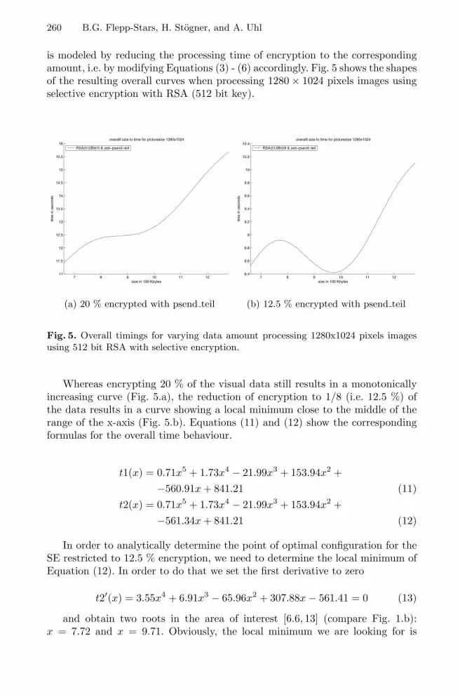
260 B.G. Flepp-Stars, H. Stogner, and A. Uhl
is modeled by reducing the processing time of encryption to the correspondingamount, i.e. by modifying Equations (3) - (6) accordingly. Fig. 5 shows the shapesof the resulting overall curves when processing 1280× 1024 pixels images usingselective encryption with RSA (512 bit key).
7 8 9 10 11 1211
11.5
12
12.5
13
13.5
14
14.5
15
15.5
16
size in 100 Kbytes
time
in s
econ
ds
overalll size to time for picturesize 1280x1024
RSA(512Bit)/5 & zeit−psend−teil
(a) 20 % encrypted with psend teil
7 8 9 10 11 128.4
8.6
8.8
9
9.2
9.4
9.6
9.8
10
10.2
10.4
size in 100 Kbytes
time
in s
econ
ds
overalll size to time for picturesize 1280x1024
RSA(512Bit)/8 & zeit−psend−teil
(b) 12.5 % encrypted with psend teil
Fig. 5. Overall timings for varying data amount processing 1280x1024 pixels imagesusing 512 bit RSA with selective encryption.
Whereas encrypting 20 % of the visual data still results in a monotonicallyincreasing curve (Fig. 5.a), the reduction of encryption to 1/8 (i.e. 12.5 %) ofthe data results in a curve showing a local minimum close to the middle of therange of the x-axis (Fig. 5.b). Equations (11) and (12) show the correspondingformulas for the overall time behaviour.
t1(x) = 0.71x5 + 1.73x4 − 21.99x3 + 153.94x2 +−560.91x + 841.21 (11)
t2(x) = 0.71x5 + 1.73x4 − 21.99x3 + 153.94x2 +−561.34x + 841.21 (12)
In order to analytically determine the point of optimal configuration for theSE restricted to 12.5 % encryption, we need to determine the local minimum ofEquation (12). In order to do that we set the first derivative to zero
t2′(x) = 3.55x4 + 6.91x3 − 65.96x2 + 307.88x− 561.41 = 0 (13)
and obtain two roots in the area of interest [6.6, 13] (compare Fig. 1.b):x = 7.72 and x = 9.71. Obviously, the local minimum we are looking for is

Confidential Transmission of Lossless Visual Data 261
attained at x = 9.71 (which can be computing by verifying t2′(9.71) < 0 andis also shown in Fig. 5.b). Relating this result to Fig. 1.b we may deduce thatthe optimal configuration of the entire system compressing 1280 × 1024 pixelsimages and applying selective encryption with 512 bit RSA to 12.5 % of the datais to compress 3 out of 8 bitplanes with JBIG.
Finally, we cover the case of processing 512× 512 pixels images with 512 bitRSA. Fig. 6 shows similar shapes of the resulting overall time curves compared tothe case of larger images before, equations (14) and (15) show the correspondingformulas. Note that only relatively small differences in the linear term causethe significant different shapes as compared to the “compression” Equation (1).Again we focus on the interesting case of encrypting 12.5 % of the data (Fig.6.b).
1.5 1.6 1.7 1.8 1.9 2 2.1 2.2 2.3 2.4 2.5
2.5
2.6
2.7
2.8
2.9
3
3.1
3.2
size in 100 Kbytes
time
in s
econ
ds
overalll size to time for picturesize 512x512
RSA(512Bit)/5 & zeit−psend−teil
(a) 20 % encrypted with psend teil
1.5 1.6 1.7 1.8 1.9 2 2.1 2.2 2.3 2.4 2.51.7
1.75
1.8
1.85
1.9
1.95
size in 100 Kbytes
time
in s
econ
dsoveralll size to time for picturesize 512x512
RSA(512Bit)/8 & zeit−psend−teil
(b) 12.5 % encrypted with psend teil
Fig. 6. Overall timings for varying data amount processing 512x512 pixels images using512 bit RSA with selective encryption.
t3(x) = 7.32x6 − 90.89x5 + 463.02x4 − 1237.72x3 + 1829.28x2 +−1416.04x + 450.73 (14)
t4(x) = 7.32x6 − 90.89x5 + 463.02x4 − 1237.72x3 + 1829.28x2 +−1416.47x + 450.73 (15)
Similarly, in order to determine the point of optimal configuration, we needto determine the local minimum of equation (15). In order to do that we set thefirst derivative to zero
t4′(x) = 43.93x5−454.43x4+1852.1x3−3713.16x2+3658.56x−1416.47 = 0 (16)

262 B.G. Flepp-Stars, H. Stogner, and A. Uhl
and obtain two roots in the area of interest [1.4, 2.6] (compare Fig. 1.a):x = 1.64 and x = 2.10. Obviously, the local minimum we are looking for isattained at x = 2.10 (which can be computing by verifying t4′(2.10) < 0 and isalso shown in Fig. 6.b). As before, we identify the optimal operation mode ofthe entire system to apply selective compression to 2 bitplanes out of 8 (to beseen from Fig. 1.a).
5 Conclusion
In the context of confidential transmission of visual data in lossless format, wehave modeled the costs of the three main steps of such a scheme, i.e. compres-sion, encryption, and transmission. Based on the behaviour of our exemplarysystem, we have shown that depending on the type of encryption involved, theoptimal configuration of the entire system may be to operate without compres-sion, with full compression, or even with partial compression. In future work wewill additionally include constraints coming from the target environment (e.g.limited channel bandwidth, certain level of security in SE) into our optimization.Additionally we will model the dependency between selective compression andselective encryption more clearly.
Acknowledgements. This work has been partially supported by the AustrianScience Fund FWF, project 15170.
References
[1] A. M. Alattar, G. I. Al-Regib, and S. A. Al-Semari. Improved selective encryp-tion techniques for secure transmission of MPEG video bit-streams. In Proceed-ings of the 1999 IEEE International Conference on Image Processing (ICIP’99),volume 4, pages 256–260, Kobe, Japan, October 1999. IEEE Signal ProcessingSociety.
[2] A. Bruckmann and A. Uhl. Selective medical image compression techniquesfor telemedical and archiving applications. Computers in Biology and Medicine,30(3):153 – 169, 2000.
[3] H. Cheng and X. Li. Partial encryption of compressed images and videos. IEEETransactions on Signal Processing, 48(8):2439–2451, 2000.
[4] P.C. Cosman, R.M. Gray, and R.A. Olshen. Evaluating quality of compressedmedical images: SNR, subjective rating, and diagnostic accuracy. Proceedings ofthe IEEE, 82(6):919–932, 1994.
[5] J. Daemen and V. Rijmen. The Design of Rijndael: AES — The Advanced En-cryption Standard. Springer Verlag, 2002.
[6] Thomas Kunkelmann. Applying encryption to video communication. In Proceed-ings of the Multimedia and Security Workshop at ACM Multimedia ’98, pages41–47, Bristol, England, September 1998.
[7] R. Norcen, M. Podesser, A. Pommer, H.-P. Schmidt, and A. Uhl. Confidential stor-age and transmission of medical image data. Computers in Biology and Medicine,33(3):277–292, 2003.

Confidential Transmission of Lossless Visual Data 263
[8] M. Podesser, H.-P. Schmidt, and A. Uhl. Selective bitplane encryption for securetransmission of image data in mobile environments. In CD-ROM Proceedingsof the 5th IEEE Nordic Signal Processing Symposium (NORSIG 2002), Tromso-Trondheim, Norway, October 2002. IEEE Norway Section. file cr1037.pdf.
[9] A. Pommer and A. Uhl. Application scenarios for selective encryption of visualdata. In J. Dittmann, J. Fridrich, and P. Wohlmacher, editors, Multimedia andSecurity Workshop, ACM Multimedia, pages 71–74, Juan-les-Pins, France, De-cember 2002.
[10] A. Pommer and A. Uhl. Selective encryption of wavelet packet subband struc-tures for secure transmission of visual data. In J. Dittmann, J. Fridrich, andP. Wohlmacher, editors, Multimedia and Security Workshop, ACM Multimedia,pages 67–70, Juan-les-Pins, France, December 2002.
[11] Lintian Qiao and Klara Nahrstedt. Comparison of MPEG encryption algorithms.International Journal on Computers and Graphics (Special Issue on Data Securityin Image Communication and Networks), 22(3):437–444, 1998.
[12] B. Schneier. Applied cryptography (2nd edition): protocols, algorithms and sourcecode in C. Wiley Publishers, 1996.
[13] C. Shi and B. Bhargava. A fast MPEG video encryption algorithm. In Proceedingsof the Sixth ACM International Multimedia Conference, pages 81–88, Bristol, UK,September 1998.
[14] Champskud J. Skrepth and Andreas Uhl. Selective encryption of visual data:Classification of application scenarios and comparison of techniques for losslessenvironments. In B. Jerman-Blazic and T. Klobucar, editors, Advanced Commu-nications and Multimedia Security, IFIP TC6/TC11 Sixth Joint Working Con-ference on Communications and Multimedia Security, CMS ’02, pages 213 – 226,Portoroz, Slovenia, September 2002. Kluver Academic Publishing.
[15] L. Tang. Methods for encrypting and decrypting MPEG video data efficiently. InProceedings of the ACM Multimedia 1996, pages 219–229, Boston, USA, November1996.
[16] M. Welschenbach. Kryptographie in C und C++. Zahlentheoretische Grundlagen,Computer-Arithmetik mit großen Zahlen, kryptographische Tools. Springer Verlag,1998.
[17] S. Wong, L. Zaremba, D. Gooden, and H.K. Huang. Radiologic image compression– a review. Proceedings of the IEEE, 83(2):194–219, 1995.
[18] Wenjun Zeng and Shawmin Lei. Efficient frequency domain video scrambling forcontent access control. In Proceedings of the seventh ACM International Multi-media Conference 1999, pages 285–293, Orlando, FL, USA, November 1999.

Author Index
Aslan, Heba K. 14
Baglietto, Pierpaolo 172Bassi, Alessandro 54Bertino, Elisa 146
Dietl, Werner 214
Ferrari, Elena 146Flepp-Stars, Bubi G. 252Furnell, Steven 65
Goh, Alwyn 1, 27, 181, 239
Herrera-Joancomartı, Jordi 226Hollosi, Arno 117Huang, Richard 76
Kent, Stephen T. 40
Laganier, Julien 54Li, Wei 205Li, Xiaoqiang 205Lines, Benn 65Lopez, Javier 158
Maresca, Massimo 172Maziero, Carlos 132Megıas, David 226Minguillon, Julia 226Miyaji, Atsuko 89Moggia, Francesco 172
Ngo, David C.L. 1, 27, 239, 181
Norcen, Roland 194
Obelheiro, Rafael R. 104Ortega, Juan J. 158
Papadaki, Maria 65Poh, G.S. 239
Rangan, Venkat P. 76Reynolds, Paul 65Rossler, Thomas 117
Sakabe, Yusuke 89Santin, Altair Olivo 132Silva Fraga, Joni da 104, 132Soshi, Masakazu 89Squicciarini, Anna C. 146Stogner, Herbert 252
Taesombut, Nut 76Troya, Jose M. 158
Uhl, Andreas 194, 214, 252
Vivas, Jose 158
Wangham, Michelle S. 104
Xue, Xiangyang 205
Yip, Kuan W. 181
Zingirian, Nicola 172