finite element approach to bending of micropolar plates
TRANSCRIPT

INTERNATIONAL JOURNAL FOR NUMERICAL METHODS IN ENGINEERING, VOL. 8, 31 1-322 (1974)
FINITE ELEMENT APPROACH TO BENDING OF MICROPOLAR PLATES
JOHN E. GOLDBERG? School of Civil Engineering. Purdue University. West Lafayetie, Indiana. U.S.A.
MOHAMMED H. BALUCHI Department of Civil Engineering. Tennessee State University. Nashville, Tennessee, U.S.A
TALAT K O R M A N ~ School of Civil Engineering, Purdue University, West Lafayette, Indiana. U .S .A
SEVERINO L. KOHT School of Aeronautics. Astronautics and Engineering Sciences, Purdue University, West Lafayette, Indiana. U S . A
INTRODUCTION
This paper is concerned primarily with a finite element formulation of the problem of bending of micropolar plates using the three-dimensional equations of the micropolar theory of elasticity in conjunction with Kirchhoff's assumption for bending of plates. The micropolar theory of elasticity is one of several modern theories attempting to described behaviour of 'oriented' or 'directed media'. Duhem' is generally credited with introducing the concept of oriented media, viewing the body as a collection of points together with directions associated with the points. An initial attempt to construct a multi-dimensional theory of oriented media was made by E. and F. Cosserat4 and subsequently extended by Ericksen and Truesdell.6 A review of the development ofthetheoryoforientedmedia upto 1960iscontainedin amonographbyTruesde1landToupin.l
The past few years have witnessed the development of several modern theories attempting to predict the behaviour of oriented media with internal structure. For a review of these theories, the reader is referred to the proceedings, edited by Kroner,'* of a relatively recent symposium. The theory relevant to the present investigation and classified as a general theory of microelastic solids was formulated by MindlinI3 and independently by Eringen and Suhubi7 using different approaches. Later Eringen8 investigated the special case of the general theory wherein the micro- displacement field is restricted to micro-rotations, classifying it as the micropolar theory of elasticity. Soon thereafter, Green and Naghdi" also formulated a similar theory using a dif- ferent approach.
If structural materials currently being used or contemplated for future use possess an internal structure such as, for example, polycrystalline materials or materials with a fibrous or coarse grain structure, it is apparent that the classical elasticity theory would be inadequate. Thus it appears that there is a need for incorporating a theory of oriented media into the engineering analysis of such materials. The main difficulty so far has been the rather extreme mathematical
t Professor. $ Assistant Professor. 1 Assistant Professor. 7 Professor.
Received Revised I0 October I973
0 1974 by John Wiley & Sons, Ltd.
31 1

312 JOHN E. GOLDBERG, MOHAMMED H. BALUCH, TALAT KORMAN AND SEVERINO L. KOH
intractability of the resulting system of equations governing the behaviour of microelastic solids. A very few simple examples have been considered by Ariman''2 using a classical solution approach. Motivated by the above mentioned difficulty, the present work endeavours to mini- mize or circumvent this difficulty by applying a finite element technique in a manner analogous to that employed in problems of classical elasticity. Baluch, Goldberg and Koh3 have previously formulated the plane problem of micropolar solids using finite elements and had postulated the extension of this technique to the current problem and to other forms of micromorphisms. Oden, Rigsby and Cornett14 have also used a finite element approach to problems in couple stress elasticity, which is a special case of micropolar elasticity.'
Several interesting features are disclosed in the finite element formulation of the micropolar plate as compared to the finite element formulation of the classical plate. In the strain energy density function, we have added terms involving not only the couple stresses map(a, p = x or y) but also terms involving the micro-stresses (tzx - txz) and (tz,,- tyz) which vanish in the classical case. Consequently, the generalized stress and strain vectors, ts and e, respectively, have only their first three elements in common with the classical case, which the reader may recall are sufficient to describe the classical case. Also the number of constitutive coefficients in the bending theory of micropolar plates is six as compared to two in the classical (Poisson-Kirchhoff) theory. A discussion of the constitutive coefficients involved in the theory of oriented media may be found in papers by Eringen' and Kroner.'' Experimental work is at present underway to answer further questions about the nature of the constitutive coefficients for specific materials. The ele- ment stiffness matrix turns out to be a 15 x 15 symmetric matrix as compared to the 9 x 9 matrix for the classical case.
STRAIN-ENERGY DENSITY
In the case of the generalized three-dimensional micropolar elasticity problem, the displacement field consists of:
(a) The displacement vector u = u,e, + uye2 + uze3. (b) The microrotation vector @ = +,el + 4,e2 + &e3 where e l , e,, e3 are the unit base vectors. Using the notation that repeated Greek subscripts represent summation over range (x, y , z)
and subscripts following a comma indicate the partial differentiation with respect to those subscripts (i.e. u,,,, = du,/ay), strain and micro-strain tensors are then defined as
eap = &Ja,p+Up,A
&a/? = Ua,p+Kapy4y
where a, /? = x, y , z and K , ~ ? is the permutation symbol, i.e.
K X y z = Kyz, = K Z x y = - K y x z = - K X z y = - K z y x = 1
and all other components being zero. Also defining the components of the classical rotation vector r in conventional fashion,
1 ra = zKapyU,,p
we write the strain energy density according to Reference 9 as
where tap is the stress tensor and map is the couple-stress tensor.

BENDING OF MICROPOLAR PLATES 31 3
Using Kirchhoff’s assumption for bending of plates, (2) may be shown to reduce, in scalar notation, to the following expression
I/ = t [ t x x e x x + t y y e y y + txy(2exy) + ( tzx - t x z ) E x z + ky- t y z ) E y z + m x x t x x + myyt , , + mxytyy + myxtxy l where.
We define generalized stress and strain column vectors, nand e, written as rows for convenience,
and the strain energy density may now be expressed in matrix form as
v = +e’n in which eT is the transpose of e.
(3)
CONSTITUTIVE EQUATIONS
According to Reference 8, the constitutive equations for the generalized three-dimensional micropolar elasticity problem may be written as
tap = Le,,d,p + 2(P + X!%p - XEap
mu8 = n14,,,hap + n 2 4 a . p + 7 ~ 3 4 p . a
where 1, p are the classical Lame constants and x, n, , n2, n3 are additional elastic constants due to the microstructure of the medium. The symbol hap is the Kronecker delta
hap = 1 if a = p h,, = 0 if a # p
For the bending problem under consideration, the constitutive equations may be shown to reduce, in scalar notation, to :
txx = (no + 2 P + x ) e x x + noeyy
t x y = ( P + $
in which
314 JOHN E. GOLDBERG, MOHAMMED H. BALUCH, TALAT KORMAN AND SEVERINO L. KOH
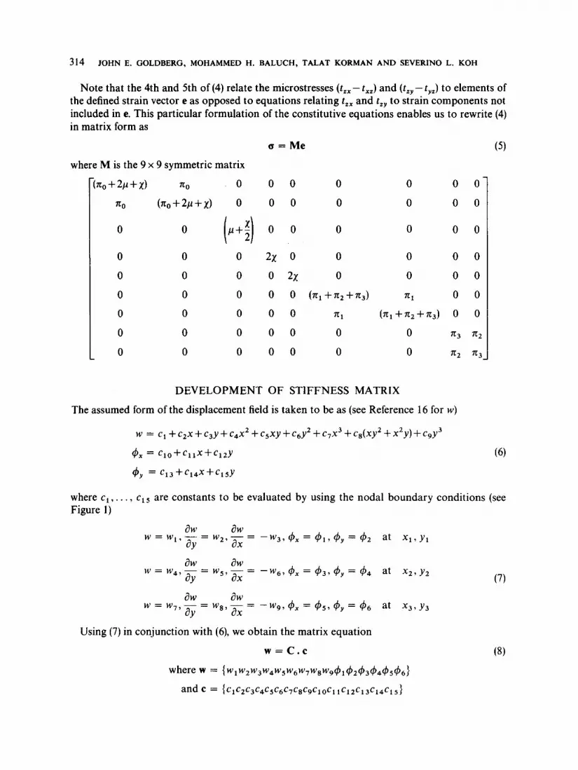
Note that the 4th and 5th of (4) relate the microstresses (t,,-t,,) and (t, ,-t, ,) to elements of the defined strain vector e as opposed to equations relating t,, and t,, to strain components not included in e. This particular formulation of the constitutive equations enables us to rewrite (4) in matrix form as
c = Me
where M is the 9 x 9 symmetric matrix
710 0 0 0 0 0 0 0
(%+2P+X) 0 0 0 0 0 0 0
0 0 0 0
0 0 0 2% 0 0 0 0 0
0 0 0 0 2% 0 0 0 0
0 0 0 0 0 ( 7 1 1 + ~ 2 + 7 1 3 ) 711 0 0
0 0 0 0 0 711 ( T C ~ + T C ~ + ~ T ~ ) 0 0
0 0 0 0 0 0 0 713 712
L O 0 0 0 0 0 0 712 713
DEVELOPMENT OF STIFFNESS MATRIX
The assumed form of the displacement field is taken to be as (see Reference 16 for w )
w = c1 + c2x + c3y + c4xz + c5xy + c6y2 + c7x3 + c8(xy2 + x2y) + c9y3
4, = c l o + ~ l l x + c l 2 Y
$y = c 1 3 + c 1 4 x + c 1 5 Y
where c l , . . . , ~ 1 5 are constants to be evaluated by using the nodal boundary conditions (see Figure 1)
at X l ? Y l
aw aw a Y ax w = w4, - - - w5, - = - w 6 9 4, = 4 3 , 4y = 44 at x2, y,
- aw aw a Y ax - - w 9 ? 4 x = 4 5 7 4 y = 4 6 at x 3 7 Y 3 w = W 7 , - - w89 -
-
Using (7) in conjunction with (6), we obtain the matrix equation
w = c.c where = { w 1 w Z w 3 w 4 w 5 w 6 w 7 w 8 w 9 ~ 1 ~ 2 ~ 3 ~ ~ ~ 5 ~ 6 }
and = ~c1c2c3c4c5c6c7c8c9c10cl 1c12c13c14c15}
(7)

BENDING OF MICROPOLAR PLATES 315
while the non-vanishing Ci,j’s of the 15 x 15 matrix C are given by
c 1 . 1 = c 2 . 3 = - c 3 , 2 = c4,l = c 5 9 3 = - c 6 , 2 = c7,1 = c8,3 = -c9,2 = c lO,10
= c 1 1 , 1 3 = c12,10 = c13,13 = c14,10 = c15,13 =
c 7 , 2 = c8.5 = -%9,4 = c14,11 = c 1 5 , 1 4 = x3
c4,3 = f C 5 , 6 = -c625 = c12,12 = c13,15 = Y2
c 7 . 3 = t C 8 . 6 = -c9,5 = c14,12 = c15,15 = Y3
1 C 7 > 4 = - 3 c 9 , 7 = x:
1 c4.6 = S C 5 , 9 = -c6.8 = Y:
2 c7 ,6 = %8,9 = Y3
c 7 , 7 = x:
c 4 , 9 = Y 2
c 7 , 9 = Y:
c 7 , 5 = X3Y3
3
c7,8 = x3Y3(x3 + y 3 )
c8.8 = x3(2Y3 + x 3 )
c9,8 = -Y3(Y3 + 2x3)
Making use of Kirchhoff’s assumption in (1) together with (6), we obtain the equation
e = Dc (9)
c = c - ’ w

316 JOHN E. GOLDBERG, MOHAMMED H. BALUCH, TALAT KORMAN AND SEVERINO L. KOH
Substituting for c from above into (9), we obtain
e = DC-Iw
or
e = Bw
where
B = DC-'
The stiffness matrix K is given by (see Reference 15)
K = J0,, BTMB d(vo1.)
Substituting for B from (10) in above, we obtain
K = Lo,, (DC-l)TMDC-' d(vo1.)
or using the transpose theorem
K = Jvol, (C- ')TDTMDC- d(vo1.)
or
K = (C-')T lo,. DTMD d(vol.)C-'
The inverse of the matrix C must be obtained numerically for each triangular element. The matrix product in (1 1)
K* = Lo,, DTMD d(vo1.)

BENDING OF MICROPOLAR PLATES 317
$2
Figure 1. Triangular plate element
and
not3 3 K6*,4 = -10,fJ

318 JOHN E. GOLDBERG, MOHAMMED H. BALUCH, TALAT KORMAN AND SEVERINO L. KOH
in which
t is thickness of plate, and
Y = n0+2p+x
n = p+xf2
A = n, + ~ 2 + n 3

BENDING OF MICROPOLAR PLATES 319
NUMERICAL EXAMPLE
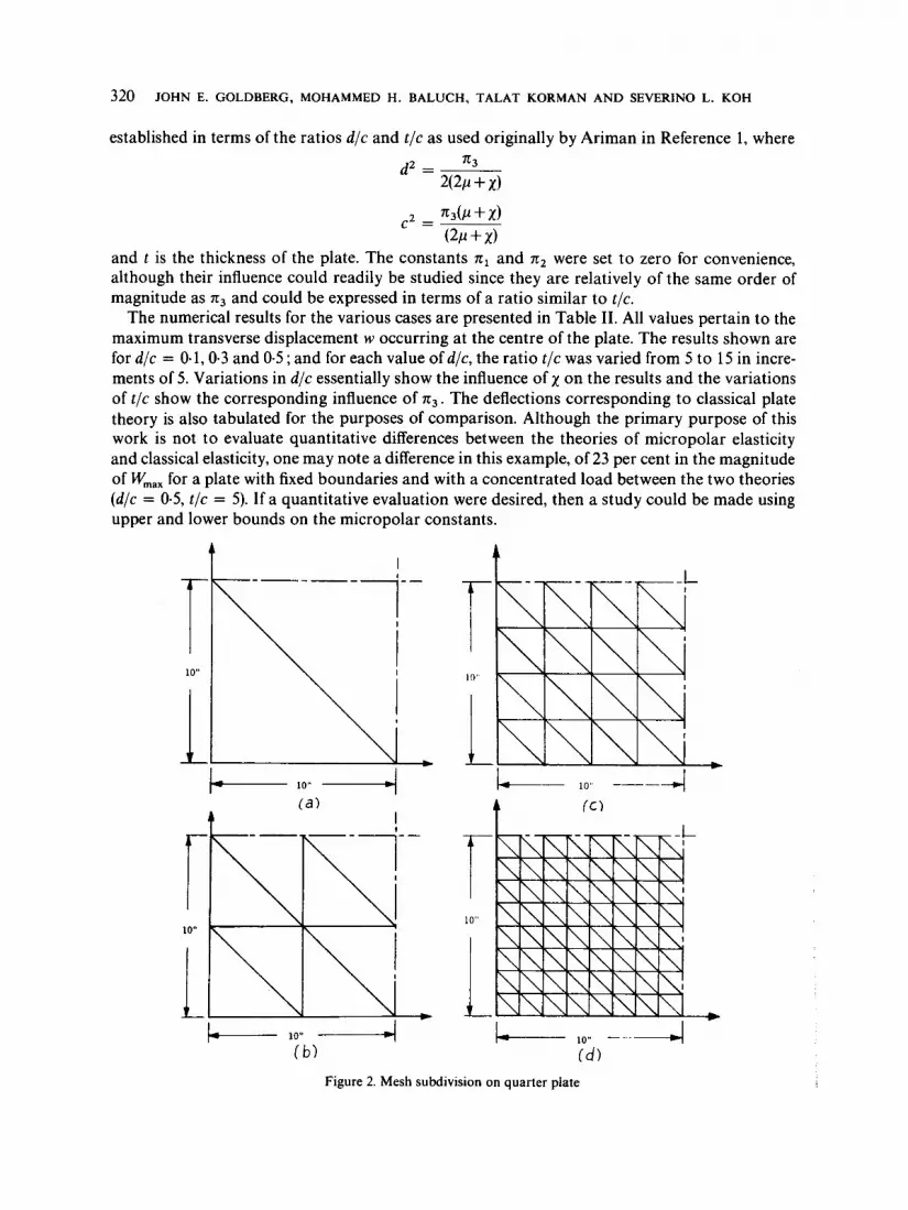
A 20 in x 20 in micropolar plate, built-in along the edges and loaded by a centrally applied concentrated load of 100 lb, was investigated. The plate thickness was taken as t = 2.5 in. It was necessary to subdivide the plate into 128 triangular elements in order to achieve convergence. (See Table 1). The conditions of symmetry permitted the analysis of one-quarter of the plate (see Figure 2).
Table I. Proof of convergence Maximum transverse deflection of a 20 in x 20 in square plate with fixed edges and loaded centrally by a concentrated load of 1001b, E = 3.0.106, v = 0.2,
t = 2.5 in
Finite element Exact solution classical plate
No. elementst W I O - ~ (in) kV10-5 (in)
8 4.1214 32 5Q830 5.2192
128 5.288 1 512 5.2702
Finite element micropolar plate
W I O - ~ (in) t /c = 5, d / ~ = 0.1
2-1093 4.901 2 5.2035 5.223 1
t For entire plate
The Lame constants I and p were established by using a value of 3.0 x lo6 psi for the modulus of elasticity E and 0.2 for Poisson ratio v. Two of the four micropolar constants x and n3 were
320 JOHN E. GOLDBERG, MOHAMMED H. BALUCH, TALAT KORMAN AND SEVERINO L. KOH
established in terms of the ratios d /c and t / c as used originally by Ariman in Reference 1, where
and t is the thickness of the plate. The constants n1 and n2 were set to zero for convenience, although their influence could readily be studied since they are relatively of the same order of magnitude as 7r3 and could be expressed in terms of a ratio similar to t /c.
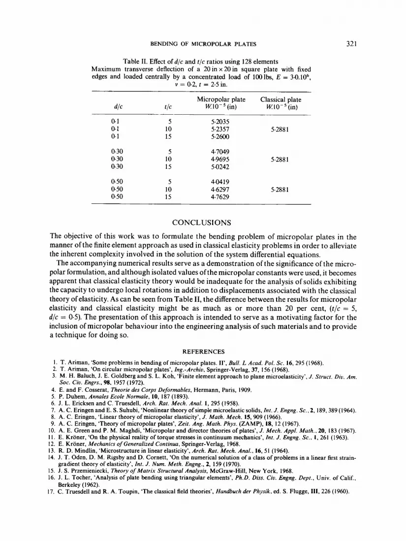
The numerical results for the various cases are presented in Table 11. All values pertain to the maximum transverse displacement w occurring at the centre of the plate. The results shown are for d/c = 0.1,0.3 and 0.5 ; and for each value of d/c, the ratio t / c was varied from 5 to 15 in incre- ments of 5. Variations in d/c essentially show the influence of x on the results and the variations of t / c show the corresponding influence of 7c3. The deflections corresponding to classical plate theory is also tabulated for the purposes of comparison. Although the primary purpose of this work is not to evaluate quantitative differences between the theories of micropolar elasticity and classical elasticity, one may note a difference in this example, of 23 per cent in the magnitude of W,,, for a plate with fixed boundaries and with a concentrated load between the two theories (d/c = 0.5, t /c = 5). I f a quantitative evaluation were desired, then a study could be made using upper and lower bounds on the micropolar constants.
t I
10"
r I I!)'
r I 10"
L 10" ---_I (d)
Figure 2. Mesh subdivision on quarter plate
BENDING OF MICROPOLAR PLATES 32 1
Table 11. Effect of d/c and t / c ratios using 128 elements Maximum transverse deflection of a 20 in x 20 in square plate with fixed edges and loaded centrally by a concentrated load of 1001bs, E = 3.0.106,
v = 0.2, t = 2.5 in.
Micropolar plate Classical plate dlc tlC WIO-’(in) WIO-’(in)
0.1 5 5.2035 0.1 10 5.2357 5.288 1 0.1 15 5.2600
0.30 5 4.7049 0.30 10 4.9695 5.288 1 0.30 15 5.0242
0.50 5 4.04 1 9 0.50 10 4.6297 5.288 1 0.50 15 4.7629
CONCLUSIONS
The objective of this work was to formulate the bending problem of micropolar plates in the manner ofthe finite element approach as used in classical elasticity problems in order to alleviate the inherent complexity involved in the solution of the system differential equations.
The accompanying numerical results serve as a demonstration of the significance of the micro- polar formulation, and although isolated values ofthe micropolar constants were used, it becomes apparent that classical elasticity theory would be inadequate for the analysis of solids exhibiting the capacity to undergo local rotations in addition to displacements associated with the classical theory of elasticity. As can be seen from Table 11, the difference between the results for micropolar elasticity and classical elasticity might be as much as or more than 20 per cent, ( t / c = 5 , d/c = 0.5). The presentation of this approach is intended to serve as a motivating factor for the inclusion of micropolar behaviour into the engineering analysis of such materials and to provide a technique for doing so.
REFERENCES
I . T. Ariman, ‘Some problems in bending of micropolar plates. II’, Bull. L Acad. Pol. Sc. 16, 295 (1968). 2. T. Ariman, ‘On circular micropolar plates’, 1ng.-Archiu, Springer-Verlag, 37, I56 (1968). 3. M. H. Baluch, J. E. Goldberg and S. L. Koh, ‘Finite element approach to plane microelasticity’, J. Struct. Diu. Am.
4. E. and F. Cosserat, Theorie des Corps Deformables, Hermann, Paris, 1909. 5. P. Duhem, Annales Ecole Normale, 10, I87 (1 893). 6. J . L. Ericksen and C. Truesdell, Arch. Rat. Mech. Anal. 1, 295 (1958). 7. A. C. Eringen and E. S. Suhubi, ‘Nonlinear theory of simple microelastic solids, Inr. J. Engng. Sc., 2, 189,389 (1964). 8. A. C. Eringen, ‘Linear theory of micropolar elasticity’, J. Mafh. Mech. 15, 909 (1966). 9. A. C. Eringen, ‘Theory of micropolar plates’, Zeit. Ang. Math. Phys. (ZAMP), 18, 12 (1967).
10. A. E. Green and P. M. Maghdi, ‘Micropolar and director theories of plates’, J. Mech. Appl. Math., 20, 183 (1967). I I . E. Kroner, ‘On the physical reality of torque stresses in continuum mechanics’, Inr. J. Engng. Sc.. 1, 261 (1963). 12. E. Kroner, Mechanics of Generalized Continua, Springer-Verlag, 1968. 13. R. D. Mindlin, ‘Microstructure in linear elasticity’, Arch. Rat. Mech. Anal., 16, 51 (1964). 14. J . T. Oden, D. M. Rigsby and D. Cornett, ‘On the numerical solution of a class of problems in a linear first strain-
15. J . S. Przemieniecki, Theory of Matrix Structural Analysis, McGraw-Hill, New York, 1968. 16. J. L. Tocher, ‘Analysis of plate bending using triangular elements’, Ph.D. Diss. Ciu. Engng. Depr., Univ. of Calif.,
17. C. Truesdell and R. A. Toupin, ‘The classical field theories’, Handbuch der Physik. ed. S . Flugge, 111, 226 (1960).
SOC. Ciu. Engrs., 98, 1957 (1972).
gradient theory of elasticity’, Int. J. Num. Meth. Engng., 2, 159 (1970).
Berkeley (1 962).