elastic stability of plates with circular and rectangular holes subjected to axial compression and...
TRANSCRIPT
This article appeared in a journal published by Elsevier. The attachedcopy is furnished to the author for internal non-commercial researchand education use, including for instruction at the authors institution
and sharing with colleagues.
Other uses, including reproduction and distribution, or selling orlicensing copies, or posting to personal, institutional or third party
websites are prohibited.
In most cases authors are permitted to post their version of thearticle (e.g. in Word or Tex form) to their personal website orinstitutional repository. Authors requiring further information
regarding Elsevier’s archiving and manuscript policies areencouraged to visit:
http://www.elsevier.com/copyright
Author's personal copy
Elastic stability of plates with circular and rectangular holes subjected toaxial compression and bending moment
Emanuele Maiorana, Carlo Pellegrino �, Claudio Modena
Department of Structural and Transportation Engineering, University of Padova, Via Marzolo, 9, 35131 Padova, Italy
a r t i c l e i n f o
Article history:
Received 18 May 2008
Received in revised form
7 July 2008
Accepted 5 August 2008Available online 11 September 2008
Keywords:
Stability
Steel girder
Steel panel
Perforated plate
Linear buckling
a b s t r a c t
In this paper linear buckling analyses of square and rectangular plates with circular and rectangular
holes in various positions subjected to axial compression and bending moment are developed. The aim
is to give some practical indications on the best position of the circular hole and the best position
and orientation of rectangular holes in steel plates, when axial compression and bending moment
act together. Two different orientations are considered for rectangular holes: holes with major
dimension parallel to the vertical plate axis (RS holes) and major dimension parallel to horizontal plate
axis (RL holes).
The effect of bending moment on the stability of the plate is studied and some differences with
respect to the uniform compression load case are shown. Some design suggestions on the best
orientation of rectangular for stability purposes are given. The influence of dimension and position of
perforations on linear buckling behaviour and, in particular, on buckling coefficient of the plate is
observed.
Some practical design formulations for the calculation of the buckling coefficient, taking into
account (a) dimensions and shape (square and rectangular) of the plate, (b) dimensions and shape
(circular and rectangular) of the hole, (c) position of the hole (centre in the ‘‘maximum’’ and in the
‘‘nodal’’ point), (d) orientation (RS and RL) of the rectangular hole, and (e) load configuration (uniform
compression, combinations of axial compression and bending and pure bending) are finally proposed.
& 2008 Elsevier Ltd. All rights reserved.
1. Introduction
The problem of stability of plates is a typical problem of steelstructures, particularly bridges. A wide literature review on elasticbuckling of perforated plates may be found in [1–5]. Thebehaviour of square shear webs having circular hole was analysedby Rockey et al. [6]; the elastic stability of bi-axially loadedrectangular plates with a single circular hole was recently studiedby El-Sawy and Martini [7]. The case of concentrated loads inperforated plates was shown in [8] while axially compressedperforated plates were studied in [9,10]. Ultimate capacity ofuniaxially compressed perforated plates was analysed by Naraya-nan and Chow [11] and strength of slender webs having eccentricholes was treated in [12]. Elasto-plastic buckling of rectangularplates in biaxial compression/tension and uniaxial compressionwas studied in [13,14]. Ultimate strength of perforated steel platesunder shear loading was recently studied by Paik [15]. Thebehaviour of perforated steel plates subjected to localised
symmetrical load, in the linear and non-linear phase, was recentlystudied by Maiorana et al. [16,17] considering the influence of theload length on stability of square and rectangular plates withcircular and rectangular perforations.
A number of studies have been developed on linear bucklingbehaviour of unperforated steel plates, few works are available onperforated plates; in particular the common case of linear bucklingbehaviour of perforated plates under both axial load and bendingmoment is not deeply investigated. A very recent work by Komurand Sonmez [18] deals with elastic buckling of rectangular plateswith a circular cutout under linearly varying in-plane normal load.In the work of Komur and Sonmez [18] only circular perforations atdifferent locations along the horizontal x-axis are considered.
In the present work, linear buckling behaviour of square andrectangular plates with circular and rectangular perforations wasstudied, studying the influence of the load configuration onbuckling behaviour. Circular perforations at different locationsalong the horizontal and vertical x- and y-axis are considered.
Emphasis is also given to the presence of rectangular holes,considering different orientations of the principal hole axis. Inparticular, two different orientations are considered for rectan-gular holes: holes with major dimension parallel to the vertical
ARTICLE IN PRESS
Contents lists available at ScienceDirect
journal homepage: www.elsevier.com/locate/tws
Thin-Walled Structures
0263-8231/$ - see front matter & 2008 Elsevier Ltd. All rights reserved.
doi:10.1016/j.tws.2008.08.003
� Corresponding author.
E-mail address: [email protected] (C. Pellegrino).
Thin-Walled Structures 47 (2009) 241–255
Author's personal copy
plate axis (RS holes) and major dimension parallel to horizontalplate axis (RL holes).
Some practical design formulations for the estimation of thebuckling coefficient, depending on stress ratio c, are proposed forvarious plate aspect ratios a/b, hole dimensions d/b and holetypical locations (hole centre in ‘‘nodal’’ and ‘‘maximum’’ points)are proposed. These design formulation for the buckling coeffi-cient are developed both for circular and rectangular perforationswith RS and RL orientations.
2. Basic concepts
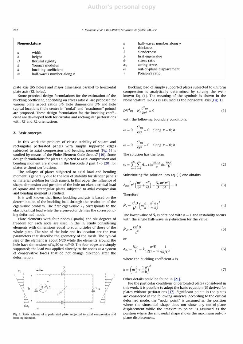
In this work the problem of elastic stability of square andrectangular perforated panels with simply supported edgessubjected to axial compression and bending moment (Fig. 1) isstudied by means of the Finite Element Code Straus7 [19]. Somedesign formulations for plates subjected to axial compression andbending moment are shown in the Eurocode 3 part 1–5 [20] forplates without perforations.
The collapse of plates subjected to axial load and bendingmoment is generally due to the loss of stability for slender panelsor material yielding for thick panels. In this paper the influence ofshape, dimension and position of the hole on elastic critical loadof square and rectangular plates subjected to axial compressionand bending moment is studied.
It is well known that linear buckling analysis is based on thedetermination of the buckling load through the resolution of theeigenvalue problem. The first eigenvalue l1 corresponds to theelastic critical load while the eigenvector defines the correspond-ing deformed mode.
Plate elements with four nodes (Quad4) and six degrees offreedom for each node are used in the FE study consideringelements with dimensions equal to submultiples of those of thewhole plate. The size of the hole and its location are the twoparameters that describe the geometry of the mesh. The typicalsize of the element is about b/20 while the elements around thehole have dimensions of b/50 or pd/40. The four edges are simplysupported; the load was applied directly to the nodes as a systemof conservative forces that do not change direction after thedeformation.
Buckling load of simply supported plates subjected to uniformcompression is analytically determined by solving the well-known Eq. (1). The meaning of the symbols is shown in theNomenclature. x-Axis is assumed as the horizontal axis (Fig. 1):
Dr4oþ N̄xq2oqx2¼ 0 (1)
with the following boundary conditions:
o ¼ 0q2oqx2¼ 0 along x ¼ 0; a
o ¼ 0q2oqy2¼ 0 along x ¼ 0; b
The solution has the form
o ¼X1m¼1
X1n¼1
Amn sinmpx
asin
npx
b(2)
Substituting the solution into Eq. (1) one obtains
Amn p4 m2
a2þ
n2
b2
� ��
N̄x
D
m2p2
a2
� �¼ 0 (3)
Therefore
N̄x ¼p2D
b2m
b
aþ
n2
m
a
b
� �2
(4)
The lower value of N̄x is obtained with n ¼ 1 and instability occurswith the single half-wave in y-direction for the value:
N̄xC ¼kp2D
b2(5)
or
sxC ¼N̄xC
t¼ k
p2E
12ð1� n2Þ
1
ðb=tÞ2(6)
where the buckling coefficient k is
k ¼ mb
aþ
1
m
a
b
� �2
(7)
Other details could be found in [21].For the particular conditions of perforated plates considered in
this work, it is possible to adopt the basic equation (6) derived forplates without perforations [17]. Significant points in the platesare considered in the following analyses. According to the criticaldeformed mode, the ‘‘nodal point’’ is assumed as the positionwhere the sinusoidal shape does not show any out-of-planedisplacement while the ‘‘maximum point’’ is assumed as theposition where the sinusoidal shape shows the maximum out-of-plane displacement.
ARTICLE IN PRESS
Nomenclature
a widthb heightD flexural rigidityE Young’s modulusk buckling coefficientm half-waves number along x
n half-waves number along y
t thicknessl slendernessl1 first eigenvaluec stress ratios0 acting stresso out-of-plane displacementn Poisson’s ratio
db
x
y
a
y
x
z
�0
��0
Fig. 1. Static scheme of a perforated plate subjected to axial compression and
bending moment.
E. Maiorana et al. / Thin-Walled Structures 47 (2009) 241–255242
Author's personal copy
3. Plates with circular hole
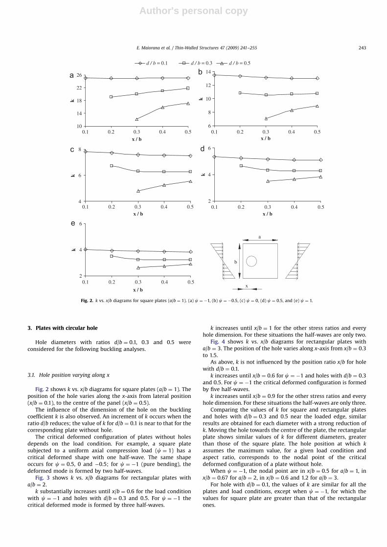
Hole diameters with ratios d/b ¼ 0.1, 0.3 and 0.5 wereconsidered for the following buckling analyses.
3.1. Hole position varying along x
Fig. 2 shows k vs. x/b diagrams for square plates (a/b ¼ 1). Theposition of the hole varies along the x-axis from lateral position(x/b ¼ 0.1), to the centre of the panel (x/b ¼ 0.5).
The influence of the dimension of the hole on the bucklingcoefficient k is also observed. An increment of k occurs when theratio d/b reduces; the value of k for d/b ¼ 0.1 is near to that for thecorresponding plate without hole.
The critical deformed configuration of plates without holesdepends on the load condition. For example, a square platesubjected to a uniform axial compression load (c ¼ 1) has acritical deformed shape with one half-wave. The same shapeoccurs for c ¼ 0.5, 0 and �0.5; for c ¼ �1 (pure bending), thedeformed mode is formed by two half-waves.
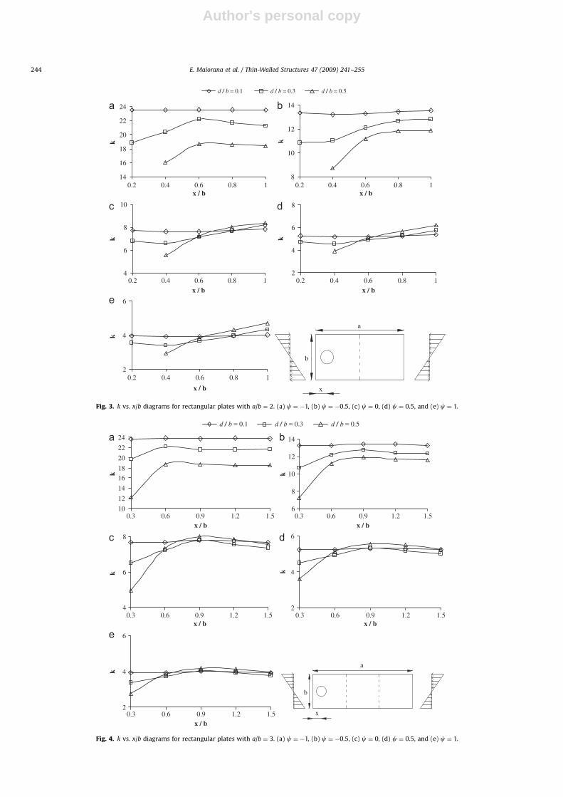
Fig. 3 shows k vs. x/b diagrams for rectangular plates witha/b ¼ 2.
k substantially increases until x/b ¼ 0.6 for the load conditionwith c ¼ �1 and holes with d/b ¼ 0.3 and 0.5. For c ¼ �1 thecritical deformed mode is formed by three half-waves.
k increases until x/b ¼ 1 for the other stress ratios and everyhole dimension. For these situations the half-waves are only two.
Fig. 4 shows k vs. x/b diagrams for rectangular plates witha/b ¼ 3. The position of the hole varies along x-axis from x/b ¼ 0.3to 1.5.
As above, k is not influenced by the position ratio x/b for holewith d/b ¼ 0.1.
k increases until x/b ¼ 0.6 for c ¼ �1 and holes with d/b ¼ 0.3and 0.5. For c ¼ �1 the critical deformed configuration is formedby five half-waves.
k increases until x/b ¼ 0.9 for the other stress ratios and everyhole dimension. For these situations the half-waves are only three.
Comparing the values of k for square and rectangular platesand holes with d/b ¼ 0.3 and 0.5 near the loaded edge, similarresults are obtained for each diameter with a strong reduction ofk. Moving the hole towards the centre of the plate, the rectangularplate shows similar values of k for different diameters, greaterthan those of the square plate. The hole position at which k
assumes the maximum value, for a given load condition andaspect ratio, corresponds to the nodal point of the criticaldeformed configuration of a plate without hole.
When c ¼ �1, the nodal point are in x/b ¼ 0.5 for a/b ¼ 1, inx/b ¼ 0.67 for a/b ¼ 2, in x/b ¼ 0.6 and 1.2 for a/b ¼ 3.
For hole with d/b ¼ 0.1, the values of k are similar for all theplates and load conditions, except when c ¼ �1, for which thevalues for square plate are greater than that of the rectangularones.
ARTICLE IN PRESS
10
14
18
22
26
0.1x / b
k
6
8
10
12
14
x / b
k4
6
8
x / b
k
2
4
6
x / b
k
2
4
6
x / b
k
a
x
b
0.50.40.30.2
0.1 0.50.40.30.2
0.1 0.50.40.30.2
0.1 0.50.40.30.2
0.1 0.50.40.30.2
d / b = 0.1 d / b = 0.3 d / b = 0.5
Fig. 2. k vs. x/b diagrams for square plates (a/b ¼ 1). (a) c ¼ �1, (b) c ¼ �0.5, (c) c ¼ 0, (d) c ¼ 0.5, and (e) c ¼ 1.
E. Maiorana et al. / Thin-Walled Structures 47 (2009) 241–255 243
Author's personal copyARTICLE IN PRESS
14
16
18
20
22
24
0.2x / b
k
8
10
12
14
x / b
k4
6
8
10
x / b
k
2
4
6
8
x / b
k
2
4
6
x / b
k
b
x
a
d / b = 0.1 d / b = 0.3 d / b = 0.5
10.80.60.4
0.2 10.80.60.4
0.2 10.80.60.4
0.2 10.80.60.4
0.2 10.80.60.4
Fig. 3. k vs. x/b diagrams for rectangular plates with a/b ¼ 2. (a) c ¼ �1, (b) c ¼ �0.5, (c) c ¼ 0, (d) c ¼ 0.5, and (e) c ¼ 1.
10
12
14
16
18
20
22
24
0.3x / b
k
6
8
10
12
14
x / b
k
4
6
8
x / b
k
2
4
6
x / b
k
2
4
6
x / b
k
a
x
b
d / b = 0.1 d / b = 0.3 d / b = 0.5
1.51.20.90.6
0.3 1.51.20.90.6
0.3 1.51.20.90.6
0.3 1.51.20.90.6
0.3 1.51.20.90.6
Fig. 4. k vs. x/b diagrams for rectangular plates with a/b ¼ 3. (a) c ¼ �1, (b) c ¼ �0.5, (c) c ¼ 0, (d) c ¼ 0.5, and (e) c ¼ 1.
E. Maiorana et al. / Thin-Walled Structures 47 (2009) 241–255244
Author's personal copy
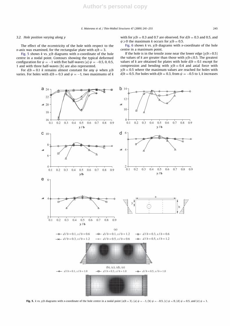
3.2. Hole position varying along y
The effect of the eccentricity of the hole with respect to thex-axis was examined, for the rectangular plate with a/b ¼ 3.
Fig. 5 shows k vs. y/b diagrams with x-coordinate of the holecentre in a nodal point. Contours showing the typical deformedconfiguration for c ¼ �1 with five half-waves (a) c ¼ �0.5, 0, 0.5,1 and with three half-waves (b) are also represented.
For d/b ¼ 0.1 k remains almost constant for any c when y/bvaries. For holes with d/b ¼ 0.3 and c ¼ �1, two maximums of k
with for y/b ¼ 0.3 and 0.7 are observed. For d/b ¼ 0.3 and 0.5, andcX0 the maximum k occurs for y/b ¼ 0.5.
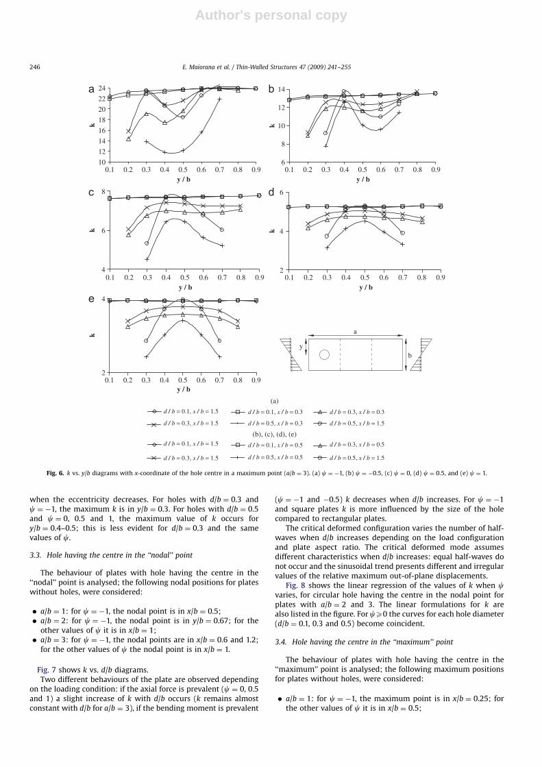
Fig. 6 shows k vs. y/b diagrams with x-coordinate of the holecentre in a maximum point.
If the hole is in the tensile zone near the lower edge (y/b40.5)the values of k are greater than those with y/bp0.5. The greatestvalues of k are obtained for plates with hole d/b ¼ 0.1 except forcompression and bending with y/b ¼ 0.4 and axial force withy/b ¼ 0.5 where the maximum values are reached for holes withd/b ¼ 0.5. For holes with d/b ¼ 0.3, from c ¼ �0.5 to 1, k increases
ARTICLE IN PRESS
(a)
d / b = 0.1, x / b = 0.6
d / b = 0.3, x / b = 1.2
d / b = 0.3, x / b = 1.0 d / b = 0.5, x / b = 1.0d / b = 0.1, x / b = 1.0
d / b = 0.1, x / b = 1.2
d / b = 0.5, x / b = 0.6
d / b = 0.3, x / b = 0.6
d / b = 0.5, x / b = 1.2
(b), (c), (d), (e)
16
18
20
22
24
0.1
y / b
k
8
10
12
14
y / b
k
4
6
8
10
0.1y/b
k
2
4
6
y / b
k
2
4
6
y / b
k
b
a
y
0.2 0.3 0.4 0.5 0.6 0.7 0.8 0.9 0.1 0.2 0.3 0.4 0.5 0.6 0.7 0.8 0.9
0.2 0.3 0.4 0.5 0.6 0.7 0.8 0.9 0.1 0.2 0.3 0.4 0.5 0.6 0.7 0.8 0.9
0.1 0.2 0.3 0.4 0.5 0.6 0.7 0.8 0.9
Fig. 5. k vs. y/b diagrams with x-coordinate of the hole centre in a nodal point (a/b ¼ 3). (a) c ¼ �1, (b) c ¼ �0.5, (c) c ¼ 0, (d) c ¼ 0.5, and (e) c ¼ 1.
E. Maiorana et al. / Thin-Walled Structures 47 (2009) 241–255 245
Author's personal copy
when the eccentricity decreases. For holes with d/b ¼ 0.3 andc ¼ �1, the maximum k is in y/b ¼ 0.3. For holes with d/b ¼ 0.5and c ¼ 0, 0.5 and 1, the maximum value of k occurs fory/b ¼ 0.4–0.5; this is less evident for d/b ¼ 0.3 and the samevalues of c.
3.3. Hole having the centre in the ‘‘nodal’’ point
The behaviour of plates with hole having the centre in the‘‘nodal’’ point is analysed; the following nodal positions for plateswithout holes, were considered:
� a/b ¼ 1: for c ¼ �1, the nodal point is in x/b ¼ 0.5;� a/b ¼ 2: for c ¼ �1, the nodal point is in y/b ¼ 0.67; for the
other values of c it is in x/b ¼ 1;� a/b ¼ 3: for c ¼ �1, the nodal points are in x/b ¼ 0.6 and 1.2;
for the other values of c the nodal point is in x/b ¼ 1.
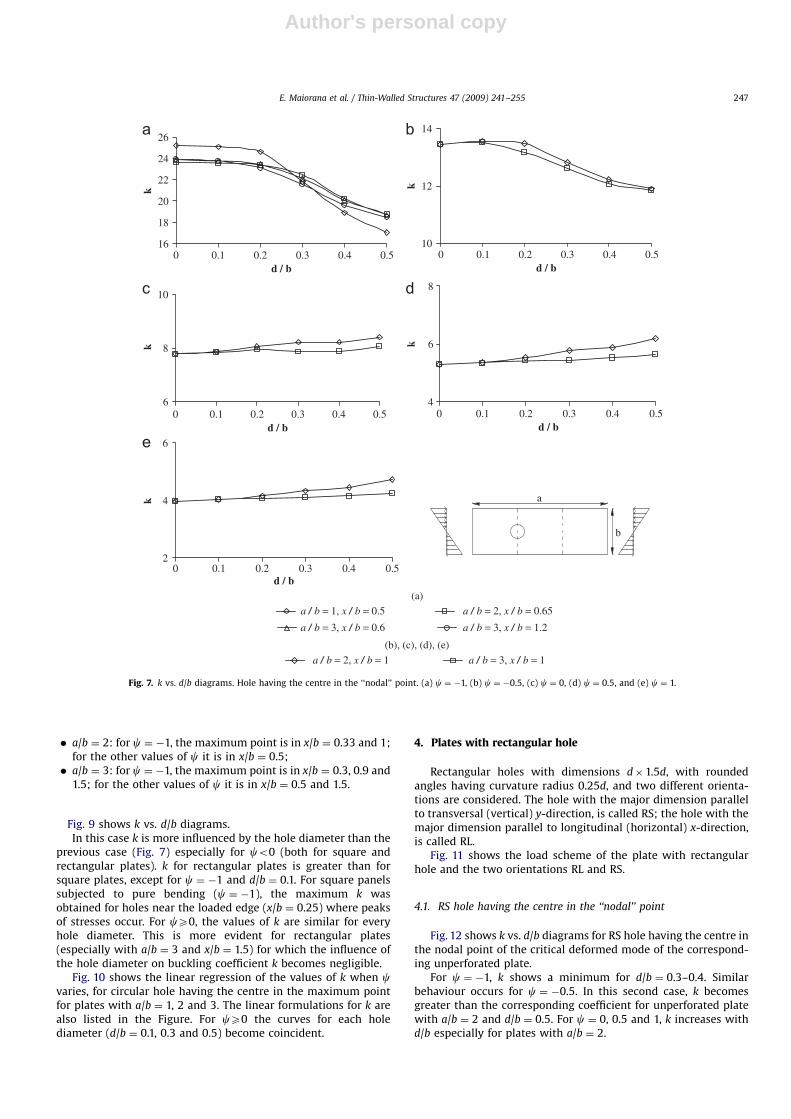
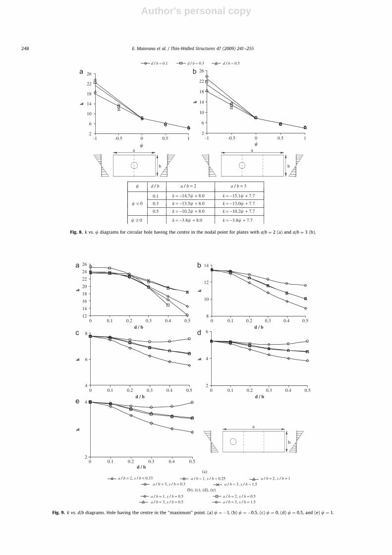
Fig. 7 shows k vs. d/b diagrams.Two different behaviours of the plate are observed depending
on the loading condition: if the axial force is prevalent (c ¼ 0, 0.5and 1) a slight increase of k with d/b occurs (k remains almostconstant with d/b for a/b ¼ 3), if the bending moment is prevalent
(c ¼ �1 and �0.5) k decreases when d/b increases. For c ¼ �1and square plates k is more influenced by the size of the holecompared to rectangular plates.
The critical deformed configuration varies the number of half-waves when d/b increases depending on the load configurationand plate aspect ratio. The critical deformed mode assumesdifferent characteristics when d/b increases: equal half-waves donot occur and the sinusoidal trend presents different and irregularvalues of the relative maximum out-of-plane displacements.
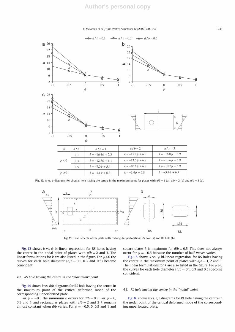
Fig. 8 shows the linear regression of the values of k when cvaries, for circular hole having the centre in the nodal point forplates with a/b ¼ 2 and 3. The linear formulations for k arealso listed in the figure. For cX0 the curves for each hole diameter(d/b ¼ 0.1, 0.3 and 0.5) become coincident.
3.4. Hole having the centre in the ‘‘maximum’’ point
The behaviour of plates with hole having the centre in the‘‘maximum’’ point is analysed; the following maximum positionsfor plates without holes, were considered:
� a/b ¼ 1: for c ¼ �1, the maximum point is in x/b ¼ 0.25; forthe other values of c it is in x/b ¼ 0.5;
ARTICLE IN PRESS
10
12
14
16
18
20
22
24
0.1y / b
k
6
8
10
12
14
y / b
k4
6
8
0.1y / b y / b
k
2
4
6
k
2
4
y / b
k
b
a
y
(a)
d / b = 0.1, x / b = 1.5
d / b = 0.3, x / b = 1.5
d / b = 0.1, x / b = 1.5
d / b = 0.3, x / b = 1.5
d / b = 0.1, x / b = 0.5
d / b = 0.5, x / b = 0.5
d / b = 0.3, x / b = 0.5
d / b = 0.5, x / b = 1.5
d / b = 0.1, x / b = 0.3
d / b = 0.5, x / b = 0.3
d / b = 0.3, x / b = 0.3
d / b = 0.5, x / b = 1.5
(b), (c), (d), (e)
0.2 0.3 0.4 0.5 0.6 0.7 0.8 0.9 0.1 0.2 0.3 0.4 0.5 0.6 0.7 0.8 0.9
0.2 0.3 0.4 0.5 0.6 0.7 0.8 0.9 0.1 0.2 0.3 0.4 0.5 0.6 0.7 0.8 0.9
0.1 0.2 0.3 0.4 0.5 0.6 0.7 0.8 0.9
Fig. 6. k vs. y/b diagrams with x-coordinate of the hole centre in a maximum point (a/b ¼ 3). (a) c ¼ �1, (b) c ¼ �0.5, (c) c ¼ 0, (d) c ¼ 0.5, and (e) c ¼ 1.
E. Maiorana et al. / Thin-Walled Structures 47 (2009) 241–255246
Author's personal copy
� a/b ¼ 2: for c ¼ �1, the maximum point is in x/b ¼ 0.33 and 1;for the other values of c it is in x/b ¼ 0.5;� a/b ¼ 3: for c ¼ �1, the maximum point is in x/b ¼ 0.3, 0.9 and
1.5; for the other values of c it is in x/b ¼ 0.5 and 1.5.
Fig. 9 shows k vs. d/b diagrams.In this case k is more influenced by the hole diameter than the
previous case (Fig. 7) especially for co0 (both for square andrectangular plates). k for rectangular plates is greater than forsquare plates, except for c ¼ �1 and d/b ¼ 0.1. For square panelssubjected to pure bending (c ¼ �1), the maximum k wasobtained for holes near the loaded edge (x/b ¼ 0.25) where peaksof stresses occur. For cX0, the values of k are similar for everyhole diameter. This is more evident for rectangular plates(especially with a/b ¼ 3 and x/b ¼ 1.5) for which the influence ofthe hole diameter on buckling coefficient k becomes negligible.
Fig. 10 shows the linear regression of the values of k when cvaries, for circular hole having the centre in the maximum pointfor plates with a/b ¼ 1, 2 and 3. The linear formulations for k arealso listed in the Figure. For cX0 the curves for each holediameter (d/b ¼ 0.1, 0.3 and 0.5) become coincident.
4. Plates with rectangular hole
Rectangular holes with dimensions d�1.5d, with roundedangles having curvature radius 0.25d, and two different orienta-tions are considered. The hole with the major dimension parallelto transversal (vertical) y-direction, is called RS; the hole with themajor dimension parallel to longitudinal (horizontal) x-direction,is called RL.
Fig. 11 shows the load scheme of the plate with rectangularhole and the two orientations RL and RS.
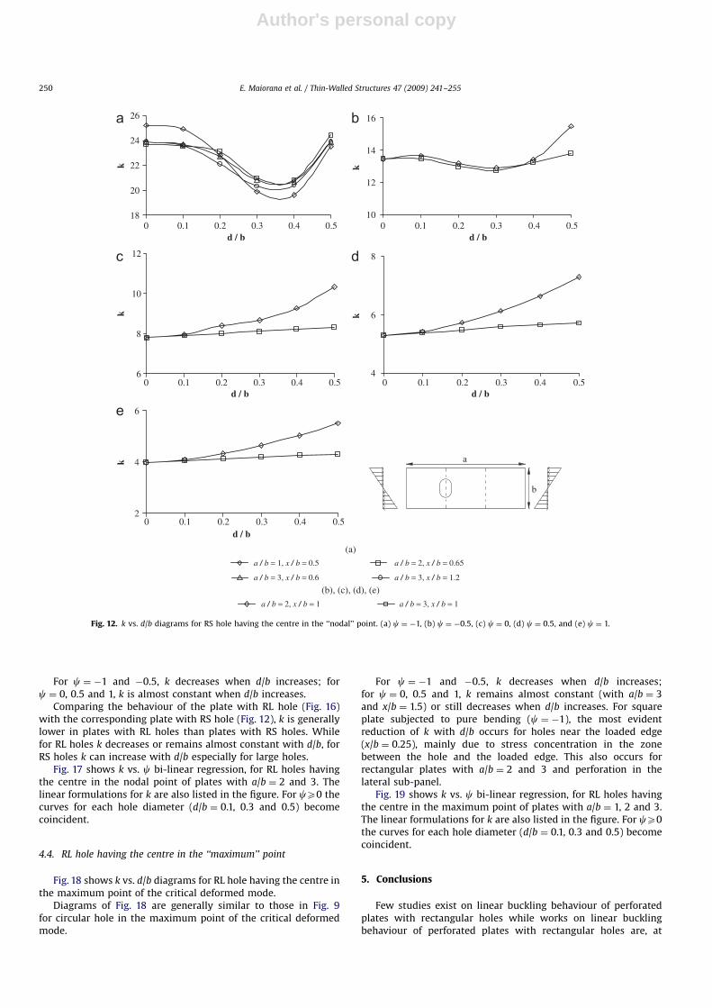
4.1. RS hole having the centre in the ‘‘nodal’’ point
Fig. 12 shows k vs. d/b diagrams for RS hole having the centre inthe nodal point of the critical deformed mode of the correspond-ing unperforated plate.
For c ¼ �1, k shows a minimum for d/b ¼ 0.3–0.4. Similarbehaviour occurs for c ¼ �0.5. In this second case, k becomesgreater than the corresponding coefficient for unperforated platewith a/b ¼ 2 and d/b ¼ 0.5. For c ¼ 0, 0.5 and 1, k increases withd/b especially for plates with a/b ¼ 2.
ARTICLE IN PRESS
16
18
20
22
24
26
0d / b
k
10
12
14
k6
8
10
0d / b
k
4
6
8
k
2
4
6
d / b
k
b
a
(a)
a / b = 1, x / b = 0.5 a / b = 2, x / b = 0.65
a / b = 3, x / b = 1.2a / b = 3, x / b = 0.6
a / b = 2, x / b = 1 a / b = 3, x / b = 1(b), (c), (d), (e)
0.1 0.2 0.3 0.4 0.5 0d / b
0.1 0.2 0.3 0.4 0.5
0.1 0.2 0.3 0.4 0.5 0d / b
0.1 0.2 0.3 0.4 0.5
0 0.1 0.2 0.3 0.4 0.5
Fig. 7. k vs. d/b diagrams. Hole having the centre in the ‘‘nodal’’ point. (a) c ¼ �1, (b) c ¼ �0.5, (c) c ¼ 0, (d) c ¼ 0.5, and (e) c ¼ 1.
E. Maiorana et al. / Thin-Walled Structures 47 (2009) 241–255 247
Author's personal copyARTICLE IN PRESS
2
6
10
14
18
22
26
-1
k
2
6
10
14
18
22
26
k
b
a
b
a
d / b
0.1 k = −14.7� + 8.0 k = −15.1� + 7.7
k = −13.0� + 7.7
k = −10.2� + 7.7
k = −3.8� + 7.7
k = −13.5� + 8.0
k = −10.2� + 8.0
k = −3.8� + 8.0
0.3
0.5
� ≥ 0
d / b = 0.1 d / b = 0.3 d / b = 0.5
-0.5 0 0.5 1
�
-1 -0.5 0 0.5 1�
�
� < 0
a / b = 2 a / b = 3
Fig. 8. k vs. c diagrams for circular hole having the centre in the nodal point for plates with a/b ¼ 2 (a) and a/b ¼ 3 (b).
12
14
16
18
20
22
24
26
0d / b
k
8
10
12
14
k
4
6
8
d / b
k
2
4
6
k
2
4
d / b
k
b
a
(a) a / b = 2, x / b = 0.33 a / b = 1, x / b = 0.25 a / b = 2, x / b = 1
a / b = 3, x / b = 1.5a / b = 3, x / b = 0.3
a / b = 1, x / b = 0.5a / b = 3, x / b = 0.5 a / b = 3, x / b = 1.5
a / b = 2, x / b = 0.5
(b), (c), (d), (e)
0.1 0.2 0.3 0.4 0.5 0d / b
0.1 0.2 0.3 0.4 0.5
0 0.1 0.2 0.3 0.4 0.5d / b
0 0.1 0.2 0.3 0.4 0.5
0 0.1 0.2 0.3 0.4 0.5
Fig. 9. k vs. d/b diagrams. Hole having the centre in the ‘‘maximum’’ point. (a) c ¼ �1, (b) c ¼ �0.5, (c) c ¼ 0, (d) c ¼ 0.5, and (e) c ¼ 1.
E. Maiorana et al. / Thin-Walled Structures 47 (2009) 241–255248
Author's personal copy
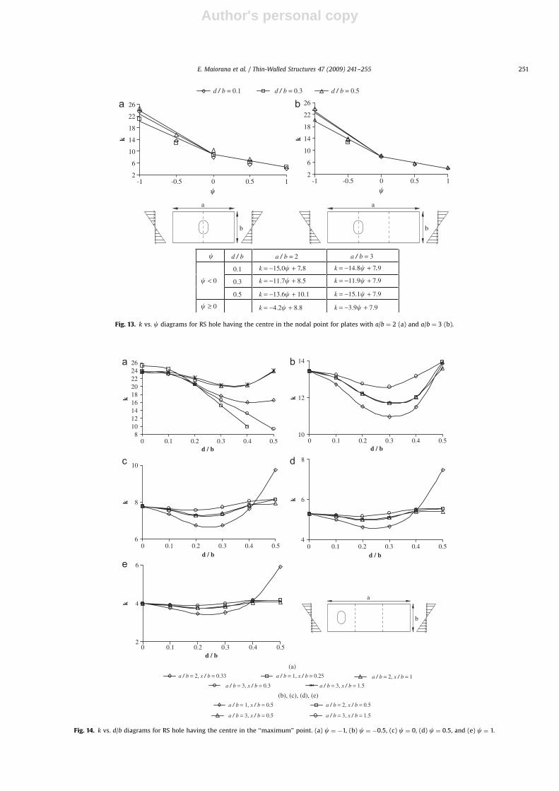
Fig. 13 shows k vs. c bi-linear regression, for RS holes havingthe centre in the nodal point of plates with a/b ¼ 2 and 3. Thelinear formulations for k are also listed in the figure. For cX0 thecurves for each hole diameter (d/b ¼ 0.1, 0.3 and 0.5) becomecoincident.
4.2. RS hole having the centre in the ‘‘maximum’’ point
Fig. 14 shows k vs. d/b diagrams for RS hole having the centre inthe maximum point of the critical deformed mode of thecorresponding unperforated plate.
For c ¼ �0.5 the minimum k occurs for d/b ¼ 0.3. For c ¼ 0,0.5 and 1 and rectangular plates with a/b ¼ 2 and 3 k remainsalmost constant when d/b varies. For c ¼ �0.5, 0, 0.5 and 1 and
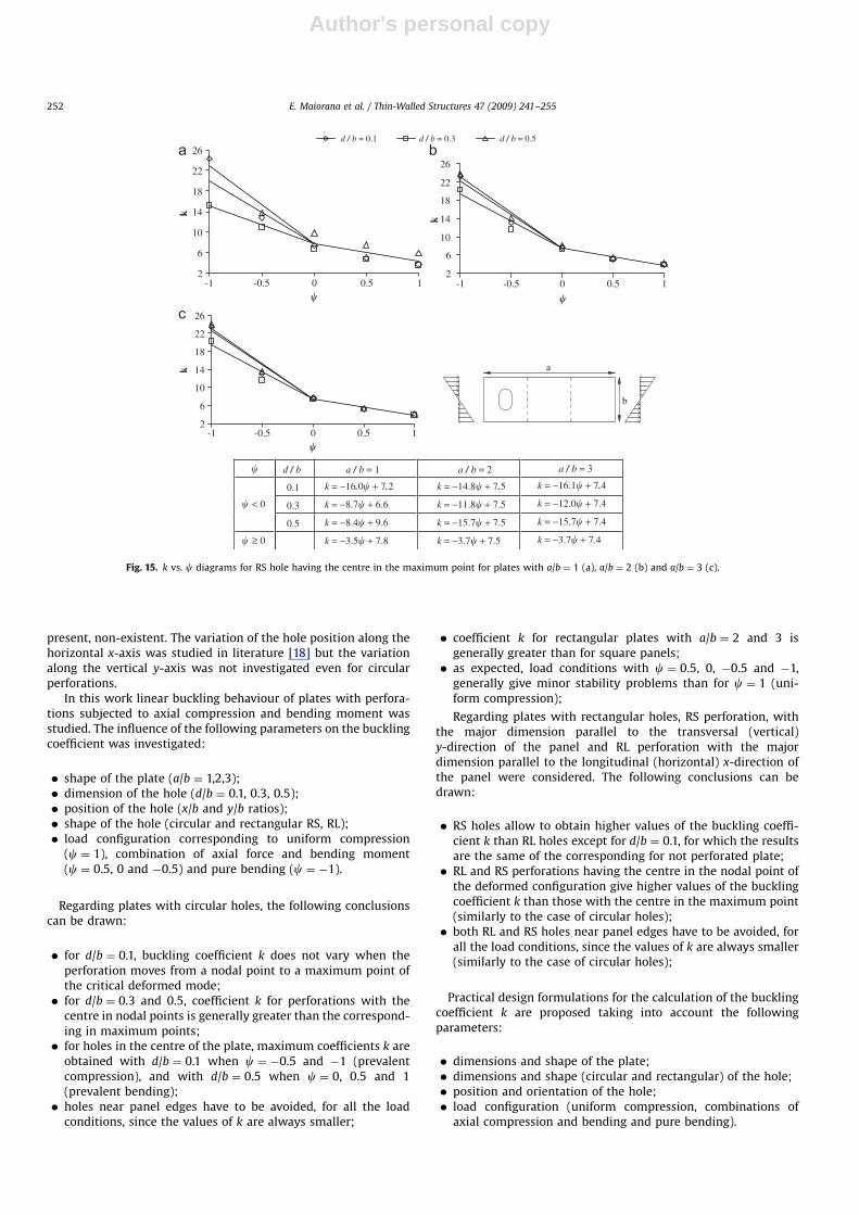
square plates k is maximum for d/b ¼ 0.5. This does not alwaysoccur for c ¼ �0.5 because the number of half-waves varies.
Fig. 15 shows k vs. c bi-linear regression, for RS holes havingthe centre in the maximum point of plates with a/b ¼ 1, 2 and 3.The linear formulations for k are also listed in the figure. For cX0the curves for each hole diameter (d/b ¼ 0.1, 0.3 and 0.5) becomecoincident.
4.3. RL hole having the centre in the ‘‘nodal’’ point
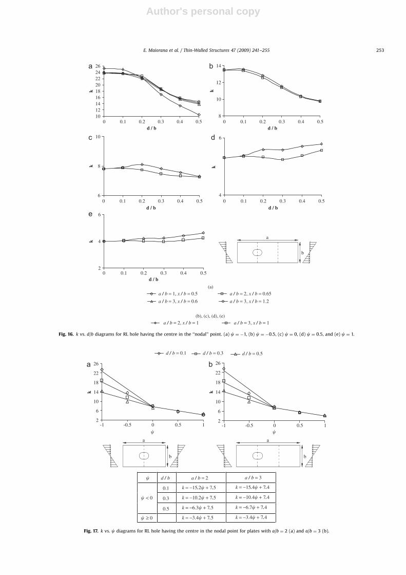
Fig. 16 shows k vs. d/b diagrams for RL hole having the centre inthe nodal point of the critical deformed mode of the correspond-ing unperforated plate.
ARTICLE IN PRESS
2
6
10
14
18
22
26
-1
k
2
6
10
14
18
22
26
k
2
6
10
14
18
22
26
k
b
a
d / b a / b = 1
0.1 k = −16.4� + 7.3
k = −12.7� + 6.1
k = −7.0� + 5.4
k = −3.1� + 6.3
a / b = 2
k = −15.9� + 6.8
k = −13.5� + 6.8
k = −10.6� + 6.8
k = −3.4� + 6.8
a / b = 3
k = −16.0� + 6.9
k = −13.6� + 6.9
k = −10.7� + 6.9
k = −3.4� + 6.9
0.3� < 0
0.5
� ≥ 0
d / b = 0.1 d / b = 0.3 d / b = 0.5
-0.5 0 0.5 1�
-1 -0.5 0 0.5 1
�
-1 -0.5 0 0.5 1�
�
Fig. 10. k vs. c diagrams for circular hole having the centre in the maximum point for plates with a/b ¼ 1 (a), a/b ¼ 2 (b) and a/b ¼ 3 (c).
y
x
z
x�0
��0
b
y
a
d
1.5d
RS
1.5d
d
RL
Fig. 11. Load scheme of the plate with rectangular perforation; RS hole (a) and RL hole (b).
E. Maiorana et al. / Thin-Walled Structures 47 (2009) 241–255 249
Author's personal copy
For c ¼ �1 and �0.5, k decreases when d/b increases; forc ¼ 0, 0.5 and 1, k is almost constant when d/b increases.
Comparing the behaviour of the plate with RL hole (Fig. 16)with the corresponding plate with RS hole (Fig. 12), k is generallylower in plates with RL holes than plates with RS holes. Whilefor RL holes k decreases or remains almost constant with d/b, forRS holes k can increase with d/b especially for large holes.
Fig. 17 shows k vs. c bi-linear regression, for RL holes havingthe centre in the nodal point of plates with a/b ¼ 2 and 3. Thelinear formulations for k are also listed in the figure. For cX0 thecurves for each hole diameter (d/b ¼ 0.1, 0.3 and 0.5) becomecoincident.
4.4. RL hole having the centre in the ‘‘maximum’’ point
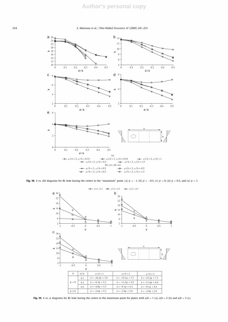
Fig. 18 shows k vs. d/b diagrams for RL hole having the centre inthe maximum point of the critical deformed mode.
Diagrams of Fig. 18 are generally similar to those in Fig. 9for circular hole in the maximum point of the critical deformedmode.
For c ¼ �1 and �0.5, k decreases when d/b increases;for c ¼ 0, 0.5 and 1, k remains almost constant (with a/b ¼ 3and x/b ¼ 1.5) or still decreases when d/b increases. For squareplate subjected to pure bending (c ¼ �1), the most evidentreduction of k with d/b occurs for holes near the loaded edge(x/b ¼ 0.25), mainly due to stress concentration in the zonebetween the hole and the loaded edge. This also occurs forrectangular plates with a/b ¼ 2 and 3 and perforation in thelateral sub-panel.
Fig. 19 shows k vs. c bi-linear regression, for RL holes havingthe centre in the maximum point of plates with a/b ¼ 1, 2 and 3.The linear formulations for k are also listed in the figure. For cX0the curves for each hole diameter (d/b ¼ 0.1, 0.3 and 0.5) becomecoincident.
5. Conclusions
Few studies exist on linear buckling behaviour of perforatedplates with rectangular holes while works on linear bucklingbehaviour of perforated plates with rectangular holes are, at
ARTICLE IN PRESS
18
20
22
24
26
0d / b
k
10
12
14
16
k
6
8
10
12
k
4
6
8
k
2
4
6
k
b
a
(a)a / b = 1, x / b = 0.5
a / b = 3, x / b = 0.6
a / b = 2, x / b = 1 a / b = 3, x / b = 1
a / b = 2, x / b = 0.65
a / b = 3, x / b = 1.2
(b), (c), (d), (e)
0.1 0.2 0.3 0.4 0.5 0d / b
0.1 0.2 0.3 0.4 0.5
0d / b
0.1 0.2 0.3 0.4 0.5 0d / b
0.1 0.2 0.3 0.4 0.5
0d / b
0.1 0.2 0.3 0.4 0.5
Fig. 12. k vs. d/b diagrams for RS hole having the centre in the ‘‘nodal’’ point. (a) c ¼ �1, (b) c ¼ �0.5, (c) c ¼ 0, (d) c ¼ 0.5, and (e) c ¼ 1.
E. Maiorana et al. / Thin-Walled Structures 47 (2009) 241–255250
Author's personal copyARTICLE IN PRESS
2
6
10
14
18
22
26
-1
k
2
6
10
14
18
22
26
k
b
a
b
a
d / b a / b = 2
0.1 k = −15.0� + 7.8
k = −11.7� + 8.5
k = −13.6� + 10.1
k = −4.2� + 8.8
a / b = 3
k = −14.8� + 7.9
k = −11.9� + 7.9
k = −15.1� + 7.9
k = −3.9� + 7.9
0.3� < 0
0.5
� ≥ 0
d / b = 0.1 d / b = 0.3 d / b = 0.5
-0.5 0 0.5 1
�
-1 -0.5 0 0.5 1�
�
Fig. 13. k vs. c diagrams for RS hole having the centre in the nodal point for plates with a/b ¼ 2 (a) and a/b ¼ 3 (b).
8101214161820222426
0d / b
k
10
12
14
k
6
8
10
k
4
6
8
k
2
4
6
k
b
a
(a)a / b = 2, x / b = 0.33
a / b = 1, x / b = 0.5
a / b = 3, x / b = 0.5 a / b = 3, x / b = 1.5
a / b = 2, x / b = 0.5
a / b = 1, x / b = 0.25
a / b = 3, x / b = 0.3 a / b = 3, x / b = 1.5
a / b = 2, x / b = 1
(b), (c), (d), (e)
0.1 0.2 0.3 0.4 0.50d / b
0.1 0.2 0.3 0.4 0.5
0d / b
0.1 0.2 0.3 0.4 0.5
0d / b
0.1 0.2 0.3 0.4 0.5
0d / b
0.1 0.2 0.3 0.4 0.5
Fig. 14. k vs. d/b diagrams for RS hole having the centre in the ‘‘maximum’’ point. (a) c ¼ �1, (b) c ¼ �0.5, (c) c ¼ 0, (d) c ¼ 0.5, and (e) c ¼ 1.
E. Maiorana et al. / Thin-Walled Structures 47 (2009) 241–255 251
Author's personal copy
present, non-existent. The variation of the hole position along thehorizontal x-axis was studied in literature [18] but the variationalong the vertical y-axis was not investigated even for circularperforations.
In this work linear buckling behaviour of plates with perfora-tions subjected to axial compression and bending moment wasstudied. The influence of the following parameters on the bucklingcoefficient was investigated:
� shape of the plate (a/b ¼ 1,2,3);� dimension of the hole (d/b ¼ 0.1, 0.3, 0.5);� position of the hole (x/b and y/b ratios);� shape of the hole (circular and rectangular RS, RL);� load configuration corresponding to uniform compression
(c ¼ 1), combination of axial force and bending moment(c ¼ 0.5, 0 and �0.5) and pure bending (c ¼ �1).
Regarding plates with circular holes, the following conclusionscan be drawn:
� for d/b ¼ 0.1, buckling coefficient k does not vary when theperforation moves from a nodal point to a maximum point ofthe critical deformed mode;� for d/b ¼ 0.3 and 0.5, coefficient k for perforations with the
centre in nodal points is generally greater than the correspond-ing in maximum points;� for holes in the centre of the plate, maximum coefficients k are
obtained with d/b ¼ 0.1 when c ¼ �0.5 and �1 (prevalentcompression), and with d/b ¼ 0.5 when c ¼ 0, 0.5 and 1(prevalent bending);� holes near panel edges have to be avoided, for all the load
conditions, since the values of k are always smaller;
� coefficient k for rectangular plates with a/b ¼ 2 and 3 isgenerally greater than for square panels;� as expected, load conditions with c ¼ 0.5, 0, �0.5 and �1,
generally give minor stability problems than for c ¼ 1 (uni-form compression);
Regarding plates with rectangular holes, RS perforation, withthe major dimension parallel to the transversal (vertical)y-direction of the panel and RL perforation with the majordimension parallel to the longitudinal (horizontal) x-direction ofthe panel were considered. The following conclusions can bedrawn:
� RS holes allow to obtain higher values of the buckling coeffi-cient k than RL holes except for d/b ¼ 0.1, for which the resultsare the same of the corresponding for not perforated plate;� RL and RS perforations having the centre in the nodal point of
the deformed configuration give higher values of the bucklingcoefficient k than those with the centre in the maximum point(similarly to the case of circular holes);� both RL and RS holes near panel edges have to be avoided, for
all the load conditions, since the values of k are always smaller(similarly to the case of circular holes);
Practical design formulations for the calculation of the bucklingcoefficient k are proposed taking into account the followingparameters:
� dimensions and shape of the plate;� dimensions and shape (circular and rectangular) of the hole;� position and orientation of the hole;� load configuration (uniform compression, combinations of
axial compression and bending and pure bending).
ARTICLE IN PRESS
2
6
10
14
18
22
26
-1
k
2
6
10
14
18
22
26
k2
6
10
14
18
22
26
k
b
a
d / b a / b = 1
0.1 k = −16.0� + 7.2
k = −8.7� + 6.6
k = −8.4� + 9.6
k = −3.5� + 7.8
a / b = 2
k = −14.8� + 7.5
k = −11.8� + 7.5
k = −15.7� + 7.5
k = −3.7� + 7.5
a / b = 3
k = −16.1� + 7.4
k = −12.0� + 7.4
k = −15.7� + 7.4
k = −3.7� + 7.4
0.3� < 0
0.5
� ≥ 0
-0.5 0 0.5 1�
-1 -0.5 0 0.5 1
�
-1 -0.5 0 0.5 1�
d / b = 0.1 d / b = 0.3 d / b = 0.5
�
Fig. 15. k vs. c diagrams for RS hole having the centre in the maximum point for plates with a/b ¼ 1 (a), a/b ¼ 2 (b) and a/b ¼ 3 (c).
E. Maiorana et al. / Thin-Walled Structures 47 (2009) 241–255252
Author's personal copyARTICLE IN PRESS
101214161820222426
0d / b
k
8
10
12
14
k
6
8
10
k
4
6
k
2
4
6
k
b
a
(a)
a / b = 1, x / b = 0.5 a / b = 2, x / b = 0.65
a / b = 3, x / b = 1.2a / b = 3, x / b = 0.6
a / b = 2, x / b = 1 a / b = 3, x / b = 1(b), (c), (d), (e)
0.1 0.2 0.3 0.4 0.5 0d / b
0.1 0.2 0.3 0.4 0.5
0d / b
0.1 0.2 0.3 0.4 0.5 0d / b
0.1 0.2 0.3 0.4 0.5
0d / b
0.1 0.2 0.3 0.4 0.5
Fig. 16. k vs. d/b diagrams for RL hole having the centre in the ‘‘nodal’’ point. (a) c ¼ �1, (b) c ¼ �0.5, (c) c ¼ 0, (d) c ¼ 0.5, and (e) c ¼ 1.
2
6
10
14
18
22
26
-1
k
2
6
10
14
18
22
26
k
b
a
b
a
d / b a / b = 2
0.1 k = −15.2� + 7.5
k = −10.2� + 7.5
k = −6.3� + 7.5
k = −3.4� + 7.5
a / b = 3
k = −15.4� + 7.4
k = −10.4� + 7.4
k = −6.7� + 7.4
k = −3.4� + 7.4
0.3� < 0
0.5
� ≥ 0
d / b = 0.1 d / b = 0.3 d / b = 0.5
-0.5 0 0.5 1
�-1 -0.5 0 0.5 1
�
�
Fig. 17. k vs. c diagrams for RL hole having the centre in the nodal point for plates with a/b ¼ 2 (a) and a/b ¼ 3 (b).
E. Maiorana et al. / Thin-Walled Structures 47 (2009) 241–255 253
Author's personal copyARTICLE IN PRESS
101214161820222426
0d / b
k
4
6
8
10
12
14
k
2
4
6
8
k
2
4
6
k
0
2
4
6
k
b
a
(a)a / b = 2, x / b = 0.33 a / b = 1, x / b = 0.25 a / b = 2, x / b = 1
a / b = 3, x / b = 1.5a / b = 3, x / b = 0.3
a / b = 1, x / b = 0.5 a / b = 2, x / b = 0.5a / b = 3, x / b = 1.5a / b = 3, x / b = 0.5
(b), (c), (d), (e)
0.1 0.2 0.3 0.4 0.5
0
d / b0.1 0.2 0.3 0.4 0.5
0d / b
0.1 0.2 0.3 0.4 0.5
0
d / b0.1 0.2 0.3 0.4 0.5
0d / b
0.1 0.2 0.3 0.4 0.5
Fig. 18. k vs. d/b diagrams for RL hole having the centre in the ‘‘maximum’’ point. (a) c ¼ �1, (b) c ¼ �0.5, (c) c ¼ 0, (d) c ¼ 0.5, and (e) c ¼ 1.
2
6
10
14
18
22
26
-1
k
2
6
10
14
18
22
26
k
2
6
10
14
18
22
26
k
b
a
d / b a / b = 1
0.1 k = −16.2� + 7.0
k = −8.3� + 5.2
k = −4.0� + 3.5
k = −2.6� + 5.2
a / b = 2
k = −15.1� + 7.3
k = −11.5� + 5.9
k = −9.1� + 4.4
k = −2.9� + 5.9
a / b = 3
k = −15.2� + 7.3
k = −11.6� + 6.0
k = −9.1� + 4.4
k = −2.9� + 2.9
0.3� < 0
0.5
� ≥ 0
d / b = 0.1 d / b = 0.3 d / b = 0.5
-0.5 0 0.5 1 -1 -0.5 0 0.5 1��
-1 -0.5 0 0.5 1�
�
Fig. 19. k vs. c diagrams for RL hole having the centre in the maximum point for plates with a/b ¼ 1 (a), a/b ¼ 2 (b) and a/b ¼ 3 (c).
E. Maiorana et al. / Thin-Walled Structures 47 (2009) 241–255254
Author's personal copy
Acknowledgement
The writers wish to thank Mr. I. Simion for the contribution tosome numerical analyses developed during the thesis.
References
[1] Shanmugam NE, Narayanan R. Elastic buckling of perforated square plates forvarious loading and edge conditions. In: Proceedings of the internationalconference on finite element methods, Shanghai, China, 1982.
[2] Azizian ZG, Roberts TM. Buckling and elasto-plastic collapse of perforatedplates. In: Morris LJ, editor. Proceedings of the international conference oninstability and plastic collapse of steel structures. London: Granada Publish-ing; 1983. p. 392–8.
[3] Brown CJ, Yettram AL. The elastic stability of square perforated plates undercombination of bending, shear and direct load. Thin-Walled Struct1986;4(3):239–46.
[4] Brown CJ, Yettram AL, Burnett M. Stability of plates with rectangular holes. JStruct Eng ASCE 1987;113(5):1111–6.
[5] Shakerley TM, Brown CJ. Elastic buckling of plates with eccentricallypositioned rectangular perforations. Int J Mech Sci 1996;38(8–9):825–38.
[6] Rockey KC, Anderson RG, Cheung YK. The behaviour of square shear webshaving circular hole. In: Proceedings of the international conference on thin-walled structures. Swansea, London: Crosby Lockwood; 1967. p. 148–69.
[7] El-Sawy KM, Martini MI. Elastic stability of bi-axially loaded rectangularplates with a single circular hole. Thin-Walled Struct 2007;45(1):122–33.
[8] Brown CJ. Elastic buckling of perforated plates subjected to concentratedloads. Comput Struct 1990;36(6):1103–9.
[9] Shanmugam NE, Thevendran V, Tan YH. Design formula for axiallycompressed perforated plates. Thin-Walled Struct 1999;34(1):1–20.
[10] El-Sawy KM, Nazmy AS. Effect of aspect ratio on the elastic buckling ofuniaxially loaded plates with eccentric holes. Thin-Walled Struct2001;39:983–98.
[11] Narayanan R, Chow FY. Ultimate capacity of uniaxially compressed perforatedplates. Thin-Walled Struct 1984;2:241–64.
[12] Narayanan R, Darwish IYS. Strength of slender webs having noncentral holes.Struct Eng 1985;63B(3):57–61.
[13] Durban D, Zuckerman Z. Elasto-plastic buckling of rectangular plates inbiaxial compression/tension. Int J Mech Sci 1999;41:751–65.
[14] El-Sawy KM, Nazmy AS, Martini MI. Elasto-plastic buckling of perforatedplates under uniaxial compression. Thin-Walled Struct 2004;42:1083–101.
[15] Paik JK. Ultimate strength of perforated steel plates under shear loading.Thin-Walled Struct 2007;45:301–6.
[16] Maiorana E, Pellegrino C, Modena C. Non-linear analysis of perforated steelplates subjected to localised symmetrical load. J Constr Steel Res 2008; inpress, doi:10.1016/j.jcsr.2008.03.018
[17] Maiorana E, Pellegrino C, Modena C. Linear buckling analysis of perforatedplates subjected to localised symmetrical load. Eng Struct 2008; in press,doi:10.1016/j.engstruct.2008.04.024.
[18] Komur MA, Sonmez M. Elastic buckling of rectangular plates under linearlyvarying in-plane normal load with a circular cutout. Mech Res Commun2008;35:361–71.
[19] G+D Computing. Straus7 user’s manual. Sydney, 2005.[20] EN 1993–1–5. Eurocode 3. Design of steel structures. Part 1–5: Stiffened
plating subjected to in plane loading. CEN European Committee forStandardization, Brussels, 2007.
[21] Timoshenko SP, Woinowsky-Krieger S. Theory of plates and shells. New York:Mc-Graw-Hill Book Company; 1959.
ARTICLE IN PRESS
E. Maiorana et al. / Thin-Walled Structures 47 (2009) 241–255 255