through holes chokes - eltron
TRANSCRIPT

www.myrra.com • [email protected]
MYRRA - 2 Boulevard de la Haye - Bussy Saint Georges - 77607 MARNE LA VALLÉE CEDEX 3 - FRANCE
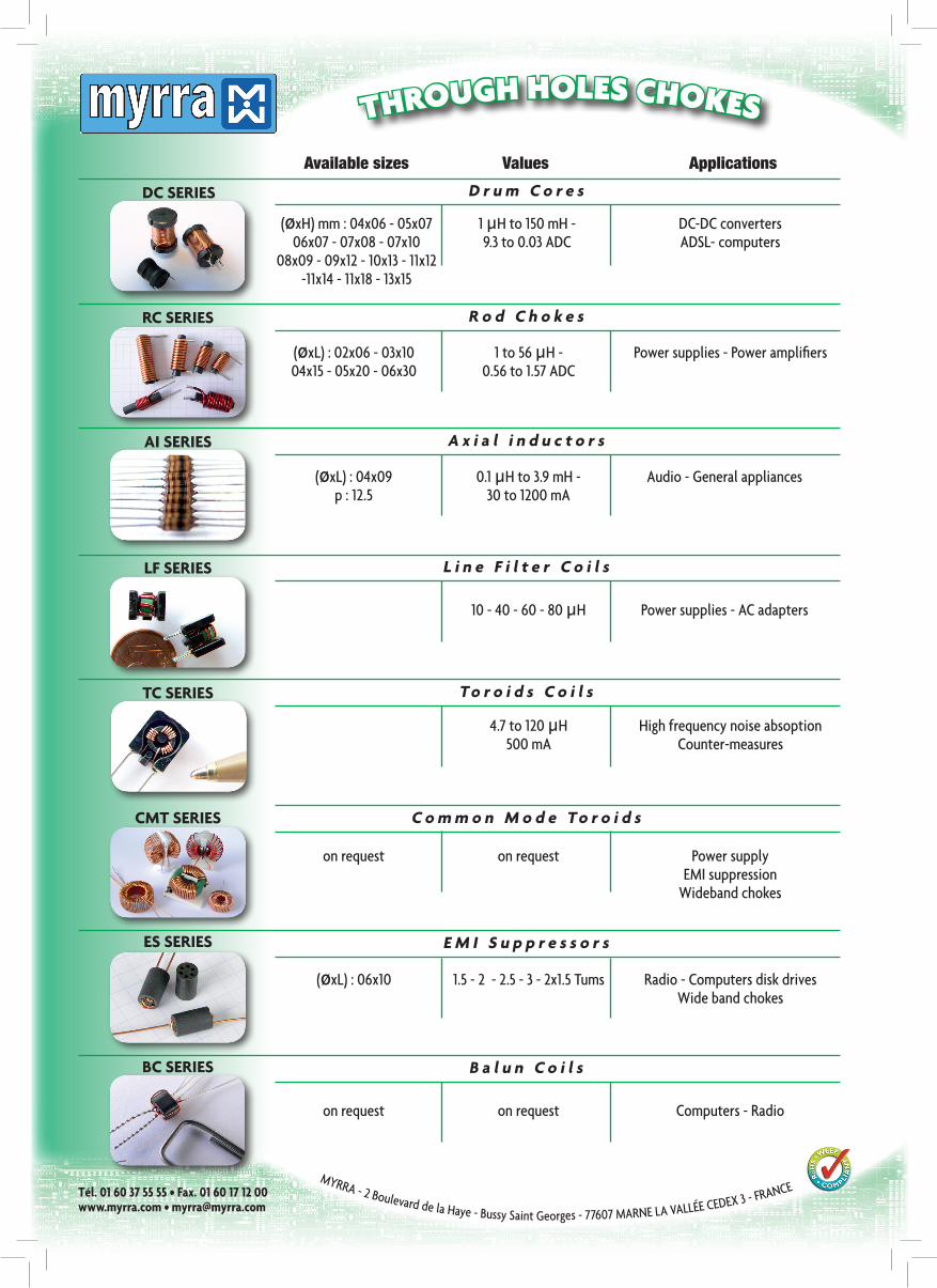
THROUGH HOLES CHOKES
Tél. 01 60 37 55 55 • Fax. 01 60 17 12 00
(øxH) mm : 04x06 - 05x07 1 µH to 150 mH - DC-DC converters 06x07 - 07x08 - 07x10 9.3 to 0.03 ADC ADSL- computers 08x09 - 09x12 - 10x13 - 11x12 -11x14 - 11x18 - 13x15
DC SERIES
R o d C h o k e sRC SERIES
A x i a l i n d u c t o r sAI SERIES
L i n e F i l t e r C o i l sLF SERIES
To r o i d s C o i l sTC SERIES
C o m m o n M o d e To r o i d s CMT SERIES
E M I S u p p r e s s o r sES SERIES
B a l u n C o i l sBC SERIES
Available sizes Values Applications
D r u m C o r e s
(øxL) : 02x06 - 03x10 1 to 56 µH - Power supplies - Power amplifiers 04x15 - 05x20 - 06x30 0.56 to 1.57 ADC
(øxL) : 04x09 0.1 µH to 3.9 mH - Audio - General appliances p : 12.5 30 to 1200 mA
10 - 40 - 60 - 80 µH Power supplies - AC adapters
4.7 to 120 µH High frequency noise absoption 500 mA Counter-measures
on request on request Power supply EMI suppression Wideband chokes
(øxL) : 06x10 1.5 - 2 - 2.5 - 3 - 2x1.5 Tums Radio - Computers disk drives Wide band chokes
on request on request Computers - Radio
www.myrra.com • [email protected]
MYRRA - 2 Boulevard de la Haye - Bussy Saint Georges - 77607 MARNE LA VALLÉE CEDEX 3 - FRANCE
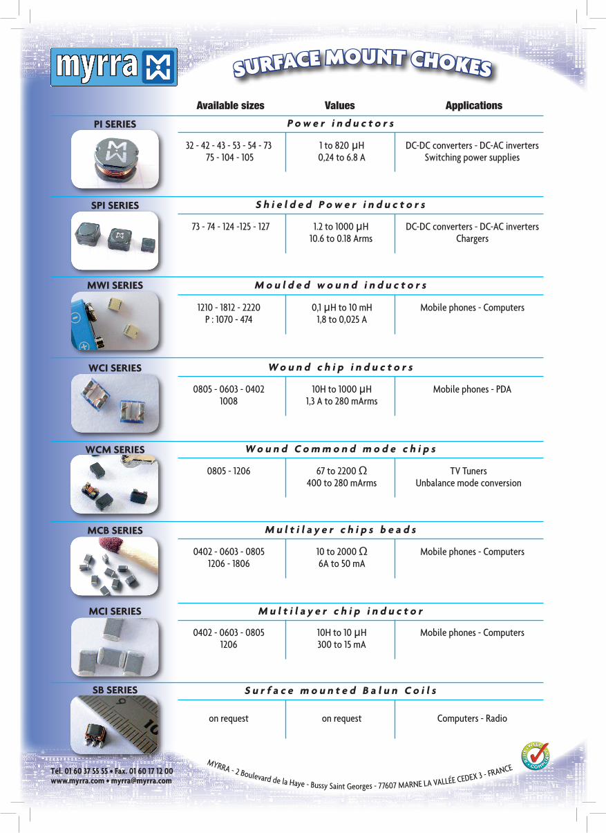
SURFACE MOUNT CHOKES
Tél. 01 60 37 55 55 • Fax. 01 60 17 12 00
32 - 42 - 43 - 53 - 54 - 73 1 to 820 µH DC-DC converters - DC-AC inverters 75 - 104 - 105 0,24 to 6.8 A Switching power supplies
PI SERIES
S h i e l d e d P o w e r i n d u c t o r sSPI SERIES
W o u n d c h i p i n d u c t o r sWCI SERIES
W o u n d C o m m o n d m o d e c h i p sWCM SERIES
M u l t i l a y e r c h i p s b e a d sMCB SERIES
M u l t i l a y e r c h i p i n d u c t o rMCI SERIES
M o u l d e d w o u n d i n d u c t o r sMWI SERIES
S u r f a c e m o u n t e d B a l u n C o i l sSB SERIES
Available sizes Values Applications
P o w e r i n d u c t o r s
73 - 74 - 124 -125 - 127 1.2 to 1000 µH DC-DC converters - DC-AC inverters 10.6 to 0.18 Arms Chargers
0805 - 0603 - 0402 10H to 1000 µH Mobile phones - PDA 1008 1,3 A to 280 mArms
0805 - 1206 67 to 2200 Ω TV Tuners 400 to 280 mArms Unbalance mode conversion
0402 - 0603 - 0805 10 to 2000 Ω Mobile phones - Computers 1206 - 1806 6A to 50 mA
0402 - 0603 - 0805 10H to 10 µH Mobile phones - Computers 1206 300 to 15 mA
1210 - 1812 - 2220 0,1 µH to 10 mH Mobile phones - Computers P : 1070 - 474 1,8 to 0,025 A
on request on request Computers - Radio
Inductors An inductor is a passive electrical device employed in electrical circuits for its property of inductance. An inductor can take many forms. Overview Inductance (measured in henries, H) is an effect which results from the magnetic field that forms around a current-carrying conductor. Electrical current through the conductor creates a magnetic flux proportional to the current. A change in this current creates a change in magnetic flux that, in turn, generates an electromotive force (emf) that acts to oppose this change in current. Inductance is a measure of the generated emf for a unit change in current. For example, an inductor with an inductance of 1 henry produces an emf of 1 V when the current through the inductor changes at the rate of 1 ampere per second. The number of turns, the area of each loop/turn, and what it is wrapped around all affect the inductance. For example, the magnetic flux linking these turns can be increased by coiling the conductor around a material with a high permeability. Applications A choke with two 47mH windings, such as might be found in a power supply. Inductors are used extensively in analog circuits and signal processing. Inductors in conjunction with capacitors and other components form tuned circuits which can emphasize or filter out specific signal frequencies. This can range from the use of large inductors as chokes in power supplies, which in conjunction with filter capacitors remove residual hum or other fluctuations from the direct current output, to such small inductances as generated by a ferrite bead or torus around a cable to prevent radio frequency interference from being transmitted down the wire. Smaller inductor/capacitor combinations provide tuned circuits used in radio reception and broadcasting, for instance. Two (or more) inductors which have coupled magnetic flux form a transformer, which is a fundamental component of every electric utility power grid. The efficiency of a transformer decreases as the frequency increases but size can be decreased as well; for this reason, aircraft used 400 hertz alternating current rather than the usual 50 or 60 hertz, allowing a great savings in weight from the use of smaller transformers. An inductor is used as the energy storage device in some switchmode power supplies. The inductor is energized for a specific fraction of the regulator's switching frequency, and de-energized for the remainder of the cycle. This energy transfer ratio determines the input-voltage to output-voltage ratio. This XL is used in complement with an active semiconductor device to maintain very accurate voltage control. Inductors are also employed in electrical transmission systems, where they are used to intentionally depress system voltages or limit fault current. In this field, they are more commonly referred to as reactors. As inductors tend to be larger and heavier than other components, their use has been reduced in modern equipment; solid state switching power supplies eliminate large transformers, for instance, and circuits are designed to use only small inductors, if any; larger values are simulated by use of gyrator circuits.
Sumary PI Series Power Inductors SPI Series Shielded Power Inductors MWI Series Moulded Wound Inductors WCI Series Wound chip Inductors WCM Series Wound Common Mode chip MCB Series Multilayer Chip Beads SMB Series Surface Mount Beads MCI Series Multilayer Chip Inductors DC Series Drum Core RC Series ROD CHOKES AI Series AXIAL INDUCTORS TCF Series Toroid Coils Filters WBC Series Wide Band Chokes CMT Series Common mode toroids BC Series Balun Coils SCC Series Spring Coils Chokes
MYRRA Page 3
All specifications are subject to change without notification
This page and its contents are covered by copyright (c) 2007 MYRRA SAS
Equivalent Model of Inductor
Cd = distributed capacitanceRs = equivalent series resistanceL = inductanceFm = Measuring frequencyQ = Quality factorSFR = Self resonance frequency
TECHNICAL INDICATIONS
EIA JIS
1005
x 10n
EIA - JIS SIZES MATCHING TABLE
05030302 08050402
0201
0403 1008
Normalized values
R12 Series
R6 Series
R3 Series
1.01.21.51.82.22.73.33.94.75.66.88.2
1.0
1.5
2.2
3.3
4.7
6.8
1.0
2.2
4.7 Q
LFmRs
...2π=
( )2..2.1SRFL
Cdπ
=
0805 20120603 1608
E +/- 0.5 %
0403 1008
1206 32161008 2520
1812 45321210 32251808 45202020 5750
Code Tolerances
INDUCTANCE TOLERANCE TABLE
+/- 2 %H +/- 3 %
F +/- 1 %G
J +/- 5 %K +/- 10 %L +/- 15 %M +/- 20 %
S -20 / +50 %N +/- 30 %
MYRRA Page 4
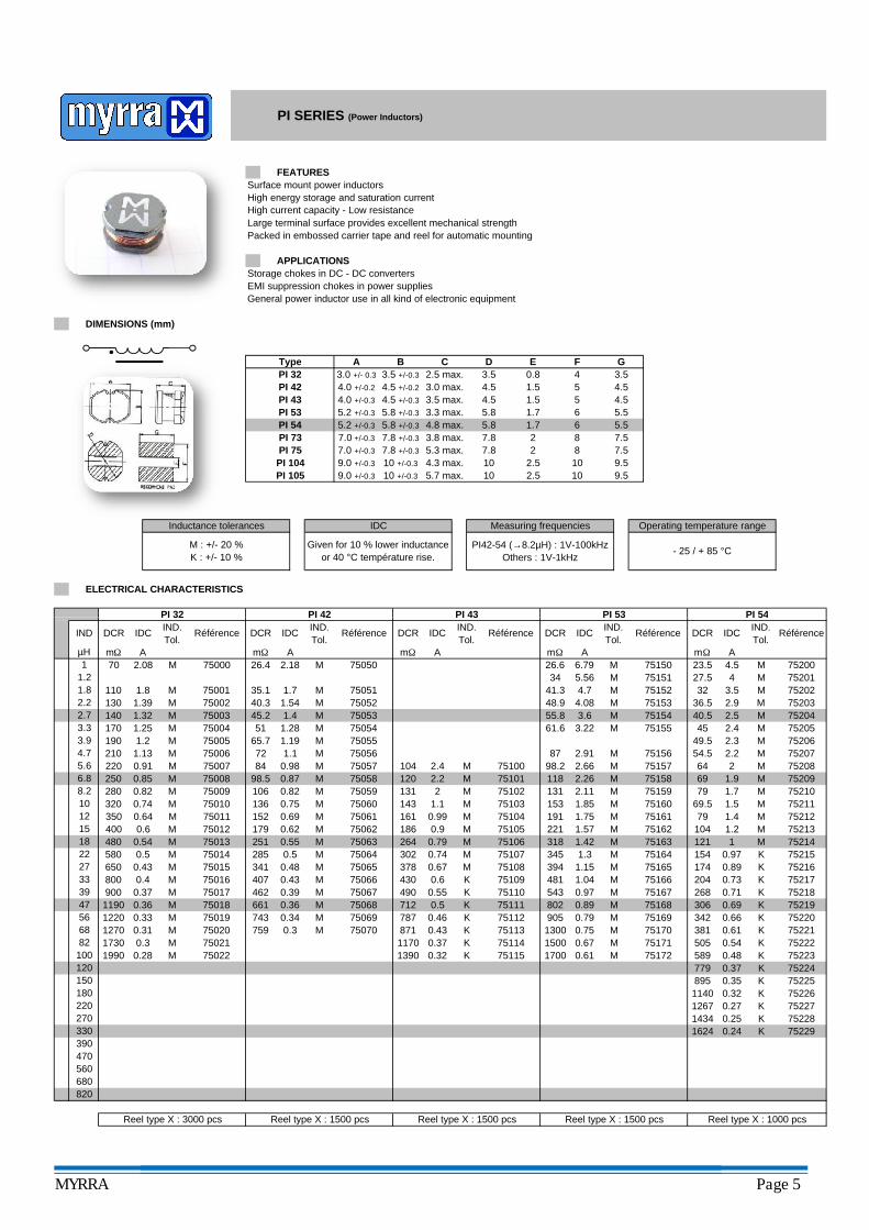
Surface mount power inductorsHigh energy storage and saturation currentHigh current capacity - Low resistanceLarge terminal surface provides excellent mechanical strengthPacked in embossed carrier tape and reel for automatic mounting
Storage chokes in DC - DC convertersEMI suppression chokes in power suppliesGeneral power inductor use in all kind of electronic equipment
PI 54
Operating temperature range
PI 53
- 25 / + 85 °C
PI 73PI 75PI 104
M : +/- 20 %K : +/- 10 %
2.5
PI 42
2.5PI 105
IDC
10
PI 43
Given for 10 % lower inductance or 40 °C température rise.
5
7.0 +/-0.3 7.8 +/-0.3 25.8 1.7
86
4.54.0 +/-0.2
5.5
4.0 +/-0.3 4.5 +/-0.3 3.5 max. 4.5 1.5 5 4.5
5.8 +/-0.3 4.8 max.7.5
7.0 +/-0.3 7.8 +/-0.3 5.3 max. 7.8 2 8 7.53.8 max. 7.8
Inductance tolerances Measuring frequencies
9.59.0 +/-0.3 10 +/-0.3 4.3 max. 1010 9.5
ELECTRICAL CHARACTERISTICS
109.0 +/-0.3 10 +/-0.3 5.7 max.
PI42-54 (→8.2µH) : 1V-100kHzOthers : 1V-1kHz
Type
PI 43
PI 54
DIMENSIONS (mm)
FEATURES
3.0 max.0.8 4
PI 42
PI 32
APPLICATIONS
PI 32 3.0 +/- 0.3 3.5 +/-0.3
A B
5.2 +/-0.3
E F3.5
4.5 +/-0.2
PI SERIES (Power Inductors)
GC D3.52.5 max.4.5
PI 53 5.2 +/-0.3 5.8 +/-0.3 3.3 max. 5.8 1.7 6 5.5
1.5
752007520175202752037520475205752067520775208752097521075211752127521375214752157521675217752187521975220752217522275223752247522575226752277522875229
Reel type X : 1000 pcsReel type X : 3000 pcs
K0.240.251434
Reel type X : 1500 pcs Reel type X : 1500 pcs Reel type X : 1500 pcs
Référence
PI 54
K
K
1.2
IND.Tol.
IND.Tol.
Référence
PI 53
DCR IDC IND.Tol.
IND DCR IDC DCR IDC
KKK
M
M1.5
M
K
10.97 K
M
K
7969
1.71.9
1.4
MM
872
75114K 75115K
K 75111
K 75113
2.2131120
143 1.1
430
0.79
0.321390
0.55
0.46
490
871
712787
4.72.4220 0.91 M 75007
72 1.1
KK
K
K
K
41.3 4.7 M
A mΩ AmΩ
PI 42
DCR IDC Référence
PI 43
µH
M
mΩ A1
75100
M
M
M40.5
427.5 M7515175150
75152
23.5 4.5
0.43
32 3.536.5 2.9
2.5
54.5 2.22.3
1624
0.890.730.71
49.5
104 64
204
M 75162318
M 75166
1.42 M
2680.6
0.990.9
121
75110 543 75167
79
M
K174M 751080.67 75165394
104
302 154264 M 75106
75107 7516475163
1.31.15 M
481 1.04K
378
69.5
1.57
MM
M
75160M 75161
1.85
K
75105191 1.75221
0.690.660.61
0.35
0.54
153
27
5668
47
161
0.74
75011400 0.6
75104
1267
381505
0.5 306
M
342
0.97 M
345
M
895
22
5.66.88.210121518
2.22.7
589
K 75112
1170 1500
3933
1140
45 2.4 M
0.480.37
0.270.32
779
3.33.9
350 0.64 M
82
120100
150180220
560
390470
270330
680820
M
2
186
75109
0.37
DCR IDC IND.Tol.
Référence
75102M 75101
M 75103
M
M
PI 32
MM
1.81.2
70 2.08 M 75000mΩ A
110 1.8 M 75001130 1.39 M 75002140 1.32 M 75003170 1.25 M 75004
75005210 1.13 M 75006190 1.2 M
250 0.85 M 75008280 0.82 M 75009320 0.74 M 75010
M 75012480 0.54 M 75013580 0.5 M 75014650 0.43 M 75015800 0.4 M 75016900 0.37 M 750171190 0.36 M 750181220 0.33 M 750191270 0.31 M 750201730 0.3 M 750211990 0.28 M 75022
26.4 2.18 M 75050
35.1 1.7 M 7505140.3 1.54 M 7505245.2 1.4 M 7505351 1.28 M 75054
65.7 1.19 M 75055M 75056
84 0.98 M 7505798.5 0.87 M 75058106 0.82 M 75059136 0.75 M 75060152 0.69 M 75061179 0.62 M 75062251 0.55 M 75063285 0.5 M 75064341 0.48 M 75065407 0.43 M 75066462 0.39 M 75067661 0.36 M 75068743 0.34 M 75069759 0.3 M 75070
IND.Tol.
Référence
26.6 6.79 MmΩ A
48.9 4.08 M
34 5.56 M
7515355.8 3.6 M 7515461.6 3.22 M 75155
2.91 M 7515698.2 2.66 M 75157118 2.26 M 75158131 2.11 M 75159
802 0.89 M 75168905 0.79 M 751691300 0.75 M 75170
751711700 0.61 M 75172
0.67
MYRRA Page 5
IDCDCR IDC DCR IDCRéférence DCRIND.Tol.
PI 73
DCR IDC
mΩ A
IND.Tol.
Référence
mΩ A mΩ A
PI 75
mΩ A
Référence
PI 104IND.Tol.
PI 105IND.Tol.
RéférenceIND
µH1
1.21.82.22.73.33.94.75.6
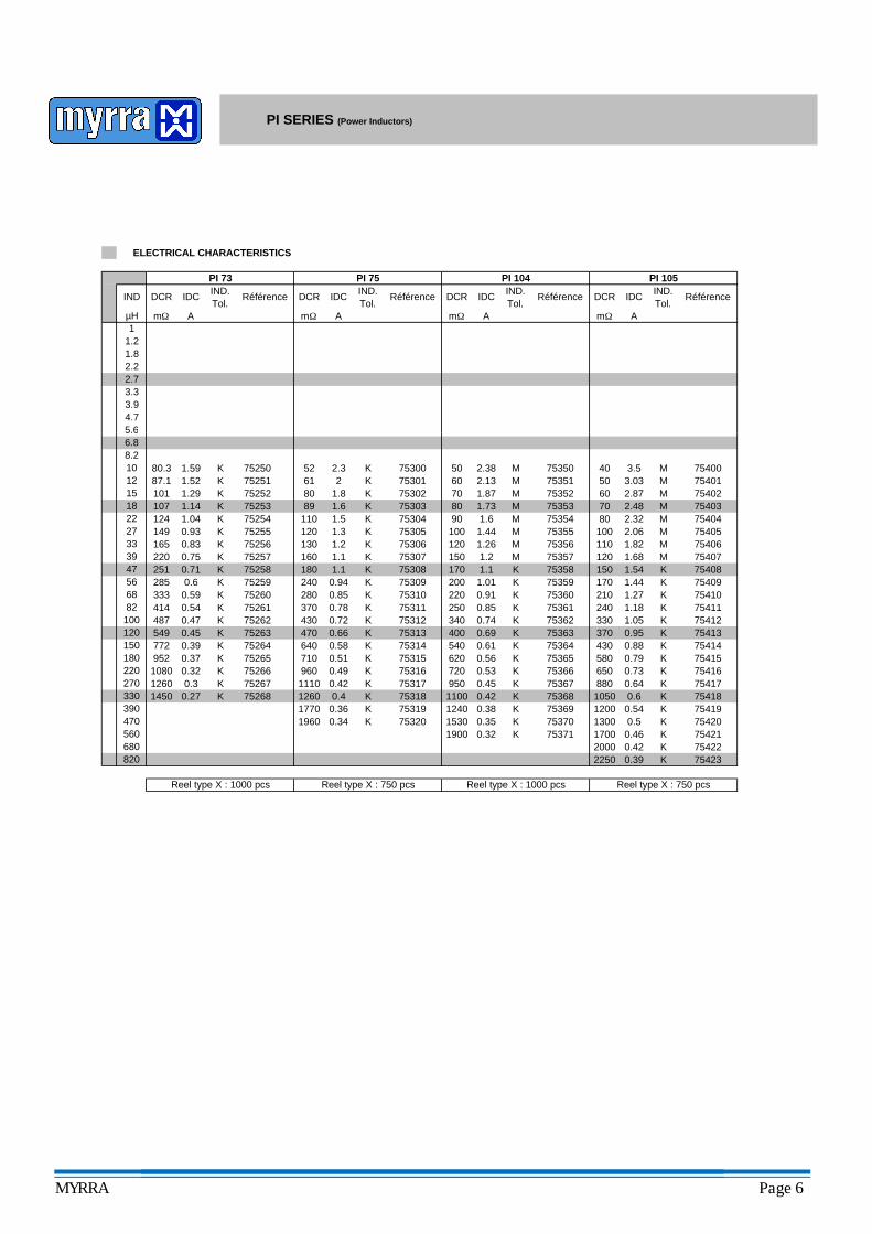
ELECTRICAL CHARACTERISTICS
PI SERIES (Power Inductors)
Reel type X : 750 pcsReel type X : 1000 pcs Reel type X : 750 pcs Reel type X : 1000 pcs
K 75421
K 75417K 75418K
K 75414
75419K 75420
K 75416K 75415
K 75412K 75413
K 75410K 75411
75407K 75408K 75409
M
75404M 75405M 75406
M
75401M 75402M 75403
MM 75400
K 75370K 75371
K 75368K 75369
K 75366K 75367
K 75364K 75365
K 75362K 75363
K 75360K 75361
K 75359
M 75356M 75357
75351M
K 75358
M 75354M 75355
K1260 0.4
K 75267 1110 0.42 75317K 75318K 75319
K 75313
K 75316
K 7531475315
K 75311K 75312
K 75309K 75310
K 75307K 75308
K 75304
K 75306K 75305
K 75302K 75303
K 75301K 75300
K 75260K 75261
75253
K 75265
7525675257
K
K 75266
75258K 75259K
KK
K 75268
952
75251K 75252
K 75423K 754222000 0.42
2250 0.39
1700 0.460.32
1200 0.541300 0.5
880 0.641050 0.6
650 0.73
1.05370 0.95430 0.88
330
580 0.79
1.68120220165
414 0.54333
0.930.830.75
100120 1.26
2.06110 1.821001.44
1.541.441.27
240 1.18
150170210
2.4880 2.32
3.0360 2.8750
70
40 3.5K 752501.521.59
10187.180.3 2.3
1.82
52
1.29K 1.6
11089
K1.04
80
124
0.59
0.71285 0.6251
107 1.14
1450 0.271260 0.31080 0.32
1.3130
0.37
0.78430
1.2
0.85
0.72
240
370
180 1.1
120
61
160
K 75255K
0.94
1.1 150
710
470772 0.39 75264
1.2
1.01170
0.47 K 75262549 0.45
75254 1.5
K
0.51
4870.66
280
149
620
75263
0.91
0.61400
250
0.69540
15301900
12401770 0.36K 75320
9600.56
0.58K
0.49
640
1.87
90 1.680 1.737060 2.1350 2.38 M 75350
M
0.85340 0.74
220
1.1200
950 0.450.42
720
11000.38
0.53
0.35
75352M 75353
1960 0.34
5.66.88.2101215182227333947566882
100120150180220
820
270330390470560680
MYRRA Page 6
Surface mount shielded power inductorsMagnetic shield : suitable for high density mountingHigh energy storageHigh current capacity - Low resistanceLarge terminal surface provides excellent mechanical strengthPacked in embossed carrier tape and reel for automatic mounting
Storage chokes in DC - DC convertersEMI suppression chokes in power suppliesGeneral power inductor use in all kind of electronic equipment
- 25 / + 85 °C M : +/- 20 %N : +/- 30 %
7.6 7
Given for 10 % lower inductance.
Isat
H2.22.2
5.45.4
5.412.6
4.5 max.
FEATURES
APPLICATIONS
SPI 73F
DIMENSIONS (mm)
E7.3 +/-0.2 3.5 max. 1.8
A BType
SPI SERIES (Shielded Power Inductors)
4.8C D
5
SPI 124 12 +/-0.3 12 +/-0.3
Given for 40 °C température rise.
SPI 125
Operating temperature range
7.66 max. 5
IrmsInductance tolerances
12 +/-0.3 12 +/-0.3 8 max. 5
Measuring frequency
1V-1kHz
7.8
SPI 127
SPI 74 7.3 +/-0.2 7.3 +/-0.2 4.8
712.65
12.6
G7.8
12 +/-0.3 12 +/-0.3
71.8 5
7.65.0 max.
7.3 +/-0.2
1.16
0.37
0.480.450.41
75513
A A
Reel type X : 1500 pcs Reel type X : 1000 pcs Reel type X : 500 pcs
IND DCR Isat Irms IND.Tol.
Isat
SPI 124
Référence
A A mΩA
75571M 75572
M
820 5760 0.21
1.84
0.65
0.80.74
1.28
1.52
0.88
1.6
0.550.6
0.550.6 75512M
0.22
0.18
0.330.310.270.25
0.410.3775517
755700.37
2050
0.34M 75569M
M 75515M
75573
M 75519
75516MM 75518
0.45
75574M 75524
0.23
0.290.25
M0.21 0.26
M 75520
M
75568
M 75565M 75566
M
M 75567
0.23
M
75552M
75555
M 7555975560 182
M 75562
0.310.28
0.2
0.25
1830
M 75523 3750
0.31
75563M 75564
980 0.5
M1.63
M 75561
130
1.211.06
1.51.67
350 0.84
0.33
0.440.391650
1.040.96
0.7
72 2.111.71.5
98
1.050.98
0.78
M 75514
75600
M 75558
1.611.4
0.84 1
1.82 1.8
1.32
M 7555175550
1.75
M
ELECTRICAL CHARACTERISTICS
2.73.9
7555385
M1.72
2.1 1.970
755100.810.61
0.75
0.630.66
1.3675511 0.78
2.04215
0.980.92
1.221.2
M1.23
M
75505M 75556M 75557
75502
M 75554M
220 1701.26
7550375504
M 75500
200M 75506M 75507
120140M
270240
0.98
100
360
75
1.461.4170190
75611169 2.19 1.73 M 75612132 1.91 M2.37
1.79 1.52 M 75614
75616266 75615M331 1.51
330
100
47
5.66.8
1130 0.48
640730 0.55
0.640.560.5
8.21012 75501M
1380
470
280
720
0.43
M
0.46
420
20001370
151822
82
120150180
M
27
3933
5668
320 75508M 75509
220
560
390470
270
680
1000
5120
0.410.4
0.188200
33903780
0.342270
0.270.29
2590
0.22
4250
25703000
M 75521M 75522
0.2
650
1200
M
M
M470
0.88
820
120
DCR Irms
1160
Irms IND.Tol.
1.2
IND.Tol.
DCR IsatRéférence
SPI 74
13.7 8.26 6.68 N
7560124.4 5.72 5 N 7560219.9 6.37 5.53 N
7560335.6 4.75 4 M 7560432.4 5.19 4.5 M
7560552.1 3.79 3.18 M 7560643.9 4.38 3.5 M
3.11 M 7560770.3 3.16 2.75 M 75608
3.3465.7
75609124 2.59 1.96 M 7561090.5 2.84 2.6 M
1.19 M
1.58 M
75617
75613
1.22 0.95 M 75618469 1.33 1.01 M525
75619824 1.05 0.74 M 75620603 1.13 0.85 M
75621932 0.95 0.69 M
A
Référence
SPI 73
mΩµH mΩ
MYRRA Page 7
AmΩ A19.7
119.62
mΩ
Irms DCRDCR Isat
A
Isat
A
Référence
SPI 127IND.Tol.
IrmsRéférence
4.5 756504.3 756513.6
4.2 M
MM M 75707
M 75708
N 75705M 75706
N 75700
75703N
N 75701N 75702
75704
5.94
12.5
7.77.016.43
IND.Tol.
SPI 125
10.5 12.9
22.5
8.5514.5
322827
3.9 75652
20.5
3.5 25
16.518.5
6.5
5.25.465.74
N
10.6
7.42
6.456.08
6.88
8.09
IND
µH1.22.73.95.66.88.2101215
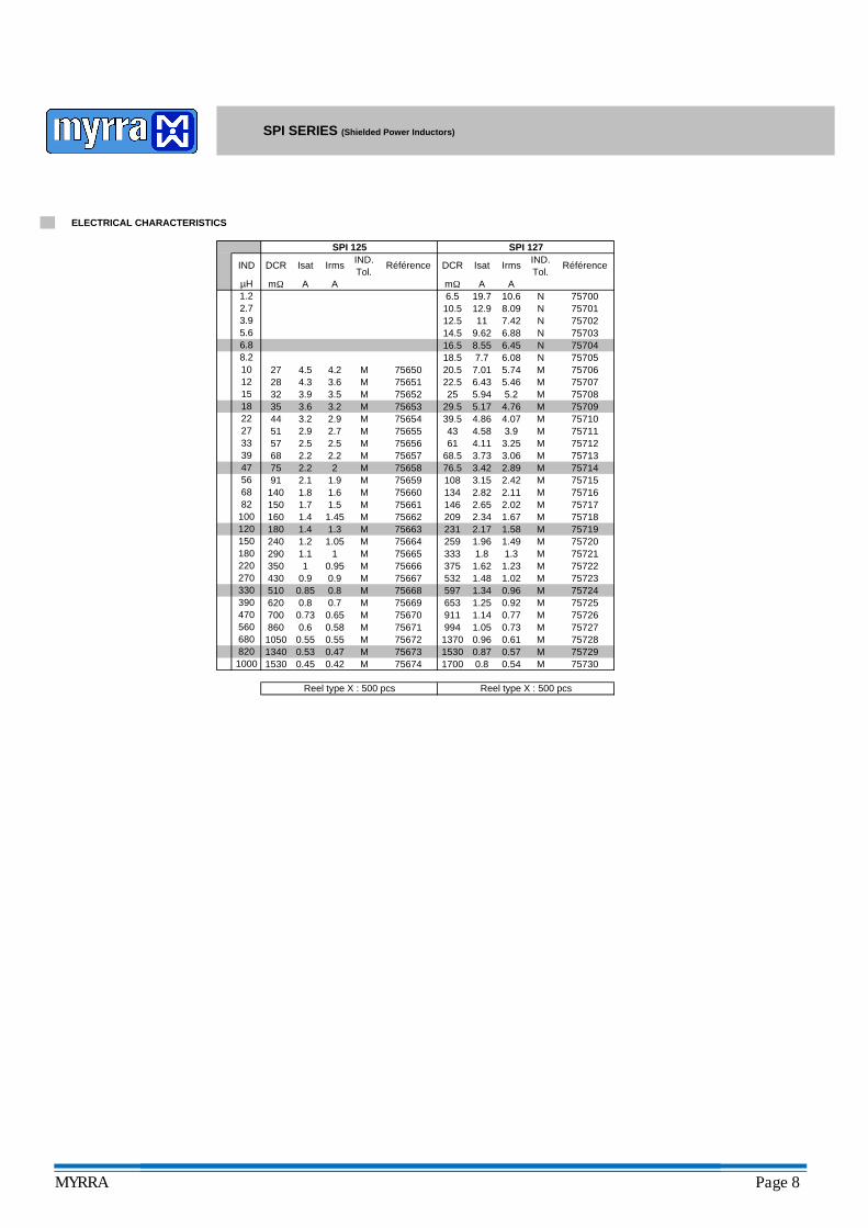
ELECTRICAL CHARACTERISTICS
SPI SERIES (Shielded Power Inductors)
Reel type X : 500 pcs Reel type X : 500 pcs
M 75730
MM 75653
2.1
0.8 M 75669
M
M
1
1.4
0.73
0.85
1.1
1.8
75662
M
75658
M
M 75723
M 75728
75726
7572475725
MM
M
M 75719
M 75722M 75721M 75720
M 75717M 75718
M 75715M 75716
M 75713M 75714
M 75711M 75712
M 75709M 75710
M 75708
M
MM
M
M
MM
0.87
75667
75664 259
1370
75670
75672M 75671
75655
75673 1530
75663
75668
M
M 0.540.8
5.94
75666
170075674
75657
2.9
1.05
1.96
M
M
0.57
2.17
2.82
333
510
150 1.5140 1.691
M
MM
75654
3.733.42
75659M2.2
1.9
5.17
22.2
32 3.9 75652
68
44 2.951 2.7
2.52.2
2.5
3.23.5
39.529.5
1.4
756601.7 75661
290 1240 1.051.2180
35 3.63.2
75
0.9350 0.95
0.9430
0.7
4361
146209
0.8
68.5
M1.45
75656
1.3
108
57
2.11
1.67231 1.58
1342.652.34160
3.0676.5 2.89
25
1.02
911 0.770.92653
597 0.96
994
532375
1530 0.420.47
0.60.55
1340 0.530.45
8601050 0.55
0.58700 0.65
75665
620
75729
1.14M1.25
1.341.48
0.61757270.73
0.96
1.621.31.81.49
2.02
3.15
1.23
2.42
3.254.113.94.584.074.76
4.86
5.215182227333947
330390470
566882
100120150
5606808201000
180220270
MYRRA Page 8
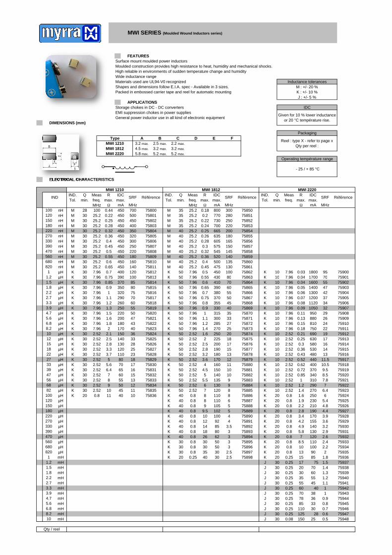
Surface mount moulded power inductorsMoulded construction provides high resistance to heat, humidity and mechanical shocks. High reliable in environments of sudden temperature change and humidityWide inductance rangeMaterials used are UL94-V0 recognizedShapes and dimensions follow E.I.A. spec - Available in 3 sizes.Packed in embossed carrier tape and reel for automatic mounting
Storage chokes in DC - DC convertersEMI suppression chokes in power suppliesGeneral power inductor use in all kind of electronic equipment
Inductance tolerancesM : +/- 20 %K : +/- 10 %J : +/- 5 %
701800
10 0.040.03
7.9695 75900
759011700KK 7.96
MHzmA
1080 75863K 50 0.55 4307.96
0.25
0.55
500450400
450450450
758060.45 75807
140120
220
0.7
M 30
2830
M
M 30M
M
M30
30
0.6
30
M
SRF
MHz
M
MM
Qmin.
Rmax.
IND.Tol.
MWI 1210
RéférenceQmin.
Rmax.
Measfreq.
IDCmax.
C D E
ELECTRICAL CHARACTERISTICS
MWI 22203.2 max.
5.2 max.
3.2 max.
5.8 max. 5.2 max.
ΩΩ mA
MWI 2220IND.Tol.
SRF SRF RéférenceQmin.
Rmax.
IDCmax.
Référence
MWI 1812
0.5
MHz
7580175800
75805
75802
700Ω
0.22
30
7580375804
30
350320300250
300.36
3900.75 75813
25.225.2470 nH
M 300.4
30 0.65
25.2M
KK
7581145075812400
100
MWI 1210MWI 1812
DIMENSIONS (mm)
3.2 max. 2.5 max. 2.2 max.
4.5 max.
MWI SERIES (Moulded Wound Inductors series)
A BType
FEATURES
APPLICATIONS
F
IDC
75810160
450450450
7580975808
180
0.22 730M
0.44
IDCmax.mA
M
IND.Tol.
450770
75850280 75851
35 0.18 800 300
220 7585375852
M 35 0.24 700250M 35
200 75854M 40 0.26 635M 40 0.25 66545030
30 0.280.32
25.225.2
450450450
1 µH
680 nH820 nH
180 nH220 nH
560 nH
270 nH330390
IND
100 nH
nH
120 nH150 nH
1.2 µH
nH180 75855
M 40 0.28 605 165 7585625.225.2
0.3 575 150 75857M 40 0.32 545 145 75858M 40
M 40 0.36 520M 40 0.4 500
475
140 75859135 75860130 75861100 75862
M 40K 50 0.5 450
0.45
25.2
25.2
25.225.2
Given for 10 % lower inductanceor 20 °C température rise.
MHz10025.2
Measfreq.
35 0.2
25.27.96
25.225.225.225.2
7.96
Measfreq.MHz25.225.225.225.225.2
25.27.96
Packaging
Reel : type X - refer to page xQty per reel :
Operating température range
- 25 / + 85 °C
Qty / reel
759467594775948J 30 150 250.08
0.6J 30
0.5J 30 1250.25
0.25 0.7110
10
580
310
4402.52
2830
2.9
3.94.4
6
16
0.91
1.21.3
1.82
2.6
60 40 1
11.5
530 14
0.72
759440.8 75945
3633
7594370 38J 30 78J 30 850.25
J 30J 30
759401.1 75941
75942J 30 55 45J 30 35 55
0.25
75939J 30J 30 30 60
20 700.251.5 759371.4 75938
J 30 17 750.25K 20 15 850.25
7593575936
K 20K 20 13 90
10 1000.8
759322.4 759332.2 75934
K 20 8.5 110K 20 7 120
75931K 20K 20 5.8 130
4.9 1400.8
759283.6 759293.2 75930
K 20 4.2 1550.8K 20 3.4 1700.8
75927K 20K 20 2.8 190
2.2 2100.8
759245.4 759254.8 75926
K 20 1.9 2300.8K 20 1.6 2500.8
75922K 75923K 729010 1.22.52
2.52
75920K 75921K 8.5340
7.82.5210 1
75918K 75919K 10.5400
370 9.510 0.62
75912K 75913K 19690
10 0.25 630 1775914
K
10 1.4 270 6.4
10 0.85
75915K
75911K
10 0.18 750 2210 240.15
2.52
K 75909
75916K 75917K 10 0.43
K
K 2926
950880
1010 0.13
7.967.96
1348010 0.52
K32
0.081050112010
10 0.097.96
10 0.310 0.36
2.522.52
2.52
75908
2.522.52
K
810
10 0.21
K7.967.96
75910
K
K 75907
K10
0.11
7.967.967.96
47
3437
707590275903759047590575906
100.05 1400
10
10
0.047.96
0.06 1300
550.04 1600
42
759011700K
10 0.07 1200
2.5 75898K 30K 20 40 30
35 30
3 758953 75896
2.5 75897K 30 30 50K 30 30 500.8
0.8
3 75894K 40K 40 26 62
18 80
4 758913.5 758923 75893
K 40 14 85K 40 12 92
4 75890K 40K 40 10 100
9.5 102
6 758875 758885 75889
K 40 9 105K 40 8 1100.8
0.8
8 75886K 50K 40 8 110
7 120
9 758839 758848 75885
K 50 6 130K 50 5.5 135
10 75882K 50K 50 5 140
4.5 150
12 7587911 7588010 75881
K 50 4 160K 50 3.6 1702.52
2.52
13 75878K 50K 50 3.2 180
2.8 190
18 7587517 7587615 75877
K 50 2.5 200K 50 2 225
20 75874K 50K 50 1.6 250
1.4 270
33 7587127 7587225 75873
K 50 1.2 285K 50 1.1 3007.96
7.96
35 75870K 50K 50 1 315
0.9 330
50 7586745 7586840 75869
K 50 0.8 355K 50 0.75 370
55 75866K 50K 50 0.7 380
0.65 390
80 7586370 7586460 75865
K 50 0.6 4107.96
K 50 0.55 4307.96
15
33282523181716
75832
75828
75
75827
7581975820
75818
75822
75825
7582375824
13
1
2601.1
5550
60
43
60
3.7
9
40
50
11
121110
7583445
K
KK
30
3.3
2.5
22.1
30
3030
1.61.8
30
305
2.8
3030
3030
0.9
30
30
30
K
K
0.85 75814390370 85
0.75
758167581770
75813
130 75826
75821200 47180
304036
170150
1.5
2.52
7.967.967.96
1.2K3030
1.3K 7.96
7.96µH
30
K
KKK
KK 30
KK
30
308
K
30
730
5.66.4
2.52
2.522.52
K
K
K
KK
K
80350
100
75815
140
320
250220
290
75833
12011080
55
758297583075831
7065
7583575836
K 30 10K 20
120 µH
180µH
µH
µH
3.93.3
1.8 µH
1.2 µH1.5
56 µH
5.6 µH6.8
10
µH8.2
µH12
2.2 mH
µH
mH820 µH1
560 µH
1.5
mH
4.7 mH
µH
µH15 µH
2.2 µH2.7
µH
4.7 µH
18 µH22 µH27 µH33 µH
100 µH
39 µH47 µH
68 µH82 µH
1.2 mH
220
µH
270 µH330 µH
150 µH
680 µH
390 µH470
mH1.8
10 mH
5.6 mH6.8 mH
mH
2.7
8.2 mH
3.3 mH3.9 mH
7.967.967.967.967.967.96
2.522.522.522.522.522.52
2.522.520.8
7.96
7.967.967.967.967.96
2.520.8
7.962.522.522.522.522.52
0.80.80.80.80.80.8
7.967.96
0.80.25
2.522.522.522.52
0.250.250.25
2.52
0.8
0.80.80.80.8
2.52
0.250.25
Surface mount high frequency wirewound inductorsClose tolerance of inductance valueWide inductance rangeShapes and dimensions follow E.I.A. spec - Available in 5 sizes.2 ranges available : Ceramic or Ferrite coreResin-coated top surface for easy automatic mounting. Packed in carrier tape and reel for automatic mounting
High frequency resonant circuits, filters, impedance adaptationC type : ceramic core : highest SRF and best temperature stability and linearity
Very High Freqency applicationsHigh allowable DC current.
F type : ferrite core : higher inductance valuesHigh Q factorLow DC resistance
1.023
Type
C : CeramicF : Ferrite
WCI 1812 4.95 max. 3.81 max. 3.43 max. 1.14 3.05
1.151.780.76 1.02
1.27
DCRQ SFR IDC RéférenceDCRMeas
0.64 0.64
WCI 0805 - CWCI 0603 - CIND. Q Meas SFRRéférence IDC RéférenceIDC DCRIND. Q
WCI 0402
WCI 0805WCI 0603
ELECTRICAL CHARACTERISTICS
SFR
0.461.19 max. 0.66 max.0.64 max.
WCI 1008
IND
WCI 0402 - CIND.
C D
WCI SERIES (Wound chip Inductors)
F
DIMENSIONS (mm)
FEATURES
Type
APPLICATIONS
Given for a 20 °C température rise.
IDC
A B E
Operating temperature range
- 40 / + 85 °C
2.92 max. 2.79 max. 2.03 max. 2.54
Inductance tolerances
J : +/- 5 %Ask us for 2 % tolerance.
0.66
1.42 max.
1.12 max.
0.361.8 max.
2.25 max. 1.7 max.
1.02 max.
Meas Meas
Qty / reel
1.8 µH1.5 µH1.2
6808201
nH
330390470560
150
5647
180220270
6882
100120
11.21.51.82.22.73.3
J 16ΩmAGHz
23 0.28J
GHz
DCRmax.
mA
170 76073170
76075
12.7 0.05 1360 76000
92 76129
190 76127230 76126
0.31
100 76018100 76019J 22 1.62 1.12
J 22 1.76 0.97150 76017
J 25J 20 2.1 0.83
2.1 0.55
400 76014400 76015200 76016
J 24 2.35 0.3J 24 2.48 0.3250
250
J 25 2.8 0.33.1 0.23
76010560 76011420 76012400 76013
J 24 3.28 0.17250250J 24
J 24 3.6 0.12250480640
76009J 22J 21 3.9 0.2
4.4 0.1 680 76008J 20 4.8 0.08 680 76007250
250
J 20 4.8 0.08J 15 4.77 0.13J 19
640 76002840 76003840 760046 0.07
960
J 19 7 0.07250J 16 10.4 0.12250
76001J 19 10.8
Qmin.
SFRmin.
IDCmax.
RéférenceDCRmax.
Measfreq.
0.7 3.7 13025 100JJ 25 0.9 3.63 76074100J 24 0.9 2.3
200 76072100
J 25J 25 0.9 2.1
0.99 1.25100100
300 76069280 76070240 76071
J 28 0.99 0.92J 32 1.3 0.72150
150
400 76068J 34J 34 1.4 0.58
1.7 0.54
600 76065600 76066400 76067
J 37 1.7 0.34J 38 1.9 0.34
600 76064J 40J 38 2 0.28
2.2 0.25
600 76061600 76062600 76063
J 38 2.3 0.26J 40 2.8 0.22
250
700 76060J 35J 38 3 0.19
3.1 0.17
700 76057700 76058700 76059
J 35 4 0.17J 35 4 0.13
700 76056J 31 4.8 0.13
J 27 5.8 0.11 700 76055250
J 22J 20
0.22
76051J 24 12.5 0.03 700 76050
J 23 0.19 2.2502550
J 33J 2325 0.34 1.9
0.38 1.76
76123290 76124250 76125
J 48 0.56 1.5J 48 0.6 1.4
350 76122J 50J 48 0.65 1
0.85 0.7
400 76119400 76120400 76121
50 0.87 0.64J 50 0.92 0.56
76117400 76118J 50 1.1 0.51
1.2 0.46150500500J 65
400400
200 500 76115J 65 1.3 0.42150 76116
60 1.45 0.38500 76114
50060 1.55 0.34
1.65 0.31200
500 76112500 76113J 60
J 60 2 0.29250200
J 60 2.05 0.27250 50076110
J 55J 55 2.5 0.25
2.6
76111
250 0.22250
600 76107600 76108500 76109500
250J 50 3.3 0.2500250
50 4 0.15500250J 50 3.4 0.17500
76103600 76104
600 7610676105
2500.11
600
600
500 4.2 0.1
6005.51000
50 4.7 0.125.5
0.08
0.06J 50 7.9 0.1
80 7.91500
nHnH
nH
10
0.056.9
nHnH
J 16
J 25
0.07
Ω
3339
3.9
nH6.8
12
nHnH
5.64.7
nHnHnH
µHµH
8.2
15182227
JnH
nHnHnHnH
J
JJ
JnH
nHnH
76102J 65
nH
250
nHnH
nH
nH
nHnHnH
nH
nHnHnH
50
J 60250
IND.Tol
Qmin.
Measfreq.
SFRmin.
Référence
800 76100600 76101
12.5
100.08
IDCmax.
Référence
mA
IDCmax.
700
760545.8 0.13
DCRmax.
GHz
0.05
IND.Tol
Qmin.
nHnH
640 76005760 76006
J
J
700 76053700 76052
700
SFRmin.
nH
IND IND.Tol
MHz Ω
2.356.9
180 76128nH J 23
250
250
250
250250
250
250250250250
Measfreq.MHz
250250
250250250
250250250250250250
250200200200150150
MHz
1500
1000
1000
500500500500500
500
250250250250250250250100
5050
Measfreq.MHz
250
150100100100
250
250250
10010010050
2525
MYRRA Page 10MYRRA Page 4
mAMHz ΩMHz
IDCmax.
RéférenceMeasfreq.
212 312.2187J 15 7.9676159
70 2 3607.9J7616031 80 1.82 3807.9J
76158J 312381.462172.0515J 7.96
1.56 4207.9J7615790 1.68 4007.9J
133 2501.32J 32 10576156J 3215 151 2621.24
1.28 49050J76155120 1.46 45050J
J 15 2841.09 34 13576154J 34189 3130.847.96
J76153150 1.1 52050J
39 170 0.84 60050
WCI 1812 - FIND.Tol
Qmin.
SFRmin.
DCRmax.
3387.9615 238417.96 630
0.517.96
mA
J76152390J 0.5622815 269 210 0.68
Ω mA
RéférenceMeasfreq.
J76151425 650
MHz
J
JJ
15
SFRmin.
Qmin.
IDCmax.
WCI 0805 - FDCRmax.
Référence
15 107
157.967.967.967.96
156
15
434
IND.Tol
76210
762007620176202762037620476205
IND.Tol
Qmin.
76209
48
76208
MHz Ω
IDCmax.
7620676207
190 0.76
MHz
WCI 1008 - FSFRmin.
DCRmax.
70076150 J 48 230 0.6215 7.96 0.46387
Measfreq.MHz
WCI SERIES (Wound chip Inductors)
111
0.76
50
Measfreq.MHz
7.97.97.97.97.97.9
5050
7.97.97.97.97.9
680 nH
IND
820 nH1 µH
1.2 µH1.5 µH1.8 µH2.2 µH2.7 µH3.3 µH3.9 µH4.7 µH5.6 µH6.8 µH
ELECTRICAL CHARACTERISTICS
33 2.8J2.3 380.79
76273J 5030 1.9 4455
76269
60 7627176272
J 33J 30 2.1 41
28.5 75 76270J 38 4.4 26.50.79
0.7985
J 38 5.2 24.5100 76267
0.79 90 76268
J 38J 38 7 22.5
8.3 20.50.790.79
120 76264115 76265105 76266
J 38 7.6 16.2J 36 9.3 14.20.79
0.79
125 76263J 33J 36 11.5 13
14.5 11.5
170 76260150 76261135 76262
J 40 12 8J 40 13.5 7
180 76259J 42J 40 16 6
20 5.5
210 76256200 76257190 76258
J 42 24 5J 45 30 4.52.5
2.5
230 76255J 45J 45 40 4
46 3.6
270 76252260 76253240 76254
J 45 58 3.2J 45 52 2.8
290 76251J 42J 42 70 2.5
85 2 310 76250
76169J 7 15 10887616815J 11262.52
2.52
76167J 15 5.62.52 13076166J 14358 2.5276165J 1489 2.52 4.615761644.62 150J 2.52761631564.161J 2.52
J 3183 1683.539 2.52 7.93307.9J76161
60 2.95 3007.9J76162204J 2.47 31 65 2.657.96212 312.2187J 15 7.96 70 2 3607.9J76160
88
15
79
52
15
99
76212
7621076211
2.52.52.52.52.52.5
2.52.52.52.50.790.79
0.790.79
7.97.9
6.8 µH8.2 µH10 µH12 µH15 µH18 µH22 µH27 µH33 µH39 µH47 µH56 µH68 µH82 µH
100 µH120 µH150 µH180 µH220 µH
µH680 µH
270 µH330 µH390 µH
820 µH1000 µH
Qty / reel
470 µH560
MYRRA Page 11
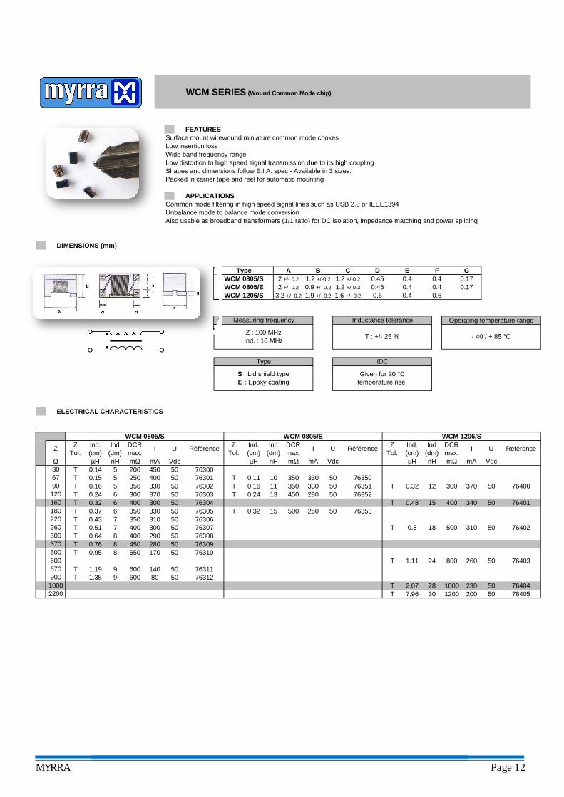
Surface mount wirewound miniature common mode chokesLow insertion lossWide band frequency rangeLow distortion to high speed signal transmission due to its high couplingShapes and dimensions follow E.I.A. spec - Available in 3 sizes.Packed in carrier tape and reel for automatic mounting
Common mode filtering in high speed signal lines such as USB 2.0 or IEEE1394Unbalance mode to balance mode conversionAlso usable as broadband transformers (1/1 ratio) for DC isolation, impedance matching and power splitting
Measuring frequency Inductance tolerance
Z : 100 MHzT : +/- 25 %
F
0.9 +/- 0.2
DC
0.451.2 +/-0.3 0.4 0.172 +/- 0.2 1.2 +/-0.2 1.2 +/-0.2 0.45 0.4 0.4 0.17
0.42 +/- 0.2
WCM SERIES (Wound Common Mode chip)
WCM 0805/SWCM 0805/E
DIMENSIONS (mm)
A B GEType
FEATURES
APPLICATIONS
WCM 1206/S 3.2 +/- 0.2 1.9 +/- 0.2 0.6
Operating temperature range
- 40 / + 85 °C
1.6 +/- 0.2 0.6 0.4 -
302.077.96
TT
28
18
101113
50250500
250 400330
50350
Ind(dm)nH55
mΩ
50150.32
310
37050
µH0.140.15
0.32
76306
Type IDC
Given for 20 °Ctempérature rise.
S : Lid shield typeE : Epoxy coating
0.8
7630315
Z : 100 MHzInd. : 10 MHz
T : +/- 25 %
mA Vdc50 76300200 450
76301
ELECTRICAL CHARACTERISTICS
ZTol.
Z UZTol.
DCRmax.
RéférenceDCRmax.
Ind.(cm)
Ind.(cm)
U
1200.160.24
56T 0.24
30Ω
160 400 300 506180 350T 503306
T0.37
50 T300
7630576304
76302 T67
T90
TT
Référence
mΩ mA Vdc
I
µH
Ind(dm)nH
T
450350
T 3500.110.16 50
280
30070.512900.64 8
220 T 35070.43260 T 400
370300 T 400
T 450
9600500 T 550 1700.95 8
1.35 9
2800.76 8
670 T 600 1401.19 76311
1000900 T 600 80
2200
50 76310
50 7631250
5076307
50 7630976308
50
0.48
76400T 300
T 400
310 76402
370 50
76401
nH
12
50
340 50
500
Ind(dm)
76353
1200
241.11
764041000 230 50
- 40 / + 85 °C
200 50
DCRmax.
I U
260 50
76405
WCM 0805/E WCM 1206/S
Vdc
ZTol.
Référence
mΩ mA
Ind.(cm)µH
WCM 0805/S
76352
7635076351
330 50
50
I
330 0.32
T
76403T 800
MYRRA Page 12
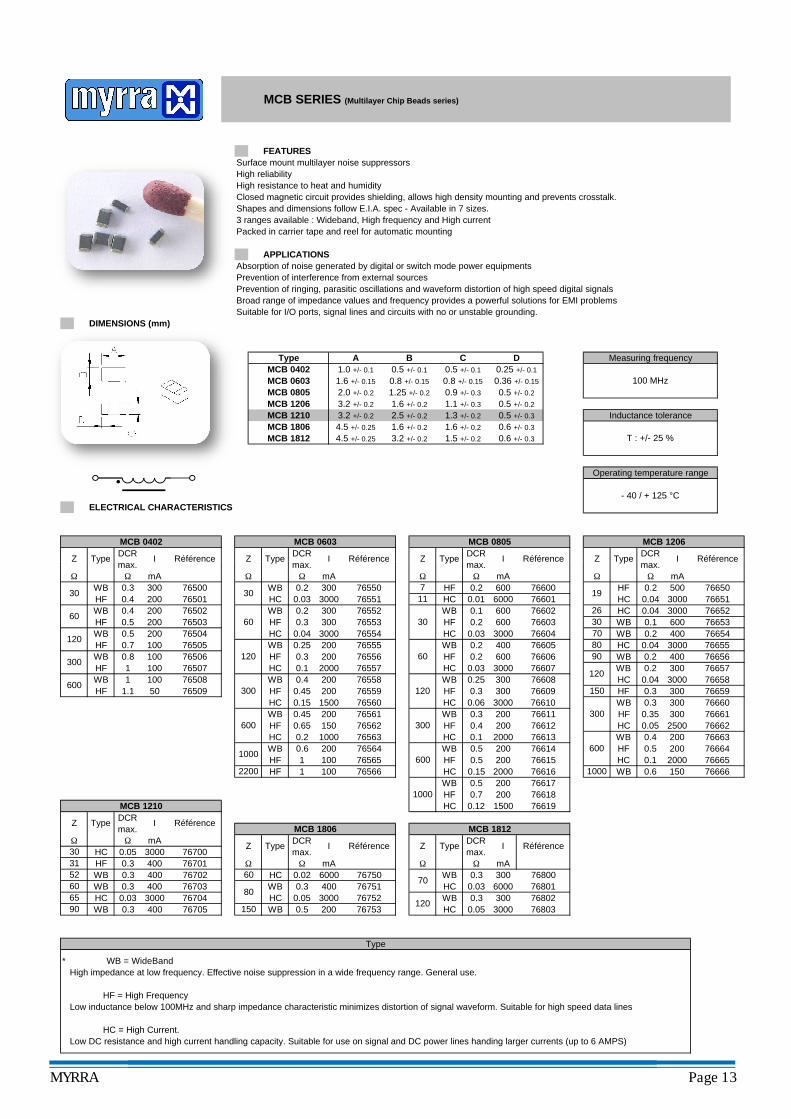
Surface mount multilayer noise suppressorsHigh reliabilityHigh resistance to heat and humidityClosed magnetic circuit provides shielding, allows high density mounting and prevents crosstalk.Shapes and dimensions follow E.I.A. spec - Available in 7 sizes.3 ranges available : Wideband, High frequency and High currentPacked in carrier tape and reel for automatic mounting
Absorption of noise generated by digital or switch mode power equipmentsPrevention of interference from external sourcesPrevention of ringing, parasitic oscillations and waveform distortion of high speed digital signalsBroad range of impedance values and frequency provides a powerful solutions for EMI problemsSuitable for I/O ports, signal lines and circuits with no or unstable grounding.
Z Type DCRmax.
1.25 +/- 0.2 0.9 +/- 0.3MCB 0805
0.5 +/- 0.1
0.8 +/- 0.15
0.5 +/- 0.1
0.8 +/- 0.15
2.0 +/- 0.2
MCB 0402MCB 0603
MCB SERIES (Multilayer Chip Beads series)
DIMENSIONS (mm)
FEATURES
A B D0.25 +/- 0.1
MCB 1812
APPLICATIONS
Type1.0 +/- 0.1
0.36 +/- 0.15
0.5 +/- 0.2
1.6 +/- 0.15
C
0.5 +/- 0.2
0.6 +/- 0.3
ELECTRICAL CHARACTERISTICS
1.1 +/- 0.3
1.6 +/- 0.2
4.5 +/- 0.25 3.2 +/- 0.2 1.5 +/- 0.2
3.2 +/- 0.2
4.5 +/- 0.25
Type
1.6 +/- 0.2
1.6 +/- 0.2
MCB 1206
MCB 18060.5 +/- 0.3MCB 1210 3.2 +/- 0.2 2.5 +/- 0.2 1.3 +/- 0.2
0.6 +/- 0.3
DCRmax.
ZI Référence
MCB 0402 MCB 0603
I Référence
MCB 0805
Z Type ZDCRmax.
I Référence Type
MCB 1206
RéférenceIDCRmax.
Measuring frequency
- 40 / + 125 °C
Inductance tolerance
100 MHz
Operating temperature range
T : +/- 25 %
mA
30WB 0.3 300HF 0.4 200
Z
Ω Ω
Typemax.
60WB 0.4 200HF 0.5 200
HF
Type
Ω
6076502
7650076501
100 7650776506
100
WBHFHCWB
76504
1200.8
76503
76509
120WB 0.5 200
50
176508
HF 0.7
600WB 1HF 1.1
300WBHF
max.
WBHC
30
Z
100100 76505
I Référence
300HCHF
HCWB
2200 HF
1000WBHF
600WBHFHC
I Référence
Ω mA0.2 300
765543000
0.3 2002000.25
0.04
76550
76801
76606
6000
HC
0.5
0.03 3000 76551WBHF
11 HC 0.01
WBHF
30
0.2WBHF
0.03
0.45 200
0.7
0.1
1000
76604HC
600.1 2000
0.2 300 765520.3 300 76553
765570.4 200 76558
7655576556
76560
765637656276561
76559
76565
I
100
200
3000
120
1000
HC
HF
300
Référence
0.150.45
0.02
100
0.65 15010000.2
2001500
7
7680376802
120
Ω
0.05
WB0.03
HC
HF6000 76601
0.2 600 76600Ω mA
Z Type
Ω
Z
0.2600 76602
Ω
0.1
max.I Référence
3000600 76603
600
0.40.3
76617
76612
200
76613200076614
7661676566
76751
400 766050.2
76608
Ω
200
mA
3000
0.6
Ω
Type
WB 0.3
DCRmax.
300
3000200
DCRmax.
I
2000
0.3 3000.25
WB
3000 76700
WBHFHC
1
WBHF
1
Z0.05
0.03 3000 76704
0.3 400 76701
0.3 400
Type
76703
0.5 200 767530.05 3000 76752
0.12
Référence
Ω mA
Imax.
0.04
0.2
HCHC
WB
766505007665176652
0.04
76653600
30003000
0.10.2 400
300076654
150 WB
76564
76619
300
76618
0.3
200
HC 0.15
MCB 1812
Référence
1500
600
76800
300
70
WB
WB
300 HFHC
150
HC
Type
76611
60
200
70 WB
766150.5 200
0.3
0.5WB
80
0.3 400
WB
76702 6000 76750
HC400 HC
0.3 400 76705
HC
HCΩ mA
90 WBHC
30 HC31 HF52 WB60 WB65
Ω
MCB 1210
Z
DCRmax.
I Référence
Ω mA
Z Type
766560.04
400
300
0.2 300
76655
766570.04 3000
2000
7666276661
200 7666476663
2500200
300
766580.3
HF
7665976660
0.4
300
19HF
26
9080
120
HC
HF
30
WB600
0.2
76610
76607
76609
0.050.350.3
0.03
0.06
WB
Type
* WB = WideBand High impedance at low frequency. Effective noise suppression in a wide frequency range. General use.
HF = High Frequency Low inductance below 100MHz and sharp impedance characteristic minimizes distortion of signal waveform. Suitable for high speed data lines
HC = High Current. Low DC resistance and high current handling capacity. Suitable for use on signal and DC power lines handing larger currents (up to 6 AMPS)
766650.5
766660.6
MCB 1806
1500.1HC
MYRRA Page 13
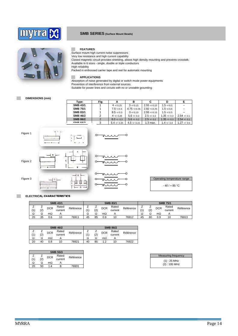
Surface mount high current noise suppressorsVery low resistance and high current capabilityClosed magnetic circuit provides shielding, allows high density mounting and prevents crosstalk.Available in 6 sizes - single, double or triple conductorsHigh reliabilityPacked in embossed carrier tape and reel for automatic mounting
Absorption of noise generated by digital or switch mode power equipmentsPrevention of interference from external sourcesSuitable for power lines and circuits with no or unstable grounding
Figure 1
2.54 +/- 0.1
1.5 +/-0.5
1.5 +/-0.5
1.5 +/-0.5
----
2 4 +/- 0.25 5.6 +/- 0.2
2.5 +/- 0.2
2.5 +/- 0.2 1.35 +/- 0.3
1.35 +/- 0.3
1.4 +/- 0.4 1.27 +/- 0.5
2.54 +/- 0.1
SMB 86/2 2 8.0 +/- 0.3 5.6 +/- 0.2
4.5 +/- 0.15
SMB 46/2SMB 83/1SMB 75/1
2.55 +/-0.15
2.92 +/-0.254.75 +/-0.257.5 +/-0.4
D EDIMENSIONS (mm)
FEATURES
APPLICATIONS
A B C4 +/-0.25
SMB SERIES (Surface Mount Beads)
--Type
SMB 43/1Fig1 2.55 +/-0.153 +/-0.15
3 +/-0.158.5 +/-0.311
SMB 55/3 3 5.4 +/- 0.25 1.3 max.
Figure 2
Figure 3
(1) : 25 MHz(2) : 100 MHz
Operating temperature range
- 40 / + 85 °C
Measuring frequency
RéférenceRated current
1080 0.9 76913
DCRZ(1)
Z(2)
SMB 75/1
A
SMB 43/1Rated current
SMB 83/1
RéférenceZ(1)
Z(2)
DCR Rated current
Référence
0.9AΩ
20 35 0.6 7691110 45
Z(1)
Ω
DCRZ(2)
ELECTRICAL CHARACTERISTICS
mΩ Ω Ω mΩ A
SMB 46/2 SMB 86/2
Ω Ω mΩ
Z(1)
Z(2)
DCR Rated current
Référence
20 40 0.8 10 76921Ω Ω mΩ A
SMB 55/3Z
(1)Z
(2)DCR Rated
currentRéférence
20 50 1.4 8 76931Ω Ω mΩ A
Z(1)
Z(2)
DCR Rated current
76922Ω Ω mΩ40
4576912
85 1.2 10A
Référence
85 10
MYRRA Page 14
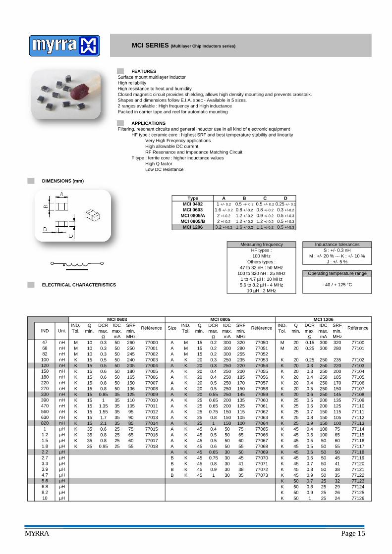
Surface mount multilayer inductorHigh reliabilityHigh resistance to heat and humidityClosed magnetic circuit provides shielding, allows high density mounting and prevents crosstalk.Shapes and dimensions follow E.I.A. spec - Available in 5 sizes.2 ranges available : High frequency and High inductancePacked in carrier tape and reel for automatic mounting
Filtering, resonant circuits and general inductor use in all kind of electronic equipmentHF type : ceramic core : highest SRF and best temperature stability and linearity
Very High Freqency applicationsHigh allowable DC current. RF Resonance and Impedance Matching Circuit
F type : ferrite core : higher inductance valuesHigh Q factorLow DC resistance
Measuring frequencyHF types : 100 MHz
Others types :47 to 82 nH : 50 MHz
0.25 +/- 0.1
MCI 0603
1.2 +/-0.2
Type
FEATURES
APPLICATIONS
MCI SERIES (Multilayer Chip Inductors series)
0.5 +/-0.31.1 +/-0.2
Inductance tolerances
0.3 +/-0.2
C D
0.5 +/-0.3
A B
2 +/-0.2
0.5 +/- 0.2
DIMENSIONS (mm)
1 +/- 0.2
1.6 +/- 0.2 0.8 +/-0.2 0.8 +/-0.2
0.5 +/- 0.2
1.2 +/-0.2 0.9 +/-0.2
0.5 +/-0.32 +/-0.2
S : +/- 0.3 nHM : +/- 20 % --- K : +/- 10 %
J : +/- 5 %
MCI 0805/AMCI 0805/BMCI 1206 3.2 +/-0.2 1.6 +/-0.2
1.2 +/-0.2
MCI 0402
ELECTRICAL CHARACTERISTICS
280 771010.15 300 320
26 771250.9
25 32
7712625 24
47 to 82 nH : 50 MHz100 to 820 nH : 25 MHz
1 to 4.7 µH : 10 MHz5.6 to 8.2 µH - 4 MHz
10 µH : 2 MHz
0.25 300
501K 50
25
77123K 50 25 29 77124K 50
0.8
50
0.7
38 77121K 45 50 35 77122K 45
0.9
50 45
30 38
77070 77119K 45
0.850 41 77120
K 450.7
50 55K 35 0.95 25 55 77018 77117K 45
0.650 50 77118
K 450.6
100 65K 35 0.8 25 60 77017
77115K 45
0.550 60 77116
K 450.5
150 100K 15 2.1 35 85 77014 77113K 45
0.5100 75 77114
K 250.4
150 11515 1.55 35 95 7701215
77111K 25
0.9150 105 77112
K 250.8
200 13515 1 35 110 7701015
77109K 25
0.7200 125 77110
K 250.6
250 150
6308201
5.6
K 1577107
K 200.5
250 145 77108K 20
0.6
250 18577006K
330390470560
77105K 20
0.5250 170 77106
K 200.4
250 22077005
K 15 0.6 50 165
77103K 20
0.4250 200 77104
K 200.30.3
250
K 15 0.6 50
1.2
K
235 771020.25K 20
20
K 15 0.5 50 205 77004
M 20
6.88.2
M7710010 0.3 50
M 10
Ω mA MHz
10
MΩ mA
Référence
MHzmA MHz
MCI 0603IND.Tol.
Qmin.
DCRmax.
IDCmax.
SRFmin.
Ω300
50
MCI 0805IND.Tol.
Qmin.
0.5 5077002
0.3
240 77003
150
K 20
77000250
M 15
180
260
7700877009
90 77013
105 77011
24577001
77007
50
KKKK
K1.5
3.94.7
1.82.22.73.3
82
150
K 1515nH220
270
120100
68
180
0.310M
nHnHnH
K 15
0.8 50
35 1250.8 50 1360.85
1.7 35
1.35 35
770157535 0.8 25 65 77016
K 35 0.6 25
AA
K 25
K 25
45
K
47
K 20
K 25
K 25
K 20
K
320
255
0.3 250
77050M 15 0.2 300 280 77051
0.2M 15
770520.3 250 235 770530.2 300
K 20
K 45
200
250K 20 0.5 250 170
250
K
77055220 77054
20 0.4 2500.4 250
185 7705677057
K
150 77058
115
77059K 20 0.5
1450.5577060
105 77063
0.65 200 135
770620.65 200 125 77061
25 0.75 150
1 1500.8 150
100
A
B 45K
B
75 77065
K 45 60 77067
77064
0.5 500.4 50
50
65 770660.5 50
55 77068K 45 0.65 30 77069K 45 0.6
50B 45 0.75 30 45
B0.8 30 41 77071
77072K45 145 0.9
30K 35 77073
Size
AA
AA
AAAAAAA
AAAA
A
A
MCI 1206IND.Tol.
Qmin.
DCRmax.
IDCmax.
SRFmin.
Référence
nHnHnH
nHnH
nHnHnHnH
µH
µHµH
µH
µHµHµHµHµH
IND Uni.IDCmax.
SRFmin.
RéférenceDCRmax.
nH
µH
Operating temperature range
- 40 / + 125 °C
µHµH
nHµH
MYRRA Page 15
ELECTRICAL CHARACTERISTICS
IND Uni.
1.2 nH1.5 nH1.8 nH2.2 nH2.7 nH3.3 nH3.9 nH4.7 nH
mAΩ
Référence
Ω mA
MCI 0603 - HFIND.Tol.
Qmin.
DCRmax.
IDCmax.
SRFmin.
Référence
300
GHzS 8 0.1 300 6 min. 77200
300
6 min. 77201S 8 0.12 300 6 min. 77202S
300
6 min. 77203S 8 0.2 300 6 min. 77204S
300
5.7 77205K 8 0.25 300 5.6 77206K
4.8 77207K
GHz
MCI 0402 - HFIND.Tol.
Qmin.
DCRmax.
IDCmax.
8
0.288
0.22
8 0.16
8 0.1
SRFmin.
MCI 0805 - HF
Size IND.Tol.
Qmin.
DCRmax.
IDCmax.
SRFmin.
Référence
A
A
A
0.1 300
GHzΩ mA
6 min. 77250A S 8 0.1 300 6 min. 77251
S 8
S 8 0.1
A
300 6 min. 77252A S 8 0.1 300 6 min. 77253
77254A K 8 0.15 300 5.4 77255
K 8
0.2 300
6 min.0.13 300
4.5 77256K 8K 8 0.4 300 5.7 77157K 8 0.3 300 6.3 77156K 8 0.3 300 6.8 77155S 8 0.2 300 7.7 77154S 8 0.2 300
10.5 77151S 8 0.1 300
8.7 771539.4 77152
12 77150S 8S 8 0.1 300
0.1 300
MCI SERIES (Multilayer Chip Inductors series)
4.7 nH5.6 nH6.8 nH8.2 nH
12 nHnH
27 nH
15 nH18 nH22 nH
10
33 nH
0.6
K 8
J
56 nH
J 8
39 nH
nH
120 nH150
8
68 nH
47 nH
470 nH
270 nH330 nH
nH
390 nH
82 nH100 nH
180
J
nH220
300
300
4.8 77207K 8 0.29 300 4.35 77208K
300
3.75 77209J 8 0.33 300 3.3 77210J
300
2.85 77211J 8 0.4 300 2.7 77212J
300
2.4 77213J 8 0.5 300 2.05 77214J
300
1.85 77215J 8 0.6 300 1.75 77216J
1.5 77217J 8 0.7 300 1.35 77218J 8
J 8 0.9 300
1 77221J 8 1 300
1.2 772191.1 77220
0.9 77222J 8J 8 2 300
1.5 300
J 8 2.5 300 0.83 77223
0.65
8
200 1.3 77169J 8 2
J 8 0.9
J 8 0.7
1.8 200 1.65 771681.7 77167
0.55
8 0.45
8
8 1.5 200
0.28
8 1 300300 1.95 77165
J 1.75 77166
0.35
8 0.3
8
771642.35J 8 0.8 300300 2.6 77163
J 8 0.6 300 2.95 77162300 3.75 77161
J 8 0.5 300 4.1 77160
A
J 8 0.5 300 4.55 77159
0.2 300 4.5 77256A K 8 0.23 300 4 77257
K 80.4 300 5.1 77158
77258A J 8 0.28 300 3 77259A J
8 0.3
300 3.658 0.25
77260A J 8 0.35 300 2.45 77261A J
K 8 0.4 300 5.7 77157
300 2A J 8 0.4
300 2.5
77262A J 8 0.45 300 1.75 77263
77264A J 8 0.55 300 1.55 77265A J
77266A J 8 0.65 77267A J 8 0.6
300 1.3300 1.35
300 1.78 0.5
A J 8 0.7 300 1.2 77268A J 8 0.75 300 1.15 77269
1 77270A J 8 0.9 300 0.85 77271A
8 1
300J 8 0.85
300 0.73 77272A J77273
B J 8 1.5 250 0.55 77274B J
8 1.8
250 0.658 1.3
250 0.5 77275B J 8 2 200 0.45 77276B J
0.38 77278200 0.4B J 8 2.5
8 3.5 150 0.33
77277B J 8 3 150
77279B J 8 4 100 0.3 77280B J
MYRRA Page 16
Vertical mount radial inductorsSmall PCB surface requiredWide range of inductance valuesCovered with UL approved shrinkable tubing
DC-DC convertersDifferential mode filtering in input and outputs of Switch Mode Power SuppliesGeneral power inductor use in all kind of electronic equipment
ELECTRICAL CHARACTERISTICS
Rmax.
Référence
M : +/- 20 %K : +/- 10 %
IND.Tol.
IDCmax.
A
Qmin.
Rmax.
IDCmax.
Ω
DC 57
M 20 0.04 2.7 78102
20 0.03 3.2 210 78100180 7810120 0.03 3154
IND.Tol.
Qmin.
MM
SRF
130110100
SRF
MHz150M
M7570
M 70M
0.06
6.8 max. 7.5 max.
7800178000
0.07
F
7 max.
7 max. 8.5 max. 0.6
0.610 min.
10 min. 15 min.
Référence
2.5
10 min.
10 min.
0.6
0.615 min.
3
DC 46
Ω2.4
DC 1112 11 max.
DC 1013 10 max.
78003
MHz
11 max.
A
15 min. 1.35 max. 2
DC 67
DC 1315
DC 78
0.515 min.
15 min.
DC 46DC 57
DIMENSIONS (mm)
4 max. 6 max. 10 min.
C
DC SERIES (Drum Core series)
A BType
FEATURES
APPLICATIONS
D E
2.22
1.9
0.8 7.5
Operating temperature range
- 25 / + 85 °C
15 min.13 max. 15 max. 10 min.
Inductance tolerance
618 max. 10 min.
DC 1114 11 max. 14 max. 10 min.
DC 1118 6
6DC 1014 10 max. 14 max. 10 min. 15 min. 0.8 5
12 max. 10 min.
3
DC 89 8 max. 9 max. 10 min.
DC 71 7.5 max. 10 max.
4.50.6
13 max. 10 min.
78002
15 min.
DC 912 9 max. 12 max. 10 min.
15 min. 0.8
15 min.
15 min. 0.8
0.815 min. 0.8
515 min. 0.6 5
0.07
DC 67IND.Tol.
Qmin.
65 0.08
IND
µH1 µH
1.2 µH
Ω A MHz
M
Rmax.
IDCmax.
SRF Référence
M 20 0.02 5 125 78201782024.3 9520 0.021.5 µH
1.8 µH
0.86100 0.8 7814833 0.04K
7814678147
K 6589.5
0.0578.1K 65
0.930.04
1.05 78144K 65 0.05 0.98 78145K 65
68.40.06
1.4 78142K 72
61.20.06 1.3 78143
K 7239.7
0.07
1.810.0821.4 78140K 72
360.07 1.49 78141
K 7231.2
2.09 78138K 72 0.09 1.95 78139K 72
18.60.1
2.55 78136K 72
16.60.11 2.25 78137
K 7211.8
0.12
3.130.156.24 78134K 72
10.60.14 2.85 78135
K 659.24
3.68 78132K 65 0.17 3.37 78133K 65
5.640.18
4.58 78130K 65
5.050.19 4.32 78131
K 653.84
0.22
6.070.282.04 78128K 50
3.480.24 5.03 78129
K 502.65
7.1 78126K 33 0.34 6.83 78127K 33
1.560.38
8.67 78124K 33
1.220.42 7.65 78125
K 331.15
0.46
100.520.64 78122K 23
0.90.48 9.6 78123
K 230.78
13 78120K 25 0.58 11 78121K 25
0.580.64
16 78118K 25
0.460.72 14 78119
K 250.41
0.76
210.920.21 78116K 29
0.350.8 18 78117
K 290.3
25 78114K 29 1 23 78115K 29
0.191.1
31 78112K 35
0.181.2 26 78113
K 350.14
1.3
351.50.1 78110M 20
0.131.4 34 78111
M 200.11
48 78108M 20 1.6 40 78109M 20
0.091.7
63 78106M 20
0.082 58 78107
M 200.07
2.1
1252.50.04 78104M 20
0.062.4 100 78105
M 200.05
0.21
0.25
780060.14 78007
75651.6
780310.160.14
4.54.2
7800845
78026
16
8.2
5.5
3.8
15
0.18
481.5
7
50
0.16
0.09
0.08
10
40
3.8
2.3
3.1
6.5
78009
100
M 65M
M
M
K
60MMM 60
65
55
4040
M
K
K
KK
K
KK
550
4550
40
K
K
2020
40
0.18
0.13
2.5 780273.4 78028
78032
780295.4 78030
0.63
7801034
18
1.4
78012
78005
0.24
1.31.21.1
780111 30
78004
0.46
250.31KK
2740
78015780160.66
780130.36 78014
0.850.73
2123
78017
1478020
4020
0.50.43 13
780181
78022
45780251.9
1.3 780231.4 78024
45
11108.7
0.350.320.3
1.1780210.3820 12
780190.57
KK 55
KK
55
55
0.9
0.72
9.4K
55
6.855 6
0.12
0.53
K
K
KK
K
0.9
0.9K
1
780031.91.7 M65
65 0.080.09
650.10.11
M 65
0.260.240.220.2
4040
0.6540
0.17803578036
78033
0.08
2.92.82.6
78034K 55 16
66
K 50 18
30
1 mH78037
K 45 32 0.06 7803820
1.82.4
2.2 mH
K 501.2 mH
K 45K 78040
36 1.71.5
780390.060.04
2.7 mH3.3 mH
K 30 72 1.4 780410.04
mH4.7 mH
6.8 mH8.2 mH10 mH
5.6
µH33 µH
µH
820 µH
18 µH22 µH27 µH
39
82 µH
150 µH
8.2 µH10 µH
47
M
KK
MM
MMM
75 7820578204
20 0.02 3.80.02 420 90
230 0.03 3.4
53
69
20 0.03 2.620 0.03 3.1
2.3 39
7820661 78207
2.5 782107820978208
4420 0.05 2.6 32
K 26
20 0.05M 20 0.06 78211
32 782137821233
26 0.08 1.70.07 2
26 0.11 1.7
22
27
K 23 0.15 1.4K 26 0.13 1.5
7821424 78215
20 7821778216
K 23 0.18 1.3K 23 0.23 1.1K 23 0.26 1K 18
17 7821816 78219
13 7822115 78220
K 18 0.35 0.90.3 0.96
K 18 0.41 0.78
10 78224K 18 0.55 0.68
12 7822211 78223
9.1 78225K 18K 18 0.75 0.58
0.63 0.63
K 18 0.9 0.53
6.2 78228K 20 1.1 0.48
8.2 782266.7 78227
6 78229K 20K 20 1.6 0.39
1.2 0.44
K 23 2 0.35
4.9 78232K 23 2.2 0.34
5.2 782304.8 78231
4.2 78233K 23K 23 3.6 0.26
2.8 0.3
K 36 4.3 0.24
3 78236K 36 4.9 0.22
3.7 782343.4 78235
2.8 78237K 78K 78 7.3 0.18
6.5 0.19
K 78 9.8 0.15
2 78240K 78 11 0.14
2.4 782382.2 78239
1.8 78241K 78K 78 18 0.11
13 0.13
K 78 20 0.1
1.3 78244K 78 27 0.09
1.6 782421.4 78243
1.2 78245K 78K 78 35 0.08
30 0.08
K 78 40 0.07
0.92 78248K 78 61 0.06
1.1 782460.99 78247
0.85 78249K 46K 46 80 0.05
69 0.06
0.78 78250K 46 92 0.05
1.8 µH2.2 µH2.7 µH3.3 µH3.9 µH4.7 µH5.6 µH
12 µH
6.8 µH
15 µH
100 µH120 µH
56 µH68 µH
180 µH220 µH270 µH
680 µH
330 µH390 µH470 µH560 µH
1.5 mH
15 mH
mH1.8
12 mH
mH
3.9
MYRRA Page 17
8.7 7852310 78522
8.3 785241.1K 22 0.25
K 15 0.31 0.95
K 11 7852112 78520
K 22 0.21 1.2
40 0.16
22 0.19
13 78519
1.3K 40 0.19 1.4
7851714 78518
1.7K 52 0.13 16
1.5K
18 785162.2K
K 52 0.1 1.90.08
25 7851322 78514K 60 0.06 2.5
60 19 78515
3M
K 60 0.06 2.6K 60 0.05 2.8
85 0.05
K 45 0.14 1.6
37 7850934 78510
3.4
28 78511M 98 0.04 3.3
M
M 100 0.043.5M 38 785083.7
55 7850547 7850645 78507
26 78512
M 115 0.02 4.6130 0.03110 0.03
M 130 0.02M 130 0.02 5.3 75 78504
4.7
150 78501100 78502M 130 0.02 5.7
M 140 0.01 6.5180 78500
ΩM 140 0.01
A
DC 89IND.Tol.
Qmin.
Rmax.
IDCmax.
SRF Référence
MHz7
9.6 784238.7 78424K 33 0.9 0.46
K 23 0.78 0.4810 78422
K 25K 23 0.64 0.52
0.58 0.58
14 7841913 7842011 78421
K 25 0.46 0.64K 25 0.41 0.72
16 78418K 29K 25 0.35 0.76
0.3 0.8
23 7841521 7841618 78417
K 29 0.21 0.92K 29 0.19 1
25 78414K 35K 29 0.18 1.1
0.14 1.2
34 7841131 7841226 78413
K 35 0.13 1.3M 20 0.11 1.4
35 78410M 20M 20 0.1 1.5
0.09 1.6
58 7840748 7840840 78409
M 20 0.08 1.7M 20 0.07 2
63 78406M 20M 20 0.06 2.1
0.05 2.478404
100 784051250.43M 20 2.5
154 78402M 20M 20 0.04 2.7
0.03 3
MHz210 78400180 78401
M 20 0.03 3.2Ω A
DC 78IND.Tol.
Qmin.
Rmax.
IDCmax.
SRF RéférenceRmax.
IDCmax.
SRF Référence
MHz188 78300
ΩM 15 0.01 7.3
A
78301M 15 0.01 5.7 145 78302M 15 0.01
0.15
1726.6
5M 15
0.025.7 115 78304
98 78305M 15 4.9 78 78306M 15
0.0278307
M 150.03
4 47 78308M 15
0.0215
0.033.7
604.50.02
3
32 78309M 15
0.043.2 30 78310
M
26 78311K 50 2.9 25 78312M 15
0.0478313
K 500.06
2.5 20 78314K 50
0.0540
0.072.4
232.60.05
2.1
18 78315K 40
0.082.2 17 78316
K
15 78317K 40 1.8 13 78318K 40
0.178319
K 350.16
1.4 11 78320K 35
0.1435
0.21.3
121.60.11
1.1
9.6 78321K 30
0.231.2 8.5 78322
K
7.7 78323K 20 1 7.1 78324K 30
0.26
IND
µH
ELECTRICAL CHARACTERISTICS
DC SERIES (Drum Core series)
DC 71IND.Tol.
Qmin.
1 µH1.2 µH1.5 µH1.8 µH2.2 µH2.7 µH3.3 µH3.9 µH4.7 µH5.6 µH6.8 µH8.2 µH10 µH12 µH15 µH18 µH22 µH27 µH33 µH39 µH47 µH56 µH68 µH82 µH100 µH
785550.32 78556
0.04182 0.03
K 35 158 0.35K 35
0.55
0.43 78553K 35 144 0.04 0.36 78554
0.47 785520.07K 58
42 96 0.05K
0.65 78549
78551K 42 82
52 0.0760
0.06
2.3
0.83 785470.88 78546
0.58 785500.08K
0.1K 42 25K 62 33 0.09 0.7 78548
62 37K 58
0.95 785451 78544
785391.5 78540
K 50 22 0.110.12K 50 17
785431.3 78542
1.7
0.14K 60 13 1.1
1.4 78541
K 55 14 0.13
K 60 11 0.150.18K 50 7.7
0.23 1.8 78538
K 50 6.7 0.20.22K 52
785360.31K 15
0.26K 50 3.6 1.9 78537
3.1 78533
78535K 50 3 0.29 2.2
2.6
K 60 4.85.4
15 1.7K 15 2.2 0.35
5.6
7.2 78525
3.9 785314.2 78530
2.9 785340.38K
15 1.2K 15 1.5 0.42
78527
4.7 78529
3.3 785320.48K
K 15 1 0.540.58K 15 0.83
K 15 0.73 0.61 5.2 78528
15 0.4K 15 0.5
0.68K 15 0.566.3 78526
0.850.76
8.3 78524K 15 0.31 0.95K
0.9 784470.8 78448K 33 100 0.04
K 65 89.5 0.040.9 78446
K 65K 65 78.1 0.05
68.4 0.05
1.3 784431.1 784441 78445
K 65 61.2 0.06K 72 39.7 0.06
1.4 78442K 72K 72 36 0.07
31.2 0.07
2 784391.8 784401.5 78441
K 72 21.4 0.08K 72 18.6 0.09
2.1 78438K 72K 72 16.6 0.1
11.8 0.11
2.9 784352.6 784362.3 78437
K 72 10.6 0.12K 72 9.24 0.14
3.1 78434K 65K 65 6.24 0.15
5.64 0.17
4.3 784313.7 784323.4 78433
K 65 5.05 0.18K 65 3.84 0.19
4.6 78430K 50K 65 3.48 0.22
2.65 0.24
6.8 784276.1 784285 78429
K 50 2.04 0.28K 33 1.56 0.34
7.1 78426K 33K 33 1.22 0.38
1.15 0.428.7 784247.6 78425
K 33 0.9 0.46K 20 1 7.1 783240.2678325
K 200.48
0.9 6 78326K 20
0.3820
0.60.8
6.60.950.3
0.65
5.4 78327K 20
0.760.7 4.8 78328
K
4 78329K 25 0.6 3.7 78330K 25
0.8878331
K 201.4
0.46 3.2 78332K 25
1.220
1.80.43
3.40.51.1
0.33
3 78333K 20
20.37 2.6 78334
K
2.3 78335K 55 0.32 2.1 78336K 20
2.5278337
K 604.5
0.26 1.7 78338K 65
3.165
60.22
1.90.283
0.2
1.6 78339K 60
6.50.21 1.5 78340
K
1.3 78341K 70 0.18 1.2 78342K 65
8.4
78344K 90
13K 8078343
0.141.10.15
0.57
0.77
1K 80 0.13
23K 850.6K 85
0.0833
11
17K 8015 78345
0.82 783460.87
0.12
300.10.09
7834778348
85 0.08K 85
78353820.06 7835261
78349
0.4478351
0.53 78350K 85 0.07 0.47
39K
K 8553
K 8593
0.0685
1050.05
0.04
0.330.36
78354K 85
1200.05 0.32 78355
K
0.3 78356K 85
100 µH120 µH150 µH180 µH220 µH270 µH330 µH390 µH470 µH560 µH680 µH820 µH1 mH
1.2 mH1.5 mH1.8 mH2.2 mH2.7 mH3.3 mH3.9 mH4.7 mH5.6 mH6.8 mH8.2 mH10 mH12 mH15 mH18 mH22 mH27 mH33 mH39 mH47 mH56 mH68 mH82 mH100 mH120 mH150 mH
MYRRA Page 18
2.2 5.6 78823K 45 0.13 2 4.9 78824K
2.5 7.4 78821K 40 0.09 2.3 6.4 78822K
3.2 9 78819K 45 0.06 3 8.2 78820
0.05
3.5 11.5 78817K 50 0.05 3.4 9.5 78818
0.04
4 14 78815K 65 0.03 3.8 13.3 78816
0.03
4.8 17 78813K 70 0.03 4.2 15 78814
0.02K 70 0.02 5 25 78812
DC 1014IND.Tol.
Qmin.
Rmax.
IDCmax.
SRF Référence
Ω A MHz
K
K
K
K
70
65
60
45
40
30
0.07
0.10.15 1.7 4.9 78724
1.8 5.4 78723K
K
20.11 2.1 6.2 78721
5.9 787220.13K 0.14
5.8 78624K 35K 35 0.18 1.5
0.15 1.6
8 786217.1 786226.2 78623
K 35 0.13 1.8K 40 0.12 1.9
K 45K 40 0.09 2.1
0.08 2.2
7861711 7861810 786198.5 78620
K 45 0.07 2.4
78616K 60
K 50 0.06 2.6
0.04 3.2 15
18 7861316 78614
78615
12
K 60 0.04 3.6K 60 0.03 3.7
20 78612M 15K 65 0.03 3.8
0.02 4
40 7860930 7861028 78611
M 15 0.02 4.6M 15 0.02 5
50 78608M 15M 15 0.02 5.4
0.01 5.7
100 7860583 7860665 78607
M 15 0.01 6M 15 0.01 6.7
120 78604M 15 0.01 6.8
Ω A
DC 912IND.Tol.
Qmin.
Rmax.
IDCmax.
SRF Référence
MHz
Rmax.
IDCmax.
SRF Référence
DC 1013IND.Tol.
Qmin.
0.03
Ω A
MK
MHz
MM
MMM
0.010.020.020.020.020.03 4.8
4.5
6.76.45.95.45.1
K
77706051362919
K
KK
78706787077870878709787107871178712
KKK
0.06K 50 0.05 3.1 14
0.04
K
4.34.23.53
0.060.070.08
0.03
2.92.72.6
0.04
141311109.79
7.8
78713787147871578716
78719
7871778718
0.09 2.4 787207K
ELECTRICAL CHARACTERISTICS
IND
µH1 µH
1.2 µH1.5 µH1.8 µH2.2 µH2.7 µH3.3 µH3.9 µH4.7 µH5.6 µH6.8 µH8.2 µH10 µH12 µH15 µH18 µH22 µH27 µH33 µH39 µH47 µH56 µH68 µH82 µH100 µH
DC SERIES (Drum Core series)
0.22 788550.21 78856K 75 56 0.07
K 75 50 0.080.25 78854
K 90K 90 41 0.1
30 0.1
0.35 788510.31 788520.27 78853
K 90 24 0.12K 90 19 0.14
0.37 78850K 85K 85 15 0.15
13 0.18
0.56 788470.5 788480.47 78849
K 85 11 0.19K 30 8.6 0.21
0.6 78846K 45K 40 7.7 0.22
6.7 0.24
0.78 788430.72 788440.66 78845
K 35 5 0.26K 35 4.2 0.28
0.82 78842K 40K 30 3.6 0.32
3 0.34
1.2 788391 78840
0.9 78841K 30 2.4 0.4K 20 2 0.44
1.4 78838K 20K 20 1.6 0.5
1.3 0.54
1.8 788351.7 788361.5 78837
K 20 1.1 0.6K 15 0.9 0.62
2.1 78834K 25K 20 0.78 0.7
0.64 0.75
2.5 788312.4 788322.3 78833
K 25 0.58 0.8K 25 0.45 0.92
2.7 78830K 25K 25 0.38 1.1
0.3 1.2
3.8 788273.5 788283.2 78829
30 0.26 1.3K 35 0.23 1.4
78825K 30 0.18 1.6 4.2 78826K 40 0.15 1.7 4.8K 45 0.13 2 4.9 78824
0.03 0.09 78762
0.5
0.42
0.33
0.26
0.22
0.18
0.04
0.15
K 305
0.12 78760K 264 0.04 0.1 78761K 187
78758K 163 0.05 0.13 78759
0.05K 120
0.21 787560.16 78757
0.07K 79K 106 0.06
78754
78749
K
0.23 787550.08K 53
K 700.25
0.07
0.29 787520.3 78751
787460.44 787470.41 787480.38
0.59
0.27 787530.1K 37
K 46 0.09
0.31 78750
0.47
K 32 0.1K 23.5
0.14
0.12
7874378742
K 19.2 0.13K 17.2K 12 0.17K 10.5
7.60.6
78744K 8.7 0.2 0.55 78745K
0.62
0.93 78740
5.40.82 78741
1.1
K 6 0.24
K 4.2 0.3K
K 3.5
787380.98 78739
K 2.2K 2.8 0.36
1.3 78736
1.6 787341.5 78735
21.8
78737K 1.5
0.44K 1.9 1.2
K 1.2 0.56K 1.1 0.62
78733K 0.8 0.68K 0.9 0.66
787322.3 78731
KK 0.65 0.79
0.54 0.88
3 787282.6 787292.2 78730
0.26 1.3
K 0.42 0.96K 0.35 1.1
3.4 787263.2 78727
KK 0.3 1.2
0.15 1.7 4.9 787244 78725K 0.21 1.5
K
0.18 786590.16 78660
78657
K 52 192 0.04
0.22
K 52 142 0.050.19 78658
K 65 92 0.06K 52 125 0.05
0.24 78656K 65K 65 81 0.06
71 0.07
0.33 786530.31 786540.26 78655
K 90 54 0.08K 90 47 0.08
0.35 78652K 90K 90 35 0.09
30 0.1
0.5 786490.45 786500.38 78651
K 90 25 0.11K 90 18 0.13
0.55 78648K 45K 90 15 0.14
13 0.15
0.7 786450.64 786460.6 78647
K 45 10 0.18K 45 8.2 0.2
0.75 78644K 45K 45 7.2 0.21
6 0.23
1.1 786411 78642
0.96 78643K 45 5 0.26K 45 4.3 0.28
1.2 78640K 33K 33 3.4 0.32
2.7 0.35
1.7 786371.5 786381.4 78639
K 33 2.2 0.4K 33 1.9 0.41
1.8 78636K 15K 25 1.5 0.47
1.2 0.5
2.6 786332.2 786342 78635
K 15 1.1 0.58K 15 0.88 0.63
2.8 78632K 15K 15 0.71 0.7
0.63 0.75
3.5 786293.3 786303.2 78631
K 15 0.53 0.82K 23 0.46 0.87
3.8 78628K 23K 23 0.41 1
0.3 1.1
5.2 786254.8 786264.5 78627
K 25 0.26 1.2K 25 0.2 1.4
5.8 78624K 35 0.18 1.5100 µH120 µH150 µH180 µH220 µH270 µH330 µH390 µH470 µH560 µH680 µH820 µH1 mH
1.2 mH1.5 mH1.8 mH2.2 mH2.7 mH3.3 mH3.9 mH4.7 mH5.6 mH6.8 mH8.2 mH10 mH12 mH15 mH18 mH22 mH27 mH33 mH39 mH47 mH56 mH68 mH82 mH100 mH120 mH150 mH
MYRRA Page 19
0.09 2.9 4.8 792230.11 2.6 4.2 79224
0.06 3.8 6 792210.07 3.2 5.4 79222
0.04 4.3 7.1 792190.05 4.1 6.4 79220
0.03 4.8 9.3 792170.04 4.4 8.4 79218
0.03 5.5 11 792150.03 5.4 9.9 79216
0.02 5.9 19 792130.02 5.7 16 79214
0.02 6.8 32 792110.02 6.5 27 79212
0.01 7.7 48 792090.02 7.4 47 79210
0.01 7.9 54 79208
0.01 9.3 77 792050.01 8.5 57 79206
Ω A MHz
DC 1315Q
min.R
max.IDCmax.
SRF Référence
KK
K
KK
KK
KK
MMMKK
KK
MM
M
IND.Tol.
4.3 79124KK 0.08 3.1
0.07 3.3
6.2 791215.4 791224.7 79123
K 0.07 3.4K 0.05 3.8
6.7 79120KK 0.05 4
0.04 4.1
8.2 791177.7 791187.3 79119
K 0.04 4.3K 0.03 4.6
11 79116KK 0.03 4.8
0.02 5.5
26 7911322 7911415 79115
K 0.02 5.8K 0.02 6.3
30 79112K 0.02 6.9
Ω A
DC 1118IND.Tol.
Qmin.
Rmax.
IDCmax.
SRF Référence
MHz
4.7 79024KK 0.13 2.1
0.1 2.4
7 790216 79022
5.2 79023K 0.08 2.9K 0.07 3.1
7.8 79020KK 0.06 3.5
0.05 3.7
9.8 790179.1 790188.3 79019
K 0.05 4K 0.04 4.5
12.5 79016KK 0.03 5
0.03 5.3
16.9 7901313.5 7901413 79015
K 0.03 5.4K 0.02 6.1
19.5 79012MK 0.02 6.4
0.02 6.8
40 7900933 7901027 79011
M 0.02 7.3M 0.01 7.7
52 79008MM 0.01 8.3
0.01 8.6 62 79007
Ω A
DC 1114IND.Tol.
Qmin.
Rmax.
IDCmax.
SRF Référence
MHz
4.7 789234.3 78924K 0.08 3.1
K 0.07 3.35.4 78922
KK 0.07 3.4
0.05 3.8
7.3 789196.7 789206.2 78921
K 0.05 4K 0.04 4.1
7.7 78918KK 0.04 4.3
0.03 4.6
15 7891511 789168.2 78917
K 0.03 4.8K 0.02 5.5
22 78914KK 0.02 5.8
0.02 6.330 7891226 78913
K 0.02 6.9
MHzΩ A
DC 1112IND.Tol.
Qmin.
Rmax.
IDCmax.
SRF RéférenceIND
µH
ELECTRICAL CHARACTERISTICS
1 µH1.2 µH1.5 µH1.8 µH2.2 µH2.7 µH3.3 µH3.9 µH4.7 µH5.6 µH6.8 µH8.2 µH10 µH12 µH15 µH18 µH22 µH27 µH33 µH39 µH47 µH56 µH68 µH82 µH100 µH
98 0.07 0.11 79259112 0.06 0.1 79260
63 0.09 0.13 7925787 0.08 0.12 79258
47 0.1 0.17 7925556 0.1 0.14 79256
28 0.13 0.22 7925334 0.12 0.18 79254
17 0.17 0.25 7925122 0.16 0.24 79252
11 0.22 0.31 7924914 0.2 0.3 79250
7 0.28 0.45 792477.9 0.27 0.41 79248
5 0.33 0.51 792455.7 0.3 0.47 79246
3.4 0.39 0.63 792434 0.38 0.57 79244
2.4 0.48 0.76 792412.8 0.45 0.71 79242
1.5 0.62 0.95 792392.1 0.51 0.81 79240
1.1 0.77 1.2 792371.3 0.63 1 79238
0.69 0.95 1.4 792351 0.8 1.3 79236
0.48 1.1 1.7 792330.6 1 1.5 79234
0.38 1.3 2 792310.44 1.2 1.8 79232
0.25 1.6 2.5 792290.34 1.4 2.2 79230
0.17 2.1 3.1 792270.22 1.8 2.8 79228
0.12 2.4 3.7 792250.15 2.2 3.2 79226
0.11 2.6 4.2 79224
KK
K
KKK
KK
KK
KK
KKK
KK
KK
KK
KK
KK
KK
KK
KK
KK
KK
KK
0.21 7915320.5K 0.170.22 79152
KK 18 0.18
14.2 0.22
0.34 791490.27 791500.25 79151
K 11.3 0.23K 9.2 0.26
0.37 79148KK 7.7 0.28
6.7 0.3
0.45 791450.43 791460.4 79147
K 5.1 0.32K 4.5 0.33
0.52 79144KK 3.6 0.38
2.8 0.45
0.69 791410.62 791420.59 79143
K 2.5 0.46K 2 0.52
0.73 79140KK 1.7 0.57
1.4 0.64
1 791370.94 791380.88 79139
K 1.1 0.73K 0.96 0.77
1.1 79136KK 0.85 0.84
0.65 0.9
1.6 791331.4 791341.3 79135
K 0.59 1K 0.43 1.1
1.7 79132KK 0.39 1.2
0.34 1.3
2.3 791291.9 791301.8 79131
K 0.31 1.4K 0.23 1.7
2.7 79128KK 0.17 2
0.13 2.3
3.7 791253.2 791262.9 79127
K 0.12 2.4K 0.11 2.7
4.3 79124K 0.08 3.1
0.21 79056KK 57 0.09
46.5 0.1
0.27 790530.26 790540.25 79055
K 41 0.11K 28.8 0.13
0.3 79052KK 24.4 0.14
18.6 0.16
0.38 790490.35 790500.32 79051
K 16 0.17K 13 0.2
0.4 79048KK 11.5 0.21
9.2 0.22
0.63 790450.49 790460.47 79047
K 7.3 0.26K 6.2 0.28
0.66 79044KK 5.5 0.3
4.6 0.34
0.84 790410.76 790420.73 79043
K 3.7 0.37K 3 0.38
0.97 79040KK 2.4 0.45
1.9 0.5
1.3 790371.1 790381 79039
K 1.6 0.56K 1.3 0.63
1.5 79036KK 1.1 0.7
0.9 0.76
1.9 790331.8 790341.6 79035
K 0.76 0.82K 0.63 0.91
2 79032KK 0.56 0.96
0.44 1.1
2.8 790292.5 790302.4 79031
K 0.37 1.2K 0.32 1.3
3.2 79028KK 0.24 1.5
0.22 1.6
4.3 790254.1 790263.5 79027
K 0.17 1.9K 0.14 2
4.7 79024K 0.13 2.1
K 20.5 0.17
0.25 789510.22 789520.21 78953
K 18 0.18K 14.2 0.22
0.27 78950KK 11.3 0.23
9.2 0.26
0.4 789470.37 789480.34 78949
K 7.7 0.28K 6.7 0.3
0.43 78946KK 5.1 0.32
4.5 0.33
0.59 789430.52 789440.45 78945
K 3.6 0.38K 2.8 0.45
0.62 78942KK 2.5 0.46
2 0.52
0.88 789390.73 789400.69 78941
K 1.7 0.57K 1.4 0.64
0.94 78938KK 1.1 0.73
0.96 0.77
1.3 789351.1 789361 78937
K 0.85 0.84K 0.65 0.9
1.4 78934KK 0.59 1
0.43 1.1
1.8 789311.7 789321.6 78933
K 0.39 1.2K 0.34 1.3
1.9 78930KK 0.31 1.4
0.23 1.7
2.9 789272.7 789282.3 78929
K 0.17 2K 0.13 2.3
3.2 78926KK 0.12 2.4
0.11 2.74.3 789243.7 78925
K 0.08 3.1100 µH120 µH150 µH180 µH220 µH270 µH330 µH390 µH470 µH560 µH680 µH820 µH1 mH
1.2 mH1.5 mH1.8 mH2.2 mH2.7 mH3.3 mH3.9 mH4.7 mH5.6 mH6.8 mH8.2 mH10 mH12 mH15 mH
47 mH
18 mH22 mH27 mH
120 mH150 mH
56 mH68 mH82 mH100 mH
33 mH39 mH
DC SERIES (Drum Core series)
MYRRA Page 20
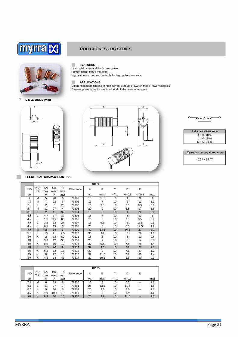
Horizontal or vertical Rod core chokesPrinted circuit board mountingHigh saturation current : suitable for high pulsed currents
Differential mode filtering in high current outputs of Switch Mode Power SuppliesGeneral power inductor use in all kind of electronic equipment
ROD CHOKES - RC SERIES
DIMENSIONS (mm)
FEATURES
APPLICATIONS
Inductance toleranceK : +/- 10 %L : +/- 15 %M : +/- 20 %
- 25 / + 85 °C
Operating temperature range
793178 22 15
0.979316
5 8.8 30
1.679314
1.432 10.5K 4.3 14 45
L9K 6.2
10.5 26
30
913 18
2710 1027
32 12
10.5 27 2.279309
0.65 131026 1.8
30
A
4.7 32 13.5
3.3
1.8
3.3
M 18 38
1.6
1.6
---
---
∅
max.
0.6
0.4
1
0.6
11.5
E
+/- 0.5
8.5
8.5
9
9
2.5
4
C
+/- 1
10
4
10
10
1010 6.8
4.7
D
+/- 0.5
2.5
A
typ.
10
B
max.
3.5
IND
2.2
1
4.7
Référence
µH mΩA
IND.Tol.
Rmax.
IDCmax.
Isatmax.
3
60 79306 310
206.515
5 20
K 1.1 3.217
4
M 5 20
L 2
M 7
27L 2
10 512
10 5.5
10 5
15 7
20
1.2
1115
6 79300
79302
32 79304137
24 79307
1
22 6 79301 10 5
10
11
K 2 15
4.7
79305L 4.7
L 3.2 13 5 11.5 0.8
10
8.2 K 4.5 1520 12
--- 1.1
6 15 8 10 6.5 --- 1.111.5
10.5 18 79353 9 10 6.5
14 0.8
19 8 79308 8
9.5 60 79311 6
793032.4 M 12 17 1.69
L 6.5
8 79352
10 6.5
10 8.5
30 79312
2.2
10
3015
17.5 1.2
20 7 10 6
--- 1.6
12
30 10 10 821 4.5 793105.6 L 13
10 K 8.510 K 3.310
1.2
16 10 79313 9.5 10 7.5 26 1.4
30 10 7.579315
7 79351
mΩ
32 11.5 10 10
19 8 79350MA A
K
25 15 10
5.6 L 11 25 13.5 106.8
20 15 7935420 K 8.3
L 9 1637
ELECTRICAL CHARACTERISTICS
RC / H
15
max. +/- 1 +/- 0.5
C D E
max.
Isatmax.
Rmax.
Référence BIND A
µH typ.
RC / V
∅IND.Tol.
IDCmax.
MYRRA Page 21
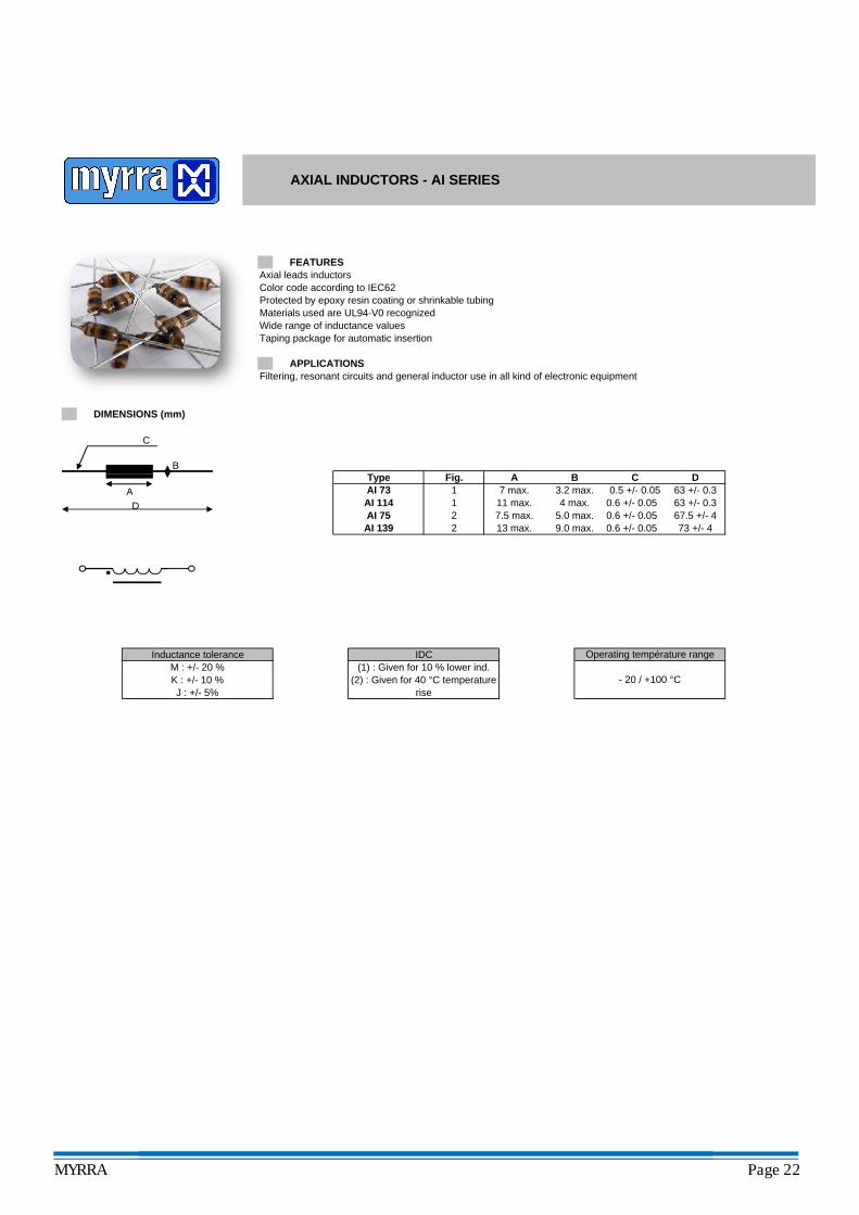
Axial leads inductorsColor code according to IEC62Protected by epoxy resin coating or shrinkable tubingMaterials used are UL94-V0 recognizedWide range of inductance valuesTaping package for automatic insertion
Filtering, resonant circuits and general inductor use in all kind of electronic equipment
Fig.
AXIAL INDUCTORS - AI SERIES
Type
DIMENSIONS (mm)
FEATURES
APPLICATIONS
A B C DB
∅ C
Inductance tolerance IDC(1) : Given for 10 % lower ind.
(2) : Given for 40 °C temperature rise
M : +/- 20 %K : +/- 10 %J : +/- 5%
Fig.11
TypeAI 73AI 114
A7 max.11 max.
AI 75AI 139
22
67.5 +/- 413 max. 9.0 max. 0.6 +/- 0.05 73 +/- 47.5 max.
B3.2 max.4 max.
C0.5 +/- 0.05
0.6 +/- 0.055.0 max. 0.6 +/- 0.05
D63 +/- 0.363 +/- 0.3
Operating température range
- 20 / +100 °C
AD
MYRRA Page 22
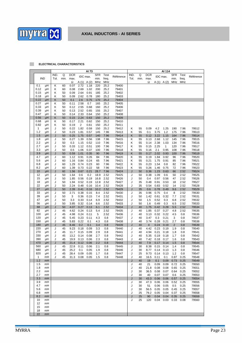
IND.Tol.
Référence
1.8
1.2
Ω
DCRmax.
Qmin.
J 79423
J
60
60
79420
J 79424
J5050
5.66.88.210
J 79421J 79422
60
7.960.73 0.22
794157941679417
60795240.63
ELECTRICAL CHARACTERISTICS
7.96
66J 50 0.36 1.23 2.52
7.9672
795227.96 79523
0.8 82K 55 0.26 1.46 0.75
7941250J 794137.96
150145
0.22
55 0.23 1.54
1
2.22.7
50µH
50J
3.33.9
7.96 79520K 55 0.21 1.75 0.91 85 79521
0.19 1.84 0.92 96
795187.96 79519
0.16 2.1K 55 0.17 2.02 0.93 100
0.95 1087.96
55 0.14
7.96
79516795170.15 2.25 1 120
2.38 1.03
164 7.963.22 1.15
134 7.96
7951455 0.13 2.68 1.12 145 7.96 7951555 0.12
7.96 7951255 0.1 3.75 1.2 175 7.96 79513
0.09 4.2 1.25 19055
4.7 60
KKKKKK 55K 55
K 55
K
MHz MHzΩ A (1) A (2)
AI 114IND.Tol.
Qmin.
DCRmax.
IDC max. SFRmin.
Testfreq.
Référence
AI 73
J 79419J 79418
7.967.967.967.96
SFRmin.MHz
7.96
7.967.967.967.96
Testfreq.MHz25.2
25.2
25.225.2
7.9613811010010090846560
28.7
25.279411
79409
0.82 50K 2 0.610.68 50K 79410µH
µH150150
0.170.19
0.47 50K 79408µH
150150
25.225.20.15
0.39 50K
0.56 50K
µH
794070.33 50K 79406160
15525.225.22.52
0.15
79404165
25.225.2
0.18 50K0.22 50
0.1 60K0.12 60K
220200185180170
58
1400.57
79400
79403
7940125.225.2
79405
0.67 0.21
0.84 0.240.74 0.23
1.01 0.350.91 0.26
1.12 0.511.06 0.37
1.81
J1.39 0.561.15 0.52
J 0.270.3
1.82 0.59
2.24 0.632.21 0.62
A (1) A (2)
0.652.33 0.64
2.58
IDC max.
2.72 1.182.69 1.022.64 0.91
1.56
0.591.121.161.29
79414
µH
1.39
0.72.55 0.68
1.75
50
500.57
0.10.110.12
1.5 50J
0.27 50KK
0.130.14
0.330.5
794022.62 0.782.6 0.75
0.230.25
IND
0.070.080.090.09
µH
50KµHµHµHµH
µHµHµH
µHµHµH
µH
µHµHµHµHµHµHµH
AXIAL INDUCTORS - AI SERIES
22 mH18 mH15 mH12 mH
0.25J 30 40 0.07 0.07 0.6
795540.06 0.57J 30 43.3 0.06
7955279553
0.07 0.64 0.25J 30 36.5 0.080.65
60J 79424
0.0840 21
0.25
0.06 0.52 0.25
0.25
79551J 40 21.8 0.080.09 0.72 0.25 79550J 0.090.09 0.73 0.25 79549J 40 19 0.1
45
45
45JJ
220
390470
270330
680820 79547
J 40 16.5 0.11 0.1 0.87 0.25 79548
1.3 0.8 79546J 25 9.73 0.14 0.13 1.2 0.8J
0.19
404579437
4545
0.8
1822
30 8.77 0.14 0.13
150180
100
560
82
120
0.14 1.4 0.8 79545J 30 8.38 0.15
47
27
3933
101215
5668
0.14 1.50.17 1.60.18 1.70.18 1.8
79544J 40 7.9 0.170.8 79543J 40 7.42 0.180.8 79542J 40 5.35 0.190.8 79541J 40 4.94 0.21
1.9 0.8 79540J 40 4.42 0.23
79538J 40 4 0.24 0.19 2 0.8 79539
0.8
4.98J 45
4.30.23 0.110.22 0.1
0.8
J 79435J
J
J2.520.80.8
4.62
3.74 0.280.21 30.21 2.7
7953740 3.13 0.32
J 40 3.47 0.34.5 0.80.224.8 2.52 79535J 40 1.85 0.37
79536
J 79433 795331.6 0.49
0.27
J
0.28 5.5 2.52 795340.42
50
40 1.75
79428
50
J 79434JJ
50
J 79430J 794310.363
J 79425J 79426
J 79429
50
79427J 2.52
0.3 6.5 2.52
795312.52 79532
0.3250 1.5 0.52 0.3 6.8
0.56
J2.52
10.410.20.41
50 1.42 0.610.4 8 2.52
2.527.779530J 35 0.96 0.75
0.49 9.6 2.52 7952935 0.6 0.78
0.48J 50 0.4
50
50 2.52 79527J 35 0.54 0.83 0.52 14 2.52
79524J
795280.53 180.56 47 2.52 79526
0.91
0.63
0.9779525
66J 50 0.36 1.23 2.520.38 1.09 0.6 50 2.52
J 35
45
5050
50
45
45
5050
J
45
79432
2.52
2.522.528.4
7.4
J
J
79436
J 79440J 79441
J 79438
45
J 79439
79442J 79443
0.80.80.80.8
794460.8
1.91.7
0.8
0.845
J 7944479445
1.5J 79447
0.80.8
0.8
2.522.522.52
7.962.522.522.52
2.72.32.22.1
0.09
3.32.9
6.15.45
4.3
3.4
0.05
0.19
0.11 0.060.1 0.05
0.13 0.060.12 0.06
0.24 0.130.24 0.11
0.14
28.718.9
6.96.6
16.8
0.14 0.08
0.2 0.10.18 0.090.15 0.09
0.32 0.140.27 0.13
0.33
0.150.38
0.52 0.19
0.15
J50
0.16
12.80.48 0.16
0.6 0.20.67 0.21
28.4
19.921.422.825.2
8.469.2311.713.2
5.455.83
3.33.854.07
1.942.242.392.71
1.561.641.85
J 794481.2
0.081 45 0.05mH
31.3
1.8mHmH
1.5
mH2.7 mH
mH
2.2
3.93.3
4.7 mH
6.85.6 mH
8.2mHmH
10 mH
µHµH
µHµHµH
µHµHµH
µHµHµHµHµHµH
J
µHµHµHµHµHµH
mH47.3 0.06
µHµHµHµHmH
79555J 30 51 0.06 0.05 0.5 0.25 79556
30
J 30 56.5 0.05 0.05 0.45 0.25 79557J 25 79.2 0.05 0.04 0.37 0.25 79558J 25 90 0.04J 25 120 0.04 0.03 0.33 0.08 79560
0.04 0.35 0.25 79559
MYRRA Page 23
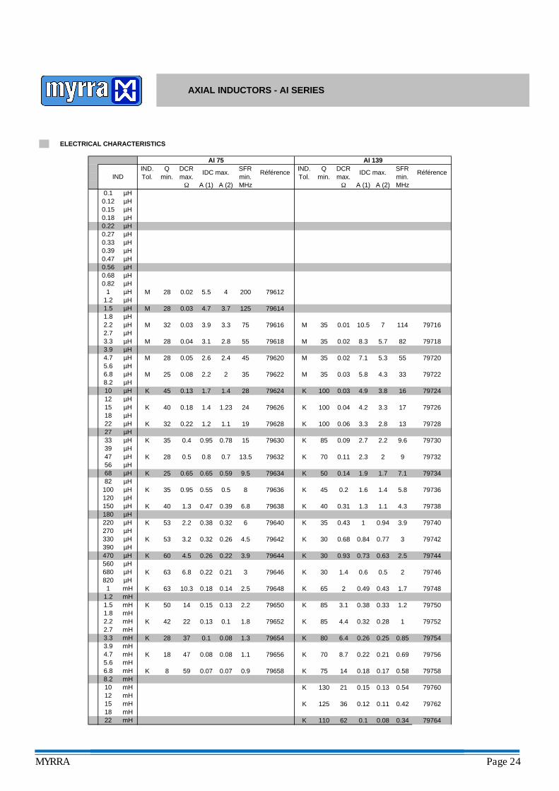
3.8 16 79724K 100 0.03 4.9
4.3 33 79722M 35 0.03 5.8
5.3 55 79720M 35 0.02 7.1
5.7 82 79718M 35 0.02 8.3
7 114 79716M 35 0.01 10.5
MHzΩ A (1) A (2)
AI 139IND.Tol.
Qmin.
DCRmax.
IDC max. SFRmin.
Référence
1.4 28 79624K 45 0.13 1.7
2 35 79622M 25 0.08 2.2
2.4 45 79620M 28 0.05 2.6
2.8 55 79618M 28 0.04 3.1
3.3 75 79616M 32 0.03 3.9
3.7 125 79614M 28 0.03 4.7
4 200 79612M 28 0.02 5.5
A (2) MHzΩ A (1)
AI 75IND.Tol.
Qmin.
DCRmax.
IDC max. SFRmin.
RéférenceIND
0.1 µH0.12 µH0.15 µH0.18 µH0.22 µH0.27 µH0.33 µH0.39 µH0.47 µH0.56 µH0.68 µH0.82 µH
1 µH1.2 µH1.5 µH1.8 µH2.2 µH2.7 µH3.3 µH3.9 µH4.7 µH5.6 µH6.8 µH8.2 µH10 µH12 µH
AXIAL INDUCTORS - AI SERIES
ELECTRICAL CHARACTERISTICS
62 0.1 0.08 797640.34K 110
0.42K 125 7976236 0.12 0.11
0.13 0.54 79760K 130 21 0.15
0.17 0.58 79758K 75 14 0.18
0.21 0.69 79756K 70 8.7 0.22
0.25 0.85 79754K 80 6.4 0.26
0.28 1 79752K 85 4.4 0.32
0.33 1.2 79750K 85 3.1 0.38
0.43 1.7 79748K 65 2 0.49
0.5 2 79746K 30 1.4 0.6
0.63 2.5 79744K 30 0.93 0.73
0.77 3 79742K 30 0.68 0.84
0.94 3.9 79740K 35 0.43 1
1.1 4.3 79738K 40 0.31 1.3
1.4 5.8 79736K 45 0.2 1.6
1.7 7.1 79734K 50 0.14 1.9
2 9 79732K 70 0.11 2.3
2.2 9.6 79730K 85 0.09 2.7
2.8 13 79728K 100 0.06 3.3
3.3 17 79726K 100 0.04 4.2
0.07 0.9 79658K 8 59 0.07
0.08 1.1 79656K 18 47 0.08
0.08 1.3 79654K 28 37 0.1
0.1 1.8 79652K 42 22 0.13
0.13 2.2 79650K 50 14 0.15
0.14 2.5 79648K 63 10.3 0.18
0.21 3 79646K 63 6.8 0.22
0.22 3.9 79644K 60 4.5 0.26
0.26 4.5 79642K 53 3.2 0.32
0.32 6 79640K 53 2.2 0.38
0.39 6.8 79638K 40 1.3 0.47
0.5 8 79636K 35 0.95 0.55
0.59 9.5 79634K 25 0.65 0.65
0.7 13.5 79632K 28 0.5 0.8
0.78 15 79630K 35 0.4 0.95
1.1 19 79628K 32 0.22 1.2
1.23 24 79626K 40 0.18 1.412 µH15 µH18 µH22 µH27 µH33 µH39 µH47 µH56 µH68 µH82 µH100 µH120 µH150 µH180 µH220 µH270 µH330 µH390 µH470 µH560 µH680 µH820 µH1 mH
1.2 mH1.5 mH1.8 mH2.2 mH2.7 mH3.3 mH3.9 mH4.7 mH5.6 mH
18 mH
6.8 mH8.2 mH10 mH
22 mH
12 mH15 mH
MYRRA Page 24
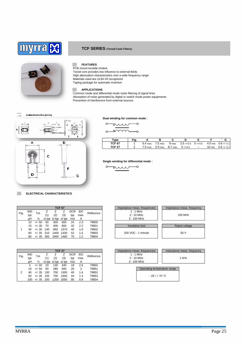
PCB mount toroidal chokesToroid core provides low influence to external fieldsHigh attenuation characteristics over a wide frequency rangeMaterials used are UL94-V0 recognizedTaping package for automatic insertion
Common mode and differential mode noise filtering of signal linesAbsorption of noise generated by digital or switch mode power equipmentsPrevention of interference from external sources
Dual winding for common mode :
Single winding for differential mode :
TCF 27
DIMENSIONS (mm)
FEATURES
APPLICATIONS
17.5 max.
TCF 67A BFig.Type
2.5 max.
TCF SERIES (Toroid Coils Filters)
5 +/-0.5
C9 max.
27.5 max.
∅ GED6.4 max. 2.5 +/-0.3
5 +/-0.5
F4.0 min
10 min.
0.6 +/- 0.1
--8.7 max. 0.6 +/- 0.1
Single winding for differential mode :
2000 1460 70 1.21.560 +/- 35 210
1
1 : 1 MHz2 : 10 MHz3 : 100 MHz
7980380 +/- 35 300
40400 800 32
1400 1430 52
24AΩ typ
1.915 +/- 35 70
2.3
40 +/- 35
100 MHz
10 +/- 50 50 300 650Ω typ
Z(3)
DCRtyp
ELECTRICAL CHARACTERISTICS
RéférenceIDCmax.
mΩµH % Ω typ
Fig. INDtyp
Tol. Z(1)
Z(2)
TCF 67
1 : 1 MHz2 : 10 MHz3 : 100 MHz
- 25 / + 70 °C
Impedance meas. frequencyImpedance meas. frequencies
79804200 VDC - 1 minute
79801
TCF 27
A1 kHz
2.2140 850 1370
µH
Impedance meas. frequencies
Insulation test
Fig. INDtyp
Z(1)
Z(2)
DCRtyp
Z(3)
5 23
2 40 13060100
150
10
798531.4
130 340 798502.679851
4440
1600
+/- 50+/- 50
+/- 35+/- 35
+/- 3550
200
%
Tol.
mΩΩ typ18
Ω typ Ω typ
798540.98520001.3
280 25700
1200700
Référence
79800Rated voltage
Inductance meas. frequency
50 V
7985213002600
IDCmax.
Operating température range
79802
MYRRA Page 25
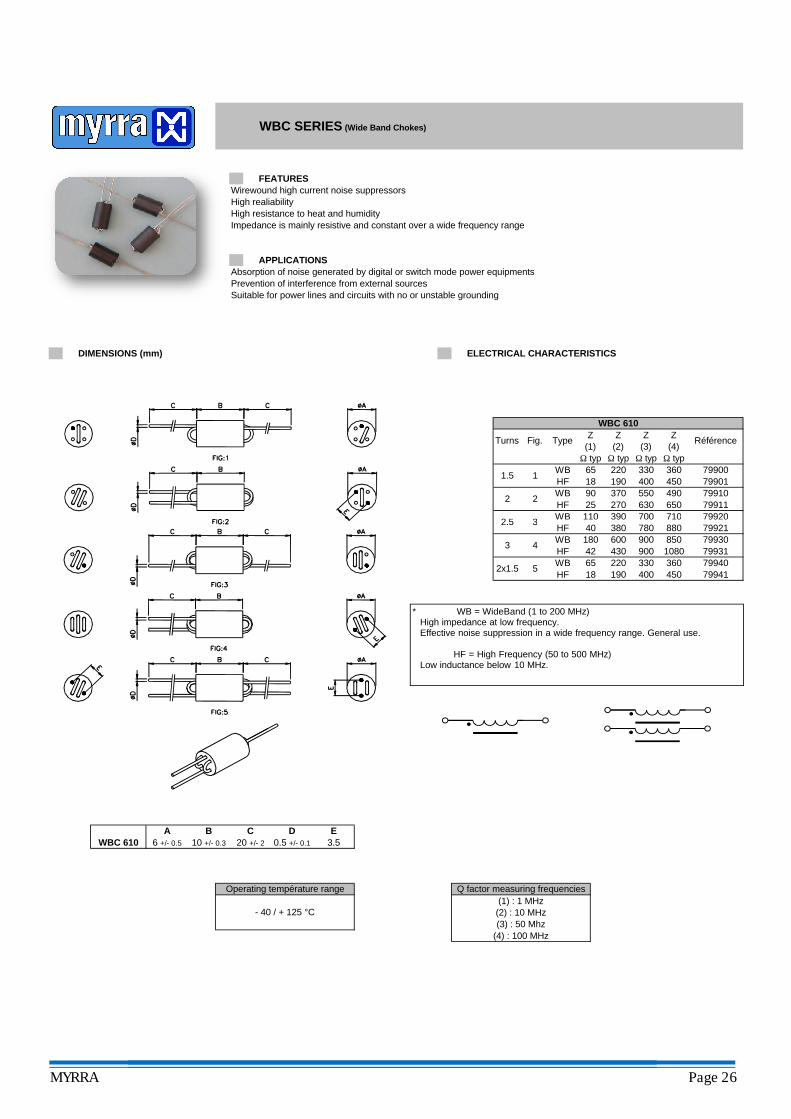
Wirewound high current noise suppressorsHigh realiabilityHigh resistance to heat and humidityImpedance is mainly resistive and constant over a wide frequency range
Absorption of noise generated by digital or switch mode power equipmentsPrevention of interference from external sourcesSuitable for power lines and circuits with no or unstable grounding
79920
360
650
330400
Z(2)
Z(3)
HF
Fig.
Ω typ220
Ω typ6518
1.5 1
Turns
79900Ω typ
190 450 79901
Ω typ
WBHF
90270 79911370 550
25490
630
3 390 700110WB
WBC SERIES (Wide Band Chokes)
2.5
ELECTRICAL CHARACTERISTICS
Type
WB
Z(1)
710
FEATURES
APPLICATIONS
DIMENSIONS (mm)
2 2
WBC 610Z
(4)Référence
79910
7992179920
Operating température range
- 40 / + 125 °C
Q factor measuring frequencies(1) : 1 MHz(2) : 10 MHz(3) : 50 Mhz
(4) : 100 MHz
3 390 70011040
WB380
A B C D
4
2.5
WBHF
900430 900
18042
79930HF
5 220 3306518HF 190
60079931
2x1.5 360450
79940400
WB79941
3 850
0.5 +/- 0.16 +/- 0.5 10 +/- 0.3 20 +/- 2 3.5WBC 610E
780 880710
1080
* WB = WideBand (1 to 200 MHz)High impedance at low frequency.Effective noise suppression in a wide frequency range. General use.
HF = High Frequency (50 to 500 MHz)Low inductance below 10 MHz.
MYRRA Page 26
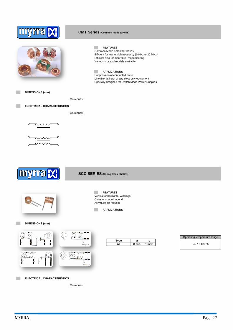
FEATURESCommon Mode Toroidal ChokesEfficient for low to high frequency (10kHz to 30 MHz)Efficient also for differential mode filteringVarious size and models available
APPLICATIONSSuppression of conducted noiseLine filter at input of any electronic equipmentSpecially designed for Switch Mode Power Supplies
On request
On request
CMT Series (Common mode toroids)
ELECTRICAL CHARACTERISTICS
DIMENSIONS (mm)
FEATURESVertical or horizontal windingsClose or spaced woundAll values on request
APPLICATIONS
On request
ELECTRICAL CHARACTERISTICS
DIMENSIONS (mm)
Operating température rangeType a b
- 40 / + 125 °CAll
SCC SERIES (Spring Coils Chokes)
8 min. 1 max.
MYRRA Page 27
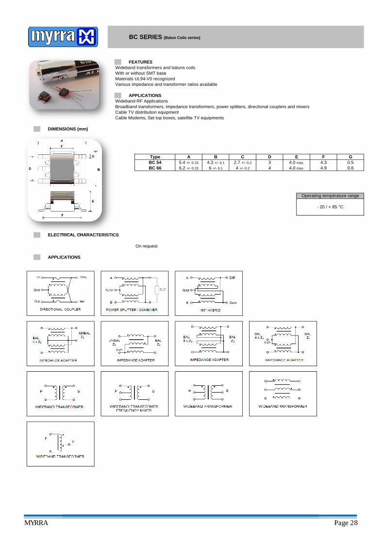
Wideband transformers and baluns coilsWith or without SMT baseMaterials UL94-V0 recognizedVarious impedance and transformer ratios available
Wideband RF ApplicationsBroadband transformers, impedance transformers, power splitters, directional couplers and mixersCable TV distribution equipmentCable Modems, Set top boxes, satellite TV equipments
On request
ELECTRICAL CHARACTERISTICS
APPLICATIONS
APPLICATIONS
0.6
Type A B C
BC 66
E F3 4.0 max.
D
BC SERIES (Balun Coils series)
BC 54
DIMENSIONS (mm)
FEATURES
5.4 +/- 0.15 4.3 +/- 0.1 2.7 +/- 0.2
6.2 +/- 0.15 4.0 max.
Operating température range
- 20 / + 85 °C
G4.3 0.54.96 +/- 0.1 4 +/- 0.2 4
MYRRA Page 28

CHINAPANYU (GUANGDONG)PRODUCTION
FRANCEBUSSY ST GEORGES (PARIS)EUROPEAN DESIGN CENTERAND SALESPRODUCTION
CHINAHONG-KONGHEAD QUARTERMARKETING / SALES CENTER
POLANDWARSAW (KALUSZYN)PRODUCTION
SPAINBARCELONESALES / DESIGN CENTER
Spe
cific
atio
ns a
re s
ubje
t to
cha
nge
with
out
notic
e.
ED
I C
ON
CE
PT
- I
mpr
imé
en U
.E.
R
éf.
1
MYRRA S.A.Z.I. Gustave Eiffel - 2, boulevard de la Haye - 77615 BUSSY ST GEORGES Cedex 3 - FRANCE
Tél. : (33) 01 60 37 55 55 - Fax. : (33) 01 60 17 12 00 - Site web : www.myrra.comAmerica : [email protected] Asia : [email protected] Europe : [email protected]
CHINAZHONGSHANPRODUCTION