final report - european commission
TRANSCRIPT
POST EARTHQUAKE DAMAGE AND USABILITY
ASSESSMENT OF BUILDINGS: FURTHER DEVELOPMENT AND APPLICATIONS
FINAL REPORT
Prepared by
Stavros A. Anagnostopoulos, Marina Moretti,
M. Panoutsopoulou, D. Panagiotopoulou, T. Thoma
EUROPEAN COMMISSION - D.G. ENVIRONMENT CIVIL PROTECTION - EPPO
POST EARTHQUAKE DAMAGE AND USABILITY ASSESSMENT OF BUILDINGS: FURTHER
DEVELOPMENT AND APPLICATIONS
FINAL REPORT
Prepared by
Stavros A. Anagnostopoulos, Marina Moretti,
M. Panoutsopoulou, D. Panagiotopoulou, T. Thoma
EUROPEAN COMMISSION - D.G. ENVIRONMENT CIVIL PROTECTION - EPPO

1
DISCLAIMER
The information contained in this manual has been compiled with every possible care and
reflects current state of knowledge and experience on the pertinent subjects. However, since
earthquake engineering is a field with many uncertainties, far from being an exact science,
application of the methods, procedures and criteria recommended herein does not guarantee
full protection of life and property. It should be applied by competent personnel and only
after careful examination of its applicability to the local conditions and structural types.
2
TABLE OF CONTENTS
Disclaimer................................................................................................…......…… 1
Table of Contents................................................................................................…… 2
List of Exhibits, Tables and Photos....................................................................…… 4
Acknowledgments................................................................................................…… 5
Photograph and Figure Credits.............................................................................…… 6
1. PURPOSE AND SCOPE .…………........................................................……… 7 2. THE EMERGENCY INSPECTIONS - INTERVENTIONS OPERATION ……… 7
2.1. A brief overview …………………………………………………........…… 7
2.2. Objectives of the operation ...............……..............................................….. 8
2.3. How is the operation carried out …..................................................……..… 9
2.3.1 Rapid Assessment .........................................................................……........ 10
2.3.2 Detailed Assessment ......................................................................……...… 10
2.3.3 Reinspections .................................................................................…….... 14
2.4. Procedure of the Damage Assessments …...........................................…….... 14
2.4.1 Rapid Assessment ........................................…........................…..........…. 20
2.4.1a General Guidelines for the Inspectors..................….................................... 20
2.4.1b Filling in the Inspection Form of Rapid Assessment.........................…........ 21
2.4.2 Detailed Assessment ....................................…........................…..........…. 23
2.4.2a General Guidelines for the Inspectors............…............................................ 23
2.4.2b Filling in the Inspection form of Detailed Assessment ...................…........ 26
2.5. Correlations of damage and colour posting....................................................… 28
2.5.1 Damage severity .................................................................…...............…..... 29
2.5.1a Reinforced concrete buildings .........................................…...............…........ 29
2.5.1b Masonry buildings .........................................…...............…...............…....... 44
2.5.1c Steel buildings ........................................…...............…...............…...........… 50
2.5.1d Wood buildings.......................................…...............…...............…...........…56
2.5.2 Overall assessment of building safety.................................…...............…..... 61
3
2.6. Hazard removal and emergency support.................................................…… 65
2.6.1 Guidelines for filling the Emergency Intervention Form...…...............…..... 68
2.7. Field Safety of inspectors ...................................................……................…. 70
2.8. Legal issues .................................................……..................................…….... 71
3. OPERATIONAL PLAN .........................................………………….........……… 72
3.1. Tasks and Responsibilities ..........................................................................…… 72
3.2. Operation set-up checklist...................................….....................................…… 77
3.3. Human Resources………........…..................................................................…… 78
3.4. Material and Equipment …........................................…................................…… 80
4 THE NEW PEADAB SYSTEM.............................…………………...….........… 82
4.1. Built in rules for posting based on the damage assessment…………...........…… 86
5. REFERENCES ………............................................………………….........…… 87
APPENDIX: PILOT TESTING IN CHANIA .................................…...............…..... 89
4
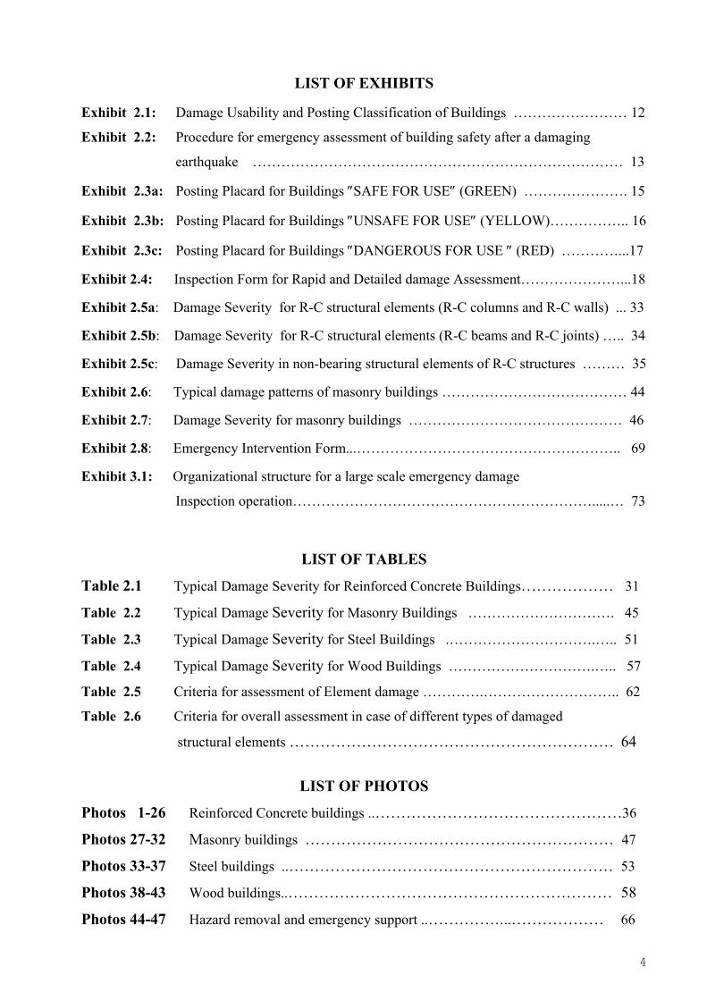
LIST OF EXHIBITS
Exhibit 2.1: Damage Usability and Posting Classification of Buildings …………………… 12
Exhibit 2.2: Procedure for emergency assessment of building safety after a damaging
earthquake …………………………………………………………………… 13
Exhibit 2.3a: Posting Placard for Buildings ″SAFE FOR USE″ (GREEN) …………………. 15
Exhibit 2.3b: Posting Placard for Buildings ″UNSAFE FOR USE″ (YELLOW)…………….. 16
Exhibit 2.3c: Posting Placard for Buildings ″DANGEROUS FOR USE ″ (RED) …………...17
Exhibit 2.4: Inspection Form for Rapid and Detailed damage Assessment…………………...18
Exhibit 2.5a: Damage Severity for R-C structural elements (R-C columns and R-C walls) ... 33
Exhibit 2.5b: Damage Severity for R-C structural elements (R-C beams and R-C joints) ….. 34
Exhibit 2.5c: Damage Severity in non-bearing structural elements of R-C structures ……… 35
Exhibit 2.6: Typical damage patterns of masonry buildings ………………………………… 44
Exhibit 2.7: Damage Severity for masonry buildings ……………………………………… 46
Exhibit 2.8: Emergency Intervention Form...……………………………………………….. 69
Exhibit 3.1: Organizational structure for a large scale emergency damage
Inspection operation……………………………………………………….....… 73
LIST OF TABLES
Table 2.1 Typical Damage Severity for Reinforced Concrete Buildings……………… 31
Table 2.2 Typical Damage Severity for Masonry Buildings …………………………. 45
Table 2.3 Typical Damage Severity for Steel Buildings .………………………….….. 51
Table 2.4 Typical Damage Severity for Wood Buildings ………………………….….. 57
Table 2.5 Criteria for assessment of Element damage ………….……………………….. 62
Table 2.6 Criteria for overall assessment in case of different types of damaged
structural elements ……………………………………………………… 64
LIST OF PHOTOS
Photos 1-26 Reinforced Concrete buildings ..…………………………………………36
Photos 27-32 Masonry buildings …………………………………………………… 47
Photos 33-37 Steel buildings ..……………………………………………………… 53
Photos 38-43 Wood buildings..……………………………………………………… 58
Photos 44-47 Hazard removal and emergency support ..……………..……………… 66
5
ACKNOWLEDGEMENTS
This is a second phase of a project funded by the European Commission, (Directorate
General Environment - Civil Protection), The Greek Agency for Earthquake Planning and
Protection (EPPO) and the Greek General Secretariat for Civil Protection. The first phase of
the project, carried out at the University of Patras, was funded by the European Commission
(DG 11, Civil Protection Unit) and the Greek General Secretariat for Research and
Development.
The procedures and material developed in the first phase were used as the basis for
further developments and improvements in this second phase, which has also included the
experience gained from the Athens,1999, earthquake.
The authors would like to thank Mr Xynidis, Chairman of the Technical Chamber of
Greece in Chania Crete and Mr M. Bouzakis, Civil Protection official of the Chania
Prefecture for their assistance with the pilot application. Thanks are also due to Ms
Miranda Dandoulaki (formerly with EPPO) and Mr Yannis Vlachos who have participated
in some of the initial project meetings and have contributed to the formulation of the
procedures detailed herein.
The programming part for the PEADAB computer system was carried by CTI, the
second partner of this project.
Finally, the project team gratefully acknowledges the valuable assistance, support and
encouragement provided by a number of people in the EC, especially Mr A Barisich and
Ms P. Bucella, former and current heads, respectively, of the Civil Protection Unit in DG
Environment, as well as Mr Panayotis Alevantis and Mr E. Schulte, former and current
officers in charge, respectively, in the same Unit.
Stavros A. Anagnostopoulos
Principal Investigator

6
FIGURE AND PHOTOGRAPH CREDITS
Photos: 2, 4, 6, 8, 9, 12, 17, 22, 25 by T. B.Allemark
1, 3, 5, 15, 21 by Stavros Anagnostopoulos
35 to 37 by BRI (Japan)
39, 40 City of Los Angeles, Dept. of Building and Safety
43 by EERI
18, 24, 26, one photo in cover page by EPPO
33, 34, 38, 41, 42 by EQE
27 to 32 by M. N. Fardis
13, 14, 16 by V. Lekidis
7, 10, 11, 19, 20, 23, three photos in cover page by Marina Moretti
Exhibit 2.6: by T. Karantoni
7
1. PURPOSE AND SCOPE
The purpose of this report is to describe further developments in the planning, setting up
and execution of building inspection operations under emergency conditions, created by
damaging or catastrophic earthquakes. Based on earlier work (2,4,7,8,9) the procedures
developed therein were reviewed and modified on the basis of recent experience from
damaging earthquakes in Greece and were tested in a pilot trial in the Greek city of Chania,
with the purpose of adapting them in the overall earthquake emergency response plan of
Greece. The testing included a new version of the computer system PEADAB, developed
to support such operations in all their phases: planning, execution and data utilization.
2. THE EMERGENCY INSPECTIONS – INTERVENTIONS OPERATION
2.1. A BRIEF OVERVIEW
The operation of emergency inspections of damaged buildings should start within hours,
if possible, after the occurrence of the earthquake. The main tasks of the operation are:
a) Inspection of all the buildings in the affected area and posting them as to their
safety.
b) Identification of the buildings that require urgent support to avoid collapse, as well
as identification of hazards associated with the damaged buildings.
c) Intervention in critical cases so as to eliminate possible casualties due to secondary
(indirect) post-earthquake damages. (Removal of local hazards, support of buildings
prone to collapsing, disconnection of utilities such as electricity, gas, etc).
Tasks (a) and (b) are performed by the inspection teams, while task (c) is performed by
the intervention crews.
The operation will be organized into 2 phases: The first is a RAPID assessment to
identify obviously undamaged hence safe, and obviously unsafe buildings, and a second
8
DETAILED assessment that will provide the final verdict concerning the building’s safety
(see Exhibit 2.2).
2.2. OBJECTIVES OF THE OPERATION
A prerequisite for the success of the operation is to have clear and well defined
objectives that all the people involved in it will know. In particular, the engineers-
inspectors, key personnel in this operation, should keep them always in mind in order to
optimise their time and efforts. Ranked by their importance, these objectives are:
Primary objectives:
• Protect human life
• Save properties
Secondary objectives:
• Minimise : (a) the number of homeless and (b) the loss of economic activities, by
identifying as soon as possible all buildings that are safe to occupy and use.
• Indicate unsafe areas around hazardous buildings, identify temporary shelter sites
and provide the number of required temporary housing units.
• Provide the necessary data for obtaining reliable estimates of the disaster that
will allow authorities to take relief measures, formulate disaster mitigation
policies and allocate available resources.
• Provide data that will identify frequent causes of damage, so that potential
rehabilitation plans may take into account such assessments.
• Provide data for practical research studies that may lead to re-evaluation of
existing codes and construction practices, to updates of seismic hazard maps and
to elaboration of seismic vulnerability models for pre-earthquake planning
purposes.
To be successful in meeting the above objectives, the operation must:
1. Be well organised.
2. Yield uniformly reliable assessments and damage data.
3. Be completed in a short period of time.

9
2.3. HOW IS THE OPERATION CARRIED OUT
Two types of damage assessment are performed after a serious earthquake: a Rapid and
a Detailed one.
The inspected buildings are classified in one of the three categories listed in Exhibit 2.1.
The basic criterion for this classification is the safety of people inside and outside the
building. (Reference is made to the original –pre earthquake– seismic capacity of the
building). A second criterion is the presence of some hazardous condition, which may exist
even in buildings whose seismic capacity has not decreased (e.g. damaged parapets,
chimneys etc.).
″SAFE FOR USE″ (green colour) are posted the buildings which have experienced
minor damage and show no signs of reduction of their original seismic capacity. If local
hazards exist, the dangerous area may be barricaded and access to it blocked and marked
“UNSAFE FOR USE”.
″DANGEROUS FOR USE″ (red colour) are characterized the buildings whose original
seismic capacity has greatly decreased and thus are prone to sudden collapsing even in
minor aftershocks. Entry is prohibited and the need for emergency support as well as
protection of the surroundings must be considered.
″UNSAFE FOR USE″ (yellow colour) are characterized the buildings with reduced
seismic capacity, though not to the extent of being in danger of sudden collapse and they
have to be repaired before they could be occupied on a continuous basis. Although some of
them may also need emergency support, the risk when entering them for short periods of
time, e.g. for removing valuables, securing contents of apartments etc., is deemed to be low
(but not negligible). It should be noted that buildings in this category present the greatest
uncertainty in the classification; if the inspector has doubts about his evaluation he should
be conservative.
For a reliable assessment of the level of damage suffered by a building, uniform
classification criteria should be adopted. The guidelines given in chapter 2.5 intend to
provide a good basis for this evaluation, but they should always be applied with sound
engineering judgement.
10
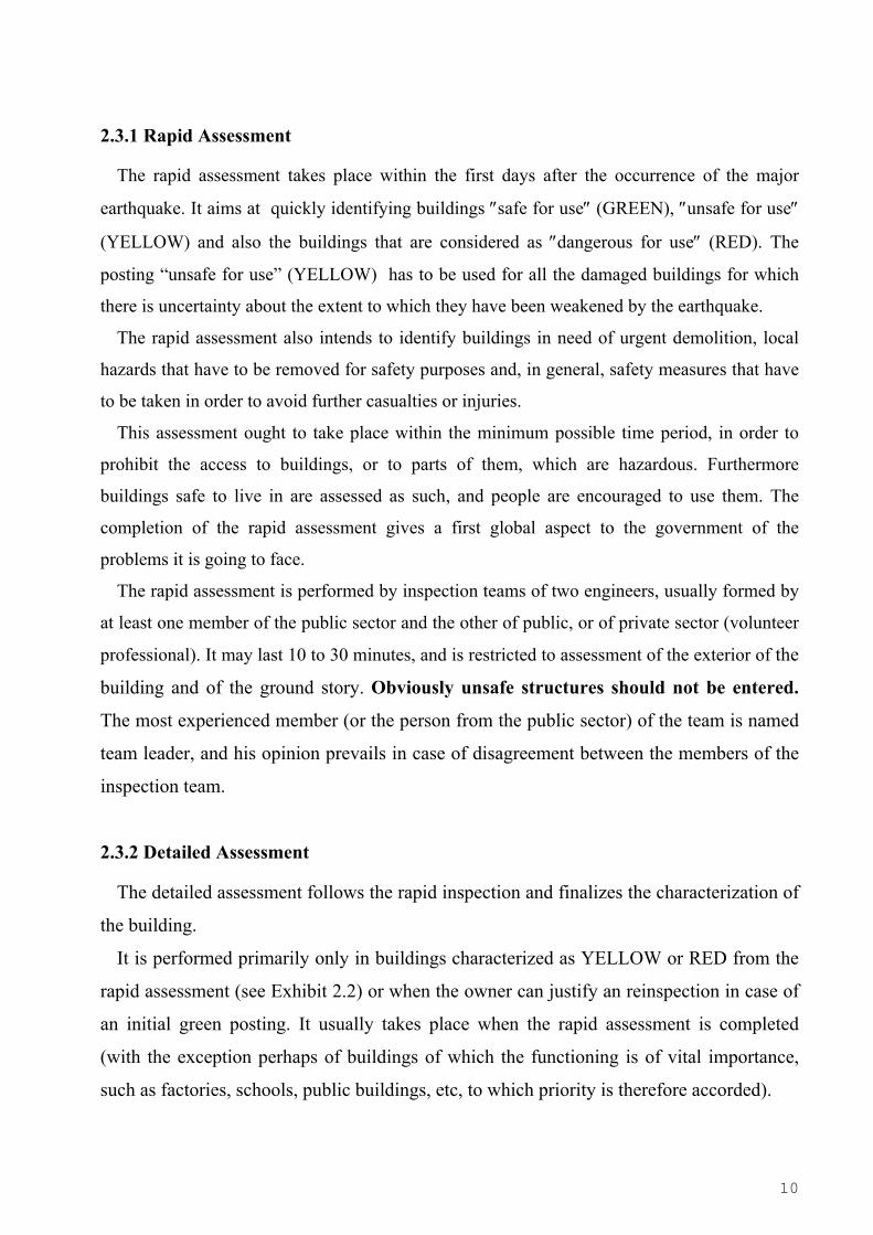
2.3.1 Rapid Assessment
The rapid assessment takes place within the first days after the occurrence of the major
earthquake. It aims at quickly identifying buildings ″safe for use″ (GREEN), ″unsafe for use″
(YELLOW) and also the buildings that are considered as ″dangerous for use″ (RED). The
posting “unsafe for use” (YELLOW) has to be used for all the damaged buildings for which
there is uncertainty about the extent to which they have been weakened by the earthquake.
The rapid assessment also intends to identify buildings in need of urgent demolition, local
hazards that have to be removed for safety purposes and, in general, safety measures that have
to be taken in order to avoid further casualties or injuries.
This assessment ought to take place within the minimum possible time period, in order to
prohibit the access to buildings, or to parts of them, which are hazardous. Furthermore
buildings safe to live in are assessed as such, and people are encouraged to use them. The
completion of the rapid assessment gives a first global aspect to the government of the
problems it is going to face.
The rapid assessment is performed by inspection teams of two engineers, usually formed by
at least one member of the public sector and the other of public, or of private sector (volunteer
professional). It may last 10 to 30 minutes, and is restricted to assessment of the exterior of the
building and of the ground story. Obviously unsafe structures should not be entered.
The most experienced member (or the person from the public sector) of the team is named
team leader, and his opinion prevails in case of disagreement between the members of the
inspection team.
2.3.2 Detailed Assessment
The detailed assessment follows the rapid inspection and finalizes the characterization of
the building.
It is performed primarily only in buildings characterized as YELLOW or RED from the
rapid assessment (see Exhibit 2.2) or when the owner can justify an reinspection in case of
an initial green posting. It usually takes place when the rapid assessment is completed
(with the exception perhaps of buildings of which the functioning is of vital importance,
such as factories, schools, public buildings, etc, to which priority is therefore accorded).

11
After damaging aftershocks, detailed assessment to buildings characterized as GREEN
in the rapid assessment may be necessary, or even re-inspection of some of the buildings
which have already undergone detailed assessment. (The PEADAB system may provide up
to 3 rapid and 2 detailed inspections).
The detailed assessment is carried out by inspection teams of three engineers, usually
formed by at least one member of the public sector and the other two of public, or of
private sector (volunteer professionals). It may last one to three hours, depending on the
size and the importance of the building inspected.
The members of the inspection team may be assisted, if resources permit, by a driver.
The most experienced member (or the person from the public sector) of the team is named
leader, and his opinion is more valid in case of disagreement between the members of the
inspection team. The members of the inspection team may be civil engineers, architects or
technical engineers. It is highly recommended that at least one member of each inspection
team ought to have previous experience in assessing earthquake damages, especially in the
case of the inspection teams for detailed assessment.
This assessment should be performed in all stories and in all the area each story covers,
unless, of course, the parts of the building to which access is judged as dangerous.
The detailed assessment may result in changing the posting, or may result also in
leaving the same as the rapid. It is also essential that all members of the inspection teams
should have previously studied the Field Manual. The organizational chart (see Exhibit
3.1) foresees also a group of trainers which are supposed to explain the objectives and the
philosophy of the post earthquake assessment of buildings, as well as the evaluation
criteria according to which the damage assessment is to be performed.
It is highly desired that the assessment of damages should be performed as much
objectively as possible, which actually is not an easy task given the individual character
and knowledge background of the inspectors, as well as the particularities of each building.
To this aim, evaluation criteria are formulated (see chapter 2.5) with the intention to
eliminate as much as possible the margins of an arbitrary classification. Of course, no
general rules may be given, as the engineering judgement in each individual case cannot be
substituted. The guidelines given intend to avoid for instance gross mistaken judgements,
as met in previous quake events, most usually due to over-conservativeness of the
inspectors (due to lack of previous experience).

12
Posting
Classification
Damage State
Usability
SAFE
FOR USE (Green)
1-2 = None - Slight
Usable - with possible
restrictions
An inspection has shown that the original seismic capacity of the
building has not materially decreased and that no major hazard is
present. Non observable or slight structural damage. Minor non-
structural damage. Use and occupancy allowed, except in areas marked
AREA UNSAFE indicating the presence of some local hazard.
UNSAFE FOR USE (Yellow)
2-3 = Moderate - Heavy
Unusable
The original seismic capacity of the building has been decreased and
aftershock hazard may be present. Moderate damage or heavy local
damage has occurred. Limited entry is permitted at owner’s risk but
not usage on a continuous basis. Entry by public prohibited. Repair
and/or strengthening is required. The need for emergency support of
the building should be considered.
DANGEROUS
FOR USE (Red)
3-4 = Severe - Total
Unusable
Building is unsafe as subject to sudden collapse. Severe structural
damage or partial failure has occurred. Entry prohibited (except by
authorities) and building surroundings should be protected. Decision
on possible repair or demolition should be made after an engineering
evaluation of technical possibilities and their economic
consequences.
Exhibit 2.1: Damage, Usability and Posting Classification of Buildings
13
RAPID ASSESSMENT
Post
SAFE
FOR USE
Green
Post
UNSAFE
FOR USE
Yellow
Post
DANGEROUS FOR USE
Red
DETAILED ASSESSMENT
Post
SAFE
FOR USE
Green
Post
UNSAFE
FOR USE
Yellow
Post
DANGEROUS
FOR USE
Red
(Repair/strengthening) (Repair/strengthening
or demolition)
ENGINEERING EVALUATION
AND REDESIGN
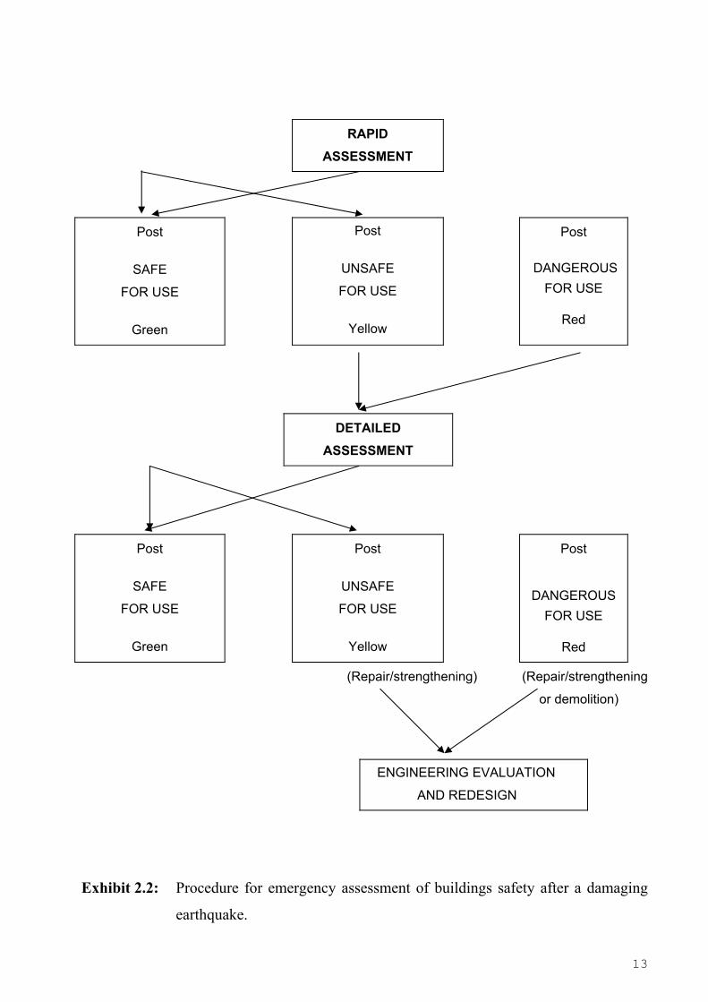
Exhibit 2.2: Procedure for emergency assessment of buildings safety after a damaging
earthquake.
14
2.3.3 Reinspections
The need for reinspection will arise in the event of aftershocks that could change the
condition of buildings already inspected. Since the strongest aftershocks occur within a
few hours to a few days after the main event, the number of buildings that might have been
inspected by then and which will require reinspection will normally be small. After
damaging aftershocks, the reinspections will be carried out in the normal mode of
operation. If the aftershock is significant, a second detailed assessment may have to be
carried out.
Furthermore, reinspection may be required if the owner can justify it in case of an initial
green posting or for buildings marked for demolition but whose owners do not give their
consent. In such cases, however, and in order to avoid an excessive number of requests, the
pertinent application should include the signed opinion of a licensed professional structural
engineer providing the arguments in support of the request. Reinspection is performed as a
detailed assessment in these cases.
2.4. PROCEDURE OF THE DAMAGE ASSESSMENTS
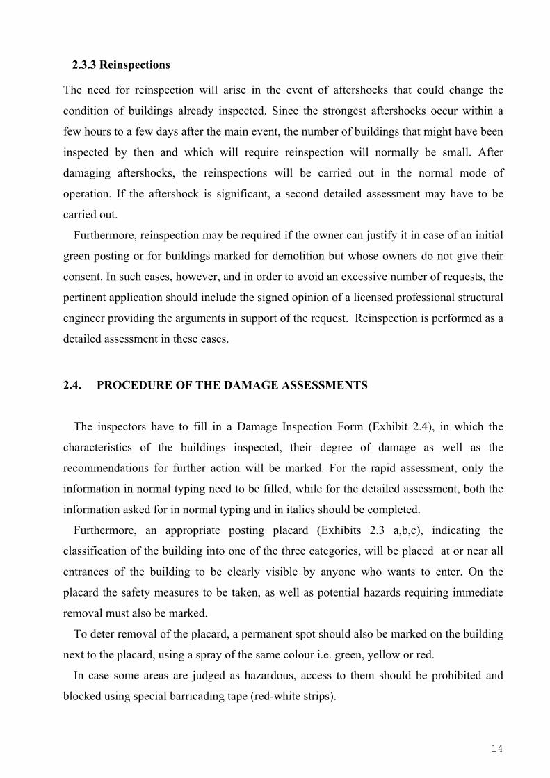
The inspectors have to fill in a Damage Inspection Form (Exhibit 2.4), in which the
characteristics of the buildings inspected, their degree of damage as well as the
recommendations for further action will be marked. For the rapid assessment, only the
information in normal typing need to be filled, while for the detailed assessment, both the
information asked for in normal typing and in italics should be completed.
Furthermore, an appropriate posting placard (Exhibits 2.3 a,b,c), indicating the
classification of the building into one of the three categories, will be placed at or near all
entrances of the building to be clearly visible by anyone who wants to enter. On the
placard the safety measures to be taken, as well as potential hazards requiring immediate
removal must also be marked.
To deter removal of the placard, a permanent spot should also be marked on the building
next to the placard, using a spray of the same colour i.e. green, yellow or red.
In case some areas are judged as hazardous, access to them should be prohibited and
blocked using special barricading tape (red-white strips).
15
SAFE FOR USE
ADDRESS : ................................................................................. SECTION No: ........................
DATE OF INSPECTION: ….....................................…................. TIME:......................................
CREW No: ......………………........................……………………. No REPORT...........................
INSPECTION TEAM DATA
1. Name/ Title …………………………..…… Signature ………………………………
2. Name / Title …………………………..…… Signature ………………………………
3. Name/ Title …………………………..…… Signature ……………………………… The building is in general safe and it may be used under the occasional restrictions mentioned. TYPE OF INSPECTION
RAPID (1st) DETAILED (2nd)
RESTRICTIONS IN USE – SAFETY MEASURES TO BE TAKEN
NO RESTRICTIONS
ACCESS TO THE FOLLOWING AREAS IS PROHIBITED: …………………………….………….
THE FOLLOWING ELEMENTS SHOULD BE DEMOLISHED OR REMOVED:………………….
………………………………………………………………………………………………………………
DO NOT REMOVE THIS PLACARD UNTIL PERMISSION IS GIVEN BY LOCAL AUTHORITIES Exhibit 2.3a: Posting Placard for Buildings ″SAFE FOR USE″ (GREEN)

16
UNSAFE FOR USE
ADDRESS : ................................................................................. SECTION No: .......................
DATE OF INSPECTION: ….....................................…................. TIME:.....................................
CREW No: ......………………........................……………………. No REPORT..........................
INSPECTION TEAM DATA
1. Name/ Title …………………………..…… Signature ………………………………
2. Name / Title …………………………..…… Signature ………………………………
3. Name/ Title …………………………..…… Signature ………………………………
The building has suffered damages (as indicated in the inspection form) and it cannot be used before the detailed (2nd) inspection takes place. Entry only at own risk and only for a limited time period. Aftershocks may cause injury or even death. Safety measures stated herein have to be taken immediately. TYPE OF ASSESSMENT
RAPID (1st) DETAILED (2nd)
RESTRICTIONS IN USE – SAFETY MEASURES TO BE TAKEN
URGENT SUPPORT REQUIRED
ACCESS TO THE FOLLOWING AREAS IS PROHIBITED: ……………………………………..
THE FOLLOWING ELEMENTS SHOULD BE DEMOLISHED OR REMOVED: ……………………
………………………………………………………………………………………………………………
THE FOLLOWING UTILITIES MUST BE DISCONNECTED:
ELECTRICITY WATER GAS
OTHER: …………………………………………………………………………………………………… DO NOT REMOVE THIS PLACARD UNTIL PERMISSION IS GIVEN BY LOCAL AUTHORITIES
Exhibit 2.3b: Posting Placard for Buildings ″UNSAFE FOR USE″ (YELLOW)
17
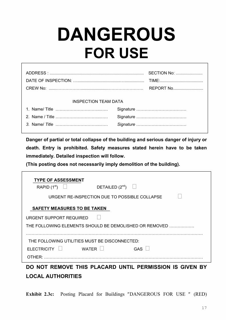
DANGEROUS FOR USE
ADDRESS : ................................................................................. SECTION No: .......................
DATE OF INSPECTION: ….....................................…................. TIME:.....................................
CREW No: ......………………........................……………………. REPORT No..........................
INSPECTION TEAM DATA
1. Name/ Title …………………………..…… Signature ………………………………
2. Name / Title …………………………..…… Signature ………………………………
3. Name/ Title …………………………..…… Signature ………………………………
Danger of partial or total collapse of the building and serious danger of injury or death. Entry is prohibited. Safety measures stated herein have to be taken immediately. Detailed inspection will follow. (This posting does not necessarily imply demolition of the building).
TYPE OF ASSESSMENT RAPID (1st) DETAILED (2nd) URGENT RE-INSPECTION DUE TO POSSIBLE COLLAPSE
SAFETY MEASURES TO BE TAKEN
URGENT SUPPORT REQUIRED
THE FOLLOWING ELEMENTS SHOULD BE DEMOLISHED OR REMOVED ………………
……………………………………………………………………………………………………………….
THE FOLLOWING UTILITIES MUST BE DISCONNECTED:
ELECTRICITY WATER GAS
OTHER: ……………………………………………………………………………………………………
DO NOT REMOVE THIS PLACARD UNTIL PERMISSION IS GIVEN BY LOCAL AUTHORITIES
Exhibit 2.3c: Posting Placard for Buildings ″DANGEROUS FOR USE ″ (RED)
18
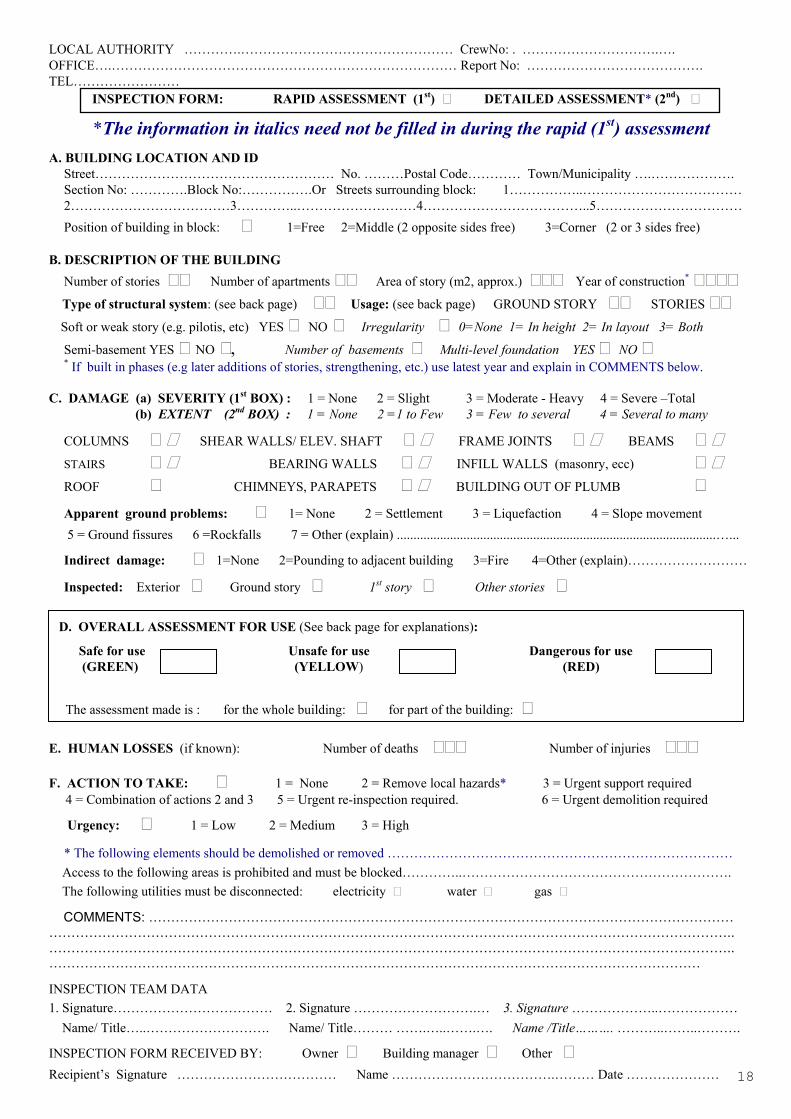
LOCAL AUTHORITY ………….………………………………………… CrewNo: . ………………………….…. OFFICE….…………………………………………………………………… Report No: …………………………………. TEL…………………… INSPECTION FORM: RAPID ASSESSMENT (1st) DETAILED ASSESSMENT* (2nd)
*The information in italics need not be filled in during the rapid (1st) assessment
Α. BUILDING LOCATION AND ID
Street……………………………………………… No. ………Postal Code………… Town/Municipality ….………………. Section No: ………….Block No:…………….Or Streets surrounding block: 1……………..……………………………… 2………………………………3…………..………………………4………………………………..5…………………………… Position of building in block: 1=Free 2=Middle (2 opposite sides free) 3=Corner (2 or 3 sides free)
Β. DESCRIPTION OF THE BUILDING
Number of stories Number of apartments Area of story (m2, approx.) Year of construction* Type of structural system: (see back page) Usage: (see back page) GROUND STORY STORIES Soft or weak story (e.g. pilotis, etc) YES NO Irregularity 0=None 1= In height 2= In layout 3= Both
Semi-basement YES NO , Number of basements Multi-level foundation YES NO * If built in phases (e.g later additions of stories, strengthening, etc.) use latest year and explain in COMMENTS below.
C. DAMAGE (a) SEVERITY (1st BOX) : 1 = None 2 = Slight 3 = Moderate - Heavy 4 = Severe –Total (b) EXTENT (2nd BOX) : 1 = None 2 =1 to Few 3 = Few to several 4 = Several to many
COLUMNS SHEAR WALLS/ ELEV. SHAFT FRAME JOINTS BEAMS STAIRS BEARING WALLS INFILL WALLS (masonry, ecc)
ROOF CHIMNEYS, PARAPETS BUILDING OUT OF PLUMB
Apparent ground problems: 1= None 2 = Settlement 3 = Liquefaction 4 = Slope movement 5 = Ground fissures 6 =Rockfalls 7 = Other (explain) ................................................................................................…...
Indirect damage: 1=None 2=Pounding to adjacent building 3=Fire 4=Other (explain)………………………
Inspected: Exterior Ground story 1st story Other stories
D. OVERALL ASSESSMENT FOR USE (See back page for explanations): Safe for use Unsafe for use Dangerous for use (GREEN) (YELLOW) (RED) The assessment made is : for the whole building: for part of the building: Ε. HUMAN LOSSES (if known): Number of deaths Number of injuries
F. ACTION TO TAKE: 1 = None 2 = Remove local hazards* 3 = Urgent support required 4 = Combination of actions 2 and 3 5 = Urgent re-inspection required. 6 = Urgent demolition required
Urgency: 1 = Low 2 = Μedium 3 = High
* The following elements should be demolished or removed …………………………………………………………………… Access to the following areas is prohibited and must be blocked…………..……………………………………………………. The following utilities must be disconnected: electricity water gas
COMMENTS: …………………………………………………………………………………………………………………… ……………………………………………………………………………………………………………………………………….. ……………………………………………………………………………………………………………………………………….. ………………………………………………………………………………………………………………………………… INSPECTION TEAM DATA 1. Signature……………………………… 2. Signature ……………………….… 3. Signature ………………..……………… Name/ Title…..………………………. Name/ Title……… …….…..…….…. Name /Title………. ………..……..……….
INSPECTION FORM RECEIVED BY: Owner Building manager Other Recipient’s Signature ……………………………… Name ……………………………….……… Date …………………
19
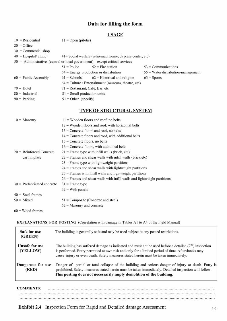
Data for filling the form
USAGE 10 = Residential 11 = Open (pilotis) 20 = Office 30 = Commercial shop 40 = Hospital/ clinic 41= Social welfare (retirement home, daycare center, etc) 50 = Administrative (central or local government) except critical services
51 = Police 52 = Fire station 53 = Communications 54 = Energy production or distribution 55 = Water distribution-management 60 = Public Assembly 61 = Schools 62 = Historical and religion 63 = Sports 64 = Culture / Entertainment (museum, theatre, etc) 70 = Hotel 71 = Restaurant, Café, Bar, etc 80 = Industrial 81 = Small production units 90 = Parking 91 = Other (specify)
TYPE OF STRUCTURAL SYSTEM
10 = Masonry 11 = Wooden floors and roof, no belts 12 = Wooden floors and roof, with horizontal belts 13 = Concrete floors and roof, no belts 14 = Concrete floors and roof, with additional belts 15 = Concrete floors, no belts 16 = Concrete floors, with additional belts 20 = Reinforced Concrete 21 = Frame type with infill walls (brick, etc) cast in place 22 = Frames and shear walls with infill walls (brick,etc) 23 = Frame type with lightweight partitions 24 = Frames and shear walls with lightweight partitions 25 = Frames with infill walls and lightweight partitions 26 = Frames and shear walls with infill walls and lightweight partitions 30 = Prefabricated concrete 31 = Frame type 32 = With panels 40 = Steel frames 50 = Mixed 51 = Composite (Concrete and steel) 52 = Masonry and concrete 60 = Wood frames EXPLANATIONS FOR POSTING (Correlation with damage in Tables A1 to A4 of the Field Manual) Safe for use The building is generally safe and may be used subject to any posted restrictions. (GREEN) Unsafe for use The building has suffered damage as indicated and must not be used before a detailed (2nd) inspection
(YELLOW) is performed. Entry permitted at own risk and only for a limited period of time. Aftershocks may cause injury or even death. Safety measures stated herein must be taken immediately. Dangerous for use Danger of partial or total collapse of the building and serious danger of injury or death. Entry is
(RED) prohibited. Safety measures stated herein must be taken immediately. Detailed inspection will follow. This posting does not necessarily imply demolition of the building. COMMENTS: …………………………………………………………………………………….…………………………….. …………………………………………………………………………………………………………..…………………………… …………………………………………………………………………………………………………..…………………………… Exhibit 2.4 Inspection Form for Rapid and Detailed damage Assessment

20
2.4.1 Rapid Assessment
2.4.1.a General Guidelines for the Inspectors 1. Examine visually:
• The building from the outside (all sides that are easily accessible) for obvious signs
of distress (partial collapse, fractured structural members, ground and foundation
problems). Look for signs of residual drift (building or parts of it out of plumb),
damage to chimneys and roof, to exterior walls, to the façade etc. Care should be
exercised for possible preexisting out of plumb.
• The ground storey, whether open (pilotis) or built. Obviously unsafe structures
should not be entered. Look for damage to all visible structural elements,
especially columns, shear walls, core elements, beams and stairways. Look for
potential residual movement of vertical elements. Also check all infill or partition
walls.
• Any part of the building for which the occupants report significant damage. Usually
only the exterior of the building and the ground floor should be inspected.
Obviously unsafe structures should not be entered.
• The ground around the building. Look for settlements, ground fissures, signs of
liquefaction and, in case of hillside buildings, for signs of slope movement and rock
fall hazards.
2. Post RED obviously unsafe buildings without entering them.
3. In case of doubts be conservative but not on a systematic basis.
4. Pay special attention to the recommendations for further action (i.e. removal of local
hazards, need for urgent support, disconnection of utilities, etc.), as well as to the level
of urgency, as it may save properties or even lives.
5. Barricade hazardous and unsafe areas with red-white tape and prohibit access to them.

21
6. Post the building according to the results of the assessment. Fill and sign the appropriate
posting placard (Exhibits 2.3) at or near all entrances of the building to be clearly visible
by anyone who wants to enter. Mark also a spot next to the placard using a spray of the
same colour i.e. green, yellow or red .
7. Give a copy of the signed inspection form to the owner or the building manager, discuss
the purpose and meaning of the posting with the occupants of the building and advise
them accordingly.
2.4.1b Filling in the Inspection Form of Rapid Assessment
• Only the vertical squares have to be filled in the Rapid Assessment.
• A square left blank implies that the corresponding parameter does not exist.
• In case of disagreement between Inspectors the opinion of the team leader prevails.
Section A: Building Location and ID
Information about the location of the building.
- Section No: It is provided by the Field Office. If not available from earlier
planning, it must be defined by dividing the area affected by the
earthquake.
- Block No: It may not exist for a specific area.
- Streets surrounding Give the road names in sequence.
block: They are indispensable in case no block number exists, or if no
GIS map of the area exists.
Section B: Description of the Building
− Information such as : Number of apartments, area of story, year of construction etc.,
may be found by asking the inhabitants, otherwise should be estimated.
− For Type of Structural System and for Usage, the Tables accompanying the Inspection
Form should be consulted.
22
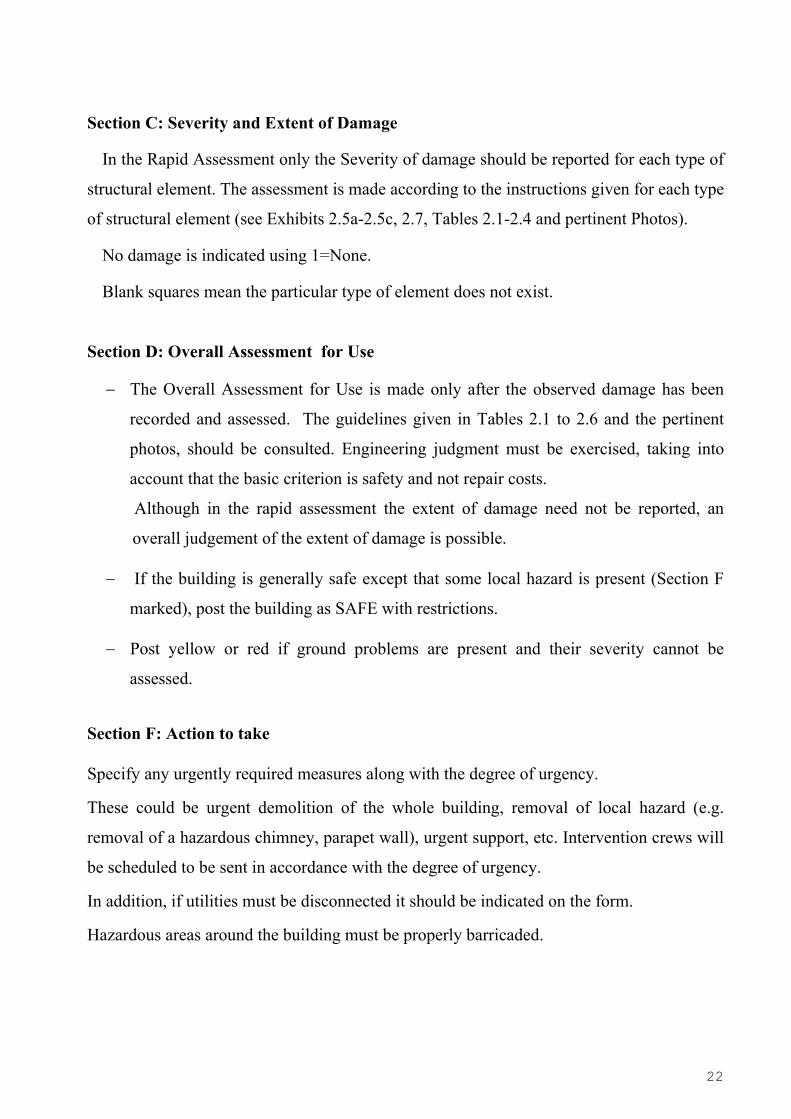
Section C: Severity and Extent of Damage
In the Rapid Assessment only the Severity of damage should be reported for each type of
structural element. The assessment is made according to the instructions given for each type
of structural element (see Exhibits 2.5a-2.5c, 2.7, Tables 2.1-2.4 and pertinent Photos).
No damage is indicated using 1=None.
Blank squares mean the particular type of element does not exist.
Section D: Overall Assessment for Use
− The Overall Assessment for Use is made only after the observed damage has been
recorded and assessed. The guidelines given in Tables 2.1 to 2.6 and the pertinent
photos, should be consulted. Engineering judgment must be exercised, taking into
account that the basic criterion is safety and not repair costs.
Although in the rapid assessment the extent of damage need not be reported, an
overall judgement of the extent of damage is possible.
− If the building is generally safe except that some local hazard is present (Section F
marked), post the building as SAFE with restrictions.
− Post yellow or red if ground problems are present and their severity cannot be
assessed.
Section F: Action to take
Specify any urgently required measures along with the degree of urgency.
These could be urgent demolition of the whole building, removal of local hazard (e.g.
removal of a hazardous chimney, parapet wall), urgent support, etc. Intervention crews will
be scheduled to be sent in accordance with the degree of urgency.
In addition, if utilities must be disconnected it should be indicated on the form.
Hazardous areas around the building must be properly barricaded.
23
Comments
Provide any comments deemed necessary either to explain the posting or the assessment of
damage, or to explain information given in the form.
Signatures
All members of the inspection team should sign and write their names and titles.
A copy of the Inspection Form must be given to the building owner or manager, who has to
sign the form.
Estimated time
Spend no more than 10-30 minutes per building.
2.4.2 Detailed Assessment
2.4.2a General Guidelines for the Inspectors 1. Request from the field office the Inspection form from the Rapid Assessment. Copy
data in Sections A and B from the Rapid Assessment form, correcting errors and filling
missing data.
2. Examine from outside (before entering the building):
• All sides of the building that are accessible. Look for signs of residual drift (building
or parts of it out of plumb), damage to chimneys and roof, to exterior walls, to the
façade etc. Care should be exercised for possible preexisting out of plumb.
• The site for ground problems or geological hazards. Look for settlements, ground
fissures, signs of liquefaction and, in case of hillside buildings, for signs of slope
movement and rock fall hazards.
24
3. Examine the building interior:
• Before entering the building look for any type of life threatening hazards. Do not
enter obviously unsafe buildings.
• Check carefully the type of structural system and look for irregularities, making every
effort to identify the load transfer mechanism for gravity and earthquake loads Look
at exposed areas such as open ground stories (pilotis), basements, stairwells or
mechanical floors.
• Proceed from the ground story upwards and inspect every floor including
penthouse and roof. Examine all visible structural elements, paying special attention to
the vertical members (columns, shear walls) and to any observable residual drift.
Move removable panels to view structural components, but do not do any destructive
exploration other than local plaster removal to check whether cracks in mortar extend
to the structural elements. Inspect for non-structural damage and take note of any
potential hazards. Examine if the cracks in infill walls are visible on both sides of the
wall or are only restricted to the plaster. If needed, remove the plaster locally.
• In concrete buildings with masonry infills, the infills are the first line of defense,
followed by elevator core or shear wall elements, if any, while the frames come last. It
is not uncommon with such buildings to have heavily cracked infills and no visible
damage in the main structural elements. Since their seismic capacity is obviously
reduced, such buildings are cases that would normally be posted YELLOW.
• Inspect the basement for foundation problems, uneven settlements, fractured slabs,
displaced columns at base and fractured or bowing perimeter walls.
• Inspect stairs and elevators and if elevator damage is suspected make sure that its
power is shut-off.
• Look for spills in areas where chemicals or other hazardous materials are stored.
4 On the basis of the detailed inspection and with the indicative damage descriptions in
Tables 2.1-2.4, Exhibits 2.5 a,b,c, 2.7 and with the pertinent photos as a guide, fill in
section C of the Inspection form recording both the severity and extent of damage. Fill
in Section D of the form on the basis of the rules given in Tables 2.5, 2.6 of this report,

25
keeping in mind that safety of the occupants is the basic criterion (see Exhibit 2.1). If
the building is generally safe except that some local hazard is present (Section F
marked), indicate the building GREEN with restrictions. Indicate YELLOW or RED if
ground problems are present and their severity cannot be assessed. The new posting
may be different from that of the Rapid assessment
5 In case of doubts be conservative but not on a systematic basis.
6 Pay special attention to any urgently required safety measures along with the degree of
urgency, unless such measures have already been taken (due to a previous Rapid
Assessment).
7 Barricade hazardous and unsafe areas with red-white tape and prohibit the access to
them.
8 Post the building according to the results of the assessment. Fill and sign the
appropriate placard (SAFE, UNSAFE, DANGEROUS) and post every entrance.
If the building was already posted following a rapid assessment, replace the old
placards. Mark also a spot next to the placard using a spray of the same colour i.e.
green, yellow or red .
If the building is posted GREEN with restrictions, barricade the unsafe area and post
it as AREA UNSAFE.
9 Give a copy of the signed inspection form to the owner or the building manager,
discuss the purpose and meaning of the posting with the occupants of the building and
advise them accordingly. In particular, explain that this inspection will not be used as
the basis for receiving financial aid for repair works.
Estimated time
Depending on the size of the building, it is anticipated that a detailed inspection could take
anywhere from one to three hours.
26
2.4.2b Filling in the Inspection Form of Detailed Assessment
• The whole building should be inspected, unless it is obviously unsafe. In this case,
an estimation of the damages should be made only from exterior examination of the
building.
• Both vertical and tilted squares have to be filled at the Detailed Assessment.
• A square left blank implies that the corresponding parameter does not exist.
• In case of disagreement between Inspectors the opinion of the team leader prevails.
In the following, explanatory details are given only for the information asked for in the
detailed inspection, which was not supplied in the rapid inspection.
Section A: Building Location and ID
Information about the location of the building is filled only in case it was not filled in the
Rapid Assessment or if errors are discovered.
Section B: Description of the Building
− Make every effort to identify the type of structural system and the load transfer
mechanism for gravity and earthquake loads.
− Information on number of basements and on multi-level foundation should be filled
in only if it is available from the building owners or if entering the basement poses no
hazard.
Section C: Severity and Extent of Damage
In the Detailed Assessment, both the Severity and the Extent of damage should be
recorded for each type of structural element. The assessment is made according to the
instructions given for each type of structural element (see Exhibits 2.5 a,b,c, 2.7, Tables
2.1-2.4 and the pertinent photos).
27
In case different degrees of damage for the same type of element exist, (e.g. damaged
columns with level of severity 2 to 4) the most heavy level of damage is indicated and for
this level of damage the respective extent of damage is recorded.
If some blocks are left blank, it is implied that the particular element does not exist.
Section D: Overall Assessment for Use
The Overall Assessment for Use should be made by taking into account Tables 2.5, 2.6
which combine the (highest observed) severity of element damage with an estimate of its
extent (number or elements having suffered the particular level of damage) as recorded in
section C of the form.
It is pointed out that the correlation between damage assessment and posting color on the
basis of severity and extent of damage is indicative and should not be followed blindly.
The final Assessment should be based on sound engineering judgement keeping in mind
that safety of the occupants, not repair costs, is the basic criterion (see Exhibit 2.2).
If the building is generally safe except that some local hazard is present (Section F
marked), post the building as SAFE (Green) with restrictions.
Post YELLOW or RED if ground problems are present and their severity cannot be
assessed.
The new posting may be different from that of the Rapid assessment
Section F: Action to take
If emergency measures dictated by the rapid assessment have already been taken, then no
action to take is marked.
28
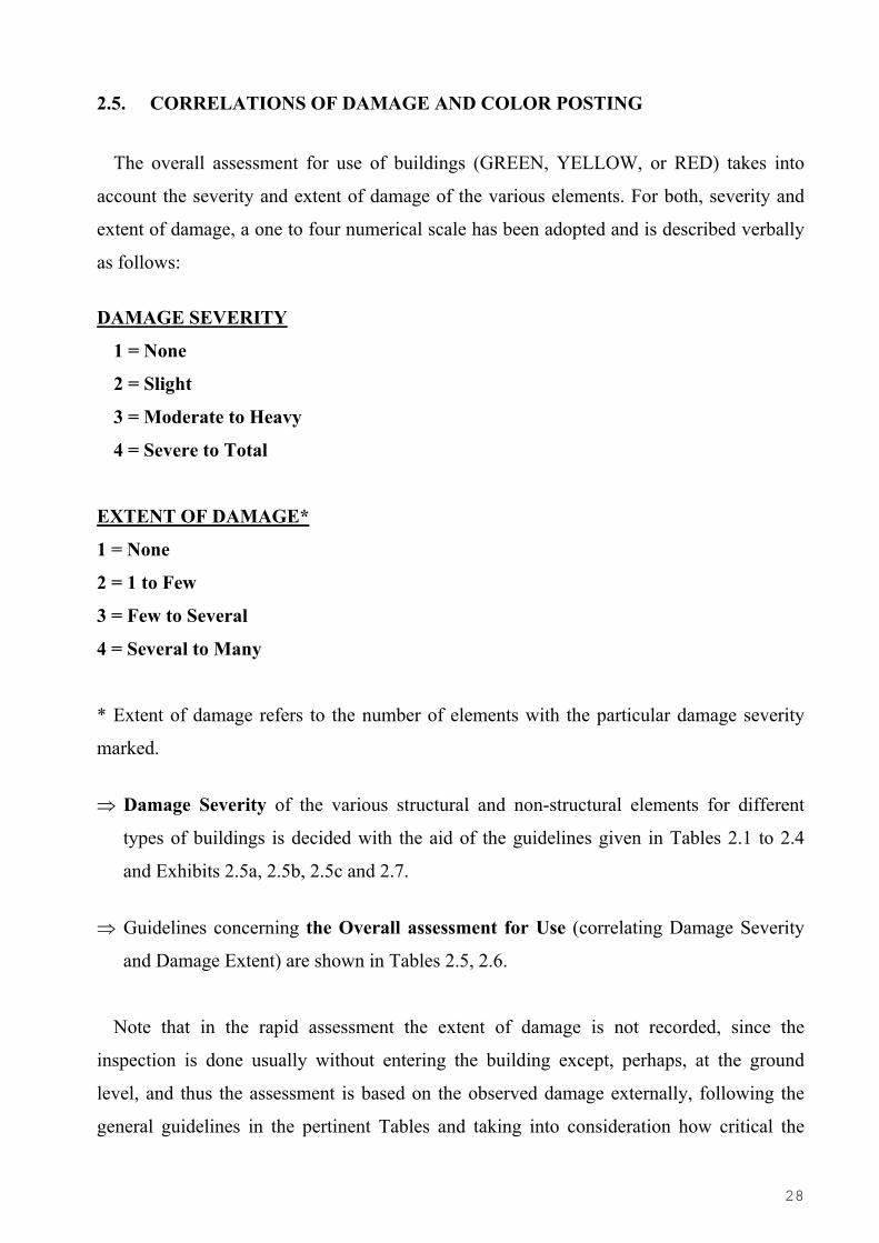
2.5. CORRELATIONS OF DAMAGE AND COLOR POSTING
The overall assessment for use of buildings (GREEN, YELLOW, or RED) takes into
account the severity and extent of damage of the various elements. For both, severity and
extent of damage, a one to four numerical scale has been adopted and is described verbally
as follows:
DAMAGE SEVERITY
1 = None
2 = Slight
3 = Moderate to Heavy
4 = Severe to Total
EXTENT OF DAMAGE*
1 = None
2 = 1 to Few
3 = Few to Several
4 = Several to Many
* Extent of damage refers to the number of elements with the particular damage severity
marked.
⇒ Damage Severity of the various structural and non-structural elements for different
types of buildings is decided with the aid of the guidelines given in Tables 2.1 to 2.4
and Exhibits 2.5a, 2.5b, 2.5c and 2.7.
⇒ Guidelines concerning the Overall assessment for Use (correlating Damage Severity
and Damage Extent) are shown in Tables 2.5, 2.6.
Note that in the rapid assessment the extent of damage is not recorded, since the
inspection is done usually without entering the building except, perhaps, at the ground
level, and thus the assessment is based on the observed damage externally, following the
general guidelines in the pertinent Tables and taking into consideration how critical the

29
damaged elements are for the safety of the building (e.g damage in columns versus damage
in beams).
2.5.1. Damage Severity
In what follows, criteria are given for assessing the Severity of damage in relation to
various types of failure for buildings with structural system of Reinforced Concrete,
Masonry, Steel and Wood. The criteria for steel and wood buildings are only preliminary
since the emphasis in this study was in the most common types of buildings in Greece, i.e
Reinforced Concrete and Masonry buildings.
It is further noted here that the various damage descriptions listed in the following
Exhibits and Tables are indicative of the corresponding level and that the presence or
absence of one type of damage given in a list does not necessarily imply classification or no
classification in the respective category. Sound engineering judgement will always be
required and the guidelines listed herein must be used as an aid rather than a
substitute for such judgement.
2.5.1a Reinforced concrete buildings
Reinforced concrete buildings constitute the dominant type of construction in the
earthquake prone countries of Europe. They can be found as single story houses, multi-
story residential or office buildings, industrial complexes etc. Concrete construction can be
cast in place or pre-cast or a combination of both.
Cast in place concrete buildings constructed before modern codes were introduced (i.e.
before ∼ 1980) can be quite vulnerable to strong earthquakes, especially if they were built
under poor quality control. The majority of multi-story buildings that have collapsed in
catastrophic earthquakes of the recent past belong to this category and are responsible for
most of the recorded human loses. Their design, not based on the modern concepts of
ductile behaviour, good confinement, strong columns-weak beams, strong shear walls with
specially detailed boundary elements etc., makes them quite more vulnerable than the new
buildings designed on the basis of modern codes. Older structures are likely to have poor
detailing so that an earthquake with several cycles of strong shaking could cause rapid
30
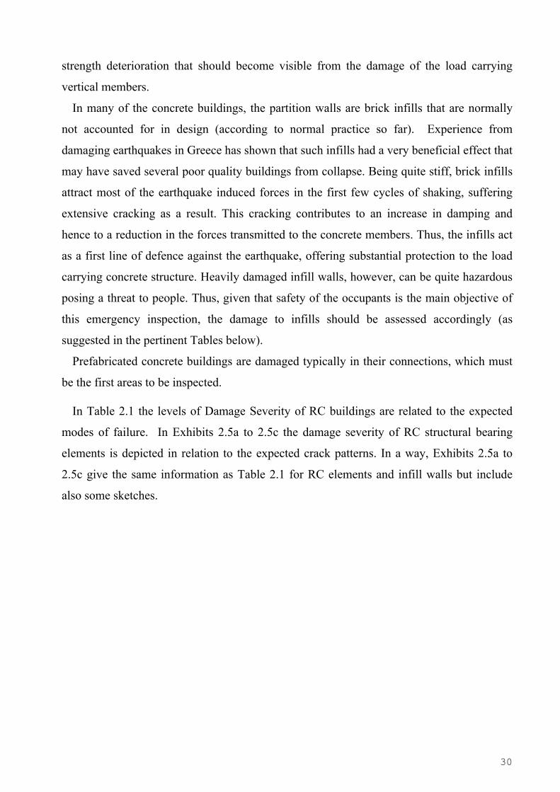
strength deterioration that should become visible from the damage of the load carrying
vertical members.
In many of the concrete buildings, the partition walls are brick infills that are normally
not accounted for in design (according to normal practice so far). Experience from
damaging earthquakes in Greece has shown that such infills had a very beneficial effect that
may have saved several poor quality buildings from collapse. Being quite stiff, brick infills
attract most of the earthquake induced forces in the first few cycles of shaking, suffering
extensive cracking as a result. This cracking contributes to an increase in damping and
hence to a reduction in the forces transmitted to the concrete members. Thus, the infills act
as a first line of defence against the earthquake, offering substantial protection to the load
carrying concrete structure. Heavily damaged infill walls, however, can be quite hazardous
posing a threat to people. Thus, given that safety of the occupants is the main objective of
this emergency inspection, the damage to infills should be assessed accordingly (as
suggested in the pertinent Tables below).
Prefabricated concrete buildings are damaged typically in their connections, which must
be the first areas to be inspected.
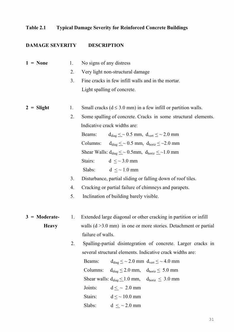
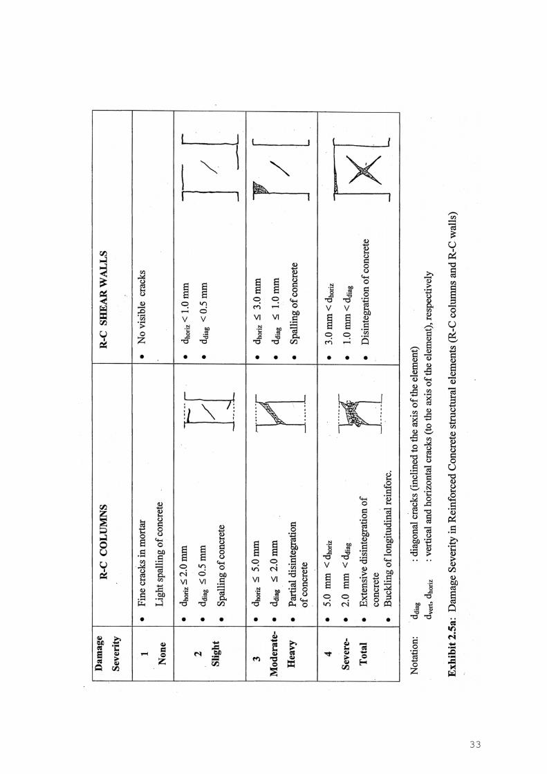
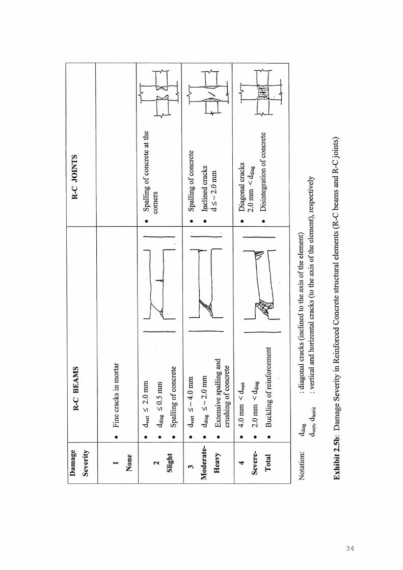
In Table 2.1 the levels of Damage Severity of RC buildings are related to the expected
modes of failure. In Exhibits 2.5a to 2.5c the damage severity of RC structural bearing
elements is depicted in relation to the expected crack patterns. In a way, Exhibits 2.5a to
2.5c give the same information as Table 2.1 for RC elements and infill walls but include
also some sketches.
31
Table 2.1 Typical Damage Severity for Reinforced Concrete Buildings
DAMAGE SEVERITY DESCRIPTION
1 = None 1. No signs of any distress
2. Very light non-structural damage
3. Fine cracks in few infill walls and in the mortar.
Light spalling of concrete.
2 = Slight 1. Small cracks (d ≤ 3.0 mm) in a few infill or partition walls.
2. Some spalling of concrete. Cracks in some structural elements.
Indicative crack widths are:
Beams: ddiag < ~ 0.5 mm, dvert < ~ 2.0 mm
Columns: ddiag < ~ 0.5 mm, dhoriz < ~2.0 mm
Shear Walls: ddiag < ~ 0.5mm, dhoriz < ~1.0 mm
Stairs: d < ~ 3.0 mm
Slabs: d < ~ 1.0 mm
3. Disturbance, partial sliding or falling down of roof tiles.
4. Cracking or partial failure of chimneys and parapets.
5. Inclination of building barely visible.
3 = Moderate- 1. Extended large diagonal or other cracking in partition or infill
Heavy walls (d >3.0 mm) in one or more stories. Detachment or partial
failure of walls.
2. Spalling-partial disintegration of concrete. Larger cracks in
several structural elements. Indicative crack widths are:
Beams: ddiag < ~ 2.0 mm dvert < ~ 4.0 mm
Columns: ddiag < 2.0 mm, dhoriz < 5.0 mm
Shear walls: ddiag < 1.0 mm, dhoriz < 3.0 mm
Joints: d < ~ 2.0 mm
Stairs: d < ~ 10.0 mm
Slabs: d < ~ 2.0 mm
32
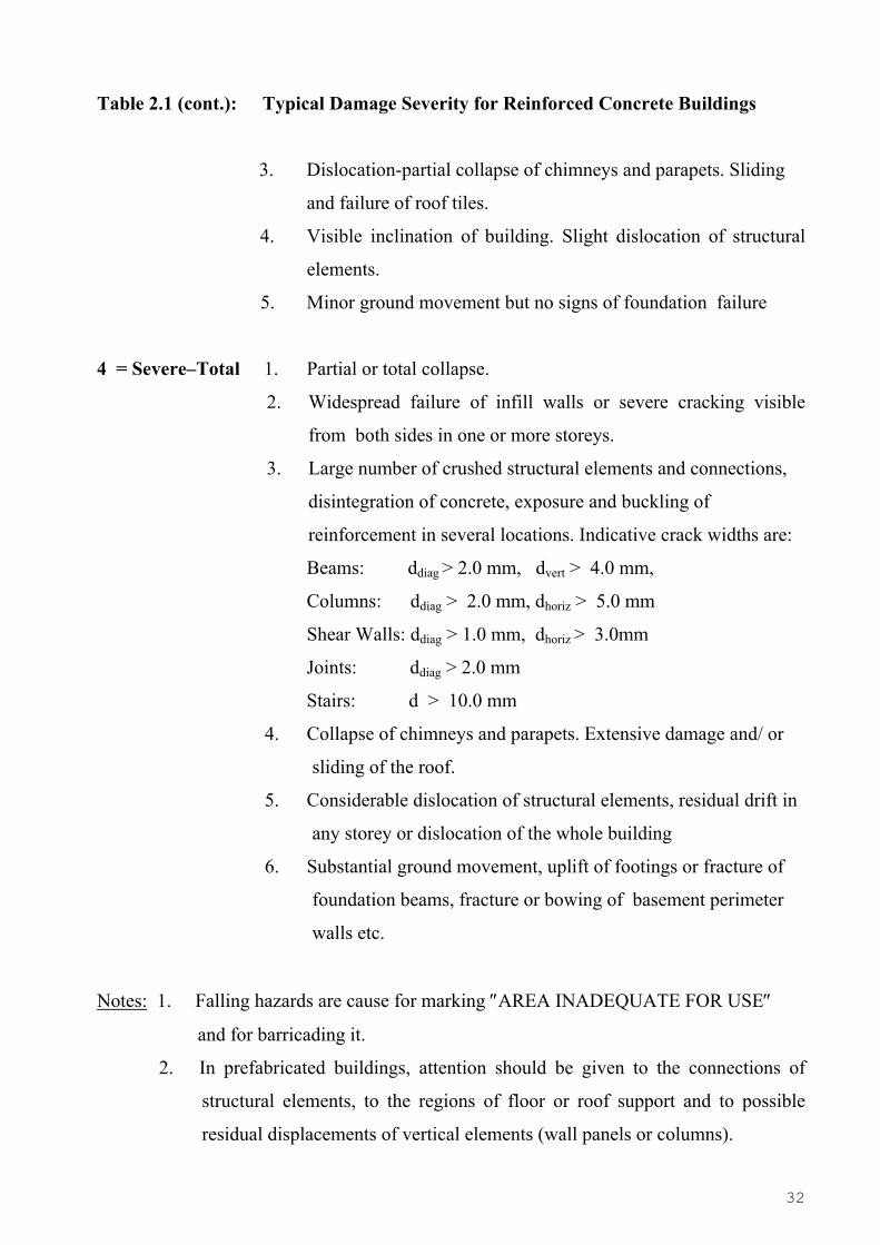
Table 2.1 (cont.): Typical Damage Severity for Reinforced Concrete Buildings
3. Dislocation-partial collapse of chimneys and parapets. Sliding
and failure of roof tiles.
4. Visible inclination of building. Slight dislocation of structural
elements.
5. Minor ground movement but no signs of foundation failure
4 = Severe–Total 1. Partial or total collapse.
2. Widespread failure of infill walls or severe cracking visible
from both sides in one or more storeys.
3. Large number of crushed structural elements and connections,
disintegration of concrete, exposure and buckling of
reinforcement in several locations. Indicative crack widths are:
Beams: ddiag > 2.0 mm, dvert > 4.0 mm,
Columns: ddiag > 2.0 mm, dhoriz > 5.0 mm
Shear Walls: ddiag > 1.0 mm, dhoriz > 3.0mm
Joints: ddiag > 2.0 mm
Stairs: d > 10.0 mm
4. Collapse of chimneys and parapets. Extensive damage and/ or
sliding of the roof.
5. Considerable dislocation of structural elements, residual drift in
any storey or dislocation of the whole building
6. Substantial ground movement, uplift of footings or fracture of
foundation beams, fracture or bowing of basement perimeter
walls etc.
Notes: 1. Falling hazards are cause for marking ″AREA INADEQUATE FOR USE″
and for barricading it.
2. In prefabricated buildings, attention should be given to the connections of
structural elements, to the regions of floor or roof support and to possible
residual displacements of vertical elements (wall panels or columns).
33
34
35
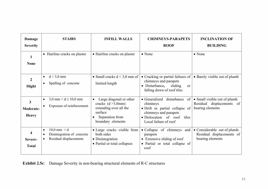
Damage
Severity
STAIRS
INFILL WALLS
CHIMNEYS-PARAPETS
ROOF
INCLINATION OF
BUILDING
1
None
• Hairline cracks on plaster
• Hairline cracks on plaster
• None
• None
2
Slight
• d < 3,0 mm
• Spalling of concrete
• Small cracks d < 3,0 mm of
limited length
• Cracking or partial failures of chimneys and parapets
• Disturbance, sliding or falling down of roof tiles
• Barely visible out of plumb
3
Moderate-
Heavy
• 3,0 mm < d ≤ 10,0 mm
• Exposure of reinforcement
• Large diagonal or other cracks (d >3,0mm) extending over all the surface
• Separation from boundary elements
• Generalized disturbance of chimneys
• Drift or partial collapse of chimneys and parapets
• Dislocation of roof tiles Local failure of roof
• Small visible out of plumb. Residual displacements of bearing elements
4
Severe-
Total
• 10,0 mm < d • Disintegration of concrete • Residual displacements
• Large cracks visible from both sides
• Disintegration • Partial or total collapses
• Collapse of chimneys and parapets
• Extensive sliding of roof • Partial or total collapse of
roof
• Considerable out of plumb. Residual displacements of bearing elements
Exhibit 2.5c: Damage Severity in non-bearing structural elements of R-C structures

36
R- C COLUMNS
Photo 1: Damage severity 1
Photo 2: Damage severity 1
Photo 3: Damage severity 2
Photo 4: Damage severity 3
37
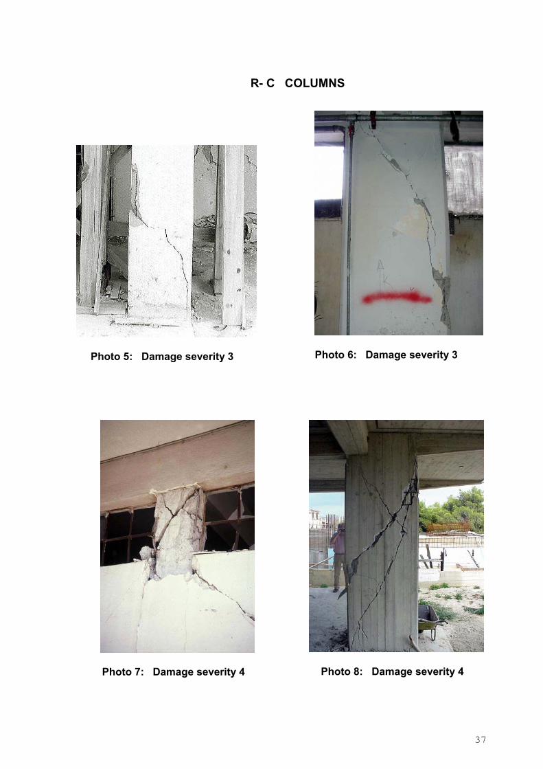
R- C COLUMNS
Photo 5: Damage severity 3
Photo 6: Damage severity 3
Photo 7: Damage severity 4
Photo 8: Damage severity 4
38
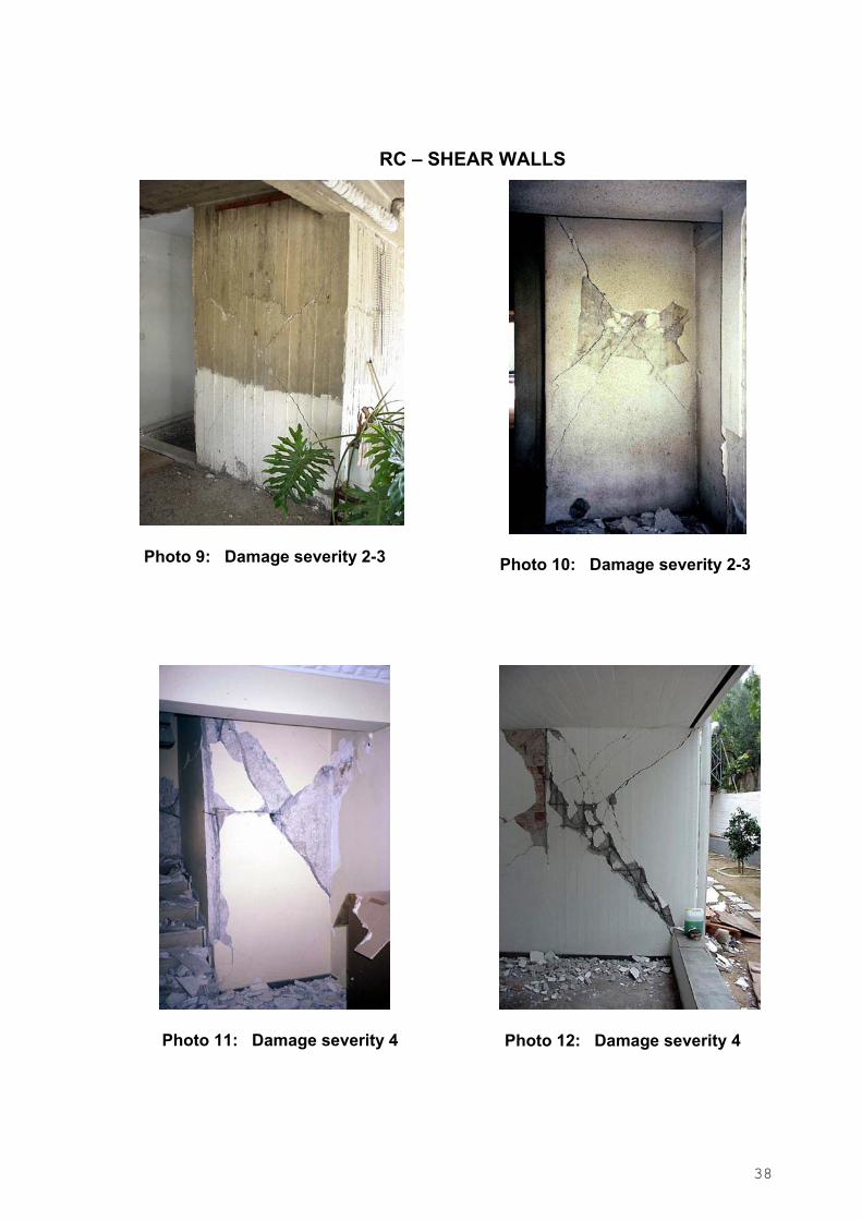
RC – SHEAR WALLS
Photo 9: Damage severity 2-3
Photo 10: Damage severity 2-3
Photo 11: Damage severity 4
Photo 12: Damage severity 4
39
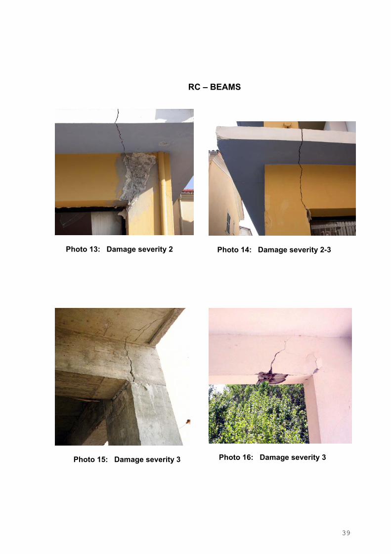
RC – BEAMS
Photo 13: Damage severity 2
Photo 14: Damage severity 2-3
Photo 15: Damage severity 3
Photo 16: Damage severity 3
40
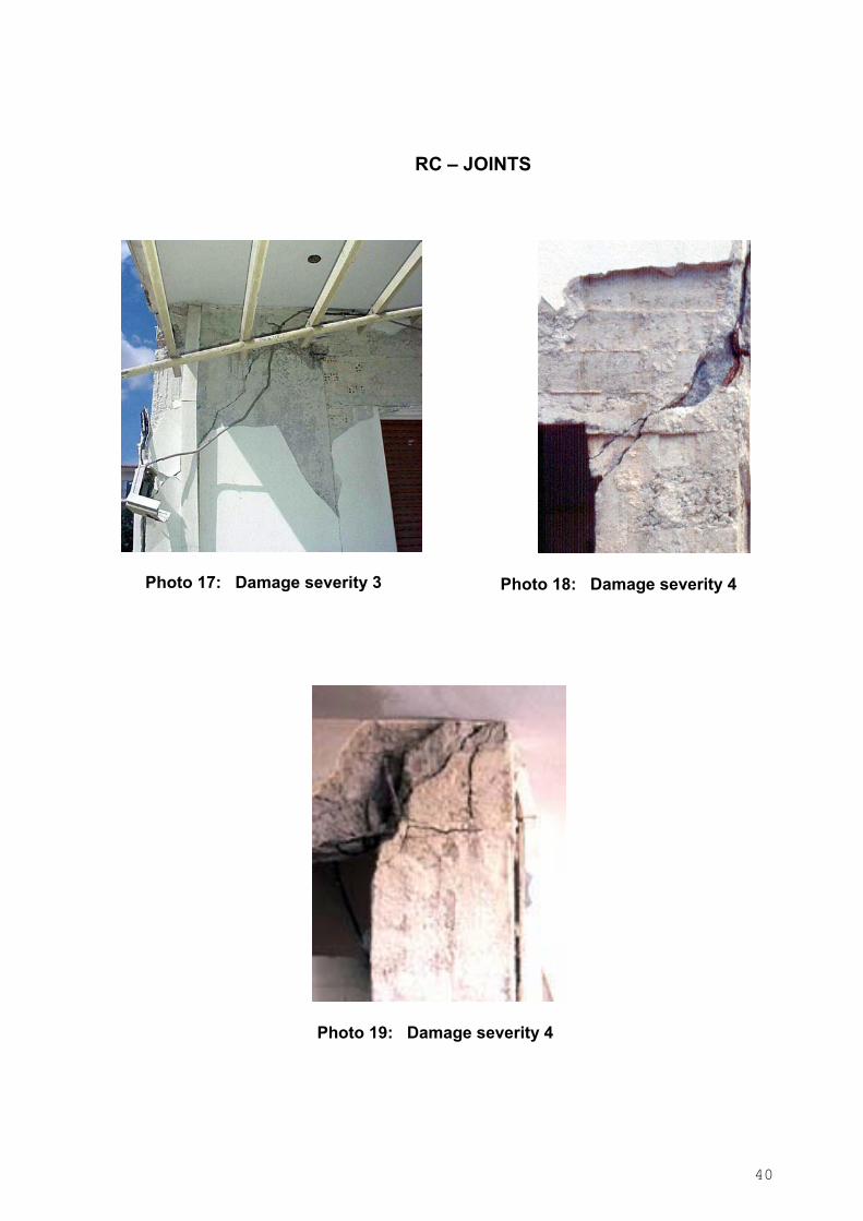
RC – JOINTS
Photo 17: Damage severity 3
Photo 18: Damage severity 4
Photo 19: Damage severity 4
41
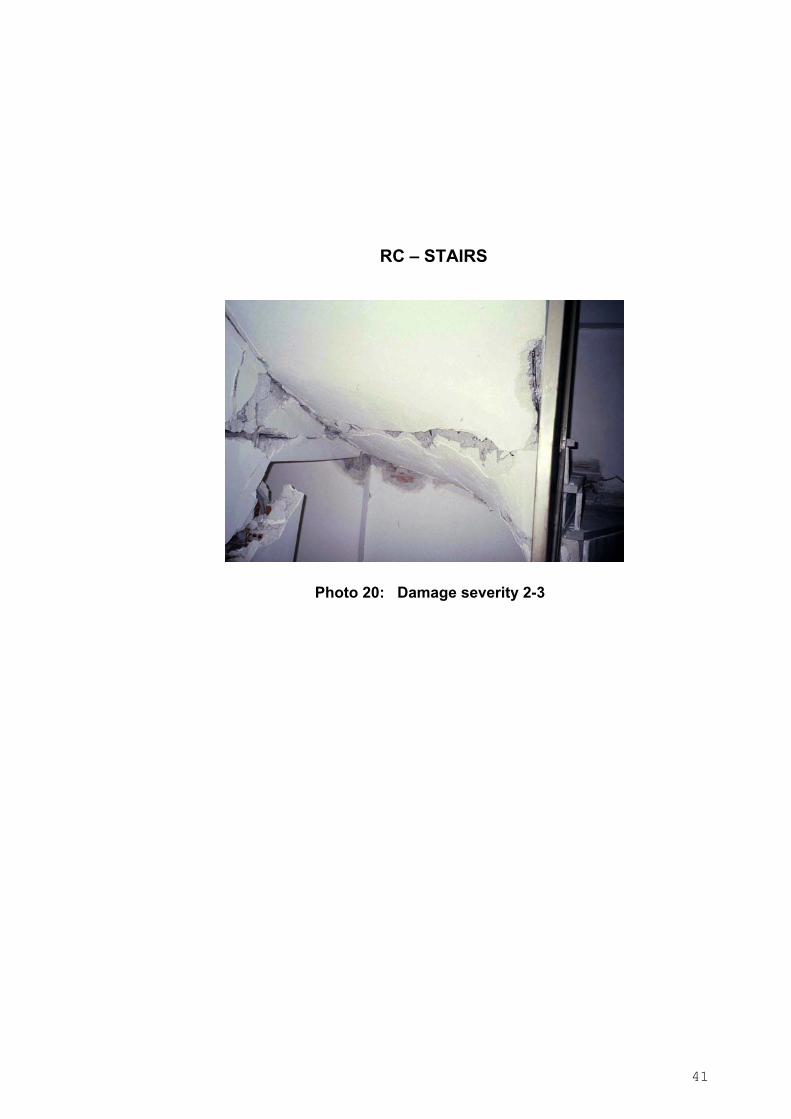
RC – STAIRS
Photo 20: Damage severity 2-3

42
RC – INFILL WALLS
Photo 21: Damage severity 1-2
Photo 22: Damage severity 2
Photo 23: Damage severity 3
Photo 24: Damage severity 3
43
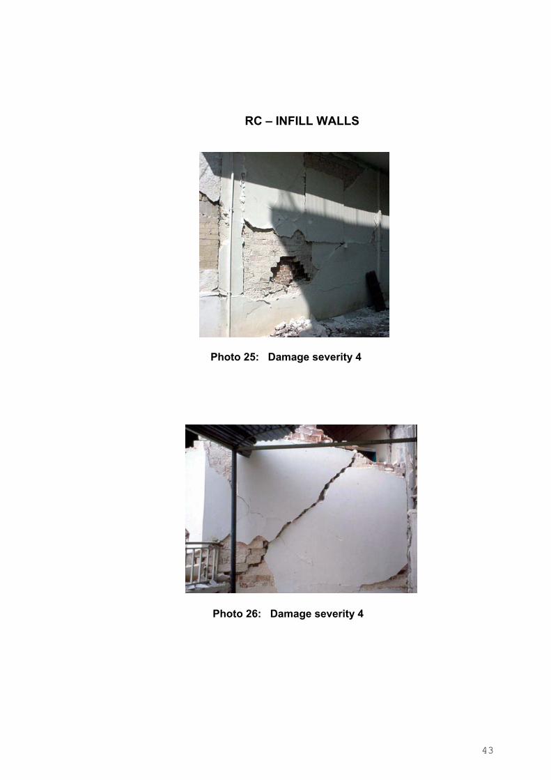
RC – INFILL WALLS
Photo 25: Damage severity 4
Photo 26: Damage severity 4

44
2.5.1b Masonry buildings
Masonry buildings may have been built from a variety of materials (e.g. stone, hollow or
solid bricks, special concrete blocks) and in a variety of ways (e.g. with or without steel
reinforcement, with or without horizontal or other belts etc.).
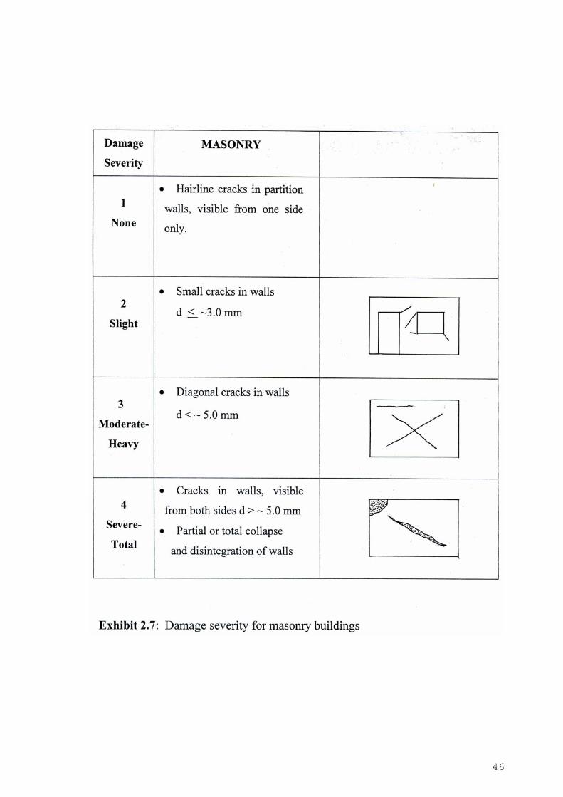
In Table 2.2 and in Exhibit 2.7 the levels of Damage Severity of Masonry buildings are
related to the expected modes of failure. Exhibit 2.6 shows typical crack patterns in the
exterior walls of Masonry buildings.
The guidelines given are general enough to cover all cases but here again sound
engineering judgement should be exercised, taking into account the great variability in the
mechanical properties of the bearing masonry walls.
Exhibit 2.6: Typical damage patterns of masonry buildings

45
Table 2.2 Typical Damage Severity for Masonry Buildings
DAMAGE SEVERITY DESCRIPTION
1 = None 1. No signs of any distress.
2. Hairline cracks in partition walls visible from one
side only.
2 = Slight 1. Small cracks in partition walls visible from both
sides ( d <~3 mm).
2. Small cracks in bearing walls, starting mostly at the
corners of a few openings (d <~ 3 mm).
3. Patches of mortar falling from ceilings or walls.
4. Disturbance, partial sliding and falling down of some roof
tiles.
3 = Moderate - Heavy 1. Substantial cracking of partition walls (d > ~ 3.0 mm).
2. Diagonal cracking in bearing walls (d< ~ 5.0 mm), but not
so extensive as to constitute failure.
3. Movement, separation or local failure of roof and floor
framing supports.
4. Dislocation and/ or partial collapse of chimneys, parapets
or roofs.
5. Local heavy damage in some part of the building
4 = Severe - Total 1. Bearing walls with large cracks (d> ~ 5.0 mm), visible
from both sides.
2. Partial or total failure of bearing walls, floors and/or roof
3. Walls out of plumb.
4. Failure of floor and roof support areas and dislocation of
their framing.
5. Any type of damage indicating considerable danger for
collapse.
Note Falling hazards are cause for marking AREA INADEQUATE FOR USE and for
barricading it.
46

47
MASONRY BUILDINGS
Photo 27: Slightly damaged (GREEN)
Photo 28: Slightly damaged (GREEN)
48
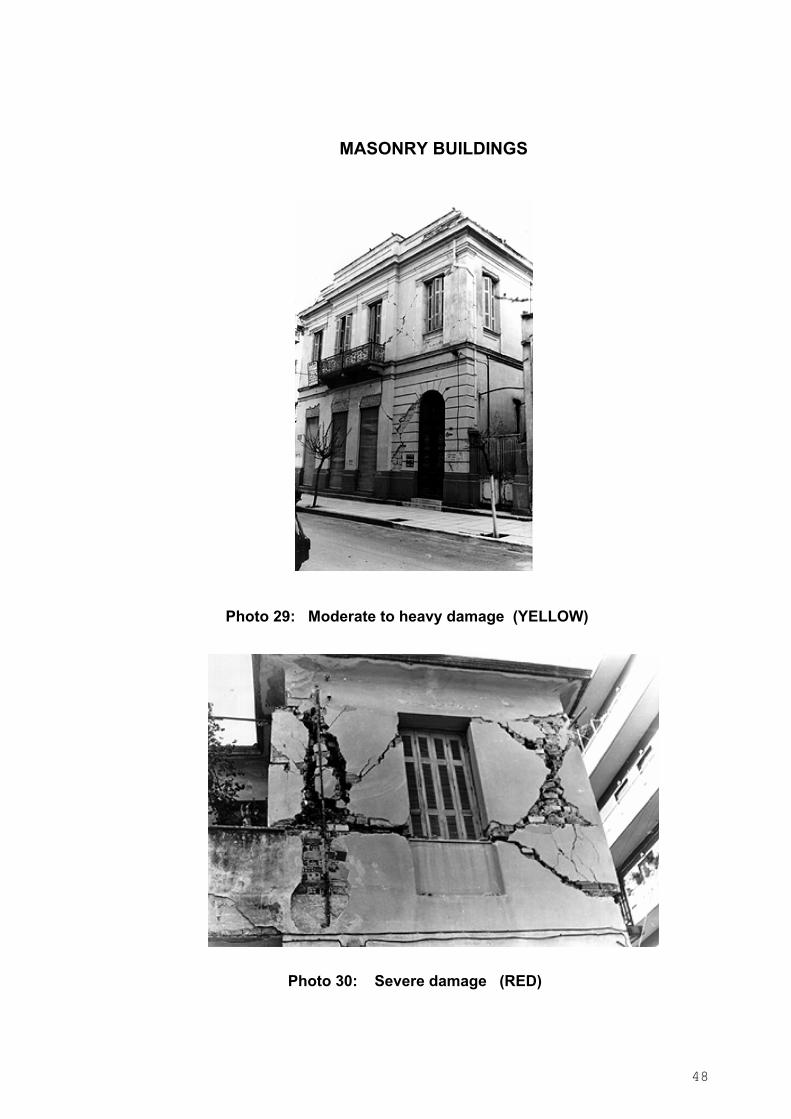
MASONRY BUILDINGS
Photo 29: Moderate to heavy damage (YELLOW)
Photo 30: Severe damage (RED)
49
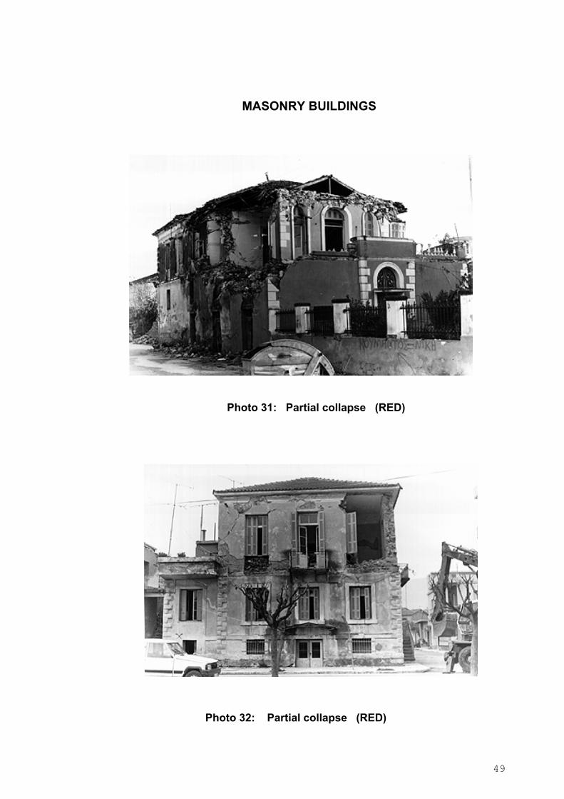
MASONRY BUILDINGS
Photo 31: Partial collapse (RED)
Photo 32: Partial collapse (RED)
50
2.5.1c Steel buildings
Steel buildings are rather rare in seismically active Southern Europe. Field evidence
from other parts of the world, however, indicates a generally good behaviour in
earthquakes, with very few collapses and hence few lives lost. This is not to say that steel
buildings do not suffer damage or that they are not vulnerable. It is noted here that in
modern steel construction lightweight partitions are normally used and in this respect such
buildings are less hazardous than concrete or order steel structures, in which brick or other
heavy masonry is used for partitions.
In Table 2.3 guidelines that may be used to assess the level of damage severity are given.

51
Table 2.3 Typical Damage Severity for Steel Buildings DAMAGE SEVERITY DESCRIPTION
1 = None - Slight 1. No signs of any distress
2. Hairline or small cracking in the plaster of partition walls
and in the masonry veneer of exterior walls
3. Minor damage in the ceilings, lighting fixtures etc.
4. Minor damage in the cladding (partial dislodgement,
some broken glass)
5. Some minor residual racking (less than 1.0 cm) of walls
6. Negligible to slight structural damage (signs of distress
in some structural members and their connections)
7. Cracks and perhaps partial failures of chimneys
2 = Moderate - Heavy 1. Moderate cracking (~ 2-4 mm) in the plaster of interior
walls and in the masonry veneer of exterior walls
2. Moderate residual racking (~ 1.0 to 2.0 cm) of walls
3. Moderate to heavy damage in ceilings (dislodgement of
suspended ceilings, disattachment of lighting fixtures
etc)
4. Moderate to heavy damage in the cladding
(dislodgement and partial failure of panels, plenty of
broken glass etc)
5. Moderate to heavy local damage in structural members
and connections (a few buckled or broken braces, flange
buckling in a few columns, slippage or cracks in some
base plates, weld or other connection failure in a few
joints, movement or failure at some shear connections
between floor diaphragms and beams, etc.
6. Collapse of chimneys and parapets in combination with
other damage listed herein
52
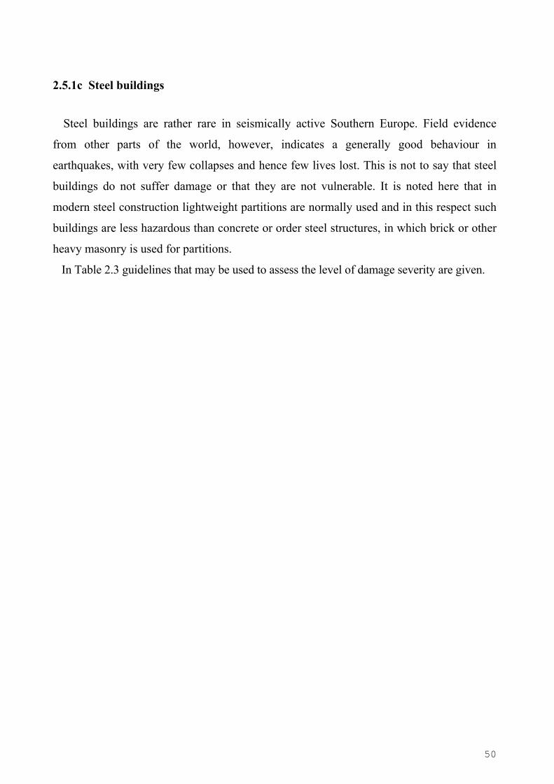
Table 2.3 (cont.): Typical Damage Severity for Steel Buildings
7. Slight dislocation of structural elements
8. Minor ground movement but no signs of foundation
failure
3 = Severe - Total 1. Partial or total collapse
2. Widespread failure of interior partition walls, cladding
and glass
3. Many failed structural members, joints and connections
(buckling or stretching of braces, buckled column
flanges, slippage or cracks in many base plates, many
cracks in welded connections, cracked bolts and gusset
plates etc)
4. Considerable dislocations of structural members, residual
drift in any storey or dislocation of the whole building
5. Substantial ground movement, fracture of base slab, or
bowing of basement perimeter walls
6. Any type of damage indicating considerable danger for
collapse
Note: Falling hazards are cause for marking AREA UNSAFE and for barricading it.
53
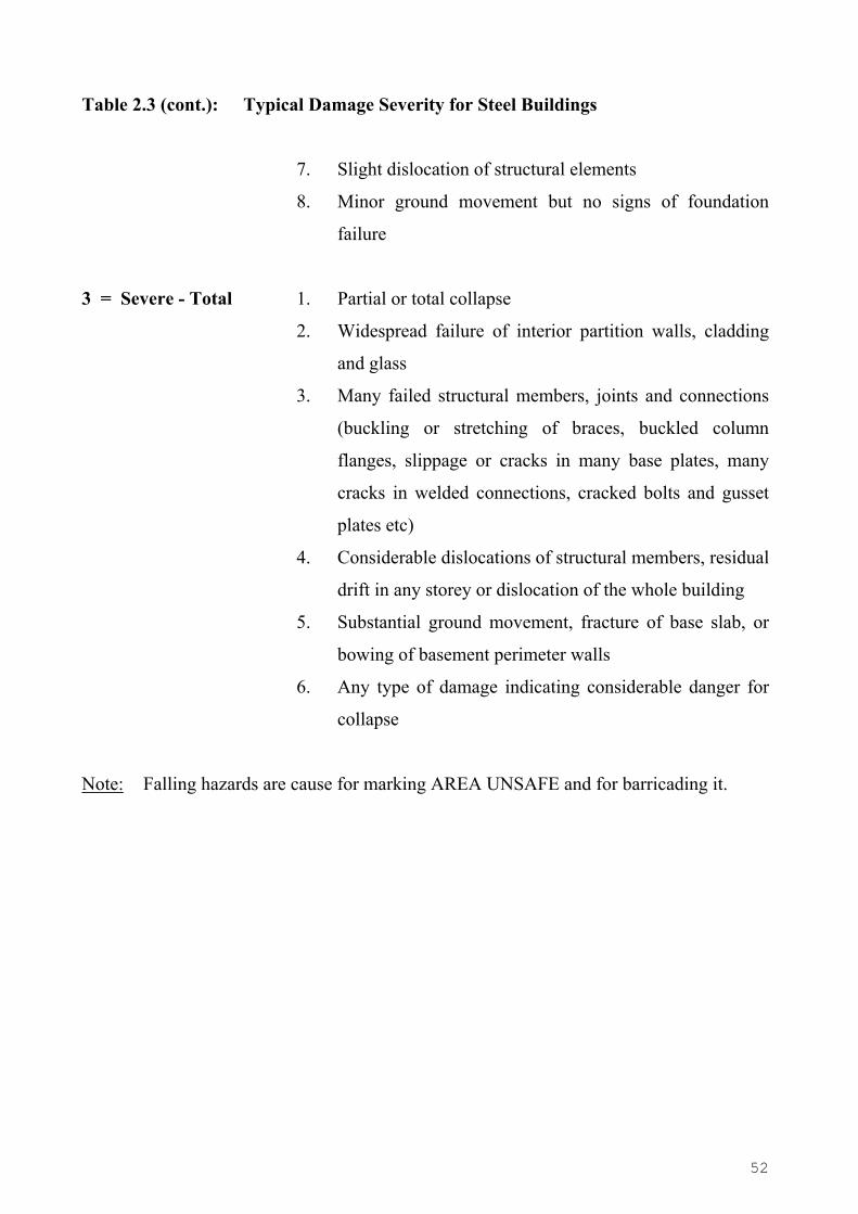
STEEL BUILDINGS
Photo 33: Four storey steel building with extensive broken glass and several buckled braces (YELLOW)
Photo 34: Buckled brace of building in Photo 29
54
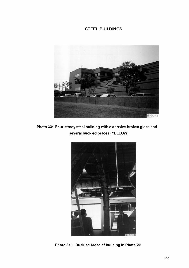
STEEL BUILDINGS
Photo 35: Complete column fracture and brace failure (YELLOW)
Photo 36: Fractured weld of the panel plate in beam-column joint (YELLOW)
55
STEEL BUILDINGS
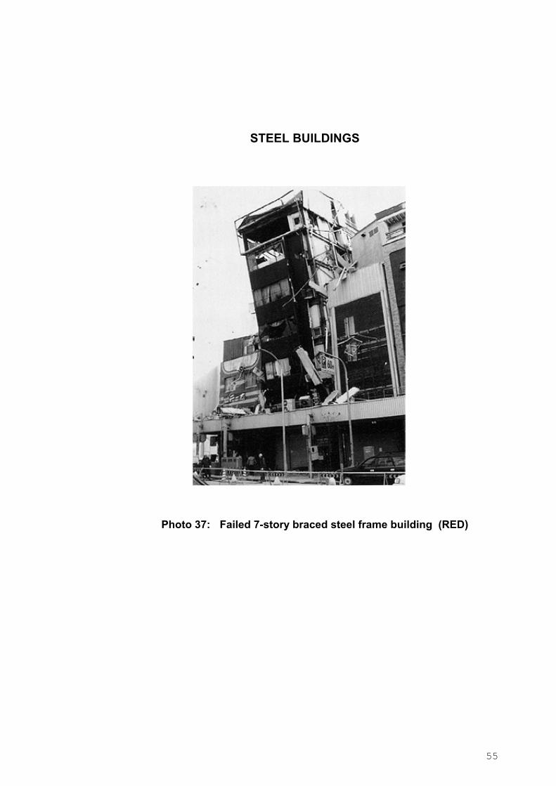
Photo 37: Failed 7-story braced steel frame building (RED)
56
2.5.1d Wood buildings
Wood buildings are used mostly as single family houses in the United States or Japan but
not in the earthquake prone countries of Europe. For completeness, however, guidelines for
such buildings have also been included in Table 2.4.
57
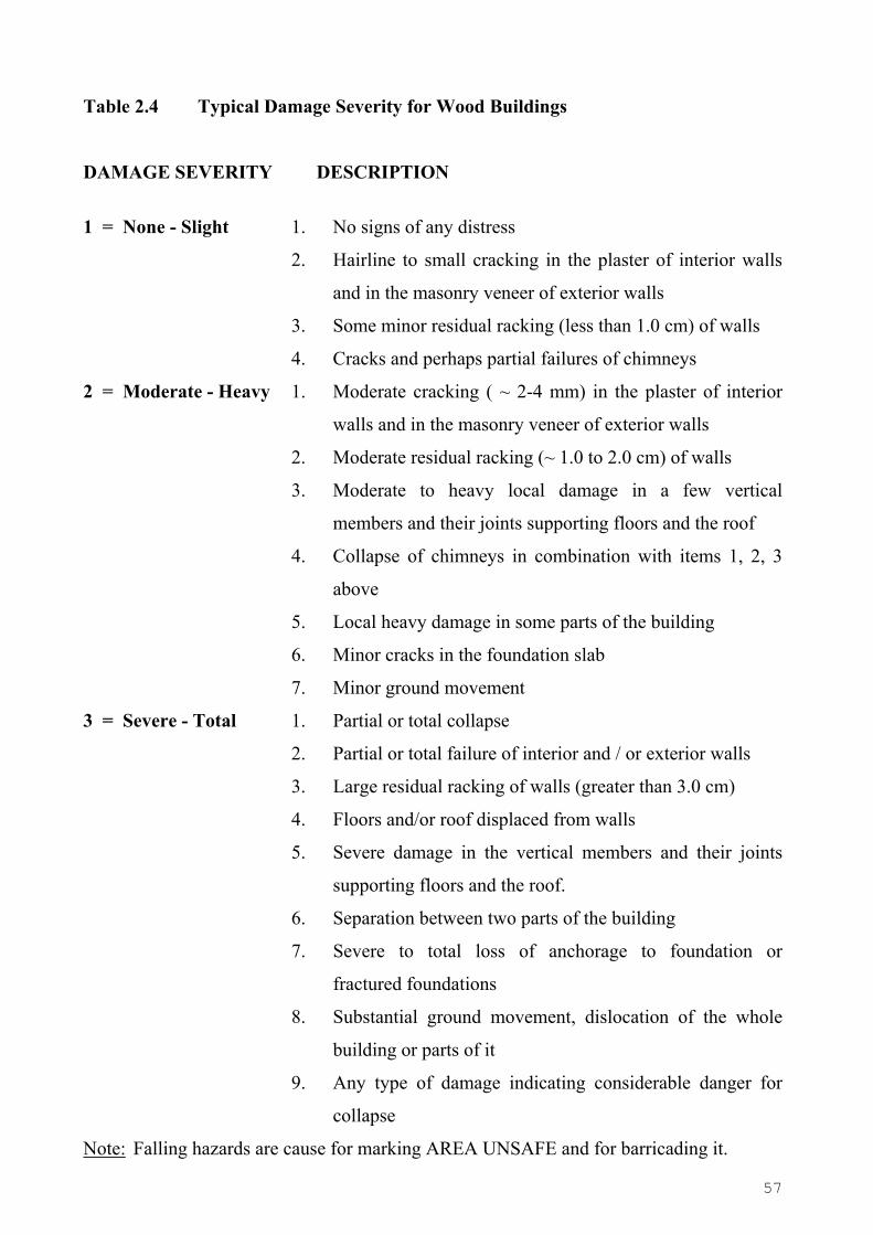
Table 2.4 Typical Damage Severity for Wood Buildings
DAMAGE SEVERITY DESCRIPTION
1 = None - Slight 1. No signs of any distress
2. Hairline to small cracking in the plaster of interior walls
and in the masonry veneer of exterior walls
3. Some minor residual racking (less than 1.0 cm) of walls
4. Cracks and perhaps partial failures of chimneys
2 = Moderate - Heavy 1. Moderate cracking ( ~ 2-4 mm) in the plaster of interior
walls and in the masonry veneer of exterior walls
2. Moderate residual racking (~ 1.0 to 2.0 cm) of walls
3. Moderate to heavy local damage in a few vertical
members and their joints supporting floors and the roof
4. Collapse of chimneys in combination with items 1, 2, 3
above
5. Local heavy damage in some parts of the building
6. Minor cracks in the foundation slab
7. Minor ground movement
3 = Severe - Total 1. Partial or total collapse
2. Partial or total failure of interior and / or exterior walls
3. Large residual racking of walls (greater than 3.0 cm)
4. Floors and/or roof displaced from walls
5. Severe damage in the vertical members and their joints
supporting floors and the roof.
6. Separation between two parts of the building
7. Severe to total loss of anchorage to foundation or
fractured foundations
8. Substantial ground movement, dislocation of the whole
building or parts of it
9. Any type of damage indicating considerable danger for
collapse
Note: Falling hazards are cause for marking AREA UNSAFE and for barricading it.

58
WOOD BUILDINGS
Photo 38: Damaged 2-storey wood frame building. Lots of broken glass and some lateral offset (YELLOW)
Photo 39: Local damage to plywood shear wall (YELLOW)

59
WOOD BUILDINGS
Photo 40: Fractured post above the hold-down (YELLOW)
Photo 41: Single story wood frame house slipped off its foundation (RED)
60
WOOD BUILDINGS
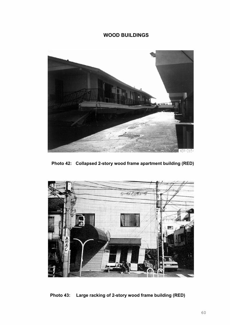
Photo 42: Collapsed 2-story wood frame apartment building (RED)
Photo 43: Large racking of 2-story wood frame building (RED)
61
2.5.2. Overall assessment of building safety
For the overall assessment of the building safety for use, both the severity and extent of
damage of the various structural elements are taken into account. It is of paramount
importance that the inspector identifies first the type of structural system (section B)
from which the ″criticality″ of each load carrying element can be assessed.
Subsequently the damage caused by the earthquake must be recorded as section C of
the Form requires. It is only then that the assessment of the building’s safety can be
made with sufficient degree of confidence. Although it is often difficult to automate such
assessment just on the basis of observed (and recorded) damage, an effort has been made
here aimed at an as much as possible objective assessment, on the basis of the general
safety and usability criteria outlined in Exhibit 2.1. It is based on the recorded damage
severity and extent for load bearing and other elements (R.C. members, bearing walls, infill
walls, chimney, parapets, roofs) and on the contribution of such elements to the building
safety.
In summary then the steps for safety assessment of the building are:
1. The damage severity (1 to 4) and extent of the damaged structural elements is
recorded (Exh. 2.5a,b,c, 2.7, Tables 2.1-2.4, Photos: Inspection form Section C).
2. An ″overall damage assessment for the individual elements″ can be decided
according to the criteria given in Table 2.5*, relating the damage severity to the
damage extent.
3. The ″overall assessment for use of the building″ (GREEN, YELLOW, or RED:
Section D of the inspection form) takes into account the partial ″overall damage
assessment classifications for each structural element″ according to Table 2.6.
It is once more emphasized however that the rules given below should always be
viewed as an aid rather than a substitute to sound engineering judgement.
The structural elements in Tables 2.5 and 2.6 are grouped into the following categories:
A RC columns, beams, shear walls, frame joints and masonry walls
B1 Stairs, B2 Infill walls, B3 Parapets, roofs, chimneys
C Building out of plumb D Ground problems
* In Rapid Assessment only Damage Severity is taken into account in Table 2.5.

62
TABLE 2.5 : Criteria for assessment of ELEMENT damage.
Α. Bearing Elements
Columns, Beams, Shear walls, Fame Joints,
Masonry Walls
Damage Severity Extent of damage
GREEN 1, 2 1, 2
YELLOW 2 3, 4
3 2
RED 3 3, 4
4 2, 3, 4
Β.1 Stairs Damage Severity Extent of damage
GREEN 1, 2 1, 2
YELLOW 2 3, 4
3 2
RED 3 3, 4
4 2, 3, 4
Β.2 Infill masonry walls Damage Severity Extent of damage
GREEN 1, 2 1, 2, 3, 4
3 2
YELLOW 3 3, 4
4 2
RED 4 3, 4
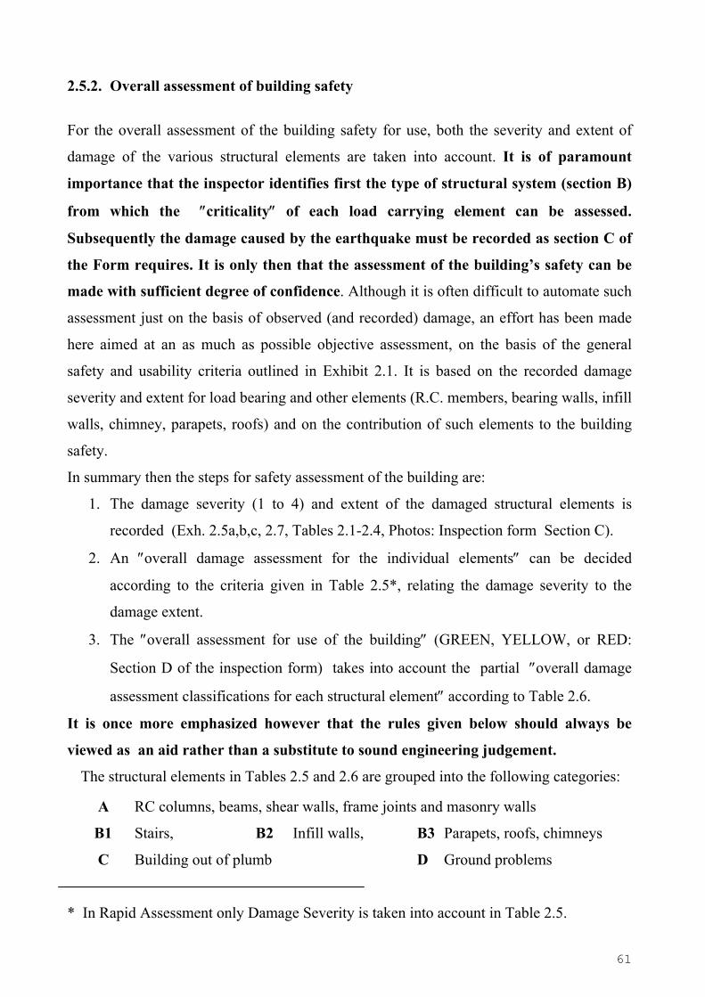
63
TABLE 2.5 (cont.) : Criteria for assessment of ELEMENT damage
Β.3 Parapets, Roofs, Chimneys Damage Severity Extent of damage
GREEN 1, 2 1, 2
YELLOW 2 3, 4
3 2
RED 4 2, 3, 4
C. Building out of plumb Damage Severity
GREEN 1, 2
YELLOW 3
RED 4
D. Ground Problems Damage Categories
GREEN 1
YELLOW or
RED 2, 3, 4, 5, 6
Note:
In the Inspection Form at ″Apparent Ground Problems″ only the mode of failure of the
ground is indicated (neither the severity nor the extent of damage).
So the classification to Yellow or Red relies on the engineering judgment of the
inspectors.

64
Table 2.6: Criteria for overall assessment in case of different types of damaged
structural elements
Damage Assessment of the various
element categories (A to D)
Overall assessment of the
building
1. Α, or Β1, or Β2: RED RED
2. Α, or Β1, or Β2 : YELLOW
and Β3 : GREEN YELLOW
3. Α and Β : GREEN
and C or D: YELLOW or RED YELLOW or RED
4. Α and Β : YELLOW
and C or D: YELLOW or RED RED
5. Α and Β1 and Β2 : GREEN
and Β3 : YELLOW or RED
(and C, D : GREEN)
GREEN
For part of the building
Need for intervention
in ….
6. Α and Β1 and Β2 and Β3 : GREEN GREEN
In the cases not adequately covered by this Table, the inspectors will decide
considering the damage descriptions and correlations in Tables 2.1 to 2.5 and using
engineering judgment.
Notation:
Α bearing elements: RC columns, beams, shear walls, frame joints and
masonry walls
B1 stairs
B2 infill walls
B3 parapets, roofs, chimneys
C building out of plumb
D ground problems

65
2.6. HAZARD REMOVAL AND EMERGENCY SUPPORT
The rapid (and the detailed) assessment of a building provides information about
hazardous conditions requiring urgent intervention. The interventions may range from the
need of urgent support and the removal of some local hazard e.g. a badly damaged
chimney or parapet, to the demolition of whole buildings that have been damaged beyond
repair or have partially collapsed. In the inspection form following the assessment the
actions to be taken are indicated together with the priority of urgency for action it presents:
Low, Medium, or High.
The daily program for hazard removal and emergency support will be prepared taking into
account the data of the buildings inspected the previous day, and input into the system. The
system will be able to group and indicate the buildings for which an intervention is
urgently required. The planning/ priority of interventions will also take into account
(include) any requests made by owners of damaged buildings.
The necessary work for the action taken will be carried out by specialised intervention
crews and requires availability of the necessary equipment. More particularly, emergency
bracing and shoring should be preferably carried out under the direction of an experienced
structural engineer.
The intervention crews are supposed to be provided with the Emergency Intervention Form
(see Exhibit 2.8) on which the available data from the inspection, rapid or detailed, will
appear. The intervention crew will indicate on the form the interventions that were
completed, and those remaining to be realized.

66
Photo 44: Partially collapsed wall and parapet, requiring urgent demolition
Photo 45: Hazardous, partially collapsed masonry building requiring urgent demolition
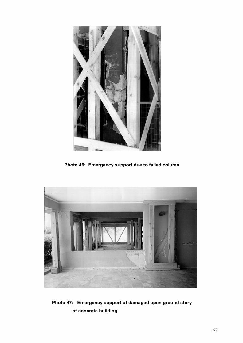
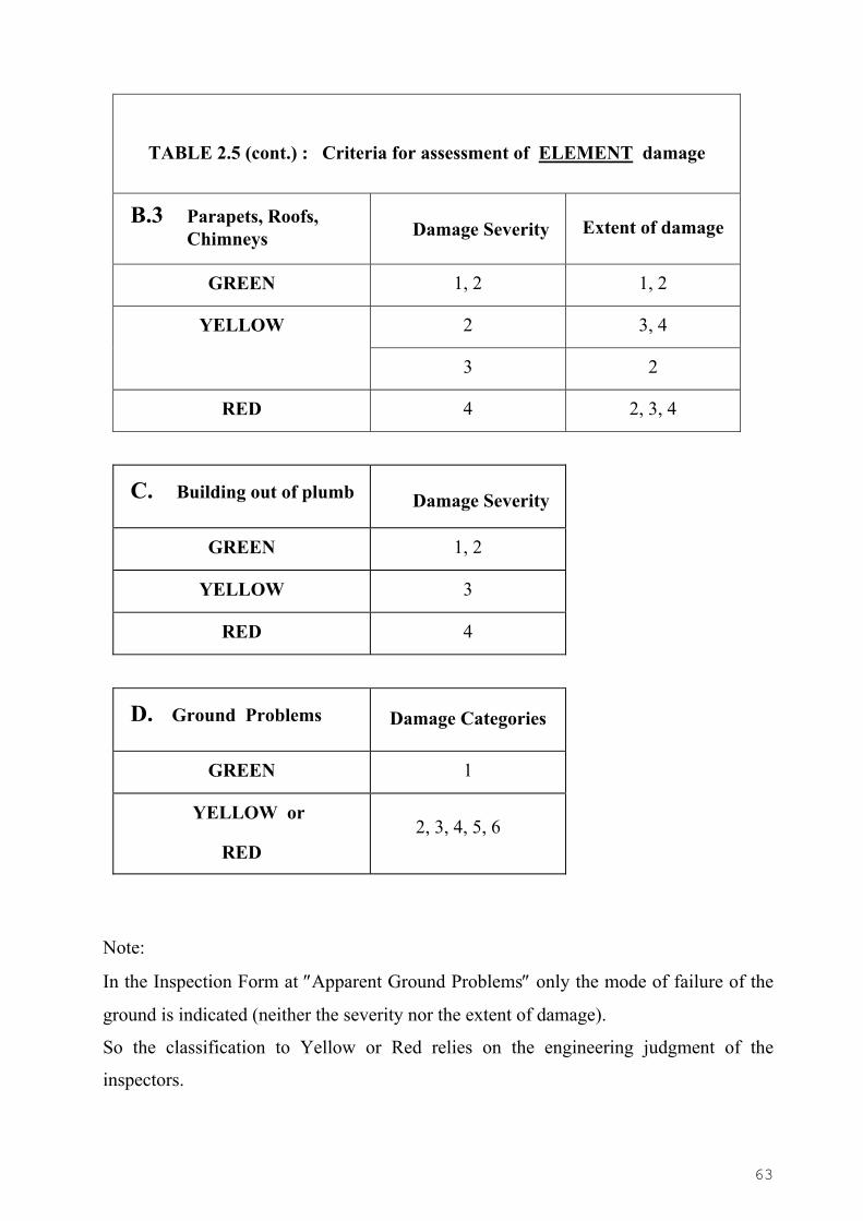
67
Photo 46: Emergency support due to failed column
Photo 47: Emergency support of damaged open ground story of concrete building
68
2.6.1 Guidelines for filling the Emergency Intervention Form
• Section F: Action Taken The Intervention crew will indicate on the Emergency Intervention Form the tasks
accomplished (see Exhibit 2.8).
− Attention should be paid to the removal of all hazards, to barricading the unsafe areas
and to disconnecting damaged utility installations.
− If it is assessed that the building is dangerous and should be demolished, the urgent
reinspection should be marked in the Intervention Form for possible demolition.

69
LOCAL AUTHORITY…………………………………………………..…… Crew No: …………………………… OFFICE….…………………………………………………………………… Report No: …………………………………. TEL……………………
EMERGENCY INTERVENTION FORM
Α. BUILDING LOCATION AND ID
Street……………………………………………… No. ………Postal Code………… Town/Municipality ….………………. Section No: ………….Block No:…………….Or Streets surrounding block: 1……………..……………………………… 2………………………………3…………..………………………4………………………………..5…………………………… Position of building in block: 1=Free 2=Middle (2 opposite sides free) 3=Corner (2 or 3 sides free)
C. DAMAGE (a) SEVERITY (1st BOX) : 1 = None 2 = Slight 3 = Moderate - Heavy 4 = Severe –Total (b) EXTENT (2nd BOX) : 1 = None 2 =1 to Few 3 = Few to several 4 = Several to many
COLUMNS SHEAR WALLS/ ELEV. SHAFT FRAME JOINTS BEAMS STAIRS BEARING WALLS INFILL WALLS (masonry, ecc)
ROOF CHIMNEYS, PARAPETS BUILDING OUT OF PLUMB
Apparent ground problems: 1= None 2 = Settlement 3 = Liquefaction 4 = Slope movement 5 = Ground fissures 6 =Rockfalls 7 = Other (explain) ................................................................................................…...
Indirect damage: 1=None 2=Pounding to adjacent building 3=Fire 4=Other (explain)………………………
Inspected: Exterior Ground story 1st story Other stories
D. OVERALL ASSESSMENT FOR USE (See back page for explanations): Safe for use Unsafe for use Dangerous for use (GREEN) (YELLOW) (RED) The assessment made is : for the whole building: for part of the building:
F. ACTION TAKEN: 1 = None* 2 = Local hazards removed* 3 = Urgent support provided 4 = Combination of actions 2 and 3 5 = Urgent re-inspection due to possible collapse
* Explain ……………………………………………………………………………………………………………………… ** The following elements have been demolished or removed …………………………………………………….……….….
Access to the following areas has been prohibited and blocked…………..…………………………………………………….
The following utilities were disconnected: electricity water gas
COMPLETION OF REQUIRED WORKS: 1= YES 2= NO
NEED FOR UNINTERRUPTED COMPLETION: 1= YES 2= NO
COMMENTS: …………………………………………………………………………………………………………………… ……………………………………………………………………………………………………………………………………….. ……………………………………………………………………………………………………………………………………….. ……………………………………………………………………………………………………………………………………….. ……………………………………………………………………………………………………………………………………….. ………………………………………………………………………………………………………………………………………..
DATA: (1) HEAD OF INTERVENTION CREW (2) INSPECTION ENGINEER
1. Signature……………………………… 2. Signature ……………………….… 3. Signature ………………..……………… Name/ Title…..………………………. Name/ Title……… …….…..…….…. Name /Title………. ………..……..……….
INTERVENTION FORM RECEIVED BY: Owner Building manager Other Recipient’s Signature ……………………………… Name ……………………………….……… Date ………………
Exhibit 2.8: Emergency Intervention Form

70
2.7. FIELD SAFETY OF INSPECTORS
The inspectors assessing the safety of a building damaged by an earthquake must be
careful not to expose themselves to hazardous conditions. Quite often, a building that has
suffered serious but not always readily observable structural damage from the main shock
may be in danger of collapse in the event of an aftershock. Therefore the basic safety rule
that inspectors must always observe and which has been emphasized throughout this
manual, is not to enter a building, unless they feel it is safe to do so. This requires a careful
survey of the building exterior for a gross assessment of the building’s condition. In
addition to this, several other precautions as explained below should be taken.
Inspectors should work in pairs, not only for reaching more reliable assessments by
exchanging views when in doubt, but also for having one team member provide assistance
or call for help in case the other member is injured. When entering a damaged building,
inspectors must be well equipped, wearing their hard hats and being in constant alert for
aftershocks, falling hazards (parapets, glazing, appendages, ornamentation etc) or leaks of
hazardous substances. In case they enter a factory, laboratory or storage area, they should
be quite careful to recognize any suspected hazardous material release either from sighting
damaged containers and spills or by odour, eye irritation, breathing problems etc, all of
which constitute warnings for potential chemical hazard. In such cases the inspectors
should exit from the suspected area, take note and inform the field office immediately.
Damaged utility installations, such as electrical or gas, may also constitute serious
hazards, e.g. in cases of exposed electrical wiring or when there are gas leaks. Gas can
usually be detected by odour and if this situation is encountered an effort should be made
to locate and shut off the main valve. Obviously the inspectors should refrain from
smoking when entering such premises and it is prudent to do so also when entering any
damaged building.
In summary, the main precautions that inspectors should take when carrying out their
field work are:
1. Travel and inspect in pairs.
2. Wear always a hard hat while in damaged building or in its surroundings.
3. Survey carefully the building exterior before entering and enter only if deemed safe.
4. Be alert for aftershocks and prepared to take cover when one comes.
71
5. Inspect carefully for falling hazards(e.g. parapets, glazing, ornamentation etc) and do
not take risks attempting to remove them.
6. Do not use elevators.
7. Be alert for damaged utility installations, avoid exposed electrical wiring or downed
power lines and try to shut off the electricity and gas supplies.
8. Be alert for leaks of hazardous (toxic or other) substances and avoid all areas where the
presence of such substances is suspected.
9. Play it safe whenever in doubt about something that may entail risk.
2.8 LEGAL ISSUES
When the emergency inspections operation is planned (before a catastrophic earthquake
strikes), the responsible authorities should take all necessary legislative steps to extend full
insurance coverage to the personnel that will be involved in the inspections for the period
the operation lasts. This may be done either by conferring upon such personnel a temporary
status of state or city employee for the period of the inspections and thus extend to them all
the pertinent coverage or by instituting specific provisions. Under all circumstances, the
inspectors should be free, by law, of any liability that may arise as a result of their posting
or more generally in the course of carrying out the inspections. This is a necessary measure
to ensure objective assessments and avoid systematic conservatisms out of fear of liability
in the event of damages that may result from the posting decision.
Another part of the operation that requires well instituted legal procedures has to do with
the emergency demolitions that will be carried out during the operation. While some
damaged buildings may constitute an obvious hazard and thus require immediate removal,
there will often be cases that the need for demolition could be debated. To avoid
subsequent litigation it is necessary to have adequate and well thought legal procedures
that will allow the demolition crews to act quickly for protecting public safety, while at the
same time securing all the rights of the property owners. Thus, buildings marked for
demolition as been hazardous to the public should be reinspected by an expert team and the
owner’s consent should be sought before any action is taken. If the owner refuses to give
his consent, he should be instructed to either remove the hazard on his own or face all the
consequences for subsequent damages that may result from his hazardous property.
72
3. OPERATIONAL PLAN
An essential element for the success of the operation is its organisational structure.
Based on experience gained from earthquakes in Greece during the past 20 years, the
structure shown in Exhibit 3.1 is recommended. It is appropriate for small as well as large
scale operations and if it is properly prepared within the general pre disaster planning
activities it can produce the desirable results. In the tree indicating the organizational
structure, each rectangle represents a certain domain of responsibility, for which the
manning is performed through respective lists of relevant available personnel. The criteria
according to which the personnel should be selected for each assignment, will be presented
in detail subsequently.
Such a plan will be part of a more general preparedness plan, designed to deal with
the emergency situation created by an earthquake. Therefore, the details of its
implementation will depend upon this general preparedness plan and thus could vary from
one country to another. However, its main elements would not need to change, if the
underlying inspection procedures remain the same.
3.1. TASKS AND RESPONSIBILITIES
The tasks and responsibilities of the different people involved in the operation are listed in
the following, according to the organisational structure shown in Exhibit 3.1.
(i) Chief of operations
1. Directs the setting up of the operation
• Secures personnel.
• Assigns duties.
• Sets up local field office.
2. Directs the operation
• Specifies priorities.
• Oversees work progress.
• Chairs meetings with coordinators.
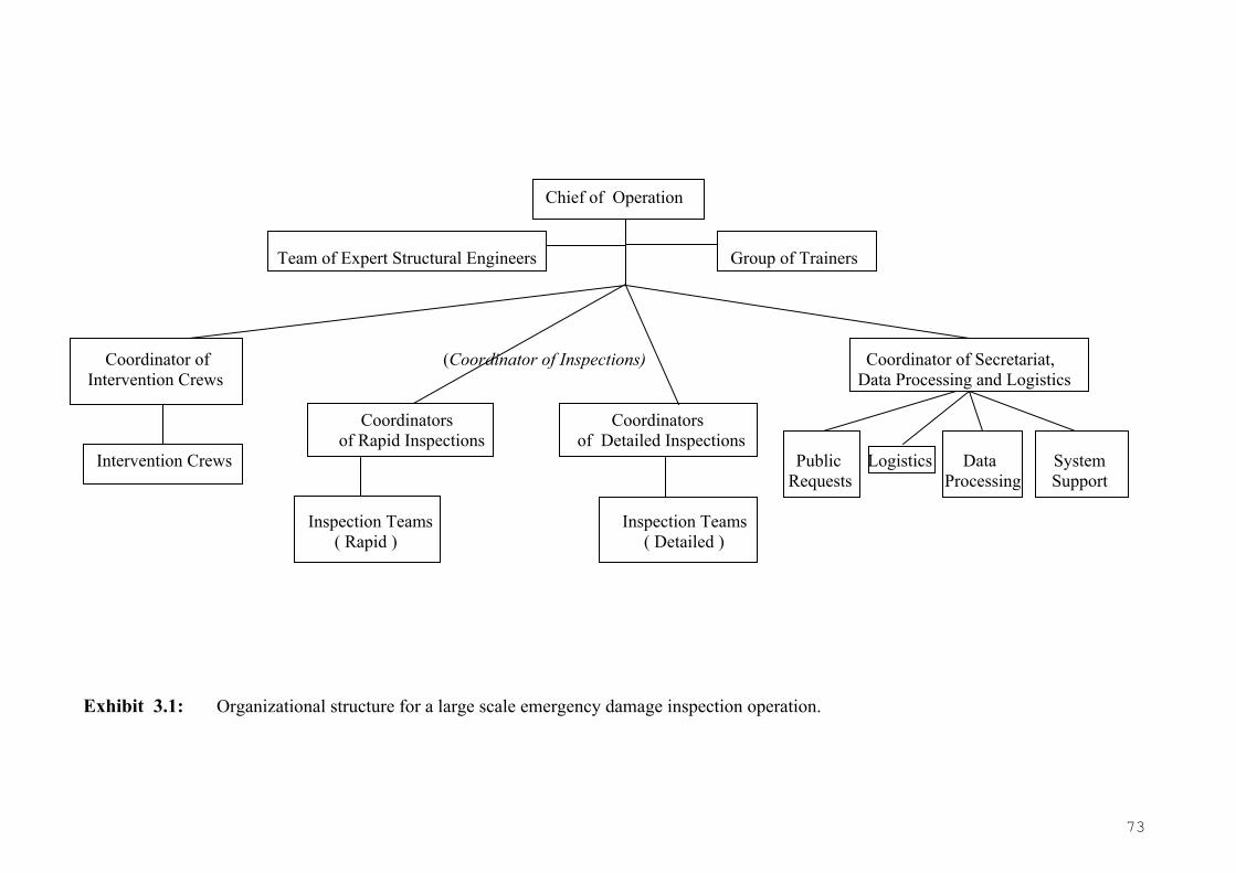
73
Chief of Operation
Team of Expert Structural Engineers Group of Trainers Coordinator of (Coordinator of Inspections) Coordinator of Secretariat, Intervention Crews Data Processing and Logistics Coordinators Coordinators of Rapid Inspections of Detailed Inspections Intervention Crews Public Logistics Data System Requests Processing Support Inspection Teams Inspection Teams ( Rapid ) ( Detailed )
Exhibit 3.1: Organizational structure for a large scale emergency damage inspection operation.

74
• Approves / changes daily work programme.
• Decides on tasks for the team of experts.
• Resolves conflicts.
• Communicates with other emergency officials and with authorities.
• Replaces personnel due to poor performance, lack or co-operation etc.
• Gives pertinent information to the appropriate authorities
3. Submits a final report to the appropriate authorities.
(ii) Team of Expert Structural Engineers
1. They inspect buildings of special interest (public, industrial sites, etc)
2. They may give their opinion concerning the appropriate support required for
buildings of particular interest.
3. They contribute in the formation of the general overview of the situation.
4. They co-operate with the Chief of Operation to set priorities.
5. They offer their assistance to the Coordinators of Inspections, or to the Coordinator
of Intervention Crews if needed.
(iii) Group of Trainers
They train before hand, i.e. before the operation is executed, the engineers who might be
involved in it (e.g. on how are such operations organized, on assessment of damage, on
emergency interventions, on procedural matters).
(iv) Coordinator of Inspections (Rapid or Detailed)
1. Coordinates and supervises the work of 10 to 15 inspection teams.
2. Names the leader of each team.
3. Assigns the areas of responsibility for each team.
4. Secures the availability of materials for the inspection teams.
5. Receives the damage inspection forms and ranks the degree of urgency of the
required actions.
6. Makes spot checks of inspected buildings.
7. Gives copies of the damage inspection forms for data processing.
75
8. Participates in the end-of-the-day meeting with the chief of operations and the
coordinator of the support and demolition crews to prepare the intervention list for
next day, review progress, solve problems etc.
9. Resolves conflicts between his teams.
10. Seeks the assistance of the team of experts teams if the need arises.
(v) Coordinator of emergency support and demolition crews
1. Coordinates, directs and supervises the work of the emergency support and
demolition crews.
2. Names the leader of each crew.
3. Assigns the work to the crews.
4. Secures the availability of tools, equipment and material for his crews.
5. Participates in the end-of-the-day meeting with the chief of operations and the
inspection team coordinators to prepare the intervention list for next day, review
progress, solve problems etc.
6. Provides technical advice and checks the work of his crews in the field.
7. In consultation with the chief of operations seeks additional technical assistance if
his crews are not sufficient.
8. Seeks the technical advice of the team of experts in difficult situations.
9. Resolves conflicts between the crews.
10. Receives the Emergency Intervention Forms and checks the interventions that have
been completed.
11. Gives the daily list for intervention as well as progress information to the data
processing unit.
(vi) Damage inspectors
1. Inspect the buildings, fill the damage inspection forms, barricade unsafe areas, mark
them and post the buildings with the appropriate placard.
2. Explain to the building occupants the safety reasons for the inspection and the
meaning of the posting. Make clear that this inspection has nothing to do with the
detailed engineering evaluation and design that will be required to receive any
governmental assistance for possible repairs.
76
3. The members of the team sign the posting placard and the damage inspection form.
In case of disagreement between the members of the team, the opinion of the leader
of the team prevails.
(vii) Coordinator of Secretariat, Data Processing and Logistics
1. Groups the requests from the public and handles them to the appropriate sectors, i.e.
coordinator of intervention crews, coordinator of inspections, or team of experts.
2. Process copies of the Damage Inspection Forms and the Emergency Inspection
Forms of the day to the Data Processing, and makes sure the data is input into the
system each evening.
3. Collects the inspection forms that are input into the system to give them to the
coordinators of inspections, and the summary reports of the buildings inspected
needing urgent interventions to the coordinator of intervention crews.
4. Is responsible for the distribution of the material to the inspection teams. Checks if
some stock needs replacement.
5. Is responsible for the smooth function of the Data processing. If any problem arises,
makes sure it is resolved by the system support as soon as possible.
(viii) Data processing
1. Process the data on the Damage Inspection Forms.
2. Produce lists with requirements for further action.
3. Process the data of the Emergency Intervention Forms.
4. Produce summary reports.
(ix) Secretariat and Logistics
1. Provide clerical and secretarial support to the operation.
2. Maintain stock and supply the materials required for the operation (see list), except
for the materials needed for emergency support and demolition.
(x) Public requests
1. Handles requests by the public (e.g. provides inspection scheduling information,
receives and processes information about emergency conditions, explains safety
classification, gives information about government assistance for repairs etc.).
77
2. Assists the secretariat and logistics unit.
(xi) System Support
1. Assists those involved with Data Processing in using PEADAB.
2. Solves hardware problem that may occur to the system (PCs, Printers, network, etc).
3.2. OPERATION SET-UP CHECKLIST
The following is a checklist of the necessary actions to set up the emergency earthquake
safety inspection operation.
1. Mobilisation. Chief of operations, designated in the general emergency mobilisation
plan, receives order.
2. Chief of operations:
• Assigns duties to support personnel (secretarial, data processing etc.).
• Names inspection team coordinators, coordinator of emergency support and
demolition works and a deputy chief.
3. Set up of local field office:
• Secure housing or temporary shelter for the operation.
• Secure telephones, office furniture and supplies.
• Secure 1 copying machine, PC’s and printers (PC’s should be connected in a
network).
4. Form inspection teams.
5. Form emergency support and demolition crews.
6. Briefing of all personnel about the operation, tasks etc.
7. Secure the availability of tools, equipment and emergency support materials.
8. Bring in and distribute material required by the inspection teams.
9. Divide the stricken area into sections and number blocks and buildings (if this has
not been provided for in the general preparedness plan).
10. Start rapid assessments and try to complete them as soon as possible
11. Begin detailed inspections starting with critical facility buildings.
78
12. As inspection data starts coming in, mobilise emergency support and demolition
crews.
13. Utilise the team of experts for important structures, difficult assessments etc.
14. Consider the demands and requests of the public.
15. Repeat inspections after major aftershocks.
3.3. HUMAN RESOURCES
The operation will be carried out mostly by people working for the city and local or state
government. Volunteer structural engineers from the private sector may also be used as
inspectors, if the available pool of structural engineers working for the public sector does not
suffice. This will normally be the case if the earthquake strikes a major city. Under such
circumstances, cooperation with engineering professional associations will help alleviate the
problem.
(i) Chief of Operations
The person who will assume the post of operations chief should be a structural
engineer official with the Building Department having jurisdiction over the affected area.
Alternatively, and depending upon the administrative structure of each county, the chief of
the operation could be a senior structural or civil engineering official of the city, the
prefecture etc. He should have a good leadership record, should be familiar with the
problem and also quite knowledgeable of the emergency mobilisation plan and the
bureaucratic machinery that will support the operation. The above should be considered by
the emergency agency planners that prepare the general mobilisation plan, in which the
official who becomes chief of operations will be designated.
(ii) Team of experts
They should be senior structural engineers from the public or private sector, well
recognised for their earthquake engineering and damage assessment expertise.
79
(iii) Group of Trainers
They should be structural engineers with knowledge of and previous participation in
such operations, experience in earthquake damage assessment and, if possible, with
previous experience in educational seminars. In Greece, it is expected that such training
will be carried out by engineers of EPPO (Earthquake Planning and Protection
Organization) as well as by specially trained engineers working in the Prefectures.
(iv) Coordinators for emergency inspections and intervention
The coordinators of the inspection teams and the coordinator of emergency support
or demolition works should be experienced structural engineering officials of the city or the
governmental agencies involved in this operation. They should also be familiar with the
mobilisation plan and the bureaucracy of the agencies supporting the operation.
(v) Damage inspectors
Damage inspectors constitute the back bone of the operation. They should be in teams of
two inspectors (rapid assessment) or three inspectors (detailed inspection), one of whom
will be the leader of the team. They may be structural engineers or architects, employees of
the city or local government in the affected area, neighbouring jurisdictions or from other
areas in the country having pertinent experience from past earthquakes. If their numbers are
insufficient, local volunteer professionals could also be commissioned and utilised, with
the assistance of the appropriate professional associations.
The person chosen as leader should be working for the public sector, with previous
experience in the assessment of earthquake damages and, in case of detailed assessments,
should preferably be a structural engineer.
(vi) Emergency support and demolition crews
They should be structural works technicians, equipment operators and structural
workers. They should come from the agencies involved in this operation (e.g. building
departments, city technical services, public works department etc.) or, if not sufficient in
number, from the private sector.
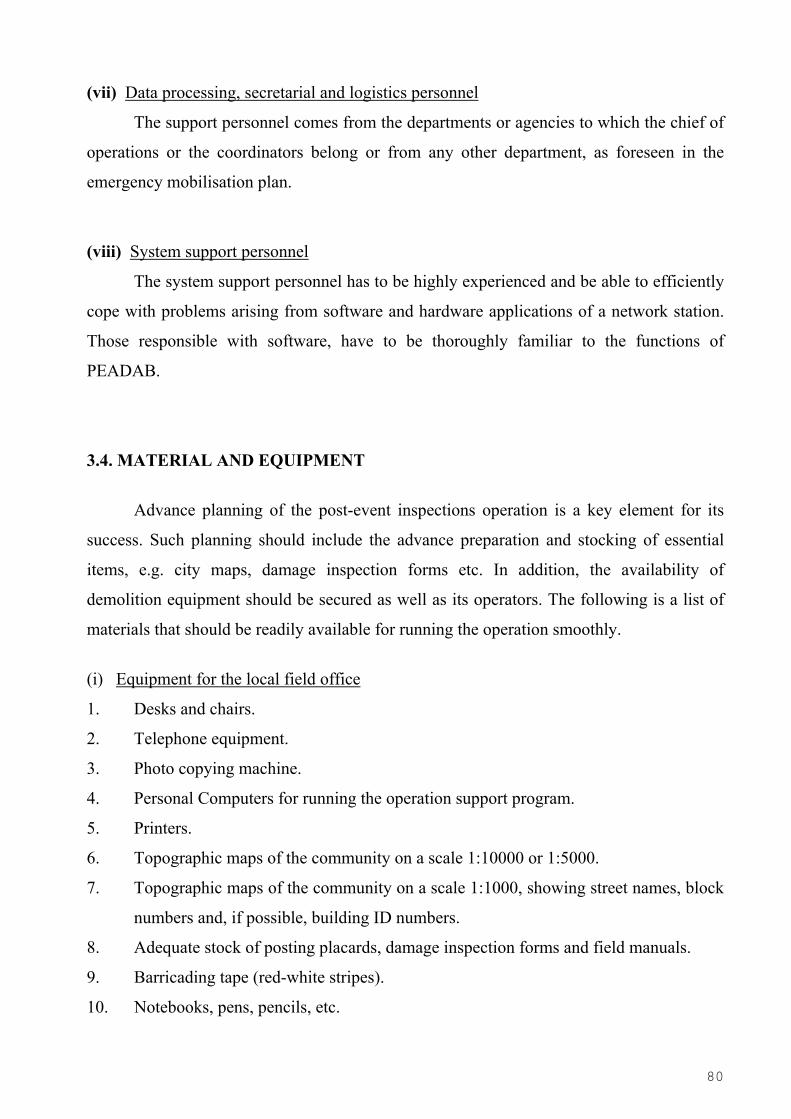
80
(vii) Data processing, secretarial and logistics personnel
The support personnel comes from the departments or agencies to which the chief of
operations or the coordinators belong or from any other department, as foreseen in the
emergency mobilisation plan.
(viii) System support personnel
The system support personnel has to be highly experienced and be able to efficiently
cope with problems arising from software and hardware applications of a network station.
Those responsible with software, have to be thoroughly familiar to the functions of
PEADAB.
3.4. MATERIAL AND EQUIPMENT
Advance planning of the post-event inspections operation is a key element for its
success. Such planning should include the advance preparation and stocking of essential
items, e.g. city maps, damage inspection forms etc. In addition, the availability of
demolition equipment should be secured as well as its operators. The following is a list of
materials that should be readily available for running the operation smoothly.
(i) Equipment for the local field office
1. Desks and chairs.
2. Telephone equipment.
3. Photo copying machine.
4. Personal Computers for running the operation support program.
5. Printers.
6. Topographic maps of the community on a scale 1:10000 or 1:5000.
7. Topographic maps of the community on a scale 1:1000, showing street names, block
numbers and, if possible, building ID numbers.
8. Adequate stock of posting placards, damage inspection forms and field manuals.
9. Barricading tape (red-white stripes).
10. Notebooks, pens, pencils, etc.

81
(ii) Equipment of the inspection teams
Essential items
1. Topographic maps (1:1000) with block & building numbers,
2. Posting Placards and Inspection Forms,
3. Pen and a notebook,
4. Field Manual,
5. Measuring tape/meter,
6. Carpenters axe or hammer,
7. Sprays with Green, Yellow and Red paint,
8. Barricading tape (red and white stripes),
9. Hard hat,
10. Official identification.
11. Camera and several roles of film.
Other suggested items
1. Flashlight and extra batteries.
2. Binoculars.
Tools and equipment for the hazard removal and demolition crews should be provided by
the city or local government technical services or other pertinent departments. If the
available equipment (bulldozers, cranes etc.) from the public sector is not sufficient, it
could be supplemented from the private sector. For operational efficiency, this should be
provided for in the general mobilisation plan in which updated lists of the required
equipment, its owners and operators should be included.
82
4. THE NEW PEADAB SYSTEM
Based on earlier work (2,4,7,8,9) the new PEADAB system has been rewritten and is
intended to be an easy to use practical tool for supporting operations of post earthquake,
emergency assessments of building safety in earthquake affected areas. It can help establish
standard procedures, necessary for the success of such operations which are often executed
under chaotic conditions and tend to be poorly organized, without the benefit of the
experience gained in previous earthquakes, as this experience is typically lost. PEADAB is
designed to document such operations and to support the planning, set up and execution of
new ones, which can draw from the experience of the past, available through PEADAB.
The PEADAB system may be used in three modes:
1. To support the Planning of the post-earthquake emergency inspections operation
beforehand, by storing the available resources (human as well as equipment and
material), which will be needed to set up the operation after a catastrophic
earthquake strikes. (Changes within the planning may be performed also during the
execution of the operation).
2. To support the execution of the operation in the Execute Operation mode by
processing the data in the Inspection and Intervention forms, checking the
consistency of the recorded damage with the given posting (color) classification and
by providing reports on various aspects of the operation as it progresses.
3. To provide information in the Extract Information mode concerning the progress of
the operation, including daily lists of the buildings requiring emergency intervention.
These lists are based on the daily processed inspection forms and are ordered
according to the urgency marked for each case on the form by the inspectors. It can
also map the inspected buildings according to their posting classification, as the
operation progresses and more generally, it can give lists of buildings with user
specified attributes, essentially with any attribute listed in the Inspection form and
for any of the possible values the attribute can take. For example it can list all
buildings, having the attributes such as: RC type, built before 1984, number of floors
> 5, location in block “corner”, posting classification: yellow. In addition to lists it
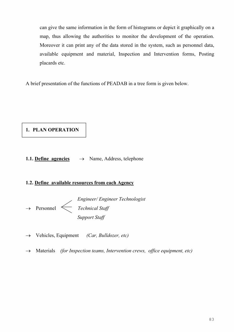
83
can give the same information in the form of histograms or depict it graphically on a
map, thus allowing the authorities to monitor the development of the operation.
Moreover it can print any of the data stored in the system, such as personnel data,
available equipment and material, Inspection and Intervention forms, Posting
placards etc.
A brief presentation of the functions of PEADAB in a tree form is given below.
1. PLAN OPERATION
1.1. Define agencies → Name, Address, telephone
1.2. Define available resources from each Agency
Engineer/ Engineer Technologist
→ Personnel Technical Staff
Support Staff
→ Vehicles, Equipment (Car, Bulldozer, etc)
→ Materials (for Inspection teams, Intervention crews, office equipment, etc)

84
1.3. Select Personnel, Equipment, Materials, etc for the Operation
1.3.1. Personnel → Select position (from Organizational Tree) → Select persons (from list of Agencies) for the positions, to form Inspection teams, etc.
1.3.2. Vehicles, Equipment → Select item (from list of Agencies) → Select team to charge with the equipment
1.3.3. Materials → Select item (from list of Agencies)
→ Select team to charge with the materials
1.4. Define Sections in the Area & assign Sections to Coordinators
map or By
specifying the roads surrounding the Section
2. REVIEW/ UPDATE OPERATION
→ Personnel (by selecting a person in the organizational tree)
→ Vehicles, Equipment
→ Materials

85
3. EXECUTE OPERATION
selecting the building on the Map or → Input Building Inspection teams Data by
giving the address of the building
→ Input Intervention crews Data
Option: No category View Histogram
View classification of input buildings: Green, Yellow, Red View Table
4. VIEW – EXTRACT INFORMATION
Available by Agency
4.1 Lists of manpower and equipment Involved by Category
4.2 Lists of buildings inspected (by inspection team, by section,
by assessment for use, etc)
4.3 Lists of buildings requiring (by category of intervention, by degree of urgency)
emergency intervention
Report or 4.4 Extract Information Histogram
86
4.1 BUILT IN RULES FOR POSTING BASED ON THE DAMAGE ASSESSMENT
In an effort to set the basis for an expert system that will assist inspectors post the
damaged buildings with uniform criteria, a number of rules have been developed, with
which the system will check the posting classification of the building for possible
inconsistencies with the recorded damage. If the posting given by the inspectors does not
agree with the rules, PEADAB will print a warning message and the inspectors will need to
review their posting. These rules have been developed only for Reinforced Concrete and
Masonry Buildings from which practically all of the Greek experience comes, and are
summarized in Table 2.6 , with details given in Chapter 2.5.2. It is noted that for Rapid
Assessment the system takes into account only the damage severity recorded in the
Inspection form (vertical square) while for Detailed Assessment the system takes into
account both the damage severity and the damage extent, also recorded in the Inspection
form (vertical and tilted squares).

87
5. REFERENCES 1 S.A. Anagnostopoulos, J. Petrovski and J.G. Bouwkamp, (1989), “Emergency
earthquake damage and usability assessment of buildings”, Earthquake Spectra, Vol. 5,
No. 3, pp. 461-476.
2 S.A. Anagnostopoulos (1996), “Large scale operations for post-earthquake emergency
assessment of building safety”, Proceedings, 11th World Conference on Earthquake
Engineering, Acapulco, Mexico, paper No. 967, Elsevier.
3 Applied technology Council (1991), “Procedures for Post-Earthquake Evaluation of
Buildings safety” (ATC-20), Governor’s Office of Emergency Services, State of
California.
4 Stavros A. Anagnostopoulos, “Post-Earthquake Emergency Assessment of Building
Safety: FIELD MANUAL”, Report submitted to the European Commission/ DG XI,
Civil Protection, University of Patras, 1997.
5 Istanbul Technical University–JICA Expert Team, “Quick Inspection of damaged
buildings”, Istanbul, September 1999.
6 N.C. Blais, H.A. Seligson and A.J. Petrow (1996), “Use of rapid damage assessment
and geographic information systems for emergency response in the Northridge
earthquake”, Proceedings, Eleventh World Conference on Earthquake Engineering,
Mexico City, Paper No. 439, Elsevier.
7 Dimitris Sardelianos and Stavros A. Anagnostopoulos, “Post-Earthquake Emergency
Assessment of Building Safety: USER’S MANUAL”, Report submitted to the European
Commission/ DG XI, Civil Protection, University of Patras, 1997.
8 Earthquake Planning and Protection Organization (EPPO), Ministry of Public Works,
“Post-Earthquake Inspection of Buildings”, Athens 1984 (in Greek).

88
9 Earthquake Planning and Protection Organization (EPPO), Ministry of Public Works,
“Instructions and Forms for carrying out first level post-earthquake inspection of
building usability”, Athens 1997 (in Greek).
89
APPENDIX: FIELD TESTING IN CHANIA
BRIEF DESCRIPTION
INSPECTION FORMS-PHOTOS OF BUILDINGS INSPECTED
90
APPENDIX
TABLE OF CONTENTS
1. Brief Description
2. Map of the sections inspected in Chania
List of Photos
3. Inspection Forms – Photos of Buildings Inspected
91
PILOT TESTING OF PEADAB IN A GREEK CITY: BRIEF DESCRIPTION
As part of the development of the new PEADAB system, intended for adoption into the
Greek State procedures for emergency response to earthquakes, a pilot application was
carried out under realistic field conditions. To this effect, the Greek city of Chania was
selected not only because it is in a seismically active region (on the island of Crete in the
Southern Aegean sea) threatened by major earthquakes, but also because a digitized map of
the city was made available to the project. This map had been produced in a framework of a
scenario type study that had been carried out for Chania under an earlier EC project, partly
funded by DG-Research.
After some preliminary discussions with local authorities, a project group of five persons
including two people from the Greek State agency for Earthquake Planning and Protection
(EPPO) went to Chania and worked there for four days. Before the trip, the Chania
prefecture sent to the project team, lists of personnel that could be mobilized and equipment
that could be used in case of an earthquake emergency. Such lists are necessary for the
planning phase of an emergency inspection operation.
The project team met in Chania with officials from the prefecture, from the mayor’s office
and from the local office of the Technical Chamber of Greece, representing all engineers in
the Chania prefecture.
Field office was established in the building of the Technical Chamber and the work was
carried out smoothly.
PEADAB was used for the planning phase of the operation, execution and for data
retrieval. Very briefly, the following was done:
A. PLANNING PHASE
For the planning phase, the various agencies that would be called to supply personnel,
equipment and material for the operation were identified and input into the system. These
are mainly agencies from the Chania Prefecture, the Chania municipality and the private
sector which, for logistic purposes, was considered as another independent agency.
92
Although the vice-mayor attended the planning meeting and promised to send the requested
data from the municipality, nothing came and so the team worked with prefecture and
private sector data.
From the personnel and material lists that had already been entered into the PEADAB
system, the operation was manned by filling the various slots of the Organizational chart
(Exhibit 3.1). Taking into account the following: (a) The overall earthquake emergency
plan of Greece, which specifies the operational and technical line of command for handling
the emergency and (b) The main personnel category that might be in short supply is the
structural engineers who will form the inspection teams. In setting up these groups, the
structural engineers working for public agencies and made available for the inspection-
operation were first used and then additional inspection teams were formed utilizing
engineers from the private sector. A list of such engineers was made available by the
Technical Chamber of Chania, which also suggested the team of expert structural engineers
required in accordance with the organizational chart.
Subsequently, the map of the city of Chania was used to allocate the work of the inspection
teams in sections of the city. The city was already divided by the civil protection group at
the prefecture in 12 geographical sections. These sections were input into the PEADAB
system and the inspection teams with their respective coordinators were assigned the
section (or sections) for which they would be responsible.
Finally, a number of streets in four different sections were selected, where teams would be
dispatched to inspect ″damaged″ buildings, fill the appropriate forms and return the forms
to the field office for processing by the PEADAB system.
B. EXECUTION PHASE
For the execution phase, an inspection team composed of three people (all structural
engineers) form the project team, ″inspected″ a number of houses in four different sections
and filled the appropriate forms by assuming various levels of damage for the various
houses. With the exception of the damage recording (because the buildings were not
actually damaged), all the other recorded information (e.g. location, number of floors,
usage, type of structural system, etc) reflected actual conditions. In total, 24 buildings were
93
inspected and the inspection forms with corresponding photos of the buildings are given in
the Appendix. For those buildings, forms for rapid as well as detailed inspections were
filled and subsequently input to the PEADAB system.
C. DATA RETRIEVAL PHASE
After the data were input, the system was asked to print various sets of information (e.g.
lists of personnel utilized in the operation, lists of buildings posted green, yellow, red from
the rapid and the detailed inspections, lists of buildings requiring emergency intervention,
buildings with specific lists of characteristics posted in one of the three categories, the
colored geographic distribution of such buildings, etc).
In addition, corresponding histograms were generated.
Some of this output has been included also in the documentation report of CTI. It is worth
to note that during the field application in Chania, the necessity for certain minor additions
or modifications to the inspection forms became apparent, and such additions/ changes
were implemented. Moreover, the PEADAB system was tested and the need for certain
changes therein was noted.
In conclusion, the pilot testing proved quite useful, as it demonstrated that the system is
operational under field conditions and also because it helped identify certain omissions and
disfunctionalities which were corrected.
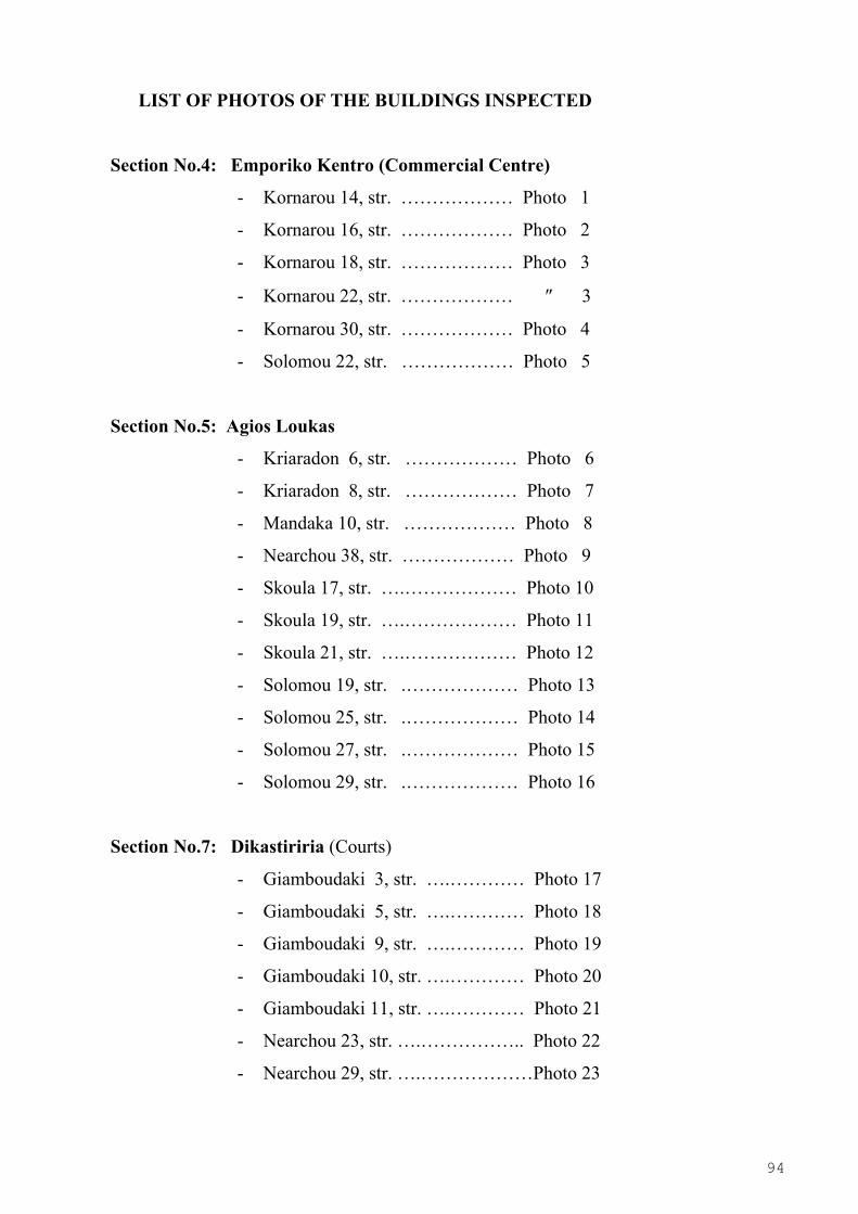
94
LIST OF PHOTOS OF THE BUILDINGS INSPECTED
Section No.4: Emporiko Kentro (Commercial Centre)
- Kornarou 14, str. ……………… Photo 1
- Kornarou 16, str. ……………… Photo 2
- Kornarou 18, str. ……………… Photo 3
- Kornarou 22, str. ……………… ″ 3
- Kornarou 30, str. ……………… Photo 4
- Solomou 22, str. ……………… Photo 5
Section No.5: Agios Loukas
- Kriaradon 6, str. ……………… Photo 6
- Kriaradon 8, str. ……………… Photo 7
- Mandaka 10, str. ……………… Photo 8
- Nearchou 38, str. ……………… Photo 9
- Skoula 17, str. ….……………… Photo 10
- Skoula 19, str. ….……………… Photo 11
- Skoula 21, str. ….……………… Photo 12
- Solomou 19, str. .……………… Photo 13
- Solomou 25, str. .……………… Photo 14
- Solomou 27, str. .……………… Photo 15
- Solomou 29, str. .……………… Photo 16
Section No.7: Dikastiriria (Courts)
- Giamboudaki 3, str. ….………… Photo 17
- Giamboudaki 5, str. ….………… Photo 18
- Giamboudaki 9, str. ….………… Photo 19
- Giamboudaki 10, str. ….………… Photo 20
- Giamboudaki 11, str. ….………… Photo 21
- Nearchou 23, str. ….…………….. Photo 22
- Nearchou 29, str. ….………………Photo 23
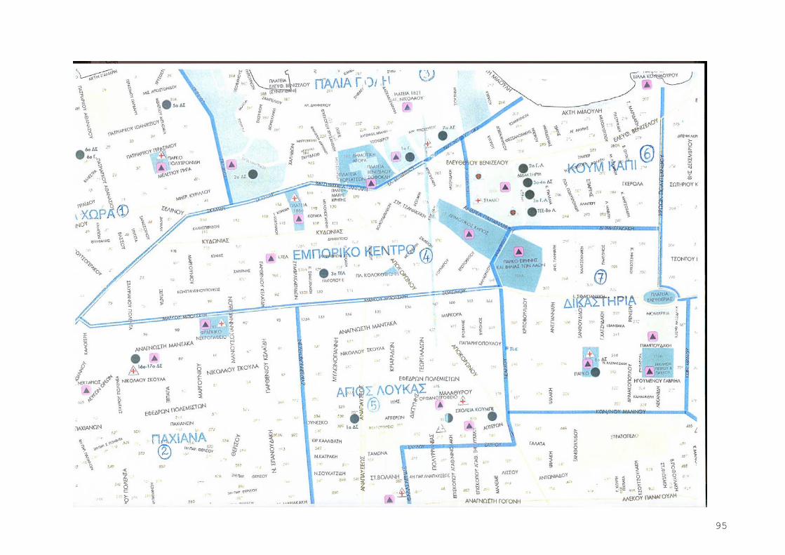
95
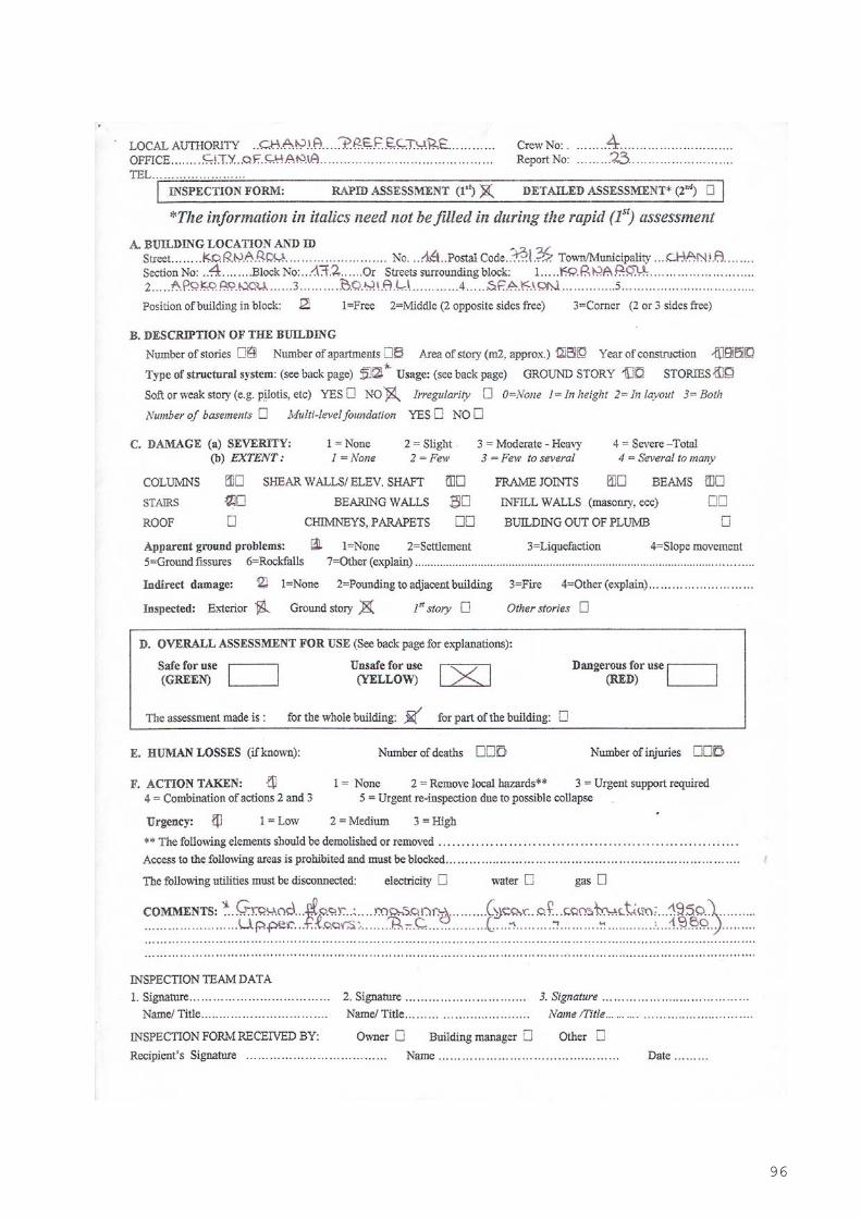
96
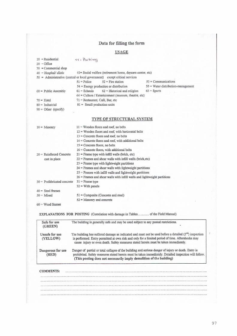
97
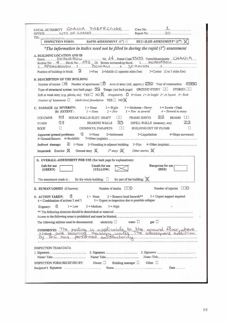
98
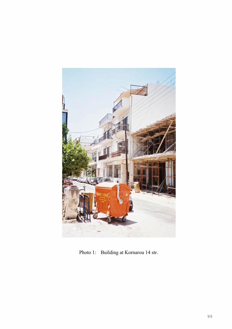
99
Photo 1: Building at Kornarou 14 str.

100
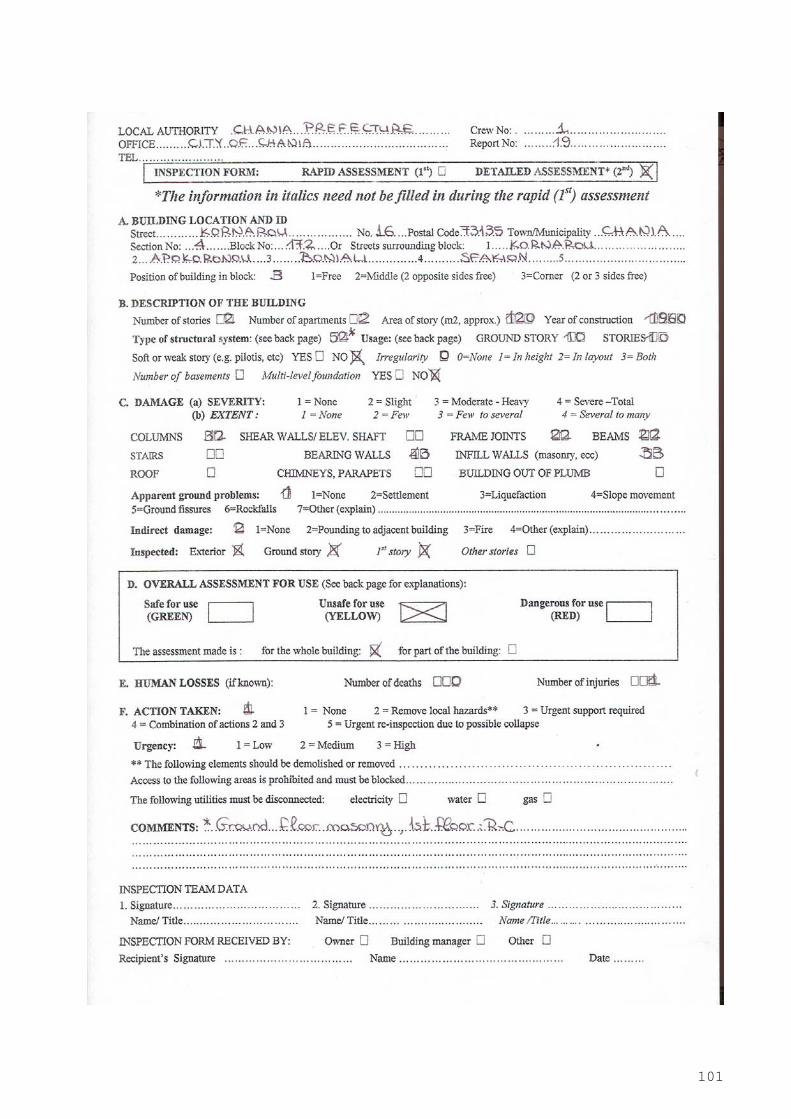
101

102
Photo 2: Building at Kornarou 16 str.
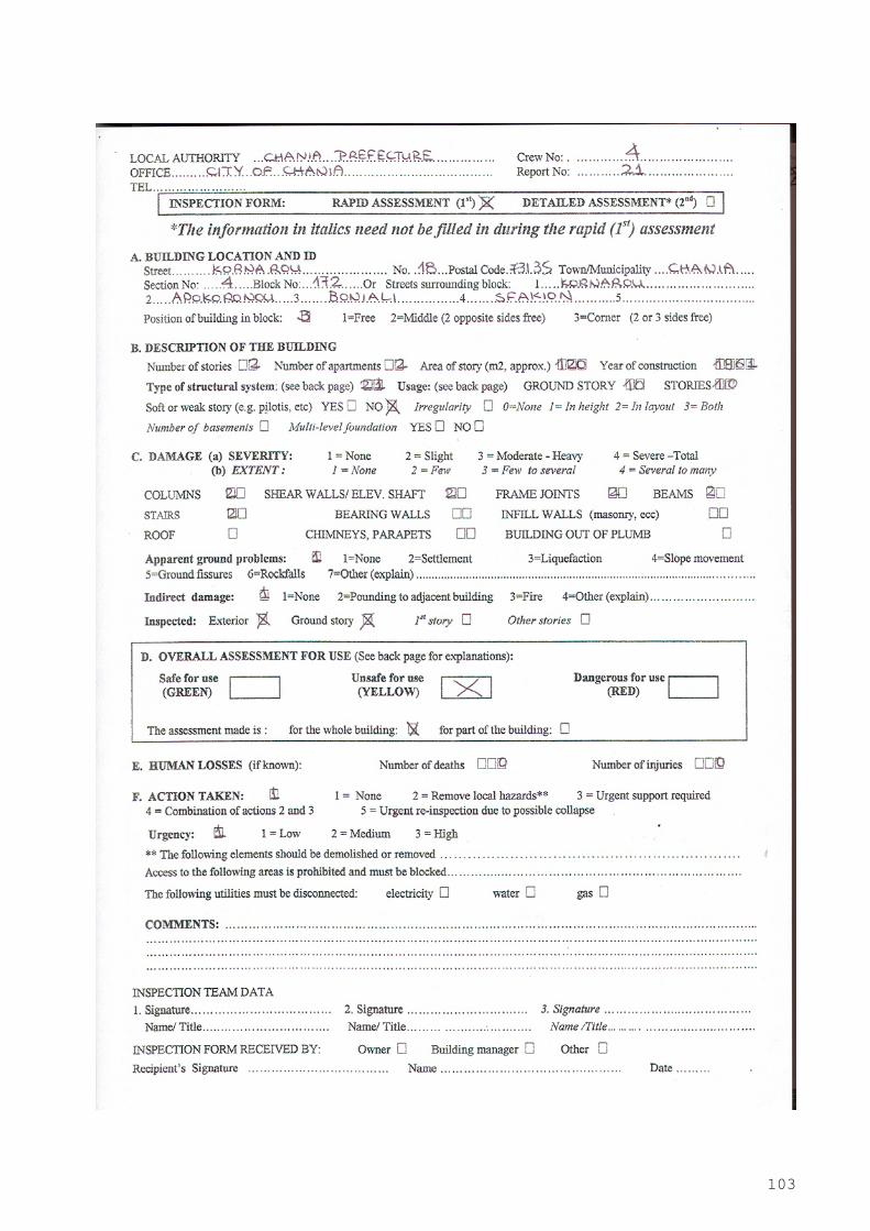
103
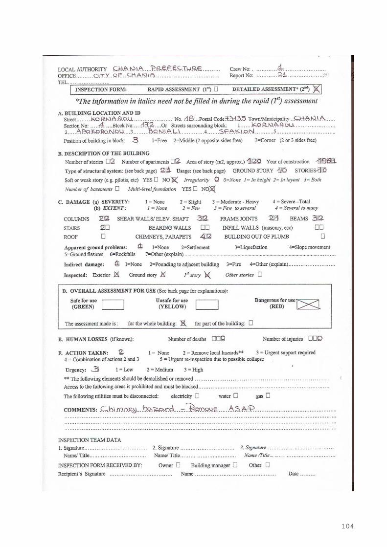
104
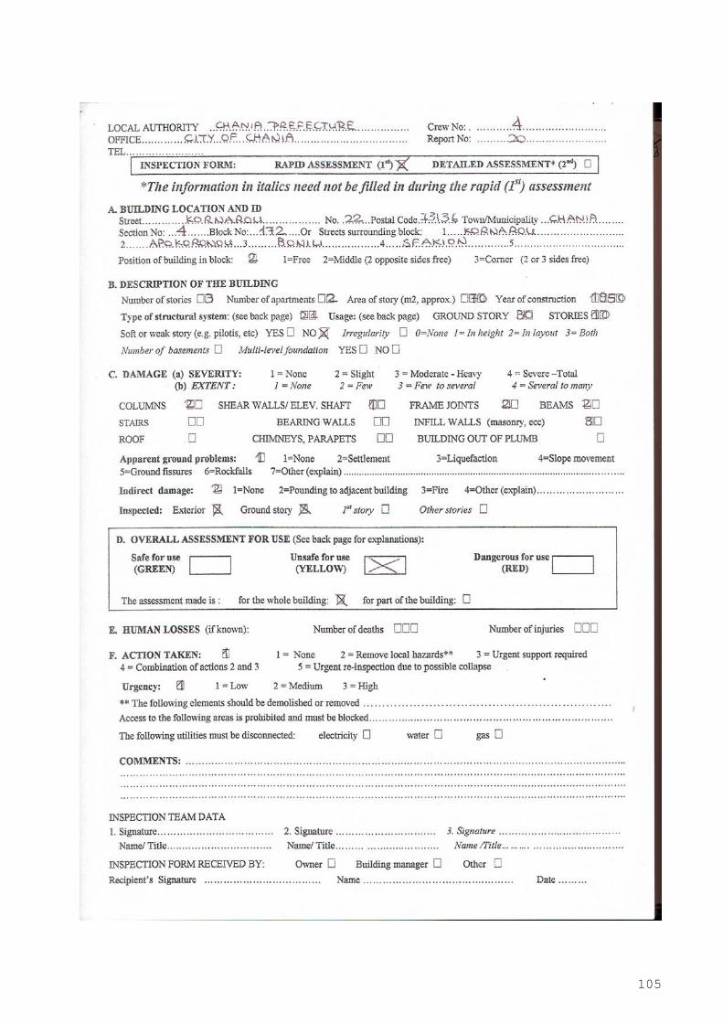
105
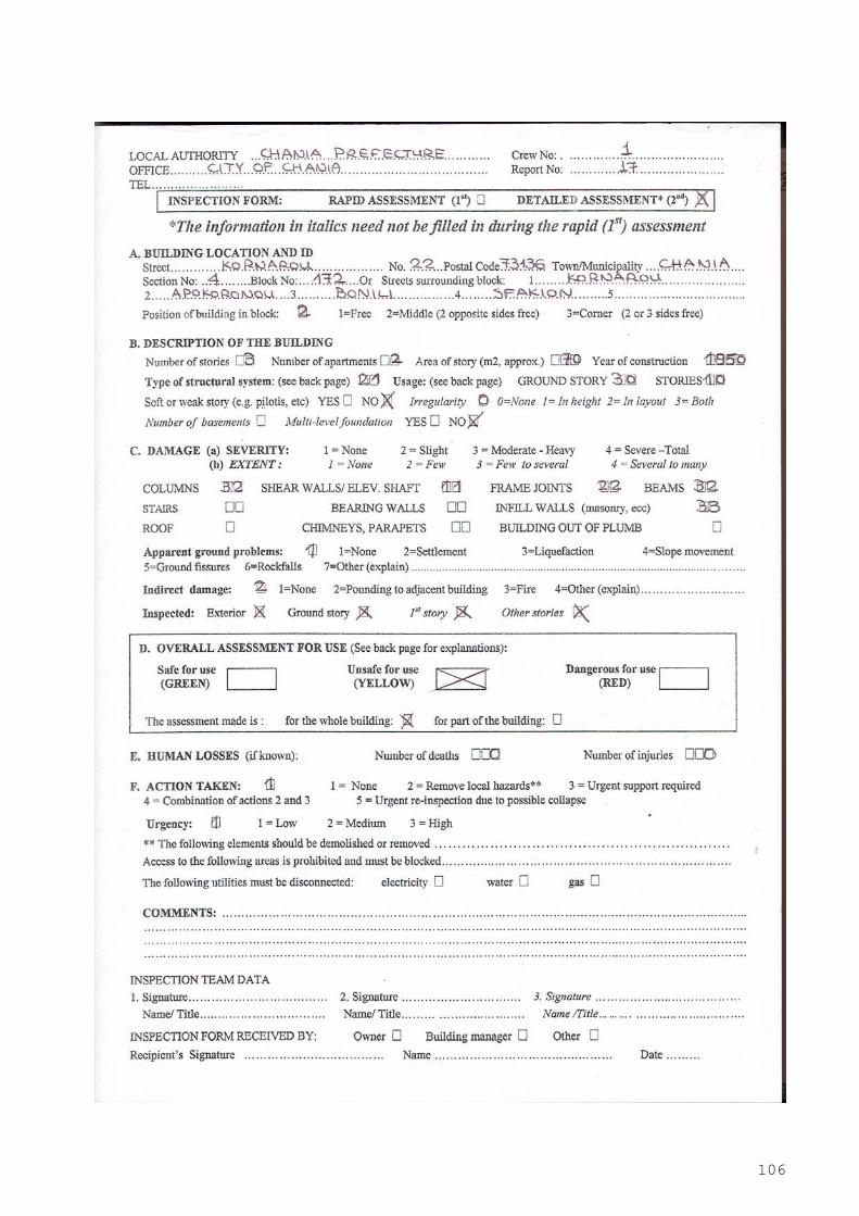
106

107
Photo 3: Buildings at Kornarou 18 and Kornarou 22 str.
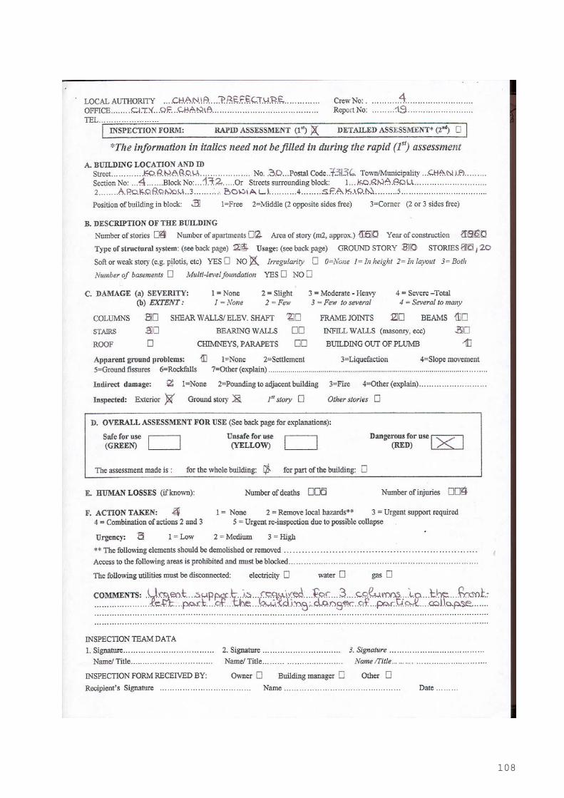
108
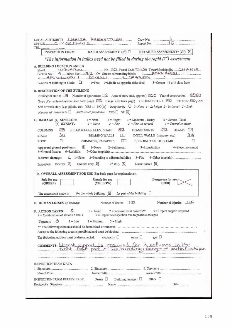
109

110
Photo 4: Building at Kornarou 30 str.
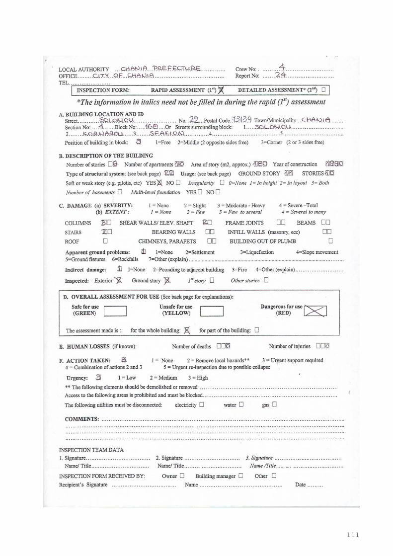
111
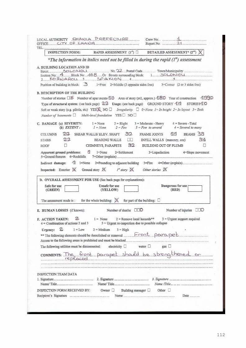
112
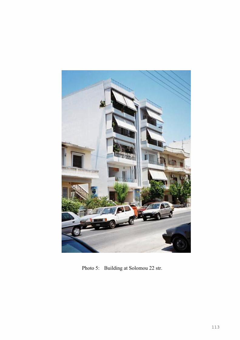
113
Photo 5: Building at Solomou 22 str.
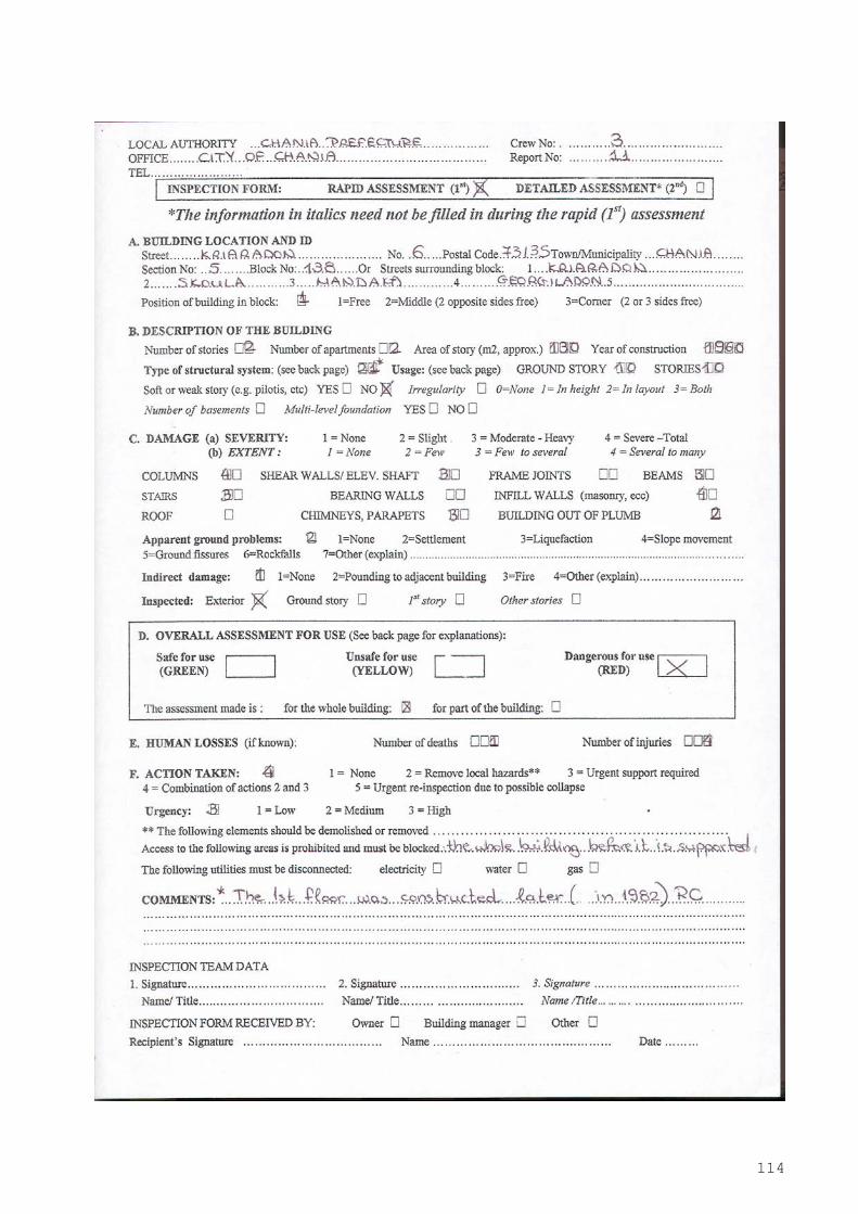
114
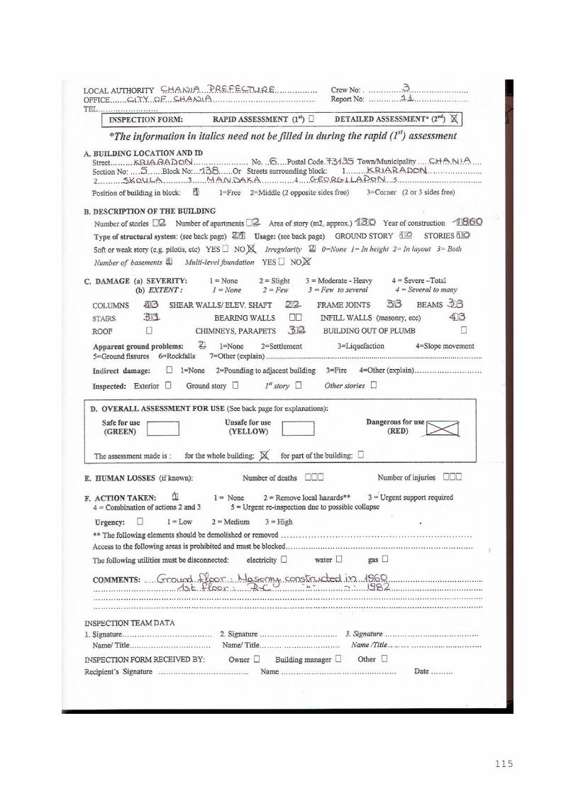
115

116
Photo 6: Building at Kriaradon 6 str.
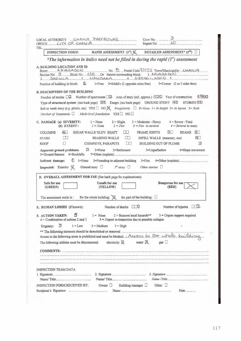
117

118

119
Photo 7: Building at Kriaradon 8, str.
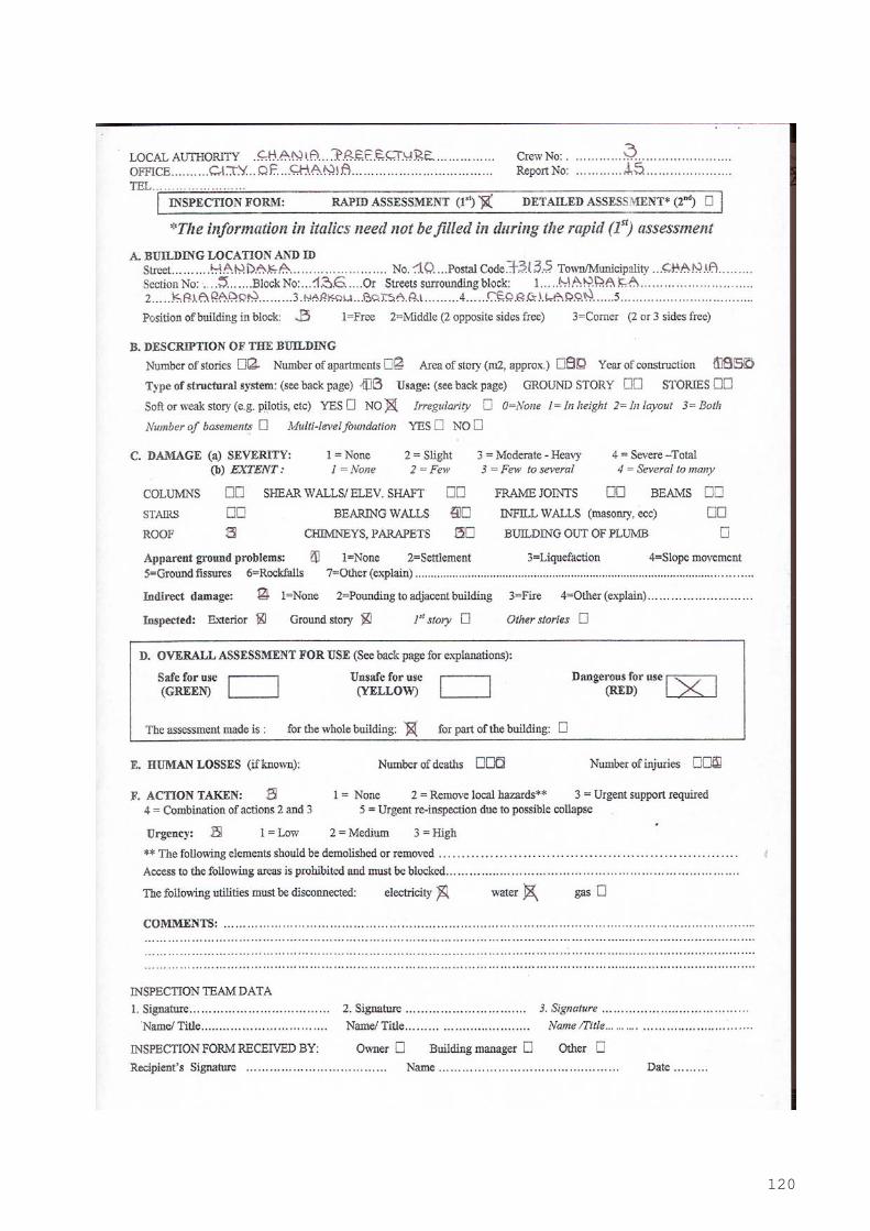
120
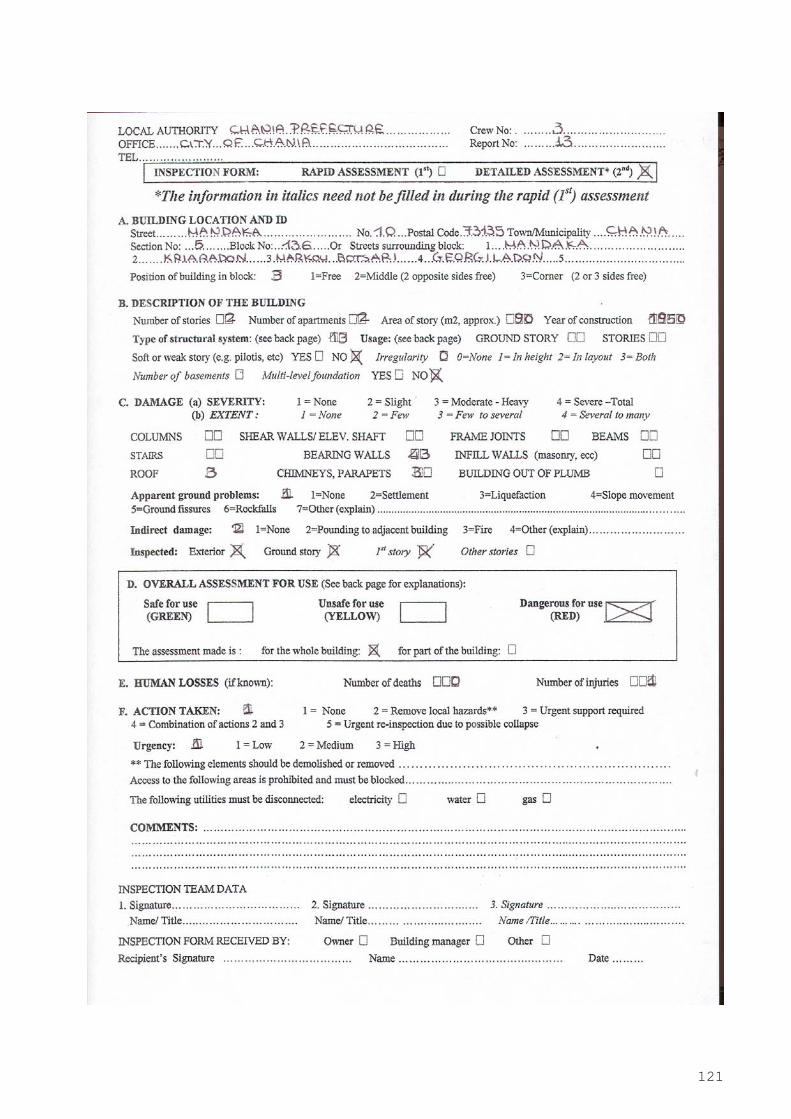
121

122
Photo 8 : Building at Mandaka 10 str.

123
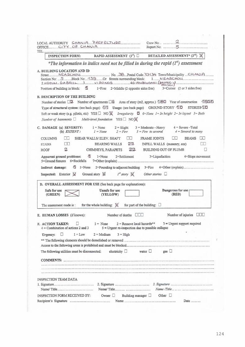
124

125
Photo 9 : Building at Nearchou 38 str.
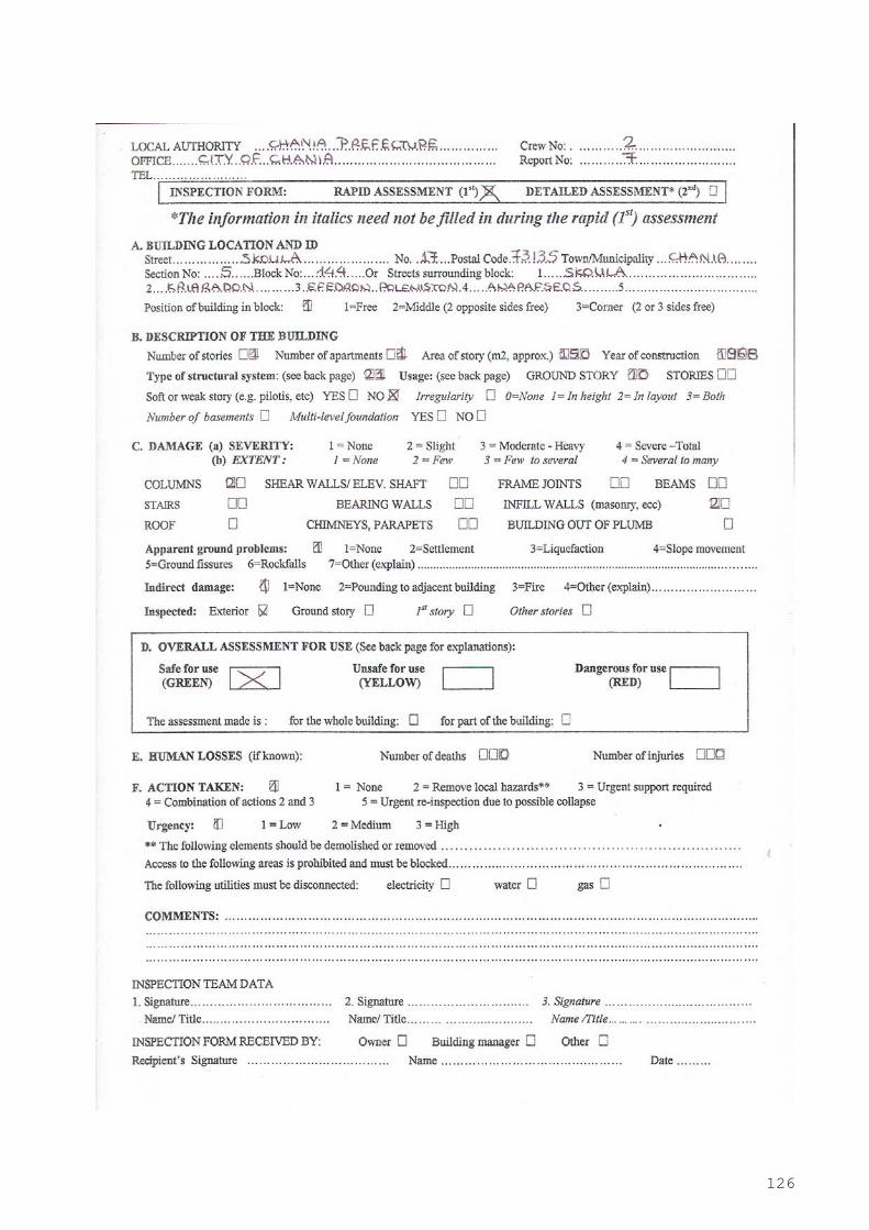
126
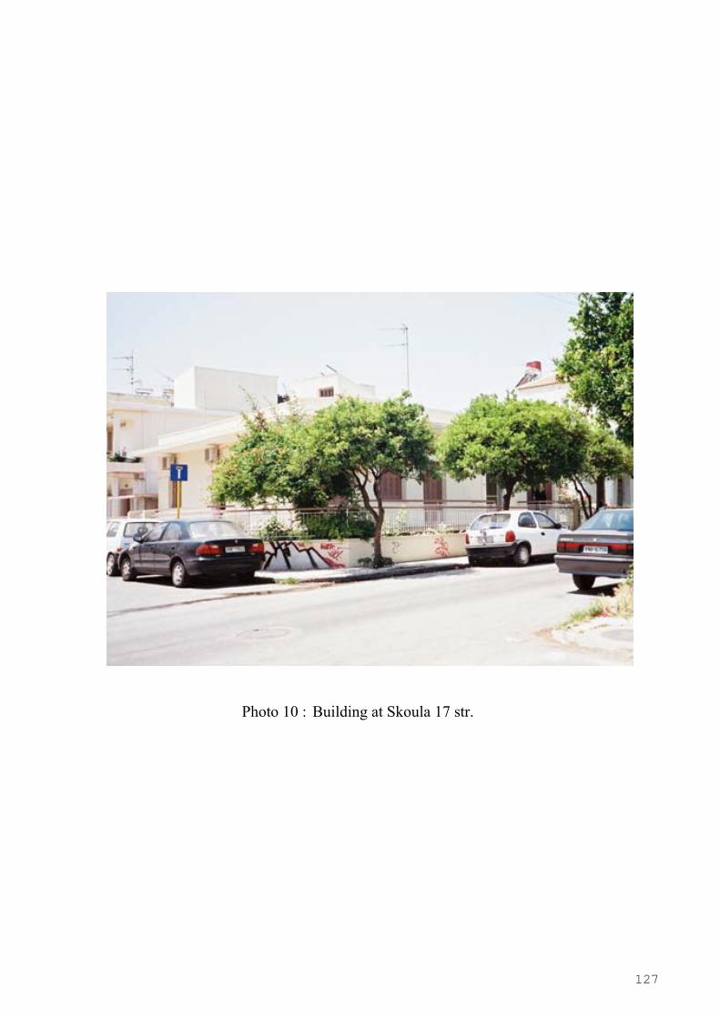
127
Photo 10 : Building at Skoula 17 str.
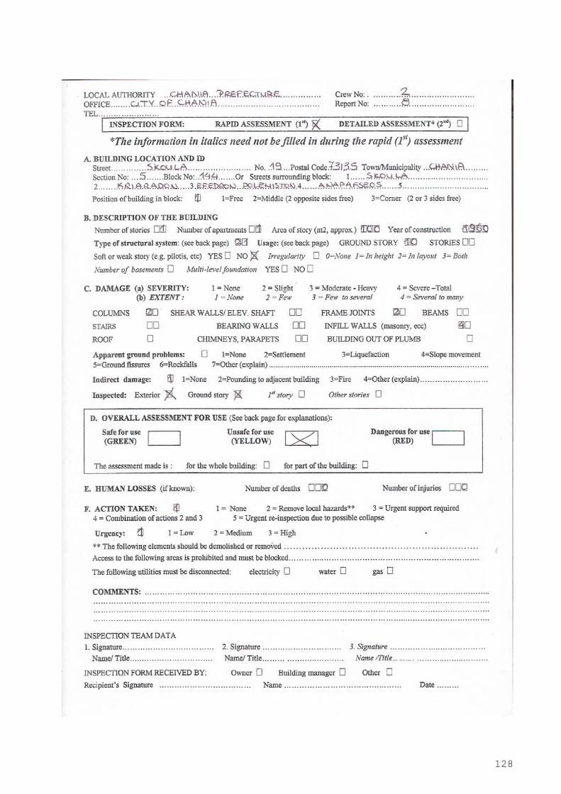
128
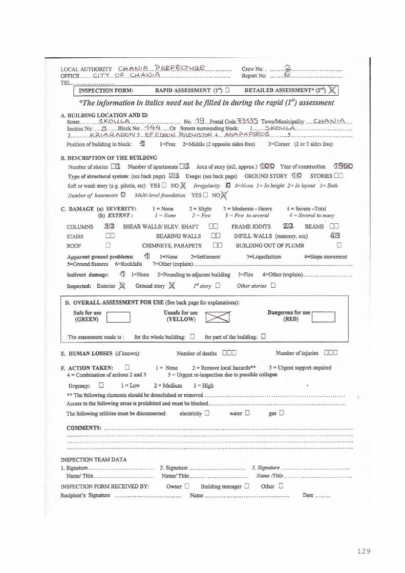
129

130
Photo 11 : Building at Skoula 19 str.
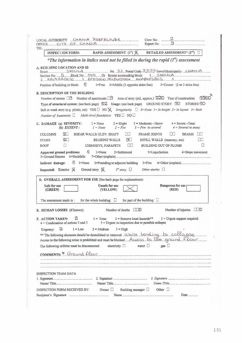
131
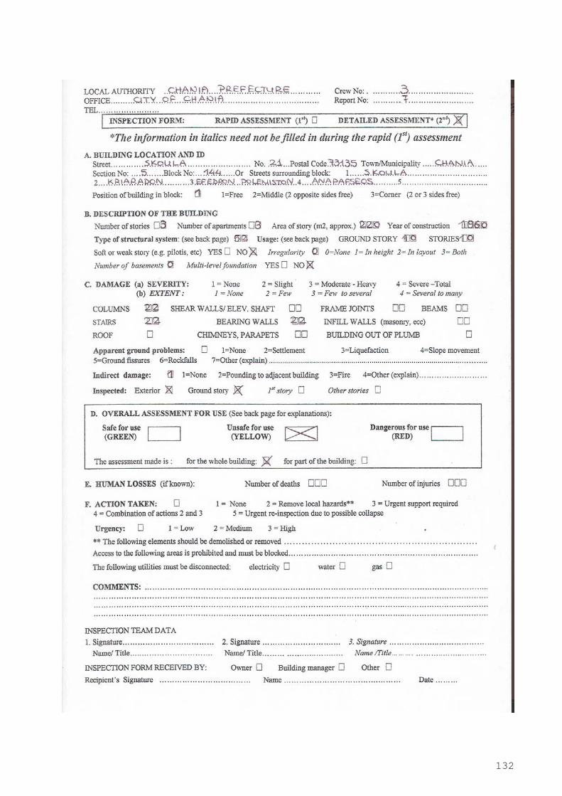
132
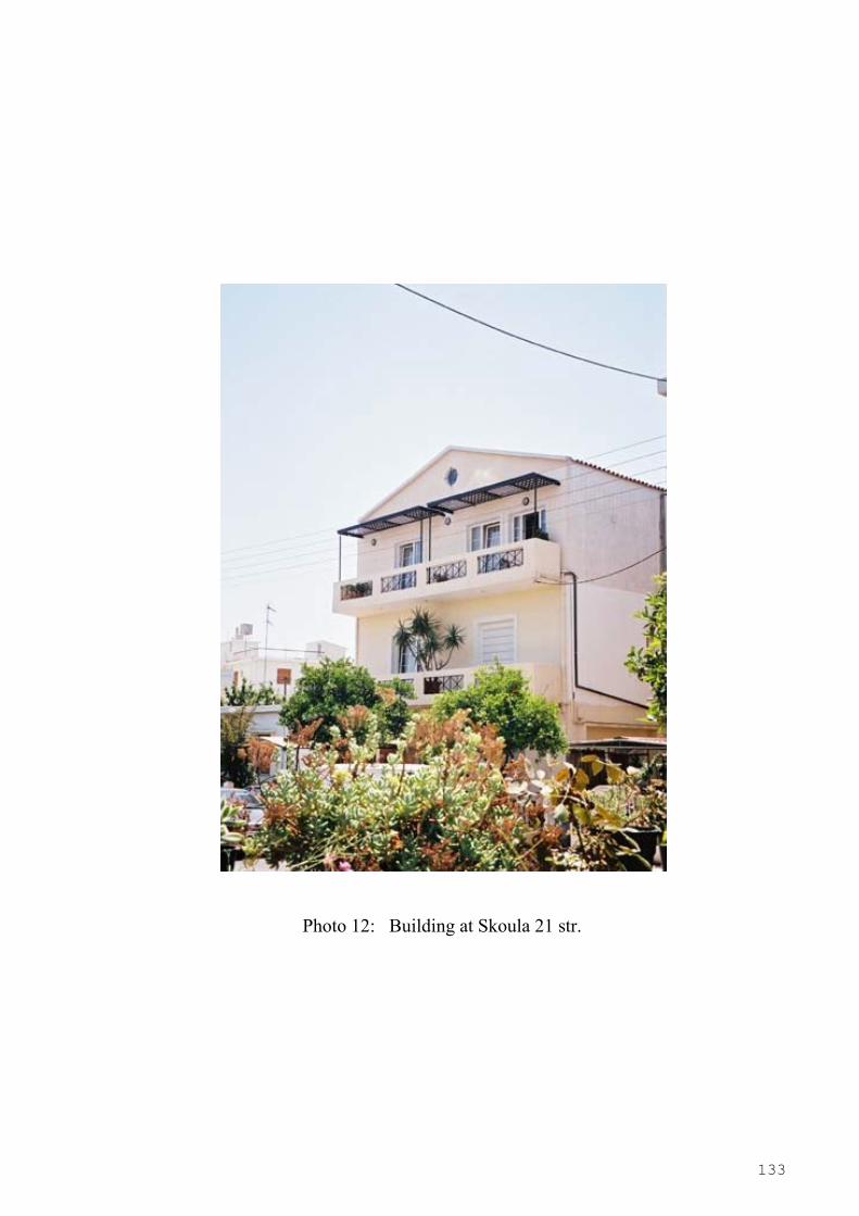
133
Photo 12: Building at Skoula 21 str.

134
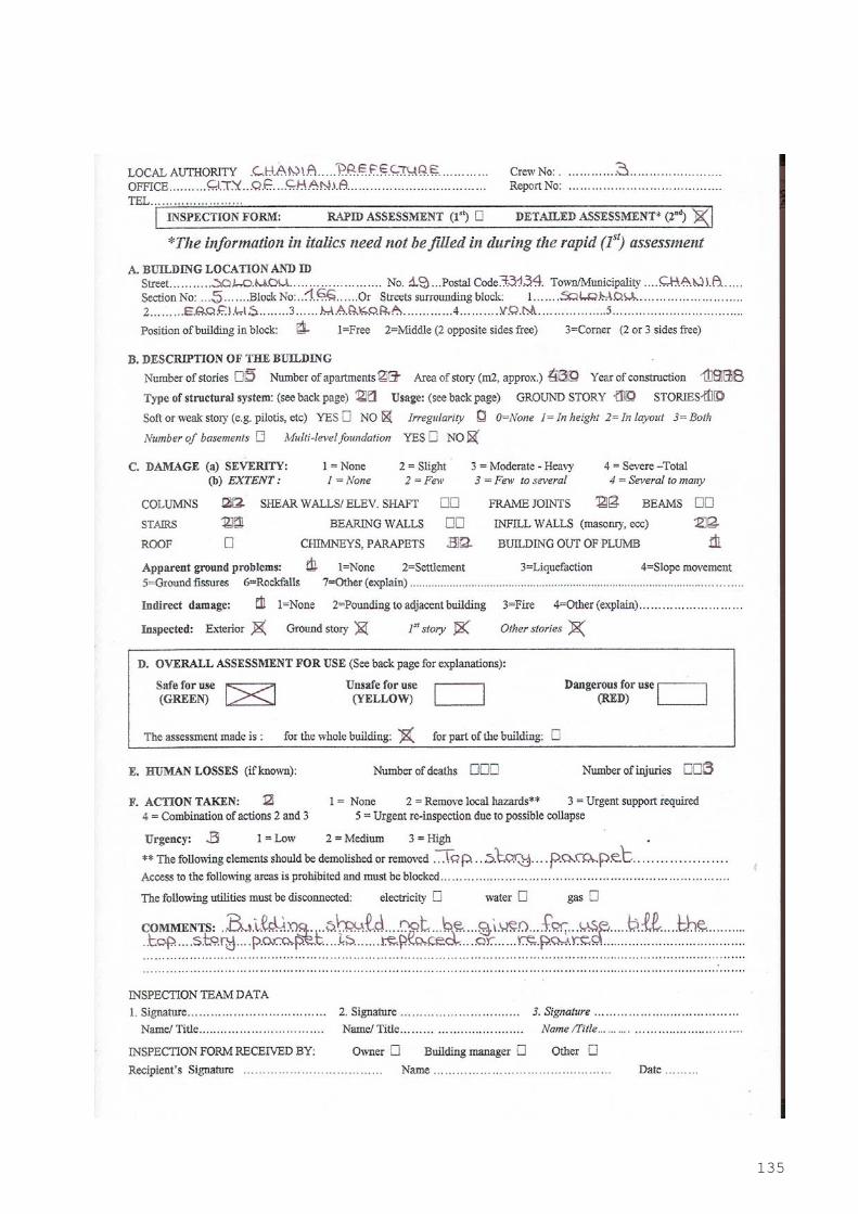
135
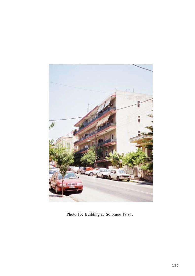
136
Photo 13: Building at Solomou 19 str.
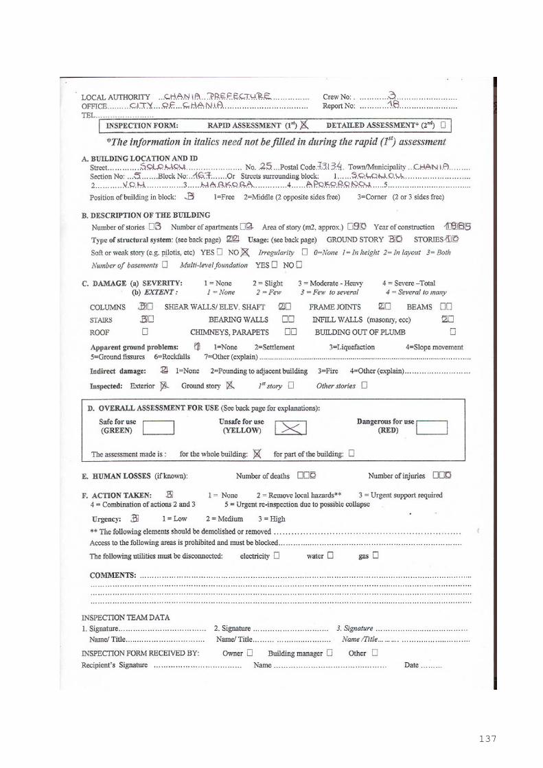
137

138

139
Photo 14: Building at Solomou 25 str.
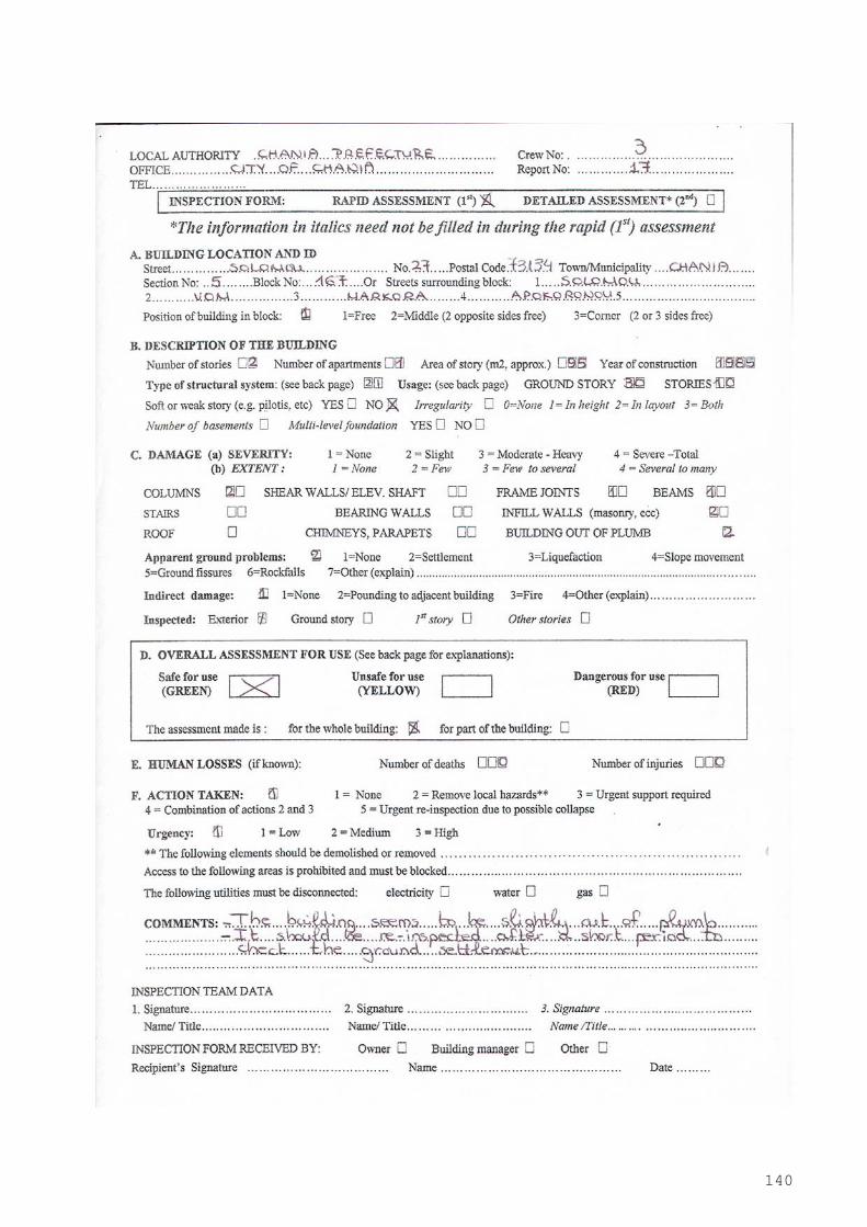
140
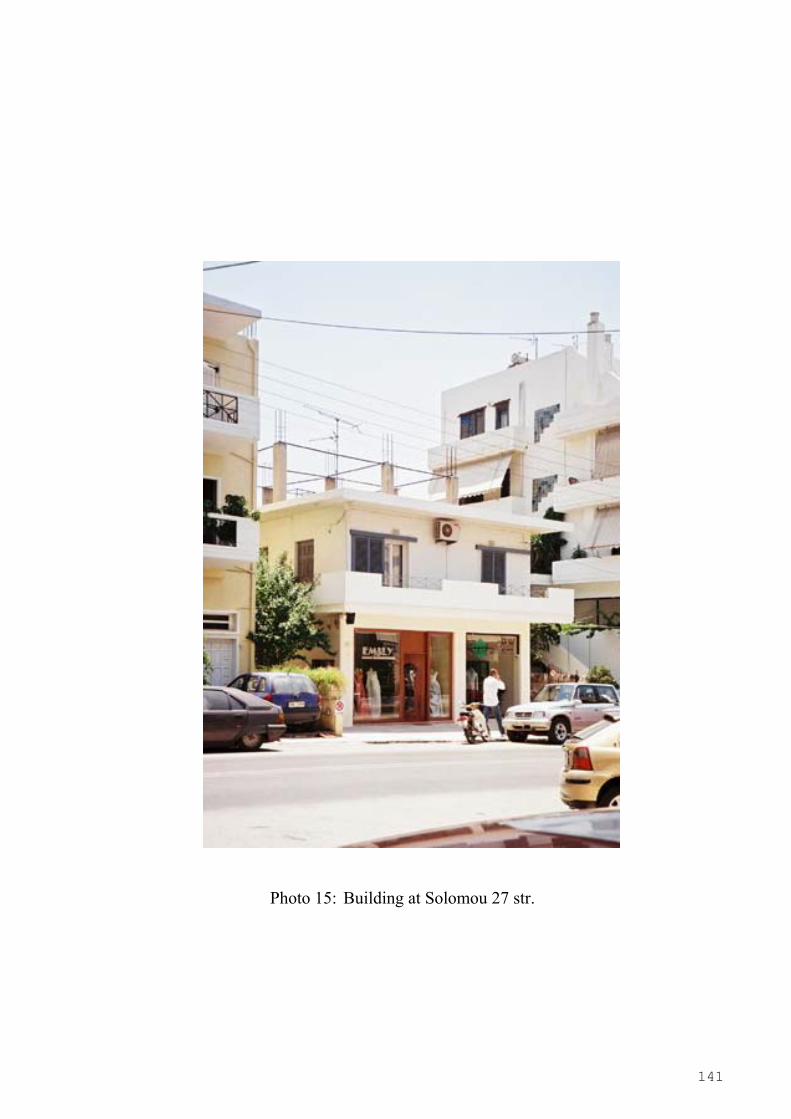
141
Photo 15: Building at Solomou 27 str.
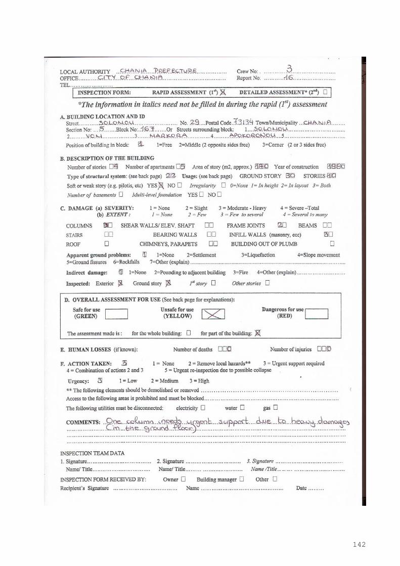
142

143

144
Photo 16: Building at Solomou 29 str.

145
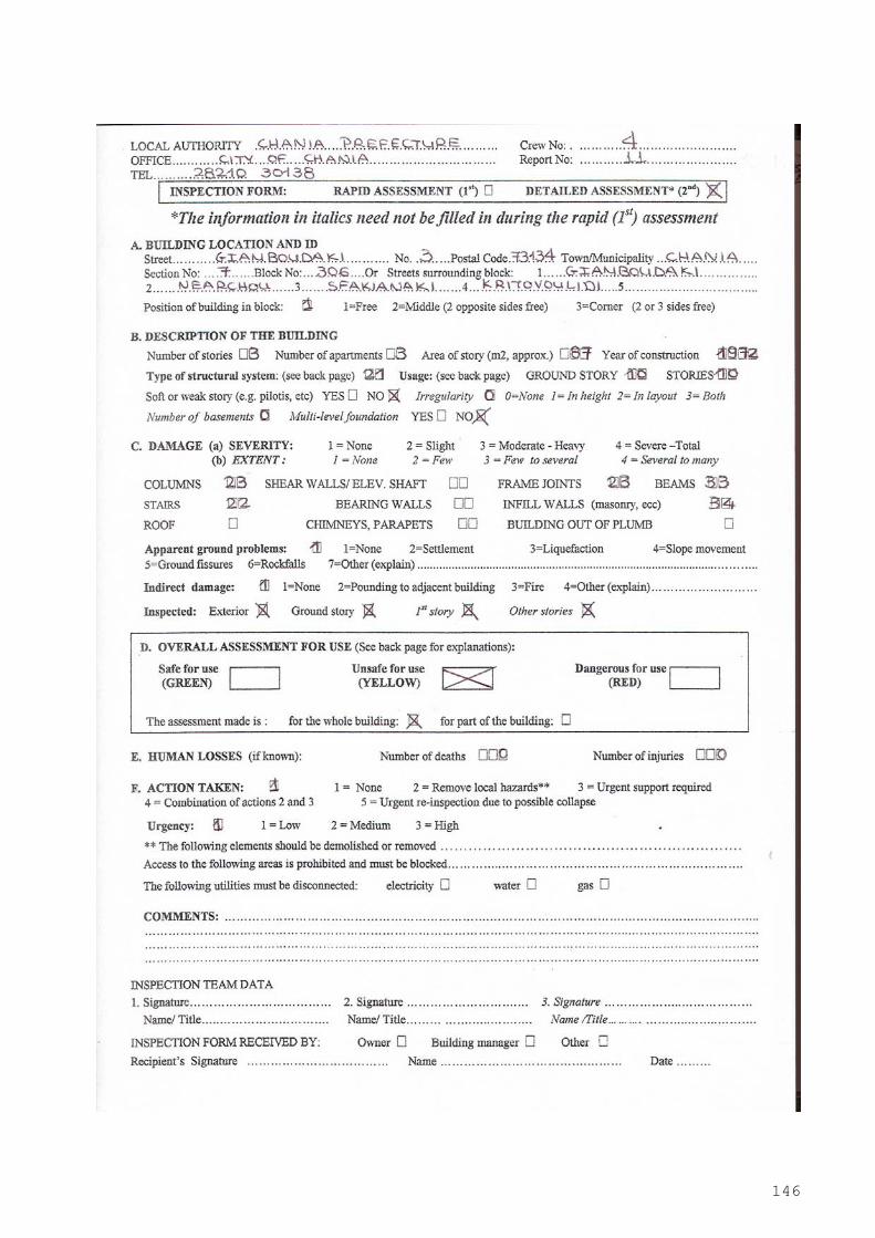
146
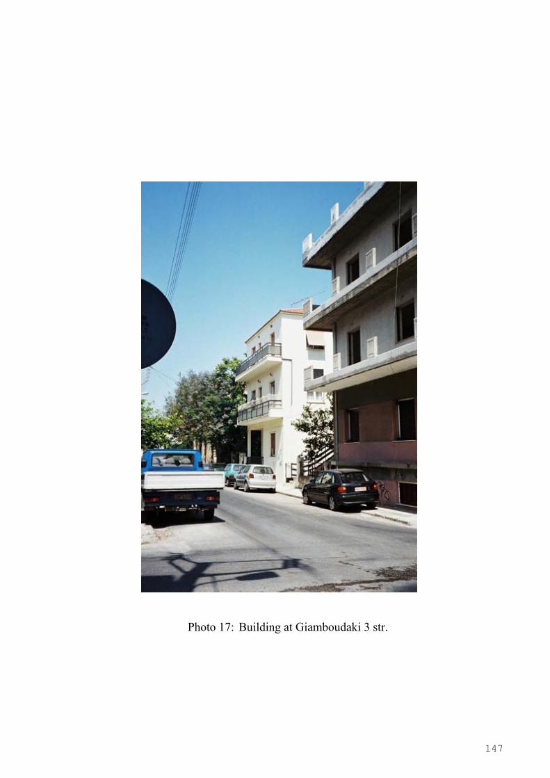
147
Photo 17: Building at Giamboudaki 3 str.
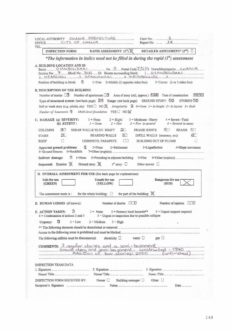
148

149

150
Photo 18: Building at Giamboudaki 5 str.

151
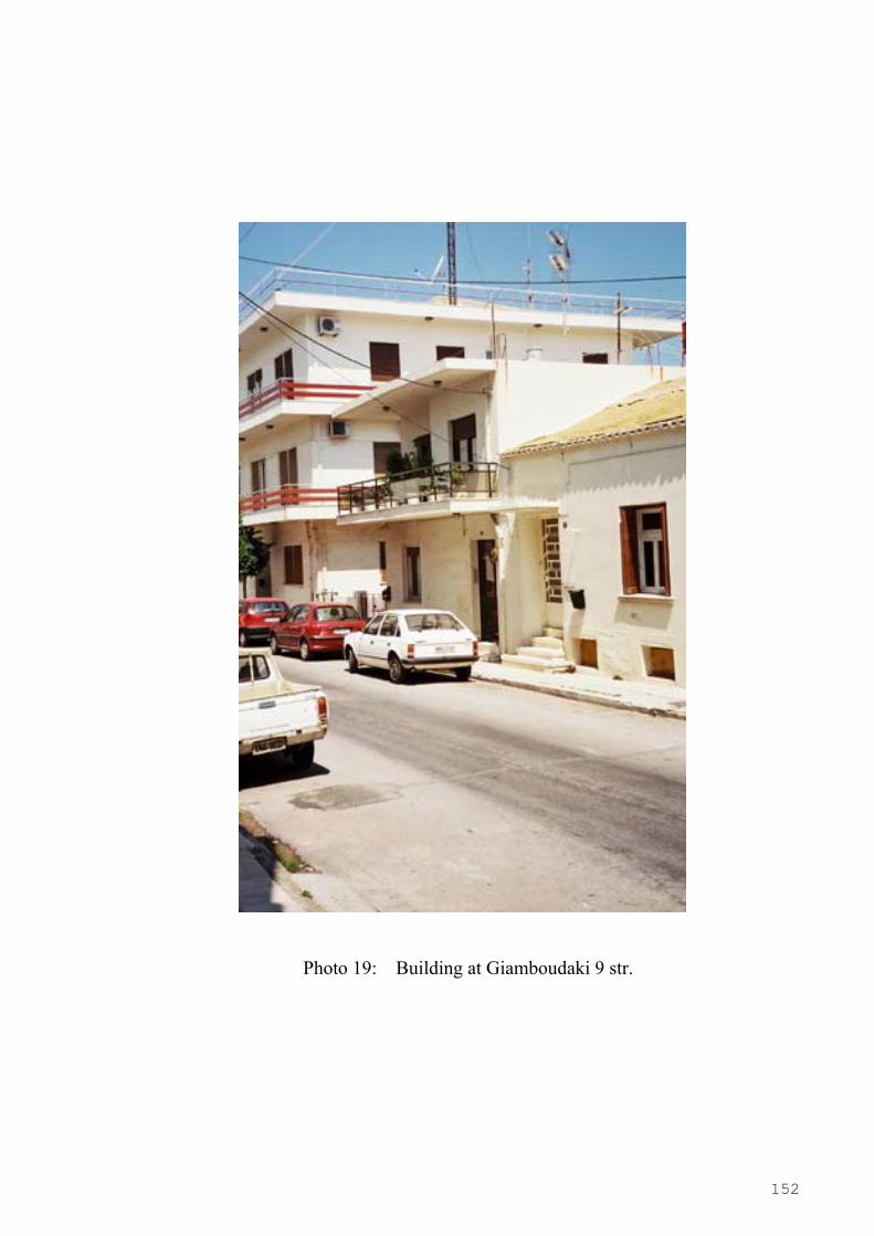
152
Photo 19: Building at Giamboudaki 9 str.
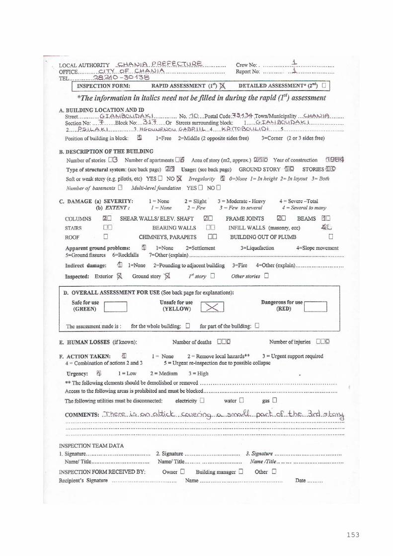
153
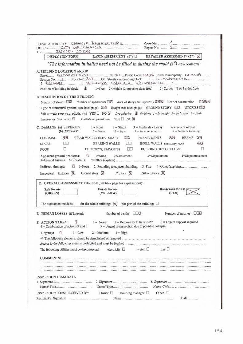
154
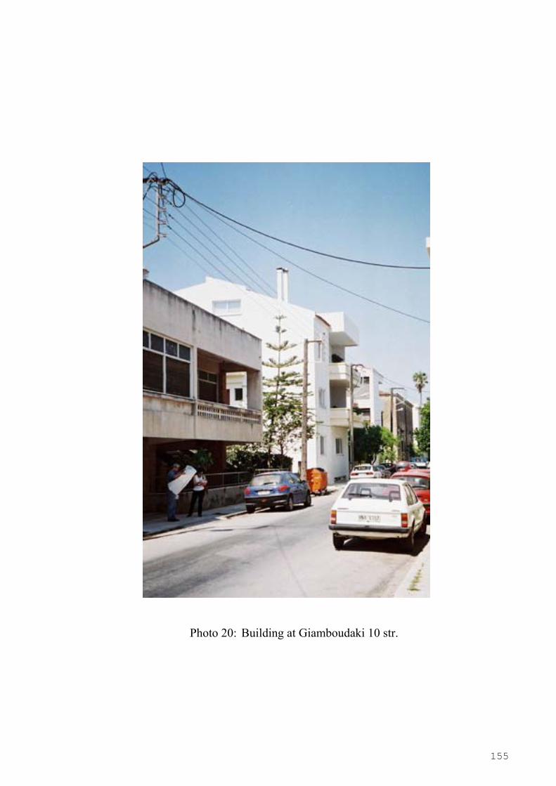
155
Photo 20: Building at Giamboudaki 10 str.
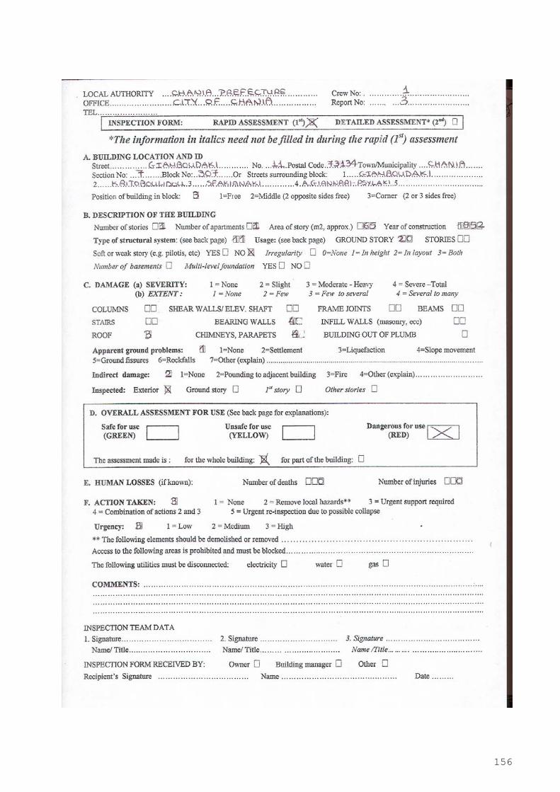
156
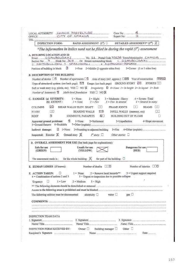
157
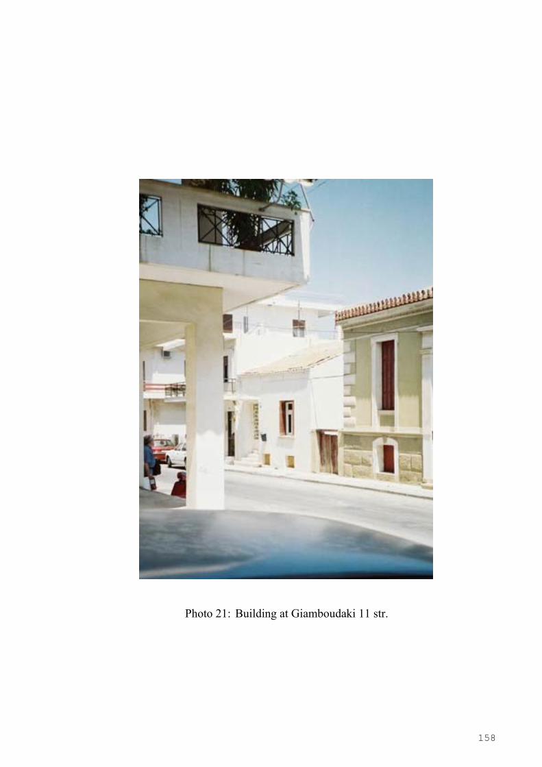
158
Photo 21: Building at Giamboudaki 11 str.

159
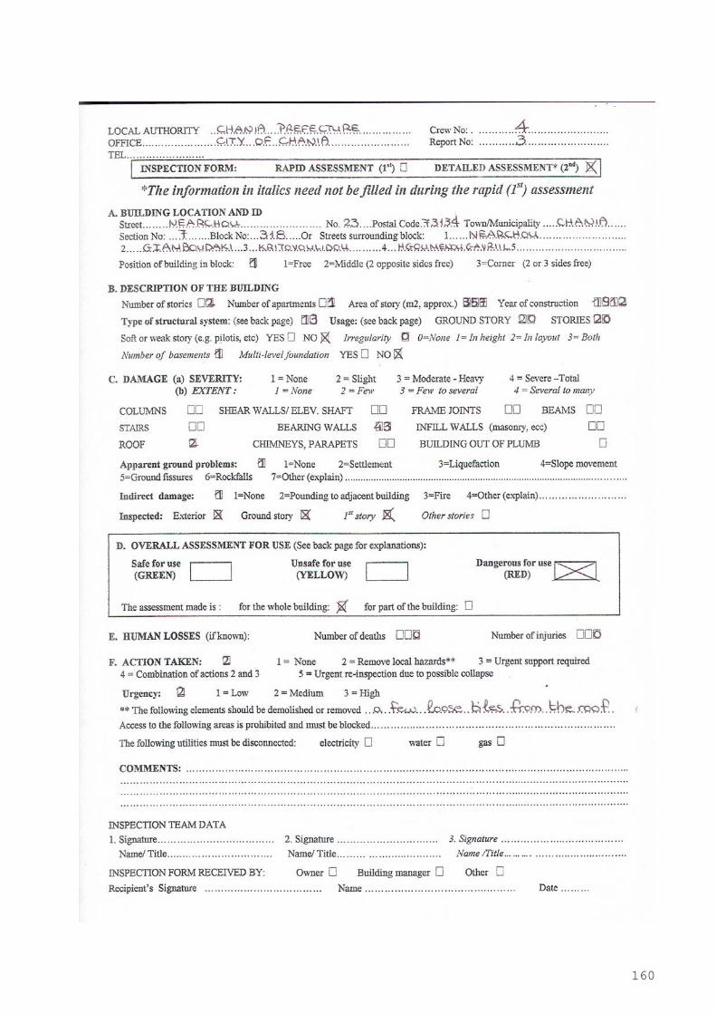
160
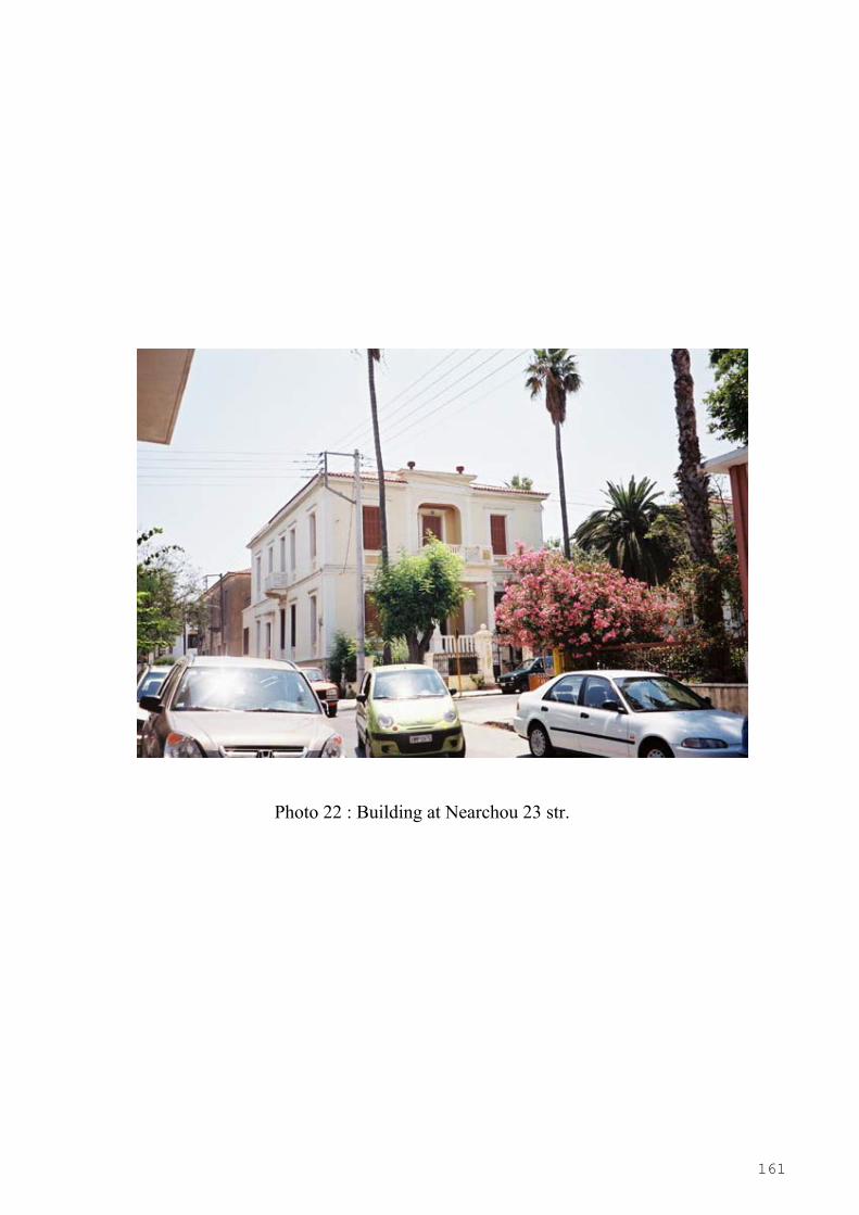
161
Photo 22 : Building at Nearchou 23 str.
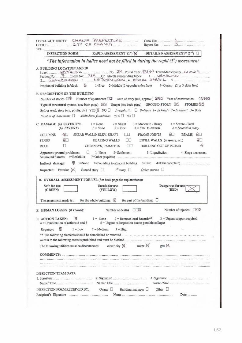
162
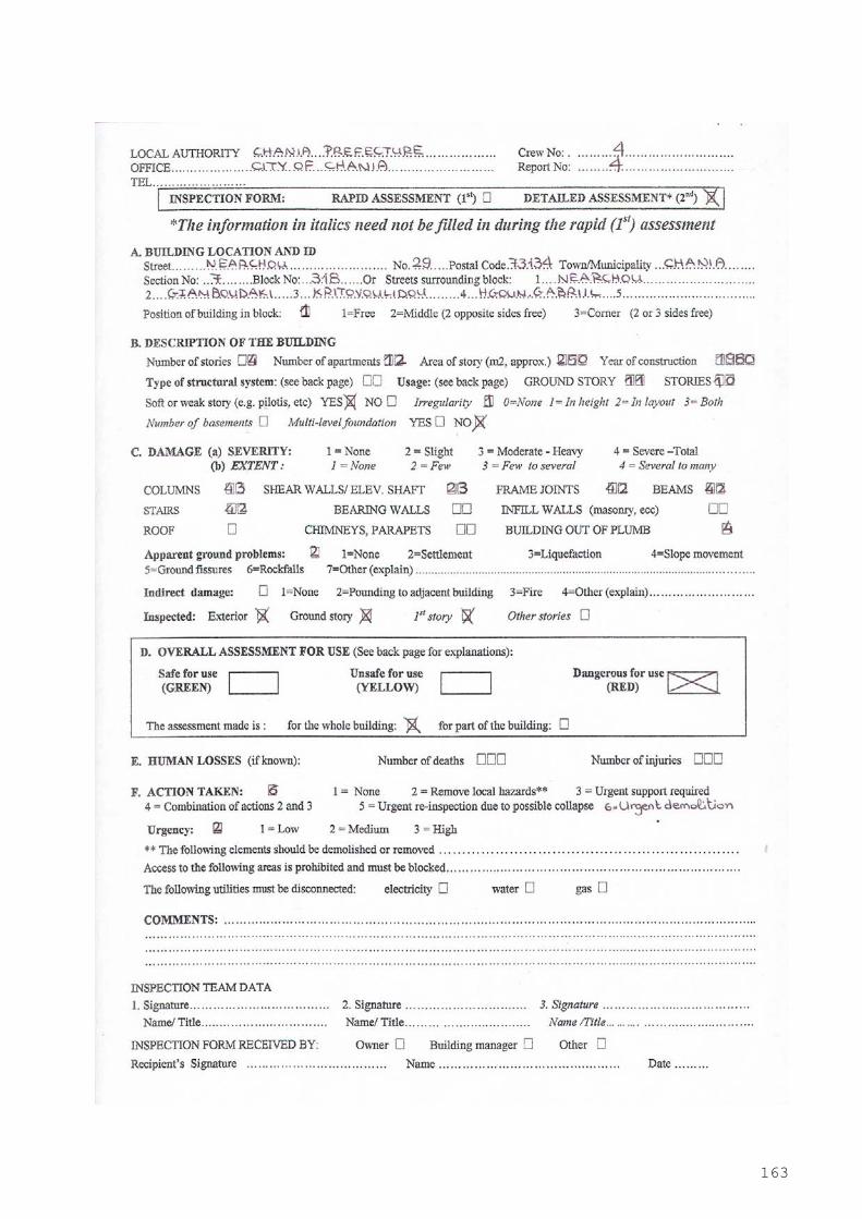
163
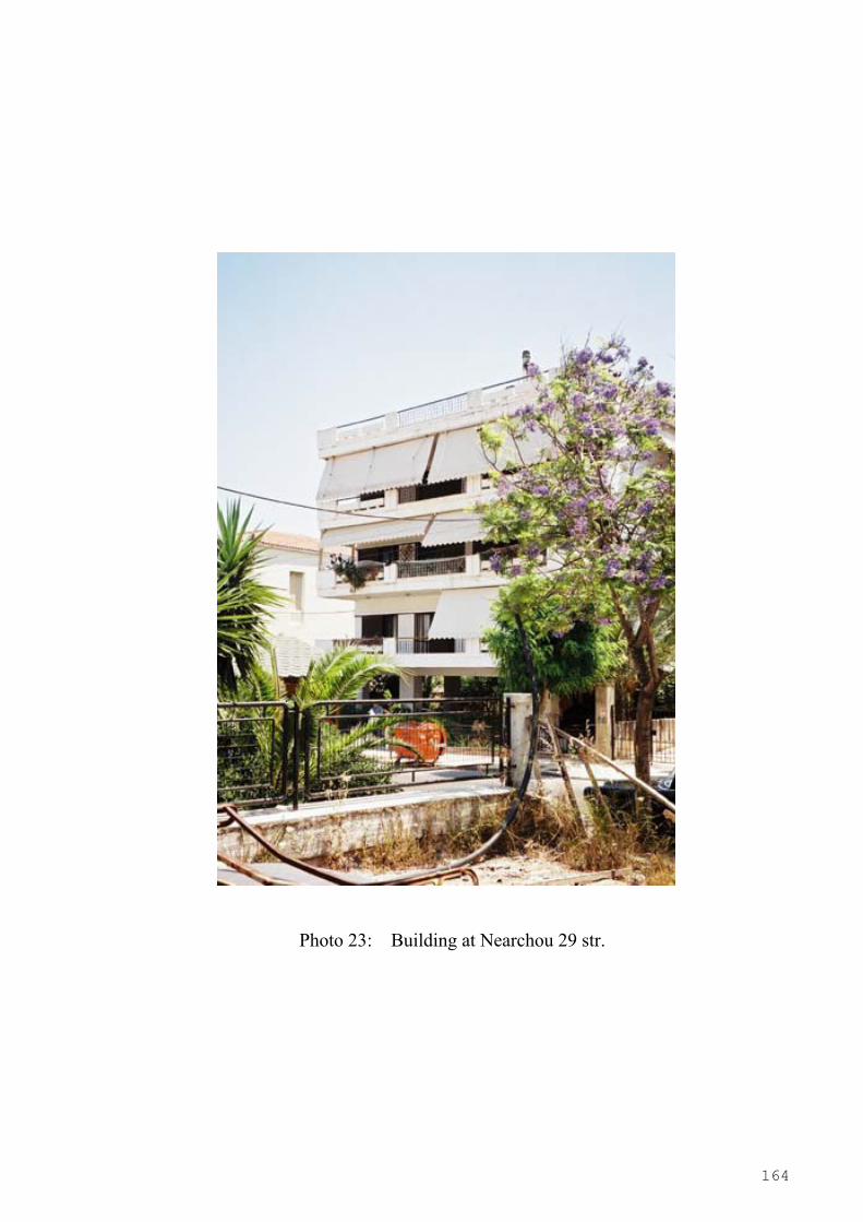
164
Photo 23: Building at Nearchou 29 str.