ficha-tecnica-b011-promig180-ma.pdf - carbone
TRANSCRIPT

Maquinas de soldadura
1
FICHA TÉCNICA
Marca: Carbone Professional Welding
Voltaje de Entrada: 1x220V/230V/240V 50/60Hz
Rodillo especial dentado para alambre tubular (sin gas):
Tipo Soldadura: IGBT INVERTER MIG/MAG (GMAW) – MMA (SMAW)
60% @ 150A/21.5V, 100% @ 120A/20V
Velocidad máx. salida del alambre (ajustable) : 12 metros x min
Rango de ajustes amperaje: 30~180A (MIG/MAG)
Inductancia MIG: Fija predefinida
Capacidad de alambre: (0.6, 0.8, 0.9, 1.0) mm
Pre y Post flujo del gas: Fija predefinida
Tipos de alambre: alambre sólido (con gas), tubular (sin gas)
Soldadura con alambre tubular sin gas (Flux cored):
Cambiar la polaridad interna de la máquina a DCEN negativo
Ciclo de trabajo en MMA: 35% @ 160 amp
Peso: 12.5 kilos
Rango de ajuste en MMA (electrodo): 15~160A
Power factor: λ=0.8
Tipo de protección: IP21S
Eficiencia: ≥0.85
Dimensiones: 450x210x320 mm
Protección de la carcasa: Clase F
Garantia: 1 año
Procedencia: Importado
Corriente nominal de Entrada: 58A
Incluido en los accesorios (0.6-0.8) mm
Potencia nominal: 6.6 KVA
Rango de ajuste voltaje: 14±3V~23.5±3V
(. 023”-. 030”-. 035”-. 040”)
No-load Voltaje: 55~75V
Ciclo de trabajo MIG: 35% @ 180A/23V
y Arco piloto de reinicio
Maquina de soldar MIG/MAG PROMIG 180 220 Spool Gun
DESCRIPCIÓN
CÓDIGO
Carbone Professional Welding
Apto para soldar todo tipo de aceros al carbón, inoxidable y aluminio. Incluye una Spool gun el cual le permitirá soldar fácilmente con rollos de (102mm) 4” difíciles de soldar como el aluminio, evitando que se trabe en la máquina. Portátil y ligero ideal para mantenimiento y fabricación en campo. Controles sencillos para ajuste rápido, incluso un principiante puede ajustarla rápidamente. Antorcha de conexión europea para rápida instalación y desinstalación en campo. Módulos inverter IGBT de siemens que le darán fiabilidad durante años de uso con esta máquina. Puede soldar en MIG hasta espesores de 3/8” en un solo pase, 5/8” en multipase y mínimo calibre 24.
B011Detalle panelAccesorios Incluidos

PROMIG180IGBT INVERTER
DC MIG/MAG/MMAWELDING MACHINE
(Suitable for 1x220V)
Operators’s ManualSafety, Setup and General Use Guide
REV.2 0 00142-16Issue Date: May. 19, 2016Manual No.: 0-1532
EMPRESAS CARBONE S.A.Calle 5ta. Rio Abajo, Panamá, PanamáTelefonos: (507) 3916309 / 3916313www.empresascarbone.com

Dear Customer, Thank you for selecting the our machine. We appreciate you as a customer and hope that you will enjoy years of use from your welder.
Please go directly to the our website to register your unit and receive your warranty information. Your
unit registration is important should any information such as product updates or re-calls be issued. It is also important so that we may track your satisfaction with our products and services. If you are unable to register by website, contact our directly through the sales department through the main customer service number in your country. Your unit will be registered and warranty will be issued and in full effect. Keep all information regarding your purchase. In the event of a problem you must contact technical support before your welder can be a candidate for warranty service and returned.
Please review the current online warranty statement and information found on the website of theour division located in or nearest to your country. Print it for your records and become familiar of itsterms and conditions.
We offers full technical support, in several different forms. We have online support available through email, and a welding support forum designed for customers and noncustomer interaction. Technical advisorsare active on the forum daily. We also divide our support into two divisions: technical and welding performance. Should you have an issue or question concerning your unit, please contact performance/technical support available through the main company headquarters available in your country. For best service call the appropriate support line and follow up with an email, particularly if off hours, or you cannot reach a live person. In the event you do not reach a live person, particularly during heavy call volume times,holidays, and off hours, leave a message and your call will normally be returned within 24 hours. Also for quick answers to your basic questions, join the company owned forum available through the website.
Should you need to call or write, always know your model name, purchase date and welder manu-facturing inspection date. This will assure the quick and accurate customer service. REMEMBER: Be as specific and informed as possible. Technical and performance advisors rely upon you to carefully describe the conditions and circumstances of your problem or question. Take notes of any issues as best you can. You may be asked many questions by the advisors to clarify prob-lems or issues that may seem very basic. However, diagnosis procedures MUST be followed to begin the warranty process. Advisors can't assume anything, even with experienced users, and must cover all aspects to properly diagnose the problem. Depending upon your issue, it is advisa-ble to have basic tools handy such as screwdrivers, wrenches, pliers, and even an inexpensive test meter with volt/ohm functions before you call.
Let us know how we may be of service to you should you have any questions.

We want you to take pride in operating our machine as much pride as we have taken in making this product for you. Please read all information in this manual before operation
PLEASE EXAMINE CARTON AND EQUIPMENT FOR DAMAGE IMMEDIATELY
When this equipment is shipped, title passes to the purchaser upon receipt from the courier. Consequently all claims for material damaged in shipment must be made by purchaser against the transportation companyused.
Please record your equipment identification below for future reference. This information can be found on data plate at rear of machine.
:Product ProMig180
Serial No. ___________________________________
Date of Purchase _____________________________
Where Purchased _____________________________
Whenever you request replacement parts or information on this equipment please always supply informationyou have recorded above This product is covered by 1 years parts and labour warranty, you are responsible for costs of shipping unit to us, we will cover cost of returning item to you. External items, torch, earth lead etc are covered by 3 months warranty. Any faults/damage found caused by customer will be charged prorata.
Pay particular attention to the safety instructions we have provided you for your protection The level of seriousness to be applied to each section is explained below
WARNING This statement appears where the information must be followed exactly to avoid serious personal injury.
CAUTION This statement appears where the information must be following to avoid a minor personal injury or damage to this equipment.
We are dedicated to providing you with the best possible equipment and service to meet the demandingjobs that you have. We want to go beyond delivering a satisfactory product to you. That is the reason we offer technical support to assist you with your needs should an occasion occur. With proper use and care your product should deliver years of trouble free service.
Safe operation and proper maintenance is your responsibility. We have compiled this operator's manual, to instruct you in basic safety, operation and maintenance of
our product to give you the best possible experience. Much of welding and cutting is based upon experience and com-mon sense. As thorough as this welding manual may be, it is no substitute for either. Exercise extreme caution and care in all activities related to welding or cutting. Your safety, health and even life depends upon it. While accidents are never planned, preventing an accident requires careful planning.
Please carefully read this manual before you operate machine. This manual is not only for the use of the machine, but to assist in obtaining the best performance out of your unit. Do not operate the unit until you have read this manual and you are thoroughly familiar with the safe operation of the unit. If you feelyou need more information please contact our Support.
The warranty does not cover improper use, maintenance or consumables. Do not attempt to alter or
defeat any piece or part of your unit, particularly any safety device. Keep all shields and covers in place during unit operation should an unlikely failure of internal components result in the possible presence of sparks and explosions. If a failure occurs, discontinue further use until mal-functioning parts or accessories have been repaired or replaced by qualified personnel.
Note on High Frequency electromagnetic disturbances: Certain welding and cutting processes generate High Frequency (HF) waves. These
waves may disturb sensitive electronic equipment such as televisions, radios, computers, cell phones, and related equipment. High Frequency may also interfere with fluorescent lights. Consult with an electrician if disturb-ance is noted. Sometimes, improper wire routing or poor shielding may be the cause.
HF can interfere with pacemakers. See EMF warnings in following safety sec-tion for further information. Always consult your physician before entering an area known to have welding or cutting equipment if you have a pacemaker.
MOVING PARTS can cause injury. Moving parts, such as fans, rotors, and belts can cut fingers and hands and catch loose clothing. Do not put your hands near the engine fan. Do not attempt to override the governor or idler by pushing on the throttle control rods while the engine is running.
SAFETY PRECAUTIONS
These safety precautions are for protection of safety and health. Failure to follow these guidelines may result in serious injury or death. Be careful to read and follow all cautions and warnings. Protect yourself and others. Welding and cutting processes produce high levels of ultraviolet (UV) radiation that can cause severe skin burn and damage. There are other potential hazards involved with welding such as severe burns and respiratory related illnesses. Therefore ob-serve the following to minimize potential accidents and injury:
Use appropriate safety glasses with wrap around shields while in the work area, even under welding helmets to protect your eyes from flying sparks and debris. When chip-ping slag or grinding, goggles and face shields may be required.
When welding or cutting, always use an approved shielding device, with the correct shade of filter installed. Always use a welding helmet in good condition. Discard any broken or cracked filters or helmets. Using broken or cracked filters or helmets can cause severe eye injury and burn. Filter shades of no less than shade 5 for cutting and no less than shade 9 for welding are highly recommended. Shades greater than 9 may be required for high amperage
welds. Keep filter lenses clean and clear for maxi-mum visibility. It is also advisable to consult with your eye doctor should you wear contacts for corrective vision before you wear them while welding.
Do not allow personnel to watch or observe the welding or cutting operation unless fullyprotected by a filter screen, protective curtains or equivalent .protective equip-ment. If no protection is available, exclude them from the work area. Even brief expo-sure to the rays from the welding arc can damage unprotected eyes. Always wear hearing protection because welding and cutting can be extremely noisy. Ear protection is necessary to prevent hearing loss. Even prolonged low levels of noise has been known to create long term hearing damage. Hearing protection also further protects against hot sparks and debris from entering the ear canal and doing harm.
Always wear personal protective clothing. Flame proof clothing is required at all times. Sparks and hot metal can lodge in pockets, hems and cuffs. Make sure loose clothing is tucked in neatly. Leather aprons and jackets are recommended. Suitable welding jackets and coats may be purchased made from fire proof material from welding supply stores. Discard any burned or frayed clothing. Keep clothing away from oil, grease and flammable liquids. Leather boots or steel toed leather boots with rubber bottoms are required for ade-quatefoot protection. Canvas, polyester and other man made materials often found in shoes will either burn or melt. Rubber or other non conductive soles are necessary to help protect from electrical shock.
Flame proof and insulated gauntlet gloves are required whether welding or cutting or handling metal. Simple work gloves for the garden or chore work are not sufficient. Gauntlet type welding gloves are available from your local welding supply companies. Never attempt to weld with out gloves. Welding with out gloves can result in serious burns and electrical shock. If your hand or body parts comes into contact with the arc of a plasma cutter or welder, instant and serious burns will occur. Proper hand protection is required at all times when working
with welding or cutting machines!
SAFETY PRECAUTIONS
WARNING! Persons with pacemakers should not weld, cut or be in the welding area until they consult with their physician. Some pacemakers are sensitive to EMF radiation and could severely malfunction while welding or while being in the vicinity of someone welding. Serious injury or death may occur!
Welding and plasma cutting processes generate electro-magnetic fields and radiation. While the effects of EMF radiation are not known, it is suspected that there may be some harm from long term exposure to electromagnetic fields. Therefore, certain pre-cautions should be taken to minimize exposure:
* Lay welding leads and lines neatly away from the body. * Never coil cables around the body. * Secure cables with tape if necessary to keep from the body. * Keep all cables and leads on the same side the body. * Never stand between cables or leads. * Keep as far away from the power source (welder) as possible while welding. * Never stand between the ground clamp and the torch. * Keep the ground clamp grounded as close to the weld or cut as possible.
Welding and cutting processes pose certain inhalation risks. Be sure to follow any guidelines from your chosen consumable and electrode suppliers regarding possible need for respiratory equipment while welding or cutting. Always weld with adequate ventilation. Never weld in closed rooms or confined spaces. Fumes and gases re-leased while welding or cutting may be poisonous. Take precautions at all times.
Any burning of the eyes, nose or throat are signs that you need to increase ventilation. * Stop immediately and relocate work if necessary until adequate ventilation is ob-tained. * Stop work completely and seek medical help if irritation and discomfort persists.
WARNING! Do not weld on galvanized steel, stainless steel, beryllium, titanium, cop-per, cadmium, lead or zinc without proper respiratory equipment and or ventilation.
WARNING! This product when used for welding or cutting produces fumes and gas-es
which contains chemicals known to the State of California to cause birth defects and in some §cases cancer. (California Safety and Health Code 25249.5 et seq.)
WARNING! Do not weld or cut around Chlorinated solvents or degreasing areas. Release of Phosgene gas can be deadly. Consider all chemicals to have potential deadly results if weldedon or near metal containing residual amounts of chemicals.
Keep all cylinders upright and chained to a wall or appropriate holding pen. Certain
regulations regarding high pressure cylinders can be obtained from OSHA or local regulatory agency. Consult also with your welding supply company in your area for further recommendations. The regulatory changes are frequent so keep informed.
All cylinders have a potential explosion hazard. When not in use, keep capped and closed.
Store chained so that overturn is not likely. Transporting cylinders incorrectly can lead to an explosion. Do not attempt to adapt regulators to fit cylinders. Do not use faulty regulators. Do not allow cylinders to come into contact with work piece or work. Do not weld or strike arcs on cylinders. Keep cylinders away from direct heat, flame and sparks.
SAFETY PRECAUTIONS
WARNING! Electrical shock can kill. Make sure all electrical equipment is properly grounded. Do not use frayed, cut or otherwise damaged cables and leads. Do not stand, leanor rest on ground clamp. Do not stand in water or damp areas while weld-ing or cutting. Keep work surface dry. Do not use welder or plasma cutter in the rain or in extremely humid conditions. Use dry rubber soled shoes and dry gloves when welding or cutting to insulate against electrical shock. Turn machine on or off only with gloved hand. Keep all parts of the body insulated from work, and work tables. Keep away from direct contact with skin against work. If tight or close quarters ne-cessitates standing or resting on work piece, insulate with dry boards and rubber mats designed to insulate the body from direct contact.
All work cables, leads, and hoses pose trip hazards. Be aware of their location and
make sure all personnel in area are advised of their location. Taping or securing ca-bles with appropriate restraints can help reduce trips and falls.
WARNING! Fire and explosions are real risks while welding or cutting. Always keep fire extinguishers close by and additionally a water hose or bucket of sand. Periodi-cally checkwork area for smoldering embers or smoke. It is a good idea to have someone help watch for possible fires while you are welding. Sparks and hot metal may travel a long distance. They may go into cracks in walls and floors and start a fire that would not be immediately visible. Here are some things you can do to reduce the possibility of fire or explosion:
* Keep all combustible materials including rags and spare clothing away from area. * Keep all flammable fuels and liquids stored separately from work area. * Visually inspect work area when job is completed for the slightest traces of smoke or embers. * If welding or cutting outside, make sure you are in a cleared off area, free from dry tender and
debris that might start a forest or grass fire. * Do not weld on tanks, drums or barrels that are closed, pressurized or anything that held
flammable liquid or material.
Metal is hot after welding or cutting! Always use gloves and or tongs when handling hotpieces of metal. Remember to place hot metal on fire-proof surfaces after han-dling. Serious burns and injury can result if material is improperly handled.
WARNING! Faulty or poorly maintained equipment can cause injury or death. Prop-
er maintenance is your responsibility. Make sure all equipment is properly maintained and serviced by qualified personnel. Do not abuse or misuse equipment.
Keep all covers in place. A faulty machine may shoot sparks or may have exploding parts. Touching uncovered parts inside machine can cause discharge of high amounts of electricity.
Do not allow employees to operate poorly serviced equipment. Always check condition of equipment thoroughly before start up. Disconnect unit from power source before any service attempt is made and for long term storage or electrical storms.
Further information can be obtained from The American Welding Society (AWS) that
relates directly to safe welding and plasma cutting. Additionally, your local welding supply company may have additional pamphlets available concerning their products. Do not operate machinery until your are comfortable with proper operation and are able to assume inherent risks of cutting or welding.
SAFETY PRECAUTIONS

TABLE OF CONTENTS
Page SAFETY PRECAUTIONS................................................. . Installation.....................................................Section A Technical Specifications...............................................A-1 Output Amps %duty cycle ...............................................A-2 Select Suitable Location...............................................A-3 Stacking ..............................................................A-3 TRANSPORT - UNLOADING ............................................A-3 Tilting. ..............................................................A-3 Environmental Area ....................................................A-3 Machine Grounding and High Frequency Interference Protection .........A-4 Input Connections ...................................................A-4 Reconnect Procedure....................................................A-5 220/230/240V Input.....................................................A-5 Attachment Plug Installation, Engine Driven Generator..................A-5 Output Connections.....................................................A-6 Output and Gas Connection for Mig Welding..............................A-6 Work Cable Connection .................................................A-6 Output Connection for Stick Welding ...................................A-6 Quick Disconnect Plug .................................................A-6 Shielding Gas Connection...............................................A-6 Operation.......................................................Section B Safety precautions.....................................................B-1 Product Description....................................................B-2 Welding Capability.....................................................B-2 Limitations ...........................................................B-2 Control Panel .....................................................B-3 Controls and Settings, ....... ....................................... B-3 Operating steps........................................................B-5 Welding in MIG mode .................................................B-11 Welding in MMA mode .................................................B-20 Maintenance .....................................................Section C Safety Precautions ....................................................C-1 Routine and periodic Maintenance.......................................C-1 Troubleshooting .................................................Section D How to Use Troubleshooting Guide ......................................D-1 Input Filter Capacitor Discharge Procedure ............................D-1 Troubleshooting Guide........................ ... ........ ...........D-2 Wiring Diagram...................................................Section E Main circuit wiring Diagram............................................E-1
Accessories......................................................Section F Parts Lists(COMPONENT LISTS)..................................... Appendix
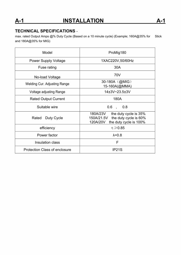
A-1 INSTALLATION A-1 TECHNICAL SPECIFICATIONS - max. rated Output Amps @% Duty Cycle (Based on a 10 minute cycle) (Example; 160A@35% for Stick and 180A@35% for MIG)
Model ProMig180
Power Supply Voltage 1XAC220V,50/60Hz
Fuse rating 30A
No-load Voltage 70V
Welding Cur. Adjusting Range 30-180A(@MIG) 15-160A(@MMA)
Voltage adjusting Range 14±3V~23.5±3V
Rated Output Current 180A
Suitable wire 0.6 , 0.8
Rated Duty Cycle 180A/23V the duty cycle is 35%
150A/21.5V the duty cycle is 60% 120A/20V the duty cycle is 100%
efficiency η≥0.85
Power factor λ=0.8
Insulation class F
Protection Class of enclosure IP21S
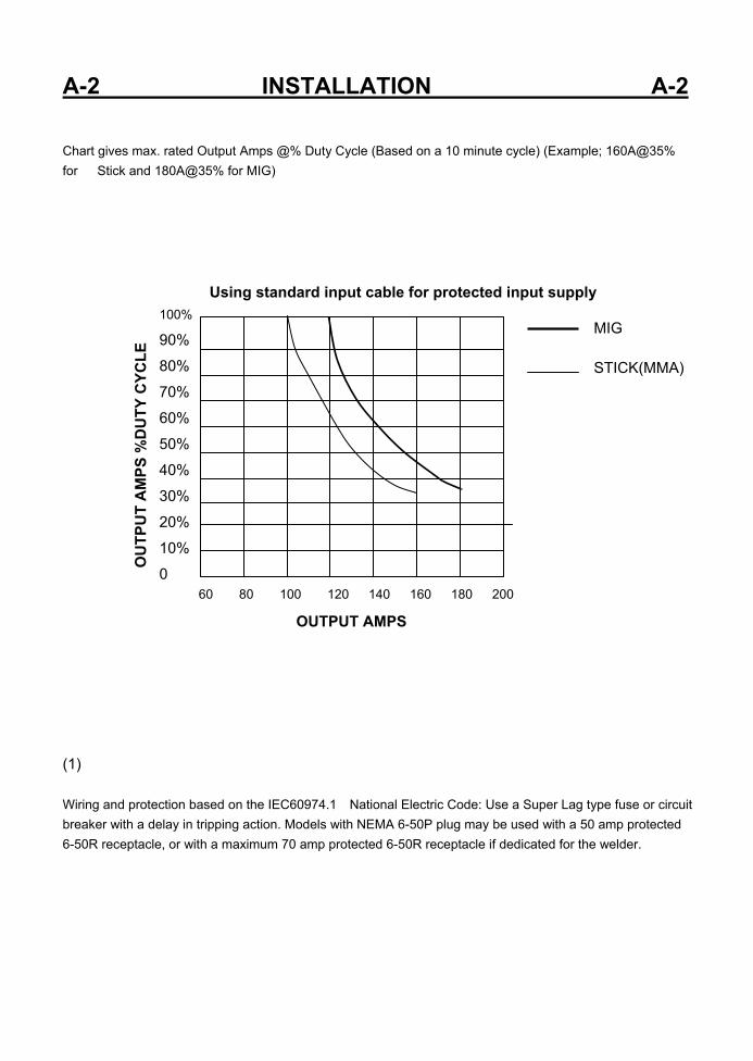
A-2 INSTALLATION A-2 Chart gives max. rated Output Amps @% Duty Cycle (Based on a 10 minute cycle) (Example; 160A@35% for Stick and 180A@35% for MIG) MIG STICK(MMA) (1) Wiring and protection based on the IEC60974.1 National Electric Code: Use a Super Lag type fuse or circuit breaker with a delay in tripping action. Models with NEMA 6-50P plug may be used with a 50 amp protected 6-50R receptacle, or with a maximum 70 amp protected 6-50R receptacle if dedicated for the welder.
60 80 100 120 140 160 180 200
100% 90% 80% 70% 60% 50% 40% 30% 20% 10% 0
OUTPUT AMPS
OU
TPU
T A
MPS
%D
UTY
CYC
LE
Using standard input cable for protected input supply
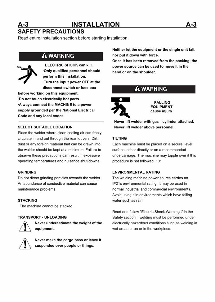
A-3 INSTALLATION A-3 SAFETY PRECAUTIONS Read entire installation section before starting installation.
ELECTRIC SHOCK can kill. ·Only qualified personnel should perform this installation. ·Turn the input power OFF at the disconnect switch or fuse box
before working on this equipment. ·Do not touch electrically hot parts. ·Always connect the MACHINE to a power supply grounded per the National Electrical Code and any local codes. SELECT SUITABLE LOCATION Place the welder where clean cooling air can freely circulate in and out through the rear louvers. Dirt, dust or any foreign material that can be drawn into the welder should be kept at a minimum. Failure to observe these precautions can result in excessive operating temperatures and nuisance shut-downs. GRINDING Do not direct grinding particles towards the welder. An abundance of conductive material can cause maintenance problems. STACKING The machine cannot be stacked. TRANSPORT - UNLOADING
Never underestimate the weight of the equipment. Never make the cargo pass or leave it suspended over people or things.
Neither let the equipment or the single unit fall, nor put it down with force. Once it has been removed from the packing, the power source can be used to move it in the hand or on the shoulder.
Never lift welder with gas cylinder attached. Never lift welder above personnel. TILTING Each machine must be placed on a secure, level surface, either directly or on a recommended undercarriage. The machine may topple over if this procedure is not followed. 10o
ENVIRONMENTAL RATING The welding machine power source carries an IP21s environmental rating. It may be used in normal industrial and commercial environments. Avoid using it in environments which have falling water such as rain. Read and follow "Electric Shock Warnings" in the Safety section if welding must be performed under electrically hazardous conditions such as welding in wet areas or on or in the workpiece.
FALLING EQUIPMENT cause injury

A-4 INSTALLATION A-4 MACHINE GROUNDING AND HIGH FREQUENCY INTERFERENCE PROTECTION This welder must be grounded! See your local and national electrical codes for proper grounding methods. The high frequency generator, being similar to a radio transmitter, may cause radio, TV and electronic equipment interference problems. These problems may be the result of radiated interference. Proper grounding methods can reduce or eliminate radiated interference. Radiated interference can develop in the following four ways: 1 Direct interference radiated from the welder. 2 Direct interference radiated from the welding leads. 3 Direct interference radiated from feedback into the power lines. 4 Interference from re-radiation of "pickup" by ungrounded metallic objects. Keeping these contributing factors in mind, installing equipment per the following instructions should minimize problems. 1 Keep the welder power supply lines as short as possible and enclose as much of them as possible in rigid metallic conduit or equivalent shielding for a distance of 50 feet (15.2m). There should be good electrical contact between this conduit and the welder case ground. Both ends of the conduit should be connected to a driven ground and the entire length should be continuous. 2 Keep the work and electrode leads as short as possible and as close together as possible. Lengths should not exceed 25 ft (7.6m). Tape the leads together when practical. 3 Be sure the torch and work cable rubber coverings are free of cuts and cracks that allow high frequency leakage. 4 Keep the torch in good repair and all connections tight to reduce high frequency leakage. 5 The work piece must be connected to an earth ground close to the work clamp, using one of the
following methods: a) A metal underground water pipe in direct contact with the earth for ten feet or more. b) A 3/4" (19mm) galvanized pipe or a 5/8" (16mm)solid galvanized iron, steel or copper rod driven at least eight feet into the ground. The ground should be securely made and the grounding cable should be as short as possible using cable of the same size as the work cable, or larger. Grounding to the building frame electrical conduit or along pipe system can result in reradiation, effectively making these members radiating antennas. 6 Keep cover and all screws securely in place. 7 Electrical conductors within 50 ft (15.2m) of the welder should be enclosed in grounded rigid metallic conduit or equivalent shielding, wherever possible. Flexible metallic conduit is generally not suitable. 8 When the welder is enclosed in a metal building, the metal building should be connected to several good earth driven electrical grounds (as in 5 (b) above) around the periphery of the building. Failure to observe these recommended installation procedures can cause radio or TV and electronic equipment interference problems and result in unsatisfactory welding performance resulting from lost high frequency power. INPUT CONNECTIONS Be sure the voltage, phase, and frequency of the input power is as specified on the rating plate, located on the rear of the machine. Have a qualified electrician provide input power supply to the receptacle or cord in accordance with all local and national electrical codes. Use a single phase line or one phase of a two or three phase line. Choose an input and grounding wire size according to local or national codes. Refer to the Technical Specifications page at the beginning of this section. Fuse the input circuit with the recommended super lag fuses or delay type circuit breakers.
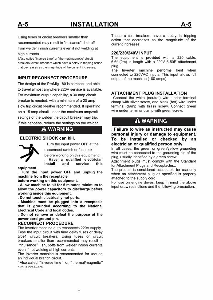
A-5 INSTALLATION A-5 Using fuses or circuit breakers smaller than recommended may result in "nuisance" shut-off from welder inrush currents even if not welding at high currents. 1Also called "inverse time" or "thermal/magnetic" circuit breakers; circuit breakers which have a delay in tripping action that decreases as the magnitude of the current increases.
INPUT RECONNECT PROCEDURE The design of the ProMig 180 is compact and able to travel almost anywhere 220V service is available. For maximum output capability, a 30 amp circuit breaker is needed, with a minimum of a 20 amp slow trip circuit breaker recommended. If operating on a 15 amp circuit near the maximum amp/volt settings of the welder the circuit breaker may trip. If this happens, reduce the settings on the welder.
ELECTRIC SHOCK can kill.
Turn the input power OFF at the disconnect switch or fuse box before working on this equipment. . Have a qualified electrician install and service this
equipment. . Turn the input power OFF and unplug the machine from the receptacle before working on this equipment. . Allow machine to sit for 5 minutes minimum to allow the power capacitors to discharge before working inside this equipment. . Do not touch electrically hot parts. . Machine must be plugged into a receptacle that is grounded according to the National Electrical Code and local codes. . Do not remove or defeat the purpose of the power cord ground pin. RECONNECT PROCEDURE The Inverter machine auto reconnects 220V supply. Fuse the input circuit with time delay fuses or delay type1 circuit breakers. Using fuses or circuit breakers smaller than recommended may result in “nuisance” shut-offs from welder inrush currents even if not welding at high currents. The Inverter machine is recommended for use on an individual branch circuit. 1Also called “inverse time” or “thermal/magnetic” circuit breakers.
These circuit breakers have a delay in tripping action that decreases as the magnitude of the current increases. 220/230/240V INPUT The equipment is provided with a 220 cable, 6.6ft.(2m) in length with a 220V 6-50P attachment plug. The Inverter machine performs best when connected to 220VAC inputs. This input allows full output of the machine (180 amps). ATTACHMENT PLUG INSTALLATION Connect the white (neutral) wire under terminal clamp with silver screw, and black (hot) wire under terminal clamp with brass screw. Connect green wire under terminal clamp with green screw.
. Failure to wire as instructed may cause personal injury or damage to equipment. To be installed or checked by an electrician or qualified person only. In all cases, the green or green/yellow grounding wire must be connected to the grounding pin of the plug, usually identified by a green screw. Attachment plugs must comply with the Standard for Attachment Plugs and Receptacles,. The product is considered acceptable for use only when an attachment plug as specified is properly attached to the supply cord. For use on engine drives, keep in mind the above input draw restrictions and the following precaution.

A-6 INSTALLATION A-6 ENGINE DRIVEN GENERATOR The Inverter machine can be operated on engine driven generators as long as the 220/230/240 volt auxiliary meets the following conditions: . The AC waveform peak voltage is below 400 volts. . The AC waveform frequency is between 45 and 65Hz. The following Lincoln engine drives meet these conditions when run in the high idle mode: ●Ranger 250,305 ●. Commander 300, 400, & 500 Some engine drives do not meet these conditions (e.g. Miller Bobcats, etc). Operation of the Inverter machine is not recommended on engine drives not conforming to these conditions. Such drives may deliver unacceptably high voltage levels to the Inverter machine power source. CONNECTIONS FOR MIG WELDING WORK CABLE CONNECTION Next, connect the work cable to the “-” output terminal in the same way. Interference Protection section of this manual for the proper procedure on grounding the work clamp and work piece.
SHIELDING GAS CONNECTION Obtain the necessary inert shielding gas (usually argon). Connect the cylinder of gas with the pressure regulator and flow gage. Install the gas hose between the regulator and gas inlet (located on the rear of the welder).
CYLINDER could explode if damaged. Keep cylinder upright and chained to a support.
Keep cylinder away from areas where it could be damaged. Never allow the torch to touch the cylinder. Keep cylinder away from live electrical circuits. Maximum inlet pressure 60 psi. A cylinder is loaded by leaning it slightly sideways and rocking it up on the platform, being careful not to allow the Under-Storage Cart to roll. Secure the cylinder in place with the provided chain. Unload by following these steps in reverse. CONNECTIONS FOR STICK (SMAW) WELDING A. POSITIVE CONNECTION B . NEGATIVE CONNECTION
STICK ELECTRODE CABLE AND WORK CABLE CONNECTION Refer to Field Installed Options in Accessories Section of this manual for STICK welding equipment which is available for use with the inverter machine. An electrode holder with Twist-Mate cable and Twist-Mate connector are available separately for use with the inverter machine.. Turn the Power Switch "OFF". Connect the Twist-Mate quick connect plug into the Electrode and turn it clockwise until it is tight. The work cable and work clamp are factory connected.
welder electrode holder
workpiece workpiece
welder electrode holder
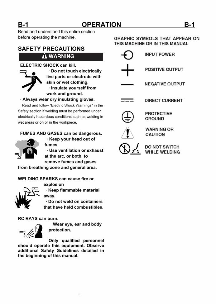
B-1 OPERATION B-1 Read and understand this entire section before operating the machine. SAFETY PRECAUTIONS
ELECTRIC SHOCK can kill.
· Do not touch electrically live parts or electrode with skin or wet clothing. · Insulate yourself from work and ground.
· Always wear dry insulating gloves. Read and follow "Electric Shock Warnings" in the Safety section if welding must be performed under electrically hazardous conditions such as welding in wet areas or on or in the workpiece. FUMES AND GASES can be dangerous.
· Keep your head out of fumes. · Use ventilation or exhaust at the arc, or both, to remove fumes and gases
from breathing zone and general area. WELDING SPARKS can cause fire or
explosion · Keep flammable material away. · Do not weld on containers that have held combustibles.
RC RAYS can burn.
Wear eye, ear and body protection. Only qualified personnel
should operate this equipment. Observe additional Safety Guidelines detailed in the beginning of this manual.
B-2 OPERATION B-2 PRODUCT DESCRIPTION The ProMig180 operates on 220V single phase input and
comes equipped with a standard 220V NEMA 5-50P plug for
convenient use in almost any standard 220V outlet. The
ProMig180’s IGBT inverter design is rated for 35% duty cycle
at 180 amps. It is designed to consume less power, provide
better arc stability and offer better duty cycle over transformer
welders in the 220V input class. There are no tapped
settings which prevent fine adjustment of either voltage or wire
speed. Both amps (wire speed) and voltage are infinitely
adjustable within their ranges.
Basic Design and Construction. The ProMig180 features
an advanced IGBT inverter design, with plug and play circuits
and controls for maximum service-ability and lifespan. The
unit has a full time high speed fan which maintains
temperature levels providing increased duty cycle and
performance. A heavy duty wire feeder mechanism
features cast aluminum and steel construction for long life.
The unit will accommo-date 4” (1-2lb) and 8” (10-12lb) rolls of
wire and fea-tures rapid tool-free, wire spool installation.
Gun connection is quick with the tool-free design of the Euro
quick connect fitting. The Work clamp is equally easy to
install, and features a 25 series DINSE style connector.
For transport or storage both MIG gun and work clamp can be
disconnected in less than 15 seconds. The standard drive
rolls included with the unit are designed for use
with .023”-.035” solid wire. The smaller groove (.6mm)
should be used with .023-.027” wire. The larger groove
(.8mm) should be used with .030 and .035 wire. For general
purpose use, our company recommends that .030” ER70S-6
wire be used for most general pur-pose welding. This
diameter wire and class is designed to work well with the
amp output range that the ProMig180 delivers. Special
applications like aluminum may be welded with the optional
spool gun. It is possible to weld aluminum with the main
feeder and gun, but a special gun liner must be purchased
and a harder wire such as 5356 should be used to prevent
“bird’s nesting” of the wire. Stainless can easily be welded
with either the spool gun or the standard gun. Using a spool
gun may be a more practical choice if welding smaller projects
with stainless or aluminum since both stainless and aluminum
wires are expensive. Either coated (copper or other
coatings) or uncoated steel wire may be used for welding
steel as long as it remains rust-free and clean.
. NOTE: For flux core use, special drive rolls with a
serrated design may be purchased from our company.
PROCESS LIMITATIONS The machines are not recommended for arc gouging due to
it's limited output capacity, and are also not recommended for
pipe thawing.
RECOMMENDED QUIPMENT/INTERFACE (See Installed Options in Accessories Section for more details)
The machines will be available as a basic Machine (Only) and
in Factory Basic module will also be available as with
Domestic,.
(SEE PACKING LIST,PLEASE)
EQUIPMENT LIMITATIONS The machines are protected from over loads beyond the
output ratings and duty cycles, per the Specifications in the
Installation Section, with Thermostat protection of the output
power coils and rectifiers.
WELDING CAPABILITY(Duty Cycle) The machine is rated at 180 amps, 23volts, at 35% duty cycle
on a ten minute basis. It is capable of higher duty cycles at
lower output currents. See rated output graph, on specification
sheet located in the Installation Section. If the duty cycle is
exceeded, a thermal protector will shut off the output until the
machine cools.
B-3 OPERATION B-3 CONTROLS AND SETTINGS
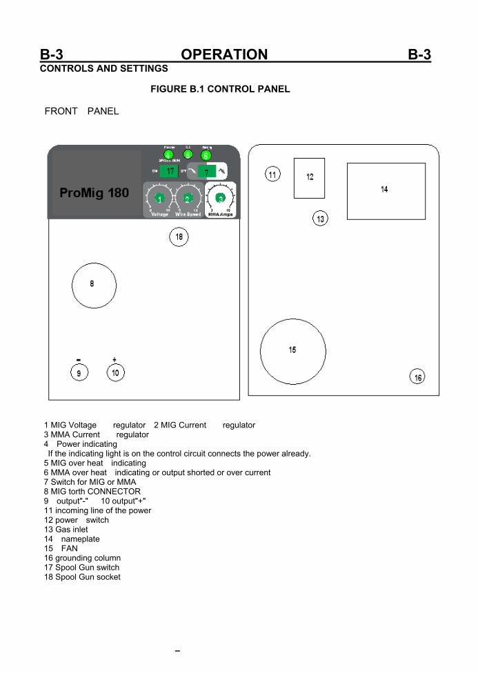
FIGURE B.1 CONTROL PANEL
FRONT PANEL
1 MIG Voltage regulator 2 MIG Current regulator 3 MMA Current regulator 4 Power indicating If the indicating light is on the control circuit connects the power already. 5 MIG over heat indicating 6 MMA over heat indicating or output shorted or over current 7 Switch for MIG or MMA 8 MIG torth CONNECTOR 9 output"-" 10 output"+" 11 incoming line of the power 12 power switch 13 Gas inlet 14 nameplate 15 FAN 16 grounding column 17 Spool Gun switch 18 Spool Gun socket
B-4 OPERATION B-4 Front Panel:
1 MIG Voltage regulator The voltage selector increases and decreases the voltage incrementally through‐out the range. Increasing the voltage helps im‐prove wet in and puddle fluidity. Too little volt‐age results in a ropey, narrow weld with poor fusion. Too much voltage results in an erratic, violent arc and undercutting.
2 MIG Current regulator The wire speed se‐lector controls amperage throughout the range by varying the speed of the wire. The relation‐ship between wire feed speed and amps is a di‐rect one. Increasing one, increases the other. Actual amp output at the same given wire speed will vary with different diameter wires. 3 MMA Current regulator 4. Power indicating. The LED’S indicate the existing status of the machine. The On indicator is lit any‐time the machine is turned on . 5. MIG over heat indicating The amber color light will be lit when the duty cycle has been ex‐ceeded. When it is lit, welding will be interrupt‐ed. (The wire will continue to feed but will not arc when the trigger is pressed.) If the duty cycle is exceeded, allow the unit to cool for 15 minutes before resetting the machine by powering it off and back on. Do no turn the welder off until the unit has sufficiently cooled.
6. MMA over heat indicating or output shorted or over current If the red over‐current light is lit, welding will also be interrupt‐ed. If this light comes on, an overcurrent/overvoltage or under voltage has occurred. Check wiring such as extension cords and circuit breakers for sufficient current carrying capacity. Also check to see if slag has bridged the space between the contact tip and the shielding gas nozzle or if the wire stick out is too long. Occa‐sionally this may occur when using larger wire (.035”) at or near maximum settings with a long stick out of the wire. Once the cause has been remedied, turn the power off and back on to re‐set the welder. If the light does not clear after remedying the cause, contact our company technical support for further diagnosis. 7. Switch for MIG or MMA 8. Euro Connector. The Euro connector provides rapid and secure connection of the MIG
gun without having to use tools. Use only hand pres‐sure to tighten the connector. Do not over‐tighten the plastic retainer collar. Both the MIG gun and optional spool gun connect to this point. Both the spool gun and MIG gun cannot be con‐nected at the same time.
9. Work Clamp Connector. This is where the work clamp connects to the welder. This is a DINSE 25 style connector. The work clamp cable can be lengthened by removing the rubber cover. Firmly grip the cover and slide it back. Under the con‐nector is a set screw that retains the cable. If arc starting becomes irregular or difficult, check to ensure the work clamp and cable are in good repair that the cable is tight in the connector.
10. output"+" 17. Spool Gun Switch. This switch changes the units output to the spool gun. The spool gun connects to the main Euro connection, and wire speed/voltage control is retained on the panel. 18. Spool Gun Connector. The spool gun control wire is connected directly to this 2 pin connector. This provides On/Off control of spool gun feed‐ing. It does not provide welding power. Rear Panel: 11. Gas Supply. Connect the Gas regulator hose to this point via the brass barb fitting. The hose barb connection must be tight to prevent gas leakage. Install an extra clamp if needed to prevent gas from escaping. Test for leaks with soapy water. Do not leave gas valve open on cylinder when not attended or in use. 12. Power Switch. Turns unit on or off. 13. Power Input Cable. The unit operates on 110/120V input power. This is a standard NEMA 5‐15P plug used in North America. 14.Nameplate The data plate stamped on the metal structure complies with the EN 60974-1, EN50199(EN60974-10) international standards and contains the following information: * (a) Manufacturer's name and address * (b) Trademark * (c) Model * (No) Serial number
~
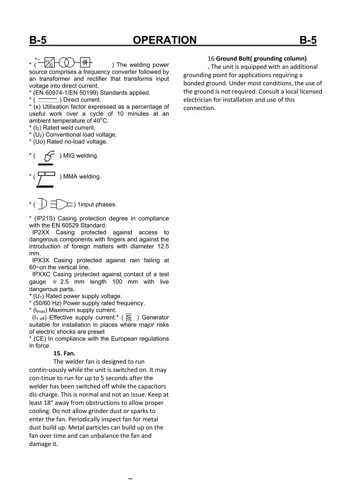
B-5 OPERATION B-5 * ( ) The welding power source comprises a frequency converter followed by an transformer and rectifier that transforms input voltage into direct current. * (EN 60974-1/EN 50199) Standards applied. * ( ) Direct current. * (x) Utilisation factor expressed as a percentage of useful work over a cycle of 10 minutes at an ambient temperature of 40oC. * (I2) Rated weld current. * (U2) Conventional load voltage. * (Uo) Rated no-load voltage. * ( ) MIG welding. * ( ) MMA welding. * ( )) 1input phases. * (IP21S) Casing protection degree in compliance with the EN 60529 Standard: IP2XX Casing protected against access to dangerous components with fingers and against the introduction of foreign matters with diameter 12.5 mm. IPX3X Casing protected against rain failing at 60~on the vertical line. IPXXC Casing protected against contact of a test gauge φ 2.5 mm length 100 mm with live dangerous parts, * (U1) Rated power supply voltage. * (50/60 Hz) Power supply rated frequency. * (llmax) Maximum supply current. (I1 eff) Effective supply current.* ( S ) Generator suitable for installation in places where major risks of electric shocks are preset * (CE) In compliance with the European regulations in force. 15. Fan. The welder fan is designed to run contin‐uously while the unit is switched on. It may con‐tinue to run for up to 5 seconds after the welder has been switched off while the capacitors dis‐charge. This is normal and not an issue. Keep at least 18” away from obstructions to allow proper cooling. Do not allow grinder dust or sparks to enter the fan. Periodically inspect fan for metal dust build up. Metal particles can build up on the fan over time and can unbalance the fan and damage it.
16 Ground Bolt( grounding column) . The unit is equipped with an additional grounding point for applications requiring a bonded ground. Under most conditions, the use of the ground is not required. Consult a local licensed electrician for installation and use of this connection.
1~ f1 f2 ~
B-6 OPERATION B-6
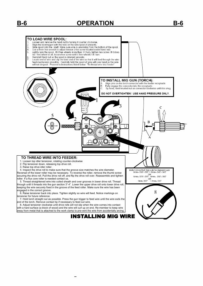
TO THREAD WIRE INTO FEEDER: 1. Loosen top idler tensioner, rotating counter-clockwise 2. Flip tensioner down, releasing top drive roll. 3. Raise top drive idler roller. 4. Inspect the drive roll to make sure that the groove size matches the wire diameter.
Reversal of the lower roller may be necessary. To reverse the roller, remove the thumb screw securing the drive roll. Pull the drive roll off, and flip the drive roll over. Reassemble and tighten roller. If a flux core roller is needed contact us.
5. Thread straightened wire into coiled sheath and over grooves in lower drive roll. Thread through until it threads into the gun section 3”-4”. Lower the upper drive roll onto lower drive roll, keeping the wire securely fixed in the groove of the feed roller. Make sure the wire has been engaged in the correct groove.
6. Raise tensioner back into place. Tighten slightly so wire will feed. Notice markings on tensioner for future reference.
7. Hold torch straight out as possible. Press the gun trigger to feed wire until the wire exits the end of the torch. Remove contact tip if necessary to feed out wire.
8. Adjust tensioner clockwise until drive rolls will not slip when the wire comes into contact with a hard surface (a block of wood) and the wire will curl up on end. Re-member to keep wire away from metal that is attached to the work clamp to pre-vent the wire from accidentally arcing.
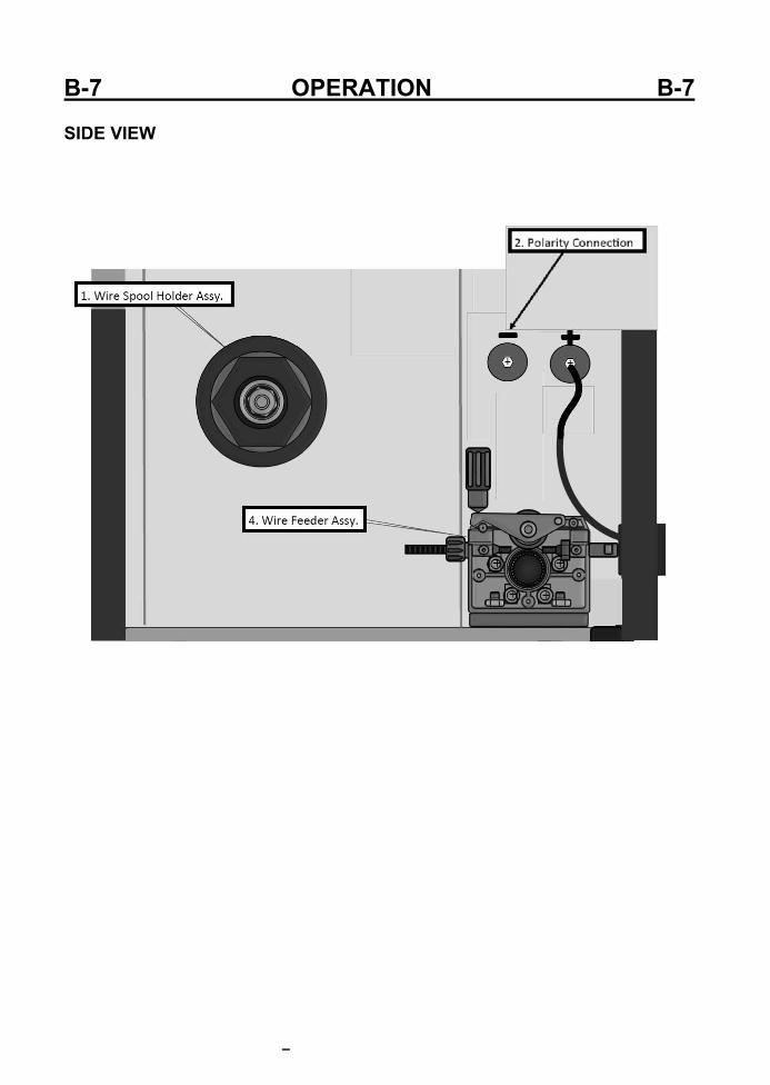
B-7 OPERATION B-7 SIDE VIEW
B-8 OPERATION B-8 Side Panel Description and Explanation: 1. Wire Spool Carrier Assembly. Make note of the correct assembly order if disassembled. The order in which they are assembled is im‐portant to be able to provide enough re‐sistance to prevent de‐spooling of the wire. When inserting the spool , make sure the small tab on the inside of the spool holder is located in one of the recesses made into the spool, if any. Tighten the hex head screw under the hand nut after installing the wire spool so that the wire will not continue to keep rolling more than a 1/4 turn after wire has stopped feeding. Do not over tighten so that the drive roller slips or the feeder strains to pull the wire due to excessive resistance. The tensioner assem‐bly can accommodate 8” spools of wire (10‐12 lbs.) However, a simple center adapter may be easily fabricated from PVC pipe to accom‐modate the smaller 4” diameter roll (2lb roll). NOTE: 4” rolls may cause excessive cast due to the tighter coiling of the wire around a smaller center hub. These can cause issues with the wire corkscrewing while welding and interfere with arc stability as the wire wanders from side to side. It also can create feeding issues as it can be more difficult to thread through the drive roller causing the wire to jump outside the groove if proper pressure is not maintained. 2. Polarity Buss Bar. Note the “+” and “‐” sym‐bols located on the inside of the unit next to the buss bar terminals. To change the polarity of the MIG torch, simply loosen the middle screw and remove the other screws on the polarity terminals. By pivoting the buss bar on the center loosened screw, swing the buss bar into position over the desired polarity. Rein‐stall the screws, lining up the holes in the buss bar with the terminal. Tighten all buss bar screws. Always remember to alter your work clamp to reflect the polarity change if using flux core. If the buss bar is connected to nega‐tive, then the work clamp should be in the “+” positive output terminal. Standard polarity for MIG is “+” (DCEP) with the work clamp in the negative. 4. Wire Feed Assembly. Note the numbers on the side of the tensioner. These numbers are a reference point to help properly tension the wire so that
the drive roller will not slip. Do not over‐tension the wire because it can create a condition known as birds nesting, where the wire will tangle up around the feeder and will not slip if the wire burns back into tip, sticks fast in the weld puddle or other resistance is met. This will continue wrap the wire around the drive mechanism or jam wire inside the gun liner until the trigger is released. Consid‐erable effort is usually needed to clear out a bird’s nest condition. Too little tension will result in wire slippage and cause rapid wear on the drive components. Do a feed test before beginning a weld. Occasional cleaning of the feeder mechanism is necessary to prevent wear and damage to the feeder and to the MIG gun liner. Regularly monitor any metal flaking and dirt build up that may occur. Clean it away gently with compressed air. Do not use harsh cleaners or solvents. Felt wire lubricators may be bought and used to keep feeding cleanly while using steel or stainless wire. You may purchase additional drive roll sizes from Our company, including flux core. Each groove will drive at least two sizes of wire. For example if the roller has a .8 mm groove and a 1.0 mm groove, this will allow either .030” and .035” wire to be used in the smaller groove. The larger groove allows .040” and .045” wire to be used. Do not forget to change the contact tip size when changing to a another wire diame‐ter. Depending upon the size wire used, the liner from the MIG gun may need to be changed to work properly. Do not attempt to feed any wire greater than .045” wire with the welder. Most common jobs can be welded with either .030” or . 035” wire. NOTE: If erratic feeding is experienced, check wire feed tensioner, Spool Tension (rolling resistance) and for correct size groove. Also make sure the wire is riding in the groove and not on the shoulder of the lower drive roll.
B-9 OPERATION B-9
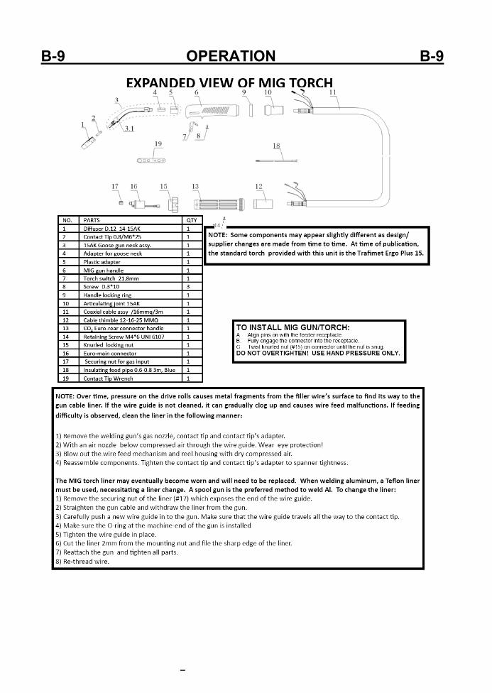
B-10 OPERATION B-10 GENERAL NOTES: 1. While welding aluminum with the Spool gun or MIG gun you must use 100% argon. You cannot use a mix as you would with steel or stainless. 2. While welding aluminum with the Spool gun or MIG gun you must use the next size up tip or a special oversize tip for the wire because the heat will cause the aluminum wire to swell and it will either drag or seize in the tip. 3. While welding aluminum with the MIG process, best results are achieved by using a dedi‐cated stainless steel brush to remove the oxide layer and acetone or aluminum cleaner before welding. Even though aluminum may appear shiny and clean, it still has an oxide layer, and a thin layer of oil left over from the manufacturing process. Some soot will ap‐pear in most MIG welds but if a lot is noticed, you have either contaminated metal, or in‐sufficient gas flow. You can also induce turbulence by having too much of a torch angle. Start with a 90 degree angle and then lean the gun slightly (about 15 degrees) to the “push” position. 4. Welding aluminum is not a short circuit process. It is a spray transfer process. Spray trans‐fer is a process that is can be used to weld many metals, but in Aluminum it must be used to weld correctly. In spray transfer, the wire does not short out against the weld material. Instead a steady “spray” of droplets of molten metal pinches off before the wire can con‐tact the material. It is a much quieter process. If you are not familiar with the spray trans‐fer process, please research it before you try it. If you incorrectly adjust the welder while welding aluminum in the MIG process, you will burn up contact tips almost instantly. 5. If you are trying to weld Aluminum with . 025 wire or smaller, you may not achieve ade‐quate results because of the higher wire feed speeds needed. Try stepping up to the next wire size and wire feed speed rate requirements will drop. 6. If using with a generator, use with only a generator rated or certified for clean power
out‐put. This a rating given by the manufacturer of the generator if the total harmonic distor‐tion is 10% or less (usually 5% or less). A generator that does not produce clean power can cause erratic operation and damage to the welder’s electronics. Ideally a generator capable of generating 3500 watts or more should be used. 7. Replace the contact tip when the orifice is noticeably enlarged or becomes egg shaped. A worn out contact tip can cause issues with arc stability. Always make sure you are using the correct size tip for the application.
B-11 OPERATION B-11

B-12 OPERATION B-12 General operation and setup. 1) Wire Tension. Always check wire tension before use. Use no more wire tension than is necessary. (See page 15 for adjustment.) 2) Work Clamp. MIG welders require good work clamp (ground) contact. Routinely inspect work clamp and cable and make sure they are in good condition and that the cables are held tight in the connectors and are free of corrosion. Always grind a small clean spot where the work clamp is to be attached. Always connect the work clamp directly to the metal being welded if possible. Hard starting or “machine gunning” at the start of the weld may be a result of a poor ground. 3) MIG gun use and maintenance. Before use make sure that collar on the Euro quick connect has been fully tightened by hand. Do not use tools. Grip the gun firmly when starting the arc to prevent push‐off and spattering/popping at the start of the weld. Trim the wire to 1/2” or less and hold the gun just as close to the metal to start the weld. Use nozzle dip or a anti spatter spray to help keep the MIG gun nozzle from becoming plugged with slag. Reg‐ularly check and clean the nozzle. Nozzle dip and anti spatter can be bought at almost any welding supply store. It is an economical way to prevent harmful accumulation of slag in and on the nozzle and can be used in the weld area to prevent spatter from sticking to the work‐piece. Do not apply too much to the nozzle or directly to the weld area or porosity may occur. Only apply when the protective qualities begin to dissipate. Nozzle dip and anti spatter also provide some lubricity to the contact tip and increases the lifespan and ease of feeding. Make sure to change contact tip size when changing the wire size. Using too large of a contact tip can cause erratic arc behavior. Using too small of a contact tip can cause jamming. When welding with aluminum, use a special alumi‐num contact tip or at least one size larger regular contact tip to accommodate the wire as it expands due to the heat. Over time, the gun liner may be‐come gradually fouled with dirt, metal filings from the coating and other possible contaminants. To prevent this, regularly remove the wire from the cable, and blow dry compressed air down the gun neck with the contact tip removed. If necessary remove the liner and replace it if becomes worn and irregular or difficult feeding or gas flow is ob‐served. NOTE: (Binzel/Trafimet 15 series) When removing the shielding gas nozzle, twist the nozzle like a screw to install or remove as it grips the noz‐zle tightly. There is a special retaining spring un‐der the nozzle that acts as a thread. This feature allows you to position the nozzle in order to vary the depth of the contact tip for different welding applications. 4) Shielding gas selection and use. For MIG opera‐tion, selection of the proper shielding gas is im‐portant. Remember, each shielding gas mixture and filler metal thickness will require a different setting of voltage and amps. A 75/25 (75% Ar‐gon/25%CO2) mixture is recommended for general purpose steel welding. This yields the best results in most circumstances. To reduce spatter further, other blends of Ar/CO2 with higher percentages of Argon (a true inert gas) may be used. The puddle may be difficult to control and cold lap may occur if the mix is over 85% Argon, especially if used in out of position welds. Generally, when there is a high‐er percentage of Argon present in the mix, the cost of the mix will be greater. Though less desirable, 100% CO2 may also be used. Greater penetration with a narrower bead profile can be achieved with 100% CO2. However, extra spatter, smoke and oxidation will be noticed. CO2 is not a a true inert gas so it can impart a dull gray, and even flaky ap‐pearance to the weld as it interacts with the molten metal. If 100% CO2 is used, regularly check to en‐sure the regulator is not freezing up. CO2 offers a cheaper option but losses in transfer efficiency (amount of metal actually deposited versus total amount consumed) and extra time spent for clean‐ing spatter may negate initial cost savings. For Stainless, a commercial Tri‐mix of gas is generally used for short circuit transfer. This is usually a pro‐prietary % blend of Argon, Helium, and CO2. Con‐sult with your local welding supply store. For alu‐minum, 100% Argon must be used.

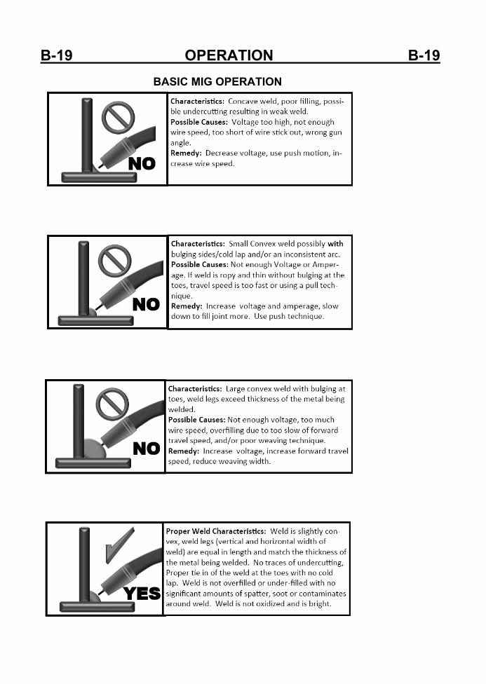
B-13 OPERATION B-13 5) Regulator and shielding gas flow adjustment. NOTE: Regulators may be supplied in LPM or CFH. Please note which has been provided before starting to weld for future reference. The regula‐tor should always be mounted nearly vertical if not with a slight upturn (for safety) so that the ball may float free. Always stand to the opposite side of the regulator and slowly open the regulator with the front and top of the regulator facing away from you. Gas flow requirements vary in MIG greatly and a lot depends upon the environment. More gas will be required in open/drafty areas. To avoid wasting shielding gas, perform some preliminary test welds. To adjust, decrease gas flow until the weld begins to bubble and exhibit porosity. Gradu‐ally increase the gas flow until the bubbles disap‐pears completely. Crack the adjustment on the regulator an small additional amount to ensure full gas coverage. This process will reduce waste and help ensure you are not introducing oxygen into the weld. As the pressure drops within the cylin‐der readjustment may be necessary. 6) MIG polarity. When using solid MIG wire, the polarity should always be electrode positive. This means the torch should always be connected to the positive (+) terminal when welding with solid wire. To check this, open the cover, and inspect the heavy power cable that runs from the front end of the wire feeder to the bolted terminals on the center divider wall that are marked either with a positive (+) sign or a negative (‐) sign. The cable should be screwed down to the terminal marked with the (+) sign for solid wire. For flux core, most (but not all) manufacturers of flux core wire specify the use of negative (‐) polarity. Consult the manu‐facturer’s recommendations regarding flux core or dual shield wire polarity before installation. If neg‐ative polarity is required, swap the feeder cable to the negative terminal. Always make sure the ter‐minal screw is fully tightened. Do not over tighten the terminal or it may strip out the terminal threads. If, after switching between solid and flux core wire, an erratic arc is noticed, double check the polarity. This is a commonly overlooked part of the changeover procedure. 7) Volt and Amp adjustment. The welder features infinite adjustment of voltage and wire feed speed within each range. Wire speed adjustment is di‐rectly related to amp output and the terms are generally used interchangeably. As wire speed in‐creases so does amperage and vice versa. In many welding charts and calculators, you may find actual amperage settings rather than a wire speed setting. Amperage output also depends upon the diameter of the wire as well. Both volts and amps are cali‐brated in numbers ranging from 1‐10 with infinite adjustment possibility between each number. These are relative numbers and are used only as a reference when repeating the same or similar set‐ up. If helpful for setting up the unit, the numbers 1‐10 can be thought of as representing 10%‐100% of full output for either voltage or wire speed. For each wire diameter, most users will find 3 to 5 settings that will fit their welding style and applica‐tions but often the ability to fine tune these settings for specific applications will be needed. At first, some experimentation will be necessary. The fol‐lowing method of setting up wires peed and voltage is commonly used by professionals in the industry to setup almost any type MIG. When setting up welding parameters, set the wire speed halfway then begin to lower the voltage until it begins to cold feed into the metal (also referred to as stub‐bing). Note the point where it begins to do so. Next, raise the voltage until the puddle becomes hot and the arc seems violent and irregular. Note that point as well. Lower the voltage to a point midway between the two extremes where the arc seems to even out. After the voltage is set, gradu‐ally adjust the wire feed/amps until the sound of the arc is crisp. Listen to the arc. A steady sizzle, or whine should be present. The weld puddle should be wetting out neatly on the edges of the weld. This sound has often been referred to as a “frying” sound. The sound should be regular, and the arc should be visually stable without significant pop‐ping and snapping. The wire should be disappear‐ing easily into the puddle without the arc stopping. If the wire speed is too high, violent popping with bits of flying wire may be noticed. If it is too low the arc will appear to melt the wire before it reach‐es the puddle and may melt irregularly, even burn‐ing back into the tip. Volts are responsible for how flat and wet the puddle appears. If too much volt‐age is used, the weld will appear wide and flat with the edges of the weld possibly exhibiting undercut. This will create weakness in the weld. If too little is used, the weld will appear rope like and may even sit on top of the metal with irregular fusion. Am‐perage/Wire speed is responsible for penetration. If it is set too high for the thickness of metal being
B-14 OPERATION B-14 used, burn through can occur, especially on thin gauge material. If welding thin materials such as used in exhaust systems or body work, make sure the wire speed is adjusted to reduce penetration before attempting a voltage change. General figures for both wire speed and amps can be easily determined. To determine wire speed, simply press the trigger (without welding) and hold it for 15 seconds. Measure the length of the wire that is run from the torch in 15 seconds and multiply by 4. This figure is your wire speed in inches per minute (IPM). To roughly determine amps, which are sometimes used by manufacturers for recommend‐ed settings, use the following formulas for the fol‐lowing wire thicknesses: .023”: IPM/3.5 = Amps .030”: IPM/2 = Amps .035”: IPM/1.6 = Amps The actual constant given in this formula represents “inches per amp”. This formula is only a guide and is only accurate in lower ranges as the function is not tru‐ly linear. But it usually will be within the overall range specified by the manufacturer. For each manufacturer, the filler wire diameter amp range may differ some‐what, though a general range can be established. Spool Gun. The spool gun is an optional, but use‐ful tool to have for welding small and medium projects aluminum projects that are 3/32” and over in thickness. The spool gun connects directly in place of the regular MIG gun. The Spool gun picks up the gas and power at the Euro connection with a separate control connection for the trigger on the spool gun. Once the spool gun panel switch is flipped, the trigger will control on and off operation of the gun. Wire speed and voltage are still controlled at the panel however. NOTE: Some guns our company sells may have a separate control mounted on the spool gun handle for wire speed, but is inoperative and is not used with this unit. When welding aluminum, the unit should be welded in the spray arc mode. Typically spool guns are good for welding 3/32” and thicker aluminum. Spray arc mode is a mode where the voltage is increased to near maxi‐mum voltage for this unit, and wire speed is adjusted so that the wire melts in a steady stream of consistently sized droplets before the wire contacts the metal. A slight hiss will be present if done correctly. There is a threshold for spray arc, and it requires higher voltage and increased wire speed to force it into this mode. This is a quieter mode than regular short circuit with quick wet in and fast forward travel. It’s recommended that .030” wire be used to achieve the best results. .023” wire may be used as well, but the unit may not achieve true spray arc mode as it requires more wire speed than the wire feeder can generate. In general, the smaller the wire, the more wire speed is required for spray arc. Larger diameter wire may cause overcur‐rents and may not feed well through the gun. More information about spray arc welding with MIG can be found in a variety of educational welding resources online. Read over materials available and watch demonstration videos for more information.
B-15 OPERATION B-15
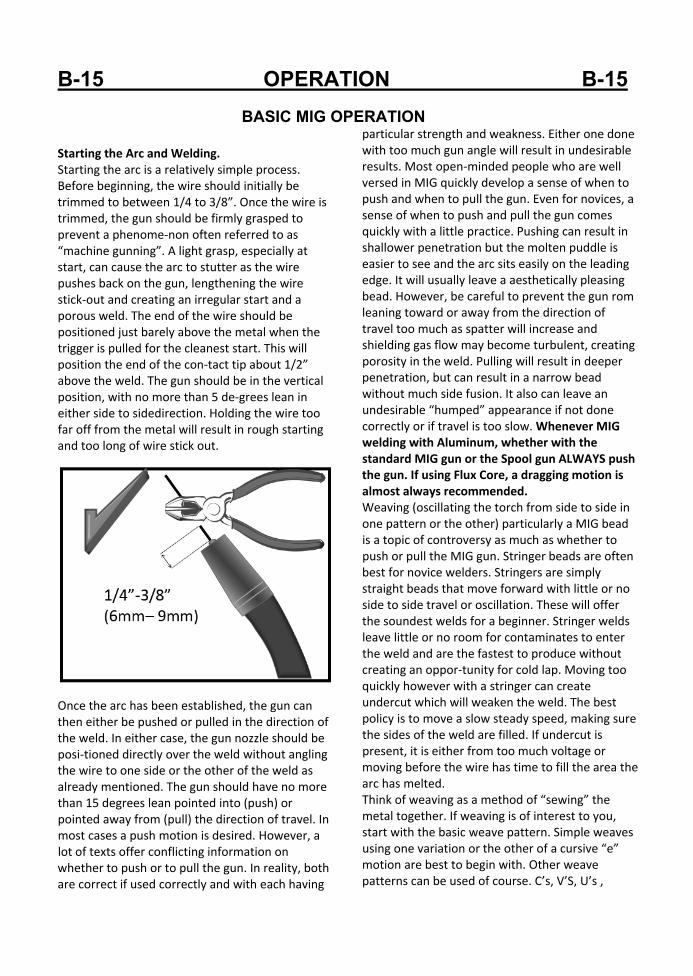
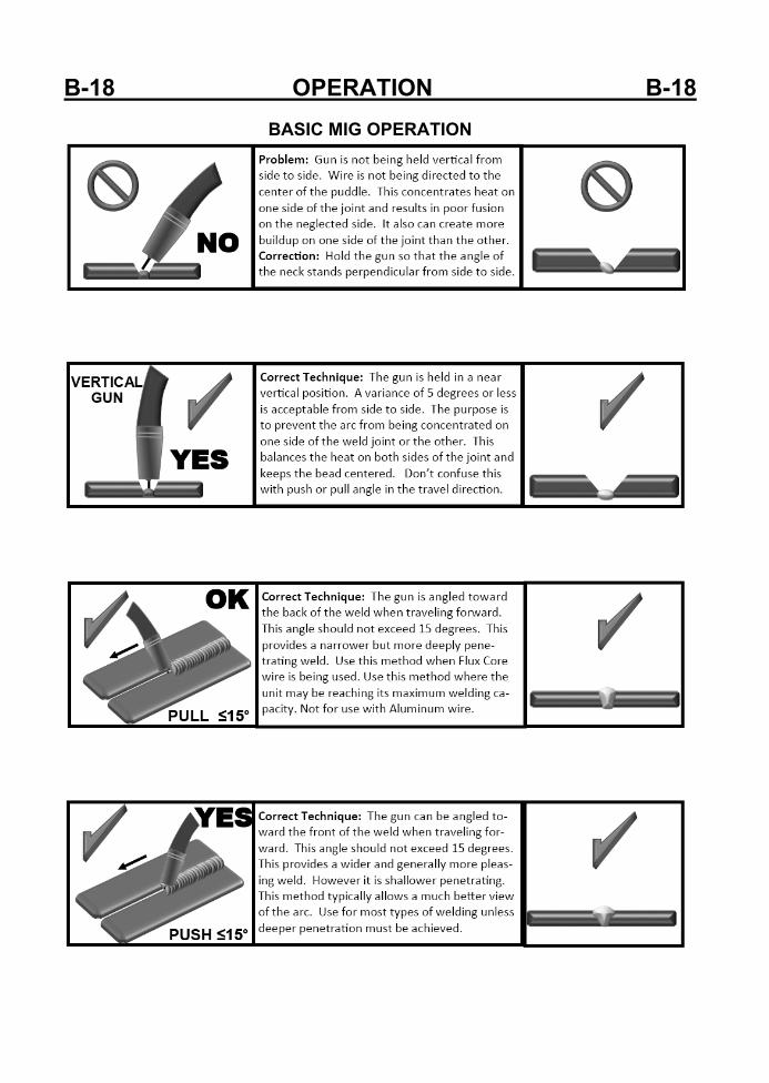
BASIC MIG OPERATION Starting the Arc and Welding. Starting the arc is a relatively simple process. Before beginning, the wire should initially be trimmed to between 1/4 to 3/8”. Once the wire is trimmed, the gun should be firmly grasped to prevent a phenome‐non often referred to as “machine gunning”. A light grasp, especially at start, can cause the arc to stutter as the wire pushes back on the gun, lengthening the wire stick‐out and creating an irregular start and a porous weld. The end of the wire should be positioned just barely above the metal when the trigger is pulled for the cleanest start. This will position the end of the con‐tact tip about 1/2” above the weld. The gun should be in the vertical position, with no more than 5 de‐grees lean in either side to sidedirection. Holding the wire too far off from the metal will result in rough starting and too long of wire stick out. Once the arc has been established, the gun can then either be pushed or pulled in the direction of the weld. In either case, the gun nozzle should be posi‐tioned directly over the weld without angling the wire to one side or the other of the weld as already mentioned. The gun should have no more than 15 degrees lean pointed into (push) or pointed away from (pull) the direction of travel. In most cases a push motion is desired. However, a lot of texts offer conflicting information on whether to push or to pull the gun. In reality, both are correct if used correctly and with each having
particular strength and weakness. Either one done with too much gun angle will result in undesirable results. Most open‐minded people who are well versed in MIG quickly develop a sense of when to push and when to pull the gun. Even for novices, a sense of when to push and pull the gun comes quickly with a little practice. Pushing can result in shallower penetration but the molten puddle is easier to see and the arc sits easily on the leading edge. It will usually leave a aesthetically pleasing bead. However, be careful to prevent the gun rom leaning toward or away from the direction of travel too much as spatter will increase and shielding gas flow may become turbulent, creating porosity in the weld. Pulling will result in deeper penetration, but can result in a narrow bead without much side fusion. It also can leave an undesirable “humped” appearance if not done correctly or if travel is too slow. Whenever MIG welding with Aluminum, whether with the standard MIG gun or the Spool gun ALWAYS push the gun. If using Flux Core, a dragging motion is almost always recommended. Weaving (oscillating the torch from side to side in one pattern or the other) particularly a MIG bead is a topic of controversy as much as whether to push or pull the MIG gun. Stringer beads are often best for novice welders. Stringers are simply straight beads that move forward with little or no side to side travel or oscillation. These will offer the soundest welds for a beginner. Stringer welds leave little or no room for contaminates to enter the weld and are the fastest to produce without creating an oppor‐tunity for cold lap. Moving too quickly however with a stringer can create undercut which will weaken the weld. The best policy is to move a slow steady speed, making sure the sides of the weld are filled. If undercut is present, it is either from too much voltage or moving before the wire has time to fill the area the arc has melted. Think of weaving as a method of “sewing” the metal together. If weaving is of interest to you, start with the basic weave pattern. Simple weaves using one variation or the other of a cursive “e” motion are best to begin with. Other weave patterns can be used of course. C’s, V’S, U’s ,

B-16 OPERATION B-16
BASIC MIG OPERATIONTriangles and many more weave patterns can be used depending upon the application. Weaves are employed for a number of reasons. Weaves are often considered to have a more pleasing appearance and can help bridge gaps where fit up is a problem. A weave is also frequently used to manage heat build up. For example: when welding vertically weaves are almost always used to prevent the molten metal from sagging due to the force of gravity. The major drawback of weaving is that it introduces a greater possibility of getting in‐clusions and other forms of contamination in the weld. Properly done weaving is a valuable tool, but it must be practiced before employing it in any struc‐tural or critical application. Metal Cleaning. MIG welding requires a well prepped surface to ob‐tain a sound weld. The removal of paint, rust mill scale, or other contaminate such as grease should be done before welding. Stick welding is more forgiving of rust and mill scale, but when MIG welding, con‐taminates will result in porosity and inclusions in the weld, weakening it. A grinder will usually prep the metal sufficiently to remove oxidation and paint. However, to remove grease a degreaser such as ace‐tone should be used. Do not use any degreaser such a brake cleaner with chlorinated solvents or death or serious injury may occur! A MIG wire such as ER70S‐6 or ER70S‐2 includes a sufficient level of deoxidizers such as silicone and copper that are formulated to allow it to handle mi‐nor to moderate amounts of rust and mill scale. These deoxidizers will float out most moderate amounts of contaminates out of the weld and will appear in the usual form of glassy like deposits on top of the cooled metal. They are easily brushed off before starting the next pass. They should not be welded over. Any pinholes that appear are a result of trapped gas in the weld and should be ground out before the next pass. It should be noted that some MIG wires such as ER70S‐3 have low levels of deoxi‐dizers and must be thoroughly cleaned and ground before welding. Multiple Pass Welds. One of the common misunderstandings that people have when beginning to MIG weld is that if
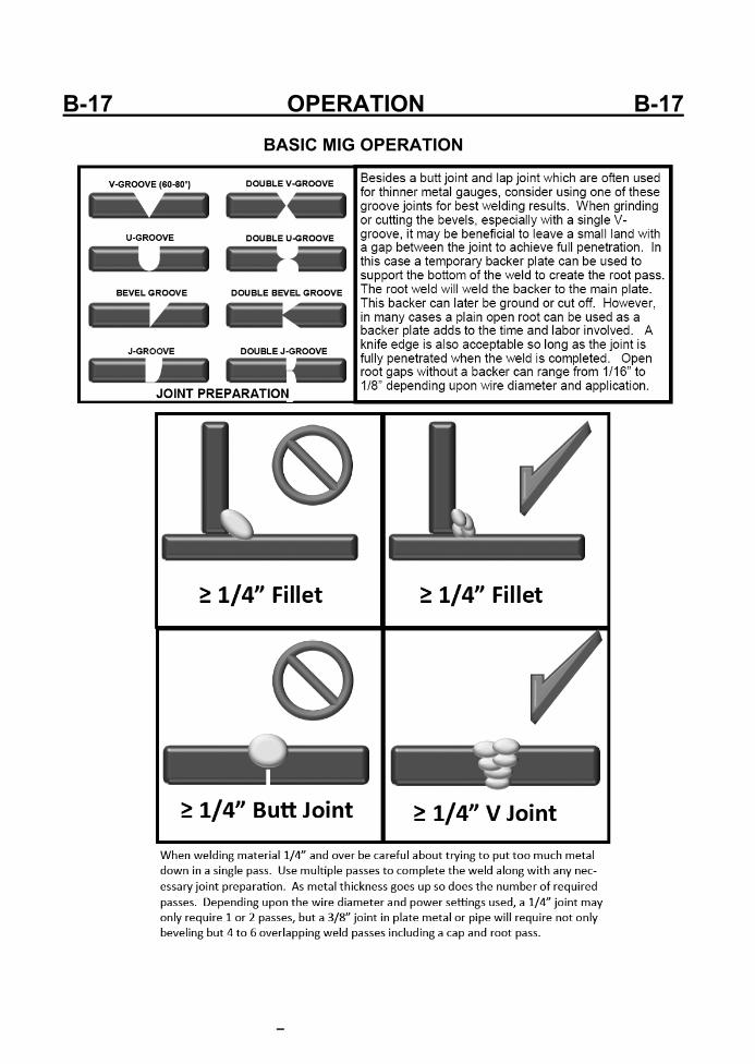
the welder has the power, then a single heavy pass will do to weld up in a single pass. This is a primary way to introduce cold lap and incomplete fusion to the weld. Single pass welds should not exceed 1/4” even with the heaviest wire the welder is capable of handling. A thick pass may also begin to cool before contaminates and gas pockets have the time to float out to the surface. It’s far better to make multiple smaller passes to complete a plate weld for a higher quality result. For best results, this requires that most joints 1/4” and over be prepared with a grinder to accept multiple weld passes. The weldment edg‐es should be ground to form a V, U or J shaped groove to create a recess where the welds can be welded one on top of another. For welding with .035” wire and under, create a bead no thicker than 3/16” in a single pass, no more than 1/8” with .030” wire, and with .025”wire and smaller no more than 3/32 for best results. This will help main‐tain proper fluidity of the weld and prevent gas from being trapped in the weld and give time for any mi‐nor contaminates to float out of the weld. It will also help to maintain reasonable forward travel speeds. Too slow of travel speeds will create excess build up and can tend to create cold lap at the weld toes resulting in poor tie in. One issue created with a weaving technique even if the metal deposited is the correct thickness s that it can slow the forward progress down. If weaving is too wide, one side of the puddle will cool and oxidize before the torch is brought back across to that side. This is a point where porosity and inclusions can be introduced.
B-17 OPERATION B-17
BASIC MIG OPERATION
B-18 OPERATION B-18
BASIC MIG OPERATION
B-19 OPERATION B-19
BASIC MIG OPERATION
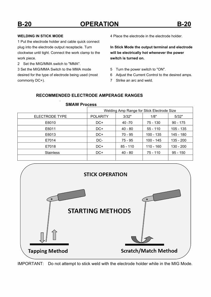
B-20 OPERATION B-20 WELDING IN STICK MODE 1 Put the electrode holder and cable quick connect plug into the electrode output receptacle. Turn clockwise until tight. Connect the work clamp to the work piece. 2 Set the MIG/MMA switch to "MMA". 3 Set the MIG/MMA Switch to the MMA mode desired for the type of electrode being used (most commonly DC+).
4 Place the electrode in the electrode holder. In Stick Mode the output terminal and electrode will be electrically hot whenever the power switch is turned on. 5 Turn the power switch to "ON". 6 Adjust the Current Control to the desired amps. 7 Strike an arc and weld.
RECOMMENDED ELECTRODE AMPERAGE RANGES . SMAW Process
Welding Amp Range for Stick Electrode Size ELECTRODE TYPE POLARITY 3/32" 1/8" 5/32"
E6010 DC+ 40 -70 75 - 130 90 - 175
E6011 DC+ 40 - 80 55 - 110 105 - 135 E6013 DC+ 70 - 95 100 - 135 145 - 180 E7014 DC- 75 - 95 100 - 145 135 - 200
E7018 DC+ 85 - 110 110 - 160 130 - 200
Stainless DC+ 40 - 80 75 - 110 95 - 150
IMPORTANT: Do not attempt to stick weld with the electrode holder while in the MIG Mode.
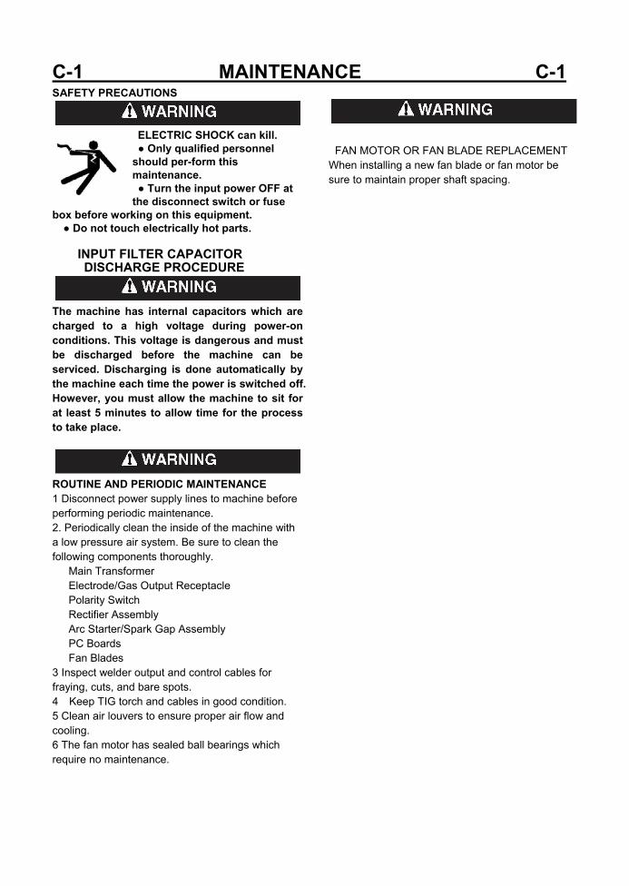
C-1 MAINTENANCE C-1 SAFETY PRECAUTIONS
ELECTRIC SHOCK can kill. ● Only qualified personnel should per-form this maintenance. ● Turn the input power OFF at the disconnect switch or fuse
box before working on this equipment. ● Do not touch electrically hot parts.
INPUT FILTER CAPACITOR DISCHARGE PROCEDURE
The machine has internal capacitors which are charged to a high voltage during power-on conditions. This voltage is dangerous and must be discharged before the machine can be serviced. Discharging is done automatically by the machine each time the power is switched off. However, you must allow the machine to sit for at least 5 minutes to allow time for the process to take place.
ROUTINE AND PERIODIC MAINTENANCE 1 Disconnect power supply lines to machine before performing periodic maintenance. 2. Periodically clean the inside of the machine with a low pressure air system. Be sure to clean the following components thoroughly. Main Transformer Electrode/Gas Output Receptacle Polarity Switch Rectifier Assembly Arc Starter/Spark Gap Assembly PC Boards Fan Blades 3 Inspect welder output and control cables for fraying, cuts, and bare spots. 4 Keep TIG torch and cables in good condition. 5 Clean air louvers to ensure proper air flow and cooling. 6 The fan motor has sealed ball bearings which require no maintenance.
FAN MOTOR OR FAN BLADE REPLACEMENT When installing a new fan blade or fan motor be sure to maintain proper shaft spacing.
D-1 TROUBLESHOOTING D-1 HOW TO USE TROUBLESHOOTING GUIDE
Service and Repair should only be performed by our Factory Trained Personnel. Unauthorized repairs performed on this equipment may result in danger to the technician and machine operator and will invalidate your factory warranty. For your safety and to avoid Electrical Shock, please observe all safety notes and precautions detailed throughout this manual. This Troubleshooting Guide is provided to help you locate and repair possible machine malfunctions. Simply follow the three-step procedure listed below. Step 1. LOCATE PROBLEM (SYMPTOM). Look under the column labeled "PROBLEM (SYMPTOMS)". This column describes possible symptoms that the machine may exhibit. Find the listing that best describes the symptom that the machine is exhibiting. Step 2. POSSIBLE CAUSE. The second column labeled "POSSIBLE CAUSE" lists the obvious external possibilities that may contribute to the machine symptom. Step 3. RECOMMENDED COURSE OF ACTION This column provides a course of action for the Possible Cause, generally it states to contact your local Authorized Field Service Facility. If you do not understand or are unable to perform the Recommended Course of Action safely, contact your local Authorized Field Service Facility. If for any reason you do not understand the test procedures or are unable to perform the tests/repairs safely, contact your Local Authorized Field Service Facility for technical troubleshooting assistance before you proceed.
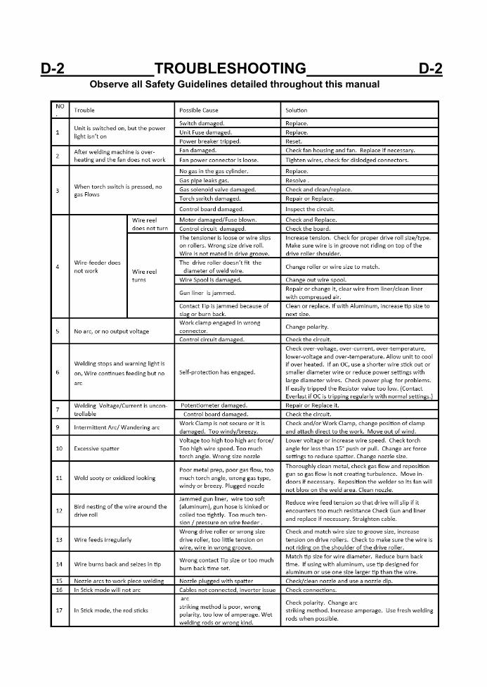
D-2 TROUBLESHOOTING D-2 Observe all Safety Guidelines detailed throughout this manual
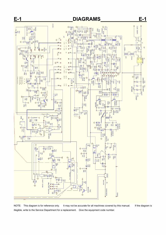
E-1 DIAGRAMS E-1
NOTE: This diagram is for reference only. It may not be accurate for all machines covered by this manual. If the diagram is
illegible, write to the Service Department for a replacement. Give the equipment code number.
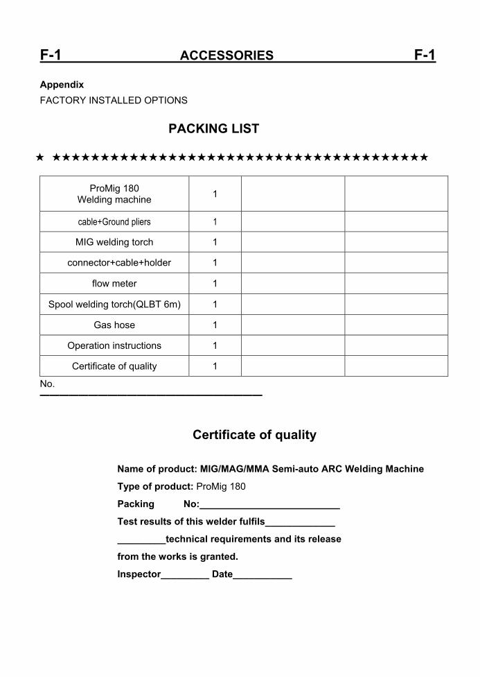
F-1 ACCESSORIES F-1 Appendix FACTORY INSTALLED OPTIONS
PACKING LIST
★ ★★★★★★★★★★★★★★★★★★★★★★★★★★★★★★★★★★★★★★★
ProMig 180 Welding machine 1
cable+Ground pliers 1
MIG welding torch 1
connector+cable+holder 1
flow meter 1
Spool welding torch(QLBT 6m) 1
Gas hose 1
Operation instructions 1
Certificate of quality 1
No. ━━━━━━━━━━━━━━━━━━━━━━━
Certificate of quality
Name of product: MIG/MAG/MMA Semi-auto ARC Welding Machine
Type of product: ProMig 180
Packing No:
Test results of this welder fulfils_____________
_________technical requirements and its release
from the works is granted.
Inspector_________ Date___________
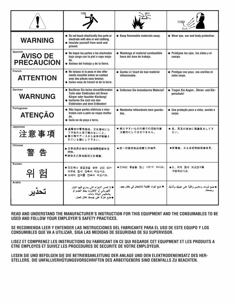
WARNING
AVISO DEPRECAUCION
ATTENTION
WARNUNG
ATENÇÃO
Spanish
French
German
Portuguese
Japanese
Chinese
Korean
Arabic
READ AND UNDERSTAND THE MANUFACTURER’S INSTRUCTION FOR THIS EQUIPMENT AND THE CONSUMABLES TO BEUSED AND FOLLOW YOUR EMPLOYER’S SAFETY PRACTICES.
SE RECOMIENDA LEER Y ENTENDER LAS INSTRUCCIONES DEL FABRICANTE PARA EL USO DE ESTE EQUIPO Y LOSCONSUMIBLES QUE VA A UTILIZAR, SIGA LAS MEDIDAS DE SEGURIDAD DE SU SUPERVISOR.
LISEZ ET COMPRENEZ LES INSTRUCTIONS DU FABRICANT EN CE QUI REGARDE CET EQUIPMENT ET LES PRODUITS AETRE EMPLOYES ET SUIVEZ LES PROCEDURES DE SECURITE DE VOTRE EMPLOYEUR.
LESEN SIE UND BEFOLGEN SIE DIE BETRIEBSANLEITUNG DER ANLAGE UND DEN ELEKTRODENEINSATZ DES HER-STELLERS. DIE UNFALLVERHÜTUNGSVORSCHRIFTEN DES ARBEITGEBERS SIND EBENFALLS ZU BEACHTEN.
� Do not touch electrically live parts orelectrode with skin or wet clothing.
� Insulate yourself from work andground.
� No toque las partes o los electrodosbajo carga con la piel o ropa moja-da.
� Aislese del trabajo y de la tierra.
� Ne laissez ni la peau ni des vête-ments mouillés entrer en contactavec des pièces sous tension.
� Isolez-vous du travail et de la terre.
� Berühren Sie keine stromführendenTeile oder Elektroden mit IhremKörper oder feuchter Kleidung!
� Isolieren Sie sich von denElektroden und dem Erdboden!
� Não toque partes elétricas e elec-trodos com a pele ou roupa molha-da.
� Isole-se da peça e terra.
� Keep flammable materials away.
� Mantenga el material combustiblefuera del área de trabajo.
� Gardez à l’écart de tout matérielinflammable.
� Entfernen Sie brennbarres Material!
� Mantenha inflamáveis bem guarda-dos.
� Wear eye, ear and body protection.
� Protéjase los ojos, los oídos y elcuerpo.
� Protégez vos yeux, vos oreilles etvotre corps.
� Tragen Sie Augen-, Ohren- und Kör-perschutz!
� Use proteção para a vista, ouvido ecorpo.
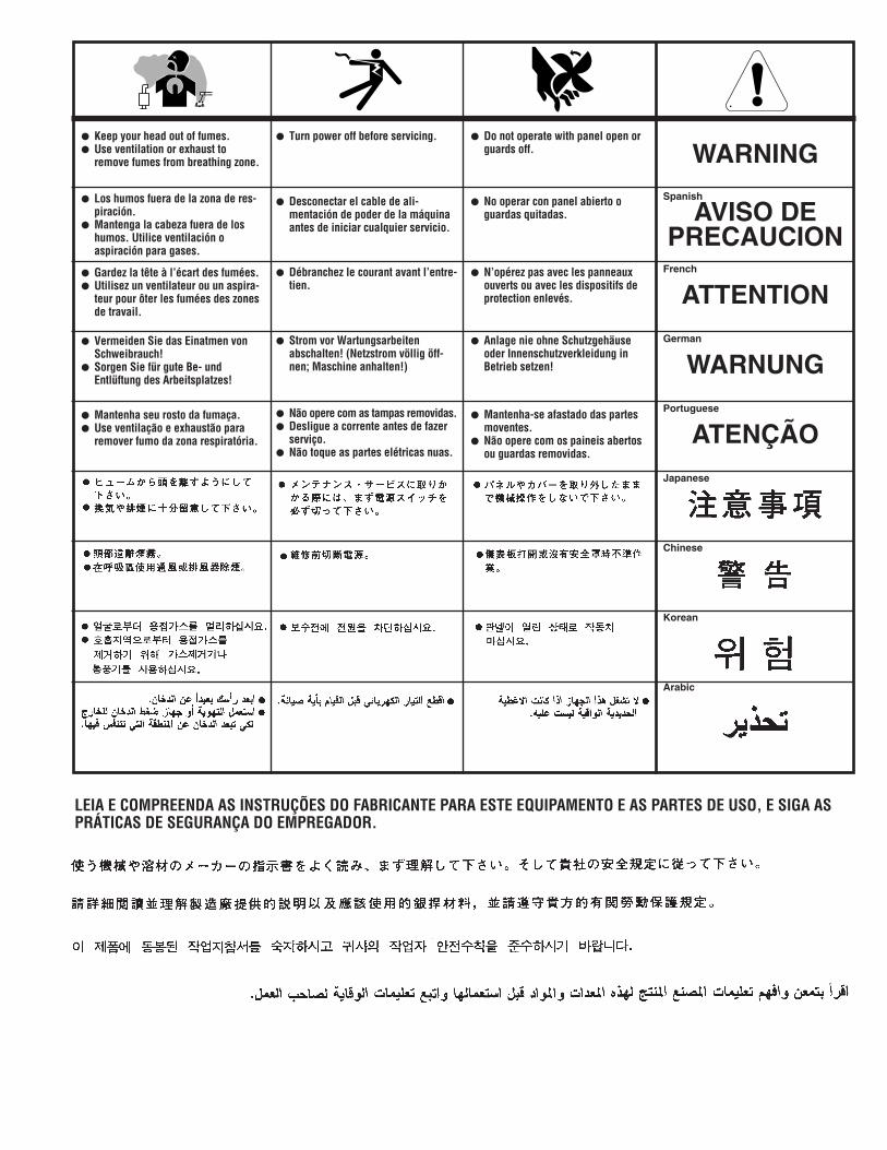
WARNING
AVISO DEPRECAUCION
ATTENTION
WARNUNG
ATENÇÃO
Spanish
French
German
Portuguese
Japanese
Chinese
Korean
Arabic
LEIA E COMPREENDA AS INSTRUÇÕES DO FABRICANTE PARA ESTE EQUIPAMENTO E AS PARTES DE USO, E SIGA ASPRÁTICAS DE SEGURANÇA DO EMPREGADOR.
� Keep your head out of fumes.� Use ventilation or exhaust to
remove fumes from breathing zone.
� Los humos fuera de la zona de res-piración.
� Mantenga la cabeza fuera de loshumos. Utilice ventilación oaspiración para gases.
� Gardez la tête à l’écart des fumées.� Utilisez un ventilateur ou un aspira-
teur pour ôter les fumées des zonesde travail.
� Vermeiden Sie das Einatmen vonSchweibrauch!
� Sorgen Sie für gute Be- undEntlüftung des Arbeitsplatzes!
� Mantenha seu rosto da fumaça.� Use ventilação e exhaustão para
remover fumo da zona respiratória.
� Turn power off before servicing.
� Desconectar el cable de ali-mentación de poder de la máquinaantes de iniciar cualquier servicio.
� Débranchez le courant avant l’entre-tien.
� Strom vor Wartungsarbeitenabschalten! (Netzstrom völlig öff-nen; Maschine anhalten!)
� Não opere com as tampas removidas.� Desligue a corrente antes de fazer
serviço.� Não toque as partes elétricas nuas.
� Do not operate with panel open orguards off.
� No operar con panel abierto oguardas quitadas.
� N’opérez pas avec les panneauxouverts ou avec les dispositifs deprotection enlevés.
� Anlage nie ohne Schutzgehäuseoder Innenschutzverkleidung inBetrieb setzen!
� Mantenha-se afastado das partesmoventes.
� Não opere com os paineis abertosou guardas removidas.