feasibility of fast neutron analysis for the detection of explosives buried in soil
TRANSCRIPT

This article appeared in a journal published by Elsevier. The attachedcopy is furnished to the author for internal non-commercial researchand education use, including for instruction at the authors institution
and sharing with colleagues.
Other uses, including reproduction and distribution, or selling orlicensing copies, or posting to personal, institutional or third party
websites are prohibited.
In most cases authors are permitted to post their version of thearticle (e.g. in Word or Tex form) to their personal website orinstitutional repository. Authors requiring further information
regarding Elsevier’s archiving and manuscript policies areencouraged to visit:
http://www.elsevier.com/copyright
Author's personal copy
Feasibility of fast neutron analysis for the detection of explosivesburied in soil
A.A. Faust a, J.E. McFee a,n, C.L. Bowman a,1, C. Mosquera a, H.R. Andrews b, V.D. Kovaltchouk b, H. Ing b
a Defence R&D Canada—Suffield, Medicine Hat, Alta., Canadab Bubble Technology Industries, Chalk River, Ont., Canada
a r t i c l e i n f o
Article history:
Received 11 April 2011
Received in revised form
18 July 2011
Accepted 19 July 2011Available online 12 August 2011
Keywords:
Thermal neutron analysis
Fast neutron analysis
Associated particle imaging
Landmine detection
Explosives detection
Improvised explosive device detection
a b s t r a c t
A commercialized thermal neutron analysis (TNA) sensor has been developed to confirm the presence
of buried bulk explosives as part of a multi-sensor anti-tank landmine detection system. Continuing
improvements to the TNA system have included the use of an electronic pulsed neutron generator that
offers the possibility of applying fast neutron analysis (FNA) methods to improve the system’s detection
capability. This paper describes an investigation into the use of FNA as a complementary component in
such a TNA system. The results of a modeling study using simple geometries and a full model of the
TNA sensor head are presented, as well as preliminary results from an experimental associated particle
imaging (API) system that supports the modeling study results. The investigation has concluded that
the pulsed beam FNA approach would not improve the detection performance of a TNA system for
landmine or buried IED detection in a confirmation role, and could not be made into a practical stand-
alone detection system for buried anti-tank landmines. Detection of buried landmines and IEDs by FNA
remains a possibility, however, through the use of the API technique.
Crown Copyright & 2011 Published by Elsevier B.V. All rights reserved.
1. Introduction
Nuclear methods have long been one of the few techniquesavailable to aid in the nonintrusive detection and identification ofhidden hazardous objects containing bulk explosives or militaryand industrial toxic chemicals. The reasons for their popularityare that these techniques provide high penetrability (to inter-rogate large containers), sensitivity (for low false alarm rates andminimal interrogation times) and specificity (to detect hiddencontraband within a bulk sample of primarily innocuous content).Of the many potential candidate radiation types that could beused in detection systems, neutrons and photons have been themost successful [1,2] because they are uncharged, allowing themto penetrate deeply into objects. Unlike photons, which predomi-nately interact with the electron clouds of the atoms composingthe target material, neutrons interact directly with the nuclei ofthe atoms. Thus, not only can they penetrate much deeper into amaterial, but neutrons can also be used to make a directobservation of the elemental composition of the material, insteadof measuring a bulk average of atomic number as photons do.
Neutron in/photon out techniques are among the most popularneutron methods which can potentially characterize elementalcomposition. A suspicious region is irradiated with neutrons andthe resulting neutron-induced gamma-ray spectrum is measured.The intensities of the resulting characteristic gamma rays can inprinciple be used to determine the ratios of specific chemicalelements within the target region.
Efforts to develop devices based on this concept have beenongoing since the 1950s [1]. The two most common methods areprompt thermal neutron capture analysis (usually called thermalneutron analysis or TNA) and fast inelastic neutron scatteringgamma-ray analysis (fast neutron analysis or FNA). This paperexamines the potential of incorporating a fast neutron analysiscapability into a thermal neutron analysis detector to providecomplementary information to assist in the detection and identi-fication of bulk explosives buried in soil.
1.1. Thermal neutron analysis
Defence R&D Canada (DRDC)—Suffield’s initial research inneutron detection of explosives led to the co-development, withBubble Technology Industries (BTI), of a commercialized thermalneutron analysis detector. It was intended as a confirmationdetector for the Improved Landmine Detector System (ILDS). ILDSwas a teleoperated, vehicle-mounted, multi-sensor anti-tank (AT)landmine detector manufactured by General Dynamics Canada
Contents lists available at ScienceDirect
journal homepage: www.elsevier.com/locate/nima
Nuclear Instruments and Methods inPhysics Research A
0168-9002/$ - see front matter Crown Copyright & 2011 Published by Elsevier B.V. All rights reserved.
doi:10.1016/j.nima.2011.07.036
n Corresponding author.
E-mail address: [email protected] (J.E. McFee).1 Now at Powertech Labs Inc., Surrey, BC, Canada.
Nuclear Instruments and Methods in Physics Research A 659 (2011) 591–601

Author's personal copy
(GDC), based on DRDC’s original design and prototype. It wasdesigned to meet the Canadian Forces requirement for rear arealandmine clearance in combat situations and peacekeeping onroads and tracks [3,4]. The system consists of three different rapidsensors, which scan the ground in front of the vehicle. Sensorinformation is combined using a suite of navigation sensors withcustom navigation, spatial registration, correspondence and datafusion algorithms to identify suspicious targets which are thentracked to within 30 cm of the rear-mounted TNA detector.
The TNA detector subsequently confirms or rejects suspectedtargets, thereby reducing false alarm rates to operationally accep-table levels. It consists of a sensor head connected by electricalcables to an electronics rack. The sensor head is an environmen-tally controlled enclosure containing a neutron source, gamma-raydetectors and radiation shielding. The rack contains electronicmodules and power supplies. The TNA detector uses a 100 mg 252Cfneutron source surrounded by four 7.62 cm�7.62 cm NaI(Tl)detectors. State-of-the art radiation transport codes, specializedshielding materials and custom high-rate, fast pulse processingelectronics were employed in the design. Anti-tank mines buried10 cm or less can be detected in roughly a minute or less, butdeeper mines and mines significantly displaced horizontally cantake considerably longer. Mines as deep as 30 cm can be detectedfor long count times (1000 s) [5].
Ongoing research is aimed at developing a next generationdetector with improved performance. Among the ongoing andcompleted work is the replacement of the 252Cf isotopic sourcewith a pulsed electronic neutron generator [6], an improved sensorhead to minimize spatial response non uniformity, improvedelectronic stability and enhanced software for background com-pensation. The inclusion of the electronic neutron generator sig-nificantly reduces the logistical burden, while allowing forimproved sensitivity to deeper and horizontally displaced buriedanti-tank landmines and to smaller landmines. A study of alter-native scintillator materials to improve time response and energyresolution [7], and thus TNA sensitivity, has led to the replacementof the NaI(Tl) detectors by 7.62 cm�7.62 cm LaBr3(Ce) detectors.A recent version of the next generation detector, with two LaBr3,four NaI(Tl) detectors and an electronic pulsed neutron generator,is shown in Fig. 1. Experiments have recently been performed todirectly compare the performance of the different scintillators inthe same sensor head and to characterize the performance of thenew TNA system against landmines buried in sand and IEDs hiddenin culverts. The results will be presented in a future paper.
The main disadvantages of thermal neutron analysis are that itis relatively slow, it is not capable of detecting carbon or oxygen,
and it has a low signal to noise ratio for small targets. In principle,the pulsed-mode electronic neutron generator now incorporatedinto the next generation thermal neutron analysis detector couldbe exploited in order to permit a form of fast neutron analysis.The generator can produce 10 ms-wide pulses of 14 MeV neutronsfrom the D–T reaction at a rate of up to 5�108 n/s. One couldthen measure the prompt photons from the fast neutron inelasticscattering interactions during the ‘‘beam on’’ pulse (typically 10%of the beam cycle). FNA has the potential to provide a measure ofthe carbon:oxygen ratio in the target. As explosives and othersubstances of interest have well known C:H:N:O ratios, combin-ing this FNA data with a measure of the hydrogen:nitrogen ratioavailable from the standard TNA could allow chemical identifica-tion of the target to be made. This information, complementary tothat of the present thermal neutron analysis detector, offers apotential improvement to the detection capability for smalltargets. Further, some nontraditional explosives contain no nitro-gen and hence FNA would allow their detection where TNA byitself would fail. It will first be necessary to assess whether suchan improvement is possible, and then to determine the capabilityof the present instrument to do fast neutron interrogation inaddition to thermal neutron interrogation.
1.2. Fast neutron analysis
The detection of explosives by neutron interrogation has beenstudied for over fifty years. In the last twenty or so years many ofthese studies focused on the detection of explosives in airlinebaggage and cargo, parcels, coal slurries or unearthed, unex-ploded ordnance (UXO) [8–11]. For these applications, the useof fast neutron interrogation was the preferred technique. Theexcitation neutrons were normally 14 MeV, readily available fromportable generators exploiting the T(d,n)a reaction, and thereactions utilized were neutron inelastic scattering (n, n0g), orinduced reactions such as (n, pg), (n, ag). In principle, fast neutroninterrogation can measure the relative concentrations of severalrelevant elements, such as C, N, O, H, Cl, which can form a featurevector to identify a particular explosive by pattern classification.
Detection of explosives buried in soil is generally much moredifficult than detection of explosives in baggage or parcels. Eventhough the basic nuclear reactions that can be used are the same,for buried explosives certain of these reactions may not beapplicable because of interference from competing reactions dueto the soil constituents surrounding the IED or landmine or theexplosive signal may be too weak with respect to the highbackground generated by the soil under neutron interrogation.For example, hydrogen, although a useful indicator of explosivesin baggage, and useful for process monitoring in coal slurryanalysis, may be of limited use for landmine detection becauseof the typically wide variability of water content in the soil.Silicon dioxide significantly interfers with buried explosivesdetection but it is not a factor in the baggage scenario. Thegamma-ray spectrum from explosives in baggage would likely besignificantly different from that of a buried landmine whenirradiated with fast neutrons. This is due to the enormous effectof neutron moderation in the soil. The monoenergetic distributionof incident fast neutrons from the source is transformed into acomplex energy spectrum by the time the neutrons reach theexplosive. This leads to significantly different ratios of nuclearreaction rates within the explosive itself, compared to the ratiosthat would be obtained in the absence of soil. The resultantneutron energy spectrum irradiating the explosive will be afunction of soil depth and soil composition. Further, the attenua-tion by the soil of the gamma rays from the landmine mayaffect the relative importance and indeed the applicability of aparticular reaction. Additionally, a fieldable system that must
D−T Neutron Source
NaI(Tl)
LaBr3
Fig. 1. Prototype TNA sensor head with electronic neutron generator.
A.A. Faust et al. / Nuclear Instruments and Methods in Physics Research A 659 (2011) 591–601592

Author's personal copy
operate robustly under various adverse environmental conditionsgives rise to additional design constraints not found in a systemsituated in an air-conditioned building, such as an airport. Thisdifference in operational environments and scenarios affects thechoice of neutron source, the sensor head design, the choice ofradiation detector and data processing electronics.
Comprehensive listings of all possible nuclear reactions forlandmine detection by neutron and photon interrogation, whichare also generally applicable for IEDs buried in soil, can be foundin [1]. The authors commented on the relative applicability ofthese reactions for landmine detection, and they did not feel thatfast neutron analysis was promising. A later study [12], that isconsidered closer to the present task of assessing the applicabilityof fast neutron interrogation for buried explosives, selected5 reactions in 3 elements as the basis of their fast and thermalneutron interrogation system for explosives. They provided datafor gamma-ray spectra, measured with HPGe and BGO detectors,and showed that all three elements could be observed by the useof fast neutron interrogation. The capability of detecting threeelements is desirable, at least for applications others than land-mine detection, since this increases the specificity for detection ofexplosives relative to other nitrogenous materials (e.g. wool,melamine). The authors also proposed an irradiation protocolinvolving bursts of fast neutrons at specific time intervals in orderto obtain gamma-ray spectra from three different nuclear inter-rogation techniques: fast neutron interrogation (prompt gammarays), thermal neutron interrogation (gamma rays immediatelyfollowing the neutron pulse) and neutron activation of elements(delayed gamma rays). Despite the fact that these investigationspertained primarily to the detection of explosives in baggage andexposed UXO, rather than landmines, the apparent success of theproposed methodology makes it a reasonable starting point forthe present investigation. Ultimately, the key issues to beresolved are whether these reactions are still applicable whenthe explosive is buried in soil and whether the same gamma raysare observable against the background gamma rays generated bythe soil itself.
Clearly, the incorporation of fast neutron interrogation tosupplement the thermal neutron technique requires a comprehen-sive reassessment of the whole technology in the context of thespecific problem, starting from fundamental physical principles.
1.2.1. FNA-augmented TNA
FNA and FNA-augmented TNA have been considered for manyyears for landmine detection. However, little detailed analysis hasbeen conducted specifically aimed at landmine or buried IEDdetection geometries and scenarios. Most experimental researchand development has been in the laboratory without having tocontend with any of the complicating factors described above. Inthe last decade, there has been some effort to develop landminedetection systems based on both fast and thermal neutroninterrogation. One example [13] employs a neutron generatorand a shielded scintillation gamma-ray detector, with no addi-tional application-specific shielding. However, in the fifteen yearsof research and development which led to the production of theonly fieldable neutron interrogation landmine detection system inexistence and subsequent improvements, we have shown that alandmine detector based on penetrating radiation must bethoughtfully designed and purpose-built expressly for the roleof landmine detection. For example, our studies have shown thatfor the high neutron rates needed for short enough measurementtimes to detect landmines in operational situations, the dominantsource of background is pulse pileup rather than silicon from thesoil [5]. Thus shielding detectors from the source and speciallydesigned electronics are key factors for success. Other TNA
detectors intended for UXO detection have used low strengthneutron sources for logistical reasons. Their count times wereunacceptably long for practical mine detection, although possiblyuseful for a range remediation role. In such TNA detectors, siliconbackground provided the limit to sensitivity [14].
Based on the authors’ experience, it is anticipated that thesensor head design of next generation TNA will need to be modifiedto accommodate the use of fast neutron interrogation. For example,fast neutron interrogation usually requires minimal materialaround the source (to maintain a clean monoenergetic beam)whereas thermal neutron interrogation requires sophisticated sen-sor head design, with substantial shielding, to optimize the thermalfluence over the interrogated soil volume. Thus, a compromisebetween these conflicting requirements must be made.
The remainder of this paper will examine whether or not FNAcan improve detector performance for buried explosives detectioncompared to TNA. It will be shown, in fact, that pulsed neutronFNA is not feasible for that role, although a form of FNA,associated particle imaging may be useful.
2. Modeling studies
Detailed Monte Carlo calculations were made using the widelyaccepted MCNP modeling code [15] to understand the compli-cated physics of gamma ray production and detection when14 MeV neutrons irradiate targets in soil. This section summarizesthose results. A more comprehensive description is found in [16].
Preliminary investigations with a very simple geometry, takinginto consideration the total anticipated mass of the variousmaterials in a typical landmine, and assuming NaI(Tl) detectorsare employed (as in the existing TNA head), allowed some generalconclusions to be reached. First, it would be difficult to detectnitrogen because of its weak lines relative to other interferences.Carbon would be a good candidate because of the strong4.443 MeV line from the 12C(n, n0) reaction, and oxygen (usingthe 6.128 MeV gamma ray from the 16O(n, n0) reaction) might bedetectable. The potential use of oxygen may be limited due to thelarge quantity of oxygen in soil (e.g. SiO2), unless the interferencefrom SiO2 can be minimized. These conclusions agree with earlierassessments, such as [1].
Having selected carbon as a promising elemental constituentof explosives to investigate, more representative spectra werethen generated with a slightly more realistic geometry. A 30 cmdiameter by 10 cm thick cylindrical landmine (�7 l) composed ofC4 explosives (equivalent to approximately 2.5, 0.4, 4.6, 4.0 kg ofC, H, O, N, respectively) was placed in ANSI soil with its symmetryaxis vertical, and a NaI(Tl) gamma-ray detector added. The soilvolume was a cylinder 80 cm in diameter and 40 cm thick, withthe landmine placed on axis at a depth of 10 cm (mine top 10 cmbelow soil surface). This somewhat small soil configurationresults in an overestimate of the relative effect of the landmine.The NaI(Tl) detector was modeled as a 5 cm thick detector slabsurrounding the sides and top of the soil volume. The full width athalf maximum (FWHM) of the energy resolution of the NaI(Tl)detector was modeled as 0.06
ffiffiffi
Ep
MeV. The modeled response wasverified against experiment and found to be acceptable for thepresent purposes [16]. Although the detector configuration wasunrealistic, it was used to reduce the computational time. TheD–T source was modeled as a uniform parallel beam of 14 MeVneutrons with diameter equal that of the soil column (80 cm), sothat the entire soil column and landmine were irradiated. Thebeam direction was parallel to the symmetry axis of the land-mine, i.e., downward into the ground.
Simulated spectra for the soil with and without a landminepresent are shown in Fig. 2 (the landmine volume was replaced
A.A. Faust et al. / Nuclear Instruments and Methods in Physics Research A 659 (2011) 591–601 593

Author's personal copy
with soil for the no landmine case). The peak area with thelandmine present (chiefly due to carbon from the mine) isapproximately twice the area with no landmine (chiefly due tosilicon dioxide from soil) in the 4.443 MeV peak. The replacementof soil (high oxygen content) by the landmine (lower oxygencontent) can be seen in the spectral region from 5 to 7 MeV whichis dominated by oxygen peaks.
2.1. System performance using the TNA sensor head
To verify the validity of the model, experiments were per-formed using the prototype TNA sensor head (Fig. 1) with afertilizer target. Monte Carlo simulations of these experimentalconditions were done using a full geometrical CAD model of theTNA head (Fig. 4). The sensor head design was intended toaddress the high source rates required for detection in operation-ally acceptable time periods (a few seconds to minutes). Sincebackground in the high energy nitrogen window is dictatedlargely by pulse pileup, it was necessary to heavily shield thedetectors. The compact, symmetric detector positioning wasintended to provide acceptable sensitivity over a 30 cm horizontalwidth roughly independent of azimuth. Lead was used to attenu-ate high energy capture gamma rays from the sensor head andsource. High density polyethylene in combination with a lithium-based gel was used to slow and capture neutrons scattered fromthe source and surroundings. To acceptably slow the 14 MeVneutrons, more thermalizing material was necessary than wasused in the 252Cf-based sensor head. Depleted uranium wasemployed as a neutron multiplier to compensate for the attendantabsorption losses. Placement and amounts of the materials wasdetermined by practical experience, trial and error, simple calcu-lations, computer simulations and experimentation. The lowenergy cut off was reduced to include the effect of thermalneutrons. Generally reasonable agreement between simulationsand experiment was found, with ratios of simulated to experi-mental count rates being between 0.5 to 1.8.
In order to explore the ultimate capability of the approach, theNaI(Tl) detectors were replaced in the simulation by high puritygermanium (HPGe) spectrometers of the same size. (The effi-ciency per detector would be approximately 70% of that of a7.62 cm�7.62 cm cylindrical NaI(Tl) detector.) Such a systemwould likely be prohibitively expensive since the detectors wouldcost over half a million dollars. However, this is the mostoptimistic physically realizable case in which to examine if FNAcould succeed in this application. The resolution of the HPGe
spectrometers was set to be relatively poor (�4 keV for1.333 MeV 60Co line) to allow for compromises that would haveto be made in the resolution to achieve high count rates.
In Fig. 3, the 4.443 MeV carbon peak is shown for three simula-tions: no landmine, a case-less landmine filled with C4 explosives,and a case-less landmine filled with pure carbon (1 g/cc).The landmine depth was 10 cm. The pure carbon landmine wasincluded to facilitate the study of the spectral dependence on thecarbon density in a landmine (carbon number density of the purecarbon sample is approximately 3 times that of the C4). Even underthese optimized conditions for the neutron source, neutron shieldingand detector resolution, a C4 landmine is still not detectable,although an explosive with more carbon (e.g. TNT) might bemarginally detectable.
The intensity of the 4.443 MeV peak in the spectrum whenthere was no landmine present was at first surprising. Investiga-tion revealed that this was due to a fast neutron reaction onoxygen, 16O(n, n0a)12Cn. Though this is a very low probabilityreaction, the large amount of oxygen in the soil results in a verysignificant 4.443 MeV peak which interferes with the detection ofin situ carbon.
2.2. Effect of detector collimation
The possibility of adding collimation to the detector systemwas investigated to see if the contribution of the soil to themeasured spectrum could be reduced. To do this, the soil volumein this simulation (surrounding the �7 l landmine) was varied todetermine the contribution from various parts of the soil. Sincecarbon makes no contribution to the spectrum above 4.443 MeV,the gross effect of the soil could be determined by integrating thespectrum above this energy. The results showed that changing thesoil depth from 45 cm to 20 cm (bottom of landmine is at 20 cm)had no effect on the detector response. An effect was found tooccur when the radius of the soil volume was reduced below35 cm. However, since the detector centerlines of the TNA headare located at a radius of 28.75 cm, these results indicate that anycollimation which does not mask the landmine will not have asignificant effect on the background count rate due to the soil.
Gamma Ray Energy (MeV)21 3 4 5 6 7 8 9
2.0E−3
1.0E−3
3.0E−3
0
Cou
nt ra
te (a
rbitr
ary
units
)
Fig. 2. Simulated FNA NaI(Tl) spectrum from a case-less landmine filled with �7 l
of C4 explosives, buried at a depth of 10 cm in soil (solid curve). Background signal
due to soil alone is presented for comparison (diamonds). The role of carbon
(4.443 MeV) as a possible FNA signature for explosives detection can be seen.
1
Gamma Ray Energy (MeV)4.464.444.42
0
2
3
Cou
nt ra
te (a
rbitr
ary
units
)
Fig. 3. Simulated HPGe spectra for C4 landmine (blue squares), no landmine (pink
diamonds), and a landmine target made of pure carbon (green triangles). (For
interpretation of the references to color in this figure legend, the reader is referred
to the web version of this article.)
A.A. Faust et al. / Nuclear Instruments and Methods in Physics Research A 659 (2011) 591–601594

Author's personal copy
2.3. Location-dependent effect of soil
In an attempt to understand the relative impact of soilvolumes in the vicinity of the landmine on the 4.443 MeV gammarays, the change in the count rate was examined as a landmine-sized (�7 l) carbon-filled test volume was located at differentpositions. The difference in detector response (count rate above4.5 MeV) between the intact soil and soil with carbon inclusionwas equal to the detector response due to the soil in the testvolume.
It was seen that the detector response to the test volumelocated at a depth of 10 cm (the depth used previously todetermine the detectability of a landmine) is about 2–3% of thatdue to the entire soil volume, roughly independent of thehorizontal position. Thus, even though the yield of the4.443 MeV gamma ray from carbon is ten times that from oxygen,this is offset by the low detector response to the landmine volumeat that location plus the background contribution from oxygen inthe soil and in the neutron shielding material in the landminedetector.
To further investigate the effect of landmine location, simula-tions were done for different burial depths of a pure carbonlandmine. The sensitivity to burial depth is shown dramatically inFig. 5. While a carbon landmine can be easily seen on the surface,it is almost indistinguishable from the soil (no landmine) even ata depth of 5 cm.
In contrast, by putting the carbon filled landmine at a depth of10 cm and varying the density of the surrounding soil, it wasfound that the soil density resulted in only a small change in the4.443 MeV peak height. Examination revealed that as the soildensity increased, the increased contribution of 4.443 MeV
gamma rays from the (n, n0a) reaction on oxygen in the soil,
compensated for the decreased relative contribution from the(n, n0) reaction on carbon in the landmine. As the soil densitydecreased, attenuation by the bulk soil volume likewisedecreased, which compensated for the decrease in production ofoxygen gamma rays [16].
2.4. Effect of changing neutron energy
Fig. 5 showed that a pure carbon landmine is easily detectableat the ground surface but it is only marginally detectable whenburied at even 5 cm due to the oxygen interference at 4.443 MeV.At 14 MeV the neutron cross-section contributing to this gammaray is increasing as a function of neutron energy for oxygen whiledecreasing for carbon. By decreasing the neutron energy to below12 MeV the oxygen contribution can be eliminated entirely.A simulation was run at a neutron energy of 11 MeV for a C4mine buried 10 cm to see whether optimizing the neutron energywould make a C4 landmine detectable. The results showed thatthe C4 landmine still could not be detected even with Gedetectors. The increase in carbon cross-section and eliminationof the oxygen cross-section was partially compensated by anincrease in the cross-sections of silicon and nitrogen and so theimprovement was insufficient to overcome the effect of the largeratio of soil to explosives volumes. The use of other signalenhancement techniques may help.
2.5. Comparison of FNA for baggage and landmines
FNA appears to be quite successful in the detection of explo-sives in baggage, yet has found almost no application for thelandmine or buried IED problem. In order to uncover the reasonswhy, the results from the two scenarios were more directlycompared. First, a bare 0.45 kg sample of C4 explosives (slightlylarger than a hockey puck) was modeled. The target, sitting in freespace, was uniformly irradiated by a beam of 14 MeV neutrons,with the resulting gamma rays measured using Ge detectors. Thebeam extended beyond the C4 sample (out to a 60 cm diameter)to simulate a collimated beam that might be used in baggagemonitoring. Because of the increased access around a single piece
DUgel
viewside
viewtop
Pb
HDPE
PMT
DUHDPE
Pb
PMT
NaI
81 cmgel
27 c
m
Fig. 4. Two dimensional representation of CAD model of the prototype TNA sensor
head. HDPE stands for high density polyethylene. DU is depleted uranium.
4.42 4.44 4.460
Gamma Ray Energy (MeV)
Cou
nt ra
te (a
rbitr
ary
units
)
2
4
6
Fig. 5. Simulated spectrum from carbon-filled landmine at depth of 0 cm (hollow
squares), 5 cm (dashes) and 10 cm (solid blue diamonds). Spectrum with no mine
(solid pink squares) is shown for comparison. (For interpretation of the references
to color in this figure legend, the reader is referred to the web version of this
article.)
A.A. Faust et al. / Nuclear Instruments and Methods in Physics Research A 659 (2011) 591–601 595
Author's personal copy
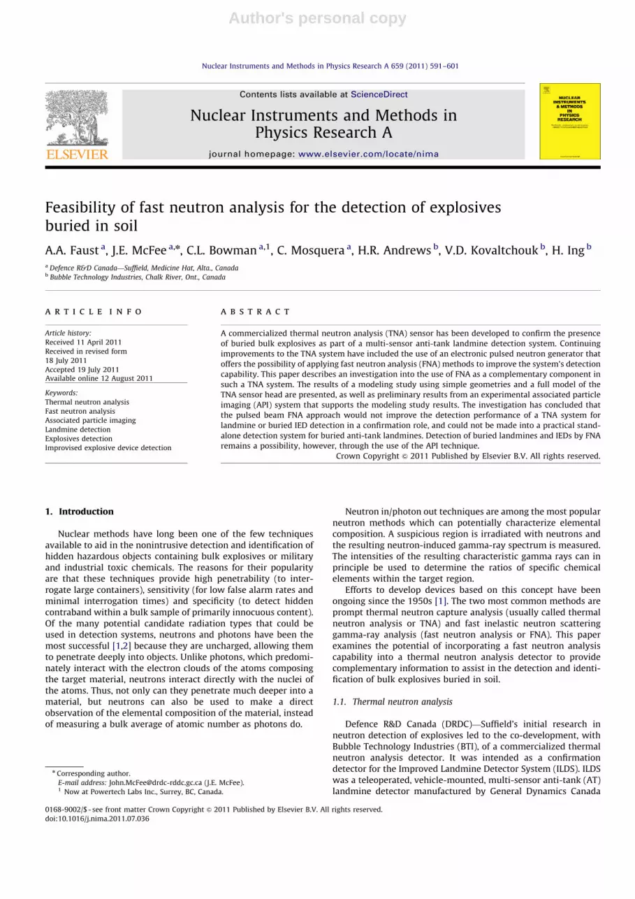
of baggage, the shielding of the detector system from the neutronsource can be greatly improved. Fig. 6(a) shows the main carbonand oxygen region of the gamma-ray spectrum. The peaks due tothe oxygen 6.128 MeV and carbon 4.443 MeV gamma rays clearlystand out.
Fig. 6(b) shows the spectrum from the same 0.45 kg C4explosives now sitting on the ground surface. Also shown in thisfigure is the spectrum from Fig. 6(a). Its peaks appear as barelyvisible bumps along the energy axis. The contribution of C4 to thetotal spectrum is overwhelmed by the contribution from the soil.The total count rate with the soil present is 150 times thatobtained with the bare C4 explosive. A baggage or packagemonitoring system using FNA has to deal with only tens ofkilograms of added material contained in the baggage/packageitself, not the hundreds of kilograms that contribute to themasking of the signal when dealing with explosives in the soil.
The initial evaluation of possible candidate peaks for use inFNA strongly pointed to carbon. However for 14 MeV neutrons,the peak at 4.443 MeV from carbon has too much interferencefrom an oxygen peak at the same energy. It is reasonable, then, toask if there are nitrogen peaks which are not interfered with byoxygen peaks and are of sufficient intensity to be useful. The sixnitrogen peaks of highest intensity are at 1.635, 2.313, 3.684,5.106, 6.727 and 7.028 MeV. The ones at 3.684 and 5.106 haveinterfering oxygen peaks (full energy or escape) leaving fourpossibilities. A comparison of the four nitrogen peaks for the C4in free space and sitting on the ground surface found that, as forcarbon, the N contribution from a C4 landmine is overwhelmedby the contribution from the soil.
2.6. Source collimation and tagged neutrons
One way to reduce the huge effect of the soil is to reduce thevolume that is irradiated by tightly collimating the neutronsource. The equivalent to a tightly collimated beam of neutronscan be roughly obtained by tagging the neutron with theassociated alpha particle created by the DT reaction. As will beseen later, this identifies the direction of the cone into which theneutron is emitted and hence provides the ability to select the soilvolume contributing to the measured spectrum. The method,known as associated particle imaging (API) or associated particlemethod (APM) has been investigated for a number of applicationsfor more than four decades [17] and has been studied for thedetection of explosives and illicit materials for almost twodecades [18]. A few recent investigations have briefly looked at
landmine detection [19], showing some hint of promise, but themethod has never been investigated in depth for this role. Inrecent years there has been significant research aimed at explo-sives and contraband detection in large cargo containers [20].
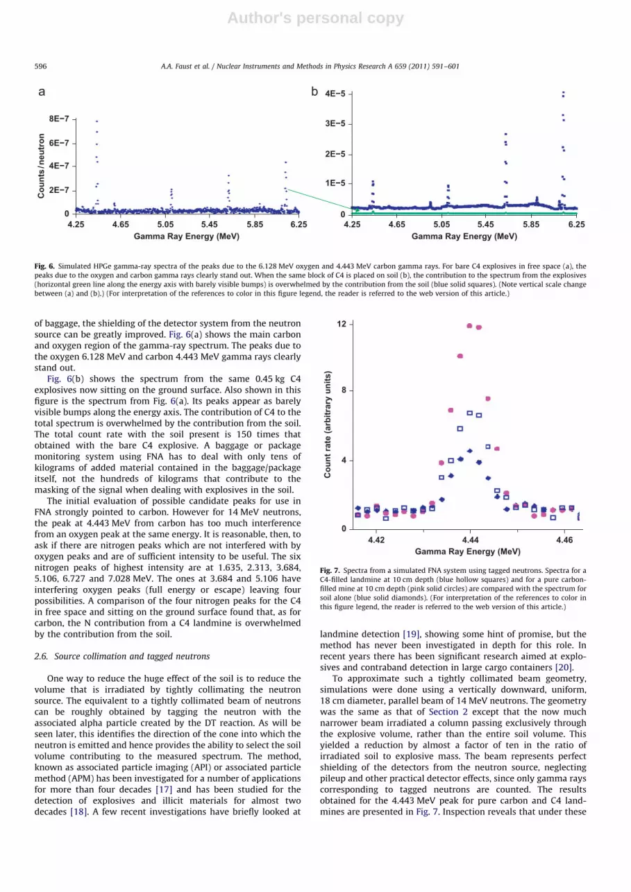
To approximate such a tightly collimated beam geometry,simulations were done using a vertically downward, uniform,18 cm diameter, parallel beam of 14 MeV neutrons. The geometrywas the same as that of Section 2 except that the now muchnarrower beam irradiated a column passing exclusively throughthe explosive volume, rather than the entire soil volume. Thisyielded a reduction by almost a factor of ten in the ratio ofirradiated soil to explosive mass. The beam represents perfectshielding of the detectors from the neutron source, neglectingpileup and other practical detector effects, since only gamma rayscorresponding to tagged neutrons are counted. The resultsobtained for the 4.443 MeV peak for pure carbon and C4 land-mines are presented in Fig. 7. Inspection reveals that under these
05.855.455.054.654.25 6.25
8E−7
6E−7
4E−7
2E−7
Gamma Ray Energy (MeV)
Cou
nts/
neut
ron
05.855.455.054.654.25 6.25
Gamma Ray Energy (MeV)
4E−5
3E−5
2E−5
1E−5
Fig. 6. Simulated HPGe gamma-ray spectra of the peaks due to the 6.128 MeV oxygen and 4.443 MeV carbon gamma rays. For bare C4 explosives in free space (a), the
peaks due to the oxygen and carbon gamma rays clearly stand out. When the same block of C4 is placed on soil (b), the contribution to the spectrum from the explosives
(horizontal green line along the energy axis with barely visible bumps) is overwhelmed by the contribution from the soil (blue solid squares). (Note vertical scale change
between (a) and (b).) (For interpretation of the references to color in this figure legend, the reader is referred to the web version of this article.)
4.44 4.464.42Gamma Ray Energy (MeV)
0
12
8
4
Cou
nt ra
te (a
rbitr
ary
units
)
Fig. 7. Spectra from a simulated FNA system using tagged neutrons. Spectra for a
C4-filled landmine at 10 cm depth (blue hollow squares) and for a pure carbon-
filled mine at 10 cm depth (pink solid circles) are compared with the spectrum for
soil alone (blue solid diamonds). (For interpretation of the references to color in
this figure legend, the reader is referred to the web version of this article.)
A.A. Faust et al. / Nuclear Instruments and Methods in Physics Research A 659 (2011) 591–601596

Author's personal copy
ideal conditions the explosives response is about twice that of thebackground soil response.
3. Experimental verification of API
3.1. Experimental description
In order to verify the key results of the simulations, namelythat soil effectively masks the FNA signal from buried explosivesand that the API method can allow the explosives signal to beseen, laboratory experiments were carried out. The experimentalsetup is shown in Fig. 8. A 1 m cubic wooden box was filled withpure sand. A thin-walled cylindrical tube was situated with itssymmetry axis vertical in the center of the box. Targets ofdifferent materials could be placed at arbitrary heights withinthe tube, either in air or completely surrounded by sand. An APIneutron generator was situated above and slightly displacedhorizontally with respect to the tube. Resultant gamma rays weredetected using a LaBr3(Ce) scintillator, whose output was pro-cessed, digitized and stored.
The neutron generator, via the T(d,n)a reaction, produces14 MeV neutron and 3.5 MeV alpha particles that are correlatedin time but travel in opposite directions. By detecting the time andposition of the alpha particle, the direction of travel and time ofproduction of the associated (tagged) neutron can be inferred. Theneutron may subsequently undergo inelastic scattering, emitting acharacteristic gamma ray which can then be detected. The com-bined a and g energy and timing information can be used toincrease selection efficiency by minimizing the contribution of thebackground multiple scatter and thermal capture spectrum. Addi-tionally, this approach allows for the equivalent of an electronicallycollimated neutron beam, further reducing the background fromthe isotropically generated neutron flux by selecting only thoseinteractions that are consistent with having originated in the targetvolume (Fig. 9). Thus the sensitivity of FNA to the distance betweenthe target object and the detector is reduced allowing for theinterrogation of wide targets from a single vantage point. Using theposition-associated FNA results, a 3D image of target volume canthen be reconstructed in terms of its chemical composition.
The speed of 14 MeV neutrons is approximately 5.1 cm/nswhile that of resulting gamma rays is 30 cm/ns. For the taggedneutron technique to succeed, one must be able to associate adetected characteristic gamma ray with a specific tagged neutron.Neglecting a complicated gamma-ray detector arrangement, this
implies that there cannot be more than one tagged neutron in theinterrogation cone at a time. If the generator and gamma-raydetector were colocated, and the maximum interrogation conelength were 2 m, this would imply a maximum neutron-gammaray flight time of approximately 46 ns. (The 3.5 MeV alphaparticle, which moves at 1.2 cm/ns, contributes a constant offsetto the total flight time due to the fixed geometry of thegenerator.) For the 51 half angle of the present generator, a46 ns time window and aZ99% probability that no more thanone neutron at a time is in the interrogation cone, the isotropicneutron emission rate of the generator cannot exceed�1.6�109 n/s. The maximum rate decreases to �4.8�107 n/sfor a 301 cone. Both rates are significantly less than the maximumoutput rate of the present neutron generator.
The neutron generator is an API-120,2 which focuses a contin-uous deuterium beam onto a tritiated target, generating 14 MeVneutrons and coincident alpha particles. The generator produces acontinuous neutron output with a maximum rate of 2�107 n/s at90 kV accelerating potential and 50 mA beam current. Alpha detec-tion is achieved by a thin, nickel-coated gallium-activated zincoxide, ZnO(Ga), scintillation layer deposited on a fibre optic window.The sensitive 64.8 mm diameter of the ZnO(Ga) layer is set at asufficient distance from the T(d,n)a interaction region to provide a 51half angle tagged neutron cone. The scintillator is well suited to therole. Its light output peaks at 390 nm and decays to 10% output inless than 5 ns, with an average yield of up to 61 photoelectrons per
Ground
Δ t min
Δ t max
stop
t
α de
tect
or
α
detec
tor
γ
Intersection Voxel
n
dTritiated target
start
t
Target
α
T(d,n)
Fig. 9. The alpha detector of the API neutron generator and a gamma-ray detector
can be used to define a voxel by means of a time of flight window. This is
equivalent to collimating the field of view of the gamma-ray detector.
PMT assembly
API neutron generator
LaBr3(Ce) assembly(some shieldingremoved for clarity)
alpha detector window
1m x 1m x 1m sand box
vertical tube
Fig. 8. Experimental setup to study API detection of explosives in soil. Most of the
electronics is not shown. 2 Thermo Scientific, Colorado, USA.
A.A. Faust et al. / Nuclear Instruments and Methods in Physics Research A 659 (2011) 591–601 597

Author's personal copy
alpha event in the energy range of interest (3.2 –5.4 MeV) [21]. Theexternal optical window was coupled to a Hammamatsu H2431-50photomultiplier tube (PMT). This is a relatively fast tube, with anelectron transit time of 16 ns and a small transit spread of 37 ps. Byusing a single PMT, voxel localization was determined by timingalone and so only a single voxel per depth slice was defined. In thefuture a multi-pixel alpha detector could be implemented simply byreplacing the photomultiplier with a multichannel photomultiplieror microchannel plate, yielding multiple voxels per depth slice.
Gamma rays were detected by a 7.62 cm�7.62 cm cylindricalLaBr3(Ce) scintillator3 coupled to an XP 5300 B/02 8-stage lowprofile PMT,4 optimized for high energy resolution and high countrate stability, with a custom-designed base and preamplifier.LaBr3 was chosen because of its fast risetime, which facilitatesthe stringent timing required by the experiment. Its excellentenergy resolution enables separation of close peaks in the FNAspectra; a benefit to the data analysis algorithms which willunfold the spectra to determine accurate carbon/oxygen ratios. Atthe same time, LaBr3 is more robust and costs less than equivalentsized HPGe detectors, making it a more practical choice whenconsidering systems that will ultimately be fielded.
A schematic of the tagged neutron data acquisition systemused to acquire time spectra at selectable energy windows isshown in Fig. 10. Because gamma-ray events are far fewer thanalpha events, the data acquisition system used the arrival of aspecific gamma ray as the start signal and then waited for a stopsignal from a time delayed alpha event. If no alpha arrived withina fixed time, the gamma-ray event was discarded. Energy spectracan be obtained for a selectable time window and time spectracan be selected for a particular energy window.
A schematic of the tagged neutron data acquisition system used toacquire energy spectra at selectable depth slices is shown in Fig. 11.
3.2. Observations
A typical time spectrum from a 2.54 cm-thick graphite(carbon) slab target in air is shown in Fig. 12. The electronicconfiguration of Fig. 10 was used to measure the time of flight
(TOF) between a delayed alpha start and a gamma-ray stop. Alsoshown is the spectrum obtained when the stop signal is furtherdelayed by a cable of precisely 4 ns in length. The precise delayallows the FWHM of the TOF distribution to be estimated to be1.3 ns. The carbon thickness corresponds to a flight time FWHMfor 14 MeV neutrons of 0.5 ns. By quadrature addition, theresolution of the data acquisition chain (including detectors) isroughly 1.2 ns.
Energy spectra acquired with and without time gating werecompared to illustrate the improvement in signal to noise ratioafforded by API. The gamma-ray spectrum for a 7.62 cm thickrectangular graphite target (density 1.8 g/cc) in sand (1.6 g/cc),obtained with the electronic configuration of Fig. 11, is shown inFig. 13 superimposed on the spectrum for sand alone. The top oftarget was 10 cm under the sand surface. The time gate for thespectrum was aligned with the top of the soil volume, andextended down 20 cm, thus bracketing the target position. (Theminimum timing requirements of the coincidence module limitedthe effective depth resolution to 4 ns or 20 cm for 14 MeVneutrons.) As predicted in the simulations of Section 2.6 (Fig. 7),the pure carbon target is readily detectable even at a burial depthof 10 cm. The spectra of Fig. 14 were acquired under the sameexperimental conditions as Fig. 13, but with time gating disabledand thus have contributions from a much greater sand columnthan that of the gated spectra. API strongly enhances the4.443 MeV full energy and first escape peaks from the carbontarget and suppresses the 6.128 MeV oxygen peaks from the sand.This clearly confirms the predictions of the modeling study ofSection 2.6 (compare Figs. 5 and 7).
The gamma-ray spectrum for an 8 cm thick granulated sucrose(C12H22O11) target (density 0.9 g/cc) in sand is shown in Fig. 15superimposed on the spectrum for sand alone. (Sucrose is a goodsimulant of the homemade explosive TATP for neutron interac-tions.) The top of the target was 10 cm under the sand surface.The 20 cm wide time-gated depth slice means that theinterrogated volume contains much more sand than target.Nevertheless, the 4.443 MeV peak due to carbon and oxygen fromsugar is visible. It would be larger if not for a decrease in countsfrom silicon and oxygen due to the dispaced volume of sand (see,for example, the peak at 6.128 MeV). Data analysis techniquesmust look for not only carbon excess in the target, but alsocompare oxygen and silicon variations in the voxels around thetarget in order to predict the true target oxygen level.
SPECTRAALPHA
SPECTRAGAMMA
TOF (Ei)i=1,...4
MCA
API ControlComputer
PREAMP FANOUT
FANOUT
API
PMT
SCA/CFD
SCA/CFD
Ei
GATE/DELAY GATE/DELAYAND
COINCIDENCE
TAC
HV
HV
Stro
be
i=1,...4
i=1,...4
AMP
i=1,...4FANOUT
OR
LABR3/PMT/BASE/PREAMP
Start
Stop
γ Channel
i=1,...4
Channelα
Fig. 10. Data acquisition system schematic used to acquire time spectra at selectable energy windows.
3 Saint Gobain, France.4 Photonis, France.
A.A. Faust et al. / Nuclear Instruments and Methods in Physics Research A 659 (2011) 591–601598

Author's personal copy
4. Conclusions
Simulations, verified by experiment, have shown that for a bestcase scenario – HPGe detectors, perfectly collimated neutron beamand no pileup effects – the fast neutron inelastic scattering gamma-ray signature of the explosives in a buried landmine or IED isbarely, if at all, visible. The explosives signature is overwhelmed bythe signal from the soil itself, principally through the interferenceof the silicon lines and the contribution of the fast inelasticscattering on oxygen, both significant components of soils.
By contrast, when the TNA approach is simulated in a similarfashion to that described above for FNA, the resulting spectrashow three sharp, clearly visible, isolated peaks (full energy, firstand second escape) from the nitrogen 10.829 MeV gamma ray inthe energy region of interest, with no interference from the10.607 MeV silicon gamma-ray triplet due to soil and minimalpeak-summing effects. However, the practical realities of fielding
the TNA were quite different [5]. The significant backgroundsfrom the source contained in the sensor-head itself requiredoptimized shielding and sensor-head design. The neutron ratesrequired for acceptable detection times resulted in substantialpulse pileup background in the nitrogen-signal region,�9�11 MeV, requiring significant research and development inhigh-speed pulse processing and background compensation inorder to obtain a manageable signal-to-noise ratio. In regard tothis latter point, it is expected that the pulse pileup situation forthe pulsed-source FNA approach would be significantly worsethan when used in TNA. When using a pulsed-neutron generatorin the TNA system, the detectors are gated-off during a 10 msneutron pulse, and then are enabled to collect spectra during thefollowing 90 ms, when the neutrons are undergoing thermaliza-tion. This procedure is repeated as a 100 ms cycle. The fast neutronanalysis would have to occur during the first 10 ms neutron pulsephase, where we have measured the instantaneous gamma-raycount rate seen at the detectors to be 32 times higher than thatduring the 90 ms thermalization period. This would severelyincrease the pulse pileup effects in any resulting spectra.
Considering the results of the FNA simulation and our experi-ences developing the TNA system, we conclude that the pulsed-beam FNA approach would not improve the detection performanceof the TNA system for landmine detection in a confirmation role,and could not be made into a practical stand-alone detectionsystem for buried AT landmines.
Detection of buried landmines through FNA may, however, bepossible using the tagged-neutron (API) approach. Simulations andexperiments have shown that target signal to background ratios canbe significantly increased by using an associated particle neutrongenerator and time gating to define a depth slice containing thetarget. Ongoing research is aimed at improving the present effectivetime resolution imposed by the NIM modules and replacing the NIMelectronics with a faster and more flexible VME-based approach.
Future study will determine whether TNA and API are comple-mentary for buried explosives detection and whether they can beincorporated in a single sensor. If the former is true but not thelatter, it may be necessary to select the most appropriate techniquefor the particular scenario. For example, one might use the more
PMT
HV
HV
LABR3/PMT/
DEL
AY
#1
DEL
AY
#2
DEL
AY
#3
TIME PICKOFFLLD
COINCIDENCEFAST
FASTCOINCIDENCE
AMPLIFIERSPECTROSCOPY
Gate MCA #3
MCA #4
MCA #6
Energy Signal
Input
API
FASTCOINCIDENCE
Channelγ
TIME PICKOFFCFD
BASE/PREAMP
α Channel
PREAMP
Fig. 11. Data acquisition system schematic used to acquire energy spectra at selectable depth slices.
Fig. 12. Carbon 4.443 MeV TOF time spectrum from a 2.54 cm-thick graphite slab
in air together with the distribution when the stop signal is delayed by a cable of
length 4 ns.
A.A. Faust et al. / Nuclear Instruments and Methods in Physics Research A 659 (2011) 591–601 599

Author's personal copy
sensitive technique for prescreening (to maintain high throughput)and when there is an indication of a positive hit, use the othertechnique to provide additional confidence or false alarm rejection.
References
[1] W. Coleman, R. Ginaven, G. Reynolds, Nuclear methods for mine detection, ADA167 968, US Army Mobility Equipment Research and Development Center,Ft. Belvoir, Virginia, final report for contract DAAK02-73-C-0139, May 1974.
[2] R. Moler, Workshop report: Nuclear techniques for mine detection research,AD A167 968, Belvoir Research and Development Center, Ft. Belvoir, Virginia,July 1985.
[3] A.A. Faust, R.H. Chesney, Y. Das, J.E. McFee, K.L. Russell, Int. J. Syst. Sci. 36 (9)(2005) 511.
[4] J.E. McFee, V. Aitken, R. Chesney, Y. Das, K. Russell, A multisensor, vehicle-mounted, teleoperated mine detector with data fusion, in: A.C. Dubey,J.F. Harvey, J.T. Broach (Eds.), Detection and Remediation Technologies forMines and Mine-like Targets III, vol. 3392, 1998, p. 1082.
[5] E. Clifford, J.E. McFee, H. Ing, H.R. Andrews, D. Tennant, E. Harper, A.A. Faust,Nucl. Instr. and Meth. Phys. Res. A 579 (2007) 418.
[6] D. Haslip, T. Cousins, H.R. Andrews, J. Chen, E. Clifford, H. Ing, J.E. McFee, DTneutron generator as a source for a thermal neutron activation system forconfirmatory land mine detection, in: R.B. James (Ed.), Hard X-Ray andGamma-Ray Detector Physics III, vol. 4507, 2001, p. 232.
[7] J.E. McFee, A.A. Faust, H.R. Andrews, V. Kovaltchouk, E. Clifford, H. Ing, IEEETrans. Nucl. Sci. 56 (3) (2009) 1584.
[8] R.C. Runkle, T.A. White, E.A. Miller, J.A. Caggiano, B.A. Collins, Nucl. Instr. andMeth. A 603 (2009) 510.
[9] S. Khan (Ed.), REP/DOT-FAA-CT-9211/1992, 1991.[10] H. Schubert, A. Kuznetsov (Eds.), Detection of Explosives and Landmines
Methods and Field Experiences, Vol. 66 of NATO Science Series II: Mathe-matics, Physics and Chemistry, 2002.
[11] A. Buffler, Radiat. Phys. Chem. 71 (2004) 853.[12] G. Vourvopoulos, F. Shultz, Nucl. Instr. and Meth. B 79 (1993) 585.
Fig. 13. Associated particle fast neutron analysis gamma-ray spectrum of a carbon target in sand (solid line) and of sand only (dotted line). Spectra correspond to a time
gate which brackets a depth slice containing the target. Live count time for each was 300 s.
Fig. 14. Associated particle fast neutron analysis gamma-ray spectrum of a carbon target in sand (solid line) and of sand only (dotted line). Experiment was identical to
that of Fig. 13 except that time gating was disabled.
16 O(n,n’αγ)4.44 MeV
28 Si(n,n’γ)6.88 MeV16 O(n,αγ)
3.68+3.85 MeV
16 O(n,n’γ)6.13 MeV12 C(n,n’γ)
4.44 MeV
Energy (keV)
+28 Si(n,n’γ)4.5 MeV
Cou
nts
(Arb
itrar
y U
nits
)
+
16 O(n,n’γ)6.92 MeV
Fig. 15. Time gated gamma-ray spectra for associated particle fast neutron
analysis. Spectrum for a sucrose (sugar) target in sand is superimposed on the
spectrum for sand alone.
A.A. Faust et al. / Nuclear Instruments and Methods in Physics Research A 659 (2011) 591–601600

Author's personal copy
[13] P. Womble, G. Vourvopoulos, J. Paschal, I. Novikov, A. Barzilov, Results of fieldtrials for the PELAN system, in: B. Barber, H. Roehrig, P. Doty, L. Porter, E. Morton(Eds.), Penetrating Radiation Systems and Applications IV, vol. 4786, 2002, p. 52.
[14] D.A. Sparrow, L.J. Porter, T. Broach, K.R. Sherbondy, Phenomenology ofprompt gamma neutron activation analysis in the detection of mines andnear-surface ordnance, in: A.C. Dubey, J.F. Harvey, J.T. Broach (Eds.), Detec-tion and Remediation Technologies for Mines and Mine-like Targets III, vol.3392, SPIE, Orlando, FL, USA, 1998, pp. 545–552.
[15] R.A. Forster, L.J. Cox, R.F. Barrett, T.E. Booth, J.F. Breismeister, F.B. Brown,J.S. Buul, G.C. Geisler, J.T. Goorley, R.D. Mesteller, S.E. Post, R.E. Prael,E.C. Selcow, A. Sood, Nucl. Instr. and Meth. B 213 (2004) 82.
[16] A.A. Faust, J.E. McFee, H.R. Andrews, H. Ing, Investigation of the feasibility offast neutron analysis for detection of buried landmines, in: R.S. Harmon,J.H. Holloway, J.T. Broach (Eds.), Detection and Remediation Technologies forMines and Mine-like Targets XI, Vol. 6217, 2006, p. 62172C1.
[17] S.P. Sitko, V.I. Strizhak, Pribory i Tekhnika Eksperimenta 6 (1967) 45.[18] E.A. Rhodes, C.W. Peters, APSTNG: neutron interrogation for detection of explo-
sives, drugs, and nuclear and chemical materials, in: J.M. Carpenter, D.B. Cline,
R.C. Lanza, D.F. Mildner (Eds.), Neutrons, X Rays, and Gamma Rays: ImagingDetectors, Material Characterization Techniques, and Applications, vol. 1737,
1993, p. 160.[19] M. Lunardon, G. Nebbia, S. Pesente, M. Barbui, M. Cinausero, G. D’Erasmo,
M. Palomba, A. Pantaleo, V. Filippini, Appl. Radiat. Isot. 61 (2004) 43.[20] S. Pesente, G. Nebbia, G. Viesti, F. Daniele, D. Fabris, M. Lunardon, S. Moretto,
K. Nad, D. Sudac, V. Valkovi�c, Nucl. Instr. and Meth. B 261 (2007) 268.[21] J.C. Cooper, D.S. Koltick, J.T. Mihalczo, J.S. Neal, Evaluation of ZnO(Ga)
coatings as alpha particle transducers within a neutron generator, in:
Proceedings of the Tenth Symposium on Radiation Measurements andApplications, vol. 505, 2003, pp. 498.
A.A. Faust et al. / Nuclear Instruments and Methods in Physics Research A 659 (2011) 591–601 601