fall 1998 gems & gemology - gia
TRANSCRIPT
EDITORIAL157 Demystifying Diamond Cut
William E. Boyajian
FEATURE ARTICLES158 Modeling the Appearance of the Round Brilliant Cut
Diamond: An Analysis of BrillianceT. Scott Hemphill, Ilene M. Reinitz, Mary L. Johnson,
and James E. Shigley
184 Cultured Abalone Blister Pearls from New ZealandCheryl Y. Wentzell
NOTES AND NEW TECHNIQUES202 Estimating Weights of Mounted Colored Gemstones
Charles I. Carmona
REGULAR FEATURES212 Gem Trade Lab Notes218 Gem News231 1998 Challenge Winners232 Book Reviews234 Gemological Abstracts
ABOUT THE COVER: Because abalone pearls are admired for their rarity, attractive col-ors, and striking iridescence, efforts have been made to culture them for more than a cen-tury. Only recently has commercial production of cultured abalone blister pearls beenachieved. A feature article in this issue examines the history, production, marketing, andidentifying characteristics of assembled cultured blister pearls from one major producer,Empress Abalone Ltd., using New Zealand’s Haliotis iris. These abalone “mabés” arebeing incorporated into distinctive jewelry designs, together with colored stones and dia-monds. The gold pendants and rings shown here contain abalone “mabés” ranging from12.5 to 17.3 mm in diameter. Jewelry courtesy of designer Ian Henderson, Dunedin, NewZealand.Photo © Harold & Erica Van Pelt––Photographers, Los Angeles, California.
Color separations for Gems & Gemology are by Pacific Color, Carlsbad, California.Printing is by Fry Communications, Inc., Mechanicsburg, Pennsylvania.© 1998 Gemological Institute of America All rights reserved. ISSN 0016-626X
T A B L E O F C O N T E N T S
pg. 159
pg. 217
pg.210
pg. 198
FALL 1998 VOLUME 34 NO. 3

Editor-in-Chief Richard T. Liddicoat
Publisher William E. Boyajian
Associate Editors D. Vincent Manson John Sinkankas
Technical Editor Carol M. Stockton
Assistant Editor Stuart Overlin
Editor Alice S. Keller 5345 Armada Drive Carlsbad, CA 92008 (760) 603-4504 e-mail: [email protected]
Senior Editor Brendan Laurs e-mail: [email protected]
Subscriptions Debbie Ortiz (800) 421-7250, ext. 7142 Fax: (760) 603-4595 e-mail: [email protected]
Editors, Gem Trade Lab Notes Thomas Moses, Ilene Reinitz, Shane F. McClure
Editors, Gem News Mary L. Johnson, John I. Koivula
Editors, Book Reviews Susan B. Johnson Jana E. Miyahira
Editor, Gemological Abstracts A. A. Levinson
Contributing Editor John I. Koivula
EDITORIAL STAFF
SUBSCRIPTIONS
MANUSCRIPT SUBMISSIONS
COPYRIGHT AND REPRINT PERMISSIONS
Subscriptions to addresses in the U.S.A. are priced as follows: $64.95 for one year (4 issues), $164.95 for three years (12 issues). Subscriptions sent elsewhere are $75.00 for one year, $195.00 for three years. Special annual subscription rates are available for all students actively involved in a GIA program: $54.95 to addresses in the U.S.A.; $65.00 elsewhere. Your student number must be listed at the time your subscription is entered. Single issues may be purchased for $16.50 in the U.S.A., $21.00 elsewhere. Discounts are given for bulk orders of 10 or more of any one issue. A limited number of back issues of G&G are also available for purchase. Please address all inquiries regarding subscriptions and the purchase of single copies or back issues to the Subscriptions Department. To obtain a Japanese translation of Gems & Gemology, contact GIA Japan, Okachimachi Cy Bldg., 5-15-14 Ueno, Taitoku, Tokyo 110, Japan. Our Canadian goods and service registration number is 126142892RT. Gems & Gemology welcomes the submission of articles on all aspects of the field. Please see the Guidelines for Authors in the Summer 1997 issue of the journal, or contact the Senior Editor for a copy. Letters on articles pub-lished in Gems & Gemology and other relevant matters are also welcome. Abstracting is permitted with credit to the source. Libraries are permitted to photocopy beyond the limits of U.S. copyright law for private use of patrons. Instructors are permitted to photocopy isolated articles for noncommercial classroom use without fee. Copying of the photographs by any means other than traditional photocopying techniques (Xerox, etc.) is prohibited without the express permission of the photographer (where listed) or author of the article in which the photo appears (where no photographer is listed). For other copying, reprint, or republication permission, please contact the editor. Gems & Gemology is published quarterly by the Gemological Institute of America, a nonprofit educational organiza-tion for the jewelry industry, 5345 Armada Drive, Carlsbad, CA 92008. Postmaster: Return undeliverable copies of Gems & Gemology to 5345 Armada Drive, Carlsbad, CA 92008. Any opinions expressed in signed articles are understood to be the opinions of the authors and not of the publisher.
Alan T. Collins London, United Kingdom G. Robert Crowningshield New York, New York John Emmett Brush Prairie, Washington,
Emmanuel Fritsch Nantes, France C. W. Fryer Santa Monica, California Henry A. Hänni Basel, Switzerland C. S. Hurlbut, Jr. Cambridge, Massachusetts
Alan Jobbins Caterham, United Kingdom Mary L. Johnson Carlsbad, California Anthony R. Kampf Los Angeles, California Robert E. Kane Lucerne, Switzerland John I. Koivula Santa Monica, California A. A. Levinson Calgary, Alberta, Canada
Thomas M. Moses New York, New York Kurt Nassau P.O. Lebanon, New Jersey George Rossman Pasadena, California Kenneth Scarratt Bangkok, Thailand Karl Schmetzer Petershausen, Germany James E. Shigley Carlsbad, California Christopher P. Smith Lucerne, Switzerland
PRODUCTION STAFF
EDITORIAL REVIEW BOARD
Art Director Seth Hogan
Production Assistant Carole Johnson
Research Assistant Alice Reynolds
he proper assessment of cut in dia-monds has long been an elusive, butintriguing, goal. As the authors pointout in the lead article, most diamondgrading systems in use today establishparameters for cut grades in round bril-liants based on a variation of propor-tions devised by Marcel Tolkowsky in1919. For nearly 80 years now, therehave been few, if any, rigorous attemptsto shed more light on the subject.
Recognizing this fact, several years agothe Gemological Institute of Americamade a long-term commitment toestablish a comprehensive understand-ing of the effects of cut and proportionson diamond appearance. Our goal was,and is, to develop modern criteria forcut assessment using today’s sophisti-cated technology, and to integrate thisknowledge into our diamond educa-tion and training courses. When thestudy has been successfully completed,this knowledge may even be applied toour laboratory reporting and instru-ment development.
This much-anticipated first article onGIA’s three-dimensional, ray-tracingcomputer model addresses the most
important appearance concept, bril-liance, based on what the authors call“weighted light return.” As the authorsstate, a brilliance measurement is one ofseveral important pieces of the “cut”puzzle; dispersion, scintillation, andperhaps symmetry and color, are oth-ers. Since a polished diamond shoulddisplay a pleasing combination of bril-liance, fire, and scintillation, the elusive“best” overall appearance might not befound among just the brightest roundbrilliant cuts. Thus, we caution you toread this article fully and carefully, andto refrain from drawing unequivocalconclusions from this initial work.
So what do we know at this point?Certainly, we know that cut is the mostcomplex of the 4 C’s, even when isolat-ed to one cutting style: the round bril-liant. We know that the success of cut-ting for weighted light return has moreto do with the interrelationship betweenthree critical proportions—table size,crown angle, and pavilion angle—thanon a selection of isolated proportionmeasurements. We know that one can-not, and must not, assess the cut of adiamond by examining any one of theseproportion parameters alone.
We also know that there are manycombinations of proportions that yieldequally attractive round-brilliant-cut dia-monds. In fact, we know that dia-monds can be cut in a fairly wide rangeof proportions to yield the same highlight return, which can lead to betterutilization of the rough and a better fitwith the myriad tastes that exist in theglobal marketplace.
Finally, we know from our extensivehistorical research on cut that therehave been numerous claims to a sin-gle set of “Ideal” proportions inround-brilliant-cut diamonds. Thesehave ranged from Wade’s AmericanIdeal in 1916 (with a 45.3% table, a35° crown angle, and a 41° pavilionangle) to Watermeyer’s Modern Idealin 1991 (with a 61% table, a 34°crown, and a 41° pavilion). Thederivation and use of the term “Ideal”is thus confusing at best, somewhatlike “blue-white” and “perfect”decades ago. Although it is not GIA’srole to discredit the concept of an“Ideal” cut, on the basis of ourresearch to date we cannot recom-mend its use in modern times.
Editorial GEMS & GEMOLOGY Fall 1998 157
Demystifying diamond cut
William E. Boyajian, PresidentGemological Institute of America
T

158 Modeling Brilliance GEMS & GEMOLOGY Fall 1998
he quality and value of faceted gem diamonds areoften described in terms of the “four C’s”: caratweight, color, clarity, and cut. Weight is the most
objective, because it is measured directly on a balance.Color and clarity are factors for which grading standardshave been established by GIA, among others. Cut, however,is much less tractable. Clamor for the standardization ofcut, and calls for a simple cut grading system, have beenheard sporadically over the last 25 years, gaining strengthrecently (Shor, 1993, 1997; Nestlebaum, 1996, 1997). Unlikecolor and clarity, for which diamond trading, consistentteaching, and laboratory practice have created a general con-sensus, there are a number of different systems for gradingcut in round brilliants. As discussed in greater detail later inthis article, these systems are based on relatively simpleassumptions about the relationship between the proportionsand appearance of the round brilliant diamond. Inherent inthese systems is the premise that there is one set (or a nar-row range) of preferred proportions for round brilliants, andthat any deviation from this set of proportions diminishesthe attractiveness of a diamond. In this article, we presentand discuss our findings with regard to the rather complexrelationship between cut proportions and brilliance.
Diamond manufacturing has undergone considerablechange during this century. For the most part, diamonds arecut within very close proportion tolerances, both to saveweight while maximizing appearance and to account forlocal market preferences (Caspi, 1997). As shown in figure 1and table 1, however, differences in proportions can producenoticeable differences in appearance in round-brilliant-cutdiamonds. Within this single cutting style, there is substan-tial debate—and some strongly held views—about whichproportions yield the best face-up appearance (Federman,1997). Yet face-up appearance depends as well on manyintrinsic physical and optical properties of diamond as a
MODELING THE APPEARANCE OFTHE ROUND BRILLIANT CUT
DIAMOND: AN ANALYSIS OF BRILLIANCEBy T. Scott Hemphill, Ilene M. Reinitz, Mary L. Johnson, and James E. Shigley
ABOUT THE AUTHORS
Mr. Hemphill is research associate, and Dr. Shigleyis director, of GIA Research, Carlsbad, California.Dr. Reinitz is manager of Research and Develop-ment at the GIA Gem Trade Laboratory (GIA GTL),New York. Dr. Johnson is manager of Researchand Development at GIA GTL, Carlsbad.
Please see acknowledgments at the end of thearticle.
Gems & Gemology, Vol. 34, No. 3, pp. 158 –183© 1998 Gemological Institute of America
TOf the “four C’s,”cut has historically been themost complex to understand and assess. Thisarticle presents a three-dimensional mathemat-ical model to study the interaction of light witha fully faceted, colorless, symmetrical round-brilliant-cut diamond. With this model, onecan analyze how various appearance factors(brilliance, fire, and scintillation) depend onproportions. The model generates images and anumerical measurement of the optical efficien-cy of the round brilliant—called weighted lightreturn (WLR)—which approximates overallbrilliance. This article examines how WLR val-ues change with variations in cut proportions,in particular crown angle, pavilion angle, andtable size. The results of this study suggest thatthere are many combinations of proportionswith equal or higher WLR than “Ideal” cuts. Inaddition, they do not support analyzing cut byexamining each proportion parameter indepen-dently. However, because brilliance is just oneaspect of the appearance of a faceted diamond,ongoing research will investigate the addedeffects of fire and scintillation.
Modeling Brilliance GEMS & GEMOLOGY Fall 1998 159
material, and on the way these properties governthe paths of light through the faceted gemstone.(Also important are properties particular to eachstone, such as polish quality, symmetry, and thepresence of inclusions.)
Diamond appearance is described chiefly interms of brilliance (white light returned through thecrown), fire (the visible extent of light dispersioninto spectral colors), and scintillation (flashes oflight reflected from the crown). Yet each of theseterms represents a complex appearance concept thathas not been defined rigorously, and that cannot beexpressed mathematically without making someassumptions and qualifications (see below).
Despite the widespread perception in the tradethat diamond appearance has been extensivelyaddressed, there is limited information in the litera-ture, and some aspects have never been examined.Several analyses of the round brilliant cut have beenpublished, starting with Wade (1916). Best knownare Tolkowsky’s (1919) calculations of the propor-tions that he believed would optimize the appear-ance of the round-brilliant-cut diamond. However,Tolkowsky’s calculations, as well as most otherssince then, involved two-dimensional images asgraphical and mathematical models. These were
used to solve sets of relatively simple equations thatdescribed what was considered to be the brillianceof a polished round brilliant diamond. (Tolkowskydid include a simple analysis of fire, but it was notcentral to his model and it will not be discussed atany length in this article.) For the most part, theexisting cut grading systems are based onTolkowsky’s research.
We believe that diamond cut, as a matter of suchimportance to the trade, deserves a more thoroughand thoughtful investigation. The issues raised canonly be resolved by considering the complex combi-nation of physical factors that influence the appear-ance of a faceted diamond (i.e., the interaction oflight with diamond as a material, the shape of agiven polished diamond, the quality of its surfacepolish, the type of light source, and the illuminationand viewing conditions), and incorporating theseinto an analysis of that appearance.
The initial goal of this research project was todevelop a theoretical model for the interaction oflight with a faceted diamond that could serve as thebasis for exploring many aspects of the effect of cuton appearance. Computer graphics simulation tech-niques were used to develop the model presentedhere, in conjunction with several years of research
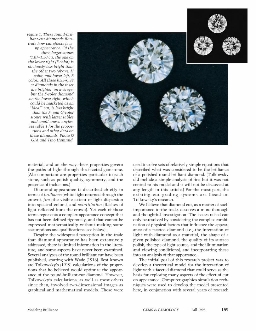
Figure 1. These round-bril-liant-cut diamonds illus-
trate how cut affects face-up appearance. Of the
three larger stones(1.07–1.50 ct), the one on
the lower right (F color) isobviously less bright than
the other two (above, Hcolor, and lower left, E
color). All three 0.35–0.38ct diamonds in the insetare brighter, on average;but the F-color diamond
on the lower right, whichcould be marketed as an“Ideal” cut, is less bright
than the F- and G-colorstones with larger tablesand small crown angles.
See table 1 for the propor-tions and other data on
these diamonds. Photo ©GIA and Tino Hammid.

160 Modeling Brilliance GEMS & GEMOLOGY Fall 1998
on how to express mathematically the interactionof light with diamond and also the various appear-ance concepts (i.e., brilliance, fire, and scintillation).Our model serves as a general framework for exam-ining cut issues; it includes mathematical represen-tations of both the shape of a faceted diamond andthe physical properties governing the movement oflight within the diamond. We plan to analyze theappearance aspects one at a time and then, ulti-mately, assemble the results in order to examinehow proportions affect the balance of brilliance, fire,and scintillation.
The general mathematical model presented inthis article uses computer graphics to examine theinteraction of light with a standard (58 facet) round-brilliant-cut diamond with a fully faceted girdle. Forany chosen set of proportions, our model can pro-duce images and numerical results for an appear-ance concept (by way of a mathematical expres-sion). To compare the appearance concepts of bril-liance, fire, and scintillation in round brilliants ofdifferent proportions, we need a quantity to mea-sure and a relative scale for each concept. A specificmathematical expression (with its built-in assump-tions and qualifications) that aids the measurementand comparison of a concept such as brilliance isknown as a metric. In this study, we derived a met-ric for brilliance that quantifies the amount of lightreturned from a modeled diamond for averaged illu-mination and viewing arrangements, as described
below. Although other factors (e.g., bodycolor orinclusions) may also influence how bright a particu-lar round brilliant appears, light return is an essen-tial feature of diamond brilliance.
In future reports on this project, we plan toaddress how fire and scintillation are affected byproportions. We also intend to examine how sym-metry, lighting conditions, and other factors affectall three of these appearance concepts. The overallgoal of this research is to provide a comprehensiveunderstanding of how cut affects the appearance ofa faceted diamond.
BACKGROUND
Early History. Diamond faceting began in about the1400s and progressed in stages toward the roundbrilliant we know today (see Tillander, 1966, 1995).In his early mathematical model of the behavior oflight in fashioned diamonds, Tolkowsky (1919) usedprinciples from geometric optics to explore howlight rays behave in a prism that has a high refrac-tive index. He then applied these results to a two-dimensional model of a round brilliant with a knife-edge girdle, using a single refractive index (that is,only one color of light), and plotted the paths ofsome illustrative light rays.
Tolkowsky assumed that a light ray is eithertotally internally reflected or totally refracted out ofthe diamond, and he calculated the pavilion angleneeded to internally reflect a ray of light enteringthe stone vertically through the table. He followedthat ray to the other side of the pavilion and foundthat a shallower angle is needed there to achieve asecond internal reflection. Since it is impossible tocreate substantially different angles on either side ofthe pavilion in a symmetrical round brilliant dia-mond, he next considered a ray that entered thetable at a shallow angle. Ultimately, he chose apavilion angle that permitted this ray to exitthrough a bezel facet at a high angle, claiming thatsuch an exit direction would allow the dispersion ofthat ray to be seen clearly. Tolkowsky also used thislimiting case of the ray that enters the table at a lowangle and exits through the bezel to choose a tablesize that he claimed would allow the most fire. Heconcluded by proposing angles and proportions for around brilliant that he believed best balanced thebrilliance and fire of a polished diamond, and thenhe compared them to some cutting proportions thatwere typical at that time. However, since Tol-kowsky only considered one refractive index, hecould not verify the extent to which any of his rays
TABLE 1. Proportions and calculated WLR values for the diamonds photographed in figure 1.
Position Color Weight Table Crown Pavilion Calcu-(ct) size angle angle lated
(%) (°) (°) WLRa
Main photoTop H 1.21 62 29.4 41.7 0.279Lower F 1.50 63 39.8 41.7 0.257right
Lower E 1.07 57 34.6 40.9 0.282left
InsetTop G 0.38 60 26.5 42.6 0.288Lower F 0.35 56 34.7 41.2 0.281right
Lower F 0.35 59 27.0 41.4 0.290left
a WLR, our metric for overall brightness, is calculated from the givencrown angle, pavilion angle, and table size, using our standard refer-ence proportions (given in table 4) for the other five parameters.
Modeling Brilliance GEMS & GEMOLOGY Fall 1998 161
would be dispersed. Nor did he calculate the lightloss through the pavilion for rays that enter the dia-mond at high angles.
Over the next 80 years, other researchers famil-iar with this work produced their own analyses,with varying results (see table 2). It is interesting(and somewhat surprising) to realize that despite thenumerous possible combinations of proportions for astandard round brilliant, in many cases eachresearcher arrived at a single set of proportions thathe concluded produced an appearance that was supe-rior to all others. Currently, many gem grading labo-ratories and trade organizations that issue cut gradesuse narrow ranges of proportions to classify cuts,including what they consider to be best (table 3).
Several cut researchers, but not Tolkowsky, used“Ideal” to describe their sets of proportions, whichvary significantly, as seen in table 2. Today, in addi-tion to systems that incorporate “Ideal” in theirnames, many people use this term to refer to mea-surements similar to Tolkowsky’s proportions, butwith a somewhat larger table (which, at the samecrown angle, yields a smaller crown height percent-age). This is what we mean when we use “Ideal” inthis article.
Recent Appearance Models and Measurements. Wefound thorough descriptions of three computermodels of round brilliant diamonds in the literature.One model explored light return numerically(Tognoni, 1990); another produced a number ofmonochromatic images, each using a differentrefractive index, and some numerical output (Astricet al., 1992); but the third (Dodson, 1979) was simi-lar to our work in several ways. Using a three-dimensional model of a fully faceted round brilliantdiamond, Dodson devised metrics for brilliance,fire, and “sparkliness” (scintillation). His mathe-matical model employed a full sphere of approxi-mately diffuse illumination centered on the dia-mond’s table. His results were presented as graphsof brilliance, fire, and sparkliness for 120 proportioncombinations. They show the complex interdepen-dence of all three appearance aspects on pavilionangle, crown height, and table size. His model (aswell as that of Shannon and Wilson, as best we candetermine from the little published on it [Lawrence,1998; Shor, 1998]) is distinct from ours in that allrays emerging from the diamond were weightedequally. Three of Dodson’s results are given in table 2.
There are also computer-aided-design (CAD)software programs for creating gemstone cuts and
analyzing the effect of cut on the appearance of thefinished gemstone. (One of these, Gem-Cad, is mar-keted by Gemsoft Enterprises, Austin, Texas.)
These computer programs and mathematicalmodels use ray-tracing algorithms to produce visualimages of gemstones or numerical data about theirappearance, or both. However, each of the programsdescribed above excludes one or more of the startingassumptions that we employ here (e.g., wavelength-dependent refractive index, accounting for sec-ondary rays, weighing observer angles; see belowand Box A). Because of these differences, our com-puter graphics program is not directly comparableto these other programs. However, the optimal pro-portions predicted by those models can be assessedand compared using our metric for brilliance.
Commercial services are currently available thatclaim to measure the brilliance of fashioned stones.The measurements of brilliance provided byDiamond Profile (Portland, Oregon) are based ondigital video images through the crown of the dia-mond under a few controlled lighting conditions,which are then combined to generate graphicresults for that particular stone (Gilbertson andWalters, 1997; Gilbertson, 1998).
DESCRIPTION OF OUR MODELIn general, within a mathematical model, all of thefactors we consider important to diamond appear-ance—the diamond itself, its proportions and facetarrangement, and the lighting and observation con-ditions—can be carefully controlled, and fixed for agiven set of analyses. Such control is nearly impos-sible to achieve with actual diamonds. Furthermore,with this model we can examine thousands of setsof diamond proportions that would not be economi-cally feasible to create from diamond rough. Thus,use of a model allows us to explore how cut propor-tions affect diamond appearance in a more compre-hensive way than would be possible through obser-vation of actual round brilliants. However, everymathematical model incorporates some assump-tions, and these built-in conditions affect the natureof the results. (The modeled diamond used inTolkowsky’s [1919] analysis, for example, was two-dimensional and had a knife-edge girdle, which lim-ited the number and paths of light rays he couldconsider.)
Real diamonds will inevitably differ from themodel conditions because of inclusions, symmetrydeviations, and the like. Nevertheless, a theoreticalmodel provides a goal to reach toward: What is the
162 Modeling Brilliance GEMS & GEMOLOGY Fall 1998
best result—best brilliance, best fire, best balanceof the two, best scintillation, best weight retention,best combination—that can be achieved from a par-ticular piece of rough? In addition, a theoreticalunderstanding of the behavior of light in a faceteddiamond could help in the design of any instru-ment intended to measure optical performance inreal diamonds.
Finally, a model of the interaction of light with afaceted diamond can be used to compare and con-trast different metrics and different lighting andobservation conditions, as well as evaluate thedependence of those metrics on proportions, symme-try, or any other property of diamond included in themodel. In the following sections, we present theassumptions and methods on which our model isbased, and introduce our metric for brilliance.
Assumptions and Methods. The mathematicalmodel presented here creates a fresh structure forexamining nearly all aspects of the influence thatcut has on a diamond’s appearance. Box A providesthe assumptions on which the model is based: adetailed list of the physical properties included inthe model, a mathematical description of the pro-portions of the round brilliant, and a description ofthe lighting condition used in this study. The inclu-sion of these many physical properties distinguishesthis model from previous work, and the details ofthe lighting conditions affect the specific numericalvalues we present here. The model traces rays fromthe modeled light source through a mathematicalrepresentation of a round brilliant of any chosenproportions (referred to hereafter as the “virtual”diamond) to produce two kinds of results: (1) digitalimages of the virtual diamond, and (2) a numericalevaluation of an appearance concept (in this case,brilliance).
A digital image (see, e.g., figure 2), drawn fromthe perspective of our choice, is a two-dimensionalarray of picture elements (pixels), each of whichcomprises a small area of the virtual diamond. Wetraced up to one million rays of various colors foreach pixel in an image, to obtain convergence of thecolor and total brightness for that small area. As thecomputer traces the first few hundred rays, random-ly selecting wavelengths and angles of incidence,the computed brightness and color for a given pixelchange rapidly. Eventually, when enough differentdirections and wavelengths have been traced, thecomputed brightness and color settle down, or con-verge, to particular values, and tracing more rays
does not change these values. The resolution of theimage depends on our choice of the number of pix-els to compute for a particular image size. For mostof the images presented in this article, we calculat-ed the color and brightness of 65,536 pixels, requir-ing up to 65,000,000,000 traced rays.
The computer program employed is not a com-mercial product, but was written specifically forthis work by the first author. It was written in C, ascientific programming language. The program hasbeen run on a Pentium personal computer, on twomodels of Digital Equipment Corp.’s Alpha work-station, and on a dual Pentium II. If the convergencethresholds and choice of resolution are maintained,the hardware used to run the program does not alterthe results. The accuracy of the program, in generaland on different kinds of hardware, was verifiedwith a simple test problem for which we had com-puted a result manually. Further details of the raytracing and computational methods will be given byHemphill et al. (in preparation). These techniquesextend the methods described by Foley (1996).
Defining Metrics: Brilliance. Our aim is to use thismodel to explore how brilliance, fire, and scintilla-tion vary with the proportions of a round brilliantdiamond. We begin with brilliance for several rea-sons. First, brilliance is the aspect of diamondappearance that is most immediately noticed.Second, it is an aspect for which the desired out-come is obvious: Bright is good and dark is not.Last, most of the previous work investigating cutfocused on brilliance (see references in table 2), andit is this work that has fueled the current tradedebate about cut.
One advantage of using a computer model is thecapability it gives us to examine thousands of pro-portion variations. To make sense of so much data,however, we needed to define a metric for bril-liance, and use it to compare the performance of thedifferent proportion combinations. The GIADiamond Dictionary (1993, p. 28) defines brillianceas the “intensity of the internal and external reflec-tions of white light from the crown. . . .” A varietyof mathematical expressions can be created todescribe such light return. Each expression requiresexplicit or implicit assumptions about what consti-tutes brilliance and about light sources, viewinggeometry, response of the human eye, and responseof the human brain. As an example of this last con-sideration, should a mathematical definition of bril-liance represent one viewing geometry—that is, a
Modeling Brilliance GEMS & GEMOLOGY Fall 1998 163
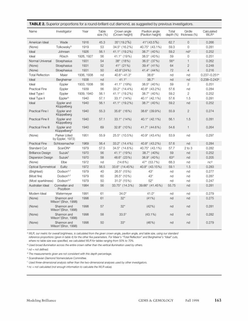
TABLE 2. Superior proportions for a round-brillant-cut diamond, as suggested by previous investigators.
Name Investigator Year Table Crown angle Pavilion angle Total Girdle Calculatedsize (%) (Crown height) (Pavilion height) depth (%) thickness (%) WLRa
American Ideal Wade 1916 45.3 35° (19.2%) 41° (43.5%) 62.7 0 0.266(None) Tolkowskyb 1919 53 34.5° (16.2%) 40.75° (43.1%) 59.3 0 0.281Ideal Johnsen 1926 56.1 41.1° (19.2%) 38.7° (40%) 59.2 ndc 0.252Ideal Rösch 1926, 1927 56 41.1° (19%) 38.5° (40%) 59 0 0.251Normal Universal Stoephasius 1931 54 38° (18%) 36.5° (37%) 56d 1 0.262(None) Stoephasius 1931 52 41° (21%) 39.4° (41%) 64 2 0.248(None) Stoephasius 1931 50 43.8° (24%) 41.4° (44%) 72 4 0.216Total Reflection Maier 1936, 1938 nd 40.8°–41.3° 38.6° nd nd 0.237–0.251a
Ideal Bergheimer 1938 nd 41.1° 38.7° nd nd 0.238–0.243a
Ideal Eppler 1933, 1938 56 41.1° (19%) 38.5° (40%) 59 2 0.251Practical Fine Eppler 1939 56 33.2° (14.4%) 40.8° (43.2%) 57.6 nd 0.284Ideal Type I Eppler 1939, 1940 56.1 41.1° (19.2%) 38.7° (40%) 59.2 2 0.252Ideal Type II Epplerb 1940 57.1 33.1° (14%) 40.1° (42.1%) 57.6 1.5 0.281Ideal Eppler and 1940 56.1 41.1° (19.2%) 38.7° (40%) 59.2 nd 0.252
KlüppelbergPractical Fine I Eppler and 1940 55.3 35.6° (16%) 38.6° (39.9%) 55.9 2 0.274
KlüppelbergPractical Fine II Eppler and 1940 57.1 33.1° (14%) 40.1° (42.1%) 56.1 1.5 0.281
KlüppelbergPractical Fine III Eppler and 1940 69 32.8° (10%) 41.7° (44.6%) 54.6 1 0.264
Klüppelbergb
(None) Parker (cited 1951 55.9 25.5° (10.5%) 40.9° (43.4%) 53.9 nd 0.297by Eppler, 1973)
Practical Fine Schlossmacher 1969 56.4 33.2° (14.4%) 40.8° (43.2%) 57.6 nd 0.284Standard Cut ScanDNe 1979 57.5 34.5° (14.6%) 40.75° (43.1%) 57.7 2 to 3 0.282Brilliance Design Suzuki f 1970 56 41.1° (19%) 38.7° (40%) 59 nd 0.252Dispersion Design Suzuki f 1970 58 48.6° (23%) 38.9° (40%) 63d nd 0.205(None) Elbe 1972 nd (14.6%) 47° (53.7%) 68.3 nd ncg
Optical Symmetrical Eulitz 1972 56.5 33.6° (14.45%) 40.8° (43.15%) 59.1 1.5 0.283(Brightest) Dodsonb,f 1979 40 26.5° (15%) 43° nd nd 0.277(Most fire) Dodsonb,f 1979 60 26.5° (10%) 43° nd nd 0.287(Most sparkliness) Dodsonb,f 1979 50 31.0° (15%) 52° nd nd 0.247Australian Ideal Connellan and 1984 56 33.75° (14.3%) 39.66° (41.45%) 55.75 nd 0.281
PozzibonModern Ideal Watermeyer 1991 61 34.0° 41.0° nd nd 0.279(None) Shannon and 1998 61 32° (41%) nd nd 0.275
Wilsonf (Shor, 1998)(None) Shannon and 1998 57 32° (42%) nd nd 0.281
Wilsonf (Shor, 1998)(None) Shannon and 1998 58 33.5° (43.1%) nd nd 0.282
Wilsonf (Shor, 1998)(None) Shannon and 1998 50 33° (46%) nd nd 0.279
Wilsonf (Shor, 1998)
a WLR, our metric for overall brightness, is calculated from the given crown angle, pavilion angle, and table size, using our standardreference proportions (given in table 4) for the other five parameters. For Maier’s “Total Reflection” and Bergheimer’s “Ideal” cuts,where no table size was specified, we calculated WLR for tables ranging from 50% to 70%.
b Used broad illumination across the entire crown rather than the vertical illumination used by others.c nd = not defined.d The measurements given are not consistent with this depth percentage.e Scandinavian Diamond Nomenclature Committee.f Used three-dimensional analysis rather than the two-dimensional analyses used by other investigators.g nc = not calculated (not enough information to calculate the WLR value).

164 Modeling Brilliance GEMS & GEMOLOGY Fall 1998
“snapshot”—or an average over many viewing situ-ations? We chose the latter approach.
Weighted Light Return. The metric we discuss inthis article is called weighted light return (WLR); itis specific to each set of modeled diamond propor-tions with the chosen illumination. After examin-ing a variety of possible metrics for brilliance, wedeveloped WLR to best represent the way the expe-rienced viewer sees a diamond, especially one
mounted in jewelry, with lighting that illuminatesthe stone from all around without excessive glare orshadow.
The WLR is a weighted sum of the amount oflight returned through the crown of the virtual dia-mond to all positions of observation above the gir-dle. Rather than using the total fraction of lightreturned through the crown for a fixed arrangementof the light source, diamond, and viewer, weweighed the relative importance of returned light
TABLE 3. Proportions for some of the cut grading systems for round brilliant diamonds used today.a
Categorya Table size (%) Crown angle (° ) Pavilion angle (° ) Pavilion depth (%)
Min. Max. Min. Max. Min. Max. Min. Max.
AGA *1A 53 58 34.3 34.7 40.5d 40.8d 42.8 43.2
1B 52.0–52.9 58.1–60.0 34.01–34.2 34.81–35.0 40.36–40.5d 40.9–41.0d 42.5–42.7 43.3–43.5
2A 51.5–51.9 60.1–63.0 32.1–33.9 35.1–35.8 40.03–40.03d 41.08–41.3d 42.0–42.4 43.6–44.0
3A 50.5–50.9 64.1–67.0 29.6–30.0 38.0–39.4 39.35–39.6d 42.0–42.3d 41.0–41.4 45.0–45.5
AGJ * Excellent 53 58 33 35 40.0d 41.3d 42 44
Very Good 52 63 32 36 40.0d 42.0d 42 45
Good 50 67 30 38 39.3d 43.2d 41 47
AGS *0 52.4 57.5 33.7 35.8 40.16d 41.2d 42.2 43.8
1 51.4–52.3 57.6–59.5 32.7–33.6 35.9–36.3 40.16d 41.3–41.5d 42.2 43.9–44.3
3 50.4–51.3 61.6–63.5 31.7–32.1 36.9–37.3 40.16d 41.3–41.5d 42.2 43.9–44.3
5 49.4–50.3 65.6–67.5 30.7–31.1 37.9–38.3 39.1–39.4d 42.2–42.5d 40.7–41.1 45.4–45.8
AGT * Excellent 53 60 33 35 40.7d 40.7d 43 43
Very Good 52 64 32 36 40.0d 41.3d 42 44
Good 51 68 30 38 39.3d 42.6d 41 46
CGL * Excellent 52 58 33 35 40.0d 41.3d 42 44
EGL * Exceptional 54 57 34 35 40.5 41.0 42.5 43.5
HRD * Very Good 53 66 30.7 37.7 39.6f 42.2f 41.5f 45f
IGI * Ideal 53 60 33 36 40.0d 41.3d 42 44
Rap * Specifi- 55 64 30 35 nd nd nd ndcation A
ScanDN * Good 52 65 30 39 40 42 42 45
a Asterisk (*) indicates top grade. Generally all parameters must be in the specified ranges for the stone to receive the top grade;variation in any parameter reduces the grade accordingly. Abbreviations: Max.= maximum, Min.= minimum, med.= medium,sl.= slightly, ex.= extra, v.= very.
b The full names and countries of the organizations are indicated below. For some organizations, only the top grade is provided.All of the information provided in this table was obtained from the respective organizations:
AGA = As reported in Fine Make, Accredited Gem Appraisers, 1997, U.S. (Class 1A and 1B = “American Ideal Cut,” Class 2A = “International Fine Cut,” Class 3A = “U.S. Domestic Average Cut.” Values given for stones ≥0.5 ct)
AGJ = Association of Gemological Laboratories, 1993, Japan
AGS = American Gem Society, 1997, U.S.
AGT = Association of Japan Gem Trust, 1995, Japan
CGL = Central Gem Laboratory, 1993, Japan
EGL = European Gemological Laboratory, U.S. (G. Sherman, pers. comm., 1997)
HRD = Hoge Raad voor Diamant, 1993, Belgium
IGI = International Gemological Institute, 1997, U.S.
Cut gradingsystemb
rays based on their exit direction. An experienceddiamond observer assesses the diamond primarilyon the basis of its face-up appearance, but also“rocks” the stone both to minimize the effect ofglare and to consider the stone from various angles,with the views closest to vertical (face-up) weighingthe most in this evaluation. We wanted the metricwe chose to behave like this assessment. Therefore,we wanted the contribution from rays that emergedstraight up to be much greater than that from rays
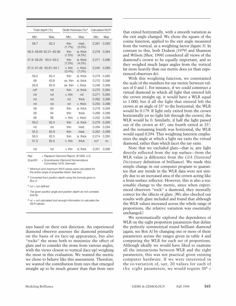
that exited horizontally, with a smooth variation asthe exit angle changed. We chose the square of thecosine function, applied to the exit angle measuredfrom the vertical, as a weighting factor (figure 3). Incontrast to this, both Dodson (1979) and Shannonand Wilson (Shor, 1998) considered all views of thediamond’s crown to be equally important, and sothey weighed much larger angles from the verticalfar more heavily than our metric does (or than expe-rienced observers do).
With this weighting function, we constrainedthe scale of the numbers for our metric between val-ues of 0 and 1. For instance, if we could construct avirtual diamond in which all light that entered leftthe crown straight up, it would have a WLR equalto 1.000; but if all the light that entered left thecrown at an angle of 25° to the horizontal, the WLRwould be 0.179. If light only exited from the crownhorizontally (or no light left through the crown), theWLR would be 0. Similarly, if half the light passedout of the crown at 45°, one fourth exited at 25°,and the remaining fourth was horizontal, the WLRwould equal 0.294. This weighting function empha-sizes the angle at which a light ray exits the virtualdiamond, rather than which facet the ray exits.
Note that we excluded glare—that is, any lightdirectly reflected from the top surface—from theWLR value (a difference from the GIA DiamondDictionary definition of brilliance). We made thissimple change in our computer program to guaran-tee that any trends in the WLR data were not sim-ply due to an increased area of the crown acting likea front-surface reflector. However, this is also a rea-sonable change to the metric, since when experi-enced observers “rock” a diamond, they mentallycorrect for the effects of glare. (We also checked ourresults with glare included and found that althoughthe WLR values increased across the whole range ofproportions, the relative variation was essentiallyunchanged.)
We systematically explored the dependence ofWLR on the eight proportion parameters that definethe perfectly symmetrical round brilliant diamond(again, see Box A) by changing one or more of theseparameters across the ranges given in table 4 andcomputing the WLR for each set of proportions.Although ideally we would have liked to examineall the interactions between WLR and the eightparameters, this was not practical given existingcomputer hardware. If we were interested inthe co-variation of, say, 20 values for each ofthe eight parameters, we would require 208 =
Modeling Brilliance GEMS & GEMOLOGY Fall 1998 165
Total depth (%) Girdle thickness (%)a Calculated WLRc
Min. Max. Min. Max. Min. Max
58.7 62.3 thin med. 0.281 0.283(1.7%) (3.0%)
58.3–58.69 62.31–62.99 thin sl. thick 0.278 0.284(1.5%) (4.5%)
57.9–58.29 63.0–63.5 thin sl. thick 0.271 0.286(1.0%) (4.5%)
57.0–57.49 63.81–64.1 v. thin v. thick 0.245 0.289(0.4%) (7.0%)
59.2 62.4 thin sl. thick 0.279 0.285
58 63.8 ex. thin sl. thick 0.270 0.286
56.8 65.9 ex. thin v. thick 0.248 0.289
nde nd thin sl. thick 0.275 0.284
nd nd v. thin nd 0.271 0.285
nd nd nd thick 0.262 0.286
nd nd nd v. thick 0.250 0.288
59 63 thin sl. thick 0.279 0.284
58 64 thin thick 0.269 0.286
56 66 v. thin v. thick 0.252 0.289
59.2 62.4 thin sl. thick 0.278 0.285
nd nd thin med. 0.284 0.284
55.5 63.9 thin med. 0.262 0.288
58.5 62.5 thin sl. thick 0.274 0.285
57.5 62.5 v. thin thick ncg nc
nd nd v. thin sl. thick 0.251 0.288
Rap = Rapaport Diamond Report, ©1998, U.S.
ScanDN = Scandinavian Diamond Nomenclature Committee,1979, Denmark
c Minimum and maximum WLR values were calculated forthe entire range of properties listed. See text.
d Converted from pavilion depth using the formula given in Box A.
e nd = not defined.
f The given pavilion angle and pavilion depth do not correlateexactly.
g nc = not calculated (not enough information to calculate theWLR values).

166 Modeling Brilliance GEMS & GEMOLOGY Fall 1998
We describe a faceted diamond as a convex polyhedron,a three-dimensional object with a surface that isbounded by flat planes and straight edges, with noindentations or clefts. The model requires that all sur-faces be faceted, including the girdle, and currentlyexcludes consideration of indented naturals or cavities.To date, we have focused our calculations on the roundbrilliant cut because of its dominant position in themarket, but this model can be used for nearly any fullyfaceted shape. Our modeled round brilliant has mathe-matically perfect symmetry; all facets are perfectlyshaped, pointed, and aligned. Also, all facet junctionsare modeled with the same sharpness and depth.
Because our modeled round brilliant has perfecteight-fold symmetry, only eight numbers (parameters)are required to specify the convex polyhedron thatdescribes its shape (figure A-1). (Modeling other shapesor including asymmetries requires additional parame-ters.) We defined these eight parameters as:
Crown angle Angle (in degrees) between the bezel facetsand the girdle plane
Pavilion angle Angle (in degrees) between the pavilion mainsand the girdle plane
Table size Table width (as percent of girdle diameter)Culet size Culet width (as percent of girdle diameter)Star length The ratio of the length of the star facets to the
distance between the table edge and girdleedge
Lower-girdle The ratio of the length of the lower-girdle facetslength to the distance between the center of the culet
and girdle edgeGirdle Measured between bezel and pavilion mainthickness facets (the thick part of the girdle) and expressed
as a percentage of girdle diameter. This differsfrom the typical use of the term girdle thick-ness (see, e.g., GIA Diamond Dictionary, 1993)
Girdle facets Total number of girdle facets
Other proportions, such as the crown height, paviliondepth, and total depth (expressed as percentages of thegirdle diameter) can be directly calculated from theseeight parameters, using these formulas:
Crown height = 1⁄2(100 − table size) × tan(crown angle)
Pavilion depth = 1⁄2(100 − culet size) × tan(pavilion angle)
Total depth = (Crown height + pavilion depth + girdle thickness)
For the results in this article, the diamond simulat-ed in our calculations (called a “virtual” diamond) hasno inclusions, is perfectly polished, and is completelycolorless. It has a polished girdle, not a bruted one, sothat the girdle facets refract light rays in the same waythat other facets do. The virtual diamond has relativeproportions but no absolute size—that is, no specificcarat weight. (The principles governing the way lightmoves through a colorless diamond do not vary with size.)
We then chose a light source to illuminate our vir-tual diamond. Most of our results to date, and all theresults presented here, used a diffuse hemisphere ofeven, white light (D65 daylight illumination) shiningon the crown. Light rays from every position on thehemisphere point in every direction, not just towardthe center of the stone (as in focused light). We selectedthis illumination condition to best average over themany different ambient light conditions in which dia-monds are seen and worn, from the basic trading viewof a diamond face-up in a tray next to large north-facingwindows, to the common consumer experience of see-ing a diamond worn outdoors or in a well-lit room.Diffuse illumination emphasizes the return of whitelight, although it is a poor lighting condition for exam-ining other aspects, such as fire. This geometry alsoeliminated the need to consider the shadow that a view-er’s head might cast on a diamond. (In addition,although many mountings, such as a Tiffany setting,allow some light to enter the diamond’s pavilion, theamount of light coming from this direction has notbeen included in the model.)
Next we examined mathematically how millionsof rays of light from the source interact with the trans-parent, three-dimensional, colorless, fully facetedround brilliant specified by our choice of proportionparameters. Diamond is a dispersive material; therefractive index is different for different wavelengths oflight. Since the angle of refraction depends on therefractive index, white light entering the virtual dia-mond is spread (dispersed) into rays of different colors,and each of these variously colored rays takes a slightlydifferent path through the stone. We used Sellmeier’sformula (see Nassau, 1983 [p. 211]; or, for a more thor-ough explanation, see Papadopoulos and Anastassakis,1991) to incorporate this dispersion into the model.With this formula, we obtained the correct refractiveindex for each of the different colored rays (taken at 1
BOX A: BASIC DESCRIPTION OF OUR MODEL
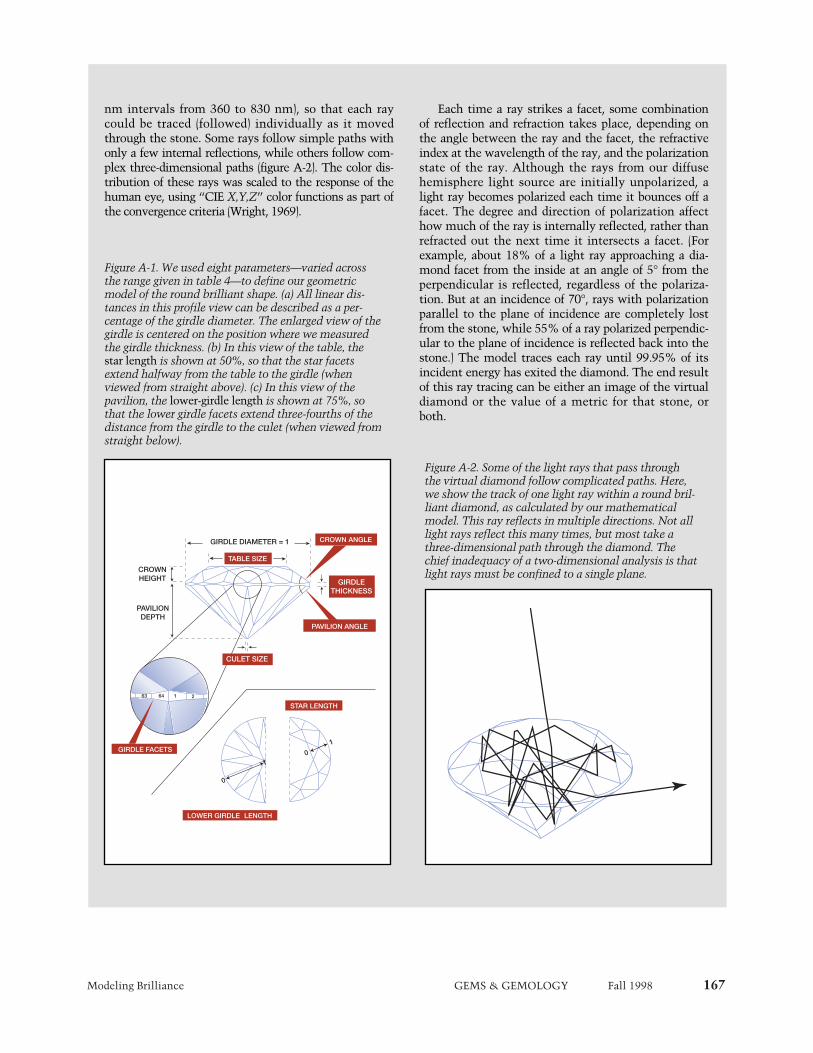
Modeling Brilliance GEMS & GEMOLOGY Fall 1998 167
nm intervals from 360 to 830 nm), so that each raycould be traced (followed) individually as it movedthrough the stone. Some rays follow simple paths withonly a few internal reflections, while others follow com-plex three-dimensional paths (figure A-2). The color dis-tribution of these rays was scaled to the response of thehuman eye, using “CIE X,Y,Z” color functions as part ofthe convergence criteria (Wright, 1969).
Each time a ray strikes a facet, some combinationof reflection and refraction takes place, depending onthe angle between the ray and the facet, the refractiveindex at the wavelength of the ray, and the polarizationstate of the ray. Although the rays from our diffusehemisphere light source are initially unpolarized, alight ray becomes polarized each time it bounces off afacet. The degree and direction of polarization affecthow much of the ray is internally reflected, rather thanrefracted out the next time it intersects a facet. (Forexample, about 18% of a light ray approaching a dia-mond facet from the inside at an angle of 5° from theperpendicular is reflected, regardless of the polariza-tion. But at an incidence of 70°, rays with polarizationparallel to the plane of incidence are completely lostfrom the stone, while 55% of a ray polarized perpendic-ular to the plane of incidence is reflected back into thestone.) The model traces each ray until 99.95% of itsincident energy has exited the diamond. The end resultof this ray tracing can be either an image of the virtualdiamond or the value of a metric for that stone, orboth.
63 64 1 2
GIRDLE DIAMETER = 1
PAVILION ANGLE
GIRDLETHICKNESS
CROWN ANGLE
PAVILIONDEPTH
CROWNHEIGHT
GIRDLE FACETS
TABLE SIZE
CULET SIZE
LOWER GIRDLE LENGTH
0
10
1
STAR LENGTH
Figure A-2. Some of the light rays that pass throughthe virtual diamond follow complicated paths. Here,we show the track of one light ray within a round bril-liant diamond, as calculated by our mathematicalmodel. This ray reflects in multiple directions. Not alllight rays reflect this many times, but most take athree-dimensional path through the diamond. Thechief inadequacy of a two-dimensional analysis is thatlight rays must be confined to a single plane.
Figure A-1. We used eight parameters—varied acrossthe range given in table 4—to define our geometricmodel of the round brilliant shape. (a) All linear dis-tances in this profile view can be described as a per-centage of the girdle diameter. The enlarged view of thegirdle is centered on the position where we measuredthe girdle thickness. (b) In this view of the table, thestar length is shown at 50%, so that the star facetsextend halfway from the table to the girdle (whenviewed from straight above). (c) In this view of thepavilion, the lower-girdle length is shown at 75%, sothat the lower girdle facets extend three-fourths of thedistance from the girdle to the culet (when viewed fromstraight below).
168 Modeling Brilliance GEMS & GEMOLOGY Fall 1998
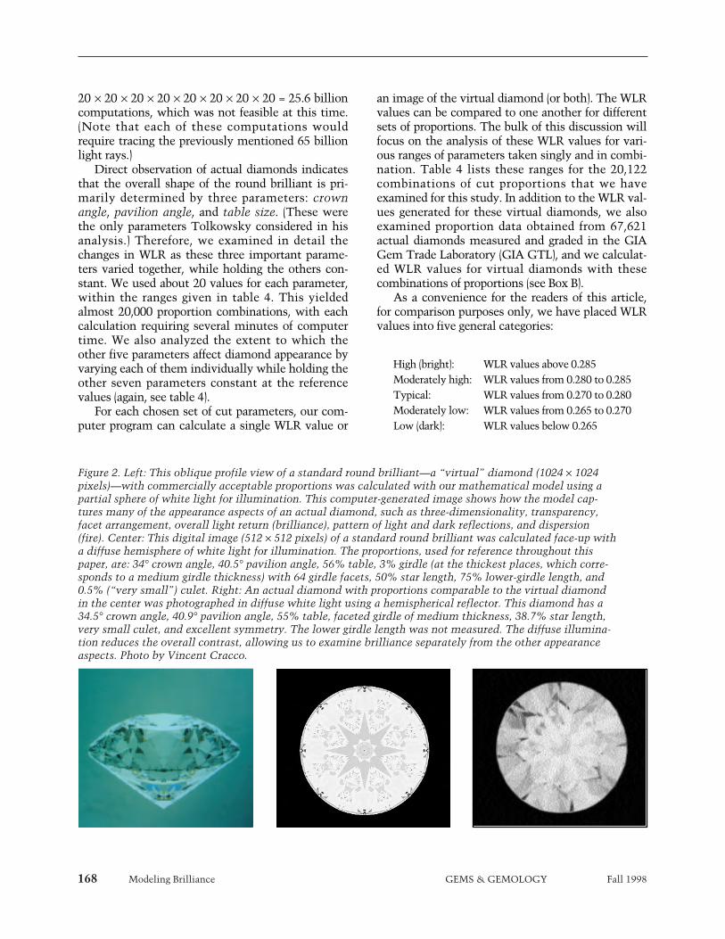
Figure 2. Left: This oblique profile view of a standard round brilliant—a “virtual” diamond (1024 × 1024pixels)—with commercially acceptable proportions was calculated with our mathematical model using apartial sphere of white light for illumination. This computer-generated image shows how the model cap-tures many of the appearance aspects of an actual diamond, such as three-dimensionality, transparency,facet arrangement, overall light return (brilliance), pattern of light and dark reflections, and dispersion(fire). Center: This digital image (512 × 512 pixels) of a standard round brilliant was calculated face-up witha diffuse hemisphere of white light for illumination. The proportions, used for reference throughout thispaper, are: 34° crown angle, 40.5° pavilion angle, 56% table, 3% girdle (at the thickest places, which corre-sponds to a medium girdle thickness) with 64 girdle facets, 50% star length, 75% lower-girdle length, and0.5% (“very small”) culet. Right: An actual diamond with proportions comparable to the virtual diamondin the center was photographed in diffuse white light using a hemispherical reflector. This diamond has a34.5° crown angle, 40.9° pavilion angle, 55% table, faceted girdle of medium thickness, 38.7% star length,very small culet, and excellent symmetry. The lower girdle length was not measured. The diffuse illumina-tion reduces the overall contrast, allowing us to examine brilliance separately from the other appearanceaspects. Photo by Vincent Cracco.
20 × 20 × 20 × 20 × 20 × 20 × 20 × 20 = 25.6 billioncomputations, which was not feasible at this time.(Note that each of these computations wouldrequire tracing the previously mentioned 65 billionlight rays.)
Direct observation of actual diamonds indicatesthat the overall shape of the round brilliant is pri-marily determined by three parameters: crownangle, pavilion angle, and table size. (These werethe only parameters Tolkowsky considered in hisanalysis.) Therefore, we examined in detail thechanges in WLR as these three important parame-ters varied together, while holding the others con-stant. We used about 20 values for each parameter,within the ranges given in table 4. This yieldedalmost 20,000 proportion combinations, with eachcalculation requiring several minutes of computertime. We also analyzed the extent to which theother five parameters affect diamond appearance byvarying each of them individually while holding theother seven parameters constant at the referencevalues (again, see table 4).
For each chosen set of cut parameters, our com-puter program can calculate a single WLR value or
an image of the virtual diamond (or both). The WLRvalues can be compared to one another for differentsets of proportions. The bulk of this discussion willfocus on the analysis of these WLR values for vari-ous ranges of parameters taken singly and in combi-nation. Table 4 lists these ranges for the 20,122combinations of cut proportions that we haveexamined for this study. In addition to the WLR val-ues generated for these virtual diamonds, we alsoexamined proportion data obtained from 67,621actual diamonds measured and graded in the GIAGem Trade Laboratory (GIA GTL), and we calculat-ed WLR values for virtual diamonds with thesecombinations of proportions (see Box B).
As a convenience for the readers of this article,for comparison purposes only, we have placed WLRvalues into five general categories:
High (bright): WLR values above 0.285Moderately high: WLR values from 0.280 to 0.285Typical: WLR values from 0.270 to 0.280Moderately low: WLR values from 0.265 to 0.270Low (dark): WLR values below 0.265

Modeling Brilliance GEMS & GEMOLOGY Fall 1998 169
These groups should not be taken as WLR orbrilliance “grades.” The authors strongly cautionagainst such usage. These terms are provided as aconvenience only, to compare the relative bright-ness of the virtual diamonds in the different WLRranges.
As seen in figure 1, large differences in WLR cor-relate to perceptible differences in the overallbrightness of actual diamonds. Even over therestricted WLR range in the inset to figure 1, thedarkest and brightest stones differ by almost 0.010;this difference is also easily perceived by a trainedviewer. In our experience, WLR differences of 0.005are discernable among stones with the same colorand clarity grades when examined with controlledobservation environments and lighting conditions.
RESULTS
Images and WLR. The calculations made with ourmodel produced realistic digital images of virtualdiamonds (again, see figure 2). These computer-gen-erated images reproduce the patterns of light anddark seen in actual round brilliant diamonds underlighting conditions similar to those used with themodel, although the light-and-dark patterns aremore symmetrical than those seen in most real dia-monds. During the course of this research, we gen-erated a variety of digital images, from different per-spectives and with different lighting conditions.However, the details of how brilliance changes withproportions can be better studied by comparing ametric, such as WLR values, than by visually exam-ining thousands of images.
Results for Key Individual Parameters. Our investi-gation of the dependence of WLR on crown angle,pavilion angle, and table size began with an exami-nation of how WLR varies with each of these threeparameters while the remaining seven parameters(again, see Box A) are held constant. Except whereotherwise noted in the text, we fixed these parame-ters at the reference proportions that are provided intable 4.
90°90°
65°
65°65°
45°
45° 45°
10°25°
50%
100%
100%
82%
82%82%
3%
50%
50%
18%
Figure 3. The weighting function used to calculateweighted light return (WLR)—the sum of thesquares of the cosines of the angles (from the verti-cal) at which light rays emerge from the dia-mond—depends on the angle of the emerging rayto the table plane, regardless of which crown facetit exits. As the relative lengths of the arrows onthis illustration indicate, light rays that emergestraight up (perpendicular to the table) are given100% weight, rays that exit at 45° to the table aregiven 50% weight, and the rays that exit at 0° (par-allel to the girdle plane) are given zero weight (i.e.,they do not contribute to the total WLR).
TABLE 4. The eight proportion parameters used for calculating the WLR values.
Round-brilliant-cut Rangeb Increment Referenceparametersa proportions
Table sizec 50% – 75% 1% 56%Crown anglec 19° – 50° 1° 34°Pavilion anglec 38° – 43° 0.25° 40.5°
Girdle facetsd 16 – 144 16 64Girdle thicknessd 1.8% – 4.0% 0.2% 3.0%Star lengthd 5% – 95% 1% 50%Lower-girdle lengthd 50% – 95% 5% 75%Culet sized 0% – 20% 0.5% 0.5%
a These eight parameters are defined in Box A. b These ranges extend beyond the widest range for diamonds nor-
mally encountered in the trade today. c These three parameters were varied together while the other five
were held at the reference proportions. A set of calculations was also made at the reference proportions with crown angle varying from 1° to 50°.
d These five parameters were varied individually. For each one, the other seven parameters were held constant at the reference pro-portions.

170 Modeling Brilliance GEMS & GEMOLOGY Fall 1998
Crown Angle. Of the three parameters, changingthe crown angle produced the greatest variation inWLR. In general, WLR increases as crown angledecreases; but, as figure 4 shows, there are threelocal maxima in WLR across the range of angles(that is, WLR varies up and down with changes incrown angle). These results suggest that, at the ref-erence proportions, a diamond with a 23° crownangle is brighter than a stone with any other crownangle greater than 10°. However, other considera-tions may dictate that a diamond must have acrown angle above a certain value (such as reduceddurability with a thin to medium girdle and a crown
flatter than, say, 25°; see, e.g., Crowningshield andMoses, 1997). Ironically, the highest WLR valuesare obtained for a round brilliant with no crown atall. It is interesting to note that the question ofreduced durability with a shallower crown was dis-cussed in Gems & Gemology in 1936, although atthat time it was the “modern” trend toward anglesof 34.5° (from the steeper angles cut previously) thatraised concern (Ware, 1936).
Figure 4 also shows images of virtual diamondsthat have crown angles of 25°, 35°, and 45°, with allother parameters at the reference proportions listedin table 4. The overall brightness clearly decreases
To get an idea of the range of WLR values for stonesseen in the diamond trade, we collected informationon the proportions of 67,621 round brilliants graded byGIA GTL. (This data set included all the D-to-Z-colorround brilliant diamonds seen during a span ofmonths.) This population of diamonds had crownangles ranging from 19.4° to 45.0°, pavilion anglesfrom 39.9° to 43°, and table sizes from 50% to 74%.More than 80% of this group of diamonds fell withinthe smaller proportion range of 30°–40° crown angles,40.2°–42.4° pavilion angles, and table sizes from 53%to 70%. The WLR values calculated for all of the dia-monds ranged from 0.235 to 0.306, with a mean andstandard deviation of 0.274 ± 0.005. The stones withaverage proportions for this sample set (represented by29% of the sample) had crown angles between 31° and35.9°, pavilion angles between 41.0° and 42.4°, andtable sizes of 61%–63%; the WLR values calculated forthis relatively small range of proportions varied from0.269 to 0.279.
In the entire data set, the diamonds with the high-est calculated WLR values had the smallest crownangles: only eight of the 67,621 stones had WLR valuesabove 0.295 (far into the high range), and of these, thelargest crown angle was 25.5°. However, crown anglealone does not determine WLR; the 61 stones withcrown angles less than 25° had WLR values rangingfrom 0.261 to 0.306 (low to high), with an average of0.288 (high). Another 3,494 stones had crown anglesbetween 25° and 30°, with more than half of thesefalling between 29.0° and 29.9°, and WLR values from0.261 to 0.296 (low to high). In contrast, round bril-
liants with high crown angles have lower WLR valueson average, although the brightest such stones yieldWLR values slightly higher than the mean for thewhole population; 7,617 diamonds had crown angles of36° or more, with WLR values that ranged from 0.235to 0.278 (low to typical). There were 275 round bril-liants that had crown angles of 40° or more, with WLRvalues ranging from 0.235 to 0.259 (all low); these val-ues indicate diamonds that are considerably darkerthan the average.
This sample of 67,621 diamonds contained veryfew with proportions that would qualify for a top gradein most of the systems shown in table 3. Only 3% ofthe sample (2,051 round brilliants) had crown anglesbetween 34.0° and 34.9°, pavilion angles between 40.2°and 41.3°, and table sizes between 53% and 57%.
Of these 2,051 round brilliants, only 76, or lessthan 4% of this group, had tables of 53%, and nearlytwice as many diamonds had pavilion angles of41°–41.3°, rather than 40.2°–40.9°. Thus, even manu-facturers who strive to cut “Ideal” proportions oftenchoose to cut a larger table or steeper pavilion anglethan Tolkowsky recommended, presumably forgreater weight retention. However, there is as yet noclear evidence whether either of these changes signifi-cantly alters the balance between brilliance and firethat Tolkowsky proposed. As shown in table 3, theproportion ranges that define the top grades in existingsystems yield WLR values of 0.275–0.285 (typical tomoderately high); yet some proportions that receivelower grades in thse same systems have higher calcu-lated WLR values.
BOX B: COMPARISON OF MODELED RESULTSTO ACTUAL DIAMOND PROPORTIONS

Modeling Brilliance GEMS & GEMOLOGY Fall 1998 171
as crown angle increases, but the pattern of lightand dark also changes substantially.
Pavilion Angle. This is often cited by diamond man-ufacturers as the parameter that matters most interms of brilliance (e.g., G. Kaplan, pers. comm.,1998). With all other parameters at the referencepositions, we see a smooth decrease in WLR awayfrom a maximum at about 40.7° (figure 5). Images ofvirtual diamonds with low, optimal, and high pavil-ion angles (again, see figure 5) are consistent withthe appearances that we would expect for actual dia-monds with these pavilion angles (“fish-eye,” nor-
mal, and “nail head,” respectively; see GIA Jeweler’sManual [1989]). However, note that although thepavilion angle is optimal at 40.7° when the otherparameters are at the reference values, this need notbe the case in general. For instance, we calculatedthe WLR values of a diamond with a completely flatcrown. As the pavilion angle of this “crownless” vir-tual diamond increased from 38° to 43°, WLRincreased smoothly from 0.270 to 0.340.
Table Size. With other proportions held at the refer-ence parameters (again, see table 4), there is onebroad maximum for WLR as a function of table size,as shown in figure 6. This maximum extends fromabout 53% to 59%; it is followed by a gradualdecrease as table size increases to 70%. (A smallshoulder is seen between 72% and 73%.) However,WLR as a function of table size behaves quite differ-ently when this parameter is varied together withcrown angle and pavilion angle, as discussed below.
Combined Effects. Some of the interactionsbetween crown angle, pavilion angle, and table
Figure 4. These digital images show how varia-tions in the crown angle from 25° to 45° affectthe appearance of a standard round brilliantdiamond. All other proportions are held con-stant at the “reference proportions” shown intable 4. These digital images confirm what thegraph of crown angle and WLR illustrates: WLRis highest at very shallow crown angles. Thegraph shows local maxima at 13°, 23°, and 34°, itbegins to drop sharply at crown angles above 38°.
403020
CROWN ANGLE (degrees)
WLR
10 15 453525
0.220
0.230
0.240
0.250
0.260
0.270
0.280
0.290
0.300
0.310
0.320
5
25°WLR = 0.299
35°WLR = 0.282
45°WLR = 0.220

172 Modeling Brilliance GEMS & GEMOLOGY Fall 1998
size—and their joint effects on WLR values—can beseen when these proportion parameters are exam-ined two at a time. One way to visualize theseeffects is to draw them to look like a topographicmap (which shows the differences in elevation of anarea of land). We can draw subsets of the data ascross-sections (slices) through the data set with oneparameter held constant, and the WLR values canthen be expressed as contours. These cross-sectionscan be read in the same manner as topographicmaps; but instead of mountains, these “peaks”show proportion combinations that produce thehighest calculated WLR values for diamonds withina small range of proportions.
As illustrated in figure 7, when the crown angleand table size are varied together, the WLR changesin an unexpected fashion. There are “ridges” at
crown angles of 23° and 34°. Along these ridges,round brilliants with large tables show unexpected-ly high WLR values: For instance, for a 40.5° pavil-ion angle, a virtual diamond with a 65% table and a23° crown angle returns more light (high WLR of0.288) than one with a 56% table and a 34° crown(moderately high WLR of 0.283; again, see figure 7).Although the first of these stones is not a typicalcommercial cut, crown angles this low are some-times seen at GIA GTL. In addition, at crown anglesup to 37°, the table size has a significant influenceon WLR; in general, WLR increases as table sizedecreases within this range.
When we attempt to illustrate the effects of allthree parameters at the same time, the limitationsof graphing on two-dimensional paper are readilyapparent. The projection of a “three-dimensional
0.282
0.280
0.278
0.276
0.274
38 39 424140 43
PAVILION ANGLE (degrees)
WLR
Figure 5. Variations in pavilion angle also affectthe appearance of a faceted diamond. These vir-tual diamonds have pavilion angles of 38°,40.5°, and 43°; all other parameters are set tothe reference proportions (table 4). Althoughdiffuse illumination reduces the contrast in allthree images, they do illustrate well-knownoptical effects, including the “fish-eye” thatresults from a very shallow pavilion (far left),and the “nail head” caused by a very deeppavilion (far right). The graph of WLR as a func-tion of pavilion angle (with all other parametersat reference proportions) shows a maximum ata pavilion angle of 40.7°.
38°WLR = 0.272
40.5°WLR = 0.282
43°WLR = 0.270

Modeling Brilliance GEMS & GEMOLOGY Fall 1998 173
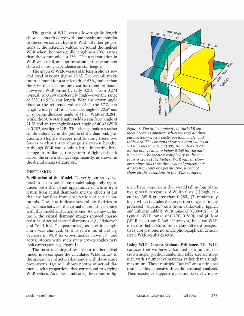
graph” in figure 8, for example, shows contours ofconstant WLR against crown angle, pavilion angle,and table size. This figure shows clearly that thehigher-value WLR surfaces have a complex depen-dence on the combination of these three parame-ters. In particular, the white contour (WLR of0.275–0.280) is concave as well as convex, anddefines a broad range of proportions that have thesame WLR values. However, only a limited regionof the WLR surfaces can be displayed on such agraph.
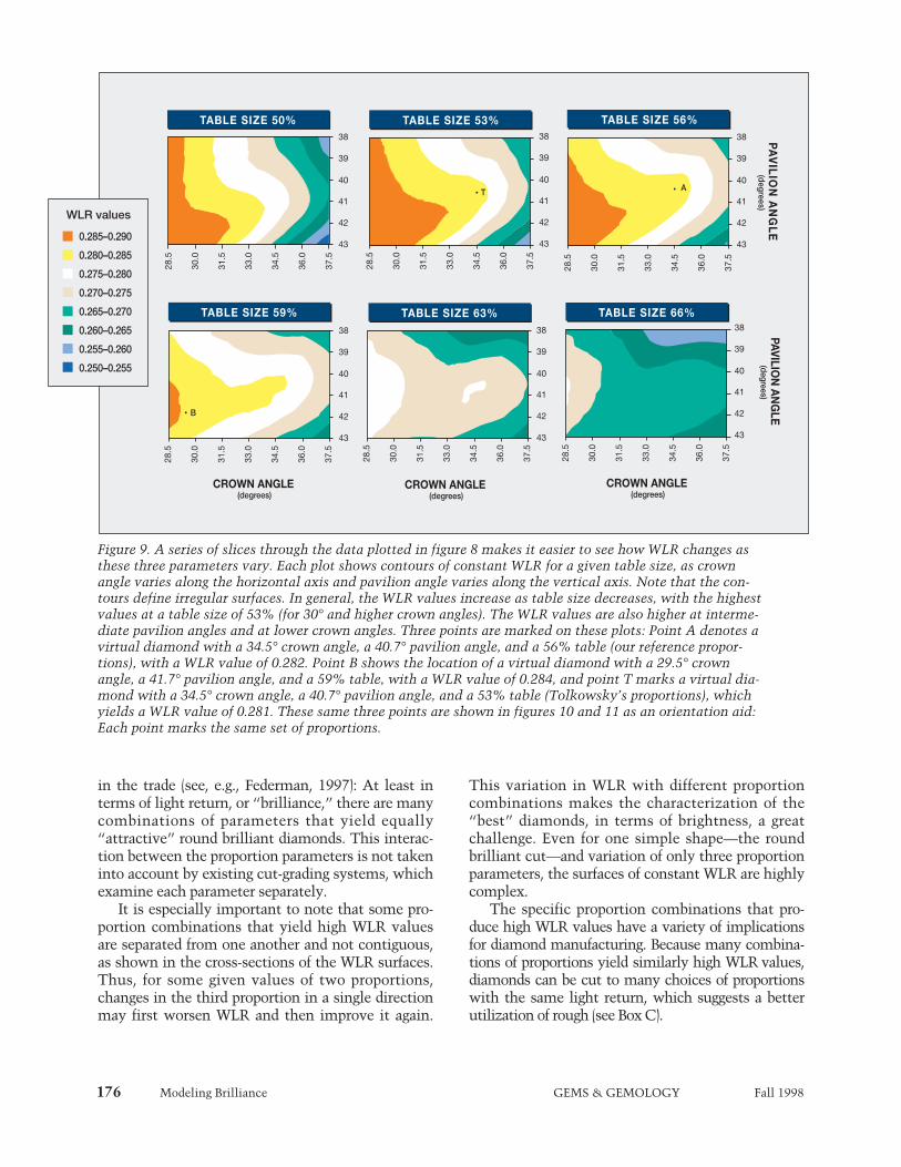
To better show this complexity, figures 9–11illustrate the results for proportion combinationsfrom three perspectives: constant table size, con-stant pavilion angle, and constant crown angle.Three points representing distinct sets of propor-tions are plotted on these cross-sections; the pointlabeled A, for example, shows the position of a vir-tual diamond with the “reference proportions”(again, see table 4) in each of the three perspectives.Tolkowsky’s proportions are shown as point T.Point B represents another high-WLR virtual dia-mond with a shallower crown angle.
Constant Table Size. Figure 9 shows the “topogra-phy” of the WLR values in a series of slices throughsurfaces of constant table size. It provides data forvirtual diamonds with crown angles between 28.5°and 37.5°, and pavilion angles between 38° and 43°,at table sizes ranging from 50% to 66%. Overall,WLR is highest for fairly small tables (53% to 59%),and increases as crown angle decreases. Note theridge of higher WLR that trends from the lower leftcorner of each constant-table-size slice to the centerof the right side. This ridge becomes broader andshallower (smaller range of WLR values) as tablesize increases. It is evident that this complexity can-not be accounted for in a model of diamond propor-tions that treats the optimal set as the center of athree-dimensional “bull’s-eye” pattern, surroundedby concentric shells of worsening results.
Constant Pavilion Angle. In figure 10, we showslices through the data at constant pavilion angle.The complex nature of the WLR surfaces is appar-ent from this view as well. The cross-section for a39.3° pavilion angle shows a pronounced ridge ofhigher WLR values starting in the upper left corner(shallow crowns and small tables), and trendingtoward higher crown angles at table sizes less than63%. This ridge is seen at all higher pavilion angles
as well; it is the same ridge seen at higher crownangles in figure 7, as viewed from many differentpavilion angles.
As the pavilion angle increases, the ridge definedby the WLR values seen in the orange, yellow, andwhite areas of figure 10 extends first to highercrown angles, and then broadens to include largertables. From this perspective, it is clear that pavil-ion angle can interact strongly with the other twoproportion parameters to produce similar WLR val-ues across broad ranges of crown angle and tablesize.
Constant Crown Angle. From the third perspective,constant crown angle (figure 11), the WLR contourslook much smoother. They form broad oval curvesat shallow crown angles, with oval maximumregions at crown angles between 30.5° and 36.5°,surrounded by relatively smooth contours ofdecreasing WLR.
For crown angles greater than 30°, the set of opti-mal parameters appears in this perspective as a“bull’s-eye” pattern, where a deviation in any direc-tion worsens the WLR. However, the pavilion andtable slices demonstrate that—in terms of WLR—there are many proportion combinations that yieldequally bright results.
0.280
0.275
0.270
0.265
0.260
50 55 60 65 70 75
TABLE SIZE (%)
WLR
Figure 6. This graph of WLR versus table size,with all other proportions at the reference val-ues, shows a broad maximum centered at about56% and a gradual drop-off toward both smallerand larger table sizes. The wide, gently slopingtop of this graph suggests that WLR is notstrongly affected as table size varies between50% and 62%, for these properties.

174 Modeling Brilliance GEMS & GEMOLOGY Fall 1998
Influence of the Other Five Parameters on WLRResults. We explored the contribution to WLR ofthe remaining five proportion parameters—girdlethickness, number of girdle facets, culet size, lower-girdle length, and star length—by calculating WLRvalues while varying one parameter and holding theother seven (including crown angle, pavilion angle,and table size) constant at the reference proportionsin table 4. We found that WLR decreases slightly asthe thickness of the faceted girdle increases, pre-sumably because more light is lost through a thick-er girdle. In addition, WLR was approximately con-
stant as the number of girdle facets varied from 32to 144. A smaller WLR value was obtained for theextremely low value of 16 girdle facets.
We expected to see a steady decrease in WLRwith culet size, similar to that seen for girdle thick-ness; instead, we found relatively constant valuesfor culets as large as 12% (which would bedescribed as very large), and then a decrease as theculet size increased further. Although we have notyet examined this result in significant detail, itimplies that relatively few light rays escape throughthe culet.
Figure 7. This diagram showsthe variation in WLR withchanges in both crown angleand table size. The WLR val-ues are contoured, like atopographic map; each line isa constant WLR value.Regions with the highestWLR are shown in black,gray, and purple. High WLRvalues are found at crownangles up to 35°, beyondwhich WLR decreases rapid-ly. Note that the highestWLR values are seen at smalltable sizes. The shape of the0.280 WLR contour linereflects the variation in WLRdue to different crown angles;the local maxima at 23° and34° in figure 4 become“ridges” in this figure. Notealso the prominence of the“ridge” at the 23° crownangle; WLR remains high formuch larger tables than ateither larger or smaller crownangles. The digital imagesshow how the pattern of lightand dark can differ for pro-portions leading to similarWLR values. The virtual dia-mond on the left has a 23°crown angle and a 65% table(high WLR of 0.285), and theone on the right has a 34°crown angle and a 56% table(moderately high WLR of0.283); all other proportionsfor both virtual diamondswere held constant at the ref-erence proportions in table 4.
0.28
0.29
0.30
0.31
0.31
0.25
0.26
0.27
WLR
CO
NT
OU
RS
40
35
30
25
20
15
CR
OW
N A
NG
LE
(deg
rees)
50 55 60 65 70 75
TABLE SIZE (%)
0.310–0.315
0.305–0.310
0.300–0.305
0.295–0.300
0.290–0.295
0.285–0.290
0.280–0.285
0.275–0.280
0.270–0.275
0.265–0.270
0.260–0.265
0.255–0.260
0.250–0.255
0.245–0.250
WLR values
23° Crown angle65% Table size
WLR = 0.288
34° Crown angle56% Table size
WLR = 0.283
Modeling Brilliance GEMS & GEMOLOGY Fall 1998 175
The graph of WLR versus lower-girdle lengthshows a smooth curve with one maximum, similarto the curve seen in figure 5. With all other propor-tions at the reference values, we found the highestWLR when the lower-girdle length was 70%, ratherthan the commonly cut 75%. The total variation inWLR was small, and optimization of this parametershowed a strong dependence on star length.
The graph of WLR versus star length shows sev-eral local maxima (figure 12A). The overall maxi-mum is found for a star length of 57%, rather thanthe 50% that is commonly cut for round brilliants.However, WLR varies by only 0.010—from 0.274(typical) to 0.284 (moderately high)—over the rangeof 25% to 95% star length. With the crown anglefixed at the reference value of 34°, the 57% starlength corresponds to a star facet angle of 22.5° andan upper-girdle-facet angle of 41.2° (WLR of 0.284),while the 50% star length yields a star facet angle of21.5° and an upper-girdle-facet angle of 40.4° (WLRof 0.282; see figure 12B). This change makes a rathersubtle difference in the profile of the diamond, pro-ducing a slightly steeper profile along these twofacets without any change in crown height.Although WLR varies only a little, indicating littlechange in brilliance, the pattern of light and darkacross the crown changes significantly, as shown inthe digital images (figure 12C).
DISCUSSIONVerification of the Model. To verify our study, weneed to ask whether our model adequately repro-duces both the visual appearance of white lightreturn from actual diamonds and the effects of cutthat are familiar from observation of actual dia-monds. The data indicate several similarities inappearance between the virtual diamonds generatedwith this model and actual stones. As we saw in fig-ure 5, the virtual diamond images showed charac-teristics of actual faceted diamonds (e.g., “fish-eye”and “nail head” appearances), as pavilion anglealone was changed. Similarly, we found a sharpdecrease in WLR for crown angles above 38°, andactual stones with such steep crown angles maylook darker (see, e.g., figure 1).
The most meaningful test of our mathematicalmodel is to compare the calculated WLR values tothe appearance of actual diamonds with those sameproportions. Figure 1 shows photos of actual dia-monds with proportions that correspond to varyingWLR values. As table 1 indicates, the stones in fig-
ure 1 have proportions that would fall in four of thefive general categories of WLR values: (1) high (cal-culated WLR greater than 0.285); (2) moderatelyhigh, which includes the proportion ranges of manyprofessed “superior” cuts (from Tolkowsky, Eppler,and Eulitz in table 2; WLR range of 0.280–0.285); (3)typical (WLR range of 0.270–0.280); and (4) low(WLR less than 0.265). However, because WLRmeasures light return from many different perspec-tives, not just one, no single photograph can demon-strate WLR results exactly.
Using WLR Data to Evaluate Brilliance. The WLRsurfaces that we have calculated as a function ofcrown angle, pavilion angle, and table size are irreg-ular, with a number of maxima, rather than a singlemaximum. These multiple “peaks” are a principalresult of this extensive three-dimensional analysis.Their existence supports a position taken by many
38
°39
°40
°41
°42
°43
°
70%
65%
60%
55%
50%
40° 39° 38° 37°34°
35°36°
33° 32° 31° 30°
Crown Angle
Table S
ize
Pavil
ion
Angl
e
Figure 8. The full complexity of the WLR sur-faces becomes apparent when we vary all threeparameters—crown angle, pavilion angle, andtable size. The contours show constant values ofWLR in increments of 0.005, from above 0.285for the orange area to below 0.250 for the darkblue area. The greatest complexity in the con-tours is seen at the highest WLR values. How-ever, since this three-dimensional projection isdrawn from only one perspective, it cannotshow all the variations in the WLR surfaces.
176 Modeling Brilliance GEMS & GEMOLOGY Fall 1998
in the trade (see, e.g., Federman, 1997): At least interms of light return, or “brilliance,” there are manycombinations of parameters that yield equally“attractive” round brilliant diamonds. This interac-tion between the proportion parameters is not takeninto account by existing cut-grading systems, whichexamine each parameter separately.
It is especially important to note that some pro-portion combinations that yield high WLR valuesare separated from one another and not contiguous,as shown in the cross-sections of the WLR surfaces.Thus, for some given values of two proportions,changes in the third proportion in a single directionmay first worsen WLR and then improve it again.
This variation in WLR with different proportioncombinations makes the characterization of the“best” diamonds, in terms of brightness, a greatchallenge. Even for one simple shape—the roundbrilliant cut—and variation of only three proportionparameters, the surfaces of constant WLR are highlycomplex.
The specific proportion combinations that pro-duce high WLR values have a variety of implicationsfor diamond manufacturing. Because many combina-tions of proportions yield similarly high WLR values,diamonds can be cut to many choices of proportionswith the same light return, which suggests a betterutilization of rough (see Box C).
TABLE SIZE 50%38
39
40
41
42
43
28.5
30.0
31.5
33.0
34.5
36.0
37.5
38
39
40
41
42
43
28.5
30.0
31.5
33.0
34.5
36.0
37.5
38
39
40
41
42
43
28.5
30.0
31.5
33.0
34.5
36.0
37.5
PA
VIL
ION
AN
GL
E (degrees)
TABLE SIZE 53% TABLE SIZE 56%
38
39
40
41
42
43
28.5
30.0
31.5
33.0
34.5
36.0
37.5
TABLE SIZE 59%38
39
40
41
42
43
28.5
30.0
31.5
33.0
34.5
36.0
37.5
TABLE SIZE 63%38
39
40
41
42
43
28.5
30.0
31.5
33.0
34.5
36.0
37.5
TABLE SIZE 66%
PAVILION
AN
GLE
(degrees)
CROWN ANGLE (degrees)
CROWN ANGLE (degrees)
CROWN ANGLE (degrees)
0.285–0.290
0.280–0.285
0.275–0.280
0.270–0.275
0.265–0.270
0.260–0.265
0.255–0.260
0.250–0.255
WLR values
T
B
A
Figure 9. A series of slices through the data plotted in figure 8 makes it easier to see how WLR changes asthese three parameters vary. Each plot shows contours of constant WLR for a given table size, as crownangle varies along the horizontal axis and pavilion angle varies along the vertical axis. Note that the con-tours define irregular surfaces. In general, the WLR values increase as table size decreases, with the highestvalues at a table size of 53% (for 30° and higher crown angles). The WLR values are also higher at interme-diate pavilion angles and at lower crown angles. Three points are marked on these plots: Point A denotes avirtual diamond with a 34.5° crown angle, a 40.7° pavilion angle, and a 56% table (our reference propor-tions), with a WLR value of 0.282. Point B shows the location of a virtual diamond with a 29.5° crownangle, a 41.7° pavilion angle, and a 59% table, with a WLR value of 0.284, and point T marks a virtual dia-mond with a 34.5° crown angle, a 40.7° pavilion angle, and a 53% table (Tolkowsky’s proportions), whichyields a WLR value of 0.281. These same three points are shown in figures 10 and 11 as an orientation aid:Each point marks the same set of proportions.
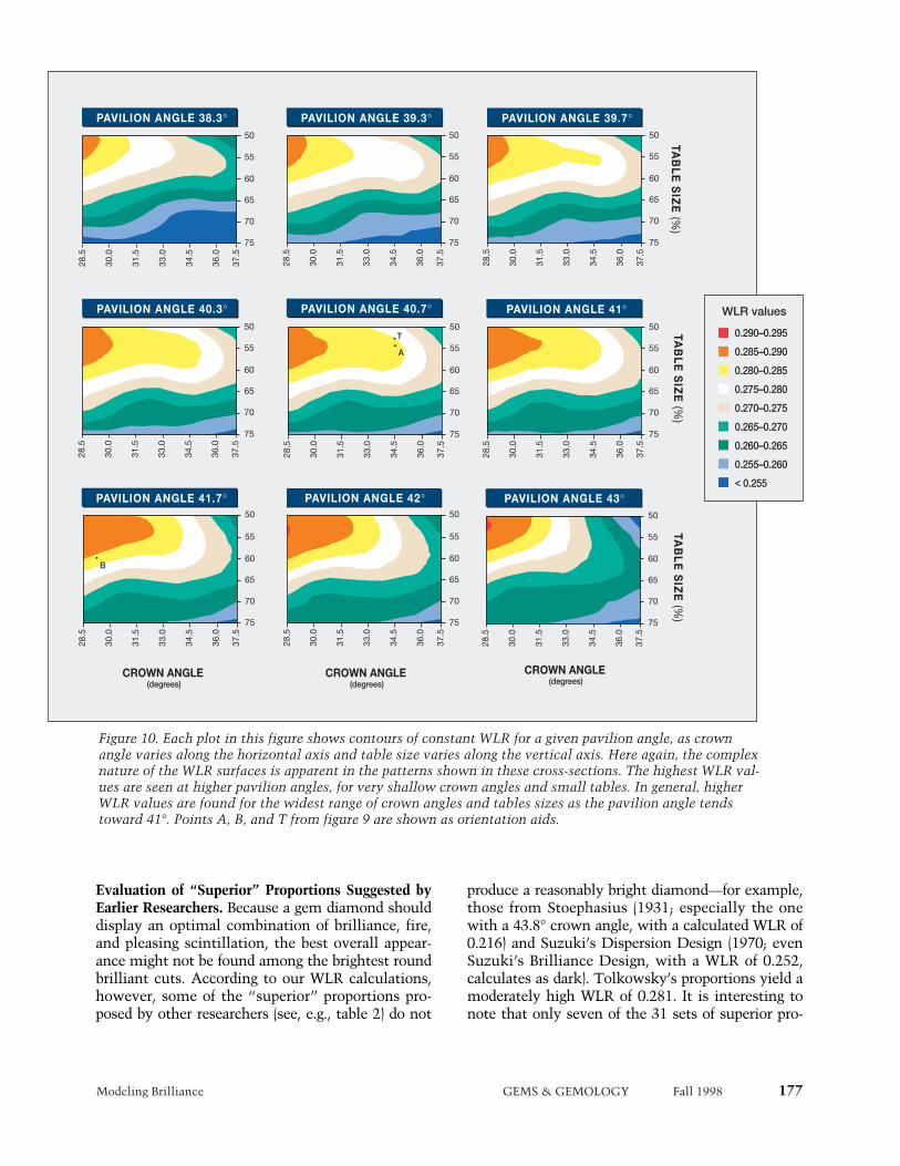
Modeling Brilliance GEMS & GEMOLOGY Fall 1998 177
PAVILION ANGLE 38.3°
TAB
LE
SIZ
E (%
)
CROWN ANGLE (degrees)
CROWN ANGLE (degrees)
CROWN ANGLE (degrees)
TAB
LE
SIZ
E (%
)TA
BL
E S
IZE
(%)
PAVILION ANGLE 39.3° PAVILION ANGLE 39.7°
PAVILION ANGLE 40.3° PAVILION ANGLE 40.7° PAVILION ANGLE 41°
PAVILION ANGLE 41.7° PAVILION ANGLE 42° PAVILION ANGLE 43°50
55
60
65
70
75
28.5
30.0
31.5
33.0
34.5
36.0
37.5
50
55
60
65
70
75
28.5
30.0
31.5
33.0
34.5
36.0
37.5
50
55
60
65
70
75
28.5
30.0
31.5
33.0
34.5
36.0
37.5
50
55
60
65
70
75
28.5
30.0
31.5
33.0
34.5
36.0
37.5
50
55
60
65
70
75
28.5
30.0
31.5
33.0
34.5
36.0
37.5
50
55
60
65
70
75
28.5
30.0
31.5
33.0
34.5
36.0
37.5
50
55
60
65
70
75
28.5
30.0
31.5
33.0
34.5
36.0
37.5
50
55
60
65
70
75
28.5
30.0
31.5
33.0
34.5
36.0
37.5
50
55
60
65
70
75
28.5
30.0
31.5
33.0
34.5
36.0
37.5
0.290–0.295
0.285–0.290
0.280–0.285
0.275–0.280
0.270–0.275
0.265–0.270
0.260–0.265
0.255–0.260
< 0.255
WLR values
T
B
A
Figure 10. Each plot in this figure shows contours of constant WLR for a given pavilion angle, as crownangle varies along the horizontal axis and table size varies along the vertical axis. Here again, the complexnature of the WLR surfaces is apparent in the patterns shown in these cross-sections. The highest WLR val-ues are seen at higher pavilion angles, for very shallow crown angles and small tables. In general, higherWLR values are found for the widest range of crown angles and tables sizes as the pavilion angle tendstoward 41°. Points A, B, and T from figure 9 are shown as orientation aids.
Evaluation of “Superior” Proportions Suggested byEarlier Researchers. Because a gem diamond shoulddisplay an optimal combination of brilliance, fire,and pleasing scintillation, the best overall appear-ance might not be found among the brightest roundbrilliant cuts. According to our WLR calculations,however, some of the “superior” proportions pro-posed by other researchers (see, e.g., table 2) do not
produce a reasonably bright diamond—for example,those from Stoephasius (1931; especially the onewith a 43.8° crown angle, with a calculated WLR of0.216) and Suzuki’s Dispersion Design (1970; evenSuzuki’s Brilliance Design, with a WLR of 0.252,calculates as dark). Tolkowsky’s proportions yield amoderately high WLR of 0.281. It is interesting tonote that only seven of the 31 sets of superior pro-
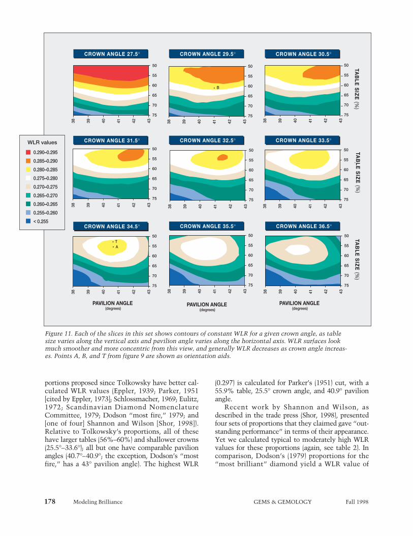
178 Modeling Brilliance GEMS & GEMOLOGY Fall 1998
portions proposed since Tolkowsky have better cal-culated WLR values (Eppler, 1939; Parker, 1951[cited by Eppler, 1973]; Schlossmacher, 1969; Eulitz,1972; Scandinavian Diamond NomenclatureCommittee, 1979; Dodson “most fire,” 1979; and[one of four] Shannon and Wilson [Shor, 1998]).Relative to Tolkowsky’s proportions, all of thesehave larger tables (56%–60%) and shallower crowns(25.5°–33.6°); all but one have comparable pavilionangles (40.7°–40.9°; the exception, Dodson’s “mostfire,” has a 43° pavilion angle). The highest WLR
(0.297) is calculated for Parker’s (1951) cut, with a55.9% table, 25.5° crown angle, and 40.9° pavilionangle.
Recent work by Shannon and Wilson, asdescribed in the trade press (Shor, 1998), presentedfour sets of proportions that they claimed gave “out-standing performance” in terms of their appearance.Yet we calculated typical to moderately high WLRvalues for these proportions (again, see table 2). Incomparison, Dodson’s (1979) proportions for the“most brilliant” diamond yield a WLR value of
PAVILION ANGLE (degrees)
PAVILION ANGLE (degrees)
PAVILION ANGLE (degrees)
CROWN ANGLE 27.5°TA
BL
E S
IZE
(%)
TAB
LE
SIZ
E (%
)TA
BL
E S
IZE
(%)
CROWN ANGLE 29.5° CROWN ANGLE 30.5°
CROWN ANGLE 31.5° CROWN ANGLE 32.5° CROWN ANGLE 33.5°
CROWN ANGLE 34.5° CROWN ANGLE 35.5° CROWN ANGLE 36.5°
50
55
60
65
70
75
38 39 40 41 42 43
50
55
60
65
70
75
38 39 40 41 42 43
50
55
60
65
70
75
38 39 40 41 42 43
50
55
60
65
70
75
38 39 40 41 42 43
50
55
60
65
70
75
38 39 40 41 42 43
50
55
60
65
70
75
38 39 40 41 42 43
50
55
60
65
70
75
38 39 40 41 42 4350
55
60
65
70
75
38 39 40 41 42 43
50
55
60
65
70
75
38 39 40 41 42 43
0.290–0.295
0.285–0.290
0.280–0.285
0.275–0.280
0.270–0.275
0.265–0.270
0.260–0.265
0.255–0.260
< 0.255
WLR values
TA
B
Figure 11. Each of the slices in this set shows contours of constant WLR for a given crown angle, as tablesize varies along the vertical axis and pavilion angle varies along the horizontal axis. WLR surfaces lookmuch smoother and more concentric from this view, and generally WLR decreases as crown angle increas-es. Points A, B, and T from figure 9 are shown as orientation aids.

0.277 (typical range) for a 40% table size (muchsmaller than any commercially cut stones), a 26.5°crown angle, and a 43° pavilion angle. However,Dodson also evaluated one metric each for fire and“sparkliness” for four table sizes, three crownheights, and 10 pavilion angles. His “most fire” pro-
portions gave a high WLR of 0.287, which is farbrighter by our calculations than his “most bril-liant” stone. The differences between our weightingtechnique and those of Dodson and of Shannon andWilson are probably responsible for thesediscrepancies.
Figure 12. (A) The graph of WLR versus star length (with all other parameters held constant at the referenceproportions) shows many local maxima within a relatively small range of WLR. This calculated WLRimplies that brilliance can be increased slightly if the star length is increased from the usual to 57%. (B)These diagrams show how longer star length results in slightly steeper angles for both the upper girdle facetsand the star facets. The upper diagram, with a star length of 50%, corresponds to the reference proportionsin table 4; the lower diagram shows a star length of 57%. (C) The virtual diamond images are of diamondswith a 50% star length (left) and a 57% star length (right). Although the image on the right is darker aroundthe edge, it has a slightly higher WLR value (0.284) than the image on the left (0.282).
Modeling Brilliance GEMS & GEMOLOGY Fall 1998 179
0.284
0.282
0.280
0.278
0.276
0.274
0.272
WLR
20 30 40 50 60 70 80 90
STAR LENGTH (%)
STAR LENGTH = 57%STAR LENGTH = 57%
STAR LENGTH = 50%STAR LENGTH = 50%
TABLE FACET
22.5°
41.2°
21.5%
40.4%
57%
50%
STAR FACET
TABLE FACET
UPPER GIRDLE FACET
UPPER GIRDLE FACET
STAR FACET
A B
C
Star length = 50%WLR = 0.282
Star length = 57%WLR = 0.284
180 Modeling Brilliance GEMS & GEMOLOGY Fall 1998
Implications for Existing Cut-Grading Systems. Ourresults disagree with the concepts on which the pro-portion grading systems currently in use by variouslaboratories appear to be based. In particular, theydo not support the idea that all deviations from anarrow range of crown angles and table sizes shouldbe given a lower grade. We have calculated theWLR values for the proportion ranges of each grad-ing system in table 3. The highest grades for most ofthose systems yield WLR values from 0.275 to0.284 (typical to moderately high). Clearly, these areattractive stones. However, the maximum WLRachievable increases as the grade worsens in thesesystems.
For example, diamonds with a 31° to 32° crownangle, a 41° to 41.4° pavilion angle, and a table sizebetween 53% and 57% have WLR values of0.284–0.285 (moderately high). Although their WLRvalues are slightly higher than those of the topgrades in table 3, these round brilliants wouldreceive lower cut grades in most systems because ofthe lower crown angle. Similarly, diamonds withcrown angles between 31° and 33°, pavilion anglesof 42°, and tables between 53% and 59% yield cal-culated WLR values from 0.281 to 0.286 (moderate-ly high to high). These values may exceed those ofdiamonds that currently receive the best grades, butsuch stones earn medium to low grades from theexisting systems because of the larger pavilionangle. Last, round brilliants with larger tables (61%to 63%) are much more common than those withsmall tables (again, see Box B). Such diamonds canshow moderately high WLR values when combinedwith crown angles between 30° and 33°, and pavil-ion angles from 40° to 42°, but diamonds with largetables are penalized heavily in most of the existingcut grading systems, regardless of their brightness.
Although arguments can be made for downgrad-ing diamonds with lower crown angles or largertables (on the basis, for example, that they do notyield enough fire), there is little documented evi-dence at present to support—or refute—suchclaims. However, at least according to Dodson(1979), both fire and scintillation depend on combi-nations of proportions, rather than on any singleparameter.
Although our results for brilliance do not sup-port current cut grading systems, we do not expectthem to surprise most diamond manufacturers. GIAGTL has seen significant numbers of diamonds thatare cut to various proportion combinations that
would correspond to moderately high to high WLRvalues. The results of this study support the empiri-cal understanding that cutters have of the relation-ships between proportions and brilliance.
FUTURE DIRECTIONS
The model presented here can be used readily toexplore many aspects of how diamond cut affectsappearance. The greatest challenge in this researchis the derivation of metrics for appearance concepts,including selection of the best lighting and observa-tion conditions for each metric. Currently, we areexploring metrics for fire, which has many possiblevariables, such as: the size, extent, placement, andexit angle of colored light rays; the distribution ofcolors observed; and how the observation and light-ing geometries govern the recombination of coloredlight rays into white light. We plan to devise a met-ric for scintillation as well, and to compare theseresults over the same proportion ranges to the met-rics for brilliance and fire. We also intend to exploreother lighting conditions, as we develop metrics forthe other appearance concepts.
In addition, we plan to explore two importantconsiderations that have been neglected thus far:symmetry and color. From our efforts and observa-tions of actual diamonds for this study, we suspectthat symmetry deviations may produce significantvariation in brilliance (this was also suggested by A.Gilbertson, pers. comm., 1998). Incorporation ofsymmetry deviations requires adding more parame-ters to describe the shape of the round brilliant, anddevising a method of tracking multiple symmetryfaults. Once this is done, the model can be used tocalculate both images and metric values that showhow symmetry deviations, both singly and in com-bination, change diamond appearance.
Incorporating color, whether letter grades (e.g.,from J to Z) or fancy colors, requires giving the vir-tual diamond a set of dimensions, applying a specif-ic absorption spectrum, and specifying the color dis-tribution (even or zoned). Then the model can keeptrack of the energy a ray loses by absorption (inaddition to leakage) as it travels through the virtualdiamond. Fluorescence effects can be included bysimilar techniques (applying a fluorescence spec-trum), and the claim that fluorescent diamondslook better at different proportions than those thatare inert (G. Tolkowsky, 1996) can be directly eval-uated.
This model can also be used to explore the many

Modeling Brilliance GEMS & GEMOLOGY Fall 1998 181
Fully symmetrical octahedral rough lends itself quitenicely to the higher crown and smaller table typical ofthe “Ideal” cut, as shown in figure C-1. However, sev-eral diamond manufacturers have estimated that onlyabout one fourth of the rough they cut is fully sym-metrical. (A. D. Klein, pers. comm., 1998). Other roughshows some irregularity in shape: shorter along onepoint-to-point distance than the other two; one ormore flattened edges with minor development of cubeor dodecahedral faces; or some relative tilt or twistbetween the two pyramids that comprise the octahe-dron. These variations in the shape of the rough can beaccommodated during cutting either by accepting alower weight yield or by modifying the cutting propor-tions.
If we consider a typical slightly asymmetric octa-hedron (see, e.g., figure C-2), one could still worktoward an “Ideal” cut despite the limitations of therough. Choosing to saw such a piece just slightly offcenter separates the top from the bottom of the octahe-dron, yielding two symmetrical square pyramids; forthe purposes of this example, let us assume that thelarger of these two pieces weighs about 1.75 ct. Aimingfor a crown height of 16% or 17% (which allows for acrown angle of 34°–35°, at a range of table sizes) pushesthe girdle down below the widest part of the rough,forcing a lower yield. After exploring the possibilitiesfor this example with a DiaExpert system (see, e.g.,Caspi, 1997), the best yield we found for top-graded
proportions as defined by most of the cut-grading sys-tems (see table 3), was 0.93 ct, with a 35.5° crownangle, a 40.8° pavilion angle, and a 57% table, giving acalculated WLR value of 0.279.
However, the shape of this rough suggests a differ-ent sawing position; it promotes cutting a shallowercrown and a larger table. From the same sawn bottompiece of about 1.75 ct, one could plan a round brilliantwith a 60% table and about a 60% total depth, with a32.7° crown angle and a 41.5° pavilion angle, whichwould achieve a calculated WLR value of 0.279 and afinal weight of 1.02 ct. In this example, striving for ahigh cut grade (table 3) results in a substantially lowerweight yield while achieving the same brightness, asexpressed by WLR.
There is broad agreement throughout the diamondtrade that cutting a diamond for maximum weightyield without consideration of the final appearanceconstitutes unacceptably poor manufacturing.Nevertheless, the disagreement over which propor-tions yield the best-looking diamonds fuels the debateas to how to maximize both weight yield and appear-ance. Although brilliance is only one aspect of overalldiamond appearance, our results indicate that for thesame piece of rough, it is possible to attain greateryield with the same WLR.
BOX C: AN EXAMPLE ILLUSTRATING CUTTING CHOICESBOX C: AN EXAMPLE ILLUSTRATING CUTTING CHOICES
Figure C-1. Starting with a rough diamond thatis a highly symmetric octahedron, one can man-ufacture a stone with the high crown typical ofthe “Ideal” and obtain a good yield.
Figure C-2. Other sets of proportions, particularlyslightly lower crown angles, often give the bestyield from commonly encountered asymmetricoctahedral diamond rough, with equivalent bright-ness. This yield can be significantly lower whensuch rough is fashioned to “Ideal” proportions.

182 Modeling Brilliance GEMS & GEMOLOGY Fall 1998
ways that faceted shape and proportions affect theface-up appearance of fancy-colored diamonds. Inaddition, we hope to address the effects that differ-ent kinds of inclusions can have on the paths oflight rays in a diamond (e.g., reflection from the sur-face of a “feather,” or scattering from a cloud of pin-points), and the additional light loss that resultsfrom poor surface finish.
CONCLUSION
In this first report of the results of our research oncut proportions, we have presented a mathematicalmodel of the round brilliant diamond that describesthis shape in terms of eight proportion parameters. Italso incorporates the physical factors that affect howlight interacts with a faceted diamond. At present,the “virtual” diamonds we have examined are allcolorless, flawless round brilliants with mathemati-cally perfect symmetry and polish; they vary only intheir proportions. We created digital images of someof these virtual diamonds that reproduce the keyfeatures of actual diamonds (again, see figures 2, 4,5, 7, and 12).
In this report, we have focused on brilliance,which was considered the main factor of diamondappearance in most previous analyses of the roundbrilliant diamond—from Tolkowsky in 1919 toShannon and Wilson in 1998. We have quantifiedbrilliance on the basis of weighted light return(WLR). After calculating WLR values for more than20,000 proportion combinations, we found that therelationship between brilliance and the three prima-ry proportion parameters (crown angle, pavilionangle, and table size) is complex, and that there area number of proportion combinations that yieldhigh WLR values. We also discovered that there aresome commercial proportion combinations thatproduce rather low WLR values (again, see figure 1and Box B). Comparisons to actual diamonds sup-port our premise that WLR captures the essence ofbrilliance.
Our model differs from its predecessors in one ormore of three ways: (1) it is three-dimensional; (2) ituses the most detailed existing data on the proper-ties of a colorless diamond; and (3) it uses an aver-aged observer condition that takes into account thelikeliest ways in which a diamond dealer or con-sumer looks at the stone. (The last is unique to thismodel.) Nevertheless, we do not consider the WLRmetric we have devised to be the whole story withregard to diamond appearance.
Brilliance is only one part of the puzzle; fire andscintillation, and probably symmetry deviations andcolor, will also have to be analyzed before theeffects of cutting on diamond appearance can befully understood. Yet, no fashioned diamond can beconsidered beautiful if it lacks brilliance. We caninfer from the WLR data that certain combinationsof proportions will produce low light return. This isimportant since a round brilliant that is severelydeficient in any one appearance aspect cannot beconsidered well cut, even if it performs well foranother aspect. For example, these WLR resultscould be used to define proportions for which around brilliant diamond will appear too dark; noamount of fire or pleasing scintillation would bal-ance such darkness to produce beauty.
Ultimately, we hope to use this model to findthe various ranges of proportions that clearly fail tobring out the attractive qualities of a round brilliantdiamond for each appearance aspect (brilliance, fire,and scintillation). The proportion ranges thatremain can be examined for balances between thedifferent appearance aspects, and an intelligent, fact-based discussion can take place regarding whichproportions produce diamonds of superior appear-ance. It is our opinion that any cut grading assess-ment devised in the absence of this broader pictureis premature.
Acknowledgments: Several people provided stimulat-ing discussions and a broader perspective: GlennNord and GIA colleagues Bill Boyajian, Brook Ellis,Richard T. Liddicoat, Vince Manson, Tom Moses,and Tom Yonelunas, as well as GIA GTL researchersPeter DeJong, Ronnie Geurts, and Marc Verboven.Dona Dirlam and the staff of the Richard T.Liddicoat Gemological Library and InformationCenter assisted with literature searches. HimikoNaka (GIA GTL) and Ronnie Geurts translated arti-cles published in Japanese and German, respectively.Sheryl Cashmore, Kim Cino, Alan DeGhionno, andJulie Lahman of GIA GTL located examples of actualdiamonds of various proportions, and Richard VonSternberg of EightStar Diamond Company, SantaRosa, California, provided a diamond that approxi-mated the symmetry of the model. A number of dia-mond manufacturers spoke with us about the vari-ables involved in creating a polished round brilliantfrom diamond rough; we especially thank those atJulius Klein, Inc., New York.
Modeling Brilliance GEMS & GEMOLOGY Fall 1998 183
REFERENCESAstric B., Merigoux H., Zecchini P. (1992) Etude de la variation
de l’aspect de pierres taillées à l’aide d’images de synthèse. LaGemmologia, Vol. 17, No. 1, pp. 7–31.
Bergheimer H. (1938) Die Schleifrichtungen auf den Facetten desDiamantbrillanten. Neues Jahrbuch für Mineralogie, Geo-logie, und Paläontologie, Vol. 75A, pp. 145–158.
Caspi A. (1997) Modern diamond cutting and polishing. Gems &Gemology, Vol. 33, No. 2, pp. 102–121.
Connellan M., Pozzibon L. (1984) The Australian ideal design forround brilliants. Australian Gemmologist, Vol. 24, pp.219–226, 243–246.
Crowningshield G.R., Moses T. (1997) Diamond: Damaged fromwear. Gem Trade Lab Notes, Gems & Gemology, Vol. 33,No. 1, pp. 55–56.
Dodson J.S. (1979) The statistical brilliance, sparkliness and fireof the round brilliant-cut diamond. Diamond Research, pp.13–17.
Elbe M.G. (1972) Erstaunliche Schmuckeffekte an Brillanten.Zeitschrift der Deutschen Gemmologischen Gesellschaft,Vol. 21, No. 4, pp. 189–212.
Eppler W.F. (1933) Der Diamant und seine Bearbeitung.Wilhelm Diebener GmbH, Leipzig, 68 pp.
Eppler W.F. (1938) Die Ideal-Schleifformen durchsichtigerEdelsteine. Zentralblatt für Mineralogie, Geologie, undPaläontologie, Abteilung A, pp. 1–5.
Eppler W.F. (1939) Die Brillanz durchsichtiger Edelsteine.Fortschritte der Mineralogie, Kristallographie, undPetrographie, Vol. 23, pp. 1–40.
Eppler W.F. (1940) Beitrag zum Brillanzproblem II. Zentralblattfür Mineralogie, Geologie, und Paläontologie, Abteilung A,No. 4, pp. 93–96.
Eppler W.F. (1973) Praktische Gemmologie. Rühle-DiebenerVerlag KG, Stuttgart.
Eppler W.F., Klüppelberg E. (1940) Die praktische Brillantschliffdes Diamanten. Neues Jahrbuch für Mineralogie, Geologie,und Paläontologie, Vol. 75A, pp. 135–144.
Eulitz W.R. (1972) Die rechnerische Ermittlung der optimalenBrillanz der Brillanten. Zeitschrift der DeutschenGemmologischen Gesellschaft, Vol. 21, No. 1, pp. 13–43.
Federman D. (1997) Make believe. Modern Jeweler, Vol. 96, No.9, pp. 23–38, 62–63.
Foley J.D., Ed. (1996) Computer Graphics: Principles andPractice, 2nd ed. in C, Addison-Wesley Publishing Co.,Reading, MA.
GIA Diamond Dictionary, 3rd ed. (1993) Gemological Instituteof America, Santa Monica, CA, 275 pp.
GIA Jeweler’s Manual (1989) Gemological Institute of America,Santa Monica, CA, 327 pp.
Gilbertson A. (1998) Letting Light Speak for Itself. DiamondProfile Inc., Portland, Oregon, 14 pp. plus appendices.
Gilbertson A., Walters C. (1997) The measure of beauty.Rapaport Diamond Report, Vol. 20, No. 6, pp. 43, 45–46.
Johnsen A. (1926) Form und Brillanz der Brillanten.Sitzungsberichte der Preussischen Akademie derWissenschaften, Physikalische-Mathematische Klasse, Vol.23, pp. 322–330.
Lawrence J. (1998) Just how much sparkle? Diamond
International, No. 53, pp. 77–78.Maier W. (1936) Brillanz geschliffener Edelsteine. Neues
Jahrbuch für Mineralogie, Geologie, und Paläontologie, Vol.71A, pp. 458–491.
Maier W. (1938) Vollreflexbrillanten. Zentralblatt fürMineralogie, Geologie, und Paläontologie, Abteilung A, pp.230–239.
Nassau K. (1983) The Physics and Chemistry of Color—TheFifteen Causes of Color. Wiley Interscience, New York, 454pp.
Nestlebaum K. (1996) New AGS lab stakes its claim on cutgrade. Rapaport Diamond Report, Vol. 19, No. 17, pp. 15–17.
Nestlebaum K. (1997) Ideals: Worth the trouble to those who cutthem. Rapaport Diamond Report, Vol. 20, No. 10, pp. 18–19.
Papadopoulos A.D, Anastassakis E. (1991) Optical properties ofdiamond. Physical Review B, Vol. 43, No. 6, pp. 5090–5097.
Rösch S. (1926) Die Brillanzwirkung des geschliffenenDiamanten. Deutsche Goldschmiede Zeitung, No. 5, pp.45–48; No. 7, pp. 65–67; No. 9, pp. 88–90.
Rösch S. (1927) Beitrag zum Brillanzproblem IV. Zeitschrift fürKristallographie, Vol. 65, pp. 46–68.
Scandinavian Diamond Nomenclature Committee (1979) TheScandinavian Diamond Nomenclature and GradingStandards: Official Version. Trade Associations of Jewellersin Denmark, Finland, Norway and Sweden, 50 pp.
Schlossmacher K. (1969) Edelsteine und Perlen, 5 Auflage. E.Schweizerbart’sche Verlagsbuchhandlung, Stuttgart.
Shor R. (1993) Cutting grades—new complications. Jewelers’Circular-Keystone, Vol. 164, No. 4, pp. 52–55.
Shor R. (1997) Consumers who care about cut: A small, butgrowing group. Jewelers’ Circular-Keystone, Vol. 168, No. 6,pp. 124–126.
Shor R. (1998) Computer engineers create proportion grade pro-gram. New York Diamonds, Vol. 44, pp. 26–28.
Stoephasius A. (1931) Lässt sich das Gewicht gefasster Brillantensicher berechnen? Deutsche Goldschmiede Zeitung, No. 45,pp. 470–474.
Suzuki S. (1970) A new design for brilliance plus dispersion.Australian Gemmologist, Vol. 10, No. 10, pp. 13–24.
Tillander H. (1966) Six centuries of diamond design. Gems &Gemology, Vol. 12, No. 3, pp. 77–95.
Tillander H. (1995) Diamond Cuts in Historical Jewellery:1381–1910. Art Books International, London.
Tognoni C. (1990) An automatic procedure for computing theoptimum cut proportions of gems. La Gemmologia, Vol. 25,No. 3–4, pp. 23–32.
Tolkowsky G. (1996) Cutting the Edges. Diamond Insight, Vol.9, No. 2, pp. 9–10.
Tolkowsky M. (1919) Diamond Design: A Study of theReflection and Refraction of Light in a Diamond. E. & F.N.Spon, London.
Wade F.B. (1916) Diamonds: A Study of the Factors that GovernTheir Value. G.P. Putnam’s Sons, New York.
Ware, J.W. (1936) New diamond cuts break more easily. Gems &Gemology, Vol. 2, No. 4, p. 68.
Watermeyer B. (1991) Diamond Cutting, 4th ed. PreskorDoornfontein, Johannesburg, 406 pp.
Wright, W.D. (1969) The Measurement of Colour, 4th ed., VanNostrand, New York.

184 Cultured Abalone Pearls GEMS & GEMOLOGY Fall 1998
balone pearls are highly prized for their rarity,dynamic colors, and remarkable iridescence.Their unusual shapes—often conical—and
potentially large sizes make these pearls especially well suit-ed for designer jewelry. The beauty of these rare pearls hasspawned several attempts at culturing, recorded as far backas the late 19th century. However, these early attemptsencountered many obstacles. Only recently have researchersbegun to overcome the challenges and difficulties presentedby abalone pearl culture. One company, Empress AbaloneLtd. of Christchurch, New Zealand, is successfully culturingbrightly colored blister pearls within New Zealand’sHaliotis iris (figure 1). These assembled cultured blisterpearls are marketed under the international trademark,Empress Pearl© (or Empress Abalone Pearl© in the U.S.). Thecompany is also pursuing the commercial production ofwhole spherical cultured abalone pearls.
This article will focus on the history, production, mar-keting, and identifying characteristics of cultured andassembled blister pearls produced by Empress Abalone Ltd.Except where referenced otherwise, information wasobtained through personal communication with the owners,Liz and Michael McKenzie, from 1996 through 1998.
HISTORY OF ABALONE PEARL CULTUREThe successful culturing of abalone pearls has been elusivebecause of the difficulty of farming and nucleating abalone.The first cultured abalone blister and spherical pearls wereexperimentally produced in the late 1890s, by French scien-tist Louis Boutan using the European ormer abalone Haliotistuberculata (Fankboner, 1991, 1995). Four decades later, LaPlace Bostwick claimed to have cultured both blister andwhole free-formed pearls in abalone from California(Bostwick, 1936). Bostwick’s work was succeeded by that ofJapanese scientist Dr. Kan Uno during the mid-1950s. Uno
CULTURED ABALONEBLISTER PEARLS FROM
NEW ZEALANDBy Cheryl Y. Wentzell
TThe successful culturing of abalone pearlshas been known since French scientistLouis Boutan’s experimentation in the late1890s, but commercial production hasbeen achieved only in recent decades. Theuse of New Zealand’s Haliotis iris, with itscolorful and iridescent nacre, has had thestrongest recent impact on this industry.Empress Abalone Ltd. is producing large,attractive cultured blister pearls in H. iris.The first commercial harvest in 1997 yield-ed approximately 6,000 jewelry-qualitycultured blister pearls, 9–20 mm in diame-ter, with vibrant blue, green, purple, andpink hues. Examination of 22 samples ofthis material by standard gemological andadvanced testing methods revealed thatthe presence and thicknesses of the conchi-olin layers had a significant impact onface-up appearance. Empress Abalone Ltd.is also experimenting with producingwhole free-formed cultured pearls in thisgastropod mollusk.
A
ABOUT THE AUTHOR
Ms. Wentzell ([email protected]) is a senior staffgemologist in Identification Services at the GIAGem Trade Laboratory in Carlsbad, California.
Please see acknowledgments at the end of thearticle.
Gems & Gemology, Vol. 34, No. 3, pp. 184ñ200© 1998 Gemological Institute of America
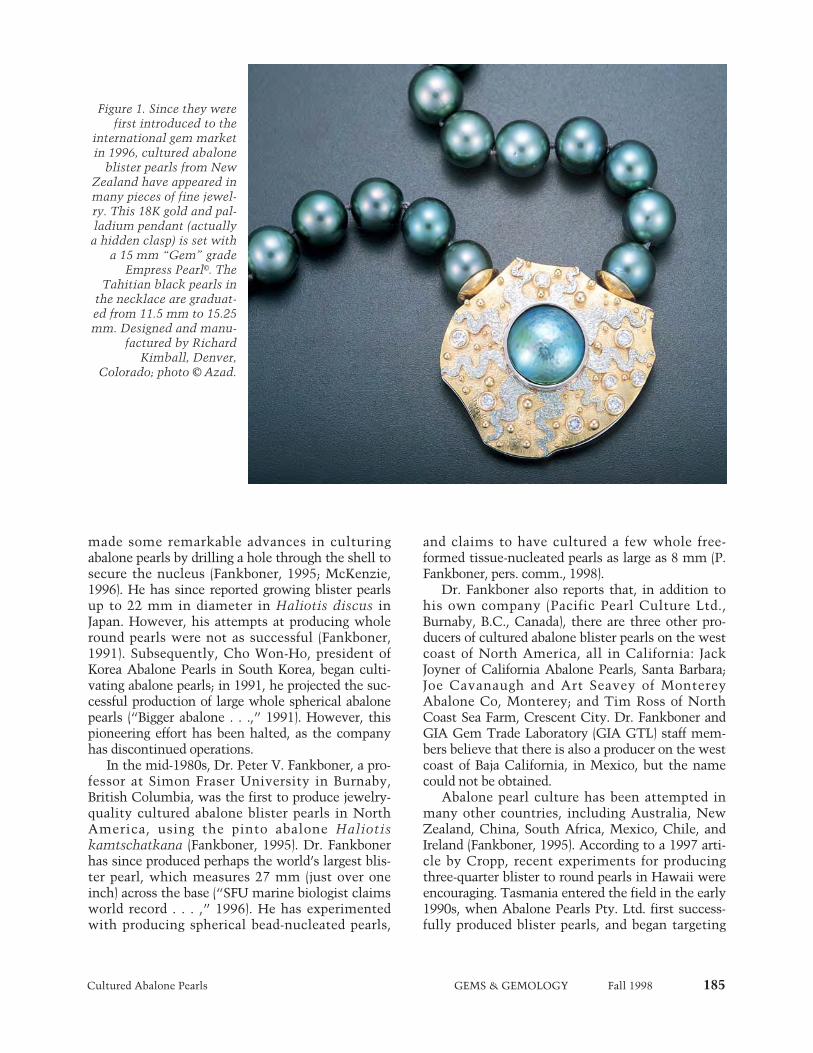
Cultured Abalone Pearls GEMS & GEMOLOGY Fall 1998 185
made some remarkable advances in culturingabalone pearls by drilling a hole through the shell tosecure the nucleus (Fankboner, 1995; McKenzie,1996). He has since reported growing blister pearlsup to 22 mm in diameter in Haliotis discus inJapan. However, his attempts at producing wholeround pearls were not as successful (Fankboner,1991). Subsequently, Cho Won-Ho, president ofKorea Abalone Pearls in South Korea, began culti-vating abalone pearls; in 1991, he projected the suc-cessful production of large whole spherical abalonepearls (“Bigger abalone . . .,” 1991). However, thispioneering effort has been halted, as the companyhas discontinued operations.
In the mid-1980s, Dr. Peter V. Fankboner, a pro-fessor at Simon Fraser University in Burnaby,British Columbia, was the first to produce jewelry-quality cultured abalone blister pearls in NorthAmerica, using the pinto abalone Haliotiskamtschatkana (Fankboner, 1995). Dr. Fankbonerhas since produced perhaps the world’s largest blis-ter pearl, which measures 27 mm (just over oneinch) across the base (“SFU marine biologist claimsworld record . . . ,” 1996). He has experimentedwith producing spherical bead-nucleated pearls,
and claims to have cultured a few whole free-formed tissue-nucleated pearls as large as 8 mm (P.Fankboner, pers. comm., 1998).
Dr. Fankboner also reports that, in addition tohis own company (Pacific Pearl Culture Ltd.,Burnaby, B.C., Canada), there are three other pro-ducers of cultured abalone blister pearls on the westcoast of North America, all in California: JackJoyner of California Abalone Pearls, Santa Barbara;Joe Cavanaugh and Art Seavey of MontereyAbalone Co, Monterey; and Tim Ross of NorthCoast Sea Farm, Crescent City. Dr. Fankboner andGIA Gem Trade Laboratory (GIA GTL) staff mem-bers believe that there is also a producer on the westcoast of Baja California, in Mexico, but the namecould not be obtained.
Abalone pearl culture has been attempted inmany other countries, including Australia, NewZealand, China, South Africa, Mexico, Chile, andIreland (Fankboner, 1995). According to a 1997 arti-cle by Cropp, recent experiments for producingthree-quarter blister to round pearls in Hawaii wereencouraging. Tasmania entered the field in the early1990s, when Abalone Pearls Pty. Ltd. first success-fully produced blister pearls, and began targeting
Figure 1. Since they werefirst introduced to the
international gem marketin 1996, cultured abalone
blister pearls from NewZealand have appeared inmany pieces of fine jewel-ry. This 18K gold and pal-ladium pendant (actuallya hidden clasp) is set with
a 15 mm “Gem” gradeEmpress Pearl©. The
Tahitian black pearls inthe necklace are graduat-ed from 11.5 mm to 15.25mm. Designed and manu-
factured by RichardKimball, Denver,
Colorado; photo © Azad.

186 Cultured Abalone Pearls GEMS & GEMOLOGY Fall 1998
spherical pearls, in the greenlip abalone Haliotislaevigata (Cropp, 1997). The latter trials, which arenearing completion, have confirmed the formationof a pearl sac, the first stage in the development ofthese cultured spherical pearls.
Since 1995, Empress Abalone Ltd. of NewZealand has successfully cultured commercialquantities of pearls in the brightly colored H. iris, orpaua, abalone. Their research and production activi-ties are described below. Another company thatuses H. iris is Rainbow Pearls, located in NewPlymouth, Taranaki, on the west coast of NewZealand’s north island. This facility, once solely acommercial abalone hatchery, now produces assem-bled cultured blister pearls.
BACKGROUND OF THE “EMPRESS PEARL”Location and Access. New Zealand is a topographi-cally and climatically diverse country that consistsof two main islands and several smaller ones (figure
2). Abalone blister pearls are cultured by EmpressAbalone Ltd. at Halfmoon Bay on the northeast sideof Stewart Island—a third, smaller island southern-most in New Zealand. This facility (figure 2, inset),which is open for visitors, is accessible fromInvercargill, on the main south island, via anapproximately one hour ferry ride or a 20 minuteflight. Empress Abalone also has a research facilityat Kaikoura, a small town on the northeast coast ofthe main south island, about 180 km (112 miles)north of Christchurch (McKenzie, 1996).
New Zealand is surrounded by three major bod-ies of water: the Pacific Ocean to the north and east,the Tasman Sea to the west, and the GreatSouthern Ocean to the south. The subtropical andsubantarctic currents converge at Stewart Island,creating an influx of nutrients and producing a richand diverse marine environment. At Kaikoura, thecontinental shelf comes very close to shore, creatinganother diverse marine environment that benefitsfrom the upwelling of rich nutrients.
Company Structure and Facilities. In 1995, Liz andMichael McKenzie of Goldrush Gem Co., a NewZealand jewelry firm, teamed up with a group ofabalone divers from Abalone Producers and Partnersto form a new company, Abalone Partners Ltd., onStewart Island’s Halfmoon Bay. This operation ismanaged by partner Ron Dennis. The McKenziefamily also holds 55% interest in Empress AbaloneLtd., of Christchurch, which has sole marketingrights for the product. The remaining interest isheld by 20 shareholders. Recently, Empress AbaloneLtd. has taken over Abalone Partners Ltd., so it isnow responsible for both the production and mar-keting of the cultured blister pearls. They have con-tracted with Goldrush Gem Co. for all of the post-harvest processing.
The abalone are housed onshore in 150 one-cubic-meter rubber tanks, each capable of holding1,000 liters of water and 70–80 abalone (figure 3).There are three full-time employees and up to sevenseasonal staff members. During the next threeyears, the McKenzies plan to build a much largerfacility, with a projected capacity of 100,000abalone, 16 km (10 miles) north of Kaikoura, in thesmall town of Maungamanu.
For its research activities, Empress Abalone Ltd.leases space at the George Knox ResearchLaboratory at Kaikoura (owned by the University ofCanterbury in Christchurch). Currently this facilityhas 25 tanks and two full-time researchers. With
Figure 2. Empress Pearls are cultured primarily onNew Zealand’s Stewart Island, with a research facili-ty at Kaikoura on the main south island. The insetshows the Stewart Island production facility, whichis located at Halfmoon Bay. Photo courtesy ofEmpress Abalone Ltd.
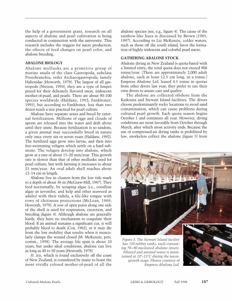
Cultured Abalone Pearls GEMS & GEMOLOGY Fall 1998 187
the help of a government grant, research on allaspects of abalone and pearl cultivation is beingconducted in conjunction with the university. Thisresearch includes the triggers for nacre production,the effects of feed changes on pearl color, andabalone breeding.
ABALONE BIOLOGYAbalone mollusks are a primitive group ofmarine snails of the class Gastropoda, subclassProsobranchia, order Archaeogastropoda, familyHaliotidae (Howorth, 1978). The largest of all gas-tropods (Nieson, 1994), they are a type of limpetprized for their delicately flavored meat, iridescentmother-of-pearl, and pearls. There are about 90–100species worldwide (Haldane, 1992; Fankboner,1995), but according to Fankboner, less than twodozen reach a size practical for pearl culture.
Abalone have separate sexes and breed by exter-nal fertilization. Millions of eggs and clouds ofsperm are released into the water and drift aboutuntil they unite. Because fertilization is so random,a given animal may successfully breed in natureonly once every six or seven years (Haldane, 1992).The fertilized eggs grow into larvae, and then intofree-swimming veligers which settle on a hard sub-strate. The veligers develop into abalone, whichgrow at a rate of about 15–20 mm/year. This growthrate is slower than that of other mollusks used forpearl culture, but with farming it increases to about25 mm/year. An oval adult shell reaches about12–14 cm in length.
Abalone live in clusters from the low tide markto a depth of about 36 m (McGraw-Hill, 1987). Theyfeed nocturnally, by scraping algae (i.e., corallinealgae as juveniles, and kelp and other seaweed asadults) with their radula, a file-like tongue withrows of chitinous projections (McLean, 1969;Howorth, 1978). A row of open pores along one sideof the shell is used for respiration, excretion, andbreeding (figure 4). Although abalone are generallyhardy, they have no mechanism to coagulate theirblood. If an animal sustains a significant cut, it willprobably bleed to death (Cox, 1962), or it may diefrom the lost mobility that results when it muscu-larly clamps the wound closed (M. McKenzie, pers.comm., 1998). The average life span is about 10years, but under ideal conditions, abalone can liveas long as 40 to 50 years (Howorth, 1978).
H. iris, which is found exclusively off the coastof New Zealand, is considered by many to boast themost vividly colored mother-of-pearl of all the
abalone species (see, e.g., figure 4). The cause of therainbow-like hues is discussed by Brown (1985,1997). According to Liz McKenzie, colder waters,such as those off the south island, favor the forma-tion of highly iridescent and colorful pearl nacre.
GATHERING ABALONE STOCKAbalone diving in New Zealand is quota-based witha limited entry; the total quota does not exceed 908tonne/year. (There are approximately 2,000 adultabalone, each at least 12.5 cm long, in a tonne.)Empress Abalone Ltd. leased 4.5 tonne in quotasfrom other divers last year; they prefer to use theirown divers to assure care and quality.
The abalone are collected offshore from theKaikoura and Stewart Island facilities. The diverschoose predominantly rocky locations to avoid sandcontamination, which can cause problems duringcultured pearl growth. Each quota season beginsOctober 1 and continues all year. However, divingconditions are most favorable from October throughMarch, after which most activity ends. Because theuse of compressed-air diving tanks is prohibited bylaw, snorkelers collect the abalone (figure 5) from
Figure 3. The Stewart Island facilityhas 150 rubber tanks, each contain-
ing 70–80 nucleated abalone (inset).Filtered and aerated water is main-
tained at 12°–15°C during the nacre-growth stage. Photos courtesy of
Empress Abalone Ltd.
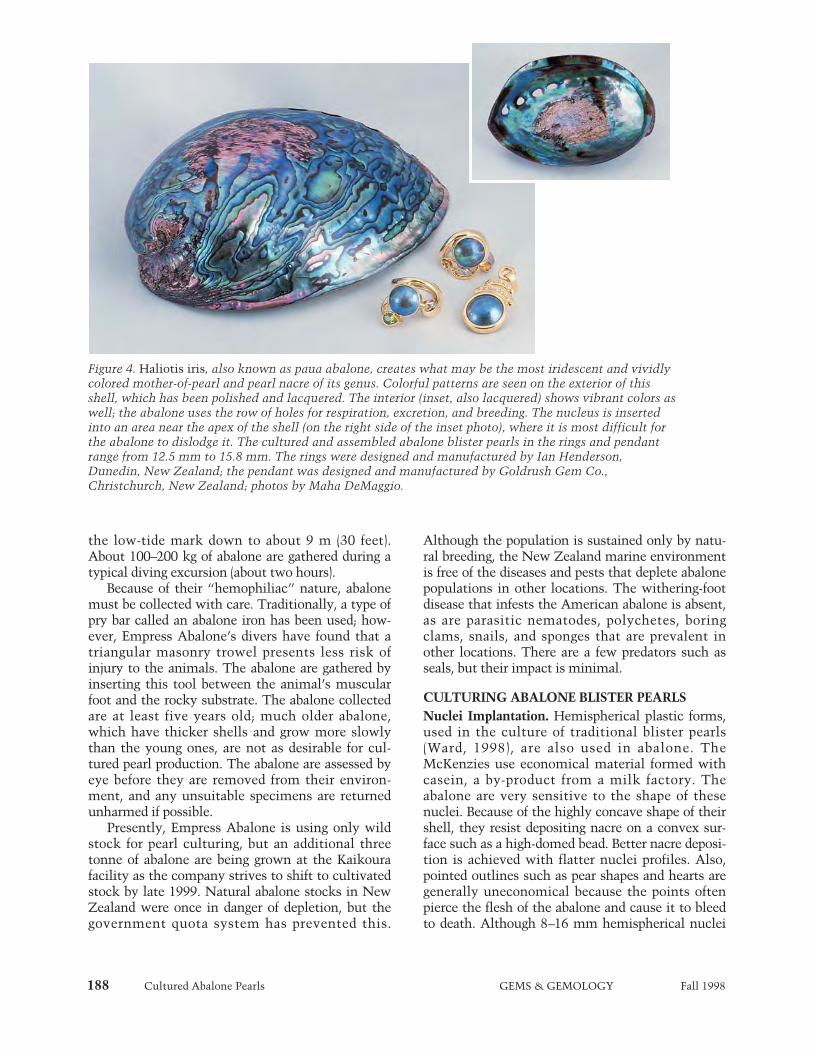
188 Cultured Abalone Pearls GEMS & GEMOLOGY Fall 1998
the low-tide mark down to about 9 m (30 feet).About 100–200 kg of abalone are gathered during atypical diving excursion (about two hours).
Because of their “hemophiliac” nature, abalonemust be collected with care. Traditionally, a type ofpry bar called an abalone iron has been used; how-ever, Empress Abalone’s divers have found that atriangular masonry trowel presents less risk ofinjury to the animals. The abalone are gathered byinserting this tool between the animal’s muscularfoot and the rocky substrate. The abalone collectedare at least five years old; much older abalone,which have thicker shells and grow more slowlythan the young ones, are not as desirable for cul-tured pearl production. The abalone are assessed byeye before they are removed from their environ-ment, and any unsuitable specimens are returnedunharmed if possible.
Presently, Empress Abalone is using only wildstock for pearl culturing, but an additional threetonne of abalone are being grown at the Kaikourafacility as the company strives to shift to cultivatedstock by late 1999. Natural abalone stocks in NewZealand were once in danger of depletion, but thegovernment quota system has prevented this.
Although the population is sustained only by natu-ral breeding, the New Zealand marine environmentis free of the diseases and pests that deplete abalonepopulations in other locations. The withering-footdisease that infests the American abalone is absent,as are parasitic nematodes, polychetes, boringclams, snails, and sponges that are prevalent inother locations. There are a few predators such asseals, but their impact is minimal.
CULTURING ABALONE BLISTER PEARLSNuclei Implantation. Hemispherical plastic forms,used in the culture of traditional blister pearls(Ward, 1998), are also used in abalone. TheMcKenzies use economical material formed withcasein, a by-product from a milk factory. Theabalone are very sensitive to the shape of thesenuclei. Because of the highly concave shape of theirshell, they resist depositing nacre on a convex sur-face such as a high-domed bead. Better nacre deposi-tion is achieved with flatter nuclei profiles. Also,pointed outlines such as pear shapes and hearts aregenerally uneconomical because the points oftenpierce the flesh of the abalone and cause it to bleedto death. Although 8–16 mm hemispherical nuclei
Figure 4. Haliotis iris, also known as paua abalone, creates what may be the most iridescent and vividlycolored mother-of-pearl and pearl nacre of its genus. Colorful patterns are seen on the exterior of thisshell, which has been polished and lacquered. The interior (inset, also lacquered) shows vibrant colors aswell; the abalone uses the row of holes for respiration, excretion, and breeding. The nucleus is insertedinto an area near the apex of the shell (on the right side of the inset photo), where it is most difficult forthe abalone to dislodge it. The cultured and assembled abalone blister pearls in the rings and pendantrange from 12.5 mm to 15.8 mm. The rings were designed and manufactured by Ian Henderson,Dunedin, New Zealand; the pendant was designed and manufactured by Goldrush Gem Co.,Christchurch, New Zealand; photos by Maha DeMaggio.
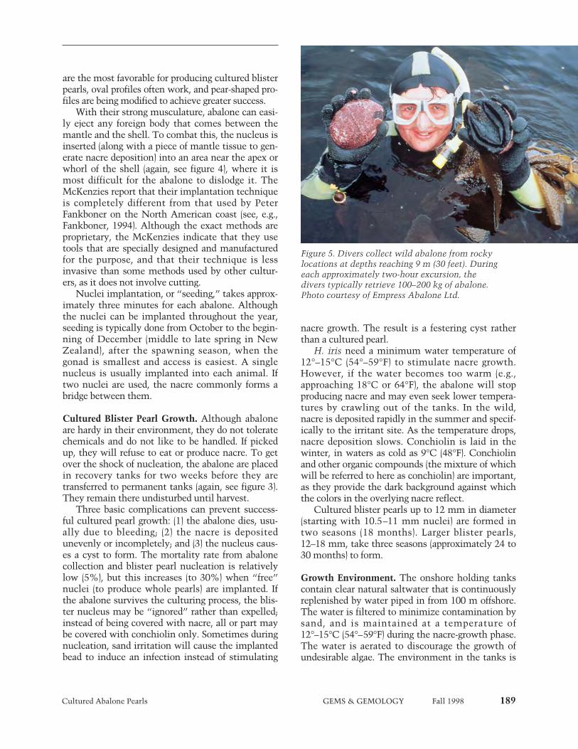
Cultured Abalone Pearls GEMS & GEMOLOGY Fall 1998 189
are the most favorable for producing cultured blisterpearls, oval profiles often work, and pear-shaped pro-files are being modified to achieve greater success.
With their strong musculature, abalone can easi-ly eject any foreign body that comes between themantle and the shell. To combat this, the nucleus isinserted (along with a piece of mantle tissue to gen-erate nacre deposition) into an area near the apex orwhorl of the shell (again, see figure 4), where it ismost difficult for the abalone to dislodge it. TheMcKenzies report that their implantation techniqueis completely different from that used by PeterFankboner on the North American coast (see, e.g.,Fankboner, 1994). Although the exact methods areproprietary, the McKenzies indicate that they usetools that are specially designed and manufacturedfor the purpose, and that their technique is lessinvasive than some methods used by other cultur-ers, as it does not involve cutting.
Nuclei implantation, or “seeding,” takes approx-imately three minutes for each abalone. Althoughthe nuclei can be implanted throughout the year,seeding is typically done from October to the begin-ning of December (middle to late spring in NewZealand), after the spawning season, when thegonad is smallest and access is easiest. A singlenucleus is usually implanted into each animal. Iftwo nuclei are used, the nacre commonly forms abridge between them.
Cultured Blister Pearl Growth. Although abaloneare hardy in their environment, they do not toleratechemicals and do not like to be handled. If pickedup, they will refuse to eat or produce nacre. To getover the shock of nucleation, the abalone are placedin recovery tanks for two weeks before they aretransferred to permanent tanks (again, see figure 3).They remain there undisturbed until harvest.
Three basic complications can prevent success-ful cultured pearl growth: (1) the abalone dies, usu-ally due to bleeding; (2) the nacre is depositedunevenly or incompletely; and (3) the nucleus caus-es a cyst to form. The mortality rate from abalonecollection and blister pearl nucleation is relativelylow (5%), but this increases (to 30%) when “free”nuclei (to produce whole pearls) are implanted. Ifthe abalone survives the culturing process, the blis-ter nucleus may be “ignored” rather than expelled;instead of being covered with nacre, all or part maybe covered with conchiolin only. Sometimes duringnucleation, sand irritation will cause the implantedbead to induce an infection instead of stimulating
nacre growth. The result is a festering cyst ratherthan a cultured pearl.
H. iris need a minimum water temperature of12°–15°C (54°–59°F) to stimulate nacre growth.However, if the water becomes too warm (e.g.,approaching 18°C or 64°F), the abalone will stopproducing nacre and may even seek lower tempera-tures by crawling out of the tanks. In the wild,nacre is deposited rapidly in the summer and specif-ically to the irritant site. As the temperature drops,nacre deposition slows. Conchiolin is laid in thewinter, in waters as cold as 9°C (48°F). Conchiolinand other organic compounds (the mixture of whichwill be referred to here as conchiolin) are important,as they provide the dark background against whichthe colors in the overlying nacre reflect.
Cultured blister pearls up to 12 mm in diameter(starting with 10.5–11 mm nuclei) are formed intwo seasons (18 months). Larger blister pearls,12–18 mm, take three seasons (approximately 24 to30 months) to form.
Growth Environment. The onshore holding tankscontain clear natural saltwater that is continuouslyreplenished by water piped in from 100 m offshore.The water is filtered to minimize contamination bysand, and is maintained at a temperature of12°–15°C (54°–59°F) during the nacre-growth phase.The water is aerated to discourage the growth ofundesirable algae. The environment in the tanks is
Figure 5. Divers collect wild abalone from rockylocations at depths reaching 9 m (30 feet). Duringeach approximately two-hour excursion, thedivers typically retrieve 100–200 kg of abalone.Photo courtesy of Empress Abalone Ltd.

190 Cultured Abalone Pearls GEMS & GEMOLOGY Fall 1998
strictly monitored to ensure the health of theabalone, as well as maximize the growth rate andnacre thickness of the cultured pearls. By maintain-ing specific water temperatures that are variedthroughout the growing process, the operators cansimulate optimal growth seasons. They also keepthe facility in darkness, so that feeding is alwaysstimulated.
Feeding. Abalone require very little care. Once theenvironment is established and the nucleiimplanted, they need only to be fed while the cul-tured blister pearls grow. No nutrients or artificialfeeds are added to the water; the captive abalonefeed exclusively on kelp and other algae collectedfrom the Great Southern Ocean (figure 6). TheMcKenzies have discovered that the brilliant col-ors of the cultured pearls are somewhat dependenton the type of feed available to the abalone. Thealga species Gracilaria chilensis has been linked toproduction of the most desirable purple, blue, andgreen hues. For this reason, the abalone are fedapproximately 50% G. chilensis and a 50% combi-nation of three other native algae—Durvillea sp,Macrocystis sp, and Laminaria sp—that varies sea-sonally. Approximately 300 kg of algae per day arerequired for two tonne of abalone.
HARVESTING AND PRODUCTIONAlthough the cultured blister pearls were first har-vested twice annually, they are now harvested con-
tinuously from the end of July through March. Thelater harvest allows thicker nacre deposition onlarger nuclei. Whereas some other mollusks areimplanted three or four times, H. iris are shucked(the shells removed; figure 7) at the first harvestbecause the cultured blister pearls must be cut fromthe shell. Both shells and meat are important by-products of the pearl harvest. Most of the meat isexported to Hong Kong. The shell is sought in jew-elry and craft manufacturing for its iridescence andvibrant colors.
The results of cultured pearl seeding and growthare unpredictable. Only 25% of the animals nucle-ated for the pilot harvest (in 1995) yielded mar-ketable cultured blister pearls. One year later, thesuccess rate was up to 50% as a result of greaterknowledge and improved techniques. Currently,there is an approximately 60%–70% average suc-cess rate for obtaining commercially marketablecultured blister pearls from the implanted abalone.
In addition to research harvests, there has beenone small pilot harvest and two larger commercialharvests to date. A third was under way at the timeof this writing. The first seeding was conducted inthe spring of 1993 by Abalone Producers andPartners. This led to the pilot harvest in 1995, whenEmpress Abalone Ltd. merged with the divers. Thatharvest yielded approximately 1,100 jewelry-qualitycultured blister pearls. The first commercial harvestof 10,000 implanted abalone took place duringOctober and November of 1997, yielding approxi-mately 6,000 cultured blister pearls of good to excel-lent quality. Another 2,000 abalone were harvestedfrom March through April of 1998, yielding about1,800 marketable pearls; the high success of thisharvest was attributed to the smaller sizes of thenuclei. The third commercial harvest produced2,000 marketable cultured blister pearls duringSeptember 1998, and another 2,000 were expectedby mid-October. By the end of March 1999, theMcKenzies expect to have harvested a total of15,000 jewelry-quality cultured blister pearls forthis growth period.
Rarely, either a natural pearl or a “keshi” isfound during the harvest. Natural pearls may formdue to suspended solids, the invasion of a flatworm,or other irritant that is brought in on the seaweed.A by-product of the culturing process, a keshi mayform around the implanted tissue that has separatedfrom the nucleus, or as a result of the introductionof another irritant during nucleation (Farn, 1986).
Figure 6. Kelp is collected from the Great SouthernOcean every three to four days to replenish theabalone diet. The H. iris eat an average of 7% oftheir body weight daily; approximately 300 kg ofalgae per day are required to feed two tonne ofabalone. Photo courtesy of Empress Abalone Ltd.
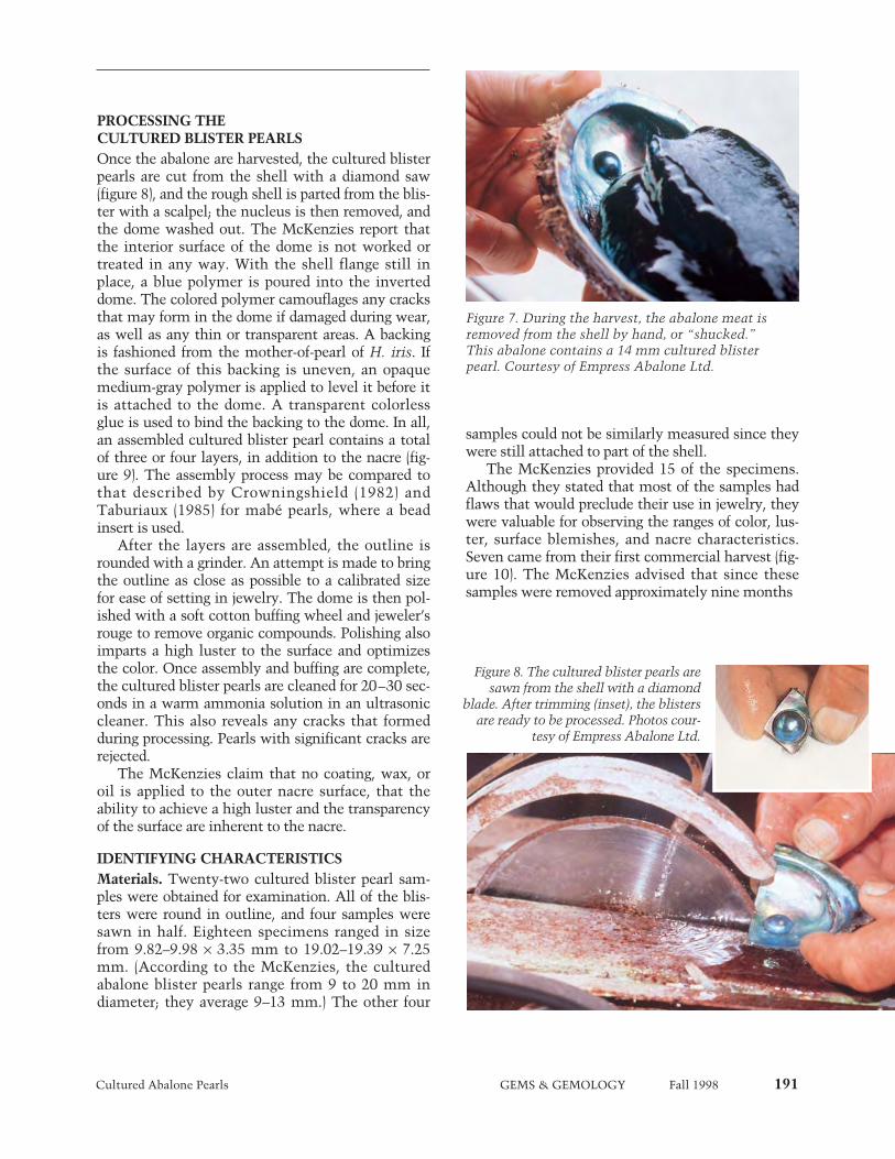
Cultured Abalone Pearls GEMS & GEMOLOGY Fall 1998 191
PROCESSING THECULTURED BLISTER PEARLSOnce the abalone are harvested, the cultured blisterpearls are cut from the shell with a diamond saw(figure 8), and the rough shell is parted from the blis-ter with a scalpel; the nucleus is then removed, andthe dome washed out. The McKenzies report thatthe interior surface of the dome is not worked ortreated in any way. With the shell flange still inplace, a blue polymer is poured into the inverteddome. The colored polymer camouflages any cracksthat may form in the dome if damaged during wear,as well as any thin or transparent areas. A backingis fashioned from the mother-of-pearl of H. iris. Ifthe surface of this backing is uneven, an opaquemedium-gray polymer is applied to level it before itis attached to the dome. A transparent colorlessglue is used to bind the backing to the dome. In all,an assembled cultured blister pearl contains a totalof three or four layers, in addition to the nacre (fig-ure 9). The assembly process may be compared tothat described by Crowningshield (1982) andTaburiaux (1985) for mabé pearls, where a beadinsert is used.
After the layers are assembled, the outline isrounded with a grinder. An attempt is made to bringthe outline as close as possible to a calibrated sizefor ease of setting in jewelry. The dome is then pol-ished with a soft cotton buffing wheel and jeweler’srouge to remove organic compounds. Polishing alsoimparts a high luster to the surface and optimizesthe color. Once assembly and buffing are complete,the cultured blister pearls are cleaned for 20–30 sec-onds in a warm ammonia solution in an ultrasoniccleaner. This also reveals any cracks that formedduring processing. Pearls with significant cracks arerejected.
The McKenzies claim that no coating, wax, oroil is applied to the outer nacre surface, that theability to achieve a high luster and the transparencyof the surface are inherent to the nacre.
IDENTIFYING CHARACTERISTICSMaterials. Twenty-two cultured blister pearl sam-ples were obtained for examination. All of the blis-ters were round in outline, and four samples weresawn in half. Eighteen specimens ranged in sizefrom 9.82–9.98 ¥ 3.35 mm to 19.02–19.39 ¥ 7.25mm. (According to the McKenzies, the culturedabalone blister pearls range from 9 to 20 mm indiameter; they average 9–13 mm.) The other four
samples could not be similarly measured since theywere still attached to part of the shell.
The McKenzies provided 15 of the specimens.Although they stated that most of the samples hadflaws that would preclude their use in jewelry, theywere valuable for observing the ranges of color, lus-ter, surface blemishes, and nacre characteristics.Seven came from their first commercial harvest (fig-ure 10). The McKenzies advised that since thesesamples were removed approximately nine months
Figure 7. During the harvest, the abalone meat isremoved from the shell by hand, or “shucked.”This abalone contains a 14 mm cultured blisterpearl. Courtesy of Empress Abalone Ltd.
Figure 8. The cultured blister pearls aresawn from the shell with a diamond
blade. After trimming (inset), the blistersare ready to be processed. Photos cour-
tesy of Empress Abalone Ltd.
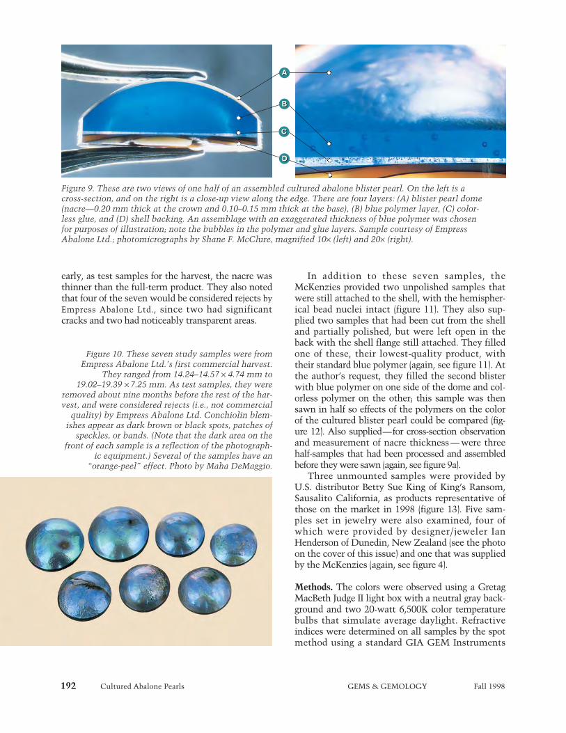
192 Cultured Abalone Pearls GEMS & GEMOLOGY Fall 1998
early, as test samples for the harvest, the nacre wasthinner than the full-term product. They also notedthat four of the seven would be considered rejects byEmpress Abalone Ltd., since two had significantcracks and two had noticeably transparent areas.
In addition to these seven samples, theMcKenzies provided two unpolished samples thatwere still attached to the shell, with the hemispher-ical bead nuclei intact (figure 11). They also sup-plied two samples that had been cut from the shelland partially polished, but were left open in theback with the shell flange still attached. They filledone of these, their lowest-quality product, withtheir standard blue polymer (again, see figure 11). Atthe author’s request, they filled the second blisterwith blue polymer on one side of the dome and col-orless polymer on the other; this sample was thensawn in half so effects of the polymers on the colorof the cultured blister pearl could be compared (fig-ure 12). Also supplied—for cross-section observationand measurement of nacre thickness — were threehalf-samples that had been processed and assembledbefore they were sawn (again, see figure 9a).
Three unmounted samples were provided byU.S. distributor Betty Sue King of King’s Ransom,Sausalito California, as products representative ofthose on the market in 1998 (figure 13). Five sam-ples set in jewelry were also examined, four ofwhich were provided by designer/jeweler IanHenderson of Dunedin, New Zealand (see the photoon the cover of this issue) and one that was suppliedby the McKenzies (again, see figure 4).
Methods. The colors were observed using a GretagMacBeth Judge II light box with a neutral gray back-ground and two 20-watt 6,500K color temperaturebulbs that simulate average daylight. Refractiveindices were determined on all samples by the spotmethod using a standard GIA GEM Instruments
Figure 9. These are two views of one half of an assembled cultured abalone blister pearl. On the left is across-section, and on the right is a close-up view along the edge. There are four layers: (A) blister pearl dome(nacre—0.20 mm thick at the crown and 0.10–0.15 mm thick at the base), (B) blue polymer layer, (C) color-less glue, and (D) shell backing. An assemblage with an exaggerated thickness of blue polymer was chosenfor purposes of illustration; note the bubbles in the polymer and glue layers. Sample courtesy of EmpressAbalone Ltd.; photomicrographs by Shane F. McClure, magnified 10¥ (left) and 20¥ (right).
Figure 10. These seven study samples were fromEmpress Abalone Ltd.’s first commercial harvest.
They ranged from 14.24–14.57 ¥ 4.74 mm to19.02–19.39 ¥ 7.25 mm. As test samples, they were
removed about nine months before the rest of the har-vest, and were considered rejects (i.e., not commercial
quality) by Empress Abalone Ltd. Conchiolin blem-ishes appear as dark brown or black spots, patches of
speckles, or bands. (Note that the dark area on thefront of each sample is a reflection of the photograph-
ic equipment.) Several of the samples have an“orange-peel” effect. Photo by Maha DeMaggio.
A
B
C
D
A
B
C
D

Cultured Abalone Pearls GEMS & GEMOLOGY Fall 1998 193
gemological refractometer. No weights or densitieswere measured because of the assembled nature ofthe pieces. Ultraviolet fluorescence was observed ina dark room using a viewing box equipped with aGIA GEM Instruments long-wave (366 nm) andshort-wave (254 nm) UV lamp. All samples wereexamined with a Gemolite Mark VII Stereo StarZoom binocular microscope. A Cuda Products vari-able-intensity pinpoint fiber-optic light source wasused for observations both with and without magni-fication. A GIA GEM Instruments table gauge wasused to measure nacre thickness on three sawnsamples.
Qualitative chemical analysis of three sampleswas performed with a Tracor X-ray Spectrace 5000energy-dispersive X-ray fluorescence (EDXRF) spec-trometer. One analysis was performed on the nacredome of a cultured blister pearl assemblage, onewas performed on a piece of unprocessed abaloneshell, and one spectrum was taken of the blue poly-mer filler. An X-ray powder diffraction pattern wasobtained with a Debye-Scherrer camera mountedon a Siemens Kristalloflex diffractometer, to deter-mine the composition of a shallow surface scrapingof the nacre on one assemblage. An Edsyn 951SXLoner soldering station was used at the maximumsetting (427°C, or 800°F) as a thermal reaction testerfor polymer coating on one lustrous sample withtransparent nacre. Attempts to detect polymer coat-ings were also made using a Nicolet Magna-IR 550Fourier-transform infrared (FTIR) spectrometer; a
spectrum was obtained of a pelletized shallow sur-face scraping from the nacre of one sample usingthe transmission mode. An FTIR attachment forobtaining diffuse reflectance spectra and aRenishaw system 2000 Raman microspectrometerwere also used to examine the surface of one samplefor polymer coatings.
Some recent coatings are the result of polishingwith compounds that leave a very thin film on thesurface. Detection of these films, which may beonly fractions to a few microns thick, requiresequipment such as the scanning electron micro-
Figure 11. The two unprocessed, unpolished sam-ples on the right were still in the shell with thehemispherical bead nuclei intact (note that theintensity of the colors is similar to the assembledproduct). The center sample is positioned face-down, to show the rough surface of the outershell. The sample on the left (also face-down) hadbeen separated from the outer shell, filled withblue polymer, and partially polished. Courtesy ofEmpress Abalone Ltd.; photo by Maha DeMaggio.
Figure 12. One side of this cultured abalone blister pearl was filled with blue polymer, and the other sidewas filled with colorless polymer (left). The sawn surface allowed observation of two thin conchiolin layersbeneath the nacre (which gave a brownish appearance to the colorless polymer). These layers were suffi-cient to minimize the effect of the blue polymer on the color of the pearl: When the two sides were viewedface-up (right), there was no discernible color difference between them. Sample courtesy of EmpressAbalone Ltd.; photos by Maha DeMaggio.

194 Cultured Abalone Pearls GEMS & GEMOLOGY Fall 1998
scope. Seven cross-section images were taken fromfreshly broken edges of a cultured blister pearlassemblage using an ElectroScan Model E3 environ-mental scanning electron microscope (ESEM). Forcomparison, three images were taken of a freshabalone shell fracture. The images ranged in magni-fication from approximately 600¥ to 6000¥.
Durability testing included the use of standardMoh’s hardness points to determine the resistanceof the surface of one sample to scratching. A fadetest was conducted with an Oriel model 81150 solarsimulator with a 300-watt xenon light source; theoutput emission approximates the daylight spec-trum at approximately two times normal intensity.One half of a cultured blister pearl was subjected to4.5 hours in the simulator, while the other half waskept in a darkened room to be used for comparison.
RESULTSColor. The McKenzies state that the main bodycol-ors of their samples range from green through “pea-cock” green-blue to deep “azure” blue, and rarely, adeep violetish blue. Secondary colors and overtonesinclude pink, purplish pink, purple, yellow, andorange. They report that the colors are typicallymore intense in the smaller cultured blister pearlsthan the larger ones. The colors in the study sam-ples were vivid, and strong iridescence caused themto appear to shift or roll across the surface. Themain bodycolors of these samples were combina-tions of blue, green, purple, and pink. Blue and thengreen were the most prevalent hues and dominatedthe coloration of most samples. Two samples were
predominantly deep “azure” blue; one sample wasdominated by purple. Others showed purple or pur-plish pink to pink areas. Two samples were a com-bination of blue and gray. Purple, pink, yellow, blue,and green overtones were observed. Although someof the smaller samples were more blue and somelarger samples contained more green, no relation-ship could be drawn between color and size. Allsamples appeared equal in intensity.
Luster. The McKenzies report that the luster oftheir product ranges from satiny to vitreous; thereflections appear diffuse to almost mirror-like. Thelusters of the polished study samples ranged fromhigh to extremely high, as compared to other kindsof pearls, and the luster and reflection descriptionsconcurred with those of the McKenzies. The lightreflecting off the conchiolin layers imparted analmost metallic apppearance to the pieces. The sur-faces of the unpolished samples had very thin layersof organic material and whitish deposits that dulledthe luster; these are removed during polishing.
Surface Characteristics. Examination of the sur-faces with 10¥ magnification revealed several fea-tures. One sample had a large dark brown spot ofconchiolin but otherwise was smooth and highlylustrous. Six other samples had smaller isolatedconchiolin spots or several dark speckles; anotherthree each had a dark brown to black band of con-chiolin (figure 10).
Observation with 10¥ magnification alsorevealed cracks in nine samples. These were usuallyquite thin and not apparent with the unaided eye:One cultured blister pearl had a small patch of craz-ing near the edge of the base, one had a network ofcracks in an isolated patch, and six had single hair-line fractures. Two of the thin cracks in the lower-quality materials had microscopic evidence of poly-mer, which typically seeps through pre-existingcracks and exposes them during processing, a bene-fit for quality control. One sample, a reject from theearly harvest, had a large crack across the crown anda large gap at the edge of the base.
Features with the appearance of small bumpsand welts gave several samples an “orange-peel”effect (figures 10, 13, and 14). These characteristicswere most often seen under the surface of the nacreat the interface with the conchiolin layer, and aretypical of abalone pearls. Also seen with magnifica-tion (and typical of abalone pearls) was the cellularstructure of the nacre (see photo in Kammerling and
Figure 13. These three cultured and assembledabalone blister pearls are representative of thosecommercially marketed in 1998. The samples mea-sured from 9.82–9.98 ¥ 3.35 mm to 15.30–15.46 ¥5.33 mm. Empress Abalone Ltd. had graded them(from left to right) as “Gem,” “A,” and “B.” Noticethe “orange-peel” effect on the “B” grade product.Samples courtesy of Betty Sue King, King’sRansom; photo by Maha DeMaggio.
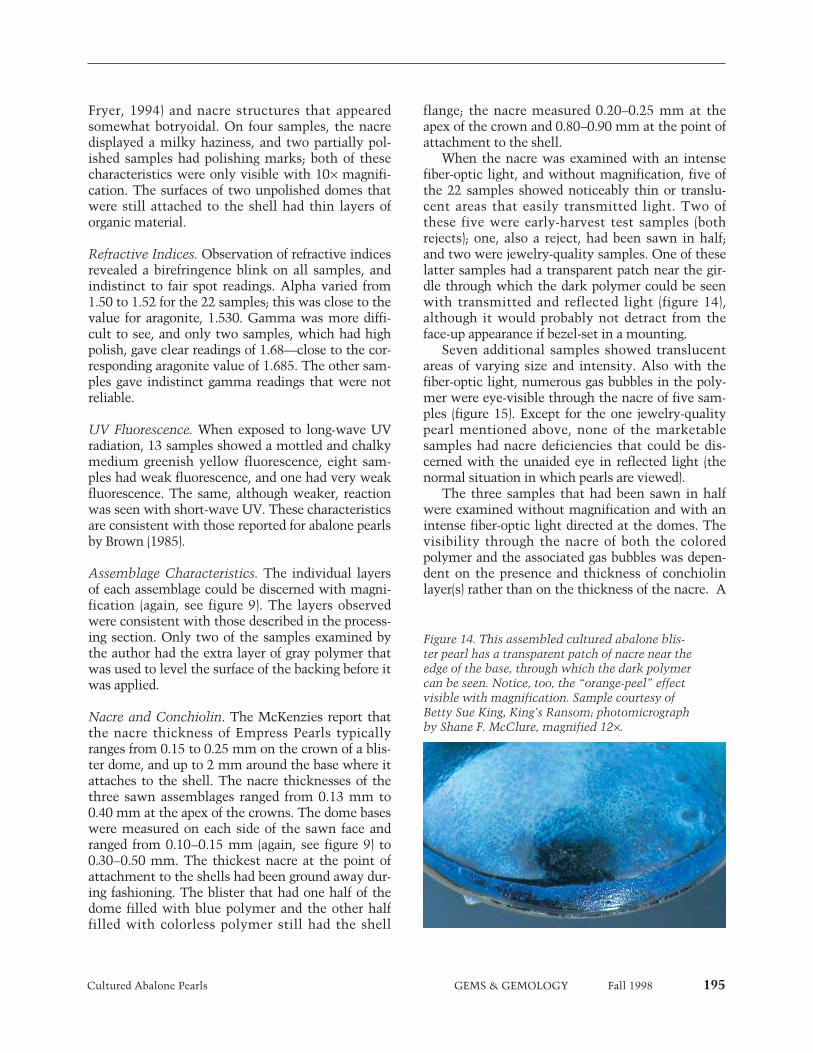
Cultured Abalone Pearls GEMS & GEMOLOGY Fall 1998 195
Fryer, 1994) and nacre structures that appearedsomewhat botryoidal. On four samples, the nacredisplayed a milky haziness, and two partially pol-ished samples had polishing marks; both of thesecharacteristics were only visible with 10¥ magnifi-cation. The surfaces of two unpolished domes thatwere still attached to the shell had thin layers oforganic material.
Refractive Indices. Observation of refractive indicesrevealed a birefringence blink on all samples, andindistinct to fair spot readings. Alpha varied from1.50 to 1.52 for the 22 samples; this was close to thevalue for aragonite, 1.530. Gamma was more diffi-cult to see, and only two samples, which had highpolish, gave clear readings of 1.68—close to the cor-responding aragonite value of 1.685. The other sam-ples gave indistinct gamma readings that were notreliable.
UV Fluorescence. When exposed to long-wave UVradiation, 13 samples showed a mottled and chalkymedium greenish yellow fluorescence, eight sam-ples had weak fluorescence, and one had very weakfluorescence. The same, although weaker, reactionwas seen with short-wave UV. These characteristicsare consistent with those reported for abalone pearlsby Brown (1985).
Assemblage Characteristics. The individual layersof each assemblage could be discerned with magni-fication (again, see figure 9). The layers observedwere consistent with those described in the process-ing section. Only two of the samples examined bythe author had the extra layer of gray polymer thatwas used to level the surface of the backing before itwas applied.
Nacre and Conchiolin. The McKenzies report thatthe nacre thickness of Empress Pearls typicallyranges from 0.15 to 0.25 mm on the crown of a blis-ter dome, and up to 2 mm around the base where itattaches to the shell. The nacre thicknesses of thethree sawn assemblages ranged from 0.13 mm to0.40 mm at the apex of the crowns. The dome baseswere measured on each side of the sawn face andranged from 0.10–0.15 mm (again, see figure 9) to0.30–0.50 mm. The thickest nacre at the point ofattachment to the shells had been ground away dur-ing fashioning. The blister that had one half of thedome filled with blue polymer and the other halffilled with colorless polymer still had the shell
flange; the nacre measured 0.20–0.25 mm at theapex of the crown and 0.80–0.90 mm at the point ofattachment to the shell.
When the nacre was examined with an intensefiber-optic light, and without magnification, five ofthe 22 samples showed noticeably thin or translu-cent areas that easily transmitted light. Two ofthese five were early-harvest test samples (bothrejects); one, also a reject, had been sawn in half;and two were jewelry-quality samples. One of theselatter samples had a transparent patch near the gir-dle through which the dark polymer could be seenwith transmitted and reflected light (figure 14),although it would probably not detract from theface-up appearance if bezel-set in a mounting.
Seven additional samples showed translucentareas of varying size and intensity. Also with thefiber-optic light, numerous gas bubbles in the poly-mer were eye-visible through the nacre of five sam-ples (figure 15). Except for the one jewelry-qualitypearl mentioned above, none of the marketablesamples had nacre deficiencies that could be dis-cerned with the unaided eye in reflected light (thenormal situation in which pearls are viewed).
The three samples that had been sawn in halfwere examined without magnification and with anintense fiber-optic light directed at the domes. Thevisibility through the nacre of both the coloredpolymer and the associated gas bubbles was depen-dent on the presence and thickness of conchiolinlayer(s) rather than on the thickness of the nacre. A
Figure 14. This assembled cultured abalone blis-ter pearl has a transparent patch of nacre near theedge of the base, through which the dark polymercan be seen. Notice, too, the “orange-peel” effectvisible with magnification. Sample courtesy ofBetty Sue King, King’s Ransom; photomicrographby Shane F. McClure, magnified 12¥.
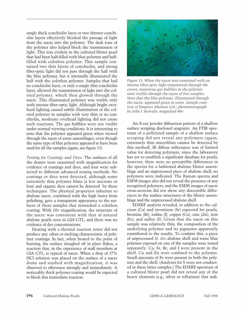
196 Cultured Abalone Pearls GEMS & GEMOLOGY Fall 1998
single thick conchiolin layer or two thinner conchi-olin layers effectively blocked the passage of lightfrom the nacre into the polymer. The dark tone ofthe polymer also helped block the transmission oflight. This was evident in the cultured blister pearlthat had been half-filled with blue polymer and half-filled with colorless polymer. This sample con-tained two thin layers of conchiolin, and strongfiber-optic light did not pass through the half withthe blue polymer, but it internally illuminated thehalf with the colorless polymer. Samples that hadno conchiolin layer, or only a single thin conchiolinlayer, allowed the transmission of light into the col-ored polymer, which then glowed through thenacre. This illuminated polymer was visible onlywith intense fiber-optic light. Although bright over-head lighting caused subtle illumination of the col-ored polymer in samples with very thin or no con-chiolin, moderate overhead lighting did not causesuch reactions. The gas bubbles were not visibleunder normal viewing conditions. It is interesting tonote that the polymer appeared green when viewedthrough the nacre of some assemblages, even thoughthe same type of blue polymer appeared to have beenused for all the samples (again, see figure 15).
Testing for Coatings and Dyes. The surfaces of allthe domes were examined with magnification forevidence of coatings and dyes, and four were sub-jected to different advanced testing methods. Nocoatings or dyes were detected, although someextremely thin polymer films (a few microns orless) and organic dyes cannot be detected by thesetechniques. The physical properties inherent toabalone nacre, combined with the high luster frompolishing, gave a transparent appearance to the sur-faces of these samples that mimicked a colorlesscoating. With 10¥ magnification, the structure ofthe nacre was consistent with that of naturalabalone pearls seen in GIA GTL, and there was noevidence of dye concentrations.
Heating with a thermal reaction tester did notproduce any odors or melting characteristic of poly-mer coatings. In fact, when heated to the point ofburning, the surface sloughed off in platy flakes, areaction that, in the experience of staff members atGIA GTL, is typical of nacre. When a drop of 37%HCl solution was placed on the surface of a nacredome and studied with magnification, it wasobserved to effervesce strongly and immediately. Anoticeably thick polymer coating would be expectedto block this immediate reaction.
An X-ray powder diffraction pattern of a shallowsurface scraping disclosed aragonite. An FTIR spec-trum of a pelletized sample of a shallow surfacescraping did not reveal any polymers (again,extremely thin microfilms cannot be detected bythis method). IR diffuse reflectance was of limitedvalue for detecting polymers, since the laboratoryhas yet to establish a significant database for pearls;however, there were no perceptible differences inthe spectra for a fashioned abalone blister assem-blage and an unprocessed piece of abalone shell; nopolymers were indicated. The Raman spectra andESEM images also did not reveal the presence of anyrecognized polymers, and the ESEM images of nacrecross-sections did not show any discernible differ-ences in the surface structures of the blister assem-blage and the unprocessed abalone shell.
EDXRF analysis revealed, in addition to the cal-cium (Ca) and strontium (Sr) expected for pearls,bromine (Br), iodine (I), copper (Cu), zinc (Zn), iron(Fe), and sulfur (S). Given that the nacre on thissample was relatively thin, the composition of theunderlying polymer and its pigments apparentlycontributed to the results. To confirm this, a pieceof unprocessed H. iris abalone shell and some bluepolymer exposed on one of the samples were testedseparately. Ca, Sr, Br, and I were present in theshell. Cu and Zn were confined to the polymer.Small amounts of Fe were present in both the poly-mer and the shell. (Analyses for S were not conduct-ed in these latter samples.) The EDXRF spectrum ofa cultured blister pearl did not reveal any of theheavy elements (e.g., silver or tellurium) that indi-
Figure 15. When the nacre was examined with anintense fiber-optic light transmitted through thecrown, numerous gas bubbles in the polymerwere visible through the nacre of five samples.Note that the blue polymer, illuminated throughthe nacre, appeared green in some. Sample cour-tesy of Empress Abalone Ltd.; photomicrographby John I. Koivula, magnified 40¥.
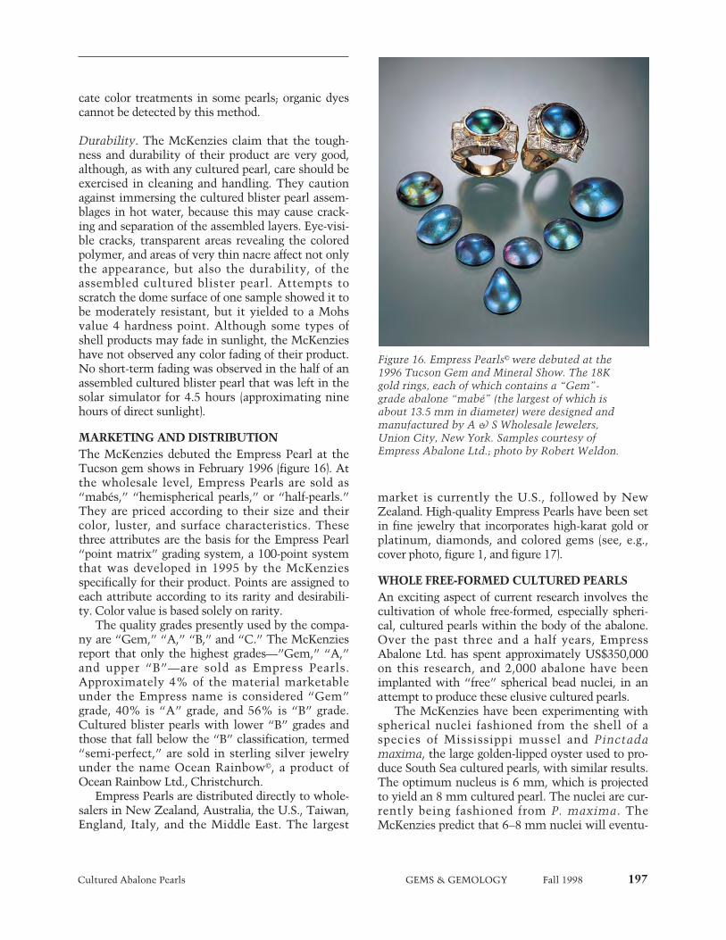
Cultured Abalone Pearls GEMS & GEMOLOGY Fall 1998 197
cate color treatments in some pearls; organic dyescannot be detected by this method.
Durability. The McKenzies claim that the tough-ness and durability of their product are very good,although, as with any cultured pearl, care should beexercised in cleaning and handling. They cautionagainst immersing the cultured blister pearl assem-blages in hot water, because this may cause crack-ing and separation of the assembled layers. Eye-visi-ble cracks, transparent areas revealing the coloredpolymer, and areas of very thin nacre affect not onlythe appearance, but also the durability, of theassembled cultured blister pearl. Attempts toscratch the dome surface of one sample showed it tobe moderately resistant, but it yielded to a Mohsvalue 4 hardness point. Although some types ofshell products may fade in sunlight, the McKenzieshave not observed any color fading of their product.No short-term fading was observed in the half of anassembled cultured blister pearl that was left in thesolar simulator for 4.5 hours (approximating ninehours of direct sunlight).
MARKETING AND DISTRIBUTIONThe McKenzies debuted the Empress Pearl at theTucson gem shows in February 1996 (figure 16). Atthe wholesale level, Empress Pearls are sold as“mabés,” “hemispherical pearls,” or “half-pearls.”They are priced according to their size and theircolor, luster, and surface characteristics. Thesethree attributes are the basis for the Empress Pearl“point matrix” grading system, a 100-point systemthat was developed in 1995 by the McKenziesspecifically for their product. Points are assigned toeach attribute according to its rarity and desirabili-ty. Color value is based solely on rarity.
The quality grades presently used by the compa-ny are “Gem,” “A,” “B,” and “C.” The McKenziesreport that only the highest grades—”Gem,” “A,”and upper “B”—are sold as Empress Pearls.Approximately 4% of the material marketableunder the Empress name is considered “Gem”grade, 40% is “A” grade, and 56% is “B” grade.Cultured blister pearls with lower “B” grades andthose that fall below the “B” classification, termed“semi-perfect,” are sold in sterling silver jewelryunder the name Ocean Rainbow©, a product ofOcean Rainbow Ltd., Christchurch.
Empress Pearls are distributed directly to whole-salers in New Zealand, Australia, the U.S., Taiwan,England, Italy, and the Middle East. The largest
market is currently the U.S., followed by NewZealand. High-quality Empress Pearls have been setin fine jewelry that incorporates high-karat gold orplatinum, diamonds, and colored gems (see, e.g.,cover photo, figure 1, and figure 17).
WHOLE FREE-FORMED CULTURED PEARLSAn exciting aspect of current research involves thecultivation of whole free-formed, especially spheri-cal, cultured pearls within the body of the abalone.Over the past three and a half years, EmpressAbalone Ltd. has spent approximately US$350,000on this research, and 2,000 abalone have beenimplanted with “free” spherical bead nuclei, in anattempt to produce these elusive cultured pearls.
The McKenzies have been experimenting withspherical nuclei fashioned from the shell of aspecies of Mississippi mussel and Pinctadamaxima, the large golden-lipped oyster used to pro-duce South Sea cultured pearls, with similar results.The optimum nucleus is 6 mm, which is projectedto yield an 8 mm cultured pearl. The nuclei are cur-rently being fashioned from P. maxima. TheMcKenzies predict that 6–8 mm nuclei will eventu-
Figure 16. Empress Pearls© were debuted at the1996 Tucson Gem and Mineral Show. The 18Kgold rings, each of which contains a “Gem”-grade abalone “mabé” (the largest of which isabout 13.5 mm in diameter) were designed andmanufactured by A & S Wholesale Jewelers,Union City, New York. Samples courtesy ofEmpress Abalone Ltd.; photo by Robert Weldon.

198 Cultured Abalone Pearls GEMS & GEMOLOGY Fall 1998
ally be used to obtain 8–10 mm whole spherical cul-tured pearls. Larger nuclei result in a high rejectionrate. One nucleus per abalone is inserted in a pro-cess that takes four to five minutes. The tools, tech-nique, and exact location within the animal are pro-prietary and were developed through originalresearch.
If an abalone’s strong muscular force does notexpel the loose bead nucleus, the exertion on thebead is usually enough to hinder satisfactory nacrecoverage, quality, and shape. The whole free-formedcultured pearls produced to date have nacreousareas up to 2–3 mm thick. This nacre is thickerthan that of the cultured blister pearls because thebead nucleus is a greater irritant.
According to the McKenzies, the whole free-formed cultured pearls have evolved from completelybaroque shapes, most with a somewhat conical out-line, to products that are more spherical. Although
results are preliminary, there have been promisingindications of success; the author had the opportu-nity to see seven of the whole free-formed bead-nucleated cultured pearls at the February 1998Tucson gem shows (figure 18).
Empress Abalone Ltd. has also been experiment-ing with whole free-formed tissue-nucleated cul-tured pearls. The tissue is implanted into the samevisceral region where the free-formed bead-nucleat-ed pearls are grown. The McKenzies describe theresulting cultured pearls as thin and curved, some-what like a fingernail, and partially hollow; theycannot be distinguished from a natural abalonepearl on the basis of their outside appearance. Todate, there is no commercial production.
DISCUSSIONMabés. Blister pearls were the first type of culturedpearls; as early as the 13th century, various types ofnuclei were implanted in oysters to be covered withmother-of-pearl, including small lead or tin formsresembling religious idols (Kammerling et al., 1990;Fankboner, 1991; Webster, 1994). More recently,hemispherical shell beads were implanted into thelarge Pteria penguin (Japan) and Pinctada maxima(Australia) to produce sizable blister pearls thatcould be assembled for use in jewelry(Crowningshield, 1982; Taburiaux, 1985; Farn,1986). These were called mabé pearls. Typically, theblister dome would be coated from the inside with atranslucent material, and a mother-of-pearl beadinserted; then any remaining voids would be filledwith a colorless glue and a mother-of-pearl backingwould be applied (see, e.g., Crowningshield, 1982;Taburiaux, 1985).
Today, an assembled cultured blister pearl fromany type of nacreous mollusk is often referred to asa mabé, and usually only epoxy or another polymerfills the dome. Empress Pearls resemble these con-temporary mabés in their assembled nature, andEmpress Abalone Ltd. often refers to their productsas “mabés.” Although the Empress process uses acolored polymer to fill the dome, the inside surfaceof the nacre is not coated, as is typical of traditionalmabés. In general, assembled cultured abalone blis-ter pearls may be separated from other types bytheir intense coloration, high iridescence, andgreenish yellow ultraviolet luminescence; the trans-parent nacre has unique botryoidal features and acellular structure (visible at high magnification).
Cultured blister pearls are being or have beenproduced in other species of abalone, including H.
Figure 17. This 18K yellow and white gold neck-lace contains five “A”-grade round (15–18 mm)Empress Pearls and one 22 ¥ 15 mm pear shape.The necklace is accented by diamonds, rubies,and sapphires. It was designed and manufac-tured by Hugh Power Designs, Anchorage,Alaska. Photo © TKO studio, New York; cour-tesy of Empress Abalone Ltd.

Cultured Abalone Pearls GEMS & GEMOLOGY Fall 1998 199
rufescens, H. fulgens, H. kamtschatkana, H. discus,H. gigantea, and H. seiboldii. These, too, have beenfashioned into “mabés.” The author had the oppor-tunity to examine a “mabé” from H. rufescens (redabalone from the west coast of North America) thatwas donated to GIA by Dr. Peter Fankboner. In thissample, the nacre dome was attached directly to themother-of-pearl and shell base with a very thin layerof transparent glue. No other layers or the domefiller were visible. The colors were pleasing, withmore silver and pink hues (again, see photos inKammerling and Fryer, 1994) compared to the moreprevalent blue hue of the blisters from H. iris. The lus-ter was high, with a slight satin quality.
Effects of Conchiolin on Appearance. The presenceand thickness of the underlying conchiolin layer(s)determine the quality of light and color reflectedback to the observer. The blue polymer did notaffect the face-up appearance of those assemblagesthat have conchiolin layers sufficiently thick toblock the passage of light. The conchiolin acted as amirror, reflecting normal overhead light backthrough the nacre toward the observer for maxi-mum light return, color, and iridescence. The face-up color of samples that contained thinner conchi-olin layers could possibly be slightly affected by theblue polymer; however, even moderately thin layersof conchiolin acted as a mirror, and the coloredpolymer in these pearls could only be discernedwith intense light. Examination of the sawn blisterdome that was half-filled with blue polymer andhalf-filled with colorless polymer confirmed thisconclusion. Face-up examination of both halvesrevealed no discernible color difference (figure 12).
Conversely, absence of this conchiolin layerdiminishes the potentially strong and appealingvisual effects; assemblages without a conchiolinlayer, or with a very thin conchiolin layer, allowedlight to enter the polymer filling. These pearls notonly showed less intense color and brilliance, butthe light passing into the colored polymer affectedthe face-up color of the pearl. On careful examina-tion in reflected light and with the unaided eye, thiswas evident on a sawn reject sample and on thelowest-quality commercial product; they bothshowed a bluish background color that was at leastpartially due to the polymer, but the extent ofimpact could not be determined.
Examination for Surface Treatments. The high lus-ter combined with the transparent nacre have led
some people to suspect a polymer coating on these“mabés.” Also, the vivid colors can mislead one tobelieve they are dyed (and some dyed traditionalmabés resemble this abalone product [R. Kane, pers.comm., 1998]). No coatings or dyes were detected inthe course of this study. Not all samples were testedby advanced techniques, and the possibility existsthat an extremely thin polymer microfilm or anorganic dye could defy detection by all the testingtechniques available to the author; however, thevibrant colors, transparency, and ability to achieve ahigh luster are properties that are inherent toabalone nacre.
Durability. Although comprehensive durabilitytesting was not performed on the Empress product,mabés in general are relatively soft (hardness 3.5-4),and their domes have moderately thin nacre. Caremust be taken during wear, as a sharp blow couldcrack them. It is the author’s opinion that the prod-uct lends itself best for use in pendants, enhancers,necklace clasps, brooches, and earrings, where thethreat of damage is reduced. Rings are only recom-mended for occasional wear.
CONCLUSIONEmpress Abalone Ltd. is commercially producingcultured blister pearls with vibrant colors and a
Figure 18. The first attempts at culturing wholefree-formed bead-nucleated abalone pearls pro-duced these irregular shapes in February 1998.Pressure exerted by the abalone on the beadcommonly prevents the nacre from covering theentire nucleus. Samples courtesy of EmpressAbalone Ltd.; photo by Maha DeMaggio.
200 Cultured Abalone Pearls GEMS & GEMOLOGY Fall 1998
rainbow-like iridescence that are unique to NewZealand’s H. iris abalone. In 1997, 6,000 commer-cial-quality cultured blister pearls were harvested,in sizes up to 12 mm in diameter, and a similarquantity is expected for 1998. In an assemblage pro-cess similar to that used for mabés from traditionalpearl oysters, the cultured blister pearls are cut fromthe shell, filled with a blue polymer, backed withmother-of-pearl, and buffed to a high luster.Examination of 22 of these “mabés” revealed thevarious components that are used to assemble theproduct, as well as the character of the nacre.Conchiolin plays an important role in the face-upappearance of the “mabés.” Where the conchiolinlayer is very thin or absent, the blue polymer usedto fill the dome can affect the color appearance ofthe nacre; whereas the presence of thicker layers ofconchiolin optimizes the naturally vivid colors andiridescence. Examination with magnification of allsamples, and advanced testing of some, revealed noevidence of any surface treatment.
These abalone “mabés” are priced according totheir size, color, luster, and surface blemishes.Empress Abalone Ltd. markets the finer qualitymaterial as Empress Pearls worldwide (EmpressAbalone Pearls in the U.S.). The lower quality mate-
rial is marketed under the name Ocean Rainbow.The abalone product, like other mabés, should beworn and treated with care.
Research is ongoing, and the prospects fordecreased mortality rates, increased productionyields, and greater control over nacre depositionappear good. Methods for the commercial produc-tion of whole free-formed bead- and tissue-nucleat-ed cultured abalone pearls are being explored.
Acknowledgments: The author thanks Liz andMichael McKenzie, of Empress Abalone Ltd.,Christchurch, New Zealand, for providing informa-tion, samples, and photos; Betty Sue King of King’sRansom, Sausalito California, for providing samples;Shane McClure of GIA GTL for photomicrography,suggestions, and support; Dino DeGhionno of GIAGTL for X-ray powder diffraction analysis; SamMuhlmeister of GIA Research for EDXRF analysis;Shane Elen of GIA Research for producing FTIR dif-fuse reflectance and Raman spectra; ClausHedegaard for producing ESEM images; Dr. Peter V.Fankboner for information; and staff members at theRichard T. Liddicoat Library and InformationCenter, and Leila Dooley of the Carlsbad CityLibrary, for assistance with the literature search.
REFERENCESBigger abalone pearls in 1992. (1991) Hong Kong Jewellery, Vol. 2,
No. 50, p. 90.Bostwick L.P. (1936) Growing pearls in the laboratory. The
Gemmologist, Vol. 5, No. 54, pp. 143–149.Brown G. (1985) The abalone and its pearls. Australian
Gemmologist, Vol. 15, No. 11, pp. 400–403.Brown G. (1997) New Zealand’s Empress Pearl©—An abalone
pearl par excellence. Jewellery World, Vol. 16, No. 2, pp.36–38.
Cox K.W. (1962) California abalones, family Haliotidae.California Department of Fish and Game Fish Bulletin, No.118, 133 pp.
Cropp D. (1997) Abalone pearls from Bass Strait. AustralianGemmologist, Vol. 19, No. 9, pp. 375–379.
Crowningshield G.R. (1982) Cultured 3/4 blister pearls. Gems &Gemology, Vol. 18, No. 1, pp. 36–38.
Fankboner P.V. (1991) Pearl culture in abalone. InfofishInternational, No. 4/91, July/August, pp. 52–55.
Fankboner P.V. (1994) Process for Producing Pearls in Abaloneand Other Shell-Bearing Molluska and Nucleus UsedTherewith. U.S. Patent Number 5,347,951, Sept. 20, 33 pp.
Fankboner P.V. (1995) Abalone pearls: Natural and cultured.Canadian Gemmologist, Vol. 16, No. 1, pp. 3–8.
Farn A.E. (1986) Pearls: Natural, Cultured and Imitation.Butterworth-Heinemann Ltd., Oxford, England, 150 pp.
Haldane D. (1992) The mystery of the missing mollusks. LosAngeles Times Magazine, January 5, pp. 23–26.
Howorth P.C. (1978) The Abalone Book. Naturegraph Publishers,Happy Camp, CA, 80 pp.
Kammerling R.C., Koivula J.I., Kane R.E. (1990) Examination ofan interesting cultured blister pearl. Australian Gemmologist,Vol. 17, No. 5, pp. 174–175.
Kammerling R.C., Fryer C.W. (1994) Lab notes: Abalone “mabé”pearl. Gems & Gemology, Vol. 30, No. 4, p. 268.
McGraw-Hill (1987) Encyclopedia of Science and Technology.6th ed. McGraw-Hill Book Co., New York, pp. 4, 22–23,587–588.
McKenzie L. (1996) The Empress Pearl©—A New Zealand cul-tured half-pearl. Australian Gemmologist, Vol. 19, No. 8, pp.336–338.
McLean J.H. (1969) Marine Shells of California. Los AngelesCounty Museum of Natural History Science Series 24,Zoology No. 11, 104 pp.
Nieson T.M. (1994) Beachcomber’s Guide to SouthernCalifornia Marine Life. Gulf Publishing Co., Houston, TX,192 pp.
SFU marine biologist claims world record for culturing mother-of-all (abalone)-pearls (1996) Simon Fraser University News,Jan. 18, pp. 1–2.
Taburiaux J. (1985) Pearls: Their Origin, Treatment &Identification. Chilton Book Co., Radnor, PA, 247 pp.
Ward F. (1998) Pearls. Gem Book Publishers, Bethesda, MD, 64pp.
Webster R. (1994) Gems: Their Sources, Descriptions andIdentification, 5th ed. Rev. by Peter Read, Butterworth-Heinemann Ltd., Oxford, England, pp. 500–558.
202 Notes and New Techniques GEMS & GEMOLOGY Fall 1998
ABOUT THE AUTHOR
Mr. Carmona, G.G., is an Accredited Senior Appraiser(ASA) and president of Guild Laboratories, Inc., LosAngeles, California [[email protected]].
Please see acknowledgments at the end of the article.
Gems & Gemology, Vol. 34, No. 3, pp. 202–211
© 1998 Gemological Insitute of America
gemstone weights, or negotiating the sale or pawnof jewelry.
Over the past two decades, estate jewelry hasbecome increasingly important in the market (fig-ure 1). No longer is all second-hand jewelry simplymelted down and the stones recut for remounting.In fact, more jewelers are entering this market, atboth wholesale and retail levels, as witnessed byregular estate jewelry sections in the trade press(see, e.g., Jewelers’ Circular-Keystone and ProfessionalJeweler), the growth of estate jewelry sections attrade shows (such as the Las Vegas JCK Show),and the prevalence of this jewelry in on-line bul-letin boards (e.g., http://www.diamonds.net,http://www.polygon.net) and Web sites (e.g.,http://www.antique-estate- jewelry.com,http://www.estatejeweler.com). For appraisers,estate jewelry dealers, and pawnbrokers in particu-lar, the ability to accurately estimate the weight ofmounted gemstones is critical to the success oftheir operations.
Tables of diamond weights according to mil-
Estimating weights of mounted gemstones hasbecome a common routine for many of today’s jew-elry tradespeople. Weight estimation is necessarywhen the stone cannot be removed from its mount-ing, either because the client will not allow it orbecause the piece might be damaged. This is typi-cally the case with estate jewelry (i.e., jewelry thathas been previously owned). Estimating weightmight be done when performing an appraisal, calcu-lating an offer to purchase jewelry with unknown
Updated formulas are presented for estimating the weights of mounted col-
ored gemstones. These formulas are derived from measurements and
weights of thousands of German-cut calibrated amethysts and citrines, rep-
resenting most commercially available shapes and sizes. As with the formu-
las taught by GIA, the dimensions of a stone are multiplied by its specific
gravity and by a “shape factor” that is determined by the stone’s face-up
outline. This article also illustrates how the shape factor changes over a con-
tinuum of common face-up outlines. As in previous formulas, a separate
weight correction factor is applied to stones that show proportion variations
in profile view.
NNOOTTEESS AANNDD NNEEWW TTEECCHHNNIIQQUUEESS
ESTIMATING WEIGHTS OF MOUNTEDCOLORED GEMSTONES
By Charles I. Carmona
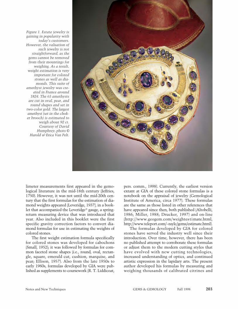
Notes and New Techniques GEMS & GEMOLOGY Fall 1998 203
limeter measurements first appeared in the gemo-logical literature in the mid-18th century (Jeffries,1750). However, it was not until the mid-20th cen-tury that the first formulas for the estimation of dia-mond weights appeared (Leveridge, 1937), in a book-let that accompanied the Leveridge‚ gauge, a spring-return measuring device that was introduced thatyear. Also included in this booklet were the firstspecific gravity correction factors to convert dia-mond formulas for use in estimating the weights ofcolored stones.
The first weight estimation formula specificallyfor colored stones was developed for cabochons(Small, 1952); it was followed by formulas for com-mon faceted stone shapes (i.e., round, oval, rectan-gle, square, emerald cut, cushion, marquise, andpear; Ellison, 1957). Also from the late 1950s toearly 1960s, formulas developed by GIA were pub-lished as supplements to coursework (R. T. Liddicoat,
pers. comm., 1998). Currently, the earliest versionextant at GIA of these colored stone formulas is anotebook on the appraisal of jewelry (GemologicalInstitute of America, circa 1977). These formulasare the same as those listed in other references thathave appeared since then, both published (Altobelli,1986; Miller, 1988; Drucker, 1997) and on-line(http://www.geogem.com/weightestimate.html,http://www.teleport.com/~raylc/gems/estimate.html).
The formulas developed by GIA for coloredstones have served the industry well since theirintroduction. Over time, however, there has beenno published attempt to corroborate these formulasor adjust them to the modern cutting styles thathave evolved with new cutting technologies,increased understanding of optics, and continuedartistic expression in the lapidary arts. The presentauthor developed his formulas by measuring andweighing thousands of calibrated citrines and
Figure 1. Estate jewelry isgaining in popularity with
today’s customers.However, the valuation of
such jewelry is notstraightforward, as the
gems cannot be removedfrom their mountings for
weighing. As a result,weight estimation is very
important for coloredstones as well as dia-monds. This suite of
amethyst jewelry was cre-ated in France around
1824. The 65 amethystsare cut in oval, pear, and
round shapes and set intwo-color gold. The largestamethyst (set in the chok-er brooch) is estimated to
weigh about 92 ct.Courtesy of David
Humphrey; photo ©Harold & Erica Van Pelt.
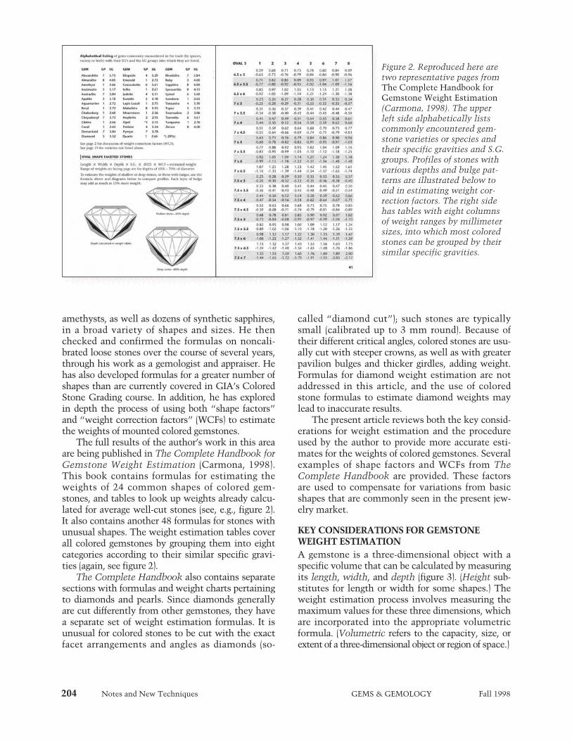
amethysts, as well as dozens of synthetic sapphires,in a broad variety of shapes and sizes. He thenchecked and confirmed the formulas on noncali-brated loose stones over the course of several years,through his work as a gemologist and appraiser. Hehas also developed formulas for a greater number ofshapes than are currently covered in GIA’s ColoredStone Grading course. In addition, he has exploredin depth the process of using both “shape factors”and “weight correction factors” (WCFs) to estimatethe weights of mounted colored gemstones.
The full results of the author’s work in this areaare being published in The Complete Handbook forGemstone Weight Estimation (Carmona, 1998).This book contains formulas for estimating theweights of 24 common shapes of colored gem-stones, and tables to look up weights already calcu-lated for average well-cut stones (see, e.g., figure 2).It also contains another 48 formulas for stones withunusual shapes. The weight estimation tables coverall colored gemstones by grouping them into eightcategories according to their similar specific gravi-ties (again, see figure 2).
The Complete Handbook also contains separatesections with formulas and weight charts pertainingto diamonds and pearls. Since diamonds generallyare cut differently from other gemstones, they havea separate set of weight estimation formulas. It isunusual for colored stones to be cut with the exactfacet arrangements and angles as diamonds (so-
called “diamond cut”); such stones are typicallysmall (calibrated up to 3 mm round). Because oftheir different critical angles, colored stones are usu-ally cut with steeper crowns, as well as with greaterpavilion bulges and thicker girdles, adding weight.Formulas for diamond weight estimation are notaddressed in this article, and the use of coloredstone formulas to estimate diamond weights maylead to inaccurate results.
The present article reviews both the key consid-erations for weight estimation and the procedureused by the author to provide more accurate esti-mates for the weights of colored gemstones. Severalexamples of shape factors and WCFs from TheComplete Handbook are provided. These factorsare used to compensate for variations from basicshapes that are commonly seen in the present jew-elry market.
KEY CONSIDERATIONS FOR GEMSTONEWEIGHT ESTIMATIONA gemstone is a three-dimensional object with aspecific volume that can be calculated by measuringits length, width, and depth (figure 3). (Height sub-stitutes for length or width for some shapes.) Theweight estimation process involves measuring themaximum values for these three dimensions, whichare incorporated into the appropriate volumetricformula. (Volumetric refers to the capacity, size, orextent of a three-dimensional object or region of space.)
204 Notes and New Techniques GEMS & GEMOLOGY Fall 1998
Figure 2. Reproduced here aretwo representative pages fromThe Complete Handbook forGemstone Weight Estimation(Carmona, 1998). The upperleft side alphabetically listscommonly encountered gem-stone varieties or species andtheir specific gravities and S.G.groups. Profiles of stones withvarious depths and bulge pat-terns are illustrated below toaid in estimating weight cor-rection factors. The right sidehas tables with eight columnsof weight ranges by millimetersizes, into which most coloredstones can be grouped by theirsimilar specific gravities.

Notes and New Techniques GEMS & GEMOLOGY Fall 1998 205
Besides the Leveridge gauge, various otherdevices are used to measure gemstones, includingscrew micrometers and calipers. All measure inmillimeter units, since the metric system is stan-dard in the international gemstone business.Generally, micrometers are the most accurate, butthey are not as versatile as the Leveridge gauge(which can also estimate to hundredths of a mil-limeter) for gemstones that are partially enclosed bymountings. The disadvantage of calipers is that theyare accurate only to tenths of a millimeter, whichwill reduce the accuracy of the results obtainedfrom the formulas.
Careful measurements are necessary to obtainaccurate weight estimations. Each dimensionshould be measured several times to find the maxi-mum value. A table gauge can be helpful for deter-mining face-up measurements of smaller stones.When a bezel setting or prong hides the edge of astone, examination with a loupe or microscope canhelp determine the extent to which the stone con-tinues into the mounting. When gallery workobscures direct measurement of the depth, an offsetmeasurement is necessary: Hold the measuringinstrument to the side of the stone and line up themeasuring device by eye with the top and bottompoints of measurement.
There are many possible sources of error in theweight estimation process. Besides measurementand mathematical errors, specific gravity variationscan affect the estimated weight. For example, airpockets trapped within a heavily included stonewill lower its S.G. Conversely, inclusions with ahigher S.G. than the host gem (such as rutile nee-
dles in quartz and tourmaline) will raise the S.G.Since samples of flawless quartz were used as thestandard for the formulas and tables presented here,included stones may require slight corrections.Potential margins of error also increase proportion-ate to the size and S.G. of a stone: The larger andheavier the stone, the greater the care needed toestimate its weight accurately.
However, the greatest challenge in estimatingweights of mounted gemstones is correcting for pro-portion variations. This requires judgment andexperience. By thinking of gemstone outlines as acontinuum of traditional shapes from one to thenext, it is easier to correct for such variations.Examples of such continuums are: round to square,round to oval to cushion to rectangle, and pear toheart. The following discussion first explains thedevelopment of the new formulas, and then illus-trates these shape sequences and provides the corre-sponding shape factors. Next, it examines profilevariations (e.g., pavilion bulge), and how weight cor-rection factors are applied to stones with nonstan-dard profiles.
DEVELOPING THE FORMULASThe proposed formulas are based on numerousweights and measurements of actual stones, not onmathematical constructs or computer models. Todevelop accurate formulas, the author weighed andmeasured several dozen parcels—totaling over 5,000stones—of calibrated German-cut amethyst and cit-rine in common shapes and sizes. The availabilityof such a large number of precision-cut stones,along with the fact that amethyst and citrine are
Figure 3. Weight estimationrequires that the followingdimensions be measured:
length (L), width (W) [orheight (H) for stones with
nonparallel sides], anddepth (Dp). Round shapes
are defined by their diame-ter (Di) and depth.

206 Notes and New Techniques GEMS & GEMOLOGY Fall 1998
two of the most common gem varieties on the mar-ket, made them logical standards for this purpose.Since these formulas were first developed in themid-1990s, hundreds of additional varieties andshapes of colored stones have been checked againstthem to verify their universality. The formulasproved to be accurate for all the colored stonesexamined.
Lots of 10 to 50 stones in standard calibratedsizes (e.g., 5 ¥ 3 mm, 6 ¥ 4 mm, 7 ¥ 5 mm, 8 ¥ 6 mm)of each shape were used. Each parcel was weighedto the hundredth of a carat (0.01 ct) using a Scien-tech SE300 electronic balance. Then, specific mea-surements of the largest, smallest, and several inter-mediate stones in each parcel were recorded to thehundredth of a millimeter using a Leveridge gauge.
The average weight of a stone in each parcel wascalculated by dividing the total weight of the parcelby the number of stones it contained. The actualweights of the stones in each lot showed minorvariations from the average weight, due to slightcutting variations. The average weight, size mea-surements, and S.G. were used to calculate a shapefactor for each calibrated size and shape, as follows:
Shape Factor = Weight
Length ¥ Width ¥ Depth ¥ S.G.
All of the shape factors (calculated for each sizewithin a given shape) were then averaged to arriveat a single factor for that shape. This process wasrepeated for each shape, for both faceted stones andcabochon cuts. The shape factor is a critical part ofthe weight estimation formulas, because it compen-sates for the fact that length ¥ width ¥ depth is thevolume of a rectangular solid, rather than the shapeof a faceted gemstone.
Once the shape factor was established, the for-mula was inverted to solve for weight (and a weightcorrection added where appropriate), as follows:
Weight = Length ¥ Width ¥ Depth ¥S.G. ¥ Shape Factor (¥ WCF)
Tables in the Complete Handbook presentranges of gemstone weights for many shapes andsizes (up to 20 mm, in half-millimeter increments),in a common range of depths. Weights for interme-diate sizes that are not normally calibrated wereinterpolated by formula. The weights are groupedinto eight narrow S.G. ranges (again, see figure 2).The first column, calculated using quartz, alsoincludes other stones with S.G.’s in the 2.55 to 2.75range (e.g., beryl, chalcedony, and feldspar). Aspreadsheet analysis was used to calculate theweights given in the other columns. Formulas for48 uncommon shapes are also presented, calculatedfrom fewer samples (3–12 for each shape). In addi-tion to quartz, flawless synthetic corundum wasused to calculate formulas for uncommon shapes,because this was the only material found in whichthese shapes occurred.
APPLYING THE FORMULASFace-Up Examination. The face-up outline (or“shape”) of the gemstone determines which shapefactor is used in the weight estimation formula.
Figure 4. Cabochons are featured by many contem-porary jewelry designers. This Bulgari parure con-sists of a necklace, bracelet, and earrings set withoval sapphire and round ruby cabochons, andaccented with diamonds. The sapphire cabochonsin the necklace range from 11 ¥ 90 mm to 17 ¥ 24mm. Jewelry courtesy of Suzanne Tennenbaum.Photo © GIA and Tino Hammid.
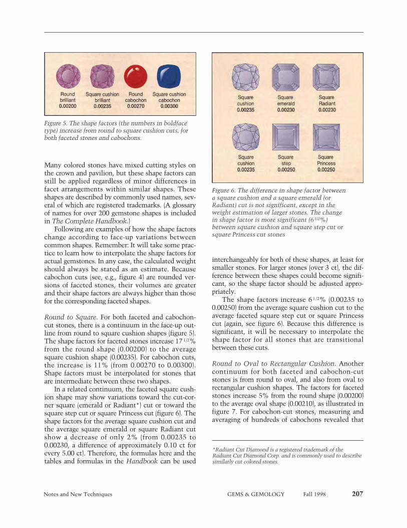
Notes and New Techniques GEMS & GEMOLOGY Fall 1998 207
Many colored stones have mixed cutting styles onthe crown and pavilion, but these shape factors canstill be applied regardless of minor differences infacet arrangements within similar shapes. Theseshapes are described by commonly used names, sev-eral of which are registered trademarks. (A glossaryof names for over 200 gemstone shapes is includedin The Complete Handbook.)
Following are examples of how the shape factorschange according to face-up variations betweencommon shapes. Remember: It will take some prac-tice to learn how to interpolate the shape factors foractual gemstones. In any case, the calculated weightshould always be stated as an estimate. Becausecabochon cuts (see, e.g., figure 4) are rounded ver-sions of faceted stones, their volumes are greaterand their shape factors are always higher than thosefor the corresponding faceted shapes.
Round to Square. For both faceted and cabochon-cut stones, there is a continuum in the face-up out-line from round to square cushion shapes (figure 5).The shape factors for faceted stones increase 17 1/2%from the round shape (0.00200) to the averagesquare cushion shape (0.00235). For cabochon cuts,the increase is 11% (from 0.00270 to 0.00300).Shape factors must be interpolated for stones thatare intermediate between these two shapes.
In a related continuum, the faceted square cush-ion shape may show variations toward the cut-cor-ner square (emerald or Radiant*) cut or toward thesquare step cut or square Princess cut (figure 6). Theshape factors for the average square cushion cut andthe average square emerald or square Radiant cutshow a decrease of only 2% (from 0.00235 to0.00230, a difference of approximately 0.10 ct forevery 5.00 ct). Therefore, the formulas here and thetables and formulas in the Handbook can be used
interchangeably for both of these shapes, at least forsmaller stones. For larger stones (over 3 ct), the dif-ference between these shapes could become signifi-cant, so the shape factor should be adjusted appro-priately.
The shape factors increase 6 1/2% (0.00235 to0.00250) from the average square cushion cut to theaverage faceted square step cut or square Princesscut (again, see figure 6). Because this difference issignificant, it will be necessary to interpolate theshape factor for all stones that are transitionalbetween these cuts.
Round to Oval to Rectangular Cushion. Anothercontinuum for both faceted and cabochon-cutstones is from round to oval, and also from oval torectangular cushion shapes. The factors for facetedstones increase 5% from the round shape (0.00200)to the average oval shape (0.00210), as illustrated infigure 7. For cabochon-cut stones, measuring andaveraging of hundreds of cabochons revealed that
*Radiant Cut Diamond is a registered trademark of theRadiant Cut Diamond Corp. and is commonly used to describesimilarly cut colored stones.
Figure 5. The shape factors (the numbers in boldfacetype) increase from round to square cushion cuts, forboth faceted stones and cabochons.
Figure 6. The difference in shape factor betweena square cushion and a square emerald (orRadiant) cut is not significant, except in theweight estimation of larger stones. The changein shape factor is more significant (61/2%)between square cushion and square step cut orsquare Princess cut stones
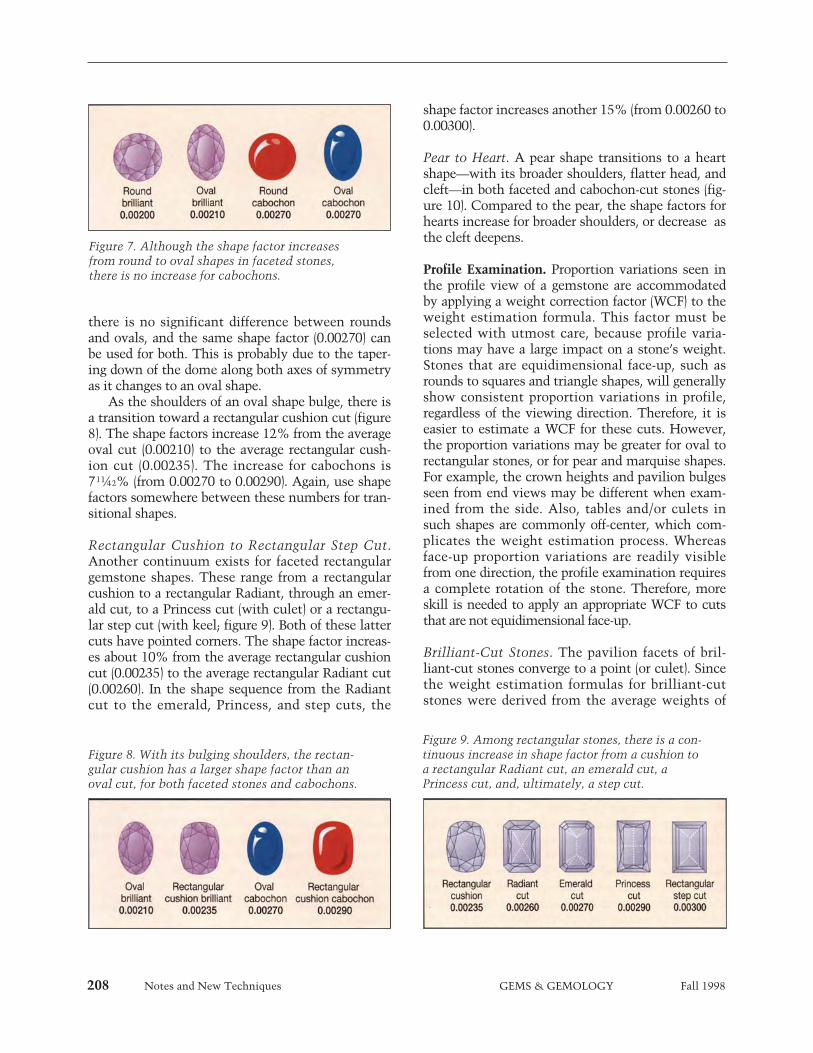
208 Notes and New Techniques GEMS & GEMOLOGY Fall 1998
there is no significant difference between roundsand ovals, and the same shape factor (0.00270) canbe used for both. This is probably due to the taper-ing down of the dome along both axes of symmetryas it changes to an oval shape.
As the shoulders of an oval shape bulge, there isa transition toward a rectangular cushion cut (figure8). The shape factors increase 12% from the averageoval cut (0.00210) to the average rectangular cush-ion cut (0.00235). The increase for cabochons is71¼2% (from 0.00270 to 0.00290). Again, use shapefactors somewhere between these numbers for tran-sitional shapes.
Rectangular Cushion to Rectangular Step Cut.Another continuum exists for faceted rectangulargemstone shapes. These range from a rectangularcushion to a rectangular Radiant, through an emer-ald cut, to a Princess cut (with culet) or a rectangu-lar step cut (with keel; figure 9). Both of these lattercuts have pointed corners. The shape factor increas-es about 10% from the average rectangular cushioncut (0.00235) to the average rectangular Radiant cut(0.00260). In the shape sequence from the Radiantcut to the emerald, Princess, and step cuts, the
shape factor increases another 15% (from 0.00260 to0.00300).
Pear to Heart. A pear shape transitions to a heartshape—with its broader shoulders, flatter head, andcleft—in both faceted and cabochon-cut stones (fig-ure 10). Compared to the pear, the shape factors forhearts increase for broader shoulders, or decrease asthe cleft deepens.
Profile Examination. Proportion variations seen inthe profile view of a gemstone are accommodatedby applying a weight correction factor (WCF) to theweight estimation formula. This factor must beselected with utmost care, because profile varia-tions may have a large impact on a stone’s weight.Stones that are equidimensional face-up, such asrounds to squares and triangle shapes, will generallyshow consistent proportion variations in profile,regardless of the viewing direction. Therefore, it iseasier to estimate a WCF for these cuts. However,the proportion variations may be greater for oval torectangular stones, or for pear and marquise shapes.For example, the crown heights and pavilion bulgesseen from end views may be different when exam-ined from the side. Also, tables and/or culets insuch shapes are commonly off-center, which com-plicates the weight estimation process. Whereasface-up proportion variations are readily visiblefrom one direction, the profile examination requiresa complete rotation of the stone. Therefore, moreskill is needed to apply an appropriate WCF to cutsthat are not equidimensional face-up.
Brilliant-Cut Stones. The pavilion facets of bril-liant-cut stones converge to a point (or culet). Sincethe weight estimation formulas for brilliant-cutstones were derived from the average weights of
Figure 8. With its bulging shoulders, the rectan-gular cushion has a larger shape factor than anoval cut, for both faceted stones and cabochons.
Figure 9. Among rectangular stones, there is a con-tinuous increase in shape factor from a cushion toa rectangular Radiant cut, an emerald cut, aPrincess cut, and, ultimately, a step cut.
Figure 7. Although the shape factor increasesfrom round to oval shapes in faceted stones,there is no increase for cabochons.
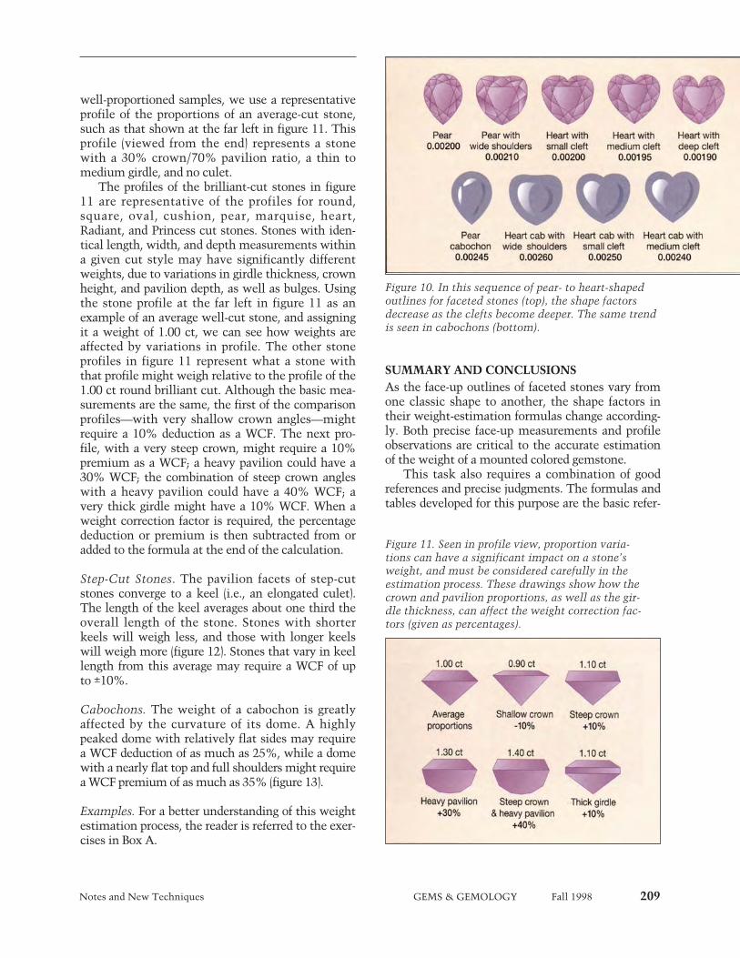
Notes and New Techniques GEMS & GEMOLOGY Fall 1998 209
well-proportioned samples, we use a representativeprofile of the proportions of an average-cut stone,such as that shown at the far left in figure 11. Thisprofile (viewed from the end) represents a stonewith a 30% crown/70% pavilion ratio, a thin tomedium girdle, and no culet.
The profiles of the brilliant-cut stones in figure11 are representative of the profiles for round,square, oval, cushion, pear, marquise, heart,Radiant, and Princess cut stones. Stones with iden-tical length, width, and depth measurements withina given cut style may have significantly differentweights, due to variations in girdle thickness, crownheight, and pavilion depth, as well as bulges. Usingthe stone profile at the far left in figure 11 as anexample of an average well-cut stone, and assigningit a weight of 1.00 ct, we can see how weights areaffected by variations in profile. The other stoneprofiles in figure 11 represent what a stone withthat profile might weigh relative to the profile of the1.00 ct round brilliant cut. Although the basic mea-surements are the same, the first of the comparisonprofiles—with very shallow crown angles—mightrequire a 10% deduction as a WCF. The next pro-file, with a very steep crown, might require a 10%premium as a WCF; a heavy pavilion could have a30% WCF; the combination of steep crown angleswith a heavy pavilion could have a 40% WCF; avery thick girdle might have a 10% WCF. When aweight correction factor is required, the percentagededuction or premium is then subtracted from oradded to the formula at the end of the calculation.
Step-Cut Stones. The pavilion facets of step-cutstones converge to a keel (i.e., an elongated culet).The length of the keel averages about one third theoverall length of the stone. Stones with shorterkeels will weigh less, and those with longer keelswill weigh more (figure 12). Stones that vary in keellength from this average may require a WCF of upto ±10%.
Cabochons. The weight of a cabochon is greatlyaffected by the curvature of its dome. A highlypeaked dome with relatively flat sides may requirea WCF deduction of as much as 25%, while a domewith a nearly flat top and full shoulders might requirea WCF premium of as much as 35% (figure 13).
Examples. For a better understanding of this weightestimation process, the reader is referred to the exer-cises in Box A.
SUMMARY AND CONCLUSIONSAs the face-up outlines of faceted stones vary fromone classic shape to another, the shape factors intheir weight-estimation formulas change according-ly. Both precise face-up measurements and profileobservations are critical to the accurate estimationof the weight of a mounted colored gemstone.
This task also requires a combination of goodreferences and precise judgments. The formulas andtables developed for this purpose are the basic refer-
Figure 10. In this sequence of pear- to heart-shapedoutlines for faceted stones (top), the shape factorsdecrease as the clefts become deeper. The same trendis seen in cabochons (bottom).
Figure 11. Seen in profile view, proportion varia-tions can have a significant impact on a stone’sweight, and must be considered carefully in theestimation process. These drawings show how thecrown and pavilion proportions, as well as the gir-dle thickness, can affect the weight correction fac-tors (given as percentages).
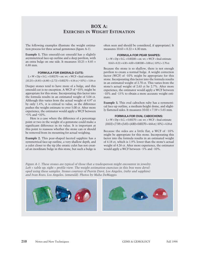
210 Notes and New Techniques GEMS & GEMOLOGY Fall 1998
BOX A: EXERCISES IN WEIGHT ESTIMATION
Figure A-1. These stones are typical of those that a tradesperson might encounter in jewelry.Left = table up; right = profile view. The weight estimation exercises in this box were devel-oped using these samples. Stones courtesy of Pravin Davé, Los Angeles, (ruby and sapphire)and Ivan Rozo, Los Angeles, (emerald). Photos by Maha DeMaggio.
The following examples illustrate the weight estima-tion process for three actual gemstones (figure A-1).
Example 1. This emerald-cut emerald has a slightlyasymmetrical face-up outline and a deep pavilion, withan extra bulge on one side. It measures 10.25 ¥ 8.85 ¥6.88 mm.
FORMULA FOR EMERALD CUTS:L ¥ W ¥ Dp ¥ S.G. ¥ 0.00270 = est. wt. ¥ WCF = final estimate
(10.25) ¥ (8.85) ¥ (6.88) ¥ (2.72) ¥ 0.00270 = 4.58 ct (+10%) = 5.04 ct
Deeper stones tend to have more of a bulge, and thisemerald cut is no exception. A WCF of +10% might beappropriate for this stone. Incorporating this factor intothe formula results in an estimated weight of 5.04 ct.Although this varies from the actual weight of 4.97 ctby only 1.4%, it is critical to value, as the differencepushes the weight estimate to over 5.00 ct. After moreexperience, the estimator would apply a WCF between+5% and +10%.
Here is a case where the difference of a percentagepoint or two in the weight of a gemstone could make asignificant difference in its value. It is important atthis point to reassess whether the stone can or shouldbe removed from its mounting for actual weighing.
Example 2. This pear-shaped faceted sapphire has asymmetrical face-up outline, a very shallow depth, anda culet closer to the tip (the erratic culet has not creat-ed an inordinate bulge in this stone, but such a bulge is
often seen and should be considered, if appropriate). Itmeasures 10.63 ¥ 8.22 ¥ 4.30 mm.
FORMULA FOR PEAR SHAPES:L ¥ W ¥ Dp ¥ S.G. ¥ 0.00200 = est. wt. ¥ WCF = final estimate
10.63 ¥ 8.22 ¥ 4.30 ¥4.00 ¥0.00200= 3.00 ct (-10%) = 2.70 ct
Because the stone is so shallow, there is not enoughpavilion to create a normal bulge. A weight correctionfactor (WCF) of -10% might be appropriate for thisstone. Incorporating this factor into the formula resultsin an estimated weight of 2.70 ct. This varies from thestone’s actual weight of 2.63 ct by 2.7%. After moreexperience, the estimator would apply a WCF between-10% and -15% to obtain a more accurate weight esti-mate.
Example 3. This oval cabochon ruby has a symmetri-cal face-up outline, a medium-height dome, and slight-ly flattened sides. It measures 10.02 ¥ 7.59 ¥ 5.65 mm.
FORMULA FOR OVAL CABOCHONS:L ¥ W ¥ Dp ¥ S.G. ¥ 0.00270 = est. wt. ¥ WCF = final estimate
(10.02) ¥ (7.59) ¥ (5.65) ¥ (4.00) ¥ 0.00270 = 4.64 ct (-10%) = 4.18 ct
Because the sides are a little flat, a WCF of -10%might be appropriate for this stone. Incorporating thisfactor into the formula results in an estimated weightof 4.18 ct, which is 1.9% lower than the stone’s actualweight of 4.26 ct. After more experience, the estimatorwould apply a WCF between -5% and -10%.

Notes and New Techniques GEMS & GEMOLOGY Fall 1998 211
ence tools needed. The formulas described in thisarticle were derived primarily from the averageweights of parcels of well-proportioned German-cutcalibrated amethysts and citrines. The personresponsible for weight estimations must then learnto make the necessary adjustments to the standardformulas. This process requires extensive experi-ence and practice. In fact, the tables and formulasdeveloped by the author were adjusted and refinedon the basis of several years of experience withactual colored stones examined in the course ofhis business.
Most tradespeople who have been estimatingweights of colored stones for any length of time areprobably using 40-year-old formulas and techniquesthat carry the disclaimer that “Even for the experi-enced grader, they are accurate only to within 10 to15%” (Gemological Institute of America, 1994).With the formulas and estimation procedures devel-oped by the present author, not only is it easier toaddress contemporary cutting styles, but it is alsopossible to reduce that potential margin of error to5% or less.
At all times, however, the person who is usingthese (or any other) formulas and techniques must
always use qualifying terms such as approximately,estimated, or about in conjunction with the weightestimate. Such disclosure is important, since thevalue of a piece of jewelry is often greatly affectedby the weights of the gemstones it contains.
The updated formulas presented here are meantto set a new standard for weight estimation and togive a fresh look at this important task for manywho make their living in the jewelry trade. Theweight estimation process may also provide anopportunity for jewelers to improve the accuracy oftheir gemological skills, while enhancing the prof-itability of their businesses.
Acknowledgments: The author thanks Renata andGonen Abrahami of ABC Gem Company, LosAngeles, for making available their vast inventoryof calibrated colored gemstones for use in develop-ing the weight estimation formulas. Margot A.McLaren, of GIA’s Richard T. LiddicoatGemological Library and Information Center, isthanked for her help in researching the history ofweight estimation formulas for colored stones.
Figure 12. The stone on the left shows an aver-age keel line length. The WCF values vary con-siderably for short or long keels.
Figure 13. The curvature of a cabochon, as seenin profile, profoundly affects the weight of thestone. As a result, the weight correction formu-las may require WCF values that vary from-25% to +35%.
REFERENCESAltobelli C. (1986) Handbook of Jewelry and Gemstone
Appraising, American Gem Society, Los Angeles, CA, pp. 45–46.Carmona C. (1998 [projected publication date]) The Complete
Handbook for Gemstone Weight Estimation, Gemania, LosAngeles, CA.
Drucker R. (1997) The GUIDE Reference Manual—ReferenceData, Gemworld International, Chicago, pp. 16–18.
Ellison J. (1957) Formulas for the weight estimation of coloredfaceted stones. Gems & Gemology, Vol. 9, No. 2, pp. 43–45.
Gemological Institute of America (circa 1977) Resident
Appraisal Notebook, GIA, Los Angeles, CA, p. 10.Gemological Institute of America (1994) Colored Stone Grading,
Assignment 18. GIA, Santa Monica, CA, p. 14.Jeffries D. (1750) A Treatise on Diamonds and Pearls. C. and J.
Ackers, London.Leveridge A. (1937) The A. D. Leveridge Weight Estimator. A. D.
Leveridge, Pompton Plains, New Jersey, p. 33.Miller A. (1988) Gems and Jewelry Appraising. Van Nostrand
Reinhold, New York, p. 176.Small J. (1952) Weight estimation of cabochons. Gems &
Gemology, Vol. 7, No. 6, pp. 191–194.
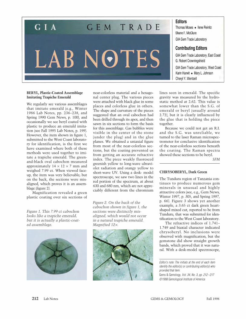
212 Lab Notes GEMS & GEMOLOGY Fall 1998
BERYL, Plastic-Coated AssemblageImitating Trapiche Emerald
We regularly see various assemblagesthat imitate emerald (e.g., Winter1986 Lab Notes, pp. 236–238, andSpring 1990 Gem News, p. 100), andoccasionally we see beryl coated withplastic to produce an emerald imita-tion (see Fall 1995 Lab Notes, p. 199).However, the item shown in figure 1,submitted to the West Coast laborato-ry for identification, is the first wehave examined where both of thesemethods were used together to imi-tate a trapiche emerald. The green-and-black oval cabochon measuredapproximately 14 ¥ 12 ¥ 7 mm andweighed 7.99 ct. When viewed face-up, the item was very believable; buton the back, the sections were mis-aligned, which proves it is an assem-blage (figure 2).
Magnification revealed a greenplastic coating over six sections of
near-colorless material and a hexago-nal center plug. The various pieceswere attached with black glue in someplaces and colorless glue in others.The shape and curvature of the piecessuggested that an oval cabochon hadbeen drilled through its apex, and thensawn in six sections to form the basisfor this assemblage. Gas bubbles werevisible in the center of the stone(under the plug) and in the glueplanes. We obtained a uniaxial figurefrom most of the near-colorless sec-tions, but the coating prevented usfrom getting an accurate refractiveindex. The piece weakly fluorescedgreenish yellow to long-wave ultravi-olet radiation and orangy yellow toshort-wave UV. Using a desk- modelspectroscope, we saw two lines in thered portion of the spectrum, at about630 and 680 nm, which are not appre-ciably different from the chromium
lines seen in emerald. The specificgravity was measured by the hydro-static method at 2.62. This value issomewhat lower than the S.G. ofemerald or beryl (usually around2.72), but it is clearly influenced bythe glue that is holding the piecetogether.
Because we could not get an R.I.and the S.G. was unreliable, weturned to the laser Raman microspec-trometer for conclusive identificationof the near-colorless sections beneaththe coating. The Raman spectrashowed these sections to be beryl.
SFM
CHRYSOBERYL, Dark Green
The Tunduru region of Tanzania con-tinues to produce numerous gemminerals in unusual and highlyattractive colors (see, e.g., Gem News,Winter 1997, p. 305, and Spring 1997,p. 66). Figure 3 shows yet anotherexample, a 3.65 ct dark green heart-shaped mixed cut, reported to be fromTunduru, that was submitted for iden-tification to the West Coast laboratory.
The refractive indices of 1.741–1.749 and biaxial character indicatedchrysoberyl. No inclusions wereobserved with magnification, but thegemstone did show straight growthbands, which proved that it was natu-ral. With a desk-model spectroscope,
Editor’s note: The initials at the end of each itemidentify the editor(s) or contributing editor(s) whoprovided that item.Gems & Gemology, Vol. 34, No. 3, pp. 212 –217©1998 Gemological Institute of America
Figure 1. This 7.99 ct cabochonlooks like a trapiche emerald,but it is actually a plastic-coat-ed assemblage.
Figure 2. On the back of thecabochon shown in figure 1, thesections were distinctly mis-aligned, which would not occurin a natural trapiche emerald.Magnified 12¥.

Lab Notes GEMS & GEMOLOGY Fall 1998 213
we saw a band at 600 nm, which isconsistent with the spectrum of lightgreen “mint” chrysoberyl, as reportedin the Fall 1996 Gem News section(pp. 215–216). The piece showed noreaction to either long- or short-waveUV radiation.
The 1996 report described bothlight green and dark green materialthat was colored by vanadium ratherthan chromium. Those samples alsocontained small quantities of Cr, aswell as iron, gallium, and tin. We sub-mitted this heart-shaped mixed cut toenergy-dispersive X-ray fluorescence(EDXRF) analysis, and found only afew differences in chemistry from thematerial seen earlier: Traces of V, Fe,and Ga were present, but there wasno tin nor any evidence of Cr.
We have seen rare examples ofsuch a saturated green color in vana-dium chrysoberyl before, includingsome material reported to be fromMyanmar. This color is also in thesame range as synthetic vanadiumchrysoberyl grown by the floating-zone method in Russia. Although thenatural and synthetic material canshow similar fluorescence reactionsand spectra, the synthetic chrysoberylinvariably has distinctive inclusions,such as gas bubbles and curved striae.
SFM
DIAMOND
Color Treated from Orangy Yellow to Reddish PurpleAlthough the East Coast lab receives
many treated-color diamonds foridentification, we rarely have theopportunity to examine a diamondand document its properties bothbefore and after treatment. About ayear ago, a friend of the laboratorysubmitted a group of small diamondsfor our examination prior to irradia-tion and heat treatment. We singledout a 0.09 ct orangy yellow roundbrilliant for thorough documentation.Viewed over diffused light (orimmersed in methylene iodide) thisdiamond showed uneven coloration,with a yellow bodycolor and sparsepale brown graining.
This diamond showed no reactionto long-wave ultraviolet radiation, butit fluoresced greenish yellow withmoderate intensity to short-wave UV.With the desk-model spectroscope,we saw increasing absorption fromabout 500 nm toward the blue. Theseproperties suggested some type Ibcomponent, which infrared spec-troscopy confirmed, showing a com-bination of type Ib and IaA absorptionpeaks (for an explanation of diamondtypes, see E. Fritsch and K. Scarratt,“Natural-Color Non-conductive Gray-to-Blue Diamonds,” Gems & Gemology,Spring 1992, pp. 35–42). Only a dia-mond that contains some type Ibcomponent can be treated to producepink, red, or purple; irradiation andheat treatment of type Ia diamondsproduces orange, brown, yellow, or
greenish yellow (see A. Collins et al.,“Absorption and LuminescenceSpectroscopy,” in J. E. Field, Ed.,Properties of Natural and SyntheticDiamond, Academic Press, London,1992, pp. 35–80).
The key to the development ofpink to purple colors with treatmentis the single substitutional nitrogenthat defines type Ib diamond.Vacancies created during irradiation(that is, the holes left in the structurewhen ionizing radiation displaces acarbon atom) migrate through the dia-mond during heat treatment and joinwith the single substitutional nitro-gen to create the NV center. Theabsorptions related to this center—at637 and 575 nm—combine with therising absorption in the blue to yieldpink, red, and/or purple (K. Scarratt,“Notes from the Laboratory,” Journalof Gemmology, Vol. 20, No. 6, 1987,pp. 358–361).
After irradiation with low-energyelectrons and subsequent heat treat-ment, the color of this 0.09 ct orangyyellow diamond changed to a reddishpurple (figure 4). It fluoresced a strongbright orange to both long- and short-wave UV radiation (somewhatstronger to short-wave UV), and thehand spectroscope showed stronglines at 637 and 575 nm, with a com-panion line at 595 nm and both yel-
Figure 3. This 3.65 ct dark greenchrysoberyl is colored by vana-dium. It reportedly came fromTunduru, Tanzania.
Figure 5. Irradiation with anelectron beam created the con-centrated purple zone seen atthe culet. The combination ofthis purple zone and the lightyellow bodycolor gives rise tothe overall “peach” color seenhere. Magnified 25¥.
Figure 4. The strong reddish pur-ple color in this 0.09 ct diamondresulted from irradiation andheat treatment of an orangy yel-low diamond known to havesome type Ib component.
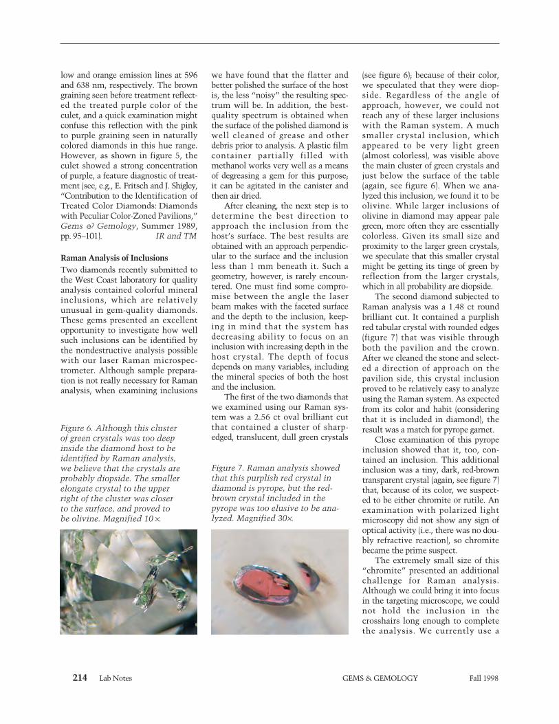
214 Lab Notes GEMS & GEMOLOGY Fall 1998
low and orange emission lines at 596and 638 nm, respectively. The browngraining seen before treatment reflect-ed the treated purple color of theculet, and a quick examination mightconfuse this reflection with the pinkto purple graining seen in naturallycolored diamonds in this hue range.However, as shown in figure 5, theculet showed a strong concentrationof purple, a feature diagnostic of treat-ment (see, e.g., E. Fritsch and J. Shigley,“Contribution to the Identification ofTreated Color Diamonds: Diamondswith Peculiar Color-Zoned Pavilions,”Gems & Gemology, Summer 1989,pp. 95–101). IR and TM
Raman Analysis of InclusionsTwo diamonds recently submitted tothe West Coast laboratory for qualityanalysis contained colorful mineralinclusions, which are relativelyunusual in gem-quality diamonds.These gems presented an excellentopportunity to investigate how wellsuch inclusions can be identified bythe nondestructive analysis possiblewith our laser Raman microspec-trometer. Although sample prepara-tion is not really necessary for Ramananalysis, when examining inclusions
we have found that the flatter andbetter polished the surface of the hostis, the less “noisy” the resulting spec-trum will be. In addition, the best-quality spectrum is obtained whenthe surface of the polished diamond iswell cleaned of grease and otherdebris prior to analysis. A plastic filmcontainer partially filled withmethanol works very well as a meansof degreasing a gem for this purpose;it can be agitated in the canister andthen air dried.
After cleaning, the next step is todetermine the best direction toapproach the inclusion from thehost’s surface. The best results areobtained with an approach perpendic-ular to the surface and the inclusionless than 1 mm beneath it. Such ageometry, however, is rarely encoun-tered. One must find some compro-mise between the angle the laserbeam makes with the faceted surfaceand the depth to the inclusion, keep-ing in mind that the system hasdecreasing ability to focus on aninclusion with increasing depth in thehost crystal. The depth of focusdepends on many variables, includingthe mineral species of both the hostand the inclusion.
The first of the two diamonds thatwe examined using our Raman sys-tem was a 2.56 ct oval brilliant cutthat contained a cluster of sharp-edged, translucent, dull green crystals
(see figure 6); because of their color,we speculated that they were diop-side. Regardless of the angle ofapproach, however, we could notreach any of these larger inclusionswith the Raman system. A muchsmaller crystal inclusion, whichappeared to be very light green(almost colorless), was visible abovethe main cluster of green crystals andjust below the surface of the table(again, see figure 6). When we ana-lyzed this inclusion, we found it to beolivine. While larger inclusions ofolivine in diamond may appear palegreen, more often they are essentiallycolorless. Given its small size andproximity to the larger green crystals,we speculate that this smaller crystalmight be getting its tinge of green byreflection from the larger crystals,which in all probability are diopside.
The second diamond subjected toRaman analysis was a 1.48 ct roundbrilliant cut. It contained a purplishred tabular crystal with rounded edges(figure 7) that was visible throughboth the pavilion and the crown.After we cleaned the stone and select-ed a direction of approach on thepavilion side, this crystal inclusionproved to be relatively easy to analyzeusing the Raman system. As expectedfrom its color and habit (consideringthat it is included in diamond), theresult was a match for pyrope garnet.
Close examination of this pyropeinclusion showed that it, too, con-tained an inclusion. This additionalinclusion was a tiny, dark, red-browntransparent crystal (again, see figure 7)that, because of its color, we suspect-ed to be either chromite or rutile. Anexamination with polarized lightmicroscopy did not show any sign ofoptical activity (i.e., there was no dou-bly refractive reaction), so chromitebecame the prime suspect.
The extremely small size of this“chromite” presented an additionalchallenge for Raman analysis.Although we could bring it into focusin the targeting microscope, we couldnot hold the inclusion in thecrosshairs long enough to completethe analysis. We currently use a
Figure 6. Although this clusterof green crystals was too deepinside the diamond host to beidentified by Raman analysis,we believe that the crystals areprobably diopside. The smallerelongate crystal to the upperright of the cluster was closerto the surface, and proved tobe olivine. Magnified 10 ¥.
Figure 7. Raman analysis showedthat this purplish red crystal indiamond is pyrope, but the red-brown crystal included in thepyrope was too elusive to be ana-lyzed. Magnified 30¥.
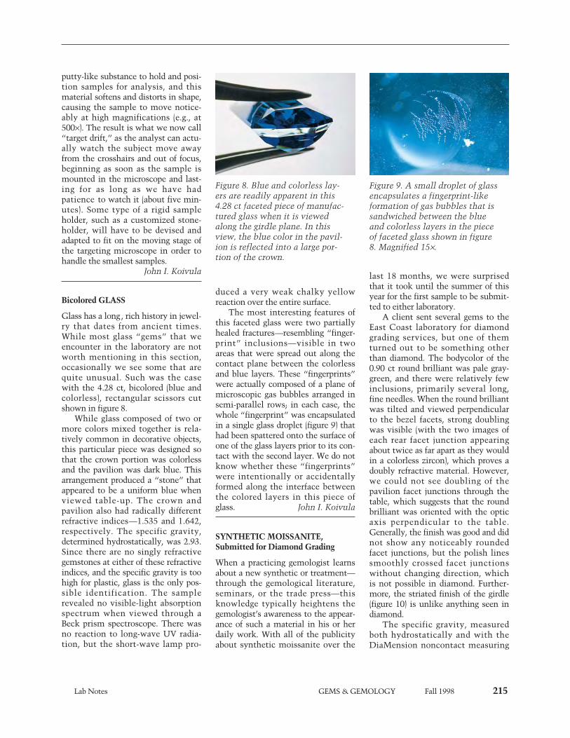
Lab Notes GEMS & GEMOLOGY Fall 1998 215
putty-like substance to hold and posi-tion samples for analysis, and thismaterial softens and distorts in shape,causing the sample to move notice-ably at high magnifications (e.g., at500¥). The result is what we now call“target drift,” as the analyst can actu-ally watch the subject move awayfrom the crosshairs and out of focus,beginning as soon as the sample ismounted in the microscope and last-ing for as long as we have hadpatience to watch it (about five min-utes). Some type of a rigid sampleholder, such as a customized stone-holder, will have to be devised andadapted to fit on the moving stage ofthe targeting microscope in order tohandle the smallest samples.
John I. Koivula
Bicolored GLASS
Glass has a long, rich history in jewel-ry that dates from ancient times.While most glass “gems” that weencounter in the laboratory are notworth mentioning in this section,occasionally we see some that arequite unusual. Such was the casewith the 4.28 ct, bicolored (blue andcolorless), rectangular scissors cutshown in figure 8.
While glass composed of two ormore colors mixed together is rela-tively common in decorative objects,this particular piece was designed sothat the crown portion was colorlessand the pavilion was dark blue. Thisarrangement produced a “stone” thatappeared to be a uniform blue whenviewed table-up. The crown andpavilion also had radically differentrefractive indices—1.535 and 1.642,respectively. The specific gravity,determined hydrostatically, was 2.93.Since there are no singly refractivegemstones at either of these refractiveindices, and the specific gravity is toohigh for plastic, glass is the only pos-sible identification. The samplerevealed no visible-light absorptionspectrum when viewed through aBeck prism spectroscope. There wasno reaction to long-wave UV radia-tion, but the short-wave lamp pro-
duced a very weak chalky yellowreaction over the entire surface.
The most interesting features ofthis faceted glass were two partiallyhealed fractures—resembling “finger-print” inclusions—visible in twoareas that were spread out along thecontact plane between the colorlessand blue layers. These “fingerprints”were actually composed of a plane ofmicroscopic gas bubbles arranged insemi-parallel rows; in each case, thewhole “fingerprint” was encapsulatedin a single glass droplet (figure 9) thathad been spattered onto the surface ofone of the glass layers prior to its con-tact with the second layer. We do notknow whether these “fingerprints”were intentionally or accidentallyformed along the interface betweenthe colored layers in this piece ofglass. John I. Koivula
SYNTHETIC MOISSANITE,Submitted for Diamond Grading
When a practicing gemologist learnsabout a new synthetic or treatment—through the gemological literature,seminars, or the trade press—thisknowledge typically heightens thegemologist’s awareness to the appear-ance of such a material in his or herdaily work. With all of the publicityabout synthetic moissanite over the
last 18 months, we were surprisedthat it took until the summer of thisyear for the first sample to be submit-ted to either laboratory.
A client sent several gems to theEast Coast laboratory for diamondgrading services, but one of themturned out to be something otherthan diamond. The bodycolor of the0.90 ct round brilliant was pale gray-green, and there were relatively fewinclusions, primarily several long,fine needles. When the round brilliantwas tilted and viewed perpendicularto the bezel facets, strong doublingwas visible (with the two images ofeach rear facet junction appearingabout twice as far apart as they wouldin a colorless zircon), which proves adoubly refractive material. However,we could not see doubling of thepavilion facet junctions through thetable, which suggests that the roundbrilliant was oriented with the opticaxis perpendicular to the table.Generally, the finish was good and didnot show any noticeably roundedfacet junctions, but the polish linessmoothly crossed facet junctionswithout changing direction, which is not possible in diamond. Further-more, the striated finish of the girdle(figure 10) is unlike anything seen indiamond.
The specific gravity, measuredboth hydrostatically and with theDiaMension noncontact measuring
Figure 8. Blue and colorless lay-ers are readily apparent in this4.28 ct faceted piece of manufac-tured glass when it is viewedalong the girdle plane. In thisview, the blue color in the pavil-ion is reflected into a large por-tion of the crown.
Figure 9. A small droplet of glassencapsulates a fingerprint-likeformation of gas bubbles that issandwiched between the blueand colorless layers in the pieceof faceted glass shown in figure8. Magnified 15¥.

216 Lab Notes GEMS & GEMOLOGY Fall 1998
system, was 3.22. In combinationwith the doubling, inclusions, andcolor, this identified the material assynthetic moissanite. The sample flu-oresced a very weak orange to long-wave UV radiation and was inert toshort-wave UV. The strong dispersionwas also observed as orange and blueflashes that were visible with themicroscope when the syntheticmoissanite was viewed culet up. Acutoff at 420 nm was seen with adesk-model spectroscope. As expectedfor synthetic moissanite, the sampleshowed a high level of thermal con-ductivity, yielding a reading of “dia-mond” on the thermal probe. Allthese properties are consistent withthe samples described by K. Nassauet al. in “Synthetic Moissanite: ANew Diamond Substitute” (Gems &Gemology, Winter 1997, pp. 260–275).
Coincidentally, as we were prepar-ing this note, another round brilliant(1.31 ct) was submitted to the EastCoast lab for diamond grading; theproperties of this “stone” were verysimilar to those of the first example.The West Coast lab reported seeing athird synthetic moissanite round bril-liant, of 1.25 ct, within a few days ofthe other two. Note that all threesamples were somewhat larger thanthe synthetic moissanites examinedfor the Gems & Gemology article.
GRC and TM
PEARLS, Freshwater Cultured
In the late 1950s, our laboratoriesbegan to encounter the first freshwa-ter tissue-nucleated cultured pearls.One of the editors recalls that theseearly white and pastel-colored cul-tured pearls, then exclusively fromLake Biwa in Japan, were sometimesreferred to in the trade as naturalpearls. The FTC guidelines at thattime defined a cultured pearl as “thecomposite product created when anucleus (usually a sphere of calcare-ous mollusk shell) planted by maninside the shell or in the mantle of amollusk is coated with nacre by themollusk.” This led to some confusionas to how these tissue-nucleatedpearls should be described. (Lack ofthe word cultured on export papersfor those pearls added to the confu-sion.) Through the 1960s, the tradeand the testing laboratories recog-nized this product as resulting fromthe combined efforts of human andmollusk, and for the most part theywere represented properly as culturedpearls.
The early production attained amaximum length of about 7.5 mm forthe ovals, and diameters of about 6 mmfor the rounds (G. R. Crowningshield,“Fresh-Water Cultured Pearls,” Gems& Gemology, Vol. 10, No. 9, 1962, pp.259–274). The size range of these cul-tured pearls varied little for threedecades. During the last five years,however, we have reported on some-what larger sizes and shapes that arerounder (Summer 1994 Lab Notes, p.118). China now dominates the pro-duction of these tissue-nucleated cul-tured pearls, especially in the largersizes. G. Bosshart and others havedescribed freshwater pearl culturingin Vietnam (“Freshwater PearlCultivation in Vietnam,” Journal ofGemmology, Vol. 23, No. 6, 1993, pp.326–332), where the sizes remainsmaller.
The necklaces shown in figure 11were examined recently in the EastCoast lab; they represent a dramaticincrease in the size of Chinese fresh-water tissue-nucleated cultured pearls(D. Federman, Gem Profile, Modern
Jeweler, June 1998, pp. 59–60). Thelengths of these primarily oval cul-tured pearls reach up to 15 mm, andtheir widths reach up to 13 mm. Thecolors include both white and pastelshades, similar to those we firstencountered in the 1950s. In thesesizes, this product now provides aninteresting and attractive alternativeto South Seas cultured pearls.
GRC and TM
QUARTZ: A Large “Crystal Ball”
Rock crystal quartz should be an easymaterial to separate from other gems;however, synthetic quartz looks verymuch like the natural material.Recently, the West Coast laboratoryreceived a large sphere, 9.6 cm indiameter (about 3 3/4 inches), for iden-tification. That it was quartz was evi-dent: The sphere had a (spot) refrac-tive index of 1.54 and a very good“bull’s-eye” optic figure. In addition,printing viewed through the sphereappeared doubled. It was inert to bothlong- and short-wave UV radiation.Because synthetic quartz is manufac-tured hydrothermally, we suspectedthat it was not available in the sizethat would have been needed to cutthis very clean sphere (without a seedplate being present), but we could notcall the piece natural without moreconclusive evidence. As is so oftenthe case in such situations, we had torely on distinctive inclusions.
However, even finding inclusionswas a significant challenge in such alarge object with a curved surface.The sphere was eye-clean and toolarge to focus through with the micro-scope. We tried using diffuse illumi-nation to locate any dark or opaqueinclusions, and we used red-filteredfiber-optic illumination in the hopethat any inclusions would appear asred sparkles within the stone. Thetechnique that finally prevailed wasto set the sphere against the well ofthe microscope’s darkfield illumina-tor, and then to look from the side forany sign of light bouncing off any fea-tures within the sphere. (The roundopening of the darkfield illuminator
Figure 10. The subtle striationson the girdle of this 0.90 ctround brilliant are typical offaceted synthetic moissanite,but this texture is unlike thefaceted, polished, or bruted fin-ish found on the girdle of a dia-mond. Magnified 50¥.
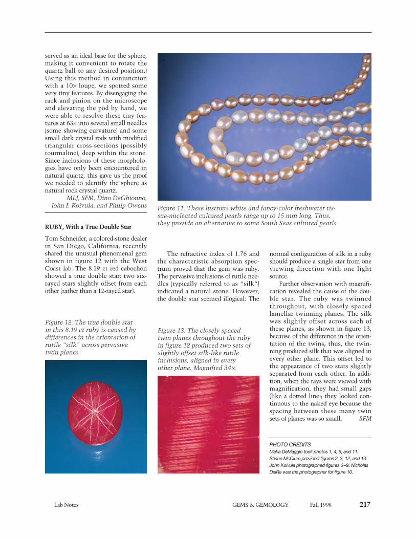
Lab Notes GEMS & GEMOLOGY Fall 1998 217
served as an ideal base for the sphere,making it convenient to rotate thequartz ball to any desired position.)Using this method in conjunctionwith a 10¥ loupe, we spotted somevery tiny features. By disengaging therack and pinion on the microscopeand elevating the pod by hand, wewere able to resolve these tiny fea-tures at 63¥ into several small needles(some showing curvature) and somesmall dark crystal rods with modifiedtriangular cross-sections (possiblytourmaline), deep within the stone.Since inclusions of these morpholo-gies have only been encountered innatural quartz, this gave us the proofwe needed to identify the sphere asnatural rock crystal quartz.
MLJ, SFM, Dino DeGhionno, John I. Koivula, and Philip Owens
RUBY, With a True Double Star
Tom Schneider, a colored-stone dealerin San Diego, California, recentlyshared the unusual phenomenal gemshown in figure 12 with the WestCoast lab. The 8.19 ct red cabochonshowed a true double star: two six-rayed stars slightly offset from eachother (rather than a 12-rayed star).
The refractive index of 1.76 andthe characteristic absorption spec-trum proved that the gem was ruby.The pervasive inclusions of rutile nee-dles (typically referred to as “silk”)indicated a natural stone. However,the double star seemed illogical: The
normal configuration of silk in a rubyshould produce a single star from oneviewing direction with one lightsource.
Further observation with magnifi-cation revealed the cause of the dou-ble star. The ruby was twinnedthroughout, with closely spacedlamellar twinning planes. The silkwas slightly offset across each ofthese planes, as shown in figure 13,because of the difference in the orien-tation of the twins; thus, the twin-ning produced silk that was aligned inevery other plane. This offset led tothe appearance of two stars slightlyseparated from each other. In addi-tion, when the rays were viewed withmagnification, they had small gaps(like a dotted line); they looked con-tinuous to the naked eye because thespacing between these many twinsets of planes was so small. SFM
PHOTO CREDITSMaha DeMaggio took photos 1, 4, 5, and 11.Shane McClure provided figures 2, 3, 12, and 13.John Koivula photographed figures 6–9. NicholasDelRe was the photographer for figure 10.
Figure 11. These lustrous white and fancy-color freshwater tis-sue-nucleated cultured pearls range up to 15 mm long. Thus,they provide an alternative to some South Seas cultured pearls.
Figure 12. The true double starin this 8.19 ct ruby is caused bydifferences in the orientation ofrutile “silk” across pervasivetwin planes.
Figure 13. The closely spacedtwin planes throughout the rubyin figure 12 produced two sets ofslightly offset silk-like rutileinclusions, aligned in everyother plane. Magnified 34¥.
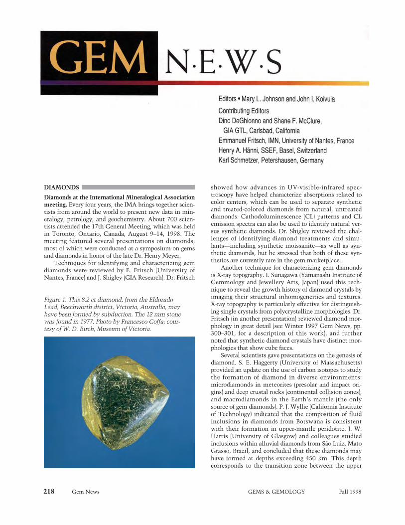
218 Gem News GEMS & GEMOLOGY Fall 1998
DIAMONDS
Diamonds at the International Mineralogical Associationmeeting. Every four years, the IMA brings together scien-tists from around the world to present new data in min-eralogy, petrology, and geochemistry. About 700 scien-tists attended the 17th General Meeting, which was heldin Toronto, Ontario, Canada, August 9–14, 1998. Themeeting featured several presentations on diamonds,most of which were conducted at a symposium on gemsand diamonds in honor of the late Dr. Henry Meyer.
Techniques for identifying and characterizing gemdiamonds were reviewed by E. Fritsch (University ofNantes, France) and J. Shigley (GIA Research). Dr. Fritsch
showed how advances in UV-visible-infrared spec-troscopy have helped characterize absorptions related tocolor centers, which can be used to separate syntheticand treated-colored diamonds from natural, untreateddiamonds. Cathodoluminescence (CL) patterns and CLemission spectra can also be used to identify natural ver-sus synthetic diamonds. Dr. Shigley reviewed the chal-lenges of identifying diamond treatments and simu-lants—including synthetic moissanite—as well as syn-thetic diamonds, but he stressed that both of these syn-thetics are currently rare in the gem marketplace.
Another technique for characterizing gem diamondsis X-ray topography. I. Sunagawa (Yamanashi Institute ofGemmology and Jewellery Arts, Japan) used this tech-nique to reveal the growth history of diamond crystals byimaging their structural inhomogeneities and textures.X-ray topography is particularly effective for distinguish-ing single crystals from polycrystalline morphologies. Dr.Fritsch (in another presentation) reviewed diamond mor-phology in great detail (see Winter 1997 Gem News, pp.300–301, for a description of this work), and furthernoted that synthetic diamond crystals have distinct mor-phologies that show cube faces.
Several scientists gave presentations on the genesis ofdiamond. S. E. Haggerty (University of Massachusetts)provided an update on the use of carbon isotopes to studythe formation of diamond in diverse environments:microdiamonds in meteorites (presolar and impact ori-gins) and deep crustal rocks (continental collision zones),and macrodiamonds in the Earth’s mantle (the onlysource of gem diamonds). P. J. Wyllie (California Instituteof Technology) indicated that the composition of fluidinclusions in diamonds from Botswana is consistentwith their formation in upper-mantle peridotite. J. W.Harris (University of Glasgow) and colleagues studiedinclusions within alluvial diamonds from São Luiz, MatoGrasso, Brazil, and concluded that these diamonds mayhave formed at depths exceeding 450 km. This depthcorresponds to the transition zone between the upper
Figure 1. This 8.2 ct diamond, from the EldoradoLead, Beechworth district, Victoria, Australia, mayhave been formed by subduction. The 12 mm stonewas found in 1977. Photo by Francesco Coffa; cour-tesy of W. D. Birch, Museum of Victoria.

Gem News GEMS & GEMOLOGY Fall 1998 219
and lower mantle, and is almost three times deeperthan areas where most gem-quality diamonds arethought to form.
In studies of gem diamonds from Australia, W. D.Birch (Museum of Victoria, Australia) pointed out thatthe sporadic association of gem-quality diamonds (figure1) with gem corundum and zircon in Victoria is consis-tent with a subduction model that has been proposed forthe origin of these diamonds. F. L. Sutherland (AustralianMuseum, Sydney) and colleagues indicated that thesource of Copeton diamonds in New South Wales is stillan enigma; these diamonds contain such unusual inclu-sions as coesite and scapolite.
There were many presentations on gem diamondsfrom Russia. T. V. Possoukhova (Moscow StateUniversity) and colleagues examined diamonds from sev-eral deposits in the Arkhangelsk region. Morphologic andspectroscopic studies have shown that diamonds fromkimberlites in the northern east-European and Siberianplatforms are typically rounded rhombododecahedra thatare type Ia. The morphology of these diamonds wasattributed to resorption during the transportation of dia-monds in kimberlite magma. At the Pionerskaya pipe inYakutia, macrodiamonds from the upper horizons showmorphologies that are typical of kimberlitic diamonds,whereas at depth microdiamonds with an unusual skele-tal morphology were recovered, resembling diamondsfound in metamorphic rocks. At the M. V. Lomonosovadeposit, diamonds apparently formed in several stagesunder oxidizing conditions, as indicated by their mor-phology, nitrogen aggregation state, isotopic composi-tion, and fluid inclusions. A. B. Makeyev and colleagues(Russian Academy of Sciences, Ukhta) reported that dia-monds are found with placer gold at the Ichetju alluvialdeposit (Middle Timan platform); a high proportion ofthe diamonds are gem quality, and many colors havebeen found (e.g., yellow, green, and brown). A. A.Rogozhin and colleagues (VIMS, Moscow) described theconcentration of fluorescent minerals (calcite, apatite,and zircon) around the kimberlite pipes in theArkhangelsk region, and proposed that such haloesmight be useful in prospecting for kimberlite pipes.
In other presentations, J. E. Butler (Naval ResearchLaboratory, Washington, D.C.) noted that drusy plates ofsynthetic diamonds grown by chemical vapor deposition(CVD) may reach 300 mm in diameter and 1 mm thick;he showed some interesting jewelry that incorporatedCVD druses. Finally, G. Harlow (American Museum ofNatural History, New York) pointed out that diamondsare quite seductive learning aids: Visitors stayed at “TheNature of Diamonds” exhibit three times longer (i.e., onehour) than is typical for the museum’s other exhibits.
Update on the Ekati project, Northwest Territories,Canada. According to BHP Ltd. press releases, diamondshave been found in two additional small pipes in theEkati project area at Lac de Gras. The 0.6 hectare Koala
North pipe (which is under the same lake as the already-studied Koala pipe) yielded 126.5 carats from 201.7 tonsof ore, for a grade of 0.63 ct/ton; the 1 hectare Beartoothpipe, 900 m north of the Panda pipe (the first pipe to bemined—others include Misery, Koala, Fox, and Sable),yielded 227 carats from 189.3 tons of ore (grade of 1.20ct/ton). The stones were evaluated in Antwerp in May;the Beartooth sample was valued conservatively atUS$79/ct, and the Koala North sample was valued at$200/ct. Much of the value of the Koala North samplecame from three gem-quality stones, which weighed 3.26to 5.41 ct.
Construction at the Ekati diamond mine is nearlycomplete, and the first production is expected in October1998 from the Panda open pit. Evaluation of other pipesin the area is proceeding. In late May, the joint-venturepartners (BHP Diamonds Inc., Dia Met Minerals Ltd.,and individuals Charles E. Fipke and Stewart Blusson)agreed that BHP Diamonds Inc. would be the sales repre-sentative for the Ekati venture.
COLORED STONES
Amethyst from Arizona. Faceted amethyst is again beingproduced at the historic Four Peaks mine in MaricopaCounty, near Phoenix. The deposit was originally discov-ered at the turn of the century, and is located in therugged Mazatzal Mountain Range at an altitude of 2,200m (7,200 feet). After more than 20 years of inactivity, themine has been purchased and reopened by a joint venturebetween Commercial Mineral Co. (the sole distributor ofthe material) and Four Peaks Mining Co. (mining opera-tions management). According to Mike Romanella ofCommercial Mineral Co., Scottsdale, Arizona, about2,000 carats of calibrated goods in many shapes are avail-able in sizes from 0.5 to 2 ct; very limited quantities of2–6 ct stones are also being sold (figure 2). The small sizeof faceted stones is due to the nature of the rough, whichis color zoned and included. Because the partners are cut-ting only “high-quality” stones, the yield of faceted
Figure 2. The historic Four Peaks mine in Arizonais again producing amethyst. These brilliant cuts,shown next to a rough crystal, weigh approximate-ly 6 and 4 ct. Photo © Jeff Scovil; courtesy ofCommercial Mineral Co.
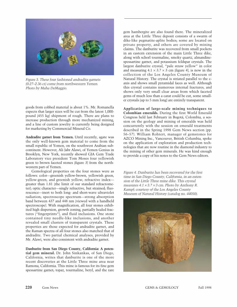
220 Gem News GEMS & GEMOLOGY Fall 1998
goods from cobbed material is about 1%. Mr. Romanellaexpects that larger sizes will be cut from the latest 1,000-pound (455 kg) shipment of rough. There are plans toincrease production through more mechanized mining,and a line of custom jewelry is currently being designedfor marketing by Commercial Mineral Co.
Andradite garnet from Yemen. Until recently, agate wasthe only well-known gem material to come from thesmall republic of Yemen, on the southwest Arabian sub-continent. However, Ali Jabr Alawi, of Yemen Genius inBrooklyn, New York, recently showed GIA Gem TradeLaboratory vice president Tom Moses four yellowishgreen to brown faceted stones (figure 3) from the north-western part of Yemen.
Gemological properties on the four stones were asfollows: color—greenish yellow-brown, yellowish green,yellow-green, and greenish yellow; refractive index—greater than 1.81 (the limit of our standard refractome-ter); optic character—singly refractive, but strained; fluo-rescence—inert to both long- and short-wave ultravioletradiation; spectroscope spectrum—strong absorptionband between 437 and 448 nm (viewed with a handheldspectroscope). With magnification, all four stones exhib-ited high dispersion, growth zoning, partially healed frac-tures (“fingerprints”), and fluid inclusions. One stonecontained tiny needle-like inclusions, and anotherrevealed small clusters of transparent crystals. Theseproperties are those expected for andradite garnet, andthe Raman spectra of all four stones also matched that ofandradite. Two partial chemical analyses, provided byMr. Alawi, were also consistent with andradite garnet.
Danburite from San Diego County, California: A poten-tial gem mineral. Dr. John Sinkankas, of San Diego,California, writes that danburite is one of the morerecent discoveries at the Little Three mine area nearRamona, California. This mine is famous for its fine gemspessartine garnet; topaz, tourmaline, beryl, and the rare
gem hambergite are also found there. The mineralizedarea at the Little Three deposit consists of a swarm ofdike-like pegmatite-aplite bodies; some are located onprivate property, and others are covered by miningclaims. The danburite was recovered from small pocketsin an eastern extension of the main Little Three dike,along with schorl tourmaline, smoky quartz, almandine-spessartine garnet, and potassium feldspar crystals. Thelargest danburite crystal, “pale straw yellow” in colorand measuring 4.1 ¥ 3.7 ¥ 3 cm (figure 4), is now in thecollection of the Los Angeles County Museum ofNatural History. The crystal is striated parallel to the c-axis and shows small pyramidal faces as well. Althoughthis crystal contains numerous internal fractures, andshows only very small clear areas from which facetedgems of much less than a carat could be cut, some small-er crystals (up to 5 mm long) are entirely transparent.
Application of large-scale mining techniques toColombian emeralds. During the first World EmeraldCongress held last February in Bogotá, Colombia, a ses-sion on the geology and mining of emeralds was heldconcurrently with the session on emerald treatmentsdescribed in the Spring 1998 Gem News section (pp.56–57). William Rohtert, manager of gemstones forAZCO Mining Inc., Vancouver, British Columbia, spokeon the application of exploration and production tech-nologies that are now routine in the diamond industry tothe mining of other gem minerals. He was kind enoughto provide a copy of his notes to the Gem News editors.
Figure 4. Danburite has been recovered for the firsttime in San Diego County, California, in an exten-sion of the Little Three mine dike. This crystalmeasures 4.1 ¥ 3.7 ¥ 3 cm. Photo by Anthony R.Kampf; courtesy of the Los Angeles CountyMuseum of Natural History (catalog no. 44050).
Figure 3. These four fashioned andradite garnets(0.27–2.36 ct) come from northwestern Yemen.Photo by Maha DeMaggio.

Gem News GEMS & GEMOLOGY Fall 1998 221
In the future, Colombian emerald deposits could beexploited systematically using an integrated approachthat combines: (1) remote sensing to locate mineral dis-tricts; (2) detailed investigations of the geology, geochem-istry, and geophysics of the mine sites; (3) measurementof mineable reserves, with data derived from coredrilling; (4) mechanized mining; and (5) automatedextraction of the emeralds from their host rocks. Thisapproach, unfortunately, can be expensive: A “pioneer”evaluation of the red beryl deposit in the United Statescost Kennecott Exploration Company about $20 million,or $4.00 per (polished) carat of the proven reserves. (Mr.Rohtert notes, however, that about half these costs wererelated to research, administration, and marketing.)
Although satellite-based remote sensing works bestin arid terrains, a promising technique for mappingemerald districts in vegetation-rich Colombia is side-scan radar. In addition, the broad haloes of pyrite thatsurround cenicero (the ash-colored altered black shale inColombian emerald deposits) might be detected usingairborne electromagnetic surveys.
Delineation of an emerald deposit on the ground stillrelies on field geology to map structural and stratigraphiccontrols on the mineralization. Also, soils overlying pro-ductive veins show elevated ratios of sodium relative topotassium; dispersion haloes containing parisite, apatite,and fluorite with elevated contents of rare-earth ele-ments are known to be indicative of mineralization. Atype of surface geophysical technique (controlled sourceaudio-frequency magneto-tellurics, or CSAMT) wouldprobably detect the carbonaceous alteration haloes sur-rounding emerald veins to depths of 610 m (2,000 feet),as well as the diffuse pyrite concentrations that typicallysurround the ore.
Even the tiniest emeralds recovered from drill coresand bulk samples may be used to determine statisticallythe likelihood of finding large gems in the deposit.Caustic fusion in high-temperature lye dissolves the hostrock and releases the beryl; pulsed-power disaggregationcan serve the same purpose. The microcrystals andmacrocrystals are collected and measured, and a log-nor-mal plot of stone frequency versus size enables predic-tion of the grade and extrapolation of the relative abun-dance of any gem mineral by weight.
Extraction techniques should be appropriate to thematerial being mined. Large volumes of low-qualitymaterial should be mined rapidly using bulk techniques,including mechanized mining, but zones with high-qual-ity material should be mined slowly and carefully. Toolsfor the select removal of large, high-value gemstonesinclude hydraulic wedges, expansion polymers, abrasionguns, and portable diamond saws. Mechanized mining“robots” could mine rock faces continuously (with norisk of loss by theft).
The large volumes of bulk-mined ore could be pro-cessed using a variety of modern techniques. For exam-ple, biochemical leaching uses bacteria to break down
iron, sulfur, and organic material in the ore, and liberatethe emeralds into a concentrate for collection.Automated techniques to remove emeralds from theconcentrate could include optic sorters or berylometers(which induce and detect short-lived radioactivity inberyllium minerals).
Most of these exploration and production techniquesare expensive: Geophysical surveys can cost up to$50,000 per district, and berylometers cost about$250,000 each. One major concern is that modern min-ing and extraction techniques greatly reduce the need forlow-skilled labor—that is, the garimpeiros who currentlyform the backbone of the Colombian emerald miningindustry. If the modernized emerald mine cannot supportthe surrounding towns in the district, the social costsmust also be considered.
Gem-quality grossular garnet from Mali. When “Gem-Quality Grossular-Andradite: A New Garnet from Mali”(M. L. Johnson et al., Gems & Gemology, Fall 1995, pp.152–166) was written, we had seen garnets from thisregion in three color types: orange to brown, somewhatdesaturated yellow-green, and bright green. All werefound to be grossular-andradite. Subsequently, however,Mark Kaufman of Kaufman Enterprises, San Diego,California, loaned one of the editors three pale, slightlyyellowish green garnets, also reportedly from Mali (west-ern Africa), that proved to be otherwise. All threestones—one 6.37 ct pear (figure 5) and two oval (4.18 ctand 5.32 ct) modified brilliants—were much paler in tonethan the grossular-andradites we had previously exam-ined and, therefore, looked more like greenish yellowgrossular garnet from other localities (such as EastAfrica). Also, all three had refractive indices between1.739 and 1.750, again in the “typical” grossular range,and outside the range we use as a criterion for grossular-andradite (1.752 and over, but not greater than 1.81).
Figure 5. This 6.37 ct pear-shaped garnet, reported-ly from Mali, was identified as grossular and notgrossular-andradite, on the basis of its refractiveindex. Courtesy of Kaufman Enterprises; photo byMaha DeMaggio.
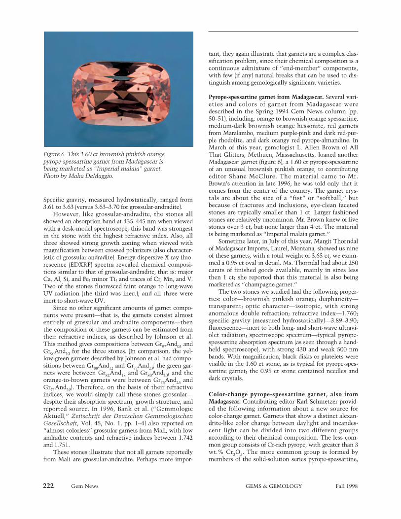
222 Gem News GEMS & GEMOLOGY Fall 1998
Specific gravity, measured hydrostatically, ranged from3.61 to 3.63 (versus 3.63–3.70 for grossular-andradite).
However, like grossular-andradite, the stones allshowed an absorption band at 435–445 nm when viewedwith a desk-model spectroscope; this band was strongestin the stone with the highest refractive index. Also, allthree showed strong growth zoning when viewed withmagnification between crossed polarizers (also character-istic of grossular-andradite). Energy-dispersive X-ray fluo-rescence (EDXRF) spectra revealed chemical composi-tions similar to that of grossular-andradite, that is: majorCa, Al, Si, and Fe; minor Ti; and traces of Cr, Mn, and V.Two of the stones fluoresced faint orange to long-waveUV radiation (the third was inert), and all three wereinert to short-wave UV.
Since no other significant amounts of garnet compo-nents were present—that is, the garnets consist almostentirely of grossular and andradite components—thenthe composition of these garnets can be estimated fromtheir refractive indices, as described by Johnson et al.This method gives compositions between Gr97And03 andGr90And10 for the three stones. (In comparison, the yel-low-green garnets described by Johnson et al. had compo-sitions between Gr88And12 and Gr77And23; the green gar-nets were between Gr82And18 and Gr80And20; and theorange-to-brown garnets were between Gr75And25 andGr71And29). Therefore, on the basis of their refractiveindices, we would simply call these stones grossular—despite their absorption spectrum, growth structure, andreported source. In 1996, Bank et al. (“GemmologieAktuell,” Zeitschrift der Deutschen GemmologischenGesellschaft, Vol. 45, No. 1, pp. 1–4) also reported on“almost colorless” grossular garnets from Mali, with lowandradite contents and refractive indices between 1.742and 1.751.
These stones illustrate that not all garnets reportedlyfrom Mali are grossular-andradite. Perhaps more impor-
tant, they again illustrate that garnets are a complex clas-sification problem, since their chemical composition is acontinuous admixture of “end-member” components,with few (if any) natural breaks that can be used to dis-tinguish among gemologically significant varieties.
Pyrope-spessartine garnet from Madagascar. Several vari-eties and colors of garnet from Madagascar weredescribed in the Spring 1994 Gem News column (pp.50–51), including: orange to brownish orange spessartine,medium-dark brownish orange hessonite, red garnetsfrom Maralambo, medium purple-pink and dark red-pur-ple rhodolite, and dark orangy red pyrope-almandine. InMarch of this year, gemologist L. Allen Brown of AllThat Glitters, Methuen, Massachusetts, loaned anotherMadagascar garnet (figure 6), a 1.60 ct pyrope-spessartineof an unusual brownish pinkish orange, to contributingeditor Shane McClure. The material came to Mr.Brown’s attention in late 1996; he was told only that itcomes from the center of the country. The garnet crys-tals are about the size of a “fist” or “softball,” butbecause of fractures and inclusions, eye-clean facetedstones are typically smaller than 1 ct. Larger fashionedstones are relatively uncommon. Mr. Brown knew of fivestones over 3 ct, but none larger than 4 ct. The materialis being marketed as “Imperial malaia garnet.”
Sometime later, in July of this year, Margit Thorndalof Madagascar Imports, Laurel, Montana, showed us nineof these garnets, with a total weight of 3.65 ct; we exam-ined a 0.95 ct oval in detail. Ms. Thorndal had about 250carats of finished goods available, mainly in sizes lessthen 1 ct; she reported that this material is also beingmarketed as “champagne garnet.”
The two stones we studied had the following proper-ties: color—brownish pinkish orange; diaphaneity—transparent; optic character—isotropic, with stronganomalous double refraction; refractive index—1.760;specific gravity (measured hydrostatically)—3.89–3.90;fluorescence—inert to both long- and short-wave ultravi-olet radiation; spectroscope spectrum—typical pyrope-spessartine absorption spectrum (as seen through a hand-held spectroscope), with strong 430 and weak 500 nmbands. With magnification, black disks or platelets werevisible in the 1.60 ct stone, as is typical for pyrope-spes-sartine garnet; the 0.95 ct stone contained needles anddark crystals.
Color-change pyrope-spessartine garnet, also fromMadagascar. Contributing editor Karl Schmetzer provid-ed the following information about a new source forcolor-change garnet. Garnets that show a distinct alexan-drite-like color change between daylight and incandes-cent light can be divided into two different groupsaccording to their chemical composition. The less com-mon group consists of Cr-rich pyrope, with greater than 3wt.% Cr2O3. The more common group is formed bymembers of the solid-solution series pyrope-spessartine,
Figure 6. This 1.60 ct brownish pinkish orangepyrope-spessartine garnet from Madagascar isbeing marketed as “Imperial malaia” garnet.Photo by Maha DeMaggio.
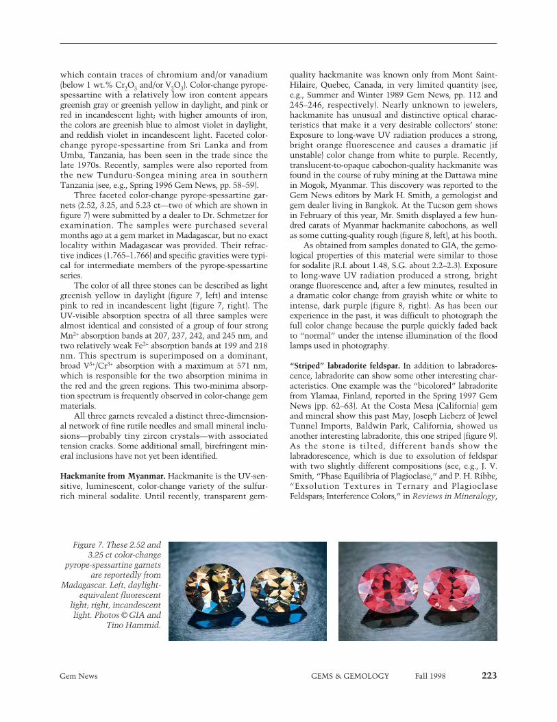
Gem News GEMS & GEMOLOGY Fall 1998 223
which contain traces of chromium and/or vanadium(below 1 wt.% Cr2O3 and/or V2O3). Color-change pyrope-spessartine with a relatively low iron content appearsgreenish gray or greenish yellow in daylight, and pink orred in incandescent light; with higher amounts of iron,the colors are greenish blue to almost violet in daylight,and reddish violet in incandescent light. Faceted color-change pyrope-spessartine from Sri Lanka and fromUmba, Tanzania, has been seen in the trade since thelate 1970s. Recently, samples were also reported fromthe new Tunduru-Songea mining area in southernTanzania (see, e.g., Spring 1996 Gem News, pp. 58–59).
Three faceted color-change pyrope-spessartine gar-nets (2.52, 3.25, and 5.23 ct—two of which are shown infigure 7) were submitted by a dealer to Dr. Schmetzer forexamination. The samples were purchased severalmonths ago at a gem market in Madagascar, but no exactlocality within Madagascar was provided. Their refrac-tive indices (1.765–1.766) and specific gravities were typi-cal for intermediate members of the pyrope-spessartineseries.
The color of all three stones can be described as lightgreenish yellow in daylight (figure 7, left) and intensepink to red in incandescent light (figure 7, right). TheUV-visible absorption spectra of all three samples werealmost identical and consisted of a group of four strongMn2+ absorption bands at 207, 237, 242, and 245 nm, andtwo relatively weak Fe2+ absorption bands at 199 and 218nm. This spectrum is superimposed on a dominant,broad V3+/Cr3+ absorption with a maximum at 571 nm,which is responsible for the two absorption minima inthe red and the green regions. This two-minima absorp-tion spectrum is frequently observed in color-change gemmaterials.
All three garnets revealed a distinct three-dimension-al network of fine rutile needles and small mineral inclu-sions—probably tiny zircon crystals—with associatedtension cracks. Some additional small, birefringent min-eral inclusions have not yet been identified.
Hackmanite from Myanmar. Hackmanite is the UV-sen-sitive, luminescent, color-change variety of the sulfur-rich mineral sodalite. Until recently, transparent gem-
quality hackmanite was known only from Mont Saint-Hilaire, Quebec, Canada, in very limited quantity (see,e.g., Summer and Winter 1989 Gem News, pp. 112 and245–246, respectively). Nearly unknown to jewelers,hackmanite has unusual and distinctive optical charac-teristics that make it a very desirable collectors’ stone:Exposure to long-wave UV radiation produces a strong,bright orange fluorescence and causes a dramatic (ifunstable) color change from white to purple. Recently,translucent-to-opaque cabochon-quality hackmanite wasfound in the course of ruby mining at the Dattawa minein Mogok, Myanmar. This discovery was reported to theGem News editors by Mark H. Smith, a gemologist andgem dealer living in Bangkok. At the Tucson gem showsin February of this year, Mr. Smith displayed a few hun-dred carats of Myanmar hackmanite cabochons, as wellas some cutting-quality rough (figure 8, left), at his booth.
As obtained from samples donated to GIA, the gemo-logical properties of this material were similar to thosefor sodalite (R.I. about 1.48, S.G. about 2.2–2.3). Exposureto long-wave UV radiation produced a strong, brightorange fluorescence and, after a few minutes, resulted ina dramatic color change from grayish white or white tointense, dark purple (figure 8, right). As has been ourexperience in the past, it was difficult to photograph thefull color change because the purple quickly faded backto “normal” under the intense illumination of the floodlamps used in photography.
“Striped” labradorite feldspar. In addition to labradores-cence, labradorite can show some other interesting char-acteristics. One example was the “bicolored” labradoritefrom Ylamaa, Finland, reported in the Spring 1997 GemNews (pp. 62–63). At the Costa Mesa (California) gemand mineral show this past May, Joseph Lieberz of JewelTunnel Imports, Baldwin Park, California, showed usanother interesting labradorite, this one striped (figure 9).As the stone is tilted, different bands show thelabradorescence, which is due to exsolution of feldsparwith two slightly different compositions (see, e.g., J. V.Smith, “Phase Equilibria of Plagioclase,” and P. H. Ribbe,“Exsolution Textures in Ternary and PlagioclaseFeldspars; Interference Colors,” in Reviews in Mineralogy,
Figure 7. These 2.52 and3.25 ct color-change
pyrope-spessartine garnetsare reportedly from
Madagascar. Left, daylight-equivalent fluorescent
light; right, incandescentlight. Photos © GIA and
Tino Hammid.

224 Gem News GEMS & GEMOLOGY Fall 1998
2nd ed., Vol. 2, Feldspar Mineralogy, MineralogicalSociety of America, Washington, DC, 1983, pp. 223–239and 241–270, respectively). However, this particular sam-ple demonstrates at least two events: the twinning thatcaused the labradorescent bands to change orientationrelative to one another, and the exsolution that causedthe labradorescence itself.
The 126.71 ct octagonal cabochon came from theextensive deposits in Madagascar, near the village of
Bekily in Tulear Province. This is one of the most prolif-ic sources in the world for small pieces of labradorite,and tons of material are mined every year. (Jewel Tunnelalone imports about 2 tons of labradorite each year.) Thelargest pieces are fashioned into gem spheres.
Colorado lapis lazuli. Geologist Gary Christopher of TheProspector’s Cache, Gunnison, Colorado, is marketinglapis lazuli from the Blue Wrinkle mine (figure 10), in thenorth Italian Mountain area about 170 km southwest ofDenver. The deposit, known since 1939, was featured inGems & Gemology shortly after its discovery (H. I.Rosencrans, “Colorado Lapis Lazuli,” Vol. 3, 1941, pp.154–156). At the Tucson gem shows last February, Mr.Christopher reported that 2–3 tons of the material(mined over the period 1959 to the present) were avail-able. Of this, an estimated 5% was lapidary quality, withthe best material occurring as veinlets within the hostrock (figure 11). The deposit has produced some largepieces of good-quality material; Mr. Christopher indicat-ed that a boulder weighing about 18 kg (40 lbs.) is in thecollection of the Denver Museum of Natural History.
Pearls highlighted at the 2nd International JewelleryShow in Kobe, Japan. GIA Gem Trade Laboratory vice-president Thomas Moses sent in the following reportfrom this show, which was held at the Kobe ConventionCenter on June 11–13, 1998. Most of the major Japanesesuppliers of cultured pearls were present, with largestocks of all types. The importance of South Seas andTahitian products continues to grow: These culturedpearls were offered in a large range of sizes, with a partic-ularly good supply of commercial-quality, as well assome high-quality, goods. Mr. Moses also saw a largeselection of treated-color Akoya and freshwater culturedpearls that were mainly blue to gray, imitating the colorsof the popular Tahitian products. Chinese freshwater cul-tured pearls were available in a wide range of sizes and
Figure 9. The labradorescence in this 40.70 ¥ 38.05¥ 8.12 mm (126.71 ct) labradorite cabochon occursin two sets of stripes with different orientations.Photo by Maha DeMaggio.
Figure 8. Before exposure to long-wave UV radiation, these hackmanites (rough, 46 mm; largest cabo-chon, 1.92 ct) from Myanmar were white to light gray (left). After one minute of exposure to a long-wave UV lamp, the hackmanites turned purple to pink (right). The color change, however, is unstableif the stones are exposed to light. Photos by Maha DeMaggio.
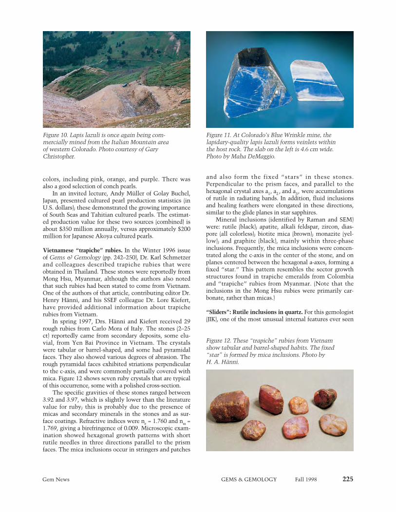
colors, including pink, orange, and purple. There wasalso a good selection of conch pearls.
In an invited lecture, Andy Müller of Golay Buchel,Japan, presented cultured pearl production statistics (inU.S. dollars); these demonstrated the growing importanceof South Seas and Tahitian cultured pearls. The estimat-ed production value for these two sources (combined) isabout $350 million annually, versus approximately $200million for Japanese Akoya cultured pearls.
Vietnamese “trapiche” rubies. In the Winter 1996 issueof Gems & Gemology (pp. 242–250), Dr. Karl Schmetzerand colleagues described trapiche rubies that wereobtained in Thailand. These stones were reportedly fromMong Hsu, Myanmar, although the authors also notedthat such rubies had been stated to come from Vietnam.One of the authors of that article, contributing editor Dr.Henry Hänni, and his SSEF colleague Dr. Lore Kiefert,have provided additional information about trapicherubies from Vietnam.
In spring 1997, Drs. Hänni and Kiefert received 29rough rubies from Carlo Mora of Italy. The stones (2–25ct) reportedly came from secondary deposits, some elu-vial, from Yen Bai Province in Vietnam. The crystalswere tabular or barrel-shaped, and some had pyramidalfaces. They also showed various degrees of abrasion. Therough pyramidal faces exhibited striations perpendicularto the c-axis, and were commonly partially covered withmica. Figure 12 shows seven ruby crystals that are typicalof this occurrence, some with a polished cross-section.
The specific gravities of these stones ranged between3.92 and 3.97, which is slightly lower than the literaturevalue for ruby; this is probably due to the presence ofmicas and secondary minerals in the stones and as sur-face coatings. Refractive indices were ne = 1.760 and nw =1.769, giving a birefringence of 0.009. Microscopic exam-ination showed hexagonal growth patterns with shortrutile needles in three directions parallel to the prismfaces. The mica inclusions occur in stringers and patches
and also form the fixed “stars” in these stones.Perpendicular to the prism faces, and parallel to thehexagonal crystal axes a1, a2 , and a3, were accumulationsof rutile in radiating bands. In addition, fluid inclusionsand healing feathers were elongated in these directions,similar to the glide planes in star sapphires.
Mineral inclusions (identified by Raman and SEM)were: rutile (black); apatite, alkali feldspar, zircon, dias-pore (all colorless); biotite mica (brown); monazite (yel-low); and graphite (black), mainly within three-phaseinclusions. Frequently, the mica inclusions were concen-trated along the c-axis in the center of the stone, and onplanes centered between the hexagonal a-axes, forming afixed “star.” This pattern resembles the sector growthstructures found in trapiche emeralds from Colombiaand “trapiche” rubies from Myanmar. (Note that theinclusions in the Mong Hsu rubies were primarily car-bonate, rather than micas.)
“Sliders”: Rutile inclusions in quartz. For this gemologist(JIK), one of the most unusual internal features ever seen
Gem News GEMS & GEMOLOGY Fall 1998 225
Figure 11. At Colorado’s Blue Wrinkle mine, thelapidary-quality lapis lazuli forms veinlets withinthe host rock. The slab on the left is 4.6 cm wide.Photo by Maha DeMaggio.
Figure 12. These “trapiche” rubies from Vietnamshow tabular and barrel-shaped habits. The fixed“star” is formed by mica inclusions. Photo by H. A. Hänni.
Figure 10. Lapis lazuli is once again being com-mercially mined from the Italian Mountain areaof western Colorado. Photo courtesy of GaryChristopher.
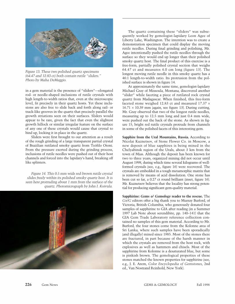
226 Gem News GEMS & GEMOLOGY Fall 1998
in a gem material is the presence of “sliders”—elongatedrod- or needle-shaped inclusions of rutile crystals withhigh length-to-width ratios that, even at the microscopiclevel, fit precisely in their quartz hosts. Yet these inclu-sions are also free to slide back and forth along rail- ortrack-like grooves in the quartz that precisely parallel thegrowth striations seen on their surfaces. Sliders wouldappear to be rare, given the fact that even the slightestgrowth hillock or similar irregular feature on the surfaceof any one of these crystals would cause that crystal tobind up, locking it in place in the quartz.
Sliders were first brought to our attention as a resultof the rough grinding of a large transparent partial crystalof Brazilian rutilated smoky quartz from Teófilo Otoni.From the pressure exerted during the grinding process,inclusions of rutile needles were pushed out of their hostchannels and forced into the lapidary’s hand, breaking offlike splinters.
The quartz containing these “sliders” was subse-quently worked by gemologist-lapidary Leon Agee ofLiberty Lake, Washington. The intention was to create ademonstration specimen that could display the movingrutile needles. During final grinding and polishing, Mr.Agee intentionally pushed the rutile needles through thesurface so they would end up longer than their polishedsmoky quartz host. The final product of this exercise is afree-form, partially polished crystal section that weighs64.47 ct and measures 4.0 cm long (figure 13). Thelongest moving rutile needle in this smoky quartz has a46:1 length-to-width ratio. Its protrusion from the pol-ished surface is shown in figure 14.
At approximately the same time, gemologist-lapidaryMichael Gray of Missoula, Montana, discovered another“slider” while faceting a piece of rutilated rock crystalquartz from Madagascar. When finished, this free-formfaceted stone weighed 12.83 ct and measured 17.37 ¥16.71 ¥ 10.39 mm (again, see figure 13). During cutting,Mr. Gray observed that two of the longest rutile needles,measuring up to 12.5 mm long and just 0.4 mm wide,were pushed out the back of the stone. As shown in fig-ure 15, bright red rutile crystals protrude from channelsin some of the polished facets of this interesting gem.
Sapphire from the Ural Mountains, Russia. According toNicolai Kuznetsov, of Stone Flower Co. in Moscow, anew deposit of blue sapphires is being mined in theChelyabinsk region of the Urals, about 3 km from thetown of Mias. Although the deposit has been known fortwo to three years, organized mining did not occur untilAugust 1998, during which time several kilograms of well-formed crystals (see, e.g., figure 16) were recovered. Thecrystals are embedded in a tough metamorphic matrix thatis removed by means of acid dissolution. One stone hasbeen cut so far, a 0.27 ct round brilliant (inset, figure 16).Mr. Kuznetsov believes that the locality has strong poten-tial for producing significant gem-quality material.
Sapphirine: Gems & Gemology reader to the rescue. TheG&G editors offer a big thank you to Murray Burford, ofVictoria, British Columbia, who generously donated foursamples of sapphirine to GIA after reading (in a Summer1997 Lab Note about serendibite, pp. 140–141) that theGIA Gem Trade Laboratory reference collection con-tained no samples of this gem material. According to Mr.Burford, the four stones come from the Kolonne area ofSri Lanka, where such samples have been sporadically(and illegally) mined since 1985. Most of the stones thereare fractured, in part because of the harsh manner inwhich the crystals are removed from the host rock, withexplosives as well as hammers and chisels. Most of thesapphirine from Kolonne is a desaturated blue, but someis pinkish brown. The gemological properties of thesestones matched the known properties for sapphirine (see,e.g., J. E. Arem, Color Encyclopedia of Gemstones, 2nded., Van Nostrand Reinhold, New York).
Figure 13. These two polished quartz specimens(64.47 and 12.83 ct) both contain rutile “sliders.”Photo by Maha DeMaggio.
Figure 14. This 0.5 mm wide red-brown rutile crystalslides freely within its polished smoky quartz host. It is
seen here protruding about 1 mm from the surface of thequartz. Photomicrograph by John I. Koivula.
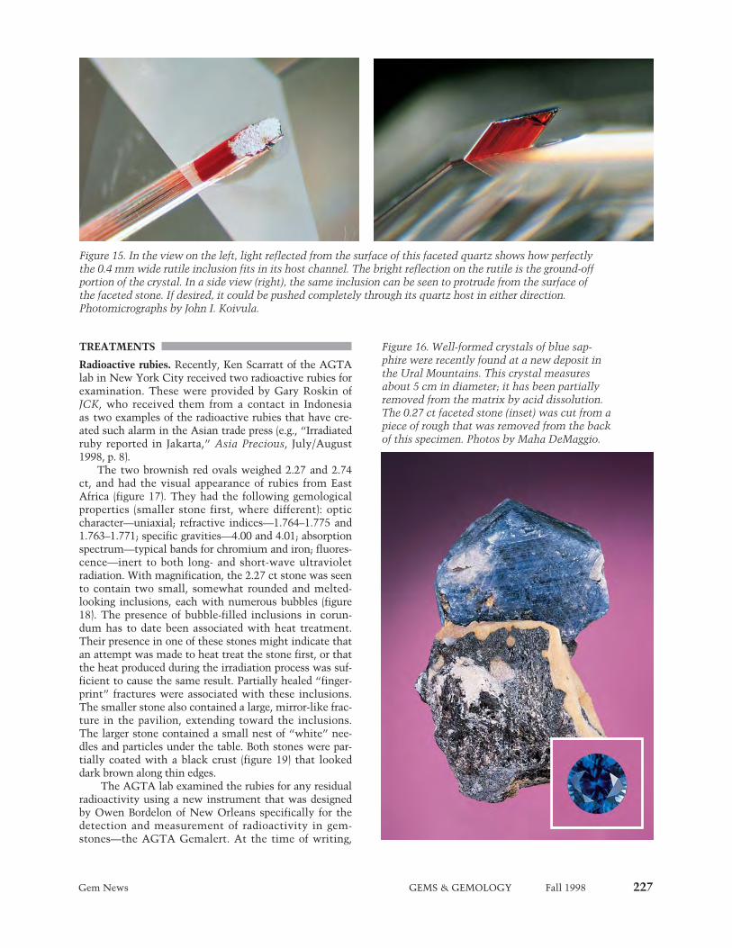
Gem News GEMS & GEMOLOGY Fall 1998 227
TREATMENTS
Radioactive rubies. Recently, Ken Scarratt of the AGTAlab in New York City received two radioactive rubies forexamination. These were provided by Gary Roskin ofJCK, who received them from a contact in Indonesiaas two examples of the radioactive rubies that have cre-ated such alarm in the Asian trade press (e.g., “Irradiatedruby reported in Jakarta,” Asia Precious, July/August1998, p. 8).
The two brownish red ovals weighed 2.27 and 2.74ct, and had the visual appearance of rubies from EastAfrica (figure 17). They had the following gemologicalproperties (smaller stone first, where different): opticcharacter—uniaxial; refractive indices—1.764–1.775 and1.763–1.771; specific gravities—4.00 and 4.01; absorptionspectrum—typical bands for chromium and iron; fluores-cence—inert to both long- and short-wave ultravioletradiation. With magnification, the 2.27 ct stone was seento contain two small, somewhat rounded and melted-looking inclusions, each with numerous bubbles (figure18). The presence of bubble-filled inclusions in corun-dum has to date been associated with heat treatment.Their presence in one of these stones might indicate thatan attempt was made to heat treat the stone first, or thatthe heat produced during the irradiation process was suf-ficient to cause the same result. Partially healed “finger-print” fractures were associated with these inclusions.The smaller stone also contained a large, mirror-like frac-ture in the pavilion, extending toward the inclusions.The larger stone contained a small nest of “white” nee-dles and particles under the table. Both stones were par-tially coated with a black crust (figure 19) that lookeddark brown along thin edges.
The AGTA lab examined the rubies for any residualradioactivity using a new instrument that was designedby Owen Bordelon of New Orleans specifically for thedetection and measurement of radioactivity in gem-stones—the AGTA Gemalert. At the time of writing,
Figure 15. In the view on the left, light reflected from the surface of this faceted quartz shows how perfectlythe 0.4 mm wide rutile inclusion fits in its host channel. The bright reflection on the rutile is the ground-offportion of the crystal. In a side view (right), the same inclusion can be seen to protrude from the surface ofthe faceted stone. If desired, it could be pushed completely through its quartz host in either direction.Photomicrographs by John I. Koivula.
Figure 16. Well-formed crystals of blue sap-phire were recently found at a new deposit inthe Ural Mountains. This crystal measuresabout 5 cm in diameter; it has been partiallyremoved from the matrix by acid dissolution.The 0.27 ct faceted stone (inset) was cut from apiece of rough that was removed from the backof this specimen. Photos by Maha DeMaggio.

228 Gem News GEMS & GEMOLOGY Fall 1998
measurements had been recorded for these stones withthis instrument at irregular intervals over a period ofonly one month. Nevertheless, it provided useful indica-tions of the level of radioactivity. The first measurementof the 2.74 ct stone revealed an activity level of 81 micro-Roentgen per hour per carat; for the 2.27 ct stone, thelevel was 95 micro-Roentgen per hour per carat. (Legallimits for the release of irradiated gemstones depend onthe particular isotopes responsible for the radioactivityand their concentrations. This information has not yetbeen established for these stones.) It is interesting to notethat measurements taken on two natural, untreatedgreen zircons during the same period resulted in similarreadings; however, the Nuclear Regulatory Commissiondoes not regulate naturally radioactive gems. Furthermeasurements were taken about 10 days and one monthlater; following calculation, they produced an approxi-mate half-life for each of the two rubies of 300 days,assuming the radioactivity came from only one isotope.Unless future calculations indicate that more than onesignificant radioisotope is present, this would mean thatthe radioactivity level for each stone would be reduced tobackground levels within two years. Thus far, no infor-mation is available as to the precise source of theserubies and their original color. Investigations are ongoinginto how the material can be identified by standardgemological methods.
SYNTHETICS AND SIMULANTS
Gallium phosphide, resembling fancy dark orange dia-mond. This unusual material was called to our attentionby graduate gemologist Robert E. La Prad, an appraiser inSanta Barbara, California. A local high-tech company,Digital Instruments, uses the manufactured product gal-lium phosphide, and an engineer brought a piece to Mr.La Prad for faceting. He noted that during faceting thesample gave off a very pungent (phosphorus) odor.
The 4.11 ct faceted sample (figure 20) had the follow-ing properties: diaphaneity—transparent; color—verydark brownish reddish orange; color distribution—even;optic character—singly refractive; refractive index—overthe limits of the standard refractometer (greater than1.81); specific gravity (measured hydrostatically)—4.15;fluorescence—inert to both long- and short-wave UVradiation; spectroscope spectrum—560 nm cutoff. Noinclusions were noted when the sample was viewedthrough a microscope; however, microscopic examina-tion was difficult because of the somewhat hazy appear-ance of the facets. According to Mr. La Prad, the Mohshardness (checked with hardness points) is 5–6.
As this was a new material for us, we ran some addi-tional tests. With energy-dispersive X-ray fluorescence(EDXRF) analysis, Sam Muhlmeister of GIA Researchfound major gallium and phosphorus. Shane Elen of GIA
Figure 18. The smaller of the two rubies in figure17 contained two melted-looking inclusions withnumerous bubbles. Photomicrograph by John I.Koivula; magnified 20¥.
Figure 17. These two rubies (2.27 and 2.74 ct) looklike typical East African stones, but they proved tobe radioactive. Photo by Maha DeMaggio.
Figure 19. Both rubies werepartially coated with ablack material (left, 2.74 ctstone in reflected light)that looked brown alongthin edges (right, in trans-mitted light). Photomicro-graphs by John I. Koivula;magnified 15¥.
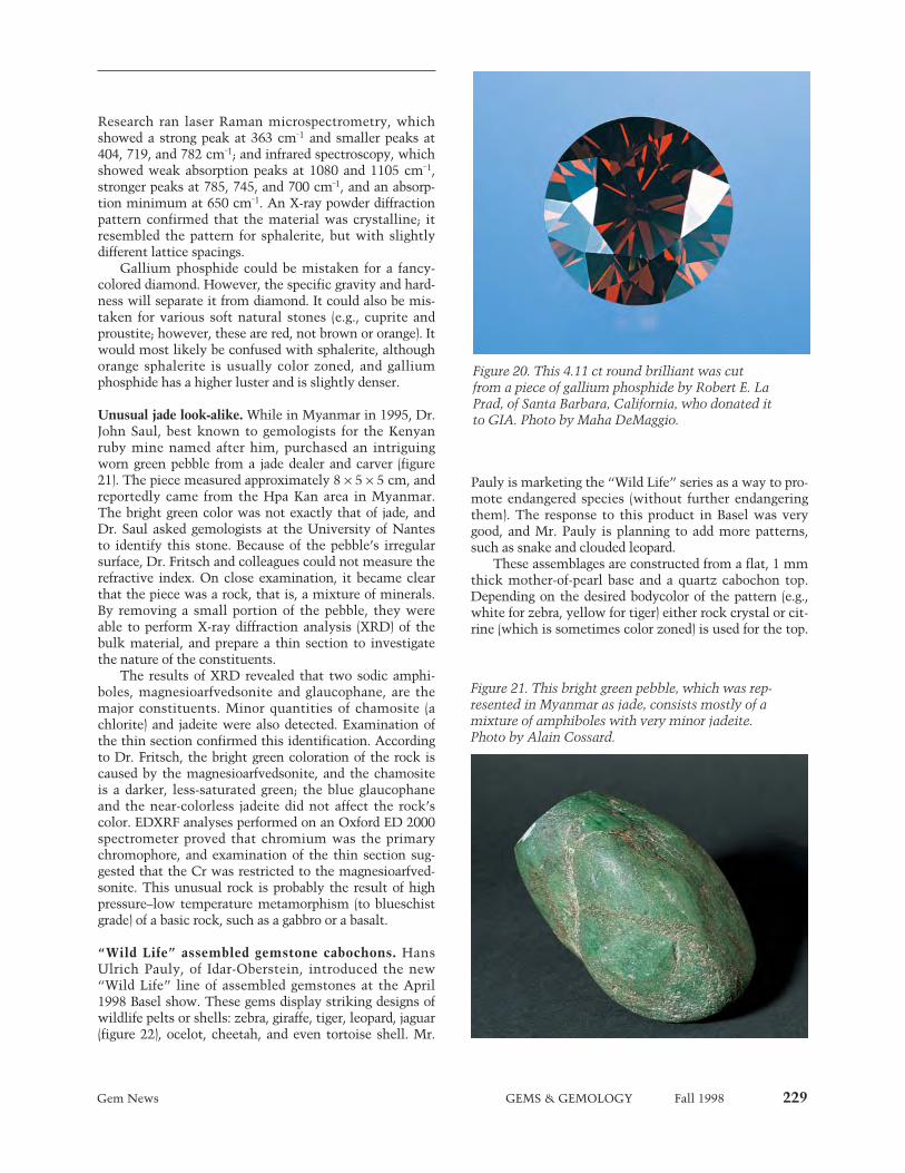
Gem News GEMS & GEMOLOGY Fall 1998 229
Research ran laser Raman microspectrometry, whichshowed a strong peak at 363 cm-1 and smaller peaks at404, 719, and 782 cm-1; and infrared spectroscopy, whichshowed weak absorption peaks at 1080 and 1105 cm-1,stronger peaks at 785, 745, and 700 cm-1, and an absorp-tion minimum at 650 cm-1. An X-ray powder diffractionpattern confirmed that the material was crystalline; itresembled the pattern for sphalerite, but with slightlydifferent lattice spacings.
Gallium phosphide could be mistaken for a fancy-colored diamond. However, the specific gravity and hard-ness will separate it from diamond. It could also be mis-taken for various soft natural stones (e.g., cuprite andproustite; however, these are red, not brown or orange). Itwould most likely be confused with sphalerite, althoughorange sphalerite is usually color zoned, and galliumphosphide has a higher luster and is slightly denser.
Unusual jade look-alike. While in Myanmar in 1995, Dr.John Saul, best known to gemologists for the Kenyanruby mine named after him, purchased an intriguingworn green pebble from a jade dealer and carver (figure21). The piece measured approximately 8 ¥ 5 ¥ 5 cm, andreportedly came from the Hpa Kan area in Myanmar.The bright green color was not exactly that of jade, andDr. Saul asked gemologists at the University of Nantesto identify this stone. Because of the pebble’s irregularsurface, Dr. Fritsch and colleagues could not measure therefractive index. On close examination, it became clearthat the piece was a rock, that is, a mixture of minerals.By removing a small portion of the pebble, they wereable to perform X-ray diffraction analysis (XRD) of thebulk material, and prepare a thin section to investigatethe nature of the constituents.
The results of XRD revealed that two sodic amphi-boles, magnesioarfvedsonite and glaucophane, are themajor constituents. Minor quantities of chamosite (achlorite) and jadeite were also detected. Examination ofthe thin section confirmed this identification. Accordingto Dr. Fritsch, the bright green coloration of the rock iscaused by the magnesioarfvedsonite, and the chamositeis a darker, less-saturated green; the blue glaucophaneand the near-colorless jadeite did not affect the rock’scolor. EDXRF analyses performed on an Oxford ED 2000spectrometer proved that chromium was the primarychromophore, and examination of the thin section sug-gested that the Cr was restricted to the magnesioarfved-sonite. This unusual rock is probably the result of highpressure–low temperature metamorphism (to blueschistgrade) of a basic rock, such as a gabbro or a basalt.
“Wild Life” assembled gemstone cabochons. HansUlrich Pauly, of Idar-Oberstein, introduced the new“Wild Life” line of assembled gemstones at the April1998 Basel show. These gems display striking designs ofwildlife pelts or shells: zebra, giraffe, tiger, leopard, jaguar(figure 22), ocelot, cheetah, and even tortoise shell. Mr.
Pauly is marketing the “Wild Life” series as a way to pro-mote endangered species (without further endangeringthem). The response to this product in Basel was verygood, and Mr. Pauly is planning to add more patterns,such as snake and clouded leopard.
These assemblages are constructed from a flat, 1 mmthick mother-of-pearl base and a quartz cabochon top.Depending on the desired bodycolor of the pattern (e.g.,white for zebra, yellow for tiger) either rock crystal or cit-rine (which is sometimes color zoned) is used for the top.
Figure 20. This 4.11 ct round brilliant was cutfrom a piece of gallium phosphide by Robert E. LaPrad, of Santa Barbara, California, who donated itto GIA. Photo by Maha DeMaggio.
Figure 21. This bright green pebble, which was rep-resented in Myanmar as jade, consists mostly of amixture of amphiboles with very minor jadeite.Photo by Alain Cossard.
230 Gem News GEMS & GEMOLOGY Fall 1998
Mr. Pauly uses a high cabochon dome to “give more life”to the designs. The flat side of the quartz cabochon isworked with a technique derived from traditionalEnglish crystal paintings: The stone is first engraved tomake a deep intaglio, then the carved areas are filledwith oil-based paint. The base is attached to the cabo-chon with a glue that contains a special preservative toprevent reaction between the adhesive and the paint overtime. The cabochons range from 8 to 50 mm in maxi-mum dimension. A German patent covers the techniqueand five patterns.
ANNOUNCEMENTS
Rossmanite, a new variety of tourmaline. Dr. George R.Rossman, Professor of Mineralogy at the CaliforniaInstitute of Technology and a longtime member of theGems & Gemology editorial review board, has had a newvariety of tourmaline named in his honor. Rossmanitewas recently described by Selway et al. (“Rossmanite,
(LiAl2)Al6(Si6O18)(BO3)3(OH)4, a New Alkali-DeficientTourmaline: Description and Crystal Structure,”American Mineralogist, Vol. 83, 1998, pp. 896–900) aswell-formed pale pink crystals from a granitic pegmatitenear Roznà in the Czech Republic. The mineral is char-acterized by an elemental vacancy in the X site (repre-sented as “ ” in the chemical formula); it forms a thirdmember in a family of lithium-aluminum tourmalinesthat includes elbaite (Na in the X site) and liddicoatite(Ca in the X site, named after Gems & Gemology editor-in-chief Richard T. Liddicoat; figure 23).
In addition to the type locality, rossmanite has beenfound at other pegmatites in the Czech Republic and atRed Cross Lake in northeastern Manitoba, Canada(Selway et al., “Tourmaline from Lepidolite-SubtypePegmatites,” Abstracts, Tourmaline 1997—InternationalSymposium on Tourmaline, Czech Republic, 1997, pp.91–92). Rossmanite has also been found as colorlesszones near the terminations of gem-quality multicoloredelbaite crystals from pegmatites on the island of Elba,Italy (Pezzotta et al., “La Rossmanite di Roznà edell’Elba,” Revista Mineralogica Italiana, Vol. 22, No. 1,1998, pp. 46–50). Pink rossmanite has been documentedfrom the Utî pegmatite in Sweden and the Tanco peg-matite in southeastern Manitoba, in a further study bySelway et al. (“Compositional Evolution of Tourmalinein Petalite-Subtype Pegmatites,” Abstracts &Programme, 17th General Meeting of the InternationalMineralogical Association, Toronto, Canada, August9–14, 1998, p. A148). Rossmanite is visually indistin-guishable from elbaite; it can be identified only by quan-titative chemical analysis.
ERRATA: In the article “Benitoite from the New IdriaDistrict, San Benito County, California,” (B. Laurs etal., Gems & Gemology, Fall 1997, pp. 166–187),Edward Swoboda and Peter Bancroft were described asunauthorized miners. It has come to our attention thatSwoboda and Bancroft did indeed have permission tovisit the mine, and did so several times in the late 1930s.The authors apologize for this misrepresentation.
The Summer 1998 Gem News item “Of rubies andrubles” (pp. 141–142) reported the location of a new rubydeposit as the Polar Urals of Siberia. Although the rubydeposit was correctly identified as the Rais mine in thePolar Urals, this area is actually west of Siberia.
Figure 22. These “Wild Life” assembled cabochonsare constructed from an etched and painted quartztop, backed by a thin slice of mother-of-pearl. Thezebra cabochon is 16 mm in diameter. Courtesy ofHans Ulrich Pauly; photo by Maha DeMaggio.
Figure 23. Dr. George R. Rossman (left) joinsRichard T. Liddicoat in the distinction of having avariety of tourmaline named after him. Photo byPeggy Wallace.

Challenge Winners GEMS & GEMOLOGY Fall 1998 231
USA ® Arizona Oro Valley: Geraldine Alex Towns. Tucson: Luella Dykhuis, Robert Stewart ® California Alamo: Sam Johnston.Burlingame: Sandra MacKenzie-Graham. Carlsbad: Marla Belbel, Lori Burdo, Michael T. Evans, Brian Genstel, William Herberts,
Jan Luree Lombardi, Roxana Lucas, Wendi Mayerson, Catherine McIntyre, Jana Miyahira, Lynn L. Myers, Shannon O’Rourke, Laura Small, Abba Steinfeld, Paula Straub, Ric Taylor, Melissa Watson-Lafond, Mike Wobby, Phil York. Chino Hills:
Virgilio M. Garcia, Jr. Elk Grove: Michael Pace. Huntington Beach: Lyndeth Esgar. Joshua Tree: Rebecca Ann Bell. Los Angeles:Veronica Clark-Hudson, David Peters. Redwood City: Starla Turner. San Diego: Tracy Nuzzo. Ukiah: Charles “Mike” Morgan
® Colorado Colorado Springs: Molly K. Knox. Denver: Alan J. Winterscheidt ® Connecticut New Haven: Matilde Paolini McAfee.Simsbury: Jeffrey A. Adams. Westport: William A. Jeffery ® Florida DeLand: Sue Angevine Guess. North Miami Beach: Fabio S. Pinto.Palm Harbor: Tim Schuler. Plantation: Garrett Walker. Surfside: Pinchas Schechter ® Georgia Brunswick: Thomas R. Hill ® Hawaii
Mililani: Abe L. Wilson ® Illinois Bloomington: Anne Blumer. St. Charles: Lori M. Mesa ® Iowa West Des Moines: Franklin Herman® Kansas Kingman: La Shawn Bauer. Louisburg: Kathylee Cook ® Maine Portland: Arthur E. Spellissy, Jr. ® Maryland Annapolis:James V. Jolliff ® Massachusetts Braintree: Alan Howarth. Brookline: Martin Haske. Uxbridge: Bernard M. Stachura ® Nebraska
Omaha: Ann Coderko u Nevada Reno: Terence E.Terras ® New Hampshire Merrimack: Kenneth M. Gatto ® New Jersey Carteret:Bela Dvorcsak. Fort Lee: Julia V. Tretyakova. Union: Thaïs Anne Lumpp ® New Mexico Albuquerque: Dr. Susan Gaspar Wilson
® North Carolina Manteo: Eileen Alexanian. Tryon: Matthew Randolph. Winston-Salem: S. Lee Hall ® Ohio Cincinnati: Jeffrey L.Basse. North Royalton: Christine M. Blankenship ® Pennsylvania Womelsdorf: Lori Perchansky. Yardley: Peter R. Stadelmeier®
South Carolina Sumter: James S. Markides ® Texas Austin: Corey Shaughnessy. Corpus Christi: Warren A. Rees, Jr. Houston: Karen L.Jensen. San Antonio: Chris Winbery. Tomball: Carroll J. Kiefer ® Virginia Hampton: Edward A. Goodman, Tony Goodman. Sterling:
Donna B. Rios ® Washington Lakebay: Karen Geiger. Seattle: Thomas Estervog ® Wisconsin East Troy: William Bailey® AUSTRALIA Avalon Beach, N.S.W.: Carol E. Wood. Coogee, Western Australia: Helen Judith Haddy. Melbourne: Katherine Kovacs.
Slacks Creek, Queensland: Ken Hunter. Sydney: Barbara Wodecki ® BELGIUM Diegem: Guy Lalous. Diksmuide: H. Loeters, LeoLoeters. Hemiksem: De Maeght Daniël. Ruiselede: Lucette Nols ® BRAZIL São Paulo: Alejandro Benjamin Ferreyra, Maria AmeliaFranco ® CANADA Bobcaygeon, Ontario: David R. Lindsay. Calgary, Alberta: Diane Koke. Coquitlam, B.C.: Dominc K.U. Tang.Cowansville, Québec: Alain Deschamps. North Vancouver, B.C.: Eva B. Nilsson. St.-Lambert, Québec: Carmen Rivet. St.-Hubert,
Québec: Sylvie Careau ® FINLAND Kajaani: Petri Tuovinen ® FRANCE Paris: Marie-France Chateau ® ITALY Caltanissetta, Sicily:Francesco Natale. Ferrara: Sonia Franzolin. Genoa: Mafalda Pasqui. Lucca: Roberto Filippi. Malnate: Gabriele Tralli. Porto Azzurro,
Elba: Diego Giuseppe Trainini. Rome: Mauro Papais. San Remo: Enrico Cannoletta. Vicenza: Francesca Zen ® THE NETHERLANDSRotterdam: E. van Velzen. Wassenaar: Jane Orsak ® NEW ZEALAND Lower Hutt: Dennis Blacklaws. Wanganui: Richard Sheppard
® PORTUGAL Vila do Bispo: Johanne C. Jack ® SCOTLAND Edinburgh: James W.M. Heatlie ® SPAIN Madrid: Maria Isabel CereijoHierro, José Antonio Gutiérrez Martínez, Shahrazad Krewi De Urquijo ® SWEDEN Järfälla: Thomas Larsson ® SWITZERLAND
Geneva: J.M. Duroc-Danner. Zollikon: Adrian Meister. Zürich: Eva Mettler ® TURKEY Istanbul: F. Oya Borahan® UNITED KINGDOM London: Jeremy L. Harding
Answers (See page 65 of the Spring 1998 issue for the questions): (1) a, (2) c, (3) d, (4) d, (5) a, (6) d, (7) b, (8) a, (9) d, (10) a, (11) d, (12) a, (13) c, (14) b, (15) a, (16) b, (17) c, (18) d, (19) b, (20) d, (21) d,
(22) a, (23) c, (24) c, (25) c
Challenge Winners 1998Once again,Once again,
over 300 Gems & Gemology readers, dedicated to their education and knowledge of the field, participated in the 1998
Gems & Gemology Challenge. Entries arrived from all corners of the world,as readers tested their knowledge on the questions in the Spring 1998
issue. Those who earned a score of 75% or better received a GIAContinuing Education Certificate recognizing their achievement.
The participants who scored a perfect 100% are listed below.

232 Book Reviews GEMS & GEMOLOGY Fall 1998
GIA GEM IDENTIFICATION
LABORATORY MANUAL
188 pp., illus. plus 2 charts, publ. byGIA, Carlsbad, CA, 1998. US$59.95*
Earlier editions of this manual weredesigned to assist students in theGIA Gem Identification course andwere structured to be used with theGem Reference Guide, the ColoredStone and Gem Identification coursematerials, and R. T. Liddicoat’sHandbook of Gem Identification(12th ed., 1993). The manual is nowaddressed to “gemologists” as well asgemology students and, for the firsttime, is available for purchase sepa-rate from the course.
First impressions are very good.The substantial cover is attractive,and a quick flick through the spiral-bound pages shows easily readableand well-laid-out text with clearblack-and-white diagrams. An initiallist of the abbreviations used isimportant but, at four pages of text, isunnecessarily long; some short wordsmight be better spelled out.
The 40-page section on the use ofinstruments generally follows a logi-cal order, but it is odd that the para-graphs on the use of the 10¥ lens
appear in the middle of the Microscopesection and not at the beginning of theMagnification section. In the samevein, why is the simple hand spectro-scope described after (and not before)the expensive wavelength model? Inthe section on immersion tech-niques, the dangers of putting assem-bled stones into liquids (other thanwater) are not mentioned, althoughthey may be in the other recom-mended references. The gem identifi-cation worksheets (one is shown) areclearly described, and their use asflow charts is agreeably apparent.
The major part of the manual(114 pages) is devoted to Gem Sep-arations, and is apparently designedto be used with Liddicoat’s Hand-book of Gem Identification. TheSeparations are divided into sevensections, arranged according to therefractive indices of the speciesdescribed: (1) Gemstones with R.I.’sover the limits of the refractometer,(2) R.I.’s from 1.70 to 1.80, (3) R.I.’sfrom 1.60 to 1.70, (4) R.I.’s from 1.50to 1.60, (5) R.I.’s of 1.50 and below, (6)Glass and Plastics, and (7) AssembledStones. In each section, an initialpage lists the gem materials describedalong with the species, as appropriate,with which they are commonly con-fused. As an example, diamond (insection 1) is compared to doublyrefracting zircon and synthetic rutile,and to singly refracting strontiumtitanate, CZ, GGG, and YAG; com-parative properties are presented intabular form. Key separation tests aresummarized in a “box” at the foot ofeach page, with the distinguishingproperties of fracture-filled diamondsand assembled diamond simulantsshown on following pages.
In citing diamonds as an example,a serious omission becomes appar-ent—synthetic moissanite is not
mentioned. This is understandable,since this manual would presumablyhave been prepared and sent for print-ing during 1997 or even earlier, whensynthetic moissanite had not beenreleased. However, the omissionought to be addressed—possibly bythe issue of a supplementary sheetfor insertion in the manual. Theomission of colorless enstatite is lessserious.
The accompanying Gem PropertyCharts A and B for common and lesscommon gem materials, respectively,are very clear and provide a concisesummary of the properties and testsfor the individual gem materials.
This well-produced manual isadmirable for teaching gem identifi-cation methods, but a standard gemidentification textbook such as Liddi-coat (1993) is a desirable adjunct.
ALAN JOBBINSCaterham, United Kingdom
CAMEOS:CLASSICAL TO COSTUME
By Monica Lynn Clements andPatricia Rosser Clements, 223 pp.,illus., publ. by Schiffer Publishing,Atglen, PA, 1998. US$59.95*
This is a lovely, glossy, picture bookwith over 1,400 photographs of 19thand 20th century commercial andcostume jewelry cameos, carved byhand and machine from stone, shell,glass, plastic, and lava. The book’shigh production quality is apparentnot only in the use of coated paper,but also in the outstanding color pho-tographs. Most of the photos, howev-
Susan B. Johnson & Jana E. Miyahira, Editors
*This book is available for purchase throughthe GIA Bookstore, 5345 Armada Drive,Carlsbad, CA 92008. Telephone: (800)421-7250, ext. 4200; outside the U.S. (760)603-4200. Fax: (760) 603-4266.
Book Reviews
Book Reviews GEMS & GEMOLOGY Fall 1998 233
er, present virtually the same carvedsubject matter—the anonymousfemale figure—which can become abit tedious.
Approximate dates and prices aregiven for all of the cameos pictured.However, the prices appear to be arbi-trary and should have been footnotedwith the following caveat: “Cameoprices vary widely from one region ofthe United States to another, as wellas globally between countries.” It alsowould have been fitting to point outthat price variances reflect supply anddemand and also the personal cameosavvy of the collector/jeweler/dealer.With cameos, estimated value is notonly subjective, it is also dependenton the scholarship of the viewer.
Although the book contains littletext, chapter 1 presents some histori-cal information on cameos. Most ofthis information is useful, if not new,but there is an error in the followingstatement on page 7: “The cameohad no apparent purpose other thanas an ornament.” In fact, ancientcameos—including Greek and Ro-man pieces from the days of the earli-est Caesars—were more than simpleornaments. These items of miniatur-ized art were used as magic talismans,religious badges, and, ultimately, asitems of political propaganda. It wasnot until the 19th century thatcameos were regarded as pure orna-ment, with the anonymous femalefigure as the primary subject. Theother six chapters offer a pictorialflood of cameos of various sizes andmaterials, with the majority set inbrooches.
I liked the ambitious format ofthe book, the quality of the illustra-tions, and especially the sectiontitled “Plaster Casts of Carved andEngraved Gems.” In the 18th and19th centuries, plaster casts wereused as teaching aids, and they can bea fascinating topic of study them-selves. Although plaster casts havebeen written about and photographedin other books on cameos, this bookcontains many pages of casts, remi-niscent of antiquarian books oncameos. The section on “Lava”cameos is also particularly interest-
ing, with some excellent examplesshown.
It is left to the reader to decidehow to use the dating and pricinginformation to aid in subject identifi-cation, buying, and selling. Somesubjects are mislabeled. For instance,several anonymous female figuresfrom the late 1800s are identified aseither the mythological goddess (ofagriculture) Demeter or the moongoddess Artemis (a crescent moon inthe hair does not always mean thefigure is Artemis); the goddess Romais mislabeled as the goddess Minerva;and a couple of figures labeled as“classical” are mythological gods.
Collecting cameos is an area inwhich study of mythology, astrology,and art history can be helpful.Cameos: Classical to Costume maybe useful to collectors who wish toincrease their basic knowledge aboutnew (from 1900 forward) cameos. Inaddition, to the authors’ credit, theyhave included a useful glossary, bibli-ography, and index. Unfortunately,there is no historical data or newtechnical information about cameosin this book, and glyptic art scholarsseeking arcane information about thesubject will have to look elsewhere.
ANNA M. MILLER, G.G.International Director,Master Valuer Program
WARMAN’S JEWELRY, 2ND ED.By Christie Romero, 293 pp., illus.,published by Krause Publications,Iola, WI, 1998, US$18.95*
This is one of the few times whenbigger does mean better! This secondedition is billed as “enlarged toinclude more listings and photos,”and it is absolutely true. There are600 crisp black-and-white photos and32 realistic color photos that illus-trate the divisions and subdivisionsof jewelry eras, from late Georgian(mid-18th century) to the mid-1970s.Each photo has a complete descrip-tion, “circa” dating, dimensions, anda buyer’s guide price (i.e., those pricesa buyer should expect to pay for apiece in excellent to very good condi-
tion). All of the photos are new; noneis from the first edition.
Each era has a well-researchedIntroduction, plus sections onHistory, References (for further inde-pendent study), Reproduction Alert,Museums, and the advisors whoassisted Ms. Romero. There are alsoadditional jewelry makers in eachera; in particular, the Studio Artistssection lists many of the lesser-known artists of the 1950s. The con-centration is not just on gemstoneand precious-metal jewelry. Thereare generous sections on CostumeJewelry (circa 1935–1975), Plastic andOther Novelty Jewelry (circa1920–1970), and Special CollectibleJewelry (Native American, Mexican,Scandinavian silver jewelry).
The most valuable section of allis “Timeline,” where Ms. Romeroproves her worth as a jewelry histori-an. “General History, Discoveriesand Inventions” is presented side byside with “Jewelry and GemstoneHistory, Discoveries andInventions.” From 1760 to 1974, his-torical milestones (e.g., the PrussianWar of Liberation against Napoleon)are juxtaposed with jewelry historyevents (e.g., Berlin iron jewelry madein Germany as a patriotic gestureduring the War of Liberation: “goldgab isch fur eisen” [“I gave gold foriron”]). This places jewelry move-ments in the context of real-lifeoccurrences, thereby eliminating theisolation of so many historical treat-ments.
Unfortunately, the publisherswere not attentive in their finalreview. The Index for Part III(Twentieth Century Jewelry) is notcorrect; the reader can locate items bysubtracting the number 16 from thelisted page number, or by contactingthe author for an errata sheet. In spiteof these inconveniences, the antiquejewelry veteran and novice alike willvalue the enormity of this project,which traces over 200 years of jewelryhistory.
GAIL BRETT LEVINE, G.G.Auction Market Resource
Rego Park, New York
234 Gemological Abstracts GEMS & GEMOLOGY Fall 1998
COLORED STONES ANDORGANIC MATERIALSFluid composition, dD of channel H2O, and d18O of lattice
oxygen in beryls: Genetic implications for Brazilian,Colombian, and Afghanistani emerald deposits. G.Giuliani, C. France-Lanord, J. L. Zimmermann, A.Cheilletz, C. Arboleda, B. Charoy, P. Coget, F.Fontan, and D. Giard, International GeologyReview, Vol. 39, 1997, pp. 400–424.
The authors examined the genetic implications of thecomposition of fluids, dD of channel H2O, and d18O ofstructural oxygen in beryl from granitic pegmatites andgreisens, and in emeralds from Brazil, Colombia, andAfghanistan. [Editor’s note: dD and d18O refer to the iso-topic compositions of hydrogen (deuterium) and oxygen,respectively, and are expressed as per mil (d) differencesrelative to the isotopic standard SMOW (standard meanocean water).] Their study led to the following conclu-sions. First, fluids in the channels of both beryl and emer-ald are mainly water and CO2, and are independent of theage and tectonic setting of emerald deposits; theColombian emeralds have the lowest contents of channelH2O (1.30–1.96 wt.%). Second, the emeralds from allthree localities have contrasting and restricted ranges ofd18O values, which suggests that these values were affect-ed by the local host rock. Relative to emeralds fromBrazil, those from Afghanistan and Colombia are stronglyenriched in d18O, indicating extensive isotopic exchange
This section is designed to provide as complete a record as prac-tical of the recent literature on gems and gemology. Articles areselected for abstracting solely at the discretion of the section edi-tor and his reviewers, and space limitations may require that weinclude only those articles that we feel will be of greatest interest to our readership.
Requests for reprints of articles abstracted must be addressed tothe author or publisher of the original material.
The reviewer of each article is identified by his or her initials at theend of each abstract. Guest reviewers are identified by their fullnames. Opinions expressed in an abstract belong to the abstrac-ter and in no way reflect the position of Gems & Gemology or GIA.
© 1998 Gemological Institute of America
AbstractsGemological
EDITORA. A. Levinson
University of Calgary, Alberta, Canada
REVIEW BOARDPeter R. BuerkiGIA, Carlsbad
Jo Ellen ColeGIA, Carlsbad
Maha DeMaggioGIA Gem Trade Laboratory,
Carlsbad
Professor R. A. HowieRoyal Holloway, University of
London
Mary L. JohnsonGIA Gem Trade Laboratory,
Carlsbad
Margot McLarenGIA, Carlsbad
Elise B. MisiorowskiLos Angeles, California
Jana E. MiyahiraGIA, Carlsbad
Carol M. StocktonAlexandria, Virginia
Rolf Tatje Duisburg University, Duisburg, Germany
Sharon WakefieldNorthwest Gem Lab
Boise, Idaho

Gemological Abstracts GEMS & GEMOLOGY Fall 1998 235
between the emerald-forming fluid and 18O-enriched sed-imentary or metamorphic host rocks. Third, in Brazil andAfghanistan the dD compositions of channel H2O inemerald are compatible with either a magmatic or ametamorphic origin; however, a magmatic origin isdemonstrated for Brazil’s Carnaiba and Socotó deposits,whereas a metamorphic origin is preferred for those ofSanta Terezinha (also Brazil). The authors propose a meta-morphic origin for Colombian emeralds. RAH
Imperial topaz. R. B. Drucker, Jewelers’ Circular-Keystone, Vol. 169, No. 3, March 1998, pp.112–115.
Many gems are intentionally mislabeled in the hope ofcapitalizing on a more appealing name or origin toincrease their value; “Imperial” topaz is one such exam-ple. The term Imperial typically refers to topaz that isyellow, yellowish orange, or orangy yellow with over-tones of red, orange, or pink. However, because no singlegroup or organization governs the use of gem names,many dealers use Imperial for nearly any topaz that fallsinto a broad range of colors, including brown. Others useterms such as precious, sherry, and hyacinth. “The termimperial . . . is nondescript,” said Shane McClure of theGIA Gem Trade Laboratory. “If you ask ten different peo-ple what imperial means, you will get ten differentanswers.” As a result, some dealers prefer dropping alldescriptive terms for topaz and referring to it by coloralone.
The best Imperial topaz, and the world’s largest sup-ply, is found in the Ouro Preto area of Minas Gerais,Brazil [see Gems & Gemology, Winter 1996, pp.232–241]. Imperial topaz with red overtones commandsthe highest prices, with pink topaz priced slightly less;true red or purplish red topaz is extremely rare and expen-sive. Barry Yampol, owner of a major Imperial topaz minein the Ouro Preto area, is stockpiling his high-qualitymaterial until the year 2000, when he expects it to com-mand considerably higher prices because of pent-updemand. MD
Mineralogical significance of fluids in channels ofColombian emeralds: A mass-spectrometric study.J. L. Zimmermann, G. Giuliani, A. Cheilletz, andC. Arboleda, International Geology Review, Vol.39, 1997, pp. 425–437.
The authors used mass spectrometry to study fluids inemeralds from 10 Colombian deposits. These fluids weretrapped in fluid inclusions and in channels within thecrystal lattice. The fluids in these two environments havethe same qualitative composition, but the fluid inclu-sions account for only 1%–7% of the total concentrationof fluids in any of these emeralds. The bulk compositionof the fluids is 80–92 mol% H2O, 3–10% N2, 2.5–5%CO2,1–5% H2, 0.1–1.5% CO, <0.5% CH4,<0.05% organ-ic compounds, and an unspecified amount of inert gases.
The total amount of fluid in the channels is higher(~20%) in emeralds from the western emerald zone than
in stones from the eastern zone. In addition, the H2O con-tent of channel fluids is higher in emeralds from the west-ern zone (1.63–2.19 wt.%) than in those from the easternzone (1.35–1.45 wt.%), the latter being the lowest rangeof H2O values worldwide for emeralds. The western zoneemeralds are also richer in Na2O than those from theeastern zone, and a good correlation is found betweenchannel H2O and Na2O content. This correlation is takenas evidence for the introduction of channel H2O in a typeII orientation (i.e., associated with alkalis in the channels)in Colombian emeralds. RAH
A new era for opal nomenclature. A. Smallwood,Australian Gemmologist, Vol. 19, No. 12, 1997, pp.486–496.
The play-of-color typical of precious opal is difficult todescribe, as it ranges over every color in the rainbow, inevery tone from light to dark, and in every degree of trans-parency. Opal also displays mineralogical differences thatreflect the varying geologic environments of its forma-tion. A scheme of opal nomenclature is outlined, basedfirst on whether a specimen is “precious” opal (has play-of-color) or common opal and potch (neither of whichexhibits play-of-color). The classification of natural opaltakes into account the type of opal (e.g., precious, potch,or common opal), variety (e.g., black, dark, or light), andtransparency. Separate criteria are listed for treated opal,composite gemstones (expressed as doublet opal or tripletopal), and synthetic and imitation opal.
The Australian Gemstone Industry Council hasaccepted this classification, as has the GemmologicalAssociation of Australia, both of which encourage its use.This classification does not establish any method of val-uation. RAH
The pearl world’s new order. D. Federman, ModernJeweler, Vol. 96, No. 10, October 1997, pp. 46–56passim.
The production and export of Tahitian cultured blackpearls have increased dramatically since 1996, a rise thatseems to have corresponded to the launching of ElizabethTaylor’s Black Pearls perfume in March of that year.Most of these pearls are sold in the United States. At thesame time, exports of white and pink Akoya pearls fromJapan have been decreasing. Rather than low demand,this decline may have been caused by decreased produc-tion, since about 50% of Japan’s nucleated oyster cropwas killed off recently by an unknown disease. Japanesedealers reportedly are buying Tahitian pearls and re-exporting them to the U.S., while several individualTahitian dealers are exporting their material directly tothe U.S. West Coast.
The availability and affordability of black pearls(which now cost 25% to 40% less than they did threeyears ago) has enticed wholesalers into the market, andsome are beginning to specialize in specific colors ofSouth Sea pearls. The pearl industry is vibrant, and in1997 two of Japan’s largest pearl companies joined U.S.
companies to gain access to all aspects of American retail-ing, from large chains and high-volume retailers to small,independent businesses. MD
Rare-earth-element-activated cathodoluminescence in apa-tite. R. H. Mitchell, J. Xiong, A. N. Mariano, and M.E. Fleet, Canadian Mineralogist, Vol. 35, August1997, pp. 979–998.
Cathodoluminescence (CL), like UV-visible absorptionspectroscopy, can help identify the trace elements presentin crystals; such a determination can then provide cluesto the geologic environment in which a particular crystalgrew. For example, apatite from a granite typically dis-plays a yellow CL, whereas that from a carbonatite showsa blue CL because of the different concentrations and pro-portions of the rare-earth elements in apatite from thesedifferent environments. Here, the authors determine theCL spectra for various rare-earth elements—cerium,praseodymium, samarium, europium, dysprosium, anderbium—in synthetic apatite crystals. These CL spectraalso resemble the spectra of the same elements in othermaterials. The authors caution that not all “lumines-cent” rare-earth elements can be detected in naturalmaterials, since the presence of other elements (i.e., otherrare earths, iron, or manganese) can enhance, suppress, oroverwhelm an element’s characteristic CL spectrum. Inaddition, structural defects not related to known lumi-nescent elements may lead to cathodoluminescence.
MLJ
Texture and structure of opal-CT and opal-C in volcanicrocks. T. Nagase and M. Akizuki, CanadianMineralogist, Vol. 35, August 1997, pp. 947–958.
Mineralogists differentiate among several varieties ofopal on the basis of their X-ray diffraction patterns. Thesepatterns are influenced by the presence of cristobalite andtridymite regions within individual crystals, the size ofthese regions, and the degree to which these regions areordered. Cristobalite and tridymite are both polymorphsof SiO2 (as is quartz) that form at high temperatures andlow pressures; their structures are the same except for dif-ferent stacking sequences of layers of atoms. Opal that isamorphous is called “opal-A.” “Opal-C” has some dif-fraction spacings that match those of cristobalite, and“opal-CT” has diffraction spacings consistent with bothcristobalite and tridymite.
Using high-resolution transmission electron micros-copy, the authors investigated the microstructures ofopal-CT and opal-C from volcanic rocks in two opalmines in Japan. They found that both materials containedtiny bladed cristobalite crystals; the difference betweenthe opal-CT and the opal-C is the relative amount of dis-ordered and ordered cristobalite. Although some of thecristobalite in the opal-CT showed considerable stackingdisorder, there was no evidence of tridymite being pres-ent. However, the disordered stacking in the cristobaliteprobably resulted in the tridymite-like diffraction-linespacing.
These volcanic opal samples probably formed by pre-cipitation from a silica-saturated solution. The opal-CTfrom volcanic rocks probably formed at higher tempera-tures than did opal-CT from sedimentary rocks. Thestudied samples were not gem quality; however, gemopals are found in volcanic environments, as well as insedimentary environments. [Abstracter’s note: Compareopals from Querétaro, Mexico (high-temperature vol-canic), for example, with the Australian opal fields (low-temperature groundwater, similar to a sedimentary envi-ronment).] MLJ
Topas. extraLapis, No. 13, 1997, 96 pp. [in German]The German magazine Lapis publishes two special issuesa year (called “extraLapis”) to highlight various mineralsor regions. This issue is devoted to topaz, and it is thethird recent monograph on this mineral (following D. B.Hoover’s Topaz, Butterworth-Heinemann Gem Books,1992; and a special issue of the Mineralogical Record [Vol.26, No. 1, 1995]).
The first full-length article is a German translation(by Maximilian Glas) of part of the “HistoricalPerspectives” chapter in Hoover’s book. This chapterexplains the etymology of the name topaz, and lists othergemstones that have been called topaz, as well as othernames that have been used for this mineral. There is alsoa list of trade names that should no longer be used, suchas “Oriental topaz” and “Madeira topaz.” The first sec-tion culminates with a paper by Dietmar Schwarz thatgives a synopsis of the gemological properties of topaz(together with its simulants) and a summary of its min-eralogical properties and crystal structure. Also providedare the geological characteristics of topaz formation anddescriptions of selected deposits (Sanarka [Russia],Katlang [Pakistan], and Ouro Preto [Brazil]), and a list ofexceptionally large cut topaz gemstones (1,463–36,853 ct;examples taken from Hoover, 1992). This article also pro-vides a valuable discussion of the causes of color in topaz,color treatment by irradiation and heating, and methodsof treatment detection. Finally, Dr. Schwarz gives a briefaccount of inclusions in topaz, illustrated with photomi-crographs by Edward Gübelin.
The second part focuses on important topaz miningdistricts. Heiner Vollstädt and Bernd Lahl describe thehistory of the Schneckenstein deposit in Saxony,Germany. This was the only major topaz producer inCentral Europe and the first deposit to be exploited com-mercially. Today, however, it is a nature preserve. Next isa reprint of part of the classic paper by Nikolai IvanovichKoksharov “Über die russischen Topase,” which original-ly appeared in German in 1855 and described the famousRussian topaz deposits in the Ural mountains and inTransbaikalia. A second article by Dietmar Schwarz onBrazilian topaz focuses mainly on Ouro Preto and theoccurrences in eastern Brazil, but it also briefly describesthe deposits in Rondonia (western Brazil), where crystalsof light blue and colorless topaz are by-products of tinmining. Today, Rondonia is the main source of the topaz
236 Gemological Abstracts GEMS & GEMOLOGY Fall 1998
used for color treatment. Andreas Weerth gives a colorfuldescription of traveling and trading in Pakistan (Katlangand the deposits of the Karakorum-Himalaya: Shengus,Dusso, Stak Nala, Niyit-Bruk, Gone) and Afghanistan(Laghman). This account is followed by the Germantranslation (by Christa Behmenburg) of a slightly short-ened and updated version of an article by Lanny R. Reamon topaz from the Thomas Range and the Wah WahMountains in Utah (Mineralogical Record, Vol. 10, No. 5,1979). Finally, Jan Kanis describes Zimbabwe’s St. Anne’smine, which was a major producer of natural blue topazbut is now closed.
The final part of the issue showcases color photo-graphs (most of them previously published) of 14 exquis-ite topaz specimens, a comprehensive list of the mostimportant and/or interesting topaz sources worldwide,and a short reference list.
[Abstracter’s note: Back issues of extraLapis are avail-able from Christian Weise-Verlag, Orleansstr. 69, D-81667 Munich; phone 89-480-29-33; fax 89-688-61-60;e-mail [email protected]. Past issueshave reported on emerald, gold, rock crystal, fluorite,alpine crystals, tourmaline, petrified wood, native silver,garnet, opal, pyrite and marcasite, and the Ziller Valley inTyrol, Austria. The most recent issue (No. 14, 1998)focused on calcite.] RT
Tsavorite garnet, king of African gems. R. W. Wise, AsiaPrecious, Vol. 6, No. 3, March 1998, pp. 26–28.
Tsavorite (green grossular garnet) from East Africa ismined in an area northwest of Mombasa, Kenya, within40 km (25 miles) of the Kenya-Tanzania border. This arti-cle primarily discusses the color, clarity, and size consid-erations that determine the value of this stone.
The finest hues of tsavorite are described as “forestgreen” and “grass green.” As with emeralds, yellow is thebane of tsavorite, and its obvious presence means the gemwill not be considered top color. Saturation of color israrely a factor in evaluating tsavorite.
Tsavorite prices are affected most by the size and loca-tion of eye-visible inclusions. Included stones are often cutinto cabochons, which typically sell for a quarter of thevalue of faceted stones of comparable size. Tsavorite is rarein sizes above 3 ct. Approximately 85% of the materialmined yields polished stones under 1 ct. Stones over 10 ctmake up about 0.1% of total production. MD
DIAMONDSAngolan progress . . . kimberlites the ultimate goal.
Mining Journal, London, Vol. 330, No. 8467,February 13, 1998, pp. 121–122.
DiamondWorks is a part owner and the mine operator oftwo alluvial deposits in Angola—Luo and Yetwene—inthe vicinity of Lucapa in Lunda Norte Province. Luo wasput into production in July 1997 and yields 6,000ct/month, valued at US$238/ct. Yetwene is expected toyield 8,000–9,000 ct/month, valued at $283/ct.
However, alluvial reserves at Luo are sufficient foronly about 18 more months of production (reserves atYetwene are estimated to last 12 years). Consequently,DiamondWorks is also examining the five known kim-berlites on the Luo concession. Two look promising:Camagico and Camatchia. The latter is being explored bya 22-hole vertical drilling program; the deepest hole, at120 m, was still in kimberlite. “Pre-feasibility” studieshave suggested that an open-pit mine is possible, poten-tially yielding 25,000–40,000 ct/month for 10 years, withan expected value of $100–$150/ct, from an ore grading0.2 ct/ton. This venture would require a serious commit-ment of capital, however. MLJ
Colorado diamonds: Too little of a good thing. R. Shor,Jewelers’ Circular-Keystone, Vol. 169, No. 7, July1998, pp. 100–101.
Redaurum Ltd., majority owner of the Kelsey Lake dia-mond mine in northern Colorado, closed the mine inSeptember 1997, citing the high cost of additional miningequipment needed to make the mine economic. Themine operated for one year at about half capacity, pro-ducing approximately 12,000 carats of rough; stones weresold only in polished form, at six stores in Colorado.[Editor’s note: For previous entries on this mine, whichrepresented the first attempt to mine diamonds commer-cially in the U.S. since the mine near Murfreesboro,Arkansas, ceased operations in the early part of this cen-tury, see: Winter 1996 Gem News, pp. 282–283, andSpring 1997 Lab Notes, pp. 54–55.] AAL
De Beers faces up to tough times. Mining Journal,London, Vol. 330, No. 8470, March 6, 1998, pp.195, 197.
In March 1998, De Beers Consolidated Mines of SouthAfrica and De Beers Centenary AG of Switzerlandreported 1997 aggregate earnings (before investments) ofUS$1.04 billion, a 1% increase over 1996. After invest-ments are considered, De Beers earned $1.23 billion;this was 9% less than its 1996 earnings, and was due pri-marily to the selling of shares in other mining stocks(JCI and Lonrho) by Anglo American Corp., of which DeBeers currently owns 38.5%. Earnings from the “dia-mond account” rose 6% (to $849 million), despite poormarket conditions toward the end of the year. The CentralSelling Organisation is still taking less than 100% of thepossible production from member mines. At the end of1997, De Beers’s diamond stockpile was down 6%, to$4.44 billion.
Diamond sales are vulnerable to overall economicconditions. The worldwide diamond market in 1997, asmeasured by the wholesale value of polished stones, pri-marily consisted of the United States (38%), Japan (20%),Asia-Pacific (mainly China and Taiwan, 15%), and Europe(12%). Sales rose 9% in the United States and 1% inEurope, but fell 19% in Japan and 18% in Asia-Pacific, foran overall drop of 4%.
Diamond supplies at the cutting centers were worth
Gemological Abstracts GEMS & GEMOLOGY Fall 1998 237
$5 billion at the start of 1998, and banks were becoming“more wary” of funding continued diamond purchases.There are also signs of polished stones being recycled tocutting centers. MLJ
Diadem outlines diamond targets. Mining Journal,London, Vol. 330, No. 8470, March 6, 1998, p. 184.
Diadem Resources Ltd. has found three large (up to 20hectares, or 50 acres) magnetic anomalies at its LeekSprings, California, diamond project. The company inter-prets these anomalies as diatremes, in part because theyoccur at the intersections of major structural lineaments.The diatremes are believed to be the main conduits fordiamond- and indicator-mineral-bearing volcanic rocks,which outcrop over a widespread area. Exploration willcontinue in 1998, to identify drilling targets. MLJ
Diamond prospecting in the Falklands. Mazal U’Bracha,Vol. 15, No. 100, March 1998, p. 63.
British-based Cambridge Mineral Resources has beengranted a six-year license to prospect for diamonds in theFalkland Islands. As the Falklands (and South America)were adjacent to Africa in the geologic past, it is hopedthat southern African diamonds were deposited on theseislands (or their contiguous continental shelf ) before thecontinents drifted apart. The company is encouraged bythe reported occurrence of diamond indicator minerals inrivers on one of the islands. AAL
A global perspective. C. Pearson, Mining Journal,London, Diamond Supplement, Vol. 329, No. 8452,October 27, 1997, pp. 11, 13.
Perception is an important factor in the diamond indus-try. In recent years, there have been great shifts in the rel-ative power of retail buyers and the merchants who sellto them. Middlemen are increasingly being squeezed out.Also, the price of smaller, cheaper diamonds has droppedprecipitously compared to the price of larger or finerstones; this may reflect the growing polarization ofincomes in the major economies (the rich get richer, themiddle classes look for bargains).
On the supply side, De Beers continues to be themajor player. The Russian (Gokhran) stockpile has beensteadily depleted over the last five years, especially inlarger, higher-quality rough. The value of Angola’s pro-duction is nearly that of Russia’s, but political instabilitymakes it hard to predict future supplies. With the promis-ing outlook for Canadian and Russian deposits, the sup-ply of diamonds could grow by 3% per year—if demandgrows also. If it does not grow, then De Beers’s reorienta-tion of its marketing activities toward “branded” dia-monds could cause minor producers still more anguish.The author suggests that diamond miners should consid-er working together on the issues of supply and demand,competing goods (synthetics, simulants, and treatedstones), and marketing. MLJ
Growing interest. L. Rombouts, Mining Journal, London,Diamond Supplement, Vol. 329, No. 8452, October27, 1997, pp. 1–3.
Diamond exploration continued unabated at the end of1997, with most activity concentrated on finding prima-ry source rocks, especially in cratons over 2.5 billionyears old. Canada has been an attractive target since thePoint Lake discoveries (now the Ekati mine) in theNorthwest Territories were first announced in 1991. Thefirst pipe at Ekati, called the Panda pipe, is scheduled toproduce 3.5 Mct/year, worth about US$130/ct, by the endof 1998. The nearby Diavik joint venture has also foundrich pipes, and production is anticipated to start in 2002.There are newly found kimberlites elsewhere in theNorthwest Territories, and at Buffalo Hills in northernAlberta.
In Russia, most of the exploration is centered aroundthe Sakha Republic, where buried kimberlite pipes havebeen found in the Nyurba district (most notablyBotuobinskaya and Nyurbinskaya). In addition, eventualproduction is expected from diamond pipes in theLomonosova and Verkhotina project areas, northeast ofArkhangelsk. The nearby Tovskaya and Ust-Pinegaregions also are being explored for diamonds, as areKarelia and neighboring Finland.
In Africa, kimberlites are being evaluated in SouthAfrica (for example, the Klipspringer dikes), Zimbabwe,Lesotho (e.g., Liquobong), Botswana (Gope and MartinsDrift), and especially Angola. Although political unrest indiamond-rich Angola makes exploitation uncertain, min-ing companies are showing interest in both kimberlitepipes (e.g., Catoca, Camafuca-Camazambo, and the AltoKwanza region) and alluvial sources (along the Luo,Chicapa, and Luachimo rivers). Alluvial diamonds arealso being sought in Western Kasai and the Kisanganiregion of the Democratic Republic of the Congo (former-ly Zaire). Several groups are pursuing offshore marinealluvial diamonds along the Namibian coast. Explorationis proceeding in several West African countries (SierraLeone, Guinea, Mali, and Mauritania), but is lessadvanced.
In Australia, results from further exploration in theKimberley region (in the general vicinity of the Argylemine) remain disappointing. Small, potentially economickimberlites have been found at Merlin, in the NorthernTerritory, and the exploration focus has now mainly shift-ed to the Yilgarn craton in southwest Australia.
In China, foreign parties have been invited to im-prove productivity at the existing diamond mines atWafangdian (Liaoning Province) and Changma (ShandongProvince), and exploration is proceeding in Hebei andSichuan Provinces. Elsewhere in Asia, alluvial diamondsare being explored both on land (Cempaka) and offshore(the Sunda Shelf) in Kalimantan, Indonesia; and negotia-tions are underway in India’s Madhya Pradesh State forjoint ventures to explore and develop known kimberlitesin the Raipur district.
238 Gemological Abstracts GEMS & GEMOLOGY Fall 1998

Kimberlite pipes have been found in Brazil (near Juinain Mato Grosso State) and Venezuela (Guanamo, west ofthe alluvial diamond fields). Exploration for alluvial dia-monds is proceeding in the Sono and Vermeiho valleys inBrazil’s Tocantins State. MLJ
Messina’s Lesotho diamonds positive. Mining Journal,London, Vol. 330, No. 8466, February 6, 1998, p.105.
Bulk sampling of two kimberlite pipes at MessinaDiamond Corporation’s Liqhobong project in Lesotho hasyielded grades of 16.2 carats per 100 tons of ore for theMain Pipe (with average value US$63.93/ct) and 68.7ct/100 tons for the Satellite Pipe (with average value$38.50/ct). Messina is considering an open-pit mine witha projected production of 700,000 ct/year from 2.6Mton/year of ore for about 11.5 years. MLJ
Namibia opens its door to us. G. Charodeyev, CurrentDigest of the Post-Soviet Press, Vol. 50, No. 13,April 29, 1998, p. 23.
Namibian President Sam Nujoma has visited Russia andsigned an agreement for a cooperative program to devel-op his country’s diamond industry. Russian companieswill carry out geologic exploration and eventually moveinto mining. The Russians will also help Namibia set upits own polishing industry and will train Namibian cut-ters. This the first time that Russia has obtained directaccess to potential mines in Namibia, and it could use thisagreement in forthcoming negotiations with De Beers.
AAL
River Ranch operations suspended. Diamond IntelligenceBriefs, Vol. 14, No. 260, March 6, 1998, p. 1628.
Redaurum Ltd. is trying to sell the River Ranch diamondmine in Zimbabwe. Operations have been suspended atthe mine, where the January 1998 production of 39,000carats sold for an average price of US$15.80/ct. [Editor’snote: This was the only diamond mine in Zimbabwe; in1997, it produced about 500,000 carats.] MLJ
Russian scene. J. Hill, Mining Journal, London, DiamondSupplement, Vol. 329, No. 8452, October 24, 1997,pp. 14–15.
Diamond deposits were discovered in Russia in the1950s. Of the 800-plus kimberlites found since then,about 150 contained diamonds, but only 13 have pro-duced stones in economic grades. In recent years, Russiahas produced about 26% (by value) of the world’s roughdiamond supply. Of the nine major operations since 1959,five are still in production: Mir, Udachnaya, Aykhal,Sytytanskaya, and XXIII Communist Party Congress(CPC). Development is underway at Yubileinaya (Jubilee);and exploration is proceeding at Botuobinskaya,Nyurbinskaya, Festivalnaya, and the Anabar Basin (allthese locations are in Sakha). There are plans to increasediamond output by 25% over the next few years if capital
is available.In the Mirny area, the Mir open pit is depleted at
workable levels, but could be deepened if technical prob-lems are overcome. Sputnik is worked out, and CPC isnearly depleted. Internationalnaya could go underground,but it also has major technical difficulties (however,early grades were an amazing 11 ct/ton). In the Udachnyarea, 480 km north of Mirny, the Udachnaya open pit isnearly depleted, but the mine could go underground;Zarnitza has not been developed due to low diamondgrades. In the Aykhal area, 400 km north of Mirny,Aykhal produces 0.5 million carats (Mct) per year, butthe stones are of “mediocre” quality. Sytytanskaya pro-duces 0.5 Mct/year, with a “significant percentage” ofvery large stones; low-grade Komsomolskaya may bemined in the future. Krasnupresnenskaya has not beendeveloped due to geologic problems, while Yubileinayamay replace Udachnaya as Russia’s largest diamondmine. The 56 hectare Yubileinaya kimberlite produced0.5 Mct in 1995, but is not yet in full production; howev-er, buyers report that the stones are not of good quality.
Diamonds have also been found in exploitable prima-ry deposits on the “Winter Coast,” 130 km northeast ofArkhangelsk. The main fields are Zolotitsa (where theLomonosova pipe could produce 3–6 Mct of high-qualitydiamonds for 30 years or more) and Verkhotina. MLJ
Trivalence starts commercial production at Aredor.Mining Journal, London, Vol. 330, No. 8475, April10, 1998, p. 286.
Trivalence Mining Corp. (Canada) has begun commercialoperations at its 85%-owned Aredor alluvial diamondmine in Guinea, having upgraded the plant’s ore-process-ing capability to 100 tons/hour. The mining operationproduced 16,907 carats of rough diamonds between July1996 and August 1997. Diamonds sold to date byTrivalence have achieved an average price of US$624/ct.The largest gem-quality stone, weighing 70.1 ct and recov-ered from the tailings of a previous processing plant (!),sold for $2.7 million (over $38,500/ct). MLJ
GEM LOCALITIESCaratterizzazione mineralogica e gemmologica dei filoni
rodingitici di vesuvianite nell’area di Bellecombe(Aosta). [Mineralogical and gemological character-istics of the vesuvianite veins in the Bellcombearea (Aosta Province)]. M. Novaga, RevistaMineralogica Italiana, Vol. 21, No. 4, 1997, pp.360–366. [in Italian with an English abstract]
This article characterizes the vesuvianite found in veinsof rodingite within Italy’s Bellecombe region. Vesuvianitefrom Mt. Ros is brown or reddish brown (attributable toits relatively high Ti content), with refractive indices of1.720–1.730 and a specific gravity of 3.412–3.415.Vesuvianite from the neighboring locality of Banchettesis green or greenish brown, with e = 1.717–1.719 and w =
Gemological Abstracts GEMS & GEMOLOGY Fall 1998 239

1.719–1.720 (for a birefringence of 0.002), and a specificgravity of 3.398–3.415. Gemstones of 1–3 ct have beencut. Chemical analyses are given for vesuvianite fromboth localities. RAH
Mining and the law: Petrified wood. C. Weller, Inter-national California Mining Journal, Vol. 67, No. 2,October 1997, pp. 19–20.
In Nevada, collecting of petrified wood from public landsis regulated by both the federal and state governments.Individuals may collect without charge up to “25 pounds[11.3 kg] in weight plus one piece” per day (totaling up to250 pounds [113 kg] per year) from public lands adminis-tered by the U.S. Bureau of Land Management or Bureauof Reclamation; “limited quantities” may be taken fromForest Service lands with the appropriate local permit.Explosives and heavy equipment may not be used, andthe material acquired cannot be bartered or sold.Museums, cities, and federal and state agencies may col-lect pieces weighing more than 250 pounds, providedthese samples are publicly displayed.
Petrified wood may be obtained for commercial pur-poses under federal sales regulations cited in this article.No petrified wood can be taken by anyone, for any pur-pose, from Petrified Forest National Park in Arizona, orfrom any land within the jurisdiction of the NevadaDivision of State Parks. Nevada’s Board of Museums andHistory may designate additional protected sites.
Most petrified wood has been silicified—replaced byquartz or chalcedony varieties, or by opal—and most is225–140 million years old. One species, Araucarioxylonarizonicum, is the state fossil of Arizona. MLJ
Opal mining company has “flying start.” QueenslandGovernment Mining Journal, Vol. 98, No. 1150,September 1997, p. 49.
An opal mining company could revolutionize “what hastraditionally been a cottage industry.” Queensland Opalsraised Aus$2.55 million through the Australian StockExchange [becoming the first opal mining company everlisted on the ASX], and used this funding to open Lucky’smine, at the Kyabra Eromanga site near Quilpie in south-west Queensland. The opal is recovered by systematicstrip mining of channel-fill sandstone, which containsboulders. About 10% of the boulders contain gem opal.
A geologic model developed for the mine site per-formed “exceptionally well.” Advanced exploration tech-niques (such as satellite imaging) and field work are beingused to find additional properties for open-cut mining.Mines are relatively short-lived, but the company hopesto be operating five open-cut mines simultaneously with-in the next five years. Queensland Opals built a cuttingand polishing center in Charleville, and is wholesalingstones (that were purchased from other mines), as well ascoordinating marketing endeavors. The ironstone opalmatrix is also being marketed. The company will coordi-nate their efforts to coincide with the year 2000 OlympicGames in Sydney. MLJ
Prospector cuts a colourful figure. T. Winter, Australia’sPaydirt, Vol. 1, No. 37, March 1998, p. 64.
Prospector George Swanson owns the only knowndeposit of blue lace agate, which is located in the districtof Karasburg, southern Namibia. This pale blue stone isfound in seams about 70 m wide, from which consistentqualities and quantities can be mined. When polishedinto a sphere, this material resembles the earth as seenfrom space, which has resulted in its adoption as a sym-bol of world ecology. Swanson sells rough material forabout $3 per kg. MD
Tanzania consolidating mining. Advertising Supplementto Mining Journal, London, Vol. 329, No. 8452,October 24, 1997, 16 pp.
This 16-page supplement begins with an overview of thegeography and geology of Tanzania, which has been animportant source of diamonds (from the Williamson, orMwadui, kimberlite) and continues to be a significantsource of other gem minerals. In 1996, Tanzania produced126,670 carats of diamonds, as well as 142,160 kg of other“precious and semiprecious” gems.
Diamondiferous kimberlites are found in theNyanzian terrain of the Tanzanian craton, in the north-central part of the country. Some of the kimberlites arerelatively young, and are thought to have formed lessthan 50 million years ago. So far, more than 300 kimber-lites have been identified, and about 20% of these containdiamonds. (In addition, magnetic surveys have foundabout 600 potential kimberlite targets.) About half ofthese occur in clusters in the region between Mwanzaand Shinyanga (about 250 km apart), and another clusteris found about 100 km to the south, around Singida. Agroup of kimberlites east of Lake Nyanza has been barrenso far, but alluvial diamonds are found in that area.
The Williamson diamond mine, which was discov-ered in 1940, reached peak production in the 1960s, with925,000 carats from 3.5 million tons of ore. By the 1970s,the ore grades had dropped from 25 carats per 100 tons to8–10 carats per 100 tons, and the processing mill hadlarge power requirements. Recent refurbishment of themill and changes in mine configuration by 75% ownerDe Beers resulted in 1996 production of 117,000 caratsfrom 1.1 million tons of ore (with a grade of 10.6 caratsper 100 tons), but this is still significantly lower than inthe past.
Colored stones are found in a variety of geologic envi-ronments in Tanzania. The Proterozoic Usagaran system,part of the Tanzanian craton, hosts high-grade metamor-phic gneisses in the Arusha region, including the graphitedeposit at Merelani, where tanzanite is found. This minehas an expected life of 40 years at current productionrates. Rubies, sapphires, and emeralds are found in high-grade granulite gneisses in the Proterozoic Ubendian andUsagaran systems. Mesozoic and Cenozoic carbonates(such as at Morogoro) locally host ruby and ornamentalmarble deposits.
The article closes with a discussion of the mining and
240 Gemological Abstracts GEMS & GEMOLOGY Fall 1998

investment codes. The Tanzanian government revisedits mining laws to encourage investments in 1990, andis working to further encourage foreign investments.Royalties are currently set at 5% for diamonds and 3%for rough colored gems. To encourage the local cuttingindustry, no royalties are paid on gems that have beencut and polished. MLJ
Team finds tourmaline. Canadian Jeweller, Vol. 119, No.3, June-July 1998, p. 6.
Geologists from the University of British Columbia andthe Canadian Museum of Nature (CMN) in Ottawa haverecently discovered gem-quality tourmaline in theCanadian Rockies near the Yukon/Northwest Territoriesborder. The colors range from emerald green to red toindigo blue. Colored tourmaline was first found in thisarea in 1994. Brad Wilson, gem cutter and owner ofAlpine Gems in Kingston, Ontario, owns the mineralrights to the site. However, there are no immediate plansto mine the deposit due to the site’s remoteness.
MM
INSTRUMENTS AND TECHNIQUESMeiji Technico model GF-252 refractometer-polariscope.
T. Linton, S. Sultman, and G. Peters, AustralianGemmologist, Vol. 19, No. 12, 1997, pp. 513–515.
A refractometer and a polariscope are built into this oneinstrument, which costs substantially less than the twoinstruments purchased separately. The polariscope is ratedas mechanically excellent, as is the quality of its images.The performance of the refractometer is also very good.Only a few limitations of the instrument are mentioned.
RAH
A rockhound’s guide to UV equipment. Rock & Gem,March 1998, Vol. 28, No. 3, pp. 29–32, 34.
Ultraviolet (UV) light assemblies are often used by gemcollectors to reveal the hidden fluorescent beauty of theirmineral specimens. These lights are now available in awide range of wavelengths and with more powerfullamps. They come in several models or styles—fromlarge, expensive display lights for museum cases, tohandheld, battery-powered models. Short-wave UV lightsare most commonly used by collectors, since the majori-ty (80%–90%) of fluorescent minerals will fluorescebrighter to short-wave than to long-wave radiation.
A UV light assembly must have a filter between thebulb and the fluorescent mineral. There are no perfect fil-ters; all will absorb some of the UV they are designed totransmit and, conversely, will transmit some of the visi-ble light that they are designed to absorb. Almost anymaterial that transmits short-wave UV will deteriorateover time when exposed to short-wave UV radiation.This deterioration, called solarization, reduces theamount of short-wave UV transmitted, resulting in weak-er fluorescence. High humidity also affects the transmis-sion of short-wave filters, because moisture forms a white
film on them. Even if this coating is removed, it is likelythat the glass underlying the filter has been damaged.Thus, short-wave filters should be replaced periodically.Long-wave filters will not solarize and need not bereplaced.
Safety is an important factor when using short-waveUV, as even brief exposure can be detrimental to the eyesand skin. Specially designed UV goggles with side protec-tion are recommended. MD
JEWELRY HISTORYContributo alla conoscenza dell’amazzonite: Studio min-
eralogico-petrografico e geochimica di elementi dimonili neolitici e di esemplari naturali. S. Balzi, S.Vannucci, O. Vaselli, and M. Sozzi, Mineralogica etPetrographica Acta (Bologna), Vol. 40, 1997, pp.357–371. [in Italian]
A petrographical, mineralogical, and geochemical investi-gation was carried out on amazonite beads used as jewel-ry from Neolithic villages in what is now southernJordan, to determine their geologic provenance. Thesesamples have a uniform mineralogy and chemistry. Thestudy was widened to include various amazonite-bearingdeposits (e.g., Colorado, Brazil, Madagascar, Egypt, andSaudi Arabia). Rb, Pb, FeO, and Na2O data from bulk sam-ples, and Pb isotope ratios of selected amazonite grains,suggest that these Neolithic samples were derived fromgranite-related pegmatitic bodies found in the Tabuikarea of Saudi Arabia. RAH
JEWELRY MANUFACTURINGAngling for pearls. R. Weldon, Professional Jeweler, Vol.
1, No. 4, May 1998, p. 70.Faceting has become a new word in the pearl lexicon. Afamily in Ko
_fu, Japan, has developed a proprietary tech-
nique for faceting pearls that has taken almost a decade toperfect. Pearl’s softness (2.5–4 on the Mohs scale) and thepropensity of the nacre to flake, present problems for thefaceter. Proper faceting requires that the pearls be per-fectly spherical and have a thick coat of nacre (with atleast two years of growth). Chinese freshwater andTahitian cultured pearls are considered ideal for facetingbecause they fulfill these requirements. MM
The renaissance in cabochons. G. L. Wykoff, Rock &Gem, Vol. 28, No. 1, January 1998, pp. 64–69.
Cabochon cutting was once assigned “blue-collar status”among lapidaries, but new techniques are reviving inter-est and respect for this art. Master cabber BerndMunsteiner and his followers in Germany have delightedthe gem world with fabulous geometric gem designs,most of which employ cabochon techniques. This newart of cabochon cutting features dramatic changes inhandling gemstones and fashioning both transparent andopaque gem materials. Today’s cutters are more creativeand must master techniques such as channeling, plateau-
Gemological Abstracts GEMS & GEMOLOGY Fall 1998 241

ing, and “running the wheel.”The single wheel is no longer the only device in the
innovative cabber’s inventory. Many of the moderneffects are accomplished with special wheels and cus-tomized arbors. Experienced cabbers, for example, havecustomized their silicon carbide wheels with diamonddressing tools to create dramatic designs. These new con-cepts merit experimentation since they may offer a wholenew approach in design and enhanced optical perfor-mance from poorly or deeply colored gems. MD
JEWELRY RETAILINGBeyond the big three: A colorful leap of faith. R. Weldon.
Jewelers’ Circular-Keystone, Vol. 168, No. 5, May1997, p. 98–102.
Today’s consumers are asking for unusual coloredstones—even one-of-a-kind gemstones—rather than thetraditional rubies, sapphires, and emeralds (the “BigThree”) that, in addition to diamonds, are staples in a jew-eler’s stock. Many of these less traditional stones havebeen popularized by the television shopping networks.This article suggests the following alternatives to the BigThree: For ruby, there is red spinel, red garnet, rubellitetourmaline, and red beryl; for blue sapphire, there is indi-colite tourmaline, blue spinel, blue zircon, and tanzanite;and for emerald, there is peridot, green tourmaline, tsa-vorite, and green zircon.
Designers have recognized the trend toward other col-ored stones and are producing exquisite jewelry that bothexcites and inspires consumers, from stones with unusu-al inclusions, colors, or patterns. These gem materials,fashioned in repeatable shapes and sizes that are suitablefor mass production, are also attracting much attention.Jewelers who offer these alternatives to discriminatingclients are learning that there is a better profit margin,since per-carat prices are generally lower than they are forthe Big Three. Mai Williams
Diamonds for label junkies. Mining Journal, London, Vol.330, No. 8470, March 6, 1998, pp. 192–193.
De Beers has announced a test-marketing plan for dia-monds inscribed with the De Beers brand name and soldthrough the Central Selling Organisation (CSO). The firstmarket will be in Manchester, United Kingdom. Theobjective will be to see if consumers will pay a premiumfor the “extra confidence” inspired by the De Beers name.The De Beers name was chosen because, unlike the CSO,it is already widely recognized by the general diamond-buying public. The marking on the diamond is only visi-
ble with magnification and, according to various grading“agencies,” does not affect the grading of the stone. DeBeers currently spends $200 million annually on adver-tising diamonds, and it hopes to spend its advertising dol-lars in a way that does not also benefit sellers of diamondsthrough outside channels. MLJ
SYNTHETICS AND SIMULANTSFluid inclusions in synthetic diamond crystals. A. A.
Tomilenko, A. I. Chepurov, A. I. Turkin, A. P.Shebanin, and N. V. Sobolev, Transactions of theRussian Academy of Sciences/Earth ScienceSections, Vol. 353, No. 2, 1997, pp. 247–250.
In the ongoing investigations of the geologic environ-ments in which diamonds form, the authors studied fluidinclusions in synthetic diamonds. Microscopic examina-tion and Raman microspectrometry were performed ondiamonds from five different synthetic growth experi-ments, one of which had a shorter growth time at slightlylower temperature and pressure than the other four. TheRaman spectra from the fluid inclusions were inconclu-sive for indicating the presence of water and carbon diox-ide; nitrogen, hydrogen and carbon were not found.Evidence for methane was found in fluid inclusions fromall samples, and a graphite film was present in the inclu-sions within synthetic diamonds that formed over longergrowth times. The authors consider this work the firstgood evidence that hydrocarbons such as methane areimportant in diamond crystallization. Whether or not hydro-carbons play a similar role in natural diamond crystal-lization processes needs to by examined in future studies.
Jeff Lewis
MISCELLANEOUSGround zero. R. Weldon, Professional Jeweler, Vol. 1, No.
8, September 1998, pp. 30–31.Using the “American Ideal Cut” as its base, the Amer-ican Gem Society (AGS) evaluates seven factors thatdefine a good cut; five of the factors deal with proportions,and the other two quality factors are polish and symme-try. Diamond cut grades range from “0” to “10,” with “0”being the highest. Diamonds must exhibit excellent pol-ish and symmetry to merit a high grade. In the last year,there has been a 200% increase in the number of stonessubmitted to the AGS laboratory for cut grading, due to agrowing interest in cut as a diamond quality factor.
MM
242 Gemological Abstracts GEMS & GEMOLOGY Fall 1998