experimental and numerical small-signal analysis of two types of gain-clamped semiconductor optical...
TRANSCRIPT

302 IEEE JOURNAL OF QUANTUM ELECTRONICS, VOL. 42, NO. 3, MARCH 2006
Experimental and Numerical Small-Signal Analysisof Two Types of Gain-Clamped Semiconductor
Optical AmplifiersSam Verspurten, Student Member, IEEE, Geert Morthier, Senior Member, IEEE, and Roel Baets, Senior Member, IEEE
Abstract—The behavior of two types of gain-clamped semicon-ductor optical amplifiers under small-signal optical modulation isanalyzed both numerically and experimentally. The small-signalgain as well as the crosstalk is investigated in two different injectingschemes. Dependence on mean input power and signal frequency isstudied. The study reveals a strong dependence of the small-signalgain on the direction of the data signal as compared to the pumpsignal. The biggest difference between both amplifier types is foundin the co-propagation scheme where the RF gain shows a clearresonance in the case the gain clamping is achieved by a longitu-dinal laser field which results in a decrease of the small-signal gainaround the resonance frequency. The behavior of the crosstalk issimilar in both cases, however still showing differences due to theorigin of the gain clamping, which will be discussed. The experi-ments confirm the results found in the numerical study in all cases.
Index Terms—All-optical devices, gain-clamped semiconductoroptical amplifier (GCSOA), linear optical amplifier, SOA, small-signal analysis.
I. INTRODUCTION
THE high crosstalk between data signals propagating si-multaneously through a semiconductor optical amplifier
(SOA) due to the power dependent gain lead to the develop-ment of linear optical amplifiers. Up till now two types of in-tegrated linear optical amplifiers exist, each of them based onthe gain clamping by an internal laser cavity. The first type,the so-called gain-clamped SOA (GCSOA) [1], uses a longitu-dinal laser cavity and is schematically depicted in Fig. 1(a). Thesecond type was given the name linear optical amplifier (LOA)and uses a vertical laser cavity to obtain the gain clamping [2].The structure of this component is shown in Fig. 1(b). Both com-ponents proved their potential in a number of high-speed appli-cations both using the linear (e.g., [1], [3]–[5]) and the nonlinearproperties (e.g., [6]–[8]).
So far, for the GCSOA a few studies have been done con-cerning the dynamic behavior under small-signal optical mod-ulation. In [9] a theoretical small-signal study was reported, in-troducing a resonance phenomenon in the crosstalk under large
Manuscript received June 22, 2005; revised December 8, 2005. This work wassupported in part by the Belgian Research Office BELSPO through the IAP5/18project and by the European Commission through the Network of Excellencee-PHOTON/ONe. The work of S. Verspurten was supported in part by the In-stitution for the Promotion of Innovation by Science and Technology (IWT),Flanders.
The authors are with Department of Information Technology, Ghent Univer-sity, 9000 Ghent, Belgium (e-mail: [email protected]).
Digital Object Identifier 10.1109/JQE.2005.864154
signal modulation. In [3] on the other hand, the usability ofthe component for CATV networks was investigated theoret-ically, and partially experimentally. Studies investigating thelaser power modulation under optical modulation were also pre-sented in order to determine the intrinsic parameters of the laserdiode [10]. However no thorough counter- or copropagatingcrosstalk measurements were performed in the small-signal op-tical modulation regime.
In the case of the LOA, the crosstalk under large signal mod-ulation was briefly studied in [11]. A small-signal analysis wasperformed in [12] where a resonance behavior was reported forthe crosstalk of a copropagating probe signal, which was con-firmed by a few experiments in [13]. However, no systematic orin-depth investigation of the complex small-signal dynamics ofboth GCSOAs and LOAs has been reported so far.
In this paper, we will discuss the results of a thorough studyof the crosstalk in these amplifiers, based on experiments andnumerical simulations in two different regimes. Also the influ-ence on the small-signal gain of the injected signal will be inves-tigated. According to our knowledge this hasn’t been reportedyet. We believe those studies can be helpful to further under-stand the dynamical behavior of the given components.
The paper is organized as follows. In Section II, a model wedeveloped to simulate the LOA will be briefly described, to-gether with an existing model used for the GCSOA simulations.Section III will present simulation results on the small-signalgain felt by an RF signal co- and counter-propagating with astrong continuous-wave (CW) pump signal in both components.Similarities and differences will be discussed and explained.The next section will report on the simulation results of thecrosstalk felt by a forward and backward propagating probesignal in both regimes. Finally, we will compare the numer-ical results to measurements showing good qualitative agree-ment with the numerically observed effects. It was not possibleto make a quantitative comparison due to the unavailability ofthe parameters of the devices used in the experiments.
II. MODELS USED FOR SIMULATIONS
The numerical study of the LOA was performed with arate equation based model similar to those developed in [11]and [14]. A wavelength independent gain relation was used,combined with the ultrafast nonlinear gain suppression, mainlycaused by spectral hole burning and carrier heating [15].Random noise sources were not included, since they are notrelevant in our study. The multisegmental character (segment
0018-9197/$20.00 © 2006 IEEE

VERSPURTEN et al.: EXPERIMENTAL AND NUMERICAL SMALL-SIGNAL ANALYSIS 303
Fig. 1. Schematic structure of both components studied in this paper. (a) GCSOA. (b) LOA.
TABLE IPHYSICAL PARAMETERS OF THE LOA USED IN THE SIMULATIONS
length approximately 10 m) enabled a.o. modeling of spa-tial hole burning effects. Input signals could be injected onboth sides of the component. The model is described by thefollowing equations:
(1)
(2)
(3)
with
(4)
It should be noted that the physical structure of the LOA isreflected in a separate laser field equation for each segment.Table I lists the meaning of different parameters used in the
TABLE IIPHYSICAL PARAMETERS OF THE GCSOA USED IN THE SIMULATIONS
equations, together with the typical values used in the simula-tions [16].
The GCSOA was studied using the computer modelCLADISS [18], a longitudinal multimodal model for theanalysis of the static, dynamic and stochastic regime of laserdiodes with distributed feedback. A GCSOA could be modeledby surrounding an active section by two passive distributedBragg reflective (DBR) sections. The laser model also offeredthe possibility of injecting signals at both facets. The materialparameters were chosen as in [19]. The dimensions togetherwith the gain suppression factor are given in Table II. Note thatthe gain suppression factors of GCSOA and LOA are identicalif expressed in cm (i.e., cm ).
III. SMALL-SIGNAL AMPLIFICATION UNDER CW INJECTION
A first study consisted of the determination of the amplifica-tion of a RF component superposed on a CW signal. Further on,this will be referred to as the copropagation setup. The depen-dence on RF frequency and CW input power was investigated.

304 IEEE JOURNAL OF QUANTUM ELECTRONICS, VOL. 42, NO. 3, MARCH 2006
Fig. 2. Small-signal gain in the copropagation regime for different CW input powers resulting from the simulation of (a) a GCSOA driven with 120 mA and (b)a LOA driven with 175 mA.
The small-signal gain is defined as the ratio of the output am-plitude and the input amplitude, which was chosen to be 10%of the CW input power. In Fig. 2(a) the simulated small-signalgain is depicted for a GCSOA driven with a current of 120mA, for different values of the CW input power. At low inputpowers, as compared to the input saturation power (approxi-mately 4.5 dBm), a fairly constant amplification as a functionof frequency is obtained. The gain remains clamped to the CWgain under all excitation frequencies. A look into the compo-nent showed that for all frequencies, apart from a little spatialhole burning in the front and the back of the amplifier, the gainis equal along the entire length of the GCSOA. At input powersin the vicinity of, but smaller then the input saturation power,a clear resonance phenomenon is observed, resulting in a de-crease in small-signal gain. This can be explained by the resultsof a one sectional small-signal analysis neglecting the gain sup-pression, as has been done also in [9]. This reveals followingrelation for the small-signal gain:
(5)
where is the frequency of the applied sine, a constant pro-portional to which is the CW signal gain per second.and are the resonance frequency and the damping of the incor-porated laser under injection of a signal. The expression withinsquare brackets is the carrier density variation averaged over thelength of the component divided buy the input signal amplitude.It can be seen that at , the variation of the carrier density ismaximal, while being in antiphase with the input signal varia-tions. This renders the dip in the AM gain. In our simple anal-ysis is proportional to the average laser power remaining inthe cavity. This explains the shift of the resonance phenomenonto lower frequencies with increasing input power. This was thecase for all the currents applied in our study (up to 300 mA).This shows that the reduction of by the decrease of the laser
power was dominant over the possible increase of due to theself- and cross-gain saturation effects [10].
The higher carrier density variations when less laser power ispresent result in an increasing dip depth of the AM gain. Thisalso shows that even if there is not a clear maximum in the laserpower oscillation any more due to an increased damping, therestill exists a clear maximum in the carrier density variations,thereby still inducing a clear minimum in the small-signal gain.Once we exceed the input saturation power, we immediatelyget the well-known high-pass characteristic of an SOA [20]. Atintermediate input power, slightly lower than the input satura-tion power, a gradual transition takes place from the resonanceregime to the SOA-regime. It should be noted that in any casethe low frequency limit is formed by the derivative of the gainversus input power, whereas the high frequency limit equals theCW gain.
Fig. 2(b) shows corresponding results for a LOA driven with175 mA. We observe different regimes depending on the inputpower. However, due to the different nature of the component,significant differences occur as compared to the GCSOA case.To understand the following, it is important to note that a LOAcan be seen as a concatenation of “independent” lasers. Withincreasing input power, subsequently lasers will be quenched,starting at the back of the LOA. At input powers for whichthe lasing is still present over the entire length of the com-ponent (e.g., 30 dBm) we get an almost constant amplifica-tion in function of frequency. Once lasing stops in a part ofthe LOA (e.g., 20 dBm) the resonating lasers with only alittle laser power remaining in the cavity again start to influencethe small-signal gain. The strength of the resulting dip how-ever is much smaller as compared to the GCSOA, because itis the result of several oscillating laser sections, each providingonly a small part of the total gain. Detailed inspection how-ever again revealed an increasing dip depth and a very small de-crease of the resonance frequency with increasing input power.The increasing dip depth mainly originates from the increasingnumber of oscillating sections which are close to cut-off, to-gether with the increased amplitude of the carrier density os-

VERSPURTEN et al.: EXPERIMENTAL AND NUMERICAL SMALL-SIGNAL ANALYSIS 305
Fig. 3. Simulated small-signal gain in the counter-propagation regime for different CW input powers injected in (a) a GCSOA driven with 120 mA and (b) a LOAdriven with 175 mA. In (b) the curves corresponding with �20 dBm and �25 dBm coincide.
Fig. 4. Evolution of the amplitude of the injected sine (expressed in dB relative to input amplitude) versus length in the (a) copropagation case and (b)counter-propagation case for a GCSOA with an injected CW power of �5 dBm. Notice that in the copropagating case the signal is injected from the left handside and the gain increases from left-hand side to right hand side, while in the counter-propagating case it is the other way around. In both cases however, theamplifier is saturated in the back part.
cillations. Once a significant part of the component stoppedlasing, this part acts as an SOA, with an associated high-passnature. This causes the drop in gain of the low frequencies athigher input powers. There exists a gradual transition to the purehigh-pass SOA characteristic. The input power range in whichthe transition takes places is much larger than in the GCSOAcase.
As a conclusion we can state there exists a frequency depen-dent amplification of a sinusoidal signal copropagating with aCW pump signal in a GCSOA as well as in a LOA. The res-onance phenomena of the incorporated clamping mechanisms,leading to a decrease in gain around this resonance frequency,gets more important in the vicinity of the input saturation power,but is less pronounced in a LOA due to the distributed origin ofthe clamping mechanism.
If the CW and the sinusoidal component are injected from op-posite facets of the amplifiers, a different behavior is observed.We studied this counter-propagating regime by injecting a CWsignal at the left facet, combined with a raised sine signal with an
amplitude equal to 10% of the CW input power at the right facet.This regime will be referred to as the counter-propagation setup.The backward small-signal gain is again defined as the ratio ofthe output amplitude to the input amplitude of the injected sine.In Fig. 3(a) the simulated gain is depicted in the case of an iden-tical GCSOA as used above. For small CW input powers weobserve again a frequency independent small-signal frequencyresponse (SSFR), due to the big reservoir of laser power storedin the cavity. At input powers in the vicinity of the input sat-uration power (e.g., 5 dBm) we observe an almost constantsmall-signal gain relation, be it with a very little resonance. Thehigh frequency limit remains the CW gain as was the case forthe forward sine. The low frequencies however are inducing arelatively small laser power oscillation, as compared to the co-propagation case. This is caused by the smaller amplitude of thesine in the part of the amplifier where gain saturation alreadyexists being most sensitive to input power variations. This canbe understood by comparing Fig. 4(a) and (b). In Fig. 4(a), wesee a clear resonance combined with low frequency absorption

306 IEEE JOURNAL OF QUANTUM ELECTRONICS, VOL. 42, NO. 3, MARCH 2006
Fig. 5. Simulated crosstalk induced on a weak probe signal of�50 dBm in the copropagation regime for different CW input powers in the case of (a) the GCSOAand (b) of the LOA. Full lines and dashed lines correspond to backward and forward propagating probes, respectively.
occurring in the right, gain flattening part of the component. InFig. 4(b), on the other hand, we can see that in this part the back-ward propagating signal still has a very small amplitude, whichonly becomes significant in the less saturated front part of thecomponent. The difference in laser modulation amplitude in-duced by co- and counter-propagation was logically the biggestfor input powers in the transition zone mentioned in the coprop-agation analysis. For the same reason, also in the SOA regimewe get a fairly constant SSFR, equal to the CW gain.
In the case of the LOA we find similar results. Simulationresults for a LOA driven with 175 mA are depicted in Fig. 3(b).The lack of a clear resonance in any case is even more logicalin this case, since the amplitude of the excitation in the vicinityof the oscillating laser sections is much smaller as compared tothe forward case.
We can conclude that in both amplifiers an almost frequencyindependent SSFR is obtained for a counter-propagating RFsignal. Even if the gain clamping is quenched by the CW inputpower, the traditional high power characteristic of an SOA isequalized.
IV. SMALL-SIGNAL CROSSTALK ANALYSIS
UNDER CW INJECTION
Although the GCSOAs were developed to reduce inter-channel crosstalk, gain fluctuations always will exist underdynamic conditions. Moreover a clear frequency dependenceis observed as mentioned in the introduction. A more in-depthstudy consisting of simulations and experiments will now begiven. It is worth noting that in the case of the probe signal wewill always talk about the forward and backward propagatingprobe, whereas for the signal and the pump we keep using theco- and counter-propagation terminology as introduced above.
A first study consisted of the determination of the amount ofcross gain modulation in forward and backward direction underthe co-propagation regime studied above. This was simulated byinjecting a very weak probe signal with a constant optical powerof 50 dBm at each facet of the component in addition to the
data signals. The wavelength was chosen 3 nm smaller then thesignal wavelength. The small-signal crosstalk was defined as theratio of the amplitude of the probe output power variations to themean probe output power, in accordance to [2].
For the same GCSOA as studied above, Fig. 5(a) depicts thecrosstalk felt by a forward and a backward propagating probeunder the copropagating setup described in Section III. In thecase of significant remaining laser power a resonance is ob-served, leading to a maximum in the gain modulation. Thiscould also be concluded from a part of (5) since the modula-tion of the probe is proportional to the carrier density modula-tion which can be found between the square brackets. This res-onance was predicted theoretically for a forward propagatingsignal under large signal modulation in [9] and for small-signalmodulation in [3]. We observe a very low crosstalk for both highand low frequencies. At low frequencies, the laser power oscil-lation is approximately in antiphase with the input signal mod-ulation, rendering only a small change in the average power inthe cavity. At high frequencies on the other hand, the carrierdensity and the laser power cannot follow the input signal vari-ations any more, due to the finite electron lifetime. At high inputpowers, we observe the convergence to the low-pass character-istic of a SOA, showing a small overshoot due to the finite lossin the cavity [21]. It can be seen that this crosstalk is alwayslarger than in any gain-clamped regime.
Inspecting the crosstalk on the backward probe it could beremarked that in any case this is smaller as compared to the for-ward crosstalk. This could be intuitively understood by the factthat the forward propagating probe signal is constantly feelingthe source of the gain modulation. At very low frequencies, thisis also the case for the backward propagating probe, which re-sults in an identical low frequency limit for both propagationdirections of the probe. As the signal frequency increases how-ever, a phase difference exists between the local carrier densitymodulation (due to the signal and forward and backward prop-agating laser powers) and the probe modulation (already accu-mulated during earlier propagation). This results in a differencebetween the crosstalk in both directions. A similar difference

VERSPURTEN et al.: EXPERIMENTAL AND NUMERICAL SMALL-SIGNAL ANALYSIS 307
Fig. 6. Simulated crosstalk induced on a weak probe signal of �50 dBm in the counter-propagation regime for different CW input powers in the case of (a) theGCSOA and (b) of the LOA. Full lines and dashed lines correspond to backward and forward propagating probes, respectively.
could be observed between the modulation of the forward andbackward propagating laser powers. At higher frequencies weobserve a stronger decrease of the backward crosstalk due tothe fact that if the components transit time becomes comparablewith the period of the signal, the backward propagating probesignal only feels an average of the carrier density change. Thiswalk-off effect has been mentioned before as being a bandwidthlimiting factor for wavelength conversion using cross-gain mod-ulation (XGM) in a SOA in the counter-propagating regime[22]. For the case of no remaining laser power we see this evenleads to a minimum when half of the period of the input signalis equal to the propagation time in the component ( 12 ps).
A discontinuity can also be observed in the case of remaininglaser power, at a frequency equal to the inverse of the round triptime m . This is the result of a resonance in thelaser power modulation at this frequency due to the excitationof one of the optical sidemodes of the cavity [23].
Similar simulations for the case of the LOA resulted incrosstalk characteristics as depicted in Fig. 5(b). Again weobserve a clear resonance if not being saturated by the inputsignal. For the forward probe this was also predicted by thesmall-signal analysis presented in [12] and experimentallyobserved in [13]. Once saturation sets in, there is a gradualtransition from this regime to the low-pass regime of a normalSOA. Detailed inspection of the SOA regime revealed againan overshoot in the characteristic, being slightly higher forthe backward probe. In all the cases there only seems to bea difference between both propagation directions at higherfrequencies, again caused by the walk-off effect mentionedabove. A minimum could again be observed for the SOA caseat a signal period equal to half of the propagation time throughthe saturated part of the component. This resulted in a decreaseof the frequency at which the minimum occurs with increasinginput power. Although it would not have been possible to besimulated with the given model, a second resonance as was thecase for the GCSOA will not be observed in this case due tothe much smaller cavity length of the incorporated laser (typ-ically a few microns) rendering a much higher second-order
resonance frequency. The differences between forward andbackward crosstalk observed at lower frequencies in the caseof the GCSOA are not present in this case. This stems fromthe local coupling between the (local) laser field and the signalin the LOA, whereas in the GCSOA there is a global couplingbetween the -dependent laser field and the -dependent signal.
The same tests were repeated for the counter-propagatingregime discussed in Section III. The results for the GCSOAcase are given in Fig. 6(a). As long as a significant amount oflaser power is present in the cavity there exists almost no dif-ference in crosstalk as compared to the copropagating regimestudied above. At input powers in the vicinity of the input sat-uration power, both regimes begin to show significant differ-ences, with overall a smaller crosstalk for the counter-propa-gating case, mainly caused by the lower degree of saturation inthe part of the amplifier where the amplitude of the signal be-comes the biggest. At higher frequencies however, the walk-offeffect discussed above tends to be less pronounced. This couldalso be seen in the SOA case, where the previously mentionedminima are not that strong any more since in parallel with theweak forward propagating probe signal, there is also the strongCW signal. It should be noted that now the overshoot in the SOAregime is more explicit as compared to the previous case. Thiscould be understood by noting that in [21] it was stated that forthe counter-propagating case an overshoot exists regardless ofthe magnitude of the waveguide loss. We can also see that dueto this overshoot the XGM 3-dB bandwidth is improved in thiscase for both propagation directions, as compared to copropa-gating case, be it with a smaller efficiency.
Fig. 6(b) shows the results for the crosstalk as induced in aLOA in the counter-propagating injection scheme. In the case ofinput powers where almost no saturation exists, characteristicswith almost the same peak value of the copropagating schemeare obtained, but with a higher resonance frequency since theresonance now originates mainly in the front part, where still alot of laser power is still present. If the input power is furtherincreased we find the combination of the low-pass character-istic of a SOA with increasing length (thus with an increasing
308 IEEE JOURNAL OF QUANTUM ELECTRONICS, VOL. 42, NO. 3, MARCH 2006
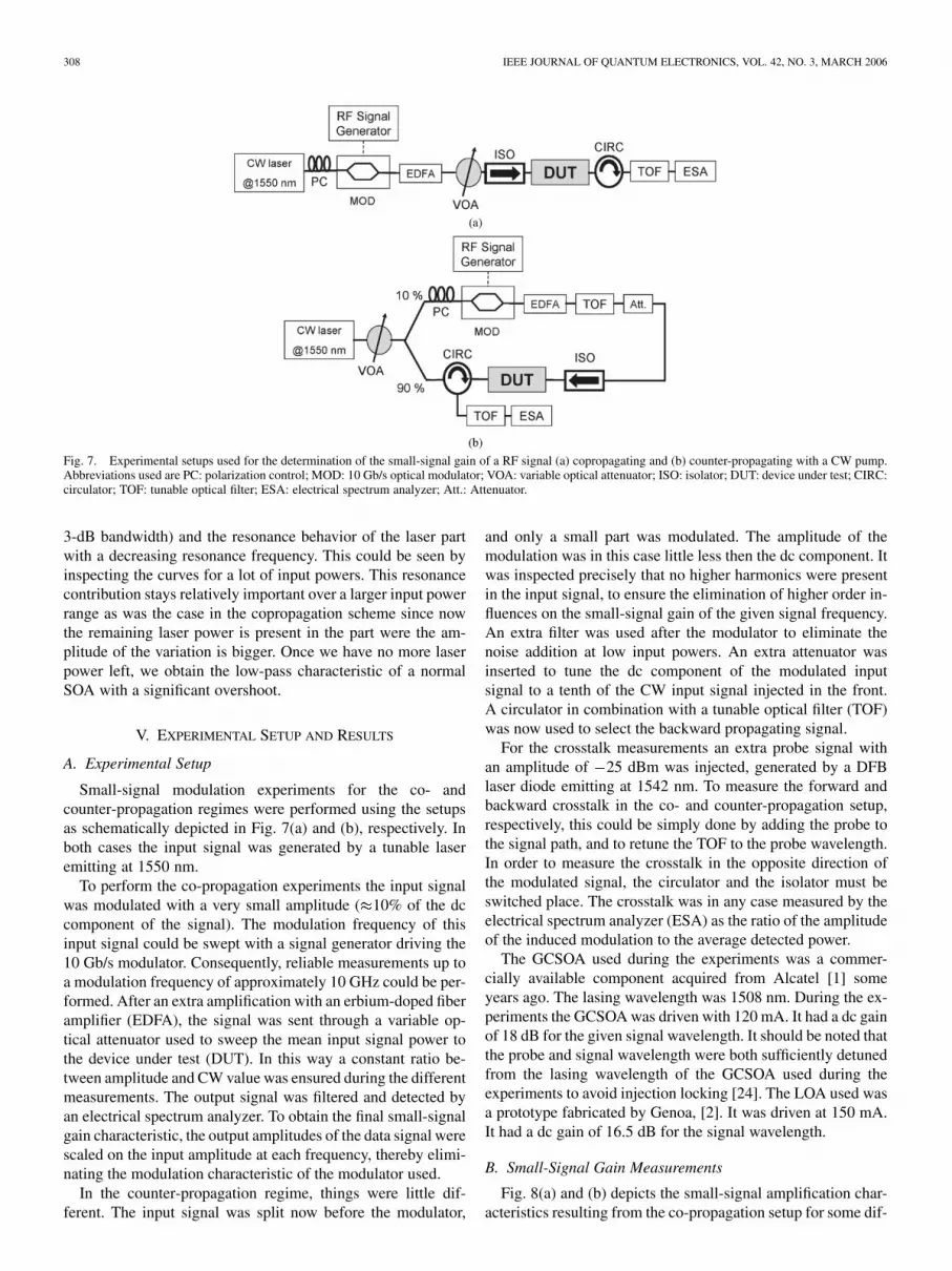
Fig. 7. Experimental setups used for the determination of the small-signal gain of a RF signal (a) copropagating and (b) counter-propagating with a CW pump.Abbreviations used are PC: polarization control; MOD: 10 Gb/s optical modulator; VOA: variable optical attenuator; ISO: isolator; DUT: device under test; CIRC:circulator; TOF: tunable optical filter; ESA: electrical spectrum analyzer; Att.: Attenuator.
3-dB bandwidth) and the resonance behavior of the laser partwith a decreasing resonance frequency. This could be seen byinspecting the curves for a lot of input powers. This resonancecontribution stays relatively important over a larger input powerrange as was the case in the copropagation scheme since nowthe remaining laser power is present in the part were the am-plitude of the variation is bigger. Once we have no more laserpower left, we obtain the low-pass characteristic of a normalSOA with a significant overshoot.
V. EXPERIMENTAL SETUP AND RESULTS
A. Experimental Setup
Small-signal modulation experiments for the co- andcounter-propagation regimes were performed using the setupsas schematically depicted in Fig. 7(a) and (b), respectively. Inboth cases the input signal was generated by a tunable laseremitting at 1550 nm.
To perform the co-propagation experiments the input signalwas modulated with a very small amplitude ( 10% of the dccomponent of the signal). The modulation frequency of thisinput signal could be swept with a signal generator driving the10 Gb/s modulator. Consequently, reliable measurements up toa modulation frequency of approximately 10 GHz could be per-formed. After an extra amplification with an erbium-doped fiberamplifier (EDFA), the signal was sent through a variable op-tical attenuator used to sweep the mean input signal power tothe device under test (DUT). In this way a constant ratio be-tween amplitude and CW value was ensured during the differentmeasurements. The output signal was filtered and detected byan electrical spectrum analyzer. To obtain the final small-signalgain characteristic, the output amplitudes of the data signal werescaled on the input amplitude at each frequency, thereby elimi-nating the modulation characteristic of the modulator used.
In the counter-propagation regime, things were little dif-ferent. The input signal was split now before the modulator,
and only a small part was modulated. The amplitude of themodulation was in this case little less then the dc component. Itwas inspected precisely that no higher harmonics were presentin the input signal, to ensure the elimination of higher order in-fluences on the small-signal gain of the given signal frequency.An extra filter was used after the modulator to eliminate thenoise addition at low input powers. An extra attenuator wasinserted to tune the dc component of the modulated inputsignal to a tenth of the CW input signal injected in the front.A circulator in combination with a tunable optical filter (TOF)was now used to select the backward propagating signal.
For the crosstalk measurements an extra probe signal withan amplitude of 25 dBm was injected, generated by a DFBlaser diode emitting at 1542 nm. To measure the forward andbackward crosstalk in the co- and counter-propagation setup,respectively, this could be simply done by adding the probe tothe signal path, and to retune the TOF to the probe wavelength.In order to measure the crosstalk in the opposite direction ofthe modulated signal, the circulator and the isolator must beswitched place. The crosstalk was in any case measured by theelectrical spectrum analyzer (ESA) as the ratio of the amplitudeof the induced modulation to the average detected power.
The GCSOA used during the experiments was a commer-cially available component acquired from Alcatel [1] someyears ago. The lasing wavelength was 1508 nm. During the ex-periments the GCSOA was driven with 120 mA. It had a dc gainof 18 dB for the given signal wavelength. It should be noted thatthe probe and signal wavelength were both sufficiently detunedfrom the lasing wavelength of the GCSOA used during theexperiments to avoid injection locking [24]. The LOA used wasa prototype fabricated by Genoa, [2]. It was driven at 150 mA.It had a dc gain of 16.5 dB for the signal wavelength.
B. Small-Signal Gain Measurements
Fig. 8(a) and (b) depicts the small-signal amplification char-acteristics resulting from the co-propagation setup for some dif-

VERSPURTEN et al.: EXPERIMENTAL AND NUMERICAL SMALL-SIGNAL ANALYSIS 309
Fig. 8. Experimentally obtained small-signal gain curves of a (a) GCSOA driven with 100 mA and of (b) a LOA driven with 150 mA in the co-propagation regime.
Fig. 9. Experimentally obtained small-signal gain curves of a (a) GCSOA driven with 100 mA and of (b) a LOA driven with 150 mA in the counter-propagationregime.
ferent input powers, in the case of a GCSOA and a LOA, re-spectively. For clarity reasons in the case of the LOA only arelatively small input power region is shown. This makes it pos-sible to see the very weak resonance effect at an input power of
11 dBm. It can be seen that for low input powers the gain isalmost equal to the dc gain for all signal frequencies. The ex-perimentally obtained SSFR of the GCSOA show a much moreexplicit resonance phenomenon as was predicted by the sim-ulations. The input saturation power tends to be approximately
9.5 dBm. A sudden switch to the high-pass SOA characteristiccan be observed once this power is exceeded, in contrast witha more gradual transition in the LOA. It should be noted thatthe resonance frequency of the LOA is little more then 1 GHz,whereas this was much higher (somewhat smaller then 10 GHz)in the simulations. In measurements of [13] a resonance of al-most 3 GHz was observed, whereas the model of [12] also re-sulted in some cases in resonance frequencies in the vicinity of10 GHz. However, this absolute value is not that important in
understanding the effects discussed here. Of course the lowerresonance frequency leads to much smaller crosstalk at higherbitrates, which is advantageous in WDM applications.
The results for the counter-propagation regime are shown inFig. 9(a) and (b) for the GCSOA and the LOA, respectively. Afairly constant amplification is obtained, within the given mea-surement accuracies. This is in good agreement with the numer-ical results. By comparison with the co-propagation measure-ment we see that the obtained constant gain is almost equal tothe high frequency limit of the previous case, with a small devia-tion in the saturated case possibly caused by a little consumptionof the dc gain by the counter-propagating modulated signal.
C. Small-Signal Crosstalk Measurements
The experimentally obtained crosstalk induced on the probesignal in forward and backward propagation direction in theco-propagation scheme are plotted both in the same figure againto make comparison possible. For the GCSOA this is shown in
310 IEEE JOURNAL OF QUANTUM ELECTRONICS, VOL. 42, NO. 3, MARCH 2006
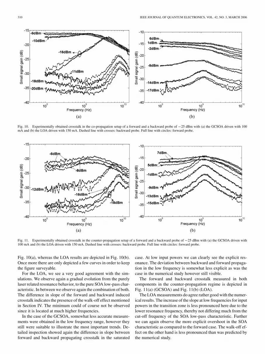
Fig. 10. Experimentally obtained crosstalk in the co-propagation setup of a forward and a backward probe of �25 dBm with (a) the GCSOA driven with 100mA and (b) the LOA driven with 150 mA. Dashed line with crosses: backward probe. Full line with circles: forward probe.
Fig. 11. Experimentally obtained crosstalk in the counter-propagation setup of a forward and a backward probe of �25 dBm with (a) the GCSOA driven with100 mA and (b) the LOA driven with 150 mA. Dashed line with crosses: backward probe. Full line with circles: forward probe.
Fig. 10(a), whereas the LOA results are depicted in Fig. 10(b).Once more there are only depicted a few curves in order to keepthe figure surveyable.
For the LOA, we see a very good agreement with the sim-ulations. We observe again a gradual evolution from the purelylaser related resonance behavior, to the pure SOA low-pass char-acteristic. In between we observe again the combination of both.The difference in slope of the forward and backward inducedcrosstalk indicates the presence of the walk-off effect mentionedin Section IV. The minimum could of course not be observedsince it is located at much higher frequencies.
In the case of the GCSOA, somewhat less accurate measure-ments were obtained in the low frequency range, however theystill were suitable to illustrate the most important trends. De-tailed inspection showed again the difference in slope betweenforward and backward propagating crosstalk in the saturated
case. At low input powers we can clearly see the explicit res-onance. The deviation between backward and forward propaga-tion in the low frequency is somewhat less explicit as was thecase in the numerical study however still visible.
The forward and backward crosstalk measured in bothcomponents in the counter-propagation regime is depicted inFig. 11(a) (GCSOA) and Fig. 11(b) (LOA).
The LOA measurements do agree rather good with the numer-ical results. The increase of the slope at low frequencies for inputpowers in the transition zone is less pronounced here due to thelower resonance frequency, thereby not differing much from thecut-off frequency of the SOA low-pass characteristic. Furtherwe can again observe the more explicit overshoot in the SOAcharacteristic as compared to the forward case. The walk-off ef-fect on the other hand is less pronounced than was predicted bythe numerical study.
VERSPURTEN et al.: EXPERIMENTAL AND NUMERICAL SMALL-SIGNAL ANALYSIS 311
Results obtained with the GCSOA tend to be a little less accu-rate, but as was the case above show most of the trends discussedabove.
VI. CONCLUSION
We performed a systematic and in-depth numerical andexperimental analysis of the dynamics of two types ofgain-clamped semiconductor amplifiers under small-signaloptical modulation. A rate equation model enabling numericalstudies of the dynamics in a LOA was developed.
A study of the small-signal gain of a RF signal co- andcounter-propagating with a strong pump resulted in the obser-vation of a clear resonance phenomenon in the co-propagatingcase leading to a dip in the SSFR. The dip seems to occur ata decreasing frequency in function of the injected CW power.This was less pronounced in the LOA due to the clampingbeing the result of several independently acting lasers eachproviding only a small part of the gain. In the counter-propa-gating case we found a fairly constant amplification in functionof signal frequency for both amplifiers. This was the result ofthe less pronounced modulation of the input signal in the partof the amplifiers being most sensitive to power variations. Thenumerically obtained results were confirmed by experiments.
In both the co- and counter-propagation regime, the crosstalkinduced on a forward and backward injected probe signal werestudied. Simulations as well as experiments showed a clear res-onant behavior in both components as long as laser light waspresent in the cavity. With increasing input power, this resultedin the LOA in a gradual transition from this regime to a low-passbehavior of a SOA. In the GCSOA, this transition took place ina smaller input power region. A walk-off effect resulted in bothcomponents in a faster decrease of the backward as compared tothe forward crosstalk for high frequencies in the co-propagationregime. In the counter-propagation case, this was somewhat lesspronounced. Also in the lower frequency range, a difference be-tween the crosstalk on a backward propagating and a forwardpropagating probe could be observed in the GCSOA due to aphase delay associated with signal, laser and probe, all propa-gating in parallel.
It is clear that the difference in clamping mechanism resultsin a clearly different RF signal amplification behavior. Thecrosstalk, on the other hand, is behaving much more similarin both cases, showing a clear resonance in the vicinity of theresonance frequencies of the incorporated lasers. In the experi-ments those resonance frequencies seemed to be much smallerfor the LOA. The study also showed that for most applicationsboth components can be used best at low saturation degrees,thereby avoiding explicit resonance effects.
REFERENCES
[1] P. Doussiere, A. Jourdan, G. Soulage, P. Garabedian, C. Graver, T. Fil-lion, E. Derouin, and D. Leclerc, “Clamped gain travelling wave semi-conductor optical amplifier for wavelength division multiplexing appli-cations,” in Proc. Int. Semiconduct. Laser Conf., Sep. 1994, pp. 185–186.
[2] D. Francis, S. DiJaili, and J. Walker, “A single chip linear optical ampli-fier,” in Proc. Opt. Fiber Commun. Conf., Mar. 2001, p. PD13.
[3] L. Tiemeijer, P. Thijs, T. van Dongen, J. Binsma, E. Jansen, and H.van Helleputte, “Reduced intermodulation distortion in 1300 nm gain-clamped MQW laser amplifiers,” IEEE Photon. Technol. Lett., vol. 7,no. 3, pp. 284–286, Mar. 1995.
[4] J. C. E. Tangdiongga, L. Spiekman, G. van den Hoven, and H. de Waardt,“Performance analysis of linear optical amplifiers in dynamic WDM sys-tems,” IEEE Photon. Technol. Lett., vol. 14, no. 8, pp. 1196–1198, Aug.2002.
[5] H. Lee, J. Oh, D. Lee, G. Lee, and S. Hwang, “Demonstration of 16 �10 Gb/s WDM transmission over 4 � 40 km of SMF using linear op-tical amplifiers combined with Raman-pumped dispersion compensationfibers under dynamic add/drop situations,” IEEE Photon. Technol. Lett.,vol. 16, no. 6, pp. 1576–1578, Jun. 2004.
[6] G. Morthier, M. Zhao, B. Vanderhaegen, and R. Baets, “Experimentaldemonstration of an all-optical 2R regenerator with adjustable deci-sion threshold and “true” regeneration characteristics,” IEEE Photon.Technol. Lett., vol. 12, no. 11, pp. 1516–1518, Nov. 2000.
[7] M. Zhao, J. D. Merlier, G. Morthier, and R. Baets, “All-optical 2R re-generation based on polarization rotation in a linear optical amplifier,”IEEE Photon. Technol. Lett., vol. 15, no. 2, pp. 305–307, Feb. 2003.
[8] E. Tangdiongga, J. Turkiewicz, G. Khoe, and H. de Waardt, “Clock re-covery by a fiber ring laser employing a linear optical amplifier,” IEEEPhoton. Technol. Lett., vol. 16, no. 2, pp. 611–613, Feb. 2004.
[9] J. Sun, G. Morthier, and R. Baets, “Numerical and theoretical study ofthe crosstalk in gain-clamped semiconductor optical amplifiers,” IEEEJ. Sel. Topics Quantum Electron., vol. 3, no. 5, pp. 1162–1167, Sep./Oct.1997.
[10] X. Jin, T. Keating, and S. L. Chuang, “Theory and experiment of high-speed cross-gain modulation in semiconductor lasers,” IEEE J. QuantumElectron., vol. 36, no. 12, pp. 1485–1493, Dec. 2000.
[11] J. Oksanen and J. Tulkki, “On crosstalk and noise in an optical amplifierwith gain clamping by vertical laser field,” J. Lightw. Technol., vol. 21,no. 9, pp. 1914–1919, Sep. 2003.
[12] C.-Y. Jin, Y.-Z. Huang, L.-J. Yu, and S.-L. Deng, “Numerical and the-oretical analysis of the crosstalk in linear optical amplifiers,” IEEE J.Quantum Electron., vol. 41, no. 5, pp. 636–641, May 2005.
[13] D. Tong, M. Wu, and S. Dijaili, “Intrinsic intermodulation distortioncharacteristics of linear optical amplifier,” in Proc. Conf. Lasers andElectro-Optics, Jun. 2003, pp. 1414–1416.
[14] C.-Y. Jin, Y.-Z. Huang, L.-J. Yu, and S. Deng, “Detailed model and in-vestigation of gain saturation and carrier spatial hole burning for a semi-conductor optical amplifier with gain clamping by a vertical laser field,”IEEE J. Quantum Electron., vol. 40, no. 5, pp. 513–518, May 2004.
[15] L. Schares, C. Schubert, C. Schmidt, H. G. Weber, L. Occhi, and G.Guekos, “Phase dynamics of semiconductor optical amplifiers at 10–40GHz,” IEEE J. Quantum Electron., vol. 39, no. 11, pp. 1394–1408, Nov.2003.
[16] M. Asghari, I. H. White, and R. V. Penty, “Wavelength conversionusing semiconductor optical amplifiers,” J. Lightw. Technol., no. 7, pp.1181–1190, Jul. 1997.
[17] K. Petermann, Laser Diode Modulation and Noise. Norwell, MA:Kluwer, 1988.
[18] P. Vankwikelberge, G. Morthier, and R. Baets, “Cladiss-a longitudinalmultimode model for the analysis of the static, dynamic, and stochasticbehavior of diode lasers with distributed feedback,” IEEE J. QuantumElectron., vol. 26, no. 10, pp. 1728–1741, Oct. 1990.
[19] G. Morthier, J. Sun, T. Gyselings, and R. Baets, “A novel optical deci-sion circuit based on a Mach–Zehnder or Michelson interferometer andgain-clamped semiconductor optical amplifiers,” IEEE Photon. Technol.Lett., vol. 10, no. 8, pp. 1162–1164, Aug. 1998.
[20] T. Durhuus, B. Mikkelsen, C. Joergensen, S. Danielsen, and K. Stubk-jaer, “All-optical wavelength conversion by semiconductor optical am-plifiers,” J. Lightw. Technol, vol. 14, no. 6, pp. 942–954, Jun. 1996.
[21] M. Nielsen, D. Blumenthal, and J. Mørk, “A transfert function approachto the small-signal response of saturated semiconductor optical ampli-fiers,” J. Lightw. Technol, vol. 18, no. 12, pp. 2151–2157, Dec. 2000.
[22] D. Marcenac and A. Mecozzi, “Switches and frequency converters basedon cross-gain modulation in semiconductor optical amplifiers,” IEEEPhoton. Technol Lett., vol. 9, no. 6, pp. 749–751, Jun. 1997.
[23] G. Morthier, R. Schatz, and O. Kjebon, “Extended modulation band-width of DBR and external cavity lasers by utilizing a cavity resonancefor equalization,” IEEE J. Quantum Electron., vol. 36, no. 12, pp.1468–1475, Dec. 2000.
[24] V. Annovazzi-Lodi, A. Scire, M. Sorel, and S. Donati, “Dynamic be-havior and locking of a semiconductor laser subjected to external injec-tion,” IEEE J. Quantum Electron., vol. 34, no. 12, pp. 2350–2357, Dec.1998.
312 IEEE JOURNAL OF QUANTUM ELECTRONICS, VOL. 42, NO. 3, MARCH 2006
Sam Verspurten (S’01) was born in Ghent, Belgium,in 1978. He received the M.S. degree in electrotech-nical engineering from Ghent University, Ghent, Bel-gium, in 2001, where he is currently working towardthe Ph.D. degree in electrical engineering.
His research interests include all-optical signalprocessing using semiconductor optical amplifiersand the modeling of the dynamics of those compo-nents.
Geert Morthier (M’93–SM’01) received the M.S.degree in electrical engineering and the Ph.D. degreefrom Ghent University, Ghent, Belgium, in 1987 and1991, respectively.
Since 1991, he has been a Member of the Perma-nent Staff of the Interuniversity MicroElectronicsCenter (IMEC), Ghent University. From 1998 to1999, he was the Project Manager of the ACTSproject ACTUAL, and since 2001 he has beenProject Manager of the IST project NEWTON onwidely tunable lasers. In 2001, he was appointed
part-time Professor at Ghent University. He has authored or coauthored around100 papers and two books in the field. His main research interests are in themodeling and characterization of optoelectronic components.
Roel Baets (M’88–SM’96) received the M.S. degreein electrical engineering and the Ph.D. degree fromGhent University, Ghent, Belgium, in 1980 and 1984,respectively, and the M.Sc. degree in electrical engi-neering from Stanford University, Stanford, CA, in1981.
Since 1981, he has been with the Department ofInformation Technology (INTEC), Ghent University,where he has been a Professor since 1989. He iscurrently the Head of the optoelectronics group.He has worked in the field of III–V devices for
optoelectronic systems. With about 200 publications and conference papers, hehas made contributions to the design and fabrication of semiconductor laserdiodes, passive guided wave devices, PICs, and microoptic components.
Dr. Baets is a Member of the Optical Society of America, the IEEE Laserand Electro-Optics Society, the International Society for Optical Engineering(SPIE), and the Flemish Engineers Association.