active neutral-point-clamped multilevel converters
TRANSCRIPT
Active-Neutral-Point-Clamped (ANPC) Multilevel Converter Technology
Peter Barbosa1, Peter Steimer2, Jürgen Steinke2, Manfred Winkelnkemper1, and Nikola Celanovic1
1ABB Switzerland Ltd Corporate Research
Segelhof 1 5405 Dättwil
2ABB Switzerland Ltd Power Electronics and MV Drives
Austrasse 5300 Turgi
Acknowledgment The authors would like to thank the Office of Naval Research for supporting part of this work under Agreement N00014-99-3-0002 “Very High Power PEBB Demonstration.”
Keywords «Multilevel converters», «power quality», «harmonics», «modulation strategy», «voltage source inverters (VSIs)»
Abstract This paper proposes a multilevel power conversion concept based on the combination of neutral-point-clamped (NPC) and floating capacitor converters. In the proposed scheme, the voltage balancing across the floating capacitors is achieved by using a proper selection of redundant switching states, and the neutral-point voltage is controlled by the classical dc offset injection. Experimental results are illustrated in the paper to demonstrate the system operation.
Introduction Multilevel topologies provide a clever way of connecting switches in series, thus enabling the processing of voltages that are higher than the device rating. The industry need for medium voltage drives has triggered considerable research in this field, in which most applications include drives for pumps, blowers, compressors, conveyors, and the like. In general, multilevel converters are effective means of reducing harmonic distortion and dv/dt of the output voltages, which makes this technology applicable to utility interface and drives.
There are a limited number of topologies that provide multilevel voltages and are suitable for medium voltage applications. The most known topologies are the neutral-point-clamped (NPC), the flying capacitor (FC), and the cascaded H-bridge multilevel converters [1] [2] [3] [4]. Other topologies such as the hybrid converters have been proposed as well, but they are not fully accepted for industrial applications [5] [6].
The NPC multilevel converter shown in Figure 1(a) is a natural extension of the three-level converter presented by Nabae (NPC3L). As can be seen, the multilevel NPC converter requires multiple clamping points to synthesize the different voltage levels across the output. The disadvantage of multiple clamping points is a limitation on the maximum modulation index that is allowed with active power to assure voltage sharing across all the dc link capacitors [7]. Another drawback of the multilevel NPC converter is the need for series connection of the clamping diodes [8].
Figure 1(b) illustrates a five-level floating capacitor converter. By properly using the dc link and floating capacitor voltages, one can synthesize the required voltage levels across the output terminals. An interesting property of the floating capacitor converter is that the redundant switching states can be used to achieve proper voltage control across the floating capacitors. In general, the energy stored in the floating capacitors is a limiting factor to increasing the number of voltage levels, which makes the five-level approach the most practical for industrial applications. An increased number of voltage levels may only be practical from the view point of floating capacitor requirements if the
Active-Neutral-Point-Clamped (ANPC) Multilevel Converter Technology BARBOSA Peter
EPE 2005 - Dresden ISBN : 90-75815-08-5 P.1
carrier frequency of the converter is increased. However, there are tradeoffs that should be observed between carrier frequency and switching losses in the converter.
The cascaded H-bridge multilevel converter shown in Figure 1(c) takes advantage of connecting single-phase inverters in series that are fed by independent dc voltage sources. The approach can be extremely modular, and a stair-cased output voltage is produced by adding and/or subtracting the voltages of the single-phase modules. The power flow may be bi-directional if active front-end rectifiers are used in the single-phase modules. Although modular, the cascaded H-bridge multilevel converter requires a complex transformer to provide the various independent dc sources.
Based upon the previous description, this paper proposes an active neutral-point-clamped (ANPC) multilevel converter that combines the flexibility of the multilevel floating capacitor converter with the robustness of industrial NPC converters to generate multilevel voltages. The proposed concept is described and supported by simulation results, and experimental validation demonstrates the proposed technology.
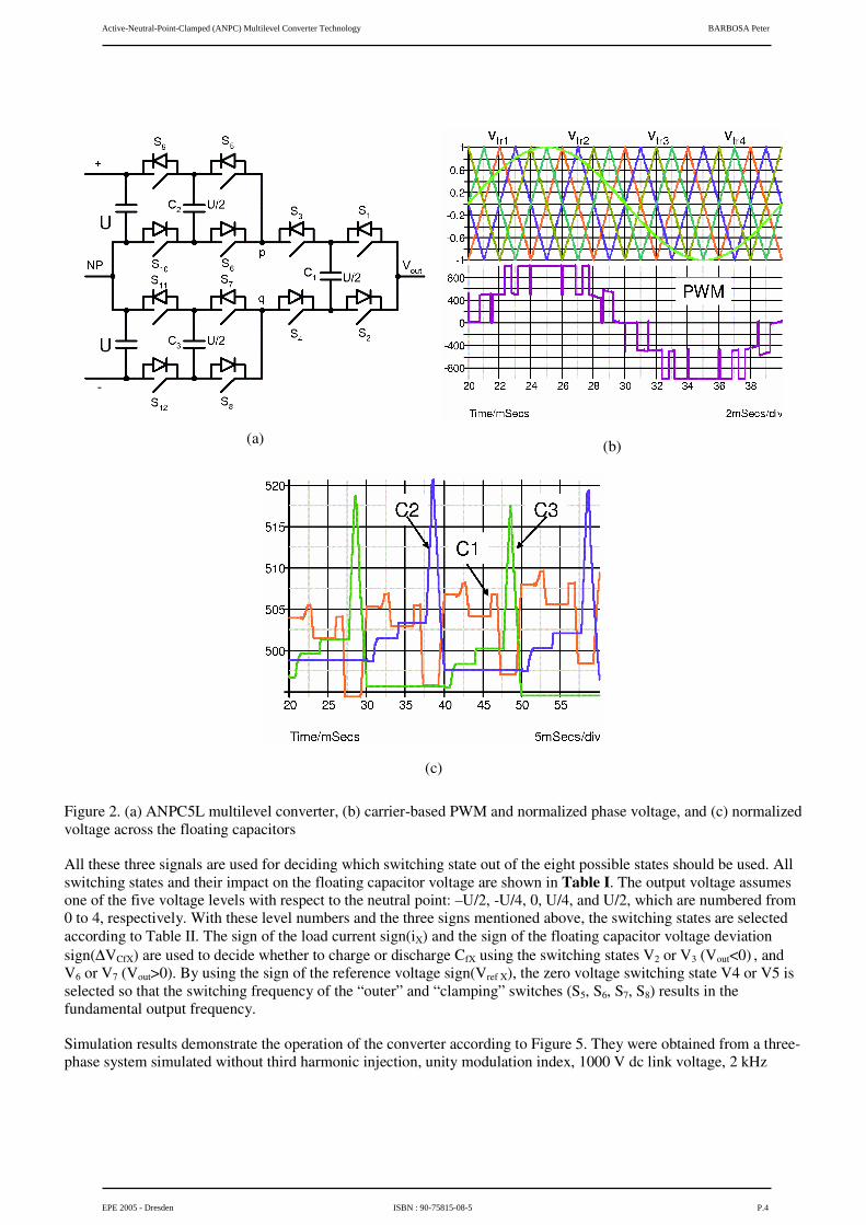
Proposed concept The proposed concept is shown in Figure 2(a), which is named active-neutral-point-clamped five-level (ANPC5L) converter. As can be seen, the proposed converter is an arrangement of two-level inverters connected in series. Two of such subsystems are connected in parallel with the dc-link capacitors. The first subsystem is comprised of S5, S6, S9, S10, and C2, while the second subsystem is comprised of S7, S8, S11, S12, and C3. A third subsystem (S1, S2, S3, S4, and C1) is then used to connect the converter to the output phase. In general, an N-level converter can be obtained by cascading (N-1)/2 two-level inverters per subsystem according to Figure 2(a).
A carrier-based PWM strategy can be used to generate the pulse pattern, as shown in Figure 2(b) [9]. Four triangular carriers are used and phase-shifted by 90°. The first carrier generates pulses to S1 and S2, the second carrier to S3 and S4, the third carrier to S5, S6, S7, and S8, and the fourth carrier to S9, S10, S11, and S12. It is worth mentioning that the switches S5 and S7 are operated in phase, and while S6 and S8 are also in phase, they are complementary to S5 and S7. A similar sequence is applied to S9, S10, S11, and S12. The resulting normalized phase voltage (normalized with respect to half of the dc-link voltage) is also illustrated in Figure 2(b), and it contains five different voltage levels as shown. For an N-level converter, it would be necessary (N-1) carrier waveforms phase-shifted by 360°/(N-1).
The voltage blocking capability of the switches in the proposed converter is only U/2, where U is half of the dc link voltage. A generalized converter with N levels would result in a voltage stress across the switches of U/((N-1)/2). It is worth mentioning that a capacitor may be connected between points p and q. Nevertheless, whenever any of the dc-link capacitors is switched in parallel with a capacitor connected between p and q, a loop current would be allowed to circulate in order to balance the voltages across the capacitors being connected in parallel, which might be any of the dc-link capacitors and the capacitor connected between p and q. Such approach is not advantageous for high power applications because the loop current that is created produces losses that are inversely proportional to the carrier frequency and the capacitance value connected between p and q [10].
Figure 2(c) shows the normalized voltages (also normalized with respect to half of the dc-link voltage) across the various floating capacitors. As can be seen, natural voltage balancing is achieved using the modulation pattern shown in Figure 2(b). At light load, however, it may be required the connection of booster circuits, which are passive networks to improve the voltage balancing performance [3].
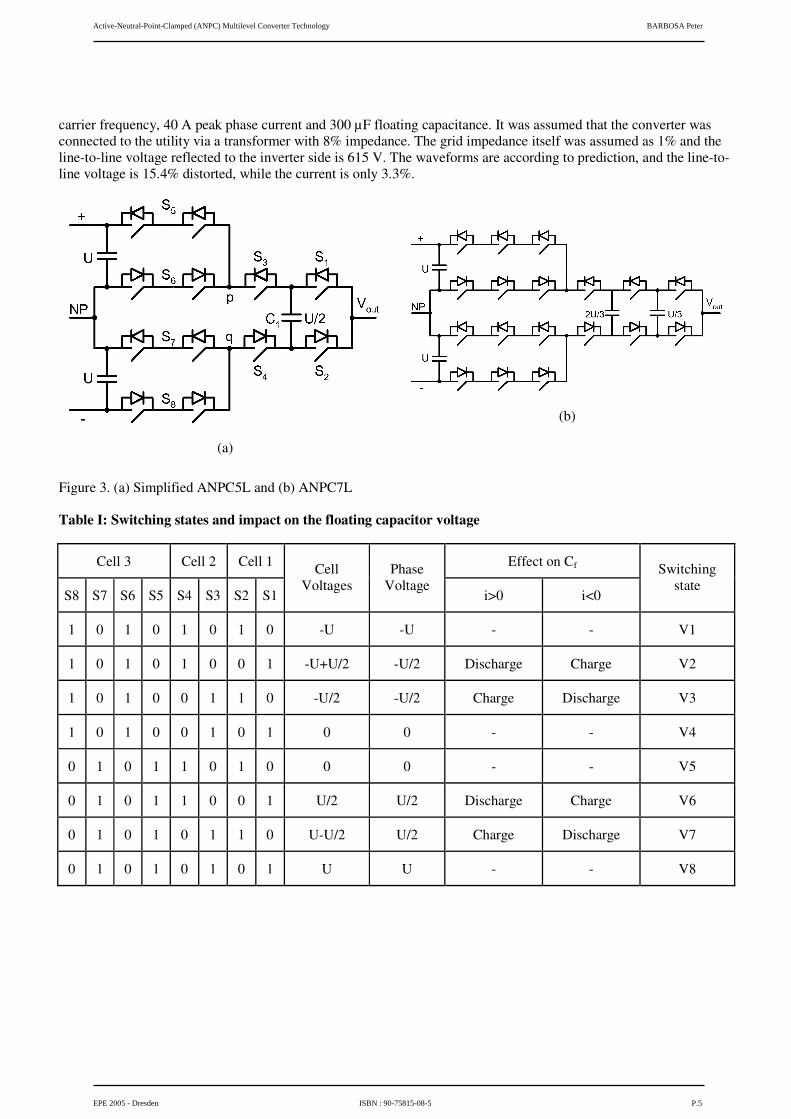
Simplified Structure One has to realize that three floating capacitors add excessive cost to the overall system, and require space for accommodating the entire volume. For this reason, it is of utmost importance to reduce the number of floating capacitors in the topology. This can be achieved by further eliminating C2 and C3 from the circuit, as shown in Figure 3(a). In fact, the converter configuration shown in Figure 3(a) is similar to the ANPC3L converter previously discussed [11]. The difference here is the strategic connection of the floating capacitor that makes it possible to upgrade the number of levels from three to five. Although the elimination of the floating capacitors C2 and C3 from
Active-Neutral-Point-Clamped (ANPC) Multilevel Converter Technology BARBOSA Peter
EPE 2005 - Dresden ISBN : 90-75815-08-5 P.2
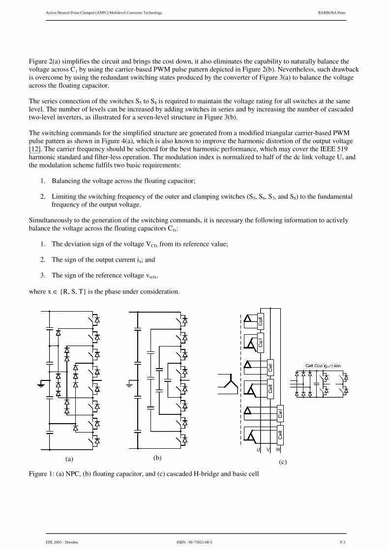
Figure 2(a) simplifies the circuit and brings the cost down, it also eliminates the capability to naturally balance the voltage across C1 by using the carrier-based PWM pulse pattern depicted in Figure 2(b). Nevertheless, such drawback is overcome by using the redundant switching states produced by the converter of Figure 3(a) to balance the voltage across the floating capacitor.
The series connection of the switches S5 to S8 is required to maintain the voltage rating for all switches at the same level. The number of levels can be increased by adding switches in series and by increasing the number of cascaded two-level inverters, as illustrated for a seven-level structure in Figure 3(b).
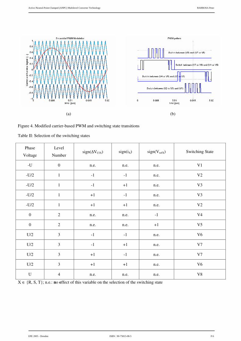
The switching commands for the simplified structure are generated from a modified triangular carrier-based PWM pulse pattern as shown in Figure 4(a), which is also known to improve the harmonic distortion of the output voltage [12]. The carrier frequency should be selected for the best harmonic performance, which may cover the IEEE 519 harmonic standard and filter-less operation. The modulation index is normalized to half of the dc link voltage U, and the modulation scheme fulfils two basic requirements:
1. Balancing the voltage across the floating capacitor;
2. Limiting the switching frequency of the outer and clamping switches (S5, S6, S7, and S8) to the fundamental frequency of the output voltage.
Simultaneously to the generation of the switching commands, it is necessary the following information to actively balance the voltage across the floating capacitors Cfx:
1. The deviation sign of the voltage VCfx from its reference value;
2. The sign of the output current ix; and
3. The sign of the reference voltage vrefx.
where x ∈ {R, S, T} is the phase under consideration.
(a)
(b)
(c)
Figure 1: (a) NPC, (b) floating capacitor, and (c) cascaded H-bridge and basic cell
Active-Neutral-Point-Clamped (ANPC) Multilevel Converter Technology BARBOSA Peter
EPE 2005 - Dresden ISBN : 90-75815-08-5 P.3
(a)
(b)
(c)
Figure 2. (a) ANPC5L multilevel converter, (b) carrier-based PWM and normalized phase voltage, and (c) normalized voltage across the floating capacitors
All these three signals are used for deciding which switching state out of the eight possible states should be used. All switching states and their impact on the floating capacitor voltage are shown in Table I. The output voltage assumes one of the five voltage levels with respect to the neutral point: –U/2, -U/4, 0, U/4, and U/2, which are numbered from 0 to 4, respectively. With these level numbers and the three signs mentioned above, the switching states are selected according to Table II. The sign of the load current sign(iX) and the sign of the floating capacitor voltage deviation sign(∆VCfX) are used to decide whether to charge or discharge CfX using the switching states V2 or V3 (Vout<0) , and V6 or V7 (Vout>0). By using the sign of the reference voltage sign(Vref X), the zero voltage switching state V4 or V5 is selected so that the switching frequency of the “outer” and “clamping” switches (S5, S6, S7, S8) results in the fundamental output frequency.
Simulation results demonstrate the operation of the converter according to Figure 5. They were obtained from a three-phase system simulated without third harmonic injection, unity modulation index, 1000 V dc link voltage, 2 kHz
Active-Neutral-Point-Clamped (ANPC) Multilevel Converter Technology BARBOSA Peter
EPE 2005 - Dresden ISBN : 90-75815-08-5 P.4
carrier frequency, 40 A peak phase current and 300 µF floating capacitance. It was assumed that the converter was connected to the utility via a transformer with 8% impedance. The grid impedance itself was assumed as 1% and the line-to-line voltage reflected to the inverter side is 615 V. The waveforms are according to prediction, and the line-to-line voltage is 15.4% distorted, while the current is only 3.3%.
(a)
(b)
Figure 3. (a) Simplified ANPC5L and (b) ANPC7L
Table I: Switching states and impact on the floating capacitor voltage
Cell 3 Cell 2 Cell 1 Effect on Cf
S8 S7 S6 S5 S4 S3 S2 S1
Cell Voltages
Phase Voltage
i>0 i<0
Switching state
1 0 1 0 1 0 1 0 -U -U - - V1
1 0 1 0 1 0 0 1 -U+U/2 -U/2 Discharge Charge V2
1 0 1 0 0 1 1 0 -U/2 -U/2 Charge Discharge V3
1 0 1 0 0 1 0 1 0 0 - - V4
0 1 0 1 1 0 1 0 0 0 - - V5
0 1 0 1 1 0 0 1 U/2 U/2 Discharge Charge V6
0 1 0 1 0 1 1 0 U-U/2 U/2 Charge Discharge V7
0 1 0 1 0 1 0 1 U U - - V8
Active-Neutral-Point-Clamped (ANPC) Multilevel Converter Technology BARBOSA Peter
EPE 2005 - Dresden ISBN : 90-75815-08-5 P.5
(a)
(b)
Figure 4. Modified carrier-based PWM and switching state transitions
Table II: Selection of the switching states
Phase
Voltage
Level
Number sign(∆VCfX) sign(iX) sign(VrefX) Switching State
-U 0 n.e. n.e. n.e. V1
-U/2 1 -1 -1 n.e. V2
-U/2 1 -1 +1 n.e. V3
-U/2 1 +1 -1 n.e. V3
-U/2 1 +1 +1 n.e. V2
0 2 n.e. n.e. -1 V4
0 2 n.e. n.e. +1 V5
U/2 3 -1 -1 n.e. V6
U/2 3 -1 +1 n.e. V7
U/2 3 +1 -1 n.e. V7
U/2 3 +1 +1 n.e. V6
U 4 n.e. n.e. n.e. V8
X ∈ {R, S, T}; n.e.: no effect of this variable on the selection of the switching state
Active-Neutral-Point-Clamped (ANPC) Multilevel Converter Technology BARBOSA Peter
EPE 2005 - Dresden ISBN : 90-75815-08-5 P.6
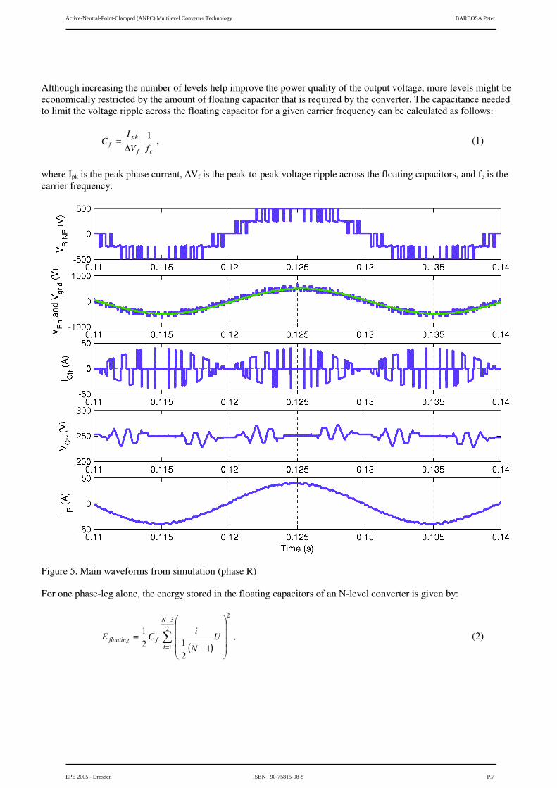
Although increasing the number of levels help improve the power quality of the output voltage, more levels might be economically restricted by the amount of floating capacitor that is required by the converter. The capacitance needed to limit the voltage ripple across the floating capacitor for a given carrier frequency can be calculated as follows:
cf
pkf fV
IC
1∆
= , (1)
where Ipk is the peak phase current, ∆Vf is the peak-to-peak voltage ripple across the floating capacitors, and fc is the carrier frequency.
Figure 5. Main waveforms from simulation (phase R)
For one phase-leg alone, the energy stored in the floating capacitors of an N-level converter is given by:
( )
�
−
= ����
�
�
����
�
�
−=
23
1
2
1212
1N
iffloating U
N
iCE , (2)
Active-Neutral-Point-Clamped (ANPC) Multilevel Converter Technology BARBOSA Peter
EPE 2005 - Dresden ISBN : 90-75815-08-5 P.7
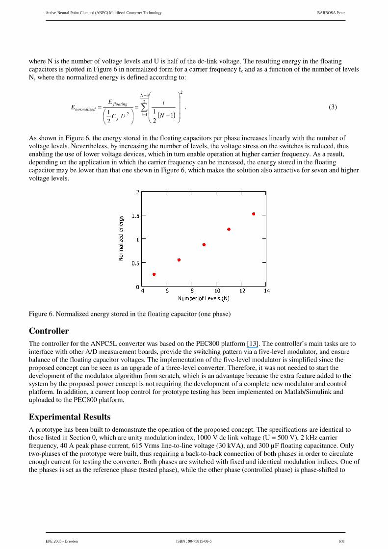
where N is the number of voltage levels and U is half of the dc-link voltage. The resulting energy in the floating capacitors is plotted in Figure 6 in normalized form for a carrier frequency fc and as a function of the number of levels N, where the normalized energy is defined according to:
( )
�
−
= ����
�
�
����
�
�
−=
��
���
�=
23
1
2
2 121
21
N
if
floatingnormalized
N
i
UC
EE . (3)
As shown in Figure 6, the energy stored in the floating capacitors per phase increases linearly with the number of voltage levels. Nevertheless, by increasing the number of levels, the voltage stress on the switches is reduced, thus enabling the use of lower voltage devices, which in turn enable operation at higher carrier frequency. As a result, depending on the application in which the carrier frequency can be increased, the energy stored in the floating capacitor may be lower than that one shown in Figure 6, which makes the solution also attractive for seven and higher voltage levels.
Figure 6. Normalized energy stored in the floating capacitor (one phase)
Controller The controller for the ANPC5L converter was based on the PEC800 platform [13]. The controller’s main tasks are to interface with other A/D measurement boards, provide the switching pattern via a five-level modulator, and ensure balance of the floating capacitor voltages. The implementation of the five-level modulator is simplified since the proposed concept can be seen as an upgrade of a three-level converter. Therefore, it was not needed to start the development of the modulator algorithm from scratch, which is an advantage because the extra feature added to the system by the proposed power concept is not requiring the development of a complete new modulator and control platform. In addition, a current loop control for prototype testing has been implemented on Matlab/Simulink and uploaded to the PEC800 platform.
Experimental Results A prototype has been built to demonstrate the operation of the proposed concept. The specifications are identical to those listed in Section 0, which are unity modulation index, 1000 V dc link voltage (U = 500 V), 2 kHz carrier frequency, 40 A peak phase current, 615 Vrms line-to-line voltage (30 kVA), and 300 µF floating capacitance. Only two-phases of the prototype were built, thus requiring a back-to-back connection of both phases in order to circulate enough current for testing the converter. Both phases are switched with fixed and identical modulation indices. One of the phases is set as the reference phase (tested phase), while the other phase (controlled phase) is phase-shifted to
Active-Neutral-Point-Clamped (ANPC) Multilevel Converter Technology BARBOSA Peter
EPE 2005 - Dresden ISBN : 90-75815-08-5 P.8
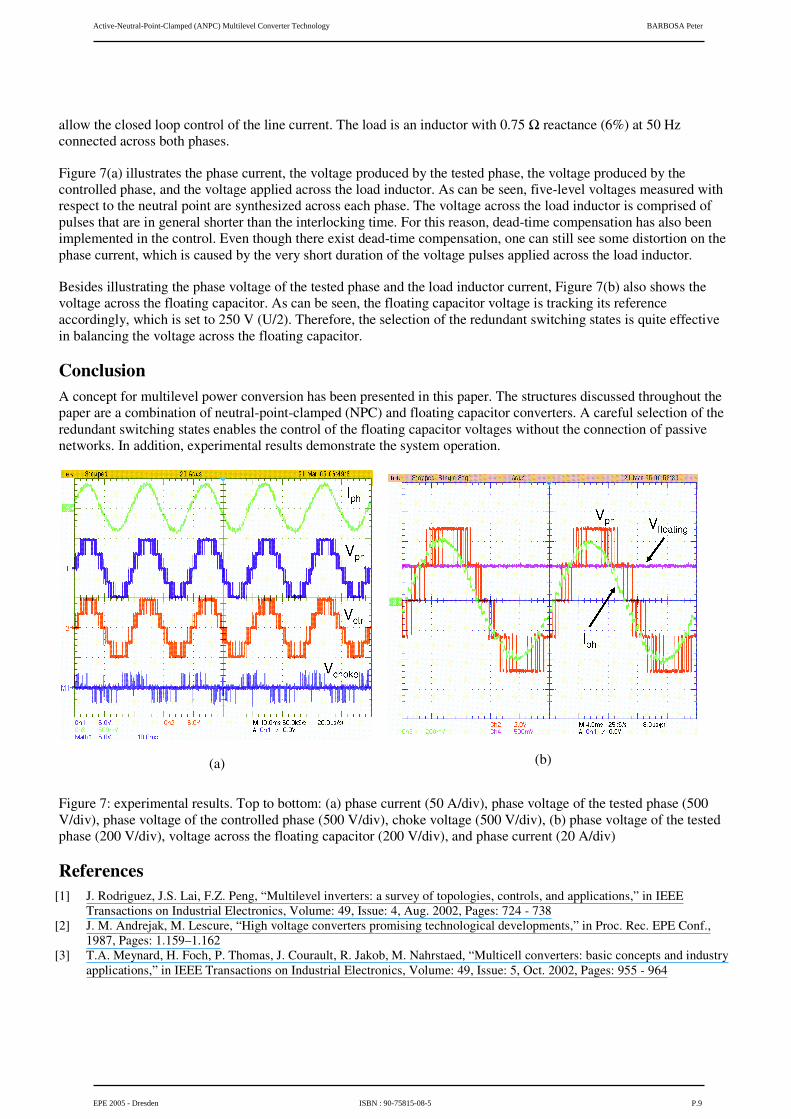
allow the closed loop control of the line current. The load is an inductor with 0.75 � reactance (6%) at 50 Hz connected across both phases.
Figure 7(a) illustrates the phase current, the voltage produced by the tested phase, the voltage produced by the controlled phase, and the voltage applied across the load inductor. As can be seen, five-level voltages measured with respect to the neutral point are synthesized across each phase. The voltage across the load inductor is comprised of pulses that are in general shorter than the interlocking time. For this reason, dead-time compensation has also been implemented in the control. Even though there exist dead-time compensation, one can still see some distortion on the phase current, which is caused by the very short duration of the voltage pulses applied across the load inductor.
Besides illustrating the phase voltage of the tested phase and the load inductor current, Figure 7(b) also shows the voltage across the floating capacitor. As can be seen, the floating capacitor voltage is tracking its reference accordingly, which is set to 250 V (U/2). Therefore, the selection of the redundant switching states is quite effective in balancing the voltage across the floating capacitor.
Conclusion A concept for multilevel power conversion has been presented in this paper. The structures discussed throughout the paper are a combination of neutral-point-clamped (NPC) and floating capacitor converters. A careful selection of the redundant switching states enables the control of the floating capacitor voltages without the connection of passive networks. In addition, experimental results demonstrate the system operation.
(a)
(b)
Figure 7: experimental results. Top to bottom: (a) phase current (50 A/div), phase voltage of the tested phase (500 V/div), phase voltage of the controlled phase (500 V/div), choke voltage (500 V/div), (b) phase voltage of the tested phase (200 V/div), voltage across the floating capacitor (200 V/div), and phase current (20 A/div)
References [1] J. Rodriguez, J.S. Lai, F.Z. Peng, “Multilevel inverters: a survey of topologies, controls, and applications,” in IEEE
Transactions on Industrial Electronics, Volume: 49, Issue: 4, Aug. 2002, Pages: 724 - 738 [2] J. M. Andrejak, M. Lescure, “High voltage converters promising technological developments,” in Proc. Rec. EPE Conf.,
1987, Pages: 1.159–1.162 [3] T.A. Meynard, H. Foch, P. Thomas, J. Courault, R. Jakob, M. Nahrstaed, “Multicell converters: basic concepts and industry
applications,” in IEEE Transactions on Industrial Electronics, Volume: 49, Issue: 5, Oct. 2002, Pages: 955 - 964
Active-Neutral-Point-Clamped (ANPC) Multilevel Converter Technology BARBOSA Peter
EPE 2005 - Dresden ISBN : 90-75815-08-5 P.9
[4] P.W. Hammond, “A new approach to enhance power quality for medium voltage AC drives,” in IEEE Transactions on Industry Applications, Volume: 33, Issue: 1, Jan.-Feb. 1997, Pages: 202 - 208
[5] M.D. Manjrekar, P.K. Steimer, T.A. Lipo, “Hybrid multilevel power conversion system: a competitive solution for high-power applications,” in IEEE Transactions on Industry Applications, Volume: 36, Issue: 3, May-June 2000, Pages: 834 – 841
[6] M. Veenstra, A. Rufer, “Control of a hybrid asymmetric multi-level inverter for competitive medium-voltage industrial drives,” in IEEE Industry Applications Conference, 2003, Volume: 1, Oct. 2003, Pages: 190 – 197
[7] J. Pou, R. Pindado, D. Boroyevich, “Voltage-balance limits in four-level diode-clamped converters with passive front ends,” in IEEE Industrial Electronics Society Annual Conference, Volume: 2, 5-8 Nov. 2002, Pages: 898 - 902
[8] X. Yuan, I. Barbi, “Fundamentals of a new diode clamping multilevel inverter,” in IEEE Transactions on Power Electronics, Volume: 15, Issue: 4, July 2000, Pages: 711 – 718
[9] B. P. McGrath, D. G. Holmes, “A comparison of multicarrier PWM strategies for cascaded and neutral point clamped multilevel inverters,” in IEEE PESC 2000, Pages 674–679
[10] F.Z. Peng, “A generalized multilevel inverter topology with self voltage balancing,” in IEEE Transactions on Industry Applications, Volume 37, Issue 2, March-April 2001, Pages: 611 - 618
[11] S. Bernet, T. Brückner, “Open-loop and closed-loop control method for a three-point converter with active clamped switches, and apparatus for this purpose,” US Patent number: US2003165071A1, Sept. 2003
[12] B.P. McGrath, D.G. Holmes, M. Manjrekar, T.A. Lipo, “An improved modulation strategy for a hybrid multilevel inverter,” in IEEE IAS 2000, Pages: 2086 - 2093
[13] P.K Steimer, “Power electronics building blocks - a platform-based approach to power electronics,” in IEEE Power Engineering Society General Meeting, 2003, Volume 3, July 2003, Pages: 1360 - 1365
Active-Neutral-Point-Clamped (ANPC) Multilevel Converter Technology BARBOSA Peter
EPE 2005 - Dresden ISBN : 90-75815-08-5 P.10