evaluating high-level models for real time embedded systems design
TRANSCRIPT
EVALUATING HIGH-LEVEL MODELS FOR REAL-TIME EMBEDDED SYSTEMS DESIGN
Lisane Brisolara1, Leandro B. Becker1, 3, Luigi Carro1, 2, Flávio R. Wagner1, and Carlos Eduardo Pereira1, 2 1 Computer Science Institute, Federal University of Rio Grande do Sul (UFRGS), Brazil 2 Electrical Engineering Depart., Federal University of Rio Grande do Sul (UFRGS), Brazil 3 Faculty of Informatics, Pontific Catholic University of Rio Grande do Sul (PUCRS), Brazil
Abstract: This paper compares different high-level modeling approaches for real-time embedded systems design: an object-oriented approach using UML diagrams against the block diagram approach provided by Simulink. This investigates the facilities provided by both approaches for expressing system requirements and functional specification. A Crane Control System is used as a case study for conducting the proposed comparison.
Key words: high-level modeling, real-time embedded systems design, UML, Simulink.
1. INTRODUCTION
Traditionally, the function block (FB) modeling approach has been used by the signal processing and control engineering communities for the development of real-time embedded systems. These models are widely accepted in industrial design, driven by an extensive set of design tools, as for instance Matlab/Simulink from MathWorks. On the other hand, as a result from a standardization process among different object-oriented (OO) design methodologies, the OMG promoted the creation of the Unified Modeling Language (UML) [1], which is considered the de facto modeling notation for any OO system. UML has gained in popularity also for real-time embedded systems specification and design [2, 3]. Efforts that describe the use of UML in different phases of an embedded system design process are shown in [4]. A relevant question is whether the use of UML presents real
2 L. Brisolara, L.B. Becker, L. Carro, F.R. Wagner, and C.E. Pereira advantages over traditional approaches for real-time embedded systems design. Therefore, an analysis is necessary in order to argue about the facilities provided by the approaches. Such analysis should reflect aspects like model readability, model validation, and model implementability.
This paper presents a study comparing the use of the UML and FB modeling approaches. In order to reach a fair comparison, a collection of criteria based on the work conducted by Ardis et al [5] is established. A case study is developed using the proposed evaluation methodology, consisting in the modeling of a Crane Control System, as proposed in [6]. The remaining of the paper is organized as follows. Section 2 gives an overview of high-level modeling applied to real-time embedded systems. In Section 3, the comparison criteria are defined. Section 4 presents the case study and shows the description of the UML and Simulink models. Section 5 discusses and summarizes the obtained results. Section 6 gives an overview of related work. In the last section, conclusions are drawn.
2. EMBEDDED SYSTEMS DESIGN OVERVIEW
The design of an embedded system consists of several steps, as follows. The first step is the development of a high-level system model, containing both requirements and a functional specification. The requirements specification relies on defining three main elements: desired behavior or functionality; quality-of-service (QoS) requirements (performance, timing, power); and problem domain structure. Once these elements are specified, designers can proceed with the development of the formal solution, that results in the system functional specification. The high-level model should reflect the nature of the application domain. It is important to use the most appropriate Model of Computation (MoC) [7], so that the model applicability is enhanced. Up to this point, no platform information has been added to the model. The concerned aspects relate only to user needs and their detailed description, which is expressed by means of specific diagrams.
The following step consists of translating the high-level model into an executable description. This process should be automatic, but depending on the modeling notation it may need different degrees of designer interaction. Such executable description is generally obtained by means of a program code, written in the programming language that best fits the adopted modeling approach and MoC. Further steps must take the executable description as input for the architectural exploration, where alternative hardware and software solutions that fulfill system requirements should be taken into account, and for the final system generation.
Evaluating High-level Models for RT Embedded Systems Design 3
The high-level modeling language should be able to express both the application requirements and the functional specification. Also, it should provide facilities to allow model validation, as well as features that can be used to guide implementation.
3. EVALUATION CRITERIA
To develop a comparison between the modeling approaches, several evaluation criteria have been established. These criteria are based on the work conducted by Ardis et al [5], which performs a qualitative comparison among several design languages for reactive systems. This work is extended here in the direction of searching for aspects that could be used to perform a quantitative evaluation of the designed models. For those criteria where a quantitative evaluation is not possible, a qualitative one is established. Moreover, additional evaluation criteria are added together with a new organization for the set of criteria. They are organized in groups that reflect the design steps introduced in the previous section as listed bellow.
a) Requirements Specification: evaluates the capacity to express and document user needs and system requirements;
b) Functional Specification: evaluates the model abstraction level and expressiveness, i.e. if it describes the problem domain and the system behavior/functionalities in a natural and straightforward manner;
c) Validation/simulation: evaluates if the specification can be validated before its implementation;
d) Implementability: evaluates if the specification can be easily refined or translated into an implementation compatible with the rest of the system;
e) Design Space Exploration Facilities: criteria evaluate whether the model incorporates facilities that can be used for design space exploration.
The comparison is based on criteria subgroups, as detailed below: a.1) Functional requirements: capability of expressing and documenting
the problem domain elements that provide interaction with the system to be designed and its desired functionalities; expressed by the number of modeling diagrams that can be used to implement the desired feature.
a.2) QoS requirements: capability of expressing the application QoS requirements and/or restrictions. This is expressed by the number of QoS requirements that can be specified.
b.1) Applicability: capability of representing system behavior or functionality by using different MoCs, according to systems nature; This criteria is expressed by the number of supported MoCs.
b.2) Modularity/Hierarchy: capability of dividing a large specification into independent modules, which could be decomposed into smaller parts;
4 L. Brisolara, L.B. Becker, L. Carro, F.R. Wagner, and C.E. Pereira
b.3) Expressiveness: capability of the modeling language primitives to describe the specification; This is expressed by three main aspects: (1) Number of modeling primitives, (2) Number of different modeling primitives in use, (3) Number of lines of code programmed by the designer;
c.1) Simulation (qualitative): capability of verifying if the specification can be used to validate the implementation.
c.2) Verifiability (qualitative): capability of demonstrating formally that the specification or generated program fulfils the requirements.
d.1) Code generation (qualitative): capability of generating an executable application from the model.
e.1) Synthesis (qualitative): capability of synthesizing the model (into hardware) or generating a program.
e.2) System tuning (qualitative): capability of adjusting the generated model by correct tuning of parameters like performance and power.
4. CASE STUDY
The crane system, proposed as a benchmark for system-level modeling [6], was developed for the comparison using UML and block diagrams.
4.1 UML Model Description
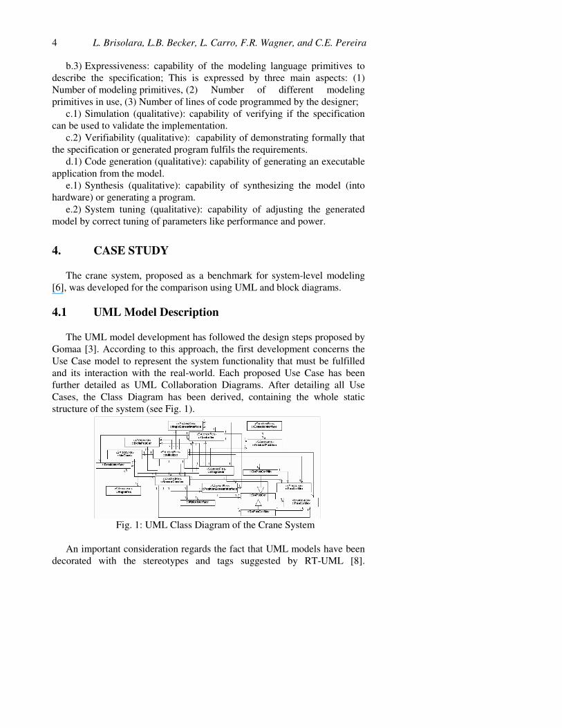
The UML model development has followed the design steps proposed by Gomaa [3]. According to this approach, the first development concerns the Use Case model to represent the system functionality that must be fulfilled and its interaction with the real-world. Each proposed Use Case has been further detailed as UML Collaboration Diagrams. After detailing all Use Cases, the Class Diagram has been derived, containing the whole static structure of the system (see Fig. 1).
Fig. 1: UML Class Diagram of the Crane System
An important consideration regards the fact that UML models have been decorated with the stereotypes and tags suggested by RT-UML [8].
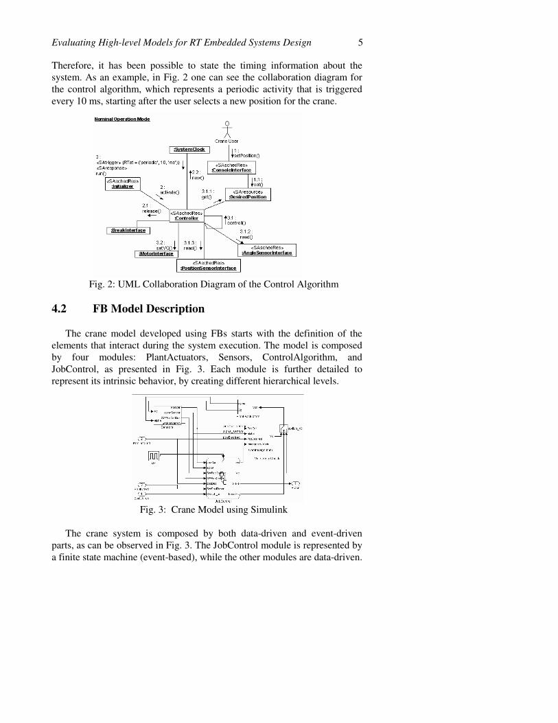
Evaluating High-level Models for RT Embedded Systems Design 5 Therefore, it has been possible to state the timing information about the system. As an example, in Fig. 2 one can see the collaboration diagram for the control algorithm, which represents a periodic activity that is triggered every 10 ms, starting after the user selects a new position for the crane.
Fig. 2: UML Collaboration Diagram of the Control Algorithm
4.2 FB Model Description
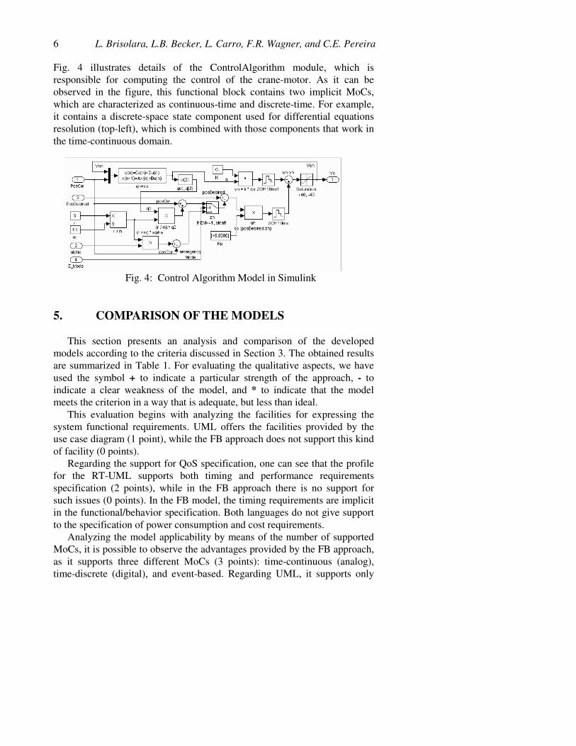
The crane model developed using FBs starts with the definition of the elements that interact during the system execution. The model is composed by four modules: PlantActuators, Sensors, ControlAlgorithm, and JobControl, as presented in Fig. 3. Each module is further detailed to represent its intrinsic behavior, by creating different hierarchical levels.
Fig. 3: Crane Model using Simulink
The crane system is composed by both data-driven and event-driven parts, as can be observed in Fig. 3. The JobControl module is represented by a finite state machine (event-based), while the other modules are data-driven.
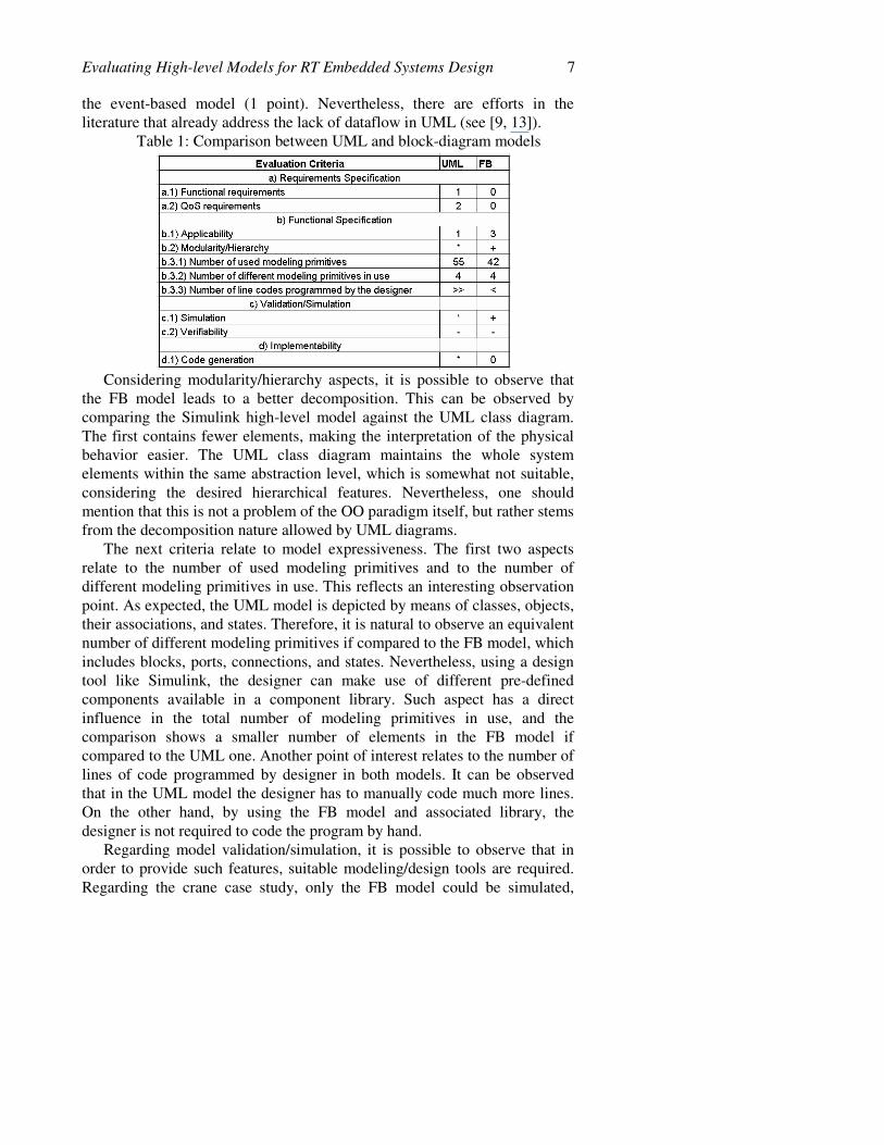
6 L. Brisolara, L.B. Becker, L. Carro, F.R. Wagner, and C.E. Pereira Fig. 4 illustrates details of the ControlAlgorithm module, which is responsible for computing the control of the crane-motor. As it can be observed in the figure, this functional block contains two implicit MoCs, which are characterized as continuous-time and discrete-time. For example, it contains a discrete-space state component used for differential equations resolution (top-left), which is combined with those components that work in the time-continuous domain.
Fig. 4: Control Algorithm Model in Simulink
5. COMPARISON OF THE MODELS
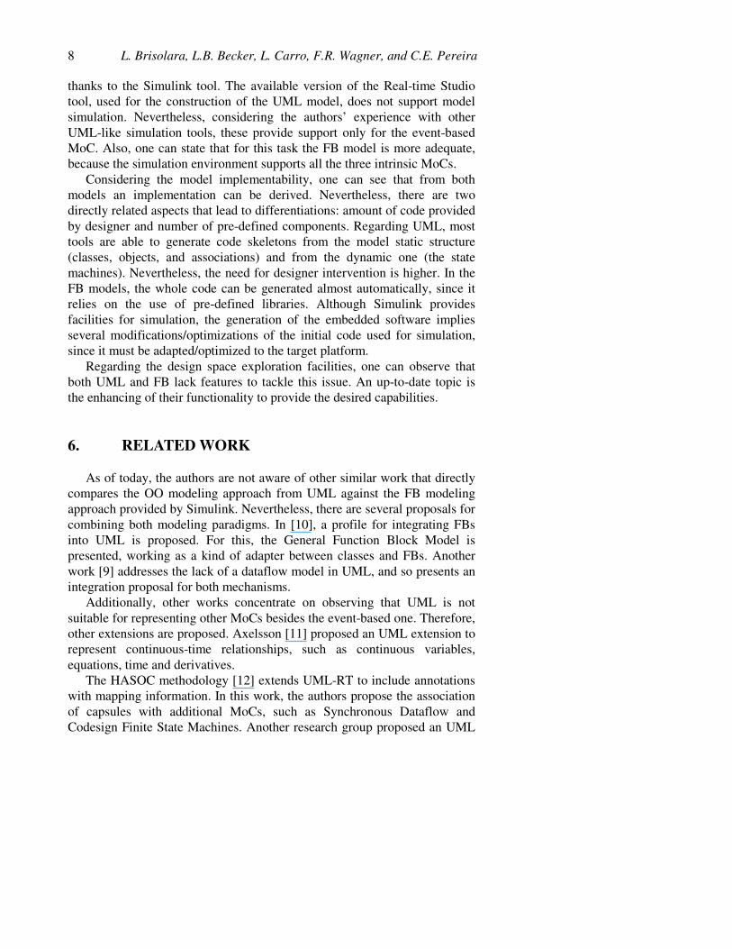
This section presents an analysis and comparison of the developed models according to the criteria discussed in Section 3. The obtained results are summarized in Table 1. For evaluating the qualitative aspects, we have used the symbol + to indicate a particular strength of the approach, - to indicate a clear weakness of the model, and * to indicate that the model meets the criterion in a way that is adequate, but less than ideal.
This evaluation begins with analyzing the facilities for expressing the system functional requirements. UML offers the facilities provided by the use case diagram (1 point), while the FB approach does not support this kind of facility (0 points).
Regarding the support for QoS specification, one can see that the profile for the RT-UML supports both timing and performance requirements specification (2 points), while in the FB approach there is no support for such issues (0 points). In the FB model, the timing requirements are implicit in the functional/behavior specification. Both languages do not give support to the specification of power consumption and cost requirements.
Analyzing the model applicability by means of the number of supported MoCs, it is possible to observe the advantages provided by the FB approach, as it supports three different MoCs (3 points): time-continuous (analog), time-discrete (digital), and event-based. Regarding UML, it supports only
Evaluating High-level Models for RT Embedded Systems Design 7 the event-based model (1 point). Nevertheless, there are efforts in the literature that already address the lack of dataflow in UML (see [9, 13]).
Table 1: Comparison between UML and block-diagram models
Considering modularity/hierarchy aspects, it is possible to observe that the FB model leads to a better decomposition. This can be observed by comparing the Simulink high-level model against the UML class diagram. The first contains fewer elements, making the interpretation of the physical behavior easier. The UML class diagram maintains the whole system elements within the same abstraction level, which is somewhat not suitable, considering the desired hierarchical features. Nevertheless, one should mention that this is not a problem of the OO paradigm itself, but rather stems from the decomposition nature allowed by UML diagrams.
The next criteria relate to model expressiveness. The first two aspects relate to the number of used modeling primitives and to the number of different modeling primitives in use. This reflects an interesting observation point. As expected, the UML model is depicted by means of classes, objects, their associations, and states. Therefore, it is natural to observe an equivalent number of different modeling primitives if compared to the FB model, which includes blocks, ports, connections, and states. Nevertheless, using a design tool like Simulink, the designer can make use of different pre-defined components available in a component library. Such aspect has a direct influence in the total number of modeling primitives in use, and the comparison shows a smaller number of elements in the FB model if compared to the UML one. Another point of interest relates to the number of lines of code programmed by designer in both models. It can be observed that in the UML model the designer has to manually code much more lines. On the other hand, by using the FB model and associated library, the designer is not required to code the program by hand.
Regarding model validation/simulation, it is possible to observe that in order to provide such features, suitable modeling/design tools are required. Regarding the crane case study, only the FB model could be simulated,
8 L. Brisolara, L.B. Becker, L. Carro, F.R. Wagner, and C.E. Pereira thanks to the Simulink tool. The available version of the Real-time Studio tool, used for the construction of the UML model, does not support model simulation. Nevertheless, considering the authors’ experience with other UML-like simulation tools, these provide support only for the event-based MoC. Also, one can state that for this task the FB model is more adequate, because the simulation environment supports all the three intrinsic MoCs.
Considering the model implementability, one can see that from both models an implementation can be derived. Nevertheless, there are two directly related aspects that lead to differentiations: amount of code provided by designer and number of pre-defined components. Regarding UML, most tools are able to generate code skeletons from the model static structure (classes, objects, and associations) and from the dynamic one (the state machines). Nevertheless, the need for designer intervention is higher. In the FB models, the whole code can be generated almost automatically, since it relies on the use of pre-defined libraries. Although Simulink provides facilities for simulation, the generation of the embedded software implies several modifications/optimizations of the initial code used for simulation, since it must be adapted/optimized to the target platform.
Regarding the design space exploration facilities, one can observe that both UML and FB lack features to tackle this issue. An up-to-date topic is the enhancing of their functionality to provide the desired capabilities.
6. RELATED WORK
As of today, the authors are not aware of other similar work that directly compares the OO modeling approach from UML against the FB modeling approach provided by Simulink. Nevertheless, there are several proposals for combining both modeling paradigms. In [10], a profile for integrating FBs into UML is proposed. For this, the General Function Block Model is presented, working as a kind of adapter between classes and FBs. Another work [9] addresses the lack of a dataflow model in UML, and so presents an integration proposal for both mechanisms.
Additionally, other works concentrate on observing that UML is not suitable for representing other MoCs besides the event-based one. Therefore, other extensions are proposed. Axelsson [11] proposed an UML extension to represent continuous-time relationships, such as continuous variables, equations, time and derivatives.
The HASOC methodology [12] extends UML-RT to include annotations with mapping information. In this work, the authors propose the association of capsules with additional MoCs, such as Synchronous Dataflow and Codesign Finite State Machines. Another research group proposed an UML
Evaluating High-level Models for RT Embedded Systems Design 9 profile for embedded system platforms [13], which allows the modeling of platforms, quantifying QoS performance and budgeting constraints and revealing platform services. Nevertheless, the adopted modeling strategy is difficult to understand, once it is hard to see a direct correspondence between the UML model and its describing equation from the physical domain. Moreover, the model is overly verbose, since it uses several modules to describe a simple equation with two multiplications. Additionally, the model abstraction level is very low, going to the micro-operation level, and is not adequate for complex embedded system modeling.
7. CONCLUSIONS
While several authors already proposed the unification between UML and the FB modeling approaches, this work focused on comparing both approaches. Our goal was to define the largest amount of quantitative evaluation criteria as possible, thus allowing a more consistent comparison.
Considering the obtained results, it seems that UML looks better for requirements specification. Nevertheless, none of the models properly deals with the specification of embedded systems requirements, since power, for example, is not included. An advantage of UML is that it can be extended to incorporate such feature. Comparing the developed functional specifications, a similar score is observed in Table 1 for both approaches. This leads to the conclusion that models are somehow equivalent, although each has pros and cons in this aspect. An observed weak aspect from UML is the lack of a suitable decomposition mechanism, which could be easily overcome by the modeling tools by adopting a hierarchical aggregation as in the SIMOO-RT framework [14]. Also, this aspect should be tackled in UML 2.0.
Moving to the facilities for validation/simulation, the FB model is advantageous especially because of the used modeling tool, coupled with its intrinsic simulation engine. Regarding the model implementability, one can see that from both approaches an implementation can be derived, although each approach has its own peculiarities. Considering the last comparison dimension, namely design space exploration facilities, one can observe that both UML and FB lack features to tackle such issue. Nevertheless, there are already proposed approaches focusing on providing the desired capabilities.
As a final remark, it must be observed that both models show clear advantages and disadvantages. One interesting research target is to combine both approaches with the care to keep the application of each one within the most adequate design phase and abstraction level, according to their original capabilities. This contrasts with other existing proposals, which extend the current models to allow their use at design levels for which the language
10 L. Brisolara, L.B. Becker, L. Carro, F.R. Wagner, and C.E. Pereira abstraction does not provide real advantages. Future investigations should focus on enhancing the existing proposals for extending UML to support a higher degree of integration with the FB paradigm and to allow the design of models using different MoCs in a natural manner.
ACKNOWLEDGMENTS
This work has been supported by CNPq and CAPES grants for some of the authors. Thanks are also due to Artisan Sw for allowing the use of the Real-Time Studio modeling tool.
REFERENCES
1. G. Booch, I. Jacobson, and J. Rumbaugh. The Unified Modeling Language User Guide. Addison-Wesley, 1999.
2. B. Douglass. Real-Time UML: Developing Efficient Objects for Embedded Systems. Addison-Wesley, 1998.
3. H. Gomaa. Designing Concurrent, Distributed, and Real-Time Applications with UML. Addison-Wesley, 2000.
4. L. Lavagno, G. Martin, and B. Selic. UML for Real: Design of Embedded Real-Time Systems. Kluwer Academic Publishers, 2003.
5. M. Ardis et al. A Framework for Evaluating Specification Methods for Reactive Systems: Experience Report. IEEE Trans. on Sw Eng. v.22, n.6, 1996. pp. 378-389.
6. E. Moser and W. Nebel. Case Study: System Model of Crane and Embedded Control. In: Proc. of DATE’1999, Munich, Germany, March 1999.
7. S. Edwards, L. Lavagno, E. A. Lee, and A. Sangiovanni-Vincentelli, Design of Embedded Systems: Formal Models, Validation, and Synthesis. Proc. of IEEE, Mar. 1997, pp. 366-390.
8. Object Management Group (OMG). UML Profile for Schedulability, Performance, and Time, 2002. OMG document n. ptc/02-03-02.
9. L. Bichler, A. Radermacher, and A. Schürr. Integrating Data Flow Equations with UML/Realtime. Real-Time Systems, n. 26, 2004, pp. 107-125.
10. Th. Heverhagen, R. Tracht, and R. Hirschfeld. A Profile for Integrating Function Blocks into the Unified Modeling Language. In Proc. of Works. on Specification and Validation of UML models for RT and Embedded Systems, San Francisco, USA, Oct. 2003.
11. J. Axelsson. Real-World Modeling in UML. In Proc. 13th International Conference on Software and Systems Engineering and their Applications, Paris, December 2000.
12. P. N. Green and M. D Edwards. The Modeling of Embedded Systems Using HASoC. In Proc. of DATE’2002, Paris, France, Mar. 2002.
13. R. Chen, M. Sgroi, G. Martin, L. Lavagno, A. Sangiovanni-Vicentelli, and J. Rabaey. Embedded System Design Using UML and Platforms. In Proc. of FDL’2000 – Forum on Specification and Design Languages, Sep., 2002.
14. L. B. Becker and C. Pereira. SIMOO-RT - An Object-oriented Framework for the Development of Real-time Industrial Automation Systems. IEEE Transactions on Robots and Automation, v.18, no.4, 2002, pp. 421-430.