etop-epc etop-epc 1230t/1231t/1235t/1530t/1531t/17
TRANSCRIPT

EXOR International
www.exorint.net
Industrial Computing SolutionseTOP-EPC eTOP-EPC 1230T/1231T/1235T/1530T/1531T/1730T/1731T/1930T/1931TUser Manual

Copyright © 2014 EXOR International S.p.A. All Rights Reserved. ii eTOP-EPC 1230T/1231T/1235T/1530T/1531T/1730T/1731T/1930T/1931T User Manual
Content
CONTENTS
PrefaceCopyright .............................................................................................. v
Disclaimer ............................................................................................... v
Acknowledgements ................................................................................ v
Regulatory Compliance Statements ......................................................... v
Declaration of Conformity ....................................................................... v
RoHS Compliance .................................................................................. vi
Warranty and RMA ................................................................................vii
Safety Information ................................................................................. ix
Installation Recommendations ................................................................ ix
Safety Precautions ................................................................................... x
Technical Support and Assistance ........................................................... xi
Conventions Used in this Manual ........................................................... xi
Global Service Contact Information ........................................................xii
Package Contents .................................................................................xiv
Ordering Information ............................................................................xvi
Chapter 1: Product IntroductioneTOP-EPC 1230T/1231T/1235T ...............................................................1
Specifications ..........................................................................................2
eTOP-EPC 1530T/1531T ..........................................................................4
Specifications ..........................................................................................5
eTOP-EPC 1730T/1731T ..........................................................................7
Specifications ..........................................................................................8
eTOP-EPC 1930T/1931T ........................................................................10
Specifications ........................................................................................11
Knowing Your eTOP-EPC Series .............................................................13
Rear Top ............................................................................................13
Rear Bottom ......................................................................................14
Rear (eTOP-EPC 1230T/1235T/1530T/1730T/1930T only) ...................15
Rear (eTOP-EPC 1231T/1531T/1731T/1931T only) ..............................16
Mechanical Dimensions .........................................................................17
eTOP-EPC 1230T/1231T/1235T ..........................................................17
Mechanical Dimensions .........................................................................18
eTOP-EPC 1530T/1531T ....................................................................18
Mechanical Dimensions .........................................................................19
eTOP-EPC 1730T/1731T ....................................................................19
Mechanical Dimensions .........................................................................20
eTOP-EPC 1930T/1931T ....................................................................20
Chapter 2: Jumpers and ConnectorsBefore You Begin ..................................................................................21
Precautions ..........................................................................................21
Jumper Settings ....................................................................................22
Locations of the Jumpers and Connectors .............................................23
Top View ...........................................................................................23
Bottom View .....................................................................................24
Jumpers and DIP Switch Settings ...........................................................25
CMOS Clear Select ............................................................................25
AT/ATX Selection ...............................................................................25
Dimming Type Select .........................................................................26

Copyright © 2014 EXOR International S.p.A. All Rights Reserved. iii eTOP-EPC 1230T/1231T/1235T/1530T/1531T/1730T/1731T/1930T/1931T User Manual
Content
Dimming Signal Level Select ..............................................................26
Panel Resolution Select ......................................................................27
LCD Panel VDD Power Select .............................................................28
Touch 4/5 Wire Select ........................................................................28
COM1 RI Pin Power Select .................................................................29
COM2 RI Pin Power Select .................................................................29
COM3 RI Pin Power Select .................................................................30
COM4 RI Pin Power Select .................................................................30
Connector Pin Definitions .....................................................................31
External I/O Interface .........................................................................31
12V-30V DC Power Input ...............................................................31
VGA Port .......................................................................................31
PS/2 Keyboard/Mouse Port .............................................................32
COM2 Port: Serial Port RS232/422/485 ..........................................32
COM1 Port: Serial Port RS232/422/485 ..........................................33
COM3 Port and Connector: Serial Port RS232 ................................34
COM4 Port and Connector: Serial Port RS232 ................................35
USB Ports .......................................................................................35
LAN2 Port ......................................................................................36
LAN1 Port ......................................................................................36
Line-out Jack ..................................................................................37
Internal Connectors ...........................................................................38
LVDS Channel 1 .............................................................................38
LVDS Channel 2 .............................................................................38
Panel Backlight Connector .............................................................39
Touch Sensor Connector ................................................................39
USB Connector ..............................................................................40
Bluetooth Connector ......................................................................40
SATA Connector .............................................................................41
SATA DOM Power Connector ............................................................41
Line-in/Mic-in Connector ...................................................................42
Speaker-out Connector ......................................................................42
GPIO Connector ................................................................................43
DIO Connector ..................................................................................44
Power/HDD LED Indicator Connector .................................................45
Backlight Control Input Connector ....................................................45
Dimming Control Button Connector ..................................................46
SIM Card Slot .................................................................................46
Mini-PCIe Slot ................................................................................47
Mini-PCIe Slot ................................................................................48
CFast Card Slot ..............................................................................49
Power Button Connector ................................................................49
Block Diagram ......................................................................................50
eTOP-EPC 1930T/APPC 1730T/APPC 1530T/APPC 1230T/APPC 1235T 50
Block Diagram ......................................................................................51
eTOP-EPC 1931T/APPC 1731T/APPC 1531T/APPC 1231T ...................51
Chapter 3: System SetupInstalling a SATA Hard Drive .................................................................52
Installing a CFast Card ..........................................................................56
Installing a SODIMM .............................................................................58
Installing a SATA DOM ..........................................................................61
Installing a Mini PCIe Module ................................................................65
Installing the Half-Size Mini PCIe Module ...........................................67
Installing the Full-Size Mini PCIe Module ............................................68
Installing a Bluetooth Module ...............................................................72
Placing Panel Mount Hole Blocks ...........................................................76
Installing the Power Adapter Bracket .....................................................78
Plugging the DC Power Cable ...............................................................82
Panel Mounting ....................................................................................83
Chapter 4: BIOS SetupAbout BIOS Setup .................................................................................85

Copyright © 2014 EXOR International S.p.A. All Rights Reserved. iv eTOP-EPC 1230T/1231T/1235T/1530T/1531T/1730T/1731T/1930T/1931T User Manual
Content
When to Configure the BIOS .................................................................85
Default Configuration ...........................................................................86
Entering Setup ......................................................................................86
Legends ................................................................................................86
BIOS Setup Utility ..................................................................................88
Main .................................................................................................88
Advanced ..........................................................................................90
Chipset ..............................................................................................99
Boot ................................................................................................102
Security ...........................................................................................104
Save & Exit ......................................................................................104
Appendix A: GPI/O Programming Guide.............106
Appendix B: Digital I/O Programming Guide......108
Appendix C: Watchdog Programming Guide......110
Appendix D: Power Consumption.......................112
Appendix E: Troubleshooting..............................114

Copyright © 2014 EXOR International S.p.A. All Rights Reserved. v eTOP-EPC 1230T/1231T/1235T/1530T/1531T/1730T/1731T/1930T/1931T User Manual
Preface
PREFACE
Copyright This publication, including all photographs, illustrations and software, is
protected under international copyright laws, with all rights reserved. No
part of this manual may be reproduced, copied, translated or transmitted
in any form or by any means without the prior written consent from EXOR
International S.p.A.
DisclaimerThe information in this document is subject to change without prior notice and
does not represent commitment from Exor International S.p.A. However, users
may update their knowledge of any product in use by constantly checking its
manual posted on our website: http://www.exorint.it EXOR shall not be liable for
direct, indirect, special, incidental, or consequential damages arising out of the
use of any product, nor for any infringements upon the rights of third parties,
which may result from such use. Any implied warranties of merchantability or
fitness for any particular purpose is also disclaimed.
AcknowledgementseTOP-EPC 1230T/1231T/1235T/1530T/1531T/1730T/1731T/1930T/193
1T is a trademark of EXOR International S.p.A. All other product names
mentioned herein are registered trademarks of their respective owners.
Regulatory Compliance StatementsThis section describes how to keep the system CE compliant.
Declaration of ConformityCE
The product(s) described in this manual complies with all applicable
European Union (CE) directives if it has a CE marking. For computer systems
to remain CE compliant, only CE-compliant parts may be used. Maintaining
CE compliance also requires proper cable and cabling techniques.

Copyright © 2014 EXOR International S.p.A. All Rights Reserved. vi eTOP-EPC 1230T/1231T/1235T/1530T/1531T/1730T/1731T/1930T/1931T User Manual
Preface
RoHS ComplianceEXOR RoHS Environmental Policy and Status Update
This publication, including all photographs, illustrations
and software, is protected under international copyright
laws, with all rights reserved. No part of this manual
may be reproduced, copied, translated or transmitted in any form or by any
means without the prior written consent from EXOR International S.p.A.
RoHS restricts the use of Lead (Pb) < 0.1% or 1,000ppm, Mercury (Hg) < 0.1%
or 1,000ppm, Cadmium (Cd) < 0.01% or 100ppm, Hexavalent Chromium
(Cr6+) < 0.1% or 1,000ppm, Polybrominated biphenyls (PBB) < 0.1% or
1,000ppm, and Polybrominated diphenyl Ethers (PBDE) < 0.1% or 1,000ppm.
In order to meet the RoHS compliant directives, EXOR has established an
engineering and manufacturing task force to implement the introduction
of green products. The task force will ensure that we follow the standard
EXOR development procedure and that all the new RoHS components and
new manufacturing processes maintain the highest industry quality levels
for which EXOR are renowned.
The model selection criteria will be based on market demand. Vendors and
suppliers will ensure that all designed components will be RoHS compliant.
All new product models launched after January 2006 will be RoHS compliant.
They will use the usual EXOR naming convention.

Copyright © 2014 EXOR International S.p.A. All Rights Reserved. vii eTOP-EPC 1230T/1231T/1235T/1530T/1531T/1730T/1731T/1930T/1931T User Manual
Preface
Warranty and RMAEXOR Warranty Period
EXOR manufactures products that are new or equivalent to new in
accordance with industry standard. EXOR warrants that products will be
free from defect in material and workmanship for 2 years, beginning on
the date of invoice by EXOR. HCP series products (Blade Server) which are
manufactured by EXOR are covered by a three year warranty period.
EXOR Return Merchandise Authorization (RMA)
▪ Customers shall enclose the “EXOR RMA Service Form” with the returned
packages.
▪ Customers must collect all the information about the problems
encountered and note anything abnormal or, print out any on-screen
messages, and describe the problems on the “EXOR RMA Service Form”
for the RMA number apply process.
▪ Customers can send back the faulty products with or without accessories
(manuals, cable, etc.) and any components from the card, such as CPU
and RAM. If the components were suspected as part of the problems,
please note clearly which components are included. Otherwise, EXOR is
not responsible for the devices/parts.
▪ Customers are responsible for the safe packaging of defective products,
making sure it is durable enough to be resistant against further damage
and deterioration during transportation. In case of damages occurred
during transportation, the repair is treated as “Out of Warranty.”
▪ Any products returned by EXOR to other locations besides the customers’
site will bear an extra charge and will be billed to the customer.
Repair Service Charges for Out-of-Warranty Products
EXOR will charge for out-of-warranty products in two categories, one is
basic diagnostic fee and another is component (product) fee.
Repair Service Charges for Out-of-Warranty Products
EXOR will charge for out-of-warranty products in two categories, one is
basic diagnostic fee and another is component (product) fee.
System Level
▪ Component fee: EXOR will only charge for main components such as
SMD chip, BGA chip, etc. Passive components will be repaired for free,
ex: resistor, capacitor.
▪ Items will be replaced with EXOR products if the original one cannot be
repaired. Ex: motherboard, power supply, etc.
▪ Replace with 3rd party products if needed.
▪ If RMA goods can not be repaired, EXOR will return it to the customer
without any charge.
Board Level
▪ Component fee: EXOR will only charge for main components, such as
SMD chip, BGA chip, etc. Passive components will be repaired for free,
ex: resistors, capacitors.
▪ If RMA goods can not be repaired, EXOR will return it to the customer
without any charge.

Copyright © 2014 EXOR International S.p.A. All Rights Reserved. viii eTOP-EPC 1230T/1231T/1235T/1530T/1531T/1730T/1731T/1930T/1931T User Manual
Preface
Warnings
Read and adhere to all warnings, cautions, and notices in this guide and
the documentation supplied with the chassis, power supply, and accessory
modules. If the instructions for the chassis and power supply are inconsistent
with these instructions or the instructions for accessory modules, contact
the supplier to find out how you can ensure that your computer meets
safety and regulatory requirements.
Cautions
Electrostatic discharge (ESD) can damage system components. Do the
described procedures only at an ESD workstation. If no such station is
available, you can provide some ESD protection by wearing an antistatic
wrist strap and attaching it to a metal part of the computer chassis.

Copyright © 2014 EXOR International S.p.A. All Rights Reserved. ix eTOP-EPC 1230T/1231T/1235T/1530T/1531T/1730T/1731T/1930T/1931T User Manual
Preface
Installation RecommendationsEnsure you have a stable, clean working environment. Dust and dirt can get
into components and cause a malfunction. Use containers to keep small
components separated.
Adequate lighting and proper tools can prevent you from accidentally
damaging the internal components. Most of the procedures that follow
require only a few simple tools, including the following:
▪ A Philips screwdriver
▪ A flat-tipped screwdriver
▪ A grounding strap
▪ An anti-static pad
Using your fingers can disconnect most of the connections. It is recommended
that you do not use needle-nose pliers to disconnect connections as these
can damage the soft metal or plastic parts of the connectors.
Safety InformationBefore installing and using the device, note the following precautions:
▪ Read all instructions carefully.
▪ Do not place the unit on an unstable surface, cart, or stand.
▪ Follow all warnings and cautions in this manual.
▪ When replacing parts, ensure that your service technician uses parts
specified by the manufacturer.
▪ Avoid using the system near water, in direct sunlight, or near a heating
device.
▪ The load of the system unit does not solely rely for support from the
rackmounts located on the sides. Firm support from the bottom is highly
necessary in order to provide balance stability.
▪ The computer is provided with a battery-powered real-time clock circuit.
There is a danger of explosion if battery is incorrectly replaced. Replace
only with the same or equivalent type recommended by the manufacturer.
Discard used batteries according to the manufacturer’s instructions.

Copyright © 2014 EXOR International S.p.A. All Rights Reserved. x eTOP-EPC 1230T/1231T/1235T/1530T/1531T/1730T/1731T/1930T/1931T User Manual
Preface
Safety Precautions1. Read these safety instructions carefully.
2. Keep this User Manual for later reference.
3. Disconnect this equipment from any AC outlet before cleaning. Use a
damp cloth. Do not use liquid or spray detergents for cleaning.
4. For plug-in equipment, the power outlet socket must be located near the
equipment and must be easily accessible.
5. Keep this equipment away from humidity.
6. Put this equipment on a stable surface during installation. Dropping it or
letting it fall may cause damage.
7. The openings on the enclosure are for air convection to protect the
equipment from overheating. DO NOT COVER THE OPENINGS.
8. Make sure the voltage of the power source is correct before connecting
the equipment to the power outlet.
9. Place the power cord in a way so that people will not step on it. Do not
place anything on top of the power cord. Use a power cord that has been
approved for use with the product and that it matches the voltage and
current marked on the product’s electrical range label. The voltage and
current rating of the cord must be greater than the voltage and current
rating marked on the product.
10. All cautions and warnings on the equipment should be noted.
11. If the equipment is not used for a long time, disconnect it from the
power source to avoid damage by transient overvoltage.
12. Never pour any liquid into an opening. This may cause fire or electrical
shock.
13. Never open the equipment. For safety reasons, the equipment should be
opened only by qualified service personnel.
14. If one of the following situations arises, get the equipment checked by
service personnel:
a. The power cord or plug is damaged.
b. Liquid has penetrated into the equipment.
c. The equipment has been exposed to moisture.
d. The equipment does not work well, or you cannot get it to work
according to the user’s manual.
e. The equipment has been dropped and damaged.
f. The equipment has obvious signs of breakage.
15. Do not place heavy objects on the equipment.
16. The unit uses a three-wire ground cable which is equipped with a third
pin to ground the unit and prevent electric shock. Do not defeat the
purpose of this pin. If your outlet does not support this kind of plug,
contact your electrician to replace your obsolete outlet.
17. CAUTION: DANGER OF EXPLOSION IF BATTERY IS INCORRECTLY
REPLACED. REPLACE ONLY WITH THE SAME OR EQUIVALENT TYPE
RECOMMENDED BY THE MANUFACTURER. DISCARD USED BATTERIES
ACCORDING TO THE MANUFACTURER’S INSTRUCTIONS.
Copyright © 2014 EXOR International S.p.A. All Rights Reserved. xi eTOP-EPC 1230T/1231T/1235T/1530T/1531T/1730T/1731T/1930T/1931T User Manual
Preface
Technical Support and Assistance1. For the most updated information of EXOR products, visit EXOR’s website
at www.exorint.it
2. For technical issues that require contacting our technical support team or
sales representative, please have the following information ready before
calling:
– Product name and serial number
– Detailed information of the peripheral devices
– Detailed information of the installed software (operating system,
version, application software, etc.)
– A complete description of the problem
– The exact wordings of the error messages
Warning!
1. Handling the unit: carry the unit with both hands and handle it with care.
2. Maintenance: to keep the unit clean, use only approved cleaning products
or clean with a dry cloth.
3. CompactFlash: Turn off the unit’s power before inserting or removing a
CompactFlash storage card.
Conventions Used in this Manual
Warning:
Information about certain situations, which if not observed,
can cause personal injury. This will prevent injury to yourself
when performing a task.
UTUTUTUTUTUTIOIOUTUTIOIOIOIOIOIOIOUTUTIOION!N!N!N!UTUTIOIOUTUTUTUTUTCAUTUTCACACAUTUTUTIOCACACACAUTUTUTUTIOIOIOION!N!N!N!CA ION!N!N!N!N!N!N!N!N!N!CAUTION!CAUTION!Caution:
Information to avoid damaging components or losing data.
Note:
Provides additional information to complete a task easily.

Copyright © 2014 EXOR International S.p.A. All Rights Reserved. xii eTOP-EPC 1230T/1231T/1235T/1530T/1531T/1730T/1731T/1930T/1931T User Manual
Preface
Package ContentsBefore continuing, verify that the package you received is complete. Your package should have all the items listed in the table.
Item Description Qty
1 PS/2 Y Cable 1
2 Panel Mount Kit 14
3 Touch Pen 1
4 DC Power Cable 1
5 Flat Head for HDD Installation 4
6 Panel Mount Hole Block 14
Item Description Qty
1 PS/2 Y Cable 1
2 Panel Mount Kit 12
3 Touch Pen 1
4 DC Power Cable 1
5 Flat Head for HDD Installation 4
6 Panel Mount Hole Block 12
Item Description Qty
1 PS/2 Y Cable 1
2 Panel Mount Kit 12
3 Touch Pen 1
4 DC Power Cable 1
5 Flat Head for HDD Installation 4
6 Panel Mount Hole Block 12
eTOP-EPC 1930T/eTOP-EPC 1931T eTOP-EPC 1730T/eTOP-EPC 1731T
Item Description Qty
1 PS/2 Y Cable 1
2 Panel Mount Kit 12
3 Touch Pen 1
4 DC Power Cable 1
5 Flat Head for HDD Installation 4
6 Panel Mount Hole Block 12
eTOP-EPC 1530T/eTOP-EPC 1531T eTOP-EPC 1230T/eTOP-EPC 1231T/eTOP-EPC 1235T
Note: Package contents may vary depending on your country region, some items may be
optional. Please contact your local distributor for more information.

Copyright © 2014 EXOR International S.p.A. All Rights Reserved. xiii eTOP-EPC 1230T/1231T/1235T/1530T/1531T/1730T/1731T/1930T/1931T User Manual
Preface
Panel Mount Kit
(eTOP-EPC 1730T/eTOP-EPC 1731T/eTOP-EPC 1530T/eTOP-EPC
1531T/eTOP-EPC 1230T/eTOP-EPC 1231T/eTOP-EPC 1235T)
PS/2 Y Cable Panel Mount Kit
(eTOP-EPC 1930T/eTOP-EPC 1931T)
Panel Mount Hole Block
(eTOP-EPC 1930T/eTOP-EPC1 931T)
Panel Mount Hole Block
(eTOP-EPC 1730T/eTOP-EPC 1731T/eTOP-EPC 1530T/eTOP-EPC
1531T/eTOP-EPC 1230T/eTOP-EPC 1231T/eTOP-EPC 1235T)
Touch Pen DC Power Cable Flat Head Screw

Copyright © 2014 EXOR International S.p.A. All Rights Reserved. xiv eTOP-EPC 1230T/1231T/1235T/1530T/1531T/1730T/1731T/1930T/1931T User Manual
Preface
Ordering InformationThe following information below provides ordering information for eTOP-EPC series.
• Barebone
eTOP-EPC 1930T
– 19” SXGA LED Backlight Touch Panel PC, Intel® Atom™ D2550
1.86 GHz, touch screen, 1GB DDR3, 2x RS232/422/485
eTOP-EPC 1931T
– 19” SXGA LED Backlight Touch Panel PC, Intel® Atom™ D2550
1.86 GHz, touch screen, 1GB DDR3, 2x RS232/422/485 and 4/4 DI/O
with isolated protection, 2x RS232, 2x2 GPI/O, Brightness adjustment
buttons
eTOP-EPC 1730T
– 17” SXGA CCFL Backlight Touch Panel PC, Intel® Atom™ D2550
1.86 GHz, touch screen, 1GB DDR3, 2x RS232/422/485
eTOP-EPC 1731T
– 17” SXGA CCFL Backlight Touch Panel PC, Intel® Atom™ D2550
1.86 GHz, touch screen, 1GB DDR3, 2x RS232/422/485 and 4/4 DI/O
with isolated protection, 2x RS232, 2x2 GPI/O, Brightness adjustment
buttons
eTOP-EPC 1530T
– 15” XGA LED Backlight Touch Panel PC, Intel® Atom™ D2550
1.86 GHz, touch screen, 1GB DDR3, 2x RS232/422/485
eTOP-EPC 1531T
– 15” XGA LED Backlight Touch Panel PC, Intel® Atom™ D2550
1.86 GHz, touch screen, 1GB DDR3, 2x RS232/422/485 and 4/4 DI/O
with isolated protection, 2x RS232, 2x2 GPI/O, Brightness adjustment
buttons
eTOP-EPC 1230T
– 12.1” SVGA LED Backlight Touch Panel PC, Intel® Atom™ D2550
1.86 GHz, touch screen, 1GB DDR3, 2x RS232/422/485
eTOP-EPC 1231T
– 12.1” SVGA LED Backlight Touch Panel PC, Intel® Atom™ D2550
1.86 GHz, touch screen, 1GB DDR3, 2x RS232/422/485 and 4/4 DI/O
with isolated protection, 2x RS232, 2x2 GPI/O, Brightness adjustment
buttons
eTOP-EPC 1235T
– 12.1” XGA LED Backlight Touch Panel PC, Intel® Atom™ D2550
1.86 GHz, touch screen, 1GB DDR3, 2x RS232/422/485
• Optional
12V, 60W AC/DC power adapter w/o power cord

Copyright © 2014 EXOR International S.p.A. All Rights Reserved. 1
Chapter 1: Product Introduction
eTOP-EPC 1230T/1231T/1235T/1530T/1531T/1730T/1731T/1930T/1931T User Manual
CHAPTER 1: PRODUCT INTRODUCTION
Key Features
▪ 4:3 12.1” SVGA Fanless LED Panel Computer (eTOP-EPC 1230T/1231T)
▪ 4:3 12.1” XGA Fanless LED Panel Computer (eTOP-EPC 1235T)
▪ Intel® Atom™ D2550, Dual Core, Low Consumption CPU
▪ Flush Panel by 5-wire Touch Screen
▪ Dual GbE/ 2nd display-VGA/ Line-in/ Line-out/ MIC-in/ PS2 KB/MS
▪ USB x4/ 2x mini-PCIe sockets/ 1x CFast/ 2x RS232/ 422/ 485
▪ Optional 3.5G/ Wi-Fi Module / 2.5”HDD/ 2x COMs / GPIO / DIO
▪ DDR3 1GB/ 2.5” HDD Bracket
▪ IP65 Compliant Front Panel
▪ Mounting Support: Panel/ Wall/ Stand/ VESA 100mm x 100mm
▪ Wide Range Power Input 12V~30V DC
eTOP-EPC 1230T/1231T/1235TOverview

Copyright © 2014 EXOR International S.p.A. All Rights Reserved. 2
Chapter 1: Product Introduction
eTOP-EPC 1230T/1231T/1235T/1530T/1531T/1730T/1731T/1930T/1931T User Manual
SpecificationsPanel
eTOP-EPC 1230T/ eTOP-EPC 1231T
▪ LED Size: 12.1”, 4:3
▪ Resolution: SVGA 800x600
▪ Luminance: 450cd/m2
▪ Contrast ratio: 700
▪ LCD color: 16.2M
▪ Viewing Angle: 65(U), 75(D), 80(L), 80(R)
▪ Backlight: LEDeTOP-EPC 1235T
▪ LED Size: 12.1”, 4:3
▪ Resolution: XGA 1024x768
▪ Luminance: 500cd/m2
▪ Contrast ratio: 700
▪ LCD color: 16.2M
▪ Viewing Angle: 80(U), 80(D), 80(L), 80(R)
▪ Backlight: LED
Touch Screen
▪ 5-wire resistive (flush panel type)
▪ Light transmission: 80%
▪ Interface: USB
System
▪ CPU: On-board Intel® Atom™ Dual Core processor D2550, 1.86GHz,1M
L2 Cache
▪ BIOS: AMI BIOS
▪ System chipset: Intel® NM10 Express chipset
▪ System memory: 2x 204-pin DDR3 SO-DIMM socket, 1G DDR3 (Default),
support up to 4GB DDR3-800/1066, Non-ECC and un-buffered
▪ Storage Device:
– 1x external locked CFast socket
– 1x hard drive bay: optional 1x 2.5” SATA HDD or 1x SATA DOM
▪ Watchdog timer: Watchdog timeout can be programmed by software
from 1 second to 255 seconds and from 1 minute to 255 minutes
(Tolerance 15% under room temperature 25°C)
▪ H/W status monitor: Monitoring system temperature, and voltage
▪ Expansion: 2x mini-PCIe sockets
(support optional Wi-Fi or 3.5G module)
▪ Panel backlight control button: Increase brightness / decrease brightness
/ Backlight On/Off (For ETOP-EPC1231T only)
Rear I/O
▪ Ethernet: 2x RJ45
▪ 2nd display VGA port: 1x DB15
▪ Audio port: 1x Line out; 1x Line in; 1x MIC-in
▪ USB: 4x USB 2.0
▪ PS2 keyboard/ mouse
▪ Power switch / Reset button
▪ COM #1: RS232/422/485 w/RI or 5V selection
▪ COM #2: RS232/422/485 w/RI or 12V selection

Copyright © 2014 EXOR International S.p.A. All Rights Reserved. 3
Chapter 1: Product Introduction
eTOP-EPC 1230T/1231T/1235T/1530T/1531T/1730T/1731T/1930T/1931T User Manual
For eTOP-EPC1231T only
DIO w/ 2.5kv isolated:
4x Digital Input (Source type)
– Input Voltage (Dry Contact): Logic 0: Close to GND
– Logic 1: Open
– Input Voltage: Logic 0: 3V max
– Logic 1: +5V ~ +30V
4x Digital Output (Sink type)
– Output Voltage: 3.6V ~ 5V
– Sink current: 200 mA max. per channel
▪ GPIO: 2x digital in / 2x digital out
▪ COM #1: RS232/422/485 w/ 2.5kv isolated
▪ COM #2: RS232/422/485 w/ 2.5kv isolated
▪ COM #3: RS232 w/ RI or 5V selection
▪ COM #4: RS232 w/ RI or 12V selection
Audio
▪ AC97 codec: Realtek ALC886-GR
▪ Audio interface: Line out/Line in/MIC-in Audio Jack
Ethernet
▪ LAN chip: dual Intel® 82574L Gigabit LAN
▪ Ethernet interface: 10/100/1000 Based-Tx Ethernet compatible
Mechanical & Environment
▪ Color: pantone black\RAL 15 00 front bezel w/ Pantone 400C\RAL
090 80 10 metal style membrane
▪ IP protection: IP65 front
▪ Mounting: panel/ wall/ stand/ VESA 100mm x 100mm
▪ Power input: 12V~ 30V DC
▪ Power adapter: Optional AC to DC power adaptor (+12V, 60W)
▪ Vibration:
– IEC 68 2-64 (w/ HDD)
– 1Grms @ sine, 5~500Hz, 1hr/axis (HDD Operating)
– 2Grms @ sine, 5~500Hz, 1hr/axis (CFast Operating)
– 2.2Grms @ random condition, 5~500Hz, 0.5hr/axis (Non-operating)
▪ Shock:
– IEC 68 2-27
– HDD: 20G@wall mount, half sine, 11ms
▪ Operating temperature: -5°C to 60°C
▪ Storage temperature: -20°C to 75°C
▪ Operating humidity: 10%~90% relative humidity, non-condensing
Limits to be at 90% RH at max 50°C
▪ Dimension: 317 x 243 x 65.89mm
▪ Weight: 3.9 Kg
Certifications
▪ CE approval

Copyright © 2014 EXOR International S.p.A. All Rights Reserved. 4
Chapter 1: Product Introduction
eTOP-EPC 1230T/1231T/1235T/1530T/1531T/1730T/1731T/1930T/1931T User Manual
Key Features
▪ 4:3 15” XGA Fanless LED Panel Computer
▪ Intel® Atom™ D2550, Dual Core, Low Consumption CPU
▪ Flush Panel by 5-wire Touch Screen
▪ Dual GbE/ 2nd display-VGA/ Line-in/ Line-out/ MIC-in/ PS2 KB/MS
▪ USB x4/ 2x mini-PCIe sockets/ 1x CFast/ 2x RS232/ 422/ 485
▪ Optional 3.5G / Wi-Fi Module / 2.5”HDD / 2x COMs / GPIO / DIO
▪ DDR3 1GB / 2.5” HDD Bracket
▪ IP65 Compliant Front Panel
▪ Mounting Support: Panel/ Wall/ Stand/ VESA 100mm x 100mm
▪ Wide Range Power Input 12V ~ 30V DC
eTOP-EPC 1530T/1531T

Copyright © 2014 EXOR International S.p.A. All Rights Reserved. 5
Chapter 1: Product Introduction
eTOP-EPC 1230T/1231T/1235T/1530T/1531T/1730T/1731T/1930T/1931T User Manual
SpecificationsPanel
▪ LED Size: 15”, 4:3 ▪ Resolution: XGA 1024x768 ▪ Luminance: 400cd/m2 ▪ Contrast ratio: 700 ▪ LCD color: 16.2M ▪ Viewing Angle: 60(U), 80(D), 80(L), 80(R)
▪ Backlight: LED
Touch Screen
▪ 5-wire resistive (flush panel type)
▪ Light transmission: 80%
▪ Interface: USB
System
▪ CPU: On-board Intel® Atom™ Dual Core processor D2550, 1.86GHz,
1M L2 Cache
▪ BIOS: AMI BIOS
▪ System chipset: Intel® NM10 Express chipset
▪ System memory: 2x 204-pin DDR3 SO-DIMM socket, 1G DDR3 (Default),
support up to 4GB DDR3-800/1066, Non-ECC and un-buffered
▪ Storage Device:
– 1x external locked CFast socket
– 1x hard drive bay: optional 1x 2.5” SATA HDD or 1x SATA DOM
▪ Watchdog timer: Watchdog timeout can be programmed by software
from 1 second to 255 seconds and from 1 minute to 255 minutes
(Tolerance 15% under room temperature 25°C)
▪ H/W status monitor: Monitoring system temperature, and voltage
▪ Expansion: 2x mini-PCIe sockets
(support optional WiFi or 3.5G module)
▪ Panel backlight control button: Increase brightness / decrease
brightness / Backlight On/Off (For eTOP-EPC1531T only)
Rear I/O
▪ Ethernet: 2x RJ45
▪ 2nd display VGA port: 1x DB15
▪ Audio port: 1x Line out; 1x Line in; 1x MIC-in
▪ USB: 4x USB 2.0
▪ PS2 keyboard/ mouse
▪ Power switch
▪ Reset button
▪ COM #1: RS232/422/485 w/RI or 5V selection
▪ COM #2: RS232/422/485 w/RI or 12V selection
For eTOP-EPC1531T only
▪ DIO w/ 2.5kv isolated:
4x Digital Input (Source type)
– Input Voltage (Dry Contact): Logic 0: Close to GND
– Logic 1: Open
– Input Voltage: Logic 0: 3V max
– Logic 1: +5V ~ +30V
4x Digital Output (Sink type)
– Output Voltage: 3.6V ~ 5V
– Sink current: 200 mA max. per channel

Copyright © 2014 EXOR International S.p.A. All Rights Reserved. 6
Chapter 1: Product Introduction
eTOP-EPC 1230T/1231T/1235T/1530T/1531T/1730T/1731T/1930T/1931T User Manual
▪ GPIO: 2x digital in/ 2x digital out
▪ COM #1: RS232/422/485 w/ 2.5kv isolated
▪ COM #2: RS232/422/485 w/ 2.5kv isolated
▪ COM #3: RS232 w/ RI or 5V selection
▪ COM #4: RS232 w/ RI or 12V selection
Audio
▪ AC97 codec: Realtek ALC886-GR
▪ Audio interface: Line out/Line in/MIC-in Audio Jack
Ethernet
▪ LAN chip: dual Intel® 82574L Gigabit LAN
▪ Ethernet interface: 10/100/1000 Based-Tx Ethernet compatible
Mechanical & Environment
▪ Color: pantone black\RAL 15 00 front bezel w/ Pantone 400C\RAL
090 80 10 metal style membrane
▪ IP protection: IP65 front
▪ Mounting: panel/ wall/ stand/ VESA 100mm x 100mm
▪ Power input: 12V~ 30V DC
▪ Power adapter: Optional AC to DC power adaptor (+12V, 60W)
▪ Vibration:
IEC 68 2-64 (w/ HDD)
– 1Grms @ sine, 5~500Hz, 1hr/axis (HDD Operating)
– 2Grms @ sine, 5~500Hz, 1hr/axis (CFast Operating)
– 2.2Grms @ random condition, 5~500Hz, 0.5hr/axis (Non-operating)
▪ Shock:
– IEC 68 2-27
– HDD: 20G@wall mount, half sine, 11ms
▪ Operating temperature: -5°C to 60°C
▪ Storage temperature: -20°C to 75°C
▪ Operating humidity: 10%~90% relative humidity, non-condensing
Limits to be at 90% RH at max 50°C
▪ Dimension: 384.37 x 309.95 x 63.2 mm
▪ Weight: 5 Kg
Certifications
▪ CE approval

Copyright © 2014 EXOR International S.p.A. All Rights Reserved. 7
Chapter 1: Product Introduction
eTOP-EPC 1230T/1231T/1235T/1530T/1531T/1730T/1731T/1930T/1931T User Manual
Key Features
▪ 4:3 17” SXGA Fanless Panel Computer
▪ Intel® Atom™ D2550, Dual Core, Low Consumption CPU
▪ Flush Panel by 5-wire Touch Screen
▪ Dual GbE/ 2nd display-VGA/ Line-in/ Line-out/ MIC-in/ PS2 KB/MS
▪ USB x4/ 2x mini-PCIe sockets/ 1x CFast/ 2x RS232/ 422/ 485
▪ Optional 3.5G / Wi-Fi Module / 2.5”HDD / 2x COMs / GPIO / DIO
▪ DDR3 1GB / 2.5” HDD Bracket
▪ IP65 Compliant Front Panel
▪ Mounting Support: Panel/ Wall/ Stand/ VESA 100mm x 100mm
▪ Wide Range Power Input 12V~ 30V DC
eTOP-EPC 1730T/1731T

Copyright © 2014 EXOR International S.p.A. All Rights Reserved. 8
Chapter 1: Product Introduction
eTOP-EPC 1230T/1231T/1235T/1530T/1531T/1730T/1731T/1930T/1931T User Manual
SpecificationsPanel
▪ LED Size: 17”, 4:3 ▪ Resolution: SXGA 1280x1024 ▪ Luminance: 380cd/m2 ▪ Contrast ratio: 1000 ▪ LCD color: 16.7M ▪ Viewing Angle: 80(U), 80(D), 85(L), 85(R)
▪ Backlight: CCFL
Touch Screen
▪ 5-wire resistive (flush panel type)
▪ Light transmission: 81%
▪ Interface: USB
System
▪ CPU: On-board Intel® Atom™ Dual Core processor D2550, 1.86GHz,
1M L2 Cache
▪ BIOS: AMI BIOS
▪ System chipset: Intel® NM10 Express chipset
▪ System memory: 2x 204-pin DDR3 SO-DIMM socket, 1G DDR3 (Default),
support up to 4GB DDR3-800/1066, Non-ECC and un-buffered
▪ Storage Device:
– 1x external locked CFast socket
– 1x hard drive bay: optional 1x 2.5” SATA HDD or 1x SATA DOM
▪ Watchdog timer: Watchdog timeout can be programmed by
software from 1 second to 255 seconds and from 1 minute to 255
minutes (Tolerance 15% under room temperature 25°C)
▪ H/W status monitor: Monitoring system temperature, and voltage
▪ Expansion: 2x mini-PCIe sockets
(support optional Wi-Fi or 3.5G module)
▪ Panel backlight control button: Increase brightness / decrease
brightness / Backlight On/Off (For eTOP-EPC1731T only)
Rear I/O
▪ Ethernet: 2x RJ45
▪ 2nd display VGA port: 1x DB15
▪ Audio port: 1x Line out; 1x Line in; 1x MIC-in
▪ USB: 4x USB 2.0
▪ PS2 keyboard/ mouse
▪ Power switch
▪ Reset button
▪ COM #1: RS232/422/485 w/RI or 5V selection
▪ COM #2: RS232/422/485 w/RI or 12V selection
For ETOP-EPC1731T only
▪ DIO w/ 2.5kv isolated:
4x Digital Input (Source type)
– Input Voltage (Dry Contact): Logic 0: Close to GND
– Logic 1: Open
– Input Voltage: Logic 0: 3V max
– Logic 1: +5V ~ +30V
4x Digital Output (Sink type)
– Output Voltage: 3.6V ~ 5V
– Sink current: 200 mA max. per channel

Copyright © 2014 EXOR International S.p.A. All Rights Reserved. 9
Chapter 1: Product Introduction
eTOP-EPC 1230T/1231T/1235T/1530T/1531T/1730T/1731T/1930T/1931T User Manual
▪ GPIO: 2x digital in/ 2x digital out
▪ COM #1: RS232/422/485 w/ 2.5kv isolated
▪ COM #2: RS232/422/485 w/ 2.5kv isolated
▪ COM #3: RS232 w/ RI or 5V selection
▪ COM #4: RS232 w/ RI or 12V selection
Audio
▪ AC97 codec: Realtek ALC886-GR
▪ Audio interface: Line out/Line in/MIC-in Audio Jack
Ethernet
▪ LAN chip: dual Intel® 82574L Gigabit LAN
▪ Ethernet interface: 10/100/1000 Based-Tx Ethernet compatible
Mechanical & Environment
▪ Color: pantone black\RAL 15 00 front bezel w/ Pantone 400C\RAL
090 80 10 metal style membrane
▪ IP protection: IP65 front
▪ Mounting: panel/ wall/ stand/ VESA 100mm x 100mm
▪ Power input: 12V~ 30V DC
▪ Power adapter: Optional AC to DC power adaptor (+12V, 60W)
▪ Vibration:
– IEC 68 2-64 (w/ HDD)
– 1Grms @ sine, 5~500Hz, 1hr/axis (HDD Operating)
– 2Grms @ sine, 5~500Hz, 1hr/axis (CFast Operating)
– 2.2Grms @ random condition, 5~500Hz, 0.5hr/axis (Non-operating)
▪ Shock:
– IEC 68 2-27
– HDD: 20G@wall mount, half sine, 11ms
▪ Operating temperature: -5°C to 50°C
▪ Storage temperature: -20°C to 75°C
▪ Operating humidity: 10%~90% relative humidity, non-condensing
Limits to be at 90% RH at max 50°C
▪ Dimension: 410.4 x 340.4 x 75.79 mm
▪ Weight: 6.6 Kg
Certifications
▪ CE approval

Copyright © 2014 EXOR International S.p.A. All Rights Reserved. 10
Chapter 1: Product Introduction
eTOP-EPC 1230T/1231T/1235T/1530T/1531T/1730T/1731T/1930T/1931T User Manual
Key Features
▪ 4:3 19” SXGA Fanless LED Panel Computer
▪ Intel® Atom™ D2550, Dual Core, Low Consumption CPU
▪ Flush Panel by 5-wire Touch Screen
▪ Dual GbE/ 2nd display-VGA/ Line-in/ Line-out/ Mic-in/ PS2 KB/MS
▪ USB x4/ 2x mini-PCIe sockets/ 1x CFast/ 2x RS232/ 422/ 485
▪ Optional 3.5G / Wi-Fi Module / 2.5”HDD / 2x COMs / GPIO / DIO
▪ DDR3 1GB / 2.5” HDD Bracket
▪ IP65 Compliant Front Panel
▪ Mounting Support: Panel/ Wall/ Stand/ VESA 100mm x 100mm
▪ Wide Range Power Input 12V~ 30V DC
eTOP-EPC 1930T/1931T

Copyright © 2014 EXOR International S.p.A. All Rights Reserved. 11
Chapter 1: Product Introduction
eTOP-EPC 1230T/1231T/1235T/1530T/1531T/1730T/1731T/1930T/1931T User Manual
SpecificationsPanel
▪ LED Size: 19”, 4:3 ▪ Resolution: SXGA 1280x1024 ▪ Luminance: 350cd/m2 ▪ Contrast ratio: 1000 ▪ LCD color: 16.7M ▪ Viewing Angle: 80(U), 80(D), 85(L), 85(R)
▪ Backlight: LED
Touch Screen
▪ 5-wire resistive (flush panel type)
▪ Light transmission: 81%
▪ Interface: USB
System
▪ CPU: On-board Intel® Atom™ Dual Core processor D2550, 1.86GHz,
1M L2 Cache
▪ BIOS: AMI BIOS
▪ System chipset: Intel® NM10 Express chipset
▪ System memory: 2x 204-pin DDR3 SO-DIMM socket, 1G DDR3 (Default),
support up to 4GB DDR3-800/1066, Non-ECC and un-buffered
▪ Storage Device:
– 1x external locked CFast socket
– 1x hard drive bay: optional 1x 2.5” SATA HDD or 1x SATA DOM
▪ Watchdog timer: Watchdog timeout can be programmed by
software from 1 second to 255 seconds and from 1 minute to 255
minutes (Tolerance 15% under room temperature 25°C)
▪ H/W status monitor: Monitoring system temperature, and voltage
▪ Expansion: 2x mini-PCIe sockets
(support optional WiFi or 3.5G module)
▪ Panel backlight control button: Increase brightness / decrease
brightness / Backlight On/Off (For eTOP-EPC1931T only)
Rear I/O
▪ Ethernet: 2x RJ45
▪ 2nd display VGA port: 1x DB15
▪ Audio port: 1x Line out; 1x Line in; 1x MIC-in
▪ USB: 4x USB 2.0
▪ PS2 keyboard/ mouse
▪ Power switch
▪ Reset button
▪ COM #1: RS232/422/485 w/RI or 5V selection
▪ COM #2: RS232/422/485 w/RI or 12V selection
For eTOP-EPC1931T only
▪ DIO w/ 2.5kv isolated:
4x Digital Input (Source type)
– Input Voltage (Dry Contact): Logic 0: Close to GND
– Logic 1: Open
– Input Voltage: Logic 0: 3V max
– Logic 1: +5V ~ +30V
4x Digital Output (Sink type)
– Output Voltage: 3.6V ~ 5V
– Sink current: 200 mA max. per channel
Copyright © 2014 EXOR International S.p.A. All Rights Reserved. 12
Chapter 1: Product Introduction
eTOP-EPC 1230T/1231T/1235T/1530T/1531T/1730T/1731T/1930T/1931T User Manual
▪ GPIO: 2x digital in/ 2x digital out
▪ COM #1: RS232/422/485 w/ 2.5kv isolated
▪ COM #2: RS232/422/485 w/ 2.5kv isolated
▪ COM #3: RS232 w/ RI or 5V selection
▪ COM #4: RS232 w/ RI or 12V selection
Audio
▪ AC97 codec: Realtek ALC886-GR
▪ Audio interface: Line out/Line in/MIC-in Audio Jack
Ethernet
▪ LAN chip: dual Intel® 82574L Gigabit LAN
▪ Ethernet interface: 10/100/1000 Based-Tx Ethernet compatible
Mechanical & Environment
▪ Color: pantone black\RAL 15 00 front bezel w/ Pantone 400C\RAL
090 80 10 metal style membrane
▪ IP protection: IP65 front
▪ Mounting: panel/ wall/ stand/ VESA 100mm x 100mm
▪ Power input: 12V~ 30V DC
▪ Power adapter: Optional AC to DC power adaptor (+12V, 60W)
▪ Vibration:
– IEC 68 2-64 (w/ HDD)
– 1Grms @ sine, 5~500Hz, 1hr/axis (HDD Operating)
– 2Grms @ sine, 5~500Hz, 1hr/axis (CFast Operating)
– 2.2Grms @ random condition, 5~500Hz, 0.5hr/axis (Non-operating)
▪ Shock:
– IEC 68 2-27
– HDD: 20G@wall mount, half sine, 11ms
▪ Operating temperature: -5°C to 50°C
▪ Storage temperature: -20°C to 75°C
▪ Operating humidity: 10%~90% relative humidity, non-condensing
Limits to be at 90% RH at max 50°C
▪ Dimension: 457.64 x 379.24 x 61.25 mm
▪ Weight: 6.5 Kg
Certifications
▪ CE approval
Copyright © 2014 EXOR International S.p.A. All Rights Reserved. 13
Chapter 1: Product Introduction
eTOP-EPC 1230T/1231T/1235T/1530T/1531T/1730T/1731T/1930T/1931T User Manual
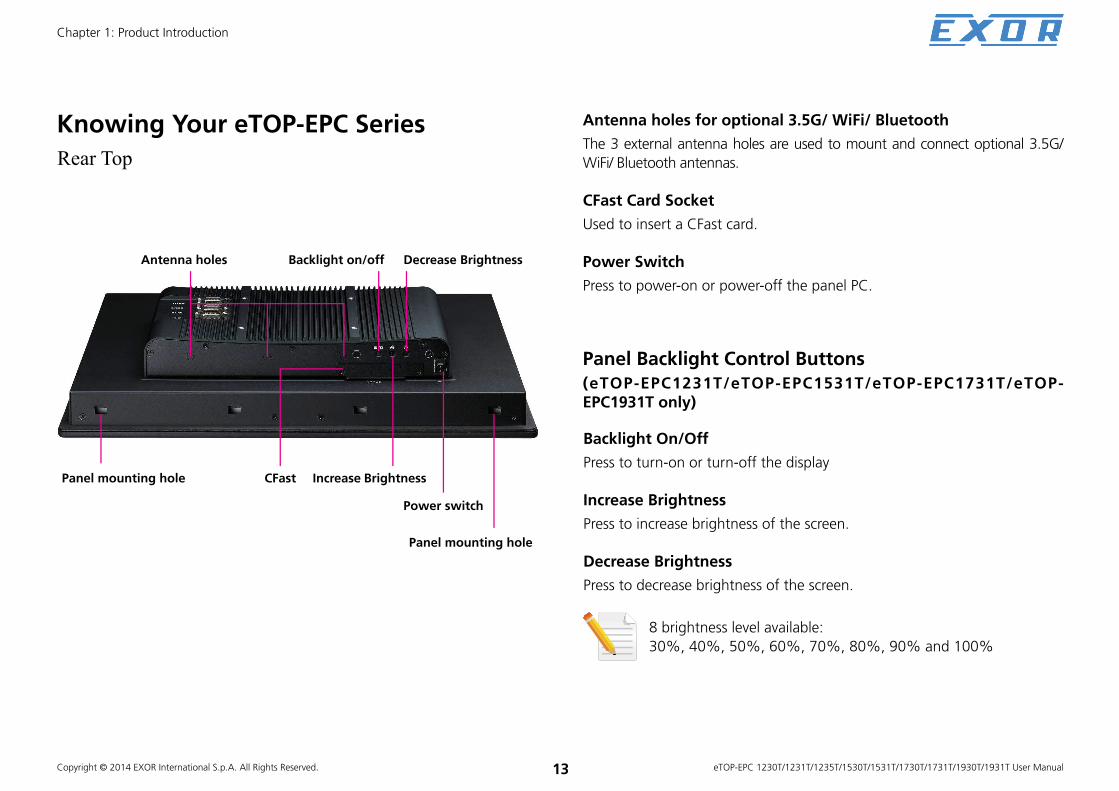
Knowing Your eTOP-EPC Series
Rear Top
Panel mounting hole
Antenna holes for optional 3.5G/ WiFi/ Bluetooth
The 3 external antenna holes are used to mount and connect optional 3.5G/
WiFi/ Bluetooth antennas.
CFast Card Socket
Used to insert a CFast card.
Power Switch
Press to power-on or power-off the panel PC.
Panel mounting hole
Power switch
CFast
Decrease Brightness
Increase Brightness
Backlight on/off
Backlight On/Off
Press to turn-on or turn-off the display
Increase Brightness
Press to increase brightness of the screen.
Decrease Brightness
Press to decrease brightness of the screen.
8 brightness level available:
30%, 40%, 50%, 60%, 70%, 80%, 90% and 100%
Antenna holes
Panel Backlight Control Buttons
(eTOP-EPC1231T/eTOP-EPC1531T/eTOP-EPC1731T/eTOP-EPC1931T only)

Copyright © 2014 EXOR International S.p.A. All Rights Reserved. 14
Chapter 1: Product Introduction
eTOP-EPC 1230T/1231T/1235T/1530T/1531T/1730T/1731T/1930T/1931T User Manual
Rear Bottom Line-in
Used to connect an audio device as sound source.
Mic-in
Used to connect an external microphone.
Line-out
Used to connect a headphone or a speaker.
LAN 1 and LAN 2
Used to connect the system to a local area network. LAN1 supports Wake up on LAN.
USB
Used to connect USB 2.0/1.1 devices.
COM 1 and COM 2
These COM ports support RS232/422/485 compatible series device by BIOS setting.COM1 of eTOP-EPC 1230T/1235T/1530T/1730T/1930T supports 5V or RI by Jumper setting.COM2 of eTOP-EPC 1230T/1235T/1530T/1730T/1930T supports 12V or RI by Jumper setting.eTOP-EPC 1231T/1531T/1731T/1931T have 2.5kV isolated protection.
PS/2 KB/MS
Used to connect a PS/2 keyboard and a PS/2 mouse
Reset Button
Press this button to restart the system.
VGA
Used to connect an analog VGA monitor.
12V-30V DC Input
Used to plug a DC power cord.
LAN 1 VGA 12V-30V
DC Input
Mic-inMic-in
LAN 2
COM 1
PS/2 KB/MS
Reset
Line-outLine-in COM 2USB

Copyright © 2014 EXOR International S.p.A. All Rights Reserved. 15
Chapter 1: Product Introduction
eTOP-EPC 1230T/1231T/1235T/1530T/1531T/1730T/1731T/1930T/1931T User Manual
Rear (eTOP-EPC 1230T/1235T/1530T/1730T/1930T only)
VESA Mounting Hole
VESA Mounting Hole
VESA Mounting Hole
VESA Mounting Hole
VESA Mounting Holes
These are mounting holes for VESA mount (100x100mm)

Copyright © 2014 EXOR International S.p.A. All Rights Reserved. 16
Chapter 1: Product Introduction
eTOP-EPC 1230T/1231T/1235T/1530T/1531T/1730T/1731T/1930T/1931T User Manual
Rear (eTOP-EPC 1231T/1531T/1731T/1931T only)
VESA Mounting HoleVESA Mounting Hole
DIO
The digital I/O connector support 4 isolated protection digital input channels
and 4 isolated protection digital output channels.
Isolation voltage: 2500 VDC
DI:
4x Digital Input (Source Type)
– Input Voltage (Dry Contact)
Logic 0: Close to GND
Logic 1: Open
– Input Voltage (Wet Contact)
Logic 0: 3V max.
Logic 1: +5V-+30VDC
4x Digital Output (Sink Type)
– Output Voltage: Typical 24VDC, 30VDC max.
Logic 0: 0-0.6VDC
Logic 1: 3.6-5VDC
– Sink Current: 200mA max. per channel
GPIO
The GPIO connector supports 2 digital input and 2 digital output.
COM3 and COM4
These COM ports support RS232 compatible serial devices.
COM3 supports 5V or RI by Jumper setting.
COM4 supports 12V or RI by Jumper setting.
VESA Mounting Holes
These are mounting holes for VESA mount (100x100mm).
DIO
GPIO
COM3
COM4
VESA Mounting HoleVESA Mounting Hole

Copyright © 2014 EXOR International S.p.A. All Rights Reserved. 17
Chapter 1: Product Introduction
eTOP-EPC 1230T/1231T/1235T/1530T/1531T/1730T/1731T/1930T/1931T User Manual
Mechanical Dimensions
eTOP-EPC 1230T/1231T/1235T

Copyright © 2014 EXOR International S.p.A. All Rights Reserved. 18
Chapter 1: Product Introduction
eTOP-EPC 1230T/1231T/1235T/1530T/1531T/1730T/1731T/1930T/1931T User Manual
Mechanical Dimensions
eTOP-EPC 1530T/1531T

Copyright © 2014 EXOR International S.p.A. All Rights Reserved. 19
Chapter 1: Product Introduction
eTOP-EPC 1230T/1231T/1235T/1530T/1531T/1730T/1731T/1930T/1931T User Manual
Mechanical Dimensions
392.40
134.4567.22
56.40
11.80
410.42
338.92
271.34
75.79
38.90
6.00
181.90
322.38
173.90
100.00
270.00
100.00
eTOP-EPC 1730T/1731T

Copyright © 2014 EXOR International S.p.A. All Rights Reserved. 20
Chapter 1: Product Introduction
eTOP-EPC 1230T/1231T/1235T/1530T/1531T/1730T/1731T/1930T/1931T User Manual
Mechanical Dimensions
eTOP-EPC 1930T/1931T
Copyright © 2014 EXOR International S.p.A. All Rights Reserved. 21 eTOP-EPC 1230T/1231T/1235T/1530T/1531T/1730T/1731T/1930T/1931T User Manual
Chapter 2: Jumpers and Connectors
CHAPTER 2: JUMPERS AND CONNECTORS
This chapter describes how to set the jumpers and connectors on the
motherboard. Note that information in this chapter applies to eTOP-EPC
1230T/ 1231T/1235T/1530T/1531T/1730T/1731T/1930T/1931T.
Before You Begin ▪ Ensure you have a stable, clean working environment. Dust and dirt can
get into components and cause a malfunction. Use containers to keep
small components separated.
▪ Adequate lighting and proper tools can prevent you from accidentally
damaging the internal components. Most of the procedures that follow
require only a few simple tools, including the following:
– A Philips screwdriver
– A flat-tipped screwdriver
– A set of jewelers screwdrivers
– A grounding strap
– An anti-static pad
▪ Using your fingers can disconnect most of the connections. It is
recommended that you do not use needle-nosed pliers to disconnect
connections as these can damage the soft metal or plastic parts of the
connectors.
▪ Before working on internal components, make sure that the power is off.
Ground yourself before touching any internal components, by touching
a metal object. Static electricity can damage many of the electronic
components. Humid environments tend to have less static electricity than
dry environments. A grounding strap is warranted whenever danger of
static electricity exists.
Precautions Computer components and electronic circuit boards can be damaged by
discharges of static electricity. Working on computers that are still connected
to a power supply can be extremely dangerous.
Follow the guidelines below to avoid damage to your computer or yourself:
▪ Always disconnect the unit from the power outlet whenever you are
working inside the case.
▪ If possible, wear a grounded wrist strap when you are working inside the
computer case. Alternatively, discharge any static electricity by touching
the bare metal chassis of the unit case, or the bare metal body of any
other grounded appliance.
▪ Hold electronic circuit boards by the edges only. Do not touch the
components on the board unless it is necessary to do so. Don’t flex or
stress the circuit board.
▪ Leave all components inside the static-proof packaging that they shipped
with until they are ready for installation. Use correct screws and do not
over tighten screws.

Copyright © 2014 EXOR International S.p.A. All Rights Reserved. 22 eTOP-EPC 1230T/1231T/1235T/1530T/1531T/1730T/1731T/1930T/1931T User Manual
Chapter 2: Jumpers and Connectors
Jumper SettingsA jumper is the simplest kind of electric switch. It consists of two metal
pins and a cap. When setting the jumpers, ensure that the jumper caps are
placed on the correct pins. When the jumper cap is placed on both pins, the
jumper is short. If you remove the jumper cap, or place the jumper cap on
just one pin, the jumper is open.
Refer to the illustrations below for examples of what the 2-pin and 3-pin
jumpers look like when they are short (on) and open (off).
Two-Pin Jumpers: Open (Left) and Short (Right)
Three-Pin Jumpers: Pins 1 and 2 are Short
12
3
12
3

Copyright © 2014 EXOR International S.p.A. All Rights Reserved. 23 eTOP-EPC 1230T/1231T/1235T/1530T/1531T/1730T/1731T/1930T/1931T User Manual
Chapter 2: Jumpers and Connectors
Locations of the Jumpers and Connectors
Top View
CN13
VGA1
CN16
JP13
CN15
JP12
USB2USB1LAN2LAN1
CN14
J12JP11
J10
J8J9
J7
JP7
JP6
JP5
SW2
CN5
CN4
J5J4
JP4
SW1
J6
CN3
CN8
CN6 CN7
CN2J2JP2
JP1
JP9 JP10
CN9 CN10
JP8J11

Copyright © 2014 EXOR International S.p.A. All Rights Reserved. 24 eTOP-EPC 1230T/1231T/1235T/1530T/1531T/1730T/1731T/1930T/1931T User Manual
Chapter 2: Jumpers and Connectors
CFast card socket
DDR3 SODIMM
DIMM1
DIMM2
Bottom View

Copyright © 2014 EXOR International S.p.A. All Rights Reserved. 25 eTOP-EPC 1230T/1231T/1235T/1530T/1531T/1730T/1731T/1930T/1931T User Manual
Chapter 2: Jumpers and Connectors
Jumpers and DIP Switch Settings
CMOS Clear SelectConnector type: 1x3 3-pin header, 2.54mm pitch
Connector location: JP1
Pin Settings
1-2 On Normal
2-3 On Clear BIOS
1-2 On: default
Pin Definition
1 NC
2 RTC Power
3 GND
AT/ATX SelectionConnector type: 1x3 3-pin header, 2.54mm pitch
Connector location: JP8
Pin Settings
1-2 On AT Mode
2-3 On ATX Mode
2-3 On: default
Pin Definition
1 AUTO (AT MODE)
2 PWRBT In
3 Manual ( ATX MODE)
1 3 1 3

Copyright © 2014 EXOR International S.p.A. All Rights Reserved. 26 eTOP-EPC 1230T/1231T/1235T/1530T/1531T/1730T/1731T/1930T/1931T User Manual
Chapter 2: Jumpers and Connectors
Dimming Signal Level SelectConnector type: 1x3 3-pin header, 2.54mm pitch
Connector location: JP6
Pin Settings Model
1-2 On 3.3V
eTOP-EPC1230T
eTOP-EPC1231T
eTOP-EPC1235T
eTOP-EPC1930T
eTOP-EPC1931T
2-3 On 5V
eTOP-EPC1530T
eTOP-EPC1531T
eTOP-EPC1730T
eTOP-EPC1731T
Pin Definition
1 VCC3
2 Power for Dimming
3 VCC5
1 3
Dimming Type SelectConnector type: 1x3 3-pin header, 2.54mm pitch
Connector location: SW2
SW2-1 SW2-2 Settings Model
On Off PWM Mode
eTOP-EPC1230T
eTOP-EPC1231T
eTOP-EPC1235T
eTOP-EPC1530T
eTOP-EPC1531T
eTOP-EPC1930T
eTOP-EPC1931T
Off On Analog ModeeTOP-EPC1730T
eTOP-EPC1731T
Default: PWM
O N1 2

Copyright © 2014 EXOR International S.p.A. All Rights Reserved. 27 eTOP-EPC 1230T/1231T/1235T/1530T/1531T/1730T/1731T/1930T/1931T User Manual
Chapter 2: Jumpers and Connectors
O N1 2 3 4
Panel Resolution SelectConnector type: 4-pin On/Off Switch
Connector location: SW1
SW1-1 SW1-2 SW1-3 SW1-4 Resolution/Color/Backlight On Model
ON ON ON ON 800 x 600/6 bits/High
OFF OFF OFF ON 800 x 600/8 bits/HigheTOP-EPC1230T
eTOP-EPC1231T
OFF ON ON ON 1024 x 768/6 bits/High
ON OFF ON ON 1024 x768/8 bits/High
eTOP-EPC1235T
eTOP-EPC1530T
eTOP-EPC1531T
OFF OFF ON ON 1280 x 1024/8 bits/LoweTOP-EPC1730T
eTOP-EPC1731T
ON OFF OFF ON 1280 x 1024/8 bits/HigheTOP-EPC1930T
eTOP-EPC1931T
ON OFF OFF OFF 1920 x 1080/8 bits/High
Copyright © 2014 EXOR International S.p.A. All Rights Reserved. 28 eTOP-EPC 1230T/1231T/1235T/1530T/1531T/1730T/1731T/1930T/1931T User Manual
Chapter 2: Jumpers and Connectors
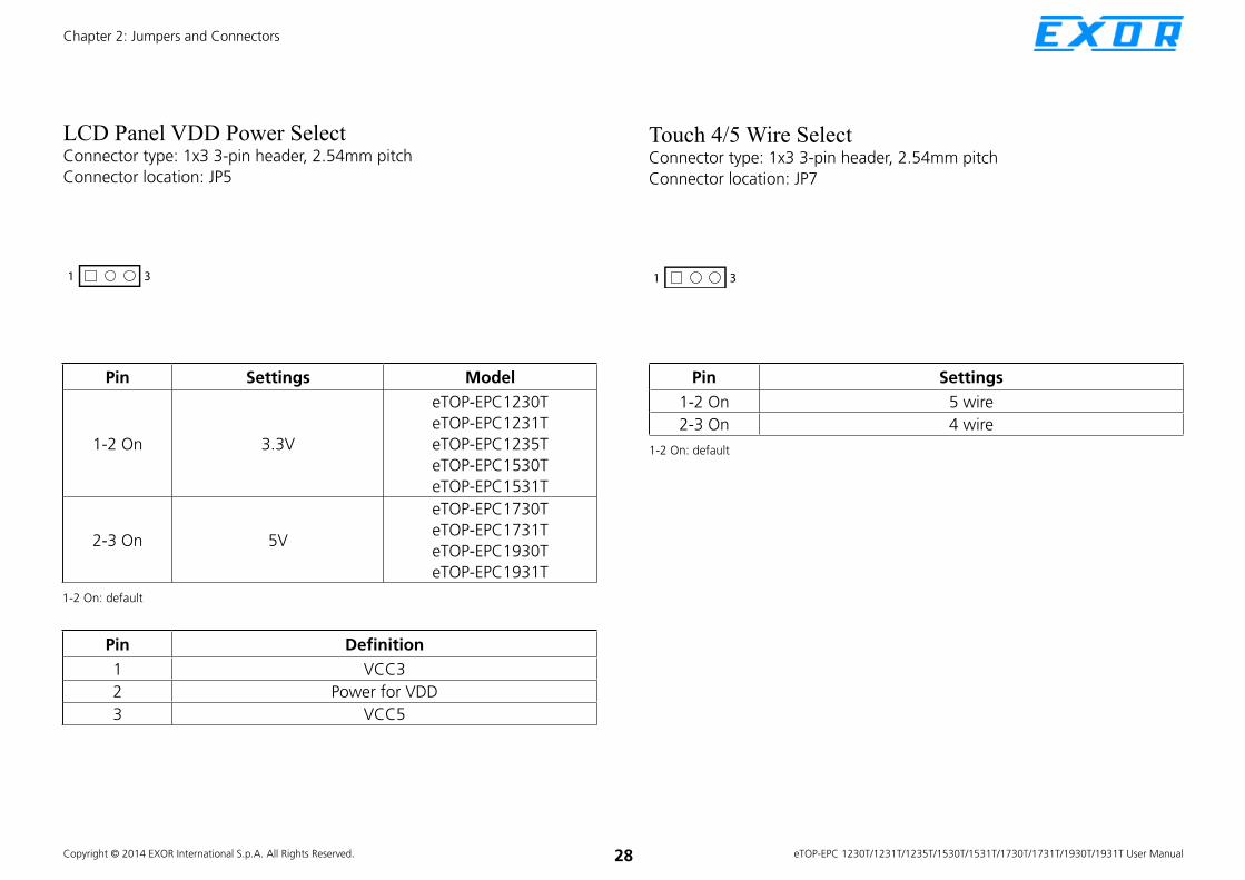
LCD Panel VDD Power SelectConnector type: 1x3 3-pin header, 2.54mm pitch
Connector location: JP5
Pin Settings Model
1-2 On 3.3V
eTOP-EPC1230T
eTOP-EPC1231T
eTOP-EPC1235T
eTOP-EPC1530T
eTOP-EPC1531T
2-3 On 5V
eTOP-EPC1730T
eTOP-EPC1731T
eTOP-EPC1930T
eTOP-EPC1931T
1-2 On: default
Pin Definition
1 VCC3
2 Power for VDD
3 VCC5
1 3
Touch 4/5 Wire SelectConnector type: 1x3 3-pin header, 2.54mm pitch
Connector location: JP7
1 3
Pin Settings
1-2 On 5 wire
2-3 On 4 wire
1-2 On: default

Copyright © 2014 EXOR International S.p.A. All Rights Reserved. 29 eTOP-EPC 1230T/1231T/1235T/1530T/1531T/1730T/1731T/1930T/1931T User Manual
Chapter 2: Jumpers and Connectors
COM1 RI Pin Power Select(eTOP-EPC 1230T/eTOP-EPC 1235T/eTOP-EPC 1530T/eTOP-EPC 1730T/
eTOP-EPC 1930T only)
Connector type: 1x3 3-pin header, 2.54mm pitch
Connector location: JP12
1 3
Pin Settings
1-2 On RING
2-3 On +5V
1-2 On: default
Pin Definition
1 SP1_RI
2 SP1_PSRI
3 VCC5
COM2 RI Pin Power Select(eTOP-EPC 1230T/eTOP-EPC 1235T/eTOP-EPC 1530T/eTOP-EPC 1730T/
eTOP-EPC 1930T only)
Connector type: 1x3 3-pin header, 2.54mm pitch
Connector location: JP13
1 3
Pin Settings
1-2 On RING
2-3 On +12V
1-2 On: default
Pin Definition
1 SP2_RI
2 SP2_PSRI
3 +12V

Copyright © 2014 EXOR International S.p.A. All Rights Reserved. 30 eTOP-EPC 1230T/1231T/1235T/1530T/1531T/1730T/1731T/1930T/1931T User Manual
Chapter 2: Jumpers and Connectors
COM3 RI Pin Power Select(eTOP-EPC 1231T/eTOP-EPC 1531T/eTOP-EPC 1731T/eTOP-EPC 1931T
only)
Connector type: 1x3 3-pin header, 2.54mm pitch
Connector location: JP9
1 3
Pin Settings
1-2 On RING
2-3 On +5V
1-2 On: default
Pin Definition
1 SP3_RI
2 SP3_PSRI
3 VCC5
COM4 RI Pin Power Select(eTOP-EPC 1231T/eTOP-EPC 1531T/eTOP-EPC 1731T/eTOP-EPC 1931T
only)
Connector type: 1x3 3-pin header, 2.54mm pitch
Connector location: JP10
1 3
Pin Settings
1-2 On RING
2-3 On +12V
1-2 On: default
Pin Definition
1 SP4_RI
2 SP4_PSRI
3 12V

Copyright © 2014 EXOR International S.p.A. All Rights Reserved. 31 eTOP-EPC 1230T/1231T/1235T/1530T/1531T/1730T/1731T/1930T/1931T User Manual
Chapter 2: Jumpers and Connectors
Connector Pin Definitions
External I/O Interface
12V-30V DC Power InputConnector type: DC 4-pin DIN power jack with shield
Connector location: CN13
Pin Settings
1 DC+
2 DC+
3 DC-
4 DC-
5 GND
1 2
3 4
5
VGA PortConnector type: DB-15 port, 15-pin D-Sub
Connector location: VGA1
Pin Definition Pin Definition
1 Red 9 +5V
2 Green 10 GND
3 Blue 11 N/C
4 N/C 12 DDC Data
5 GND 13 HSYNC
6 GND 14 VSYNC
7 GND 15 DDC Clock
8 GND

Copyright © 2014 EXOR International S.p.A. All Rights Reserved. 32 eTOP-EPC 1230T/1231T/1235T/1530T/1531T/1730T/1731T/1930T/1931T User Manual
Chapter 2: Jumpers and Connectors
PS/2 Keyboard/Mouse PortConnector type: PS/2, Mini-DIN-6, 2.0mm pitch
2x4 8-pin header, 2.54mm pitch
Connector location: JP4
Pin Settings
1 KB_DATA
2 MS_DATA
3 GND
4 VCC5
5 KB_CLK
6 MS_CLK
12
34
56
COM2 Port: Serial Port RS232/422/485 eTOP-EPC 1230T/eTOP-EPC 1235T/eTOP-EPC 1530T/eTOP-EPC 1730T/
eTOP-EPC 1930T
(Ring or +12V Power for Pin 9)
eTOP-EPC 1231T/eTOP-EPC 1531T/eTOP-EPC 1731T/eTOP-EPC 1931T
(Isolation protection with RS232/422/485)
Connector type: 9-pin D-Sub
Connector location: CN16
Pin Definition
1 COM2_DCD
2 COM2_RXD
3 COM2_TXD
4 COM2_DTR
5 COM2_GND
6 COM2_DSR
7 COM2_RTS
8 COM2_CTS
9COM2_RI (Could be a
+12V Power Pin)
RS232
Pin Definition Pin Definition
1 VCC5 2 VCC5
3 KB_DATA 4 MS_DATA
5 KB_CLK 6 MS_CLK
7 GND 8 GND
1 7
2 8
External Connector
Internal Connector

Copyright © 2014 EXOR International S.p.A. All Rights Reserved. 33 eTOP-EPC 1230T/1231T/1235T/1530T/1531T/1730T/1731T/1930T/1931T User Manual
Chapter 2: Jumpers and Connectors
Pin Definition
1 COM2_TXD-
2 COM2_TXD+
3 COM2_RXD+
4 COM2_RXD-
5 COM2_GND
6 COM2_RTS-
7 COM2_RTS+
8 COM2_CTS+
9COM2_CTS- (Could be a
+12V Power Pin)
RS422
Pin Definition
1COM2_TXD-
COM2_RXD-
2COM2_TXD+
COM2_RXD+
3 Reserve
4 Reserve
5 Reserve
6 Reserve
7 Reserve
8 Reserve
9Reserve (Could be a
+12V Power Pin)
RS485
COM1 Port: Serial Port RS232/422/485 eTOP-EPC 1230T/eTOP-EPC 1235T/eTOP-EPC 1530T/eTOP-EPC 1730T/
eTOP-EPC 1930T
(Ring or +5V Power for Pin 9)
eTOP-EPC 1231T/eTOP-EPC 1531T/eTOP-EPC 1731T/eTOP-EPC 1931T
(Isolation protection with RS232/422/485)
Connector type: 9-pin D-Sub
Connector location: CN15
Pin Definition
1 COM1_DCD: Data Carrier Detect
2 COM1_RXD: Receive Data
3 COM1_TXD: Transmit Data
4 COM1_DTR: Data Terminal Ready
5 COM1_GND
6 COM1_DSR: Data Set Ready
7 COM1_RTS: Request To Send
8 COM1_CTS: Clear To Send
9 COM1_RI: Ring Indicator (Could be a +5V Power Pin)
RS232

Copyright © 2014 EXOR International S.p.A. All Rights Reserved. 34 eTOP-EPC 1230T/1231T/1235T/1530T/1531T/1730T/1731T/1930T/1931T User Manual
Chapter 2: Jumpers and Connectors
Pin Definition
1 COM1_TXD-: Transmit Data Negative
2 COM1_TXD+: Transmit Data Positive
3 COM1_RXD+: Receive Data Positive
4 COM1_RXD-: Receive Data Negative
5 COM1_GND
6 COM1_RTS-: Request To Send Negative
7 COM1_RTS+: Request To Send Positive
8 COM1_CTS+: Clear To Send Positive
9COM1_CTS-: Clear To Send Negative (Could be a +5V
Power Pin)
RS422
Pin Definition
1COM1_TXD-: Transmit Data Negative
COM1_RXD-: Receive Data Negative
2COM1_TXD+: Transmit Data Positive
COM1_RXD+: Receive Data Positive
3 Reserve
4 Reserve
5 Reserve
6 Reserve
7 Reserve
8 Reserve
9 Reserve (Could be a +5V Power Pin)
RS485
COM3 Port and Connector: Serial Port RS232 eTOP-EPC 1231T/eTOP-EPC 1531T/eTOP-EPC 1731T/eTOP-EPC 1931T
Only
(Ring or +5V Power for Pin 9)
Connector type: 9-pin D-Sub
2x5 10-pin header, 2.0mm pitch
Connector location: CN9
Pin Definition
1 COM3_DCD
2 COM3_RXD
3 COM3_TXD
4 COM3_DTR
5 COM3_GND
6 COM3_DSR
7 COM3_RTS
8 COM3_CTS
9 COM3_RI (Could be a +5V Power Pin)
10 GND
RS232
1 9
2 10

Copyright © 2014 EXOR International S.p.A. All Rights Reserved. 35 eTOP-EPC 1230T/1231T/1235T/1530T/1531T/1730T/1731T/1930T/1931T User Manual
Chapter 2: Jumpers and Connectors
USB PortsConnector type: Dual USB port
Connector location: USB1 and USB2
Pin Definition Pin Definition
1 VCC5 5 VCC5
2 USB0- 6 USB1-
3 USB0+ 7 USB1+
4 GND 8 GND
USB1
Pin Definition Pin Definition
1 VCC5 5 VCC5
2 USB2- 6 USB3-
3 USB2+ 7 USB3+
4 GND 8 GND
USB2
COM4 Port and Connector: Serial Port RS232 eTOP-EPC 1231T/eTOP-EPC 1531T/eTOP-EPC 1731T/eTOP-EPC 1931T
Only
(Ring or +12V Power for Pin 9)
Connector type: 9-pin D-Sub
2x5 10-pin header, 2.0mm pitch
Connector location: CN10
Pin Definition
1 COM4_DCD
2 COM4_RXD
3 COM4_TXD
4 COM4_DTR
5 COM4_GND
6 COM4_DSR
7 COM4_RTS
8 COM4_CTS
9 COM4_RI (Could be a +12V Power Pin)
10 GND
RS232
1 9
2 10

Copyright © 2014 EXOR International S.p.A. All Rights Reserved. 36 eTOP-EPC 1230T/1231T/1235T/1530T/1531T/1730T/1731T/1930T/1931T User Manual
Chapter 2: Jumpers and Connectors
LAN2 PortConnector type: RJ45 port with LEDs
Connector location: LAN2
Act Status
Yellow blinking Data activity
Off No activity
Pin Definition Pin Definition
1 LAN2M0+ 5 LAN2M2-
2 LAN2M0- 6 LAN2M1-
3 LAN2M1+ 7 LAN2M3+
4 LAN2M2+ 8 LAN2M3-
Link Status
Steady green 1000M link
Steady orange 100M link
Off 10M or no link
LAN1 PortSupport Wake on LAN (WOL)
Connector type: RJ45 port with LEDs
Connector location: LAN1
Act Status
Yellow blinking Data activity
Off No activity
Pin Definition Pin Definition
1 LAN1M0+ 5 LAN1M2-
2 LAN1M0- 6 LAN1M1-
3 LAN1M1+ 7 LAN1M3+
4 LAN1M2+ 8 LAN1M3-
Link Status
Steady green 1000M link
Steady orange 100M link
Off 10M or no link
ACT LINK ACT LINK

Copyright © 2014 EXOR International S.p.A. All Rights Reserved. 37 eTOP-EPC 1230T/1231T/1235T/1530T/1531T/1730T/1731T/1930T/1931T User Manual
Chapter 2: Jumpers and Connectors
Line-out JackConnector type: 3.5mm Earphone Jack
Connector location: CN14
Pin Definition
1 LOUT_R
2 JD
3 NC
4 LOUT_L
5 GND
6 GND

Copyright © 2014 EXOR International S.p.A. All Rights Reserved. 38 eTOP-EPC 1230T/1231T/1235T/1530T/1531T/1730T/1731T/1930T/1931T User Manual
Chapter 2: Jumpers and Connectors
Internal ConnectorsLVDS Channel 1Connector type: 2x10 20-pin header, 1.25mm pitch
Connector location: CN5
Pin Definition Pin Definition
1 NC 11 LVDS_CLK1+(Odd)
2 NC 12 LVDS_DAT1-(Odd)
3 VDD 13 LVDS_CLK1-(Odd)
4 LVDS_DAT0+(Odd) 14 GND
5 LVDS_DAT3+(Odd) 15 GND
6 LVDS_DAT0-(Odd) 16 +12V
7 LVDS_DAT3-(Odd) 17 LVDS_DAT2+(Odd)
8 VDD 18 +12V
9 GND 19 LVDS_DAT2-(Odd)
10 LVDS_DAT1+(Odd) 20 GND
1 19
2 20
LVDS Channel 2Connector type: 2x10 20-pin header, 1.25mm pitch
Connector location: CN4
Pin Definition Pin Definition
1 NC 11 LVDS_CLK2+(Even)
2 NC 12 LVDS_DAT5-(Even)
3 VDD 13 LVDS_CLK2-(Even)
4 LVDS_DAT4+(Even) 14 GND
5 LVDS_DAT7+(Even) 15 GND
6 LVDS_DAT4-(Even) 16 +12V
7 LVDS_DAT7-(Even) 17 LVDS_DAT6+(Even)
8 VDD 18 +12V
9 GND 19 LVDS_DAT6-(Even)
10 LVDS_DAT5+(Even) 20 GND
1 19
2 20

Copyright © 2014 EXOR International S.p.A. All Rights Reserved. 39 eTOP-EPC 1230T/1231T/1235T/1530T/1531T/1730T/1731T/1930T/1931T User Manual
Chapter 2: Jumpers and Connectors
Panel Backlight ConnectorConnector type: 1x7 7-pin header JST, 2.5mm pitch
Connector location: J7
Pin Definition Pin Definition
1 VCC5 5 GND
2 12V 6 GND
3 12V 7 BKLEN
4 BKCTRL
7 1
Touch Sensor ConnectorConnector type: 1x5 5-pin header JST, 2.5mm pitch
Connector location: J9
Pin 4-wire 5-wire
1 Left LL (L)
2 Top UL (Y)
3 N/A Sense (S)
4 Right LR (X)
5 Bottom UR (H)
5 1

Copyright © 2014 EXOR International S.p.A. All Rights Reserved. 40 eTOP-EPC 1230T/1231T/1235T/1530T/1531T/1730T/1731T/1930T/1931T User Manual
Chapter 2: Jumpers and Connectors
USB ConnectorConnector type: 1x6 6-pin header JST, 2.5mm pitch
Connector location: J8
Pin Definition
1 +5V
2 HUBUSB DM1-
3 HUBUSB DP1+
4 HUBUSB DM2-
5 HUBUSB DP2+
6 GND
6 1
Bluetooth ConnectorConnector type: 1x10 10-pin header, 1.0mm pitch
Connector location: J6
110
Pin Definition Pin Definition
1 GND 6 NC
2 HUBUSB_DP3+ 7 NC
3 HUBUSB_DM3- 8 3.3V
4 NC 9 NC
5 NC 10 GND

Copyright © 2014 EXOR International S.p.A. All Rights Reserved. 41 eTOP-EPC 1230T/1231T/1235T/1530T/1531T/1730T/1731T/1930T/1931T User Manual
Chapter 2: Jumpers and Connectors
SATA ConnectorConnector type: Standard Serial ATAII 7P (1.27mm, SATA-M-180)
Connector location: CN3
1 7
Pin Definition
1 GND
2 TX0+
3 TX0-
4 GND
5 RX0-
6 RX0+
7 GND
SATA DOM Power ConnectorConnector type: 1x2 2-pin header, JST 2.5mm pitch
Connector location: J2
Pin Definition
1 +5V
2 GND
1 2

Copyright © 2014 EXOR International S.p.A. All Rights Reserved. 42 eTOP-EPC 1230T/1231T/1235T/1530T/1531T/1730T/1731T/1930T/1931T User Manual
Chapter 2: Jumpers and Connectors
Line-in/Mic-in ConnectorConnector type: 2x4 8-pin header, 2.54mm pitch
Connector location: JP11
Pin Definition Pin Definition
1 LINE IN_LP 2 MIC_L3
3 LINE IN_JD 4 MIC_JD
5 GND 6 GND
7 LINE IN_RP 8 MIC_R3
Line-in Mic-in
1 7
2 8
Speaker-out ConnectorConnector type: 1x4 4-pin header, 2.54mm pitch
Connector location: J12
Pin Definition
1 OUT-L+
2 OUT-L-
3 OUT-R+
4 OUT-R-
1 4

Copyright © 2014 EXOR International S.p.A. All Rights Reserved. 43 eTOP-EPC 1230T/1231T/1235T/1530T/1531T/1730T/1731T/1930T/1931T User Manual
Chapter 2: Jumpers and Connectors
GPIO Connector(eTOP-EPC1931T/eTOP-EPC1721T/eTOP-EPC1531T/eTOP-EPC1231T
only)
Connector type: 2x5 10-pin header, 2.0mm pitch
DB15 male 10-pin
Connector location: JP2
Pin Definition Pin Definition
1 +5V 2 GND
3 GPIO22 (GPO) 4 GPIO20 (GPI)
5 GPIO23 (GPO) 6 GPIO21 (GPI)
7 NC 8 NC
9 NC 10 NC
1 9
2 10
Pin Definition Pin Definition
1 +5V 2 GPIO20 (GPI)
3 GPIO21 (GPI) 4 NC
5 NC 6 GND
7 GPIO22 (GPO) 8 GPIO23 (GPO)
9 NC 10 NC
Internal Connector
External Connector
1 5
6 10

Copyright © 2014 EXOR International S.p.A. All Rights Reserved. 44 eTOP-EPC 1230T/1231T/1235T/1530T/1531T/1730T/1731T/1930T/1931T User Manual
Chapter 2: Jumpers and Connectors
DIO ConnectorConnector type: 2x8 16-pin header, 2.0mm pitch
DB15 male 15-pin
Connector location: CN2
Pin Definition Pin Definition
1 DI1 2 DO1
3 DI2 4 DO2
5 DI3 6 DO3
7 DI4 8 DO4
9 NC 10 NC
11 COM 12 NC
13 GND 14 GND
15 GND 16 GND
1 15
2 16
Pin Definition Pin Definition
1 DI1 2 DI2
3 DI3 4 DI4
5 GND 6 COM
7 NC 8 NC
9 DO1 10 DO2
11 DO3 12 DO4
13 GND 14 GND
15 GND
Internal Connector External Connector
1 5
11 15
DI1~DI4: Isolated digital input pins
DO1~DO4: Isolated digital output pins
COM: Common pin for connecting inductive loads of isolated output channels DO1~DO4
GND: Isolated ground

Copyright © 2014 EXOR International S.p.A. All Rights Reserved. 45 eTOP-EPC 1230T/1231T/1235T/1530T/1531T/1730T/1731T/1930T/1931T User Manual
Chapter 2: Jumpers and Connectors
Power/HDD LED Indicator ConnectorConnector type: 1x5 5-pin header JST, 2.0mm pitch
Connector location: J10
Pin Definition
1 HDD_GND
2 HDD_PWR
3 PWR_GND
4 5VSB
5 VCC5
5 1
Backlight Control Input ConnectorConnector type: 1x4 4-pin header JST, 2.0mm pitch
Connector location: J5
Pin Definition
1 GND
2 Tact Switch input
3 PIR IN
4 VCC3
14

Copyright © 2014 EXOR International S.p.A. All Rights Reserved. 46 eTOP-EPC 1230T/1231T/1235T/1530T/1531T/1730T/1731T/1930T/1931T User Manual
Chapter 2: Jumpers and Connectors
Dimming Control Button ConnectorConnector type: 1x5 5-pin header JST, 2.0mm pitch
Connector location: J4
Pin Definition
1 GND
2 Decreased input
3 Increased input
4 Light sensor input
5 VCC3
5 1
SIM Card SlotConnector location: CN8
C3
C2
C1
C7
C6
C5
Pin Definition Pin Definition
C1 UIM_PWR C5 GND
C2 UIM_RST C6 UIM_VCCP
C3 UIM_CLK C7 UIM_DAT

Copyright © 2014 EXOR International S.p.A. All Rights Reserved. 47 eTOP-EPC 1230T/1231T/1235T/1530T/1531T/1730T/1731T/1930T/1931T User Manual
Chapter 2: Jumpers and Connectors
Mini-PCIe SlotConnector location: CN6
1 2
51 52
Pin Definition Pin Definition
1 WAKE0# 2 +3.3V_MINI
3 NC 4 GND
5 NC 6 +1.5V_MINI
7 PCIE_CLKREQ 8 SIM_PWR
9 GND 10 SIM_DAT
11 GPP_CLK1- 12 SIM_CLK
13 GPP_CLK1+ 14 SIM_RST
15 GND 16 SIM_VCCP
17 NC 18 GND
19 NC 20 MINICARD1_DIS#
21 GND 22 PCIE_RST#
23 PCIE_RX2- 24 +3.3V_MINI
25 PCIE_RX2+ 26 GND
Pin Definition Pin Definition
27 GND 28 +1.5V_MINI
29 GND 30 SMB_CLK
31 PCIE_TX3- 32 SMB_DAT
33 PCIE_TX3+ 34 GND
35 GND 36 USB6-
37 GND 38 USB6+
39 +3.3V_MINI 40 GND
41 +3.3V_MINI 42 NC
43 GND 44 NC
45 NC 46 NC
47 NC 48 +1.5V_MINI
49 NC 50 GND
51 NC 52 +3.3V_MINI

Copyright © 2014 EXOR International S.p.A. All Rights Reserved. 48 eTOP-EPC 1230T/1231T/1235T/1530T/1531T/1730T/1731T/1930T/1931T User Manual
Chapter 2: Jumpers and Connectors
Mini-PCIe SlotConnector location: CN7
1 2
51 52
Pin Definition Pin Definition
1 WAKE0# 2 +3.3V_MINI
3 NC 4 GND
5 NC 6 +1.5V_MINI
7 NC 8 NC
9 GND 10 NC
11 GPP_CLK1- 12 NC
13 GPP_CLK1+ 14 NC
15 GND 16 NC
17 NC 18 GND
19 NC 20 MINICARD1_DIS#
21 GND 22 PCIE_RST#
23 PCIE_RX2- 24 +3.3V_MINI
25 PCIE_RX2+ 26 GND
Pin Definition Pin Definition
27 GND 28 +1.5V_MINI
29 GND 30 SMB_CLK
31 PCIE_TX3- 32 SMB_DAT
33 PCIE_TX3+ 34 GND
35 GND 36 USB6-
37 GND 38 USB6+
39 +3.3V_MINI 40 GND
41 +3.3V_MINI 42 NC
43 GND 44 NC
45 NC 46 NC
47 NC 48 +1.5V_MINI
49 NC 50 GND
51 NC 52 +3.3V_MINI

Copyright © 2014 EXOR International S.p.A. All Rights Reserved. 49 eTOP-EPC 1230T/1231T/1235T/1530T/1531T/1730T/1731T/1930T/1931T User Manual
Chapter 2: Jumpers and Connectors
CFast Card SlotConnector type: Standard CFast connector
Connector location: J13
Pin Definition Pin Definition
S1 GND PC6 NC
S2 SATA_TX1+ PC7 GND
S3 SATA_TX1- PC8 CFAST_LED1_C
S4 GND PC9 CFAST_LED2_C
S5 SATA_RX1- PC10 NC
S6 SATA_RX1+ PC11 NC
S7 GND PC12 NC
PC1 CFAST_CDI PC13 VCC3
PC2 GND PC14 VCC3
PC3 NC PC15 GND
PC4 NC PC16 GND
PC5 NC PC17 CFAST_CDO
S7 PC17PC1S1
Power Button ConnectorConnector type: 1x2 2-pin header, JST 2.0 mm pitch
Connector location: J11
Pin Definition
1 PWRBT
2 GND
1 2
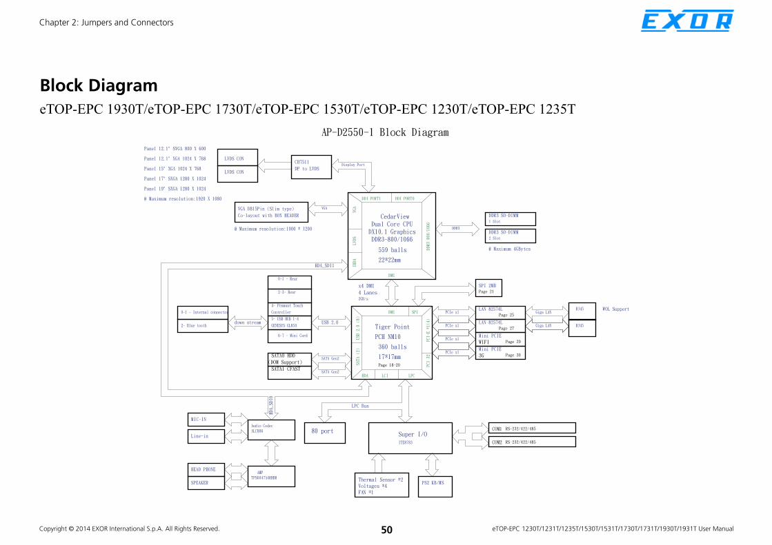
Copyright © 2014 EXOR International S.p.A. All Rights Reserved. 50 eTOP-EPC 1230T/1231T/1235T/1530T/1531T/1730T/1731T/1930T/1931T User Manual
Chapter 2: Jumpers and Connectors
Block Diagram
eTOP-EPC 1930T/eTOP-EPC 1730T/eTOP-EPC 1530T/eTOP-EPC 1230T/eTOP-EPC 1235T

Copyright © 2014 EXOR International S.p.A. All Rights Reserved. 51 eTOP-EPC 1230T/1231T/1235T/1530T/1531T/1730T/1731T/1930T/1931T User Manual
Chapter 2: Jumpers and Connectors
Block Diagram
eTOP-EPC 1931T/eTOP-EPC 1731T/eTOP-EPC 1531T/eTOP-EPC 1231T

Copyright © 2014 EXOR International S.p.A. All Rights Reserved. 52 eTOP-EPC 1230T/1231T/1235T/1530T/1531T/1730T/1731T/1930T/1931T User Manual
Chapter 3: System Setup
CHAPTER 3: SYSTEM SETUP
Installing a SATA Hard Drive Prior to removing the chassis cover, make sure the unit’s power
is off and disconnected from the power sources to prevent
electric shock or system damage.
UTUTUTUTIOIOIOIOIOIOIOIOIOIOUTUTIOION!N!N!N!UTUTIOIOUTUTUTUTCAUTCAUTUTCACACAUTUTUTIOCACACACAUTUTUTUTIOIOIOION!N!N!N!CA ION!N!N!N!N!N!N!N!N!CAUTION!CAUTION!
1. Remove the mounting screws around the chassis cover and then remove the cover.
The dots denote the locations of the screws.

Copyright © 2014 EXOR International S.p.A. All Rights Reserved. 53 eTOP-EPC 1230T/1231T/1235T/1530T/1531T/1730T/1731T/1930T/1931T User Manual
Chapter 3: System Setup
2. Remove the mounting screws of the drive bay.
Mounting screw
SATA power cable and SATA cable
3. Remove the drive bay. The drive bay is used to hold a SATA hard drive.

Copyright © 2014 EXOR International S.p.A. All Rights Reserved. 54 eTOP-EPC 1230T/1231T/1235T/1530T/1531T/1730T/1731T/1930T/1931T User Manual
Chapter 3: System Setup
4. Place the SATA hard drive on the drive bay.
SATA drive
Drive bay
5. Align the mounting holes that are on the sides of the SATA drive with the mounting holes on the drive bay and then use the provided mounting screws to secure the drive in place.
Mounting screw

Copyright © 2014 EXOR International S.p.A. All Rights Reserved. 55 eTOP-EPC 1230T/1231T/1235T/1530T/1531T/1730T/1731T/1930T/1931T User Manual
Chapter 3: System Setup
6. Place the SATA drive in the chassis and then use the provided mounting screws to secure the drive in the chassis.
Connect the SATA data cable and SATA power cable to the
connectorson the SATA drive.
SATA drive
SATA data cable
SATA power cable

Copyright © 2014 EXOR International S.p.A. All Rights Reserved. 56 eTOP-EPC 1230T/1231T/1235T/1530T/1531T/1730T/1731T/1930T/1931T User Manual
Chapter 3: System Setup
Installing a CFast Card
1. The CFast card socket is located on the rear top side of the chassis.
CFast card socketMounting screw
2. Remove the mounting screws of the CFast socket’s cover.

Copyright © 2014 EXOR International S.p.A. All Rights Reserved. 57 eTOP-EPC 1230T/1231T/1235T/1530T/1531T/1730T/1731T/1930T/1931T User Manual
Chapter 3: System Setup
3. With the CFast card’s label facing up, insert the card until it is completely seated in the socket.
CFast card
4. Push the CFast card to remove the CFast card.

Copyright © 2014 EXOR International S.p.A. All Rights Reserved. 58 eTOP-EPC 1230T/1231T/1235T/1530T/1531T/1730T/1731T/1930T/1931T User Manual
Chapter 3: System Setup
Installing a SODIMM
1. Remove the mounting screws around the chassis cover and then remove the cover.

Copyright © 2014 EXOR International S.p.A. All Rights Reserved. 59 eTOP-EPC 1230T/1231T/1235T/1530T/1531T/1730T/1731T/1930T/1931T User Manual
Chapter 3: System Setup
2. Remove the mounting screws on the metal support plate. 3. Gently lift the motherboard support plate upwards and locate the SODIMM socket underneath.

Copyright © 2014 EXOR International S.p.A. All Rights Reserved. 60 eTOP-EPC 1230T/1231T/1235T/1530T/1531T/1730T/1731T/1930T/1931T User Manual
Chapter 3: System Setup
4. Insert the module into the socket at an approximately 30 degrees angle. Apply firm even pressure to each end of the module until it slips into the socket. The gold-plated connector on the edge of the module will almost completely disappear inside the socket.
5. Push the module down until the clips on both sides of the socket lock into position. You will hear a distinctive “click”, indicating the module is correctly locked into position.
SODIMM
SODIMM socket
Note:
1. If only one SO DIMM is installed, please install to the one
closest to the panel.
2. The maximum RAM size is 4G (2x 2G or 1x 4G)

Copyright © 2014 EXOR International S.p.A. All Rights Reserved. 61 eTOP-EPC 1230T/1231T/1235T/1530T/1531T/1730T/1731T/1930T/1931T User Manual
Chapter 3: System Setup
1. Remove the drive bay bracket. The SATA connector is readily accessible upon removing the bracket.
Installing a SATA DOM
SATA connector
2. Remove the screw.

Copyright © 2014 EXOR International S.p.A. All Rights Reserved. 62 eTOP-EPC 1230T/1231T/1235T/1530T/1531T/1730T/1731T/1930T/1931T User Manual
Chapter 3: System Setup
3. The SATA DOM package includes a supporting stud. The stud is used to stabilize the SATA DOM module.
Supportingstud
Supportingstud
Cable
SATA DOM
4. Install the supporting stud. Make sure the stud is fastened in place.

Copyright © 2014 EXOR International S.p.A. All Rights Reserved. 63 eTOP-EPC 1230T/1231T/1235T/1530T/1531T/1730T/1731T/1930T/1931T User Manual
Chapter 3: System Setup
5. Connect one end of the provided cable to the connector on the module.
Connector on the module
Cable
6. Install the module to the SATA port via the connector at the solder side of the module and then secure the module using the mounting screw you removed in step 2.
SATA DOM
Mounting screw

Copyright © 2014 EXOR International S.p.A. All Rights Reserved. 64 eTOP-EPC 1230T/1231T/1235T/1530T/1531T/1730T/1731T/1930T/1931T User Manual
Chapter 3: System Setup
7. Connect the other end of the cable to the connector on the board.

Copyright © 2014 EXOR International S.p.A. All Rights Reserved. 65 eTOP-EPC 1230T/1231T/1235T/1530T/1531T/1730T/1731T/1930T/1931T User Manual
Chapter 3: System Setup
Installing a Mini PCIe Module
The Mini PCIe module package includes the following items:
Mini PCIe Module
Antennas
RF Cables
RALINK 802.11b/g/n 2T3R wireless mini card module kit QCOM:Q802XKN
3.5G module kit Sierra Wireless MC8790V
802.11b/g QN-MU-A0028 wireless mini card module kit
INTEL112.BNHMWG

Copyright © 2014 EXOR International S.p.A. All Rights Reserved. 66 eTOP-EPC 1230T/1231T/1235T/1530T/1531T/1730T/1731T/1930T/1931T User Manual
Chapter 3: System Setup
If you are installing the 802.11b/g QN-MU-A0028 wireless mini card
module (half-size), before proceeding with the installation, please assemble
the Wi-Fi module bracket first by following the instructions below:
1. Align the mounting holes on the Wi-Fi mini card module to the mounting holes on the Wi-Fi module bracket.
Wi-Fi module bracketMounting holes
2. Tighten screws onto the mounting holes to secure the bracket.

Copyright © 2014 EXOR International S.p.A. All Rights Reserved. 67 eTOP-EPC 1230T/1231T/1235T/1530T/1531T/1730T/1731T/1930T/1931T User Manual
Chapter 3: System Setup
Installing the Half-Size Mini PCIe Module
Mini PCIe slot
Mini PCIe module
1. Insert the Mini PCIe module into the Mini PCIe slot at a 45 degrees angle until the gold-plated connector on the edge of the module completely disappears inside the slot.
2. Secure the module with mounting screws.
3. Please go to step 3 on page 69 to proceed.

Copyright © 2014 EXOR International S.p.A. All Rights Reserved. 68 eTOP-EPC 1230T/1231T/1235T/1530T/1531T/1730T/1731T/1930T/1931T User Manual
Chapter 3: System Setup
1. Insert the Mini PCIe module into the Mini PCIe slot at a 45 degrees angle until the gold-plated connector on the edge of the module completely disappears inside the slot.
Mini PCIe slot
Mini PCIe module
Installing the Full-Size Mini PCIe Module
2. Secure the module with mounting screws.
Mounting screw
Mounting screw

Copyright © 2014 EXOR International S.p.A. All Rights Reserved. 69 eTOP-EPC 1230T/1231T/1235T/1530T/1531T/1730T/1731T/1930T/1931T User Manual
Chapter 3: System Setup
3. Attach one end of the RF cables onto the module.
RF cable RF cable
4. Push the antenna hole cover.

Copyright © 2014 EXOR International S.p.A. All Rights Reserved. 70 eTOP-EPC 1230T/1231T/1235T/1530T/1531T/1730T/1731T/1930T/1931T User Manual
Chapter 3: System Setup
5. Remove the antenna hole covers. 6. Insert the antenna jack end of the cable through the antenna hole.
Antenna jack end of the cable

Copyright © 2014 EXOR International S.p.A. All Rights Reserved. 71 eTOP-EPC 1230T/1231T/1235T/1530T/1531T/1730T/1731T/1930T/1931T User Manual
Chapter 3: System Setup
7. Insert the ring onto the antenna jack end of the cable.
Ring
Antenna jack
Antenna jack
Ring
8. Connect external antennas to the antenna jacks.
Antenna
RF cableMini PCIe module
Antenna

Copyright © 2014 EXOR International S.p.A. All Rights Reserved. 72 eTOP-EPC 1230T/1231T/1235T/1530T/1531T/1730T/1731T/1930T/1931T User Manual
Chapter 3: System Setup
Installing a Bluetooth Module
The Bluetooth module package includes the following items:
Bluetooth module
1. Remove the sticker on one side of the square rubber pad, then place that side on the back of the Bluetooth module.
Square rubber pad
Module’s backside
2. Connect the cable to the connector on the Bluetooth module.
Connector
Cable

Copyright © 2014 EXOR International S.p.A. All Rights Reserved. 73 eTOP-EPC 1230T/1231T/1235T/1530T/1531T/1730T/1731T/1930T/1931T User Manual
Chapter 3: System Setup
3. Remove the mounting screws of the drive bay.
Mounting screw
4. Remove the drive bay and locate the Bluetooth connector and mounting hole on the mainboard.
Bluetoothconnector
Mountinghole

Copyright © 2014 EXOR International S.p.A. All Rights Reserved. 74 eTOP-EPC 1230T/1231T/1235T/1530T/1531T/1730T/1731T/1930T/1931T User Manual
Chapter 3: System Setup
6. Align the mounting hole on the Bluetooth module to the mounting hole on the mainboard, then tighten screws to secure it. Once the module is secured, connect the cable to the Bluetooth connector.
Mountinghole
Bluetoothconnector
5. Remove the sticker on the square rubber pad
Sticker
Module’s backside

Copyright © 2014 EXOR International S.p.A. All Rights Reserved. 75 eTOP-EPC 1230T/1231T/1235T/1530T/1531T/1730T/1731T/1930T/1931T User Manual
Chapter 3: System Setup
7. Install the drive bay back to its original position.
Attach RFcable to the module
8. Attach one end of the RF cable onto the module.
9. Mount the other end of the cable to the Bluetooth mounting hole located at the rear top panel of the chassis.

Copyright © 2014 EXOR International S.p.A. All Rights Reserved. 76 eTOP-EPC 1230T/1231T/1235T/1530T/1531T/1730T/1731T/1930T/1931T User Manual
Chapter 3: System Setup
Placing Panel Mount Hole Blocks
The eTOP-EPC series comes with panel mount hole blocks to cover the
panel mount openings on the chassis to prevent dust invasion. You can also
choose to cover the panel mount holes when VESA mount is used.
Panel Mount Hole Block
(eTOP-EPC 1930T/eTOP-EPC1 931T)
Panel Mount Hole Block
(eTOP-EPC 1730T/eTOP-EPC 1731T/eTOP-EPC 1530T/
eTOP-EPC 1531T/eTOP-EPC 1230T/eTOP-EPC 1231T/
eTOP-EPC 1235T)
1. Locate the panel mount openings on the chassis.

Copyright © 2014 EXOR International S.p.A. All Rights Reserved. 77 eTOP-EPC 1230T/1231T/1235T/1530T/1531T/1730T/1731T/1930T/1931T User Manual
Chapter 3: System Setup
2. Insert the hole block into the opening until it is pushed in completely.

Copyright © 2014 EXOR International S.p.A. All Rights Reserved. 78 eTOP-EPC 1230T/1231T/1235T/1530T/1531T/1730T/1731T/1930T/1931T User Manual
Chapter 3: System Setup
Installing the Power Adapter Bracket(For eTOP-EPC 193xT series only)
1. Locate the mounting screws for the bracket on the back side of the chassis.
2. Remove the mounting screws and store them in a safe place for later use.

Copyright © 2014 EXOR International S.p.A. All Rights Reserved. 79 eTOP-EPC 1230T/1231T/1235T/1530T/1531T/1730T/1731T/1930T/1931T User Manual
Chapter 3: System Setup
3. Wire the power adapter cabling into the cable opening on the bracket, then place the adapter inside the bracket.
Cable opening Power adapter cable

Copyright © 2014 EXOR International S.p.A. All Rights Reserved. 80 eTOP-EPC 1230T/1231T/1235T/1530T/1531T/1730T/1731T/1930T/1931T User Manual
Chapter 3: System Setup
4. Turn the bracket over to the back side, and place the cable tie into the two tie mounts.
Cable tieTie mount
5. Wrap the power adapter cable, then secure the cable firmly by tying the cable tie.

Copyright © 2014 EXOR International S.p.A. All Rights Reserved. 81 eTOP-EPC 1230T/1231T/1235T/1530T/1531T/1730T/1731T/1930T/1931T User Manual
Chapter 3: System Setup
6. With the bracket still facing backwards, align the mounting holes on the bracket to the mounting holes on the back of the chassis, then tighten screws to secure it. Once secured, plug the power adapter cable into the DC input.
DC input

Copyright © 2014 EXOR International S.p.A. All Rights Reserved. 82 eTOP-EPC 1230T/1231T/1235T/1530T/1531T/1730T/1731T/1930T/1931T User Manual
Chapter 3: System Setup
Plugging the DC Power Cable
1. Plug the DC 4-pin DIN power jack (male) into the DC 4-pin DIN power jack (female) that is on the system.
2. The table below shows the pin definition of the cable.
Color Pin Definition
Black GND
Red&Yellow DC+
Blue&Black DC-

Copyright © 2014 EXOR International S.p.A. All Rights Reserved. 83 eTOP-EPC 1230T/1231T/1235T/1530T/1531T/1730T/1731T/1930T/1931T User Manual
Chapter 3: System Setup
Panel Mounting
1. Select a place on the panel where you will mount the Panel PC.
2. Cut out a shape on the panel that corresponds to the Panel PC’s rear dimensions.
The thickness of the panel (e.g. steel board, plank, acrylic board, wall,
etc.) where you will mount the Panel PC must not exceed 7mm
for eTOP-EPC 1230T/1231T/1235T/1730T/1731T, and 6mm for
eTOP-EPC 1530T/1531T/1930T/1931T. If the distance between the front
bezel and panel mount hole is too wide, it will not fit the panel mount kit.
304.50
230.00
7mm
eTOP-EPC 1230T/1231T/1235T
eTOP-EPC 1530T/1531T
371.00
297.00
6mm
399.00
329.00
7mm
eTOP-EPC 1730T/1731T

Copyright © 2014 EXOR International S.p.A. All Rights Reserved. 84 eTOP-EPC 1230T/1231T/1235T/1530T/1531T/1730T/1731T/1930T/1931T User Manual
Chapter 3: System Setup
3. Slide the Panel PC through the hole until it is properly fitted against the panel.
4. Position the mounting clamps along the rear edges of the Panel PC. The first and second clamps must be positioned and secured diagonally prior to mounting the rest of the clamps. Tighten the clamp’s screw until it touches the panel.
eTOP-EPC 1930T/1931T
Panel
Clamp
436.00
366.00
6mm
UTUTUTUTUTUTUTUTUTIOIOIOUTUTUTIOIOIOIOIOIOIOIOUTUTUTIOIOION!N!N!N!UTUTUTIOIOIOUTUTUTUTUTUTUTCAUTUTCACACACAUTUTUTUTIOCACACACAUTUTUTUTIOIOIOION!N!N!N!CAUTION!N!N!N!N!N!N!N!N!CAUTION!CAUTION!Do not overtighten the screws to prevent damaging the
Panel PC.
Copyright © 2014 EXOR International S.p.A. All Rights Reserved. 85 eTOP-EPC 1230T/1231T/1235T/1530T/1531T/1730T/1731T/1930T/1931T User Manual
Chapter 4: BIOS Setup
CHAPTER 4: BIOS SETUP
This chapter describes how to use the BIOS setup program for the ETOP-EPC
Series. The BIOS screens provided in this chapter are for reference only and may
change if the BIOS is updated in the future.
To check for the latest updates and revisions, visit the EXOR Web site at www.
exorint.it
About BIOS SetupThe BIOS (Basic Input and Output System) Setup program is a menu driven
utility that enables you to make changes to the system configuration and
tailor your system to suit your individual work needs. It is a ROM-based
configuration utility that displays the system’s configuration status and
provides you with a tool to set system parameters.
These parameters are stored in non-volatile battery-backed-up CMOS RAM that
saves this information even when the power is turned off. When the system is
turned back on, the system is configured with the values found in CMOS.
With easy-to-use pull down menus, you can configure such items as:
▪ Hard drives, diskette drives, and peripherals
▪ Video display type and display options
▪ Password protection from unauthorized use
▪ Power management features
The settings made in the setup program affect how the computer performs.
It is important, therefore, first to try to understand all the setup options, and
second, to make settings appropriate for the way you use the computer.
When to Configure the BIOS ▪ This program should be executed under the following conditions:
▪ When changing the system configuration
▪ When a configuration error is detected by the system and you are
prompted to make changes to the setup program
▪ When resetting the system clock
▪ When redefining the communication ports to prevent any conflicts
▪ When making changes to the Power Management configuration
▪ When changing the password or making other changes to the security
setup
Normally, CMOS setup is needed when the system hardware is not consistent
with the information contained in the CMOS RAM, whenever the CMOS
RAM has lost power, or the system features need to be changed.

Copyright © 2014 EXOR International S.p.A. All Rights Reserved. 86 eTOP-EPC 1230T/1231T/1235T/1530T/1531T/1730T/1731T/1930T/1931T User Manual
Chapter 4: BIOS Setup
Default ConfigurationMost of the configuration settings are either predefined according to
the Load Optimal Defaults settings which are stored in the BIOS or are
automatically detected and configured without requiring any actions. There
are a few settings that you may need to change depending on your system
configuration.
Entering SetupWhen the system is powered on, the BIOS will enter the Power-On Self
Test (POST) routines. These routines perform various diagnostic checks; if an
error is encountered, the error will be reported in one of two different ways:
▪ If the error occurs before the display device is initialized, a series of beeps
will be transmitted.
▪ If the error occurs after the display device is initialized, the screen will
display the error message.
Powering on the computer and immediately pressing <Del> allows you to
enter Setup. Another way to enter Setup is to power on the computer and
wait for the following message during the POST:
TO ENTER SETUP BEFORE BOOT PRESS Ctrl
+ Alt
+
Press the key to enter Setup:
Legends
Key Function
Moves the highlight left or right to select a menu.
Moves the highlight up or down between
sub¬menus or fields.
Exits the BIOS Setup Utility.
Scrolls forward through the values or options of the
highlighted field.
Scrolls backward through the values or options of
the highlighted field.
Selects a field.
Displays General Help.
Load previous values.
Load optimized default values.
Saves and exits the Setup program.
Press <Enter> to enter the highlighted sub¬menu

Copyright © 2014 EXOR International S.p.A. All Rights Reserved. 87 eTOP-EPC 1230T/1231T/1235T/1530T/1531T/1730T/1731T/1930T/1931T User Manual
Chapter 4: BIOS Setup
Scroll Bar
When a scroll bar appears to the right of the setup screen, it indicates that
there are more available fields not shown on the screen. Use the up and
down arrow keys to scroll through all the available fields.
Submenu
When “u” appears on the left of a particular field, it indicates that a
submenu which contains additional options are available for that field. To
display the submenu, move the highlight to that field and press .

Copyright © 2014 EXOR International S.p.A. All Rights Reserved. 88 eTOP-EPC 1230T/1231T/1235T/1530T/1531T/1730T/1731T/1930T/1931T User Manual
Chapter 4: BIOS Setup
BIOS Setup UtilityOnce you enter the AMI BIOS Setup Utility, the Main Menu will appear on
the screen. The main menu allows you to select from several setup functions
and one exit. Use arrow keys to select among the items and press to
accept or enter the submenu.
MainThe Main menu is the first screen that you will see when you enter the BIOS
Setup Utility.
Save & ExitAdvanced Chipset Boot SecurityMain
Version 2.14.1219. Copyright (C) 2011 American Megatrends, Inc.
Aptio Setup Utility - Copyright (C) 2011 American Megatrends, Inc.
→←: Select Screen
↑↓: Select Item
Enter: Select
+/-: Change Opt.
F1: General Help
F2: Previous Values
F3: Optimized Defaults
F4: Save & Exit
ESC: Exit
Intel Reference Code versionBIOS Information
BIOS Vendor
Core Version
Compliancy
Project Version
Build Date and Time
Intel RC Version
System Date
System Time
Access Level
American Megatrends
4.6.5.1
UEFI 2.3; PI 1.2
AD27-002
06/27/2012 09:31:18
[Wed 07/18/2012]
[18:26:37]
Administrator
Intel RC Version
Displays the Intel Reference Code version.
Save & ExitAdvanced Chipset Boot SecurityMain
Version 2.14.1219. Copyright (C) 2011 American Megatrends, Inc.
Aptio Setup Utility - Copyright (C) 2011 American Megatrends, Inc.
→←: Select Screen
↑↓: Select Item
Enter: Select
+/-: Change Opt.
F1: General Help
F2: Previous Values
F3: Optimized Defaults
F4: Save & Exit
ESC: Exit
Intel RC Version
INTEL CEDARVIEW
INTEL MRC
INTEL NM10
INTEL P-UNIT
INTEL IGFX VBIOS
INTEL ACPI
0.9.0-1
1.00
1.6.0
012
1071
0.9.0-1

Copyright © 2014 EXOR International S.p.A. All Rights Reserved. 89 eTOP-EPC 1230T/1231T/1235T/1530T/1531T/1730T/1731T/1930T/1931T User Manual
Chapter 4: BIOS Setup
System Date
The date format is <day>, <month>, <date>, <year>. Day displays a day,
from Monday to Sunday. Month displays the month, from January to
December. Date displays the date, from 1 to 31. Year displays the year, from
1999 to 2099.
System Time
The time format is <hour>, <minute>, <second>. The time is based on the
24-hour military-time clock. For example, 1 p.m. is 13:00:00. Hour displays
hours from 00 to 23. Minute displays minutes from 00 to 59. Second displays
seconds from 00 to 59.
Access Level
Displays the access level of the current user in the BIOS.

Copyright © 2014 EXOR International S.p.A. All Rights Reserved. 90 eTOP-EPC 1230T/1231T/1235T/1530T/1531T/1730T/1731T/1930T/1931T User Manual
Chapter 4: BIOS Setup
Advanced
The Advanced menu allows you to configure your system for basic operation.
Some entries are defaults required by the system board, while others, if
enabled, will improve the performance of your system or let you set some
features according to your preference.
Setting incorrect field values may cause the system to malfunction.
Save & ExitAdvanced Chipset Boot SecurityMain
Version 2.14.1219. Copyright (C) 2011 American Megatrends, Inc.
Aptio Setup Utility - Copyright (C) 2011 American Megatrends, Inc.
→←: Select Screen
↑↓: Select Item
Enter: Select
+/-: Change Opt.
F1: General Help
F2: Previous Values
F3: Optimized Defaults
F4: Save & Exit
ESC: Exit
Enable or Disable Boot Option
for Lan1Legacy OpROM Support
Launch Lan1 PXE OpROM
Launch Lan2 PXE OpROM
CPU Confi gurationIDE Confi gurationUSB Confi gurationSuper IO Confi gurationH/W Monitor
[Disabled]
[Disabled]
Launch Lan1 PXE OpROM
Disabled
Enabled
Launch LAN1/2 PXE OpROM
Enables or disables the boot option for legacy network devices connected
to LAN1 and LAN2.

Copyright © 2014 EXOR International S.p.A. All Rights Reserved. 91 eTOP-EPC 1230T/1231T/1235T/1530T/1531T/1730T/1731T/1930T/1931T User Manual
Chapter 4: BIOS Setup
CPU Configuration
This section is used to configure the CPU.
Advanced
Version 2.14.1219. Copyright (C) 2011 American Megatrends, Inc.
Aptio Setup Utility - Copyright (C) 2011 American Megatrends, Inc.
→←: Select Screen
↑↓: Select Item
Enter: Select
+/-: Change Opt.
F1: General Help
F2: Previous Values
F3: Optimized Defaults
F4: Save & Exit
ESC: Exit
Enabled for Windows XP and
Linux (OS optimized for Hyper-
Threading Technology) and
Disabled for other OS (OS not
optimized for Hyper-Threading
Technology).
CPU Confi guration
Processor Type
EMT64
Proceddor Speed
System Bus Speed
Ratio Status
Actual Ratio
System Bus Speed
Processor Stepping
Microcode Revision
L1 Cache RAM
L2 Cache RAM
Processor Core
Hyper-Threading
Hyper-ThreadingExecute Disable BitLimit CPUID Maximum
Intel(R) Atom (TM) CPU
Supported
2132 MHZ
533MHZ
16
16
533MHZ
30661
262
2x56 k
2x512 k
Dual
Supported
[Enabled]
[Enabled]
[Disabled]
Hyper-Threading
This field is used to enable or disable hyper-threading.
Execute Disable Bit
This field is used to enable or disable execute disable bit. When this field is
set to Disabled, it will force the XD feature flag to always return to 0. XD can
prevent certain classes of malicious buffer overflow attacks when combined
with a supporting OS (Windows Server 2003 SP1, Windows XP SP2, SuSE
Linux 9.2, RedHat Enterprise 3 Update 3).
Limit CPUID Maximum
The CPUID instruction of some newer CPUs will return a value greater
than 3. The default is Disabled because this problem does not exist in the
Windows series operating systems. If you are using an operating system
other than Windows, this problem may occur. To avoid this problem, enable
this field to limit the return value to 3 or lesser than 3.

Copyright © 2014 EXOR International S.p.A. All Rights Reserved. 92 eTOP-EPC 1230T/1231T/1235T/1530T/1531T/1730T/1731T/1930T/1931T User Manual
Chapter 4: BIOS Setup
IDE Configuration
This section is used to configure the IDE devices.
Configure SATA as
Configures the SATA as IDE or AHCI mode.
IDE
AHCI
This option configures the Serial ATA drives as Parallel ATA physical
storage device.
This option configures the Serial ATA drives to use AHCI (Advanced
Host Controller Interface). AHCI allows the storage driver to enable
the advanced Serial ATA features which will increase storage
performance.
Advanced
Version 2.14.1219. Copyright (C) 2011 American Megatrends, Inc.
Aptio Setup Utility - Copyright (C) 2011 American Megatrends, Inc.
→←: Select Screen
↑↓: Select Item
Enter: Select
+/-: Change Opt.
F1: General Help
F2: Previous Values
F3: Optimized Defaults
F4: Save & Exit
ESC: Exit
Select a confi guraton for SATS
ControllerSATA Port0
SATA Port1
SATA Controller(s)
Confi gure SATA as
Not Present
Not Present
[Enabled]
[AHCI]
Confi gure SATA as
IDE
AHCI
SATA Controller(s)
Enables or disables SATA controller.

Copyright © 2014 EXOR International S.p.A. All Rights Reserved. 93 eTOP-EPC 1230T/1231T/1235T/1530T/1531T/1730T/1731T/1930T/1931T User Manual
Chapter 4: BIOS Setup
USB Configuration
This section is used to configure USB devices.
Legacy USB Support
Due to the limited space of the BIOS ROM, the support for legacy USB
keyboard (in DOS mode) is by default set to Disabled. With more BIOS
ROM space available, it will be able to support more advanced features
as well as provide compatibility to a wide variety of peripheral devices.
If a PS/2 keyboard is not available and you need to use a USB keyboard
to install Windows (installation is performed in DOS mode) or run any
program under DOS, set this field to Enabled.
EHCI Hand-off
This is a workaround for OSs that does not support EHCI hand-off. The EHCI
ownership change should be claimed by the EHCI driver.
Device reset time-out
Selects the USB mass storage device’s start unit command timeout.Advanced
Version 2.14.1219. Copyright (C) 2011 American Megatrends, Inc.
Aptio Setup Utility - Copyright (C) 2011 American Megatrends, Inc.
→←: Select Screen
↑↓: Select Item
Enter: Select
+/-: Change Opt.
F1: General Help
F2: Previous Values
F3: Optimized Defaults
F4: Save & Exit
ESC: Exit
Enables Legacy USB support.
AUTO option disables legacy
support if no USB devices are
connected. DISABLE option will
keep USB devices available
only for EFI applications.
USB Confi guration
USB Devices:
1 Keyboard, 1 Hub
Legacy USB Support
EHCI Hand-off
Device reset time-out
[Auto]
[Enabled]
[40 sec]

Copyright © 2014 EXOR International S.p.A. All Rights Reserved. 94 eTOP-EPC 1230T/1231T/1235T/1530T/1531T/1730T/1731T/1930T/1931T User Manual
Chapter 4: BIOS Setup
Super IO Configuration
This section is used to configure serial ports 0 to 4.
Super IO Chip
Displays the Super I/O chip used on the board.
Advanced
Version 2.14.1219. Copyright (C) 2011 American Megatrends, Inc.
Aptio Setup Utility - Copyright (C) 2011 American Megatrends, Inc.
→←: Select Screen
↑↓: Select Item
Enter: Select
+/-: Change Opt.
F1: General Help
F2: Previous Values
F3: Optimized Defaults
F4: Save & Exit
ESC: Exit
Set Parameters of Serial Port
0 (COMA)Super IO Confi guration
Super IO Chip
u Serial Port 0 Confi guration
u Serial Port 1 Confi guration
u Serial Port 2 Confi guration
u Serial Port 3 Confi guration
IT8783F
Serial Port 0 Configuration
This section is used to configure serial port 0.
Serial Port
Enables or disables the serial port.
Change Settings
Selects an optimal setting for the Super IO device.
Onboard Serial Port 0 Mode
This field is used to configure the mode of serial port 0 as RS232, RS422,
RS485 or RS485 AUTO.
Advanced
Version 2.14.1219. Copyright (C) 2011 American Megatrends, Inc.
Aptio Setup Utility - Copyright (C) 2011 American Megatrends, Inc.
→←: Select Screen
↑↓: Select Item
Enter: Select
+/-: Change Opt.
F1: General Help
F2: Previous Values
F3: Optimized Defaults
F4: Save & Exit
ESC: Exit
Enable or Disable Serial Port
(COM)Serial Port 0 Confi guration
Serial Port
Device Settings
Change Settings
Onboard Serial Port 0 Mode
Onboard Serial Port Max Baud Rate
[Enabled]
IO=3F8h; IRQ=4;
[IO=3F8h; IRQ=4;]
[RS232]
[115200 bps]
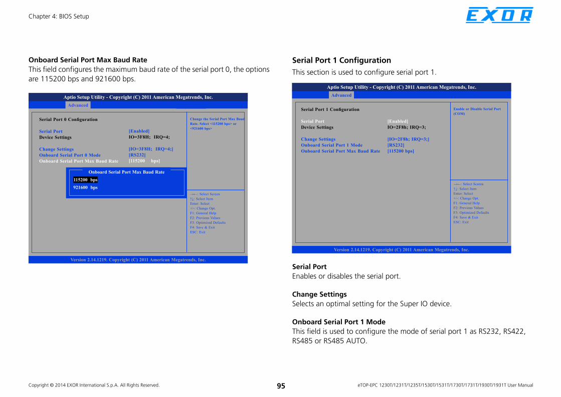
Copyright © 2014 EXOR International S.p.A. All Rights Reserved. 95 eTOP-EPC 1230T/1231T/1235T/1530T/1531T/1730T/1731T/1930T/1931T User Manual
Chapter 4: BIOS Setup
Onboard Serial Port Max Baud Rate
This field configures the maximum baud rate of the serial port 0, the options
are 115200 bps and 921600 bps.
Save & ExitAdvanced Chipset Boot SecurityMain
Version 2.14.1219. Copyright (C) 2011 American Megatrends, Inc.
Aptio Setup Utility - Copyright (C) 2011 American Megatrends, Inc.
→←: Select Screen
↑↓: Select Item
Enter: Select
+/-: Change Opt.
F1: General Help
F2: Previous Values
F3: Optimized Defaults
F4: Save & Exit
ESC: Exit
Change the Serial Port Max Baud
Rate. Select <115200 bps> or
<921600 bps>
Serial Port 0 Confi guration
Serial Port
Device Settings
Change Settings
Onboard Serial Port 0 Mode
Onboard Serial Port Max Baud Rate
[Enabled]
IO=3F8H; IRQ=4;
[IO=3F8H; IRQ=4;]
[RS232]
[115200 bps]
Onboard Serial Port Max Baud Rate
115200 bps
921600 bps
Serial Port 1 Configuration
This section is used to configure serial port 1.
Serial Port
Enables or disables the serial port.
Change Settings
Selects an optimal setting for the Super IO device.
Onboard Serial Port 1 Mode
This field is used to configure the mode of serial port 1 as RS232, RS422,
RS485 or RS485 AUTO.
Advanced
Version 2.14.1219. Copyright (C) 2011 American Megatrends, Inc.
Aptio Setup Utility - Copyright (C) 2011 American Megatrends, Inc.
→←: Select Screen
↑↓: Select Item
Enter: Select
+/-: Change Opt.
F1: General Help
F2: Previous Values
F3: Optimized Defaults
F4: Save & Exit
ESC: Exit
Enable or Disable Serial Port
(COM)Serial Port 1 Confi guration
Serial Port
Device Settings
Change Settings
Onboard Serial Port 1 Mode
Onboard Serial Port Max Baud Rate
[Enabled]
IO=2F8h; IRQ=3;
[IO=2F8h; IRQ=3;]
[RS232]
[115200 bps]

Copyright © 2014 EXOR International S.p.A. All Rights Reserved. 96 eTOP-EPC 1230T/1231T/1235T/1530T/1531T/1730T/1731T/1930T/1931T User Manual
Chapter 4: BIOS Setup
Onboard Serial Port Max Baud Rate
This field configures the maximum baud rate of the serial port 1, the options
are 115200 bps and 921600 bps.
Save & ExitAdvanced Chipset Boot SecurityMain
Version 2.14.1219. Copyright (C) 2011 American Megatrends, Inc.
Aptio Setup Utility - Copyright (C) 2011 American Megatrends, Inc.
→←: Select Screen
↑↓: Select Item
Enter: Select
+/-: Change Opt.
F1: General Help
F2: Previous Values
F3: Optimized Defaults
F4: Save & Exit
ESC: Exit
Change the Serial Port Max Baud
Rate. Select <115200 bps> or
<921600 bps>
Serial Port 1 Confi guration
Serial Port
Device Settings
Change Settings
Onboard Serial Port 1 Mode
Onboard Serial Port Max Baud Rate
[Enabled]
IO=2F8H; IRQ=3;
[IO=2F8H; IRQ=3;]
[RS232]
[115200 bps]
Onboard Serial Port Max Baud Rate
115200 bps
921600 bps
Serial Port 2 Configuration
This section is used to configure serial port 2.
Serial Port
Enables or disables the serial port.
Change Settings
Selects an optimal setting for the Super IO device.
Advanced
Version 2.14.1219. Copyright (C) 2011 American Megatrends, Inc.
Aptio Setup Utility - Copyright (C) 2011 American Megatrends, Inc.
→←: Select Screen
↑↓: Select Item
Enter: Select
+/-: Change Opt.
F1: General Help
F2: Previous Values
F3: Optimized Defaults
F4: Save & Exit
ESC: Exit
Enable or Disable Serial Port
(COM)Serial Port 2 Confi guration
Serial Port
Device Settings
Change Settings
Onboard Serial Port Max Baud Rate
[Enabled]
IO=3E8h; IRQ=7;
[IO=3E8h; IRQ=7;]
[115200 bps]

Copyright © 2014 EXOR International S.p.A. All Rights Reserved. 97 eTOP-EPC 1230T/1231T/1235T/1530T/1531T/1730T/1731T/1930T/1931T User Manual
Chapter 4: BIOS Setup
Onboard Serial Port Max Baud Rate
This field configures the maximum baud rate of the serial port 2, the options
are 115200 bps and 921600 bps.
Save & ExitAdvanced Chipset Boot SecurityMain
Version 2.14.1219. Copyright (C) 2011 American Megatrends, Inc.
Aptio Setup Utility - Copyright (C) 2011 American Megatrends, Inc.
→←: Select Screen
↑↓: Select Item
Enter: Select
+/-: Change Opt.
F1: General Help
F2: Previous Values
F3: Optimized Defaults
F4: Save & Exit
ESC: Exit
Change the Serial Port Max Baud
Rate. Select <115200 bps> or
<921600 bps>
Serial Port 2 Confi guration
Serial Port
Device Settings
Change Settings
Onboard Serial Port Max Baud Rate
[Enabled]
IO=3E8H; IRQ=7;
[IO=3E8H; IRQ=7;]
[115200 bps]
Onboard Serial Port Max Baud Rate
115200 bps
921600 bps
Serial Port 3 Configuration
This section is used to configure serial port 3.
Serial Port
Enables or disables the serial port.
Change Settings
Selects an optimal setting for the Super IO device.
Advanced
Version 2.14.1219. Copyright (C) 2011 American Megatrends, Inc.
Aptio Setup Utility - Copyright (C) 2011 American Megatrends, Inc.
→←: Select Screen
↑↓: Select Item
Enter: Select
+/-: Change Opt.
F1: General Help
F2: Previous Values
F3: Optimized Defaults
F4: Save & Exit
ESC: Exit
Enable or Disable Serial Port
(COM)Serial Port 3 Confi guration
Serial Port
Device Settings
Change Settings
Onboard Serial Port Max Baud Rate
[Enabled]
IO=2E8h; IRQ=6;
[IO=2E8h; IRQ=6;]
[115200 bps]
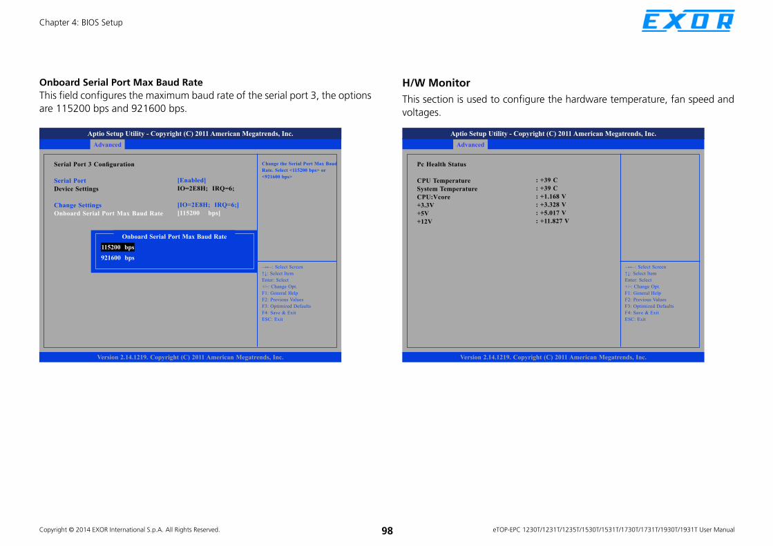
Copyright © 2014 EXOR International S.p.A. All Rights Reserved. 98 eTOP-EPC 1230T/1231T/1235T/1530T/1531T/1730T/1731T/1930T/1931T User Manual
Chapter 4: BIOS Setup
Onboard Serial Port Max Baud Rate
This field configures the maximum baud rate of the serial port 3, the options
are 115200 bps and 921600 bps.
Save & ExitAdvanced Chipset Boot SecurityMain
Version 2.14.1219. Copyright (C) 2011 American Megatrends, Inc.
Aptio Setup Utility - Copyright (C) 2011 American Megatrends, Inc.
→←: Select Screen
↑↓: Select Item
Enter: Select
+/-: Change Opt.
F1: General Help
F2: Previous Values
F3: Optimized Defaults
F4: Save & Exit
ESC: Exit
Change the Serial Port Max Baud
Rate. Select <115200 bps> or
<921600 bps>
Serial Port 3 Confi guration
Serial Port
Device Settings
Change Settings
Onboard Serial Port Max Baud Rate
[Enabled]
IO=2E8H; IRQ=6;
[IO=2E8H; IRQ=6;]
[115200 bps]
Onboard Serial Port Max Baud Rate
115200 bps
921600 bps
Save & ExitAdvanced Chipset Boot SecurityMain
Version 2.14.1219. Copyright (C) 2011 American Megatrends, Inc.
Aptio Setup Utility - Copyright (C) 2011 American Megatrends, Inc.
→←: Select Screen
↑↓: Select Item
Enter: Select
+/-: Change Opt.
F1: General Help
F2: Previous Values
F3: Optimized Defaults
F4: Save & Exit
ESC: Exit
Pc Health Status
CPU Temperature
System Temperature
CPU:Vcore
+3.3V
+5V
+12V
: +39 C
: +39 C
: +1.168 V
: +3.328 V
: +5.017 V
: +11.827 V
H/W Monitor
This section is used to configure the hardware temperature, fan speed and
voltages.

Copyright © 2014 EXOR International S.p.A. All Rights Reserved. 99 eTOP-EPC 1230T/1231T/1235T/1530T/1531T/1730T/1731T/1930T/1931T User Manual
Chapter 4: BIOS Setup
ChipsetThis section is used to configure the system based on the specific features
of the chipset.
Save & ExitAdvanced Chipset Boot SecurityMain
Version 2.14.1219. Copyright (C) 2011 American Megatrends, Inc.
Aptio Setup Utility - Copyright (C) 2011 American Megatrends, Inc.
→←: Select Screen
↑↓: Select Item
Enter: Select
+/-: Change Opt.
F1: General Help
F2: Previous Values
F3: Optimized Defaults
F4: Save & Exit
ESC: Exit
Host Bridge Parameters Host Bridge
South Bridge
Setting incorrect field values may cause the system to malfunction.
Host Bridge
Displays the memory information
Save & ExitAdvanced Chipset Boot SecurityMain
Version 2.14.1219. Copyright (C) 2011 American Megatrends, Inc.
Aptio Setup Utility - Copyright (C) 2011 American Megatrends, Inc.
→←: Select Screen
↑↓: Select Item
Enter: Select
+/-: Change Opt.
F1: General Help
F2: Previous Values
F3: Optimized Defaults
F4: Save & Exit
ESC: Exit
Confi g Intel IGD SettingsIntel IGD Confi guration
******* Memory Information*******
Memory Frequency
Total Memory
1067 MHz (DDR3)
4096 MB

Copyright © 2014 EXOR International S.p.A. All Rights Reserved. 100 eTOP-EPC 1230T/1231T/1235T/1530T/1531T/1730T/1731T/1930T/1931T User Manual
Chapter 4: BIOS Setup
Intel® IGD Configuration
This section is used to configure the Intel® IGD Graphic configurations.
Save & ExitAdvanced Chipset Boot SecurityMain
Version 2.14.1219. Copyright (C) 2011 American Megatrends, Inc.
Aptio Setup Utility - Copyright (C) 2011 America Megatrends, Inc.
→←: Select Screen
↑↓: Select Item
Enter: Select
+/-: Change Opt.
F1: General Help
F2: Previous Values
F3: Optimized Defaults
F4: Save & Exit
ESC: Exit
Select the Video Device Which will be activated during POST. This has no effect if external graphics present.
Intel IGD Confi guration
IGFX - Boot Type
LCD Panel Type
Backlight Control Select
Backlight On/Off Reverse
Backlight Dimming Control Select
Backlight
Fixed Graphics Memory Size
[LVDS]
1280x1024 (19inch)
[Pyroelectric sensor]
[Normal]
[Manual]
[100%]
[128MB]
IGFX – Boot Type
This field is used to configure which video device will be activated during
POST. This has no effect if external graphics present. The options are CRT,
LVDS, LVDS + CRT and CRT + HDMI.
Backlight Control Select
The available options are Pyroelectric sensor and Tact Switch. The default
setting is Tact Switch for eTOP-EPC 1231T/eTOP-EPC 1531T/eTOP-EPC
1731T/eTOP-EPC 1931T, and the Backlight On/Off button is functional only
in this mode.
IGFX - Boot Type
CRT
LVDS
LVDS + CRT
CRT + HDMI
Backlight On/Off Reverse
Please configure this option only when changing the panel, otherwise the
display may not work.
Backlight Dimming Control Select
The options are Tact Switch, Manual and Light sensor.
The default setting is Manual for eTOP-EPC
1230T/1235T/1530T/1730T/1930T and the Backlight option below will be
configurable.
The default setting is Tact Switch for 1231T/1531T/1731T/1931T and the
Backlight option below will not be configurable, please use the brightness
button on the panel to adjust it.
Backlight
Adjusts the brightness of the backlight.
Fixed Graphics Memory Size
This field is used to configure the memory size of the fixed graphics, the
options are 128MB and 256MB.

Copyright © 2014 EXOR International S.p.A. All Rights Reserved. 101 eTOP-EPC 1230T/1231T/1235T/1530T/1531T/1730T/1731T/1930T/1931T User Manual
Chapter 4: BIOS Setup
South Bridge
Azalia Controller
This section disables Azalia or enables HD Audio.
SMBus Controller
This section is used to disable or enable SMBus controller.
High Precision Timer
This section is used to configure High Precision Event Timer.
Save & ExitAdvanced Chipset Boot SecurityMain
Version 2.14.1219. Copyright (C) 2011 American Megatrends, Inc.
Aptio Setup Utility - Copyright (C) 2011 American Megatrends, Inc.
→←: Select Screen
↑↓: Select Item
Enter: Select
+/-: Change Opt.
F1: General Help
F2: Previous Values
F3: Optimized Defaults
F4: Save & Exit
ESC: Exit
Azalia ControllerAzalia Controller
SMBus Controller
High Precision Event Timer Confi guration
High Precision Timer
Restore AC Power Loss
Blue-tooth
Beep
[HD Audio]
[Enabled]
[Enabled]
[Power On]
[Enabled]
[Enabled]
Restore AC Power Loss
Power Off
When power returns after an AC power failure, the system’s power is
off. You must press the Power button to power-on the system.
Power On
When power returns after an AC power failure, the system will automatically
power-on.
Last State
When power returns after an AC power failure, the system will return
to the state where you left off before power failure occurs. If the
system’s power is off when AC power failure occurs, it will remain
off when power returns. If the system’s power is on when AC power
failure occurs, the system will power-on when power returns.
Blue-tooth
Enables or disables blue-tooth, settings for the optional Bluetooth module.
Beep
Enables or disables beep.

Copyright © 2014 EXOR International S.p.A. All Rights Reserved. 102 eTOP-EPC 1230T/1231T/1235T/1530T/1531T/1730T/1731T/1930T/1931T User Manual
Chapter 4: BIOS Setup
BootThis section is used to configure the boot features.
Setup Prompt Timeout
This section configures the number of seconds to wait for the setup
activation key.
Bootup NumLock State
This allows you to determine the default state of the numeric keypad. By
default, the system boots up with NumLock on wherein the function of the
numeric keypad is the number keys. When set to Off, the function of the
numeric keypad is the arrow keys.
Save & ExitAdvanced Chipset Boot SecurityMain
Version 2.14.1219. Copyright (C) 2011 American Megatrends, Inc.
Aptio Setup Utility - Copyright (C) 2011 American Megatrends, Inc.
→←: Select Screen
↑↓: Select Item
Enter: Select
+/-: Change Opt.
F1: General Help
F2: Previous Values
F3: Optimized Defaults
F4: Save & Exit
ESC: Exit
Number of seconds to wait
for setup activation key.
65535(0xFFFF) means indefi nite
waiting.
Boot Confi guration
Setup Prompt Timeout
Bootup NumLock State
Quiet Boot
CSM16 Module Version
GateA20 Active
Option ROM Messages
Interrupt 19 Capture
Boot Option Priorities
Boot Option #1
Hard Drive BBS Priorities
[On]
[Disabled]
07.65
[Upon Request]
[Force BIOS]
[Disabled]
[SATA SM: 4GB SATA...]
1
Quiet Boot
Enabled Displays OEM logo instead of the POST messages.
Disabled Displays normal POST messages.
GateA20 Active
Upon Request GA20 can be disabled using BIOS services.
Always Do not allow disabling GA20; this option is useful when
any RT code is executed above 1MB.
Option ROM Messages
This field is used to set display mode for Option ROM.
Interrupt 19 Capture
Allows Option ROMs to trap Interrupt 19 when enabled.
Boot Option Priorities
Adjust the boot sequence of the system. Boot Option #1 is the first boot
device that the system will boot from, next will be #2 and so forth.

Copyright © 2014 EXOR International S.p.A. All Rights Reserved. 103 eTOP-EPC 1230T/1231T/1235T/1530T/1531T/1730T/1731T/1930T/1931T User Manual
Chapter 4: BIOS Setup
Hard Drive BBS Priorities
Sets the order of the legacy devices in this group.
Save & ExitAdvanced Chipset Boot SecurityMain
Version 2.14.1219. Copyright (C) 2011 American Megatrends, Inc.
Aptio Setup Utility - Copyright (C) 2011 American Megatrends, Inc.
→←: Select Screen
↑↓: Select Item
Enter: Select
+/-: Change Opt.
F1: General Help
F2: Previous Values
F3: Optimized Defaults
F4: Save & Exit
ESC: Exit
Sets the system boot orderBoot Option #1 [SATA SM: 4GB SATA . . .]

Copyright © 2014 EXOR International S.p.A. All Rights Reserved. 104 eTOP-EPC 1230T/1231T/1235T/1530T/1531T/1730T/1731T/1930T/1931T User Manual
Chapter 4: BIOS Setup
Security
Save & ExitAdvanced Chipset Boot SecurityMain
Version 2.14.1219. Copyright (C) 2011 American Megatrends, Inc.
Aptio Setup Utility - Copyright (C) 2011 American Megatrends, Inc.
→←: Select Screen
↑↓: Select Item
Enter: Select
+/-: Change Opt.
F1: General Help
F2: Previous Values
F3: Optimized Defaults
F4: Save & Exit
ESC: Exit
Set Administrator PasswordPassword Description
If ONLY the Administrator’s password is set,
then this only limits access to Setup and is
only asked for when entering Setup.
If ONLY the User’s password is set, then this
is a power on password and must be entered to
boot or enter Setup. In Setup the User Will
have Administrator rights.
The password length must be
in the following range:
Minimum length 3
Maximum 20
Administrator Password
User Password
Administrator Password
Select this to reconfigure the administrator’s password.
User Password
Select this to reconfigure the user’s password.
Save & ExitAdvanced Chipset Boot SecurityMain
Version 2.14.1219. Copyright (C) 2011 American Megatrends, Inc.
Aptio Setup Utility - Copyright (C) 2011 American Megatrends, Inc.
→←: Select Screen
↑↓: Select Item
Enter: Select
+/-: Change Opt.
F1: General Help
F2: Previous Values
F3: Optimized Defaults
F4: Save & Exit
ESC: Exit
Exit systm setup after saving the changes.
Save Changes and Exit
Discard Changes and Exit
Save Changes and Reset
Discard Changes and Reset
Save Options
Save Changes
Discard Changes
Restore Defaults
Save as User Defaults
Restore User Defaults
Boot Override
SATA SM: 4GB SATA Flash Drive
Launch EFI Shell from fi lesystem device
Save & Exit
Save Changes and Exit
To save the changes and exit the Setup utility, select this field then press
<Enter>. A dialog box will appear. Confirm by selecting Yes. You can also
press <F4> to save and exit Setup.
Discard Changes and Exit
To exit the Setup utility without saving the changes, select this field then
press <Enter>. You may be prompted to confirm again before exiting. You
can also press <ESC> to exit without saving the changes.

Copyright © 2014 EXOR International S.p.A. All Rights Reserved. 105 eTOP-EPC 1230T/1231T/1235T/1530T/1531T/1730T/1731T/1930T/1931T User Manual
Chapter 4: BIOS Setup
Save Changes and Reset
To save the changes and reset, select this field then press <Enter>. A dialog
box will appear. Confirm by selecting Yes.
Discard Changes and Reset
To exit the Setup utility and reboot the system without saving the changes,
select this field then press <Enter>. You may be prompted to confirm again
before exiting.
Save Changes
To save changes and continue configuring the BIOS, select this field then
press <Enter>. A dialog box will appear. Confirm by selecting Yes.
Discard Changes
To discard the changes, select this field then press <Enter>. A dialog box will
appear. Confirm by selecting Yes to discard all changes made and restore
the previously saved settings.
Restore Defaults
To restore the BIOS to default settings, select this field then press <Enter>. A
dialog box will appear. Confirm by selecting Yes.
Save as User Defaults
To use the current configurations as user default settings for the BIOS, select
this field then press <Enter>. A dialog box will appear. Confirm by selecting
Yes.
Restore User Defaults
To restore the BIOS to user default settings, select this field then press
<Enter>. A dialog box will appear. Confirm by selecting Yes.
Boot Override
To bypass the boot sequence from the Boot Option List and boot from a
particular device, select the desired device and press <Enter>.
Launch EFI Shell from filesystem device
To launch EFI shell from a filesystem device, select this field and press
<Enter>.

Copyright © 2014 EXOR International S.p.A. All Rights Reserved. 106 eTOP-EPC 1230T/1231T/1235T/1530T/1531T/1730T/1731T/1930T/1931T User Manual
Appendix A: GPI/O Programming Guide
APPENDIX A: GPI/O PROGRAMMING GUIDE
GPI/O (General Purpose Input/Output) pins are provided for custom system
design. This appendix provides definitions and its default setting for the ten
GPI/O pins in the APPC series. The pin definition is shown in the following
table:
1 5106
Pin GPI/O mode PowerOn
Default
Address Pin GPI/O mode PowerOn
Default
Address
1 +5V - - 2 GPI20 High A04h (bit0)
3 GPI21 High A04h (bit1) 4 NC - -
5 NC - - 6 GND - -
7 GPO22 Low A04h (bit2) 8 GPO23 Low A04h (bit3)
9 NC - - 10 NC - -
Control the GPO pin (7/8) level from I/O port A04h bit (2/3).
The bit is Set/Clear indicated output High/Low

Copyright © 2014 EXOR International S.p.A. All Rights Reserved. 107 eTOP-EPC 1230T/1231T/1235T/1530T/1531T/1730T/1731T/1930T/1931T User Manual
Appendix A: GPI/O Programming Guide
GPIO programming sample code
#define GPIO_PORT 0xA04
#define GPO7 (0x01 <<2)
#define GPO8 (0x01 <<3)
#define GPO7_HI outportb(GPIO_PORT, 0x04)
#define GPO7_LO outportb(GPIO_PORT, 0x00)
#define GPO8_HI outportb(GPIO_PORT, 0x08)
#define GPO8_LO outportb(GPIO_PORT, 0x00)
void main(void)
{
GPO7_HI;
GPO8_LO;
}

Copyright © 2014 EXOR International S.p.A. All Rights Reserved. 108 eTOP-EPC 1230T/1231T/1235T/1530T/1531T/1730T/1731T/1930T/1931T User Manual
Appendix B: Digital I/O Programming Guide
APPENDIX B: DIGITAL I/O PROGRAMMING GUIDE
Digital I/O (Digital Input/Output) pins are provided for custom system
design. This appendix provides definitions and its default setting for the
fifteen Digital I/O pins in the APPC series. The pin definition is shown in the
following table:
Pin GPI/O mode PowerOn
Default
Address Pin GPI/O mode PowerOn
Default
Address
1 DI1 High A05h (bit0) 2 DI2 High A05h (bit1)
3 DI3 High A05h (bit2) 4 DI4 High A05h (bit3)
5 GND - - 6 COM - -
7 NC - - 8 NC - -
9 DO1 Low A05h (bit4) 10 DO2 Low A05h (bit5)
11 DO3 Low A05h (bit6) 12 DO4 Low A01h (bit7)
13 GND - - 14 GND - -
15 GND - -
Control the DO pin (9/10/11/12) level from I/O port A05h bit (4/5/6) and A01h bit (7).
The bit is Set/Clear indicated output High/Low
1 5
11 15

Copyright © 2014 EXOR International S.p.A. All Rights Reserved. 109 eTOP-EPC 1230T/1231T/1235T/1530T/1531T/1730T/1731T/1930T/1931T User Manual
Appendix B: Digital I/O Programming Guide
GPIO programming sample code
#define DIO_PORT 0xA05
#define DIO_PORTI 0xA01
#define DO9 (0x01 <<4)
#define DO10 (0x01 <<5)
#define DO11 (0x01 <<6)
#define DO12 (0x01 <<7)
#define DO9_HI outportb(GPIO_PORT, 0x10)
#define DO9_LO outportb(GPIO_PORT, 0x00)
#define DO10_HI outportb(GPIO_PORT, 0x20)
#define DO10_LO outportb(GPIO_PORT, 0x00)
#define DO11_HI outportb(GPIO_PORT, 0x40)
#define DO11_LO outportb(GPIO_PORT, 0x00)
#define DO12_HI outportb(GPIO_PORTI, 0x80)
#define DO12_LO outportb(GPIO_PORTI, 0x00)
void main(void)
{
DO9_HI;
DO10_LO;
DO11_HI;
DO12_LO;
}

Copyright © 2014 EXOR International S.p.A. All Rights Reserved. 110 eTOP-EPC 1230T/1231T/1235T/1530T/1531T/1730T/1731T/1930T/1931T User Manual
Appendix C: Watchdog Programming Guide
APPENDIX C: WATCHDOG PROGRAMMING GUIDE
eTOP-EPC Series Watch Dog Function Configuration Sequence Description:
Start
Step1. See “SetupWDT” procedure
#Setup Watchdog Timer Environment
Step2. See “TimeBaseWDT” procedure
#Initial Watchdog Timer.
Users can select second or minute.
Step3. See “TimeCountWDT” procedure
#Set Watchdog Timer Time-out Value.
Users can set time-out value.
Step4: See ExitSetup procedure
#Exit Setup Environment
End

Copyright © 2014 EXOR International S.p.A. All Rights Reserved. 111 eTOP-EPC 1230T/1231T/1235T/1530T/1531T/1730T/1731T/1930T/1931T User Manual
Appendix C: Watchdog Programming Guide
out 2fh, al
ret
TimeBaseWDT ENDP
===============================================
TimeCountWDT PROC
mov al, 73h ;WDT Time-out register.
out 2eh, al
mov al, 03h ;Here!! Set count 3.
out 2fh, al
ret
TimeCountWDT ENDP
===============================================
ExitSetup PROC
mov al, 02h
out 2eh, al
mov al, 02h
out 2fh, al
ret
ExitSetup ENDP
===============================================
===============================================
SetupWDT PROC
mov dx, 2eh
mov al, 087h
out dx, al
nop
nop
mov al, 01h
out dx, al
nop
nop
mov al, 55h
out dx, al
nop
nop
out dx, al ;Write operations to special address
port (2E) for entering MB PnP Mode.
mov al, 07h
out 2eh, al
mov al, 07h ;Select logical device for Watch Dog.
out 2fh, al
ret
SetupWDT ENDP
===============================================
TimeBaseWDT PROC
mov al, 72h
out 2eh, al
mov al, 10h ;Set WDT reset upon PWROK
or al, 80h ;Here!! set 80h for second, set 00h for minute

Copyright © 2014 EXOR International S.p.A. All Rights Reserved. 112 eTOP-EPC 1230T/1231T/1235T/1530T/1531T/1730T/1731T/1930T/1931T User Manual
Appendix D: Power Consumption
APPENDIX D: POWER CONSUMPTION
Power Consumption Management
Purpose
The purpose of the power consumption test is to verify the power dissipation
of the system and the load of the power supply.
Test Equipment
1. PROVA CM-07 AC/DC CLAMP METER
2. Burn-in test ver:2.0
Device Under Test
DUT: sys#1/
Test Procedure
1. Power up DUT and then boot Windows 7.
2. Enter the standby mode (HDD power down).
3. Measure the power consumption and record it.
4. Run the Burn-in test program to apply 100% full loading.
5. Measure the power consumption and record it.
+12V +24V +30V
Full-Loading Mode 3.2A 1.65A 1.26A
Total 38.4W 39.6W 37.8W
Standby Mode 0.75A 0.41A 0.36A
Total 9W 9.84W 10.8W
eTOP-EPC 1930T/1931T
+12V +24V +30V
Full-Loading Mode 4.2A 2A 1.63A
Total 50.4W 48W 48.9W
Standby Mode 0.74A 0.41A 0.34A
Total 8.88W 9.84W 10.2W
eTOP-EPC 1730T/1731T

Copyright © 2014 EXOR International S.p.A. All Rights Reserved. 113 eTOP-EPC 1230T/1231T/1235T/1530T/1531T/1730T/1731T/1930T/1931T User Manual
Appendix D: Power Consumption
+12V +24V +30V
Full-Loading Mode 2.5A 1.28A 1A
Total 30W 30.72W 30W
Standby Mode 0.76A 0.41A 0.36A
Total 9.12W 9.84W 10.8W
eTOP-EPC 1530T/1531T
+12V +24V +30V
Full-Loading Mode 2.26A 1.11A 0.9A
Total 27.12W 26.64W 27W
Standby Mode 0.76A 0.41A 0.35A
Total 9.12W 9.84W 10.5W
eTOP-EPC 1230T/1231T
+12V +24V +30V
Full-Loading Mode 2.5A 1.24A 1.01A
Total 30W 29.76W 30.3W
Standby Mode 0.79A 0.43A 0.36A
Total 9.48W 10.32W 10.8W
eTOP-EPC 1235T

Copyright © 2014 EXOR International S.p.A. All Rights Reserved. 114 eTOP-EPC 1230T/1231T/1235T/1530T/1531T/1730T/1731T/1930T/1931T User Manual
Appendix E: Troubleshooting
APPENDIX E: TROUBLESHOOTING
1. I cannot make voice calls using 3.5G mini-PCIe card as network connection.
Answer: eTOP-EPC series’ 3.5G connection only supports data transmission and does not support voice transmission.
2. The second VGA display is not working under DOS operating system.
Answer: Second VGA display is not supported under DOS operating system.
3. In Windows XP Device Manager, why is there an exclamation mark on Audio Device on High Definition Audio Bus?
Answer: Please disable Azalia controller in the BIOS menu to fix this issue, for more information on BIOS settings, please refer to Chapter 4: BIOS Setup
section of the user manual.
4. In Windows XP, there is no image on the screen when CRT+LVDS is selected as the option in BIOS.
Answer: Please configure the BIOS setting according to the table below:
Win XP CRT LVDS HDMI CRT+LVDS CRT+HDMI LVDS+HDMI
BIOS single single single clone extend clone extend clone extend
CRT ü ü ü ü ü ü ü ü ü
LVDS ü ü ü ü ü ü ü ü ü
CRT+LVDS ü ü ü ü ü ü ü ü ü
LVDS+CRT (Default) û ü ü û û û û ü ü
CRT+HDMI ü ü ü ü ü ü ü ü ü