estimation complete combustion coefficient in rotary kilns
TRANSCRIPT
�����������������
Citation: Bujak, J.; Sitarz, P.; Bujak, K.;
Majkowski, S.; Pasela, R. Estimation
Complete Combustion Coefficient in
Rotary Kilns. Energies 2022, 15, 1143.
https://doi.org/10.3390/en15031143
Academic Editor: Ali Turan
Received: 21 January 2022
Accepted: 1 February 2022
Published: 3 February 2022
Publisher’s Note: MDPI stays neutral
with regard to jurisdictional claims in
published maps and institutional affil-
iations.
Copyright: © 2022 by the authors.
Licensee MDPI, Basel, Switzerland.
This article is an open access article
distributed under the terms and
conditions of the Creative Commons
Attribution (CC BY) license (https://
creativecommons.org/licenses/by/
4.0/).
energies
Article
Estimation Complete Combustion Coefficient in Rotary KilnsJanusz Bujak 1,* , Piotr Sitarz 2, Krzysztof Bujak 2, Sebastian Majkowski 2 and Rafał Pasela 1
1 Faculty of Environmental Engineering, Bydgoszcz University of Science and Technology, Kaliskiego 7,85-796 Bydgoszcz, Poland; [email protected]
2 PPM PROMONT Bujak Sp. z o.o., Sp. K., Jagiellonska 35, 85-097 Bydgoszcz, Poland;[email protected] (P.S.); [email protected] (K.B.); [email protected] (S.M.)
* Correspondence: [email protected]; Tel.: +48-501541185
Abstract: This paper presents a model-based analysis of variability of thermodynamic and chemicalparameters in a rotary kiln (RK) during thermal treatment of animal waste. The core process ofchemical treatment of waste takes place in RKs; the process involves heating, gasification andpartial combustion of the waste. Control over these parameters, and especially the level of completecombustion, determines the quality and efficiency of the process. In operational practice, control andanalysis of the variability of process parameters is complicated by the high degree of simultaneity ofindividual transformations, random disruptions of the process and metrological difficulties resultingfrom high temperature and chemical activity of the materials being processed. The purpose ofpreparing the model was to obtain a tool for predicting variability of selected process parameters.By definition, model calculations assume no influence of disturbances on output values, whichmakes it possible to acquire accurate results that can be compared with corresponding empiricallyobtained data. The result of the analyses conducted is a theoretical model of the analysed processand a graphical presentation of the calculation results in the form of graphs and charts. A formulafor calculating the level of complete combustion and the results of calculation of this index on thebasis of empirical data from an industrial waste incineration plant are also presented herein. Thepresented model is a useful tool providing an insight into interdependencies between selected processparameters and facilitating design of corrective actions oriented towards process optimisation.
Keywords: waste thermal treatment; rotary kiln; parameter predictions; process model
1. Introduction
Thermal treatment of animal waste is an activity that effectively eliminates the risks tohuman and animal health associated with this material. The advantages of this method are arelatively small amount of solid residue (ash) and the possibility to recover chemical energyof the waste. However, for the process of thermal waste treatment to be implementedproperly, it must meet a number of conditions resulting from stringent legal regulations [1,2],intended to maintain sanitary safety and reduce negative impact on natural environment.On the other hand, investors have their expectations regarding efficiency and low costs ofthis process. Furthermore, there are numerous technical and operational limitations relatedto the technology used and the design of thermal waste treatment installations (TWTIs).For these reasons, it is necessary to carry out research in order to improve and optimisethis process taking into account the best available techniques (BATs) [3].
Of particular importance is the research and analysis of the main stages of thermalwaste treatment, which are the thermodynamic and chemical processes carried out inthe rotary kiln (RK) and the afterburning chamber (ACH). The main process of chemicaltreatment of waste involving heating, gasification and partial combustion of the wastetakes place in the combustion chamber. In the case of carbon and its compounds, theyare converted to CO and CO2 in the chamber. The resulting ratio of these chemical com-pounds depends on a number of factors related to how the thermal treatment process
Energies 2022, 15, 1143. https://doi.org/10.3390/en15031143 https://www.mdpi.com/journal/energies
Energies 2022, 15, 1143 2 of 11
is carried out. In the immediately downstream section of the installation, which is theafterburning chamber, the remaining carbon monoxide is afterburnt. Phenomena occurringin combustion and afterburning chambers can be described by parameters such as fluegas temperature, oxygen concentration in flue gas as well as mass and volume flow rate.Keeping these parameters within suitable ranges determines the quality and efficiencyof the process. However, in operational practice, the control and analysis of the variabil-ity of process parameters is complicated by a high degree of simultaneity of individualtransformations. Additionally, there are various random disturbances of the process andmetrological (measurement) difficulties resulting from the prevailing high temperature andchemical activity of the processed materials. In this situation, it is advisable to first preparea theoretical model of variability of the analysed parameters. The model allows predictionof correlations of selected input and output variables for a much wider range of changes ofthe analysed parameters than the range possible in the actual system. By definition, modelcalculations assume no influence of disturbances on output values, which makes it possibleto obtain accurate results that can be compared with corresponding empirically obtaineddata. For this purpose, the universal detailed theoretical model described in paper [4],which is based on known balances of mass and energy fluxes allowing for the specificity ofthe thermal waste treatment installation, has been used.
A literature review indicates that presently a great number of studies are being con-ducted worldwide with the aim of improving the environmental safety as well as technicaland economic efficiency of waste incineration processes. For example, issues related toreduction of emission of harmful substances to the natural environment are discussed inpapers [5–10]. The conditions of energy and material recovery in these processes havebeen tackled in articles [11–13]. New ways of managing waste from the meat industry [14]and medical industry [15] have also been presented. In a number of papers, advancedmathematical modelling and numerical calculation techniques have been used to analysecomplex, multivariate processes [16–20].
This paper presents a model-based analysis of RK operation relying on mass andenergy balances. The results of the theoretical calculations have been visualised in the formof charts and graphs. The input and output parameters for the model have been identifieddescriptively. The input variables are mass fluxes of waste and air supplied to the RKcombustion chamber with concurrent assumption of a level of complete combustion CCc(rk)(maintained ratio of CO2 to CO in the flue gas). The output variables analysed are flue gastemperature, flue gas mass flux and O2 concentration in the flue gas.
The general theoretical model used in this work allows the analysis of the combustionprocess of waste with different elemental composition and calorific value. For example,these can be materials with typical chemical and energy characteristics, such as medicalwaste, RDF (Refuse Derived Fuel), MBM (Meat Bone Meal). It is also possible to introduceany material by determining its elemental composition. The main parameters character-izing the burnt material are the percentage of carbon, hydrogen, oxygen and water. Forthe process analysis, it is also necessary to determine the non-flammable fraction (ash)in the combusted material. The share of other elements such as sulphur, chlorine, flu-orine and nitrogen is also determined. The percentage of these elements is lower butas a result of thermal transformation processes, create chemical compounds dangerousto the environment. Appropriate neutralization methods must be designed and imple-mented for these compounds (sulphur dioxide, hydrogen chloride, hydrogen fluoride,nitrogen oxides).
In the presented study, it was decided to address the analysis for one type of waste(MBM with a defined elemental composition and energy value). The reason for this was thepossibility of verifying the results on a facility that carries out the meal combustion processwith high efficiency (2.5 Mg/h). This plant uses only locally produced, solid elementalwaste meal. The flour is fed into the oven continuously, with a constant capacity by a screwconveyor. Thus, stable conditions are maintained with minimal influence of disturbingfactors. Such conditions are difficult to maintain when other types of waste are incinerated.
Energies 2022, 15, 1143 3 of 11
Typically, incinerators treat material (medical waste, animal waste) with a large randomvariation in elemental composition, moisture and ash content, and energy value.
The calculation formula presented in the paper is intended to estimate the degree ofcomplete combustion in a rotary kiln for thermal transformation of MBM material. Thecalculations were based on empirical data recorded by the supervisory control system (a setof PLC controllers and visualization software) and by the exhaust gas monitoring system.The model presented in this paper has been used to analyse the variability of the level ofcomplete combustion in RKs based on empirical data recorded in a large-scale meat bonemeal (MBM) incineration plant.
2. Assumptions for Model Calculations
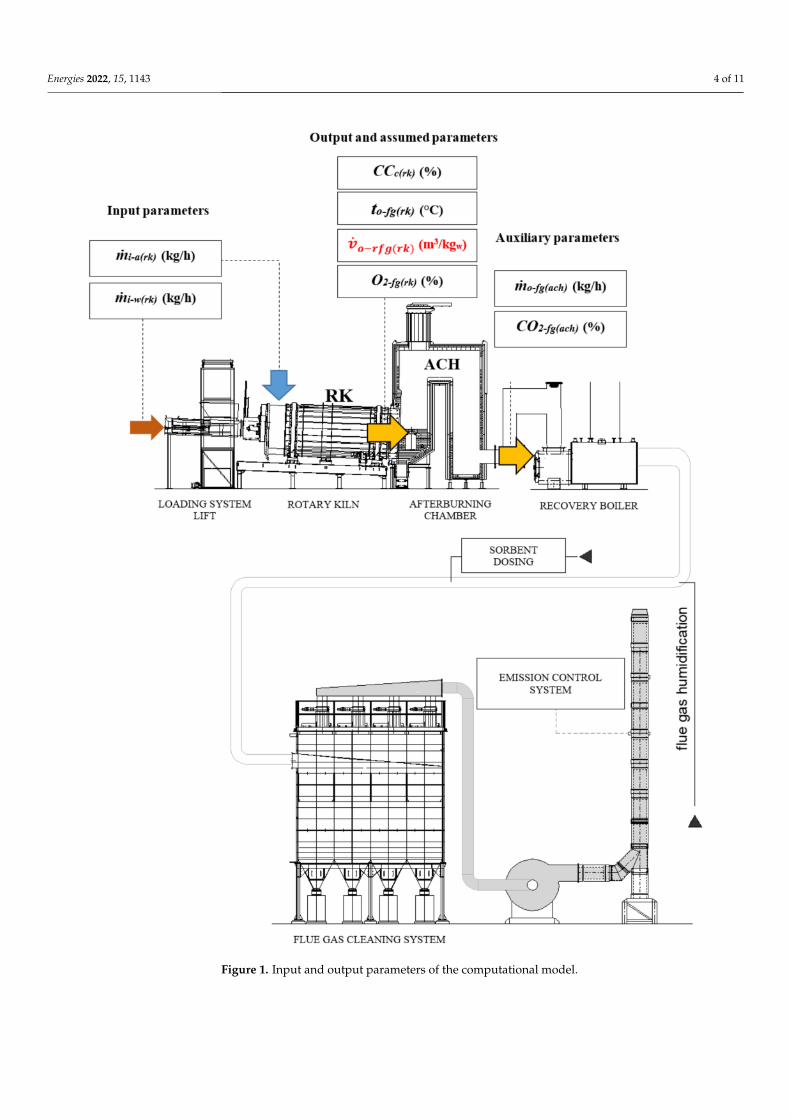
The thermodynamic and chemical processes (including gasification) associated withthermal waste treatment in RKs had been initially analysed using a theoretical model. Aprediction of variability of the studied process parameters of the process under analysiswas prepared using a theoretical model [4]. During configuration of the theoretical model,variables were selected in order for the model to best reflect the technology of the TWTIunder study. A schematic diagram of the installation, showing the variables taken intoaccount in the model tests, is presented in Figure 1; the input and output variables analysedin this case are also listed in that figure.
The algorithm included the following calculations for the output variables characteris-ing the status of the waste incineration process immediately downstream of the RK as afunction of the selected input variables with concurrent assumption of a level of completecombustion CCc(rk):
to− f g(rk) = f( .
mi−w(rk),.
mi−a(rk), CCc(rk)
)(1)
O2− f g(rk) = f( .
mi−w(rk),.
mi−a(rk), CCc(rk)
)(2)
.vo−r f g(rk) = f
( .mi−w(rk),
.mi−a(rk), CCc(rk)
)(3)
where to− f g(rk) is flue gas temperature at RK outlet (◦C), O2− f g(rk) oxygen concentration influe gas at RK outlet (%),
.vo−r f g(rk) unit real flue gas volume flux at RK outlet (m3/kgw),
.mi−w(rk) MBM waste mass flux at RK inlet (kg/h),
.mi−a(rk) mass flux of air supplied to RK
(kg/h) and CCc(rk) assumed complete combustion coefficient (%).The complete combustion coefficient CCc(rk) is described by the following formula:
CCc(rk) =
.mo−CO2(rk)
.mo−CO(rk) +
.mo−CO2(rk)
·100 (4)
where.
mo−CO2(rk) is CO2 mass flux at RK outlet (kg/h),.
mo−CO(rk) CO mass flux at RKoutlet (kg/h). It determines the status of the process of oxidation of the elemental carboncontained in waste in RK, between the extreme possibilities where the reaction productsare only CO or only CO2.
The waste mass flux.
mi−w(rk) is controlled by controlling the screw conveyor throughwhich the waste (MBM) in the plant under study is fed into the RK. The elemental compo-sition, density and energy value of the burnt meal were determined through laboratorytests (Table 1).
Energies 2022, 15, 1143 4 of 11
Figure 1. Input and output parameters of the computational model.
Energies 2022, 15, 1143 5 of 11
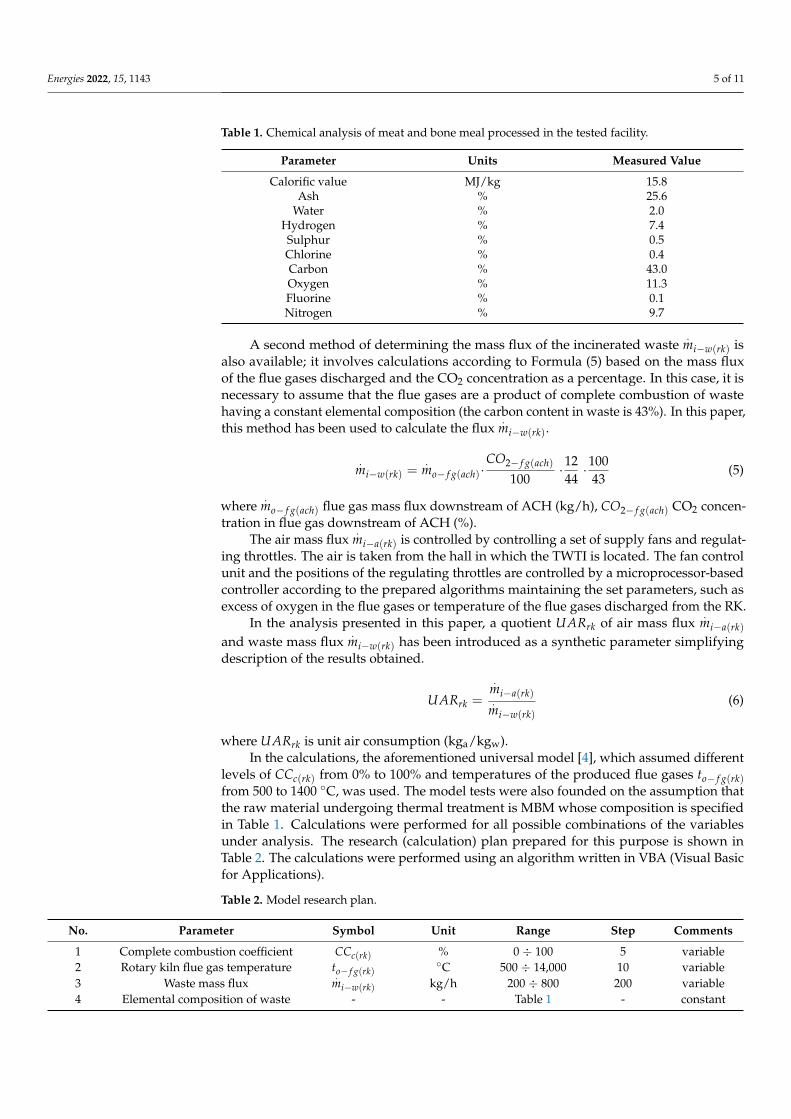
Table 1. Chemical analysis of meat and bone meal processed in the tested facility.
Parameter Units Measured Value
Calorific value MJ/kg 15.8Ash % 25.6
Water % 2.0Hydrogen % 7.4Sulphur % 0.5Chlorine % 0.4Carbon % 43.0Oxygen % 11.3Fluorine % 0.1Nitrogen % 9.7
A second method of determining the mass flux of the incinerated waste.
mi−w(rk) isalso available; it involves calculations according to Formula (5) based on the mass fluxof the flue gases discharged and the CO2 concentration as a percentage. In this case, it isnecessary to assume that the flue gases are a product of complete combustion of wastehaving a constant elemental composition (the carbon content in waste is 43%). In this paper,this method has been used to calculate the flux
.mi−w(rk).
.mi−w(rk) =
.mo− f g(ach)·
CO2− f g(ach)
100·1244
·10043
(5)
where.
mo− f g(ach) flue gas mass flux downstream of ACH (kg/h), CO2− f g(ach) CO2 concen-tration in flue gas downstream of ACH (%).
The air mass flux.
mi−a(rk) is controlled by controlling a set of supply fans and regulat-ing throttles. The air is taken from the hall in which the TWTI is located. The fan controlunit and the positions of the regulating throttles are controlled by a microprocessor-basedcontroller according to the prepared algorithms maintaining the set parameters, such asexcess of oxygen in the flue gases or temperature of the flue gases discharged from the RK.
In the analysis presented in this paper, a quotient UARrk of air mass flux.
mi−a(rk)and waste mass flux
.mi−w(rk) has been introduced as a synthetic parameter simplifying
description of the results obtained.
UARrk =
.mi−a(rk).
mi−w(rk)(6)
where UARrk is unit air consumption (kga/kgw).In the calculations, the aforementioned universal model [4], which assumed different
levels of CCc(rk) from 0% to 100% and temperatures of the produced flue gases to− f g(rk)from 500 to 1400 ◦C, was used. The model tests were also founded on the assumption thatthe raw material undergoing thermal treatment is MBM whose composition is specifiedin Table 1. Calculations were performed for all possible combinations of the variablesunder analysis. The research (calculation) plan prepared for this purpose is shown inTable 2. The calculations were performed using an algorithm written in VBA (Visual Basicfor Applications).
Table 2. Model research plan.
No. Parameter Symbol Unit Range Step Comments
1 Complete combustion coefficient CCc(rk) % 0 ÷ 100 5 variable2 Rotary kiln flue gas temperature to− f g(rk)
◦C 500 ÷ 14,000 10 variable3 Waste mass flux
.mi−w(rk) kg/h 200 ÷ 800 200 variable
4 Elemental composition of waste - - Table 1 - constant
Energies 2022, 15, 1143 6 of 11
3. Results of the Model Calculations3.1. Visualisation of Results of the Model Calculations
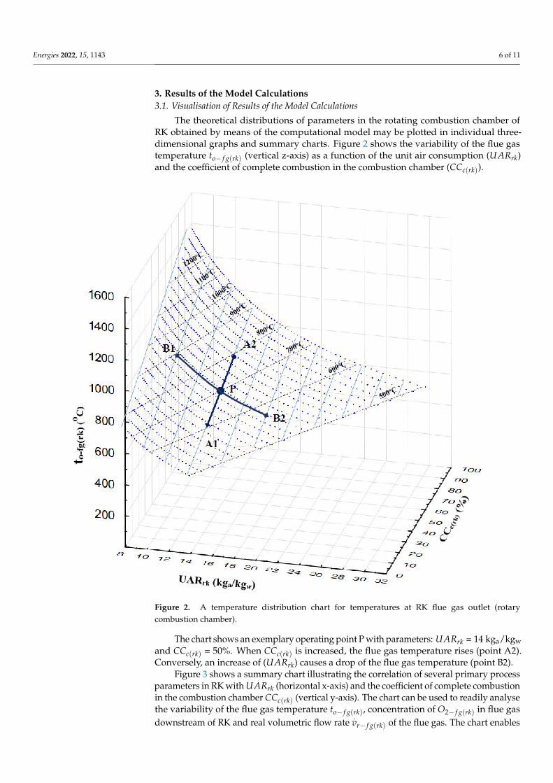
The theoretical distributions of parameters in the rotating combustion chamber ofRK obtained by means of the computational model may be plotted in individual three-dimensional graphs and summary charts. Figure 2 shows the variability of the flue gastemperature to− f g(rk) (vertical z-axis) as a function of the unit air consumption (UARrk)and the coefficient of complete combustion in the combustion chamber (CCc(rk)).
Figure 2. A temperature distribution chart for temperatures at RK flue gas outlet (rotarycombustion chamber).
The chart shows an exemplary operating point P with parameters: UARrk = 14 kga/kgwand CCc(rk) = 50%. When CCc(rk) is increased, the flue gas temperature rises (point A2).Conversely, an increase of (UARrk) causes a drop of the flue gas temperature (point B2).
Figure 3 shows a summary chart illustrating the correlation of several primary processparameters in RK with UARrk (horizontal x-axis) and the coefficient of complete combustionin the combustion chamber CCc(rk) (vertical y-axis). The chart can be used to readily analysethe variability of the flue gas temperature to− f g(rk), concentration of O2− f g(rk) in flue gasdownstream of RK and real volumetric flow rate
.vr− f g(rk) of the flue gas. The chart enables

Energies 2022, 15, 1143 7 of 11
prediction of the strength and direction of the correlations between these output variablesfor the expected change in values of the input parameters.
Figure 3. Chart of variability of process parameters in the rotary combustion chamber.
For instance, a transition from operating point P with coordinates: UARrk = 14 kga/kgwand CCc(RK) = 50% to point A2 (increasing CCc(rk) to 70%) causes a rise in flue gas tempera-ture to−fg(rk) and unit real flue gas volume flux
.vr− f g(rk), in parallel with a decrease in flue
gas oxygen concentration O2− f g(rk). In another example, a transition from operating pointP to B2 (increasing UARrk to 18 kga/kgw) entails a drop in flue gas temperature to− f g(rk)and a higher flue gas oxygen content O2− f g(rk) and unit real flue gas volume flux
.vr− f g(rk).
3.2. Derivation of a Formula for CCc(rk) Calculation
A transformation of Equation (1) permits derivation of a formula for calculation of theotherwise directly immeasurable level of complete combustion CCc(rk).
CCc(rk) = f(
to− f g(rk), UAR (rk)
)(7)
Arguments of this function are temperature downstream of the rotary chamberto− f g(rk) and unit air consumption UARrk in RK as defined by Formula (6). In a regressionanalysis conducted for this purpose, response surface modelling was adopted for resultsachieved according to the plan in Table 2. where for each assumed combination of valuesCCc(RK) and to− f g(rk) the value of UARrk was calculated. The calculation of the parametersof the regression function was performed with the software STATISTICA. The followingform of the function has been assumed:
CCc(rk) = a1 + a2to− f g(rk) + a3to− f g(rk)2 + a4UARrk + a5UARrk
2 + a6to− f g(rk)UARrk (8)
Energies 2022, 15, 1143 8 of 11
Formula (9) has been derived as a result. The notation omits the term in whichcoefficient a3 was equal to zero.
CCc(rk) = −88.9− 0.004to− f g(rk)− 2.015UARrk − 0.006UARrk2 − 0.016to− f g(rk)UARrk (9)
The coefficient of determination R2 for this model is 0.999. The formula presentedabove is intended to estimate the degree of full combustion for waste with the compositiongiven in Table 1. This formula allows for a quick, cyclical calculation of this parameterbased on empirical data on the tested object. This enables, for example, the analysis of thecorrelation CCc(RK) with other parameters of the MBM waste incineration process. In orderto analyze waste with a different elementary composition, a separate calculation should bemade with an appropriately corrected plan. Table 2.
4. Results of Calculations for Empirical Data
The next stage of the analyses made practical use of Formula (9) to calculate the levelof complete combustion CCc(RK) in an actual industrial facility equipped with a RK. Inthe plant in question, MBM goes through the process of thermal treatment. Elementalcomposition of the incinerated MBM, for which Formula (6) has been derived, is detailedin Table 1.
Hourly averages of the process parameters—temperature of flue gas downstream ofthe rotary chamber to− f g(rk), mass flux of air supplied to the rotary chamber
.mi−a(rk) and
mass flux of the incinerated waste.
mi−w(rk)—recorded over a period of 5 days were usedfor the calculations. Temperature was measured using a TTSC-22 thermocouple sensor(measuring range 0 ÷ 1600 ◦C, measurement error 2%). The mass flux of the incineratedwaste was calculated according to Formula (5) on the basis of flue gas parameters recordeddownstream of the afterburning chamber by the flue gas monitoring system. A D-RX 250monitor (measuring range 0 ÷ 50.000 m3/h, measurement error 2%) was used to measurethe flue gas mass flux
.mo− f g(ach). Carbon dioxide concentration in flue gas CO2− f g(ach) was
measured with a CX-4000 analyser (measuring range 0 ÷ 20%, measurement error 2%).The mass flux of air supplied to the combustion chamber
.mi−a(rk) was determined based
on specifications of the supply fan WPT700/28 and measurement of air pressure at the RKinlet manifold. The air pressure at the manifold was measured using a DPC4000 transducer(measuring range 0 ÷ 2500 Pa %, measurement error 0.5%).
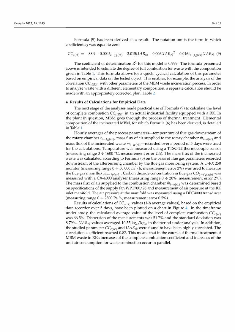
Results of calculations of CCc(rk) values (1-h average values), based on the empiricaldata recorder over 5 days, have been plotted on a chart in Figure 4. In the timeframeunder study, the calculated average value of the level of complete combustion CCc(rk)was 66.5%. Dispersion of the measurements was 51.7% and the standard deviation was8.79%. UARrk values averaged 10.55 kga/kgw in the period under analysis. In addition,the studied parameter CCc(rk) and UARrk were found to have been highly correlated. Thecorrelation coefficient reached 0.87. This means that in the course of thermal treatment ofMBM waste in RKs increases of the complete combustion coefficient and increases of theunit air consumption for waste combustion occur in parallel.
Energies 2022, 15, 1143 9 of 11
Figure 4. Chart of variability of process parameters in RK.
5. Conclusions
The theoretical model of the process of thermal waste treatment in RKs describedin this paper permits a preliminary analysis of the process and prediction of the processparameters achieved. It is a useful tool providing an insight into interdependencies betweenselected process parameters and facilitating design of corrective actions oriented towardsprocess optimisation. For example, it is possible to use the chart in Figure 3 to predictthe direction and strength of concomitance of changes in flue gas temperature to− f g(rk),concentration of O2− f g(rk) in flue gas downstream of the rotary combustion chamber andunit real flue gas volume flux
.vr− f g(rk) in case of a known increase in unit air consumption
UARrk or complete combustion coefficient CCc(rk). In operational practice, without the useof this tool, control and analysis of the variability of process parameters would be severelycomplicated by the high degree of simultaneity of individual transformations, influence ofthe process control system, random disruptions and measurement uncertainty.
The theoretical model may additionally be used for estimation of unknown values ofCCc(rk) in the rotary combustion chamber. The calculations employing the empirical datarecorded over a period of 5 days (with automatic correction algorithms turned off duringthis period) have attested to the determination that the average value of this parameterwas 66.5%, with an 8.79% standard deviation. Moreover, it has been determined that thevariables CCc(rk) and UARrk are strongly correlated (correlation coefficient = 0.87), i.e., adecrease or increase of the complete combustion coefficient coincides with a respectivedecrease or increase of the unit consumption of air supplied for waste incineration.
The method of estimating the degree of complete combustion in a rotary kiln describedin the article will be used by the authors for in-depth analysis and searching for optimizationof waste incineration processes. Previously, the authors conducted a number of studiesrelated to various technological, economic and ecological aspects of the incineration ofmedical, animal and plastic waste. In these cases, a significant difficulty for researchers is
Energies 2022, 15, 1143 10 of 11
the random variability of the elemental composition and calorific value of waste. Therewere also many disturbing factors resulting from the implementation of these processesin industrial mode (e.g., variability in the amount of material processed or the level ofwaste energy collection). Contrary to that, in the installation analysed in this article, it ispossible to conduct a program of tests related to CCc(rk) for one type of waste and withthe minimization of disturbances. On the other hand, it is also planned to perform similartheoretical calculations and analyses for other types of waste.
Author Contributions: Conceptualisation, J.B., P.S., R.P., K.B. and S.M.; methodology, J.B., P.S., K.B.and S.M.; data curation, J.B., P.S., R.P., K.B. and S.M.; formal analysis, J.B., P.S., R.P., K.B. and S.M.;writing—review and editing, J.B., P.S., R.P., K.B. and S.M. All authors have read and agreed to thepublished version of the manuscript.
Funding: This research received no external funding.
Institutional Review Board Statement: Not applicable.
Informed Consent Statement: Not applicable.
Data Availability Statement: Data available on request due to restrictions, e.g., privacy.
Conflicts of Interest: The authors declare no conflict of interest.
References1. The European Parliament and the Council of the European Union. Directive 2010/75/EU of the European Parliament and of the
Council of 24 November 2010 on industrial emissions (integrated pollution prevention and control). Off. J. Eur. Union L 2010,334, 17–119. Available online: https://eur-lex.europa.eu/legal-content/EN/TXT/?uri=celex%3A32010L0075 (accessed on 20December 2021).
2. The Waste Incineration Directive 2000. The Waste Incineration Directive 2000/76/EC. Available online: https://www.eea.europa.eu/themes/waste/links/waste-incineration-directive-2000-76-ec (accessed on 18 December 2021).
3. Commission Implementing Decision (EU) 2019/2010 of 12 November 2019 Establishing the Best Available Tech-Niques (BAT)Conclusions, under Directive 2010/75/EU of the European Parliament and of the Council, for Waste Incin-Eration (Notified underDocument C(2019) 7987). Available online: https://eur-lex.europa.eu/legal-content/EN/TXT/?uri=CELEX%3A32019D2010(accessed on 15 December 2021).
4. Bujak, J. Determination of the Optimal Area of Waste Incineration in a Rotary kiln Using a Simulation Model. Waste Manag. 2015,42, 148–158. [CrossRef] [PubMed]
5. Johansson, J.; Normann, F.; Andersson, K. Techno-Economic Evaluation of Co-Removal of NOx and SOx Species from Flue Gasesvia Enhanced Oxidation of NO by ClO2—Case Studies of Implementation at a Pulp and Paper Mill, Waste-to-Heat Plant and aCruise Ship. Energies 2021, 14, 8512. [CrossRef]
6. Oh, H.; Annamalai, K.; Sweeten, J.M.; Heflin, K. Reburning of Animal Waste Based Biomass with Coals for NOx Reduction, PartII: Dairy Biomass (DB) and Coal–DB Blends. Energies 2021, 14, 8076. [CrossRef]
7. Bujak, J.; Sitarz, P. Reduction of NOx and CO Emissions through the Optimization of Incineration Parameters in a Rotary Kiln;Environment Protection Engineering. 2016. Available online: http://epe.pwr.wroc.pl/2016/1-2016/Bujak_1-2016.pdf (accessedon 1 December 2021).
8. Bujak, J.; Nakielska, M.; Sitarz, P. Analysis of meat and bone meal clean combustion conditions. J. Clean. Prod. 2021, 280, 2.Available online: https://www.sciencedirect.com/science/article/abs/pii/S0959652620344723 (accessed on 12 December 2021).[CrossRef]
9. Bujak, J.; Sitarz, P.; Pasela, R. Possibilities for Reducing CO and TOC Emissions in Thermal Waste Treatment Plants: A Case Study.Energies 2021, 14, 2901. [CrossRef]
10. Wielgosinski, G. Pollutant Formation in Combustion Processes, Advances in Chemical Engineering. Available online: https://www.intechopen.com/books/advances-in-chemical-engineering/pollutants-formation-in-combustion-processes (accessed on12 December 2021).
11. Bujak, J. Experimental Study of the Energy Efficiency of an Incinerator for Medical Waste. Appl. Energy 2009, 86, 2386–2393.[CrossRef]
12. Bujak, J. Production of waste energy and heat in hospital facilities. Energy 2015, 91, 350–362. [CrossRef]13. Giakoumakis, G.; Politi, D.; Sidiras, D. Medical Waste Treatment Technologies for Energy, Fuels, and Materials Production: A
Review. Energies 2021, 14, 8065. [CrossRef]14. Bujak, J. New insights into waste management—Meat industry. Renew. Energy 2015, 83, 1174–1186. Available online: https:
//www.sciencedirect.com/science/article/abs/pii/S0960148115300306 (accessed on 21 December 2021). [CrossRef]15. Bujak, J. Thermal treatment of medical waste in a rotary kiln. J. Environ. Manag. 2015, 162, 139–147. [CrossRef] [PubMed]

Energies 2022, 15, 1143 11 of 11
16. Bujak, J.; Nakielska, M.; Sitarz, P. Multidimensional Analysis of Meat and Bone Meal (MBM) Incineration Process. Energies 2020,13, 5787. [CrossRef]
17. Sang, Z.; Bo, Z.; Lv, X.; Weng, Y. Numerical Investigations of the Influencing Factors on a Rotary Regenerator-Type CatalyticCombustion Reactor. Catalysts 2018, 8, 173. [CrossRef]
18. Giel, R.; Kierzkowski, A. A Fuzzy Multi-Criteria Model for Municipal Waste Treatment Systems Evaluation in-cluding EnergyRecovery. Energies 2022, 15, 31. [CrossRef]
19. Becidan, M.; Ditaranto, M.; Carlsson, P.; Bakken, J.; Olsen, M.; Stuen, J. Oxyfuel Combustion of a Model MSW—An ExperimentalStudy. Energies 2021, 14, 5297. [CrossRef]
20. Luo, Z.; Chen, W.; Wang, Y.; Cheng, Q.; Yuan, X.; Zhigang Li, Z.; Junjie Yang, J. Numerical Simulation of Combustion andCharacteristics of Fly Ash and Slag in a “V-type” Waste Incinerator. Energies 2021, 14, 7518. [CrossRef]