equivalent lateral loads using ubc-97 - seismic consolidation
TRANSCRIPT

Equivalent Lateral Loads using UBC-97
1Structural Engineering by Dr. Muhammad Burhan Sharif

General Terms
• BASE is the level at which the earthquake motions areconsidered to be imparted to the structure or the level at whichthe structure as a dynamic vibrator is supported.
• BASE SHEAR, is the total design lateral force or shear at thebase of a structure.
• BRACED FRAME is an essentially vertical truss system of theconcentric or eccentric type that is provided to resist lateralforces.
• BUILDING FRAME SYSTEM is an essentially complete spaceframe that provides support for gravity loads.
2Structural Engineering (CE 401) by Dr. Muhammad Burhan Sharif
General Terms
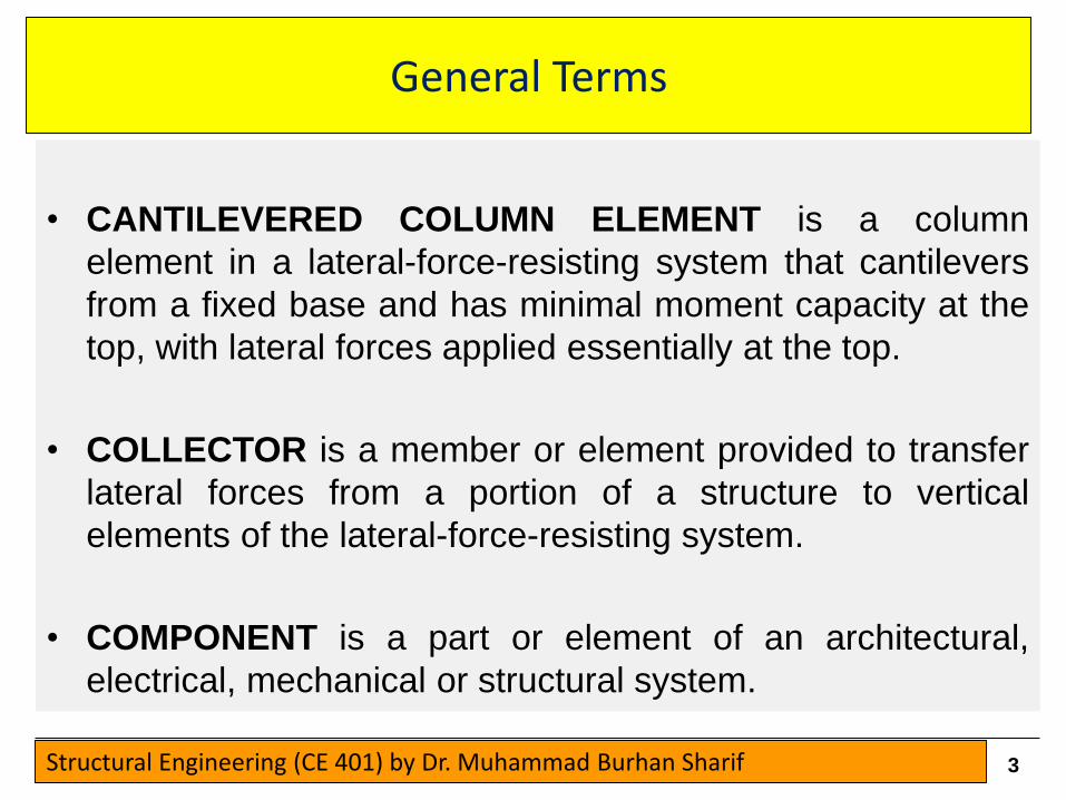
• CANTILEVERED COLUMN ELEMENT is a column
element in a lateral-force-resisting system that cantilevers
from a fixed base and has minimal moment capacity at the
top, with lateral forces applied essentially at the top.
• COLLECTOR is a member or element provided to transfer
lateral forces from a portion of a structure to vertical
elements of the lateral-force-resisting system.
• COMPONENT is a part or element of an architectural,
electrical, mechanical or structural system.
3Structural Engineering (CE 401) by Dr. Muhammad Burhan Sharif

General Terms
• DESIGN BASIS GROUND MOTION is that ground motion
that has a 10 percent chance of being exceeded in 50
years as determined by a site-specific hazard analysis or
may be determined from a hazard map. A suite of ground
motion time histories with dynamic properties
representative of the site characteristics shall be used to
represent this ground motion. The dynamic effects of the
Design Basis Ground Motion may be represented by the
Design Response Spectrum.
4Structural Engineering (CE 401) by Dr. Muhammad Burhan Sharif

General Terms
• DIAPHRAGM is a horizontal or nearly horizontal system acting totransmit lateral forces to the vertical-resisting elements. The term“diaphragm” includes horizontal bracing systems.
• LATERAL-FORCE-RESISTING SYSTEM is that part of the structuralsystem designed to resist the Design Seismic Forces.
• MOMENT-RESISTING FRAME is a frame in which members and jointsare capable of resisting forces primarily by flexure.
• MOMENT-RESISTING WALL FRAME (MRWF) is a masonry wallframe especially detailed to provide ductile behavior and designed inconformance with Section 2108.2.5.
• ORDINARY BRACED FRAME (OBF) is a steel-braced frame designedin accordance With the provisions of Section 2-9
5Structural Engineering (CE 401) by Dr. Muhammad Burhan Sharif

General Terms
STORY is the space between levels. Story x is the story below Level x.
STORY DRIFT is the lateral displacement of one level relative to the levelabove or below.
STORY DRIFT RATIO is the story drift divided by the story height.
STORY SHEAR, is the summation of design lateral forces above the storyunder consideration.
STRENGTH is the capacity of an element or a member to resist factoredload as specified in Chapters 16, 18, 19, 21 and 22.
STRUCTURE is an assemblage of framing members designed to supportgravity loads and resist lateral forces. Structures may be categorized asbuilding structures or non-building structures.
6Structural Engineering (CE 401) by Dr. Muhammad Burhan Sharif

CRITERIA SELECTION
1629.1 Basis for Design
The procedures and the limitations for the design of structures
shall be determined considering
1) seismic zoning
2) site characteristics
3) occupancy configuration,
4) structural system and
5) height in accordance with this section
7Structural Engineering (CE 401) by Dr. Muhammad Burhan Sharif

CRITERIA SELECTION
1629.1 Basis for Design (contd)
Structures shall be designed with adequate strength to
withstand the lateral displacements induced by the Design
Basis Ground Motion, considering the inelastic response of
the structure and the inherent redundancy, over-strength and
ductility of the lateral-force- resisting system.
The minimum design strength shall be based on the Design
Seismic Forces determined in accordance with the static
lateral force procedure of Section 1630, except as modified by
Section 1631.5.4.
8Structural Engineering (CE 401) by Dr. Muhammad Burhan Sharif

1. Occupancy Category
1629.2 Occupancy Categories.
For purposes of earthquake resistant design, each structure
shall be placed in one of the occupancy categories listed in
Table 16-K.
9Structural Engineering (CE 401) by Dr. Muhammad Burhan Sharif

1. Occupancy Category
10Structural Engineering (CE 401) by Dr. Muhammad Burhan Sharif

2. Site Geology and Soil Chracteristics
1629.3 Site Geology and Soil Characteristics.
Each site shall be assigned a soil profile type based on
properly substantiated geotechnical data using the site
categorization procedure set forth in Division V, Section 1636
and Table 16-J.
EXCEPTION: When the soil properties are not known in sufficient detail to
determine the soil profile type, Type SD shall be used. Soil Profile Type SE
or SF need not be assumed unless the building official determines that
Type SE or SF may be present at the site.
11Structural Engineering (CE 401) by Dr. Muhammad Burhan Sharif

2. Site Geology and Soil Chracteristics
12Structural Engineering (CE 401) by Dr. Muhammad Burhan Sharif

3. Site Seismic Hazard Characteristics and Zones
1629.4 Site Seismic Hazard Characteristics.
Seismic hazard characteristics for the site shall be established
based on the seismic zone and proximity of the site to active
seismic sources, site soil profile characteristics and the
structure’s importance factor.
1629.4.1 Seismic zone.
Each site shall be assigned a seismic zone in accordance with
Figure 16-2. Each structure shall be assigned a seismic zone
factor Z in accordance with Table 16-I.
13Structural Engineering (CE 401) by Dr. Muhammad Burhan Sharif

1. Occupancy Category
14Structural Engineering (CE 401) by Dr. Muhammad Burhan Sharif

4. Seismic Zone factor
1629.4.2 Seismic Zone 4 near-source factor.
In Seismic Zone 4, each site shall be assigned a near-source
factor in accordance with Table 16-S and the Seismic Source
Type set forth in Table 16-U.
15Structural Engineering (CE 401) by Dr. Muhammad Burhan Sharif

4. Near Source Factors
16Structural Engineering (CE 401) by Dr. Muhammad Burhan Sharif
5. Seismic Response Coefficients
1629.4.3 Seismic response coefficients.
Each structure shall be assigned a seismic coefficient, Ca, in
accordance with Table 16-Q and a seismic coefficient, Cv, in
accordance with Table 16-R.
17Structural Engineering (CE 401) by Dr. Muhammad Burhan Sharif

5. Seismic Response Coefficients
18Structural Engineering (CE 401) by Dr. Muhammad Burhan Sharif

Height Limitations
1629.7 Height Limits.
Height limits for the various structural systems in Seismic
Zones 3 and 4 are given in Table 16-N.
19Structural Engineering (CE 401) by Dr. Muhammad Burhan Sharif

Height Limitations
20Structural Engineering (CE 401) by Dr. Muhammad Burhan Sharif

Static Lateral Force Procedure
1629.8.3 Static.
The static lateral force procedure of Section 1630 may be
used for the following structures:
1. All structures, regular or irregular, in Seismic Zone 1 and in
Occupancy Categories 4 and 5 in Seismic Zone 2.
2, Regular structures under 240 feet (73 152 mm) in height
with lateral force resistance provided by systems listed in
Table 16-N, except where Section 1629.8.4, Item 4, applies.
3. Irregular structures not more than five stories or 65 feet (19
812 mm) in height.
21Structural Engineering (CE 401) by Dr. Muhammad Burhan Sharif

Static Lateral Force Procedure
22Structural Engineering (CE 401) by Dr. Muhammad Burhan Sharif

Static Lateral Force Procedure
23Structural Engineering (CE 401) by Dr. Muhammad Burhan Sharif

Static Lateral Force Procedure
24Structural Engineering (CE 401) by Dr. Muhammad Burhan Sharif

Static Lateral Force Procedure
25Structural Engineering (CE 401) by Dr. Muhammad Burhan Sharif

Static Lateral Force Procedure
26Structural Engineering (CE 401) by Dr. Muhammad Burhan Sharif

Problem-1
Determine the UBC-97 design seismic forces for a three-story
concrete shear Wall office building. It is located in Dir District
KPK province on rock with a shear Wave velocity of 3000 ft/
sec. The story heights are 13 feet for the first floor and 11 feet
for the second and third floors. The story dead loads are 2200,
2000 and 1700 kips from the bottom up. The plan dimensions
are 180 feet by 120 feet. The Walls in the direction under
consideration are 120 feet long and are Without openings.
The shear walls do not carry vertical loads.
27Structural Engineering (CE 401) by Dr. Muhammad Burhan Sharif

Problem-1
28Structural Engineering (CE 401) by Dr. Muhammad Burhan Sharif
Problem-2
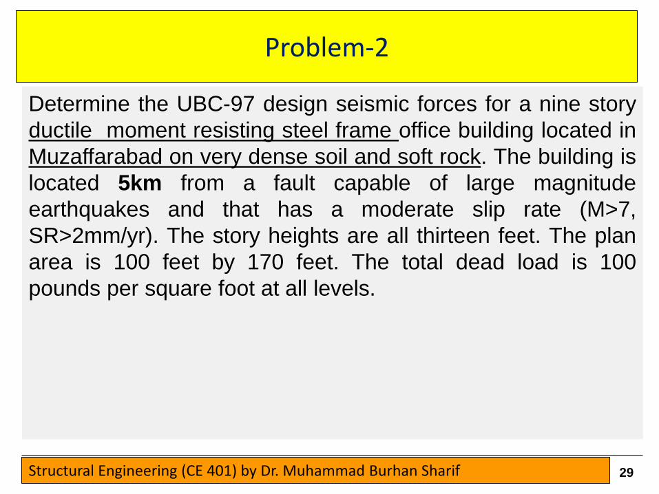
Determine the UBC-97 design seismic forces for a nine story
ductile moment resisting steel frame office building located in
Muzaffarabad on very dense soil and soft rock. The building is
located 5km from a fault capable of large magnitude
earthquakes and that has a moderate slip rate (M>7,
SR>2mm/yr). The story heights are all thirteen feet. The plan
area is 100 feet by 170 feet. The total dead load is 100
pounds per square foot at all levels.
29Structural Engineering (CE 401) by Dr. Muhammad Burhan Sharif

Problem-2
30Structural Engineering (CE 401) by Dr. Muhammad Burhan Sharif