equations - hvacsimplified.in
TRANSCRIPT

Equations
5PA R T5
H VA C E Q U AT I O N S , D ATA , A N D R U L E S O F T H U M B
36 PART 5
5.01 Cooling and Heating Equations
HS = 1.08 × CFM × ∆T
HS = 1.1 × CFM × ∆T
HL = 0.68 × CFM × ∆WGR.
HL = 4840 × CFM × ∆WLB.
HT = 4.5 × CFM × ∆h
HT = HS + HL
H = U × A × ∆T
SHR = =
LB. STM/HR =
HS = Sensible Heat (Btu/Hr.)
HL = Latent Heat (Btu/Hr.)
HT = Total Heat (Btu/Hr.)
∆T = Temperature Difference (°F.)
∆WGR. = Humidity Ratio Difference (Gr.H2O/Lb.DA)
∆WLB. = Humidity Ratio Difference (Lb.H2O/Lb.DA)
∆h = Enthalpy Difference (Btu/Lb.DA)
CFM = Air Flow Rate (Cubic Feet per Minute)
U = U-Value (Btu/Hr. Sq. Ft. °F.)
A = Area (Sq. Ft.)
SHR = Sensible Heat Ratio
HFG = Latent Heat of Vaporization at Design Pressure (1989 ASHRAE
Fundamentals)
5.02 R-Values/U-Values
R = = × Thickness
U =
R = R-Value (Hr. Sq. Ft. °F./Btu.)
U = U-Value (Btu./Hr. Sq. Ft. °F.)
C = Conductance (Btu./Hr. Sq. Ft. °F.)
K = Conductivity (Btu. In./Hr. Sq. Ft. °F.)
ΣR = Sum of the Individual R-Values
1�ΣR
1�K
1�C
BTU/HR�
HFG
HS�HS + HL
HS�HT
Equations 37
5.03 Water System Equations
H = 500 × GPM × ∆T
GPMEVAP. =
GPMCOND. =
H = Total Heat (Btu/Hr.)
GPM = Water Flow Rate (Gallons per Minute)
∆T = Temperature Difference (°F.)
TONS = Air Conditioning Load (Tons)
GPMEVAP. = Evaporator Water Flow Rate (Gallons per Minute)
GPMCOND. = Condenser Water Flow Rate (Gallons per Minute)
5.04 Air Change Rate Equations
=
CFM =
AC/HR. = Air Change Rate per Hour
CFM = Air Flow Rate (Cubic Feet per Minute)
VOLUME = Space Volume (Cubic Feet)
5.05 Mixed Air Temperature
TMA = �TROOM × � + �TOA × �TMA = �TRA × � + �TOA × �CFMSA = Supply Air (CFM)
CFMRA = Return Air (CFM)
CFMOA = Outside Air (CFM)
TMA = Mixed Air Temperature (°F)
TROOM = Room Design Temperature (°F)
TRA = Return Air Temperature (°F)
TOA = Outside Air Temperature (°F)
5.06 Ductwork Equations
TP = SP + VP
VP = � �2
=(V)2
�(4005)2
V�4005
CFMOA�CFMSA
CFMRA�CFMSA
CFMOA�CFMSA
CFMRA�CFMSA
�H
AC
R� × VOLUME
��60
CFM × 60��VOLUME
AC�HR
TONS × 30��
∆T
TONS × 24��
∆T
38 PART 5
V = =
DEQ =
TP = Total Pressure
SP = Static Pressure, Friction Losses
VP = Velocity Pressure, Dynamic Losses
V = Velocity, Ft./Min.
Q = Flow through Duct (CFM)
A = Area of Duct (Sq. Ft.)
W = Width of Duct (Inches)
H = Height of Duct (Inches)
DEQ = Equivalent Round Duct Size for Rectangular Duct (Inches)
A = One Dimension of Rectangular Duct (Inches)
B = Adjacent Side of Rectangular Duct (Inches)
5.07 Fan Laws
=
= � �2
= � �2
= � �3
= � �3
= � �1.5
BHP =
MHP =
CFM = Cubic Feet/Minute
RPM = Revolutions/Minute
SP = In. W.G.
BHP = Break Horsepower
Fan Size = Constant
Air Density = Constant
SP.GR. (Air) = 1.0
FANEFF. = 65–85%
M/DEFF. = 80–95%
M/D = Motor/Drive
5.08 Pump Laws
=
= � �2
= � �2RPM2
�RPM1
GPM2�GPM1
HD2�HD1
RPM2�RPM1
GPM2�GPM1
BHP�M/DEFF.
CFM × SP × SP.GR.���
6356 × FANEFF.
SP2�SP1
RPM2�RPM1
CFM2�CFM1
BHP2�BHP1
RPM2�RPM1
CFM2�CFM1
SP2�SP1
RPM2�RPM1
CFM2�CFM1
1.3 × (A × B)0.625
��(A + B)0.25
Q × 144�W × H
Q�A
Equations 39
�B
B
H
H
P
P2
1
� = � �3
= � �3
= � �1.5
BHP =
MHP =
VH =
HD =
GPM = Gallons/Minute
RPM = Revolutions/Minute
HD = Ft. H2O
BHP = Break Horsepower
Pump Size = Constant
Water Density = Constant
SP.GR. = Specific Gravity of Liquid with Respect to Water
SP.GR. (Water) = 1.0
PUMPEFF. = 60–80%
M/DEFF. = 85–95%
M/D = Motor/Drive
P = Pressure in Psi
VH = Velocity Head in Ft.
V = Velocity in Ft./Sec.
g = Acceleration due to Gravity (32.16 Ft./Sec2)
5.09 Pump Net Positive Suction Head (NPSH) Calculations
NPSHAVAIL > NPSHREQ’D
NPSHAVAIL = HA � HS − HF − HVP
NPSHAVAIL = Net Positive Suction Available at Pump (Feet)
NPSHREQ’D = Net Positive Suction Required at Pump (Feet)
HA = Pressure at Liquid Surface (Feet—34 Feet for Water at Atmospheric
Pressure)
HS = Height of Liquid Surface Above (+) or Below (−) Pump (Feet)
HF = Friction Loss between Pump and Source (Feet)
HVP = Absolute Pressure of Water Vapor at Liquid Temperature (Feet—1989
ASHRAE Fundamentals)
5.10 Air Conditioning Condensate
GPMAC COND =
GPMAC COND =CFM × ∆WGR.
��SpV × 8.33 × 7000
CFM × ∆WLB.��
SpV × 8.33
P × 2.31�SP.GR.
V2
�2g
BHP�M/DEFF.
GPM × HD × SP.GR.���
3960 × PUMPEFF.
HD2�HD1
RPM2�RPM1
GPM2�GPM1
40 PART 5
GPMAC COND = Air Conditioning Condensate Flow (Gallons/Minute)
CFM = Air Flow Rate (Cu.Ft./Minute)
SpV = Specific Volume of Air (Cu.Ft./Lb.DA)
∆WLB. = Specific Humidity (Lb.H2O/Lb.DA)
∆WGR. = Specific Humidity (Gr.H2O/Lb.DA)
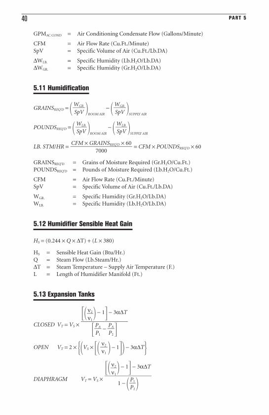
5.11 Humidification
GRAINSREQ’D = � �ROOM AIR
− � �SUPPLY AIR
POUNDSREQ’D = � �ROOM AIR
− � �SUPPLY AIR
LB. STM/HR = = CFM × POUNDSREQ’D × 60
GRAINSREQ’D = Grains of Moisture Required (Gr.H2O/Cu.Ft.)
POUNDSREQ’D = Pounds of Moisture Required (Lb.H2O/Cu.Ft.)
CFM = Air Flow Rate (Cu.Ft./Minute)
SpV = Specific Volume of Air (Cu.Ft./Lb.DA)
WGR. = Specific Humidity (Gr.H2O/Lb.DA)
WLB. = Specific Humidity (Lb.H2O/Lb.DA)
5.12 Humidifier Sensible Heat Gain
HS = (0.244 × Q × ∆T) + (L × 380)
HS = Sensible Heat Gain (Btu/Hr.)
Q = Steam Flow (Lb.Steam/Hr.)
∆T = Steam Temperature − Supply Air Temperature (F.)
L = Length of Humidifier Manifold (Ft.)
5.13 Expansion Tanks
CLOSED VT = VS ×
OPEN VT = 2 × ��VS × �� � − 1�� − 3α∆T�
DIAPHRAGM VT = VS ×
���ν
ν
2
1
�� − 1� − 3α∆T
��
1 − ��P
P1
2
��
ν2�ν1
���ν
ν
2
1
�� − 1� − 3α∆T
��
��P
PA
1
� − �P
PA
2
��
CFM × GRAINSREQ’D × 60���
7000
WLB.�SpV
WLB.�SpV
WGR.�SpV
WGR.�SpV
Equations 41
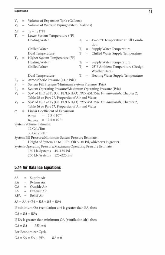
VT = Volume of Expansion Tank (Gallons)
VS = Volume of Water in Piping System (Gallons)
∆T = T2 − T1 (°F)
T1 = Lower System Temperature (°F)
Heating Water T1 = 45–50°F Temperature at Fill Condi-
tion
Chilled Water T1 = Supply Water Temperature
Dual Temperature T1 = Chilled Water Supply Temperature
T2 = Higher System Temperature (°F)
Heating Water T2 = Supply Water Temperature
Chilled Water T2 = 95°F Ambient Temperature (Design
Weather Data)
Dual Temperature T2 = Heating Water Supply Temperature
PA = Atmospheric Pressure (14.7 Psia)
P1 = System Fill Pressure/Minimum System Pressure (Psia)
P2 = System Operating Pressure/Maximum Operating Pressure (Psia)
V1 = SpV of H2O at T1 (Cu. Ft./Lb.H2O) 1989 ASHRAE Fundamentals, Chapter 2,
Table 25 or Part 27, Properties of Air and Water
V2 = SpV of H2O at T2 (Cu. Ft./Lb.H2O) 1989 ASHRAE Fundamentals, Chapter 2,
Table 26 or Part 27, Properties of Air and Water
α = Linear Coefficient of Expansion
αSTEEL = 6.5 × 10⁻⁶
αCOPPER = 9.5 × 10⁻⁶
System Volume Estimate:
12 Gal./Ton
35 Gal./BHP
System Fill Pressure/Minimum System Pressure Estimate:
Height of System +5 to 10 Psi OR 5–10 Psi, whichever is greater.
System Operating Pressure/Maximum Operating Pressure Estimate:
150 Lb. Systems 45–125 Psi
250 Lb. Systems 125–225 Psi
5.14 Air Balance Equations
SA = Supply Air
RA = Return Air
OA = Outside Air
EA = Exhaust Air
RFA = Relief Air
SA = RA + OA = RA + EA + RFA
If minimum OA (ventilation air) is greater than EA, then
OA = EA + RFA
If EA is greater than minimum OA (ventilation air), then
OA = EA RFA = 0
For Economizer Cycle
OA = SA = EA + RFA RA = 0
42 PART 5
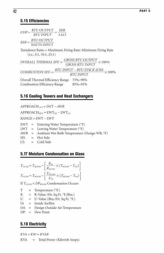
5.15 Efficiencies
COP = =
EER =
Turndown Ratio = Maximum Firing Rate: Minimum Firing Rate
(i.e., 5:1, 10:1, 25:1)
OVERALL THERMAL EFF. = × 100%
COMBUSTION EFF. = × 100%
Overall Thermal Efficiency Range 75%–90%
Combustion Efficiency Range 85%–95%
5.16 Cooling Towers and Heat Exchangers
APPROACHCT’S = LWT − AWB
APPROACHHE’S = EWTHS − LWTCS
RANGE = EWT − LWT
EWT = Entering Water Temperature (°F)
LWT = Leaving Water Temperature (°F)
AWB = Ambient Wet Bulb Temperature (Design WB, °F)
HS = Hot Side
CS = Cold Side
5.17 Moisture Condensation on Glass
TGLASS = TROOM − � × (TROOM − TOA)�TGLASS = TROOM − � × (TROOM − TOA)�If TGLASS < DPROOM Condensation Occurs
T = Temperature (°F.)
R = R-Value (Hr. Sq.Ft. °F./Btu.)
U = U-Value (Btu./Hr. Sq.Ft. °F.)
IA = Inside Airfilm
OA = Design Outside Air Temperature
DP = Dew Point
5.18 Electricity
KVA = KW + KVAR
KVA = Total Power (Kilovolt Amps)
UGLASS�
UIA
RIA�RGLASS
BTU INPUT − BTU STACK LOSS����
BTU INPUT
GROSS BTU OUTPUT���
GROSS BTU INPUT
BTU OUTPUT��WATTS INPUT
EER�3.413
BTU OUTPUT��
BTU INPUT
Equations 43
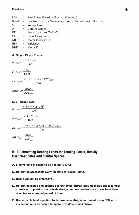
KW = Real Power, Electrical Energy (Kilowatts)
KVAR = Reactive Power or “Imaginary” Power (Kilovolt Amps Reactive)
V = Voltage (Volts)
A = Current (Amps)
PF = Power Factor (0.75–0.95)
BHP = Break Horsepower
MHP = Motor Horsepower
EFF = Efficiency
M/D = Motor Drive
A. Single Phase Power:
KW1φ =
KVA1φ =
BHP1φ =
MHP1φ =
B. 3-Phase Power:
KW3φ =
KVA3φ =
BHP3φ =
MHP3φ =
5.19 Calculating Heating Loads for Loading Docks, HeavilyUsed Vestibules and Similar Spaces.
A. Find volume of space to be heated (Cu.Ft.).
B. Determine acceptable warm-up time for space (Min.).
C. Divide volume by time (CFM).
D. Determine inside and outside design temperatures—assume inside space temper-
ature has dropped to the outside design temperature because doors have been
open for an extended period of time.
E. Use sensible heat equation to determine heating requirement using CFM and
inside and outside design temperatures determined above.
BHP3φ�M/DEFF.
�3 × V × A × PF × DEVICEEFF.����
746
�3 × V × A��
1000
�3 × V × A × PF��
1000
BHP1φ�M/DEFF.
V × A × PF × DEVICEEFF.���
746
V × A�1000
V × A × PF��
1000
44 PART 5
5.20 Ventilation of Mechanical Rooms with RefrigerationEquipment
A. For a more detailed description of ventilation requirements for mechanical rooms
with refrigeration equipment see ASHRAE Standard 15 and Part 9, Ventilation Rules
of Thumb.
B. Completely Enclosed Equipment Rooms:
CFM = 100 × G0.5
CFM = Exhaust Air Flow Rate Required (Cu.Ft./Minute)
G = Mass of Refrigerant of Largest System (Pounds)
C. Partially Enclosed Equipment Rooms:
FA = G0.5
FA = Ventilation Free Opening Area (Sq.Ft.)
G = Mass of Refrigerant of Largest System (Pounds)
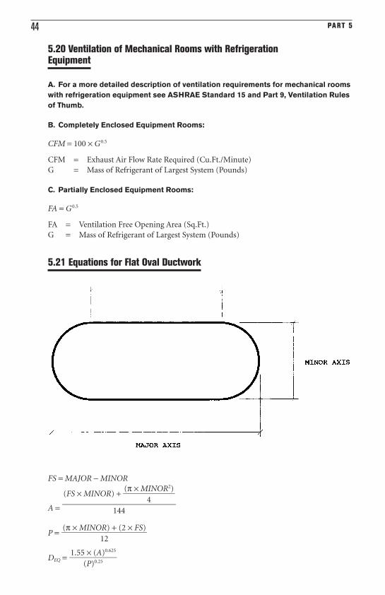
5.21 Equations for Flat Oval Ductwork
FS = MAJOR − MINOR
A =
P =
DEQ =1.55 × (A)0.625
��(P)0.25
(π × MINOR) + (2 × FS)���
12
(FS × MINOR) +�(π × M
4
INOR2)�
����144
Equations 45
FS = Flat Span Dimension (Inches)
MAJOR = Major Axis Dimension [Inches (Larger Dimension)]
MINOR = Minor Axis Dimension [Inches (Smaller Dimension)]
A = Cross-Sectional Area (Square Feet)
P = Perimeter or Surface Area (Square Feet per Lineal Feet)
DEQ = Equivalent Round Duct Diameter
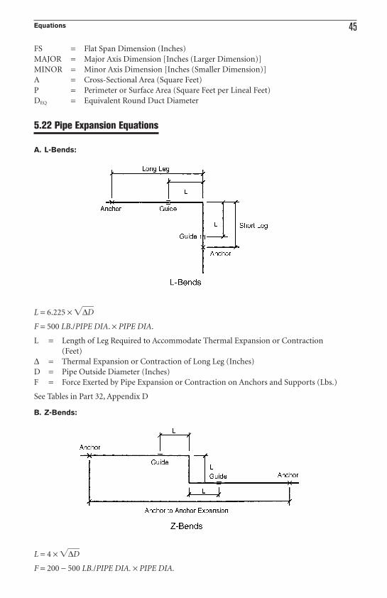
5.22 Pipe Expansion Equations
A. L-Bends:
L = 6.225 × �∆D
F = 500 LB./PIPE DIA. × PIPE DIA.
L = Length of Leg Required to Accommodate Thermal Expansion or Contraction
(Feet)
∆ = Thermal Expansion or Contraction of Long Leg (Inches)
D = Pipe Outside Diameter (Inches)
F = Force Exerted by Pipe Expansion or Contraction on Anchors and Supports (Lbs.)
See Tables in Part 32, Appendix D
B. Z-Bends:
L = 4 × �∆D
F = 200 − 500 LB./PIPE DIA. × PIPE DIA.
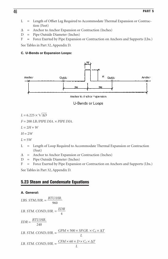
46 PART 5
L = Length of Offset Leg Required to Accommodate Thermal Expansion or Contrac-
tion (Feet)
∆ = Anchor to Anchor Expansion or Contraction (Inches)
D = Pipe Outside Diameter (Inches)
F = Force Exerted by Pipe Expansion or Contraction on Anchors and Supports (Lbs.)
See Tables in Part 32, Appendix D.
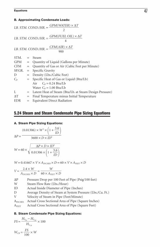
C. U-Bends or Expansion Loops:
L = 6.225 × �∆D
F = 200 LB./PIPE DIA. × PIPE DIA.
L = 2H + W
H = 2W
L = 5W
L = Length of Loop Required to Accommodate Thermal Expansion or Contraction
(Feet)
∆ = Anchor to Anchor Expansion or Contraction (Inches)
D = Pipe Outside Diameter (Inches)
F = Force Exerted by Pipe Expansion or Contraction on Anchors and Supports (Lbs.)
See Tables in Part 32, Appendix D.
5.23 Steam and Condensate Equations
A. General:
LBS. STM./HR. =
LB. STM. COND./HR. =
EDR =
LB. STM. COND./HR. =
LB. STM. COND./HR. =CFM × 60 × D × CP × ∆T���
L
GPM × 500 × SP.GR. × CP × ∆T����
L
BTU/HR.��
240
EDR�
4
BTU/HR.��
960
Equations 47
B. Approximating Condensate Loads:
LB. STM. COND./HR. =
LB. STM. COND./HR. =
LB. STM. COND./HR. =
STM. = Steam
GPM = Quantity of Liquid (Gallons per Minute)
CFM = Quantity of Gas or Air (Cubic Feet per Minute)
SP.GR. = Specific Gravity
D = Density (Lbs./Cubic Feet)
CP = Specific Heat of Gas or Liquid (Btu/Lb)
Air CP = 0.24 Btu/Lb
Water CP = 1.00 Btu/Lb
L = Latent Heat of Steam (Btu/Lb. at Steam Design Pressure)
∆T = Final Temperature minus Initial Temperature
EDR = Equivalent Direct Radiation
5.24 Steam and Steam Condensate Pipe Sizing Equations
A. Steam Pipe Sizing Equations:
∆P =
W = 60 × ��
W = 0.41667 × V × AINCHES × D = 60 × V × AFEET × D
V = =
∆P Pressure Drop per 100 Feet of Pipe (Psig/100 feet)
W Steam Flow Rate (Lbs./Hour)
ID Actual Inside Diameter of Pipe (Inches)
D Average Density of Steam at System Pressure (Lbs./Cu. Ft.)
V Velocity of Steam in Pipe (Feet/Minute)
AINCHES Actual Cross Sectional Area of Pipe (Square Inches)
AFEET Actual Cross Sectional Area of Pipe (Square Feet)
B. Steam Condensate Pipe Sizing Equations:
FS = × 100
WCR = × WFS�100
HSSS− HSCR
��HLCR
W��60 × AFEET × D
2.4 × W��AINCHES × D
∆P × D × ID5
���
0.01306 × �1 + �3
ID
.6��
(0.01306) × W 2 × �1 + �3
ID
.6��
���3600 × D × ID5
CFM(AIR) × ∆T��
900
GPM(FUEL OIL) × ∆T���
4
GPM(WATER) × ∆T���
2
48 PART 5
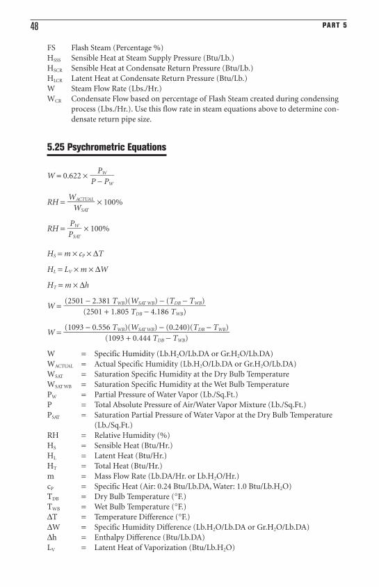
FS Flash Steam (Percentage %)
HSSS Sensible Heat at Steam Supply Pressure (Btu/Lb.)
HSCR Sensible Heat at Condensate Return Pressure (Btu/Lb.)
HLCR Latent Heat at Condensate Return Pressure (Btu/Lb.)
W Steam Flow Rate (Lbs./Hr.)
WCR Condensate Flow based on percentage of Flash Steam created during condensing
process (Lbs./Hr.). Use this flow rate in steam equations above to determine con-
densate return pipe size.
5.25 Psychrometric Equations
W = 0.622 ×
RH = × 100%
RH = × 100%
HS = m × cP × ∆T
HL = LV × m × ∆W
HT = m × ∆h
W =
W =
W = Specific Humidity (Lb.H2O/Lb.DA or Gr.H2O/Lb.DA)
WACTUAL = Actual Specific Humidity (Lb.H2O/Lb.DA or Gr.H2O/Lb.DA)
WSAT = Saturation Specific Humidity at the Dry Bulb Temperature
WSAT WB = Saturation Specific Humidity at the Wet Bulb Temperature
PW = Partial Pressure of Water Vapor (Lb./Sq.Ft.)
P = Total Absolute Pressure of Air/Water Vapor Mixture (Lb./Sq.Ft.)
PSAT = Saturation Partial Pressure of Water Vapor at the Dry Bulb Temperature
(Lb./Sq.Ft.)
RH = Relative Humidity (%)
HS = Sensible Heat (Btu/Hr.)
HL = Latent Heat (Btu/Hr.)
HT = Total Heat (Btu/Hr.)
m = Mass Flow Rate (Lb.DA/Hr. or Lb.H2O/Hr.)
cP = Specific Heat (Air: 0.24 Btu/Lb.DA, Water: 1.0 Btu/Lb.H2O)
TDB = Dry Bulb Temperature (°F.)
TWB = Wet Bulb Temperature (°F.)
∆T = Temperature Difference (°F.)
∆W = Specific Humidity Difference (Lb.H2O/Lb.DA or Gr.H2O/Lb.DA)
∆h = Enthalpy Difference (Btu/Lb.DA)
LV = Latent Heat of Vaporization (Btu/Lb.H2O)
(1093 − 0.556 TWB)(WSAT WB) − (0.240)(TDB − TWB)�����
(1093 + 0.444 TDB − TWB)
(2501 − 2.381 TWB)(WSAT WB) − (TDB − TWB)�����
(2501 + 1.805 TDB − 4.186 TWB)
PW�PSAT
WACTUAL�
WSAT
PW�P − PW
Equations 49
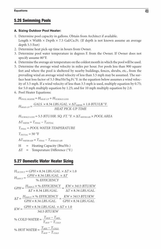
5.26 Swimming Pools
A. Sizing Outdoor Pool Heater:
1. Determine pool capacity in gallons. Obtain from Architect if available.
Length × Width × Depth × 7.5 Gal/Cu.Ft. (If depth is not known assume an average
depth 5.5 Feet)
2. Determine heat pick-up time in hours from Owner.
3. Determine pool water temperature in degrees F. from the Owner. If Owner does not
specify assume 80°F.
4. Determine the average air temperature on the coldest month in which the pool will be used.
5. Determine the average wind velocity in miles per hour. For pools less than 900 square
feet and where the pool is sheltered by nearby buildings, fences, shrubs, etc., from the
prevailing wind an average wind velocity of less than 3.5 mph may be assumed. The sur-
face heat loss factor of 5.5 Btu/Hr/Sq.Ft.°F. in the equation below assumes a wind veloc-
ity of 3.5 mph. If a wind velocity of less than 3.5 mph is used, multiply equation by 0.75;
for 5.0 mph multiply equation by 1.25; and for 10 mph multiply equation by 2.0.
6. Pool Heater Equations:
HPOOL HEATER = HHEAT-UP + HSURFACE LOSS
HHEAT-UP =
HSURFACE LOSS = 5.5 BTU/HR. SQ. FT. °F. × ∆TWATER/AIR × POOL AREA
∆TWATER = TFINAL − TINITIAL
TFINAL = POOL WATER TEMPERATURE
TINITIAL = 50 °F
∆TWATER/AIR = TFINAL − TAVERAGE AIR
H = Heating Capacity (Btu/Hr.)
∆T = Temperature Difference (°F.)
5.27 Domestic Water Heater Sizing
HOUTPUT = GPH × 8.34 LBS./GAL. × ∆T × 1.0
HINPUT =
GPH = =
∆T = =
KW =
% COLD WATER =
% HOT WATER =TMIX − TCOLD��THOT − TCOLD
THOT − TMIX��THOT − TCOLD
GPH × 8.34 LBS./GAL. × ∆T × 1.0����
3413 BTU/KW
KW × 3413 BTU/KW���GPH × 8.34 LBS./GAL.
HINPUT × % EFFICIENCY���
GPH × 8.34 LBS./GAL.
KW × 3413 BTU/KW���∆T × 8.34 LBS./GAL.
HINPUT × % EFFICIENCY���
∆T × 8.34 LBS./GAL.
GPH × 8.34 LBS./GAL. × ∆T���
% EFFICIENCY
GALS. × 8.34 LBS./GAL. × ∆TWATER × 1.0 BTU/LB.°F.������
HEAT PICK-UP TIME
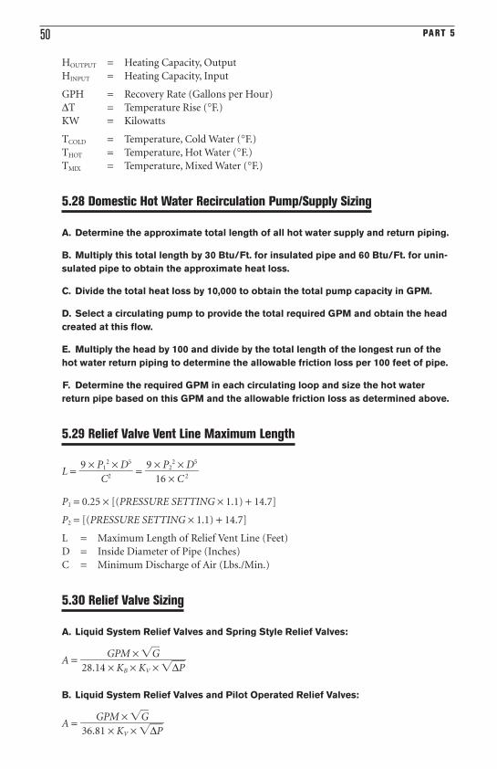
50 PART 5
HOUTPUT = Heating Capacity, Output
HINPUT = Heating Capacity, Input
GPH = Recovery Rate (Gallons per Hour)
∆T = Temperature Rise (°F.)
KW = Kilowatts
TCOLD = Temperature, Cold Water (°F.)
THOT = Temperature, Hot Water (°F.)
TMIX = Temperature, Mixed Water (°F.)
5.28 Domestic Hot Water Recirculation Pump/Supply Sizing
A. Determine the approximate total length of all hot water supply and return piping.
B. Multiply this total length by 30 Btu/Ft. for insulated pipe and 60 Btu/Ft. for unin-
sulated pipe to obtain the approximate heat loss.
C. Divide the total heat loss by 10,000 to obtain the total pump capacity in GPM.
D. Select a circulating pump to provide the total required GPM and obtain the head
created at this flow.
E. Multiply the head by 100 and divide by the total length of the longest run of the
hot water return piping to determine the allowable friction loss per 100 feet of pipe.
F. Determine the required GPM in each circulating loop and size the hot water
return pipe based on this GPM and the allowable friction loss as determined above.
5.29 Relief Valve Vent Line Maximum Length
L = =
P1 = 0.25 × [(PRESSURE SETTING × 1.1) + 14.7]
P2 = [(PRESSURE SETTING × 1.1) + 14.7]
L = Maximum Length of Relief Vent Line (Feet)
D = Inside Diameter of Pipe (Inches)
C = Minimum Discharge of Air (Lbs./Min.)
5.30 Relief Valve Sizing
A. Liquid System Relief Valves and Spring Style Relief Valves:
A =
B. Liquid System Relief Valves and Pilot Operated Relief Valves:
A =GPM × �G
��36.81 × KV × �∆P
GPM × �G���28.14 × KB × KV × �∆P
9 × P22 × D5
��16 × C 2
9 × P12 × D5
��C2
Equations 51
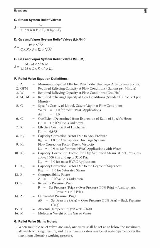
C. Steam System Relief Valves:
A =
D. Gas and Vapor System Relief Valves (Lb./Hr.):
A =
E. Gas and Vapor System Relief Valves (SCFM):
A =
F. Relief Valve Equation Definitions:
1. A = Minimum Required Effective Relief Valve Discharge Area (Square Inches)
2. GPM = Required Relieving Capacity at Flow Conditions (Gallons per Minute)
3. W = Required Relieving Capacity at Flow Conditions (Lbs./Hr.)
4. SCFM = Required Relieving Capacity at Flow Conditions (Standard Cubic Feet per
Minute)
5. G = Specific Gravity of Liquid, Gas, or Vapor at Flow Conditions
Water = 1.0 for most HVAC Applications
Air = 1.0
6. C = Coefficient Determined from Expression of Ratio of Specific Heats
C = 315 if Value is Unknown
7. K = Effective Coefficient of Discharge
K = 0.975
8. KB = Capacity Correction Factor Due to Back Pressure
KB = 1.0 for Atmospheric Discharge Systems
9. KV = Flow Correction Factor Due to Viscosity
KV = 0.9 to 1.0 for most HVAC Applications with Water
10. KN = Capacity Correction Factor for Dry Saturated Steam at Set Pressures
above 1500 Psia and up to 3200 Psia
KN = 1.0 for most HVAC Applications
11. KSH = Capacity Correction Factor Due to the Degree of Superheat
KSH = 1.0 for Saturated Steam
12. Z = Compressibility Factor
Z = 1.0 If Value is Unknown
13. P = Relieving Pressure (Psia)
P = Set Pressure (Psig) + Over Pressure (10% Psig) + Atmospheric
Pressure (14.7 Psia)
14. ∆P = Differential Pressure (Psig)
∆P = Set Pressure (Psig) + Over Pressure (10% Psig) − Back Pressure
(Psig)
15. T = Absolute Temperature (°R = °F. + 460)
16. M = Molecular Weight of the Gas or Vapor
G. Relief Valve Sizing Notes:
1. When multiple relief valves are used, one valve shall be set at or below the maximum
allowable working pressure, and the remaining valves may be set up to 5 percent over the
maximum allowable working pressure.
SCFM × �TGZ���1.175 × C × K × P × KB
W × �TZ���C × K × P × KB × �M
W���51.5 × K × P × KSH × KN × KB
52 PART 5
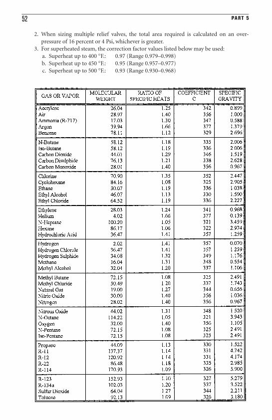
2. When sizing multiple relief valves, the total area required is calculated on an over-
pressure of 16 percent or 4 Psi, whichever is greater.
3. For superheated steam, the correction factor values listed below may be used:
a. Superheat up to 400 °F.: 0.97 (Range 0.979–0.998)
b. Superheat up to 450 °F.: 0.95 (Range 0.957–0.977)
c. Superheat up to 500 °F.: 0.93 (Range 0.930–0.968)
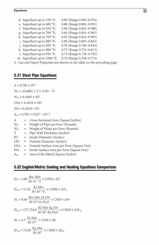
Equations 53
d. Superheat up to 550 °F.: 0.90 (Range 0.905–0.974)
e. Superheat up to 600 °F.: 0.88 (Range 0.882–0.993)
f. Superheat up to 650 °F.: 0.86 (Range 0.861–0.988)
g. Superheat up to 700 °F.: 0.84 (Range 0.841–0.963)
h. Superheat up to 750 °F.: 0.82 (Range 0.823–0.903)
i. Superheat up to 800 °F.: 0.80 (Range 0.805–0.863)
j. Superheat up to 850 °F.: 0.78 (Range 0.786–0.836)
k. Superheat up to 900 °F.: 0.75 (Range 0.753–0.813)
l. Superheat up to 950 °F.: 0.72 (Range 0.726–0.792)
m. Superheat up to 1000 °F.: 0.70 (Range 0.704–0.774)
4. Gas and Vapor Properties are shown in the table on the preceding page:
5.31 Steel Pipe Equations
A = 0.785 × ID2
WP = 10.6802 × T × (OD − T)
WW = 0.3405 × ID2
OSA = 0.2618 × OD
ISA = 0.2618 × ID
AM = 0.785 × (OD2 − ID2)
A = Cross-Sectional Area (Square Inches)
WP = Weight of Pipe per Foot (Pounds)
WW = Weight of Water per Foot (Pounds)
T = Pipe Wall Thickness (Inches)
ID = Inside Diameter (Inches)
OD = Outside Diameter (Inches)
OSA = Outside Surface Area per Foot (Square Feet)
ISA = Inside Surface Area per Foot (Square Feet)
AM = Area of the Metal (Square Inches)
5.32 English/Metric Cooling and Heating Equations Comparison
HS = 1.08 × CFM × ∆T
HSM = 72.42 × CMM × ∆TM
HL = 0.68 × CFM × ∆W
HLM = 177,734.8 × CMM × ∆WM
HT = 4.5 × CFM × ∆h
HTM = 72.09 × CMM × ∆hM
Kg Min�Hr M3
Lb Min�Hr Ft3
KJ Min Kg DA��Hr M3 Kg H2O
Btu Min Lb DA��Hr Ft3 Gr H2O
KJ Min��Hr M3 °C
Btu Min�Hr Ft3 °F
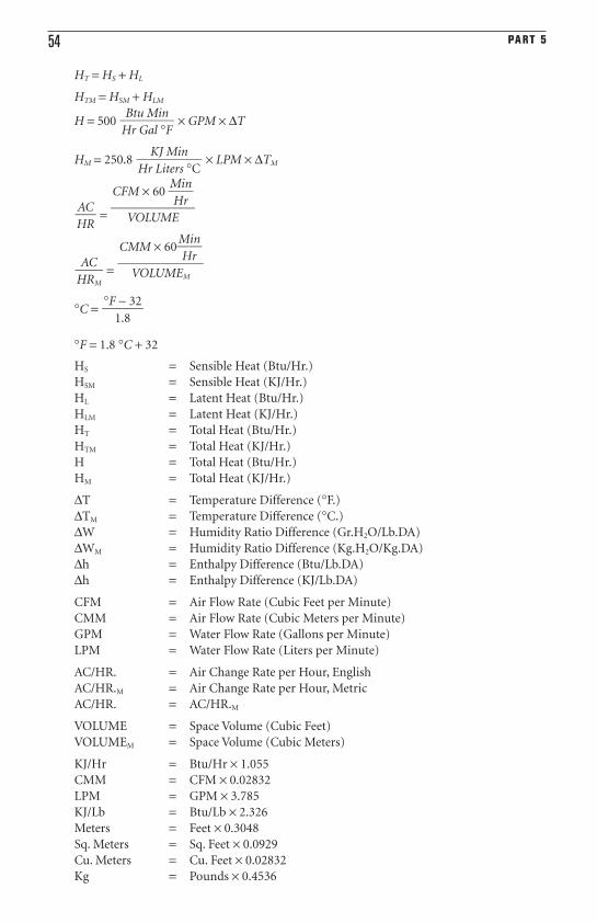
54 PART 5
HT = HS + HL
HTM = HSM + HLM
H = 500 × GPM × ∆T
HM = 250.8 × LPM × ∆TM
=
=
°C =
°F = 1.8 °C + 32
HS = Sensible Heat (Btu/Hr.)
HSM = Sensible Heat (KJ/Hr.)
HL = Latent Heat (Btu/Hr.)
HLM = Latent Heat (KJ/Hr.)
HT = Total Heat (Btu/Hr.)
HTM = Total Heat (KJ/Hr.)
H = Total Heat (Btu/Hr.)
HM = Total Heat (KJ/Hr.)
∆T = Temperature Difference (°F.)
∆TM = Temperature Difference (°C.)
∆W = Humidity Ratio Difference (Gr.H2O/Lb.DA)
∆WM = Humidity Ratio Difference (Kg.H2O/Kg.DA)
∆h = Enthalpy Difference (Btu/Lb.DA)
∆h = Enthalpy Difference (KJ/Lb.DA)
CFM = Air Flow Rate (Cubic Feet per Minute)
CMM = Air Flow Rate (Cubic Meters per Minute)
GPM = Water Flow Rate (Gallons per Minute)
LPM = Water Flow Rate (Liters per Minute)
AC/HR. = Air Change Rate per Hour, English
AC/HR.M = Air Change Rate per Hour, Metric
AC/HR. = AC/HR.M
VOLUME = Space Volume (Cubic Feet)
VOLUMEM = Space Volume (Cubic Meters)
KJ/Hr = Btu/Hr × 1.055
CMM = CFM × 0.02832
LPM = GPM × 3.785
KJ/Lb = Btu/Lb × 2.326
Meters = Feet × 0.3048
Sq. Meters = Sq. Feet × 0.0929
Cu. Meters = Cu. Feet × 0.02832
Kg = Pounds × 0.4536
°F − 32�
1.8
CMM × 60�M
H
i
r
n�
��VOLUMEM
AC�HRM
CFM × 60 �M
H
i
r
n�
��VOLUME
AC�HR
KJ Min��Hr Liters °C
Btu Min��Hr Gal °F
Equations 55
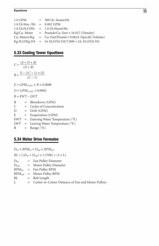
1.0 GPM = 500 Lb. Steam/Hr.
1.0 Lb.Stm. /Hr = 0.002 GPM
1.0 Lb.H2O/Hr = 1.0 Lb.Steam/Hr.
Kg/Cu. Meter = Pounds/Cu. Feet × 16.017 (Density)
Cu. Meters/Kg = Cu. Feet/Pound × 0.0624 (Specific Volume)
Kg H2O/Kg DA = Gr H2O/Lb DA/7,000 = Lb. H2O/Lb DA
5.33 Cooling Tower Equations
C =
B =
E = GPMCOND. × R × 0.0008
D = GPMCOND. × 0.0002
R = EWT − LWT
B = Blowdown (GPM)
C = Cycles of Concentration
D = Drift (GPM)
E = Evaporation (GPM)
EWT = Entering Water Temperature (°F.)
LWT = Leaving Water Temperature (°F.)
R = Range (°F.)
5.34 Motor Drive Formulas
DFP × RPMFP = DMP × RPMMP
BL = [(DFP + DMP) × 1.5708] + (2 × L)
DFP = Fan Pulley Diameter
DMP = Motor Pulley Diameter
RPMFP = Fan Pulley RPM
RPMMP = Motor Pulley RPM
BL = Belt Length
L = Center-to-Center Distance of Fan and Motor Pulleys
E − [(C − 1) × D]��
(C − 1)
(E + D + B)��
(D + B)