epe online - february 2007, vol. 36, no. 2
TRANSCRIPT

PIC DIGITAL GEIGER COUNTERQ LCD ReadoutQ USB InterfaceQ Internal Real-Time Clock
PROGRAMMABLE ROBOTFully manoeuvrable with programmable sound, light sensing etc.
COURTESY LIGHT DELAYGive your car that luxury feel
$6.95 US $8.99 CANFEB 2007 PRINTED IN THE UK

Copyright Ó 2007, Wimborne Publishing Ltd (408 Wimborne Road East, Ferndown, Dorset, BH22 9ND, UK)
and TechBites Interactive Inc.,
(PO Box 857, Madison, Alabama 35758, USA)
All rights reserved.
WARNING! The materials and works contained within EPE Online — which are made available by Wimborne Publishing Ltd and TechBites Interactive Inc — are copyrighted. You are permitted to make a backup copy of the downloaded file and one (1) hard copy of such materials and works for your personal use. International copyright laws, however, prohibit any further copying or reproduction of such materials and works, or any republication of any kind. TechBites Interactive Inc and Wimborne Publishing Ltd have used their best efforts in preparing these materials and works. However, TechBites Interactive Inc and Wimborne Publishing Ltd make no warranties of any kind, expressed or implied, with regard to the documentation or data contained herein, and specifically disclaim, without limitation, any implied warranties of merchantability and fitness for a particular purpose. Because of possible variances in the quality and condition of materials and workmanship used by readers, EPE Online, its publishers and agents disclaim any responsibility for the safe and proper functioning of reader-constructed projects based on or from information published in these materials and works. In no event shall TechBites Interactive Inc or Wimborne Publishing Ltd be responsible or liable for any loss of profit or any other commercial damages, including but not limited to special, incidental, consequential, or any other damages in connection with or arising out of furnishing, performance, or use of these materials and works.

BULL GROUP LTDUNIT D HENFIELD BUSINESS PARK
HENFIELD SUSSEX BN5 9SLTERMS: C/ CARDS, CASH, PO, CHEQUE OR
ONLINE ORDERING. PRICES PLUS VAT
UK DELIVERY £5.50
TEL 0870 7707520 FAX 01273 491813
HB7 Stirling Engine
Base measurements: 128 mm x 108 mm x 170 mm, 1 kg
Base plate: beech - Working rpm: 2000 rpm/min. (the
engine has a aluminium good cooling Cylinder)
Bearing application: 10 high-class ball-bearings
Material: screw, side parts all stainless steel
Cylinder brass, Rest aluminium and stainless steel.
Available as a kit £80.75 or built £84.99
www.mamodspares.co.uk
HB9 Stirling engine
Base measurements: 156 mm x 108 mm x 130 mm, 0,6
Kg Base plate: beech Working rpm: approx. 2,000 min
Bearing application: 6 high-class ball-bearings
Material of the engine: brass, aluminium, stainless steel
running time: 30-45 min.
Available as a kit £97.75 or built £101.99
www.mamodspares.co.uk
HB10 Stirling Engine
Base measurements: 156 mm x 108 mm x 130 mm, 0,6
Kg Base plate: beech Working rpm: approx. 2,000 rpm
Bearing application: 6 high-class ball-bearings
Material of the engine: brass, aluminium, stainless steel
running time: 30-45 min
Available as a kit £97.75 or built £101.99
www.mamodspares.co.uk
HB11 Stirling Engine
Base measurements: 156 mm x 108 mm x 130 mm, 0,7
Kg Base plate: beech
Working rpm: 2000 - 2500 rpm/min,run Bearing applica-
tion: 4 high-class ball-bearings Material: screw, side parts
total stainless steel Cylinder brass Rest aluminium, stain-
less steel.
Available as a kit £97.75 or built £101.99
www.mamodspares.co.uk
HB12 Stirling Engine
Base measurements: 156 mm x 108 mm x 130 mm, 1 Kg
Base plate: beech Working rpm: 2000 - 2500
rpm/min,Bearing application: 6 high-class ball-bearings
Material: screw, side parts total stainless steel
Cylinder brass Rest aluminium, stainless steel.
Available as a kit £136 or built £140.25
www.mamodspares.co.uk
HB13 Stirling Engine
Base measurements: 156 mm x 108 mm x 150 mm, 0,75
kg Base plate: beech Working rpm: 2000 - 2500 rpm/min,
Bearing application: 6 high-class ball-bearings Material:
screw, side parts total stainless steel Cylinder brass
Available as a kit £97.75 or built £101.99
Everything in the kit enables you to build a fully functional
model steam engine. The main material is brass and the
finished machine demonstrates the principle of oscillation.
The boiler, uses solid fuel tablets, and is quite safe. All
critical parts (boiler, end caps, safety vent etc.) are ready
finished to ensure success. The very detailed instruction
booklet (25 pages) makes completion of this project pos-
sible in a step by step manner. Among the techniques
experienced are silver soldering, folding, drilling, fitting
and testing. £29.70 ref STEAMKIT Silver solder/flux pack
£3.50 ref SSK
www.mamodspares.co.uk
STEAM ENGINE KIT
HB14 Stirling Engine
Base measurements: 156 mm x 108 mm x 150 mm, 1 kg
Base plate: beech Working rpm: 2000 - 2500 rpm/min, .
Incl. drive-pulley for external drives Bearing application:
10 high-class ball-bearings Material: screw, side parts total
stainless steelCylinder brass Rest aluminium, stainless
steel Available as a kit £140.25 or built £144.50
www.mamodspares.co.uk
HB15 Stirling Engine
Base measurements: 128 mm x 108 mm x 170 mm, 0,75
kg Base plate: beech Working rpm: 2000 rpm/min. (the
engine has a aluminium good cooling Cylinder)
Bearing application: 6 high-class ball-bearings
Material: screw, side parts total stainless steel
Cylinder brass Rest aluminium, stainless steel
Available as a kit £97.75 or built £102
www.mamodspares.co.uk
HB16 Stirling Engine
Base measurements: 128 mm x 108 mm x 170 mm, 1 kg
Base plate: beech Working rpm: 2000 rpm/min. (the
engine has a aluminium good cooling Cylinder)
Bearing application: 10 high-class ball-bearings
Material: screw, side parts total stainless steel
Cylinder brass Rest aluminium, stainless steel.
Available as a kit £140.25 or built £144.50
2kW WIND TURBINE KIT
The 2kW wind turbine is sup-
plied as the following kit: turbine
generator 48v three taper/
twisted fibreglass blades & hub
8m tower (four x 2m sections)
guylines / anchors / tensioners /
clamps foundation steel rectifier
2kW inverter heavy-duty pivot
tower. £1,499
Solar Panels
We stock a range of solar photovoltaic panels. These are
polycrystalline panels made from wafers of silicon lami-
nated between an impact-resistant transparent cover and
an EVA rear mounting plate. They are constructed with a
lightweight anodised aluminium frame which is predrilled
for linking to other frames/roof mounting structure, and
contain waterproof electrical terminal box on the rear. 5
watt panel £29 ref 5wnav 20 watt panel £99 ref 20wnav
60 watt panel £249 ref 60wnav. Suitable regulator for up
to 60 watt panel £20 ref REGNAV
Solar evacuated tube panels
(20 tube shown) These top-of-the-range solar panel
heat collectors are suitable for heating domestic hot
water, swimming pools etc - even in the winter! One unit
is adequate for an average household (3-4people), and
it is modular, so you can add more if required. A single
panel is sufficient for a 200 litre cylinder, but you can fit
2 or more for high water usage, or for heating swimming
pools or underfloor heating. Some types of renewable
energy are only available in certain locations, however
free solar heating is potentially available to almost every
house in the UK! Every house should have one -really!
And with an overall efficiency of almost 80%, they are
much more efficient than electric photovoltaic solar pan-
els (efficiency of 7-15%). Available in 10, 20 and 30 tube
versions. 10 tube £199, 20 tube £369, 30 tube £549.
Roof mounting kits (10/20 tubes) £12.50, 30 tube
mounting kit £15
BENCH PSU 0-15V 0-2a Output
and voltage are both smooth
and can be regulated according
to work, Input 230V, 21/2-num-
ber LCD display for voltage and
current, Robust PC-grey hous-
ing Size 13x15x21cm, Weight
3,2kg £48 REF trans2
NEW ELECTRONIC CONSTRUCTION KITS
This 30 in 1 electronic kit includes an introduction to elec-
trical and electronic technology. It provides conponents
that can be used to make a variety of experiments includ-
ing Timers and Burglar Alarms. Requires: 3 x AA batter-
ies. £15.00 ref BET1803
AM/FM Radio This kit enables you to learn about elec-
tronics and also put this knowledge into practice so you
can see and hear the effects. Includes manual with
explanations about the components and the electronic
principles. Req’s: 3 x AA batts. £13 ref BET1801
This 40 in 1 electronic kit includes an introduction to
electrical and electronic technology. It provides conpo-
nents that can be used in making basic digital logic cir-
cuits, then progresses to using Integrated circuits to
make and test a variety of digital circuits, including Flip
Flops and Counters. Req’s: 4 x AA batteries. £17 ref
BET1804
The 75 in 1 electronic kit includes an nintroduction to
electrical and electronic technology. It provides conpo-
nents that can be used to make and test a wide variety of
experiments including Water Sensors, Logic Circuits and
Oscillators. The kit then progresses to the use of an inter-
grated circuit to produce digital voice and sound record-
ing experiments such as Morning Call and Burglar Alarm.
Requires: 3 x AA batteries. £20 ref BET1806
www.slips.co.uk

ISSN 0262 3617
PROJECTS . . . THEORY . . .NEWS . . . COMMENT . . .POPULAR FEATURES . . .
VOL. 36. No. 2 FEBRUARY 2007
Everyday Practical Electronics, February 2007 1
© Wimborne Publishing Ltd 2007. Copyright in alldrawings, photographs and articles published inEVERYDAY PRACTICAL ELECTRONICS is fullyprotected, and reproduction or imitations in whole orin part are expressly forbidden.
Our March 2007 issue will be published on Thursday,8 February 2007, see page 80 for details.
Readers’ Services • Editorial and Advertisement Departments 7
www.epemag.co.ukEPE Online: www.epemag.com
Projects and CircuitsProjects and CircuitsPPIICC DDIIGGIITTAALL GGEEIIGGEERR CCOOUUNNTTEERR by Robert Lane and Steve Thompson 11With LCD readout and USB interface
CCOOUURRTTEESSYY LLIIGGHHTT DDEELLAAYY by John Clarke 26Universal circuit fits all vehicles
PPRROOGGRRAAMMMMAABBLLEE RROOBBOOTT by Thomas Scarborough 44Bump and respond; random motion; programmable sound; light sensing
IINNGGEENNUUIITTYY UUNNLLIIMMIITTEEDD –– Sharing your ideas with others 54Alternating LED Flasher
CCHHAARRGGEERR FFOORR DDEEEEPP--CCYYCCLLEE 1122VV BBAATTTTEERRIIEESS –– PPAARRTT 22 by John Clarke 58A 16A, 3-step PIC controlled design
Series and FeaturesSeries and FeaturesTTEECCHHNNOO TTAALLKK by Mark Nelson 10Soldering Schadenfreude
PPIICC NN’’ MMIIXX by Keith Anderson 24Implementing a software PLL for serious users of PICs – Part 2
IINNTTEERRFFAACCEE by Robert Penfold 32Improved Visual BASIC controls
CC FFOORR PPIICCss –– PPaarrtt 44 by Mike Hibbett 34A practical implementation of using C for USB control of LCDs
CCIIRRCCUUIITT SSUURRGGEERRYY By Ian Bell 56Line level – What it is
NNEETT WWOORRKK –– TTHHEE IINNTTEERRNNEETT PPAAGGEE surfed by Alan Winstanley 73More Internet Explorer tips; Don’t print it – PDF it! How to shop online smoothly
Regulars and ServicesRegulars and ServicesEEDDIITTOORRIIAALL 7
NNEEWWSS – Barry Fox highlights technology’s leading edge 8Plus everyday news from the world of electronics
PPIICC RREESSOOUURRCCEESS CCDD--RROOMM 21EPE PIC Tutorial V2, plus PIC Toolkit Mk3 and a selection of PIC-related articles
SSUUBBSSCCRRIIBBEE TTOO EEPPEE and save money 22
CCDD--RROOMMSS FFOORR EELLEECCTTRROONNIICCSS 40A wide range of CD-ROMs for hobbyists, students and engineers
BBAACCKK IISSSSUUEESS 52Did you miss these?
EELLEECCTTRROONNIICC MMAANNUUAALLSS 70The Modern Electronics Manual and Electronics Service Manual on CD-ROM
RREEAADDOOUUTT John Becker addresses general points arising 71
DDIIRREECCTT BBOOOOKK SSEERRVVIICCEE 74A wide range of technical books available by mail order, plus more CD-ROMs
PPIICC PPRROOJJEECCTTSS 77A plethora of PIC projects on CD-ROM
EEPPEE PPCCBB SSEERRVVIICCEE 78PCBs for EPE projects
AADDVVEERRTTIISSEERRSS’’ IINNDDEEXX 8800
INCORPORATING ELECTRONICS TODAY INTERNATIONAL

ABC Maxi AVR Development BoardThe ABC Maxi isideal for developing new designs. Openarchitecture builtaround an ATMEL AVR AT90S8535 microcontroller. All circuits are embedded within the package and additional add-on expansion modules are available to assistyou with project development.Features 8 Kb of In-System Programmable Flash (1000write/erase cycles) 512 bytes internal SRAM512 bytes EEPROM 8 analogue inputs (range 0-5V) 4 Opto-isolated Inputs (I/Os are bi-directional with internal pull-up resistors) Output buffers can sink 20mA current (direct LED drive) 4 x 12A open drain MOSFET outputs RS485 network connector 2-16 LCD Connector 3.5mm Speaker Phone Jack Supply: 9-12Vdc
The ABC Maxi STARTER PACK includes one assembled Maxi Board, parallel and serial cables, and Windows software CD-ROM featuring an Assembler, BASIC com-piler and in-system programmer.Order Code ABCMAXISP - £89.95The ABC Maxi boards only can also be purchased separately at £69.95 each.
Rolling Code 4-Channel UHF Remote State-of-the-Art. High secu-rity. 4 channels. Momentary or latching relay output.Range up to 40m. Up to 15 Tx’s can be learnt by one Rx(kit includes one Tx but more available separately). 4 indicator LED ’s.Rx: PCB 77x85mm, 12Vdc/6mA (standby).Two & Ten Channel versions also available.Kit Order Code: 3180KT - £44.95 Assembled Order Code: AS3180 - £51.95
Computer Temperature Data LoggerSerial port 4-channel tem-perature logger. °C or °F.Continuously logs up to 4separate sensors located200m+ from board. Wide range of free software
applications for storing/using data. PCB just38x38mm. Powered by PC. Includes one DS1820 sensor and four header cables.Kit Order Code: 3145KT - £18.95 Assembled Order Code: AS3145 - £25.95 Additional DS1820 Sensors - £3.95 each
Quasar Electronics Limited PO Box 6935, Bishops Stortford CM23 4WP, United KingdomTel: 0870 246 1826 Fax: 0870 460 1045 E-mail: [email protected]: www.QuasarElectronics.com
All prices INCLUDE 17.5% VAT.Postage & Packing Options (Up to 2Kg gross weight): UK Standard 3-7 Day Delivery - £3.95; UK Mainland Next Day Delivery - £8.95; Europe (EU)- £6.95; Rest of World - £9.95 (up to 0.5Kg). !Order online for reduced price UK Postage!Payment: We accept all major credit/debit cards. Make cheques/PO’s payable to Quasar Electronics. Call now for our FREE CATALOGUE with details of over 300 kits, projects, modules and publications. Discounts for bulk quantities.
Credit CardSales
NEW! USB & Serial Port PIC ProgrammerUSB/Serial connection.Header cable for ICSP.Free Windows XP soft-ware. See website for PICssupported. ZIF Socket and USB lead extra. 18Vdc.
Kit Order Code: 3149KT - £37.95 Assembled Order Code: AS3149 - £49.95
NEW! USB 'All-Flash' PIC Programmer USB PIC programmer for all‘Flash’ devices. No externalpower supply making it truly portable. Supplied with box and Windows XP Software. ZIFSocket and USB lead not incl.Assembled Order Code: AS3128 - £44.95 Assembled with ZIF socket Order Code:AS3128ZIF - £59.95
‘PICALL’ ISP PIC ProgrammerWill program virtually all 8 to 40 pin serial-mode ANDparallel-mode (PIC15C family) PIC microcontrol-lers. Free Windows soft-
ware. Blank chip auto detect for super fastbulk programming. Optional ZIF socket.Assembled Order Code: AS3117 - £24.95 Assembled with ZIF socket Order Code:AS3117ZIF - £39.95
ATMEL 89xxxx Programmer Uses serial port and any standard terminal commsprogram. 4 LED’s display the status. ZIF sockets notincluded. Supply: 16Vdc.
Kit Order Code: 3123KT - £24.95 Assembled Order Code: AS3123 - £34.95
Introduction to PIC ProgrammingGo from complete beginner to burning a PIC and writing code in no time! Includes 49 page step-by-step PDFTutorial Manual, Program-ming Hardware (with LED test section), Win 3.11—XP Programming Software (Program, Read, Verify & Erase),and 1rewritable PIC16F84A that you can use with different code (4 detailed examples pro-vided for you to learn from). PC parallel port.Kit Order Code: 3081KT - £16.95 Assembled Order Code: AS3081 - £24.95
PIC & ATMEL ProgrammersWe have a wide range of low cost PIC andATMEL Programmers. Complete range and documentation available from our web site.
Programmer Accessories: 40-pin Wide ZIF socket (ZIF40W) £15.00 18Vdc Power supply (PSU010) £19.95 Leads: Parallel (LDC136) £4.95 / Serial(LDC441) £4.95 / USB (LDC644) £2.95
DTMF Telephone Relay SwitcherCall your phone number using a DTMF phone fromanywhere in the world and remotely turn on/off any ofthe 4 relays as desired.User settable Security Password, Anti-Tamper, Rings to Answer, Auto Hang-up and Lockout. Includes plastic case. 130 x 110 x30mm. Power: 12Vdc.Kit Order Code: 3140KT - £46.95 Assembled Order Code: AS3140 - £59.95
Serial Port Isolated I/O Relay ModuleComputer controlled 8 channelrelay board. 5A mains rated relay outputs and 4 opto-isolated digital inputs (for monitoring switch states, etc).Useful in a variety of control
and sensing applications. Programmed via serial port (use our new Windows interface,terminal emulator or batch files). Serial cablecan be up to 35m long. Once programmed,unit can operate without PC. Includes plasticcase 130x100x30mm. Power: 12Vdc/500mA.Kit Order Code: 3108KT - £54.95 Assembled Order Code: AS3108 - £64.95
Infrared RC 12–Channel Relay BoardControl 12 onboard relays withincluded infrared remote con-trol unit. Toggle or momentary.15m+ range. 112 x 122mm.Supply: 12Vdc/0.5A
Kit Order Code: 3142KT - £47.95 Assembled Order Code: AS3142 - £59.95
PC / Standalone UnipolarStepper Motor Driver Drives any 5, 6 or 8-lead unipolar stepper motor rated up to 6 Amps max.Provides speed and direc-tion control. Operates in stand-alone or PC-controlled mode. Up to six 3179 driver boardscan be connected to a single parallel port.Supply: 9Vdc. PCB: 80x50mm.Kit Order Code: 3179KT - £11.95 Assembled Order Code: AS3179 - £18.95
Bi-Polar Stepper Motor Driver also avail-able (Order Code 3158 - details on website)
DC Motor Speed Controller (100V/7.5A)Control the speed of almostany common DC motor rated up to 100V/7.5A.Pulse width modulation output for maximum motor
torque at all speeds. Supply: 9-18Vdc. Boxsupplied. Dimensions (mm): 60Wx100Lx60H.Kit Order Code: 3067KT - £13.95 Assembled Order Code: AS3067 - £19.95
Bidirectional DC Motor Driver also avail-able (Order Code 3166 - details on website)
Controllers & LoggersHere are just a few of the controller and data acquisition and control units we have.See website for full details. Suitable PSUfor all units: Order Code PSU445 £8.95
Most items are available in kit form (KT suffix) or pre-assembled and ready for use (AS prefix).
Get Plugged In!Get Plugged In!Get Plugged In!Get Plugged In!

Secure Online Ordering Facilities Full Product Listing, Descriptions & Photos Kit Documentation & Software Downloads
500-in-1 Electronic Project LabTop of the range. Com-plete self-contained elec-tronics course. Takes you from beginner to ‘A’ Levelstandard and beyond!Contains all the hardware and manuals to assemble500 projects. You get 3comprehensive coursebooks (total 368 pages) - Hardware Entry Course, Hardware Advanced Course and amicroprocessor based Software Program-ming Course. Each book has individual circuitexplanations, schematic and connection dia-grams. Suitable for age 12+.Order Code EPL500 - £149.95Also available - 30-in-1 £15.95, 130-in-1 £37.95 & 300-in-1 £59.95 (details on website)
Precision Digital Multitester (4.5 Digit) A highly featured, high-precision digital multime-ter with a large 4.5 digitLCD display. High accu-racy (0.05%). Auto-zeroing, polarity selection and over-range indication. Supplied complete withshrouded test leads,shock-proof rubber hol-ster, built-in probe holder and stand. Supplied fully assembled with holster,
battery and presentation box. Features in-clude:Capacitance • Audio Frequency • Data Hold • hFE / Diode Test • Auto Power OffTechnical SpecificationsDC voltage: 200mV-1000V • AC voltage: 2V-700V • DC current: 2mA-20A • AC current: 20mA-20A • Resistance: 200 -200M • Capacitance: 2nF-20uF• Frequency: 20kHz • Max display: 19999Order Code: MM463 - Was £44.95 Now onsale at just £29.95!See our website for more special offers!
Tools & Test EquipmentWe stock an extensive range of soldering tools, test equipment, power supplies,inverters & much more - please visit web-site to see our full range of products.
Most items are available in kit form (KT suffix) or assembled and ready for use (AS prefix).
MMTX' Micro-Miniature 9V FM Room BugOur best selling bug! Good performance. Just 25x15mm.Sold to detective agenciesworldwide. Small enough tohide just about anywhere.Operates at the 'less busy' top
end of the commercial FM waveband and also up into the more private Air band.Range: 500m. Supply: PP3 battery.Kit Order Code: 3051KT - £8.95 Assembled Order Code: AS3051 - £14.95
HPTX' High Power FM Room BugOur most powerful room bug.Very impressive perform-ance. Clear and stable out-put signal thanks to the extra circuitry employed. Range:1000m @ 9V. Supply: 6-12VDC (9V PP3 battery clip supplied). 70x15mm.Kit Order Code: 3032KT - £9.95 Assembled Order Code: AS3032 - £17.95
MTTX' Miniature Telephone TransmitterAttach anywhere along phone line. Tune a radio into the signal and hear exactly what both parties are saying. Transmits only
when phone is used. Clear, stable signal.Powered from phone line so completelymaintenance free once installed. Requires no aerial wire - uses phone line as antenna.Suitable for any phone system worldwide.Range: 300m. 20x45mm.Kit Order Code: 3016KT - £7.95 Assembled Order Code: AS3016 - £13.95
Wide Band Synthesised FM TransmitterPLL based crystal-lockedwide band FM transmitter delivering a high quality,stable 10mW output.Accepts both MIC audiosignal (10mV) and LINEinput (1v p-p) for example
hi-fi, CD, audio mixer (like our kit 1052) or computer sound card. Supply: 9-15Vdc.Kit Order Code: 3172KT - £19.95 Assembled Order Code: AS3172 - £32.95
3 Watt FM TransmitterSmall, powerful FMtransmitter. Audio pre-amp stage and three RFstages deliver 3 watts ofRF power. Use with the
electret microphone supplied or any line levelaudio source (e.g. CD or tape OUT, mixer,sound card, etc). Aerial can be an open di-pole or Ground Plane. Ideal project for the novice wishing to get started in the fascinat-ing world of FM broadcasting. 45x145mm.Kit Order Code: 1028KT - £23.95 Assembled Order Code: AS1028 - £31.95
FM Bugs & TransmittersOur extensive range goes from discreetsurveillance bugs to powerful FM broadcasttransmitters. Here are a few examples. Allcan be received on a standard FM radio and have adjustable transmitting frequency.EPE Ultrasonic Wind Speed Meter
Solid-state designwind speed meter (anemometer) thatuses ultrasonic tech-niques and has nomoving parts and
does not need calibrating. It is intended for sports-type activities, such as track events,sailing, hang-gliding, kites and model aircraftflying, to name but a few. It can even be usedto monitor conditions in your garden. The probe is pointed in the direction from which the wind is blowing and the speed is dis-played on an LCD display.Specifications Units of display: metres per second, feet per
second, kilometres per hour and miles per hour Resolution: Nearest tenth of a metre Range: Zero to 50mph approx.
Based on the project published in Everyday Practical Electronics, Jan 2003. We have made a few minor design changes (see web-site for full details). Power: 9Vdc (PP3 bat-tery). Main PCB: 50x83mm. Kit Order Code: 3168KT - £36.95
Audio DTMF Decoder and DisplayDetects DTMF tones viaan onboard electretmicrophone or directfrom the phone linesthrough an audio trans-former. The numbersare displayed on a 16
character, single line display as they are received. Up to 32 numbers can be displayed by scrolling the display left and right. There isalso a serial output for sending the detected tones to a PC via the serial port. The unit will not detect numbers dialled using pulse dial-ling. Circuit is microcontroller based. Supply:9-12V DC (Order Code PSU445). Main PCB:55x95mm.Kit Order Code: 3153KT - £20.95 Assembled Order Code: AS3153 - £29.95
EPE PIC Controlled LED FlasherThis versatile PICbased LED or filament bulb flasher can beused to flash from 1 to 176LEDs. The user
arranges the LEDs in any pattern they wish.The kit comes with 8 super bright red LEDs and 8 green LEDs. Based on the Versatile PIC Flasher, EPE Magazine Dec 02. Seewebsite for full details. Board Supply: 9-12Vdc. LED supply: 9-45Vdc (depending on number of LED used). PCB: 43x54mm.Kit Order Code: 3169KT - £11.95
Hot New Kits This Summer!Here are a few of the most recent kitsadded to our range. See website or join our email Newsletter for all the latest news.
Electronic Project Labs Great introduction to the world of electron-ics. Ideal gift for budding electronics expert!
Get Plugged In!


1kV/500V Insulation Tester
EPETEACH-IN 2004COMPLETE 12 PARTSERIES FROM NOV03All parts to follow thisEducational ElectronicsCourse. Inc. Bread-board, and wire, aslisted on p752 Nov 03’KIT920..£29.99
Additional Parts aslisted in ‘misc.’ Sec-tion(less RF modules,Lock, and Motor/g.box)
KIT921.£12.99Reprints £1.00 per
part.
EPEPIC Toolkit 3As in EPE Apr/May/Jun ‘03 and on PIC Resources CD
Magenta Designed Toolkit 3 board with printed com-ponent layout, green solder mask, places for 8,18, 28(wide and slim), and 40 pin PICs. and many Magentaextras. Also runs with WinPic800 prog. Software. 16 x 2 LCD, PIC chip all parts and sockets included.
·Follow John Becker’s excellent ‘PIC tutorial 2’ series.
www.magenta2000.co.uk Tel: 01283 565435 Fax: 01283 546932 email: [email protected]
20W Stereo Amp.
KIT 914 ...... £11.90(includes all parts & heatsink for stereo or mono)
EPE May ‘05 -- Magenta Stereo/Mono ModuleWide band Lowdistortion 11W /channel Stereo20W Mono. True(rms) Real Power
Short Circuit &Overheat Protect-ed. Needs 8 to 18Vsupply.Latest Technology - Stable, Reliable, highperformance IC with local feedback.
BrainiBorg
KIT 912 ... £29.99KIT 913 ... £38.95
BrainiBorg comes withPC software CD(WIN95+& XP)with illustrated con-struction details, and canbe programmed to walkand respond to light andobstacles on any smoothsurface.
Kit includes all hardware, components, & 3 motor/gearboxes.Uses 4 AA batteries (not supplied).
A super walking programmable robot witheyes that sense obstacles and daylight.
(Kit with CD Rom &Serial Lead)(As 912 but Built &Tested Circuit board)
(With 16F84Chip)KIT 880 ...£34.99
KIT 880 ... (With 16F877Chip)£39.99
OR - Built & Tested £49.99 & £55.99
E L E C T R O N I C S L T D 135 Hunter Street Burton on TrentStaffs DE14 2ST UK
MAGENTA BRAINIBOT I & II
KIT910..£16.99KIT911..£24.99
· Full kit with ALL hard-ware and electronics.
· As featured inEPEFeb‘03 (KIT 910)
· Seeks light, beeps, andavoids obstacles
· Spins and reverseswhen ‘cornered’’
· Uses 8 pin PIC chipALSO KIT 911 - As 910PLUSprogrammablefrom PC serial portleads and software CDincluded.
ICEBREAKER
KIT 900..£34.99
PIC Real TimeIn-Circuit EmulatorWith serial lead & software disk, PCB, Breadboard,
PIC16F877, LCD, all components and patch leads.
PSU £3.99· Featured inEPE Mar’00
Ideal for beginners &experienced users. Win-dows (95 to XP) Soft-ware included
ICEbreaker uses PIC16F877 in-circuit debugger functions.
SUPER PIC PROGRAMMERMagenta’s original parallel port programmer. Runs withdownloaded WINDOWS 95 - XP software. Use standardMicrochip .HEX files. Read/Prog/Verify wide range of18,28,and 40 pin PICs. Including 16F84/876/877, 627/8, (Inc.‘A’ versions) + 16xx OTPs.
KIT 862. £29.99Power Supply £3.99
From Aug/Sept.’99EPE.Featuring 8 analogue inputs andserial data transfer to PC.Magenta redesigned PCB - LCDplugs directly onto board. Use as Data Loggeroras a testbed for developing other PIC16F877 projects. Kit includeslcd, programmed chip, PCB, Case, all partsand 8 x 256kEEPROMs
8 CHANNEL DATA LOGGER
KIT 877.........£49.95
PIC STEPPING MOTOR DRIVERPCB with components and PIC16F84 programmed with dem-onstration software to drive any 4 phase unipolar motor up to24 Volts at 1 Amp.Kit includes 100 Step Hybrid SteppingMotor Full software source code supplied on disc. Use thisproject to develop your own applications. PCB allows ‘simplePIC programmer’ ‘SEND’ software to be used to reprogramchip. KIT 863.........£18.99
PIC LCD DISPLAY DRIVER
KIT 860.£19.99
16 Character x 2 Line dis-play, pcb, programmedPIC16F84, software disk andall components to experimentwith standard intelligent al-phanumeric displays. In-cludes full PIC source codewhich can be changed tomatch your application.
· Learn how to drive the dis-play and write your owncode.
· Ideal development base formeters, calculators,counters, timers --- justwaiting for your application
·Top quality display withindustry standard driver,data and instructions
12V EPROM ERASERA safe low cost eraser for up to 4 EPROMS or other UVerasable windowed devices at a time in 20 minutes.Operates from a 12 Volt supply (400mA). Ideal for mobilework -and in educational applications where mains voltagesare to be avoided. Safety interlock prevents contact with UV.
KIT 790 ..... £29.90
PIC PIPE DESCALER SIMPLE TO BUILD SWEPT FREQUENCY OUTPUT HIGH POWER AUDIO & VISUAL MONITORING
An affordable circuit which sweeps theincoming water supply with varyingfrequency electromagnetic signals.May reduce scale formation, dissolveexisting scale and improve the waysalts in the water behave.Kit includes case PCB coupling coiland all components.High coil current ensures maximumeffect. LED and piezo monitor.
KIT 868 .. £22.95 PSU £3.99
PIC WATERDESCALER
EPE PROJECT PICsProgrammed PICs for EPE Projects
12C508/9-£3.90; 16F627/8 - £4.9016F84/71/ - £5.90
16F876/877/ 18Fxxxx - £10.00All inc. VAT and Postage
KIT 848...£32.95
Super design. Regulatedoutput and efficient cir-cuit. Dual scale meter,compact case. Reads upto 200 Megohms.Kit includes wound ferritetransformer, drilled andpunched case, meterscale, PCB & ALL compo-nents. (Needs PP3 bat-tery).
DUAL OUTPUTTENS UNITAn excellent kit for this project based on the EPE March’97Design. Our Full Kit includes all components, hardware andan improved Magenta pcb. All hardware and electrodes areincluded. Designed for simple assembly and testing, provid-ing a high level controlled dual output drive.
KIT 866 .. £32.90Inc. 4 electrodes
Set of 4 SpareElectrodes £6.50
EPE MICROCHIP P.I.Treasure Hunter
Stable Sensitive Pulse Induction detector. Easy to build anduse. No ground effect - works in sea water. Detects GoldSilver, ferrous and non ferrous metals.
KIT 847 ... £63.95Kit Includes Head-phones, coil and
all Hardware
Stepping & DC Motors
MD100 100 step Unipolar..... £9.99MD200 200 step Unipolar..... £12.99MD24 Type ‘23’ size 200 step..£22.95
A range of motors for many applications:Visit our website for more details
Ultrasonic PEsT ScarersTwo Ultrasonic PEsT Scarers.Kit 812 produces regular highlevel pulses of 32kHz. Kit 867 produces Random pulses andcan work with an optional slave unit to give two separateultrasound sources. Both kits need 9V supply.
Kit 812 ... £14.81psu. 3.99Kit 867 ... £19.99 867Slave £12.51
MOSFET MKII Bench PSU0-25V 2.5A
Based on Mk1 design, withswitching pre-regulator forhigh efficiency. Panel metersfor A and V. Toroidal trans-former. Variable Volts 0 - 25AND Variable Current limitfrom 0 -2.5AKit includes punched and la-belled case. A classic andessential piece of test gear
Kit 845 ... £64.9568000 Trainer Kit 621.. 99.95
All Prices Include VAT, Add £3.00 P&P perorder, or £7.99 for next day.Chqs. P.O. & Most major cards accepted.See our Website for many more kits, prod-ucts, & Secure On Line ordering.Mail Order Only.
BAT DETECTORSMagenta’s Super Heterodyne Bat detectors. Our best sellingkit 861 now includes a drilled case and front panel label.The MkIIb and digital MkIII are supplied built & ready to go
KIT 861 .. £37.99MkIIb .. £49.95 MkIII .. £89.95
Soft Zip Up Pouchfor all 3....£5.99

Prices Exclude Vat @17½%.UK Carriage £2.50 (less than 1kg)
£5.50 greater than 1kgCheques / Postal orders payable to
ESR Electronic Components.PLEASE ADD CARRIAGE & VAT TO ALL ORDERS
www.esr.co.uk
Station RoadCullercoatsTyne & WearNE30 4PQ
Tel: 0191 2514363Fax: 0191 [email protected]
4000 Series4000B £0.274001B £0.164002B £0.194008B £0.234009UB £0.234010B £0.234011B £0.164012B £0.164013B £0.184014B £0.304015B £0.274016B £0.204017B £0.204018B £0.294019B £0.254020B £0.254021B £0.314022B £0.324023B £0.234024B £0.224025B £0.204026B £0.674027B £0.214028B £0.214029B £0.384030B £0.174035B £0.314040B £0.194041B £0.314042B £0.194043B £0.354044B £0.354046B £0.354047B £0.244048B £0.344049B £0.294049UB £0.174050B £0.204051B £0.234052B £0.324053B £0.224054B £0.564055B £0.344060B £0.164063B £0.414066B £0.184067B £2.204068B £0.194069UB £0.174070B £0.154071B £0.204072B £0.184073B £0.174075B £0.174076B £0.304077B £0.284078B £0.304081B £0.164082B £0.214085B £0.284086B £0.334093B £0.164094B £0.294098B £0.224099B £0.354502B £0.324503B £0.404508B £1.404510B £0.454511B £0.304512B £0.274515B £0.994516B £0.444518B £0.264520B £0.344521B £0.624526B £0.404527B £0.404529B £0.444532B £0.244536B £1.004538B £0.404541B £0.334543B £0.474555B £0.324556B £0.404584B £0.274585B £0.474724B £0.9440106B £0.1940109B £0.5840174B £0.4640175B £0.4174HC Series74HC00 £0.1674HC02 £0.1774HC03 £0.2174HC04 £0.1474HC08 £0.1674HC10 £0.2174HC11 £0.2174HC14 £0.1874HC20 £0.2874HC27 £0.1674HC30 £0.2274HC32 £0.1474HC42 £0.3674HC73 £0.4074HC74 £0.1574HC75 £0.3174HC85 £0.2374HC86 £0.2174HC107 £0.4074HC123 £0.3374HC125 £0.2674HC126 £0.4674HC132 £0.2674HC133 £0.3474HC137 £0.3074HC138 £0.2674HC139 £0.3174HC151 £0.33
74HC153 £0.3074HC154 £0.9474HC157 £0.2274HC158 £0.2374HC160 £0.6474HC161 £0.2774HC162 £0.4574HC163 £0.2674HC164 £0.2374HC165 £0.2174HC173 £0.3874HC174 £0.2774HC175 £0.3574HC193 £0.3974HC195 £0.3274HC240 £0.3274HC241 £0.3774HC244 £0.4074HC245 £0.3474HC251 £0.3074HC253 £0.2574HC257 £0.2574HC259 £0.2974HC273 £0.3274HC299 £0.6174HC365 £0.2874HC367 £0.3874HC368 £0.2974HC373 £0.3574HC374 £0.3474HC390 £0.5274HC393 £0.3674HC563 £0.5674HC573 £0.2774HC574 £0.3074HC595 £0.2774HC597 £0.2274HC688 £0.4674HC4002 £0.3174HC4017 £0.3674HC4020 £0.3674HC4040 £0.2974HC4049 £0.3174HC4051 £0.5074HC4052 £0.3474HC4053 £0.2274HC4060 £0.2374HC4075 £0.2774HC4078 £0.3274HC4511 £0.6474HC4514 £0.8474HC4538 £0.4174HC4543 £0.9074LS Series74LS00 £0.3874LS01 £0.1474LS02 £0.2274LS03 £0.2974LS04 £0.3074LS05 £0.1474LS08 £0.1974LS09 £0.1574LS10 £0.2774LS11 £0.1774LS12 £0.2574LS14 £0.3374LS15 £0.2474LS20 £0.2774LS21 £0.2074LS26 £0.1774LS27 £0.2574LS30 £0.2074LS32 £0.2374LS37 £0.3174LS38 £0.1874LS40 £0.1474LS51 £0.2474LS73 £0.3674LS75 £0.3074LS83 £0.3874LS85 £0.4874LS86 £0.2574LS92 £0.4574LS93 £0.5874LS107 £0.3074LS109 £0.2174LS112 £0.2474LS113 £0.2374LS114 £0.3674LS122 £0.3174LS123 £0.3174LS125 £0.2874LS126 £0.2574LS132 £0.4774LS133 £0.3674LS136 £0.2374LS138 £0.3374LS139 £0.2674LS145 £0.5674LS148 £0.6474LS151 £0.2974LS153 £0.3874LS156 £0.3674LS157 £0.2274LS158 £0.2174LS160 £0.4874LS161 £0.3274LS162 £0.4474LS163 £0.3274LS164 £0.4374LS165 £0.4874LS173 £0.2474LS174 £0.2474LS175 £0.3074LS190 £0.6074LS191 £0.2774LS192 £0.6074LS193 £0.4374LS195 £0.2474LS221 £0.4174LS240 £0.3274LS241 £0.3274LS243 £0.30
74LS244 £0.4174LS245 £0.4574LS247 £0.6074LS251 £0.2474LS257 £0.2474LS258 £0.2474LS266 £0.1474LS273 £0.3274LS279 £0.2474LS283 £0.4774LS365 £0.2174LS367 £0.2174LS368 £0.2174LS373 £0.3974LS374 £0.3874LS378 £0.6274LS390 £0.3474LS393 £0.3374LS395 £0.26
Linear ICsAD524AD £23.04AD548JN £2.48AD590JH £5.28AD595AQ £13.92AD620AN £9.88AD625JN £16.20AD633JN £5.92AD648JN £2.57AD654JN £5.51AD711JN £1.97AD712JN £2.51AD736JN £5.80AD797AN £7.25AD811N £5.50AD812AN £6.32AD820AN £3.41AD822AN £5.20AD829JN £6.41AD830AN £5.44AD847JN £5.95AD9696KN £7.73ADEL2020A £5.06ADM222AH £3.55ADM232AA £3.55ADM485JN £2.97ADM666AN £2.72ADM690AN £5.13ADM691AN £6.48ADM695AN £6.48ADM699AN £3.58CA3046 £0.65CA3130E £0.87CA3140E £0.63CA3240E £0.91DG211CJ £1.25DG411DJ £2.00ICL7106CPL £2.21ICL7107CPL £2.06ICL7109CLP £5.76ICL7611DCP £1.00ICL7621 £0.84ICL7660SCP £0.80ICM7555 £0.41ICM7556 £1.04L165V £2.36L272M £1.21L293E £4.20L297 £5.12L298N £6.67L4960 £2.81L6219 £4.48LF347N £0.46LF351N £0.44LF353N £0.40LF356 £0.52LM311N8 £0.17LM319N14 £0.90LM324 £0.20LM335Z £1.12LM339N £0.19LM348N £0.36LM35DZ £0.76LM358N £0.13LM380N £0.90LM386 £0.45LM392N £0.79LM393N £0.21LM1881 £2.90LM2901N £0.15LM2917N8 £1.98LM3900N £0.72LM3914 £1.97LM3915 £2.24LM13700 £1.35LMC660CN £1.26LMC6032IN £1.55LP311N £0.74LP324N £0.75LP339N £0.75LT1013CN8 £4.64M34-1 £0.30M34-2 £0.30MAX202CPE £2.00MAX208CN £6.99MAX220CPE £5.06MAX222CPE £5.06MAX232CPE £1.30MAX483CP £3.13MAX485CP £2.04MAX631ACP £4.99MAX635ACP £4.99MAX1232CP £2.80MC1458N £0.27MC1488 £0.40MC1489 £0.35MC3302 £0.56MC4558P £0.40MK484 £0.66NE521N £6.39NE555N £0.16NE556N £0.24NE565N £2.30NE592 £0.62
NE5532N £0.48NE5534N £0.54NE5539N £4.35OP07CN £0.80OP27CN £2.33OP90GP £2.91OP97FP £1.84OP113GP £3.44OP176GP £2.09OP177GP £2.18OP200GP £5.60OP213FP £5.20OP275GP £2.57OP282GP £2.27OP283GP £5.20OP290GP £4.28OP297GP £4.64OP400GP £11.81OP495GP £8.69RC4136 £1.00SG3524N £0.82SG3543 £6.88SSM2141P £3.21SSM2142P £6.16SSM2143P £3.78TBA120S £1.04TBA800 £0.75TBA810S £0.64TBA820M £0.53TDA1170S £4.80TDA2004 £2.24TDA2030AV £1.24TDA2050V £2.51TDA2611A £1.88TDA2822A £0.79TDA2653A £2.99TED3718DP £5.03TEA5115 £3.11TL061CP £0.37TL062CP £0.60TL064CN £0.29TL071CN £0.30TL072CN £0.40TL074CN £0.25TL081 £0.28TL082CN £0.32TL084CN £0.37TL7705ACP £0.82TLC271 £0.63TS272CN £0.57TS274CN £0.50TS555CN £0.40TMP01FP £5.60UA741CN £0.18ULN2003A £0.38ULN2004A £0.44ULN2803A £0.42ULN2804A £0.41
74 Series7407 £0.40
RAMGM76C88. £3.60
EPROM’s24LC08BP £0.7324LC16BP £0.6924LC32AP £1.1427128-200 £3.9927256-200 £3.9927C64A-15F £2.8027C256B-15F£3.0027C512-15F1£2.8527C1001-15. £3.1727C2001-15. £4.4127C4001-10F£5.9893C46N £0.33
A/D ConvertersData Acquisi-tionAD420AN £25.38AD7528JN £11.42AD7545AK £14.04AD7828KN £20.33DAC0800 £2.40ICL7109CPL £7.75uControllersAT89C2051 £6.38PIC Series12C508A04P £0.7812C509A04P £0.8316C54C04P £1.4916C54BJW £7.6016C56A-04P £1.6316F84-04P £3.1416F84-10P £3.7616F627-04P £1.5316F627-20IP £1.8017F628-20IP £2.5816F867-04SP £5.1016F877-20P £5.79
Diodes1N914 £0.051N916 £0.051N4001 £0.051N4002 £0.051N4003 £0.031N4004 £0.041N4005 £0.041N4006 £0.041N4007 £0.031N4148 £0.031N4149 £0.071N5400 £0.081N5401 £0.081N5402 £0.081N5404 £0.091N5406 £0.101N5407 £0.101N5408 £0.106A05 £0.276A1 £0.306A2 £0.276A4 £0.286A6 £0.326A8 £0.306A10 £0.35BA157 £0.07BA158 £0.08BA159 £0.13BAT41 £0.12BAT42 £0.07BAT46 £0.12BAT85 £0.09BAV21 £0.07BAW62 £0.07BAX16 £0.05BY127 £0.18BY133 £0.10OA47 £0.70OA90 £0.33OA91 £0.32OA200 £0.56UF4001 £0.08UF4002 £0.08UF4003 £0.09UF4004 £0.08UF4005 £0.10UF4006 £0.10UF4007 £0.14Zeners 2.7 to 33V500mW £0.061.3W £0.10
VoltageRegulators7805 £0.277806 £0.297808 £0.277812 £0.207815 £0.2778L05 £0.2278L06 £0.3278L08 £0.2278L12 £0.1678L15 £0.2678L24 £0.3978S05 £0.5378S12 £0.4278S15 £0.327905 £0.237912 £0.247915 £0.227924 £0.3879L05 £0.2079L12 £0.2679L15 £0.2879L24 £0.30ADM666AN £3.44L200CV £1.67
L296 £4.42L387A £2.72LM2940CT5 £0.75LM317LZ £0.25LM317T £0.30LM317K £2.28LM323K £2.40LM334Z £0.96LM337T £0.64LM338K £5.31LM338T £1.10LM723 £0.40LP2950CZ5.0 £0.72REF01CP £2.31REF195GP £3.04TL431CP £0.14
TriacsBT136-500 £0.58BT136-600 £0.50BT137-600 £0.58BT139-500 £1.00BT139-600 £1.20BTA08-600B £0.84BTA08-600BW£0.76BTA08-600C £0.96BTA08-600SW£0.93BTA08-600TW£1.10BTA12-600BW£0.92BTA16-600CW£1.45BTA16-600B £1.28BTA26-600B £2.78TIC206D £0.70TIC206M £0.75TIC226D £0.80TIC226M £1.00TIC246D £1.00TIC246M £1.00TIC236D £1.12ZO105DA £0.53
Thyristors2N5060 £0.192N5061 £0.19BT151-500R £0.65C106D1 £0.36PO102AA £0.30TIC106D £0.49TIC116D £0.66TIC126D £0.77
Bridge Rectifiers1A 50V £0.351A 100V £0.321A 200V £0.391A 600V £0.401A 800V £0.431.5A 50V £0.191.5A 100V £0.111.5A 200V £0.191.5A 400V £0.201.5A 600V £0.241.5A 800V £0.261.5A 1kV £0.182A 100V £0.342A 200V £0.342A 400V £0.352A 800V £0.362A 1000V £0.453A 200V £0.343A 400V £0.403A 600V £0.333A 1000V £0.334A 100V £0.784A 200V £0.804A 400V £0.864A 600V £0.906A 100V £0.496A 200V £0.646A 400V £0.536A 600V £0.676A 800V £0.378A 100V £0.988A 200V £1.008A 400V £1.208A 600V £1.338A 1000V £1.0525A 100V £1.4725A 200V £1.5425A 400V £1.9825A 600V £1.8235A 50V £1.6735A 100V £1.5735A 200V £1.8035A 400V £1.4435A 600V £1.9035A 1000V £2.32
Transistors2N2222A £0.162N2369A £0.512N2646 £1.022N2904A £0.352N2905A £0.302N2907A £0.282N3053 £0.382N3054 £0.852N3055 £0.582N3439 £0.622N3440 £0.502N3702 £0.092N3703 £0.102N3704 £0.112N3705 £0.082N3771 £1.442N3772 £1.722N3773 £2.302N3819 £0.272N3903 £0.112N3904 £0.052N3905 £0.102N3906 £0.052N4401 £0.082N4403 £0.092N5245 £0.802N5296 £0.572N5401 £0.122N5551 £0.072N6491 £1.582N7000 £0.192SB548 £0.30AC127 £0.50AC128 £0.76AC187 £0.68AC188 £0.97ACY17 £4.84AD149 £1.29AD161 £0.73AD162 £0.95BC107 £0.15BC107B £0.14BC108 £0.13BC108B £0.14BC108C £0.18BC109 £0.17BC109C £0.16BC114 £0.19BC115 £0.41BC118 £0.41BC132 £0.36BC134 £0.36BC135 £0.36BC140 £0.75BC142 £0.50BC143 £0.38BC159 £0.17BC160 £0.28BC170B £0.16BC171B £0.16BC177 £0.15BC178 £0.18
BC179 £0.15BC182B £0.09BC182L £0.11BC183L £0.09BC184 £0.09BC184L £0.12BC206B £0.72BC208 £0.72BC209A £0.72BC212L £0.09BC213L £0.12BC214 £0.08BC214L £0.10BC225 £0.15BC237B £0.11BC238B £0.11BC250A £0.15BC261B £0.30BC262B £0.24BC267B £0.30BC319C £0.13BC327 £0.08BC327-25 £0.08BC328 £0.09BC337-16 £0.10BC337-25 £0.07BC348B £0.14BC357 £0.25BC393 £0.73BC461 £0.41BC463 £0.29BC477 £0.52BC479 £0.32BC516 £0.21BC517 £0.12BC546B £0.06BC546C £0.08BC547A £0.09BC547B £0.09BC547C £0.10BC548A £0.08BC548B £0.09BC548C £0.08BC549B £0.09BC549C £0.09BC550C £0.11BC556A £0.08BC556B £0.10BC557A £0.09BC557B £0.09BC557C £0.09BC558A £0.08BC558B £0.09BC559A £0.08BC560A £0.09BC636 £0.10BC637 £0.19BC638 £0.21BC639 £0.09BC640 £0.13BCY72 £0.20BD124P £6.86BD131 £0.48BD132 £0.46BD135 £0.22BD136 £0.21BD137 £0.23BD138 £0.19BD139 £0.23BD140 £0.14BD150C £0.82BD201 £0.40BD202 £0.70BD232 £0.50BD237 £0.32BD238 £0.44BD240C £0.37BD245C £1.10BD246C £1.18BD283 £0.61BD284 £0.61BD400 £0.79BD437 £0.17BD438 £0.22BD442 £0.37BD534 £0.47BD535 £0.50BD581 £0.62BD597 £0.92BD646 £0.52BD648 £0.52BD650 £0.53BDX32 £1.78BDX34C £0.45BDX53C £0.53BDX54C £0.50BF180 £0.31BF182 £0.31
BF245B £0.40BF257 £0.33BF259 £0.33BF337 £0.40BF422 £0.15BF423 £0.15BF459 £0.33BF469 £0.36BFX29 £0.29BFX84 £0.31BFX85 £0.33BFX88 £0.27BFY50 £0.30BFY51 £0.22BFY52 £0.24BS107 £0.21BS170 £0.15BU208A £1.53BU326A £1.40BU500 £1.54BU508A £1.40BU508D £0.98BU806 £1.06BUT11A £0.57BUT11AF £1.14BUX84 £0.78BUZ900P £5.60BUZ905P £5.60IRF530 £0.53IRF540 £0.78IRF630 £0.42IRF640 £0.63IRF730 £0.66IRF740 £0.91IRF830 £0.68IRF840 £0.78MJ2955 £0.90MJ2501 £1.60MJ3001 £1.84MJ11015 £2.45MJ11016 £2.78MJE340 £0.33MJE350 £0.32MPSA05 £0.14MPSA13 £0.09MPSA42 £0.14MPSA55 £0.13MPSA56 £0.12STW80NE-10£3.80TIP29A £0.32TIP29C £0.33TIP30A £0.47TIP30C £0.27TIP31A £0.23TIP31C £0.35TIP32A £0.29TIP32C £0.30TIP33C £0.74TIP41A £0.32TIP41C £0.32TIP42A £0.47TIP42C £0.43TIP50 £0.28TIP110 £0.28TIP120 £0.30TIP121 £0.32TIP122 £0.24TIP125 £0.31TIP126 £0.31TIP127 £0.35TIP132 £0.50TIP137 £0.64TIP141 £0.93TIP142 £0.93TIP147 £1.07TIP2955 £0.46TIP3055 £0.46ZVN2106A £0.40ZVN2110A £0.45ZVN3306A £0.28ZVN4206A £0.52ZVN4210A £0.56ZVN4306A £0.74ZVN4310A £0.88ZVP2106A £0.42ZVP2110A £0.46ZVP3306A £0.32ZTX302 £0.17ZTX450 £0.19ZTX451 £0.19ZTX453 £0.26ZTX500 £0.16ZTX502 £0.17ZTX550 £0.22ZTX551 £0.33ZTX600 £0.33ZTX600B £0.35ZTX605 £0.36
ZTX651 £0.33ZTX653 £0.37ZTX689B £0.40ZTX690B £0.37ZTX705 £0.39ZTX750 £0.25ZTX751 £0.34ZTX753 £0.40ZTX789A £0.41ZTX790A £0.41ZTX851 £0.50ZTX853 £0.50ZTX951 £0.54ZTX1048A £0.48ZTX1051A £0.46ZTX1053A £0.45
DiacDB3, 32V £0.08
per 100 of onevalue onlyResistors - Please State Value Required
1/8W Carbon Film 5% E12 Series 10W-1M0 £0.02 Each, £0.80 per 100¼W Carbon Film 5% E12 Series 1W-10M £0.02 Each, £0.60 per 100¼W Metal Film 1% E24 Series 10W-1M £0.04 Each, £1.72 per 100½W Carbon Film 5% E12 Series 1W-10M £0.02 Each, £0.95 per 1002.5W Wirewound 5% E12 Series 0W1-220W £0.23 Each1W, 2W, 5W, 20W, 25W & 50W also in stock - selected values only, contact sales dept.Preset Resistors - Please State Value RequiredEnclosed, 10mm Square Horz / Vert. 100W - 1M0 0.15W £0.12 EachSkeleton, 10mm Dia. Horizontal. 100W - 1M0 0.1W £0.09 EachSub-min, 6mm Dia, Horizontal E3 200W-1M0 0.1W £0.12 EachMultiturn, 10mm Square, Top Adjust. E3 100W-1M0 0.5W £0.81 EachMultiturn, 19mm Long, End Adjust. E3 50W-1M0 0.5W £0.59 EachPotentiometers - Please State Value RequiredSingle Gang ¼” Shaft, 25mm Dia. 470W-2M2 Linear £0.56 EachSingle Gang ¼” Shaft, 25mm Dia. 4k7,10k,47k,100k,1M,2M2 Log £0.56 EachDual Gang¼” Shaft, 20mm Dia. 1k0-2M2 Linear £1.54 EachDual Gang¼” Shaft, 20mm Dia. 10k-470k Logarithmic £1.54 EachSwitched ¼” Shaft, 20mm Dia. 1k0-2M2 Linear £1.92 EachSwitched ¼” Shaft, 20mm Dia. 4k7-2M2 Logarithmic £1.92 EachPCB Mount, Splined Shaft, 16mm Dia. 470W-1M0 Linear £0.48 EachPCB Mount, Splined Shaft, 16mm Dia. 470W,4k7,100k,1M0 Log £0.56 EachDual PCB, Splined Shaft, 16mm Dia. 10k,50k100k,500k Lin £1.05 EachDual PCB, Splined Shaft, 16mm Dia. 10k,50k,100k,500k Log £1.00 Each
We carry a large range of capacitors in stock, including:Ceramic Mini Disc, Dipped Ceramic Multilayer, Dipped & Boxed Polyester,Mylar Film, Polystyrene, Plastic Film, MKT Polyester, Tantalum Bead, Sub-min-iature Radial, 105°C Radial, Low Leakage Radial, Non Polarised Radial & Ax-ial, PCB Can Electrolytics, Polypropylene & Ceramic Trimmers and Tuningcapacitors. Full technical details available.
QualityComponentsNo surplus or
redundant stock.All from leadingmanufactures.
QualityService
Sameday des-patch on allstock items.
Friendly helpfulstaff.
Fast DeliveryNextday servicefor all orders atno extra charge.
No MinimumOrder
Order what youneed, no pack
quantities or minorder value.
QuantityDiscountsAvailable
We offer dis-counts for all
items subject toquantity re-
quired, phone,fax or email for
a quote.
Potty aboutPots!
We now carry instock a wide
range ofpositive position
pots.With either witha centre click or41 click posi-tions. Log, Lin,Single or Dual
gang.
Alwaysonline!
Our catalogueis available toview or down-
load.Up to date withnew products &
prices
1006
NEW ONLINETransformersLarge selection
of mains &audio
transformers.
Fuses20mm, 32mmQuick Blow &
Time-lagGlass, Ceramic
www.esr.co.uk
Editorial Offices:EVERYDAY PRACTICAL ELECTRONICS EDITORIALWimborne Publishing Ltd., 408 Wimborne Road East, Ferndown,Dorset BH22 9NDPhone: (01202) 873872. Fax: (01202) 874562.Email: [email protected] Site: www.epemag.co.ukEPE Online (downloadable version of EPE): www.epemag.comEPE Online Shop: www.epemag.wimborne.co.uk/shopdoor.htmSee notes on Readers’Technical Enquiries below – we regrettechnical enquiries cannot be answered over the telephone.Advertisement Offices:EVERYDAY PRACTICAL ELECTRONICS ADVERTISEMENTS408 Wimborne Road East, Ferndown, Dorset BH22 9NDPhone: 01202 873872 Fax: 01202 874562Email: [email protected]
Editor: MIKE KENWARDConsulting Editors: DAVID BARRINGTON
JOHN BECKERBusiness Manager: DAVID J. LEAVERSubscriptions: MARILYN GOLDBERGGeneral Manager: FAY KEARNEditorial/Admin: (01202) 873872Advertising Manager:STEWART KEARN (01202) 873872On-Line Editor: ALAN WINSTANLEYEPE Online (Internet version) Editors:CLIVE (MAX) MAXFIELD and ALVIN BROWN
READERS’TECHNICAL ENQUIRIESE-mail: [email protected] are unable to offer any advice on the use,purchase, repair or modification of commercialequipment or the incorporation or modificationof designs published in the magazine. Weregret that we cannot provide data or answerqueries on articles or projects that are morethan five years’ old. Letters requiring a personalreply must be accompanied by a stampedself-addressed envelope or a self-addressed envelope and international replycoupons. We are not able to answer techni-cal queries on the phone.
PROJECTS AND CIRCUITSAll reasonable precautions are taken to ensurethat the advice and data given to readers is reli-able. We cannot, however, guarantee it and wecannot accept legal responsibility for it.A number of projects and circuits published inEPE employ voltages than can be lethal. Youshould not build, test, modify or renovateany item of mains-powered equipmentunless you fully understand the safetyaspects involved and you use an RCDadaptor.
COMPONENT SUPPLIESWe do not supply electronic components orkits for building the projects featured, thesecan be supplied by advertisers.We advise readers to check that all parts arestill available before commencing any pro-ject in a back-dated issue.
ADVERTISEMENTSAlthough the proprietors and staff ofEVERYDAY PRACTICAL ELECTRONICS takereasonable precautions to protect the interestsof readers by ensuring as far as practicable thatadvertisements are bona fide, the magazineand its publishers cannot give any undertak-ings in respect of statements or claims madeby advertisers, whether these advertisementsare printed as part of the magazine, or ininserts.The Publishers regret that under no circum-stances will the magazine accept liability fornon-receipt of goods ordered, or for latedelivery, or for faults in manufacture.
TRANSMITTERS/BUGS/TELEPHONEEQUIPMENTWe advise readers that certain items of radiotransmitting and telephone equipment whichmay be advertised in our pages cannot belegally used in the UK. Readers should checkthe law before buying any transmitting ortelephone equipment, as a fine, confiscation ofequipment and/or imprisonment can resultfrom illegal use or ownership. The laws varyfrom country to country; readers should checklocal laws.
AVAILABILITYCopies of EPE are available on subscriptionanywhere in the world (see opposite) and fromall UK newsagents (distributed by SEYMOUR).EPE can also be purchased from retail magazineoutlets around the world. An Internet on-line ver-sion can be purchased and downloaded for just$15.99US (approx £9.00) per year available fromwww.epemag.com
SUBSCRIPTIONSSubscriptions for delivery direct to any address in theUK: 6 months £18.75, 12 months £35.50, two years£66; Overseas: 6 months £21.75 standard air service or£30.75 express airmail, 12 months £41.50 standard airservice or £59.50 express airmail, 24 months £78 stan-dard air service or £114 express airmail. To subscribefrom the USA or Canada call Express Mag toll free on1877-363-1310Online subscriptions, for downloading the magazine viathe Internet, $15.99US (approx £9.00) for one yearavailable from www.epemag.com.Cheques or bank drafts (in £ sterling only) payable toEveryday Practical Electronics and sent to EPE Subs.Dept., Wimborne Publishing Ltd. 408 Wimborne RoadEast, Ferndown, Dorset BH22 9ND. Tel: 01202 873872.Fax: 01202 874562. Email: [email protected] via the Web at: http://www.epemag.wimborne.co.uk.Subscriptions start with the next available issue. We acceptMasterCard, Amex, Diners Club, Maestro or Visa. (For pastissues see the Back Issues page.)BINDERSBinders to hold one volume (12 issues) are availablefrom the above address. These are finished in bluep.v.c., printed with the magazine logo in gold on thespine. Price £7.95 plus £3.50 p&p (for overseas readersthe postage is £6.00 to everywhere except Australiaand Papua New Guinea which cost £10.50). Normallysent within seven days but please allow 28 days fordelivery – more for overseas.Payment in £ sterling only please. Visa, Amex, DinersClub, Maestro and MasterCard accepted. Send, fax orphone your card number, card expiry date and cardsecurity code (the last 3 digits on or just under the sig-nature strip), with your name, address etc. Or order onour secure server via our UK web site. Overseas cus-tomers – your credit card will be charged by the cardprovider in your local currency at the existingexchange rate.
Everyday Practical Electronics, February 2007 7
VOL. 36 No. 2 FEBRUARY 2007
Windy!Last month I discussed the ITER fusion project and how it might provide the world’s
energy needs in 100 years’ time. I also mentioned wind power, and we have recently beeninvestigating the possibility of publishing a wind-powered generator design. Whilst thisis possible it does not seem to be very realistic.
The mechanical aspects are quite onerous – beside some sort of tower (mounted inconcrete) which would need siting away from buildings etc. – there is also a requirementfor high quality mountings and bearings to allow the whole thing to rotate to face thewind, and for the generator to be mounted. Add to this the need for an efficient genera-tor and the whole thing becomes a rather complex task.
Even with one metre blades the actual amount of power that can be generated wouldbe rather limited and could only charge 12V batteries, with an inverter to provide 230VAC. I guess if you live on a remote hillside with high levels of prevailing wind – notwhere most of the UK population live – then it might just be a worthwhile DIY project;otherwise it only seems sensible for experimentation.
Our advertiser Bull Group Ltd (see the inside front cover) sell a range of turbine kitsthat solve the mechanical construction problems, and that will provide much greater out-put from purpose designed generators than can be achieved using something like a caralternator or washing machine motor etc.
We could, however, come up with a design for those that are keen to experiment, havethe ability to work, turn and weld the necessary metalwork, and who are prepared tospend a reasonable figure on a generator. All this, of course, without any guarantee thatthe energy produced will make it particularly cost effective. Let us know if it is a projectyou would be interested in, so we can judge if it is worthwhile publishing something indue course. Also bear in mind that planning permission would be required and that anyclose neighbours might well object.
As I indicated, taking all the metal bashing and potential problems into account, I won-der if it is a sensible EPE project – but maybe you feel differently!
TTHHEE UUKK’’ss NNoo..11 MMAAGGAAZZIINNEE FFOORR EELLEECCTTRROONNIICCSS TTEECCHHNNOOLLOOGGYY && CCOOMMPPUUTTEERR PPRROOJJEECCTTSS
Colour CD Labels at Last?Hewlett Packard may have solved the problem of laser printing CD labels for
domestic use. Barry Fox reports.
8 Everyday Practical Electronics, February 2007
NNeewwss .. .. .. A roundup of the latestEveryday News from the world
of electronics
PATENT Offices around the worldremain the best source of inside infor-
mation on what companies are planning tosell next. Hewlett Packard has for severalyears been promoting the Lightscribesystem for printing high quality labelsdirectly onto CDs and DVDs.
A graphics package on a PC programsthe laser in a slightly modified recorderdrive to burn an image into light sensitivedye on the label side of a specially coatedblank disc. The graphics quality is high,but monochrome. The only way to intro-duce any colour is to use a blank that hasbeen coated with coloured dye. But theimage is still only in a single colour, blackover slate or gold for instance.
Add to this the fact that the writingprocess is time consuming and it is notsurprising that Lightscribe has been veryslow to catch on. HP clearly recognisesthat the system will only take off, andmake the sale of downloaded music realcompetition for pressed CDs, ifLightscribe drives can write a full colour,
high resolution label image. HP has beenhinting that a full colour system launch isexpected soon but a series of patents filedby the company already tell how it works(see US patent applications2006/0132585 and 0132588).
Colour trickThe trick is to coat the label side of the
blank disc with three colour-forming lay-ers, one cyan, one magenta and one yellow.All three layers respond to heat, from thelaser in the recorder, and heating is helpedby antenna particles, small specks of metalthat absorb laser light and radiate heat.
The laser is tightly focussed on the discsurface and antenna particles, so heatsmainly the top layer. As the disc spins thelaser pulses heat spots in the top, yellowlayer, to write the yellow content of the pic-ture. Then an ultraviolet lamp of frequency420nm built into the disc drive shines downon the disc to ‘fix’ the top layer by inacti-vating any remaining yellow dye.
Spot heatThe laser now heats spots on the surface
which represent the magenta content of thepicture. The antenna particles and inactivatedyellow layer transfer the heat down to themagenta layer underneath, so that it forms animage of the magenta content. Shining ultra-violet light of a different frequency (365nm)on the disc inactivates any remaining magen-ta dye.
Finally, the laser heats spots on the topsurface which represent the cyan content ofthe picture. The heat drills down throughthe inactivated yellow and magenta layersto write the third colour layer. The result isa full colour label, printed with very fineresolution. The only extra hardware neededin the colour drive is the pair of UV lamps.
HP also suggests using a disc with fre-quency-dependent dyes and a drive withlasers of three different wavelengths,980nm for magenta writing, 830nm forcyan and 780nm for yellow. But this willadd cost and complexity.
Enter the DragonsNew from Rapid Electronics is the
Golden Dragon family of power LEDsmanufactured by Osram. The GoldenDragons use Osram’s advanced thin filmIndium Gallium Nitride technology to pro-duce high levels of light output and effi-ciency from a miniature surface mountpackage.
Driven at 500mA, the cool white variantcan emit 64 lumens of light (for compari-son, a Luxeon I emits around 30 lumens).They have a wide viewing angle, with a halfangle of 120 degrees. Optical efficiency is40lm/W (lumens per watt) compared with adomestic light bulb at 12lm/w, halogenlamps at 18lm/W and fluorescent tubes ataround 50lm/W. Under optimal conditionsthese devices will give 50,000 hours service.
Rapid has also introduced a brand newrange of NIC surface mount power induc-tors. These inductors can be used as directreplacements for the Bourns – J. W. Millerproducts. You can purchase NIC productsfrom Rapid in small quantities as required.As an added convenience, Rapid can alsosupply handy development kits for proto-typing and design.
Their Sound and Light catalogue is alsoout now. They have teamed up with HQPower and Velleman to bring you a widerange of high quality PA, Audio, DJ andlighting equipment.
With products suitable for amateurs, pro-fessionals, schools and colleges, Rapid saythat they can now be your one stop Soundand Light shop. The price list, which accom-panies the catalogue, contains all productcodes, descriptions and prices and is avail-able for download on the Rapid website:www.rapidonline.com.
Furthermore, Rapid’s biggest-ever Toolscatalogue has recently been published. Itfeatures hundreds of products includingelectronic and electrical tools, mechanicaland power tools. Inside this catalogue youwill find products from leading supplierssuch as Stanley, Ryobi, AEG, CK,Milwaukee and Draper, alongside theirown branded tools, which offer excellentvalue for money. Recently introduced havebeen DeWalt power tools and accessories,and Blackspur mechanical and electricaltools. The catalogue contains some specialoffers, including a Stanley heavy dutyJetcut saw for only £6.49 (excl. VAT).
There is a Milwaukee 18V cordless heavyduty combi drill on offer too, at £219.95(excl. VAT). All purchases of the Milwaukee18V cordless heavy duty combi drill willreceive a Free Milwaukee Jobsite Radioworth over £100.
Contact details are Rapid Electronics Ltd,Dept EPE, Severalls Lane, Colchester, EssexCO4 5JS. Tel: 01206 751166. Fax: 01206751188. Email: [email protected]: www.rapidonline.com.
Alpha Micro Case Study
Suitable for both corporate and edu-cational environments, 3Touch’s solu-tions allow individals to walk into anyclassroom, lecture theatre or board-room and instantly access a networkedpresentation from a 3Touch lecturn orcontrol panel. Eliminating the need forfloppy disks, USB memory sticks andnetworked PCs or laptops.
Using NetPort’s embedded web serv-er, real-time communications and mon-itoring can be conducted via any stan-dard web browser. NetPort is a ‘plugand play’ adaptor and can literally beplugged into a serial port of a machineand start sending and receiving infor-mation over the Ethernet in a matter ofminutes.
Based on proven technology, NetPortutilises the popular XPort device serv-er from Lantronix and is currentlybeing used in a number of differentapplications from industrial sensors tovending machines.
For more information browsewww.alphamicro.net. Tel: +44 (0) 125685 1770. Email: [email protected] mention EPE if you get theopportunity.

Everyday Practical Electronics, February 2007 9
Underwater CommsFallacy
Radio waves don’t travel through water,do they? Isn’t that why white vans driveround collecting environmental water sam-ples and underwater vehicles surface anddock to deliver oil exploration results.Divers can’t talk or text wirelessly, either,can they? British company Wireless FibreSystems of Livingston in Scotland wants toupdate the perceived wisdom.
At a recent conference on UnmannedUnderwater Vehicles held in Southampton,WFS unveiled a wireless modem thatworks underwater. Water, especially saltsea water, conducts electricity very well soshort circuits the electrical component ofany radio waves emitted by an underwaterantenna.
Light can carry high rate data but isblocked by muddy water. Modulated soundwaves carry a few hundred bits of data persecond for several kilometres, but ice, tur-bulence and reflections from the sea bedand surface spoil transmission.
Loud sound signals can disturb marinelife. Cold War systems used a transmitterof several megawatts, and huge land-based antennae to send signals at very lowfrequency, around 70Hz, round the world.But they could carry only a few bits ofdata per second – just enough to tell asubmarine to surface and use ordinaryradio to reply.
WFS exploits the fact that the magneticcomponent of a radio signal is not shortcircuited and can travel through water. Anunderwater antenna coil radiates magnet-ism which is detected by a sensitive receiv-er coil, just as a hearing aid picks up cine-ma or theatre sound radiated by magneticcoils around the hall.
Tests in the Firth of Forth, with fundingfrom the UK’s Defence Science andTechnology Lab and a Scottish ExecutiveSMART award, have shown that a five-metre loop antenna, radiating at 4kHz, cancarry a 1kbps signal through 200 metres of
sea water. Modern data compression tech-niques, developed for cellphones and digi-tal radio systems, can squeeze speech intothis signal. If the distance is reduced to onemetre, the data rate can be 10Mbps. Thislets a vehicle exchange survey data with asubmerged dock without any physicalconnection.
For long-range high-rate communicationthe magnetic signal is beamed upwards,and escapes from the water. It is picked upby a dry land receiver and relayed by radiothrough the air to a distant transmitterwhich radiates magnetism down into thewater again.
Says Gwyn Griffiths, Head of theUnderwater Systems Lab at the NationalOceanography Centre in Southampton, “Iget an incredible sense of deja vu when Iread the WFS paper. In 1975 my thirdyear thesis was on electrical communica-tion through seawater. It’s been a neglect-ed technology. The physics hasn’tchanged but the signal processing tech-nology has. You can do more today withthe same physics. What would kill this isbeing oversold on applications it can’tdeliver. Sound is still best for long dis-tance communication in deep water. Butthey have seen and targeted niche applica-tions. I can’t help wondering what I couldhave done in the 1970s with today’s signalprocessing”. Barry Fox
EMC RETROSPECTEXPRESS
Smith Micro Software has announcedthe arrival of EMC Retrospect Express –simple, reliable software to protect yourPC.
The company states that when it comesto protecting your home computer, nothingbeats EMC Retrospect Express HD. Builton award-winning technology that protectsmore than 10 million PCs worldwide,Retrospect backup and recovery softwareconsistently takes top honours fromexperts.
Retrospect Express HD protects yourmusic, photos, videos, email, games, taxreturns, schoolwork, computer settings,important documents – everything byautomatically backing up your PC to anyavailable hard drive. Other backup software requires time-consuming fullbackups every week. Retrospect’s award-winning technology captures just new or changed data. It is fast and efficient!
You can start your first backup in min-utes. A wizard guides you through threesimple steps: choose what to protect,select a hard drive to store your backups,and set a schedule.
Schedule your backups at a time con-venient to you, or protect informationinstantly with a click of the Backup but-ton. To guard against loss of a backupdrive, use two external drives and rotatethem. No matter which drive you use,Retrospect quickly adds new or changeddata.
Restores remain fast and easy – the sys-tem rapidly restores a file, a folder, oryour entire hard drive. If you accidentallydelete a file, simply select a previousbackup and locate the missing file.
If a virus or new software installationwreaks havoc on your PC. Retrospectreturns your entire computer to its exactstate at a prior point in time. You don’tneed to re-install applications, downloadupdates, and personalise your settings.
System Requirements: 1.0 GHz or high-er processor, 256MB of RAM (512MBrecommended),Windows 2000 Profes-sional or Windows XP (32-bit or x64), 500MB of available hard drive for storingbackups, including USB, FireWire (IEEE1394), eSATA, or networked hard drives,TCP/IP networking if backing up to a net-work hard drive.
“Save over 20% off the regular retailprice and buy EMC Retrospect ExpressHD today for only $39.99”, so say Smithin their press release. Browsewww.stuffit.com.
FIRST MICROCHIP SHUNTSMicrochip has announced the first general-
purpose Flash PIC microcontrollers withperipherals for more cost-effective controlof fans or small motors. The 14-pinPIC16F616/610 and the 8-pin PIC12F615/609 microcontrollers can substantial-ly reduce component count and cost with spe-cialised peripherals such as full-bridge pulse-width modulation (PWM) with deadbandcontrol – Timer1 Gate Control for pulse widthmeasurement, a comparator with hysteris forHall-effect sensor interfaces, and an A-to-Dconverter for temperature and other monitor-ing functions.
The PIC16HV616/610 and PIC12HV615/609 variants add an internal shuntregulator which allows the PIC to run fromhigher voltage rails without the addition ofexternal voltage regulators. Specific applica-tion examples include home appliances, cool-ing fans and other motor control, power tools,system control and monitoring, battery charg-ers and power supplies.
For further information browse:www.microchip.com/startnow.

OF course I would. There’s nothingbetter than seeing the biter bit and a
backlash is already under way followingthe move to force us off using solder witha lead content. Of course, only a foolwould deny the virtue and logic ofEuropean RoHS (restriction of hazardoussubstances) legislation, although the useof lead-free solder brings with it someproblems for hobbyists, as we have men-tioned here before.
But it appears distributors have under-estimated the requirement for traditionalsolder and more important, componentswith traditional tin-lead dipped connec-tions. Ironically, while some electroniccomponent manufacturers have ceasedmaking leaded components others arefinding their business is booming. Areport in trade newspaper EE TimesEurope states that some of the largestcomponent suppliers, such as TycoElectronics (their well-known brandnames include AMP, Bowthorpe,Raychem and Schrack) are actually boost-ing production of tin-lead parts.
The reason, the article explains, is thatexempted firms that use these parts, suchas the aerospace, defence and medicalsectors, need to protect their stocks. Insome cases they are even signing con-tracts with manufacturers that guaranteecontinued production, which makers likeTyco are happy to underwrite. However,Tyco is offering no assurance that pricesremain constant, simply because pricingdepends on volume and costs are inverse-ly related to volume.
Eye candy bookMoney always seems to be short in the
months after Christmas (well, it is for meanyway!) but I’m still going to recom-mend a book to buy, simply because it’sinteresting, well-written and well sea-soned with the kind of nuggets in it thatyou won’t find elsewhere. It’s calledTelevision Innovations: 50 TechnologicalDevelopments. Dicky Howett is theauthor of this large-format 128-pagepaperback published at £14.95 by KellyBooks.
Considering the number of words writ-ten on the subject of television technolo-gy, you might think it hard to come upwith anything new. I myself have read fartoo many books on television, many ofthem poor or indifferent, to the extent thatI did not believe anybody could writesomething genuinely new and worth print-ing. Fortunately, Howett’s book managesthis brilliantly and even better, it is jargon-free and readable.
I love the book: it is informative, hon-est, amusing and different enough tomake it highly recommendable. Theillustrations are not the hackneyed pub-licity shots that one has seen a hundredtimes before; instead they are either spe-cially taken or resurrected from long-forgotten publications from days goneby.
The approach is sufficiently individualto make it can’t-put-down-able.Obviously, there’s no way you can con-dense the entire technology of televisioninto a single book, particularly if you wantto keep it ‘accessible’. Howett doesn’t trythis; instead he has wisely gone for aselection and a good selection too. Whilstwritten from a British perspective, thebook is not Anglo-centric, and presents agenuinely global view of television devel-opment.
Finally, however, it’s the ‘eye candy’ orpictures that give this book the edge. Ifyou get a warm feeling from looking atmassive TV cameras that look the part,not like consumer toys, lavish studioscenes and lumbering old outside broad-cast vans, this is the book for you.
You won’t find it in many shops but youcan order it instantly through the publish-er’s website (www.kellybooks.net).
Unbox arrivesAlthough I live in a parallel universe
where names like Mullard andRadiospares are closer to reality than theirnew-fangled replacements, I am assuredthat I am not alone and that some of youreaders inhabit that same world. So it mayjust be that you haven’t heard of Unboxyet, which offers a potentially interestingway of taking the sting out of missing aprogramme on telly.
Whereas the BBC website offers anexcellent ‘Listen Again’ facility for radioprogrammes, its ‘Watch Again’ facility forvideo clips covers only a limited selectionand is nowhere near DVD quality. But ifyou visit the Amazon.com website andsearch for ‘Unbox’ you will discover amuch wider choice of programmes thatyou can download in DVD quality at rea-sonable cost.
“If you can unwrap a DVD, you can doDVD-quality downloads. It’s that easy,and less sticky,” gushes Amazon. All told,there are thousands of DVD-qualitymovies, TV shows and more in the Unboxvideo store.
From the BBC alone there are already41 popular BBC entertainment shows thatyou can view for $1.99 an episode. Thedownloads are said to be in full DVD
quality and although I cannot see anythingabout saving (or not saving!) them, thereis certainly software on the market thatwill ensure you can watch them a secondtime!
Go to www.amazon.com/unbox/ ifyou want to learn more about Unbox. Ifyou feel like checking out programs thatcan capture streaming video – for acade-mic interest of course – then try ReplayA/V (http://applian.com/replay-av/) andWM Recorder (www.wmrecorder.com).
Quotable quotesI’m a voracious reader, so it’s not sur-
prising that it takes a lot to stop me in mytracks as I devour the words. But everynow and again I see statements that forceme to stop and wonder. Perhaps you findthe same thing. In any case, here are twoexamples.
The first was spoken by the famousauthor/broadcaster/academic C.S. Lewissome years ago but it is still as valid todayas when he first uttered it. “When medioc-rity is the norm, it is not long before medi-ocrity becomes the ideal.” We see so muchmediocrity nowadays.
The second quotation is much morerecent. It’s possibly equally profound,although I do wonder. According to AlainLevy, chairman of EMI Music, the CDwill not last long, at least in its presentform.
Speaking to an audience at the LondonBusiness School in October, he told them“The CD as it is right now is dead.”Downloads are now the thing and 60 percent of the consumers who still boughtCDs did so in order to listen to them ondigital music players.
This did not signify the end of physicalmedia for music entirely, however,adding: “You’re not going to offer yourmother-in-law iTunes downloads forChristmas. But we have to be much moreinnovative in the way we sell physicalcontent. By the beginning of next year,none of our content will come withoutadditional material.”
Really? I buy CDs for the music onthem, not for mugshots of the band orinterviews. And will we get all this ‘addi-tional material’ without price rises?Dream on!
As Stereophile magazine remarkedafterwards, once again we have the spec-tacle of a major music mogul confessingthat he doesn’t have a clue what his cus-tomers want. Nothing new then, althoughto be fair, this affects every market sectorthat is forced to follow the changing tastesof the public.
10 Everyday Practical Electronics, February 2007
Soldering SchadenfreudeIf you enjoy irony, Schadenfreude may well appeal too. In case the word doesn’t
ring a bell, it’s a borrowing from German that describes pleasure in other people’s misfortune, not something that Mark Nelson would admit to
personally. Or would he?
TTTT EEEECCCCHHHHNNNNOOOO----TTA L KA L K MARK NE LMARK NE LS O NS O N

00 EverydayPracticalElectronics,February2007 EverydayPracticalElectronics,February2007 11
Constructional Project Constructional Project
There is something fascinating about an instrument that can sense that which is invisible and undetectable to all human senses.
This article is about the design and building of a portable Digital Geiger Counter (DGC) device as shown in the photos
with many unique features
By ROBERT LANE & STEVE THOMPSONnuclear weapons tests conducted in the 1950s and 1960s and were dis-persed worldwide. Sr-90 has a half-life of 28.8 years so about 77% of the Sr-90 from a nuclear weapon test in 1945 has already decayed.
PIC Digital Geiger Counter
Characteristics• The 500V DC G-M tube biasing voltage is generated by a PIC micro-
controller in a boost power supply configuration
• The display is menu driven with a four-line LCD digital readout
• Radiation measurements are date/time stamped by an internal real time clock
• Microprocessor ‘sleep’ mode is used to reduce power consumption
• Internal memory can store 125 radiation measurements using PIC18F2455, (375 using PIC18F2550)
• Built-in USB interface for data upload to a personal computer
• PIC firmware is written in freely available C language
• Personal computer software is written in latest version of Visual Basic.Net
• Device is portable, powered by four AA lithium hydride batteries (5 volts)
R ADIATION is energy that comes from a source and travels through any kind of material
and through space. Light, radio, and microwaves are types of radiation. The kind of radiation discussed in this article is called ionizing radia-tion because it can produce charged particles (ions) in matter.
Ionizing radiationThere are three types of ionizing
radiation. An alpha particle consists of two protons and two neutrons (i.e. the nucleus of a helium atom). The two protons give the alpha particle a positive charge. A Beta particle is simply an electron from the nucleus of an atom.
A gamma ray is a packet of electro-magnetic energy – a photon. Gamma photons have about 10,000 times as much energy as the photons in the visible range of the electromagnetic spectrum. Gamma rays can penetrate deeply into the human body.
There are both natural and man-made radionuclides. Potassium-40 and Carbon-14 are weak beta emitters that are found naturally in our bodies. Large amounts of man-made Sr-90 were produced during atmospheric

12 EverydayPracticalElectronics,February2007 EverydayPracticalElectronics,February2007 13
Constructional Project Constructional Project Constructional Project Constructional Project
Hardware designThe state of the art for radiation de-
tection for hobbyists has changed very little since Hans Geiger invented the gas filled radiation detector while working with Ernest Rutherford in 1908. The design of this device was later refined in the 1920s by Hans Geiger and Wilhelm Mueller. It is sometimes called simply a Geiger counter or a G-M counter and is the most commonly used portable radiation instrument.
A GM tube is a gas-filled device that, when a high voltage is applied, creates an electrical pulse when radiation in-teracts with the wall or gas in the tube. These pulses are converted to a reading on the instrument’s meter.
The main drawback of the G-M counter is its inability to provide infor-mation on the energy of the radiation it detects. To count alpha particles the G-M tube must also have a very thin delicate mica window. G-M tubes come in a bewildering assortment of shapes and sizes. For this project we chose the model LND712 because of its small size and alpha sensitivity.
Take your PICThe Microchip PIC18F2455 micro-
processor was chosen for this project. Several features recommended this chip:
1. Built-in full speed USB capability2. Multiple built-in 10-bit ana-
logue to digital conversion capability
3. 24K of flash program memory (8K of program memory will be used to store data)
4. Built-in Inter-Integrated Circuit (I2C) bus capability
5. Speeds up to 48MHz6. Small 28-pin footprint (also
surface mount)7. Self programmability8. Four separate timers9. Low cost10. Free C compiler and subrou- tine libraries availableBecause the full speed USB module
clock must run at 48MHz, the Micro-chip PIC18F2455 has a flexible oscilla-tor scheme that allows the microproc-essor and peripherals to run at other clock speeds. This is accomplished
Fig.1: Complete circuit diagram for the PIC Digital Geiger Counter

12 EverydayPracticalElectronics,February2007 EverydayPracticalElectronics,February2007 13
Constructional Project Constructional Project Constructional Project Constructional Project
by a number of configuration bits that are set when the microprocessor is programmed.
These configuration bits allow the user to use almost any oscillator from 4MHz to 48MHz to drive the PIC18F2455. By setting these bits (PLLDIV=5, CPU_DIV=OSC1_PLL2, USBDIV=2 and FOSC=HSPLL_HS), we can use a 20MHz crystal to drive the microprocessor at 48MHz and the USB at full speed.
If you are going to program your own PIC18F2455, the circuit board has been designed with a programming connec-tor that can be used to download the PIC firmware from a computer. If you use a preprogrammed chip, the pro-gramming connector and associated components can be deleted.
The PIC18F2550 can also be used for this project. The F2550 has 32K bytes of program memory and can store 250 additional radiation measurements.
CircuitThe full circuit diagram for the PIC
Digital Geiger Counter is shown in Fig.1. The GM tube requires 500V to 1000V DC to operate. Always take ex-treme caution when working on high voltage circuits.
The LND Inc. 712 GM tube operates at 500V. To generate this we have used the built-in pulse width modulation (PWM) feature of the PIC18F2455 in a boost power supply configuration. This is used to generate a 4000Hz squarewave with a 50% duty factor output on pin 13 (RC2). This square-wave is used to switch the IRFBC20 MOSFET (Q1) on and off.
The inductor L1, diode D1, and ca-pacitor C4 shown in Fig.1 are used as a boost power supply to increase the voltage from 5V DC to over 500V DC.
Radiation will cause the insulating property of the gas in the GM tube to momentarily break down, which will cause a voltage spike on the tube output. This voltage spike is sent to Q3, an 2N3904 NPN transistor. The positive pulse causes the transistor to switch and its collector (c) is brought to ground. Each negative transition on pin 6 of IC2 causes the TIMER0 value to increase by one, up to a maximum count of 65535.
One of the challenges was in getting the Digital Geiger Counter (DGC) to keep track of time. Microchip suggests
implementing a simple low power real time clock on the PIC18F2455 by add-ing an external 32.768kHz crystal and two 22pF capacitors on Timer1 inputs (Ref.1).
In order to keep accurate time, microprocessor IC1 needs to be pow-ered at all times. This eliminates the need for a manual power switch. The microprocessor uses an interrupt scheme and the ‘sleep’ operating mode to keep battery drain to a minimum.
When the microprocessor is put to sleep, the main 20MHz oscillator stops and IC1 executes no instructions. Transis-tor Q2 is used to turn off the LCD before entering sleep mode and turn on the LCD when the microprocessor wakes up.
In sleep mode, the 32.768kHz crystal connected to TIMER1 will continue to oscillate and TIMER1 will continue to in-crement. When TIMER1 overflows (once per second), an interrupt will occur and the microprocessor will wake up, incre-ment the time and go back to sleep.
Parts List – PIC Digital Geiger Counter1 PCboard,code607,available
fromtheEPE PCB Service,size98mm×70mm
1 plasticinstrumentcase152mm×95mm×57mm
1 LND712orZP1401orsimilar500VGeigertube(Ref1)
1 20MHzcrystal1 32.768kHzcrystal1 12mHinductor–seetext
–60mof36swg(32awg)enamelledcopperwire
1 4-line×20characteralpha-numericLCD–HJD44780based
1 2-pinheader1 5-pinheader1 20-pinheader1 USBconnector1 4AAbatteryholder1 20-pinIDCsocketforLCD2 squaremomentarycontact
switchesFixingsforPCBandLCD,18-way
ribboncable,connectingwire
Semiconductors1 PIC18F2455orPIC18F2550
(seetext)preprogrammedmicrocontroller
1 IRFBC20powerMOSFET2 2N3904npntransistors1 MR856fast600Vdiode1 redLED1 greenLED
Capacitors1 18pFceramic1 470nFceramic1 5pFceramic1 33pFceramic1 22pFceramic
Resistors (0.25W 1%)147kΩ 12.2kΩ510kΩ 310MΩ3100kΩ 120Ω3560kΩ 127Ω1150kΩ 1660Ω
Potentiometers110kcarbonpreset1100kcarbonpreset
Component layout on the prototype double-sided PCB
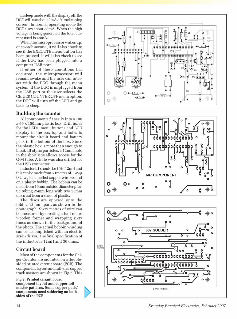
14 EverydayPracticalElectronics,February2007 EverydayPracticalElectronics,February2007 15
Constructional Project Constructional Project Constructional Project Constructional Project
In sleep mode with the display off, the DGC will use about 2mA of timekeeping current. In normal operating mode the DGC uses about 38mA. When the high voltage is being generated the total cur-rent used is 48mA.
When the microprocessor wakes up, once each second, it will also check to see if the EXECUTE menu button has been pressed. It will also check to see if the DGC has been plugged into a computer USB port.
If either of these conditions has occurred, the microprocessor will remain awake and the user can inter-act with the DGC through the menu system. If the DGC is unplugged from the USB port or the user selects the GEIGER COUNTER OFF menu option, the DGC will turn off the LCD and go back to sleep.
Building the counterAll components fit easily into a 100
x 60 x 150mm plastic box. Drill holes for the LEDs, menu buttons and LCD display in the box top and holes to mount the circuit board and battery pack in the bottom of the box. Since the plastic box is more than enough to block all alpha particles, a 12mm hole in the short side allows access for the G-M tube. A hole was also drilled for the USB connector.
Inductor L1 should be 10 to 12mH and this can be made from 60 metres of 36swg (32awg) enamelled copper wire wound on a plastic bobbin. The bobbin can be made from 10mm outside diameter plas-tic tubing 25mm long with two 25mm discs cut from a sheet of plastic.
The discs are epoxied onto the tubing 13mm apart, as shown in the photograph. Sixty metres of wire can be measured by creating a half metre wooden former and wrapping sixty times as shown in the background of the photo. The actual bobbin winding can be accomplished with an electric screwdriver. The final specification of the inductor is 12mH and 36 ohms.
Circuit boardMost of the components for the Gei-
ger Counter are mounted on a double-sided printed circuit board (PCB). The component layout and full-size copper track masters are shown in Fig.2. This
Fig.2: Printed circuit board component layout and copper foil master patterns. Some copper pads/components need soldering on both sides of the PCB
607 COMPONENT
607 sOldEr
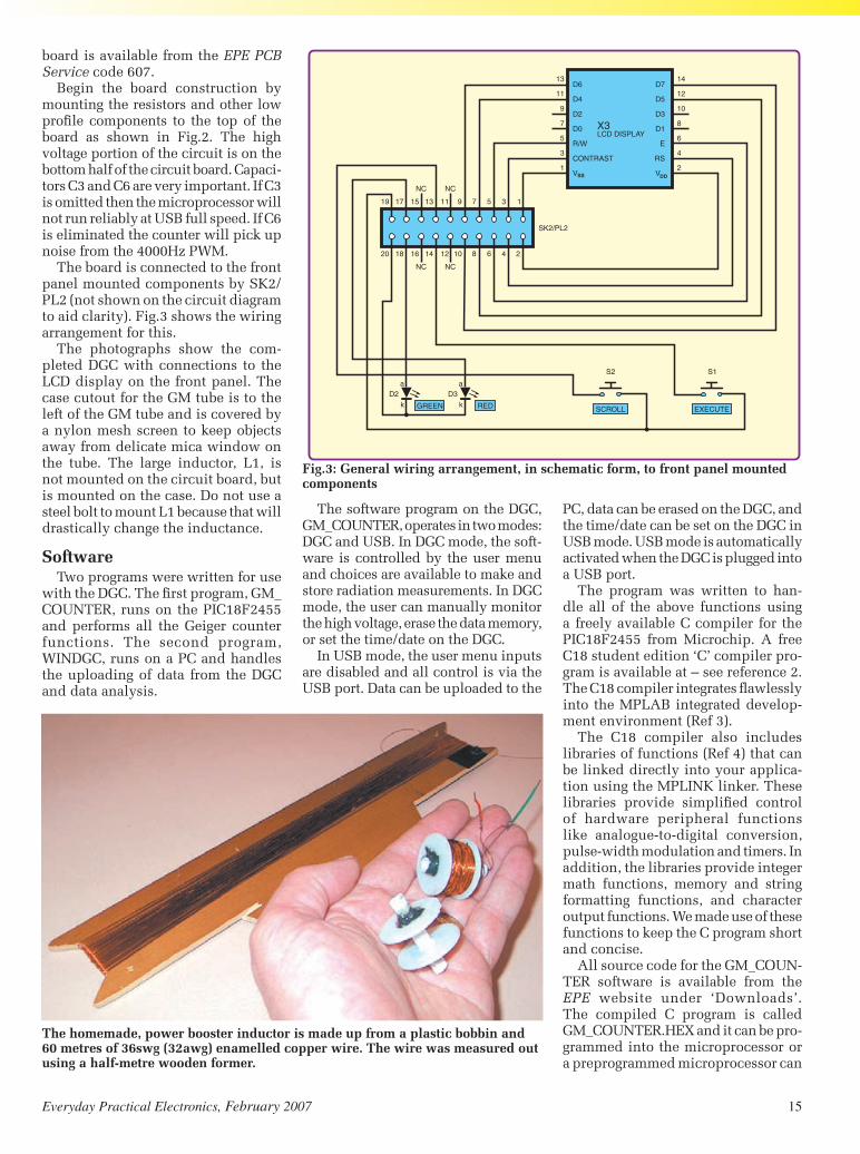
14 EverydayPracticalElectronics,February2007 EverydayPracticalElectronics,February2007 15
Constructional Project Constructional Project Constructional Project Constructional Project
board is available from the EPE PCB Service code 607.
Begin the board construction by mounting the resistors and other low profile components to the top of the board as shown in Fig.2. The high voltage portion of the circuit is on the bottom half of the circuit board. Capaci-tors C3 and C6 are very important. If C3 is omitted then the microprocessor will not run reliably at USB full speed. If C6 is eliminated the counter will pick up noise from the 4000Hz PWM.
The board is connected to the front panel mounted components by SK2/PL2 (not shown on the circuit diagram to aid clarity). Fig.3 shows the wiring arrangement for this.
The photographs show the com-pleted DGC with connections to the LCD display on the front panel. The case cutout for the GM tube is to the left of the GM tube and is covered by a nylon mesh screen to keep objects away from delicate mica window on the tube. The large inductor, L1, is not mounted on the circuit board, but is mounted on the case. Do not use a steel bolt to mount L1 because that will drastically change the inductance.
SoftwareTwo programs were written for use
with the DGC. The first program, GM_COUNTER, runs on the PIC18F2455 and performs all the Geiger counter functions. The second program, WINDGC, runs on a PC and handles the uploading of data from the DGC and data analysis.
The software program on the DGC, GM_COUNTER, operates in two modes: DGC and USB. In DGC mode, the soft-ware is controlled by the user menu and choices are available to make and store radiation measurements. In DGC mode, the user can manually monitor the high voltage, erase the data memory, or set the time/date on the DGC.
In USB mode, the user menu inputs are disabled and all control is via the USB port. Data can be uploaded to the
PC, data can be erased on the DGC, and the time/date can be set on the DGC in USB mode. USB mode is automatically activated when the DGC is plugged into a USB port.
The program was written to han-dle all of the above functions using a freely available C compiler for the PIC18F2455 from Microchip. A free C18 student edition ‘C’ compiler pro-gram is available at – see reference 2. The C18 compiler integrates flawlessly into the MPLAB integrated develop-ment environment (Ref 3).
The C18 compiler also includes libraries of functions (Ref 4) that can be linked directly into your applica-tion using the MPLINK linker. These libraries provide simplified control of hardware peripheral functions like analogue-to-digital conversion, pulse-width modulation and timers. In addition, the libraries provide integer math functions, memory and string formatting functions, and character output functions. We made use of these functions to keep the C program short and concise.
All source code for the GM_COUN-TER software is available from the EPE website under ‘Downloads’. The compiled C program is called GM_COUNTER.HEX and it can be pro-grammed into the microprocessor or a preprogrammed microprocessor can
Fig.3: General wiring arrangement, in schematic form, to front panel mounted components
The homemade, power booster inductor is made up from a plastic bobbin and 60 metres of 36swg (32awg) enamelled copper wire. The wire was measured out using a half-metre wooden former.

16 EverydayPracticalElectronics,February2007 EverydayPracticalElectronics,February2007 17
Constructional Project Constructional Project Constructional Project Constructional Project
be obtained from Magenta Electronics or Reference 5.
The menu system is based on a number of different machine states. There is a unique machine state for each screen. Machine states of related screens are grouped together. For ex-ample, all machine states relating to the opening screen are in the 1 to 9 range. The machine state is control-led by the variable MENUSTATE. Generally, navigation between the different machine states is done with the SCROLL and EXECUTE pushbuttons.
Pulse countingWhen the user begins the count,
the STARTCOUNT routine is called. STARTCOUNT calculates the number of one second intervals in the desired count time and stores this value as TIME_TARGET. TIME_ELAPSED and the pulse count are cleared by writing 0 to TIMER0. G-M tube pulses provide the clock input to TIMER0. A COUNT-ING flag is set.
TIMER1 will cause the interrupt routine to execute every second and
increment TIME_ELAPSED. If TIME_ELAPSED equals TIME_TARGET, then the desired count time has elapsed and TIMER0 is closed to stop the counting. MENUSTATE is set to 60 to display the final count value and the COUNTING flag is cleared.
Automatic counting periods of 15, 30, 45 seconds and 1, 5 and 10 min-utes can be selected from the menu. In addition, multiple measurements can be made by selecting the ‘MULTIPLE SAMPLE’ menu option.
Memory and USB interfaceThe program can remember up to 125
data measurements in flash program memory at addresses 0x5000 to 0x5fff. This memory is not volatile and meas-urements will not be lost when the DGC batteries are removed. When the batter-ies are installed, the DGC will determine the number of the next data point to be stored. The routines MemcpyRam2Flash and MemcpyFlash2Ram are used to store data in flash program memory and read data out of flash memory.
For the USB interface, we used the approach of Reference 6 which is to define the DGC as a USB communi-cation device. This approach has two major advantages:
1. Microchip has written and freely distributes PIC software for the Communication Device class to emu-late RS232 over a USB connection
2. From the PC side, the DGC will look as if it is connected to a standard COM port to the Windows software. This simplifies the PC software.
The USB specification allows periph-erals to be plugged and unplugged with-out powering down the computer. The enumeration process involves communi-cating with the peripheral to discover the identity of the device driver that should be loaded. A unique address is assigned to each peripheral during enumeration to be used for run-time transfers. During
Prototype DGC showing general component positioning inside the plastic box. The lid-mounted components, including the LCD module, are interlinked to the PCB via the ribbon cable.
Front panel layout of the completed DGC unit

16 EverydayPracticalElectronics,February2007 EverydayPracticalElectronics,February2007 17
Constructional Project Constructional Project Constructional Project Constructional Project
Table 2: USB Commands and Responses used to transmit data between the DGC and a PC
COMMAND PCSEND DGCRESPONSE
QUERY Q nR
ERASE E R
SETCLOCK Smdyhms RorN
UPLOAD Ux xttccmmddyyhhmmss zzzzzzzzzzzzzzzzRorN
SendNifproper#ofcharactersarenotreceived
x is a specific datapoint n is the total number of data points z bytes are currently unused
Lower case characters are binary bytes Upper case characters are ASCII characters.
run-time, the host PC initiates transac-tions to specific peripherals and each peripheral accepts its transactions and responds accordingly. The data for the enumeration is contained in the US-BDSC.C file.
Two free programs are useful for verifying that the USB connection is working: USBVIEW [Reference 7] and USB Command Verifier (USBCV) [Reference 8]. USBVIEW reports the results of the enumeration process as shown. USBCV is the compliance test tool which evaluates full-speed USB devices for conformance to the USB Device Framework, Chapter 9 of the USB specification.
The DGC device with GM_COUN-TER software has passed all twenty-two of the USBCV tests. The output of the USBCV tests is available at the RESOURCES download site.
GM_COUNTER reports the status of the USB interface in LEDs as shown in Table 1. If the USB is in the configured state, then user data may be transferred to the PC. The GM_COUNTER program uses a very simple command/response protocol to communicate with the PC.
Sleep mode and real time clock
The menu item ‘GEIGER COUNTER OFF’ can be used to save power. This option turns off the LCD display, turns off the LCD power, and puts the microproc-essor into power-saving sleep mode.
The one second interrupt from
TIMER1 wakes up the microprocessor if it is asleep and updates the real time clock. The microprocessor will go back to sleep if it has been sleeping, unless the DGC has been plugged into a USB port or the EXECUTE switch has been pressed.
If the EXECUTE switch has been pressed, the Geiger counter enters DGC mode. If the counter has been plugged into a USB port, it enters the USB mode.
PC software designIn order to upload and analyse data
from the DGC, PC software is required. The WINDGC program presented here
is the latest incarnation of Visual Basic called VB.NET. As mentioned previ-ously, by defining the DGC as a USB communication device class, the USB connection will appear as a standard COM serial port to the VB software. Microsoft has examples of VB.NET soft-ware that will communicate with COM serial port. The WINDGC PC software performs the following functions:
1. Uploads data from the DGC2. Erases all data from the DGC3. Sets date and time on DGC to
system date and time on PC4. Adds data to database5. Plots data from database
Table 1: USB Status is reported by the LEDs presented by the GM_COUNTER program
RED GREEN MODE CONDITIONON OFF USB USBDevicehasbeenreset.
OFF ON USB USBDevicehasbeenaddressed.
ALTERNATE ALTERNATE USBDeviceisconfigured.AlldescriptorinformationhasBLINKING BLINKING USB beensuccessfullyreceivedbythepersonalcomputer.
SYNCHRONISED SYNCHRONISED USB USBdeviceisinasuspendedstateBLINKING BLINKING
ON NA DGC HighvoltagebeinggeneratedforGMtube
NA BLINKING1OUT DGC Timekeepingoscillator(32.768kHz)oscillatorrunning. OF10SECONDS
OFF OFF SeeCondition IfLCDisoffthismeansDGCisinsleepmode.IfLCDis onthismeanstimekeepingoscillatorhasnotyetstarted oscillatingafterinsertingbatteries.

18 EverydayPracticalElectronics,February2007 EverydayPracticalElectronics,February2007 19
Constructional Project Constructional Project Constructional Project Constructional Project
6. StatisticallyanalysesdataThe complete source code for the
WINDGC program is available fromtheEPEwebsite.Asyoulookthroughthesourcecode,youwillnoticethatthereisneveracalltoanyUSBfunc-tion.Thatisbecause,asfarasthePCisconcerned, theprogramis talkingtoastandardserialCOMport,notaUSBport.IfyoudonothaveacopyofVISUALBASIC.NET,youcanusetheexecutablethatissuppliedonanyPCrunningtheWindowsXPoperat-ingsystem.
The WINDGC program begins bytesting for COM ports 1 through 9.When the program finds an active COMport,itreportsitasshownabove.The first step is to select a COM port usingtheCommmenu.Thenextstepistoselectthe‘QueryDGC’menuitemontheDGCmenu.Thisdeterminesiftheselectedportisactuallyconnectedto a DGC. If a DGC is connected tothe selected port, then the numberofsaveddatapointsontheDGCwillbereportedinthestatuswindowasshownabove.
TherearemenuitemstoerasethedataontheDGCandtosetthedate/timeontheDGC.Themostimportantmenuitemis‘UploadDatafromDGC’.Fig.5.istheresultofan‘UploadDatafromDGC’menuselection.
Atthispointthedatacanbeplot-ted using the Data Analysis menu.WehadoriginallyplannedtousetheExcel component library to do thedataplotting,butdecidedagainstthisoptionbecauseitwouldlimittheoftheprogramtoonlythoseuserswhohadMicrosoftExcelinstalledontheircomputer. The approach used wasto write all the graphical and data
processingfunctionsdirectlyinVisualBasic.Net.
Writing the functions in VB.NETwas more work, but resulted in asmaller program that everyone canuse.TheDataAnalysismenuallowstheusertoplotandgatherstatisticaldataaboutselectedpoints.MovingthemouseoveraparticulardatapointwillreporttheXandYcoordinateintheMOUSE(X,Y)LOCATIONtextbox.
on.Youcancalibrate thedisplay toyourvoltmeterbyadjustingR20.Beawarethatyourvoltmetermayreducethehighvoltageoutputduringthecali-bration.NowyouarereadytoconnecttheLND712GeigerMuellertube.
Selectthe‘GEIGERCOUNTEROFF’menuoptionandplugthedeviceintoaPCusingaUSBcable.YoushouldpointthehardwarewizardtotheDGC.INFfile supplied with the GM_COUNTER software. Reading the DGC.INF file will causetheWindowsXPcommunicationdevicedriverstobeloaded.
Testing phase 2Aftercheckingout theelectronics,
the first thing to do is to try to measure aradioactivesource.Wheredowegetthisradioactivesource?Forabout£5youcanbuyaonemicrocurieAmeri-cium-141alphasourceintheformofan ionizing smoke detector. Ionizingsmokedetectorshavingaradioactivesourcewillhaveawarninglabelstatingthetypeandstrengthofthesource.
Fig.4: The WINDGC opening screen shows the result of the QUERY DGC menu item on COM6
Fig.5: The WINDGC screen showing the result after an upload of 13 data points
Locating the alpha source, under a black grid/cage, in a ionising smoke detector
Fig.6: The LCD display after welcome on power-up
Testing phase 1The first test is to verify that the
LCDisworking.PlugintheLCDandmakesure theLCDcontrastcontrol,VR2,issettomidrange.PoweruptheunitandthewelcomescreenshouldappearfollowedbythemainmenuasshowninFig.6.Youshouldbeabletosettherealtimeclockusingthemenusystem.Ifthereisaproblemwiththe32.768kHz oscillator the LCD timedisplaywillnotincrement.
Once the display and clock areworking properly, select the HIGHVOLTAGEscreen from theUTILITYmenu.Youshouldmeasureapproxi-mately500VDCatTP1.Youshouldnowbeabletoread500voltsontheLCDdisplaywhenthehighvoltageis

18 EverydayPracticalElectronics,February2007 EverydayPracticalElectronics,February2007 19
Constructional Project Constructional Project Constructional Project Constructional Project
References
Reference 1 Geiger Mueller tubes from LND Inc at http://lndinc.com/product.htm. Price $79 (US) plus tax and shipping, email [email protected] (UK shipping and export handling $50, plus import duty if shipped to the UK). The Centronics (ZP1401) tube is available from Alrad Instru-ments at www.alrad.co.uk Tel: 07000 425723, email [email protected], price £75.79 including UK p&p and VAT.
Reference 2 C18 C compiler (student edition) Version 3.0 free 22Mb download retrieved 10/28/2005 from http://www.microchip.com/stel-lent/idcplg?IdcService=SS_GET_PAGE&nodeId=1406&dDocName=en010014&part=SW006011
Reference 3 MPLAB IDE Version 7.22 free 31Mb download re-trieved 10/28/2005 from http://www.microchip.com/stellent/idcplg?IdcService=SS_GET_PAGE&nodeId=1406&dDocName=en019469&part=SW007002
Reference 4 MPLAB C18 C Compiler Library Reference download retrieved 10/24/2005 from http://ww1.microchip.com/downloads/en/DeviceDoc/MPLAB_C18_Libraries_51297f.pdf
Reference 5 Preprogrammed PIC18F2455 microprocessors are available from Magenta Electronics at www.magenta2000.co.uk and the Digital Geiger Counter website at http://home.comcast.net/~rblang/dgc/dgc.htm
Reference 6 Rojvanit, Rawin, ‘Migrating Applications to USB from RS-232 UART with Minimal Impact on PC Software,’ Microchip Appli-cation Note AN956 available at http://www.microchip.com/stellent/idcplg?IdcService=SS_GET_PAGE&nodeId=2121&fragment6_Nex-tRow=151
Reference 7 The USBVIEW program is available at http://www.ftdichip.com/Resources/Utilities.htm
Reference 8 The USB Command Verifier test program (USBCV) is available at http://www.usb.org/developers/tools/
Reference 9 White Sands Missile Range website at http://www.wsmr.army.mil/pao/TrinitySite/trinst.htm
You can check the previous state-ment for yourself. Place the Americi-um-141 alpha source (smoke detector) about 3mm from the G-M tube’s mica window. Take a number of samples in MULTIPLE SAMPLE mode. Now insert one sheet of paper between the alpha source and the G-M tube and continue taking samples. Finally, remove the alpha source completely and take a few more samples.
Place the DGC in sleep mode by selecting the ‘GEIGER COUNTER OFF’ menu item and plug into the personal computer’s USB port. The DGC will wake up when plugged into the USB port. Start the WINDGC program on the PC. Query the DGC and then upload the data. Select the data analysis menu and display the data graphically. Your data should look like Fig.4.
By selecting different parts of the data to analyse, it was determined that the average count with the alpha source was 54168 counts/minute. With the sheet of paper inserted, the average count dropped to 536 counts/minute. Finally, when the alpha source was re-moved completely, the count dropped to a background average of 24 counts/minute. A sheet of paper is an effective shield (factor of 100 reduction) against alpha particles.
Trinity and ground zeroLiving in New Mexico, I was
aware that the first nuclear weapon was exploded at 5:29am on July 16, 1945, at the Trinity Site (33°40’30”N, 106°28’30” W). The site is about thirty miles southeast of Socorro, New Mex-ico on what is now the White Sands Missile Range.
The 1945 explosion was a test of an implosion-design plutonium bomb, the same type of weapon later dropped on Nagasaki, Japan. The detonation
was equivalent to an explosion of around 20 kilotons of TNT. This was where we decided to conduct the final test of the DGC.
We contacted White Sands and told them what we had in mind and they said we would be welcome to make measurements any time during the 12 hours a year that the Trinity ground zero site is open to the public [Reference 9]. On the appointed day, we began the 135 mile drive to the Trinity site.
After passing over the now only 20 foot wide Rio Grande and about twelve
miles East of San Antonio, there is a small wooden sign which says:
After a picture identification and weapons check at the White Sands Missile Test range Stallion Gate, we proceeded on Range Road 7. Approxi-mately 18 miles from the Stallion Gate we arrived at the Trinity site nestling at the base of the Oscura Mountains rising 8600 feet towards the east. The half–mile diameter site is surrounded by a metal wire fence. We took some
Trinity SiteWorld’s first atomic explosion
occurred here on July 16, 1945. This marked the beginning of the atomic age and the culmination of the Manhattan Project. The site is now part of the White Sands Missile Range and is closed to the public.
Fig.7: Measurement screen
Fig.9: Upload screen
As shown in the photograph, the alpha source, pointed to by the pencil, is located under a black grid. As far as danger is concerned, a sheet of paper or a few centimeters of air will reduce the radiation from this alpha particle source to a negligible level.

20 EverydayPracticalElectronics,February2007 EverydayPracticalElectronics,February2007 00
Constructional Project Constructional Project Constructional Project Constructional Project
BIORobert Lang is a professional
electrical engineer interested in embedded microprocessors, me-chanical musical instruments and MIDI. He is a freelance writer for electronic hobbyist, computer and synthesizer magazines. He can be reached at [email protected] or by a GOOGLE search for HARPSITRON.
Steve Thompson is a nuclear engineer with experience in reactor core design.
He can be reached at [email protected].
DGC radiation measurements outside the fence and found the readings to be normal background, about 24 counts/minute.
We proceeded to walk the ¼ mile to the Trinity ground zero marker and took additional radiation measure-ments. We measured about 240 counts per minute or about ten times normal background radiation at ground zero.
Because the bomb was on a 100 foot tower, the explosion made a small de-pression instead of a crater. The heat of the blast vaporized all of the steel tower, except for one reinforced concrete foot-ing and melted the desert sand into an ugly green glassy, porous, and brittle substance. After the blast, this green Trinitite completely covered the depres-sion. The depression was later filled and
much of the Trinitite was removed by the Atomic Energy Commision. Some Trinitite can still be found at the site. Our typical contact Trinitite readings were about 400 counts per minute.
As we were exiting the site, we noticed a sign that said the radiation at ground zero was about ten times background. We were pleased that we were able to confirm that sign with our measurements, 240 vs 24. The radiation level at ground zero was said to be about 1/1000 Roentgen Equivalent Man (REM) per hour. This provided us with a con-venient conversion factor for our DGC (240 counts/minute = 1mREM/hour). To put this in prospective, a typical flight from London to New York gives a dose of 2mREM from cosmic rays. EPE
The authors comparing results at the Trinity site ground zero marker (Photo: Neal Ulevich)
TAKE A LOOK, A FREE ISSUE IS AVAILABLE
Get your magazine ‘instantly’ anywhere in the world – buy and
download from the web.A one year subscription (12 issues) costs just $15.99 (US)
www.epemag.com

EPE PIC Tutorial V2 complete series of articles plusdemonstration software, John Becker, April, May, June ’03
PIC Toolkit Mk3 (TK3 hardware construction details),John Becker, Oct ’01
PIC Toolkit TK3 for Windows (software details), JohnBecker, Nov ’01
Plus these useful texts to help you get the most out of yourPIC programming:
How to Use Intelligent L.C.D.s, Julyan Ilett, Feb/Mar ’97 PIC16F87x Microcontrollers (Review), John Becker,
April ’99 PIC16F87x Mini Tutorial, John Becker, Oct ’99 Using PICs and Keypads, John Becker, Jan ’01 How to Use Graphics L.C.D.s with PICs, John Becker,
Feb ’01 PIC16F87x Extended Memory (how to use it),
John Becker, June ’01 PIC to Printer Interfacing (dot-matrix), John Becker,
July ’01 PIC Magick Musick (use of 40kHz transducers),
John Becker, Jan ’02 Programming PIC Interrupts, Malcolm Wiles, Mar/Apr ’02 Using the PIC’s PCLATH Command, John Waller,
July ’02 EPE StyloPIC (precision tuning musical notes),
John Becker, July ’02 Using Square Roots with PICs, Peter Hemsley, Aug ’02 Using TK3 with Windows XP and 2000, Mark Jones,
Oct ’02 PIC Macros and Computed GOTOs, Malcolm Wiles,
Jan ’03 Asynchronous Serial Communications (RS-232),
John Waller, unpublished Using I2C Facilities in the PIC16F877, John Waller,
unpublished Using Serial EEPROMs, Gary Moulton, unpublished Additional text for EPE PIC Tutorial V2,
John Becker, unpublished
Order on-line fromwww.epemag.wimborne.co.uk/shopdoor.htm
or www.epemag.com (USA $ prices)or by Phone, Fax, Email or Post.
EPE PICRESOURCESCD-ROM V2
Version 2 includes the EPE PICTutorial V2 series of Supplements(EPE April, May, June 2003)The CD-ROM contains the followingTutorial-related software and texts:
NOTE: The PDF files on this CD-ROM are suitable touse on any PC with a CD-ROM drive. They requireAdobe Acrobat Reader – included on the CD-ROM
ONLY££1144..4455
INCLUDINGVAT and P&P
Everyday Practical Electronics, February 2006 21
VERSION 2
NOW AVAILABLE
Please send me ........ (quantity) EPE PIC RESOURCES V2 CD-ROM
Price £14.45 each – includes postage to anywhere in the world.
Name . . . . . . . . . . . . . . . . . . . . . . . . . . . . . . . . . . . . . . . . . . . . . .
Address . . . . . . . . . . . . . . . . . . . . . . . . . . . . . . . . . . . . . . . . . . . .
. . . . . . . . . . . . . . . . . . . . . . . . . . . . . . . . . . . . . . . . . . . . . . . . . . .
. . . . . . . . . . . . . . . . . . . . . . . . . . . . . . . . . . . . . . . . . . . . . . . . . . .
. . . . . . . . . . . . . . . . . . . . . . . . . . . Post Code . . . . . . . . . . . . .
I enclose cheque/P.O./bank draft to the value of £ . . . . . . . . .
Please charge my Visa/Mastercard/Amex/Diners Club/ Maestro
£ . . . . . . . . . . . . . . . . . . . . . . . . . . . . . . . . . . . . . . . . . . . . . . . . . .
Card No. . . . . . . . . . . . . . . . . . . . . . . . . . . . . . . . . . . . . . . . . . . .
Card Security Code . . . . . . . . . . (The last 3 digits on or just under the signature strip)
Valid From . . . . . . . . . . . . . . . . .Expiry Date . . . . . . . . . . . . . . .
Maestro Issue No. . . . . . . . . . . . . . .
SEND TO: Everyday Practical Electronics,Wimborne Publishing Ltd.,
408 Wimborne Road East, Ferndown, Dorset BH22 9ND.Tel: 01202 873872. Fax: 01202 874562.Email: [email protected]
Payments must be by card or in £ Sterling – cheque or bank draftdrawn on a UK bank.
Normally supplied within seven days of receipt of order.Send a copy of this form, or order by letter if you do not wish to cut your issue.
BECOME A PIC WIZARD WITH THE HELP OF EPE!
EPE PIC RESOURCES V2CD-ROM ORDER FORM

22 Everyday Practical Electronics, February 2007
EPE SUBSCRIPTION PRICESSubscriptions for delivery direct to any address in the UK:6 months £18.75, 12 months £35.50, two years £66; Overseas:6 months £21.75 standard air service or £30.75 express airmail,12 months £41.50 standard air service or £59.50 express airmail,24 months £78 standard air service or £114 express airmail.Cheques or bank drafts (in £ sterling only) payable to EverydayPractical Electronics and sent to EPE Subs. Dept., WimbornePublishing Ltd., 408 Wimborne Road East, Ferndown, DorsetBH22 9ND. Tel: 01202 873872. Fax: 01202 874562. Email:[email protected]. Also via the Web athttp://www.epemag.co.uk. Subscriptions start with the nextavailable issue. We accept MasterCard, Amex, Diners Club,Maestro or Visa. (For past issues see the Back Issues page.)
ONLINE SUBSCRIPTIONSOnline subscriptions, for downloading the magazine via theInternet, $15.99US (approx. £9.00) for one year available fromwww.epemag.com.
USA/CANADA SUBSCRIPTIONSTo subscribe to EPE from the USA or Canada please telephoneExpress Mag toll free on 1877 363-1310 and have your creditcard details ready. Or fax (514) 355 3332 or write to Express Mag,PO Box 2769, Plattsburgh, NY 12901-0239 or Express Mag,8155 Larrey Street, Anjou, Quebec, H1J 2L5.Email address: [email protected] site: www.expressmag.com.USA price $60(US) per annum, Canada price $97(Can) perannum – 12 issues per year.Everyday Practical Electronics, periodicals pending, ISSN 0262 3617 ispublished twelve times a year by Wimborne Publishing Ltd., USA agentUSACAN at 1320 Route 9, Champlain, NY 12919. Subscription price in US$60(US) per annum. Periodicals postage paid at Champlain NY and atadditional mailing offices. POSTMASTER: Send USA and Canada addresschanges to Everyday Practical Electronics, c/o Express Mag., PO Box2769, Plattsburgh, NY, USA 12901-0239.
6 Months: UK £18.75, Overseas £21.75(standard air service), £30.75 (express airmail)
1 Year: UK £35.50, Overseas £41.50 (standard air service)£59.50 (express airmail)
2 Years: UK £66.00, Overseas £78.00 (standard air service)£114 (express airmail)
To: Everyday Practical Electronics,Wimborne Publishing Ltd., 408 Wimborne Road East,
Ferndown, Dorset BH22 9NDTel: 01202 873872 Fax: 01202 874562
E-mail: [email protected]
I enclose payment of £ ........... (cheque/PO in £ sterlingonly), payable to Everyday Practical Electronics
My card number is: .......................................................................Please print clearly, and check that you have the number correct
Signature .........................................................................................
Card Security Code .................. (The last 3 digits on or just under the
signature strip)
Card Ex. Date ..................................... Maestro Issue No. ..............
SUBSCRIPTION ORDER FORM
Subscriptions can only start with the next available issue.
Name ...............................................................................................
Address ...........................................................................................
Post code ................................. Tel. ..............................................
UUKK rreeaaddeerrss yyoouu ccaann
SSAAVVEE 5544ppoonn eevveerryy iissssuuee ooff EEPPEE
How would you like to pay £2.96 instead of £3.50 for your copy of EPE? Well you can – just take out a one year subscription and save 54p an issue,
or £6.50 over the year
You can even save 75p an issue if you subscribe for two years – a total saving of £18.00
Overseas rates also represent exceptional valueYou also:
Avoid any cover price increase for the duration of your subscription
Get your magazine delivered to your door each month
Ensure your copy, even if the newsagents sell out
Order by phone or fax with a credit card or by post with a cheque or postal order, orbuy on-line from www.epemag.co.uk (click on “Subscribe Now”)

Everyday Practical Electronics, February 2007 23
ByVac Electronics
Purchase Options: On-Line at www.byvac.co.uk • Telephone 07905 734 348 • email [email protected] • Cheque or Postal Order to: ByVac, PO BOX 4049,Penistone, SHEFFIELD, S36 6WPPost and packing UK £2.50 World Wide £3.50 www.byvac.co.uk
MONEY BACK GUARANTEE
If you are not completely satisfied, return the goods within 30 days for a full refund.
Control hardware using simple text commandsControl hardware using simple text commandsControl hardware using simple text commandsControl hardware using simple text commands
* **
All
cont
rolle
dw
ith
2w
ire
seri
albu
s**
*
8052—89S8252 based
No programmer needed
Includes Tiny BASIC
On board power supply
BV30
5 Microcontroller
Making complex tasks simple:Using a two letter text command, control LCD displays, Analogue to digital converters, motors,keypads, LED matrix displays. All products work by serial connection.
Connect using a PC RS232 or Microcontroller UART
Scrolling Text
Backlight and contrast control
Binary to text displayMuch more... BV
4103
LCD Display
£22.90
Control any compatible LCD
Up to 4 lines by 20 characters
Scrolling textMuch more... BV
4108
LCD Controller
£11.00
4 x Analogue to digital
4 x digital input or output
Pulse width modulationTrigger controlBV
4106
A/D Control
£11.00
8 x 8 Bi Colour Red/Green
Brightness control
User defined bit patterns
Switch on ‘splash screen’ BV41
02
Dot Matrix
£14.95
£14.95 KIT£+4.50 RBT
4 x 4 matrix keypad controller
16 key buffer
Row, column configurable
Additional digital inputBV41
07
Keypad Control
£11.00
This is just a small selectionvisit the web site for hints tipsand free software
www.antex.co.uk2 Westbridge Industrial Estate Tavistock
Devon PL19 8DE Tel 01822 613565
24 Everyday Practical Electronics, February 2007
Implementing a software PLL for serious users of PICs – Part Two
PIC N’ MIX KEITH ANDERSONOur periodic column for your PIC programming enlightenment
LAST month we examined the basicsof a software PLL. We conclude by looking at the detailed implem-
entation
DetailAssembly programs need a lot of house-
keeping instructions and often it isn’t easyto discover where they start. This programhas three components. The label Begin is atiny stub that just does: goto Begin. This iswhere the application specific procedureswould go in a practical program.
The label Interrupt is the start of theinterrupt procedure that does the work. Tounderstand the program it is best to starthere and to trust the third component, start-ing at the label Startup, to have set thespecial function registers properly soInterrupt will work.
The interrupt is generated by the ana-logue-to-digital converter (ADC) andoccurs when the latest conversion com-pletes and PIR1,ADIF is set. This mightbe unexpected. Although TMR1 forms thevoltage controlled oscillator (VCO), it doesthis by counting up to the value inCCPR1H and CCPR1L, and the capturecompare module is set to mode 0x0B,which automatically resets TMR1 and trig-gers the ADC to start another conversion.The interrupt enable bit is set for the ADCbut not for TMR1 or the CCPR module.
At each interrupt, the specific sample iscounted by the variable TickCount, and acomputed goto is used to perform theappropriate action for the latest value ofTickCount. It is possible to compact thiscode a lot for this demonstration, but it isuseful to resist the temptation to do that.For a practical application the cost of repli-cating the appropriate 16-bit add and sub-tract instructions is much less importantthan being able to insert application specif-ic actions easily and reliably at appropriatetimes within each cycle.
MacrosThe 16-bit operations are implemented
by macros defined in the appropriateInclude files. For example, AddVV16 addsa 16-bit variable to another 16-bit variableand is defined in the Include fileMathAddSub16.asm. Hopefully, it is easyto guess that SubVV16 subtracts 16-bitvariables and that AddKV16 adds a 16-bitconstant to a 16-bit variable.
Macros have benefits and liabilities. Theydon’t just save typing. They save reinventingwheels, and they reduce the opportunitiesfor bugs to party, party, party! If the macrocontains a bug and is used often, it makes
the bug conspicuous so it is fixed. They alsohelp to focus on the application, rather thanon the means to implement the application;the forest, rather than the trees. However,macros can make programs seem a littlemysterious at first reading, and it is not easyto trust that they really do what they looklike they might do.
When reading this program, the opti-mum strategy is to remember that it hasbeen tested and does work, so it is moreuseful to trust mysterious statements to dowhat they claim to do than to wrestle withthe details of how they do it. For example,the statement SaveContext looks like itmight save context at the start of interrupt.It does. When all interrupt processing iscomplete, RestoreContext restores thatcontext before returning from an interrupt.These macros are defined in the fileSystemContext.asm.
It isn’t always easy to follow the opti-mum strategy, and the macros can be foundin an appropriate Include file when thetemptation to examine the detail becomesirresistible.
OperationsAs implied by the general description
above, for phase PLL00, the ADC sampleis ignored, and the variableLatestCycleTot is cleared.
The symbol EdgeStrategy is a hint of analternative strategy that uses all samplesand does not ignore the samples at PLL00and PLL08. This has been simulated inExcel but not tested in a PIC. The simula-tion indicates that it has no benefits and afew liabilities.
For phases PLL01 to PLL07, the latestsample is added to LatestCycleTot. Forphase PLL08, the ADC sample is ignored,and LatestCycleTot is not changed. Forphases PLL09 to PLL15, the latest sampleis subtracted from LatestCycleTot.
Phase PLL15 is where all the real workis done. Shift and add instructions are usedto compute:
PreviousCycleTot = ((3/2) × PreviousCycleTot) – ((4/2) × LatestCycleTot)The absolute value of this is a good indi-
cation of the phase error, and is tested. If itis suitably small, then the loop is probablylocked. If it remains suitably small for sev-eral consecutive cycles, then the probabili-ty that the loop is locked increases.Specifically, if the error is less thanLoopError1K, then the macro DecToZ8decrements LoopCount to, but not past,zero. If not, LoopCount is reset toLoopError1K. Testing indicates that this
lock detect strategy is very conservative.The signed value in the variable
PreviousCycleTot is scaled to be theamount by which the value in CCPR1Hand CCPR1L needs to be adjusted to setthe appropriate period for the next cycle.The new value for CCPR1H and CCPR1Lis computed in IW0 and IW1. The algo-rithm for the linear PLL does not attempt tocorrect all of the error in one cycle, it justmakes relatively small adjustments eachcycle until the error is reduced to zero.Other PLLs can lock faster, but are sensi-tive to noise.
In small PICs like the 12F683, the tem-porary registers IW0 and IW1 are notstrictly essential. They hint at a useful strat-egy for managing bank selection in largerPICs. The strategy is reasonably efficientand it is useful to resist the temptation to dosomething ‘more efficient’ in the smallerPICs.
Loading CCPR1 depends upon a trick. Ifit is just loaded, TMR1 might match pre-maturely and trigger a spurious ADC con-version and TMR1 reset. Instead, IW0,7 isset so that the value initially loaded will bemuch bigger than any value expected inTMR1. After both bytes of CCPR1 havebeen loaded, CCPR1H,7 is cleared.
For this application, CCPR1 is notexpected to exceed 0x0FFF, so this strate-gy should be very safe.
PerformancePLLs aren’t only difficult to analyse
mathematically, they are difficult to test. Itis easy to show that the loop is locked, butit isn’t easy to introduce small disturbancesto show the behaviour when the loop is disturbed.
For demonstration and debugging, theprogram provides two outputs. A signalthat is in-phase with VADC and that conse-quently lags VAC by 90 degrees is provid-ed at GPIO,0 and is called VcoP. A signalthat is in-phase with VAC is provided atGPIO,1 and is called VcoQ. The namesare mnemonic when referenced to VADC.
An oscilloscope can be used to confirmthat the loop is suitably stable for a reason-able range of values of the loop filterparameter, B, and for a reasonable range ofinput voltages. For the recommended val-ues, the loop reports lock in about one sec-ond, but most of this is due to the very con-servative lock detect strategy. The loop ishighly tolerant of gross distortion of theinput waveform.
The signal at GPIO,4 and called PllTimeis used to test how busy the PIC is. ThePLL is activated by the ADC each time a

Everyday Practical Electronics, February 2007 25
fresh sample is available. There are 16samples per cycle. For 15 interrupts, thenew value is just added to or subtractedfrom the current total, and the interruptcompletes in about 30µs. For the 16thinterrupt, the latest result is filtered and thenew value of CCPR is computed, and theinterrupt completes in about 80µs. It is rea-sonable to hope that the loop might workfor frequencies up to 500Hz, but there is asubtlety. The PLL needs accuracy as wellas speed, and at high frequencies, CCPRmight ‘hunt’ between values, neither ofwhich is right.
Modifying the ProgramThe PLL strategy needs a capture com-
pare module that can reset TMR1 and alsotrigger ADC conversions. The 12F683 isabout the smallest PIC with this capability.Most PICs with a capture compare PWMmodule are probably suitable.
Although it is possible to build applica-tions with one PIC dedicated to imple-menting the PLL program and another
implementing the application-specific pro-gram, this is usually unnecessary andextravagant. Instead, one PIC would nor-mally implement both the PLL programand the application specific program.
If activities synchronised with the inputpower are needed, they can be triggered atany suitable phase of the input power.There are at least three strategies. Often itis suitable to set a flag within Interrupt totrigger action performed outside Interrupt.This minimizes congestion withinInterrupt, but risks that some actionsmight be missed. When it is important toensure that no actions are missed, and theaction can be performed suitably quickly,then the action can be performed insideInterrupt, but this risks congestingInterrupt. Sophisticated applicationsmight update a counter inside Interruptand perform appropriate actions outsideInterrupt. The counter can contain theinformation needed to compensate formissed actions.
The PLL does not use TMR0 or TMR2.These are available for other times thatmight or might not be synchronised withthe input power.
It is possible to implement the PLL strat-egy with other than 16 samples per cycle.The number of samples should be even, butneed not be a power of 2. The difficulty isthat the appropriate value for the loop filterparameter, B, is not easy to discover. Thisis an opportunity for further investigation.
Some PICs have two capture compare mod-ules, and in this case, it is CCPR2, not CCPR1that triggers TMR1 and ADC conversion. Theassignment of bits to the special purpose regis-ters is not well standardized from PIC to PIC,so it is necessary to read the data sheets care-fully to ensure that TMR1, the CCPR module,and the ADC are all configured correctly. Theprogram was written initially for a 16F876 andthen converted to a 12F683. The conversionwas not unusually difficult, but revealed theneed to examine the data sheets carefully.
Mike Hibbett returns next month
Please mention EPE when responding to advertisements.
To advertise in EPE please contact our Advertising Manager Stewart Kearn.
Tel: 01202 873872 email: [email protected]

26 EverydayPracticalElectronics,February2007 EverydayPracticalElectronics,February2007 27
Constructional Project Constructional Project Constructional Project Constructional Project
A courtesy light delay is a great feature for your car. it enables you to see to insert
the ignition key and find your seatbelt when it is dark outside, without having to leave the door open.
however, many cars lack this fea-ture, particularly older models. When the car door is opened, the cabin lights do light up but as soon as the door is closed, the lights go out. this happens just when you are about to get settled into the seat. of course, you can fum-ble around and find the interior light switch but wouldn’t it be nice if the lights stayed on automatically for a short time instead?
and wouldn’t it be classy if the lights faded out at the end of the timing period instead of a sudden switch off?
another feature that would be use-ful is to have the courtesy light(s) automatically switch off whenever the parking lights are switched on. this would allow you to drive off if ready to go, before the courtesy lights had timed out.
The final feature of this design is its ease of installation. Past courtesy
Give your car that luxury feel by extending the time that your interior lights remain on once the car doors have closed. For that extra touch of class, the lights fade to darkness at the end of the time period
By JohN clarKe
light delay circuits have presented real problems for installation because of the various wiring combinations for courtesy lights in modern cars.
in presenting this design, we particularly wanted to solve the connection problems.
Courtesy light circuitsthe automotive industry is renowned
for its lack of standardisation when it comes to car wiring and this is certainly revealed when it comes to lighting cir-cuits. Fig.1(a) and Fig.1(b) show how the courtesy lights can be wired. some cars will have the lights connected to the +12V supply rail and the door switches connecting to the car chassis, while other cars will have the opposite connection, with the courtesy lights con-necting to chassis and the door switches connecting to the +12V rail.
Note that we have shown only two lights and two switches. some cars will have more switches (one in each door plus a manual courtesy switch inside) and more lights. the switches are all wired in parallel and extra lights are also wired together in parallel.
all of the courtesy lights switch on whenever one of the door switches is closed. this occurs when a door is opened. When all doors are closed, all the switches will be open and the courtesy lights will be off.
similarly, the two possible tail light connections are shown in Fig.1(c) and Fig.1(d). the tail lights are on when the lights switch is closed. this switch would also power the side lights at the front of the car but this is not shown in this circuit.
For our courtesy light delay circuit to work, we simply need to connect it across one of the door switches. We also need to connect it to the tail light wiring, so that the courtesy lights are immediately switched off if the tail lights are switched on during the timing period.
Universal circuit fits all vehicles
Main Features• Adjustable delay period from
7 to 40s
• Lights fade out at end of time period
• Courtesy lights switch off if parking lights switched on
• No standby current drain from battery when lights are off
• Universal circuit works with any 12V car system (can be modified for 24V systems)
• Low parts count
• Easy to install
Courtesy light delay for cars

26 EverydayPracticalElectronics,February2007 EverydayPracticalElectronics,February2007 27
Constructional Project Constructional Project Constructional Project Constructional Project
In practice, this means that the Courtesy Light Delay requires just four connections to the car’s wiring. Two wiring leads connect across the door switch, while the other two connect directly across one of the tail light filaments.
How it worksFig.2 shows the full circuit details of
the Courtesy Light Delay. It comprises a MOSFET (Q1), an optocoupler (OPTO1), a diode (D1), a diode bridge (BR1) and a few capacitors and resistors.
Q1 acts as a switch. It’s effectively wired in parallel with the door switch-es and switches power to the courtesy lights during the timing period, when all door switches are open.
Note that the door switches are marked with plus and minus signs in Fig.1(a) and Fig.1(b). The positive rail of the delay circuit connects to the plus side of the door switch, while the nega-tive rail connects to the minus side.
In operation, the circuit derives its power from the vehicle’s 12V battery via the courtesy lamp filaments. As
a result, the lamps act as low-value resistors in series with the supply. However, because the circuit draws so little current when it is operating, there’s very little voltage drop across the lamp filaments and so the circuit operates from almost the full battery voltage.
Note that the current flows via the courtesy lamp filaments – it doesn’t matter whether the lamp filaments are connect directly to the +12V supply as shown in Fig.1(a) or to ground as in Fig.1(b).
The circuit operation is as follows. When a car door is opened, one of the door switches closes and the courtesy lights switch on as normal. During this time, the switch shorts out MOSFET Q1 and so there will be no voltage across the courtesy light delay circuit; ie, between its plus and minus termi-nals. As a result, capacitor C1 will be discharged via R1, while C3 will be discharged via resistors R3 and R4.
Subsequently, when the door switch opens again (ie, the door is closed), the courtesy lights will go out and there will be close to 12V across the drain (D) and source (S) of Q1. This voltage also immediately appears across a series connected network consisting of capacitor C1, diode D1 and capaci-tor C2.
Initially, C1 has a much lower impedance than C2, since it has 10 times greater capacitance – ie, 470µF vs 47µF. As a result, C2 is rapidly charged via C1 and so has almost the full supply voltage across it soon after power is applied to the circuit.
In practice, if we ignore the voltage drop across diode D1, capacitor C1 will initially have about 1.1V across it and C2 will have 10.9V across it.
What happens now is that C1 charges to the 12V supply via resis-tor R1. During charging, the voltage on the negative side of C1 gradually drops to the negative supply rail. At the same time, diode D1 prevents C2 from discharging since it is reverse biased. As a result, C2 remains with about 10.9V across it.
At this point we need to under-stand how MOSFET Q1 works. These devices have three terminals, called ‘gate’, ‘drain’ and ‘source’.
When the gate voltage is at the same voltage as the source, the MOSFET is off and no current flows. How-ever, when the gate voltage rises to its threshold of around 3 to 4V, the
Fig.1: the two possible wiring configurations for the courtesy lights are shown at Fig.1(a) and Fig.1(b), while Fig.1(c) and Fig.1(d) show the alternative tail light wiring configurations. (Door switches closed – car doors open).
Fig.1(a) Fig.1(b) Fig.1(c) Fig.1(d)
Fig.2: the circuit uses MOSFET Q1 to switch power to the courtesy lights when the car’s door is closed (ie, the door switch opens). Trimpot VR1 sets the time delay, while bridge rectifier BR1 monitors the tail lights and switches off Q1 via optoisolator OPTO1 if the tail lights are switched on.

28 EverydayPracticalElectronics,February2007 EverydayPracticalElectronics,February2007 29
Constructional Project Constructional Project Constructional Project Constructional Project
resistance between the drain and source suddenly goes low and so current can flow between these two terminals. In practice, the drain-source resistance depends on the gate voltage and is at its lowest (about 0.1Ω) when the gate voltage is more than 10V above the source.
Switch-onNow take a look at the circuitry in-
volving capacitor C3, resistors R3 and R4 and the optocoupler (OPTO1).
When power is first applied (ie, when the door is closed), C3 initially behaves like a short circuit (since it is discharged). As a result, current flows via R3 and switches on the transistor inside the optocoupler, thus clamping Q1’s gate at its source voltage. At this point, C2 has about 10.9V across it (as already stated) but is prevented from quickly discharging since it is isolated from the optocoupler by resistor R2 (100kΩ).
Capacitor C3 now quickly charges via resistors R3 and R4 and removes the base drive to the optocoupler’s transistor, about 1ms after power is applied. However, this time period is so short that it does not allow C2 to discharge to any extent.
Now that the optocoupler’s transis-tor is off, Q1’s gate voltage will be equal to the voltage that’s across C2. As a result, Q1 switches on to drive the courtesy lights.
From this, it might appear that the courtesy lights will briefly switch off when the door is closed, before the circuit switches them back on again. In theory, this is true but the ‘off-time’ is so short that it is virtually unnoticeable.
So why do we use the optocoupler to briefly hold Q1’s gate low (ie, for that 1ms period)? The answer is that without this feature, Q1 would switch on as soon as C2’s voltage reached the MOSFET’s conduction threshold of 3 to 4V. This would effectively ‘kill’ the
supply to the circuit and prevent C2 from charging any further. C2 would then quickly discharge via VR1 and the 220kΩ resistor to below Q1’s gate threshold and so the courtesy lights would go out again almost immedi-ately.
By contrast, by using the opto-coupler to hold Q1’s gate low for 1ms, C2 charges to above 10.9V before MOSFET Q1 switches on. And that means that C2 must then discharge from 10.9V down to below 4V before Q1 switches off (and switches off the courtesy lights).
The time it takes to do this gives us the delayed on period for the lights. Trimpot VR1 allows this delay period to be adjusted by varying the discharge resistance for C2.
At the end of the timing period, the lamp fades out as Q1’s resistance rap-idly increases as its gate voltage falls below about 5V. This means that the voltage across Q1 gradually rises from about 0V when it is fully on to 12V when it is off. As a result, capacitors C1 & C3 slowly charge to the 12V sup-ply, via R1 and R3 & R4 respectively. This slow rate of charge prevents C1 from recharging C2 and stops C3 from switching the optocoupler’s transistor on again.
Tail light circuitAs mentioned earlier, the circuit
turns the courtesy lights off immedi-ately if the side lights (or the head-lights) are turned on. This is achieved using bridge rectifier BR1 and the optocoupler.
In practice, we don’t monitor the side lights or the headlights directly. Instead, the circuit monitors the tail lights, since these are always on with both the side lights and the headlights.
As shown, the bridge rectifier is connected directly across the tail lights (ie, in parallel with one of the lamps). When the tail lights are on, there is 12V across them and this is applied to BR1, which then drives the LED inside the optocoupler via a 680Ω current-limit-ing resistor.
This in turn switches on the transis-tor inside the optocoupler and so Q1 switches off and the courtesy lights go out.
So the optocoupler performs a dual function: (1) it forms part of the initial 1ms delay circuit and (2) it plays a vital role in switching off the courtesy lights when the tail lights are switched on.
Note that the connections to the tails-lights can be made without any regard as to the polarity. That’s due to
Table 1: Resistor Colour Codes
o No. Value 4-Band Code (1%) 5-Band Code (1%) o 1 220kΩ redredyellowbrown redredblackorangebrown o 1 100kΩ brownblackyellowbrown brownblackblackorangebrown o 1 22kΩ redredorangebrown redredblackredbrown o 1 10kΩ brownblackorangebrown brownblackblackredbrown o 1 680Ω bluegreybrownbrown bluegreyblackblackbrown o 1 470Ω yellowvioletbrownbrown yellowvioletblackblackbrown
Fig.3: install the parts on the PC board as shown here, taking care to ensure that the polarised parts are all oriented correctly.

28 EverydayPracticalElectronics,February2007 EverydayPracticalElectronics,February2007 29
Constructional Project Constructional Project Constructional Project Constructional Project
BR1, which ensures that the positive voltage rail is fed to the anode of the optocoupler’s internal LED.
The wiring arrangement of the tail light circuit is also unimportant since the circuit simply monitors the voltage across the lamps.
ConstructionAll the parts for the Courtesy Light
Delay are mounted on a PC board, coded 603 (78 x 46mm). This then clips into a standard plastic case measuring just 82 x 54 x 31mm.
Fig.3 shows the assembly details. Begin by checking the PC board for any shorts between tracks or breaks in the copper. That done, remove the corners of the PC board if this hasn’t already been done, so that the board clears the four pillars inside the case.
Now for the parts assembly. First, install the resistors in the positions shown, followed by diode D1 and the optocoupler (OPTO1). Table 1 shows the resistor colour codes but it’s also a good idea to check each one using a digital multimeter before installing it on the board.
Take care when installing D1 and OPTO1 – they must be oriented as shown (see also Fig.2 for the device pinouts).
Next, install trimpot VR1 (this may be coded 105), then install the three capacitors, bridge rectifier BR1 and the two 2-way terminals. Again, check to make sure that BR1 and the two electrolytic capacitors (C1 & C2) are oriented correctly.
Finally, install MOSFET Q1 by bending its leads at right angles so that they fit into their allocated holes. This device is fitted with a small U-shaped heatsink and the assembly is secured to the PC board with a screw and nut.
The PC board is mounted inside the case by simply clipping it into the mounting clips. Before doing this, you will have to mark out and drill two holes in one end of the case, to allow for wire entry to the screw terminals. These holes are located 11mm down from the lip and 18mm in from the outside edge of the case and are made using a 6mm drill.
Note: for 24V operation, change both C1 and C2 to 25V working and change the 680Ω resistor to 1.2kΩ.
InstallationThe Courtesy Light Delay can be
mounted in any convenient location under the dashboard. It’s up to you how you secure it, since the circum-stances will vary from vehicle to vehicle.
To connect the unit, you will need to access one of the car door switches and the tail light connections. Note that some door switches will have two wires, while others will only have a single wire connection. In the latter case, one contact is connected directly to chassis at the switch mounting position.
Note also that it’s important to get the door switch connections to the unit the right way around – ie, the positive door switch connection must go to the positive rail of the Courtesy Light de-lay. You can quickly determine which is the positive door switch connection by using your multimeter to measure the voltage across the door switch when it is pushed open.
If there’s only a single wire running to the switch, this will be the positive (the chassis connection is negative).
It’s a good idea to disconnect the vehicle’s battery before running the wiring, to prevent any inadvertent short circuits. Note that all wiring should be run using proper automotive cable and connectors.
The ‘Tail lights’ terminals on the Courtesy Light Delay are simply con-nected across one of the tail lights. You can access this wiring either directly at the tail lights or at the lights switch or the fusebox.
Alternatively, you can connect these terminals across one of the side lights at the front of the car. It doesn’t matter which way around you connect them, since the bridge rectifier automatically caters for both polarities (as explained previously).
Once the wiring is complete, recon-nect the battery and check that the
Parts List1 PC board, code 603, available
from the EPE PCB Service, size 78 x 46mm
1 front panel label, see Fig.41 plastic box, 82 x 54 x 31mm1 mini heatsink, 19 x 19 x 10mm2 2-way PC board mount screw
terminals, 5.08mm spacing1 M3 x 10mm screw & nut1 1MΩ trimpot (horizontal mount)
Semiconductors1 MTP3055E 14A 60V MOSFET
(Q1)1 4N28 optocoupler (OPTO1)1 W04 1.2A bridge rectifier (BR1)1 1N914 or 1N4148 diode (D1)
Capacitors1 470µF 16V PC electrolytic (C1)1 47µF 16V PC electrolytic (C2)1 100nF MKT polyester (C3)
Resistors (0.25W 1%)1 220kΩ 1 10kΩ1 100kΩ 1 680Ω1 22kΩ 1 470Ω
MiscellaneousAutomotive wire, connectors, mounting brackets, etc.
The completed PC board clips into the side pillars of a standard plastic case. Note the small heatsink fitted to MOSFET Q1, to keep it cool.

30 EverydayPracticalElectronics,February2007 EverydayPracticalElectronics,February2007 29
Constructional Project Constructional Project Constructional Project Constructional Project
courtesy lights remain on after the door is closed. Now turn the side lights on – the courtesy lights should im-mediately go out again.
You can now trigger the courtesy lights again and set the ‘lights-on’ delay period using VR1. Turning VR1 clockwise will increase the delay period.
TroubleshootingIf the courtesy lights are always on, it may be because the
door switch terminals have been connected with reverse polarity. If that happens, the courtesy lights turn on via the intrinsic reverse diode inside Q1. Simply swapping the leads to the door switch will fix this problem.
If the lights do not remain on after the door is closed (and the connections are correct), check that there is no voltage applied to the ‘Tail light’ terminals on the PC board. If there’s no voltage here, the problem will be on the PC board itself.
The first step is to carefully check the copper side of the board for missed solder joints and solder bridges between adjacent tracks. That done, check that all com-ponents are oriented correctly and that they are in their correct positions.
Finally, check that there is 12V between the drain and source terminals of Q1 when the door switches are open (ie, with the doors closed). If there is no voltage here, check your wiring back to the door switch. EPE
Fig.4: here are full-size artworks for the PC board etching pattern and for the front panel.
603
GD
S
Reproduced by arrangement with SILICON CHIP magazine 2007.www.siliconchip.com.au
HP 182T with 8557A 10kHz-350MHz . . . . . . . . . . . . .£300-£400HP 140T with 8555A 10MHz-18GHz . . . . . . . . . . . . . . . . . .£500ADVANTEST TR4131 10kHz-3.5GHz . . . . . . . . . . . . . . . . . .£950WAYNE KERR SSA1000A 150kHz-1GHz . . . . . . . . . . . . . .£950MARCONI 2382 200Hz-400MHz High Resolution . . . . . . .£1250MARCONI 2370 30Hz-110MHz . . . . . . . . . . . . . . . . . . . . . .£500HP 8754A Network Analyser 4-1300MHz . . . . . . . . . . . . . . .£500MARCONI 6500A Amplitude Analyser with head . . . . . . . . .£750HP 334A DIstortion Analyser 5Hz-600kHz . . . . . . . . . . . . . .£100
HP 8350B Sweeper with 83592B 10MHz-20GHz . . . . . . .£1500HP 8350A Sweeper with 83592A 10MHz-20GHz . . . . . . .£1250HP 8350B Main Frame Only . . . . . . . . . . . . . . . . . . . . . . . . .£125HP 83525B RF Plug-in for 8350 0.01-8.4GHz . . . . . . . . . . .£500HP 83590A RF Plug-in for 8350 2-20GHz . . . . . . . . . . . . . .£800HP 8660C Sig Gen 1.3GHz . . . . . . . . . . . . . . . . . . . . . . . . . .£450HP 8660C Sig Gen 2.6GHz . . . . . . . . . . . . . . . . . . . . . . . . . .£750HP 86603A RF Plug-in for 8660C 1-2600MHz . . . . . . . . . .£.......HP86631B Axillary Section for 8660C . . . . . . . . . . . . . . . . .£.......HP86632B Modulation Section for 8660C . . . . . . . . . . . . . .£.......MARCONI 2017 0.01-124MHz Low Phase Noise . . . . . . . .£500MARCONI 2019 Synthesised AM/FM 80kHz-1040MHz . . .£325FLUKE 6060B AM/FM Syn Sig Gen 10kHz-1050MMHz . . .£300LEADER LSG221B Sig Gen 25-950MHz . . . . . . . . . . . . . . .£200HP 8656B Synthesised 0.1-990MHz . . . . . . . . . . . . . . . . . . .£500HP 8656A Synthesised 0.1-990MHz . . . . . . . . . . . . . . . . . . .£400HP 8640A AM/FM 500kHz-512MHz . . . . . . . . . . . . . . . . . . .£150HP 8620C Sweep Osc with 86290B 2-18.6GHz . . . . . . . . .£500HP8620C Sweep Osc with 86222B 0.01-2.4GHz . . . . . . . .£400HP8620C/B/A with any of the following plug-ins . . . . .£150-£200
HP 86220A Plug in 10-1300MHzHP 86230B Plug in 1.5-4GHzHP 86235A Plug in 1.7-4.3GHzHP 86240A Plug in 2-8.5GHzHP 86240C Plug in 3-6-8.6GHzHP 86245A Plug in 5.9-12.4GHzHP86250B Plug in 8-12.4GHzHP 86250D Plug in 8-12.4GHzHP 86260A Plug in 12.4-18GHz
MARCONI TF2015 AM/FM 10-520MHz . . . . . . . . . . . . . . . . .£95MARCONI TF2016 AM/FM 10kHz-120MHz . . . . . . . . . . . . . .£95PHILIPS PM5328 100kHz-180MHz with 200MHz Freq Counter IEEE . . . . . . . . . . . . . . . . . . . . . . .£225PANASONIC VP8117A AM/FM 100kHz-110MHz FM 0-100kHz Digital Display etc. Unused . . . . . . . . . . . . .£225
HP 8165A Programmable Signal Source 1MHz-50MHz (Pulse/ Function) . . . . . . . . . . . . . . . . . . . .£325HP 3325A Synthesised Function Gen 21MHz . . . . . . . . .£350HP 3312A Function Gen 0.1Hz-13MHz AM/FM Sleep/Tri/Burst etc. . . . . . . . . . . . . . . . . . . . . . . . . . . . . . .£200WAVETEK 21 Stabilised Function Gen 11MHz . . . . . . . .£225WAVETEK 23 Synthesised Function Gen 12MHz . . . . . .£275EXACT 529 AM/FM Function Gen 20MHz . . . . . . . . . . . .£150ANALOGUE 2030 Synthesised Multi Function Waveform £250THANDER TG503 Pulse/Function Gen 5MHz . . . . . . . . .£195THANDER TG502 Sweep/Function Gen 5MHz . . . . . . . .£195KRON-HITE 5200A Sweep Func Gen 0.00003Hz-3MHz .£150HP 3310B Info as 3310A + etc. . . . . . . . . . . . . . . . . . . . .£120HP 3310A Func Gen 0.005Hz-5MHz Sine/Sq/Tri/Ramp/Pulse .£80PHILIPS PM5132 Function Gen 0.1Hz-2MHz . . . . . . . . . . . . . .£95PHILIPS PM5131 Function Gen 0.1Hz-2MHz . . . . . . . . . . . . . .£75FEEDBACK FG601 Func Gen 0.001Hz-1MHz . . . . . . . . . . . . .£60HP 8112A Pulse Gen 50MHz . . . . . . . . . . . . . . . . . . . . . . . . . . .£750HP 8111A Pulse Generator 20MHz . . . . . . . . . . . . . . . . . . . . . .£400LYONS PG73N Pulse Gen 20MHz . . . . . . . . . . . . . . . . . . . . . . . .£50LEADER LAG120B Sine/Sq Audio Generator 10Hz-1MHz . . .£60FARNELL LFM4 Sine/Sq Osc. 10Hz-1MHz Low Distortion, TTL Output, Amplitutde Meter . . . . . . . . . . . . . . . . . . . . . . . . . . . .£60GOULD J3B Sine/Sq Osc 10Hz-100kHz Low Distortion . .£50-£75FARNELL LF1 Sine/Sq Oscillator 10Hz-1MHz . . . . . . . . . . . . . .£50MARCONI SANDERS 6055C Signal Source 850-2000MHz .£125MARCONI SANDERS 6055B Signal Source 850-2150MHz .£125MARCONI SANDERS 6056B Signal Source 2-4GHz . . . . . . .£125MARCONI SANDERS 6057B Signal Source 4.5-8.5GHz . . . .£125MARCONI SANDERS 6059A Signal Source 12-18GHz . . . . .£125MARCONI SANDERS 6070A Signal Source 400-1200MHz .£125FLUKE 6011A Synthesised 11MHz . . . . . . . . . . . . . . . . . . . . . .£125PHILIPS 5514V Colour Bar Generator Video . . . . . . . . . . . . . .£195BLACK STAR ORION Colour Bar Gen . . . . . . . . . . . . . . . . . . . .£50BLACK STAR ORION Later Version Metal Case . . . . . . . . . . . .£75
EIP 371 Source Locking Microwave Counter 10Hz-18GHz . . .£325EIP 331 Autohet Microwave Counter 825MHz-18GHz . . . . . . .£195HP 5386A Counter 10Hz-3GHz . . . . . . . . . . . . . . . . . . . . . . . . .£350FEEDBACK SC230 Counter 1.3GHz . . . . . . . . . . . . . . . . . . . . .£75RACAL 9916 Counter 10Hz-520MHz . . . . . . . . . . . . . . . . . . . . .£75RACAL 9906 Universal Counter 200MHz . . . . . . . . . . . . . . . . . .£95RACAL 9904 Counter Timer 50MHz . . . . . . . . . . . . . . . . . . . . . .£50RACAL 1991 Counter/Timer 160MHz 9 digit . . . . . . . . . . . . . .£195MARCONI 2431A Frequency Meter 200MHz . . . . . . . . . . . . . . .£50MARCONI 2437 Counter/Timer 100MHz . . . . . . . . . . . . . . . . . .£75HP 5340A Automet Microwave Counter 10Hz-18GHz . . . . . . .£250
HP 5316A Universal Counter 0-100MHz HPIB . . . . . . . . . . . . . .£95THANDAR TF810 Frequency Counter 5Hz-200MHz Battery . .£60THANDAR TF200 Frequency Meter 10Hz-200MHz 8 digit . . . .£40BLACK STAR Meteor 100 Counter 5Hz-100MHz . . . . . . . . . . .£50BLACK STAR 1325 Counter Timer 1300MHz . . . . . . . . . . . . .£150BECKMAN UC10A Universal Counter 120MHz . . . . . . . . . . . . .£60LEADER LDC9043 Digital Counter 100MHz . . . . . . . . . . . . . .£125
SOLARTRON 7150 6½ digit True RMS IEEE. . . . . . . . . . . . . . £75SOLARTRON 7150Plus As Above + Temp Measurement . . . £100DATRON 1065 5½ digit Autocal AC/DC Resistance IEEE . . . . £95FLUKE 77 3½ digit Handheld . . . . . . . . . . . . . . . . . . . . . . . . . . £35FLUKE 77 Series 2 3½ digit Handheld . . . . . . . . . . . . . . . . . . £45FLUKE 8060A 4½ digit True RMS Handheld . . . . . . . . . . . . . . £75BECKMAN HD110 3½ digit Handheld in Carry Case . . . . . . . £30TTI 1905A 5½ digit Bench. . . . . . . . . . . . . . . . . . . . . . . . . . . . . £60SOLARTRON 7045 4½ digit Bench . . . . . . . . . . . . . . . . . . . . . £30AVO DA116 3½ digit with Batteries & Leads . . . . . . . . . . . . . . £20AVO 8 Mk6 in Ever Ready Case with Leads etc. . . . . . . . . . . . £75AVO 8 Mk5 with Leads etc . . . . . . . . . . . . . . . . . . . . . . . . . . . . £50RACAL 9301A True RMS RF Millivoltmeter . . . . . . . . . . . . . . £125RACAL 9300 True RMS Millivoltmeter 5Hz-20MHzusable to 60MHz . . . . . . . . . . . . . . . . . . . . . . . . . . . . . . . . . . . . £30RACAL 9300B as 9300. . . . . . . . . . . . . . . . . . . . . . . . . . . . . . . £45GOODWILL GVT427 Dual Chan AC Millivoltmeter 10mV in 12 ranges 10Hz-1MHz Unused . . . . . . . . . . . . . . . . . . . . . . . . . £75KENWOOD VT176 Dual Chan Millivoltmeter . . . . . . . . . . . . . . £40
FARNELL XA35.2T 0-35V 0-2A Twice Digital. . . . . . . . . . . . . . £95FARNELL LT30-2 0-30V 0-2A Twice. . . . . . . . . . . . . . . . . . . . £110FARNELL B30/20 30V 20A Variable No Meters . . . . . . . . . . . £110FARNELL B30/10 30V 10A Variable No Meters . . . . . . . . . . . . £55FARNELL LT30-1 0-30V 0-1A Twice. . . . . . . . . . . . . . . . . . . . . £75FARNELL L30.2 0-30V 0-2A. . . . . . . . . . . . . . . . . . . . . . . . . . . £55FARNELL L30.1 0-30V 0-1A. . . . . . . . . . . . . . . . . . . . . . . . . . . £40FARNELL E350 0-350V 0-200mA . . . . . . . . . . . . . . . . . . . . . £125FARNELL D30-2T 0-30V 0-2A Twice Digital . . . . . . . . . . . . . . . £95THURLBY PL330 0-32V 0-3A Digital (Kenwood badged) . . . . £75THURLBY TS3021S 0-30V 0-2A LCD . . . . . . . . . . . . . . . . . . . £65THURLBY PL320 0-30V 0-2A Digital . . . . . . . . . . . . . . . . . . . . £55TAKASAGO GMO35-3 0-35V 0-3A 2 Meters . . . . . . . . . . . . . . £45TAKASAGO TMO35-2 0-35V 0-2A 2 Meters . . . . . . . . . . . . . . £35ISOLATING TRANSFORMER - Yellow - 500VA with 13Amp Socket . . . . . . . . . . . . . . . . . . . . . . . . . . . . . . . . . . . . . . £35
TEKTRONIX 2247A 4 Channel 100MHz Counter/Timer/ Voltmeter . . . . . . . . . . . . . . . . . . . . . . . . .£275TEKTRONIX 2335 Dual Trace 100MHz Delay Sweep . . .£125TEKTRONIX 485 Dual Trace 350MHz Delay Sweep . . . .£300IWATSU SS5711 4 Channel 100MHz Delay Sweep . . . .£150PHILIPS 3065 2+1 Channel 100MHz Dual TB/Delay – Autoset £200PHILIPS 3055 2+1 Channel 60MHz Dual TB/Delay – Autoset £150PHILIPS PM3217 Dual Trace 50MHz Delay Sweep . . . . .£125KIKUSUI COS6100 5 Trace 100MHz Delay . . . . . . . . . . .£150TEKTRONIX 475A Dual Trace 250MHz Delay Sweep . . .£175TEKTRONIX 475 Dual Trace 200MHz Delay Sweep . . . .£150TEKTRONIX 465B Dual Trace 100MHz Delay Sweep . . .£125TEKTRONIX 465 Dual Trace 100MHz Delay Sweep . . . . .£95PHILIPS PM3209 Dual Trace 40MHz Delay . . . . . . . . . . .£125PHILIPS PM3215 Dual Trace 50MHz . . . . . . . . . . . . . . . . .£75KENWOOD CS4035 Dual Trace 40MHz . . . . . . . . . . . . . .£50PANASONIC VP5564A Dual Trace 40MHz . . . . . . . . . . . .£50HITACHI V525 Dual Trace 50MHz Cusors . . . . . . . . . . . . .£95HITACHI V523 Dual Trace 50MHz Delay . . . . . . . . . . . . . .£80HITACHI V425 Dual Trace 40MHz Cursors . . . . . . . . . . . . .£75HITACHI V422 Dual Trace 40MHz . . . . . . . . . . . . . . . . . . .£60HITACHI V223 Dual Trace 20MHz Delay . . . . . . . . . . . . . .£60HITACHI V222 Dual Trace 20MHz . . . . . . . . . . . . . . . . . . .£50HITACHI V212 Dual Trace 20MHz . . . . . . . . . . . . . . . . . . .£50FARNELL DTV12-14 Dual Trace 12MHz . . . . . . . . . . . . . .£40
STORAGEPHILIPS PM3320 Dual Trace 200MHz 250Ms/S . . . . . . .£300LECROY 9400 Dual Trace 125MHz . . . . . . . . . . . . . . . . .£325TEKTRONIX 468 Dual Trace 100MHz Delay Sweep DigitalStorage . . . . . . . . . . . . . . . . . . . . . . . . . . . . . . . . . . . . . . .£200VELLEMAN HPS5 1MHz 5MHz Sampling. Handheld Unused £60
ADVANTEST R3265A 100Hz-8GHz . . . . . . . . . . . . . . . . . .£4500TEKTRONIX 492P 50kHz-21GHz . . . . . . . . . . . . . . . . . . . .£2250HP8560A 50Hz-2.9GHz Built In Tracking Gen . . . . . . . . . .£3250HP 8560A 50Hz-2.9GHz . . . . . . . . . . . . . . . . . . . . . . . . . . .£2950HP 8569A 10MHz-22GHz . . . . . . . . . . . . . . . . . . . . . . . . . . .£950HP 8565A 10MHz-22GHz . . . . . . . . . . . . . . . . . . . . . . . . . . .£750HP 853A with 8559A 100kHz-21GHz . . . . . . . . . . . . . . . .£1100HP 182T with 8559A 100kHz-21GHz . . . . . . . . . . . . . . . . . .£750HP182T with 8558B 100kHz-1500MHz . . . . . . . . . . . . . . . .£600
Used Equipment – GUARANTEED. Manuals suppliedThis is a VERY SMALL SAMPLE OF STOCK. SAE or Telephone for lists.
Please check availability before ordering.CARRIAGE all units £16. VAT to be added to Total of Goods and Carriage
STEWART of READING17A King Street, Mortimer, Near Reading RG7 3RSTelephone: (0118) 933 1111. Fax: (0118) 933 2375
www.stewart-of-reading.co.ukOpen 9am-5.00pm Monday to Friday (other times by arrangement)
PLEASE ENSURE YOU TELEPHONE TO CHECK AVAILABILITY OFEQUIPMENT BEFORE ORDERING OR CALLING.
SPECIAL OFFERSOSCILLOSCOPES
ANALYSERS
SIGNAL GENERATORSDIGITAL MULTIMETERS ETC
POWER SUPPLIES
FREQUENCY COUNTERS/TIMERS
stewart of reading-DEC05.qxp 29/11/2006 11:32 Page 1

Everyday Practical Electronics, February 2007 31
www.BatteryPlanet.co.uk
UK Battery Specialist Brand new secure online shop
Trade & Bulk Enquiries Welcome!
Zinc Chloride Batteries GP NiMh Rechargeable Batteries Memorex AA Zinc Chloride (4pk) £0.49 GP NiMh 600mAh AAA (4pk) £2.49 Memorex AAA Zinc Chloride (4pk) £0.49 GP NiMh 750mAh AAA (4pk) £3.29 Memorex C Zinc Chloride (2pk) £0.59 GP NiMh 800mAh AAA (4pk) £3.69 Memorex D Zinc Chloride (2pk) £0.59 GP NiMh 850mAh AAA (4pk) £3.99 Memorex 9v Zinc Chloride (1pk) £0.59 GP NiMh 1300mAh AA (4pk) £2.99 Panasonic Special Power AA (4pk) £0.79 GP NiMh 2100mAh AA (4pk) £3.99 Panasonic Special Power AAA (4pk) £0.79 GP NiMh 2500mAh AA (4pk) £6.49 Panasonic Special Power C (2pk) £0.79 GP NiMh 2600mAh AA (4pk) £6.99 Panasonic Special Power D (2pk) £0.79 GP NiMh 2200mAh C (2pk) £3.99 Panasonic Special Power 9v (1pk) £0.79 GP NiMh 2200mAh D (2pk) £3.99
GP NiMh 170mAh PP3 (1pk) £3.99 Alkaline Batteries Memorex AA Alkaline (4pk) £0.99 Lithium Coin Cells Memorex AAA Alkaline (4pk) £0.99 CR1216 £0.69 Memorex C Alkaline (2pk) £1.29 CR1616 £0.69 Memorex D Alkaline (2pk) £1.29 CR2016 £0.77 Memorex 9v Alkaline (1pk) £1.29 CR2025 £0.77 Panasonic Xtreme AA (4pk) £1.49 CR2032 £0.77 Panasonic Xtreme AAA (4pk) £1.49 CR2430 £0.95 Panasonic Xtreme C (2pk) £1.49 Panasonic Xtreme D (2pk) £1.49 Alkaline Button Cells Panasonic Xtreme 9v (1pk) £1.49 LR41/L736/AG3 £0.19
LR43/L1142/AG12 £0.19 Lithium/Camera Batteries LR44/L1154/AG13 £0.19 Mitsubishi 6v Lithium 2CR5 (1pk) £0.99 LR48/L754/AG5 £0.19 Mitsubishi 3v Lithium CR2 (1pk) £0.99 LR54/L1131/AG10 £0.19 Mitsubishi 3v Lithium CR123A (1pk) £0.99 LR60/L621/AG1 £0.19 Mitsubishi 6v Lithium CR-P2 (1pk) £0.99 Other Button/Coin Cells available Call£ Energizer Ultimate Lithium AA (2pk) £3.99 Energizer Ultimate Lithium AA (4pk) £5.99 Other Batteries & Accessories Energizer Ultimate Lithium AAA (2pk) £3.99 Battery Boxes (Switched/Unswitched) Call£ Energizer Ultimate Lithium AAA (4pk) £5.99 Battery Holders (PP3/Flying Leads) Call£
Battery Snaps (PP3/PP9) Call£ Zinc Air Hearing Aid Batteries Battery Connectors (PP3/PP9/PCB) Call£ Rayovac 1.5v 10AE (Yellow) (6pk) £2.99 Tagged/PCB Batteries Call£ Rayovac 1.5v 13AE (Orange) (6pk) £2.99 Rayovac 1.5v 312AE (Brown) (6pk) £2.99 GP Chargers also available Call£ Rayovac 1.5v 675AE (Blue) (6pk) £2.99 (USmart, Smart2, Quick2 & Universal)
16 Field Street Cannock Staffs. WS11 5QP Tel: 0845 166 2314 Fax: 0845 166 2315 [email protected]
All prices include Vat @ 17.5% UK P&P for batteries £1.00 for 1st item,
then additional £0.25 per item. Except C/D Cells, £1.50 for 1st item, then
additional £0.50 per item. Bulk orders please call to arrange
carriage. UK P&P for Battery Chargers is £2.95
each Please allow upto 14 days for delivery.
SHERWOOD ELECTRONICS
SP1 15 x 5mm Red LEDsSP2 12 x 5mm Green LEDsSP3 12 x 5mm Yellow LEDsSP5 25 x 5mm 1 part LED clipsSP6 15 x 3mm Red LEDsSP7 12 x 3mm Green LEDsSP8 10 x 3mm Yellow LEDsSP9 25 x 3mm 1 part LED clipsSP10 100 x 1N4148 diodesSP11 30 x 1N4001 diodesSP12 30 x 1N4002 diodesSP18 20 x BC182 transistorsSP20 20 x BC184 transistorsSP23 20 x BC549 transistorsSP24 4 x CMOS 4001SP25 4 x 555 timersSP26 4 x 741 Op.AmpsSP28 4 x CMOS 4011SP29 3 x CMOS 4013SP33 4 x CMOS 4081SP34 20 x 1N914 diodesSP36 25 x 10/25V radial elect. caps.SP37 12 x 100/35V radial elect. caps.SP38 15 x 47/25V radial elect capsSP39 10 x 470/16V radial elect. caps.SP40 15 x BC237 transistorsSP41 20 x Mixed transistorsSP42 200 x Mixed 0·25W C.F. resistorsSP47 5 x Min. PB switchesSP49 4 x 5 metres stranded core wireSP101 8 Metres 22SWG solderSP102 20 x 8-pin DIL socketsSP103 15 x 14-pin DIL socketsSP104 15 x 16-pin DIL socketsSP105 4 x 74LS00SP109 15 x BC557 transistorsSP112 4 x CMOS 4093SP115 3 x 10mm Red LEDsSP116 3 x 10mm Green LEDsSP118 2 x CMOS 4047SP124 20 x Assorted ceramic disc capsSP126 6 x Battery clips – 3 ea.
PP3 + PP9SP130 100 x Mixed 0·5W C.F. resistorsSP131 2 x TL071 Op.AmpsSP133 20 x 1N4004 diodesSP134 15 x 1N4007 diodes
SP135 5 x Miniature slide switchesSP136 3 x BFY50 transistorsSP137 4 x W005 1·5A bridge rectifiersSP138 20 x 2·2/63V radial elect. caps.SP140 3 x W04 1·5A bridge rectifiersSP142 2 x CMOS 4017SP143 5 Pairs min. crocodile clips
(Red & Black)SP144 5 Pairs min.crocodile clips
(assorted colours)SP146 10 x 2N3704 transistorsSP147 5 x Stripboard 9 strips x
25 holesSP151 4 x 8mm Red LEDsSP152 4 x 8mm Green LEDsSP153 4 x 8mm Yellow LEDsSP154 15 x BC548 transistorsSP156 3 x Stripboard, 14 strips x
27 holesSP160 10 x 2N3904 transistorsSP161 10 x 2N3906 transistorsSP164 2 x C106D thyristorsSP165 2 x LF351 Op.AmpsSP166 20 x 1N4003 diodesSP167 5 x BC107 transistorsSP168 5 x BC108 transistorsSP171 8 Metres 18SWG solderSP172 4 x Standard slide switchesSP173 10 x 220/25V radial elect. capsSP174 20 x 22/25V radial elect. capsSP175 20 x 1/63V radial elect. caps.SP177 10 x 1A 20mm quick blow fusesSP178 10 x 2A 20mm quick blow fusesSP181 5 x Phono plugs – asstd coloursSP182 20 x 4·7/63V radial elect. caps.SP183 20 x BC547 transistorsSP187 15 x BC239 transistorsSP189 4 x 5 metres solid core wireSP192 3 x CMOS 4066SP195 3 x 10mm Yellow LEDsSP197 6 x 20 pin DIL socketsSP198 5 x 24 pin DIL socketsSP199 5 x 2·5mm mono jack plugsSP200 5 x 2·5mm mono jack sockets
22000077 Catalogue available £1 inc.P&P or FFRREEEE with first order.P&P £1.75 per order. NO VAT
Cheques and Postal Orders to:SShheerrwwoooodd EElleeccttrroonniiccss,,
77 WWiilllliiaammssoonn SStt..,, MMaannssffiieelldd,,NNoottttss.. NNGG1199 66TTDD..
RESISTOR PACKS – C.FilmRP3 5 each value – total 365 0·25W £3.40RP7 10 each value – total 730 0·25W £4.65RP10 1000 popular values 0·25W £6.60RP4 5 each value-total 345 0·5W £4.30RP8 10 each value-total 690 0·5W £6.95RP11 1000 popular values 0·5W £8.95
Buy 10 x £1 Special Packs and choose another one FREE

RECENT Interface articles have coveredways of using Visual BASIC to pro-
duce virtual controls, panel meters, etc.This month’s article continues this themewith an improved control program for a cir-cuit that was featured in a previousInterface article (EPE September 2005).
The circuit in question is the computer-controlled power supply (Fig.1). This pro-vides an output voltage that can be variedfrom 0 to 12.75 volts with a resolution of50 millivolt (0.05 volts). Output currents ofup to one amp can be accommodated.
The CircuitOperation of the circuit will not be con-
sidered in detail here as it has been fullydescribed in previous Interface articles.The basic scheme of things is to have IC2provide a stable 5V supply to an 8-bit digi-tal-to-analogue converter based on IC1.IC3 acts as a voltage amplifier that booststhe output of IC1 by a factor of five, givinga 0 to 12.75V output range from the 0 to2.55V output from IC1. Variable preset(resistor) VR1 enables the voltage gain ofIC1 to be adjusted so that precisely therequired output voltage range is obtained.
TR1 is a power Darlington transistor thatacts as a buffer stage so that high outputcurrents can be accommodated. This devicehas to dissipate up to around 16 watts or soat high output currents and low outputpotentials, so it must be fitted on a largeheatsink. Correct operation of the circuit isreliant upon the very high current gain ofTR1, and there is no chance of the unitworking properly if an ordinary power tran-sistor is used here.
Transistor TR2 and resistor R3 act as aconventional current limiter that preventsoutput currents of more than about 20mAfrom being drawn. Two relays are con-trolled from handshake outputs of the
parallel port via switching transistors TR3and TR4. The two sets of relay contacts(RLA1 and RLB1) can be used to shunt R4or R5 across R3, providing respective limitcurrents of about 100mA and 1A.
The circuit must be powered from a rea-sonably stable 16V to 18V supply that canprovide output currents of up to about 1.1A.
SoftwareThe original control program used a
scrollbar component to set the output volt-age, plus three command buttons to enablethe required limit current to be selected.This program works well enough, but usingthe techniques described in recent Interfacearticles it is possible to produce a more
professional control program. The finalprogram is shown in operation in Fig.2.
A simple keypad is used to enter therequired output potential. As each characteris entered, it is added to the digital display.The Cancel button can be used to removethe last digit entered, and using multipleoperations it is possible to remove severalcharacters. The Enter button is operatedonce the correct voltage has been entered,and the virtual panel meter then changes toindicate that the output voltage has beenchanged. A different method of controllingthe limit current is used in the new pro-gram. The three command buttons of theoriginal have been replaced by a three posi-tion virtual rotary switch.
Operation of the numeric keypad will notbe considered in detail here,since it is essen-tially the same asthe one describedin a previousInterface article.It was movedinto the currentprogram usingthe Copy andPaste method. It has to be bornein mind thatreusing programsand sections ofprograms in thisway can produceone or two prob-lems. The usualcause of these isthat componentnames in the new
INTERINTERFFFFAAAACCCCEEEERobert Penfold
COMPUTER-CONTROLLED POWER SUPPLY CONTROLS
32 Everyday Practical Electronics, February 2007
Fig. 2: The improved control program for the power supply has a keypad that is usedto enter the required output voltage. A three-position virtual rotary switch is used toselect the limit current
Fig.1: The circuit diagram for the computer-controlled power supply. It provides an output voltage range of0 to 12.75 volts with a resolution of 50 millivolts

material duplicate those already present in theprogram. In order to correct this it is just amatter of renaming the offending compo-nents, and then changing the program code tomatch.
Of course, it will usually be necessary tomake changes to the program code in orderto obtain the desired result. In this case theroutine for the Enter key (Command11)includes an Out instruction that writes theappropriate value to the printer port. Asusual, it is necessary for Inpout32.dll to beavailable to the program, and the BAS filesupplied with it must be loaded into VisualBASIC 6 if you wish to experiment with ormodify the program.
The number generated by the keypad isthe required output potential in volts, butthe output port requires an 8-bit value. Inorder to obtain a value in the range 0 to 255it is merely necessary to multiply the valuefrom the keypad by 20.
MeterThe meter was also taken from a previous
program and merged into the current oneusing the Copy and Paste method. It willinevitably be necessary to make slightadjustments to the program to accommo-date the fact that the ‘pasted’ meter will bein a different position on the form. Thepointer of the virtual meter is provided bythe Line66 component, and it is just a mat-ter of using an appropriate value for its X2parameter.
The basic X2 value is obtained by multi-plying the value for the output port by 30. Itis then necessary to add an appropriate off-set to this value so that the pointer appearsin the appropriate part of the screen. Oneway of obtaining the offset is to select thelong horizontal line in the meter’s scale,and then read its X1 value from theProperties Window. In this case the X1value, and therefore the required offset, isequal to 3960.
A similar problem occurs when the virtu-al rotary switch is transferred to anotherprogram with a different form. Clickingone of its legends sets the appropriate limitcurrent and moves the red dot to the appro-priate position. This enables the user to seethe currently selected current. The correctco-ordinates for the dot (Shape53) will bedifferent when the switch is used at a newposition on the form. The easy way to findthe new co-ordinates is to move the dot intoeach of the three positions, making a noteof the Top and Left parameters in theProperties Window for each position.
These values are then used at the appro-priate points in the program (the routinesfor Label2, Label3, and Label4). The rou-tines for these label components must also
output the appropriatevalues to the hand-shake output registerof the parallel port,which will normallybe at address &H37A.
A short routinesets the limit currentat an initial settingof 20mA when theform loads. A differ-ent initial settingcould be used, butthe lowest currentrepresents the safestdefault setting. Asfeatured in an earli-er Interface article,the virtual rotaryswitch actually hadfive positions.Converting it tothree-way operation
for use in this program simply entaileddeleting the label components for whatwere originally positions one and five.
FinallyUsing Visual BASIC 6 it is quite easy to
produce virtual controls and to integratethem into the controlling software for real-world devices. Reusing virtual controls,meters, etc., in other programs is generallyquite straightforward, but some changeswill usually be required. Problems withduplicate names are easily rectified, andcan be avoided in the first place with care-ful naming of components.
In some cases it is necessary to alter theco-ordinates used in the program, but as wehave seen, the Properties Window can usu-ally be made to provide the informationyou require. Obviously, it will sometimesbe necessary to add to an existing design orremove parts of it, but both types of opera-tion are normally straightforward.Modifying an existing design should cer-tainly be quicker and easier than startingfrom scratch.
Everyday Practical Electronics, February 2007 33
Fig.3: Connection details for the PC parallel port. The con-nections to the port are made via a 25-way male D-typeconnector.
Public output As Variant
Private Sub Command1_Click()output = output & “1”Label1.Caption = outputEnd Sub
Private Sub Command10_Click()output = output & “0”Label1.Caption = outputEnd Sub
Private Sub Command11_Click()output = output * 20output = output \ 1If output > 255 Then Label1.Caption =“Error”If output > 255 Then output = 0Reading = output * 30Reading = Reading + 3960Line66.X2 = ReadingOut &H378, outputoutput = “”End Sub
Private Sub Command12_Click()output = output & “.”Label1.Caption = outputEnd Sub
Private Sub Command13_Click()Length = Len(output)If Length = 0 Then Exit SubLength = Length - 1output = Left(output, Length)Label1.Caption = outputEnd Sub
Private Sub Command2_Click()output = output & “2”Label1.Caption = outputEnd Sub
Private Sub Command3_Click()output = output & “3”Label1.Caption = outputEnd Sub
Private Sub Command4_Click()output = output & “4”Label1.Caption = outputEnd Sub
Private Sub Command5_Click()output = output & “5”Label1.Caption = outputEnd Sub
Private Sub Command6_Click()output = output & “6”Label1.Caption = outputEnd Sub
Private Sub Command7_Click()output = output & “7”Label1.Caption = outputEnd Sub
Private Sub Command8_Click()output = output & “8”Label1.Caption = outputEnd Sub
Private Sub Command9_Click()output = output & “9”Label1.Caption = outputEnd Sub
Private Sub Form_Load()Shape53.Top = 6360Shape53.Left = 960Out &H37A, 3End Sub
Private Sub Label2_Click(Index As Integer)Shape53.Top = 6360Shape53.Left = 960Out &H37A, 3End Sub
Private Sub Label3_Click(Index As Integer)Shape53.Top = 6120Shape53.Left = 1560Out &H37A, 2End Sub
Private Sub Label4_Click(Index As Integer)Shape53.Top = 6360Shape53.Left = 2160Out &H37A, 1End Sub
Listing 1

Special Series Special SeriesSpecial Series Special Series
34 EverydayPracticalElectronics,February2007 EverydayPracticalElectronics,February2007 35
WE have covered some fairly dry material over the last three
months, and possibly surprised some of you by the lack of code being dis-cussed. Hopefully, however, you will agree that there is a lot going on ‘under the hood’ of a compiler, and that the journey has been worth the effort. Perhaps things are beginning to make some sense.
Compilers from the variety of ven-dors will take different approaches to implementing the various steps required to build your programs but they all have to deal with the same issues – they have a pre-processor, libraries, start-up code and linker files. They will just handle things in differ-ent ways, but you should be able to recognise the processes going on.
Constructional challengeThis month – finally – we get into
a real C programming challenge. This is where you will get to see just how different high level programming and assembly language can be. We are go-ing to take a complex project – a USB device – and create it from a standing start within a few hours.
Although this article is in effect a constructional project we are going to depart from the normal editorial style and instead concentrate on the thought processes that go on as the design is created. Programming efficiently in high level languages is often more of a construction process; finding and then studying existing blocks of freely available software and working out how to tie them together with a little glue logic.
This month, we set ourselves an arbitrary challenge – ‘it would be nice to design a simple LCD display that can interface to a PC through the USB
interface. The USB interface can sup-ply the power, so the unit should be small and require no external power supply. Let’s put a couple of buttons on it too, so we can have an interac-tive display.’
That’s not an unreasonable chal-lenge – USB can work with cables up to 5 metres in length, so this could act as a remote display/interface to the PC.
What’s availableOur first port of call will be the
Microchip website to see what PICs support USB. The PIC18F4550 fam-ily look good; the PIC18F2550 in particular comes in a small DIP28 or SO28 package. Importantly, it is also available from the supplier Farnell in one-off quantities.
We downloaded the datasheet for the part and skimmed through it. It has the usual collection of I/O ports, but interestingly a higher clock frequency. This device can run at 48MHz – 20% faster than other PIC18F devices.
The datasheet indicates that the wiring for USB is simple, when bus powered: a 220nF capacitor and a USB connector. This is simpler than an RS232 interface, which will make our circuit very straight forward.
The section detailing the selection of the oscillator clock frequency is a little confusing, but it eventually becomes clear that while the USB peripheral must run at a particular frequency for full speed operation (48MHz) there are many options for the choice of external crystal frequency. We will opt for 20MHz, since a crystal of that frequency is to hand.
A search of the Microchip website for application notes on USB yields several, but one in particular catches
our eye – ‘AN956 Migrating Applica-tions to USB from RS-232 UART’. Sounds perfect. And there is an associ-ated code download available, which we download.
The application note describes the set of USB functions provide by Microchip, functions which are im-plemented in C and freely available. Once the downloaded code file (CDC_RS232_Emulation.exe) is installed it will provide a complete MPLAB project with the USB functions and example code included. Perfect!
Simply running the downloaded program will start the installation process. Just click on ‘Accept’ and ‘Next’ at the various confirmation dialogs, and when finished a new directory structure will be created under C:\MCHPFSUSB containing all the source files.
The circuitFrom studying the datasheet we now
have a good idea of a design for the USB Interface, and the clock frequency that we should run the processor at. Next, we need to work out how best to interface an LCD display. Over the years there have been many designs in EPE which include LCDs, so we know all that is required is a 4.7kW trimmer to set the LCD voltage and a few wires to connect the data bus and control signals. The question is, however, to where should we connect the LCD?
As we will be using the C library LCD functions to control the display, we go and take a look in the C library manual for inspiration on which port pins to connect to. Sure enough, the section ‘External LCD Functions’, short as it is, gives a table showing the default port connections. To save complicating matters (you would have
C for PICsA four part beginners guide to using the C programming language
for PIC microcontrollersPart 4 – A practical implementation of using C for USB
control of LCDs
By Mike Hibbett

Special Series Special SeriesSpecial Series Special Series
34 EverydayPracticalElectronics,February2007 EverydayPracticalElectronics,February2007 35
to re-compile the library source files to use different pins) we will connect to the default port pins: PORTB0-3 for LCD data, PORTB4 for the E signal, PORTB5 for the RS signal and PORTB6 for the RW signal.
Now we know the connections for the LCD we are free to choose the two port pins for our switches. For simplic-ity, we will use PORTA0 for switch 1, and PORTA1 for switch 2.
Adding a few pull-up resistors and a couple of decoupling capacitors, we quickly arrive at the circuit diagram in Fig.1.
Building the circuit should not be a challenge; the USB connector has four pins on a 0.1 inch pitch, which will fit to stripboard. The connection to the LCD, TB1, is for a CDL4162 2 × 16 LCD that uses a 16-pin 0.1 inch pitch header. It should be easy to con-nect up to any 2 × 16 LCD based on the popular HD44780 controller.
Software configurationThe example code will have been in-
stalled into the directory C:\MCHPF-SUSB, with several subdirectories. The code to the project can be found in the fw\cdc sub directory. You will
find the file MCHPUSB.mcw MPLAB project file in this directory; if you dou-ble-click on it you will open the entire project in the MPLAB program.
So what does the CDC emulation firmware actually do for us? Reading the application note, it explains that the code will enable the PIC, when plugged into a USB port, to appear as a new COM port on the computer. You may then use any serial port code (or HyperTerminal for that matter) to connect to the board as though it were on an RS232 interface.
Obviously, we must take a look at what the software does before we can start to modify it to make it work with our specific hardware. Reading the application note and scanning the main source files (main.c, user.c) give some ideas; the ‘framework’ of code should start-up, wait for a keypress and then display a message on any terminal program that is connected to the virtual com port.
Key press? What key? Searching through the code reveals a couple of macros that decide which port pins ‘map’ to the switch input signals used by the software. Unsurprisingly, the port pins used by the software do
not match ours; therefore, we need to change these macros in the source code. You will find these definitions in io_cfg.h.
At the moment they point to ports B4 and B5; we want to use A0 and A1 – so let’s change them:
#define mInitAllSwitches() TRIS Abits.TRISA0=1;TRISAbits.TRI SA1=1;
#define mInitSwitch2() TRISA bits.TRISA0=1;
#define mInitSwitch3() TRISA bits.TRISA1=1;
#define sw2 PORTAbits.RA0
#define sw3 PORTAbits.RA1
As we mentioned in an earlier arti-cle, it is always a good idea to explic-itly specify the config register settings in your source code. The example code does not do that, so we will add it, to the beginning of the file main.c (anywhere near the top of the file). The code you should add is:
#pragma config PLLDIV=5, CPUDIV=OSC1_PLL2, USBDIV=2
Fig.1: circuit diagram for the USB Interface for LCD control

Special Series Special SeriesSpecial Series Special Series
36 EverydayPracticalElectronics,February2007 EverydayPracticalElectronics,February2007 37
#pragma config IESO=OFF, FCMEM=OFF, FOSC=HSPLL_HS
#pragma config PWRT=OFF, B O R = O F F, V R E G E N = O N , MCLRE=ON
#pragma config PBADEN=OFF, STVREN=ON, LVP=OFF
#pragma config XINST=OFF, DEBUG=OFF, WDT=OFF
The example code has several configuration options for different hardware designs. As we are going to be bus powered only, we do not need to implement code to check to see when the USB cable is plugged in – the board is not powered unless the cable is plugged in! To handle that design decision we must remove a line of code in the file usbcfg.h:
#define USE_USB_BUS_SENSE_IO
Either remove it completely or sim-ply comment it out, like this:
// #define USE_USB_BUS_SENSE_IO
We are now at the stage where we can test the code to see if the simple example works.
In the IDE, right click over the entry MCHPUSB.mcp in the mcw window, and select ‘Build All’. You may get a strange message about ‘Different tool used last time’. Just accept the default alternative and continue; the message will not ap-pear again.
Once the build has completed, check for any errors in the output window. You will get a few warning messages – ‘expression is always true’ and several ‘suspicious pointer con-version’, these are acceptable and are as a result of Microchip’s design.
The .hex file will be found in the _output sub-directory. Program it into your PIC18F2550 using your favourite programmer, and then plug it into your circuit.
USB driverWhen you connect your board to
the PC, there will be a brief period of hard disk activity, then a driver instal-lation wizard dialog box will appear prompting you to select the driver for the new USB device.
What the PC is looking for here is a driver information file (.inf) that will
describe to Win-dows how to talk to our hardware. Microchip have cre-ated such a file, and you can find it in the directory C:\MCHPFSUSB\F W \ C D C \ I N F \WIN2K_WINXP . We will use the ‘Wizard’ to locate and install the file. This only needs to be done once. The steps vary slightly between Windows 2000 and Windows XP, but ultimately what you are doing is locating the .inf file and installing it.
Once the ‘Found New Hardware Wizard’ dialog appears, click Next, then Next again. (Under XP you will be asked if Windows can connect to Windows Update – select No to that option.) You should be prompted to tell Windows where to look for the driver; click on ‘Specify a location’, and click Next. Click on Browse, and then navi-gate to the directory specified above.
If prompted to do so, double click on the file mchpcdc.inf. Click Next, (you may be required to click on ‘continue anyway’) and the driver for mapping our USB device to a com port will complete. On Windows XP you will be prompted for the directory first, and the .inf file will be auto-discovered. You should end up with a message similar to that in Fig.2.
Click ‘Finish’, and your hardware will now be ready for use. You should be able to open up HyperTerminal and select the new com port. The com port parameters are irrelevant – this is a virtual com port – so just select 9600, 8 data bits, no parity, no stop bits. Press the buttons on the unit and you should see a message written to the HyperTerminal window.
Once you get to this stage you can be confident with adding some real functionality to the code; it’s time to get the LCD working!
LCD CodeThe first step will be to add the
LCD initialisation code at the start of the program. In main.c, right at the beginning of the main function, add the (indented) code:
OpenXLCD(FOUR_BIT & LINES_5X7);
putrsXLCD(“EPE USB DISPLAY”);while(BusyXLCD());WriteCmdXLCD(BLINK_OFF &
CURSOR_OFF);
This will enable the display, and turn the cursor and blink functions off. As we are referencing LCD functions we will have to add the following in-clude file at the top of main.c (put it at the end of the other include files):
#include <xlcd.h>
The LCD routines require three functions to be written by the user: DelayFor18TCY(), DelayXLCD() and DelayPORXLCD() . These three routines implement delays – 18 cycles, 5ms and 15ms respec-tively, to provide delay timings required by the LCD module. You can implement these anywhere in your code; we have added them in main.c. As these routines are commonly implemented you will find an explanation of how to write them in the C Library document. They are very simple.
In the file user.c we must remove the following lines of code, in the function inituser()
InitTempSensor();InitializeUSART()
Obviously we do not have a US-ART or temperature sensor on our hardware, so these calls would only interfere with ours.
Fig.2: final completion screen

Special Series Special SeriesSpecial Series Special Series
36 EverydayPracticalElectronics,February2007 EverydayPracticalElectronics,February2007 37
We can now add our actual code in the function processio() within user.c, just twenty lines of code to handle the keypresses and writing to the LCD.
To save printing the code here we have included all the modified source files (main.c, user.c, io_cfg.h, usbcfg.h) in the Pic N’ Mix section of the down-load page on the EPE website (access via www.epemag.co.uk).
The code added to processio() is very simple; we look to see if either of the buttons have been pressed, and if so, print a ‘1’ or ‘2’ character over the virtual serial port back to the PC. That’s four lines of code. A further 26 lines of code poll the virtual se-rial port for incoming characters; if a character is received, a simple if-else statement tests for special characters (0x0C – clear the LCD, 0x0D – move to next line), otherwise the character is simply printed to the LCD. This code is simple, short, clear – and required no knowledge of implementing USB firmware.
When you download the code onto the PIC and re-connect the hardware to your PC, the hardware will be detected automatically – no need to reload the driver.
If you run HyperTerminal now, pressing the keys on the unit should result in the characters ‘1’ and ‘2’ appearing on the HyperTerminal window. Any keys pressed on the PC keyboard will be displayed on the LCD. If you press the <enter> key
the LCD will move to the start of the second line. If you press <CTRL> and <L> simultaneously, the LCD display should clear. You can control the unit in Visual Basic or any other program-ming language by simply referring to the (virtual) com port.
That’s a lot of functionality for about 30 lines of code!
ImprovementsThere are several ways in which
this code could be easily improved. Adding control to the backlight by connecting it to a spare output port would be useful; you can add a new clause in the if-else statements in the function ProcessIO() that uses another non-printable character (0x07 perhaps) to toggle the backlight on and off. It wouldn’t be difficult to add a piezo buzzer to the board – then you could use the device as a remote console to the PC, perhaps to buzz and display a notification when an email comes in.
There is another, very useful piece of software supplied by Microchip that can make software development very easy. You may have stumbled on the fact if you looked at the contents of the .hex file of our project – there is a big gap at the beginning of memory before the program starts. This is be-cause the code written by Microchip has been designed to co-exist with a USB bootloader, another program freely available on the Microchip
website. A discussion of the use of the bootloader is beyond the scope of this series of articles, but you may like to download the bootloader code and examine it. The link to it is provided in the references. If there is sufficient interest we may cover this in a future article (let us know).
We hope you have found this to be an interesting series of articles, and that we have fired your enthusiasm for experimenting with C. Although complicated at the start, the rewards are high, and the language may make a welcome change from the challenges of assembly. If nothing else, it is an-other tool in your toolbox!
If you would like to discuss any of the topics raised in this series of arti-cles, feel free to join the conversation on the Chat Zone forum, which can be accessed from the EPE website, as above. You may also contact the au-thor, Mike Hibbett, directly at [email protected]
References PIC18F4550 datasheet:www.microchip.comRS232 Example Code – AN956
Source Code:www.microchip.com/stellent/
idcplg?IdcService=SS_GET_PAGE&nodeId=2121&fragment6_Nex-tRow=151
USB Bootloader Firmware:www.microchip.com/stellent/
idcplg?IdcService=SS_GET_PAGE&
NEWSAGENTS ORDER FORMPlease reserve/deliver a copy of Everyday Practical Electronics for me each month
Name and Address ...............................................................................................................
..................................................... Post Code ........................... Tel ....................................Everyday Practical Electronics is published on the second Thursday of each month and distributed S.O.R. by SEYMOUR
Make sure of your copy each month – cut out or photocopy this form, fill it in and hand it to your newsagent

Magnetic Cartridge Pre-ampKC-5433 £11.75 + post & packingThis kit is used to amplify the 3-4mV signals from a phono cartridge to line level, so you canuse your turntable with the CD or tuner inputs onyour Hi-Fi amplifier - most modern amps don'tinclude a phono input any more. Dust off the oldLP collection or use it to record your LPs on toCD. The design is suitable for 12" LPs, and alsoallows for RIAA equalisation of all the really old78s. Please note that the input sensitivity of thisdesign means it's only suitable formoving-magnet, not moving-coilcartridges. Kit includes PCB withoverlay and all electroniccomponents.• Requires 12VAC
power
POST AND PACKING CHARGES:Order Value Cost£20 - £49.99 £5£50 - £99.99 £10£100 - £199.99 £20
Order Value Cost£200 - £499.99 £30£500+ £40
Max weight 12lb (5kg). Heavierparcels POA. Minimum order £20.Note: Products are dispatched from Australia,so local customs duty and taxes may apply.
Theremin Synthesiser MKIIKC-5426 £43.50 + post & packingBy moving your hand between the metalantennae, create unusual sound effects! TheTheremin MkII improves on its predecessor byallowing adjustments to the tonal quality byproviding a better waveform. With a multitude ofcontrols, this instrument's musical potential is onlylimited by the skill and imagination of its player.Kit includes stand, PCB with overlay, machinedcase with silkscreen printed lid, loudspeaker, pitchantennae, all specified electronic components and clear English instructions.
Claw your way through our FREE 410+ page catalogue from Australia. Log on to our website
www.jaycarelectronics.co.uk/catalogueAll prices in £ Stg.
IR Romote Control Extender MKIIKC-5432 £7.25 + post & packingOperate your DVD player or digital decoderusing its remote control from another room. Itpicks up the signal from the remote control andsends it via a 2-wire cable to an infrared LEDlocated close to the device. This improvedmodel features fast data transfer, capable oftransmitting Foxtel digital remote control signalsusing the Pace 400 series decoder. Kit suppliedwith case, screenprinted front panel,PCB with overlayand all electroniccomponents.
As used in the
Beach Boys
classic hit ‘Good
Vibrations’
Galactic Voice Kit KC-5431 £13.25 + post & packingBe the envy of everyone atthe next InterplanetaryConference for EvilBeings with this galacticvoice simulator kit.Effect and depthcontrols allow you tovary the effect tosimulate everything fromthe metallically-challengedC-3PO, to the hystericalranting of Daleks hell-bent on exterminatinganything not nailed down. The kit includes PCBwith overlay, enclosure, speaker and allcomponents. For those who really need to get outof the house a lot more. Take me to your leader.• Requires 9V battery
Requires 9-12VDC wall adaptor
(Maplin #UG01B£13.99)
ImprovedModel!
Requires 9VDCwall adaptor
(Maplin #GS74R£10.99)
ImprovedModel!Battery Zapper MKII KC-5427 £29.00 + post & packingThis kit attacks a common cause of failure in wetlead acid cell batteries: sulphation. The circuitproduces short bursts of high level energy toreverse the damaging sulphation effect. This newimproved unit features a battery health checkerwith LED indicator, new circuit protection againstbadly sulphated batteries, test points for a DMMand connection for a batterycharger. Kit includes casewith screen printed lid, PCBwith overlay, allelectronic componentsand clear Englishinstructions. Suitable for 6, 12 and24V batteries• Powered by the
battery itself
ImprovedModel!
DC Relay SwitchKC-5434 £4.50 + post & packingAn extremely useful and versatile kit that enablesyou to use a tiny trigger current - as low as400µA at 12V to switch up to 30A at 50VDC. Ithas an isolated input, and is suitable for a varietyof triggering options. The kitincludes PCB with overlay andall electronic components withclear English instructions.
Speedo Corrector MkII KC-5435 £14.50 + post & packingWhen you modify your gearbox, diff ratio orchange to a large circumference tyre, it mayresult in an inaccurate speedometer. This kitalters the speedometer signal up or down from0% to 99% of the original signal. With thisimproved model, the input set-up selection canbe automatically selected and it also features anLED indicator to show when the inputsignal is being received. Kitsupplied with PCB with overlayand all electroniccomponents with clearEnglishinstructions.
High Range AdjustableTemperature Switch for CarsKC-5376 £22.75 + post & packingThis temperature switch can be set anywhere upto 1200°C, so it is extremely versatile. The relaycan be used to trigger an extra thermo fan on anintercooler, a sensor near your turbo manifold totrigger water spray cooling, or a simple buzzer toindicate high temperature. The LCD displays thetemperature constantly and can easily be dashmounted. Kit included PCB with overlay and allelectronic componentswith clear Englishinstructions.
Radar Speed Gun KC-5429 £29.00 + post & packingThis Doppler radar gun reads speed inkm/h or mph up to 250 km/h or 155mph. It has a resolution of 1 km/h or 1 mph withan accuracy of 1%, and also has a hold switch soyou can freeze the reading. There's ajiffy box to mount the electronicsin, and the enclosure for the radargun assembly is made from 2 xcoffee tins or similar. Detailsincluded. Kit includes PCB andall specified components withclear English instructions. • Requires 12VDC power.
ImprovedModel!

Everyday Practical Electronics Feature Kits
AC/DC Current Clamp Meter Kit for DMMsKC-5368 £8.75 + post & packingA great low cost alternative. It uses a simplehall effect sensor, an iron ring core andconnects to your digital multimeter. It willmeasure AC and DC current and has acalibration dial to allow for any magnetising ofthe core. Kit supplied with PCB, clamp, casewith silkscreened front panel and all electroniccomponents.• As published in
Everyday PracticalElectronics January2006
Audio Video Booster KitKC-5350 £31.95 + post & packingThis kit will boost your video and audio signalspreserving them for the highest qualitytransmission to your projector or large screen TV.It boosts composite, S-Video, and stereo audiosignals. Kit includes case with silkscreened andpunched panels, PCB and all electroniccomponents. • As published in Everyday Practical Electronics
March 2006
Requires 9VAC wall adaptor (Maplin #GU09K £9.99).
Smart Card Reader and Programmer KitKC-5361 £15.95 + post & packingProgram both the microcontroller and EEPROM in thepopular gold, silver and emerald wafer cards. Card usedneeds to conform to ISO-7816 standards, which includesones sold by Jaycar. Powered by9-12 VDC wall adaptor or a 9Vbattery. Instructions outlinesoftware requirements that arefreely available on the internet.Kit supplied with PCB, wafercard socket and all electroniccomponents. PCB measures: 141 x 101mm. • As published in Everyday
Practical Electronics May 2006
Requires 9-12VDCwall adaptor (Maplin
#UG01B £13.99)
Log on towww.jaycarelectronics.co.uk/catalogue
for your FREE catalogue!
0800 032 7241(Monday - Friday 09.00 to 17.30 GMT + 10 hours only).
For those who want to write: 100 Silverwater RdSilverwater NSW 2128 Sydney AUSTRALIA
410+ pageCatalogue
All pricesin £
2 Amp DC-DC Converter Kit KC-5358 £13.75 + post & packingThis kit will step-up 12V to between 13.8 and24VDC. Use it to charge 12V sealed lead acidbatteries (6.5Ah or larger), run your laptop andmany other devices from a 12V supply. It uses anefficient switchmode design, features fuse andreverse polarity protection, and an LED powerindicator. Kit includes PCB, all electroniccomponents, and silkscreened front panel.• As published in Everyday Practical Electronics
August 2006
Jaycar cannot accept responsibility for the operation ofthis device, its related software, or its potential to beused in relation to illegal copying of smart cards in
cable TV set top boxes.
50MHz Frequency Meter KitKC-5369 £22.50 + post & packingThis meter is autoranging and displays thefrequency in either hertz, kilohertz ormegahertz. Features compact size (130 x 67 x44mm), 8 digit LCD, high and low resolutionmodes, 0.1Hz resolution up to 150Hz, 1Hzresolution maximum up to 150Hz and 10Hzresolution above 16MHz. Kit includes PCB,case with machined and silkscreened lid, pre-programmed PIC and all electroniccomponents with clear English instructions. • As published in Everyday Practical
Electronics September 2006
Requires 9VDC wall adaptor (Maplin #GS74R £10.99).
Studio 350 High Power Amplifier KitKC-5372 £55.95 + post & packingIt delivers a whopping 350WRMS into 4 ohms, or 200WRMS into 8ohms. Using eight 250V 200W plasticpower transistors, It is super quiet, with asignal to noise ratio of -125dB(A) at full 8ohm power. Harmonic distortion isjust 0.002%, and frequencyresponse is almost flat (lessthan -1dB) between 15Hz and60kHz. Kit supplied in short formwith PCB and electronic components. Kitrequires heatsink and +/- 70V power supply (a suitable supply is described in the instructions).• As published in Everyday Practical Electronics
October & November 2006
EPE had been publishing a series of popular kits by the acclaimed Silicon Chip Magazine Australia. These projects arebrilliantly designed, ‘bullet proof’ and already tested down under. All Jaycar kits are supplied with specified board
components, quality fibreglass tinned PCBs and have clear English instructions.
Delta Throttle TimerKC-5373 £7.95 + post & packingIt will trigger a relay when the throttle is depressed or lifted quickly.There is a long list of uses for this kit, such as automatic transmissionswitching of economy to power modes, triggering electronic blow-offvalves on quick throttle lifts and much more. It is completelyadjustable, and uses the output of a standard throttleposition sensor. Kit supplied with PCB and allelectronic components.• As published in Everyday Practical
Electronics November 2006
Recommended box UB3HB-6013 £1.05
Jaycar ElectronicsCelebrates its25th Year!
Tiptronic Style Gear IndicatorKC-5344 £20.30 + post & packingThis display indicates up to 9 gears, neutral andreverse. The unit is calibrated in setup, so it willwork with almost any vehicle. Using a PICmicrocontroller, it calculates the gear via theengine RPM and speed. Gear indication isdisplayed on a 7 segment LED and it featuresan automatic dimmer for night driving. Suppliedwith case, pre-punched silkscreened front panel,PCB and all electronic components with clearEnglish instructions. Hall effectsensor included!• As published in
Everyday PracticalElectronics January2006

Prices for each of the CD-ROMs above are:(Order form on third page)
Hobbyist/Student .................................................£45 inc VATInstitutional (Schools/HE/FE/Industry)..............£99 plus VATInstitutional 10 user (Network Licence) ..........£249 plus VATSite Licence........................................................£499 plus VAT
Complimentary output stage
Virtual laboratory – Traffic Lights
Digital Electronics builds on the knowledge of logic gates covered in ElectronicCircuits & Components (opposite), and takes users through the subject of digitalelectronics up to the operation and architecture of microprocessors. The virtuallaboratories allow users to operate many circuits on screen.Covers binary and hexadecimal numbering systems, ASCII, basic logic gates,monostable action and circuits, and bistables – including JK and D-type flip-flops.Multiple gate circuits, equivalent logic functions and specialised logic functions.Introduces sequential logic including clocks and clock circuitry, counters, binarycoded decimal and shift registers. A/D and D/A converters, traffic light controllers,memories and microprocessors – architecture, bus systems and their arithmetic logicunits. Sections on Boolean Logic and Venndiagrams, displays and chip types havebeen expanded inVersion 2 and new sections include shift registers, digital faultfinding, programmable logic controllers, and microcontrollers and microprocessors.The Institutional versions now also include several types of assessment forsupervisors, including worksheets, multiple choice tests, fault finding exercises andexamination questions.
(UK and EU customers add VAT at 17.5% to “plus VAT’’ prices)
Analogue Electronics is a complete learning resource for this most difficultbranch of electronics. The CD-ROM includes a host of virtual laboratories,animations, diagrams, photographs and text as well as a SPICE electronic circuitsimulator with over 50 pre-designed circuits.Sections on the CD-ROM include: Fundamentals – Analogue Signals (5sections),Transistors (4 sections), Waveshaping Circuits (6 sections). Op.Amps– 17 sections covering everything from Symbols and Signal Connections toDifferentiators. Amplifiers – Single Stage Amplifiers (8 sections), Multi-stageAmplifiers (3 sections). Filters – Passive Filters (10 sections), Phase ShiftingNetworks (4 sections), Active Filters (6 sections). Oscillators – 6 sections fromPositive Feedback to Crystal Oscillators. Systems – 12 sections from AudioPre-Amplifiers to 8-Bit ADC plus a gallery showing representative p.c.b. photos.
Analogue Filters is a complete course in designing active and passive filters thatmakes use of highly interactive virtual laboratories and simulations to explainhow filters are designed. It is split into five chapters: Revision which providesunderpinning knowledge required for those who need to design filters. FilterBasics which is a course in terminology and filter characterization, importantclasses of filter, filter order, filter impedance and impedance matching, and effectsof different filter types. Advanced Theory which covers the use of filter tables,mathematics behind filter design, and an explanation of the design of activefilters. Passive Filter Design which includes an expert system and filtersynthesis tool for the design of low-pass, high-pass, band-pass, and band-stopBessel, Butterworth and Chebyshev ladder filters. Active Filter Design whichincludes an expert system and filter synthesis tool for the design of low-pass,high-pass, band-pass, and band-stop Bessel, Butterworth and ChebyshevFilter synthesis
EPE IS PLEASED TO BE ABLE TO OFFER YOU THESE
ELECTRONICS CD-ROMS
ANALOGUE FILTERS
ANALOGUE ELECTRONICS
Logic Probe testing
ELECTRONICS PROJECTS
DIGITAL ELECTRONICS V2.0
PRICES
Electronic Projects is split into two main sections: Building Electronic Projectscontains comprehensive information about the components, tools and techniquesused in developing projects from initial concept through to final circuit boardproduction. Extensive use is made of video presentations showing soldering andconstruction techniques. The second section contains a set of ten projects forstudents to build, ranging from simple sensor circuits through to power amplifiers. Ashareware version of Matrix’s CADPACK schematic capture, circuit simulation andp.c.b. design software is included.The projects on the CD-ROM are: Logic Probe; Light, Heat and Moisture Sensor;NE555 Timer; Egg Timer; Dice Machine; Bike Alarm; Stereo Mixer; PowerAmplifier; Sound Activated Switch; Reaction Tester. Full parts lists, schematicsand p.c.b. layouts are included on the CD-ROM.
ELECTRONICSCAD PACK
Electronics CADPACK allows users todesign complex circuit schematics, to viewcircuit animations using a unique SPICE-based simulation tool, and to designprinted circuit boards. CADPACK is madeup of three separate software modules.(These are restricted versions of the fullLabcenter software.) ISIS Lite whichprovides full schematic drawing featuresincluding full control of drawingappearance, automatic wire routing, andover 6,000 parts. PROSPICE Lite(integrated into ISIS Lite) which usesunique animation to show the operation ofany circuit with mouse-operated switches,pots. etc. The animation is compiled usinga full mixed mode SPICE simulator. ARESLite PCB layout software allowsprofessional quality PCBs to be designedand includes advanced features such as16-layer boards, SMT components, andan autorouter operating on user generatedNet Lists.
PCB Layout
VERSION 2
ELECTRONIC CIRCUITS & COMPONENTS V2.0Provides an introduction to the principles and application of the most common types ofelectronic components and shows how they are used to form complete circuits. Thevirtual laboratories, worked examples and pre-designed circuits allow students tolearn, experiment and check their understanding. Version 2 has been considerablyexpanded in almost every area following a review of major syllabuses (GCSE, GNVQ,A level and HNC). It also contains both European and American circuit symbols.Sections include: Fundamentals: units & multiples, electricity, electric circuits,alternating circuits. Passive Components: resistors, capacitors, inductors,transformers. Semiconductors: diodes, transistors, op.amps, logic gates. PassiveCircuits. Active Circuits. The Parts Gallery will help students to recognise commonelectronic components and their corresponding symbols in circuit diagrams.Included in the Institutional Versions are multiple choice questions, exam stylequestions, fault finding virtual laboratories and investigations/worksheets.Circuit simulation screen
VERSION 2
ROBOTICS &MECHATRONICS
Robotics and Mechatronics is designed toenable hobbyists/students with littleprevious experience of electronics todesign and build electromechanicalsystems. The CD-ROM deals with allaspects of robotics from the controlsystems used, the transducers available,motors/actuators and the circuits to drivethem. Case study material (including theNASA Mars Rover, the Milford Spider andthe Furby) is used to show how practicalrobotic systems are designed. The resultis a highly stimulating resource that willmake learning, and building robotics andmechatronic systems easier. TheInstitutional versions have additionalworksheets and multiple choice questions. Interactive Virtual Laboratories Little previous knowledge required Mathematics is kept to a minimum and
all calculations are explained Clear circuit simulations
Case study of the MilfordInstruments Spider
40 Everyday Practical Electronics, February 2007
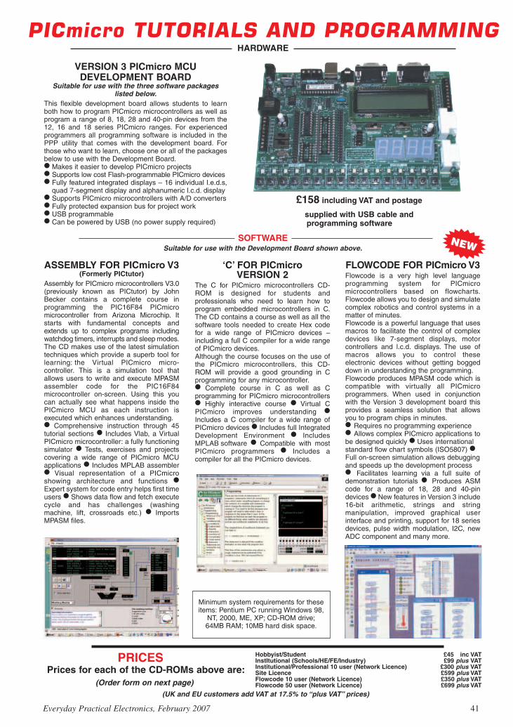
Prices for each of the CD-ROMs above are:(Order form on next page)
Hobbyist/Student £45 inc VATInstItutional (Schools/HE/FE/Industry) £99 plus VATInstitutional/Professional 10 user (Network Licence) £300 plus VATSite Licence £599 plus VATFlowcode 10 user (Network Licence) £350 plus VATFlowcode 50 user (Network Licence) £699 plus VAT
(UK and EU customers add VAT at 17.5% to “plus VAT’’ prices)
PRICES
VERSION 3 PICmicro MCUDEVELOPMENT BOARD
Suitable for use with the three software packageslisted below.
This flexible development board allows students to learnboth how to program PICmicro microcontrollers as well asprogram a range of 8, 18, 28 and 40-pin devices from the12, 16 and 18 series PICmicro ranges. For experiencedprogrammers all programming software is included in thePPP utility that comes with the development board. Forthose who want to learn, choose one or all of the packagesbelow to use with the Development Board. Makes it easier to develop PICmicro projects Supports low cost Flash-programmable PICmicro devices Fully featured integrated displays – 16 individual l.e.d.s,
quad 7-segment display and alphanumeric l.c.d. display Supports PICmicro microcontrollers with A/D converters Fully protected expansion bus for project work USB programmable Can be powered by USB (no power supply required)
ASSEMBLY FOR PICmicro V3(Formerly PICtutor)
Assembly for PICmicro microcontrollers V3.0(previously known as PICtutor) by JohnBecker contains a complete course inprogramming the PIC16F84 PICmicromicrocontroller from Arizona Microchip. Itstarts with fundamental concepts andextends up to complex programs includingwatchdog timers, interrupts and sleep modes.The CD makes use of the latest simulationtechniques which provide a superb tool forlearning: the Virtual PICmicro micro-controller. This is a simulation tool thatallows users to write and execute MPASMassembler code for the PIC16F84microcontroller on-screen. Using this youcan actually see what happens inside thePICmicro MCU as each instruction isexecuted which enhances understanding. Comprehensive instruction through 45tutorial sections Includes Vlab, a VirtualPICmicro microcontroller: a fully functioningsimulator Tests, exercises and projectscovering a wide range of PICmicro MCUapplications Includes MPLAB assembler Visual representation of a PICmicroshowing architecture and functions Expert system for code entry helps first timeusers Shows data flow and fetch executecycle and has challenges (washingmachine, lift, crossroads etc.) ImportsMPASM files.
‘C’ FOR PICmicroVERSION 2
The C for PICmicro microcontrollers CD-ROM is designed for students andprofessionals who need to learn how toprogram embedded microcontrollers in C.The CD contains a course as well as all thesoftware tools needed to create Hex codefor a wide range of PICmicro devices –including a full C compiler for a wide rangeof PICmicro devices.Although the course focuses on the use ofthe PICmicro microcontrollers, this CD-ROM will provide a good grounding in Cprogramming for any microcontroller. Complete course in C as well as Cprogramming for PICmicro microcontrollers Highly interactive course Virtual CPICmicro improves understanding Includes a C compiler for a wide range ofPICmicro devices Includes full IntegratedDevelopment Environment IncludesMPLAB software Compatible with mostPICmicro programmers Includes acompiler for all the PICmicro devices.
FLOWCODE FOR PICmicro V3Flowcode is a very high level languageprogramming system for PICmicromicrocontrollers based on flowcharts.Flowcode allows you to design and simulatecomplex robotics and control systems in amatter of minutes.Flowcode is a powerful language that usesmacros to facilitate the control of complexdevices like 7-segment displays, motorcontrollers and l.c.d. displays. The use ofmacros allows you to control theseelectronic devices without getting boggeddown in understanding the programming.Flowcode produces MPASM code which iscompatible with virtually all PICmicroprogrammers. When used in conjunctionwith the Version 3 development board thisprovides a seamless solution that allowsyou to program chips in minutes. Requires no programming experience Allows complex PICmicro applications tobe designed quickly Uses internationalstandard flow chart symbols (ISO5807) Full on-screen simulation allows debuggingand speeds up the development process Facilitates learning via a full suite ofdemonstration tutorials Produces ASMcode for a range of 18, 28 and 40-pindevices New features in Version 3 include16-bit arithmetic, strings and stringmanipulation, improved graphical userinterface and printing, support for 18 seriesdevices, pulse width modulation, I2C, newADC component and many more.
Minimum system requirements for theseitems: Pentium PC running Windows 98,
NT, 2000, ME, XP; CD-ROM drive;64MB RAM; 10MB hard disk space.
Suitable for use with the Development Board shown above.
Everyday Practical Electronics, February 2007 41
PICmicro TUTORIALS AND PROGRAMMINGHARDWARE
SOFTWARE
£158 including VAT and postage
supplied with USB cable and programming software
NEW

TEACH-IN 2000 – LEARN ELECTRONICS WITH EPEEPE’s own Teach-In CD-ROM, containsthe full 12-part Teach-In 2000 series byJohn Becker in PDF form plus the Teach-In interactive software (Win 95, 98, MEand above) covering all aspects of theseries. We have also added AlanWinstanley’s highly acclaimed BasicSoldering Guide which is fully illustratedand which also includes Desoldering. TheTeach-In series covers: Colour Codes andResistors, Capacitors, Potentiometers,Sensor Resistors, Ohm’s Law, Diodesand L.E.D.s, Waveforms, Frequency andTime, Logic Gates, Binary and Hex Logic,Op.amps, Comparators, Mixers, Audioand Sensor Amplifiers, Transistors,Transformers and Rectifiers, VoltageRegulation, Integration, Differentiation, 7-segment Displays, L.C.D.s, Digital-to-Analogue.Each part has an associated practical section and the series includes a simple PCinterface (Win 95, 98, ME ONLY) so you can use your PC as a basic oscilloscope with thevarious circuits.A hands-on approach to electronics with numerous breadboard circuits to try out.
£12.45 including VAT and postage. Requires Adobe Acrobat (available free from theInternet – www.adobe.com/acrobat).FREE WITH EACH TEACH-IN CD-ROM – Understanding Active Components booklet,Indentifying Electronic Components booklet and The Best Of Circuit Surgery CDROM.
Minimum system requirements for these CD-ROMs: Pentium PC, CD-ROM drive, 32MB RAM, 10MB hard disk space. Windows 95/98/NT/2000/ME/XP, mouse, sound card, web browser.
CD-ROM ORDER FORM Electronic Projects Electronic Circuits & Components V2.0 Analogue Electronics Version required: Digital Electronics V2.0 Hobbyist/Student Analogue Filters Institutional Electronics CAD Pack Institutional/Professional 10 user Robotics & Mechatronics Site licence Assembly for PICmicro V3 ‘C’ for PICmicro V2 Flowcode V3 for PICmicro Digital Works 3.0
PICmicro Development Board V3 (hardware)
Teach-In 2000 + FREE BOOK Electronic Components Photos Project Design – Single User Project Design – Multiple User (under 500 students) Project Design – Multiple User (over 500 students)
Full name: . . . . . . . . . . . . . . . . . . . . . . . . . . . . . . . . . . . . . . . . . . . . . . . . . . . . . . . . . . . . . . . . . . . . . . . . .
Address: . . . . . . . . . . . . . . . . . . . . . . . . . . . . . . . . . . . . . . . . . . . . . . . . . . . . . . . . . . . . . . . . . . . . . . . . . . .
. . . . . . . . . . . . . . . . . . . . . . . . . . . . .Post code: . . . . . . . . . . . . . . . . .Tel. No: . . . . . . . . . . . . . . . . . . . . .
Signature: . . . . . . . . . . . . . . . . . . . . . . . . . . . . . . . . . . . . . . . . . . . . . . . . . . . . . . . . . . . . . . . . . . . . . . . . . . .
I enclose cheque/PO in £ sterling payable to WIMBORNE PUBLISHING LTD for £ Please charge my Visa/Mastercard/Amex/Diners Club/Switch: £
Valid From: . . . . . . . . . . . . . . . . . . . . .Card expiry date: . . . . . . . . . . . . . . . . . . . . . . . . . . . . . .
Card No: . . . . . . . . . . . . . . . . . . . . . . . . . . . . . . . . . . . . . . . . . . . . . . . . . . . . Maestro Issue No. . . . . . . . . .
Card Security Code . . . . . . . . . . (The last 3 digits on or just under the signature strip)
ORDERINGALL PRICES INCLUDE UK
POSTAGE
Student/Single User/Standard Versionprice includes postage to most
countries in the worldEU residents outside the UK add £5 for
airmail postage per order
Institutional, Multiple User and DeluxeVersions – overseas readers add £5 to thebasic price of each order for airmail postage(do not add VAT unless you live in an EU(European Union) country, then add 17½%VAT or provide your official VAT registrationnumber).
Send your order to:Direct Book Service
Wimborne Publishing Ltd408 Wimborne Road East
Ferndown, Dorset BH22 9NDTo order by phone ring
01202 873872. Fax: 01202 874562Goods are normally sent within seven days
E-mail: [email protected]
Online shop:www.epemag.wimborne.co.uk/shopdoor.htm
Note: The software on each version isthe same, only the licence for use varies.
ELECTRONICCOMPONENTS PHOTOS
A high quality selection of over 200 JPGimages of electroniccomponents. Thisselection of highresolution photos can beused to enhanceprojects andpresentations or to helpwith training andeducational material.They are royalty free foruse in commercial orpersonal printed projects, and can also beused royalty free in books, catalogues,magazine articles as well as worldwide webpages (subject to restrictions – see licence forfull details).Also contains a FREE 30-day evaluation ofPaint Shop Pro 6 – Paint Shop Pro imageediting tips and on-line help included!
Price £19.95 inc. VAT
Please send me:
PROJECT DESIGN WITH CROCODILE TECHNOLOGYAn Interactive Guide to Circuit Design
An interactive CD-ROM to guide you through the process of circuit design. Choose from an extensive range of input,process and output modules, including CMOS Logic, Op-Amps, PIC/PICAXE, Remote ControlModules (IR and Radio), Transistors, Thyristors, Relays and much more.Click Data for a complete guide to the pin layouts of i.c.s, transistors etc. Click More Informationfor detailed background information with many animated diagrams.Nearly all the circuits can be instantly simulated in Crocodile Technology* (notincluded on the CD-ROM) and you can customise the designs as required.
WHAT’S INCLUDEDLight Modules, Temperature Modules, Sound Modules, Moisture Modules, SwitchModules, Astables including 555, Remote Control (IR & Radio), Transistor Amplifiers,Thyristor, Relay, Op-Amp Modules, Logic Modules, 555 Timer, PIC/PICAXE, OutputDevices, Transistor Drivers, Relay Motor Direction & Speed Control, 7 Segment Displays.Data sections with pinouts etc., Example Projects, Full Search Facility, FurtherBackground Information and Animated Diagrams.Runs in Microsoft Internet Explorer*All circuits can be viewed, but can only be simulated if your computer has CrocodileTechnoloy version 410 or later. A free trial version of Crocodile Technology can bedownloaded from: www.crocodile-clips.com. Animated diagrams run without Crocodile Technology.
Single User £39.00 inc. VAT.Multiple Educational Users (under 500 students) £59.00 plus VAT. Over 500 students £79.00 plus VAT.
(UK and EU customers add VAT at 17·5% to “plus VAT’’ prices)
Sine wave relationship values
FREE TWOBOOKLETS
PLUS CD-ROMWITH
TEACH-IN2000
Digital Works Version 3.0 is a graphicaldesign tool that enables you to constructdigital logic circuits and analyze theirbehaviour. It is so simple to use that it willtake you less than 10 minutes to make yourfirst digital design. It is so powerful that youwill never outgrow its capability Softwarefor simulating digital logic circuits Createyour own macros – highly scalable Createyour own circuits, components, and i.c.sEasy-to-use digital interface Animationbrings circuits to life Vast library of logicmacros and 74 series i.c.s with data sheetsPowerful tool for designing and learning.Hobbyist/Student £45 inc. VAT.Institutional £99 plus VAT.Institutional 10 user £249 plus VAT.Site Licence £599 plus VAT.
Counterproject
DIGITAL WORKS 3.0
42 Everyday Practical Electronics, February 2007
NEW
Over 150 pagesOver 600 images
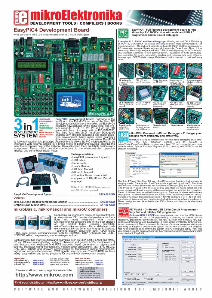
Examples in C, BASIC and Pascal language: Printing text on LCD, LED blinkingon PORTB, MMC/SD/CF card read and write example, USB communication, 4x4Keypad example, PS2 keyboard example, software SPI/I2C/RS232 communications,AD conversion example Seven segment digit example, Timer 0 and Timer 1 timemeasuring, Measuring temperature with DS1820 and displaying on LCD, GraphicLCD example, examples for SPI communication, examples for CAN communica-tion, examples for Sound generation, sending and receiving data over Ethernet,Interrupt upon PORTB state change, Detection of button pressed on port and manymore...
mikroElektronikaDEVELOPMENT TOOLS | COMPILERS | BOOKS
mikroBasic, mikroPascal and mikroC compilers
Supporting an impressive range of microcontrollers,an easy-to-use IDE, hundreds of ready-to-use func-tions and many integrated tools makesMikroElektronika compilers one of the best choiceson the market today. Besides mikroICD,mikroElektronika compilers offer a statistical mod-ule, simulator, bitmap generator for graphic displays,7-segment display conversion tool, ASCII table,
HTML code export, communications tools for SD/MMC, UDP (Ethernet) and USB ,EEPROM editor, programming mode management, etc.
Each compiler has many routines and examples such as EEPROM, FLASH and MMC,SD and CF card reading/writing, writing to character and graphic LCDs, manipulation ofpush-buttons, 4x4 keyboard and PS/2 keyboard input, generation of signals andsounds, character string manipulation, mathematical calculations, I2C, SPI, RS232,CAN, USB, RS485 and OneWire communications, Manchester coding management,logical and numerical conversion, PWM signals, interrupts, etc. The CD-ROM containsmany ready-written and tested programs for use with our development boards.
Regular price:mikroBasic(PIC) $149.00 USDmikroPascal(PIC) $149.00 USDmikroC(PIC) $249.00 USD
Buy one of our compil-ers with one of our PICdevelopment boards atup to 30% discount.
Price with discount:mikroBasic(PIC) (-30%) $99.00 USD
mikroPascal(PIC) (-30%) $99.00 USD
mikroC(PIC) (-30%) $175.00 USD
S O F T W A R E A N D H A R D W A R E S O L U T I O N S F O R E M B E D D E D W O R L D
Find your distributor: http://www.mikroe.com/en/distributors/
Please visit our web page for more info
http://www.mikroe.com
EasyPIC4 development board: Following in thetradition of the EasyPIC3 as one of the best PICdevelopment systems on the market, the EasyPIC4has more new features for the same price. The sys-tem supports 8, 14, 18, 20, 28 and 40 pin PICmicrocontrollers (it comes with a PIC16F877A).The ultra fast mikroICD (In-circuit Debugger)enables very efficient debugging and faster proto-type development. Many ready made examplesguarantee successful use of the system. EasyPIC4
is fully optimized for fast prototype development. It allows the PIC microcontroller to beinterfaced with external circuits to a broad range of peripheral devices, allowing theuser to concentrate on just the software. On a silkscreen there are labels beside everycomponent. These marks describe connections to the microcontroller, operationmodes, and some other useful notes.
Package contains: - EasyPIC4 development system,- USB cable,- Serial cable,- User’s Manual,- PICFlash Manual,- MikroICD Manual,- CD with software, drivers andexamples in C, BASIC and Pascallanguage.
Note: LCD, DS1820 temp sensorand GLCD are optional.
EasyPIC4 Development System ............................................................ $119.00 USD
Optional:
2x16 LCD and DS1820 temperature sensor ......................................... $15.00 USDGraphic LCD 128x64 dots ...................................................................... $17.00 USD
mikroICD is a highly effective tool for Real-Time debugging on a hard-ware level. The ICD debugger enables you to execute amikroC/mikroPascal/mikroBasic program on a host PIC microcontroller and viewvariable values, Special Function Registers (SFR), memory and EEPROM as theprogram is running.
- All of our products are shipped in special protective boxes.
- On-line secure ordering provides a fast and safe way to buy our products.
EasyPIC4 Development Boardwith on-board USB 2.0 programmer and In Circuit Debugger
Step Into [F7] and Step Over [F8] are mikroICD debugger functions that are used instepping mode. There is also Real-Time mode supported by mikroICD. Functionsthat are used in Real-Time mode are Run/ Pause Debugger [F6] and Run to cursor[F4]. Pressing F4 goes to the line selected by user. User just has to select line withcursor and press F4, and program will be executed until the selected line is reached.Breakpoints have been separated into two groups. There are hardware and softwarebreak points. Hardware breakpoints are placed in PIC and they provide fast debug.Number of hardware breakpoints is limited (1 for P16 and up to 3 for P18). If all hard-ware brekpoints are used, new breakpoints that will be used as software breakpoints.Those breakpoints are placed inside mikroICD software, and they simulate hardwarebreakpoints.
mikroICD - On-board In-Circuit Debugger - Prototype yourdesigns more efficiently and effectively.
On-board USB 2.0 PICFlash programmer – An ultra fast USB 2.0 pro-grammer for fast MCU programming. Continuing its tradition as the
fastest PIC programmer on the market, the new PICFlash with mikroICD now sup-ports more PIC MCUs giving the developer a wider choice of PIC MCU for further pro-totype development. There is no need for the use of external equipment during pro-gramming as EasyPIC4 development system has its own on-board USB program-mer. All you need to do is connect the system to a PC using USB cable. Then, loadyour program into the microcontroller via the PICFlash2 programming software whichis supplied with EasyPIC4.
PICFlash2 - On-Board USB 2.0 In-Circuit Programmer -Very fast and reliable PIC progammer
EasyPIC4 - Full-featured development board for theMicrochip PIC MCU's. Now with on-board USB 2.0 programmer and In-Circuit Debugger.
36 buttons forprogram develop-ing needs.
PS2 (PC key-board) connector.
Digital thermome-ter DS1820.
System can beeasily configuredvia DIP switch.
4 seven-segmentdigits in multiplexmode.
Crystal can bereplaced byanother one.
36 diodes for dis-playing states ofall pins.
GLCD - GraphicLCD 128x64.
All pins are con-nected to IDCconnectors.
Pull up or Pulldown port defin-ing.
RS-232 communi-cation availableon-board.
USB connectorfor MCU with on-chip USB comm.
Character LCDsupport.
Reset circuit. ADC inputs viatwo selectablepotentiometers.

Constructional Project Constructional Project Constructional Project Constructional Project
44 EverydayPracticalElectronics,February2007 EverydayPracticalElectronics,February2007 45
THIS CIRCUIT lets you design your own robot to suit your own taste. It would not be difficult,
for instance, to convert this design to a credible ‘R2D2’, without any modi-fication to the PC board. With a little imagination, the possibilities would be even wider. The circuit could operate a pulley system, serve as a line-tracker or rotate motors in response to broken beams of varying intensity, without modification to the PC board.
The robot is programmable, there-fore, the drive circuit is merely a slave to the software and is of a relatively simple design. The circuit is based on a PICAXE-08 micro. Although more limited than a ‘raw’ microcontroller, it is a little marvel nonetheless – both for cutting out the need for a program-
mer and for placing respectable power at the service of the constructor with great simplicity.
All that the Programmable Robot requires in its support is a PC and a se-rial cable. The programming software is free (www.rev-ed.co.uk) and comes in the form of a telegram-style BASIC and flowchart programming.
Note that the Programmable Ro-bot’s memory is limited – not all the features listed above can be used at the same time. However, with careful programming, the robot will perform most dual or even triple tasks with aplomb. As an example, light-seeking, bump-and-respond and sound can all be incorporated in a single program.
Since the PICAXE-08 microcon-troller represents the Programmable
Robot’s ‘control room’, this is where we shall begin. Unfortunately, the PICAXE-08 is confusing in its pin num-bering, which has become something of a legend in its own time – therefore we shall resort to the standard IC pin numbering here; ie, pins 1-8, with pin 1 being situated next to the small indentation on top of the IC.
Circuit detailsThe complete circuit is shown in
Fig.1. The PICAXE-08’s pin 1 (+V) and pin 8 (0V) are connected to a 6V battery via switch S2 and diode D2. D2 serves a dual purpose – first, to prevent reverse polarity, which could do considerable damage, and second, to drop the supply voltage to about 5.4V, which is more suitable for the PICAXE-08.
Pin 7 (P0) is designated by the manufacturers for output only and is used to switch both of the motors on or off at the same time. It may also be used to pulse the motors on and off (pulse-width modulation) for speed control or special effects. When it is ‘high’, the motors are on; when it is ‘low’ they are off.
Pin 5 (P2) is designated for input or output. In this circuit, it is used for
ROBOT
High Low
Pin7(P0) Bothmotorson BothmotorsoffPin5(P2) Leftmotorbackwards LeftmotorforwardsPin3(P4) Rightmotorbackwards Rightmotorforwards
Table 1: PICAXE Motor Control Outputs
By THOMAS SCARBOROUGH
This table shows the most important PICAXE-08 outputs – ie, for motor control.
Programmable
This Programmable Robot features full manoeuvrability – forward, reverse, turn and stop, with pulse-width modulation for speed control. It also sports bump-and-respond, random motion, programmable sound, light sensing (16 levels) and EEPROM byte-wise addressing.

Constructional Project Constructional Project Constructional Project Constructional Project
44 EverydayPracticalElectronics,February2007 EverydayPracticalElectronics,February2007 45
1N54
04
, 1N
5404
Fig.1: a PICAXE-08 microcontroller, 10 MOSFETs and not much else comprise the circuit of this robot. All the intelligence is contained in the micro’s software.
output only and controls the direction (forward or reverse) of the lefthand motor, as seen from the rear of the ro-bot. Pin 3 (P4) is likewise designated for input or output and is used here to control the direction (forward or reverse) of the righthand motor.
Note that neither pin 5 nor pin 3 will accomplish anything unless both motors are switched on first
via pin 7 (P0). Both pins 5 and 3 cause a wheel to roll forwards when
it is ‘low’ and backwards when it is ‘high’. Pins 7, 5 and 3 together may be used not only to make the robot drive forwards or reverse but also to turn, gyrate, wiggle, judder or do virtually anything else one may think of! These motions may also be strung together sequentially, as part of a programmed sequence (within limits, since memory is at a premium).
Pin 4 (P3) is designated for input only and is used to sense collisions through the robot’s bumper bar. The robot need not only do a simple reverse-and-turn, but it may also be programmed to re-spond in various ways. Pin 6 (P1) is des-ignated for output, input or analogue input. In this circuit, it is used only for output and analogue input.
In ‘output’ mode, it is used to drive a piezo sounder for programmable sound. The piezo sounder will beep, play tunes or, with a little ingenuity, create sound effects such as a police siren or a cat’s purr.
In ‘analogue’ mode, pin 6 reads the light level at the front of the robot. Note that this first requires the correct adjustment of VR1 with the help of the LDR ADJUST program. The robot is capable of detecting sixteen levels of light which may be used for light-seek-ing (or light-avoidance), line tracking and day-night sensing.
Several short programs are pro-vided, including a FIGURE-8 DEMO, LIGHT & BUMP DEMO, PWM DEMO, RANDOM DEMO and WALTZING MATILDA DEMO, these are available from the Downloads area on the EPE UK website.
The WALTZING MATILDA DEMO has been designed not only for fun but as a ‘get you going’ program during assembly, while the LIGHT & BUMP DEMO will give the best overall

Constructional Project Constructional Project Constructional Project Constructional Project
46 EverydayPracticalElectronics,February2007 EverydayPracticalElectronics,February2007 47
functionality. This seeks out light and drives towards it, reverses and turns away from obstacles, as well as hav-ing sound.
For the sake of clarity, the most im-portant PICAXE-08 outputs are listed in Table 1.
Pin 7 (P0) activates both motors simultaneously via MOSFETs Q2 & Q5. These two MOSFETs are wired in parallel and these should work satisfactorily with a small heatsink for the small motors used here. While D2 can cope with two 9W motors, the prototype’s motors used only about 1.6W each under load.
If the drain on the battery is too heavy when the motors are switched on, this could lead to a voltage drop which could make the PICAXE-08 do strange things. Therefore, the battery
should be suitably rated for powering the motors. The prototype used a 6V 4Ah battery. AA batteries in series are unlikely to be adequate, except for the most lightweight of motors.
Pin 6 (P1), used in ‘output’ mode, drives piezo sounder X1. Since VR1 and LDR1 are connected to the same pin, two 330Ω resistors are included as protection for these components. In an-alogue mode, pin 6 monitors LDR1 and the PICAXE-08 interprets the voltage as 16 discrete levels, between <0.22V (level 1) and >3.38V (level 16).
Ideally, the darkest areas of a room should read about 3.6V at pin 6. This can be arranged by means of the LDR ADJUST program (see below).
A value of 10kΩ for VR1 should prove suitable if the specified NORP-12 Light Dependent Resistor (LDR1) is
used. Virtually any other LDR may be used but the value of VR1 may need to be modified to match, in order to provide a voltage of about 3.6V at pin 6 when surveying the darkest areas of a room. If the resistance of the LDR in darkness is known, VR1 should be adjusted to roughly 70% of this.
It might be asked what use a single LDR is, since it would seem that two LDRs would be required to compare light level from different directions. However, since LDR1 is mounted on a moving platform, light levels from different areas can be compared over time. Thus the robot measures light level in one part of the room, stores it, then turns to measure light level in another part of the room. The different light levels can then be compared and the robot can respond accordingly.
1N54
04
602
Fig.2: follow this parts layout diagram when assembling the PC board.
Fig.3: this is the full-size etching pattern for the PC board
Table 2: Resistor Colour Codes
o No. Value 4-Band Code (1%) 5-Band Code (1%) o 3 47kΩ yellowvioletorangebrown yellowvioletblackredbrown o 4 22kΩ redredorangebrown redredblackredbrown o 1 10kΩ brownblackorangebrown brownblackblackredbrown o 2 330Ω orangeorangebrownbrown orangeorangeblackblackbrown

Constructional Project Constructional Project Constructional Project Constructional Project
46 EverydayPracticalElectronics,February2007 EverydayPracticalElectronics,February2007 47
Pins 3 & 5 switch two power MOS-FET H-bridges (Q3, Q4 and Q9,Q10) to control the direction of the motors (forward or reverse). The two 100nF capacitors and diode D1 are included to suppress interference.
Transistors Q1 and Q8 are used as inverters, so that when the ‘forward motion’ MOSFETs are disabled, the ‘reverse motion’ MOSFETs are acti-vated. Pin 4 is normally held low by its 47kΩ resistor. When bump-and-respond switch S1 (the bumper bar) is closed, pin 4 is pulled high. The 10µF capacitor and the 47kΩ resistor determine how long a bump will be ‘remembered’ and the values of these components may be modified as de-sired. These components are required because the software, as it executes, may need a moment to reach the pro-gram line which monitors the status of S1 – and because there is bound to be some switch-bounce too.
Pins 2 (Serial In) and 7 (Serial Out) are used for downloading programs, with pin 7 doing double duty for switching the motors, as described earlier. Since pin 7 does double duty, the robot’s motors may twitch a lit-tle as a program is downloaded or debugged.
A 220µF capacitor provides supply decoupling and the 22kΩ bleed resis-tor ensures that the circuit powers down properly when switched off, so that there will be no unpredictable behaviour when it is switched on
again. After switching off the robot, allow a few seconds for the 220µF capacitor to discharge before switch-ing on again.
Board assemblyAll the parts, with the exception of
the bump switch, LDR, piezo sounder and battery, are mounted on a PC board coded 602, measuring 92 × 67mm. The component overlay is shown in Fig.2 and the wiring details in Fig.6.
PC board and hardware construc-tion are inter-linked and both of these sections need to be read first before final construction of the robot is un-dertaken. The following procedure is recommended when soldering com-ponents to the PC board: (1) solder the 14 PC pins (insert these from the copper track side), as well as the wire links; (2) solder the 8-pin dual-in-line (DIP) socket (observe the correct orientation) and CON1; (3) solder the 10 resistors and preset potentiometer VR1; (4) install the two diodes and the two electrolytic capacitors, taking care with polarity; (5) install the two 100nF capacitors; (6) solder in the two transistors (Q1 & Q8) and the 10 MOSFETs; (7) fit a small heatsink to MOSFETs Q2 & Q5.
Robot platformThe physical construction of
the Programmable Robot begins with a suitable baseboard to which everything else is attached. The
prototype’s baseboard measured 200mm from front to back and 160mm wide. The prototype used hardboard, a strong material that is easy to work with.
Parts List1 Hardboard baseboard, 200 x
160mm1 PC board, code 602, 92 x
67mm, available from the EPE PCB Service
1 piezo sounder (without integral electronics) (X1)
1 bumper switch (S1 – see text)1 miniature toggle switch (S2)1 10kΩ cermet trimpot (top adjust)1 NORP-12 light dependent
resistor (LDR1 – see text)1 3.5mm PC-mount stereo jack
socket (CON1)2 reversible 6V geared motors
(ideally <2W each under load)1 8-pin DIP socket1 6V 4Ah SLA battery2 spade connectors to suit
battery14 PC stakes2 60mm dia. wheels (to suit
gearbox shafts)1 40mm dia. rear wheel130mm 2.5mm dia. steel wire for
rear wheels4 corner brackets for battery
Semiconductors1 PICAXE-08 microcontroller
(IC1)10 MTP3055V N-channel
MOSFETs (Q2-Q7,Q9-Q12)2 BC547 NPN transistors
(Q1,Q8)1 1N4004 silicon diode (D1)1 1N5404 silicon diode (D2)
Capacitors1 220µF 16V PC electrolytic1 10µF 16V PC electrolytic2 100nF (0.1µF) MKT polyester
or ceramic
Resistors (0.25W, 1%)3 47kΩ 1 10kΩ4 22kΩ 2 330Ω
Also requiredPICAXE Programming Editor software – available free from www.picaxe.co.uk
PICAXE download cable
The completed PC board is secured to the base using machine screws and nuts. Note the heatsink that’s fitted to the tabs of MOSFETs Q2 & Q5.

Constructional Project Constructional Project Constructional Project Constructional Project
48 EverydayPracticalElectronics,February2007 EverydayPracticalElectronics,February2007 49
Two reversible 6V DC geared mo-tors with ‘through-shafts’ were bolted to the baseboard. The platform of the prototype was raised a little above the motors with 10mm square wood bat-terns, to provide more vertical room for the rear swivel-wheel.
The motors purchased use about 250mA under load and at 6V run free at about 6000 RPM. This is divided down to 70 RPM with the gearbox and this comes down to perhaps 50 RPM under load, when the voltage drop via D2 is taken into account.
60mm diameter gear wheels were used for the two drive wheels and these were simply pressed onto the drive shafts. The motors are mounted so that they each ‘face the same way’ as they turn – that is, their drive shafts both turn the same way when the robot is moving forward. This is
because there may be inequalities in the forward and reverse speeds of DC motors and this ensures that the robot will drive in a reasonably straight line when the motors are activated.
Next, attach leads with spade con-nectors to suit the battery and connect the motors as well. That done, attach LDR1 at the front of the robot by means of suitable wires. A short tube over LDR1 is required for directionality (see below). You also need to attach bump-and-respond switch S1 (ie, the bumper bar – see below), the piezo sounder and switch S2 using suitable leads.
Finally, insert the PICAXE (IC1) in the DIP socket.
Once the assembly is complete, carefully check the PC board for any solder bridges or dry joints, and check all components for correct placement and orientation.
More construction detailThe easiest way of working out the
correct mounting of the motors will be through trial and error. First, wire them both up as shown, observing the correct polarity of the motors. That done, run the WALTZING-MATILDA DEMO.
Immediately after the first line of ‘Waltzing Matilda’, the wheels should both roll so as to propel the robot forwards – then there should be a beep and only the left motor (viewed from the rear of the robot) should reverse. If the motors do not rotate as described, then re-orientate them so that they do.
Once the drive motors have been fastened into place, the battery should be mounted on top of the platform – slightly back from the two drive shafts, so that the robot’s load is slightly to
Fig.5: this diagram shows the details of the collision switch.
Fig.4: a swivel wheel is used at the rear of the robot for simplicity of steering.

Constructional Project Constructional Project Constructional Project Constructional Project
48 EverydayPracticalElectronics,February2007 EverydayPracticalElectronics,February2007 49
Finally, switch S2, piezo sounder X1, and LDR1 are connected to the PC board. Switch S2 may be mounted on the hardboard platform. The piezo sounder may be fixed underneath the PC board with a little glue.
A short tube (say 15mm in length) should be slipped over the LDR and this should be mounted on the front of the robot with a clear view in front. Without this ‘blinker’ tube, the LDR does not have sufficient directionality to be of much use.
Once the circuit is complete, piezo sounder X1 presents a quick and easy way of testing for life in the circuit. Us-ing the WALTZING-MATILDA DEMO, only the piezo sounder and battery need to be wired up at first.
Switch on the circuit, being vigilant for any sparks or abnormal heating! If the slightest problem should be sus-pected, switch off immediately and thoroughly re-check the PC board. Program the PICAXE-08 by means of the serial cable. This is done by
This close-up view shows how the LDR is housed in a short (15mm) length of tube. It sits just behind the collision switch.
This underside view shows how the motor/gearbox assemblies are secured to two wooden rails using machine screws and nuts. Note also the rear swivel-wheel assembly.
the rear of the platform. This gives it a good weight distribution and gives traction to the drive wheels, while not overburdening the rear swivel-wheel.
Four corner brackets were used to hold the battery in place and a length of telephone wire (or a cable tie) can be used to tie it to the platform through drilled holes.
The prototype used a rear swivel-wheel, and a 40mm diameter pulley wheel was used for the wheel. A sturdy 130mm length of 2.5mm diameter steel wire, together with a metal bracket, was used to attach the wheel to the platform. Nuts were slipped over this wire and glued into place as shown, to hold the wire in the bracket, and to hold the wheel in place.
It is important that this wheel should touch the ground at a point central to the other two wheels, other-wise the robot is likely to have a ‘lean’ to it, and this is why the steel wire is curved as it is. Together with the other wheels, the swivel-wheel should also, at all times, provide a three-point base on which the robot may rest, so as not to tip over.
Make sure that the swivel-wheel has the freedom to swivel through 360°. It should not, for instance, bump into the motors or the on-off switch, or be impeded by drooping wires. This robot has the potential for ‘wild’ mo-tion and could run into trouble if the swivel-wheel snags.
Mounting the PC boardThe PC board is mounted on top of
the platform at the back, behind the battery, with the jack socket facing the rear for easy insertion of the serial cable. For neatness, holes may be drilled in the platform beneath the PC board, so that sheathed wires may be run underneath the platform. In the prototype, the PC board was raised above the platform on bolts, which made the wiring easier, as well as making room for the piezo sounder and the screws used to secure the swivel-wheel assembly.
A simple bumper bar is fixed to the front of the robot for the bumper switch S1. All that is required here is that S1’s contacts should close on collision. The prototype used a brass strip that was ‘sprung’ on two brass loops, making contact with a brass stub on the plat-form when a collision took place.
Reproduced by arrangement with SILICON CHIP magazine 2007.www.siliconchip.com.au

Constructional Project Constructional Project Constructional Project Constructional Project
50 EverydayPracticalElectronics,February2007 EverydayPracticalElectronics,February2007 00
Fig.6: follow this diagram to complete the wiring for the Robot. Power comes from a 6V 4Ah sealed lead acid battery which is mounted just behind the front axle assembly
opening the WALTZING-MATILDA DEMO file and then pressing F5.
If the motors have been attached at this stage, the robot will wiggle briefly – then the first line of ‘Waltzing Mat-ilda’ will play, and the robot will drive forwards. Then it will turn and repeat the sequence.
If the motors have not yet been attached, the sound of ‘Waltzing Matilda’ will give confirmation that a good deal is already working – the programming system, the serial ca-ble, the PICAXE-08 IC and some of the surrounding components at the very least.
To adjust the PICAXE-08 to the surrounding light level, run the LDR ADJUST program, and keep the serial cable connected while you do so. Adjust VR1 and as you do, observe variable b3 on your computer screen. When the robot is aimed at the darkest areas of the room, b3 should read 160, while lighter areas should show lesser numbers.
What is most important is that there should be maximum variation in this number (b3) as the robot surveys dif-ferent areas of a room.
Turning it loose!Once complete, place the Program-
mable Robot on a hard floor and switch on. All being well, it will wiggle, then follow the rest of its programmed behaviour.
The best ‘general purpose’ program is the LIGHT & BUMP DEMO. Place a lamp on the floor, switch off any other lights, and then switch on the robot – facing any direction at all. This demo never fails to impress, with the Programmable Robot head-ing for the light like a moth to a flame. EPE
The PC board is elevated on its mounting bolts to allow the wiring to the motors, etc to pass through holes drilled through the baseboard beneath it.


BBAACCKK IISSSSUUEESSOCT ’05
PROJECTS Haloween Howler PIC BasedUSB Interface Photic Phone Telephone Switch Parking Radar FEATURES Introducing the Virtual DIY Calculator Ingenuity Unlimited Back To Basics – 7 CircuitSurgery Techno Talk PIC ‘N’ Mix Interface NetWork – The Internet Page
NOV ’05 Photocopies onlyPROJECTS Speed Camera Watch Mk2 PICChromatone Multi-Function R/C Switch Noughtsand Crosses Enigma Weather Vane RepeaterFEATURES Teach-In 2006 – Part 1 CircuitSurgery Back To Basics – 8 Techno Talk Practically Speaking Ingenuity Unlimed PIC‘N’ Mix NetWork – The Internet Page
DEC ’05 Photocopies onlyPROJECTS Vehicle Frost Box Mk2 PropellerMonitor Solid-State Hammond Solid State ValvePower SupplyFEATURES Teach-In 2006 – Part 2 Techno Talk Viewing The Future Circuit Surgery Interface PIC ‘N’ Mix NetWork – The Internet Page
JAN ’06 Photocopies onlyPROJECTS A “Tiptronic-Style” Gear Indicator Sunset Switch PIC Ambilux Current ClampAdapter For MultimetersFEATURES Teach-In 2006 – Part 3 CircuitSurgery Techno Talk Practically Speaking PIC ‘N’ Mix NetWork – The Internet Page
FEB ’06 Photocopies onlyPROJECTS Highly Flexible Keypad Alarm Active 3-way Crossover Status Monitor JazzyHeart.FEATURES Teach-In 2006 – Part 4 TechnoTalk Circuit Surgery Interface PIC ’N’ Mix Network – The Internet Page
MAR ’06 Photocopies onlyPROJECTS PortaPAL Public Address Amplifier– Part 1 Telescope Interface Power Up Video– Audio BoosterFEATURES Teach-In 2006 – Part 5 PracticallySpeaking Circuit Surgery Techno Talk PIC’N’ Mix Net Work – The Internet Page
APR ’06 Photocopies onlyPROJECTS A Programmable Continuity Tester Omni Pendulum PortaPAL Public Address Amplifier– Part 2 ‘Smart’ Slave Flash TriggerFEATURES Teach-In 2006 – Part 6 ConsumerElectronics Show E-Chip Review Techno Talk PIC-’N’-Mix Net Work – The Internet Page
MAY ’06PROJECTS LED Lighting For Your Car SmartCard Reader and Programmer Nail Sniffer andVolts Hound Digital Reaction Timer.FEATURES Teach-In 2006 – Part 7 PracticallySpeaking Ingenuity Unlimited Circuit Surgery Techo Talk PIC ‘N’ Mix Net Work – The InternetPage
JUN ’06PROJECTS Poor Man’s Metal Locator WidgyBox Distortion Effects For Your Guitar PhoneRing & Test Digital Instrument Display For Cars– Part 1.FEATURES Interface Circuit Surgery IngenuityUnlimited Techno Talk PIC ‘N’ Mix Teach-In2006 – Part 8 Net Work – The Internet Page
JUL ’06 Photocopies onlyPROJECTS PIC Sudoku Unit A Dirt CheapHigh Current Bench Supply PC Power Monitor Digital Instrument Display For Cars – Part 2.FEATURES Teach-In 2006 – Part 9 IngenuityUnlimited Practically Speaking Circuit Surgery Techno Talk PIC ‘N’ MIX Net Work – TheInternet Page
AUG ’06PROJECTS Loudspeaker Level Meter Telephone Dialler for Burglar Alarms AdjustableDC-DC Converter for Cars High Intensity TorchFEATURES Circuit Surgery Techno Talk Teach-In 2006 – Part 10 PIC ’N’ Mix Interface Ingenuity Unlimited Net Work – The Internet Page
SEPT ’06PROJECTS Low Cost 50 MHz Frequency Meter Smart Mixture Display for Your Car HumanPowered LED Torches Water Level GaugeFEATURES Teach-In 2006 – Part 11 Ingenuity Unlimited Circuit Surgery TechnoTalk PIC ’N’ Mix Practically Speaking NetWork – The Internet Page
OCT ’06PROJECTS Studio 350 Power Amplifier - Part 1 Fridge Door-Open Alarm Through-Glass Alarm Linear Supply for 1W Star LEDsFEATURES Ingenuity Unlimited CircuitSurgery Techno Talk PIC ’N’ Mix Interface Net Work – The Internet Page
NOV ’06PROJECTS Giant LED Message Display Micropower Battery Protector Quick Brake Studio350 Power Amplifier – Part 2FEATURES C For PICs – Part 1 IngenuityUnlimited Circuit Surgery Techno Talk PIC’N’ Mix Practically Speaking Net Work – TheInternet Page
DEC ’06PROJECTS USB Power Injector RGB ToComponent Video Converter Lapel MicrophoneAdaptor For PA Systems Mind TrainerFEATURES C For PICs – Part 2 CircuitSurgery Interface Ingenuity Unlimited Techno Talk PIC ‘N’ Mix Net Work – TheInternet Page
JAN ’07PROJECTS Balanced Microphone Preamp Jumping Spider High Efficiency Power SupplyFor 1W Luxeon Star LEDs Charger For Deep-Cycle 12V Batteries – Part 1FEATURES C For PICs – Part 3 CircuitSurgery Practically Speaking Techno Talk PIC ‘N’ Mix Net Work – The Internet Page
We can supply back issues of EPE by post, most issues from the past five years are available. An EPE index for the last five years is also available atwww.epemag.co.uk or see order form below. Alternatively, indexes are published in the December issue for that year. Where we are unable to provide aback issue a photocopy of any one article (or one part of a series) can be purchased for the same price. Issues from Jan. 99 are available on CD-ROM –see next page – and back issues from recent years are also available to download from www.epemag.com.
Please make sure all components are still available before commencing any project from a back-dated issue.
BACK ISSUES ONLY £4.00 each inc. UK p&p.Overseas prices £4.75 each surface mail, £5.75 each airmail.
We can also supply issues from earlier years:2001 (exceptFeb., May, Aug.to Nov.), 2002 (exceptFeb., June, Aug.to Nov.), 2003(except June), 2004 (except June, July, Oct.and Dec.), 2005 (except Feb., Nov., Dec.), 2006 (except Jan., Feb., Mar., Apr.andJuly).Where we do not have an issue a photocopy of any one article or one partof a series can be provided at the same price.
OORRDDEERR FFOORRMM – BACK ISSUES – PHOTOCOPIES– INDEXES
Send back issues dated . . . . . . . . . . . . . . . . . . . . . . . . . . . . . . . . . . . . . . . . . . . . . . . . . . . . . . . . . . . . . . . . . . . . . . .
Send photocopies of (article title and issue date) . . . . . . . . . . . . . . . . . . . . . . . . . . . . . . . . . . . . . . . . . . . . . . . . . . .
Send copies of last five years indexes (£4.00 for five inc. p&p – Overseas £4.75 surface, £5.75 airmail)
Name . . . . . . . . . . . . . . . . . . . . . . . . . . . . . . . . . . . . . . . . . . . . . . . . . . . . . . . . . . . . . . . . . . . . . . . . . . . . . . . . . . . . . . . .
Address . . . . . . . . . . . . . . . . . . . . . . . . . . . . . . . . . . . . . . . . . . . . . . . . . . . . . . . . . . . . . . . . . . . . . . . . . . . . . . . . . . . . . .
. . . . . . . . . . . . . . . . . . . . . . . . . . . . . . . . . . . . . . . . . . . . . . . . . . . . . . . . . . .Tel: . . . . . . . . . . . . . . . . . . . . . . . . . . . . . . .
I enclose cheque/P.O./bank draft to the value of £ . . . . . . . . . . . . . . . . . . . . . . . . . . . . . . . . . . . . . . . . . . . . . . . . . .
Please charge my Visa/Mastercard/Amex/Diners Club/Switch £ . . . . . . . . . . . . . . . . . . . . . . . . . . . . . . . . . . . . . . .
Card No. . . . . . . . . . . . . . . . . . . . . . . . . . . . . . . . . . . . . . . . . . . . . . . . . . . . . . . . . . . . . . Maestro Issue No . . . . . . . . . . . . .. .
Valid From . . . . . . . . . . . . . . . . . .Card Expiry Date . . . . . . . . . . . . Card Security Code . . . . . . . . . .(The last 3 digits on or just under the signature strip)
SEND TO: Everyday Practical Electronics, Wimborne Publishing Ltd., 408 Wimborne Road East, Ferndown, Dorset BH22 9ND.Tel: 01202 873872. Fax: 01202 874562.
E-mail: [email protected] On-line Shop: www.epemag.wimborne.co.uk/shopdoor.htmPayments must be in £ sterling – cheque or bank draft drawn on a UK bank. Normally supplied within seven days of receipt of order.
Send a copy of this form, or order by letter if you do not wish to cut your issue.M02/07
52 Everyday Practical Electronics, February 2006
DDIIDD YYOOUU MMIISSSS TTHHEESSEE??
“TIPTRONIC” STYLE
GEAR INDICATORF O R C A R S A N D M O T O R C Y C L E SI N D I C AT E S U P T O 9 G E A R SD I S P L AY D I M M I N GE A S Y T O F I T
S U N S E T S W I T C HF o r S e c u r i t y
S a f e t y
T E A C H - I N 2 0 0 6 – 3C h a r g e a n d C a p a c i t a n c eI n t r o d u c i n g C a p a c i t o r s
JANUARY 2006 £3.30
P L U SP I C A m b i l u xC u r r e n t C l a m pA d a p t o r F o r M u l t i m e t e r s
THE No1 UK MAGAZINE FOR ELECTRONICS TECHNOLOGYAND COMPUTER PROJECTS

SSTTOORREE YYOOUURR BBAACCKK IISSSSUUEESS OONN CCDD--RROOMMSS
A great way to buy EPE Back Issues – our CD-ROMs contain backissues from our EPE Online website plus bonus articles, all the rele-
vant PIC software and web links. Note: no free gifts are included.All this for just £14.45 each including postage and packing.
VOL 1: BACK ISSUES – January 1999 to June 1999Plus some bonus material from Nov and Dec 1998
VOL 2: BACK ISSUES – July 1999 to December 1999VOL 3: BACK ISSUES – January 2000 to June 2000VOL 4: BACK ISSUES – July 2000 to December 2000VOL 5: BACK ISSUES – January 2001 to June 2001VOL 6: BACK ISSUES – July 2001 to December 2001VOL 7: BACK ISSUES – January 2002 to June 2002VOL 8: BACK ISSUES – July 2002 to December 2002VOL 9: BACK ISSUES – January 2003 to June 2003VOL 10: BACK ISSUES – July 2003 to December 2003VOL 11: BACK ISSUES – January 2004 to June 2004VOL 12: BACK ISSUES – July 2004 to December 2004VOL 13: BACK ISSUES – January 2005 to June 2005VOL 14: BACK ISSUES – July 2005 to December 2005VOL 15: BACK ISSUES – January 2006 to June 2006
NOTE: These CD-ROMs are suitable for use on any PC with aCD-ROM drive. They require Adobe Acrobat Reader (available free
from the Internet – www.adobe.com/acrobat)
WHAT IS INCLUDEDAll volumes include the EPE Online editorial content of every listedissue, plus all the available PIC Project Codes for the PIC projectspublished in those issues.Note: Some supplements etc. can be downloaded free from theLibrary on the EPE Online website at www.epemag.com.No advertisements are included in Volumes 1 and 2; from Volume 5onwards the available relevant software for Interface articles isalso included.
EXTRA ARTICLES – ON ALL VOLUMESBASIC SOLDERING GUIDE – Alan Winstanley’s internationallyacclaimed fully illustrated guide. UNDERSTANDING PASSIVE COMPO-NENTS – Introduction to the basic principles of passive components.HOW TO USE INTELLIGENT L.C.Ds, by Julyan Ilett – An utterly practi-cal guide to interfacing and programming intelligent liquid crystal displaymodules. PhyzzyB COMPUTERS BONUS ARTICLE 1 – Signed andUnsigned Binary Numbers. By Clive “Max” Maxfield and Alvin Brown.PhyzzyB COMPUTERS BONUS ARTICLE 2 – Creating an EventCounter. By Clive “Max” Maxfield and Alvin Brown. INTERGRAPHCOMPUTER SYSTEMS 3D GRAPHICS – A chapter from Intergraph’sbook that explains computer graphics technology. FROM RUSSIA WITHLOVE, by Barry Fox – Russian rockets launching American Satellites.PC ENGINES, by Ernest Flint – The evolution of Intel’s microprocessors.THE END TO ALL DISEASE, by Aubrey Scoon – The original work ofRife. COLLECTING AND RESTORING VINTAGE RADIOS, by PaulStenning. THE LIFE & WORKS OF KONRAD ZUSE – a brilliant pioneerin the evolution of computers. A bonus article on his life and work writtenby his eldest son, including many previously unpublished photographs.
Note: Some of the EXTRA ARTICLES require WinZip to unzip them.
BACK ISSUES CD-ROM ORDER FORM
Please send me the following Back Issue CD-ROMs. Volume
Numbers:. . . . . . . . . . . . . . . . . . . . . . . . . . . . . . . . . . . . . . . . . . . . . . . . . .
. . . . . . . . . . . . . . . . . . . . . . . . . . . . . . . . . . . . . . . . . . . . . . . . . . . . . . . . . . .
. . . . . . . . . . . . . . . . . . . . . . . . . . . . . . . . . . . . . . . . . . . . . . . . . . . . . . . . . . .
Price £14.45 each – includes postage to anywhere in the world.
Name . . . . . . . . . . . . . . . . . . . . . . . . . . . . . . . . . . . . . . . . . . . . . .
Address . . . . . . . . . . . . . . . . . . . . . . . . . . . . . . . . . . . . . . . . . . . .
. . . . . . . . . . . . . . . . . . . . . . . . . . . . . . . . . . . . . . . . . . . . . . . . . . .
. . . . . . . . . . . . . . . . . . . . . . . . . . . Post Code . . . . . . . . . . . . .
I enclose cheque/P.O./bank draft to the value of £ . . . . . . . . .
Please charge my Visa/Mastercard/Amex/Diners
Club/Maestro
£ . . . . . . . . . . . . . . . . . . . . . . . . . . . . . . . . . . . . . . . . . . . . . . . . . .
Card No. . . . . . . . . . . . . . . . . . . . . . . . . . . . . . . . . . . . . . . . . . . .
Card Security Code . . . . . . . . . . (The last 3 digits on or just under the signature strip)
Valid From . . . . . . . . . . .Expiry Date . . . . . . . . .
Maestro Issue No. . . . . . . . . . . . . . .
SEND TO: Everyday Practical Electronics,Wimborne Publishing Ltd.,
408 Wimborne Road East, Ferndown, Dorset BH22 9ND.
Tel: 01202 873872. Fax: 01202 874562.E-mail: [email protected]
Payments must be by card or in £ Sterling – cheque or bankdraft drawn on a UK bank.
Normally supplied within seven days of receipt of order.
Everyday Practical Electronics, February 2006 53
Order on-line fromwww.epemag.wimborne.co.uk/
shopdoor.htmor www.epemag.com (USA $ prices)
or by phone, Fax, E-mail or Post
ONLY££1144..4455 each
including VATand p&p
VVOOLL 1155NNOOWW AAVVAAIILLAABBLLEE

54 Everyday Practical Electronics, February 2007
Readers’ Circuits
Our regular round-up ofreaders’ own circuits. We pay between £10 and£50 for all material pub-lished, depending on lengthand technical merit. We’relooking for novel applications and circuit designs, not simply mechani-cal, electrical or software ideas. Ideas must be the reader’s own workand mmuusstt nnoott hhaavvee bbeeeenn ppuubblliisshheedd oorr ssuubbmmiitttteedd ffoorr ppuubblliiccaattiioonn eellssee--wwhheerree.. The circuits shown have NOT been proven by us. IngenuityUnlimited is open to ALL abilities, but items for consideration in thiscolumn should be typed or word-processed, with a brief circuitdescription (between 100 and 500 words maximum) and include a fullcircuit diagram showing all component values. PPlleeaassee ddrraaww aallll cciirrccuuiittsscchheemmaattiiccss aass cclleeaarrllyy aass ppoossssiibbllee.. Send your circuit ideas to:Ingenuity Unlimited, Wimborne Publishing Ltd., 408 Wimborne RoadEast, Ferndown, Dorset BH22 9ND. (We ddoo nnoott accept submissionsfor IU via email.) Your ideas could earn you some cash aanndd aa pprriizzee!!
IngenuitIngenuity Unlimitedy UnlimitedWWIINN AA PPIICCOO PPCC--BBAASSEEDD
OOSSCCIILLLLOOSSCCOOPPEE WWOORRTTHH ££558866 55GGSS//ss DDuuaall CChhaannnneell SSttoorraaggee
OOsscciilllloossccooppee
5500MMHHzz SSppeeccttrruummAAnnaallyysseerr
MMuullttiimmeetteerr
FFrreeqquueennccyy MMeetteerr
UUSSBB IInntteerrffaaccee..
IIff yyoouu hhaavvee aa nnoovveell
cciirrccuuiitt iiddeeaa wwhhiicchh
wwoouulldd bbee ooff uussee ttoo
ootthheerr rreeaaddeerrss tthheenn aa
PPiiccoo TTeecchhnnoollooggyy PPCC--bbaasseedd oosscciilllloossccooppee ccoouulldd bbee yyoouurrss..
EEvveerryy 1122 mmoonntthhss,, PPiiccoo TTeecchhnnoollooggyy wwiillll bbee aawwaarrddiinngg aa
PPiiccooSSccooppee 33220055 ddiiggiittaall ssttoorraaggee oosscciilllloossccooppee ffoorr tthhee bbeesstt IIUU
ssuubbmmiissssiioonn.. IInn aaddddiittiioonn aa DDrrDDAAQQ DDaattaa LLooggggeerr//SSccooppee
wwoorrtthh ££5599 wwiillll bbee pprreesseenntteedd ttoo tthhee rruunnnneerr uupp..
AN alternating LED flasher may be usedto simulate aircraft lights for example,
or to give a flash which seems more‘aggressive’ than a single LED. TheFlasher shown in Fig.1 flashes two LEDsalternately at a brisk pace, just over 1Hzfor the full two-LED cycle.
IC1a is configured as a simple Schmittinverter relaxation oscillator or clock gen-erator. The full flash cycle is determined byresistor R1 and capacitor C1. The outputsof IC1b and IC1c go low alternately. WhenIC1b output pin 4 goes low, so C2 pushes apulse of curent through LED D2. WhenIC1b output pin 4 goes high, so C2 dis-charges, aided by the voltage limitingdiode D1. The same applies to the identicalcircuit surrounding IC1c. Since IC1b and
IC1c switch alternately, they also cause theLEDs to flash alternately.
Both D2 and D4 should be ultrabrightLEDs. Resistors R2 and R3 limit the cur-rent flowing through them. To change thespeed of the flasher, change the value of R1(lower resistance for a faster flash, and viceversa).
The CD40106BE hex Schmitt trigger ICwas found to work best for IC1.Equivalents should work well, but maycause a slight residual glow after flashing.Current consumption is nearly 3mA. Thatis, it is modest but not small. A set of AAbatteries should last for two to three weeksin continuous use.
Thomas Scarborough,Cape Town, South Africa
AAlltteerrnnaattiinngg LLEEDD FFllaasshheerr –– RReecciipprrooccaattiinngg WWaarrnniinngg
Fig.1: Circuit diagram for the Alternating LED Flasher
TEACH-IN 2006COMPETITION WINNERS
We are pleased to announce the
prize winners for our Teach-In 2006Competition for which the prizes
were kindly donated by Rapid
Electronics.
1st Prize: Jonathan N Crawford
receives a magnificent 72-piece
tool kit from Rapid Electronics,
worth £323.00
Runners Up Prizes – each person
receives a zipped case tool kit from
Rapid Electronics, each worth £13.51:
Lee Archer; Bill Smith; Jay Lister;
Gary Bleads; Jeremy Peterson;
Anderson Kho; Vic Gossage;
Carlos Dahdah; Chai Chien Liang;
Tiong Sie Liik; Robert Wilson; Rick
Allsop; Emmanuel Poitier; George
Guerin; Steven Dean; John Swales;
Tim Dodds
Note: We have been unable to con-
tact some of the prize winners. If
your name appears above – and if
you have not already done so –
please let us have, via email only,
your full postal address for the prize
to be posted to you.

Everyday Practical Electronics, February 2007 55
ww
w.e
pem
ag.c
o.uk
To advertise your company inEEPPEE MMaaggaazziinnee
Please contact Stewart KearnTel: 01202 873872 Email: [email protected]

CircuitCircuitSurgerSurgeryy
use calculus). This was the case in old tele-phone systems which used 600Ω matchedinput and output impedances, and this inturn led to early audio equipment using thesame standard, but this is no longer rele-vant to modern audio signals. However, thepower transfer aspect of matching isimportant in other situations, such aspower amplifier output to speakers.
PowerNext we need to look at power and its
relationship to AC signal measurement.The power dissipated in a resistor when aconstant voltage (DC) is applied is easy tocalculate. It is
P = IV = I2R = V2/R
When we have any form of varying volt-age or current (i.e. AC) the situation is
more complicated. The power dissipated ina resistor driven by an AC wave variesfrom instant to instant in accordance withthe equations above.
However, we often need to know whatthe average power dissipated (or averagesignal level) is over a period of time. Thisis not simply a matter of taking the averagevoltage or current – it is zero for a sine-wave, but practical experience quicklydemonstrates that a resistor will get hot ifan AC source of sufficient magnitude isconnected to it – so the average power isobviously not zero. In fact, it is the heatingeffect produced in a resistor that forms thebasis of the how we define power for non-DC signals.
To work out the power for an arbitrarycyclic waveform we need to add up all thecontributions for instantaneous power andaverage them over the cycle. To find the
Regular Clinic
RECENTLY Alan Jones posed thequestion. “What level is Line Input?”
on the EPE Chatzone forum (access viawww.epemag.co.uk). He went on to say,“Perhaps this is a silly question, but Ihaven’t found a definitive answer.According to which article you read, it canbe 500mV, 707mV, 1V or even 1.414V. Mycomputer’s soundcard needs 1V to drive it:the output from my amplifier is 450mV (yetanother value!). Is there a standard value,or is it (as I suspect) whatever the design-er/manufacturer decides to use?”
This prompted quite a few responses,including helpful pointers to standard sig-nal level definitions. Here we will take upthe general theme of measuring and defin-ing signal levels, particularly in audio systems.
MatchingMatching is often mentioned when talk-
ing about audio signals, so we will startwith a quick look at what this means (wewill refer to it again later, as it is relevant tothe definition of standard signal levels).Consider a source with impedance ZS con-nected to load of impedance ZL, as shownin Fig.1. The ‘matching’ problem is basi-cally choosing the most appropriate ZLgiven that we know ZS.
The two impedances form a potentialdivider. Thus the voltage across the load isgiven by
We get this equation by using Ohm’s lawto get the current through the two imped-ances (VS divided by the total impedance)and applying Ohm’s law again to get thevoltage drop across ZL (multiplying ZL bythe current). From the equation we see thatif we want VL to be as large as possiblethen ZL must be much larger than ZS (weare assuming ZS is fixed). If ZL is verymuch larger than ZS then the load voltageis effectively equal to the source voltage.This is the situation with most modernaudio equipment, that is high input imped-ance and low output impedance. It is some-times called voltage matching.
So what happens when ZS = ZL, and whymight this be useful? The answer is thatmaximum power is transferred from sourceto load (in order to prove this you have to
average height of a number of people youmeasure the height of each, add up all theheights and divide by the number of peo-ple. To find the average of the power itwould seem to follow that we take I2R foreach instant of the waveform, add them allup and divide by the number of instants.
IntegrationUnfortunately, there is an infinite num-
ber of instantaneous power values – thecurrent varies continuously, unlike peoplewhere there is a finite number of individu-als. So we have to use a special mathemat-ical technique called integration to find ouraverage power.
The average power dissipated in a resis-tor R, for a cyclically varying current i,over the cycle time T, of a waveform isgiven by the equation below. We integrate(indicated by the symbol ) the waveformover one cycle (0 to T) to add up all theinstantaneous contributions and divide byT to get the average. The dt in the equationrepresents an instant of time (t).
If we compare this formula with P = I2Rfor DC we can find a value of DC currentwhich would give the same heating effect(power dissipation) as i averaged over onecycle. This is obtained by dividing theabove equation by R and taking a squareroot (if this is hard to follow note we wouldget I if we did the same to I2R , which isour DC power value). The result is
So that P = R × IDCequivalent. This equivalentcurrent is called the Root Mean Square orRMS value of the AC current. Observe thatthe current is being squared (i2 in the equa-tion), averaged by integration (hence mean)and square-rooted ( in the equation) – thisis where the name comes from. We candefine an RMS voltage in the same way.
If we have a sine wave then i =Ipeaksin(2πt/T) where t is time and Ipeak isthe peak value of the AC current. Now wehave to do some more maths – substitutethe sinusoidal current into the equationabove and perform the integration. We willnot go into the details here, but we get
IDCequivalent = Ipeak 2 or 0.707Ipeak.
Line Level – What It Is
56 Everyday Practical Electronics, February 2007
IIaann BBeellll
∫=T
ntDCequivale dtiT
I0
21
∫=T
RdtiT
P0
21
( ) SLS
LL V
ZZZV+
=
Fig.1: source and load connectedtogether
∫

This is a formula that may be well knownto many readers – to find the RMS value ofan AC voltage or current divide the peakvalue by the square root of 2.
The ratio of a waveform’s peak value toits RMS value is known as the crest factor.The crest factor is 2 for sine waves. It isimportant to understand that IRMS =0.707Ipeak is only true for pure sine waves.For any other wave-shape we have to applythe RMS integration equation again fromscratch.
Loudness perceptionIf we want to discuss audio measure-
ments it is useful to start by consideringhearing, and specifically human perceptionof loudness. The human ear is able to hearsounds of a very large range of intensities(which is measured in Watts per squaremeter – Wm-2).
The quietest sound which can be per-ceived is called the threshold of hearingand is about 1(10-12 Wm-2. The thresholdof pain is about 10,000,000,000,000 timesmore than this at about 10Wm-2 (thesethreshold figures are only approximate andvary with individuals and frequency).
An exponential increase in sound intensi-ty from the quietest audible to the loudesttolerable sound is perceived by us as abasically linear increase in loudness. It isworth mentioning here that while soundintensity in Watts per square meter is rigid-ly defined, loudness is a matter of humanperception and will vary between individu-als and with frequency, however, the gen-eral exponential nature of the relationshipjust described remains valid.
We recently discussed exponential func-tions in some depth in the context of resis-tor-capacitor timing circuits. Exponentialis the inverse of logarithmic – the intensityvaries exponentially, our ears respond log-arithmically, so we perceive a linearincrease in loudness.
Put another way, each tenfold increase ofsound intensity gives an equal stepincrease in loudness. We could also sayeach doubling of sound intensity gives anequal step increase in loudness – thesewould be smaller steps than for a tenfoldincrease of course.
Signal levelSound intensity from an audio system is
basically dependent on the signal level,specifically power, but for a more-or-lessfixed load impedance we can considervoltage or current. So it follows that audiocircuits need to handle signals over a verywide range of levels and hence we need ameans of expressing and presenting signalmeasurements in a way that can cope withthis massive range of values.
If we plot signal levels on an ordinarygraph then we will only be able to see vari-ations in the high signal levels; any varia-tion at the lower end of the exponentialrange will be too small to see. However,the behaviour of our system at small sig-nals may be very important, for examplethey may correspond with the quietestparts of a piece of music reproduced by ahifi system.
Similarly, if we plot the gain of a filteragainst frequency we may be interested indetails of variations in gain in both the passand stop bands, but these gains may differ
Everyday Practical Electronics, February 2007 57
by a factor of 1000 or more and cannotboth be shown on the same graph.
DecibelsWe overcome this problem by scaling
our signal levels or gains so that an expo-nential variation in original values trans-lates to a linear variation in the scaled ver-sion. To do this we take a reference level(say the threshold of hearing for soundintensity) and the level we are interestedin and find the ratio between them – thatis we find by what factor our intensity islarger than the reference. Then if we takea logarithm of the ratio we get the scaledvalue.
For gain we have a ratio anyway (outputreferenced to input). For other measure-ments we take an agreed reference level,for example, threshold of hearing, if we aredealing with sound intensity, or a particularpower level, say 1mW, if we are dealingwith audio signals. In fact, this approach isthe basis of the commonly used decibelnotation.
The definition of a decibel (dB) is basedon the logarithm of the power ratio oftwo signals P1 and P2, such that the powerratio in decibels is given by 10 ×log10(P2/P1)dB. The term decibel meansone tenth (deci, hence d) of a bel (symbolB). The bell is named after AlexanderGraham Bell.
One bel is log10(P2/P1), but as we use 10× log10(P2/P1) we are counting in tenths ofa bel. If we are expressing power gain (e.g.of an amplifier) then P1 would be the inputpower and P2 the output power. For mea-suring a power quantity relative to a refer-ence, P1 would be the agreed referencelevel and P2 the value we are measuring.
Because power ratios are used in thedecibel definition, it does not matter if P1and P2 are expressed as peak or RMS val-ues as long as both are expressed in thesame way. As an example, if your mp3player is delivering 2 × 10⁻² Wm-2 of soundpower to your eardrums this would be103dB relative to a threshold of hearingreference at 1 × 10-12 Wm-2. The calcula-tion is: 10 × log10(2 × 10⁻² / 1 × 10-12) =103.
Note that if the measured value is equalto the reference, or the gain of the systemis 1, then we get 0dB. If a circuit reducespower, i.e. it is an attenuator, then we getnegative decibel values. For example, ifthe power output is 50 times smaller thanthe input then the ‘gain’ is -17dB. If thepower is reduced by one half then the out-put is at -3dB.
This is a figure that many readers maybe familiar with as the cut-off frequencyof a filter (or the bandwidth of an amplifi-er) is usually quoted as the point wherethe gain falls 3dB below the value in thepass band. At this frequency the outputpower from the filter is half the value it isin the pass band (for equal input power).
Voltage and current gainSo far we have only discussed power
ratios – this was obviously appropriate forsound intensities, but in circuits we oftenmeasure signals as voltages and currents.Power is related to the square of voltage orcurrent. If we square something inside alogarithm it is equivalent to multiplyingthe log by two (without the square). That is
log(V2) = 2log(V). So to express a voltagegain (V1/V2) in decibels we use 20 ×log10(V2/V1).
Note that we are multiplying by 20, notby 10 as we did with the power gain.Strictly speaking this formula is only validif the two voltages are applied across thesame value of resistance, but in many caseswe are only interested in the voltage gain(not the power gain) and the 20 ×log10(V2/V1) formula is widely used forthis purpose (V2 is the output, V1 is theinput). Similarly, current gains can beexpressed in decibels using 20 x log10(I2 /I1).
Power baseGains in decibels are relatively easy to
understand because the ratio is input tooutput, but for measuring signal level weneed to make sure we know what referencelevel we are dealing with and whether it ispower or voltage measurement.
If we work with matched systems, wherethe input and output impedances are allbasically the same, then it makes sense tomeasure signals in power terms (thematching achieves maximum power trans-fer). This was the case with the old 600Ωmatched systems. For the signals in thesesystems, one milliwatt was a convenientreference level for decibel power measure-ment, so the unit dBm (or dBmW) wasused for this purpose. Given an impedanceof 600Ω the 1mW reference power corre-sponds to a voltage of 0.775V (RMS). Thisis easily verified using P = V2 / R = 0.7752
/ 600 = 0.001mW.Under these conditions it made sense to
use 0.775V RMS as a reference level fordecibel voltage measurements. We have touse a different unit for this as dBm is apower measurement not a voltage mea-surement so dBu (or dBv) is used. As withother voltage-based decibel measurement,the resistance may be ignored or unspeci-fied, although the dBu unit is often statedas referring to an open circuit situation,that is unloaded or unterminated,hence the u.
Note again that 0.775V RMS is about1.1V peak (not 1.0V) for a sine wave sig-nal, the value 0.775V RMS relates topower into a 600Ω load and not conversionfrom peak to RMS voltages.
If you are not using a 600Ω system then,apart from its historical precedence, the0.775V RMS reference level seems veryarbitrary. For this reason a reference usingthe round number of 1V RMS is some-times used instead. The symbol for this isdBV. 1dBV is equal to 2.2dBu (from 20 xlog10(1/0.775)) and 1dBu is equal to-2.2dBV (from 20 x log10(0.775/1)). Theimpedance is not specified for dBVmeasurements.
There are a couple of standard signal lev-els used for audio equipment. These are+4dBu and -10dBV. The +4dBu value,which is typical for professional audioequipment, is 1.23V RMS (from 0.775 ×10(4 / 20), or check that 20log(1.23/0.775) =4). The -10dBV value, which is typical forconsumer equipment, is 0.316V RMS(from 1 × 10(-10/20), or check that20log(0.316/1) = -10). Meters on audioequipment will typically be calibrated tothese levels (e.g. 0dB on the meter is+4dBu or 1.23V signal).

Constructional Project Constructional Project Constructional Project Constructional Project
58 EverydayPracticalElectronics,February2007 EverydayPracticalElectronics,February2007 59
A charger for deep-cycle 12V batteries
P t . 2 B y J O H N C L A R K E
The Battery Charger is built on three PC boards. these are the
Power PC board code 604 and meas-uring 224 x 77mm, the Control PC board code 605 and measuring 92 x 69mm and the Display PC board code 606 and measuring 141 x 66mm; all available from the EPE PCB Service. these are housed inside a metal case measuring 88mm high x 279mm deep x 304mm wide. the Power Controller components are mounted on a fan-as-sisted heatsink which is cooled using
In this second article on the 3-Step Battery Charger, we present the full construction details, the parts list and set-up procedure. It is designed to fully charge and maintain deep-cycle lead acid batteries, so that they can deliver their full capacity.
an 80mm 12V fan. the transformer is a 300Va toroid.
On the front panel are the power switch, control switches and the LCD module. at the rear of the case are the charger leads, the temperature sensor input socket, the fuses and the heat-sink fan. Also there is a finger guard to cover the fan blades.
Building the PC boardsBefore installing any parts, check
all the PC boards for any shorts
between the copper tracks or for breaks in the connections. also check the hole sizes. you will need 3mm holes for the mounting screws and the regulator screw. the holes for the power connections at each side of sense resistor r1 and ad-jacent to transistor Q2 need to be 4mm in diameter to suit M4 screws. the component layouts for all three boards are shown in Fig.6.
Start by installing the PC stakes at the wiring and test points, then install the links and low-wattage resistors on the Power PC board. Use table 1 as a guide to selecting each resistor and check each value using a multimeter.
Next, insert the diodes (taking care with their orientation), then install IC1 and IC2. Be sure to install the LM358 in the IC1 position, while IC2 must be the LM393. Both ICs must be installed with the correct orientation, as shown on Fig.6.
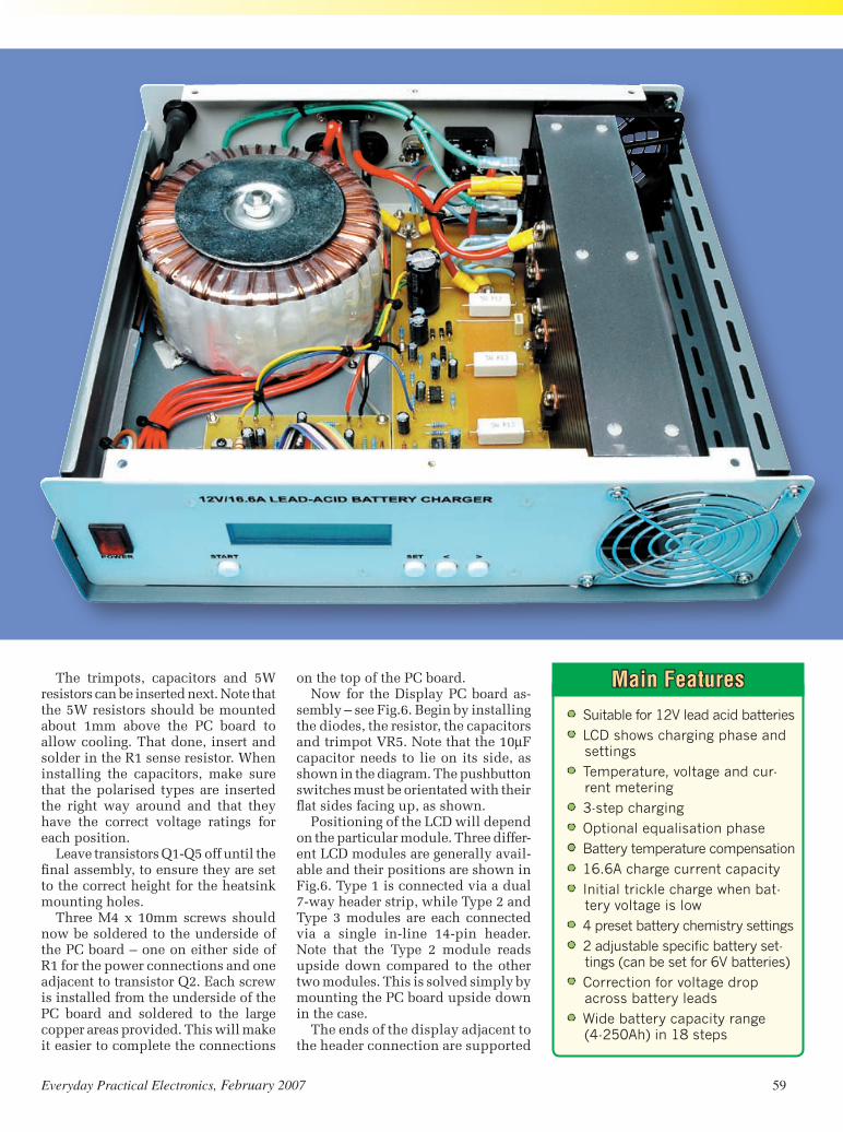
Constructional Project Constructional Project Constructional Project Constructional Project
58 EverydayPracticalElectronics,February2007 EverydayPracticalElectronics,February2007 59
A charger for deep-cycle 12V batteries
Main Features• Suitable for 12V lead acid batteries
• LCD shows charging phase and settings
• Temperature, voltage and cur-rent metering
• 3-step charging
• Optional equalisation phase
• Battery temperature compensation
• 16.6A charge current capacity
• Initial trickle charge when bat-tery voltage is low
• 4 preset battery chemistry settings
• 2 adjustable specific battery set-tings (can be set for 6V batteries)
• Correction for voltage drop across battery leads
• Wide battery capacity range (4-250Ah) in 18 steps
The trimpots, capacitors and 5W resistors can be inserted next. Note that the 5W resistors should be mounted about 1mm above the PC board to allow cooling. That done, insert and solder in the R1 sense resistor. When installing the capacitors, make sure that the polarised types are inserted the right way around and that they have the correct voltage ratings for each position.
Leave transistors Q1-Q5 off until the final assembly, to ensure they are set to the correct height for the heatsink mounting holes.
Three M4 x 10mm screws should now be soldered to the underside of the PC board – one on either side of R1 for the power connections and one adjacent to transistor Q2. Each screw is installed from the underside of the PC board and soldered to the large copper areas provided. This will make it easier to complete the connections
on the top of the PC board.Now for the Display PC board as-
sembly – see Fig.6. Begin by installing the diodes, the resistor, the capacitors and trimpot VR5. Note that the 10µF capacitor needs to lie on its side, as shown in the diagram. The pushbutton switches must be orientated with their flat sides facing up, as shown.
Positioning of the LCD will depend on the particular module. Three differ-ent LCD modules are generally avail-able and their positions are shown in Fig.6. Type 1 is connected via a dual 7-way header strip, while Type 2 and Type 3 modules are each connected via a single in-line 14-pin header. Note that the Type 2 module reads upside down compared to the other two modules. This is solved simply by mounting the PC board upside down in the case.
The ends of the display adjacent to the header connection are supported

Constructional Project Constructional Project Constructional Project Constructional Project
60 EverydayPracticalElectronics,February2007 EverydayPracticalElectronics,February2007 61
using M2.5 x 15mm screws and M2.5 nuts. The 4-way and 6-way header pins are right-angle types. Make up the plugs by terminating the 6-way and 4-way rainbow cable into the header clips and insert the clips into the header shells. The plugs are placed at each end of the wire cabling.
Note that the PC board overlays show a pin 1 orientation for these connectors. Ensure that their polari-ties are correct.
You can now start work on the Control PC board by installing the resistors, diodes and PC stakes. IC3 and IC4 are soldered directly to the PC board while IC5 (the PIC micro-controller) is mounted in a socket (don’t plug IC5 in yet). The regulator mounts horizontally and is secured to the board using an M3 x 10mm screw and M3 nut.
Next, install trimpots VR3 and VR4, making sure the 200Ω trimpot goes into the VR4 position, near the regulator. The capacitors can then be installed, again making sure that the electrolytics are correctly orientated.
Testing the PC boardsThe Control and Display PC boards
can now be tested for correct opera-tion. First, connect them together us-ing the 4-way and 6-way cabling as shown in Fig.9. Make sure IC5 has not been installed and set trimpot VR4 fully anticlockwise.
Next, apply power (ie, any DC volt-age between 12V and 25V) between
the +25V supply pin and the GND pin. That done, connect a multimeter set to read 10V between the GND pin and the tab on the regulator (REG1). Adjust VR4 for a 5.0V output.
Assuming all is OK, switch off the power, install IC5 into its socket and solder SENSOR 1 to the PC stakes. Wait a minute or so until the sensor cools after soldering, then install the shorting jumpers JP1 and JP2.
Re-apply power and adjust trimpot VR5 on the display PC board for best display contrast. Check that the dis-play shows BATTERY AMP HOUR and <60Ah>. Also, press the Set switch and check that the display now shows BATTERY TYPE and <LEAD ACID>. Press Start and check that the display shows BULK and 26 Deg C 0.0V 0.0A (for example).
Next, adjust trimpot VR3 so that the display shows the same temperature as the ambient (this can be measured using another thermometer). Note that the display reads in 2°C increments, so set the display to the nearest value available. This may need to be re-checked to be sure the reading tracks the ambient value correctly.
To test the Power PC board, apply between 12V and 25V DC to the +25V and GND pins. That done, check the voltage between pins 8 & 4 of IC1 and IC2 – this voltage should be similar to the input supply. The voltage across ZD3 should be close to 5.1V if the supply is around 25V but may be lower than this if the power supply is only 12V.
Drilling the caseYou will need to drill quite a few
holes and make cutouts in the case. We should note at the outset that the case used in our prototype has a drawback in that its bottom panel has a section of mesh right where we wanted to mount the transformer. This means that it needs an additional large metal plate underneath to provide secure anchor-ing for the transformer bolt.
On the rear panel, holes and cutouts are required for the fan and finger guards, mini XLR socket, bridge rectifi-er BR2, blade fuseholder, cable glands for the charger leads, mains cord-grip grommet and the fuseholder.
The fan is mounted towards the far edge of the panel. It requires a 75mm diameter cutout and this is made by drilling a series of holes around the perimeter and then knocking out the centre piece. File the cutout to shape.
On the front panel, cutouts and holes are required for the fan outlet and finger guard mounting, the LCD win-dow, the control and power switches and the mounting pillars for Display
Table 1: Resistor Colour Codes
Table 2: Capacitor Codes
Value μF Code EIA Code IEC Code 470nF 0.47μF 474 470n 220nF 0.22μF 224 220n 100nF 0.1μF 104 100n 1nF 0.001μF102 1n
o No. Value 4-Band Code (1%) 5-Band Code (1%) o 1 1MΩ brownblackgreenbrown brownblackblackyellowbrown o 1 910kΩ whitebrownyellowbrown whitebrownblackorangebrown o 1 100kΩ brownblackyellowbrown brownblackblackorangebrown o 1 43kΩ yelloworangeorangebrown yelloworangeblackredbrown o 4 22kΩ redredorangebrown redredblackredbrown o 5 10kΩ brownblackorangebrown brownblackblackredbrown o 1 5.6kΩ greenblueredbrown greenblueblackbrownbrown o 2 3.3kΩ orangeorangeredbrown orangeorangeblackbrownbrown o 1 1.8kΩ browngreyredbrown browngreyblackbrownbrown o 5 1kΩ brownblackredbrown brownblackblackbrownbrown o 1 330Ω orangeorangebrownbrown orangeorangeblackblackbrown o 1 270Ω redvioletbrownbrown redvioletblackblackbrown o 1 150Ω browngreenbrownbrown browngreenblackblackbrown o 1 120Ω brownredbrownbrown brownredblackblackbrown o 1 10Ω brownblackblackbrown brownblackblackgoldbrown
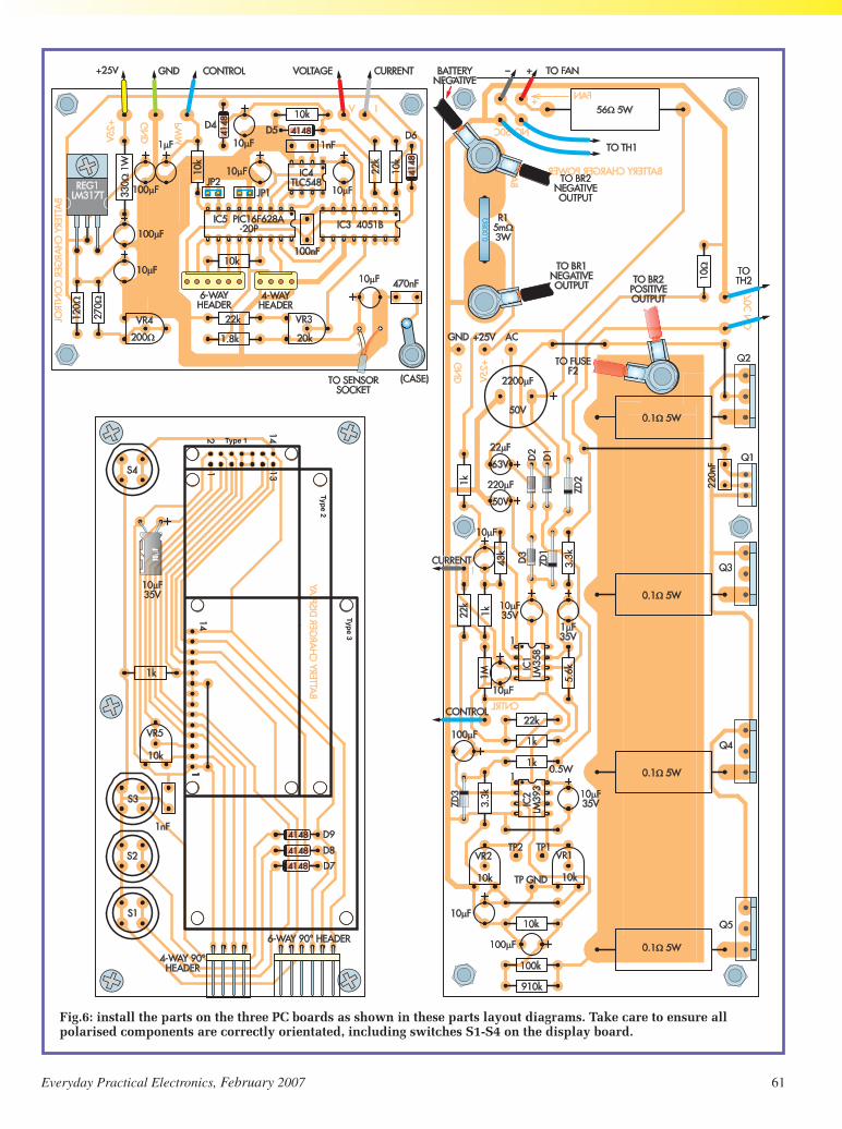
Constructional Project Constructional Project Constructional Project Constructional Project
60 EverydayPracticalElectronics,February2007 EverydayPracticalElectronics,February2007 61
Type 1
Type 2
Type 3
Fig.6: install the parts on the three PC boards as shown in these parts layout diagrams. Take care to ensure all polarised components are correctly orientated, including switches S1-S4 on the display board.

Constructional Project Constructional Project Constructional Project Constructional Project
62 EverydayPracticalElectronics,February2007 EverydayPracticalElectronics,February2007 63
3
Fig.8: the mains earth solder lug must be securely attached to the metal chassis as shown here. Tighten the first nut very firmly before winding on the second ‘lock nut’. Note: scrape away any paint or powder coating from around the mounting point, to ensure a good connection.
PC board. The latter holes for the PC board pillars need to be countersunk, to suit countersink screws.
The LCD window cutout required is 67 x 19mm, suitable for fitting the Perspex window. The fan cutout is half a circle and this is on the side where the heatsink is positioned. The cutout position for the LCD window depends on the particular module that is used. Fit the front panel label and the Per-spex window to the front panel.
The front panel can be assembled now. Insert the M3 x 5mm Nylon countersunk screws for the Display PC board mounting and secure these with the 10mm tapped standoffs. The Display PC board is attached to these screws and held in place with M3 nuts. The fan guard is secured with M3 x 10mm screws and M3 nuts, while the the mains switch is simply clipped into its rectangular cutout (make sure that it is a tight fit, so that it doesn’t come adrift).
Holes in the box baseplate are re-quired for the mains earth solder lug mounting, the transformer mounting bolt and for mounting the PC boards and the heatsink. In addition, two holes are required for the 3-way mains terminal block.
Our prototype box included side panels which are used to increase the case height and these have side flanges. The panel for the transformer side of the box needs to have these flanges removed. We used a nibbling tool to cut these flanges away and filed the edges down to a smooth finish.
The flanges on the fan side also need to be removed near the fan to allow it to be positioned without fouling.
In addition, the front panel requires a 50 x 4mm notch adjacent to where the heatsink mounts on the top and bottom mounting flanges. These are required to allow the heatsink to fit without touching the panel.
Insulated heatsink mountingAn important aspect of the charger
design is the heatsink which is com-pletely insulated from the case. This was done so that no mica or silicone washers are required when mount-ing the bridge rectifier and the five power transistors (Q1-Q5) and this maximises heat transfer from those components.
In addition, it greatly simplifies the high-current power connections to the collectors of the five power transis-tors. The +18V output from the main bridge rectifier simply connects to the heatsink and since all the transistor collector tabs are also bolted to the heatsink, that makes the connection. Simple – but you do have to make sure the heatsink is properly isolated, so there is no chance of shorts between it and the case.
The heatsink requires tapped holes to mount the bridge rectifier (BR1), the
Fig.7: this diagram shows the hardware codes (above) for the main wiring diagram (Fig.9). At right are the wiring connections for an alternative transformer.

Constructional Project Constructional Project Constructional Project Constructional Project
62 EverydayPracticalElectronics,February2007 EverydayPracticalElectronics,February2007 63
PLASTIC
OV
OV115V
115V
Fig.9: this is the main wiring diagram for the battery charger. Be sure to use heavy-duty cables where indicated (see text) and take care with the mains wiring. The terminals of switch S5 should all be insulated (see text), as should the terminals for Fuse F1 (using heatshrink). Once the wiring is in place, it should be secured using cable ties, as shown in the photos.

Constructional Project Constructional Project Constructional Project Constructional Project
64 EverydayPracticalElectronics,February2007 EverydayPracticalElectronics,February2007 65
two thermostats, Q1-Q5 and the posi-tive supply connection. In addition, the top and bottom surfaces require six holes each.
A sheet of 0.5mm plastic insulating sheet (225 x 45mm) is fixed to the top and bottom surfaces of the heatsink to ensure that it cannot short to either the base or the lid of the case. The bottom holes are tapped M4, so that the heat-sink can be attached to the baseplate using Nylon M4 screws (the plastic sheet is sandwiched between the heat-sink and the base of the case).
The holes in the top of the heatsink are tapped M3 so that the second 225 x 45 x 0.5mm plastic sheet can be secured using M3 countersunk Nylon screws. Do not use glue to secure the plastic sheeting.
Fig.10 shows the drilling and tap-ping details for the heatsink.
Attach the thermal cutouts to the heatsink using a smear of heatsink compound to the back of the sen-sors before securing them with M3 x 10mm screws and star washers. That
done, install the heatsink in the case. Check that it is isolated from the case by measuring the resistance between them with a multimeter – the meter should indicate an open circuit.
Installing the power boardNext, install the PC board standoffs
onto the baseplate using the M3 tapped 6mm Nylon standoffs and the M3 x 15mm screws and place the Power PC board in place. That done, insert the five power transistors (Q1-Q5) and adjust their height above the PC board so that the holes in the transistor tabs line up with their respective tapped holes in the heatsink. You can then carefully lift the board out and solder the centre leg of each power transistor. When you’ve done this, replace the board and re-check alignment before soldering the other transistor leads.
The power transistors can now be bolted to the heatsink. To do this, first, apply a smear of heatsink compound to their mounting faces, then secure the Power PC board in place with M3
This view shows how the parts are arranged on the rear panel and also shows how the display board is mounted. Be sure to insulate the mains switch terminals and use cable ties to secure the wiring.
nuts. The power transistors can then be fastened to the heatsink using M4 x 10mm screws and star washers. Q1 (BD649) is secured using an M3 x 10mm screw and star washer.
Similarly, apply heatsink compound to the back of bridge rectifier BR1 be-fore securing it in place with an M4 x 15mm screw and star washer. Make sure it is oriented with its positive (‘+’) terminal positioned as shown.
The Control PC board can now be attached to the baseplate using 6mm standoffs, M3 x 15mm screws and M3 nuts. Note that the lower right mounting point connects the 470nF capacitor to chassis via a solder lug. Check that this is earthed using a multimeter between chassis and this earth point (you should measure this as a short circuit).
Note that one of the extra securing points for connecting the rear panel to the baseplate is located beneath where the fan mounts. The M3 securing nut for this should be glued in place so as to make assembly easier.
Fig.9 shows how the hardware is installed on the rear panel. Secure the bridge rectifier (BR2), the blade

Constructional Project Constructional Project Constructional Project Constructional Project
64 EverydayPracticalElectronics,February2007 EverydayPracticalElectronics,February2007 65
Fig.10: here are the drilling and tapping details for the heatsink. It is completely isolated from the chassis, to avoid using insulation washers for the power devices.

Constructional Project Constructional Project Constructional Project Constructional Project
66 EverydayPracticalElectronics,February2007 EverydayPracticalElectronics,February2007 67
Parts List – Battery Charger
1 Power PC board code 604, 224 x 77mm1 Control PC board code 605, 92 x 69mm1 Display PC board code 606, 141 x 66mm. All PCBs are available from the
EPE PCB Service1 88.1mm high x 279mm deep x
304mm wide metal case1 230V to 18V 300VA mains
toroidal transformer (2 x 9V or 2 x 18V secondaries) (T1)
1 fan-assisted heatsink, 225 long1 80mm 12V DC 2.4W fan2 80mm fan finger guards1 NO 50°C thermostat switch (TH1)1 NO 70°C thermostat switch (TH2)1 M205 panel-mount safety fuse-
holder (F1) 1 3A M205 slow blow fuse1 30A chassis blade fuseholder
(F2) 1 20A blade fuse10 100mm long cable ties6 20 x 20 x 8mm large adhesive
rubber feet2 4-8mm waterproof cable glands1 cordgrip clamp for mains cord1 7.5A mains cord and plug1 3-way 10A terminal strip2 50A insulated battery clips (1 red, 1 black)2 2.54mm jumper shunts
(JP1,JP2)2 2-way header terminal strips1 2-line, 16 characters per line
alphanumeric LCD module 1 14-way SIL header strip for Type
1 and Type 2 LCD modules1 14-way DIL header strip for Type
1 LCD module1 6-way polarised header plug1 6-way polarised right angle
header plug
2 6-way polarised header sockets1 4-way polarised header plug1 4-way polarised right angle
header plug2 4-way polarised header sockets 6 5.3mm ID eyelet crimp connec-
tors suiting 6mm wire9 female insulated 6.4mm spade
connectors suiting 4.8mm wire2 female insulated 6.4mm spade
connectors suiting 6mm wire1 solder lug1 mini XLR 3-pin line plug1 mini XLR 3-pin chassis mount
socket1 SPST neon illuminated 230V 6A
rocker switch (S5)4 White SPST PC board mount
tactile snap action switches (S1-S4)
1 18-pin DIL IC socket10 M3 tapped x 6mm Nylon
standoffs5 M3 tapped x 10mm standoffs3 M4 x 15mm screws12 M4 x 10mm screws6 M4 x 12 Nylon screws5 M4 nuts19 M4 star washers12 M3 x 15 screws5 M3 x 15mm Nylon countersunk
screw12 M3 x 10mm screws 6 M3 x 6mm Nylon countersunk
screws10 M3 nuts12 M3 star washers2 M2.5 x 12mm screws2 M2.5 nuts23 PC stakes1 50 x 50mm piece of plastic insu-
lating material1 67 x 19mm sheet of 2.5-3mm
clear Acrylic or Perspex2 225 x 45mm pieces of 0.5mm
flexible sheet plastic to insulate
heatsink top and bottom (eg thin plastic chopping mat)
1 225 x 80mm piece of 0.5mm flexible sheet plastic to insulate below the power PC board
2 30 x 70mm pieces of 0.5mm flexible sheet plastic for cov-ering ventilation holes in fan airway tunnel
1 1.5m length of single core shielded cable
1 200mm length of 6-way rainbow cable
1 200mm length of 4-way rainbow cable
1 200mm length of 0.7mm tinned copper wire
1 1.5m 3.3mm squared 30A red automotive wire (12G)
1 1.5m 3.3mm squared 30A black automotive wire (12G)
1 500mm length of 24 x 0.2mm red hookup wire
1 500mm length of 24 x 0.2mm black hookup wire
1 200mm length of 32 x 0.2mm brown hookup wire
1 200mm length of 32 x 0.2mm blue hookup wire
1 100mm length of 16mm heat-shrink tubing
1 100mm length of 10mm heat-shrink tubing
1 50mm length of 6mm heatshrink tubing
Semiconductors1 LM358 dual op amp (IC1)1 LM393 dual comparator (IC2)1 4051 analogue 1 of 8 selector
(IC3)1 TLC548 8-bit serial A/D converter
(IC4)1 PIC16F628A-20P microcontroller
programmed with battchrg.hex (IC5) available for free download from the EPE website at: www.epemag.co.uk.
fuseholder, the mini XLR panel socket, the fan and the fan guard, as shown in this diagram. That done, secure the cable glands for the battery leads and the M205 fuseholder.
The fan should be orientated so that it blows air inside the case. If you look closely, you will see arrows on the fan that indicate the blade direction and airflow (ours was installed with the labelled side facing inside the box).
Note that we have specified extra star washers in the parts list. This is so that you can place them under the screws attaching the panels to assem-ble the case. The star washers will bite into the metal to ensure the panels are earthed correctly to the baseplate. Note also that you should scrape away any paint or powder coating around the screw holes, to ensure good metal-to-metal contact.
Once the case has been assem-bled, each separate panel should be checked for a good connection to the baseplate using a multimeter set to read low ohms. Don’t skip this step – it’s vital to ensure that all panels are correctly earthed, to ensure safety.
WiringFig.9 shows all the wiring details. First,
strip back 250mm of the sheathing at

Constructional Project Constructional Project Constructional Project Constructional Project
66 EverydayPracticalElectronics,February2007 EverydayPracticalElectronics,February2007 67
Pre-programmedPICsareavail-ablefromMagenta Electronics
1BD649NPNDarlingtontransistor(Q1)
4TIP3055NPNpowertransistors(Q2-Q5)
1LM335Ztemperaturesensor(SENSOR1)
150A600Vbridgerectifier(BR1)135A400Vbridgerectifier(BR2)31N40041Adiodes(D1-D3)61N4148diodes(D4-D9)215V5WZenerdiodes(ZD1,ZD2)15.1V1WZenerdiode(ZD3)
Capacitors12200µF50VPCelectrolytic1220µF50VPCelectrolytic4100µF25VPCelectrolytic122µF63VPCelectrolytic1110µF35VPCelectrolytic21µF35VPCelectrolytic1470nF50VMKTpolyester1220nF50VMKTpolyester1100nF50VMKTpolyester21nF50VMKTpolyester
Resistors (0.25W 1%)11MΩ 41kΩ1910kΩ 11kΩ0.5W1100kΩ 1330Ω1W143kΩ 1270Ω422kΩ 1120Ω510kΩ 156Ω5W15.6kΩ 110Ω23.3kΩ 40.1Ω5W11.8kΩ10.005Ω3W1%
Trimpots310kΩhorizontaltrimpots
(VR1,VR2,VR5)120kΩhorizontaltrimpot(VR3)1200Ωhorizontaltrimpot(VR4)
MiscellaneousHeatsinkcompound,solder.
the end of the 3-core mains cable. That done, secure the cord into the back panel using a cord-grip grommet. This grom-met needs to be really tight, so that the cord cannot be pulled out. Cut the Live (brown) and the Earth (green/yellow) wires to 70mm length. The earth wire connects to the solder lug – it should be soldered in place rather than crimped to ensure a good earth connection is made. Also, scrape away the paint
from the earth position on the baseplate to ensure a reliable connection to the case and use an M4 x 15mm screw, a star washer and an M4 nut to attach the lug in place. A second M4 lock nut is then fitted, so that the assembly cannot possibly come undone.
Now measure the resistance between chassis and the earth pin on the mains plug. This should be zero ohms. If not, re-check the connections to chassis. Check also that you get a zero ohm reading between the earth pin of the mains plug and all case panels.
The Live lead is connected to the fuseholder by first passing the wire through a 50mm length of 16mm heatshrink tubing and then solder-ing it in place. The other terminal of the fuseholder also passes through the heatshrink tubing before it is soldered in place. Finally, slip the heatshrink tubing over the fuseholder before shrinking it down with a hot-air gun.
Note: be sure to use a safety fuse-holder for fuse F1 (see parts list), so that there is no danger of receiving a shock if the fuse is removed while the unit is plugged into the mains.
Transformer mountingTypically, the mains transformer
will be supplied with two circular rub-ber washers, a dished metal mounting plate and a mounting bolt. As noted previously, the prototype’s case re-quired an additional plate underneath to provide secure anchoring for the transformer bolt.
The 3-way mains terminal block is placed over a 50 x 50mm piece of plastic insulating material and is held in place using two M3 x 15mm screws and M3 nuts. The wiring to the mains side of the power transformer depends on its windings (the power transformer will be supplied with one of two dif-ferent winding arrangements).
The prototype transformer had 2 x 115V windings and 2 x 9V windings. This requires the two 115V windings
to be connected in series, suitable for a 230V mains input. The two 9V windings need to be connected in se-ries to obtain 18V. Other transformers will have a single 230V winding and two 18V windings. The 18V windings will need to be connected in parallel. The different wiring arrangements are shown in Figs.7 & 9.
Use 250VAC-rated wire to connect between the power switch terminals and the terminal block. Insulated 6.3mm crimp spade lugs make the connections to the switch, while the remaining wiring is as shown in Fig.9. Note that heavy-duty 12-gauge wire is used for the connections to BR1 and BR2 and for the screw terminals on the PC board via crimp eyelets.
The battery leads are also run us-ing 12-gauge wires. These leads must be exactly 880mm long and they pass through the cable glands in the rear panel and are terminated to the battery clips. The battery clips we used require the jaw to be first removed and the wire passed through the handle of its plastic clip before the lead is soldered.
Note: if you want leads longer than 880mm, you can use heavier gauge wire so that you get 0.01Ω total resist-ance in both the positive and negative leads (this exact resistance is required for the control circuit to accurately calculate the voltage loss in the battery leads). For example, you can use 2m each of 8-gauge wire (8mm2).
Alternatively, the voltage sensing lead that connects to fuse F2 inside the unit can be extended to the full length of the charger lead and connected to the positive battery clip. This provides remote sensing in the positive lead. In this case, the negative lead could be 1.76m long using 12-gauge wire or 4m long using (thicker) 8-gauge wire.
Heavy-duty hookup wire is used to make the remaining connections to the PC boards, except for the shielded cable used for the temperature sensor lead. This runs from the back of the mini XLR socket to the control PC
Fig.12: here’s how to wire the temperature sensor. It’s protected by covering it with heatshrink tubing.

Constructional Project Constructional Project Constructional Project Constructional Project
68 EverydayPracticalElectronics,February2007 EverydayPracticalElectronics,February2007 00
board. Cable ties are used to hold the wires together and stop them from coming adrift. This is important for the mains wires – use cable ties to secure the wires at the rear of fuse F1, at the mains switch and at the terminal block.
Temperature sensorThe temperature sensor (Sensor 1) is mounted at the end
of a 900mm length of shielded cable. It can be inserted into a 5mm inside diameter tube and covered in heatshrink tubing. Alternatively, wire the sensor and cover it in heat-shrink without the tube. Make sure the probe does not have exposed metal that can short to the battery terminals or to the case.
The other end of the wire connects to pins 1 and 3 of a mini XLR plug. Use the shield connection for pin 1.
Final testsDo a thorough check of all your wiring, then fit the lid
on the case before applying power. Check that the power switch lights up when on. The LCD should also be on.
Next, disconnect power and remove the lid. That done, reconnect power and measure the supply voltage between the GND pin and pin 8 of both IC1 and IC2. These should be around 30V and 25V respectively. Check also that ZD3 has 5.1V across it.
Adjust VR1 so that the voltage between TP1 and TP GND is 1.7V, then adjust VR2 for 1.8V between TP2 and TP GND. This sets the circuit over-voltage and over-current levels to 17V and 18A respectively.
The over-voltage adjustment sets the maximum allow-able voltage when charging during equalisation. You may wish to raise this to allow the equalisation to operate for the full three hours. Alternatively, you can reduce the value to prevent damage to any equipment connected to the bat-tery during equalisation. Note that the over-voltage value is restricted to 10-times the TP1 voltage.
Final pointsThe cooling fan will cycle on and off during charging, par-
ticularly at the higher currents. To ensure adequate cooling, the air inlet at the rear of the unit should not be blocked.
When using the charger, make sure that the battery clips are correctly connected to the battery terminals. Check the Ah setting for the battery. Remember that a battery with a reserve capacity (RC) rating will need this value to be multiplied by 0.42 to convert it to the Ah capacity. Also, be sure to set the correct battery type.
At the start of bulk charging, it will take a few seconds to bring the current up to the 25% of Ah current. Note that an already charged battery will cycle through to the float charge in a short space of time. This fast cycling through to float can also indicate a faulty battery, if it has not been charged recently.
The temperature sensor does not necessarily need to be placed on the battery case during charging. In most cases, the sensor can be located adjacent to the battery, to monitor the ambient temperature.
However, the sensor does need to be placed on the battery if it has been brought to the charger from a different tem-perature environment, such as a cold room. You can secure the sensor to the battery using masking tape. Alternatively, you can use adhesive-backed Velcro material if the battery is to be charged regularly. EPE
Fig.11: this artwork can be used as a drilling and cutout template for the front panel. Note that the display cutout position shown here is for the Type 1 LCD and is different for the Type 2 and Type 3 LCDs.
Reproduced by arrangement with SILICON CHIP magazine 2007.
www.siliconchip.com.au


EELLEECCTTRROONNIICCSS MMAANNUUAALLSS OONN CCDD--RROOMM ££2299..9955 EEAACCHH
Everything you need to know to getstarted in repairing electronic equipment Around 900 pages Fundamental principles Troubleshootingtechniques Servicing techniques Choosing and using testequipment Reference data Manufacturers’ web links Easy-to-use Adobe Acrobat format Clear and simple layout Vital safety precautions Professionally written Supplements
SAFETY: Safety Regulations, Electrical Safety and First Aid.UNDERPINNING KNOWLEDGE: Electrical and Electronic Principles,Active and Passive Components, Circuit Diagrams, CircuitMeasurements, Radio, Computers, Valves and Manufacturers’ Data,etc. PRACTICAL SKILLS: Learn how to identify ElectronicComponents, Avoid Static Hazards, Carry Out Soldering and Wiring,Remove and Replace Components. TEST EQUIPMENT: How toChoose and Use Test Equipment, Assemble a Toolkit, Set Up aWorkshop, and Get the Most from Your Multimeter and Oscilloscope,etc. SERVICING TECHNIQUES: The Manual includes vital guidelineson how to Service Audio Amplifiers. The Supplements include similarguidelines for Radio Receivers, TV Receivers, Cassette Recorders,Video Recorders, Personal Computers, etc. TECHNICAL NOTES:Commencing with the IBM PC, this section and the Supplements dealwith a very wide range of specific types of equipment – radios, TVs,cassette recorders, amplifiers, video recorders etc. REFERENCEDATA: Diodes, Small-Signal Transistors, Power Transistors, Thyristors,Triacs and Field Effect Transistors. Supplements include OperationalAmplifiers, Logic Circuits, Optoelectronic Devices, etc.
The essential reference work foreveryone studying electronics Over 800 pages In-depth theory Projects to build Detailed assembly instructions Full componentschecklists Extensive data tables Manufacturers’ weblinks Easy-to-use Adobe Acrobat format Clear andsimple layout Comprehensive subject range Professionally written SupplementsBASIC PRINCIPLES: Electronic Components and theirCharacteristics; Circuits Using Passive Components;Power Supplies; The Amateur Electronics Workshop; TheUses of Semiconductors; Digital Electronics; OperationalAmplifiers; Introduction to Physics, including practicalexperiments; Semiconductors and Digital Instruments.CIRCUITS TO BUILD: The Base Manual describes 12projects including a Theremin and a Simple TENSUnit.ESSENTIAL DATA: Extensive tables on diodes,transistors, thyristors and triacs, digital and linear i.c.s.EXTENSIVE GLOSSARY: Should you come across atechnical word, phrase or abbreviation you’re not familiarwith, simply look up the glossary and you’ll find acomprehensive definition in plain English.The Manual also covers Safety and provides web linksto component and equipment Manufacturers andSuppliers.
Your CD-ROM(s) will beposted to you by first class
mail or airmail, normallywithin four working days of
receipt of your order
ORDER FORMSimply complete and return the order
form with your payment to thefollowing address:
Wimborne Publishing Ltd,408 Wimborne Road East, Ferndown,
Dorset BH22 9NDPrice includes postage to anywhere in
the World
PLEASE send me
THE MODERN ELECTRONICS MANUAL CD-ROM
ELECTRONICS SERVICE MANUAL CD-ROMI enclose payment of £29.95 (for one Manual) or £49.90 for both Manuals (saving £10 byordering both together).
FULL NAME . . . . . . . . . . . . . . . . . . . . . . . . . . . . . . . . . . . . . . . . . . . . . . . . . . . . . . . . . . . . . . . .
ADDRESS . . . . . . . . . . . . . . . . . . . . . . . . . . . . . . . . . . . . . . . . . . . . . . . . . . . . . . . . . . . . . . . . .
. . . . . . . . . . . . . . . . . . . . . . . . . . . . . . . . . . . . . . . . . . . . . . . . . . . . . . . . . . . . . . . . . . . . . . . . . .
. . . . . . . . . . . . . . . . . . . . . . . . . . . . . . . . . . . . . . . . . . . . . .POSTCODE . . . . . . . . . . . . . . . . . .
SIGNATURE . . . . . . . . . . . . . . . . . . . . . . . . . . . . . . . . . . . . . . . . . . . . . . . . . . . . . . . . . . . . . . . .
I enclose cheque/PO in UK pounds payable to Wimborne Publishing Ltd.
Please charge my Visa/Mastercard/Amex/Diners Club/Switch/Maestro
Card No . . . . . . . . . . . . . . . . . . . . . . . . . . . . . . . . . . . . . . . Switch/Maestro Issue No . . . . . .
Valid From . . . . . . . . . . . . . Expiry Date . . . . . . . . . . . . . . .
Card Security Code . . . . . . . . . . . . (The last 3 digits on or just under the signature strip)
(PLEASE PRINT)
Wimborne Publishing Ltd., 408 Wimborne Road East, Ferndown, Dorset BH22 9ND. Tel: 01202 873872. Fax: 01202 874562.
ELECTRONICS SERVICE MANUAL
SSPPEECCIIAALLOOFFFFEERR
Order both Manualstogether and
SSAAVVEE ££1100
THE MODERN ELECTRONICS MANUAL
We will happily exchange any faultyCD-ROMs but since the content can be printed
out we do not offer a refund on these items.
70 Everyday Practical Electronics, February 2006
Full contents list available online at: www.epemag.wimborne.co.uk
SUPPLEMENTS: Additional CD-ROMs each containing approximately 500 pages of additional information on specific areas ofelectronics are available for £19.95 each. Information on the availability and content of each Supplement CD-ROM will be sent to you.
Presentation: CD-ROM suitable for any modern PC. Requires Adobe Acrobat Reader which is included on the CD-ROM.
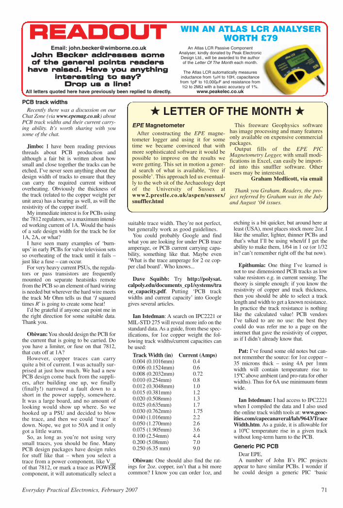
RREEAADDOOUUTTJJoohhnn BBeecckkeerr aaddddrreesssseess ssoommeeooff tthhee ggeenneerraall ppooiinnttss rreeaaddeerrss
hhaavvee rraaiisseedd.. HHaavvee yyoouu aannyytthhiinnggiinntteerreessttiinngg ttoo ssaayy??
DDrroopp uuss aa lliinnee!!
WIN AN ATLAS LCR ANALYSERWORTH £79
An Atlas LCR Passive ComponentAnalyser, kindly donated by Peak ElectronicDesign Ltd., will be awarded to the authorof the Letter Of The Month each month.
The Atlas LCR automatically measuresinductance from 1µH to 10H, capacitancefrom 1pF to 10,000µF and resistance from1Ω to 2MΩ with a basic accuracy of 1%.
www.peakelec.co.uk
Email: [email protected]
All letters quoted here have previously been replied to directly.
suitable trace width. They’re not perfect,but generally work as good guidelines.
You could probably Google and findwhat you are looking for under PCB traceamperage, or PCB current carrying capa-bility, something like that. Maybe even‘What is the trace amperage for 2 oz cop-per clad board’. Who knows...
Dave Squibb: Try http://polysat.calpoly.edu/documents_cp1/systems/trace_capacity.pdf. Putting ‘PCB trackwidths and current capacity’ into Googlegives several articles.
Ian Istedman: A search on IPC2221 orMIL-STD 275 will reveal more info on thestandard data. As a guide, from these spec-ifications, for 1oz copper weight the fol-lowing track widths/current capacities canbe used:
Track Width (in) Current (Amps) 0.004 (0.1016mm) 0.4 0.006 (0.1524mm) 0.6 0.008 (0.2032mm) 0.72 0.010 (0.254mm) 0.8 0.012 (0.3048mm) 1.0 0.015 (0.381mm) 1.2 0.020 (0.508mm) 1.3 0.025 (0.635mm) 1.7 0.030 (0.762mm) 1.75 0.040 (1.016mm) 2.2 0.050 (1.270mm) 2.6 0.075 (1.905mm) 3.6 0.100 (2.54mm) 4.4 0.200 (5.08mm) 7.0 0.250 (6.35 mm) 9.0
Obiwan: One should also find the rat-ings for 2oz. copper, isn’t that a bit morecommon? I know you can order 1oz, and
etching is a bit quicker, but around here atleast (USA), most places stock more 2oz. Ilike the smaller, lighter, thinner PCBs andthat’s what I’ll be using when/if I get theability to make them, 1/64 in 1 oz (or 1/32in? can’t remember right off the bat now).
Epithumia: One thing I’ve learned isnot to use dimensioned PCB tracks as lowvalue resistors e.g. in current sensing. Thetheory is simple enough: if you know theresistivity of copper and track thickness,then you should be able to select a tracklength and width to get a known resistance.In practice the track resistance is nothinglike the calculated value! PCB vendorsI’ve talked to are no use: the best theycould do was refer me to a page on theinternet that gave the resistivity of copper,as if I didn’t already know that.
Pat: I’ve found some old notes but can-not remember the source: for 1oz copper –35 microns thick – using 4A per 1mmwidth will contain temperature rise to15ºC above ambient (and pro-rata for otherwidths). Thus for 6A use minimuum 6mmwide.
Ian Istedman: I had access to IPC2221when I compiled the data and I also usedthe online track width tools at: www.geoc-ities.com/capecanaveral/lab/9643/TraceWidth.htm. As a guide, it is allowable fora 10ºC temperature rise in a given trackwithout long-term harm to the PCB.
Generic PIC PCBDear EPE,A number of John B’s PIC projects
appear to have similar PCBs. I wonder ifhe could design a generic PIC ‘basic
PCB track widthsRecently there was a discussion on our
Chat Zone (via www.epemag.co.uk) aboutPCB track widths and their current carry-ing ability. It’s worth sharing with yousome of the chat.
Jimbo: I have been reading previousthreads about PCB production andalthough a fair bit is written about howsmall and close together the tracks can beetched, I’ve never seen anything about thedesign width of tracks to ensure that theycan carry the required current withoutoverheating. Obviously the thickness ofthe track (related to the copper weight perunit area) has a bearing as well, as will theresistivity of the copper itself.
My immediate interest is for PCBs usingthe 7812 regulators, so a maximum intend-ed working current of 1A. Would the basisof a safe design width for the track be for1A, 2A, or what?
I have seen many examples of ‘burn-ups’ in early PCBs for valve television setsso overheating of the track until it fails –just like a fuse – can occur.
For very heavy current PSUs, the regula-tors or pass transistors are frequentlymounted on separate heatsinks remotefrom the PCB so an element of hard wiringis needed but wherever the hard wire meetsthe track Mr Ohm tells us that ‘I squaredtimes R’ is going to create some heat!
I’d be grateful if anyone can point me inthe right direction for some suitable data.Thank you.
Obiwan:You should design the PCB forthe current that is going to be carried. Doyou have a limiter, or fuse on that 7812,that cuts off at 1A?
However, copper traces can carryquite a bit of current. I was actually sur-prised at just how much. We had a newPCB design come back from the suppli-ers, after building one up, we finally(finally!) narrowed a fault down to ashort in the power supply, somewhere.It was a large board, and no amount oflooking would show up where. So wehooked up a PSU and decided to blowthe trace, and then we could ‘trace’ itdown. Nope, we got to 50A and it onlygot a little warm.
So, as long as you’re not using verysmall traces, you should be fine. ManyPCB design packages have design rulesfor stuff like that – when you select atrace from a power component, like Voutof that 7812, or mark a trace as POWERcomponent, it will automatically select a
LETTER OF THE MONTH EPE Magnetometer
After constructing the EPE magne-tometer logger and using it for sometime we became convinced that withmore sophisticated software it would bepossible to improve on the results wewere getting. This set in motion a gener-al search of what is available, ‘free ifpossible’. This approach led us eventual-ly to the web sit of the Archaeology deptof the University of Sussex atwww2.prestle.co.uk/aspen/sussex/snuffler.html
This freeware Geophysics softwarehas image processing and many featuresonly available on expensive commercialpackages.
Output fills of the EPE PICMagnetometry Logger, with small modi-fications in Excel, can easily be import-ed into this snuffler software. Otherusers may be interested.
Graham Medlicott, via email
Thank you Graham. Readers, the pro-ject referred by Graham was in the Julyand August ‘04 issues.
Everyday Practical Electronics, February 2007 71

72 Everyday Practical Electronics, February 2007
board’ that contains the PIC, crystal, pro-gram connector, LCD, power supply con-nections etc, and then bring out the rest ofwhat you normally use, to a daughter boardconnector.
The idea being, you wouldn’t have todesign the same board over and over, youand the users could make a whole stack ofthem at one time, maybe even justifyingthe cost of having them sent out and havesome professional service, solder mask andall that.
Then when you design a project, youdesign from the daughter board connectionup. Then the end user only needs to manu-facture the daughter board. Plug the daugh-ter board into the mother board and turn iton.
This should ease the board design on youand the end user. And if you played yourcards right, you could re-use the sameboard (mother board only) for several pro-jects, just the main board no daughterboard needed. Those would be ‘rare birds’,but mostly ones like the graphics demo orthe tape measure that were just a PIC, LCDand a few glue circuits.
Naturally, you couldn’t do this for everyproject, only the ones that have a lot incommon.
George Johnson (Obiwan on ourChat Zone), via email
George, you’re the second person to sug-gest a ‘universal’ board. I told him I didn’twish to tie myself to a given design, and tofeel free to change things as the needs arise– a universal board would inhibit me,though I agree that the occasional board issimilar to another, and indeed will havebeen a mod of that previous design –graphics LCD designs in particular.
EPE has done multipurpose boardsbefore, and indeed I’ve done at least oneseries that had the same board through-out, with different component values andpositions depending on needs. But no, Ibasically need to be free! I can neverreally tell what I may come up with in thefuture.
On my current Polyphonium (yet to bepublished) I use two PCBs and threePICs, master controller and PC inter-face, top octave and note generator, andLED interface, similar to the recentGiant LED Message Display (Nov ’06).It’s all brand new, except that many ofthe concepts I’ve used before. Andinevitably I have my own PCB layoutstyle developed over 30+ years!
IP CamerasDear EPE,I note the comments in Net Work
December regarding IP cameras. Theydon’t need a host PC, but without a host PCthe device would be on public networksand hence open to cracking; look onGoogle to see the amount of open camerasavailable. Imagine if this was your ownhome and someone was watching your pri-vate moments.
The encryption stated in the article ispurely the wireless encryption, and eventhat is flaky with only the simplest of tools
required to crack it. The TCP/IP element isopen to the world, unless that too isencrypted or ‘tunnelled’.
The best recommended installationwould be to have a decent wireless routerwith all of the cameras on a local networkscheme, I prefer the 192.168 schememyself, then password protect and accesscontrol all the cameras, such that they canonly be accessed from nominatedmachines.
It’s pretty academic really, as even with acamera, what will it stop? Sadly, nothing.Someone can be in and out so fast if theyare hungry for something.
Also, can you help the free world bytalking about Linux sometime too please.I’m sure 99% of people think there is nochoice outside the Microsoft empire.
Simon Topley, Silver Fox Computers,Folkestone, Kent.
As the author of Net Work, Alan repliedto Simon:
Thanks for your feedback. Point taken, acamera with a dedicated IP is accessibleon the open network, but they would haveto know or find the IP address or URL, andeven with that, they might still not knowwhere the camera was physically situated.This is no consolation for those having aromantic night indoors!
There have been a couple of recent caseswhere homeowners have been alerted viawebcams to break-in attempts and the localpolice caught the culprits in time. Therehave also been cases of ‘open’ camerasbeing found on Google, as you say. Thiscan be done by searching for certain textstrings (eg as commonly used in Axis net-work cam setups). I’ve just found viaGoogle, an IP network cam overlooking atraffic intersection in Norway and then anempty machine-shop full of expensive look-ing gear, but I have no idea where it is!These cameras are inherently expensiveand seem to appear mostly in commercialor industrial applications.
My point about the IP camera not need-ing a host PC (unlike a standard USB web-cam) was only to get across the idea that IPInternet hardware has its own networkaddress and operates as a standalone unit.I agree and have mentioned previously thata router is the best defense, with clientmachines operating on a LAN with theirown private IP addresses (192.. ), all run-ning behind the the router’s firewall.
I understand the frustrations of Windowsv. Linux (next month, I discuss MS IE7), butthe best I can do is allude to Linux as analternative OS because the magazine col-umn is a general interest Internet feature,and the huge majority of readers (rightly orwrongly) have Windows OS. I couldn’t dojustice to Linux with such a small magazinespace and Apple users feel the same way. Ido agree though and would like to spendsome time running up a Linux machinemyself, but I never get the time to gainhands-on experience, and it would becomea hobby challenge in itself. I will continueto bear it in mind though.
Alan Winstanley
To which I would add that I’ll be happyto run a few letters on such in Readout ifanyone cares to email me via the address atthe top of the Readout page.
Extremely Good C BookDear EPE,I have been reading Mike Hibbett’s very
interesting series on C for PICs and lookforward to the next edition. In the mean-time, I accidentally came across and pur-chased an extremely good book called 123PIC Microcontroller Experiments for theEvil Genius (from Amazon, standard UKprice £14.99).
I did not know at the time that it is basedon the HT-Soft PICC Lite C compiler andso should be OK for the Microchip C com-piler. It contains a wealth of informationand there are literally 123 worthwhile pro-jects to do, eg IR sensing, Motor Control,Sound Detection, etc.
Stephen Alsop, via email
Thanks Stephen, I also passed your infoon to Mike Hibbett.
Food AllergyDear EPE,Quite right Bryon Epps (Readout Dec
’06), your immune system can’t react toanything in an insulated glass tube. Theallergen has to get into the body sufficient-ly for the white cells to ‘see’ it. Unless thereis a specific, rare and severe reaction calledanaphylaxis, any allergy is going to takesome time to manifest itself. Skin resis-tance depends on sweating, which does notcorrelate directly with allergy.
Sad but true, modern life makes peoplefeel vaguely ill due to the stresses imposed.Evolution has not yet caught up with theserapid changes and so, unless the cause isrecognised, people assume a medical con-dition and go looking for a diagnosis fol-lowed by a prescription. There is no diseasethat a medical test can show, but manypatients are unwilling to try existing meansof coping (such as anti-depressants). Theyderive some benefit from continuing toinsist that they have a ‘medical’ conditionand then become easy prey for unprovenideas. It’s easy to become obsessed thatsome food allergy is the cause of all ills andspend great effort on strange and uselessdiets.
What a pity that society is sufficientlydeveloped to change rapidly into a formthat causes stresses, but not sufficientlycivilised to recognise and deal with theunderlying problem. A true allergy test istypically done by applying skin patchesand reading the amount of any redness overseveral days. Whether or not the allergensthus detected are actually of everyday sig-nificance is still not clear even then.
Life is difficult enough, but until weadmit to (rather than distract from) theproblems, we cannot even begin to solvethem.
Godfrey Manning via email
Thank you very much for that opinionGodfrey – soundly based I believe.

Surfing The Internet
Net WorkNet WorkAAllaann WWiinnssttaannlleeyy
More Internet Explorer tipsLast month I introduced Microsoft’s latest incarnation of their web
browser, Internet Explorer 7. This major upgrade can be installedoptionally as part of Windows Automatic Update, or can be down-loaded from www.microsoft.com/windows/ie/. The browser interfacehas been restyled in line with the current fashion for shiny plastic andglassy buttons. The browser’s online security has been tightened up tothe point of becoming obstructive, but expert users can review settingsin Tools/Internet Options/Security/Custom. The long overdue multi-tabbed browsing system works well, and at last several web sites canbe opened side by side and compared easily.
Microsoft’s IE7 includes a new anti-phishing tool, that in theauthor’s experience has yet to prove its worth. Look for the tiny phish-ing bargraph ‘scanning’ (see screenshot). You can right-click it anddisable the phishing filter (Turn Off Automatic Web Site checking) tospeed up the loading of web pages. The phishing filter settings areaccessed via the new Tools drop-down menu, and you can also reporta phishing site to Microsoft the same way. This requires the user tointerpret some incomprehensible ‘ransom note’ characters, which isintended to ensure that the submitter is not a malicious automated pro-gram. If you cannot decipher the characters, click the Refresh buttonnearby to generate another string.
Phishing attacks are continuing unabated though, and whilstMicrosoft’s phishing filter is a welcome addition, it does not seemto be sufficiently up to date to catch real-time phishing attempts.Readers could try the Netcraft toolbar as an alternative, fromhttp://toolbar.netcraft.com.
Don’t print it – PDF it!The IE7 Toolbar also has a new Page… dropdown button. Use this
to make the text larger in most web pages, or send a URL link or eventhe entire page by email. As mentioned last month, one extremely wel-come update is that IE7 now makes a decent fist of printing web pages,by reflowing them properly to fit the printer paper. Cropped printingis a thing of the past.
Here’s a tip: instead of printing web pages, order acknowledge-ments or receipts onto paper, send them to a PDF document instead.You can always print it off-line later if you still need to, using AdobeReader. This is especially useful for retaining online order confirma-tions. A free PDF driver is available from www.primopdf.com. Afterinstalling the software, choose the PDF driver as your “printer” andgive the file a name, then save it to your hard disk.
You can also decide what information to include in the Headersand Footers of your web page printouts: see the Page Setup optionsvia the IE7 Print menu. The character codes are described in theIE7 Help file under ‘Headers, Printing Web pages’. For example,include ‘&u’ in the string forces IE7 to print the URL on your webpage printouts, and you can add your own header or footer plaintext in there as well.
Finally, on the subject of Windows updates, readers may wish toconsider updating Windows Media Player to Version 11. It has beengiven the same new look and some of the navigation buttons nowmatch those of Internet Explorer 7. A free download is available atwww.microsoft.com/windows/windowsmedia/ The programenables audio and video to be played, and it is a valuable tool for cre-ating MP3s from a music CD or for playing your favourite collections.In the UK, as announced in the December 2006 Budget speech, thetechnical illegality of creating MP3s for personal use from one’s ownmusic collection is going to be relaxed in the future.
How to shop online smartlyAt the time of writing, several weeks remain before Christmas 2006
is upon us and the UK is experiencing something of an online shoppingboom. UK shoppers are reportedly spending £180 million online perday during the festive season, a 38% rise over the previous year’s peak.This is not surprising given the cost and hassle of travelling and parking,the increasing pressure on disposable income and the frequently indif-ferent or sub-standard service forced onto consumers by major retailers.
Unlike many retail store staff, a computer monitor gives you itsundivided attention, and online shopping is personal and dedicated toyou. Merchandise delivery systems are now in place (such as ‘HomeDelivery Network’, hand-delivered by cheerful people in cars), andthere are clear signs of online stores harnessing the increasing pur-chasing power of online buyers.
Clever web site programming and dynamic interaction affords cus-tomers a convenient and stress-free way of buying and customisingtheir requirements via a web site (e.g. Amazon, or send a personalisedchocogram via the glorious Hotel Chocolat). Online services informcustomers of order progress and email them with timely special offers.Services such as ‘Live Chat’ offer teleprinter-style discussions withreal customer service staff, on demand. Consumer confidence in buy-ing online has been cemented.
A savvy buyer plans his requirements in advance, compares pricesonline, reads product reviews (see www.ciao.co.uk andwww.reevoo.com) and if necessary groups his requirements togetherto minimise the impact of P&P charges. The best advice the author cangive is to get a ‘feel’ for prices by shopping around and flickingthrough brochures and web sites, then draw up a short-list based onreviews. Shop smartly and you can recognise a bargain when you seeone, and hopefully avoid that feeling of having been ‘mugged’ whenyou see online prices at 20 to 50% cheaper than the price a High Streetretailer just charged you for the same thing.
The downside of online shopping is with stock availability and deliv-eries. Amazon got it right at Christmas 2006 by showing confidence-boosting clear advice and the likely delivery dates. Also bear in mindthe Distance Selling Regulations (in the UK), allowing a seven-daycooling off period for most goods bought at arm’s length. You canreturn them as new and undamaged, for a full refund, though you mayhave to pay for return postage. Check the seller’s terms before you buy.
You can contact Alan at: [email protected].
Everyday Practical Electronics, February 2007 73
The Phishing Filter icon can be disabled by right-clicking theicon at the bottom of the browser screen
The new-look Windows Player Version 11 (minimised view)

this book is ideal for use in schools and colleges. It is theideal introduction for students, teachers, technicians andelectronics enthusiasts. The step-by-step explanationsmake it ideal for self-study too: this is not a reference book– you start work with the PIC straight away.
The revised third edition covers the popular repro-grammable Flash PICs: 16F54/16F84 as well as the12F508 and 12F675.
eBAY FOR BEGINNERS Cherry NixonThere are two kinds of people, those who are trading oneBay and the rest who are missing out. Though eBayhas been embraced by entrepreneurs all over the world,it remains the peoples’ site and offers the largest mar-ket for the smallest fee.
eBay presents an opportunity for everyone, the trickis to master it. This book shows you how to start tradingon eBay UK. It also offers advice on getting organisedand tips to put you ahead.
The book has been developed from Cherry’s popu-lar hands-on course “Buying and Selling on eBay forTechnological Simpletons”. In addition to fully explan-ing eBay and how to trade on it there are sections onPaypal, producing pictures of your sale items, feesand accounts, safety and security including what todo when things go wrong and what protection is provided.
NEWNES PC TROUBLESHOOTINGPOCKET BOOK – THIRD EDITIONHoward Anderson, Mike Tooley
All the essential data for PC fault-finding and upgrad-ing. This book provides a concise and compact referencethat describes, in a clear and straightforward manner, theprinciples and practice of fault-finding and upgrading PCsand peripherals. The book is aimed at anyone who isinvolved with the installation, configuration, maintenance,upgrading, repair or support of PC systems. It also pro-vides non-technical users with sufficient backgroundinformation, charts and checklists to enable the diagnosisof faults and help to carry out simple modifications andrepairs. In order to reflect rapid changes in computer tech-nology (both hardware and software) this new edition hasbeen completely revised and rewritten.
INTRODUCING ROBOTICS WITH LEGO MINDSTORMSRobert PenfoldShows the reader how to build a variety of increasingly sophis-ticated computer controlled robots using the brilliant LegoMindstorms Robotic Invention System (RIS). Initially coversfundamental building techniques and mechanics needed toconstruct strong and efficient robots using the various “click-together’’ components supplied in the basic RIS kit. Thenexplains in simple terms how the “brain’’ of the robot may beprogrammed on screen using a PC and “zapped’’ to the robotover an infra-red link. Also, shows how a more sophisticatedWindows programming language such as Visual BASIC maybe used to control the robots.
Details building and programming instructions provided,including numerous step-by-step photographs.
MORE ADVANCED ROBOTICS WITH LEGOMINDSTORMS – Robert Penfold
Shows the reader how to extend the capabilities ofthe brilliant Lego Mindstorms Robotic Invention System(RIS) by using Lego’s own accessories and some sim-ple home constructed units. You will be able to buildrobots that can provide you with ‘waiter service’ whenyou clap your hands, perform tricks, ‘see’ and avoidobjects by using ‘bats radar’, or accurately follow a linemarked on the floor. Learn to use additional types ofsensors including rotation, light, temperature, soundand ultrasonic and also explore the possibilities provid-ed by using an additional (third) motor. For the lessexperienced, RCX code programs accompany most ofthe featured robots. However, the more adventurousreader is also shown how to write programs usingMicrosoft’s VisualBASIC running with the ActiveX con-trol (Spirit.OCX) that is provided with the RIS kit.
Detailed building instructions are provided for the fea-tured robots, including numerous step-by-step pho-tographs. The designs include rover vehicles, a virtualpet, a robot arm, an ‘intelligent’ sweet dispenser and acolour conscious robot that will try to grab objects of aspecific colour.
ANDROIDS, ROBOTS AND ANIMATRONS – SecondEdition – John IovineBuild your own working robot or android using both off-the-shelf and workshop constructed materials anddevices. Computer control gives these robots andandroids two types of artificial intelligence (an expert sys-tem and a neural network). A lifelike android hand can bebuilt and programmed to function doing repetitive tasks. Afully animated robot or android can also be built and pro-grammed to perform a wide variety of functions.
The contents include an Overview of State-of-the-ArtRobots; Robotic Locomotion; Motors and PowerControllers; All Types of Sensors; Tilt; Bump; Road andWall Detection; Light; Speech and Sound Recognition;Robotic Intelligence (Expert Type) Using a Single-BoardComputer Programmed in BASIC; Robotic Intelligence(Neutral Type) Using Simple Neural Networks (InsectIntelligence); Making a Lifelike Android Hand; AComputer-Controlled Robotic Insect Programmed inBASIC; Telepresence Robots With Actual Arcade andVirtual Reality Applications; A Computer-ControlledRobotic Arm; Animated Robots and Androids; Real-WorldRobotic Applications.
BASIC RADIO PRINCIPLES AND TECHNOLOGY Ian PooleRadio technology is becoming increasingly important intoday’s high technology society. There are the traditionaluses of radio which include broadcasting and point topoint radio as well as the new technologies of satellitesand cellular phones. All of these developments meanthere is a growing need for radio engineers at all levels.
Assuming a basic knowledge of electronics, this bookprovides an easy to understand grounding in the topic.
Chapters in the book: Radio Today, Yesterday, andTomorrow; Radio Waves and Propagation; Capacitors,Inductors, and Filters; Modulation; Receivers;Transmitters; Antenna Systems; Broadcasting; Satellites;Personal Communications; Appendix – BasicCalculations.
PROJECTS FOR RADIO AMATEURS AND S.W.L.S.R. A. PenfoldThis book describes a number of electronic circuits, mostof which are quite simple, which can be used to enhancethe performance of most short wave radio systems.
The circuits covered include: An aerial tuning unit; Asimple active aerial; An add-on b.f.o. for portable sets;
263 pages £18.99Order code NE30
A wavetrap to combat signals on spurious responses; Anaudio notch filter; A parametric equaliser; C.W. and S.S.B.audio filters; Simple noise limiters; A speech processor; Avolume expander.
Other useful circuits include a crystal oscillator, andRTTY/C.W. tone decoder, and a RTTY serial to parallelconverter. A full range of interesting and useful circuits forshort wave enthusiasts.
AN INTRODUCTION TO AMATEUR RADIO I. D. PooleAmateur radio is a unique and fascinating hobby whichhas attracted thousands of people since it began at theturn of the century. This book gives the newcomer acomprehensive and easy to understand guide throughthe subject so that the reader can gain the most from thehobby. It then remains an essential reference volume tobe used time and again. Topics covered include thebasic aspects of the hobby, such as operating proce-dures, jargon and setting up a station. Technical topicscovered include propagation, receivers, transmitters andaerials etc.
92 pages £4.45Order code BP304
Radio
DIRECT BOOK SERVICENNOOTTEE:: AALLLL PPRRIICCEESS IINNCCLLUUDDEE UUKK PPOOSSTTAAGGEE
The books listed have been selected by Everyday PracticalElectronics editorial staff as being of special interest to everyoneinvolved in electronics and computing. They are supplied by mailorder to your door. Full ordering details are given on the last book
For a further selection of books see the next two issues of EPE.
Robotics
Computers and ComputingTHE INTERNET FOR THE OLDER GENERATIONJim GatenbyEspecially written for the over 50s. Uses only clear andeasy-to-understand language. Larger type size for easyreading. Provides basic knowledge to give you confi-dence to join the local computer class.This book explains how to use your PC on the Internetand covers amongst other things: Choosing and settingup your computer for the Internet. Getting connected tothe Internet. Sending and receiving emails, pho-tographs, etc., so that you can keep in touch with fam-ily and friends all over the world. Searching for andsaving information on any subject. On-line shoppingand home banking. Setting up your own simple website.
BUILD YOUR OWN PC –Fourth EditionMorris Rosenthal More and more people are building their own PCs. Theyget more value for their money, they create exactly themachine they want, and the work is highly satisfyingand actually fun. That is, if they have a unique begin-ner’s guide like this one, which visually demonstrateshow to construct a state-of-the-art computer from startto finish.
Through 150 crisp photographs and clear but minimaltext, readers will confidently absorb the concepts ofcomputer building. The extra-big format makes it easyto see what’s going on in the pictures. The author goes‘under the hood’’ and shows step-by-step how to createa Pentium 4 computer or an Athlon 64 or Athlon 64FX,covering: What first-time builders need to know; How toselect and purchase parts; How to assemble the PC;How to install Windows XP. The few existing books onthis subject, although badly outdated, are in steadydemand. This one delivers the expertise and new tech-nology that fledgling computer builders are eagerlylooking for.
THE PIC MICROCONTROLLERYOUR PERSONAL INTRODUCTORY COURSE – THIRDEDITION John MortonDiscover the potential of the PIC micro- controller through graded projects – this book couldrevolutionise your electronics construction work!
A uniquely concise and practical guide to getting upand running with the PIC Microcontroller. The PIC is oneof the most popular of the microcontrollers that are trans-forming electronic project work and product design.
Assuming no prior knowledge of microcontrollers andintroducing the PICs capabilities through simple projects,
150 pages £5.49Order code BP257
228 pages £8.99
224 pages – large format £16.99Order code MGH2
224 pages £16.99Order code MGH1 256 pages £19.99Order code NE41
74 Everyday Practical Electronics, February 2007
288 pages – large format £14.99Order code BP901
EEPPEE TTEEAACCHH--IINN22000000 CCDD--RROOMM
The whole of the 12-part Teach-In 2000 series by JohnBecker (published in EPE Nov ’99 to Oct 2000) is nowavailable on CD-ROM. Plus the Teach-In 2000 interactivesoftware (Win 95, 98, ME and above) covering all aspectsof the series and Alan Winstanley’s Basic SolderingGuide (including illustrations and Desoldering).
Teach-In 2000 covers all the basic principles of elec-tronics from Ohm’s Law to Displays, including Op.Amps,Logic Gates etc. Each part has its own section on the inter-active software where you can also change componentvalues in the various on-screen demonstration circuits.
The series gives a hands-on approach to electronicswith numerous breadboard circuits to try out, plus a sim-ple computer interface (Win 95, 98, ME only) whichallows a PC to be used as a basic oscilloscope.
ONLY £12.45 including VAT and p&p
Order code Teach-In CD-ROM
298 pages £14.99Order code BP902
Order code BP600
Covers the Vision Command System
178 pages £8.99Order code BP551
FREE Two booklets and a Circuit SurgeryCD-ROM with Teach-In 2000 CD-ROM
270 pages £18.99Order code NE36
Music, Audio and Video
Theory and Reference
MAKING MUSIC WITH YOUR COMPUTERStephen BennettNearly everyone with musical aspirations also has a com-puter. This same computer can double as a high qualityrecording studio capable of producing professionalrecordings. This book tells you what software and hard-ware you will need to get the best results.
You’ll learn about recording techniques, software andeffects, mixing, mastering and CD production.
Suitable for PC and Mac users, the book is full of tips,“how to do” topics and illustrations. It’s the perfect answerto the question “How do I use my computer to produce myown CD?”
QUICK GUIDE TO ANALOGUE SYNTHESISIan WaughEven though music production has moved into the digi-tal domain, modern synthesisers invariably use ana-logue synthesis techniques. The reason is simple –analogue synthesis is flexible and versatile, and it’s rel-atively easy for us to understand. The basics are thesame for all analogue synths, and you’ll quickly be ableto adapt the principles to any instrument, to edit exist-ing sounds and create exciting new ones. This bookdescribes: How analogue synthesis works; The essen-tial modules every synthesiser has; The three steps tosynthesis; How to create phat bass sounds; How togenerate filter sweeps; Advanced synth modules; Howto create simple and complex synth patches; Where tofind soft synths on the Web.
If you want to take your synthesiser – of the hardwareor software variety – past the presets, and programyour own sounds and effects, this practical and well-illustrated book tells you what you need to know.
QUICK GUIDE TO MP3 AND DIGITAL MUSICIan WaughMP3 files, the latest digital music format, have taken themusic industry by storm. What are they? Where do youget them? How do you use them? Why have they thrownrecord companies into a panic? Will they make musiceasier to buy? And cheaper? Is this the future of music?
All these questions and more are answered in thisconcise and practical book which explains everything
you need to know about MP3s in a simple and easy-to-understand manner. It explains:
How to play MP3s on your computer; How to useMP3s with handheld MP3 players; Where to find MP3son the Web; How MP3s work; How to tune into Internetradio stations; How to create your own MP3s; How torecord your own CDs from MP3 files; Other digitalaudio music formats.
Whether you want to stay bang up to date with the lat-est music or create your own MP3s and join the on-linedigital music revolution, this book will show you how.
THE INVENTOR OF STEREO – THE LIFE AND WORKSOF ALAN DOWER BLUMLEINRobert Charles AlexanderThis book is the definitive study of the life and works ofone of Britain’s most important inventors who, due to acruel set of circumstances, has all but been overlookedby history.
Alan Dower Blumlein led an extraordinary life inwhich his inventive output rate easily surpassed that ofEdison, but whose early death during the darkest daysof World War Two led to a shroud of secrecy which hascovered his life and achievements ever since.
His 1931 Patent for a Binaural Recording Systemwas so revolutionary that most of his contemporariesregarded it as more than 20 years ahead of its time.Even years after his death, the full magnitude of itsdetail had not been fully utilized. Among his 128patents are the principal electronic circuits critical tothe development of the world’s first elecronic televisionsystem. During his short working life, Blumlein pro-duced patent after patent breaking entirely new groundin electronic and audio engineering.
During the Second World War, Alan Blumlein wasdeeply engaged in the very secret work of radar devel-opment and contributed enormously to the systemeventually to become ‘H2S’ – blind-bombing radar.Tragically, during an experimental H2S flight in June1942, the Halifax bomber in which Blumlein and severalcolleagues were flying, crashed and all aboard werekilled. He was just days short of his thirty-ninth birthday.
VIDEO PROJECTS FOR THEELECTRONICS CONSTRUCTORR. A. Penfold Written by highly respected author R. A. Penfold, thisbook contains a collection of electronic projects spe-cially designed for video enthusiasts. All the projectscan be simply constructed, and most are suitable forthe newcomer to project construction, as they areassembled on stripboard.
There are faders, wipers and effects units which willadd sparkle and originality to your video recordings, anaudio mixer and noise reducer to enhance your sound-tracks and a basic computer control interface. Also,there’s a useful selection on basic video productiontechniques to get you started.
Complete with explanations of how the circuit works,shopping lists of components, advice on construction,and guidance on setting up and using the projects, thisinvaluable book will save you a small fortune.
Circuits include: video enhancer, improved videoenhancer, video fader, horizontal wiper, improvedvideo wiper, negative video unit, fade to grey unit,black and white keyer, vertical wiper, audio mixer,stereo headphone amplifier, dynamic noise reducer,automatic fader, pushbutton fader, computer controlinterface, 12 volt mains power supply.
60 pages £7.45Order code PC118
420 pages NE32 £17.99Order code NE32
60 pages £7.45Order code PC119
124 pages £10.95 £5.45Order code PC115
Everyday Practical Electronics, February 2007 75
ELECTRONIC CIRCUITS – FUNDAMENTALS & APPLICATIONSThird EditionMike TooleyA comprehensive reference text and practical electronicshandbook in one volume – at an affordable price!New chapter on PIC microcontrollers – the most popularchip family for use in project work by hobbyists and incolleges and universities.New companion website: spreadsheet design tools tosimplify circuit calculations; circuit models and templatesto enable virtual simulation; a bank of on-line questionsfor lecturers to set as assignments, and on-line self-testmultiple choice questions for each chapter with automaticmarking, to enable students to continually monitor theirprogress and understanding.The book’s content is matched to the latest pre-degreelevel courses, making this an invaluable reference for allstudy levels, and its broad coverage is combined withpractical case studies, based in real-world engineeringcontexts throughout the text.The unique combination of a comprehensive referencetext, incorporating a primary focus on practical applica-tions, ensures this text will prove a vital guide for stu-dents and also for industry-based engineers, who areeither new to the field of electronics, or who wish torefresh their knowledge.
BEBOP TO THE BOOLEAN BOOGIESecond EditionClive (Max) Maxfield
This book gives the “big picture’’ of digitalelectronics. This indepth, highly readable, up-to-the-minuteguide shows you how electronic devices work and howthey’re made. You’ll discover how transistors operate, howprinted circuit boards are fabricated, and what the innards ofmemory ICs look like. You’ll also gain a working knowledgeof Boolean Algebra and Karnaugh Maps, and understandwhat Reed-Muller logic is and how it’s used. And there’smuch, MUCH more. The author’s tongue-in-cheek humourmakes it a delight to read, but this is a REAL technical book,extremely detailed and accurate. Comes with a free CD-ROM which contains an eBook version with full text searchplus bonus chapter – An Illustrated History of Electronicsand Computing.
Contents: Fundamental concepts; Analog versusdigital; Conductors and insulators; Voltage, current,resistance, capacitance and inductance;Semiconductors; Primitive logic functions; Binary arith-metic; Boolean algebra; Karnaugh maps; State dia-grams, tables and machines; Analog-to-digital and dig-ital-to-analog; Integrated circuits (ICs); Memory ICs;Programmable ICs; Application-specific integrated cir-cuits (ASICs); Circuit boards (PWBs and DWBs);Hybrids; Multichip modules (MCMs); Alternative andfuture technologies.
BEBOP BYTES BACK (and theBeboputer Computer Simulator)CD-ROMClive (Max) Maxfield and AlvinBrown
This follow-on to Bebop to theBoolean Boogie is a multime-dia extravaganza of informa-tion about how computerswork. It picks up where “BebopI’’ left off, guiding you throughthe fascinating world of computerdesign . . . and you’ll have a fewchuckles, if not belly laughs, along the way. In additionto over 200 megabytes of mega-cool multimedia, theCD-ROM contains a virtual microcomputer, simulatingthe motherboard and standard computer peripherals inan extremely realistic manner. In addition to a wealth oftechnical information, myriad nuggets of trivia, and hun-dreds of carefully drawn illustrations, the CD-ROM con-tains a set of lab experiments for the virtual microcom-puter that let you recreate the experiences of early com-puter pioneers. If you’re the slightest bit interested in theinner workings of computers, then don’t dare to missthis!Over 800 pages in Adobe Acrobat format
GETTING THE MOST FROM YOURMULTIMETERR. A. PenfoldThis book is primarily aimed at beginners and those of lim-ited experience of electronics. Chapter 1 covers the basicsof analogue and digital multimeters, discussing the rela-tive merits and the limitations of the two types. In Chapter2 various methods of component checking are described,
including tests for transistors, thyristors, resistors, capaci-tors and diodes. Circuit testing is covered in Chapter 3,with subjects such as voltage, current and continuitychecks being discussed.
In the main little or no previous knowledge orexperience is assumed. Using these simple compo-nent and circuit testing techniques the reader shouldbe able to confidently tackle servicing of most elec-tronic projects.
STARTING ELECTRONICS, THIRD EDITIONKEITH BRINDLEY
A punchy practical introduction to self-build electronics.The ideal starting point for home experimenters, techni-cians and students who want to develop the real hands-onskills of electronics construction.
A highly practical introduction for hobbyists, students,and technicians. Keith Brindley introduces readers to thefunctions of the main component types, their uses, and thebasic principles of building and designing electronic cir-cuits.
Breadboard layouts make this very much a ready-to-runbook for the experimenter, and the use of multimeter, butnot oscilloscopes, and readily available, inexpensive com-ponents makes the practical work achievable in a home orschool setting as well as a fully equiped lab.
THE AMATEUR SCIENTISTCD-ROM – VERSION 2The complete collection of The Amateur Scientist articlesfrom Scientific American maga-zine. Over 1,000 classic scienceprojects from a renownedsource of winning projects. Allprojects are rated for cost, diffi-culty and possible hazards. Plusover 1,000 pages of helpful sci-ence techniques that neverappeared in ScientificAmerican.Exciting science projects in:Astronomy; Earth Science;Biology; Physics; Chemistry;Weather . . . and much more! The most complete resourceever assembled for hobbyists, and professionals looking fornovel solutions to research problems. Includes extensiveScience Software Library with even more science tools.Suitable for Mac, Windows, Linux or UNIX. 32MB RAMminimum, Netscape 4.0 or higher or Internet Explorer 4.0or higher. Over 1,000 projects
96 pages £5.49
CD-ROM
500 pages £27.50Order code BEB1
400 pages £21.99Order code NE43CD-ROM £21.95Order code BEB2 CD-ROM
BOOK PLUSCD-ROM
Order code BP239
92 pages £10.95Order code PC120
288 pages £10.99Order code NE42
CD-ROM
CD-ROM £19.95Order code AS1 CD-ROM
ALL PRICES INCLUDEUK POST & PACKING
FOR A FURTHER SELECTION OF BOOKS
SEE THE NEXT TWOISSUES

PRACTICAL ELECTRONIC FILTERS Owen Bishop This book deals with the subject in a non-mathematicalway. It reviews the main types of filter, explaining in sim-ple terms how each type works and how it is used.
The book also presents a dozen filter-based projectswith applications in and around the home or in theconstructor’s workshop. These include a number of audioprojects such as a rythm sequencer and a multi-voicedelectronic organ.
Concluding the book is a practical step-by-step guide todesigning simple filters for a wide range of purposes, withcircuit diagrams and worked examples.
DIGITAL LOGIC GATES AND FLIP-FLOPSIan R. SinclairThis book, intended for enthusiasts, students and techni-cians, seeks to establish a firm foundation in digital elec-tronics by treating the topics of gates and flip-flops thor-oughly and from the beginning.Topics such as Boolean algebra and Karnaugh mappingare explained, demonstrated and used extensively, andmore attention is paid to the subject of synchronous coun-ters than to the simple but less important ripple counters.No background other than a basic knowledge of electron-ics is assumed, and the more theoretical topics areexplained from the beginning, as also are many workingpractices. The book concludes with an explaination ofmicroprocessor techniques as applied to digital logic.
A BEGINNER’S GUIDE TO TTL DIGITAL ICs R. A. Penfold This book first covers the basics of simple logic circuits ingeneral, and then progresses to specific TTL logicintegrated circuits. The devices covered include gates,oscillators, timers, flip/flops, dividers, and decoder cir-cuits. Some practical circuits are used to illustrate the useof TTL devices in the “real world’’.
MICROCONTROLLER COOKBOOKMike JamesThe practical solutions to real problems shown in this cook-book provide the basis to make PIC and 8051 devices real-ly work. Capabilities of the variants are examined, andways to enhance these are shown. A survey of commoninterface devices, and a description of programmingmodels, lead on to a section on development techniques.The cookbook offers an introduction that will allow anyuser, novice or experienced, to make the most of micro-controllers.
ELECTRONIC PROJECT BUILDINGFOR BEGINNERS R. A. PenfoldThis book is for complete beginners to electronic projectbuilding. It provides a complete introduction to the practi-cal side of this fascinating hobby, including the followingtopics:
Component identification, and buying the right parts;resistor colour codes, capacitor value markings, etc; adviceon buying the right tools for the job; soldering; making easywork of the hard wiring; construction methods, includingstripboard, custom printed circuit boards, plain matrixboards, surface mount boards and wire-wrapping; finishingoff, and adding panel labels; getting “problem’’ projects towork, including simple methods of fault-finding.
In fact everything you need to know in order to get start-ed in this absorbing and creative hobby.
ELECTRONIC PROJECTS FOR EXPERIMENTERS R. A. PenfoldMany electronic hobbyists who have been pursuing theirhobby for a number of years seem to suffer from thedreaded “seen it all before’’ syndrome. This book is fairlyand squarely aimed at sufferers of this complaint, plusany other electronics enthusiasts who yearn to try some-thing a bit different. No doubt many of the projects fea-tured here have practical applications, but they are allworth a try for their interest value alone.
The subjects covered include:- Magnetic field detector,Basic Hall effect compass, Hall effect audio isolator, Voicescrambler/descrambler, Bat detector, Bat style echo loca-tion, Noise cancelling, LED stroboscope, Infra-red “torch’’,Electronic breeze detector, Class D power amplifier,Strain gauge amplifier, Super hearing aid.
PRACTICAL FIBRE-OPTIC PROJECTS R. A. PenfoldWhile fibre-optic cables may have potential advantagesover ordinary electric cables, for the electronics
138 pages £5.45Order code BP371
88 pages £5.49Order code BP299
200 pages £9.95Order code PC106
BOOK ORDERING DETAILSAll prices include UK postage. For postage to Europe (air) and the rest of the world (surface)please add £2 per book. For the rest of the world airmail add £3 per book. CD-ROM pricesinclude VAT and/or postage to anywhere in the world. Send a PO, cheque, international moneyorder (£ sterling only) made payable to Direct Book Service or card details, Visa, Mastercard,Amex, Diners Club or Maestro to:
DIRECT BOOK SERVICE, WIMBORNE PUBLISHING LTD.,408 WIMBORNE ROAD EAST, FERNDOWN, DORSET BH22 9ND.
Orders are normally sent out within seven days of receipt, but please allow 28 days for deliv-ery – more for overseas orders. Please check price and availability (see latest issue of EverydayPractical Electronics) before ordering from old lists.
For a further selection of books and CD-ROMs see the next two issues of EPE.Tel 01202 873872 Fax 01202 874562. Email: [email protected]
Order from our online shop at: www.epemag.co.uk/shopdoor.htm142 pages £5.45Order code BP332
enthusiast it is probably their novelty value that makesthem worthy of exploration. Fibre-optic cables provide aninnovative interesting alternative to electric cables, but inmost cases they also represent a practical approach tothe problem. This book provides a number of tried andtested circuits for projects that utilize fibre-optic cables.
The projects include:- Simple audio links, F.M. audiolink, P.W.M. audio links, Simple d.c. links, P.W.M. d.c. link,P.W.M. motor speed control, RS232C data links, MIDIlink, Loop alarms, R.P.M. meter.
All the components used in these designs are readilyavailable, none of them require the constructor to take outa second mortgage.
DISCOVERING PICSW.D.PhillipsA good introduction to PICprogramming, covering every-thing you need to know to getyou started. No previous knowledge of microcontrollers isrequired, but some previous experience with electroniccircuits is assumed. Covers the basic concept of a micro-controller, fundamentals of a PIC-based circuit and usingthe MPLAB program. Further chapters introduce binary,PIC architecture, the instruction set, the PIC memory mapand special registers plus real world programming. Foursimple projects are also fully described; a Wavy Wand, anElectronic Dice, a Games Timer and a Pulse Monitor.
The associated CDROM contains the book in PDF format,MPLAB (plus instruction manuals in PDF format) and all theprograms covered in the book as assembler (ASM) files.Those that wish to programme their own PICs will require aPIC programmer.
In addition a p.c.b. based hardware kit is also available thatmakes up into the Wavy Wand which will spell out a shortmessage via a line of l.e.d.s when waved through the air.
Data andDesign
Project Building & Testing
132 pages £5.45Order code BP374
76 Everyday Practical Electronics, February 2007
BOOK/CD-ROM ORDER FORMFull name: ...............................................................................................................................................
Address: ..................................................................................................................................................
.................................................................................................................................................................
.................................................................................................................................................................
.............................................. Post code: ........................... Telephone No: .............................................
Signature: ................................................................................................................................................
1 I enclose cheque/PO payable to DIRECT BOOK SERVICE for £ ...................................................
1 Please charge my card £ .................................................................. Card expiry date....................
Card Number ........................................................................................... Maestro Issue No..................
Card Security Code ............... (The last 3 digits on or just below the signature strip)
Please send book/CD-ROM order codes: ..............................................................................................
.................................................................................................................................................................
Please continue on separate sheet of paper if necessaryIf you do not wish to cut your magazine, send a letter or copy of this form
RADIO BYGONESWe also carry a selection of books
aimed at readers of EPE’s sister maga-zine on vintage radio Radio Bygones.These books include the ComprehensiveRadio Valve Guides. Also Jonathan Hill’sexcellent Radio Radio, a comprehensivebook with hundreds of photos depictingthe development of the British wirelessset up to the late 1960s.
The four volumes of our own WirelessFor the Warrior by Louis Meulstee arealso available. These are a technical his-tory of radio communication equipment inthe British Army and clandestine equip-ment from pre-war through to the 1960s.
For details see the shop on our UK website at www.epemag.co.uk or contact usfor a list of Radio Bygones books.
BOOKPLUS CDROM
PLUS HARDWARE
240 pages £23.99Order code NE26
190 pages, A4 spiral bound
£22.00
£28.50
Book + CDROM Order code DOC1
Book + CDROM + Hardware Order code DOC2
135 pages £5.49Order code BP392

PIC-Based Ultrasonic Tape MeasureYou’ve got it taped if you PIC this ultrasonic distance measuringcalculatorEPE Mind PICklerWant seven ways to relax? Try our PIC-controlled mind machine!PIC MIDI Sustain PedalAdd sustain and glissando to your MIDI line-up with thisinexpensive PIC-controlled effects unitPIC-based MIDI HandbellsRing out thy bells with merry tolling – plus a MIDI PIC-up, ofcourse!EPE Mood PICkerOh for a good night’s sleep! Insomniacs rejoice – your wakefulnights could soon be over with this mini-micro under the pillow!PIC Micro-ProbeA hardware tool to help debug your PIC softwarePIC Video CleanerImproving video viewing on poorly maintained TVs and VCRsPIC Graphics LCD ScopeA PIC and graphics LCD signal monitor for your workshopPIC to Printer InterfaceHow to use dot-matrix printers as data loggers with PICmicrocontrollersPIC PolywhatsitA novel compendium of musical effects to delight the creativemusicianPIC Magick MusickConjure music from thin air at the mere untouching gesture of afingertipPIC Mini-EnigmaShare encrypted messages with your friends — true spymasterentertainmentPIC Virus ZapperCan disease be cured electronically? Investigate thiscontroversial subject for yourselfPIC Controlled Intruder AlarmA sophisticated multi-zone intruder detection system that offers avariety of monitoring facilitiesPIC Big-Digit DisplayControl the giant ex-British Rail platform clock 7-segment digitsthat are now available on the surplus marketPIC Freezer AlarmHow to prevent your food from defrosting unexpectedlyPIC World ClockGraphically displays world map, calendar, clock and globaltime-zone dataPICAXE ProjectsA 3-part series using PICAXE devices – PIC microcontrollersthat do not need specialist knowledge or programmingequipmentPIC-based Tuning Fork and MetronomeThrill everyone by at long last getting your instrument properlytuned!Versatile PIC FlasherAn attractive display to enhance your Christmas decorations oryour child’s ceiling
Please send me ........ (quantity) EPE PIC PROJECTS VOL 1 CD-ROM
Price £14.45 each – includes postage to anywhere in the world.
Name . . . . . . . . . . . . . . . . . . . . . . . . . . . . . . . . . . . . . . . . . . . . . .
Address . . . . . . . . . . . . . . . . . . . . . . . . . . . . . . . . . . . . . . . . . . . .
. . . . . . . . . . . . . . . . . . . . . . . . . . . . . . . . . . . . . . . . . . . . . . . . . . .
. . . . . . . . . . . . . . . . . . . . . . . . . . . . . . . . . . . . . . . . . . . . . . . . . . .
. . . . . . . . . . . . . . . . . . . . . . . . . . . Post Code . . . . . . . . . . . . .
I enclose cheque/P.O./bank draft to the value of £ . . . . . . . . .
Please charge my Visa/Mastercard/Amex/Diners Club/Maestro
£ . . . . . . . . . . . . . . . . . . . . . . . . . . . . . . . . . . . . . . . . . . . . . . . . . .
Card No. . . . . . . . . . . . . . . . . . . . . . . . . . . . . . . . . . . . . . . . . . . .
Card Security Code . . . . . . . . . . (The last 3 digits on or just under the signature strip)
Start Date . . . . . . . Expiry Date . . . . . . . . . Maestro Issue No. . . .
SEND TO: Everyday Practical Electronics,Wimborne Publishing Ltd.,
408 Wimborne Road East, Ferndown, Dorset BH22 9ND.Tel: 01202 873872. Fax: 01202 874562.Email: [email protected]
Payments must be by card or in £ Sterling – cheque or bank draftdrawn on a UK bank.
Normally supplied within seven days of receipt of order.Send a copy of this form, or order by letter if you do not wish to cut your issue.
Order on-line fromwww.epemag.wimborne.co.uk/shopdoor.htm
or www.epemag.com (USA $ prices)or by Phone, Fax, Email or Post.
EPE PIC PROJECTSVOLUME 1
MINI CD-ROMA plethora of 20 “hand-PICked” PICProjects from selected past issues of EPETogether with the PIC programming software for each project plus bonus articlesThe projects are:
NOTE: The PDF files on this CD-ROM are suitable to use on any PC with aCD-ROM drive. They require Adobe Acrobat Reader.
ONLY££1144..4455
INCLUDINGVAT and P&P
Everyday Practical Electronics, February 2007 77
EPE PIC PROJECTS CD-ROMORDER FORM
BECOME A PIC PROJECT BUILDER WITH THE HELP OF EPE!

78 Everyday Practical Electronics, February 2007
EPE PRINTED CIRCUIT BOARD SERVICEOrder Code Project Quantity Price
.....................................................................................
Name ...........................................................................
Address .......................................................................
..............................................................................
Tel. No. .........................................................................
I enclose payment of £................ (cheque/PO in £ sterling only) to:
Everyday Practical Electronics
MasterCard, Amex, DinersClub, Visa or Switch/Maestro
Card No ................................................................................
Valid From ....................... Expiry Date ...............................
Card Security Code ............... Maestro Issue No ...........(The last 3 digits on or just under the signature strip)
Signature ..............................................................................
NOTE: You can also order p.c.b.s by phone, Fax, Email or via ourWeb site on a secure server:
http://www.epemag.wimborne.co.uk/shopdoor.htm
EEPPEE SSOOFFTTWWAARREE
PPCCBB SSEERRVVIICCEEPrinted circuit boards for most recent EPE constructional projects are available fromthe PCB Service, see list. These are fabricated in glass fibre, and are fully drilled androller tinned. All prices include VAT and postage and packing. Add £1 per board forairmail outside of Europe. Remittances should be sent to The PCB Service,Everyday Practical Electronics,Wimborne Publishing Ltd., 408 Wimborne RoadEast, Ferndown, Dorset BH22 9ND. Tel: 01202 873872; Fax 01202 874562;Email: [email protected]. On-line Shop: www.epemag.wimborne.co.uk/shopdoor.htm. Cheques should be crossed and made payable toEveryday Practical Electronics (Payment in £ sterling only).NOTE: While 95% of our boards are held in stock and are dispatched withinseven days of receipt of order, please allow a maximum of 28 days for delivery– overseas readers allow extra if ordered by surface mail.Back numbers or photocopies of articles are available if required – see the BackIssues page for details. We do not supply kits or components for our projects.
Please check price and availability in the latest issue. A large number of older boards
are listed on our website.Boards can only be supplied on a payment with order basis.
All software programs for EPE Projects marked with an asterisk, andothers previously published, can be downloaded free from our Downloadssite, accessible via our home page at: www.epemag.co.uk.
PROJECT TITLEPROJECT TITLE Order CodeOrder Code CostCost
PPCCBB MMAASSTTEERRSSPCB masters for boards published from the March ‘06 issue onwards canalso be downloaded from our UK website (www.epemag.co.uk); go to the“Downloads” section.
Audio System AUG ‘05– Preamplifier 516 £6.02– Mic. Supply Board 517 £5.23– Power Amp 518 £6.02
Pain Monitor 519 £7.14MotorAmp 520 £7.45Back-To-Basics 5 – Kitchen Timer 521 £5.87
– Room Thermometer 522 £6.02
All-Band Radio – Full Version SEPT ’05 523 £5.71– Mini Version 524 £5.23
Multicore Cable Tester – Main 525 £6.19– Active 526 £5.55
Back-To-Basics 6 – Daily Reminder 527 £6.19– Whistle Switch 528 £5.87
Model Railway Signal Control 529 £6.19Snooker/Darts Scoreboard 530 £8.72
Photic Phone – Transmitter OCT ’05 531– Receiver 532
Back-To-Basics 7 – Parking Radar 533 £5.71– Telephone Switch 534 £5.55
Haloween Howler 535 £6.02PIC-Based USB Interface 536 £6.19
pair £6.98
PIC Chromatone NOV ’05 537 £6.82Back-To-Basics 8 – Noughts and Crosses Enigma 538 £6.66
– Weather Vane Repeater 539 £6.18Multi-Function R/C Switch 540 £5.87Speed Camera Watch Mk2 541 £6.35
Solid-State Valve Power Supply DEC ’05 542 £6.35Vehicle Frost Box Mk2 543 £5.71Propeller Monitor 544 £6.02Solid-State Hammond 545 £6.18
PIC Ambilux JAN ’06 546 £5.71Sunset Switch 547 £6.98Current Clamp Adaptor for Multimeters 548 £5.39Tiptronic-Style Gear Indicator
– Micro Board 549– Display Board 550 £7.61– Hall Speed Board 551
perset
Keypad Alarm FEB ’06 552 £6.023-Way Active Crossover 553 £9.20Jazzy Heart 554 £6.02Status Monitor– Transmitter 555
– Reciever 556pair £7.61
Power Up MAR ’06 557 £6.82Video/Audio Booster (double-sided) 558 £12.00Telescope Interface 559 £6.50
Smart Card Reader/Programmer MAY ’06 567 £7.61LED Lighting For Your Car (set of 15 boards) 568 £14.75Digital Reaction Timer 569 £7.13
Poor Man’s Metal Locator JUN ’06 570 £5.71Digital Instrument Display for Cars
– Micro Board 571– Display Board 572
Widgy Box 573 £7.29Phone Ring & Test 574 £6.82
pair £7.77
Sudoku Unit JUL ’06 575 £6.66PC Power Monitor 576 £6.50
Home Theatre Sound Level Checker AUG ’06 577 £6.66Adjustable DC-DC Converter For Cars 578 £6.50Telephone Dialler For Buglar Alarms 579 £6.97High Intensity Torch 580 £5.39
Low Cost 50MHz Frequency Meter SEP ’06Version 1 581 £6.66Version 2 582 £6.66Version 3 583 £6.66
Smart Mixture Display for your Car 584 £6.50Water Level Gauge – Sensor 585
– Display 586pair £6.98
PROJECT TITLEPROJECT TITLE Order CodeOrder Code CostCost
Fridge Door-Open Alarm OCT ’06 587 £5.71Linear Supply For 1W Star LEDs (Pair) 588a & b £6.50Through-Glass Alarm 589 £7.61
‘Smart’ Slave Flash APR ‘06 560 £6.18Programmable Continuity Tester 561 £5.87PortaPAL
– Microphone Board 562 £6.18– Auxilary Board 563 £5.87– Main Board 564 £8.56– Charger Board 565 £6.66
Omni Pendulum 566 £6.34
Quick Brake NOV ’06 590 £6.50Studio 350 Power Amplifier 591 £9.51Micropower Battery Protector 592 £5.71Giant LED Message Display – Master 594 £5.55
– Slave 595 £6.50
Lapel Microphone Adaptor DEC ’06 593 £6.18RGB To Component Video Converter (double sided) 596 £12.69USB Power Injector 597 £5.87Mind Trainer 598 £6.50
Balanced Microphone Preamp JAN ’07 599 £6.82High-Efficiency Power Supply for 1W Star LEDs 600 £6.19Jumping Spider 601 £5.71
Programmable Robot FEB ’07 602 £6.50Courtesy Light Delay 603 £5.87Deep Cycle Battery Charger
Power Board 604Control Board 605 £11.10Display Board 606
PIC Digital Geiger Counter (double sided) 607 £12.53
set

If you want your advertisements to be seen by the largest readership at the most economical price our classified and semi-display pagesoffer the best value.The prepaid rate for semi-display space is £10 (+VAT) per single column centimetre (minimum 2·5cm).The prepaid ratefor classified adverts is 40p (+VAT) per word (minimum 12 words).All cheques, postal orders, etc., to be made payable to Everyday Practical Electronics. VAT must be added. Advertisements, together withremittance, should be sent to Everyday Practical Electronics Advertisements, 408 Wimborne Road East, Ferndown, Dorset BH22 9ND.Phone: 01202 873872. Fax: 01202 874562. Email: [email protected]. For rates and information on display and classified advertis-ing please contact our Advertisement Manager, Stewart Kearn as above.
Everyday Practical Electronics reaches more UKreaders than any other UK monthly hobby elec-tronics magazine, our sales figures prove it. Wehave been the leading monthly magazine in thismarket for the last twenty-two years.
NATIONAL ELECTRONICSVCE ADVANCED ICT
HNC AND HND ELECTRONICSFOUNDATION DEGREES
NVQ ENGINEERING AND ITDESIGN AND TECHNOLOGY
BTEC ELECTRONICSTECHNICIAN TRAINING
LONDON ELECTRONICS COLLEGE20 PENYWERN ROAD
EARLS COURT, LONDON SW5 9SUTEL: (020) 7373 8721
www.lec.org.uk
Everyday Practical Electronics, February 2007 79
CLASSIFIED ADVERTISEMENTS
BOWOOD ELECTRONICS LTDSuppliers of Electronic Components
Place a secure order on our website or call our sales lineAll major credit cards accepted
Web: www.bowood-electronics.co.ukUnit 1, McGregor’s Way, Turnoaks Business Park,
Chesterfield, S40 2WB. Sales: 01246 200222Send 60p stamp for catalogue
N.R. BARDWELL Ltd – est 1948Electronic Component Supplies
LED’s, Semis, IC’s Resistors, Caps, etcsend 44p for lists. 1000’s bargains at our
secure site: www.bardwells.co.uk288, Abbeydale Rd. Sheffield. S7 1FL
0845 166 2329 (local rate)
Your own complete eCommerce 24/7 site for only £10 per week! Domain, secure hosting, emails,shopping basket, etc, included.details: www.eConcept.co.uk
MiscellaneousVALVES AND ALLIED COMPO-NENTS IN STOCK. Phone for free list.Valves, books and magazines wanted.Geoff Davies (Radio), tel. 01788 574774.
WANTED OLD HALF INCH FERRITERODS. Must be half inch (12.7mm) indiameter and be six inches long or more, willpay very good money for the rods. ContactPeter Tankard on 0114 2316321 between9am and 10pm.
FOR ½ PRICE VALVE CLEARANCEcatalogue send £1.00 in 1st or 2nd classstamps FOR COMBINED VALVE &COMPONENT CLEARANCE list send£1.50 in 1st or 2nd class stamps. W.Burcher, 676 Foxhall Road, Ipswich,Suffolk, IP3 8NQ. Tel: 01473 272218.
HEROS TECHNOLOGY LTDhttp://www.herostechnology.co.uk
Electronic Components and Services.RF Components.PIC microcontollers practical applications never beenso simple with our Modules Boards and Software.
for Developers, Pre-production, Educationaland Hobby applications.
Get your magazine“instantly” anywhere
in the world – buyand download from
the web.TAKE A LOOK, AFREE ISSUE IS
AVAILABLEA one year
subscription (12 issues) costs just
$15.99 (US)
Back issues are also available
VISIT OURONLINE SHOP
TO ORDERBACK ISSUES,
CD-ROMS,BOOKS, PCBsAND MANUALS
www.epemag.co.uk

ADVERTISERS INDEXAGAR . . . . . . . . . . . . . . . . . . . . . . . . . . . . . . . . . . . . . . . . . .55ANTEX . . . . . . . . . . . . . . . . . . . . . . . . . . . . . . . . . . . . . . . . .23AUDON ELECTRONICS . . . . . . . . . . . . . . . . . . . . . . . . . . . .23BETA-LAYOUT . . . . . . . . . . . . . . . . . . . . . . . . . . . . . . . . . . .31BULL GROUP . . . . . . . . . . . . . . . . . . . . . . . . . . . . . .Cover (ii)BYVAC . . . . . . . . . . . . . . . . . . . . . . . . . . . . . . . . . . . . . . . . .23DISPLAY ELECTRONICS . . . . . . . . . . . . . . . . . . . . . . . . . 80EASYSYNC . . . . . . . . . . . . . . . . . . . . . . . . . . . . . . . . . . . . .69EPT SOFTWARE . . . . . . . . . . . . . . . . . . . . . . . . . . . . . . . . .31ESR ELECTRONIC COMPONENTS . . . . . . . . . . . . . . . . . . .6JAYCAR ELECTRONICS . . . . . . . . . . . . . . . . . . . . . . . . .38/39JPG ELECTRONICS . . . . . . . . . . . . . . . . . . . . . . . . . . . . . .80LABCENTER . . . . . . . . . . . . . . . . . . . . . . . . . . . . . . .Cover (iv)LASER BUSINESS SYSTEMS . . . . . . . . . . . . . . . . . . . . . . .55MAGENTA ELECTRONICS . . . . . . . . . . . . . . . . . . . . . . . . . .5MIKROELEKTRONIKA . . . . . . . . . . . . . . . . . . . . . . . . . . . . .43MILFORD INSTRUMENTS . . . . . . . . . . . . . . . . . . . . . . . . . . .4NURVE NETWORKS LLC . . . . . . . . . . . . . . . . . . . . . . . . . .55PALTRONIX . . . . . . . . . . . . . . . . . . . . . . . . . . . . . . . .Cover (iii)PEAK ELECTRONIC DESIGN . . . . . . . . . . . . . . . . . . . . . . .51PICO TECHNOLOGY . . . . . . . . . . . . . . . . . . . . . . . . . . . . . .25QUASAR ELECTRONICS . . . . . . . . . . . . . . . . . . . . . . . . . .2/3SAFFRON ELECTRONICS . . . . . . . . . . . . . . . . . . . . . . . . .31SCANTOOL . . . . . . . . . . . . . . . . . . . . . . . . . . . . . . . . . . . . .55SHERWOOD ELECTRONICS . . . . . . . . . . . . . . . . . . . . . . .31STEWART OF READING . . . . . . . . . . . . . . . . . . . . . . . . . . .30
ADVERTISEMENT OFFICES:408 WIMBORNE ROAD EAST, FERNDOWN, DORSET BH22 9NDPHONE: 01202 873872 FAX: 01202 874562EMAIL: [email protected]
For Editorial address and phone numbers see page 7
Published on approximately the second Thursday of each month by Wimborne Publishing Ltd., 408 Wimborne Road East, Ferndown, Dorset BH22 9ND. Printed in England by Apple Web Offset Ltd., Warrington,WA1 4RW. Distributed by Seymour, 86 Newman St., London W1T 3EX. Subscriptions INLAND: £18.75 (6 months); £35.50 (12 months); £66 (2 years). OVERSEAS: Standard air service, £21.75 (6 months);£41.50 (12 months); £78 (2 years). Express airmail, £30.75 (6 months); £59.50 (12 months); £114 (2 years). Payments payable to “Everyday Practical Electronics’’, Subs Dept, Wimborne Publishing Ltd. Email:[email protected]. EVERYDAY PRACTICAL ELECTRONICS is sold subject to the following conditions, namely that it shall not, without the written consent of the Publishers first having beengiven, be lent, resold, hired out or otherwise disposed of by way of Trade at more than the recommended selling price shown on the cover, and that it shall not be lent, resold, hired out or otherwise disposed ofin a mutilated condition or in any unauthorised cover by way of Trade or affixed to or as part of any publication or advertising, literary or pictorial matter whatsoever.
Everyday Practical Electronics, ISSN 0262 3617 is published monthly (12times per year) by Wimborne Publishing Ltd., USA agent USACAN MediaDist. Srv. Corp. at 26 Power Dam Way Suite S1-S3, Plattsburgh, NY 12901.Periodicals postage paid at Plattsburgh, NY and at additional mailing Offices.POSTMASTER: Send address changes to Everyday Practical Electronics,c/o Express Mag., PO Box 2769, Plattsburgh, NY, USA 12901-0239.
NEXT MONTHNEXT MONTHPIC POLYPHONIUMVisiting various steam fairs, such as the Great Dorset SteamFair, the author has been fascinated by the grandeur of thesights and sounds of the superb showmans’ fairground organsthere in abundance. At last he has found a way to commemoratethem – a novel, truly polyphonic, PIC-controlled musical design.
Music data is entered via a PC’s keyboard and, aided by anextra font, is displayed on-screen in standard musical scoreformat. Sheet music scores of any chosen themes can be keyedonto the screen, or musical users can also be creative andkey in their own scores.
IR REMOTE CHECKERDo your remote controls often fail? Is it due to dead batteries,poor contacts under the switch buttons or a more serious fault?How would you know if it was working anyway? Here is theanswer – a Remote Control Checker.
SMS CONTROLLERWould you like to be immediately informed when your burglaralarm is activated, as well as which sectors were tripped? Whatabout if you could reset the alarm or even isolate one or moresectors? Well, this is just one of a huge number of possibileapplications for our SMS Controller. Other applications includeswitching home appliances, rebooting a server or locating yourcar in a car park.
MARCH ’07 ISSUE ON SALE FEB 8
Europe’s Largest Surplus Store
20,000,000 Items on line NOW !New items added daily
Established for over 25 years, UK company
Display Electronics prides itself on offering a
massive range of electronic and associated
electro-mechanical equipment and parts to
the Hobbyist, Educational and Industrial
user. Many current and obsolete hard to get
parts are available from our vast stocks,
which include: 6,000,000 Semiconductors
5,000 Power Supplies
25,000 Electric Motors
10,000 Connectors
100,000 Relays & Contactors
2000 Rack Cabinets & Accessories
4000 Items of Test Equipment
5000 Hard Disk Drives
www.distel.co.ukDisplay Electronics29 / 35 Osborne RoadThornton HeathSurrey UK CR7 8PD
Telephone
[44] 020 8653 3333Fax [44] 020 8653 8888
We ShipWorldwide
Surplus Wanted
Rechargeable Batteries With Solder Tags
NIMH
AA 2000mAh ......................£2.82C 4Ah ...................................£4.70D 9Ah ...................................£7.60PP3 150mAh ..................... £4.95
Instrument case with edge connector and screw terminals
Size 112mm x 52mm x 105mm tall
This box consists of a cream base with a PCB slot, a cover plate to pro-tect your circuit, a black lid with a 12 way edge connector and 12 screwterminals built in (8mm pitch) and 2 screws to hold the lid on. The creambases have minor marks from dust and handling price £2.00 +VAT(=£2.35) for a sample or £44.00+VAT (=£51.70) for a box of 44.
866 battery pack originally intended to beused with an orbitel mobile telephone itcontains 10 1·6Ah sub C batteries (42 x22 dia. the size usually used in cordlessscrewdrivers etc.) the pack is new andunused and can be broken open quiteeasily £7.46 + VAT = £8.77
Please add £1.66 + VAT = £1.95 postage & packing per order
JPG ElectronicsShaws Row, Old Road, Chesterfield, S40 2RB.
Tel 01246 211202 Fax 01246 550959www.JPGElectronics.com
Mastercard/Visa/Switch Callers welcome 9.30 a.m. to 5.30 p.m. Monday to Saturday
NICAD
AA 650mAh...................... £1.41C 2.5Ah ...............................£3.60D 4Ah ...................................£4.95

Microcontroller Development Tools
Paltronix Limited www.paltronix.com
Robo-BOX 3.0 Robot Kit—£99 PoScope USB Oscilloscope/Logic Analyser—only £99
• Complete robot kit including con-troller, programming software andall mechanical parts.
• Build different robot configura-tions from one kit, includingwheel-based and track-based.
• Program intelligence to followlight, detect collisions and tracelines.
• Low-cost PC-based instrumentfeaturing oscilloscope, spectrumanalyser, logic analyser, patterngenerator, and chart recorder.
• Decodes serial buses includingUART, SPI, I2C and 1-wire.
• Supplied with logic analyser testlead set, two oscilloscope probes,USB cable and software.
Digital Logic Training System—£99
• Teaches both assembly languageprogramming and interfacing.
• Based on the popular PIC16F877A.
• Includes USB programmer.
• Features built-in I/O devices andsolderless breadboard.
• Supplied with tutorial and programexamples.
PICmicro Microcontroller Training System—£99
• Ideal for learning about and experi-menting with digital logic devices.
• Built-in logic and pulse switches,LEDs, 7-segment displays, piezospeaker, pulse generator, logicprobe and solderless breadboard.
• Supplied with useful range of ICs,jumper wire and mains adapter.
The new EasyPIC4 development board now supports even more PICsincluding 8, 14, 18, 20, 28 and 40-pin devices from the 10F, 12F, 16Fand 18F families. With its on-board USB programmer, mikroICD in-circuit debugger and useful I/O devices, the EasyPIC4 must be thebest-value development board on the market. Our Starter Pack in-cludes the EasyPIC4 board, USB cable, 16x2 LCD, 128x64 GLCD,DS1820 temperature sensor and a starter’s guide with example pro-grams in assembly language, BASIC, C and Pascal.
MikroElektronika’s popular mikroBASIC, mikroC and mikroPascalcompilers now include the mikroICD in-circuit debugger for use withthe EasyPIC4 and BIGPIC4 development boards—programs can nowbe executed on a target PIC with variable values, special functionregisters, memory and EEPROM viewed on the PC screen. Greatvalue at £85 each for mikroBASIC/mikroPascal and £145 for mikroC,or when bought with an EasyPIC4/BIGPIC4 only £59.50 each formikroBASIC/mikroPascal, and £101.50 for mikroC.
PICmicro Starter Pack now with ICD—still £99
• High-quality development boardwith on-board USB programmerand built-in I/O devices.
• Supports 8, 14, 18, 20, 28 and 40-pin PICs in 10F, 12F, 16F and 18Ffamilies.
• Now features mikroICD in-circuitdebugger.
• Supplied with PIC16F877A.
PICmicro BASIC, C and Pascal Compilers—from £59.50
• Easy to use with user-friendly IDE.
• Features simulator and mikroICDin-circuit debugger.
• Plentiful ready-written routines andexample programs.
• 30% discount for customers pur-chasing EasyPIC4/BIGPIC4 devel-opment boards.
The PICmicro Microcontroller Training System is an ideal platform forstudents and hobbyists alike to learn about PIC microcontrollers. Theexperiment board features a range of built-in I/O devices and a solder-less breadboard on which experiments may be conducted. Circuits areconnected using the provided jumper wires. A USB programmer isalso supplied and connects to the experiment board to program thePIC. Also included are a mains power adapter, 16x2 character LCD,connecting leads and a tutorial with example programs.
The Digital Logic Training System makes learning about digital logicand experimenting with discrete logic ICs easy. The experiment boardfeatures a range of built-in I/O devices and a solderless breadboard onwhich experiments may be conducted. Circuits are connected usingthe provided jumper wires and the system includes features such as apower supply, pulse generator and logic probe. Also included is amains power adapter, selection of ICs and a tutorial with examplecircuits.
Educational Products
Robots and Accessories Test Equipment
Tel: 0845 226 9451 Fax: 0845 226 9452 Email: [email protected]
Learn about, experiment and have fun with robotics with Robo-BOX3.0—an incredibly easy-to-build yet adaptable and expandable robot.Various wheel-based and track-based robots can be built from thestandard kit including light-following, collision-detecting and line-tracing models. Programming is carried out in graphical Logo. A rangeof low-cost options allow for easy expansion and the development ofmore sophisticated robots. We also stock similar robot kits based onPICmicro, 8051 and 68HC11 microcontrollers.
PoScope has to be one of the best-value pieces of test equipmentavailable and features a dual channel oscilloscope (100Hz to 200kHzsample rate), 16 channel logic analyser (1kHz to 8MHz sample rate),and 8-channel pattern generator (1kHz to 1MHz). What makes thePoScope really useful to those working with microcontrollers is itsability to decode serial communications including RS-232, I2C, SPIand 1-wire. Priced at only £99, the PoScope comes with a USB cable,logic analyser test lead set, two oscilloscope probes and software.
All prices exclude UK delivery (£5 standard/£10 next-day) and VAT. Major credit and debit cards accepted. Secure online ordering.
We also stock other trainers, circuit labs and solderless breadboards—please see our website for details
We also stock development tools for 8051, ARM, AVR, dsPIC, PICmicro, PSoC and other devices—please see our website for details
