ep 1 263 347 b1
TRANSCRIPT
Note: Within nine months from the publication of the mention of the grant of the European patent, any person may givenotice to the European Patent Office of opposition to the European patent granted. Notice of opposition shall be filed ina written reasoned statement. It shall not be deemed to have been filed until the opposition fee has been paid. (Art.99(1) European Patent Convention).
Printed by Jouve, 75001 PARIS (FR)
(19)E
P1
263
347
B1
��&��� ��������(11) EP 1 263 347 B1
(12) EUROPEAN PATENT SPECIFICATION
(45) Date of publication and mention of the grant of the patent: 16.05.2007 Bulletin 2007/20
(21) Application number: 01914153.0
(22) Date of filing: 14.03.2001
(51) Int Cl.: �A61C 19/06 (2006.01)
(86) International application number: PCT/IL2001/000243
(87) International publication number: WO 2001/068038 (20.09.2001 Gazette 2001/38) �
(54) SYSTEM FOR THE CONTROLLED DELIVERY OF AN ACTIVE MATERIAL TO A DENTAL SITE
SYSTEM FÜR DIE KONTROLLIERTE ABGABE VON AKTIVEN MATERIALIEN AN EINE ZAHNOBERFLÄCHE
SYSTEME D’APPORT COMMANDE D’UNE MATIERE ACTIVE A UN SITE DENTAIRE
(84) Designated Contracting States: AT BE CH CY DE DK ES FI FR GB GR IE IT LI LU MC NL PT SE TR
(30) Priority: 14.03.2000 IL 13506100
(43) Date of publication of application: 11.12.2002 Bulletin 2002/50
(73) Proprietor: Coll Partners Ltd. �Road Town, Tortola (VG) �
(72) Inventors: • JODAIKIN, Ahron
90840 Kiryat Telstone (IL) �
• JODAIKIN, Hilary90840 Kiryat Telstone (IL) �
(74) Representative: Bratel, GérardCabinet GERMAIN & MAUREAU 12, rue Boileau BP 615369466 Lyon Cedex 06 (FR) �
(56) References cited: EP- �A- 0 389 224 US- �A- 2 835 628US- �A- 3 754 332 US- �A- 4 741 700US- �A- 4 892 483
EP 1 263 347 B1
2
5
10
15
20
25
30
35
40
45
50
55
Description
Field of the Invention
�[0001] The present invention relates generally to thestrategic delivery of materials to the dental surfaces ofthe intraoral cavity, in particular materials having a de-sired or predetermined activity with respect to such dentalsurfaces. More particularly, the present invention is di-rected at the delivery of fluoridising and other agents tointerproximal sites among others, specially to contactpoints/ �areas (aproximal sites), to enable inter alia the pre-vention, treatment, diagnosis, elimination or retardationof dental caries.
Background of the Invention
�[0002] Dental caries (demineralisation, �decay) ranksamong the most significant of human diseases simplybecause of its frequency of occurrence in the modemworld where over 90% of the population is affected, rank-ing dental caries first amongst the chronic diseases af-fecting humans in terms of the numbers of people in-volved.�(see Poole, D.F.G. and Silverstone,�L.M. in HardTissue Growth,�Repair and Remineralisation pp 35-52 Ci-ba Foundation Symposium No. 11, Elsevier ScientificPublishing Company, 1973; Legler D.W. and Menaker,L. in The Biological Basis of Dental Caries; Menaker,�L.pp 211-225, Harper & Row, 1980; Winston, A.E. andBhaskar S.N. JADA 129:�1579-1587, 1998, Achieve-ments in (US) Public Health, 48�(41):�933, 1999).�[0003] Although the severity of this disease in termsof its life threatening potential is limited to rare instances,certain important consequences exist. Dental cariestreatment is costly (requiring highly skilled and exactingmanpower as well as complex biomaterials), it is timeconsuming , it often involves pain and discomfort (bothbecause of sequellae and treatment); it affects aestheticsand furthermore there is a need to avoid or limit restor-ative dentistry because of the potential hazards of radi-ation, treatment and dental materials slowly degradingin the oral cavity over many years (see Nathanson, D. etal. JADA 128: �1517-1523, 1997; Berry, T.C. et al. JADA129: �1547-1556,1998; Saxe, S.R. et al. JADA 130:191-199, 1999; Soderholm, K.J. and Marlott, A. JADA130: �201-209, 1999).�[0004] The major etiological factors involved in thedemineralization process (dental caries) is the interplayover time of host factors (the teeth and the saliva), themicroflora and the diet. Many factors can prevent dentalcaries such as oral hygiene, diet, fissure sealants andfluoride; the latter being the most simple, least time con-suming and the most cost effective. Indeed, teeth are notdead tissue as they undergo ion exchange which deter-mines whether there is demineralization or remineraliza-tion. The demineralization leaves the soft tooth matterporous but it has been shown that within certain limitstooth tissue may recover its original hardness after rem-
ineralisation. In all cases remineralisation processes aresignificantly enhanced by the presence of fluoride ions(Poole, D.F.G., Silverstone, L.M. in Hard Tissue Growth,Repair and Remineralisation, pp 35-52 Ciba Foundation,1973; Donty, K.J. et al. JADA 130: �817-825, 1999) foradequate periods of time or frequency (Ostrom C. A. inthe Biological Basis of Dental Caries, Menaker L.445-460, Harper & Row, 1980).�[0005] Tooth mineral consists primarily of carbonatedcalcium hydroxyapatite (substitutions of carbonate for aportion of phosphate in calcium hydroxyapatite) whichbecomes increasingly soluble as the localised pH drops.Teeth are in a constant flux of demineralization when thepH drops and remineralization when the plaque acids areneutralised by the saliva. Remineralization occurs whencalcium and phosphate ions are present in adequate pro-portions forming hydroxyapatite which is less solublethan original carbonated calcium hydroxyapatite. How-ever, when fluoride is present fluorapatite is formed whichis even less soluble than hydroxyapatite and remineral-ization of carious lesions occurs when fluoride also allowsthe deposition of a mixture of fluoride salts. Furthermore,fluoride has antimicrobial activity itself (Ostrom, C.A. inthe Biological Basis of Dental Caries, Menaker,�L.445-460, Harper & Row 1980; Kautsky, M.B. and Feath-erstone, J.D.B. Caries Res. 27, 373-377, 1993).�[0006] The disadvantage of current topical fluoride ap-plications are toxicity, dilution and buffering effects of sa-liva, the lack of ability to reach into all susceptible sites,especially interproximally (Guo M.K. et al. J. Dent. Res.68:�496-498, 1989) and failure to penetrate through thedepth of plaque and the need for relatively frequent ap-plications. These failures are primarily governed by thelack of time that the topical fluoride can be held in themouth and by the potential toxicity of swallowing the ac-tive agent which is used in a gross form and in relativelylarge amounts, even by more advanced methods (USPatent No. 5,770,182) which is also cumbersome, un-comfortable, unhygienic and fails to reach contact pointsor areas of teeth. An attempt to overcome some of theseproblems was reported by Rose K. et al J. Dent. Res.IADR Abs. 77: �972, 1998. It is felt that the wedges de-scribed therein would not physically reach the contactpoints or areas of teeth and they would not be retainedfor extensive periods in a clinical situation because ofphysical and chemical considerations. Another approachis US Patent No. 6,136,297 which also does not deal withdirectly negotiating the contact points or areas, nor doesan extensive literature review (Rawls, H.R. Adv. Dent.Res. 5,50-55 1991) refer to this approach. Furthermore,nor do orthodontic bands, which hold archwires onto or-thodontic brackets, and release fluoride (available in theU.S.A. from Ortho-�Byte) specifically target the interprox-imal contact points/�areas. Rather, these bands releasethe fluoride into the saliva.�[0007] Referring to Figure 1, there are primarily threetooth zones that are more susceptible to caries:- the fis-sures, marked (A), the contact points/ �areas (B1) (approx-
1 2

EP 1 263 347 B1
3
5
10
15
20
25
30
35
40
45
50
55
imal zones) of interproximal regions marked (B), and thecervical margins, marked (C), which can extend into theinterproximal sites at the gingival margins. Contact pointsexists between adjacent teeth: with aging, these pointswear to form small areas of contact. Fissure sealants arereasonably effective for fissures but besides being costlyand not always durable, they are not applicable to inter-proximal regions which are even more costly and difficultto treat. Topical fluoride applications (e.g., as in US Pat-ent Nos. 5,770,182 and 6,136,297) are effective at cer-vical regions which are more prevalent today as geriatricpatients have saved many of their teeth with exposedweaker dentin due to gingival recession (Mandel, IDQuintessence Int. 16,81-87 1985). However, there is aneed for a more localised or targeted means of preventingmicroscopic cervical caries.�[0008] Dentinal caries comprises four zones, namelythe infected necrotic zone, the infected superficial dem-ineralised zone, the affected deep demineralised zoneand the hypermineralised zone (Massler, M. Dental Clin-ics of North America pp 663-673, 1967). Although bac-teria are abundant in the superficial demineralised zoneonly on rare occasions are a few bacteria found in theaffected deep demineralised zone which comprises wellformed residual tubular matrices. Indeed the major dif-ference between this zone and sound dentin appears tobe depletion of the mineral components. The clinical ap-pearance at this zone is that of dry leathery dentinal struc-ture (Hoffman, S. in The Biological Basis of Dental Caries.Menaker, L. pp 226-246, Harper & Row, 1980) which isthe dentin collagen which may be partially denatured.Current dental treatment involves mechanically remov-ing this layer and the more superficial layers using drillsand mechanical excavation. Attempts to avoid this inva-sive and painful technique include air abrasion, lasers,atraumatic restorative therapy, and chemomechanicalcaries removal. None of these techniques have been fullyaccepted clinically because of a series of disadvantagesand failures. This further emphasises the need for effec-tive preventative techniques.�[0009] US 3 754 332 discloses a member for use inthe treatment of caries in the teeth, which comprises anappropriate chemical agent carried by a section of themember. The member is worked between two teeth at acontact area. The detachable section carrying the chem-ical agent remains between the teeth and dissolves inthe mouth when wet, whereas the rest of the member isremoved.�[0010] An aim of the present invention is to provide asystem for the controlled or sustained delivery of a ma-terial having a desired or predetermined activity to a de-sired dental site in the oral cavity that overcomes thedisadvantages of prior art systems.�[0011] It is another aim of the present invention to pro-vide such a system that is particularly directed to the con-tact points/�areas of interproximal sites, and�[0012] that employs a polymeric matrix as a carrier forthe active material
�[0013] It is another aim of the present invention to pro-vide such a system in which the matrix for the activematerial may be biodegradable, resorbable or non- �re-sorbable.�[0014] It is another aim of the present invention to pro-vide such a system which is particularly adapted for phys-ical fixation onto the dental site, in particular on and/oraround the interproximal contact points/�areas, for at leasta predetermined time period, typically sufficient to enablethe controlled or sustained delivery of a required quantityof the active material from the matrix to the site.�[0015] It is another aim of the present invention to pro-vide such a system in which fixation of the matrix is byway of a physical property of the matrix, in particularwherein the matrix comprises a hydrophilic polymerwhich softens and swells in situ by the hydration thereofin the oral cavity after accommodation at the dental site.�[0016] It is another aim of the present invention to pro-vide such a system in which physical fixation of the matrixis primarily by means of a carrier member which is itselfadapted on the one hand to accommodate the matrix andalign the same with the dental site, and on the other handis also adapted for affixing the carrier at the site by virtueof its shape, configuration and elasticity/�resilience of thematerial from which it is made. In particular, such adap-tation includes sufficient elasticity and toughness of thematrix material, which are important criteria when posi-tioning the matrix between teeth.�[0017] It is another aim to provide such a systemwherein the matrix is sufficiently flexible for insertion intothe interproximal site, and at the same time of sufficienttoughness to maintain mechanical integrity thereat, whilebeing soft enough not to be a source of discomfort withinthe oral cavity.�[0018] It is another aim of the present invention to pro-vide any one or combination of a plurality of chemicaland other agents that have a desired activity at the dentalsite, in particular such as to enable inter alia the preven-tion, treatment, diagnosis, elimination or retardation ofdental caries at tooth surfaces or at tooth interfaces withrestorations or prostheses.�[0019] Other purposes and advantages of the inven-tion will appear as the description proceeds.
Summary of the Invention
�[0020] The present invention relates to a system forthe controlled delivery of at least one material having apredetermined intraoral activity to an interproximal siteof at least one dental surface in an oral cavity, comprisinga polymeric matrix containing said material, said matrixbeing adapted for affixing at said interproximal site for atleast a predetermined time period correlated to the de-livery of a predetermined portion of said material to saidsite. The interproximal site typically comprises an areaof contact between said dental surface and an adjacentdental surface.�[0021] In one embodiment of the present invention, the
3 4
EP 1 263 347 B1
4
5
10
15
20
25
30
35
40
45
50
55
matrix comprises a hydrophilic polymer such as to enablethe matrix to be fixed by swelling in situ by the hydrationthereof in the oral cavity after accommodation at saidinterproximal site. In particular, the polymeric matrix hasa three dimensional form having at least one externalsurface, wherein at least a portion of said external surfaceis adapted for contact with at least said interproximal siteof said dental surface such as to deliver said material tosaid site. The matrix may be in the form of a disc havingat least one external substantially flat surface for contactwith at least said interproximal site of said dental surfacesuch as to deliver said material to said site. Alternatively,the matrix may be in the form of a disc having at leastone external substantially concave surface for contactwith at least said interproximal site of said dental surfacesuch as to deliver said material to said site. Alternativelythe matrix may be in the form of a pellet having at leastone external substantially oval surface for contact withat least said interproximal site of said dental surface suchas to deliver said material to said site. Alternatively, thematrix may be in the form of a toroidal ring having at leastone external substantially annular surface for contactwith at least said interproximal site of said dental surfacesuch as to deliver said material to said site.�[0022] In another embodiment, the matrix is in the formof a wedge having at least one external longitudinal sur-face for contact with at least said interproximal site ofsaid dental surface such as to deliver said material tosaid site. Alternatively, the matrix may be in the form ofa wedge having at least one winged member at least atone longitudinal end thereof, said wedge having at leastone external longitudinal surface for contact with at leastsaid interproximal site of said dental surface such as todeliver said material to said site, and said winged memberhaving suitable contact surfaces for delivering a portionof said material to a portion of said dental surface andan adjacent dental surface mesial and distal to said in-terproximal site.�[0023] In yet another embodiment of the present in-vention, the system further comprises a suitable supportmember for fixing said matrix to said site, said supportmember comprising a peripheral frame portion surround-ing a net portion, said frame portion being made from aresilient material capable of enabling the support mem-ber to be accommodated at said interproximal site suchas to align said net portion therewith, and wherein saidnet portion is adapted for accommodating said matrixand for enabling said material to be delivered therefromto said site. The frame member may be in the form of aring, wherein said member is attached to the inner con-cave surface of said ring. Optionally, the frame memberfurther comprises at least one niche, and preferably twoniches, for facilitating gripping of the said frame memberto enabling affixing thereof at the interproximal site. Al-ternatively, the frame member may further comprise atleast one loop, and preferably two, for facilitating grippingof the said frame member to enabling affixing thereof atthe interproximal site. The support member is preferably
made from any suitable material including natural rubberlatex (cis 1,4- polyisoprene), PVC (polyvinyl chloride),Nitrile (acrylonitrile and butadiene), Neoprene (chloro-prene), plastic (polyethylene) or Tactylon (styrene-�basedcopolymers).�[0024] Optionally, the matrix may be substantially bi-odegradable, or resorbable or non-�resorbable.�[0025] In another embodiment, the matrix is in the formof a ribbon, which may be joined in the form of a loopsuch as to circumscribe the periphery of a tooth compris-ing said dental surface and said site.�[0026] In another embodiment, the matrix is in the formof a cord, which may be joined in the form of a loop suchas to circumscribe the periphery of a tooth comprisingsaid dental surface and said site. The cord may be similar,physically and chemically, to catgut or made from anysuitable material.�[0027] In another embodiment, the matrix is in the formof a cervical corset, which may be fixed with respect tosaid dental surface and said site by means of one or morerestraining straps adapted for securing said corset to atooth comprising said dental surface. The straps typicallycircumscribe at least a portion of said tooth.�[0028] In another embodiment, the matrix is in the formof an orthodontic interproximal "I" device, which may befixed with respect to said dental surface and said site bymeans of an orthodontic arch wire previously secured inthe intraoral cavity for securing said "I" device to a toothcomprising said dental surface.�[0029] In a further aspect, the present invention alsorelates to a system for the controlled delivery of a materialhaving a predetermined intra oral activity to an occlusalsite of at least one dental surface in an oral cavity, com-prising a matrix containing said material; said matrix be-ing adapted for affixing at said occlusal site for at least apredetermined time period correlated to the delivery of apredetermined portion of said material to said site. In oneembodiment, the matrix is in the form of an occlusal cor-set, which may be affixed with respect to said dental sur-face and said site by means of one or more restrainingstraps adapted for securing said corset to a tooth com-prising said dental surface. Preferably, the straps circum-scribe at least a portion of said tooth, and at least onesaid strap circumscribes at least a portion of an adjacenttooth.�[0030] For all embodiments, the active material maybe, for example, any one of inorganic or organic fluoride-containing chemical agent. The material may be any oneof sodium fluoride, stannous fluoride, stannous hex-afluorozirconate, calcium fluoride, difluorosilane, hydro-gen fluoride, sodium monofluorophosphate, ytterbium tri-fluoride, sodium hexafluorosilicate, ammonium fluoride,an amine fluoride, fluoroaluminosilicate glass and anymixture thereof.�[0031] The matrix comprises a synthetic polymer or anatural polymer which may be at least one of polysacac-charides, lipids, polyisoprene, gum and proteins, or anymixture thereof. The natural polymer may be a protein
5 6
EP 1 263 347 B1
5
5
10
15
20
25
30
35
40
45
50
55
selected from collagen and gelatin. Preferably, the poly-mer is cross- �linked, typically by at least one of glutaral-dehyde, formaldehyde, glycol dimethacrylate, tannic acidand allyl methacrylate.�[0032] The matrix optionally further comprises an aux-iliary agent which may be any one of an enhancing agentfor enhancing the release of the active material, platicis-er, elasticiser, coloring and staining agent, fillers and sof-teners, and preserving and sterilising agents. Such aplasticiser may be sorbitol.�[0033] The present invention also relates to a supportmember for fixing a polymeric matrix comprising a ma-terial having a predetermined intraoral activity to an in-terproximal site of at least one dental surface in an in-traoral cavity, said support member comprising a periph-eral frame portion surrounding a net portion, said frameportion being made from a resilient material capable ofenabling the support member to be accommodated atsaid interproximal site such as to align said net portiontherewith, and wherein said net portion is adapted foraccommodating said matrix and for enabling said mate-rial to be delivered therefrom to said site. In one embod-iment, the frame member is in the form of a ring, whereinsaid member is attached to the inner concave surface ofsaid ring. The frame member optionally further comprisesat least one niche for facilitating gripping of the said framemember to enabling affixing thereof at the interproximalsite. Alternatively, the frame member further comprisesat least one loop for facilitating gripping of the said framemember to enabling affixing thereof at the interproximalsite. Typically, the support member is made from anysuitable material including natural rubber latex (cis 1,4polyisoprene), PVC (polyvinyl-�chloride), Nitrile (acryloni-trile and butadiene), Neoprene (chloroprene), plastic(polyethylene) or Tactylon (styrene-�based copolymers).
Brief Description of the Figures
�[0034]
Figures 1�(a) and 1�(b) illustrate, in side view, a labialand buccal portion of the anterior teeth and the pos-terior teeth, respectively, illustrating the three majortooth zones that are particularly susceptible to dentalcaries.
Figures 2�(a) to 2�(d) illustrate, in front view, alternativeconfigurations according to a first embodiment of thepresent invention; Figure 2�(e) and 2 �(f) illustrate, inside view, a portion of the anterior teeth and the pos-terior teeth, respectively, illustrating the configura-tions of Figures 2�(a) to 2 �(d) fixed in situ with respectto various interproximal zones. Figure 2 �(g) illustratesa transverse cross-�sectional view of the embodimentof Figure 2 �(a) taken along X-�X.
Figures 3�(a) to 3�(d) illustrate, in front view, alternativeconfigurations according to a second embodiment
of the present invention; Figures 3�(e) and 3�(f) illus-trate, in side view, a portion of the anterior teeth andthe posterior teeth, respectively, illustrating the con-figurations of Figures 3�(a), 3�(b) and the configurationof Figures 3�(c), respectively, fixed in situ with respectto various interproximal zones. Figure 3 �(g) illustratesa transverse cross-�sectional view of the embodimentof Figure 3 �(a) taken along Y-�Y.
Figures 4 �(a) to 4 �(c) illustrate, in front view, alternativeconfigurations according to a third embodiment ofthe present invention; Figures 4�(d) and 4�(e) illustrate,in side view, a portion of the anterior teeth and theposterior teeth, respectively, illustrating the configu-rations of Figures 4�(a), 4�(b) and of Figure 4�(c), re-spectively, fixed in situ with respect to various inter-proximal zones.
Figures 5 �(a) and 5 �(b) illustrate, in perspective view,alternative configurations according to a fourth em-bodiment of the present invention; Figures 5 �(c) and5 �(d) illustrate, in side view, a portion of the anteriorteeth and the posterior teeth, respectively, illustrat-ing the configurations of Figure 5�(a) and Figure 5 �(b),fixed in situ with respect to various cervical and in-terproximal zones.
Figures 6 �(a) and 6 �(b) illustrate, in perspective view,alternative configurations according to a fifth embod-iment of the present invention; Figure 6�(c) illustrates,in side view, a portion of the anterior teeth illustratingthe configuration of Figure 6 �(a) fixed in situ with re-spect to various cervical and interproximal zones;Figure 6 �(d) illustrates, in perspective view, a portionof the posterior teeth, illustrating the configuration ofFigure 6 �(b) fixed in situ with respect to various oc-clusial and interproximal zones.
Figures 7 �(a) illustrates, in front view, a sixth embod-iment of the present invention; Figure 7�(b) illustrates,in side view, a portion of the anterior teeth illustratingthe embodiment of Figure 7 �(a) fixed in situ with re-spect to a labial tooth surface.
Figure 8 illustrates, in side view, a portion of the pos-terior teeth, illustrating the configurations of Figure4 �(b) and Figure 5 �(b) fixed in situ with respect to var-ious interproximal and cervical zones.
Description
�[0035] The present invention is defined by the claims,the contents of which are to be read as included withinthe disclosure of the specification, and will now be de-scribed by way of example with reference to the accom-panying Figures.�[0036] Throughout this specification and the claimswhich follow, unless the context requires otherwise, the
7 8

EP 1 263 347 B1
6
5
10
15
20
25
30
35
40
45
50
55
word "comprise", and variations such as "comprises" and"comprising", will be understood to imply the inclusion ofa stated integer or step or group of integers or steps butnot the exclusion of any other integer or step or group ofintegers or steps.�[0037] The present invention relates to a system forthe controlled or sustained delivery of a material havinga predetermined intra-�oral activity to a dental site of theoral cavity, typically on tooth surfaces or carious lesions,and in particular to contact points/�areas of an interprox-imal site of at least one dental surface of the oral cavity,the system comprising a matrix containing said material.The matrix is adapted for the controlled or sustained re-lease of the active material, and is further adapted forfixation at the dental site, and in particular the interprox-imal site, for at least a predetermined time period that iscorrelated to the delivery of a predetermined portion ofsaid material to said site. This time period typically de-pends on the nature of the active material and on thesubject being treated, and may comprise about fourhours or indeed even about four days, for example, whenfluoridising an interproximal site according to the presentinvention. It is to be appreciated that a major factor inestablishing the rate of release of the active material isthe structure of the polymeric matrix. Thus, desired ratesof release may be achieved by employing specific poly-mers, which are preferably cross-�linked to a degree af-fording the desired rate of release. Matrices that are high-ly cross- �linked would release the active material moreslowly, and vice versa. The man of skill in the art of phar-macy and delivery system is familiar with such consider-ations, which are described in many articles and text-books, e.g., Remington’s Pharmaceutical Sciences,Gennaro A. R. ed., Mack Publishing Company, Easton,Pennsylvania, 1990, which is fully incorporated hereinby reference.�[0038] Referring to Figure 1�(a) and Figure 1�(b), theinterproximal site (B) comprises a point/�area (B1) of con-tact between a dental surface of interest, i.e., wherein itis desired to deliver the active material, and an adjacentdental surface. The interproximal site (B) also comprisesa space (B2) where the adjacent teeth do not touch. Ac-cording to the present invention, said active material maybe delivered to the point/ �area of contact (B1) and/orspace (B2) where the teeth do not make direct contact,and to either one or both of the adjacent teeth.�[0039] In a first embodiment if the present invention,and referring to Figures 2�(a) to 2 �(g), the delivery systemcomprises a polymeric matrix (10) containing the activematerial, and a suitable carrier or support member (20)for fixing said matrix (10) to the desired interproximal site,typically the point/ �area of contact (B1) thereof. The saidsupport member (20) comprises a peripheral frame (22)surrounding a net portion (24). The frame portion (22) istypically made from a resilient material capable of ena-bling the support member (20) to be accommodated atthe corresponding area of contact (B1) of the interprox-imal site (B) such as to align said net portion (24) there-
with, as illustrated in Figures 2�(e) and 2�(f). The net portion(24) is adapted for accommodating and retaining the saidmatrix (10) and for enabling the active material containedtherein to be delivered from the matrix (10) to the site(B). Furthermore, the net portion (24) also facilitates thepositioning of the matrix at the interproximal site. Thus,the net portion (24) acts as a retentive, receiving vesselor seat for the matrix (10) affixing the matrix to the supportmember (20). At the same time the plurality of aperturesor orifices comprised in the net portion (24) also enablesthe active material to be delivered to both adjacent teethat the area of contact (B1), as illustrated in Figures 2�(a)to 2�(d).�[0040] Referring to Figure 2�(a), in a first configurationof the support member (20), the frame member (22) issubstantially ring-�like or annular, wherein said net mem-ber (24) is attached to the inner cylindrical or concavesurface of the ring. In the first configuration, the framemember (22) also comprises a pair of diametrically op-posed niches (26) for the purpose of positioning the sup-port member (20) in between the teeth. This is accom-plished by placing the beaks of a rubber dam pliers, or-thodontic pliers, a custom designed pliers, dental floss,or any other apparatus which stretches the member (20)in order to maneuver it interproximally.�[0041] A second configuration of the first embodiment,illustrated in Figure 2�(b), comprises the same elementsas described hereinbefore with respect to the first con-figuration, mutatis mutandis, with the exception that in-stead of the niches (26), the frame member (22) alsocomprises a pair of diametrically opposed loops (28) ex-tending from the outer rim of the frame member (22) forthe purpose of placing the support member (20) in-�be-tween adjacent teeth, as for the first configuration. How-ever, the loops (28) have an additional advantage in thatwider beaks may be used, and in that they are also enablethe support member (20) to be stretched by hand.�[0042] A third configuration of the first embodiment,illustrated in Figure 2�(c), comprises the same elementsas described hereinbefore with respect to the first con-figuration, mutatis mutandis, with the exception that thenet member comprises a smaller mesh than in the firstconfiguration, and furthermore lacks the said niches (26).�[0043] In a fourth configuration of the first embodiment,illustrated in Figure 2 �(d), the frame member is in the formof a strip having a centrally disposed circular aperture,wherein said net member (24) is attached to the innercylindrical or concave surface of the aperture. In thefourth configuration, the frame member (22) also com-prises a pair of diametrically opposed niches (29) alignedalong the length of the strip for the purpose of placingthe support member (20) in-�between adjacent teeth, asfor the first configuration. However, the additional lengthafforded by the strip facilitate placement by hand.�[0044] In the first embodiment of the present invention,the frame member (22) is typically integral with the netmember (24) and may be made as a molded item fromany suitable materials that facilitate placement of the ac-
9 10
EP 1 263 347 B1
7
5
10
15
20
25
30
35
40
45
50
55
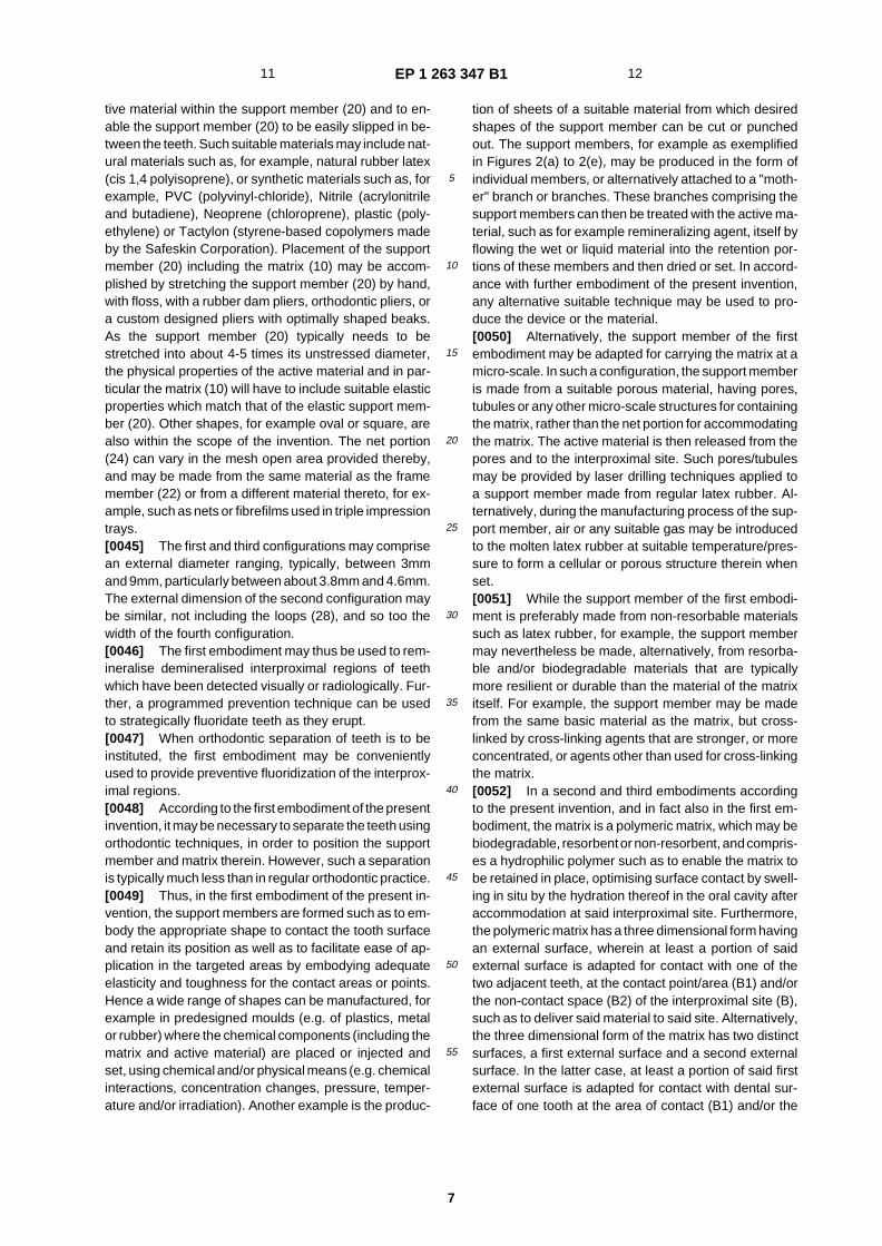
tive material within the support member (20) and to en-able the support member (20) to be easily slipped in be-tween the teeth. Such suitable materials may include nat-ural materials such as, for example, natural rubber latex(cis 1,4 polyisoprene), or synthetic materials such as, forexample, PVC (polyvinyl-�chloride), Nitrile (acrylonitrileand butadiene), Neoprene (chloroprene), plastic (poly-ethylene) or Tactylon (styrene-�based copolymers madeby the Safeskin Corporation). Placement of the supportmember (20) including the matrix (10) may be accom-plished by stretching the support member (20) by hand,with floss, with a rubber dam pliers, orthodontic pliers, � ora custom designed pliers with optimally shaped beaks.As the support member (20) typically needs to bestretched into about 4-5 times its unstressed diameter,the physical properties of the active material and in par-ticular the matrix (10) will have to include suitable elasticproperties which match that of the elastic support mem-ber (20). Other shapes, for example oval or square, arealso within the scope of the invention. The net portion(24) can vary in the mesh open area provided thereby,and may be made from the same material as the framemember (22) or from a different material thereto, for ex-ample, such as nets or fibrefilms used in triple impressiontrays.�[0045] The first and third configurations may comprisean external diameter ranging, typically, between 3mmand 9mm, particularly between about 3.8mm and 4.6mm.The external dimension of the second configuration maybe similar, not including the loops (28), and so too thewidth of the fourth configuration.�[0046] The first embodiment may thus be used to rem-ineralise demineralised interproximal regions of teethwhich have been detected visually or radiologically. Fur-ther, a programmed prevention technique can be usedto strategically fluoridate teeth as they erupt.�[0047] When orthodontic separation of teeth is to beinstituted, the first embodiment may be convenientlyused to provide preventive fluoridization of the interprox-imal regions.�[0048] According to the first embodiment of the presentinvention, it may be necessary to separate the teeth usingorthodontic techniques, in order to position the supportmember and matrix therein. However, such a separationis typically much less than in regular orthodontic practice.�[0049] Thus, in the first embodiment of the present in-vention, the support members are formed such as to em-body the appropriate shape to contact the tooth surfaceand retain its position as well as to facilitate ease of ap-plication in the targeted areas by embodying adequateelasticity and toughness for the contact areas or points.Hence a wide range of shapes can be manufactured, forexample in predesigned moulds (e.g. of plastics, metalor rubber) where the chemical components (including thematrix and active material) are placed or injected andset, using chemical and/or physical means (e.g. chemicalinteractions, concentration changes, pressure, temper-ature and/or irradiation). Another example is the produc-
tion of sheets of a suitable material from which desiredshapes of the support member can be cut or punchedout. The support members, for example as exemplifiedin Figures 2�(a) to 2 �(e), may be produced in the form ofindividual members, or alternatively attached to a "moth-er" branch or branches. These branches comprising thesupport members can then be treated with the active ma-terial, such as for example remineralizing agent, itself byflowing the wet or liquid material into the retention por-tions of these members and then dried or set. In accord-ance with further embodiment of the present invention,any alternative suitable technique may be used to pro-duce the device or the material.�[0050] Alternatively, the support member of the firstembodiment may be adapted for carrying the matrix at amicro- �scale. In such a configuration, the support memberis made from a suitable porous material, having pores,tubules or any other micro-�scale structures for containingthe matrix, rather than the net portion for accommodatingthe matrix. The active material is then released from thepores and to the interproximal site. Such pores/�tubulesmay be provided by laser drilling techniques applied toa support member made from regular latex rubber. Al-ternatively, during the manufacturing process of the sup-port member, air or any suitable gas may be introducedto the molten latex rubber at suitable temperature/ �pres-sure to form a cellular or porous structure therein whenset.�[0051] While the support member of the first embodi-ment is preferably made from non-�resorbable materialssuch as latex rubber, for example, the support membermay nevertheless be made, alternatively, from resorba-ble and/or biodegradable materials that are typicallymore resilient or durable than the material of the matrixitself. For example, the support member may be madefrom the same basic material as the matrix, but cross-linked by cross-�linking agents that are stronger, or moreconcentrated, or agents other than used for cross-�linkingthe matrix.�[0052] In a second and third embodiments accordingto the present invention, and in fact also in the first em-bodiment, the matrix is a polymeric matrix, which may bebiodegradable, resorbent or non-�resorbent, and compris-es a hydrophilic polymer such as to enable the matrix tobe retained in place, optimising surface contact by swell-ing in situ by the hydration thereof in the oral cavity afteraccommodation at said interproximal site. Furthermore,the polymeric matrix has a three dimensional form havingan external surface, wherein at least a portion of saidexternal surface is adapted for contact with one of thetwo adjacent teeth, at the contact point/ �area (B1) and/orthe non-�contact space (B2) of the interproximal site (B),such as to deliver said material to said site. Alternatively,the three dimensional form of the matrix has two distinctsurfaces, a first external surface and a second externalsurface. In the latter case, at least a portion of said firstexternal surface is adapted for contact with dental sur-face of one tooth at the area of contact (B1) and/or the
11 12
EP 1 263 347 B1
8
5
10
15
20
25
30
35
40
45
50
55
space (B2) of said interproximal site (B), and at least aportion of said second external surface is adapted forcontact with the dental surface of the adjacent tooth atthe area of contact (B1) and/or the space (B2), such asto deliver the active material to both adjacent teeth at theinterproximal site (B). As with the first embodiment, theadjacent teeth are actually separated at area of contact(B1) when the delivery system is fixed in place.�[0053] Thus, in the second embodiment, and referringto Figure 3�(a) the polymeric matrix is particularly adaptedfor providing the active material to the contact area (B1).�[0054] In a first configuration of the second embodi-ment, and referring to Figures 3 �(a) and 3 �(g), the poly-meric matrix (10) is in the form of a disc (30) having op-posed first and second external substantially concavesurfaces, (32) and (34) respectively, for contact with atleast the contact area (B1) of said dental surfaces of theadjacent teeth at the of the interproximal site (B) such asto deliver said material to said site.�[0055] In a second configuration of the second embod-iment, and referring to Figure 3�(b), the polymeric matrix(10) is in the form of a disc (30’) having opposed first andsecond external substantially flat surfaces, for contactwith at least the contact area (B1) of said dental surfacesof the adjacent teeth at the of the interproximal site (B)such as to deliver said material to said site�[0056] In a third configuration of the second embodi-ment, and referring to Figure 3�(c), the polymeric matrix(10) is in the form of a ring (30") having opposed first andsecond external substantially annular surfaces, for con-tact with at least the contact area (B1) of said dental sur-faces of the adjacent teeth at the of the interproximal site(B) such as to deliver said material to said site.�[0057] In a fourth configuration of the second embod-iment, and referring to Figure 3�(d), the polymeric matrixis in the form of a longitudinal strip or pellet (30"’) havingopposed first and second external substantially oval sur-faces, for contact with at least the contact area (B1) ofsaid dental surfaces of the adjacent teeth at the of theinterproximal site (B) such as to deliver said material tosaid site. This elongated configuration facilitates stretch-ing by hand for positioning of the matrix interproximally.�[0058] Where necessary, a dental practicioner mayprise adjacent teeth apart using, for example, a woodenwedge, or a metal separating device, in order to facilitateplacement of the system therebetween. Thereafter, thewedge or separating device is removed.�[0059] Thus, in the second embodiment of the presentinvention, the polymeric matrix (10) is anatomicallyshaped to fit the interproximal anatomy of the teeth inorder to reach the contact points or areas, for the slowrelease of the active material, typically fluoride and/orother agents, as illustrated in Figures 3 �(e)�and3 �(f).�[0060] In the first, second, third and fourth configura-tions of the second embodiment, the external diametermay range, typically, between 3mm and 9mm, particu-larly between about 3.8mm and 4.6mm. Also, othershapes, for example oval or square, are also within the
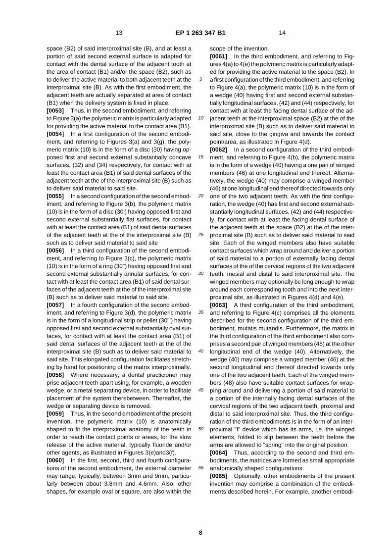
scope of the invention.�[0061] In the third embodiment, and referring to Fig-ures 4�(a) to 4�(e) the polymeric matrix is particularly adapt-ed for providing the active material to the space (B2). Ina first configuration of the third embodiment, and referringto Figure 4�(a), the polymeric matrix (10) is in the form ofa wedge (40) having first and second external substan-tially longitudinal surfaces, (42) and (44) respectively, forcontact with at least the facing dental surface of the ad-jacent teeth at the interproximal space (B2) at the of theinterproximal site (B) such as to deliver said material tosaid site, close to the gingiva and towards the contactpoint/�area, as illustrated in Figure 4�(d).�[0062] In a second configuration of the third embodi-ment, and referring to Figure 4�(b), the polymeric matrixis in the form of a wedge (40) having a one pair of wingedmembers (46) at one longitudinal end thereof. Alterna-tively, the wedge (40) may comprise a winged member(46) at one longitudinal end thereof directed towards onlyone of the two adjacent teeth. As with the first configu-ration, the wedge (40) has first and second external sub-stantially longitudinal surfaces, (42) and (44) respective-ly, for contact with at least the facing dental surface ofthe adjacent teeth at the space (B2) at the of the inter-proximal site (B) such as to deliver said material to saidsite. Each of the winged members also have suitablecontact surfaces which wrap around and deliver a portionof said material to a portion of externally facing dentalsurfaces of the of the cervical regions of the two adjacentteeth, mesial and distal to said interproximal site. Thewinged members may optionally be long enough to wraparound each corresponding tooth and into the next inter-proximal site, as illustrated in Figures 4�(d) and 4 �(e).�[0063] A third configuration of the third embodiment,and referring to Figure 4 �(c) comprises all the elementsdescribed for the second configuration of the third em-bodiment, mutatis mutandis. Furthermore, the matrix inthe third configuration of the third embodiment also com-prises a second pair of winged members (48) at the otherlongitudinal end of the wedge (40). Alternatively, thewedge (40) may comprise a winged member (46) at thesecond longitudinal end thereof directed towards onlyone of the two adjacent teeth. Each of the winged mem-bers (48) also have suitable contact surfaces for wrap-ping around and delivering a portion of said material toa portion of the internally facing dental surfaces of thecervical regions of the two adjacent teeth, proximal anddistal to said interproximal site. Thus, the third configu-ration of the third embodiments is in the form of an inter-proximal "I" device which has its arms, i.e. the wingedelements, folded to slip between the teeth before thearms are allowed to "spring" into the original position.�[0064] Thus, according to the second and third em-bodiments, the matrices are formed as small appropriateanatomically shaped configurations.�[0065] Optionally, other embodiments of the presentinvention may comprise a combination of the embodi-ments described herein. For example, another embodi-
13 14
EP 1 263 347 B1
9
5
10
15
20
25
30
35
40
45
50
55
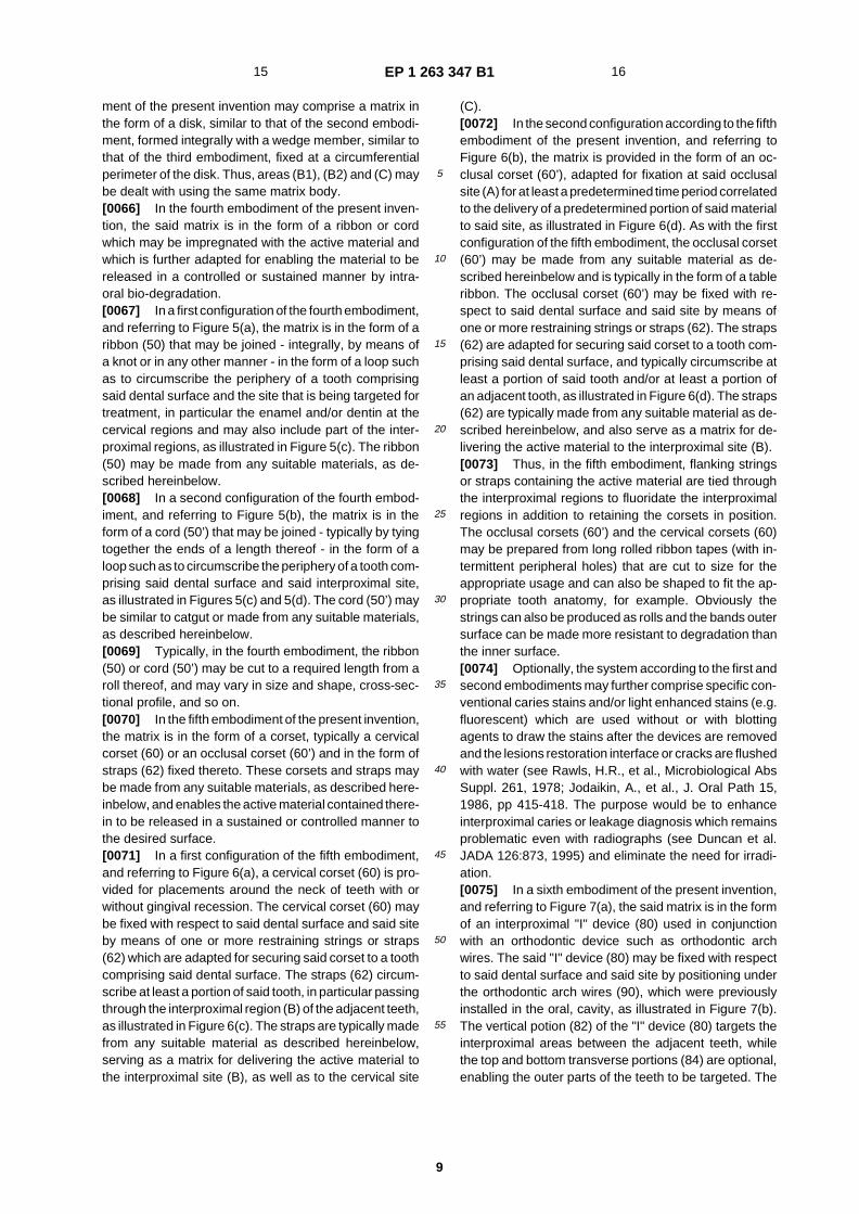
ment of the present invention may comprise a matrix inthe form of a disk, similar to that of the second embodi-ment, formed integrally with a wedge member, similar tothat of the third embodiment, fixed at a circumferentialperimeter of the disk. Thus, areas (B1), (B2) and (C) maybe dealt with using the same matrix body.�[0066] In the fourth embodiment of the present inven-tion, the said matrix is in the form of a ribbon or cordwhich may be impregnated with the active material andwhich is further adapted for enabling the material to bereleased in a controlled or sustained manner by intra-oral bio- �degradation.�[0067] In a first configuration of the fourth embodiment,and referring to Figure 5 �(a), the matrix is in the form of aribbon (50) that may be joined - integrally, by means ofa knot or in any other manner - in the form of a loop suchas to circumscribe the periphery of a tooth comprisingsaid dental surface and the site that is being targeted fortreatment, in particular the enamel and/or dentin at thecervical regions and may also include part of the inter-proximal regions, as illustrated in Figure 5�(c). The ribbon(50) may be made from any suitable materials, as de-scribed hereinbelow.�[0068] In a second configuration of the fourth embod-iment, and referring to Figure 5�(b), the matrix is in theform of a cord (50’) that may be joined - typically by tyingtogether the ends of a length thereof - in the form of aloop such as to circumscribe the periphery of a tooth com-prising said dental surface and said interproximal site,as illustrated in Figures 5�(c) and 5 �(d). The cord (50’) maybe similar to catgut or made from any suitable materials,as described hereinbelow.�[0069] Typically, in the fourth embodiment, the ribbon(50) or cord (50’) may be cut to a required length from aroll thereof, and may vary in size and shape, cross-�sec-tional profile, and so on.�[0070] In the fifth embodiment of the present invention,the matrix is in the form of a corset, typically a cervicalcorset (60) or an occlusal corset (60’) and in the form ofstraps (62) fixed thereto. These corsets and straps maybe made from any suitable materials, as described here-inbelow, and enables the active material contained there-in to be released in a sustained or controlled manner tothe desired surface.�[0071] In a first configuration of the fifth embodiment,and referring to Figure 6�(a), a cervical corset (60) is pro-vided for placements around the neck of teeth with orwithout gingival recession. The cervical corset (60) maybe fixed with respect to said dental surface and said siteby means of one or more restraining strings or straps(62) which are adapted for securing said corset to a toothcomprising said dental surface. The straps (62) circum-scribe at least a portion of said tooth, in particular passingthrough the interproximal region (B) of the adjacent teeth,as illustrated in Figure 6�(c). The straps are typically madefrom any suitable material as described hereinbelow,serving as a matrix for delivering the active material tothe interproximal site (B), as well as to the cervical site
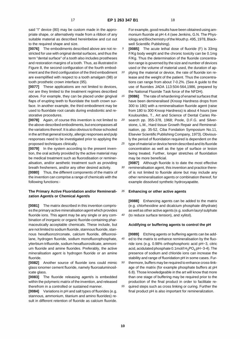
(C).�[0072] In the second configuration according to the fifthembodiment of the present invention, and referring toFigure 6�(b), the matrix is provided in the form of an oc-clusal corset (60’), adapted for fixation at said occlusalsite (A) for at least a predetermined time period correlatedto the delivery of a predetermined portion of said materialto said site, as illustrated in Figure 6 �(d). As with the firstconfiguration of the fifth embodiment, the occlusal corset(60’) may be made from any suitable material as de-scribed hereinbelow and is typically in the form of a tableribbon. The occlusal corset (60’) may be fixed with re-spect to said dental surface and said site by means ofone or more restraining strings or straps (62). The straps(62) are adapted for securing said corset to a tooth com-prising said dental surface, and typically circumscribe atleast a portion of said tooth and/or at least a portion ofan adjacent tooth, as illustrated in Figure 6�(d). The straps(62) are typically made from any suitable material as de-scribed hereinbelow, and also serve as a matrix for de-livering the active material to the interproximal site (B).�[0073] Thus, in the fifth embodiment, flanking stringsor straps containing the active material are tied throughthe interproximal regions to fluoridate the interproximalregions in addition to retaining the corsets in position.The occlusal corsets (60’) and the cervical corsets (60)may be prepared from long rolled ribbon tapes (with in-termittent peripheral holes) that are cut to size for theappropriate usage and can also be shaped to fit the ap-propriate tooth anatomy, for example. Obviously thestrings can also be produced as rolls and the bands outersurface can be made more resistant to degradation thanthe inner surface.�[0074] Optionally, the system according to the first andsecond embodiments may further comprise specific con-ventional caries stains and/or light enhanced stains (e.g.fluorescent) which are used without or with blottingagents to draw the stains after the devices are removedand the lesions restoration interface or cracks are flushedwith water (see Rawls, H.R., et al., Microbiological AbsSuppl. 261, 1978; Jodaikin, A., et al., J. Oral Path 15,1986, pp 415-418. The purpose would be to enhanceinterproximal caries or leakage diagnosis which remainsproblematic even with radiographs (see Duncan et al.JADA 126:�873, 1995) and eliminate the need for irradi-ation.�[0075] In a sixth embodiment of the present invention,and referring to Figure 7�(a), the said matrix is in the formof an interproximal "I" device (80) used in conjunctionwith an orthodontic device such as orthodontic archwires. The said "I" device (80) may be fixed with respectto said dental surface and said site by positioning underthe orthodontic arch wires (90), which were previouslyinstalled in the oral, cavity, as illustrated in Figure 7�(b).The vertical potion (82) of the "I" device (80) targets theinterproximal areas between the adjacent teeth, whilethe top and bottom transverse portions (84) are optional,enabling the outer parts of the teeth to be targeted. The
15 16
EP 1 263 347 B1
10
5
10
15
20
25
30
35
40
45
50
55
said "I" device (80) may be custom made in the appro-priate shape, or alternatively made from a ribbon of anysuitable material as described hereinbelow and cut outto the required shape and size.�[0076] The embodiments described above are not re-stricted for use with original dental surfaces, and thus theterm "dental surface" of a tooth also includes prosthesesand restoration margins of a tooth. Thus, as illustrated inFigure 8, the second configuration of the fourth embod-iment and the third configuration of the third embodimentare exemplified with respect to a tooth amalgam (98) ortooth prosthetic crown interface (95).�[0077] These applications are not limited to devices,nor are they limited to the treatment regimes describedabove. For example, they can be placed under gingivalflaps of erupting teeth to fluoridate the tooth crown sur-face. In another example, the third embodiment may beused to fluoridate root canals during endodontic and re-storative procedures.�[0078] Again, of course this invention is not limited tothe above-�described embodiments, but encompasses allthe variations thereof. It is also obvious to those schooledin the art that general toxicity, allergic responses and pulpresponses need to be investigated prior to applying theproposed techniques clinically.�[0079] In the system according to the present inven-tion, the oral activity provided by the active material maybe medical treatment such as fluorodisation or reminer-alisation, and/or aesthetic treatment such as providingbreath fresheners, and/or any other desired activity.�[0080] Thus, the different components of the matrix ofthe invention can comprise a range of chemicals with thefollowing functions:-
The Primary Active Fluoridation and/or Reminerali-zation Agent/s or Chemical Agent/s
�[0081] The matrix described in this invention compris-es the primary active mineralisation agent which providesfluoride ions. This agent may be any single or any com-bination of inorganic or organic fluoride-�containing phar-maceutically acceptable chemicals. These include, butare not limited to sodium fluoride, stannous fluoride, stan-nous hexafluorozirconate, calcium fluoride, difluorosi-lane, hydrogen fluoride, sodium monofluorophosphate,ytterbium trifluoride, sodium hexafluorosilicate, ammoni-um fluoride and amine fluorides. Preferably, the activemineralisation agent is hydrogen fluoride or an aminefluoride.�[0082] Another source of fluoride ions could mimicglass ionomer cement fluoride, namely fluoroaluminosil-icate glass.�[0083] The fluoride releasing agent/s is embeddedwithin the polymeric matrix of the invention, and releasedtherefrom in a controlled or sustained manner.�[0084] Variations in pH and salt types of fluorides (e.g.stannous, ammonium, titanium and amino fluorides) re-sult in different retention of fluoride as calcium fluoride.
For example, good results have been obtained using am-monium fluoride at pH 4.4 (see Jenkins, G.N. The Phys-iology and Biochemistry of the Mouth p. 495, 1978, Black-well Scientific Publishing).�[0085] The acute lethal dose of fluoride (F) is 33mgF/Kg body weight and the chronic toxicity can be 0.1mgF/Kg. Thus the determination of the fluoride concentra-tion range is governed by the size and number of devicesused or the volume of material used, the duration of ap-plying the material or device, the rate of fluoride ion re-lease and the weight of the patient. Thus the concentra-tions can range from about 7-0.2%. (See A guide to theuse of fluorides JADA 113:�504-564,1986, prepared bythe National Fluoride Task force of the NFDH).�[0086] The rate of rehardening of enamel surfaces thathave been demineralised (Knoop Hardness drops from300 to 180) with a remineralisation fluoride agent (raisefrom 180 to 300 Knoop Hardness) is about 4 hours (seeKoulourides, T., Art and Science of Dental Caries Re-search pp. 355-378, 1968; Poole, D.F.G. and Silver-stone, L.M., Hard tissue Growth Repair and Remineral-isation, pp. 35-52, Ciba Fondation Symposium No.�11,Elsevier Scientific Publishing Company, 1973). Obvious-ly the period of fluoridation required is dependent on thetype of material or device herein described and its fluorideconcentration as well as the type of surface or lesionbeing treated. Further, longer stretches of fluoridationmay be more beneficial.�[0087] Although fluoride is to date the most effectiveremineralisation agent, this invention and practice there-of is not limited to fluoride alone but may include anyother remineralisation agents or combination thereof, forexample dissolved synthetic hydroxyapatite.
Enhancing or other active agents
�[0088] Enhancing agents can be added to the matrix(e.g. chlorhexidine and dicalcium phosphate dihydrate)as well as other active agents (e.g. sodium lauryl sulphate(to reduce surface tension), and xylitol).
Acidifying or buffering agents to control the pH
�[0089] Etching agents or buffering agents can be add-ed to the matrix to enhance remineralisation by the fluo-ride ions (e.g. 0.98% orthophosphoric acid pH~3, citricacid, acidulated phosphate 0.1mol/l H3PO4 pH~3-4). Thepresence of sodium and chloride ions can increase thestability and range of fluoridation pH in some cases. Fur-thermore, buffers may be required to enhance cross-�link-age of the matrix (for example phosphate buffers at pH6.8). Those knowledgeable in the art will know that morethan one stage of buffering may be required prior to theproduction of the final product in order to facilitate re-quired steps such as cross linking or curing. Further thefinal product pH is also important for remineralization.
17 18
EP 1 263 347 B1
11
5
10
15
20
25
30
35
40
45
50
55
The Matrix
�[0090] The role of the matrix is to carry the primaryactive fluoridation agent or any other enhancing or activeagent and provide the required viscosity for applicationand/or the required stability or degradation (e.g. intraoralenzymatic biodegregation or self-�generated degrada-tion) for the delivery of the active and any auxiliary agents,in order to provide the optimal rate and time span of ionor chemical bombardment of the tooth surface and toprovide a mobile environment for the fluoride ions and/orother chemicals to reach the tooth surface. Those knowl-edgeable and skilled in the art can alter the degradationby varying the concentrations and the degree of curingor cross- �linking and type of cross- �linking, or combinationsthereof.�[0091] The types of possible matrices are wide. Theycan include agents yet unused for dental treatment andagents such as those used as denture adhesives, im-pression materials, temporary, provisional or permanentrestorations, sutures, perio- or surgical packs and peri-odontal agents (see Dental Therapeutics Digest OdontosPub Inc.: Kay L.W. Drugs in Dentistry, Bristol 1972; O’Br-ien, W.J. and Ryge, G. An Outline of Dental Materials,Saunders 1978; Steinberg, D et al., J. Dent Res. 67-208Abstract No. 767, 1988; US Patent Nos. 5,324,519;4,938,763; 5,278,201; 5,077,049; 5,739,176;5,733,950). The matrix materials may be sub- �classifiedinto natural products and synthetic products.
Natural Products
�[0092] Polysacaccharide polymers (e.g. starch, cellu-lose, agar, alginates and retted flax extracts), lipids,polyisoprenes (e.g. latex rubber and gutta percha), resinsand gums (e.g. tragacanth and storax) and proteins (e.g.collagen or denatured collagen in the form of gelatin) areexamples.�[0093] Purified collagen can be untreated or treatedwith fixing agents to prolong its resistance to digestion(similar to catgut surgical suture production). Denaturedcollagen can be impregnated with chromium salts to pro-long its tensile strength and retard its absorption. A pre-ferred polymeric matrix is a gelatin matrix, although thoseexperienced in the art know the method of dissolution ofgelatin is highly technique-�sensitive and the method usedcan cause considerable differences in the texture of theproduct ranging from jelly-�like to thick and ’ropey’. Fur-ther, gelatin, like collagen, can be lysine- �cross linked withglutaraldehyde (an organelle preservant which has alsobeen used for human aortic valve implants and dentalpulp treatments; Kopel, H.M. et al., J. of Dent, for Child47: 425-430, 1980) Another possible crosslinking agentis formaldehyde, which forms intra- and intermolecularmethylene bridges between various amino acids. Furtherexamples are tannic acid and hexamethylenediisocy-anate. Again, the biocompatability of these agents mustbe carefully examined even though they have been used
clinically. The gelatin may be of any source, for examplebovine or non-�mammalian gelatin. Bovine gelatin is pref-erably used when a matrix with higher rigidity is required.�[0094] It is prudent to note that a completely naturalmatrix of gelatin without crosslinking can also be usedwith an appropriate cover (e.g. support members as de-scribed for the first embodiment, which may be com-posed primarily of 1,4-�polyisoprene). Furthermore, nat-ural cross-�linkings are also feasable, for example calciumand hydroxylysinorleucine, dihydroxylysinone or leucine(Traub W., and Piez, K., A. Adv. Protein Chem. 25:243-352, 1971) and dehydrodihydroxylysinonorleucineBailey, A.J. et al., Biechem. Biophys. Res. Commun. 35:663-671 1969).
Synthetic Products
�[0095] Likely candidates within the boundary of possi-ble synthetic products that may serve for the matrices ofthis invention are homopolymers or copolymers with awide molecular weight range formed by condensation,additional anionic, cationic and/or catalytic polymeriza-tion systems. Examples are cynoacrylates, polycar-bonates, polyurethane, polyester urethane dimethacr-ylate, polycaprolactones, ethyl triglycide methacrylate,polysulphides, povidone, polyacrylic methacrylic acid,acrylic and modifications such as poly �(hydroxyethylmethacrylate), poly�(methylmethacrylate) modified withsmall amounts of ethyl butyl or other alkyl methacrylatesand other carbomers. Some of these are indeed com-mercial products such as aqueous methacrylic polymerformulations for sustained and controlled release of den-tal and other products (e.g. EudragitR Rohm). These pol-ymers may require activators and cross-�linking (see be-low). However, other agents are at times required, forexample retarding agents such as hydroquinone andeugenol. Other yet different examples are zinc eugeno-late, petrolateum and stearyl alcohol.
Cross linking agents
�[0096] Examples are amino acids (lysine and ar-ginine), peptides proteins, polysaccarides (e.g. dextran),lipids (e.g. sodium docusate) calcium, strontium, glutar-aldehyde, formaldehyde, glycol dimethacrylate, tannicacid and allyl methacrylate.�[0097] It is to be appreciated that the degree of cross-linking is of major significance to the rate of release ofthe active and/or auxiliary agents. The determination ofthe degree of cross- �linking of the polymeric matrix is with-in the capabilities of the man of skill in the art of pharmacy.
Liquid vehicles
�[0098] Liquid vehicles may be used particularly whenpreparing the matrix. Examples are water, ethyl alcoholor glycerine (glycerol) alone or in any combination, withwater being preferred.
19 20

EP 1 263 347 B1
12
5
10
15
20
25
30
35
40
45
50
55
Plasticisers and Elasticisers
�[0099] Plasticisers and elasticisers may be used tomodify the mechanical properties of the matrix, whereneeded and desired. Examples are polyethylene glycol,dibutyl phthalate, glycerol, sorbitol, mineral salts, oliveoil, linseed oil, light mineral oil, polymers of ethylene pro-pylene, styrene-�butadiene, vinyl ethylene acetate copol-ymers, butadiene isoprene, gum base and elastin (a nat-ural rubbery protein from Ligamentum nuchae). A pre-ferred platiciser is sorbitol.�[0100] According to the first and second embodimentsof present invention, the matrix may be made from anysuitable material as described above, such as for exam-ple gelatin, in combination with an elasticiser, such asfor example sorbitol and/or gum base, the gelatin beingpreferably cross-�linked using any suitable material suchas for example glutaraldehyde and/or tannic acid. Suchmatrices have adequate plastic properties and are at thesame time of sufficient toughness to maintain the me-chanical integrity of the system when affixed within theinterproximal space.�[0101] According to the third embodiment of thepresent invention, the matrix is preferably rigid for thewedge portion, and thus typically lacks the plasticisingmaterial of the first embodiment. Nonetheless, the wingmembers of this embodiment are preferably more elasticand thus may comprise a plasticising and/or elasticisingagent.�[0102] According to the fourth, fifth and sixth embodi-ments the matrices, in the form of the corsets, straps and"I" members may be similar as described for the first em-bodiment mutatis mutandis, with the exception that inthese embodiments less elasticising material or none atall may be used in the matrix.
Fillers and Softeners
�[0103] The matrix may also comprise fillers and/or sof-teners, such as gum mastic, flour, kaolin (aluminium sil-icate), magnesium oxide, silicon dioxide or other variousinorganic molecules are examples. It should be notedthat certain ions may inhibit remineralisation in some cas-es (for example P2O7, HCO3, SiO4, CrO4, Mg and Zn)and some inorganic fillers can be coated with water re-pellant coupling agents such as vinyl silane. Examplesof softeners are lecithin and waxes.
Colouring or staining agents
�[0104] These include agents to enhance the appear-ance of the applied matrix, and dyes which are releasedto enhance caries detection, as discussed above.�[0105] Examples are fuchsin or acid red 52 in propyl-ene glycol. These diagnostic dyes include conventionalhistological stains, clinical decay detection agents andagents whose detection can be enhanced with light, forexample fluorescence agents by UV light or other agents
activated by intense light within the visual spectrum, oragents drawn by blotting of the lesion after the device ormaterial is removed and the tooth surface rinsed.
Flavouring agents and breath fresheners
�[0106] Various flavouring may be added to the matrix,for example, menthol, sodium saccharin, sorbitol, aspar-tam, sodium chloride. Also breath fresheners may beadded to the matrix, for example parsley seed, sunfloweroils, and peppermint oil.
Preservatives and sterilizing agents
�[0107] The addition of preservatives and sterilisingagents may be advantageous particularly for long-�dwell-ing matrices, as they will inhibit the development of var-ious microorganisms such as bacteria, fungi and yeast.Examples of preservatives are phenol, methylparabenand sorbic acid and examples of sterilizsing agents areiodine, potassium and alcohol.
Hemostatic agent
�[0108] This includes vasoconstrictors (e.g. adrenalin),absorbable agents (e.g. oxidised cellulose, fibrin, calci-um alginate), thromboplastic agents (e.g. thrombin),chemical agents (e.g. tannic acid, ferric chloride, zincchloride, alum, hydrogen peroxide) or physical plugging(e.g. the device includes bone wax). The role of a hemo-stat would be to stop bleeding which could hamper fluor-idation or chemical treatment in regions where bleedingis caused by gingival or other bleeding.�[0109] The matrix is preferably made from a material,such as for example gelatin cross- �linked by tannic acidand/or glutaraldehyde, that is resorbable and/or biode-gradable in the saliva by host enzymes, bacteria or bymeans of the dissolution properties of the saliva or drinks.Nonetheless, the matrix may alternatively be made froma non-�resorbable material which also releases the activematerial that is being delivered to the target area. Forexample, the matrix may be made from rubber latex, apolymer or any one of a large variety of sugars, lipids,nucleic acids or other proteins found in rubber latex bond-ed to an amine fluoride which is released in the mouthbecause of, for example, a host enzyme.�[0110] The matrices and devices of this invention andthe manufacture thereof are not limited to the hereabovechemical components, but encompasses all their varia-tions, and include other chemicals as only examples havebeen presented above. Further, the biocompatability ofthese agents and their interactions need to be carefullyexamined and tested prior to clinical application.
Claims
1. A system for the controlled delivery of at least one
21 22

EP 1 263 347 B1
13
5
10
15
20
25
30
35
40
45
50
55
material having a predetermined intraoral activity toan interproximal site of at least one dental surfacein an oral cavity, comprising a polymeric matrix con-taining said material, said system being adapted forphysical fixation at said interproximal site for at leasta predetermined time period correlated to the deliv-ery of a predetermined portion of said material tosaid site.
2. A system as claimed in claim 1, wherein said inter-proximal site comprises an area of contact betweensaid dental surface and an adjacent dental surface.
3. A system as claimed in claim 2, wherein said matrixcomprises a hydrophilic polymer such as to enablethe matrix to be fixed by swelling in situ by the hy-dration thereof in the oral cavity after accommoda-tion at said interproximal site.
4. A system as claimed in claim 3, wherein said poly-meric matrix has a three dimensional form having anexternal surface, wherein at least a portion of saidexternal surface is adapted for contact with at leastsaid interproximal site of said dental surface such asto deliver said material to said site.
5. A system as claimed in claim 4, wherein said matrixis in the form of a disc having at least one externalsubstantially flat surface for contact with at least saidinterproximal site of said dental surface such as todeliver said material to said site.
6. A system as claimed in claim 5, wherein said matrixis in the form of a disc having at least one externalsubstantially concave surface for contact with atleast said interproximal site of said dental surfacesuch as to deliver said material to said site.
7. A system as claimed in claim 4, wherein said matrixis in the form of a pellet having at least one externalsubstantially oval surface for contact with at leastsaid interproximal site of said dental surface such asto deliver said material to said site.
8. A system as claimed in claim 4, wherein said matrixis in the form of a toroidal ring having at least oneexternal substantially annular surface for contactwith at least said interproximal site of said dentalsurface such as to deliver said material to said site.
9. A system as claimed in claim 4, wherein said matrixis in the form of a wedge having at least one externallongitudinal surface for contact with at least said in-terproximal site of said dental surface such as to de-liver said material to said site.
10. A system as claimed in claim 4, wherein said matrixis in the form of a wedge having at least one winged
member at least at one longitudinal end thereof, saidwedge having at least one external longitudinal sur-face for contact with at least said interproximal siteof said dental surface such as to deliver said materialto said site, and said winged member having suitablecontact surfaces for delivering a portion of said ma-terial to a portion of said dental surface and an ad-jacent dental surface mesial and distal to said inter-proximal site.
11. A system as claimed in claim 2, wherein said matrixhas a three dimensional form having a first externalsurface and a second external surface, wherein atleast a portion of said first external surface is adaptedfor contact with at least said interproximal site of saiddental surface and wherein at least a portion of saidsecond external surface is adapted for contact withat least said interproximal site of said adjacent dentalsurface such as to deliver said material to said site.
12. A system as claimed in claim 11, wherein said matrixis in the form of a disc having opposed first and sec-ond external substantially flat surfaces for contactwith at least said interproximal site of said dentalsurface and said adjacent dental surface, respec-tively, such as to deliver said material to said site.
13. A system as claimed in claim 11, wherein said matrixis in the form of a disc having opposed first and sec-ond external substantially concave surfaces for con-tact with at least said interproximal site of said dentalsurface and said adjacent dental surface, respec-tively, such as to deliver said material to said site.
14. A system as claimed in claim 11, wherein said matrixis in the form of a pellet having opposed first andsecond external substantially oval surfaces for con-tact with at least said interproximal site of said dentalsurface and said adjacent dental surface, respec-tively, such as to deliver said material to said site.
15. A system as claimed in claim 11, wherein said matrixis in the form of a toroidal ring having opposed firstand second external substantially annular surfacesfor contact with at least said interproximal site of saiddental surface and said adjacent dental surface, re-spectively, such as to deliver said material to saidsite.
16. A system as claimed in claim 11, wherein said matrixis in the form of a wedge having first and secondexternal substantially longitudinal surfaces for con-tact with at least said interproximal site of said dentalsurface and said adjacent dental surface, respec-tively, such as to deliver said material to said site.
17. A system as claimed in claim 11, wherein said matrixis in the form of a wedge having at least one pair of
23 24
EP 1 263 347 B1
14
5
10
15
20
25
30
35
40
45
50
55
winged members at least at one longitudinal endthereof, said wedge having first and second externalsubstantially longitudinal surfaces for contact with atleast said interproximal site of said dental surfaceand said adjacent dental surface, respectively, suchas to deliver said material to said site, and saidwinged members having suitable contact surfacesfor delivering a portion of said material to a portionof said dental surface and to a portion of said adja-cent surface mesial and distal to said interproximalsite.
18. A system as claimed in claim 2, wherein said systemfurther comprises a suitable support member for fix-ing said matrix to said site, said support membercomprising a peripheral frame portion surrounding anet portion, said frame portion being made from aresilient material capable of enabling the supportmember to be accommodated at said interproximalsite such as to align said net portion therewith, andwherein said net portion is adapted for accommo-dating said matrix and for enabling said material tobe delivered therefrom to said site.
19. A system as claimed in claim 18, wherein said framemember is in the form of a ring, wherein said memberis attached to the inner concave surface of said ring.
20. A system as claimed in claim 19, wherein said framemember further comprises at least one niche for fa-cilitating gripping of the said frame member to ena-bling affixing thereof at the interproximal site.
21. A system as claimed in claim 19, wherein said framemember further comprises at least one loop for fa-cilitating gripping of the said frame member to ena-bling affixing thereof at the interproximal site.
22. A system according to claim 18, wherein said supportmember is made from any suitable material includingnatural rubber latex (cis 1,4-�polyisoprene), PVC (pol-yvinyl chloride), Nitrile (acrylonitrile and butadiene),Neoprene (chloroprene), plastic (polyethylene) orTactylon (styrene- �based copolymers).
23. A system as claimed in claim 1, wherein said matrixis substantially biodegradable.
24. A system as claimed in claim 1, wherein said matrixis substantially resorbable
25. A system as claimed in claim 1, wherein said matrixis substantially non- �resorbable.
26. A system as claimed in claim 2, wherein said matrixis in the form of a ribbon.
27. A system as claimed in claim 26, wherein said ribbon
may be joined in the form of a loop such as to cir-cumscribe the periphery of a tooth comprising saiddental surface and said site.
28. A system as claimed in claim 2, wherein said matrixis in the form of a cord.
29. A system as claimed in claim 28, wherein said cordmay be joined in the form of a loop such as to cir-cumscribe the periphery of a tooth comprising saiddental surface and said site.
30. A system as claimed in claim 29, wherein said cordis made from catgut.
31. A system as claimed in claim 2, wherein said matrixis in the form of a cervical corset.
32. A system as claimed in claim 31, wherein said corsetmay be fixed with respect to said dental surface andsaid site by means of one or more restraining strapsadapted for securing said corset to a tooth compris-ing said dental surface.
33. A system as claimed in claim 32, wherein said strapscircumscribe at least a portion of said tooth.
34. A system as claimed in claim 2, wherein said matrixis in the form of an orthodontic interproximal "I" de-vice.
35. A system as claimed in claim 34, wherein said "I"device may be fixed with respect to said dental sur-face and said site by means of an orthodontic archwire previously secured in the intraoral cavity for se-curing said "I" device to a tooth comprising said den-tal surface.
36. A system for the controlled delivery of a material hav-ing a predetermined intra oral activity to an occlusalsite of at least one dental surface in an oral cavity,comprising a matrix containing said material; saidsystem being adapted for affixing at said occlusalsite for at least a predetermined time period corre-lated to the delivery of a predetermined portion ofsaid material to said site.
37. A system as claimed in claim 36, wherein said matrixis in the form of an occlusal corset.
38. A system as claimed in claim 37, wherein said corsetmay be affixed with respect to said dental surfaceand said site by means of one or more restrainingstraps adapted for securing said corset to a toothcomprising said dental surface.
39. A system as claimed in claim 38, wherein said strapscircumscribe at least a portion of said tooth.
25 26

EP 1 263 347 B1
15
5
10
15
20
25
30
35
40
45
50
55
40. A system as claimed in claim 39, wherein at leastone said strap circumscribes at least a portion of anadjacent tooth.
41. A system as claimed in any one of claims 1 to 40,wherein said active material is any one of inorganicor organic fluoride-�containing chemical agent.
42. A system as claimed in claim 41, wherein said ofmaterial is any one of sodium fluoride, stannous flu-oride, stannous hexafluorozirconate, calcium fluo-ride, difluorosilane, hydrogen fluoride, sodiummonofluorophosphate, ytterbium trifluoride, sodiumhexafluorosilicate, ammonium fluoride, an amine flu-oride, fluoroaluminosilicate glass and any mixturethereof.
43. A system as claimed in any one of claims 1 to 40,wherein said matrix comprises a synthetic polymeror a natural polymer which may be any one ofpolysacaccharides, lipids, polyisoprene, gum andproteins, or any mixture thereof.
44. A system as claimed in claim 43, wherein said naturalpolymer is a protein selected from collagen and gel-atin.
45. A system as claimed in claim 42, wherein said matrixcomprises a synthetic polymer or a natural polymerwhich may be any one of polysacaccharides, lipids,polyisoprene, gum and proteins, or any mixturethereof.
46. A system as claimed in claim 45, wherein said naturalpolymer is a protein selected from collagen and gel-atin.
47. A system as claimed in claim 45 wherein said poly-mer is cross-�linked.
48. A system as claimed in claim 47, wherein said pol-ymer is cross-�linked by at least one of glutaralde-hyde, formaldehyde, glycol dimethacrylate, tannicacid and allyl methacrylate.
49. A system as claimed in claim 43, wherein said matrixfurther comprises an auxiliary agent which may beany one of an enhancing agent for enhancing therelease of the active material, platiciser, elasticiser,coloring agents, staining agent, fillers and softeners,and preserving and sterilising agents.
50. A system as claimed in claim 49, wherein said plas-ticiser is sorbitol.
51. A support member for fixing a polymeric matrix com-prising a first material having a predetermined in-traoral activity to an interproximal site of at least one
dental surface in an intraoral cavity, said supportmember comprising a peripheral frame portion sur-rounding a net portion, said frame portion beingmade from a resilient second material capable of en-abling the support member to be accommodated atsaid interproximal site such as to align said net por-tion therewith, wherein said net portion is adaptedfor accommodating said matrix and for enabling saidfirst material to be delivered therefrom to said site,and wherein said support member is adapted forphysical fixation at said interproximal site for at leasta predetermined time period correlated to the deliv-ery of a predetermined portion of said first materialto said site.
52. A support member as claimed in claim 51, whereinsaid frame member is in the form of a ring, whereinsaid member is attached to the inner concave sur-face of said ring.
53. A support member as claimed in claim 51, whereinsaid frame member further comprises at least oneniche for facilitating gripping of the said frame mem-ber to enabling affixing thereof at the interproximalsite.
54. A support member as claimed in claim 51, whereinsaid frame member further comprises at least oneloop for facilitating gripping of the said frame memberto enabling affixing thereof at the interproximal site.
55. A support member according to any one of claims51 to 54 wherein said support member is made fromany suitable material including natural rubber latex(cis 1,4 polyisoprene), PVC (polyvinyl-�chloride), Ni-trile (acrylonitrile and butadiene), Neoprene (chloro-prene), plastic (polyethylene) or Tactylon (styrene-based copolymers).
Patentansprüche
1. System für die kontrollierte Abgabe von mindestenseinem Material mit einer vorbestimmten intraoralenAktivität an eine interproximale Stelle mindestens ei-ner zahnoberfläche in einem oralen Hohlraum, auf-weisend eine Polymermatrix, die das Material ent-hält, wobei das System zur physikalischen Fixierungan der interproximalen Stelle für mindestens einevorbestimmte Zeitdauer im Zusammenhang mit derAbgabe eines vorbestimmten Teils des Materials andie Stelle geeignet ist.
2. System nach Anspruch 1, wobei die interproximaleStelle einen Kontaktbereich zwischen der Zahnober-fläche und einer angrenzenden Zahnoberfläche um-fasst.
27 28

EP 1 263 347 B1
16
5
10
15
20
25
30
35
40
45
50
55
3. System nach Anspruch 2, wobei die Matrix ein hy-drophiles Polymer umfasst, um es zu ermöglichen,dass die Matrix durch deren Hydratisierung durchQuellen in situ in dem oralen Hohlraum nach Auf-nahme an der interproximalen Stelle fixiert werdenkann.
4. System nach Anspruch 3, wobei die Polymermatrixeine dreidimensionale Form mit einer Außenflächeaufweist, wobei mindestens ein Abschnitt der Au-ßenfläche zum Kontakt mit mindestens der interpro-ximalen Stelle der Zahnoberfläche geeignet ist der-art, dass das Material an die Stelle abgegeben wird.
5. System nach Anspruch 4, wobei die Matrix in Formeiner Scheibe mit mindestens einer im wesentlichenflachen Außenfläche zum Kontakt mit mindestensder interproximalen Stelle der Zahnoberfläche vor-liegt, um das Material an die Stelle abzugeben.
6. System nach Anspruch 5, wobei die Matrix in Formeiner Scheibe mit mindestens einer im Wesentlichenkonkaven Außenfläche zum Kontakt mit mindestensder interproximalen Stelle der Zahnoberfläche vor-liegt, um das Material an die Stelle abzugeben.
7. System nach Anspruch 4, wobei die Matrix in Formeiner Tablette bzw. eines Kügelchens oder Pelletsmit mindestens einer im Wesentlichen ovalen Au-ßenfläche zum Kontakt mit mindestens der interpro-ximalen Stelle der Zahnoberfläche vorliegt, um dasMaterial an die Stelle abzugeben.
8. System nach Anspruch 4, wobei die Matrix in Formeines torischen Rings mit mindestens einer im We-sentlichen ringförmigen Außenfläche zum Kontaktmit mindestens der interproximalen Stelle derZahnoberfläche vorliegt, um das Material an die Stel-le abzugeben.
9. System nach Anspruch 4, wobei die Matrix in Formeines Keils mit mindestens einer Längsaußenflächezum Kontakt mit mindestens der interproximalenStelle der Zahnoberfläche vorliegt, um das Materialan die Stelle abzugeben.
10. System nach Anspruch 4, wobei die Matrix in Formeines Keils mit mindestens einem Flügelelement anmindestens einem Längsende von diesem vorliegt,wobei der Keil mindestens eine Längsaußenflächezum Kontakt mit mindestens der interproximalenStelle der Zahnoberfläche aufweist, um das Materialan die Stelle abzugeben, und wobei das Flügelele-ment geeignete Kontaktflächen zur Abgabe einesTeils des Materials an einen Abschnitt der Zahnober-fläche und eine angrenzende Zahnoberfläche mesi-al und distal zu der interproximalen Stelle aufweist.
11. System nach Anspruch 2, wobei die Matrix eine drei-dimensionale Form mit einer ersten Außenflächeund einer zweiten Außenfläche aufweist, wobei zu-mindest ein Abschnitt der ersten Außenfläche zumKontakt mit mindestens der interproximalen Stelleder Zahnoberfläche geeignet ist, und wobei zumin-dest ein Abschnitt der zweiten Außenfläche zumKontakt mit mindestens der interproximalen Stelleder angrenzenden Zahnoberfläche geeignet ist, umdas Material an die Stelle abzugeben.
12. System nach Anspruch 11, wobei die Matrix in Formeiner Scheibe mit gegenüberliegenden ersten undzweiten im Wesentlichen flachen Außenflächen zumKontakt mit mindestens der interproximalen Stelleder Zahnoberfläche bzw. der angrenzendenZahnoberfläche vorliegt, um das Material an die Stel-le abzugeben.
13. System nach Anspruch 11, wobei die Matrix in Formeiner Scheibe mit gegenüberliegenden ersten undzweiten im Wesentlichen konkaven Außenflächenzum Kontakt mit mindestens der interproximalenStelle der Zahnoberfläche bzw. der angrenzendenZahnoberfläche vorliegt, um das Material an die Stel-le abzugeben.
14. System nach Anspruch 11, wobei die Matrix in Formeiner Tablette bzw. eines Kügelchens oder Pelletsmit gegenüberliegenden ersten und zweiten im We-sentlichen ovalen Außenflächen zum Kontakt mitmindestens der interproximalen Stelle derZahnoberfläche bzw. der angrenzenden Zahnober-fläche vorliegt, um das Material an die Stelle abzu-geben.
15. System nach Anspruch 11, wobei die Matrix in Formeines torischen Rings mit gegenüberliegenden er-sten und zweiten im Wesentlichen ringförmigen Au-ßenflächen zum Kontakt mit mindestens der inter-proximalen Stelle der Zahnoberfläche bzw. der an-grenzenden Zahnoberfläche vorliegt, um das Mate-rial an die Stelle abzugeben.
16. System nach Anspruch 11, wobei die Matrix in Formeines Keils mit ersten und zweiten im Wesentlichenlänglichen Außenflächen zum Kontakt mit minde-stens der interproximalen Stelle der Zahnoberflächebzw. der angrenzenden Zahnoberfläche vorliegt, umdas Material an die Stelle abzugeben.
17. System nach Anspruch 11, wobei die Matrix in Formeines Keils mit mindestens einem Paar von Flügel-elementen an mindestens einem Längsende vondiesem vorliegt, wobei der Keil erste und zweite imWesentlichen längliche Außenflächen zum Kontaktmit mindestens der interproximalen Stelle derZahnoberfläche bzw. der angrenzenden Zahnober-
29 30
EP 1 263 347 B1
17
5
10
15
20
25
30
35
40
45
50
55
fläche aufweist, um das Material an die Stelle abzu-geben, und wobei die Flügelelemente geeigneteKontaktflächen zur Abgabe eines Teils des Materialsan einen Abschnitt der Zahnoberfläche und an einenAbschnitt der angrenzenden Zahnoberfläche mesialund distal zu der interproximalen Stelle aufweisen.
18. System nach Anspruch 2, wobei das System fernerein geeignetes Trägerelement zum Fixieren der Ma-trix an der Stelle aufweist, wobei das Trägerelementeinen Umfangsrahmenabschnitt aufweist, der einenNetzabschnitt umgibt, wobei der Rahmenabschnittaus einem federnden Material gefertigt ist, das esermöglichen kann, dass das Trägerelement an derinterproximalen Stelle aufgenommen wird, um denNetzabschnitt damit auszurichten, und wobei derNetzabschnitt geeignet ist, die Matrix aufzunehmenund es zu ermöglichen, dass das Material von dieseran die Stelle abgegeben wird.
19. System nach Anspruch 18, wobei das Rahmenele-ment in Form eines Rings vorliegt, wobei das Ele-ment an der konkaven Innenfläche des Rings ange-bracht ist.
20. System nach Anspruch 19, wobei das Rahmenele-ment ferner mindestens eine Nische zum Erleichterndes Ergreifens des Rahmenelements aufweist, umdas Befestigen desselben an der interproximalenStelle zu ermöglichen.
21. System nach Anspruch 19, wobei das Rahmenele-ment ferner mindestens eine Schlinge zum Erleich-tern des Ergreifens des Rahmenelements aufweist,um das Befestigen desselben an der interproximalenStelle zu ermöglichen.
22. System nach Anspruch 18, wobei das Trägerele-ment aus irgendeinem geeigneten Material gefertigtist, einschließlich Naturkautschuklatex (cis-�1,4-�Po-lyisopren), PVC (Polyvinylchlorid), Nitril (Acrylnitrilund Butadien), Neopren (Chloropren), Kunststoff(Polyethylen) oder Tactylon (Copolymere auf Styrol-basis).
23. System nach Anspruch 1, wobei die Matrix im We-sentlichen biologisch abbaubar ist.
24. System nach Anspruch 1, wobei die Matrix im We-sentlichen resorbierbar ist.
25. System nach Anspruch 1, wobei die Matrix im We-sentlichen nicht resorbierbar ist.
26. System nach Anspruch 2, wobei die Matrix in Formeines Bandes vorliegt.
27. System nach Anspruch 26, wobei das Band in Form
einer Schlinge zusammengefügt werden kann, umden Umfang eines Zahnes, der die Zahnoberflächeund die Stelle umfasst, zu begrenzen.
28. System nach Anspruch 2, wobei die Matrix in Formeiner Schnur vorliegt.
29. System nach Anspruch 28, wobei die Schnur in Formeiner Schlinge zusammengefügt werden kann, umden Umfang eines Zahnes, der die Zahnoberflächeund die Stelle umfasst, zu begrenzen.
30. System nach Anspruch 29, wobei die Schnur ausKatgut gefertigt ist.
31. System nach Anspruch 2, wobei die Matrix in Formeiner Zervikalstütze vorliegt.
32. System nach Anspruch 31, wobei die Stütze in Be-zug auf die Zahnoberfläche und die Stelle mittelseines oder mehrerer Halteriemen fixiert werdenkann, die dazu geeignet sind, die Stütze an einemZahn, der die Zahnoberfläche umfasst, zu sichern.
33. System nach Anspruch 32, wobei die Riemen min-destens einen Abschnitt des Zahnes begrenzen.
34. System nach Anspruch 2, wobei die Matrix in Formeiner kieferorthopädischen interproximalen "I"-�Vor-richtung vorliegt.
35. System nach Anspruch 34, wobei die "I"-�Vorrichtungin Bezug auf die Zahnoberfläche und die Stelle mit-tels eines kieferorthopädischen Bogendrahtes fixiertwerden kann, der zuvor in dem intraoralen Hohlraumgesichert wurde, um die "I"-�Vorrichtung an einemZahn, der die Zahnoberfläche umfasst, zu sichern.
36. System zur gesteuerten Abgabe eines Materials miteiner vorbestimmten intraoralen Aktivität an eineKaustelle mindestens einer zahnoberfläche in einemoralen Hohlraum, aufweisend eine Matrix, die dasMaterial enthält, wobei das System zum Befestigenan der Kaustelle für mindestens einen vorbestimm-ten Zeitraum im Zusammenhang mit der Abgabe ei-nes vorbestimmten Teils des Materials an die Stellegeeignet ist.
37. System nach Anspruch 36, wobei die Matrix in Formeiner Kaustütze vorliegt.
38. System nach Anspruch 37, wobei die Stütze in Be-zug auf die Zahnoberfläche und die Stelle mittelseines oder mehrerer Halteriemen fixiert werdenkann, die geeignet sind, die Stütze an einem Zahn,der die Zahnoberfläche umfasst, zu sichern.
39. System nach Anspruch 38, wobei die Riemen min-
31 32
EP 1 263 347 B1
18
5
10
15
20
25
30
35
40
45
50
55
destens einen Abschnitt des Zahnes begrenzen.
40. System nach Anspruch 39, wobei mindestens einerder Riemen mindestens einen Abschnitt eines an-grenzenden Zahns begrenzt.
41. System nach einem der Ansprüche 1 bis 40, wobeidas aktive Material eines von einem anorganischesoder organisches Fluorid enthaltenden chemischenAgens ist.
42. System nach Anspruch 41, wobei das Material einesvon Natriumfluorid, Zinn�(II)-fluorid, Zinnhexafluorzir-konat, Calciumfluorid, Difluorsilan, Wasserstofffluo-rid, Natriummonofluorphosphat, Ytterbiumtrifluorid,Natriumhexafluorsilikat, Ammoniumfluorid, einemAminfluorid, Fluoraluminosilikatglas und jedem Ge-misch davon ist.
43. System nach einem der Ansprüche 1 bis 40, wobeidie Matrix ein synthetisches Polymer oder ein natür-liches Polymer aufweist, das jedes von Polysaccha-riden, Lipiden, Polyisopren, Gummi und Proteinenoder irgendeinem Gemisch davon sein kann.
44. System nach Anspruch 43, wobei das natürliche Po-lymer ein Protein ist, das aus Kollagen und Gelatineausgewählt ist.
45. System nach Anspruch 42, wobei die Matrix ein syn-thetisches Polymer oder ein natürliches Polymeraufweist, das jedes von Polysacchariden, Lipiden,Polyisopren, Gummi und Proteinen, oder irgendei-nem Gemisch davon sein kann.
46. System nach Anspruch 45, wobei das natürliche Po-lymer ein Protein ist, das aus Kollagen und Gelatineausgewählt ist.
47. System nach Anspruch 45, wobei das Polymer ver-netzt ist.
48. System nach Anspruch 47, wobei das Polymer durchmindestens eines von Glutaraldehyd, Formaldehyd,Glycoldimethacrylat, Gerbsäure und Allylmethacry-lat vernetzt ist.
49. System nach Anspruch 43, wobei die Matrix fernerein Hilfsmittel aufweist, das jedes von einem Mittelzur Verbesserung der Freisetzung des aktiven Ma-terials, einem Plastifikator, einem Elastikator, Farb-mitteln, Färbemitteln, Füllstoffen und Weichma-chern und Konservierungs- und Sterilisierungsmit-teln sein kann.
50. System nach Anspruch 49, wobei der PlastifikatorSorbitol ist.
51. Trägerelement zum Fixieren einer Polymermatrix,aufweisend ein erstes Material mit einer vorbe-stimmten intraoralen Aktivität zu einer interproxima-len Stelle von mindestens einer Zahnoberfläche ineinem intraoralen Hohlraum, wobei das Trägerele-ment einen umfangsrahmenabschnitt aufweist, dereinen Netzabschnitt umgibt, wobei der Rahmenab-schnitt aus einem federnden zweiten Material gefer-tigt ist, das es ermöglichen kann, dass das Träge-relement an der interproximalen Stelle aufgenom-men wird, um den Netzabschnitt damit auszurichten,wobei der Netzabschnitt dazu geeignet ist, die Matrixaufzunehmen und es zu ermöglichen, dass das ersteMaterial von dieser an die Stelle abgegeben wird,und wobei das Trägerelement zur physikalischen Fi-xierung an der interproximalen Stelle für mindestenseine vorbestimmte Zeitdauer im Zusammenhang mitder Abgabe eines vorbestimmten Teils des erstenMaterials an die Stelle geeignet ist.
52. Trägerelement nach Anspruch 51, wobei das Rah-menelement in Form eines Rings vorliegt, wobei dasElement an der konkaven Innenfläche des Rings an-gebracht ist.
53. Trägerelement nach Anspruch 51, wobei das Rah-menelement ferner mindestens eine Nische zum Er-leichtern des Ergreifens des Rahmenelements auf-weist, um das Befestigen desselben an der interpro-ximalen Stelle zu erleichtern.
54. Trägerelement nach Anspruch 51, wobei das Rah-menelement ferner mindestens eine Schlinge zumErleichtern des Ergreifens des Rahmenelementsaufweist, um das Befestigen desselben an der inter-proximalen Stelle zu erleichtern.
55. Trägerelement nach einem der Ansprüche 51 bis 54,wobei das Trägerelement aus irgendeinem geeig-neten Material gefertigt ist, einschließlich Naturkau-tschuklatex (cis-�1,4-�Polyisopren), PVC (Polyvinyl-chlorid), Nitril (Acrylnitril und Butadien), Neopren(Chloropren), Kunststoff (Polyethylen) oder Tactylon(Copolymere auf Styrolbasis).
Revendications
1. Système destiné à délivrer de façon contrôlée aumoins une matière ayant une activité intrabuccaleprédéterminée à un site interproximal d’au moinsune surface dentaire dans une cavité buccale, com-prenant une matrice polymère contenant ladite ma-tière, ledit système étant adapté pour une fixationphysique au niveau dudit site interproximal pendantau moins une période de temps prédéterminée encorrélation avec la fourniture d’une partie prédéter-minée de ladite matière audit site.
33 34

EP 1 263 347 B1
19
5
10
15
20
25
30
35
40
45
50
55
2. Système selon la revendication 1, dans lequel leditsite interproximal comprend une zone de contact en-tre ladite surface dentaire et une surface dentaireadjacente.
3. Système selon la revendication 2, dans lequel laditematrice comprend un polymère hydrophile de sorteà permettre à la matrice d’être fixée par gonflage insitu par l’hydratation de celle-�ci dans la cavité buc-cale après logement au niveau dudit site interproxi-mal.
4. Système selon la revendication 3, dans lequel laditematrice polymère a une forme tridimensionnelleayant une surface externe, dans laquelle au moinsune partie de ladite surface externe est adaptée pourun contact avec au moins ledit site interproximal deladite surface dentaire de sorte à délivrer ladite ma-tière audit site.
5. Système selon la revendication 4, dans lequel laditematrice est sous la forme d’un disque ayant au moinsune surface externe sensiblement plane pour uncontact avec au moins ledit site interproximal de la-dite surface dentaire de sorte à délivrer ladite matièreaudit site.
6. Système selon la revendication 5, dans lequel laditematrice est sous la forme d’un disque ayant au moinsune surface externe sensiblement concave pour uncontact avec au moins ledit site interproximal de la-dite surface dentaire de sorte à délivrer ladite matièreaudit site.
7. Système selon la revendication 4, dans lequel laditematrice est sous la forme d’une pastille ayant aumoins une surface externe sensiblement ovale pourun contact avec au moins ledit site interproximal deladite surface dentaire de sorte à délivrer ladite ma-tière audit site.
8. Système selon la revendication 4, dans lequel laditematrice est sous la forme d’un anneau toroïdal ayantau moins une surface externe sensiblement annu-laire pour un contact avec au moins ledit site inter-proximal de ladite surface dentaire de sorte à délivrerladite matière audit site.
9. Système selon la revendication 4, dans lequel laditematrice est sous la forme d’un coin ayant au moinsune surface externe longitudinale pour un contactavec au moins ledit site interproximal de ladite sur-face dentaire de sorte à délivrer ladite matière auditsite.
10. Système selon la revendication 4, dans lequel laditematrice est sous la forme d’un coin ayant au moinsun élément à ailettes au moins à une extrémité lon-
gitudinale de celle- �ci, ledit coin ayant au moins unesurface longitudinale externe pour un contact avecau moins ledit site interproximal de ladite surfacedentaire de sorte à délivrer ladite matière audit site,et ledit élément à ailettes ayant des surfaces de con-tact appropriées pour délivrer une partie de laditematière à une partie de ladite surface dentaire etd’une surface dentaire adjacente mésiale et distalevers ledit site interproximal.
11. Système selon la revendication 2, dans lequel laditematrice a une forme tridimensionnelle ayant une pre-mière surface externe et une seconde surface ex-terne, dans lequel au moins une partie de ladite pre-mière surface externe est adaptée pour un contactavec au moins ledit site interproximal de ladite sur-face dentaire et dans lequel au moins une partie deladite seconde surface externe est adaptée pour uncontact avec au moins ledit site interproximal de la-dite surface dentaire adjacente de sorte à délivrerladite matière audit site.
12. Système selon la revendication 11, dans lequel la-dite matrice est sous la forme d’un disque ayant despremière et seconde surfaces externes opposéessensiblement planes pour un contact avec au moinsledit site interproximal de ladite surface dentaire etde ladite surface dentaire adjacente, respective-ment, de sorte à délivrer ladite matière audit site.
13. Système selon la revendication 11, dans lequel la-dite matrice est sous la forme d’un disque ayant despremière et seconde surfaces externes opposéessensiblement concaves pour un contact avec aumoins ledit site interproximal de ladite surface den-taire et de ladite surface dentaire adjacente, respec-tivement, de sorte à délivrer ladite matière audit site.
14. Système selon la revendication 11, dans lequel la-dite matrice est sous la forme d’une pastille ayantdes première et seconde surfaces externes oppo-sées sensiblement ovales pour un contact avec aumoins ledit site interproximal de ladite surface den-taire et de ladite surface dentaire adjacente, respec-tivement, de sorte à délivrer ladite matière audit site.
15. Système selon la revendication 11, dans lequel la-dite matrice est sous la forme d’un anneau toroïdalayant des première et seconde surfaces externesopposées sensiblement annulaires pour un contactavec au moins ledit site interproximal de ladite sur-face dentaire et de ladite surface dentaire adjacente,respectivement, de sorte à délivrer ladite matièreaudit site.
16. Système selon la revendication 11, dans lequel la-dite matrice est sous la forme d’un coin ayant despremière et seconde surfaces externes sensible-
35 36

EP 1 263 347 B1
20
5
10
15
20
25
30
35
40
45
50
55
ment longitudinales pour un contact avec au moinsledit site interproximal de ladite surface dentaire etde ladite surface dentaire adjacente, respective-ment, de sorte à délivrer ladite matière audit site.
17. Système selon la revendication 11, dans lequel la-dite matrice est sous la forme d’un coin ayant aumoins une paire d’éléments à ailettes au moins àune extrémité longitudinale de celle-�ci, ledit coinayant des première et seconde surfaces externessensiblement longitudinales pour un contact avec aumoins ledit site interproximal de ladite surface den-taire et de ladite surface dentaire adjacente, respec-tivement, de sorte à délivrer ladite matière audit site,et lesdits éléments à ailettes ayant des surfaces decontact appropriées pour délivrer une partie de laditematière à une partie de ladite surface dentaire et àune partie de ladite surface adjacente médiale et dis-tale vers ledit site interproximal.
18. Système selon la revendication 2, dans lequel leditsystème comprend en outre un élément de supportapproprié pour fixer ladite matrice audit site, ledit élé-ment de support comprenant une partie de cadrepériphérique entourant une partie nette, ladite partiede cadre étant réalisée à partir d’une matière élas-tique pouvant permettre à l’élément de support d’êtrelogé au niveau dudit site interproximal de sorte àaligner ladite partie nette sur celui-�ci, et dans lequelladite partie nette est adaptée pour loger ladite ma-trice et pour permettre à ladite matière d’être délivréeà partir de celle-�ci audit site.
19. Système selon la revendication 18, dans lequel leditélément de cadre est sous la forme d’un anneau,dans lequel ledit élément est fixé à la surface con-cave interne dudit anneau.
20. Système selon la revendication 19, dans lequel leditélément de cadre comprend en outre au moins uneniche pour faciliter la mise en prise dudit élément decadre afin de permettre la fixation de celui-�ci au ni-veau du site inerproximal.
21. Système selon la revendication 19, dans lequel leditélément de cadre comprend en outre au moins uneboucle pour faciliter la mise en prise dudit élémentde cadre afin de permettre la fixation de celui-�ci auniveau du site inerproximal.
22. Système selon la revendication 18, dans lequel leditélément de support est réalisé à partir de n’importequelle matière appropriée comprenant le latex decaoutchouc naturel (cis 1,4-�polyisoprène), le PVC(chlorure de polyvinyle), le Nitrile (acrylonitrile et bu-tadiène), le Néoprène (chloroprène), le plastique(polyéthylène) ou le Tactylon (copolymères à basede styrène).
23. Système selon la revendication 1, dans lequel laditematrice est sensiblement biodégradable.
24. Système selon la revendication 1, dans lequel laditematrice est sensiblement résorbable.
25. Système selon la revendication 1, dans lequel laditematrice est sensiblement non-�résorbable.
26. Système selon la revendication 2, dans lequel laditematrice est sous la forme d’un ruban.
27. Système selon la revendication 26, dans lequel leditruban peut être assemblé sous la forme d’une bouclede sorte à circonscrire la périphérie d’une dent com-prenant ladite surface dentaire et ledit site.
28. Système selon la revendication 2, dans lequel laditematrice est sous la forme d’une corde.
29. Système selon la revendication 28, dans lequel la-dite corde peut être assemblée sous la forme d’uneboucle de sorte à circonscrire la périphérie d’unedent comprenant ladite surface dentaire et ledit site.
30. Système selon la revendication 29, dans lequel la-dite corde est réalisée à partir de catgut.
31. Système selon la revendication 2, dans lequel laditematrice est sous la forme d’un corset cervical.
32. Système selon la revendication 31, dans lequel leditcorset peut être fixé par rapport à ladite surface den-taire et audit site au moyen d’une ou plusieurs bridesde retenue pour fixer ledit corset sur une dent com-prenant ladite surface dentaire.
33. Système selon la revendication 32, dans lequel les-dites brides circonscrivent au moins une partie deladite dent.
34. Système selon la revendication 2, dans lequel laditematrice est sous la forme d’un dispositif "I" interproxi-mal orthodontique.
35. Système selon la revendication 34, dans lequel leditdispositif "1" peut être fixé par rapport à ladite surfacedentaire et audit site au moyen d’un arc orthodonti-que préalablement fixé dans la cavité intrabuccalepour fixation dudit dispositif "I" à une dent compre-nant ladite surface dentaire.
36. Système destiné à délivrer de façon contrôlée aumoins une matière ayant une activité intrabuccaleprédéterminée à un site occlusal d’au moins une sur-face dentaire dans une cavité buccale, comprenantune matrice contenant ladite matière, ledit systèmeétant adapté pour une fixation au niveau dudit site
37 38
EP 1 263 347 B1
21
5
10
15
20
25
30
35
40
45
50
55
occlusal pendant au moins une période de tempsprédéterminée en corrélation avec la fournitured’une partie prédéterminée de ladite matière auditsite.
37. Système selon la revendication 36, dans lequel la-dite matrice est sous la forme d’un corset occlusal.
38. Système selon la revendication 37, dans lequel leditcorset peut être fixé par rapport à ladite surface den-taire et audit site au moyen d’une ou plusieurs bridesde retenue adaptées pour fixer ledit corset sur unedent comprenant ladite surface dentaire.
39. Système selon la revendication 38, dans lequel les-dites brides circonscrivent au moins une partie deladite dent.
40. Système selon la revendication 39, dans lequel aumoins une dite bride circonscrit au moins une partied’une dent adjacente.
41. Système selon l’une quelconque des revendications1 à 40, dans lequel ladite matière active est l’un quel-conque d’un agent chimique inorganique ou organi-que contenant du fluorure.
42. Système selon la revendication 41, dans lequel la-dite matière est l’un quelconque du fluorure de so-dium, fluorure d’étain, de l’hexafluorozirconated’étain, du fluorure de calcium, du difluorosilane, dufluorure d’hydrogène, du monofluorophosphate desodium, du trifluorure d’ytterbium, de l’hexafluorosi-licate de sodium, du fluorure d’ammonium, du fluo-rure d’amine, du verre de fluoroaluminosilicate etn’importe quel mélange de ceux-�ci.
43. Système selon l’une quelconque des revendications1 à 40, dans lequel ladite matrice comprend un po-lymère synthétique ou un polymère naturel qui peutêtre l’un quelconque de polysaccharides, lipides, po-lyisoprène, gomme et protéines, ou n’importe quelmélange de ceux- �ci.
44. Système selon la revendication 43, dans lequel leditpolymère naturel est une protéine choisie parmi lecollagène et la gélatine.
45. Système selon la revendication 42, dans lequel la-dite matrice comprend un polymère synthétique ouun polymère naturel qui peut être l’un quelconquede polysaccharides, lipides, polyisoprène, gommeet protéines, ou n’importe quel mélange de ceux-�ci.
46. Système selon la revendication 45, dans lequel leditpolymère naturel est une protéine choisie parmi lecollagène et la gélatine.
47. Système selon la revendication 45, dans lequel leditpolymère est réticulé.
48. Système selon la revendication 47, dans lequel leditpolymère est réticulé par au moins un du glutaraldé-hyde, formaldéhyde, diméthacrylate de glycol, acidetannique et méthacrylate d’allyle.
49. Système selon la revendication 43, dans lequel la-dite matrice comprend en outre un agent auxiliairequi peut être n’importe lequel d’un agent facilitantpour améliorer la libération de la matière active, duplastifiant, de l’élastifiant, des agents colorants, desagents de teinture, des charges et adoucissants, etdes agents de conservation et de stérilisation.
50. Système selon la revendication 49, dans lequel leditplastifiant est un sorbitol.
51. Elément de support pour fixer une matrice polymèrecomprenant une première matière ayant une activitéintrabuccale prédéterminée à un site interproximald’au moins une surface dentaire dans une cavité in-trabuccale, ledit élément de support comprenant unepartie de cadre périphérique entourant une partienette, ladite partie de cadre étant réalisée à partird’une seconde matière élastique pouvant permettreà l’élément de support d’être logé au niveau duditsite interproximal de sorte à aligner ladite partie nettesur celui-�ci, dans lequel ladite partie nette est adap-tée pour loger ladite matrice et pour permettre à la-dite première matière d’être délivrée à partir de celle-ci audit site, et dans lequel ledit élément de supportest adapté pour une fixation physique au niveau du-dit site interproximal pendant au moins une périodede temps prédéterminée en corrélation avec la four-niture d’une partie prédéterminée de ladite premièrematière audit site.
52. Elément de support selon la revendication 51, danslequel ledit élément de cadre est sous la forme d’unanneau, dans lequel ledit élément est fixé à une sur-face interne concave dudit anneau.
53. Elément de support selon la revendication 51, danslequel ledit élément de cadre comprend en outre aumoins une niche pour faciliter la mise en prise duditélément de cadre pour permettre la fixation de celui-ci au niveau du site interproximal.
54. Elément de support selon la revendication 51, danslequel ledit élément de cadre comprend en outre aumoins une boucle pour faciliter la mise en prise duditélément de cadre pour permettre la fixation de celui-ci au niveau du site interproximal.
55. Elément de support selon l’une quelconque des re-vendications 51 à 54, dans lequel ledit élément de
39 40

EP 1 263 347 B1
22
5
10
15
20
25
30
35
40
45
50
55
support est réalisé à partir de n’importe quelle ma-tière appropriée comprenant le latex de caoutchoucnaturel (cis 1,4 polyisoprène), le PVC (chlorure depolyvinyle), le Nitrile (acrylonitrile et butadiène), leNéoprène (chloroprène), le plastique (polyéthylène)ou le Tactylon (copolymères à base de styrène).
41 42

EP 1 263 347 B1
23

EP 1 263 347 B1
24
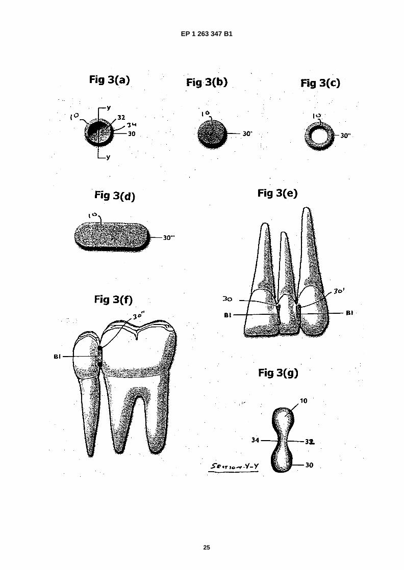
EP 1 263 347 B1
25
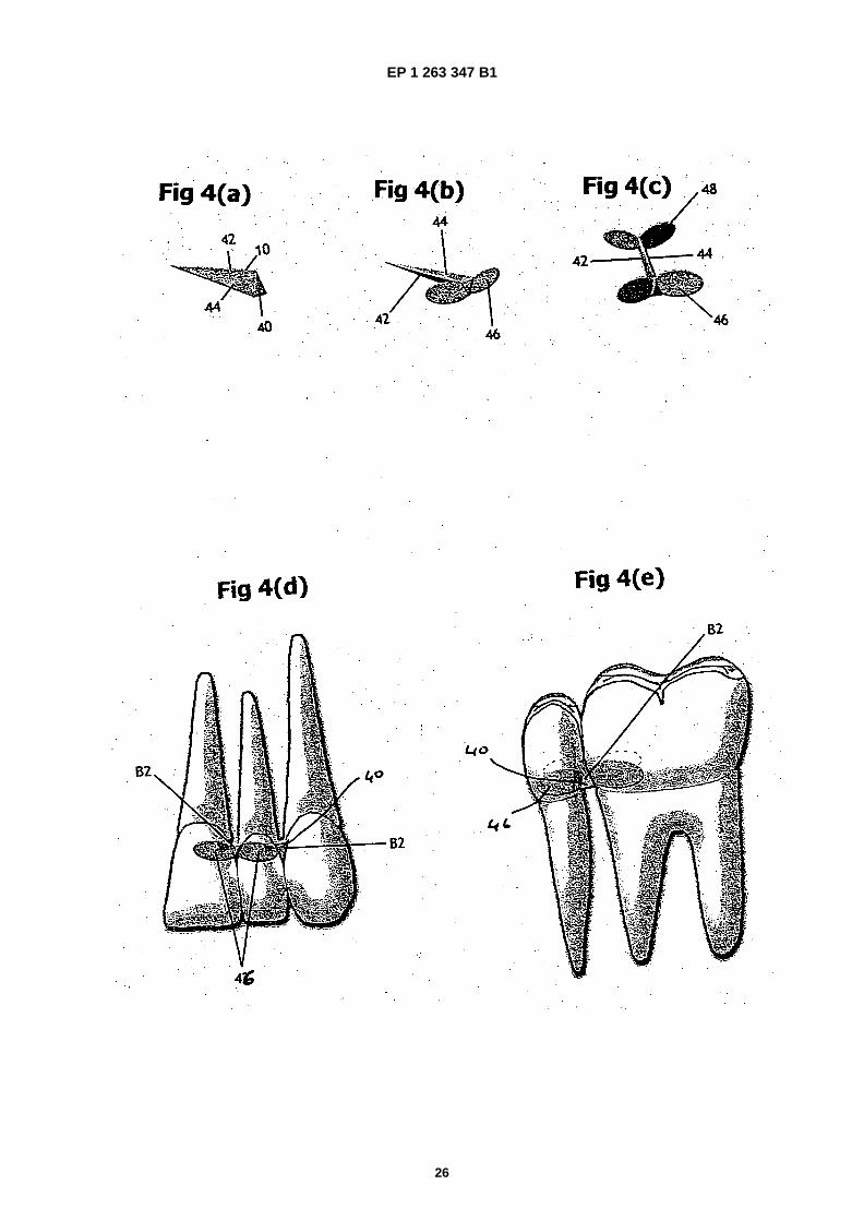
EP 1 263 347 B1
26

EP 1 263 347 B1
27

EP 1 263 347 B1
28
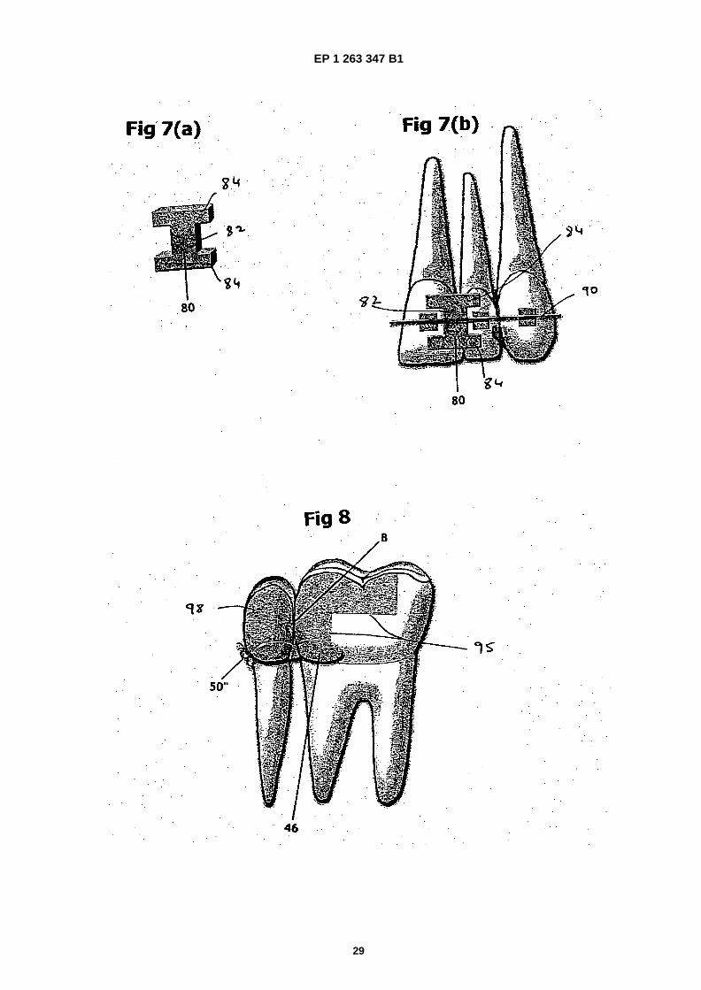
EP 1 263 347 B1
29