eoi stern gear - goa shipyard limited
TRANSCRIPT
GOA SHIPYARD LIMITED
Indigenisation Department
VASCO-DA-GAMA, GOA 403 802
NOTICE FOR INVITING EXPRESSION OF INTEREST (EOI)
FOR SUPPLY OF ‘‘STERN GEAR (CONTROLLABLE PITCH PROPELLER) SYSTEM’’
1. Ref No. 05/1267-68/EOI/ stern gear system
2. Date of issue of EOI 19 February, 2021
3. Date & time of closing of EOI 12 March, 2021, 1500 HRS
4. Description EOI FOR SUPPLY OF ‘STERN GEAR (CONTROLLABLE PITCH PROPELLER) SYSTEM’
5. Qty ‘02’ Nos
1. Goa Shipyard Limited invites 'Expression of Interest (EOI)' on non-commitment
basis from reputed Indian Manufacturers for STERN GEAR (CONTROLLABLE PITCH
PROPELLER) SYSTEM for upcoming Project at GSL as per GOI ‘Make in India’ initiative.
2. GSL invites only the Technical bid (without price) from reputed Indian
manufacturers in SINGLE BID SYSTEM for the above equipment. Price bids will be invited
separately from technically qualified bidders, after evaluation of the technical & financial
capabilities.
3. This EOI seeks response from the Equipment Manufacturer Only and unsolicited response from Integrators/ Collaborators/ intermediaries/ Sister Concerns will not be accepted. The bidder should have the experience and capability to manufacture the complete system of STERN GEAR SYSTEM in India and Integrate Onboard the vessel being constructed by GSL. 4. The equipment is to be fitted onboard/ provided meeting ABS class notation +A1, + AMS, (E), OSR-S2, HELIDK, +DPS-1, FFV2, +ACCU, CRC, ENVIRO, NBLES and equivalent of IRS ie SWASTIKA SUL, RS-0, SWASTIKA IY , OIL RECOVERY, HELDK, DP(1), AGNI-2, SYJ, STS, EP, IBS.
5. Description of Work. The ‘STERN GEAR SYSTEM’ to be supplied should meet the technical specifications as per Enclosure-A and following conditions:-
(a) Product Support.
(i) The service life of the vessel is 25 years. Hence, OEM is to confirm product support in terms of maintenance, material and spares (OBS and B&D) for the life cycle of the equipment from the date of delivery of the
vessel at all Indian port. Onboard spares for maintenance of equipment for three years from date of induction of the vessel to be provided alongwith equipment.
(ii) Even after the said mandatory period, the OEM would be bound to give at least 2 years notice prior to closure of said production line, to assess the requirement of life time buy of all spares and will form an integral part of the Contract.
(iii) All upgrades and modifications carried out on the equipment during its life cycle must be intimated to the user. Further the OEM should undertake to maintain currency/ upgrade software for all equipment upto 3 years from the date of delivery of the last vessel.
(b) Training of Crew and Maintenance Personnel. The crew of the vessel is required to be trained on operation and maintenance aspects by OEM.
(c) Commissioning of equipment by OEM.
(d) Equipment shall be capable for operation in tropical condition (i.e. 45 Deg ambient air and 32 Deg sea water temperature).
6. Pre-Qualification Criteria. The Manufacturer must fulfill the following pre-qualification criteria and shall necessarily submit the relevant documents to support the claim.
(a) Technical Criteria.
(i) The bidder must have experience on design, manufacturing, testing & certifying items for which EOI has been issued. The reference list of equipment for which EOI is issued that is delivered by the firm for fitment onboard ship to be enclosed.
(ii) The bidder shall be an Indian Manufacturer having its own development & production facilities & with hands on experience of manufacturing similar items in past. The bidder has to submit documentary evidence (preliminary design/ work) to establish the capacity to undertake design, development & manufacturing of the item.
(iii) The bidder has to submit proof of his capabilities to undertake Indigenous design, development & manufacture of Items in India. The bidder has to clearly specify in his offer that items offered will be: -
(aa) Indigenously designed, developed, manufactured & tested in India.
(ab) Raw materials used in manufacturing will be sourced in India.
(iv) The bidder has to submit the documentary evidence of above requirements; offers received without documentary evidence are liable for rejection.
(v) The drawings of the equipment with technical details to be submitted for
evaluation.
(vi) Type approval certificate of the equipment to be submitted as required in the Technical Specifications. (vii) Clausewise confirmation to the technical specification (Enclosure-A) to be submitted.
(b) Commercial.
(i) The bidder shall be an Indian registered company having its registered office & manufacturing facilities in India.
(ii) The bidder shall be an original Indian equipment designer, developer & manufacturer of Items.
(iii) The bidder shall provide the following details to determine their capabilities: -
(aa) Company Profile with date of registration.
(ab) Products manufactured
(ac) Installed capacity at works
(ad) Design & manufacturing facilities available in house
(ae) Previous Projects executed of similar nature
(af) Certified balance sheet of previous three years
(ag) Quality accreditations
(ah) Manufacturing capabilities (aj) After-sales support infrastructure
(iv) Manufacturer has to submit GST/PAN/TAN No.
(v) Response from Traders/ Agents/ Foreign Bidders/ Consultant/
Intermediaries shall not be considered.
7. Delivery Schedule. The proposed manufacturing, testing of the ‘STERN GEAR SYSTEM’ is to be completed within schedule indicated at technical specifications at Enclosure-A.
8. Future Business Potential. This document is not intended to form the basis of any decision to purchase/finalize contract and it does not constitute an offer or invitation or solicitation of an offer to purchase.
9. Submission of EOI.
(a) Issue of EOI Document. The EOI can be downloaded from GSL website.
(b) Submission of EOI. EOI bids are to be submitted in sealed envelope prior to closing date & time. Bidders shall ensure timely submission of their interest well in advance, in order to avoid the difficulties. The bids are to be submitted in person or by registered post clearly indicating "BID for EOI for the supply of ‘STERN GEAR SYSTEM’ on top of envelope. Bids received after EOI closing date & time will be not

considered for evaluation. (c) In case of any queries, the firm can contact for any assistance Mr. D. S. Patekar, Addl General Manager (Design/ Engg) or Mr. Rayson Botelho, Senior Manager (Design/ Engg) on their e-mails: [email protected] & [email protected] respectively. (d) The EOI proposal (One Original Copy + One soft Copy) shall be addressed to Mr. D. S. Patekar, Addl General Manager (Design/Engg) Goa Shipyard Limited, New Vaddem, Vasco Da Gama, 403802
Clause
No.
Technical Specifications Remarks
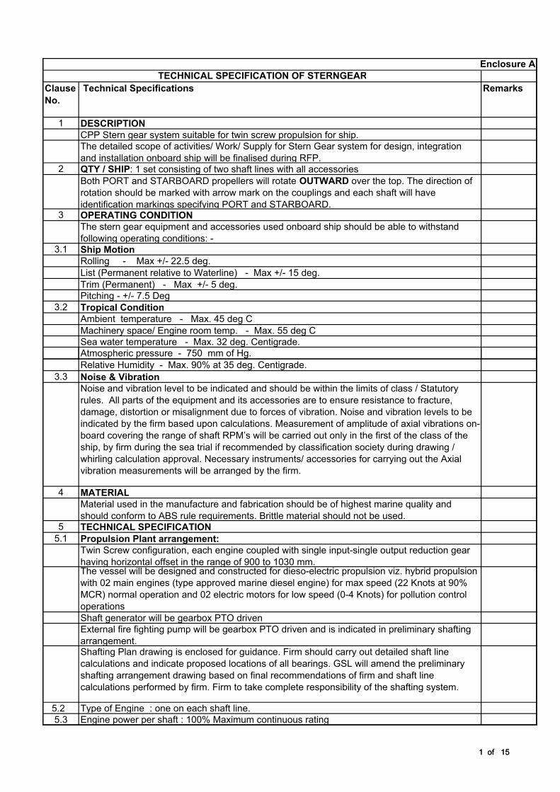
1 DESCRIPTION
CPP Stern gear system suitable for twin screw propulsion for ship.
The detailed scope of activities/ Work/ Supply for Stern Gear system for design, integration
and installation onboard ship will be finalised during RFP.2 QTY / SHIP: 1 set consisting of two shaft lines with all accessories
Both PORT and STARBOARD propellers will rotate OUTWARD over the top. The direction of
rotation should be marked with arrow mark on the couplings and each shaft will have
identification markings specifying PORT and STARBOARD.3 OPERATING CONDITION
The stern gear equipment and accessories used onboard ship should be able to withstand
following operating conditions: - 3.1 Ship Motion
Rolling - Max +/- 22.5 deg.
List (Permanent relative to Waterline) - Max +/- 15 deg.
Trim (Permanent) - Max +/- 5 deg.
Pitching - +/- 7.5 Deg
3.2 Tropical Condition
Ambient temperature - Max. 45 deg C
Machinery space/ Engine room temp. - Max. 55 deg C
Sea water temperature - Max. 32 deg. Centigrade.
Atmospheric pressure - 750 mm of Hg.
Enclosure A
TECHNICAL SPECIFICATION OF STERNGEAR
1 of 15
Atmospheric pressure - 750 mm of Hg.
Relative Humidity - Max. 90% at 35 deg. Centigrade.
3.3 Noise & Vibration
Noise and vibration level to be indicated and should be within the limits of class / Statutory
rules. All parts of the equipment and its accessories are to ensure resistance to fracture,
damage, distortion or misalignment due to forces of vibration. Noise and vibration levels to be
indicated by the firm based upon calculations. Measurement of amplitude of axial vibrations on-
board covering the range of shaft RPM’s will be carried out only in the first of the class of the
ship, by firm during the sea trial if recommended by classification society during drawing /
whirling calculation approval. Necessary instruments/ accessories for carrying out the Axial
vibration measurements will be arranged by the firm.
4 MATERIAL
Material used in the manufacture and fabrication should be of highest marine quality and
should conform to ABS rule requirements. Brittle material should not be used.5 TECHNICAL SPECIFICATION
5.1 Propulsion Plant arrangement:
Twin Screw configuration, each engine coupled with single input-single output reduction gear
having horizontal offset in the range of 900 to 1030 mm. The vessel will be designed and constructed for dieso-electric propulsion viz. hybrid propulsion
with 02 main engines (type approved marine diesel engine) for max speed (22 Knots at 90%
MCR) normal operation and 02 electric motors for low speed (0-4 Knots) for pollution control
operations
Shaft generator will be gearbox PTO driven
External fire fighting pump will be gearbox PTO driven and is indicated in preliminary shafting
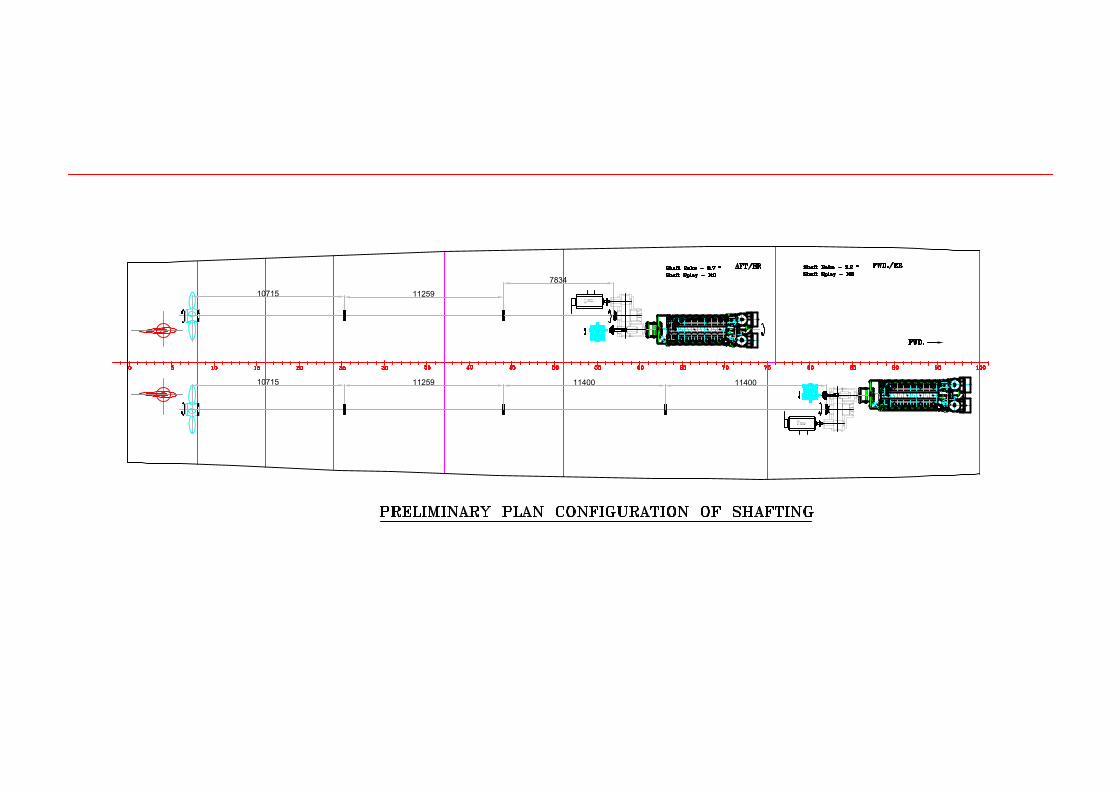
arrangement.Shafting Plan drawing is enclosed for guidance. Firm should carry out detailed shaft line
calculations and indicate proposed locations of all bearings. GSL will amend the preliminary
shafting arrangement drawing based on final recommendations of firm and shaft line
calculations performed by firm. Firm to take complete responsibility of the shafting system.
5.2 Type of Engine : one on each shaft line.
5.3 Engine power per shaft : 100% Maximum continuous rating
1 of 15
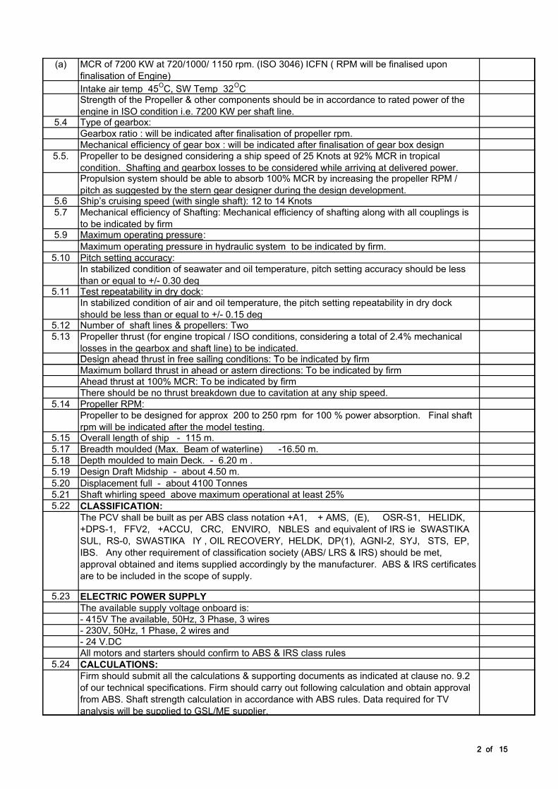
(a) MCR of 7200 KW at 720/1000/ 1150 rpm. (ISO 3046) ICFN ( RPM will be finalised upon
finalisation of Engine)
Intake air temp 45OC, SW Temp 32
OC
Strength of the Propeller & other components should be in accordance to rated power of the
engine in ISO condition i.e. 7200 KW per shaft line.5.4 Type of gearbox:
Gearbox ratio : will be indicated after finalisation of propeller rpm.
Mechanical efficiency of gear box : will be indicated after finalisation of gear box design
5.5. Propeller to be designed considering a ship speed of 25 Knots at 92% MCR in tropical
condition. Shafting and gearbox losses to be considered while arriving at delivered power. Propulsion system should be able to absorb 100% MCR by increasing the propeller RPM /
pitch as suggested by the stern gear designer during the design development. 5.6 Ship’s cruising speed (with single shaft): 12 to 14 Knots
5.7 Mechanical efficiency of Shafting: Mechanical efficiency of shafting along with all couplings is
to be indicated by firm5.9 Maximum operating pressure:
Maximum operating pressure in hydraulic system to be indicated by firm.
5.10 Pitch setting accuracy:
In stabilized condition of seawater and oil temperature, pitch setting accuracy should be less
than or equal to +/- 0.30 deg 5.11 Test repeatability in dry dock:
In stabilized condition of air and oil temperature, the pitch setting repeatability in dry dock
should be less than or equal to +/- 0.15 deg 5.12 Number of shaft lines & propellers: Two
5.13 Propeller thrust (for engine tropical / ISO conditions, considering a total of 2.4% mechanical
losses in the gearbox and shaft line) to be indicated.Design ahead thrust in free sailing conditions: To be indicated by firm
2 of 15
Design ahead thrust in free sailing conditions: To be indicated by firm
Maximum bollard thrust in ahead or astern directions: To be indicated by firm
Ahead thrust at 100% MCR: To be indicated by firm
There should be no thrust breakdown due to cavitation at any ship speed.
5.14 Propeller RPM:
Propeller to be designed for approx 200 to 250 rpm for 100 % power absorption. Final shaft
rpm will be indicated after the model testing.5.15 Overall length of ship - 115 m.
5.17 Breadth moulded (Max. Beam of waterline) -16.50 m.
5.18 Depth moulded to main Deck. - 6.20 m .
5.19 Design Draft Midship - about 4.50 m.
5.20 Displacement full - about 4100 Tonnes
5.21 Shaft whirling speed above maximum operational at least 25%
5.22 CLASSIFICATION:
The PCV shall be built as per ABS class notation +A1, + AMS, (E), OSR-S1, HELIDK,
+DPS-1, FFV2, +ACCU, CRC, ENVIRO, NBLES and equivalent of IRS ie SWASTIKA
SUL, RS-0, SWASTIKA IY , OIL RECOVERY, HELDK, DP(1), AGNI-2, SYJ, STS, EP,
IBS. Any other requirement of classification society (ABS/ LRS & IRS) should be met,
approval obtained and items supplied accordingly by the manufacturer. ABS & IRS certificates
are to be included in the scope of supply.
5.23 ELECTRIC POWER SUPPLY
The available supply voltage onboard is:
- 415V The available, 50Hz, 3 Phase, 3 wires
- 230V, 50Hz, 1 Phase, 2 wires and
- 24 V.DC
All motors and starters should confirm to ABS & IRS class rules
5.24 CALCULATIONS:
Firm should submit all the calculations & supporting documents as indicated at clause no. 9.2
of our technical specifications. Firm should carry out following calculation and obtain approval
from ABS. Shaft strength calculation in accordance with ABS rules. Data required for TV
analysis will be supplied to GSL/ME supplier.
2 of 15
a) Axial and lateral vibration calculations (limited to natural frequencies),
b) Bending, vibration and whirling calculations,
c) Bending moments, deflections and stresses,
d) Alignment procedure,
e) Necessary data to enable main engine maker to carryout torsion vibration calculations,
f) Calculations of bearing reaction forces (static & dynamic),and maximum estimated forces
exerted on the bearings to be indicated.g) Push-up calculation for mounting sleeve and flange (oil injection type) couplings,
h) Any other data / drawings / calculations required by ABS / Shipbuilder/ Propulsion
machinery manufacturer.j) Alignment calculations.
k) Following data for of propeller geometry for determination of ship vibration characteristics to
be provided alongwith the offer:
i) Propeller RPM
ii) Propeller blade number
iii) Propeller geometry diameter
iv) Propeller Pitch
v) Propeller Rake
vi) Propeller Skew angle
vii) Propeller chord length.
viii) Propeller section profiles.
Class approved document will be made available to GSL for the record .
6 SCOPE OF SUPPLY (for each shaft line):
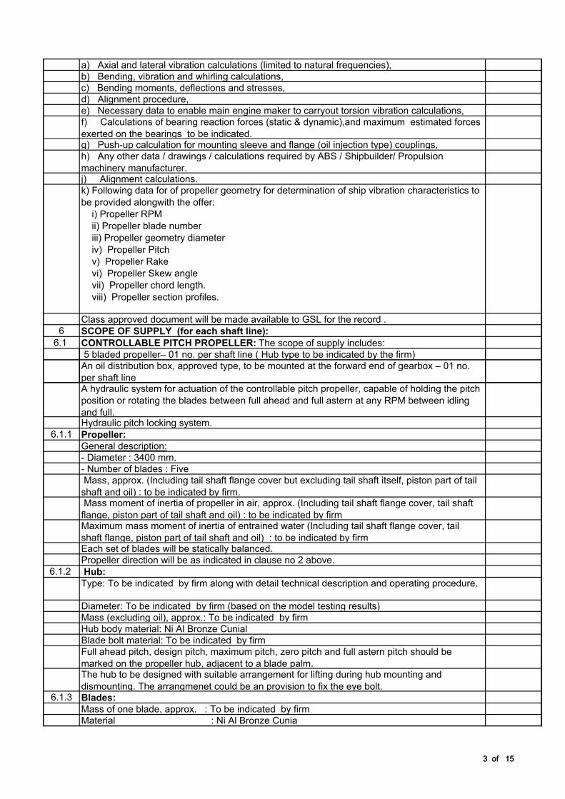
6.1 CONTROLLABLE PITCH PROPELLER: The scope of supply includes:
5 bladed propeller– 01 no. per shaft line ( Hub type to be indicated by the firm)
An oil distribution box, approved type, to be mounted at the forward end of gearbox – 01 no.
3 of 15
An oil distribution box, approved type, to be mounted at the forward end of gearbox – 01 no.
per shaft lineA hydraulic system for actuation of the controllable pitch propeller, capable of holding the pitch
position or rotating the blades between full ahead and full astern at any RPM between idling
and full.Hydraulic pitch locking system.
6.1.1 Propeller:
General description:
- Diameter : 3400 mm.
- Number of blades : Five
Mass, approx. (Including tail shaft flange cover but excluding tail shaft itself, piston part of tail
shaft and oil) : to be indicated by firm. Mass moment of inertia of propeller in air, approx. (Including tail shaft flange cover, tail shaft
flange, piston part of tail shaft and oil) : to be indicated by firmMaximum mass moment of inertia of entrained water (Including tail shaft flange cover, tail
shaft flange, piston part of tail shaft and oil) : to be indicated by firmEach set of blades will be statically balanced.
Propeller direction will be as indicated in clause no 2 above.
6.1.2 Hub:
Type: To be indicated by firm along with detail technical description and operating procedure.
Diameter: To be indicated by firm (based on the model testing results)
Mass (excluding oil), approx.: To be indicated by firm
Hub body material: Ni Al Bronze Cunial
Blade bolt material: To be indicated by firm
Full ahead pitch, design pitch, maximum pitch, zero pitch and full astern pitch should be
marked on the propeller hub, adjacent to a blade palm.The hub to be designed with suitable arrangement for lifting during hub mounting and
dismounting. The arrangmenet could be an provision to fix the eye bolt.6.1.3 Blades:
Mass of one blade, approx. : To be indicated by firm
Material : Ni Al Bronze Cunial
3 of 15
Blade Area Ratio, approx. : To be indicated by firm
The blades skew angle to be as per the propeller design requirement and to be indicated in
the offer.Manufacturing tolerances and surface finish will be in accordance with ISO 484/1-1981
class S.The propeller should be designed to permit removal and replacement of the palm mounted
propeller blades without opening the hub. The blades should be completely interchangeable
and should fit in any hub position.The blades should be designed to ensure good efficiency over the full working range. The
blades should not show face cavitation, singing and harmful cavitation erosion.Cunial Chemical & mechanical properties to be indicated in the offer.
6.1.4 Oil distribution box
The oil distribution box will be gearbox mounted. Drg of OD box to be submitted by firm
indicating gearbox interface data.Type :To be indicated by firm
Length : To be indicated by firm
Mass, approx. : To be indicated by firm
The oil distribution box should contain a feedback unit with potentiometers for pitch indication
and feedback sensing to the remote control system. Feedback unit and potentiometers to be
located on outboard side for easy access for maintainance for both port & STBD units. A
mechanical pitch indicator should be located on the side of oil distribution box.
All the fasteners required for the installation of the oil distribution box to be supplied by firm.
Port and starboard oil distribution boxes to be identical. Oil distribution box should be supplied
completely assembled and tested by firm.6.2 Hydraulic system
4 of 15
6.2 Hydraulic system
6.2.1 General description ( Detail description of the hydraulic sytem along with hydraulic system
diagram to be included in the offer)For each shaft line, the hydraulic system shall consists of the following sub-assemblies:
a) One hydraulic power pack, consisting of the main tank, on which are mounted the
electrically driven pump and the hydraulic components. Power packs to be of mirror image for
mounting on port and stbd side with control panel facing inboard.b) One gearbox driven CPP pump,
c) One header tank,
d) starter for the electric motor,
e) One Local Control Panel.
f) One fixed hand pump for emergency pitch setting (enabling to move pitch astern or pitch
ahead).6.2.3 Main components of hydraulic power pack
6.2.3.1 Main tank
Mounting: on anti-vibration mounts
Oil capacity : To be indicated by firm
Oil specification and make: To be indicated by the firm.
Preliminary overall dimensions (including all tank-mounted items, excluding anti-vibration
mounts,):- Length : To be indicated by firm
- Width : To be indicated by firm
- Height : To be indicated by firm
- Mass, excluding oil : To be indicated by firm
A minimum clearance required above the hydraulic power pack for minimum maintenance
space all around the equipment to be indicated. Location of HPP tank bottom above centreline
of the gearbox driven pump to be indicated. GSL space constraints for installing the hydraulic
power pack should be noted by firm and efforts should be made to try and make hydraulic
power pack fit into the required space.
4 of 15
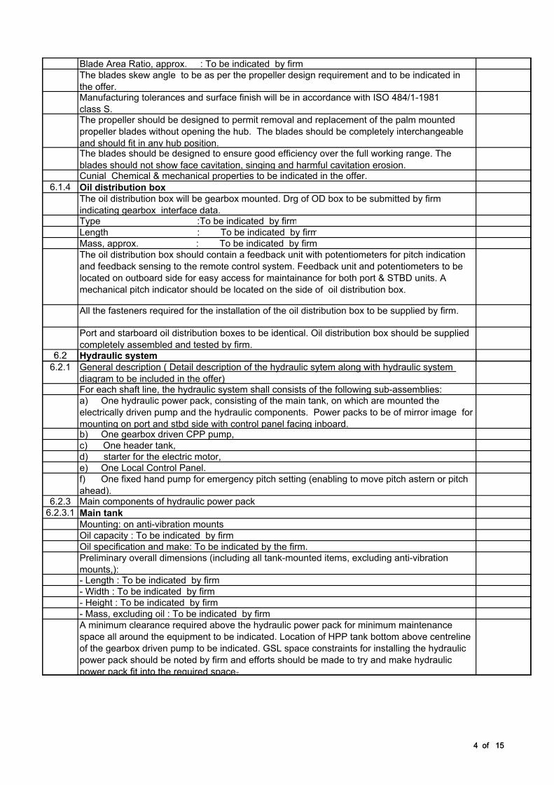
6.2.3.2 Electrically driven pump set consisting of pump and Electric motor
Pump type: Screw type
Pump maker & model (or equivalent) : To be indicated by firm
Pump speed : To be indicated by firm
Pump pressure, approx. : To be indicated by firm
Pump flow, approx. : To be indicated by firm
E-motor type & class: Cage rotor, IP54, class F
Supply voltage: 415 VAC / 3 phase / 50 Hz
Electric motor power, approx to be indicated by firm
Mass, including motor : To be indicated by firm
Pump and E-motor characteristics may vary, depending on the final blade design.
6.2.3.3 Oil cooler (OC)
Type: Plate type
Cooling fluid: Seawater
Max. Water inlet temperature : To be indicated by firm
Material of plates: Titanium
Heat dissipation, approx. : To be indicated by firm
Required cooling water flow, Pressure & temperature , approx. : To be indicated by firm
Space requirement for maintenance of the cooler will be indicated by firm in order GSL can
check the interference with the hull.6.2.3.4 All necessary anti-vibration mounts
6.2.3.5 All necessary Flexible hoses along with mating flanges / adopters to be supplied.
6.2.4 Gearbox driven pump:
Pump type: Screw type
Pump make & model : To be indicated by firm
Pump pressure, approx. : To be indicated by firm
Pump flow, approx. at nominal pump speed : To be indicated by firm
5 of 15
Pump flow, approx. at nominal pump speed : To be indicated by firm
Nominal pump speed : To be indicated by firm
Mass, approx. : To be indicated by firm
One pump will be right-handed and one pump will be left-handed.
The gearbox driven pump will be equipped with SAE connections. All the fasteners required
for the installation of the gearbox driven pump should be supplied. Firm to ensure suitable
pump selection so that pitch actuation is not sluggish at engine RPM of 400 and above.
6.2.5 Starter
Starter type: Star-Delta.
6.2.6 Local Control Panel
The Local Control Panel will include:
Ø A pitch indicator, (Ahead / Astern)
Ø An indicating lamp "zero pitch",
Ø A Selector switch "local / remote".
Panel mass: To be indicated
6.2.7 Fixed hand pump:
One fixed hand pump (enabling to move pitch ahead or pitch astern) will be supplied loose.
This pump will be permanently connected to the main oil tank by GSL (interconnecting piping
will be firm’s scope of supply) and will be equipped with a flexible hose and a quick connecting
coupling for connection to the oil distribution box in case of emergency.6.2.8 Double oil piping:
The shafting shall be hollow bored to contain the hydraulic oil piping consisting of two co-axial
pipes:In case of a hydraulic failure, pitch can be changed towards ahead or astern with a fixed hand
pump. In case of hydraulic failure locking the pitch in any position to be possible , to be
clarified in the offer.
5 of 15
The required size of the bore in the gearbox output shaft has to be indicated. :
6.3 Hydraulic pitch locking device
The CPP should be locked with a pitch locking mechanism enabeling the propeller blades to
be locked hydraulically in case of emergency.
Value of pitch to be locked should be such that excessive jerk is not experienced by the
vessel. Firm has to take GSL consent before finalising the pitch value. Detail operating
principle / methodology of the hydraulic locking mechanism to be submitted along with the
offer. 6.4 SHAFTLINE
The scope of supply per shaft line is given below from aft to forward. All the shaft line items will
be supplied by firm except outboard coupling GRP coating material and application.
6.4.1 Propeller shaft
Length: To be indicated by firm.
Length from propeller centre plane to fwd end: To be indicated by firm.
Aft diameter : To be indicated by firm.
Nominal diameter : To be indicated by firm.
Aft flange diameter: To be indicated by firm.
Bore diameter: To be indicated by firm.
Material: To be indicated by firm
Bronze liner in way of aft bracket bearing:
Length: To be indicated by firm.
Inner diameter: To be indicated by firm.
Outer diameter: To be indicated by firm.
Bronze liner in way of middle bracket bearing:
Length: To be indicated by firm
Inner diameter: To be indicated by firm.
6 of 15
Inner diameter: To be indicated by firm.
Outer diameter: To be indicated by firm.
Bronze liner aft of outboard coupling:
Length: To be indicated by firm.
Inner diameter: To be indicated by firm.
Outer diameter: To be indicated by firm.
GRP coating length, approx.: To be indicated by firm.
Shaft mass, approx. (incl. oil piping): To be indicated by firm.
The propeller shaft will have an integral flange at the aft end and will be equipped with a
hydraulic sleeve coupling at the forward end for connection to the stern tube shaft. The
propeller shaft will be supported by an aft "A" bracket and middle bracket and shaft will be
fitted with shrunk-on bronze liners of seawater resistant bronze in way of these brackets and
aft of the outboard coupling. The parts between the bronze liners should be delivered
protected by a GRP coating (Glass fibre Reinforced Plastic) as indicated at clause No. 6.4.7.2
below to prevent seawater corrosion. Any additional coating of paint over the GRP coating if
required to be applied before launching of ship in water to be indicated during detail
engineering.
6.4.2 Sleeve Coupling
The coupling between the propeller shaft and the stern tube shaft will be hydraulic sleeve
coupling.Type: To be indicated by firm.
Diameter: To be indicated by firm.
Mass, approx. (incl. fairing cones): To be indicated by firm.
Split cast aluminium rotating fair water caps should be included in the scope of supply of firm.
GRP coating to be applied on the sleeve coupling and the caps to prevent seawater corrosion
by the firm. All fasteners, sealant, locking wire made of stainless steel (stainless steel to AISI
316) to be supplied by firm as applicable for rotating fair water caps of sleeve coupling.
6.4.3 Stern tube shaft
Length (including hydrulic flange coupling: To be indicated by firm.
Diameter in stern tube: To be indicated by firm.
Diameter forward of the stern tube: To be indicated by firm.
6 of 15
Bore diameter: To be indicated by firm.
Material: To be indicated by firm
Bronze liner forward of outboard coupling:
Length: To be indicated by firm.
Inner diameter: To be indicated by firm.
Outer diameter: To be indicated by firm.
GRP coating length, approx.: To be indicated by firm.
Shaft mass, approx. (incl. Piping): To be indicated by firm.
The stern tube shaft will be equipped with a hydraulic flange coupling at the forward end for
connection to the intermediate shaft. The stern tube shaft will be supported by an stern tube
bearing and will be fitted with shrunk-on bronze liners.The stern tube shaft will be protected against seawater corrosion by GRP coating between the
bronze liners.6.4.4 Flange Coupling
A hydraulic loose flange coupling will be fitted at the forward end of the stern tube shaft for the
connection with the intermediate shaft(Port & Stbd.) and also will be fitted at the forward end of
the intermediate shaft for connection with Gearbox (Port) / (Stbd).and additional flange
coupling between intermediate shaft (stbd.) and stern tube shaft(stbd.)only.
Type: To be indicated by firm.
Diameter: To be indicated by firm.
Mass, approx.: To be indicated by firm.
Coupling overall length: To be indicated by firm.
This coupling should enable adjustment of the shaft line length by ±25 mm, thus avoiding the
need for any adjusting ring. No machining should be required on the coupling. Shaft line length
adjustment will be performed by moving the coupling axially on the shaft.6.4.5.1 Intermediate shaft for PORT side
7 of 15
6.4.5.1 Intermediate shaft for PORT side
At forward end of intermediate shaft, provision will be made for fitting of an ICCP ring
(length 100mm), which will be provided by the yard.Length approx : To be indicated by firm.
Diameter : To be indicated by firm.
Diameter in way of plummer bearing :To be indicated by firm.
Diameter in way of bulkhead seal : To be indicated by firm.
Bore diameter: To be indicated by firm.
Aft flange diameter : To be indicated by firm.
Forward flange diameter : To be indicated by firm.
Material: To be indicated by firm
Shaft mass, approx. (incl. Piping) To be indicated by firm.
6.4.5.2 Intermediate shaft 1 for STBD
At forward end of intermediate shaft, provision will be made for fitting of an ICCP ring
(length 100mm), which will be provided by the yard.Length approx : To be indicated by firm.
Diameter : To be indicated by firm.
Diameter in way of plummer bearing :To be indicated by firm.
Diameter in way of bulkhead seal : To be indicated by firm.
Bore diameter: To be indicated by firm.
Aft flange diameter : To be indicated by firm.
Forward flange diameter : To be indicated by firm.
Material: To be indicated by firm
Shaft mass, approx. (incl. Piping) To be indicated by firm.
6.4.5.3 Intermediate shaft 2 for STBD
Length approx : To be indicated by firm.
Diameter : To be indicated by firm.
Diameter in way of plummer bearing :To be indicated by firm.
Diameter in way of bulkhead seal : To be indicated by firm.
7 of 15
Bore diameter: To be indicated by firm.
Aft flange diameter : To be indicated by firm.
Forward flange diameter : To be indicated by firm.
Material: To be indicated by firm
Shaft mass, approx. (incl. Piping) To be indicated by firm.
6.4.6 Coupling bolts
1 set of fitted coupling bolts (per entire shaft line) should be included in scope of supply.
Coupling bolts, connecting the Sterntube shaft to intermediate shaft and intermediate shaft to
Gearbox (Port) and connecting the Sterntube shaft to intermediate shaft1, intermediate shaft1
to intermediate shaft2 and intermediate shaft2 to Gearbox (Stbd.) .Output shaft will be 2 mm
oversized for final machining and fitting by the shipyard.6.4.7 Materials
6.4.7.1 Chemical & physical properties of materials of each of the main components like shafts,
couplings, liners, propellers, bolts etc of the shafting system to be indicated in the offer. 6.4.7.2 GRP coating
The tail shaft and the stern tube shaft will be delivered duly coated.
6.4.8 SHAFTLINE ACCESSORIES
The scope of supply per shaft line is given below.
6.4.8.1 Shaft bearings
Aft bracket bearings, middle bracket bearings and stern tube Bearings will be water lubricated
and comply as per clause 5.22.General information for water lubricated bearings
Each water lubricated bracket bearing consists of a non-split bronze housing complete with a
split bearing (half-shelf), installed with a single/double tapered key. The non-split housing with
a split bearing allows for removal of the bearing without removal of the propeller or shaft,
space permitting. The bronze housing will be chockfasted in the bracket boss.
8 of 15
Maximum acceptable bearing wear down:To be indicated by firm
The clearance shaft / retainer ring when above maximum acceptable wear down is achieved is
equal to 1.5 mm.6.4.8.2 Aft bracket bearing, including bronze housing
Number per shaft line : 1
Maker : Thordon / Railko/equivalent
Type : COMPAC (split design)/NF21/ equivalent
Shaft diameter : To be indicated by firm
Housing outer diameter : To be indicated by firm
Total length : To be indicated by firm
Mass, approx. : To be indicated by firm
6.4.8.3 Middle bracket bearing, including bronze housing
Number per shaft line : 1
Maker : Thordon / Railko/equivalent
Type : COMPAC (split design)/NF21/equivalent
Shaft diameter : To be indicated by firm
Housing outer diameter : To be indicated by firm
Total length : To be indicated by firm
Mass, approx. : To be indicated by firm
6.4.8.4 Aft stern tube bearing(Necessity of this bearing to be confirmed by the firm with
calculations)Number per shaft line : 1
Maker : Thordon / Railko/equivalent
Type : COMPAC (split design)/NF21/ equivalent
Shaft diameter : To be indicated by firm
Housing outer diameter : To be indicated by firm
8 of 15
Total length, approx. : To be indicated by firm
Mass, approx. : To be indicated by firm
Gearbox bearing loads limits should not exceed when this maximum wear down is reached.
However, firm should confirm and prove the same with the shaft line calculations that load and
wear down of other bearings on the shaft line will not exceed than their maximum permissible
limits. Firm should correspond with gearbox manufacturer so that loads and displacement
values of forward and aft bearings of gearbox will not exceed their maximum permissible limits
at maximum wear down of aft stern tube bearing.6.4.8.6 Shaft seal
For each shaft line, the scope of supply includes one forward face type stern tube seal.
Provision should be made for local and remote monitoring of stern tube cooling water flow
and temperature alongwith low flow and high temperature alarms. Low flow rate and high
temperature alarm probes for remote monitoring will be integrated to IMCS. 6.4.8.6.
1
Forward stern tube seal, including inflatable seal
Number per shaftline : 1
Maker Deep Sea Seals/equivalent
Type Fully split : To be indicated by firm
Face material : To be indicated by firm
Shaft diameter : To be indicated by firm
Seal Length : To be indicated by firm
Mass, approx. : To be indicated by firm
All the components are to be split and can be changed without disturbing the shaft line
arrangement.Following is applicable for the forward stern tube seal:
Ø All components are fully split.
Ø The stern tube seal includes an inflatable seal for stern tube seal for maintenance afloat.
9 of 15
Ø The stern tube seal includes an inflatable seal for stern tube seal for maintenance afloat.
Ø the stern tube being GSL design and supply.
Ø Seal to be provided with Flow sensor for measuring the sea water flow with provision for
low and high flow alarm. The flow parameters will be monitored in MCR on the Multi Function
Workstation (MFW) along with the other shafting parameters. Provision to be made for
monitoring the flow locally. Unit for measurement of flow to be Liters / Hour.Ø Sea water flow and pressure requirements to be indicated by the firm.
Ø Provision for poker gauge to measure the shaft wear down to be made on the seal. Poker
gauge to be supplied by firm. Depth of the poker gauge should be suitable for measuring the
depth of aft "A" bracket bearing, middle "A" bracket bearing and seal.6.4.8.7 Torsionmeter
Number per shaftline : 1
Maker : Kyma / Brolich/ VAAF/Equivalent
Type : To be indicated by firm.
Total mass, approx . : To be indicated by firm.
Overall axial length : To be indicated by firm.
Each torsion meter should include:
Ø Rotor assembly (split type), to be mounted on stern tube shaft,
Ø Pedestal base stator assembly, housing power transformer, RPM pick up unit and
electronic unit,Ø Remote Display Unit on the Engine Control Room console / interface with the remote
control system for displaying the parameters on the Multifunction work station in MCR.Ø Interface box for 4- 20 mA analogue outputs.
9 of 15
The scope of supply includes technical assistance of torsion meter supplier during
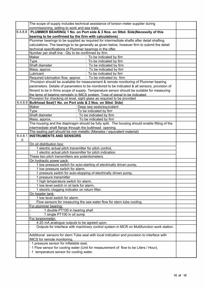
commissioning, setting to work and sea trials. 6.4.8.8
PLUMMER BEARING( 1 No. on Port side & 3 Nos. on Stbd. Side)Necessity of this
bearing to be confirmed by the firm with calculations)Plummer bearings to be supplied as required for intermediate shafts after detail shafting
calculations. The bearings to be generally as given below, however firm to submit the detail
technical specifications of Plummer bearings in the offer.Number per shaft line : Qty to be confirmed by firm
Maker : To be indicated by firm
Type : To be indicated by firm
Shaft diameter : To be indicated by firm
Mass, approx. : To be indicated by firm
Lubricant : To be indicated by firm
Required lubrication flow, approx. : To be indicated by firm
Provision should be available for measurement & remote monitoring of Plummer bearing
parameters. Details of parameters to be monitored to be indicated & all sensors, provision of
fitment to be in firms scope of supply. Temperature sensor should be suitable for measuring
the temp of bearing remotely in IMCS system. Type of signal to be indicatedProvision for checking oil level, sight glass as required to be provided
6.4.8.9 Bulkhead Seal(1 No. on Port side & 2 Nos. on Stbd. Side)
Maker : Deep sea seals/equivalent
Type : To be indicated by firm
Shaft diameter : To be indicated by firm
Mass, approx. : To be indicated by firm
The housing and the diaphragm should be fully split. The housing should enable fitting of the
intermediate shaft flange through the bulkhead opening.The sealing part should be non metallic (Manetex / equivalent material)
10 of 15
The sealing part should be non metallic (Manetex / equivalent material)
6.4.8.1
0
INSTRUMENTS AND SENSORS
On oil distribution box:
· 1 electric actual pitch transmitter for pitch control,
· 1 electric actual pitch transmitter for pitch indication.
These two pitch transmitters are potentiometers.
On hydraulic power pack:
· 1 low pressure switch for auto-starting of electrically driven pump,
· 1 low pressure switch for alarm,
· 1 pressure switch for auto-stopping of electrically driven pump,
· 1 pressure transmitter
· 1 high temperature switch for alarm,
· 1 low level switch in oil tank for alarm,
· 1 electric clogging indicator on return filter.
On header tank:
· 1 low level switch for alarm.
· Flow sensors for measuring the sea water flow for stern tube cooling.
For plummer bearing:
- 1 double PT100 in bearing shell
- 1 single PT100 in oil sump
For torsionmeter:
· 4-20 mA analogue outputs to be agreed upon.
· Outputs for interface with machinery control system in MCR on Multifunction work station.
Additional sensors for stern Tube seal with local indication and provision to interface with
IMCS for remote monitoring.· 1 pressure sensor for inflatable seal,
· 1 Flow sensor for cooling water (Unit for measurement of flow to be Liters / Hour),
· 1 temperature sensor for cooling water.
10 of 15
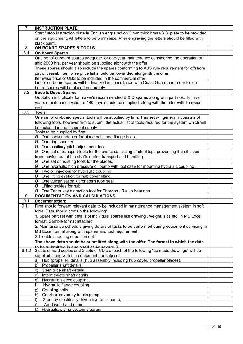
7 INSTRUCTION PLATE
Start / stop instruction plate in English engraved on 3 mm thick brass/S.S. plate to be provided
on the equipment. All letters to be 5 mm size. After engraving the letters should be filled with
black paint.8 ON BOARD SPARES & TOOLS
8.1 On board Spares
One set of onboard spares adequate for one-year maintenance considering the operation of
ship 2000 hrs. per year should be supplied alongwith the offer.
These spares should also include the spares conforming to ABS rule requirement for offshore
patrol vessel. Item wise price list should be forwarded alongwith the offer.
Itemwise price of OBS to be included in the commercial offer.List of on-board spares will be finalized in consultation with Coast Guard and order for on-
board spares will be placed separately.8.2 Base & Depot Spares
Quotation in triplicate for maker’s recommended B & D spares along with part nos. for five
years maintenance valid for 180 days should be supplied along with the offer with itemwise
cost.8.3 Tools
One set of on-board special tools will be supplied by firm. This set will generally consists of
following tools, however firm to submit the actual list of tools required for the system which will
be included in the scope of supply :Tools to be supplied by firm:
Ø One socket adapter for blade bolts and flange bolts,
Ø One ring spanner,
Ø One auxiliary pitch adjustment tool,
Ø One set of transport tools for the shafts consisting of steel taps preventing the oil pipes
from moving out of the shafts during transport and handling.
11 of 15
from moving out of the shafts during transport and handling.Ø One set of hoisting tools for the blades,
Ø One hydraulic high pressure oil pump with tool case for mounting hydraulic coupling .
Ø Two oil injectors for hydraulic coupling,
Ø One lifting eyebolt for hub cover lifting.
Ø One vulcanisation kit for stern tube seal
Ø Lifting tackles for hub,
Ø One Taper key extraction tool for Thordon / Railko bearings.
9 DOCUMENTATION AND CALCULATIONS
9.1 Documentation:
9.1.1 Firm should forward relevant data to be included in maintenance management system in soft
form. Data should contain the following:
1. Spare part list with details of individual spares like drawing , weight, size etc. in MS Excel
format. Sample format attached.
2. Maintainance schedule giving details of tasks to be performed during equipment servicing in
MS Excel format along with spares and tool requirement.
3.Trouble shooting of equipment.
The above data should be submitted along with the offer. The format in which the data
to be submitted is enclosed at Annexure C9.1.2 3 sets of hard copies and 2 sets of CD’s of each of the following “as made drawings” will be
supplied along with the equipment per ship set.a) Hub (propeller) details (hub assembly including hub cover, propeller blades),
b) Propeller shaft details
c) Stern tube shaft details
d) Intermediate shaft details
e) Hydraulic sleeve coupling,
f) Hydraulic flange coupling,
g) Coupling bolts,
h) Gearbox driven hydraulic pump,
i) Standby electrically driven hydraulic pump,
j) Air-driven hand pump,
k) Hydraulic piping system diagram,
11 of 15
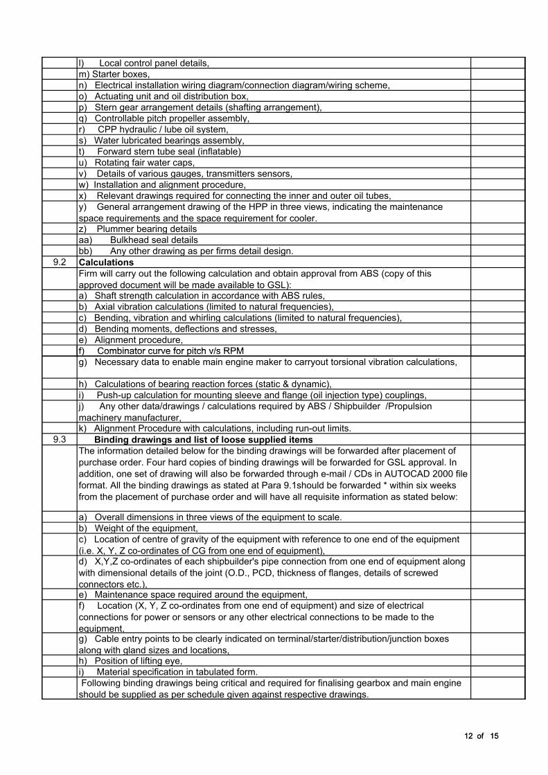
l) Local control panel details,
m) Starter boxes,
n) Electrical installation wiring diagram/connection diagram/wiring scheme,
o) Actuating unit and oil distribution box,
p) Stern gear arrangement details (shafting arrangement),
q) Controllable pitch propeller assembly,
r) CPP hydraulic / lube oil system,
s) Water lubricated bearings assembly,
t) Forward stern tube seal (inflatable)
u) Rotating fair water caps,
v) Details of various gauges, transmitters sensors,
w) Installation and alignment procedure,
x) Relevant drawings required for connecting the inner and outer oil tubes,
y) General arrangement drawing of the HPP in three views, indicating the maintenance
space requirements and the space requirement for cooler.z) Plummer bearing details
aa) Bulkhead seal details
bb) Any other drawing as per firms detail design.
9.2 Calculations
Firm will carry out the following calculation and obtain approval from ABS (copy of this
approved document will be made available to GSL):a) Shaft strength calculation in accordance with ABS rules,
b) Axial vibration calculations (limited to natural frequencies),
c) Bending, vibration and whirling calculations (limited to natural frequencies),
d) Bending moments, deflections and stresses,
e) Alignment procedure,
f) Combinator curve for pitch v/s RPM
12 of 15
f) Combinator curve for pitch v/s RPM
g) Necessary data to enable main engine maker to carryout torsional vibration calculations,
h) Calculations of bearing reaction forces (static & dynamic),
i) Push-up calculation for mounting sleeve and flange (oil injection type) couplings,
j) Any other data/drawings / calculations required by ABS / Shipbuilder /Propulsion
machinery manufacturer,k) Alignment Procedure with calculations, including run-out limits.
9.3 Binding drawings and list of loose supplied items
The information detailed below for the binding drawings will be forwarded after placement of
purchase order. Four hard copies of binding drawings will be forwarded for GSL approval. In
addition, one set of drawing will also be forwarded through e-mail / CDs in AUTOCAD 2000 file
format. All the binding drawings as stated at Para 9.1should be forwarded * within six weeks
from the placement of purchase order and will have all requisite information as stated below:
a) Overall dimensions in three views of the equipment to scale.
b) Weight of the equipment,
c) Location of centre of gravity of the equipment with reference to one end of the equipment
(i.e. X, Y, Z co-ordinates of CG from one end of equipment),d) X,Y,Z co-ordinates of each shipbuilder's pipe connection from one end of equipment along
with dimensional details of the joint (O.D., PCD, thickness of flanges, details of screwed
connectors etc.),e) Maintenance space required around the equipment,
f) Location (X, Y, Z co-ordinates from one end of equipment) and size of electrical
connections for power or sensors or any other electrical connections to be made to the
equipment,g) Cable entry points to be clearly indicated on terminal/starter/distribution/junction boxes
along with gland sizes and locations,h) Position of lifting eye,
i) Material specification in tabulated form.
Following binding drawings being critical and required for finalising gearbox and main engine
should be supplied as per schedule given against respective drawings.
12 of 15
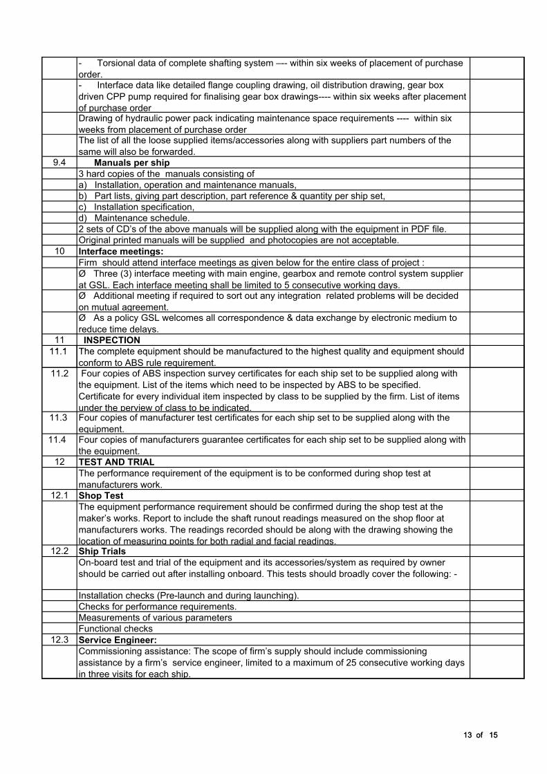
- Torsional data of complete shafting system –-- within six weeks of placement of purchase
order.- Interface data like detailed flange coupling drawing, oil distribution drawing, gear box
driven CPP pump required for finalising gear box drawings---- within six weeks after placement
of purchase orderDrawing of hydraulic power pack indicating maintenance space requirements ---- within six
weeks from placement of purchase orderThe list of all the loose supplied items/accessories along with suppliers part numbers of the
same will also be forwarded.9.4 Manuals per ship
3 hard copies of the manuals consisting of
a) Installation, operation and maintenance manuals,
b) Part lists, giving part description, part reference & quantity per ship set,
c) Installation specification,
d) Maintenance schedule.
2 sets of CD’s of the above manuals will be supplied along with the equipment in PDF file.
Original printed manuals will be supplied and photocopies are not acceptable.
10 Interface meetings:
Firm should attend interface meetings as given below for the entire class of project :
Ø Three (3) interface meeting with main engine, gearbox and remote control system supplier
at GSL. Each interface meeting shall be limited to 5 consecutive working days.Ø Additional meeting if required to sort out any integration related problems will be decided
on mutual agreement. Ø As a policy GSL welcomes all correspondence & data exchange by electronic medium to
reduce time delays.11 INSPECTION
11.1 The complete equipment should be manufactured to the highest quality and equipment should
13 of 15
11.1 The complete equipment should be manufactured to the highest quality and equipment should
conform to ABS rule requirement.11.2 Four copies of ABS inspection survey certificates for each ship set to be supplied along with
the equipment. List of the items which need to be inspected by ABS to be specified.
Certificate for every individual item inspected by class to be supplied by the firm. List of items
under the perview of class to be indicated.11.3 Four copies of manufacturer test certificates for each ship set to be supplied along with the
equipment.11.4 Four copies of manufacturers guarantee certificates for each ship set to be supplied along with
the equipment.12 TEST AND TRIAL
The performance requirement of the equipment is to be conformed during shop test at
manufacturers work.12.1 Shop Test
The equipment performance requirement should be confirmed during the shop test at the
maker’s works. Report to include the shaft runout readings measured on the shop floor at
manufacturers works. The readings recorded should be along with the drawing showing the
location of measuring points for both radial and facial readings.12.2 Ship Trials
On-board test and trial of the equipment and its accessories/system as required by owner
should be carried out after installing onboard. This tests should broadly cover the following: -
Installation checks (Pre-launch and during launching).
Checks for performance requirements.
Measurements of various parameters
Functional checks
12.3 Service Engineer:
Commissioning assistance: The scope of firm’s supply should include commissioning
assistance by a firm’s service engineer, limited to a maximum of 25 consecutive working days
in three visits for each ship.
13 of 15
13 TRAINING
Training for Coast Guard personnel & GSL staff to be imparted onboard to familiarize with the
capability of operation and onboard maintenance of the equipment. The concept of training will
include the following: -- System operation
- Function of system
- System interface
Control and operation of equipment
Troubleshooting
- Minor repairs and part replacement
- Periodic and preventive checks.
- Propeller hub assembly.
14 WEIGHT
Estimated weight in Kg of the equipment and components should be indicated in the drawing.
The weighed weight of major items of the equipment at the time of dispatch should be
indicated in the dispatch documents. It is to be ensured that the weight of the equipment is
kept within +/- 2% of the estimated weight. 15 SPECIAL REQUIREMENTS
15.1 The contractors/suppliers should ensure that the capacities of auxiliaries supplied by them
would be sufficient for the proper performance of the main items offered. All fittings and/or
accessories for the machineries covered by the contract should be delivered as per technical
specification.15.2 100mm dia. pressure gauges and thermometers should be supplied for the machinery
equipment under supply as per technical specification and these should be indicated in the
installation drawings for the unit. The pressure gauges should have white face and black
figures. Vacuum gauges should have red figures.15.3 All the thermometers should be as per marine standard.
14 of 15
15.3 All the thermometers should be as per marine standard.
15.4 All the pressure gauges and thermometers should be marked in Kg/sq. cm. and deg.C
respectively. All the pressure gauges and thermometers scale ranges should be selected so
that the maximum normal operating pressure and temperature respectively will be approx.
75% of the full-scale range.15.5 Pressure sensing devices and pressure gauges should be provided with isolating valve.
Temperature sensing devices should have the facility to allow for instrument removal without
impairing the integrity of the system.15.6 Arrangements to allow for instrument isolation and removal, without impairing the integrity of
the system. 15.7 Counter flanges of weldable steel/GM material should be supplied for all pipes and pipes
connections of the machinery equipment complete with bolts and nuts.15.8 For screwed connections, if any, special unions should be supplied.
15.9 All flexible pipes/hoses for oil and water should be ABS approved type.
15.10 Non-metallic flexible pipes/hoses for oil service are to be resistant and reinforced with wire-
braid or other material.15.11 Bursting pressure for all flexible pipes should be 5 times the set pressure of relief valve.
16 PAINTING SCHEME
16.1 Metal surface of the equipment should be treated properly before painting like degreasing,
acid, pickling passivating16.2 Primer - Two coats as per maker standards.
16.3
Final Two coats of final painting as per makers standards.
14 of 15

17 COMMISSIONING SPARES
The firm should supply spares required during commissioning the ship. List of Commisioning
Spares/ consumables should be indicated in the offer. Shelf life of consumables to be
indicated in the offer.18 PRESERVATION
The equipment should be supplied duly preserved (period to be indicated). The procedure for
re-preservation to be supplied by the firm.19 Delivery Schedule
Equipment shoul be delivered within 10 months from order finalisation
20 Firm’s offer should include the following:-
20.1 Clause wise acceptance with deviation/comments if any to be forwarded against each of the
clauses of the technical specification.20.2 Preliminary drawings
20.3 Brief description of the items along with drawings/ catalogues for all the items included in the
scope of supply to be submitted along with the offer
15 of 1515 of 15
1071511259
7834
1071511259 11400 11400
PTI
n = 1500 rpm
P = 750 kW
PTI
n = 1500 rpm
P = 750 kW