entropy - mdpi
TRANSCRIPT

entropy
Article
Probabilistic Strategic Conflict-Management for 4DTrajectories in Free-Route Airspace
Javier Alberto Pérez-Castán * , Álvaro Rodríguez-Sanz , Luis Pérez Sanz,Rosa M. Arnaldo Valdés , V. Fernando Gómez Comendador , Clemence Greatti andLidia Serrano-Mira
Higher Technical School of Aeronautical and Space Engineering (ETSIAE), Polytechnic University of Madrid,Plaza Cardenal Cisneros, 28040 Madrid, Spain; [email protected] (Á.R.-S.); [email protected] (L.P.S.);[email protected] (R.M.A.V.); [email protected] (V.F.G.C.);[email protected] (C.G.); [email protected] (L.S.-M.)* Correspondence: [email protected]; Tel.: +34-910-67-59-36
Received: 26 November 2019; Accepted: 27 January 2020; Published: 30 January 2020�����������������
Abstract: The expected growth of air traffic in the following decades demands the implementation ofnew operational concepts to avoid current limitations of the air traffic management system. This paperfocuses on the strategic conflict management for four-dimensional trajectories (4DT) in free-routeairspace. 4DT has been proposed as the future operational concept to manage air traffic. Thus,aircraft must fulfil temporary restrictions at specific waypoints in the airspace based on time windows.Based on the temporary restrictions, a strategic conflict management method is proposed to calculatethe conflict probability of an aircraft pair (that intersects in the air) and to calculate temporary-blockingwindows that quantify the time span at which an aircraft cannot depart because one conflict couldoccur. This methodology was applied in a case-study for an aircraft pair, including the uncertaintyassociated with 4DT. Moreover, a sensitivity analysis was performed to characterise the impact ofwind conditions and speed control on the temporary-blocking windows. The results concluded that itis feasible to propose 4DT strategic de-confliction based on temporary-blocking windows. Although,uncertainty variables such as wind and speed control impact on the conflict probability and the sizeof the temporary-blocking windows.
Keywords: 4D trajectories; strategic conflict management; conflict detection; conflict probability;temporary-blocking windows; free-route airspace
1. Introduction
The continuous growth of air traffic is expected to double their present values around 2040 [1].The current system of air traffic management (ATM) presents several inefficiencies and will not be ableto manage the air traffic increase. The European macro programme Single European Sky ATM Research(SESAR) addresses the development and implementation of the future ATM system [2]. Among otheroperational concepts, this paper focuses on the trajectory-based operations (TBO) or four-dimensionaltrajectories (4DT) and their implementation on a free-route airspace (FRA).
The 4D trajectory of an aircraft consists of the three spatial dimensions plus time as a fourthdimension, defining each waypoint by position (latitude, longitude and flight level) and time [3].This operational framework foresees trajectory restrictions regarding time: users will follow trajectorieswithout practically any geographical limitations (according to free-route trajectories), as long as theycomply with the planned times. Thus, the main objective of this approach is to ensure an optimaltrajectory (free-route trajectory whenever would be possible) by "forcing" the aircraft to accuratelymeet the time of arrival at designated waypoints in exchange [4]. Most of the proposed methods to
Entropy 2020, 22, 159; doi:10.3390/e22020159 www.mdpi.com/journal/entropy
Entropy 2020, 22, 159 2 of 17
model 4DT and solve the aircraft trajectory prediction problem can be categorised into two approaches:deterministic and probabilistic [5]. The traditional approach is based on a deterministic formulation,a mathematical problem that describes the aircraft motion. If some external forces or parameters(e.g., aircraft performance, weather conditions, navigation systems accuracy, traffic regulations) areunknown or cannot be precisely appraised, the probabilistic approach transforms the problem into astochastic one [6,7].
The TBO concept involves separating aircraft via strategic (long-term) trajectory definition, ratherthan the currently-practised tactical (short-term) conflict resolution [8]. This aims to increase the airtraffic capacity by reducing the controllers’ workload. Nevertheless, real-time measures (over thetrajectory) will be required to improve reliability, react to unplanned conditions and thus maintain theexpected capacity [9].
Numerous studies focus on conflict detection and resolution in a short-term horizon based oncollision avoidance manoeuvres. Several techniques were developed for conflict detection and theprojection of the further status of both aircraft; the authors recommend [10,11] for a full understandingof the techniques. Moreover, more complex solutions were developed by different authors basedon mathematical techniques [12–14]. Particularly, conflict detection in free-flight is not a novelconcept [15,16]. Paielli and Erzberger [17] developed the concept of trajectory specification based onpairwise conflict detection and resolution. The authors paved the way with this work for furtherassessment of 4DT. Barnier and Allignol [18] presented an optimisation problem to estimate the cost ofdirectly solving conflicts in the upper airspace with delays. However, there is few research that focuseson mathematical criteria and probabilistic assessment to appraise the viability of the introduction of4DT in a FRA.
Typically, conflict detection was tackled based on a static approach. Typically, there existsa cylinder-shaped “forbidden volume or protected airspace zone” around the aircraft definedlongitudinally by 5 Nautical Miles (NM) and vertically by 1000 feet (ft.). The conflict area orcritical section refers to the whole airspace near an intersection where an aircraft can infringethe separation minima depending on the relative position of other aircraft. Geisinger [19] consideredan airspace intersection geometry without any geometrical boundaries. International Civil AviationOrganisation ICAO [20] denoted a conflict area around the intersecting point shaped like a rectangle.Netjasov [21] transformed this conflict area to a critical section as a circle around the intersecting points.Although every geometrical concept is valid, the problem arises when uncertainties are associated withthe aircraft movement (stochastic approach). Among different solutions, one of them at the presenttime is the blocking-area concept [22,23]. The blocking-area allows knowing if an aircraft influences thetrajectory of other aircraft and may imply a modification of the other trajectory. When the blocking-areatransforms its application from location to time, it evolves to a temporary-blocking window [24–26].In this case, the temporary-blocking window provides the time span an aircraft cannot enter in thecritical section because one conflict will arise. Then, it provides temporary restrictions to the operationof an aircraft. The main question arises when it is demanded to know if it is possible to specifytemporary restrictions between aircraft departing from different airports based on 4DT for the futurescheduling process.
This research provides a probabilistic assessment of the incompatibilities between 4DT dependingon the city-pairs. The goal is to provide the temporary-blocking windows on the strategic horizon thatlimits the departures between different airports. This concept tries to solve the typical approach ofsolving the conflicts in-flight in order to avoid departure delays [17,27]. However, air traffic is expectedto double their values in the following 20 years and, in addition, there is a lack of capacity because ofair traffic control (ATC) limitations [28]. The integration of 4DT together with temporary-blockingwindows can ensure conflict-free trajectories and, in turn, increase capacity because of a reductionof ATC workload. Therefore, this paper tackles the safe integration of 4DT by strategic conflictmanagement. This approach analyses the impact of uncertainty of 4DT in terms of conflict probabilityaccording to temporary restrictions that must be fulfilled by aircraft. A further goal is to calculate the

Entropy 2020, 22, 159 3 of 17
temporary-blocking windows that block the departure of an aircraft depending on another aircraftoperating 4D trajectories.
The remainder of this work is structured as follows. Section 3 introduces the methodology totackle the problem. Section 3 details the probabilistic assessment for the strategic conflict managementand Section 4 describes the process to analyse the conflict probability. Section 5 presents the resultsin a real case evaluating ideal results with the inclusion of uncertainty parameters. Lastly, Section 6provides the primary conclusions.
2. Methods
2.1. Path Modelling for Free-Route Airspace
Currently, airspace users (AUs) define the flight profile based on the predefined routes andwaypoints. The operational concept of FRA seeks the path optimisation depending on the AU needs.In this way, the AUs can select the trajectory that best fulfils its operational requirement according tofuel consumptions, aviation charges or flight duration. Herein, it is assumed that full airspace is FRAand, therefore, aircraft will fly according to the shortest route (orthodromic routes) between city-pairs.Equation (1) provides the orthodromic route:
sin(λ− λ0) = tan(θ0)tan(ϕ) (1)
where λ and ϕ are the longitude and latitude of each point, θ0 is the path course at the equator,and λ0 the latitude at the equator. In this way, the lateral path is calculated based on the geographicalcoordinates of the city-pair. Although it is considered the shortest route, the straight route is not theflight with the shortest flying-time in aviation because the shortest flying-time flight is the maximumcircle arc. Optimised or loxodromic routes could be as well introduced depending on the AU prioritiesbecause the information required for the conflict-detection model is just the 4DT.
According to the vertical profile, the trajectory is defined based on a simple model that entails:a continuous climbing up to Top of Climb (ToC), a cruise level phase (constant speed is assumed) anda continuous descending phase from the Top of Descent (ToD).
Moreover, the 4D trajectory is not characterised by pre-defined waypoints, but it demands newwaypoints or “control points” based on distance-separation criterion [3]. Herein, N waypoints arefixed for time-windows requirements of 4DT. They are separated by a constant distance l that is beingcurrently considered from 150 to 200 NM because the path degradation can be assumed [4]. The Nwaypoints are uniformly distributed from the ToC to the ToD.
The geographical coordinates of the new waypoints are calculated based on Equation (2).
sin(l) =sin
(ϕ j −ϕi
)cos(θi)
(2)
where the indicators i and j denote two consecutive waypoints.Figure 1 shows that l is the distance between the two consecutive waypoints, t is the time, and tToC,
tWPi and tToD are the time of the aircraft at the ToC, waypoint i and ToD. The generation of trajectoriesis based on BADA performance model [29].

Entropy 2020, 22, 159 4 of 17
Entropy 2020, 22, 159 3 of 17
the results in a real case evaluating ideal results with the inclusion of uncertainty parameters. Lastly, Section 6 provides the primary conclusions.
2. Methods
2.1. Path Modelling for Free-Route Airspace
Currently, airspace users (AUs) define the flight profile based on the predefined routes and waypoints. The operational concept of FRA seeks the path optimisation depending on the AU needs. In this way, the AUs can select the trajectory that best fulfils its operational requirement according to fuel consumptions, aviation charges or flight duration. Herein, it is assumed that full airspace is FRA and, therefore, aircraft will fly according to the shortest route (orthodromic routes) between city-pairs. Equation (1) provides the orthodromic route: 𝑠𝑖𝑛(𝜆 − 𝜆 ) = 𝑡𝑎𝑛(𝜃 ) 𝑡𝑎𝑛 (𝜑) (1)
where 𝜆 and 𝜑 are the longitude and latitude of each point, 𝜃 is the path course at the equator, and 𝜆 the latitude at the equator. In this way, the lateral path is calculated based on the geographical coordinates of the city-pair. Although it is considered the shortest route, the straight route is not the flight with the shortest flying-time in aviation because the shortest flying-time flight is the maximum circle arc. Optimised or loxodromic routes could be as well introduced depending on the AU priorities because the information required for the conflict-detection model is just the 4DT.
According to the vertical profile, the trajectory is defined based on a simple model that entails: a continuous climbing up to Top of Climb (ToC), a cruise level phase (constant speed is assumed) and a continuous descending phase from the Top of Descent (ToD).
Moreover, the 4D trajectory is not characterised by pre-defined waypoints, but it demands new waypoints or “control points” based on distance-separation criterion [3]. Herein, 𝑁 waypoints are fixed for time-windows requirements of 4DT. They are separated by a constant distance 𝑙 that is being currently considered from 150 to 200 NM because the path degradation can be assumed [4]. The N waypoints are uniformly distributed from the ToC to the ToD. The geographical coordinates of the new waypoints are calculated based on Equation (2). 𝑠𝑖𝑛(𝑙) = 𝑠𝑖𝑛(𝜑 − 𝜑 )𝑐𝑜𝑠 (𝜃 ) (2)
where the indicators 𝑖 and 𝑗 denote two consecutive waypoints. Figure 1 shows that 𝑙 is the distance between the two consecutive waypoints, 𝑡 is the time, and 𝑡 , 𝑡 and 𝑡 are the time of the aircraft at the ToC, waypoint 𝑖 and ToD. The generation of
trajectories is based on BADA performance model [29].
Figure 1. Vertical trajectory profile. Figure 1. Vertical trajectory profile.
2.2. Conflict-Detection Model
The goal of this module is to develop the conflict-detection model for 4DT by an aircraft pairflying intersecting city-pairs. This model determines the temporary-blocking windows that shouldapply between departures, according to both trajectories. The temporary-blocking windows calculatethe required on-ground time-based separation to ensure separation assurance at the crossing point.This model only considers the case of aircraft departing from different airports. This limitation impliesthat trailing conflicts are out of the scope of this research. Nonetheless, the authors recommend thework of [21] and [30] that propose different methods to solve this type of conflicts.
Conflict is the safety metric considered herein because it is one of the most used worldwide.However, to detect the number of conflicts and then the conflict probability means several issuesbecause different features of the conflicts are not considered. Other safety metrics considered bydifferent authors [20,26,31–33] are out of the scope of this problem. In future work, to bear in mindother safety metrics could improve the risk assessment of 4DT.
2.2.1. Critical Section
A conflict is defined as the situation where a separation minima infringement will occur.This infringement is modelled herein based on the critical section [34,35]. The critical section (dcri) islocated around the intersection of two trajectories depending on the separation minima Smin and thecrossing angle γ.
dcri =Smin
sin(γ)(3)
The best situation is the geometry with a crossing angleγ = 90◦. As the crossing angle deviates from90º, both the critical section and the conflict probability increases. Netjasov [21] already investigatedthe way it can affect and concluded that the crossing angle is a crucial variable to take into account.
2.2.2. Temporary-Blocking Window
The operational concept of the temporary-blocking window is it calculates on-ground time-basedseparation on-ground for an aircraft pair ensuring the separation assurance at the crossing point.Based on the position of the aircraft m, there are two critical situations regarding the initial or finalpoints of the temporary-blocking windows. If the aircraft pierces into these two critical situations,a separation minima infringement will occur:
• The initial critical situation occurs when the aircraft m is at the beginning of the critical section,and the n aircraft is leaving.
• The final critical situation occurs when the aircraft m is leaving the critical section, and the aircraftn is entering.

Entropy 2020, 22, 159 5 of 17
Figure 2 represents critical situations.
Entropy 2020, 22, 159 4 of 17
2.2. Conflict-Detection Model
The goal of this module is to develop the conflict-detection model for 4DT by an aircraft pair flying intersecting city-pairs. This model determines the temporary-blocking windows that should apply between departures, according to both trajectories. The temporary-blocking windows calculate the required on-ground time-based separation to ensure separation assurance at the crossing point. This model only considers the case of aircraft departing from different airports. This limitation implies that trailing conflicts are out of the scope of this research. Nonetheless, the authors recommend the work of [21] and [30] that propose different methods to solve this type of conflicts.
Conflict is the safety metric considered herein because it is one of the most used worldwide. However, to detect the number of conflicts and then the conflict probability means several issues because different features of the conflicts are not considered. Other safety metrics considered by different authors [20,26,31–33] are out of the scope of this problem. In future work, to bear in mind other safety metrics could improve the risk assessment of 4DT.
2.2.1. Critical Section
A conflict is defined as the situation where a separation minima infringement will occur. This infringement is modelled herein based on the critical section [34,35]. The critical section (𝑑 ) is located around the intersection of two trajectories depending on the separation minima 𝑆 and the crossing angle 𝛾. 𝑑 = 𝑆𝑠𝑖𝑛 (𝛾) (3)
The best situation is the geometry with a crossing angle 𝛾 = 90º. As the crossing angle deviates from 90º, both the critical section and the conflict probability increases. Netjasov [21] already investigated the way it can affect and concluded that the crossing angle is a crucial variable to take into account.
2.2.2. Temporary-Blocking Window
The operational concept of the temporary-blocking window is it calculates on-ground time-based separation on-ground for an aircraft pair ensuring the separation assurance at the crossing point. Based on the position of the aircraft 𝑚, there are two critical situations regarding the initial or final points of the temporary-blocking windows. If the aircraft pierces into these two critical situations, a separation minima infringement will occur:
• The initial critical situation occurs when the aircraft 𝑚 is at the beginning of the critical section, and the 𝑛 aircraft is leaving.
• The final critical situation occurs when the aircraft 𝑚 is leaving the critical section, and the aircraft 𝑛 is entering.
Figure 2 represents critical situations.
Figure 2. At the left initial critical situation; at the right final critical situation. Figure 2. At the left initial critical situation; at the right final critical situation.
The initial critical situation is characterised because the aircraft m is located at the instant tme at the
entry point of the critical section. It should be noted that the origin time is the departure time of theaircraft n (tn
dep). According to the conflict geometry and the operational parameters of the aircraft n:
tmint = tn
e +dcrivn
(4)
where tnint is the expected time for the aircraft n to be at the intersection, and vn is the cruise ground
speed. Going backwards in the trajectory of the aircraft m, the initial departing time (tmdepini
) can becalculated at which the aircraft m should not depart to not generate a conflict.
tmdepini
= tme − tm
ToC − tmcr
tmcr =
d(tme ) − dm
ToCvm
(5)
where tmToC is the expected time of the aircraft m to be located at the ToC, tm
cr is the time required fromthe aircraft m to cover the separation between the ToC and the entry point of the critical section (d(tm
e )).The final critical situation is characterised because the aircraft m leaves the critical section at the
time tmf while the aircraft n is piercing into the critical section. According to the geometry of both
trajectories, the following condition must be fulfilled:
tmf = tn
int −dcrivn
(6)
The final departing time (tmdep f in
) at which the aircraft m should not depart in order not to generate
conflict is:tmdep f in
= tmf − tm
ToC − tmcr −
2dcrivm
tmcr =
d(tme ) − dm
ToCvm
(7)
In this way, the time span[tmdep; tm
dep f in
]provides the temporary-blocking windows for the aircraft
m between the aircraft m and n. In other words, in the case the aircraft m departs inside thetemporary-blocking windows, a conflict can occur between both aircrafts at the critical section.The crossing angle affects the size of temporary-blocking windows by dcri. The greater the value of dcri,the temporary-blocking windows increases. One issue that should be investigated in further research isthe operational application of the temporary-blocking windows. The operational application is crucialbecause if it considers the application prior to the push-back, the aircraft reduces fuel consumption butnew uncertainties are considered. If it considers the location before reaching the departure, it will have
Entropy 2020, 22, 159 6 of 17
a great impact on the queue because of an unfair burden. This research only considers the strategichorizon in which the temporary-blocking windows applies into the allocation of flight plans
3. Probabilistic Models
Once the trajectories for both city-pairs are calculated based on FRA, the uncertainties associatedwith different operational factors are introduced. First, the trajectories are going to be modelled basedon the uncertainty associated with 4DT time windows. This is the most complex step because theaircraft must ensure they are going to ensure time windows at specific waypoints based on predefinedtrajectories. Second, the aircraft evolution suffers uncertainty throughout the stretch between bothwaypoints, mainly by the wind and speed. The goal of this work is strategic conflict management;therefore, it only has been considered the uncertainty from the last waypoint before the intersection tothe next waypoint. In other words, the previous deviations to the last waypoint before the intersectionare introduced in the uncertainty at these waypoints.
3.1. Uncertainty Associated With 4D Trajectories
The introduction of 4DT implies the fulfilment of an agreement between the AUs and the airnavigation service providers (ANSPs). This agreement entails the definition of a set of waypointsthroughout the trajectories, in which the pilot must pass through them fulfilling a predefined timewindow of +/- 2 min the 95% of the time [36]. The main implications of this concept are there is a fairdistribution of the responsibility between AUs, ANSPs and the Network Manager (NM) in Europe [37].Initial validation activities and exercises about 4DT concept confirmed that the trajectory must beadjusted between NM and AUs at the strategic level. Once the 4DT is defined, pilots must ensure thatthey fulfilled the time-windows requirement supported by ATC. Then, the workload can be increasedboth pilot and ATC at a tactical level depending on the proper development in the strategic andpre-tactical operational phases.
Herein, the previous waypoints to the intersection are denoted as X for the aircraft m and Y forthe aircraft n. 4DT uncertainty at the waypoints can be modelled as µ = 0 and σ = 60 to ensure 95%(2σ) the time required at a specific waypoint. For instance, the time span the aircraft m must fulfil atwaypoint X is
[tmX − 2σ; tm
X + 2σ]. Where tm
X is the time of the aircraft m at the waypoint X.
3.2. Speed Uncertainty
When both aircraft reach the waypoints X and Y respectively, there is speed uncertainty untilthe intersection. The planned speed in advance can be different from the operating speed. Once theaircraft crosses a waypoint, it should adjust the speed to fulfil the time windows at the next waypoints.With the aim of seeking different possibilities, two different speed uncertainty modes have beenanalysed: adjusted and updated speed. These modes are applied independently to both aircraft.
3.2.1. Mode of Adjusted Speed
This mode adjusts the speed to the average value of the 4DT time windows for the next waypoint.In the case the aircraft reaches the waypoint X beforehand or delayed to the estimated average value(tX), the speed up to the next waypoint is modified to achieve the next estimated average value.Therefore, in the case the aircraft reaches before the expected time ((∆t < 0), it will speed down;otherwise, the aircraft will speed up. The adjusted speed v′ is calculated as follows:
v′ = l∆t+ l
v
∆t = tX − tX′
(8)
Entropy 2020, 22, 159 7 of 17
where tX′ is the real-time of the aircraft at the waypoint X. Moreover, the speed modification is
constrained up to 5% nominal speed to avoid disproportionate and non-operating speed modificationsduring the en-route phase.
3.2.2. Mode of Updated Speed
This mode modifies the planned speed with an updating factor α. This updating factor relates theexpected average time at the waypoint with the real crossing time, i.e., it updates the speed (v′′ ) to thereal speed the aircraft has operated, and it is expected to continue flying.
v′′ = αv
α =(tX − tToC)(tX′ − tToC
′)
(9)
One operational problem of this concept is that speed adjustments increase operational costs forairlines. However, 4DT concept may involve this type of requirements to ensure the achievement oftime windows.
3.3. Wind Uncertainty
The wind is the most important source of uncertainty in the planning of trajectory because of theinaccuracy of the forecasts. The wind is modelled following two assumptions: (1) The wind remainsconstant throughout the trajectory, and (2) the wind varies at different geographical areas. However,one of the assumptions of this study is that we only consider the effect of the wind in the ground speed(GS) and not in the path adhesion. The aircraft deviation with regard to the lateral path due to thewind is not considered. Then, the real speed is calculated as:
GS = v−Wcos(β) (10)
where W is the wind and β is the angle of the wind concerning the aircraft heading. Convective weathercan generate hardest delays or non-compliance of time windows because aircraft would have to avoidthese areas. However, this type of non-standard events are not considered and requires further research.
4. Probabilistic Assessment
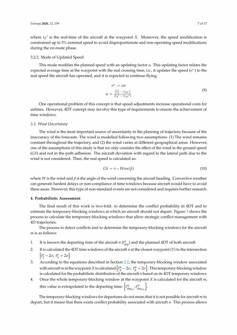
The final result of this work is two-fold: to determine the conflict probability in 4DT and toestimate the temporary-blocking windows at which an aircraft should not depart. Figure 3 shows theprocess to calculate the temporary-blocking windows that allow strategic conflict management with4D trajectories.
The process to detect conflicts and to determine the temporary-blocking windows for the aircraftm is as follows:
1. It is known the departing time of the aircraft n (tndep) and the planned 4DT of both aircraft.
2. It is calculated the 4DT time windows of the aircraft n at the closest waypoint (Y) to the intersection[tnY − 2σ; tn
Y + 2σ].
3. According to the equations described in Section 2.2, the temporary-blocking window associated
with aircraft m at the waypoint X is calculated[tmX − 2σ; tm
X + 2σ]. This temporary-blocking window
is calculated for the probabilistic distribution of the aircraft n based on its 4DT temporary windows.4. Once the whole temporary-blocking window at the waypoint X is calculated for the aircraft m,
this value is extrapolated to the departing time:[tmdepini
; tmdep f in
].
The temporary-blocking windows for departures do not mean that it is not possible for aircraft m todepart, but it means that there exists conflict probability associated with aircraft n. This process allows
Entropy 2020, 22, 159 8 of 17
determining the conflict probability between both aircraft for specific departing times considering 4DTtime windows. The conflict probability is calculated by the number of infringements detected basedon the total number of simulations:
P =No con f licts
No simulations(11)
Entropy 2020, 22, 159 7 of 17
3.3. Wind Uncertainty
The wind is the most important source of uncertainty in the planning of trajectory because of the inaccuracy of the forecasts. The wind is modelled following two assumptions: 1) The wind remains constant throughout the trajectory, and 2) the wind varies at different geographical areas. However, one of the assumptions of this study is that we only consider the effect of the wind in the ground speed (𝐺𝑆) and not in the path adhesion. The aircraft deviation with regard to the lateral path due to the wind is not considered. Then, the real speed is calculated as: 𝐺𝑆 = 𝑣 − 𝑊𝑐𝑜𝑠 (𝛽) (10)
where 𝑊 is the wind and 𝛽 is the angle of the wind concerning the aircraft heading. Convective weather can generate hardest delays or non-compliance of time windows because aircraft would have to avoid these areas. However, this type of non-standard events are not considered and requires further research.
4. Probabilistic Assessment
The final result of this work is two-fold: to determine the conflict probability in 4DT and to estimate the temporary-blocking windows at which an aircraft should not depart. Figure 3 shows the process to calculate the temporary-blocking windows that allow strategic conflict management with 4D trajectories.
Figure 3. Process of the strategic conflict management based on 4D trajectories.
The process to detect conflicts and to determine the temporary-blocking windows for the aircraft 𝑚 is as follows: 1. It is known the departing time of the aircraft 𝑛 (𝑡 ) and the planned 4DT of both aircraft. 2. It is calculated the 4DT time windows of the aircraft 𝑛 at the closest waypoint (𝑌) to the
intersection 𝑡 − 2𝜎; 𝑡 + 2𝜎 . 3. According to the equations described in Section 2.2, the temporary-blocking window
associated with aircraft 𝑚 at the waypoint 𝑋 is calculated 𝑡 − 2𝜎; 𝑡 + 2𝜎 . This temporary-blocking window is calculated for the probabilistic distribution of the aircraft 𝑛 based on its 4DT temporary windows.
Figure 3. Process of the strategic conflict management based on 4D trajectories.
5. Results and Discussion
5.1. Description of Case Study
Strategic conflict management is applied to a case study between two city-pairs in Spain.The city-pairs are Sevilla (LESV)–Barcelona (LEBL) and Vigo (LEVX)–Murcia (LELC), which areseparated by similar distance and aircraft operationally and statistically fly at similar flight levels.Table 1 provides the main parameters of the case study. The value of the different times is provided asminutes: seconds.
Table 1. Parameters of the case-study.
City-Pair Sevilla-Barcelona Vigo-Murcia
Departure 5◦53′35” W, 37◦25′05” N 8◦37′36” W, 42◦13′54” NArrival 2◦04′42” E, 41◦17′49” N 0◦48′45” W, 37◦46′30” NMach v1 = 0.78 v2 = 0.78
Flight Level 350 350Climbing time t1
ToC = 25:00 t2ToC =26:00
Departure time - t2dep = 00:00
Time at intersection - t2int = 47:00
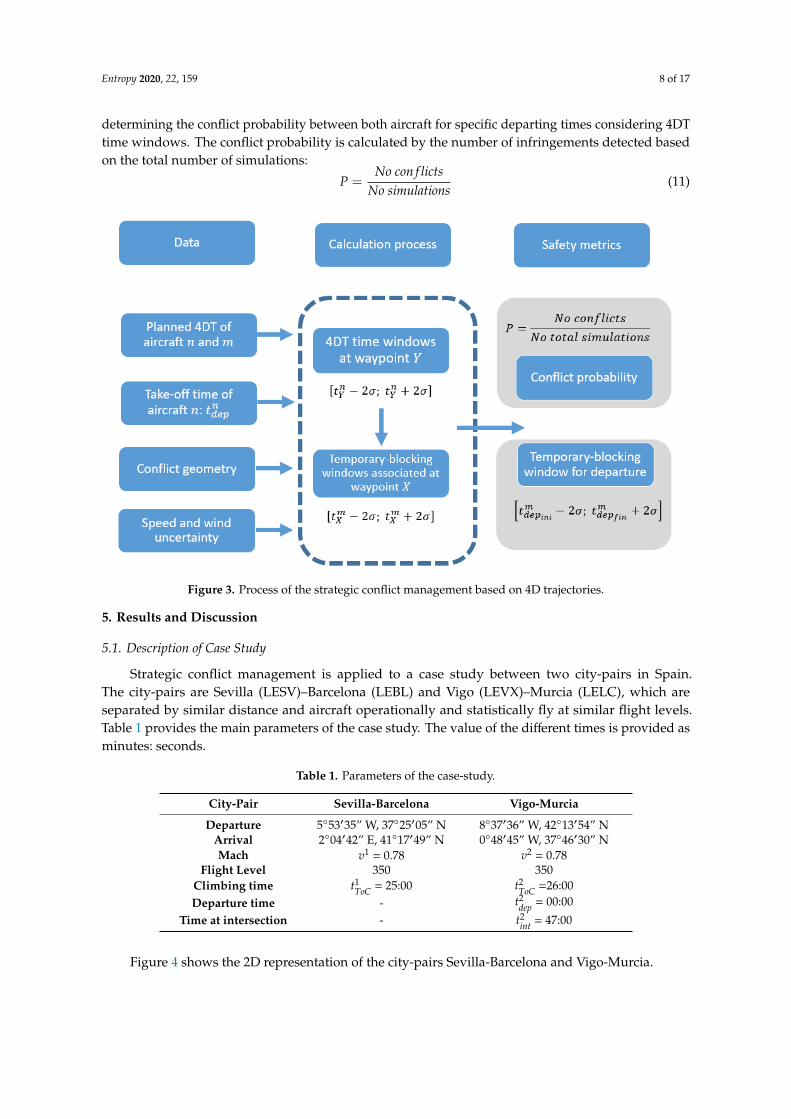
Figure 4 shows the 2D representation of the city-pairs Sevilla-Barcelona and Vigo-Murcia.

Entropy 2020, 22, 159 9 of 17
Entropy 2020, 22, 159 9 of 17
Figure 4. 2D representation of case-study.
5.2. Conflict-Detection Management without Uncertainty
For the case study of Section 5.1, the temporary-blocking windows were calculated to the departures of the city-pair Sevilla–Barcelona. In this case, no 4DT uncertainty was considered, either wind or speed. The static temporary-blocking window for departures was [21:43; 24:34], a time span of 171 s. This was the baseline to be compared with the introduction of the probabilistic assessment.
5.3. Probabilistic Assessment
The next step was to introduce the uncertainty models described in Section 3 and to analyse how they modified the static temporary-blocking window. 10 combinations assessed the integration of both trajectories because of the introduction of 4DT time windows.
5.2.1. 4DT Uncertainty
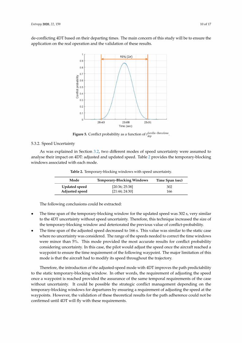
In this section, the 4DT time windows were applied to calculate the new temporary-blocking window. By applying the process described in Section 4, the new temporary-blocking window based on 4DT uncertainty was [20:43; 25:31] for the 95% (2𝜎), an increase of 112 s with the static temporary-blocking window. Figure 5 represents the probabilistic distribution obtained for the MC simulations.
Figure 5. Conflict probability as a function of 𝑡 .
Figure 4. 2D representation of case-study.
It can be observed at both trajectories that they are constituted by four waypoints at which the4DT temporary restrictions must be fulfilled. The distance between the waypoints is l = 100 NM.Waypoints X and Y (the last waypoints before the intersection) are highlighted in Figure 4, as well asthe intersecting point. The geographic coordinates of these three points are:
X{λX = −3.9461ϕX = 38.4566
Y{λY = −3.9471ϕY = 39.6966
Int{λint = −2.822228ϕint = 39.028519
5.2. Conflict-Detection Management without Uncertainty
For the case study of Section 5.1, the temporary-blocking windows were calculated to thedepartures of the city-pair Sevilla–Barcelona. In this case, no 4DT uncertainty was considered, eitherwind or speed. The static temporary-blocking window for departures was [21:43; 24:34], a time span of171 s. This was the baseline to be compared with the introduction of the probabilistic assessment.
5.3. Probabilistic Assessment
The next step was to introduce the uncertainty models described in Section 3 and to analyse howthey modified the static temporary-blocking window. 104 combinations assessed the integration ofboth trajectories because of the introduction of 4DT time windows.
5.3.1. 4DT Uncertainty
In this section, the 4DT time windows were applied to calculate the new temporary-blockingwindow. By applying the process described in Section 4, the new temporary-blocking windowbased on 4DT uncertainty was [20:43; 25:31] for the 95% (2σ), an increase of 112 s with the statictemporary-blocking window. Figure 5 represents the probabilistic distribution obtained for theMC simulations.
The conflict probability between both aircraft depended on the combination of both departingtimes. The average value of the conflict probability distribution is very high, exceeding 80% conflictprobability. Therefore, it can be concluded that the introduction of 4DT trajectories (fulfilling temporaryrestrictions of 2 min at specific waypoints) can be introduced with a temporary-blocking window of283 s to avoid conflict between this city-pair. This technique allows calculating the conflict probabilitybased on 4DT and temporary requirements and the calculation of temporary-blocking windows for
Entropy 2020, 22, 159 10 of 17
de-conflicting 4DT based on their departing times. The main concern of this study will be to ensure theapplication on the real operation and the validation of these results.
Entropy 2020, 22, 159 9 of 17
Figure 4. 2D representation of case-study.
5.2. Conflict-Detection Management without Uncertainty
For the case study of Section 5.1, the temporary-blocking windows were calculated to the departures of the city-pair Sevilla–Barcelona. In this case, no 4DT uncertainty was considered, either wind or speed. The static temporary-blocking window for departures was [21:43; 24:34], a time span of 171 s. This was the baseline to be compared with the introduction of the probabilistic assessment.
5.3. Probabilistic Assessment
The next step was to introduce the uncertainty models described in Section 3 and to analyse how they modified the static temporary-blocking window. 10 combinations assessed the integration of both trajectories because of the introduction of 4DT time windows.
5.2.1. 4DT Uncertainty
In this section, the 4DT time windows were applied to calculate the new temporary-blocking window. By applying the process described in Section 4, the new temporary-blocking window based on 4DT uncertainty was [20:43; 25:31] for the 95% (2𝜎), an increase of 112 s with the static temporary-blocking window. Figure 5 represents the probabilistic distribution obtained for the MC simulations.
Figure 5. Conflict probability as a function of 𝑡 . Figure 5. Conflict probability as a function of tSevilla−Barcelona
dep .
5.3.2. Speed Uncertainty
As was explained in Section 3.2, two different modes of speed uncertainty were assumed toanalyse their impact on 4DT: adjusted and updated speed. Table 2 provides the temporary-blockingwindows associated with each mode.
Table 2. Temporary-blocking windows with speed uncertainty.
Mode Temporary-Blocking Windows Time Span (sec)
Updated speed [20:36; 25:38] 302Adjusted speed [21:44; 24:30] 166
The following conclusions could be extracted:
• The time span of the temporary-blocking window for the updated speed was 302 s, very similarto the 4DT uncertainty without speed uncertainty. Therefore, this technique increased the size ofthe temporary-blocking window and deteriorated the previous value of conflict-probability.
• The time span of the adjusted speed decreased to 166 s. This value was similar to the static casewhere no uncertainty was considered. The range of the speeds needed to correct the time windowswere minor than 5%. This mode provided the most accurate results for conflict probabilityconsidering uncertainty. In this case, the pilot would adjust the speed once the aircraft reached awaypoint to ensure the time requirement of the following waypoint. The major limitation of thismode is that the aircraft had to modify its speed throughout the trajectory.
Therefore, the introduction of the adjusted-speed mode with 4DT improves the path predictabilityto the static temporary-blocking window. In other words, the requirement of adjusting the speedonce a waypoint is reached provided the assurance of the same temporal requirements of the casewithout uncertainty. It could be possible the strategic conflict management depending on thetemporary-blocking windows for departures by ensuring a requirement of adjusting the speed at thewaypoints. However, the validation of these theoretical results for the path adherence could not beconfirmed until 4DT will fly with these requirements.

Entropy 2020, 22, 159 11 of 17
5.3.3. Wind Uncertainty
The last analysis focused on the way the wind uncertainty affects 4DT in terms of strategic conflictmanagement. As was mentioned before, two different evaluations were performed depending on thewind that was considered as uniform throughout the scenario, or it varied in different geographical areas.
Constant Wind
The first analysis assumed a constant wind throughout the trajectories. This simplification can beused in typical non-convective days where the wind variation is reduced. It was simulated a uniformwind for every direction, and the intensity varied from 0 to 40 knots (kts). These values were typicalwind values that could appear for similar altitude conditions. Besides, wind direction varied every 20◦.Table 3 shows the temporary-blocking windows for different cases.
Table 3. Temporary-blocking windows for constant wind.
WindDirection
Intensity (kts)
0 5 10 15 20 30 40
0◦
[20:43; 25:31]
[20:29; 25:15] [20:16; 25:03] [19:54; 24:43] [19:50; 24:38] [19:18; 24:06] [18:42; 23:32]20◦ [20:31; 25:19] [20:26; 25:15] [20:15; 25:05] [20:05; 24:55] [19:36; 24:26] [19:13; 24:05]40◦ [20:40; 25:28] [20:38; 25:28] [20:31; 25:20] [20:27; 25:18] [20:14; 25:06] [20:03; 24:55]60◦ [20:48; 25:37] [20:49; 25:39] [20:49; 25:41] [20:50; 25:42] [20:48; 25:42] [20:55; 25:51]80◦ [20:54; 25:44] [20:53; 25:45] [21:12; 25:36] [21:18; 26:10] [21:35; 26:30] [21:52; 26:49]
100◦ [21:02; 25:50] [21:11; 26:01] [21:23; 26:14] [21:45; 26:39] [22:12; 27:07] [22:42; 27:38]120◦ [20:57; 25:47] [21:15; 26:06] [21:43; 26:33] [21:57; 26:49] [22:32; 27:26] [23:15; 28:12]140◦ [21:05; 25:53] [21:32; 26:24] [21:44; 26:35] [21:59; 26:51] [22:47; 27:40] [23:31; 28:24]160◦ [20:56; 25:46] [21:23; 26:12] [21:49; 26:41] [21:59; 26:49] [22:41; 27:31] [23:21; 28:13]180◦ [20:59; 25:47] [21:18; 26:06] [21:32; 26:20] [21:51; 26:39] [22:18; 27:07] [22:53; 27:41]200◦ [21:00; 25:50] [21:07; 25:54] [21:17; 26:05] [21:23; 26:11] [21:49; 26:35] [22:09; 26:55]220◦ [20:52; 25:40] [21:03; 25:15] [20:57; 25:43] [20:58; 25:44] [21:15; 26:00] [21:20; 26:03]240◦ [20:47; 25:35] [20:46; 25:32] [20:41; 25:27] [20:37; 25:21] [20:38; 25:21] [20:29; 25:10]260◦ [20:36; 25:23] [20:34; 25:20] [20:19; 25:04] [20:09; 24:52] [19:52; 24:36] [19:42; 24:23]280◦ [20:29; 25:17] [20:23; 25:09] [20:04; 24:50] [19:58; 24:42] [19:24; 24:08] [19:05; 23:46]300◦ [20:20; 25:10] [20:06; 24:52] [19:54; 24:39] [19:43; 24:29] [19:09; 24:51] [18:38; 23:20]320◦ [20:27; 25:15] [20:06; 24:52] [19:51; 24:37] [19:30; 24:16] [18:56; 24:43] [18:25; 23:09]340◦ [20:30; 25:18] [20:09; 24:56] [19:55; 24:42] [19:34; 24:20] [19:08; 24:56] [18:26; 23:12]
From previous results, the temporary-blocking windows varied their time span and location foreach combination of intensity and direction:
• The variation of the time span increased with the wind intensity, although the increase was limiteduntil 3.1% (9 s). Therefore, the variation of the wind intensity below 40 kts can be neglected withrespect to the size of the temporary-blocking windows with 4DT.
• However, the temporal displacement of the temporary-blocking windows cannot be neglected.Those variations could generate a delay or advance for the same wind direction up to 168 sof delay (wind direction 140◦) and 138 s of advancement (direction 320◦). The size of the 4DTtemporary-blocking windows without speed uncertainty is 283 s (Section 5.3.1), this implied thatthere were temporal displacements over 40%. In the case the static temporary-blocking windowswere considered, the displacement could reach up to 100%.
Lastly, Figure 6 shows the variations of the temporary-blocking windows for the differentcombinations of intensity and direction compared with the reference case (0 kts). The temporary-blockingwindows were delayed when the points are located outside of the envelope of 0 kts and advanced whenthey were inside of it. It was observed that the cross from advancement to delay was roughly obtainedfor 50◦ and 240◦. Therefore, winds with directions from 50◦ to 240◦ advanced the temporary-blockingwindow and winds with directions from 240◦ to 50◦ delayed the temporary-blocking window.Nonetheless, these wind directions mainly depended on the city-pair selected and will affect differentlyfor each city-pair.

Entropy 2020, 22, 159 12 of 17
Entropy 2020, 22, 159 12 of 17
Figure 6. Envelope of temporary-blocking windows with 4DT and constant wind uncertainty.
According to the above results, the wind uncertainty affected the location of the temporary-blocking window but not their time span. To minimise the wind impact to the temporary-blocking windows, the wind direction should be known in advance with an accuracy of +/-20°. Therefore, the wind direction is a crucial factor for the calculation of temporary-blocking windows in strategic conflict management.
5.2.3.2. Variable Wind
The analysis for the influence of variable wind throughout the trajectories depended on the geographical areas they have flown. The airspace was divided into four geographical areas (see Figure 7) with a similar length around 100 NM where the wind typically does not exceed 10% variations. Hence, geographical areas 1 and 4 did not take part in the calculation of the uncertainty because the path stretch to study were located at geographical areas 2 and 3. Throughout geographical areas 1 and 4, the aircraft should take the necessary actions to ensure the 4DT time windows.
The variation of the wind in geographical areas 2 and 3 was modelled with a variation of the direction of ±5° and intensity of ±10% from the geographical area 1. Although the wind variations were the same in module, the uncertainty was calculated independently for geographical area 2 and 3.
-150
-100
-50
0
50
100
150
2000º
20º
40º
60º
80º
100º
120º
140º
160º180º
200º
220º
240º
260º
280º
300º
320º
340º
Wind envelope0 kts
5 kts
10 kts
15 kts
20 kts
30 kts
40 kts
Figure 6. Envelope of temporary-blocking windows with 4DT and constant wind uncertainty.
According to the above results, the wind uncertainty affected the location of the temporary-blockingwindow but not their time span. To minimise the wind impact to the temporary-blocking windows,the wind direction should be known in advance with an accuracy of +/-20◦. Therefore, the wind directionis a crucial factor for the calculation of temporary-blocking windows in strategic conflict management.
Variable Wind
The analysis for the influence of variable wind throughout the trajectories depended on thegeographical areas they have flown. The airspace was divided into four geographical areas (seeFigure 7) with a similar length around 100 NM where the wind typically does not exceed 10% variations.Hence, geographical areas 1 and 4 did not take part in the calculation of the uncertainty because thepath stretch to study were located at geographical areas 2 and 3. Throughout geographical areas 1and 4, the aircraft should take the necessary actions to ensure the 4DT time windows.
The variation of the wind in geographical areas 2 and 3 was modelled with a variation of thedirection of ±5◦ and intensity of ±10% from the geographical area 1. Although the wind variationswere the same in module, the uncertainty was calculated independently for geographical area 2 and 3.
Table 4 shows the results of the temporary-blocking windows for variable wind consideringdifferent wind directions. For the sake of clarity, Table 4 only shows the results for a nominal wind of30 kts (which represents the worst scenario). The column difference indicates the variation in moduleof the case of variable wind compared with constant wind, and the column displacement indicates thevariation of the location between the cases of variable wind compared with constant wind.

Entropy 2020, 22, 159 13 of 17Entropy 2020, 22, 159 13 of 17
Figure 7. Limits of the areas where the wind varies.
Table 4 shows the results of the temporary-blocking windows for variable wind considering different wind directions. For the sake of clarity, Table 4 only shows the results for a nominal wind of 30 kts (which represents the worst scenario). The column difference indicates the variation in module of the case of variable wind compared with constant wind, and the column displacement indicates the variation of the location between the cases of variable wind compared with constant wind.
Table 4. Temporary-blocking windows for constant and variable wind.
Variable wind Difference Displacement 0° [19:23; 24:02] 2 sec (0,7%) −5 sec 20° [19:54; 24:28] 0 sec (0%) 2 sec 40° [20:22; 24:04] 1 sec (0,3%) −2,5 sec 60° [20:25; 24:46] 0 sec (0%) 4 sec 80° [21:26; 24:29] 0 sec (0%) −1 sec
100° [22:32; 24:04] -1 sec (–0,3%) −2,5 sec 120° [22:28; 24:28] -2 sec (–0,7%) 3 sec 140° [22:27; 24:38] -1 sec (–0,3%) −1,5 sec 160° [22:27; 24:31] 0 sec (0%) 0 sec 180° [22:27; 24:07] -1 sec (–0,3%) 0,5 sec 200° [21:26; 24:35] 0 sec (0%) 0 sec 220° [21:25; 24:55] -1 sec (–0,4%) −4,5 sec 240° [20:25; 24:16] 1 sec (0,4%) −5,5 sec 260° [19:54; 24:39] -3 sec (–1,1%) 4,5 sec 280° [19:44; 24:11] -2 sec (–0,7%) 4 sec 300° [19:23; 24:51] 1 sec (0,4%) −0,5 sec 320° [18:53; 24:42] 0 sec (0%) −1 sec 340° [18:23; 24:45] -2 sec (–0,7%) −5 sec
The variation of the difference in module between the time span of the temporary-blocking windows did not exceed three seconds. Then, the influence of 10% wind variation between consecutive areas could be neglected. This result agreed with the results of the constant wind effect. About the displacement of the temporary-blocking windows, the effect of the variable wind implied a movement to both sides depending on the uniform wind. Moreover, this displacement did not
Figure 7. Limits of the areas where the wind varies.
Table 4. Temporary-blocking windows for constant and variable wind.
Variable Wind Difference Displacement
0◦ [19:23; 24:02] 2 sec (0.7%) −5 sec20◦ [19:54; 24:28] 0 sec (0%) 2 sec40◦ [20:22; 24:04] 1 sec (0.3%) −2.5 sec60◦ [20:25; 24:46] 0 sec (0%) 4 sec80◦ [21:26; 24:29] 0 sec (0%) −1 sec100◦ [22:32; 24:04] −1 sec (−0.3%) −2.5 sec120◦ [22:28; 24:28] −2 sec (−0.7%) 3 sec140◦ [22:27; 24:38] −1 sec (−0.3%) −1.5 sec160◦ [22:27; 24:31] 0 sec (0%) 0 sec180◦ [22:27; 24:07] −1 sec (−0.3%) 0.5 sec200◦ [21:26; 24:35] 0 sec (0%) 0 sec220◦ [21:25; 24:55] −1 sec (−0.4%) −4.5 sec240◦ [20:25; 24:16] 1 sec (0.4%) −5.5 sec260◦ [19:54; 24:39] −3 sec (–1.1%) 4.5 sec280◦ [19:44; 24:11] −2 sec (−0.7%) 4 sec300◦ [19:23; 24:51] 1 sec (0.4%) −0.5 sec320◦ [18:53; 24:42] 0 sec (0%) −1 sec340◦ [18:23; 24:45] −2 sec (−0.7%) −5 sec
The variation of the difference in module between the time span of the temporary-blockingwindows did not exceed three seconds. Then, the influence of 10% wind variation between consecutiveareas could be neglected. This result agreed with the results of the constant wind effect. About thedisplacement of the temporary-blocking windows, the effect of the variable wind implied a movementto both sides depending on the uniform wind. Moreover, this displacement did not exceed 5 s,the displacement could be neglected because it modified the size of the temporary-blocking windowsless than 2%. However, it should be studied in further work the inclusion of a constant factor in orderto take the wind variation into consideration.
Finally, these results concluded that the introduction of temporary-blocking windowscould be a reliable and trustworthy system for strategic conflict management based on 4DT.The temporary-blocking windows were a powerful tool for air traffic management to ascertaindeparting restrictions between city-pairs. The implications could imply a reduction in the ATCworkload by the reduction of conflict probability, but, it will demand to pilot modifications to ensure4DT time windows that will mean pilot workload increase. Then, the model developed herein
Entropy 2020, 22, 159 14 of 17
and the results achieved require further study. There are levels of error in the calculation of thetemporary-blocking windows that should be reduced. On the one hand, the temporary-blockingwindows were conservative because there were situations assumed as conflicts, but a more detailedassessment could indicate that there was no conflict. The strategic conflict management requiredknowledge of wind that cannot be ascertained at this strategic horizon; then, it is necessary to introducenew techniques to include more real wind conditions. Lastly further work will include the integrationof temporary-blocking windows in the whole European path network; in other words, to tackle themulti-aircraft conflict-detection problem based on 4DT and the optimisation of the results.
6. Conclusions
In this paper, the authors presented the results of a new methodology to deal with the strategicconflict management based on 4D trajectories, while taking a free-route scenario into account.The proposed methodology consisted of the calculation of conflict probability and temporary-blockingwindows between two city-pairs. The temporary-blocking windows provided temporary time spansthat blocked the departure of one aircraft because of the potential separation infringement in the air.The introduction of 4DT implied that aircraft must fulfil temporary restrictions at specific waypointsthroughout the trajectories (4DT time windows). Moreover, the probabilistic assessment took intoaccount the main uncertainties because of speed and wind effect. Speed was modelled based on twomodels: (1) Updated speed that recalculated the nominal speed based on the time the aircraft passesthrough the waypoint, and (2) adjusted speed that recalculated the nominal speed to fulfil the estimatedaverage time at the next waypoint. The wind was modelled based on two assumptions as well: (1) Thewind was constant throughout the trajectories, and (2) the wind varied throughout the trajectoriesdepending on different geographical areas. The results of the probabilistic assessment were founded in109 Monte Carlo simulations for each experiment. Particularly, this research only considered conflictprobability because it is the most widespread safety metric. The main concern of this safety metric isthat it does not take into account the specific features of the separation infringements as the severity,duration or minimum distance. Although there is no unique and accepted safety metric, differentsafety metrics should be considered in further work to deepen in the characteristics of the conflicts,and to bring to the light new insights and methods to tune up conflict management.
First, the length (time span) of the temporary-blocking windows increased with the introductionof uncertainty. The introduction of 4DT time windows implied a temporary-blocking window ofalmost 300 s while the static approach was 180 s. The introduction of the speed uncertainty provideddifferent results depending on the mode analysed. Updated speed provided an increase of thetemporary-blocking windows because of the uncertainty and modifications of the speed. However,adjusted mode reduced the temporary-blocking windows because the aircraft adjusted the speed tofulfil the estimated average time at the next waypoint. This case improved the results and reduced theuncertainty until similar values to the static case. Second, the introduction of wind did not influencethe length of the temporary-blocking windows, although the variation of the intensity encompassedfrom 0 to 40 kts. However, the wind displaced the temporary-blocking windows by the advancementor delay from its original time location. This displacement was bigger depending on the wind directionand the wind intensity.
Therefore, the solution proposed in this work was the implementation of temporary-blockingwindows between aircraft of different city-pairs. This solution would imply scheduling restrictionsduring the strategic phase based on 4DT, and it would demand a collaboration decision-makingprocedure between the airspace users, the ANSPs and the network manager. About the length of thetemporary-blocking windows, the best solution demanded to minimise the conflict probability andthe strategic conflict-management by the usage of the speed adjusted mode. This concept ensuresthat the pilot fulfils the temporary requirements for the 4D time windows, which, in turn, willincrease the pilot workload because of the path modifications demanded. The main concern will be toensure the application of this concept on the future real operation and the validation of these results.

Entropy 2020, 22, 159 15 of 17
Further research should focus on the analysis of this study in the whole European network and thespecifications to comply between AUs, ATC, ANSPs and NM.
Author Contributions: J.A.P.-C. was the leader of this research by developing the framework and ideas thatwill underlie the study. In addition, he was the main contributor to this paper both its redaction and reviewingprocess. Á.R.-S. helped on the concept development about the integration of 4D trajectories in real aerospace andsupported also the writing process. L.P.S. worked during the concept development about the potential issues thatcould arise by the integration of 4DT in free-rout airspace and during the reviewing process. V.F.G.C. and R.M.A.V.supported the development of the project with their conceptual design. C.G. developed the software and thedifferent technical aspects of the study, helped by L.S.-M. that supported the reviewing process. All authors haveread and agreed to the published version of the manuscript.
Funding: This research received no external funding
Conflicts of Interest: The authors declare no conflict of interest.
References
1. Eurocontrol. EUROCONTROL Seven-Year Forecast February 2018. Available online: https://www.eurocontrol.int/publication/seven-year-forecast-flight-movements-and-service-units-february-2019 (accessedon 30 March 2019).
2. SESAR JU. SESAR Solutions Catalogue 2019, 3rd ed. 2019. Available online: https://www.sesarju.eu/index.php/newsroom/brochures-publications/sesar-solutions-catalogue (accessed on 11 June 2019).
3. SESAR Joint Undertaking. SESAR 2020 Concept of Operations. 2017. Available online: https://www.sesardeploymentmanager.eu/wp-content/uploads/2016/12/421968-SESAR-Deployment-Programme-edition-2017-Hfdst-1.pdf (accessed on 22 February 2019).
4. Rodríguez-Sanz, Á.; Comendador, F.G.; Valdés, R.M.A.; Pérez-Castán, J.A.; García, P.G.; Godoy, M.N.G.N.4D-trajectory time windows: Definition and uncertainty management. Aircr. Eng. Aerosp. Technol. 2019, 91,761–782. [CrossRef]
5. Matsuno, Y.; Tsuchiya, T. Stochastic 4D Trajectory Optimization for Aircraft Conflict Resolution.In Proceedings of the 2014 IEEE Aerospace Conference, Big Sky, MT, USA, 1–8 March 2014.
6. Margellos, K.; Lygeros, J. Toward 4-D Trajectory Management in Air Traffic Control: A Study Based onMonte Carlo Simulation and Reachability Analysis. IEEE Trans. Control Syst. Technol. 2013, 21, 1820–1833.[CrossRef]
7. Casado, E.; Goodchild, C.; Vilaplana, M. Identification and Initial Characterization of Sources of UncertaintyAffecting the Performance of Future Trajectory Management Automation Systems. Presented at 2ndInternational Conference on Application and Theory of Automation in Command and Control Systems,London, UK, 29–31 May 2012.
8. Chaimatanan, S.; Delahaye, D.; Mongeau, M. Aircraft 4D Trajectories Planning under Uncertainties.In Proceedings of the 2015 IEEE Symposium Series on Computational Intelligence (SSCI 2015), Cape Town,South Africa, 7–10 December 2015; pp. 51–58. [CrossRef]
9. SESAR. SESAR Concept of Operations Step 2 Edition 2014 (Ed. 01.01.00); SESAR Joint Undertaking: Brussels,Belgium, 2014.
10. Krozel, J.; Peters, M.E.; Hunter, G. Conflict Detection and Resolution for Future Air Transportation; TR97138-01;NASA: Washington, DC, USA, 1997.
11. Kuchar, J.K.; Yang, L.C. Conflict Detection and Resolution, Air Traffic Control, Alerting Systems, WarningSystems. IEEE Trans. Intell. Transp. Syst. 2000, 1, 179–189. [CrossRef]
12. Erzberger, H.; Heere, K. Algorithm and Operational Concept for Resolving Short-Range Conflicts. Proc. Inst.Mech. Eng. Part G J. Aerosp. Eng. 2010, 224, 225–243. [CrossRef]
13. Lehouillier, T.; Nasri, M.I.; Soumis, F.; Desaulniers, G.; Omer, J. Solving the Air Conflict Resolution ProblemUnder Uncertainty Using an Iterative Biobjective Mixed Integer Programming Approach. Transp. Sci. 2017,51, 1242–1258. [CrossRef]
14. Sunil, E.; Ellerbroek, J.; Hoekstra, J.M.; Maas, J. Three-Dimensional Conflict Count Models for Unstructuredand Layered Airspace Designs. Transp. Res. Part C Emerg. Technol. 2018, 95, 295–319. [CrossRef]
15. Alam, S.; Shafi, K.; Abbass, H.A.; Barlow, M. An Ensemble Approach for Conflict Detection in Free Flight byData Mining. Transp. Res. Part C Emerg. Technol. 2009, 17, 298–317. [CrossRef]
Entropy 2020, 22, 159 16 of 17
16. Paielli, R.A.; Erzberger, H. Conflict Probability Estimation for Free Flight. J. Guid. Control. Dyn. 1997, 20,588–596. [CrossRef]
17. Paielli, R.A.; Erzberger, H. Trajectory Specification for Terminal Air Traffic: Pairwise Conflict Detection andResolution. In Proceedings of the 17th AIAA Aviation Technology, Integration, and Operations Conference,Denver, CO, USA, 5–9 June 2017.
18. Barnier, N.; Allignol, C. 4D-Trajectory Deconfliction Through Departure Time Adjustment. Available online:https://hal-enac.archives-ouvertes.fr/hal-00938231/ (accessed on 28 January 2009).
19. Geisinger, K.E. Airspace Conflict Equations. Transp. Sci. 1985, 19, 139–153. [CrossRef]20. ICAO. Doc 9689-AN/953 - Manual on Airspace Planning Methodology for the Determination of Separation
Minima. Available online: https://searchworks.stanford.edu/view/4026380 (accessed on 18 January 2019).21. Netjasov, F. Framework for Airspace Planning and Design Based on Conflict Risk Assessment Part 1: Conflict
Risk Assessment Model for Airspace Strategic Planning. Transp. Res. Part C Emerg. Technol. 2012, 24, 190–212.[CrossRef]
22. Speijker, L.J.P.; Blom, H.A.P.; Bakker, G.J.; Karwal, A.K.; Van baren, G.B.; Klompstra, M.B.; Kruijsen, E.A.C.RASMAR Final Report: Risk Analysis of Simultaneous Missed Approaches on Schiphol Converging Runways I9Rand 22; Nationaal Nationaal Lucht- en Ruimtevaartlaboratorium: Amsterdam, The Netherlands, 2001.
23. Henry, M.; Schmitz, S.; Revenko, N.; Kelbaugh, K. A Monte Carlo Simulation for Evaluating AirborneCollision Risk in Intersecting Runways. In Proceedings of the AIAA Modeling and Simulation Technologies(MST) Conference, Boston, MA, USA, 19–22 August 2013.
24. Pérez-Castán, J.A.; Gómez Comendador, F.; Rodríguez-Sanz, A.; Barragán Montes, R.; Arnaldo Valdés, R.;Pérez Sanz, L. Impact of Continuous Climb Operations on Airport Capacity. Transp. Res. Part C Emerg. Technol.2018, 96, 231–250. [CrossRef]
25. Pérez-Castán, J.A.; Comendador, F.G.; Rodríguez-Sanz, Á.; Barragán, R.; Arnaldo-Valdés, R.M. Design of aConflict-Detection Air Traffic Control Tool for the Implementation of Continuous Climb Operations: A CaseStudy at Palma TMA. Proc. Inst. Mech. Eng. Part G J. Aerosp. Eng. 2019, 233, 095441001983119. [CrossRef]
26. Pérez-Castán, J.A.; Comendador, F.G.; Rodriguez-Sanz, Á.; Arnaldo Valdés, R.M.; Agueda, G. RPASIntegration in Non-Segregated Airspace: Safety Metrics for Tactical Planning. Proc. Inst. Mech. Eng. Part G J.Aerosp. Eng. 2019, 233. [CrossRef]
27. Erzberger, H.; Lauderdale, T.A.; Chu, Y.-C. Automated conflict resolution, arrival management, and weatheravoidance for air traffic management. Proc. Inst. Mech. Eng. Part G J. Aerosp. Eng. 2012, 226, 930–949.[CrossRef]
28. EUROCONTROL. European Aviation in 2040—Challenges of Growth. 2018. Available online: https://www.eurocontrol.int/publication/challenges-growth-2018 (accessed on 26 January 2020).
29. EUROCONTROL. User Manual for the Base of Aircraft DAta (BADA), Family 4. 2014. Available online:https://www.eurocontrol.int/publication/user-manual-base-aircraft-data-bada. (accessed on 26 January 2020).
30. Rey, D.; Rapine, C.; Fondacci, R.; Faouzi, N.-E. Subliminal Speed Control in Air Traffic Management:Optimization and Simulation. Transp. Sci. 2016, 50, 240–262. [CrossRef]
31. Piric, S.; De Boer, R.J.; Roelen, A.; Karanikas, N.; Kaspers, S. How Does Aviation Industry Measure SafetyPerformance Current Practice and Limitations. Int. J. Aviat. Manag. 2019, 4, 224. [CrossRef]
32. Campos, L.M.B.C.; Marques, J.M.G. On a Dimensionless Alternative to the ICAO Target Level of Safety.Proc. Inst. Mech. Eng. Part G J. Aerosp. Eng. 2016, 230, 1548–1557. [CrossRef]
33. Netjasov, F.; Janic, M. A Review of Research on Risk and Safety Modelling in Civil Aviation. J. AirTransp. Manag. 2008, 14, 213–220. [CrossRef]
34. Netjasov, F. Framework for Airspace Planning and Design Based on Conflict Risk Assessment. Part 2:Conflict Risk Assessment Model for Airspace Tactical Planning. Transp. Res. Part C Emerg. Technol. 2012, 24,213–226. [CrossRef]
35. Pérez-Castán, J.A.; Gómez Comendador, F.; Rodríguez-Sanz, Á.; Arnaldo Valdés, R.M. Conflict-RiskAssessment Model for Continuous Climb Operations. Aerosp. Sci. Technol. 2019, 84, 812–820. [CrossRef]

Entropy 2020, 22, 159 17 of 17
36. EUROCONTROL. “RECAT-EU” European Wake Turbulence Categorisation and Separation Minima onApproach and Departure. 2018. Available online: https://www.eurocontrol.int/publication/european-wake-turbulence-categorisation-and-separation-minima-approach-and-departure. (accessed on 26 January 2020).
37. SESAR Joint Undertaking. Optimised Airspace User Operations. 2016. Available online: https://www.eurocontrol.int/project/optimised-airspace-users-operations. (accessed on 26 January 2020).
© 2020 by the authors. Licensee MDPI, Basel, Switzerland. This article is an open accessarticle distributed under the terms and conditions of the Creative Commons Attribution(CC BY) license (http://creativecommons.org/licenses/by/4.0/).