engineering standard
TRANSCRIPT
ENGINEERING STANDARD
NO.: SP-054070-01 TITLE: INSTALLATION, OPERATION AND MAINTENANCE PROCEDURE FOR TOM WHEATLEY (TW) SWING CHECK VALVE WITH STANDARD NON-EXTENDED SHAFT
DATE: Jan 16 2010
REV.: 01
PAGE: 1 OF 31
SUBMITTED BY: J. JOSEPH
APPROVED BY: ED PEARSON
Overview Vendor: Cameron Valves and Measurement
3250 Briarpark Drive Houston, Texas 77041 U.S.A.
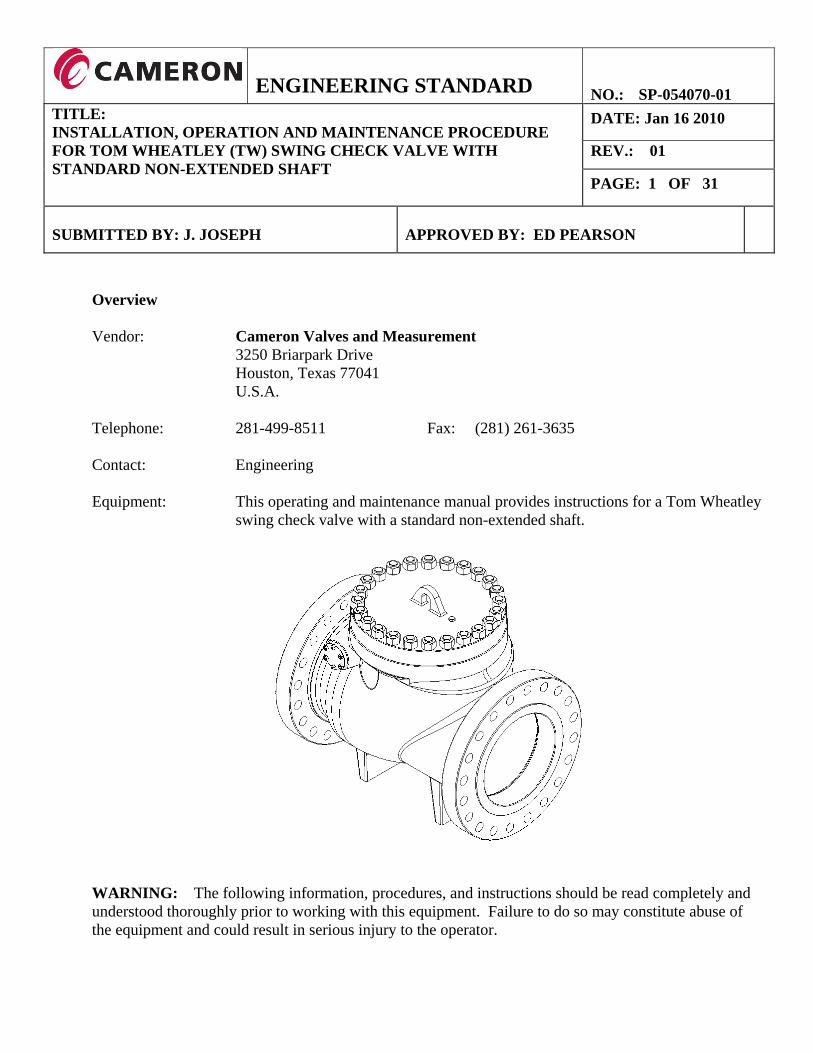
Telephone: 281-499-8511 Fax: (281) 261-3635 Contact: Engineering Equipment: This operating and maintenance manual provides instructions for a Tom Wheatley
swing check valve with a standard non-extended shaft.
WARNING: The following information, procedures, and instructions should be read completely and understood thoroughly prior to working with this equipment. Failure to do so may constitute abuse of the equipment and could result in serious injury to the operator.

ENGINEERING STANDARD
NO.: SP-054070-01
TITLE: INSTALLATION, OPERATION AND MAINTENANCE PROCEDURE FOR TOM WHEATLEY (TW) SWING CHECK VALVE WITH STANDARD NON-EXTENDED SHAFT
DATE: Jan 16 2010
REV.: 01
PAGE: 2 OF 31
Table of Contents
1.0. INTRODUCTION ................................................................................................................. 3 2.0. SAFETY ............................................................................................................................... 3 2.1. HANDLING AND LIFTING ....................................................................................................................... 4 2.2 PRESSURE LIMITATIONS ........................................................................................................................ 4
3.0. PRESERVATION AND STORAGE ..................................................................................... 5 4.0. VALVE CONFIGURATION AND COMPONENTS .............................................................. 7 5.0. INSTALLATION AND PRE-COMMISSIONING ................................................................. 10 5.1. UNPACKING THE VALVE ...................................................................................................................... 10 5.2. INSTALLING THE VALVE IN THE PIPELINE ............................................................................................ 10 5.3. HYDROSTATIC TESTING ....................................................................................................................... 11
6.0. VALVE OPERATION ......................................................................................................... 11 6.1. GENERAL DESIGN ................................................................................................................................ 11 6.2. ROUTINE MAINTENANCE ..................................................................................................................... 12 6.3. PIGGING OPERATIONS ......................................................................................................................... 12 6.4. TROUBLE SHOOTING ........................................................................................................................... 13
7.0. DISASSEMBLY AND REPAIR .......................................................................................... 14 7.1. PREPARATION FOR DISASSEMBLY OF THE CHECK VALVE ................................................................... 14 7.2. DISASSEMBLY OF COVER .................................................................................................................... 14 7.3. DISASSEMBLY OF SHAFT/ GLAND PLATE ............................................................................................. 16 7.4. DISASSEMBLY OF ARM/CLAPPER ........................................................................................................ 18 7.5. DISASSEMBLY OF RENEWABLE SEAT (IF SO EQUIPPED) ....................................................................... 20 7.6. INSPECTION AND REPAIR ..................................................................................................................... 21
8.0 RE-ASSEMBLY OF VALVE .............................................................................................. 22 8.1. RE-ASSEMBLY OF RENEWABLE SEAT (IF SO EQUIPPED) ....................................................................... 22 8.2. RE-ASSEMBLY OF ARM/CLAPPER ......................................................................................................... 23 8.3. ASSEMBLY OF SHAFT .......................................................................................................................... 24 8.4. ASSEMBLY OF GLAND PLATE .............................................................................................................. 26 8.5. ASSEMBLY OF COVER .......................................................................................................................... 27
9.0 RECOMMENDED SPARE PARTS .................................................................................... 29 APPENDIX A – TABLES ............................................................................................................. 30

ENGINEERING STANDARD
NO.: SP-054070-01
TITLE: INSTALLATION, OPERATION AND MAINTENANCE PROCEDURE FOR TOM WHEATLEY (TW) SWING CHECK VALVE WITH STANDARD NON-EXTENDED SHAFT
DATE: Jan 16 2010
REV.: 01
PAGE: 3 OF 31
1.0. INTRODUCTION The purpose of this document is to give instructions on the installation, operation, and maintenance of a
Tom Wheatley swing check valve.
A Tom Wheatley swing check valve is designed to allow flow through a pipeline in only one direction
and to close instantly when flow ceases to prevent back flow. This is accomplished by a free swinging
clapper that pivots about a shaft. The clapper opens automatically when there is flow in the normal or
preferred direction. When flow ceases the clapper returns to the closed position creating an instant
barrier to reverse flow.
Tom Wheatley swing check valves are manufactured per the API-6D/ISO 14313 standard. Raised face
and ring type joint flanges comply with the requirements of ASME B16.5 and ASME B16.47 as
appropriate. Weld end valves comply with ASME B16.25 unless otherwise agreed with the customer.
All valves are full bore, full conduit design and will allow passage of various pipeline inspections gauges
and spheres.
2.0. SAFETY
The following information, procedures, and instructions should be read completely and understood
thoroughly prior to working with this equipment. Failure to do so may constitute abuse of the equipment
and result in serious injury to the operator.
Cameron Tom Wheatley does not accept any responsibility for damage to people, property, or plant due to:
• Defective or incorrect installation • Defective or incorrect maintenance of the valves by the client • Incorrect use of the valves • Using untrained personnel for maintenance operations that do not have a basic knowledge of
valves • Failure to comply with this manual and safety standards

TITINSFORSTA
2
2
TLE: STALLATIOR TOM WHANDARD N
.1. Handl
It
pr
ca
Th
.2 Pressu
To
cla
da
att
ON, OPERAHEATLEY NON-EXTE
ling and Lift
is important
roblems asso
ables availab
he valve sho
ure Limitatio
om Wheatley
asses design
amage to the
tached to the
ENGI
ATION AN(TW) SWIN
ENDED SHA
ting
t that all han
ociated with
ble and the w
ould be lifted
ons
y swing chec
nated in API-
e valve and/o
e valve body
INEERIN
ND MAINTENG CHECKAFT
ndling operat
handling he
weights to be
d using the li
ck valves are
-6D/ISO 143
or serious inj
y for the pres
NG STAN
ENANCE PK VALVE W
tions are carr
avy objects.
e lifted.
ifting points
e designed to
313. Exceed
jury or death
ssure limits o
NDARD
PROCEDURWITH
ried out by p
Check the
shown in Fi
o operate at
ding those pr
h to personne
of the valve.
NO
RE DA
RE
PA
personnel tra
maximum li
igure 1.
the pressure
ressure limit
el. Consult t
.
O.: SP-054ATE: Jan 16
EV.: 01
AGE: 4 OF
ained in relat
ifting capaci
e limits of th
tations could
the namepla
4070-01 6 2010
F 31
tion to the
ity of the
he pressure
d result in
ate that is

ENGINEERING STANDARD
NO.: SP-054070-01
TITLE: INSTALLATION, OPERATION AND MAINTENANCE PROCEDURE FOR TOM WHEATLEY (TW) SWING CHECK VALVE WITH STANDARD NON-EXTENDED SHAFT
DATE: Jan 16 2010
REV.: 01
PAGE: 5 OF 31
3.0. PRESERVATION AND STORAGE
When valves have to be stored on site for a prolonged period of time before being installed in the
pipeline, they should be stored in a dry place, under cover. The integrity of packaging and protective
materials must be maintained. Valves are supplied with suitable caps or end covers to protect the
internal parts of the valve. These caps should not be removed unless carrying out maintenance or
inspection. Afterward the caps should be refitted. If valves are to be stored for more than 6 months, it is
recommended that silica gel packets or other suitable desiccant be place inside the valve to absorb
moisture.
Cameron suggests that when valves are to be stored for prolonged lengths of time, the following should be
considered to insure the protection of the various components.
The body cavity can be protected by using Shell VPI #300, (powder or tablets), or COR-TAB brand
tablets, in amounts listed in column 3 of Table 1. This material can be inserted in the pipe plug of the
valve cover. It is recommended that more tablets be added every 6 months per Table 1 Column 3.

ENGINEERING STANDARD
NO.: SP-054070-01
TITLE: INSTALLATION, OPERATION AND MAINTENANCE PROCEDURE FOR TOM WHEATLEY (TW) SWING CHECK VALVE WITH STANDARD NON-EXTENDED SHAFT
DATE: Jan 16 2010
REV.: 01
PAGE: 6 OF 31
Table 1: Recommended amount of desiccant tablets for long term storage
Nominal Valve Size (IN)
Valve Thru-Bore Recommended Amount of
Tablets (GRAMS)
Body Cavities Recommended Amount of Tablets (GRAMS)
2 .5 .5 4 .5 .5 6 .5 .5 8 1 .5 10 2 1 12 3 1 14 4 1 16 5 1 18 7.0 2 20 10 2 22 12 2 24 14 3 26 17 3 28 22 3 30 26 4 32 33 4 34 40 5 36 48 5 40 60 6 42 76 8 48 100 9 56 140 11
NOTE: EACH .5 GRAM TABLET WILL PROTECT 864 CUBIC INCHES

ENGINEERING STANDARD
NO.: SP-054070-01
TITLE: INSTALLATION, OPERATION AND MAINTENANCE PROCEDURE FOR TOM WHEATLEY (TW) SWING CHECK VALVE WITH STANDARD NON-EXTENDED SHAFT
DATE: Jan 16 2010
REV.: 01
PAGE: 7 OF 31
4.0. VALVE CONFIGURATION AND COMPONENTS

ENGINEERING STANDARD
NO.: SP-054070-01
TITLE: INSTALLATION, OPERATION AND MAINTENANCE PROCEDURE FOR TOM WHEATLEY (TW) SWING CHECK VALVE WITH STANDARD NON-EXTENDED SHAFT
DATE: Jan 16 2010
REV.: 01
PAGE: 8 OF 31

ENGINEERING STANDARD
NO.: SP-054070-01
TITLE: INSTALLATION, OPERATION AND MAINTENANCE PROCEDURE FOR TOM WHEATLEY (TW) SWING CHECK VALVE WITH STANDARD NON-EXTENDED SHAFT
DATE: Jan 16 2010
REV.: 01
PAGE: 9 OF 31
Renewable Seat Integral Seat
Table 2: Parts List
Item # Description 1 Body 2 Renewable Seat (if supplied) 3 Arm 4 Clapper 5 Seat Set Screw (if supplied) 6 Seat O-ring (if supplied) 7 Bearing 8 Bearing Retainer 9 Shaft 10 Gland Body 11 Gland Body O-ring 12 Gland Body Stud 13 Gland Body Nut 14 Clapper Nut 15 Cotter Pin 16 Cover 17 Cover O-ring 18 Cover Stud 19 Cover Nut 20 Pipe Plug 21 Clapper O-ring

ENGINEERING STANDARD
NO.: SP-054070-01
TITLE: INSTALLATION, OPERATION AND MAINTENANCE PROCEDURE FOR TOM WHEATLEY (TW) SWING CHECK VALVE WITH STANDARD NON-EXTENDED SHAFT
DATE: Jan 16 2010
REV.: 01
PAGE: 10 OF 31
5.0. INSTALLATION AND PRE-COMMISSIONING
5.1. Unpacking the Valve
Remove the packing protective material. A wooden shipping member may have been placed inside
the valve to immobilize the clapper during shipment. DO NOT install the valve until this component
has been removed.
5.2. Installing the Valve in the Pipeline
When lifting or moving the valve, use the lifting points illustrated in Section 2.1.
For flanged end valves, install the valve in the pipeline with appropriate gaskets to seal the valve
flanges to the pipeline flanges and fasten the valve in place.
REMOVE THIS PIECE

ENGINEERING STANDARD
NO.: SP-054070-01
TITLE: INSTALLATION, OPERATION AND MAINTENANCE PROCEDURE FOR TOM WHEATLEY (TW) SWING CHECK VALVE WITH STANDARD NON-EXTENDED SHAFT
DATE: Jan 16 2010
REV.: 01
PAGE: 11 OF 31
For weld end valves, install the valve in the pipeline and weld with an appropriate weld procedure.
Cameron-Tom Wheatley does not recommend welding procedures as this is the responsibility of the
pipeline constructor.
The check valve must be installed in a pipeline with the arrow (located on the outside of the body)
pointing in the direction of flow. Since it is gravity that swings the clapper to the closed position,
angling the outlet upwards will increase the pressure drop through the valve at a given flow rate
while angling the outlet downwards will decrease the pressure drop.
5.3. Hydrostatic Testing
Test valve in accordance with API-6D/ISO 14313.
The preferred method of filling the valve or pipeline is from the up-stream side of the check valve.
The valve or pipeline should also be pressured from the up-stream side.
Caution: The valve clapper should never be tested to pressures exceeding the original factory
seat pressure tests.
6.0. VALVE OPERATION
6.1. General Design
The check valve is provided with a standard non-extended shaft and gland cover plate. The clapper
arm is free swinging. The clapper hangs in the closed position due to gravity and opens when fluid is
flowing through the valve. The valve functions to allow flow in the normal (preferred) direction and
prevent reverse flow automatically. No operator intervention is required.

ENGINEERING STANDARD
NO.: SP-054070-01
TITLE: INSTALLATION, OPERATION AND MAINTENANCE PROCEDURE FOR TOM WHEATLEY (TW) SWING CHECK VALVE WITH STANDARD NON-EXTENDED SHAFT
DATE: Jan 16 2010
REV.: 01
PAGE: 12 OF 31
6.2. Routine Maintenance
Tom Wheatley check valves have provided years of trouble free service with little or no maintenance.
However, periodic visual inspections commensurate with the type of service and pressure rating are
recommended.
6.3. Pigging Operations
CAUTION: Pigging operations must be conducted in the direction of primary flow.
The valve clapper is designed to withstand the impact of a pig during normal pigging operations. To
minimize the effects of pigs impacting onto the clapper, a bumper nose on the pigs is strongly
recommended. Scraper, cleaning, and gauging pigs can be passed through the valve. Multi cup pigs
can be used. Their design shall ensure continuous support throughout the valve and they should be
designed with the minimum of flow bypass.

ENGINEERING STANDARD
NO.: SP-054070-01
TITLE: INSTALLATION, OPERATION AND MAINTENANCE PROCEDURE FOR TOM WHEATLEY (TW) SWING CHECK VALVE WITH STANDARD NON-EXTENDED SHAFT
DATE: Jan 16 2010
REV.: 01
PAGE: 13 OF 31
6.4. Trouble Shooting
Malfunction Probable Cause Solution
Leak from the body/cover seal. Seal is damaged. Contact Cameron Tom Wheatley for replacement parts and /or service.
Leak from the body/gland seal. Seal is damaged. Contact Cameron Tom Wheatley for replacement parts and /or service.
Valve leaks internally to the upstream side.
1. Clapper seal is damaged. 2. Seat face or O-ring is damaged. 3. Debris stuck between the clapper and seat.
4. Debris in belly of valve inhibiting clapper movement.
1. Contact Cameron Tom Wheatley for replacement parts and /or service.
2. If possible, flush line or create flow through the pipeline to dislodge debris.

ENGINEERING STANDARD
NO.: SP-054070-01
TITLE: INSTALLATION, OPERATION AND MAINTENANCE PROCEDURE FOR TOM WHEATLEY (TW) SWING CHECK VALVE WITH STANDARD NON-EXTENDED SHAFT
DATE: Jan 16 2010
REV.: 01
PAGE: 14 OF 31
7.0. DISASSEMBLY AND REPAIR
7.1. Preparation for Disassembly of the Check Valve
7.1.1. Mark all components with alignment marks to assure proper orientation when re-assembling.
7.1.2. Gather tools necessary for disassembly of the valve. Hydraulic torque wrenches will be
necessary to tighten the bolting on larger valve. A crane will be necessary to remove the
cover and arm/clapper on larger valve. Please check with Cameron – Tom Wheatley on the
weights of valve assemblies and parts.
7.1.3. See recommended spare parts list in Section 9.0 for spares. Contact Cameron – Tom
Wheatley for specific parts numbers.
7.1.4. Light grease or 30 weight oil will aid reassembly of valve.
7.2. Disassembly of Cover
7.2.1. After line de-pressurization, carefully remove the vent plug located on top of the valve cover
to release pressure that may be present.

ENGINEERING STANDARD
NO.: SP-054070-01
TITLE: INSTALLATION, OPERATION AND MAINTENANCE PROCEDURE FOR TOM WHEATLEY (TW) SWING CHECK VALVE WITH STANDARD NON-EXTENDED SHAFT
DATE: Jan 16 2010
REV.: 01
PAGE: 15 OF 31
7.2.2. Remove cover nuts.
7.2.3. Attach lift line with bolted shackle to the lift eye located on the cover.
7.2.4. Carefully lift the cover clear of the valve body and remove the cover seal.

TITINSFORSTA
7
TLE: STALLATIOR TOM WHANDARD N
.3. Disas
7.3.1.
7.3.2.
7.3.3.
7.3.4.
ON, OPERAHEATLEY NON-EXTE
sembly of Sh
Loosen and
Remove gla
Extract stud
Remove the
ENGI
ATION AN(TW) SWIN
ENDED SHA
haft/ Gland P
remove glan
and cover pla
ds from valve
gland cover
INEERIN
ND MAINTENG CHECKAFT
Plate
nd cover nut
ate from side
e body.
r seal for ins
NG STAN
ENANCE PK VALVE W
ts.
e of valve.
spection and
NDARD
PROCEDURWITH
cleaning.
NO
RE DA
RE
PA
O.: SP-054ATE: Jan 16
EV.: 01
AGE: 16 O
4070-01 6 2010
F 31

TITINSFORSTA
TLE: STALLATIOR TOM WHANDARD N
7.3.5. A
7.3.6.
t
7.3.7.
ON, OPERAHEATLEY NON-EXTE
Attach a cra
allowing it t
Extract the s
Spacers may
assembly th
the clapper a
Remove the
ENGI
ATION AN(TW) SWIN
ENDED SHA
ane sling or s
to slightly “f
shaft and bea
y have been
e valve corre
and loss of a
bearing from
INEERIN
ND MAINTENG CHECKAFT
strap to the a
float” to ease
aring retaine
used to cent
ectly. Care s
any spacers t
m the bearin
NG STAN
ENANCE PK VALVE W
arm-clapper
e the extracti
er from the b
ter the clapp
should be tak
that may hav
ng retainer fo
NDARD
PROCEDURWITH
assembly an
ion of the sh
body by usin
er to the valv
ken to preven
ve been used
or inspection
NO
RE DA
RE
PA
nd use the cra
haft.
ng an eyebolt
ve bore, mar
nt damaging
d.
n and cleanin
O.: SP-054ATE: Jan 16
EV.: 01
AGE: 17 O
ane to suppo
t or other pu
rk spacer in
g the sealing
ng.
4070-01 6 2010
F 31
ort its weight
ulling device
order to
surface of
t
.

ENGINEERING STANDARD
NO.: SP-054070-01
TITLE: INSTALLATION, OPERATION AND MAINTENANCE PROCEDURE FOR TOM WHEATLEY (TW) SWING CHECK VALVE WITH STANDARD NON-EXTENDED SHAFT
DATE: Jan 16 2010
REV.: 01
PAGE: 18 OF 31
7.4. Disassembly of Arm/Clapper
7.4.1. Carefully lift the arm/clapper assembly free from the valve body using the sling previously
attached. Care should be taken to prevent damaging the sealing surface of the clapper.
(Not shown in image)
7.4.2. Place the arm/clapper assembly such that the clapper sealing face is on a flat surface.
7.4.3. Remove cotter pin by straightening bent ends. (Note: image below shows cotter pin ends
unbent)
7.4.4. Unthread slotted nut.

ENGINEERING STANDARD
NO.: SP-054070-01
TITLE: INSTALLATION, OPERATION AND MAINTENANCE PROCEDURE FOR TOM WHEATLEY (TW) SWING CHECK VALVE WITH STANDARD NON-EXTENDED SHAFT
DATE: Jan 16 2010
REV.: 01
PAGE: 19 OF 31
7.4.5. Remove clapper arm from clapper.
7.4.6. Remove the seal for inspection and cleaning.
7.4.7. Remove bearing from blind end of shaft bore.

TITINSFORSTA
7
TLE: STALLATIOR TOM WHANDARD N
.5. Disas
7.5.1.
7.5.2.
7.5.3.
ON, OPERAHEATLEY NON-EXTE
sembly of R
Loosen and
Remove the
Inspect the s
ENGI
ATION AN(TW) SWIN
ENDED SHA
Renewable S
remove the
seat from th
seat O-ring s
INEERIN
ND MAINTENG CHECKAFT
Seat (if so eq
seat setscrew
he seat pocke
seal for dama
NG STAN
ENANCE PK VALVE W
quipped)
ws.
et. Be caref
age and rem
NDARD
PROCEDURWITH
ful not to dam
move if neces
NO
RE DA
RE
PA
mage the sea
ssary.
O.: SP-054ATE: Jan 16
EV.: 01
AGE: 20 O
aling surface
4070-01 6 2010
F 31
e of the seat.

TITINSFORSTA
7
TLE: STALLATIOR TOM WHANDARD N
.6. Inspec
7.6.1.
7.6.2.
h
7.6.3.
ON, OPERAHEATLEY NON-EXTE
ction and Re
Inspect all s
damage, inc
Clean all sur
holes, shaft
Lubricate se
designed to
ENGI
ATION AN(TW) SWIN
ENDED SHA
epair
eals and sea
clusions, or a
rface areas t
bore, etc.
eals and seal
operate dry
INEERIN
ND MAINTENG CHECKAFT
aling surface
any other imp
throughout v
grooves bef
and do not n
NG STAN
ENANCE PK VALVE W
areas on cov
perfections.
valve body an
fore installin
need lubricat
NDARD
PROCEDURWITH
ver, body, an
Replace sea
nd compone
ng seals. No
tion.
NO
RE DA
RE
PA
nd clapper, a
als and parts
ents before re
ote that the sh
O.: SP-054ATE: Jan 16
EV.: 01
AGE: 21 O
and gland co
as required.
eassembly in
haft bearings
4070-01 6 2010
F 31
over for any
.
ncluding bol
s are
lt

ENGINEERING STANDARD
NO.: SP-054070-01
TITLE: INSTALLATION, OPERATION AND MAINTENANCE PROCEDURE FOR TOM WHEATLEY (TW) SWING CHECK VALVE WITH STANDARD NON-EXTENDED SHAFT
DATE: Jan 16 2010
REV.: 01
PAGE: 22 OF 31
8.0 RE-ASSEMBLY OF VALVE 8.1. Re-assembly of Renewable Seat (if so equipped)
8.1.1. Insert the seat seal into the groove on the back of the seat.
8.1.2. Insert the seat into the valve and install into the seat pocket in the body.
8.1.3. Assemble and tighten the seat set screws into the seat. Tighten the screws evenly in a star
pattern. Torque the screws according to the table in Appendix A.

ENGINEERING STANDARD
NO.: SP-054070-01
TITLE: INSTALLATION, OPERATION AND MAINTENANCE PROCEDURE FOR TOM WHEATLEY (TW) SWING CHECK VALVE WITH STANDARD NON-EXTENDED SHAFT
DATE: Jan 16 2010
REV.: 01
PAGE: 23 OF 31
8.2. Re-assembly of arm/clapper
8.2.1. Insert bearing into blind end of shaft hole.
8.2.2. Place clapper arm over clapper and assemble slotted nut with slots facing away from arm. Rotate slotted nut until one of the slots aligns with the hole in the clapper stem while leaving a clearance of approximately 0.07” between the clapper and the arm.

ENGINEERING STANDARD
NO.: SP-054070-01
TITLE: INSTALLATION, OPERATION AND MAINTENANCE PROCEDURE FOR TOM WHEATLEY (TW) SWING CHECK VALVE WITH STANDARD NON-EXTENDED SHAFT
DATE: Jan 16 2010
REV.: 01
PAGE: 24 OF 31
8.2.3. Insert new cotter pin through slotted nut and clapper. Bend ends of pin to assure the nut cannot
unthread.
8.2.4. Attached sling to arm/clapper assembly. Carefully lift the arm/clapper assembly and place into
the valve body using the sling previously attached. Care should be taken to prevent damaging the
sealing surface of the clapper.
8.3. Assembly of Shaft
8.3.1. Insert shaft into the valve body through the arm and into the blind end of the shaft bore.

ENGINEERING STANDARD
NO.: SP-054070-01
TITLE: INSTALLATION, OPERATION AND MAINTENANCE PROCEDURE FOR TOM WHEATLEY (TW) SWING CHECK VALVE WITH STANDARD NON-EXTENDED SHAFT
DATE: Jan 16 2010
REV.: 01
PAGE: 25 OF 31
8.3.2. Place any spacer in their appropriate side while sliding the shaft through the valve body and
clapper arm.
8.3.3. Insert the other bearing into the bearing retainer and insert into the shaft bore.

TITINSFORSTA
8
TLE: STALLATIOR TOM WHANDARD N
8.4. Ass
8.4.1. Ch
8.4.2. In
8.4.3. In
8.4.4. A
Ap
8.4.5. Re
ON, OPERAHEATLEY NON-EXTE
embly of Gl
heck for any
nsert appropr
nsert gland pl
ssemble and
ppendix A.
emove sling
ENGI
ATION AN(TW) SWIN
ENDED SHA
land Plate
y damage, in
riate studs on
late with O-r
d torque nuts
from arm cl
INEERIN
ND MAINTENG CHECKAFT
clusions, or
nto side of v
ring onto va
s per Tom W
lapper.
NG STAN
ENANCE PK VALVE W
other possib
valve body.
alve body by
Wheatley Eng
NDARD
PROCEDURWITH
ble imperfect
aligning stu
gineering Sta
NO
RE DA
RE
PA
tions on the
uds with the
andard SK-4
O.: SP-054ATE: Jan 16
EV.: 01
AGE: 26 O
seal of the g
bolt holes.
4-133 or Tab
4070-01 6 2010
F 31
gland plate.
le 4 in

TITINSFORSTA
8
TLE: STALLATIOR TOM WHANDARD N
8.5. Ass
8.5.1. Fo
se
8.5.2. Lo
ON, OPERAHEATLEY NON-EXTE
embly of Co
or soft cover
eals, place th
ower valve c
ENGI
ATION AN(TW) SWIN
ENDED SHA
over
r seals, place
he ring gaske
cover onto th
INEERIN
ND MAINTENG CHECKAFT
e seal into its
et into the gr
he valve bod
NG STAN
ENANCE PK VALVE W
s appropriate
oove in the t
dy, making su
NDARD
PROCEDURWITH
e groove in t
top of the bo
ure alignmen
NO
RE DA
RE
PA
the cover. Fo
ody.
nt marks lin
O.: SP-054ATE: Jan 16
EV.: 01
AGE: 27 O
or metal ring
e-up.
4070-01 6 2010
F 31
g gasket

TITINSFORSTA
TLE: STALLATIOR TOM WHANDARD N
8.5.3. Ti
tig
Fo
ON, OPERAHEATLEY NON-EXTE
ighten cover
ghtened per
or ring type g
ENGI
ATION AN(TW) SWIN
ENDED SHA
r nuts in a sta
Tom Wheatl
gaskets, A g
Figure 1: Gap
INEERIN
ND MAINTENG CHECKAFT
ar pattern to
ley Engineer
ap of ” to ¼
p of 1/8" to 1/4
NG STAN
ENANCE PK VALVE W
assure unifo
ring Standar
¼” will be vis
4" for RTJ ga
NDARD
PROCEDURWITH
orm loading
rd SK-4-133
sible after tigh
asket assembly
NO
RE DA
RE
PA
of cover sea
or Table 4.
htening. See b
y after tighten
O.: SP-054ATE: Jan 16
EV.: 01
AGE: 28 O
al. Cover nut
below:
ning.
4070-01 6 2010
F 31
ts should be

TITINSFORSTA
9.0
TLE: STALLATIOR TOM WHANDARD N
8.5.4. Ap
co
RECOMM
ON, OPERAHEATLEY NON-EXTE
pply Teflon
over and tigh
MENDED S
ENGI
ATION AN(TW) SWIN
ENDED SHA
to threads o
hten per Tab
SPARE PAR
1 2 3 4 5
INEERIN
ND MAINTENG CHECKAFT
n pipe plug.
le 5.
RTS
Table 3
RENEW
S
NG STAN
ENANCE PK VALVE W
Insert pipe p
3: Spare Pa
WABLE SEAT (ISEAL, COVSEAL, CLAPSEAL, SEA
SEAL, GLAND
NDARD
PROCEDURWITH
plug into ap
arts
IF SUPPLIED)VER PER AT BODY
NO
RE DA
RE
PA
propriate ho
O.: SP-054ATE: Jan 16
EV.: 01
AGE: 29 O
ole located on
4070-01 6 2010
F 31
n valve

ENGINEERING STANDARD
NO.: SP-054070-01
TITLE: INSTALLATION, OPERATION AND MAINTENANCE PROCEDURE FOR TOM WHEATLEY (TW) SWING CHECK VALVE WITH STANDARD NON-EXTENDED SHAFT
DATE: Jan 16 2010
REV.: 01
PAGE: 30 OF 31
APPENDIX A – TABLES Table 4: Tightening Torques for Nuts/Studs and Socket Head Cap Screws
Stud Size (Unified Thread)
Torque (Ft·Lb) Torque (N·M)
Dry Lubed1) Teflon Dry Lubed1) Teflon
1/4 – 20 UNC 3 2.5 1.2 4 3 2 3/8 – 16 UNC 10 7 4 14 9 5 1/2 – 13 UNC 60 55 30 81 75 41 5/8 – 11 UNC 120 105 60 163 142 81 3/4 – 10 UNC 210 190 105 285 258 142 7/8 – 9 UNC 340 300 170 461 407 231 1 – 8 UNC 510 450 250 692 610 339
1 1/8 – 8 UN 750 660 360 1,017 895 488 1 1/4 – 8 UN 1,050 900 500 1,424 1,221 678 1 3/8 – 8 UN 1,400 1,250 650 1,899 1,695 882 1 1/2 – 8 UN 1,850 1,650 850 2,509 2,238 1,153 1 5/8 – 8 UN 2,200 1,950 1,000 2,984 2,645 1,356 1 3/4 – 8 UN 3,050 2,650 1,400 4,137 3,594 1,899 1 7/8 – 8 UN 3,750 3,300 1,750 5,086 4,476 2,374
2 – 8 UN 4,600 4,050 2,100 6,239 5,493 2,848 2 1/4 – 8 UN 6,600 5,800 3,050 8,952 7,867 4,137 2 1/2 – 8 UN 9,100 8,000 4,150 12,342 10,850 5,629 2 3/4 – 8 UN 12,300 10,900 5,600 16,682 14,784 7,595
3 – 8 UN 16,000 14,200 7,300 21,701 19,259 9,901 3 1/4 – 8 UN 20,000 18,200 9,300 27,126 24,685 12,614 3 1/2 – 8 UN 25,600 22,800 11,600 34,721 30,924 15,733 3 3/4 – 8 UN 31,800 28,200 14,300 43,130 38,248 19,395
Metric thread 2)
Stud Size (Metric)
Torque (Ft·Lb)
( 1))
Torque (N·M)(Lubed1))
Stud Size (Metric)
Torque (Ft·Lb)
( 1))Torque (N·M)(Lubed1)) 3)
M8×1.25 17 23 M52×3.00 4,544 6,164 M10×1.50 33 45 M56×4.00 5,482 7,436 M12×1.75 58 79 M60×4.00 6,819 9,249 M14×2.00 82 111 M64×4.00 8,374 11,358 M16×2.00 128 174 M68×4.00 10,164 13,786 M18×2.50 175 238 M72×4.00 12,172 16,509 M20×2.50 251 340 M76×4.00 14,409 19,542 M22×2.50 346 469 M80×4.00 16,924 22,954 M24×3.00 433 588 M85×4.00 20,458 27,747 M27×3.00 642 871 M90×4.00 24,455 33,169 M30×3.50 867 1,177 M95×4.00 28,899 39,196 M33×3.50 1,020 1,383 M100×4.00 32,972 44,719 M36×3.00 1,410 1,912 M105×6.00 36,522 49,535 M39×3.00 1,825 2,476 M110×4.00 40,598 55,063 M42×3.00 2,307 3,128 M120×4.00 53,126 72,055 M45×3.00 2,880 3,906 M150×6.00 102,165 138,567 M48×3.00 3,530 4,788
(Based on bolt pre‐stress of 50,000 lbs/in2, for ASTM A193 B7/B7M, A320 L7/L7M, or equivalent, value can be ±10%)

ENGINEERING STANDARD
NO.: SP-054070-01
TITLE: INSTALLATION, OPERATION AND MAINTENANCE PROCEDURE FOR TOM WHEATLEY (TW) SWING CHECK VALVE WITH STANDARD NON-EXTENDED SHAFT
DATE: Jan 16 2010
REV.: 01
PAGE: 31 OF 31
1) For studs and nuts coated with anti-seize lubricant 2) Data from Cameron UTP562 3) For Teflon coated studs and nuts, use half of values for lubed or per bolting manufacturer’s instruction
TABLE 2 PIPE PLUG RECOMMENDED TORQUE (FT-LBS)
SIZE HEX & SQUARE HEAD 1/16 12 1/8 20 1/4 50 3/8 100 1/2 150 3/4 250 1 350
1-1/4 450 1-1/2 575
2 789