engineering model transformations with transml
TRANSCRIPT

Software and Systems Modeling manuscript No.(will be inserted by the editor)
Engineering Model Transformations with transML
Esther Guerra1 ⋆, Juan de Lara1, Dimitrios S. Kolovos2, Richard F. Paige2, Osmar Marchi dosSantos2
1 Universidad Autonoma de Madrid (Spain), e-mail: {Esther.Guerra, Juan.deLara}@uam.es2 University of York (UK), e-mail: {dkolovos, paige, osantos}@cs.york.ac.uk
Received: date / Revised version: date
Abstract Model transformation is one of the pillars ofModel-Driven Engineering (MDE). The increasing com-plexity of systems and modelling languages has dramat-ically raised the complexity and size of model trans-formations as well. Even though many transformationlanguages and tools have been proposed in the last fewyears, most of them are directed to the implementationphase of transformation development. In this way, eventhough transformations should be built using sound en-gineering principles – just like any other kind of soft-ware – there is currently a lack of cohesive support forthe other phases of the transformation development, likerequirements, analysis, design and testing.
In this paper, we propose a unified family of lan-guages to cover the life-cycle of transformation develop-ment enabling the engineering of transformations. More-over, following an MDE approach, we provide tools topartially automate the progressive refinement of modelsbetween the different phases and the generation of codefor several transformation implementation languages.
Key words Model Driven Engineering – Model Trans-formation – Domain-Specific Languages
1 Introduction
Model-Driven Engineering (MDE) relies on models toconduct the software development process. In this way,high-level models are refined using automated transfor-mations until the code of the final application is ob-tained. A key aspect in MDE is the automation of modelmanagement operations. In particular, there is a recur-ring need to transform models between different lan-guages and levels of abstraction, e.g. to migrate between
Send offprint requests to:⋆ Present address: Computer Science Department, Univer-
sidad Autonoma de Madrid, 28049 Madrid (Spain)
language versions, to translate models into semantic do-mains for analysis, to generate platform-dependent fromplatform-independent models, or to refine and abstractmodels. This kind of transformation is called Model-to-Model (M2M) transformation.
In MDE, transformations are seldom specified withgeneral-purpose programming languages (e.g. Java) butwith M2M transformation languages specially tailoredfor the task of transforming models [12]. Prominent ex-amples of such languages are QVT [52], ATL [36], TripleGraph Grammars [57] and ETL [40].
M2M transformations are deployed as software and,like any other software, they need to be analysed, de-signed, implemented and tested. Therefore, their devel-opment requires systematic engineering processes, no-tations, methods and tools. This need is more acutein industrial projects, where the complexity of modelsand modelling languages makes necessary large and com-plex transformations. Surprisingly, most transformationlanguages proposed by the MDE community nowadaysare either directed towards the implementation phase oftransformations, or are not integrated in a unified engi-neering process. As a consequence, there is a lack of co-hesive support for transformations – involving notations,methods and tools – across all development phases. Thismakes more difficult the design of large-scale transfor-mations, hinders the standardization and codification ofbest practices (e.g. patterns [1,6] analogous to designpatterns in UML), and complicates the maintenance andunderstandability of the transformation code.
In this paper we present a family of modelling lan-guages, called transML, which covers the whole life-cycleof transformation development: requirements, analysis,design and testing. It can be used together with anytransformation implementation language. Moreover, fol-lowing an MDE approach to the construction of trans-formations, we provide partial automation for the refine-ment of transML models and the generation of code forseveral transformation implementation languages. Wealso provide support for reengineering transformation

code by its parsing into transML models, and facilitatingplatform migration.
This paper is an extended version of [29]. Most no-tably, here we incorporate a new diagram type for trans-formation testing – in a style similar to the xUnit testingframeworks [4] – together with a supporting platform;we illustrate the use of platform models to character-ize different implementation languages and validate rulediagrams for them; we support the generation of QVTcode from transML models; and we elaborate on two ex-tended case studies.
The paper is organized as follows. Section 2 reviewsprevious attempts to model transformations, pointingout limitations and motivating the needs for high-levelmodelling languages for transformations. Next, Section 3gives an overview of transML, our family of languagesthat cover the identified needs to build transformationsin the large. The following sections describe each lan-guage of the family: Section 4 describes our support forthe requirements and analysis phases; Section 5 showsour notation to model the architecture; Section 6 intro-duces the languages to model the high-level (mappings)and low-level (rule structure and behaviour) design; andSection 7 explains our support for testing. Then, Sec-tion 8 shows how all these languages are integrated bymeans of traceability relations. Section 9 presents toolsupport for forward and reverse transformation engineer-ing, followed by Section 10, which evaluates the approachwith two case studies. Finally, Section 11 concludes.
2 Related work
Most research in M2M transformation focuses on the im-plementation phase, either to develop new languages toimplement transformations, or to test final implementa-tions. This is likely due to the infancy of M2M transfor-mation research, and is analogous to early research onsoftware engineering languages, where the focus was di-rected to implementation languages. There, analysis anddesign notations came later, when issues of system scalebecame a concern. In the following we review languagesand approaches directed to modelling transformation de-velopment phases other than implementation.
Requirements and Analysis. Very few attempts todescribe methods for capturing and representingmodel transformation requirements can be found inthe literature. In [26], the authors propose apply-ing test-driven development [4] to model transforma-tions. Thus, requirements are captured in the formof test cases made of an input model, together withoutput fragments and assertions expressed in OCL.This representation is however not suitable to cap-ture non-functional requirements, or to express re-lationships between functional ones. Other recentworks only target a specific non-functional require-ment type, such as [34,48], where the expected qual-
ity attributes for transformations are modelled andsubsequently used to discriminate between alterna-tive transformation design solutions.
Design. As for analysis, there is limited work propos-ing design notations for transformations. For in-stance, [53] presents a language to design trans-formations, but focused only on their implementa-tion. There are several approaches that use UML ob-ject diagrams to represent each rule pre and post-conditions [11,20] as well as notations similar to ac-tivity diagrams to represent rule control flow. As anexample, UML-like class diagrams are used to rep-resent the structure of rules and cover the low-leveldesign of transformations in [18]. In [27] the authorspropose a UML profile for modelling transformations.In particular, they use a stereotyped activity diagramwhere each activity is tagged with the name of a rule,and rule behaviour is expressed by class diagramswith stereotypes (like create and destroy). The aimof that work is to enable the generation of code fordifferent transformation engines.There is also work on architectural design languagesallowing for the composition and orchestration oftransformations. Whereas [55] is a specific languagefor composing ATL transformations, the approachin [64] is more platform independent. Kleppe pro-posed the MCC environment [37], which offers ascripting language with composition operators en-abling the design of transformation chains. In [66] theauthors propose mechanisms to compose transforma-tion chains by defining correspondence meta-models.In [2] the authors present a tool integration frame-work enabling the description and execution of MDEprocesses. In all cases, other phases of transformationdevelopment are neglected.
Validation and Verification. Validation and Verifi-cation is an integral task of software development. Inthe context of model transformations, there are manyworks targeting the verification of transformation im-plementations. We distinguish two approaches: thosebased on the use of a formal transformation language,like graph transformation [16,17], and those trans-lating the transformation specifications into a for-mal domain enabling analysis, such as Petri nets [14],rewriting logic [8] or a SAT problem [10].There are also works dealing with model transforma-tion testing [3,9,21,43]. In [46], the authors presenta testing framework for the C-SAW transformationlanguages atop the GME meta-modelling environ-ment. A test case in this approach consists of a sourcemodel and its expected output model. An executionengine runs the tests and displays the differencesbetween the actual and expected output. The ap-proaches in [26,41] follow a similar philosophy to thexUnit framework but for transformation testing.Another branch of related works deals with the gen-eration of input test models for transformation test-
2

ing [21,58]. These works tend to consider only thefeatures of the input meta-models in order to gen-erate the test models, but not properties of thetransformations (i.e. they support black-box testing).There are a few exceptions though. For example,in [43], the authors propose using all possible overlap-ping models of each pair of rules in a transformationas input models for testing as well (i.e. white-boxtesting).Other works target the testing of transformation en-gines [13,61]. For instance, in [13], the authors gen-erate test models in order to test the pattern match-ing algorithm of graph transformation engines. Thegenerated test models consider the structure of therule pre-conditions, the specific semantics of graphtransformation (e.g. dangling edges, non-injectivematches) and fault injection techniques.Finally, some approaches bring techniques from com-piler testing for the purpose of testing model-basedcode generators [56,62]. For example, MetaTest [56]is a tool directed to testing model-based processors,like code generators or model simulators. It allowsthe specification of the model syntax using contextfree grammars, and their semantics using inferencerules. Then, the tool uses the inference rules to gen-erate models satisfying certain syntactic and seman-tic coverability criteria. In [62], the authors test op-timization rules in model-based C code generationfrom Simulink models. The semantics of the opti-mization rule under test is given by a graph transfor-mation rule, and its (possibly infinite) input spaceis partitioned into a finite number of equivalenceclasses. Then, test cases are automatically generatedto compare the execution of the Simulink model andthe generated C code.
Complete Life-Cycle. Only a few works cover severalphases of transformation development, being closerto our engineering view of developing transforma-tions. For instance, [59] identifies a transformationdevelopment life-cycle and proposes describing trans-formations incrementally, starting from transforma-tional patterns and partial specifications that aregradually refined. Unfortunately, no concrete nota-tion or tool is proposed. The position paper [42] en-visages a mapping and a transformation view fortransformations. Its aim is providing a precise se-mantics for mappings in terms of Petri nets so thatthe transformation view can be generated from themappings view. Still, the framework seems ad-hoc fortheir particular transformation approach and cannotbe applied to other implementation languages.In the context of the QVT RFP, the authors in [5]propose using a tool/technology- independent trans-formation representation, which could be used to re-alize the transformation using several implementa-tion languages. The suggested platform-independentrepresentation is UML, modelling transformations as
operations in a class diagram, and resorting to ac-tivity diagrams to express the transformation be-haviour. Even though this work recognises that trans-formations should be developed similarly to othersoftware, it obviates the fact that activities like anal-ysis and testing are required as well, and that trans-formation development requires from specific ab-stractions and primitives not present in UML. Thus,from the point of view of transformation designers, itis more productive to have notations with native sup-port for transformation concepts like mapping, ruleor transformation.
In summary, we observe a lack of modelling notationsand tools to cover the complete life-cycle of transforma-tion development in a cohesive way. Transformation de-velopers should be able to use such notations with theirfavourite transformation implementation languages, inthe same way as the UML can be used with any object-oriented programming language. Having available suchtransformation modelling notations would make possibleto apply systematic engineering principles to transfor-mation development, to trace the models in the differentstages of the transformation development in a non ad-hoc way, as well as to apply MDE techniques to obtaintransformation code from high-level models. Such nota-tions are urgently needed in order to be able to benefitfrom proven software engineering principles, like designpatterns for model transformations [1,6,33].
3 Overview of transML: A family of languagesto model transformations
How are transformations developed? The answer is toofrequently “in an ad-hoc manner”. Jumping directly toan implementation language may be sufficient for simpletransformations, but this approach is challenging in thelarge. If transformation technology is to be used in indus-try, transformations must be constructed using engineer-ing principles [5]. Hence, the process of transformationdevelopment should include other phases in addition tocoding and testing, namely: requirements, analysis, ar-chitectural design, high-level design and detailed design.
The notations to be used in these phases have toconsider the specificities of model transformation devel-opment. Fig. 1 gives an overview of transML, the familyof languages we propose, and their relations. The upperpart of the figure shows the languages in the family: a re-quirements diagram, formal specification diagrams andscenarios to cover the transformation analysis; an archi-tecture diagram to break the transformation in modu-lar units; a high-level design view of the transformationspecified as a mapping diagram; and rule diagrams forthe low-level design. The figure also shows relations toenable tracing elements across diagrams, e.g. to discoverthe requirements each rule is addressing. The objective
3

of these diagrams is guiding the construction of the soft-ware artifacts shown to the bottom of the figure: thetransformation code (in any implementation languagesuch as QVT or ETL), the generation of test cases andtesting models (also supported by transML) to exercisethe transformation using different criteria, the run-timeverification of transformation code, and the orchestra-tion of transformations.
Traceability links
Rulediagrams
Transformation code(e.g. ETL, ATL, QVT…)
generation reengineering
Behaviouraldiagrams
Mappingdiagram
Requirements
Formalspecification
TestCases
generationinje
ct
assert
ion
s
Simplescenarios
Testingmodel
High-leveldesign
Low-level design
Orchestrationcode
generation
Analysis
Architecturediagram
Derived traceability links
Fig. 1 Model transformation framework.
We do not prescribe a particular process in whichthese phases should occur, but in our experience, trans-formations are often built in an iterative, incrementalway. Our testing models allow test-driven developmentof transformations as well [26]. We do not suggest ei-ther that all diagrams have to be used when building atransformation, just like when building object-orientedsystems it is not mandatory to use all UML diagramtypes. Depending on the project characteristics, we mayemphasize the use of the formal specification languagee.g. for complex transformations that should preserve be-haviour, or just use the high-level design diagrams butnot the low-level ones for small, one-to-one transforma-tions. Nonetheless, the full power of transML comes byusing its diagrams in combination.
The following sections present transML in detail. Wewill use as a running example the class-to-relationaltransformation to ease understanding, and provide eval-uation of its use with two more complex transformations– one of them in an industrial project – in Section 10.
4 Requirements and analysis
4.1 Requirements elicitation
Just like in the development of any other kind ofsoftware, transformation developers need to record thetransformation rationale, identifying functional and non-functional requirements. Therefore, notations helpingthe hierarchical decomposition of requirements and per-mitting traceability to further models are especially use-ful. Here we can use any technique and notation from
the Requirements Engineering community [63]. However,in order to trace requirements into subsequent phases,transML includes a representation of requirements inthe form of diagrams. In particular, we use a notationsimilar to SySML requirements diagrams [22], where wehave left out elements not deemed necessary for gather-ing transformation requirements, and added other con-cepts specific to transformations (e.g. a classification ofthe source of requirements).
The meta-model for this representation, shown inFig. 2, enables hierarchical decomposition, classification,refinement and traceability of requirements. Require-ments contain an index indicating their relative positionin the hierarchical decomposition, and are classified ina dual way: attending to whether they are functional ornot, and to whether they are requirements of the inputmodels, the output models or the transformation itself.
requirements
ReqDiagram
−name:String
−description:String
Requirement
−name:String
−text:String
−source:ReqSource
−type:ReqType
−/index:String
*
refines+*derives+ *
children+*
{ordered}
<< enumeration >>
ReqSource
+sourceModel:int=1
+targetModel:int=2
+transformation:int=3
<< enumeration >>
ReqType
+functional:int=1
+nonFunctional:int=2
Fig. 2 Requirements meta-model.
Since transformations are sometimes not meant towork properly with all possible instances of the inputmeta-models, but with a restriction of them, it is im-portant to explicitly record the requirements needed byinput models to qualify for the transformation. Simi-larly, the transformation may not be able to generateeach possible instance of the output meta-models (i.e.it may be not surjective), and this knowledge should berecorded too. In our diagram it is possible to differenti-ate between these two requirement types. We will see innext subsection that our formal specification language isable to precisely describe some of these requirements.
As an example, Fig. 3 shows the requirements dia-gram for the class-to-relational transformation. Require-ments for the input model are annotated with a right-wards arrow in the upper right corner, whereas require-ments of the transformation are annotated with dentedwheels. The children of a requirement are shown below it,
4

connected with lines terminated in a divided circle, andindexed concatenating consecutive numbers to the indexof the parent. In the figure, requirement 0.1 restricts in-put models to have no redefined attributes, whereas re-quirement 0.3.1 derives from requirements 0.3.2 and0.3.3.
«requirement»OO2DB Transformation
The objective is, given a class diagram to create a DB schema
able to store the information of instances of the class diagram
«requirement»
Features
Features are transformedto columns
«requirement»Classes
Classes are transformed into tables
«requirement»
Single-Val-Attributes
Single valued attributes
are transformed into columns
«requirement»Multi-Val-Attributes
Multi-valued attributes are transformed into a table,
with a foreign key and a
column for their values
«requirement»
References
References are
transformed into foreign keys
«requirement»
Inherited Attributes
Inherited attributes are copied to the table
«requirement»No Redefined Attributes
Redefined attributes in the class
diagrams are not allowed
0
0.1 0.2 0.3
0.3.1 0.3.2 0.3.3 0.3.4
<<derives>>
<<derives>>
Fig. 3 Requirements for the example transformation.
4.2 Analysis
Software engineers use a variety of mechanisms to anal-yse, understand and reason about requirements. We haveidentified techniques based on scenarios and on for-mal specification languages, which we have adapted fortransML.
First, once some requirements are fixed, engineerscan write scenarios that provide examples of the trans-formation (similar to the role of uses cases in UML). Wecall these examples transformation cases, which describehow concrete source models are transformed into targetones. The examples may contain either full-fledged mod-els or model fragments.
As an example, Fig. 4 shows a transformation caseexplaining that a multi-valued attribute should be trans-lated into a table with a foreign key from the table as-sociated to its owner class. Actually, this transforma-tion case is given through model fragments as, in a cor-rect OO model, classes need to be enclosed in packages,whereas in correct DB models tables should belong to aschema. Although in this case we have used the abstractsyntax for both models, we could use a concrete syntaxas well.
The use of transformation cases serves different pur-poses. First, they are used to understand and rea-son about what the transformation has to do. Second,they can be used as input to model transformation-by-example techniques [65] which derive a rough sketch ofthe transformation. Third, they can drive the transfor-mation implementation using test-driven developmentapproaches [26], and they can also be used as test casesto validate the transformation implementation (see Sec-tion 7).
Class with Multi-Valued Attributefragment
OO DB
c:Class
name = “Book”
co2:Column
name = ”authorId”
child
co1:Column
t1:Table
name = ”BookId”
a:Attribute
name = “author”isMany = true
t2:Table
name = “author” parent
fk:ForeignKey
name = ”Book”
co3:Column
name = “value”
co4:Column
name = ” id”
Fig. 4 Transformation case with model fragments.
The second notation we use in this phase is a visual,formal specification language [28]. Similar to the role ofZ [60] or Alloy [35] for general software engineering, thislanguage is used to: (i) describe in an abstract mannerwhat the transformation has to do without stating howto do it, (ii) specify correctness properties that the im-plementation should satisfy, and (iii) specify restrictionson the input or output models. These specifications canbe used later for formal reasoning of transformation re-quirements, and for specification-driven testing of trans-formations through the generation of an oracle functionto test the transformation.
Our specification language abstracts from concreteexamples through declarative patterns that express al-lowed or forbidden relations between two models. Itsmeta-model is shown in Fig. 5, and its formalization isavailable at [28,30]. Patterns have a graphical part (classConstraintTripleGraph in the meta-model), and can in-clude conditions on the attribute values and constraints(we use EOL [38] for this). Patterns expressing allowedrelations are called positive, while those expressing for-bidden relations are called negative. Thus, the languagesupports constructive and non-constructive specificationstyles, in contrast to scenarios which are always con-structive. Moreover, patterns permit specifying proper-ties for both uni-directional and bi-directional transfor-mations, as they can be interpreted source-to-target andtarget-to-source.
Since transML is designed to be independent of thelanguage used to implement the transformation, ourspecification language supports the two most commonstyles for M2M transformation: trace-based and trace-less, depending on whether explicit traces are given be-tween source and target elements or not. Examples oflanguages that use an explicit declaration of traces areQVT-Core and Triple Graph Grammars, whereas exam-ples of traceless languages are QVT-Relations, ATL andETL. In the case of a trace-based specification, patternscan define positive and negative graph pre-conditions(associations positivePrecondition and negativePrecon-ditions in the meta-model of Fig. 5), and the graphi-cal part of the patterns is made of two Graphs relatedthrough a CorrespondenceGraph which stores the traces.
5

analysis
Graph
Object
-identifier:String
-type:String
objects+*
Reference*refersTo+
Feature
-name:Stringfeatures+
*
Attribute
-variable:String
-value:String
NegativePattern PositivePattern
Specification
-name:String
-sourceMetamodel:String
-correspondenceMetamodel:String
-targetMetamodel:String
Pattern
-name:String
-when:String[*]
-where:String[*]
patterns+
1..*
ConstraintTripleGraph
-name:String
-attributeConditions:String [*]
CorrespondenceGraph
correspondenceGraph+ 0..1
Mapping
mappings+*
sourceGraph+ targetGraph+
source+
target+
constraint+
negativePreconditions+
*
positivePrecondition+
0..1
Fig. 5 Meta-model of the specification language.
In the case of a traceless specification, there is no corre-spondence graph, but patterns are similar to QVT rela-tions [52] and can include graph pre- and post-conditions(when and where clauses respectively).
Our patterns have a formal semantics which allowsanswering correctness questions about specifications, e.g.whether there are conflicts between patterns. In addi-tion, we provide a compilation of patterns into OCL ex-pressions for the purpose of testing if a pair of models(usually an input model and the result of its transfor-mation) satisfies the pattern or not. The details of thiscompilation are given in [28].
Finally, we maintain traceability between our pat-terns, the transformation cases and the requirements ofthe requirement diagram. A pattern addressing some re-quirement in the requirements diagram is said to refineit. As patterns can be used also for testing, this traceabil-ity enables the detection of non-satisfied requirements.
As an example, the left of Fig. 6 shows a negativepattern (indicated by the N(...)) used to express arestriction on the input models. The pattern refines re-quirement 0.1 in Fig. 3 (no redefined attributes). Itchecks the existence of two classes c and p such that pis an ancestor of c, having both an attribute with samename (represented by variable X). In our language, at-tributes may have a specific value, or may be assigned toa variable, which then can be included in a constraint.As the pattern is negative, models in which the pat-tern occurs are invalid. In this respect, we can inject inthe transformation code the OCL expressions generatedfrom the pattern in order to test whether a given inputmodel qualifies for the transformation.
The right of the figure shows a positive pattern (in-dicated by the P(...)) expressing a property of thetransformation. The pattern refines requirement 0.3.1(inherited attributes). It expresses that if a class p hastwo children classes c1 and c2, then each attribute inthe ancestor class p has to be replicated as a column inthe tables associated to c1 and c2. The tables in which
N(N R d fi dAtt ) P(I h it dAtt )
p:Class
N(NoRedefinedAttrs)
a:Attribute
P(InheritedAttrs)
p: Class a: Attribute t1:Table t2:Table
OO DB OO DB
p:Class a:Attribute
name=X
c:Class ar:Attribute c1: Class
p: Class a: Attribute
name=X
c2: Class
name=C1 name=C2
d:Column e:Column
name=X
c.general.includes(p) c1.general.includes(p) and c2.general.includes(p)
name=C1 name=C2 name=X name=X
Fig. 6 Restriction on the input model (left). Verificationproperty (right).
the classes are transformed are located by equality ofnames (variables C1 and C2), but any formula relatingtheir names is also allowed. We can use patterns likethis one for several purposes. First, we can inject theOCL code generated from the pattern in the transfor-mation, in order to check whether the implementationgenerates target models satisfying these properties. Sec-ond, we can use the patterns as assertions in testingmodels, so that combined with a suitable set of inputmodels enable transformation testing in a similar styleto the xUnit framework. Finally, we can use these pat-terns to reason about the correctness of the requirementsthemselves.
Although there is considerable research in languagesto express patterns on graphs [31,51,54], our languagehas the characteristic of being specifically designed forM2M transformations. Hence, our patterns contain botha source and a target model (graph pattern languagesonly consider one graph) and their bidirectional se-mantics enables their interpretation forwards and back-wards.
5 Architecture
Large software is seldom monolithic, but is decomposedinto interacting blocks. Hence engineers have to designits architecture. Moreover, it is often the case that atransformation has to be integrated with further soft-
6

ware components providing extra functionality, such ascode generators. For these reasons we have included amodelling language for architectural design which per-mits the modular decomposition of transformations infunctional units, as well as their integration with othersoftware artifacts. This is very useful in large-scale trans-formations that need to be split in different units andorchestrated. For the design of this language we havetaken some ideas from works dealing with orchestrationof transformations [55,64], as well as from architecturaldescription languages [25].
Our architectural language is made of componentsand connectors, as the meta-model in Fig. 7 shows. Com-ponents interact through directional interfaces with atype given by meta-models, event types, artefacts orother components (to allow higher-order transforma-tions). They can have a set of constraints, can be ar-ranged hierarchically, and may represent transforma-tions (model-to-model, model-to-text, text-to-model orin-place), software (a black-box) or actors (to model hu-man intervention). As we will see later, transML foreseesdifferent kinds of constraints: interpreted constraints insome language like OCL, opaque constraints written e.g.in natural language, and constraints given by a patternspecification like the ones used during the analysis phase(previous section). Constraints act like a contract [50] tofurther restrict the expected inputs and outputs of acomponent. Moreover, assigning constraints to ports en-ables conformance checking when connecting two com-ponents.
architecture
Architecture
ArchComponent
-name:String
ArchComposite
SWComponentTransformation
Actor
components+*
Interface
-name:String
-direction:Direction
<< enumeration >>
Direction
+IN:int=0
+OUT:int=1
+INOUT:int=2
ports+
*
Connector
*
*
IType
-name:String
types+*
children+
*
type+0..1
MetamodelEvent Artefact
<< from mappings >>
Constraint
constraints+*
Fig. 7 Architecture meta-model.
Fig. 8 shows a simple architectural diagram for ourexample. The model depicts a chain of transformations:the first takes an OO model and transforms it into aDB model, the second optimises this DB model, andthe third generates textual code for a particular plat-form. The diagram shows the transformations as com-
ponents with typed, directional interfaces. The typeof the interfaces is given by a meta-model, togetherwith extra constraints to rule out models that conformto the meta-model but are not handled by the trans-formation. Models conforming to those interfaces canbe input/output of the transformations. For example,the input interface of component OO2DB has the UMLmeta-model as type, and is constrained by the patternN(NoRedefinedAttrs) shown in Fig. 6. The typealso allows checking compatibility when connecting twotransformation components.
N(NoRedefinedAttrs)
OO2DB
in out
Normalize
in out
GenSchSQL
in out«M2M» «inPlace» «M2text»
UML DBSQL Grammar
ISO/IEC 9075:2008
Fig. 8 Architectural diagram: transformation-centric view.
Fig. 9 shows a type-centric view of the same model.This view is similar to a mega-model [19], where trans-formation components are visualized as arrows connect-ing interface types. This architectural view can bridgemodelware and grammarware technical spaces by includ-ing model-to-text and text-to-model transformations.
UML DBOO2DB
Normalize
SQL Grammar
ISO/IEC 9075:2008
GenSchSQL
Fig. 9 Architectural diagram: type-centric view.
6 Design
6.1 High-level design: Mappings
The design of a transformation benefits from proceedingfrom a high to a lower level of abstraction, and thereforewe provide different notations for them. The high-leveldesign of a transformation is given by a mapping dia-gram that defines the mappings between the elements ofthe arbitrary number of languages involved in the trans-formation. This diagram provides an intuition of whichis transformed into what, without giving details on thehow, thus enabling the transition between analysis anddesign. We use a concrete syntax similar to Triple GraphGrammar schemas [57], however our mappings are notintended to be used as an auxiliary tracing mechanismto guide the actual execution of the transformation code.
Fig. 10 shows the mappings meta-model. A mappingmodel is established between several languages, each oneof them defined by a meta-model. The directionality of
7
the transformation is established using the navigable at-tribute inModelEnds. Models are structured in packages,each one of them containing mappings that can be orga-nized hierarchically as well. Mappings connect elementsin the meta-models of the involved languages throughMappingEnds. Mappings are provided with constraintsto express when a mapping holds. Constraints can begiven either in uninterpreted text, in some language likeOCL, or using our formal specification patterns. Themapping meta-model refers to the meta-models of thelanguages involved in the transformation. We use an ab-stract class ModellingElement to represent meta-modelelements, which can be replaced by any concrete meta-modelling infrastructure.
mappings
MappingModel ModelEnd
-name:String
-navigable:Boolean
1..*
Language
*
MetaModel
ModellingElement
children+*
*
*
MappingEnd
-name:String
-min:int
-max:int
-navigable:Boolean
when+0..1
Mapping
Constraint
-text:StringOpaqueConstraint
InterpretedConstraint
-language:String
Package
<< from analysis >>
Pattern
1..*
*
Fig. 10 Mappings meta-model.
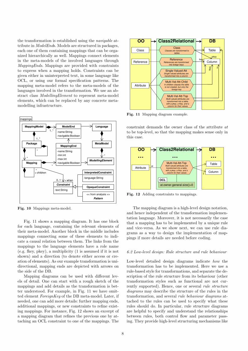
Fig. 11 shows a mapping diagram. It has one blockfor each language, containing the relevant elements oftheir meta-model. Another block in the middle includesmappings connecting some of these elements to indi-cate a causal relation between them. The links from themappings to the language elements have a role name(e.g. fkey, pkey), a multiplicity (1 is assumed if it is notshown) and a direction (to denote either access or cre-ation of elements). As our example transformation is uni-directional, mapping ends are depicted with arrows onthe side of the DB.
Mapping diagrams can be used with different lev-els of detail. One can start with a rough sketch of themappings and add details as the transformation is bet-ter understood. For example, in Fig. 11 we have omit-ted element ForeignKey of the DB meta-model. Later, ifneeded, one can add more details: further mapping ends,additional mappings, or new constraints to refine exist-ing mappings. For instance, Fig. 12 shows an excerpt ofa mapping diagram that refines the previous one by at-taching an OCL constraint to one of the mappings. The
Table
Column
pkey
ClassClasses are transformed to
tables
3
ReferenceReferences are transformed
into foreign keys
Single-Valued-AttSingle-valued attributes are transformed into a column
fkey
DBClass2Relational
Multi-Val-Att-TopMulti-valued attributes are transformed into a table, with a pkey, a fkey, and a
column for their values
Multi-Val-Att-ChildIn children classes the table is not created, but only the
foreign key
fke
y
Class
Attribute
Reference
OO
Fig. 11 Mapping diagram example.
constraint demands the owner class of the attribute atto be top-level, so that the mapping makes sense only inthis case.
Table
Column
at
DBClass2Relational
Multi-Val-Att-TopMulti-valued attributes are
transformed into a table,
with a pkey, a fkey, and a
column for their values
Attribute
OO
3
… … …
at.owner.general.size()=0
OCL
Fig. 12 Adding constraints to mappings.
The mapping diagram is a high-level design notation,and hence independent of the transformation implemen-tation language. Moreover, it is not necessarily the casethat a mapping has to be implemented by a unique ruleand vice-versa. As we show next, we can use rule dia-grams as a way to design the implementation of map-pings if more details are needed before coding.
6.2 Low-level design: Rule structure and rule behaviour
Low-level detailed design diagrams indicate how thetransformation has to be implemented. Here we use arule-based style for transformations, and separate the de-scription of the rule structure from its behaviour (othertransformation styles such as functional are not cur-rently supported). Hence, one or several rule structurediagrams may describe the structure of the rules in thetransformation, and several rule behaviour diagrams at-tached to the rules can be used to specify what theserules should do. In particular, rule structure diagramsare helpful to specify and understand the relationshipsbetween rules, both control flow and parameter pass-ing. They provide high-level structuring mechanisms like
8

blocks, which perhaps are not present in the target im-plementation language, as well as a compact notation toexpress common dependencies. Our notation can alsohelp in describing good practices and transformationpatterns, in the same way as UML helps to record object-oriented patterns. Finally, rule diagrams are also usefulto generate code for different platforms and reengineer-ing of existing code, so that implementation code can bebetter understood using a more abstract notation.
Fig. 13 shows part of the meta-model of the rulestructure diagrams. This kind of diagram depicts thestructure of rules (input and output parameters), theirexecution flow, and data dependencies between them(e.g. parameter passing). Rule diagrams refine mappingdiagrams by giving the low-level design of how the spec-ified mappings are to be realized. In this way, a rulecan contribute to implement several mappings, and amapping can be realized by several rules. Regarding rulestructure, we can declare uni-directional or bi-directionalrules, their involved domains and their parameters. It isalso possible to specify helpers, i.e. auxiliary operationsto be used by rules.
Concerning the execution flow, we support bothexplicit flows (subclasses of Flow) as well as non-deterministic constructs found e.g. in graph transfor-mation, as one can place a collection of rules inside anon-deterministic Block. Among the flows, we differenti-ate between rule execution order (class After), alterna-tive execution flows (Choice), and explicit invocations toother rules (or blocks of rules) which may imply param-eter passing (classes When and Call for invocations thatoccur before or after the rule, respectively).
Fig. 14 shows a rule structure diagram with fourrules, which considers ETL as the implementation lan-guage of the transformation. The diagram is semi-collapsed, as it only shows the parameters of the OOdomain. The diagram shows the rule execution flow bymeans of rounded rectangles (Block objects), in a no-tation similar to activity diagrams. Hence, the start-ing point is the block containing rule Class2Table,which implements the Class mapping. After execut-ing this rule, the control passes to another block withthree rules, to be executed in any order. In particu-lar, rule MultiValuedAtt2Table has been designed to im-plement two mappings: Multi-Val-Att-Child andMulti-Val-Att-Top. In all cases, rules are appliedat all matches of the input parameters. As previouslystated, note how blocks serve as a useful structuringmechanism, which may not be present in the target im-plementation language (ETL in this case).
In contrast to the previous stages in the transforma-tion modelling, where the designer can remain obliviousof the language finally used to implement the transfor-mation, in this stage the particular language should betaken into account. This is so as the rule structure dia-gram models the actual rules of the transformation, theirrelations and the execution flow. Since the features of the
Directional Transformation
from OO to DB (ETL)
c:Class
OO DB
calls
{c.parent}
SingleValuedAtt
2Column{Single-Valued-Att}
MultiValuedAtt
2Table{Multi-Val-Att-Child, Multi-Val-Att-Top}
after
a:Attribute
Reference2Column{Reference}
r:Reference
a:AttributeDBOO
DBOO
DBOO
Class2Table{Class}
Fig. 14 Rule structure diagram for ETL.
great variety of implementation languages are heteroge-neous, targeting one language or other may result in dif-ferent rule diagrams. For instance, Fig. 15 shows the rulestructure diagram in case the transformation is beingwritten with QVT-Relations. In this case, Class2Tableis a top rule (indicated with a double thicker border),there is an additional rule ChClass-Table to handle thetransformation of children classes, and the rules in theright block are explicitly invoked receiving a class andtable as parameters (since all rules in this block receivethe same parameters, we use a shortcut notation and in-dicate the parameters in the block instead of in each oneof the rules). This diagram cannot be used for ETL be-cause ETL rules are allowed to have only one parameterin the source domain.
c:C
lass
t:T
able
Directional Transformation
from OO to DB (QVT-R)
calls {c,t}
OO DB
Class2Table{Class}
calls {c,t}
c:Class
OO DB
MultiValuedAtt
2Table{Multi-Val-Att-Child,Multi-Val-Att-Top}
a:Attribute
OO DB
Reference2Column{Reference}
r:Reference
OO DB
SingleValuedAtt
2Column{Single-Valued-Att}
a:Attribute
calls {c1,t}
calls{c1,t}
ChClass-Table{Class}
OO
DBc1:Class
c:Class t:Table
Fig. 15 Rule structure diagram for QVT-Relations.
Thus, although our rule language captures the mainfeatures of transformation languages, a particular rulediagram has to consider the specific implementationplatform. For example, rules can have an arbitrary num-ber of input parameters if we use ATL as the implemen-tation language, whereas they only have one input pa-rameter if we use ETL, and we have object patterns if us-ing QVT-Relations. Also, platforms differ in the execu-tion control of their rules. While in graph transformationthe execution scheme is “as long as possible” (ALAP)and we can have rule priorities or layers, in ETL rules
9

rules-structure
Transformation
-isBidirectional:Boolean
<< from mappings >>
MappingModel
implements+
Flow
*
Component
-isALAP:Boolean
rules+1..*src+
*
{ordered}
tar+
*
{ordered}
After
Choice
Invocation
DataDependency
-expressionParam:String
*
<< from mappings >>
Constraint
guard+
Parameter
src+ *tar+
Rule
-isAbstract:Boolean
-isTop:Boolean
-isLazy:Boolean
-priority:int
Block
-isConcurrent:Boolean
-isNondeterministic:Boolean
-isInitial:Boolean
DirectionalRule BidirectionalRule
elements+
*
guard+
0..1
children+*0..1
Domain* *
<< from mappings >>
ModellingElement
type+
<< from mappings >>
Mapping
implements+
*
<< from mappings >>
Language
Call When
Helper
return
+ 0..1params+
*
{ordered}
Fig. 13 Excerpt of the meta-model of the rule structure diagram.
are executed once at each instance of the input parame-ter type. Hence, even though our language for modellingrule structure covers the most widely used styles of trans-formation, for its use with particular platforms we defineplatform models for different transformation languages.These models contain the features allowed in each lan-guage, and can be used to check whether a rule model iscompliant with an execution platform when code is gen-erated, as well as by editors to guide the user in buildingcompliant models with the platform. Hence, they act asa kind of profiling mechanism for different transforma-tion languages.
Fig. 16 shows the meta-model of our platform mod-els. This allows customizing the supported control flowconstructions, rule features, number and type of rule pa-rameters, and execution policy of transformation lan-guages. Boolean features, such rule extension and ab-straction, can be either present or absent in a certainlanguage. Features with type SupportType can be eitherthe only possible choice in the language (value all), it canbe an optional feature (selectable) or unsupported. For in-stance, in QVT-Relations rules are always executed aslong as possible (all), we can choose whether they are topor not (selectable), and rule priorities are not supported.
As an example, Table 1 depicts in the form of a tablethe platform models for the languages ETL and QVT-Relations. Platform models allow comparison of trans-formation languages. While QVT-Relations supports bi-directionality and rules with arbitrary parameters, ETLis directional and rules support one parameter in thefrom domain. Hence, platform models allow comparingdifferent transformation approaches, in a similar way asin [12].
From the point of view of the rule structure diagrams,rules are black-boxes: their behaviour is still missing, in
platform
PlatformModel
-platform:String
ControlFlow
-call:boolean
-when:boolean
-after:boolean
-choice:boolean
-helper:boolean
flow+
RuleParameters
-maxParameters:int
-linksAllowed:boolean
RuleFeatures
-abstract:boolean
-extension:boolean
-top:SupportType
-lazy:SupportType
-priority:SupportType
-alap:SupportType
params+
ExecutionPolicy
-concurrency:SupportType
-nonDeterminism:SupportType
-alap:SupportType
-bx:SupportType
execution+rules+
<< enumeration >>
SupportType
+all:int=0
+selectable:int=1
+unsupported:int=2
Fig. 16 Platform meta-model.
Table 1 Platform models for ETL and QVT-Relations.
ETL QVT-R
Control flow
call true truewhen false trueafter true falsechoice true truehelper true true
Rule features
abstract true falseextension true falsetop unsup. selec.lazy selec. unsup.priority unsup. unsup.as long as possible all all
Rule parametersmax parameters 1 ∗links allowed false false
Execution policy
concurrency unsup. unsup.non determinism unsup. allas long as possible all allbidirectionality unsup. selec.
particular, attribute computations and object and linkcreations are not specified. We use rule behaviour di-agrams to specify the actions each rule performs. We
10

have identified three ways of expressing behaviour: (i) ac-tion languages, (ii) declarative, graphical pre- and post-conditions, and (iii) object diagrams annotated with op-erations like new, delete or forbidden.
In the case of an action language, one can use theconcrete syntax of existing transformation implementa-tion languages such as ATL or ETL. The case of pre-and post-conditions follows the style of graph transfor-mation [57]. The third option is present in tools likeFujaba [23]. As an example, the left of Fig. 17 showsa behavioural diagram using this third type of syntaxwhere created elements are annotated with the new key-word. The right of the figure shows the same rule usingan action language with ETL syntax.
c:Class
OO
«new»
t:Table
DB
Class2Table
name:=c.name
«new»
pk:Column
name:=t.pkName()
type:=‘NUMBER’
columns primaryKeys«new» «new»
transform c: OO!Class
to t:DB!Table, pk: DB!Column
t.name:=c.name;
pk.name:=t.pkName();
pk.type:=‘NUMBER’;
t.columns.add(pk);
t.primaryKeys.add(pk);
Fig. 17 Behavioural rule diagram in visual (left) and textual(right) notation.
7 Implementation and testing
transML does not include any implementation language,but we can use any existing target language to imple-ment the transformations (e.g. QVT, ATL or ETL). Us-ing the MDE philosophy, code for different platformscan be generated from the diagrams, specifically fromthe rule (structure and behaviour) diagrams. Currently,we support both ETL and QVT-Relations, but manyother languages, like ATL, could be targeted as well.
With respect to testing, transML includes a ded-icated language for model-based testing, of which itsmeta-model is shown in Fig. 18. This language enablesthe description of test cases, including both the test in-put models (class TestInput) and the expected outcomeor oracle function (class Assertion). The language sup-ports four different formats for the input data: models(which can be either a file or a transML graph model),meta-models, graph constraints and constructive oper-ational specifications (for instance written in EOL). Inthe case of meta-models and graph constraints, it is pos-sible to specify cardinality for the number of instancemodels to be generated as input, as well as a set of gener-ation criteria guiding the test generation procedure anddefining coverage criteria [21] (e.g. class, association andattribute coverage among others). The expected outputfor a specific test case can be given as an operation over
a given model or as an oracle function. The first possibil-ity is useful to check whether the transformation resultis equals, includes or overlaps with a given model. Thesecond approach allows checking verification propertiesof the resulting model, which can be defined either asa specification (e.g. written in OCL) or as a graph con-straint using a pattern of our formal specification lan-guage.
Test cases can be automatically generated from thetransformation cases as these already define the ex-pected output for a given input, as well as from the for-mal specification built in the analysis phase, in this caseby deriving AssertionGraphConstraint assertions fromeach one of the verification properties. Thus, having anexplicit model for the test suite makes it possible to traceback detected errors to the specific transformation casesand properties that were violated during a particulartransformation execution.
As an example, Listing 1 shows a testing model forthe class-to-relational transformation, using a textualconcrete syntax. It contains a test case derived fromthe transformation case in Fig. 4, which exemplified thetransformation of multi-valued attributes. Its input isthe OO model in the transformation case where, in ad-dition, the operation ‘complete’ in line 9 indicates thatthe model fragment is being added the necessary ele-ments to obtain a valid instance of the OO meta-model.This is necessary as, in general, transformations assumecorrect input models. The assertion in lines 11-19 checkswhether transforming the OO model yields a model thatincludes the DB model in the transformation case. Notehow, in lines 3-4, the test case is annotated with thename of the transformation case from which it was de-rived.
1 TestSuite "OO2DB.etl" <OO:"OO", DB:"DB"> {2
3 @transformationcase(name=4 "Class with Multi-Valued Attribute")5 test Class_with_Multi-Valued_Attribute {6 input model OO {7 c:Class { name="Book"; features=@a; }8 a:Attribute { name="author"; isMany="true"; } }9 .complete()
10
11 assert model DB {12 t1:Table { name="Book"; columns=[@co1,@co2]; }13 t2:Table { name="author"; columns=[@co3,@co4]; }14 co1:Column { name="BookId"; }15 co2:Column { name="authorId"; }16 co3:Column { name="value"; }17 co4:Column { name="id"; }18 fk:ForeignKey { child=@co2; parent=@co4; } }19 .included()20 }21 }
Listing 1 Test case derived from a transformation case.
Listing 2 contains another set of test cases for ourtransformation. In this case the input models are filesspecified at the test suite level (lines 3 and 4), thereforethey are being used as input by all the test cases in thesuite. Lines 8-23 correspond to a test case derived fromthe specification property shown to the right of Fig. 6.
11

tests
TestSuite
-transformationURI:String
TestCase
-name:String
-isExecutable:boolean
extends+
*
*
TransformationTestCase
TestInput
-name:String
-cardinality:int=1
GenerationCriterion*
ExtensibleInput
TestSpecification TestGraphConstraint TestModel
-modelURI:String
TestMetaModel
extends+
**
<< from mappings >>
InterpretedConstraint
<< from analysis >>
Pattern
<< from analysis >>
Graph
0..1
RuleTestCase
Assertion
AssertionSpecification AssertionGraphConstraintOperation
-URI:String
0..1
globInputs+ *
1..*
locInputs+
*
assertions
+ *
Fig. 18 Excerpt of the meta-model of the tests diagram.
This is an assertion of type AssertionGraphConstraint,and it uses a textual concrete syntax for the property.Another test case is shown in lines 25-34, which illus-trates the use of a constraint language such as EOL tospecify model assertions. The first assertion checks theabsence of duplicated columns in tables, while the secondchecks that as many tables are generated as classes, ormore (in case of transforming multi-valued attributes).
1 TestSuite "OO2DB.etl" <OO:"OO", DB:"DB"> {2
3 input model "models/OOInstance1.xmi"4 input model "models/OOInstance2.xmi"5
6 @property(name="InheritedAttrs")7 @requirement(name="0.3.1")8 test InheritedAttrsProperty {9 assert ppattern InheritedAttrs {
10 OO {11 p:Class { features=@a; }12 c1:Class { name=C1; }13 c2:Class { name=C2; }14 a:Attribute { name=X; } }15 DB {16 t1:Table { name=C1; columns=@d; }17 t2:Table { name=C2; columns=@e; }18 d:Column { name=X; }19 e:Column { name=X; } }20 condition: "c1.general.includes(p)",21 "c2.general.includes(p)";22 }23 }24
25 test transformationOfClasses {26 assert constraint nonDuplicatedColumns (27 "DB!Table.allInstances().forAll(t |28 t.columns.forAll(co1 |29 not t.columns.exists(co2 |30 co1.name=co2.name and co1<>co2)) )")31 assert constraint numberOfTables (32 "DB!Table.allInstances().size() >=33 OO!Class.allInstances().size()")34 }35 }
Listing 2 Test case derived from a verification property andtest case defining constraint-based assertions.
The automatically generated test cases performblack-box testing of transformations, where the gran-ularity level is the complete transformation as the ex-pected output is evaluated only after the transformationis completely executed. Nonetheless it is also possibleto check assertions after rule executions through classRuleTestCase, allowing for a finer control of errors. Re-garding white-box testing, here one is interested in spec-ifying input models enabling the execution (or not) ofsequences of rules. Some degree of automation could beachieved for this purpose by taking into account the de-fined rule diagrams. The more detailed and complete therule models, the more accurate the generated tests.
Complementing the test cases, it is also possible togenerate assertion code from the formal specificationof transformation properties, and directly inject it inthe final transformation code for its run-time verifica-tion. This injected code is an oracle function, indepen-dent from the actual language used to implement thetransformation. As an example, Listing 3 shows partof the EOL code automatically generated from patternN(NoRedefinedAttrs) in Fig. 6, which can be in-jected into the pre section of the ETL transformationcode to discard non-supported input models.
1 operation sat_NoRefinedAttrs () : Boolean {2 return not3 OO!Class.allInstances().exists(p |4 OO!Class.allInstances().exists(c | c <> p and5 OO!Attribute.allInstances().exists(a |6 p.features.includes(a) and7 OO!Attribute.allInstances().exists(ar |8 ar <> a and c.features.includes(ar) and9 checkatt_NoRefinedAttrs(p, c, a, ar)))));
10 }11
12 operation checkatt_NoRefinedAttrs(p:OO!Class,13 c:OO!Class, a:OO!Attribute, ar:OO!Attribute)14 : Boolean {15 var X := a.name;16 var Xar := ar.name;
12

17 return c.general.includes(p) and X=Xar;18 }
Listing 3 EOL code derived from a specification property.
8 Putting everything together: Traceability
Even though the different transML diagrams can be usedin isolation, their power comes from their combined use.This is so as one can trace requirements into the codeand build the final transformation by the progressive re-finement of models. For this purpose, we have definedtraceability relations between the different diagrams asshown in Fig. 19. These relations correspond to the dot-ted arrows in Fig. 1.
<< from requirements >>
Requirement
<< from architecture >>
ArchComponent
<< from architecture >>
Interface
satisfies+ * satisfies+ *
<< from mappings >>
Mappingsatisfies+
*
<< from rules-structure >>
Rule
implements+ *
<< from rules-behaviour >>
BehaviouralDiagram
refines+
<< from analysis >>
Patternrefines+
*
<< from rules-structure >>
Transformation
implements+ *
<< from mappings >>
MappingModel
implements+
<< from tests >>
TestCase
*
tests+ *
*
addresses+ *
Fig. 19 Traceability links.
In particular, it is possible to trace which require-ments are addressed by a given transformation case orspecification pattern (refines relationship). Architecturalcomponents, mappings and test cases are also traced torequirements. We can trace the mappings a rule imple-ments, and the behavioural diagrams that refine a rule.Therefore, we can trace the requirements each rule ad-dresses and vice versa. Finally, test cases can refer tothe requirements they address, and to the transforma-tion cases or verification patterns they test.
Making available explicit traces between the differenttransML models permits automating the generation ofrequirement traceability matrices [63] documenting therequirements of a transformation against its test casesor analysis properties. As an example, Fig. 23 shows therequirement traceability matrix for the test cases of ourexample, using a web-based user-friendly format.
Finally, we provide some automation for traceability.For instance, we create traces when generating the skele-ton of a rule structure diagram from a mapping diagram(see Fig. 20) or when generating a test case from a trans-formation case (see Listing 1). However, most traceabil-ity links have to be specified by hand (see for example
the annotations in Listing 2). A higher degree of automa-tion (e.g. inference or maintenance of traces) is left forfuture work.
9 Tool support: Towards the model-drivenengineering of transformations
We have built Ecore meta-models for the presented lan-guages, together with several model transformations andcode generators that allow automating the conversionbetween diagrams, as shown in Fig. 20. The purpose ofthese transformations is to provide partial automationfor model refinement from requirements to code gen-eration and testing. Hence, they enable the construc-tion of model transformations using MDE. For example,given a mapping diagram we generate a skeleton of a rulestructure diagram, which has to be completed with therule behaviour model by the transformation developer.All model transformations have been implemented withETL, and all code generators with EGL.
Rule Diagram
ETL Transformation code
Architecture
DiagramEGL
program
Orchestration
code (ANT files)
ETL transf.
EGL
program parser
ETL
transf.
ETL
transf.
AggregatedScenarios
FormalSpecification
1
2
3 7
assertions
PlatformModel
EVLinvariants
check
& fix
AggregatedScenarios
Testing
Model
4 6AggregatedScenarios
TransformationCases5
check
8
9 9
MappingDiagram
Fig. 20 Scheme of tool support.
The code generator with label “1” takes as input thearchitecture diagram, and generates ANT files that or-chestrate the execution of the transformation chain spec-ified in the architecture (i.e. it will ask the user the mod-els to transform and pass them to the appropriate trans-formations). This generator also produces one additionalANT file for each transformation in the architecture,which defines tasks to automate the other labelled ac-tivities in the figure.
Transformation “2” generates one mapping diagramfor each transformation in the architecture. The map-ping diagrams are added a mapping for each concreteclass defined by the input port types. Then, the transfor-mation designer is in charge of connecting the mappingswith the appropriate output types.
13

Transformation “3” generates a simple rule diagramfrom a mapping diagram that contains one rule for eachmapping. Each rule stores a trace pointing to the map-ping it implements. The opposite transformation is alsopossible for reengineering (label “7”).
As stated before, one may use features of rule di-agrams that are not available in the specific executionplatform. In order to check whether a rule diagram fitsa particular platform, we have created an EVL [39] pro-gram made of OCL-like constraints which validate arule diagram for a specific platform model, discoveringwhether it conforms to the features of the platform, andautomatically repairing the detected errors when possi-ble (label “8”).
In “4”, code is generated from the structural rule di-agram, taking into account the flow directives. In ourcurrent implementation we generate ETL code, and aparser for reverse engineering (label “6”) generates arule diagram from ETL code. Although not shown inthe figure, we support the generation of QVT-Relationscode from structural diagrams as well, but not its reverseengineering.
The generator in “5” produces OCL code from theproperties defined with the specification language. Thereare two ways to inject this code into ETL transforma-tions. Firstly, code generated from patterns specifyingrestrictions on the input model is included in the presection of the transformation, and checked on the inputmodel before the transformation starts. If the model vi-olates these constraints, a pop-up window informs theuser of the unsatisfied properties. Secondly, code gen-erated from patterns specifying properties of the trans-formation or of the expected output models is injectedin the post section of the transformation, and checkedwhen the transformation ends. This is used to performrun-time verification of the transformation. When theexecution of a transformation finishes, the user is in-formed of any violated property and of the rules thatare responsible for the error. An example screenshot isshown in Fig. 38.
In order to enable systematic transformation testing,a testing model is generated from the formal propertiesand transformation cases (label “9”). The generated testcases can be executed to test the final transformation.Currently, we only support model files as input test data,and all assertion types in our meta-model. Supportingother criteria for input model generation is left as fu-ture work. The execution of a test case for a given inputmodel returns whether the result of transforming themodel violates any of the specified assertions. As an ex-ample, Fig. 21 shows in the upper right window part ofa test case (the complete test case was previously shownin Listing 2). The lower right window contains the resultof running the test case.
Additionally, starting from the transML models,we generate different requirement traceability matriceswhich can be visualized in a web browser. In particu-
Fig. 21 Result of running a transformation test case.
lar, we trace requirements against test cases to anal-yse whether every requirement has been tested, as wellas against transformation cases and verification prop-erties. Fig. 22 shows a screenshot of a requirementsdiagram being edited, while Fig. 23 shows the gen-erated matrix tracing requirements (rows) against ex-isting test cases (columns). Crossed cells have differ-ent colours depending on whether there is a directtraceability link between the requirement and the testcase (e.g. requirement Inherited Attributes andtest InheritedAttrs), or if the test covers a sub-requirement of a given one (e.g. requirement Featuresand test InheritedAttrs). Moreover, each require-ment in the matrix is linked to a web page containingthe details of all its traces.
10 Case studies
This section illustrates the use of transML with tworeal case studies. In the first one the aim was to trans-late models of productions systems into Petri nets fortheir analysis, and the chosen transformation languagewas QVT-Relations. The second example is an industrialproject in the railway domain for which we used ETL.
14

Fig. 22 Editor for the transformation requirements.
Fig. 23 Generated requirement traceability matrix.
10.1 From production plants to time Petri nets
In this section we describe the use of transML for build-ing a transformation chain for the verification of pro-duction plant models [15] using time Petri nets [49].Petri nets have powerful analysis techniques and henceare a frequently used analysis domain for higher-levelmodelling languages like UML or domain-specific lan-guages [7].
We use a domain-specific language to describe pro-duction plants as nets of interconnected machines andconveyors with a certain capacity. There are four typesof machines: generators of cylinders and bars, assem-blers, and packaging machines. Generators introduce agiven kind of part (a cylinder or a bar) in a factory con-veyor, assemblers take one cylinder and a bar and pro-duce an assembled part, and packaging machines removeassembled parts from the factory. All machines are char-acterized by some processing delay given by a uniformtime interval, whereas for simplicity conveyors have zerotransport time.
As a first step in the development of our transforma-tion, we defined several transformation cases with exam-ples of specific models or model fragments and the ex-pected time Petri net in each case. For example, Fig. 24depicts how the connection between two conveyors of ca-pacity 4 and 3 should be expressed in time Petri nets,
where in addition the target conveyor is full as it containsthree parts (two cylinders and one assembled part). Inthis example we can see that conveyors should be trans-formed into a set of places, one for each kind of part (e.g.the places cvs cyl, cvs bar and cvs assem corre-spond to conveyor cvs). The Petri net representationfor conveyors should also include an additional place toensure the maximum capacity constraint of conveyors(places cvs cap and cvt cap). This transformationcase is an example of situation where the target conveyoris full (zero tokens in the place for capacity constraint),so that no part from the incoming conveyor can move.
cvs
[0, 0]
cvs bar
cvs assem
cvs
cap
cap=4
cvt
cap=3
move
cyl
[0, 0]
move
bar
[0, 0]
move
assem
cvs cyl
cvt bar
cvt assem
cvt cyl
cvtcap
Conveyor connection with deadlockfragment
Fig. 24 Transformation case showing the time Petri net se-mantics of two connected conveyors.
Fig. 25 shows another transformation case, this timean example of the transformation of a complete factorymodel. The factory contains a generator of bars gb, agenerator of cylinders gc, an assembler asse, and apackaging machine pack. One conveyor feeds pieces intothe assembler, and another conveyor moves the assem-bled parts to the packaging machine. From this examplewe learnt how to transform the different kinds of ma-chines and that unused places of conveyors should bedeleted.
cv
[1,2.5]gc
cap=4
asse[3,3.5]
cva
cap=3
pack[5,6.5]
[1.5,2.3]gb
gc
[1,2.5]
cv bar
cvcap
cv cyl
gb
[1.5,2.3]
assestart
asse idle
assebusy
asse
end
2
cva pack
cva cap
[0,0]
[3,3.5]
[5,6.5]
Simple plant model 1model
Fig. 25 Transformation case for simple plant model.
15

The Petri nets generated by our transformation mustensure the preservation of the maximum capacity forconveyors. As the transformation case in Fig. 24 showed,this should be implemented by an extra place connectedto each transition, and removing or adding tokens to theset of places modelling the conveyor. More in detail, if atransition adds tokens (parts) to the places of the con-veyor, it should remove the same amount of tokens fromthe capacity constraining place. This property can beformally expressed using our specification language asshown in Fig. 26. We also defined a similar pattern forincoming transitions to capacity places.
[l,h]
x+’ cap’
w
[l,h]
x+’ cap’
w
P(Capacity)
t t
w=t.inarcs.select(a | a.inp.name=x+y).
collect(a | a.weight).sum()
P(inWeights)
Fig. 26 Correctness property for the target model.
Other desired properties of the generated time Petrinets were the absence of non-used places (which couldcome from conveyors not connected directly or indirectlyto some generator) as well as the absence of dead tran-sitions (i.e. transitions that can never fire as they areconnected to an incoming place with zero tokens andwithout any other input transition). These two proper-ties were specified with the patterns shown in Fig. 27.
pl
N(Unconnected places)
pl.inarcs.size()=0 and
pl.outarcs.size()=0
pl
N(Dead transitions 1)
pl.inarcs.size()=1 and
pl.outarcs.size()=1 and
pl.tokens.size() =0
pl
N(Dead transitions 2)
pl.inarcs.size()=0 and
pl.tokens.size() =0
Fig. 27 Verification properties for the target model.
Regarding the transformation design, we decided tobreak the transformation in two steps: the first one trans-forming the factory models into time Petri nets, and thesecond one simplifying the resulting net by eliminatingunconnected places and dead transitions. Altogether, ourarchitectural diagram is shown in Fig. 28. The two trans-formation steps are included in a composite block, forwhich the output is constrained by some of the identi-fied verification properties. Afterwards, a model-to-texttransformation would produce code for its analysis withthe Romeo tool [24].
Next, we built the mapping diagram shown inFig. 29 for the first transformation step, namedProdSys2TPNets. The diagram only reflects the trans-formation of entities (i.e. conveyors, machines and parts)but not the net topology (i.e. connections). This was
ProdSys2
TPNets
in out
Optimize
in out
ProdSysTime
PetriNets
GenRomeo
in out
Romeo
format
«M2M» «inPlace» «M2text»
Romeo
«SW»in out
PS2TPNs «M2M»
N(Unconnected places)
N(Dead transitions 1)
N(Dead transitions 2)
Fig. 28 Architecture of the transformation chain.
quite useful as we only wanted to focus on this aspectof the transformation, instead of having to specify alldetails. Thus, the diagram shows that any kind of gen-erator should be translated into one transition, thatany part should be transformed into a token, and thatassemblers should be transformed into two places, twotransitions and one token.
Transition
Place
GeneratorsGenerators are transformed
into transitions
AssemblersAssembler machines are
transformed into a busy/idle
pair of places connected to
two transitions
2
TimePetriNetsProdSys2TPNets
Generator
Assembler
Production
Systems
2
Packaging
PackagingPackaging machines are
transformed into transitions,
which remove tokens
Conveyor
ConveyorsComveyors are transformed
into 4 places: 3 to store each
type of piece, and another
constraining the capacity
4
PartParts
Parts are transformed into
Tokens.
Token
Fig. 29 Mapping diagram for the first transformation.
We chose QVT-Relations to implement the firsttransformation due to its declarative nature, which wasvery convenient because the source and target languageswere heterogeneous and we had to create complex pat-terns in the target model. Fig. 30 shows the rule struc-ture diagram, which is organized in two main blocks: En-tities and Topology. The Entities block contains one ruleto transform each entity kind, according to the mappingdiagram of Fig. 29. The translation of parts is handledby block genParts, which is collapsed so that it onlyshows the number of rules it contains (4, one for eachkind of part and another one for the capacity constraintplaces). The Topology block contains rules to connect thePetri net fragments generated by the first block. Indeed,these rules have dependencies with the rules in the firstblock. For instance, rule Connect Packaging can be exe-cuted only when rules Packaging2Transition and Con-veyor2Places (this latter dependency indicated in theblock) have been executed. Altogether, we found thisdiagram useful to understand the relationships between
16

rules. Moreover, it provided structuring mechanisms likeblocks which were not present in QVT-Relations, as wellas a compact notation to express common dependencies(e.g. we specified a when dependency for all rules in blockTopology with a single arrow).
PS PN
Generator2
Transition{Generators}
g:Generator
Assembler2
capConstNet{Assemblers}
PS PN
a:Assembler
Packaging2
Transition{Packaging}
PS PN
p:Packaging
Conveyor2
Places{Conveyors}
PS PN
c:Conveyor
4 rules
{Parts}
genParts
2 rules
connAssembwhen
2 rules
connGenswhen
ConnectPackaging
when
Connect
Conveyors
PS PN
PS PN
when
Entities Topology
Directional Transformation
ProdSys2TPNets (QVT-R)
calls {…}
Fig. 30 Rule structure diagram.
Starting from our rule diagram, we used our codegenerator for QVT-Relations to generate a skeletonof the transformation implementation, which ended upwith some 350 lines of code (LOC). The simplificationtransformation was written in EOL and contained 7 op-erations and 85 LOC. Finally, we wrote the code gener-ator with EGL (60 LOC).
During the process, we also wrote some tests mod-els. Some of them were derived from the transformationcases and the verification properties. Listing 4 shows anexcerpt of a test model declaring two test cases. The firstone (lines 4-7) tests the scenario of Fig. 25, while the sec-ond one (lines 12-43) checks the properties of Fig. 27 onthree input models.
1 TestSuite "PS2TPNs.ant" <PS:"ProductionSystems",2 PN:"TimePetriNets"> {3 @transformationcase(name="Simple Plan Model 1")4 test SimplePlanModel1 {5 input model "SimpleModel1.xmi"6 assert model "PetriNetModel1.xmi".equals()7 }8
9 @property(name="Unconnected places")10 @property(name="Dead transitions 1")11 @property(name="Dead transitions 2")12 test AssertionProperties {13 input model "SimpleModel1.xmi"14 input model "SimpleModel2.xmi"15 input model "ConveyorSequence.xmi"16
17 assert npattern UnconnectedPlaces {
18 PS {}19 PN { pl:Place {} }20 condition: "pl.inarcs.size()=0",21 "pl.outarcs.size()=0";22 }23
24 assert npattern DeadTransitions1 {25 PS {}26 PN { pl:Place { outarcs=@a1; inarcs=@a2; }27 a1:ArcPT { outt=@t; }28 a2:ArcTP { intt=@t; }29 t:Transition {} }30 condition: "pl.inarcs.size()=1",31 "pl.outarcs.size()=1",32 "pl.tokens.size()=0";33 }34
35 assert npattern DeadTransitions2 {36 PS {}37 PN { pl:Place { outarcs=@a; }38 a:ArcPT { outt=@t; }39 t:Transition {} }40 condition: "pl.inarcs.size()=0",41 "pl.tokens.size()=0";42 }43 }44 }
Listing 4 A test suite for the case study (excerpt).
Altogether, transML offered a step-by-step guidelineto engineer the transformation. In particular, we inten-sively used the transformation cases, which were usedfor automated testing later. The specification languagewas useful to explicitly formalize knowledge of Petri netpatterns and idioms (e.g. how capacity constraint placeswork, Fig. 26), as well as specific properties of our tar-get models (Fig. 27). The architecture diagram was ameans to modularize and organize the transformation.The mapping diagram provided a first sketch of how ele-ments in both languages corresponded to each other, andserved well for the purpose of understanding the trans-formation design. Finally, the rule structure diagramsallowed a more structured way to coding, and constitutea good means for documenting and understanding thetransformation code.
10.2 From UML (for railway systems) into PROMELA
INESS (INtegrated European Signalling System –http://www.iness.eu) is an industry-focusedproject funded by the FP7 programme of the Euro-pean Union, comprising 30 partners, including 6 railwaycompanies. Its objective is to provide a common rail-way signalling system that integrates existing Europeanones. In the project, experts have been modelling a spec-ification of the proposed integrated signalling systemusing xUML [47]. This is a subset of UML comprisingclass diagrams and state machines, as well as an actionlanguage to specify class operations and state actions.The idea is to use the specified xUML models to checkfor inconsistencies in the requirements and against coreproperties of the system provided by professional rail-way engineers. Currently, xUML models can be analysedonly via simulation, but due to safety-critical require-ments involved in railway signalling systems, our work
17

in the project is to enable the analysis of models usingformal verification.
In order to achieve this goal, we are using atransformation-based approach for the formal analy-sis of the xUML models. This entails on the automatictranslation of xUML models to the input language offormal verification tools, like SPIN [32]. While previousworks in the literature [44,45] have analysed subsets ofUML (in particular Statechart diagrams) using modelcheckers, the main feature of this project is that we dealwith the action language of xUML in its full generality.
Because of the research nature of the project, we werenot given initial requirements about the transformation.Instead, they began emerging as we started designingthe transformation. In the first stages, we agreed onsome guidelines for the experts to build the xUML mod-els. Expressing these requirements using transML ver-ification patterns automates checking if a given xUMLmodel satisfies these guidelines and therefore qualifies forthe transformation. Some of the main requirements in-cluded: (i) classes always have exactly one associated be-haviour, of type state machine; (ii) multiple-inheritanceis not allowed; (iii) a transition always has a unique trig-ger; (iv) a change-event can be associated to at mostone trigger; (v) transition triggers have to be of typechange-event, time-event or signal-event; (vi) a specialclass called “Application” is used to instantiate a sce-nario (representing a railway track layout) for the exe-cution of the model; (vii) objects can only be created inthe state-machine of the “Application” class. As an ex-ample, Fig. 31 shows the verification pattern formalizingrequirement (i), while Fig. 32 partially describes require-ment (vii). For this latter requirement, another similarpattern is needed, to check the creation of objects intransition actions.
c:Class
P(Class)
c:Class
P(hasOneStateMachine)
sm:StateMachine
classifierBehaviour
c.ownedBehaviour.size()=1
Fig. 31 Pattern expressing requirement (i).
s :State
entry=X
exit=Y
doActivity=Z
:RegionsubVertex
stateMachine
ownedBehaviour
name=“Application”
“CreateObject”.isSubstringOf(X) or
“CreateObject”.isSubstringOf(Y) or
“CreateObject”.isSubstringOf(Z)
P(StateCreateObject) P(InApplication)
s :State
entry=X
exit=Y
doActivity=Z :StateMachine
:Class
Fig. 32 Pattern expressing requirement (vii).
The main difficulties found in our transformationwere dealing with both the action language and inher-itance in the xUML language. First, dealing with theaction language in its full generality means that certainactions have to be specially encoded in the target lan-guage (formal languages normally comprise a more basicset of statements). Second, since every class has an as-sociated state-machine, by inheriting a class, two statemachines have to be executed in parallel in the targetlanguage. Additional sources of complexity included col-lecting the possible state configurations in the state ma-chines, the transitions that can fire in parallel as well asresolving the order of firing entry and exit actions.
In order to deal with these issues in a more structuredand efficient way, we decided to split the transforma-tion in several steps. The architecture representing thetransformation to the input language of the SPIN model-checker is shown in Fig. 33. It makes use of an inter-mediate meta-model, called (transition-based) tbUML,which is a simplified UML meta-model that only con-siders the structure of class diagrams and the possibleset of transitions of the state-machines. In this way, thefirst transformation performs a flattening of the classesand states machines, and the second one transforms theobtained tbUML model into a PROMELA model – theinput language to SPIN – from which code conforming tothe PROMELA grammar is generated as input to SPIN.
Fig. 33 Architecture diagram for the project.
Splitting the transformation facilitates the elicitationof requirements. For instance, requirements related tothe flattening of classes in the first transformation in-clude copying attributes, associations and states for eachclass and its generalizations. A pattern specifying the re-quirement on attributes is described in Fig. 34, the otherrequirements about the flattening of classes are definedsimilarly. Requirements related to the flattening of statemachines include aggregating and creating transitionsdepending on concurrent events of orthogonal states andof state machines associated to super-classes, as well ason exit actions in composite states. We were also able to
18

express these requirements using our specification lan-guage.
c1:Class
c2.generalization.exists(g | g.target.includes(c1))
p:Property
name=X
ownedAttribute
t:Type
name=T
type
c2:Class
name=N
c3:Class
name=N
a:Attribute
name=Xtype=T
attribute
UML tbUML
P(flatSuperAttrs)
Fig. 34 A verification property for UML to tbUML.
We chose ETL to implement the transformations andEGL for code generation. We did not define a mappingdiagram for the first transformation (UML to tbUML)as it was straightforward, but we built the mapping di-agram shown in Fig. 35 for the second transformation(tbUML to PROMELA). In this case, StateNodes andSignals are translated to Constants with a unique value;Objects (i.e. classes that appear in the “Application”class) are translated to a Proctype which represents aPROMELA execution unit; and models are transformedinto another model and an Init process that is responsi-ble for starting the objects in the model – for example,creating communication channels and setting referencesaccordingly.
Fig. 35 Mapping diagram for tbUML to PROMELA.
In this way, the complexity of our transformationsdid not come from a large number of rules, but fromthe complexity of the helper computations associatedto certain rules. For this reason, the rule diagrams forthis case study made intensive use of helpers. Fig. 36shows the rule structure diagram for the second trans-formation, which displays the two main helpers in thetransformation: parseActions and createInit. The formeris called whenever an action is found in the transitionbody/entry and exit body of a transition and a state.The function is responsible for translating the xUMLaction language into PROMELA constructions. The cre-ateInit helper method is used by rule Mod2Mod, andcreates an Init process in the target model, provided the
correct reference to the objects (i.e. classes in the “Ap-plication” class).
Directional Transformationfrom tbUML to PROMELA (ETL)
State2Constant{Constant}
s:StateNode c:Constant
Signal2Constant{Constant}
s:Signal c:Constant
PROMELAtbUML
after
c:Class
Obj2Proc{Object}
tbUML PROMELA
p:Proctype
calls {c,p}
after
m:Model
Mod2Mod{Model}
tbUML PROMELA
m1:Model
i:Init
calls{m.objects}
PROMELAtbUML
parseActions
c: Class p: Proctype
createInit
o:Object[*]
returns
Fig. 36 Rule structure diagram for tbUML to PROMELA.
We also attached a behaviour diagram to some of therules, giving additional details about their expected im-plementation. As an example, Fig. 37 shows the diagramthat corresponds to rule Model2Model of the first trans-formation. This creates a tbUML model with two specialstates (called StateNodes) starting from a UML model.The state node root is created in order to maintain areference that can be used to compute the Least Com-mon Ancestor during the flattening of the state machines– all other states are within this one. The state nodeinit represents the initial pseudo-states in the state-machines of the model. This way, initial pseudo-statesare abstracted and the initial actions found in them aredirectly associated to the classes.
Fig. 37 Behaviour diagram for rule Model2Model.
The implementation of the first transformation in ourarchitecture ended up with more than 5000 lines of ETLcode, whereas the second one had more than 2500 LOC.In order to validate both implementations, we made useof the verification patterns specified at the first stages ofour design. In particular, we generated assertion code forthe run-time verification of the transformations. Fig. 38shows a moment in the execution of the first transfor-mation, where a violation of the verification propertyflatSuperAttrs occurs. By having traceability fromthe models into the code we were able to identify theerroneous rule. Additionally, we built some testing mod-
19

els which enabled automated testing of the verificationproperties as well as checking the correct translation ofspecific input UML models.
Fig. 38 Testing the implementation.
Altogether, in this project we found particularly use-ful the formal specification language, as it enabled toformally gather requirements about the input modelsas well as verification properties for the transformation.Guaranteeing the satisfaction of these safety-critical re-quirements was essential due to the application domainof the project. Moreover, we were able to provide ameans to automatically validate such properties on in-put xUML models. However, our specification languagecannot be used to express dynamic correctness criteriafor the transformation (e.g. that a step in the Statechartcorresponds to a step in Promela), which is left for fu-ture work. For this project, the rule structure diagramswere less useful, as the complexity of the transformationswere not on the number of rules or on their data depen-dencies, but it was on the operations and helpers usedby the rules. Nonetheless, rule structure diagrams werereally useful in the first case study due to the complex-ity of rule dependencies. Hence, we can conclude thateach transformation project has its own characteristics,and engineers need to select the most useful transMLdiagrams for each particular situation, just like softwareengineers select the most useful kinds of UML diagramsto construct software systems.
11 Conclusions and lines of future work
Transformations should be engineered, not hacked. Forthis purpose we have presented transML, a family oflanguages to help building transformations using well-founded engineering principles. The languages cover thecomplete life-cycle of the transformation development in-cluding requirements, analysis, architecture, design and
testing. We have provided partial tool support and au-tomation for the MDE of transformations, and evaluatedthe approach using several case studies, which showedthe benefits of modelling transformations.
We are currently working in improving the tool sup-port for our approach, in particular the usability of thevisual editors and the integration of the different lan-guages. Regarding our language for testing, we are cur-rently developing tool support for the automatic genera-tion of input test models according to different coveragecriteria, combining techniques based on meta-models,constraints and specifications as seed for the generation.We are also planning the use of transML in further casestudies, and investigating processes for transformationdevelopment.
Acknowledgements. We thank the referees fortheir useful comments. This work has been sponsoredby the Spanish Ministry of Science and Innovation withproject METEORIC (TIN2008-02081), and by the R&Dprogram of the Community of Madrid with projects“e-Madrid” (S2009/TIC-1650). Parts of this work weredone during the research stays of Esther and Juan atthe University of York, with financial support from theSpanish Ministry of Science and Innovation (grant refs.JC2009-00015, PR2009-0019 and PR2008-0185).
References
1. A. Agrawal, A. Vizhanyo, Z. Kalmar, F. Shi,A. Narayanan, and G. Karsai. Reusable idioms and pat-terns in graph transformation languages. Electron. NotesTheor. Comput. Sci., 127:181–192, 2005.
2. A. Balogh, G. Bergmann, G. Csertan, L. Gonczy,A. Horvath, I. Majzik, A. Pataricza, B. Polgar, I. Rath,D. Varro, and et al. Workflow-driven tool integrationusing model transformations. In Graph Transformationsand Model-Driven Engineering, volume 5765 of LNCS,pages 224–248. Springer, 2010.
3. B. Baudry, S. Ghosh, F. Fleurey, R. B. France, Y. L.Traon, and J.-M. Mottu. Barriers to systematic modeltransformation testing. Commun. ACM, 53(6):139–143,2010.
4. K. Beck. Test Driven Development: By Example.Addison-Wesley, 2003.
5. J. Bezivin, N. Farcet, J.-M. Jezequel, B. Langlois, andD. Pollet. Reflective model driven engineering. In UML,volume 2863 of LNCS, pages 175–189. Springer, 2003.
6. J. Bezivin, F. Jouault, and J. Palies. Towards modeltransformation design patterns. In EWMT’05, 2005.
7. A. Bondavalli, I. Mura, and I. Majzik. Automatic de-pendability analysis for supporting design decisions inuml. In HASE’99, pages 64–72, 1999.
8. A. Boronat, J. A. Carsı, and I. Ramos. Algebraic speci-fication of a model transformation engine. In FASE’06,volume 3922 of LNCS, pages 262–277. Springer, 2006.
9. E. Brottier, F. Fleurey, J. Steel, B. Baudry, and Y. L.Traon. Metamodel-based test generation for model trans-formations: an algorithm and a tool. In ISSRE, pages85–94. IEEE CS, 2006.
20

10. J. Cabot, R. Clariso, E. Guerra, and J. de Lara. Verifica-tion and validation of declarative model-to-model trans-formations through invariants. Journal of Systems andSoftware, 83(2):283–302, 2010.
11. G. Csertan, G. Huszerl, I. Majzik, Z. Pap, A. Pataricza,and D. Varro. VIATRA - visual automated transforma-tions for formal verification and validation of uml models.In ASE’02, pages 267–270. IEEE CS, 2002.
12. K. Czarnecki and S. Helsen. Feature-based survey ofmodel transformation approaches. IBM Systems Journal,45(3):621–646, 2006.
13. A. Darabos, A. Pataricza, and D. Varro. Towards testingthe implementation of graph transformations. Electron.Notes Theor. Comput. Sci., 211:75–85, April 2008.
14. J. de Lara and E. Guerra. Formal support for QVT-Relations with coloured Petri nets. In MoDELS’09, vol-ume 5795 of LNCS, pages 256–270. Springer, 2009.
15. J. de Lara and H. Vangheluwe. Automating thetransformation-based analysis of visual languages. For-mal Aspects of Computing, 22:297–326, 2010.
16. H. Ehrig, K. Ehrig, U. Prange, and G. Taentzer. Fun-damentals of algebraic graph transformation. Springer-Verlag, 2006.
17. H. Ehrig and U. Prange. Formal analysis of modeltransformations based on triple graph rules with ker-nels. In ICGT’08, volume 5214 of LNCS, pages 178–193.Springer, 2008.
18. A. Etien, C. Dumoulin, and E. Renaux. Towards a uni-fied notation to represent model transformation. Tech-nical Report RR-6187, INRIA, 2007.
19. J.-M. Favre and T. Nguyen. Towards a megamodelto model software evolution through transformations.Electr. Notes Theor. Comput. Sci., 127(3):59–74, 2005.
20. T. Fischer, J. Niere, L. Torunski, and A. Zundorf. Storydiagrams: A new graph rewrite language based on theunified modeling language and Java. In TAGT’98, vol-ume 1764 of LNCS, pages 296–309. Springer, 2000.
21. F. Fleurey, B. Baudry, P.-A. Muller, and Y. Traon. Quali-fying input test data for model transformations. Softwareand Systems Modeling, 8:185–203, 2009.
22. S. Friedenthal, A. Moore, and R. Steiner. A PracticalGuide to SysML: The Systems Modeling Language. Mor-gan Kaufmann, 2009. See also http://www.omg.org/spec/SysML/1.1/.
23. Fujaba. http://www.fujaba.de.24. G. Gardey, D. Lime, M. Magnin, and O. H. Roux.
Romeo: A tool for analyzing time Petri nets. In CAV,volume 3576 of LNCS, pages 418–423. Springer, 2005.
25. D. Garlan, R. T. Monroe, and D. Wile. Acme: Ar-chitectural description of component-based systems. InFoundations of Component-Based Systems, pages 47–68.Cambridge University Press, 2000.
26. P. Giner and V. Pelechano. Test-driven development ofmodel transformations. In MoDELS’09, volume 5795 ofLNCS, pages 748–752. Springer, 2009.
27. P. V. Gorp, A. Keller, and D. Janssens. Transformationlanguage integration based on profiles and higher ordertransformations. In SLE, volume 5452 of LNCS, pages208–226. Springer, 2008.
28. E. Guerra, J. de Lara, D. S. Kolovos, and R. F. Paige. Avisual specification language for model-to-model trans-formations. In VLHCC’10, pages 119–126. IEEE CS,2010.
29. E. Guerra, J. de Lara, D. S. Kolovos, R. F. Paige, andO. M. dos Santos. transML: A family of languages tomodel model transformations. In MoDELS (1), volume6394 of LNCS, pages 106–120. Springer, 2010.
30. E. Guerra, J. de Lara, and F. Orejas. Inter-modellingwith patterns. Software and Systems Modeling, In press,2011.
31. A. Habel and K.-H. Pennemann. Nested constraints andapplication conditions for high-level structures. In For-mal Methods in Software and Systems Modeling, volume3393 of LNCS, pages 293–308. Springer, 2005.
32. G. J. Holzmann. The model checker SPIN. IEEE Trans-actions on Software Engineering, 23(5):279–295, 1997.
33. M. Iacob, M. Steen, and L. Heerink. Reusable modeltransformation patterns. In 3M4EC’08, pages 1–10,2008.
34. E. Insfran, J. Gonzalez-Huerta, and S. Abrahao. Designguidelines for the development of quality-driven modeltransformations. In MoDELS-10, volume 6395 of LNCS,pages 288–302. Springer, 2010.
35. D. Jackson. Software Abstractions: Logic, Language, andAnalysis. The MIT Press, 2006.
36. F. Jouault, F. Allilaire, J. Bezivin, and I. Kurtev.ATL: A model transformation tool. Science of Com-puter Programming, 72(1-2):31 – 39, 2008. See alsohttp://www.emn.fr/z-info/atlanmod/index.php/Main_Page. Last accessed: Nov. 2010.
37. A. Kleppe. MCC: A model transformation environment.In ECMDA-FA’06, volume 4066 of LNCS, pages 173–187. Springer, 2006.
38. D. S. Kolovos, R. F. Paige, and F. Polack. The Ep-silon Object Language (EOL). In ECMDA-FA’06, vol-ume 4066 of LNCS, pages 128–142. Springer, 2006.
39. D. S. Kolovos, R. F. Paige, and F. Polack. Detecting andrepairing inconsistencies across heterogeneous models. InICST’08, pages 356–364. IEEE CS, 2008.
40. D. S. Kolovos, R. F. Paige, and F. Polack. The EpsilonTransformation Language. In ICMT’08, volume 5063 ofLNCS, pages 46–60. Springer, 2008.
41. D. S. Kolovos, R. F. Paige, L. M. Rose, and F. A. Po-lack. Unit testing model management operations. InMoDeVVa’08, pages 97–104. IEEE CS, 2008.
42. A. Kusel. TROPIC - a framework for building reusabletransformation components. In Doctoral Symposium atMODELS, 2009.
43. J. M. Kuster and M. Abd-El-Razik. Validation of modeltransformations - first experiences using a white box ap-proach. In MoDELS Workshops, volume 4364 of LNCS,pages 193–204. Springer, 2007.
44. D. Latella, I. Majzik, and M. Massink. Automatic verifi-cation of a behavioural subset of uml statechart diagramsusing the SPIN model-checker. Formal Asp. Comput.,11(6):637–664, 1999.
45. J. Lilius and I. Paltor. vUML: A tool for verifying UMLmodels. In ASE, pages 255–258, 1999.
46. Y. Lin, J. Zhang, and J. Gray. A framework for testingmodel transformations. In Model-driven Software Devel-opment - Research and Practice in Software Engineering.Springer, 2005.
47. S. J. Mellor and M. J. Balcer. Executable UML: A Foun-dation for Model-Driven Architecture. Addison-WesleyProfessional, 2002.
21

48. J. Merilinna. A tool for quality-driven architecture modeltransformation. Master’s thesis, Technical Research Cen-tre of Finland, 2005.
49. P. M. Merlin and D. J. Farber. Recoverability of com-munication protocols. IEEE Trans. Computers, 24(9),1976.
50. B. Meyer. Applying ”design by contract”. Computer,25:40–51, October 1992.
51. F. Orejas. Symbolic graphs for attributed graph con-straints. J. Symb. Comput., 46(3):294–315, 2011.
52. QVT. http://www.omg.org/docs/ptc/05-11-01.pdf.
53. L. A. Rahim and S. B. R. S. Mansoor. Proposed designnotation for model transformation. In ASWEC’08, pages589–598. IEEE CS, 2008.
54. A. Rensink. Representing first-order logic using graphs.In ICGT’04, volume 3256 of LNCS, pages 319–335.Springer, 2004.
55. J. E. Rivera, D. Ruiz-Gonzalez, F. Lopez-Romero,J. Bautista, and A. Vallecillo. Orchestrating ATL modeltransformations. In MtATL 2009, pages 34–46, 2009.
56. P. Sampath, A. C. Rajeev, K. C. Shashidhar, andS. Ramesh. Verification of model processing tools. Int.J. Passeng. Cars Electron. Electr. Syst., 1:45–52, 2009.
57. A. Schurr. Specification of graph translators with triplegraph grammars. In WG’94, volume 903 of LNCS, pages151–163. Springer, 1994.
58. S. Sen, B. Baudry, and J.-M. Mottu. Automatic modelgeneration strategies for model transformation test-ing. In ICMT, volume 5563 of LNCS, pages 148–164.Springer, 2009.
59. M. Siikarla, M. Laitkorpi, P. Selonen, and T. Systa.Transformations have to be developed ReST assured. InICMT’08, volume 5063 of LNCS, pages 1–15. Springer,2008.
60. J. M. Spivey. An introduction to Z and formal specifica-tions. Softw. Eng. J., 4(1):40–50, 1989.
61. J. Steel and M. Lawley. Model-based test driven devel-opment of the Tefkat model-transformation engine. InISSRE’04, pages 151–160, 2004.
62. I. Sturmer, M. Conrad, H. Dorr, and P. Pepper. Sys-tematic testing of model-based code generators. IEEETrans. Software Eng., 33(9):622–634, 2007.
63. A. van Lamsweerde. Requirements Engineering. FromSystem Goals to UML Models to Software Specifications.Wiley, 2009.
64. B. Vanhooff, D. Ayed, S. V. Baelen, W. Joosen, andY. Berbers. Uniti: A unified transformation infrastruc-ture. In MODELS’07, volume 4735 of LNCS, pages 31–45, 2007.
65. D. Varro. Model transformation by example. In MOD-ELS’06, volume 4199 of LNCS, pages 410–424, 2006.
66. A. Yie, R. Casallas, D. Deridder, and D. Wagelaar. Real-izing model transformation chain interoperability. Soft-ware and Systems Modeling, In press, 2011.
22