emotron msf 2.0 serial communication option
TRANSCRIPT
Emotron MSF 2.0 Serial Communication Option
Instruction manualEnglish


Document number: 01-5926-01Edition: r1Date of release: 2015-04-20© Copyright CG Drives & Automation Sweden AB 2001-2015CG Drives & Automation retain the right to change specifications and illustrations in the text, without prior notification. The contents of this document may not be copied without the explicit permission of CG Drives & Automation Sweden AB.
Valid for the following models:Emotron Modbus RTU
Serial Communication OptionInstruction Manual - English

CG Drives & Automation 01-5926-01r1 Safety
Safety
Instruction manualIt is important to be familiar with the softstarter to fully understand this instruction manual.
Technically qualified personnelInstallation, commissioning, demounting, making measurements, etc. of or on the CG Drives & Automation products may only be carried out by personnel technically qualified for the task.
InstallationThe installation must be made by authorised personnel and must be made according to the local standards.
Opening the softstarter
Always take adequate precautions before opening the softstarter. Although the connections for the control signals and the jumpers are isolated from the mains voltage. Always take adequate precautions before opening the softstarter.
EMC RegulationsEMC regulations must be followed to fulfil the EMC standards.
DANGER! ALWAYS SWITCH OFF THE MAINS VOLTAGE BEFORE OPENING THE UNIT.

Safety CG Drives & Automation 01-5926-01r1

CG Drives & Automation 01-5926-01r1 1
ContentsSafety .......................................................................................... 1
1. General information ................................................................... 3
1.1 Introduction................................................................................................. 3
1.2 Description. ................................................................................................. 3
1.3 Users............................................................................................................ 3
1.4 Safety........................................................................................................... 4
1.5 Delivery and unpacking.............................................................................. 4
2. Modbus RTU................................................................................ 5
2.1 General ........................................................................................................ 5
2.2 Framing ....................................................................................................... 8
2.3 Functions.................................................................................................. 11
2.4 Errors, exception codes........................................................................... 22
3. Installation................................................................................ 25
3.1 Installation on MSF-017 to MSF-145..................................................... 25
3.2 Installation of MSF-170 to MSF-1400 ................................................... 27
3.3 RS485 Multipoint network...................................................................... 28
3.4 RS232 point to point network ................................................................ 30
4. Communication parameters.................................................... 33
4.1 Set-up Communication Parameters ....................................................... 33
4.2 Serial communication as control source ............................................... 36
4.3 Parameter List ......................................................................................... 37
4.4 Coil status list........................................................................................... 37
4.5 Input status list ........................................................................................ 38
4.6 Input register list...................................................................................... 38
4.7 Holding register list.................................................................................. 42
4.8 Parameter description............................................................................. 46
4.9 Performance ............................................................................................ 47
5. CRC Generation ........................................................................ 49
5.1 Generation in steps: ................................................................................ 49

2 CG Drives & Automation 01-5926-01r1
CG Drives & Automation 01-5926-01r1 General information 3
1. General information
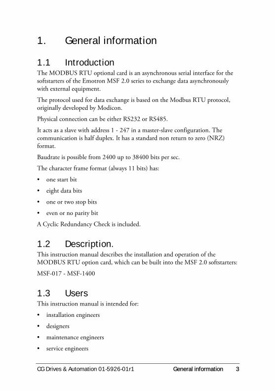
1.1 IntroductionThe MODBUS RTU optional card is an asynchronous serial interface for the softstarters of the Emotron MSF 2.0 series to exchange data asynchronously with external equipment.
The protocol used for data exchange is based on the Modbus RTU protocol, originally developed by Modicon.
Physical connection can be either RS232 or RS485.
It acts as a slave with address 1 - 247 in a master-slave configuration. The communication is half duplex. It has a standard non return to zero (NRZ) format.
Baudrate is possible from 2400 up to 38400 bits per sec.
The character frame format (always 11 bits) has:
• one start bit
• eight data bits
• one or two stop bits
• even or no parity bit
A Cyclic Redundancy Check is included.
1.2 Description.This instruction manual describes the installation and operation of the MODBUS RTU option card, which can be built into the MSF 2.0 softstarters:
MSF-017 - MSF-1400
1.3 UsersThis instruction manual is intended for:
• installation engineers
• designers
• maintenance engineers
• service engineers

4 General information CG Drives & Automation 01-5926-01r1
1.4 SafetyBecause this option is a supplementary part of the sofstarter, the user must be familiar with the original instruction manual of the MSF 2.0 sofstarter. All safety instructions, warnings etc. as mentioned in these instruction manuals are to be known to the user.
The following indications can appear in this manual. Always read these first and be aware of their content before continuing.
1.5 Delivery and unpacking.Check for any visible signs of damage. Inform your supplier immediately of any damage found. Do not install the option card if damage is found.
If the option card is moved from a cold storage room to the room where it is to be installed, condensation can form on it. Allow the option card to become fully acclimatised and wait until any visible condensation has evaporated before installing it in the softstarter.
NOTE: Additional information as an aid to avoiding problems.
CAUTION!Failure to follow these instructions can result in malfunction or damage to the softstarter.
WARNING!Failure to follow these instructions can result in serious injury to the user in addition to serious damage to the softstarter.
!
CG Drives & Automation 01-5926-01r1 Modbus RTU 5
2. Modbus RTU
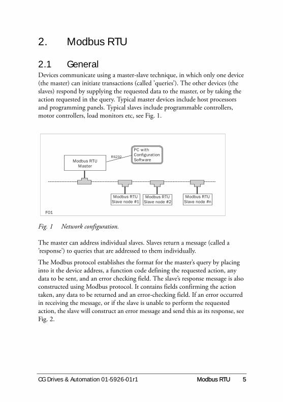
2.1 GeneralDevices communicate using a master-slave technique, in which only one device (the master) can initiate transactions (called ’queries’). The other devices (the slaves) respond by supplying the requested data to the master, or by taking the action requested in the query. Typical master devices include host processors and programming panels. Typical slaves include programmable controllers, motor controllers, load monitors etc, see Fig. 1.
Fig. 1 Network configuration.
The master can address individual slaves. Slaves return a message (called a ’response’) to queries that are addressed to them individually.
The Modbus protocol establishes the format for the master’s query by placing into it the device address, a function code defining the requested action, any data to be sent, and an error checking field. The slave’s response message is also constructed using Modbus protocol. It contains fields confirming the action taken, any data to be returned and an error-checking field. If an error occurred in receiving the message, or if the slave is unable to perform the requested action, the slave will construct an error message and send this as its response, see Fig. 2.
Modbus RTU
Master
Modbus RTU
Slave node #1
Modbus RTU
Slave node #2
Modbus RTU
Slave node #n
PC with
Configuration
SoftwareRS232
F01

6 Modbus RTU CG Drives & Automation 01-5926-01r1
Fig. 2 Shows the MODBUS RTU data exchange.
Modbus RTU uses a binary transmission protocol.
If even parity is used, each character (8 bit data) is sent as:
If no parity is used each character (8 bit data) is sent as:
Table 1
1 Start bit.
8 Data bits, hexadecimal 0-9,A-F, least significant bit sent first.
1 Even parity bit.
1 Stop bit.
Table 2
1 Start bit.
8 Data bits, hexadecimal 0-9,A-F, least significant bit sent first.
2 Stop bit.
Modbus
RTU
Master
Query Frame
Trailer Output Data Header
Response Frame
Header Input Data Trailer
Modbus
RTU Slave
Immediate
response
F02

CG Drives & Automation 01-5926-01r1 Modbus RTU 7
Fig. 3 Timing diagram for a transaction (query and response messages) (bottom in figure), a message frame (middle in figure) and a character frame (top in figure).
time
Stop bitStop/Parity bit
Data bit 7Data bit 6
Data bit 5Data bit 4
Data bit 3Data bit 2
Data bit 1Data bit 0
Start bit
time
CRC HighCRC Low
Data character nData character 2
Data character 1Function code
Time between characters must not exceed 3.5 character times.Slave adress
timeThe master recognises end of message.
At least 3.5 character silence time.Slave has finished transmission of response.
Transmission time.Slave start sending the response message.
Response delay time. Slave processes the query and prepare a response.The addressed slave recognise end of message.
At least 3.5 character silence time.Master has finished transmission of query.
Transmission time.Master start sending a query message.
At least 3.5 character silence time.
0 0/1 0/10/1 0/1 0/1 0/1 0/1 10/1 0/1
C
H
A
R
A
C
T
E
R
F
R
A
M
E
M
E
S
S
A
G
E
F
R
A
M
E
T
R
A
N
S
A
C
T
I
O
N
F03
8 Modbus RTU CG Drives & Automation 01-5926-01r1
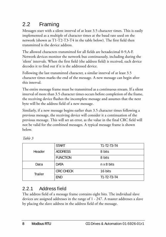
2.2 FramingMessages start with a silent interval of at least 3.5 character times. This is easily implemented as a multiple of character times at the baud rate used on the network (shown as T1-T2-T3-T4 in the table below). The first field then transmitted is the device address.
The allowed characters transmitted for all fields are hexadecimal 0-9,A-F. Network devices monitor the network bus continuously, including during the ’silent’ intervals. When the first field (the address field) is received, each device decodes it to find out if it is the addressed device.
Following the last transmitted character, a similar interval of at least 3.5 character times marks the end of the message. A new message can begin after this interval.
The entire message frame must be transmitted as a continuous stream. If a silent interval of more than 3.5 character times occurs before completion of the frame, the receiving device flushes the incomplete message and assumes that the next byte will be the address field of a new message.
Similarly, if a new message begins earlier than 3.5 character times following a previous message, the receiving device will consider it a continuation of the previous message. This will set an error, as the value in the final CRC field will not be valid for the combined messages. A typical message frame is shown below.
2.2.1 Address fieldThe address field of a message frame contains eight bits. The individual slave devices are assigned addresses in the range of 1 - 247. A master addresses a slave by placing the slave address in the address field of the message.
Table 3
Header
START T1-T2-T3-T4
ADDRESS 8 bits
FUNCTION 8 bits
Data DATA n x 8 bits
TrailerCRC CHECK 16 bits
END T1-T2-T3-T4

CG Drives & Automation 01-5926-01r1 Modbus RTU 9
When the slave sends its response, it places its own address in this address field of the response to let the master know which slave is responding.
2.2.2 Function fieldThe function code field of a message frame contains eight bits. Valid codes are in the range of 1 - 6, 15, 16 and 23. See section 2.2, page 8.
When a message is sent from a master to a slave device, the function code field tells the slave what kind of action to perform.
Examples are:
• to read the ON/OFF states of a group of inputs;
• to read the data contents of a group of parameters;
• to read the diagnostic status of the slave;
• to write to designated coils or registers within the slave.
When the slave responds to the master, it uses the function code field to indicate either a normal (error-free) response or that some kind of error occurred (called an exception response). For a normal response, the slave simply echoes the original function code. For an exception response, the slave returns a code that is equivalent to the original function code with its most significant bit set to a logic 1.
In addition to its modification of the function code for an exception response, the slave places an unique code into the data field of the response message. This tells the master what kind of error occurred, or the reason for the exception, see section 2.4.2, page 22.
The master device’s application program has the responsibility of handling exception responses. Typical processes are to post subsequent retries of the message, to try diagnostic messages to the slave and to notify operators.
Additional information about function codes and exceptions comes later in this chapter.
10 Modbus RTU CG Drives & Automation 01-5926-01r1
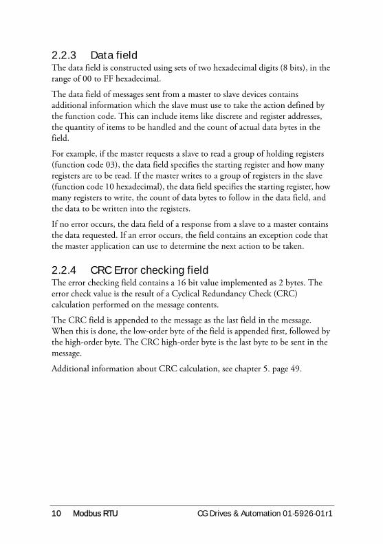
2.2.3 Data fieldThe data field is constructed using sets of two hexadecimal digits (8 bits), in the range of 00 to FF hexadecimal.
The data field of messages sent from a master to slave devices contains additional information which the slave must use to take the action defined by the function code. This can include items like discrete and register addresses, the quantity of items to be handled and the count of actual data bytes in the field.
For example, if the master requests a slave to read a group of holding registers (function code 03), the data field specifies the starting register and how many registers are to be read. If the master writes to a group of registers in the slave (function code 10 hexadecimal), the data field specifies the starting register, how many registers to write, the count of data bytes to follow in the data field, and the data to be written into the registers.
If no error occurs, the data field of a response from a slave to a master contains the data requested. If an error occurs, the field contains an exception code that the master application can use to determine the next action to be taken.
2.2.4 CRC Error checking fieldThe error checking field contains a 16 bit value implemented as 2 bytes. The error check value is the result of a Cyclical Redundancy Check (CRC) calculation performed on the message contents.
The CRC field is appended to the message as the last field in the message. When this is done, the low-order byte of the field is appended first, followed by the high-order byte. The CRC high-order byte is the last byte to be sent in the message.
Additional information about CRC calculation, see chapter 5. page 49.

CG Drives & Automation 01-5926-01r1 Modbus RTU 11
2.3 FunctionsEmotron supports the following MODBUS function codes.
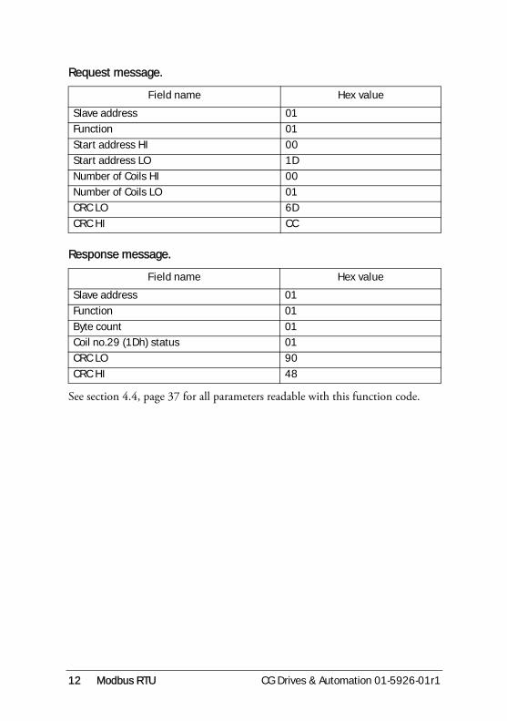
2.3.1 Read Coil StatusRead the status of digital changeable parameters.
ExampleRequesting the motor PTC input ON/OFF-state. It is ON.
PTC input: Modbus no = 29 (1Dh)
On: Yes = 1 coil = 0001
1 byte of data: Byte count=01
Function name Function code
Read Coil Status 1 (01h)
Read Input Status 2 (02h)
Read Holding Registers 3 (03h)
Read Input Registers 4 (04h)
Force Single Coil 5 (05h)
Force Single Register 6 (06h)
Force Multiple Coils 15 (0Fh)
Force Multiple Registers 16 (10h)
Force/Read Multiple Holding Registers
23 (17h)
12 Modbus RTU CG Drives & Automation 01-5926-01r1
Request message.
Response message.
See section 4.4, page 37 for all parameters readable with this function code.
Field name Hex value
Slave address 01
Function 01
Start address HI 00
Start address LO 1D
Number of Coils HI 00
Number of Coils LO 01
CRC LO 6D
CRC HI CC
Field name Hex value
Slave address 01
Function 01
Byte count 01
Coil no.29 (1Dh) status 01
CRC LO 90
CRC HI 48
CG Drives & Automation 01-5926-01r1 Modbus RTU 13
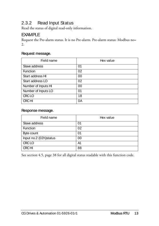
2.3.2 Read Input StatusRead the status of digital read-only information.
EXAMPLE Request the Pre-alarm status. It is no Pre-alarm. Pre-alarm status: Modbus no= 2.
Request message.
Response message.
See section 4.5, page 38 for all digital status readable with this function code.
Field name Hex value
Slave address 01
Function 02
Start address HI 00
Start address LO 02
Number of Inputs HI 00
Number of Inputs LO 01
CRC LO 18
CRC HI 0A
Field name Hex value
Slave address 01
Function 02
Byte count 01
Input no.2 (02h)status 00
CRC LO A1
CRC HI 88

14 Modbus RTU CG Drives & Automation 01-5926-01r1
2.3.3 Read Holding RegistersRead the value of analogue changeable information.
Example, requesting the Nominal Motor Voltage, Nominal Motor Frequency and the Nominal Motor Current. Their values are 400.0 V, 60 Hz and 15.5 A.
400.0V, unit 0.1V - 4000 (0FA0h)
60Hz unit 1Hz - 60 (003Ch)
15.5A, unit 0.1A - 155 (009Bh)
Request message.
Response message.
See section 4.7, page 42 for all analogue changeable parameters readable with this function code.
Field name Hex value
Slave address 01
Function 03
Start address HI 00
Start address LO 00
Number of Registers HI 00
Number of Registers LO 03
CRC LO 05CRC HI CB
Field name Hex value
Slave address 01
Function 03
Byte count 06
Reg no. 0, (0h) data HI 0F
Reg no. 0, (0h) data LO A0
Reg no. 1, (1h) data HI 00
Reg no. 1, (1h) data LO 3C
Reg no. 2, (2h) data HI 00
Reg no. 2, (2h) data LO 9B
CRC LO 20
CRC HI 34

CG Drives & Automation 01-5926-01r1 Modbus RTU 15
2.3.4 Read Input RegistersRead the contents of analogue read-only information.
EXAMPLE Request the Shaft Torque. It is 452.0 Nm. It has a long representation, 2 registers are used.
452.0 Nm, unit 0.1 Nm - 4520 (000011A8h).
Request message.
Response message.
See section 4.6, page 38 and section 4.9, page 47 for all analogue read-only information readable with this function code.
Field name Hex value
Slave address 01
Function 04
Start address HI 00
Start address LO 0A
Number of Registers HI 00
Number of Registers LO 02
CRC LO 51
CRC HI C9
Field name Hex value
Slave address 01
Function 04
Byte count 04
Reg no. 10 (0Ah) data HI 00
Reg no. 10 (0Ah) data LO 00
Reg no. 11 (0Bh) data HI 11
Reg no. 11 (0Bh) data LO A8
CRC LO F6
CRC HI 6A

16 Modbus RTU CG Drives & Automation 01-5926-01r1
2.3.5 Force Single CoilSet the status of one changeable digital parameter.
EXAMPLE Set the Start Command to ON. This will cause the motor to start.
Modbus no = 1 - address LO 1 (01h)
Run = 1 - 0 Data HI 255 (0FFh), Data LO 00 (00h)
Request message.
Response message.
See section 4.4, page 37 for all parameters changeable with this function code.
Field name Hex value
Slave address 01
Function 05
Start address HI 00
Start address LO 01
Data HI FF
Data LO 00
CRC LO DD
CRC HI FA
Field name Hex value
Slave address 01
Function 05
Start address HI 00
Start address LO 01
Data HI FF
Data LO 00
CRC LO DD
CRC HI FA
CG Drives & Automation 01-5926-01r1 Modbus RTU 17
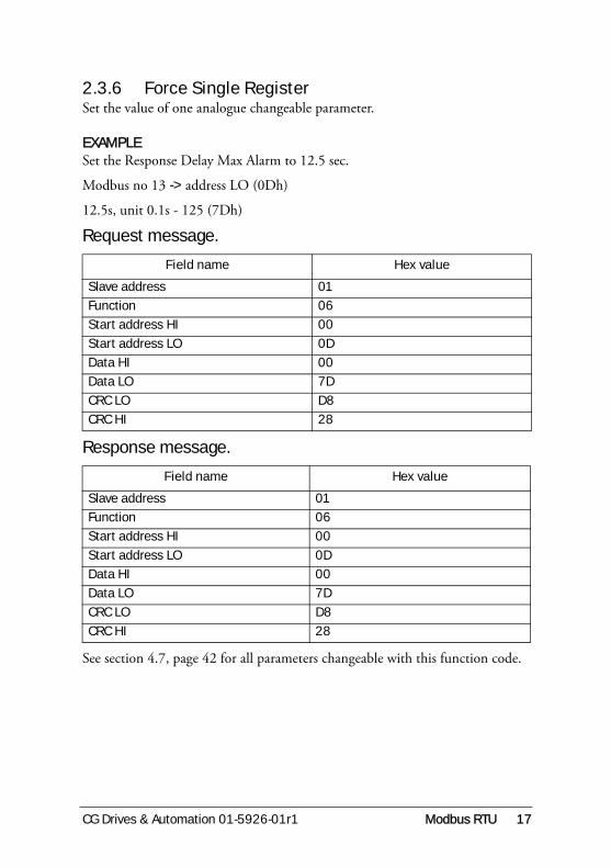
2.3.6 Force Single RegisterSet the value of one analogue changeable parameter.
EXAMPLE Set the Response Delay Max Alarm to 12.5 sec.
Modbus no 13 -> address LO (0Dh)
12.5s, unit 0.1s - 125 (7Dh)
Request message.
Response message.
See section 4.7, page 42 for all parameters changeable with this function code.
Field name Hex value
Slave address 01
Function 06
Start address HI 00
Start address LO 0D
Data HI 00
Data LO 7D
CRC LO D8
CRC HI 28
Field name Hex value
Slave address 01
Function 06
Start address HI 00
Start address LO 0D
Data HI 00
Data LO 7D
CRC LO D8
CRC HI 28
18 Modbus RTU CG Drives & Automation 01-5926-01r1
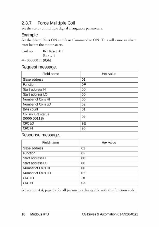
2.3.7 Force Multiple CoilSet the status of multiple digital changeable parameters.
Example Set the Alarm Reset ON and Start Command to ON. This will cause an alarm reset before the motor starts.
Coil no. = 0-1 Reset -> 1Run = 1
->- 00000011 (03h)
Request message.
Response message.
See section 4.4, page 37 for all parameters changeable with this function code.
Field name Hex value
Slave address 01
Function 0F
Start address HI 00
Start address LO 00
Number of Coils HI 00
Number of Coils LO 02
Byte count 01
Coil no. 0-1 status (0000 0011B)
03
CRC LO 9E
CRC HI 96
Field name Hex value
Slave address 01
Function 0F
Start address HI 00
Start address LO 00
Number of Coils HI 00
Number of Coils LO 02
CRC LO D4
CRC HI 0A

CG Drives & Automation 01-5926-01r1 Modbus RTU 19
2.3.8 Force Multiple RegisterSet the contents of multiple changeable analogue parameters.
Example Set the min power alarm response delay to 25.0 sec and the min alarm margin to 55%.
25.0 sec, unit 0.1 sec -> - 250 (00FAh)
55%, unit 1% -> 55 (0037h)
Request message.
Response message.
See section 4.7, page 42 for all parameters changeable with this function code.
Field name Hex value
Slave address 01
Function 10
Start address HI 00
Start address LO 11
Number of Registers HI 00
Number of Registers LO 02
Byte count 04
Data HI reg 17 (11h) 00
Data LO reg 17 (11h) FA
Data HI reg 18 (12h) 00
Data LO reg 18 (12h) 37
CRC LO 52
CRC HI 88
Field name Hex value
Slave address 01
Function 10
Start address HI 00
Start address LO 11
Number of Registers HI 00
Number of Registers LO 02
CRC LO 11
CRC HI CD

20 Modbus RTU CG Drives & Automation 01-5926-01r1
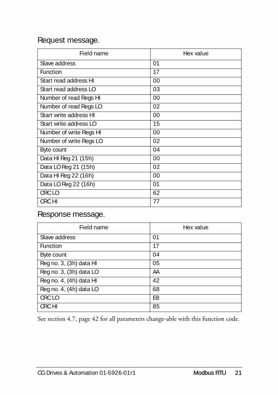
2.3.9 Force/Read Multiple RegisterSet and read the contents of multiple analogue changeable parameters in the same message.
Example Set the Parameter Set parameter to 2 and Relay 1 function to 1 and read the Nominal Motor Speed and the Nominal Motor Power. They are 1450 rpm and 17000 W.
1450 rpm, unit 1 rpm → 1450 (05AAh)
17000 W, unit 1 W → 17000 (4268h)
CG Drives & Automation 01-5926-01r1 Modbus RTU 21
Request message.
Response message.
See section 4.7, page 42 for all parameters change-able with this function code.
Field name Hex value
Slave address 01
Function 17
Start read address HI 00
Start read address LO 03
Number of read Regs HI 00
Number of read Regs LO 02
Start write address HI 00
Start write address LO 15
Number of write Regs HI 00
Number of write Regs LO 02
Byte count 04
Data HI Reg 21 (15h) 00
Data LO Reg 21 (15h) 02
Data HI Reg 22 (16h) 00
Data LO Reg 22 (16h) 01
CRC LO 62
CRC HI 77
Field name Hex value
Slave address 01
Function 17
Byte count 04
Reg no. 3, (3h) data HI 05
Reg no. 3, (3h) data LO AA
Reg no. 4, (4h) data HI 42
Reg no. 4, (4h) data LO 68
CRC LO E8
CRC HI 85
22 Modbus RTU CG Drives & Automation 01-5926-01r1
2.4 Errors, exception codesTwo kinds of errors are possible:
• Transmission errors.
• Operation errors.
2.4.1 Transmission errorsTransmission errors are:
• Frame error (stop bit error).
• Parity error (if parity is used).
• CRC error.
• No message at all.
These errors are caused by i.e. electrical interference from machinery or damage to the communication channel (cables, contact, I/O ports etc.). This unit will not act on or answer the master when a transmission error occurs. (Same result as if a non-existing slave is addressed). The master will eventually cause a time-out condition.
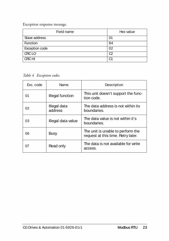
2.4.2 Operation errorsIf no transmission error is detected in the master query, the message is examined. If an illegal function code, data address or data value is detected, the message is not acted upon but an answer with an exception code is sent back to the master. This unit can also send back an exception code when a set (force) function message is received during some busy operation states.
Bit 8 (most significant bit) in the function code byte is set to a ’1’ in the exception response message. Example with an illegal data address when reading an input register.
CG Drives & Automation 01-5926-01r1 Modbus RTU 23
Exception response message.
Field name Hex value
Slave address 01
Function 84
Exception code 02
CRC LO C2
CRC HI C1
Table 4 Exception codes.
Exc. code Name Description
01 Illegal function This unit doesn’t support the func-tion code.
02Illegal data address
The data address is not within its boundaries.
03 Illegal data value The data value is not within it’s boundaries.
06 Busy The unit is unable to perform the request at this time. Retry later.
07 Read only The data is not available for write access.

24 Modbus RTU CG Drives & Automation 01-5926-01r1
CG Drives & Automation 01-5926-01r1 Installation 25
3. Installation
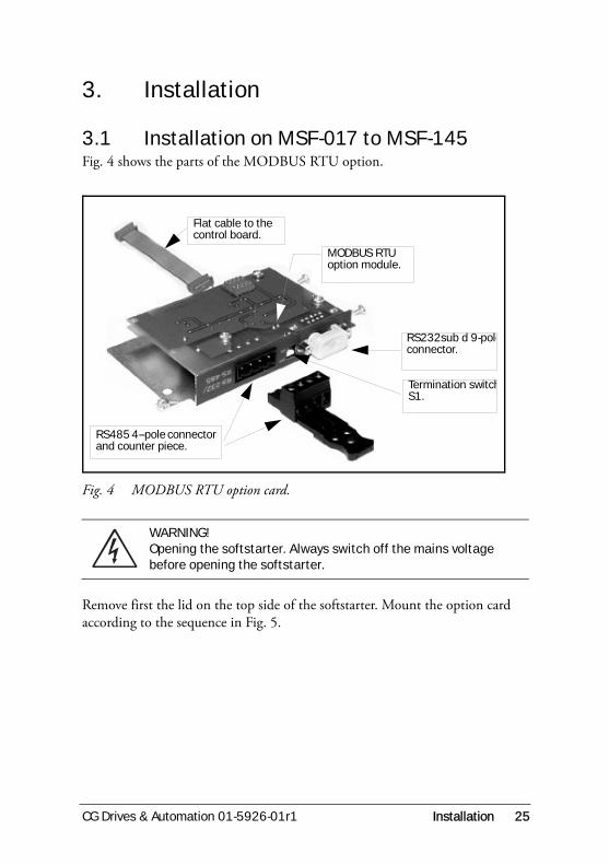
3.1 Installation on MSF-017 to MSF-145Fig. 4 shows the parts of the MODBUS RTU option.
Fig. 4 MODBUS RTU option card.
Remove first the lid on the top side of the softstarter. Mount the option card according to the sequence in Fig. 5.
WARNING!Opening the softstarter. Always switch off the mains voltage before opening the softstarter.
Flat cable to the control board.
MODBUS RTU option module.
RS232sub d 9-poleconnector.
Termination switchS1.
RS485 4--pole connector and counter piece.

26 Installation CG Drives & Automation 01-5926-01r1
Fig. 5 Installation of the option board.
Fig. 6 Mounting of the option card seen from the top.
1) Remove the origi-nal lid before installing the option card.
4) Use tiewrap for strain relief.
2)Mount the 3 screws in their position.3)
Mount the flat cable between the option card and the control board. Either of the two connectors on the option card can be used

CG Drives & Automation 01-5926-01r1 Installation 27
3.2 Installation of MSF-170 to MSF-1400
Fig. 7
Fig. 8
28 Installation CG Drives & Automation 01-5926-01r1
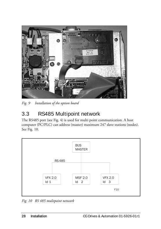
Fig. 9 Installation of the option board
3.3 RS485 Multipoint networkThe RS485 port (see Fig. 4) is used for multi point communication. A host computer (PC/PLC) can address (master) maximum 247 slave stations (nodes). See Fig. 10.
Fig. 10 RS 485 mulitpoint network
BUSMASTER
VFX 2.0Id 1
MSF 2.0Id 2
VFX 2.0Id 3
R 485S
F10

CG Drives & Automation 01-5926-01r1 Installation 29
3.3.1 RS485 connection
The connector is a 4-pole male connector. The wiring should be done according to Fig. 11.
Fig. 11 RS485 wiring
3.3.2 RS485 terminationThe RS485 network must always be terminated, to avoid transmission problem. The termination must take place at the end of the network. In Fig. 11 this means that the termination must take place at the slave 2 unit.
Switch S1 (see Fig. 4) sets the termination ON or OFF as indicated in the Fig. 12 and Fig. 13.
Table 5
RS485 pin Function
1 Ground
2 A-line
3 B-line
4 PE
Connection to Modbus
RTU Host PC/PLC
Male connectors on
Modbus RTU option cards
GND
RS485-A
Shield
PE
RS485-B
4
3
2
1
4
3
2
1
4
3
2
1GND
RS485-A
Shield
RS485-B
Master Slave 1 Slave 2
30 Installation CG Drives & Automation 01-5926-01r1
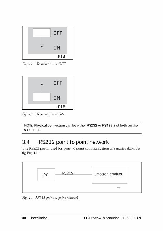
Fig. 12 Termination is OFF.
Fig. 13 Termination is ON.
3.4 RS232 point to point networkThe RS232 port is used for point to point communication as a master slave. See fig Fig. 14.
Fig. 14 RS232 point to point network
NOTE: Physical connection can be either RS232 or RS485, not both on the same time.
OFF
ON
F14
OFF
ON
F15
R 232SPC Emotron product
F13
CG Drives & Automation 01-5926-01r1 Installation 31
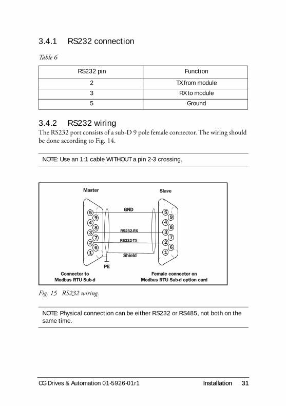
3.4.1 RS232 connection
3.4.2 RS232 wiringThe RS232 port consists of a sub-D 9 pole female connector. The wiring should be done according to Fig. 14.
Fig. 15 RS232 wiring.
Table 6
RS232 pin Function
2 TX from module
3 RX to module
5 Ground
NOTE: Use an 1:1 cable WITHOUT a pin 2-3 crossing.
NOTE: Physical connection can be either RS232 or RS485, not both on the same time.
1
2
3
4
5
6
7
8
9
GND
Connector to
Modbus RTU Sub-d
1
2
3
4
5
6
7
8
9
Female connector on
Modbus RTU Sub-d option card
RS232-TX
Shield
PE
RS232-RX
Master Slave

32 Installation CG Drives & Automation 01-5926-01r1

CG Drives & Automation 01-5926-01r1 Communication parameters 33
4. Communication parameters
4.1 Set-up Communication ParametersThe following parameters have to be set-up:
• Unit address.
• Baud rate.
• Parity
• Behaviour when contact broken.
Setting up the communication parameter must be made in local ’Control panel’ mode. See section 4.2.1, page 36.
Serial comm. unit address [270].
Serial comm. baudrate [271]
Serial comm. unit address
Default: 1
Range: 1-247
1-247 Unit address.
Serial comm. baudrate
Default: 9.6 kBaud
Range: 2.4 - 38.4 kBaud
2.4-38.4 Baudrate.
1
2 7 0 Setting
9. 6
2 7 1 Setting

34 Communication parameters CG Drives & Automation 01-5926-01r1
Serial comm. parity [272]
Serial comm. broken alarm [273]If the softstarter is configured for control via serial communications (menu [200] = 3) and the serial communication contact is broken during operation, an F15 alarm can be configured to occur. In this menu the alarm can be enabled and an action to be performed can be chosen. The following options are availa-ble:
OFFSerial communication contact broken alarm is disabled.
WARNINGAlarm message F15 is shown in the display and relay K3 is activated (for default configuration of the relays). However, the motor is not stopped and operation continues. The alarm message will disappear and the relay will be reset when the fault disappears. The alarm may also be reset manually from the control panel.
COASTAlarm message F15 is shown in the display and relay K3 is activated (for default configuration of the relays). The motor voltage is automatically switched off. The motor freewheels until it stops.
Serial comm. parity
Default: 0
Range: 0, 1
0 No parity
1 Even parity.
0
2 7 2 Setting
CG Drives & Automation 01-5926-01r1 Communication parameters 35
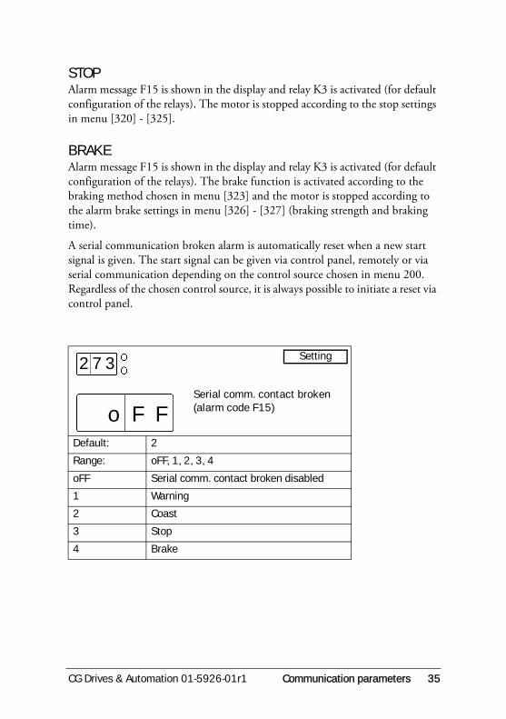
STOPAlarm message F15 is shown in the display and relay K3 is activated (for default configuration of the relays). The motor is stopped according to the stop settings in menu [320] - [325].
BRAKEAlarm message F15 is shown in the display and relay K3 is activated (for default configuration of the relays). The brake function is activated according to the braking method chosen in menu [323] and the motor is stopped according to the alarm brake settings in menu [326] - [327] (braking strength and braking time).
A serial communication broken alarm is automatically reset when a new start signal is given. The start signal can be given via control panel, remotely or via serial communication depending on the control source chosen in menu 200. Regardless of the chosen control source, it is always possible to initiate a reset via control panel.
Serial comm. contact broken (alarm code F15)
Default: 2
Range: oFF, 1, 2, 3, 4
oFF Serial comm. contact broken disabled
1 Warning
2 Coast
3 Stop
4 Brake
Fo
2 7 3
F
Setting

36 Communication parameters CG Drives & Automation 01-5926-01r1
4.2 Serial communication as control sourceThe source from where operation and parameter settings are made is selected in the Control Source parameter menu 200.
When serial communication control source (3) is selected, it is possible to:
• Operate the soft starter only via serial comm.
• Set up parameters only via serial comm. Exceptions for the serial comm.parameters described above.
• Readout all view information and all parameters.
• Set up the control source parameter from local MSF control panel.
• Inspect all parameters from local MSF control panel.
4.2.1 Selection of control sourcesSetting up the control source has to be done from the local MSF 2.0 control panel.
Independent of the chosen control source it is always possible to read out all the information in the softstarter via serial communication, both parameters and view information.
Control source
Default: 2 (remote control)
Range: 1, 2, 3
1 Control panel.
2 Remote control.
3 Serial communication control.
NOTE: When Reset to factory settings is made via serial comm., the control source will remain in serial comm. control.
2
2 0 0
Setting

CG Drives & Automation 01-5926-01r1 Communication parameters 37
4.3 Parameter ListThe product MSF menu column show the menu number on the control panel for the parameter.
For more information on any parameter/function, see Instruction Manual MSF 2.0 Softstarter.
4.4 Coil status listTable 7
Modbus no Function/Name Range Comment Menu
no.
0 Reset alarm 0, 1 0->1=Reset
1 Start/Stop 0, 1 Stop=0, Run=1
2 Jog forward 0, 1 0=No Jog, 1=Jog
3 Jog reverse 0, 1 0=No Jog, 1=Jog
4 Autoset 0, 1 0->1=Auto-set 411
5 Reset power consumption 0, 1 0->1=Reset 732
20 Control panel locked for settings 0, 1 0=Unlocked. 1=Locked 201
24 Enable US-units 0, 1 0=Off, 1=On 202
25 Preset pump control parameters 0, 1 0=No, 1=Yes 300
27 Bypass 0, 1 Off, on; off=0, on=1 340
28 Power Factor Control PFC 0, 1 Off, on; off=0, on=1 341
29 PTC input 0, 1 No, yes; no=0, yes=1 221
32 Jog forward enable 0, 1 No, yes; no=0, yes=1 334
33 Jog reverse enable 0, 1 No, yes; no=0, yes=1 335
36 Fan continuously on 0, 1 Off, on; off=0, on=1 342
38 Communication parameters CG Drives & Automation 01-5926-01r1
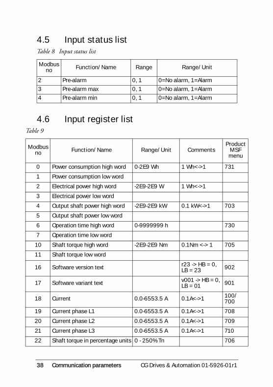
4.5 Input status list
4.6 Input register list
Table 8 Input status list
Modbus no Function/Name Range Range/Unit
2 Pre-alarm 0, 1 0=No alarm, 1=Alarm
3 Pre-alarm max 0, 1 0=No alarm, 1=Alarm
4 Pre-alarm min 0, 1 0=No alarm, 1=Alarm
Table 9
Modbus no Function/Name Range/Unit Comments
Product MSF menu
0 Power consumption high word 0-2E9 Wh 1 Wh<->1 731
1 Power consumption low word
2 Electrical power high word -2E9-2E9 W 1 Wh<->1
3 Electrical power low word
4 Output shaft power high word -2E9-2E9 kW 0.1 kW<->1 703
5 Output shaft power low word
6 Operation time high word 0-9999999 h 730
7 Operation time low word
10 Shaft torque high word -2E9-2E9 Nm 0.1Nm <-> 1 705
11 Shaft torque low word
16 Software version text r23 -> HB = 0, LB = 23 902
17 Software variant text v001 -> HB = 0, LB = 01 901
18 Current 0.0-6553.5 A 0.1A<->1 100/700
19 Current phase L1 0.0-6553.5 A 0.1A<->1 708
20 Current phase L2 0.0-6553.5 A 0.1A<->1 709
21 Current phase L3 0.0-6553.5 A 0.1A<->1 710
22 Shaft torque in percentage units 0 - 250% Tn 706

CG Drives & Automation 01-5926-01r1 Communication parameters 39
23 Line main voltage 0.0-720.0 V 0.1V<->1 701
24 Line main voltage L1-L2 0.0-720.0 V 0.1V<->1 711
25 Line main voltage L1-L3 0.0-720.0 V 0.1V<->1 712
26 Line main voltage L2-L3 0.0-720.0 V 0.1V<->1 713
27 Softstarter type 1-19 See description in 4.8.1. 900
29 Analogue output value 0-100% 725
30 Serial comm. unit address 1-247 270
31 Serial comm. baudrate 2.4--38.4 kBaud 0.1 kBaud <-> 1 271
32 Serial comm. parity 0=No parity 1=Even parity 272
34 Actual parameter set 1, 2, 3, 4 241
35 Output Shaft power % 0% -200% Pn413/704
36 Softstarter temperature 29.0-96.0 °C84.0-204.0 °F 0.1 deg <-> 1 707
37 Time to next allowed start 0-60 min 227
40 Mode 1-8 See description in § 4.8.3.
41 Softstarter status 1-12 720
42 Digital input status 0000-1111 L<->0, H<->1 721
43 Analogue/digital input value 0-100% 723
44 Analogue/digital input status 0,1 L<->0, H<->1 722
45 Relay status 000-111 L<->0, H<->1 724
46 Used thermal capacity 0-150% 223/715
47 Power factor 0.00-1.00 1.00 <-> 100 702
50 Phase sequence 0, 1, 20 = None, 1 = RTS, 2 = RST
439/714
51 Emotron product 2 2=MSF
Table 9
Modbus no Function/Name Range/Unit Comments
Product MSF menu

40 Communication parameters CG Drives & Automation 01-5926-01r1
100 Alarm list, latest error, time stamp high word 0-9999999 h 1 h<->1
101 Alarm list, latest error, time stamp low word
102 Alarm list, latest error 0- 17 800
103 Alarm list, error 14, time stamp high word 0-9999999 h 1 h<->1
104 Alarm list, error 14, time stamp low word
105 Alarm list, error 14 0- 17 801
106 Alarm list, error 13, time stamp high word 0-9999999 h 1 h<->1
107 Alarm list, error 13, time stamp low word
108 Alarm list, error 13 0- 17 802
109 Alarm list, error 12, time stamp high word 0-9999999 h 1 h<->1
110 Alarm list, error 12, time stamp low word
111 Alarm list, error 12 0- 17 803
112 Alarm list, error 11, time stamp high word 0-9999999 h 1 h<->1
113 Alarm list, error 11, time stamp low word
114 Alarm list, error 11 0- 17 804
115 Alarm list, error 10, time stamp high word 0-9999999 h 1 h<->1
116 Alarm list, error 10, time stamp low word
117 Alarm list, error 10 0- 17 805
118 Alarm list, error 9, time stamp high word 0-9999999 h 1 h<->1
119 Alarm list, error 9, time stamp low word
Table 9
Modbus no Function/Name Range/Unit Comments
Product MSF menu

CG Drives & Automation 01-5926-01r1 Communication parameters 41
120 Alarm list, error 9 0- 17 806
121 Alarm list, error 8, time stamp high word 0-9999999 h 1 h<->1
122 Alarm list, error 8, time stamp low word
123 Alarm list, error 8 0- 17 807
124 Alarm list, error 7, time stamp high word 0-9999999 h 1 h<->1
125 Alarm list, error 7, time stamp low word
126 Alarm list, error 7 0- 17 808
127 Alarm list, error 6, time stamp high word 0-9999999 h 1 h<->1
128 Alarm list, error 6, time stamp low word
129 Alarm list, error 6 0- 17 809
130 Alarm list, error 5, time stamp high word 0-9999999 h 1 h<->1
131 Alarm list, error 5, time stamp low word
132 Alarm list, error 5 0- 17 810
133 Alarm list, error 4, time stamp high word 0-9999999 h 1 h<->1
134 Alarm list, error 4, time stamp low word
135 Alarm list, error 4 0- 17 811
136 Alarm list, error 3, time stamp high word 0-9999999 h 1 h<->1
137 Alarm list, error 3, time stamp low word
138 Alarm list, error 3 0- 17 812
139 Alarm list, error 2, time stamp high word 0-9999999 h 1 h<->1
Table 9
Modbus no Function/Name Range/Unit Comments
Product MSF menu
42 Communication parameters CG Drives & Automation 01-5926-01r1
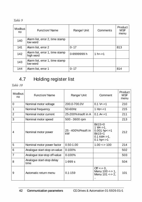
4.7 Holding register list
140 Alarm list, error 2, time stamp low word
141 Alarm list, error 2 0- 17 813
142 Alarm list, error 1, time stamp high word 0-9999999 h 1 h<->1
143 Alarm list, error 1, time stamp low word
144 Alarm list, error 1 0- 17 814
Table 10
Modbus no Function/Name Range/Unit Comment
Product MSF menu
0 Nominal motor voltage 200.0-700.0V 0.1 V<->1 210
1 Nominal frequency 50-60Hz 1 Hz<->1 215
2 Nominal motor current 25-200% Insoft in A 0.1 A<->1 211
3 Nominal motor speed 500 - 3600 rpm 213
4 Nominal motor power 25 - 400% Pnsoft in kW
Bit15=01 W<->1, 0.001 hp<->1Bit15=10.1 kW<->1,0.1 hp<->1
212
5 Nominal motor power factor 0.50-1.00 1.00 <-> 100 214
6 Analogue start-stop on-value 0-100% 502
7 Analogue star-stop off-value 0-100% 503
8 Analogue start-stop delay time 1-999 s 504
9 Automatic return menu 0.1-159
Off <-> 0, Menu 100 <-> 1, Menu 101 <-> 2, ..
101
Table 9
Modbus no Function/Name Range/Unit Comments
Product MSF menu
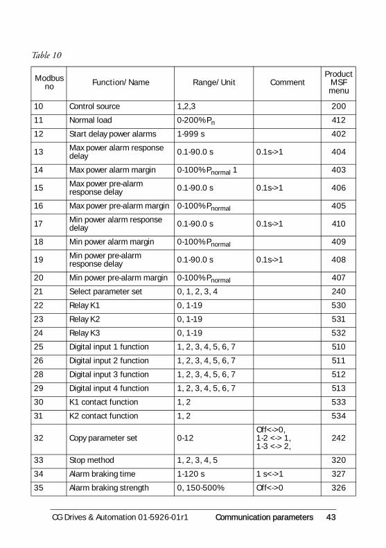
CG Drives & Automation 01-5926-01r1 Communication parameters 43
10 Control source 1,2,3 200
11 Normal load 0-200% Pn 412
12 Start delay power alarms 1-999 s 402
13 Max power alarm response delay 0.1-90.0 s 0.1s->1 404
14 Max power alarm margin 0-100% Pnormal 1 403
15 Max power pre-alarm response delay 0.1-90.0 s 0.1s->1 406
16 Max power pre-alarm margin 0-100% Pnormal 405
17 Min power alarm response delay 0.1-90.0 s 0.1s->1 410
18 Min power alarm margin 0-100% Pnormal 409
19 Min power pre-alarm response delay 0.1-90.0 s 0.1s->1 408
20 Min power pre-alarm margin 0-100% Pnormal 407
21 Select parameter set 0, 1, 2, 3, 4 240
22 Relay K1 0, 1-19 530
23 Relay K2 0, 1-19 531
24 Relay K3 0, 1-19 532
25 Digital input 1 function 1, 2, 3, 4, 5, 6, 7 510
26 Digital input 2 function 1, 2, 3, 4, 5, 6, 7 511
28 Digital input 3 function 1, 2, 3, 4, 5, 6, 7 512
29 Digital input 4 function 1, 2, 3, 4, 5, 6, 7 513
30 K1 contact function 1, 2 533
31 K2 contact function 1, 2 534
32 Copy parameter set 0-12Off<->0, 1-2 <-> 1, 1-3 <-> 2,
242
33 Stop method 1, 2, 3, 4, 5 320
34 Alarm braking time 1-120 s 1 s<->1 327
35 Alarm braking strength 0, 150-500% Off<->0 326
Table 10
Modbus no Function/Name Range/Unit Comment
Product MSF menu

44 Communication parameters CG Drives & Automation 01-5926-01r1
36 Analogue output value 1, 2, 3, 4 521
37 Analogue output 0, 1, 2, 3, 4 520
38 Scaling analogue output, min 0-500% 522
40 Scaling analogue output, max 0-500% 523
2000 Initial voltage at start 25-90% U 313
2001 Start time 1-60 s 1 s<->1 315
2002 Step down voltage at stop 100-40% U 322
2003 Stop time 1-120 s 1 s<->1 325
2008 Initial torque at start 0-250% Tn 311
2009 End torque at start 25-250% Tn, 312
2010 Start method 1, 2, 3, 4 310
2012 Current limit at start 0, 150-500% In Off <-> 0 314
2013 Braking strength 150-500% 324
2015 Torque boost current limit 0, 300-700% In Off <-> 0 316
2016 Torque boost active time 0.1-2.0 s 0.1 s<->1 317
2017 Digital input pulses 1-100 501
2018 Slow speed strength 10-100 330
2019 Slow speed time at start 0, 1-60 s Off <-> 0 331
2020 Slow speed time at stop 0, 1-60 s Off <-> 0 332
2021 DC-brake at slow speed 0, 1-60 s Off <-> 0 333
2022 Internal protection class 0, 2-40 s 1 s<->1 222
2023 Number of starts per hour 0, 1-99 225
2024 Locked rotor alarm 1.0-10.0 1.0 s<->10 229
2025 Unbalance voltage level 2-25% Un 431
2026 Response delay voltage unbalance alarm 1-90 s 1 s<->1 432
2027 Over voltage level 100-150% Un 434
2028 Response delay over voltage alarm 1-90 s 1 s<->1 435
Table 10
Modbus no Function/Name Range/Unit Comment
Product MSF menu
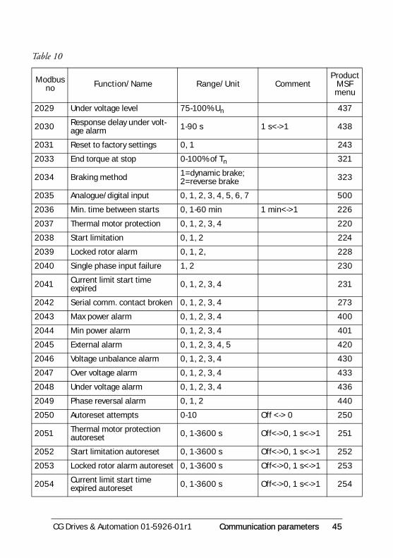
CG Drives & Automation 01-5926-01r1 Communication parameters 45
2029 Under voltage level 75-100% Un 437
2030 Response delay under volt-age alarm 1-90 s 1 s<->1 438
2031 Reset to factory settings 0, 1 243
2033 End torque at stop 0-100% of Tn 321
2034 Braking method 1=dynamic brake; 2=reverse brake 323
2035 Analogue/digital input 0, 1, 2, 3, 4, 5, 6, 7 500
2036 Min. time between starts 0, 1-60 min 1 min<->1 226
2037 Thermal motor protection 0, 1, 2, 3, 4 220
2038 Start limitation 0, 1, 2 224
2039 Locked rotor alarm 0, 1, 2, 228
2040 Single phase input failure 1, 2 230
2041 Current limit start time expired 0, 1, 2, 3, 4 231
2042 Serial comm. contact broken 0, 1, 2, 3, 4 273
2043 Max power alarm 0, 1, 2, 3, 4 400
2044 Min power alarm 0, 1, 2, 3, 4 401
2045 External alarm 0, 1, 2, 3, 4, 5 420
2046 Voltage unbalance alarm 0, 1, 2, 3, 4 430
2047 Over voltage alarm 0, 1, 2, 3, 4 433
2048 Under voltage alarm 0, 1, 2, 3, 4 436
2049 Phase reversal alarm 0, 1, 2 440
2050 Autoreset attempts 0-10 Off <-> 0 250
2051 Thermal motor protection autoreset 0, 1-3600 s Off<->0, 1 s<->1 251
2052 Start limitation autoreset 0, 1-3600 s Off<->0, 1 s<->1 252
2053 Locked rotor alarm autoreset 0, 1-3600 s Off<->0, 1 s<->1 253
2054 Current limit start time expired autoreset 0, 1-3600 s Off<->0, 1 s<->1 254
Table 10
Modbus no Function/Name Range/Unit Comment
Product MSF menu

46 Communication parameters CG Drives & Automation 01-5926-01r1
4.8 Parameter descriptionFor more information on any parameter/function, see MSF 2.0 Softstarter Instruction manual.
4.8.1 Softstarter type (Input register 27)
4.8.2 Serial comm. contact broken (Holding register 2042)
Communication is considered lost if no request is made to this unit within 15 sec. See section 4.1, page 33
2055 Max power alarm autoreset 0, 1-3600 s Off<->0, 1 s<->1 255
2056 Min power alarm autoreset 0, 1-3600 s Off<->0, 1 s<->1 256
2057 External alarm autoreset 0, 1-3600 s Off<->0, 1 s<->1 257
2058 Phase input failure autoreset 0, 1-3600 s Off<->0, 1 s<->1 258
2059 Voltage unbalance alarm autoreset 0, 1-3600 s Off<->0, 1 s<->1 259
2060 Over voltage alarm autoreset 0, 1-3600 s Off<->0, 1 s<->1 260
2061 Under voltage alarm autore-set 0, 1-3600 s Off<->0, 1 s<->1 261
2062 Serial communication autore-set 0, 1-3600 s Off<->0, 1 s<->1 262
2063 Softstarter overheated autoreset 0, 1-3600 s Off<->0, 1 s<->1 263
Table 11 Softstarter type
1 MSF-017 2 MSF-030 3 MSF-045 4 MSF-060 5 MSF-075 6 MSF-085
7 MSF-110 8 MSF-145 9 MSF-170 10 MSF-210 11 MSF-250 12 MSF-310
13 MSF-370 14 MSF-450 15 MSF-570 16 MSF-710 17 MSF-835 18 MSF-1000
19 MSF-1400
Table 10
Modbus no Function/Name Range/Unit Comment
Product MSF menu
CG Drives & Automation 01-5926-01r1 Communication parameters 47
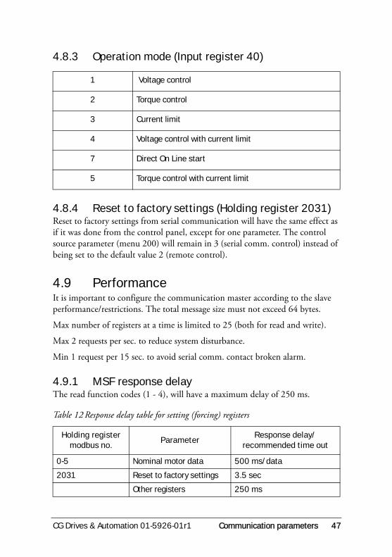
4.8.3 Operation mode (Input register 40)
4.8.4 Reset to factory settings (Holding register 2031)Reset to factory settings from serial communication will have the same effect as if it was done from the control panel, except for one parameter. The control source parameter (menu 200) will remain in 3 (serial comm. control) instead of being set to the default value 2 (remote control).
4.9 PerformanceIt is important to configure the communication master according to the slave performance/restrictions. The total message size must not exceed 64 bytes.
Max number of registers at a time is limited to 25 (both for read and write).
Max 2 requests per sec. to reduce system disturbance.
Min 1 request per 15 sec. to avoid serial comm. contact broken alarm.
4.9.1 MSF response delayThe read function codes (1 - 4), will have a maximum delay of 250 ms.
1 Voltage control
2 Torque control
3 Current limit
4 Voltage control with current limit
7 Direct On Line start
5 Torque control with current limit
Table 12 Response delay table for setting (forcing) registers
Holding register modbus no.
ParameterResponse delay/
recommended time out
0-5 Nominal motor data 500 ms/data
2031 Reset to factory settings 3.5 sec
Other registers 250 ms

48 Communication parameters CG Drives & Automation 01-5926-01r1
CG Drives & Automation 01-5926-01r1 CRC Generation 49
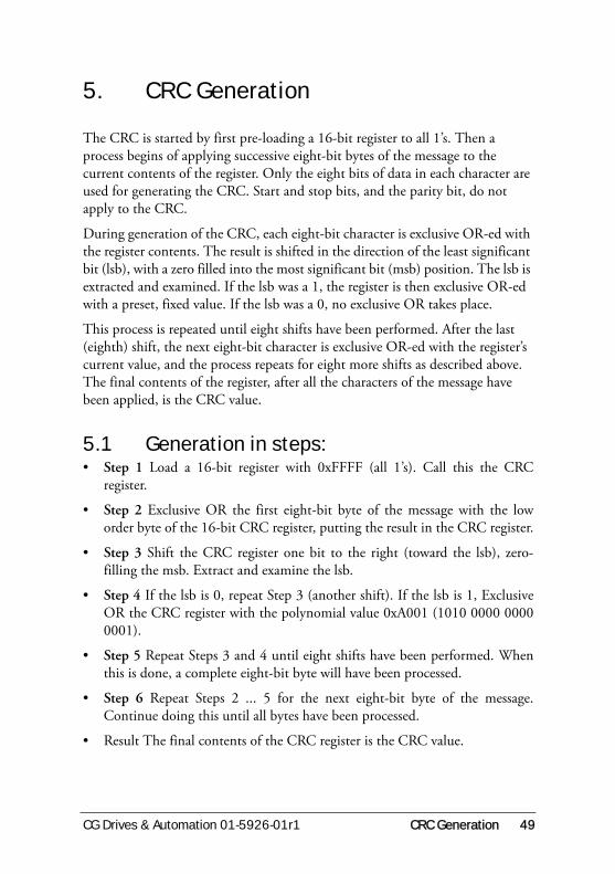
5. CRC Generation
The CRC is started by first pre-loading a 16-bit register to all 1’s. Then a process begins of applying successive eight-bit bytes of the message to the current contents of the register. Only the eight bits of data in each character are used for generating the CRC. Start and stop bits, and the parity bit, do not apply to the CRC.
During generation of the CRC, each eight-bit character is exclusive OR-ed with the register contents. The result is shifted in the direction of the least significant bit (lsb), with a zero filled into the most significant bit (msb) position. The lsb is extracted and examined. If the lsb was a 1, the register is then exclusive OR-ed with a preset, fixed value. If the lsb was a 0, no exclusive OR takes place.
This process is repeated until eight shifts have been performed. After the last (eighth) shift, the next eight-bit character is exclusive OR-ed with the register’s current value, and the process repeats for eight more shifts as described above. The final contents of the register, after all the characters of the message have been applied, is the CRC value.
5.1 Generation in steps:• Step 1 Load a 16-bit register with 0xFFFF (all 1’s). Call this the CRC
register.
• Step 2 Exclusive OR the first eight-bit byte of the message with the loworder byte of the 16-bit CRC register, putting the result in the CRC register.
• Step 3 Shift the CRC register one bit to the right (toward the lsb), zero-filling the msb. Extract and examine the lsb.
• Step 4 If the lsb is 0, repeat Step 3 (another shift). If the lsb is 1, ExclusiveOR the CRC register with the polynomial value 0xA001 (1010 0000 00000001).
• Step 5 Repeat Steps 3 and 4 until eight shifts have been performed. Whenthis is done, a complete eight-bit byte will have been processed.
• Step 6 Repeat Steps 2 ... 5 for the next eight-bit byte of the message.Continue doing this until all bytes have been processed.
• Result The final contents of the CRC register is the CRC value.

50 CRC Generation CG Drives & Automation 01-5926-01r1
• Step 7 When the CRC is placed into the message, its upper and lower bytesmust be swapped as described below.
• Placing the CRC into the Message
• When the 16-bit CRC (two eight-bit bytes) is transmitted in the message,the low order byte will be transmitted first, followed by the high order byte -e.g., if the CRC value is 0x1241.
Example of CRC Generation FunctionAn example of a C language function performing CRC generation is shown on this page.
The function takes two arguments:
• Unsigned char *puchMsg; A pointer to the message buffer containingbinary data to be used for generating the CRC.
• Unsigned int usDataLen; The quantity of bytes in the message buffer.
The function returns the CRC as a type unsigned int.
• Unsigned int CRC16 (unsigned int usDataLen, unsigned char *puchMsg)
Table 13
Message
CRC LO 41
CRC HI 12

CG Drives & Automation 01-5926-01r1 CRC Generation 51
Fig. 16 CRC example.
#define CRC_POLYNOMIAL 0xA001
unsigned int crc_reg;
unsigned char i,k;
crc_reg = 0xFFFF;
for (i=0 ; i<usDataLen ; i++)
{
crc_reg ^= *puchMsg++;
for (k=0 ; k<8 ; k++)
{
if (crc_reg & 0x0001)
{
crc_reg >>= 1;
crc_reg ^= CRC_POLYNOMIAL;
}

CG
Driv
es &
Aut
omat
ion,
01-
5926
-01r
1, 2
015-
04-2
0
CG Drives & Automation Sweden ABMörsaregatan 12Box 222 25SE-250 24 HelsingborgSwedenT +46 42 16 99 00 F +46 42 16 99 49www.cgglobal.com / www.emotron.com