elena llorens domenjó
TRANSCRIPT
Advanced Electrospun Scaffolds based onBiodegradable Polylactide and Poly(ButyleneSuccinate) for Controlled Drug Delivery and
Tissue Engineering
Adv
ance
d E
lect
rosp
un S
caff
olds
bas
ed o
n B
iode
grad
able
Pol
ylac
tide
and
Poly
(But
ylen
e Su
ccin
ate)
for
Con
trol
led
Dru
g D
eliv
ery
and
Tis
sue
Eng
inee
ring
Ele
na L
lore
ns D
omen
jó
Elena Llorens Domenjó
Elena Llorens, was born in Lleida in 1985, is passionate about reading, traveling and science. She graduated in Chemistry and Biochemistry in Universitat Rovira i Virgili. After the experience in different industries in material processing and chemical analysis, she decided to increase her knowl-edge in polymer science starting a Master in Polymers and Biopoly-mers, which gave her the chance to initiate a PhD program in Universi-tat Politècnica de Catalunya.But her ambition on how the indus-tries are managed, motivated her to do a Master in Business Academy and Master in Leadership and Management Skills.Given the opportunity to work in a chemical company, now is time to deepen her detailed knowledge in the polymer industry, after having gained an experience and solid research background in biomateri-als and polymers for more than four years.
UNIVERSITAT POLITÈCNICA DE CATALUNYABarcelona 2014
“Advanced Electrospun Scaffolds based on
Biodegradable Polylactide and Poly(Butylene
Succinate) for Controlled Drug Delivery and
Tissue Engineering”
Elena Llorens Domenjó
Advisors
Dr. Jordi Puiggalí Bellalta Dr. Luis J del Valle Mendoza
Universitat Politècnica de Catalunya
Departament d’Enginyeria Química
Escola Tècnica Superior d’Enginyeria Industrial de Barcelona
Barcelona 2014
Ph.D. Thesis submitted to obtain degree of Doctor in Polymers and
Biopolymers Program

2
“La lógica te llevará de la A a la B.
La imaginación te llevará a todas partes”
Albert Einstein

4
i
ABSTRACT
Abstract
As one of the most promising developments of micro/nanotechnology, electrospinning has
gathered a great deal of interest in the last decades. The electrospinning technique allows the
preparation of fiber matrices in controlled conditions, with diameters ranging from micron to
nanoscale. Basically, electrospinning can produce fibers through the action of an external
electric field that creates an electrically charged jet from a polymer solution drop and fibers after
the rapid evaporation of the solvent. This versatile technique has allowed processing a wide
variety of polymers. However, a large number of variables must be taken into account as they
can directly influence the characteristics of the resulting fibers. These variables are either related
to the material and solution properties (e.g., solubility, molecular weight, viscosity, etc.) or to
the specific processing parameters (applied voltage, flow rate or tip-collector distance).
Scaffolds constituted by electrospun fibers have a large specific surface area, light weight and
high porosity, and, consequently, are interesting for a wide variety of applications including
nanocomposites and biomedical such as tissue templates, prosthesis and drug delivery systems.
In this Thesis, micro/nanofibers conveniently modified were prepared by electrospinning to get
novel materials for biomedical applications. Four blocks were mostly covered in this dissertation
with different focus on drug delivery and/or tissue engineering.
In the first block, polylactide (PLA) was electrospun in micro/nanofibers and loaded with four
different molecules with antioxidant activity (i.e. vitamin B6 in pyridoxine and pyridoxal forms,
p-coumaric acid and caffeic acid). The influence of different antioxidant molecules was studied
regarding their physical properties, morphology, in-vitro drug release profiles and
biocompatibility. As the antioxidant activity was previously assessed, it was interesting to test
these new materials as an application to inhibit oxidative DNA damage caused by free radicals
initiatiors. This damage was evaluated in-vitro and in-vivo by measuring the conversion of
supercoiled plasmid DNA into open circular and linear forms. It was demonstrated that these
antioxidants, in solution, could significantly inhibit the oxidative DNA damage and could
maintain their protective role in-vitro and in-vivo against oxidative DNA damage when they
were loaded in PLA nanofibers. Thus, these electrospun mats appear to be interesting for their
use in the purification of plasmidic or genomic DNA.
In the second block, PLLA matrices loaded with two or three drugs were prepared in order to
get a multifunctional activity. Thus, antioxidant, anti-inflammatory and antimicrobial molecules
were considered in order to prevent chain oxidation processes in different biomolecules
(proteins, DNA, etc.), avoiding the subsequent local inflammatory process and reducing the
potential risk of microbial infection of wounds, respectively. These matrices have a special
interest due to the synergies and antagonisms, which may occur during the simultaneous release
of different drugs. In all cases, antimicrobial activity was tested and the biocompatibility of
derived scaffolds evaluated.
ii
ii
Advanced electrospun scaffolds based on biodegradable polylactide and poly(butylene succinate)
for controlled drug delivery and tissue engineering
ii
The third block deals on the possibility of preparing biodegradable scaffolds from non
electrospinable polymers that have advantages like conductivity/electroactivity or bactericide
activity. In the first case, PLA nanofibers were successfully loaded with
polyhexamethylenebiguanide hydrochloride (PHMB), which is a low molecular weight polymer
with a well-known bactericide activity. Finally 3D biodegradable scaffolds had a well proven
antibacterial activity and a release that was highly dependent on the hydrophilicity of the
medium. In the second case, hybrid scaffolds constituted by different ratios of polylactide as a
biodegradable polymer and poly(3-thiophene methyl acetate) (P3TMA) as an electroactive
polymer were studied. The incorporation of P3TMA slightly affected the fiber morphology and
lead to a significant electroactivity when its weight percentage was close to 50 wt-%. Obviously,
scaffolds with higher percentages were not able to be prepared due to the low molecular weight
of the conducting polymer.
Finally, in the fourth block, electrospun scaffolds were obtained using a sacrificial polymer (e.g.,
polyethyleneglycol (PEG)) that could easily be subsequently removed by solubilization in
aqueous media. This block considered three possibilities: a) Preparation of scaffolds constituted
by different ratios of PLA and PEG electrospun fibers, b) Preparation of scaffolds constituted
electrospun fibers having different PLA and PEG contents; c) Preparation of scaffolds
constituted by coaxial electrospun fibers with different core-shell polymer distributions. In
general, all procedures gave interesting results since porosity of scaffolds was increased and cell
colonization logically favoured. The three considered procedures gave also the possibility of
preparing scaffolds with different drug release behaviors.
iii
ACKNOWLEDGEMENTS
Acknowledgements
There are many people I am grateful to for making it possible for me to earn my Ph.D. degree.
First and foremost, I would like to start thanking my supervisors, Prof. Dr, Jordi Puiggalí, for
taking a chance and believe in me when he give me the opportunity to work in this laboratory,
his wisdom and ideas on how to deepen the understanding of my work were invaluable; and Dr.
Luis J. del Valle, for his guidance, inspiration and constant encouragement and patience
throughout the project. His unfailing optimism and enthusiasm for science made the most
difficult problems very exciting endeavors. Both of them have taken considerable amount of
time and energy to teach me, and their ideas and suggestions always lead to a better
understanding of my thesis topic. They have always pushed me to work hard and challenged my
mind with insightful questions.
I would like to thank Dr. Lourdes Franco for her time invested in explaining and helping me
with the calorimetric analysis. I am exceedingly grateful to Dr. María Teresa Casas and Dr.
Trifon Trifonov for training me in microscope techniques, Dr. Montse Domínguez and Dr.
Alfonso Rodríguez-Galan for the XPS and RMN analysis, respectively. Their support and
encouragement enriched my experience.
I must also extend thanks to research fellow labmates: Angélica, Sara, Yolanda, Ricard, Silvia,
Heliazar, Sergi, Gustavo, Georgina, Ester, Dani… I always love the talks we had, the food we
shared, and the challenges we worked through together. They have all contributed to this study
in some way. I know I would not be at this point without all their help.
Lastly, I want to express my biggest appreciation to my parents and sister, for their unconditional
love and selfless support through all these years. They sacrificed too much to rise me up and
always give me full support to pursue my dreams. No matter where I am and what I am going
to be, I know they always be with me. I give my heartfelt thanks to my dearest friends: Montse,
Natàlia and Virgínia. Those tears and laughter shared with you are priceless memories that I
treasure deep in my heart. A special thank you to Javi, who being always there in the most
difficult times to listen me despite thinking that I am like a broken record. His endless love and
happiness are invaluable for me.

4
v
PUBLICATIONS
v
Publications
Llorens, E.; del Valle, L. J.; Díaz, A.; Casas, M. T.; Puiggalí, J. Polylactide Nanofibers Loaded
with Vitamin B6 and Polyphenols as Bioactive Platform for tissue Engineering. Macromol.
Res. 2013, 21 (7), 775-787.
Llorens, E.; Armelin, E.; Pérez-Madrigal, M. M.; del Valle, L.J.; Alemán, C.; Puiggalí; J.
Review: Nanomembranes and Nanofibers from Biodegradable and Conducting polymers.
Polymers. 2013. 5 (3), 1115-1157.
Llorens, E.; del Valle, L. J.; Puiggalí, J. Inhibition of Radical-Induced Oxidative DNA
Damage by Antioxidants Loaded in Electrospun Polylactide Nanofibers. Macromol. Res.
2014, 22 (4), 388-396.
Llorens, E.; del Valle, L. J.; Ferran, R.; Rodríguez-Galán, A.; Puiggalí, J. Scaffolds with
Tuneable Hydrophilicity from Electrospun Microfibers of Polylactide and Poly(ethylene
glycol) Mixtures: Morphology, Drug Release Behavior and Biocompatibility. J. Polym. Res.
2014, 21 (2), 360-375.
Llorens, E.; Pérez-Madrigal, M.M.; Armelin, E.; Alemán, C.; del Valle, L.J.; Puiggalí; J.
Electrospun Nanofibers from Biodegradable Polylactide and Conducting Poly(thiophenen
methyl acetate) Mixtures. RSC Adv. 2014, 4, 15245-15255.
Llorens, E.; Calderón, S.; Rodríguez-Galán, A.; del Valle, L. J.; Puiggalí, J. Polybiguanide
(PHMB) Loaded in PLA Scaffolds Displaying Superhydrophobic, Biocompatibility and
Antibacterial Properties. Mater. Sci. Eng. C. Submitted.
Llorens, E.; Bellmunt, S.; del Valle, L. J.; Puiggalí, J. Scaffolds Constituted by Mixed
Polylactide and Poly(Ethylene Glycol) Electrospun Microfibres. J. Polym. Res. Submitted.
Llorens, E.; Ibañez, H.; del Valle, L. J.; Puiggalí, J. Biocompatibility and Drug Release
Behavior of Scaffolds Prepared by Coaxial Electrospinning of Poly(Butylene Succinate)
and Polyethylene Glycol. Mater. Sci. Eng. C. Submitted.
Llorens, E.; del Valle, L. J.; Puiggalí, J. Electrospun Scaffolds of Polylactide with a Different
Enantiomeric Content and Loaded with Anti-Inflammatory and Antibacterial Drugs.
Express Polym. Lett. Submitted.
vi
Advanced electrospun scaffolds based on biodegradable polylactide and poly(butylene succinate)
for controlled drug delivery and tissue engineering
vi
Llorens, E.; del Valle, L. J.; Puiggalí, J. Multifunctional Ternary Drug-Loaded Electrospun
Scaffolds. J. Appl. Polym. Sci. Submitted.
vii
vii
CONTRIBUTIONS
TO CONFERENCES
Contributions to Conferences
Llorens, E.; Puiggalí, J.; del Valle, L. J. Loading of Polylactyde Electrospun Nanofibers with
Antioxidant Agents: Evaluation of the Effect on Cells under Oxidative Stress Conditions
and Applications for DNA Purification. 4th International Conference “Smart Materials,
Structures and Systems”. CIMTEC. Poster. Montecatini Terme, Tuscany, Italy, 2012.
Llorens, E.; Calderón, S.; Puiggalí, J.; del Valle, L. J. Electrospun Polylactyde Scaffolds with
Multifunctional Activity (Antimicrobial, Antioxidant and Anti-Inflammatory): Properties
and Delivery. 5th International Conference on Molecular Materials. MOLMAT. Poster.
Barcelona, 2012.
Llorens, E.; Ferran, R.; Franco, L.; Rodríguez-Galán, A.; Puiggalí, J.; del Valle, L. J.
Electrospun Hybrid Scaffolds Composed of PLA/PEG Mixtures for Tissue Engineering
and Drug Delivery. 3rd International Symposium Frontiers in Polymer Science. Poster. Sitges,
2013.
Llorens, E.; Calderón, S.; Puiggalí, J.; del Valle, L. J. Antibacterial Activity of
Polyhexamethylene Biguanide Loaded in PLA Electrospun Microfibers. 3rd International
Symposium Frontiers in Polymer Science. Poster. Sitges, 2013.

8
ix
ix
TABLE OF
CONTENTS
Table of Contents
ABSTRACT _______________________________________________________ I
ACKNOWLEDGEMENTS ________________________________________ III
PUBLICATIONS _________________________________________________ V
CONTRIBUTIONS TO CONFERENCES ___________________________ VII
TABLE OF CONTENTS __________________________________________ IX
ABREVIATIONS AND ACRONYMS ______________________________ XIII
1. INTRODUCTION ______________________________________________ 3
1.1 Biomaterials ...................................................................................................................... 3
1.1.1 Poly(lactic acid) (PLA) 4
1.1.2 Polybutylene succinate (PBS) 5
1.1.3 Polyethylene glycol (PEG) 6
1.1.4 Conducting Polymers 7
1.2 Biomedical Applications .................................................................................................. 8
1.3 Tissue Engineering ........................................................................................................... 9
1.4 Drug Delivery ................................................................................................................. 12
1.5 Other Applications .......................................................................................................... 13
1.5.1 Surgical Fixation Devices 13
1.5.2 Wound Dressings 14
1.6 Electrospinning ............................................................................................................... 15
1.6.1 Brief history 15
1.6.2 Electrospinning set-up 17
1.6.3 Electrospinning parameters 18
1.6.4 Advances on the electrospinning technique 19
1.7 Electrospinning of biodegradable polymers as bioactive systems ................................. 21
1.7.1 Biodegradable polymer loaded with drugs 21
1.7.2 Biodegradable polymer meshed with conductive polymers 23
1.8 References ....................................................................................................................... 25
2. OBJECTIVES ________________________________________________ 33
3. ANTIOXIDANT LOADED BIODEGRADABLE SCAFFOLDS AND
POTENTIAL APPLICATION FOR DNA PURIFICATION___________39
3.1 Polylactide Nanofibers Loaded with Vitamin B6 and Polyphenols as a Potential Bioactive
Platform for Tissue Engineering ..................................................................................... 43
3.1.1 Introduction 44
3.1.2 Experimental Section 47
3.1.3 Results and Discussion 51
3.1.4 Conclusions 69
3.1.5 References 70
Advanced electrospun scaffolds based on biodegradable polylactide and poly(butylene succinate)
for controlled drug delivery and tissue engineering
x
3.2 Inhibition of Radical-Induced Oxidative DNA Damage by Antioxidants Loaded in
Electrospun Polylactide Nanofibers ................................................................................ 73
3.2.1 Introduction 74
3.2.2 Experimental Section 76
3.2.3 Results and Discussion 79
3.2.4 Conclusions 90
3.2.5 References 91
4. MULTIFUNCTIONAL BIODEGRADABLE FIBER SCAFFOLDS
______________________________________________________________ 93
4.1 Electrospun Scaffolds of Polylactide with a Different Enantiomeric Content and Loaded
with Anti-Inflammatory and Antibacterial Drugs........................................................... 97
4.1.1 Introduction 98
4.1.2 Experimental Section 100
4.1.3 Results and Discussion 104
4.1.4 Conclusions 119
4.1.5 References 120
4.2 Electrospun Ternary Drug-Loaded Multiactive Scaffolds............................................ 123
4.2.1 Introduction 124
4.2.2 Experimental Section 126
4.2.3 Results and Discussion 130
4.2.4 Conclusions 146
4.2.5 References 147
5. PREPARATION OF BIODEGRADABLE SCAFFOLDS
INCORPORATING NON-ELECTROSPINABLE POLYMERS ______ 151
5.1 PLA Scaffolds Incorporating Bactericide Polybiguadine (PHMB) ............................. 155
5.1.1 Introduction 1556
5.1.2 Experimental Section 158
5.1.3 Results and Discussion 162
5.1.4 Conclusions 178
5.1.5 References 179
5.2 Electrospun Nanofibers from Biodegradable Polylactide and Conducting Poly(3-
Thiophene Methyl Acetate) Mixtures ........................................................................... 183
5.2.1 Introduction 184
5.2.2 Experimental Section 186
5.2.3 Results and Discussion 190
5.2.4 Conclusions 206
5.2.5 References 207
6. BIODEGRADABLE POLYMER MATRICES INCORPORATING
POLYETHYLENE GLYCOL AS A SACRIFICIAL POLYMER______209
6.1 Scaffolds with Tuneable Hydrophilicity from Electrospun Microfibers of Polylactide and
Poly(Ethylene Glycol) Mixtures: Morphology, Drug Release Behavior and
Biocompatibility ............................................................................................................ 213
xi
xi
TABLE OF
CONTENTS
6.1.1 Introduction 214
6.1.2 Experimental Section 216
6.1.3 Results and Discussion 220
6.1.4 Conclusions 236
6.1.5 References 237
6.2 Scaffolds Constituted by Mixed Polylactide and Poly(Ethylene Glycol) Electrospun
Microfibers ................................................................................................................... 241
6.2.1 Introduction 242
6.2.2 Experimental Section 245
6.2.3 Results and Discussion 248
6.2.4 Conclusions 2600
6.2.5 References 2611
6.3 Biocompatibility and Drug Release Behavior of Scaffolds Prepared by Coaxial
Electrospinning of Poly(Butylene succinate) and Polyethylene Glycol ...................... 265
6.3.1 Introduction 266
6.3.2 Experimental Section 269
6.3.3 Results and Discussion 273
6.3.4 Conclusions 289
6.3.5 References 290
6. CONCLUSIONS _____________________________________________ 293
General Conclusions 295

xiii
xiii
ABBREVIATIONS
AND ACRONYMS
Abreviations and Acronyms
A
AAPH 2,2’-Azobis(2-methylpropionamidine) dihydrochloride
ANOVA Analysis of variance
ATR Attenuated total reflectance
C
CA Contact angle
CAF Caffeic acid
CC50 Cytotoxic concentration to reduce cell population by 50%
CCV Control cyclic voltammetry
CDCl3 Deuterated chloroform
CFU Colony forming units
CHX Chlorhexidine (1,1'-hexamethylene-bis-5-(4-chlorophenyl) biguanide
COS-7 Kidney fibroblast cells derived from African Green Monkey
CUM p-Coumaric acid
CUR Curcumine
D
d Doublet
DCM Dichloromethane
DH5α Escherichia coli DH5α, strain for routine cloning applications
DMEM Dulbeccos’ modified eagle medium
DMF N,N-dimethylformamide
DMSO Dimethylsulfoxide
DSC Differential scanning calorimetry
DTGA Derivative thermogravimetric analysis
xiv xiv
Advanced electrospun scaffolds based on biodegradable polylactide and poly(butylene succinate)
for controlled drug delivery and tissue engineering
E
E Tensile modulus
E.coli Escherichia coli
ECM Extracellular matrix
EDTA Ethylenediaminetetraacetic acid
EtOH Ethanol
F
FTIR Fourier transform infrared
H
h Hour(s)
HEP-2 Epithelial cells derived from human laryngeal carcinoma
I
I Intensity
IC50 Half maximal Inhibitory Concentration
J
J Coupling constant
K
KH Higuchi release constant
K1 First order release constant
L
L Litre(s)
LB Luria Bertrani
M
m (in NMR) Multiplet
M Molar
M.luteus Micrococcus luteus
MDCK Madin-Darby canine kidney cells
xv
xv
ABBREVIATIONS
AND ACRONYMS
MG-63 Human osteosarcoma cells
Mn Number-average molecular weight
MRC-5 Human fetal lung fibroblast cells
MTT 3-(4,5-dimethylthiazol-2-yl)-2,5-diphenyl-2H-tetrazolium bromide
Mw Weight-average molecular weight
min Minute(s)
N
n Number of repeat units
NMR Nuclear magnetic resonance
P
P3TMA Poly(3-thiophen methyl acetate)
PBS Poly(butylene succinate)
PBS Phosphate saline buffer solution
PCL Poly(ε-caprolactone))
PDI Polydispersity index
PEG Poly(ethylene glycol)
PHMB Polyhexamethylenebiguanide hydrochloride
PHT or P3HT Poly(3-hexylthiophene)
PL Pyridoxal hydrochloride
PLA Polylactic acid
PLGA Poly(lactic-co-glycolic acid)
HFIP 1,1,1,3,3,3-Hexafluoroisopropanol
PN Pyridoxine hydrochloride
PPy Polypyrrole
PS Polystyrene
pUC19 Plasmid DNA
ppm Parts per million
xvi xvi
Advanced electrospun scaffolds based on biodegradable polylactide and poly(butylene succinate)
for controlled drug delivery and tissue engineering
Q
q Scattering vector
R
RCS Refrigeration cooling system
ROP Ring-opening polymerization
S
s Singlet
SS Phosphate saline buffer solution
SEC Size exclusion microscopy
SEM Scanning electron microscopy
T
t Time
t (in NMR) Triplet
TBE Tris-Borate-EDTA buffer
TC Crystallization temperature
TCM Trichloromethane
TCPS Tissue culture plate of polystyrene
TCS Triclosan
TEM Transmission electron microscopy
Tg Glass transition
TGA Thermogravimetric analysis
Tm Melting temperature
Tris Tris(Hydroxymethyl)aminomethane
TRX 6-hydroxy-2,5,7,8-tetramethylchroman-2-carboxylic acid (Trolox)
U
UV Ultra-violet spectroscopy
xvi
i
xvii
ABBREVIATIONS
AND ACRONYMS
V
VERO Kidney epithelial cells derived from African green monkey
W
W/O Water-in-oil
WAXD Wide-angle X-ray diffraction
X
XPS X-ray photoelectron spectroscopy
#
3TAA 3-Thiophene acetic acid
3TMA 3-Thiophenen methyl acetate
δ (in IR) Bending
r (in IR) Rocking (s – symmetric, as – asymmetric)
(in IR) Vibration (s – symmetric, as – asymmetric)
ΔCp Increment of heat capacity
ΔHc Increment of enthalpy of crystallization
ΔHm Increment of enthalpy of fusion
χc Degree of crystallinity
χMAP Mobile amorphous phase fraction
χRAP Rigid amorphous phase fraction
Tensile strength
Tensile elongation

xviii

1.
Introduction

INTRODUCTION
3
1. Introduction
1.1 Biomaterials
The term of biomaterial refers to any material, natural or man-made, that comprises whole or
part of a living structure or biomedical device, which performs, augments, or replaces a natural
function.[1] To interact with biological systems, the biomaterials must be biocompatible,
meaning that they must have the ability to perform an appropriate host response in a specific
application. New materials are designed to elicit an effective interaction with tissues, provoking
physiological responses such as cell growth and/or differentiation at the site of implantation.[2]
The biomaterials used as implants can be divided into permanent or temporary biomaterials.[3]
Permanent biomaterials are used to replace damaged tissues for an undetermined period of time,
but in some situations the support only is needed to temporarily fill the damaged region until
tissue recomposition is completed, or guided by the regeneration process. With temporary
biomaterials, the term biodegradable can be applied to polymers and the solid devices that
undergo dispersion in vivo as a result of macromolecular degradation.[4] Biodegradable polymers
can be attacked by biological elements so that the integrity of the system is affected, forming
fragments and other degradation products that can be removed from the site of action but not
necessarily from the body.[4] Another revelant feature for materials used as temporary devices is
the bioresorbability, in this case degradation is followed by a reduction in the size of the
biomaterial and resorbed in vivo, which means that materials can be removed by cellular activity
(e.g., phagocytosis) in the organism.
Nowadays, biodegradable polymers have gained increasing attention due to their greater demand
for diverse biomedical applications including regenerative medicine, tissue engineering,
controlled drug delivery and gene therapy.[5] Some polymers of this type are polylactide (PLA),
polycaprolactone (PCL), polyglycolide (PGL) and their copolymers [e.g., poly(lactic-co-
glycolic acid) (PLGA)] (Figure 1.1). These are the most commonly used synthetic polymers
despite the ongoing efforts focused on designing novel biomaterials with enhanced
performance.[6]
4
Advanced electrospun scaffolds based on biodegradable polylactide and poly(butylene succinate)
for controlled drug delivery and tissue engineering
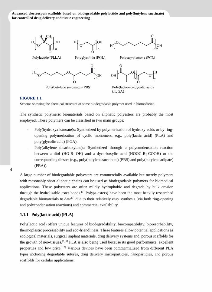
FIGURE 1.1
Scheme showing the chemical structure of some biodegradable polymer used in biomedicine.
The synthetic polymeric biomaterials based on aliphatic polyesters are probably the most
employed. These polymers can be classified in two main groups:
- Poly(hydroxyalkanoate)s: Synthetized by polymerization of hydroxy acids or by ring-
opening polymerization of cyclic monomers, e.g., poly(lactic acid) (PLA) and
poly(glycolic acid) (PGA).
- Poly(alkylene dicarboxylate)s: Synthetized through a polycondensation reaction
between a diol (HO-R1-OH) and a dycarboxylic acid (HOOC-R2-COOH) or the
corresponding diester (e.g., poly(butylene succinate) (PBS) and poly(butylene adipate)
(PBA)).
A large number of biodegradable polyesters are commercially available but merely polymers
with reasonably short aliphatic chains can be used as biodegradable polymers for biomedical
applications. These polyesters are often mildly hydrophobic and degrade by bulk erosion
through the hydrolizable ester bonds.[7] Poly(α-esters) have been the most heavily researched
degradable biomaterials to date[7] due to their relatively easy synthesis (via both ring-opening
and polycondensation reactions) and commercial availability.
1.1.1 Poly(lactic acid) (PLA)
Poly(lactic acid) offers unique features of biodegradability, biocompatibility, bioresorbability,
thermoplastic processability and eco-friendliness. These features allow potential applications as
ecological materials, surgical implant materials, drug delivery systems and, porous scaffolds for
the growth of neo-tissues.[8, 9] PLA is also being used because its good performance, excellent
properties and low price.[10] Various devices have been commercialized from different PLA
types including degradable sutures, drug delivery microparticles, nanoparticles, and porous
scaffolds for cellular applications.
5
INTRODUCTION
5
The diversification of PLA applications is such that a single polymer can be useful in many
applications by simple modifications of their physical-chemical structure. In many cases, the
polymer can be blended or copolymerized with other polymeric or non-polymeric components
to achieve the desired behaviour.[11] The surface properties of materials play a critical role in
determining its applications, especially when biocompatibility is required. Different surface
modification strategies - such as physical, chemical, plasma and radiation[12] induced methods
- have been employed to reduce degradation time and create desirable surface properties.[13]
PLA can be used as biodegradable polymer implants, which remain temporarily in the body and
disappear upon degradation. However, PLA is unsuitable for sutures because its degradation rate
is very slow.[14] On the contrary, PLA is the preferred material for applications where a long
retention of the strength is required. These include ligament and tendon reconstruction, and
stents for vascular and neural reconstruction.[15] Three-dimensional porous scaffolds of PLA
have been created for culturing different cell types, and used in cell-based gene therapy for
cardiovascular diseases.
1.1.2 Poly(butylene succinate) (PBS)
Polybutylene succinate (PBS) was synthetized in 1990 and commercialized under the trademark
Bionolle®.[16] PBS is one of the most accessible biodegradable polymers. It is an aliphatic
polyester with good processability, and easy preparation and flexibility, with degradation
products that are non-toxic. Thus, succinic acid is an intermediate in the biological tricarboxylic
acid (TCA) cycle. In addition, PBS could degrade into CO2 and H2O through naturally occurring
enzymes and microorganisms.[17-20]
PBS is a semicrystalline polyester with a melting point higher than that of PLA. Its mechanical
and thermal properties depend on the crystal structure and the degree of crystallinity.[21] The
relatively poor mechanical flexibility of PBS limits the applications of 100% PBS-based
products. However, this feature can be overcome by blending with PLA or starch in order to
provide similar properties than polyolefins.[21] Specifically, materials with a good tensile and
impact resistance, and moderate stiffness and strength can be achieved. By changing the polymer
composition in the blend of PBS/PLA, the mechanical properties can be adjusted to suit the
required application.[22] These blends, have been extensively studied for commercial
applications in agriculture, fishery, forestry, construction, and other industrial fields as a
conventional plastic.[23] Applications of PBS or its blends have also been proposed as a support
for different approaches in the medical field.[24]
PBS can be easily produced in a wide variety of forms and structures, such as yarns, non-wovens,
films and mono-filaments that provide, as above explained, excellent mechanical properties that
are comparable with those of polyethylene or polypropylene.[37, 40] In light of its biodegradability
and harmless degradation products, PBS is an excellent choice to use as scaffolds support in
tissue regeneration.[25]
6
Advanced electrospun scaffolds based on biodegradable polylactide and poly(butylene succinate)
for controlled drug delivery and tissue engineering
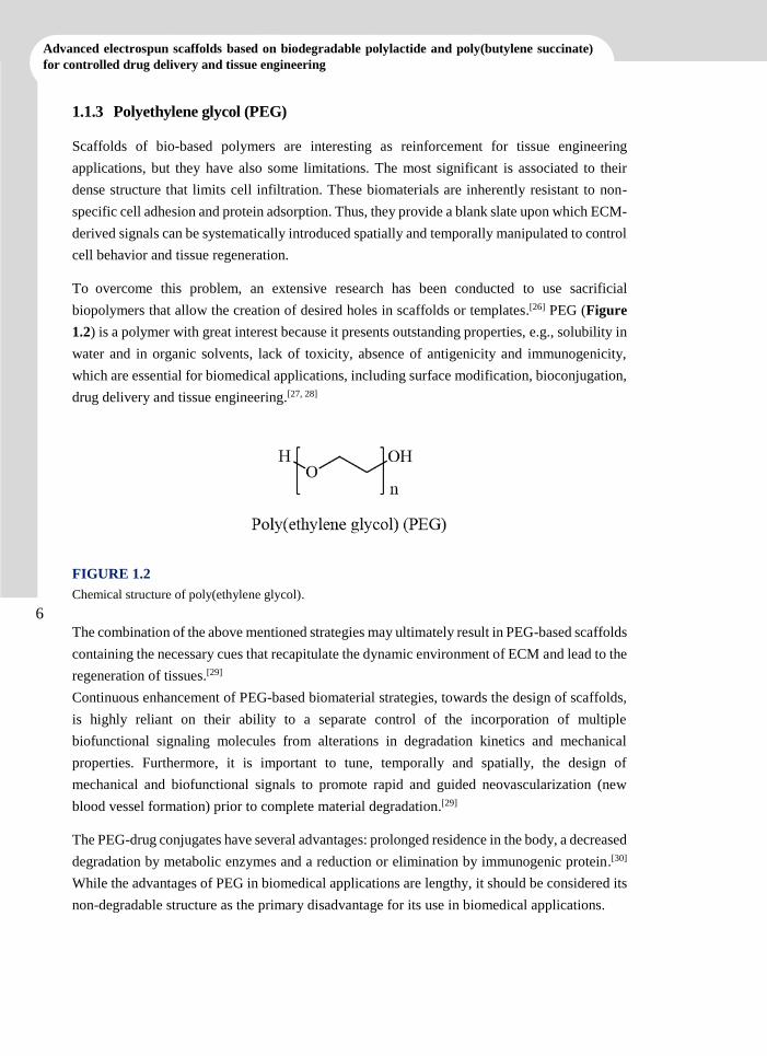
1.1.3 Polyethylene glycol (PEG)
Scaffolds of bio-based polymers are interesting as reinforcement for tissue engineering
applications, but they have also some limitations. The most significant is associated to their
dense structure that limits cell infiltration. These biomaterials are inherently resistant to non-
specific cell adhesion and protein adsorption. Thus, they provide a blank slate upon which ECM-
derived signals can be systematically introduced spatially and temporally manipulated to control
cell behavior and tissue regeneration.
To overcome this problem, an extensive research has been conducted to use sacrificial
biopolymers that allow the creation of desired holes in scaffolds or templates.[26] PEG (Figure
1.2) is a polymer with great interest because it presents outstanding properties, e.g., solubility in
water and in organic solvents, lack of toxicity, absence of antigenicity and immunogenicity,
which are essential for biomedical applications, including surface modification, bioconjugation,
drug delivery and tissue engineering.[27, 28]
FIGURE 1.2
Chemical structure of poly(ethylene glycol).
The combination of the above mentioned strategies may ultimately result in PEG-based scaffolds
containing the necessary cues that recapitulate the dynamic environment of ECM and lead to the
regeneration of tissues.[29]
Continuous enhancement of PEG-based biomaterial strategies, towards the design of scaffolds,
is highly reliant on their ability to a separate control of the incorporation of multiple
biofunctional signaling molecules from alterations in degradation kinetics and mechanical
properties. Furthermore, it is important to tune, temporally and spatially, the design of
mechanical and biofunctional signals to promote rapid and guided neovascularization (new
blood vessel formation) prior to complete material degradation.[29]
The PEG-drug conjugates have several advantages: prolonged residence in the body, a decreased
degradation by metabolic enzymes and a reduction or elimination by immunogenic protein.[30]
While the advantages of PEG in biomedical applications are lengthy, it should be considered its
non-degradable structure as the primary disadvantage for its use in biomedical applications.
7
INTRODUCTION
7
1.1.4 Conducting Polymers
Conducting polymers (CPs) provide a type of processable materials with characteristics that
range between those of semiconductors and metals (e.g., electrical and optical properties).
Furthermore, the attractive properties associated with conventional polymers such as low
density, stability, lightness, easy of synthesis and processing, have given a wide range of
applications in the microelectronics industry (e.g., batteries,[31] electrochromic devices,[32]
supercapacitors,[33] electroluminescence[34] and photovoltaic cells[35]), in biological field (e.g.,
biomedical engineering[36] and drug delivery[37]) and mechanical and chemical sensors (e.g.,
biosensor).[38] The main focus in the use of these polymers lies in the scope of their low
manufacturing cost.
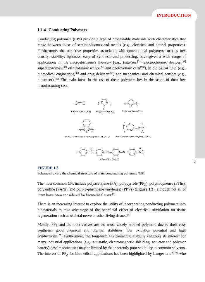
FIGURE 1.3
Scheme showing the chemical structure of main conduncting polymers (CP).
The most common CPs include polyacetylene (PA), polypyrrole (PPy), polythiophenes (PThs),
polyaniline (PANi), and poly(p-phenylene vinylenes) (PPVs) (Figure 1.3), although not all of
them have been considered for biomedical uses.[6]
There is an increasing interest to explore the utility of incorporating conducting polymers into
biomaterials to take advantage of the beneficial effect of electrical stimulation on tissue
regeneration such as skeletal nerve or other living tissues.[6]
Mainly, PPy and their derivatives are the most widely studied polymers due to their easy
synthesis, good chemical and thermal stabilities, low oxidation potential and high
conductivity.[39] Furthermore, the long-term environmental stability enhances its interest for
many industrial applications (e.g., antistatic, electromagnetic shielding, actuator and polymer
battery) despite some uses may be limited by the inherently poor solubility in common solvents.
The interest of PPy for biomedical applications has been highlighted by Langer et al.[31] who
8
Advanced electrospun scaffolds based on biodegradable polylactide and poly(butylene succinate)
for controlled drug delivery and tissue engineering
showed that the electrical stimulation from the application of an external electrical field through
a PPy film could significantly improve the spreading in cultured neurons. Then, it has been
shown its ability to improve the effect of nerve growth factor (NGF) for inducing neuronal
differentiation of PC12 cells in electric stimulation.[40]
However, in the last two decades some PTh derivatives with excellent electrical and
electrochemical properties, characteristic chemical structure, as well as very high environmental
stability, have been reported.[41, 42] Among them, PEDOT, is the most important due to its high
conductivity (up to 400-600 S·cm-1), good thermal and chemical stability, fast redox processes
and excellent biocompatibility.[43] Consequently, this CP has attracted considerable interest
based on its properties and many applications have been rapidly developed, e.g., antistatic
coatings, electrode material in supercapacitors, hole injection layer in organic light-emitting
diodes, and solar cells.[44] Poly(3-thiophene methyl acetate) (P3TMA) is another polythiophene
derivative that is characterized by bearing carboxylate substituents in the 3-position of the
heterocyclic ring. The P3TMA can be easily prepared via oxidative chemical[45] and
photochemical[46] reactions and appears a suitable candidate for being processed by
electrospinning since has a good solubility in organic solvents like chloroform. Furthermore, it
has currently been demonstrated that it’s very stable free-standing nanomembranes.
Electroactive and biodegradable properties can be achieved by combining P3TMA and
polyesters, such as poly(tetramethylene succinate), and even thermoplastic polyurethanes and
poly(vinylidene fluoride).[47, 48]
Finally, PANi is an electroactive conjugated polymer with three primary oxidation states
(leucoemeraldine, emeraldine and pernigranilin[49, 50]) that shows very good environmental
stability. PANi became an important studied subject since 1980 because of its significant
potential for technological applications such as in batteries (as electrodes), electromagnetic
shielding, capacitors, sensor, corrosion inhibitors, actuators and electrochromic devices.[51] For
example, PANi and its derivatives were found to be able to function as biocompatible substrates,
upon which both H9c2 cardiac myoblasts and PC12 pheochromocytoma cells can adhere, grow
and differentiate.[52]
1.2 Biomedical Applications
Nowadays, a variety of polymers are used for biomedical applications such as tissue engineering
scaffolds,[53] filtration membranes[54, 55] and in drug delivery systems. Naturally occurring
polymers normally exhibit better biocompatibility and low immunogenicity than synthetic
polymers.[56] A strong reason is the inherent capacity for binding cells since they carry specific
protein sequences such as RGD.[57] Scaffolds fabricated from natural polymers promise better
clinical functionality, although problems like their partial denaturation should be taken into
account. Synthetic polymers often offer many advantages over natural polymers as they can be
9
INTRODUCTION
9
tailored to give a wider range of properties such as necessary mechanical properties and desired
degradation rate.[58]
One of the main areas of research in biomedical applications is drug delivery where controlled
release is an efficient process of delivering drugs in medical therapy. Also, the effective release
of therapeutic agents towards alleviating medical conditions is one aspect of polymeric
biomaterials design.
Tissue engineering (TE) is being one of the most important areas of research in health care,
which has revolutionized medical engineering and has the potential to push the limitations even
further in future. TE is a growing interdisciplinary scientific area that involve the knowledge
from biology, medicine, engineering and material science field[59] towards the development of
biological substitutes to create, repair or replace tissue function.
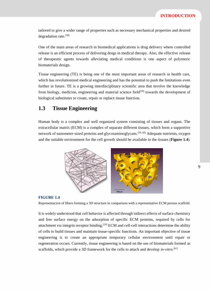
1.3 Tissue Engineering
Human body is a complex and well organized system consisting of tissues and organs. The
extracellular matrix (ECM) is a complex of separate different tissues, which form a supportive
network of nanometer-sized proteins and glycosaminoglycans.[59, 60] Adequate nutrients, oxygen
and the suitable environment for the cell growth should be available in the tissues (Figure 1.4).
FIGURE 1.4
Representacion of fibers forming a 3D structure in comparison with a representative ECM porous scaffold.
It is widely understood that cell behavior is affected through indirect effects of surface chemistry
and free surface energy on the adsorption of specific ECM proteins, required by cells for
attachment via integrin receptor binding.[29] ECM and cell-cell interactions determine the ability
of cells to build tissues and maintain tissue-specific functions. An important objective of tissue
engineering is to create an appropriate temporary cellular environment until repair or
regeneration occurs. Currently, tissue engineering is based on the use of biomaterials formed as
scaffolds, which provide a 3D framework for the cells to attach and develop in-vitro.[61]
10
Advanced electrospun scaffolds based on biodegradable polylactide and poly(butylene succinate)
for controlled drug delivery and tissue engineering
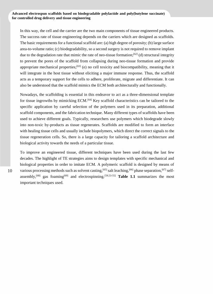
In this way, the cell and the carrier are the two main components of tissue engineered products.
The success rate of tissue engineering depends on the carriers which are designed as scaffolds.
The basic requirements for a functional scaffold are: (a) high degree of porosity; (b) large surface
area-to-volume ratio; (c) biodegradability, so a second surgery is not required to remove implant
due to the degradation rate that mimic the rate of neo-tissue formation;[62] (d) structural integrity
to prevent the pores of the scaffold from collapsing during neo-tissue formation and provide
appropriate mechanical properties;[63] (e) no cell toxicity and biocompatibility, meaning that it
will integrate in the host tissue without eliciting a major immune response. Thus, the scaffold
acts as a temporary support for the cells to adhere, proliferate, migrate and differentiate. It can
also be understood that the scaffold mimics the ECM both architecturally and functionally.
Nowadays, the scaffolding is essential in this endeavor to act as a three-dimensional template
for tissue ingrowths by mimicking ECM.[64] Key scaffold characteristics can be tailored to the
specific application by careful selection of the polymers used in its preparation, additional
scaffold components, and the fabrication technique. Many different types of scaffolds have been
used to achieve different goals. Typically, researchers use polymers which biodegrade slowly
into non-toxic by-products as tissue regenerates. Scaffolds are modified to form an interface
with healing tissue cells and usually include biopolymers, which direct the correct signals to the
tissue regeneration cells. So, there is a large capacity for tailoring a scaffold architecture and
biological activity towards the needs of a particular tissue.
To improve an engineered tissue, different techniques have been used during the last few
decades. The highlight of TE strategies aims to design templates with specific mechanical and
biological properties in order to imitate ECM. A polymeric scaffold is designed by means of
various processing methods such as solvent casting,[65] salt leaching,[66] phase separation,[67] self-
assembly,[68] gas foaming[69] and electrospinning.[59,53-55] Table 1.1 summarizes the most
important techniques used.
11
INTRODUCTION
11
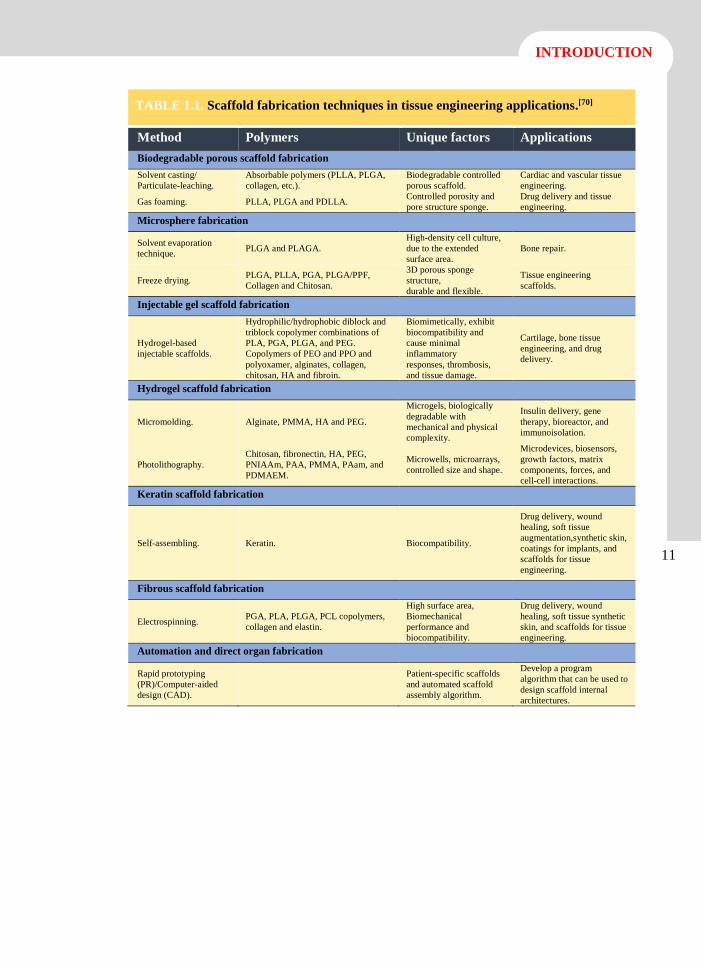
TABLE 1.1. Scaffold fabrication techniques in tissue engineering applications.[70]
Method Polymers Unique factors Applications
Biodegradable porous scaffold fabrication
Solvent casting/
Particulate-leaching.
Absorbable polymers (PLLA, PLGA,
collagen, etc.).
Biodegradable controlled
porous scaffold.
Cardiac and vascular tissue
engineering.
Gas foaming. PLLA, PLGA and PDLLA. Controlled porosity and
pore structure sponge.
Drug delivery and tissue
engineering.
Microsphere fabrication
Solvent evaporation
technique. PLGA and PLAGA.
High-density cell culture,
due to the extended
surface area.
Bone repair.
Freeze drying. PLGA, PLLA, PGA, PLGA/PPF,
Collagen and Chitosan.
3D porous sponge
structure,
durable and flexible.
Tissue engineering
scaffolds.
Injectable gel scaffold fabrication
Hydrogel-based
injectable scaffolds.
Hydrophilic/hydrophobic diblock and
triblock copolymer combinations of
PLA, PGA, PLGA, and PEG.
Copolymers of PEO and PPO and
polyoxamer, alginates, collagen,
chitosan, HA and fibroin.
Biomimetically, exhibit
biocompatibility and
cause minimal
inflammatory
responses, thrombosis,
and tissue damage.
Cartilage, bone tissue
engineering, and drug
delivery.
Hydrogel scaffold fabrication
Micromolding. Alginate, PMMA, HA and PEG.
Microgels, biologically
degradable with
mechanical and physical
complexity.
Insulin delivery, gene
therapy, bioreactor, and
immunoisolation.
Photolithography.
Chitosan, fibronectin, HA, PEG,
PNIAAm, PAA, PMMA, PAam, and
PDMAEM.
Microwells, microarrays,
controlled size and shape.
Microdevices, biosensors,
growth factors, matrix
components, forces, and
cell-cell interactions.
Keratin scaffold fabrication
Self-assembling. Keratin. Biocompatibility.
Drug delivery, wound
healing, soft tissue
augmentation,synthetic skin,
coatings for implants, and
scaffolds for tissue
engineering.
Fibrous scaffold fabrication
Electrospinning. PGA, PLA, PLGA, PCL copolymers,
collagen and elastin.
High surface area,
Biomechanical
performance and
biocompatibility.
Drug delivery, wound
healing, soft tissue synthetic
skin, and scaffolds for tissue
engineering.
Automation and direct organ fabrication
Rapid prototyping
(PR)/Computer-aided
design (CAD).
Patient-specific scaffolds
and automated scaffold
assembly algorithm.
Develop a program
algorithm that can be used to
design scaffold internal
architectures.
12
Advanced electrospun scaffolds based on biodegradable polylactide and poly(butylene succinate)
for controlled drug delivery and tissue engineering
1.4 Drug Delivery
Polymeric drug delivery systems are advantageous because they can be controlled to deliver
drugs efficiently to a localized area.[65] Design of the polymeric structure is a basic point to
stablish appropriate interactions with the drug, to get a desired degradation rate and to provide
a good mechanism for its removal from the body. Molecular weight, crystallinity, lability of
bonds, and degradability play an important role for achieving controlled release. Polymers may
be excreted directly via kidney (renal clearance) or biodegraded (metabolic clearance) into
smaller molecules.
The goal of all sophisticated drug delivery systems is to distribute intact medications to
specifically targeted parts of the body through a mean which can control the therapy
administration via either a physiological or a chemical trigger. To achieve this goal, researchers
are turning to advances in the worlds of micro- and nanotechnology. During the past decade,
polymeric microspheres, polymer micelles and hydrogel-type materials have been shown to be
effective in enhancing drug targeting specificity, lowering systemic drug toxicity, improving
treatment absorption rates, and providing protection for pharmaceuticals against biochemical
degradation.[71]
Basically, two broad categories of polymer systems have been studied: reservoir devices and
matrix devices. The former involves the encapsulation of a pharmaceutical product within a
polymer shell, whereas the latter describes a system in which a drug is physically entrapped
within a polymer network.
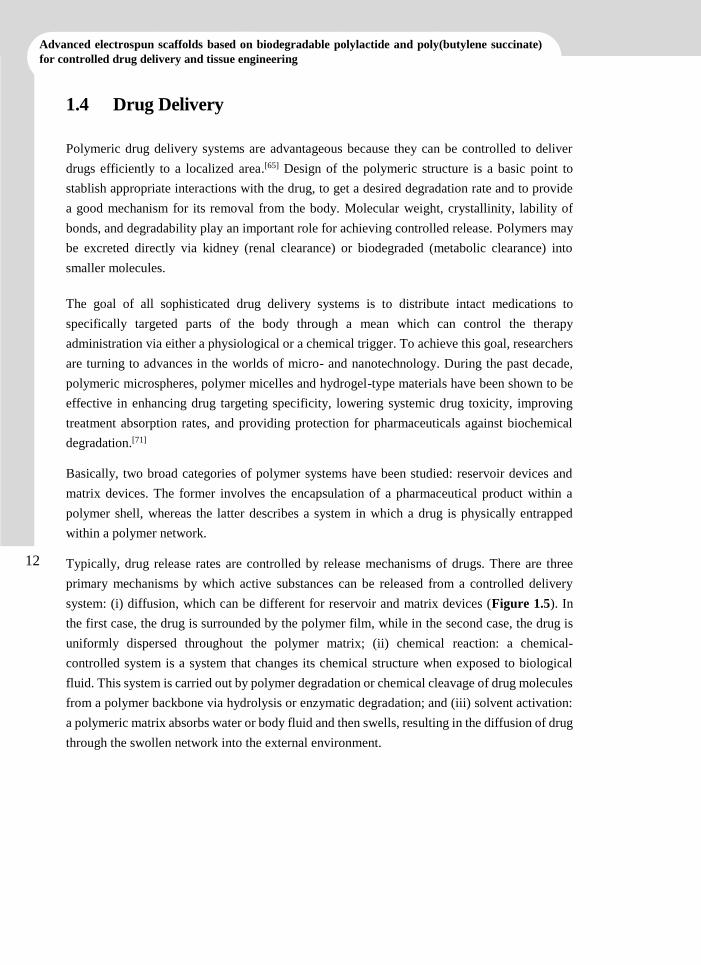
Typically, drug release rates are controlled by release mechanisms of drugs. There are three
primary mechanisms by which active substances can be released from a controlled delivery
system: (i) diffusion, which can be different for reservoir and matrix devices (Figure 1.5). In
the first case, the drug is surrounded by the polymer film, while in the second case, the drug is
uniformly dispersed throughout the polymer matrix; (ii) chemical reaction: a chemical-
controlled system is a system that changes its chemical structure when exposed to biological
fluid. This system is carried out by polymer degradation or chemical cleavage of drug molecules
from a polymer backbone via hydrolysis or enzymatic degradation; and (iii) solvent activation:
a polymeric matrix absorbs water or body fluid and then swells, resulting in the diffusion of drug
through the swollen network into the external environment.
13
INTRODUCTION
13
FIGURE 1.5
Schematic illustration showing the release of the anti-inflammatory drug from electrospun nanofibers (a)
without and (b) with an alginate hydrogel coating.
Currently, modern research is aimed to explore the use of biodegradable polymer systems as the
matrix system. These drug deliverers degrade into biologically acceptable compounds, often
through the process of hydrolysis, which subsequently leave their incorporated medications
behind. This erosion process occurs either in bulk (wherein the matrix degrades uniformly) or at
the polymer surface (whereby release rates are related to the polymer surface area). For example,
the PLGA in its degradation process involves the breakdown of polymers into lactic and glycolic
acids. These acids are eventually reduced by the Kreb’s cycle to carbon dioxide and water, which
the body can easily expel. Hence, a second surgery is not required to remove the reservoir or
matrix devices.[71]
1.5 Other Applications
1.5.1 Surgical Fixation Devices
In a situation of a healing wound, a broken bone or a damaged blood vessel, surgical fixation
devices (e.g., sutures, clips, pins, plates and vascular grafts) are the corresponding support
devices. About 40 types of biodegradable polymers and their copolymers are currently identified
as alternatives to metal implants since these have clear disadvantages such as the sensitivity of
patients to metal and the need for a removal operation. For instance, PGA, and PLGA
copolymers have been successfully used as absorbable sutures because they can be processed as
strong filaments and hydrolyzed in-vitro and in vivo. The most commercially utilized absorbable
sutures are a multifilament PGA (Dexon®), the copolymer PLLA (8%)-co-PGA (92%) (Vicryl®)
and poly(p-dioxanone) (PDS®).
Related to surgical sutures, the development of materials with adequate properties to be used as
a coating is also highly interesting. These coating could contain different agents (e.g., triclosan,
14
Advanced electrospun scaffolds based on biodegradable polylactide and poly(butylene succinate)
for controlled drug delivery and tissue engineering
chlorhexidine) that could render and additional activity (e.g., antibacterial or anti-inflammatory
responses).[72]
1.5.2 Wound Dressings
When the skin is injured, the human body initiates a process that eventually leads to an
epithelialization (regeneration of epithelial tissue) of the wound area and reestablishment of the
skin barrier function.[73] The subsequent processes are ECM degradation and re-synthesis of
tissue cells, which eventually results in a scar. The four phases of the wound healing process are
inflammation; reconstruction; epithelialization; and maturation.
In the inflammatory phase, the body prepares itself for healing by removing foreign matter and
dead cells. After any injury to the skin that breaches the epidermis, damaged blood vessels will
constrict within seconds to limit blood loss. When a blood vessel is damaged, sub-endothelial
tissue is exposed resulting in the aggregation of platelets (platelet plug). The platelets at the
wound site will release growth factors, which attract white blood cells and stimulate the release
of other chemical mediators, e.g., cytokines, which are necessary for wound healing.
Consequently, macrophages contained within the surrounding blood vessels are readily moved
into the tissue via vasodilation. The final and longest state, maturation phase, is a progressive
decrease in the vascularity of the wound which becomes more organized and then gains strength
as the collagen matures. Maturation of a wound may take months to complete and in large open
wounds, it can take years.
The time period for each phase depends on the wound type. All four physiological processes
occur in the healing of all soft tissue injuries, e.g., chronic ulcerative wounds (leg ulcers, pressure
sores), traumatic wounds (lacerations, skin flaps, abrasions, burns), and surgical wounds.
However, concentrations of reactive oxygen species (ROS) such as hydroxyl radicals (·OH),
singlet oxygen (O2), hydroperoxyl radicals (·OOH), and hydrogen peroxide (H2O2) can produce
“oxidative stress”. Chronic and severe oxidative stress conditions may delay the healing
condition due to prolonged inflammation. Thus, the wound healing process may be assisted by
the use of antioxidant wound dressings that reacts specifically with excess ROS, leading to the
reduction of oxidative stress. The ROS inhibitors impregnated into the wound dressings include
flavonoids, vitamin E, carnosin, mexidol, trypsin, and dieton.[74]
15
INTRODUCTION
15
1.6 Electrospinning
1.6.1 Brief history
Scientists have been interested in the use of electrostatic force to deform liquid for centuries.[75]
In the late 1500’s William Gilbert set out to describe the behaviour of the known magnetic and
electrostatic phenomenon.[75] He distinguished between the force arising from a loadstone and
the force from rubber amber[76] and invented the term electricity to describe the force from
amber. One of his more obscure observations was that when a suitably charged piece of amber
was brought near a droplet of water it would form a cone shape and small droplets would be
ejected from the tip of the cone. This is the first recorded observation of electrospraying.
Throughout the 20th century, electrodynamic atomization[77-79] was studied and patents for a
process similar to electrospinning were accepted as early as 1902 by William James Morton,[80,
81] which demonstrate the application of high voltage electrostatic fields to both electrospray and
electrospun colloids fluids, separating the fluids into fine particles and fibers which could be
collected on rotating collectors (Figure 1.6 a, b).
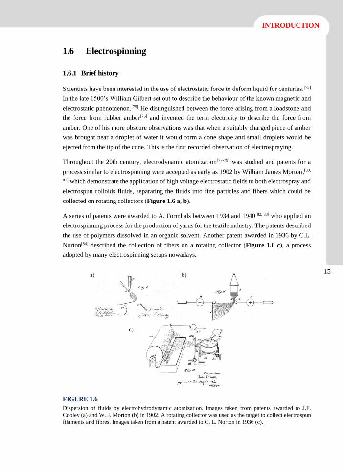
A series of patents were awarded to A. Formhals between 1934 and 1940[82, 83] who applied an
electrospinning process for the production of yarns for the textile industry. The patents described
the use of polymers dissolved in an organic solvent. Another patent awarded in 1936 by C.L.
Norton[84] described the collection of fibers on a rotating collector (Figure 1.6 c), a process
adopted by many electrospinning setups nowadays.
FIGURE 1.6
Dispersion of fluids by electrohydrodynamic atomization. Images taken from patents awarded to J.F.
Cooley (a) and W. J. Morton (b) in 1902. A rotating collector was used as the target to collect electrospun
filaments and fibres. Images taken from a patent awarded to C. L. Norton in 1936 (c).
16
Advanced electrospun scaffolds based on biodegradable polylactide and poly(butylene succinate)
for controlled drug delivery and tissue engineering
Interest to use electrospinning for the textile research continued to increase from this point
onwards. On 1969, Taylor performed one of the first systematic studies on how the electrostatic
field competes with the surface tension of spherical viscous polymer droplets placed at the tip
of a needle, pulling the droplet first into a cone shape, and then, as the field strength was
increased, ejecting a stream of solution from the tip of the cone.[85] In 1981, Larrondo and
Manley were the first to demonstrate that a molten polymer could be electrospun in a similar
fashion,[86-88] a finding backed up by more recent discoveries.[89] In the late 1980’s the
electrospinning effect was further studied by Reneker group, who established how the unstable
whipping effect was caused by the jet elongation in the electric field and how changing the
strength of the electric field and the proportion of solvent to polymer affected nanofibre size and
production.[90]
Despite these early discoveries, electrospinning did not gain a lot of interest and was not utilized
commercially until the 90s. It is only after the emergence of nanotechnology, in the 1990s, that
electrospinning gained increasing attention as a way of manufacturing fibers at the nanoscale
range. Researchers have looked at the potential of electrospinning to produce complex and
highly functionalized systems, which could be used in a variety of scientific and commercial
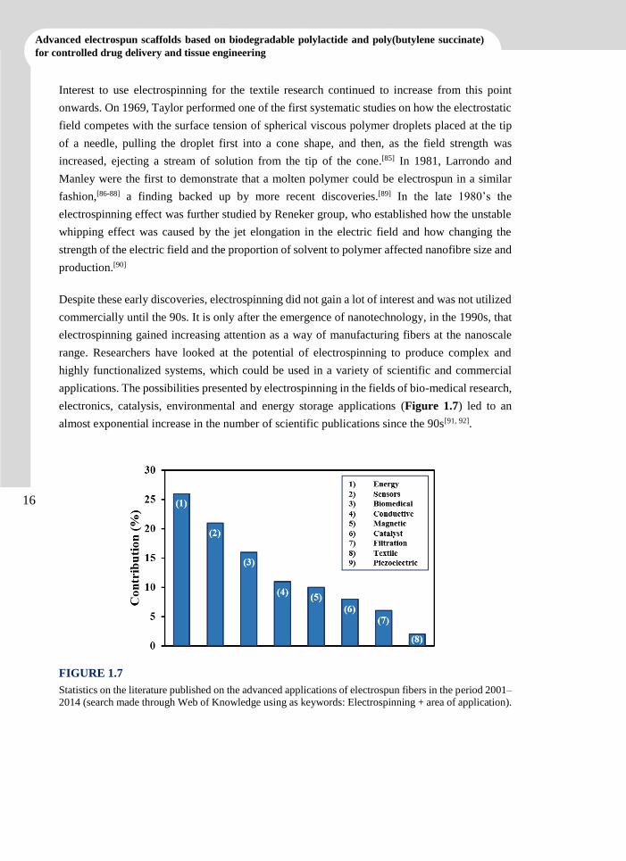
applications. The possibilities presented by electrospinning in the fields of bio-medical research,
electronics, catalysis, environmental and energy storage applications (Figure 1.7) led to an
almost exponential increase in the number of scientific publications since the 90s[91, 92].
FIGURE 1.7
Statistics on the literature published on the advanced applications of electrospun fibers in the period 2001–
2014 (search made through Web of Knowledge using as keywords: Electrospinning + area of application).
17
INTRODUCTION
17
1.6.2 Electrospinning set-up
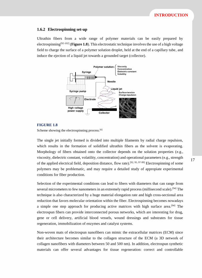
Ultrathin fibers from a wide range of polymer materials can be easily prepared by
electrospinning[92-102] (Figure 1.8). This electrostatic technique involves the use of a high voltage
field to charge the surface of a polymer solution droplet, held at the end of a capillary tube, and
induce the ejection of a liquid jet towards a grounded target (collector).
FIGURE 1.8
Scheme showing the electrospinning process.[6]
The single jet initially formed is divided into multiple filaments by radial charge repulsion,
which results in the formation of solidified ultrathin fibers as the solvent is evaporating.
Morphology of fibers obtained onto the collector depends on the solution properties (e.g.,
viscosity, dielectric constant, volatility, concentration) and operational parameters (e.g., strength
of the applied electrical field, deposition distance, flow rate).[92, 95, 97-99] Electrospinning of some
polymers may be problematic, and may require a detailed study of appropiate experimental
conditions for fiber production.
Selection of the experimental conditions can lead to fibers with diameters that can range from
several micrometers to few nanometers in an extremely rapid process (millisecond scale).[94] The
technique is also characterized by a huge material elongation rate and high cross-sectional area
reduction that favors molecular orientation within the fiber. Electrospinning becomes nowadays
a simple one step approach for producing active matrices with high surface area.[94] The
electrospun fibers can provide interconnected porous networks, which are interesting for drug,
gene or cell delivery, artificial blood vessels, wound dressings and substrates for tissue
regeneration, immobilization of enzymes and catalyst systems.
Non-woven mats of electrospun nanofibers can mimic the extracellular matrices (ECM) since
their architecture becomes similar to the collagen structure of the ECM (a 3D network of
collagen nanofibers with diameters between 50 and 500 nm). In addition, electrospun synthetic
materials can offer several advantages for tissue regeneration: correct and controllable
18
Advanced electrospun scaffolds based on biodegradable polylactide and poly(butylene succinate)
for controlled drug delivery and tissue engineering
topography (e.g., 3D porosity, nanoscale size, and alignment), encapsulation and local sustained
release of drugs (e.g., growth factors, antioxidants, anti-inflammatory agents), and surface
functionalization. Electrospun nanofiber-mats can also be used for the development of complex
nanosensory systems to detect biomolecules (e.g., glucose-recognition) in a less than nanomolar
concentrations.[103]
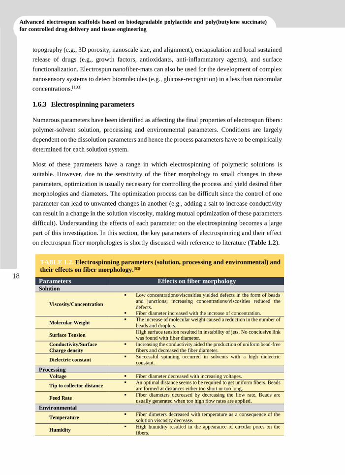
1.6.3 Electrospinning parameters
Numerous parameters have been identified as affecting the final properties of electrospun fibers:
polymer-solvent solution, processing and environmental parameters. Conditions are largely
dependent on the dissolution parameters and hence the process parameters have to be empirically
determined for each solution system.
Most of these parameters have a range in which electrospinning of polymeric solutions is
suitable. However, due to the sensitivity of the fiber morphology to small changes in these
parameters, optimization is usually necessary for controlling the process and yield desired fiber
morphologies and diameters. The optimization process can be difficult since the control of one
parameter can lead to unwanted changes in another (e.g., adding a salt to increase conductivity
can result in a change in the solution viscosity, making mutual optimization of these parameters
difficult). Understanding the effects of each parameter on the electrospinning becomes a large
part of this investigation. In this section, the key parameters of electrospinning and their effect
on electrospun fiber morphologies is shortly discussed with reference to literature (Table 1.2).
TABLE 1.2. Electrospinning parameters (solution, processing and environmental) and
their effects on fiber morphology.[53]
Parameters Effects on fiber morphology
Solution
Viscosity/Concentration
Low concentrations/viscosities yielded defects in the form of beads
and junctions; increasing concentrations/viscosities reduced the
defects. Fiber diameter increased with the increase of concentration.
Molecular Weight The increase of molecular weight caused a reduction in the number of
beads and droplets.
Surface Tension High surface tension resulted in instability of jets. No conclusive link was found with fiber diameter.
Conductivity/Surface
Charge density
Increasing the conductivity aided the production of uniform bead-free
fibers and decreased the fiber diameter.
Dielectric constant Successful spinning occurred in solvents with a high dielectric
constant.
Processing
Voltage Fiber diameter decreased with increasing voltages.
Tip to collector distance An optimal distance seems to be required to get uniform fibers. Beads
are formed at distances either too short or too long.
Feed Rate Fiber diameters decreased by decreasing the flow rate. Beads are
usually generated when too high flow rates are applied.
Environmental
Temperature Fiber dimeters decreased with temperature as a consequence of the
solution viscosity decrease.
Humidity High humidity resulted in the appearance of circular pores on the
fibers.
19
INTRODUCTION
19
1.6.4 Advances on the electrospinning technique
The basic set-up for electrospinning is so simple that it has already found widespread use in
many research laboratories. Due to the bending instability, a typical electrospinning jet deposits
fibers in a random mat. Nevertheless, there are several applications where fibers should be
deposited in a more controlled fashion. Thus, several techniques for influencing the layout of
the fiber deposition have been developed. These can generally be grouped in two categories:
mechanical and electrical.
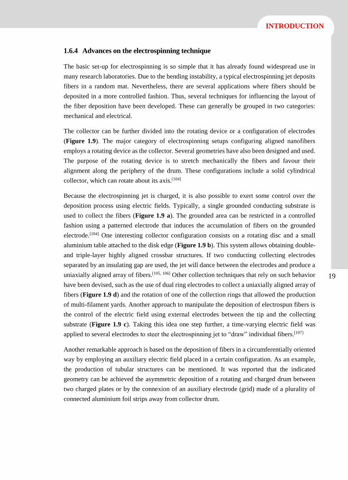
The collector can be further divided into the rotating device or a configuration of electrodes
(Figure 1.9). The major category of electrospinning setups configuring aligned nanofibers
employs a rotating device as the collector. Several geometries have also been designed and used.
The purpose of the rotating device is to stretch mechanically the fibers and favour their
alignment along the periphery of the drum. These configurations include a solid cylindrical
collector, which can rotate about its axis.[104]
Because the electrospinning jet is charged, it is also possible to exert some control over the
deposition process using electric fields. Typically, a single grounded conducting substrate is
used to collect the fibers (Figure 1.9 a). The grounded area can be restricted in a controlled
fashion using a patterned electrode that induces the accumulation of fibers on the grounded
electrode.[104] One interesting collector configuration consists on a rotating disc and a small
aluminium table attached to the disk edge (Figure 1.9 b). This system allows obtaining double-
and triple-layer highly aligned crossbar structures. If two conducting collecting electrodes
separated by an insulating gap are used, the jet will dance between the electrodes and produce a
uniaxially aligned array of fibers.[105, 106] Other collection techniques that rely on such behavior
have been devised, such as the use of dual ring electrodes to collect a uniaxially aligned array of
fibers (Figure 1.9 d) and the rotation of one of the collection rings that allowed the production
of multi-filament yards. Another approach to manipulate the deposition of electrospun fibers is
the control of the electric field using external electrodes between the tip and the collecting
substrate (Figure 1.9 c). Taking this idea one step further, a time-varying electric field was
applied to several electrodes to steer the electrospinning jet to “draw” individual fibers.[107]
Another remarkable approach is based on the deposition of fibers in a circumferentially oriented
way by employing an auxiliary electric field placed in a certain configuration. As an example,
the production of tubular structures can be mentioned. It was reported that the indicated
geometry can be achieved the asymmetric deposition of a rotating and charged drum between
two charged plates or by the connexion of an auxiliary electrode (grid) made of a plurality of
connected aluminium foil strips away from collector drum.
20
Advanced electrospun scaffolds based on biodegradable polylactide and poly(butylene succinate)
for controlled drug delivery and tissue engineering
FIGURE 1.9
Collector configurations: a) solid cylinder; b) disc collector; c) parallel plates and, d) dual rings.[104]
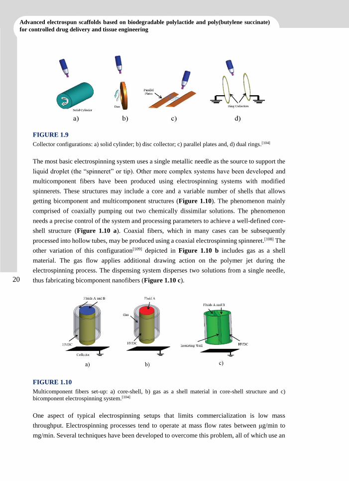
The most basic electrospinning system uses a single metallic needle as the source to support the
liquid droplet (the “spinneret” or tip). Other more complex systems have been developed and
multicomponent fibers have been produced using electrospinning systems with modified
spinnerets. These structures may include a core and a variable number of shells that allows
getting bicomponent and multicomponent structures (Figure 1.10). The phenomenon mainly
comprised of coaxially pumping out two chemically dissimilar solutions. The phenomenon
needs a precise control of the system and processing parameters to achieve a well-defined core-
shell structure (Figure 1.10 a). Coaxial fibers, which in many cases can be subsequently
processed into hollow tubes, may be produced using a coaxial electrospinning spinneret.[108] The
other variation of this configuration[109] depicted in Figure 1.10 b includes gas as a shell
material. The gas flow applies additional drawing action on the polymer jet during the
electrospinning process. The dispensing system disperses two solutions from a single needle,
thus fabricating bicomponent nanofibers (Figure 1.10 c).
FIGURE 1.10
Multicomponent fibers set-up: a) core-shell, b) gas as a shell material in core-shell structure and c)
bicomponent electrospinning system.[104]
One aspect of typical electrospinning setups that limits commercialization is low mass
throughput. Electrospinning processes tend to operate at mass flow rates between μg/min to
mg/min. Several techniques have been developed to overcome this problem, all of which use an
21
INTRODUCTION
21
array of multiple electrospinning spinnerets operating in parallel. This technique is usually
manifested in systems employing an array of needles that are fed by the same electrospinning
solution.[110]
1.7 Electrospinning of biodegradable polymers as bioactive
systems
1.7.1 Biodegradable polymer loaded with drugs
Electrospinning offers great flexibility in terms of material selection for drug delivery
applications, being a wide variety of drugs physically or chemically formulated within
electrospun fibers or on their surfaces. These include for example antibiotics,[111-115] anti-cancer
drugs,[111-115] proteins,[118, 119] and DNA.[120-122] The drug release mechanism can be associated
with polymer degradation and diffusion pathway. Specifically, the release profile of drug from
electrospun fibers may be tuned by the polymer composition and fiber morphology.[123]
Many strategies can be used to control the release of proteins and growth factors from fiber
scaffolds. When biodegradable polymers are used, a common approach is to load the growth
factors (e.g., bioactive molecules) on the material and use the combined effects of diffusion and
erosion to mediate the release kinetics. Fiber meshes inherently have an appropriate structure to
maximize surface area. Additionally, the hydrophilicity can be optimized by using surface-
modification methods. In general, it is accepted that hydrophobic materials are more compatible
with the biological systems.
The electrospinning process, being solvent based, allows the mixing of drugs and bioactive
agents before the production of micro/nanofibers. However, the solvent needs to be harmless for
the loaded bioactive agent, and must not compromise its functionality. Depending on the
chemical interactions between drug and polymer carrier, different modes of interaction may be
explored:[124]
- Drug as particles or inclusions trapped in the fiber structure.
- Blend of drugs and carrier materials integrated into one mesh of composite fibers.
- Carrier material electrospun into a tubular form in which the drug particles are
encapsulated.
- Drug adsorbed onto fiber mats.
Drug-release systems can be tailored to tune the release kinetics, to regulate local distribution
and to minimize toxic side effects, thereby enhancing the effectiveness of the bioactive agent
released.[125] Electrospinning also allows control of the fiber diameter, to some extent, and
control the release of kinetics by the diameter of the fibers, both in diffusion- and in degradation-
controlled release. Moreover, the electrospinning process, being based in solvents, does not
involve high temperatures which is particularly useful for heat-sensitive drugs. Furthermore, it
22
Advanced electrospun scaffolds based on biodegradable polylactide and poly(butylene succinate)
for controlled drug delivery and tissue engineering
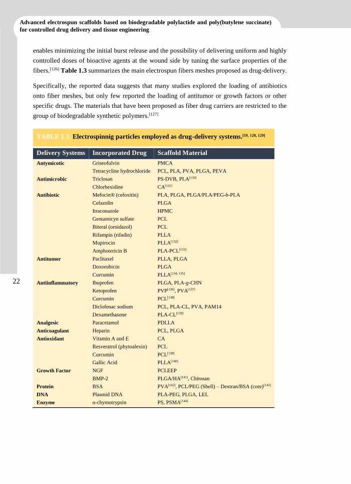
enables minimizing the initial burst release and the possibility of delivering uniform and highly
controlled doses of bioactive agents at the wound side by tuning the surface properties of the
fibers.[126] Table 1.3 summarizes the main electrospun fibers meshes proposed as drug-delivery.
Specifically, the reported data suggests that many studies explored the loading of antibiotics
onto fiber meshes, but only few reported the loading of antitumor or growth factors or other
specific drugs. The materials that have been proposed as fiber drug carriers are restricted to the
group of biodegradable synthetic polymers.[127]
TABLE 1.3. Electrospinnig particles employed as drug-delivery systems.[59, 128, 129]
Delivery Systems Incorporated Drug Scaffold Material
Antymicotic Griseofulvin PMCA
Tetracycline hydrochloride PCL, PLA, PVA, PLGA, PEVA
Antimicrobic Triclosan PS-DVB, PLA[130]
Chlorhexidine CA[131]
Antibiotic Mefocin® (cefoxitin) PLA, PLGA, PLGA/PLA/PEG-b-PLA
Cefazolin PLGA
Itraconazole HPMC
Gentamicyn sulfate PCL
Biteral (ornidazol) PCL
Rifampin (rifadin) PLLA
Mupirocin PLLA[132]
Amphotericin B PLA-PCL[133]
Antitumor Paclitaxel PLLA, PLGA
Doxorubicin PLGA
Curcumin PLLA[134, 135]
Antiinflammatory Ibuprofen PLGA, PLA-g-CHN
Ketoprofen PVP[136], PVA[137]
Curcumin PCL[138]
Diclofenac sodium PCL, PLA-CL, PVA, PAM14
Dexamethasone PLA-CL[139]
Analgesic Paracetamol PDLLA
Anticoagulant Heparin PCL, PLGA
Antioxidant Vitamin A and E CA
Resveratrol (phytoalexin) PCL
Curcumin PCL[138]
Gallic Acid PLLA[140]
Growth Factor NGF PCLEEP
BMP-2 PLGA/HA[141], Chitosan
Protein BSA PVA[142], PCL/PEG (Shell) – Dextran/BSA (core)[143]
DNA Plasmid DNA PLA-PEG, PLGA, LEL
Enzyme α-chymotrypsin PS, PSMA[144]
23
INTRODUCTION
23
1.7.2 Biodegradable polymer meshed with conductive polymers
Electrically conducting polymers are considered important because of their unique properties as
mentioned above. Recently, several groups have demonstrated the preparation of conducting
polymer nanofibers via electrospinning. Obtention of conductive nanofibers by electrospinning
is not trivial and different strategies have been undertaken: (a) Incorporation of conductive
particles [e.g., carbon nanotubes (CNT)] into the fibers, being usually necessary a surface
treatment of particles in order to increase their affinity for the polymer matrix; (b) Direct
electrospinning of conducting polymers with problems related to their stiffness and low
solubility; (c) Blending the conducting polymer with another electrospinnable polymer (used as
a carrier), being the detriment of the electronic properties the major inconvenience; and (d)
Coating electrospun nanofibers with conductive materials.[6]
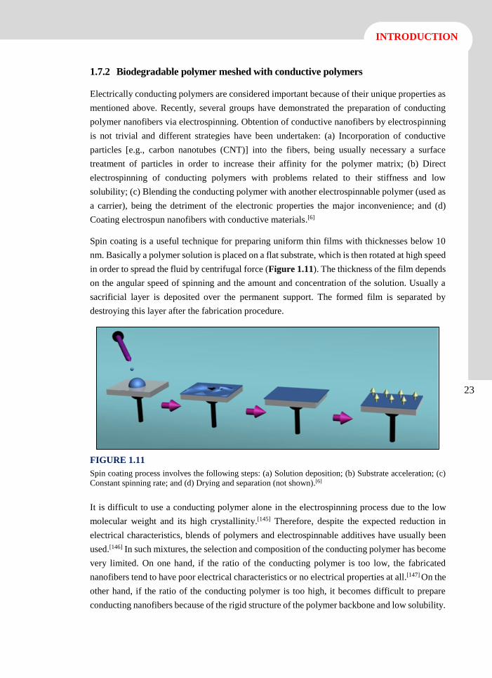
Spin coating is a useful technique for preparing uniform thin films with thicknesses below 10
nm. Basically a polymer solution is placed on a flat substrate, which is then rotated at high speed
in order to spread the fluid by centrifugal force (Figure 1.11). The thickness of the film depends
on the angular speed of spinning and the amount and concentration of the solution. Usually a
sacrificial layer is deposited over the permanent support. The formed film is separated by
destroying this layer after the fabrication procedure.
FIGURE 1.11
Spin coating process involves the following steps: (a) Solution deposition; (b) Substrate acceleration; (c)
Constant spinning rate; and (d) Drying and separation (not shown).[6]
It is difficult to use a conducting polymer alone in the electrospinning process due to the low
molecular weight and its high crystallinity.[145] Therefore, despite the expected reduction in
electrical characteristics, blends of polymers and electrospinnable additives have usually been
used.[146] In such mixtures, the selection and composition of the conducting polymer has become
very limited. On one hand, if the ratio of the conducting polymer is too low, the fabricated
nanofibers tend to have poor electrical characteristics or no electrical properties at all.[147] On the
other hand, if the ratio of the conducting polymer is too high, it becomes difficult to prepare
conducting nanofibers because of the rigid structure of the polymer backbone and low solubility.
24
Advanced electrospun scaffolds based on biodegradable polylactide and poly(butylene succinate)
for controlled drug delivery and tissue engineering
Other promising investigations about the use of polymer matrices as drug transport devices have
also been undertaken. For example, the use of conducting/electroactive polymers as a medium-
sensing and bioactive molecule-releasing system. Drug delivery with these conducting polymer
membranes is achieved through the controlled ionic transport of counterions (dopants) in and
out of the membranes. Specifically, redox reactions regulate the necessary electrochemical
switching, thus allowing electrostatically entrapped anionic dopants (such as the biological
molecule ATP, which has been investigated for various cardiovascular therapies) to be either
retained or released. In fact, initial studies that mainly involved a polypyrrole-based polymer
membranes have proved quite promising. Results indicated that the drug delivery rate, chemical
sensing, and electrochemical triggering can all be and precisely controlled.[6]
25
INTRODUCTION
25
1.8 References
[1] D.F. Williams, Proceedings of a Consensus Conference of the Europe a Society for
Biomaterials, Elsevier, England, 1987.
[2] E.S. Place, J.H. George, C.K. Williams, M.M. Stevens, Chem Soc Rev, 38 (2009) 1139-
1151.
[3] P. Tormala, T. Pohjonen, P. Rokkanen, P I Mech Eng H, 212 (1998) 101-111.
[4] A. Rodrigues Santos, Bioresorbable polymers for tissue engineering, in: D. Eberly (Ed.)
Tissue Engineering, InTech, 2010.
[5] L.S. Nair, C.T. Laurencin, Prog Polym Sci, 32 (2007) 762-798.
[6] E. Llorens, E. Armelin, M.M. Pérez-Madrigal, L.J. del Valle, C. Aleman, J. Puiggali,
Polymers, 5 (2013) 1115-1157.
[7] B.D. Ulery, L.S. Nair, C.T. Laurencin, J Polym Sci Part B Polym Phys, 49 (2011) 832-
864.
[8] B. Gupta, N. Revagade, J. Hilborn, Prog Polym Sci, 32 (2007) 455-482.
[9] H. Yamane, K. Sasai, Polymer, 44 (2003) 2569-2575.
[10] R.E. Drumright, P.R. Gruber, D.E. Henton, Adv Mater, 12 (2000) 1841-1846.
[11] Y. Cheng, S. Deng, P. Chen, R. Ruan, Front Chem China, 4 (2009) 259-264.
[12] J.S. Loo, C.P. Ooi, F.Y. Boey, Biomaterials, 26 (2005) 1359-1367.
[13] A.J.R. Lasprilla, G.A.R. Martinez, B.H. Lunelli, A.L. Jardini, R.M. Filho, Biotechnol
Adv, 30 (2012) 321-328.
[14] Q. Wang, J. Liu, C. Wang, L. Ma, Y. Liu, J. Li, J. Liu, World Congress on Medical
Physics and Biomedical Engineering, Springer Berlin Heidelberg, Beijing, China, 2012.
[15] L. Durselen, M. Dauner, H. Hierlemann, H. Planck, L.E. Claes, A. Ignatius, J Biomed
Mater Res, 58 (2001) 666-672.
[16] T. Fujimaki, Polym Degrad Stabil, 59 (1998) 209-214.
[17] J. Nicklin, K. Graeme-Cook, T. Paget, R.A. Killington, Instant Notes in Micriobiology,
BIOS Scientific Publishers Limited, Oxford, 1999.
[18] K. Bahari, H. Mitomo, T. Enjoji, F. Yoshii, K. Makuuchi, Polym Degrad Stabil, 61
(1998) 245-252.
26
Advanced electrospun scaffolds based on biodegradable polylactide and poly(butylene succinate)
for controlled drug delivery and tissue engineering
[19] T. Hashitani, E. Yano, Y. Ando, Fujitsu Sci Tech J, 38 (2002) 112-118.
[20] V. Tserki, P. Matzinos, E. Pavlidou, D. Vachliotis, C. Panayiotou, Polym Degrad Stabil,
91 (2006) 367-376.
[21] R. Babu, K. O'Connor, R. Seeram, Progr Biomater, 2 (2013) 8.
[22] L. Liu, J. Yu, L. Cheng, W. Qu, Compos Part A-Appl S, 40 (2009) 669-674.
[23] W.S. Lyoo, J.H. Kim, W.S. Yoon, B.C. Ji, J.H. Choi, J. Cho, J. Lee, S.B. Yang, Y. Yoo,
Polymer, 41 (2000) 9055-9062.
[24] R. Vasita, D.S. Katti, Int J Nanomedicine, 1 (2006) 15-30.
[25] N. De Geyter, R. Morent, Non-Thermal Plasma Surface Modification of Biodegradable
Polymers, in: D.N. Ghista (Ed.) Biomedical Science, Engineering and Technology,
InTech, 2012.
[26] C. Somerville, Annu Rev Cell Dev Biol, 22 (2006) 53-78.
[27] J.H. Lee, H.B. Lee, J.D. Andrade, Prog Polym Sci, 20 (1995) 1043-1079.
[28] N.A. Alcantar, E.S. Aydil, J.N. Israelachvili, J Biomed Mater Res, 51 (2000) 343-351.
[29] G. Papavasiliou, S. Sokic, M. Turturro, Synthetic PEG Hydrogels as Extracellular Matrix
Mimics for Tissue Engineering Applications, in: R.H. Sammour (Ed.) Biotechnology -
Molecular Studies and Novel Applications for Improved Quality of Human Life, InTech,
2012.
[30] F.M. Veronese, G. Pasut, Drug Discov Today, 10 (2005) 1451-1458.
[31] G. Decher, Science, 277 (1997) 1232-1237.
[32] X. Qin, H. Wang, X. Wang, S. Li, Z. Miao, N. Huang, Q. Chen, Mater Sci Eng C, 29
(2009) 1453-1457.
[33] J.B. Schlenoff, S.T. Dubas, Macromolecules, 34 (2001) 592-598.
[34] E. Blomberg, E. Poptoshev, P.M. Claesson, F. Caruso, Langmuir, 20 (2004) 5432-5438.
[35] Y. Guo, W. Geng, J. Sun, Langmuir, 25 (2009) 1004-1010.
[36] G. Decher, J.D. Hong, J. Schmitt, Thin Solid Films, 210 (1992) 831-835.
[37] M. Kolasińska, P. Warszyński, Appl Surf Sci, 252 (2005) 759-765.
[38] A. Ulman, An Introduction to Ultrathin Organic Films: From Langmuir–Blodgett to Self-
Assembly, Academic Press, Boston, 1991.
27
INTRODUCTION
27
[39] A.F. Diaz, K.K. Kanazawa, G.P. Gardini, J Chem Soc Chem Commun, (1979) 635-636.
[40] A. Kotwal, C.E. Schmidt, Biomaterials, 22 (2001) 1055-1064.
[41] G. Inzelt, Conducting Polymers: A new era in electrochemistry, Springer, Berlin, 2008.
[42] G.G. Wallace, G.M. Spinks, L.A.P. Kane-Maguire, P.R. Teasdale, Conducting
Electroactive Polymers: Intelligent Polymer Systems, CRC Press, New York, 2008.
[43] N. Rozlosnik, Anal Bioanal Chem, 395 (2009) 637-645.
[44] L. Groenendaal, G. Zotti, P.H. Aubert, S.M. Waybright, J.R. Reynolds, Adv Mater, 15
(2003) 855-879.
[45] E. Armelin, A.L. Gomes, M.M. Perez-Madrigal, J. Puiggali, L. Franco, L.J. del Valle, A.
Rodriguez-Galan, J.S.D. Campos, N. Ferrer-Anglada, C. Aleman, J Mater Chem, 22
(2012) 585-594.
[46] A.L. Gomes, M.B.P. Zakia, J. Filho, E. Armelin, C. Aleman, J.S.D. Campos, Polymer
Chemistry, 3 (2012) 1334-1343.
[47] M.M. Perez-Madrigal, E. Armelin, L.J. del Valle, F. Estrany, C. Aleman, Polym Chem,
3 (2012) 979-991.
[48] M.M. Perez-Madrigal, M.I. Giannotti, G. Oncins, L. Franco, E. Armelin, J. Puiggali, F.
Sanz, L.J. del Valle, C. Aleman, Polym Chem, 4 (2013) 568-583.
[49] T.J. Skotheim, R.L. Elsenbaumer, J.R. Reynolds, Handbook of Conducting Polymers,
2nd ed., Marcel Dekker, New York, 1998.
[50] P. Chandrasekhar, Conducting Polymers, Fundamentals and Applications: A Practical
Approach, Kluwer Academic Publishers, Boston, 1999.
[51] A.F. Diaz, J.A. Logan, J Electroanal Chem, 111 (1980) 111-114.
[52] P.R. Bidez, S.X. Li, A.G. MacDiarmid, E.C. Venancio, Y. Wei, P.I. Lelkes, J Biomat
Sci-Polym E, 17 (2006) 199-212.
[53] Q.P. Pham, U. Sharma, A.G. Mikos, Tissue Eng, 12 (2006) 1197-1211.
[54] C. Burger, B.S. Hsiao, B. Chu, Annu Rev Mater Re, 36 (2006) 333-368.
[55] N. Bhardwaj, S.C. Kundu, Biotechnol Adv, 28 (2010) 325-347.
[56] S.K. Sahu, A.K. Prusty, Int J Curr Pharm Res, 3 (2010) 08-12.
[57] M.D. Pierschbacher, E. Ruoslahti, Nature, 309 (1984) 30-33.
[58] M. Hakkarainen, Adv Polym Sci, 157 (2002) 113-138.
28
Advanced electrospun scaffolds based on biodegradable polylactide and poly(butylene succinate)
for controlled drug delivery and tissue engineering
[59] S. Agarwal, J.H. Wendorff, A. Greiner, Polymer, 49 (2008) 5603-5621.
[60] C.Y. Xu, R. Inai, M. Kotaki, S. Ramakrishna, Tissue Eng, 10 (2004) 1160-1168.
[61] B. Sharma, J.H. Elisseeff, Ann Biomed Eng, 32 (2004) 148-159.
[62] F. Rosso, G. Marino, A. Giordano, M. Barbarisi, D. Parmeggiani, A. Barbarisi, J Cell
Physiol, 203 (2005) 465-470.
[63] D.W. Hutmacher, Biomaterials, 21 (2000) 2529-2543.
[64] L.E. Freed, G. Vunjaknovakovic, R.J. Biron, D.B. Eagles, D.C. Lesnoy, S.K. Barlow, R.
Langer, Bio-Technol, 12 (1994) 689-693.
[65] S. Selvam, W.V. Chang, T. Nakamura, D.M. Samant, P.B. Thomas, M.D. Trousdale,
A.K. Mircheff, J.E. Schechter, S.C. Yiu, Tissue Eng Part C-Me, 15 (2009) 463-474.
[66] B.P. Ma, J.H. Elisseeff, Taylor & Francis Group, CRC Press, Boca Raton, FL, 2006.
[67] P. van de Witte, P.J. Dijikstra, J.W.A. van der Berg, J. Feijen, J Membrane Sci, 117
(1996) 1-31.
[68] G.M. Whitesides, J.K. Kriebel, B.T. Mayers, in: W.T.S. Huck (Ed.) Nanoscale Assembly,
Springer US, 2005, pp. 217-239.
[69] A. Salerno, M. Oliviero, E. Di Maio, S. Iannace, P.A. Netti, J Mater Sci-Mater M, 20
(2009) 2043-2051.
[70] B. Dhandayuthapani, Y. Yoshida, T. Maekawa, D.S. Kumar, Int J Polym Sci, (2011).
[71] C.T. Vogelson, Nanotechnology, 4 (2001) 49-52.
[72] R. Zurita, J. Puiggali, A. Rodriguez-Galan, Macromol Biosci, 6 (2006) 58-69.
[73] P. Martin, Science, 276 (1997) 75-81.
[74] G.I. Klebanov, O.B. Lyubitsky, S.E. ll'ina, E.O. Medusheva, V.V. Ryltsev, V.N. Filatov,
Biochemistry (Moscow) Supplement Series B: Biomedical Chemistry, 1 (2007).
[75] W. Gilbert, The Magnet, Bernard Quaritch, London, 1628.
[76] W.M. Saslow, Electricity, Magnetism and Light, Academic Press, 2002.
[77] J. Zelany, Phys Rev Lett, 3 (1914) 69-91.
[78] W.A. Macky, P R Soc Lond a-Conta, 133 (1931) 565-587.
[79] B. Vonnegut, R.L. Neubauer, J Coll Sci Imp U Tok, 7 (1952) 616-622.
[80] W. Morton, in: U. Patent (Ed.), 1902.
29
INTRODUCTION
29
[81] J.F. Cooley, Charles Patent Office, Massachusetts, 1902.
[82] A. Formhals, in: U. patent (Ed.), USA, 1934.
[83] A. Formhals, in: U. Patent (Ed.), USA, 1944.
[84] C.L. Norton, in: U. Patent (Ed.), 1944.
[85] G. Taylor, Proc R Soc Lon Ser-A, 313 (1969) 453-&.
[86] L. Larrondo, R.S.J. Manley, J Polym Sci Pol Phys, 19 (1981) 909-920.
[87] L. Larrondo, R.S.J. Manley, J Polym Sci Pol Phys, 19 (1981) 921-932.
[88] L. Larrondo, R.S.J. Manley, J Polym Sci Pol Phys, 19 (1981) 933-940.
[89] J. Lyons, C. Li, F. Ko, Polymer, 45 (2004) 7597-7603.
[90] J. Doshi, D.H. Reneker, J Electrostat, 35 (1995) 151-160.
[91] A. Greiner, J.H. Wendorff, Angew Chem Int Edit, 46 (2007) 5670-5703.
[92] D. Li, Y.N. Xia, Adv Mater, 16 (2004) 1151-1170.
[93] D.H. Reneker, I. Chun, Nanotechnology, 7 (1996) 216-223.
[94] D.H. Reneker, A.L. Yarin, H. Fong, S. Koombhongse, J Appl Phys, 87 (2000) 4531-
4547.
[95] A. Frenot, I.S. Chronakis, Curr Opin Colloid Interface Sci, 8 (2003) 64-75.
[96] Y. Dzenis, Science, 304 (2004) 1917-1919.
[97] K. Jayaraman, M. Kotaki, Y.Z. Zhang, X.M. Mo, S. Ramakrishna, J Nanosci
Nanotechnol, 4 (2004) 52-65.
[98] S.R. Dhakate, B. Singla, M. Uppal, R.B. Mathur, Adv Mater Lett, 1 (2010) 200-204.
[99] S. Sharma, Adv Mater Lett, 4 (2013) 522-533.
[100] R. Dersch, M. Steinhart, U. Boudriot, A. Greiner, J.H. Wendorff, Polym Adv Technol,
16 (2005) 276-282.
[101] I.S. Chronakis, J Mater Process Tech, 167 (2005) 283-293.
[102] J.M. Deitzel, J. Kleinmeyer, D. Harris, N.C.B. Tan, Polymer, 42 (2001) 261-272.
[103] A. Tiwari, D. Terada, C. Yoshikawa, H. Kobayashi, Talanta, 82 (2010) 1725-1732.
[104] R. Sahay, V. Thavasi, S. Ramakrishna, Journal of Nanomaterials, 2011 (2001) 17.
30
Advanced electrospun scaffolds based on biodegradable polylactide and poly(butylene succinate)
for controlled drug delivery and tissue engineering
[105] D. Li, Y. Wang, Y. Xia, Nano Lett, 3 (2003) 1167-1171.
[106] D. Li, Y. Wang, Y. Xia, Adv Mater, 16 (2004) 361-366.
[107] L.M. Bellan, H.G. Craighead, J Vac Sci Technol B, 24 (2006) 3179-3183.
[108] D. Li, Y.N. Xia, Nano Lett, 4 (2004) 933-938.
[109] Y. Lin, Y. Yao, X. Yang, N. Wei, X. Li, P. Gong, R. Li, D. Wu, J Appl Polym Sci, 107
(2008) 909-917.
[110] S.A. Theron, A.L. Yarin, E. Zussman, E. Kroll, Polymer, 46 (2005) 2889-2899.
[111] K. Kim, Y.K. Luu, C. Chang, D. Fang, B.S. Hsiao, B. Chu, M. Hadjiargyrou, J Control
Release, 98 (2004) 47-56.
[112] E.R. Kenawy, G.L. Bowlin, K. Mansfield, J. Layman, D.G. Simpson, E.H. Sanders, G.E.
Wnek, J Control Release, 81 (2002) 57-64.
[113] E.R. Kenawy, F.I. Abdel-Hay, M.H. El-Newehy, G.E. Wnek, Mater Chem Phys, 113
(2009) 296-302.
[114] X.L. Xu, W. Zhong, S.F. Zhou, A. Trajtman, M. Alfa, J Appl Polym Sci, 118 (2010) 588-
595.
[115] N. Yan, X. Zhang, Q. Cai, X. Yang, X. Zhou, B. Wang, X. Deng, J Biomater Sci Polym
Ed, 23 (2012) 1005-1019.
[116] X.L. Xu, X.S. Chen, P.A. Ma, X.R. Wang, X.B. Jing, Eur J Pharm Biopharm, 70 (2008)
165-170.
[117] J. Xie, C.-H. Wang, Pharm Res, 23 (2006) 1817-1826.
[118] N. Charernsriwilaiwat, P. Opanasopit, T. Rojanarata, T. Ngawhirunpat, Int J Pharm, 427
(2012) 379-384.
[119] J.J. Won, R. Nirmala, R. Navamathavan, H.Y. Kim, Int J Biol Macromol, 50 (2012)
1292-1298.
[120] M. Chen, S. Gao, M. Dong, J. Song, C. Yang, K.A. Howard, J. Kjems, F. Besenbacher,
ACS Nano, 6 (2012) 4835-4844.
[121] H. Nie, C.-H. Wang, J Control Release, 120 (2007) 111-121.
[122] D. Liang, Y.K. Luu, K. Kim, B.S. Hsiao, M. Hadjiargyrou, B. Chu, Nucleic Acids Res,
33 (2005) e170.
[123] T.J. Sill, H.A. von Recum, Biomaterials, 29 (2008) 1989-2006.
31
INTRODUCTION
31
[124] Z.M. Huang, Y.Z. Zhang, M. Kotaki, S. Ramakrishna, Comp Sci Technol, 63 (2003)
2223-2253.
[125] M. Goldberg, R. Langer, X.Q. Jia, J Biomat Sci-Polym E, 18 (2007) 241-268.
[126] A. Martins, R.L. Reis, N.M. Neves, Int Mater Rev, 53 (2008) 257-274.
[127] J.I. Langford, A.J.C. Wilson, J App Crystallogr, 11 (1978) 102-113.
[128] Z. M., P. M.P., R. S., Int J Nanomedicine, 8 (2013) 2997-3017.
[129] A. Martins, J.V. Araújo, R.L. Reis, N.M. Neves, Nanomedicine, 2 (2007) 929-942.
[130] L.J. del Valle, A. Diaz, M. Royo, A. Rodriguez-Galan, J. Puiggali, Express Polym Lett,
6 (2012) 266-282.
[131] L. Chen, L. Bromberg, T.A. Hatton, G.C. Rutledge, Polymer, 49 (2008) 1266-1275.
[132] R.A. Thakur, C.A. Florek, J. Kohn, B.B. Michniak, Int J Pharm, 364 (2008) 87-93.
[133] G. Buschle-Diller, J. Cooper, Z. Xie, Y. Wu, J. Waldrup, X.J. Ren, Cellulose, 14 (2007)
553-562.
[134] E. Thangaraju, N.T. Srinivasan, R. Kumar, P.K. Sehgal, S. Rajiv, Fiber Polym, 13 (2012)
823-830.
[135] Y. Chen, J. Lin, Y.N. Fei, H.B. Wang, W.D. Gao, Fiber Polym, 11 (2010) 1128-1131.
[136] D.G. Yu, X. Wang, X.Y. Li, W. Chian, Y. Li, Y.Z. Liao, Acta Biomater, 9 (2013) 5665-
5672.
[137] E.R. Kenawy, F.I. Abdel-Hay, M.H. El-Newehy, G.E. Wnek, Mat Sci Eng a-Struct, 459
(2007) 390-396.
[138] J.G. Merrell, S.W. McLaughlin, L. Tie, C.T. Laurencin, A.F. Chen, L.S. Nair, Clin Exp
Pharmacol P, 36 (2009) 1149-1156.
[139] N.M. Vacanti, H. Cheng, P.S. Hill, J.D.T. Guerreiro, T.T. Dang, M.L. Ma, S. Watson,
N.S. Hwang, R. Langer, D.G. Anderson, Biomacromolecules, 13 (2012) 3031-3038.
[140] P. Chuysinuan, N. Chimnoi, S. Techasakul, P. Supaphol, Macromol Chem Physic, 210
(2009) 814-822.
[141] H. Nie, M.-L. Ho, C.-K. Wang, C.-H. Wang, Y.-C. Fu, Biomaterials, 30 (2009) 892-901.
[142] J. Zeng, A. Aigner, F. Czubayko, T. Kissel, J.H. Wendorff, A. Greiner,
Biomacromolecules, 6 (2005) 1484-1488.
32
Advanced electrospun scaffolds based on biodegradable polylactide and poly(butylene succinate)
for controlled drug delivery and tissue engineering
[143] H.L. Jiang, Y.Q. Hu, P.C. Zhao, Y. Li, K.J. Zhu, J Biomed Mater Res B, 79B (2006) 50-
57.
[144] T.E. Herricks, S.H. Kim, J. Kim, D. Li, J.H. Kwak, J.W. Grate, S.H. Kim, Y.N. Xia, J
Mater Chem, 15 (2005) 3241-3245.
[145] A. Laforgue, L. Robitaille, Chem Mater, 22 (2010) 2474-2480.
[146] J.H. Choi, J. Lee, J. Choi, D. Jung, S.E. Shim, Synthetic Met, 160 (2010) 1415-1421.
[147] N.J. Pinto, A.T. Johnson, A.G. MacDiarmid, C.H. Mueller, N. Theofylaktos, D.C.
Robinson, F.A. Miranda, Appl Phys Lett, 83 (2003) 4244-4246.
33
2.
Objectives

OBJECTIVES
35
2. Objectives
The present doctoral dissertation mainly aims to investigate the functionalization of three-
dimensional templates of micro/nanofibers obtained from biodegradable polymers. These
matrices will be loaded with bioactive molecules with a specific activity, such as antimicrobial,
anti-inflammatory, antioxidant and/or anticancerigen. The incorporation of these molecules in
the fibers is intended to provide a pharmacological functionality to the matrix and a controlled
release of the loaded drugs. Moreover, the incorporation of polymers with specific properties
like conductivity, and electroactivity while biodegradability is mantained will be also
considered. Therefore, four specific objectives will be considered:
First Block: Antioxidant loaded biodegradable scaffolds and potential application
for DNA purification
Antioxidants have been chosen to be loaded into biodegradable scaffolds to prevent tissue
damage. This process is called stress-oxidative, where cells and DNA should be controlled or
treated in order to enhance tissue regeneration. The targets of this block are:
i. Preparation of 3D scaffolds from electrospun polylactide nanofibers loaded with
antioxidants (i.e., vitamin B6 in pyridoxine and pyridoxal form and two polyphenols,
caffeic and p-coumaric acids) to prevent oxidative stress of cells colonizing the
material.
Study of the morphology and the physicochemical characterization of new loaded
matrices, with the determination of drug release kinetics, and the evaluation of
antioxidant bioactivity.
ii. a) Evaluation of the effect of the selected compounds to inhibit oxidative damage in
solution of plasmid DNA.
b) Preparation of electrospun nanofiber matrices loaded with antioxidants and
evaluation of their ability to inhibit oxidative DNA damage.
c) Study of the application of new matrices as support for the purification of DNA
subjected to oxidative stress.
36
36
Advanced electrospun scaffolds based on biodegradable polylactide and poly(butylene succinate)
for controlled drug delivery and tissue engineering
Second Block: Multifunctional biodegradable fiber scaffolds
Development of multifunctional electrospun materials for regenerative medicine applications.
These are based on polylactide fibers that are loaded with active agents of different nature and
with diverse therapeutic effects. The targets of this block are:
i. Preparation of electrospun scaffolds from PLAs having slightly different ratios between
L- and D-lactide units.
Evaluation of dual and ternary systems involving triclosan (TCS) as an antibacterial
agent, ketoprofen (KTP) as a conventional anti-inflammatory drug and p-coumaric
(CUM) as an antioxidant drug.
ii. Modulation of the therapeutic effect caused by the simultaneous incorporation of
different drugs.
iii. Evaluation of the influence of the polymer matrix crystallinity on the release behavior.
Third Block: Preparation of biodegradable scaffolds that incorporate non-
electrospinable polymers
Several polymers with highly interesting properties like conductivity/electroactivity or having
bactericide activity cannot be electrospun directly. Therefore, the development of scaffolds
based on blends of such polymers and biodegradable polymers may render new materials with
highly promising properties for their application in the biomedical field. The targets of this block
are:
i. a) Development of biodegradable scaffolds containing PHMB as bactericide agent and
optimization of electrospinning conditions for different PLA/PHMB ratios.
b) Study of micro/nanofiber morphology and physicochemical characterization of
PLA/PHMB scaffolds.
c) Evaluation of the release kinetics, antimicrobial activity against both Gram negative
and Gram positive bacteria (i.e. E. coli and M. luteus) and biocompatibility of
PLA/PHMB scaffolds.
ii. Establishment of the electrospun conditions required to get continuous micro/nanofibers
from mixtures of P3TMA with PLA as well as performing a basic characterization of
morphology and properties (e.g., ability to store charge and biocompatibility) of the
derived scaffolds.
Fourth Block: Biodegradable polymer matrices incorporating polyethylene glycol
as a sacrificial polymer
PEG can be considered a good sacrificial polymer due to its high solubility in aqueuos media.
Scaffolds incorporating PEG will increase their porosity and favour cell colonization after
exposure to such media. The targets of this block are:
OBJECTIVES
37
i. a) Optimization of electrospinning conditions to get PLA/PEG scaffolds from polymer
mixtures in a wide range of compositions (i.e., PEG content varying from 10 to 70 wt-
%).
b) Evaluation of the solubility of the newly prepared scaffolds in different aqueous
media since scaffold texture may be drastically affected and biocompatibility altered
depending on the composition and the washing process.
c) Getting information concerning the distribution of PEG and PLA phases.
d) Study of drug loading and release profiles in media with different hydrophobicity.
ii. a) Preparation of scaffolds constituted by electrospun fibers of PLA and PEG. This
process allows an easy modulation without any restriction of the ratio between both
kind of fibers and even makes feasible the combination of fibers with highly different
morphologic features.
b) Evaluation of the biocompatibility of new scaffolds and the bactericide effect caused
by incorporation of drugs with well-differentiated hydrophobic/hydrophilic character
such as triclosan (TCS) and polyhexamethylene biguanide hydrochloride (PHMB).
iii. a) Study of coaxial electrospun scaffolds constituted by PEG and PBS with different
core-shell distributions.
b) Evaluation of the morphological changes caused by the rapid solubilization of PEG
in aqueous media.
c) Evaluation of scaffolds as drug delivery systems considering the independent load
of drugs with different characteristics (e.g., triclosan and curcumin) in the two polymer
components.

3.
Antioxidant loaded
biodegradable scaffolds and
potential application for DNA
purification


The work described in this chapter previously appeared in:
[1] Llorens, E.; del Valle, L. J.; Díaz, A.; Casas, M. T.; Puiggalí, J. Macromol Res. 2013, 21 (7), 775-787.
[2] Llorens, E.; del Valle, L.; Puiggalí, J. Macromol Res. 2014, 22 (4), 388-396.

Polylactide Nanofibers Loaded with Vitamin B6
and Polyphenols as a Potential Bioactive
Platform for Tissue Engineering
Electrospun polylactide nanofibers loaded with different
antioxidants (i.e. vitamin B6 in pyridoxine and pyridoxal
form, p-coumaric acid and caffeic acid) are prepared from
N,N-dimethylformamide/dimethylsulfoxide solutions.
Morphology, structure and crystallinity are evaluated by
TEM, SEM, X-ray diffraction and DSC techniques. Fibers
are highly amorphous but able to cold crystallize easily due
to the high molecular orientation induced by the
electrospinning process. The drug molecules are
incorporated into the polymeric matrix or formed isolated
crystals. A fast release of loaded drug occurs within the first
8 h in hydrophobic medium; but, a slow and sustained
release during several days occurs in a hydrophilic medium.
Cells attachment on the loaded scaffolds are unaffected by
the incorporation of the antioxidants. In contrast, cells
proliferation increases with high antioxidative activity
against free radicals responsible for cell damage. These new
electrospun scaffolds provide high protection of cells against
oxidative stress and resulting in innovative 3D fibrous
platforms for tissue growth and proliferation
3.1
44
Antioxidant loaded biodegradable scaffolds and potential application for DNA purification
3.1.1 Introduction
One of the most important current problems in tissue engineering is the rejection of biomaterial
scaffolds introduced in human body. The main cause of rejection is that the immune system
identifies foreign material within the body and attempts to destroy it.[1] However, there is another
problem concerning biomaterials, i.e. the generation and harmful effects of reactive oxygen
species (ROS) in transplanted organs, which has been demonstrated experimentally.[2]
ROS include different oxidizing molecules like hydrogen peroxide (H2O2), superoxide anions
(O2-) and free radicals such as hydroxyl (HO.) and peroxyl (R-COO.), which are usually highly
reactive and short-lived. ROS form as a natural by-product of the normal metabolism of oxygen
and have important roles in cell signalling, inflammatory responses and apoptosis (or
programmed cell death).[3] ROS levels can increase dramatically in some specific situations,
damaging cell structures significantly. This is known as oxidative stress. This problem can affect
cellular components including lipids (by oxidation of their polyunsaturated fatty acids), DNA,
proteins, carbohydrates and other biological molecules, leading to many pathological
processes.[4, 5]
Fortunately, biological systems can protect themselves against harmful effects of ROS by
production of molecules with antioxidant performance. Antioxidant activities essentially
suppress the formation of ROS or oppose their reaction. Cellular antioxidants typically
correspond to enzymes such as superoxide dismutases, catalases, lactoperoxidases, glutathione
peroxidases and peroxiredoxins, and also to small molecules like ascorbic acid (vitamin C),
tocopherol (vitamin E), pyridoxine (vitamin B6), pyridoxal (vitamin B6 analogue), uric acid and
glutathione.[6]
In recent years, there has been an increased interest in the application of antioxidants to medical
treatment as information linking the development of human diseases to oxidative stress is
constantly gathered. The generally accepted hypothesis is that in any biological system proper
balance must be maintained between the formation and removal of reactive oxygen. Within this
context, it has also been stated that success in organ transplantation may be related to the use of
molecules with antioxidant activity.[7, 8]
The growing need for organ replacement has led to the development of tissue engineering
techniques. Specifically several biodegradable polymers have been designed as temporary
support for growth and differentiation of cells to form regenerated tissues.[9-12] Thus, three-
dimensional (3D) structures can be typically produced by several methods such as particle
leaching,[13-15] emulsion freeze-drying,[16] and phase separation.[15, 17] Despite significant
advances, there are, however, potential limitations such as lack of desired mechanical stability
and porosity. Electrospun scaffolds offer an attractive approach for mimicking the natural
extracellular matrix and even for controlling final porosity.[18] These 3D structures facilitate cell
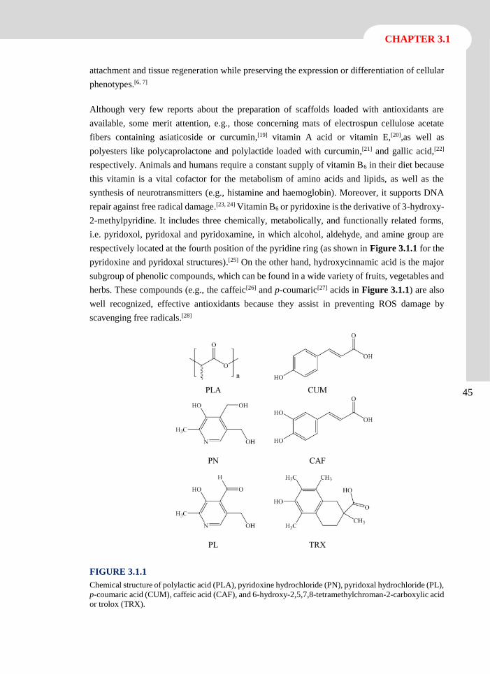
CHAPTER 3.1
45
attachment and tissue regeneration while preserving the expression or differentiation of cellular
phenotypes.[6, 7]
Although very few reports about the preparation of scaffolds loaded with antioxidants are
available, some merit attention, e.g., those concerning mats of electrospun cellulose acetate
fibers containing asiaticoside or curcumin,[19] vitamin A acid or vitamin E,[20],as well as
polyesters like polycaprolactone and polylactide loaded with curcumin,[21] and gallic acid,[22]
respectively. Animals and humans require a constant supply of vitamin B6 in their diet because
this vitamin is a vital cofactor for the metabolism of amino acids and lipids, as well as the
synthesis of neurotransmitters (e.g., histamine and haemoglobin). Moreover, it supports DNA
repair against free radical damage.[23, 24] Vitamin B6 or pyridoxine is the derivative of 3-hydroxy-
2-methylpyridine. It includes three chemically, metabolically, and functionally related forms,
i.e. pyridoxol, pyridoxal and pyridoxamine, in which alcohol, aldehyde, and amine group are
respectively located at the fourth position of the pyridine ring (as shown in Figure 3.1.1 for the
pyridoxine and pyridoxal structures).[25] On the other hand, hydroxycinnamic acid is the major
subgroup of phenolic compounds, which can be found in a wide variety of fruits, vegetables and
herbs. These compounds (e.g., the caffeic[26] and p-coumaric[27] acids in Figure 3.1.1) are also
well recognized, effective antioxidants because they assist in preventing ROS damage by
scavenging free radicals.[28]
FIGURE 3.1.1
Chemical structure of polylactic acid (PLA), pyridoxine hydrochloride (PN), pyridoxal hydrochloride (PL),
p-coumaric acid (CUM), caffeic acid (CAF), and 6-hydroxy-2,5,7,8-tetramethylchroman-2-carboxylic acid
or trolox (TRX).
46
Antioxidant loaded biodegradable scaffolds and potential application for DNA purification
The main goal of this work is to prepare 3D scaffolds from electrospun polylactide nanofibers
loaded with antioxidants (i.e., vitamin B6 in pyridoxine and pyridoxal form and two polyphenols,
caffeic and p-coumaric acids) to prevent oxidative stress of cells colonizing the material. For
this purpose, the morphology and physicochemical characterization of the new loaded matrices,
together with drug release kinetics, are studied and antioxidant bioactivity is evaluated.
CHAPTER 3.1
47
3.1.2 Experimental Section
Materials
Polylactide (PLA), a product of Natureworks (polymer 2002D), was kindly supplied by Nupik
International (Polinyà, Spain). According to the manufacturer, this PLA has a D content of
4.25%, a residual monomer content of 0.3%, a density of 1.24 g·cm-3, a glass transition
temperature (Tg) of 58 ºC and a melting point of 153 ºC. N,N- dimethylformamide (DMF),
dimethylsulfoxide (DMSO), pyridoxine hydrochloride (PN).[25] pyridoxal hydrochloride
(PL),[25] trolox (6-hydroxy-2,5,7,8-tetramethylchroman-2-carboxylic acid) (TRX), 2,2’-
azobis(2-methylpropionamidine) dihydrochloride (AAPH), 3-(4,5-dimethylthiazol-2-yl)-2,5-
diphenyl-2H-tetrazolium bromide (MTT) were purchased from Sigma-Aldrich (St. Louis,
USA). Caffeic acid (3,4-dihydroxycinnamic acid) (CAF) and p-coumaric acid (p-
hydroxycinnamic acid) (CUM) were purchased from Acros Organics (New Jersey, USA). HEp-
2 (epithelial cells derived from human laryngeal carcinoma), MDCK (kidney epithelial cells
derived from Madin-Darby Canine) and Cos-7 (kidney fibroblast cells derived from African
green monkey) and MG-63 (human osteosarcoma cells) were purchased from ATCC (USA).
Antioxidant Loaded PLA Nanofibers from Electrospinning
Nanofibers of PLA unloaded and loaded with an antioxidant (PN, PL, CAF or CUM) were
prepared by the electrospinning technique under optimal operational parameters obtained
experimentally. To this end, 1 g of PLA was dissolved in 9 mL of anhydrous DMF and the
polymer solution was maintained for 12-16 hours at 70 ºC to obtain a clear solution. Then, 1 mL
of DMSO containing the corresponding drug (0.1 g) was added and the mixture was vortexed to
obtain an electrospinable solution with a 10 and 1 w/v-% concentration of PLA and antioxidant,
respectively. Controls consisting of PLA only and a sample containing a typical drug (TRX)
with potent antioxidant activity were prepared by the same procedure. It should be pointed out
that TRX is a synthetic analogue derivative of vitamin E and cannot be applied to biomedical
use (i.e., only research and not human use). A plastic syringe of 10 mL (Becton Dickson, Spain)
was filled with the polymer solution; electrospinning was then carried out between the needle
(18G; Terumo, Belgium) connected to the anode and the static collector connected to the
cathode. The DC voltage was applied using a high voltage supply (ES30-5W model, Gamma
High Voltage Research, USA). The flow was controlled using a KD100 infusion syringe pump
(KD Scientific Inc., USA). The polymer jet was collected on an aluminium foil and on coverslips
of 14 mm diameter to evaluate cell adhesion and proliferation. All electrospinning experiments
were conducted at room temperature.
48
Antioxidant loaded biodegradable scaffolds and potential application for DNA purification
Morphology and Crystallinity of Drug Loaded PLA Nanofibers
The diameter of electrospun fibers was measured with a Philips TECNAI 10 transmission
electron microscope (TEM) at an accelerating voltage of 80 kV and using a SIS MegaView II
digital camera. Fibers were directly electrospun on 400 mesh Cu grids coated with a thin carbon
film. Inspection of fiber surfaces was performed by scanning electron microscopy using a Focus
Ion Beam Zeiss Neon 40 instrument (Carl Zeiss, Germany). Carbon coating was accomplished
with a Mitec K950 Sputter Coater (dotted with a film thickness monitor k150x). Samples were
viewed at an accelerating voltage of 5 kV. Wide angle X-ray diffraction patterns were acquired
at the CRG beamline (BM16) of the European Synchrotron Radiation Facility of Grenoble. The
beam was monochromatized to a wavelength of 0.098 nm. Scaffold samples were confined
between Kapton films. The WAXD detector was calibrated with diffractions of a standard of an
alumina (Al2O3) sample. The diffraction profiles were normalized to the beam intensity and
corrected considering the empty sample background. Calorimetric data were obtained by
differential scanning calorimetry with a TA Instruments Q100 series equipped with a
refrigeration cooling system (RCS). Experiments were conducted under a flow of dry nitrogen
with a sample weight of approximately 5 mg and the calibration of equipment was performed
with indium. Heating runs were carried out at a rate of 20 ºC·min-1.
Antioxidante Release Experiments
Controlled release measurements were performed with mats of electrospun samples cut into
square pieces (20 x 20 x 0.1 mm3). They were weighed and incubated in 50 mL tubes containing
30 mL of the release medium at 37 ºC and orbital shaking (200 rpm) for 1 week. Sörensen’s
buffer (pH 7.4) containing a 70 v/v-% of ethanol and alternatively TBE buffer (89 mM Tris, 89
mM boric acid, 2 mM EDTA, pH 8.4) were assayed as release media. Drug concentration in the
release media was evaluated by UV spectroscopy using a UV-3600 (Shimadzu, Japan).
Calibration curves were obtained by plotting the absorbance measured at the corresponding
wavelengths against drug concentration. Samples (1 mL) were drawn from the release medium
at predetermined intervals and an equal volume of fresh medium was added to the release vessel.
All the drug release tests were carried out using three replicates to control the homogeneity of
the release, and the results obtained from the samples were averaged.
Porosity of Antioxidant Loaded PLA Scaffolds
The porosity of the nanofiber scaffolds was measured using the liquid intrusion method.[29]
Scaffolds (n = 3) were weighed prior to immersion in ethanol (liquid intrusion). Vacuum was
applied for 10 min, and the scaffolds were left on a shaker table for 1 hour to allow diffusion of
ethanol into the void volume. The scaffolds were taken out and reweighed. The porosity was
calculated according to Equation 1:
𝑃 = [(𝑆𝑤−𝑆𝑑)
𝑑𝐸𝑡𝑂𝐻] / [
(𝑆𝑤−𝑆𝑑)
𝑑𝐸𝑡𝑂𝐻+
𝑆𝑑
𝑑𝑃𝐿𝐴] (1)
CHAPTER 3.1
49
where Sw, Sd are the weights of the wet and dry scaffolds, respectively, and dEtOH and dPLA the
densities of ethanol (0.789 g·mL-1) and amorphous PLA (1.24 g·mL-1), respectively. The latter
density was selected due to the low crystallinity and drug content of PLA scaffolds.
In-vitro Biocompatibility Assays: Cell Adhesion and Proliferation
HEp-2, MDCK, and Cos-7 cells were cultured in Dulbecco’s modified Eagle medium (DMEM)
supplemented with 10% fetal bovine serum, 1% penicillin/streptomycin and 2 mM L-glutamine
at 37 ºC in a humidified atmosphere with 5% CO2 and 95% air. The culture medium was changed
every two days and, for sub-culture, the cell monolayers were rinsed with phosphate buffered
saline (PBS) and detached by incubation with trypsin-EDTA (0.25%) at 37 ºC for 2-5 min. Cell
concentration was established by count with a Neubauer camera using 4% trypan-blue as dye
vital. The detached cells with viability ≥ 95% were used for cultures the conditions for
biocompatibility assays.
The unloaded and antioxidant loaded electrospun PLA nanofibers were collected on circular
coverslips (diameter 1.4 cm). These samples were placed into the wells of a multiwell culture
plate and sterilized by UV-radiation in a laminar flux cabinet for 15 min. To fix the samples in
the well, a small drop of silicone (Silbione® MED ADH 4300 RTV, Bluestar Silicones France
SAS, Lyon, France) was used as the adhesive. The samples were incubated with 1 mL of the
culture medium in culture conditions for 30 min to equilibrate the material. Finally, the medium
was aspired and the material was evaluated for cell adhesion and proliferation by exposing cells
to direct contact with the material surface.
To assess cell adhesion, aliquots of 50-100 µL containing 5x10⁴ cells were seeded onto the
electrospun samples in the wells. The plate was incubated in culture conditions for 30 min to
allow cell attachment to the material surface. Then, 1 mL of the culture medium was added to
each well and the plate was incubated for 24 h. Finally, cell viability was determined by the
MTT assay.[9, 10] Controls were performed by cell culture on the polystyrene surface of the plate
(TCPS).
Cell proliferation was evaluated by a similar procedure to the adhesion assay, but the aliquot of
50-100 µL contained 2x10⁴ cells. The cultures were maintained for 7 days to allow cell growth
and adequate cell confluence in the well. The media were renewed every two days. Finally,
viability was determined by the MTT assay.
Each sample was evaluated using five replicates and the results were averaged and graphically
represented. The statistical analysis was performed by one-way ANOVA to compare the means
of all groups; t-Test was then applied to determine a statistically significant difference between
two studied groups. The tests were performed with a confidence level of 95% (p < 0.05).
To obtain SEM images, samples from adhesion and proliferation assays were processed as
follows. First, they were fixed in 2.5% glutaraldehyde-PBS overnight at 4 ºC, and then
50
Antioxidant loaded biodegradable scaffolds and potential application for DNA purification
dehydrated by washing in an alcohol battery (30º, 50º, 70º, 90º, 95º and 100º) at 4 ºC for a
minimum of 30 min per step. Finally, the samples were dried and covered by carbon sputtering
for SEM examination.
Antioxidative Effect of PLA Scaffolds Loaded with Vitamin B6 and Polyphenols
This assay was performed to determine the protective potential of antioxidant loaded PLA
nanofibers and to compare the results with unloaded PLA nanofibers. Samples were exposed to
oxidative stress induced by AAPH. This water soluble compound has a well-recognized
capability to generate free radicals at a constant rate.[30]
MG-63 cells were cultured and manipulated as described above for other cell lines. An aliquot
of 50-100 µL containing 2x10⁴ cells was seeded onto the electrospun samples. The plate was
incubated in culture conditions for 30 min to allow cell attachment to the material. Then, 1 mL
of the culture medium was added to each well and the plate was incubated for 48 h. The medium
was subsequently replaced with a fresh one supplemented with different concentrations of the
AAPH radical initiator and the culture was continued for 24 h. Finally, all the media were
replaced again with a fresh medium without AAPH and supplemented with the MTT reactive to
determine cell viability.[9, 10] TCPS controls without and with AAPH were performed to obtain
the highest and lowest viability, respectively. The results were statistical analyzed as described
above.
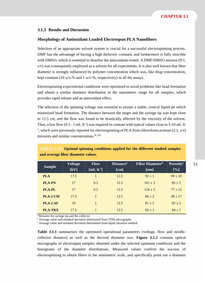
CHAPTER 3.1
51
3.1.3 Results and Discussion
Morphology of Antioxidant Loaded Electrospun PLA Nanofibers
Selection of an appropriate solvent system is crucial for a successful electrospinning process.
DMF has the advantage of having a high dielectric constant, and furthermore is fully miscible
with DMSO, which is essential to dissolve the antioxidants tested. A DMF/DMSO mixture (9:1,
v/v) was consequently employed as a solvent for all experiments. It is also well known that fiber
diameter is strongly influenced by polymer concentration which was, like drug concentration,
kept constant (10 w/v-% and 1 w/v-%, respectively) in all the assays.
Electrospinning experimental conditions were optimized to avoid problems like bead formation
and obtain a similar diameter distribution in the nanometric range for all samples, which
provides rapid release and an antioxidant effect.
The selection of the spinning voltage was essential to ensure a stable, conical liquid jet which
minimized bead formation. The distance between the target and the syringe tip was kept close
to 12.5 cm, and the flow was found to be drastically affected by the viscosity of the solvent.
Thus, a low flow (0.5 - 1 mL·h-1) was required in contrast with typical values close to 5-10 mL·h-
1, which were previously reported for electrospinning of PLA from chloroform:acetone (2:1, v/v)
mixtures and similar concentrations.[9, 10]
TABLE 3.1.1. Optimal spinning conditions applied for the different studied samples
and average fiber diameter values.
Sample Voltage
[kV]
Flow
[mL·h-1]
Distancea
[cm]
Fiber Diameterb
[nm]
Porosityc
[%]
PLA 17.5 1 12.5 92 ± 1 69 ± 10
PLA-PN 17 0.5 12.5 101 ± 3 85 ± 5
PLA-PL 17 0.5 12.5 124 ± 3 77 ± 12
PLA-CUM 17.5 1 12.5 86 ± 2 49 ± 17
PLA-CAF 19 1 12.5 81 ± 2 82 ± 5
PLA-TRX 17.5 1 12.5 63 ± 1 84 ± 1
a Between the syringe tip and the collector b Average value and standard deviation determined from TEM micrographs c Average value and standard deviation determined from liquid intrusion method
Table 3.1.1 summarizes the optimized operational parameters (voltage, flow and needle-
collector distance) as well as the derived diameter size. Figure 3.1.2 contains optical
micrographs of electrospun samples obtained under the selected optimum conditions and the
histograms of the diameter distributions. Measured values confirm the success of
electrospinning to obtain fibers in the nanometric scale, and specifically point out a diameter
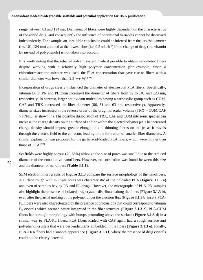
52
Antioxidant loaded biodegradable scaffolds and potential application for DNA purification
range between 63 and 124 nm. Diameters of fibers were highly dependent on the characteristics
of the added drug, and consequently the influence of operational variables cannot be discussed
independently. For example, an unreliable conclusion could be inferred from the largest diameter
(i.e. 101-124 nm) attained at the lowest flow (i.e. 0.5 mL·h-1) if the change of drug (i.e. vitamin
B6 instead of polyphenols) is not taken into account.
It is worth noting that the selected solvent system made it possible to obtain nanometric fibers
despite working with a relatively high polymer concentration (for example, when a
chloroform:acetone mixture was used, the PLA concentration that gave rise to fibers with a
similar diameter was lower than 2.5 w/v-%).[10]
Incorporation of drugs clearly influenced the diameter of electrospun PLA fibers. Specifically,
vitamin B6 in PN and PL form increased the diameter of fibers from 92 to 101 and 123 nm,
respectively. In contrast, larger antioxidant molecules having a carboxylic group such as CUM,
CAF and TRX decreased the fiber diameter (86, 81 and 63 nm, respectively). Apparently,
diameter sizes increased in the reverse order of the drug molecular volume (TRX > CUM/CAF
> PN/PL, as shown in). The possible dissociation of TRX, CAF and CUM into ionic species can
increase the charge density on the surface of and/or within the ejected polymer jet. The increased
charge density should impose greater elongation and thinning forces on the jet as it travels
through the electric field to the collector, leading to the formation of smaller fiber diameters. A
similar explanation was proposed for the gallic acid-loaded PLA fibers, which were thinner than
those of PLA.[22]
Scaffolds were highly porous (70-85%) although the size of pores was small due to the reduced
diameter of the constitutive nanofibers. However, no correlation was found between this size
and the diameter of nanofibers (Table 3.1.1).
SEM electron micrographs of Figure 3.1.3 compare the surface morphology of the nanofibers.
A surface rough with multiple holes was characteristic of the unloaded PLA (Figure 3.1.3 a)
and even of samples having PN and PL drugs. However, the micrographs of PLA-PN samples
also highlight the presence of isolated drug crystals distributed along the fibers (Figure 3.1.3 b),
even after the partial melting of the polymer under the electron flux (Figure 3.1.3 b, inset). PLA-
PL fibers were also characterized by the presence of protrusions that could correspond to vitamin
B6 crystals which seemed better integrated in the fiber structure (Figure 3.1.3 c). PLA-CUM
fibers had a rough morphology with bumps protruding above the surface (Figure 3.1.3 d) in a
similar way to PLA-PL fibers. PLA fibers loaded with CAF again had a rough surface and
polyphenol crystals that were perpendicularly embedded in the fibers (Figure 3.1.3 e). Finally,
PLA-TRX fibers had a smooth appearance (Figure 3.1.3 f) where the presence of drug crystals
could not be clearly detected.
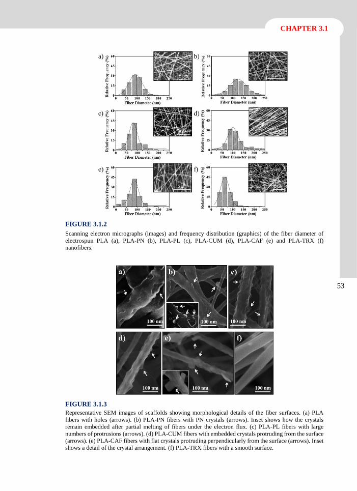
CHAPTER 3.1
53
FIGURE 3.1.2
Scanning electron micrographs (images) and frequency distribution (graphics) of the fiber diameter of
electrospun PLA (a), PLA-PN (b), PLA-PL (c), PLA-CUM (d), PLA-CAF (e) and PLA-TRX (f)
nanofibers.
FIGURE 3.1.3
Representative SEM images of scaffolds showing morphological details of the fiber surfaces. (a) PLA
fibers with holes (arrows). (b) PLA-PN fibers with PN crystals (arrows). Inset shows how the crystals
remain embedded after partial melting of fibers under the electron flux. (c) PLA-PL fibers with large
numbers of protrusions (arrows). (d) PLA-CUM fibers with embedded crystals protruding from the surface
(arrows). (e) PLA-CAF fibers with flat crystals protruding perpendicularly from the surface (arrows). Inset
shows a detail of the crystal arrangement. (f) PLA-TRX fibers with a smooth surface.
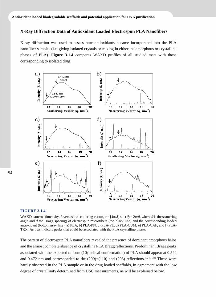
54
Antioxidant loaded biodegradable scaffolds and potential application for DNA purification
X-Ray Diffraction Data of Antioxidant Loaded Electrospun PLA Nanofibers
X-ray diffraction was used to assess how antioxidants became incorporated into the PLA
nanofiber samples (i.e. giving isolated crystals or mixing in either the amorphous or crystalline
phases of PLA). Figure 3.1.4 compares WAXD profiles of all studied mats with those
corresponding to isolated drug.
FIGURE 3.1.4
WAXD patterns (intensity, I, versus the scattering vector, q = [4/] sin () = 2/d, where is the scattering
angle and d the Bragg spacing) of electrospun microfibers (top black line) and the corresponding loaded
antioxidant (bottom gray line): a) PLA, b) PLA-PN, c) PLA-PL, d) PLA-CUM, e) PLA-CAF, and f) PLA-
TRX. Arrows indicate peaks that could be associated with the PLA crystalline phase.
The pattern of electrospun PLA nanofibers revealed the presence of dominant amorphous halos
and the almost complete absence of crystalline PLA Bragg reflections. Predominant Bragg peaks
associated with the expected -form (103 helical conformation) of PLA should appear at 0.542
and 0.472 nm and corresponded to the (200)+(110) and (203) reflections.[9, 31-33] These were
hardly observed in the PLA sample or in the drug loaded scaffolds, in agreement with the low
degree of crystallinity determined from DSC measurements, as will be explained below.

CHAPTER 3.1
55
No peaks associated with PL crystals were observed in the diffractograms of PLA-PL samples
(Figure 3.1.4 c), suggesting that this drug was well mixed in the polymeric matrix, as also
inferred from morphological observations (Figure 3.1.3 c). On the contrary, crystalline
reflections with a relatively low intensity (Figure 3.1.4 b) were detected in the PN loaded
scaffolds; note that in this case a low number of crystals were observed in the electron
micrographs (Figure 3.1.3 b).
Samples loaded with CUM and CAF polyphenols gave rise to X-ray profiles (Figures 3.1.4 d
and 3.1.4 e) where the characteristic reflections of the corresponding drug crystals appeared with
high intensity. Differences on the peak width allowed deducing a smaller size of CAF crystals
(i.e. those with the higher width) according to the Scherrer equation.[34] The relative intensity of
peaks associated with CAF crystals changed slightly in the loaded scaffold with respect to the
powder drug (Figure 3.1.4 e), suggesting that crystals were deposited in the PLA nanofibers in
a preferred orientation, as also suggested by the morphological observations (Figure 3.1.3 e).
Finally, the X-ray profile of the PLA-TRX sample revealed the absence of TRX crystals,
indicating that these antioxidant molecules were well integrated in the polylactide matrix.
However, the appearance of new Bragg reflections also merits attention because it suggested
that a new phase can occur by the interaction between TRX and PLA molecules.
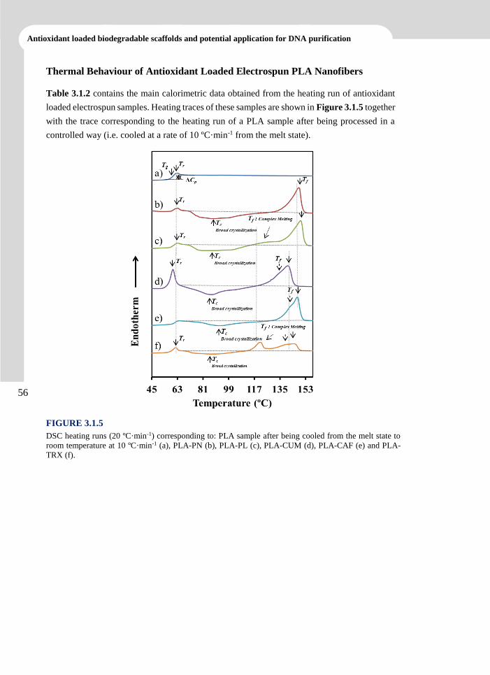
56
Antioxidant loaded biodegradable scaffolds and potential application for DNA purification
Thermal Behaviour of Antioxidant Loaded Electrospun PLA Nanofibers
Table 3.1.2 contains the main calorimetric data obtained from the heating run of antioxidant
loaded electrospun samples. Heating traces of these samples are shown in Figure 3.1.5 together
with the trace corresponding to the heating run of a PLA sample after being processed in a
controlled way (i.e. cooled at a rate of 10 ºC·min-1 from the melt state).
FIGURE 3.1.5
DSC heating runs (20 ºC·min-1) corresponding to: PLA sample after being cooled from the melt state to
room temperature at 10 ºC·min-1 (a), PLA-PN (b), PLA-PL (c), PLA-CUM (d), PLA-CAF (e) and PLA-
TRX (f).
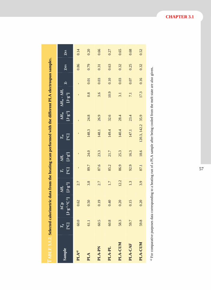
CHAPTER 3.1
57
T
AB
LE
3.1
.2.
Sel
ecte
d c
alo
rim
etri
c d
ata
fro
m t
he
hea
tin
g s
can
per
form
ed w
ith
th
e d
iffe
ren
t P
LA
ele
ctr
osp
un
sa
mp
les. χ
RA
0.1
4
0.2
0
0.6
6
0.2
7
0.6
5
0.6
8
0.5
2
a) F
or
com
par
ativ
e p
urp
ose
s d
ata
corr
esp
ond
ing
to
a h
eati
ng r
un
of
a P
LA
sam
ple
aft
er b
eing
co
ole
d f
rom
th
e m
elt
stat
e ar
e al
so g
iven
.
χM
A
0.8
6
0.7
9
0.3
1
0.6
3
0.3
2
0.2
5
0.3
2
χc
- 0.0
1
0.0
3
0.1
0
0.0
3
0.0
7
0.1
6
ΔH
m -
ΔH
c
[J·g
-1] - 0
.8
3.6
10
.9
3.1
7.1
17
.3
ΔH
m
[J·g
-1]
- 24
.8
26
.9
32
.6
28
.4
23
.4
35
.9
Tm
[ºC
] -
14
8.3
14
8.1
14
9.4
14
0.4
14
7.1
12
0.3
, 14
2.2
ΔH
c
[J·g
1] -
24
.0
23
.3
21
.7
25
.3
16
.3
18
.6
Tc
[ºC
] -
89
.7
87
.6
85
.2
86
.9
92
.9
87
.1
ΔH
r
[J·g
-1]
2.7
3.8
2.7
1.7
12
.2
1.3
3.9
ΔC
p
[J·g
-1·º
C-1
]
0.6
2
0.5
0
0.1
9
0.4
0
0.2
0
0.1
5
0.2
0
Tg
[ºC
]
60
.0
61
.1
60
.5
60
.8
58
.3
59
.7
59
.8
Sa
mp
le
PL
Aa)
PL
A
PL
A-P
N
PL
A-P
L
PL
A-C
UM
PL
A-C
AF
PL
A-C
UM
58
Antioxidant loaded biodegradable scaffolds and potential application for DNA purification
Several features deserve attention:
All electrospun samples had a broad exothermic peak (70-120 ºC) indicative of the cold
crystallization of PLA. Its appearance, enthalpy and specific temperature range depended
on the sample nature (i.e. the antioxidant added to PLA). The high molecular orientation
attained in the electrospun fibers facilitated the crystallization process, as previously
reported,[9, 33] which was not observed when the PLA sample was processed by slow cooling
from the melt state (Figure 3.1.5 a). On the contrary, unloaded electrospun PLA samples
again were able to crystallize (Table 3.1.2).
Electrospun samples showed melting peaks which were mainly due to the cold
crystallization process. The difference between melting and cold crystallization enthalpies
was low, and consequently samples crystallized with high difficulty during the
electrospinning process. The degree of crystallinity (c) of the electrospun samples could
be evaluated from the above enthalpic difference and the reported melting enthalpy (106
J·g-1) for a 100% crystalline sample.[35, 36] Significant crystallinity differences were found
between the electrospun samples although these values were always relatively low.
Specifically, samples loaded with TRX and PL had the highest values (i.e. 17.3 and 10.9%,
respectively). It should be pointed out that these were the only samples where no crystals
of the added drug were detected in the X-ray profiles. Note also that all samples attained
moderate crystallinity (i.e. 22-34%) after the cold crystallization process.
The melting process, which was relatively complex, gave rise to a main peak (149-140 ºC)
together with a small shoulder, and in some cases to an additional minor peak at a lower
temperature. The main peak temperature changed slightly depending on the loaded drug and
specifically on its capability to be incorporated into the crystalline structure. This capability
was higher for the CUM molecules, as deduced from the higher decrease in the melting
temperature and even in the crystallinity (Table 3.1.2). The shoulder and the main peak
detected in the heating runs seem to correspond to the characteristic PLA double melting
peak, which is associated with a recrystallization process where thinner lamellae become
thicker. The minor peak observed in two cases (i.e. PLA-TRX and PLA-PL samples) at a
temperature close to 120 ºC is indicative of the existence of highly defective crystals (i.e.
those with a significantly lower thickness or a high drug content).
All PLA heating traces had a clear glass transition, as could be presumed for practically
amorphous samples (i.e. those obtained before cold crystallization), and also a relaxation
endothermic peak that usually appeared later. This peak is indicative of the trend of the
metastable PLA glassy material to achieve equilibrium thermodynamic conditions with a
lower specific volume, enthalpy and entropy, which logically render a material with higher
stiffness. The glass transition temperature was practically constant for all samples, and
consequently the incorporation of the aromatic drug molecules did not facilitate the mobility
CHAPTER 3.1
59
of the rigid PLA molecules. However, the strong impact on the relaxation process for the
PLA-CUM sample is worth noting.
The amorphous phase of PLA is complex and should usually be analyzed assuming a
biphasic model where a mobile amorphous phase (MAP), responsible for the heat capacity
jump in the glass transition region, and a rigid amorphous phase (RAP) associated with the
hindered molecular motions of chains within lamellar stacks, can be distinguished.
Specifically, these fractions are determined as MAP = Cp/CP0 and RAP = 1-c -MAP,
where Cp and CP0 correspond to the heat capacity jump of the studied sample and a fully
amorphous PLA (i.e. 0.623 J·g-1·ºC-1). Results in Table 3.1.2 again show significant
differences between all loaded PLA samples and, interestingly, a loss of correlation between
c and RAP fractions since both should change in a similar way (i.e. both should increase
or decrease). Discrepancies suggest the existence of interfaces between drug crystals and
PLA that increased theRAP fraction.
Spectral Characteristics Related to the Antioxidants Release from PLA
Electrospun
The release of molecules loaded in an electrospun matrix is intimately related to the morphology
and structure of the constituting fibers and also to the environment where such release occurs.
After the analysis of the characteristics of the loaded PLA nanofibers, it seemed interesting to
study the behavior in solution of the selected drugs. To this end, two media of different
hydrophobicity/hydrophilicity were selected to vary the affinity with the released drug.
Specifically, a Sörensen-ethanol (3:7, v/v; pH 7.4) mixture and a TBE buffer (pH 8.4) were taken
as examples of hydrophobic and hydrophilic release media, respectively. UV-Vis spectroscopy
was used to quantify the amount of released antioxidant and to detect spectral/electronic changes
undergone by the released molecules (Figure 3.1.6). The PBS buffer was also tested as release
hydrophilic medium (data not shown), and the release kinetic results were similar to those
obtained in Sörensen-ethanol (3:7, v/v; pH 7.4) buffer; however, TBE buffer has the advantage
of facilitating the detection of vitamins and polyphenols by UV-Vis spectroscopy due to
electronic changes in these molecules by the presence of the borate ions in the buffer. For this
reason, TBE buffer was chosen as the hydrophilic medium for release assays.
The spectrum of PN in the hydrophobic medium (Figure 3.1.6 a) is characterized by two bands
at 280 nm and 325 nm associated with the presence of the 3-hydroxyl group (i.e. that directly
linked to the pyridine ring). In aqueous solution, the spectrum became clearly dependent on the
pH.[37] A single maximum at 292 nm is characteristic when pH values are equal to or lower than
3, but it gradually decreased and two new bands appeared at 255 and 325 nm as the pH was
raised to 7.4, which is precisely the value of the medium tested. This splitting is characteristic
of the presence of the hydroxyl groups since it was never observed for 3-methoxy derivatives.[37]
In contrast, the absorption spectra of PN in the pH 8.4 TBE hydrophilic buffer (Figure 3.1.6 b)
showed a single band at 292 nm, which can be explained by the presence of the borate ions in
60
Antioxidant loaded biodegradable scaffolds and potential application for DNA purification
the buffer. The borate-PN complex, which has been reported in previous works, consisted of the
coordination of bore atoms with two PN molecules through their oxygen atoms in positions 3
and 4. This complex kept the physiological activity of PN and was thermostable in neutral
solutions.[37, 38]
The PL and PN spectra in the hydrophobic and hydrophilic media (Figures 3.1.6 c and 3.1.6 d,
respectively) were similar, although a new band appeared near 400-410 nm, most probably
because of the presence of the aldehyde group of PL.
The spectra of CUM in the Sörensen-ethanol medium correspond to a single band with a
maximum at 285 nm and a shoulder at 310 nm (Figure 3.1.6 e). This main band can be attributed
to the 3-hydroxyl aromatic substitution and basically remains unchanged when the hydrophilic
medium is used (Figure 3.1.6 f). The spectrum of CAF with 3 and 4- hydroxyl aromatic
substitutions is clearly different since now two bands appear at 285 nm and 310 nm in the
Sörensen-ethanol buffer (Figure 3.1.6 g). A notable change in the spectrum occurred in the
hydrophilic medium since the intensity of the peaks is reversed and specifically the intensity of
the peak at 310 nm increases significantly (Figure 3.1.6 h).
The TRX molecules in both hydrophobic and hydrophilic media (Figures 3.1.6 i and 3.1.6 j)
have identical spectral characteristics defined by a single band at 291 nm (Sörensen-ethanol
buffer) and 289 nm (TBE buffer). Note that the molecule has only a hydroxyl substitution, and
therefore a simple spectrum should be expected.
Finally, for all antioxidants, lineal plots of absorbance (measured at the specific wavelength
corresponding to the maximum determined for each release medium) versus drug concentration
were obtained (insets of Figures 3.1.6 a-3.1.6 j) and used to estimate the drug concentration in
the subsequent release experiments.
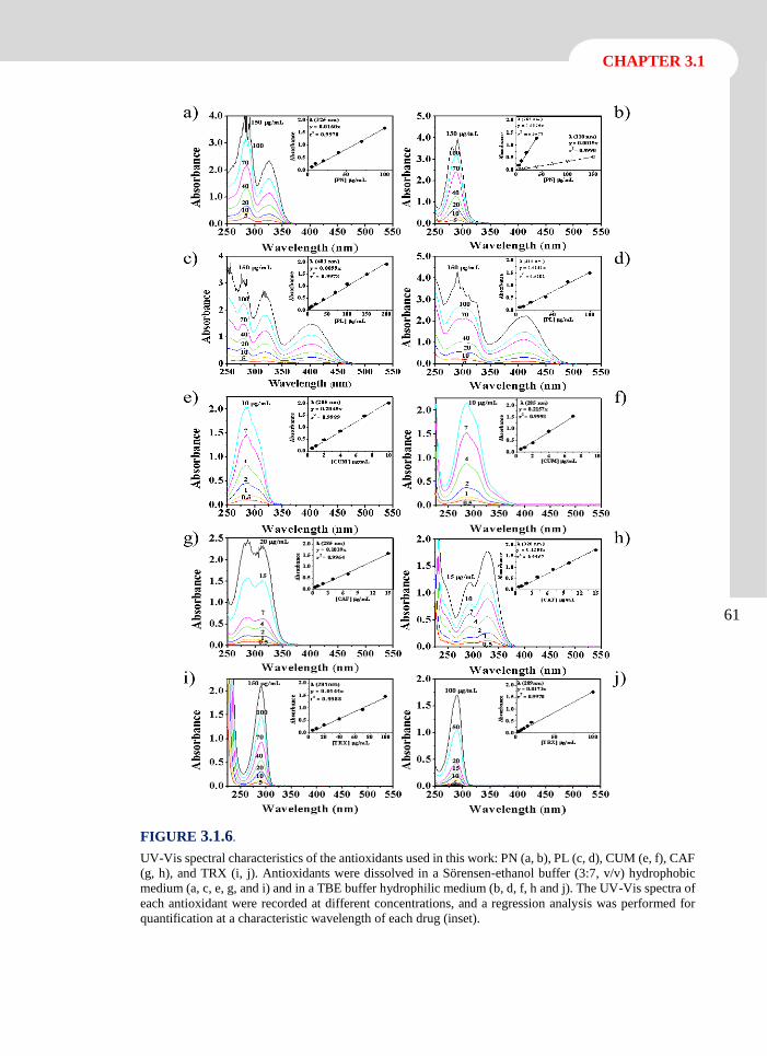
CHAPTER 3.1
61
FIGURE 3.1.6.
UV-Vis spectral characteristics of the antioxidants used in this work: PN (a, b), PL (c, d), CUM (e, f), CAF
(g, h), and TRX (i, j). Antioxidants were dissolved in a Sörensen-ethanol buffer (3:7, v/v) hydrophobic
medium (a, c, e, g, and i) and in a TBE buffer hydrophilic medium (b, d, f, h and j). The UV-Vis spectra of
each antioxidant were recorded at different concentrations, and a regression analysis was performed for
quantification at a characteristic wavelength of each drug (inset).
62
Antioxidant loaded biodegradable scaffolds and potential application for DNA purification
The release kinetics can be calculated from experimental results by several theoretical models,
typically first-order,[39, 40] Higuchi[41, 42] and their combination.[43] The release generally occurred
in two different steps, i.e. rapid release of molecules that should be deposited mainly on the high
surface area of nanofibers and slow release that should involve the diffusion of molecules
through the polymer bulk towards the release medium. In this way, a combined model based on
the Higuchi and first-order models (Equation 2 and 3) is usually used to describe the first (0-
60%) and second (40-100%) parts of the release, respectively:
Mt M0⁄ =kht1 2⁄ (0 ≤ Mt M0 ≤ 0.6⁄ ) (2)
ln(1- Mt M0⁄ ) =a-k1t (0.4≤ Mt M0≤1.0⁄ ) (3)
where kh is the Higuchi release constant, k1 is the first-order release constant, a takes into account
the release in the first step, Mt is the percentage of drug released at time t, and M0 is the drug
equilibrium percentage (considered as the maximum drug percentage).
The release of the studied drugs in the two media is graphically shown in Figure 3.1.7, whereas
the deduced kinetic constants are summarized in Table 3.1.3. In general, the release could be
well fitted using only the Higuchi model, although in some specific cases (i.e. PL and TRX in
the Sörensen-ethanol medium), this model had a limited range of application, and therefore the
second part of the release should be fitted with a first-order kinetics.
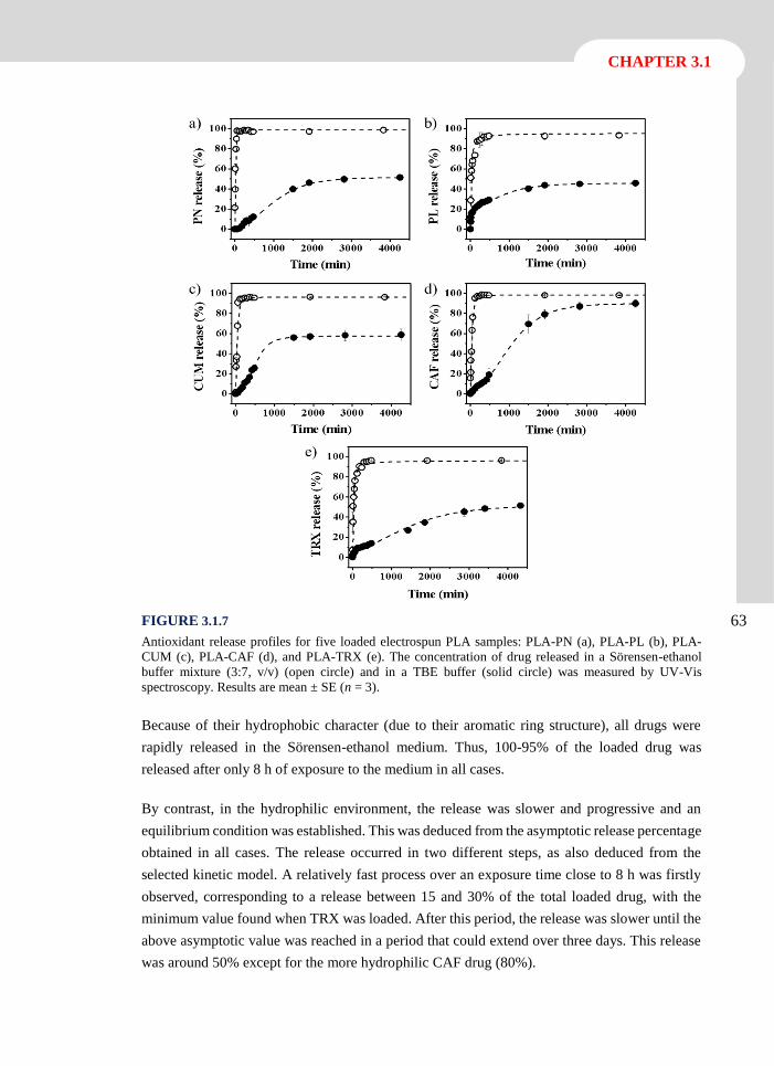
CHAPTER 3.1
63 FIGURE 3.1.7
Antioxidant release profiles for five loaded electrospun PLA samples: PLA-PN (a), PLA-PL (b), PLA-
CUM (c), PLA-CAF (d), and PLA-TRX (e). The concentration of drug released in a Sörensen-ethanol
buffer mixture (3:7, v/v) (open circle) and in a TBE buffer (solid circle) was measured by UV-Vis
spectroscopy. Results are mean ± SE (n = 3).
Because of their hydrophobic character (due to their aromatic ring structure), all drugs were
rapidly released in the Sörensen-ethanol medium. Thus, 100-95% of the loaded drug was
released after only 8 h of exposure to the medium in all cases.
By contrast, in the hydrophilic environment, the release was slower and progressive and an
equilibrium condition was established. This was deduced from the asymptotic release percentage
obtained in all cases. The release occurred in two different steps, as also deduced from the
selected kinetic model. A relatively fast process over an exposure time close to 8 h was firstly
observed, corresponding to a release between 15 and 30% of the total loaded drug, with the
minimum value found when TRX was loaded. After this period, the release was slower until the
above asymptotic value was reached in a period that could extend over three days. This release
was around 50% except for the more hydrophilic CAF drug (80%).
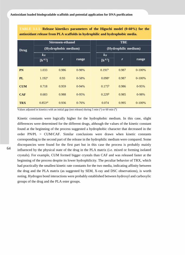
64
Antioxidant loaded biodegradable scaffolds and potential application for DNA purification
TABLE 3.1.3. Release kinetikcs parameters of the Higuchi model (0-60%) for the
antioxidant release from PLA scaffolds in hydrophilic and hydrophobic media.
Drug
Sörensen-ethanol
TBE
(Hydrophobic medium) (Hydrophilic medium)
kH
r range
kH
r range [h-0.5] [h-0.5]
PN 1.033 0.986 0-98% 0.191b 0.987 0-100%
PL 1.192a 0.93 0-58% 0.098a 0.987 0-100%
CUM 0.718 0.959 0-94% 0.175b 0.986 0-95%
CAF 0.683 0.988 0-95% 0.229b 0.985 0-98%
TRX 0.853a) 0.936 0-76% 0.074 0.995 0-100%
Values adjusted in kinetics with an initial gap (not release) during 5 min (a) or 60 min (b)
Kinetic constants were logically higher for the hydrophobic medium. In this case, slight
differences were determined for the different drugs, although the values of the kinetic constant
found at the beginning of the process suggested a hydrophobic character that decreased in the
order PN/PL > CUM/CAF. Similar conclusions were drawn when kinetic constants
corresponding to the second part of the release in the hydrophilic medium were compared. Some
discrepancies were found for the first part but in this case the process is probably mainly
influenced by the physical state of the drug in the PLA matrix (i.e. mixed or forming isolated
crystals). For example, CUM formed bigger crystals than CAF and was released faster at the
beginning of the process despite its lower hydrophilicity. The peculiar behavior of TRX, which
had practically the smallest kinetic rate constants for the two media, indicating affinity between
the drug and the PLA matrix (as suggested by SEM, X-ray and DSC observations), is worth
noting. Hydrogen bond interactions were probably established between hydroxyl and carboxylic
groups of the drug and the PLA ester groups.
CHAPTER 3.1
65
Biocompatibility of Antioxidant Loaded Electrospun PLA Nanofibers: Cell
Adhesion and Proliferation
PLA nanofiber matrices loaded with antioxidants were evaluated as appropriate scaffolds to
support cell adhesion and proliferation. Thus, epithelial cells like MDCK and HEp-2, and
fibroblast-like cells such as Cos-7 were seeded in direct contact with the studied materials
(Figure 3.1.8). Cell adhesion was determined after 24 hours as an early event of cell colonization
on the scaffolds while cell proliferation was determined at 7 days as an endpoint that
demonstrated cell growth on the materials.
Cell attachment was evaluated considering the ratio between the number of adhered cells and
cell viability (i.e. number of cells adhered on the TCPS control) for each cultured well of the
plate. In this way, it was clearly established that a high number of cells, close to 80%, adhered
to the scaffold surface although this surface corresponded to only 68% of the total well surface.
This important feature was found for all tested cells (i.e. Cos-7, MDCK and HEp-2, as shown in
Figure 3.1.8 a, 3.1.8 c and 3.1.8 e, respectively). Specifically, the adhesion/viability ratio of the
scaffold, together with the ratio obtained for the remaining plate surface of the well that
contained the sample, was similar to the control. In conclusion, the obtained results clearly
exclude any possible cytotoxic effect generated by the PLA matrices after being loaded with the
selected antioxidants.Cell proliferation was determined as the total growth in the wells
containing the electrospun samples. Thus, the three cell lines (Cos-7, MDCK and HEp-2 cells)
showed a significant increase in the cell number when the well contained antioxidant loaded
PLA scaffolds (Figure 3.1.8 b, 3.1.8 d and 3.1.8 f). This increase demonstrated that cell growth
and/or cell culture had a self-basal oxidative stress[4, 6-8] and that the antioxidant activity of
vitamin B6, its derivative and polyphenols released from the loaded scaffold improved the
cellular environment considerably by their radical-scavenging capacity. It should be pointed out
that the selected natural antioxidants gave better results than the well-recognized TRX, which
was used as a positive control. The effect of the natural antioxidants changed slightly according
to their nature and the cells tested. Thus, the highest proliferation was found for MDCK cells
grown on CUM loaded scaffolds (i.e. more than 50% compared to the TCPS control), whereas
the lowest proliferation corresponded to HEp-2 cells on PLA-CUM scaffolds (i.e. only more
than 20% compared to the control). Changes in the antioxidant effect of vitamin B6, its derivative
and polyphenols during prolonged culture could be related to decomposition and pro-oxidative
effects of the products of this decomposition.[44]
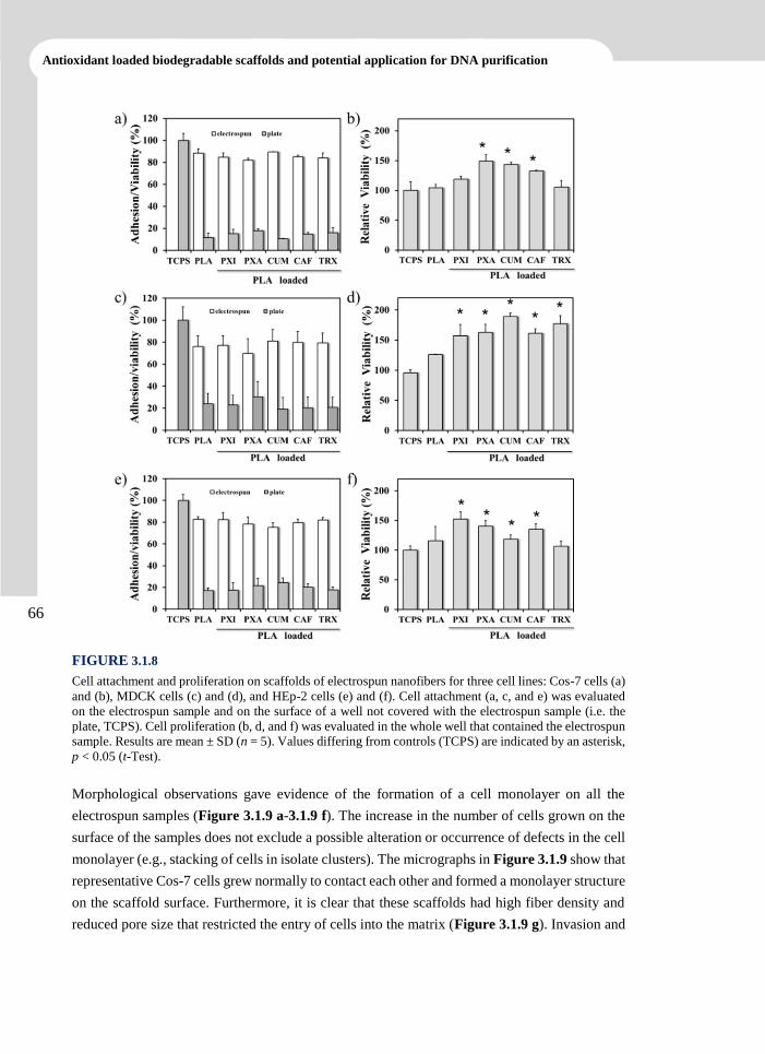
66
Antioxidant loaded biodegradable scaffolds and potential application for DNA purification
FIGURE 3.1.8
Cell attachment and proliferation on scaffolds of electrospun nanofibers for three cell lines: Cos-7 cells (a)
and (b), MDCK cells (c) and (d), and HEp-2 cells (e) and (f). Cell attachment (a, c, and e) was evaluated
on the electrospun sample and on the surface of a well not covered with the electrospun sample (i.e. the
plate, TCPS). Cell proliferation (b, d, and f) was evaluated in the whole well that contained the electrospun
sample. Results are mean ± SD (n = 5). Values differing from controls (TCPS) are indicated by an asterisk,
p < 0.05 (t-Test).
Morphological observations gave evidence of the formation of a cell monolayer on all the
electrospun samples (Figure 3.1.9 a-3.1.9 f). The increase in the number of cells grown on the
surface of the samples does not exclude a possible alteration or occurrence of defects in the cell
monolayer (e.g., stacking of cells in isolate clusters). The micrographs in Figure 3.1.9 show that
representative Cos-7 cells grew normally to contact each other and formed a monolayer structure
on the scaffold surface. Furthermore, it is clear that these scaffolds had high fiber density and
reduced pore size that restricted the entry of cells into the matrix (Figure 3.1.9 g). Invasion and
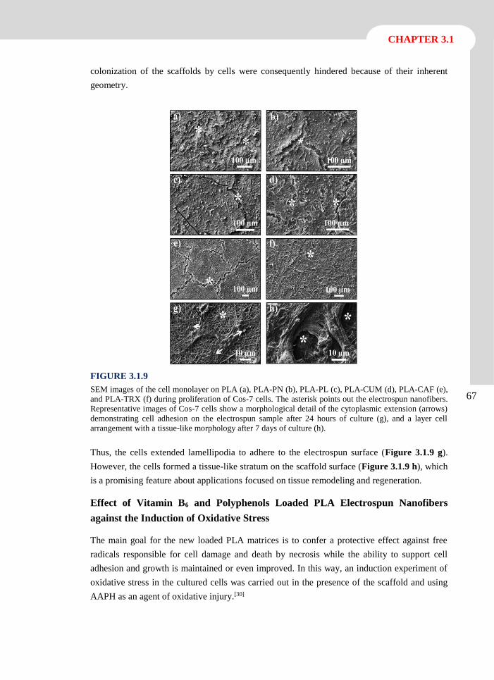
CHAPTER 3.1
67
colonization of the scaffolds by cells were consequently hindered because of their inherent
geometry.
FIGURE 3.1.9
SEM images of the cell monolayer on PLA (a), PLA-PN (b), PLA-PL (c), PLA-CUM (d), PLA-CAF (e),
and PLA-TRX (f) during proliferation of Cos-7 cells. The asterisk points out the electrospun nanofibers.
Representative images of Cos-7 cells show a morphological detail of the cytoplasmic extension (arrows)
demonstrating cell adhesion on the electrospun sample after 24 hours of culture (g), and a layer cell
arrangement with a tissue-like morphology after 7 days of culture (h).
Thus, the cells extended lamellipodia to adhere to the electrospun surface (Figure 3.1.9 g).
However, the cells formed a tissue-like stratum on the scaffold surface (Figure 3.1.9 h), which
is a promising feature about applications focused on tissue remodeling and regeneration.
Effect of Vitamin B6 and Polyphenols Loaded PLA Electrospun Nanofibers
against the Induction of Oxidative Stress
The main goal for the new loaded PLA matrices is to confer a protective effect against free
radicals responsible for cell damage and death by necrosis while the ability to support cell
adhesion and growth is maintained or even improved. In this way, an induction experiment of
oxidative stress in the cultured cells was carried out in the presence of the scaffold and using
AAPH as an agent of oxidative injury.[30]
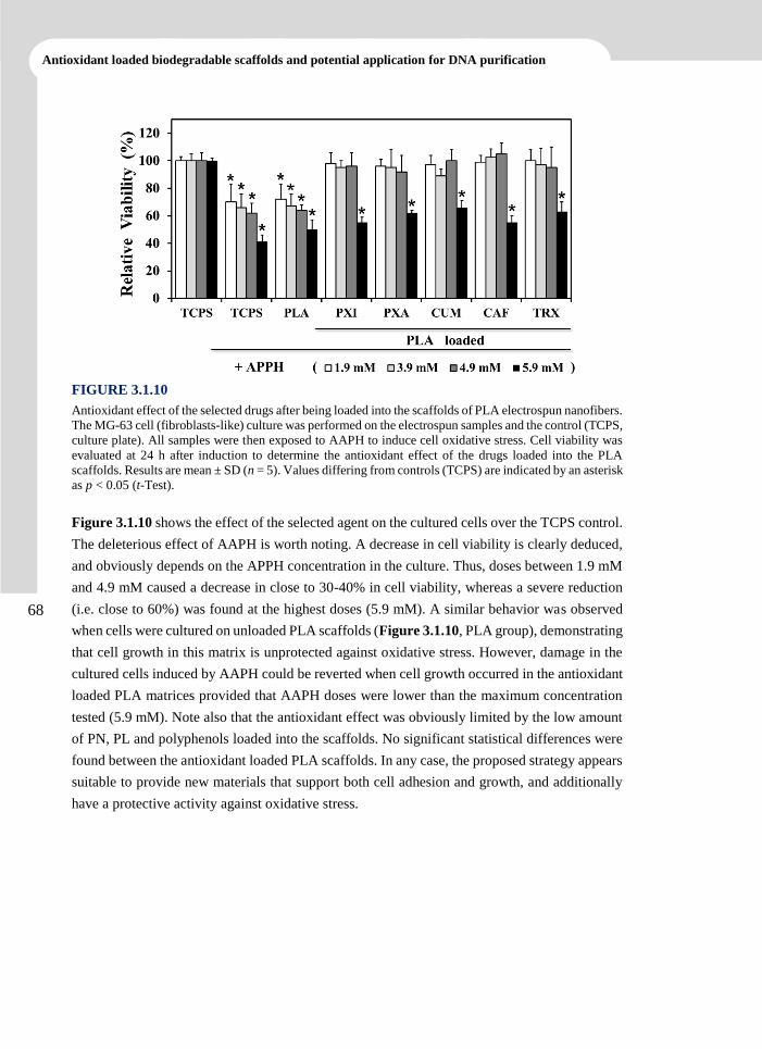
68
Antioxidant loaded biodegradable scaffolds and potential application for DNA purification
FIGURE 3.1.10
Antioxidant effect of the selected drugs after being loaded into the scaffolds of PLA electrospun nanofibers.
The MG-63 cell (fibroblasts-like) culture was performed on the electrospun samples and the control (TCPS,
culture plate). All samples were then exposed to AAPH to induce cell oxidative stress. Cell viability was
evaluated at 24 h after induction to determine the antioxidant effect of the drugs loaded into the PLA
scaffolds. Results are mean ± SD (n = 5). Values differing from controls (TCPS) are indicated by an asterisk
as p < 0.05 (t-Test).
Figure 3.1.10 shows the effect of the selected agent on the cultured cells over the TCPS control.
The deleterious effect of AAPH is worth noting. A decrease in cell viability is clearly deduced,
and obviously depends on the APPH concentration in the culture. Thus, doses between 1.9 mM
and 4.9 mM caused a decrease in close to 30-40% in cell viability, whereas a severe reduction
(i.e. close to 60%) was found at the highest doses (5.9 mM). A similar behavior was observed
when cells were cultured on unloaded PLA scaffolds (Figure 3.1.10, PLA group), demonstrating
that cell growth in this matrix is unprotected against oxidative stress. However, damage in the
cultured cells induced by AAPH could be reverted when cell growth occurred in the antioxidant
loaded PLA matrices provided that AAPH doses were lower than the maximum concentration
tested (5.9 mM). Note also that the antioxidant effect was obviously limited by the low amount
of PN, PL and polyphenols loaded into the scaffolds. No significant statistical differences were
found between the antioxidant loaded PLA scaffolds. In any case, the proposed strategy appears
suitable to provide new materials that support both cell adhesion and growth, and additionally
have a protective activity against oxidative stress.
CHAPTER 3.1
69
3.1.4 Conclusions
PLA nanofibers loaded with different antioxidants can be prepared by electrospinning from
DMF-DMSO (9:1, v/v) mixtures under optimized conditions. Thus, diameters ranging between
63 and 124 nm were attained using polymer and drug concentrations of 10 and 1 w/v-%, flows
between 0.5 and 1 mL·h-1, voltages between 17 and 19 kV and a distance between the collector
and the spinneret of 12.5 cm. Fiber morphology (diameter and texture) and crystallinity were
dependent on the drug added, which in addition appeared well mixed into the PLA matrix (e.g.,
the PL analogue of vitamin B6) or formed isolated crystals (e.g., CUM) depending on its
chemical nature.
Hydrophobic medium allowed a fast, practically complete release of all studied drugs (PL, PN,
CUM, CAF and TRX), whereas clear differences were found in the release kinetics when a
hydrophilic medium was used. Furthermore, in this case, the amount of drug released depended
on equilibrium conditions. Specifically, the maximum amount was obtained when the more
hydrophilic drug (i.e. CAF) was considered.
Cell proliferation was higher when antioxidant loaded scaffolds were used since the cellular
environment was improved by the radical-scavenging capacity of drugs. Furthermore, the new
loaded PLA matrices had a protective effect against free radicals responsible for cell damage
and death by necrosis even when agents of oxidative injury were added to the cultured cells.
In summary, the new antioxidant loaded PLA scaffolds appear suitable to support both cell
adhesion and growth, and additionally have a protective activity against oxidative stress.
70
Antioxidant loaded biodegradable scaffolds and potential application for DNA purification
3.1.5 References
[1] M.D. Jenkins, R.K. Woo, R.S. Greco, Nanoscale Technology in Biological Systems, in:
R.S. Greco, F.B. Prinz, R.L. Smith (Eds.) Nanoscale Technology in Biological Systems,
CRC Press, Boca Raton, FL, USA, 2004.
[2] W.F. Liu, M. Ma, K.M. Bratlie, T.T. Dang, R. Langer, D.G. Anderson, Biomaterials, 32
(2011) 1796-1801.
[3] H.U. Simon, A. Haj-Yehia, F. Levi-Schaffer, Apoptosis, 5 (2000) 415-418.
[4] C. Leeuwenburgh, J.W. Heinecke, Curr Med Chem, 8 (2001) 829-838.
[5] S.C. Sikka, Front Biosci, 1 (1996) 78-86.
[6] A.R. Collins, Am J Clin Nutr, 81 (2005) 261-267.
[7] H.P. Neeff, E. von Dobschuetz, O. Sommer, U.T. Hopt, O. Drognitz, Transpl Int, 21
(2008) 1081-1089.
[8] W. Jassem, N.D. Heaton, Kidney Int, 66 (2004) 514-517.
[9] L.J. del Valle, R. Camps, A. Diaz, L. Franco, A. Rodriguez-Galan, J. Puiggali, J Polym
Res, 18 (2011) 1903-1917.
[10] L.J. del Valle, A. Diaz, M. Royo, A. Rodriguez-Galan, J. Puiggali, Express Polym Lett,
6 (2012) 266-282.
[11] T.J. Sill, H.A. von Recum, Biomaterials, 29 (2008) 1989-2006.
[12] S.A. Sell, P.S. Wolfe, K. Garg, J.M. McCool, I.A. Rodriguez, G.L. Bowlin, Polymers-
Basel, 2 (2010) 522-553.
[13] L.J. del Valle, D. Roca, L. Franco, J. Puiggali, A. Rodriguez-Galan, J Appl Polym Sci,
122 (2011) 1953-1967.
[14] A.G. Mikos, M.D. Lyman, L.E. Freed, R. Langer, Biomaterials, 15 (1994) 55-58.
[15] E. Traversa, B. Mecheri, C. Mandoli, S. Soliman, A. Rinaldi, S. Licoccia, G. Forte, F.
Pagliari, S. Pagliari, F. Carotenuto, M. Minieri, P. Di Nardo, J Exp Nanosci, 3 (2008) 97-
110.
[16] D.J. Mooney, D.F. Baldwin, N.P. Suh, L.P. Vacanti, R. Langer, Biomaterials, 17 (1996)
1417-1422.
[17] H.D. Kim, E.H. Bae, I.C. Kwon, R.R. Pal, J.D. Nam, D.S. Lee, Biomaterials, 25 (2004)
2319-2329.
CHAPTER 3.1
71
[18] S. Soliman, S. Sant, J.W. Nichol, M. Khabiry, E. Traversa, A. Khademhosseini, J Biomed
Mater Res A, 96A (2011) 566-574.
[19] O. Suwantong, U. Ruktanonchai, P. Supaphol, J Biomed Mater Res A, 94A (2010) 1216-
1225.
[20] P. Taepaiboon, U. Rungsardthong, P. Supaphol, Eur J Pharm Biopharm, 67 (2007) 387-
397.
[21] J.G. Merrell, S.W. McLaughlin, L. Tie, C.T. Laurencin, A.F. Chen, L.S. Nair, Clin Exp
Pharmacol P, 36 (2009) 1149-1156.
[22] P. Chuysinuan, N. Chimnoi, S. Techasakul, P. Supaphol, Macromol Chem Physic, 210
(2009) 814-822.
[23] J.M. Matxain, M. Ristila, A. Strid, L.A. Eriksson, J Phys Chem A, 110 (2006) 13068-
13072.
[24] A.S. Chen, T. Taguchi, S. Aoyama, M. Sugiura, M. Haruna, M.W. Wang, I. Miwa, Free
Radical Bio Med, 35 (2003) 1392-1403.
[25] IUPAC-IUB, Pure Appl Chem, 33 (1973) 447-452.
[26] I. Gulcin, Toxicology, 217 (2006) 213-220.
[27] M. Stražišar, S. Andrenšek, A. Šmidovnik, Food Chem, 110 (2008) 636-642.
[28] E. Pino, A.M. Campos, C. Lopez-Alarcon, A. Aspee, E. Lissi, J Phys Org Chem, 19
(2006) 759-764.
[29] S. Honarbakhsh, B. Pourdeyhimi, J Mater Sci, 46 (2011) 2874-2881.
[30] I. Elisia, D.D. Kitts, Mol Cell Biochem, 312 (2008) 139-145.
[31] P. De Santis, A.J. Kovacs, Biopolymers, 6 (1968) 299-306.
[32] W. Hoogsteen, A.R. Postema, A.J. Pennings, G. Tenbrinke, P. Zugenmaier,
Macromolecules, 23 (1990) 634-642.
[33] J. Zeng, X. Chen, Q. Liang, X. Xu, X. Jing, Macromol Biosci, 4 (2004) 1118-1125.
[34] J.I. Langford, A.J.C. Wilson, J Appl Crystallogr, 11 (1978) 102-113.
[35] T.Y. Cho, G. Strobl, Polymer, 47 (2006) 1036-1043.
[36] J.R. Sarasua, R.E. Prud'homme, M. Wisniewski, A. Le Borgne, N. Spassky,
Macromolecules, 31 (1998) 3895-3905.
[37] J.V. Scudi, W.A. Bastedo, T.J. Webb, J Biol Chem, 136 (1940) 399-406.
72
Antioxidant loaded biodegradable scaffolds and potential application for DNA purification
[38] J.V. Scudi, J Biol Chem, 139 (1941) 707-720.
[39] M. Gibaldi, S. Feldman, J Pharm Sci, 56 (1967) 1238-1242.
[40] J.G. Wagner, J Pharm Sci, 58 (1969) 1253-1257.
[41] T. Higuchi, J Pharm Sci, 50 (1961) 874-875.
[42] T. Higuchi, J Pharm Sci, 52 (1963) 1145-1149.
[43] R.W. Baker, in, John Wiley & Sons, New York, USA, 1987.
[44] S. Andueza, L. Manzocco, M.P. de Pena, C. Cid, C. Nicoli, Food Res Int, 42 (2009) 51-
55.
Inhibition of Radical-Induced Oxidative DNA
Damage by Antioxidants Loaded in
Electrospun Polylactide Nanofibers
Polylactide (PLA) nanofibers loaded with antioxidants, i.e.
vitamin B6 or pyridoxine (PN) and its analogue pyridoxal
(PL), and with hydroxycinnamic acids, i.e. p-coumaric acid
(CUM) and caffeic acid (CAF), were prepared by
electrospinning technique. Control consisted of nanofibers
loaded with trolox (TRX). Experimentally, these new
materials were tested on the inhibition of oxidative DNA
damage caused by free radicals initiated by 2,2’-azobis(2-
amidinopropane hydrochloride) (AAPH). This damage was
assessed in-vitro and in-vivo by measuring the conversion of
supercoiled pUC19 plasmid DNA to open circular and linear
forms. It was found that these antioxidants, in solution, could
inhibit oxidative DNA damage significantly and that the
antioxidants loaded in the PLA nanofibers maintained in-vitro
and in-vivo their protective role against oxidative DNA
damage. Thus, electrospun mats derived from PLA nanofibers
loaded with the considered compounds have capacity to
protect DNA against to oxidative damage and appear
interesting for their use in the purification of plasmidic or
genomic DNA.
3.2
74
Antioxidant loaded biodegradable scaffolds and potential application for DNA purification
3.2.1 Introduction
Now there is clear evidence that free radical-induced oxidative damage of cell membranes, DNA
and proteins is closely associated with aging and several degenerative diseases,[1, 2] such as
cancer,[3] atherosclerosis and cataract.[4] Particularly, the oxidative DNA damage produce
diverse lesions such as modifications of the bases and sugar cycles to form first adduct radicals
and then strand breaks, which are considered the most significant nuclear lesion. The oxidative
damage mainly affects the gene expression,[4] cell cycle regulation,[5] and reparation of DNA.[6]
Antioxidants, like α-tocopherol (vitamin E), L-ascorbic acid (vitamin C) and β-carotene, might
have beneficial effects on protecting DNA against these diseases. Thus, the supplementation of
antioxidants has become an attractive therapeutic strategy for reducing their risk of occurrence.[7-
9]
Vitamin B6 is a water-soluble compound that exists in three major chemical forms: pyridoxine,
pyridoxal and pyridoxamine. It performs a wide variety of functions and is essential for good
health; e.g., vitamin B6 is required for more than 100 enzymes involved in proteins metabolism,
and for haemoglobin synthesis. A deficiency of this vitamin can result in a type of anaemia.
Moreover, animal studies have shown that its deficiency can decrease antibody production and
suppress the immune response.[10] Recent research has also revealed that DNA damage from
deficiency of micronutrients, including vitamin B6 and other vitamins, is likely to be a major
cause of cancer.[11] Vitamin B6 has a crucial role in 1-carbon metabolism, which involves DNA
synthesis and DNA methylation[12] and can modulate gene expression.[13] Although not classified
as an antioxidant compound, pyridoxine and its derivatives have recently been shown to have
highly effective antioxidant properties.[14]
Hydroxycinnamic acids (e.g., coumaric and caffeic acids) and their derivatives are frequently
considered to be among the most valuable antioxidants in natural products and beverages. The
presence of phenolic moieties confers to these compounds their free radical scavenging
capabilities. In particular, caffeic acid is one of the most active compounds of the family because
of the presence of two vicinal hydroxyl groups. The chemical structure of cinnamic acid
derivatives (such as conjugated double bond or number and position of hydroxyl groups in the
aromatic ring) was evaluated to ascertain their ability to act as free radical scavengers.[15]
Recent advances in biomaterials are related to the use of scaffolds for drug delivery and tissue
engineering.[16, 17] Many groups are exploring the development of biomaterial-biochemical
composites incorporating biological agents such as growth factor and other cell regulatory
molecules.[16, 18] These efforts are carried out to mimic the natural scaffold that for most tissues
is the extracellular matrix (ECM).[19] The ECM has a highly porous morphology with a wide
pore size distribution that contributes to rigidity and tensile strength of bone, resilience of
cartilage, flexibility and hydrostatic strength of blood vessels, and elasticity of skin.
75
CHAPTER 3.2
Different approaches use electrospinning from polymer solutions to fabricate scaffolds with
micro structured fibres. Electrospinning occurs when the surface tension force of a polymer
solution is overcome by an applied electrical force and tiny droplets or fibres are extruded from
the solution. This method produces non-woven membranes with individual fibre diameters
typically ranging from nano to micro scale. The fibres form a large and interconnected porous
network that is ideal for drug, gene, as well as cell delivery [20].
We have recently prepared polylactide (PLA) nanofibers loaded with pyridoxine and pyridoxal,
and polyphenols such as p-coumaric and caffeic acids to assess their delivery in several release
media and to study the biocompatibility of such biomaterials for cell adhesion and growth.[21] It
is also of great interest to extend this research study to other oxidative substrates such as DNA,
since DNA is also a major target of free radical attack. We herein examine the effects of
antioxidant loaded PLA scaffolds on the inhibition of AAPH-induced oxidative damage of
plasmid DNA (in this model, the supercoiled and closed circular plasmid DNA are converted by
oxidative damage to open circular and/or linear forms). The present work has three main goals:
a) Evaluation of the effect of the selected compounds to inhibit oxidative damage in solution of
plasmid DNA; b) Preparation of electrospun nanofiber matrices loaded with antioxidants and
evaluation of their ability to inhibit oxidative DNA damage; c) Study of the application of new
matrices as support for the purification of DNA subjected to oxidative stress.
76
Antioxidant loaded biodegradable scaffolds and potential application for DNA purification
3.2.2 Experimental Section
Materials
Pyridoxine (PN), Pyridoxal (PL), Trolox (TRX), 2,2’-Azobis(2-amidinopropane hydrochloride
(AAPH), N,N-dimethylformamide (DMF) and dimethylsulfoxide (DMSO) were purchased from
Sigma-Aldrich (Sigma-Aldrich Chemical Co., USA) with the highest purity available and used
as received. Caffeic acid (3,4-dihydroxycinnamic acid) (CAF) and p-coumaric acid (p-
hydroxycinnamic acid) (CUM) were purchased from Acros Organics (New Jersey, USA).
Polylactide (PLA), a product of Natureworks (polymer 2002D), was kindly supplied by Nupik
International (Polinyà, Spain).
Preparation and characterization of electrospun PLA fibers
Unloaded and antioxidant (PN, PL, CAF or CUM) loaded PLA nanofibers were prepared by
electrospinning under optimal operational parameters obtained experimentally. To this end, an
electrospinable solution were prepared with a 10 and 1 w/v-% concentration of PLA and
antioxidant, respectively; and mixed with a DMF-DMSO 90:10 v/v mixture. The polymer
solution was maintained overnight at 70 ºC to obtain a clear solution. Controls consisting of PLA
and PLA loaded with TRX were prepared by the same electrospinning procedure. TRX is the
usual antioxidant control due to its high activity. It should be pointed out that TRX is a synthetic
analogue derivative of vitamin E which cannot be used for biomedical applications (i.e. no
human use). A plastic syringe of 10 mL was filled with the polymer solution and then
electrospinning was carried out between the needle (18G) connected to the anode and the static
collector connected to the cathode. The direct current (DC voltage) was applied using a high
voltage supply (ES30-5W model, Gamma High Voltage Research, USA). The flow was
controlled using a KD100 infusion syringe pump (KD Scientific Inc., USA). The polymer jet
was collected on an aluminium foil. All electrospinning procedures were conducted at room
temperature.
Scanning electron microscopy (SEM, Focus Ion Beam Neon-40, Carl Zeiss, Germany) was used
to examine the morphology and surface of the electrospun fibers. Fourier transform infrared
(FTIR) spectra were recorded on an ATR-IR spectrometer (FT-IR 4100 Serie, Jasco Inc., USA).
Assay for oxidative DNA strand breaks
The pUC19 plasmid (Invitrogen, USA) was cloned in Escherichia coli DH5 used as the
competent bacterium (Invitrogen, USA). Bacterial growth was carried out in Luria-Bertani (LB)
medium supplemented with 100 µg·mL-1 ampicillin. Plasmid DNA was purified using a
commercial kit (Quiagen, USA).
Induction of DNA strand breaks by AAPH was determined by measuring the conversion of
supercoiled pUC19 plasmid DNA to open circular and linear forms.[22] Briefly, 2.7 µg of pUC19
77
CHAPTER 3.2
plasmid DNA was incubated at 37 ºC for 90 min using 20 µL of a solution containing 3 µL of
0.9 µg·mL-1 stock DNA, 0.5-15 µL of 100 mM AAPH stock, and 2-17 µL of phosphate- buffered
saline (PBS, 137 mM NaCl, 2.7 mM KCl, 8.1 mM Na2HPO4 and 1.5 mM KH2PO4) for
complement. The reaction was carried out in microtubes of 200 µL at 37 ºC and 200 rpm for 90
min. Following incubation, the samples were mixed with 4 µL of gel loading buffer and
immediately loaded into a 1% agarose gel containing TBE (40 mM Tris, 20 mM sodium borate
and 2 mM EDTA), and electrophoresed in a horizontal slab gel apparatus in TBE buffer for 1 h
(90 V, constant). After electrophoresis, the gels were photographed under UV light. DNA strand
breaks were evaluated using the untreated DNA under the same incubation conditions as a
control. The GenoSoft software (VWR, USA) was used to quantify all DNA forms in the gel.
Assay for inhibition of oxidative DNA strand breaks
In the inhibition experiments, the selected antioxidants (i.e. PN, PL, CUM, CAF and TRX) were
firstly dissolved in ethanol to 1 M concentration and then the solution was diluted with PBS to
get a 100 mM stock. An aliquot (0.5-9 µL) of the antioxidant stock was mixed with 3 µL of 0.9
µg·mL-1 of pUC19 plasmid DNA stock, 4 µL of 100 mM AAPH stock, and 4-17 µL of PBS for
complement (Scheme 3.2.I a). Thus, all incubations had approximately a 20 mM AAPH final
concentration. The reaction was carried out at 200 rpm and 37 ºC for 90 min. The products of
the reaction were evaluated in agarose gel, as indicated above.
Inhibition of oxidative DNA strand breaks using electrospun PLA scaffolds
Antioxidant-loaded electrospun PLA nanofibers were tested to evaluate their inhibitory activity
on oxidative stress induced by AAPH. In-vitro assays were performed in 1.5 mL microtubes
containing an electrospun sample of c.a. 20 mg (a mat of 1 cm x 1cm x 0.1-0.2 cm), and 3 µL
of 0.9 µg·mL-1 pUC19 plasmid DNA stock, 50 µL of 100 mM AAPH stock, and 200 µL of PBS.
Thus, all incubations had approximately a 20 mM AAPH final concentration. A control test was
performed in the absence of AAPH to determine the maximum amount of DNA recovered. A
negative and a positive control test were conducted with an unloaded electrospun PLA scaffold
and a TRX-loaded electrospun PLA scaffold, respectively. The reaction was carried out at 37 ºC
and at 200 rpm for 90 min. The products of the reaction were recovered by centrifugation at 4
ºC and 10000 rpm for 5 min. The scaffolds were washed in 100 µL of PBS and the supernatants
were recovered by centrifugation. Supernatants from reaction and wash were mixed (350 µL in
total), and the DNA was precipitated by addition of 70 µL of 5 M sodium acetate and 875 µL of
pure ethanol at -20 °C for 30 min. The precipitated DNA was recovered as a pellet after
centrifugation of the microtube at 13000 rpm for 10 min, and was then washed with 70% ethanol
(Scheme 3.2.I b). Finally, the DNA was dried under vacuum and evaluated by electrophoresis
using agarose gel (1%), as indicated above.
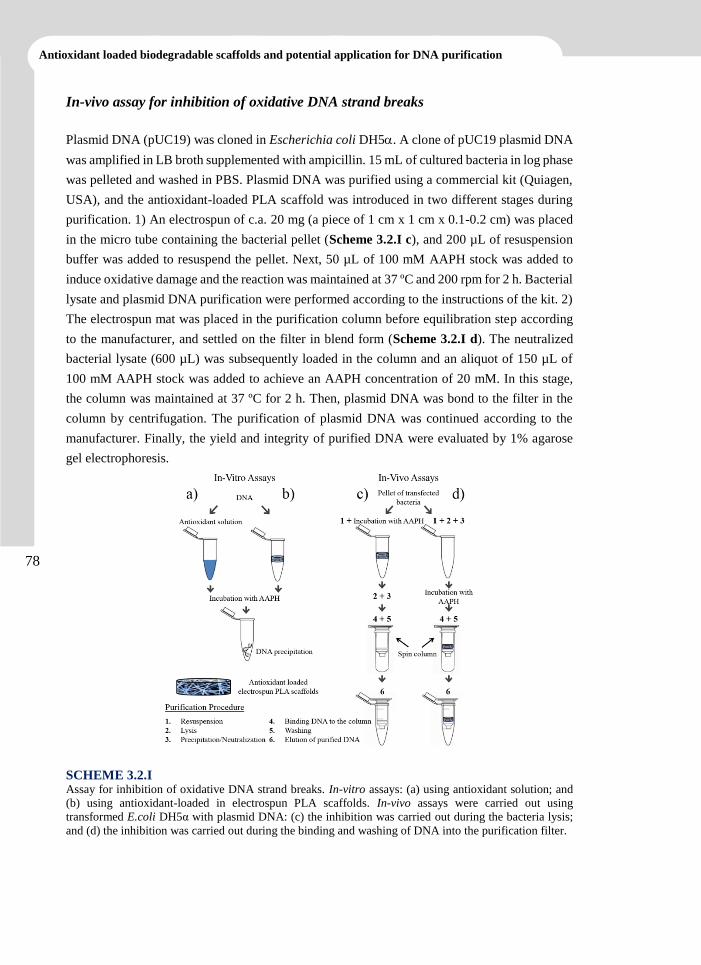
78
Antioxidant loaded biodegradable scaffolds and potential application for DNA purification
In-vivo assay for inhibition of oxidative DNA strand breaks
Plasmid DNA (pUC19) was cloned in Escherichia coli DH5. A clone of pUC19 plasmid DNA
was amplified in LB broth supplemented with ampicillin. 15 mL of cultured bacteria in log phase
was pelleted and washed in PBS. Plasmid DNA was purified using a commercial kit (Quiagen,
USA), and the antioxidant-loaded PLA scaffold was introduced in two different stages during
purification. 1) An electrospun of c.a. 20 mg (a piece of 1 cm x 1 cm x 0.1-0.2 cm) was placed
in the micro tube containing the bacterial pellet (Scheme 3.2.I c), and 200 µL of resuspension
buffer was added to resuspend the pellet. Next, 50 µL of 100 mM AAPH stock was added to
induce oxidative damage and the reaction was maintained at 37 ºC and 200 rpm for 2 h. Bacterial
lysate and plasmid DNA purification were performed according to the instructions of the kit. 2)
The electrospun mat was placed in the purification column before equilibration step according
to the manufacturer, and settled on the filter in blend form (Scheme 3.2.I d). The neutralized
bacterial lysate (600 µL) was subsequently loaded in the column and an aliquot of 150 µL of
100 mM AAPH stock was added to achieve an AAPH concentration of 20 mM. In this stage,
the column was maintained at 37 ºC for 2 h. Then, plasmid DNA was bond to the filter in the
column by centrifugation. The purification of plasmid DNA was continued according to the
manufacturer. Finally, the yield and integrity of purified DNA were evaluated by 1% agarose
gel electrophoresis.
SCHEME 3.2.I Assay for inhibition of oxidative DNA strand breaks. In-vitro assays: (a) using antioxidant solution; and
(b) using antioxidant-loaded in electrospun PLA scaffolds. In-vivo assays were carried out using
transformed E.coli DH5α with plasmid DNA: (c) the inhibition was carried out during the bacteria lysis;
and (d) the inhibition was carried out during the binding and washing of DNA into the purification filter.
79
CHAPTER 3.2
3.2.3 Results and Discussion
Characterization of Antioxidant-Loaded Electrospun PLA
The morphology and diameter of electrospun PLA nanofibers are dependent on several
parameters such as solvent characteristics, solution concentration, flow (ϕ), applied voltage (V)
and electrospinning distance (h) (i.e. the distance from the tip of the needle to the collector),[23,
24] In addition, incorporation of small percentages of drug in the polymer solution can affect the
morphology of electrospun PLA fibres and probably the operational parameters should be
modified.[16, 24, 25] Figure 3.2.1 contains SEM images of the antioxidant-loaded electrospun PLA
fiber mats. The fine, continuous morphology and structure of the nanofibers resulted from the
optimization of the experimental conditions to avoid undesirable forms of fibers, such as beads
on fiber strings, notches and local non-uniformity in the thickness of nanofibers. The best solvent
was a mixture of DMF (good solvent for PLA) and DMSO (good solvent for the studied
antioxidants) due to the impossibility to find a common solvent for polymer and drugs. The
optimal experimental conditions to obtain antioxidant-loaded electrospun PLA nanofibers were
similar for all combinations, i.e. values were in the range of 17-19 kV for V, 0.5-1 mL·h-1 for ϕ
and 12.5 cm for h. Figure 3.2.1 g shows that, in all cases, the distribution of fibers was fitted to
a Gaussian model. An average diameter of 92 ± 1 nm was determined for unloaded PLA fibers.
By contrast, larger diameters were obtained for PLA loaded with PN and PL (101 ± 3 nm and
124 ± 3 nm, respectively). PLA fibers loaded with CUM and CAF had smaller diameters than
unloaded PLA fibers (86 ± 2 nm and 81 ± 2 nm, respectively). The diameter of TRX-loaded
PLA fibers was the smallest one (63 ± 1 nm).
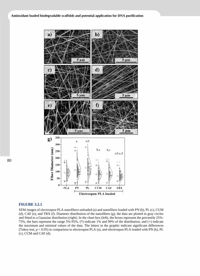
80
Antioxidant loaded biodegradable scaffolds and potential application for DNA purification
FIGURE 3.2.1
SEM images of electrospun PLA nanofibers unloaded (a) and nanofibers loaded with PN (b), PL (c), CUM
(d), CAF (e), and TRX (f). Diameter distribution of the nanofibers (g), the data are plotted in gray circles
and fitted to a Gaussian distribution (right). In the chart-box (left), the boxes represent the percentile 25%-
75%, the bars represent the range 5%-95%, (*) indicate 1% and 99% of the distribution, and (+) indicate
the maximum and minimal values of the data. The letters in the graphic indicate significant differences
(Tukey test, p < 0.05) in comparison to electrospun PLA (a), and electrospun PLA loaded with PN (b), PL
(c), CUM and CAF (d).
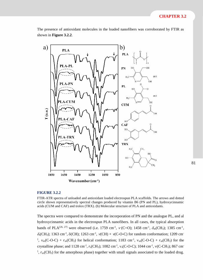
81
CHAPTER 3.2
The presence of antioxidant molecules in the loaded nanofibers was corroborated by FTIR as
shown in Figure 3.2.2.
FIGURE 3.2.2
FTIR-ATR spectra of unloaded and antioxidant loaded electrospun PLA scaffolds. The arrows and dotted
circle shown representatively spectral changes produced by vitamin B6 (PN and PL), hydroxycinnamic
acids (CUM and CAF) and trolox (TRX). (b) Molecular structure of PLA and antioxidants.
The spectra were compared to demonstrate the incorporation of PN and the analogue PL, and al
hydroxycinnamic acids in the electrospun PLA nanofibers. In all cases, the typical absorption
bands of PLA[26, 27] were observed (i.e. 1759 cm-1, (C=O); 1458 cm-1, as(CH3); 1385 cm-1,
s(CH3); 1363 cm-1, (CH); 1263 cm-1, (CH) + (C-O-C) for random conformation; 1209 cm-
1, as(C-O-C) + ras(CH3) for helical conformation; 1183 cm-1, as(C-O-C) + ras(CH3) for the
crystalline phase; and 1128 cm-1, rs(CH3); 1082 cm-1, s(C-O-C); 1044 cm-1, (C-CH3); 867 cm-
1, ras(CH3) for the amorphous phase) together with small signals associated to the loaded drug.
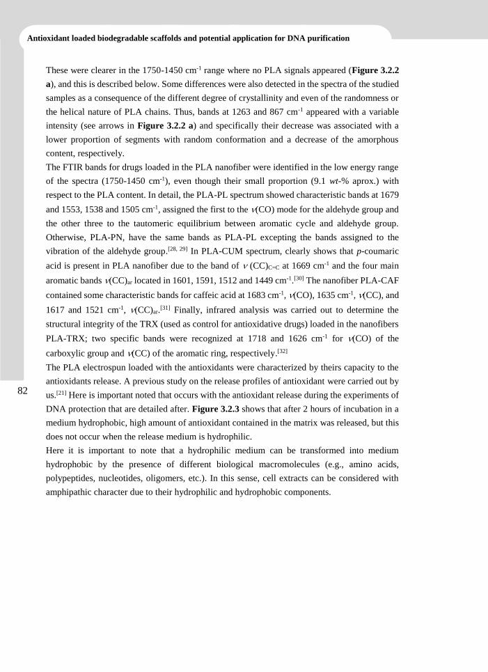
82
Antioxidant loaded biodegradable scaffolds and potential application for DNA purification
These were clearer in the 1750-1450 cm-1 range where no PLA signals appeared (Figure 3.2.2
a), and this is described below. Some differences were also detected in the spectra of the studied
samples as a consequence of the different degree of crystallinity and even of the randomness or
the helical nature of PLA chains. Thus, bands at 1263 and 867 cm-1 appeared with a variable
intensity (see arrows in Figure 3.2.2 a) and specifically their decrease was associated with a
lower proportion of segments with random conformation and a decrease of the amorphous
content, respectively.
The FTIR bands for drugs loaded in the PLA nanofiber were identified in the low energy range
of the spectra (1750-1450 cm-1), even though their small proportion (9.1 wt-% aprox.) with
respect to the PLA content. In detail, the PLA-PL spectrum showed characteristic bands at 1679
and 1553, 1538 and 1505 cm-1, assigned the first to the (CO) mode for the aldehyde group and
the other three to the tautomeric equilibrium between aromatic cycle and aldehyde group.
Otherwise, PLA-PN, have the same bands as PLA-PL excepting the bands assigned to the
vibration of the aldehyde group.[28, 29] In PLA-CUM spectrum, clearly shows that p-coumaric
acid is present in PLA nanofiber due to the band of (CC)C=C at 1669 cm-1 and the four main
aromatic bands (CC)ar located in 1601, 1591, 1512 and 1449 cm-1.[30] The nanofiber PLA-CAF
contained some characteristic bands for caffeic acid at 1683 cm-1, (CO), 1635 cm-1, (CC), and
1617 and 1521 cm-1, (CC)ar.[31] Finally, infrared analysis was carried out to determine the
structural integrity of the TRX (used as control for antioxidative drugs) loaded in the nanofibers
PLA-TRX; two specific bands were recognized at 1718 and 1626 cm-1 for (CO) of the
carboxylic group and (CC) of the aromatic ring, respectively.[32]
The PLA electrospun loaded with the antioxidants were characterized by theirs capacity to the
antioxidants release. A previous study on the release profiles of antioxidant were carried out by
us.[21] Here is important noted that occurs with the antioxidant release during the experiments of
DNA protection that are detailed after. Figure 3.2.3 shows that after 2 hours of incubation in a
medium hydrophobic, high amount of antioxidant contained in the matrix was released, but this
does not occur when the release medium is hydrophilic.
Here it is important to note that a hydrophilic medium can be transformed into medium
hydrophobic by the presence of different biological macromolecules (e.g., amino acids,
polypeptides, nucleotides, oligomers, etc.). In this sense, cell extracts can be considered with
amphipathic character due to their hydrophilic and hydrophobic components.
83
CHAPTER 3.2
FIGURE 3.2.3
Antioxidant release from five loaded electrospun PLA. The concentration of drug released was measured
after 2 hours of incubation in a Sörensen-ethanol buffer mixture (3:7, v/v) (hydrophobic medium) and in a
TBE buffer (hydrophilic medium). Results are mean ± SE (n = 3). The asterisk (*) indicates p < 0.05
between both media.
AAPH-Induced Oxidative Damage of Plasmid DNA
The conversion of supercoiled and closed circular form of plasmid DNA to open circular and
further linear forms can be used as a clear indicator of DNA damage. The formation of open
circular form of DNA is indicative of single-strand breaks whereas the formation of linear form
of DNA is indicative of double-strand breaks (e.g., the BamHI restriction enzyme has a single
cutting site of both pUC19 DNA strands, resulting in linear DNA).[33, 34] Since AAPH is water-
soluble and the rate of free radical generation from AAPH can be easily controlled and measured,
this molecule has been extensively used as a free radical initiator for biological studies.[35]
Thermal decomposition of AAPH at physiological temperature generates alkyl radicals, which
can react with oxygen and produce alkylperoxyl radical (ROO·). This radical can attack plasmid
DNA, leading to oxidative DNA damage.[22]
Figure 3.2.4 shows AAPH-induced plasmid DNA strand breaks. It is observed that, at a lower
AAPH concentration (2.5-5 mM), the supercoiled DNA band decreases, the open circular DNA
band (single DNA chain break) increases and a linear DNA band (double DNA chain break)
appears between the supercoiled and the open circular band. At intermediate AAPH
concentrations (10-30 mM), the supercoiled DNA band decreases completely and the open
circular DNA band decreases gradually, leading to an increase in the linear DNA band. The
smear below the linear band suggests the occurrence of multiple breaks in the DNA strands,
leading to the formation of low molecular weight fragments. Highly fragmented DNA is
predominant when plasmid DNA is treated with high AAPH concentrations (45-75 mM). It can
be concluded that the oxidative damage of pUC19 DNA (in general, of plasmid DNA and by
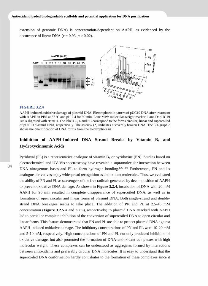
84
Antioxidant loaded biodegradable scaffolds and potential application for DNA purification
extension of genomic DNA) is concentration-dependent on AAPH, as evidenced by the
occurrence of linear DNA (r = 0.93, p > 0.02).
FIGURE 3.2.4
AAPH-induced oxidative damage of plasmid DNA. Electrophoretic pattern of pUC19 DNA after treatment
with AAPH in PBS at 37 ºC and pH 7.4 for 90 min. Lane MW: molecular weight marker. Lane D: pUC19
DNA digested with BamHI. The labels C, L and SC correspond to the forms circular, linear and supercoiled
of pUC19 plasmid DNA, respectively. The asterisk (*) indicates a severely broken DNA. The 3D-graphic
shows the quantification of DNA forms from the electrophoresis.
Inhibition of AAPH-Induced DNA Strand Breaks by Vitamin B6 and
Hydroxycinnamic Acids
Pyridoxal (PL) is a representative analogue of vitamin B6 or pyridoxine (PN). Studies based on
electrochemical and UV-Vis spectroscopy have revealed a supramolecular interaction between
DNA nitrogenous bases and PL to form hydrogen bonding.[36, 37] Furthermore, PN and its
analogue derivatives enjoy widespread recognition as antioxidant molecules. Thus, we evaluated
the ability of PN and PL as scavengers of the free radicals generated by decomposition of AAPH
to prevent oxidative DNA damage. As shown in Figure 3.2.4, incubation of DNA with 20 mM
AAPH for 90 min resulted in complete disappearance of supercoiled DNA, as well as in
formation of open circular and linear forms of plasmid DNA. Both single-strand and double-
strand DNA breakages seems to take place. The addition of PN and PL at 2.5-45 mM
concentration (Figure 3.2.5 a and 3.2.5), respectively) to plasmid DNA attacked with AAPH
led to partial or complete inhibition of the conversion of supercoiled DNA to open circular and
linear forms. This feature demonstrated that PN and PL are able to protect plasmid DNA against
AAPH-induced oxidative damage. The inhibitory concentrations of PN and PL were 10-20 mM
and 5-10 mM, respectively. High concentrations of PN and PL not only produced inhibition of
oxidative damage, but also promoted the formation of DNA-antioxidant complexes with high
molecular weight. These complexes can be understood as aggregates formed by interactions
between antioxidants and preferably circular DNA molecules. It is easy to understand that the
supercoiled DNA conformation hardly contributes to the formation of these complexes since it
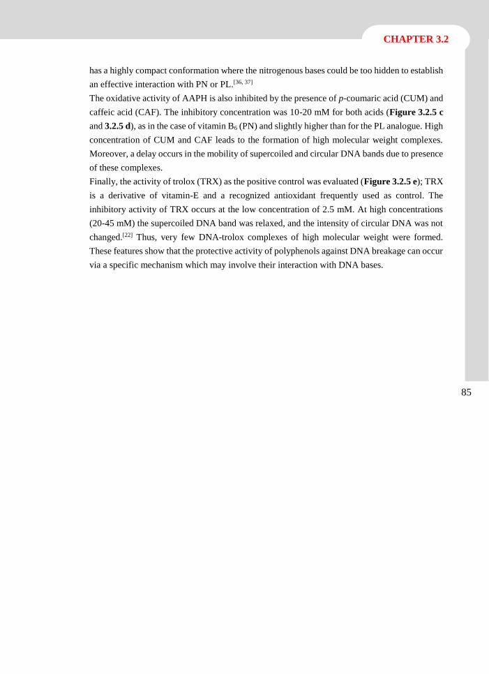
85
CHAPTER 3.2
has a highly compact conformation where the nitrogenous bases could be too hidden to establish
an effective interaction with PN or PL.[36, 37]
The oxidative activity of AAPH is also inhibited by the presence of p-coumaric acid (CUM) and
caffeic acid (CAF). The inhibitory concentration was 10-20 mM for both acids (Figure 3.2.5 c
and 3.2.5 d), as in the case of vitamin B6 (PN) and slightly higher than for the PL analogue. High
concentration of CUM and CAF leads to the formation of high molecular weight complexes.
Moreover, a delay occurs in the mobility of supercoiled and circular DNA bands due to presence
of these complexes.
Finally, the activity of trolox (TRX) as the positive control was evaluated (Figure 3.2.5 e); TRX
is a derivative of vitamin-E and a recognized antioxidant frequently used as control. The
inhibitory activity of TRX occurs at the low concentration of 2.5 mM. At high concentrations
(20-45 mM) the supercoiled DNA band was relaxed, and the intensity of circular DNA was not
changed.[22] Thus, very few DNA-trolox complexes of high molecular weight were formed.
These features show that the protective activity of polyphenols against DNA breakage can occur
via a specific mechanism which may involve their interaction with DNA bases.
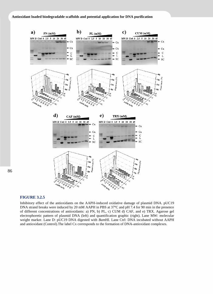
86
Antioxidant loaded biodegradable scaffolds and potential application for DNA purification
FIGURE 3.2.5
Inhibitory effect of the antioxidants on the AAPH-induced oxidative damage of plasmid DNA. pUC19
DNA strand breaks were induced by 20 mM AAPH in PBS at 37ºC and pH 7.4 for 90 min in the presence
of different concentrations of antioxidants: a) PN, b) PL, c) CUM d) CAF, and e) TRX. Agarose gel
electrophoretic pattern of plasmid DNA (left) and quantification graphic (right). Lane MW: molecular
weight marker. Lane D: pUC19 DNA digested with BamHI. Lane Ctrl: DNA incubated without AAPH
and antioxidant (Control).The label Cx corresponds to the formation of DNA-antioxidant complexes.
87
CHAPTER 3.2
Inhibition of AAPH-Induced DNA Damage by Antioxidant Loaded Electrospun
PLA Nanofiber Mats
Effects on purified DNA
After evaluation of the activity of antioxidants in solution, it was determined whether the
electrospun nanofiber loaded with antioxidants can inhibit AAPH-induced oxidative damage of
plasmid DNA. AAPH concentration was 20 mM, for all experiments. Figure 3.2.6 shows that
electrospun PLA has no protective effect against this type of damage. This is obvious because
supercoiled DNA becomes open-circular and then linear. On the other hand, no significant
damage was observed in supercoiled DNA attacked with AAPH in the presence of electrospun
PLA scaffolds loaded with PN, PL, CUM and CAF. Moreover, in all cases this was accompanied
by an increase in the percentage of circular DNA. However, the absence of the linear DNA band
suggests that this increase could correspond to the presence of relaxed DNA. In addition, no
complexes of high molecular weight DNA were observed.
FIGURE 3.2.6
Inhibitory effect of antioxidant-loaded electrospun PLA on pUC19 DNA. pUC19 DNA strand breaks were
induced by 20 mM AAPH in PBS at 37ºC and pH 7.4 for 90 min in the presence of electrospun PLA
unloaded (lane PLA) and loaded with antioxidants (lane PN, lane PL, lane CUM, lane CAF and lane TRX).
After incubation, the DNA was precipitated and running on an agarose gel (above) to evaluate and
quantifying (under) the forms of plasmid DNA. Lane MW: molecular weight marker. Lane D: pUC19
DNA digested with BamHI. Lane Ctrl: DNA incubated without AAPH and electrospun.
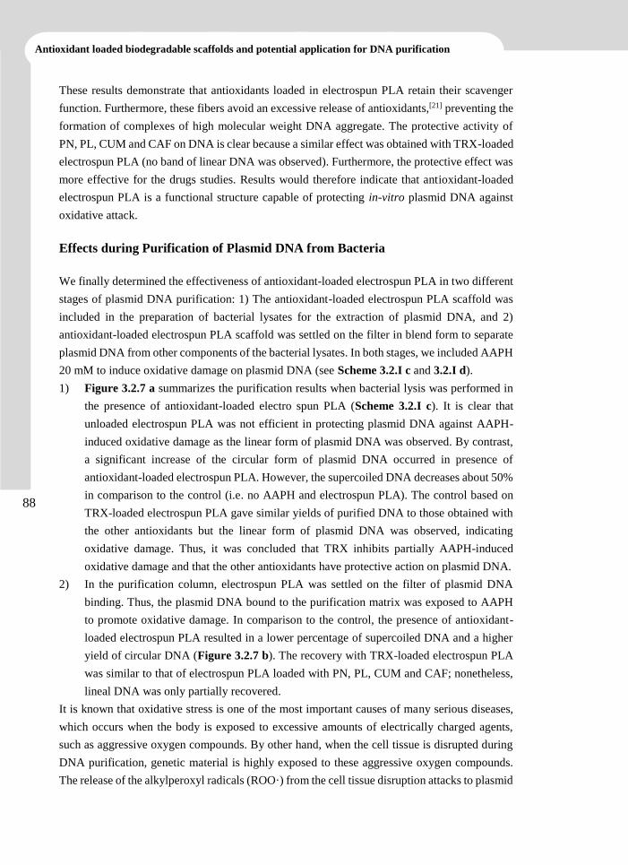
88
Antioxidant loaded biodegradable scaffolds and potential application for DNA purification
These results demonstrate that antioxidants loaded in electrospun PLA retain their scavenger
function. Furthermore, these fibers avoid an excessive release of antioxidants,[21] preventing the
formation of complexes of high molecular weight DNA aggregate. The protective activity of
PN, PL, CUM and CAF on DNA is clear because a similar effect was obtained with TRX-loaded
electrospun PLA (no band of linear DNA was observed). Furthermore, the protective effect was
more effective for the drugs studies. Results would therefore indicate that antioxidant-loaded
electrospun PLA is a functional structure capable of protecting in-vitro plasmid DNA against
oxidative attack.
Effects during Purification of Plasmid DNA from Bacteria
We finally determined the effectiveness of antioxidant-loaded electrospun PLA in two different
stages of plasmid DNA purification: 1) The antioxidant-loaded electrospun PLA scaffold was
included in the preparation of bacterial lysates for the extraction of plasmid DNA, and 2)
antioxidant-loaded electrospun PLA scaffold was settled on the filter in blend form to separate
plasmid DNA from other components of the bacterial lysates. In both stages, we included AAPH
20 mM to induce oxidative damage on plasmid DNA (see Scheme 3.2.I c and 3.2.I d).
1) Figure 3.2.7 a summarizes the purification results when bacterial lysis was performed in
the presence of antioxidant-loaded electro spun PLA (Scheme 3.2.I c). It is clear that
unloaded electrospun PLA was not efficient in protecting plasmid DNA against AAPH-
induced oxidative damage as the linear form of plasmid DNA was observed. By contrast,
a significant increase of the circular form of plasmid DNA occurred in presence of
antioxidant-loaded electrospun PLA. However, the supercoiled DNA decreases about 50%
in comparison to the control (i.e. no AAPH and electrospun PLA). The control based on
TRX-loaded electrospun PLA gave similar yields of purified DNA to those obtained with
the other antioxidants but the linear form of plasmid DNA was observed, indicating
oxidative damage. Thus, it was concluded that TRX inhibits partially AAPH-induced
oxidative damage and that the other antioxidants have protective action on plasmid DNA.
2) In the purification column, electrospun PLA was settled on the filter of plasmid DNA
binding. Thus, the plasmid DNA bound to the purification matrix was exposed to AAPH
to promote oxidative damage. In comparison to the control, the presence of antioxidant-
loaded electrospun PLA resulted in a lower percentage of supercoiled DNA and a higher
yield of circular DNA (Figure 3.2.7 b). The recovery with TRX-loaded electrospun PLA
was similar to that of electrospun PLA loaded with PN, PL, CUM and CAF; nonetheless,
lineal DNA was only partially recovered.
It is known that oxidative stress is one of the most important causes of many serious diseases,
which occurs when the body is exposed to excessive amounts of electrically charged agents,
such as aggressive oxygen compounds. By other hand, when the cell tissue is disrupted during
DNA purification, genetic material is highly exposed to these aggressive oxygen compounds.
The release of the alkylperoxyl radicals (ROO·) from the cell tissue disruption attacks to plasmid
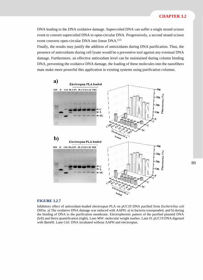
89
CHAPTER 3.2
DNA leading to the DNA oxidative damage. Supercoiled DNA can suffer a single strand scissor
event to convert supercoiled DNA to open-circular DNA. Progressively, a second strand scissor
event converts open-circular DNA into linear DNA.[22]
Finally, the results may justify the addition of antioxidants during DNA purification. Thus, the
presence of antioxidants during cell lysate would be a preventive tool against any eventual DNA
damage. Furthermore, an effective antioxidant level can be maintained during column binding
DNA, preventing the oxidative DNA damage, the loading of these molecules into the nanofibers
mats make more powerful this application in existing systems using purification columns.
FIGURE 3.2.7
Inhibitory effect of antioxidant-loaded electrospun PLA on pUC19 DNA purified from Escherichia coli
DH5α. a) The oxidative DNA damage was induced with AAPH: a) in bacteria resuspended, and b) during
the binding of DNA to the purification membrane. Electrophoretic pattern of the purified plasmid DNA
(left) and theirs quantification (right). Lane MW: molecular weight marker. Lane D: pUC19 DNA digested
with BamHI. Lane Ctrl: DNA incubated without AAPH and electrospun.
90
Antioxidant loaded biodegradable scaffolds and potential application for DNA purification
3.2.4 Conclusions
Electrospun PLA nanofibers loaded with antioxidants, i.e. vitamin B6 or pyridoxine (PN) and
its analogue pyridoxal (PL), and hydroxycinnamic acids, i.e. p-coumaric acid (CUM) and caffeic
acid (CAF) were obtained by electrospinning under conditions optimized for mixtures of PLA
in dimethylformamide and antioxidants in DMSO.
AAPH-induced oxidative damage of plasmid DNA can be inhibited in-vitro by antioxidants (PN,
PL, CUM, and CAF) in solution and by electrospun PLA scaffolds loaded with PN, PL, CUM,
and CAF.
Finally, electrospun PLA loaded with PN, PL, CUM or CAF can inhibit oxidative damage of
plasmid DNA during purification from bacteria. Thus, in-vitro and in-vivo results clearly
demonstrate the potential application of antioxidant-loaded electrospun PLA to inhibit oxidative
damage of plasmid DNA during extraction and purification. This protective activity potentially
can also be applied to other macromolecules.
91
CHAPTER 3.2
3.2.5 References
[1] T. Finkel, N.J. Holbrook, Nature, 408 (2000) 239-247.
[2] K.J. Barnham, C.L. Masters, A.I. Bush, Nat Rev Drug Discov, 3 (2004) 205-214.
[3] S.P. Hussain, L.J. Hofseth, C.C. Harris, Nat Rev Cancer, 3 (2003) 276-285.
[4] M.S. Cooke, M.D. Evans, M. Dizdaroglu, J. Lunec, Faseb J, 17 (2003) 1195-1214.
[5] J.G. Pizarro, J. Folch, A. Vazquez De la Torre, E. Verdaguer, F. Junyent, J. Jordan, M.
Pallas, A. Camins, Free Radical Res, 43 (2009) 985-994.
[6] R.W. Pero, M.W. Anderson, G.A. Doyle, C.H. Anna, F. Romagna, M. Markowitz, C.
Bryngelsson, Cancer Res, 50 (1990) 4619-4625.
[7] D.E. Brash, P.A. Havre, P Natl Acad Sci USA, 99 (2002) 13969-13971.
[8] C.A. Rice-Evans, A.T. Diplock, Free Radic Biol Med, 15 (1993) 77-96.
[9] Y.J. Surh, Nat Rev Cancer, 3 (2003) 768-780.
[10] K. Shibata, M. Mushiage, T. Kondo, T. Hayakawa, H. Tsuge, Biosci Biotech Bioch, 59
(1995) 2060-2063.
[11] B.N. Ames, Mutat Res-Fund Mol M, 475 (2001) 7-20.
[12] S.C. Larsson, E. Giovannucci, A. Wolk, Gastroenterology, 128 (2005) 1830-1837.
[13] Y. Natori, T. Oka, Nutr Res, 17 (1997) 1199-1207.
[14] J.M. Matxain, M. Ristila, A. Strid, L.A. Eriksson, J Phys Chem A, 110 (2006) 13068-
13072.
[15] E. Pino, A.M. Campos, C. Lopez-Alarcon, A. Aspee, E. Lissi, J Phys Org Chem, 19
(2006) 759-764.
[16] T.J. Sill, H.A. von Recum, Biomaterials, 29 (2008) 1989-2006.
[17] W. Cui, J. Chang, P.D. Dalton, Electrospun Fibers for Drug Delivery, in: Comprehensive
Biomaterials, 2011, 445-462.
[18] R.T. Gorsline, P. Tangkawattana, J.J. Lannutti, M. Yamaguchi, C.C. Kaeding, A.L.
Bertone, J Biomed Sci Eng, 3 (2010) 908-916.
[19] W.J. Li, C.T. Laurencin, E.J. Caterson, R.S. Tuan, F.K. Ko, J Biomed Mater Res, 60
(2002) 613-621.
92
Antioxidant loaded biodegradable scaffolds and potential application for DNA purification
[20] Y.K. Luu, K. Kim, B.S. Hsiao, B. Chu, M. Hadjiargyrou, J Control Release, 89 (2003)
341-353.
[21] E. Llorens, L.J. del Valle, A. Diaz, M.T. Casas, J. Puiggali, Macromol Res, 21 (2013)
775-787.
[22] Q.Y. Wei, B. Zhou, Y.J. Cai, L. Yang, Z.L. Liu, Food Chem, 96 (2006) 90-95.
[23] C. Burger, B.S. Hsiao, B. Chu, Annu Rev Mater Res, 36 (2006) 333-368.
[24] L.J. del Valle, R. Camps, A. Diaz, L. Franco, A. Rodriguez-Galan, J. Puiggali, J Polym
Res, 18 (2011) 1903-1917.
[25] L.J. del Valle, M. Roa, A. Diaz, M.T. Casas, J. Puiggali, A. Rodriguez-Galan, J Polym
Res, 19 (2012).
[26] C. Ribeiro, V. Sencadas, C.M. Costa, J.L.G. Ribelles, S. Lanceros-Mendez, Sci Technol
Adv Mat, 12 (2011).
[27] B.D. Kevadiya, G.V. Joshi, H.A. Patel, P.G. Ingole, H.M. Mody, H.C. Bajaj, J Biomater
Appl, 25 (2010) 161-177.
[28] F. Bartl, H. Urjasz, B. Brzezinski, J Mol Struct, 441 (1998) 77-81.
[29] J.S. Casas, A. Castineiras, F. Condori, M.D. Couce, U. Russo, A. Sanchez, J. Sordo, J.M.
Varela, Polyhedron, 19 (2000) 813-819.
[30] R. Swislocka, M. Kowczyk-Sadowy, M. Kalinowska, W. Lewandowski, Spectrosc-Int J,
27 (2012) 35-48.
[31] Y. Xing, H.Y. Peng, M.X. Zhang, X. Li, W.W. Zeng, X.E. Yang, J Zhejiang Univ Sci B,
13 (2012) 487-493.
[32] L. Gastaldi, E. Ugazio, S. Sapino, P. Iliade, I. Miletto, G. Berlier, Phys Chem Chem Phys,
14 (2012) 11318-11326.
[33] B. Teixeira-Dias, L.J. del Valle, F. Estrany, E. Armelin, R. Oliver, C. Aleman, Eur Polym
J, 44 (2008) 3700-3707.
[34] C. Aleman, B. Teixeira-Dias, D. Zanuy, F. Estrany, E. Armelin, L.J. del Valle, Polymer,
50 (2009) 1965-1974.
[35] P. Zhang, S.T. Omaye, Food Chem Toxicol, 39 (2001) 239-246.
[36] S.Q. Liu, M.L. Cao, S.L. Dong, Bioelectrochemistry, 74 (2008) 164-169.
[37] S.Q. Liu, W.H. Sun, L.C. Li, H. Li, X.L. Wang, Int J Electrochem Sc, 7 (2012) 324-337.
4.
Multifunctional biodegradable
fiber scaffolds


The work described in this chapter previously appeared in:
[1] Llorens, E.; del Valle, L. J.; Puiggalí, J. Express. Polym. Lett. Submitted.
[2] Llorens, E.; del Valle, L.; Puiggalí, J. J. Appl. Polym. Sci. Submitted.

3
Electrospun Scaffolds of Polylactide with a
Different Enantiomeric Content and Loaded
with Anti-Inflammatory and Antibacterial
Drugs
Polylactide (PLA) electrospun microfibers were prepared and
loaded with triclosan (TCS), ketoprofen (KTP) or their
combination to obtain multifunctional scaffolds with
bactericide and anti-inflammatory properties. Continuous and
porous fibers with diameters in the micrometer scale and an
unimodal distribution were successfully attained using a
chloroform:acetone:dimethylsulfoxide mixture capable of
effectively dissolving compounds with highly different
solubility characteristics such as PLA and the above drugs.
Scaffolds were prepared using two PLA grades having slightly
different D-lactide content (i.e. 2 and 4.2 wt-%). It was
observed that small differences had a strong influence on
physicochemical properties and drug release behavior.
Thermal properties of new scaffolds were determined by
differential scanning calorimetry and the release evaluated in
two media having different hydrophilicity. Dual drug-loaded
scaffolds showed a peculiar release that contrasted with single
drug-loaded systems and suggested the establishment of
intermolecular interactions that delayed TCS and KTP
release. Antimicrobial activity of all TCS-loaded electrospun
scaffolds was tested and demonstrated against E.coli and
M.luteus bacteria. In addition, KTP-loaded samples showed
slight bactericide activity. Biocompatibility of scaffolds was
evaluated by adhesion and proliferation assays using two
epithelial cell lines. Results correlated with drug release
observations; interestingly, the dual drug-load systems were
able to support high TCS doses without adverse effects.
4.1
98
Multifunctional biodegradable fiber scaffolds
4.1.1 Introduction
Polylactide (PLA) is currently one of most attractive biodegradable polymers because it is
derived from renewable resources, can be easily processed and has many applications ranging
from commodity to specialty uses.[1-5] PLA is gaining special attention in the biomedical field.
Specifically, devices including degradable sutures, drug releasing micro/nanoparticles, and
porous scaffolds for cellular applications can be mentioned.[6-10] The great advantages of PLA
are due in part to its ability to degrade into the naturally occurring metabolite lactic acid under
physiological conditions, but other exceptional qualities, like biocompatibility, FDA approval
for clinical use, low immunogenicity and good mechanical properties must also be considered.
PLA can be obtained by ring-opening polymerization of L-lactide and/or D-lactide, a process
that allows obtaining a large number of stereo-copolymers by changing their L/D ratio.
Properties of PLA are strongly dependent on its optical purity, for example, PLA can range from
semicrystalline to completely amorphous.[11] The degree of crystallinity and even molecular
orientation also have a strong influence on PLA biodegradability, specifically, the selection of
adequate processing conditions is important to achieve a specific orientation for a given
stereoregularity. For example, Lee et al. concluded that molecular orientation in amorphous PLA
increased with decreasing stretching temperature whereas semycristalline samples required
increasing temperatures.[12] It seems that, for amorphous samples, the most important effect
concerns the highest orientation when molecular relaxation is hindered by a temperature
decrease. For semicrystalline samples, the orientation phenomenon involves the deformation of
formed spherulites, and consequently higher temperatures are needed.
Electrospinning is currently one of the simplest methods to draw nano and microfibers from a
polymer solution. Basically, the surface tension of a liquid droplet can be counteracted by the
electrostatic repulsion due to the charging of the body of the liquid by a sufficiently high voltage.
The droplet is stretched and may form a liquid jet if its molecular cohesion is sufficiently high.[13]
Scaffolds prepared by electrospinning showed particularly good potential for drug delivery
applications due to their large surface area and interconnected pore structure.[14, 15] Moreover,
drug release behavior can be easily controlled by the morphology and composition of fibers.[16,
17] Drug-loaded electrospun scaffolds can also be easily fabricated into various shapes (e.g.,
membranes or tubes) for different applications, such as wound dressing and nerve conduits.[18,
19] To date, most studies of electrospun scaffolds for drug delivery have been focused on
sustained release of a single drug. However, it is clear that the use of different drugs is a
promising strategy that allows combination therapy and may even induce synergic effects.
Studies on dual drug-loaded systems, mainly fibers fabricated by coaxial electrospinning[20] and
multilayered electrospun polymer mats,[21] demonstrated different release kinetics from simple
systems and/or that the severe initial burst release could be retarded or even negated.
One of the main applications for electrospun scaffolds is its potential use as a matrix for wound
healing. The success in wound healing can be handled by the control of various events, such as
accelerating tissue regeneration (e.g., by promoting cell proliferation), preventing rejection of
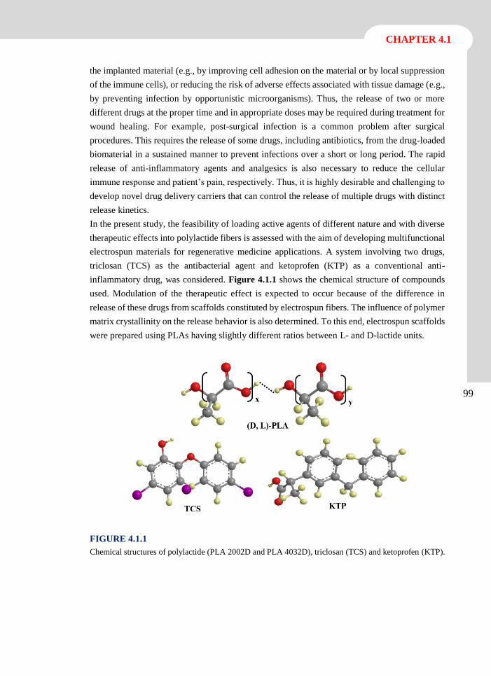
CHAPTER 4.1
99
the implanted material (e.g., by improving cell adhesion on the material or by local suppression
of the immune cells), or reducing the risk of adverse effects associated with tissue damage (e.g.,
by preventing infection by opportunistic microorganisms). Thus, the release of two or more
different drugs at the proper time and in appropriate doses may be required during treatment for
wound healing. For example, post-surgical infection is a common problem after surgical
procedures. This requires the release of some drugs, including antibiotics, from the drug-loaded
biomaterial in a sustained manner to prevent infections over a short or long period. The rapid
release of anti-inflammatory agents and analgesics is also necessary to reduce the cellular
immune response and patient’s pain, respectively. Thus, it is highly desirable and challenging to
develop novel drug delivery carriers that can control the release of multiple drugs with distinct
release kinetics.
In the present study, the feasibility of loading active agents of different nature and with diverse
therapeutic effects into polylactide fibers is assessed with the aim of developing multifunctional
electrospun materials for regenerative medicine applications. A system involving two drugs,
triclosan (TCS) as the antibacterial agent and ketoprofen (KTP) as a conventional anti-
inflammatory drug, was considered. Figure 4.1.1 shows the chemical structure of compounds
used. Modulation of the therapeutic effect is expected to occur because of the difference in
release of these drugs from scaffolds constituted by electrospun fibers. The influence of polymer
matrix crystallinity on the release behavior is also determined. To this end, electrospun scaffolds
were prepared using PLAs having slightly different ratios between L- and D-lactide units.
FIGURE 4.1.1
Chemical structures of polylactide (PLA 2002D and PLA 4032D), triclosan (TCS) and ketoprofen (KTP).
100
Multifunctional biodegradable fiber scaffolds
4.1.2 Experimental Section
Materials
Two commercial PLA grades from Natureworks® with 95.8 and 98 wt-% L-lactic isomer content
were used, i.e. PLA 2002D and PLA 4032D, respectively. According to the manufacturer, PLA
2002D is a transparent solid with a density of 1.24 g·cc-1. Its calorimetric and mechanical
properties are defined by a glass transition temperature (Tg) of 58 ºC, a melting point (Tm) of 153
ºC, a tensile modulus (E) of 3500 MPa, a tensile strength () of 53-60 MPa and a tensile
elongation () of 6%. PLA 4032D has a translucent appearance, a density of 1.24 g·cc-1 and very
different properties from the sample with higher D-lactide content. Thus, Tg, Tm, E, and
values were reported to be 70 ºC, 160 ºC, 3440-3784 Ma, 103.2-144.5 MPa, 100-180%,
respectively. Molecular weights determined by GPC were quite similar, specifically Mn, Mw and
polydispersity index were 98,100 g·mol-1, 181,000 g·mol-1 and 1.85 for PLA 2002D and 84,200
g·mol-1, 179,400 g·mol-1 and 2.13 for PLA 4032D.[22, 23]
Trichloromethane (TCM), acetone, dimethylsulfoxide (DMSO), triclosan or irgasan (TCS),
ketoprofen (KTP), 3-(4,5-dimethylthiazol-2-yl)-2,5-diphenyl-2H-tetrazolium bromide (MTT)
were purchased from Sigma-Aldrich (St. Louis, USA). VERO (kidney epithelial cells extracted
from African green monkey) and MDCK (kidney epithelial cells derived from Madin-Darby
Canine) were purchased from ATCC (USA). Escherichia coli CECT 101 and Micrococcus
luteus CECT 245 bacteria strains were obtained from the Spanish Collection of Type Culture
(Valencia, Spain).
Drug loaded PLA electrospun microfibers
Scaffolds constituted by PLA 2002D and PLA 4032D microfibers were prepared by
electrospinning, which also allowed loading the two selected drugs (i.e., TCS and KTP). The
procedure consisted in dissolving the PLA grade in a chloroform-acetone mixture (2:1 v/v). For
drug-loaded samples, 1 mL of dimethysulfoxide (DMSO) containing the corresponding drug
was subsequently added and the mixture was vortexed to obtain an electrospinable solution.
Final PLA concentration was 10 w/v-% whereas for drug loaded samples KTP and TCS
concentrations were 1 w/v-% and 3 w/v-%, respectively.
A plastic syringe of 5 mL (Becton Dickson, Spain) was filled with the corresponding solution
and electrospinning was carried out between the tip of a 18G needle (Terumo, Belgium)
connected to the anode and the static collector connected to the cathode. The DC voltage was
applied using a high voltage supply (ES30-5W model, Gamma High Voltage Research, USA).
The flow rate was controlled using a KD100 infusion syringe pump (KD Scientific Inc., USA).
The polymer jet was collected on an aluminum foil and 14 mm diameter coverslips to evaluate
cell adhesion and proliferation. All electrospinning procedures were conducted at room
temperature.
CHAPTER 4.1
101
Morphology and crystallinity of dual drug-loaded PLA microfibers
Diameter measurements and inspection of fiber textures were performed by scanning electron
microscopy (SEM) using a Focus Ion Beam Zeiss Neon 40 instrument (Carl Zeiss, Germany).
Carbon coating was accomplished with a Mitec K950 Sputter Coater (fitted with a film thickness
monitor k150x). Samples were viewed at an accelerating voltage of 5 kV.
Calorimetric data were obtained by differential scanning calorimetry (DSC) with a TA
Instruments Q100 series equipped with a refrigeration cooling system (RCS). Experiments were
conducted under a flow of dry nitrogen with a sample weight of approximately 5 mg and
calibration was performed with indium. Heating and cooling runs were carried out at a rate of
20 ºC·min-1 and 10 ºC·min-1, respectively.
FTIR spectra were recorded on a FTIR 4100 Jasco spectrophotometer. The samples were placed
in an attenuated total reflectance accessory with thermal control and a diamond crystal (Specac
model MKII Golden Gate Heated Single Reflection Diamond ATR).
Release experiments
Controlled release experiments were performed with electrospun scaffolds cut into small square
pieces (20 x 20 x 0.1 mm3). The samples were weighed and placed into polypropylene tubes.
Two release media with different hydrophobicity and solvent ability were used: a typical
phosphate buffer saline or (PBS) and PBS supplemented with 70 v/v-% of ethanol. The second
one was less hydrophilic than PBS and was interesting for simulating the supplement of serum
in the medium.[24] Drug-release was carried out in 50 mL of the release medium at 25 ºC for 1
week. Drug concentration in the release medium was evaluated by UV-Vis spectroscopy using
a UV-3600 spectrophotometer (Shimadzu, Japan). Calibration curves were obtained by plotting
the absorbance measured at the corresponding wavelengths against drug concentration. Samples
(1 mL) were drawn from the release medium at predetermined intervals and an equal volume of
fresh medium was added to the release vessel. All the drug release tests were carried out using
three replicates to control the homogeneity of the release, and the results obtained were averaged.
Antimicrobial test: assay of bacterial growth and adhesion
Escherichia coli (E.coli) and Micrococcus luteus (M.luteus) bacteria were selected to evaluate
the antimicrobial effect of TCS and KP loaded electrospun scaffolds. The bacteria were
previously grown aerobically to exponential phase in broth culture (5 g·L-1 beef extract, 5 g·L-1
NaCl, 10 g·L-1 peptone, pH 7.2).
Growth experiments were performed in tubes of 15 mL. 103 CFU (colony forming units) were
seeded in 5 mL of broth culture in the presence of the electrospun scaffolds. The cultures were
incubated at 37 ºC and agitated at 80 rpm. After incubation for 24 and 48 h, an aliquot of 100
µL was diluted 10 times with distilled water and the absorbance at 600 nm was measured. The
bacterial number was determined using a McFarland curve.
102
Multifunctional biodegradable fiber scaffolds
Adhesion experiments were carried out by seeding 107-108 CFU in 5 mL of broth culture in the
presence of the electrospun scaffolds. The cultures were incubated at 37 ºC and agitated at 80
rpm. After incubation, the cultures were aspired and the material washed once with distilled
water. Then, 1 mL of sterile 0.01 M sodium thiosulfate was added and the mixture was vortexed
for 2 min and left to repose for 30 min in order to remove the bacteria. Finally, 4 mL of broth
culture was added and the tubes were incubated at 37 ºC for 24 h and agitated at 80 rpm. The
bacterial number was determined as above indicated
All assays were performed in triplicate and the results averaged. ANOVA followed by t-Student
test were conducted as statistical analysis at a confidence level of 95 % (p < 0.05). Additionally,
correlation coefficients (r) were calculated to evaluate the relation between antibacterial effect
and the drug release.
In-vitro biocompatibility assays: cell adhesion and proliferation
MDCK, and VERO cells were cultured in Dulbecco’s modified Eagle medium (DMEM)
supplemented with 10% fetal bovine serum, 1% penicillin/streptomycin and 2 mM L-glutamine
at 37ºC in a humidified atmosphere with 5% CO2 and 95% air. The culture medium was changed
every two days and, for sub-culture, cell monolayers were rinsed with phosphate buffered saline
(PBS) and detached by incubation with trypsin-EDTA (0.25%) at 37ºC for 2-5 min. Cell
concentration was determined by counting with a Neubauer chamber using 4% trypan-blue as
dye vital. Detached cells with viability ≥ 95% were used for biocompatibility assays.
The unloaded and antioxidant loaded electrospun PLA microfibers were cut into square pieces
(10 x 10 x 0.1 mm3). These samples were placed into the wells of a multi-well culture plate and
sterilized by UV-radiation in a laminar flux cabinet for 15 min. To fix the samples in the well, a
small drop of silicone (Silbione® MED ADH 4300 RTV, Bluestar Silicones France SAS, Lyon,
France) was used as the adhesive. Samples were incubated with 1 mL of the culture medium
under culture conditions for 30 min to equilibrate the material. Finally, the medium was aspired
and the material was evaluated for cell adhesion and proliferation by exposing cells to direct
contact with the material surface.
To assess cell adhesion, aliquots of 50-100 µL containing 5x10⁴ cells were seeded onto the
electrospun scaffolds in the wells. The plate was incubated in culture conditions for 30 min to
allow cell attachment to the material surface. Then, 1 mL of the culture medium was added to
each well and the plate was incubated for 24 h. Finally, cell viability was determined by the
MTT assay. Controls were performed by cell culture on the polystyrene surface of the plate
(TCPS).
Cell proliferation was evaluated by a similar procedure to the adhesion assay, but the aliquot of
50-100 µL contained 2x10⁴ cells. The cultures were maintained for 7 days to allow cell growth
and adequate cell confluence in the well. The media were renewed every two days. Finally, cell
viability was determined by the MTT assay.
CHAPTER 4.1
103
Each sample was evaluated using five replicates and the results were averaged and graphically
represented. The statistical analysis was performed by one-way ANOVA to compare the means
of all groups; t-Student test was then applied to determine a statistically significant difference
between two studied groups. The tests were performed with a confidence level of 95% (p <
0.05).
To obtain representative SEM images of samples coming from adhesion and proliferation
assays, the following protocol was applied. First, samples were fixed in glutaraldehyde 2.5% in
PBS overnight at 4ºC, and then dehydrated by washing in an alcohol battery (30º, 50º, 70º, 90º,
95º and 100º) at 4ºC for a minimum of 30 min per step. Finally, samples were dried and sputter-
coated for SEM examination.
104
Multifunctional biodegradable fiber scaffolds
4.1.3 Results and Discussion
Morphology of Dual Drug-Loaded PLA Microfibers PLA
Morphology of electrospun fibers depends on both solution properties (e.g., viscosity, surface
tension, dielectric constant, volatility and concentration) and operational parameters (e.g.,
strength of the applied electrical field, tip-collector distance and flow rate).[25-27] Selection of an
appropriate solvent system is one of the most crucial points, especially in electrospinning of
compounds with highly different characteristics (e.g., polymer and drugs). It should be pointed
out that physicochemical properties of the solution can be affected by the incorporation of active
drugs and that the system must be accurately chosen to support the load of one or both drugs and
render appropriate electrospun fibers.[28]
It was reported that the selection of solvent was also crucial to control the diameter of PLA
electrospun fibers. Thus, diameters could be easily varied from 100 nm (i.e., nanometer scale)
to 2 µm (i.e. micrometer scale) by using dimethyl formamide and chloroform-acetone (2:1 v/v)
mixture as solvents, respectively, when polymer concentration was kept at 10 w/v-%.[29, 30]
Nevertheless, PLA concentration also played a determinant role because nanofibers could again
be obtained when it was lower than 5 w/v-%.[31]
The above conclusions were taken into account in this study since a micrometer scale was
preferred to detect release differences between drugs and from distinct PLA matrices. The main
problem was to choose a solvent based on the chloroform-acetone mixture able to dissolve 10
w/v-% of PLA and the two selected drugs with solubility characteristics different from those of
PLA. Note the large difference between Hildebrand parameters reported for PLA[32] (i.e., 9.87
(cal·cm-3)0.5) and TCS[33] (i.e.,14.38 (cal·cm-3)0.5). Finally, drugs were dissolved in dimethyl
sulfoxide and subsequently added to the former PLA solution to obtain a tricomponent solvent
mixture (chloroform:acetone:DMSO 6:3:1 v/v/v) compatible with the selected concentrations of
PLA (10 w/v-%), TCS (3 w/v-%) and KTP (1 w/v-%).
Figure 4.1.2 shows the SEM images of the fiber matrices and the corresponding diameter
distribution analysis of electrospun fibers prepared under previously optimized operational
parameters (i.e. applied voltage, flow rate and tip-collector distance of 15 kV, 10 mL·h-1 and
12.5 cm, respectively). A unimodal Gaussian diameter distribution was always determined
(insets of Figure 4.1.2).
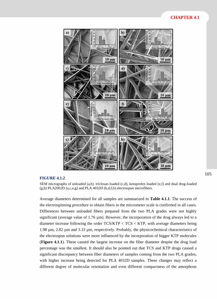
CHAPTER 4.1
105 FIGURE 4.1.2
SEM micrographs of unloaded (a,b). triclosan loaded (c,d), ketoprofen loaded (e,f) and dual drug-loaded
(g,h) PLA2002D (a,c,e,g) and PLA 4032D (b,d,f,h) electrospun microfibers.
Average diameters determined for all samples are summarized in Table 4.1.1. The success of
the electrospinning procedure to obtain fibers in the micrometer scale is confirmed in all cases.
Differences between unloaded fibers prepared from the two PLA grades were not highly
significant (average value of 1.76 µm). However, the incorporation of the drug always led to a
diameter increase following the order TCS/KTP < TCS < KTP, with average diameters being
1.98 µm, 2.82 µm and 3.33 µm, respectively. Probably, the physicochemical characteristics of
the electrospun solutions were more influenced by the incorporation of bigger KTP molecules
(Figure 4.1.1). These caused the largest increase on the fiber diameter despite the drug load
percentage was the smallest. It should also be pointed out that TCS and KTP drugs caused a
significant discrepancy between fiber diameters of samples coming from the two PLA grades,
with higher increase being detected for PLA 4032D samples. These changes may reflect a
different degree of molecular orientation and even different compactness of the amorphous
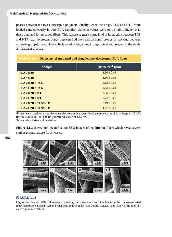
106
Multifunctional biodegradable fiber scaffolds
phases between the two electrospun polymers. Finally, when the drugs, TCS and KTP, were
loaded simultaneously in both PLA samples, diameter values were only slightly higher than
those obtained for unloaded fibers. This feature suggests some kind of interaction between TCS
and KTP (e.g., hydrogen bonds between hydroxyl and carbonyl groups or stacking between
aromatic groups) that could also be favored by higher total drug content with respect to the single
drug-loaded systems.
aFibers were obtained using the same electrospinning operational parameters: applied voltage of 15 kV,
flow rate of 10 mL·h-1 and tip-collector distance of 12.5 cm. bMean value ± standard deviation.
Figure 4.1.3 shows high-magnification SEM images of the different fibers which reveal a very
similar porous texture for all cases.
FIGURE 4.1.3
High-magnification SEM micrographs showing the surface texture of unloaded (a,b), triclosan-loaded
(c,d), ketoprofen-loaded (e,f) and dual drug-loaded (g,h) PLA 2002D (a,c,e,g) and PLA 4032D (b,d,f,h)
electrospun microfibers.
TABLE 4.1.1. Diameters of unloaded and drug loaded electrospun PLA fibers.
Sample Diametera,b (µm)
PLA 2002D 1.86 ± 0.06
PLA 4032D 1.66 ± 0.05
PLA 2002D + TCS 2.12 ± 0.01
PLA 4032D + TCS 3.53 ± 0.04
PLA 2002D + KTP 2.95 ± 0.02
PLA 4032D + KTP 3.72 ± 0.06
PLA 2002D + TCS/KTP 2.19 ± 0.01
PLA 4032D + TCS/KTP 1.77 ± 0.03
CHAPTER 4.1
107
Incorporation of Drugs Into Electrospun Microfibers
FTIR spectra of unloaded and drug-loaded PLA 2002D samples in Figure 4.1.4 illustrate two
interesting points. First, no significant differences exist between typical PLA absorption bands
of scaffolds prepared from the two PLA grades or scaffolds loaded with the drugs or their
combination. The given spectral region is sensitive to molecular conformation, consequently, it
can be concluded that differences between electrospun samples were not large enough to be
detected by FTIR. As will be discussed later, although the amorphous content may change
slightly with the PLA grade and drug load, it seems that polymer chains attained a similar
molecular conformation after the electrospinning process. In fact, processed PLA microfibers
were always practically amorphous but a high degree of molecular orientation was induced
during electrospinning.[34] Note, for example, that all spectra have similar intensity for the
shoulder band at 1209 cm-1 (as (C-O-C) + ras(CH3) for a 107 helical conformation) and the band
at 1263 cm-1 ( (CH) + (C-O-C) for a random conformation). Also, the relative proportion
between bands at 1385 cm-1 (s (CH3), amorphous form) and 1363 cm-1 ((CH), semycrystalline
form) became practically invariable.[35]
FTIR spectra were sufficiently sensitive to detect the incorporated drugs despite the relatively
low loading percentages. More precisely, TCS was clearly identified in the microfibers through
the characteristic peak at 1476 cm-1, attributed to the C=C stretching vibration of benzene
rings.[36] However, lesser loaded KTP (i.e. 1 w/v-% as opposed to 3 w/v-%) could be hardly
detected through the strongest peak at 1652 cm-1, attributed to the C=O stretching.[37]
Unfortunately, FTIR spectra were not able to detect specific interactions in the dual drug-loaded
system due to the low intensity of the involved peaks.
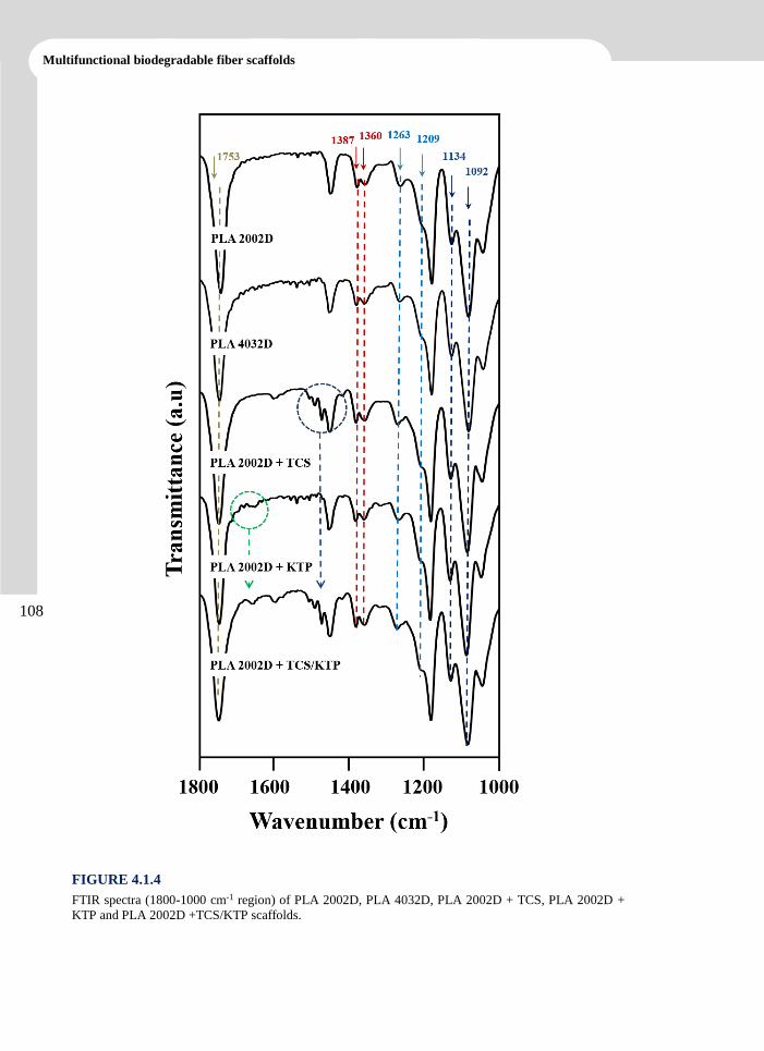
108
Multifunctional biodegradable fiber scaffolds
FIGURE 4.1.4
FTIR spectra (1800-1000 cm-1 region) of PLA 2002D, PLA 4032D, PLA 2002D + TCS, PLA 2002D +
KTP and PLA 2002D +TCS/KTP scaffolds.
CHAPTER 4.1
109
Thermal Properties of Unloaded and Drug Loaded PLA Electrospun Scaffolds
Table 4.1.2 summarizes the main calorimetric data obtained from the heating run of unloaded
and drug-loaded scaffolds from the two PLA grades, whereas the corresponding DSC traces are
shown in Figure 4.1.5.
Data corresponding to the two PLA pellets are also given for comparative purposes. It is clear
that both samples were manufactured in a semicrystalline form attained after annealing
treatment. Values clearly reflect the impact of a small increase of D-lactide content (i.e. from 2
wt-% to 4.2 wt-%) on both amorphous and crystalline phases, with remarkable changes in glass
transition and melting temperatures, respectively. More interestingly, the thermal characteristics
of electrospun samples are significantly different from the initial ones. First, both PLA 2002D
and PLA 4032D electrospun samples became practically amorphous (degree of crystallinity, c,
close to 0.07-0.008 as indicated in Table 4.1.2) although a remarkable degree of molecular chain
orientation could be inferred. Note that cold crystallization peaks can be clearly observed during
the heating run of both samples and relatively high degree of crystallinities (i.e. 0.25 and 0.29)
could be estimated from the subsequent melting enthalpies. These values were close to those
deduced for the corresponding commercial pellet samples and clearly higher than those obtained
from the heating run performed with commercial samples after being slowly cooled from the
melt state.[29] The high relaxation peak observed for the PLA 4032D electrospun sample, which
indicates the great ability of this PLA grade to achieve the equilibrium thermodynamic
conditions characterized by higher stiffness and lower enthalpy an volume, is also worth noting.
In addition, this close to equilibrium condition led to a fictive glass transition temperature[38]
clearly lower than that observed in the initial sample of PLA 4032D (i.e. 62.4 ºC as opposed to
69.3 ºC) and close to those detected for both PLA2002D initial and electrospun samples (59.6
ºC and 59.3 ºC). Cold crystallization took place in a narrow temperature range for PLA 4032D,
whereas the use of PLA 2002D involved a wide temperature range suggesting greater difficulty
for molecular rearrangement.
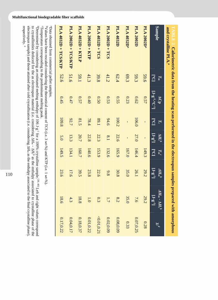
110
Multifunctional biodegradable fiber scaffolds
aData o
btain
ed fro
m co
mm
ercial pellet sam
ples.
bValu
es hav
e been
rescaled co
nsid
ering th
e theo
retical con
tent o
f TC
S (i.e. 3
wt-%
) and
KT
P (i.e. 1
wt-%
). cT
emp
erature co
rrespo
nd
ing
to th
e pred
om
inan
t meltin
g p
eak.
dDeterm
ined
by
con
siderin
g an
estimated
meltin
g en
thalp
y o
f 10
6 J·g
-1 for a 1
00%
crystallin
e samp
le. [39, 4
0] L
eft and
right v
alues co
rrespond
to cry
stallinities d
edu
ced fo
r the as electro
spu
n m
aterial (i.e. con
siderin
g Δ
Hm - Δ
Hc b as th
e enth
alpy
associated
to cry
stalline p
hase o
f the
electrosp
un
samp
le) and
tho
se attained
after cold
crystallizatio
n (i.e. co
nsid
ering
ΔH
m as th
e enth
alpy asso
ciated to
the fin
al crystallin
e ph
ase),
respectiv
ely. e
PL
A 4
03
2D
+ T
CS
/KT
P
PL
A 2
00
2D
+ T
CS
/KT
P
PL
A 4
03
2D
+ K
TL
P
PL
A 2
00
2D
+ K
TP
PL
A 4
03
2D
+ T
CS
PL
A 2
00
2D
+ T
CS
PL
A 4
03
2D
PL
A 4
03
2D
a
PL
A 2
00
2D
PL
A 2
00
2D
a
Sa
mp
le
TA
BL
E 2
. Ca
lorim
etric da
ta fr
om
the h
eatin
g sca
n p
erform
ed in
the elec
trosp
un
sam
ples p
repa
red
with
am
orp
ho
us
an
d cr
ysta
lline P
LA
. a
52
.6
51
.6
59
.1
41
.3
39
.8
41
.2
62
.4
69
.3
59
.3
59
.6
Tm
[ºC]
0.4
5
0.4
7
0.5
7
0.4
0
0.5
0
0.5
3
0.5
5
0.2
3
0.6
2
0.5
7
ΔC
p
[J·g
-1·ºC-1]
10
9.8
92
.7
81
.5
78
.4
89
.1
94
.6
10
0.2
-
10
6.0
-
Tc
[ºC]
5.0
13
.3
20
.7
22
.8
22
.3
8.1
22
.6
-
27
.0
-
ΔH
c b
[J·g
1]
14
9.5
13
4.1
16
0.7
14
0.6
15
3.9
13
2.6
16
5.9
16
7.0
14
6.4
14
9.3
Tm
c
[ºC]
23
.6
17
.6
39
.5
23
.8
22
.6
9.8
30
.8
35
.0
26
.1
29
.2
ΔH
mb
[J·g
-1]
18
.6
4.3
18
.8
1.0
0.3
1.7
8.2
35
.0
7.6
29
.2
ΔH
m - Δ
Hc b
[J·g
-1]
0.1
7,0
.22
0.0
4,0
.17
0.1
8,0
.37
0.0
1,0
.22
<0
.01
,0.2
1
0.0
2,0
.09
0.0
8,0
.09
0.3
3
0.0
7,0
.25
0.2
8
χc d
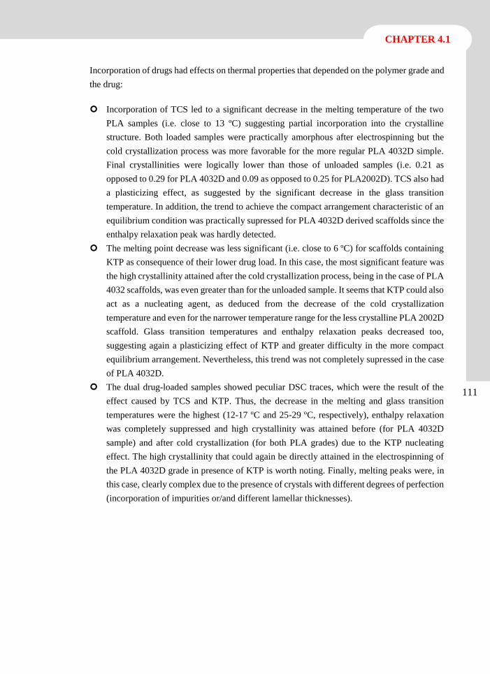
CHAPTER 4.1
111
Incorporation of drugs had effects on thermal properties that depended on the polymer grade and
the drug:
Incorporation of TCS led to a significant decrease in the melting temperature of the two
PLA samples (i.e. close to 13 ºC) suggesting partial incorporation into the crystalline
structure. Both loaded samples were practically amorphous after electrospinning but the
cold crystallization process was more favorable for the more regular PLA 4032D simple.
Final crystallinities were logically lower than those of unloaded samples (i.e. 0.21 as
opposed to 0.29 for PLA 4032D and 0.09 as opposed to 0.25 for PLA2002D). TCS also had
a plasticizing effect, as suggested by the significant decrease in the glass transition
temperature. In addition, the trend to achieve the compact arrangement characteristic of an
equilibrium condition was practically supressed for PLA 4032D derived scaffolds since the
enthalpy relaxation peak was hardly detected.
The melting point decrease was less significant (i.e. close to 6 ºC) for scaffolds containing
KTP as consequence of their lower drug load. In this case, the most significant feature was
the high crystallinity attained after the cold crystallization process, being in the case of PLA
4032 scaffolds, was even greater than for the unloaded sample. It seems that KTP could also
act as a nucleating agent, as deduced from the decrease of the cold crystallization
temperature and even for the narrower temperature range for the less crystalline PLA 2002D
scaffold. Glass transition temperatures and enthalpy relaxation peaks decreased too,
suggesting again a plasticizing effect of KTP and greater difficulty in the more compact
equilibrium arrangement. Nevertheless, this trend was not completely supressed in the case
of PLA 4032D.
The dual drug-loaded samples showed peculiar DSC traces, which were the result of the
effect caused by TCS and KTP. Thus, the decrease in the melting and glass transition
temperatures were the highest (12-17 ºC and 25-29 ºC, respectively), enthalpy relaxation
was completely suppressed and high crystallinity was attained before (for PLA 4032D
sample) and after cold crystallization (for both PLA grades) due to the KTP nucleating
effect. The high crystallinity that could again be directly attained in the electrospinning of
the PLA 4032D grade in presence of KTP is worth noting. Finally, melting peaks were, in
this case, clearly complex due to the presence of crystals with different degrees of perfection
(incorporation of impurities or/and different lamellar thicknesses).
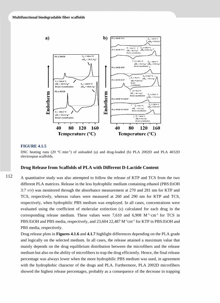
112
Multifunctional biodegradable fiber scaffolds
FIGURE 4.1.5
DSC heating runs (20 ºC·min-1) of unloaded (a) and drug-loaded (b) PLA 2002D and PLA 4032D
electrospun scaffolds.
Drug Release from Scaffolds of PLA with Different D-Lactide Content
A quantitative study was also attempted to follow the release of KTP and TCS from the two
different PLA matrices. Release in the less hydrophilic medium containing ethanol (PBS:EtOH
3:7 v/v) was monitored through the absorbance measurement at 270 and 281 nm for KTP and
TCS, respectively, whereas values were measured at 260 and 290 nm for KTP and TCS,
respectively, when hydrophilic PBS medium was employed. In all cases, concentrations were
evaluated using the coefficient of molecular extinction (ε) calculated for each drug in the
corresponding release medium. These values were 7,610 and 6,908 M-1·cm-1 for TCS in
PBS:EtOH and PBS media, respectively, and 23,604 22,487 M-1cm-1 for KTP in PBS:EtOH and
PBS media, respectively.
Drug release plots in Figures 4.1.6 and 4.1.7 highlight differences depending on the PLA grade
and logically on the selected medium. In all cases, the release attained a maximum value that
mainly depends on the drug equilibrium distribution between the microfibers and the release
medium but also on the ability of microfibers to trap the drug efficiently. Hence, the final release
percentage was always lower when the more hydrophilic PBS medium was used, in agreement
with the hydrophobic character of the drugs and PLA. Furthermore, PLA 2002D microfibers
showed the highest release percentages, probably as a consequence of the decrease in trapping

CHAPTER 4.1
113
efficiency caused by their lower molecular orientation and less dense molecular arrangement.
Thus, for example the release of TCS and KTP from PLA 2002D scaffolds after 8 h of exposure
to PBS medium rose 40% and 30%, respectively (Figure 4.1.6 a), while these percentages
decreased to 30% and 5% for a similar exposure time when PLA 4032D scaffolds were
employed (Figure 4.1.6 c). A similar trend was observed in PBS:EtOH medium, specifically,
the percentages of TCS and KTP release from PLA 2002D scaffolds after 8 h of exposure were,
respectively 80% and 60% (Figure 4.1.7 a) and from PLA 4032D scaffolds, 50% and 30% ,
respectively (Figure 4.1.7 c). The influence of release medium and type of polymer matrix on
drug release was also observed when dual drug-loaded scaffolds were evaluated (Figures 4.1.6
c, 4.1.6 d, 4.1.7 c and 4.1.7 d).
FIGURE 4.1.6
Release curves in PBS medium of TCS (□) and KTP (○) from single drug-loaded (a,c) and dual drug-
loaded (b,d) PLA 2002D (a,b) and PLA 4032D (c,d) electrospun scaffolds.
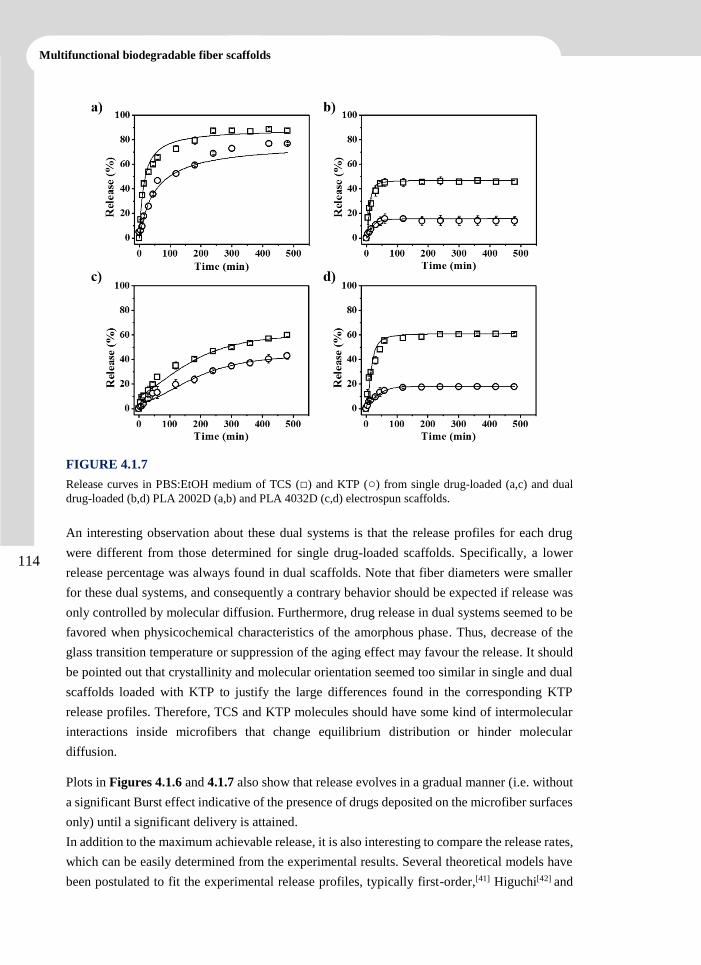
114
Multifunctional biodegradable fiber scaffolds
FIGURE 4.1.7
Release curves in PBS:EtOH medium of TCS (□) and KTP (○) from single drug-loaded (a,c) and dual
drug-loaded (b,d) PLA 2002D (a,b) and PLA 4032D (c,d) electrospun scaffolds.
An interesting observation about these dual systems is that the release profiles for each drug
were different from those determined for single drug-loaded scaffolds. Specifically, a lower
release percentage was always found in dual scaffolds. Note that fiber diameters were smaller
for these dual systems, and consequently a contrary behavior should be expected if release was
only controlled by molecular diffusion. Furthermore, drug release in dual systems seemed to be
favored when physicochemical characteristics of the amorphous phase. Thus, decrease of the
glass transition temperature or suppression of the aging effect may favour the release. It should
be pointed out that crystallinity and molecular orientation seemed too similar in single and dual
scaffolds loaded with KTP to justify the large differences found in the corresponding KTP
release profiles. Therefore, TCS and KTP molecules should have some kind of intermolecular
interactions inside microfibers that change equilibrium distribution or hinder molecular
diffusion.
Plots in Figures 4.1.6 and 4.1.7 also show that release evolves in a gradual manner (i.e. without
a significant Burst effect indicative of the presence of drugs deposited on the microfiber surfaces
only) until a significant delivery is attained.
In addition to the maximum achievable release, it is also interesting to compare the release rates,
which can be easily determined from the experimental results. Several theoretical models have
been postulated to fit the experimental release profiles, typically first-order,[41] Higuchi[42] and
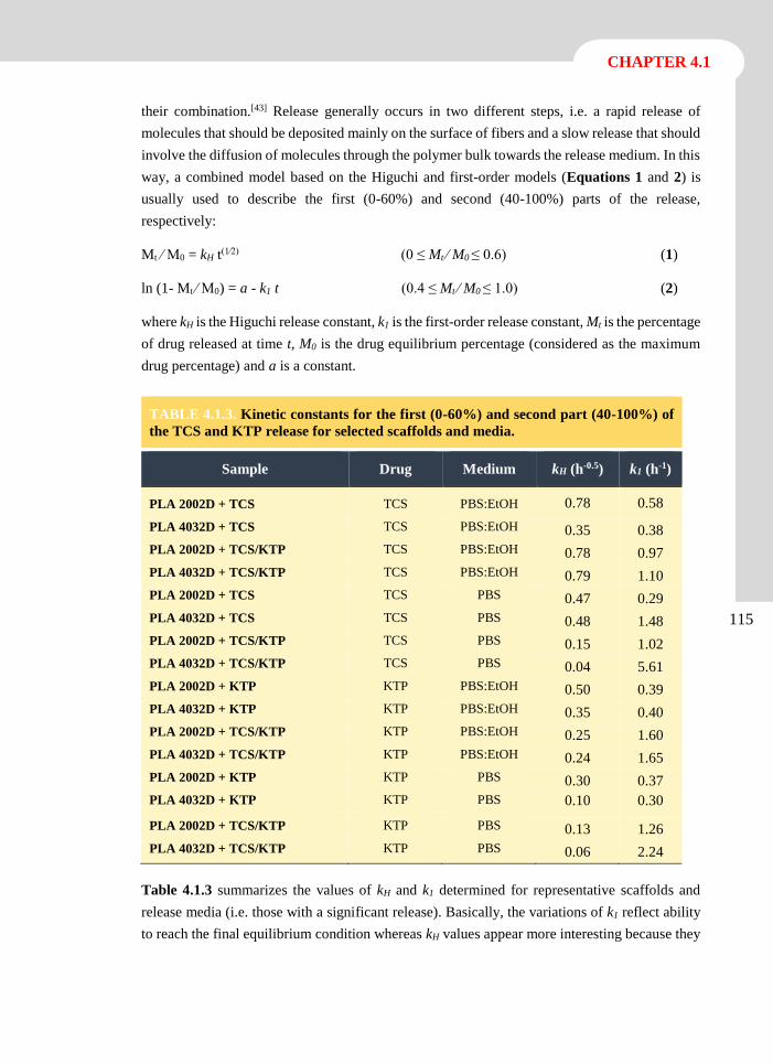
CHAPTER 4.1
115
their combination.[43] Release generally occurs in two different steps, i.e. a rapid release of
molecules that should be deposited mainly on the surface of fibers and a slow release that should
involve the diffusion of molecules through the polymer bulk towards the release medium. In this
way, a combined model based on the Higuchi and first-order models (Equations 1 and 2) is
usually used to describe the first (0-60%) and second (40-100%) parts of the release,
respectively:
Mt ⁄ M0 = kH t(1⁄2) (0 ≤ Mt ⁄ M0 ≤ 0.6) (1)
ln (1- Mt ⁄ M0 ) = a - k1 t (0.4 ≤ Mt ⁄ M0 ≤ 1.0) (2)
where kH is the Higuchi release constant, k1 is the first-order release constant, Mt is the percentage
of drug released at time t, M0 is the drug equilibrium percentage (considered as the maximum
drug percentage) and a is a constant.
TABLE 4.1.3. Kinetic constants for the first (0-60%) and second part (40-100%) of
the TCS and KTP release for selected scaffolds and media.
Sample Drug Medium kH (h-0.5) k1 (h-1)
PLA 2002D + TCS TCS PBS:EtOH 0.78 0.58
PLA 4032D + TCS TCS PBS:EtOH 0.35 0.38
PLA 2002D + TCS/KTP TCS PBS:EtOH 0.78 0.97
PLA 4032D + TCS/KTP TCS PBS:EtOH 0.79 1.10
PLA 2002D + TCS TCS PBS 0.47 0.29
PLA 4032D + TCS TCS PBS 0.48 1.48
PLA 2002D + TCS/KTP TCS PBS 0.15 1.02
PLA 4032D + TCS/KTP TCS PBS 0.04 5.61
PLA 2002D + KTP KTP PBS:EtOH 0.50 0.39
PLA 4032D + KTP KTP PBS:EtOH 0.35 0.40
PLA 2002D + TCS/KTP KTP PBS:EtOH 0.25 1.60
PLA 4032D + TCS/KTP KTP PBS:EtOH 0.24 1.65
PLA 2002D + KTP KTP PBS 0.30 0.37
PLA 4032D + KTP KTP PBS 0.10 0.30
PLA 2002D + TCS/KTP KTP PBS 0.13 1.26
PLA 4032D + TCS/KTP KTP PBS 0.06 2.24
Table 4.1.3 summarizes the values of kH and k1 determined for representative scaffolds and
release media (i.e. those with a significant release). Basically, the variations of k1 reflect ability
to reach the final equilibrium condition whereas kH values appear more interesting because they
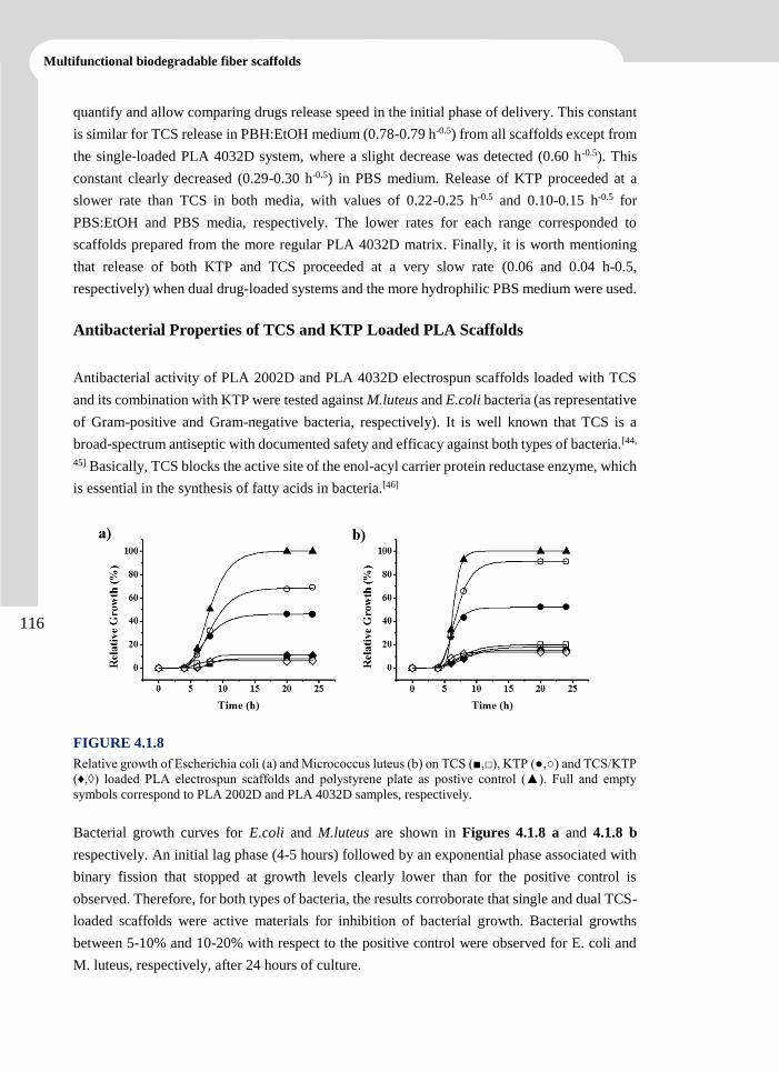
116
Multifunctional biodegradable fiber scaffolds
quantify and allow comparing drugs release speed in the initial phase of delivery. This constant
is similar for TCS release in PBH:EtOH medium (0.78-0.79 h-0.5) from all scaffolds except from
the single-loaded PLA 4032D system, where a slight decrease was detected (0.60 h-0.5). This
constant clearly decreased (0.29-0.30 h-0.5) in PBS medium. Release of KTP proceeded at a
slower rate than TCS in both media, with values of 0.22-0.25 h-0.5 and 0.10-0.15 h-0.5 for
PBS:EtOH and PBS media, respectively. The lower rates for each range corresponded to
scaffolds prepared from the more regular PLA 4032D matrix. Finally, it is worth mentioning
that release of both KTP and TCS proceeded at a very slow rate (0.06 and 0.04 h-0.5,
respectively) when dual drug-loaded systems and the more hydrophilic PBS medium were used.
Antibacterial Properties of TCS and KTP Loaded PLA Scaffolds
Antibacterial activity of PLA 2002D and PLA 4032D electrospun scaffolds loaded with TCS
and its combination with KTP were tested against M.luteus and E.coli bacteria (as representative
of Gram-positive and Gram-negative bacteria, respectively). It is well known that TCS is a
broad-spectrum antiseptic with documented safety and efficacy against both types of bacteria.[44,
45] Basically, TCS blocks the active site of the enol-acyl carrier protein reductase enzyme, which
is essential in the synthesis of fatty acids in bacteria.[46]
FIGURE 4.1.8
Relative growth of Escherichia coli (a) and Micrococcus luteus (b) on TCS (■,□), KTP (●,○) and TCS/KTP
(♦,◊) loaded PLA electrospun scaffolds and polystyrene plate as postive control (▲). Full and empty
symbols correspond to PLA 2002D and PLA 4032D samples, respectively.
Bacterial growth curves for E.coli and M.luteus are shown in Figures 4.1.8 a and 4.1.8 b
respectively. An initial lag phase (4-5 hours) followed by an exponential phase associated with
binary fission that stopped at growth levels clearly lower than for the positive control is
observed. Therefore, for both types of bacteria, the results corroborate that single and dual TCS-
loaded scaffolds were active materials for inhibition of bacterial growth. Bacterial growths
between 5-10% and 10-20% with respect to the positive control were observed for E. coli and
M. luteus, respectively, after 24 hours of culture.
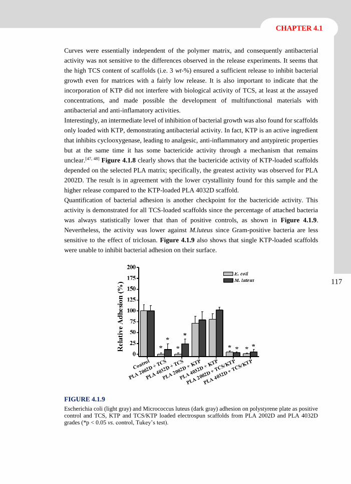
CHAPTER 4.1
117
Curves were essentially independent of the polymer matrix, and consequently antibacterial
activity was not sensitive to the differences observed in the release experiments. It seems that
the high TCS content of scaffolds (i.e. 3 wt-%) ensured a sufficient release to inhibit bacterial
growth even for matrices with a fairly low release. It is also important to indicate that the
incorporation of KTP did not interfere with biological activity of TCS, at least at the assayed
concentrations, and made possible the development of multifunctional materials with
antibacterial and anti-inflamatory activities.
Interestingly, an intermediate level of inhibition of bacterial growth was also found for scaffolds
only loaded with KTP, demonstrating antibacterial activity. In fact, KTP is an active ingredient
that inhibits cyclooxygenase, leading to analgesic, anti-inflammatory and antypiretic properties
but at the same time it has some bactericide activity through a mechanism that remains
unclear.[47, 48] Figure 4.1.8 clearly shows that the bactericide activity of KTP-loaded scaffolds
depended on the selected PLA matrix; specifically, the greatest activity was observed for PLA
2002D. The result is in agreement with the lower crystallinity found for this sample and the
higher release compared to the KTP-loaded PLA 4032D scaffold.
Quantification of bacterial adhesion is another checkpoint for the bactericide activity. This
activity is demonstrated for all TCS-loaded scaffolds since the percentage of attached bacteria
was always statistically lower that than of positive controls, as shown in Figure 4.1.9.
Nevertheless, the activity was lower against M.luteus since Gram-positive bacteria are less
sensitive to the effect of triclosan. Figure 4.1.9 also shows that single KTP-loaded scaffolds
were unable to inhibit bacterial adhesion on their surface.
FIGURE 4.1.9
Escherichia coli (light gray) and Micrococcus luteus (dark gray) adhesion on polystyrene plate as positive
control and TCS, KTP and TCS/KTP loaded electrospun scaffolds from PLA 2002D and PLA 4032D
grades (*p < 0.05 vs. control, Tukey’s test).
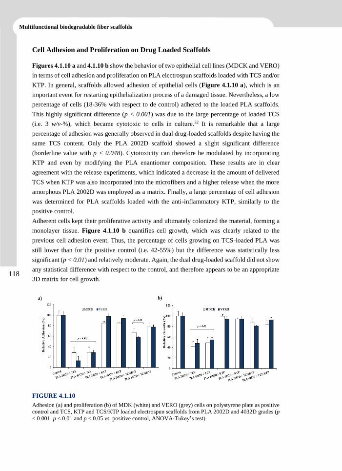
118
Multifunctional biodegradable fiber scaffolds
Cell Adhesion and Proliferation on Drug Loaded Scaffolds
Figures 4.1.10 a and 4.1.10 b show the behavior of two epithelial cell lines (MDCK and VERO)
in terms of cell adhesion and proliferation on PLA electrospun scaffolds loaded with TCS and/or
KTP. In general, scaffolds allowed adhesion of epithelial cells (Figure 4.1.10 a), which is an
important event for restarting epithelialization process of a damaged tissue. Nevertheless, a low
percentage of cells (18-36% with respect to de control) adhered to the loaded PLA scaffolds.
This highly significant difference (p < 0.001) was due to the large percentage of loaded TCS
(i.e. 3 w/v-%), which became cytotoxic to cells in culture.32 It is remarkable that a large
percentage of adhesion was generally observed in dual drug-loaded scaffolds despite having the
same TCS content. Only the PLA 2002D scaffold showed a slight significant difference
(borderline value with p < 0.048). Cytotoxicity can therefore be modulated by incorporating
KTP and even by modifying the PLA enantiomer composition. These results are in clear
agreement with the release experiments, which indicated a decrease in the amount of delivered
TCS when KTP was also incorporated into the microfibers and a higher release when the more
amorphous PLA 2002D was employed as a matrix. Finally, a large percentage of cell adhesion
was determined for PLA scaffolds loaded with the anti-inflammatory KTP, similarly to the
positive control.
Adherent cells kept their proliferative activity and ultimately colonized the material, forming a
monolayer tissue. Figure 4.1.10 b quantifies cell growth, which was clearly related to the
previous cell adhesion event. Thus, the percentage of cells growing on TCS-loaded PLA was
still lower than for the positive control (i.e. 42-55%) but the difference was statistically less
significant (p < 0.01) and relatively moderate. Again, the dual drug-loaded scaffold did not show
any statistical difference with respect to the control, and therefore appears to be an appropriate
3D matrix for cell growth.
FIGURE 4.1.10
Adhesion (a) and proliferation (b) of MDK (white) and VERO (grey) cells on polystyrene plate as positive
control and TCS, KTP and TCS/KTP loaded electrospun scaffolds from PLA 2002D and 4032D grades (p
< 0.001, p < 0.01 and p < 0.05 vs. positive control, ANOVA-Tukey’s test).
CHAPTER 4.1
119
4.1.4 Conclusions
Continuous electrospun microfibers of polylactide containing antibacterial and anti-
inflammatory agents (i.e. triclosan and ketoprofen) can be successfully prepared using optimized
processing parameters and a mixture of chloroform, acetone and dimethylsulfoxide as solvent.
Thermal properties of electrospun microfibers were highly dependent on small variation in the
D-lactide content of PLA and the incorporation of small ratios of TCS and/or KTP. Specifically,
microfibers containing KTP and prepared from the more regular PLA 4032D sample were
crystalline as a result of the molecular orientation induced by the electrospinning process and
the nucleating effect of the incorporated drug.
Release of TCS and KTP from PLA electrospun scaffolds depended on the hydrophilicity of the
media, the stereoregularity of the polymer matrix and the potential establishment of
intermolecular interactions in dual drug-loaded scaffolds. In particular, percentages of released
drugs and release rates were lower in dual drug-loaded scaffolds than in single systems. All
TCS-loaded scaffolds exhibited antibacterial properties independently of the selected PLA grade
and the presence of KTP. In addition, KTP-loaded scaffolds also showed bacteriostatic activity,
which was more significant at higher D-lactide content of PLA.
Cytotoxicity of TCS-loaded scaffolds could be suppressed and bactericide activity maintained
when KTP was also incorporated into the microfibers due to the slower and reduced release from
these dual drug-loaded systems.
120
Multifunctional biodegradable fiber scaffolds
4.1.5 References
[1] L.T. Lim, R. Auras, M. Rubino, Prog Polym Sci, 33 (2008) 820-852.
[2] O. Wolf, M. Crank, M. Patel, F. Marscheider-Weidemann, EUR No. 22103 EN.
European Commission, 2005.
[3] K.M. Nampoothiri, N.R. Nair, R.P. John, Bioresour Technol, 101 (2010) 8493-8501.
[4] R. Auras, B. Harte, S. Selke, Macromol Biosci, 4 (2004) 835-864.
[5] C.J. Weber, V. Haugaard, R. Festersen, G. Bertelsen, Food Addit Contam. 19 (2002)
172–177.
[6] J.J. Conn, R. Oyasu, M. Welsh, J.M. Beal, Am J Surg, 128 (1974) 19-23.
[7] E.E. Schmitt, R.A. Polistina, in: A.C. Co (Ed.), United States, 1967.
[8] C. Burger, K. Kabir, C. Rangger, M. Mueller, T. Minor, R. Tolba, Arch Orthop Trauma
Surg, 126 (2006) 695-705.
[9] B. Dhandayuthapani, Y. Yoshida, T. Maekawa, D.S. Kumar, Int J Polym Sci, (2011)
290602.
[10] J. Heller, CRC Crit Rev Ther Drug Carrier Syst, 1 (1984) 39-90.
[11] J.R. Sarasua, A.L. Arraiza, P. Balerdi, I. Maiza, J Mater Sci, 40 (2005) 1855.
[12] J.K. Lee, K.H. Lee, B.S. Jin, Eur Polym J, 37 (2001) 907-914.
[13] Z.W. Ma, M. Kotaki, R. Inai, S. Ramakrishna, Tissue Eng, 11 (2005) 101-109.
[14] J. Zeng, X. Xu, X. Chen, Q. Liang, X. Bian, L. Yang, X. Jing, J Control Release, 92
(2003) 227-231.
[15] W.J. Li, C.T. Laurencin, E.J. Caterson, R.S. Tuan, F.K. Ko, J Biomed Mater Res, 60
(2002) 613-621.
[16] A.M. Piras, F. Chiellini, E. Chiellini, L. Nikkola, N. Ashammakhi, J Bioact Compat Pol,
23 (2008) 423-443.
[17] B. Song, C. Wu, J. Chang, J Biomed Mater Res Part B, 100B (2012) 2178-2186.
[18] Y. Wang, W. Qiao, B. Wang, Y. Zhang, P. Shao, T. Yin, Polym J, 43 (2011) 478-483.
[19] E. Llorens, M.M. Perez-Madrigal, E. Armelin, L.J. del Valle, J. Puiggali, C. Aleman,
RSC Adv, 4 (2014) 15245-15255.
[20] T. Okuda, K. Tominaga, S. Kidoaki, J Control Release, 143 (2010) 258-264.
CHAPTER 4.1
121
[21] A. Schneider, X.Y. Wang, D.L. Kaplan, J.A. Garlick, C. Egles, Acta Biomater, 5 (2009)
2570-2578.
[22] J. Cailloux, O.O. Santana, E. Franco-Urquiza, J.J. Bou, F. Carrasco, J. Gamez-Perez,
M.L. Maspoch, Express Polym Lett, 7 (2013) 304-318.
[23] J. Cailloux, O.O. Santana, E. Franco-Urquiza, J.J. Bou, F. Carrasco, M.L. Maspoch, J
Mater Sci, 49 (2014) 4093-4107.
[24] R. Zurita, J. Puiggali, A. Rodriguez-Galan, Macromol Biosci, 6 (2006) 58-69.
[25] D. Li, Y.N. Xia, Adv Mater, 16 (2004) 1151-1170.
[26] S.R. Dhakate, B. Singla, M. Uppal, R.B. Mathur, Adv Mater Lett, 1 (2010) 200-204.
[27] E. Luong-Van, L. Grondahl, K.N. Chua, K.W. Leong, V. Nurcombe, S.M. Cool,
Biomaterials, 27 (2006) 2042-2050.
[28] G. Buschle-Diller, J. Cooper, Z. Xie, Y. Wu, J. Waldrup, X.J. Ren, Cellulose, 14 (2007)
553-562.
[29] E. Llorens, L.J. del Valle, A. Diaz, M.T. Casas, J. Puiggali, Macromol Res, 21 (2013)
775-787.
[30] L.J. del Valle, R. Camps, A. Diaz, L. Franco, A. Rodriguez-Galan, J. Puiggali, J Polym
Res, 18 (2011) 1903-1917.
[31] L.J. del Valle, A. Diaz, M. Royo, A. Rodriguez-Galan, J. Puiggali, Express Polym Lett,
6 (2012) 266-282.
[32] D. Karst, Y. Yang, J Appl Polym Sci, 96 (2005) 416-422.
[33] D.M. Aragón, D.A. Chiappetta, J. Degrossi, E.F. Vargas, C. Bregni, A. Sosnik, F.
Martínez, Rev Colomb Cienc Quím Farm, 37 (2008) 241-257.
[34] J. Zeng, X. Chen, Q. Liang, X. Xu, X. Jing, Macromol Biosci, 4 (2004) 1118-1125.
[35] H. Urayama, S.-I. Moon, Y. Kimura, Macromol Mater Eng, 288 (2003) 137-143.
[36] A. Celebioglu, O.C.O. Umu, T. Tekinay, T. Uyar, Colloid Surface B, 116 (2014) 612-
619.
[37] M.L. Vueba, M.E. Pina, F. Veiga, J.J. Sousa, L.A.E.B. de Carvalho, Inter J Pharm, 307
(2006) 56-65.
[38] M.L. Cerrada, G.B. McKenna, Macromolecules, 33 (2000) 3065-3076.
122
Multifunctional biodegradable fiber scaffolds
[39] T.Y. Cho, G. Strobl, Polymer, 47 (2006) 1036-1043.
[40] J.R. Sarasua, R.E. Prud'homme, M. Wisniewski, A. Le Borgne, N. Spassky,
Macromolecules, 31 (1998) 3895-3905.
[41] J.G. Wagner, J Pharm Sci, 58 (1969) 1253-1257.
[42] T. Higuchi, J Pharm Sci, 52 (1963) 1145-1149.
[43] R.W. Baker, in, John Wiley & Sons, New York, USA, 1987.
[44] H.N. Bhargava, P.A. Leonard, Am J Infect Control, 24 (1996) 209-218.
[45] L.M. McMurry, M. Oethinger, S.B. Levy, Nature, 394 (1998) 531-532.
[46] C.W. Levy, A. Roujeinikova, S. Sedelnikova, A.R. Stuitje, A.R. Salabas, D.W. Rice, J.B.
Rafferty, Nature, 398 (1999) 383-384.
[47] S.G. Dastidar, K. Ganguly, K. Chaudhuri, A.N. Chakrabarty, Int J Antimicrob Ag, 14
(2000) 249-251.
[48] H.A. Abbas, F.M. Serry, E.M. El-Masry, Asian J Res Pharm Sci, 2 (2012) 66-72.
Electrospun Ternary Drug-Loaded Multiactive
Scaffolds
Multifunctional electrospun scaffolds were prepared from two
PLA grades having slightly different D-lactide content (4.2 wt-
% and 2.0 wt-%). Triclosan (TCS), ketoprofen (KTP) and p-
coumaric acid (CUM) were selected as bactericide, anti-
inflammatory and antioxidant agents, respectively. Single,
binary and ternary drug-loaded microfibers having a unimodal
diameter distribution could be prepared using a common
chloroform:acetone:dimethylsulfoxide mixture and similar
operational parameters (i.e., voltage, flow rate and tip-
collector distance). FTIR spectra were sensitive to the low
amount of drugs loaded and even showed slight differences in
PLA conformation. DSC heating scans clearly demonstrated
the ability of electrospinning to induce molecular orientation
of PLA and also the nucleation effect of incorporated drugs to
induce crystallization. Thus, crystallinity of binary drug-loaded
scaffolds was significantly higher than observed for unloaded
samples.
Release behavior of the three drugs from loaded scaffolds and
PLA matrices in PBS:ethanol medium was evaluated. A rapid
release was always detected, together with partial drug
retention which was higher when the more stereoregular PLA
matrix was employed. A strong bactericide effect was found
when scaffolds were loaded with 3 wt-% of TCS, but
incorporation of when a small percentage of KTP (i.e. 1 wt-%)
had a bacteriostatic effect even in the absence of TCS. The
inherent cytotoxicity of TCS could be well neutralized by
enhancing cell viability by incorporation of CUM and/or KTP.
4.2
124
Multifunctional biodegradable fiber scaffolds
4.2.1 Introduction
The principle of tissue engineering and regenerative medicine is the application of material
scaffolds to develop biomimic and bioinspired materials. These scaffolds can be specifically
prepared to display biological activities that induce regeneration of both tissues and organs and
restore the function of diseased or traumatized tissues in the human body.[1]
Scaffolds are defined as three-dimensional porous solid biomaterials which should offer a
unique combination of inherent properties, such as physical stability within implanted injury
site. Besides promoting tissue regeneration, scaffolds have other very important
characteristics/functions: (i) capability to favor cell-biomaterial interactions (i.e. cell adhesion
and extracellular matrix (ECM) deposition), (ii) enhancement of cell survival (proliferation and
differentiation), (iii) compatibility of biodegradation rate with required time for tissue
regeneration and (iv) ability to cause minimum inflammation or toxicity in vivo resulting from
toxic metabolic byproducts.[1] In addition, scaffolds can be used as carriers and/or delivery
system of drugs or biomolecules to palliate different stages during replacement and regeneration
of tissue or to avoid rejection of implanted biomaterial.
Natural and synthetic polymers have been widely used as biomaterials for medical devices and
tissue engineering scaffolds.[2, 3] The most commonly used synthetic polymers in tissue
engineering are polylactide (PLA), polyglicolide (PGA) and their copolymers (PLGA).[4] These
materials provide synthetic scaffolds characterized by excellent mechanical properties, highly
interconnected porous structure, ability to activate their surfaces to yield specific chemical
properties, and geometry adapted to direct tissue regeneration.[5]
Different techniques to prepare scaffolds are currently available, but electrospinning is probably
one of the simplest processes to obtain porous matrices constituted by fibers in the micrometer
or nanometer scales. Furthermore, since fibers can be easily loaded with drugs during their
preparation, electrospinning provides the most promising results for tissue engineering, tissue
regeneration and drug delivery applications.[6, 7] Specifically, electrospun scaffolds can be used
for musculoskeletal tissue engineering include bone and cartilage, and also as control delivery
systems for drugs, proteins and DNA.[8] Electrospinning has been widely applied to obtain
scaffolds from natural polymers such as collagen,[9] gelatin,[10] chitosan,[11] HA,[12] and silk
fibroin,[13] and well as from synthetic polymers like polylactide,[14] polyurethane,[15]
polycaprolactone,[16] poly(lactide-co-glicolide),[17] polyvinilalcohol,[18] and poly(lactide-co-
caprolactone).[5]
Several health problems have been associated with the use of biomaterials, for example
infecrion related to the use of catheters[19] or prosthetic bones[20] among others. Other problems
concerning damaged tissue, such as inflammation produced by cell necrosis, must be
considered, too. Inflammation and oxidative stress are two cellular processes in the tissue that
must be treated to restart rapid recovery from tissue injury. In this sense, scaffolds should be
designed to be used not only as appropriate platforms to support cell proliferation but also as
active elements to mediate cell recovery through local tissue medication.
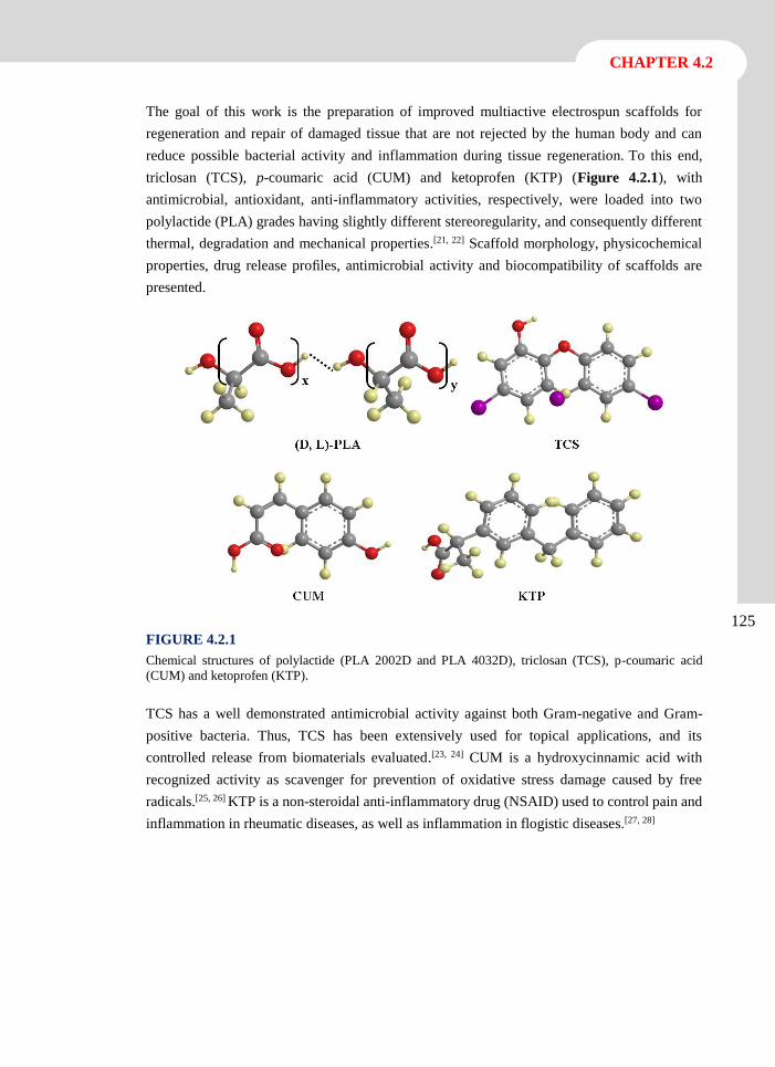
125
CHAPTER 4.2
The goal of this work is the preparation of improved multiactive electrospun scaffolds for
regeneration and repair of damaged tissue that are not rejected by the human body and can
reduce possible bacterial activity and inflammation during tissue regeneration. To this end,
triclosan (TCS), p-coumaric acid (CUM) and ketoprofen (KTP) (Figure 4.2.1), with
antimicrobial, antioxidant, anti-inflammatory activities, respectively, were loaded into two
polylactide (PLA) grades having slightly different stereoregularity, and consequently different
thermal, degradation and mechanical properties.[21, 22] Scaffold morphology, physicochemical
properties, drug release profiles, antimicrobial activity and biocompatibility of scaffolds are
presented.
FIGURE 4.2.1
Chemical structures of polylactide (PLA 2002D and PLA 4032D), triclosan (TCS), p-coumaric acid
(CUM) and ketoprofen (KTP).
TCS has a well demonstrated antimicrobial activity against both Gram-negative and Gram-
positive bacteria. Thus, TCS has been extensively used for topical applications, and its
controlled release from biomaterials evaluated.[23, 24] CUM is a hydroxycinnamic acid with
recognized activity as scavenger for prevention of oxidative stress damage caused by free
radicals.[25, 26] KTP is a non-steroidal anti-inflammatory drug (NSAID) used to control pain and
inflammation in rheumatic diseases, as well as inflammation in flogistic diseases.[27, 28]
126
Multifunctional biodegradable fiber scaffolds
4.2.2 Experimental Section
Materials
Two commercial PLA grades from Natureworks® with 95.8 and 98 wt-% of L-lactic isomer
content were used; i.e. PLA 2002D and PLA 4032D, respectively. According to the
manufacturer, PLA 2002D is a transparent solid with a density of 1.24 g·cc-1. Its calorimetric
and mechanical properties are defined by a glass transition temperature (Tg) of 58 ºC, a melting
point (Tm) of 153 ºC, a tensile modulus (E) of 3500 MPa, a tensile strength () of 53-60 MPa
and a tensile elongation () of 6%. PLA 4032D has a translucent appearance, a density of 1.24
g·cc-1 and highly different properties from those of the sample with higher D content. Thus, Tg,
Tm, E, and values were reported to be 70 ºC, 160 ºC, 3440-3784 Ma, 103.2-144.5 MPa, 100-
180%, respectively. Molecular weights determined by GPC were quite similar, and specifically
Mn, Mw and polydispersity index were 98,100 g·mol-1, 181,000 g·mol-1 and 1.85 for PLA 2002D
and 84,200 g·mol-1, 179,400 g·mol-1 and 2.13 for PLA 4032D.[21, 22]
Trichloromethane (TCM), acetone (AC), dimethylsulfoxide (DMSO), Triclosan (IrgasanTM)
(TCS), ketoprofen (KTP) 3-(4,5-dimethylthiazol-2-yl)-2,5-diphenyl-2H-tetrazolium bromide
(MTT) were purchased from Sigma-Aldrich (St. Louis, USA) and p-coumaric acid (CUM) were
purchased from Acros Organics (New Jersey, USA). VERO (African green monkey kidney
epithelial cells), MDCK (Madin-Darby canine kidney epithelial cells) were purchased from
ATCC (USA).
Preparation of fibers by electrospinning
Both PLA 2002D and PLA 4032D (1 g) were dissolved in 9 mL of a chloroform-acetone
mixture (2:1 v/v). Then, 1 mL of dimethysulfoxide (DMSO) containing the drugs was added
and the mixture was homogenized by vortex to obtain an electrospinable solution of 10 w/v-%
PLA, and 3 w/v-% TCS, 1 w/v-% KTP and 1 w/v-% CUM. Furthermore, PLA samples loaded
with one single drug and dual-drug combinations (e.g., TCS/CUM and KTP/CUM) were also
prepared as controls.
A plastic syringe of 5 mL (Becton Dickson, Spain) was filled with the corresponding PLA drug
solution. Electrospinning was carried out between the needle (18G; Terumo, Belgium)
connected to the anode and the static collector connected to the cathode. The voltage was
applied by a high voltage supply (Gamma High Voltage Research, ES30-5W model). The flow
rate was controlled using a KD100 infusion syringe pump (KD Scientific Inc., USA). All
electrospinning experiments were conducted at room temperature (aprox. 25ºC).
127
CHAPTER 4.2
Morphology and crystallinity of drug loaded PLA nanofibers
Diameter measurements and inspection of fiber surfaces were performed by scanning electron
microscopy using a Focus Ion Beam Zeiss Neon 40 instrument (Carl Zeiss, Germany). Carbon
coating was accomplished with a Mitec K950 Sputter Coater (dotted with a film thickness
monitor k150x). Samples were viewed at an accelerating voltage of 5 kV.
Calorimetric data were obtained by differential scanning calorimetry with a TA Instruments
Q100 series equipped with a refrigeration cooling system (RCS). Experiments were conducted
under a flow of dry nitrogen with a sample weight of approximately 5 mg and calibration was
performed with indium. Heating and cooling runs were carried out at a rate of 20 ºC·min-1 and
10 ºC·min-1, respectively.
FTIR spectra of CUM, KTP, TCS and unloaded and drug loaded PLA both PLA 4032D and
PLA 2002D grades were recorded on a Jasco FTIR 4100 spectrophotometer. Samples were
placed on an attenuated total reflection accessory with thermal control and a diamond crystal
(Specac MKII Golden Gate Heated Single Reflection Diamond ATR).
Release experiments
Controlled release experiments were performed with electrospun scaffolds cut into small square
pieces (20 x 20 x 0.1 mm3). The samples were weighed and placed into polypropylene tubes. A
typical phosphate buffer saline (PBS) supplemented with 70 v/v-% of ethanol was used as the
release medium. This medium, which is less hydrophilic than PBS, was interesting to simulate
the usual serum supplemented medium.[23] Drug release was carried out in 50 mL of the release
medium at 25 ºC for 1 week. Drug concentration in the release medium was evaluated by UV-
Vis spectroscopy using a UV-3600 spectrophotometer (Shimadzu, Japan). Calibration curves
were obtained by plotting the absorbance measured at the corresponding wavelengths against
drug concentration. Samples (1 mL) were drawn from the release medium at predetermined
intervals and an equal volume of fresh medium was added to the release vessel. All the drug
release tests were carried out using three replicates to control release homogeneity, and the
results obtained from the samples were averaged.
128
Multifunctional biodegradable fiber scaffolds
Antimicrobial test: assay of bacterial growth and adhesion
Escherichia coli (E.coli) and Micrococcus luteus (M.luteus) were selected as representative of
Gram-negative and Gram-positive bacteria, respectively, to evaluate the antimicrobial effect of
CUM, TCS/CUM, KTP/CUM and TCS/KTP/CUM loaded electrospun scaffolds. The bacteria
were previously grown aerobically to exponential phase in broth culture (5 g·L-1 beef extract, 5
g·L-1 NaCl, 10 g·L-1 peptone, pH 7.2).
Growth experiments were performed in tubes of 15 mL. 103 CFU (colony forming units) were
seeded in 5 mL of broth culture in the presence of the electrospun scaffolds. The cultures were
incubated at 37 ºC and agitated at 80 rpm. After incubation for 24 and 48 h, an aliquot of 100
µL was diluted 10 times with distilled water and absorbance at 600 nm was measured. The
bacterial number was determined using a McFarland curve scale.
Adhesion experiments were carried out by seeding 107-108 CFU in 5 mL of broth culture in the
presence of the electrospun scaffolds. The cultures were incubated at 37 ºC and agitated at 80
rpm. After incubation, the cultures were aspired and the material washed once with distilled
water. Then, 1 mL of sterile 0.01 M sodium thiosulfate was added and the mixture was vortexed
for 2 min and left to repose for 30 min in order for the bacteria to be removed. Finally, 4 mL of
broth culture was added and the tubes were incubated at 37 ºC for 24 h and agitated at 80 rpm.
The bacterial number was determined as above described.
All assays were performed in triplicate and the results averaged. ANOVA followed by t-Student
test were conducted as statistical analyses at a confidence level of 95 % (p < 0.05). Additionally,
correlation coefficients (r) were calculated to evaluate the relation between the antibacterial
effect and the drug release.
In-vitro biocompatibility assays: cell adhesion and proliferation
MDCK, and VERO cells were cultured in Dulbecco’s modified Eagle Medium (DMEM)
supplemented with 10% fetal bovine serum, 1% penicillin/streptomycin and 2 mM L-glutamine
at 37ºC in a humidified atmosphere with 5% CO2 and 95% air. The culture medium was changed
every two days and, for sub-culture, cell monolayers were rinsed with phosphate buffered saline
(PBS) and detached by incubation with trypsin-EDTA (0.25%) at 37ºC for 2-5 min. Cell
concentration was determined by counting with a Neubauer camera using 4% trypan-blue as
dye vital. Detached cells with viability ≥ 95% were used for biocompatibility assays.
Unloaded and drug-loaded PLA electrospun microfibers were cut into square pieces (10 x 10 x
0.1 mm3). These samples were placed into the wells of a multi-well culture plate and sterilized
by UV-radiation in a laminar flux cabinet for 15 min. To fix the samples in the well, a small
drop of silicone (Silbione® MED ADH 4300 RTV, Bluestar Silicones France SAS, Lyon,
France) was used as the adhesive. Samples were incubated in 1 mL of the culture medium under
culture conditions for 30 min to equilibrate the material. Finally, the medium was aspired and
129
CHAPTER 4.2
the material was evaluated for cell adhesion and proliferation by exposing cells to direct contact
with the material surface.
To assess cell adhesion, aliquots of 50-100 µL containing 5x10⁴ cells were seeded onto the
electrospun scaffolds placed in the wells. The plate was incubated in culture conditions for 30
min to allow cell attachment to the material surface. Then, 1 mL of the culture medium was
added to each well and the plate was incubated for 24 h. Finally, cell viability was determined
by the MTT assay. Positive controls were performed on unloaded PLA electrospun scaffolds
by cell culture, whereas those loaded with 3 w/v-% of TCS were used as negative controls.
Cell proliferation was evaluated by a similar procedure to the adhesion assay, but the aliquot of
50-100 µL contained 2x10⁴ cells. The cultures were maintained for 7 days to allow cell growth
and adequate cell confluence in the well. The medium were renewed every two days. Finally,
cell viability was determined by the MTT assay.
Each sample was evaluated using five replicates and the results were averaged and graphically
represented. The statistical analysis was performed by one-way ANOVA to compare the means
of all groups; t-Student test was then applied to determine a statistically significant difference
between two studied groups. The tests were performed with a confidence level of 95% (p <
0.05).
130
Multifunctional biodegradable fiber scaffolds
4.2.3 Results and Discussion
Morphology of PLA Multifunctional Electrospun Scaffolds
The success of electrospinning process requires strict control of the operational parameters of
each polymer (e.g., strength of the applied electrical field, tip-collector distance and flow rate)
and solution properties (e.g., viscosity, surface tension, dielectric constant, volatility, and
concentration).[29-31] Selection of an appropriate solvent system is probably one of the most
crucial points, especially when compounds of highly different characteristics (e.g., polylactides
samples and the above selected drugs) must be electrospun.[32] Note, for example, the large
difference between reported Hildebrand parameters for PLA[33] (i.e., 9.87 (cal·cm-3)0.5) and
TCS[34] (i.e., 14.38 (cal·cm-3)0.5). In addition, a relatively high polymer concentration is required
to avoid formation of drops or beads[35] and obtain continuous fibers in a micrometer scale,
which appears more appropriate for sustained drug release. These factors made us select a
chloroform:acetone:dimethylsulfoxide mixture with a 6:3:1 v/v/v ratio, specifically, the two first
solvents were appropriate to obtain PLA electrospun microfibers,[24] whereas the third solvent
was essential to allow dissolution of the three selected drugs (TCS, CUM and KTP).
With regard to operational parameters, the selection of the spinning voltage (15 kV) was
essential to ensure a stable, conical liquid jet which minimized bead formation. The distance
between the target and the syringe tip was kept close to 12.5 cm, and the flow rate was found
to be drastically affected by the viscosity of the final solution. Thus, a flow rate of 10 mL·h-1
was chosen except when the three drugs dissolved simultaneously. In this case, it was necessary
to reduce the flow rate to 5 mL·h-1 due to increased viscosity of the final solution.
Figure 4.2.2 shows low magnification SEM images of electrospun fibers obtained under the
selected conditions for the different PLA grades and loaded drugs (in particular, single, binary
and ternary drug-loaded scaffolds with CUM as a common drug). Analysis of these images
revealed that fibers had a unimodal Gaussian diameter distribution (Figure 4.2.3) with average
diameters between 1.7 µm and 3.8 µm, as summarized in Table 4.2.1.
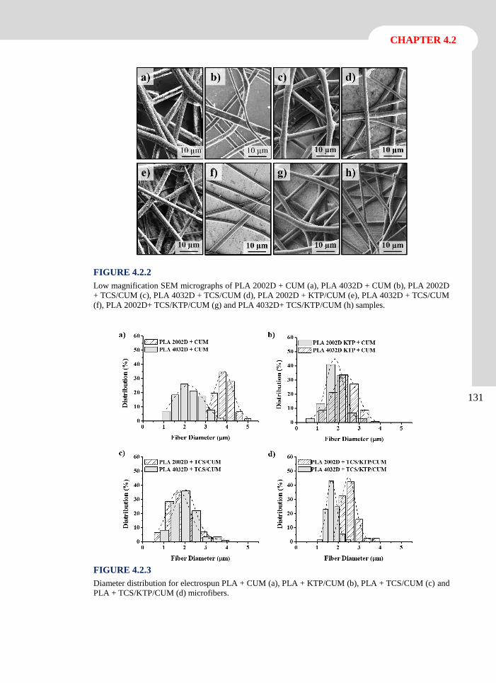
131
CHAPTER 4.2
FIGURE 4.2.2
Low magnification SEM micrographs of PLA 2002D + CUM (a), PLA 4032D + CUM (b), PLA 2002D
+ TCS/CUM (c), PLA 4032D + TCS/CUM (d), PLA 2002D + KTP/CUM (e), PLA 4032D + TCS/CUM
(f), PLA 2002D+ TCS/KTP/CUM (g) and PLA 4032D+ TCS/KTP/CUM (h) samples.
FIGURE 4.2.3
Diameter distribution for electrospun PLA + CUM (a), PLA + KTP/CUM (b), PLA + TCS/CUM (c) and
PLA + TCS/KTP/CUM (d) microfibers.
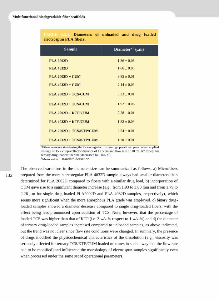
132
Multifunctional biodegradable fiber scaffolds
TABLE 4.2.1. Diameters of unloaded and drug loaded
electrospun PLA fibers.
Sample Diametera,b (m)
PLA 2002D 1.86 ± 0.06
PLA 4032D 1.66 ± 0.05
PLA 2002D + CUM 3.85 ± 0.01
PLA 4032D + CUM 2.14 ± 0.03
PLA 2002D + TCS/CUM 3.23 ± 0.01
PLA 4032D + TCS/CUM 1.92 ± 0.06
PLA 2002D + KTP/CUM 2.28 ± 0.01
PLA 4032D + KTP/CUM 1.82 ± 0.03
PLA 2002D + TCS/KTP/CUM 2.54 ± 0.01
PLA 4032D + TCS/KTP/CUM 1.70 ± 0.01
aFibers were obtained using the following electrospinning operational parameters: applied
voltage of 15 kV, tip-collector distance of 12.5 cm and flow rate of 10 mL·h-1 except for ternary drug-loaded fiber that decreased to 5 mL·h-1. bMean value ± standard deviation.
The observed variations in the diameter size can be summarized as follows: a) Microfibers
prepared from the more stereoregular PLA 4032D sample always had smaller diameters than
determined for PLA 2002D compared to fibers with a similar drug load, b) incorporation of
CUM gave rise to a significant diameter increase (e.g., from 1.93 to 3.80 mm and from 1.79 to
2.26 m for single drug-loaded PLA2002D and PLA 4032D samples, respectively), which
seems more significant when the more amorphous PLA grade was employed. c) binary drug-
loaded samples showed a diameter decrease compared to single drug-loaded fibers, with the
effect being less pronounced upon addition of TCS. Note, however, that the percentage of
loaded TCS was higher than that of KTP (i.e. 3 w/v-% respect to 1 w/v-%) and d) the diameter
of ternary drug-loaded samples increased compared to unloaded samples, as above indicated,
but the trend was not clear since flow rate conditions were changed. In summary, the presence
of drugs modified the physicochemical characteristics of the dissolution (e.g., viscosity was
seriously affected for ternary TCS/KTP/CUM loaded mixtures in such a way that the flow rate
had to be modified) and influenced the morphology of electrospun samples significantly even
when processed under the same set of operational parameters.
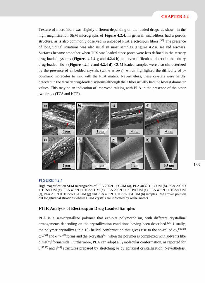
133
CHAPTER 4.2
Texture of microfibers was slightly different depending on the loaded drugs, as shown in the
high magnification SEM micrographs of Figure 4.2.4. In general, microfibers had a porous
structure, as is also commonly observed in unloaded PLA electrospun fibers.[35] The presence
of longitudinal striations was also usual in most samples (Figure 4.2.4, see red arrows).
Surfaces became smoother when TCS was loaded since pores were less defined in the ternary
drug-loaded systems (Figures 4.2.4 g and 4.2.4 h) and even difficult to detect in the binary
drug-loaded fibers (Figure 4.2.4 c and 4.2.4 d). CUM loaded samples were also characterized
by the presence of embedded crystals (withe arrows), which highlighted the difficulty of p-
coumaric molecules to mix with the PLA matrix. Nevertheless, these crystals were hardly
detected in the ternary drug-loaded systems although their fiber usually had the lowest diameter
values. This may be an indication of improved mixing with PLA in the presence of the other
two drugs (TCS and KTP).
FIGURE 4.2.4
High magnification SEM micrographs of PLA 2002D + CUM (a), PLA 4032D + CUM (b), PLA 2002D
+ TCS/CUM (c), PLA 4032D + TCS/CUM (d), PLA 2002D + KTP/CUM (e), PLA 4032D + TCS/CUM
(f), PLA 2002D+ TCS/KTP/CUM (g) and PLA 4032D+ TCS/KTP/CUM (h) samples. Red arrows pointed
out longitudinal striations wheres CUM crystals are indicated by withe arrows.
FTIR Analysis of Electrospun Drug Loaded Samples
PLA is a semicrystalline polymer that exhibits polymorphism, with different crystalline
arrangements depending on the crystallization conditions having been described.[26] Usually,
the polymer crystallizes in a 107 helical conformation that gives rise to the so-called -,[36-38]
’-[39] and ’’-[40] forms and the -crystals[41] when the polymer is complexed with solvents like
dimethylformamide. Furthermore, PLA can adopt a 32 molecular conformation, as reported for
and structures prepared by stretching or by epitaxial crystallization. Nevertheless,
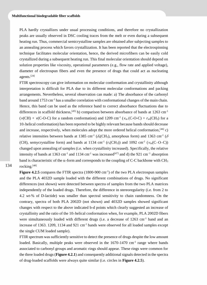
134
Multifunctional biodegradable fiber scaffolds
PLA hardly crystallizes under usual processing conditions, and therefore no crystallization
peaks are usually observed in DSC cooling traces from the melt or even during a subsequent
heating run. Thus, commercial semicrystalline samples are obtained after subjecting samples to
an annealing process which favors crystallization. It has been reported that the electrospinning
technique facilitates molecular orientation, hence, the derived microfibers can be easily cold
crystallized during a subsequent heating run. This final molecular orientation should depend on
solution properties like viscosity, operational parameters (e.g., flow rate and applied voltage),
diameter of electrospun fibers and even the presence of drugs that could act as nucleating
agents.[24]
FTIR spectroscopy can give information on molecular conformation and crystallinity although
interpretation is difficult for PLA due to its different molecular conformations and packing
arrangements. Nevertheless, several observation can made: a) The absorbance of the carbonyl
band around 1753 cm-1 has a smaller correlation with conformational changes of the main chain.
Hence, this band can be used as the reference band to correct absorbance fluctuations due to
differences in scaffold thickness,[45] b) comparison between absorbance of bands at 1263 cm-1
((CH) + (C-O-C) for a random conformation) and 1209 cm-1 (as (C-O-C) + ras(CH3) for a
107 helical conformation) has been reported to be highly relevant because bands should decrease
and increase, respectively, when molecules adopt the more ordered helical conformation,[46] c)
relative intensities between bands at 1385 cm-1 (s(CH3), amorphous form) and 1363 cm-1 (
(CH), semycrystalline form) and bands at 1134 cm-1 (rs(CH3)) and 1092 cm-1 (as(C–O–C))
changed upon annealing of samples (i.e. when crystallinity increased). Specifically, the relative
intensity of bands at 1363 cm-1 and 1134 cm-1 was increased[47] and d) the 921 cm−1 absorption
band is characteristic of the -form and corresponds to the coupling of C-C backbone with CH3
rocking.[48]
Figure 4.2.5 compares the FTIR spectra (1800-900 cm-1) of the two PLA electrospun samples
and the PLA 4032D sample loaded with the different combinations of drugs. No significant
differences (not shown) were detected between spectra of samples from the two PLA matrices
independently of the loaded drugs. Therefore, the difference in stereoregularity (i.e. from 2 to
4.2 wt-% of D-lactide) was smaller than spectral sensitivity to chain randomness. On the
contrary, spectra of both PLA 2002D (not shown) and 4032D samples showed significant
changes with respect to the above indicated b-d points which clearly suggested an increase of
crystallinity and the ratio of the 107 helical conformation when, for example, PLA 2002D fibers
were simultaneously loaded with different drugs (i.e. a decrease of 1263 cm-1 band and an
increase of 1363. 1209, 1134 and 921 cm-1 bands were observed for all loaded samples except
the single CUM loaded sample).
FTIR spectrum was sufficiently sensitive to detect the presence of drugs despite the low amount
loaded. Basically, multiple peaks were observed in the 1670-1470 cm-1 range where bands
associated to carbonyl groups and aromatic rings should appear. These rings were common for
the three loaded drugs (Figure 4.2.1) and consequently additional signals detected in the spectra
of drug-loaded scaffolds were always quite similar (i.e. circles in Figure 4.2.5).
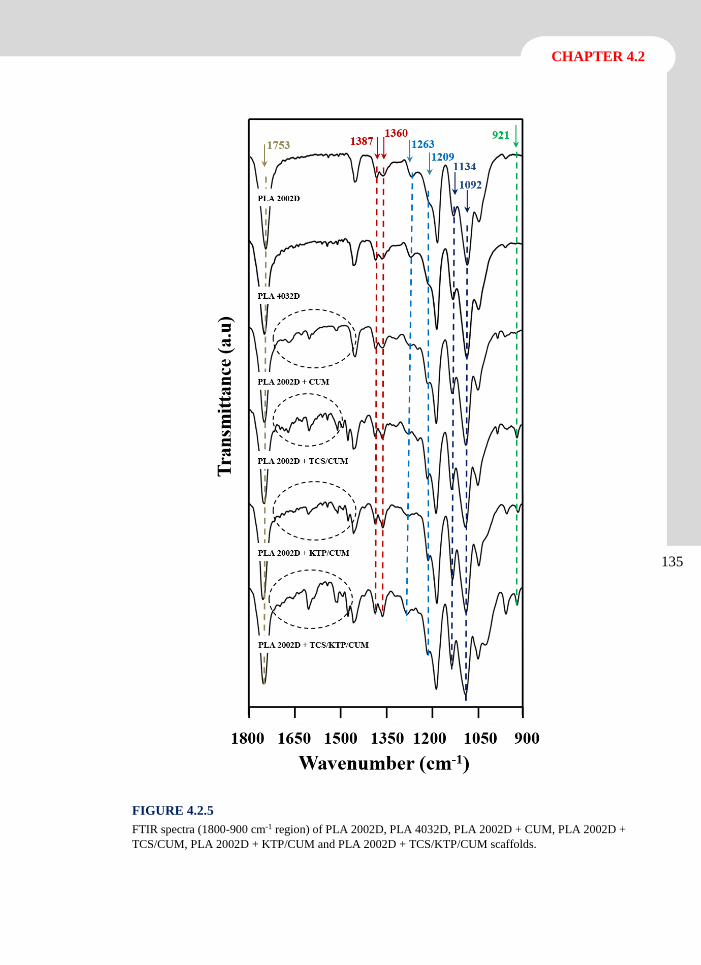
135
CHAPTER 4.2
FIGURE 4.2.5
FTIR spectra (1800-900 cm-1 region) of PLA 2002D, PLA 4032D, PLA 2002D + CUM, PLA 2002D +
TCS/CUM, PLA 2002D + KTP/CUM and PLA 2002D + TCS/KTP/CUM scaffolds.
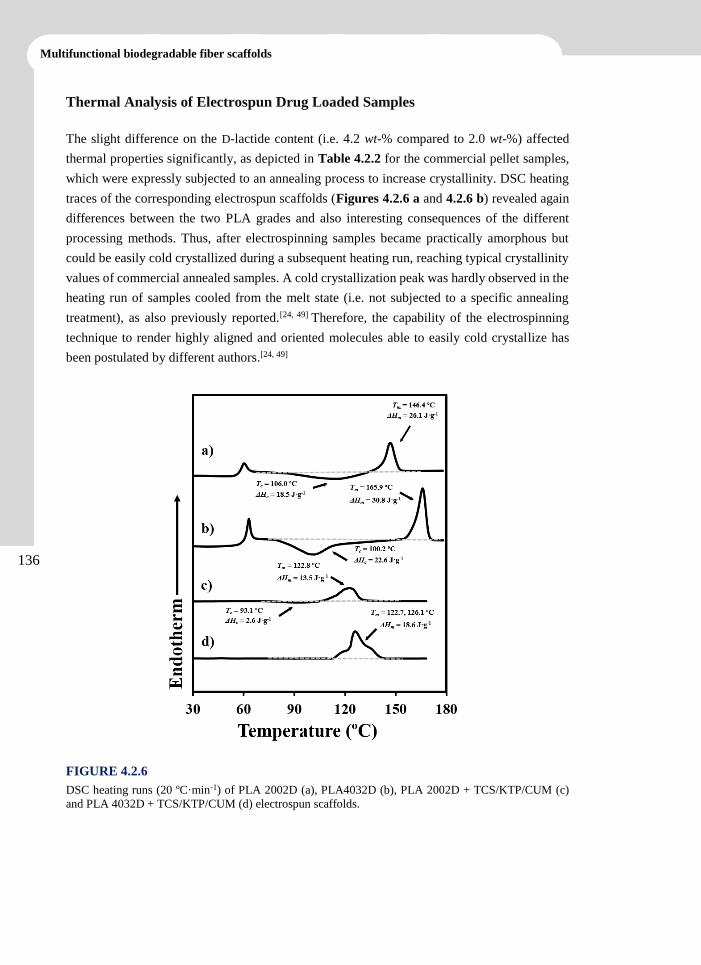
136
Multifunctional biodegradable fiber scaffolds
Thermal Analysis of Electrospun Drug Loaded Samples
The slight difference on the D-lactide content (i.e. 4.2 wt-% compared to 2.0 wt-%) affected
thermal properties significantly, as depicted in Table 4.2.2 for the commercial pellet samples,
which were expressly subjected to an annealing process to increase crystallinity. DSC heating
traces of the corresponding electrospun scaffolds (Figures 4.2.6 a and 4.2.6 b) revealed again
differences between the two PLA grades and also interesting consequences of the different
processing methods. Thus, after electrospinning samples became practically amorphous but
could be easily cold crystallized during a subsequent heating run, reaching typical crystallinity
values of commercial annealed samples. A cold crystallization peak was hardly observed in the
heating run of samples cooled from the melt state (i.e. not subjected to a specific annealing
treatment), as also previously reported.[24, 49] Therefore, the capability of the electrospinning
technique to render highly aligned and oriented molecules able to easily cold crystallize has
been postulated by different authors.[24, 49]
FIGURE 4.2.6
DSC heating runs (20 ºC·min-1) of PLA 2002D (a), PLA4032D (b), PLA 2002D + TCS/KTP/CUM (c)
and PLA 4032D + TCS/KTP/CUM (d) electrospun scaffolds.
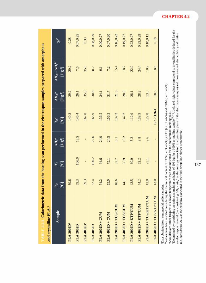
137
CHAPTER 4.2
TA
BL
E 4
.2.2
. C
alo
rim
etri
c d
ata
fro
m t
he
hea
tin
g s
can
per
form
ed i
n t
he
elec
tro
spu
n s
am
ple
s p
rep
are
d w
ith
am
orp
ho
us
an
d c
ry
sta
llin
e P
LA
.a
χcd
0.2
8
0.0
7,0
.25
0.3
3
0.0
8,0
.29
0.0
0,0
.27
0.0
7,0
.30
0.1
6,0
.22
0.1
9,0
.27
0.2
2,0
.27
0.2
5,0
.29
0.1
0,0
.13
0.1
8
a Dat
a o
bta
ined
fro
m c
om
mer
cial
pel
let
sam
ple
s.
bV
alu
es h
ave
bee
n r
esca
led
con
sider
ing
the
theo
reti
cal
con
tent
of
TC
S (
i.e.
3 w
t-%
) ,a
KT
P (
i.e.
, 1
wt-
%)
and C
UM
(i.
e. 1
wt-
%).
c S
ho
uld
ers
are
rath
er f
req
uen
t at
a l
ow
er t
emper
atu
re t
han
that
in
dic
ated
fo
r th
e p
redo
min
ant
mel
ting
pea
k.
dD
eter
min
ed b
y c
on
sider
ing a
n e
stim
ated
mel
tin
g e
nth
alpy
of
106
J/g
fo
r a
10
0%
cry
stal
lin
e sa
mple
[50,
51] .
Lef
t an
d r
igh
t val
ues
co
rres
pond
to
cry
stal
linit
ies
ded
uce
d f
or
the
as e
lect
rosp
un m
ater
ial
(i.e
. co
nsi
der
ing Δ
Hm -
ΔH
cb a
s th
e en
thal
py
ass
oci
ated
to
cry
stal
line
phas
e o
f th
e el
ectr
osp
un
sam
ple
) an
d t
hose
att
ained
aft
er c
old
cry
stal
liza
tio
n
(i.e
. co
nsi
der
ing
ΔH
m a
s th
e en
thal
py a
ssoci
ated
to t
he
fin
al c
ryst
alli
ne
ph
ase)
, re
spec
tivel
y.
ΔH
m -
ΔH
cb
[J·g
-1]
29
.2
7.6
35
.0
8.2
0.1
7.2
15
.4
18
.7
22
.9
24
.4
10
.9
18
.6
ΔH
mb
[J·g
-1]
29
.2
26
.1
35
.0
30
.8
24
.1
31
.7
21
.5
28
.9
28
.1
28
.2
13
.5
18
.6
Tm
c
[ºC
]
14
9.3
14
6.4
16
7.0
16
5.9
13
6.5
15
6.3
13
2.2
14
7.2
11
2.9
13
8.9
12
2.8
12
2.7
,126
.1
ΔH
cb
[J·g
1] -
18
.5
-
22
.6
24
.0
24
.5
6.1
10
.2
5.2
3.8
2.6
-
Tc
[ºC
] -
10
6.0
-
10
0.2
94
.6
75
.1
92
.7
65
.9
60
.0
52
.2
93
.1
-
Tg
[ºC
]
59
.6
59
.3
69
.3
62
.4
54
.2
55
.0
48
.6
44
.1
43
.5
44
.2
43
.0
43
.0
Sa
mp
le
PL
A 2
00
2D
a
PL
A 2
00
2D
PL
A 4
03
2D
a
PL
A 4
03
2D
PL
A 2
00
2D
+ C
UM
PL
A 4
03
2D
+ C
UM
PL
A 2
00
2D
+ T
CS
/CU
M
PL
A 4
03
2D
+ T
CS
/CU
M
PL
A 2
00
2D
+ K
TP
/CU
M
PL
A 4
03
2D
+ K
TP
/CU
M
PL
A 2
00
2D
+ T
CS
/KT
P/C
UM
PL
A 4
03
2D
+ T
CS
/KT
P/C
UM
138
Multifunctional biodegradable fiber scaffolds
DSC heating runs of drug-loaded samples are more complex, especially those of ternary drug-
loaded systems (Figures 4.2.6 c and 4.2.6 d). The main thermal characteristics deduced from
the different loaded scaffolds (summarized in Table 4.2.2) allow the following general remarks
to be made:
The glass transition temperature decreases compared to that observed for the
corresponding unloaded scaffolds, suggesting a plasticizing effect caused by the
incorporation of the small drug molecules. In addition, the enthalpic relaxation peak
tended to be supressed, in contrast with unloaded samples. Therefore, the compact
arrangement characteristic of an equilibrium condition is less favored.
The melting peak temperature decreases dramatically compared to the value of
unloaded scaffolds. Furthermore, this decrease is more and less significant for ternary
and single drug-loaded scaffolds, respectively. In addition, multiple peaks could be
observed for the more complex loaded systems. These features suggest that drugs can
be partially incorporated into the crystalline structure and even led to different degrees
of perfection. It should be pointed out that the melting peaks could only be associated
with the PLA polymer matrix because the melting temperatures of TCS and KTP were
lower (55-57 ºC and 93-96 ºC, respectively), whereas p-coumaric acid melted at a
clearly higher temperature (i.e, 208-217 ºC).
Binary and ternary drug-loaded systems became highly crystalline after the
electrospinning process. Note the reduced cold crystallization enthalpy and the high
melting enthalpy (i.e. the relatively high Hm - Hc values). The degrees of
crystallinity are clearly higher than determined from unloaded samples, suggesting a
nucleating effect of incorporated drugs. This effect was more pronounced when the
more regular PLA 4032D sample is used. Logically, all studied samples showed a
degree of crystallinity after cold crystallization slightly lower than determined for the
commercial annealed samples. The temperature of the cold crystallization peak tends
to diminish for drug-loaded samples, suggesting again a nucleating effects of drugs.
139
CHAPTER 4.2
Drug Release from Binary and Ternary Drug Loaded PLA Electrospun Scaffolds
Drug release from electrospun fibers in a given medium is intimately related to their
morphology and crystallinity and to possible intermolecular interactions between drugs and the
polymer matrix. Therefore, a quantitative release study was performed considering both PLA
2002D and PLA 4032D matrices and single, binary and ternary drug-loaded systems. According
to our previous studies, we selected a phosphate buffer saline (PBS) supplemented with ethanol
(PBS:EtOH 3:7 v/v) 70%) to facilitate the delivery of highly hydrophobic molecules such as
TCS, KTP and CUM and avoid the establishment of equilibrium conditions that typically limit
their release when only PBS is employed.[23]
Figures 4.2.7 a and 4.2.7 b show the release peofile of CUM from the single drug-loaded PLA
2002D and PLA 4032D scaffolds, respectively. It can be observed that a higher release
percentage was attained from the less stereoregular PLA matrix (i.e., 80% compared to 60%),
indicating that CUM was better retained in the presence of polymer crystalline domains. In any
case, the release of CUM was very fast and reached values of 60-50% after only one hour of
exposure to the medium.
Figures 4.2.7 c-4.2.7 h show the release profiles of TCS, KTP and CUM drugs in the binary
and ternary drug-loaded systems. The following observation can be made: a) The release
profiles for a given scaffold are similar for the three dugs independently of the PLA grade and
the kind of system (binary or ternary), b) the maximum release percentage is always greater
from PLA 2002D scaffolds than from the corresponding PLA 4032D scaffolds; c) release
percentages increase slightly when more drugs were simultaneously loaded in PLA 4032D
scaffolds (i.e., 60%, 60-70% and 80% for CUM in single, binary and ternary drug-loaded
scaffolds, respectively), whereas percentages remain practically constant for PLA 2002D
scaffolds. It seems that a slight synergic effect and the release are increased in complex systems
and matrices that had higher encapsulation efficiency (e.g., PLA 4032D). This is interesting
since it suggests that binary and ternary drug-loaded scaffolds have greater availability for their
local action in the host tissue.
Release rates can be quantitatively compared considering postulated theoretical kinetic models
in order to fit the experimental release profiles. Release generally occurs in two different steps,
with the fast release initially observed (0-60%) being well-described by the Higuchi Equation
1:[52, 53]
Mt ⁄ M0 = kH t(1⁄2) (0 ≤ Mt ⁄ M0 ≤ 0.6) (1)
where kH is the Higuchi release constant, Mt is the percentage of drug released at time t and M0
is the drug equilibrium percentage (considered as the maximum drug percentage).
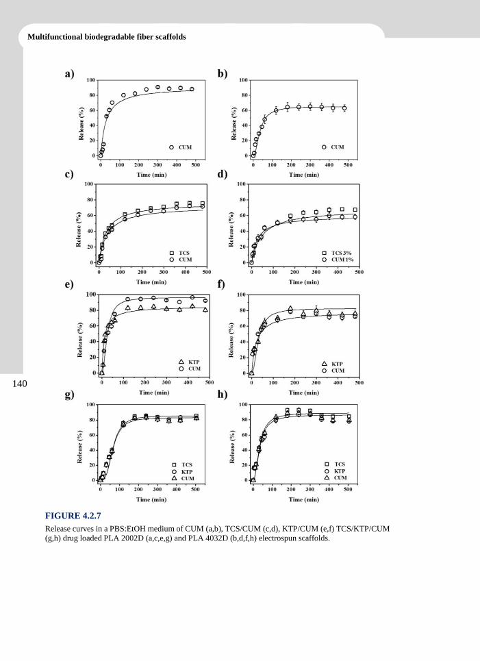
140
Multifunctional biodegradable fiber scaffolds
FIGURE 4.2.7
Release curves in a PBS:EtOH medium of CUM (a,b), TCS/CUM (c,d), KTP/CUM (e,f) TCS/KTP/CUM
(g,h) drug loaded PLA 2002D (a,c,e,g) and PLA 4032D (b,d,f,h) electrospun scaffolds.
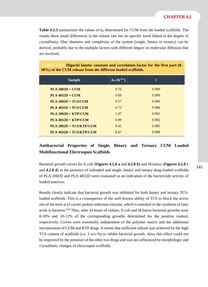
141
CHAPTER 4.2
Table 4.2.3 summarizes the values of kH determined for CUM from the loaded scaffolds. The
results show small differences in the release rate but no specific trend linked to the degree of
crystallinity, fiber diameter and complexity of the system (single, binary or ternary) can be
derived, probably due to the multiple factors with different impact on molecular diffusion that
are involved.
TABLE 4.2.3. Higuchi kinetic constant and correlation factor for the first part (0-
60%) of the CUM release from the different loaded scaffolds.
Sample kH (h-0.5) r
PLA 2002D + CUM 0.76 0.989
PLA 4032D + CUM 0.69 0.990
PLA 2002D + TCS/CUM 0.57 0.990
PLA 4032D + TCS/CUM 0.72 0.986
PLA 2002D + KTP/CUM 1.07 0.991
PLA 4032D + KTP/CUM 0.89 0.982
PLA 2002D + TCS/KTP/CUM 0.41 0.985
PLA 4032D + TCS/KTP/CUM 0.67 0.998
Antibacterial Properties of Single, Binary and Ternary CUM Loaded
Multifunctional Electrospun Scaffolds
Bacterial growth curves for E.coli (Figures 4.2.8 a and 4.2.8 b) and M.luteus (Figures 4.2.8 c
and 4.2.8 d) in the presence of unloaded and single, binary and ternary drug-loaded scaffolds
of PLA 2002D and PLA 4032D were evaluated as an indication of the bactericide activity of
loaded matrices.
Results clearly indicate that bacterial growth was inhibited for both binary and ternary TCS-
loaded scaffolds. This is a consequence of the well-known ability of TCS to block the active
site of the enol-acyl carrier protein reductase enzyme, which is essential in the synthesis of fatty
acids in bacteria.[54] Thus, after 24 hours of culture, E.coli and M.luteus bacterial growths were
8-10% and 10-12% of the corresponding growths determined for the positive control,
respectively. Curves were essentially independent of the polymer matrix and the additional
incorporation of CUM and KTP drugs. It seems that sufficient release was achieved by the high
TCS content of scaffolds (i.e. 3 w/v-%) to inhibit bacterial growth. Also, this effect could not
be improved by the presence of the other two drugs and was not influenced by morphologic and
crystallinity changes of electrospun scaffolds.
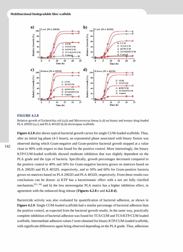
142
Multifunctional biodegradable fiber scaffolds
FIGURE 4.2.8
Relative growth of Escherichia coli (a,b) and Micrococcus luteus (c,d) on binary and ternary drug-loaded
PLA 2002D (a,c) and PLA 4032D (b,d) electrospun scaffolds.
Figure 4.2.8 also shows typical bacterial growth curves for single CUM-loaded scaffolds. Thus,
after an initial lag phase (4-5 hours), an exponential phase associated with binary fission was
observed during which Gram-negative and Gram-positive bacterial growth stopped at a value
close to 90% with respect to that found for the positive control. More interestingly, the binary
KTP/CUM-loaded scaffolds showed moderate inhibition that was slightly dependent on the
PLA grade and the type of bacteria. Specifically, growth percentages decreased compared to
the positive control to 40% and 50% for Gram-negative bacteria grown on matrices based on
PLA 2002D and PLA 4032D, respectively, and to 50% and 60% for Gram-positive bacteria
grown on matrices based on PLA 2002D and PLA 4032D, respectively. From these results two
conclusions can be drawn: a) KTP has a bacteriostatic effect with a not yet fully clarified
mechanism,[55, 56] and b) the less stereoregular PLA matrix has a higher inhibition effect, in
agreement with the enhanced drug release (Figures 4.2.8 c and 4.2.8 d).
Bactericide activity was also evaluated by quantification of bacterial adhesion, as shown in
Figure 4.2.9. Single CUM-loaded scaffolds had a similar percentage of bacterial adhesion than
the positive control, as expected from the bacterial growth results. In the same way, practically
complete inhibition of bacterial adhesion was found for TCS/CUM and TCS/KTP/CUM loaded
scaffolds. Intermediate adhesion values f were obtained for binary KTP/CUM-loaded scaffolds,
with significant differences again being observed depending on the PLA grade. Thus, adhesions
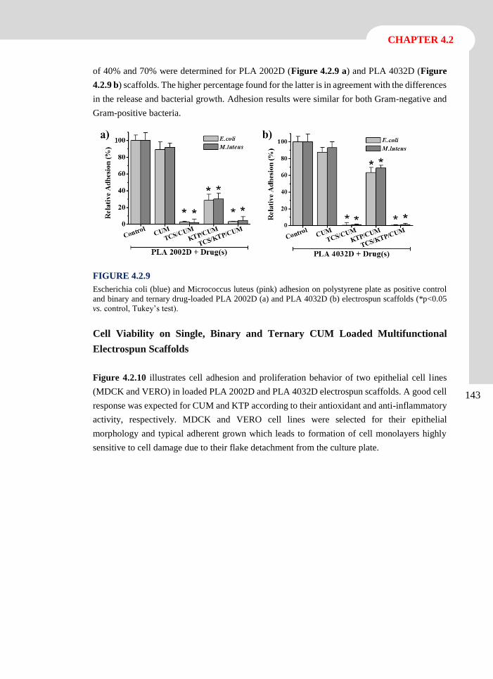
143
CHAPTER 4.2
of 40% and 70% were determined for PLA 2002D (Figure 4.2.9 a) and PLA 4032D (Figure
4.2.9 b) scaffolds. The higher percentage found for the latter is in agreement with the differences
in the release and bacterial growth. Adhesion results were similar for both Gram-negative and
Gram-positive bacteria.
FIGURE 4.2.9
Escherichia coli (blue) and Micrococcus luteus (pink) adhesion on polystyrene plate as positive control
and binary and ternary drug-loaded PLA 2002D (a) and PLA 4032D (b) electrospun scaffolds (*p<0.05
vs. control, Tukey’s test).
Cell Viability on Single, Binary and Ternary CUM Loaded Multifunctional
Electrospun Scaffolds
Figure 4.2.10 illustrates cell adhesion and proliferation behavior of two epithelial cell lines
(MDCK and VERO) in loaded PLA 2002D and PLA 4032D electrospun scaffolds. A good cell
response was expected for CUM and KTP according to their antioxidant and anti-inflammatory
activity, respectively. MDCK and VERO cell lines were selected for their epithelial
morphology and typical adherent grown which leads to formation of cell monolayers highly
sensitive to cell damage due to their flake detachment from the culture plate.
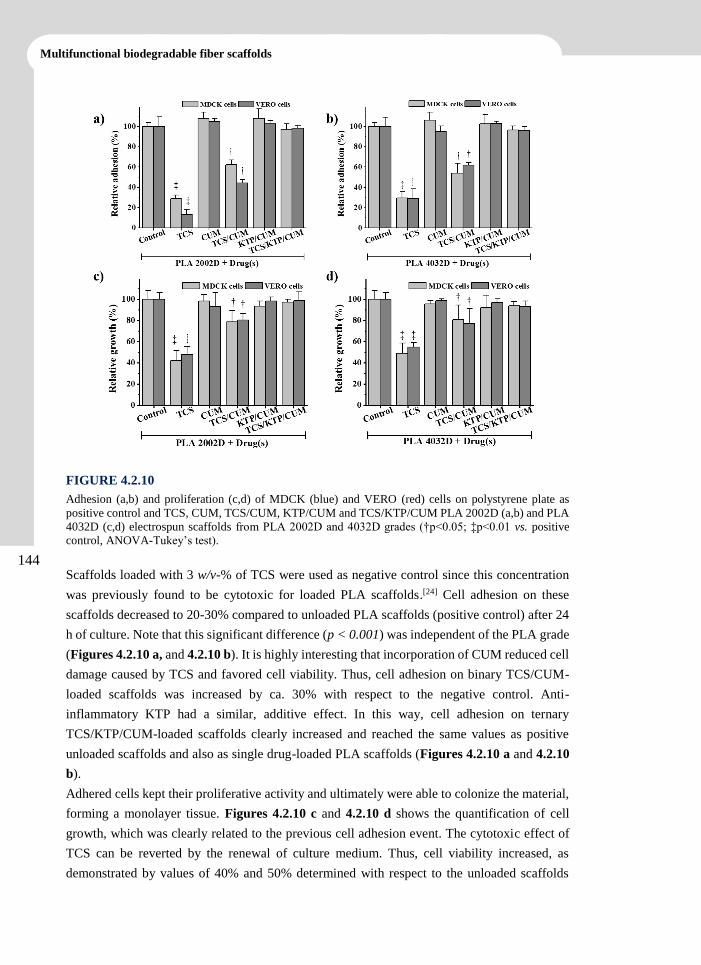
144
Multifunctional biodegradable fiber scaffolds
FIGURE 4.2.10
Adhesion (a,b) and proliferation (c,d) of MDCK (blue) and VERO (red) cells on polystyrene plate as
positive control and TCS, CUM, TCS/CUM, KTP/CUM and TCS/KTP/CUM PLA 2002D (a,b) and PLA
4032D (c,d) electrospun scaffolds from PLA 2002D and 4032D grades (†p<0.05; ‡p<0.01 vs. positive
control, ANOVA-Tukey’s test).
Scaffolds loaded with 3 w/v-% of TCS were used as negative control since this concentration
was previously found to be cytotoxic for loaded PLA scaffolds.[24] Cell adhesion on these
scaffolds decreased to 20-30% compared to unloaded PLA scaffolds (positive control) after 24
h of culture. Note that this significant difference (p < 0.001) was independent of the PLA grade
(Figures 4.2.10 a, and 4.2.10 b). It is highly interesting that incorporation of CUM reduced cell
damage caused by TCS and favored cell viability. Thus, cell adhesion on binary TCS/CUM-
loaded scaffolds was increased by ca. 30% with respect to the negative control. Anti-
inflammatory KTP had a similar, additive effect. In this way, cell adhesion on ternary
TCS/KTP/CUM-loaded scaffolds clearly increased and reached the same values as positive
unloaded scaffolds and also as single drug-loaded PLA scaffolds (Figures 4.2.10 a and 4.2.10
b).
Adhered cells kept their proliferative activity and ultimately were able to colonize the material,
forming a monolayer tissue. Figures 4.2.10 c and 4.2.10 d shows the quantification of cell
growth, which was clearly related to the previous cell adhesion event. The cytotoxic effect of
TCS can be reverted by the renewal of culture medium. Thus, cell viability increased, as
demonstrated by values of 40% and 50% determined with respect to the unloaded scaffolds
145
CHAPTER 4.2
after 7 days of culture, which were higher that the above adhesion percentages. Nevertheless,
viability was still significantly lower (p < 0.01) than determined for the control. Again, positive
effects on cell proliferation (p > 0.95) were found for binary TCS/CUM-scaffolds compared to
the negative TCS-loaded control, resulting in an increase cell viability up to 80%. This
represents an increase close to 30% with respect to the viable cells measured in single TCS-
loaded scaffolds. Cell proliferation in ternary TCS/KTP/CUM-loaded scaffolds was similar to
that of positive controls, as expected from the cell adhesión results, demonstrating that cell
damage caused by TCS could be neutralized by the positive effect on cell viability caused by
the incorporation of CUM and KTP. Finally, it should be indicated that no significant
differences were observed between scaffolds prepared from the two PLA grades despite slight
differences on drug release.
146
Multifunctional biodegradable fiber scaffolds
4.2.4 Conclusions
Bactericide, anti-inflammatory and antioxidant drugs like triclosan, ketoprofen and p-coumaric
acid, respectively, could be simultaneously loaded into PLA microfibers by the electrospinning
technique. Porous and continuous microfibers with an unimodal diameter distribution could be
prepared from a 10 w/v-% solution of PLA in a chloroform:acetone:dimethylsulfoxide mixture
and using electrospinning parameters of 15 kV, 12.5 cm and 5-10 mL·h-1 for voltage, tip-
collector distance and flow rate, respectively.
Electrospun scaffolds had highly variable crystallinity which depended slightly on the PLA
grade (at least when D-lactide content varied only from 4.2 to 2.0 wt-%) and strongly on the
incorporation drugs. Thus, drugs seemed to produce a nucleating effect that, in some cases, led
to crystallization levels of commercial annealed samples even for binary drug-loaded systems.
Drug-loaded scaffolds also showed a decrease in the glass transition temperature that favored
molecular diffusion processes and a decrease in the melting temperature as a consequence of
incorporation of drugs in amorphous and crystalline phases, respectively.
The three drugs were released in a similar and fast way from a given scaffold (i.e. for a selected
PLA matrix and a single, binary or ternary drug-loaded system) in a PBS:ethanol medium that
mimics a typical serum supplemented PBS medium. In all cases, a significant amount of drug
was retained inside PLA microfibers, especially the more relevant when the more stereoregular
polymer. The entrapping efficiency of PLA was limited and the release of a specific drug
seemed to increase with the complexity of the system (i.e. from single to ternary drug-loaded
scaffolds), suggesting a synergic effect. New multifunctional scaffolds appear highly interesting
since, besides imparting their expected and specific properties (i.e., antioxidant and anti-
inflammatory), KTP and CUM can neutralize the cytotoxic effect caused by a moderate/high
triclosan load. In summary, multifunctional PLA scaffolds with both high cell viability and
protection against microorganism can be easily prepared by the electrospinning technique.
147
CHAPTER 4.2
4.2.5 References
[1] R. Sahay, P.S. Kumar, R. Sridhar, J. Sundaramurthy, J. Venugopal, S.G. Mhaisalkar, S.
Ramakrishna, J Mater Chem, 22 (2012) 12953-12971.
[2] L.S. Nair, C.T. Laurencin, Prog Polym Sci, 32 (2007) 762-798.
[3] Y. Ji, K. Ghosh, X.Z. Shu, B. Li, J.C. Sokolov, G.D. Prestwich, R.A. Clark, M.H.
Rafailovich, Biomaterials, 27 (2006) 3782-3792.
[4] P.X. Ma, Mater Today, 7 (2004) 30-40.
[5] B. Dhandayuthapani, Y. Yoshida, T. Maekawa, D.S. Kumar, Inter J Polym Sci, (2011).
[6] Z.W. Ma, M. Kotaki, R. Inai, S. Ramakrishna, Tissue Eng, 11 (2005) 101-109.
[7] S.R. Bhattarai, N. Bhattarai, H.K. Yi, P.H. Hwang, D.I. Cha, H.Y. Kim, Biomaterials,
25 (2004) 2595-2602.
[8] R. Vasita, D.S. Katti, Int J Nanomedicine, 1 (2006) 15-30.
[9] X. Geng, O.H. Kwon, J. Jang, Biomaterials, 26 (2005) 5427-5432.
[10] I.C. Um, D. Fang, B.S. Hsiao, A. Okamoto, B. Chu, Biomacromolecules, 5 (2004) 1428-
1436.
[11] H.J. Jin, J.S. Chen, V. Karageorgiou, G.H. Altman, D.L. Kaplan, Biomaterials, 25 (2004)
1039-1047.
[12] F. Yang, R. Murugan, S. Wang, S. Ramakrishna, Biomaterials, 26 (2005) 2603-2610.
[13] S.A. Riboldi, M. Sampaolesi, P. Neuenschwander, G. Cossu, S. Mantero, Biomaterials,
26 (2005) 4606-4615.
[14] W.J. Li, K.G. Danielson, P.G. Alexander, R.S. Tuan, J Biomed Mater Res A, 67A (2003)
1105-1114.
[15] K. Uematsu, K. Hattori, Y. Ishimoto, J. Yamauchi, T. Habata, Y. Takakura, H. Ohgushi,
T. Fukuchi, M. Sato, Biomaterials, 26 (2005) 4273-4279.
[16] E.R. Kenawy, G.L. Bowlin, K. Mansfield, J. Layman, D.G. Simpson, E.H. Sanders, G.E.
Wnek, J Control Release, 81 (2002) 57-64.
[17] X.M. Mo, C.Y. Xu, M. Kotaki, S. Ramakrishna, Biomaterials, 25 (2004) 1883-1890.
[18] G. Verreck, I. Chun, J. Rosenblatt, J. Peeters, A. Van Dijck, J. Mensch, M. Noppe, M.E.
Brewster, J Control Release, 92 (2003) 349-360.
148
Multifunctional biodegradable fiber scaffolds
[19] S.M. Jacobsen, D.J. Stickler, H.L.T. Mobley, E. Shirtliff, Clin Microbiol Rev, 21 (2008)
26-59.
[20] D. Fuster, J. Duch, A. Soriano, S. García, X. Setoain, G. Bori, S. Rubí, D. Rodríguez, B.
Doménech, C. Piera, J. Mensa, F. Pons, Rev Esp Med Nucl Imagen Mol, 27 (2008) 430-
435.
[21] J. Cailloux, O.O. Santana, E. Franco-Urquiza, J.J. Bou, F. Carrasco, J. Gamez-Perez,
M.L. Maspoch, Express Polym Lett, 7 (2013) 304-318.
[22] J. Cailloux, O.O. Santana, E. Franco-Urquiza, J.J. Bou, F. Carrasco, M.L. Maspoch, J
Mater Sci, 49 (2014) 4093-4107.
[23] R. Zurita, J. Puiggali, A. Rodriguez-Galan, Macromol Biosci, 6 (2006) 58-69.
[24] L.J. del Valle, R. Camps, A. Diaz, L. Franco, A. Rodriguez-Galan, J. Puiggali, J Polym
Res, 18 (2011) 1903-1917.
[25] E. Llorens, L.J. del Valle, A. Diaz, M.T. Casas, J. Puiggali, Macromol Res, 21 (2013)
775-787.
[26] E. Llorens, L.J. del Valle, J. Puiggalí, Macromol Res, 22 (2014) 388-396.
[27] P.P. Shah, P.R. Desai, M. Singh, J Control Release, 158 (2012) 336-345.
[28] M.L. Vueba, M.E. Pina, F. Veiga, J.J. Sousa, L.A.E.B. de Carvalho, Int J Pharm, 307
(2006) 56-65.
[29] D. Li, Y.N. Xia, Adv Mater, 16 (2004) 1151-1170.
[30] S.R. Dhakate, B. Singla, M. Uppal, R.B. Mathur, Adv Mater Lett, 1 (2010) 200-204.
[31] E. Luong-Van, L. Grondahl, K.N. Chua, K.W. Leong, V. Nurcombe, S.M. Cool,
Biomaterials, 27 (2006) 2042-2050.
[32] G. Buschle-Diller, J. Cooper, Z. Xie, Y. Wu, J. Waldrup, X. Ren, Cellulose, 14 (2007)
553-562.
[33] D. Karst, Y. Yang, J Appl Polym Sci, 96 (2005) 416-422.
[34] D.M. Aragón, D.A. Chiappetta, J. Degrossi, E.F. Vargas, C. Bregni, A. Sosnik, F.
Martínez, Rev Col Cienc Quím Farm, 37 (2008) 241-257.
[35] E. Llorens, L.J. Valle, R. Ferrán, A. Rodríguez-Galán, J. Puiggalí, J Polym Res, 21
(2014) 1-15.
[36] P. De Santis, A.J. Kovacs, Biopolymers, 6 (1968) 299-306.
149
CHAPTER 4.2
[37] C. Alemán, B. Lotz, J. Puiggali, Macromolecules, 34 (2001) 4795-4801.
[38] S. Sasaki, T. Asakura, Macromolecules, 36 (2003) 8385-8390.
[39] J. Zhang, K. Tashiro, A.J. Domb, H. Tsuji, Macromol Symp, 242 (2006) 274-278.
[40] H. Marubayashi, S. Akaishi, S. Akasaka, S. Asai, M. Sumita, Macromolecules, 41
(2008) 9192-9203.
[41] H. Marubayashi, S. Asai, M. Sumita, Macromolecules, 45 (2012) 1384-1397.
[42] B. Eling, S. Gogolewski, A.J. Pennings, Polymer, 23 (1982) 1587-1593.
[43] J. Puiggali, Y. Ikada, H. Tsuji, L. Cartier, T. Okihara, B. Lotz, Polymer, 41 (2000) 8921-
8930.
[44] L. Cartier, T. Okihara, Y. Ikada, H. Tsuji, J. Puiggali, B. Lotz, Polymer, 41 (2000) 8909-
8919.
[45] T. Fujiwara, M. Miyamoto, Y. Kimura, S. Sakurai, Polymer, 42 (2001) 1515-1523.
[46] H. Urayama, S.-I. Moon, Y. Kimura, Macromol Mater Eng, 288 (2003) 137-143.
[47] C. Ribeiro, V. Sencadas, C.M. Costa, J.L.G. Ribelles, S. Lanceros-Mendez, Sci Technol
Adv Mat, 12 (2011).
[48] S.O. Kang, S.L. Hsu, H.D. Stidham, P.B. Smith, M.A. Leugers, X. Yang,
Macromolecules, 34 (2001) 4542-4548.
[49] J. Zeng, X. Chen, Q. Liang, X. Xu, X. Jing, Macromol Biosci, 4 (2004) 1118-1125.
[50] T.Y. Cho, G. Strobl, Polymer, 47 (2006) 1036-1043.
[51] J.R. Sarasua, R.E. Prud'homme, M. Wisniewski, A. Le Borgne, N. Spassky,
Macromolecules, 31 (1998) 3895-3905.
[52] T. Higuchi, J Pharm Sci, 52 (1963) 1145-1149.
[53] R.W. Baker, in, John Wiley & Sons, New York, USA, 1987.
[54] C.W. Levy, A. Roujeinikova, S. Sedelnikova, A.R. Stuitje, A.R. Salabas, D.W. Rice,
J.B. Rafferty, Nature, 398 (1999) 383-384.
[55] S.G. Dastidar, K. Ganguly, K. Chaudhuri, A.N. Chakrabarty, Int J Antimicrob Ag, 14
(2000) 249-251.
[56] H.A. Abbas, F.M. Serry, E.M. El-Masry, Asian J Res Pharm Sci, 2 (2012) 66-72.

5.
Preparation of biodegradable
scaffolds incorporating non-
electrospinable polymers


The work described in this chapter previously appeared in:
[1] Llorens, E.; Calderón, S.; Rodríguez-Galán, A.; del Valle, L. J.; Puiggalí, J. Mater. Sci. Eng. C.
Submitted.
[2] Llorens, E.; Pérez-Madrigal, M. M.; Armelin, E.; Alemán, C.; del Valle, L.; Puiggalí, J. R. Soc.
Chem. Adv. 2014, 4, 15245-15255.

PLA Scaffolds Incorporating Bactericide
Polybiguanide (PHMB)
Polyhexamethylenebiguanide hydrochloride (PHMB),
a low molecular weight polymer related to
chlorohexidine (CHX), is a well-known antibacterial
agent. In this study, polylactide (PLA) nanofibers
loaded with PHMB were produced by electrospinning
to obtain 3D biodegradable scaffolds with
antibacterial properties. PLA fibers loaded with CHX
were used as control. The electrospun fibers were
studied and analyzed by SEM, FTIR, DSC and contact
angle measurements. PHMB and CHX release from
loaded scaffolds was evaluated, as well as their
antibacterial activity and biocompatibility. The results
showed that the nanofibers became smoother and their
diameter smaller with increasing the amount of loaded
PHMB, which also led to increased hydrophobicity of
scaffolds due to the increase in scaffold surface
roughness. PHMB release was highly dependent on
the hydrophilicity of the medium and differed from that
determined for CHX. Lastly, PHMB-loaded PLA
scaffolds showed antibacterial properties since they
inhibited adhesion and bacterial growth, and
exhibited biocompatible characteristics for the
adhesion and proliferation of both fibroblast and
epithelial cell lines.
5.1
Preparation of biodegradable scaffolds incorporating non-electrospinable polymers
156
5.1.1 Introduction
Topical formulations containing antimicrobial agents (e.g., mouthwashes, gels or toothpastes)
are commonly used for the treatment of infections and burn injuries.[1-3] These formulations
ensure direct access of high concentrations of the antimicrobial agent to the site of infection.
The agent acts locally or systematically inhibiting microorganism growth around the wound,
reducing the probability of resistance development, minimizing deleterious host responses, and
reducing the risk of environmental pollution.[4-6]
Several compounds have been extensively studied for their antibacterial activity, with
benzalkonium chlorides, cetylpyridinium chloride, aldehydes, anilides, diamidines and silver
being the most representative examples.[7-9] Biguanide, commonly known as chlorhexidine (1,1′-
hexamethylene- bis-5-(4-chlorophenyl) biguanide, CHX), is also a widely employed
antimicrobial agent.[10] Specifically, CHX is an important antiseptic, disinfectant,
pharmaceutical and cosmetic preservative and antiplaque agent. The high activity of this drug
towards microorganisms is due to the presence of secondary amines that can be protonated, and
therefore positively charged under normal pH conditions.[11] Immobilized antimicrobial agents
offer an alternative which eliminates patient exposure to active agents and potentially increases
the duration of antimicrobial efficacy.[12, 13] Agents can be immobilized on a wide variety of
materials including metals and plastics, as well as natural and man-made fabrics such as
electrospun scaffolds (specifically, inside constituent micro/nanofibers).
Additional advantages of biguanide compounds are related to their ability to form quadricovalent
cationic complexes with silver ions which are stable in ambient conditions. In this way, a
synergic effect can be derived from the combination of biguanide and silver antimicrobial
activities.[1]
Other chemical compounds also bearing biguanide groups, such as
polyhexamethylenebiguanide hydrochloride (PHMB), have been developed.[14, 15] Specifically,
PHMB is a cationic oligomer having with a average of 7-11 biguanide groups spaced by flexible
hexamethylene segments. PHMB has chemical stability, low toxicity, high effectiveness against
microorganisms and reasonable cost.[16, 17] Gilbert et al. demonstrated that activity increased
with the number of biguanide groups and that maximum biocidal efficiency was obtained when
the hexamethylene group was employed as spacer.[18, 19]
In a recent paper, Koburger et al.[20] compared the antiseptic efficacy of several antibacterial
agents such as triclosan, octenidine, PHMB, PVP-Iodine and chlorhexidine digluconate,
concluding that PHMB was the best antiseptic in prolonged use. PHMB action against
microorganisms was described as a consequence of its binding to the negatively charged
phosphate head groups of phospholipids at the bacterial cell wall. Binding increased rigidity,
sank non-polar segments into hydrophobic domains, and disrupted the membrane with
subsequent cytoplasmic shedding that culminated in cell death.[18, 19]
CHAPTER 5.1
157
Recently, micro/nanofiber nonwoven membranes produced by electrospinning have shown great
potential in applications such as biomedical devices (e.g., scaffolds for tissue engineering) due
to their typically high surface area and porosity. Furthermore, the unique properties of
electrospun fibers have triggered a broad range of other potential applications, including
composites, sensors, protective clothing, filtration membranes, magneto-responsive fibers and
superhydrophobic membranes.[4] In addition, the electrospinning process provides a simple way
to encapsulate drugs within a micro/nanofiber matrix that can lead to a controlled and sustained
release.
Several natural and synthetic biodegradable polymers have been successfully electrospun (e.g.,
polyglycolide,[21] polylactide,[21, 22] polycaprolactone,[23] collagen[24, 25] and chitosan[25, 26]).
Polylactide (PLA) is one of the most widely used materials in biomedical applications due to the
combination of interesting characteristics like tunable mechanical properties, degradation into
natural metabolites, biocompatibility and low cost. Thus, biodegradable polymers containing
active ingredients, such as antimicrobials and antibiotics, were also studied in wound dressing
materials to protect against contaminations and infections.[27, 28] Specifically, PHMB has been
employed as a highly effective antimicrobial agent for composites of cellulose acetate and
polyester urethane.[29] The reported results have opened highly interesting perspectives for the
use of PHMB in biomedical applications where a rapid release in hydrophilic systems is desired.
In this study, the antimicrobial PHMB agent was incorporated into electrospun PLA
micro/nanofibers to evaluate the potential application of these materials as temporary and
medicated scaffolds. For this purpose, electrospinning conditions were optimized, morphology
of micro/nanofibers studied and physicochemical characterization of scaffolds performed.
Release kinetics, antimicrobial activity against Gram negative and positive bacteria (i.e. E. coli
and M. luteus) and biocompatibility were also evaluated.
Preparation of biodegradable scaffolds incorporating non-electrospinable polymers
158
5.1.2 Experimental Section
Materials
Polylactide (PLA), a product of Natureworks (polymer 2002D), was kindly supplied by Nupik
International (Polinyà, Spain). According to the manufacturer, this PLA has a D content of
4.25%, a residual monomer content of 0.3%, a density of 1.24 g·cc-1, a glass transition
temperature (Tg) of 58 ºC and a melting point of 153 ºC.
All solvents, clorhexidine (CHX), 3-(4,5-dimethylthiazol-2-yl)-2,5-diphenyl-2H-tetrazolium
bromide (MTT) and cell culture labware were purchased from Sigma-Aldrich (Spain).
Cosmocil® (polyhexamethylenebiguanide hydrochloride, PHMB) was kindly provided by B.
BRAUN Surgical S.A. The microbial culture was prepared with reagents and labware from
Scharlab (Spain).
Escherichia coli CECT 101 and Micrococcus luteus CECT 245 bacterial strains were obtained
from Spanish Collection of Type Culture (Valencia, Spain). MDCK (Madin-Darby canine
kidney) epithelial cells and MRC5 (human fetal lung fibroblast) cells were purchased from
ATCC (USA).
Electrospinning
Mixtures of PLA with CHX or PHMB were electrospun from chloroform/acetone mixtures (1:2
v/v) supplied with formic acid (10:1 v/v). PLA concentration in the solution was 10 w/v-%,
whereas CHX and PHMB concentrations were 0.5 w/v-% and 0.02-0.25 w/v-%, respectively.
Thus, processed fibers should contain 5 and 0.2-2.5 wt-% of CHX and PHMB, respectively.
Samples will be named using the drug abbreviation and percentage, i.e. PLA-CHX 5 and PLA-
PHMB 2.5 correspond to PLA scaffolds loaded with 5 and 2.5 wt-% of CHX and PHMB,
respectively.
Electrospun fibers were collected on a target placed at different distances (10-25 cm) from the
needle tip (inside diameter of 0.84 mm). The voltage was varied between 10 and 30 kV and
applied to the target using a high-voltage supply (Gamma High Voltage Research, ES30-5W).
Polymer solutions were delivered via a KDS100 infusion syringe pump (KD Scientific, USA)
to control the mass-flow rate (from 0.5 to 10 mL·h-1). All electrospinning experiments were
carried out at room temperature. Electrospun unloaded and CHX and PHMB loaded fibers were
prepared using optimized parameters (e.g., height, voltage and flow) and solvent conditions
(e.g., solvent ratio, and polymer and drug concentration).
CHAPTER 5.1
159
Morphology and properties of electrospun PLA-CHX and PLA-PHMB mixtures
Optical and scanning electron microscopy
Optical microscopy studies were performed with a Zeiss Axioskop 40 microscope. Micrographs
were taken with a Zeiss AxiosCam MRC5 digital camera.
Detailed inspection of texture and morphology of electrospun samples was conducted by
scanning electron microscopy using a Focus Ion Beam Zeiss Neon 40 instrument (Carl Zeiss,
Germany). Carbon coating was accomplished by using a Mitec K950 Sputter Coater fitted with
a film thickness monitor k150x. Samples were visualized at an accelerating voltage of 5 kV.
Diameter of electrospun fibers was measured with the SmartTiff software from Carl Zeiss SMT
Ltd.
Fourier transform infrared spectroscopy (FTIR)
Infrared absorption spectra were recorded with a Fourier Transform FTIR 4100 Jasco
spectrometer in the 1850-950 cm-1 range. A Specac model MKII Golden Gate attenuated total
reflection (ATR) equipment with a heated Diamond ATR Top-Plate was used.
Differential scanning calorimetry (DSC)
Calorimetric data were obtained by differential scanning calorimetry with a TA Instruments
Q100 series equipped with a refrigeration cooling system (RCS). Experiments were conducted
under a flow of dry nitrogen with a sample weight of approximately 5 mg and calibration of
equipment was performed with indium. Heating runs were carried out at a rate of 20 ºC·min-1.
Contact angle (CA)
Contact angles (CA) were measured at room temperature with sessile drops using an OCA-15
plus Contact Angle Microscope (Dataphysics, USA) and SCA20 software. Contact angle values
of the right and left sides of distilled water drops were measured and averaged. Measurements
were performed 10 s after the drop (5 L) was deposited on the sample surface. All CA data
were an average of six measurements on different surface locations.
Release experiments
Controlled release measurements were made with square pieces (20 x 20 x 0.1 mm3) of the
electrospun scaffolds. These pieces were weighed and incubated at 37 ºC in an orbital shaker at
200 rpm in tubes of 50 mL for 1 week. PBS buffer (hydrophilic medium) and alternatively its
mixture with different ratios of ethanol (i.e. 9:1 v/v, 5:5 v/v, 3:7 v/v and 1:9 v/v) as a more
hydrophobic component were employed as release media. Drug concentration was evaluated by
UV spectroscopy using a Shimadzu 3600 spectrometer. Calibration curves were obtained by
Preparation of biodegradable scaffolds incorporating non-electrospinable polymers
160
plotting the absorbance measured at 252 and 234 nm versus CHX and PHMB concentration,
respectively, in the hydrophilic medium, whereas 261 (for CHX) and 236 nm (for PHMB) were
considered when ethanol was added. Samples were withdrawn from the release medium at
predetermined time intervals. The volume was kept constant by addition of fresh medium. All
drug release tests were carried out using three replicates and the results were averaged.
Antimicrobial test
Escherichia coli (E. coli) and Micrococcus luteus (M. luteus) bacteria were selected to evaluate
the antimicrobial effect of electrospun CHX and PHMB loaded fibers. The bacteria were
previously grown aerobically to exponential phase in broth culture (5 g·L-1 beef extract, 5 g·L-1
NaCl, 10 g·L-1 peptone, pH 7.2).
Growth experiments were performed on a 24-well culture plate. Square pieces (10×10×0.1 mm3)
of the electrospun scaffolds were placed into each well. Then, 1 mL of broth culture containing
103 CFU was seeded on the electrospun fiber mats. The cultures were incubated at 37 ºC and
agitated at 200 rpm. Aliquots of 50 L were taken at predetermined time intervals for absorbance
measurement at 650 nm in a plate reader. Thus, turbidity was directly related to bacterial growth.
Bacterial adhesion onto scaffolds was also determined. The culture media were aspirated after
incubation and the material washed once with distilled water. Then, 0.5 mL of sterile 0.01 M
sodium thiosulfate was added to each well. After addition of 4 mL of broth culture, the plate was
incubated at 37 ºC and agitated at 200 rpm for 24 h. The bacterial number was determined as
above indicated. All assays were conducted in triplicate and the results averaged.
Scaffolds were fixed with 2.5 w/v-% formaldehyde at 4 ºC overnight. Then, they were washed
three times with distilled water and Gram stained for observation by light microscopy.
Cellular adhesion and proliferation assays
MDCK and MRC-5 cells were cultured in Dulbecco’s modified Eagle medium (DMEM) as
previously reported.[30] Electrospun unloaded and drug loaded PLA scaffolds were collected on
round coverslips (diameter 1.5 cm) that were placed into the wells of a multiwell culture plate.
Samples were fixed in the wells with a small drop of silicone (Silbione® MED ADH 4300 RTV,
Bluestar Silicones France SAS, Lyon, France) and then sterilized by UV-radiation in a laminar
flux cabinet for 15 min. For the cell adhesion assay, aliquots of 50-100 µL containing 5x10⁴
cells were seeded onto the electrospun samples in each well and incubated for 24 h (adhesion
assay) or 4 days (proliferation assay).
Samples were evaluated by the standard adhesion and proliferation method[30] using five
replicates and the results were averaged. Samples with adhered and grown cells on the mats were
CHAPTER 5.1
161
fixed with 2.5 w/v-% glutaraldehyde at 4 ºC overnight. They were subsequently dehydrated and
processed for observation by scanning electronic microscopy.
Statistical analysis
Values were averaged and graphically represented, together with their respective standard
deviations. Statistical analysis was performed by one-way ANOVA test to compare the means
of all groups, and then Tukey’s test was applied to determine a statistically significant difference
between two groups. The test confidence level was set at 95% (p < 0.05).
Preparation of biodegradable scaffolds incorporating non-electrospinable polymers
162
5.1.3 Results and Discussion
Electrospinning of PLA-CHX and PLA-PHMB Mixtures
Several solvents and binary solvent mixtures were tested at different voltages, flow rates,
polymer concentrations and needle tip-collector distances in order to determine the optimal
conditions to obtain continuous fibers from all PLA-PHMB and PLA-CHX mixtures.
In fact, the solvent plays a fundamental role in continuous micro/nanofiber production.[31, 32] A
relatively high polymer concentration is typically required to avoid formation of droplets and
electrospun beads when a good solvent is selected.[33] Because PLA is highly soluble in
chloroform,[30, 34] it was selected as a starting point in the optimization of processing conditions.
However, solubilization of CHX and PHMB required more hydrophilic solvents (e.g., DMSO,
formic acid, water or ethanol). It is known that the alternating chemical structure of hydrophilic-
hydrophobic segments in PHMB can give rise to peculiar characteristics such as micelle
formation in aqueous media with methylene segments pointing toward the center of the micelle
and hydrophilic biguanide groups pointing outward. This arrangement was not found in solvents
that establish lower interactions, for example ethanol.[16] Thus, the selection of an appropriate
solvent system is crucial for a successful electrospinning process of the polymer loaded with the
PHMB drug.
CHX and PHMB have a different number of biguanide groups in their chemical structure
(Figure 5.1.1 a) and slightly different solubility. While CHX is soluble in chloroform upon
addition of acetone, PHMB requires an additional percentage of formic acid. Therefore,
experiments were carried out using a common solvent mixture (i.e. chloroform/acetone/formic
acid (1:2:0.3 v/v/v)) for PLA, CHX and PHMB.
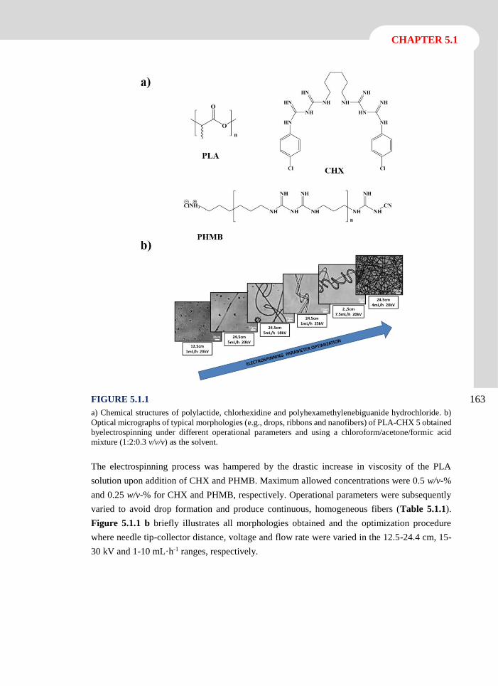
CHAPTER 5.1
163 FIGURE 5.1.1
a) Chemical structures of polylactide, chlorhexidine and polyhexamethylenebiguanide hydrochloride. b)
Optical micrographs of typical morphologies (e.g., drops, ribbons and nanofibers) of PLA-CHX 5 obtained
byelectrospinning under different operational parameters and using a chloroform/acetone/formic acid
mixture (1:2:0.3 v/v/v) as the solvent.
The electrospinning process was hampered by the drastic increase in viscosity of the PLA
solution upon addition of CHX and PHMB. Maximum allowed concentrations were 0.5 w/v-%
and 0.25 w/v-% for CHX and PHMB, respectively. Operational parameters were subsequently
varied to avoid drop formation and produce continuous, homogeneous fibers (Table 5.1.1).
Figure 5.1.1 b briefly illustrates all morphologies obtained and the optimization procedure
where needle tip-collector distance, voltage and flow rate were varied in the 12.5-24.4 cm, 15-
30 kV and 1-10 mL·h-1 ranges, respectively.
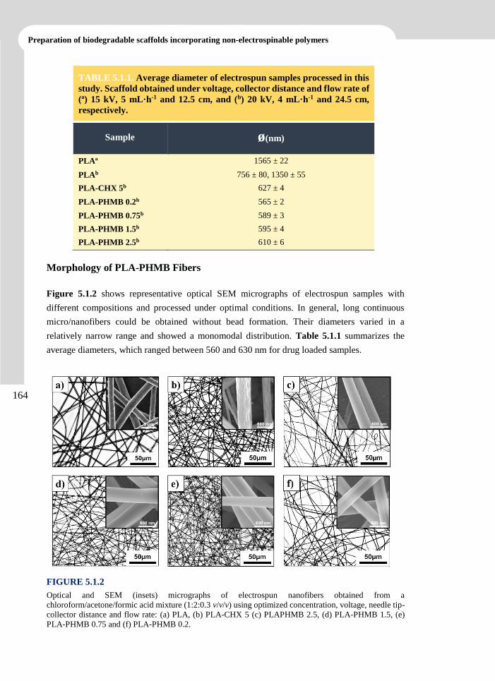
Preparation of biodegradable scaffolds incorporating non-electrospinable polymers
164
TABLE 5.1.1. Average diameter of electrospun samples processed in this
study. Scaffold obtained under voltage, collector distance and flow rate of
(ª) 15 kV, 5 mL·h-1 and 12.5 cm, and (b) 20 kV, 4 mL·h-1 and 24.5 cm,
respectively.
Sample ø(nm)
PLAª 1565 ± 22
PLAb 756 ± 80, 1350 ± 55
PLA-CHX 5b 627 ± 4
PLA-PHMB 0.2b 565 ± 2
PLA-PHMB 0.75b 589 ± 3
PLA-PHMB 1.5b 595 ± 4
PLA-PHMB 2.5b 610 ± 6
Morphology of PLA-PHMB Fibers
Figure 5.1.2 shows representative optical SEM micrographs of electrospun samples with
different compositions and processed under optimal conditions. In general, long continuous
micro/nanofibers could be obtained without bead formation. Their diameters varied in a
relatively narrow range and showed a monomodal distribution. Table 5.1.1 summarizes the
average diameters, which ranged between 560 and 630 nm for drug loaded samples.
FIGURE 5.1.2
Optical and SEM (insets) micrographs of electrospun nanofibers obtained from a
chloroform/acetone/formic acid mixture (1:2:0.3 v/v/v) using optimized concentration, voltage, needle tip-
collector distance and flow rate: (a) PLA, (b) PLA-CHX 5 (c) PLAPHMB 2.5, (d) PLA-PHMB 1.5, (e)
PLA-PHMB 0.75 and (f) PLA-PHMB 0.2.
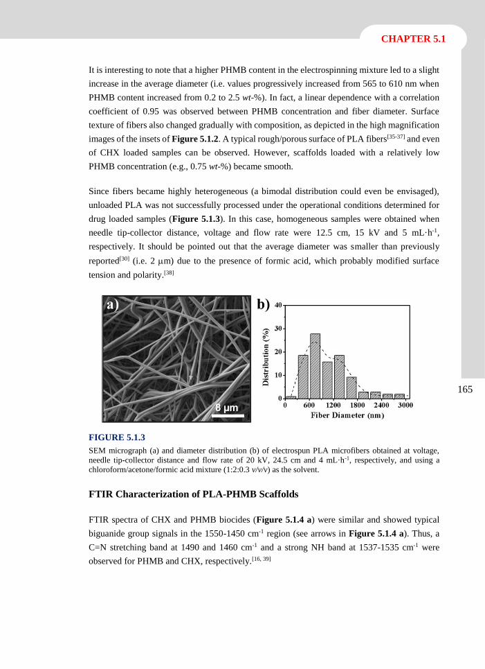
CHAPTER 5.1
165
It is interesting to note that a higher PHMB content in the electrospinning mixture led to a slight
increase in the average diameter (i.e. values progressively increased from 565 to 610 nm when
PHMB content increased from 0.2 to 2.5 wt-%). In fact, a linear dependence with a correlation
coefficient of 0.95 was observed between PHMB concentration and fiber diameter. Surface
texture of fibers also changed gradually with composition, as depicted in the high magnification
images of the insets of Figure 5.1.2. A typical rough/porous surface of PLA fibers[35-37] and even
of CHX loaded samples can be observed. However, scaffolds loaded with a relatively low
PHMB concentration (e.g., 0.75 wt-%) became smooth.
Since fibers became highly heterogeneous (a bimodal distribution could even be envisaged),
unloaded PLA was not successfully processed under the operational conditions determined for
drug loaded samples (Figure 5.1.3). In this case, homogeneous samples were obtained when
needle tip-collector distance, voltage and flow rate were 12.5 cm, 15 kV and 5 mL·h-1,
respectively. It should be pointed out that the average diameter was smaller than previously
reported[30] (i.e. 2 m) due to the presence of formic acid, which probably modified surface
tension and polarity.[38]
FIGURE 5.1.3
SEM micrograph (a) and diameter distribution (b) of electrospun PLA microfibers obtained at voltage,
needle tip-collector distance and flow rate of 20 kV, 24.5 cm and 4 mL·h-1, respectively, and using a
chloroform/acetone/formic acid mixture (1:2:0.3 v/v/v) as the solvent.
FTIR Characterization of PLA-PHMB Scaffolds
FTIR spectra of CHX and PHMB biocides (Figure 5.1.4 a) were similar and showed typical
biguanide group signals in the 1550-1450 cm-1 region (see arrows in Figure 5.1.4 a). Thus, a
C=N stretching band at 1490 and 1460 cm-1 and a strong NH band at 1537-1535 cm-1 were
observed for PHMB and CHX, respectively.[16, 39]
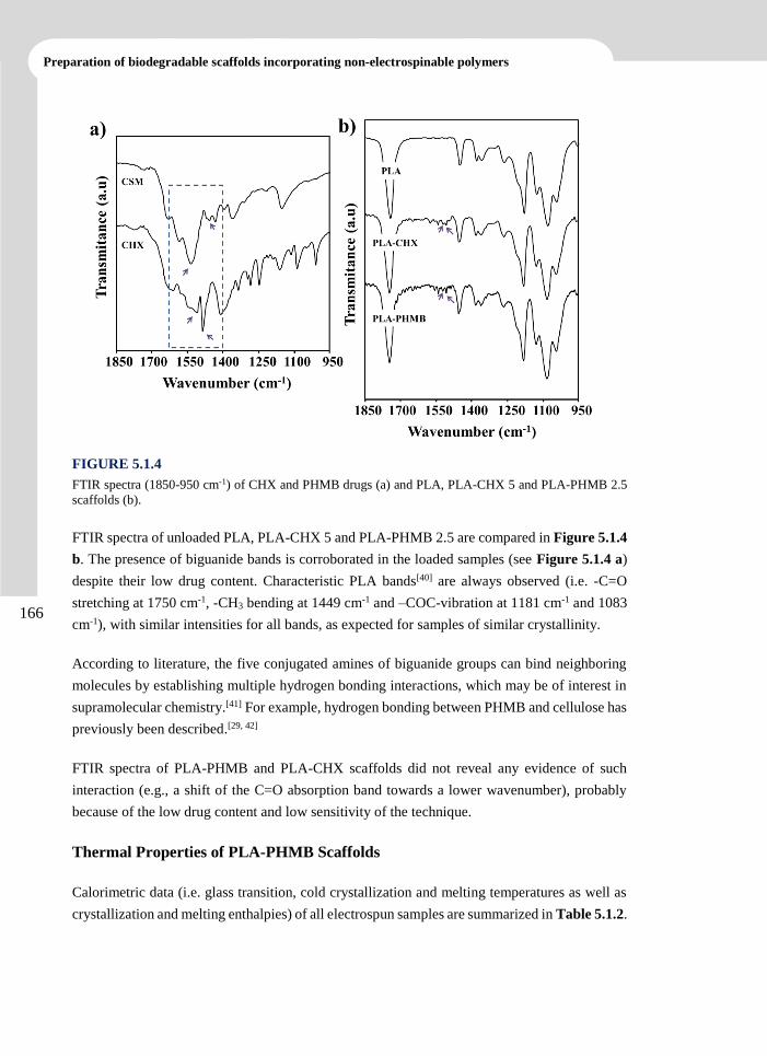
Preparation of biodegradable scaffolds incorporating non-electrospinable polymers
166
FIGURE 5.1.4
FTIR spectra (1850-950 cm-1) of CHX and PHMB drugs (a) and PLA, PLA-CHX 5 and PLA-PHMB 2.5
scaffolds (b).
FTIR spectra of unloaded PLA, PLA-CHX 5 and PLA-PHMB 2.5 are compared in Figure 5.1.4
b. The presence of biguanide bands is corroborated in the loaded samples (see Figure 5.1.4 a)
despite their low drug content. Characteristic PLA bands[40] are always observed (i.e. -C=O
stretching at 1750 cm-1, -CH3 bending at 1449 cm-1 and –COC-vibration at 1181 cm-1 and 1083
cm-1), with similar intensities for all bands, as expected for samples of similar crystallinity.
According to literature, the five conjugated amines of biguanide groups can bind neighboring
molecules by establishing multiple hydrogen bonding interactions, which may be of interest in
supramolecular chemistry.[41] For example, hydrogen bonding between PHMB and cellulose has
previously been described.[29, 42]
FTIR spectra of PLA-PHMB and PLA-CHX scaffolds did not reveal any evidence of such
interaction (e.g., a shift of the C=O absorption band towards a lower wavenumber), probably
because of the low drug content and low sensitivity of the technique.
Thermal Properties of PLA-PHMB Scaffolds
Calorimetric data (i.e. glass transition, cold crystallization and melting temperatures as well as
crystallization and melting enthalpies) of all electrospun samples are summarized in Table 5.1.2.
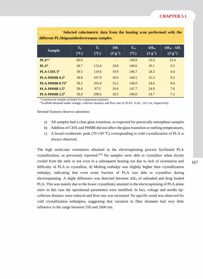
CHAPTER 5.1
167
a Commercial sample included for comparison purposes. b Scaffold obtained under voltage, collector distance and flow rate of 20 kV, 4 mL, 24.5 cm, respectively.
Several features deserve attention:
a) All samples had a clear glass transition, as expected for practically amorphous samples
b) Addition of CHX and PHMB did not affect the glass transition or melting temperatures,
c) A broad exothermic peak (70-130 ºC) corresponding to cold crystallization of PLA is
always observed.
The high molecular orientation obtained in the electrospinning process facilitated PLA
crystallization, as previously reported.[42] No samples were able to crystallize when slowly
cooled from the melt or not even in a subsequent heating run due to lack of orientation and
difficulty of PLA to crystallize, d) Melting enthalpy was slightly higher than crystallization
enthalpy, indicating that even some fraction of PLA was able to crystallize during
electrospinning. A slight difference was detected between ΔHm of unloaded and drug loaded
PLA. This was mainly due to the lower crystallinity attained in the electrospinning of PLA alone
since in this case the operational parameters were modified. In fact, voltage and needle tip-
collector distance were reduced and flow rate was increased. No specific trend was observed for
cold crystallization enthalpies, suggesting that variation in fiber diameter had very little
influence in the range between 550 and 1600 nm.
TABLE 5.12. Selected calorimetric data from the heating scan performed with the
different PLAbiguanideelectrospun samples.
Sample Tg
(ºC)
Tc
(ºC)
ΔHc
(J·g-1)
Tm
(ºC)
ΔHm
(J·g-1)
ΔHm - ΔHc
(J·g-1)
PLAº,a 60.0 - - 149.8 33.4 33.4
PLAb 58.7 113.4 19.8 146.6 20.1 0.3
PLA-CHX 5b 58.5 110.6 19.9 146.7 24.3 4.4
PLA-PHMB 0.2b 58.8 107.9 16.0 146.5 25.3 9.3
PLA-PHMB 0.75b 58.5 103.4 15.2 146.0 24.6 9.4
PLA-PHMB 1.5b 58.6 97.5 19.0 147.7 24.9 7.6
PLA-PHMB 2.5b 58.4 108.6 18.3 146.6 24.7 7.2
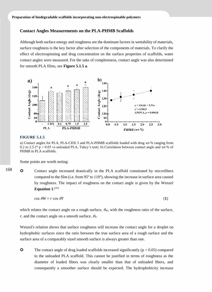
Preparation of biodegradable scaffolds incorporating non-electrospinable polymers
168
Contact Angles Measurements on the PLA-PHMB Scaffolds
Although both surface energy and roughness are the dominant factors in wettability of materials,
surface roughness is the key factor after selection of the components of materials. To clarify the
effect of electrospinning and drug concentration on the surface properties of scaffolds, water
contact angles were measured. For the sake of completeness, contact angle was also determined
for smooth PLA films, see Figure 5.1.5 a.
FIGURE 5.1.5
a) Contact angles for PLA, PLA-CHX 5 and PLA-PHMB scaffolds loaded with drug wt-% ranging from
0.2 to 2.5 (* p < 0.05 vs unloaded PLA, Tukey’s test). b) Correlation between contact angle and wt-% of
PHMB in PLA scaffolds.
Some points are worth noting:
Contact angle increased drastically in the PLA scaffold constituted by microfibers
compared to the film (i.e. from 95º to 110º), showing the increase in surface area caused
by roughness. The impact of roughness on the contact angle is given by the Wenzel
Equation 1:[43]
cos W = r cos Y (1)
which relates the contact angle on a rough surface, W, with the roughness ratio of the surface,
r, and the contact angle on a smooth surface, Y.
Wenzel's relation shows that surface roughness will increase the contact angle for a droplet on
hydrophobic surfaces since the ratio between the true surface area of a rough surface and the
surface area of a comparably sized smooth surface is always greater than one.
The contact angle of drug loaded scaffolds increased significantly (p < 0.05) compared
to the unloaded PLA scaffold. This cannot be justified in terms of roughness as the
diameter of loaded fibers was clearly smaller than that of unloaded fibers, and
consequently a smoother surface should be expected. The hydrophobicity increase
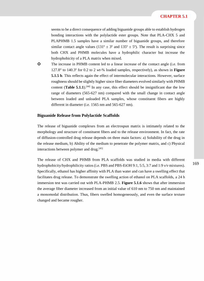
CHAPTER 5.1
169
seems to be a direct consequence of adding biguanide groups able to establish hydrogen
bonding interactions with the polylactide ester groups. Note that PLA-CHX 5 and
PLAPHMB 1.5 samples have a similar number of biguanide groups, and therefore
similar contact angle values (131º ± 3º and 135º ± 5º). The result is surprising since
both CHX and PHMB molecules have a hydrophilic character but increase the
hydrophobicity of a PLA matrix when mixed.
The increase in PHMB content led to a linear increase of the contact angle (i.e. from
127.8° to 140.3º for 0.2 to 2 wt-% loaded samples, respectively), as shown in Figure
5.1.5 b. This reflects again the effect of intermolecular interactions. However, surface
roughness should be slightly higher since fiber diameters evolved similarly with PHMB
content (Table 5.1.1).[44] In any case, this effect should be insignificant due the low
range of diameters (565-627 nm) compared with the small change in contact angle
between loaded and unloaded PLA samples, whose constituent fibers are highly
different in diameter (i.e. 1565 nm and 565-627 nm).
Biguanide Release from Polylactide Scaffolds
The release of biguanide complexes from an electrospun matrix is intimately related to the
morphology and structure of constituent fibers and to the release environment. In fact, the rate
of diffusion-controlled drug release depends on three main factors: a) Solubility of the drug in
the release medium, b) Ability of the medium to penetrate the polymer matrix, and c) Physical
interactions between polymer and drug.[45]
The release of CHX and PHMB from PLA scaffolds was studied in media with different
hydrophobicity/hydrophilicity ratios (i.e. PBS and PBS-EtOH 9:1, 5:5, 3:7 and 1:9 v/v mixtures).
Specifically, ethanol has higher affinity with PLA than water and can have a swelling effect that
facilitates drug release. To demonstrate the swelling action of ethanol on PLA scaffolds, a 24 h
immersion test was carried out with PLA-PHMB 2.5. Figure 5.1.6 shows that after immersion
the average fiber diameter increased from an initial value of 610 nm to 750 nm and maintained
a monomodal distribution. Thus, fibers swelled homogeneously, and even the surface texture
changed and became rougher.
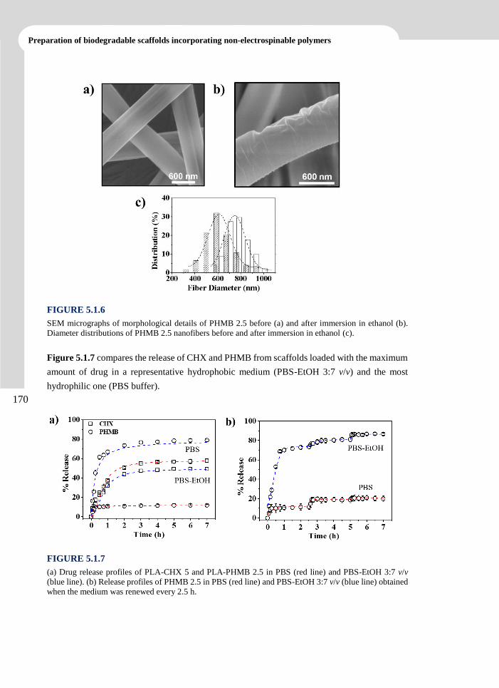
Preparation of biodegradable scaffolds incorporating non-electrospinable polymers
170
FIGURE 5.1.6
SEM micrographs of morphological details of PHMB 2.5 before (a) and after immersion in ethanol (b).
Diameter distributions of PHMB 2.5 nanofibers before and after immersion in ethanol (c).
Figure 5.1.7 compares the release of CHX and PHMB from scaffolds loaded with the maximum
amount of drug in a representative hydrophobic medium (PBS-EtOH 3:7 v/v) and the most
hydrophilic one (PBS buffer).
FIGURE 5.1.7
(a) Drug release profiles of PLA-CHX 5 and PLA-PHMB 2.5 in PBS (red line) and PBS-EtOH 3:7 v/v
(blue line). (b) Release profiles of PHMB 2.5 in PBS (red line) and PBS-EtOH 3:7 v/v (blue line) obtained
when the medium was renewed every 2.5 h.
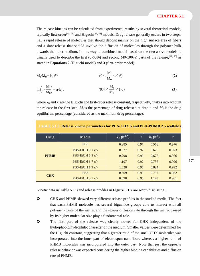
CHAPTER 5.1
171
The release kinetics can be calculated from experimental results by several theoretical models,
typically first-order[45, 46] and Higuchi[47, 48] models. Drug release generally occurs in two steps,
i.e., a rapid release of molecules that should deposit mainly on the high surface area of fibers
and a slow release that should involve the diffusion of molecules through the polymer bulk
towards the outer medium. In this way, a combined model based on the two above models is
usually used to describe the first (0-60%) and second (40-100%) parts of the release,[49, 50] as
stated in Equations 2 (Higuchi model) and 3 (first-order model):
Mt/M0= kHt1/2 (0 ≤ Mt
M0
≤ 0.6) (2)
ln (1-Mt
M0
) = a-k1t (0.4 ≤ Mt
M0
≤ 1.0) (3)
where kH and k1 are the Higuchi and first-order release constant, respectively, a takes into account
the release in the first step, Mt is the percentage of drug released at time t, and M0 is the drug
equilibrium percentage (considered as the maximum drug percentage).
Kinetic data in Table 5.1.3 and release profiles in Figure 5.1.7 are worth discussing:
CHX and PHMB showed very different release profiles in the studied media. The fact
that each PHMB molecule has several biguanide groups able to interact with all
polymer chains of the matrix and the slower diffusion rate through the matrix caused
by its higher molecular size play a fundamental role.
The first part of the release was clearly slower for CHX independent of the
hydrophobic/hydrophilic character of the medium. Smaller values were determined for
the Higuchi constant, suggesting that a greater ratio of the small CHX molecules was
incorporated into the inner part of electrospun nanofibers whereas a higher ratio of
PHMB molecules was incorporated into the outer part. Note that just the opposite
release behavior was expected considering the higher binding capabilities and diffusion
rate of PHMB.
TABLE 5.1.3. Release kinetic parameters for PLA-CHX 5 and PLA-PHMB 2.5 scaffolds.
Drug Media kH (h-0.5) r k1 (h-1) r
PHMB
PBS 0.985 0.974 0.568 0.976
PBS-EtOH 9:1 v/v 0.527 0.971 0.679 0.973
PBS-EtOH 5:5 v/v 0.798 0.962 0.676 0.956
PBS-EtOH 3:7 v/v 1.107 0.973 0.756 0.996
PBS-EtOH 1:9 v/v 1.028 0.969 0.824 0.992
CHX PBS 0.609 0.990 0.737 0.982
PBS-EtOH 3:7 v/v 0.598 0.956 1.149 0.981
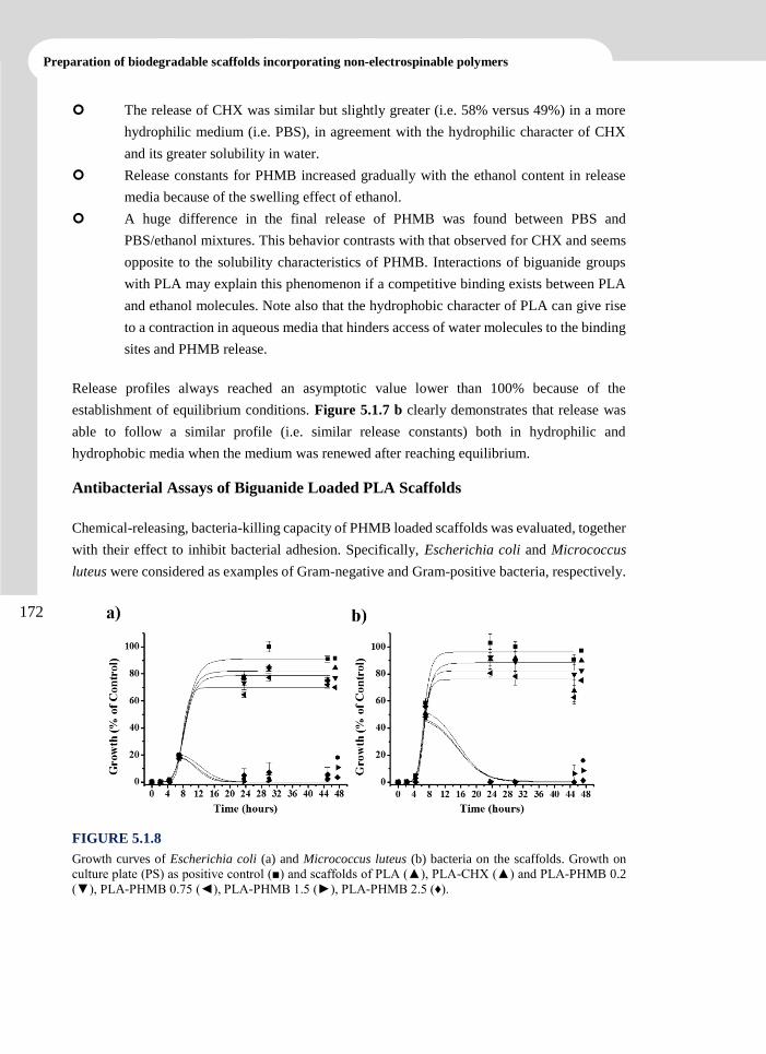
Preparation of biodegradable scaffolds incorporating non-electrospinable polymers
172
The release of CHX was similar but slightly greater (i.e. 58% versus 49%) in a more
hydrophilic medium (i.e. PBS), in agreement with the hydrophilic character of CHX
and its greater solubility in water.
Release constants for PHMB increased gradually with the ethanol content in release
media because of the swelling effect of ethanol.
A huge difference in the final release of PHMB was found between PBS and
PBS/ethanol mixtures. This behavior contrasts with that observed for CHX and seems
opposite to the solubility characteristics of PHMB. Interactions of biguanide groups
with PLA may explain this phenomenon if a competitive binding exists between PLA
and ethanol molecules. Note also that the hydrophobic character of PLA can give rise
to a contraction in aqueous media that hinders access of water molecules to the binding
sites and PHMB release.
Release profiles always reached an asymptotic value lower than 100% because of the
establishment of equilibrium conditions. Figure 5.1.7 b clearly demonstrates that release was
able to follow a similar profile (i.e. similar release constants) both in hydrophilic and
hydrophobic media when the medium was renewed after reaching equilibrium.
Antibacterial Assays of Biguanide Loaded PLA Scaffolds
Chemical-releasing, bacteria-killing capacity of PHMB loaded scaffolds was evaluated, together
with their effect to inhibit bacterial adhesion. Specifically, Escherichia coli and Micrococcus
luteus were considered as examples of Gram-negative and Gram-positive bacteria, respectively.
FIGURE 5.1.8
Growth curves of Escherichia coli (a) and Micrococcus luteus (b) bacteria on the scaffolds. Growth on
culture plate (PS) as positive control (■) and scaffolds of PLA (▲), PLA-CHX (▲) and PLA-PHMB 0.2
(▼), PLA-PHMB 0.75 (◄), PLA-PHMB 1.5 (►), PLA-PHMB 2.5 (♦).
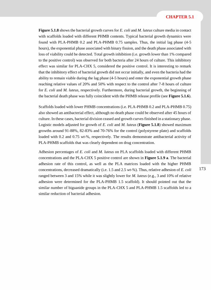
CHAPTER 5.1
173
Figure 5.1.8 shows the bacterial growth curves for E. coli and M. luteus culture media in contact
with scaffolds loaded with different PHMB contents. Typical bacterial growth dynamics were
found with PLA-PHMB 0.2 and PLA-PHMB 0.75 samples. Thus, the initial lag phase (4-5
hours), the exponential phase associated with binary fission, and the death phase associated with
loss of viability could be detected. Total growth inhibition (i.e. growth lower than 1% compared
to the positive control) was observed for both bacteria after 24 hours of culture. This inhibitory
effect was similar for PLA-CHX 5, considered the positive control. It is interesting to remark
that the inhibitory effect of bacterial growth did not occur initially, and even the bacteria had the
ability to remain viable during the lag phase (4-5 hours) and enter the exponential growth phase
reaching relative values of 20% and 50% with respect to the control after 7-8 hours of culture
for E. coli and M. luteus, respectively. Furthermore, during bacterial growth, the beginning of
the bacterial death phase was fully coincident with the PHMB release profile (see Figure 5.1.6).
Scaffolds loaded with lower PHMB concentrations (i.e. PLA-PHMB 0.2 and PLA-PHMB 0.75)
also showed an antibacterial effect, although no death phase could be observed after 45 hours of
culture. In these cases, bacterial division ceased and growth curves finished in a stationary phase.
Logistic models adjusted for growth of E. coli and M. luteus (Figure 5.1.8) showed maximum
growths around 91-88%, 82-83% and 70-76% for the control (polystyrene plate) and scaffolds
loaded with 0.2 and 0.75 wt-%, respectively. The results demonstrate antibacterial activity of
PLA-PHMB scaffolds that was clearly dependent on drug concentration.
Adhesion percentages of E. coli and M. luteus on PLA scaffolds loaded with different PHMB
concentrations and the PLA-CHX 5 positive control are shown in Figure 5.1.9 a. The bacterial
adhesion rate of this control, as well as the PLA matrices loaded with the higher PHMB
concentrations, decreased dramatically (i.e. 1.5 and 2.5 wt-%). Thus, relative adhesion of E. coli
ranged between 3 and 15% while it was slightly lower for M. luteus (e.g., 3 and 10% of relative
adhesion were determined for the PLA-PHMB 1.5 scaffold). It should pointed out that the
similar number of biguanide groups in the PLA-CHX 5 and PLA-PHMB 1.5 scaffolds led to a
similar reduction of bacterial adhesion.
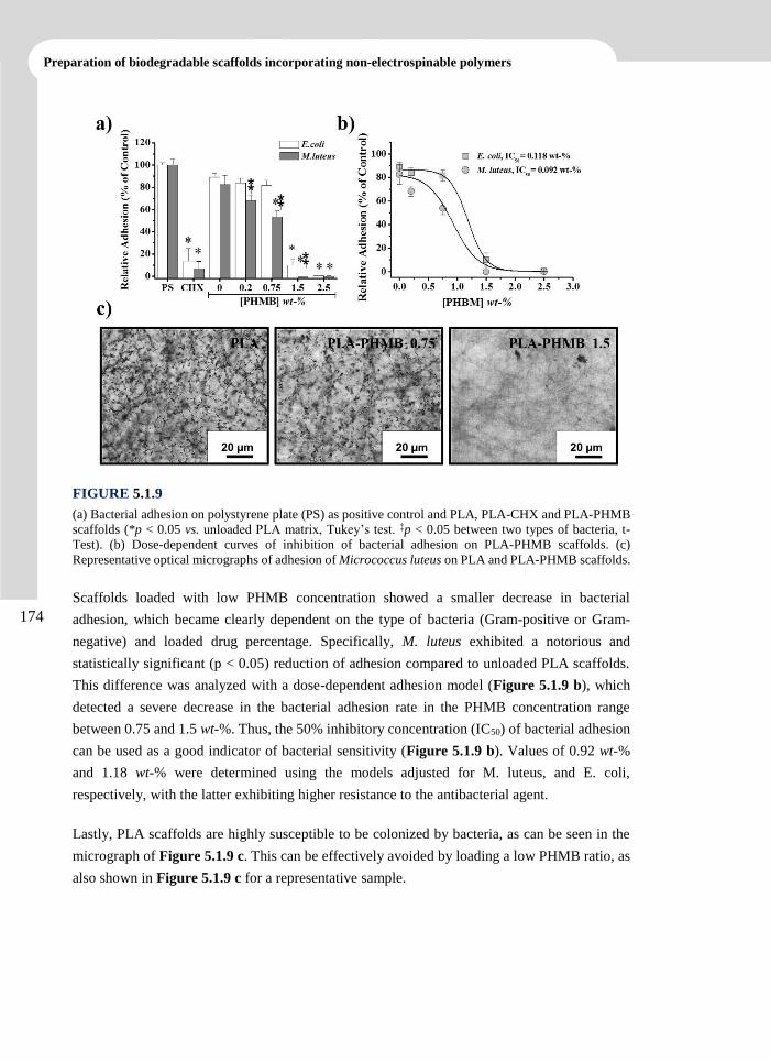
Preparation of biodegradable scaffolds incorporating non-electrospinable polymers
174
FIGURE 5.1.9
(a) Bacterial adhesion on polystyrene plate (PS) as positive control and PLA, PLA-CHX and PLA-PHMB
scaffolds (*p < 0.05 vs. unloaded PLA matrix, Tukey’s test. ‡p < 0.05 between two types of bacteria, t-
Test). (b) Dose-dependent curves of inhibition of bacterial adhesion on PLA-PHMB scaffolds. (c)
Representative optical micrographs of adhesion of Micrococcus luteus on PLA and PLA-PHMB scaffolds.
Scaffolds loaded with low PHMB concentration showed a smaller decrease in bacterial
adhesion, which became clearly dependent on the type of bacteria (Gram-positive or Gram-
negative) and loaded drug percentage. Specifically, M. luteus exhibited a notorious and
statistically significant (p < 0.05) reduction of adhesion compared to unloaded PLA scaffolds.
This difference was analyzed with a dose-dependent adhesion model (Figure 5.1.9 b), which
detected a severe decrease in the bacterial adhesion rate in the PHMB concentration range
between 0.75 and 1.5 wt-%. Thus, the 50% inhibitory concentration (IC50) of bacterial adhesion
can be used as a good indicator of bacterial sensitivity (Figure 5.1.9 b). Values of 0.92 wt-%
and 1.18 wt-% were determined using the models adjusted for M. luteus, and E. coli,
respectively, with the latter exhibiting higher resistance to the antibacterial agent.
Lastly, PLA scaffolds are highly susceptible to be colonized by bacteria, as can be seen in the
micrograph of Figure 5.1.9 c. This can be effectively avoided by loading a low PHMB ratio, as
also shown in Figure 5.1.9 c for a representative sample.
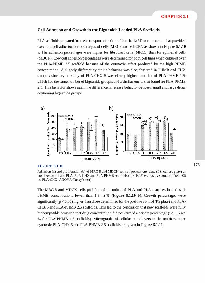
CHAPTER 5.1
175
Cell Adhesion and Growth in the Biguanide Loaded PLA Scaffolds
PLA scaffolds prepared from electrospun micro/nanofibers had a 3D pore structure that provided
excellent cell adhesion for both types of cells (MRC5 and MDCK), as shown in Figure 5.1.10
a. The adhesion percentages were higher for fibroblast cells (MRC5) than for epithelial cells
(MDCK). Low cell adhesion percentages were determined for both cell lines when cultured over
the PLA-PHMB 2.5 scaffold because of the cytotoxic effect produced by the high PHMB
concentration. A slightly different cytotoxic behavior was also observed in PHMB and CHX
samples since cytotoxicity of PLA-CHX 5 was clearly higher than that of PLA-PHMB 1.5,
which had the same number of biguanide groups, and a similar one to that found for PLA-PHMB
2.5. This behavior shows again the difference in release behavior between small and large drugs
containing biguanide groups.
FIGURE 5.1.10
Adhesion (a) and proliferation (b) of MRC-5 and MDCK cells on polystyrene plate (PS, culture plate) as
positive control and PLA, PLA-CHX and PLA-PHMB scaffolds (*p < 0.05) vs. positive control, ** p< 0.05
vs. PLA-CHX; ANOVA-Tukey’s test).
The MRC-5 and MDCK cells proliferated on unloaded PLA and PLA matrices loaded with
PHMB concentrations lower than 1.5 wt-% (Figure 5.1.10 b). Growth percentages were
significantly (p < 0.05) higher than those determined for the positive control (PS plate) and PLA-
CHX 5 and PLA-PHMB 2.5 scaffolds. This led to the conclusion that new scaffolds were fully
biocompatible provided that drug concentration did not exceed a certain percentage (i.e. 1.5 wt-
% for PLA-PHMB 1.5 scaffolds). Micrographs of cellular monolayers in the matrices more
cytotoxic PLA-CHX 5 and PLA-PHMB 2.5 scaffolds are given in Figure 5.1.11.
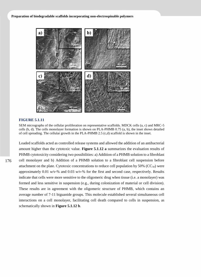
Preparation of biodegradable scaffolds incorporating non-electrospinable polymers
176
FIGURE 5.1.11
SEM micrographs of the cellular proliferation on representative scaffolds. MDCK cells (a, c) and MRC-5
cells (b, d). The cells monolayer formation is shown on PLA-PHMB 0.75 (a, b), the inset shows detailed
of cell spreading. The cellular growth in the PLA-PHMB 2.5 (c,d) scaffold is shown in the inset.
Loaded scaffolds acted as controlled release systems and allowed the addition of an antibacterial
amount higher than the cytotoxic value. Figure 5.1.12 a summarizes the evaluation results of
PHMB cytotoxicity considering two possibilities: a) Addition of a PHMB solution to a fibroblast
cell monolayer and b) Addition of a PHMB solution to a fibroblast cell suspension before
attachment on the plate. Cytotoxic concentrations to reduce cell population by 50% (CC50) were
approximately 0.01 w/v-% and 0.03 w/v-% for the first and second case, respectively. Results
indicate that cells were more sensitive to the oligomeric drug when tissue (i.e. a monolayer) was
formed and less sensitive in suspension (e.g., during colonization of material or cell division).
These results are in agreement with the oligomeric structure of PHMB, which contains an
average number of 7-11 biguanide groups. This molecule established several simultaneous cell
interactions on a cell monolayer, facilitating cell death compared to cells in suspension, as
schematically shown in Figure 5.1.12 b.
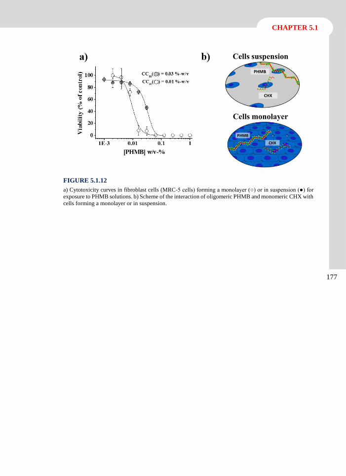
CHAPTER 5.1
177
FIGURE 5.1.12
a) Cytotoxicity curves in fibroblast cells (MRC-5 cells) forming a monolayer (○) or in suspension (●) for
exposure to PHMB solutions. b) Scheme of the interaction of oligomeric PHMB and monomeric CHX with
cells forming a monolayer or in suspension.
Preparation of biodegradable scaffolds incorporating non-electrospinable polymers
178
5.1.4 Conclusions
PLA nanofibers loaded with PHMB and having average diameters ranging between 560 and 630
nm were obtained by electrospinning and using a chloroform/acetone/formic acid mixture
(1:2:0.3 v/v/v) as a solvent. The fiber diameter increased and the surface texture became
smoother with increasing the loaded PHMB concentration. Nanofibers had a high molecular
orientation that facilitated PLA cold crystallization during heating.
Addition of PHMB to PLA scaffolds increased the hydrophobicity of the sample, which was
surprising considering the hydrophilic character of PHMB. The highly-hydrophobicity of these
scaffolds conditioned PHMB release, which was prevented in the hydrophilic medium and was
facilitated when hydrophobicity was more hydrophobic. The molecular size of PHMB also
resulted in a clearly different release behavior from that of the biguanide monomer. PHMB
released from PLA scaffolds inhibited bacterial growth and prevented cell adhesion and
colonization due to controlled and sustained release. The significant inhibition of bacterial
growth required a PHMB concentration higher than 0.75 wt-%.
PHMB loaded scaffolds were fully biocompatible and led to significant adhesion and
proliferation of both fibroblast and epithelial cell lines. Controlled release made it possible to
load scaffolds with a large amount of PHMB, which was higher than the cytotoxic dose (CC50).
In summary, addition of PHMB to PLA scaffolds resulted in characteristics different from those
obtained by addition of small drugs (CHX) containing a single biguanide group. These PHMB
loaded scaffolds are particularly interesting because of their potential biomedical applications.
CHAPTER 5.1
179
5.1.5 References
[1] R. Ben-Knaz, R. Pedahzur, D. Avnir, Adv Funct Mater, 20 (2010) 2324-2329.
[2] R.J.W. Lambert, M.D. Johnston, G.W. Hanlon, S.P. Denyer, J App Microbiol, 94 (2003)
747-759.
[3] H. Behar-Levy, D. Avnir, Chem Mater, 14 (2002) 1736-1741.
[4] S. Pal, E.J. Yoon, S.H. Park, E.C. Choi, J.M. Song, J Antimicrob Chemoth, 65 (2010)
2134-2140.
[5] D.S. Jones, A.F. Brown, A.D. Woolfson, A.C. Dennis, L.J. Matchett, S.E.J. Bell, J Pharm
Sci, 89 (2000) 563-571.
[6] M. Addy, Adv Drug Deliver Rev, 13 (1994) 123-134.
[7] G.E. McDonnell, First Edition ed., ASM Press, Washington D.C., 2007.
[8] D.R. Monteiro, L.F. Gorup, A.S. Takamiya, A.C. Ruvollo, E.R. Camargo, D.B. Barbosa,
Int J Antimicrob Ag, 34 (2009) 103-110.
[9] M. Zilberman, J.J. Elsner, J Control Release, 130 (2008) 202-215.
[10] K. Kaehn, Skin Pharmacol Phys, 23 (2010) 7-16.
[11] J.B.D. Green, T. Fulghum, M.A. Nordhaus, First Edition ed., Formatex, Badajoz, 2011.
[12] K. Vasilev, J. Cook, H.J. Griesser, Expert Rev Med Devic, 6 (2009) 553-567.
[13] M. Charnley, M. Textor, C. Acikgoz, React Funct Polym, 71 (2011) 329-334.
[14] A.M. Milstone, C.L. Passaretti, T.M. Perl, Clin Infect Dis, 46 (2008) 274-281.
[15] K.S. Lim, P.C.A. Kam, Anaesth Intens Care, 36 (2008) 502-512.
[16] G.F. de Paula, G.I. Netto, L.H.C. Mattoso, Polymers, 3 (2011) 928-941.
[17] B. Roth, F.H.H. Brill, Skin Pharmacol Phys, 23 (2010) 4-6.
[18] M.J. Allen, G.F. White, A.P. Morby, Microbiology, 152 (2006) 989-1000.
[19] P. Gilbert, D. Pemberton, D.E. Wilkinson, J App Bacteriol, 69 (1990) 593-598.
[20] T. Koburger, N.O. Hubner, M. Braun, J. Siebert, A. Kramer, J Antimicrob Chemoth, 65
(2010) 1712-1719.
[21] Y. You, B.M. Min, S.J. Lee, T.S. Lee, W.H. Park, J Appl Polym Sci, 95 (2005) 193-200.
[22] S.G. Cao, B.H. Hu, H.Q. Liu, Acta Polym Sin, (2010) 1193-1198.
Preparation of biodegradable scaffolds incorporating non-electrospinable polymers
180
[23] V. Thomas, M.V. Jose, S. Chowdhury, J.F. Sullivan, D.R. Dean, Y.K. Vohra, J Biomat
Sci Polym E, 17 (2006) 969-984.
[24] S.A. Sell, M.J. McClure, K. Garg, P.S. Wolfe, G.L. Bowlin, Adv Drug Deliver Rev, 61
(2009) 1007-1019.
[25] Z.G. Chen, X.M. Mo, F.L. Qing, Mater Lett, 61 (2007) 3490-3494.
[26] H. Homayoni, S.A.H. Ravandi, M. Valizadeh, Carbohyd Polym, 77 (2009) 656-661.
[27] N. Hiraishi, C.K.Y. Yiu, N.M. King, F.R. Tay, D.H. Pashley, Dent Mater, 24 (2008)
1391-1399.
[28] Y.N. Lin, K.M. Chang, S.C. Jeng, P.Y. Lin, R.Q. Hsu, J Mater Sci Mater M, 22 (2011)
571-577.
[29] X. Liu, T. Lin, Y. Gao, Z. Xu, C. Huang, G. Yao, L. Jiang, Y. Tang, X. Wang, J Biomed
Mater Res B Appl Biomater, 100 (2012) 1556-1565.
[30] L.J. del Valle, R. Camps, A. Diaz, L. Franco, A. Rodriguez-Galan, J. Puiggali, J Polym
Res, 18 (2011) 1903-1917.
[31] S.V. Fridrikh, J.H. Yu, M.P. Brenner, G.C. Rutledge, Phys Rev Lett, 90 (2003) 144502-
144504.
[32] M.G. McKee, C.L. Elkins, T.E. Long, Polymer, 45 (2004) 8705-8715.
[33] C.J. Luo, M. Nangrejo, M. Edirisinghe, Polymer, 51 (2010) 1654-1662.
[34] E. Armelin, A.L. Gomes, M.M. Perez-Madrigal, J. Puiggali, L. Franco, L.J. del Valle, A.
Rodriguez-Galan, J.S.D. Campos, N. Ferrer-Anglada, C. Aleman, J Mater Chem, 22
(2012) 585-594.
[35] A. Agrawal, A.D. Saran, S.S. Rath, A. Khanna, Polymer, 45 (2004) 8603-8612.
[36] Z.G. Wang, L.S. Wan, Z.M. Liu, X.J. Huang, Z.K. Xu, J Mol Catal B-Enzym, 56 (2009)
189-195.
[37] Z.M. Huang, Y.Z. Zhang, M. Kotaki, S. Ramakrishna, Compos Sci Technol, 63 (2003)
2223-2253.
[38] N. Bhardwaj, S.C. Kundu, Biotech Adv, 28 (2010) 325-347.
[39] L. Chen, L. Bromberg, T.A. Hatton, G.C. Rutledge, Polymer, 49 (2008) 1266-1275.
[40] G. Kister, G. Cassanas, M. Vert, Polymer, 39 (1998) 3335-3340.
[41] O. Lebel, T. Maris, J.D. Wuest, Can J Chem, 84 (2006) 1426-1433.
CHAPTER 5.1
181
[42] R.S. Blackburn, A. Harvey, L.L. Kettle, J.D. Payne, S.J. Russell, Langmuir, 22 (2006)
5636-5644.
[43] R.N. Wenzel, Ind Eng Chem, 28 (1936) 988-994.
[44] S.B. Zhou, H.S. Peng, X.J. Yu, X.T. Zheng, W.G. Cui, Z.R. Zhang, X.H. Li, J.X. Wang,
J. Weng, W.X. Jia, F. Li, J Phys Chem B, 112 (2008) 11209-11216.
[45] H. Liu, K.K. Leonas, Y.P. Zhao, J Eng Fiber Fabr, 5 (2010) 10-19.
[46] M. Gibaldi, S. Feldman, J Pharm Sci, 56 (1967) 1238-1242.
[47] J.G. Wagner, J Pharm Sci, 58 (1969) 1253-1257.
[48] T. Higuchi, J Pharm Sci, 50 (1961) 874-875.
[49] T. Higuchi, J Pharm Sci, 52 (1963) 1145-1149.
[50] R.W. Baker, John Wiley & Sons, New York, USA, 1987.

2
Electrospun Nanofibers from Biodegradable
Polylactide and Conducting Poly(3-Thiophene
Methyl Acetate) Mixtures
Hybrid scaffolds constituted by polylactide (PLA) as
a biodegradable polymer and poly(3-thiophene
methyl acetate) (P3TMA) as an electroactive polymer
were prepared and studied. Both polymers had a
similar solubility and consequently could be easily
electrospun using a common solvent. Electrospinning
operational parameters were optimized to get
continuous micro/nanofibers with a homogeneous
diameter that ranged between 600 and 900 nm
depending on the PLA/P3TMA ratio. Electrospinning
was only effective when the P3TMA content was at
maximum 50 wt-%. The incorporation of P3TMA
slightly decreased the fibre diameter, led to smoother
fibre surfaces and gave rise to some heterogeneous
clusters inside the fibers. PLA was highly oriented
inside the electrospun fibers and able to easily cold
crystallize by heating. Thermal degradation was not
highly influenced by the presence of P3TMA, although
the onset temperature slightly increased since the first
decomposition step of PLA was prevented. New
scaffolds had promising electrochemical properties
and even provided a good substrate for cell adhesion
and cell proliferation. Therefore, these hybrids
materials are suitable to improve the cellular
response towards physiological processes.
5.2
184
Preparation of biodegradable scaffolds incorporating non-electrospinable polymers
5.2.1 Introduction
Polymeric materials with both biodegradable and electrically conducting properties have a
growing interest in biomedical applications because of both the lack of long-term health risk and
their good behavior as supportive matrix for tissue regeneration. The electrochemical response
of conducting polymers makes feasible the local stimulation of desired tissue and the
enhancement of either the proliferation or differentiation of various cell types.[1-4] Nevertheless,
it remains a considerable challenge to synthesize an ideal electroactive polymer that meets the
biocompatibility and biodegradability requirements to minimize the inflammatory reaction in
the host tissue that could be raised by the use of non-degradable materials. An alternative
strategy is the use of conducting polymer/biopolymer blends since unique properties that justify
their potential technological applications in biomedical devices can be achieved.
The requirements for materials used in tissue engineering applications are biocompatibility and
biodegradability since they should degrade with time and should be replaced with newly
regenerated tissues. The architecture of the biomaterial is also very important and, specifically,
scaffolds constituted by electrospun nanofibers have promising features, such as big surface area
for absorbing proteins and abundance of binding sites for cell membrane receptors.
Ultrathin fibers from a wide range of polymer materials can be easily prepared by
electrospinning.[5-11] This electrostatic technique involves the use of a high voltage field to
charge the surface of a polymer solution droplet, held at the end of a capillary tube, and induce
the ejection of a liquid jet towards a grounded target (collector).
Two different approaches have been applied to develop scaffolds constituted by conducting and
biodegradable polymers: a) By coating an electrospun mat of a well-known biocompatible and
reabsorbable biomaterial with the conducting polymer; and b) By direct electrospinning of a
conducting/biodegradable polymer mixture. The second option is easier to perform but requires
a good solubility of the conducting polymer in the electrospinning solution and gives rise to
scaffolds with lower conductivity.
First works providing novel conductive materials well suited as biocompatible scaffolds for
tissue engineering involved polyaniline-gelatin blend nanofibers.[12] Picciani et al.[13] considered
the use of poly(L-lactide) as the support polymeric matrix for the preparation of polyaniline-
based conducting nanofibers and evaluated the influence of operational parameters on the
morphology of electrospun fibers. Several polyaniline and poly(D,L-lactide) mixtures at
different weight percents were also successfully electrospun from 1,1,1,3,3,3-
hexafluoroisopropanol solutions and their conductivity and biocompatibility evaluated.[14]
Nanofibrous blends of HCl-doped poly(aniline-co-3-aminobenzoic acid) copolymer and
poly(lactic acid) (PLA) were fabricated by electrospinning solutions of the polymers in a
dimethyl sulfoxide/tetrahydrofuran mixture.[15] Scarce works concern the electrospinning of
mixtures based on polypyrrole and basically deal with scaffolds constituted by
polypyrrole/polycaprolactone (PCL)/gelatin nanofibers.[16] Specifically, conductive nanofibers
185
CHAPTER 5.2
containing 15% polypyrrole exhibited the most suitable balance of electrical conductivity,
mechanical properties and biodegradability, matching the requirements for the regeneration of
cardiac tissue. Furthermore, such scaffold promoted cell attachment and proliferation as well as
the interaction and expression of cardiac-specific proteins.
Polythiophenes constitute a group of conducting polymers with high technological potential due
to their optical, electroluminescents, electronic and, specially, electrochemical properties.[17, 18]
Different derivatives can be considered and, specifically, several works were focused on the
preparation of nanofibers from mixtures of poly(3-hexylthiophene) (P3HT) and PCL or
poly(lactic-co-glycolic acid) (PLGA) as biodegradable polymers.[19, 20] Thus, P3HT domains in
concentrated PCL solution were highly stretched from the electrospinning electrode and formed
fibrils with very small diameters (i.e. ∼30 nm) embedded inside PCL composite fibers.
Interestingly, fibrils became connected one to another during the volume shrinkage of the
solution by solvent evaporation, generating PCL composite fibers with continuous P3HT fibrils
embedded inside. On the other hand, it was found that PLGA–P3HT nanofibers have a
significant influence on cell adhesion and proliferation. These new electrically conducting
axially aligned nanofibers provided both electrical and structural cues and could be potentially
used as scaffolds for neural regeneration.
Poly(3-thiophene methyl acetate) (P3TMA) is another polythiophene derivative that is
characterized by bearing carboxylate substituents in the 3-position of the heterocyclic ring. The
polymer can be easily prepared via oxidative chemical[21] and photochemical[22] reactions and
appears a suitable candidate for being processed by electrospinning since has a good solubility
in organic solvents like chloroform. Furthermore, it has currently been demonstrated that very
stable free-standing nanomembranes with electroactive and biodegradable properties can be
prepared by combining P3TMA and polyesters, such as poly(tetramethylene succinate), and
even thermoplastic polyurethanes and poly(vinylidene fluoride).[21-24]
The main goal of the present work is the establishment of the electrospun conditions required to
get continuous micro/nanofibers from mixtures of P3TMA with PLA as well as to perform a
basic characterization of morphology and properties (e.g., ability to store charge and
biocompatibility) of the derived scaffolds. PLA has been just selected as the biodegradable
component due to its excellent properties and its wide use in the biomedical field.
186
Preparation of biodegradable scaffolds incorporating non-electrospinable polymers
5.2.2 Experimental Section
Materials
3-Thiophene acetic acid (3TAA) (98.0%) was purchased from Fluka (Sigma-Aldrich). Iron
chloride anhydrous (97.0%), dry methanol (99.5%), chloroform (99.9%) were purchased from
Panreac Quimica S.A.U. (Spain) and used as received without further purification. PLA, a
product of Natureworks (polymer 2002D), was kindly supplied by Nupik International (Polinyà,
Spain). According to the manufacturer, this PLA has a D content of 4.25%, a residual monomer
content of 0.3%, a density of 1.24 g·cc-1, a glass transition temperature (Tg) of 58 ºC and a
melting point of 153 ºC.
Kidney epithelial cells derived from African green monkey (VERO) were purchased from
ATCC (USA).
Synthesis of poly(3-thiophene methyl acetate)
The 3-thiophene methyl acetate (3TMA) monomer was obtained with a 74% yield by refluxing
3TAA in dry methanol for 24 hours at a temperature of 90 ºC.[21] The polythiophene derivative,
P3TMA, was subsequently prepared by a chemical oxidative coupling in dry chloroform
following the procedure described by Kim et al.[25] Anhydrous ferric chloride (FeCl3) was used
as oxidant and dopant. The polymerization yield was ca. 61% after removing the residual oxidant
and oligomers.
Molecular weights and polydispersity index (PDI) were estimated by size exclusion
chromatography (SEC) using a liquid chromatograph (Shimadzu, model LC-8A) equipped with
an Empower computer program (Waters). A PL HFIP gel column (Polymer Lab) and a refractive
index detector (Shimadzu RID-10A) were employed. Polymers were dissolved and eluted in
1,1,1,3,3,3-hexafluoroisopropanol at a flow rate of 0.5 mL·min-1 (injected volume 100 µL,
sample concentration 1.5 mg·mL-1). The number and weight average molecular weights were
calculated using polymethyl methacrylate standards. The resulting number and weight average
molecular weights were [Mn = 59,300 g·mol-1 and Mw = 117,500 g·mol-1] and [Mn = 10,700
g·mol-1 and Mw = 22,500 g·mol-1] for PLA and P3TMA, respectively.
Electrospinning
Mixtures of PLA and P3TMA were electrospun from different solvents such as chloroform,
acetone and chloroform/acetone mixtures at polymer concentrations of 5 w/v-% and 1-5 w/v-%
for PLA and P3TMA, respectively. Samples will be named indicating only the PLA weight
percentage (e.g., PLA/P3TMA-100, and PLA/P3TMA-67 corresponds to PLA alone, and a
mixture with 67% PLA and 33% P3TMA, respectively).
The electrospun fibers were collected on a target, which was placed at different distances (10-
20 cm) from the syringe tip (inside diameter of 0.84 mm). The voltage was varied between 10
and 30 kV and applied to the collecting target using a high-voltage supply (Gamma High Voltage
Research, ES30-5W). The polymer solutions were delivered via a KDS100 infusion syringe
187
CHAPTER 5.2
pump from KD Scientific to control the mass-flow rate (from 0.5 to 10 mL·h-1). All
electrospinning experiments were carried out at room temperature.
Composition, morphology and properties of electrospun polylactide/poly(3-thiophene methyl
acetate) mixtures
1H-NMR spectra were acquired with a Bruker AMX-300 spectrometer operating at 300.1 MHz.
Chemical shifts were calibrated using tetramethylsilane as an internal standard. Deuterated
chloroform was used as the solvent.
Infrared absorption spectra were recorded with a Fourier Transform FTIR 4100 Jasco
spectrometer in the 4000-600 cm-1 range. A Specac model MKII Golden Gate attenuated total
reflection (ATR) with a heated Diamond ATR Top-Plate was used.
Optical morphologic observations were performed using a Zeiss Axioskop 40 microscope.
Micrographs were taken with a Zeiss AxiosCam MRC5 digital camera.
Inspection of the morphology of electrospun samples was conducted by scanning electron
microscopy using a Focus Ion Beam Zeiss Neon 40 instrument (Carl Zeiss, Germany). Carbon
coating was accomplished by using a Mitec K950 Sputter Coater fitted with a film thickness
monitor k150x. Samples were visualized at an accelerating voltage of 5 kV. Diameter of
electrospun fibers was measured with the SmartTiff software from Carl Zeiss SMT Ltd.
Calorimetric data were obtained by differential scanning calorimetry with a TA Instruments
Q100 series equipped with a refrigeration cooling system (RCS). Experiments were conducted
under a flow of dry nitrogen with a sample weight of approximately 5 mg and calibration was
performed with indium. Heating runs were carried out at a rate of 20 ºC·min-1 with both
electrospun and samples slowly cooled (10 ºC·min-1) from the melt state.
Thermal degradation was studied at a heating rate of 20 ºC/min with around 5 mg samples in a
Q50 thermogravimetric analyzer of TA Instruments and under a flow of dry nitrogen. Test
temperatures ranged from 50 to 600 ºC.
X-ray powder diffraction patterns were obtained with a PANalytical X´Pert diffractometer with
Cu Kα radiation (λ = 0.1542 nm) and a silicium monocrystal sample holder.
Electrochemical characterization
In order to assess the electrochemical behavior of the PLA/P3TMA scaffolds cyclic voltammetry
(CV) studies were conducted with an Autolab PGSTAT302N galvanostat equipped with the
ECD module (Ecochimie, The Netherlands). Measurements were performed on fiber mats,
which were deposited by electrospinning on both sides of steel AISI 316 sheets of 1×1 cm2. All
188
Preparation of biodegradable scaffolds incorporating non-electrospinable polymers
electrochemical assays were performed using a threeelectrode two compartment cell under
nitrogen atmosphere and at room temperature.
The cell was filled with 50 mL of phosphate buffered saline (PBS, pH=7.4) with 0.1 M LiClO4
as supporting electrolyte. Steel sheets were used as working electrode, while an Ag|AgCl
electrode containing KCl saturated aqueous solution was the reference electrode (offset potential
versus the standard hydrogen electrode, E0 = 0.222 V at 25 ºC). Steel AISI 316 sheets of 1×1
cm2 were used as counter electrode.
PLA/P3TMA fiber mats were deposited by electrospinning onto both sides of stainless steel
sheets and electrochemical measurements were carried out i from -0.4 V to 1.1V, at scan rate of
50 mV·s-1.
Five consecutive oxidation-reduction cycles were conducted to assess the loss of
electrochemical activity, which was determined as:
LEA (%) = ΔQ/Q1·100 (1)
where ΔQ is the difference of anodic voltammetric charge between the first cycle and the last
cycle and Q1 is the anodic voltammetric charge corresponding to the first cycle.
Wettability
Contact angle measurements were performed using the water drop method at room temperature.
Images of 0.5 μL distilled water drops were recorded after stabilization (30 s) using an OCA 20
(DataPhysics Instruments GmbH, Filderstadt). The contact angle values were obtained as the
average of eight independent measures for each sample. The software SCA 20 was used to
analyze the images and acquire the contact angle values.
Cellular adhesion and proliferation assays
Vero cells were cultured in Dulbecco’s modified Eagle medium (DMEM) supplemented with
10% fetal bovine serum, 1% penicillin/streptomycin and 2 mM L-glutamine at 37ºC in a
humidified atmosphere with 5% CO2 and 95% air. The culture medium was changed every two
days and, for sub-culture, the cell monolayers were rinsed with phosphate buffered saline (PBS)
and detached by incubation with trypsin-EDTA (0.25%) for 2-5 min at 37ºC. Cell concentration
was established by count with the Neubauer camera using 4% trypan-blue as dye vital. The
detached cells with viability ≥ 95% were used for cultures following the conditions for
biocompatibility assays.
PLA/P3TMA electrospun nanofibers were collected on circular coverslips (diameter 1.5 cm).
These samples were placed into the wells of a multiwell culture plate and then sterilized by UV-
radiation for 15 min in a laminar flux cabinet. For fixing the samples on the well, a small drop
of silicone (Silbione® MED ADH 4300 RTV, Bluestar Silicones France SAS, Lyon, France)
was used as adhesive. Samples were incubated with 1 mL of culture medium during 30 min
under culture conditions to equilibrate the material. Finally, the medium was aspired and the
189
CHAPTER 5.2
material was evaluated for cell adhesion and proliferation by exposing cells to direct contact
with the material surface.
For the cellular adhesion assay, aliquots of 50-100 µL containing 5×10⁴ cells were seeded onto
the electrospun samples placed in each well. The plate was incubated under culture conditions
for 30 min to allow cellular attachment onto the material surface. Then, 1 mL of the culture
medium was added to each well, and the plate was incubated during 24 h.
Finally, the cell viability was determined by the MTT (3-(4,5-dimethylthiazol-2-yl)-2,5-
diphenyl-2H-tetrazolium bromide) assay. The controls were realized by cells culture on self-
polystyrene surface of the plate (TCPS).
For the cellular proliferation assay, the procedure was similar to the adhesion assay, but the
aliquot of 50-100 µL contained 2×10⁴ cells. Cultures were maintained during 7 days to allow
the cellular growth and an adequate cellular confluence in the well. The media were renewed
each two days; and finally, the viability was determined by the MTT assay.
Each sample was evaluated using five replicates, results being averaged and graphically
represented. The statistical analysis was performed by one-way ANOVA test to compare the
means of all groups. The t-Test was applied to determine a statistically significant difference
between different groups. The tests were performed with a confidence level of 95% (p < 0.05).
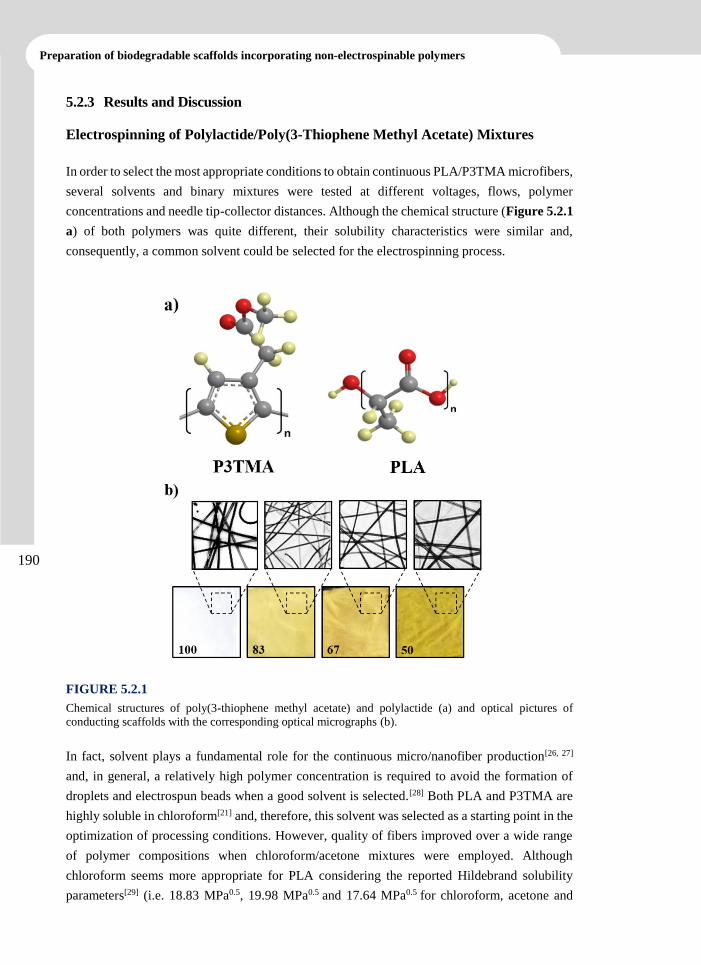
190
Preparation of biodegradable scaffolds incorporating non-electrospinable polymers
5.2.3 Results and Discussion
Electrospinning of Polylactide/Poly(3-Thiophene Methyl Acetate) Mixtures
In order to select the most appropriate conditions to obtain continuous PLA/P3TMA microfibers,
several solvents and binary mixtures were tested at different voltages, flows, polymer
concentrations and needle tip-collector distances. Although the chemical structure (Figure 5.2.1
a) of both polymers was quite different, their solubility characteristics were similar and,
consequently, a common solvent could be selected for the electrospinning process.
FIGURE 5.2.1
Chemical structures of poly(3-thiophene methyl acetate) and polylactide (a) and optical pictures of
conducting scaffolds with the corresponding optical micrographs (b).
In fact, solvent plays a fundamental role for the continuous micro/nanofiber production[26, 27]
and, in general, a relatively high polymer concentration is required to avoid the formation of
droplets and electrospun beads when a good solvent is selected.[28] Both PLA and P3TMA are
highly soluble in chloroform[21] and, therefore, this solvent was selected as a starting point in the
optimization of processing conditions. However, quality of fibers improved over a wide range
of polymer compositions when chloroform/acetone mixtures were employed. Although
chloroform seems more appropriate for PLA considering the reported Hildebrand solubility
parameters[29] (i.e. 18.83 MPa0.5, 19.98 MPa0.5 and 17.64 MPa0.5 for chloroform, acetone and
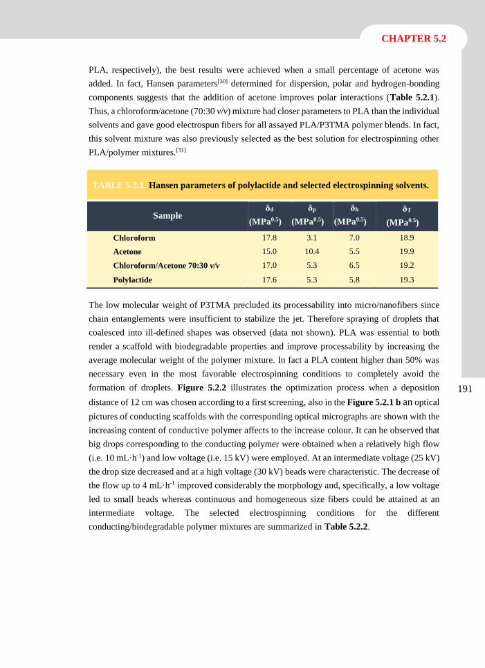
191
CHAPTER 5.2
PLA, respectively), the best results were achieved when a small percentage of acetone was
added. In fact, Hansen parameters[30] determined for dispersion, polar and hydrogen-bonding
components suggests that the addition of acetone improves polar interactions (Table 5.2.1).
Thus, a chloroform/acetone (70:30 v/v) mixture had closer parameters to PLA than the individual
solvents and gave good electrospun fibers for all assayed PLA/P3TMA polymer blends. In fact,
this solvent mixture was also previously selected as the best solution for electrospinning other
PLA/polymer mixtures.[31]
The low molecular weight of P3TMA precluded its processability into micro/nanofibers since
chain entanglements were insufficient to stabilize the jet. Therefore spraying of droplets that
coalesced into ill-defined shapes was observed (data not shown). PLA was essential to both
render a scaffold with biodegradable properties and improve processability by increasing the
average molecular weight of the polymer mixture. In fact a PLA content higher than 50% was
necessary even in the most favorable electrospinning conditions to completely avoid the
formation of droplets. Figure 5.2.2 illustrates the optimization process when a deposition
distance of 12 cm was chosen according to a first screening, also in the Figure 5.2.1 b an optical
pictures of conducting scaffolds with the corresponding optical micrographs are shown with the
increasing content of conductive polymer affects to the increase colour. It can be observed that
big drops corresponding to the conducting polymer were obtained when a relatively high flow
(i.e. 10 mL·h-1) and low voltage (i.e. 15 kV) were employed. At an intermediate voltage (25 kV)
the drop size decreased and at a high voltage (30 kV) beads were characteristic. The decrease of
the flow up to 4 mL·h-1 improved considerably the morphology and, specifically, a low voltage
led to small beads whereas continuous and homogeneous size fibers could be attained at an
intermediate voltage. The selected electrospinning conditions for the different
conducting/biodegradable polymer mixtures are summarized in Table 5.2.2.
TABLE 5.2.1. Hansen parameters of polylactide and selected electrospinning solvents.
Sample δd
(MPa0.5)
δp
(MPa0.5)
δh
(MPa0.5)
δT
(MPa0.5)
Chloroform 17.8 3.1 7.0 18.9
Acetone 15.0 10.4 5.5 19.9
Chloroform/Acetone 70:30 v/v 17.0 5.3 6.5 19.2
Polylactide 17.6 5.3 5.8 19.3
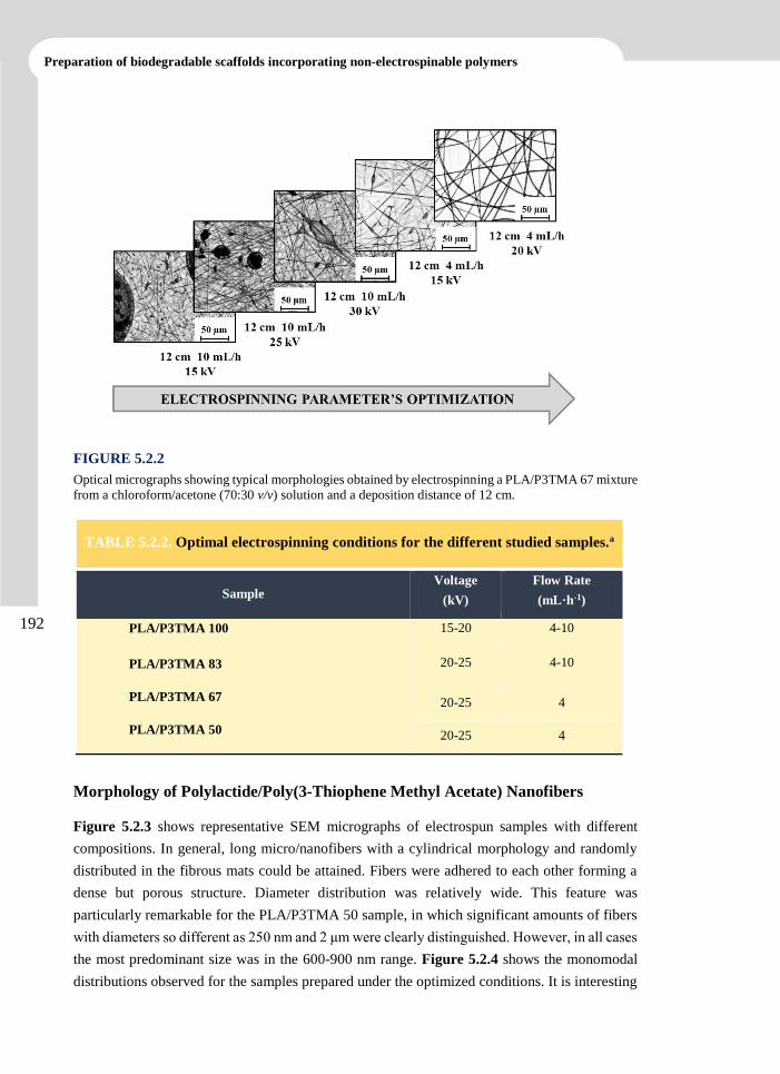
192
Preparation of biodegradable scaffolds incorporating non-electrospinable polymers
FIGURE 5.2.2
Optical micrographs showing typical morphologies obtained by electrospinning a PLA/P3TMA 67 mixture
from a chloroform/acetone (70:30 v/v) solution and a deposition distance of 12 cm.
Morphology of Polylactide/Poly(3-Thiophene Methyl Acetate) Nanofibers
Figure 5.2.3 shows representative SEM micrographs of electrospun samples with different
compositions. In general, long micro/nanofibers with a cylindrical morphology and randomly
distributed in the fibrous mats could be attained. Fibers were adhered to each other forming a
dense but porous structure. Diameter distribution was relatively wide. This feature was
particularly remarkable for the PLA/P3TMA 50 sample, in which significant amounts of fibers
with diameters so different as 250 nm and 2 μm were clearly distinguished. However, in all cases
the most predominant size was in the 600-900 nm range. Figure 5.2.4 shows the monomodal
distributions observed for the samples prepared under the optimized conditions. It is interesting
TABLE 5.2.2. Optimal electrospinning conditions for the different studied samples.a
Sample Voltage
(kV)
Flow Rate
(mL·h-1)
PLA/P3TMA 100 15-20 4-10
PLA/P3TMA 83 20-25 4-10
PLA/P3TMA 67 20-25 4
PLA/P3TMA 50 20-25 4
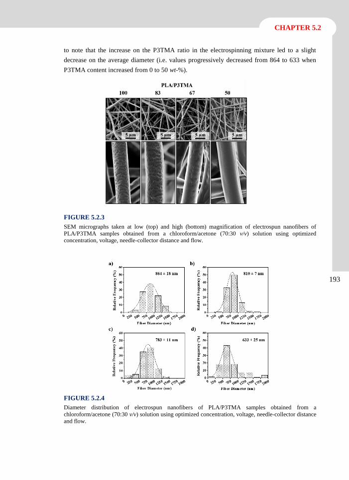
193
CHAPTER 5.2
to note that the increase on the P3TMA ratio in the electrospinning mixture led to a slight
decrease on the average diameter (i.e. values progressively decreased from 864 to 633 when
P3TMA content increased from 0 to 50 wt-%).
FIGURE 5.2.3
SEM micrographs taken at low (top) and high (bottom) magnification of electrospun nanofibers of
PLA/P3TMA samples obtained from a chloroform/acetone (70:30 v/v) solution using optimized
concentration, voltage, needle-collector distance and flow.
FIGURE 5.2.4
Diameter distribution of electrospun nanofibers of PLA/P3TMA samples obtained from a
chloroform/acetone (70:30 v/v) solution using optimized concentration, voltage, needle-collector distance
and flow.
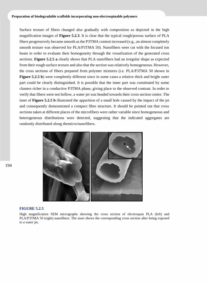
194
Preparation of biodegradable scaffolds incorporating non-electrospinable polymers
Surface texture of fibers changed also gradually with composition as depicted in the high
magnification images of Figure 5.2.3. It is clear that the typical rough/porous surface of PLA
fibers progressively became smooth as the P3TMA content increased (e.g., an almost completely
smooth texture was observed for PLA/P3TMA 50). Nanofibers were cut with the focused ion
beam in order to evaluate their homogeneity through the visualization of the generated cross
sections. Figure 5.2.5 a clearly shows that PLA nanofibers had an irregular shape as expected
from their rough surface texture and also that the section was relatively homogeneous. However,
the cross sections of fibers prepared from polymer mixtures (i.e. PLA/P3TMA 50 shown in
Figure 5.2.5 b) were completely different since in some cases a relative thick and bright outer
part could be clearly distinguished. It is possible that the inner part was constituted by some
clusters richer in a conductive P3TMA phase, giving place to the observed contrast. In order to
verify that fibers were not hollow, a water jet was headed towards their cross section centre. The
inset of Figure 5.2.5 b illustrated the apparition of a small hole caused by the impact of the jet
and consequently demonstrated a compact fibre structure. It should be pointed out that cross
sections taken at different places of the microfibers were rather variable since homogeneous and
heterogeneous distributions were detected, suggesting that the indicated aggregates are
randomly distributed along themicro/nanofibers.
FIGURE 5.2.5
High magnification SEM micrographs showing the cross section of electrospun PLA (left) and
PLA/P3TMA 50 (right) nanofibers. The inset shows the corresponding cross section after being exposed
to a water jet.
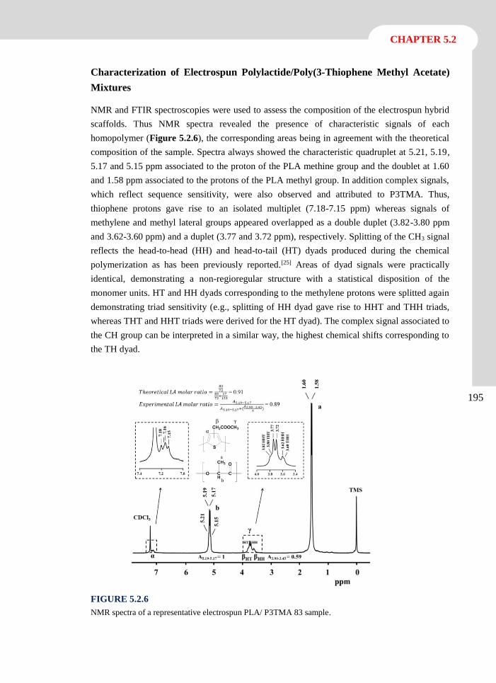
195
CHAPTER 5.2
Characterization of Electrospun Polylactide/Poly(3-Thiophene Methyl Acetate)
Mixtures
NMR and FTIR spectroscopies were used to assess the composition of the electrospun hybrid
scaffolds. Thus NMR spectra revealed the presence of characteristic signals of each
homopolymer (Figure 5.2.6), the corresponding areas being in agreement with the theoretical
composition of the sample. Spectra always showed the characteristic quadruplet at 5.21, 5.19,
5.17 and 5.15 ppm associated to the proton of the PLA methine group and the doublet at 1.60
and 1.58 ppm associated to the protons of the PLA methyl group. In addition complex signals,
which reflect sequence sensitivity, were also observed and attributed to P3TMA. Thus,
thiophene protons gave rise to an isolated multiplet (7.18-7.15 ppm) whereas signals of
methylene and methyl lateral groups appeared overlapped as a double duplet (3.82-3.80 ppm
and 3.62-3.60 ppm) and a duplet (3.77 and 3.72 ppm), respectively. Splitting of the CH3 signal
reflects the head-to-head (HH) and head-to-tail (HT) dyads produced during the chemical
polymerization as has been previously reported.[25] Areas of dyad signals were practically
identical, demonstrating a non-regioregular structure with a statistical disposition of the
monomer units. HT and HH dyads corresponding to the methylene protons were splitted again
demonstrating triad sensitivity (e.g., splitting of HH dyad gave rise to HHT and THH triads,
whereas THT and HHT triads were derived for the HT dyad). The complex signal associated to
the CH group can be interpreted in a similar way, the highest chemical shifts corresponding to
the TH dyad.
FIGURE 5.2.6
NMR spectra of a representative electrospun PLA/ P3TMA 83 sample.
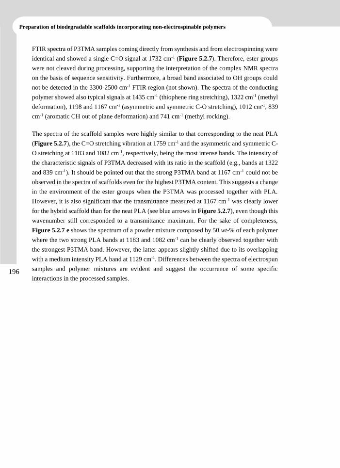
196
Preparation of biodegradable scaffolds incorporating non-electrospinable polymers
FTIR spectra of P3TMA samples coming directly from synthesis and from electrospinning were
identical and showed a single C=O signal at 1732 cm-1 (Figure 5.2.7). Therefore, ester groups
were not cleaved during processing, supporting the interpretation of the complex NMR spectra
on the basis of sequence sensitivity. Furthermore, a broad band associated to OH groups could
not be detected in the 3300-2500 cm-1 FTIR region (not shown). The spectra of the conducting
polymer showed also typical signals at 1435 cm-1 (thiophene ring stretching), 1322 cm-1 (methyl
deformation), 1198 and 1167 cm-1 (asymmetric and symmetric C-O stretching), 1012 cm-1, 839
cm-1 (aromatic CH out of plane deformation) and 741 cm-1 (methyl rocking).
The spectra of the scaffold samples were highly similar to that corresponding to the neat PLA
(Figure 5.2.7), the C=O stretching vibration at 1759 cm-1 and the asymmetric and symmetric C-
O stretching at 1183 and 1082 cm-1, respectively, being the most intense bands. The intensity of
the characteristic signals of P3TMA decreased with its ratio in the scaffold (e.g., bands at 1322
and 839 cm-1). It should be pointed out that the strong P3TMA band at 1167 cm-1 could not be
observed in the spectra of scaffolds even for the highest P3TMA content. This suggests a change
in the environment of the ester groups when the P3TMA was processed together with PLA.
However, it is also significant that the transmittance measured at 1167 cm-1 was clearly lower
for the hybrid scaffold than for the neat PLA (see blue arrows in Figure 5.2.7), even though this
wavenumber still corresponded to a transmittance maximum. For the sake of completeness,
Figure 5.2.7 e shows the spectrum of a powder mixture composed by 50 wt-% of each polymer
where the two strong PLA bands at 1183 and 1082 cm-1 can be clearly observed together with
the strongest P3TMA band. However, the latter appears slightly shifted due to its overlapping
with a medium intensity PLA band at 1129 cm-1. Differences between the spectra of electrospun
samples and polymer mixtures are evident and suggest the occurrence of some specific
interactions in the processed samples.
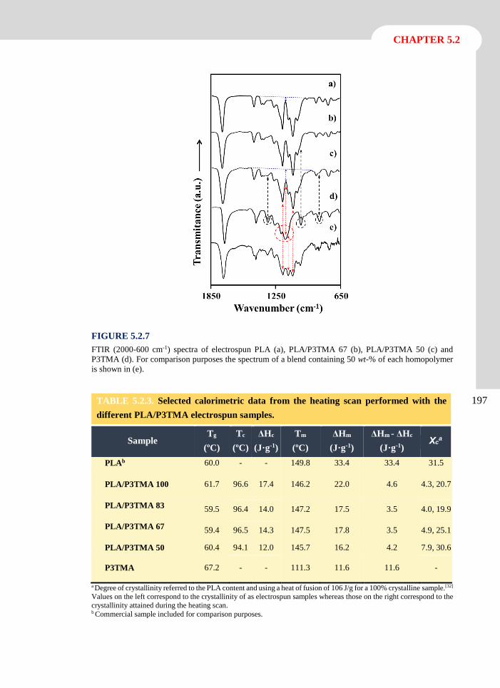
197
CHAPTER 5.2
FIGURE 5.2.7
FTIR (2000-600 cm-1) spectra of electrospun PLA (a), PLA/P3TMA 67 (b), PLA/P3TMA 50 (c) and
P3TMA (d). For comparison purposes the spectrum of a blend containing 50 wt-% of each homopolymer
is shown in (e).
a Degree of crystallinity referred to the PLA content and using a heat of fusion of 106 J/g for a 100% crystalline sample.[32] Values on the left correspond to the crystallinity of as electrospun samples whereas those on the right correspond to the
crystallinity attained during the heating scan. b Commercial sample included for comparison purposes.
TABLE 5.2.3. Selected calorimetric data from the heating scan performed with the
different PLA/P3TMA electrospun samples.
Sample Tg
(ºC)
Tc
(ºC)
ΔHc
(J·g-1)
Tm
(ºC)
ΔHm
(J·g-1)
ΔHm - ΔHc
(J·g-1) Χc
a
PLAb 60.0 - - 149.8 33.4 33.4 31.5
PLA/P3TMA 100 61.7 96.6 17.4 146.2 22.0 4.6 4.3, 20.7
PLA/P3TMA 83 59.5 96.4 14.0 147.2 17.5 3.5 4.0, 19.9
PLA/P3TMA 67 59.4 96.5 14.3 147.5 17.8 3.5 4.9, 25.1
PLA/P3TMA 50 60.4 94.1 12.0 145.7 16.2 4.2 7.9, 30.6
P3TMA 67.2 - - 111.3 11.6 11.6 -
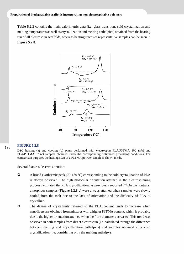
198
Preparation of biodegradable scaffolds incorporating non-electrospinable polymers
Table 5.2.3 contains the main calorimetric data (i.e. glass transition, cold crystallization and
melting temperatures as well as crystallization and melting enthalpies) obtained from the heating
run of all electrospun scaffolds, whereas heating traces of representative samples can be seen in
Figure 5.2.8.
FIGURE 5.2.8
DSC heating (a) and cooling (b) scans performed with electrospun PLA/P3TMA 100 (a,b) and
PLA/P3TMA 67 (c) samples obtained under the corresponding optimized processing conditions. For
comparison purposes the heating scan of a P3TMA powder sample is shown in (d).
Several features deserve attention:
A broad exothermic peak (70-130 ºC) corresponding to the cold crystallization of PLA
is always observed. The high molecular orientation attained in the electrospinning
process facilitated the PLA crystallization, as previously reported.[32] On the contrary,
amorphous samples (Figure 5.2.8 c) were always attained when samples were slowly
cooled from the melt due to the lack of orientation and the difficulty of PLA to
crystallize.
The degree of crystallinity referred to the PLA content tends to increase when
nanofibers are obtained from mixtures with a higher P3TMA content, which is probably
due to the higher orientation attained when the fibre diameter decreased. This trend was
observed in both samples from direct electrospun (i.e. calculated through the difference
between melting and crystallization enthalpies) and samples obtained after cold
crystallization (i.e. considering only the melting enthalpy).
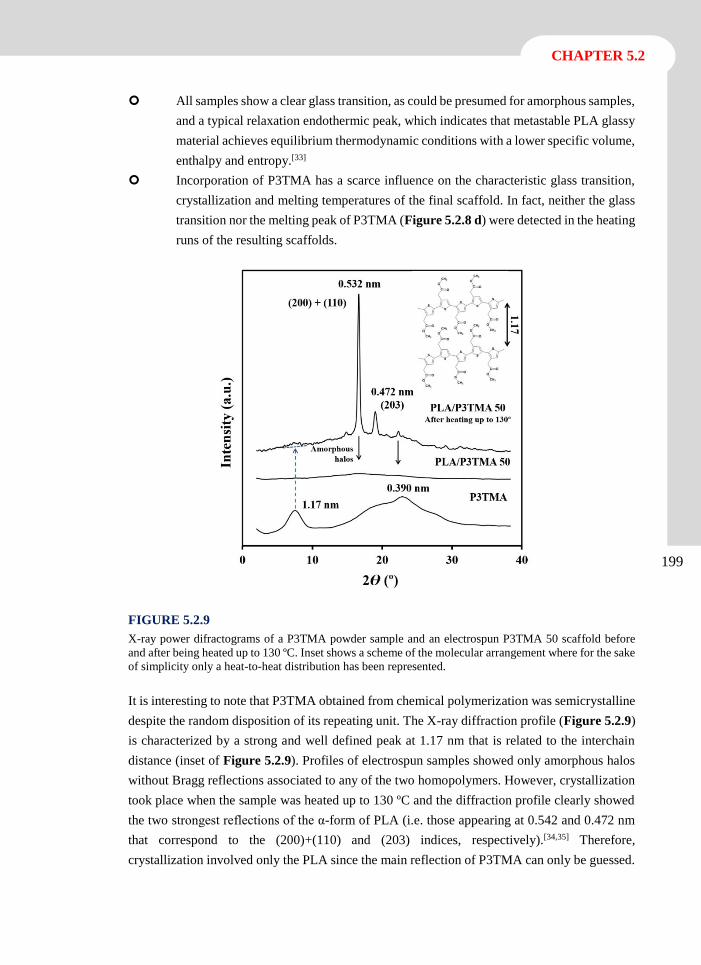
199
CHAPTER 5.2
All samples show a clear glass transition, as could be presumed for amorphous samples,
and a typical relaxation endothermic peak, which indicates that metastable PLA glassy
material achieves equilibrium thermodynamic conditions with a lower specific volume,
enthalpy and entropy.[33]
Incorporation of P3TMA has a scarce influence on the characteristic glass transition,
crystallization and melting temperatures of the final scaffold. In fact, neither the glass
transition nor the melting peak of P3TMA (Figure 5.2.8 d) were detected in the heating
runs of the resulting scaffolds.
FIGURE 5.2.9
X-ray power difractograms of a P3TMA powder sample and an electrospun P3TMA 50 scaffold before
and after being heated up to 130 ºC. Inset shows a scheme of the molecular arrangement where for the sake
of simplicity only a heat-to-heat distribution has been represented.
It is interesting to note that P3TMA obtained from chemical polymerization was semicrystalline
despite the random disposition of its repeating unit. The X-ray diffraction profile (Figure 5.2.9)
is characterized by a strong and well defined peak at 1.17 nm that is related to the interchain
distance (inset of Figure 5.2.9). Profiles of electrospun samples showed only amorphous halos
without Bragg reflections associated to any of the two homopolymers. However, crystallization
took place when the sample was heated up to 130 ºC and the diffraction profile clearly showed
the two strongest reflections of the α-form of PLA (i.e. those appearing at 0.542 and 0.472 nm
that correspond to the (200)+(110) and (203) indices, respectively).[34,35] Therefore,
crystallization involved only the PLA since the main reflection of P3TMA can only be guessed.
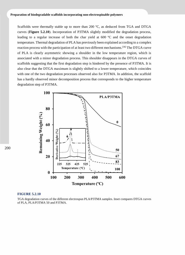
200
Preparation of biodegradable scaffolds incorporating non-electrospinable polymers
Scaffolds were thermally stable up to more than 200 ºC, as deduced from TGA and DTGA
curves (Figure 5.2.10). Incorporation of P3TMA slightly modified the degradation process,
leading to a regular increase of both the char yield at 600 ºC and the onset degradation
temperature. Thermal degradation of PLA has previously been explained according to a complex
reaction process with the participation of at least two different mechanisms.[36] The DTGA curve
of PLA is clearly asymmetric showing a shoulder in the low temperature region, which is
associated with a minor degradation process. This shoulder disappears in the DTGA curves of
scaffolds suggesting that the first degradation step is hindered by the presence of P3TMA. It is
also clear that the DTGA maximum is slightly shifted to a lower temperature, which coincides
with one of the two degradation processes observed also for P3TMA. In addition, the scaffold
has a hardly observed minor decomposition process that corresponds to the higher temperature
degradation step of P3TMA.
FIGURE 5.2.10
TGA degradation curves of the different electrospun PLA/P3TMA samples. Inset compares DTGA curves
of PLA, PLA/P3TMA 50 and P3TMA.
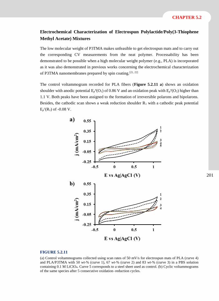
201
CHAPTER 5.2
Electrochemical Characterization of Electrospun Polylactide/Poly(3-Thiophene
Methyl Acetate) Mixtures
The low molecular weight of P3TMA makes unfeasible to get electrospun mats and to carry out
the corresponding CV measurements from the neat polymer. Processability has been
demonstrated to be possible when a high molecular weight polymer (e.g., PLA) is incorporated
as it was also demonstrated in previous works concerning the electrochemical characterization
of P3TMA nanomembranes prepared by spin coating.[21, 22]
The control voltammogram recorded for PLA fibers (Figure 5.2.11 a) shows an oxidation
shoulder with anodic potential Epa(O1) of 0.86 V and an oxidation peak with Ep
a(O2) higher than
1.1 V. Both peaks have been assigned to the formation of irreversible polarons and bipolarons.
Besides, the cathodic scan shows a weak reduction shoulder R1 with a cathodic peak potential
Epc(R1) of -0.08 V.
FIGURE 5.2.11
(a) Control voltammograms collected using scan rates of 50 mV/s for electrospun mats of PLA (curve 4)
and PLA/P3TMA with 50 wt-% (curve 1), 67 wt-% (curve 2) and 83 wt-% (curve 3) in a PBS solution
containing 0.1 M LiClO4. Curve 5 corresponds to a steel sheet used as control. (b) Cyclic voltammograms
of the same species after 5 consecutive oxidation–reduction cycles.
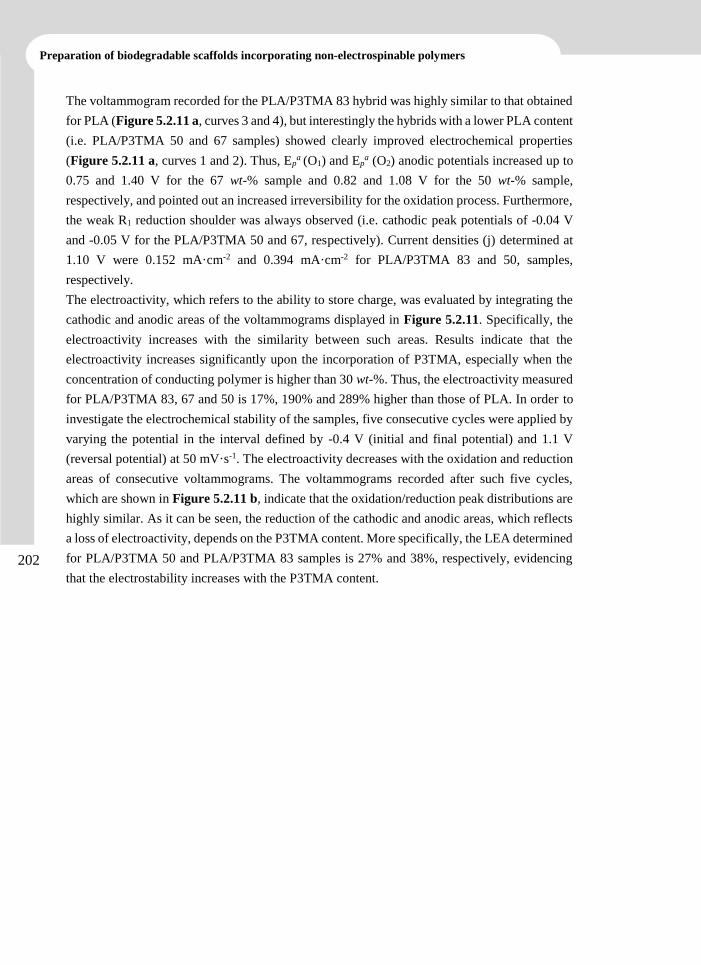
202
Preparation of biodegradable scaffolds incorporating non-electrospinable polymers
The voltammogram recorded for the PLA/P3TMA 83 hybrid was highly similar to that obtained
for PLA (Figure 5.2.11 a, curves 3 and 4), but interestingly the hybrids with a lower PLA content
(i.e. PLA/P3TMA 50 and 67 samples) showed clearly improved electrochemical properties
(Figure 5.2.11 a, curves 1 and 2). Thus, Epa (O1) and Ep
a (O2) anodic potentials increased up to
0.75 and 1.40 V for the 67 wt-% sample and 0.82 and 1.08 V for the 50 wt-% sample,
respectively, and pointed out an increased irreversibility for the oxidation process. Furthermore,
the weak R1 reduction shoulder was always observed (i.e. cathodic peak potentials of -0.04 V
and -0.05 V for the PLA/P3TMA 50 and 67, respectively). Current densities (j) determined at
1.10 V were 0.152 mA·cm-2 and 0.394 mA·cm-2 for PLA/P3TMA 83 and 50, samples,
respectively.
The electroactivity, which refers to the ability to store charge, was evaluated by integrating the
cathodic and anodic areas of the voltammograms displayed in Figure 5.2.11. Specifically, the
electroactivity increases with the similarity between such areas. Results indicate that the
electroactivity increases significantly upon the incorporation of P3TMA, especially when the
concentration of conducting polymer is higher than 30 wt-%. Thus, the electroactivity measured
for PLA/P3TMA 83, 67 and 50 is 17%, 190% and 289% higher than those of PLA. In order to
investigate the electrochemical stability of the samples, five consecutive cycles were applied by
varying the potential in the interval defined by -0.4 V (initial and final potential) and 1.1 V
(reversal potential) at 50 mV·s-1. The electroactivity decreases with the oxidation and reduction
areas of consecutive voltammograms. The voltammograms recorded after such five cycles,
which are shown in Figure 5.2.11 b, indicate that the oxidation/reduction peak distributions are
highly similar. As it can be seen, the reduction of the cathodic and anodic areas, which reflects
a loss of electroactivity, depends on the P3TMA content. More specifically, the LEA determined
for PLA/P3TMA 50 and PLA/P3TMA 83 samples is 27% and 38%, respectively, evidencing
that the electrostability increases with the P3TMA content.
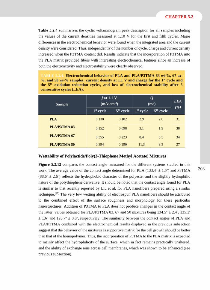
203
CHAPTER 5.2
Table 5.2.4 summarizes the cyclic voltammogram peak description for all samples including
the values of the current densities measured at 1.10 V for the first and fifth cycles. Major
differences in the electrochemical behavior were found when the integrated area and the current
density were considered. Thus, independently of the number of cycle, charge and current density
increased when the P3TMA content did. Results indicate that the incorporation of P3TMA into
the PLA matrix provided fibers with interesting electrochemical features since an increase of
both the electroactivity and electrostability were clearly observed.
Wettability of Polylactide/Poly(3-Thiophene Methyl Acetate) Mixtures
Figure 5.2.12 compares the contact angle measured for the different systems studied in this
work. The average value of the contact angle determined for PLA (133.4º ± 1.5º) and P3TMA
(88.6º ± 2.6º) reflects the hydrophobic character of the polyester and the slightly hydrophilic
nature of the polythiophene derivative. It should be noted that the contact angle found for PLA
is similar to that recently reported by Liu et al. for PLA nanofibers prepared using a similar
technique.[37] The very low wetting ability of electrospun PLA nanofibers should be attributed
to the combined effect of the surface roughness and morphology for these particular
nanostructures. Addition of P3TMA to PLA does not produce changes in the contact angle of
the latter, values obtained for PLA/P3TMA 83, 67 and 50 mixtures being 134.5º ± 2.4º, 135.1º
± 1.6º and 128.7º ± 0.8º, respectively. The similarity between the contact angles of PLA and
PLA/P3TMA combined with the electrochemical results displayed in the previous subsection
suggest that the behavior of the mixtures as supportive matrix for the cell growth should be better
than that of the homopolymer. Thus, the incorporation of P3TMA to the PLA matrix is expected
to mainly affect the hydrophilicity of the surface, which in fact remains practically unaltered,
and the ability of exchange ions across cell membranes, which was shown to be enhanced (see
previous subsection).
TABLE 5.2.4. Electrochemical behavior of PLA and PLA/P3TMA 83 wt-%, 67 wt-
%, and 50 wt-% samples: current density at 1.1 V and charge for the 1st cycle and
the 5th oxidation-reduction cycles, and loss of electrochemical stability after 5
consecutive cycles (LEA).
Sample
j at 1.1 V
(mA·cm-2)
Q
(mc) LEA
(%) 1st cycle 5th cycle 1st cycle 5th cycle
PLA 0.138 0.102 2.9 2.0 31
PLA/P3TMA 83 0.152 0.098 3.1 1.9 38
PLA/P3TMA 67 0.355 0.223 8.4 5.5 34
PLA/P3TMA 50 0.394 0.290 11.3 8.3 27
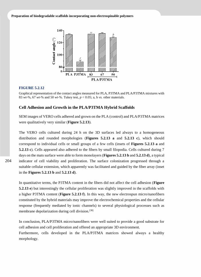
204
Preparation of biodegradable scaffolds incorporating non-electrospinable polymers
FIGURE 5.2.12
Graphical representation of the contact angles measured for PLA, P3TMA and PLA/P3TMA mixtures with
83 wt-%, 67 wt-% and 50 wt-%. Tukey test, p < 0.05; a, b vs. other materials.
Cell Adhesion and Growth in the PLA/P3TMA Hybrid Scaffolds
SEM images of VERO cells adhered and grown on the PLA (control) and PLA/P3TMA matrices
were qualitatively very similar (Figure 5.2.13).
The VERO cells cultured during 24 h on the 3D surfaces led always to a homogeneous
distribution and rounded morphologies (Figures 5.2.13 a and 5.2.13 c), which should
correspond to individual cells or small groups of a few cells (insets of Figures 5.2.13 a and
5.2.13 c). Cells appeared also adhered to the fibers by small filopodia. Cells cultured during 7
days on the mats surface were able to form monolayers (Figures 5.2.13 b and 5.2.13 d), a typical
indicator of cell viability and proliferation. The surface colonization progressed through a
suitable cellular extension, which apparently was facilitated and guided by the fiber array (inset
in the Figures 5.2.13 b and 5.2.13 d).
In quantitative terms, the P3TMA content in the fibers did not affect the cell adhesion (Figure
5.2.13 e) but interestingly the cellular proliferation was slightly improved in the scaffolds with
a higher P3TMA content (Figure 5.2.13 f). In this way, the new electrospun micro/nanofibers
constituted by the hybrid materials may improve the electrochemical properties and the cellular
response (frequently mediated by ionic channels) to several physiological processes such as
membrane depolarization during cell division.[38]
In conclusion, PLA/P3TMA micro/nanofibers were well suited to provide a good substrate for
cell adhesion and cell proliferation and offered an appropriate 3D environment.
Furthermore, cells developed in the PLA/P3TMA matrices showed always a healthy
morphology.
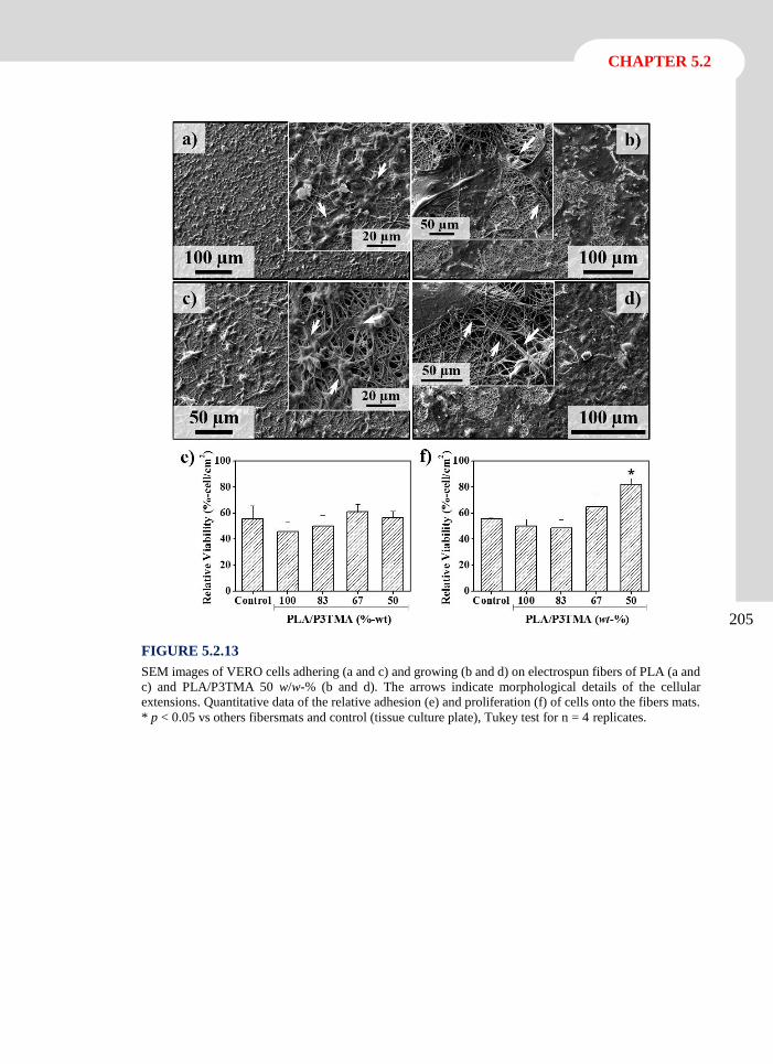
205
CHAPTER 5.2
FIGURE 5.2.13
SEM images of VERO cells adhering (a and c) and growing (b and d) on electrospun fibers of PLA (a and
c) and PLA/P3TMA 50 w/w-% (b and d). The arrows indicate morphological details of the cellular
extensions. Quantitative data of the relative adhesion (e) and proliferation (f) of cells onto the fibers mats.
* p < 0.05 vs others fibersmats and control (tissue culture plate), Tukey test for n = 4 replicates.
206
Preparation of biodegradable scaffolds incorporating non-electrospinable polymers
5.2.4 Conclusions
Mixtures of PLA and P3TMA can be effectively electrospun to render hybrid micro/nanofibers
that combine the biocompatibility and electrochemical properties of each homopolymer.
Processing conditions (solvent, concentration, flow, voltage, collector distance) were optimized
to allow incorporating up to 50 wt-% of P3TMA and keeping continuous fiber morphology.
Increasing contents of the conducting polymer gave rise to smoother fiber surfaces, smaller
diameters, higher orientation of PLA chains and the sporadic formation of cluster aggregates
inside the fibers.
Incorporation of P3TMA into the PLA matrix provided an increase of the electroactivity and
electrostability, both charge and current intensity clearly increasing with the P3TMA content.
Current density determined at 1.10 V was as high as 0.394 mA·cm-2 for fiber mats containing
50 wt-% of P3TMA while the electroactivity of such hybrid was 289% higher than that of PLA.
The electrostability of samples was probed since the average charge loss was less than 27% after
performing five consecutive oxidation-reduction cycles. New hybrid scaffolds were good
substrates for cell adhesion and cell proliferation and even the last was clearly enhanced respect
to the parent PLA scaffolds. Cellular response to physiological processes seemed to be improved
by the incorporation of P3TMA.
207
CHAPTER 5.2
5.2.5 References
[1] Y. Wei, P.I. Lelkes, A.G. MacDiarmid, E. Guterman, S. Cheng, K. Palouian, Peking
University Press, Beijing, 2004.
[2] P.R. Bidez, S.X. Li, A.G. MacDiarmid, E.C. Venancio, Y. Wei, P.I. Lelkes, J Biomat
Sci-Polym E, 17 (2006) 199-212.
[3] A. Kotwal, C.E. Schmidt, Biomaterials, 22 (2001) 1055-1064.
[4] R.F. Valentini, CRC Press LLC, Boca Raton, 2000.
[5] D.H. Reneker, I. Chun, Nanotechnology, 7 (1996) 216-223.
[6] A. Frenot, I.S. Chronakis, Curr Opin Colloid In, 8 (2003) 64-75.
[7] Y. Dzenis, Science, 304 (2004) 1917-1919.
[8] D. Li, Y.N. Xia, Adv Mater, 16 (2004) 1151-1170.
[9] K. Jayaraman, M. Kotaki, Y.Z. Zhang, X.M. Mo, S. Ramakrishna, J Nanosci
Nanotechno, 4 (2004) 52-65.
[10] R. Dersch, M. Steinhart, U. Boudriot, A. Greiner, J.H. Wendorff, Polym Advan Technol,
16 (2005) 276-282.
[11] J.M. Deitzel, J.D. Kleinmeyer, J.K. Hirvonen, N.C.B. Tan, Polymer, 42 (2001) 8163-
8170.
[12] M.Y. Li, Y. Guo, Y. Wei, A.G. MacDiarmid, P.I. Lelkes, Biomaterials, 27 (2006) 2705-
2715.
[13] P.H.S. Picciani, E.S. Medeiros, Z.L. Pan, W.J. Orts, L.H.C. Mattoso, B.G. Soares, J Appl
Polym Sci, 112 (2009) 744-753.
[14] K.D. McKeon, A. Lewis, J.W. Freeman, J Appl Polym Sci, 115 (2010) 1566-1572.
[15] M. Gizdavic-Nikolaidis, S. Ray, J.R. Bennett, A.J. Easteal, R.P. Cooney, Macromol
Biosci, 10 (2010) 1424-1431.
[16] D. Kai, M.P. Prabhakaran, G.R. Jin, S. Ramakrishna, J Biomed Mater Res A, 99A (2011)
376-385.
[17] J. Roncali, Chem Rev, 97 (1997) 173-205.
[18] O. Bertran, E. Armelin, F. Estrany, A. Gomes, J. Torras, C. Aleman, J Phys Chem B, 114
(2010) 6281-6290.
[19] S. Lee, G.D. Moon, U. Jeong, J Mater Chem, 19 (2009) 743-748.
208
Preparation of biodegradable scaffolds incorporating non-electrospinable polymers
[20] A. Subramanian, U.M. Krishnan, S. Sethuraman, J Mater Sci-Mater M, 23 (2012) 1797-
1809.
[21] E. Armelin, A.L. Gomes, M.M. Perez-Madrigal, J. Puiggali, L. Franco, L.J. del Valle, A.
Rodriguez-Galan, J.S.D. Campos, N. Ferrer-Anglada, C. Aleman, J Mater Chem, 22
(2012) 585-594.
[22] A.L. Gomes, M.B.P. Zakia, J. Filho, E. Armelin, C. Aleman, J.S.D. Campos, Polym
Chem-Uk, 3 (2012) 1334-1343.
[23] M.M. Perez-Madrigal, E. Armelin, L.J. del Valle, F. Estrany, C. Aleman, Polym Chem-
Uk, 3 (2012) 979-991.
[24] M.M. Perez-Madrigal, M.I. Giannotti, G. Oncins, L. Franco, E. Armelin, J. Puiggali, F.
Sanz, L.J. del Valle, C. Aleman, Polym Chem-Uk, 4 (2013) 568-583.
[25] B.S. Kim, L. Chen, J.P. Gong, Y. Osada, Macromolecules, 32 (1999) 3964-3969.
[26] S.V. Fridrikh, J.H. Yu, M.P. Brenner, G.C. Rutledge, Phys Rev Lett, 90 (2003) 144502-
144504.
[27] M.G. McKee, C.L. Elkins, T.E. Long, Polymer, 45 (2004) 8705-8715.
[28] C.J. Luo, M. Nangrejo, M. Edirisinghe, Polymer, 51 (2010) 1654-1662.
[29] D.W. van Krevelen, Elsevier, Amsterdam, 1990.
[30] C.M. Hansen, CRC Press, Florida, 2000.
[31] A. Agrawal, A.D. Saran, S.S. Rath, A. Khanna, Polymer, 45 (2004) 8603-8612.
[32] L.J. del Valle, R. Camps, A. Diaz, L. Franco, A. Rodriguez-Galan, J. Puiggali, J Polym
Res, 18 (2011) 1903-1917.
[33] J.R. Sarasua, R.E. Prud'homme, M. Wisniewski, A. Le Borgne, N. Spassky,
Macromolecules, 31 (1998) 3895-3905.
[34] P. De Santis, A.J. Kovacs, Biopolymers, 6 (1968) 299-306.
[35] W. Hoogsteen, A.R. Postema, A.J. Pennings, G. Tenbrinke, P. Zugenmaier,
Macromolecules, 23 (1990) 634-642.
[36] K. Chrissafis, Thermochim Acta, 511 (2010) 163-167.
[37] W.Y. Liu, J.C. Wei, Y.W. Chen, P. Huo, Y. Wei, Acs Appl Mater Inter, 5 (2013) 680-
685.
[38] M.H. Bolin, K. Svennersten, X.J. Wang, I.S. Chronakis, A. Richter-Dahlfors, E.W.H.
Jager, M. Berggren, Sensor Actuat B-Chem, 142 (2009) 451-456
6.
Biodegradable polymer
matrices incorporating
polyethylene glycol as a
sacrificial polymer


The work described in this chapter previously appeared in:
[1] Llorens, E.; del Valle, L. J.; Ferran, R.; S.; Rodríguez-Galán, A.; Puiggalí, J. J. Polym. Res. 2014, 21
(2), 360-375.
[2] Llorens, E.; Bellmunt, S.; del Valle, L.; Puiggalí, J. J. Polym. Res. Submitted.
[3] Llorens, E.; Ibañez, H.; del Valle, L.; Puiggalí, J. Mater. Sci. Eng. C. Submitted.

Scaffolds with Tuneable Hydrophilicity from
Electrospun Microfibers of Polylactide and
Poly(Ethylene Glycol) Mixtures: Morphology,
Drug Release Behavior and Biocompatibility
Electrospun mats were obtained from different mixtures of polylactide
(PLA) and poly(ethylene glycol) (PEG). Processing conditions were
optimized for all compositions and the resulting micro/nanofiber
morphologies (i.e. diameter size and surface texture) were characterized by
scanning electron microscopy (SEM). NMR and FTIR spectroscopies were
employed to verify the final composition and thermal properties were
evaluated by DSC and TGA. XPS spectroscopy revealed that PEG was
mainly deposited on the surface of electrospun micro/nanofibers, leading to
smooth textures. Interestingly, PLA/PEG scaffold solubility in ethanol was
very different to that in water, since a significant amount of PEG was
effectively retained in the PLA matrix after immersion in ethanol whereas
only a low level of PEG was retained in the PLA matrix after immersion in
water. The hydrophilicities of the scaffolds obtained from PLA/PEG
mixtures were consequently higher than that of the PLA, even after the
exposure to water.
As PEG can be used as a sacrificial polymer because of its high solubility
in water, it was possible to increase the porosity of PLA/PEG scaffolds.
PLA/PEG scaffolds loaded with triclosan (TCS) had very different release
profiles in hydrophilic (e.g., PBS) and hydrophobic (e.g., Sörensen/ethanol
(30:70 v/v) mixture) media, while differences were small between scaffolds
having different PLA/PEG ratios. TCS loaded scaffolds exhibited good
antibacterial properties for all compositions and allowed adhesion of
epithelial cells (i.e. MDCK and VERO). Significant differences in cell
proliferation were found between unloaded and TCS loaded scaffolds due to
the clear improvement of cell colonization by increasing PEG content.
6.1
Biodegradable polymer matrices incorporating polyethylenen glycol as a sacrificial polymer
214
6.1.1 Introduction
Scaffolds based on biodegradable and/or biocompatible polymers for tissue engineering
applications are receiving much attention because of their potential use as temporary templates
for cell seeding, migration, proliferation and differentiation prior to regeneration of the natural
extracellular matrix (ECM) or a biological functional tissue.[1-4] Several methodologies have
been developed to prepare suitable scaffold structures, including electrospinning techniques.[5,
6] This electrostatic process involves the use of a high voltage field to charge the surface of a
polymer solution droplet held at the end of a capillary tube and induce the ejection of a liquid
jet towards a grounded target (collector). Selection of appropriate experimental conditions for
a given polymer (i.e. solvent, polymer concentration and operational parameters such as
strength of the applied electric field, deposition distance and flow) can lead to fibers with
diameters ranging from several micrometers to a few nanometres in an extremely rapid process
(millisecond scale).[7-10]
The deposition of electrospun micro/nanofibers can give rise to interconnected porous
networks, which are interesting substrates for tissue regeneration and even for drug delivery. In
fact, these scaffolds have morphologies similar to the structures of natural ECM, as well as large
surface area-to-volume ratios that facilitate cell adhesion and proliferation, provide an ideal
porous structure for nutrient and metabolic waste exchange, and promote vascularization.[11]
Several biodegradable polymers coming from both synthetic and natural routes have been
successfully electrospun (e.g., polyglycolide,[12] polylactide,[12-15] polycaprolactone,[16]
collagen[17, 18] and chitosan[15, 18, 19]). Polylactide (PLA) (Figure 6.1.1 a) is one of the most
widely used materials in clinical applications due to the combination of interesting
characteristics like tuneable mechanical properties, degradation into natural metabolites,
biocompatibility and low cost. However, PLA has some problems associated with its inherent
hydrophobic nature which may reduce expression of phenotypic markers and hinder cell
attachment and proliferation.[20, 21] In order to solve this problem, chemical modifications (e.g.,
grafting hydrophilic moieties[22] or incorporating hydrophilic blocks[23] into the PLA main
chain) as well as the use of amphiphilic mixtures like its blends with poly(ethylene glycol)
(PEG) have been considered (Figure 6.1.1 a).[24-26] In fact, PEG is also widely employed in the
biomedical field due to its lack of toxicity, good biocompatibility and elimination from human
body when its molecular weight is low.[27]
Spasova et al.[24] were the first to prepare electrospun mats from chloroform solutions of PLA
and a maximum PEG content of 30 wt-%. Interestingly, the scaffolds with the highest PEG
content facilitated the arrangement of osteoblast-like cells in tissue-like structures. It was also
demonstrated that the incorporation of PEG can favor the electrospinning process and
particularly the production of regular and continuous fibers due to the reduction of solution
viscosity caused by the low molecular weight PEG.[25] Finally, it should be pointed out that
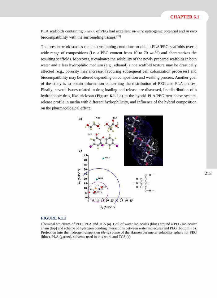
CHAPTER 6.1
215
PLA scaffolds containing 5 wt-% of PEG had excellent in-vitro osteogenic potential and in vivo
biocompatibility with the surrounding tissues.[26]
The present work studies the electrospinning conditions to obtain PLA/PEG scaffolds over a
wide range of compositions (i.e. a PEG content from 10 to 70 wt-%) and characterizes the
resulting scaffolds. Moreover, it evaluates the solubility of the newly prepared scaffolds in both
water and a less hydrophilic medium (e.g., ethanol) since scaffold texture may be drastically
affected (e.g., porosity may increase, favouring subsequent cell colonization processes) and
biocompatibility may be altered depending on composition and washing process. Another goal
of the study is to obtain information concerning the distribution of PEG and PLA phases.
Finally, several issues related to drug loading and release are discussed, i.e. distribution of a
hydrophobic drug like triclosan (Figure 6.1.1 a) in the hybrid PLA/PEG two-phase system,
release profile in media with different hydrophilicity, and influence of the hybrid composition
on the pharmacological effect.
FIGURE 6.1.1
Chemical structures of PEG, PLA and TCS (a). Coil of water molecules (blue) around a PEG molecular
chain (top) and scheme of hydrogen bonding interactions between water molecules and PEG (bottom) (b).
Projection into the hydrogen-dispersion (δh-δp) plane of the Hansen parameter solubility sphere for PEG
(blue), PLA (garnet), solvents used in this work and TCS (c).
Biodegradable polymer matrices incorporating polyethylenen glycol as a sacrificial polymer
216
6.1.2 Experimental Section
Materials
Polylactide (PLA), a product of Natureworks (polymer 2002D), was kindly supplied by Nupik
International (Polinyà, Spain). Poly(ethylene glycol) (PEG) of number average molecular
weights of 10.000 and 35.000 g·mol-1 were purchased from Sigma-Aldrich. Solvents and
triclosan were purchased from Sigma Aldrich and used as received.
Escherichia coli CECT 101 and Micrococcus luteus CECT 245 bacterial strains were obtained
from Spanish Collection of Type Culture (Valencia, Spain). MDCK (kidney epithelial cells
derived from Madin-Darby canine) and VERO (kidney epithelial cells derived from African
green monkey) were purchased from ATCC (USA).
Electrospinning
Polylactide (PLA), poly(ethylene glycol) (PEG) and their mixtures were electrospun from
different solvents such as chloroform, dichloromethane and dichloromethane/
dimethylformamide mixtures, and using a polymer weight percentage of 7% for PLA, 35% for
PEG and between 7-35% for the studied mixtures. Samples will be named indicating only the
polylactide weight percentage (i.e. PLA/PEG-100, PLA/PEG-60 and PLA/PEG-0 correspond
to PLA alone, a blend with 60% PLA and 40% PEG, and PEG alone, respectively). The
electrospun fibers were collected on a target placed at different distances (10-20 cm) from the
syringe tip (inside diameter of 0.84 mm). The voltage was varied between 10 and 30 kV, and
the polymer solutions were delivered via infusion syringe pump with mass-flow rate from 0.5
to 10 mL·h-1. All electrospinning experiments were carried out at room temperature. Triclosan
loaded electrospun fibers were prepared under optimized conditions determined for the
corresponding polymer solutions. The triclosan contents of these solutions were 3 and 0.5 w/v-
% for samples used for release and antibacterial assays, and for cytotoxicity assays,
respectively.
Composition, morphology and thermal properties of PLA/PEG scaffolds
Optical morphological observations were made using a Zeiss Axioskop 40 microscope, during
the electrospun optimization. Then, morphological details of electrospun samples was
conducted by scanning electron microscopy using a Focus Ion Beam Zeiss Neon 40 (Carl Zeiss,
Germany). The mats were coating with carbon and visualized at 5 kV.
Calorimetric data were obtained by DSC with a TA Instruments Q100 series equipped with a
refrigeration cooling system (RCS). Experiments were conducted under a flow of dry nitrogen
with a sample weight of approximately 5 mg, and calibration was performed with indium.
Heating runs were carried out at a rate of 20 ºC·min-1.
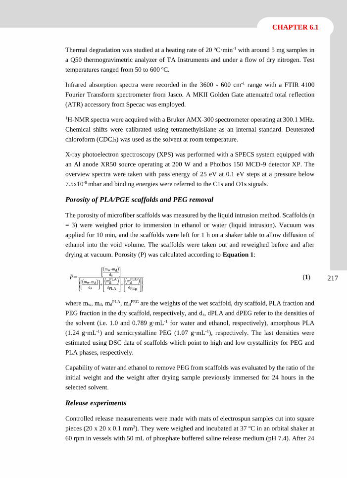
CHAPTER 6.1
217
Thermal degradation was studied at a heating rate of 20 ºC·min-1 with around 5 mg samples in
a Q50 thermogravimetric analyzer of TA Instruments and under a flow of dry nitrogen. Test
temperatures ranged from 50 to 600 ºC.
Infrared absorption spectra were recorded in the 3600 - 600 cm-1 range with a FTIR 4100
Fourier Transform spectrometer from Jasco. A MKII Golden Gate attenuated total reflection
(ATR) accessory from Specac was employed.
1H-NMR spectra were acquired with a Bruker AMX-300 spectrometer operating at 300.1 MHz.
Chemical shifts were calibrated using tetramethylsilane as an internal standard. Deuterated
chloroform (CDCl3) was used as the solvent at room temperature.
X-ray photoelectron spectroscopy (XPS) was performed with a SPECS system equipped with
an Al anode XR50 source operating at 200 W and a Phoibos 150 MCD-9 detector XP. The
overview spectra were taken with pass energy of 25 eV at 0.1 eV steps at a pressure below
7.5x10⁻⁹ mbar and binding energies were referred to the C1s and O1s signals.
Porosity of PLA/PGE scaffolds and PEG removal
The porosity of microfiber scaffolds was measured by the liquid intrusion method. Scaffolds (n
= 3) were weighed prior to immersion in ethanol or water (liquid intrusion). Vacuum was
applied for 10 min, and the scaffolds were left for 1 h on a shaker table to allow diffusion of
ethanol into the void volume. The scaffolds were taken out and reweighed before and after
drying at vacuum. Porosity (P) was calculated according to Equation 1:
𝑃=[(mw-md)
ds]
{[(mw-md)
ds]+[
(mdPLA)
dPLA]+[
(mdPEG)
dPEg]}
(1)
where mw, md, mdPLA, md
PEG are the weights of the wet scaffold, dry scaffold, PLA fraction and
PEG fraction in the dry scaffold, respectively, and ds, dPLA and dPEG refer to the densities of
the solvent (i.e. 1.0 and 0.789 g·mL-1 for water and ethanol, respectively), amorphous PLA
(1.24 g·mL-1) and semicrystalline PEG (1.07 g·mL-1), respectively. The last densities were
estimated using DSC data of scaffolds which point to high and low crystallinity for PEG and
PLA phases, respectively.
Capability of water and ethanol to remove PEG from scaffolds was evaluated by the ratio of the
initial weight and the weight after drying sample previously immersed for 24 hours in the
selected solvent.
Release experiments
Controlled release measurements were made with mats of electrospun samples cut into square
pieces (20 x 20 x 0.1 mm3). They were weighed and incubated at 37 ºC in an orbital shaker at
60 rpm in vessels with 50 mL of phosphate buffered saline release medium (pH 7.4). After 24
Biodegradable polymer matrices incorporating polyethylenen glycol as a sacrificial polymer
218
h this hydrophilic medium was replaced by the more hydrophobic Sörensen/ethanol (30:70 v/v)
medium. The triclosan concentration in the release media was carried out by UV spectroscopy.
Calibration curves were obtained by plotting the absorbance measured at 283 nm against
triclosan concentration. All drug release tests were carried out using six replicates to control the
homogeneity of the drug release, and the results were averaged.
Antimicrobial test: Assay of Bacterial Growth and Adhesion
Escherichia coli (E. coli) and Micrococcus luteus (M. luteus) bacteria were selected to evaluate
the antimicrobial effect of triclosan loaded electrospun fibers.
Growth experiments were performed by seeding 103 CFU (colony forming units) in 5 mL of
broth culture (Luria-Bertani medium) in the presence of the electrospun fiber mats. The cultures
were incubated at 37 ºC and agitated at 200 rpm. After incubation for 24 and 48 h, an aliquot of
100 µL was diluted 10 times with distilled water and absorbance at 600 nm measured. The
bacterial number was determined by absorbance measurements at 600 nm and using a
McFarland curve.
Adhesion experiments were carried out by seeding 107-108 CFU in 5 mL of broth culture in the
presence of the electrospun fiber mats. The cultures were incubated at 37 ºC and agitated at 200
rpm. After incubation (24 h), the cultures were aspired and the material washed one time with
distilled water. Then, 1 mL of sterile 0.01 M sodium thiosulfate was added and the mixture
vortexed for 2 min and kept in repose for 30 min to remove the bacteria. Finally, tubes were
incubated at 37 ºC and agitated at 200 rpm for 24 h after addition of 4 mL of broth culture. The
bacterial number was determined as above indicated.
All assays were conducted in triplicate and the results averaged. t-Student test was performed
as statistical analysis at a confidence level of 95% (p < 0.05).
In-vitro biocompatibility assays: adhesion and cellular proliferation
MDCK and VERO cells were cultured in Dulbecco’s modified Eagle medium (DMEM)
supplemented with 10% fetal bovine serum, 1% penicillin/streptomycin and 2 mM L-glutamine
at 37 ºC in a humidified atmosphere with 5% CO2 and 95% air.
Unloaded and triclosan loaded PLA/PEG electrospun nanofibers were collected on circular
coverslips (diameter 1.5 cm), placed into the wells of a multiwell culture plate and sterilized by
UV-radiation in a laminar flux cabinet for 15 min. The samples were fixed in the well using a
small drop of silicone (Silbione® MED ADH 4300 RTV, Bluestar Silicones France SAS, Lyon,
France) as adhesive. The samples were then incubated in 1 mL of culture medium under culture
conditions for 30 min to stabilize the material. Finally, the medium was aspired and the material
was evaluated for cell adhesion and proliferation by exposing cells to direct contact with the
material surface.
CHAPTER 6.1
219
For cell adhesion assay, aliquots of 50-100 µL containing 5x10⁴ cells were seeded onto the
electrospun samples in the wells. The plate was incubated under culture conditions for 30 min
to allow cell attachment to the material surface. Then, 1 mL of the culture medium was added
to each well and the plate incubated for 24 h. Finally, cell viability was determined by MTT (3-
(4,5-dimethylthiazol-2-yl)-2,5-diphenyl-2H-tetrazolium bromide) assay. Controls were
conducted by cell culture on the polystyrene surface of the plate (TCPS).
The cell proliferation assay was similar to the adhesion assay, but the aliquot of 50-100 µL
contained 2x10⁴ cells. Cultures were maintained for 7 days to allow cell growth and adequate
cell confluence. The media were renewed every two days. Finally, viability was determined by
the MTT assay.
All samples were evaluated using five replicates and the results were averaged and graphically
represented. The statistical analysis was performed by one-way ANOVA test to compare the
means of all groups. A statistically significant difference between the studied groups was
determined by t-Test, which was performed with a confidence level of 95% (p < 0.05).
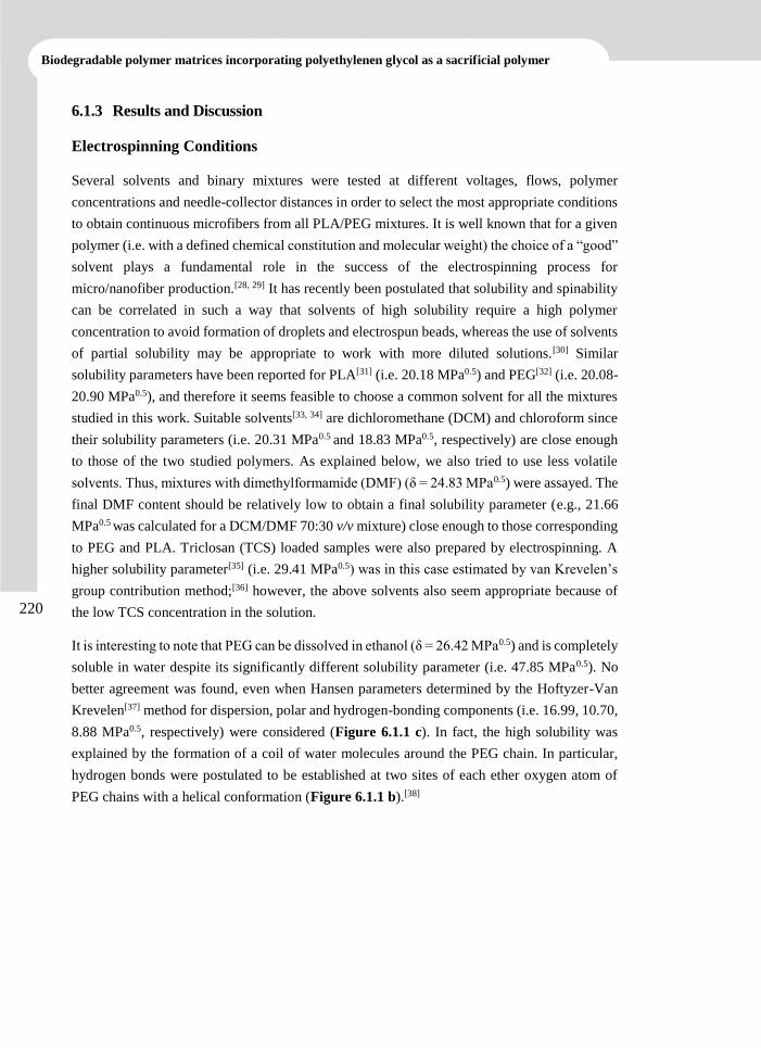
Biodegradable polymer matrices incorporating polyethylenen glycol as a sacrificial polymer
220
6.1.3 Results and Discussion
Electrospinning Conditions
Several solvents and binary mixtures were tested at different voltages, flows, polymer
concentrations and needle-collector distances in order to select the most appropriate conditions
to obtain continuous microfibers from all PLA/PEG mixtures. It is well known that for a given
polymer (i.e. with a defined chemical constitution and molecular weight) the choice of a “good”
solvent plays a fundamental role in the success of the electrospinning process for
micro/nanofiber production.[28, 29] It has recently been postulated that solubility and spinability
can be correlated in such a way that solvents of high solubility require a high polymer
concentration to avoid formation of droplets and electrospun beads, whereas the use of solvents
of partial solubility may be appropriate to work with more diluted solutions.[30] Similar
solubility parameters have been reported for PLA[31] (i.e. 20.18 MPa0.5) and PEG[32] (i.e. 20.08-
20.90 MPa0.5), and therefore it seems feasible to choose a common solvent for all the mixtures
studied in this work. Suitable solvents[33, 34] are dichloromethane (DCM) and chloroform since
their solubility parameters (i.e. 20.31 MPa0.5 and 18.83 MPa0.5, respectively) are close enough
to those of the two studied polymers. As explained below, we also tried to use less volatile
solvents. Thus, mixtures with dimethylformamide (DMF) (δ = 24.83 MPa0.5) were assayed. The
final DMF content should be relatively low to obtain a final solubility parameter (e.g., 21.66
MPa0.5 was calculated for a DCM/DMF 70:30 v/v mixture) close enough to those corresponding
to PEG and PLA. Triclosan (TCS) loaded samples were also prepared by electrospinning. A
higher solubility parameter[35] (i.e. 29.41 MPa0.5) was in this case estimated by van Krevelen’s
group contribution method;[36] however, the above solvents also seem appropriate because of
the low TCS concentration in the solution.
It is interesting to note that PEG can be dissolved in ethanol (δ = 26.42 MPa0.5) and is completely
soluble in water despite its significantly different solubility parameter (i.e. 47.85 MPa0.5). No
better agreement was found, even when Hansen parameters determined by the Hoftyzer-Van
Krevelen[37] method for dispersion, polar and hydrogen-bonding components (i.e. 16.99, 10.70,
8.88 MPa0.5, respectively) were considered (Figure 6.1.1 c). In fact, the high solubility was
explained by the formation of a coil of water molecules around the PEG chain. In particular,
hydrogen bonds were postulated to be established at two sites of each ether oxygen atom of
PEG chains with a helical conformation (Figure 6.1.1 b).[38]
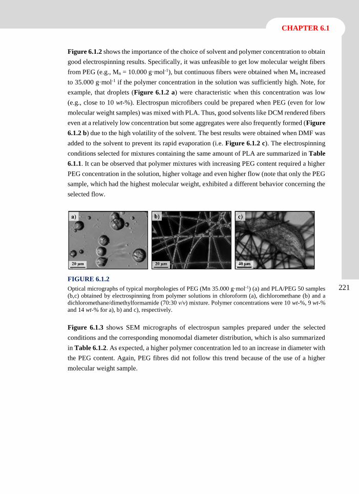
CHAPTER 6.1
221
Figure 6.1.2 shows the importance of the choice of solvent and polymer concentration to obtain
good electrospinning results. Specifically, it was unfeasible to get low molecular weight fibers
from PEG (e.g., Mn = 10.000 g·mol-1), but continuous fibers were obtained when Mn increased
to 35.000 g·mol-1 if the polymer concentration in the solution was sufficiently high. Note, for
example, that droplets (Figure 6.1.2 a) were characteristic when this concentration was low
(e.g., close to 10 wt-%). Electrospun microfibers could be prepared when PEG (even for low
molecular weight samples) was mixed with PLA. Thus, good solvents like DCM rendered fibers
even at a relatively low concentration but some aggregates were also frequently formed (Figure
6.1.2 b) due to the high volatility of the solvent. The best results were obtained when DMF was
added to the solvent to prevent its rapid evaporation (i.e. Figure 6.1.2 c). The electrospinning
conditions selected for mixtures containing the same amount of PLA are summarized in Table
6.1.1. It can be observed that polymer mixtures with increasing PEG content required a higher
PEG concentration in the solution, higher voltage and even higher flow (note that only the PEG
sample, which had the highest molecular weight, exhibited a different behavior concerning the
selected flow.
FIGURE 6.1.2
Optical micrographs of typical morphologies of PEG (Mn 35.000 g·mol-1) (a) and PLA/PEG 50 samples
(b,c) obtained by electrospinning from polymer solutions in chloroform (a), dichloromethane (b) and a
dichloromethane/dimethylformamide (70:30 v/v) mixture. Polymer concentrations were 10 wt-%, 9 wt-%
and 14 wt-% for a), b) and c), respectively.
Figure 6.1.3 shows SEM micrographs of electrospun samples prepared under the selected
conditions and the corresponding monomodal diameter distribution, which is also summarized
in Table 6.1.2. As expected, a higher polymer concentration led to an increase in diameter with
the PEG content. Again, PEG fibres did not follow this trend because of the use of a higher
molecular weight sample.
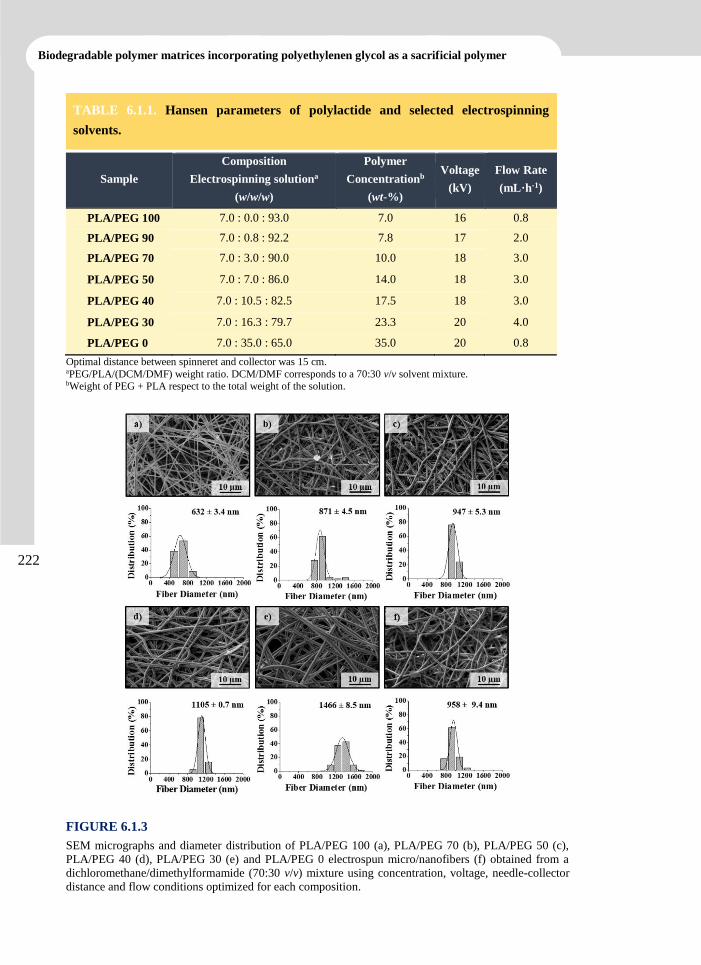
Biodegradable polymer matrices incorporating polyethylenen glycol as a sacrificial polymer
222
TABLE 6.1.1. Hansen parameters of polylactide and selected electrospinning
solvents.
Sample
Composition
Electrospinning solutiona
(w/w/w)
Polymer
Concentrationb
(wt-%)
Voltage
(kV) Flow Rate
(mL·h-1)
PLA/PEG 100 7.0 : 0.0 : 93.0 7.0 16 0.8
PLA/PEG 90 7.0 : 0.8 : 92.2 7.8 17 2.0
PLA/PEG 70 7.0 : 3.0 : 90.0 10.0 18 3.0
PLA/PEG 50 7.0 : 7.0 : 86.0 14.0 18 3.0
PLA/PEG 40 7.0 : 10.5 : 82.5 17.5 18 3.0
PLA/PEG 30 7.0 : 16.3 : 79.7 23.3 20 4.0
PLA/PEG 0 7.0 : 35.0 : 65.0 35.0 20 0.8
Optimal distance between spinneret and collector was 15 cm. aPEG/PLA/(DCM/DMF) weight ratio. DCM/DMF corresponds to a 70:30 v/v solvent mixture. bWeight of PEG + PLA respect to the total weight of the solution.
FIGURE 6.1.3
SEM micrographs and diameter distribution of PLA/PEG 100 (a), PLA/PEG 70 (b), PLA/PEG 50 (c),
PLA/PEG 40 (d), PLA/PEG 30 (e) and PLA/PEG 0 electrospun micro/nanofibers (f) obtained from a
dichloromethane/dimethylformamide (70:30 v/v) mixture using concentration, voltage, needle-collector
distance and flow conditions optimized for each composition.
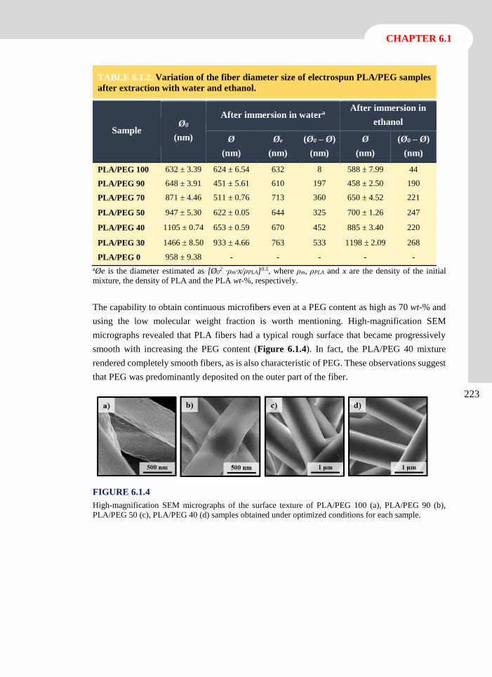
CHAPTER 6.1
223
TABLE 6.1.2. Variation of the fiber diameter size of electrospun PLA/PEG samples
after extraction with water and ethanol.
Sample Ø0
(nm)
After immersion in watera After immersion in
ethanol
Ø
(nm)
Øe
(nm)
(Ø0 – Ø)
(nm)
Ø
(nm)
(Ø0 – Ø)
(nm)
PLA/PEG 100 632 ± 3.39 624 ± 6.54 632 8 588 ± 7.99 44
PLA/PEG 90 648 ± 3.91 451 ± 5.61 610 197 458 ± 2.50 190
PLA/PEG 70 871 ± 4.46 511 ± 0.76 713 360 650 ± 4.52 221
PLA/PEG 50 947 ± 5.30 622 ± 0.05 644 325 700 ± 1.26 247
PLA/PEG 40 1105 ± 0.74 653 ± 0.59 670 452 885 ± 3.40 220
PLA/PEG 30 1466 ± 8.50 933 ± 4.66 763 533 1198 ± 2.09 268
PLA/PEG 0 958 ± 9.38 - - - - -
aØe is the diameter estimated as [Ø02 ·ρm·x/ρPLA]0.5, where ρm, ρPLA and x are the density of the initial
mixture, the density of PLA and the PLA wt-%, respectively.
The capability to obtain continuous microfibers even at a PEG content as high as 70 wt-% and
using the low molecular weight fraction is worth mentioning. High-magnification SEM
micrographs revealed that PLA fibers had a typical rough surface that became progressively
smooth with increasing the PEG content (Figure 6.1.4). In fact, the PLA/PEG 40 mixture
rendered completely smooth fibers, as is also characteristic of PEG. These observations suggest
that PEG was predominantly deposited on the outer part of the fiber.
FIGURE 6.1.4
High-magnification SEM micrographs of the surface texture of PLA/PEG 100 (a), PLA/PEG 90 (b),
PLA/PEG 50 (c), PLA/PEG 40 (d) samples obtained under optimized conditions for each sample.
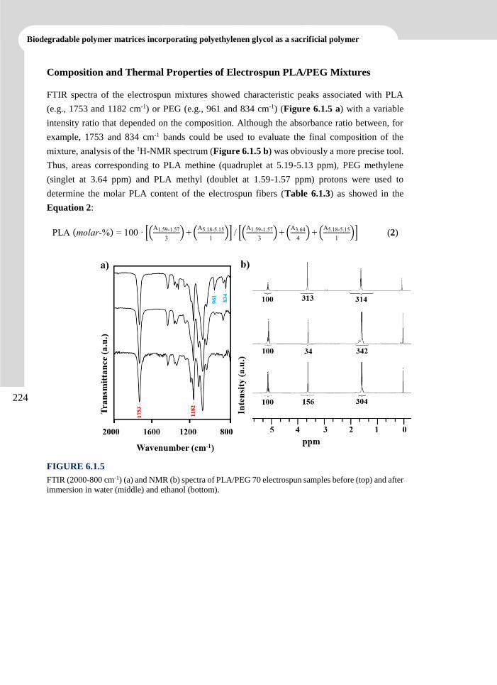
Biodegradable polymer matrices incorporating polyethylenen glycol as a sacrificial polymer
224
Composition and Thermal Properties of Electrospun PLA/PEG Mixtures
FTIR spectra of the electrospun mixtures showed characteristic peaks associated with PLA
(e.g., 1753 and 1182 cm-1) or PEG (e.g., 961 and 834 cm-1) (Figure 6.1.5 a) with a variable
intensity ratio that depended on the composition. Although the absorbance ratio between, for
example, 1753 and 834 cm-1 bands could be used to evaluate the final composition of the
mixture, analysis of the 1H-NMR spectrum (Figure 6.1.5 b) was obviously a more precise tool.
Thus, areas corresponding to PLA methine (quadruplet at 5.19-5.13 ppm), PEG methylene
(singlet at 3.64 ppm) and PLA methyl (doublet at 1.59-1.57 ppm) protons were used to
determine the molar PLA content of the electrospun fibers (Table 6.1.3) as showed in the
Equation 2:
PLA (molar-%) = 100 · [(A1.59-1.57
3) + (
A5.18-5.15
1)] / [(
A1.59-1.57
3) + (
A3.64
4) + (
A5.18-5.15
1)] (2)
FIGURE 6.1.5
FTIR (2000-800 cm-1) (a) and NMR (b) spectra of PLA/PEG 70 electrospun samples before (top) and after
immersion in water (middle) and ethanol (bottom).
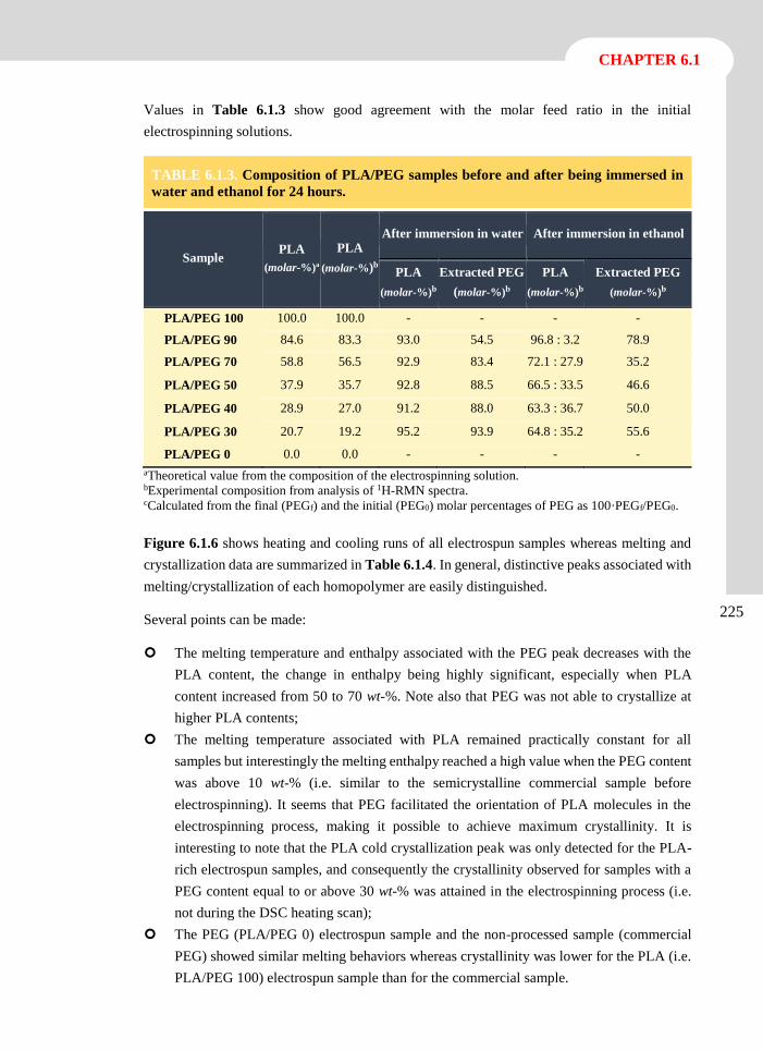
CHAPTER 6.1
225
Values in Table 6.1.3 show good agreement with the molar feed ratio in the initial
electrospinning solutions.
TABLE 6.1.3. Composition of PLA/PEG samples before and after being immersed in
water and ethanol for 24 hours.
Sample PLA
(molar-%)a
PLA
(molar-%)b
After immersion in water After immersion in ethanol
PLA
(molar-%)b
Extracted PEG
(molar-%)b
PLA
(molar-%)b
Extracted PEG
(molar-%)b
PLA/PEG 100 100.0 100.0 - - - -
PLA/PEG 90 84.6 83.3 93.0 54.5 96.8 : 3.2 78.9
PLA/PEG 70 58.8 56.5 92.9 83.4 72.1 : 27.9 35.2
PLA/PEG 50 37.9 35.7 92.8 88.5 66.5 : 33.5 46.6
PLA/PEG 40 28.9 27.0 91.2 88.0 63.3 : 36.7 50.0
PLA/PEG 30 20.7 19.2 95.2 93.9 64.8 : 35.2 55.6
PLA/PEG 0 0.0 0.0 - - - -
aTheoretical value from the composition of the electrospinning solution. bExperimental composition from analysis of 1H-RMN spectra. cCalculated from the final (PEGf) and the initial (PEG0) molar percentages of PEG as 100·PEGf/PEG0.
Figure 6.1.6 shows heating and cooling runs of all electrospun samples whereas melting and
crystallization data are summarized in Table 6.1.4. In general, distinctive peaks associated with
melting/crystallization of each homopolymer are easily distinguished.
Several points can be made:
The melting temperature and enthalpy associated with the PEG peak decreases with the
PLA content, the change in enthalpy being highly significant, especially when PLA
content increased from 50 to 70 wt-%. Note also that PEG was not able to crystallize at
higher PLA contents;
The melting temperature associated with PLA remained practically constant for all
samples but interestingly the melting enthalpy reached a high value when the PEG content
was above 10 wt-% (i.e. similar to the semicrystalline commercial sample before
electrospinning). It seems that PEG facilitated the orientation of PLA molecules in the
electrospinning process, making it possible to achieve maximum crystallinity. It is
interesting to note that the PLA cold crystallization peak was only detected for the PLA-
rich electrospun samples, and consequently the crystallinity observed for samples with a
PEG content equal to or above 30 wt-% was attained in the electrospinning process (i.e.
not during the DSC heating scan);
The PEG (PLA/PEG 0) electrospun sample and the non-processed sample (commercial
PEG) showed similar melting behaviors whereas crystallinity was lower for the PLA (i.e.
PLA/PEG 100) electrospun sample than for the commercial sample.
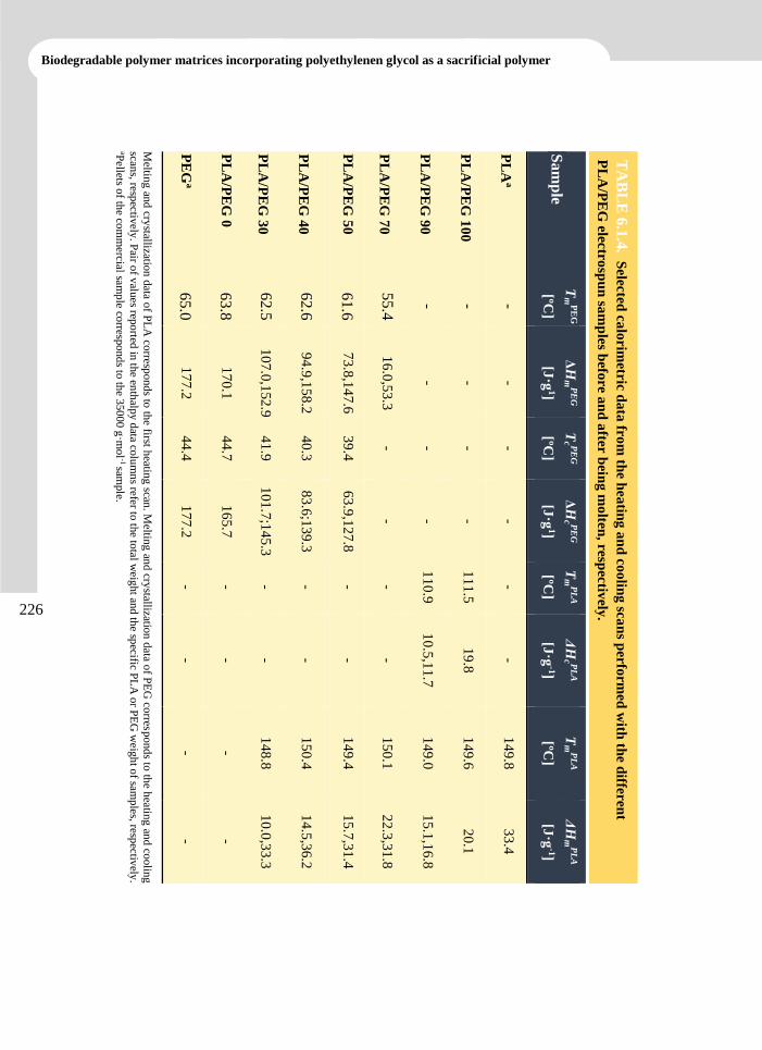
Biodegradable polymer matrices incorporating polyethylenen glycol as a sacrificial polymer
226
Meltin
g an
d cry
stallization
data o
f PL
A co
rrespond
s to th
e first heatin
g scan
. Meltin
g an
d cry
stallization
data o
f PE
G co
rrespond
s to th
e heatin
g an
d co
olin
g
scans, resp
ectively
. Pair o
f valu
es repo
rted in
the en
thalp
y d
ata colu
mn
s refer to th
e total w
eight an
d th
e specific P
LA
or P
EG
weig
ht o
f samp
les, respectiv
ely.
aPellets o
f the co
mm
ercial samp
le corresp
ond
s to th
e 350
00
g·m
ol
-1 sam
ple.
PE
Ga
PL
A/P
EG
0
PL
A/P
EG
30
PL
A/P
EG
40
PL
A/P
EG
50
PL
A/P
EG
70
PL
A/P
EG
90
PL
A/P
EG
10
0
PL
Aa
Sa
mp
le
TA
BL
E 6
.1.4
. Selected
calo
rimetric d
ata
from
the h
eatin
g a
nd
coo
ling
scan
s perfo
rmed
with
the d
ifferen
t
PL
A/P
EG
electro
spu
n sa
mp
les befo
re a
nd
after
bein
g m
olten
, resp
ectively
.
65.0
63.8
62.5
62.6
61.6
55.4
- - -
Tm
PE
G
[ºC]
17
7.2
17
0.1
10
7.0
,152
.9
94
.9,1
58
.2
73
.8,1
47
.6
16
.0,5
3.3
- - -
ΔH
mP
EG
[J·g
1]
44
.4
44
.7
41
.9
40
.3
39
.4
- - - -
Tc P
EG
[ºC]
17
7.2
16
5.7
10
1.7
;14
5.3
83
.6;1
39
.3
63
.9,1
27
.8
- - - -
ΔH
c PE
G
[J·g
1]
- - - - - -
11
0.9
11
1.5
-
Tm
PL
A
[ºC]
- - - - - -
10
.5,1
1.7
19
.8
-
ΔH
c PL
A
[J·g
-1]
- -
14
8.8
15
0.4
14
9.4
15
0.1
14
9.0
14
9.6
14
9.8
Tm
PL
A
[ºC]
- -
10
.0,3
3.3
14
.5,3
6.2
15
.7,3
1.4
22
.3,3
1.8
15
.1,1
6.8
20
.1
33
.4
ΔH
mP
LA
[J·g
-1]
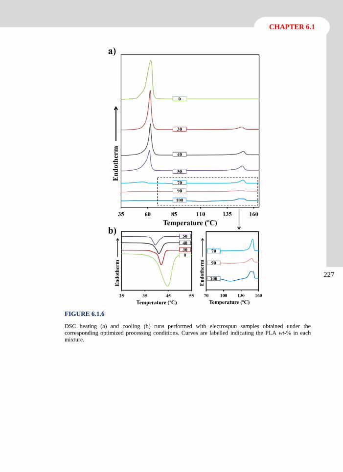
CHAPTER 6.1
227
FIGURE 6.1.6
DSC heating (a) and cooling (b) runs performed with electrospun samples obtained under the
corresponding optimized processing conditions. Curves are labelled indicating the PLA wt-% in each
mixture.
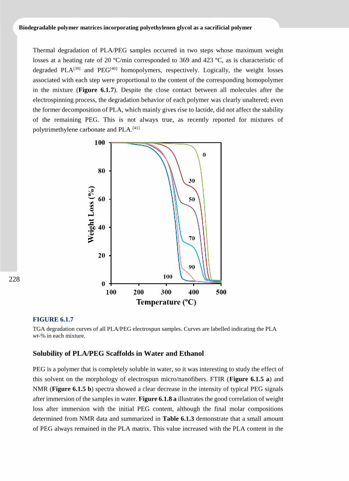
Biodegradable polymer matrices incorporating polyethylenen glycol as a sacrificial polymer
228
Thermal degradation of PLA/PEG samples occurred in two steps whose maximum weight
losses at a heating rate of 20 ºC/min corresponded to 369 and 423 ºC, as is characteristic of
degraded PLA[39] and PEG[40] homopolymers, respectively. Logically, the weight losses
associated with each step were proportional to the content of the corresponding homopolymer
in the mixture (Figure 6.1.7). Despite the close contact between all molecules after the
electrospinning process, the degradation behavior of each polymer was clearly unaltered; even
the former decomposition of PLA, which mainly gives rise to lactide, did not affect the stability
of the remaining PEG. This is not always true, as recently reported for mixtures of
polytrimethylene carbonate and PLA.[41]
FIGURE 6.1.7
TGA degradation curves of all PLA/PEG electrospun samples. Curves are labelled indicating the PLA
wt-% in each mixture.
Solubility of PLA/PEG Scaffolds in Water and Ethanol
PEG is a polymer that is completely soluble in water, so it was interesting to study the effect of
this solvent on the morphology of electrospun micro/nanofibers. FTIR (Figure 6.1.5 a) and
NMR (Figure 6.1.5 b) spectra showed a clear decrease in the intensity of typical PEG signals
after immersion of the samples in water. Figure 6.1.8 a illustrates the good correlation of weight
loss after immersion with the initial PEG content, although the final molar compositions
determined from NMR data and summarized in Table 6.1.3 demonstrate that a small amount
of PEG always remained in the PLA matrix. This value increased with the PLA content in the
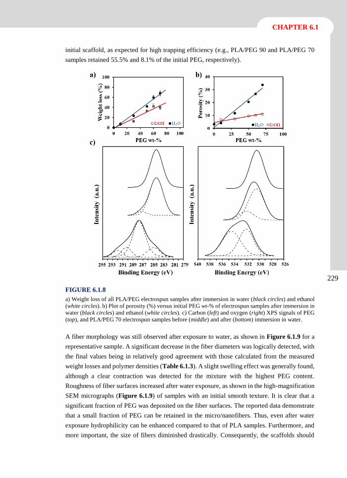
CHAPTER 6.1
229
initial scaffold, as expected for high trapping efficiency (e.g., PLA/PEG 90 and PLA/PEG 70
samples retained 55.5% and 8.1% of the initial PEG, respectively).
FIGURE 6.1.8
a) Weight loss of all PLA/PEG electrospun samples after immersion in water (black circles) and ethanol
(white circles). b) Plot of porosity (%) versus initial PEG wt-% of electrospun samples after immersion in
water (black circles) and ethanol (white circles). c) Carbon (left) and oxygen (right) XPS signals of PEG
(top), and PLA/PEG 70 electrospun samples before (middle) and after (bottom) immersion in water.
A fiber morphology was still observed after exposure to water, as shown in Figure 6.1.9 for a
representative sample. A significant decrease in the fiber diameters was logically detected, with
the final values being in relatively good agreement with those calculated from the measured
weight losses and polymer densities (Table 6.1.3). A slight swelling effect was generally found,
although a clear contraction was detected for the mixture with the highest PEG content.
Roughness of fiber surfaces increased after water exposure, as shown in the high-magnification
SEM micrographs (Figure 6.1.9) of samples with an initial smooth texture. It is clear that a
significant fraction of PEG was deposited on the fiber surfaces. The reported data demonstrate
that a small fraction of PEG can be retained in the micro/nanofibers. Thus, even after water
exposure hydrophilicity can be enhanced compared to that of PLA samples. Furthermore, and
more important, the size of fibers diminished drastically. Consequently, the scaffolds should
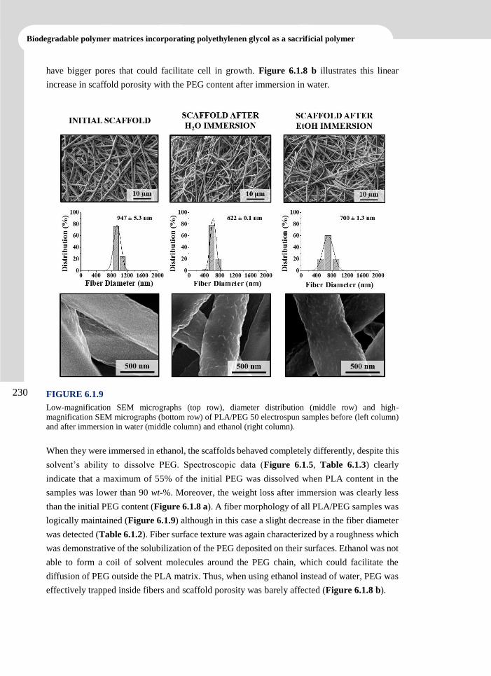
Biodegradable polymer matrices incorporating polyethylenen glycol as a sacrificial polymer
230
have bigger pores that could facilitate cell in growth. Figure 6.1.8 b illustrates this linear
increase in scaffold porosity with the PEG content after immersion in water.
FIGURE 6.1.9
Low-magnification SEM micrographs (top row), diameter distribution (middle row) and high-
magnification SEM micrographs (bottom row) of PLA/PEG 50 electrospun samples before (left column)
and after immersion in water (middle column) and ethanol (right column).
When they were immersed in ethanol, the scaffolds behaved completely differently, despite this
solvent’s ability to dissolve PEG. Spectroscopic data (Figure 6.1.5, Table 6.1.3) clearly
indicate that a maximum of 55% of the initial PEG was dissolved when PLA content in the
samples was lower than 90 wt-%. Moreover, the weight loss after immersion was clearly less
than the initial PEG content (Figure 6.1.8 a). A fiber morphology of all PLA/PEG samples was
logically maintained (Figure 6.1.9) although in this case a slight decrease in the fiber diameter
was detected (Table 6.1.2). Fiber surface texture was again characterized by a roughness which
was demonstrative of the solubilization of the PEG deposited on their surfaces. Ethanol was not
able to form a coil of solvent molecules around the PEG chain, which could facilitate the
diffusion of PEG outside the PLA matrix. Thus, when using ethanol instead of water, PEG was
effectively trapped inside fibers and scaffold porosity was barely affected (Figure 6.1.8 b).
CHAPTER 6.1
231
The composition of the surface layer of each PLA/PEG scaffolds (i.e. the surface of the
constitutive micro/nanofibers) was studied from the analysis of C1s and O1s peaks of the XPS
spectra (Figure 6.1.8 c). PEG spectra were characterized by C1s and O1s peaks at binding
energies of 284.6 eV and 532 eV, respectively, whereas PLA spectra were more complicated
since three C1s peaks were observed at 292.0 eV (CO), 290.0eV (CH) and 287.7 eV (CH3) and
two O1 peaks at 534.8 eV (O-C) and 532.4 eV (O=C) in the deconvoluted spectra. Figure 6.1.8
c clearly shows the correspondence of XPS spectra of PLA/PEG 70 to PEG, which strongly
supports the idea that this polymer was preferentially deposited on the fiber surface during
electrospinning. Note that this mixture had the highest PLA content, and is therefore the best
sample to demonstrate a preferential deposition of PEG on the surface. Logically, XPS spectra
of scaffolds with a higher PEG content also revealed that the fiber surface was mainly
constituted by PEG. The spectra changed dramatically when scaffolds were immersed in water
due to the solubilization of PEG. Thus, practically only the signals attributed to PLA were
detected after immersion, as shown in Figure 6.1.8 c (bottom). However, very small signals
attributed to PEG could still be observed, in agreement with NMR data, demonstrating the
retention of a small amount of PEG in the PLA matrix.
Triclosan Loading and Release from PLA/PEG Scaffolds
The micro/nanofibers of samples were easily loaded with triclosan by adding the appropriate
amount of the drug (3 w/v-%) in the initial electrospinning solutions. In this way, triclosan-
loaded scaffolds were prepared under the same processing conditions determined for the
unloaded samples. Figure 6.1.10 illustrates the final morphology of the representative
PLA/PEG 50 sample. The diameters of loaded fibers were generally rather similar to those
previously determined for the unloaded samples. Variations were not significant (e.g., 947 nm
versus 913 nm and 1105 nm versus 1181 nm for unloaded and TCS loaded PLA/PEG 50 and
PLA/PEG 40 samples, respectively). Furthermore, the diameters were found to increase or
decrease slightly (i.e. with no specific trend) for different compositions of the polymer mixture.
More interestingly, the roughness of the fiber surface increased upon the addition of triclosan,
as can be deduced by comparing the TCS loaded PLA/PEG 50 sample with the unloaded one,
which was characterized by a smooth surface (Figure 6.1.10 c and 6.1.10 d). This change in
the fiber surface morphology may play an important role in supporting cell attachment.
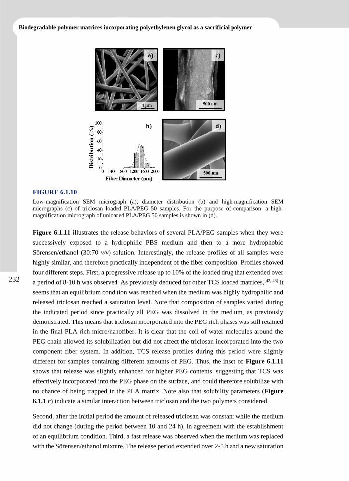
Biodegradable polymer matrices incorporating polyethylenen glycol as a sacrificial polymer
232
FIGURE 6.1.10
Low-magnification SEM micrograph (a), diameter distribution (b) and high-magnification SEM
micrographs (c) of triclosan loaded PLA/PEG 50 samples. For the purpose of comparison, a high-
magnification micrograph of unloaded PLA/PEG 50 samples is shown in (d).
Figure 6.1.11 illustrates the release behaviors of several PLA/PEG samples when they were
successively exposed to a hydrophilic PBS medium and then to a more hydrophobic
Sörensen/ethanol (30:70 v/v) solution. Interestingly, the release profiles of all samples were
highly similar, and therefore practically independent of the fiber composition. Profiles showed
four different steps. First, a progressive release up to 10% of the loaded drug that extended over
a period of 8-10 h was observed. As previously deduced for other TCS loaded matrices,[42, 43] it
seems that an equilibrium condition was reached when the medium was highly hydrophilic and
released triclosan reached a saturation level. Note that composition of samples varied during
the indicated period since practically all PEG was dissolved in the medium, as previously
demonstrated. This means that triclosan incorporated into the PEG rich phases was still retained
in the final PLA rich micro/nanofiber. It is clear that the coil of water molecules around the
PEG chain allowed its solubilization but did not affect the triclosan incorporated into the two
component fiber system. In addition, TCS release profiles during this period were slightly
different for samples containing different amounts of PEG. Thus, the inset of Figure 6.1.11
shows that release was slightly enhanced for higher PEG contents, suggesting that TCS was
effectively incorporated into the PEG phase on the surface, and could therefore solubilize with
no chance of being trapped in the PLA matrix. Note also that solubility parameters (Figure
6.1.1 c) indicate a similar interaction between triclosan and the two polymers considered.
Second, after the initial period the amount of released triclosan was constant while the medium
did not change (during the period between 10 and 24 h), in agreement with the establishment
of an equilibrium condition. Third, a fast release was observed when the medium was replaced
with the Sörensen/ethanol mixture. The release period extended over 2-5 h and a new saturation
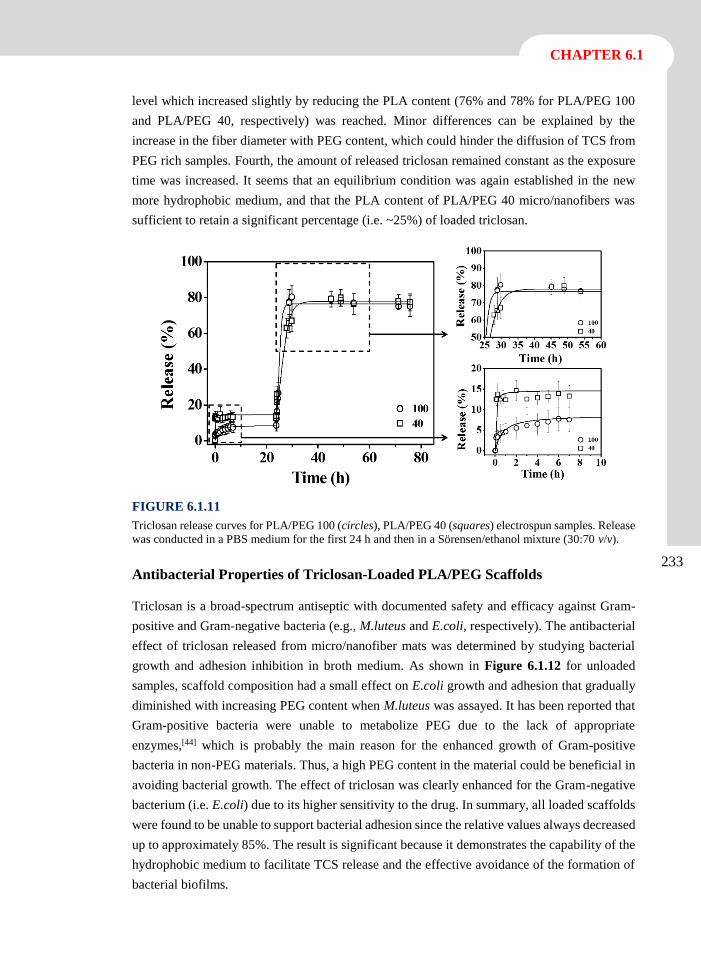
CHAPTER 6.1
233
level which increased slightly by reducing the PLA content (76% and 78% for PLA/PEG 100
and PLA/PEG 40, respectively) was reached. Minor differences can be explained by the
increase in the fiber diameter with PEG content, which could hinder the diffusion of TCS from
PEG rich samples. Fourth, the amount of released triclosan remained constant as the exposure
time was increased. It seems that an equilibrium condition was again established in the new
more hydrophobic medium, and that the PLA content of PLA/PEG 40 micro/nanofibers was
sufficient to retain a significant percentage (i.e. ~25%) of loaded triclosan.
FIGURE 6.1.11
Triclosan release curves for PLA/PEG 100 (circles), PLA/PEG 40 (squares) electrospun samples. Release
was conducted in a PBS medium for the first 24 h and then in a Sörensen/ethanol mixture (30:70 v/v).
Antibacterial Properties of Triclosan-Loaded PLA/PEG Scaffolds
Triclosan is a broad-spectrum antiseptic with documented safety and efficacy against Gram-
positive and Gram-negative bacteria (e.g., M.luteus and E.coli, respectively). The antibacterial
effect of triclosan released from micro/nanofiber mats was determined by studying bacterial
growth and adhesion inhibition in broth medium. As shown in Figure 6.1.12 for unloaded
samples, scaffold composition had a small effect on E.coli growth and adhesion that gradually
diminished with increasing PEG content when M.luteus was assayed. It has been reported that
Gram-positive bacteria were unable to metabolize PEG due to the lack of appropriate
enzymes,[44] which is probably the main reason for the enhanced growth of Gram-positive
bacteria in non-PEG materials. Thus, a high PEG content in the material could be beneficial in
avoiding bacterial growth. The effect of triclosan was clearly enhanced for the Gram-negative
bacterium (i.e. E.coli) due to its higher sensitivity to the drug. In summary, all loaded scaffolds
were found to be unable to support bacterial adhesion since the relative values always decreased
up to approximately 85%. The result is significant because it demonstrates the capability of the
hydrophobic medium to facilitate TCS release and the effective avoidance of the formation of
bacterial biofilms.
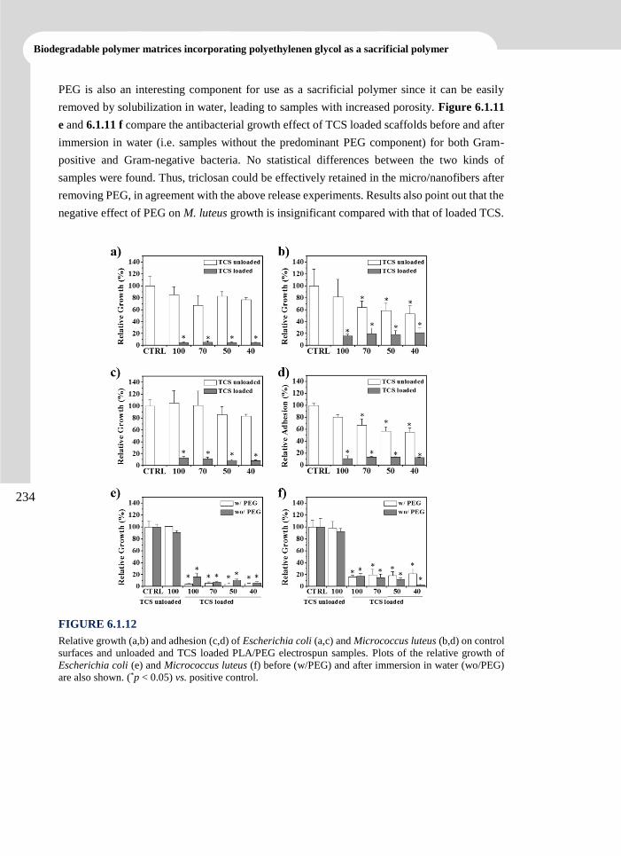
Biodegradable polymer matrices incorporating polyethylenen glycol as a sacrificial polymer
234
PEG is also an interesting component for use as a sacrificial polymer since it can be easily
removed by solubilization in water, leading to samples with increased porosity. Figure 6.1.11
e and 6.1.11 f compare the antibacterial growth effect of TCS loaded scaffolds before and after
immersion in water (i.e. samples without the predominant PEG component) for both Gram-
positive and Gram-negative bacteria. No statistical differences between the two kinds of
samples were found. Thus, triclosan could be effectively retained in the micro/nanofibers after
removing PEG, in agreement with the above release experiments. Results also point out that the
negative effect of PEG on M. luteus growth is insignificant compared with that of loaded TCS.
FIGURE 6.1.12
Relative growth (a,b) and adhesion (c,d) of Escherichia coli (a,c) and Micrococcus luteus (b,d) on control
surfaces and unloaded and TCS loaded PLA/PEG electrospun samples. Plots of the relative growth of
Escherichia coli (e) and Micrococcus luteus (f) before (w/PEG) and after immersion in water (wo/PEG)
are also shown. (*p < 0.05) vs. positive control.
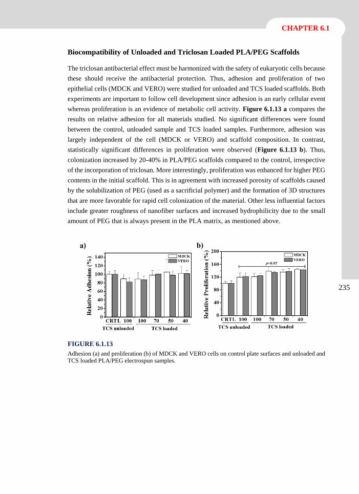
CHAPTER 6.1
235
Biocompatibility of Unloaded and Triclosan Loaded PLA/PEG Scaffolds
The triclosan antibacterial effect must be harmonized with the safety of eukaryotic cells because
these should receive the antibacterial protection. Thus, adhesion and proliferation of two
epithelial cells (MDCK and VERO) were studied for unloaded and TCS loaded scaffolds. Both
experiments are important to follow cell development since adhesion is an early cellular event
whereas proliferation is an evidence of metabolic cell activity. Figure 6.1.13 a compares the
results on relative adhesion for all materials studied. No significant differences were found
between the control, unloaded sample and TCS loaded samples. Furthermore, adhesion was
largely independent of the cell (MDCK or VERO) and scaffold composition. In contrast,
statistically significant differences in proliferation were observed (Figure 6.1.13 b). Thus,
colonization increased by 20-40% in PLA/PEG scaffolds compared to the control, irrespective
of the incorporation of triclosan. More interestingly, proliferation was enhanced for higher PEG
contents in the initial scaffold. This is in agreement with increased porosity of scaffolds caused
by the solubilization of PEG (used as a sacrificial polymer) and the formation of 3D structures
that are more favorable for rapid cell colonization of the material. Other less influential factors
include greater roughness of nanofiber surfaces and increased hydrophilicity due to the small
amount of PEG that is always present in the PLA matrix, as mentioned above.
FIGURE 6.1.13
Adhesion (a) and proliferation (b) of MDCK and VERO cells on control plate surfaces and unloaded and
TCS loaded PLA/PEG electrospun samples.
Biodegradable polymer matrices incorporating polyethylenen glycol as a sacrificial polymer
236
6.1.4 Conclusions
Scaffolds constituted by a variable ratio of poly(ethylene glycol) and polylactide in various
ratios were prepared by the electrospinning technique using
dicloromethane/dimethylformamide (70:30 v/v) as the solvent. The resulting micro/nanofibers
were found to be continuous even at a high PEG content (i.e. 70 wt-%) and have smoother
surfaces as this content was increased. A preferential deposition of PEG on the outermost part
of each fibers was inferred, as also demonstrated by XPS analysis.
Most of the PEG was easily removed by exposure to water, although a small amount was always
found to be retained in the PLA matrix. Scaffolds with different hydrophilicity, and even with
high porosities, were thus obtained if PEG was used as a sacrificial polymer. A completely
different behavior was observed for scaffolds exposed to ethanol as a large amount of PEG was
retained inside the fibers and practically only the PEG deposited on the surface was effectively
solubilized.
The roughnesses of the triclosan-loaded samples increased, and release was marked by the
achievement of an equilibrium condition that varied significantly with the hydrophilicity of the
exposure medium. Slight differences in the release behavior were detected depending on the
composition; specifically, an increase in PLA content resulted in higher retention of the drug,
especially in a hydrophilic medium.
Triclosan-loaded PLA/PEG scaffolds exhibited antibacterial activity regardless of the
composition, although a slight decreasing trend with the PEG content was detected for the
Gram-positive bacteria. Cell adhesion and proliferation were well supported by PLA/PEG
scaffolds, even when they were loaded with triclosan. Cell proliferation was significantly
dependent on the initial PEG content; in particular, cell colonization was enhanced in the more
porous 3D structures attained after solubilization of PEG.
CHAPTER 6.1
237
6.1.5 References
[1] E.S. Place, J.H. George, C.K. Williams, M.M. Stevens, Chem Soc Rev, 38 (2009) 1139-
1151.
[2] P.A. Madurantakam, C.P. Cost, D.G. Simpson, G.L. Bowlin, Nanomedicine (Lond), 4
(2009) 193-206.
[3] M.P. Lutolf, J.A. Hubbell, Nat Biotechnol, 23 (2005) 47-55.
[4] K.F. Leong, C.K. Chua, N. Sudarmadji, W.Y. Yeong, J Mech Behav Biomed Mater, 1
(2008) 140-152.
[5] D.H. Reneker, I. Chun, Nanotechnology, 7 (1996) 216-223.
[6] S.F. Badylak, D.O. Freytes, T.W. Gilbert, Acta Biomater, 5 (2009) 1-13.
[7] Y. Dzenis, Science, 304 (2004) 1917-1919.
[8] D. Li, Y.N. Xia, Adv Mater, 16 (2004) 1151-1170.
[9] K. Jayaraman, M. Kotaki, Y.Z. Zhang, X.M. Mo, S. Ramakrishna, J Nanosci
Nanotechno, 4 (2004) 52-65.
[10] D.H. Reneker, A.L. Yarin, H. Fong, S. Koombhongse, J Appl Phys, 87 (2000) 4531-
4547.
[11] J. Rouwkema, N.C. Rivron, C.A. van Blitterswijk, Trends Biotechnol, 26 (2008) 434-
441.
[12] Y. You, B.M. Min, S.J. Lee, T.S. Lee, W.H. Park, J Appl Polym Sci, 95 (2005) 193-200.
[13] O. Suwantong, P. Pankongadisak, S. Deachathai, P. Supaphol, J Polym Res, 19 (2012)
9896-9886.
[14] J.Y. Park, I.H. Lee, J Polym Res, 18 (2011) 1287-1291.
[15] M. Peesan, R. Rujiravanit, P. Supaphol, J Biomat Sci-Polym E, 17 (2006) 547-565.
[16] Y.H. Nien, C.Y. Shih, C.Y. Yang, C.J. Lu, Q.X. Ye, J Polym Res, 20 (2013) 166-171.
[17] S.A. Sell, M.J. McClure, K. Garg, P.S. Wolfe, G.L. Bowlin, Adv Drug Deliver Rev, 61
(2009) 1007-1019.
[18] Z.G. Chen, X.M. Mo, F.L. Qing, Mater Lett, 61 (2007) 3490-3494.
[19] H. Homayoni, S.A.H. Ravandi, M. Valizadeh, Carbohyd Polym, 77 (2009) 656-661.
[20] S.N. Stephansson, B.A. Byers, A.J. Garcia, Biomaterials, 23 (2002) 2527-2534.
Biodegradable polymer matrices incorporating polyethylenen glycol as a sacrificial polymer
238
[21] Y. Lin, L.L. Wang, P.B. Zhang, X. Wang, X.S. Chen, X.B. Jing, Z.H. Su, Acta Biomater,
2 (2006) 155-164.
[22] X.W. Jiang, E.B. Vogel, M.R. Smith, G.L. Baker, J Polym Sci Pol Chem, 45 (2007)
5227-5236.
[23] Y.K. Luu, K. Kim, B.S. Hsiao, B. Chu, M. Hadjiargyrou, J Control Release, 89 (2003)
341-353.
[24] M. Spasova, O. Stoilova, N. Manolova, I. Rashkov, G. Altankov, J Bioact Compat Pol,
22 (2007) 62-76.
[25] B.Y. Wang, S.Z. Fu, P.Y. Ni, J.R. Peng, L. Zheng, F. Luo, H. Liu, Z.Y. Qian, J Biomed
Mater Res A, 100A (2012) 441-449.
[26] P.Y. Ni, S.Z. Fu, M. Fan, G. Guo, S.A. Shi, J.R. Peng, F. Luo, Z.Y. Qian, Int J Nanomed,
6 (2011) 3065-3075.
[27] D.A. Herold, K. Keil, D.E. Bruns, Biochem Pharmacol, 38 (1989) 73-76.
[28] S.V. Fridrikh, J.H. Yu, M.P. Brenner, G.C. Rutledge, Phys Rev Lett, 90 (2003).
[29] M.G. McKee, C.L. Elkins, T.E. Long, Polymer, 45 (2004) 8705-8715.
[30] C.J. Luo, M. Nangrejo, M. Edirisinghe, Polymer, 51 (2010) 1654-1662.
[31] D. Karst, Y.Q. Yang, J Appl Polym Sci, 96 (2005) 416-422.
[32] M.J. Fernández-Berridi, T.F. Otero, G.M. Guzman, J.M. Elorza, Polymer, 23 (1982)
1361-1366.
[33] J. Brandrup, E.H. Immergut, E.A. Grulke, A. Abe, D.R. Bloch, Fourth ed., John Wiley
& Sons, New York, 2003.
[34] R.C. Weast, M.J. Astle, 60th ed., CRC Press Inc., Boca Raton. Florida, 1980.
[35] D.M. Aragón, D.A. Chiappetta, J. Degrossi, E.F. Vargas, C. Bregni, A. Sosnik, F.
Martínez, Rev Col Cienc Quím Farm, 37 (2008) 241-257.
[36] A. Barton, 2nd ed., CRC Press Inc. , New York, 1991.
[37] D.W. van Krevelen, P.J. Hoftyzer, Angew Makromol Chem, 52 (1976) 101-109.
[38] Y. Aray, M. Manuel, J. Rodriguez, D. Vega, Y. Simon-Manso, S. Coll, C. Gonzalez,
D.A. Weitz, J Phys Chem B, 108 (2004) 2418-2424.
[39] F.D. Kopinke, M. Remmler, K. Mackenzie, M. Moder, O. Wachsen, Polym Degrad
Stabil, 53 (1996) 329-342.
[40] S.L. Madorsky, S. Straus, J Polym Sci, 36 (1959) 183-194.
CHAPTER 6.1
239
[41] Y. Marquez, L. Franco, J. Puiggali, Thermochim Acta, 550 (2012) 65-75.
[42] R. Zurita, J. Puiggali, A. Rodriguez-Galan, Macromol Biosci, 6 (2006) 58-69.
[43] L.J. del Valle, R. Camps, A. Diaz, L. Franco, A. Rodriguez-Galan, J. Puiggali, J Polym
Res, 18 (2011) 1903-1917.
[44] A.I. Lopez, R.Y. Reins, A.M. McDermott, B.W. Trautner, C.Z. Cai, Mol Biosyst, 5
(2009) 1148-1156.

Scaffolds Constituted by Mixed Polylactide and
Poly(Ethylene Glycol) Electrospun Microfibers
Scaffolds constituted by different ratios of poly(ethylene glycol)
(PEG) and polylactide (PLA) electrospun fibers have been
prepared by using a single rotatory collector. Electrospinning
parameters and solution conditions were optimized to obtain
continuous fibers and a homogeneous distribution of both
polymers in the final scaffold. Short needle-collector distances
allowed good overlapping of the two incident and independent
jets. The composition of the scaffold was effectively tuned by
varying the flow rate of the PLA solution. PEG and PLA fibers
could be well distinguished in the scaffold because of their
smooth and rough textures, and diameters in the nanometric
and micrometer range. Greater sizes corresponded to
polylactide and clearly depended on the flow rate. Drugs such
as triclosan and polyhexamethylene biguanide hydrochloride,
which have different hydrophilic/hydrophobic character and
molecular size, were loaded into PLA microfibers by
electrospinning. The high water solubility of PEG justified its
use as a sacrificial polymer. Thus, it was possible to prepare
scaffolds with tuned porosity (from 40 to 80%) by water
immersion of dual samples having different PEG content.
Porosity greatly affected the release rate; specifically a
practically instantaneous or a sustained release were
determined for triclosan in an appropriate medium. Drug
loaded scaffolds had a clear bactericidal effect that was more
effective for Gram-positive bacteria. Cell proliferation studies
indicate that fibroblast colonization increased by 20-25% in
PLA/PEG scaffolds with high PEG content compared to the
control, whereas this effect was not observed for epithelial cells.
6.2
Biodegradable polymer matrices incorporating polyethylenen glycol as a sacrificial polymer
242
6.2.1 Introduction
Electrospinning is one of the simplest procedures for generating 3D scaffolds for tissue
engineering applications. This technique is highly versatile because it allows fibers with
diameters varying from the micrometer to the nanometer range to be obtained from a wide
diversity of polymers. Basically, a polymer solution is ejected from a capillary by a strong
electrostatic potential and collected as a non-woven fibrous mat on an electrically grounded
target. Selection of appropriate experimental conditions for a given polymer (i.e. solvent,
polymer concentration and operational parameters such as strength of the applied electric field,
needle-collector distance and flow rate) are basic to get homogeneous and continuous fibers
with a selected diameter.[1-4] Furthermore, it is possible to prepare core-shell structures by using
a coaxial spinneret[5] or even by replacing the electrospinning solution by a water-in-oil (W/O)
emulsion.[6]
Scaffolds usually employed in the biomedical field are based on biodegradable polyesters such
as polycaprolactone and polylactide (PLA). However, these polymers generally have problems
related to their inherent hydrophobic nature that may reduce expression of phenotypic markers
and hinder cell attachment and proliferation.[7, 8] Among approaches that have been proposed
to increase hydrophilicity of electrospun fibers, some consider the use of polyethylene glycol
(PEG). This polymer can be easily eliminated from human body, is biocompatible and shows
interesting properties for biomedical applications.[9] Efforts have mainly focused on decreasing
the hydrophobicity of polylactide due to its excellent combination of characteristics like tunable
mechanical properties, degradation into natural metabolites, biocompatibility and low cost.
Thus, scaffolds with increased hydrophilicity have been obtained by: a) Electrospinning of
diblock or triblock copolymers having PEG segments,[10-12] b) Emulsion electrospinning of PEG
and PLA-b-PEG diblock copolymers,[13] c) Electrospinning of solution mixtures of PLA and
PEG.
Spasova et al.[14] demonstrated the possibility to easily modulate the hydrophilicity of PLA
nanofibers by adding PEG to the spinning solutions. They also reported that osteoblasts tended
to arrange in tissue-like structures for long-term cultures, especially in scaffolds with the highest
PEG content. An excellent in-vitro osteogenic potential and in vivo biocompatibility with the
surrounding tissues was found for PLA scaffolds containing 5 wt-% of PEG.[15] Electrospinning
of PLA could also be improved by addition of low molecular weight PEG because regular and
continuous fibers were produced due to the reduction of solution viscosity.[16] These fibers could
be prepared up to a 79 wt-% of PEG and rendered scaffolds with enhanced cell proliferation
because of the more porous 3D structures obtained after solubilization of PEG.[17] On the other
hand, the use of PLA/PEG mixtures has inherent problems related to the difficulty of
electrospinning PEG.
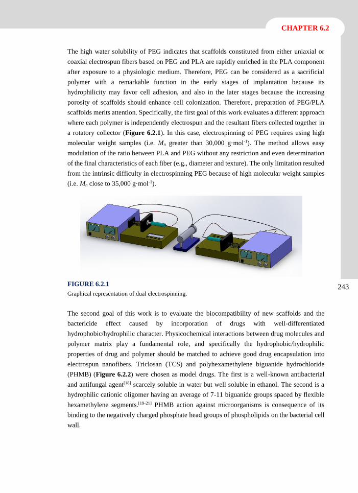
CHAPTER 6.2
243
The high water solubility of PEG indicates that scaffolds constituted from either uniaxial or
coaxial electrospun fibers based on PEG and PLA are rapidly enriched in the PLA component
after exposure to a physiologic medium. Therefore, PEG can be considered as a sacrificial
polymer with a remarkable function in the early stages of implantation because its
hydrophilicity may favor cell adhesion, and also in the later stages because the increasing
porosity of scaffolds should enhance cell colonization. Therefore, preparation of PEG/PLA
scaffolds merits attention. Specifically, the first goal of this work evaluates a different approach
where each polymer is independently electrospun and the resultant fibers collected together in
a rotatory collector (Figure 6.2.1). In this case, electrospinning of PEG requires using high
molecular weight samples (i.e. Mn greater than 30,000 g·mol-1). The method allows easy
modulation of the ratio between PLA and PEG without any restriction and even determination
of the final characteristics of each fiber (e.g., diameter and texture). The only limitation resulted
from the intrinsic difficulty in electrospinning PEG because of high molecular weight samples
(i.e. Mn close to 35,000 g·mol-1).
FIGURE 6.2.1
Graphical representation of dual electrospinning.
The second goal of this work is to evaluate the biocompatibility of new scaffolds and the
bactericide effect caused by incorporation of drugs with well-differentiated
hydrophobic/hydrophilic character. Physicochemical interactions between drug molecules and
polymer matrix play a fundamental role, and specifically the hydrophobic/hydrophilic
properties of drug and polymer should be matched to achieve good drug encapsulation into
electrospun nanofibers. Triclosan (TCS) and polyhexamethylene biguanide hydrochloride
(PHMB) (Figure 6.2.2) were chosen as model drugs. The first is a well-known antibacterial
and antifungal agent[18] scarcely soluble in water but well soluble in ethanol. The second is a
hydrophilic cationic oligomer having an average of 7-11 biguanide groups spaced by flexible
hexamethylene segments.[19-21] PHMB action against microorganisms is consequence of its
binding to the negatively charged phosphate head groups of phospholipids on the bacterial cell
wall.
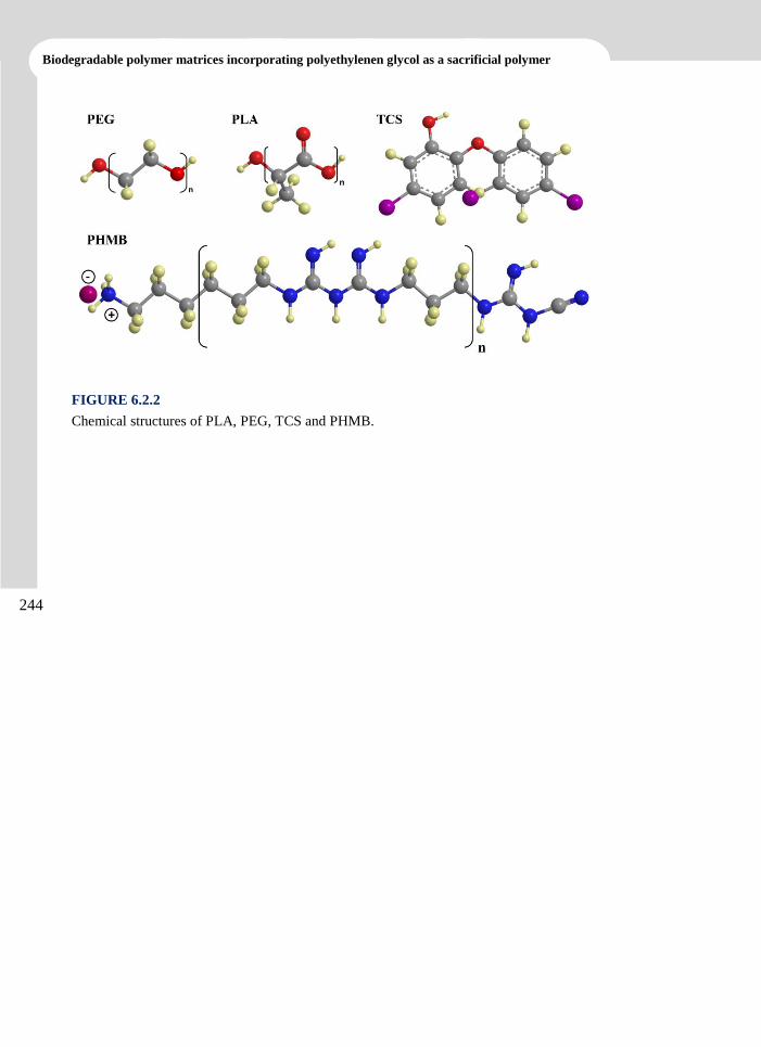
Biodegradable polymer matrices incorporating polyethylenen glycol as a sacrificial polymer
244
FIGURE 6.2.2
Chemical structures of PLA, PEG, TCS and PHMB.
CHAPTER 6.2
245
6.2.2 Experimental Section
Materials
PEG with number average molecular weight of 35,000 g·mol-1 was purchased from Sigma-
Aldrich. Polylactide (PLA), a product of Natureworks (polymer 2002D), was kindly supplied
by Nupik International (Polinyà, Spain). According to the manufacturer, this PLA has a D
content of 4.25%, a residual monomer content of 0.3%, a density of 1.24 g·cc-1, a glass transition
temperature (Tg) of 58 ºC and a melting point of 153 ºC. Solvents, Triclosan (TCS) and cell
culture labware were purchased from Sigma-Aldrich (USA). Polyhexamethylene biguanide
hydrochloride (PHMB) was kindly provided by B. Braun Surgical S.A. (Rubí, Spain).
Escherichia coli CECT 101 and Micrococcus luteus CECT 245 bacterial strains were obtained
from Spanish Collection of Type Culture (Valencia, Spain). Human fetal lung fibroblast cells
(MRC-5) and African green monkey kidney epithelial cells (VERO) were from ATCC (USA).
Electrospinning
A dual electrospinning system was used to prepared scaffods constituted by a mixture of PEG
and PLA microfibers, as depicted in Figure 6.2.1. Samples will be denoted by the experimental
polylactide molar percentage (i.e. PLA/PEG-100, PLA/PEG-67 and PLA/PEG-0 correspond to
PLA alone, a blend with 67 molar-% of PLA and 33 molar-% of PEG, and PEG alone,
respectively). Electrospun fibers were collected on a rotary ground collector operating at 30
rpm and placed at a variable distance (6-25 cm) from two equidistant needle tips (inside
diameter of 0.84 mm). The needles were placed facing each other in order to minimize
disturbing effects between the two electrically charged jets of PLA and PEG solutions. The
voltage was varied between 10 and 30 kV and applied to the collector using two high-voltage
suppliers (Gamma High Voltage Research, ES30-5W). Polymer solutions were delivered via
two KDS100 infusion syringe pumps (KD Scientific, USA) to control the flow rate (from 0.5
to 10 mL·h-1). All electrospinning experiments were carried out at room temperature. Unloaded
and TCS and PHMB loaded electrospun fibers were prepared using optimized parameters (e.g.,
needle-collector distance, voltage and flow rates) and solvent conditions (e.g., solvent ratio, and
polymer and drug concentrations). The TCS and PHMB contents of the electrospinning
solutions were 1 and 0.25 w/v-%, respectively.
Morphology and properties of electrospun scaffolds
Optical microscopy studies were performed with a Zeiss Axioskop 40 microscope. Micrographs
were taken with a Zeiss AxiosCam MRC5 digital camera.
Detailed inspection of texture and morphology of electrospun samples was conducted by
scanning electron microscopy using a Focus Ion Beam Zeiss Neon 40 instrument (Carl Zeiss,
Germany). Carbon coating was accomplished by using a Mitec K950 Sputter Coater fitted with
a k150x film thickness monitor. Samples were visualized at an accelerating voltage of 5 kV.
Biodegradable polymer matrices incorporating polyethylenen glycol as a sacrificial polymer
246
The diameter of electrospun fibers was measured with the SmartTiff software from Carl Zeiss
SMT Ltd.
Contact angles (CA) were measured at room temperature with sessile drops using an OCA-15
plus Dynamic Contact Angle Microscope (Dataphysics, USA) and SCA20 software. Contact
angle values of the right and left sides of distilled water drops were measured and averaged.
Measurements were performed 10 s after the drop (5 mL) was deposited on the sample surface.
All CA data were an average of six measurements on different surface locations.
Calorimetric data were obtained by differential scanning calorimetry (DSC) with a TA
Instruments Q100 series equipped with a refrigeration cooling system (RCS). Experiments were
conducted under a flow of dry nitrogen with a sample weight of approximately 5 mg, and
calibration was performed with indium. Heating runs were carried out at a rate of 20 ºC·min-1.
Thermal degradation was studied at a heating rate of 20 ºC·min-1 with around 5 mg samples in
a Q50 thermogravimetric analyzer (TGA) of TA Instruments and under a flow of dry nitrogen.
Test temperatures ranged from 50 to 600 ºC.
Porosity of PLA/PEF scaffolds
The porosity of scaffolds was measured by the liquid intrusion method. Scaffolds (n = 3) were
weighed prior to immersion in water (intrusion liquid). Vacuum was applied for 10 min, and
the scaffolds were placed on a shaker table for 1 h to allow diffusion of water into the avoid
volume. The scaffolds were taken out and reweighed. Porosity was calculated according to
Equation 1:
P = [(mw - md) / dw)] /[(mw - md) / dw] + [mdPLA / dPLA] + [md
PEG / dPEG] (1)
where mw, md, mdPLA, md
PEGare the weights of the wet scaffold, dry scaffold, PLA fraction and
PEG fraction in the dry scaffold, respectively, and dw, dPLA and dPEG refer to the densities of the
solvent (i.e. 1.0 g·mL-1 for water), amorphous PLA (1.24 g·mL-1) and semicrystalline PEG
(1.07 g·mL-1), respectively. The last two densities were estimated using DSC data of scaffolds
which point to high and low crystallinity of PEG and PLA homopolymers, respectively.
Release experiments
Controlled release measurements were made with square pieces (weighting approximately 200
mg) of the electrospun scaffolds. These pieces were weighed and incubated at 37 ºC in an orbital
shaker at 200 rpm in tubes of 50 mL for 1 week. PBS buffer (hydrophilic medium) and
alternatively its mixture with ethanol (i.e. 3:7 v/v ratio) as a more hydrophobic component were
employed as release media. Drug concentration was evaluated by UV spectroscopy using a
Shimadzu 3600 spectrometer. Calibration curves were obtained by plotting the absorbance
measured at 281 and 236 nm versus TCS and PHMB concentration. Samples were withdrawn
from the release medium at predetermined time intervals. The volume was kept constant by
CHAPTER 6.2
247
addition of fresh medium. All drug release tests were carried out using three replicates and the
results were averaged.
Antimicrobial test
Escherichia coli (E. coli) and Micrococcus luteus (M. luteus) bacteria were selected to evaluate
the antimicrobial effect of TCS and PHMB loaded electrospun fibers. The bacteria were
previously grown aerobically to exponential phase in broth culture (5 g·L-1 beef extract, 5 g·L-
1 NaCl, 10 g·L-1 peptone, pH 7.2).
Bacterial adhesion experiments were performed on a 24-well culture plate. Square pieces
(0.5×0.5×0.1 mm3) of the electrospun scaffolds were placed into each well. Then, 1 mL of broth
culture containing 103 CFU was seeded on the electrospun fiber mats. The cultures were
incubated at 37 ºC and agitated at 200 rpm. The culture media were aspirated after incubation
and the material washed once with distilled water. Then, 0.5 mL of sterile 0.01M sodium
thiosulfate was added to each well. After addition of 4 mL of broth culture, the plate was
incubated at 37 ºC and agitated at 200 rpm for 24 h. The bacterial number was determined as
above indicated. All assays were conducted in triplicate and the results averaged.
Cellular adhesion and proliferation assays
MRC-5 and VERO cells were cultured in Dulbecco’s modified Eagle medium (DMEM) as
previously reported.[22]
Square pieces (0.5×0.5×0.1 mm3) of the electrospun scaffolds were placed into the wells of a
multiwell culture plate. Samples were fixed in the wells with a small drop of silicone (Silbione®
MED ADH 4300 RTV, Bluestar Silicones France SAS, Lyon, France) and then sterilized by
UV-radiation in a laminar flux cabinet for 15 min. For the cell adhesion and proliferation assays,
aliquots of 50-100 µL containing 5x10⁴ (adhesion assay) and 2x10⁴ (proliferation assay) cells
were seeded onto the electrospun samples in each well and incubated for 24 h (adhesion assay)
or 4 days (proliferation assay).
Samples were evaluated by the standard adhesion and proliferation method[22] using MTT
reactive. The experiments were carried out using three replicates and the results were averaged.
Samples with adhered and grown cells on the mats were fixed with 2.5 w/v-% formaldehyde at
4 ºC overnight. They were subsequently dehydrated and processed for observation by scanning
electronic microscopy.
Statistical analysis
The statistical analysis was performed by one-way ANOVA followed by Tukey test. The
analyses were performed with a confidence level of 95% (p < 0.05).
Biodegradable polymer matrices incorporating polyethylenen glycol as a sacrificial polymer
248
6.2.3 Results and Discussion
Electrospinning Conditions
Solvent and polymer concentration conditions could be selected from previous works on PLA
and PEG because each polymer was electrospun independently. Chloroform/acetone 2:1 v/v and
dichloromethane/dimethylformamide 7:3 v/v mixtures were employed for PLA and PEG,
respectively.[17, 22] PLA required a low polymer concentration (5-7 wt-%) due to the high
viscosity of the final solution, whereas PEG was difficult to electrospun and a minimum
concentration of 35 wt-% was necessary for the commercial sample with a molecular weight of
35,000 g·mol-1. This forced the use of a PLA flow rate higher than that of PEG when scaffolds
had to keep a structural consistency capable of dissolving PEG after exposure to aqueous
environments. Experiments were performed with maximum (i.e. 10 wt-%) and minimum (i.e.
35 wt-%) PLA and PEG concentrations, respectively, to minimize the difference between flow
rates. Scaffolds with variable composition were prepared by varying the PLA flow rate (from
0.8 to 10 mL·h-1) and keeping the rate of PEG at a minimum value (0.8 mL·h-1) to maintain
good fiber morphology.
The distance between the needles and the rotary collector was also fundamental to obtain
scaffolds with a homogeneous composition. For example, ejected jets did not perfectly overlap
onto the collector when distances were greater than 10 cm. High dispersion of compositions
was therefore found after NMR analysis of specimens taken along a diagonal of the obtained
scaffold. Short distances (e.g., 3 cm) were also inappropriate because of considerable defects in
fibers caused by poor solvent evaporation.
Optimization of the electrospinning process indicated that a needle-collector distance of 6 cm
and voltages of 20 and 15 kV for PEG and PLA, respectively, were adequate for all the indicated
flow rates. PLA and PEG fibers could easily be distinguished on account of their morphology
as shown in Figures 6.2.3 and 6.2.4.
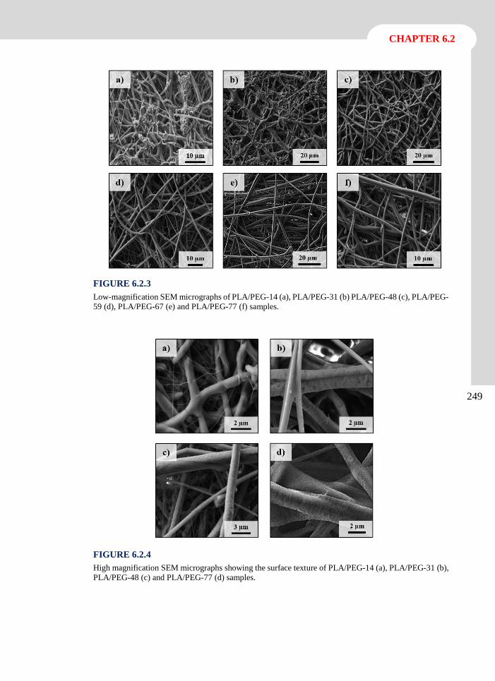
CHAPTER 6.2
249
FIGURE 6.2.3
Low-magnification SEM micrographs of PLA/PEG-14 (a), PLA/PEG-31 (b) PLA/PEG-48 (c), PLA/PEG-
59 (d), PLA/PEG-67 (e) and PLA/PEG-77 (f) samples.
FIGURE 6.2.4
High magnification SEM micrographs showing the surface texture of PLA/PEG-14 (a), PLA/PEG-31 (b),
PLA/PEG-48 (c) and PLA/PEG-77 (d) samples.
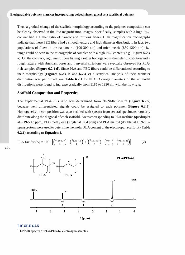
Biodegradable polymer matrices incorporating polyethylenen glycol as a sacrificial polymer
250
Thus, a gradual change of the scaffold morphology according to the polymer composition can
be clearly observed in the low magnification images. Specifically, samples with a high PEG
content had a higher ratio of narrow and tortuous fibers. High magnification micrographs
indicate that these PEG fibers had a smooth texture and high diameter distribution. In fact, two
populations of fibers in the nanometric (100-300 nm) and micrometric (850-1200 nm) size
range could be seen in the micrographs of samples with a high PEG content (e.g., Figure 6.2.4
a). On the contrary, rigid microfibers having a rather homogeneous diameter distribution and a
rough texture with abundant pores and tranversal striations were typically observed for PLA-
rich samples (Figure 6.2.4 d). Since PLA and PEG fibers could be differentiated according to
their morphology (Figures 6.2.4 b and 6.2.4 c) a statistical analysis of their diameter
distribution was performed, see Table 6.2.1 for PLA. Average diameters of the unimodal
distributions were found to increase gradually from 1185 to 1830 nm with the flow rate.
Scaffold Composition and Properties
The experimental PLA/PEG ratio was determined from 1H-NMR spectra (Figure 6.2.5)
because well differentiated signals could be assigned to each polymer (Figure 6.2.5).
Homogeneity in composition was also verified with spectra from several specimens regularly
distribute along the diagonal of each scaffold. Areas corresponding to PLA methine (quadruplet
at 5.19-5.13 ppm), PEG methylene (singlet at 3.64 ppm) and PLA methyl (doublet at 1.59-1.57
ppm) protons were used to determine the molar PLA content of the electrospun scaffolds (Table
6.2.1) according to Equation 2.
PLA (molar-%) = 100 · [(A1.59-1.57
3) + (
A5.18-5.15
1)] / [(
A1.59-1.57
3) + (
A3.64
4) + (
A5.18-5.15
1)] (2)
FIGURE 6.2.5
1H-NMR spectra of PLA/PEG-67 electrospun samples.
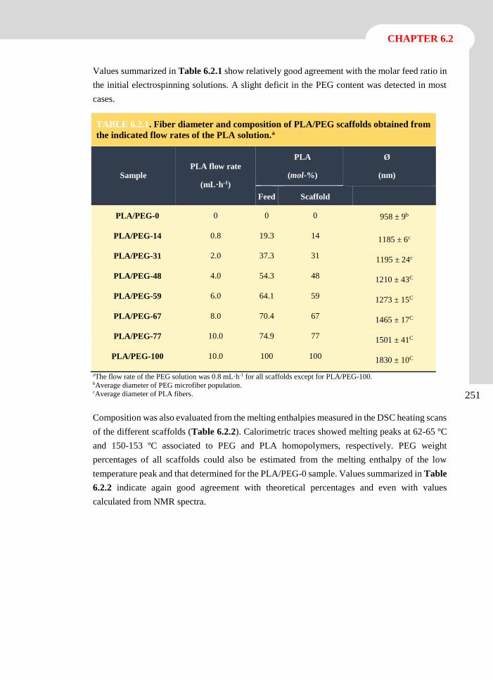
CHAPTER 6.2
251
Values summarized in Table 6.2.1 show relatively good agreement with the molar feed ratio in
the initial electrospinning solutions. A slight deficit in the PEG content was detected in most
cases.
aThe flow rate of the PEG solution was 0.8 mL·h-1 for all scaffolds except for PLA/PEG-100. bAverage diameter of PEG microfiber population. cAverage diameter of PLA fibers.
Composition was also evaluated from the melting enthalpies measured in the DSC heating scans
of the different scaffolds (Table 6.2.2). Calorimetric traces showed melting peaks at 62-65 ºC
and 150-153 ºC associated to PEG and PLA homopolymers, respectively. PEG weight
percentages of all scaffolds could also be estimated from the melting enthalpy of the low
temperature peak and that determined for the PLA/PEG-0 sample. Values summarized in Table
6.2.2 indicate again good agreement with theoretical percentages and even with values
calculated from NMR spectra.
TABLE 6.2.1. Fiber diameter and composition of PLA/PEG scaffolds obtained from
the indicated flow rates of the PLA solution.a
Sample PLA flow rate
(mL·h-1)
PLA
(mol-%)
Ø
(nm)
Feed Scaffold
PLA/PEG-0 0 0 0 958 ± 9b
PLA/PEG-14 0.8 19.3 14 1185 ± 6c
PLA/PEG-31 2.0 37.3 31 1195 ± 24c
PLA/PEG-48 4.0 54.3 48 1210 ± 43C
PLA/PEG-59 6.0 64.1 59 1273 ± 15C
PLA/PEG-67 8.0 70.4 67 1465 ± 17C
PLA/PEG-77 10.0 74.9 77 1501 ± 41C
PLA/PEG-100 10.0 100 100 1830 ± 10C
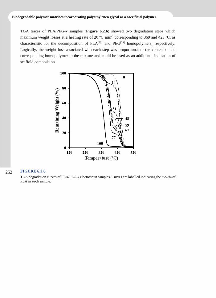
Biodegradable polymer matrices incorporating polyethylenen glycol as a sacrificial polymer
252
TGA traces of PLA/PEG-x samples (Figure 6.2.6) showed two degradation steps which
maximum weight losses at a heating rate of 20 ºC·min-1 corresponding to 369 and 423 ºC, as
characteristic for the decomposition of PLA[23] and PEG[24] homopolymers, respectively.
Logically, the weight loss associated with each step was proportional to the content of the
corresponding homopolymer in the mixture and could be used as an additional indication of
scaffold composition.
FIGURE 6.2.6
TGA degradation curves of PLA/PEG-x electrospun samples. Curves are labelled indicating the mol-% of
PLA in each sample.
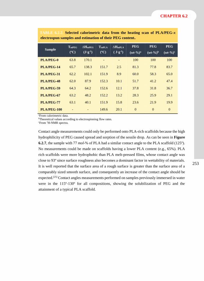
CHAPTER 6.2
253
aFrom calorimetric data. bTheoretical values according to electrospinning flow rates. cFrom 1H-NMR spectra.
Contact angle measurements could only be performed onto PLA-rich scaffolds because the high
hydrophilicity of PEG caused spread and sorption of the sessile drop. As can be seen in Figure
6.2.7, the sample with 77 mol-% of PLA had a similar contact angle to the PLA scaffold (125º).
No measurements could be made on scaffolds having a lower PLA content (e.g., 65%). PLA
rich scaffolds were more hydrophobic than PLA melt-pressed films, whose contact angle was
close to 93º since surface roughness also becomes a dominant factor in wettability of materials.
It is well reported that the surface area of a rough surface is greater than the surface area of a
comparably sized smooth surface, and consequently an increase of the contact angle should be
expected.[25] Contact angles measurements performed on samples previously immersed in water
were in the 115º-130º for all compositions, showing the solubilization of PEG and the
attainment of a typical PLA scaffold.
TABLE 6.2.2. Selected calorimetric data from the heating scan of PLA/PEG-x electrospun samples and estimation of their PEG content.
Sample TmPEG
(ºC)
∆HmPEG
(J·g-1)
TmPLA
(ºC)
∆HmPLA
( J·g-1)
PEG
(wt-%)a
PEG
(wt-%)b
PEG
(wt-%)c
PLA/PEG-0 63.8 170.1 - - 100 100 100
PLA/PEG-14 65.7 138.3 151.7 2.5 81.3 77.8 83.7
PLA/PEG-31 62.2 102.1 151.9 8.9 60.0 58.3 65.0
PLA/PEG-48 62.0 87.9 152.3 10.1 51.7 41.2 47.4
PLA/PEG-59 64.3 64.2 152.6 12.1 37.8 31.8 36.7
PLA/PEG-67 63.2 48.2 152.2 13.2 28.3 25.9 29.1
PLA/PEG-77 63.1 40.1 151.9 15.8 23.6 21.9 19.9
PLA/PEG-100 - - 149.6 20.1 0 0 0
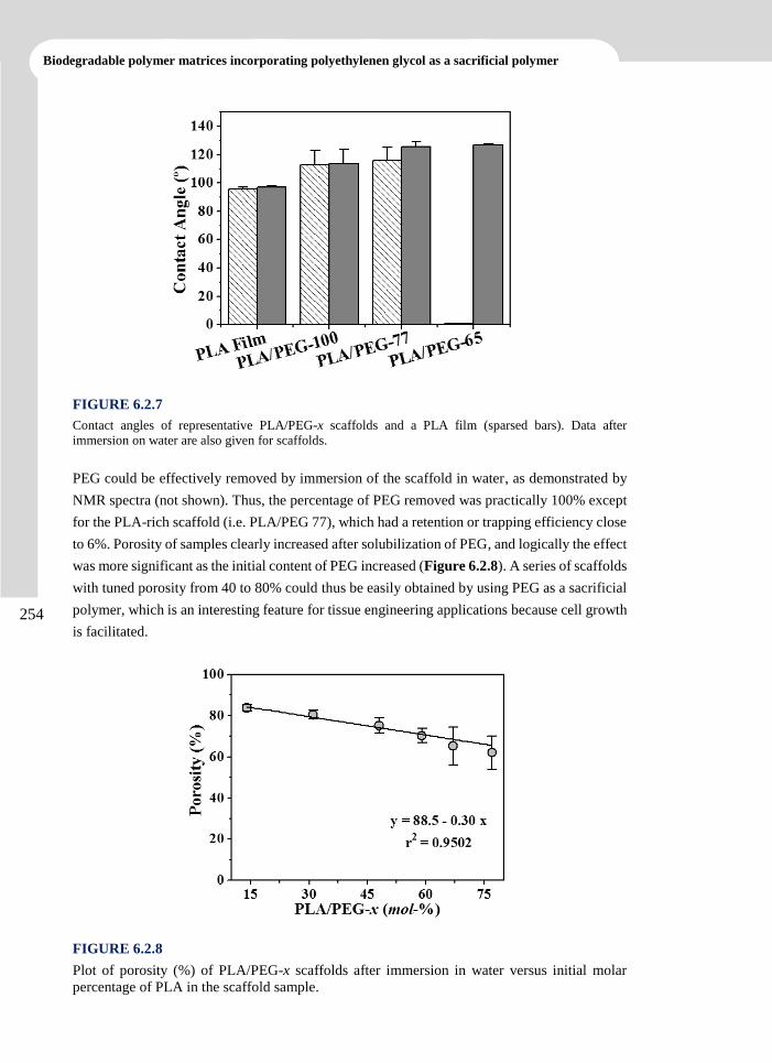
Biodegradable polymer matrices incorporating polyethylenen glycol as a sacrificial polymer
254
FIGURE 6.2.7
Contact angles of representative PLA/PEG-x scaffolds and a PLA film (sparsed bars). Data after
immersion on water are also given for scaffolds.
PEG could be effectively removed by immersion of the scaffold in water, as demonstrated by
NMR spectra (not shown). Thus, the percentage of PEG removed was practically 100% except
for the PLA-rich scaffold (i.e. PLA/PEG 77), which had a retention or trapping efficiency close
to 6%. Porosity of samples clearly increased after solubilization of PEG, and logically the effect
was more significant as the initial content of PEG increased (Figure 6.2.8). A series of scaffolds
with tuned porosity from 40 to 80% could thus be easily obtained by using PEG as a sacrificial
polymer, which is an interesting feature for tissue engineering applications because cell growth
is facilitated.
FIGURE 6.2.8
Plot of porosity (%) of PLA/PEG-x scaffolds after immersion in water versus initial molar
percentage of PLA in the scaffold sample.
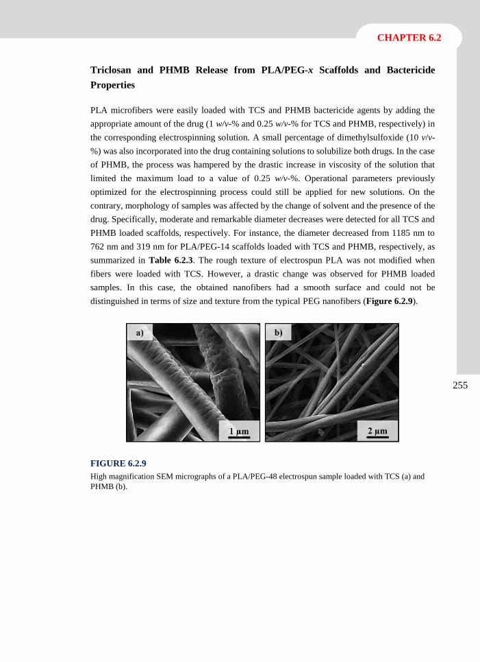
CHAPTER 6.2
255
Triclosan and PHMB Release from PLA/PEG-x Scaffolds and Bactericide
Properties
PLA microfibers were easily loaded with TCS and PHMB bactericide agents by adding the
appropriate amount of the drug (1 w/v-% and 0.25 w/v-% for TCS and PHMB, respectively) in
the corresponding electrospinning solution. A small percentage of dimethylsulfoxide (10 v/v-
%) was also incorporated into the drug containing solutions to solubilize both drugs. In the case
of PHMB, the process was hampered by the drastic increase in viscosity of the solution that
limited the maximum load to a value of 0.25 w/v-%. Operational parameters previously
optimized for the electrospinning process could still be applied for new solutions. On the
contrary, morphology of samples was affected by the change of solvent and the presence of the
drug. Specifically, moderate and remarkable diameter decreases were detected for all TCS and
PHMB loaded scaffolds, respectively. For instance, the diameter decreased from 1185 nm to
762 nm and 319 nm for PLA/PEG-14 scaffolds loaded with TCS and PHMB, respectively, as
summarized in Table 6.2.3. The rough texture of electrospun PLA was not modified when
fibers were loaded with TCS. However, a drastic change was observed for PHMB loaded
samples. In this case, the obtained nanofibers had a smooth surface and could not be
distinguished in terms of size and texture from the typical PEG nanofibers (Figure 6.2.9).
FIGURE 6.2.9
High magnification SEM micrographs of a PLA/PEG-48 electrospun sample loaded with TCS (a) and
PHMB (b).
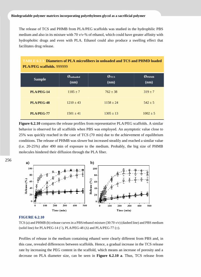
Biodegradable polymer matrices incorporating polyethylenen glycol as a sacrificial polymer
256
The release of TCS and PHMB from PLA/PEG scaffolds was studied in the hydrophilic PBS
medium and also in its mixture with 70 v/v-% of ethanol, which could have greater affinity with
hydrophobic drugs and even with PLA. Ethanol could also produce a swelling effect that
facilitates drug release.
Figure 6.2.10 compares the release profiles from representative PLA/PEG scaffolds. A similar
behavior is observed for all scaffolds when PBS was employed. An asymptotic value close to
25% was quickly reached in the case of TCS (70 min) due to the achievement of equilibrium
conditions. The release of PHMB was slower but increased steadily and reached a similar value
(i.e. 20-25%) after 490 min of exposure to the medium. Probably, the big size of PHMB
molecules hindered their diffusion through the PLA fiber.
FIGURE 6.2.10
TCS (a) and PHMB (b) release curves in a PBS/ethanol mixture (30:70 v/v) (dashed line) and PBS medium
(solid line) for PLA/PEG-14 (◯), PLA/PEG-48 () and PLA/PEG-77 (□).
Profiles of release in the medium containing ethanol were clearly different from PBS and, in
this case, revealed differences between scaffolds. Hence, a gradual increase in the TCS release
rate by increasing the PEG content in the scaffold, which means an increase of porosity and a
decrease on PLA diameter size, can be seen in Figure 6.2.10 a. Thus, TCS release from
TABLE 6.2.3. Diameters of PLA microfibers in unloaded and TCS and PHMD loaded
PLA/PEG scaffolds. 999999
Sample Øunloaded
(nm)
ØTCS
(nm)
ØPHMB
(nm)
PLA/PEG-14 1185 ± 7 762 ± 38 319 ± 7
PLA/PEG-48 1210 ± 43 1158 ± 24 542 ± 5
PLA/PEG-77 1501 ± 41 1305 ± 13 1002 ± 5
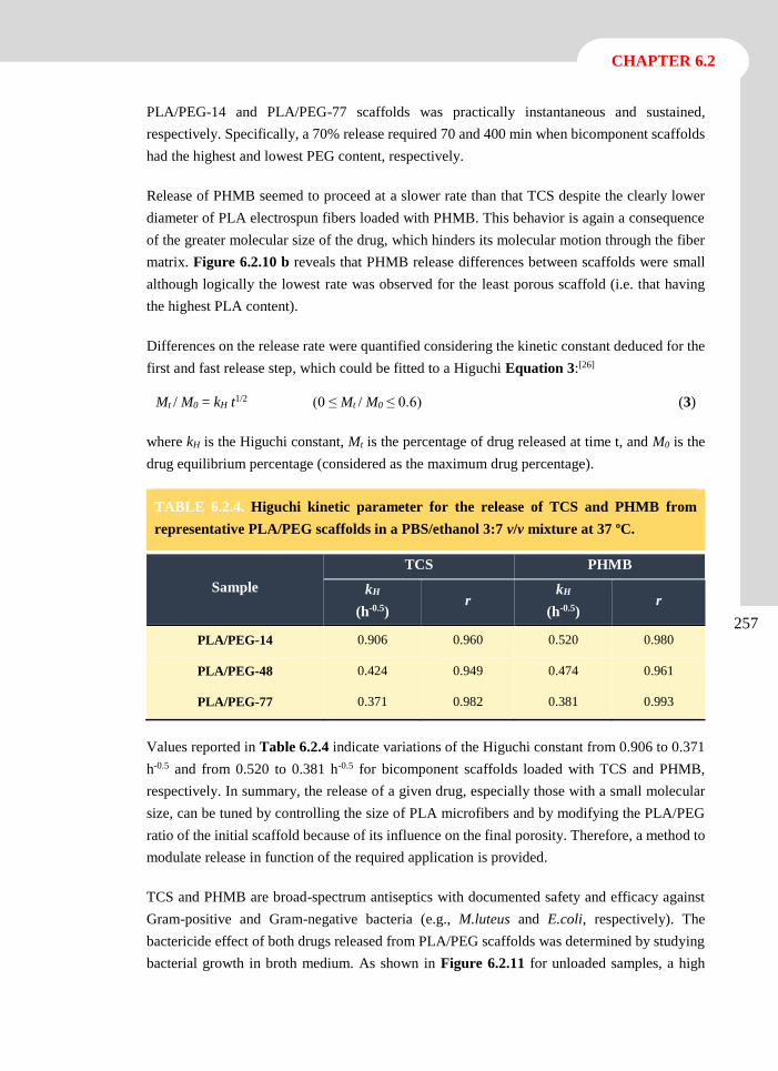
CHAPTER 6.2
257
PLA/PEG-14 and PLA/PEG-77 scaffolds was practically instantaneous and sustained,
respectively. Specifically, a 70% release required 70 and 400 min when bicomponent scaffolds
had the highest and lowest PEG content, respectively.
Release of PHMB seemed to proceed at a slower rate than that TCS despite the clearly lower
diameter of PLA electrospun fibers loaded with PHMB. This behavior is again a consequence
of the greater molecular size of the drug, which hinders its molecular motion through the fiber
matrix. Figure 6.2.10 b reveals that PHMB release differences between scaffolds were small
although logically the lowest rate was observed for the least porous scaffold (i.e. that having
the highest PLA content).
Differences on the release rate were quantified considering the kinetic constant deduced for the
first and fast release step, which could be fitted to a Higuchi Equation 3:[26]
Mt / M0 = kH t1/2 (0 ≤ Mt / M0 ≤ 0.6) (3)
where kH is the Higuchi constant, Mt is the percentage of drug released at time t, and M0 is the
drug equilibrium percentage (considered as the maximum drug percentage).
TABLE 6.2.4. Higuchi kinetic parameter for the release of TCS and PHMB from
representative PLA/PEG scaffolds in a PBS/ethanol 3:7 v/v mixture at 37 ºC.
Sample
TCS PHMB
kH
(h-0.5) r
kH
(h-0.5) r
PLA/PEG-14 0.906 0.960 0.520 0.980
PLA/PEG-48 0.424 0.949 0.474 0.961
PLA/PEG-77 0.371 0.982 0.381 0.993
Values reported in Table 6.2.4 indicate variations of the Higuchi constant from 0.906 to 0.371
h-0.5 and from 0.520 to 0.381 h-0.5 for bicomponent scaffolds loaded with TCS and PHMB,
respectively. In summary, the release of a given drug, especially those with a small molecular
size, can be tuned by controlling the size of PLA microfibers and by modifying the PLA/PEG
ratio of the initial scaffold because of its influence on the final porosity. Therefore, a method to
modulate release in function of the required application is provided.
TCS and PHMB are broad-spectrum antiseptics with documented safety and efficacy against
Gram-positive and Gram-negative bacteria (e.g., M.luteus and E.coli, respectively). The
bactericide effect of both drugs released from PLA/PEG scaffolds was determined by studying
bacterial growth in broth medium. As shown in Figure 6.2.11 for unloaded samples, a high
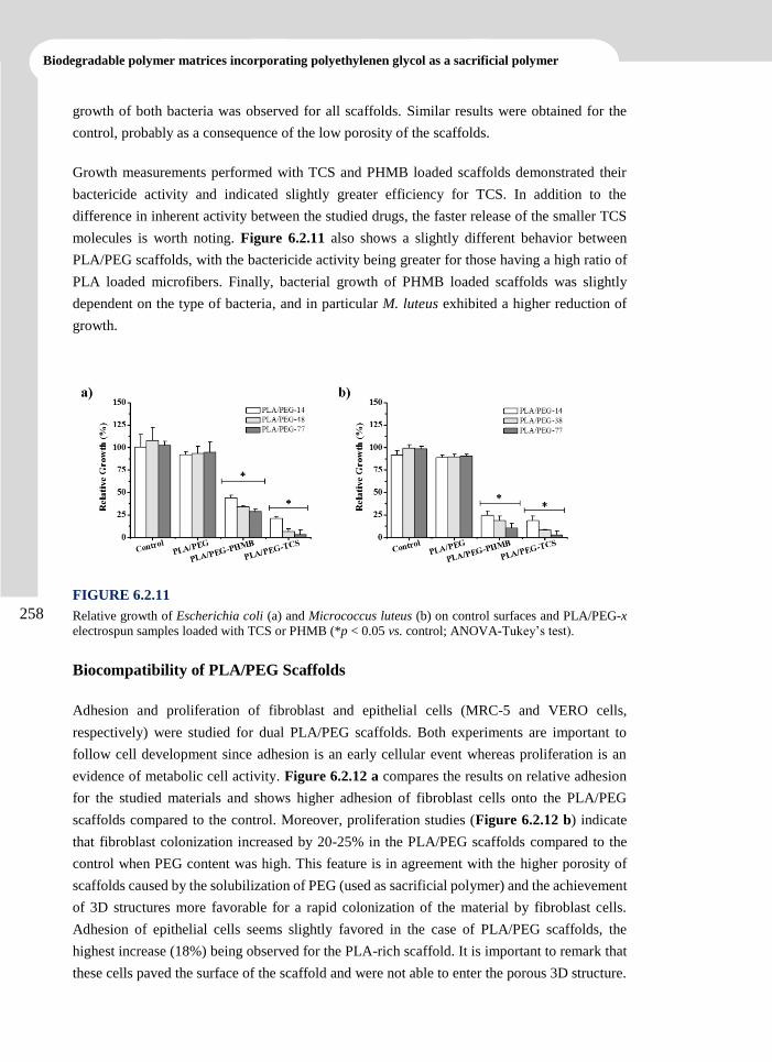
Biodegradable polymer matrices incorporating polyethylenen glycol as a sacrificial polymer
258
growth of both bacteria was observed for all scaffolds. Similar results were obtained for the
control, probably as a consequence of the low porosity of the scaffolds.
Growth measurements performed with TCS and PHMB loaded scaffolds demonstrated their
bactericide activity and indicated slightly greater efficiency for TCS. In addition to the
difference in inherent activity between the studied drugs, the faster release of the smaller TCS
molecules is worth noting. Figure 6.2.11 also shows a slightly different behavior between
PLA/PEG scaffolds, with the bactericide activity being greater for those having a high ratio of
PLA loaded microfibers. Finally, bacterial growth of PHMB loaded scaffolds was slightly
dependent on the type of bacteria, and in particular M. luteus exhibited a higher reduction of
growth.
FIGURE 6.2.11
Relative growth of Escherichia coli (a) and Micrococcus luteus (b) on control surfaces and PLA/PEG-x
electrospun samples loaded with TCS or PHMB (*p < 0.05 vs. control; ANOVA-Tukey’s test).
Biocompatibility of PLA/PEG Scaffolds
Adhesion and proliferation of fibroblast and epithelial cells (MRC-5 and VERO cells,
respectively) were studied for dual PLA/PEG scaffolds. Both experiments are important to
follow cell development since adhesion is an early cellular event whereas proliferation is an
evidence of metabolic cell activity. Figure 6.2.12 a compares the results on relative adhesion
for the studied materials and shows higher adhesion of fibroblast cells onto the PLA/PEG
scaffolds compared to the control. Moreover, proliferation studies (Figure 6.2.12 b) indicate
that fibroblast colonization increased by 20-25% in the PLA/PEG scaffolds compared to the
control when PEG content was high. This feature is in agreement with the higher porosity of
scaffolds caused by the solubilization of PEG (used as sacrificial polymer) and the achievement
of 3D structures more favorable for a rapid colonization of the material by fibroblast cells.
Adhesion of epithelial cells seems slightly favored in the case of PLA/PEG scaffolds, the
highest increase (18%) being observed for the PLA-rich scaffold. It is important to remark that
these cells paved the surface of the scaffold and were not able to enter the porous 3D structure.
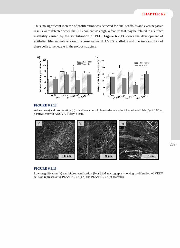
CHAPTER 6.2
259
Thus, no significant increase of proliferation was detected for dual scaffolds and even negative
results were detected when the PEG content was high, a feature that may be related to a surface
instability caused by the solubilization of PEG. Figure 6.2.13 shows the development of
epithelial film monolayers onto representative PLA/PEG scaffolds and the impossibility of
these cells to penetrate in the porous structure.
FIGURE 6.2.12
Adhesion (a) and proliferation (b) of cells on control plate surfaces and not loaded scaffolds (*p < 0.05 vs.
positive control; ANOVA-Tukey’s test).
FIGURE 6.2.13
Low-magnification (a) and high-magnification (b,c) SEM micrographs showing proliferation of VERO
cells on representative PLA/PEG-77 (a,b) and PLA/PEG-77 (c) scaffolds.
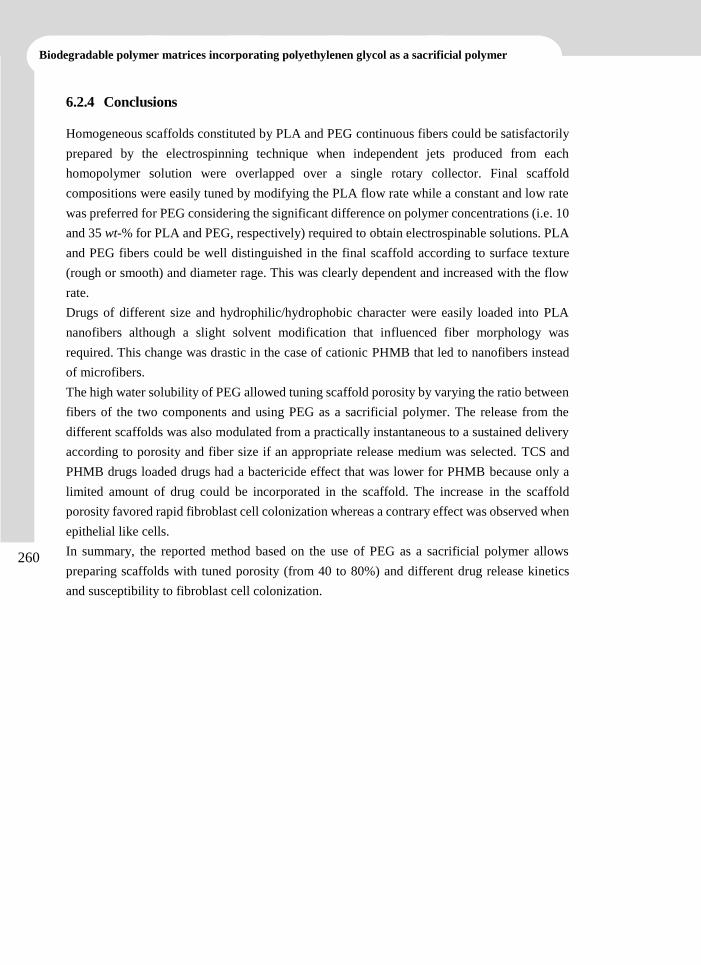
Biodegradable polymer matrices incorporating polyethylenen glycol as a sacrificial polymer
260
6.2.4 Conclusions
Homogeneous scaffolds constituted by PLA and PEG continuous fibers could be satisfactorily
prepared by the electrospinning technique when independent jets produced from each
homopolymer solution were overlapped over a single rotary collector. Final scaffold
compositions were easily tuned by modifying the PLA flow rate while a constant and low rate
was preferred for PEG considering the significant difference on polymer concentrations (i.e. 10
and 35 wt-% for PLA and PEG, respectively) required to obtain electrospinable solutions. PLA
and PEG fibers could be well distinguished in the final scaffold according to surface texture
(rough or smooth) and diameter rage. This was clearly dependent and increased with the flow
rate.
Drugs of different size and hydrophilic/hydrophobic character were easily loaded into PLA
nanofibers although a slight solvent modification that influenced fiber morphology was
required. This change was drastic in the case of cationic PHMB that led to nanofibers instead
of microfibers.
The high water solubility of PEG allowed tuning scaffold porosity by varying the ratio between
fibers of the two components and using PEG as a sacrificial polymer. The release from the
different scaffolds was also modulated from a practically instantaneous to a sustained delivery
according to porosity and fiber size if an appropriate release medium was selected. TCS and
PHMB drugs loaded drugs had a bactericide effect that was lower for PHMB because only a
limited amount of drug could be incorporated in the scaffold. The increase in the scaffold
porosity favored rapid fibroblast cell colonization whereas a contrary effect was observed when
epithelial like cells.
In summary, the reported method based on the use of PEG as a sacrificial polymer allows
preparing scaffolds with tuned porosity (from 40 to 80%) and different drug release kinetics
and susceptibility to fibroblast cell colonization.
CHAPTER 6.2
261
6.2.5 References
[1] D.H. Reneker, I. Chun, Nanotechnology, 7 (1996) 216-223.
[2] Y. Dzenis, Science, 304 (2004) 1917-1919.
[3] D. Li, Y.N. Xia, Adv Mater, 16 (2004) 1151-1170.
[4] K. Jayaraman, M. Kotaki, Y.Z. Zhang, X.M. Mo, S. Ramakrishna, J Nanosci
Nanotechno, 4 (2004) 52-65.
[5] Z.C. Sun, E. Zussman, A.L. Yarin, J.H. Wendorff, A. Greiner, Adv Mater, 15 (2003)
1929-1932.
[6] Y. Liao, L. Zhang, Y. Gao, Z.-T. Zhu, H. Fong, Polymer, 49 (2008) 5294-5299.
[7] S.N. Stephansson, B.A. Byers, A.J. Garcia, Biomaterials, 23 (2002) 2527-2534.
[8] Y. Lin, L.L. Wang, P.B. Zhang, X. Wang, X.S. Chen, X.B. Jing, Z.H. Su, Acta Biomater,
2 (2006) 155-164.
[9] D.A. Herold, K. Keil, D.E. Bruns, Biochem Pharmacol, 38 (1989) 73-76.
[10] Y.K. Luu, K. Kim, B.S. Hsiao, B. Chu, M. Hadjiargyrou, J Control Release, 89 (2003)
341-353.
[11] X. Xu, L. Yang, X. Xu, X. Wang, X. Chen, Q. Liang, J. Zeng, X. Jing, J Control Release,
108 (2005) 33-42.
[12] X.H. Zong, H. Bien, C.-Y. Chung, L.F. Yin, D. Fang, B.S. Hsiao, B. Chu, E. Entcheva,
Biomaterials, 26 (2005) 5330-5338.
[13] X. Xu, X. Zhuang, X. Chen, X. Wang, L. Yang, X. Jing, Macromol Rapid Comm, 27
(2006) 1637-1642.
[14] M. Spasova, O. Stoilova, N. Manolova, I. Rashkov, G. Altankov, J Bioact Compat Pol,
22 (2007) 62-76.
[15] P.Y. Ni, S.Z. Fu, M. Fan, G. Guo, S.A. Shi, J.R. Peng, F. Luo, Z.Y. Qian, Int J Nanomed,
6 (2011) 3065-3075.
[16] B.Y. Wang, S.Z. Fu, P.Y. Ni, J.R. Peng, L. Zheng, F. Luo, H. Liu, Z.Y. Qian, J Biomed
Mater Res A, 100A (2012) 441-449.
[17] E. Llorens, L.J. Valle, R. Ferrán, A. Rodríguez-Galán, J. Puiggalí, J Polym Res, 21
(2014) 1-15.
[18] A.D. Russell, J AntimicrobChemoth, 53 (2004) 693-695.
Biodegradable polymer matrices incorporating polyethylenen glycol as a sacrificial polymer
262
[19] G.F. de Paula, G.I. Netto, L.H.C. Mattoso, Polymers, 3 (2011) 928-941.
[20] B. Roth, F.H.H. Brill, Skin Pharmacol Phys, 23 (2010) 4-6.
[21] P. Gilbert, D. Pemberton, D.E. Wilkinson, J App Bacteriol, 69 (1990) 593-598.
[22] E. Llorens, L.J. del Valle, A. Diaz, M.T. Casas, J. Puiggali, Macromol Res, 21 (2013)
775-787.
[23] F.D. Kopinke, M. Remmler, K. Mackenzie, M. Moder, O. Wachsen, Polym Degrad
Stabil, 53 (1996) 329-342.
[24] S.L. Madorsky, S. Straus, J Polym Sci, 36 (1959) 183-194.
[25] R.N. Wenzel, Ind Eng Chem, 28 (1936) 988-994.
[26] T. Higuchi, J Pharm Sci, 50 (1961) 874-875.
Biocompatibility and Drug Release Behavior of
Scaffolds Prepared by Coaxial Electrospinning
of Poly(Butylene succinate) and Polyethylene
Glycol
I
Scaffolds constituted by electrospun microfibers of poly(ethylene
glycol) (PEG) and poly(butylene succinate) (PBS) were studied.
Specifically, coaxial microfibers having different core-shell
distributions and compositions were considered as well as uniaxial
micro/nanofibers prepared from mixtures of both polymers.
Processing conditions were optimized for all geometries and
compositions and resulting morphologies (i.e. diameter and
surface texture) characterized by scanning electron microscopy.
Chemical composition, molecular interactions and thermal
properties were evaluated by means of FTIR, NMR and XPS and
differential scanning calorimetry. The PEG component of
electrospun fibers could be solubilized by immersion of scaffolds
in aqueous medium, giving rise to high porosity and hydrophobic
samples. Nevertheless, a small amount of PEG was retained in the
PBS matrix, suggesting some degree of mixing. Solubilization was
slightly dependent on fiber structure; specifically, the distribution
of PEG in the core or shell of coaxial fibers led to higher or lower
retention levels, respectively. Scaffolds could be effectively loaded
with hydrophobic drugs having antibacterial and anticancerigen
activities like triclosan and curcumin, respectively. The release
was highly dependent on their chemical structure and the medium
composition. Thus, low and high release rates were observed in
phosphate saline buffer solution (SS) and SS/ethanol (30:70 v/v),
respectively. Slight differences in the release of triclosan were
found depending on fiber distribution and composition.
Antibacterial activity and biocompatibility were evaluated for both
loaded and unloaded scaffolds.
6.3
Biodegradable polymer matrices incorporating polyethylenen glycol as a sacrificial polymer
266
6.3.1 Introduction
Electrospinning is currently one of the simplest methods of drug loading into micro/nanofiber
scaffolds. The drug is dissolved or dispersed in a polymer solution that is subsequently exposed
to a strong electrical potential. Electrical charges accumulate on the surface of a liquid droplet
placed at the tip of a capillary and a charged jet is ejected towards a grounded electrode when
the Coulombic repulsion of the charges overcomes the surface tension of the polymer droplet.[1-
4] The solvent evaporates as it travels from the tip to the grounded target and fibers with different
morphology are collected depending on solution properties (e.g., viscosity, dielectric constant,
volatility, concentration, etc.) and operational parameters (e.g., strength of the applied electrical
field, deposition distance, flow rate, etc.).[5, 6]
Electrospun scaffolds for tissue regeneration and drug delivery applications have been
successfully been prepared from both natural polymers like collagen, gelatin, chitosan, silk
fibroin and hyaluronic acid and synthetic homopolymers and copolymers such as poly(lactic
acid) (PLA), poly(-caprolactone) (PCL), polyethylene glycol (PEG), poly(butylene succinate),
poly (L-lactide-co-caprolactone) and poly(lactic-co-glycolic acid) (PLGA).[7-11]
Drug-loaded micro/nanofibrous scaffolds can be applied topically or as an implant for
antibiotic, antifungal, antimicrobial,[12] antioxidant[13] and anticancer[14] drug delivery. Despite
the simplicity of this encapsulation procedure based on electrospinning, some requirements
should be met to attain optimal results. Thus, release behavior becomes highly dependent on
the distribution of drug molecules in electrospun fibers, as well as on the final morphology of
the fibers. Physicochemical interactions between drug molecules and the polymer matrix play
a fundamental role, and specifically the hydrophobic-hydrophilic properties of drug and
polymer should be matched in order to achieve a good drug encapsulation inside the electrospun
nanofibers. Lack of good interactions may cause drug migration during electrospinning on or
near the fiber surface, resulting in a significant burst effect.[15] In order to achieve sustained
release and improve molecular interactions, blending hydrophilic-hydrophobic polymers in
different ratios has been considered.[16, 17]
Coaxial electrospinning is a modification of the classical procedure that enables production of
micro/nanofibers with a core-shell structure and highly different compositions. In this case, two
polymer solutions are supplied by means of two separate syringe pumps and pipelines leading
to a core-shell nozzle. At the exit of this special needle a core-shell droplet appears and acquires
a shape similar to the Taylor cone. Nevertheless, the core material may be not entrained into
the shell jet, giving rise to monolithic instead of core-shell jets.[18] In fact, electric charges
escape very rapidly to the outer surface of the forming jet and core entrainment becomes only
possible by viscous tractions.[19]. Successful encapsulation of drug to the core of coelectrospun
fibers is determined by various parameters (e.g., shell polymer concentration, core polymer
concentration, molecular weight and drug concentration) as well as the relative flow rate of the
core and shell solutions.[20] Fiber morphology is sometimes critical and incorporation of a highly
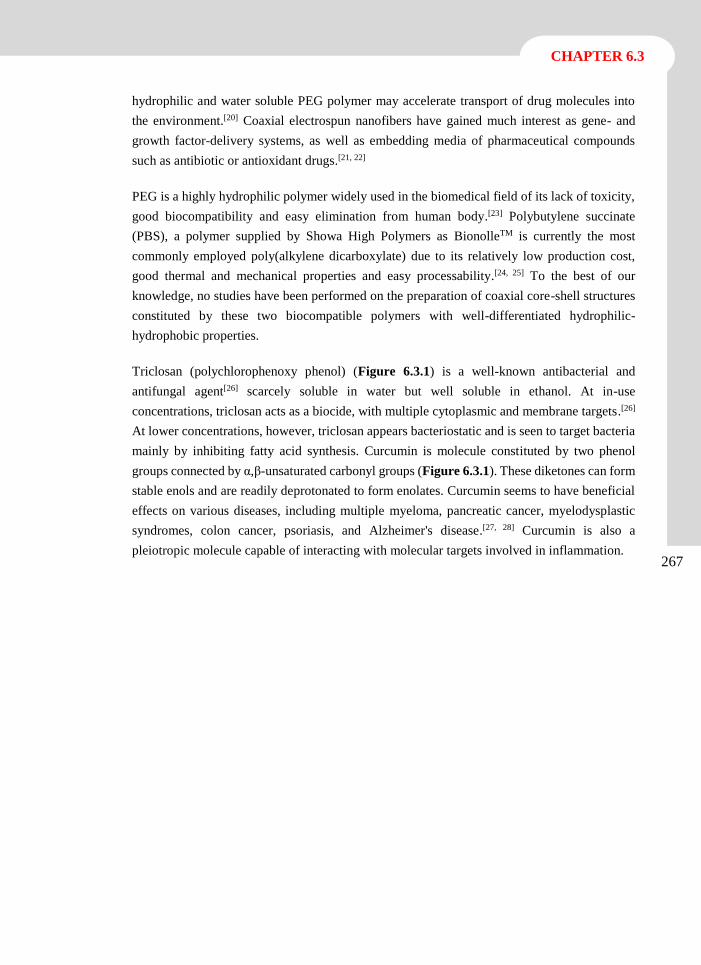
CHAPTER 6.3
267
hydrophilic and water soluble PEG polymer may accelerate transport of drug molecules into
the environment.[20] Coaxial electrospun nanofibers have gained much interest as gene- and
growth factor-delivery systems, as well as embedding media of pharmaceutical compounds
such as antibiotic or antioxidant drugs.[21, 22]
PEG is a highly hydrophilic polymer widely used in the biomedical field of its lack of toxicity,
good biocompatibility and easy elimination from human body.[23] Polybutylene succinate
(PBS), a polymer supplied by Showa High Polymers as BionolleTM is currently the most
commonly employed poly(alkylene dicarboxylate) due to its relatively low production cost,
good thermal and mechanical properties and easy processability.[24, 25] To the best of our
knowledge, no studies have been performed on the preparation of coaxial core-shell structures
constituted by these two biocompatible polymers with well-differentiated hydrophilic-
hydrophobic properties.
Triclosan (polychlorophenoxy phenol) (Figure 6.3.1) is a well-known antibacterial and
antifungal agent[26] scarcely soluble in water but well soluble in ethanol. At in-use
concentrations, triclosan acts as a biocide, with multiple cytoplasmic and membrane targets.[26]
At lower concentrations, however, triclosan appears bacteriostatic and is seen to target bacteria
mainly by inhibiting fatty acid synthesis. Curcumin is molecule constituted by two phenol
groups connected by α,β-unsaturated carbonyl groups (Figure 6.3.1). These diketones can form
stable enols and are readily deprotonated to form enolates. Curcumin seems to have beneficial
effects on various diseases, including multiple myeloma, pancreatic cancer, myelodysplastic
syndromes, colon cancer, psoriasis, and Alzheimer's disease.[27, 28] Curcumin is also a
pleiotropic molecule capable of interacting with molecular targets involved in inflammation.
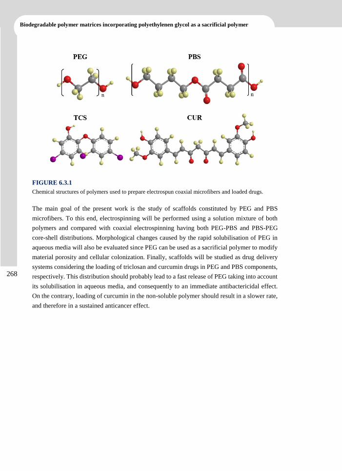
Biodegradable polymer matrices incorporating polyethylenen glycol as a sacrificial polymer
268
FIGURE 6.3.1
Chemical structures of polymers used to prepare electrospun coaxial microfibers and loaded drugs.
The main goal of the present work is the study of scaffolds constituted by PEG and PBS
microfibers. To this end, electrospinning will be performed using a solution mixture of both
polymers and compared with coaxial electrospinning having both PEG-PBS and PBS-PEG
core-shell distributions. Morphological changes caused by the rapid solubilisation of PEG in
aqueous media will also be evaluated since PEG can be used as a sacrificial polymer to modify
material porosity and cellular colonization. Finally, scaffolds will be studied as drug delivery
systems considering the loading of triclosan and curcumin drugs in PEG and PBS components,
respectively. This distribution should probably lead to a fast release of PEG taking into account
its solubilisation in aqueous media, and consequently to an immediate antibactericidal effect.
On the contrary, loading of curcumin in the non-soluble polymer should result in a slower rate,
and therefore in a sustained anticancer effect.
CHAPTER 6.3
269
6.3.2 Experimental Section
Materials
Poly(ethylene glycol) samples of number average molecular weight of 35,000 g·mol-1 weas
purchased from Sigma-Aldrich. Polybutylene succinate is a commercial product (Bionolle®
1001) supplied by Showa Denko K.K. (Germany). The polymer has a melt flow index of 1.6
g·10 min-1 (measured at 190 ºC under a load of 2.16 Kg according to ASTM-D1238). Solvents,
curcumin, triclosan and cell culture labware were purchased from Sigma-Aldrich (USA).
Escherichia coli CECT 101 and Micrococcus luteus CECT 245 bacterial strains were obtained
from Spanish Collection of Type Culture (Valencia, Spain). Fibroblast-like Cos-7 and
ephithelial-like Vero cells from kidney African green monkey were purchased from ATCC
(USA).
Electrospinning
Electrospun fibers were collected on a target placed at different distances (10-25 cm) from the
needle tip (inside diameter of 0.84 mm) or the core-shell nozzle (inside diameters 1.37 mm and
2.39 mm) for single fiber or core-shell structure preparations, respectively. The voltage was
varied between 10 and 30 kV and applied to the target using a high-voltage supply (Gamma
High Voltage Research, ES30-5W). Polymer solutions were delivered via a single or two
KDS100 infusion syringe pumps (KD Scientific, USA) to control the flow rate (from 1 to 5
mL·h-1). All electrospinning experiments were carried out at room temperature. Unloaded and
triclosan and curcumin loaded electrospun fibers were prepared using optimized parameters
(e.g., collector distance, voltage and flow rate) and solvent conditions (e.g., polymer and drug
concentrations). The triclosan and curcumin contents of the electrospinning solutions were 1
and 0.5 w/v-% for samples used for release and antibacterial assays, and for cytotoxicity assays,
respectively. Coaxial electrospun microfibers will be denoted by subscripts s and c, which
indicate the polymer that constitutes the shell and the core, respectively. Absence of these
scripts indicates fibers prepared from a polymer mixture. Weight percentages of each polymer
in the electrospinning solutions are also given in the sample abbreviation.
Morphology, composition and properties of electrospun scaffolds
Optical microscopy studies were performed with a Zeiss Axioskop 40 microscope. Micrographs
were taken with a Zeiss AxiosCam MRC5 digital camera.
Detailed inspection of texture and morphology of electrospun samples was conducted by
scanning electron microscopy using a Focus Ion Beam Zeiss Neon 40 instrument (Carl Zeiss,
Germany). Carbon coating was accomplished by using a Mitec K950 Sputter Coater fitted with
a film thickness monitor k150x. Samples were visualized at an accelerating voltage of 5 kV.
Diameter of electrospun fibers was measured with the SmartTiff software from Carl Zeiss SMT
Ltd.
Biodegradable polymer matrices incorporating polyethylenen glycol as a sacrificial polymer
270
1H-NMR spectra were acquired with a Bruker AMX-300 spectrometer operating at 300.1 MHz.
Chemical shifts were calibrated using tetramethylsilane as an internal standard. Deuterated
chloroform (CDCl3) was used as the solvent at room temperature.
Infrared absorption spectra were recorded in the 3600 - 600 cm-1 range on a Jasco FTIR 4100
Fourier Transform spectrometer. A Specac MKII Golden Gate attenuated total reflection (ATR)
accessory was employed.
X-ray photoelectron spectroscopy (XPS) was performed with a SPECS system equipped with
an Al anode XR50 source operating at 200 W and a Phoibos 150 MCD-9 detector XP. Samples
were fixed in a special sample holder with double sided carbon adhesive tape. The overview
spectra were recorded with pass energy of 25 eV at 0.1 eV steps at a pressure below 7.5x10⁻⁹
mbar, with binding energies being referred to the C1s and O1s signals. The overlapping peaks
were deconvoluted using the PeakFit v4 program by Jandel Scientific Software.
Contact angles (CA) were measured at room temperature with sessile drops using an OCA-15
plus Contact Angle Microscope (Dataphysics, USA) and SCA20 software. Contact angle values
of the right and left sides of distilled water drops were measured and averaged. Measurements
were performed 10 s after the drop (5 mL) was deposited on the sample surface. All CA data
were an average of six measurements on different surface locations.
Calorimetric data were obtained by differential scanning calorimetry with a TA Instruments
Q100 series equipped with a refrigeration cooling system (RCS). Experiments were conducted
under a flow of dry nitrogen with a sample weight of approximately 5 mg, and calibration was
performed with indium. Heating and cooling runs were carried out at rates of 20 ºC·min-1 and
10 ºC·min-1, respectively.
Porosity of PLA/PGE scaffolds
The porosity of electrospun scaffolds was measured by the liquid intrusion method. Vacuum
dried scaffolds (n = 3) were weighed prior to immersion in water for 1 h using a shaker table to
allow diffusion of water into the void volume. The scaffolds were taken out and reweighed.
Porosity was calculated according to Equation 1:
P = [(mw - md) / ds)] / (mw - md) / ds] + [mdPBS / dPBS] + [md
PEG / dPEG] (1)
where mw, md, mdPBS, md
PEGare the weights of the wet scaffold, dry scaffold, PBS fraction and
PEG fraction in the dry scaffold, respectively, and ds, dPBS and dPEG refer to the densities of water
(i.e. 1.0 g·mL-1), semicrystalline PBS (1.26 g·mL-1) and semicrystalline PEG (1.07 g·mL-1),
respectively. The last densities were estimated using DSC data of scaffolds which pointed to a
high crystallinity for both PEG and PBS phases.
CHAPTER 6.3
271
Release experiments
Controlled release measurements were made with square pieces (weighting approximately 200
mg) of the electrospun scaffolds. These pieces were weighed and incubated at 37 ºC in an orbital
shaker at 200 rpm in tubes of 50 mL for 1 week. Phosphate saline buffer solution (SS) and
alternatively its mixture with ethanol (i.e. 3:7 v/v ratio) as a more hydrophobic component were
employed as release media. Drug concentration was evaluated by UV spectroscopy using a
Shimadzu 3600 spectrometer. Calibration curves were obtained by plotting the absorbance
measured at 290 and 243 nm versus triclosan and curcumine concentration, respectively, in the
hydrophilic medium, whereas 280 nm was considered for triclosan when ethanol was added in
the medium. Samples were withdrawn from the release medium at predetermined time intervals.
The volume was kept constant by addition of fresh medium. All drug release tests were carried
out using three replicates and the results were averaged.
Cellular adhesion and proliferation assays
Human fetal lung fibroblast (MRC-5) and African green monkey kidney epithelial (Vero) cells
were cultured in Dulbecco’s modified Eagle medium (DMEM) as previously reported.[29]
Square pieces (0.5×0.5×0.1 mm3) of the electrospun scaffolds were placed into each well of a
multiwell culture plate. Samples were fixed in the wells with a small drop of silicone (Silbione®
MED ADH 4300 RTV, Bluestar Silicones France SAS, Lyon, France) and then sterilized by
UV-radiation in a laminar flux cabinet for 15 min. For the cell adhesion assay, aliquots of 50-
100 µL containing 5x10⁴ cells were seeded onto the electrospun samples in each well and
incubated for 24 h (adhesion assay) or 4 days (proliferation assay).
Samples were evaluated by the standard adhesion and proliferation method[13] using three
replicates and the results were averaged. Samples with adhered and grown cells on the mats
were fixed with 2.5 w/v-% formaldehyde at 4 ºC overnight. They were subsequently dehydrated
and processed for observation by scanning electronic microscopy.
Antimicrobial test
Escherichia coli (E. coli) and Micrococcus luteus (M. luteus) bacteria were selected to evaluate
the antimicrobial effect of electrospun CUM and TCS loaded fibers. The bacteria were
previously grown aerobically to exponential phase in broth culture (5 g·L-1 beef extract, 5 g·L-
1 NaCl, 10 g·L-1 peptone, pH 7.2).
Growth experiments were performed on a 24-well culture plate. Square pieces (0.5×0.5×0.1
mm3) of the electrospun scaffolds were placed into each well. Then, 1 mL of broth culture
containing 103 CFU was seeded on the electrospun fiber mats. The cultures were incubated at
37 ºC and agitated at 200 rpm. Aliquots of 50 L were taken at predetermined time intervals
for absorbance measurement at 650 nm in a plate reader. Thus, turbidity was directly related to
bacterial growth.
Biodegradable polymer matrices incorporating polyethylenen glycol as a sacrificial polymer
272
Bacterial adhesion onto scaffolds was also determined. The culture media were aspirated after
incubation and the material washed once with distilled water. Then, 0.5 mL of sterile 0.01 M
sodium thiosulfate was added to each well. After addition of 4 mL of broth culture, the plate
was incubated at 37 ºC and agitated at 200 rpm for 24 h. The bacterial number was determined
as above indicated. All assays were conducted in triplicate and the results averaged.
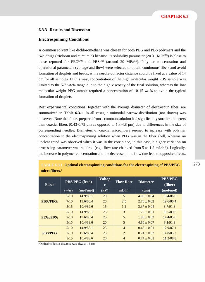
CHAPTER 6.3
273
6.3.3 Results and Discussion
Electrospinning Conditions
A common solvent like dichloromethane was chosen for both PEG and PBS polymers and the
two drugs (triclosan and curcumin) because its solubility parameter (20.31 MPa0.5) is close to
those reported for PEG[30] and PBS[31] (around 20 MPa0.5). Polymer concentration and
operational parameters (voltage and flow) were selected to obtain continuous fibers and avoid
formation of droplets and beads, while needle-collector distance could be fixed at a value of 14
cm for all samples. In this way, concentration of the high molecular weight PBS sample was
limited to the 5-7 wt-% range due to the high viscosity of the final solution, whereas the low
molecular weight PEG sample required a concentration of 10-15 wt-% to avoid the typical
formation of droplets.
Best experimental conditions, together with the average diameter of electrospun fiber, are
summarized in Table 6.3.1. In all cases, a unimodal narrow distribution (not shown) was
observed. Note that fibers prepared from a common solution had significantly smaller diameters
than coaxial fibers (0.43-0.75 µm as opposed to 1.8-4.8 µm) due to differences in the size of
corresponding needles. Diameters of coaxial microfibers seemed to increase with polymer
concentration in the electrospinning solution when PEG was in the fiber shell, whereas an
unclear trend was observed when it was in the core since, in this case, a higher variation on
processing parameter was required (e.g., flow rate changed from 5 to 1.2 mL·h-1). Logically,
the increase in polymer concentration and the decrease in the flow rate lead to opposite effects.
TABLE 6.3.1. Optimal electrospinning conditions for the electrospining of PBS/PEG
microfibers.a
Fiber PBS/PEG (feed)
Voltag
e Flow Rate Diameter
PBS/PEG
(fiber)
(w/w) (mol/mol) (kV) mL·h-1 (µm) (mol/mol)
5/10 14.9/85.1 20 5 4.08 ± 0.04 13.4/86.6
PBSs/PEGc 7/10 19.6/80.4 20 2.5 2.76 ± 0.02 19.6/80.4
5/15 10.4/89.6 15 1.2 3.37 ± 0.04 8.7/91.3
5/10 14.9/85.1 25 3 1.79 ± 0.01 10.5/89.5
PEGs/PBSc 7/10 19.6/80.4 25 5 1.96 ± 0.02 14.4/85.6
5/15 10.4/89.6 20 5 4.80 ± 0.07 8.1/91.9
5/10 14.9/85.1 25 4 0.43 ± 0.01 12.9/87.1
PBS/PEG 7/10 19.6/80.4 25 2 0.74 ± 0.02 14.8/85.2
5/15 10.4/89.6 20 4 0.74 ± 0.01 11.2/88.8
aOptical collector distance was always 14 cm.
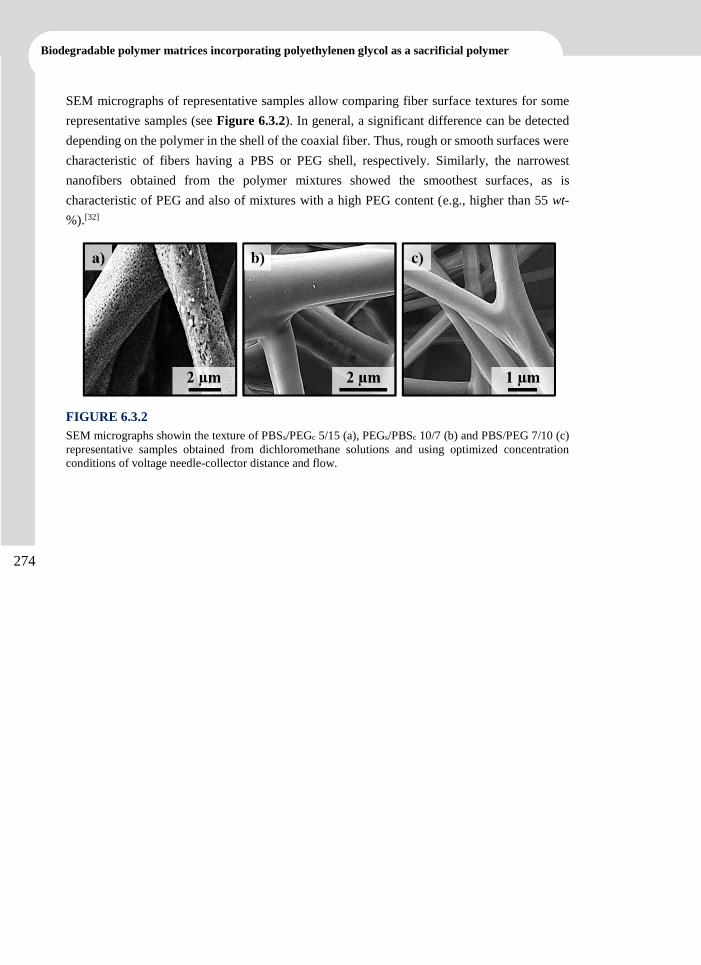
Biodegradable polymer matrices incorporating polyethylenen glycol as a sacrificial polymer
274
SEM micrographs of representative samples allow comparing fiber surface textures for some
representative samples (see Figure 6.3.2). In general, a significant difference can be detected
depending on the polymer in the shell of the coaxial fiber. Thus, rough or smooth surfaces were
characteristic of fibers having a PBS or PEG shell, respectively. Similarly, the narrowest
nanofibers obtained from the polymer mixtures showed the smoothest surfaces, as is
characteristic of PEG and also of mixtures with a high PEG content (e.g., higher than 55 wt-
%).[32]
FIGURE 6.3.2
SEM micrographs showin the texture of PBSs/PEGc 5/15 (a), PEGs/PBSc 10/7 (b) and PBS/PEG 7/10 (c)
representative samples obtained from dichloromethane solutions and using optimized concentration
conditions of voltage needle-collector distance and flow.
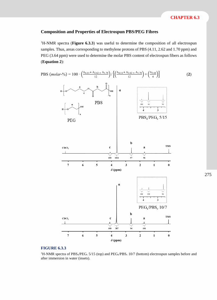
CHAPTER 6.3
275
Composition and Properties of Electrospun PBS/PEG Fibres
1H-NMR spectra (Figure 6.3.3) was useful to determine the composition of all electrospun
samples. Thus, areas corresponding to methylene protons of PBS (4.11, 2.62 and 1.70 ppm) and
PEG (3.64 ppm) were used to determine the molar PBS content of electrospun fibers as follows
(Equation 2):
PBS (molar-%) = 100 · (A4.11+ A2.62 + A1.70
12) / [(
A4.11+ A2.62 + A1.70
12) + (
A3.64
4)] (2)
FIGURE 6.3.3 1H-NMR spectra of PBSs/PEGc 5/15 (top) and PEGs/PBSc 10/7 (bottom) electrospun samples before and
after immersion in water (insets).
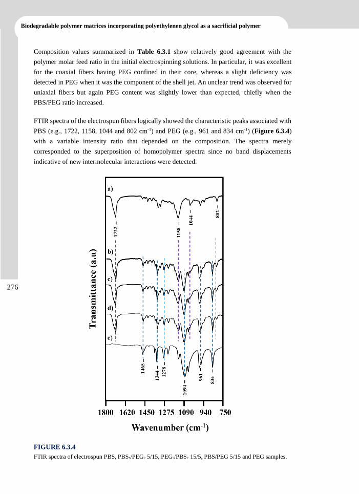
Biodegradable polymer matrices incorporating polyethylenen glycol as a sacrificial polymer
276
Composition values summarized in Table 6.3.1 show relatively good agreement with the
polymer molar feed ratio in the initial electrospinning solutions. In particular, it was excellent
for the coaxial fibers having PEG confined in their core, whereas a slight deficiency was
detected in PEG when it was the component of the shell jet. An unclear trend was observed for
uniaxial fibers but again PEG content was slightly lower than expected, chiefly when the
PBS/PEG ratio increased.
FTIR spectra of the electrospun fibers logically showed the characteristic peaks associated with
PBS (e.g., 1722, 1158, 1044 and 802 cm-1) and PEG (e.g., 961 and 834 cm-1) (Figure 6.3.4)
with a variable intensity ratio that depended on the composition. The spectra merely
corresponded to the superposition of homopolymer spectra since no band displacements
indicative of new intermolecular interactions were detected.
FIGURE 6.3.4
FTIR spectra of electrospun PBS, PBSs/PEGc 5/15, PEGs/PBSc 15/5, PBS/PEG 5/15 and PEG samples.
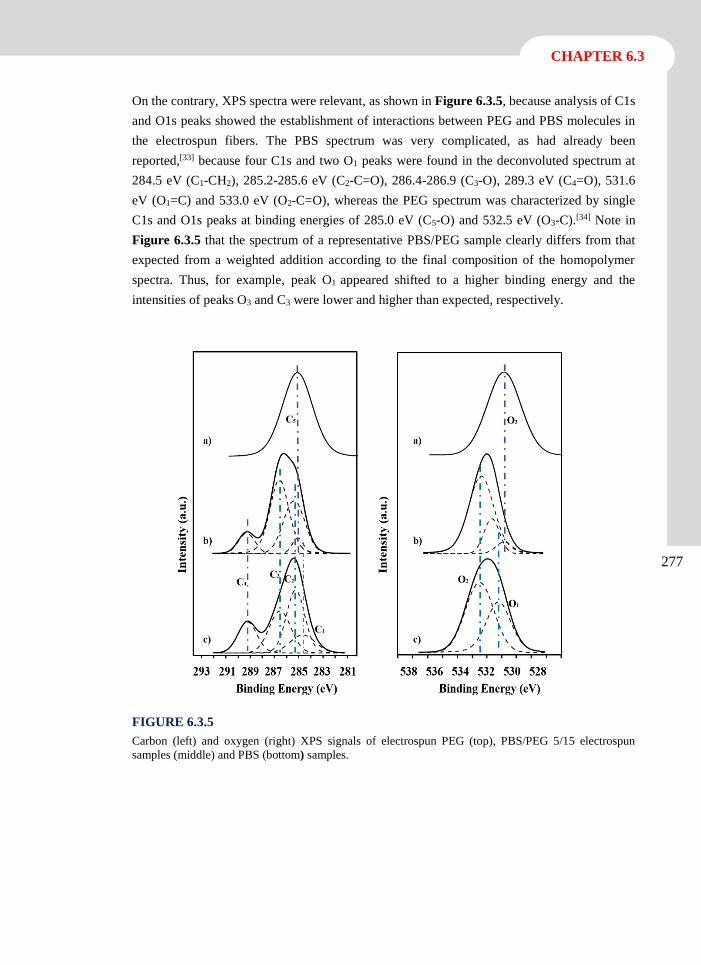
CHAPTER 6.3
277
On the contrary, XPS spectra were relevant, as shown in Figure 6.3.5, because analysis of C1s
and O1s peaks showed the establishment of interactions between PEG and PBS molecules in
the electrospun fibers. The PBS spectrum was very complicated, as had already been
reported,[33] because four C1s and two O1 peaks were found in the deconvoluted spectrum at
284.5 eV (C1-CH2), 285.2-285.6 eV (C2-C=O), 286.4-286.9 (C3-O), 289.3 eV (C4=O), 531.6
eV (O1=C) and 533.0 eV (O2-C=O), whereas the PEG spectrum was characterized by single
C1s and O1s peaks at binding energies of 285.0 eV (C5-O) and 532.5 eV (O3-C).[34] Note in
Figure 6.3.5 that the spectrum of a representative PBS/PEG sample clearly differs from that
expected from a weighted addition according to the final composition of the homopolymer
spectra. Thus, for example, peak O1 appeared shifted to a higher binding energy and the
intensities of peaks O3 and C3 were lower and higher than expected, respectively.
FIGURE 6.3.5
Carbon (left) and oxygen (right) XPS signals of electrospun PEG (top), PBS/PEG 5/15 electrospun
samples (middle) and PBS (bottom) samples.
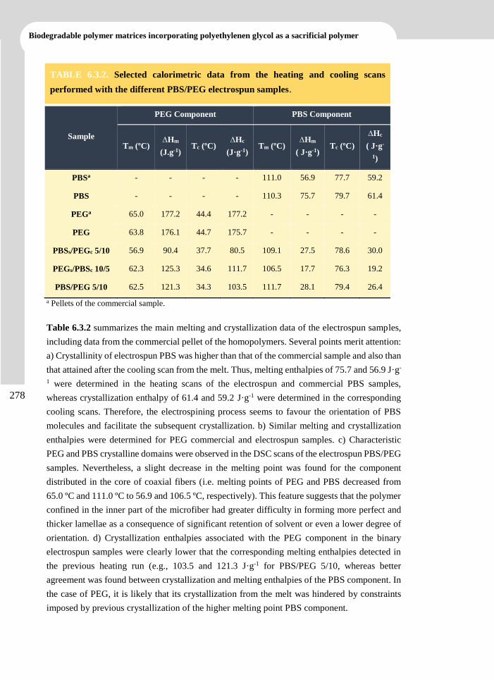
Biodegradable polymer matrices incorporating polyethylenen glycol as a sacrificial polymer
278
a Pellets of the commercial sample.
Table 6.3.2 summarizes the main melting and crystallization data of the electrospun samples,
including data from the commercial pellet of the homopolymers. Several points merit attention:
a) Crystallinity of electrospun PBS was higher than that of the commercial sample and also than
that attained after the cooling scan from the melt. Thus, melting enthalpies of 75.7 and 56.9 J·g-
1 were determined in the heating scans of the electrospun and commercial PBS samples,
whereas crystallization enthalpy of 61.4 and 59.2 J·g-1 were determined in the corresponding
cooling scans. Therefore, the electrospining process seems to favour the orientation of PBS
molecules and facilitate the subsequent crystallization. b) Similar melting and crystallization
enthalpies were determined for PEG commercial and electrospun samples. c) Characteristic
PEG and PBS crystalline domains were observed in the DSC scans of the electrospun PBS/PEG
samples. Nevertheless, a slight decrease in the melting point was found for the component
distributed in the core of coaxial fibers (i.e. melting points of PEG and PBS decreased from
65.0 ºC and 111.0 ºC to 56.9 and 106.5 ºC, respectively). This feature suggests that the polymer
confined in the inner part of the microfiber had greater difficulty in forming more perfect and
thicker lamellae as a consequence of significant retention of solvent or even a lower degree of
orientation. d) Crystallization enthalpies associated with the PEG component in the binary
electrospun samples were clearly lower that the corresponding melting enthalpies detected in
the previous heating run (e.g., 103.5 and 121.3 J·g-1 for PBS/PEG 5/10, whereas better
agreement was found between crystallization and melting enthalpies of the PBS component. In
the case of PEG, it is likely that its crystallization from the melt was hindered by constraints
imposed by previous crystallization of the higher melting point PBS component.
TABLE 6.3.2. Selected calorimetric data from the heating and cooling scans
performed with the different PBS/PEG electrospun samples.
Sample
PEG Component PBS Component
Tm (ºC) ∆Hm
(J.g-1)
Tc (ºC) ∆Hc
(J·g-1)
Tm (ºC) ∆Hm
( J·g-1) Tc (ºC)
∆Hc
( J·g-
1)
PBSa - - - - 111.0 56.9 77.7 59.2
PBS - - - - 110.3 75.7 79.7 61.4
PEGa 65.0 177.2 44.4 177.2 - - - -
PEG 63.8 176.1 44.7 175.7 - - - -
PBSs/PEGc 5/10 56.9 90.4 37.7 80.5 109.1 27.5 78.6 30.0
PEGs/PBSc 10/5 62.3 125.3 34.6 111.7 106.5 17.7 76.3 19.2
PBS/PEG 5/10 62.5 121.3 34.3 103.5 111.7 28.1 79.4 26.4
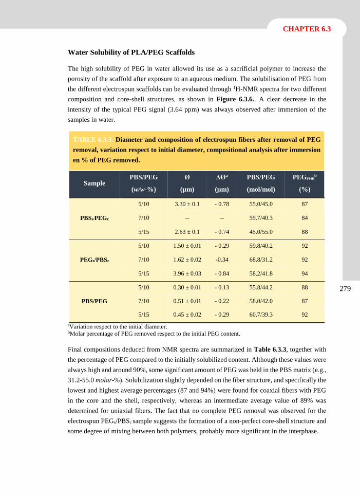
CHAPTER 6.3
279
Water Solubility of PLA/PEG Scaffolds
The high solubility of PEG in water allowed its use as a sacrificial polymer to increase the
porosity of the scaffold after exposure to an aqueous medium. The solubilisation of PEG from
the different electrospun scaffolds can be evaluated through 1H-NMR spectra for two different
composition and core-shell structures, as shown in Figure 6.3.6.. A clear decrease in the
intensity of the typical PEG signal (3.64 ppm) was always observed after immersion of the
samples in water.
TABLE 6.3.3. Diameter and composition of electrospun fibers after removal of PEG
removal, variation respect to initial diameter, compositional analysis after immersion
en % of PEG removed.
Sample PBS/PEG
(w/w-%)
Ø
(µm)
ΔØa
(µm)
PBS/PEG
(mol/mol)
PEGremb
(%)
PBSs/PEGc
5/10 3.30 ± 0.1 - 0.78 55.0/45.0 87
7/10 -- -- 59.7/40.3 84
5/15 2.63 ± 0.1 - 0.74 45.0/55.0 88
PEGs/PBSc
5/10 1.50 ± 0.01 - 0.29 59.8/40.2 92
7/10 1.62 ± 0.02 -0.34 68.8/31.2 92
5/15 3.96 ± 0.03 - 0.84 58.2/41.8 94
PBS/PEG
5/10 0.30 ± 0.01 - 0.13 55.8/44.2 88
7/10 0.51 ± 0.01 - 0.22 58.0/42.0 87
5/15 0.45 ± 0.02 - 0.29 60.7/39.3 92
ªVariation respect to the initial diameter. bMolar percentage of PEG removed respect to the initial PEG content.
Final compositions deduced from NMR spectra are summarized in Table 6.3.3, together with
the percentage of PEG compared to the initially solubilized content. Although these values were
always high and around 90%, some significant amount of PEG was held in the PBS matrix (e.g.,
31.2-55.0 molar-%). Solubilization slightly depended on the fiber structure, and specifically the
lowest and highest average percentages (87 and 94%) were found for coaxial fibers with PEG
in the core and the shell, respectively, whereas an intermediate average value of 89% was
determined for uniaxial fibers. The fact that no complete PEG removal was observed for the
electrospun PEGs/PBSc sample suggests the formation of a non-perfect core-shell structure and
some degree of mixing between both polymers, probably more significant in the interphase.
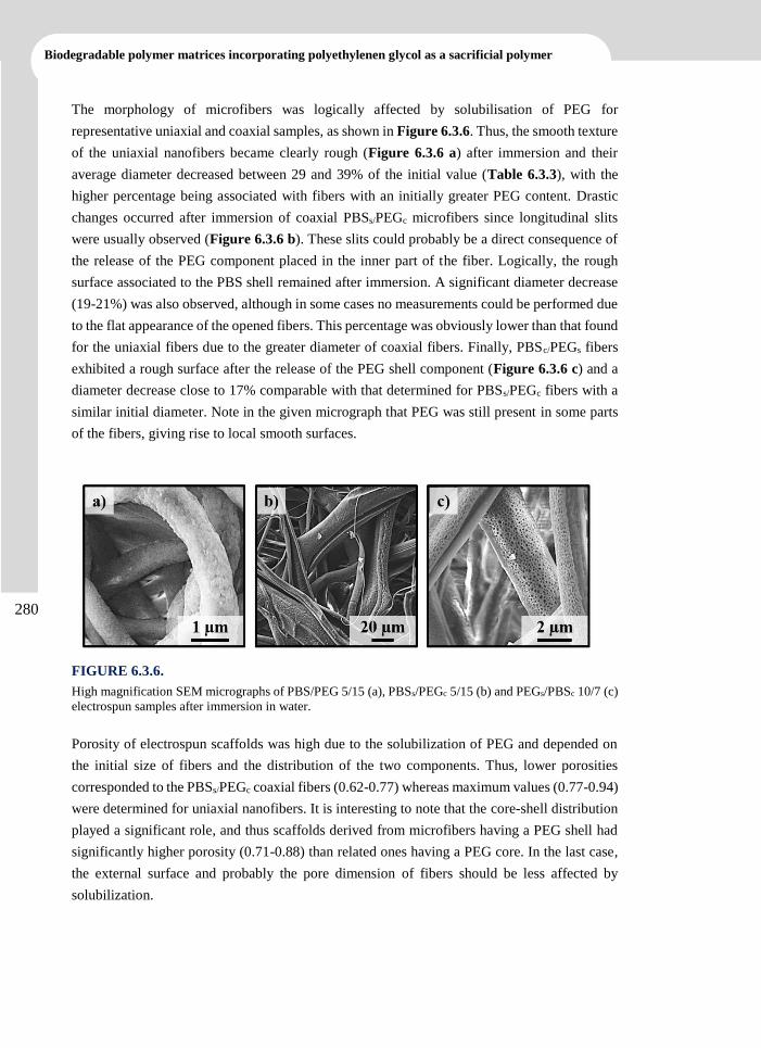
Biodegradable polymer matrices incorporating polyethylenen glycol as a sacrificial polymer
280
The morphology of microfibers was logically affected by solubilisation of PEG for
representative uniaxial and coaxial samples, as shown in Figure 6.3.6. Thus, the smooth texture
of the uniaxial nanofibers became clearly rough (Figure 6.3.6 a) after immersion and their
average diameter decreased between 29 and 39% of the initial value (Table 6.3.3), with the
higher percentage being associated with fibers with an initially greater PEG content. Drastic
changes occurred after immersion of coaxial PBSs/PEGc microfibers since longitudinal slits
were usually observed (Figure 6.3.6 b). These slits could probably be a direct consequence of
the release of the PEG component placed in the inner part of the fiber. Logically, the rough
surface associated to the PBS shell remained after immersion. A significant diameter decrease
(19-21%) was also observed, although in some cases no measurements could be performed due
to the flat appearance of the opened fibers. This percentage was obviously lower than that found
for the uniaxial fibers due to the greater diameter of coaxial fibers. Finally, PBSc/PEGs fibers
exhibited a rough surface after the release of the PEG shell component (Figure 6.3.6 c) and a
diameter decrease close to 17% comparable with that determined for PBSs/PEGc fibers with a
similar initial diameter. Note in the given micrograph that PEG was still present in some parts
of the fibers, giving rise to local smooth surfaces.
FIGURE 6.3.6.
High magnification SEM micrographs of PBS/PEG 5/15 (a), PBSs/PEGc 5/15 (b) and PEGs/PBSc 10/7 (c)
electrospun samples after immersion in water.
Porosity of electrospun scaffolds was high due to the solubilization of PEG and depended on
the initial size of fibers and the distribution of the two components. Thus, lower porosities
corresponded to the PBSs/PEGc coaxial fibers (0.62-0.77) whereas maximum values (0.77-0.94)
were determined for uniaxial nanofibers. It is interesting to note that the core-shell distribution
played a significant role, and thus scaffolds derived from microfibers having a PEG shell had
significantly higher porosity (0.71-0.88) than related ones having a PEG core. In the last case,
the external surface and probably the pore dimension of fibers should be less affected by
solubilization.
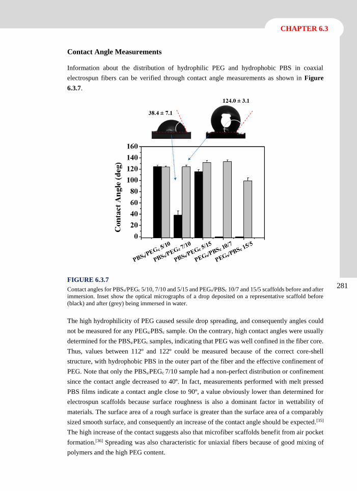
CHAPTER 6.3
281
Contact Angle Measurements
Information about the distribution of hydrophilic PEG and hydrophobic PBS in coaxial
electrospun fibers can be verified through contact angle measurements as shown in Figure
6.3.7.
FIGURE 6.3.7
Contact angles for PBSs/PEGc 5/10, 7/10 and 5/15 and PEGs/PBSc 10/7 and 15/5 scaffolds before and after
immersion. Inset show the optical micrographs of a drop deposited on a representative scaffold before
(black) and after (grey) being immersed in water.
The high hydrophilicity of PEG caused sessile drop spreading, and consequently angles could
not be measured for any PEGs/PBSc sample. On the contrary, high contact angles were usually
determined for the PBSs/PEGc samples, indicating that PEG was well confined in the fiber core.
Thus, values between 112º and 122º could be measured because of the correct core-shell
structure, with hydrophobic PBS in the outer part of the fiber and the effective confinement of
PEG. Note that only the PBSs/PEGc 7/10 sample had a non-perfect distribution or confinement
since the contact angle decreased to 40º. In fact, measurements performed with melt pressed
PBS films indicate a contact angle close to 90º, a value obviously lower than determined for
electrospun scaffolds because surface roughness is also a dominant factor in wettability of
materials. The surface area of a rough surface is greater than the surface area of a comparably
sized smooth surface, and consequently an increase of the contact angle should be expected.[35]
The high increase of the contact suggests also that microfiber scaffolds benefit from air pocket
formation.[36] Spreading was also characteristic for uniaxial fibers because of good mixing of
polymers and the high PEG content.
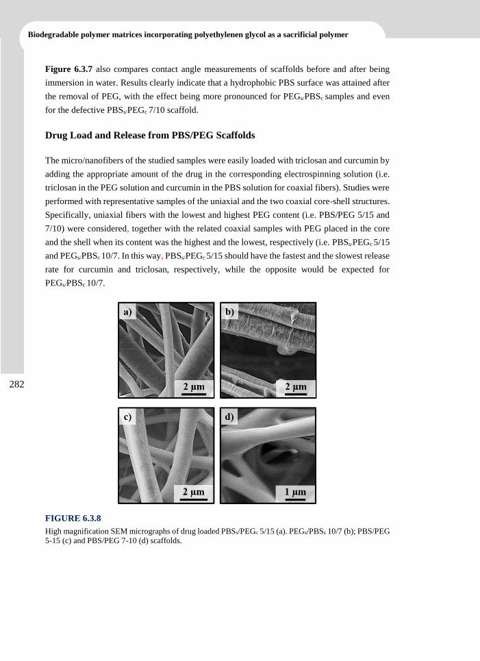
Biodegradable polymer matrices incorporating polyethylenen glycol as a sacrificial polymer
282
Figure 6.3.7 also compares contact angle measurements of scaffolds before and after being
immersion in water. Results clearly indicate that a hydrophobic PBS surface was attained after
the removal of PEG, with the effect being more pronounced for PEGs/PBSc samples and even
for the defective PBSs/PEGc 7/10 scaffold.
Drug Load and Release from PBS/PEG Scaffolds
The micro/nanofibers of the studied samples were easily loaded with triclosan and curcumin by
adding the appropriate amount of the drug in the corresponding electrospinning solution (i.e.
triclosan in the PEG solution and curcumin in the PBS solution for coaxial fibers). Studies were
performed with representative samples of the uniaxial and the two coaxial core-shell structures.
Specifically, uniaxial fibers with the lowest and highest PEG content (i.e. PBS/PEG 5/15 and
7/10) were considered, together with the related coaxial samples with PEG placed in the core
and the shell when its content was the highest and the lowest, respectively (i.e. PBSs/PEGc 5/15
and PEGs/PBSc 10/7. In this way, PBSs/PEGc 5/15 should have the fastest and the slowest release
rate for curcumin and triclosan, respectively, while the opposite would be expected for
PEGs/PBSc 10/7.
FIGURE 6.3.8
High magnification SEM micrographs of drug loaded PBSs/PEGc 5/15 (a). PEGs/PBSs 10/7 (b); PBS/PEG
5-15 (c) and PBS/PEG 7-10 (d) scaffolds.
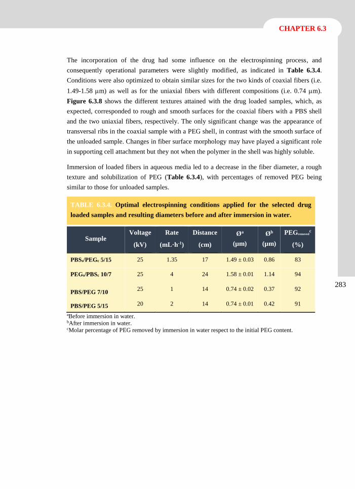
CHAPTER 6.3
283
The incorporation of the drug had some influence on the electrospinning process, and
consequently operational parameters were slightly modified, as indicated in Table 6.3.4.
Conditions were also optimized to obtain similar sizes for the two kinds of coaxial fibers (i.e.
1.49-1.58 m) as well as for the uniaxial fibers with different compositions (i.e. 0.74 m).
Figure 6.3.8 shows the different textures attained with the drug loaded samples, which, as
expected, corresponded to rough and smooth surfaces for the coaxial fibers with a PBS shell
and the two uniaxial fibers, respectively. The only significant change was the appearance of
transversal ribs in the coaxial sample with a PEG shell, in contrast with the smooth surface of
the unloaded sample. Changes in fiber surface morphology may have played a significant role
in supporting cell attachment but they not when the polymer in the shell was highly soluble.
Immersion of loaded fibers in aqueous media led to a decrease in the fiber diameter, a rough
texture and solubilization of PEG (Table 6.3.4), with percentages of removed PEG being
similar to those for unloaded samples.
ªBefore immersion in water. bAfter immersion in water. cMolar percentage of PEG removed by immersion in water respect to the initial PEG content.
TABLE 6.3.4. Optimal electrospinning conditions applied for the selected drug
loaded samples and resulting diameters before and after immersion in water.
Sample Voltage
(kV)
Rate
(mL·h-1)
Distance
(cm)
Øa
(µm)
Øb
(µm)
PEGremovedc
(%)
PBSs/PEGc 5/15 25 1.35 17 1.49 ± 0.03 0.86 83
PEGs/PBSc 10/7 25 4 24 1.58 ± 0.01 1.14 94
PBS/PEG 7/10 25 1 14 0.74 ± 0.02 0.37 92
PBS/PEG 5/15 20 2 14 0.74 ± 0.01 0.42 91
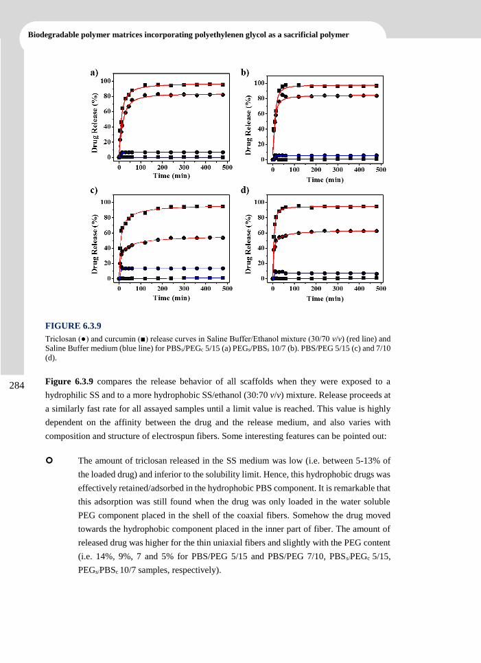
Biodegradable polymer matrices incorporating polyethylenen glycol as a sacrificial polymer
284
FIGURE 6.3.9
Triclosan (●) and curcumin (■) release curves in Saline Buffer/Ethanol mixture (30/70 v/v) (red line) and
Saline Buffer medium (blue line) for PBSs/PEGc 5/15 (a) PEGs/PBSs 10/7 (b). PBS/PEG 5/15 (c) and 7/10
(d).
Figure 6.3.9 compares the release behavior of all scaffolds when they were exposed to a
hydrophilic SS and to a more hydrophobic SS/ethanol (30:70 v/v) mixture. Release proceeds at
a similarly fast rate for all assayed samples until a limit value is reached. This value is highly
dependent on the affinity between the drug and the release medium, and also varies with
composition and structure of electrospun fibers. Some interesting features can be pointed out:
The amount of triclosan released in the SS medium was low (i.e. between 5-13% of
the loaded drug) and inferior to the solubility limit. Hence, this hydrophobic drugs was
effectively retained/adsorbed in the hydrophobic PBS component. It is remarkable that
this adsorption was still found when the drug was only loaded in the water soluble
PEG component placed in the shell of the coaxial fibers. Somehow the drug moved
towards the hydrophobic component placed in the inner part of fiber. The amount of
released drug was higher for the thin uniaxial fibers and slightly with the PEG content
(i.e. 14%, 9%, 7 and 5% for PBS/PEG 5/15 and PBS/PEG 7/10, PBSs/PEGc 5/15,
PEGs/PBSc 10/7 samples, respectively).
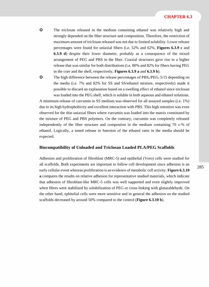
CHAPTER 6.3
285
The triclosan released in the medium containing ethanol was relatively high and
strongly depended on the fiber structure and composition. Therefore, the restriction of
maximum amount of triclosan released was not due to limited solubility. Lower release
percentages were found for uniaxial fibers (i.e. 52% and 62%, Figures 6.3.9 c and
6.3.9 d) despite their lower diameter, probably as a consequence of the mixed
arrangement of PEG and PBS in the fiber. Coaxial structures gave rise to a higher
release that was similar for both distributions (i.e. 80% and 82% for fibers having PEG
in the core and the shell, respectively, Figures 6.3.9 a and 6.3.9 b).
The high difference between the release percentages of PBSs/PEGc 5/15 depending on
the media (i.e. 7% and 82% for SS and SS/ethanol mixture, respectively) made it
possible to discard an explanation based on a swelling effect of ethanol since triclosan
was loaded into the PEG shell, which is soluble in both aqueous and ethanol solutions.
A minimum release of curcumin in SS medium was observed for all assayed samples (i.e. 1%)
due to its high hydrophobicity and excellent interaction with PBS. This high retention was even
observed for the thin uniaxial fibers where curcumin was loaded into the matrix constituted by
the mixture of PEG and PBS polymers. On the contrary, curcumin was completely released
independently of the fiber structure and compostion in the medium containing 70 v-% of
ethanol. Logically, a tuned release in function of the ethanol ratio in the media should be
expected.
Biocompatibility of Unloaded and Triclosan Loaded PLA/PEG Scaffolds
Adhesion and proliferation of fibroblast (MRC-5) and epithelial (Vero) cells were studied for
all scaffolds. Both experiments are important to follow cell development since adhesion is an
early cellular event whereas proliferation is an evidence of metabolic cell activity. Figure 6.3.10
a compares the results on relative adhesion for representative studied materials, which indicate
that adhesion of fibroblast-like MRC-5 cells was well supported and even slightly improved
when fibres were stabilized by solubilization of PEG or cross-linking with glutaraldehyde. On
the other hand, ephitelial cells were more sensitive and in general the adhesion on the studied
scaffolds decreased by around 50% compared to the control (Figure 6.3.10 b).
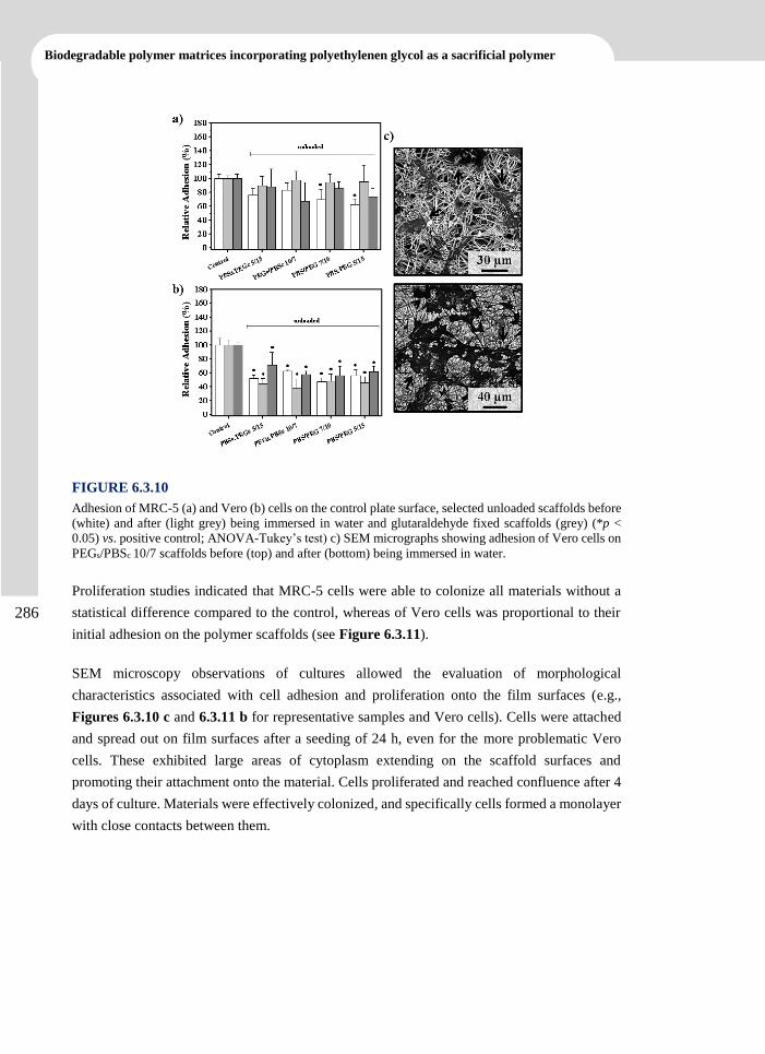
Biodegradable polymer matrices incorporating polyethylenen glycol as a sacrificial polymer
286
FIGURE 6.3.10
Adhesion of MRC-5 (a) and Vero (b) cells on the control plate surface, selected unloaded scaffolds before
(white) and after (light grey) being immersed in water and glutaraldehyde fixed scaffolds (grey) (*p <
0.05) vs. positive control; ANOVA-Tukey’s test) c) SEM micrographs showing adhesion of Vero cells on
PEGs/PBSc 10/7 scaffolds before (top) and after (bottom) being immersed in water.
Proliferation studies indicated that MRC-5 cells were able to colonize all materials without a
statistical difference compared to the control, whereas of Vero cells was proportional to their
initial adhesion on the polymer scaffolds (see Figure 6.3.11).
SEM microscopy observations of cultures allowed the evaluation of morphological
characteristics associated with cell adhesion and proliferation onto the film surfaces (e.g.,
Figures 6.3.10 c and 6.3.11 b for representative samples and Vero cells). Cells were attached
and spread out on film surfaces after a seeding of 24 h, even for the more problematic Vero
cells. These exhibited large areas of cytoplasm extending on the scaffold surfaces and
promoting their attachment onto the material. Cells proliferated and reached confluence after 4
days of culture. Materials were effectively colonized, and specifically cells formed a monolayer
with close contacts between them.
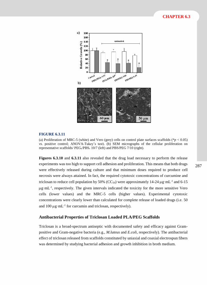
CHAPTER 6.3
287
FIGURE 6.3.11
(a) Proliferation of MRC-5 (white) and Vero (grey) cells on control plate surfaces scaffolds (*p < 0.05)
vs. positive control; ANOVA-Tukey’s test). (b) SEM micrographs of the cellular proliferation on
representative scaffolds/ PEGs/PBSc 10/7 (left) and PBS/PEG 7/10 (right).
Figures 6.3.10 and 6.3.11 also revealed that the drug load necessary to perform the release
experiments was too high to support cell adhesion and proliferation. This means that both drugs
were effectively released during culture and that minimum doses required to produce cell
necrosis were always attained. In fact, the required cytotoxic concentrations of curcumine and
triclosan to reduce cell population by 50% (CC50) were approximately 14-24 g·mL-1 and 6-15
g·mL-1, respectively. The given intervals indicated the toxicity for the more sensitive Vero
cells (lower values) and the MRC-5 cells (higher values). Experimental cytotoxic
concentrations were clearly lower than calculated for complete release of loaded drugs (i.e. 50
and 100 g·mL-1 for curcumin and triclosan, respectively).
Antibacterial Properties of Triclosan Loaded PLA/PEG Scaffolds
Triclosan is a broad-spectrum antiseptic with documented safety and efficacy against Gram-
positive and Gram-negative bacteria (e.g., M.luteus and E.coli, respectively). The antibacterial
effect of triclosan released from scaffolds constituted by uniaxial and coaxial electrospun fibers
was determined by studying bacterial adhesion and growth inhibition in broth medium.
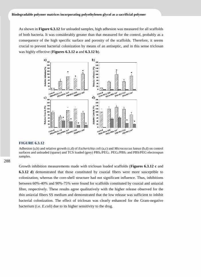
Biodegradable polymer matrices incorporating polyethylenen glycol as a sacrificial polymer
288
As shown in Figure 6.3.12 for unloaded samples, high adhesion was measured for all scaffolds
of both bacteria. It was considerably greater than that measured for the control, probably as a
consequence of the high specific surface and porosity of the scaffolds. Therefore, it seems
crucial to prevent bacterial colonization by means of an antiseptic, and in this sense triclosan
was highly effective (Figures 6.3.12 a and 6.3.12 b).
FIGURE 6.3.12
Adhesion (a,b) and relative growth (c,d) of Escherichia coli (a,c) and Micrococcus luteus (b,d) on control
surfaces and unloaded (sparse) and TCS loaded (grey) PBSs/PEGc. PEGs/PBSc and PBS/PEG electrospun
samples.
Growth inhibition measurements made with triclosan loaded scaffolds (Figures 6.3.12 c and
6.3.12 d) demonstrated that those constituted by coaxial fibers were more susceptible to
colonization, whereas the core-shell structure had not significant influence. Thus, inhibitions
between 60%-40% and 90%-75% were found for scaffolds constituted by coaxial and uniaxial
fibre, respectively. These results agree qualitatively with the higher release observed for the
thin uniaxial fibers SS medium and demonstrated that the low release was sufficient to inhibit
bacterial colonization. The effect of triclosan was clearly enhanced for the Gram-negative
bacterium (i.e. E.coli) due to its higher sensitivity to the drug.
CHAPTER 6.3
289
6.3.4 Conclusions
Coaxial microfibers with different core-shell distributions and constituted by PEG and PBS
could be prepared from dichloromethane solutions and optimized processing parameters. These
fibers had different surface textures depending on the polymer in the shell (i.e. smooth and
rough for PEG and PBS, respectively), suggesting the success of coaxial electrospinning. This
was also corroborated by contact angle measurements that demonstrated the hydrophilicity and
hydrophobicity of coaxial fibers having a shell of PEG and PBS, respectively.
Calorimetric data indicated a high crystallinity for PBS rich domains caused by a molecular
orientation favored by the electrospinning process. A decrease in the corresponding melting
temperature also suggested that the polymer confined in the fiber core developed more defective
crystals.
XPS spectroscopy revealed that establishment of new interactions between PBS and PEG were
established in the uniaxial nanofibers prepared from a common dissolution of both polymers.
Thus, a significant amount of PEG remained in the scaffolds after immersion in water. This
amount was dependent on the fiber distribution, with higher and lower values being associated
with coaxial fibers with a PBS shell and a PEG shell, respectively.
Release of triclosan and curcumin from loaded scaffolds was highly dependent on the media
and their hydrophobicity. Slight differences were also detected depending on the structure of
the fiber. Specifically, the lowest release was found for PEG-rich uniaxial nanofibers exposed
to SS medium whereas the highest value corresponded to coaxial microfibers exposed to
SS/ethanol mixtures. Scaffolds constituted by coaxial microfibers were more susceptible to
colonization by both Gram-positive and Gram-negative bacteria whereas the core-shell
structure had no significant influence.
Biodegradable polymer matrices incorporating polyethylenen glycol as a sacrificial polymer
290
6.3.5 References
[1] D.H. Reneker, I. Chun, Nanotechnology, 7 (1996) 216-223.
[2] A. Frenot, I.S. Chronakis, Curr Opin Colloid Interface Sci, 8 (2003) 64-75.
[3] Y. Dzenis, Science, 304 (2004) 1917-1919.
[4] K. Jayaraman, M. Kotaki, Y.Z. Zhang, X.M. Mo, S. Ramakrishna, J Nanosci
Nanotechno, 4 (2004) 52-65.
[5] S.R. Dhakate, B. Singla, M. Uppal, R.B. Mathur, Adv Mater Lett, 1 (2010) 200-204.
[6] S. Sharma, Adv Mater Lett, 4 (2013) 522-533.
[7] M. Zamani, M.P. Prabhakaran, S. Ramakrishna, Int J Nanomedicine, 8 (2013) 2997-
3017.
[8] M. Spasova, O. Stoilova, N. Manolova, I. Rashkov, G. Altankov, J Bioact Compat Pol,
22 (2007) 62-76.
[9] L.J. del Valle, R. Camps, A. Diaz, L. Franco, A. Rodriguez-Galan, J. Puiggali, J Polym
Res, 18 (2011) 1903-1917.
[10] E.H. Jeong, S.S. Im, J.H. Youk, Polymer, 46 (2005) 9538-9543.
[11] Y. Liu, J.-H. He, J.-Y. Yu, Fibres Text East Eur, 15 (2007) 30-33.
[12] X. Zong, S. Li, E. Chen, B. Garlick, K.-s. Kim, D. Fang, J. Chiu, T. Zimmerman, C.
Brathwaite, B.S. Hsiao, B. Chu, Ann Surg, 240 (2004) 910-915.
[13] E. Llorens, L.J. del Valle, A. Diaz, M.T. Casas, J. Puiggali, Macromol Res, 21 (2013)
775-787.
[14] R. Toshkova, N. Manolova, E. Gardeva, M. Ignatova, L. Yossifova, I. Rashkov, M.
Alexandrov, Int J Pharm, 400 (2010) 221-233.
[15] J. Zeng, L.X. Yang, Q.Z. Liang, X.F. Zhang, H.L. Guan, X.L. Xu, X.S. Chen, X.B. Jing,
J Control Release, 105 (2005) 43-51.
[16] K. Kim, Y.K. Luu, C. Chang, D. Fang, B.S. Hsiao, B. Chu, M. Hadjiargyrou, J Control
Release, 98 (2004) 47-56.
[17] H. Cao, X.G. Jiang, C.L. Chai, S.Y. Chew, J Control Release, 144 (2010) 203-212.
[18] S.N. Reznik, A.L. Yarin, E. Zussman, L. Bercovici, Phys Fluids (1994), 18 (2006).
[19] A.L. Yarin, Polymers Adv Tech, 22 (2011) 310-317.
[20] I.C. Liao, S. Chen, J.B. Liu, K.W. Leong, J Control Release, 139 (2009) 48-55.
CHAPTER 6.3
291
[21] C.L. He, Z.M. Huang, X.J. Han, L. Liu, H.S. Zhang, L.S. Chen, J Macromol Sci, Part B,
45 (2006) 515-524.
[22] C.-L. He, Z.-M. Huang, X.-J. Han, J Biomed Mater Res A, 89A (2009) 80-95.
[23] D.A. Herold, K. Keil, D.E. Bruns, Biochem Pharmacol, 38 (1989) 73-76.
[24] T. Fujimaki, Polym Degrad Stabil, 59 (1998) 209-214.
[25] S.M. Lai, C.K. Huang, H.F. Shen, J Appl Polym Sci, 97 (2005) 257-264.
[26] A.D. Russell, J Antimicrob Chemoth, 53 (2004) 693-695.
[27] H. Hatcher, R. Planalp, J. Cho, F.M. Torti, S.V. Torti, Cell Mol Life Sci, 65 (2008) 1631-
1652.
[28] Y. Jiao, J. Wilkinson, X. Di, W. Wang, H. Hatcher, N.D. Kock, R. D'Agostino, M.A.
Knovich, F.M. Torti, S.V. Torti, Blood, 113 (2009) 462-469.
[29] S.C. Gupta, S. Prasad, J.H. Kim, S. Patchva, L.J. Webb, I.K. Priyadarsini, B.B.
Aggarwal, Nat Prod Rep, 28 (2011) 1937-1955.
[30] D. Karst, Y.Q. Yang, J Appl Polym Sci, 96 (2005) 416-422.
[31] M. Imaizumi, T. Nagata, Y. Goto, Y. Okino, T. Takahashi, K. Koyama, Kobunshi
Ronbunshu, 62 (2005) 438-440.
[32] E. Llorens, L.J. Valle, R. Ferrán, A. Rodríguez-Galán, J. Puiggalí, J Polym Res, 21
(2014) 1-15.
[33] H.Y. Wang, J.H. Ji, W. Zhang, Y.H. Zhang, J. Jiang, Z.W. Wu, S.H. Pu, P.K. Chu, Acta
Biomater, 5 (2009) 279-287.
[34] M. Cerruti, S. Fissolo, C. Carraro, C. Ricciardi, A. Majumdar, R. Maboudian, Langmuir,
24 (2008) 10646-10653.
[35] R.N. Wenzel, Ind Eng Chem, 28 (1936) 988-994.
[36] A.B.D. Cassie, S. Baxter, Trans Faraday Soc, 40 (1944) 546-551.

7.
Conclusions

CONCLUSIONS
295
General Conclusions
First Block: Antioxidant loaded biodegradable scaffolds and potential application
The study of 3D scaffolds from electrospun polylactide nanofibers loaded with antioxidants
(i.e., vitamin B6 in pyridoxine and pyridoxal form and two polyphenols, caffeic and p-coumaric
acids) prepared by electrospinning under optimized conditions leads to the following
conclusions:
i. Fiber morphology (diameter and texture) and crystallinity were dependent on the drug
load. Furthermore, the drug release was influenced by the kind of drug and release
medium (hydrophobic or hydrophilic medium).
ii. The new loaded PLA scaffolds were suitable to support both cell adhesion and growth,
and additionally had a protective activity against the oxidative stress responsible for
cell damage and death by necrosis.
iii. New antioxidative scaffolds demonstrated in-vivo and in-vitro inhibition of the
oxidative damage on DNA under both in-vivo and in-vitro conditions. Thus, they could
be used as platform to improve the process of DNA extraction and purification.
Second Block: Multifunctional biodegradable fiber scaffolds
Multifunctional PLA scaffolds were obtained by loading different drugs simultaneously during
the process of electrospinning:
i. PLA scaffolds with antibacterial, antioxidant and/or anti-inflammatory activity were
obtained by loading triclosan, ketoprofen and/or p-coumaric acid, respectively. Thus,
the scaffolds obtained were dual or ternary drug-loaded systems.
ii. The drug release from these multifunctional scaffolds was modulated by: first, the PLA
enantiomeric grade, because its influence thermal, to the degradation and the
mechanical properties of the matrix; second, the chemical structure of the drugs that
are combined in the scaffold and their behaviours against the different release media
(hydrophilic or hydrophobic medium).
iii. These new materials have therapeutic advantage because they effectively respond to
the need of procuring a simultaneous control over potential microbial infections, and
inflammatory-oxidative processes that can occur during wound closure and tissue
repair.
296
Advanced electrospun scaffolds based on biodegradable polylactide and poly(butylene succinate)
for controlled drug delivery and tissue engineering
Third Block: Preparation of biodegradable scaffolds that incorporate non-
electrospinable polymers
The development of fiber scaffolds from mixtures of electrospinable and non-electrospinable
polymers allowed obtaining new hybrid materials in the biomedical field:
i. Antibacterial scaffolds can be prepared from the mixture of PLA and PHMB
(polyhexamethylenebiguanide hydrochloride). The antibacterial activity of PHMB
loaded scaffolds is much greater than those loaded with chlorhexidine (CHX)
monomer.
ii. Conducting scaffolds were successfully prepared from mixtures of PLA and P3TMA
(poly 3-thiophene methyl acetate). These PLA/P3TMA hybrid scaffolds maintained
the biocompatible and current conducting (e.g., capability to store charge) properties
of each individual component. Thus, these new matrices provide the possibility to get
cellular growth and differentiation through electrical stimulation.
Fouth Block: Biodegradable polymer matrices incorporating polyethylene glycol
as a sacrificial polymer
Scaffolds containing a sacrificial polymer (e.g., polyethylene glycol (PEG)) are reshaped when
this polymer is removed. PEG is considered an appropiate sacrificial polymer in the biomedical
field due to its non-toxicity, high biocompatibility and easy removal from the human body. The
following specific issues were derived from the study of electrospun using PEG as a sacrificial
polymer:
i. Scaffolds having to different ratios of PEG and PLA were easily obtained by
electrospinning solution mixtures of both homopolymers. A high amount of PEG (e.g.,
70 wt-%) can be supported by these fibers, giving rise after its removal to matrices that
maintain their ability to support cell adhesion and growth. In addition, fibers can be
loaded with hydrophobic drugs achieving a burst effect at the beginning of their
release.
ii. Electrospinning from independent solutions of PLA and PEG and using a single
rotatory collector gave rise to matrices constituted by well-differentiated fibers of each
homopolymer. The process allows an easy control to get homogeneous fibers and
scaffolds constituted by variable ratios of PEG and PLA. Furthermore, the process
allows loading independently each polymer with different drugs in such a way that a
rapid or a sustained release can be achieved. The independent loading process can
minimize the effect of the drug on the fiber morphology (e.g., size and texture) by
modulating the processing parameters.
iii. Coaxial microfibers with different core-shell distributions and constituted by PEG and
poly(butylene succinate) (PBS) were successfully prepared. PEG could be easily
solubilized even if it was placed in the core of the fibers. The corresponding
electrospun scaffolds appear interesting to get a fast and slow release of drugs loaded
CONCLUSIONS
297
in the highly soluble PEG and the hydrophobic PBS component, respectively. Coaxial
microfibers showed a slightly faster release than uniaxial fibers with similar
composition and size. Scaffolds constituted by coaxial microfibers were also more
susceptible to colonization by both Gram-positive and Gram-negative bacteria,
whereas the core-shell structure had no significant influence
