electrowetting and droplet impalement experiments on superhydrophobic multiscale structures
TRANSCRIPT

This paper is published as part of Faraday Discussions volume 146:
Wetting Dynamics of Hydrophobic and Structured Surfaces
Introductory Lecture Exploring nanoscale hydrophobic hydration
Peter J. Rossky, Faraday Discuss., 2010
DOI: 10.1039/c005270c
Papers
Dynamical superhydrophobicity Mathilde Reyssat, Denis Richard, Christophe Clanet and David Quéré, Faraday Discuss., 2010 DOI: 10.1039/c000410n
Superhydrophobic surfaces by hybrid raspberry-like particles Maria D'Acunzi, Lena Mammen, Maninderjit Singh, Xu Deng, Marcel Roth, Günter K. Auernhammer, Hans-Jürgen Butt and Doris Vollmer, Faraday Discuss., 2010 DOI: 10.1039/b925676h
Microscopic shape and contact angle measurement at a superhydrophobic surface Helmut Rathgen and Frieder Mugele, Faraday Discuss., 2010 DOI: 10.1039/b925956b
Transparent superhydrophobic and highly oleophobic coatings Liangliang Cao and Di Gao, Faraday Discuss., 2010 DOI: 10.1039/c003392h
The influence of molecular-scale roughness on the surface spreading of an aqueous nanodrop Christopher D. Daub, Jihang Wang, Shobhit Kudesia, Dusan Bratko and Alenka Luzar, Faraday Discuss., 2010 DOI: 10.1039/b927061m
Discussion
General discussion Faraday Discuss., 2010 DOI: 10.1039/c005415c
Papers
Contact angle hysteresis: a different view and a trivial recipe for low hysteresis hydrophobic surfaces Joseph W. Krumpfer and Thomas J. McCarthy, Faraday Discuss., 2010 DOI: 10.1039/b925045j
Amplification of electro-osmotic flows by wall slippage: direct measurements on OTS-surfaces Marie-Charlotte Audry, Agnès Piednoir, Pierre Joseph and Elisabeth Charlaix, Faraday Discuss., 2010 DOI: 10.1039/b927158a
Electrowetting and droplet impalement experiments on superhydrophobic multiscale structures F. Lapierre, P. Brunet, Y. Coffinier, V. Thomy, R. Blossey and R. Boukherroub, Faraday Discuss., 2010 DOI: 10.1039/b925544c
Macroscopically flat and smooth superhydrophobic surfaces: Heating induced wetting transitions up to the Leidenfrost temperature Guangming Liu and Vincent S. J. Craig, Faraday Discuss., 2010 DOI: 10.1039/b924965f
Drop dynamics on hydrophobic and superhydrophobic surfaces B. M. Mognetti, H. Kusumaatmaja and J. M. Yeomans, Faraday Discuss., 2010 DOI: 10.1039/b926373j
Dynamic mean field theory of condensation and evaporation processes for fluids in porous materials: Application to partial drying and drying J. R. Edison and P. A. Monson, Faraday Discuss., 2010 DOI: 10.1039/b925672e
Publ
ishe
d on
06
May
201
0. D
ownl
oade
d by
Uni
v L
ille
1 on
23/
04/2
014
09:2
5:55
. View Article Online / Journal Homepage / Table of Contents for this issue

Molecular dynamics simulations of urea–water binary droplets on flat and pillared hydrophobic surfaces Takahiro Koishi, Kenji Yasuoka, Xiao Cheng Zeng and Shigenori Fujikawa, Faraday Discuss., 2010 DOI: 10.1039/b926919c
Discussion
General discussion Faraday Discuss., 2010 DOI: 10.1039/c005416j
Papers
First- and second-order wetting transitions at liquid–vapor interfaces K. Koga, J. O. Indekeu and B. Widom, Faraday Discuss., 2010 DOI: 10.1039/b925671g
Hierarchical surfaces: an in situ investigation into nano and micro scale wettability Alex H. F. Wu, K. L. Cho, Irving I. Liaw, Grainne Moran, Nigel Kirby and Robert N. Lamb, Faraday Discuss., 2010 DOI: 10.1039/b927136h
An experimental study of interactions between droplets and a nonwetting microfluidic capillary Geoff R. Willmott, Chiara Neto and Shaun C. Hendy, Faraday Discuss., 2010 DOI: 10.1039/b925588e
Hydrophobic interactions in model enclosures from small to large length scales: non-additivity in explicit and implicit solvent models Lingle Wang, Richard A. Friesner and B. J. Berne, Faraday Discuss., 2010 DOI: 10.1039/b925521b
Water reorientation, hydrogen-bond dynamics and 2D-IR spectroscopy next to an extended hydrophobic surface Guillaume Stirnemann, Peter J. Rossky, James T. Hynes and Damien Laage, Faraday Discuss., 2010 DOI: 10.1039/b925673c
Discussion
General discussion Faraday Discuss., 2010 DOI: 10.1039/c005417h
Papers
The search for the hydrophobic force law Malte U. Hammer, Travers H. Anderson, Aviel Chaimovich, M. Scott Shell and Jacob Israelachvili, Faraday Discuss., 2010 DOI: 10.1039/b926184b
The effect of counterions on surfactant-hydrophobized surfaces Gilad Silbert, Jacob Klein and Susan Perkin, Faraday Discuss., 2010 DOI: 10.1039/b925569a
Hydrophobic forces in the wetting films of water formed on xanthate-coated gold surfaces Lei Pan and Roe-Hoan Yoon, Faraday Discuss., 2010 DOI: 10.1039/b926937a
Interfacial thermodynamics of confined water near molecularly rough surfaces Jeetain Mittal and Gerhard Hummer, Faraday Discuss., 2010 DOI: 10.1039/b925913a
Mapping hydrophobicity at the nanoscale: Applications to heterogeneous surfaces and proteins Hari Acharya, Srivathsan Vembanur, Sumanth N. Jamadagni and Shekhar Garde, Faraday Discuss., 2010 DOI: 10.1039/b927019a
Discussion
General discussion Faraday Discuss., 2010 DOI: 10.1039/c005418f
Concluding remarks
Concluding remarks for FD 146: Answers and questions Frank H. Stillinger, Faraday Discuss., 2010 DOI: 10.1039/c005398h
Publ
ishe
d on
06
May
201
0. D
ownl
oade
d by
Uni
v L
ille
1 on
23/
04/2
014
09:2
5:55
. View Article Online

PAPER www.rsc.org/faraday_d | Faraday DiscussionsPu
blis
hed
on 0
6 M
ay 2
010.
Dow
nloa
ded
by U
niv
Lill
e 1
on 2
3/04
/201
4 09
:25:
55.
View Article Online
Electrowetting and droplet impalementexperiments on superhydrophobic multiscalestructures
F. Lapierre,a P. Brunet,a Y. Coffinier,ba V. Thomy,*a R. Blosseyb
and R. Boukherroubba
Received 4th December 2009, Accepted 13th January 2010
DOI: 10.1039/b925544c
The reversible actuation of droplets on superhydrophobic surfaces under
ambient conditions is currently an important field of research due to its potential
applicability in microfluidic lab-on-a-chip devices. We have recently shown that
Si-nanowire (NW) surfaces allow for reversible actuation provided that the
surface structures show certain characteristics. In particular it appears that, for
such surfaces, the presence of structures with multiple specific length scales is
indeed needed to have a robust reversibility of contact angle changes. Here we
report on electrowetting (EW) and impalement experiments on double-scale
structured surfaces prepared by a combination of silicon micropillars prepared by
an association of optical lithography and silicon etching, and nanowire growth
on top of these surfaces. We show that while micropillar surfaces have a low
impalement threshold and irreversible EW behaviour, a surface with double-scale
texture can show both a very high resistance to impalement and a limited
reversibility under EW, provided that the roughness of the micro-scale is large
enough - i.e. that the pillars are tall enough. The optimal performance is obtained
for a space between pillars that is comparable to the height of the nanostructure.
I. Introduction
The superhydrophobic character of a surface generally arises from an interplaybetween the surface roughness and its chemical composition. Seminal contributionsto an understanding of such surfaces already date to long ago by Adam,1 and lateron formalised by Cassie and Baxter2 for the situation of a composite interface. Alter-natively, Wenzel’s approach addresses the state of homogeneous wetting.3 Therecent upsurge of interest in the subject is driven by the development of more andmore sophisticated techniques for the production of surface micro- and nano-structures, which make it possible to mimic water-repellent biosurfaces such asLotus leaves. Such surfaces have already found numerous applications such astextiles, roof and window coatings, coatings in household materials, microelectro-mechnical systems (MEMS), or lab-on-a-chip (LOC) devices.4–7
In order to control the contact angle, electrowetting8 has emerged as a versatile tech-nique with a number of microsystems being at the stage of commercialization, e.g.adjustable lenses9 or electronic displays.10 The state of the field from both theoreticaland applied aspects has recently been reviewed by Mugele and Baret.11 For lab-on-a-chip systems and their requirement of low contamination or material loss,
aInstitut d’Electronique, de Micro�electronique et de Nanotechnologies (IEMN), UMR CNRS8520, F-59652, Villeneuve d’Ascq, FrancebInterdisciplinary Research Institute (IRI), USR CNRS 3078, 50 Avenue Halley, F-59658Villeneuve d’Ascq, France
This journal is ª The Royal Society of Chemistry 2010 Faraday Discuss., 2010, 146, 125–139 | 125

Publ
ishe
d on
06
May
201
0. D
ownl
oade
d by
Uni
v L
ille
1 on
23/
04/2
014
09:2
5:55
.
View Article Online
electrowetting on superhydrophobic substrates has attracted recent interest.7,12–15
While electrowetting on planar hydrophobic surfaces is usually reversible underambient conditions, i.e., the contact angle changes back to its original value oncethe applied voltage is turned off, most published results on superhydrophobic surfacesshowed an irreversibility of the contact angle change. There is therefore ongoingactivity in order to find surface structures which favor reversibility of electrowettingunder superhydrophobic conditions. Recently, Vrancken et al. designed a corrugatedsurface structure for which the transition from a Cassie–Baxter state with quasi-nullhysteresis to a Wenzel state with liquid impalement stays reversible for maximumcontact angles of 130�.16
Apart from this very recently reported case, up to now surfaces with a doubletexturation (micron-sized posts and nanotexturation) were proposed as the mostpromising solutions in order to obtain a robust Cassie state for a high resistance toimpalement.17–19 The work reported in this communication is a continuation of ourprevious work20–22 on forests of nanowires, here extended on the preparation andwetting properties - including robustness upon external pressure - of double-scalemicro-pillar nanowire surfaces. While silicon micropillars are prepared by the combi-nation of optical lithography and silicon etching, the nanotexturation is obtained bysilicon nanowire growth leading to unique wetting properties,20 shown in Fig. 1. Inorder to compare the hierarchical integration of our specific nanoscale texturedsurfaces consisting of microscale pillar-like structures with nanowires on top, twotypes of superhydrophobic surfaces have been realized: micropillars (single-scaleroughness) and micropillars covered by nanowires (micro/nano double-scale rough-ness) (Fig. 2 (a)–(d)). Different parameters such as pillar width, spacing and height,and height and density of nanowires layers have been investigated.
The comparison of the wetting properties of these surfaces is performed usingelectrowetting (EW) and drop impact experiments. In particular, we determine therobustness of the so-called ‘Fakir’ (Cassie–Baxter2) state against partial or totalimpalement.23 Concerning the first method, after an EW cycle the variation of thecontact angle (CA) is determined. We assumed that the Cassie state is maintainedif a total CA reversibility is observed. Hence, the observation of irreversible behavi-our during EW suggests that the liquid has partially or totally impaled the texture(Wenzel state3). For the second method, we determined the impalement threshold,
Fig. 1 SEM image of VLS Nanowire carpet coated with C4F8. The total height is about 50 mm.A double nanotexturation is observed: at the bottom, a dense and messy NW layer, on the top,sparse straight NW.
126 | Faraday Discuss., 2010, 146, 125–139 This journal is ª The Royal Society of Chemistry 2010

Fig. 2 SEM images of (a) pillar P510(20) (Top view), (b) P7
10(4) + NW-VLS2, (c) P710(10) +
NW-VLS2, (d) P710(19) + NW-VLS2, all coated with C4F8.
Publ
ishe
d on
06
May
201
0. D
ownl
oade
d by
Uni
v L
ille
1 on
23/
04/2
014
09:2
5:55
.
View Article Online
i.e., the maximum drop velocity at impact, beyond which some liquid remainspinned on the surface.
Our experimental results show a correlation between the resistance to impalementfor both EW and drop impact, and allows us to draw the following trends:�Micropillar surfaces have a small impalement threshold and an irreversible EW
behavior. Their weak performances make them inappropriate for droplet actuationby EW.� As previously shown,20–22 thick double-layered nanotextured surfaces both have
a very high resistance impalement to drop impact, and a total reversibility duringEW. These offer up to now one of the best performances available for robustnessagainst liquid impalement. Otherwise surfaces made of a thinner layer of NWs aremuch less robust against impalement.20,21
� The double-scale surfaces resulting from a combination of short NWs andmicropillars, and specifically investigated in this paper, provide a good performanceunder the condition that the geometrical parameters fulfil some requirements. Moreprecisely the height of the micropillars has to be large enough and the space betweenthe pillars has to be of the same order at the length of the NWs. A correlationbetween EW reversibility and drop impact impalement threshold is observed as well.
II. Surface preparation and characterization
1 Fabrication of silicon micropillars
Single-side polished silicon (100) oriented p-type wafers (Siltronix) (phosphorus-doped, 0.009–0.01 Ohm-cm resistivity) were used as substrate. The surface was firstdegreased in acetone and isopropanol, rinsed with Milli-Q water and then cleaned ina piranha solution (3 : 1 concentrated H2SO4/30% H2O2) for 15 min at 80 �Cfollowed by extensive rinsing with Milli-Q water. A negative resist AZnLOF 2035(Clariant, France) is spin-coated at 3000 rpm to create a 3.5 mm thick resin layer.A softbake for 1 min on a hot plate at 90 �C is required in order to partially eva-porate the solvent and hence to prevent adhesion of resin onto the mask. Then,
This journal is ª The Royal Society of Chemistry 2010 Faraday Discuss., 2010, 146, 125–139 | 127

Publ
ishe
d on
06
May
201
0. D
ownl
oade
d by
Uni
v L
ille
1 on
23/
04/2
014
09:2
5:55
.
View Article Online
exposure, post-exposure bake and development are conducted in order to transferthe mask patterns to the resist (latent image). Then, the silicon wafer was etchedusing Deep Reactive Ion Etching (DRIE), (Silicon Technology System) leading tohigh aspect ratio micro-pillars. We varied the etching time to obtain different heightsof m-pillars, i.e. 4, 10 and 19 mm.
2 Silicon nanowire (NWs) synthesis
The NWs were grown on Si/SiO2 substrates using the vapour–liquid–solid (VLS)growth mechanism. Both the silicon surfaces and silicon surfaces featuring siliconm-pillars are immersed in 50% hydrofluoric acid to remove the native oxide. Next,a SiO2 layer (300 nm thick) is grown by Chemical Vapour Deposition (CVD).Finally, a gold layer (4 nm thick) is deposited by sputtering onto the Si/SiO2
surface. The metallized interfaces are introduced in a CVD furnace chamberand heated at 500 �C under an SiH4 flow. At this temperature, gold film dewet-ting leads to the formation of 10–100 nm diameter gold nanodroplets serving ascatalysts for preferential silane decomposition. This decomposition leads to theformation of a liquid Au–Si eutectic. Oversaturation of these eutectic dropletsby silicon atoms leads to the precipitation of Si and then to the formation ofnuclei at the solid–liquid interface. After a certain time wires are obtained (elon-gation step) with the gold nanoparticle on top. Thus, the nanowire diameter isdefined by the catalyst diameter, and the length is a function of time and pres-sure. All the samples have been prepared using 40 sccm of SiH4 at 500 �C anda total pressure of 0.532 mbar during 60 min and 10 min for the VLS8 andVLS2 interfaces, respectively.20–22 The protocols correspond to processes P1(VLS2) and P2 (VLS8) in ref. 21. No doping reagent was used during thesynthesis of nanowires.
3 Polymer plasma-based coating
A fluoropolymer (C4F8) was then deposited on the silicon nanowires and the siliconnanowires on the m-pillar interfaces. The interfaces were placed onto a holder andthen directly placed in the plasma chamber (Silicon Technology System) leadingto a coverage of 30 nm thick of C4F8 [passivation gas, C4F8 (50 sccm); passivationtime, 10 s] which is considered an insulator.
The polymer layer (C4F8) presents a contact angle of 105� and a hysteresis of 22�
on a planar surface. We chose this polymer for a reason of uniformity betweenpillars and NWs: because the layer can be plasma-deposited, similarly to that usedon NWs. The coating technique used by Bahadur et al.,15 using a spin-coated Teflonpolymer, offers a better hydrophobicity and a better resistance to impalement duringEW, but cannot be applied on NWs as the spin-coating would damage them.
4 Surface characterization
Scanning electron microscopy (SEM) images were obtained using an electron micro-scope ULTRA 55 (Zeiss, France) equipped with a thermal field emission emitter andthree different detectors (EsB detector with filter grid, high-efficiency In-lens SEdetector, Everhart-Thornley secondary electron detector).
Table 1 summarizes the different surfaces we have realized. We characterize themwith the notation Px
y(h) where P stands for pillar, x is its diameter, y its spacing and hits height. Fig. 2 shows a few representative cases. The basic setup consists of cylin-drical posts, as shown in Fig. 2 (a). These pillars of variable size (see Table 1) arethen covered with short NWs according to protocol VLS2 (Fig. 2 b–d). We havealso produced surfaces with long NWs, grown on top of the pillars according toprotocol VLS8 (not shown). On these surfaces the pillars, whose height is shorterthan the height of long NWs, are completely shadowed by a forest of NWs so
128 | Faraday Discuss., 2010, 146, 125–139 This journal is ª The Royal Society of Chemistry 2010

Table 1 Contact angle, hysteresis and impalement degree after EW at 225 VTRMS
Pxy/h + C4F8 fs r q0
theo (�) q0Exp (�) Hysteresis (�) Impalement EW
P24(4) 0.35 2.74 141.3 — 25 160 � 98 ¼ 62
P210(4) 0.54 2.09 128.9 — 35 160 � 99 ¼ 61
P510(4) 0.35 1.69 141.3 — 23 158 � 97 ¼ 61
P710(4) 0.27 1.54 150.9 — 19 162 � 84 ¼ 78
P24(10) 0.35 4.49 141.3 145 23 160 � 122 ¼ 38
P510(10) 0.54 3.18 128.9 134 24 161 � 108 ¼ 53
P710(10) 0.35 2.39 141.3 137 26 160 � 102 ¼ 58
P24(10) 0.27 2.08 150.9 148 19 160 � 106 ¼ 54
P24(19) 0.35 7.98 141.3 145 23 153 � 97 ¼ 56
P210(19) 0.54 5.36 128.9 144 24 158 � 96 ¼ 62
P510(19) 0.35 3.79 141.3 146 26 161 � 94 ¼ 67
P710(19) 0.27 3.17 150.9 151 19 161 � 85 ¼ 76
NWs 160 0 see text
Publ
ishe
d on
06
May
201
0. D
ownl
oade
d by
Uni
v L
ille
1 on
23/
04/2
014
09:2
5:55
.
View Article Online
that a drop deposited on top of the surface merely sees the micro-scale modulationsinduced by pillars, see the discussion below.
III. Wetting and electrowetting experiments
1 Contact angle and hysteresis measurements
We performed contact angle and hysteresis measurements on each surface. For thecontact angle measurement, a 3 ml deionised water droplet is deposited on eachsurface (pillar, pillar + NW) and a goniometer (GBX, France) determines eachcontact angle. The hysteresis was measured by spreading a 4 ml droplet on thesurface (giving qa) and then sucking it (giving qr). The hysteresis is obtained fromDq¼ qa� qr, see Table 1. The impalement under EWOD is determined by the differ-ence of the contact angle before and after applying the voltage. We observed that thecontact angle evolved as a function of the surface fraction. The contact angle isobserved to increase with the pillar spacing. Therefore, the hysteresis measurementshowed the same trend; whatever the height of the pillar, P7
10(h) surfaces presentedthe lowest hysteresis (CAH ¼ 19�). After the NW growth and the hydrophobiccoating on each surface, the contact angle went up to 160� and the hysteresis to0� � 1�. Hence, this NW texturation on the micro-pillars leads to superhydrophobicsurfaces with very low friction.
The contact angles measured on micro pillars surfaces are comparable to thoseobtained theoretically, see Table 1. To evaluate theoretically the CA, we assumethat a drop deposited on the surface before EW, is in the Cassie state,2
cos qCtheo ¼ fs(1 + cos q) � 1 (1)
with fs as the surface fraction obtained for our cylindrical pillars,
fs ¼px2
4ðxþ yÞ2(2)
We also calculated the roughness r of the pillar surfaces
r ¼ 1þ pxh
ðxþ yÞ2¼ 1þ 4fsh
x(3)
This journal is ª The Royal Society of Chemistry 2010 Faraday Discuss., 2010, 146, 125–139 | 129

Publ
ishe
d on
06
May
201
0. D
ownl
oade
d by
Uni
v L
ille
1 on
23/
04/2
014
09:2
5:55
.
View Article Online
2 EW experiments
In parallel, we carried out electrowetting experiments (EW) on each surface. Themeasurements are obtained in the following way: the voltage is applied betweenthe drop and the substrate with a signal generator (CENTRAD GF 265, ELC,France), 0.5 to 21 V output at 1 kHz, coupled to a 50 dBm high-voltage amplifier(TEGAM, USA). This leads to a voltage range between 12.5 V to 250 V at amplifieroutput. A goniometer (GBX, France) was used to record and measure the CAduring EW. To determine the reproducibility of the EW phenomenon, the followingprotocol is applied:
(1) Droplet formation on the surface (3� 0.1 mL) through a metallic, hydrophobicneedle;
(2) A single voltage is applied (during 0.5 s) to the droplet through the sameconductive needle at the beginning of the first EW cycle;
(3) Return to 0 V during 0.5 s (end of the first EW cycle);(4) Steps 2 and 3 are repeated at least four times (EWOD cycle) at the same
voltage in order to reach a stable value of CA.These experiments constitute tests for the reversibility during EW, and reflect
whether or not the liquid has changed from Cassie–Baxter to Wenzel states. EWallows for applying an external pressure to the liquid depending on some parametersas will be developed in Section V - Discussion.
3 EW on micropillars
Independently of the surface and the applied voltage (starting from 25 VTRMS, thesame phenomenon under EW is observed: from a contact angle around 160�, theapplied voltage decreases the contact angle, which stays stuck at a constant valuewhen the voltage is turned off (Fig. 3).
The variation of cosines of CA induced by EW versus squared voltage is plotted inFig. 4 (a) for the four surfaces of pillar height equal to 19 mm. The trends for the twoother surfaces (i.e., 4 mm and 10 mm height) are similar: on the same surface, thehigher the voltage, the larger the decrease of the CA, leading to a deeper impalementwith a maximum CA variation of about 80� at 225 VTRMS. The EW saturation
Fig. 3 Contact angle measurement during the EW cycle (at 225 VTRMS) on P710(20) + C4F8. It
shows a complete irreversibility with EW, a transition from superhydrophobic to hydrophilicbehaviour.
130 | Faraday Discuss., 2010, 146, 125–139 This journal is ª The Royal Society of Chemistry 2010

Fig. 4 Variation of the contact angle versus the squared voltage, after the first EW cycle, fordifferent micro/nano double-scale roughness described by Px
y(h) + NW + C4F8 where P standsfor pillar, x is its diameter, y its spacing and h its height.
Publ
ishe
d on
06
May
201
0. D
ownl
oade
d by
Uni
v L
ille
1 on
23/
04/2
014
09:2
5:55
.
View Article Online
appears at a voltage of about 140 VTRMS with a maximum variation of the cosinebetween 0.7 and 1.0.
When comparing the different surfaces, no clear difference is seen at the samevoltage. The level of impalement seems not to depend directly on the characteristicsof the microstructures. EW on the microstructured surface leads to a transition froma superhydrophobic to a hydrophobic state (or hydrophilic in a few cases; below90�). The droplet starts from a Cassie state, then moves to a Wenzel state oncethe voltage is on, and it never returns to the Cassie state when the voltage is turnedoff (i.e., after the end of the first cycle).
4 EW on micropillars covered by nanowires
Different behaviours have been observed under EW according to the geometricproperties of the corresponding surface.
This journal is ª The Royal Society of Chemistry 2010 Faraday Discuss., 2010, 146, 125–139 | 131

Publ
ishe
d on
06
May
201
0. D
ownl
oade
d by
Uni
v L
ille
1 on
23/
04/2
014
09:2
5:55
.
View Article Online
In Fig. 4 (b) we compare the CA variation for the same height of micropillars (i.e.19 mm) with and without nanowire structures, after the first application of thevoltage. Here again, as for the surfaces with micropillars only, the trend is thesame for the three heights of micropillars. While the cosine variation is between0.7 and 1.0 for the pillars-only surfaces at 250 VTRMS, this variation is inferior to0.15 for the double-scale surfaces (micropillars covered by short NWs) at thesame voltage. The saturation of EW appears at about 200 VTRMS and no clear differ-ence can be ascribed to the different double-scale surfaces after the first EW appli-cation. It is to be noted that, according to the measurement accuracy and to thestrong heterogeneity of the surface, the error range of CA is about 6�.
To discriminate these surfaces through their robustness, we carried out CAmeasurements during more than four EW cycles. We performed 4 EW cycles oneach surface, and compared their degree of reversibility. To quantify this degree,we defined CA1, the CA during the first EW pulse and CA2, the CA at the end ofthe EW cycle. CA2–CA1 represents the variation of CA after 4 EW cycles (Fig. 6)at 225 VTRMS. In this particular case the difference of the reached values CA1–CA2 during an EW cycle depends on pillar height and on the surface fraction(Fig. 5). This CA difference quantifies the performance of the surface for dropletactuation, as it is related to the capillary force that can be induced by EW underreversible conditions.� For short pillars P7
10(4) + NW-VLS2 + C4F8, the CA starts at 160� at 0 V, thendecreases to CA1 ¼ 146� when the voltage is prescribed (at 225 VTRMS), andremained at this value whenever we turn the voltage off or on (CA1 ¼ CA2). TheCA variation is completely irreversible under EW.� For intermediate pillars P7
10(10) + NW-VLS2 + C4F8, the CA starts at 158� at0 V, then decreases to CA1 ¼ 141� when the voltage is applied (at 225 VTRMS) butgoes back up to CA2 ¼ 152� when the voltage is off. For each EW following cycle,the CA under EW is constant (CA ¼ 141�) but after each relaxation (voltage turnedoff), the CA decreases until it reaches the CA after the first EW. After this first cycle,the drop seems to be in a partially impaled state. Depending on the roughness, theWenzel state is reached after a variable number of EW cycles.
Fig. 5 Contact angle measurement during the EW cycle (at 225 VTRMS) on the different micro/nano double-scale roughness. Notation characterizing the pillar geometry is as before. CA1
corresponds to the contact angle during the first EW cycle, and CA2 is the contact anglewhen the EW cycle is stopped.
132 | Faraday Discuss., 2010, 146, 125–139 This journal is ª The Royal Society of Chemistry 2010

Fig. 6 CA2–CA1, the degree of reversibility for each surface (square symbols). It increaseswith the height and the space between the pillars. Comparison with the pressure thresholdPc for impalement obtained by drop impact (circles). The arrows denote that Pc is largerthan 13 kPa for these specific surfaces.
Publ
ishe
d on
06
May
201
0. D
ownl
oade
d by
Uni
v L
ille
1 on
23/
04/2
014
09:2
5:55
.
View Article Online
� For tall pillars P710(19) + NW-VLS2 + C4F8, the CA starts at 158� at 0 voltage,
then decreases to CA1 ¼ 141� when the voltage is applied (at 225 VTRMS) and risesup to CA2 ¼ 152� when the voltage is off. Meanwhile, for each EW step, the CArelaxes to a permanent value. The surface stays in a semi-reversible state after theEW cycles.
While the NWs introduce a more robust superhydrophobic state on pillarswithout EW, the height of the pillars acts as a barrier to the total impalement ofthe droplet under EW: for the 4 mm short pillars + NWs, the Wenzel state is imme-diately obtained under EW; for the intermediate 10 mm pillars + NWs the CA showsa variation smaller than 5�, indicating that the liquid drop is deeply but partiallyimpaled. Finally, the 19 mm pillars + NWs measurements seem to indicate thatthe drop is shallowly impaled, with about 10� of difference between CA1 andCA2. A comparison between the 10 mm and the 19 mm height pillars indicates thatthe P7
10 surfaces present the most important degree of reversibility. Furthermore,for these two height values, the quantity CA1–CA2 seems directly linked to thesurface fraction fs: the P7
10 presents the smallest surface fraction, the CA variationunder EW is the most important while the P2
10 has the largest surface fraction witha quasi-null CA variation under EW. This is consistent with the measurementsobtained with the P5
10 and P210 surfaces which offer the same surface fraction: the
degree of reversibility is approximately the same (i.e., about 2� and 6� for the pillarswith 10 mm and 19 mm height, respectively). Fig. 6 summarises all these results,together with the results of drop impact experiments described hereafter.
IV. Droplet impalement experiments
Description of the set-up
To carry out drop impact experiments, we used the same set-up as previouslydescribed,21 which is shown in Fig. 7 (a). A sub-millimetric nozzle releases a dropof liquid (water/glycerin 50/50 mixture) from a height H that prescribes the impactvelocity U ¼ (2gH)1/2 - which can be up to 4.7 m s�1. The diameter of the drop isdetermined by the capillary length, and is well reproducible at d ¼ 2.6 � 0.1 mm.
This journal is ª The Royal Society of Chemistry 2010 Faraday Discuss., 2010, 146, 125–139 | 133

Fig. 7 (a) Experimental set-up, see text for details. (b) Typical snapshots from the high-speedcamera, here showing a bouncing drop after impact and leaving an impaled tiny droplet at theimpact location.
Publ
ishe
d on
06
May
201
0. D
ownl
oade
d by
Uni
v L
ille
1 on
23/
04/2
014
09:2
5:55
.
View Article Online
The physical parameters of the liquid are: kinematic viscosity n ¼ 6.2 cSt, surfacetension s ¼ 0.066 N m�1 and density r ¼ 1126 kg m�3. The mixture has a viscositylarger than water, which prevents both splashing - i.e., the splitting of the main dropinto tiny ones - and corrugations at the border of the drop during the spreadingphase. Hence during the spreading and the retraction, the drop mostly remainsaxisymmetric. Using backlighting together with a high-speed camera (at a maximalrate of 8000 frames/s, with a resolution of 256 � 512), the shape of the interfaceduring the spreading and bouncing processes can be determined. The magnificationallows for an accuracy of about 8 mm per pixel.
To determine the pressure threshold for impalement, we determine the minimalheight (or impact velocity) for which some liquid remains at the impact location.The height of fall H is increased until a sequence like in Fig. 7 (b) is observed,i.e., some liquid in the form of a tiny droplet stays impaled at the centre of the impactlocation. This minimal height Hmin gives the pressure threshold Pc ¼ rgHmin. There-fore, the key point to prevent the transition to Wenzel state as much as possible is tohave the largest possible Pc. Our drop impact set-up allows for prescribing
a dynamical pressure of Pdyn ¼1
2rU2up to about 13 kPa.
134 | Faraday Discuss., 2010, 146, 125–139 This journal is ª The Royal Society of Chemistry 2010

Publ
ishe
d on
06
May
201
0. D
ownl
oade
d by
Uni
v L
ille
1 on
23/
04/2
014
09:2
5:55
.
View Article Online
It is noticeable that all pillar+long NWs surfaces (growth with VLS8 protocol, seesection II.2 and Fig. 1) had threshold values much larger than the limit of 13 kPa.Actually, the length of NWs (about 40 mm) is much larger than the height of themicro-pillars, and it turns out that these surfaces have impalement properties thatare very similar to those of the long NWs alone, without pillars. In this specificcase, the micro-structure is shadowed by the NWs and has no influence.
Hence, in the aim for understanding the combined contribution of pillars andNWs on the robustness, it is more suitable to use the shorter NWs (ProtocolVLS2) which height is comparable to or smaller than the height of the pillars. Theshort NWs of average height about 4 mm presented before, and represented inFig. 2, are adapted to such a study. Therefore in what follows, we report only thequantitative results obtained for the surfaces of micro-pillars covered by the shorterNWs.
Previous existing results
Previous experiments have evidenced that droplet impact experiments are suitablefor the determination of the impalement threshold on textured SH surfaces,21,27–29
where the entry pressure is relatively large. By testing various surfaces textured byperiodic arrays of micro-pillars, Reyssat et al. showed a relationship betweengeometrical properties of the texture and the impalement threshold 29 that can bewritten as:
Pc ¼ ash
l2(4)
where a x 0.048. The geometrical parameters h and l respectively stand for theheight of the posts and the space between them. Therefore, the taller the pillarsand the narrower the space between them, the better the robustness to impalement.They found the best robustness for h ¼ 26 mm and l ¼ 3 mm, corresponding toa dynamical pressure of Pdyn ¼ 4.5 kPa.29
At almost the same time, Bartolo et al. carried out the same type of experiments.28
Although less exhaustive than ref. 29 and with less robust surfaces, their resultsevidenced two important points: (1) the pillar height h ceases to have a noticeableinfluence on robustness beyond a certain limit (in their experiments, the robustnesswas not improved by an increase of h above about 25 mm); (2) by comparing theimpalement pressure in both impact and (static) evaporation experiments, theauthors concluded that hydrodynamic forces do not play any significant role inthe impalement transition. Therefore, the pressure threshold is the same whetherit is prescribed dynamically by drop impact, or statically by other means likeevaporation, drop squeezing or electrowetting.
Based on these quantitative results on micro-pillars, it is straightforward thata much better robustness would be obtained by using a much smaller, rougherand denser texture. One of our recent studies21 showed that a dense array of siliconnanowires, coated with an ad-hoc chemical, was robust enough to prevent liquidimpalement. Our best surfaces were covered with long NWs that form a lower denseand entangled structure and an upper looser but more regular structure (see Fig. 1),had an impalement threshold Pc larger than 17 kPa.
Our results on multi-scale textured surfaces
We tested various surfaces for their robustness on drop impact impalement, andcompared them with potential reversibility during EW. The results are presentedin Table 2, and plotted in Fig. 6 in comparison with EW experiments. Due to thelimited height of fall in our laboratory it was not possible to measure the exactthreshold for some of the surfaces as they were too robust. In this case we indicate
This journal is ª The Royal Society of Chemistry 2010 Faraday Discuss., 2010, 146, 125–139 | 135

Table 2 Impalement thresholds in drop impact for various double-scale substrates. Pc* is the
pressure that would be found for substrates made only of micro-pillars, according to the results
of ref. 29, see eqn (4)
Pillar height Pillar width Interspace Pc Pc*
(mm) (mm) (mm) (kPa) (kPa)
4 4 2 7.025 1.41
4 10 2 6.53 1.41
4 10 5 11.264 0.225
4 10 7 5.66 0.115
10 10 2 8.19 3.52
10 10 5 $13 0.562
19 4 2 7.36 6.68
19 10 2 10.62 6.68
19 10 5 $13 1.07
19 10 7 $13 0.545
No pillar, only NWs — — 7.14 0
Publ
ishe
d on
06
May
201
0. D
ownl
oade
d by
Uni
v L
ille
1 on
23/
04/2
014
09:2
5:55
.
View Article Online
that the threshold is larger than the maximal accessible dynamical pressure of13 kPa.
By comparing the different results, it turns out that:� in comparison to micro-pillars surfaces tested in ref. 29, the adjunction of NWs
increases significantly the robustness against impalement as quantified by Pc;� in comparison to surfaces with short NWs only, the combination of pillars and
NWs can both significantly increase or decrease Pc. The double-scale seems to get itsbest efficiency when micro-pillars are much taller than the height of the NWs andwhen the pillar interspace is comparable to NWs height: here, a spacing of 5 mmwith NWs of height 4 mm gave the best results.
Therefore, a double-scale structure is not necessarily a guarantee for robustness.One has to take into account the length ratio between micro- and nano-scale elemen-tary units. To some extend, the threshold Pc can be related to the degree of rever-sibility CA2–CA1 (see Fig. 6), except for P2
4(19) and P510(4) surfaces.
V. Discussion
The performance of the droplet actuation by EW on a double-textured (micro/nano)surface depends on two parameters: the roughness r (mostly dependent on the heightof the micro-structuration) and the surface fraction fs. The total impalement of theliquid inside the pillars is prevented only by the surfaces with the tallest micropillars.As far as it is concerned, the surface fraction can be ascribed to the reversibility ofthe CA (we have called it degree of reversibility under EW cycles). In other words thetransition to the Wenzel state is prevented by the height of the pillars. Once thisvertical impalement is limited, a shallower impalement (‘quasi-Cassie state’) ispromoted by a decrease of the surface fraction, and by a space between pillars ofthe same order as the length of the nano-textutation.
To sum up the previous results, and put them in a broader and more fundamentalperspective, we comparatively evaluate the liquid impalement in the texture viaa prescribed pressure within two configurations:� The impact of a droplet. In this case, we have a dynamical pressure due to the
initial kinetic energy of the drop, which equals Pdyn ¼1
2rU2, where U is the impact
velocity;� The deformation of the droplet in the vicinity of the contact-line induced by EW.
136 | Faraday Discuss., 2010, 146, 125–139 This journal is ª The Royal Society of Chemistry 2010

Publ
ishe
d on
06
May
201
0. D
ownl
oade
d by
Uni
v L
ille
1 on
23/
04/2
014
09:2
5:55
.
View Article Online
In this latter case, the pressure is due to the strong local curvature that builds upclose to the contact-line. The Laplace pressure PL balances the Maxwell stress due tothe accumulation of charges near the contact-line, as shown by Mugele andB€uhrle.24,25 More precisely, under the action of EW the drop apparent contact-angleqapp is modified down to a certain scale l. The apparent contact angle is given by theYoung–Lippman eqn (8):
cos�qapp
�¼ cosðq0Þ þ
1
2s
303V 2
l(5)
where V stands for the applied voltage, 30 stands for the permittivity of the vacuumand 3 stands for the relative effective permittivity of the surface dielectric.
However, accurate visualizations evidenced that the contact angle alwaysconverges towards the Young’s contact-angle - i.e., the angle q0 in the absence ofvoltage - at a distance from the contact-line smaller than l.24 The length l corre-sponds to an effective width of the dielectric, as shown in Figures 10 and 11 ofref. 24. Another direct evidence of this phenomenon was reported in a stillunpublished paper,26 where it was shown by reflection microscopy that the impale-ment first starts at the contact-line.
Therefore, the local slope of the drop evolves from the apparent (macroscopic)contact-angle given by eqn (5) to the microscopic contact-angle within a distanceof l. For textured surfaces, the microscopic angle is the Cassie–Baxter angle if theliquid has not impaled the texture yet.
To check Mugele and B€uhrle’s observations on our surfaces, we acquired magni-fied images of a drop during electrowetting at the vicinity of the contact line. Fig. 8
Fig. 8 Magnified view of the vicinity of the contact-line (a) For a substrate showing irrever-sibility (impalement) before, during and after electrowetting. (b) For a totally reversiblesubstrate with higher NWs, showing a transition from apparent qapp to Cassie–Baxter q0 angleclose to the contact-line.
This journal is ª The Royal Society of Chemistry 2010 Faraday Discuss., 2010, 146, 125–139 | 137

Publ
ishe
d on
06
May
201
0. D
ownl
oade
d by
Uni
v L
ille
1 on
23/
04/2
014
09:2
5:55
.
View Article Online
(a) represents three images before, during and after EW for a surface where liquid isimpaled during EW. It turns out that the ‘quality’ of the surface, i.e. its resistanceunder EW or drop impact impalement, is visible close to the contact-line. Whenthe liquid is impaled during EW (Fig. 8 (a)), the drop profile shows a unique slope.This is understandable considering that, as the liquid has impaled the surface, itleads to a drastic decrease of the effective thickness of dielectric l. On the contrary,if the liquid stays shallow and does not enter significantly into the texture, we clearlysee a transition from the macroscopic Lippmann (apparent) angle to the Cassie–Baxter angle q0 close to the contact-line (Fig. 8 (b) and magnified view therein).This is a direct evidence that the effective thickness of dielectric l is large enoughto be observed. We estimated it to about 35 mm from this picture. Again, this isconsistent with Mugele’s observations of a water drop immersed in oil on flat,non-textured surfaces. Here this is the first time that it was directly observed ona textured surface in ambient air.
The local Gaussian curvature is given by the secondary derivative of the dropprofile r(z), with z standing for the vertical coordinate. If l is small enough, onecan approximate the second derivative by the finite difference of first derivatives.Therefore, the Laplace pressure close to the contact-line equals
PL ¼ skxs
�d2r
dz2
�z¼l
x
�dr
dz
�z¼l
��
dr
dz
�z¼0
l(6)
The derivativesdr
dzare related to the apparent and Cassie–Baxter angles, leading to
the following expression
k ¼ 1
l
�cot�qapp
�� cotðq0Þ
�(7)
From eqn (7) and after a bit of algebra, we obtain the expression
PL ¼ sk ¼ s
l
303
2slV 2 þ cosðq0Þffiffiffiffiffiffiffiffiffiffiffiffiffiffiffiffiffiffiffiffiffiffiffiffiffiffiffiffiffiffiffiffiffiffiffiffiffiffiffiffiffiffiffiffiffiffiffiffiffiffiffi
1��
303
2slV 2 þ cosðq0Þ2
�s � cotðq0Þ
0BBBB@
1CCCCA (8)
The Laplace pressure versus voltage V obtained from eqn (8) is plotted in Fig. 9for three different values of dielectric thickness l. From these plots, it is clear whyimpalement occurs at low voltage on surfaces with short NWs, as the pressureinduced by EW reaches rapidly a few tens of kPa (which is far beyond the measuredimpalement threshold, see Table 2). Not only are short NWs intrinsically lessresistant to impalement (as evidenced by drop impact experiments (21)), but alsotheir thin layer of dielectric produces a larger pressure for the same CA difference.Hence, for the same actuation force under EW, which is quantified by the differ-ence cos(qapp) � cos(q0), taller NWs like those produced by the VLS8 protocolhave to support a smaller pressure due to the larger effective thickness of dielectric(see eqn (7)). Once the liquid has not impaled, this large effective thickness ispreserved.
To conclude, we explained why the height of the pillars and that of NWs are essen-tial to prevent irreversible behaviour under EW. For double-scale surfaces, tallpillars associated with shorter NWs are optimal if the space between pillars l iscomparable to the height of the NWs.
138 | Faraday Discuss., 2010, 146, 125–139 This journal is ª The Royal Society of Chemistry 2010
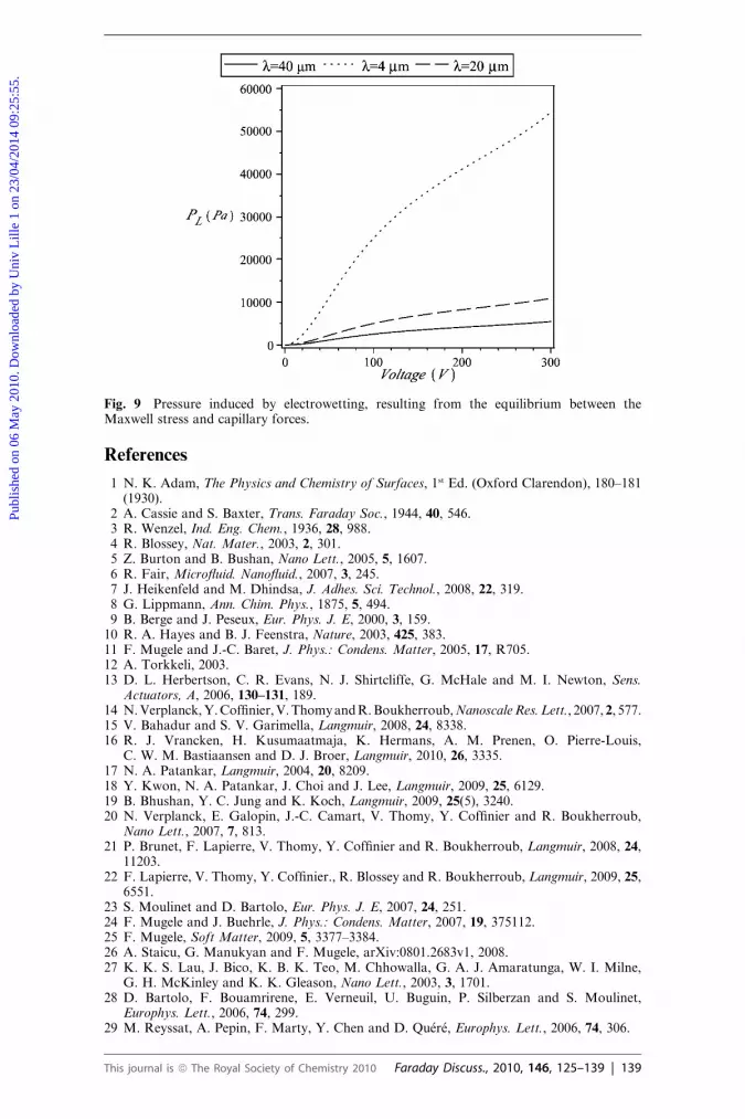
Fig. 9 Pressure induced by electrowetting, resulting from the equilibrium between theMaxwell stress and capillary forces.
Publ
ishe
d on
06
May
201
0. D
ownl
oade
d by
Uni
v L
ille
1 on
23/
04/2
014
09:2
5:55
.
View Article Online
References
1 N. K. Adam, The Physics and Chemistry of Surfaces, 1st Ed. (Oxford Clarendon), 180–181(1930).
2 A. Cassie and S. Baxter, Trans. Faraday Soc., 1944, 40, 546.3 R. Wenzel, Ind. Eng. Chem., 1936, 28, 988.4 R. Blossey, Nat. Mater., 2003, 2, 301.5 Z. Burton and B. Bushan, Nano Lett., 2005, 5, 1607.6 R. Fair, Microfluid. Nanofluid., 2007, 3, 245.7 J. Heikenfeld and M. Dhindsa, J. Adhes. Sci. Technol., 2008, 22, 319.8 G. Lippmann, Ann. Chim. Phys., 1875, 5, 494.9 B. Berge and J. Peseux, Eur. Phys. J. E, 2000, 3, 159.
10 R. A. Hayes and B. J. Feenstra, Nature, 2003, 425, 383.11 F. Mugele and J.-C. Baret, J. Phys.: Condens. Matter, 2005, 17, R705.12 A. Torkkeli, 2003.13 D. L. Herbertson, C. R. Evans, N. J. Shirtcliffe, G. McHale and M. I. Newton, Sens.
Actuators, A, 2006, 130–131, 189.14 N. Verplanck, Y. Coffinier, V. Thomy and R. Boukherroub, Nanoscale Res. Lett., 2007, 2, 577.15 V. Bahadur and S. V. Garimella, Langmuir, 2008, 24, 8338.16 R. J. Vrancken, H. Kusumaatmaja, K. Hermans, A. M. Prenen, O. Pierre-Louis,
C. W. M. Bastiaansen and D. J. Broer, Langmuir, 2010, 26, 3335.17 N. A. Patankar, Langmuir, 2004, 20, 8209.18 Y. Kwon, N. A. Patankar, J. Choi and J. Lee, Langmuir, 2009, 25, 6129.19 B. Bhushan, Y. C. Jung and K. Koch, Langmuir, 2009, 25(5), 3240.20 N. Verplanck, E. Galopin, J.-C. Camart, V. Thomy, Y. Coffinier and R. Boukherroub,
Nano Lett., 2007, 7, 813.21 P. Brunet, F. Lapierre, V. Thomy, Y. Coffinier and R. Boukherroub, Langmuir, 2008, 24,
11203.22 F. Lapierre, V. Thomy, Y. Coffinier., R. Blossey and R. Boukherroub, Langmuir, 2009, 25,
6551.23 S. Moulinet and D. Bartolo, Eur. Phys. J. E, 2007, 24, 251.24 F. Mugele and J. Buehrle, J. Phys.: Condens. Matter, 2007, 19, 375112.25 F. Mugele, Soft Matter, 2009, 5, 3377–3384.26 A. Staicu, G. Manukyan and F. Mugele, arXiv:0801.2683v1, 2008.27 K. K. S. Lau, J. Bico, K. B. K. Teo, M. Chhowalla, G. A. J. Amaratunga, W. I. Milne,
G. H. McKinley and K. K. Gleason, Nano Lett., 2003, 3, 1701.28 D. Bartolo, F. Bouamrirene, E. Verneuil, U. Buguin, P. Silberzan and S. Moulinet,
Europhys. Lett., 2006, 74, 299.29 M. Reyssat, A. Pepin, F. Marty, Y. Chen and D. Qu�er�e, Europhys. Lett., 2006, 74, 306.
This journal is ª The Royal Society of Chemistry 2010 Faraday Discuss., 2010, 146, 125–139 | 139