electrochemical effects of silane pretreatments containing cerium nitrate on cathodic disbonding...
TRANSCRIPT
Electrochemical effects of silane pretreatments containing cerium nitrateon cathodic disbonding properties of epoxy coated steel
Sadeq Hooshmand Zaferania*, Mahmood Peikaria, Davood Zaareib and Iman Danaeia
aDepartment of Technical Inspection Engineering, Petroleum University of Technology, Abadan, Iran;bTechnical Faculty, Islamic Azad University, Tehran, Iran
(Received 13 April 2012; accepted 20 February 2013)
In the recent years, silane materials, because of their environmental friendly nature and easeof application have been attended as an alternative for chromate conversion coatings. Dif-ferent materials were searched for improvement of the efficiency of silane formulation. Inthis research, pretreatment of carbon steel substrates was carried out using γ-glycidoxypro-pyl-trimethoxysilane (γ-GPS) as functionalized silane. Cerium nitrate as a corrosion inhibi-tor material was introduced into the silane material and epoxy resin was applied on thepretreated steel substrates. Effects of the pretreatment on electrochemical properties, catho-dic disbondment, dry and wet adhesion strength, and surface morphology of resultantepoxy coating were investigated. Results showed that pretreatment of steel substrate with γ-glycidoxypropyl-trimethoxysilane (γ-GPS) doped with cerium nitrate leads to improvementof cathodic disbondment and also dry and wet adhesion of epoxy coating. Furthermore, thistype of pretreatment reduced the disruption of interfacial bonds at the binder/substrate inter-face. Addition of 2wt% cerium nitrate into the silane formulation led to the maximum effi-ciency of resultant coating.
Keywords: adhesives; carbon steel; cathodic disbondment; coating
1. Introduction
Organic barrier coatings are used to protect immersed structures from corrosion by preventingdirect contact between corrosive species and the steel surface. In addition to adequate adhe-sion, these coatings must have a low permeability towards corrosive species because theprotective action of barrier coatings relies on their high resistance towards ionic transport.[1,2] On this basis, silane coatings are easily applied; they have good barrier properties andprovide good adhesion between metal and polymer coating, so they are quite often used asadhesion promoters. On the other hand, because of their environmental friendly nature,[3]application of these coatings on different substrates such as steel,[4–8] aluminum,[9–15] cop-per,[16,17] and magnesium [18–21] were searched.
One of the most important requirements of the protective coatings is resistance to cathodicdisbondment.[22,23] Alkalization is the predominant reason for cathodic disbonding whichprecedes either through hydrolysis of the interfacial bonds that attach the coating to thesubstrate resulting in direct disbonding, or through hydrolysis of the coating itself resulting inde-polymerization.[24] In this field, experimental and theoretic studies have shown that the
*Corresponding author. Email: [email protected]
Journal of Adhesion Science and Technology, 2013Vol. 27, No. 22, 2411–2420, http://dx.doi.org/10.1080/01694243.2013.779068
� 2013 Taylor & Francis
Dow
nloa
ded
by [
Sade
q H
oosh
man
d Z
afer
ani]
at 0
3:31
21
Sept
embe
r 20
13
amount of water and oxygen consumed by the cathodic reaction underneath a delaminatedcoating is less than the amount of water and oxygen that diffuses through a typical anticorro-sive coating; this means that the transport of oxygen and water cannot control the rate ofcathodic delamination.[25] Therefore, the rate-determining step of cathodic delamination ofinert-pigmented epoxy coatings appears to be the transport of positively charged hydratedions to the cathodic areas.[25]
Active corrosion inhibitors, added to coatings’ formulation to limit the kinetics of thecathodic reaction, are especially effective in prolonging coating life.[1,26] However, extensiveefforts have been devoted to the development of nontoxic or even less toxic inhibitors or pas-sivators, such as molybdates,[27] silicates,[28] rare earth salts (such as cerium nitrate),[29]and organic compounds.[6] Among the rare earth salts, cerium compounds have been usedwidely as corrosion inhibitor. Corrosion inhibition properties of cerium nitrate have been dis-cussed in literature.[30–35]
This study was set up to assess the effect of using cerium nitrate into the silane coatingas pretreatment on steel and evaluate subsequent epoxy coating adhesion and cathodicdisbondment rates. The premise here is that chemical functionality is introduced onto the steelsubstrate by its reaction with an appropriate functionalized silane.
2. Materials
Cold-rolled carbon steel panels (6.5 cm� 6.5 cm� 0.3 cm) were used as metallic substrates.The panels were subjected to a sequence of a chemical cleaning and a mechanical surfacepolishing with emery papers from #400 to #1000 to remove any trace of surface oxides andcleaned panels were kept in desiccators. Prior to the coating application, the panels wereultrasonically cleaned with acetone then cleaned by an alkaline solution (0.3mol L�1 NaOHsolution) at 60 °C for 10min. For using as a primer, prior to substrate pretreatment, a typicalformulation including 50 parts of γ-glycidoxypropyltrimethoxysilane (γ-GPS) was diluted withabout 950 parts of methanol, in pH 4.5 (adjusted with acetic acid) and allowed for the hydro-lysis of silane. Preparation procedure for doped silane with cerium nitrate pigments was thesame, except that 1, 2, 3 wt% of cerium nitrate was added to the methanol solution prior to(γ-GPS) addition, then this solution was mixed with a propeller stirrer at 1600 rpm for 30minat room temperature. The cerium nitrate containing dispersions were then sonicated for30min at 40 °C with an external cooling bath. The ultrasonication process was performed at afrequency of 20 kHz with an inlet ultrasound power of around 1W/mL using UIP 1000 ultra-sonic processor (Hielscher, Germany). Substrate pretreatment was carried out by rinsing eachpanel for 100 s with the appropriate silane solution. After treatment, the panels were allowedto dry at room temperature for 24 h, then the pretreated panels were coated with a two-packamine-cured epoxy. (Epon 828, shell Co.) to make 90 μm wet film thickness. Epoxy coatedpanels were allowed to cure for 1 h at 115 °C, after curing of epoxy coatings; the dry filmthickness was about 60 μm.
2.1. Cathodic disbonding test
Cathodic disbonding tests were carried out conventionally on coatings containing an artifi-cially introduced defect according to ASTM G-95 standard. Thus, 4mm diameter circularhole was mechanically milled in the coating down to the substrate using a flat milling tool. APVC tube of 4.7 cm inner diameter was pasted with silicon adhesive on surface of coatedsubstrates. The electrochemical cell was prepared by placing the above-mentioned sampleshorizontally on the bottom in a standard flat cell configuration. Taking into account that the
2412 S.H. Zaferani et al.
Dow
nloa
ded
by [
Sade
q H
oosh
man
d Z
afer
ani]
at 0
3:31
21
Sept
embe
r 20
13
exposed sample surface area of 17 cm2 acted as the working electrode,the samples were con-nected to cathode and palatine electrode was connected to anode, then the voltage wasadjusted to 3V exposed to 3.5wt% aerated NaCl aqueous solution. Electrical connectionswere made to each panel using insulated wire.
2.2. Electrochemical measurements
Electrochemical impedance spectroscopy (EIS) is a nondestructive useful technique in study-ing, measuring, and estimating the coating durability.[36] A large area platinum counter elec-trode was positioned parallel to the exposed sample and a saturated Ag/AgCl electrode wasemployed as the reference electrode and the cell was placed in an aluminum Faraday cage. TheEIS measurements were carried out with Autolab PGSTAT 302N Potentiosat/Galvanostat(Autolab, Italy) at open circuit potential with AC amplitude of 5mV over a frequency range of100–10MHz. The samples were immersed in 3.5 wt% aerated NaCl aqueous solution. Theimpedance diagrams were obtained at different exposure times with applying cathodic potentialup to 30 days. Fitting of experimental data to the proposed theoretical models was done bymeans of home written least square software based on the Marquardt method for optimizationof functions and Macdonald weighting for the real and imaginary parts of the impedance.[37]
2.3. Pull-off adhesion test
The coating initial adhesion and retaining of adhesion after immersion in 3.5wt% aqueousNaCl solution were measured by using a direct pull-off adhesion test method based on ASTMD4541 type III (self aligning adhesion tester). The dollies with an area of 0.5 cm2 werebonded to the coating using an appropriate adhesive (Cyanoacrylate MC1500). In the case ofadhesion measurement after exposure, the samples were removed from the solution at the endof 10 days immersion, rinsed completely with deionised water, and allowed to dry for 48 h atambient temperature. The glued dollies were then allowed to dry for 48 h at room tempera-ture. A digital adhesion tester (Elcometer 108, Elcometer Co., England) was employed. Toensure reproducibility and to statistically characterizing the test area, all the measurementswere obtained from at least three experiments.
2.4. Characterization of surface of the coatings
The effect of surface morphology of the pure epoxy doped with silane/cerium nitrate oncathodic disbonding process was determined by atomic force microscopy (AFM). Measure-ments were performed under ambient conditions using a commercial atomic force microscope(Nanosurf easy Scan 2 AFM, Switzerland). The contact-mode AFM technique was used forall images. An area with dimension of 5 micron was scanned at a constant force with setpoint of 20 nm.
3. Results and discussion
3.1. EIS measurements
To investigate EIS results, the EIS data were fitted by equivalent circuits as shown in Figure 1.To obtain a satisfactory impedance simulation of coating, it is necessary to replace the capaci-tor C with a constant phase element (CPE), Q, in the equivalent circuit. The most widelyaccepted explanation for the presence of CPE behavior and depressed semicircles on solidelectrodes is microscopic roughness, causing an inhomogeneous distribution in the solution
Journal of Adhesion Science and Technology 2413
Dow
nloa
ded
by [
Sade
q H
oosh
man
d Z
afer
ani]
at 0
3:31
21
Sept
embe
r 20
13
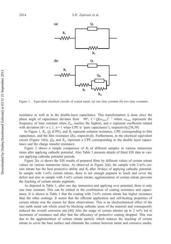
resistance as well as in the double-layer capacitance. This transformation is done since thephase angle of capacitance deviates from �90°, C =Q(ωmax)
n�1 where ωmax represents thefrequency of time constant when Zim reaches the highest; and n represent coefficient relatedwith deviation (0 < n6 1, n= 1 when CPE is ‘pure capacitance’), respectively.[38,39]
In Figure 1, Rs, Qf (CPE), and Rf represent solution resistance, CPE corresponding to filmcapacitance, and the film resistance (Rf), respectively. Furthermore, in the electrical equivalentcircuit (Figure 1(b)), Qdl and Rct represent a CPE corresponding to the double layer capaci-tance and the charge transfer resistance.
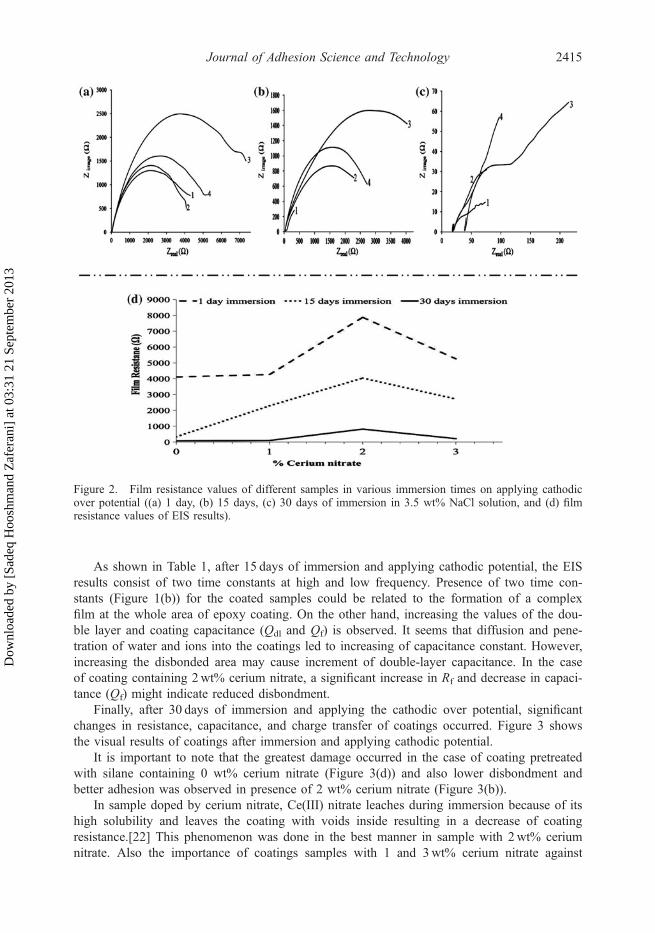
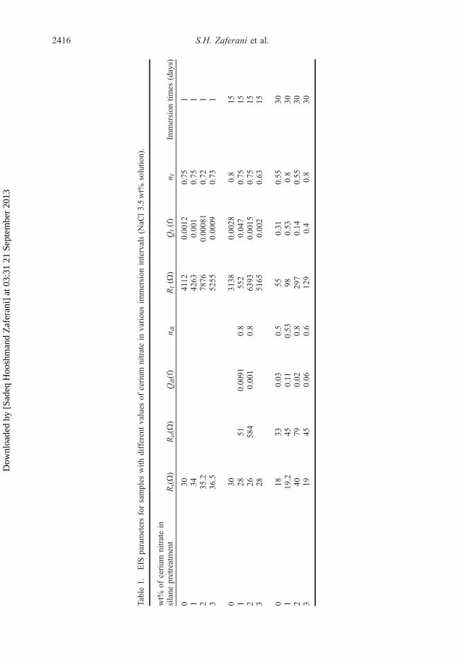
Figure 2 shows a simple comparison of Rf of different samples in various immersiontimes after applying cathodic potential. Also Table 1 presents details of fitted EIS data in vari-ous applying cathodic potential periods.
Figure 2(a–c) shows the EIS results of prepared films by different values of cerium nitratevalues on various immersion times. As observed in Figure 2(d), the sample with 2wt% cer-ium nitrate has the best protective ability and Rf after 30 days of applying cathodic potential.In sample with 1wt% cerium nitrate, there is not enough pigment to leach and cover thedefect and also in sample with 3wt% cerium nitrate; agglomeration of cerium nitrate preventsthe leaching of cerium nitrate pigments.
As depicted in Table 1, after one day immersion and applying over potential, there is onlyone time constant. This can be related to the combination of coating resistance and capaci-tance. It is shown in Table 1 that the coating with 2wt% cerium nitrate has higher resistancethan the other coatings. It seems that the efficient application and self-healing properties ofcerium nitrate was the reason for these observations. This is an electrochemical effect of therare earth metal salt which acted by blocking cathodic areas of the material and consequentlyreduced the overall corrosion rate.[40] Also the usage of cerium nitrates up to 2 wt% led toincrement of resistance and after that the efficiency of protective coating dropped. This wasdue to the agglomeration of cerium nitrate particle which reduces the leaching of ceriumnitrate to cover the bare surface and eliminate the contact between metal and corrosive media.
Figure 1. Equivalent electrical circuits of coated metal, (a) one time constant (b) two time constants.
2414 S.H. Zaferani et al.
Dow
nloa
ded
by [
Sade
q H
oosh
man
d Z
afer
ani]
at 0
3:31
21
Sept
embe
r 20
13
As shown in Table 1, after 15 days of immersion and applying cathodic potential, the EISresults consist of two time constants at high and low frequency. Presence of two time con-stants (Figure 1(b)) for the coated samples could be related to the formation of a complexfilm at the whole area of epoxy coating. On the other hand, increasing the values of the dou-ble layer and coating capacitance (Qdl and Qf) is observed. It seems that diffusion and pene-tration of water and ions into the coatings led to increasing of capacitance constant. However,increasing the disbonded area may cause increment of double-layer capacitance. In the caseof coating containing 2wt% cerium nitrate, a significant increase in Rf and decrease in capaci-tance (Qf) might indicate reduced disbondment.
Finally, after 30 days of immersion and applying the cathodic over potential, significantchanges in resistance, capacitance, and charge transfer of coatings occurred. Figure 3 showsthe visual results of coatings after immersion and applying cathodic potential.
It is important to note that the greatest damage occurred in the case of coating pretreatedwith silane containing 0 wt% cerium nitrate (Figure 3(d)) and also lower disbondment andbetter adhesion was observed in presence of 2 wt% cerium nitrate (Figure 3(b)).
In sample doped by cerium nitrate, Ce(III) nitrate leaches during immersion because of itshigh solubility and leaves the coating with voids inside resulting in a decrease of coatingresistance.[22] This phenomenon was done in the best manner in sample with 2wt% ceriumnitrate. Also the importance of coatings samples with 1 and 3wt% cerium nitrate against
Figure 2. Film resistance values of different samples in various immersion times on applying cathodicover potential ((a) 1 day, (b) 15 days, (c) 30 days of immersion in 3.5 wt% NaCl solution, and (d) filmresistance values of EIS results).
Journal of Adhesion Science and Technology 2415
Dow
nloa
ded
by [
Sade
q H
oosh
man
d Z
afer
ani]
at 0
3:31
21
Sept
embe
r 20
13
Table
1.EIS
parametersforsamples
with
differentvalues
ofcerium
nitratein
variou
sim
mersion
intervals(N
aCl3.5wt%
solutio
n).
wt%
ofcerium
nitratein
silane
pretreatment
Rs(Ω)
Rct(Ω
)Qdl(f)
n dl
Rf(Ω
)Qf(f)
n fIm
mersion
times
(days)
030
��
�4112
0.00
120.75
11
34�
��
4263
0.00
10.75
12
35.2
��
�78
760.00
081
0.72
13
36.5
��
�52
550.00
090.73
1
030
��
�31
380.00
280.8
151
2851
0.00
910.8
552
0.04
70.75
152
2658
40.00
10.8
6393
0.00
150.75
153
28�
��
5165
0.00
20.63
15
018
330.03
0.5
550.31
0.55
301
19.2
450.11
0.53
980.53
0.8
302
4079
0.02
0.8
297
0.14
0.55
303
1945
0.06
0.6
129
0.4
0.8
30
2416 S.H. Zaferani et al.
Dow
nloa
ded
by [
Sade
q H
oosh
man
d Z
afer
ani]
at 0
3:31
21
Sept
embe
r 20
13
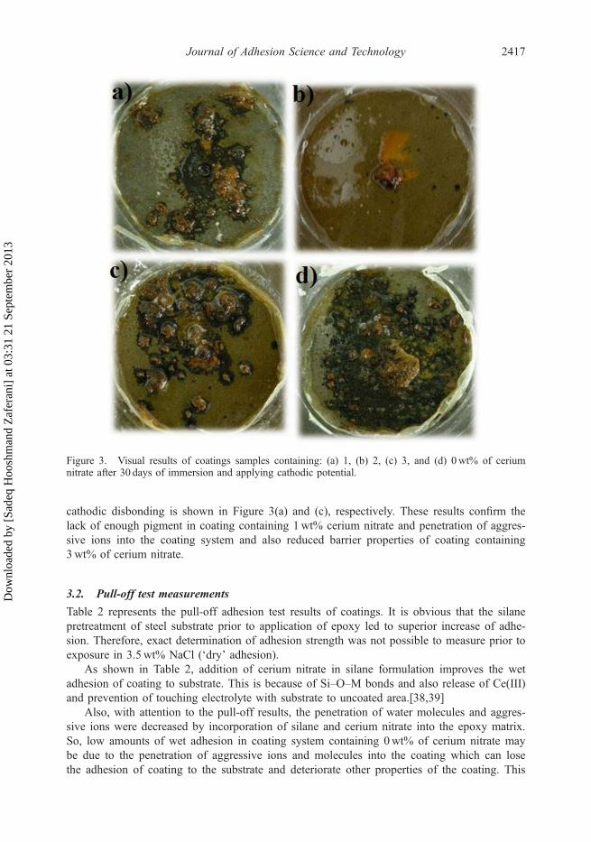
cathodic disbonding is shown in Figure 3(a) and (c), respectively. These results confirm thelack of enough pigment in coating containing 1wt% cerium nitrate and penetration of aggres-sive ions into the coating system and also reduced barrier properties of coating containing3wt% of cerium nitrate.
3.2. Pull-off test measurements
Table 2 represents the pull-off adhesion test results of coatings. It is obvious that the silanepretreatment of steel substrate prior to application of epoxy led to superior increase of adhe-sion. Therefore, exact determination of adhesion strength was not possible to measure prior toexposure in 3.5wt% NaCl (‘dry’ adhesion).
As shown in Table 2, addition of cerium nitrate in silane formulation improves the wetadhesion of coating to substrate. This is because of Si–O–M bonds and also release of Ce(III)and prevention of touching electrolyte with substrate to uncoated area.[38,39]
Also, with attention to the pull-off results, the penetration of water molecules and aggres-sive ions were decreased by incorporation of silane and cerium nitrate into the epoxy matrix.So, low amounts of wet adhesion in coating system containing 0wt% of cerium nitrate maybe due to the penetration of aggressive ions and molecules into the coating which can losethe adhesion of coating to the substrate and deteriorate other properties of the coating. This
Figure 3. Visual results of coatings samples containing: (a) 1, (b) 2, (c) 3, and (d) 0wt% of ceriumnitrate after 30 days of immersion and applying cathodic potential.
Journal of Adhesion Science and Technology 2417
Dow
nloa
ded
by [
Sade
q H
oosh
man
d Z
afer
ani]
at 0
3:31
21
Sept
embe
r 20
13
effect is decreased by increasing the cerium nitrate loading to the epoxy matrix up to 2wt%cerium nitrate. Table 2 also shows that the wet adhesion of coating containing 3wt% ceriumnitrate is lower than the coating containing 2wt% cerium nitrate. This indicates that theexcess amount of cerium nitrate in the film leads to a negative effect on the interfacial adhe-sion and a premature film delamination from the substrate.[40]
As a result for γ-GPS and epoxy chemistry, the formation of primary bonds between thecoating polymer and functional substrate surface is the obvious mechanism for the observedimprovements in adhesion (bond) strength. The disbonding data confirm that interfacial modi-fication by γ-GPS was effective in reducing the cathodic disbonding rate of an epoxy-basedbinder chemistry. Thus, for γ-GPS and epoxy chemistry, the disbondment mechanism mustinvolve interfacial degradation (since interfacial modification affects the disbondment rate).
3.3. Surface morphology of coating films
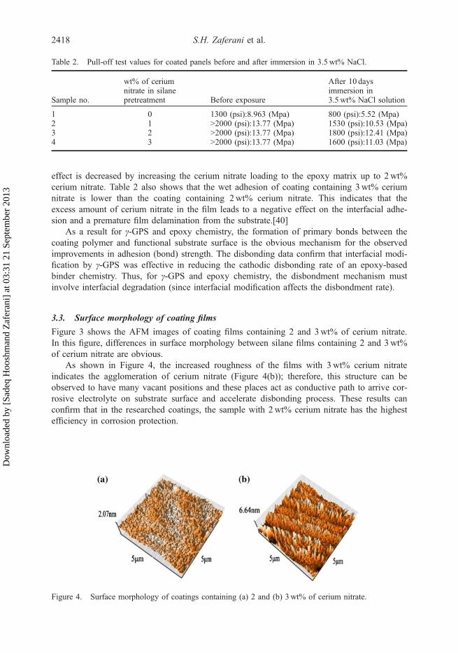
Figure 3 shows the AFM images of coating films containing 2 and 3wt% of cerium nitrate.In this figure, differences in surface morphology between silane films containing 2 and 3wt%of cerium nitrate are obvious.
As shown in Figure 4, the increased roughness of the films with 3wt% cerium nitrateindicates the agglomeration of cerium nitrate (Figure 4(b)); therefore, this structure can beobserved to have many vacant positions and these places act as conductive path to arrive cor-rosive electrolyte on substrate surface and accelerate disbonding process. These results canconfirm that in the researched coatings, the sample with 2wt% cerium nitrate has the highestefficiency in corrosion protection.
Table 2. Pull-off test values for coated panels before and after immersion in 3.5wt% NaCl.
Sample no.
wt% of ceriumnitrate in silanepretreatment Before exposure
After 10 daysimmersion in3.5wt% NaCl solution
1 0 1300 (psi):8.963 (Mpa) 800 (psi):5.52 (Mpa)2 1 >2000 (psi):13.77 (Mpa) 1530 (psi):10.53 (Mpa)3 2 >2000 (psi):13.77 (Mpa) 1800 (psi):12.41 (Mpa)4 3 >2000 (psi):13.77 (Mpa) 1600 (psi):11.03 (Mpa)
Figure 4. Surface morphology of coatings containing (a) 2 and (b) 3wt% of cerium nitrate.
2418 S.H. Zaferani et al.
Dow
nloa
ded
by [
Sade
q H
oosh
man
d Z
afer
ani]
at 0
3:31
21
Sept
embe
r 20
13
4. Conclusions
(1) Surface modification of carbon steel substrates using appropriate functionalizedorganosilane significantly improved both the dry and wet adhesion strength of epoxycoatings.
(2) Introduction of cerium nitrate in the formulation of silane pretreatment of carbon steelsubstrates reduced the cathodic disbondment and enhanced the corrosion protection ofcoating.
(3) The amount of cerium nitrate in the formulation of silane was important. However,usage of high values of cerium nitrate led to the formation of agglomerates and so,reduction of protective properties of final coating system.
(4) The best results of protection were obtained using 2wt% of cerium nitrate in the silanepretreatment formulation.
References[1] Harun MK, Marsh J, Lyon SB. The effect of surface modification on the cathodic disbondment rate
of epoxy and alkyd coatings. Prog. Org. Coat. 2005;54:317–321.[2] Sørensena PA, Dam-Johansena K, Weinellb CE, Kiila S. Cathodic delamination: Quantification of
ionic transport rates along coating-steel interfaces. Prog. Org. Coat. 2010;68:283–292.[3] Bajat JB, Mišković-Stanković VB, Kačarević-Popović Z. Corrosion stability of epoxy coatings on
aluminum pretreated by vinyltriethoxysilane. Corros. Sci. 2008;50:2078–2084.[4] Suegama PH, de Melo HG, Benedetti AV, Aoki IV. Influence of cerium (IV) ions on the mecha-
nism of organosilane polymerization and on the improvement of its barrier properties. Electrochim.Acta. 2009;54:2655–2662.
[5] Yang L, Feng J, Zhang W, Qu J. Film forming kinetics and reaction mechanism of γ-glycidoxypro-pyltrimethoxysilane on low carbon steel surfaces. Appl. Surf. Sci. 2010;256:6787–6794.
[6] Kong G, Lu J, Zhang S, Che C, Wu H. A comparative study of molybdate/silane composite filmson galvanized steel with different treatment processes. Surf. Coat. Technol. 2010;205:545–550.
[7] Tittarelli F, Moriconi G. The effect of silane-based hydrophobic admixture on corrosion of galva-nized reinforcing steel in concrete. Corros. Sci. 2010;52:2958–2963.
[8] Cies´lik M, Engvall K, Pan J, Kotarba A. Silane–parylene coating for improving corrosion resis-tance of stainless steel 316L implant material. Corros. Sci. 2011;53:296–301.
[9] Zhu D, van Ooij W. Corrosion protection of AA 2024–T3 by bis-[3-(triethoxysilyl)propyl]tetrasul-fide in sodium chloride solution: part 2: mechanism for corrosion protection. Corros. Sci.2003;45:2177–2197.
[10] Franquet A, Le Pen C, Terryn H, Vereecken J. Effect of bath concentration and curing time on thestructure of non-functional thin organosilane layers on aluminium. Electrochim. Acta.2003;48:1245–1255.
[11] Donley MS, Mantz RA, Khramov AN, Balbyshev VN, Kasten LS, Gaspar DJ. The self-assemblednanophase particle (SNAP) process: a nanoscience approach to coatings. Prog. Org. Coat.2003;47:401–415.
[12] Jovanović Ž, Bajat JB, Jančić-Heinemann RM, Dimitrijević M, Mišković-Stanković VB. Methac-ryloxypropyltrimethoxysilane films on aluminium: electrochemical characteristics, adhesion andmorphology. Prog. Org. Coat. 2009;66:393–399.
[13] Trueba M, Trasatti SP. Pyrrole-based silane primer for corrosion protection of commercial Alalloys: Part I: synthesis and spectroscopic characterization. Prog. Org. Coat. 2009;66:254–264.
[14] Brusciotti F, Batan A, De Graeve I, Wenkin M, Biessemans M, Willem R, Reniers F, Pireaux JJ,Piens M, Vereecken J, Terryn H. Characterization of thin water-based silane pre-treatments on alu-minium with the incorporation of nano-dispersed CeO2 particles. Surf. Coat. Technol.2010;205:603–613.
[15] Wei X, Ruilin M, Chang M, Tianlan P. Study on corrosion resistance of the BTESPT silane coop-erating with rare earth cerium on the surface of aluminum-tube. J. Rare Earths. 2010;28:117–122.
[16] Kim H, Jang J. Corrosion protection and adhesion promotion for polyimide/copper system usingsilane-modified polymeric materials. Polymer. 2000;41:6553–6561.
Journal of Adhesion Science and Technology 2419
Dow
nloa
ded
by [
Sade
q H
oosh
man
d Z
afer
ani]
at 0
3:31
21
Sept
embe
r 20
13
[17] Deflorian F, Rossi S, Fedrizzi L. Silane pre-treatments on copper and aluminium. Electrochim.Acta. 2006;51:6097–6103.
[18] Zucchi F, Grassi V, Frignani A, Monticelli C, Trabanelli G. Influence of a silane treatment on thecorrosion resistance of a WE43 magnesium alloy. Surf. Coat. Technol. 2006;200:4136–4143.
[19] Zucchi F, Frignani A, Grassi V, Balbo A, Trabanelli G. Organo-silane coatings for AZ31 magne-sium alloy corrosion protection. Mater. Chem. Phys. 2008;110:263–268.
[20] Montemor MF, Ferreira MGS. Analytical characterisation and corrosion behaviour of bis-aminosi-lane coatings modified with carbon nanotubes activated with rare-earth salts applied on AZ31 Mag-nesium alloy. Surf. Coat. Technol. 2008;202:4766–4774.
[21] Pinto R, Carmezim MJ, Ferreira MGS, Montemor MF. A two-step surface treatment, combininganodisation and silanisation, for improved corrosion protection of the Mg alloy WE54. Prog. Org.Coat. 2010;69:143–149.
[22] Mahdavian M, Attar MM. The effect of benzimidazole and zinc acetylacetonate mixture on catho-dic disbonding of epoxy coated mild steel. Prog. Org. Coat. 2009;66:137–140.
[23] Naderi R, Attar MM. The role of zinc aluminum phosphate anticorrosive pigment in ProtectivePerformance and cathodic disbondment of epoxy coating. Corros. Sci. 2010;52:1291–1296.
[24] Martinez S, Valek Zˇulj L, Kapor F. Disbonding of underwater-cured epoxy coating caused bycathodic protection current. Corros. Sci. 2009;51:2253–2258.
[25] Sørensen PA, Dam-Johansen K, Weinell CE, Kiil S. Cathodic delamination: Quantification of ionictransport rates along coating-steel interfaces. Prog. Org. Coat. 2010;68:70–78.
[26] Rodr´ıguez MT, Gracenea JJ, Saura JJ, Suay JJ. The influence of the critical pigment volume con-centration (CPVC) on the properties of an epoxy coating: part II. Anticorrosion and economicproperties. Prog. Org. Coat. 2004;50:68–74.
[27] Tang PT, Bech-Nielsen G, Moller PM. Molybdate based passivation of zinc. Trans. Inst. Met. Fin-ish. 1997;75:144–151.
[28] Aramaki K. Self-healing mechanism of an organosiloxane polymer film containing sodium silicateand cerium(III) nitrate for corrosion of scratched zinc surface in 0.5 M NaCl. Corros. Sci.2001;44:1621–1632.
[29] Lu JT, Wu HJ, Kong G, Che CS, Xu QY. Corrosion resistance of silane film on hot-depped galva-nized steel by molybdate post sealing. Trans. Nonferrous Met. Soc. China. 2006;16:17–20.
[30] Trabelsi W, Cecilio P, Ferreira MGS, Montemor MF. Electrochemical assessment of the self-heal-ing properties of Ce-doped silane solutions for the pre-treatment of galvanised steel substrates.Prog. Org. Coat. 2005;54:276–284.
[31] Montemor MF, Simões AMP, Ferreira MGS. Composition and corrosion behaviour of galvanisedsteel treated with rare earth salts. The effect of the cation. Prog. Org. Coat. 2002;44:111–120.
[32] Montemor MF, Simões AMP, Ferreira MGS. Composition and behaviour of cerium films on gal-vanised steel. Prog. Org. Coat. 2001;43:274–281.
[33] Kasten LS, Grant JT, Grebasch N, Voevodin N, Arnold FE, Donley MS. An XPS study of ceriumdopants in sol–gel coatings for aluminum 2024–T3. Surf. Coat. Technol. 2001;140:11–15.
[34] Garcia-Heras M, Morales AJ, Casal B, Galvan JC, Radzki S, Villegas MA. Preparation and electro-chemical study of cerium-silica sol�gel thin films. J. Alloys Compd. 2004;380:219–224.
[35] Pepe A, Aparicio M, Cer´e S, Dur´an A. Preparation and characterization of cerium doped silicasol–gel coatings on glass and aluminum substrates. J. Non-Cryst. Solids. 2004;348:162–171.
[36] Leng A, Streckel H, Stratmann M. The delamination of polymeric coatings from steel. Part 2: firststage of delamination, effect of type and concentration of cations on delamination, chemical analy-sis of the interface. Corros. Sci. 1999;41:579–597.
[37] Danaee I, Jafarian M, Forouzandeh F, Gobal F, Mahjani MG. Impedance spectroscopy analysis ofglucose electro-oxidation on Ni-modified glassy carbon electrode. Electrochim. Acta.2008;53:6602–6609.
[38] Nematollahi M, Heidarian M, Peikari M, Kassiriha SM, Arianpouya N, Esmaeilpour M. Compari-son between the effect of nanoglass flake and montmorillonite organoclay on corrosion perfor-mance of epoxy coating. Corros. Sci. 2010;52:1809–1817.
[39] Allie L, Thorn J, Aglan H. Evaluation of nanosilicate filled poly (vinyl chloride-co-vinyl acetate)and epoxy coatings. Corros. Sci. 2008;50:2189–2196.
[40] Van Ooij WJ, Zhu D, Stacy M, Seth A, Mugada T, Gandhi J, Puomi P. Corrosion protection prop-erties of organofunctional silanes – an overview. Tsinghua Sci Technol. 2005;10:639–664.
2420 S.H. Zaferani et al.
Dow
nloa
ded
by [
Sade
q H
oosh
man
d Z
afer
ani]
at 0
3:31
21
Sept
embe
r 20
13