electric machinery fundamentals, 4th edition
TRANSCRIPT
CHAPTER
6 SYNCHRONOUS MOTORS
Synchronous motors are synchronous machines used to convert electrical power to mechanical power. This chapter explores the basic operati on of
synchronous motors and relates their behavior to that of synchronous generators .
6.1 BASIC PRINCIPLES OF MOTOR OPERATION
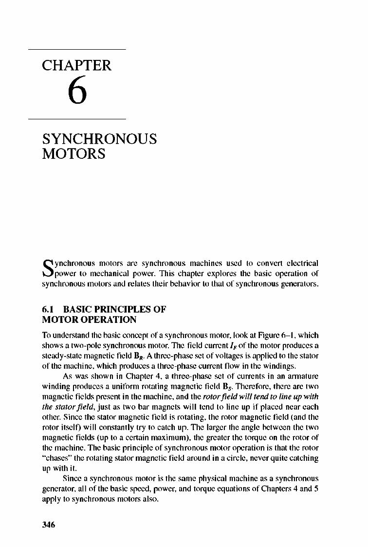
To understand the basic concept of a synchronous motor, look at Figure 6-1 , which shows a two-pole synchronous motor. 1lle field current IF of the motor produces a steady-state magnetic field HR. A three-phase set of voltages is applied to the stator orthe machine, which produces a three-phase current fl ow in the windings.
As was shown in Chapter 4, a three-phase sct of currents in an annature winding produces a uniform rotating magnetic fie ld Bs. Therefore, there are two magnetic fields present in the machine, and the rotor field will tend to line up with the stator field , just as two bar magnets will tend to line up if placed near each other. Since the stator magnetic field is rotating, the rotor magnetic field (and the rotor itself) will constantly try to catch up. TIle larger the angle between the two magnetic fi e lds (up to a certain maximum), the greater the torque on the rotor of the machine. The basic principle of synchronous motor operation is that the rotor "chases" the rotating stator magnetic field around in a circle, never quite catching up with it.
Since a synchronous motor is the same physical machine as a synchronous generator, all of the basic speed, power, and torque equations of Chapters 4 and 5 apply to synchronous motors also.
346
SYNCHRONOUS MOTORS 347
o /,11,
0, o
Tind ",k HRx nS '" counterclockwise
o
FIGURE 6-1 A two-pole synchronous motor.
The Equivalent Circuit of a Synchronolls Motor
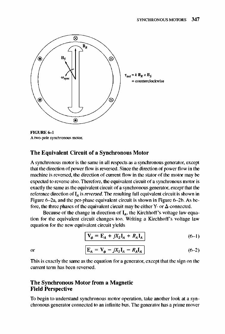
A synchronous motor is the same in all respects as a synchronous generator, except that the direction of power fl ow is reversed. Since the direction of power fl ow in the machine is reversed, the direction of current fl ow in the stator of the motor may be expected to reverse also. Therefore, the equivalent circuit of a synchronous motor is exactly the same as the equivalent circuit of a synchronous generator, except that the reference direction of IA. is reversed. 1lle resulting full equivalent circuit is shown in Figure 6- 2a, and the per-phase equivale nt circuit is shown in Figure 6- 2b. As before, the three phases of the equivalent circuit may be either Y- or d-connected.
Because of the change in direction of lA. , the Kirchhoff 's voltage law equation for the equiva lent circuit changes too. Writing a Kirchhoff's voltage law eq uation for the new eq ui vale nt circuit yields
I V4> - EA + jXS IA + RAIA I
lEA - V4> - jXS IA - RAIA I
(6-1)
(6-2)
This is exactly the srune as the equation for a generator, except that the sign on the current term has been reversed .
The Synchronolls Motor from a Magnetic Field Perspective
To begin to understand synchronous motor operation, take another look at a synchronous generator connected to an infinite bus. The generator has a prime mover
348 ELECTRIC MACHINERY RJNDAMENTALS
I"
j Xs R,
)v., E"
I,
R .. I"
R, j Xs
) V.'
R,
V, + E" "-'
L,
I" -j Xs R,
)v" E"
(a)
I, RJ,{
I, - -/' j Xs R,
V, L, E, V.
,b, ""GURE 6- 2 (a) The full equivalent circuit of a three-phase synchronous motor. (b) The per-phase equivalent circuit.
turning its shaft, causing it to rotate. The direction of the applied torque Tapp from the prime mover is in the direction of moti on, because the prime mover makes the generator rotate in the first place.
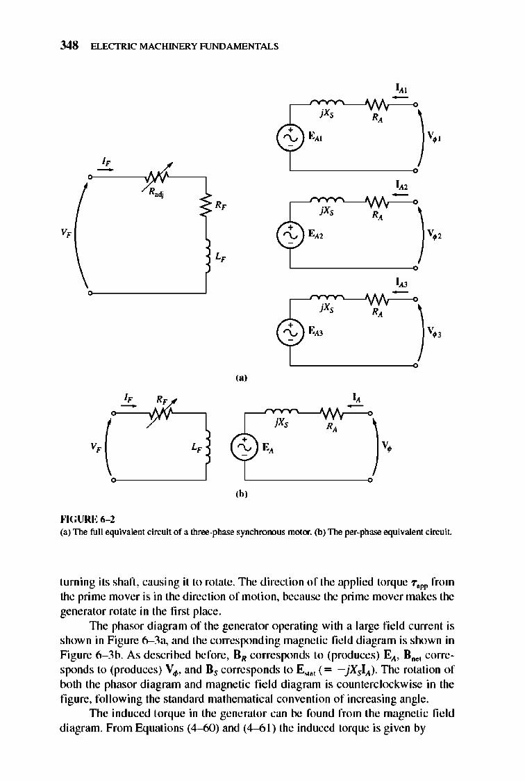
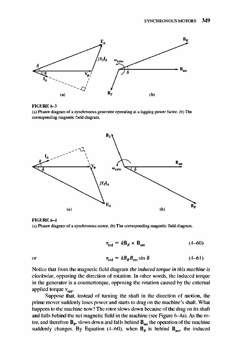
The phasor diagram of the gene rator operating with a large fi e ld current is shown in Figure 6-3a, and the corresponding magnetic fie ld diagram is shown in Figure 6- 3b. As described before, RR corresponds to (produces) EA , Rnet corresponds to (produces) Vo/>, and Rs corresponds to E"at (= -jXsIA) . TIle rotation of both the phasor diagram and magnetic fi e ld diagram is counterclockwise in the fi gure, following the standard mathematical convention of increasing angle .
TIle induced torque in the generator can be found from the magnetic field diagram. From Equations (4-60) and (4-6 1) the induced torque is given by
,
FIGURE 6-3
(a)
• ,
SYNCHRONOUS MOTORS 349
B,
w.~
-rlf, =------- B~
,b,
(a) Phasor diagram ofa synchronous generator operating at a lagging power factor. (b) The corresponding magnetic field diagram.
~/~ -- , , 8 ,
FIGURE 6-4
u,
, ' V,
,,~
w.~ "cr,-------'"
,b, B,
(a) Phasor diagram ofa synchronous motor. (b) T he corresponding magnetic field diagram.
(4-60)
(4-61)
Notice that from the magnetic fie ld diagram the induced torque in this machine is clockwise, opposing the direction of rotation. In other words, the induced torque in the generator is a countertorque, opposing the rotation caused by the external applied torque "Taw
Suppose that , instead of turning the shaft in the direction of motion, the prime mover suddenly loses power and starts to drag on the machine 's shaft. What happens to the machine now? The rotor slows down because of the drag on its shaft and falls behind the net magnetic fie ld in the machine (see Figure 6-4a). As the rotor, and therefore BR, slows down and fa lls behind Bne, the operation of the machine sudde nly changes. By Equation (4--60), when BR is behind B ... " the induced
350 ELECTRIC MACHINERY RJNDAMENTALS
torque's direction reverses and becomes counterclockwise. In other words, the machine's torque is now in the direction of motion, and the machine is acting as a motor. The increasing torque angle 8 results in a larger and larger torque in the direction of rotation, until eventually the motor 's induced torque equals the load torque on its shaft. At that point, the machine will be operating at steady state and synchronous speed again, but now as a motor.
TIle phasor diagram corresponding to generator operation is shown in Figure 6-3a, and the phasor diagram corresponding to motor operation is shown in Figure 6-4a. TIle reason that the quantity jXsI), points from Vo/>, to E), in the generator and from E), to Vo/> in the motor is that the reference direction of I), was reversed in the definition of the motor equi valent circuit. The basic difference between motor and generator operation in synchronous machines can be seen either in the magnetic field diagram or in the phasor diagram. In a generator, E), lies ahead of Vo/>, and BR lies ahead of 8 0 ... In a motor, E), lies behind Vo/>' and BR lies behind Boe, . In a motor the induced torque is in the direction of motion, and in a generator the induced torque is a countertorque opposing the direction of motion.
6.2 STEADY-STATE SYNCHRONOUS MOTOR OPERATION
TIlis section ex pl ores the behavior of synchronous motors under varying conditions of load and fi eld current as we ll as the question of power-factor correction with synchronous motors. The following discussions will generally ignore the armature resistance of the motors for simpli city. However, R), will be considered in some of the worked numerical calculations.
The Synchronous Motor Torque-Speed Characteristic Curve
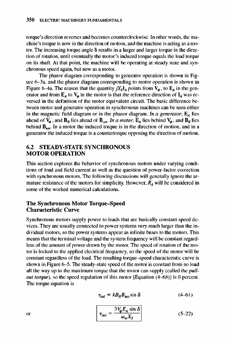
Synchronous motors supply power to loads that are basically constant-speed devices . They are usually connected to power systems very much larger than the individual motors, so the power systems appear as infinite buses to the motors. TIlis means that the terminal voltage and the system frequency will be constant regardless of the amount of power drawn by the motor. 1lle speed of rotation of the motor is locked to the applied electrical frequency, so the speed of the motor will be constant regardless of the load. The resulting torque-speed characteristic curve is shown in Figure 6- 5. The steady-state speed of the motor is constant from no load all the way up to the maximum torque that the motor can supply (called the pullout torque), so the speed regulation of this motor [Equation (4-68)] is 0 percent. 1lle torque equation is
(4-<>1 )
(5- 22)
SYNCHRONOUS MOTORS 351
fpullou1 -----------------
n_. - n, SR= on xlOO%
'" SR=O%
f",,0<1 -----------------
L-__________________ ~-------- ,.
'.~
FIGURE 6-S The torque-speed characteristic of a synchronous motor. Since the speed of the motor is oonstam. its speed regulation is zero.
The maximum or pullout torque occurs when /j = 900 . Nonnal full-load torques are much less than that , however. In fact, the pullout torque may typically be 3 times the full-load torque of the machine.
When the torque on the shaft of a synchronous motor exceeds the pullout torque, the rotor can no longer remain locked to the stator and net magnetic fie lds. Instead, the rotor starts to slip behind them. As the rotor slows down, the stator magnetic field "laps" it repeatedly, and the direction of the induced torq ue in the rotor reverses with each pass. The resulting huge torque surges, first one way and then the other way, cause the whole motor to vibrate severely. The loss of sy nchronization after the pullout torque is exceeded is known as slipping poles.
The maximum or pullout torq ue of the motor is given by
(6-3)
(6-4)
These equations indicate that the larger the field current (and hence E,...) , the greater the maximum torque of the nwtor. There is therefore a stability advantage in operating the motor with a large field current or a large E,.,.
The Effect of Load Changes on a Synchronous Motor
If a load is attached to the shaft of a sy nchronous motor, the motor will develop enough torque to keep the motor and its load turning at a synchronous speed . What happens when the load is changed on a synchronous motor?
352 ELECTRIC MACHINERY RJNDAMENTALS
(a)
, , , ,
IIA2 ilAl
""GURE 6-6
, , , , , , , IV,
EA4 "j' __ CC ____________ _
(b)
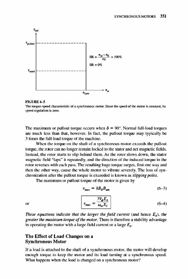
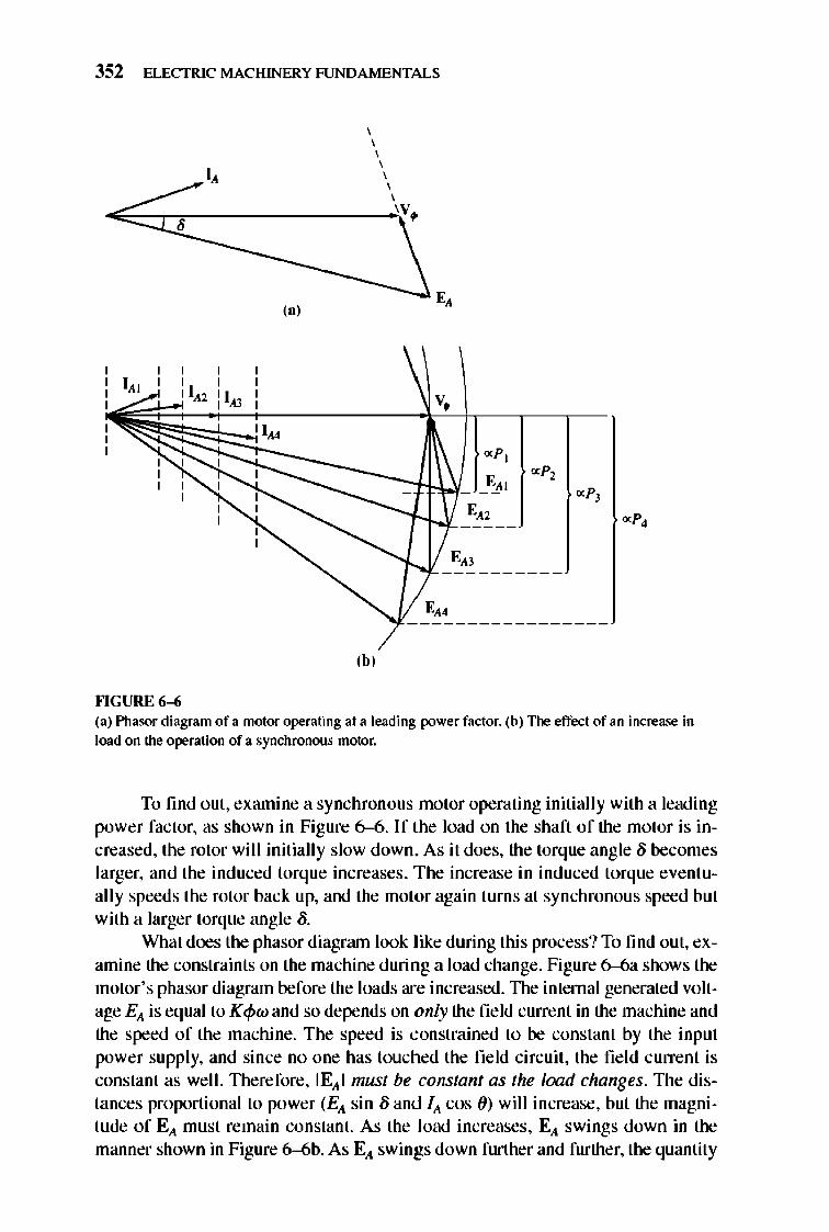
(a) Pltasor diagram of a motor operating at a leading power factor. (b) The effect of an increase in load on the operation of a synchronous motor.
To find oul, examine a synchronous motor operating initially with a leading power factor, as shown in Figure 6--6. If the load on the shaft of the motor is increased, the rotor wi ll initially slow down. As it does, the torque angle 8 becomes larger, and the induced torque increases . T he increase in induced torque eventually speeds the rotor back up, and the motor again turns at synchronous speed but with a larger torque angle 8.
What does the phasor diagrrun look like during this process? To find out, examine the constraints on the machine during a load change. Figure 6--6a shows the motor's phasor diagram before the loads are increased. The internal generated voltage EA is equal to K<pw and so depends on only the field current in the machine and the speed of the machine. The speed is constrained to be constant by the input power supply, and since no one has touched the field circuit , the fie ld current is constant as well. TIlerefore, lEAl must be constant as the load changes. TIle distances proportional to power (EA sin 8 and JA cos ()) will increase, but the magnitude of EA must remain constant. As the load increases, EA swings down in the manner shown in Figure 6-6b. As EA swings down further and further, the quantity
SYNCHRONOUS MOTORS 353
jXSIA has to increase to reach from the tip of EA to Vo/> , and therefore the annature
c urrent IA also increases. Notice that the power-factor angle () changes too, becom
ing Jess and less leading and then more and more lagging.
Exam ple 6-1. A 20S-V, 4S-kVA, O.S-PF-Ieading, a-connected, 60-Hz synchronous machine has a synchronous reactance of 2.5 0 and a negligible armature resistance. Its friction and windage losses are 1.5 kW, and its core losses are 1.0 kW. Initially, the shaft is supplying a IS-hp load, and the motor's power factor is O.SO leading.
(a) Sketch the phasor diagram of this motor, and find the values of lA, fL' and EA. (b) Assume that the shaft load is now increased to 30 hp. Sketch the behavior of the
phasor diagram in response to this change. (c) Find lA, fL' and EA after the load change. What is the new motor power factor ?
Solutioll (a) Initially, the motor 's output power is 15 hp. This corresponds to an output of
POOl = (15 hp)(0.746 KWlhp) = 11.19 kW
Therefore, the electric power supplied to the machine is
Pin = Pout + P""",blo<s + P CO/IeJo.. + Pel""l.,..
= 11.I9kW+ I.5kW+ 1.0kW+OkW = 13.69kW
Since the motor's power factor is O.SO leading, the resulting line current flow is
I - ccciP-"," CC-o L - v'3VTcos 0
13.69 kW = V3"(20S VXO.SO) = 47.5 A
and the annature current is h/V'!, with O.Sleading power factor, which gives the result
IA = 27.4 L 36.S7° A
To find EA, apply Kirchhoff's voltage law [Equation (6-2)]:
EA = Vo/> - jXsIA
= 20S L 0° V - (j2.5 0)(27.4 L 36.S7° A)
= 20S L 0° V - 6S.5 L 126.S7° V
=249.I -jS4.SV =2SSL - 12.4° V
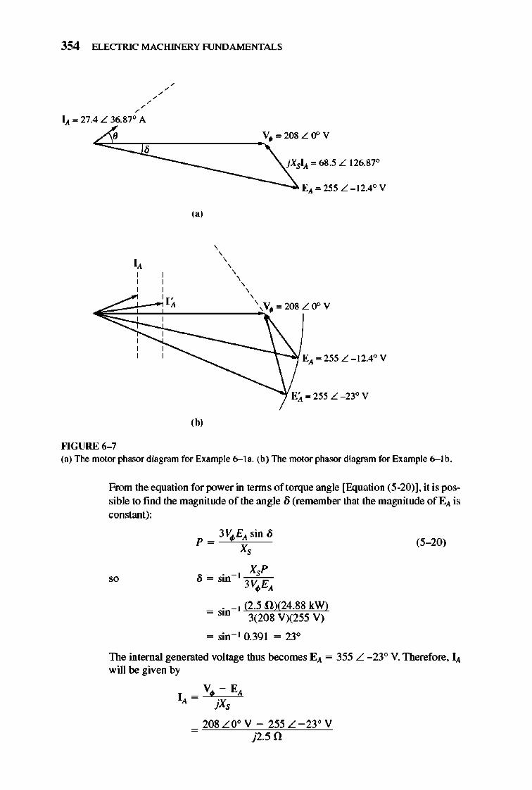
The resulting phasor diagram is shown in Figure 6-7a. (b) As the power on the shaft is increased to 30 hp, the shaft slows momentarily, and
the internal generated voltage EA swings out to a larger angle /j while maintaining a constant magnitude. The resulting phasor diagram is shown in Figure 6-7b.
(c) After the load changes, the electric input power of the machine becomes
Pin = Pout + Pmoc.b lo<s + PCO/IeJo.. + P el""l.,..
= (30 hpXO.746 kWlhp) + 1.5 kW + 1.0 kW + 0 kW
= 24.SSkW
354 ELECTRIC MACHINERY RJNDAMENTALS
, , , 1..1. '" 27.4 L 36.87° A
8
""GURE 6-7
"J
(b,
, , , , ,
V. '" 208 L r:f' V
j XSIA '" 68.5 L 126.87°
EA"'255L - 12.4°Y
, , , , \ V.",208Lr:f'V
E;" '" 255 L _23° V
(a) The motor phasor diagram for Example 6-la. (b) The motor phasor diagram for Example 6- lb.
From the equation for power in tenns of torque angle [Equation (5-20)], it is possible to find the magnitude of the angle /j (remember that the magnitude of EA is constant):
'0
p = 3VI/!EA sin Ii X,
_ . _ ] XsP ii -sill 3VE . ,
_ . _] (2.5 flX24.SS kW) - Sill 3(20S V)(255 V)
= sin- ] 0.391 = 23°
(5- 20)
The internal generated voltage thus becomes EA = 355 L _23° V. Therefore, IA will be given by
_ VI/! - EA IA - 'X J ,
20SLooY-255L-23°Y = j2.5fl
SYNCHRONOUS MOTORS 355
,.,
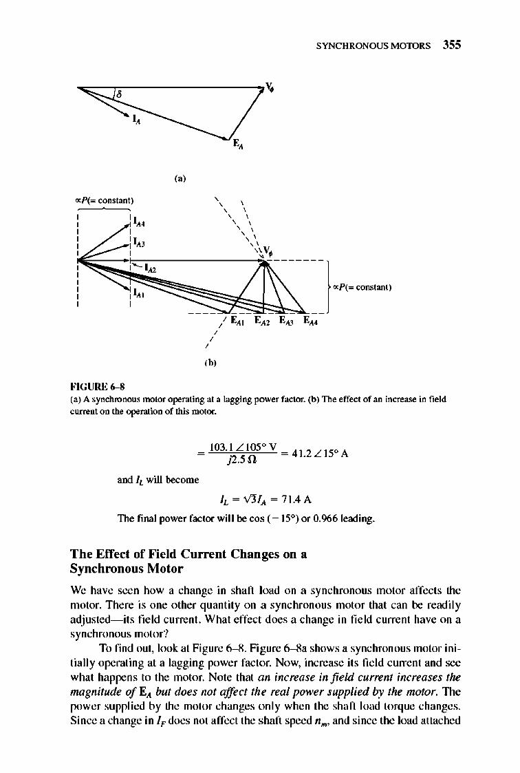
,b, FIGURE 6-8 (a) A synchronous motor operating at a Jagging power factor. (b) The effect of an increase in field current on the operation of this motor.
and IL will become
IL = V3IA = 7 1.4 A
The final power factor will be cos (-ISO) or 0.966 leading.
The Effect of Field Current Changes on a Synchronous Motor
We have seen how a change in shaft load on a synchronous motor affects the motor. There is one other quantity on a synchronous motor that can be readily adjusted- its field current. What effect does a change in fie ld current have on a synchronous motor?
To find out, look at Figure 6--8 . Fi gure 6--8a shows a synchronous motor initially operating at a lagging power factor. Now, increase its fi e ld current and see what happens to the motor. Note that an increase in field current increases the magnitude of E,t but does not affect the real power supplied by the motor. 1lle power supplied by the motor changes only when the shaft load torque changes. Since a change in IF does not affect the shaft speed nm , and since the load attached
356 ELECTRIC MACHINERY RJNDAMENTALS
Lagging power factor
PF '" 1.0
Leading power factor
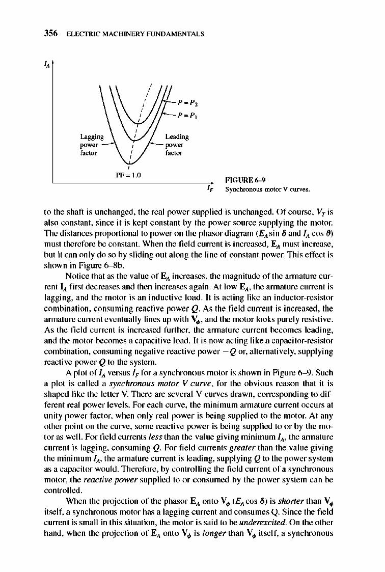
FIGURE 6-9 IF Synchronous motor V curves.
to the shaft is unchanged, the real power supplied is unchanged. Of course, VT is also constant, since it is kept constant by the power source supplying the motor. The distances proportional to power on the phasor diagram (EA sin 8 and IA cos ()) must therefore be constant. When the field current is increased, EA must increase, but it can only do so by sliding out along the line of constant power. 111is effect is shown in Figure 6--8b.
Notice that as the value of EA increases, the magnitude of the annature current IA first decreases and then increases again. At low EA, the armature current is lagging, and the motor is an inductive load . It is acting like an inductor-resistor combination, consuming reactive power Q. As the field current is increased, the annature current eventually lines up with Vo/> , and the motor looks purely resistive. As the fie ld current is increased further, the annature current becomes leading, and the motor becomes a capacitive load. 11 is now acting like a capacitor-resistor combination, consuming negative reactive power -Q or, alternatively, supplying reacti ve power Q to the syste m.
A plot of IA versus IF for a synchrono us motor is shown in Figure 6- 9. Such a plot is called a synchronous motor V cu",e, for the obvious reason that it is shaped like the letter V. There are several V curves drawn, corresponding to different real power levels. For each curve, the minimum armature current occurs at unity power factor, when only real power is being supplied to the motor. At any other point on the curve, some reactive power is being supplied to or by the motor as well. For field currents less than the value giving minimum lA, the annature current is lagging, consuming Q. For fi e ld currents greater than the value giving the minimum lA, the annature current is leading, supplying Q to the power system as a capacit or would. 111erefore, by controlling the field current of a synchronous motor, the reactive power supplied to or consumed by the power system can be controlled.
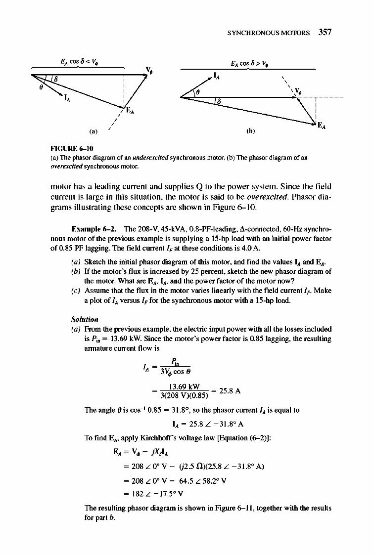
Whe n the projection of the phasor EA onto V 0/> (EA cos 8) is shoner than V 0/>
itself, a synchronous motor has a lagging c urrent and consumes Q. Since the field c urrent is small in this situation, the motor is said to be underexcited. On the other hand, when the projection of EA ont o Vo/> is longer than Vo/> it self, a synchronous
SYNCHRONOUS MOTORS 357
FIGURE 6-10 (a) The phasor diagram of an underexcited synchronous motor. (b) The phasor diagram of an overexcited synchronous motor.
motor has a leading current and supplies Q to the power system. Since the fi e ld current is large in this situation, the motor is said to be overexcited. Phasor diagrams illustrating these concepts are shown in Figure 6-10.
EXllmple 6-2. The 20S-V, 45-kVA, O.S-PF-Ieading, 8-cOIUlected, 60-Hz synchronous motor of the previous example is supplying a 15-hp load with an initial power factor of 0.85 PF lagging. The field current I" at these conditions is 4.0 A.
(a) Sketch the initial phasor diagram of this motor, and fmd the values IA and EA. (b) If the motor 's flux is increased by 25 percent, sketch the new phasor diagram of
the motor. What are EA, lA, and the power factor of the motor now? (c) Assume that the flux in the motor varies linearly with the field current I". Make
a plot of 1..1 versus I" for the synchronous motor with a IS-hp load.
Solutioll (a) From the previous example, the electric input power with all the losses included
is p~ = 13.69 kW. Since the motor 's power factor is 0.85 lagging, the resulting annature current flow is
I - n,R",~"::-;; A - 3VoIIcos(J
13.69 kW = 3(20S V)(0.S5) = 25.8 A
The angle (J is cos-1 0.85 = 31.8°, so the phasor current 1..1 is equal to
1..1 = 25.8 L -31.So A
To find EA, apply Kirchhoff's voltage law [Equation (6--2)]:
EA = VoII - jXSIA
= 20S L 0° V - (j2.5 0)(25.8 L - 31.So A )
=20SLOo V - 64.5L5S.2° V
= 182L - 17.5° V
The resulting phasor diagram is shown in Figure 6- 11, together with the results for part b.
358 ELECTRIC MACHINERY RJNDAMENTALS
, , ,
I;' I ,
I" , , ,
fV~"'208LOOV
EA",182L - 17.5° Y.J '- E;' '" 227.5 L _ 13.9° Y
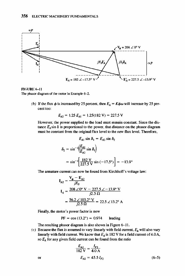
""GURE 6-11 The phasor diagram of the motor in Example 6--2.
(b) If the flux cp is increased by 25 percent, then EA = Kcpw will increase by 25 percent too:
EA2 = 1.25 EAI = 1.25(182 V) = 227.5 V
However, the power supplied to the load must remain constant. Since the distance EA sin /) is proportional to the power, that distance on the phasor diagram must be constant from the original flux level to the new flux level. Therefore,
EA] sin 8] = EA2 sin ~
~ = sin- t(EAt sin 8]) E"
The annature current can now be found from Kirchhoff's voltage law:
_ VI/! - EA2 1..1.2 - ·X J ,
I _ 208 LO° V - 227.5 L - 13.9° V ..1. - j2.50
= 56.2 ~.~OA2° V = 22.5 L 13.2° A
Finally, the motor 's power factor is now
PF = cos (13.2°) = 0.974 leading
The resulting phasor diagram is also shown in Figure 6-11. (e) Because the flux is assumed to vary linearly with field current, EA will also vary
linearly with field current. We know that EA is 182 V for a field current of 4.0A, so EA for any given field current can be fOlUld from the ratio
~-~ 182V -4.0A
(6-5)
SYNCHRONOUS MOTORS 359
The torque angle lj for any given field current can be found from the fact that the power supplied to the load must remain constant:
EA I sin 01 = EA2 sin ~
~ = sin- I ( EA I sin 01) E" (6-6)
These two pieces of infonnation g ive us the phasor voltage EA. Once EA is available, the new armature current can be calculated from Kirchhoff's voltage law:
_ V</I - EAl IA l - 'X J ,
(6- 7)
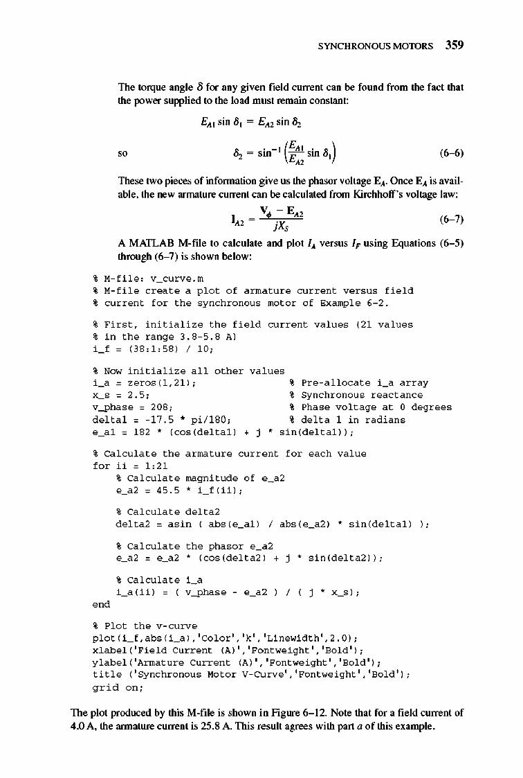
A MATLAB M-file to calculate and plot IA versus IF using Equations (6- 5) through (6- 7) is shown below:
% M-fil e : v_curve. m
% M-fil e c reat e a p l o t o f a rmatur e curre nt ver s u s fi e l d % current f o r the syn chro n ou s mo t o r o f Exampl e 6- 2 .
% Firs t , initia liz e the fi e l d curre nt values (2 1 va lues % in the range 3 . S- 5.S A) i _ f = (3S : 1 :5S ) / 1 0;
% Now initia liz e a ll o ther values i _a = z e r os( 1 ,2 1 ) ; x_s = 2.5; v_pha se = 20S; del tal = -1 7 .5 .. p i / 1 SO;
% Pre - a llocate i _a array
% Syn chro n o u s reac tance % Phase vo lt age at 0 degrees
% de lt a 1 in radian s e_a l = l S2 .. (cos (delta l ) + j .. s in (delt a l )) ;
% Ca l culat e the armature current f o r each value f or ii = 1: 21
ond
% Ca l culat e magnitude o f e _a2 e_a2 = 45.5 .. i _ f (ii ) ;
% Ca l culat e delta2 delta2 = as in ( abs (e_a l ) / abs (e_a2 ) .. s in (de ltal ) ) ;
% Ca l culat e the phasor e_a2 e_a2 = e_a2 " (cos (delt a2 ) + j" s in (delt a2 )) ;
% Ca l culat e i _a
i _a( ii ) = ( v_pha se
% Plot the v - c urve p l ot ( i _ f. abs ( i _a) , ' Co l or ' , 'k' , 'Linewi dth' , 2.0 ) ; x l abel ( 'Fie l d Current (A) ' , 'Fo ntwe i ght' , 'So l d ' ) ; y l abel ( ' Armature Current (A) ' , 'Fo ntwe i ght ' , 'So ld' ) ; titl e ( ' Syn c hro n o u s Mo tor V- CUrve ' , 'Fo ntwe i ght ' , 'So l d ' ) ;
gr id on;
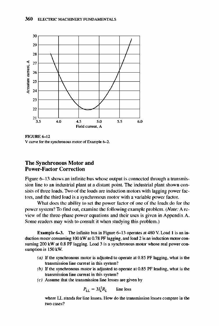
The plot produced by this M-flle is shown in Fig ure 6-12. Note that for a field current of 4.0 A, the annature current is 25.8 A. This result agrees with part a of this example.
360 ELECTRIC MACHINERY RJNDAMENTALS
30
29
28
< 27
" ~ 26
! 25
~ 24
23
22
\ \
\ \
/ /
/
/ /
/ "
21 3.' 4.0 4.5 5.0 ,.5 6.0
Field current. A
""GURE 6- 12 V curve for the synchronous motor of Example 6--2.
The Synchronolls Motor and Power-Factor Correction
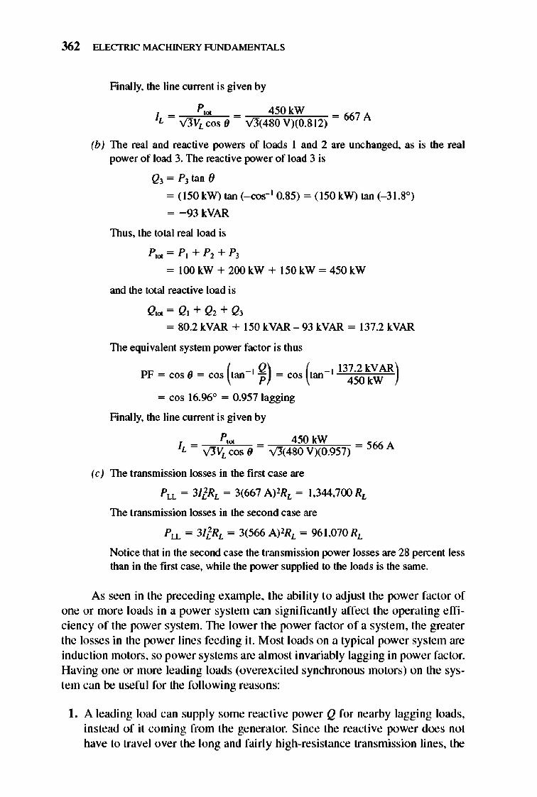
Figure 6-13 shows an infinite bus whose OUlpUI is connected through a transmission line 10 an industrial plant at a distant point. The indu strial plant shown consists of three loads. Two of the loads are induction motors with lagging power factors, and the third load is a synchronous motor with a variable power factor.
What does the ability to set the power factor of one of the loads do for the power system? To find out, examine the following example problem. (Note: A review of the three-phase power equations and their uses is given in Appendix A. Some readers may wish to consult it when studying this problem.)
Example 6-3. The infinite bus in Figure 6-13 operates at 480 V. Load I is an induction motor consruning 100 kW at 0.78 PF lagging, and load 2 is an induction motor consruning 200 kW at 0.8 PF lagging. Load 3 is a synchronous motor whose real power consrunption is 150 kW.
(a) If the synchronous motor is adjusted to operate at 0.85 PF lagging, what is the transmission line current in this system?
(b) If the synchronous motor is adjusted to operale at 0.85 PF leading, what is the transmission line current in this system?
(c) Assrune thai the transmission line losses are given by
line loss
where LL stands for line losses. How do the transmission losses compare in the two cases?
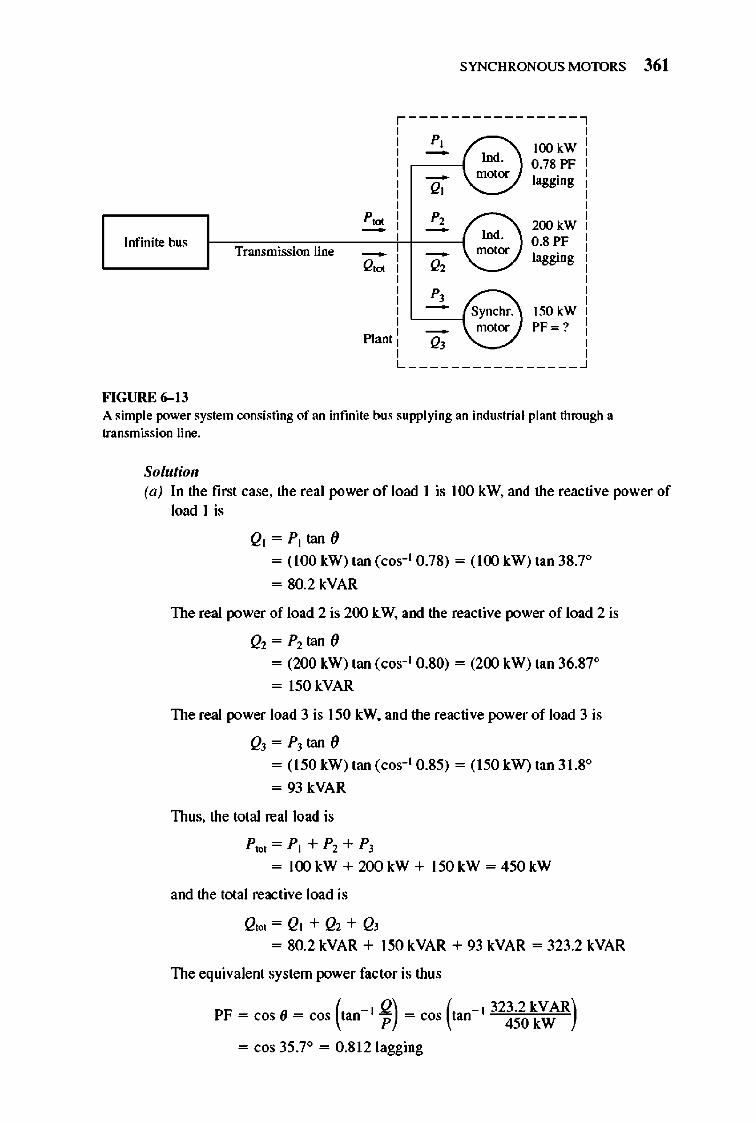
p,. -Infinite bus Transmission line -Q,.
Plant
FIGURE 6-13
SYNCHRONOUS MOTORS 361
,----------------, P, --Q,
P, --'" P, --Q,
Ind. motor
Ind. motor
Synchr. motor
lOO kW 0.78 PF lagging
200 kW 0.8 PF lagging
150 kW PF = ?
L ________________ ~
A simple power system consisting of an infinite bus supplying an industrial plant through a transmission line.
Solutioll (a) In the first case, the real power o f load I is 100 kW, and the reactive power of
load I is
Ql = P t tan ()
= (1 00 kW) tan (cos- l 0 .7S) = (100 kW) tan 3S.7°
= SO.2 kVAR
The real power of load 2 is 200 kW, and the reactive power of load 2 is
Q2= P2tan()
= (200 kW) tan (cos- l O.SO) = (200 kW) tan 36.S7°
= 150 kVAR
The real power load 3 is 150 kW. and the reactive power of load 3 is
Q]= p] tan()
= (150 kW) tan (cos- l 0 .S5) = (150 kW) tan 3 1.So
= 93 kVAR
Thus, the total real load is
P'o< = P t + P2 + p]
= l OO kW + 200 kW + 150 kW = 450 kW
and the total reactive load is
Q,o<=Qt+ Q2+Q]
= SO.2 kVAR + 150 kVAR + 93 kVAR = 323.2 kVAR
The equivalent system power fac tor is thus
PF = cos (J = cos (tan- I .2) = cos (tan- l 323.2 kVAR) P 450 kW
= cos 35 .7° = 0 .Sl2 lagging
362 ELECTRIC MACHINERY RJNDAMENTALS
Finally, the line current is given by
P trX 450 kW IL = v'JVLcos 0 = v'J(480V)(0.812) = 667 A
(b) The real and reactive powers of loads I and 2 are unchanged, as is the real power of load 3. The reactive power of load 3 is
Q3 = PJ tan()
= (150 kW) tan (_ cos- l 0.85) = (150 kW) tan (_31.8°)
= -93 kVAR
Thus, the total real load is
P'fJI = PI + P2 + PJ
= lOOkW + 200kW + 150kW = 450kW
and the total reactive load is
Q'fJI= QI+Q2+ Q3 = 80.2 kVAR + 150 kVAR - 93 kVAR = 137.2 kVAR
The equivalent system power factor is thus
PF = cos O = cos (tan - l Q) = cos (tan - l 137.2kVAR) P 450kW
= cos 16.96° = 0.957 lagging
Finally, the line current is given by
P'fJI 450 kW IL = V3VL cos 0 = v'3(480 VXO.957) = 566 A
(e) The transmission losses in the first case are
The transmission losses in the second case are
Notice that in the second case the transmission power losses are 28 percent less than in the first case, while the power supplied to the loads is the same.
As seen in the preceding example, the abi lity to adjust the power factor of one or more loads in a power system can significantly affect the operating e fficiency of the power system. TIle lower the power factor of a system, the greater the losses in the power lines feeding it. Most loads on a typical power system are induction motors, so power syste ms are almost invariably lagging in power factor. Having one or more leading loads (overexcited synchronous motors) on the system can be useful for the fo llowing reasons:
I. A leading load can supply some reactive power Q for nearby lagging loads, instead of it coming from the generator. Since the reactive power does not have to trave l over the long and fairly high-resistance transmission lines, the
SYNCHRONOUS MOTORS 363
transmission line current is reduced and the power system losses are much lower. (nlis was shown by the previous example.)
2. Since the transmission lines carry less current, they can be smaller for a given rated power flow. A lower eq uipment current rating reduces the cost of a power system significantly.
3. In addition, requiring a synchronous motor to operate with a leading power factor means that the motor mu st be run overexcited. nlis mode of operation increases the motor 's maximum torque and reduces the chance of accidentally exceeding the pullout torque.
The use of synchronous motors or other equipment to increase the overall power factor of a power system is called power-factor correction. Since a synchronous motor can provide power-factor correction and lower power system costs, many loads that can accept a constant-speed motor (even though they do not necessarily need one) are driven by synchronous motors. Even though a synchronous motor may cost more than an induction motor on an individual basis, the ability to operate a synchronous motor at lead ing power factors for power-factor correction saves money for industrial plants. This results in the purchase and use of synchronous motors.
Any synchronous motor that exists in a plant is run overexcited as a matter of course to achieve power-factor correction and to increase its pullout torque. However, running a synchronou s motor overexcited requires a high field current and flux , which causes significant rotor heating. An operator mu st be careful not to overheat the field windings by exceeding the rated field current.
The Synchronolls Capacitor or Synchronous Condenser
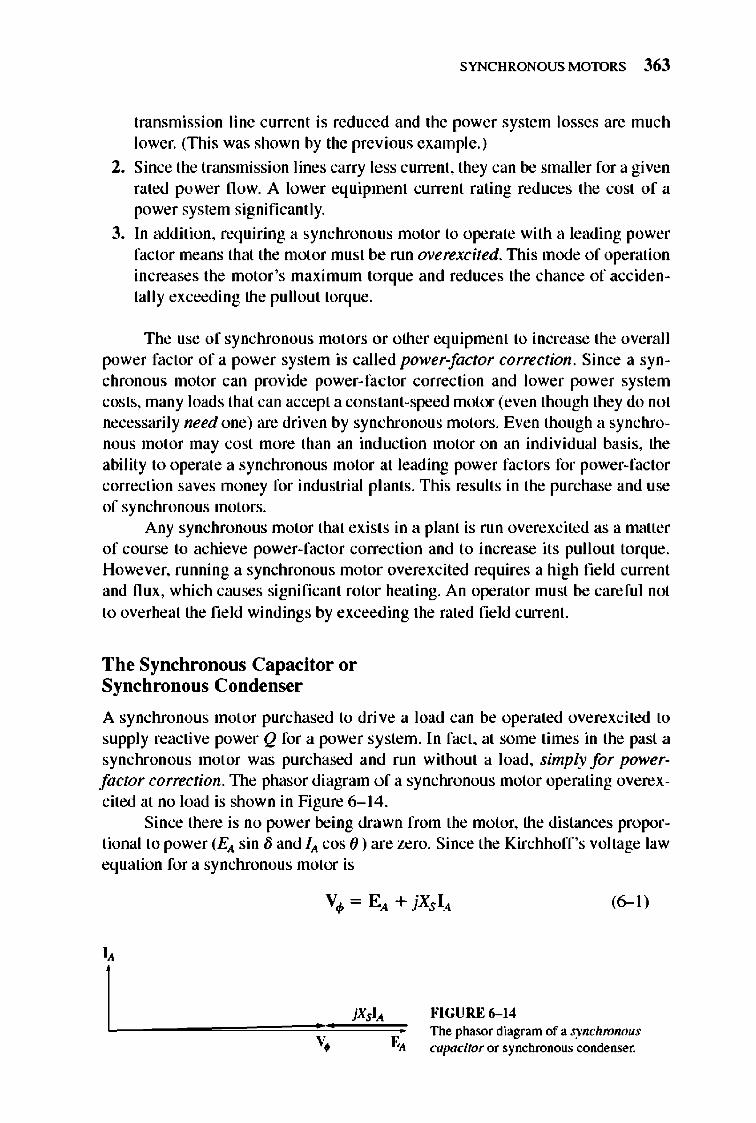
A synchronous motor purchased to drive a load can be operated overexcited to supply reactive power Q for a power system. In fact, at some times in the past a synchronous motor was purchased and run without a load, simply for powerfactor correction. nle phasor diagram of a synchronous motor operating overexcited at no load is shown in Figure 6- 14.
Since there is no power being drawn from the motor, the distances proportional to power (Ell sin /j and III cos () ) are zero. Since the Kirchhoff 's voltage law equation for a synchronous motor is
I,
I
(6-1)
""GURE 6- 14 The phasor diagram of a synchronous Cllpacitor or synchronous condenser.
364 ELECTRIC MACHINERY RJNDAMENTALS
Lagging PF
(+ Q consumed)
Saturation
Leading PF
(+ QsuppIied) L-________ ~ _________ ~
(a)
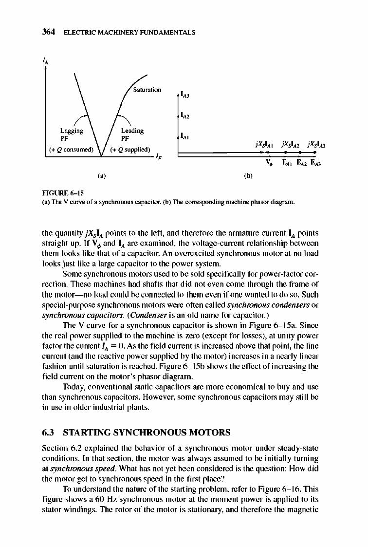
""GURE 6-15
,b,
(a) The V curve of a synchronous capacitor. (b) The corresponding machine phasor diagram.
the quantity jXSIA. points to the left, and therefore the armature current IA. points straight up. If V 4> and IA. are examined, the voltage-current relati onship between them looks like that of a capacitor. An overexcited synchronous motor at no load looks just like a large capacitor to the power system.
Some synchronous motors used to be sold specifically for power-factor correction. 1llese machines had shafts that did not even come through the frame of the motor- no load could be connected to them even if one wanted to do so. Such special-purpose synchronous motors were often called synchronous condensers or synchronous capacitors. (Condenser is an old name for capacitor.)
1lle V curve for a synchronous capacitor is shown in Figure 6-15a. Since the real power supplied to the machine is zero (except for losses), at unity power factor the current fA. = D. As the fie ld current is increased above that point, the line current (and the reactive power supplied by the motor) increases in a nearly linear fashion until saturation is reached. Figure 6- I 5b shows the effect of increasing the field current on the motor 's phasor diagram.
Today, conventional static capacitors are more economical to buy and use than synchronous capacitors. However, some synchronous capacitors may still be in use in older indu strial plants.
6.3 STARTING SYNCHRONOUS MOTORS
Section 6.2 explained the behavior of a synchronous motor under steady-state conditions. In that section, the motor was always assumed to be initially turning at synchronous speed. What has not yet been considered is the question: How did the motor get to synchronou s speed in the first place?
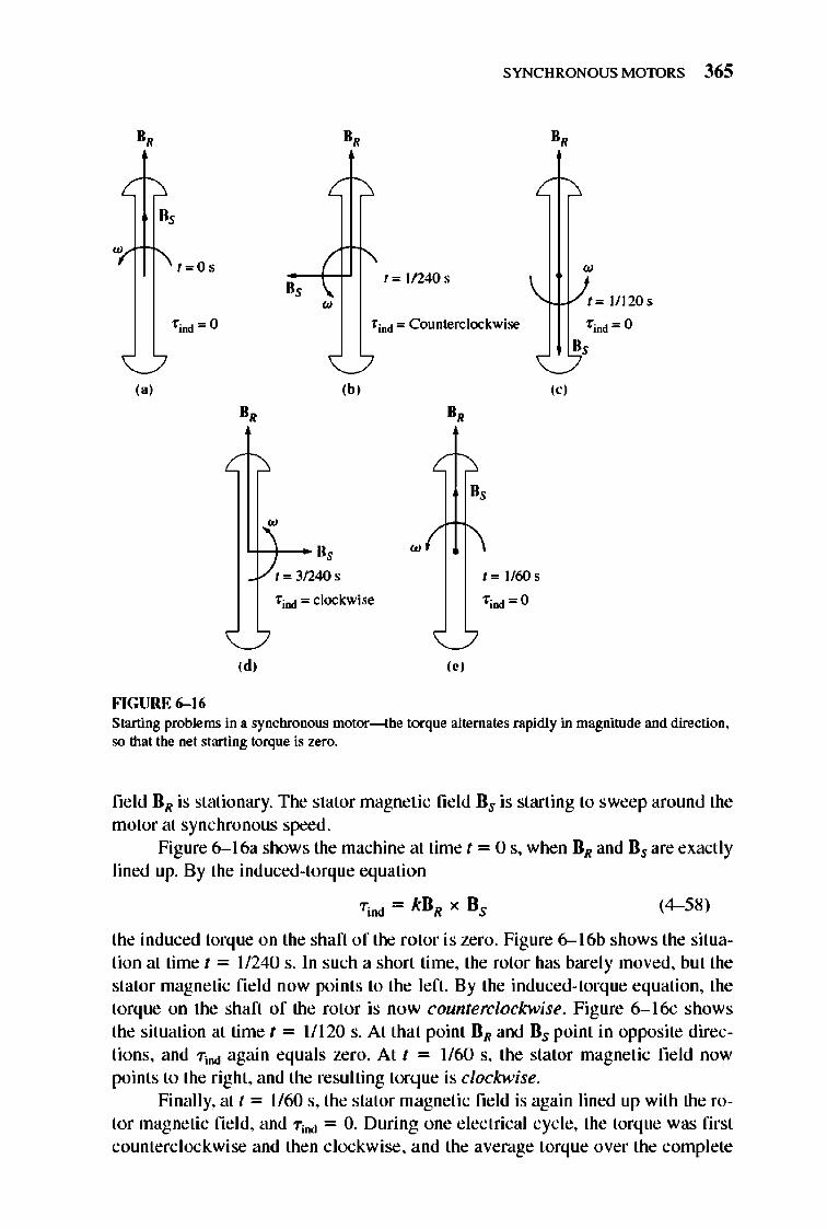
To understand the nature of the starting problem, refer to Figure 6- I 6. nlis figure shows a 6D- Hz synchronous motor at the moment power is applied to its stator windings. The rotor of the motor is stationary, and therefore the magnetic
D,
B,
f=O S
'find = 0
,,'
FIGURE 6-16
SYNCHRONOUS MOTORS 365
D, D,
• f=I1240s
w
'find = Counterclockwise
'{.u-/I= 111205
'find = 0
B,
,b, ,,' B, B,
w
't-t-- B, w
1 = 31240 5 1=I/60s
'f;nd = clockwise 'f;nd = 0
,d, ,., Staning problems in a synchronous motor---the torque alternates rapidly in magnitude and direction. so that the net 5taning torque is zero.
field DR is stationary. The stator magnetic fie ld Ds is starting to sweep around the motor at synchronous speed.
Figure 6-1 6a shows the machine at time t = 0 s, when DR and Ds are exactly lined up. By the induced-torque equation
(4- 58)
the induced torque on the shaft of the rotor is zero. Figure 6--16b shows the situation at time t = 11240 s. In such a short time, the rotor has bare ly moved, but the stator magnetic fie ld now points to the left. By the induced-torque equation, the torque on the shaft of the rotor is now counterclockwise. Figure 6-1 6c shows the situation at time t = 1/ 120 s. At that point DR and Ds point in opposite directions, and TiDd again equals zero. At t = 1160 s, the stator magnetic field now points to the right, and the resulting torque is clockwise.
Finally, at t = 1/60 s, the stator magnetic field is again lined up with the rotor magnetic fie ld, and T iDd = O. During one electrical cycle, the torque was first counterclockwise and then clockwisc, and the average torque over the complete
366 ELECTRIC MACHINERY RJNDAMENTALS
cycle was zero. What happens to the motor is that it vibrates heavily with each e lectri cal cycle and finally overheats.
Such an approach to synchronou s motor starting is hardl y satisfactorymanagers tend to frown on employees who burn up their expensive equipment. So just how can a synchronous motor be started?
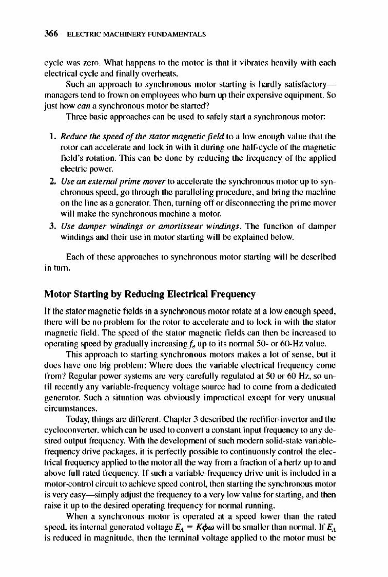
TIuee basic approaches can be used to safely start a synchronous motor:
I. Reduce the speed of the stator mngneticfield to a low enough value that the rotor can accelerate and lock in with it during one half-cycle of the magnetic field 's rotation. Thi s can be done by reducing the frequency of the applied electric power.
2. Use an extenwl prime mover to accelerate the synchronous motor up to synchronous speed, go through the parall e ling procedure, and bring the machine on the line as a generator. TIlen, turning off or disconnecting the prime mover wil I make the synchronous machine a motor.
3. Use damper windings or amortisseur windings. The function of damper windings and their use in motor starting will be explained be low.
Each of these approaches to synchronous motor starting will be described in turn.
Motor Starting by Reducing Electrical Frequency
I f the stator magnetic fields in a synchrono us motor rotate at a low e nough speed, there will be no proble m for the rotor to accele rate and to lock in with the stator magnetic fie ld. TIle speed of the stator magnetic fi e lds can then be increased to operating speed by gradually increasingf .. up to its normal 50- or 6O- Hz val ue.
TIlis approach to starting synchronous motors makes a lot of sense, but it does have one big proble m: Where does the variable electrical frequency corne from? Regular power systems are very carefully regulated at 50 or 60 Hz, so until recently any variable-frequency voltage source had to come from a dedicated generator. Such a situation was o bviously impractical except for very unusual circumstances.
Today, things are different. Chapter 3 described the rectifier-inverter and the cycloconverter, which can be used to convert a constant input frequency to any desired output frequency. With the deve lopment of such modern solid-state variablefrequency drive packages, it is perfectly possible to continuously control the electrical frequency applied to the motor all the way from a fraction of a hertz up to and above full rated frequency. If such a variable-frequency drive unit is included in a motor-control circuit to achieve speed control, then starting the synchronous motor is very easy- simply adjust the frequency to a very low value for starting, and then raise it up to the desired operating freque ncy for normal running.
When a synchronous motor is ope rated at a speed lower than the rated speed, its internal generated voltage Ell = Kcpw will be smaller than normal. If Ell is reduced in magnitude, then the terminal voltage applied to the motor must be
SYNCHRONOUS MOTORS 367
reduced as well in order to keep the stator current at safe leve ls. The voltage in any variable-frequency drive or variable-frequency starter circuit must vary roughly linearly with the applied frequency.
To learn more about such solid-state motor-drive units, refer to Chapter 3 and Reference 9.
Motor Starting with an External Prime Mover
The second approach to starting a synchronous mo tor is to attach an external starting motor to it and bring the synchrono us machine up to full speed with the external motor. 1l1en the synchronous mac hine can be paralleled with its power system as a generator, and the starting motor can be detached from the shaft of the machine. Once the starting motor is turned off, the shaft of the machine slows down, the rotor magnetic field BR falls behind B ... " and the synchronous machine starts to act as a motor. Once paralleling is completed, the synchrono us motor can be loaded down in an ordinary fashion.
This whole procedure is not as preposterous as it sounds, since many synchronous motors are parts of motor-generator sets, and the synchronous machine in the motor-generat or set may be started with the other machine serving as the starting motor. Also, the starting motor only needs to overcome the inertia of the synchronous machine without a load- no load is attached until the motor is paralleled to the power system. Since only the motor 's inertia mu st be overcome, the starting motor can have a much small er rating than the synchrono us motor it starts.
Since most large synchronous motors have brushless excitation syste ms mounted on their shafts, it is often possible to use these exciters as starting motors.
For many medium-size to large synchronous motors, an external starting motor or starting by using the exciter may be the only possible solution, because the power syste ms they are tied to may not be able to handle the starting currents needed to use the amortisseur winding approach described next.
Motor Starting by Using Amortisseur Wi ndings
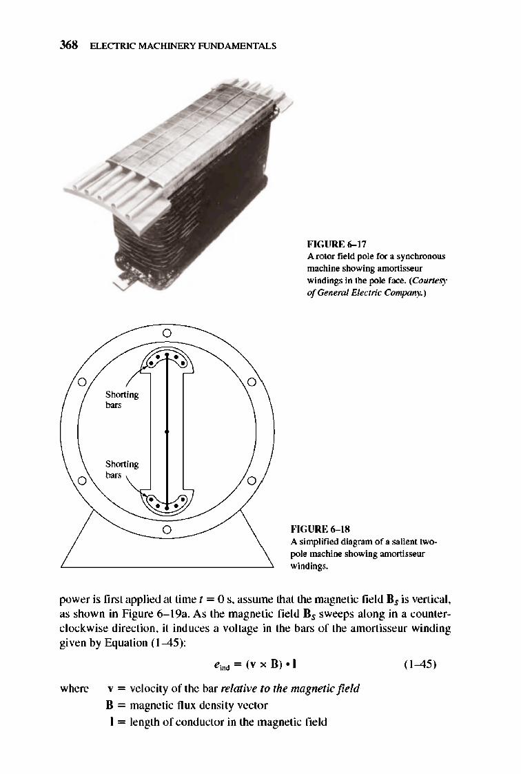
By far the most popular way to start a sy nchronous motor is to employ anwrtisseur or damper windings. Amortisseur windings are special bars laid int o notches carved in the face of a synchronous motor's rotor and then shorted out on each end by a large shoT1ing ring. A pole face with a set of amortisseurwindings is shown in Figure 6-17, and amortisseur windings are visible in Figures 5- 2 and 5-4.
To understand what a set of amortisseur windings does in a synchrono us motor, examine the stylized salie nt two-pole rotor shown in Figure 6- 18. This rotor shows an amortisseur winding with the shorting bars on the ends of the two rotor pole faces connected by wires. (This is not quite the way nonnal machines are constructed, but it will serve beautifully to illustrate the point of the windings.)
Assume initially that the main rotor field winding is disconnected and that a three-phase set of voltages is applied to the stator of this machine . When the
368 ELECTRIC MACHINERY RJNDAMENTALS
o
o
Shorting
"'"
Shorting
"'"
o
o
o
o
FIGURE 6-17 A rotor field pole for a synchronous machine showing amortisseur windings in the pole face. (Courtesy ofGeneml Electric Company.)
fo'IGURE 6- 18 A simplified diagram of a salient twopole machine showing amortisseur windings.
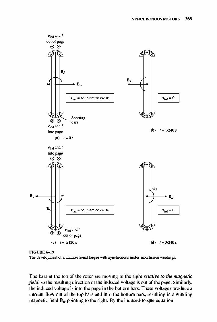
power is first applied at time t = a s, assume that the magnetic fie ld Bs is vertical, as shown in Figure 6- 19a. As the magnetic fie ld Bs sweeps along in a counterclockwise direction, it induces a voltage in the bars of the amortisseur winding given by Equation (1-45):
where
ei!>d = (v x B) • I
v = velocity of the bar relative to the magnetic field
B = magnetic nux density vector
I = length of conductor in the magnetic fie ld
( 1-45)
eind and i
out of page
®®
w 1-+'-- 8.
00 00
00 eind and i
into page
I f ind = counterclockwise
Shorting b=
(a) 1=05
eind and i
into page
00 00 00
'" I find = counterclockwise
". • • d . eind an J
® ® out of page
(c) 1= 11120&
FIGURE 6-19
SYNCHRONOUS MOTORS 369
"0 0"
(b) 1=112405
0 0 00
+t)--u,
I f ind=O
0 0 0 0
(d) 1=312405
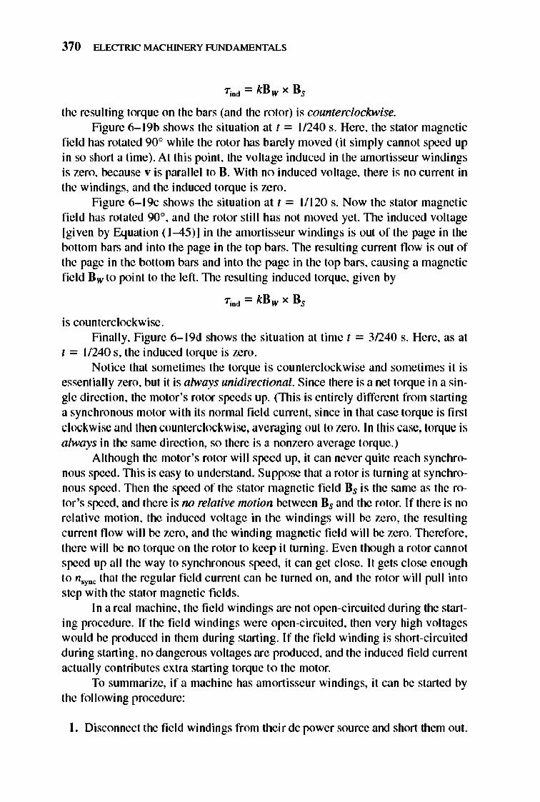
The development of a unidirectional torque with synchronous motor amonisseur windings.
The bars at the top of the rotor are moving to the right relative to the magnetic field, so the resulting direction of the induced voltage is out of the page. Similarly, the induced voltage is into the page in the bottom bars . These voltages produce a current fl ow out of the top bars and int o the bottom bars, resulting in a winding magnetic fie ld Bw pointing to the right. By the induced-torque equation
370 ELECTRIC MACHINERY RJNDAMENTALS
the resulting torque on the bars (and the rotor) is counterclockwise. Figure 6-1 9b shows the situation at t = 11240 s. Here, the stator magnetic
field has rotated 90° while the rotor has barely moved (it simply cannot speed up in so short a time). At this point, the voltage induced in the amortisseur windings is zero, because v is parallel to B. With no induced voltage, there is no current in the windings, and the induced torque is zero.
Figure 6-1 9c shows the situation at t = 11120 s. Now the stator magnetic fi e ld has rotated 900, and the rotor still has not moved yet. TIle induced voltage [given by Equation ( 1-45)] in the amortisseur windings is out of the page in the bottom bars and into the page in the top bars. The resulting current flow is out of the page in the bottom bars and into the page in the top bars, causing a magnetic field Bw to point to the left . 1lle resulting induced torque, given by
T;Dd = k Bw x Bs
is counterclockwise . Finally, Figure 6-1 9d shows the situation at time t = 31240 s. Here, as at
t = 11240 s, the induced torque is zero. Notice that sometimes the torque is counte rcl ockwise and sometimes it is
essentially zero, but it is always unidirectional. Since there is a net torque in a single direction, the motor 's rotor speeds up. (1llis is entirely different from starting a synchronous motor with its normal fie ld current, since in that case torque is first c lockwise and then counterclockwise, averaging out to zero. In this case, torque is always in the same direction, so there is a nonzero average torque.)
Although the motor 's rotor will speed up, it can never quite reach synchronous speed. This is easy to understand. Suppose that a rotor is turning at synchronous speed . Then the speed of the stator magnetic field Bs is the same as the rotor 's speed, and there is no relative motion between Bs and the rotor. If there is no re lative motion, the induced voltage in the windings wi ll be zero, the resulting current fl ow wi ll be zero, and the winding magnetic fie ld will be zero. Therefore , there will be no torque on the rotor to keep it turning. Even though a rotor cannot speed up all the way to synchronous speed, it can get close. It gets close enough to n'YD< that the regular fie ld current can be turned on, and the rotor will pull into step with the stator magnetic fields.
In a real machine, the field windings are not open-circuited during the starting procedure. If the fie ld windings were open-circuited, then very high voltages wou ld be produced in them during starting. I f the field winding is short-circuited during starting, no dangerous voltages are produced, and the induced fie ld current actually contributes extra starting torque to the motor.
To summarize, if a machine has amortisseur windings, it can be started by the fo llowing procedure:
I. Disconnect the fi e ld windings from their dc power source and short them out.
SYNCHRONOUS MOTORS 371
2. Apply a three-phase voltage to the stator of the motor, and let the rotor accelerate up to near-synchronous speed . The motor should have no load on its shaft , so that its speed can approach n.ync as closely as possible.
3. Connect the dc fie ld circuit to its power source. After this is done, the motor wi ll lock into step at synchronous speed, and loads may then be added to its shaft.
The Effect of Amortisseur Windings on Motor Stability
If amortisseur windings are added to a synchronous machine for starting, we get a free bonus-an increase in machine stability. The stator magnetic fi eld rotates at a constant speed n.YD<, which varies only when the system frequency varies. I f the rotor turns at n,YD<, then the amortisseur windings have no induced voltage at all. If the rotor turns slower than n,YD<, then there wi ll be relative motion between the rotor and the stator magnetic fi eld and a voltage wi ll be induced in the windings. nlis voltage produces a current fl ow, and the current fl ow produces a magnetic field. The interaction of the two magne tic fie lds produces a torque that tends to speed the machine up again. On the other hand, if the rotor turns faster than the stator magnetic fie ld, a torque wi ll be produced that tries to slow the rotor down. Thus, the torque produced by the anwrtisseur windings speeds up slow mnchines and slows down fast machines.
These windings therefore tend to dampen out the load or other transients on the machine. It is for this reason that amortisseur windings are also called damper windings. Amortisseur windings are also used on synchronous generators, where they serve a similar stabilizing function when a generator is operating in parallel with other generators on an infinite bus. If a variation in shaft torq ue occurs on the generat or, its rotor wi ll momentarily speed up or slow down, and these changes wi ll be opposed by the amortisseur windings. Amortisseur windings improve the overall stability of power systems by reducing the magnitude of power and torque transients.
Amortisseur windings are responsible for most of the subtransient current in a faulted synchronous machine. A short circuit at the terminals of a generator is just another fonn of transient, and the amortisseur windings respond very quickly to it.
6.4 SYNCHRONOUS GENERATORS AND SYNCHRONOUS MOTORS
A synchronous generator is a synchronous machine that converts mechanical power to e lectric power, while a synchronous motor is a synchronous machine that converts electric power to mechani cal power. In fact, they are both the same physical machine.
372 ELECTRIC MACHINERY RJNDAMENTALS
Supply Consume reactive power E" cos {j > V6 reactive power E" cos {j < V.
Q Q
Supply pow~
P E, E,
"
~. ~\V • , , o • ~ I,
E" leads
V.
Consume pow~
p I,
"
~ ~V' ~ E ,
E" Jags E,
V,
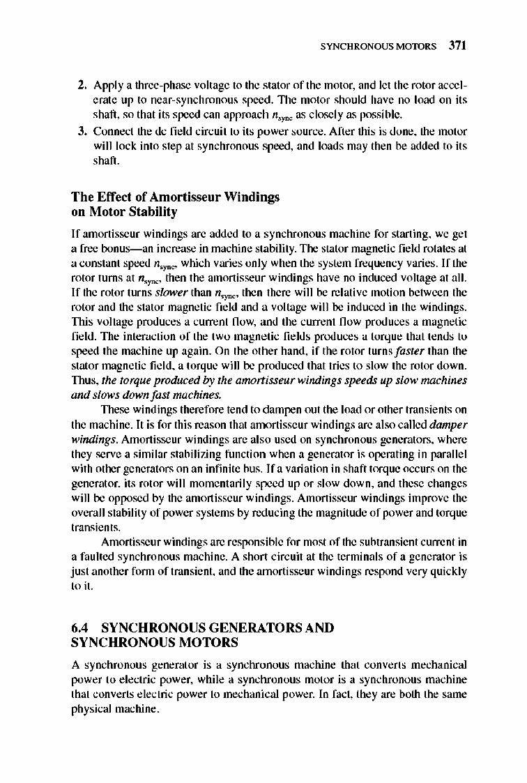
""GURE 6-10 Phasor diagrams showing the generation and consumption of real power P and reactive power Q by synchronous generators and motors.
A synchronous machine can supply real power to or consume real power from a power system and can supply reactive power to or consume reactive power from a power system. All four combinations of real and reactive power fl ows are possible, and Figure 6-20 shows the phasor diagrams for these conditions.
Notice from the figure that
I . The distinguishing characteristic of a synchronous generator (supplying P) is that E" lies ahead o/V", while for a motor E" lies behind V",.
2. The distinguishing characteristic of a machine supplying reactive power Q is that E" cos lj > V", regardless of whether the machine is acting as a generator or as a motor. A machine that is consuming reactive power Q has E" cos lj < V",.
6.5 SYNCHRONOUS MOTOR RATINGS
Since synchronous motors are the same physical machines as synchronous generators, the basic machine ratings are the same . The one major difference is that a large
SYNCHRONOUS MOTORS 373
'" GENERAL@ ELECTRIC " SYNCHRONOUS MOTOR
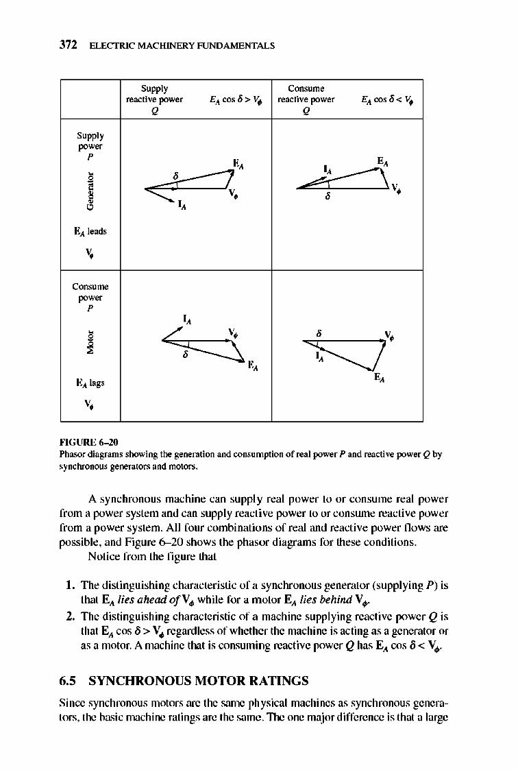
FIGURE 6-21 A typical nameplate for a large synchronous motor. (Courtesy o!General Electric Company.)
Ell gives a leading power factor instead of a lagging one, and therefore the effect of the maximum field current limit is expressed as a rating at a leading power factor. Also, since the output of a synchronous motor is mechanical power, a synchronous motor 's power rating is usually given in horsepower rather than kilowatts.
TIle nameplate of a large synchronous motor is shown in Figure 6-21. In addition to the information shown in the figure, a smaller synchronous motor would have a service factor on its nameplate.
In general, synchronous motors are more adaptable to low-speed, highpower applications than induction motors (see Chapter 7). They are therefore commonly used for low-speed, high-power loads.
6.6 SUMMARY
A synchronous motor is the same physical machine as a synchronous generator, except that the direction of real power fl ow is reversed. Since synchronous motors are usually connected to power systems containing generators much larger than the motors, the frequency and tenninal voltage of a synchronous motor are fixed (i.e., the power system looks like an infinite bus to the motor).
The speed of a synchronous motor is constant from no load to the maximum possible load on the motor. The speed of rotation is
_ _ 120..r.: nm - n sync - p
The maximum possible power a machine can produce is
_ 3V1>EA Pm:u.- X , (5- 21)

374 ELECTRIC MACHINERY RJNDAMENTALS
If this value is exceeded, the rotor will not be able to stay locked in with the stator magnetic fields, and the motor will slip poles.
I f the fie ld current of a synchronous motor is varied while its shaft load remains constant, then the reactive power supplied or consumed by the motor will vary. If Ell cos 8 > ~, the motor will suppl y reactive power, while if Ell cos 8< Vo/» the motor will consume reactive power.
A synchronous motor has no net starting torque and so cannot start by itself. TIlere are three main ways to start a synchronous motor:
I. Reduce the stat or frequency to a safe starting level.
2. Use an external prime mover.
3. Put amortisseur or damper windings on the motor to acce lerate it to nearsynchronous speed before a direct current is applied to the field windings .
If damper windings are present on a motor, they will also increase the stability of the motor during load transient s.
QUESTIONS
6-1. What is the difference between a synchronous motor and a synchronous generator? 6-2. What is the speed regulation of a synchronous motor? 6-3. When would a synchronous motor be used even though its constant-speed charac-
teristic was not needed? 6-4. Why can't a synchronous motor start by itself? 6-5. What techniques are available to start a synchronous motor? 6-6. What are amortisseur windings? Why is the torque produced by them unidirectional
at starting, while the torque produced by the main field winding alternates direction? 6-7. What is a synchronous capacitor? Why would one be used? 6-8. Explain, using phasor diagrams, what happens to a synchronous motor as its field
current is varied. Derive a synchronous motor V curve from the phasor diagram. 6-9. Is a synchronous motor's field circuit in more danger of overheating when it is op
erating at a leading or at a lagging power factor? Explain, using phasor diagrams. 6-10. A synchronous motor is operating at a fixed real load, and its field current is in
creased. If the armature current falls, was the motor initially operating at a lagging or a leading power factor?
6-11. Why must the voltage applied to a synchronous motor be derated for operation at frequencies lower than the rated value?
PROBLEMS
6-1. A 480-V, 60 Hz four-pole synchronous motor draws 50 A from the line at unity power factor and full load. Assuming that the motor is lossless, answer the following questions: (a) What is the output torque of this motor? Express the answer both in newton
meters and in pound-feet.
SYNCHRONOUS MOTORS 375
(b) What must be done to change the power factor to 0.8 leading? Explain your answer, using phasor diagrams.
(c) What will the magnitude of the line current be if the power factor is adjusted to 0.8 leading?
6-2. A 480-V, 60 Hz 4OO-hp, 0.8-PF-Ieading, six-pole, ~-connected synchronous motor has a synchronous reactance of 1.1 {} and negligible annature resistance. Ignore its friction, windage, and core losses for the purposes of this problem. (a) If this motor is initially supplying 400 hp at 0.8 PF lagging, what are the mag
nitudes and angles of EA and IA? (b) How much torque is this motor producing? What is the torque angle O? How
near is this value to the maximum possible induced torque of the motor for this field current setting?
(c) If lEAl is increased by IS percent, what is the new magnitude of the armature current? What is the motor 's new power factor?
(d) Calculate and plot the motor's V curve for this load condition. 6-3. A 2300-V, I()(X)-hp, 0.8-PF leading, 60-Hz, two-pole, Y-cotulected synchronous mo
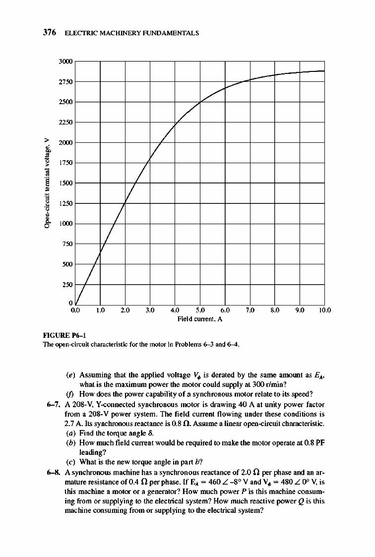
tor has a synchronous reactance of2.8 n and an annature resistance of 0.4 n. At 60 Hz, its friction and windage losses are 24 kW, and its core losses are 18 kW. The field circuit has a dc voltage of2oo V, and the maximwn IF is 10 A. The open-circuit characteristic of this motor is shown in Figure P6-1. Answer the following questions about the motor, assuming that it is being supplied by an infinite bus. (a) How much field current would be required to make this machine operate at
tulity power factor when supplying full load? (b) What is the motor 's efficiency at full load and unity power factor? (c) If the field current were increased by 5 percent, what would the new value of
the annature current be? What would the new power factor be? How much reactive power is being consumed or supplied by the motor?
(d) What is the maximrun torque this machine is theoretically capable of supplying at tulity power factor? At 0.8 PF leading?
6-4. Plot the V curves (fA versus IF) for the synchronous motor of Problem 6- 3 at noload, half-load, and full-load conditions. (Note that an electronic version of the open-circuit characteristics in Figure P6-1 is available at the book's website. It may simplify the calculations required by this problem. Also, you may assrune that RA is negligible for this calculation.)
6-5. If a 60-Hz synchronous motor is to be operated at 50 Hz, will its synchronous reactance be the same as at 60 Hz, or will it change? (Hint: Think about the derivation of Xs.)
6-6. A 480-V, lOO-kW, 0.85-PF-Ieading, 50-Hz, six-pole, V-connected synchronous motor has a synchronous reactance of 1.5 n and a negligible annature resistance. The rotational losses are also to be ignored. This motor is to be operated over a continuous range of speeds from 300 to 1000 rlmin, where the speed changes are to be accomplished by controlling the system frequency with a solid-state drive. (a) Over what range must the input frequency be varied to provide this speed con
trol range? (b) How large is EA at the motor's rated conditions? (c) What is the maximwn power that the motor can produce at rated speed with the
EA calculated in part (b)? (d) What is the largest EA could be at 300 r/min?
376 ELECTRIC MACHINERY RJNDAMENTALS
3(XX)
2750
2500
2250
2(XX)
1750
1500
1250
IlXXl
750
250 / /
o 0.0
""GURE 1'(;-1
/
/ /
1.0 2.0
/" /
/ /
/
3.0 4.0 5.0 6.0 Field current. A
The open-circuit characteristic for the motor in Problems 6-3 and 6-4.
7.0 8.0 9.0 10.0
(e) Assuming that the applied voltage V. is derated by the same amOlUlt as EA. what is the maximwn power the motor could supply at 300 r/min?
if) How does the power capability of a synchronous motor relate to its speed?
6-7. A 20S-V. Y-connected synchronous motor is drawing 40 A at unity power factor from a 20S-V power system. The field current flowing under these conditions is 2.7 A. Its synchronous reactance is O.S n. Assume a linear open-circuit characteristic. (a) Find the torque angle o. (b) How much field current would be required to make the motor operate at O.S PF
leading? (c) What is the new torque angle in part b?
6-8. A synchronous machine has a synchronous reactance of 2.0 n per phase and an armature resistance of 0.4 n per phase. If EA = 460 L -80 V and V. = 4S0 L 0° V, is this machine a motor or a generator? How much power P is this machine consuming from or supplying to the electrical s ystem? How much reactive power Q is this machine consuming from or supplying to the electrical system?
SYNCHRONOUS MOTORS 377
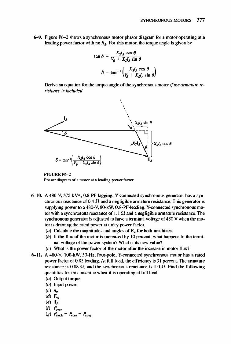
6-9. Figure P6--2 shows a synchronous motor phasor diagram for a motor operating at a leading power factor with no R". For this motor. the torque angle is given by
~X~,J~'!;;CO~'~''-co tan 0 = -;-VI/! + Xsl" sin ()
_, ( Xsl" cos () ) • - tan - VI/! + Xi " sin ()
Derive an equation for the torque angle of the synchronous motor if the amlature resistance is included.
, , , ,
FIGURE P6-2
, , , , . , Xsl" Sin 0
V. \,"---" --'1
,
jXsl" 0 : Xsl" cos () ,
Phasor diagram of a motor at a Jeading power factor.
6-10. A 4S0-V, 375-kVA, O.S-PF-Iagging, V-connected synchronous generator has a synchronous reactance of 0 .4 n and a negligible armature resistance. This generator is supplying power to a 4S0-V, SO-kW, 0 .8-PF-Ieading, V-connected synchronous motor with a synchronous reactance of 1.1 n and a negligible annature resistance. The synchronous generator is adjusted to have a terminal voltage of 480 V when the motor is drawing the rated power at unit y power factor. (a) Calculate the magnitudes and angles of E" for both machines. (b) If the flux of the motor is increased by 10 percent , what happens to the tenni
nal voltage of the power system? What is its new value? (c) What is the power factor of the motor aft er the increase in motor flux ?
6- 11 , A 4S0-V, l OO-kW, 50-Hz, four-pole, V-connected synchronous motor has a rated power factor of 0 .S5 Ieading. At full load, the efficiency is 9 1 percent. The annature resistance is O.OS n, and the synchronous reactance is 1.0 n. Find the following quantities for this machine when it is operating at full load: (a) Output torque (b) Input power (c) n ..
(d) E" (e) 11,,1 if) P coov
(g) P mocb + P core + P ""'Y

378 ELECTRIC MACHINERY RJNDAMENTALS
6-12. The V-connected synchronous motor whose nameplate is shown in Figure 6-21 has a per-unit synchronous reactance of 0.9 and a per-unit resistance of 0.02. (a) What is the rated input power of this motor? (b) What is the magnitude of EA at rated conditions? (c) If the input power of this motor is 10 MW. what is the maximum reactive
power the motor can simultaneous ly supply? Is it the annature curre nt or the field current that limits the reactive power output?
(d) How much power does the field circuit consume at the rated conditions? (e) What is the efficiency of this motor at full load? if) What is the output torque of the motor at the rated conditions? Express the an
swer both in newton-meters and in pound-feet. 6-13. A 440-V. three-phase. V-connected synchronous motor has a synchronous reactance
of 1.5 n per phase. The field ClUTe nt has been adjusted so that the torque angle 0 is 28° when the power supplied by the generator is 90 kW. (a) What is the magnitude of the internal generated voltage EA in this machine? (b) What are the magnitude and angle of the armature current in the machine?
What is the motor 's power factor? (c) If the fi eld current remains constant. what is the absolute maximum power this
motor could supply? 6-14. A 460-V, 200-kVA. 0.80-PF-Ieading. 400-Hz. six-pole. V-connected synchronous
motor has negligible armature resistance and a synchronous reactance of 0.50 per unit. Ignore all losses. (a) What is the speed of rotation of this motor? (b) What is the output torque of this motor at the rated conditions? (c) What is the internal generated voltage of this motor at the rated conditions? (d) With the fi eld ClUTent remaining at the value present in the motor in part c. what
is the maximwn possible output power from the machine?
6-15. A lOO-hp. 440-V. 0.8-PF-Ieading. 6.-cormected synchronous motor has an annature resistance of 0.22 n and a synchronous reactance of 3.0 O. Its efficiency at full load is 89 percent. (a) What is the input power to the motor at rated conditions? (b) What is the line ClUTent of the motor at rated conditions? What is the phase cur
rent of the motor at rated conditions? (c) What is the reactive power consumed by or supplied by the motor at rated
conditions? (d) What is the internal generated voltage EA of this motor at rated conditions? (e) What are the stator copper losses in the motor at rated conditions? if) What is P OOIIV at rated conditions? (g) If EA is decreased by 10 percent. how much reactive power will be consumed
by or supplied by the motor? 6-16. Answer the following questions about the machine of Problem 6-1 5.
(a) If EA = 430 L 13.5° V and V. = 440 L 0° V. is this machine consuming real power from or supplying real power to the power system? Is it consuming react ive power from or supplying reactive power to the power system?
(b) Calculate the real power P and reactive power Q supplied or consumed by the machine under the conditions in part a. Is the machine operating within its ratings nnder these circumstances?
SYNCHRONOUS MOTORS 379
(c) If E,\ = 470 L _1 20 V and V. = 440 L 00 V, is this machine consuming real power from or supplying real power to the power system? Is it consuming reactive power from or supplying reactive power to the power system?
(d) Calculate the real power P and reactive power Q supplied or consruned by the machine WIder the conditions in part c. Is the machine operating within its ratings under these circumstances?
REFERENCES
1. Chaston. A. N. Electric Machinery. Reston. Va.: Reston Publishing. 1986. 2. Del Toro. V. Electric Machines atuf Pov.·er Systems. Englewood Cliffs. NJ : Prentice-Hall.
1985. 3. Fitzgerald. A. E.. and C. Kingsley. Jr. Electric Machinery. New York: McGraw-HilL 1952. 4. Fitzgerald. A. E.. C. Kingsley. Jr .. and S. D. Umans. Electric Machinery, 5th ed. New York:
McGraw-Hill. 1990. 5. Kosow. l rving L. Control of Electric Motors. Englewood Cliffs. N.J.: Prentice-Hall. 1972. 6. Liwschitz..Garik. MichaeL and Clyde Whipple. Alternating-Current Machinery. Princeton. N.J.:
Van Nostrand. 1961. 7. Nasar. Syed A. (ed.). Handbook of Electric Machines. New York: McGraw-Hill. 1987. 8. Siemon. G. R., and A. Straughen. Electric Machines. Reading. Mass.: Addison-Wesley. 1980. 9. Vithayathil. Joseph. PO'we, Electronics: Principles and Applications. New YorK: McGraw-Hill.
1995. 10. Werninck. E. H. (ed. ). Electric MOlOr Handaook. London: McGraw-Hill. 1978.
CHAPTER
7 INDUCTION MOTORS
I n the last chapter, we saw how amortisseur windings on a synchronous motor cau Id develop a starting torque without the necessity of supplyi ng an external
fi e ld current to them. In fact, amortisscur windings work so well that a motor could be built without the synchronous motor's main de fie ld circuit at all. A machine with only amortisseur windings is called an induction machine. Such machines are called induction machines because the rotor voltage (which produces the rotor current and the rotor magnetic fi e ld) is induced in the rotor windings rather than being physically connected by wires. The distinguishing feature of an induction motor is that no de field current is required to run the machine .
Although it is possible to use an induction machine as either a motor or a generator, it has many disadvantages as a generator and so is rarely used in that manner. For this reason, induction machines are usually referred to as induction motors.
7.1 INDUCTION MOTOR CONSTRUCTION
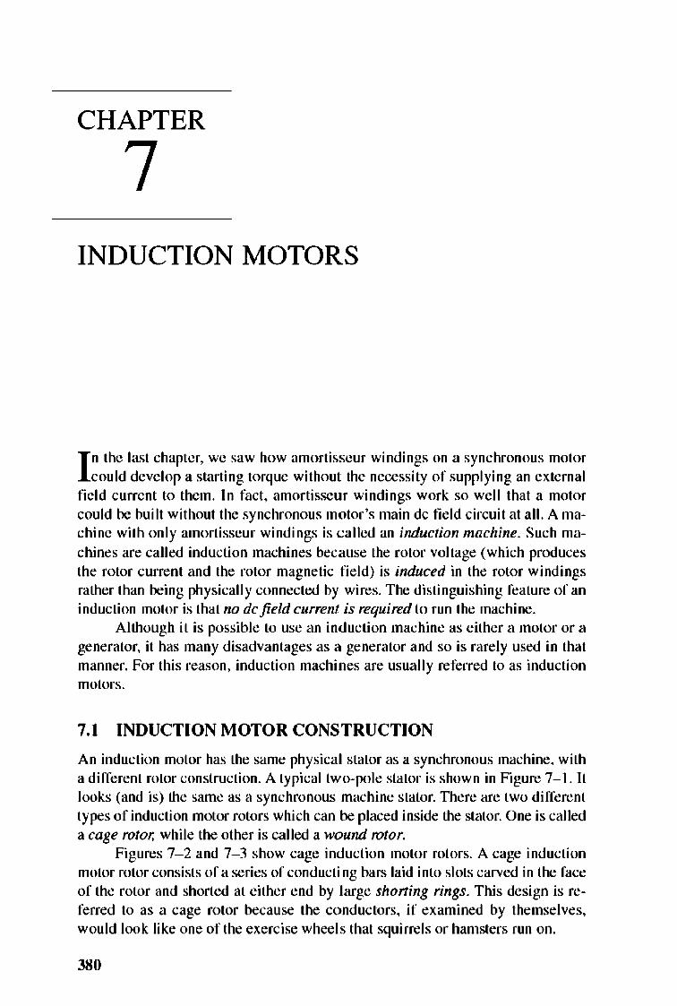
An induction motor has the same physical stator as a synchronous machine, with a different rotor construction. A typical two-pole stator is shown in Figure 7-1. It looks (and is) the same as a synchronous machine stator. TIlere are two different types of induction motor rotors which can be placed inside the stator. One is called a cage rotor, while the other is called a wound rotor.
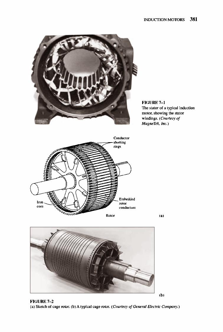
Figures 7- 2 and 7- 3 show cage induction motor rotors. A cage induction motor rotor consists ofa series of conducting bars laid into slots carved in the face of the rotor and shorted at either end by large shoT1ing rings. This design is referred to as a cage rotor because the conductors, if examined by themselves, would look like one of the exercise wheels that squirrels or hamsters run on.
380
,ore
FIGURE 7-2
Condoctor
rings
Rotor
rotor conductors
INDUCTION MOTORS 381
FIGURE 7-1 The stator of a typical induction motor. showing the stator windings. (Courlesy of MagneTek, Inc.)
,.,
,b, (a) Sketch of cage rotor. (b) A typical cage rotor. (Courtesy ofGeneml Electric Company.)
382 ELECTRIC MACHINERY RJNDAMENTALS
,,'
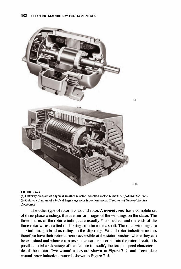
,b, ""GURE 7-3 (a) Cutaway diagram of a typical small cage rotor induction motor. (Courtesy of Ma8neTek. Inc. ) (b) Cutaway diagram of a typical large cage TOIor induction motor. (Counesy ofGeneml Electric Company.)
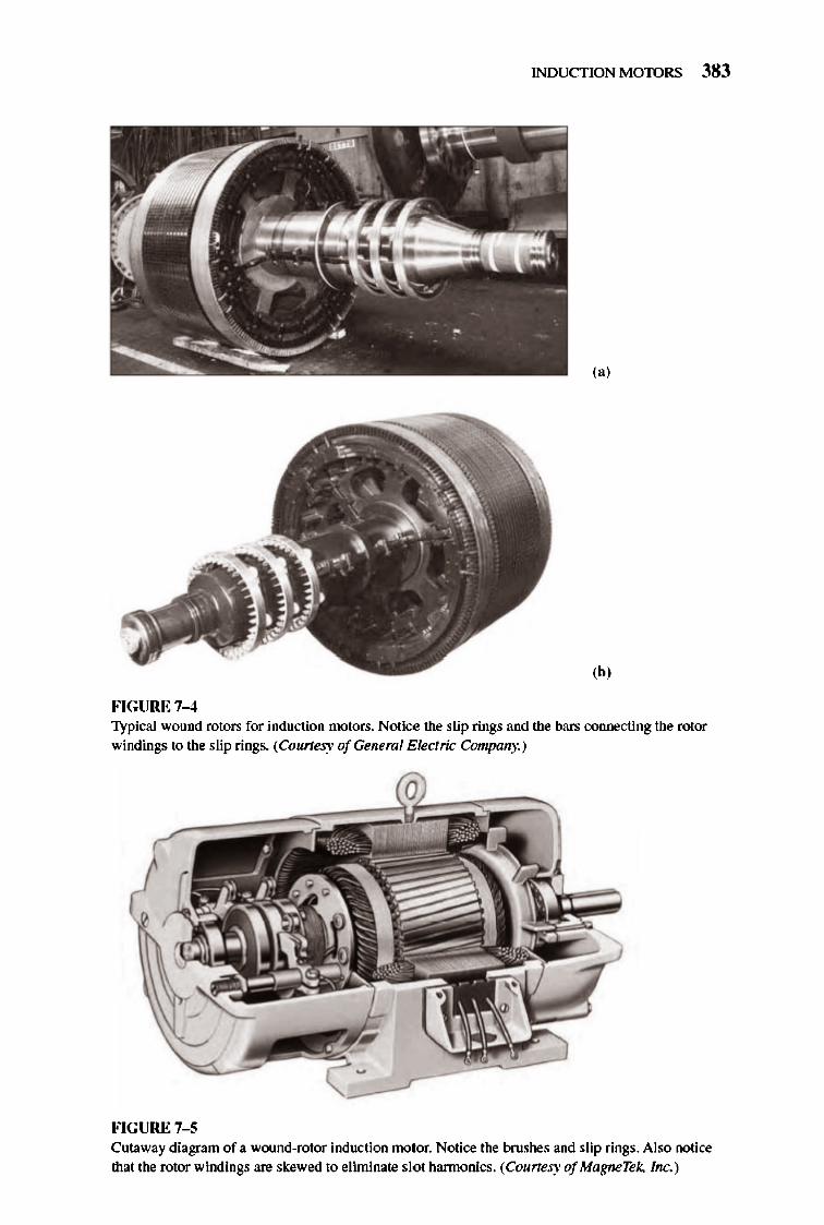
TIle other type of rotor is a wound rotor. A wound rotor has a complete set of three-phase windings that are mirror images of the windings on the stator. The three phases of the rotor windings are usually V-connected, and the ends of the three rotor wires are tied to slip rings on the rotor's shaft. TIle rotor windings are shorted through brushes riding on the slip rings. Wound-rotor induction motors therefore have their rotor currents accessible at the stator brushes, where they can be examined and where extra resistance can be inserted into the rotor circuit. It is possible to take advantage of this feature to modify the torque- speed characteristic of the motor. Two wound rotors are shown in Figure 7-4, and a complete wound-rotor induction motor is shown in Figure 7- 5.
INDUCTION MOTORS 383
(a)
,b,
FIGURE 7-4 Typical wound rotors for induction motors. Notice the slip rings and the bars connecting the rotor windings to the slip rings. (Courtel)' ofGeneml Electric Company.)
FIGURE 7-5 Cuta.way diagram of a. wound-rotor induction motor. Notice the brushes and slip rings. Also notice that the rotor windings are skewed to eliminate slot h3.ITllonics. (Courtesy of MagneTe/:. Inc.)
384 ELECTRIC MACHINERY RJNDAMENTALS
Wou nd-rotor induction motors are more expensive than cage induction motors, and they require much more maintenance because of the wear associated with their brushes and slip rings. As a result, wound-rotor induction motors are rarely used .
7.2 BASIC INDUCTION MOTOR CONCEPTS
Induction motor operation is basically the srune as that of amortisseur windings on synchronous motors. That basic operation will now be reviewed, and some important induction motor tenns will be defined.
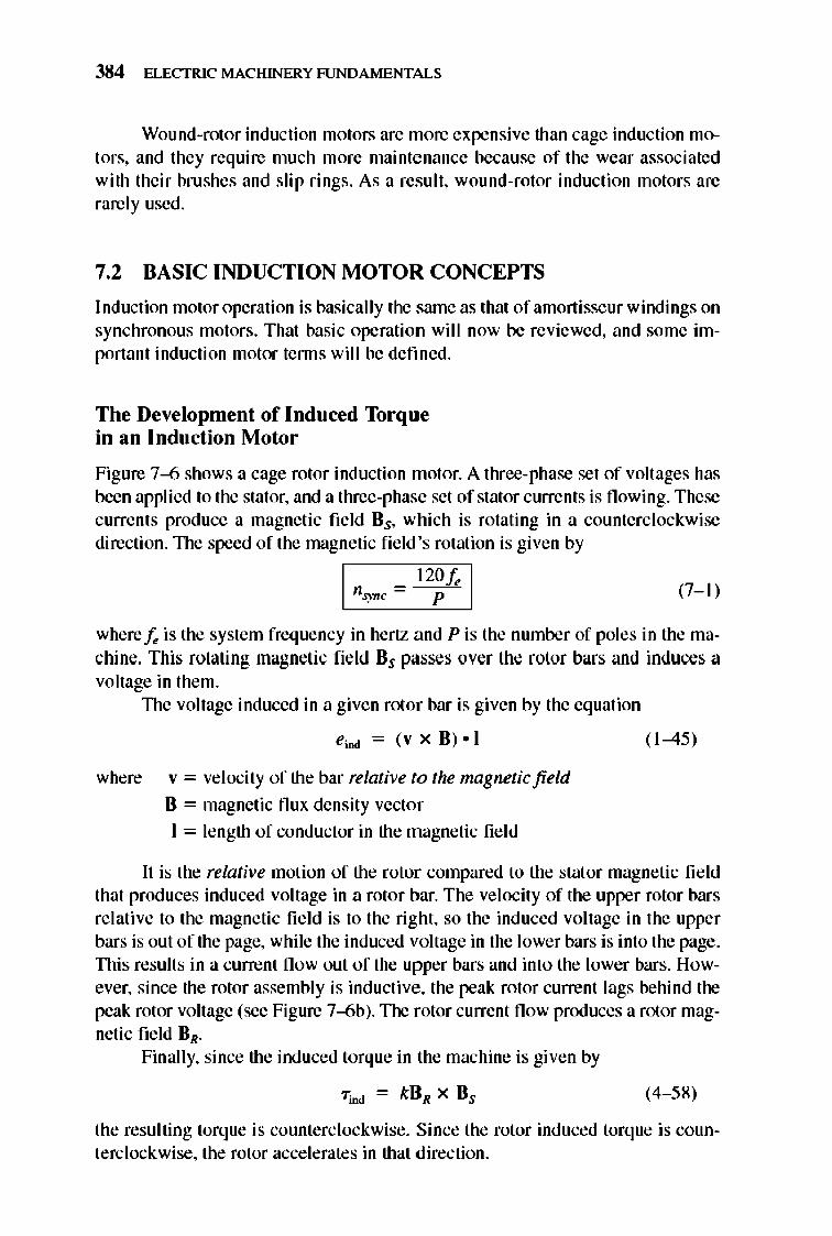
The Development of Induced Torque in an Induction Motor
Figure 7--6 shows a cage rotor induction motor. A three-phase set of voltages has been applied to the stator, and a three-phase set of stator currents is flowing. These currents prod uce a magnetic field Bs, which is rotating in a counterclockwise direction.1lle speed of the magnetic fi e ld's rotation is given by
(7-1 )
where Ie is the system frequency in hertz and P is the number of poles in the machine. This rotating magnetic field Bs passes over the rotor bars and induces a voltage in them.
1lle voltage induced in a given rotor bar is given by the equation
eioo = (v x H) • I
where v = velocity of the bar relative to the magnetic field
B = magnetic flux density vector
I = length of conductor in the magnetic fie ld
( 1-45)
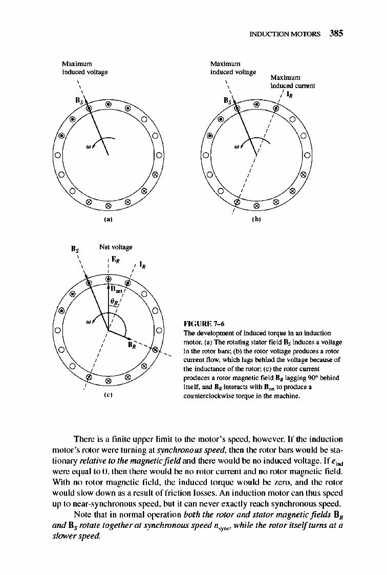
It is the relative motion of the rotor compared to the stat or magnetic field that prod uces induced voltage in a rotor bar. The velocity of the upper rotor bars relative to the magnetic field is to the right, so the induced voltage in the upper bars is out of the page, while the induced voltage in the lower bars is into the page. nlis results in a current flow out of the upper bars and into the lower bars. However, since the rotor assembly is inductive, the peak rotor current lags behind the peak rotor voltage (see Figure 7--6b). The rotor current fl ow produces a rotor magnetic field HR.
Finally, since the induced torque in the machine is given by
(4- 58)
the resulting torque is counterclockwise. Since the rotor induced torque is counterc lockwise, the rotor accelerates in that direction.
Maximum induced voltage , , ,
@ @
@ 0
@
• 0
0
0 " " " " ,., II, Net voltage ,
I ER , , I , , , , , ,
@ 0
@
• , 0
, , ,
IIi', 0
, , , , 0 ,
" " " ,,'
0
0
"
0
0
INDUCTION MOTORS 385
Maximum induced voltage
Maximum , induced current , ,
" IR H, ,
@ 0
@ 0
• , 0
, 0 , ,
0 ,
" , , ,
0 , "
" " ,b,
""CURE 7-6 The development of induced torque in an induction motor. (a) The rotating stator field lis induces a voUage in the rotor bars; (b) the rotor voltage produces a rotor currem flow. which lags behind the voUage because of the inductance of the rotor; (c) the rotor currem
produces a rotor magnetic field liN lagging 90° behind itself. and liN imeracts with II ... to produce a counterclockwise torque in the machine.
There is a fmite upper limit to the motor's speed, however. If the induction motor 's rotor were turning at synchronous speed, then the rotor bars wou ld be stationary relative to the magnetic field and there would be no induced voltage. If eioo
were equal to 0, then there would be no rotor current and no rotor magnetic fie ld. With no rotor magnetic fi e ld, the indu ced torque would be zero, and the rotor would slow down as a result of fri ction losses. An induction motor can thus speed up to near-synchronous speed, but it can never exactly reach synchronous speed.
Note that in nonnal operation both the rotor and stator mngnetic fields BR and Bs rotate together at synchronous speed n,yDC' while the rotor itselftums at a slower speed.
386 ELECTRIC MACHINERY RJNDAMENTALS
The Concept of Rotor Slip
TIle voltage induced in a rotor bar of an induction motor depends on the speed of the rotor relative to the magnetic fields. Si nce the behavior of an induction motor depends on the rotor's voltage and current, it is often more logical to talk about this re lative speed. Two tenns are commonly used to de fine the relative motion of the rotor and the magnetic fields. One is slip speed, defined as the difference between synchronous speed and rotor speed:
where n.up = slip speed of the machine
n,yDC = speed of the magnetic fields
nm = mechanical shaft speed o f motor
(7- 2)
TIle other tenn used to describe the relative motion is slip, which is the relative speed expressed on a per-unit or a percentage basis. That is, slip is defined as
" " s = ~(x 100%) n sync
(7- 3)
" - n s = 'YDC m(x 100%) n.".
(7-4)
lllis equation can also be expressed in terms of angu lar velocity w (radians per second) as
W - W S = sync m(x 100%)
w~oc (7- 5)
Notice that if the rotor turns at synchronous speed, s = 0, while if the rotor is stationary, s = 1. All normal motor speeds fall somewhere between those two limits .
It is possible to ex press the mechanical speed of the rotor shaft in tenns of synchronous speed and slip. Solving Equations (7-4) and (7- 5) for mechanical speed yields
I nm = ( 1 - s)n,yDC I (7-6)
"' I wm ~ ( I - s)w,ync I (7- 7)
lllese equations are useful in the derivation of induction motor torque and power relationships.
The Electrical Frequency on the Rotor
An induction motor works by inducing voltages and currents in the rotor of the machine, and for that reason it has sometimes been called a rotating transformer. Like a transformer, the primary (stator) induces a voltage in the secondary (rotor),
INDUCTION MOTORS 387
but unlike a transfonner, the secondary frequency is not necessarily the same as the primary frequency.
If the rotor of a motor is locked so that it cannot move, then the rotor will have the same frequency as the stator. On the other hand, if the rotor turns at synchronous speed, the frequency on the rotor will be zero. What will the rotor frequency be for any arbitrary rate of rotor rotation?
At nm = 0 rlmin, the rotor frequency fr = Jr, and the slip s = I. At nm = n,ync' the rotor frequency fr = 0 Hz, and the slip s = O. For any speed in between, the rotor frequency is directly proportional to the difference between the speed of the magnetic field n.ync and the speed of the rotor nm. Since the slip of the rotor is defined as
(7-4)
the rotor freque ncy can be expressed as
(7-8)
Several alternative fonns of this expression ex ist that are sometimes useful. One of the more common expressions is deri ved by substituting Equation (7-4) for the slip into Equation (7--8) and then substituting for n,ync in the denominator of the expression:
But n,yDC = 120 fr I P [from Equation (7- 1 )], so
Therefore,
(7- 9)
Example 7-1. A 20S-V, lO-hp, four-pole, 60-Hz, V-connected induction motor has a full-load slip of 5 percent.
(a) What is the synchronous speed of this motor? (b) What is the rotor speed of this motor at the rated load? (c) What is the rotor frequency of this motor at the rated load? (d) What is the shaft torque of this motor at the rated load?
Solution (a) The synchronous speed of this motor is
_ 120f,. n,ync - - p-
= 120(60 Hz) _ 4 poles - ISOOr/ min
(7- 1)
388 ELECTRIC MACHINERY RJNDAMENTALS
(b) The rotor speed of the motor is given by
n", = (I - s)n.yDC
= (I - 0.95)(l800r/min) = 17lOr/ min
(c) The rotor frequency of this motor is given by
Ir = s/e = (0.05)(60 Hz) = 3 Hz
Alternatively, the frequency can be found from Equation (7-9):
p /, = 120 (n,ync - nm)
= lio(l800r/ min - 17IOr/ min) = 3 Hz
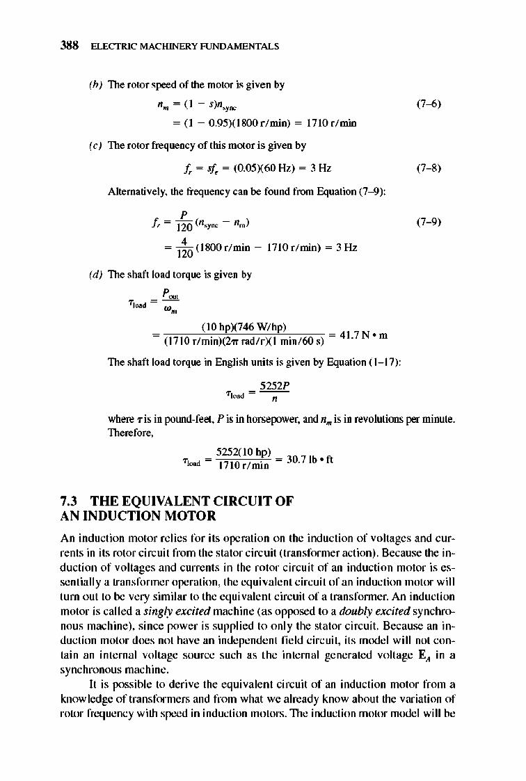
(d) The shaft load torque is given by
(10 hpX746 W/ hp) = (l7IOr/ min)(2'lTrad/ rXI min/ 60s) = 41.7N
om
The shaft load torque in English uni ts is given by Equation (1- 17):
5252P
(7--6)
(7--8)
(7-9)
where 'Tis in pOlUld-feet, P is in horser.ower, and n .. is in revolutions per minute. Therefore,
5252(10 hp) Tload = 17lOr/ min = 30.71b o ft
7.3 THE EQUIVA LENT CIRCUIT OF AN INDUCTION MOTOR
An induction motor re lies for its operation on the induction of voltages and currents in its rotor circuit from the stator circuit (transformer action). Because the induction of voltages and curre nts in the rotor circuit of an induction motor is essentially a transformer operation, the equivalent circuit of an induction motor will turn o ut to be very s imilar to the equivalent circuit of a transfonner. An induction motor is called a singly excited machine (as opposed to a doubly excited synchronous machine), since power is supplied to only the stator circuit. Because an induction motor does not have an independe nt field circ uit , its mode l will not contain an internal voltage source such as the internal generated voltage E,t in a synchronous machine .
lt is possible to derive the equivalent circuit of an induction motor from a knowledge of transformers and from what we already know about the variation of rotor frequency with speed in induction motors. TIle induction motor model will be
v,
INDUCTION MOTORS 389
I, R, I , I, - - -I . j + +
Rc jXM E,
-
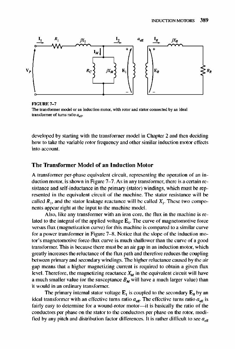
FIGURE 7-7 The transformer model or an induction motor. with rotor and stator connected by an ideal transformer of turns ratio a,/f"
developed by starting with the transformer mode l in Chapter 2 and the n deciding how to take the variable rotor frequency and other similar induction motor effects into account.
The Transformer Model of an Induction Motor
A transfonner per-phase equivalent circuit , representing the operation of an induction motor, is shown in Figure 7- 7. As in any transfonner, there is a certain resistance and self-inductance in the primary (stator) windings, which must be represented in the equivalent circuit of the machine. The stator resistance will be called R1• and the stator leakage reactance will be called X l. These two compone nts appear right at the input to the machine mode l.
Also, like any transformer with an iron core, the nux in the machine is related to the integral of the applied voltage E l . TIle curve of magnetomotive force versus nux (magnetization curve) for thi s machine is compared to a similar curve for a power transfonner in Figure 7- 8. Notice that the slope of the induction motor 's magnetomotive force-nux curve is much shallower than the c urve of a good transformer. TIlis is because there must be an air gap in an induction motor, which greatly increases the reluctance of the nux path and therefore reduces the coupling between primary and secondary windings. TIle higher reluctance caused by the air gap means that a higher magnetizing c urrent is required to obtain a give n nux leve l. Therefore, the magnetizing reactance XM in the equivalent circuit will have a much smaller value (or the susceptance EM will have a much larger value) than it would in an ordinary transformer.
The primary internal stator voltage El is coupled to the secondary EN by an ideal transformer with an effective turn s ratio a.ff" The effective turns ratio a.ff is fairly easy to detennine for a wound-rotor motor- it is basically the ratio of the conductors per phase on the stator to the conductors per phase on the rotor, modified by any pitch and distribution factor differences. It is rather difficult to see a.ff
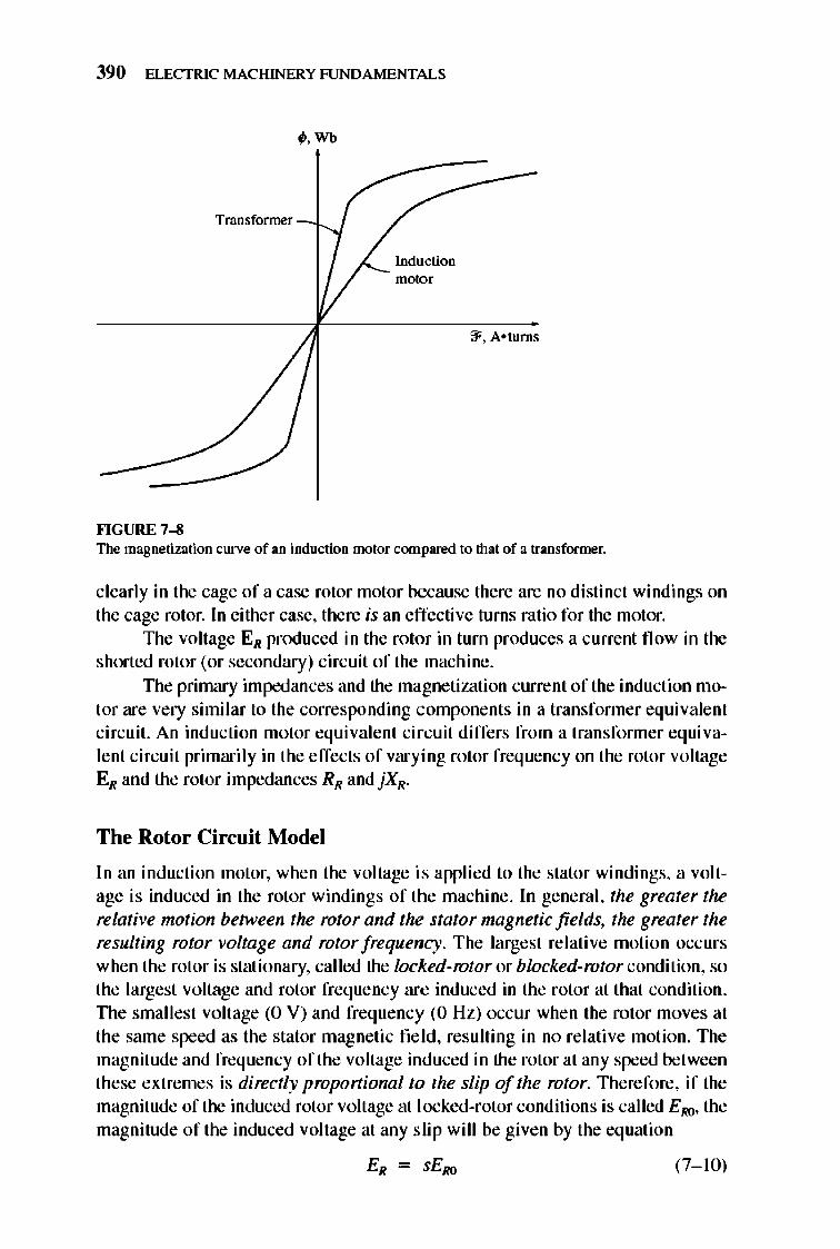
390 ELECTRIC MACHINERY RJNDAMENTALS
Transformer
""GURE 7-8
;.Wb
Induction motor
~, A-turns
The magnetization curve of an induction motor compared to that of a transformer,
clearly in the cage of a case rotor motor because there are no distinct windings on the cage rotor. In either case, there is an effective turns ratio for the motor,
1lle voltage ER produced in the rotor in turn produces a current fl ow in the shorted rotor (or secondary) circuit of the machine,
TIle primary impedances and the magnetiwtion current of the induction motor are very similar to the corresponding components in a transformer equivalent circuit. An inducti on motor equivalent circuit differs from a transfonner equivalent circuit primarily in the effects of varying rotor frequency on the rotor voltage ER and the rotor impedances RR and jXR'
The Rotor Circuit Model
In an induction motor, when the voltage is applied to the stator windings, a voltage is induced in the rotor windings of the machine, In general, the greater the relative motion between the rotor and the stator magnetic fields, the greater the resulting rotor voltage and rotor frequency, The largest relative motion occ urs when the rotor is stationary, called the locked-rotor or blocked-rotor condition, so the largest voltage and rotor frequency arc induced in the rotor at that condition, TIle smallest voltage (0 V) and frequency (0 Hz) occur when the rotor moves at the same speed as the stator magnetic field, resulting in no re lative motion, The magnitude and frequency of the voltage induced in the rotor at any speed between these extremes is directly propoT1ional to the slip of the rotor, Therefore, if the magnitude of the induced rotor voltage at locked-rotor conditions is called EIlQ, the magnitude of the induced voltage at any s lip will be given by the equation
(7-1 0)
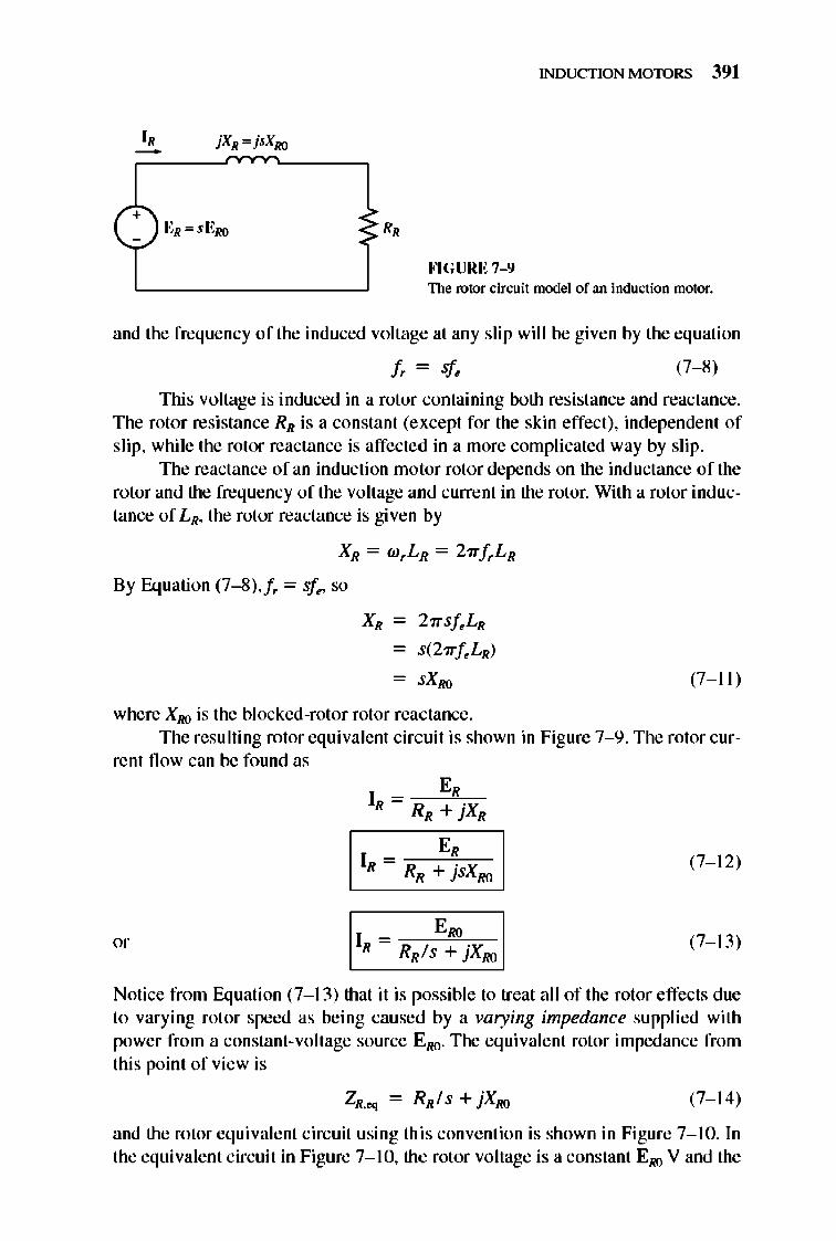
INDUCTION MOTORS 391
+ R,
FlGURE 7-9 The rotor ci['(;uit model of an induction motor.
and the frequency of the induced voltage at any slip will be given by the equation
(7-8)
This voltage is induced in a rotor containing both resistance and reactance. The rotor resistance RR is a constant (except for the skin effect), independent of slip, whi le the rotor reactance is affected in a more complicated way by slip.
The reactance of an inducti on motor rotor depends on the inductance of the rotor and the frequency of the voltage and current in the rotor. With a rotor inductance of LR, the rotor reactance is given by
XR = wrLR = 27rfrLR
By Equation (7--8),/, = sf~, so
XR - 27rSfeLR
- s(27rfeLR)
- sXRO (7 -11 )
where XRO is the blocked-rotor rotor reactance. The resulting rotor equivalent circuit is shown in Figure 7- 9. The rotor cur
rent flow can be fo und as
E, IR =
RR + jsXRO (7-1 2)
E", IR = R I + X R S } RO
(7-1 3)
Notice from Equation (7-1 3) that it is possible to treat all of the rotor effects due to varying rotor speed as being caused by a varying impedance supplied with power from a constant-voltage source ERO. The eq ui valent rotor impedance from this point of view is
(7-1 4)
and the rotor eq ui valent circuit using this convention is shown in Figure 7- 10. In the equivalent circuit in Figure 7-1 0, the rotor voltage is a constant EIiO V and the
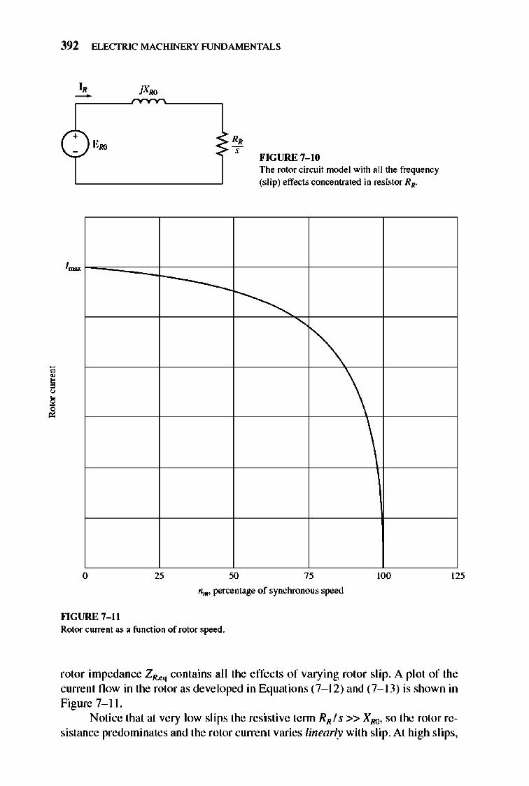
392 ELECTRIC MACHINERY RJNDAMENTALS
o 25
R, , I'IGURE 7-10 The rotor cirwit model with all the frequency (s lip) effects concentrated in resistor RR.
~
~ \
100
nm. percentage of synchronous speed
""GURE 7-11 Rotor currem as a function of rotor speed.
125
rotor impedance ZR .• q contains all the effects of varying rotor sli p. A plot of the current flow in the rotor as developed in Equations (7-1 2) and (7- 13) is shown in Figure7-11.
Notice that at very low sli ps the resistive tenn RR I s» XRQ, so the rotor resistance predominates and the rotor current varies linearly with slip. At high slips,
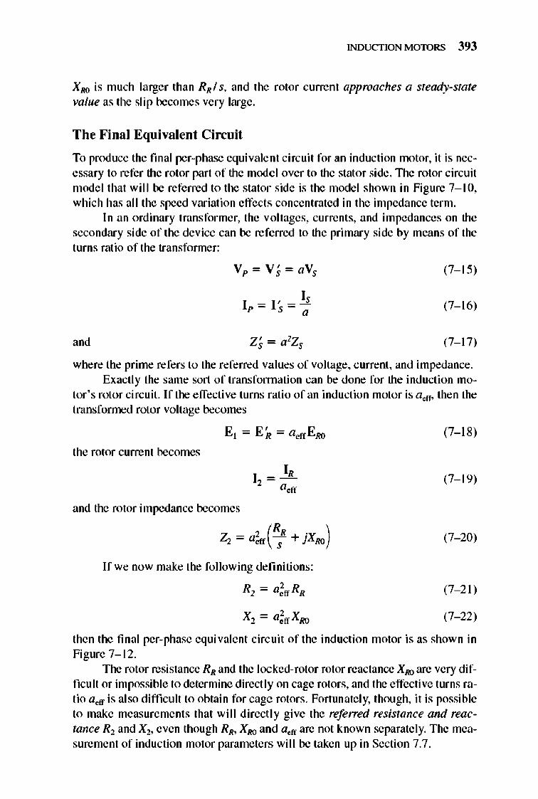
INDUCTION MOTORS 393
XRO is much larger than RR I s, and the rotor current approaches a steady-state value as the slip becomes very large.
The Final Equivalent Circuit
To produce the fmal per-phase equivalent circuit for an inducti on motor, it is necessary to refer the rotor part of the model over to the stator side. 1lle rotor circuit model that will be referred to the stator side is the model shown in Figure 7-1 0, which has all the speed variation effects concentrated in the impedance term.
In an ordinary transformer, the voltages, currents, and impedances on the secondary side of the device can be referred to the primary side by means of the turns ratio of the transfonner:
(7-1 5)
Ip = I, _ 1: ,- a
(7-1 6)
and (7-1 7)
where the prime refers to the referred values of voltage, current , and impedance. Exactly the same sort of transfonnati on can be done for the induction mo
tor 's rotor circuit. If the effective turns ratio of an induction motor is a off, then the transfonned rotor voltage becomes
the rotor current becomes
and the rotor impedance becomes
Ifwe now make the following definiti ons:
R2 = a;ff RR
(7-1 8)
(7-1 9)
(7- 20)
(7- 21)
(7- 22)
then the final per-phase equivalent circ uit of the induction motor is as shown in Figure 7-1 2.
The rotor resistance RR and the locked-rotor rotor reactance XIIQ are very diffi cult or impossible to determine directly on cage rotors, and the effective turns ratio a off is also difficult to obtain for cage rotors. Fortunate ly, though, it is possible to make measurements that will directly give the referred resistance and reactance Rl and Xl, even though RR, XRO and aeff are not known separately. The measurement of induction motor parameters will be taken up in Section 7.7.
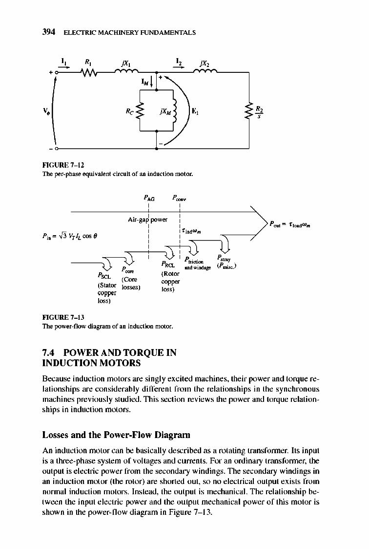
394 ELECTRIC MACHINERY RJNDAMENTALS
I, R, I , - -+ 1. 1 ~
v • Rc j XM E,
-7 -
""GURE 7-12 The per-phase equivalent ci['(;uit of an induction motor.
Air-gap power : , ,
::~~' "~oow. r Pu,,,,,f3vrhcos6 :: ,
R,~ P trictiOll '-L ODdwiD<!ay
""GURE 7-1J
p=
(Stator copper loss)
(C~
losses)
(Rotor 00_ loss)
The power-flow diagram of an induction motor.
7.4 POWER AND TORQUE IN INDUCTION MOTORS
Because induction motors are singly exci led machines, their power and torque relationships are considerably different from the relationships in the synchronou s machines previously studied. TIlis section reviews the power and torque relationships in induction motors.
Losses and the Power-Flow Diagram
An induction motor can be basically described as a rotating transfonner. Its input is a three-phase system of voltages and currents. For an ordinary transfonner, the output is e lectric power from the secondary windings. TIle secondary windings in an induction motor (the rotor) are shorted out, so no e lectrical output exists from normal induction motors. Instead, the output is mechanical. The re lationship between the input electric power and the output mechanical power of this motor is shown in the power-flow diagram in Figure 7- 13.
INDUCTION MOTORS 395
The input powerto an induction motor fln is in the form of three-phase electric voltages and currents . TIle first losses encountered in the machine are [ 2R
losses in the stat or windings (the stator copper loss PSCL) ' Then some amount of power is lost as hysteresis and eddy currents in the stator (P.:ore). The power remaining at this point is transferred to the rotor of the machine across the air gap between the stator and rotor. This power is called the air-gap power PAG of the machine. After the power is transferred to the rotor, some of it is lost as / lR losses (the rotor copper loss PRCL), and the res.t is converted from e lectrical to mechanical form (P C<JII¥)' Finally, fri ction and windage losses PF&W and stray losses Pmlsc are subtracted. The remaining power is the output of the motor Pout.
The core losses do not always appear in the power-flow diagram at the point shown in Figure 7- 13. Because of the nature of core losses, where they are accou nted for in the machine is somewhat arbitrary. The core losses of an induction motor come partially from the stator circuit and partially from the rotor circuit. Since an induction motor nonnally operates at a speed near synchronous speed, the relative motion of the magnetic fie lds over the rotor surface is quite slow, and the rotor core losses are very tiny compared to the stator core losses. Since the largest fraction of the core losses comes from the stat or circuit , all the core losses are lumped together at that point on the diagram. These losses are represented in the induction motor equivalent circuit by the resistor Rc (or the conductance Gd. If core losses are just given by a number (X watts) instead of as a circuit e lement they are often lumped together with the mechanical losses and subtracted at the point on the diagram where the mechanical losses are located.
The higher the speed of an induction motor, the higher its friction, windage, and stray losses. On the other hand, the higherthe speed of the motor (up to n,ync)' the lower its core losses. Therefore, these three categories of losses are sometimes lumped together and called rotational losses . The total rotational losses of a motor are often considered to be constant with changing speed, since the component losses change in opposite directions with a change in speed .
Example 7-2, A 4S0-V, 60-Hz, SO-hp, three-phase induction motor is drawing 60 A at 0.S5 PF lagging. The stator copper losses are 2 kW, and the rotor copper losses are 700 W. The friction and windage losses are 600 W, the core losses are ISOO W, and the stray losses are negligible. Find the following quantities:
(a) The air-gap power PAG
(b) The power converted P """" (c) TheoutputpowerPOIIt
(d) The efficiency of the motor
Solutioll To answer these questions, refer to the power-flow diagram for an induction motor (Figure 7- 13).
(a) The air-gap power is just the input power minus the stator j 2R losses. The input power is given by
396 ELECTRIC MACHINERY RJNDAMENTALS
Pin = V3"VT h cos ()
= V3"(480 V)(60 A)(O.8S) = 42.4 kW
From the power-flow diagram, the air-gap power is given by
PAG = Pin - PSCL. - P.:ore = 42.4kW - 2 kW - 1.8kW = 38.6kW
(b) From the power-flow diagram, the power converted from electrical to mechanical fonn is
P C<JiIV = P AG - PRCL
= 38.6 kW - 700 W = 37.9 kW
(c) From the power-flow diagram, the output power is given by
Pout = P C<JiIV - P F& W - P mi«:
= 37.9kW - 600W - OW = 37.3kW
or, in horsepower,
1 hp Pout = (37.3 kW) 0.746 kW = SOhp
(d) Therefore, the induction motor's efficiency is
Power and Torque in an Induction Motor
Figure 7- 12 sho ws the per-phase equivale nt circuit of an induction motor. If the equi vale nt circuit is examined closely, it can be used to derive the power and torque equations governing the operation o f the motor.
TIle input current to a phase of the motor can be found by di viding the input voltage by the total equi valent impedance:
V. I I - (7- 23)
Z~
where Zeq = RI + JXI + . I Gc - )BM + V2/S + jX2
(7- 24)
Therefore, the stator copper losses, the core losses, and the rotor copper losses can be found. The stator copper losses in the three phases are given by
(7- 25)
The core losses are given by
(7- 26)
INDUCTION MOTORS 397
so the air-gap power can be found as
ICp-A-G-~-R-;"---p-,c-c---P-,~-' (7- 27)
Look closely at the equivalent circuit of the rotor. The only element in the equi valent circuit where the air-gap power can be consumed is in the resistor Rl/S . Therefore, the air-gap power can also be given by
I PAG = 3Ii~ 1 (7- 28)
The actual resistive losses in the rotor circuit are given by the equati on
PRG- = 31~ RR (7- 29)
Since power is unchanged when referred across an ideal transfonner, the rotor copper losses can also be expressed as
I'P-R-cc-~-31~lC-R-,'1 (7- 30)
After stator copper losses, core losses, and rotor copper losses are subtracted from the input power to the motor, the remaining power is converted from electrical to mechanical form. This power converted , which is sometimes called developed mechanical power, is given by
= 3Ii R2 _ 312R , " = 31~ R2(~ - 1)
(7- 3 1)
Notice from Equations (7- 28) and (7- 30) that the rotor copper losses are equal to the air-gap power times the slip:
(7- 32)
Therefore, the lower the slip of the motor, the lower the rotor losses in the machine. Note also that if the rotor is not turning, the slip S = 1 and the air-gap power is entirely consumed in the rotor. This is logical, since if the rotor is not turning, the output power Pout (= "Tload w",) must be zero. Since P.:<>D¥ = PAG - PRCL,
this also gives another relationship between the air-gap power and the power converted from electrical to mechanical fonn:
P.:onv = PAG - PRCL
(7- 33)
398 ELECTRIC MACHINERY RJNDAMENTALS
Finall y, if the fri ction and windage losses and the stray losses are known, the output power can be found as
'I "pooC-, -_~~CO-",---Cp~,-&-W---CP~~-."-'1 (7- 34)
TIle induced torque rind in a machine was defined as the torque generated by the internal electric-to-rnechanical power conversion. This torque differs from the torque actually available at the tenninals of the motor by an amount equal to the fri ction and windage torques in the machine. The induced torque is given by the equation
(7- 35)
TIlis torque is also called the developed torque of the machine. TIle induced torque of an induction motor can be expressed in a different
fonn as well. Equati on (7- 7) expresses actual speed in terms of synchronous speed and slip, whi le Equati on (7- 33) expresses P"DDY in terms of PAG and slip. Substituting these two equations into Equation (7- 35) yields
( 1 - s)PA G
r ind = ( 1 s)WSytlC
(7- 36)
TIle last equation is especially usefu l beca use It expresses induced torque direct ly in tenns of air-gap power and synchronous speed, which does not vary. A knowledge of PAG thus directly yields r ind .
Separating the Rotor Copper Losses and the Power Converted in an Induction Motor 's Equivalent Circuit
Part of the power coming across the air gap in an induction motor is consumed in the rotor copper losses, and part of it is converted to mechanical power to drive the motor's shaft. It is possible to separate the two uses of the air-gap power and to indicate them separately on the motor equivale nt circuit.
Equation (7- 28) gives an ex pression for the total air-gap power in an induction motor, whi le Equation (7- 30) gives the actual rotor losses in the motor. TIle air-gap power is the power which would be consumed in a resistor of value Ris, while the rotor copper losses are the power which would be consumed in a resistor of value R2. TIle difference between them is P eDDY' which must therefore be the power consumed in a resistor of value
Reonv = ~2 - R2 = R2(~ - 1)
(7- 37)
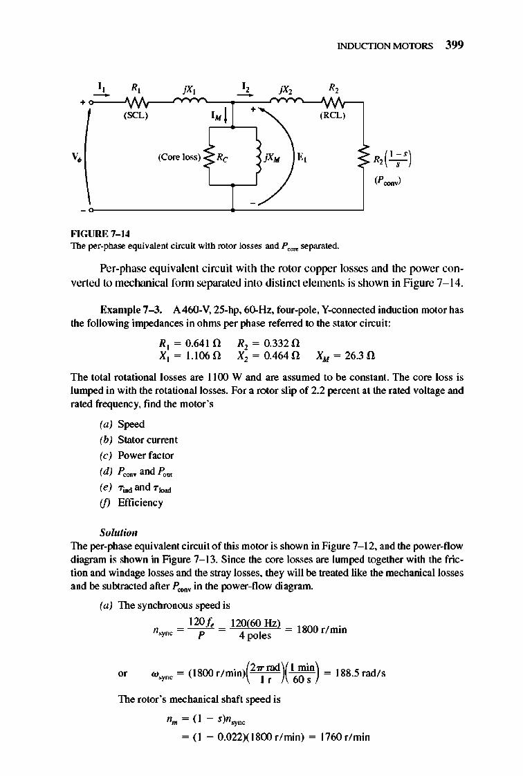
INDUCTION MOTORS 399
I, R, I , - -+ (SCL) 1. 1 + (RCL)
(Core loss) R, jXM E,
J./ -
FIGURE 7- 14 The per-phase equivalent circuit with rotor losses and P CO« separated.
Pe r-phase equivalent circuit with the rotor copper losses and the power conve rted to mechanica l fonn separated into distinct e lements is shown in Figure 7- 14.
Example 7-3. A 460-V. 25-hp. 6()"'Hz. four-pole. V-connected induction motor has the following impedances in ohms per phase referred to the stator circuit:
R t = 0.641 n XI = 1.106 n
Rl = 0.332 n Xl = 0.464 n XM = 26.3 n
The total rotational losses are 1100 W and are assumed to be constant. The core loss is lumped in with the rotational losses. For a rotor slip of 2.2 percent at the rated voltage and rated frequency. find the motor 's
(a) Speed
(b) Stator current
(c) Power factor
(d) P OO<IV and Pout
(e) Tiad and Tiood
(jJ Efficiency
Solutioll The per-phase equivalent circuit of this motor is shown in Figure 7- 12. and the power-flow diagram is shown in Figure 7- 13. Since the core losses are Iwnped together with the friction and windage losses and the stray losses. they will be treated like the mechanical losses and be subtracted after P coov in the power-flow diagram.
(a) The synchronous speed is
120 fe n,yDC = - P- = 129(60 Hz) _ 1800 r/ min
4 poles
The rotor 's mechanical shaft speed is
nm = (I - s)n,yDC
= (1 - 0.022XI800r/ min) = 1760r/ min
400 ELECTRIC MACHINERY RJNDAMENTALS
or w". = (1 - s)w.ry1tC
= (1 - 0.022XI88.5rad/s) = 184.4rad/ s
(b) To find the stator clUTent, get the equivalent impedance of the circuit. The first step is to combine the referred rotor impedance in parallel with the magnetization branch, and then to add the stator impedance to that combination in series. The referred rotor impedance is
R, z, = - +jX2 ,
= 0.332 + '0 464 0.022 J.
= 15.00 + jO.464 [! = 15.IOLI.76° [!
The combined magnetization plus rotor impedance is given by
1 Z/ = I/jXM + 1!L;
= ~=~~1=~~ jO.038 + 0.0662L 1.76°
1 = 0.0773L 31.1 0 = 12.94L31.I O[!
Therefore, the total impedance is
z..,. = z. ... , + Z/
= 0.641 + j1.106 + 12.94L31.1° [!
= 11.72 + j7.79 = 14.07L33.6° [!
The resulting stator current is
V I - ~ ,- z..
_ 266LO° V _ - 14.07 L33.6° [! -
(c) The power motor power factor is
PF = cos 33.6° = 0.833
(d) The input power to this motor is
Pin = V3"VT h cos ()
18.88L - 33.6° A
lagging
= V3"(460 VX18.88 A)(0.833) = 12,530 W
The stator copper losses in this machine are
PSCL = 3/f R]
= 3(18.88 A)2(0.64 I [!) = 685 W
The air-gap power is given by
PAG = P;n - PSCL = 12,530 W - 685 W = 11,845 W
Therefore, the power converted is
(7- 25)
INDUCTION MOTORS 401
P.:oov = (1 - S)PAG = (I - 0.022X11,845 W) = 11,585 W
The power P"", is given by
Pout = P.:oov - Prot = 11,585W - llOOW = 1O,485W
( 1 hp ) = 10,485 W 746 W = 14.1 hp
(e) The induced torque is given by
PAG Tind = -
w' )'''''
11,845 W = 18S.5rad/s = 62.8 N om
and the output torque is given by
p-, Tload =
10,485 W = 184.4 radls = 56.9 Nom
(In English lUlits, these torques are 46.3 and 41.9 Ib-ft, respectively.) (jJ The motor's efficiency at this operating condition is
p~ 7f = R x 100% ,.
10,485 W 12530 W x 100% = 83.7%
7.5 INDUCTION MOTOR TORQUE-SPEED CHARACTERISTICS
How does the torque of an induction motor change as the load changes? How much torque can an induction motor supply at starting conditions? How much does the speed of an induction motor drop as its shaflload increases? To find out the answers to these and similar questions, it is necessary to clearly understand the relationships among the motor's torque, speed, and power.
In the following material , the torque- speed re lationship will be examined first from the physical viewpoint of the motor's magnetic field behavior. TIlen, a general equation for torque as a fu nction of sli p wil I be derived from the induction motor equivalent circuit (Figure 7- 12).
Induced Torque from a Physical Standpoint
Figure 7-1 5a shows a cage rotor induction motor that is initially operating at no load and therefore very nearly at synchronous speed . llle net magnetic fie ld BDeI in this machine is produced by the magnetization current 1M flowing in the motor 's equivalent circuit (see Figure 7-1 2). The magnitude of the magnetization current and hence of BDeI is directly proportional to the voltage E). If E] is constant, then the
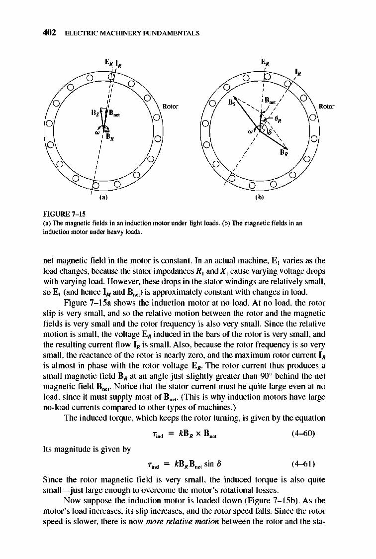
402 ELECTRIC MACHINERY RJNDAMENTALS
ER IR E, , I,
0 0 , 0 " 0 0
, "
, " 0 ' , 0 0 " 0 I B .... /
D~g.~ Rotor , ' ,
0 ,
0 0 ' e, w , .,
0 , ,
0 ,
0 , , , , , H, , 0
, 0
, 0
, , , , , 0 0 0 ,
0 0 0 (,' (b'
""GURE 7- 15 (a) The magnetic fields in an induction motor under light loods. (b) The magnetic fields in an induction motor under heavy loads.
0
0
0
Rotor
net magnetic fie ld in the motor is constant. In an actual machine, E l varies as the load changes, because the stator impedances Rl and Xl cause varying voltage drops with varying load. However, these drops in the stator wi ndi ngs are relatively small, so El (and hence 1M and Bo..) is approximalely constanl with changes in load .
Figure 7-l 5a shows the induction motor at no load . At no load, the rotor slip is very smaJl, and so the relalive motion between the rotor and the magnetic fi e lds is very smaJi and the rotor frequency is also very small. Since the relative motion is smaJl , the voltage ER induced in the bars of the rotor is very smaJl, and the resulting currenl fl ow IR is small. Also, because the rotor frequency is so very small, the reactance of the rotor is nearly zero, and the maximum rotor currenl IR
is almost in phase with the rotor voltage ER. TIle rotor current thus produces a small magnetic field DR at an angle just s lighlly greater than 90° behind the net magnetic fie ld Boe, . Notice that the stator current must be quite large even at no load, since it must supply most of Bne,. (TIlis is why inducti on motors have large no-load currents compared to other types of machines.)
TIle induced torque, which keeps the rotor turning, is given by the equation
(4-60)
Its magnitude is given by
"Tind = kBRBoe, sin /j (4-6 1)
Since the rotor magnetic field is very smaJl, the induced torque is also quite small- just large enough to overcome the motor 's rotational losses.
Now suppose the inducti on motor is loaded down (Figure 7-15b). As the motor's load increases, its slip increases, and the rotor speed falls. Since the rotor speed is slower, there is now more relative motion between the rotor and the sta-
INDUCTION MOTORS 403
tor magnetic fields in the machine. Greater relative motion produces a stronger rotor voltage ER which in turn produces a larger rotor current IR. With a larger rotor current , the rotor magnetic field DR also increases. However, the angle of the rotor current and DR changes as well. Since the rotor slip is larger, the rotor frequency rises (f, = st ), and the rotor's reactance increases (WLR). Therefore, the rotor current now lags further behind the rotor voltage, and the rotor magnetic field shifts with the current. Figure 7-15b shows the induction motor operating at a fairly high load. Notice that the rotor current has increased and that the angle 8 has increased . The increase in BR tends to increase the torque, while the increase in angle 8 tends to decrease the torque (TiDd is proportional to sin 8, and 8 > 90°). Since the first effect is larger than the second one, the overall induced torq ue increases to supply the motor's increased load.
When does an induction motor reach pullout torque? This happens when the point is reached where, as the load on the shaft is increased, the sin 8 tenn decreases more than the BR tenn increases. At that point, a further increase in load decreases "TiDd, and the motor stops.
It is possible to use a knowledge of the machine's magnetic fi e lds to approximately derive the output torque-versus-speed characteristic of an induction motor. Remember that the magnitude of the induced torque in the machine is given by
(4-61)
Each tenn in this expression can be co nsidered separately to derive the overall machine behavior. The individual tenns are
L BR . TIle rotor magnetic field is directly proportional to the current fl owing in the rotor, as long as the rotor is unsaturated . TIle current fl ow in the rotor increases with increasing slip (decreasing speed) according to Equation (7-1 3). This current fl ow was plotted in Figure 7-11 and is shown again in Figure 7-16a.
2. B"",. The net magnetic field in the motor is proportional to E] and therefore is approximately constant (E ] actually decreases with increasing current flow, but this effect is small compared to the other two, and it will be ignored in this graphical development). TIle curve for B"", versus speed is shown in Figure 7-16b.
3. sin 8. TIle angle 8 between the net and rotor magnetic fields can be expressed in a very useful way. Look at Figure 7-15b. In this figure, it is clear that the angle 8 is just equal to the power-factor angle of the rotor plus 90°:
(7-38)
TIlerefore, sin 8 = sin (OR + 90°) = cos OR. TIlis tenn is the power factor of the rotor. The rotor power-factor angle can be calculated from the equation
(7-39)
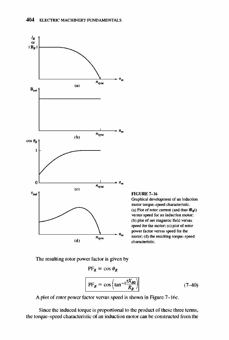
404 ELECTRIC MACHINERY RJNDAMENTALS
J, oe
I DRI r---_~
~---------7~-- '. n,ymc ,.,
L----------c-~-_ '. '.-,b,
0 '. ,e, '.-
,~
,d, '.- '.
The resulting rotor power factor is given by
PFR = cos (JR
FlGURE 7- 16 Grapltical development of an induction motor torque-speed cltaT3cteristic. (a) Plot of rotor current (and titus IURI ) versus speed for an induction motor; (b) plot of net magnetic field versus speed for the motor; (c) plot of rotor power factor versus speed for the motor; (d) the resulting torque-speed characteristic.
PF = cos (tan -1SXRQ
) , R, (7-40)
A plot of rotor power factor versus speed is shown in Figure 7-1 6c .
Since the induced torque is proportional to the product of these three tenns, the torque-speed characteristic of an induc ti on motor can be constructed from the
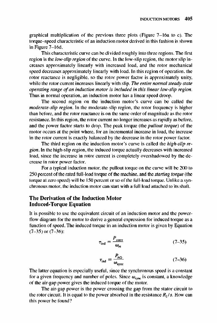
INDUCTION MOTORS 405
graphical multiplication of the previous three plots (Figure 7-1 6a to c). 1lle torq ue-speed characteristic of an induction motor derived in this fashion is shown in Figure7-16d.
This characteristic curve can be di vided roughly into three regions. The first region is the low-slip region of the curve. In the low-slip region, the motor slip increases approximately linearly with increased load, and the rotor mechanical speed decreases approximately linearly with load . In this region of operation, the rotor reactance is negligible, so the rotor power factor is approximately unity, whi le the rotor current increases Ii nearly with slip. The entire normnl steady-state operating range of an induction motor is included in this linear low-slip region. Thus in normal operation, an induction motor has a linear speed droop.
The second region on the induction motor's curve can be called the moderate-slip region . In the moderate-sli p region, the rotor freq uency is higher than before, and the rotor reactance is on the same order of magnitude as the rotor resistance. In this region, the rotor current no longer increases as rapid ly as before, and the power factor starts to drop. TIle peak torque (the pullout torque) of the motor occurs at the point where, for an incremental increase in load, the increase in the rotor current is exactly balanced by the decrease in the rotor power factor.
The third region on the induction motor 's curve is called the high-slip region. In the high-slip region, the induced torque actual ly decreases with increased load, since the increase in rotor current is completely overshadowed by the decrease in rotor power factor.
For a typical induction motor, the pullout torque on the curve will be 200 to 250 percent of the rated fu ll-load torque of the machine, and the starting torque (the torque at zero speed) will be 150 percent or so of the fu ll-load torque. Unlike a synchronous motor, the induction motor can start with a fuJI load attached to its shaft.
The Derivation of the Induction Motor Induced-Torque Equation
It is possible to use the eq ui valent circuit of an induction motor and the powerflow diagram for the motor to derive a general expression for induced torque as a function of speed . The induced torq ue in an induction motor is given by Equation (7- 35) or (7- 36) :
(7- 35)
(7- 36)
The latter equation is especially useful, since the synchronous speed is a constant for a given frequency and number of poles. Since w' ync is constant, a knowledge of the air-gap power gives the induced torque of the motor.
The air-gap power is the power crossing the gap from the stator circuit to the rotor circuit. It is equal to the power absorbed in the resistance R2! s. How can this power be found?
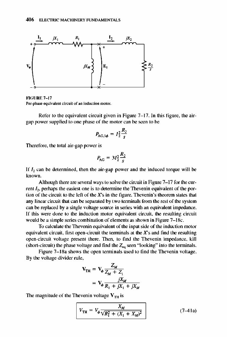
406 ELECTRIC MACHINERY RJNDAMENTALS
+
v •
-
I, -
""GURE 7-17
, R, I , -+
j XM E,
-
Per-phase equivalent circuit of an induction motor.
~
Refer to the equivalent circuit given in Figure 7-17. In this figure, the airgap power supplied to one phase of the motor can be seen to be
, R, PAG.t4> = 12s
Therefore, the total air-gap power is
_ 2 R2 PAG -312 ,
If / l can be determined, then the air-gap power and the induced torque will be known.
Although there are several ways to solve the circuit in Figure 7-1 7 for the current l l, perhaps the easiest one is to detennine the lllevenin equivalent of the portion of the circuit to the left of the X's in the fi gure. Thevenin's theorem states that any linear circuit that can be separated by two tenninals from the rest of the system can be replaced by a single voltage source in series with an equivalent impedance. If this were done to the induction motor eq ui valent circuit, the resulting circuit would be a simple series combination of elements as shown in Figure 7-1 8c.
To calculate the lllevenin equivalent of the input side of the induction motor equivalent circuit, first open-circuit the terminals at the X's and fmd the resulting open-circuit voltage present there. lllen, to find the Thevenin impedance, kill (short-circuit) the phase voltage and find the Zeq seen " looking" into the tenninals.
Figure 7-1 8a shows the open tenninals used to find the Thevenin voltage. By the voltage divider rule,
ZM VTH = V4> Z + Z M ,
= V jXM 4>R t + jX] + jXM
llle magnitude of the Thevenin voltage Vru is
(7-4 I a)
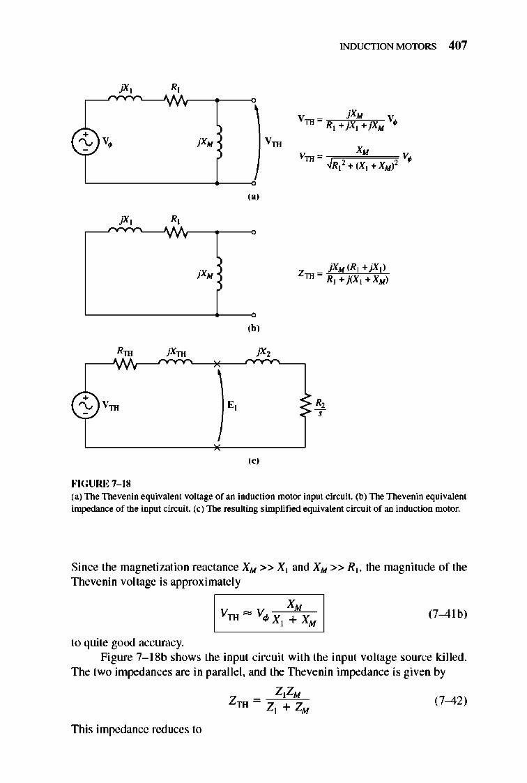
INDUCTION MOTORS 407
jX, : , v '" jX/oI V
TH R]+jX]+jX/oI •
(-t)V, jX/oI Vrn XM
VTH '" V. ~R]2+(X] +X/oI)2
('J
jX, R,
(bJ
jXrn
(oj
FIGURE 7- 18 (a) The Thevenin equivalent voltage of an induction ntotor input circuit. (b) The Thevenin equivalent impedance of the input circuit. (c) The resulting simplified equivalent circuit of an induction motor.
Since the magnetization reactance XM » X] and XM » RJ, the magnitude of the Thevenin voltage is approximately
(7-4 (b)
to quite good accuracy. Figure 7-1 8b shows the input circuit with the input voltage source killed.
The two impedances are in paralle l, and the TIlevenin impedance is given by
ZIZM ZTH = Z l + ZM (7-42)
This impedance reduces to
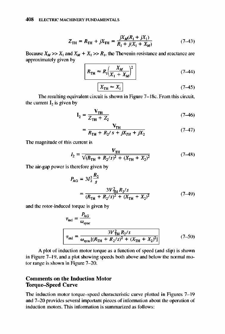
408 ELECTRIC MACHINERY RJNDAMENTALS
(7-43)
Because XM » Xl and XM + Xl »Rb the TIlevenin resistance and reactance are approximately given by
(7-44)
(7-45)
TIle resulting equivalent circuit is shown in Figure 7-1 8c. From this circuit, the current 12 is given by
VTH 12 = ZTH +2;
_ ~~~~V~TH!lL~~~ Rrn + R2/ s + jXTH + jX2
The magnitude of this current is
VTH
/2 = Y(RTH + R2/sP + (Xrn + X2)2
TIle air-gap power is therefore given by
R, P = 3[ 2 -
AG 2 S
= (Rrn + R2/si + (Xrn + X2)2
and the rotor-induced torque is given by
PAG T;nd=w
~oc
(7-46)
(7-47)
(7-48)
(7-49)
(7- 50)
A plot of induction motor torque as a function of speed (and slip) is shown in Figure 7-1 9, and a plot showing speeds both above and below the normal motor range is shown in Figure 7- 20.
Comments on the Induction Motor Torque-Speed Curve
TIle induction motor torque-speed characteristic curve plotted in Figures 7-1 9 and 7- 20 provides several important pieces ofinfonnation about the operation of induction motors . TIlis infonnation is summarized as follows:
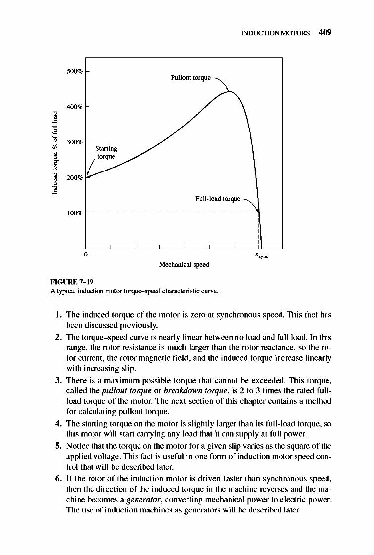
INDUCTION MOTORS 409
Pullout torque \
400%
" ~ = • • 300% • Starting • " torque
§ ( ~ 200%
" ~
100% ____________________ ~U~l~~~~~:~~
o Mechanical speed
FIGURE 7-19 A typical induction motor torque-speed characteristic curve.
I. 1lle induced torque of the motor is. zero at synchronous speed. 1llis fact has been discussed previously.
2. 1lle torque- speed curve is nearly linear between no load and full load. In this range, the rotor resistance is much larger than the rotor reactance, so the rotor current , the rotor magnetic fi e ld, and the induced torque increase linearly with increasing slip.
3. There is a maximum possible torque that cannot be exceeded. nlis torque, called the pullout torque or breakdown torque, is 2 to 3 times the rated full load torque of the motor. The next section of this chapter contains a method for calculating pullout torque.
4. 1lle starting torque on the motor is slightly larger than its full -load torq ue, so this motor will start carrying any load that it can supply at fu ll power.
5. Notice that the torq ue on the motor for a given slip varies as the square of the applied voltage. nli s fact is useful in one fonn of induction motor speed control that will be described later.
6. If the rotor of the induction motor is driven faster than synchronous speed, then the direction of the induced torque in the machine reverses and the machine becomes a generator, converting mechanical power to e lectric power. 1lle use of induction machines as generators will be described later.
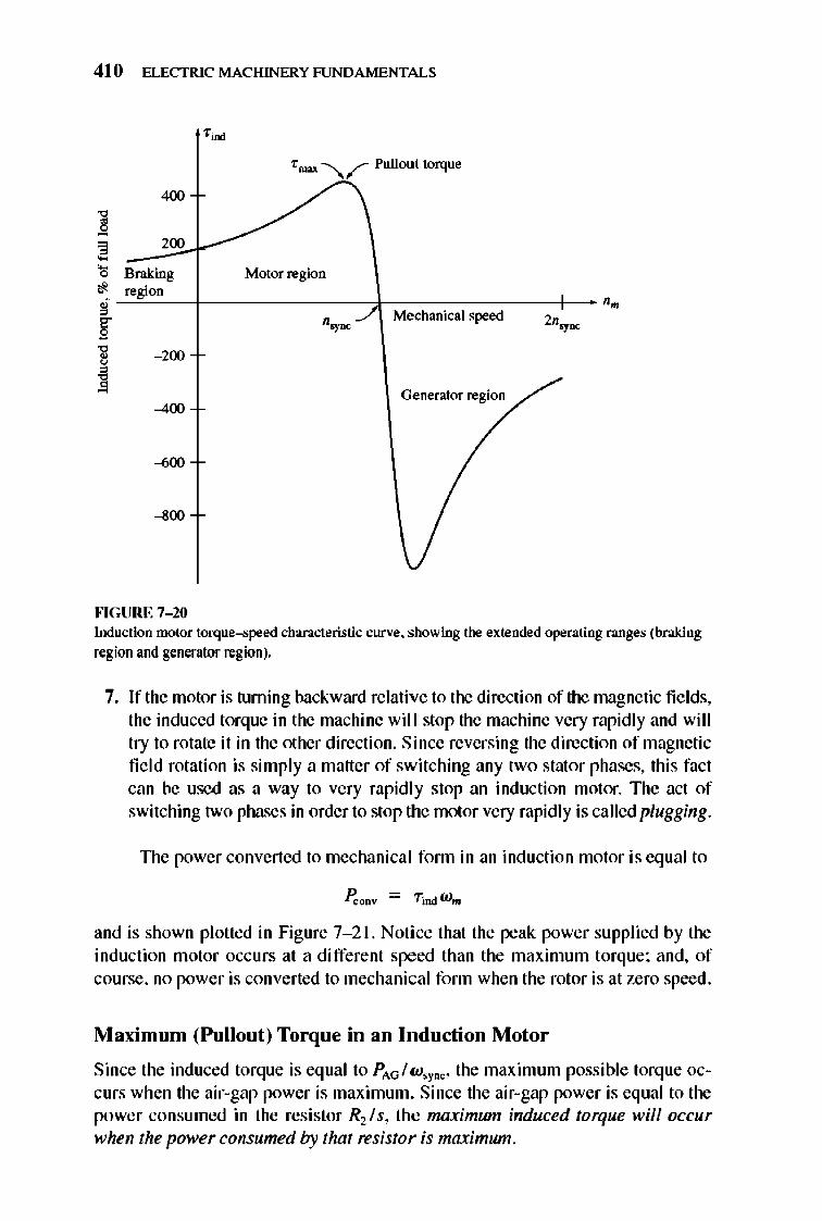
410 ELECTRIC MACHINERY RJNDAMENTALS
400
] = 200 e '0 Braking If region ; § ] - 200
~ -400
""GURE 7-10
Tmn --........~ Pullout torque
Motor region
nsyDC..-/ Mechanical speed
Generator region
Induction motor torque-speed characteristic curve. showing the extended operating ranges (braking region and generator region).
7. If the motor is turning backward relative to the direction of the magnetic fi e lds, the induced torque in the machine will stop the machine very rapidly and will try to rotate it in the other direction. Since reversing the direction of magnetic fi e ld rotation is simply a matter of switching any two stator phases, this fact can be used as a way to very rapidl y stop an induction motor. The act of switching two phases in order to stop the motor very rapid ly is called plugging.
TIle power converted to mechanical fonn in an induction motor is equal to
and is shown plotted in Figure 7- 21. Noti ce that the peak power supplied by the induction motor occurs at a different speed than the maximum torque ; and, of course, no power is converted to mechanical fonn when the rotor is at zero speed .
Maximum (pullout) Torque in an Induction Motor
Since the induced torque is equal to PAG/ w'Y"'" the maximum possible torque occurs when the air-gap power is maximum. Since the air-gap power is equal to the power consumed in the resistor R2 /s, the maximum induced torque will occur when the power consumed by that resistor is maximum.
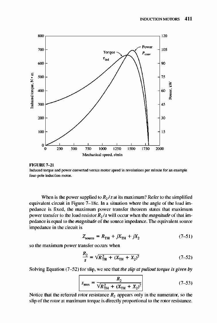
INDUCTION MOTORS 411
800 120
700 105
600 90
, 500 75 •
Z ~ ,
~ 400 60 c , ~ " , ,
" 300 45 0
200 30
100 15
0 0 250 500 750 1000 1250 1500 1750 2000
Mechanical speed. r/min
FIGURE 7-21 Induced torque and power convened versus motor speed in revolutions per minute for an example four-pole induction motor.
When is the power supplied to Rl/s at its maximum? Refer to the simplified equivalent circuit in Figure 7- 18c. In a situation where the angle of the load impedance is fixed, the maximum power transfer theorem states that maximum power transfer to the load resistor Rll s wi l I occur when the magnitude of that impedance is equal to the magnitude of the source impedance. TIle equivalent source impedance in the circuit is
Zsoun:c = RTH + jXTH + jX2
so the maximum power transfer occurs when
R -i- = YRfH + (XTH + Xii
(7- 51)
(7- 52)
Solving Equation (7- 52) for slip, we see that the slip at pullout torque is given by
(7- 53)
Notice that the referred rotor resistance Rl appears only in the numerator, so the slip of the rotor at maximum torque is direct ly proportional to the rotor resistance.
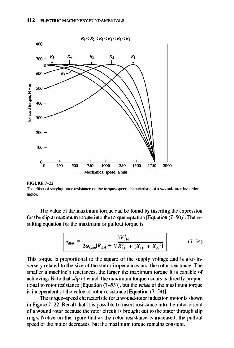
41 2 ELECTRIC MACHINERY RJNDAMENTALS
800 ,--------------------------------,
R, I
700
600 R.
;"" z • ~400 "I ~ 300
200
100
R, R,
o~~~~~~~~~~~~~~~~ o 250 500 750 1000 1250 1500 1750 2000
Mechanical speed. r/min
""GURE 7- 22 The effect of varying rotor resistance on the torque-.\peed characteristic of a wound-rotor induction motor.
TIle value of the maximum torque can be found by inserting the expression for the slip at maximum torque into the torque equation [Equation (7- 50)]. TIle resulting equation for the maximum or pullo ut torque is
(7- 54)
TIlis torque is proportional to the sq uare of the supply voltage and is also inversely re lated to the size of the stat or impedances and the rotor reactance. The smaller a machine's reactances, the larger the maximum torque it is capable of achieving. Note that slip at which the maximum torque occurs is directly proportional to rotor resistance [Equation (7- 53)], but the value of the maximum torque is independent of the value of rotor resistance [Equation (7- 54)].
TIle torque-speed characteristic for a wound-rotor induction motor is shown in Figure 7- 22. Recall that it is possible 1.0 insert resistance into the rotor circuit of a wound rotor because the rotor circuit is brought out to the stator through slip rings. Notice on the fi gure that as the rotor resistance is increased, the pullout speed of the motor decreases, but the maximum torque remains constant.
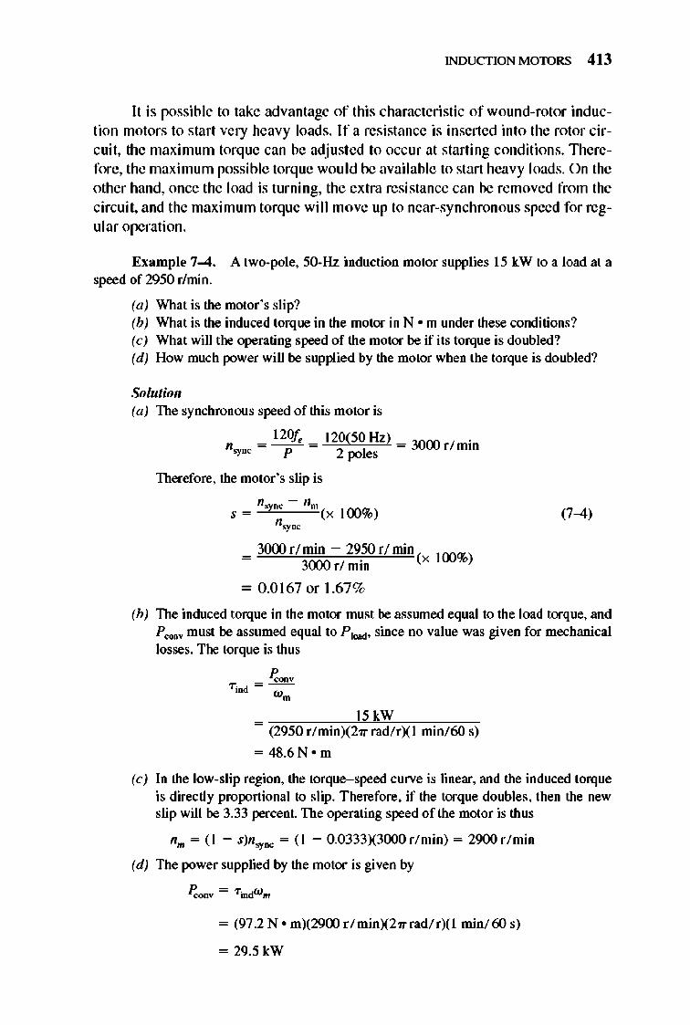
INDUCTION MOTORS 413
It is possible to take advantage of this characteristic of wound-rotor induction motors to start very heavy loads. If a resistance is inserted into the rotor circuit , the maximum torq ue can be adjusted to occur at starting conditions. Therefore, the maximum possible torq ue would be available to start heavy loads. On the other hand, once the load is turning, the extra resistance can be removed from the circuit , and the maximum torque will move up to near-synchronous speed for regular operation.
Example 7-4. A two-pole, 50-Hz induction motor supplies 15 kW to a load at a speed of 2950 r/min.
(a) What is the motor 's slip? (b) What is the induced torque in the motor in Nom under these conditions? (c) What will the operating speed of the motor be if its torque is doubled? (d) How much power will be supplied by the motor when the torque is doubled?
Solution (a) The synchronous speed of this motor is
= 120f,. = 120(50 Hz) = 30CXl r / min n.yDC P 2 poles
Therefore, the motor's slip is
= 3000r/min - 29.50 r / min(x 100%) 3(x)() rl mm
= 0.0167 or 1.67%
(7-4)
(b) The induced torque in the motor must be assruned equal to the load torque, and P OO/IiV must be assumed equal to P load' since no value was given for mechanical losses. The torque is thus
~oov TiDd =W-
m
~~~~~15~k~W~c.-~~-c = (2950 r/ minX27Trad/ rXI min/60 s)
= 48.6N o m
(c) In the low-slip region, the torque-speed curve is linear, and the induced torque is directly proportional to slip. Therefore, if the torque doubles, then the new slip will be 3.33 percent. The operating speed of the motor is thus
11m = (1 - s)n.yDC = (1 - 0.0333X3000r/min) = 2900 r / min
(d) The power supplied by the motor is given by
= (97.2 N 0 m)(2900 r / minX27Trad/ rXI minI 60 s)
= 29.5 kW
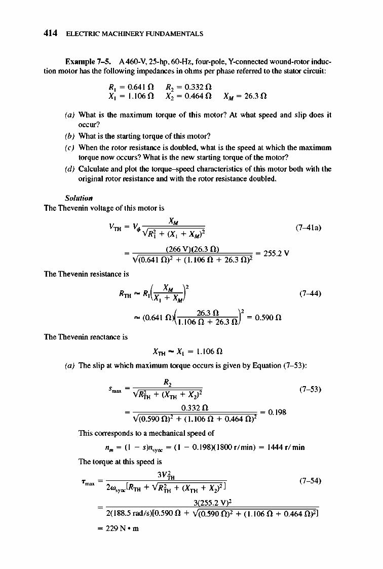
414 ELECTRIC MACHINERY RJNDAMENTALS
Example 7-5. A460-V. 25-hp. 60-Hz. four-pole. Y-cOIlllected wOlUld-rotor induction motor has the following impedances in ohms per phase referred to the stator circuit:
Rl = 0.641 0 Xl = 1.106 0
R2 = 0.3320 X2 = 0.4640 XM = 26.3 0
(a) What is the maximrun torque of this motor? At what speed and slip does it occur?
(b) What is the starting torque of this motor?
(c) When the rotor resistance is doubled. what is the speed at which the maximum torque now occurs? What is the new starting torque of the motor?
(d) Calculate and plot the torque-speed characteristics of this motor both with the original rotor resistance and with the rotor resistance doubled.
Solutioll The Thevenin voltage of this motor is
(7-4la)
The Thevenin resistance is
(7-44)
J 26.3 n )' - (0.641 0-'\1.1060 + 26.3 0 = 0.590 0
The Thevenin reactance is
XTH - Xl = 1.106 0
(a) The slip at which maximum torque occurs is given by Equation (7- 53):
R, Smax = ~VijRijfu=cc+c=i(X~rn"=,,+=x~~' (7- 53)
0.3320 = =0.198 Y(0.590 0)1 + (1.106 0 + 0.464 0)2
This corresponds to a mechanical speed of
nm = (I - S)n,yDC = (I - 0.198)(l800r/min) = 1444r/ min
The torque at this speed is
~--,"--c-ce3,Vfl"~cc==C=~" Trrw; = 2W'YDC[RTH + YRfu + (XTH + X;l2 ]
= 3(255.2 V)2
(7- 54)
2(188.5 rad /s)[O.590 0 + Y(0.590 O)l + (1.106 0 + 0.464 0)2]
= 229N om
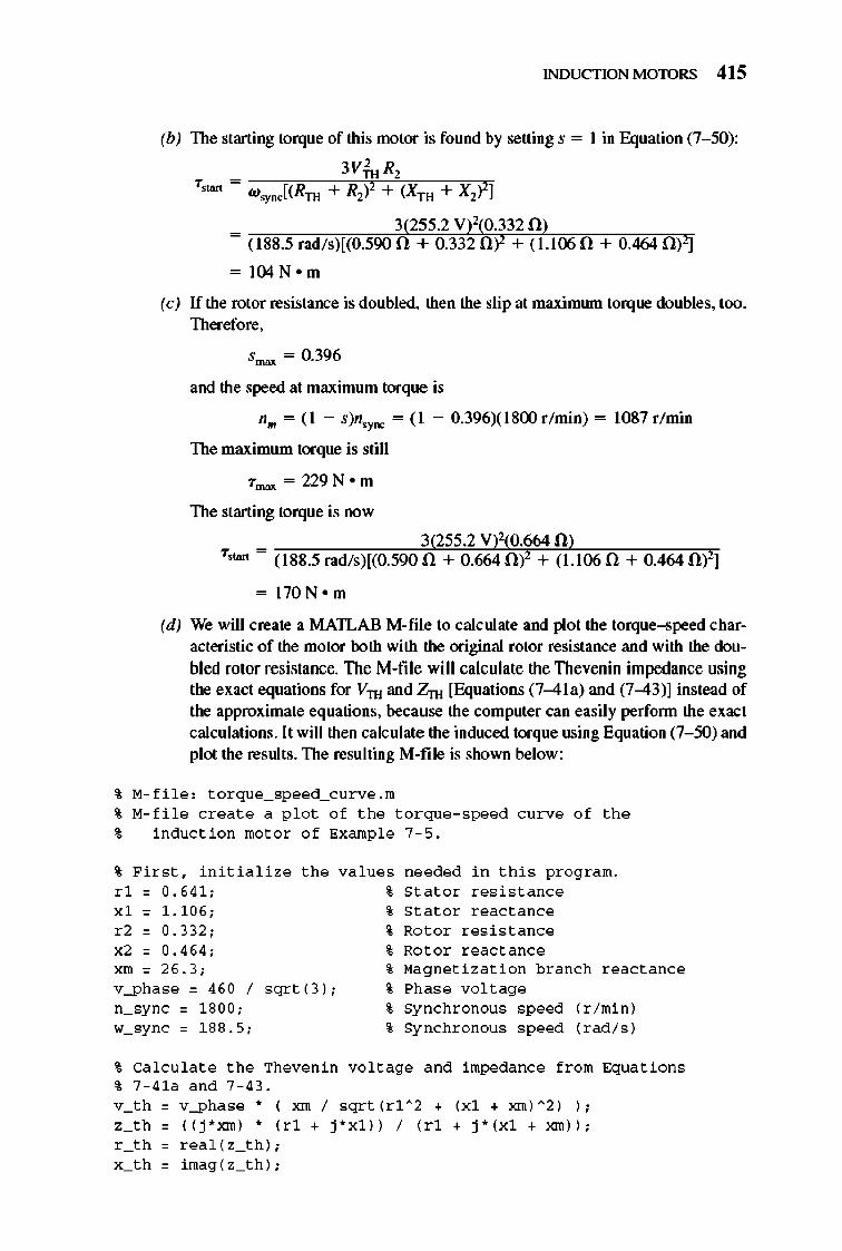
INDUCTION MOTORS 415
(b) The starting torque of this motor is found by setting s = I in Equation (7- 50):
3ViHRl T,tan= W I(R +R)'+(X +X)'l
'YDC TH 2 rn 2
_ 3(255.2 V)1:0.3320) - (188.5 rad/s)[(0.590 0 + 0.3320)2 + (1.I()5 0 + 0.464 0)2]
= I04N om
(c) If the rotor resistance is doubled, then the slip at maximwn torque doubles, too. Therefore,
Smax = 0.396
and the speed at maximum torque is
nm = (I - s)n.yDC = (1 - 0.396)(1800 r /min) = 1087 r /min
The maximum torque is still
Trrw; = 229 Nom
The starting torque is now
_ 3(255.2 V)2(0.664 0) Tot"" - (188.5 rad/s)[(0.590.n + 0.6640)2 + (1.106 0 + 0.4640)2]
= 170 Nom
(d) We will create a MATLAB M-file to calculate and plot the torque-speed characteristic of the motor both with the original rotor resistance and with the doubled rotor resistance. The M-file will calculate the Thevenin impedance using the exact equations for Vlll and Zrn [Equations (7-4la) and (7-43)] instead of the approximate equations, because the computer can easily perfonn the exact calculations. It will then calculate the induced torque using Equation (7- 50) and plot the results. The resulting M-file is shown below:
% M-file, t o rque_speed_curve.m
% M-file c reate a p l o t o f the t o rque- speed c u rve o f the % ind u c tio n mo t o r o f Exampl e 7 - 5.
% Fir s t , initia liz e the va lues needed in thi s program. rl = 0.641; % Stat o r res i s tance xl = 1.10 6; % Stat o r r eactance r2 = 0.332; % Rotor r es i s tance x2 = 0.464, xm = 26.3, v-ph ase = 460 / sqrt (3) , n_syn c = 1800, w_syn c = 188.5;
% Ca l c ulate the Thevenin % 7 - 41a a n d 7 - 43. v_th 0 v-ph ase • ( = I
% Rotor r eactance % Magne tizati o n bran c h r eactance % Phase volt age % Syn chro n ou s speed ( r / min ) % Sy n chro n ou s speed ( rad /s)
vo lt age and impedance fro m Equat i ons
sqrt (rl " 2 • (xl • xm )" 2 ) I ; , " 0 ( ( j*xm ) • (d • - j*xl ) ) I (r1 • j * (xl • xm ) ) ,
r -" 0 real ( z_ th ) ,
x -" 0 imag ( z_ th ) ,
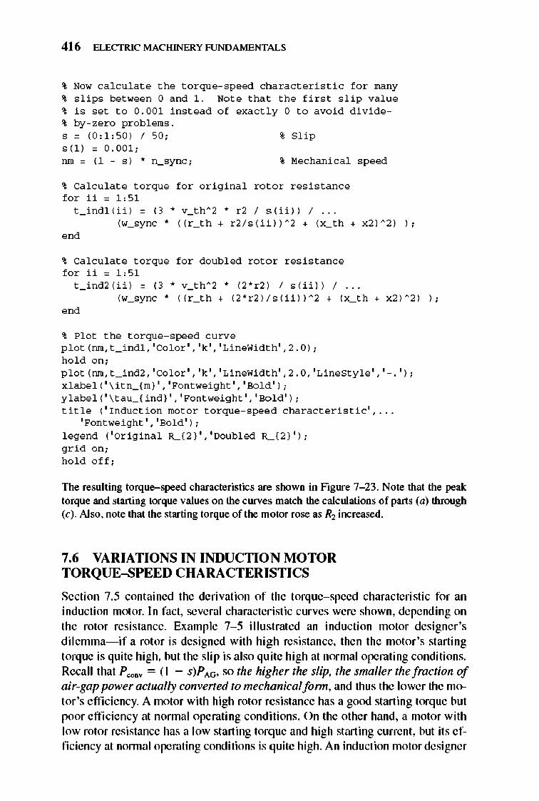
416 ELECTRIC MACHINERY RJNDAMENTALS
~ Now ca l c ulate the t o rqu e- speed chara c teri s ti c f or many ~ s lips between 0 and 1. Not e that the fir s t s lip value ~ i s set t o 0.00 1 ins tead of exact l y 0 to avoi d d i v i de~ by-zero probl ems. s = (0 ,1,50 ) / 50; s( l ) = 0 . 001;
% Slip
run = (1 - s) * n_sync; % Mech a ni cal speed
~ Ca l c ulate t o rque f o r o riginal rotor r es i s tance f o r ii = 1,51
t _ indl (U ) = (3 * v_th" 2 * r2 / s (U )) / ... (w_sync * (( r _ th + r2 / s (ii )) " 2 + (x_th + x2 ) " 2 ) ) ;
ond
~ Ca l c ulate t o rque f o r doubl ed roto r r es i s tance f o r ii = 1,51
t _ ind2 (U ) = (3 * v_th" 2 * (2*r2 ) / s( U )) / ... (w_sync " (( r _ th + (2*r2 )/s( U ))" 2 + (x_th + x2 )" 2 ) ) ;
ond
~ Plo t the t o rque- speed c urve p l o t (run , t _ indl, ' Co l or' , 'k' , 'LineWi dth ' ,2 . 0); h o l d on; p l o t (nm , t _ ind2, ' Co l or', 'k' , 'LineWi dth ' ,2.0, 'LineStyl e ' , '-. ' ) ; x l abe l ( ' \ itn_( m)' , 'Pontwei ght' , 'Bo l d ' ) ; y l abe l ( ' \ tau_( ind) ' , 'Pontwei ght' , 'Bo l d ' ) ; title ( 'Ind uc tio n mo t o r t o rque- speed c harac teri s ti c ' , ...
'Pontwe i ght' , 'Bo l d ' ) ; l egend ( ' Original R_(2) ' , 'Doubled R_(2} ' ) ; gri d on; h o l d o ff ;
The resulting torque-speed characteristics are shown in Figure 7- 23 . Note that the peak torque and starting torque values on the curves match the calculations of parts (a) through (c). Also. note that the starting torque of the motor rose as R2 increased.
7.6 VARIATIONS IN INDUCTION MOTOR TORQUE-SPEED CHARACTERISTICS
Section 7.5 contained the derivation of the torque-speed characteristic for an induction motor. In fact, several characteristic curves were shown, depending on the rotor resistance. Example 7- 5 illustrated an inducti on motor designer 's dilemma-if a rotor is designed with high resistance, then the motor 's starting torque is quite high, but the slip is also quite high at normal operating conditions. Recall that P C<X1V = ( I - s)p AG, so the higher the slip, the smaller the fraction of air-gap power actually converted to mechanicalfonn, and thus the lower the motor 's e ffi ciency. A motor with high rotor resistance has a good starting torque but poor e ffi ciency at nonnal operating conditions. On the other hand, a motor with low rotor resistance has a low starting torque and high starting current, but its e ffi ciency at nonnal operating conditions is quite high. An induction motor designer
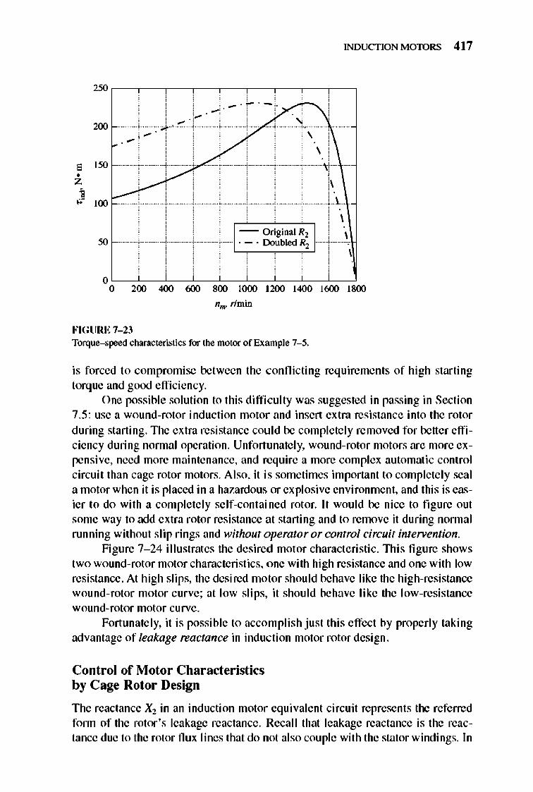
INDUCTION MOTORS 41 7
2'0 ,--,---,--,---,--,---,--,---,--,
.-200
\ .-\
, I'" • z '0---- , , " ." 100 r-
FIGURE 7-23
-- Original R2 . - . Doubled R2
nO. rlmin
Torque-speed characteristics for the motor of Example 7- 5.
, ,
is forced to compromise between the conflicting req uirements of high starting torque and good efficiency.
One possible solution to this difficulty was suggested in passing in Section 7.5: use a wound-rotor induction motor and insert extra resistance into the rotor during starting. 1lle extra resistance could be complete ly removed for better efficiency during nonnal operation. Unfort unate ly, wound-rotor motors are more expensive, need more maintenance, and require a more complex automatic control circuit than cage rotor motors. Also, it is sometimes important to completely seal a motor when it is placed in a hazardous or explosive environment, and this is easier to do with a completely self-contained rotor. It would be nice to fi gure out some way to add extra rotor resistance at starting and to remove it during normal running without slip rings and without operator or control circuit inteTYention.
Figure 7- 24 illustrates the desired motor characteristic. 1llis fi gure shows two wound-rotor motor characteristics, one with high resistance and one with low resistance. At high slips, the desired motor should behave like the high-resistance wound-rotor motor curve; at low slips, it should behave like the low-resistance wound-rotor motor curve.
Fortunate ly, it is possible to accomplish just this effect by properly taking advantage of leakage reactance in inducti on motor rotor design.
Control of Motor Char acteristics by Cage Rotor Design
The reactance Xl in an induction motor equivalent circuit represents the referred fonn of the rotor's leakage reactance. Recall that leakage reactance is the reactance due to the rotor nux lines that do not also couple with the stator windings. In
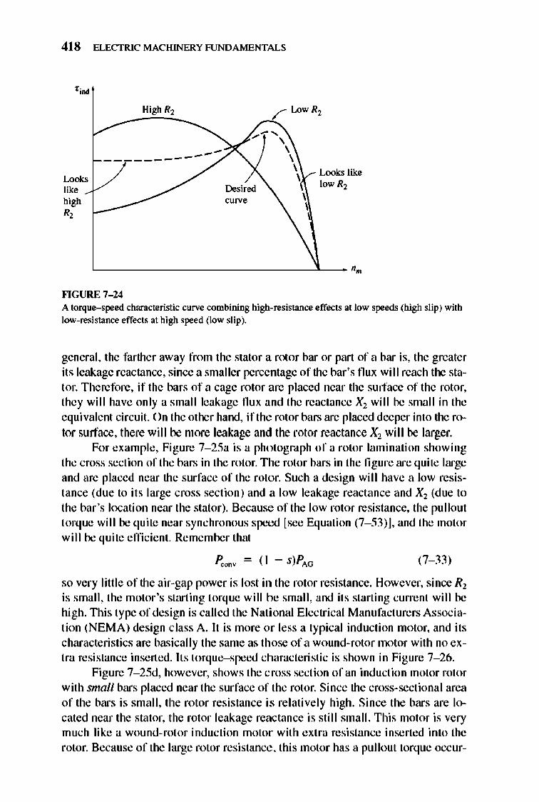
418 ELECTRIC MACHINERY RJNDAMENTALS
Loo" like h.igh. R,
------------Desired curve
Looks like lowR2
'---------------------------------'---- '. ""GURE 7-14 A torque-speed characteristic curve combining high-resistance effects at low speeds (high slip) with low-resistance effects at high speed (low slip).
general, the farther away from the stator a rotor bar or part of a bar is, the greater its leakage reactance, since a smaller percentage of the bar's flux will reach the stator. Therefore , if the bars of a cage rotor are placed near the surface of the rotor, they will have only a small leakage flux and the reactance Xl will be small in the equivalent circuit. On the other hand, if the rotor bars are placed deeper into the rotor surface, there will be more leakage and the rotor reactance X2 will be larger.
For example, Figure 7- 25a is a photograph of a rotor lamination showing the cross section of the bars in the rotor. The rotor bars in the fi gure are quite large and are placed near the surface of the rotor. Such a design will have a low resistance (due to its large cross section) and a low leakage reactance and Xl (due to the bar's location near the stator). Because of the low rotor resistance, the pullout torque will be quite near synchronous speed [see Equation (7- 53)], and the motor will be quite efficient. Remember that
P.,oo¥ = ( I - s)PAG (7- 33)
so very little of the air-gap power is lost in the rotor resistance. However, since Rl is small, the motor 's starting torque will be small, and its starting current will be high. TIli s type of design is called the National Electrical Manufacturers Association (NEMA) design class A. It is more or less a typical induction motor, and its characteristics are basically the same as th ose of a wound-rotor motor with no extra resistance inserted. Its torque-speed characteristic is shown in Figure 7- 26.
Figure 7- 25d, however, shows the cross section of an induction motor rotor with smnll bars placed near the surface of the rotor. Since the cross-sectional area of the bars is small , the rotor resistance is relatively high. Since the bars are located near the stator, the rotor leakage reactance is still small. This motor is very much like a wound-rot or inducti on motor with extra resistance inserted into the rotor. Because of the large rotor resistance, this motor has a pullout torque occur-
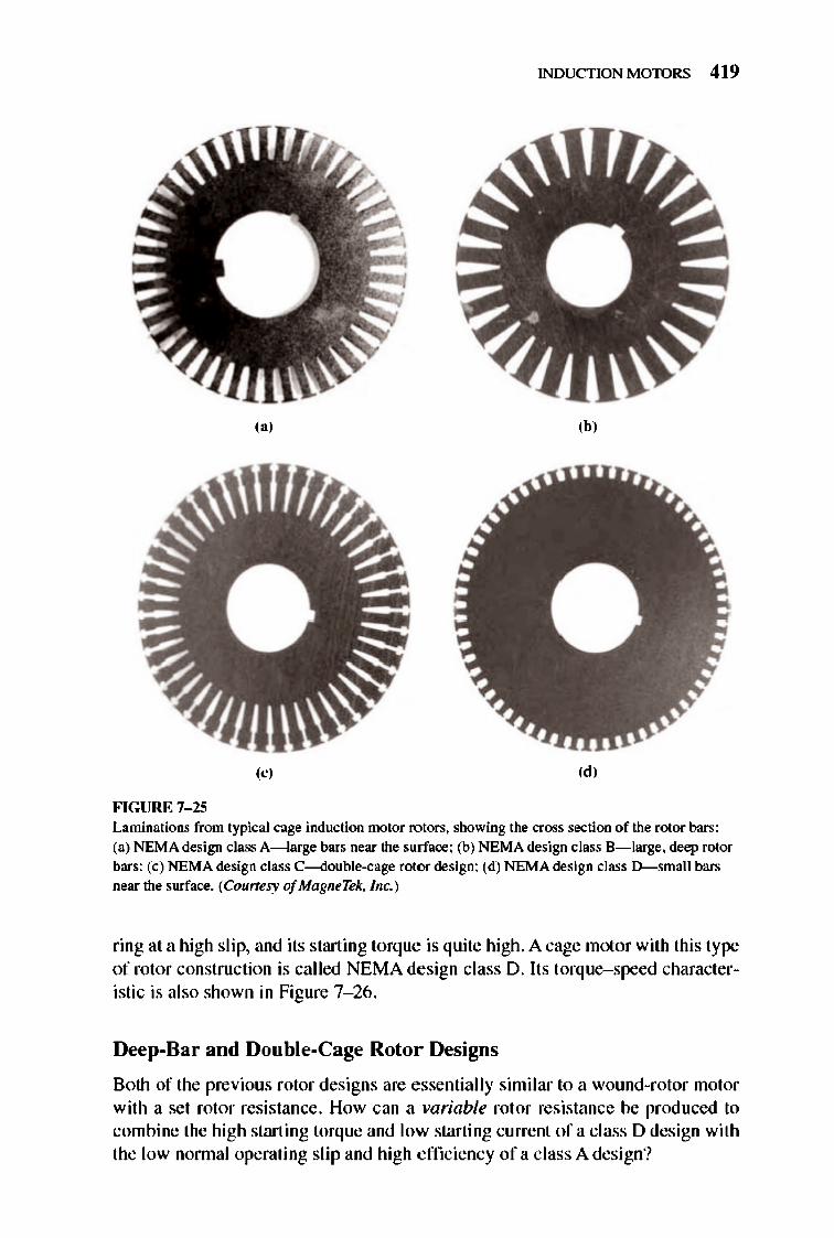
INDUCTION MOTORS 41 9
,,' ,b,
'e' ,d, FIGURE 7-1.5 Laminations from typical cage induction motor rotors. showing the cross section of the rotor bars:
(a) NEMA design class A- large bars near the surface; (b) NEMA design class B- large, deep rotor bars; (e) NEMA design class C--double-cage rotor design; (d) NEMA desisn class D-small bars near the surface. (Counesy of MagneTek, Inc. )
ring at a high slip, and its starting torque is quite high. A cage motor with this type of rotor construction is called NEMA design class D. Its torque-speed characteristic is also shown in Figure 7- 26 .
Deep-Bar and Double-Cage Rotor Designs
Both of the previous rotor designs are essentially similar to a wound-rotor motor with a sct rotor resistance . How can a variable rotor resistance be produced to combine the high starting torque and low starting current of a class 0 design with the low nonnal operating slip and high efficiency of a class A design?
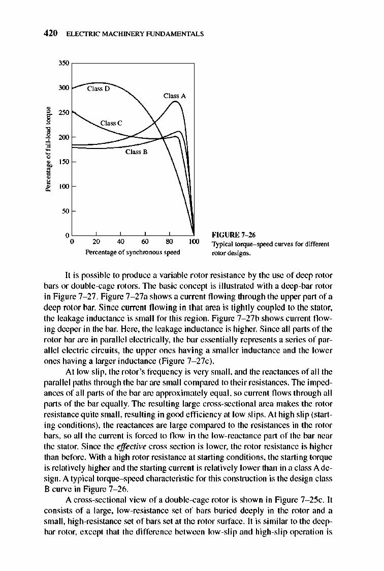
420 ELECTRIC MACHINERY RJNDAMENTALS
o~~~~~~--~--~ o 20 40 60 80 100
Percentage of synchronous speed
FIGURE 7-16 Typical torque-speed curves for different rotor designs.
Ii is possible to produce a variable rotor resistance by the use of deep rotor bars or double-cage rotors. TIle basic concept is illustrated with a deep-bar rotor in Figure 7-27. Figure 7-27a shows a current flowing through the upper part ofa deep rotor bar. Since current fl owing in that area is tightly coupled to the stator, the leakage inductance is small for this region. Figure 7-27b shows current fl owing deeper in the bar. Here, the leakage inductance is higher. Since all parts of the rotor bar are in parallel e lectrically, the bar essentially represents a series of parallel electric circuits, the upper ones having a smaller inductance and the lower ones having a larger inductance (Figure 7- 27c) .
At low slip, the rotor's frequency is very small, and the reactances of all the parallel paths through the bar are small co mpared to their resistances. The impedances of all parts of the bar are approximately equal, so current flows through all parts of the bar eq ually. The resulting large cross-sectional area makes the rotor resistance quite small, resulting in goOO efficiency at low slips. At high slip (starting conditions), the reactances are large compared to the resistances in the rotor bars, so all the current is forced to flow in the low-reactance part of the bar near the stator. Since the effective cross section is lower, the rotor resistance is higher than before. With a high rotor resistance at starting conditions, the starting torque is relatively higher and the starting current is relatively lower than in a class A design. A typical torque-speed characteristic for this construction is the design class B curve in Figure 7- 26.
A cross-sectional view of a double-cage rotor is shown in Figure 7- 25c. Ii consists of a large, low-resistance set of bars buried deeply in the rotor and a small, high-resistance set of bars set at the rotor surface . Ii is similar to the deepbar rotor, except that the difference between low-slip and high-slip operation is
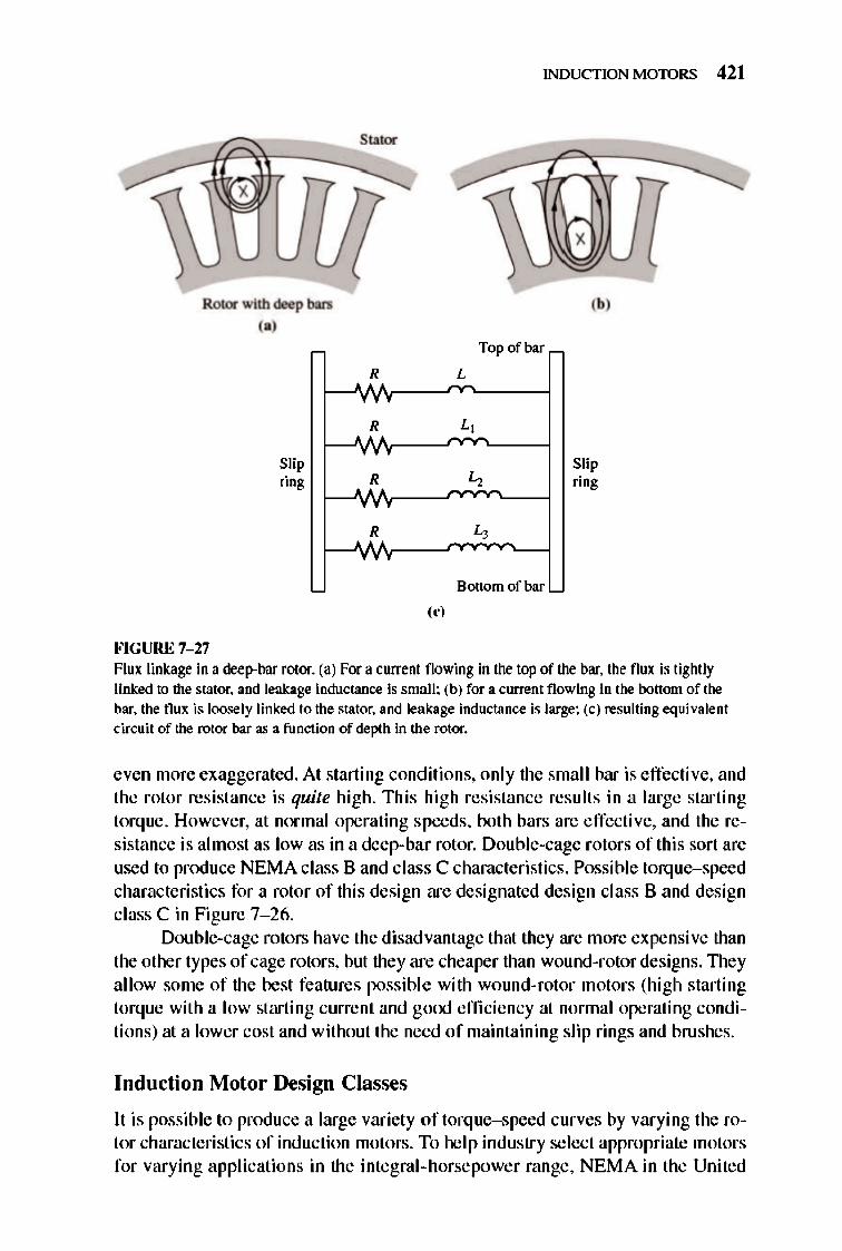
Stator
a--:::::------
Rotor with deep bars
"j
FIGURE 7-27
Slip ring
,f R
R
R
, 'j
INDUCTION MOTORS 421
Top of bar
L
L,
L,
L,
Bottom of bar
'bj
Slip ring
Flux linkage in a deep-bar rotor. (a) For a current flowing in the top of the bar. the flux is tightly linked to the stator. and leakage inductance is small; (b) for a current flowing in the bottom of the bar. the flux is loosely linked to the stator. and leakage inductance is large; (c) resulting equivalent circuit of the rotor bar as a function of depth in the rotor.
even more exaggerated. At starting conditions, only the small bar is effective, and the rotor resistance is quite high. This high resistance results in a large starting torque. However, at normal operating speeds, both bars are effective, and the resistance is almost as low as in a deep-bar rotor. Double-cage rotors of this sort are used to produce NEMA class 8 and class C characteristics. Possible torque-speed characteristics for a rotor of this design are designated design class 8 and design class C in Figure 7- 26.
Double-cage rotors have the disadvantage that they are more expensive than the other types of cage rotors, but they are cheaper than wound-rotor designs. TIley allow some of the best features possible with wound-rotor motors (high starting torque with a low starting current and go<Xl effi ciency at nonnal operating conditions) at a lower cost and without the need of maintaining slip rings and brushes.
Induction M otor Design C lasses
It is possible to produce a large variety oftorque-speed curves by varying the rotor characteristics of induction motors. To help industry select appropriate motors for varying applications in the integral-horsepower range, NEMA in the United

422 ELECTRIC MACHINERY RJNDAMENTALS
States and the International Electrotechni cal Commission (IEC) in Europe have defined a series of standard designs with different torque- speed curves . TIlese standard designs are referred to as design classes, and an individual motor may be referred to as a design class X motor. It is these NEMA and IEC design classes that were referred to earlier. Figure 7-26 shows typical torque-speed curves for the four standard NEMA design classes. The characteristic features of each standard design class are given below.
DESIGN CLASS A. Design class A motors are the standard motor design, with a normal starting torque, a nonnal starting current, and low slip. TIle full-load slip of design A motors must be less than 5 percent and must be less than that of a design B motor of equivalent rating. TIle pullout torque is 200 to 300 percent of the full-load torque and occurs at a low slip (less than 20 percent). TIle starting torq ue of thi s design is at least the rated torque for larger motors and is 200 percent or more of the rated torque for smaller motors. TIle principal problem with this design class is its extremely high inrush current on starting. Current fl ows at starting are typically 500 to 800 percent of the rated current. In sizes above about 7.5 hp, some form of reduced-voltage starting mu st be used with these motors to prevent voltage dip problems on starting in the power system they are connected to. In the past, design class A motors were the standard design for most applications below 7.5 hp and above about 200 hp, but they have largely been replaced by design class 8 motors in recent years. Typical applications for these motors are driving fans, blowers, pumps, lathes, and other machine tools.
DESIGN CLASS B. Design class 8 motors have a nonnal starting torque, a lower starting current, and low slip. TIlis motor produces about the same starting torque as the class A motor with about 25 percent less current. TIle pullout torque is greater than or equal to 200 percent of the rated load torque, but less than that of the class A design because of the increased rotor reactance. Rotor slip is still relatively low (less than 5 percent) at full load. Applications are similar to those for design A, but design B is preferred because of its lower starting-current requirements. Design class 8 motors have largely replaced design class A motors in new installations.
DESIGN CLASS C. Design class C motors have a high starting torque with low starting currents and low slip (less than 5 percent) at full load. TIle pullout torque is slightly lower than that for class A motors, while the starting torque is up to 250 percent of the full-load torque. TIlese motors are built from double-cage rotors, so they are more expensive than motors in the previous classes. They are used for high-starting-torque loads, such as loaded pumps, compressors, and conveyors.
DESIGN CLASS D. Design class D motors have a very high starting torque (275 percent or more of the rated torque) and a low starting current, but they also have a high slip at full load. TIley are essentially ordinary class A induction motors, but with the rotor bars made smaller and with a higher-resistance material. The high rotor resistance shifts the peak torque to a very low speed . It is even possible for
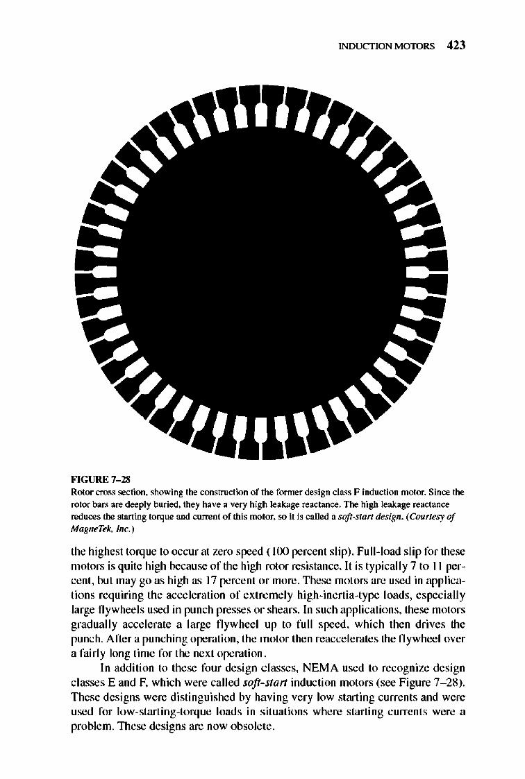
INDUCTION MOTORS 423
FIGURE 7-18 Rotor cross section. showing the construction of the former design class F induction motor. Since the rotor bars are deeply buried. they have a very high leakage reactance. The high leakage reactance reduces the starting torque and current of this motor. so it is called a soft-start design. (Courtesy of MagneTek, Inc.)
the highest torque to occur at zero speed ( 100 percent sli p). Full-load sli p for these motors is quite high because of the high rotor resistance. It is typicall y7 to II percent. but may go as high as 17 percent or more. These motors are used in applications requiring the acceleration of extremely high-inertia-type loads, especially large flywheels used in punch presses or shears. In such applications, these motors gradually accelerate a large fl ywheel up to full speed, which then drives the punch. After a punching operation, the motor then reaccelerates the flywheel over a fairly long time for the next operation.
In addition to these four design classes, NEMA used to recognize design classes E and F, which were called soft-start induction motors (see Figure 7- 28). These designs were distinguished by having very low starting currents and were used for low-starling-torque loads in situations where starting currents were a problem. 1l1ese designs are now obsolete.
424 ELECTRIC MACHINERY RJNDAMENTALS
Example 7-6. A460-V. 30-hp. 60-Hz. four-pole. V-connected induction motor has two possible rotor designs. a single-cage rotor and a double-cage rotor. (The stator is identical for either rotor design.) The motor with the single-cage rotor may be modeled by the following impedances in ohms per phase referred to the stator circuit:
Rl = 0.641 0 Xl = 0.750 0
Rl = 0.3000 Xl = 0.5000 XM = 26.3 0
The motor with the double-cage rotor may be modeled as a tightly coupled. highresistance outer cage in parallel with a loosely coupled. low-resistance inner cage (similar to the structure of Figure 7- 25c). The stator and magnetization resistance and reactances will be identical with those in the single-cage design.
The resistance and reactance of the rotor outer cage are:
Ru, = 3.200 0 Xu, = 0.500 0
Note that the resistance is high because the outer bar has a small cross section. while the reactance is the same as the reactance of the single-cage rotor. since the outer cage is very close to the stator. and the leakage reactance is small.
The resistance and reactance of the inner cage are
Ru = 0.400 0 Xu = 3.300 0
Here the resistance is low because the bars have a large cross-sectional area. but the leakage reactance is quite high.
Calculate the torque-speed characteristics associated with the two rotor designs. How do they compare?
Solutio" The torque-speed characteristic of the motor with the single-cage rotor can be calculated in exactly the same manner as Example 7- 5. The torque-speed characteristic of the motor with the double-cage rotor can also be calculated in the same fashion. except that at each slip the rotor resistance and reactance will be the parallel combination of the impedances of the iIiller and outer cages. At low slips. the rotor reactance will be relatively lUlimportant. and the large inner cage will playa major part in the machine's operation. At high slips. the high reactance of the inner cage almost removes it from the circuit.
A MATLAB M-ftle to calculate and plot the two torque-speed characteristics is shown below:
~ M-file: t o rque_speed_2. m ~ M-file c reate and p l o t of the torque - speed ~ i nduc t i o n mo t o r wi th a doubl e - cage rotor
curve o f an des i gn.
~ Fir s t , i nit i a li ze rl = 0.64 1;
" 0 0.750;
e' 0 0.300;
e2i 0 0.400;
e' o 0 3.200;
" 0 0.500;
the va l u es n eeded i n thi s program. % Stato r r es i s tance
• Stato r r eactance
• Rotor r es i s tance foe s i ngl e -
• cage motor
• Rotor r es i s tance f oe i nner
• cage of doubl e - cage mo t o r
• Rotor r es i s tance foe outer
• cage of doubl e - cage mo t o r
• Rotor r eactance foe s i ngl e -
• cage motor
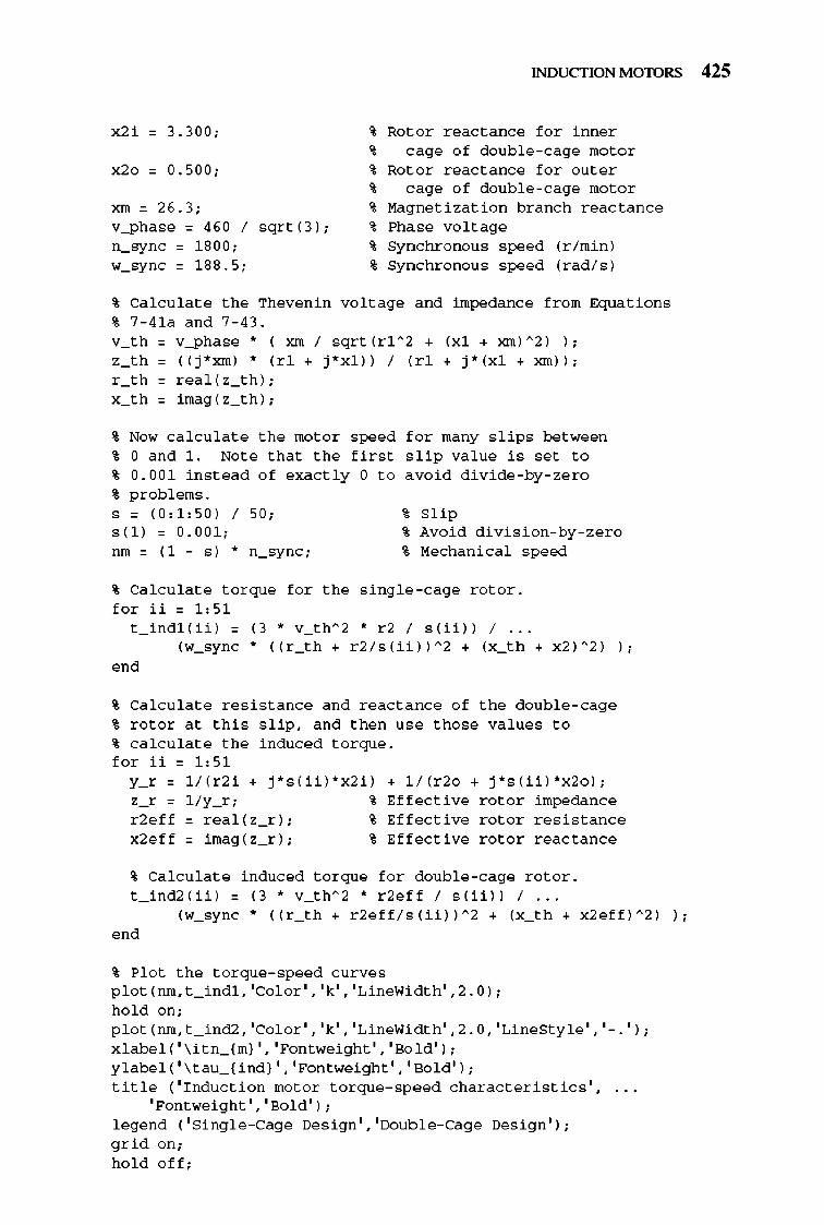
x2 i = 3.300;
x20 = 0.500;
xm = 26.3; v-ph ase = 460 / sqrt (3) ; n_syn c = 1 800; w_syn c = 1 88.5;
% Ca l c ula t e the Thevenin % 7 - 4 1a a n d 7 - 43. v_th 0 v-ph ase • ( = I
INDUCTION MOTORS 425
~ Ro t o r r eact a nce f o r inne r ~ c age o f dou b l e - cage mo t o r ~ Ro t o r r eact a nce f o r o ut e r ~ c age o f dou b l e - cage mo t o r ~ Magn e ti zatio n b r a n c h r eac t a n ce ~ Phase vo lt age ~ Syn c hro n o u s speed (r / min ) % Syn c hro n o u s speed (r ad / s)
vo lt age a n d impedance fro m Eq u a tio n s
sqrt (rl " 2 • (x l • xm ) " 2 ) I ; , " 0 ( ( j *xm ) • (d • - j *xl ) ) I (r1 • j * (x l • xm ) ) ; r -" 0 r ea l ( z_ th ) ; x -" 0 imag ( z_ th ) ;
% Now ca l c ula t e the mo t o r speed f o r ma ny s lips bet ween % 0 a n d 1. No t e tha t the fir s t s lip va lue i s set t o % 0.00 1 in s t ead o f exactly 0 t o avo i d d i v i de - by- ze r o % p r obl e ms.
% Slip s = ( 0, 1 ,50 ) / 50; s( l ) = 0.00 1 ; % Avoi d d i v i s i o n-by- zer o run = ( 1 - s) * n_sync; % Mech a ni cal speed
% Ca l c ula t e t o r q u e f o r the s ing l e - cage r o t o r . f o r ii = 1 ,5 1
t _ ind l ( ii ) = (3 * v_th" 2 * r 2 / s( ii )) / ... (w_syn c * (( r _ th + r 2 / s( ii ))" 2 + (x_ th + x2 )" 2 ) ) ;
e o d
% Ca l c ula t e r es i s t a nce a n d r eact a nce o f the dou b l e - cage % r o t o r a t thi s s lip, a n d the n u se those va lues t o % ca l c ula t e the ind uced t o r q ue. f o r ii = 1 :5 1
L r 0 1 / ( r 2 i • j *s ( ii ) *x2 i ) • 1 / (r 20 • j *s (ii ) *x2o ) ; , - r 0 l / y_r ; • Eff ective r o t o r impedan ce r 2e ff 0 r ea l ( z_ r ) ; • Eff ective r o t o r r es i s t a n ce x2e ff 0 imag ( z_ r ) ; • Eff ective r o t o r r eac t a n ce
~ Ca l c ula t e ind uced t o r q u e f o r dou b l e - cage r o t o r . t _ ind2 ( ii ) = (3 * v_th" 2 * r 2e ff / s( ii )) / ...
(w_syn c * (( r _ th + r 2e f f/s (ii ))" 2 + (x_ th + x2eff )" 2 ) ) ;
e o d
% Plo t the t o r q u e - speed c urves p l o t ( run , t _ ind l , ' Col or' , 'k' , 'LineWi d th' ,2.0 ) ;
h o l d o n ; p l o t ( run , t _ ind2, ' Col or' , 'k' , 'LineWi d th' ,2.0, 'LineSt y l e ' , '- . ' ) ; x l abe l ( ' \ itn_ (m} ' , 'Fontwei ght' , 'Bo l d ' ) ; y l abe l ( ' \ t a u _ ( ind} ' , 'Fontwei ght' , 'Bo l d ' ) ; title ( 'Ind u c ti o n mo t o r t o r q u e - spe ed c h a r ac t e ri s tics ' ,
'Po ntwei ght' , 'Bo l d ' ) ; l egen d ( ' Sing l e - Cage Des i g n' , ' Dou b l e - Cage Des i g n' ) ;
g rid o n ; h o l d o ff ;
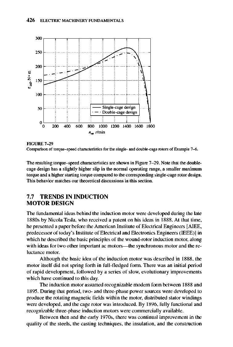
426 ELECTRIC MACHINERY RJNDAMENTALS
300
250 ~> . -. , 200
E • Z 150 ]
./" ~
/ ;? 1
-100
50 Single-cage design .- . Double-cage design
o o 200 400 600 800 1000 1200 1400 1600 1800
n",. rlmin
""GURE 7- 29 Comparison of torque-speed characteristics for the single- and double-cage rotors of Example 7-6.
The resulting torque-speed characteristics are shown in Figure 7- 29. Note Ihal the doublecage design has a slightly higher slip in the normal operating range, a smaller maximum torque and a higher starting torque compared to Ihe corresponding single-cage rotor design. This behavior matches our theoretical discussions in this section.
7.7 TRENDS IN INDUCTION MOTOR DESIGN
TIle fundamental ideas behind the induction motor were deve loped during the late 1880s by Nicola Tesla, who received a patent on his ideas in 1888. At that time, he presented a paper before the American lnstitute of Electrical Engineers [AlEE, predecessor of today's Institute of Electri cal and Electronics Engineers (IEEE)] in which he described the basic principles of the wound-rotor induction motor, along with ideas for two other important ac motors-the synchronous motor and the reluctance motor.
Although the basic idea of the induction motor was described in 1888, the motor itself did not spring forth in full-fledged fonn. There was an initial period of rapid development, fo ll owed by a series of slow, evoluti onary improveme nt s which have continued to this day.
TIle induction motor assumed recog nizable modem form between 1888 and 1895. During that period, two- and three-phase power sources were deve loped to produce the rotating magnetic fields within the motor, distributed stator windings were developed, and the cage rotor was introduced. By 1896, full y functional and recognizable three-phase induction motors were commercially available .
Between then and the early 1970s, there was continual improvement in the quality of the steels, the casting techniques, the insulation, and the construction
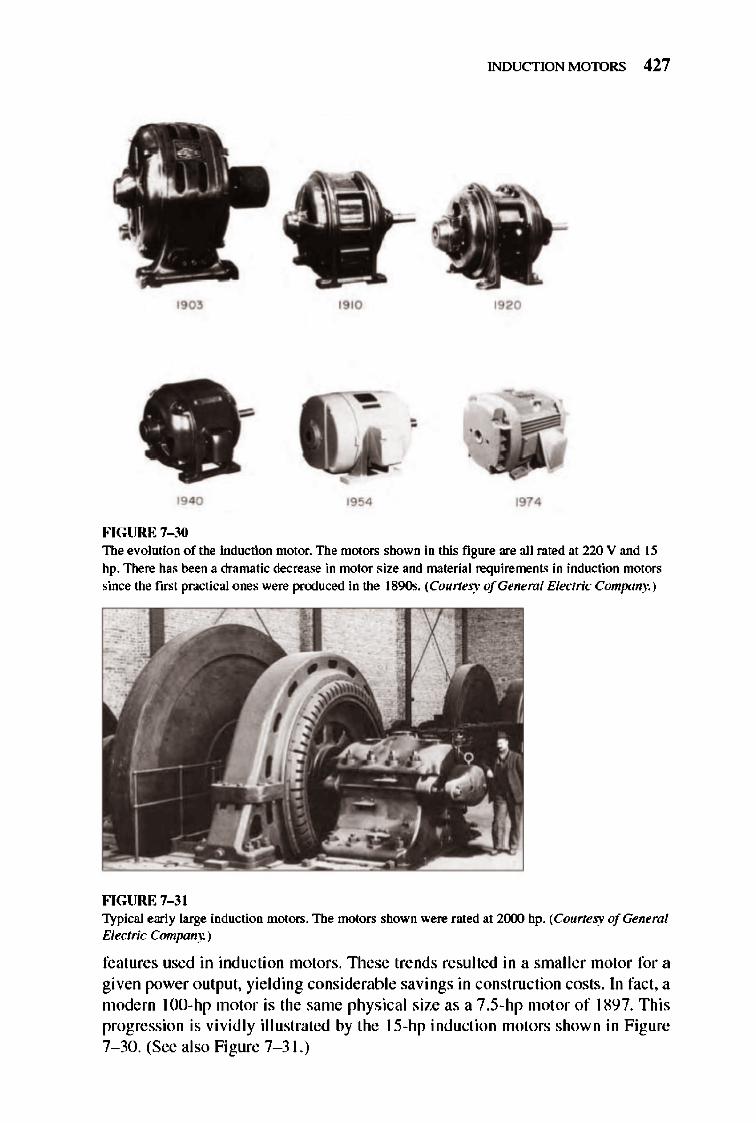
INDUCTION MOTORS 427
1903 1910 1920
,
1940 19!54 1974
FIGURE 7-30 The evolution of the induction motor. The motors shown in this figure are all rated at 220 V and 15
hp. There has been a dramatic decrease in motor size and material requirements in induction motors since the first practical ones were produced in the 1890s. (Courtesy ofGeneml Electric Company.)
FIGURE 7-31 Typical early large induction motors. The motors shown were rated at 2(xx) hp. (Courtesy ofGeneml Electric Company.)
features used in inducti on motors. 1l1ese trends resulted in a smaller motor for a given power output, yielding considerable savings in construction costs. In fact, a modern 100-hp motor is the same physical size as a 7.S-hp motor of 1897. This progression is vividly illustrated by the IS-hp induction motors shown in Figure 7- 30. (See also Figure 7- 3 1.)
428 ELECTRIC MACHINERY RJNDAMENTALS
However, these improvements in induction motor design did not necessarily lead to improvements in motor operating effi ciency. The major design effort was directed toward reducing the initial materials cost of the machines, not toward increasing their efficiency. The design effort was oriented in that direction because e lectri city was so inexpensive, making the up-front cost of a motor the principal criterion used by purchasers in its selection.
Since the price of oil began it s spectacular climb in 1973, the lifetime operating cost of machines has become more and more important, and the initial installation cost has become relatively less important. As a result of these trends, new emphasis has been placed on motor e ffi ciency both by designers and by end users of the machines.
New lines of high-effi ciency induction motors are now being produced by all major manufacturers, and they are fanning an ever-increasing share of the induction motor market. Several techniques are used to improve the efficiency of these motors compared to the traditional standard-efficiency designs. Among these techniques are
I. More copper is used in the stator windings to red uce copper losses.
2. The rotor and stator core length is increased to reduce the magnetic nux density in the air gap of the machine. This reduces the magnetic saturation of the machine, decreasing core losses.
3. More steel is used in the stator of the machine, al lowing a greater amount of heat transfer out of the motor and reducing its operating temperature. The rotor's fan is then redesigned to reduce windage losses.
4. The stee l used in the stat or is a special high-grade electrical steel with low hysteresis losses.
5. The steel is made of an especially thin gauge (i.e. , the laminations are very close together), and the stee l has a very high internal resistivity. Both effects tend to reduce the eddy current losses in the motor.
6. The rotor is carefull y machined to produce a unifonn air gap, reducing the stray load losses in the motor.
In addition to the general techniques described above, each manufacturer has his own unique approaches to improving motor efficiency. A typical higheffi ciency induction motor is shown in Figure 7- 32.
To aid in the comparison of motor efficiencies, NEMA has adopted a standard technique for measuring motor e ffi c iency based on Method 8 of the IEEE Standard 11 2, Test Procedure for Polyphase Induction Motors and Generators. NEMA has also introduced a rating call ed NEMA nominal efficiency, which appears on the nameplates of design class A, 8 , and C motors. The nominal e fficiency identifies the average efficiency of a large number of motors of a given model, and it also guarantees a certain minimum effi ciency for that type of motor. The standard NEMA nominal e ffi ciencies are shown in Figure 7- 33.
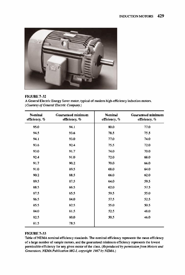
INDUCTION MOTORS 429
FIGURE 7-32 A General Electric Energy Saver motor. typical of modem high-efficiency induction motors. (Courtesy ofGeneml Electric Company.)
Nomin al Guanmh.'t!d minimum Nomina l Guara nte ... >d minimum effic iency, o/~ efficiency, % efficiency, % efficiency, '7~
95.0 94.1 SO.O 77.0
94.5 93.6 78.5 75.5
94.1 93.0 77.0 74.0
93.6 92.4 75.5 72.0
93.0 91.7 74.0 70.0
92.4 91.0 72.0 68.0
91.7 90.2 70.0 66.0
91.0 89.5 68.0 64.0
90.2 88.5 66.0 62.0
89.5 87.5 64.0 59.5
88.5 86.5 62.0 57.5
87.5 85.5 59.5 55.0
86.5 84.0 57.5 52.5
85.5 82.5 55.0 50.'
84.0 81.5 52.5 48.0
82.5 80.0 50.' 46.0
81.5 78.5
FIGURE 7-33 Table of NEMA nominal efficiency standards. The nominal efficiency represents the mean efficiency of a large number of sample motors. and the 8uar:mteed minimum efficiency represents the lowest permissible efficiency for any given motor of the class. (Reproduced by permission from Motors and GenemfOrs, NEMA Publication MG-I. copyright 1987 by NEMA.)
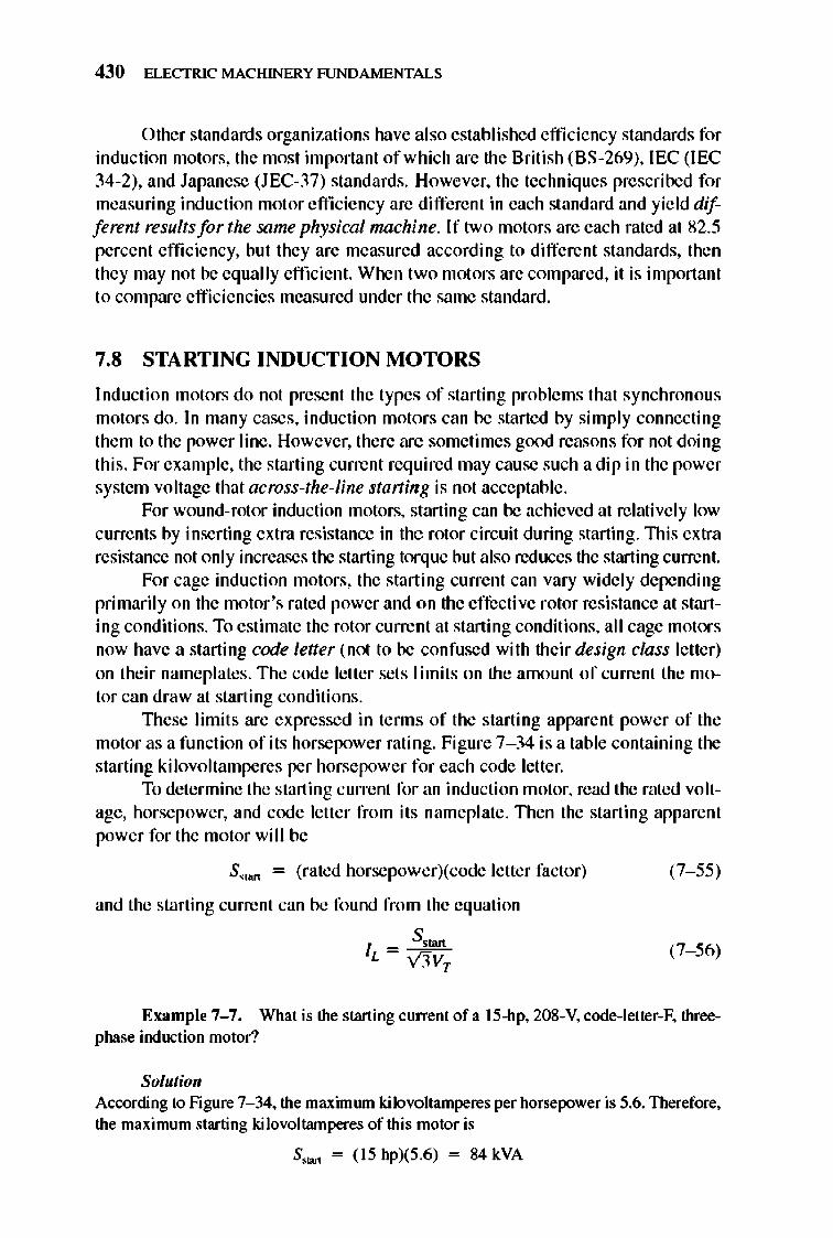
430 ELECTRIC MACHINERY RJNDAMENTALS
Other standards organizations have also established efficiency standards for induction motors, the most important of which are the 8ritish (8S-269), IEC (IEC 34-2), and Japanese (JEC-37) standards. However, the techniques prescribed for measuring induction motor e fficiency are different in each standard and yield different results for the same physical machine. If two motors are each rated at 82.5 percent efficiency, but they are measured according to different standards, then they may not be equally effi cient. When two motors are compared, it is important to compare efficiencies measured under the same standard.
7.8 STARTING INDUCTION MOTORS
Induction motors do not present the types of starting problems that synchronous motors do. In many cases, induction motors can be started by simply connecting them to the power line . However, there are sometimes good reasons for not doing this. For example, the starting current requi red may cause such a dip in the power system voltage that across-the-line staning is not acceptable .
For wound-rotor induction motors, starting can be achieved at relatively low currents by inserting extra resistance in the rotor circuit during starting. lllis extra resistance not only increases the starting torque but also reduces the starting current.
For cage induction motors, the starting current can vary widely depending primarily on the motor 's rated power and on the effecti ve rotor resistance at starting conditions. To estimate the rotor current at starting conditions, all cage motors now have a starting code letter (not to be confused with their design class letter) on their nameplates. The code letter sets limits on the amount of current the motor can draw at starting conditions.
1l1ese limits are expressed in tenns of the starting apparent power of the motor as a function of its horsepower rating. Figure 7- 34 is a table containing the starting kilovoltamperes per horsepower for each code letter.
To determine the starting current for an induction motor, read the rated voltage, horsepower, and code letter from its nameplate. 1l1en the starting apparent power for the motor wi ll be
S.1Mt = (rated horsepower)(code letter factor)
and the starting current can be found from the equation
S.tan IL = V3V
T
(7- 55)
(7- 56)
Example 7-7. What is the starting ClUTent of a 15-hp, 208-V, code-Ietter-F, threephase induction motor?
Solutio" According to Figure 7- 34, the maximwn kilovoltamperes per horsepower is 5.6. Therefore, the maximum starting kilovoltamperes of this motor is
S,w<. = (15 hp)(5.6) = 84 kVA
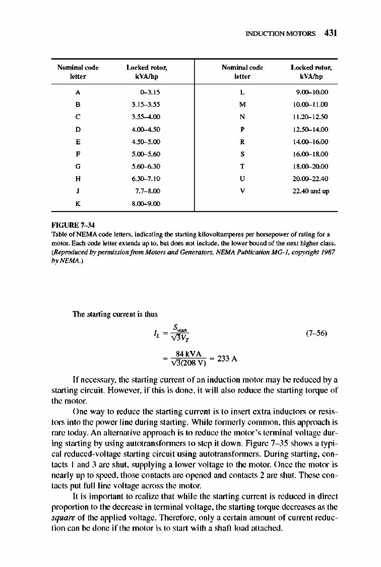
INDUCTION MOTORS 431
Nominal code Lock ... >d rotor, Nominal code Locked rotor, letter kYAJhp letter kVAJhp
A 0--3.15 L 9.00-10.00
B 3.15--3.55 M 10.00-11.00
C 3.55-4.00 N 11.20-12.50
D 4.00-4.50 P 12.50-14.00
E 4.50-5.00 R 14.00-16.00
F 5.00-5.60 S 16.00-18.00
G 5.60--6.30 T 18.00-20.00
H 6.30--7.10 U 20.00-22.40
J 7.7- 8.00 V 22.40 and up
K 8.00-9.00
FIGURE 7-34 Table of NEMA code letters. indicating the starting kilovolt amperes per horsepower of rating for a motor. Each code letter extends up to. but does not include. the lower bound of the next higher class. (Reproduced 17y permission from Motors and Generators. NEMA Publication MG-I. copyright 1987 byNEMA.)
The starting current is thus
(7- 56)
84kVA = vi3"(208 V) = 233 A
If necessary, the starting current of an induction motor may be reduced by a starting circuit. However, if this is done, it will also reduce the starting torque of the motor.
One way to reduce the starting current is to insert extra inductors or resistors into the power line during starting. While fonnerly common, this approach is rare today. An alternative approach is to reduce the motor 's terminal voltage during starting by using autotransformers to step it down. Figure 7- 35 shows a typical reduced-voltage starting circuit using autotransfonners. During starting, contacts 1 and 3 are shut, supplying a lower voltage to the motor. Once the motor is nearly up to speed, those contacts are opened and contacts 2 are shut. These contacts put fu JI line voltage across the motor.
It is important to realize that while the starting current is reduced in direct proportion to the decrease in terminal voltage, the starting torq ue decreases as the square of the applied voltage. Therefore, only a certain amount of current reduction can be done if the motor is to start with a shaft load attached.
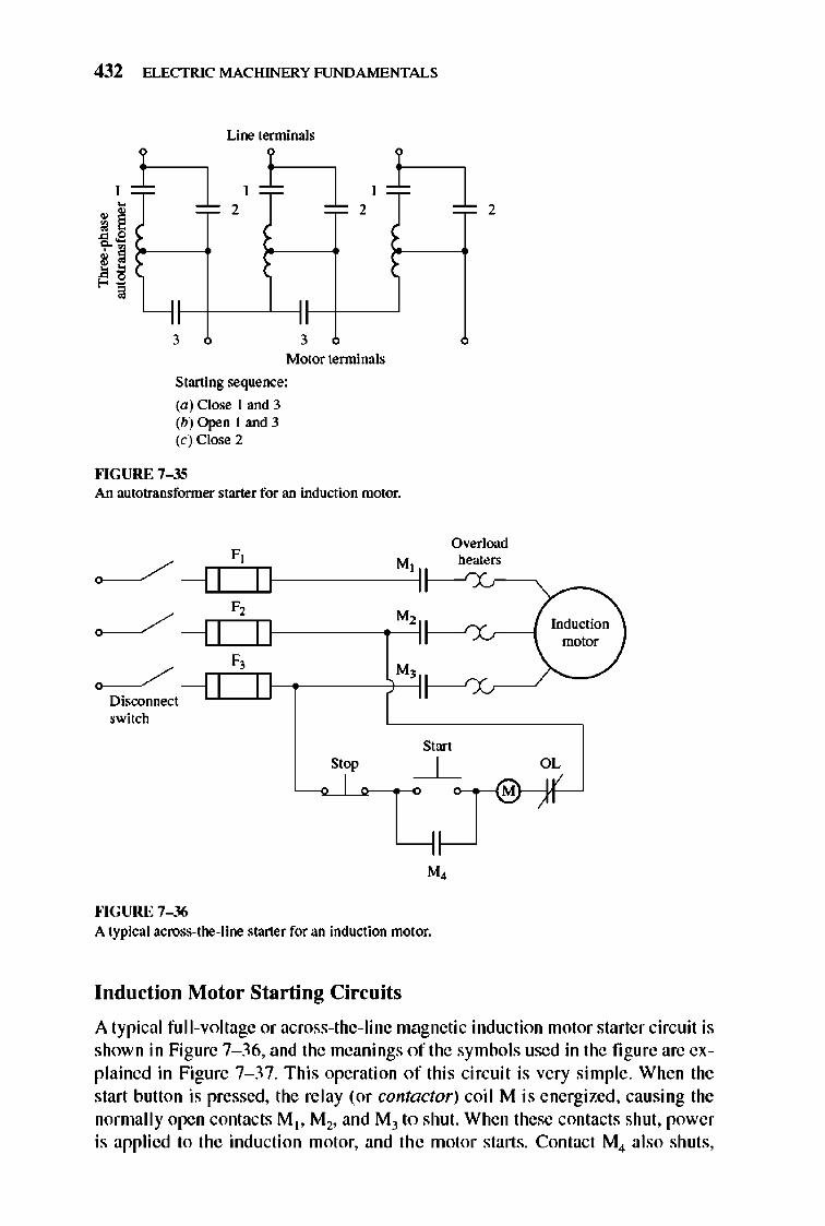
432 ELECTRIC MACHINERY RJNDAMENTALS
Line terminals
2 2
" " " " 3 3
Motor terminals
Starting sequence:
(a) Close I and 3 (b) Open I and 3 (c) Close 2
""GURE 7- 35 An autotransfonner starter for an induction motor.
~ ---1 1 F,
M'I II ~
F, M,
~ F, M,
Disronnect switch
Start
Overload heaters
Induction motor
Stop OL
LL---r ---"--;~M
""GURE 7- 36 A typical across-too-line starter for an induction motor.
Induction Motor Starting Circuits
A typical full- voltage or across-the-Iine magnetic induction motor starter circuit is shown in Figure 7- 36, and the meanings of the symbols used in the fi gure are explained in Figure 7- 37. This operation of this circuit is very simple. When the start button is pressed, the relay (or contactor) coil M is energized, causing the normally open contacts M t , M2, and M) to shut. When these contacts shut, power is applied to the induction motor, and the motor starts. Contact M4 also shuts,
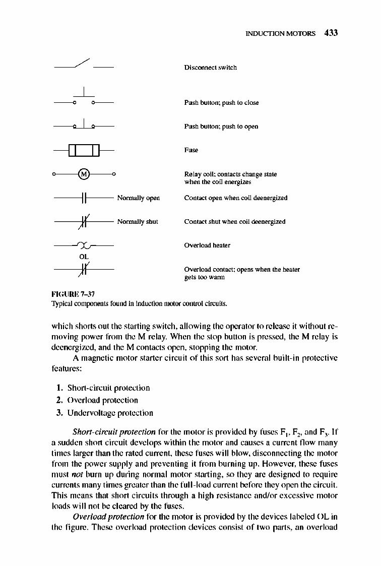
---11 If-0 e 0
II
)( rx, OL
)f FIGURE 7-37
Normally open
Normally shut
INDUCTION MOTORS 433
Disconnect switch
Push button; push to close
Push button; push to open
Relay coil; contacts change state when the coil energizes
Contact open when coil deenergized
Contact shut when coil deenergized
Overload heater
Overload contact; opens when the heater gets too wann
Typical components found in induction motor control circuits.
which shorts out the starting switch, allowing the operator to release it without removing power from the M relay. When the stop button is pressed, the M relay is deenergized, and the M contacts open, stopping the motor.
A magnetic motor starter circuit of this sort has several bui It-in protective features:
I. Short-circuit protection
2. Overload protection
3. Undervoltage protection
Short-circuit protection for the molor is provided by fuses F t , F2, and Fl. If a sudden short circuit develops within the motor and causes a current fl ow many limes larger than the rated current, these fuses will blow, disconnecting the motor from the power supply and preventing it from burning up. However, these fuses must not burn up during normal molor starting, so they are designed to req uire currents many times greater than the full -load current before they open the circuit. This means that short circuits through a high resistance and/or excessive motor loads will not be cleared by the fuses.
Overload protection for the motor is provided by the devices labeled OL in the fi gure. These overload protection devices consist of two parts, an overload
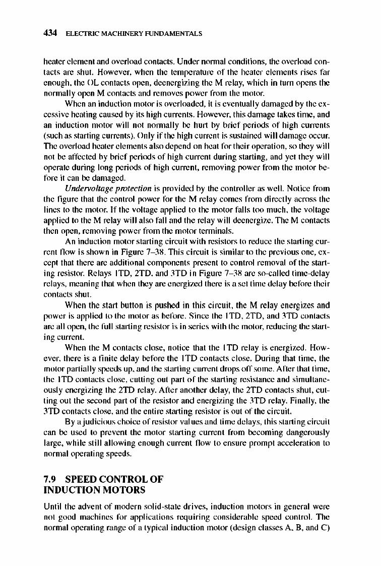
434 ELECTRIC MACHINERY RJNDAMENTALS
heater element and overload contacts. Under nonnal conditions, the overload contacts are shut. However, when the temperature of the heater e lements rises far enough, the OL contacts open, deenergizing the M relay, which in turn opens the normally open M contacts and removes power from the motor.
When an induction motor is overloaded, it is eventually drunaged by the excessive heating caused by its high currents . However, this damage takes time, and an induction motor will not nonnally be hurt by brief periods of high current s (such as starting currents). Only if the high current is sustained will damage occur. The overload heater elements also depend on heat for their operati on, so they wil l not be affected by brief perioos of high current during starting, and yet they wil I operate during long periods of high current, removing power from the motor before it can be damaged.
Undefi!oltage protection is provided by the controller as well. Notice from the fi gure that the control power for the M relay comes from directly across the lines to the motor. If the voltage applied to the motor fall s too much, the voltage applied to the M relay will also fall and the relay will deenergize. TIle M contacts then open, removing power from the motor tenninals.
An induction motor starting circuit with resistors to reduce the starting current fl ow is shown in Figure 7- 38. TIlis circuit is similar to the previous one, except that there are additional components present to control removal of the starting resistor. Relays lID, 2TD, and 3TD in Figure 7- 38 are so-called time-delay re lays, meaning that when they are energized there is a set time delay before their contacts shut.
When the start button is pushed in this circuit, the M relay energizes and power is applied to the motor as before. Since the 1 ID, 2TD, and 3ID contacts are all open, the full starting resistor is in series with the motor, reducing the starting current.
When the M contacts close, notice that the 1 ID relay is energized. However, there is a finite delay before the lTD contacts close. During that time, the motor partially speeds up, and the starting current drops off some. After that time, the 1 TO contacts close, cutting out part of the starting resistance and simultaneously energizing the 2TD relay. After another delay, the 2TD contacts shut, cutting out the second part of the resistor and energizing the 3TD relay. Finally, the 3TD contacts close, and the entire starting resistor is out of the circuit.
By a judicious choice of resistor val ues and time delays, this starting circuit can be used to prevent the motor startin g current from becoming dangerously large, while still allowing enough current fl ow to ensure prompt acceleration to normal operating speeds.
7.9 SPEED CONTROL OF INDUCTION MOTORS
Until the advent of modern solid-state drives, inducti on motors in general were not good machines for applications requiring considerable speed control. The normal operating range of a typical induction motor (design classes A, B, and C)
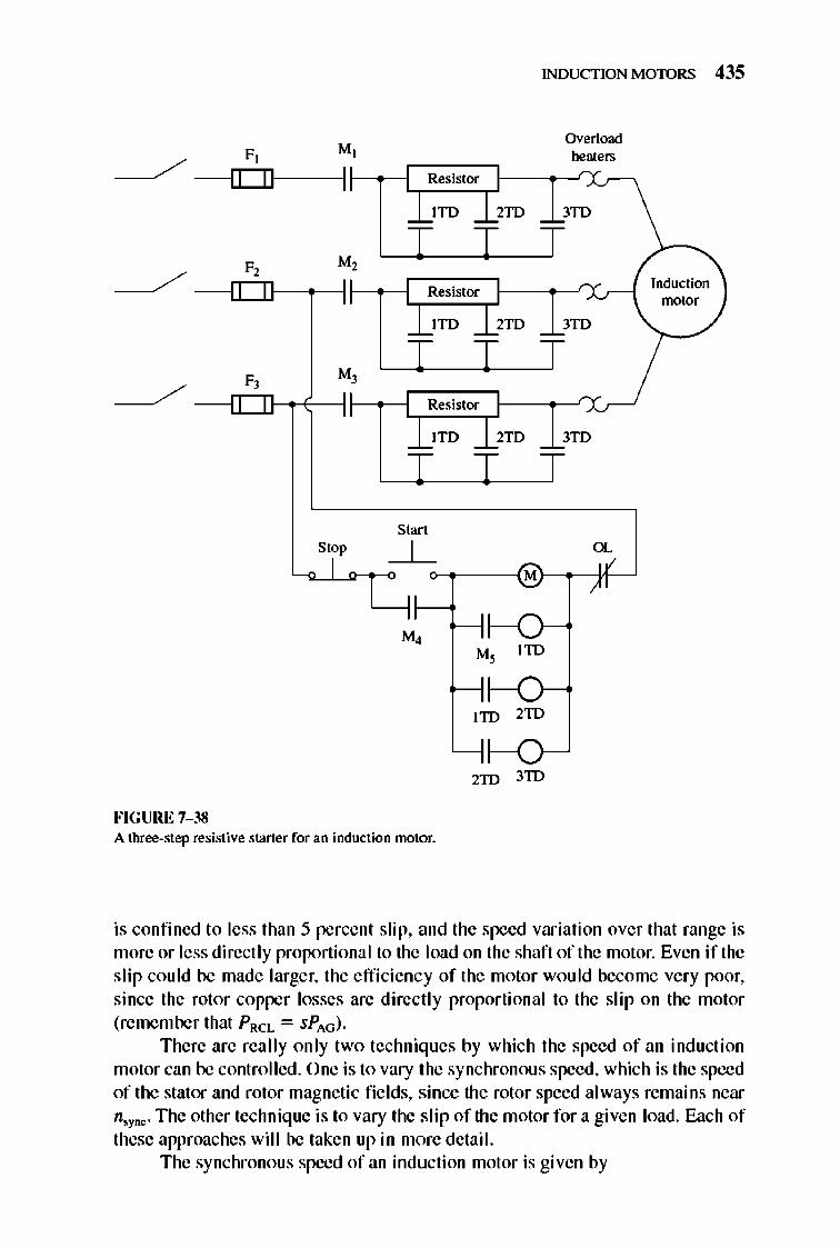
INDUCTION MOTORS 435
Overload F M] heaters
/~I r~~~~ ----- - l..L....l..I- 1 r--- Resis]or
3TD
Resis]or
lTD 2TD 3TD
Resistor
lTD 2TD 3TD
S<w Stop
I OL
lID
lID 2ID
2ID 3ID
FIGURE 7-38 A three-step resistive staner for an induction motor.
Induction motor
is confined to less than 5 percent slip, and the speed variation over that range is more or less direct ly proportional to the load on the shaft of the motor. Even if the slip could be made larger, the e ffi ciency of the motor wou ld become very poor, since the rotor copper losses are directly proportional to the slip on the motor (remember that PRCL = sPAG).
There are really only two techniques by which the speed of an inducti on motor can be controlled. One is to vary the synchronous speed, which is the speed of the stator and rotor magnetic fields, since the rotor speed always remains near n,ync. The other technique is to vary the s li p of the motor for a given load. E:1.ch of these approaches will be taken up in more detail.
The synchronous speed of an inducti on motor is given by
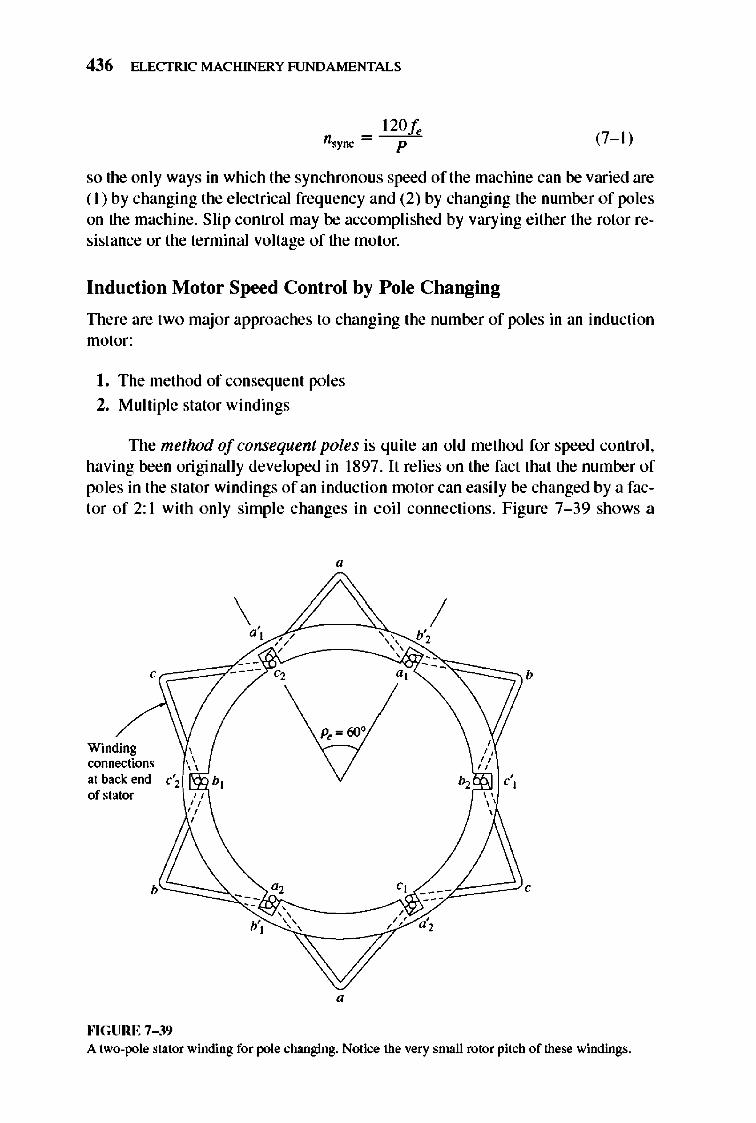
436 ELECTRIC MACHINERY RJNDAMENTALS
120fe p (7- 1)
so the only ways in which the synchronous speed of the machine can be varied are ( I) by changing the electrical frequency and (2) by changing the number of poles on the machine. Slip control may be accomplished by varying either the rotor resistance or the terminal voltage of the motor.
Induction Motor Speed Control by P ole Changing
TIlere are two major approaches to changing the number of poles in an induction motor:
I. The method of conseq uent poles
2. Multiple stator windings
TIle method of consequent poles is quite an old method for speed control , having been originally developed in 1897. It relies on the fact that the number of poles in the stator windings of an induction motor can easily be changed by a factor of 2: I with only simple changes in coil connections. Figure 7- 39 shows a
,
Winding connections at back end of stator
b
fo'IGURE 7-39
\ d,
---b',
p~= 60°
0, , " " , ,
/ ' , b', " " , ---" b
" ---- , " /' a,
A two-pole stator winding for pole changing. Notice the very small rotor pitch of these windings.
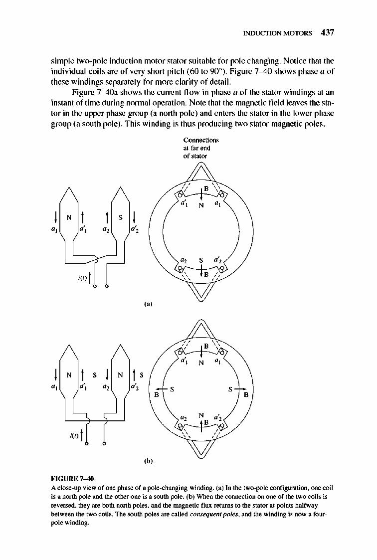
INDUCTION MOTORS 437
simple two-pole induction motor stator suitable for pole changing. Notice that the individual coil s are of very short pitch (60 to 90°). Figure 7-40 shows phase a of these windings separately for more clarity of detail.
Figure 7-40a shows the current n ow in phase a of the stator windings at an instant of time during nonnal operation. Note that the magnetic field leaves the stator in the upper phase group (a north pole) and enters the stator in the lower phase group (a south pole). This winding is thus pnxlucing two stator magnetic poles.
a',
I(t) I
,,'
) NtS ) N t S a] d] a2 d 2 S
B
-
,b, FIGURE 7-40
Connections at far end of stator
," ,
, " "
," ,
", , " "
" B \'
B /,
"
" B \'
N a', B
S B
A close-up view of one phase of a pole-changing winding. (a) In the two-pole configuration. one coil is a north pole and the other one is a south pole. (b) When the connection on one of the two coils is reversed. they are both nonh poles. and the magnetic flux returns to the stator at points halfway between the two coils. The south poles are called consequent poles. and the winding is now a fourpole winding.
438 ELECTRIC MACHINERY RJNDAMENTALS
Now suppose that the direction of current flow in the lower phase group on the stator is reversed (Figure 7--40b).1llen the magnetic fie ld wi ll leave the stator in both the upper phase group and the lower phase group-each one will be a north magnetic pole. The magnetic fl ux in this machine must return to the stator between the two phase groups, producing a pair of consequent south magnetic poles. Notice that now the stator has four magnetic poles-twice as many as before.
1lle rotor in such a motor is of the cage design, since a cage rotor always has as many poles induced in it as there are in the stator and can thus adapt when the number of stator poles changes .
When the motor is reconnected from two-pole to four-pole operation, the resulting maximum torque of the induction motor can be the same as before (constant-torque connection), half of its previous value (sq uare-law-torque connection, used for fans, etc.), or twi ce its previous value (constant-output-power connection), depending on how the stator windings are rearranged . Figure 7--4 1 shows the possible stator connections and their effect on the torque-speed curve.
1lle major disadvantage of the conseq uent-pole method of changing speed is that the speeds must be in a ratio of 2: I. 1lle traditional approach to overcoming this limitation was to employ multiple stator windings with different numbers of poles and to energize only one set at a time. For example, a motor might be wound with a four-pole and a six-pole set of stator windings, and its synchronous speed on a 6O- Hz system could be switched from 1800 to 1200 r/min simply by supplying power to the other set of windings. Unfortunate ly, multiple stator windings increase the expense of the motor and are therefore used only when absolutely necessary.
By combining the method of consequent poles with multiple stator windings, it is possible to build a four-speed induction motor. For example, with separate four- and six-pole windings, it is possible to produce a 6O- Hz motor capable of running at 600, 900, 1200, and 1800 r/min.
Speed Control by Changing the Line Frequency
I f the electrical frequency applied to the stator of an induction motor is changed, the rate of rotation of its magnetic fi e lds " ' )'DC will change in direct proportion to the change in e lectrical frequency, and the no- load point on the torque-speed characteristic curve will change with it (see Figure 7--42). The synchronous speed of the motor at rated conditions is known as the base speed. By using variable frequency control, it is possible to adjust the speed of the motor either above or below base speed. A properly designed variable-frequency inducti on motor drive can be very fl exible. It can control the speed of an induction motor over a range from as little as 5 percent of base speed up to about twi ce base speed . However, it is important to maintain certain voltage and torque limits on the motor as the frequency is varied, to ensure safe operation.
When running at speeds below the base speed of the motor, it is necessary to reduce the terminal voltage applied to the stator for proper operation. 1lle terminal voltage applied to the stator should be decreased linearly with decreasing
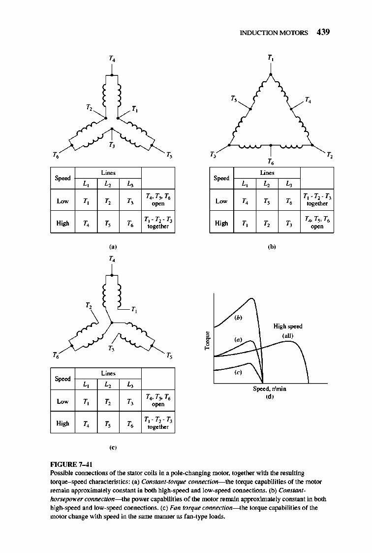
INDUCTION MOTORS 439
T, T,
T, T, T,
T, T, T, T,
Lines Lines S",""
L, L, L, S"""d
L, L, L,
Low T, T, T, T4, T~ T6
Low T, T, T, Tt -T2-Tj
High T,
T,
T,
S","" L,
Low T,
High T,
FIGURE 7-4 1
T,
(a)
T,
T,
Lines
L,
T,
T,
(,)
T,
T,
L,
T,
T,
0",,"
T)-TrTJ together
T,
T4, T." T6 0",,"
T)-TrTJ together
High T, T, T,
(b)
(b, High speed
1:: (all)
, l""d(:"'::::1r---' ~
(Cl
Speed, rlmin (d)
together
T4, T~, T6 0",,"
Possible connections of the stator coils in a pole-changing motor. together with the resulting
torque-speed characteristics: (a) Constant-torque connection- the torque capabilities of the motor
remain approximately constant in both high-speed and low-speed connections. (b) Constantlwrsepok'er connection---lhe power capabilities of the motor remain approximately constant in both h.igh-speed and low-speed connections. (el Fan torque connection---lhe torque capabilities of the
motor change with speed in the same manner as f.an-type loads.
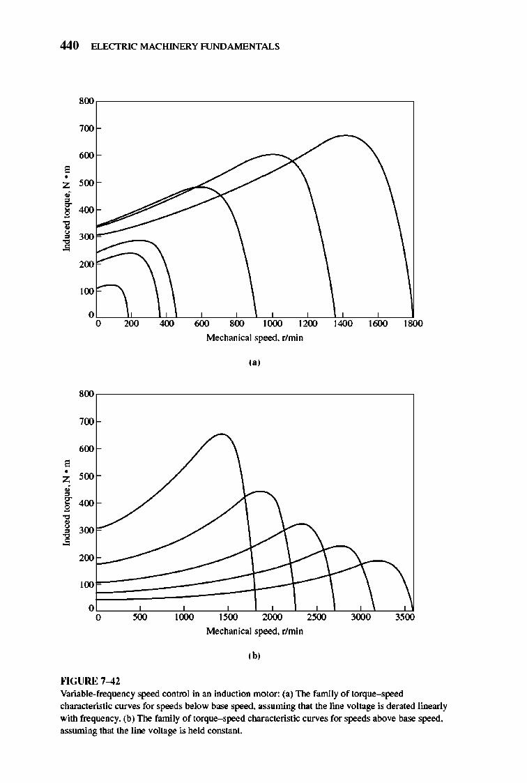
440 ELECTRIC MACHINERY RJNDAMENTALS
800 ,-------------------------------------,
700
600 , • Z 500
• ¥ 400
~ I 300
200
lOO e--,
800
700
600 , • Z 500
• ~ 400
" , 300 0
~ 200
100
0 0
""GURE 7-42
Mechanical speed. r/min
,.,
1000 1500 2000 2500 3000 3500
Mechanical speed. r/min
,b,
Variable-frequency speed control in an induction motor: (a) The family of torque-speed characteristic curves for speeds below base speed. assuming that the line voltage is derated linearly with frequency. (b) The family of torque-speed characteristic curves for speeds above base speed. assuming that the line voltage is held constant.
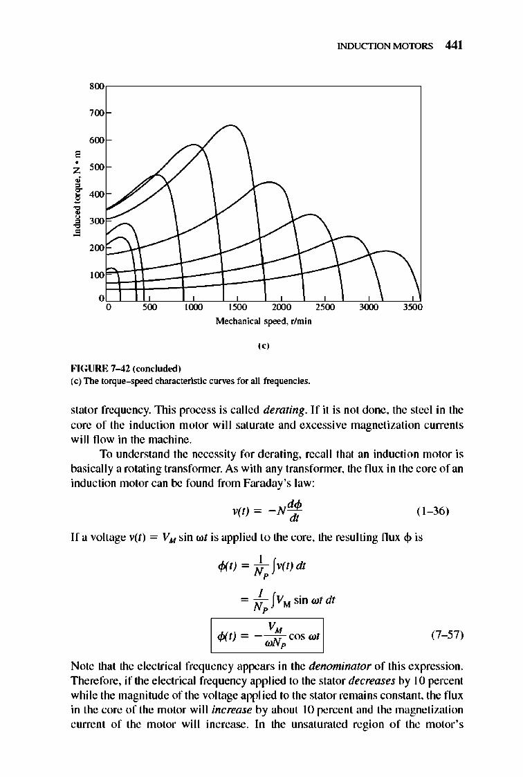
INDUCTION MOTORS 441
800,-------------------------------------,
700
600 , • Z 500 ,~ 400
] 300
• 200P\\-------\
o o 500
FIGURE 7-42 (roncluded)
1000 1500 2000
Mechanical speed. r/min
I"
(c) The torque-speed characteristic curves for all frequencies.
2500 3000 3500
stator frequency. This process is called derating. If it is not done, the steel in the core of the induction motor will saturate and excessive magnetization currents will flow in the machine.
To understand the necessity for derating, recall that an induction motor is basicall y a rotating transfonner. As with any transfonner, the flux in the core of an induction motor can be found from Faraday's law:
vet) = -N~ dl
( 1-36)
If a voltage vet) = VM sin wt is applied to the core, the resulting flux ~ is
'Wi ~ J h l)dl p
= ~ !VM sinwtdt p
I ~t) = -~cos wt l (7- 57)
Note that the electrical frequency appears in the denominator of this expression. Therefore, if the electrical frequency applied to the stator decreases by 10 percent while the magnitude of the voltage appl ied to the stator remains constant, the flux in the core of the motor wi I I increase by about 10 percent and the magnetization current of the motor wi ll increase. In the unsaturated region of the motor's
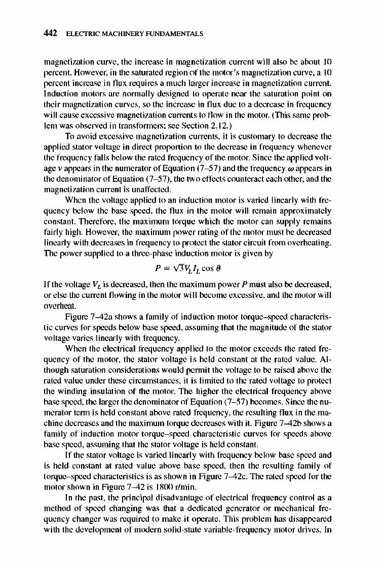
442 ELECTRIC MACHINERY RJNDAMENTALS
magnetization curve, the increase in magnetization current will also be about 10 percent. However, in the saturated region of the motor 's magnetiwtion curve, a 10 percent increase in flux requires a much larger increase in magnetization current. Induction motors are normally designed to operate near the saturation point on their magnetization curves, so the increase in flux due to a decrease in frequency will cause excessive magnetization currents to flow in the motor. (This same problem was observed in transfonners; see Section 2.1 2.)
To avoid excessive magnetization currents, it is customary to decrease the applied stat or voltage in direct proportion to the decrease in frequency whenever the frequency falls below the rated frequency of the motor. Since the applied voltage v appears in the numerator of Equation (7-57) and the frequency wappears in the denominator of Equation (7-57), the two effects counteract each other, and the magnetization current is unaffected.
When the voltage applied to an induction motor is varied linearly with frequency below the base speed, the flux in the motor will remain approximately constant. TIlerefore, the maximum torque which the motor can supply remains fairly high. However, the maximum power rating of the motor must be decreased linearly with decreases in frequency to protect the stator circuit from overheating. TIle power supplied to a three-phase induction motor is given by
P = v'JVLIL cos (J
If the voltage VL is decreased, then the maximum power P must also be decreased, or e lse the current flowing in the motor wi II become excessive, and the motor will overheat.
Figure 7-42a shows a family of induction motor torque-speed characteristic curves for speeds below base speed, assuming that the magnitude of the stator voltage varies linearly with frequency.
When the electrical frequency applied to the motor exceeds the rated frequency of the motor, the stator voltage is he ld constant at the rated value. Although saturation considerations would pennit the voltage to be raised above the rated value under these circumstances, it is limited to the rated voltage to protect the winding insulation of the motor. The higher the electrical frequency above base speed, the larger the denominator of Equation (7-57) becomes. Since the numerator tenn is he ld constant above rated frequency, the resulting flux in the machine decreases and the maximum torque decreases with it. Figure 7-42b shows a family of inducti on motor torque- speed characteristic curves for speeds above base speed, assuming that the stator voltage is held constant.
If the stator voltage is varied linearl y with frequency below base speed and is held constant at rated value above base speed, then the resulting family of torque-speed characteristics is as shown in Figure 7-42c. TIle rated speed for the motor shown in Figure 7-42 is 1800 r/min.
In the past, the principal disadvantage of e lectrical frequency control as a method of speed changing was that a dedicated generator or mechanical frequency changer was required to make it operate. This problem has disappeared with the development of modern solid-state variable- frequency motor drives. In
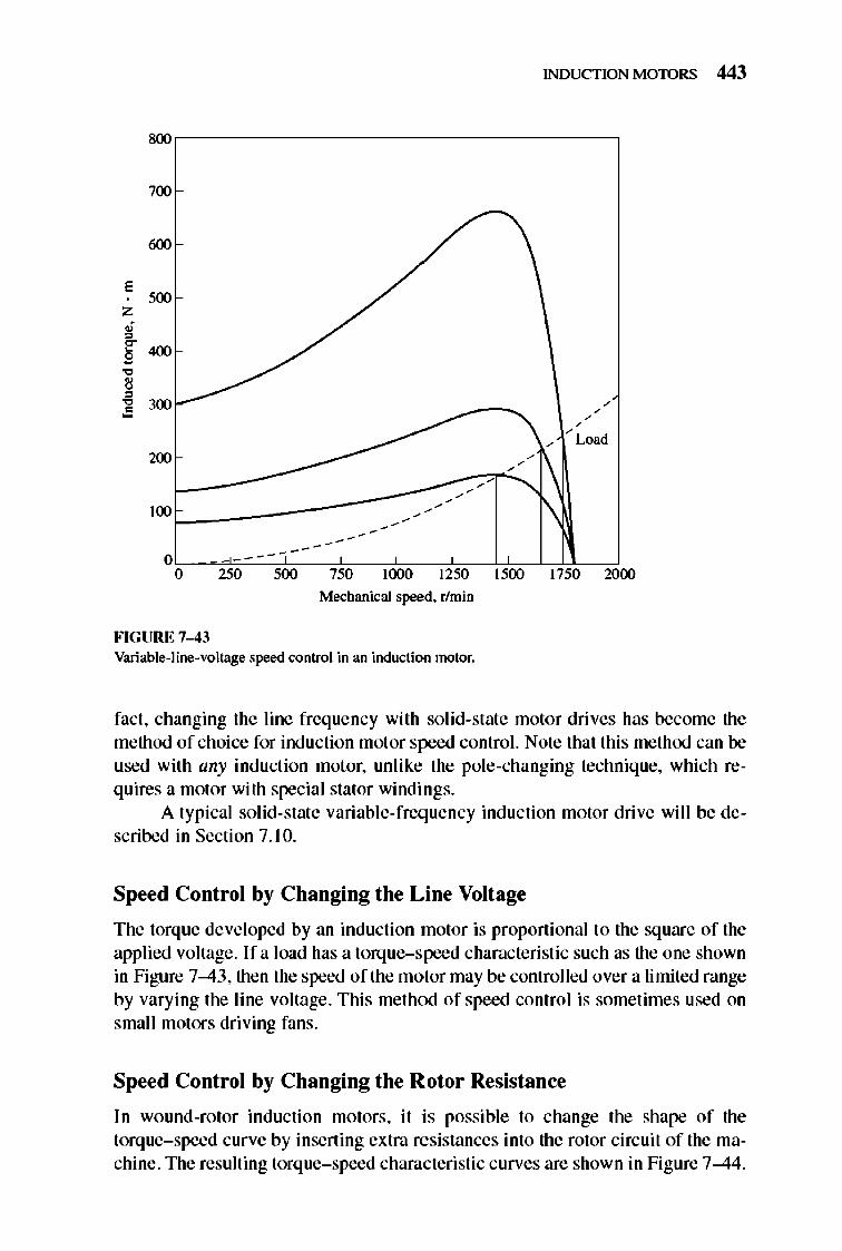
INDUCTION MOTORS 443
800
700
600
E
"" Z
; ~
400 ~ • , , • 300 • / -/ Lo,'
200
100
0 --------0 250 '00 "" 1000 1250 1500 1750 2000
Mechanical speed. r/min
FIGURE 7-43 Variable-line-voltage speed control in an induction motor.
fact, changing the line frequency with solid-state motor drives has become the method of choi ce for induction motor speed control. Note that this method can be used with any induction motor, unlike the pole-changing technique, which requires a motor with special stator windings.
A typical solid-state variable-frequency induction motor drive wi ll be described in Section 7.10.
Speed Control by Changing the Line Voltage
The torque developed by an induction motor is proportional to the sq uare of the applied voltage. Ifa load has a torque-speed characteristic such as the one shown in Figure 7-43, then the speed of the motor may be controlled over a limited range by varying the line voltage. This method of speed control is sometimes used on small motors driving fans.
Speed Control by Changing the Rotor Resistance
In wound-rotor induction motors, it is possible to change the shape of the torque- speed curve by inserting extra resistances into the rotor circuit of the machine. The resulting torque- speed characteristic curves are shown in Figure 7-44.
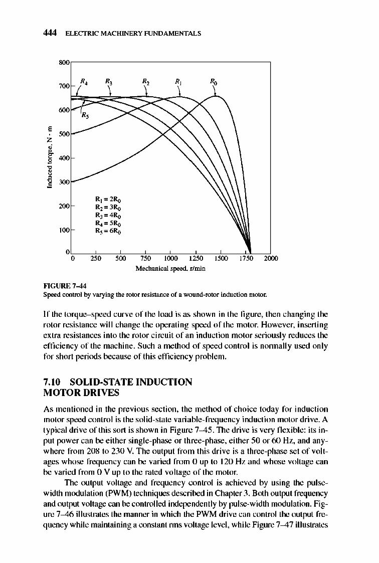
444 ELECTRIC MACHINERY RJNDAMENTALS
800
700 R, R, R,
(j()()
E 500
Z
• , ~ 400 g
" , , ~ 300
R] '" 2Ro 200 R2", 3Ro
RJ ",4Ro RJ '" 5Ro
100 R3", 6Ro
0 0 250 500 750 1000 1250 1500 17'" 2000
Mechanical speed. r/min
fo'IGURE 7-44 Speed control by varying the rotor resistance of a wound-rotor induction motor.
If the torque-speed curve of the load is as shown in the figure, then changing the rotor resistance wi ll change the operating speed of the motor. However, inserting extra resistances into the rotor circuit of an induction motor seriously red uces the effi ciency of the machine. Such a method of speed control is nonnally used only for short periods because of this effi ciency problem.
7.10 SOLID·STATE INDUCTION MOTOR DRIVES
As mentioned in the previous section, the method of choice today for induction motor speed control is the solid-state variable-freq uency induction motor drive. A typical drive of this sort is shown in Figure 7--45. TIle drive is very flexible: its input power can be either single-phase or three-phase, either 50 or 60 Hz, and anywhere from 208 to 230 V. The output from this drive is a three-phase set of voltages whose frequency can be varied from 0 up to 120 Hz and whose voltage can be varied from 0 V up to the rated voltage of the motor.
TIle output voltage and frequency control is achieved by using the pulsewidth modulation (PWM) techniques described in Chapter 3. Both output frequency and output voltage can be controlled independently by pulse-width modulation. figure 7--46 illustrates the manner in which the PWM drive can control the output frequency while maintaining a constant nns voltage level, while Figure 7--47 illustrates
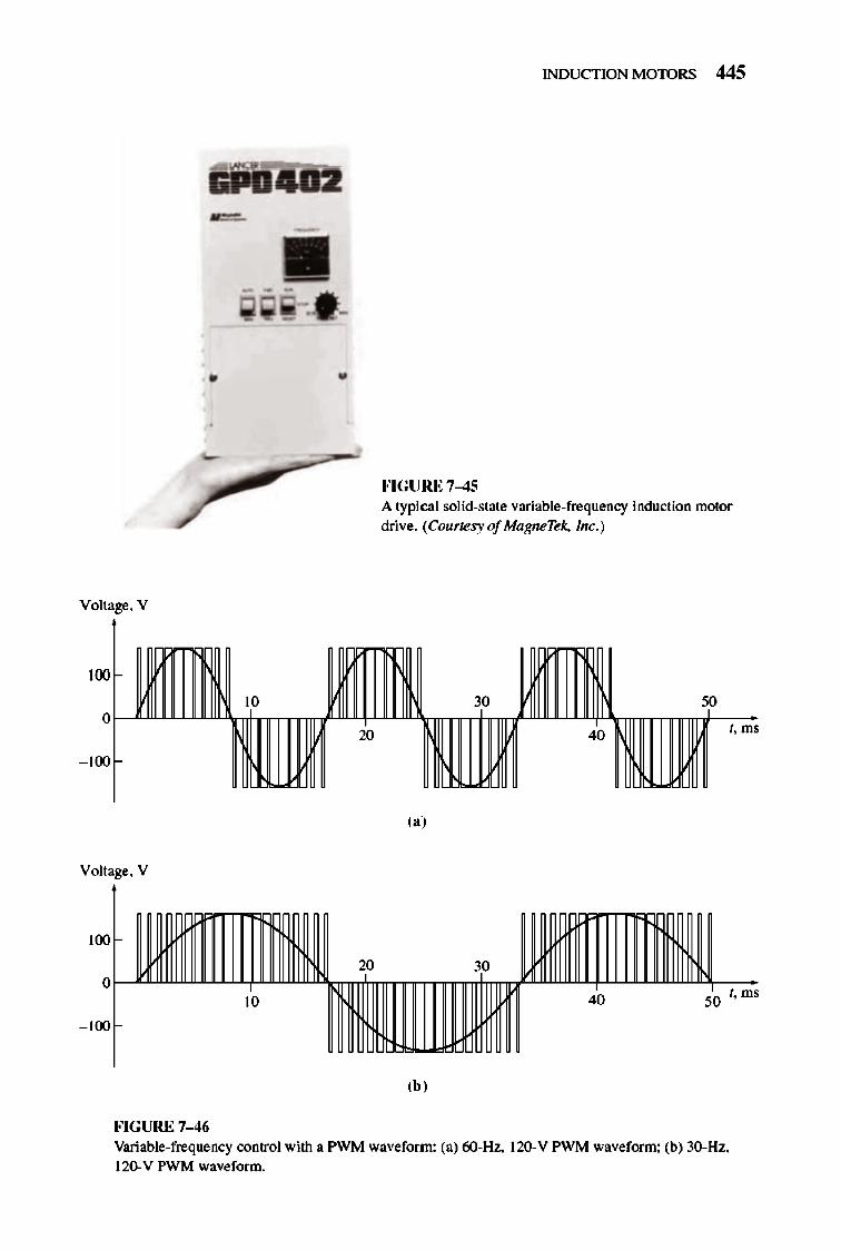
• •
/ Voltage. V
Voltage. V
100
20 o
10
- 100
FIGURE 7-46
INDUCTION MOTORS 445
fo'IGURE 7-45 A typical solid-state variable-frequency induction motor drive. (Courtesy of MagneTek, Inc.)
I. ms
(a)
30
40 50 I. ms
,bl
Variable-frequency control with a PWM waveform: (a) 6O-Hz.. 120-V PWM waveform: (b) 30-Hz. 12()' V PWM waveform.
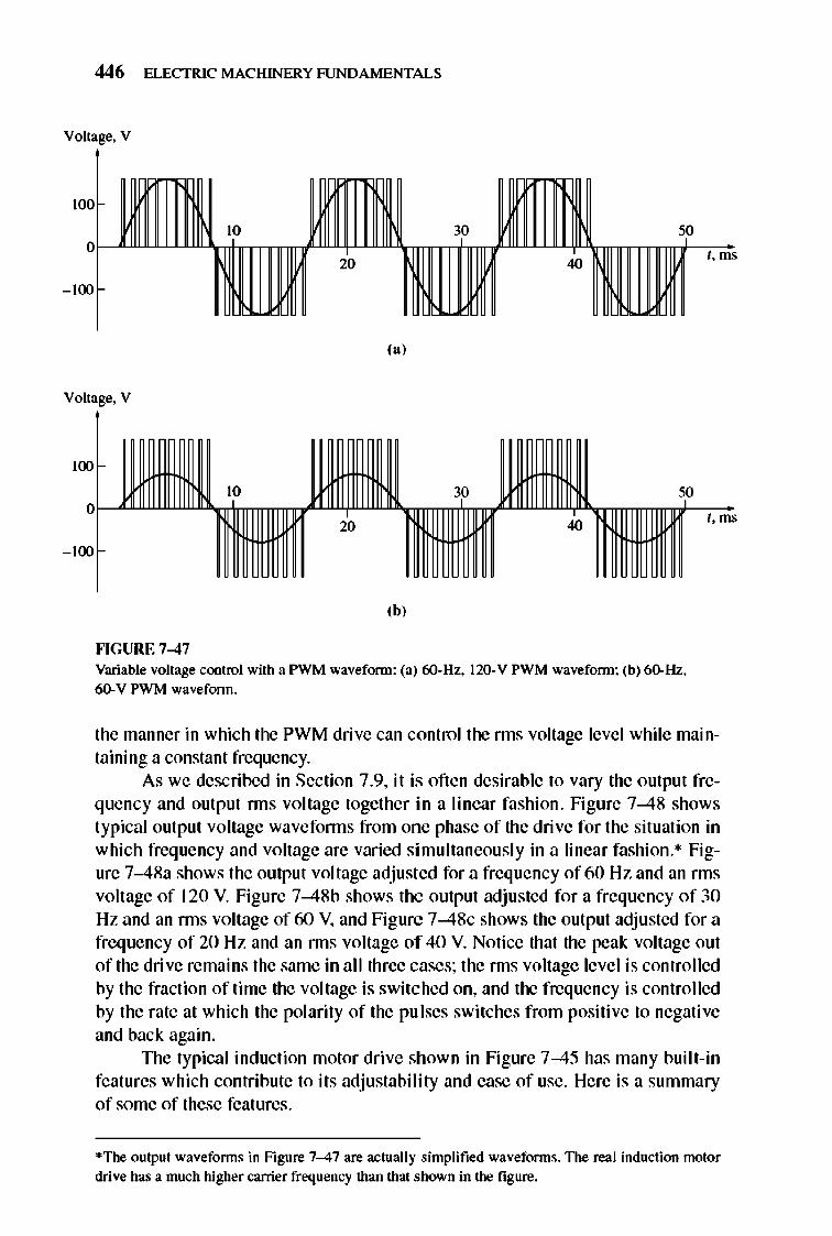
446 ELECTRIC MACHINERY RJNDAMENTALS
Voltage, V
100
t , ms
- 100
"J
Voltage, V
100
10 30 50 O~ mf t , ms
- 100
20 40
'bJ
""GURE 7-47 Variable voltage control with a PWM waveform: (a) 6O-Hz, 120-V PWM waveform: (b) 6().Hz, 6(). V PWM waveform.
the manner in which the PWM drive can control the nns voltage level while maintaining a constant frequency.
As we described in Section 7.9, it is oft en desirable to vary the output frequency and output nns voltage together in a linear fashion. Figure 7-48 shows typical output voltage wavefonns from one phase of the drive for the situation in which frequency and voltage are varied simultaneously in a linear fashion.· Figure 7-48a shows the output voltage adjusted for a frequency of60 Hz and an nns voltage of 120 V. Figure 7-48b shows the output adju sted for a frequency of 30 Hz and an nns voltage of 60 V, and Figure 7-48c shows the output adjusted for a frequency of 20 Hz and an nns voltage of 40 V. Notice that the peak voltage out of the dri ve remains the same in al l three cases; the nns voltage level is controlled by the fraction of time the voltage is switched on, and the frequency is controlled by the rate at which the polarity of the pulses switches from positive to negative and back again.
TIle typical induction motor dri ve shown in Figure 7-45 has many built-in features which contribute to its adjustability and ease of use. Here is a summary of some of these features.
*The output waveforms in Figure 7-47 are actually simplified waveforms. The real induction motor drive has a much higher carrier frequency than that shown in the figure.
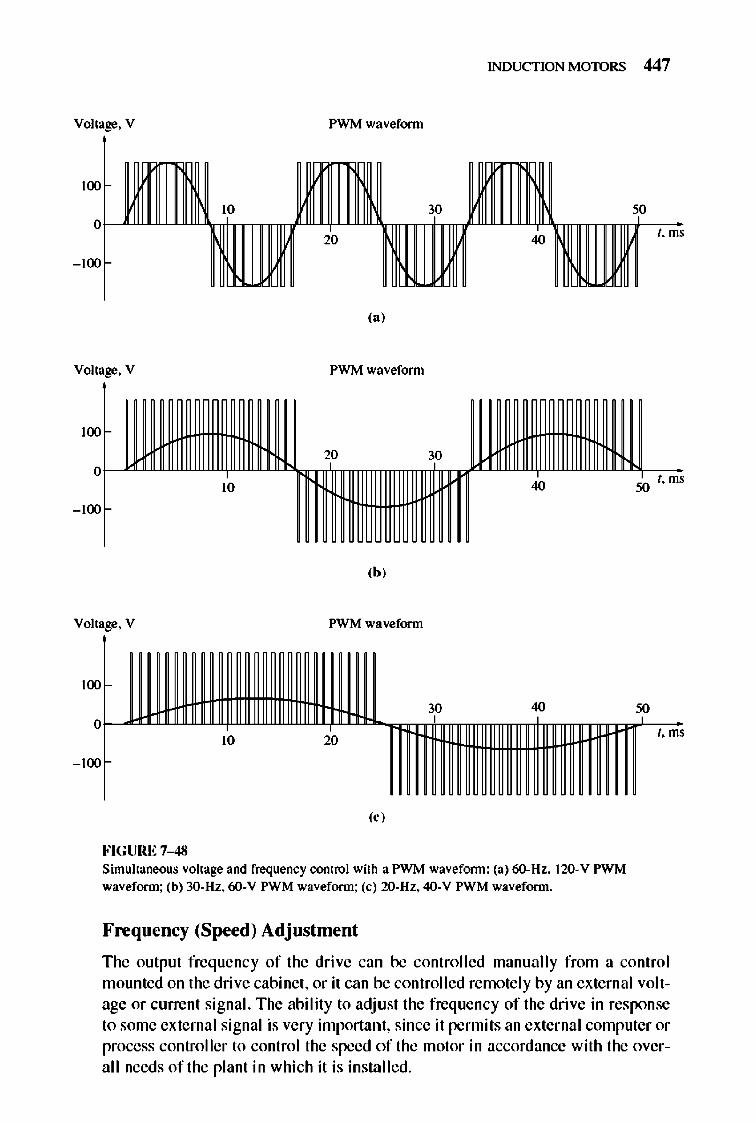
INDUCTION MOTORS 447
Voltage. V P\VM waveform
t. ms
,., Voltage. V P\VM waveform
100
20 30 o
10 40 50 t. ms
- 100
,b,
Voltage. V PWM waveform
100
oWUlli:lm 30 , 40
t. ms
- 100
10 20
,< ,
FIGURE 7-48 Simultaneous voltage and frequency control with a P\VM wavefonn: (a) 6O-Hz. 120-V PWM waveform: (b) 30-Hz. 60-V PWM waveform: (c) 2O-Hz. 40-V PWM waveform.
Frequency (Speed) Adjustment
The output frequency of the drive can be controlled manually from a control mounted on the drive cabinet, or it can be controlled remote ly by an external voltage or current signal. The abi lity to adj ust the frequency of the drive in response to some external signal is very important, since it permits an external computer or process controller to control the speed of the motor in accordance with the overall needs of the plant in which it is installed.
448 ELECTRIC MACHINERY RJNDAMENTALS
A Choice of Voltage and Frequency Patterns
TIle types of mechanical loads which mi ght be attached to an inducti on motor vary greatly. Some loads such as fans require very little torque when starting (or running at low speeds) and have torques which increase as the square of the speed. Other loads might be harder to start, requiring more than the rated full-load torque of the motor just to get the load moving. TIlis drive provides a variety of voltageversus-frequency patterns which can be selected to match the torque from the induction motor to the torque required by its load. TIlree of these patterns are shown in Figures 7-49 through 7- 5 J.
Figure 7-49a shows the standard or general-purpose voltage-versusfrequency pattern, described in the previous section. This pattern changes the output voltage linearly with changes in output frequency for speeds below base speed and holds the output voltage constant for speeds above base speed. (The small constant-voltage region at very low frequencies is necessary to ensure that there will be some starting torque at the very lowest speeds.) Figure 7-49b shows the resulting induction motor torque-speed characteristics for several operating frequencies below base speed.
Figure 7- 50a shows the voltage-versus-frequency pattern used for loads with high starting torques. This pattern also changes the output voltage linearly with changes in output frequency for speeds below base speed, but it has a shallower slope at frequencies below 30 Hz. For any given frequency below 30 Hz, the output voltage will be higherthan it was with the previous pattern. This higher voltage will produce a higher torque, but at the cost of increased magnetic saturation and higher magnetization currents. The increased saturation and higher currents are often acceptable for the short periods required to start heavy loads. Figure 7- 50b shows the induction motor torque-speed characteristics for several operating frequencies below base speed. Notice the increased torque available at low frequencies compared to Figure 7-49b.
Figure 7-51 a shows the voltage-versus-frequency pattern used for loads with low starting torques (called soft-start loads). TIlis pattern changes the output voltage parabolically with changes in output frequency for speeds below base speed. For any given frequency bel ow 60 Hz, the output voltage will be lower than it was with the standard pattern. TIlis lower voltage will produce a lower torque, providing a slow, smooth start for low-torque loads. Figure 7- 5 I b shows the induction motor torque-speed characteristics for several operating frequencies below base speed. Notice the decreased torque available at low frequencies compared to Figure 7-49.
Independently Adjustable Acceleration and Deceleration Ramps
When the desired operating speed of the motor is changed, the drive controlling it will change frequency to bring the motor to the new operating speed. If the speed change is sudden (e.g., an instantaneous jump from 900 to 1200 rIm in), the drive
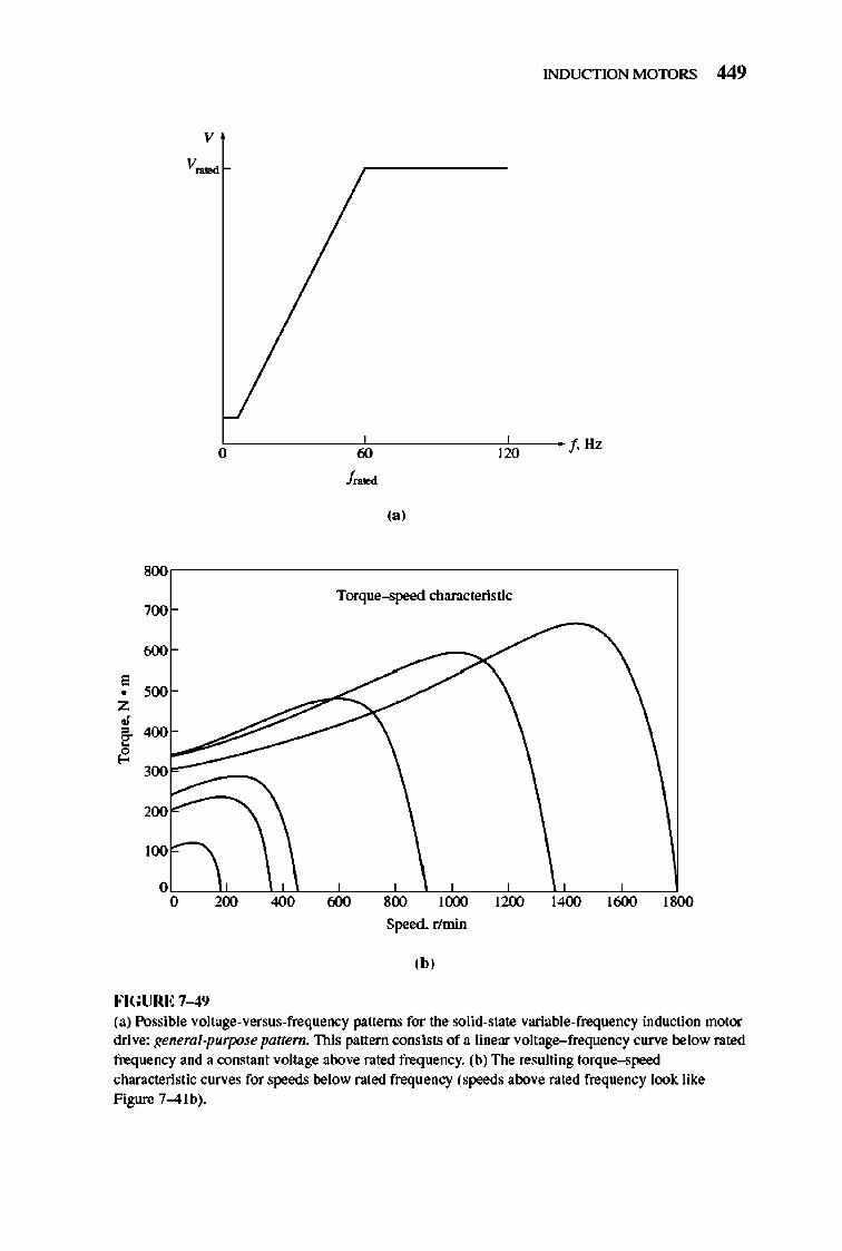
v
8O\l
700
roo
E • '00 Z
• , 4O\l ~ ~
300
WO
100
0 0
FIGURE 7-49
INDUCTION MOTORS 449
O~----------~ffiC----------C1~Wc---- f HZ f_. (a)
Torque--speed characteristic
200 4O\l roo 800 1000 12lXl 1400
Speed. rlmin
,b,
1roo 18O\l
(a) Possible voltage-versus-frequency patterns for the solid-state variable-frequency induction motor drive: general-purpose paT/ern. This pattern consists of a linear voltage-frequency curve below rated frequency and a constant voltage above rated frequency. (b) The resulting torque-speed characteristic curves for speeds below rated frequency (speeds above rated frequency look like Figure 7-4lb).
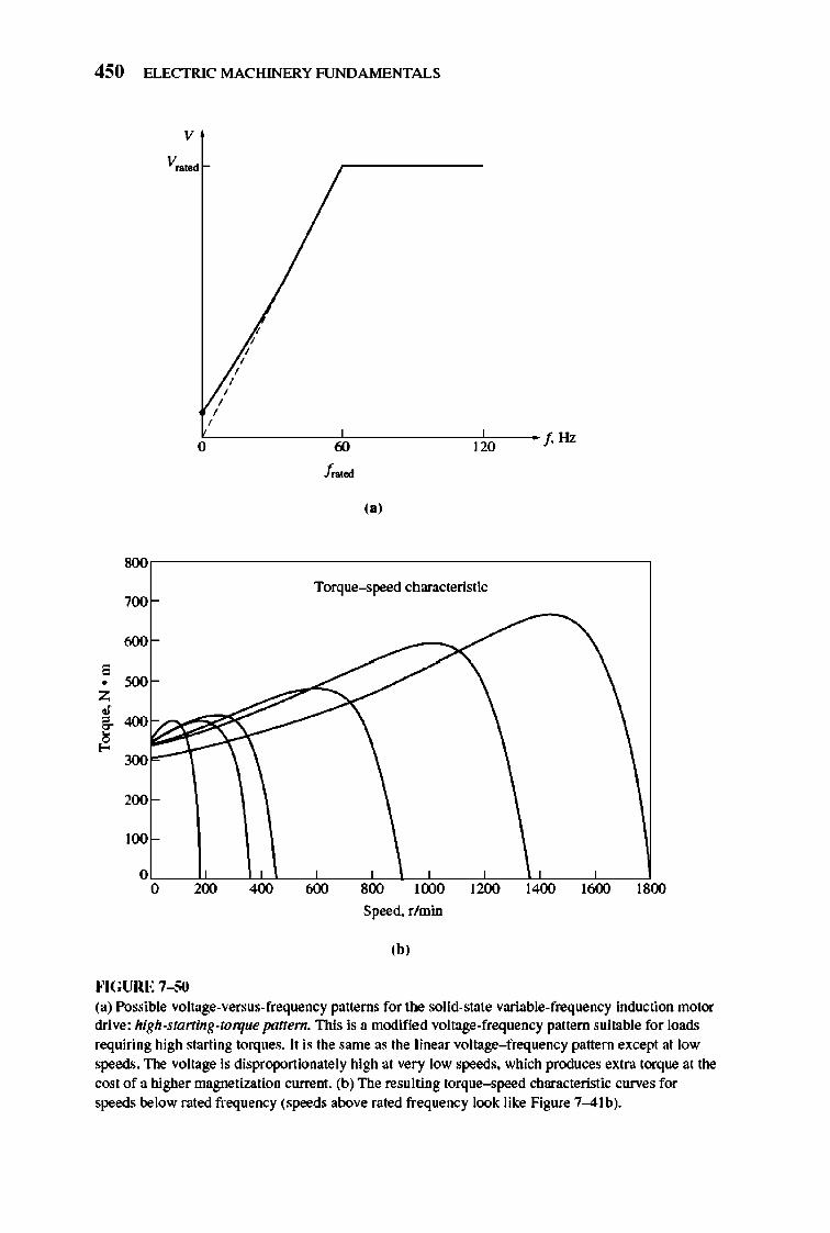
450 ELECTRIC MACHINERY RJNDA MENTALS
, • Z
• , ~
~
8O\l
700
600
5O\l
2llll
100
v
V .. ,od
, , ,
, ,
, , , ,
o!------~60~----~1~2~O--f. Hz
f~.
"I
Torque-speed characteristic
O~~~~~~~-o~L,,~-e~-+~-..~-.t, o 200 400 600 800 1000 1200 1400 1600 1800
Speed. r/min
'hI
fo'IG URE 7-50 (a) Possible voltage-versus-frequency patterns for the solid-state variable-frequency induction motor drive: high-starting-torque patfem. This is a modified voltage-frequency pattern suitable for loads requiring high starting torques. lt is the same as the linear voltage- frequency pattern except at low speeds. The voltage is disproportionately high at very low speeds. which produces extra torque at the cost of a h.igher magnetization current. (b) The resulting torque-speed characteristic curves for speeds below rated frequency (speeds above rated frequency look like Figure 7--41b).
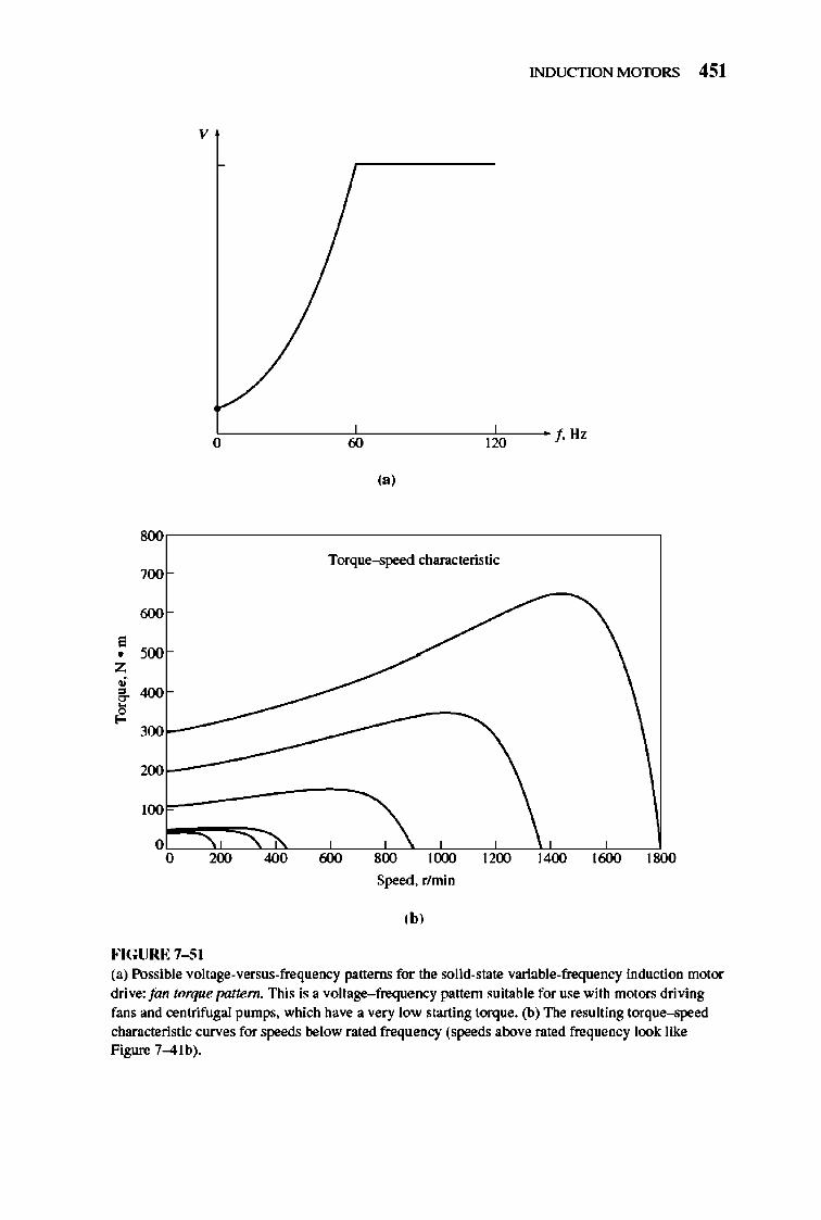
INDUCTION MOTORS 451
v
O~----------iro'----------'I~Wo---- f Hz
(a)
8O\l
Torque--speed characteristic 700
roo E • '00 Z
• , 4O\l ~ ~
300
WO
100
0 0 200 4O\l 800 1000 12lXl 1400 lroo 18O\l
Speed. r/min
'h' FIGURE 7-5 1 (a) Possible voltage-versus-frequency patterns for the solid-state variable-frequency induction motor drive:fan torque pattern. This is a voltage-frequency pattern suitable for use with motors driving fans and centrifugal pumps. which have a very low starting torque. (b) The resulting torque-speed characteristic curves for speeds below rated frequency (speeds above rated frequency look like Figure 7-4lb).
452 ELECTRIC MACHINERY RJNDAMENTALS
does not try to make the motor instantaneously jump from the old desired speed to the new desired speed. Instead, the rate of motor acceleration or deceleration is limited to a safe level by special circuits built into the e lectronics of the drive. TIlese rates can be adjusted independently for accelerations and decelerations.
Motor Protection
TIle induction motor drive has built into it a variety of features designed to protect the motor attached to the drive. The drive can detect excessive steady-state currents (an overload condition), excessive instantaneous currents, overvoltage conditions, or undervoltage conditions. In any of the above cases, it will shut down the motor.
Induction motor drives like the one described above are now so flexible and re li able that induction motors with these drives are displacing dc motors in many applications which require a wide range of speed variation.
7.11 DETERMINING CIRCUIT MODEL PARAMETERS
TIle equi valent circuit of an induction motor is a very useful tool for detennining the motor 's response to changes in load. However, if a model is to be used for a real machine, it is necessary to detennine what the e lement val ues are that go into the model. How can Rl> R2 , Xl> X2, and XM be detennined for a real motor?
These pieces of information may be found by perfonning a series of tests on the induction motor that are analogous to the short-circuit and open-circuit tests in a transfonner. TIle tests must be performed under precisely controlled conditions, since the resistances vary with temperature and the rotor resistance also varies with rotor frequency. The exact details of how each induction motor test must be performed in order to achieve accurate results are described in IEEE Standard 11 2. Although the detail s of the tests are very complicated, the concepts behind them are relatively straightforward and will be explained here.
The No-Load Test
TIle no-load test of an induction motor measures the rotational losses of the motor and provides infonnation about its magnetization current. The test circuit for this test is shown in Figure 7- 52a. Wattmeters, a voltmeter, and three ammeters are connected to an induction motor, which is allowed to spin freely. The only load on the motor is the fri ction and windage losses, so all Peon v in this motor is consumed by mechanical losses, and the s lip of the motor is very small (possibly as small as 0.00 1 or less). TIle equivalent circuit of thi s motor is shown in Figure 7- 52b. With its very small slip, the resistance corresponding to its power converted, Rl l - sys, is much much larger than the resistance corresponding to the rotor copper losses R2 and much larger than the rotor reactance X2. I n this case, the equivalent circuit reduces approximately to the last circuit in Figure 7- 52b. There,
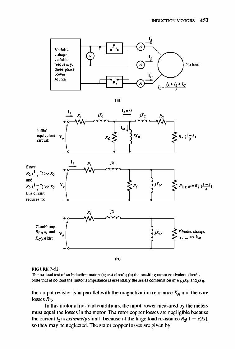
Initial
Variable voltage, variable frequency, three-phase power 00.=
I, -+
equivalent V. ( cin:uit:
I, Since -R2('~S)>>R2
+
v.( ,,' R2 (' - s)>>X2, , this cin:uit
reduces to:
+
Combining
V. ( RF&w and
Reyields:
FIGURE 7-52
R, jXt
R, ,
R,
INDUCTION MOTORS 453
I, -P, A
I , -A No load
I , -P, A lit + IB+ Ie IL = 3
,., 12= 0 - jX2 R,
" I. j R, jXM ~ R2(';S)
~ Rfri<:tiOll, win<b!O,
~ &""'" »XM
'h' The no-load test of an induction motor: (a) test circuit; (b) the resulting motor equivalent cin:uit. Note that at no load the motor's impedance is essentially the series combination of RI,jX j • andJXM .
the output resistor is in parallel with the magnetizati on reactance XM and the core losses Re.
In this motor at no- load conditions, the input power measured by the meters must equal the losses in the motor. The rotor copper losses are negligible because the current / l is extremely small [because of the large load resistance R2( 1 - s)/s], so they may be neglected . The stator copper losses are given by
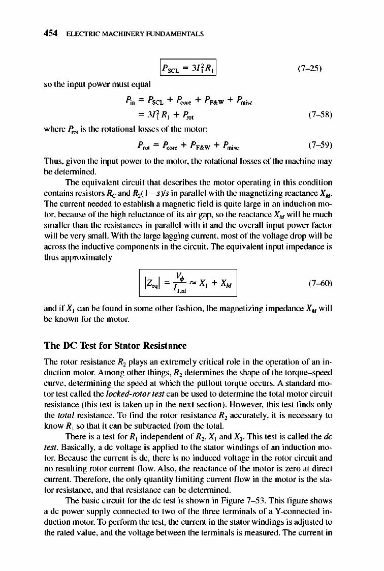
454 ELECTRIC MACHINERY RJNDAMENTALS
so the input power must equal
P;o = P SCL + P.:orc + PF& W + Pmisc
= 3f r RI + Prot
where Prot is the rotational losses of the motor:
PM = Poore + PF&W + Pmis.c
(7- 25)
(7- 58)
(7- 59)
TI1US, given the input power to the motor, the rotational losses of the machine may be detennined.
TIle equi valent circuit that describes the motor operating in this condition contains resistors Re and R2( I - sys in para llel with the magnetizing reactance XM .
The current needed to establish a magnetic fi e ld is quite large in an induction motor, because of the high reluctance of its air gap, so the reactance XM will be much smaller than the resistances in paralle l with it and the overall input power factor will be very small. With the large lagging current , most of the voltage drop will be across the inductive components in the circuit. The equi valent input impedance is thus approximate ly
(7-60)
and if Xl can be found in some other fashi on, the magnetizing impedance XM will be known for the motor.
The DC Test for Stator Resistance
TIle rotor resistance R2 plays an extremely critical role in the operation of an induction motor. Among other things, Rl determines the shape of the torque-speed curve, detennining the speed at which the pullout torque occurs. A standard motor test called the locked-rotor test can be used to detennine the total motor circuit resistance (thi s test is taken up in the next section). However, this test ftnds only the total resistance. To find the rotor resistance Rl acc urate ly, it is necessary to know RI so that it can be subtracted from the total.
TIlere is a test for Rl independent of Rl , Xl and X2. This test is called the dc test. Basically, a dc volt age is applied to the stator windings of an induction motor. Because the current is dc, there is no induced volt age in the rotor circuit and no resulting rotor current now. Al so, the reactance of the motor is zero at direct current. TIlerefore, the only quantity limiting current n ow in the motor is the stator resistance, and that resistance can be detennined.
TIle basic circuit for the dc test is shown in Figure 7- 53 . This fi gure shows a dc power supply connected to two of the three terminals of a V-connected induction motor. To perfonn the test, the current in the stator windings is adjusted to the rated value, and the voltage between the terminals is measured. TIle current in
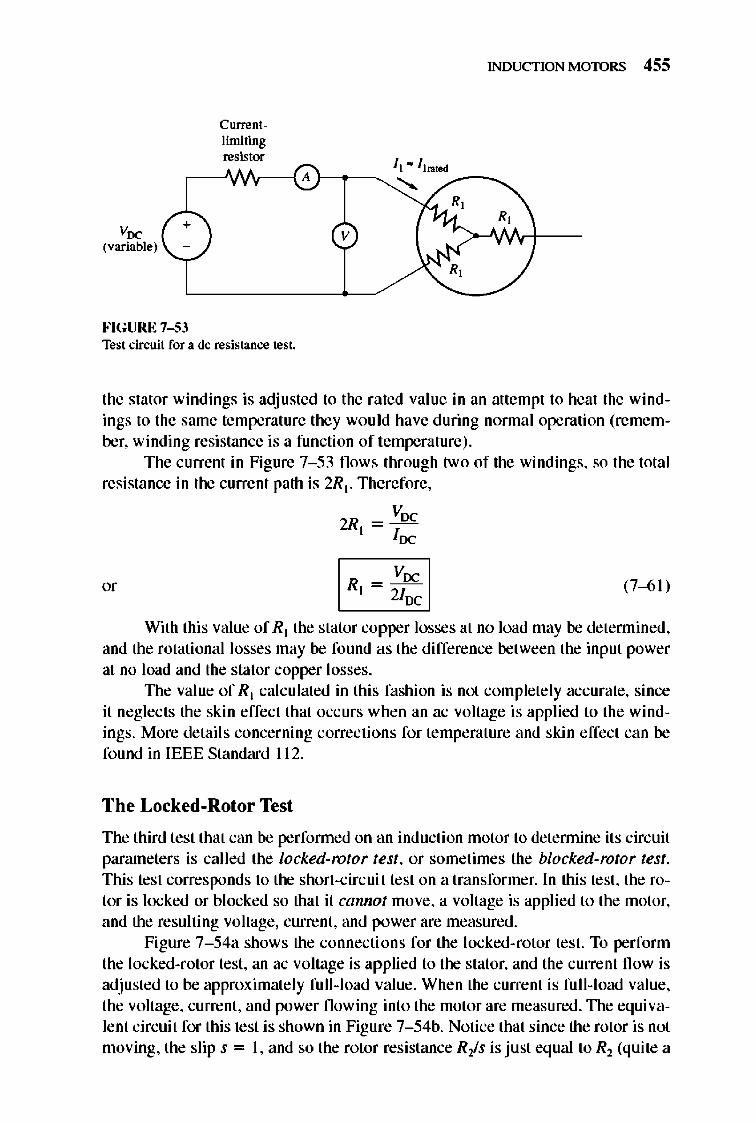
Voc (variable)
+
'-/
FIGURE 7-53
Currentlimiting resistor
Test ci['(;uit for a dc resistance test.
INDUCTION MOTORS 455
R,
the stator windings is adjusted to the rated value in an attempl to heat the windings to the same temperature they would have during nonnal operation (remember, winding resistance is a function of temperat ure).
The currenl in Figure 7- 53 flows through two of the windings, so the total resistance in the current path is 2R t . Therefore,
Voe 2Rt = -J-
oe
I R, Vee I 2loc (7-6 1)
With this value of Rt the stator copper losses at no load may be detennined, and the rotational losses may be found as the difference between the input power at no load and the stator copper losses.
The value of Rt calculated in this fashion is not completely accurate, since it neglects the skin effect that occurs when an ac voltage is applied to the windings. More details concerning corrections for temperature and skin effect can be fo und in IEEE Standard 11 2.
The Locked-Rotor Test
The third test that can be perfonned on an induction motor to detennine its circuit parameters is called the locked-rotor test, or sometimes the blocked-rotor test. This test corresponds to the short-circuit test on a transformer. In this test, the rotor is locked or blocked so that it cannot move, a voltage is applied to the motor, and the resulting voltage, current, and power are measured.
Figure 7- 54a shows the connecti ons for the locked-rotor test. To perform the locked-rotor test, an ac voltage is applied to the stator, and the current flow is adjusted to be approximately fu ll-load value. When the current is fu ll-load value, the voltage, current, and power flowing into the motor are measured. TIle equivalent circuit for this test is shown in Figure 7- 54b. Notice that since the rotor is not moving, the slip s = 1, and so the rotor resistance Ris is just eq ual to R2 (quite a
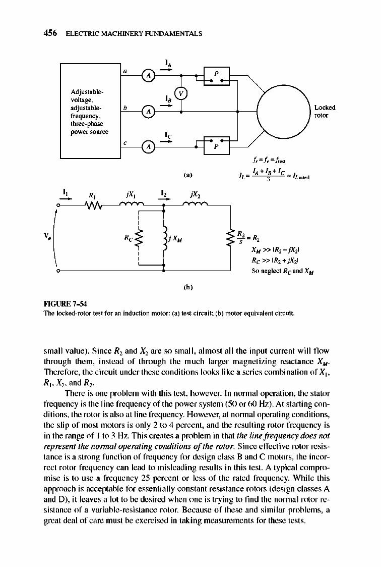
456 ELECTRIC MACHINERY RJNDAMENTALS
I, -Adjustable- V voltage. I , adjustable- b -A frequency. three-phase power source I , , -A
,,' I, R, I , --
v,
'h' I<'IGURE 7-54
p
p
/,= /,= It .. ,
XM »IR2+jX21
Rc »IR2 + jX21
So neglect Rc and XM
The locked-rotor test for an induction motor: (a) test circuit: (b) motor equivalem circuit.
small value). Since R2 and X2 are so small, almost all the input current will fl ow through them, instead of through the much larger magnetizing reactance XM .
Therefore, the circuit under these conditions looks like a series combination of X ], R ], X2 , and Rl .
nlere is one problem with this test, however. In nonnal operation, the stator frequency is the line frequency of tile power system (50 or 60 Hz). At starting conditions, the rotor is also at line frequency. However, at nonnal operating conditions, the slip of most motors is only 2 to 4 percent, and the resulting rotor frequency is in the range of I to 3 Hz. nlis creates a problem in that the line frequency does not represent the nonnal operating conditions of the rotor. Since effecti ve rotor resistance is a strong function of frequency for design class Band C motors, the incorrect rotor frequency can lead to misleading results in this test. A typical compromise is to use a frequency 25 percent or less of the rated frequency. While this approach is acceptable for essentially constant resistance rotors (design classes A and D), it leaves a lot to be desired when one is trying to find the nonnal rotor resistance of a variable-resistance rotor. Because of these and similar problems, a great deal of care must be exercised in taking measurements for these tests.
INDUCTION MOTORS 457
After a test voltage and frequency have been set up, the current fl ow in the motor is quickly adjusted to about the rated value, and the input power, voltage, and current are measured before the rotor can heat up too much. 1lle input power to the motor is given by
P = V3"VT IL cos (J
so the locked-rotor power factor can be found as
PF = cos (} = V3V, I
" and the impedance angle (J is just equal to cos- l PF.
(7-62)
The magnitude of the total impedance in the motor circuit at this time is
and the angle of the total impedance is O. Therefore,
~ = RLR + jXi.R
~ IZ"loo, e + jIZ"I'in e The locked-rotor resistance RLR is equal to
I R" - R, + R, I
while the locked-rotor reactance X~ is equal to
X LR = X ; + X;
(7-63)
(7-64)
(7-65)
(7-66)
where X; and X; are the stator and rotor reactances at the test frequency, respective ly.
The rotor resistance Rl can now be found as
(7-67)
where Rl was detennined in the dc test. The total rotor reactance referred to the stator can also be found. Since the reactance is directly proportional to the frequency, the total equivalent reactance at the nonnal operating frequency can be found as
X LR = ~ra1.ed X LR = Xl + X 2 llesl
(7-68)
Unfortunate ly, there is no simple way to separate the contributi ons of the stator and rotor reactances from each other. Over the years, experience has shown that motors of certain design types have certain proportions between the rotor and stator reactances. Figure 7- 55 summarizes this experience. In nonnal practice, it really does not matter just how XLR is broken down, since the reactance appears as the sum XI + X2 in all the torque equati ons.
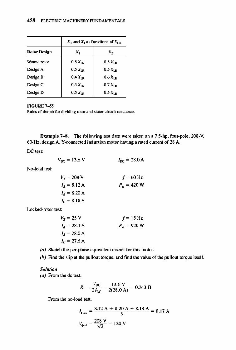
458 ELECTRIC MACHINERY RJNDAMENTALS
Xl a nd Xl as f unctions of X LR
Rotor Dcsi ~n X, X,
Wound rotor 0.5 XU! 0.5 XU!
Design A 0.5 XU! 0.5 XU!
Design B 0.4 XU! 0.6 XU!
Design C 0.3 XU! 0.7 XU!
Design D 0.5 XU! 0.5 XU!
H GURE 7-55 Rules of thumb for dividing rotor and stator ci["(;uit reactance.
Example 7-S. The following test data were taken on a 7.S-hp, four-pole, 20S-V, 60-Hz, design A, Y-colUlected induction motor having a rated current of 28 A.
DC test:
No-load test:
Voc = 13.6 V
Vr = 20SV
IA = S.12A
la = S.20A
le = S.18A
loc = 28.0A
f = 60 Hz
P",,= 420W
Locked-rotor test:
Vr = 25 V
IA = 28.IA
fa = 28.0A
Ie = 27.6A
f = IS Hz
P"" = 920W
(a) Sketch the per-phase equivalent circuit for this motor.
(b) Find the slip at the pullout torque, and find the value of the pullout torque itself.
Solutio" (a) From the dc test,
Voc 13.6 V R[ = 2/0c = 2(2S.0A) = 0.2430
From the no-load test,
IL.av = S.12A + 8.2~A + 8.ISA = S.17A
20S V V</l,nl =~ = 1lOV
INDUCTION MOTORS 459
Therefore,
1 1 120 V
ZnJ = 8.17 A = 14.70 = XI + XM
When XI is known, XM can be fOlUld. The stator copper losses are
PSCL = 3/ f RI = 3(8.17 A)2(0.243 n) = 48.7 W
Therefore, the no-load rotational losses are
= 420W - 48.7 W = 371.3 W
From the locked-rotor test,
I = 28.IA + 28.0A + 27.6A = 279A L.av 3 .
The locked-rotor impedance is
1 1_1'. _--"'- _ 25V -
ZLR - 110. - ..;J/1o. - V3"(27.9 A) - 0.517 n
and the impedance angle (J is
_ _ I P,n () - cos V!VTh
_ _ I 920W - cos v'3(25 VX27.9 A)
= cos- t 0.762 = 40.4 0
Therefore, RLR = 0.517 cos 40.4° = 0.394 0 = RI + R2. SinceRI = 0.243 n, R2 must be 0.151 n. The reactance at IS Hz is
X LR = 0.517 sin 40.4 0 = 0.335 0
The equivalent reactance at 60 Hz is
X LR = ;: X LR = (~~~~) 0.3350 = 1.340
For design class A induction motors, this reactance is assumed to be divided equally between the rotor and stator, so
XI = X2 = 0.67 n XM = IZruI - XI = 14.7 n - 0.67 0 = 14.03 n
The final per-phase equivalent circuit is shown in Figure 7- 56. (b) For this equivalent circuit, the Thevenin equivalents are fOlUld from Equations
(7-41 b), (7-44), and (7-45) to be
Vlll = 114.6 V Rlll = 0.221 n Xlll = 0.67 n Therefore, the slip at the pullout torque is given by
,~~~R~,~~~, ' -mox - v'R~ + (Xlll + X;ll (7- 53)
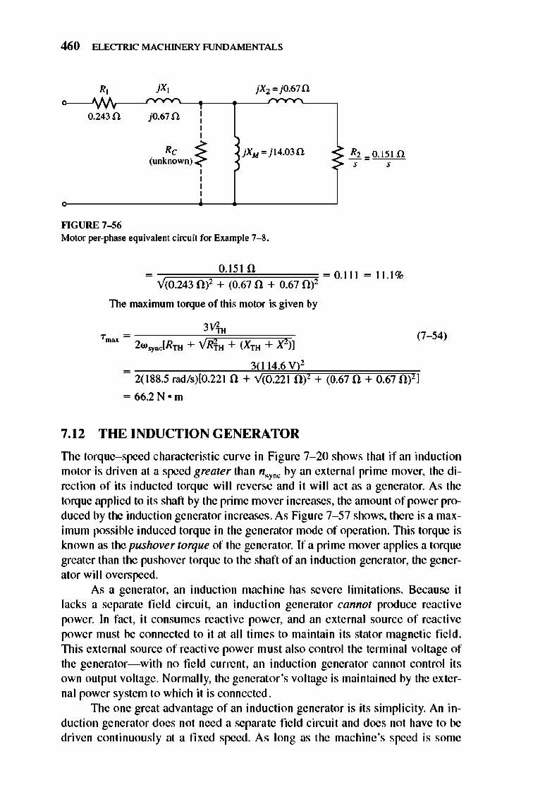
460 ELECTRIC MACHINERY RJNDAMENTALS
R,
""GURE 7-56
jO.67 fl. , , , ,
Rc -s: (unknown) <
, , , ,
jXM=j14.03fl.
Motor per-phase equivalent circuit for Example 7-8.
= 0.1510 =0.111 = 11.1% V(0.243 0)2 + (0.67 0 + 0.67 0)2
The maximum torque of this motor is given by
Tmox = 2 W'YDC[Rll{ + VRfu + (Xll{ + X2)]
_ 3(114.6 V)l
(7- 54)
- 2(188.5 rad /s)[O.22 1 0 + V(0.221 Of + (0.670 + 0.67 Of]
= 66.2N o m
7.12 THE INDUCTION GENERATOR
TIle torque-speed characteristic curve in Figure 7- 20 shows that if an induction motor is driven at a speed greater than n.y"" by an external prime mover, the direction of its inducted torque will reverse and it will act as a generator. As the torq ue applied to its shaft by the prime mover increases, the amount of power produced by the induction generator increases. As Figure 7- 57 shows, there is a maximum possible induced torque in the generator mode of operation. This torque is known as the pushover torque of the generator. If a prime mover applies a torq ue greater than the pushover torque to the shaft of an induction generator, the generator wil I overspeed.
As a generator, an induction machine has severe limitations. Because it lacks a separate field circuit, an inducti on generator cannot produce reactive power. In fact, it consumes reactive power, and an external source of reactive power must be connected to it at all times to maintain its stat or magnetic fi e ld. 1llis external source of reacti ve power mu st also control the terminal voltage of the generator-with no fie ld current , an induction generator cannot control its own output voltage. Normally, the generator's voltage is maintained by the external power system to which it is connected .
1lle one great advantage of an indu ction generator is its simplicity. An induction generator does not need a separate field circuit and does not have to be driven continuously at a fi xed speed. As long as the machine's speed is some
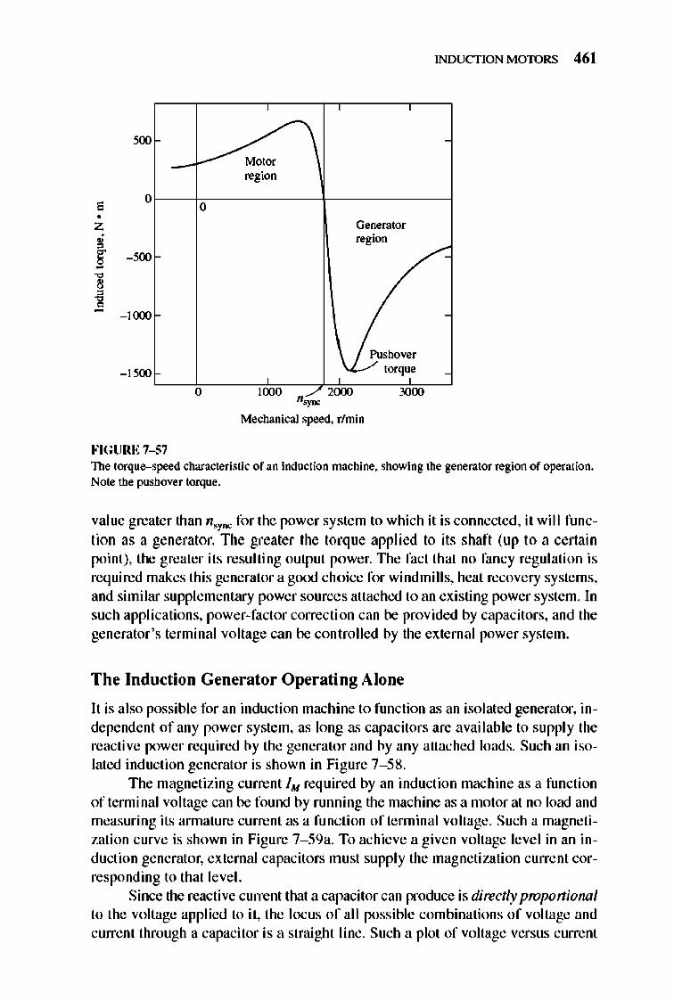
, 0 0
•
- 1(XX)
- 1500
0
FIGURE 7-57
~ region
Generator region
~
1000 _/2000 "~
Mechanical speed. r/min
Pushover torque
3000
INDUCTION MOTORS 461
The torque-speed characteristic of an induction machine. showing the generator region of operation. Note the pushover torque.
value greater than n.ync for the power system to which it is connected , it will function as a generator. The greater the torque applied to its shaft (up to a certain point), the greater its resulting output power. TIle fact that no fancy regulation is required makes this generator a gooj choice for windmills, heat recovery systems, and similar supplementary power sources attached to an existing power system. In such applications, power-factor correcti on can be provided by capacitors, and the generator 's tenninal voltage can be controlled by the external power system.
The Induction Generator Operating Alone
It is also possible for an induction machine to function as an isolated generator, independent of any power system, as long as capacitors are avai lable to supply the reactive power req uired by the generator and by any attached loads. Such an isolated induction generator is shown in Fi gure 7- 58.
The magnetizing current 1M required by an induction machine as a function of tenninal voltage can be found by running the machine as a motor at no load and measuring its annature current as a function of terrninal voltage. Such a magnetization curve is shown in Figure 7- 59a. To achieve a given voltage level in an induction generator, external capacitors mu st supply the magnetization current corresponding to that level.
Since the reactive current that a capacitor can produce is directly proportional to the voltage applied to it, the locus of all possible combinations of voltage and current through a capacitor is a straight line. Such a plot of voltage versus current
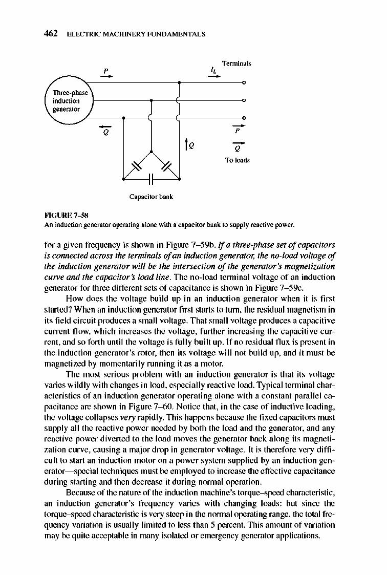
462 ELECTRIC MACHINERY RJNDAMENTALS
Terminals p I, - -
Three-phase induction generator
- -Q p
I Q -Q
To loads
Capacitor bank
""GURE 7-58 An induction generator operating alone with a capacitor bank to supply reactive power.
for a given frequency is shown in Figure 7-59b. If a three-phase set of capacitors is connected across the terminnls of an induction generator, the no-load voltage of the induction generator will be the intersection of the generator's magnetization CUlVe and the capacitor s load line. TIle no-load tenninal voltage of an induction generator for three different sets of capacit.:1.nce is shown in Figure 7-59c.
How does the voltage build up in an induction generator when it is first started ? When an induction generator first starts to turn, the residual magnetism in its fi e ld circuit produces a smal I voltage. TImt smal I voltage produces a capaciti ve current fl ow, which increases the voltage, further increasing the capacitive current, and so forth until the voltage is fully built up. If no residual flux is present in the induction generator 's rotor, then its voltage will not build up, and it must be magnetized by momentarily running it as a motor.
TIle most serious problem with an induction generator is that its voltage varies wildly with changes in load, especially reactive load . Typi cal tenninal characteristics of an induction generator operating alone with a constant parallel capacitance are shown in Figure 7-60. Notice that , in the case of inductive loading, the voltage collapses very rapidly. This happens because the fi xed capacitors must supply all the reactive power needed by both the load and the generator, and any reacti ve power diverted to the load moves the generator back along its magnetization curve, causi ng a major drop in generator voltage. It is therefore very difficult to start an inducti on motor on a power system supplied by an induction generator- special techniques must be employed to increase the effective capacitance during starting and then decrease it during nonnal operation.
Because of the nature of the induction machine's torque-speed characteristic, an induction generator 's frequency varies with changing loads : but since the torque-speed characteristic is very steep in the nonnal operating range, the total frequency variation is usually limited to less than 5 percent. This amount of variation may be quite acceptable in many isolated or emergency generator applications.
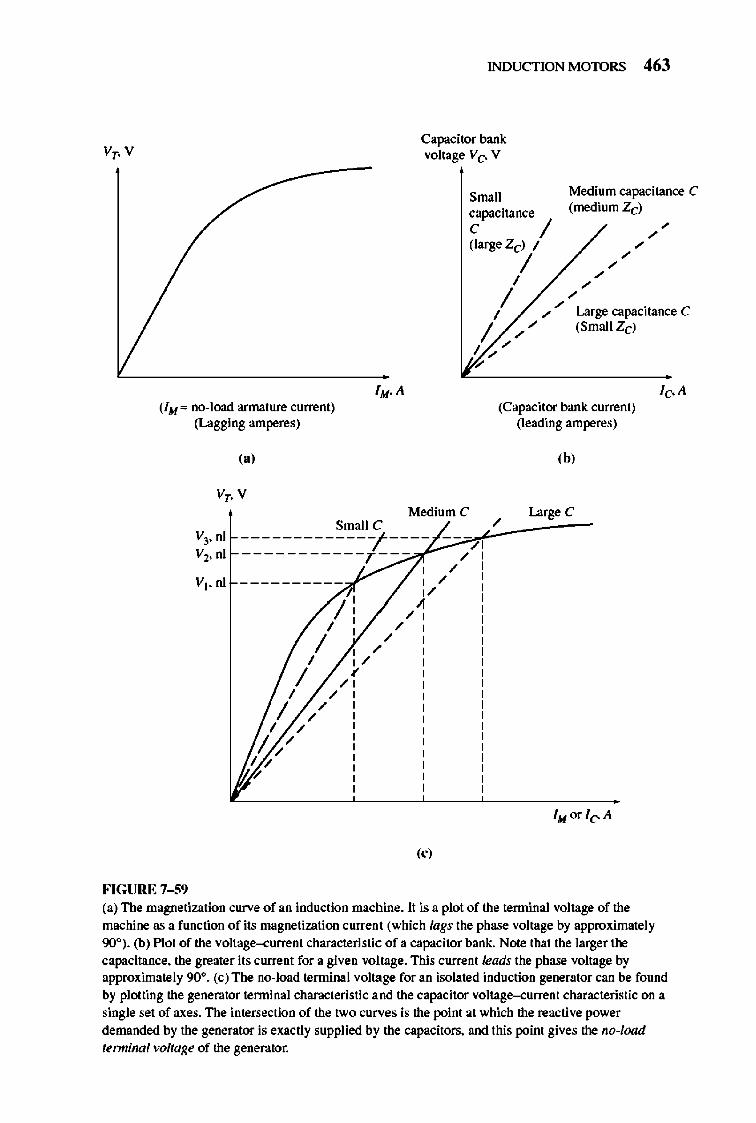
INDUCTION MOTORS 463
Capacitor bank: voltage Vc- V
(1M" no-load armature current) (Lagging amperes)
(a)
Medium C Small C -------------;'----
-----------r ---
'0' FIGURE 7-59
Small Medium capacitance C (mediumZd capacitance
C / ~/ (large Zcl / ~
/ / 1 /
/ / / ~ Large capacitance C
/ ~ ~ (Small Zcl 1/ ,
(Capacitor bank: current) (leading amperes)
,b,
I Large C
(a) The magnetization curve of an induction machine. It is a plot of the tenninal voltage of the machine as a function of its magnetization current (which lags the phase voltage by approximately 90°). (b) Plot of the voltage-.::urrent characteristic of a capacitor ban k:. Note that the larger the capacitance. the greater it s current for a given voltage. This current leads the phase voltage by approximately 90°. (c) The no-load terntinal voltage for an isolated induction generator can be found by ploning the generator terminal characteristic and the capacitor voltage-.::urrent characteristic on a single set of axes. The intersection of the two curves is the point at which the reactive power demanded by the generator is exactly supplied by the capacitors. and thi s point gives the no-load ferminall"Oltage of the generator.

464 ELECTRIC MACHINERY RJNDAMENTALS
v,
""GURE 7-60 The terminal voItage--<:urrent characteristic of an induction generator for a load with a constant lagging power factor.
Induction Generator Applications
Induction generators have been used since early in the twentieth century, but by the 1960s and 1970s they had largely disappeared from use. However, the induction generator has made a comeback since the oil price shocks of 1973. With energy costs so high, energy recovery became an important part of the economics of most industrial processes. The induction generator is ideal for such applications because it requires very litt Ie in the way of control systems or maintenance.
Because of their simplicity and small size per kilowatt of output power, induction generators are also favored very strongly for small windmills. Many commercial windmi lls are designed to operate in parall el with large power systems, supplying a fraction of the customer 's total power needs. In such operation, the power system can be relied on for voltage and frequency control , and static capacitors can be used for power-factor correction.
7.13 INDUCTION MOTOR RATINGS
A nameplate for a typical high-efficiency integral-horsepower inducti on motor is shown in Figure 7--6 1. The most important ratings present on the nameplate are
L Output power
2, Voltage
), Current
4, Power factor
5, Speed
6, Nominal efficiency
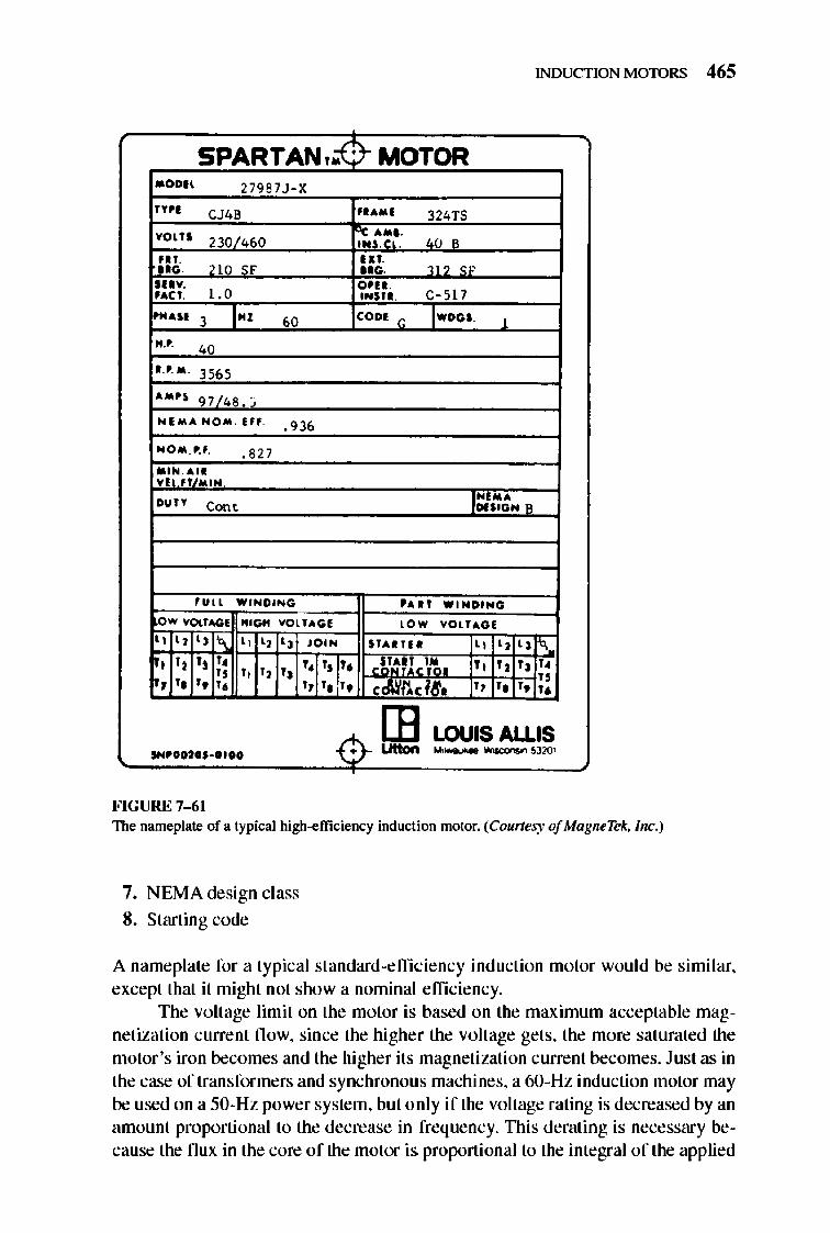
INDUCTION MOTORS 4 65
I ..... N O " . Hf .
LOUIS ALLIS
FIGURE 7-61 The nameplate of a typical lIigh-efficiency induction motor. (Courtesy of MagneTek, Inc.)
7. NEMA design class
8. Starting code
A nameplate for a typical standard-efficiency induction motor would be simi lar, except that it might not show a nominal efficiency.
The voltage limit on the motor is based on the maximum acceptable magnetization current flow, since the higher the voltage gets, the more saturated the motor 's iron becomes and the higher its magnetization current becomes. Just as in the case of transformers and synchronous machines, a 60-Hz induction motor may be used on a 50-Hz power system, but only if the voltage rating is decreased by an amount proportional to the decrease in frequency. nlis derating is necessary because the flux in the core of the motor is. proportional to the integral of the applied
466 ELECTRIC MACHINERY RJNDAMENTALS
voltage. To keep the maximum nux in the core constant while the period of integration is increasing, the average voltage leve l mu st decrease.
TIle current limit on an induction motor is based on the maximum acceptable heating in the motor's windings, and the power limit is set by the combination of the voltage and current ratings with the machine's power factor and efficiency.
NEMA design classes, starting code letters, and nominal efficiencies were discussed in previous sections of this chapter.
7. 14 SUMMA RY
TIle induction motor is the most popular type of ac motor because of its simplicity and ease of operation. An induction motor does not have a separate field circuit; instead, it depends on transfonner action to induce voltages and currents in its field circuit. In fact, an induction motor is basically a rotating transfonner. Its equivalent circuit is similar to that of a transfonner, except for the effects of varying speed.
An induction motor nonnally operates at a speed near synchronous speed, but it can never operate at exactly n,yDC. There must always be some relative moti on in order to induce a voltage in the induction motor 's fi e ld circuit. TIle rotor voltage induced by the relative motion between the rotor and the stator magnetic field produces a rotor current, and that rotor current interacts with the stator magnetic field to produce the induced torque in the motor.
In an induction motor, the slip or speed at which the maximum torque occurs can be controlled by varying the rotor resistance. The value of that maximum torque is independent of the rotor resistance. A high rotor resistance lowers the speed at which maximum torque occurs and thu s increases the starting torque of the motor. However, it pays for this starting torque by having very poor speed regulation in its normal operating range. A low rotor resistance, on the other hand, reduces the motor 's starting torque while improving its speed regulation. Any normal induction motor design must be a compromise between these two conflicting requirements.
One way to achieve such a compromise is to employ deep-bar or doublecage rotors. lllese rotors have a high effective resistance at starting and a low effective resistance under normal running conditions, thus yielding both a high starting torque and good speed regulation in the same motor. The same effect can be achieved with a wound-rotor induction motor if the rotor field resistance is varied.
Speed control of induction motors can be accomplished by changing the number of poles on the machine, by changing the applied electrical frequency, by changing the applied tenninal voltage, or by changing the rotor resistance in the case of a wound-rotor induction motor.
TIle induction machine can also be used as a generator as long as there is some source of reacti ve power (capacitors or a synchronous machine) available in the power system. An induction generator operating alone has serious voltage regulation problems, but when it operates in parallel with a large power system, the power system can control the machine's voltage. Induction generators are usually

INDUCTION MOTORS 467
rather small machines and are used principally with alternative e nergy sources, such as windmills, or with energy recovery syste ms. A lm ost all the really large generators in use are synchronou s generators.
QUESTIONS
7-1. What are slip and slip speed in an induction motor? 7-2. How does an induction motor develop torque? 7-3. Why is it impossible for an induction motor to operate at synchronous speed?
7-4. Sketch and explain the shape of a typical induction motor torque-speed characteristic curve.
7-5. What equivalent circuit element has the most direct control over the speed at which the pullout torque occurs?
7...(j. What is a deep-bar cage rotor? Why is it used? What NEMA design c1ass(es) can be built with it?
7-7. What is a double-cage cage rotor? Why is it used? What NEMA design class(es) can be built with it?
7-8. Describe the characteristics and uses of wound-rotor induction motors and of each NEMA design class of cage motors.
7-9. Why is the efficiency of an induction motor (wolUld-rotor or cage) so poor at high slips?
7-10. Name and describe four means of cont rolling the speed of induction motors. 7-11. Why is it necessary to reduce the voltage applied to an induction motor as electrical
frequency is reduced? 7-12. Why is tenninal voltage speed control limited in operating range? 7-13. What are starting code factors? What do they say about the starting current of an in-
duction motor? 7-14. How does a resistive starter circuit for an induction motor work? 7-15. What infonnation is learned in a locked-rotor test? 7-16. What infonnation is learned in a no-load test? 7-17. What actions are taken to improve the efficiency of modern high-efficiency induc-
tion motors? 7-18. What controls the tenninal voltage of an induction generator operating alone? 7-19. For what applications are induction generators typically used? 7-20. How can a wOlUld-rotor induction motor be used as a frequency changer? 7-2 1. How do different voltage-frequency patterns affect the torque-speed characteristics
of an induction motor? 7-22. Describe the major features of the solid-state induction motor drive featured in Sec
tion 7.10. 7-23. Two 480-V, lOO-hp induction motors are manufactured. One is designed for 50-Hz
operation, and one is designed for 6O-Hz operation, but they are otherwise similar. Which of these machines is larger?
7-24. An induction motor is rlUlning at the rated conditions. If the shaft load is now increased, how do the following quantities change? (a) Mechanical speed (b) Slip
468 ELECTRIC MACHINERY RJNDAMENTALS
(c) Rotor induced voltage (d) Rotor current (e) Rotor frequency (j) PRCL
(g) Synchronous speed
PROBLEMS
7-1. A dc test is performed on a 460-V. ~-connected. lOO-hp induction motor. If Voc = 24 V and foc = 80A. what is the stator resistance R]? Why is this so?
7-2. A 220-V, three-phase. two-pole. 50-Hz induction motor is ruooing at a slip of 5 percent. Find: (a) The speed of the magnetic fields in revolutions per minute (b) The speed of the rotor in revolutions per minute (c) The slip speed of the rotor (d) The rotor frequency in hertz
7-3. Answer the questions in Problem 7- 2 for a 480-V. three-phase. four-pole. 60-Hz induction motor running at a slip of 0.035.
7-4. A three-phase. 60-Hz induction motor runs at 890 rhnin at no load and at 840 rlmin at full load. (a) How many poles does this motor have? (b) What is the slip at rated load? (c) What is the speed at one-quarter of the rated load? (d) What is the rotor's electrical frequency at one-quarter of the rated load?
7-5, ASO-kW, 440-V, 50-Hz, six-pole induction motor has a slip of 6 percent when operating at full-load conditions. At full-load conditions, the friction and windage losses are 300 W, and the core losses are 600 W. Find the following values for fullload conditions: (a) The shaft speed n .. (b) The output power in watts (c) The load torque 1lood in newton-meters (d) The induced torque 11 ... in newton-meters (e) The rotor frequency in hertz
7-6. A three-phase, 60-Hz, four-pole induction motor runs at a no-load speed of 1790 rlmin and a full-load speed of 1720 r/min. Calculate the slip and the electrical frequency of the rotor at no-load and full-load conditions. What is the speed regulation of this motor [Equation (4-68)]?
7-7, A 208-V, two-pole, 60-Hz, V-connected woood-rotor induction motor is rated at IS hp. Its equivalent circuit components are
Rl = 0.200 n Xl = O.4lOn
P moc.b = 250 W
For a slip of 0.05, find (a) The line ClUTent h
R2 = 0.120 n X2 = 0.410 n
P.u.c""O
(b) The stator copper losses P SCL
(c) The air-gap power PAG
XM = IS.On
P<Ote = 180W
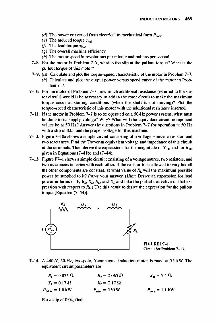
INDUCTION MOTORS 469
(d) The power converted from electrical to mechanical fonn P <oov
(e) The induced torque Tm (f) The load torque Tload
(g) The overall machine efficiency (h) The motor speed in revolutions per minute and radians per second
7-8. For the motor in Problem 7- 7. what is the slip at the pullout torque? What is the pullout torque of this motor?
7-9. (a) Calculate and plot the torque-speed characteristic of the motor in Problem 7- 7. (b) Calculate and plot the output power versus speed curve of the motor in Prob
lem 7- 7.
7-10. For the motor of Problem 7- 7. how much additional resistance (referred to the stator circuit) would it be necessary to add to the rotor circuit to make the maximum torque occur at starting conditions (when the shaft is not moving)? Plot the torque-speed characteristic of this motor with the additional resistance inserted.
7-11. If the motor in Problem 7- 7 is to be operated on a 50-Hz power system. what must be done to its supply voltage? Why? What will the equivalent circuit component values be at 50 Hz? Answer the questions in Problem 7- 7 for operation at 50 Hz with a slip of 0.05 and the proper voltage for this machine.
7-12. Figure 7-1 8a shows a simple circuit consisting of a voltage source. a resistor. and two reactances. Find the Thevenin equi valent voltage and impedance of this circuit at the terminals. Then derive the expressions for the magnitude of Vrn and for Rrn given in Equations (7-4lb) and (7-44).
7-13. Figure P7-1 shows a simple circuit consisting of a voltage source. two resistors. and two reactances in series with each other. If the resistor RL is allowed to vary but all the other components are constant. at what value of RL will the maximum possible power be supplied to it? Prove your answer. (Hint: Derive an expression for load power in terms of V. Rs. Xs. RL• and XL and take the partial derivative of that expression with respect to Rd Use this result to derive the expression for the pullout torque [Equation (7- 54)].
jXs
v(Z)
FlGURE 1'7-1 Circuit for Problem 7- 13.
7-14. A 440-V. 50-Hz, two-pole, V-connected induction motor is rated at 75 kW. The equivalent circuit parameters are
R[ = 0.075 0
X[ = 0.170
PFAW = 1.0 kW
For a slip of 0.04, find
R2 = 0.065 n X2 = O.170
Pmioc = 150W
XM = 7.20
P axe = 1.1 kW
470 ELECTRIC MACHINERY RJNDAMENTALS
(a) The line clUTent h (b) The stator power factor (c) The rotor power factor (d) The stator copper losses PSCL
(e) The air-gap power PAG
(j) The power converted from electrical to mechanical fonn P OO/IiY
(g) The induced torque 7; ...
(h) The load torque Tlood
(i) The overall machine efficiency 71 OJ The motor speed in revolutions per minute and radians per second
7-15. For the motor in Problem 7-14, what is the pullout torque? What is the slip at the pullout torque? What is the rotor speed at the pullout torque?
7-16. If the motor in Problem 7-14 is to be driven from a 440-V, 60-Hz power supply, what will the pullout torque be? What will the slip be at pullout?
7-17. Plot the following quantities for the motor in Problem 7-14 as slip varies from 0 to 10 percent: (a) Tind: (b) P OOGY: (c) P 00': (d) efficiency 71. At what slip does P 00i. equal the rated power of the machine?
7-18. A 20S-V, 60 Hz six-pole, V-connected, 25-hp design class B induction motor is tested in the laboratory, with the following results:
No load:
Locked rotor:
OC test:
208 V, 22.0 A, 1200 W, 60 Hz
24.6 V, 64.5 A, 2200 W, 15 Hz
13.5 V, 64 A
Find the equivalent circuit of this motor, and plot its torque-speed characteristic curve.
7-19. A 460-V, four-pole, 50-hp, 60-Hz, Y-colUlected, three-phase induction motor develops its full-load induced torque at 3.S percent slip when operating at 60 Hz and 460 V. The per-phase circuit model impedances of the motor are
RI = 0.33 n XI = 0.42 n
XM =30 n
X2 = 0.42 n
Mechanical, core, and stray losses may be neglected in this problem. (a) Find the value of the rotor resistance R2.
(b) Find TmalI , s"""v and the rotor speed at maximum torque for this motor. (c) Find the starting torque of this motor. (d) What code letter factor should be assigned to this motor?
7-20. Answer the following questions about the motor in Problem 7-1 9. (a) If this motor is started from a 460-V infinite bus, how much current will flow in
the motor at starting? (b) If transmission line with an impedance of 0.35 + jO.25 n per phase is used to
connect the induction motor to the infinite bus, what will the starting current of the motor be? What will the motor 's tenninal voltage be on starting?
(c) If an ideal 1.4: I step-down autotransformer is connected between the transmission line and the motor, what will the ClUTent be in the transmission line during starting? What will the voltage be at the motor end of the transmission line during starting?
INDUCTION MOTORS 471
7-21. In this chapter. we learned that a step-down autotransformer could be used to reduce the starting current drawn by an induction motor. While this technique works. an autotransfonner is relatively expensive. A much less expensive way to reduce the starting current is to use a device called y-~ starter. If an induction motor is nonnally ~-cOIUlected. it is possible to reduce its phase voltage V. (and hence its starting current) by simply reconnecting the swtor windings in Y during starting. and then restoring the cOlUlections to ~ when the motor comes up to s~ed. Answer the following questions about this type of starter. (a) How would the phase voltage at starting compare with the phase voltage under
normal lUlUling conditions? (b) How would the starting current of the Y-colUlected motor compare to the start
ing current if the motor remained in a ~-connection during starting?
7-22. A 460-V. lOO-hp. four-pole. ~-connected. 60-Hz. three-phase induction motor has a full-load slip of 5 percent. an efficiency of 92 percent. and a power factor of 0.87 lagging. At start-up. the motor develops 1.9 times the full-load torque but draws 7.5 times the rated current at the rated voltage. This motor is to be started with an autotransformer reduced-volwge starter. (a) What should the output volwge of the starter circuit be to reduce the starting
torque until it equals the rated torque of the motor? (b) What will the motor starting ClUTent and the current drawn from the supply be
at this voltage?
7-23. A wound-rotor induction motor is operating at rated voltage and frequency with its slip rings shorted and with a load of about 25 percent of the rated value for the machine. If the rotor resistance of this machine is doubled by inserting external resistors into the rotor circuit. explain what hap~ns to the following: (a) Slip s (b) Motor speed n .. (c) The induced voltage in the rotor (d) The rotor current (e) "rio<!
(f) P out
(g) PRCL
(h) Overall efficiency 7f
7-24. Answer the following questions about a 460-V, ~-COlUlected. two-pole. 75-hp. 60-Hz. starting-code-Ietter-E induction motor: (a) What is the maximum current starting current that this machine 's controller
must be designed to handle? (b) If the controller is designed to switch the stator windings from a ~ connection
to a Y connection during starting. what is the maximum starting current that the controller must be designed to handle?
(c) If a 1.25: I step-down autotransfonner starter is used during starting. what is the maximum starting current that will be drawn from the line?
7-25. When it is necessary to stop an induction motor very rapidly. many induction motor controllers reverse the direction of rotation of the magnetic fields by switching any two stator leads. When the direction of rotation of the magnetic fields is reversed. the motor develops an induced torque opposite to the current direction of rotation. so it quickly stops and tries to start turning in the opposite direction. If power is removed from the stator circuit at the moment when the rotor s~ed goes through zero.

472 ELECTRIC MACHINERY RJNDAMENTALS
then the motor has been stopped very rapidly. This technique for rapidly stopping an induction motor is called plugging. The motor of Problem 7- 19 is running al rated conditions and is to be stopped by plugging. (a) What is the slip s before plugging? (b) What is the frequency of the rotor before plugging? (c) What is the induced torque "ria<! before plugging? (d) What is the slip s inunediately after switching the stator leads? (e) What is the frequency of the rotor immediately after switching the stator leads? (j) What is the induced torque "ria<! immediately after switching the stator leads?
REFERENCES
I. Alger. Phillip. Induction Machines. 2nd ed. New York: Gordon and Breach. 1970. 2. Del Toro. V. Electric Machines and Power Systems. Englewood Cliffs. N.J.: Prentice-Hall.
1985. 3. Filzgerald. A. E. and C. Kings ley. Jr. Electric Machinery. New York: McGraw-Hilt. 1952. 4. Filzgera ld. A. E .• C. Kings ley. Jr .• and S. D. Umans. Electric Machinery. 51h ed. New York:
McGraw-Hilt. 1990. 5. Institute of Electrical and Electronics Engineers. Standard Test Procedure for Pol)phase
Induction MOlOrs and Genemtors. IEEE Standaro 112-1996. New York: IEEE. 1996. 6. Kosow. Irving L. Control of Electric Motors. Englewood Cliffs. N.J.: Prentice-Hall. 1972. 7. McPherson. George. An Introduction 10 Electrical Machines and Tmnsfonners. New York:
Wiley. 1981. 8. National Eleclrical Manufaclurers Association. MOlOrs and GenemlOrs. Publication No. MG I-
1993. Washington. D.C.: NEMA.I993. 9. Siemon. G. R .• and A. Siraughen. Electric Machines. Reading. Mass. : Addison-Wesley. 1980.
10. Vithayalhil. Joseph. Pov.'ef Electronics: Principles and Applications. New York: McGraw-Hill. 1995.
II. Weminck. E. H. (ed. ). Electric MOlOr Handbook. London: McGraw-Hill. 1978.
CHAPTER
8 DC MACHINERY
FUNDAMENTALS
DC machines are generators that convert mechanical energy to de e lectric energy and motors that convert de e lectric energy to mechanical energy.
Most de machines are like ac machines in that they have ac voltages and currents within the rn---dc machines have a de output only because a mechanism ex ists that converts the inte rnal ac voltages to de voltages at the ir tenninals. Since this mechanism is called a commutator, de machinery is also known as commutating machinery.
The fundamental principles invo lved in the operati on of de machines are very simple. Unfortunately, they are usually somewhat obscured by the complicated construction of real machines. This chapter will first explain the principles of de machine operation by using simple examples and then consider some of the complications that occ ur in real dc machines.
S.I A SIMPLE ROTATING LOOP BETWEEN CURVED POLE FACES
The linear machine studied in Section 1.8 served as an introduction to basic machine behavior. Its response to loading and to changing magnetic fields closely resembles the behavior of the real dc generators and motors that we will study in Chapter 9. However, real generators and motors do not move in a straight linethey rotate. The next step toward understanding real dc machines is to study the simplest possible example of a rotating machine.
The simplest possible rotating dc machine is shown in Figure 8-1. It consists of a si ngle loop of wire rotating about a fixed axis. The rotating part of this machine is called the rotor, and the stationary part is called the stator. TIle magnetic
473
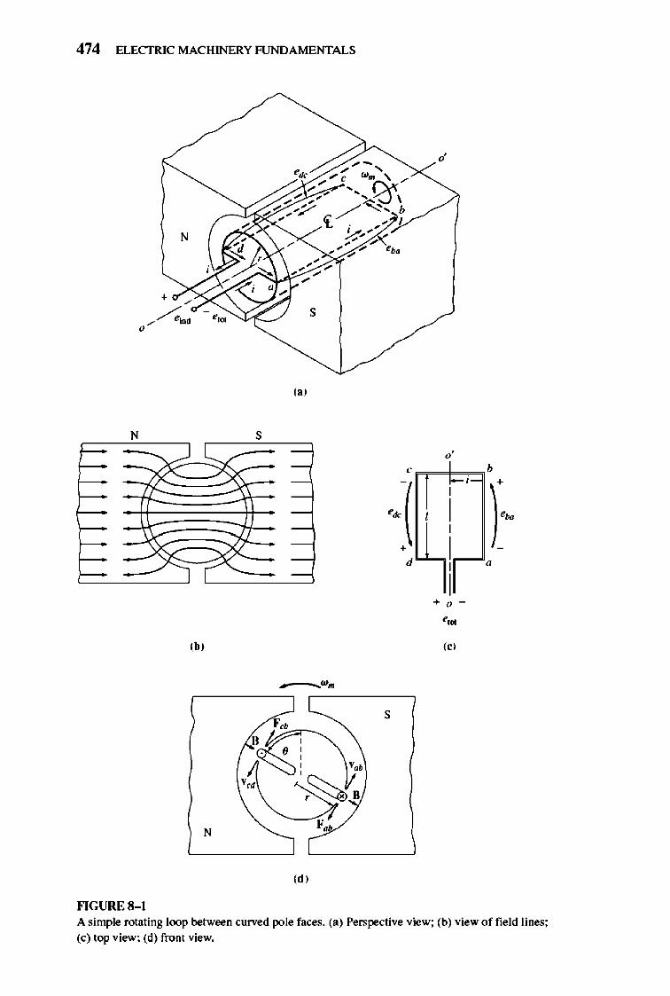
474 ELECTRIC MACHINERY RJNDAMENTALS
d
N
s
(. )
N s
r-= >s -
f:::: = '-- -
~ -
~ -
f-- -
0 '
< b
.. -( ): . •
d "
• " ',. (b) «)
F" s
• ,
N F "
(d)
""GURE 8-1 A simple rotating loop between curved pole faces. (a) Perspective view; (b) view of field lines; (e) top view; (d) front view.
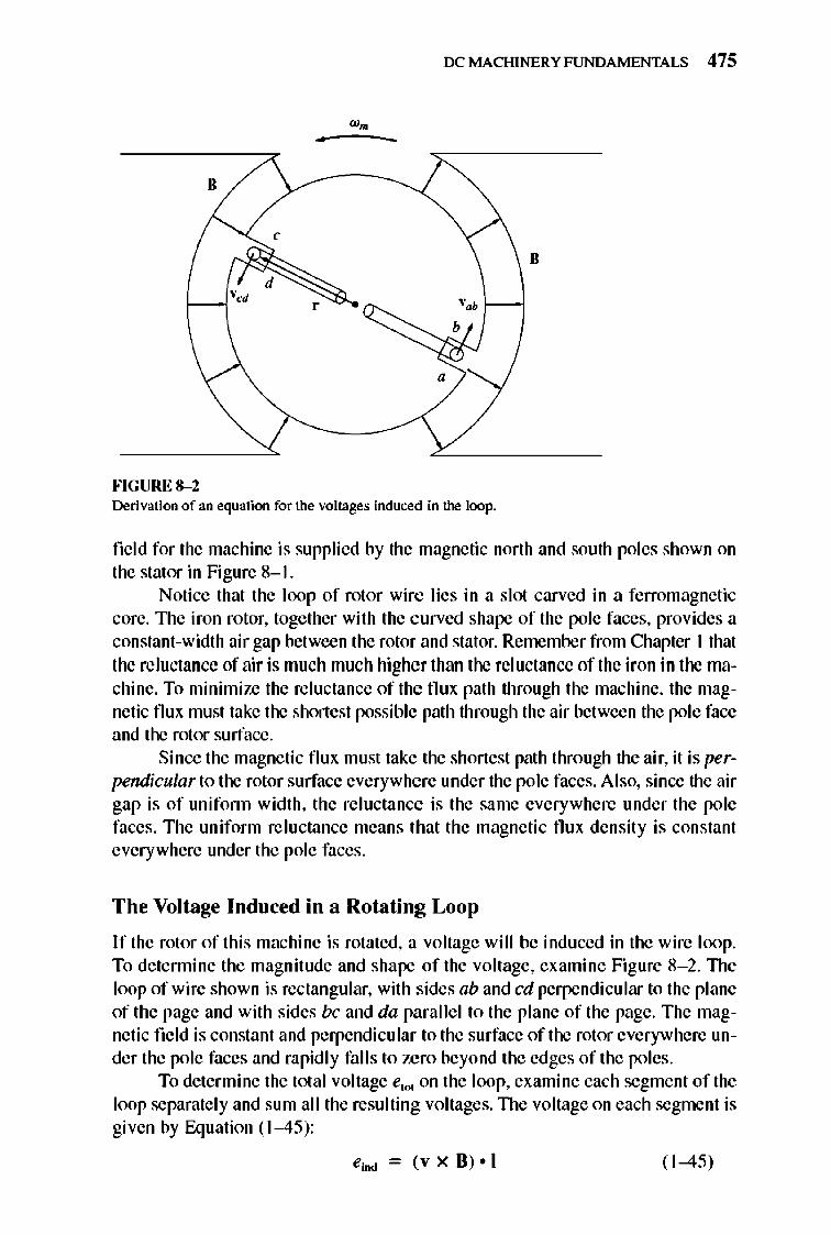
OCMACHINERYFUNDAMENTALS 475
.. -
"
•
FIGURE 8-2 Derivation of an equation for the voltages induced in the loop.
field for the machine is supplied by the magnetic north and south poles shown on the stator in Figure 8- 1.
Notice that the loop of rotor wire lies in a slot carved in a ferromagnetic core. 1lle iron rotor, together with the curved shape of the pole faces, provides a constant-width air gap between the rotor and stator. Remember from Chapter I that the reluctance of air is much much higher than the rei uctance of the iron in the machine. To minimize the reluctance of the flux path through the machine, the magnetic flux must take the shortest possible path through the air between the pole face and the rotor surface.
Since the magnetic flux must take the shortest path through the air, it is perpendicular to the rotor surface everywhere under the pole faces. Also, since the air gap is of unifonn width, the reluctance is the same everywhere under the pole faces. The uniform reluctance means that the magnetic flux density is constant everywhere under the pole faces.
The Voltage Induced in a Rotating Loop
If the rotor of this machine is rotated, a voltage will be induced in the wire loop. To detennine the magnitude and shape of the voltage, examine Figure 8- 2. 1lle loop of wire shown is rectangular, with sides ab and cd perpendicular to the plane of the page and with sides be and da paralle l to the plane of the page. The magnetic field is constant and perpendicular to the surface of the rotor everywhere under the pole faces and rapid ly falls to zero beyond the edges of the poles.
To determine the total voltage e,OI on the loop, examine each segment of the loop separate ly and sum all the resulting voltages. TIle voltage on each segment is given by Equation (1-45):
eind = (v x B) • I ( 1-45)
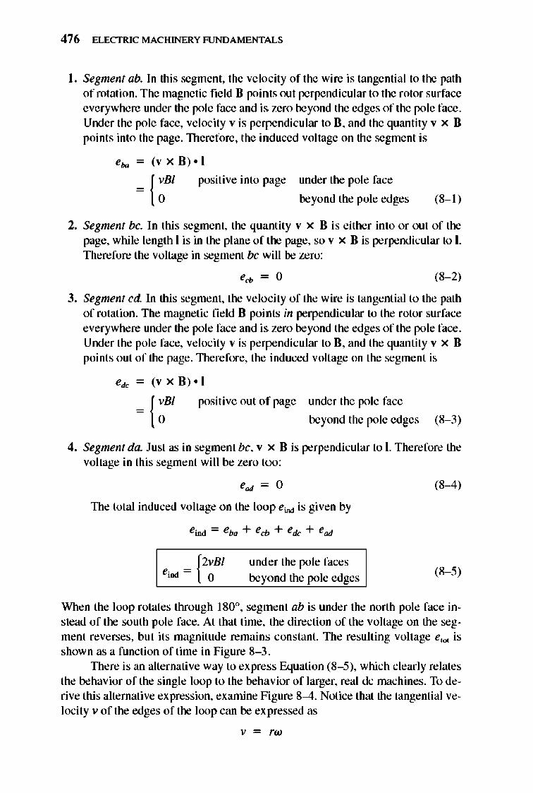
476 ELECTRIC MACHINERY RJNDAMENTALS
I. Segment abo In this segment, the velocity of the wire is tangential to the path of rotation. The magnetic field 8 points out perpendicular to the rotor surface everywhere under the pole face and is. zero beyond the edges of the pole face. Under the pole face, ve locity v is perpendicular to 8 , and the quantity v x 8 points into the page. TIlerefore, the induced voltage on the segment is
positive into page under the pole face
beyond the pole edges (8-1 )
2. Segment be. In this segment, the quantity v x 8 is either into or out of the page, while length 1 is in the plane of the page, so v x 8 is perpendicular to I. Therefore the voltage in segment be will be zero:
ecb = 0 (8- 2)
3. Segment ed. In this segment, the velocity of the wire is tangential to the path of rotation. The magnetic fie ld 8 points in perpendicular to the rotor surface everywhere under the pole face and is. zero beyond the edges of the pole face. Under the pole face, ve locity v is perpendicular to 8 , and the quantity v x 8 points out of the page. 1llerefore, the induced voltage on the segment is
positive out of page under the pole face
beyond the pole edges (8- 3)
4. Segment da. Ju st as in segment be, v x 8 is perpendicular to I. Therefore the voltage in this segment will be zero too :
ead = 0 (8-4)
1lle total induced voltage on the loop ei!>d is given by
under the pole faces beyond the pole edges
(8- 5)
When the loop rotates through 180°, segment ab is under the north pole face instead of the south pole face. At that time, the direction of the voltage on the segment reverses, but its magnitude remains constant. The resulting voltage e,,,, is shown as a function of time in Figure 8- 3 .
1llere is an alternative way to express Equation (8- 5), which clearly relates the behavior of the single loop to the behavior of larger, real dc machines. To derive this alternative expression, examine Figure 8-4. Notice that the tangential velocity v of the edges of the loop can be expressed as
v = rw
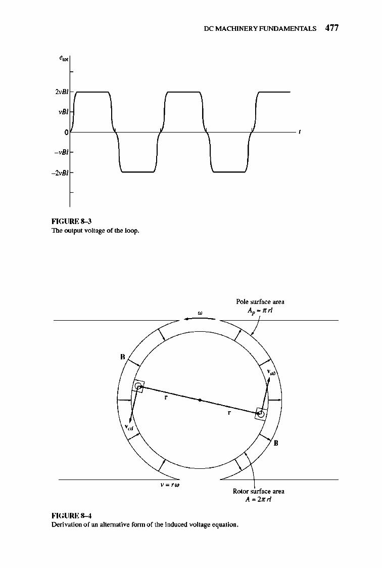
IX: MACHINERY FUNDAMENTALS 477
2vBI C r----,
, 81
0r-----~.------r------~------T_------ ,
- vBI
- 2vBI
FIGURE 8-3 The output voltage of the loop.
-
v=rw
FIGURE 8-4
w
,
Pole surface area Ap .. nrl
•
Rotor surface area A =2nrl
Derivation of an alternative form of the induced voltage equation.
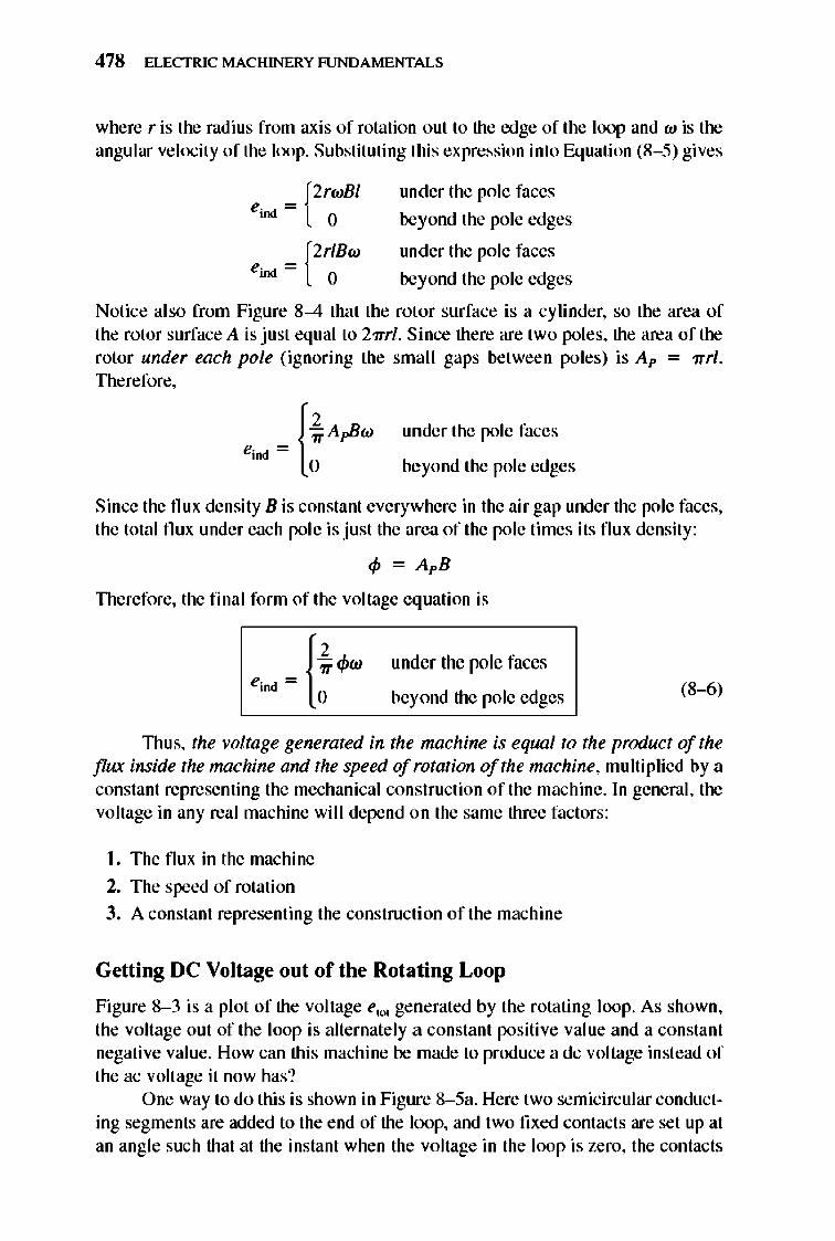
478 ELECTRIC MACHINERY RJNDAMENTALS
where r is the radius from axis of rotation out to the edge of the loop and w is the angular velocity of the loop. Substituting this expression into Equation (8- 5) gives
_ [2rWBI eioo - 0
eioo
= {2r~BW
under the pole faces
beyond the pole edges
under the pole faces
beyond the pole edges
Notice also from Figure 8-4 that the rotor surface is a cylinder, so the area of the rotor surface A is just equal to 2nrl. Since there are two poles, the area of the rotor under each pole (ignoring the small gaps between poles) is Ap = nrl. TIlerefore,
under the pole faces
beyond the pole edges
Since the nux density B is constant everywhere in the air gap under the pole faces, the total flux under each pole is just the area of the pole times its flux density:
Therefore, the final form of the voltage equation is
e. , ~ {~"'W '" 0
under the pole faces
beyond the pole edges (8-6)
TIms, the voltage generated in the machine is equnl to the product of the flux inside the mnchine and the speed of rotation of the machine, multiplied by a constant representing the mechanical construction of the machine. In general, the voltage in any real machine will depend on the same three factors:
I. The flux in the machine
2. The speed of rotation
3. A constant representing the construction of the machine
Getting DC Voltage out of the Rotating Loop
Figure 8- 3 is a pl ot of the voltage e"", generated by the rotating loop. As shown, the voltage out of the loop is alternately a constant positive value and a constant negative value. How can this machine be made to produce a dc voltage instead of the ac voltage it now has?
One way to do this is shown in Figure 8- 5a. Here two semicircular conducting segments are added to the end of the loop, and two fixed contacts are set up at an angle such that at the instant when the voltage in the loop is zero, the contacts
IX: MACHINERY FUNDAMENTALS 479
N
Commutator
s Brushes
(.)
- <'W
(b)
FIGURE 8-S Producing a dc output from the machine with a commutator and brushes. (a) Perspective view; (b) the resulting output voltage.
short-circuit the two segments. In this fashion, every time the voltage of the loop switches direction, the contacts also switch connections, and the output of the contacts is always built up in the same way (Figure 8- 5b). This connection-switching process is known as commutation. TIle rotating semicircular segments are called commutator segments, and the fi xed contacts are calJed brushes.
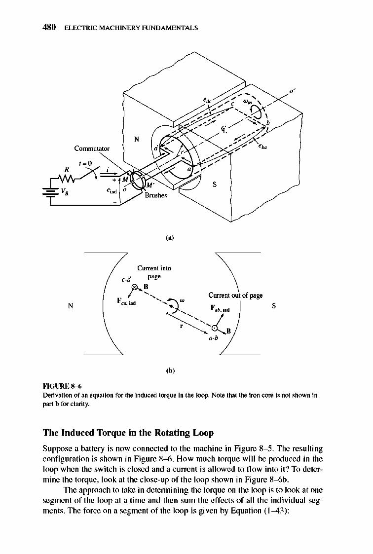
480 ELECTRIC MACHINERY RJNDAMENTALS
N Commutator
s
(a)
Current into cod page
N
,...!..... Current out of page F cJ, imd .......... :::J w, S
~,Z, "-b
(h)
""GURE 8-6 Derivation of an equation for the induced torque in the loop. Note that the iron core is not shown in part b for clarity.
The Induced Torque in the Rotating Loop
Suppose a battery is now connected to the machine in Figure 8- 5. The resulting configuration is shown in Figure 8-6 . How much torque will be produced in the loop when the switch is closed and a current is allowed to fl ow into it ? To determine the torque, look at the close-up of the loop shown in Figure 8-6b .
TIle approach to take in detennining the torque on the loop is to look at one segment of the loop at a time and then sum the effects of all the indi vidual segments . TIle force on a segment of the loop is given by Equation (1-43):
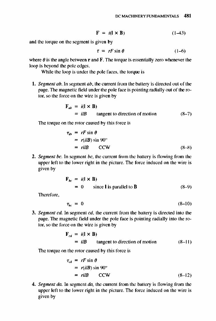
IX: MACHINERY FUNDAMENTALS 481
F = i(lx8) ( 1-43)
and the torque on the segment is given by
T = rFsin () (1-6)
where () is the angle between rand F. The torque is essentially zero whenever the loop is beyond the pole edges .
While the loop is under the pole faces, the torque is
I. Segmentab. In segment ab, the current from the battery is directed out of the page. TIle magnetic fie ld under the pole face is pointing radially out of the rotor, so the force on the wire is given by
Fab- i(lx8)
- ilB tangent to direction of motion
TIle torque on the rotor caused by this force is
"Tab - rF sin ()
- r(iIB) sin 900
- rilB CCW
(8- 7)
(8-8)
2. Segment be. In segment be, the current from the battery is flowing from the upper left to the lower right in the pi cture. The force induced on the wire is given by
Fbc - i(lx8)
- 0 since I is parallel to 8 (8- 9)
TIlerefore,
"Tb< = 0 (8-10)
3. Segment ed. In segment ed, the current from the battery is directed into the page. The magnetic fie ld under the pole face is pointing radially into the rotor, so the force on the wire is given by
Fed - i(l X 8 )
- ilB tangent to direction of motion
TIle torque on the rotor caused by this force is
"Ted - rF sin ()
- r(iIB) sin 900
- rilB CCW
(8-11 )
(8-1 2)
4. Segment 00. In segment 00, the current from the battery is flowing from the upper left to the lower right in the pi cture. The force induced on the wire is given by
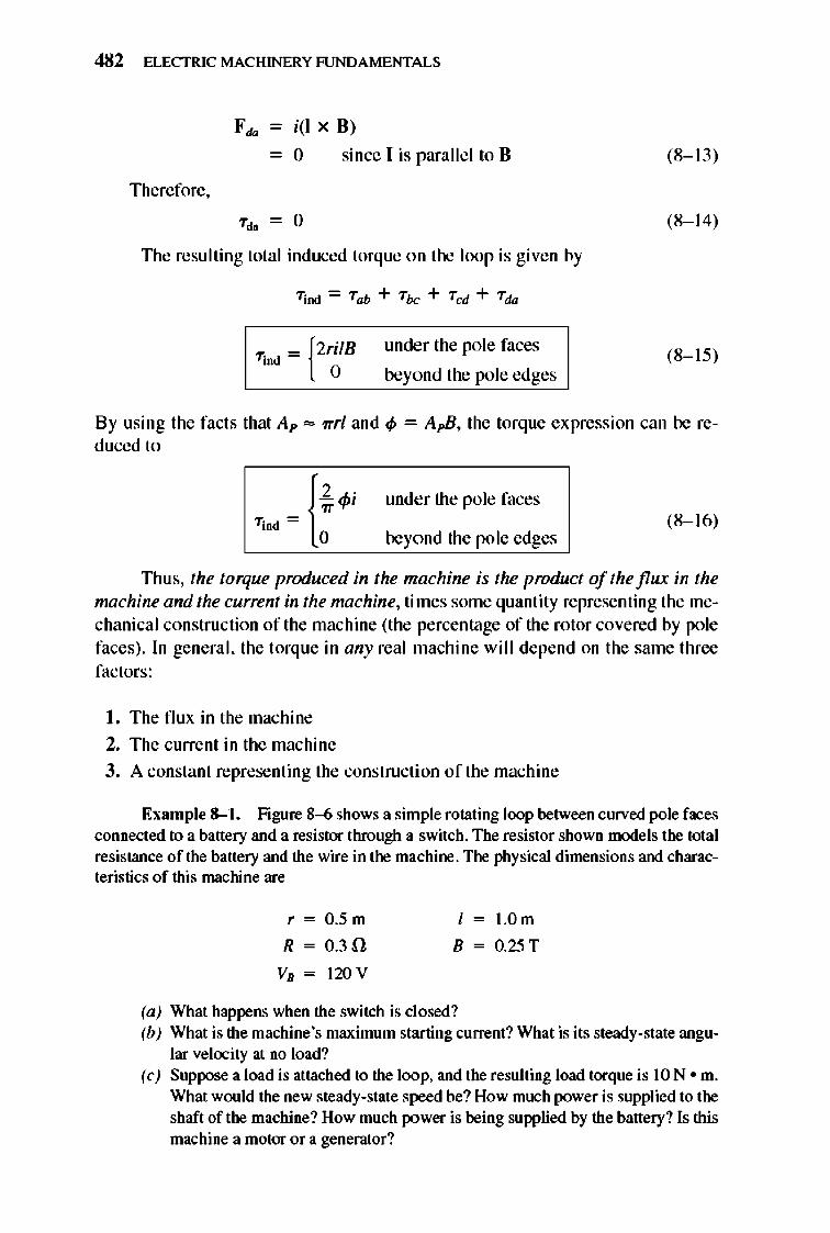
482 ELECTRIC MACHINERY RJNDAMENTALS
Fda - i(I XB)
- 0 since I is parallel to B
Therefore ,
Tdo = 0
TIle resulting total induced torque on the loop is given by
under the pole faces
beyond the pole edges
(8-13)
(8-14)
(8-15)
By using the facts that Ap ,., rrrl and cp = ApB, the torque expression can be reduced to
{, ~. - ~,
Tind = : under the pole faces
(8-16) beyond the pole edges
TIlU S, the torque produced in the machine is the product of the flux in the machine and the current in the machine, times some quantity representing the mechanical construction of the machine (the percentage of the rotor covered by pole faces) . In general, the torque in any real machine will depend on the same three factors:
L The flux in the machine 2, The current in the machine
), A constant representing the construction of the machine
Example 8-1. Figure 8--6 shows a simple rotating loop between curved pole faces connected to a battery and a resistor through a switch. The resistor shown models the total resistance of the battery and the wire in the machine. The physical dimensions and characteristics of this machine are
r = O.5m
R = 0.3!l
VB = 120 V
I = 1.0m
B = O.25T
(a) What happens when the switch is closed? (b) What is the machine's maximum starting current? What is its steady-state angu
lar velocity at no load? (c) Suppose a load is attached to the loop, and the resulting load torque is 10 N· m.
What would the new steady-state speed be? How much power is supplied to the shaft of the machine? How much power is being supplied by the battery? Is this machine a motor or a generator?
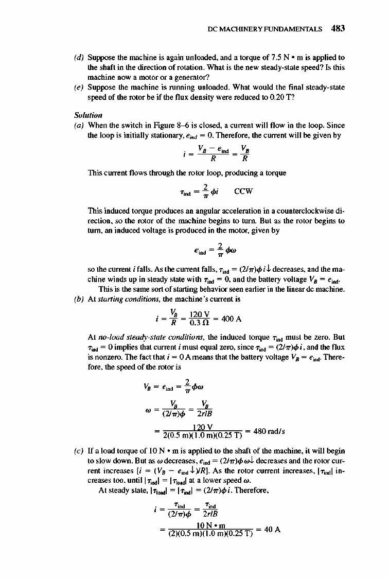
IX: MACHINERY FUNDAMENTALS 483
(d) Suppose the machine is again unloaded, and a torque of 7.5 N • m is applied to the shaft in the direction of rotation. What is the new steady-state speed? Is this machine now a motor or a generator?
(e) Suppose the machine is rulUling unloaded. What would the final steady-state speed of the rotor be if the flux density were reduced to 0.20 T?
Solution (a) When the switch in Figure 8-6 is closed, a current will flow in the loop. Since
the loop is initially stationary, e jod = O. Therefore, the current will be given by
VB - e i od VB i = = R R
This current flows through the rotor loop, producing a torque
2.; 7iod = - 'I"
~ ccw
This induced torque produces an angular acceleration in a counterclockwise direction, so the rotor of the machine begins to turn. But as the rotor begins to tum, an induced voltage is produced in the motor, given by
so the current i falls. As the current falls, 7ind = (2hr)cpi.t.. decreases, and the machine winds up in steady state with 7iod = 0, and the battery voltage VB = eind'
This is the same sort of starting behavior seen earlier in the linear dc machine. (b) At starting conditions, the machine's current is
. VB l20V I = J[ = 0.3fi = 400 A
At no-load steady-state conditions, the induced torque 7ind must be zero. But 7ind = 0 implies that current i must equal zero, since 7ind = (2hr)cpi, and the flux is nonzero. The fact that i = 0 A means that the battery voltage VB = eind' Therefore, the speed of the rotor is
_ VB _ ~ W - (2i1r)cp - 2rlB
l20V = 2(0.5 mXI.O mXO.25 T) = 480 rad/ s
(c) If a load torque of 10 N om is applied to the shaft of the machine, it will begin to slow down. But as w decreases , eind = (2hr)cpwJ. decreases and the rotor current increases [i = (VB - eind.t.. )/R]. As the rotor current increases, ITIOdI increases too, until I 7;",,1 = 171Nd1 at a lower speed w.
At steady state, 171 .... 1 = 17indl = (2hr)cpi. Therefore,
. 7 jod 7ind 1= = --(2hr)cp 2rlB
ION om = (2XO.5 m)(1.0 mXO.25 T) = 40 A
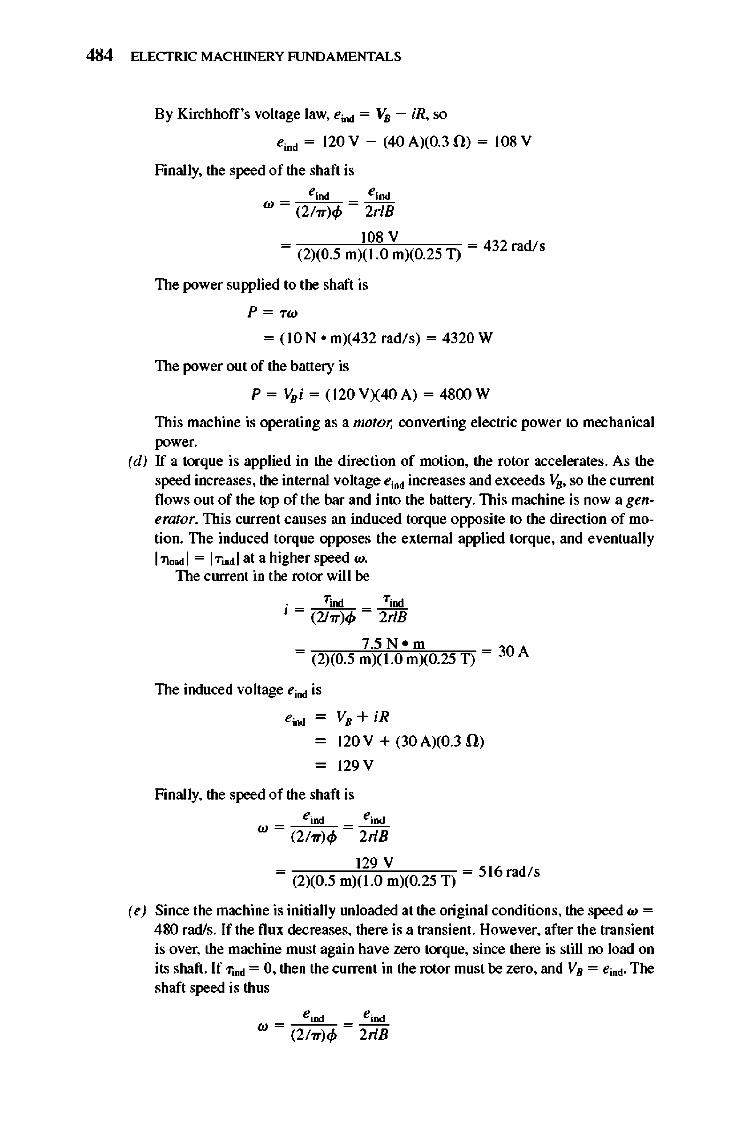
484 ELECTRIC MACHINERY RJNDAMENTALS
By Kirchhoff 's voltage law, eind = VB - iR, so
eiDd = 120 V - (40 AXO.3 ll) = 108 V
Finally, the speed of the shaft is ejDd eiDd
w = (2/Tr)q, = 2rlB
108 V = (2)(0.5 mX1. 0 m)(0.25 1) = 432 radls
The power supplied to the shaft is
P = T W
= ( 10 N • mX432 rad/s) = 4320 W
The power out of the battery is
P = VBi = (120 V)(40 A) = 4800 W
This machine is operating as a motor, converting electric power to mechanical power.
(d) If a torque is applied in the direction of motion, the rotor accelerates. As the speed increases, the internal voltage eind increases and exceeds Vs, so the current flows o ut of the top of the bar and into the battery. This machine is now a genemtor. This current causes an induced torque opposite to the direction of motion. The induced torque opposes the external applied torque, and eventually I11NdI = ITUldI at a higher speed w.
The current in the rotor will be
. 7ind Tim I = (2hr)q, = 2rlB
7.5 N. m = (2)(0.5 mX1.0 mXO.25 T) = 30 A
The induced voltage eind is
eind - VB + iR
- 120 V + (30 AXO.3 !l)
- 129 V
Finally, the speed of the shaft is eiod eiDd
W = (2/Tr)q, = 2rlB
129 V = (2X0.5 m)( 1.0 mXO.25 T) = 516 radls
(e) Since the machine is initially lUlloaded at the original conditions, the speed w = 480 radls. If the flux decreases, there is a transient. However, after the transient is over, the machine must again have zero torque, since there is still no load on its shaft. If"TIDd = 0, then the current in the rotor must be zero, and VB = eind. The shaft speed is thus
eiod eiDd w = (2/Tr)q, = 2rlB
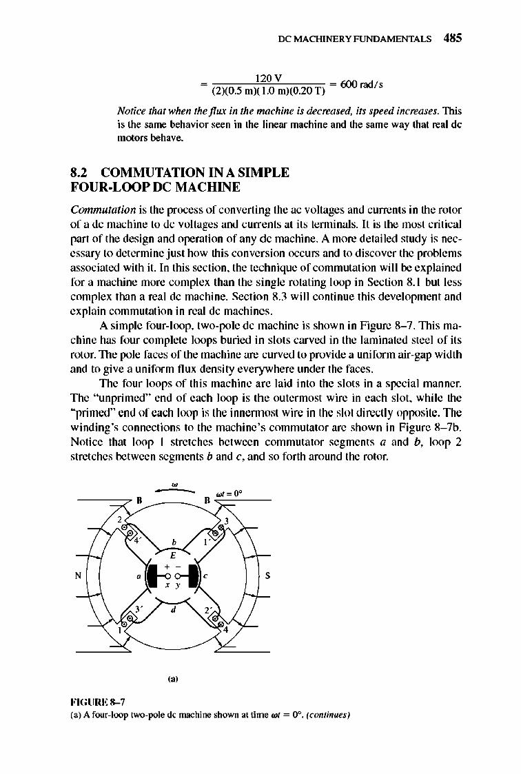
IX: MACHINERY FUNDAMENTALS 485
120 V = (2)(0.5 mX 1.0 m)(0.20 T) = 600 rad /s
Notice that when the flux in the machine is decreased, its speed increases. This is the same behavior seen in the linear machine and the same way that real dc motors behave.
8.2 COMMUTATION IN A SIMPLE FOUR-LOOP DC MACHINE
Commutation is the process of converting the ac voltages and currents in the rotor of a dc machine to dc voltages and currents at its tenninals. It is the most critical part of the design and operation of any dc machine. A more detailed study is necessary to determine just how this conversion occurs and to discover the problems associated with it. In this section, the technique of commutation will be explained for a machine more complex than the single rotating loop in Section 8. 1 but less complex than a real dc machine. Section 8.3 will continue this development and explain commutation in real dc machines.
A simple four-l oop, two-pole dc machine is shown in Figure 8- 7.lllis machine has four complete loops buried in slots carved in the laminated steel of its rotor. TIle pole faces of the machine are curved to provide a uniform air-gap width and to give a uniform nux density everywhere under the faces .
The four loops of this machine are laid into the slots in a special manner. The "unprimed" end of each loop is the outermost wire in each slot, while the "primed" end of each loop is the innennost wire in the slot directly opposite. The winding's connections to the machine 's commutator are shown in Figure 8- 7b. Notice that loop 1 stretches between commutator segment s a and b, loop 2 stretches between segments band c, and so forth around the rotor .
•
N s
d
(. J
FIGURE 8-7 (a) A four-toop two-pole dc machine shown at time WI = 0°. (continues)
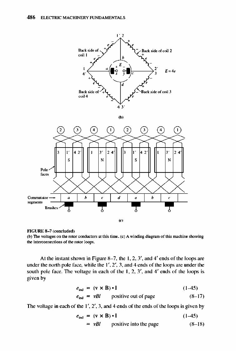
486 ELECTRIC MACHINERY RJNDAMENTALS
Back side of coil I
Back side of coil 4
3 I ' 42'
S
Pol , faces
Comrnutator _ segments -~-
Brushes
""GURE 8-7 (roncluded)
3' 24'
N
I ' 2
,
b
43'
(bl
Back side of coil 2 • ,
E=4~
Back side of coil 3
3 ] ' 42'
S
3' 24'
N
("
(b) The voltages on the rotor conductors at this time, (c) A winding diagram of this machine showing
the interconnections of the rotor loops.
At the instant shown in Figure 8- 7, the \ ,2,3', and 4' ends of the loops are under the north pole face, while the \ ',2',3, and 4 ends of the loops are underthe south pole face. TIle voltage in each of the 1,2,3', and 4' ends of the loops is given by
eind - (v x B) • I
positi ve out of page
( 1-45)
(8-1 7)
TIle voltage in each of the 1 " 2', 3, and 4 ends of the ends of the loops is given by
- vBI positive into the page
( 1-45)
(8-1 8)
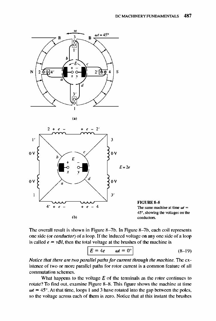
IX: MACHINERY FUNDAMENTALS 487
" -----:7 ,,/ ·---,;..3,--__., • .;:"",::=.::45,-' __
I '
b
N
3'
I"
2 + e -
I '
ov
ov
4' + e -
Ib,
d
+ e - 2'
,
d
+ e - 4
4 S
3
ov
ov
3'
E=2e
FIGURE 8-8 The same machine at time WI =
45°. showing the voltages on the conductors.
The overall result is shown in Figure 8- 7b. In Figure 8- 7b, each coil represents one side (or conductor) of a loop. Ir the induced voltage on anyone side of a loop is called e = vB I, then the total voltage at the brushes or tile machine is
1£ -4, wt -O' I (8-1 9)
Notice that there are two parallel paths for current through the machine. The existence of two or more parallcl paths for rotor current is a common feature of all commutation schemes.
What happens to the voltage E of the terminals as the rotor continues to rotate? To fmd out , examine Figure 8- 8. lllis fi gure shows the machine at time wt = 45 °. At that time, loops 1 and 3 have rotated into the gap between the poles, so the voltage across each of them is zero. Notice that at this instant the brushes
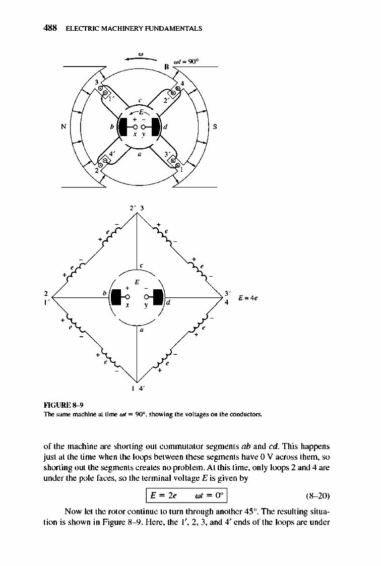
488 ELECTRIC MACHINERY RJNDAMENTALS
w • - wl= 90°
" 3
, ~E~
N b ~f-I d s
" 2
The same machine at time WI = 90°, showing the voltages on the conductors.
of the machine are shorting out commutator segments ab and cd. This happens just at the time when the loops between these segments have 0 V across them, so shorting out the segments creates no problem. At this time, only loops 2 and 4 are under the pole faces, so the terminal voltage E is given by
I E ~ " (8- 20)
Now let the rotor continue to turn through another 45°. TIle resulting situation is shown in Figure 8- 9. Here, the 1',2,3, and 4' ends of the loops are under
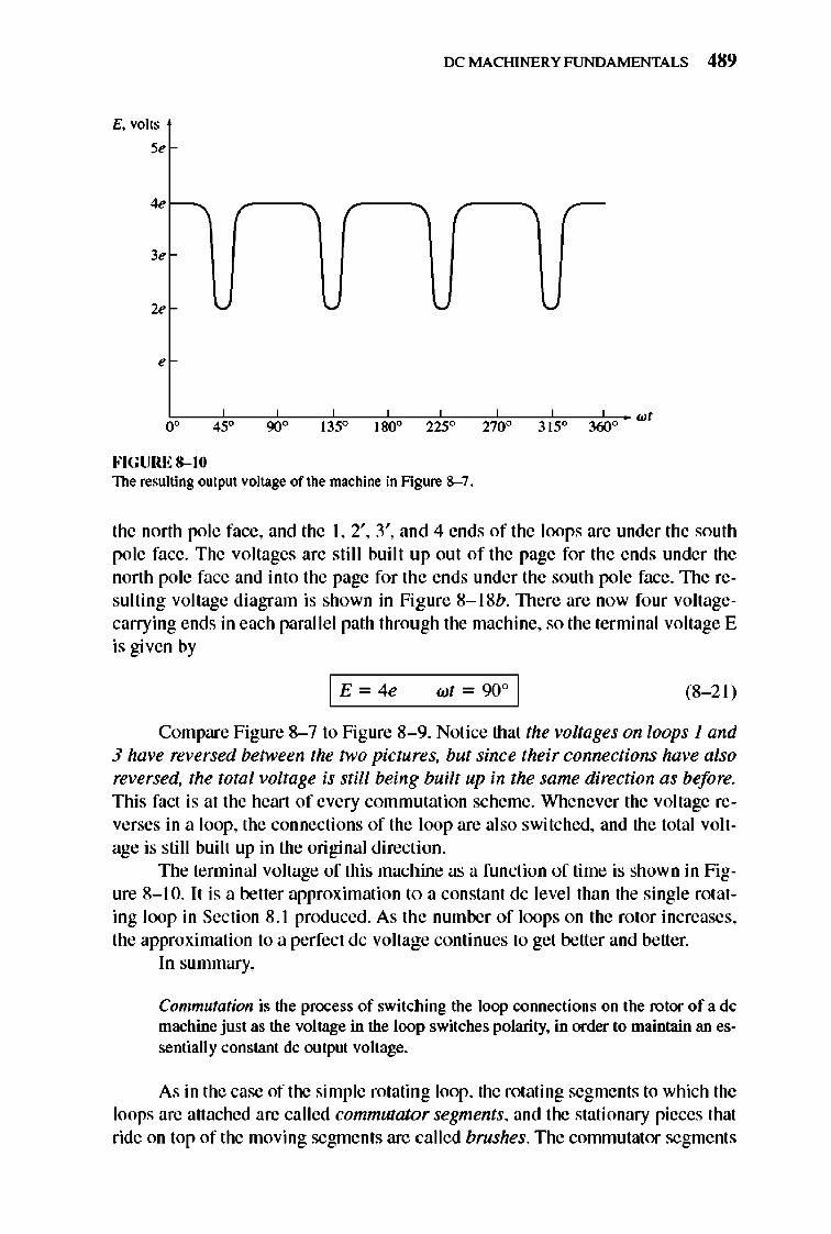
E. volts
5 ,
4 ,
3 ,
2 ,
,
o °
FIGURE 8-10
'-'
45 ° 90 ° °
IX: MACHINERY FUNDAMENTALS 489
~
180 ° 225 ° 270 ° ° 315 360 ° wI
The resulting output voltage of the machine in Figure 8- 7 .
the north pole face, and the I, 2', 3', and 4 ends of the loops are under the south pole face. The voltages are still built up out of the page for the ends under the north pole face and into the page for the ends under the south pole face. 1lle resulting voltage diagram is shown in Figure 8-1 8b. There are now four voltagecarrying ends in each paralle l path through the machine, so the terminal voltage E is given by
wt - 900 1 (8- 21)
Compare Figure 8- 7 to Figure 8- 9. Notice that the voltages on loops 1 and 3 have reversed between the two pictures. but since their connections have also reversed, the total voltage is still being built up in the same direction as before. This fact is at the heart of every commutation scheme. Whenever the voltage reverses in a loop, the connections of the loop are also switched, and the total voltage is still built up in the original direction.
The terminal voltage of this machine as a function of time is shown in Figure 8-1 0. It is a better approximation to a constant dc level than the single rotating loop in Section 8 .1 produced. As the number of loops on the rotor increases, the approximation to a perfect dc voltage continues to get better and better.
In summary,
Commutation is the process of switching the loop COIUlections on the rotor of a dc machine just as the voltage in the loop switches polarity, in order to maintain an essentially constant dc output voltage.
As in the case of the simple rotating loop, the rotating segments to which the loops are attached are called commutator segments, and the stationary pieces that ride on top of the moving segments are called brushes. The commutator segments
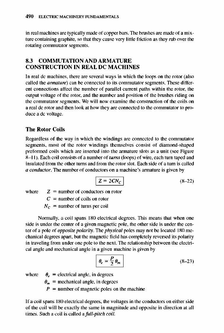
490 ELECTRIC MACHINERY RJNDAMENTALS
in real machines are typically made of copper bars. The brushes are made of a mixture containing graphite, so that they cause very little fri ction as they rub over the rotating commutator segments.
8.3 COMMUTATION AND ARMATURE CONSTRUCTION IN REAL DC MACHINES
In real dc machines, there are several ways in which the loops on the rotor (also called the armature) can be connected to its commutator segments. nlese different connections affect the number of parallel current paths within the rotor, the output voltage of the rotor, and the number and position of the brushes riding on the commutator segments. We wil l now examine the construction of the coils on a real dc rotor and then look at how they are connected to the commutator to produce a dc voltage.
The Rotor Coils
Regardless of the way in which the windings are connected to the commutator segments, most of the rotor windings themselves consist of diamond-shaped preformed coils which are inserted into the armature slots as a unit (see Figure 8-11 ). Each coil consists of a number of turns (loops) of wire, each turn taped and insulated from the other turns and from the rotor slot. Each side of a turn is called a conductor. 1lle number of conductors on a machine 's annature is given by
where
I Z ~ 2eNc I
Z = number of conductors on rotor
C = number of coils on rotor
Nc = number of turns per coil
(8- 22)
Nonnally, a coil spans 180 electrical degrees. nlis means that when one side is under the center of a given magnetic pole, the other side is under the center of a pole of opposite polarity. The physical poles may not be located 180 mechanical degrees apart, but the magnetic fi e ld has complete ly reversed its polarity in traveling from under one pole to the next. The relationship between the e lectrical angle and mechanical angle in a given machine is given by
where Oe = electrical angle, in degrees
0", = mechanical angle, in degrees
P = number of magnetic poles on the machine
(8- 23)
If a coil spans 180 e lectrical degrees, the voltages in the conductors on either side of the coil will be exact ly the same in magnitude and opposite in direction at all times. Such a coil is called afull-pitch coil.
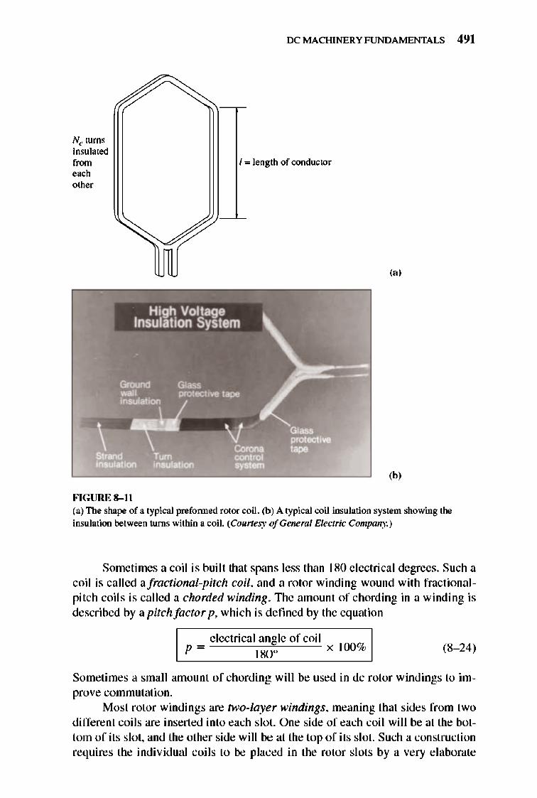
Nc turns insulated from ,~h
other
FIGURE 8-11
OCMACHINERYFUNDAMENTALS 491
I", length of conductor
(a)
(b)
(a) The shape of a typical prefornled rotor coil. (b) A typical coil insulation system showing the insulation between turns within a coil. (Courtesy ofGeneml Electric Company.)
Sometimes a coil is built that spans less than 180 e lectrical degrees. Such a coil is called afractional-pitch coil, and a rotor winding wound with fractionalpitch coils is called a chorded winding. 1lle amount of chording in a winding is described by a pitch factor p, which is defined by the equation
e lectrical angle of coil p = 180 0 x 100% (8- 24)
Sometimes a small amount of chording will be used in dc rotor windings to improve commutation.
Most rotor windings are hi!o-layer windings, meaning that sides from two different coils are inserted into each slot. One side of each coil will be at the bottom of its slot, and the other side will be at the top of its slot. Such a construction requires the individual coils to be placed in the rotor slots by a very elaborate
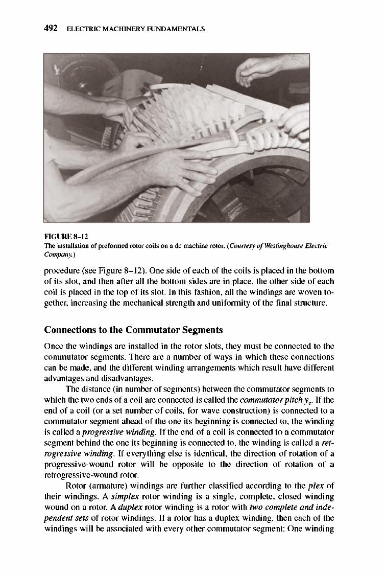
492 ELECTRIC MACHINERY RJNDAMENTALS
, \ • ,
---:.------
""GURE 8-12 The installation of prefonned rotor coils on a dc machine rotor. (Courtesy of Westinghouse Electric Company.)
procedure (see Figure 8-1 2). One side of each of the coil s is placed in the bottom of its slot, and then after all the bottom sides are in place, the other side of each coil is placed in the top of its slot. In this fashion, all the windings are woven together, increasing the mechanical strength and unifonnity of the final structure.
Connections to the Commutator Segments
Once the windings are installed in the rotor slots, they must be connected to the commutator segments. There are a number of ways in which these connections can be made, and the different winding arrangements which result have different advantages and disadvantages.
TIle distance (in number of segments) between the commutator segments to which the two ends of a coil are connected is called the commutator pitch Ye. If the end of a coil (or a set number of coils, for wave construction) is connected to a commutator segment ahead of the one its beginni ng is connected to, the winding is called a progressive winding. If the end of a coil is connected to a commutator segment behind the one its beginning is connected to, the winding is called a retrogressive winding. If everything else is identical, the direction of rotation of a progressive-wound rotor will be oppos.ite to the direction of rotation of a retrogressive-wound rotor.
Rotor (armature) windings are further classified according to the plex of their windings. A simplex rotor winding is a single, complete, closed winding wound on a rotor. A duplex rotor winding is a rotor with two complete and independent sets of rotor wi ndings. I f a rotor has a duplex winding, then each of the windings will be associated with every other commutator segment: One winding
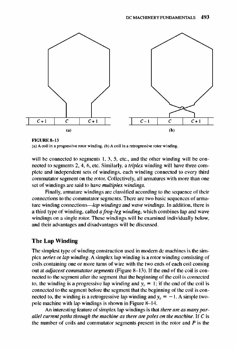
IX: MACHINERY FUNDAMENTALS 493
c+ I c C+I C-I C C+I
I" Ib,
FIGURE 8-13 (3) A coil in 3 progressive rotor winding. (b) A coil in 3 retrogressive rotor winding.
will be connected to segments I, 3, 5, etc., and the other winding will be connected to segments 2, 4, 6, etc. Similarly, a triplex winding will have three complete and independent sets of windings, each winding connected to every third commutator segment on the rotor. Collectively, all armatures with more than one set of windings are said to have multiplex windings.
Finally, annature windings are classified according to the seq uence of their connections to the commutator segments. There are two basic sequences of arrnature winding connections-iap windings and wave windings. In addition, there is a third type of winding, called a frog-leg winding, which combines lap and wave windings on a single rotor. These windings will be examined individually below, and their advantages and disadvantages will be discussed.
The Lap Winding
The simplest type of winding construction used in modem dc machines is the simplex series or lap winding. A simplex lap winding is a rotor winding consisting of coils containing one or more turns of wire with the two ends of each coil coming out at adjacent commutator segments (Figure 8- 13). If the end of the coil is connected to the segment after the segment that the beginning of the coil is connected to, the winding is a progressive lap winding and Yc = I; if the end of the coil is connected to the segment before the segment that the beginning of the coil is connected to, the winding is a retrogressive lap winding and Yc = - I. A simple twopole machine with lap windings is shown in Figure 8- 14.
An interesting feature of simplex lap windings is that there are as many parallel current paths through the machine as there are poles on the mnchine. If C is the number of coil s and commutat or segments present in the rotor and P is the
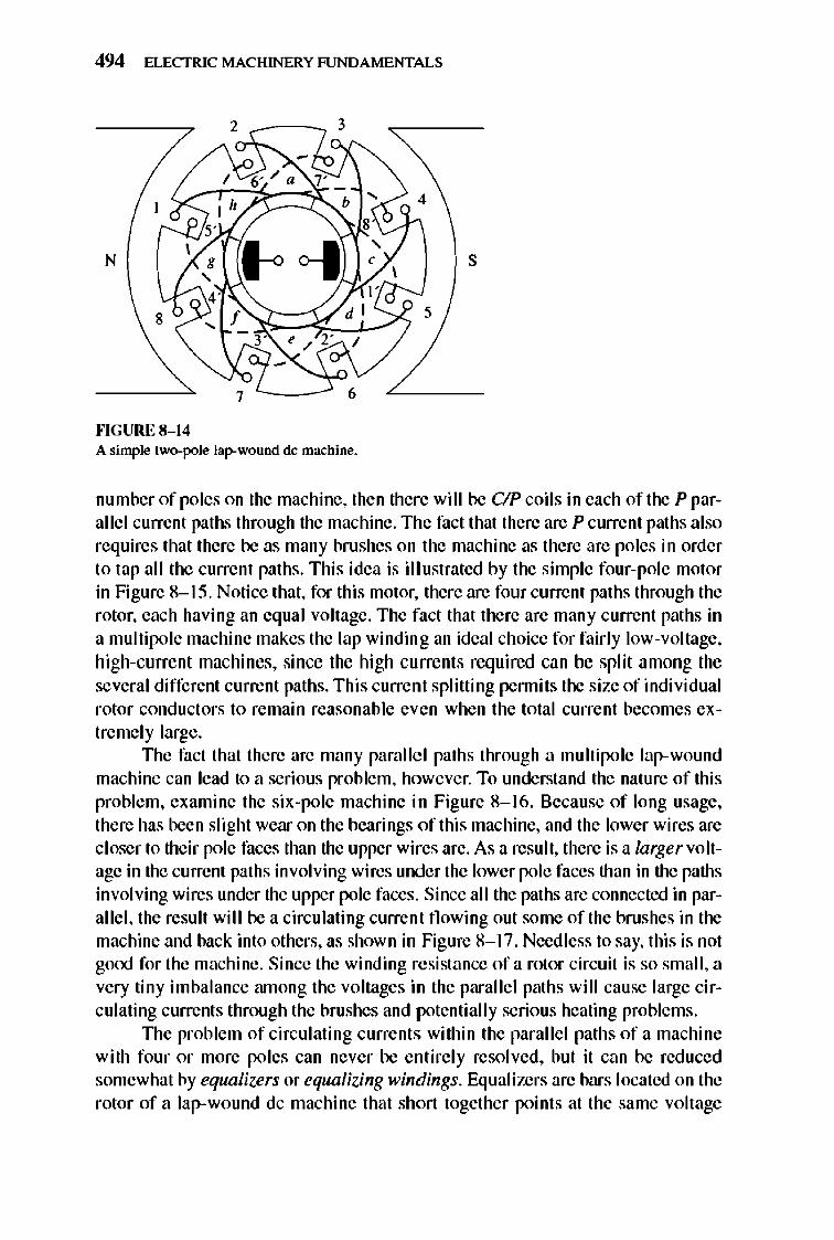
494 ELECTRIC MACHINERY RJNDAMENTALS
2
N I-oo--J s \
8 5
""GURE 8-14 A simple two-pole lap-wound dc machine.
number of poles on the machine, then there will be c/P coils in each of the P parallel current paths through the machine. The fact thai there are P current paths also requires that there be as many brushes on the machine as there are poles in order to tap all the current paths. This idea is illustrated by the simple four-pole motor in Figure 8-15. Notice that, for this motor, there are four current paths through the rotor, each having an equal voltage. The fact that there are many current paths in a multi pole machine makes the lap winding an ideal choice for fairl y low-voltage, high-current machines, since the high currents required can be split among the several different current paths. This current splitting pennits the size of individual rotor conductors to remain reasonable even when the total current becomes extremely large.
TIle fact that there are many parallel paths through a multipole lap-wound machine can lead to a serious problem, however. To understand the nature of this problem, examine the six-pole machine in Figure 8-1 6. Because of long usage, there has been slight wear on the bearings of this machine, and the lower wires are closer to their pole faces than the upper wires are. As a result, there is a larger voltage in the current paths involving wires under the lower pole faces than in the paths involving wires under the upper pole faces. Since all the paths are connected in parallel, the result will be a circulating current fl owing out some of the brushes in the machine and back into others, as shown in Figure 8-17. Need less to say, this is not gooj for the machine. Since the winding resistance of a rotor circuit is so small, a very tiny imbalance runong the voltages in the parallel paths will cause large circulating currents through the brushes and potentially serious heating problems.
TIle problem of circulating currents within the parallel paths of a machine with four or more poles can never be entire ly resolved, but it can be reduced somewhat by equalizers or equalizing windings. Equalizers are bars located on the rotor of a lap-wound dc machine that short together points at the same voltage
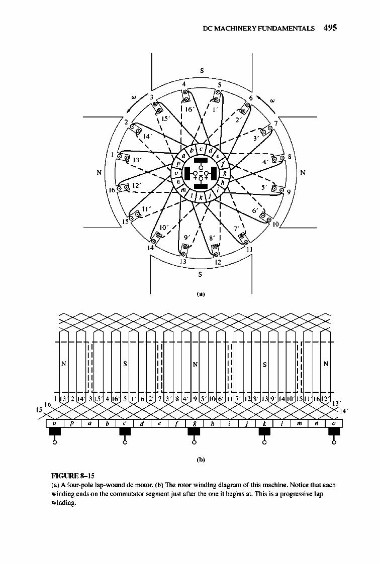
N
N
lit ·
" " " " " I 13 2 14 3 IS ,16y IXX'>: yP ,
FIGURE 8- 15
16
s
41651 ' 62'7
XXx 6 , d ,
IX: MACHI NERY FUNDAMENTALS 495
s
4 s
N
IOL-__
II
13 12
s
,.,
;x ;X
N " " " " " " 3' 8 4 ' 9 5' 10 6 ' 117' I
;X :xxx :xxx 8 h
,b,
s
,- i"
" " N
" " I
8' 139' 1410 151116~ 13'
;:xxx :X14·
• m '~
(a) A four-pole lap-wound de motor. (b) The rotor winding diagram of this machine. Notice that each winding ends on the commutator segment just after the one it begins at. This is a progressive lap winding.
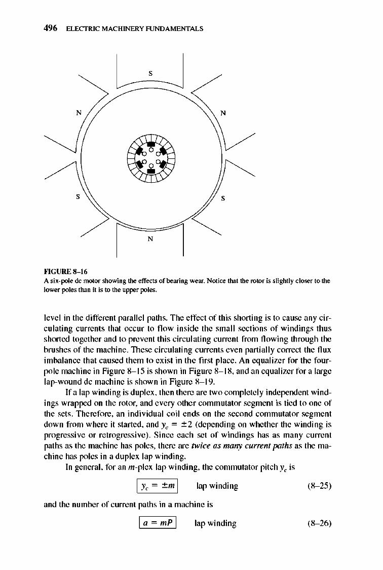
496 ELECTRIC MACHINERY RJNDAMENTALS
s
N N
s s
N
""GURE 8-16 A six-pole dc motor showing the effects of bearing wear. Notice that the rotor is slightly closer to the lower poles than it is to the upper poles.
level in the different paralle l paths. The effect of this shorting is 10 cause any circulating currents that occur to now inside the small sections of windings thu s shorted together and to prevent this circulating current from flowing through the brushes of the machine. TIlese circulating currents even partially correct the flux imbalance that caused them to exi st in the first place. An equalizer for the fourpole machine in Figure 8-1 5 is shown in Figure 8-1 8, and an equalizer for a large lap-wound dc machine is shown in Figure 8-1 9.
If a lap winding is duplex, then there are two complete ly independent windings wrapped on the rotor, and every othe r commutator segment is tied to one of the sets . Therefore, an indi vidual coil ends on the second commutat or segment down from where it started, and Yc = ~2 (depending on whe ther the winding is progressive or retrogressive). Since each set of windings has as many current paths as the machine has poles, there are twice as many current paths as the machine has poles in a duplex lap winding.
In general, for an m-plex lap winding, the commutator pitch Yc is
lap winding (8- 25)
and the number of current paths in a machine is
I a -mpl lap winding (8- 26)
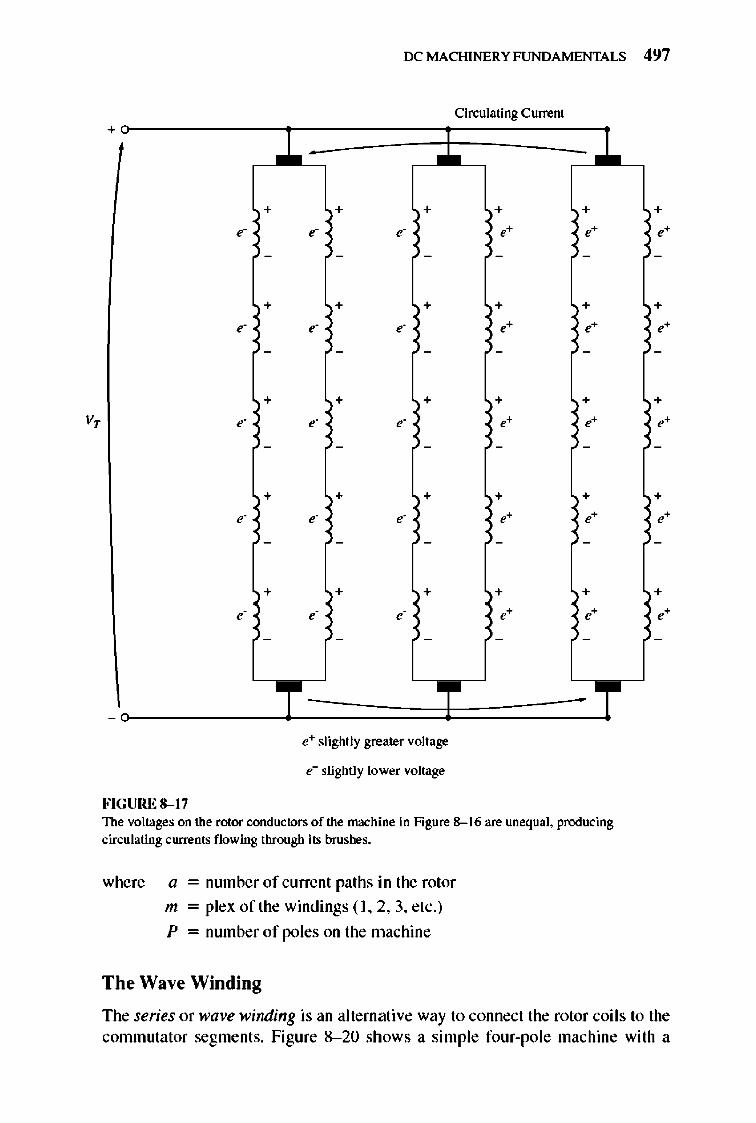
v,
IX: MACHINERY FUNDAMENTALS 497
Cirwlating Current +
.l. .l. ... + + + + +
, , , " "
- - - - -
+ + + + + , , ,
" " - - - - -
+ + + + + , , ,
" " - - - - -
+ + + + + , , ,
" " - - - - -
+ + + + + , , ,
" " - - - - -
T T T -
e+ slightly greater voltage
e- slightly lower voltage
FIGURE 8-17 The voltages on the rotor conductors of the machine in Figure 8--16 are unequal. producing circulating currents flowing through its brushes.
where a = number of current paths in the rotor
m = plex of the windings ( I, 2, 3, etc.)
P = number of poles on the machine
The Wave Winding
+
+
+
+
+
The series or wave winding is an alternati ve way to connect the rotor coils to the commutator segments. Figure 8- 20 shows a sim ple four-pole machine with a
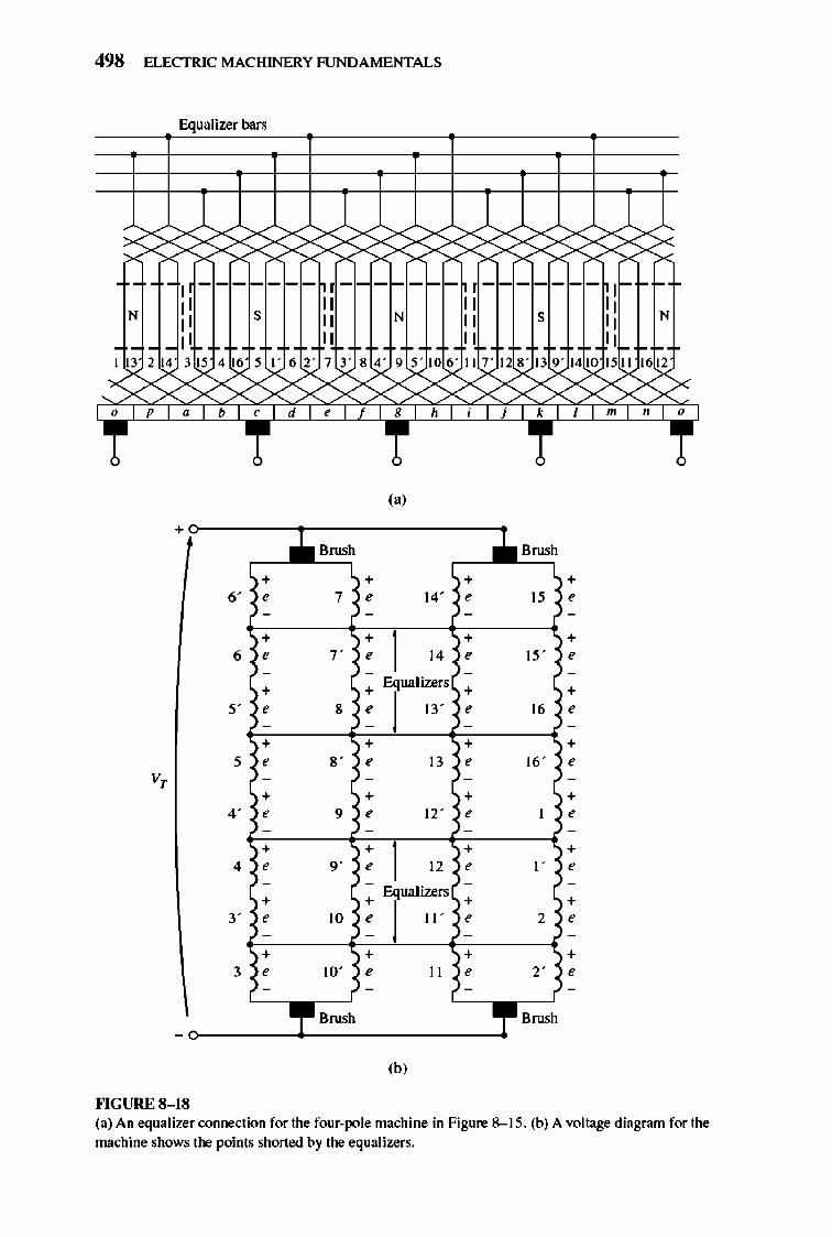
498 ELECTRIC MACHINERY RJNDA MENTALS
Equalizer bars
1 ?< > X
----- - ----- -
Ii I r------- I
" " " N
I: I ,
I: I N
':1 ,
II N
" " " II 1 13 2 14 3 5 4 6 5 I' 6::k 7 3' 8 4' 9 5' 10 6' II 7' 1 8' 13 9' 14 10 15~1612
XXX >< >< X XX< x,;x X x,;x x,;x >x: >< f'""" 'h ' "m"~
+
~ + +
6' , , , - -
+ + 6 , " ,
- -
+ +
" , 8 , - -
+ + , , 8' , v, - -
+ + 4' , 9 ,
- -
+ + 4 , " ,
- -
+ + ,- , 10 ,
- -
+ + 3 , 10' ,
- -
~ -
""GURE 8-18
,,)
+
'" , -
+ 14 ,
-Equalizers +
13' , -
+ 13 ,
-
+ 12' ,
-
+ 12 ,
-Equal izers
+ 11' ,
-
+ 11 ,
-
(b)
B=h
"
W
16
16'
, , ' 2
,-
B=h
+ ,
+ , + , + , + , + , + , + ,
(a) An equalizer connection for the four-pole machine in Figure 8--15. (b) A voltage diagram for the machine shows the points shoned by the equalizers.
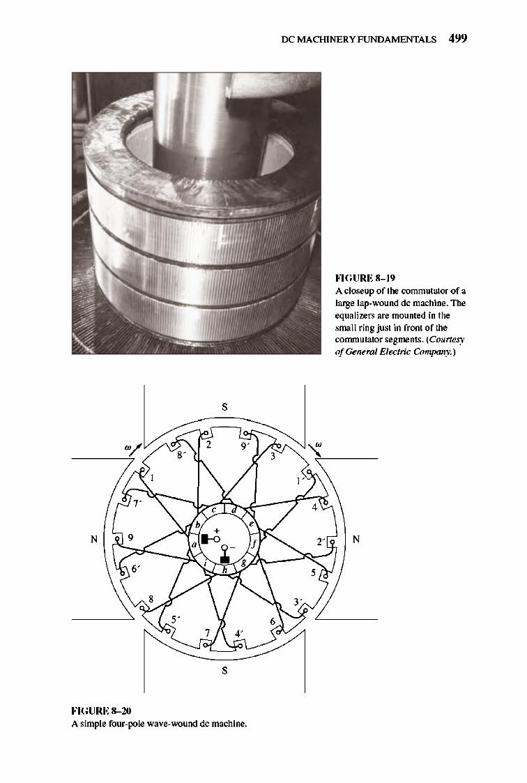
s
2
"
, b
+ N • .-0 .1.-,
h
7
s
FIGURE 8-10 A simple four-pole wave-wound dc machine.
IX: MACHI NERY FUNDAMENTALS 499
FlGURE 8- 19 A closeup of the commutator of a large lap-wound de machine. The equalizers are moumed in the smaIl ring just in front of the commutator segments. (Courtesy ofGeneml Electric Company.)
N
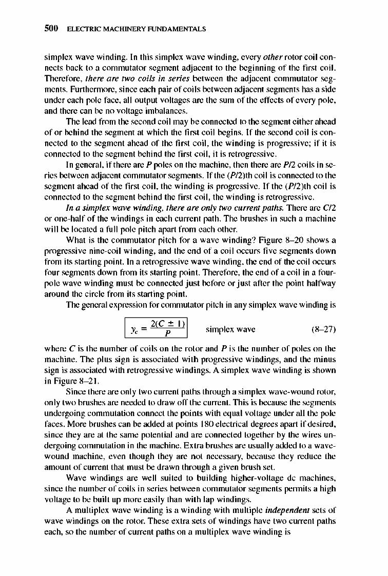
500 ELECTRIC MACHINERY RJNDAMENTALS
simplex wave winding. In this simplex wave winding, every other rotor coil connects back to a commutator segme nt adjacent to the beginning of the first coil. TIlerefore, there are two coils in series between the adjacent commutator segme nts. Furthennore, since each pair of coils between adjacent segments has a side under each pole face, all output voltages are the sum of the effects of every pole, and there can be no voltage imbalances.
TIle lead from the second coil may be connected to the segme nt either ahead of or behind the segment at which the first coil begins. If the second coil is connected to the segment ahead of the first coil, the winding is progressive; if it is connected to the segment behind the first coil, it is retrogressive.
I n general, if there are P poles on the machine, then there are PI2 coils in series between adjacent commutator segments. If the (PI2)th coi I is connected to the segment ahead of the first coil, the winding is progressive . If the (PI2)th coil is connected to the segment behind the first coil, the winding is retrogressive.
In a simplex wave winding, there are only two current paths. There are c/2 or one-half of the windings in each current path. The brushes in such a machine will be located a full pole pitch apart from each other.
What is the commutator pitch for a wave winding? Figure 8- 20 shows a progressive nine-coil winding, and the e nd of a coil occurs five segments down from its starting point. In a retrogressive wave winding, the end of the coil occurs four segments down from its starting point. Therefore , the end of a coil in a fo urpole wave winding mu st be connected just before or just after the point halfway around the circle from its starting point.
TIle general expression for commutator pitch in any simplex wave winding is
simplex wave (8- 27)
where C is the number of coils on the rotor and P is the number of poles on the machine . The plus sign is associated with progressive windings, and the minu s sign is associated with retrogressi ve wind ings. A simplex wave winding is shown in Figure 8- 2 1.
Since there are only two current paths through a simplex wave-wound rotor, only two brushes are needed to draw off the current. TIlis is because the segments undergoing commutation connect the points with equal voltage under all the pole faces . More brushes can be added at points 180 e lectrical degrees apart if desired, since they are at the same potential and are connected togethe r by the wires undergoing commutation in the machine . Extra brushes are usually added to a wavewound machine, even tho ugh they are not necessary, because they reduce the amount of current that must be drawn through a given brush set.
Wave windings are well suited to bui lding higher-voltage dc machines, since the number of coils in series between commutator segme nts pennits a high voltage to be built up more easily than with lap windings.
A multiplex wave winding is a winding with multiple independent sets of wave windings on the rotor. These extra sets of windings have two current paths each, so the number of current paths on a multiplex wave winding is
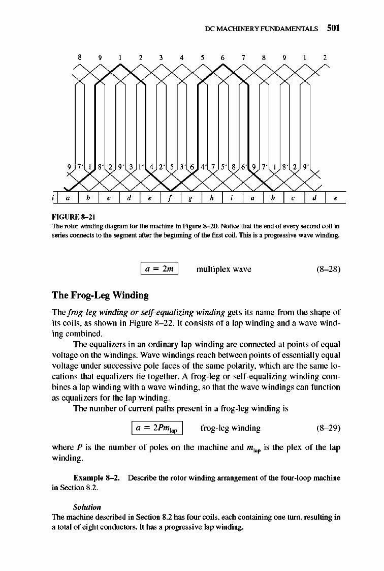
IX: MACHINERY FUNDAMENTALS 501
8 9 2 3 4 5 6 7 8 9 2
9 7' 1 8' 2 9' 3 I' 4 2' 5 3' 6 4 7 5' 8 6' 9 7' 1 8' 2 9'
d ,
FIGURE 8-21 The rotor winding diagram for the machine in fi gure 8-20. Notice that the end of every second coil in series connects to the segment after the beginning of the first coil. This is a progressive wave winding.
I a - 2m I rnul1iplex wave (8- 28)
The Frog-Leg Winding
Thefrog-leg winding or self-equaliZing winding gets its name from the shape of its coils, as shown in Figure 8- 22. It consists of a lap winding and a wave winding combined.
The equalizers in an ordinary lap winding are connected at points of equal voltage on the windings. Wave windings reach between points of essentially equal vol1age under successive pole faces of the same polarity, which are the same locations that equali zers tie together. A frog- leg or self-eq ualizing winding combines a lap winding with a wave winding, so that the wave windings can function as equalizers for the lap winding.
The number of current paths present in a frog- leg winding is
I a - ' Pm,." I frog-leg winding (8- 29)
where P is the number of poles on the machine and mJap is the plex of the lap winding.
EXIllllpie 8-2. Describe the rotor winding arrangement of the four-loop machine in Section 8.2.
Solutioll The machine described in Section 8.2 has four coils. each containing one turn. resulting in a total of eight conductors. It has a progressive lap winding.
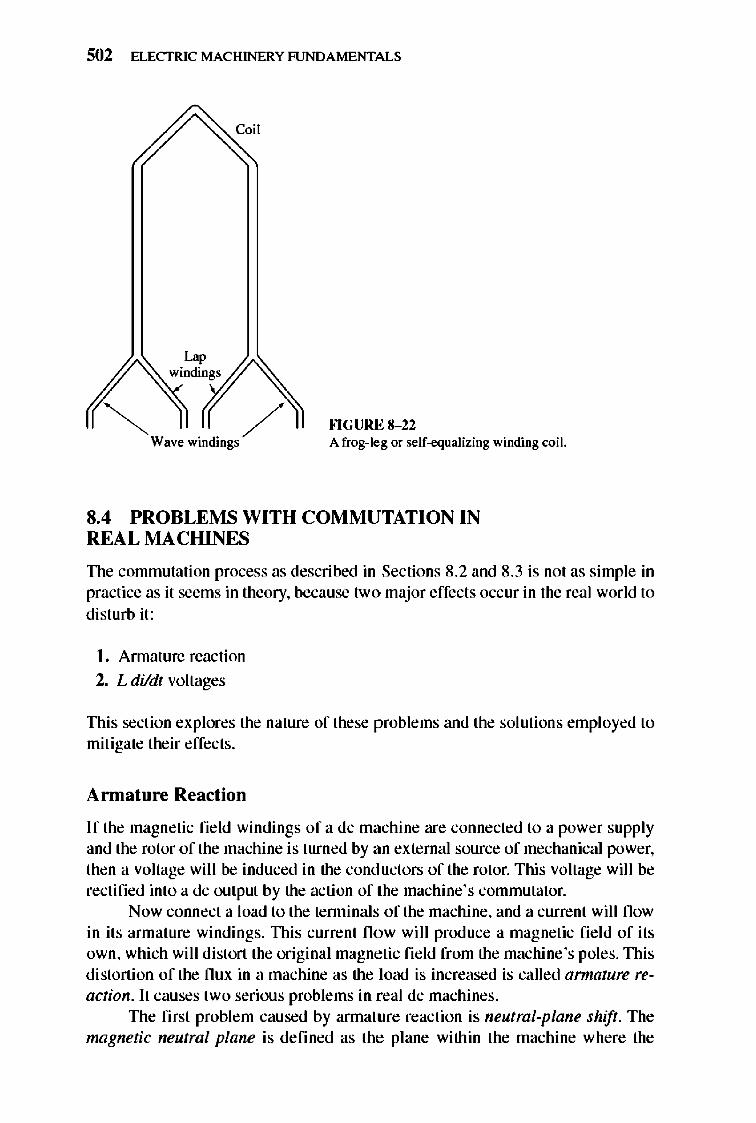
502 ELECTRIC MACHINERY RJNDAMENTALS
Coil
~~r,~ W ·d· / ave Win lOgS
Fl GURE 8-22 A frog-leg or self-equalizing winding coil.
8.4 PROBLEMS WITH COMMUTATION IN REAL MACHINES
TIle commutation process as described in Sections 8.2 and 8.3 is not as simple in practice as it seems in theory, because two major effects occ ur in the real world to dist urb it:
L Annature reaction 2, L dildt voltages
TIlis section explores the nature of these problems and the sol utions employed to mitigate their effects.
Annature Reaction
If the magnetic field windings of a dc machine are connected to a power supply and the rotor of the machine is turned by an external source of mechanical power, then a voltage wi ll be induced in the cond uctors of the rotor. This voltage wil I be rectified into a dc output by the action of the machine's commutator.
Now connect a load to the tenninaIs of the machine, and a current will fl ow in its armat ure windings. TIlis current flow wi ll prod uce a magnetic fi e ld of its own, which wi ll distort the original magnetic fie ld from the machine 's poles. TIlis distortion of the flux in a machine as the load is increased is called armature reaction. It causes two serious problems in real dc machines.
TIle first problem caused by annature reaction is neutral-plane shift. The mngnetic neutral plane is defined as the plane within the machine where the
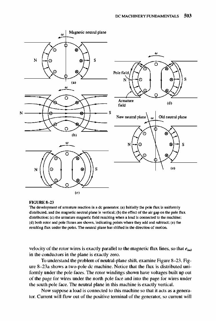
N
IX: MACHINERY FUNDAMENTALS 503
Magnetic neutral plane ;:,w-I--_
New neutral plane w Old neutral plane y-t---
(b) 0 " w N 0 " S ~
0
" 0 "
N 0 " S ( .)
o (,)
FIGURE 8-23 The development of annature reaction in a dc gelJerator. (a) Initially the pole flux is unifonnly distributed. and the magnetic neutral plane is vertical; (b) the effect of the air gap on the pole flux distribution; (c) the armature magnetic field resulting when a load is connected to the machine; (d) both rotor and pole fluxes are shown. indicating points where they add and subtract; (e) the resulting flux under the poles. The neutral plane has shifted in the direction of motion.
velocity of the rotor wires is exactly parallel to the magnetic nux lines, so that eind
in the conductors in the plane is exactly zero. To understand the problem of neutral-plane shift, exrunine Figure 8- 23 . Fig
ure 8- 23a shows a two-pole dc machine. Notice that the nux is distributed unifonn ly under the pole faces. The rotor windings shown have voltages built up out of the page for wires under the north pole face and into the page for wires under the south pole face. The neutral plane in this machine is exactly vertical.
Now suppose a load is connected to this machine so that it acts as a generator. Current will now out of the positive terminal of the generator, so current wi ll
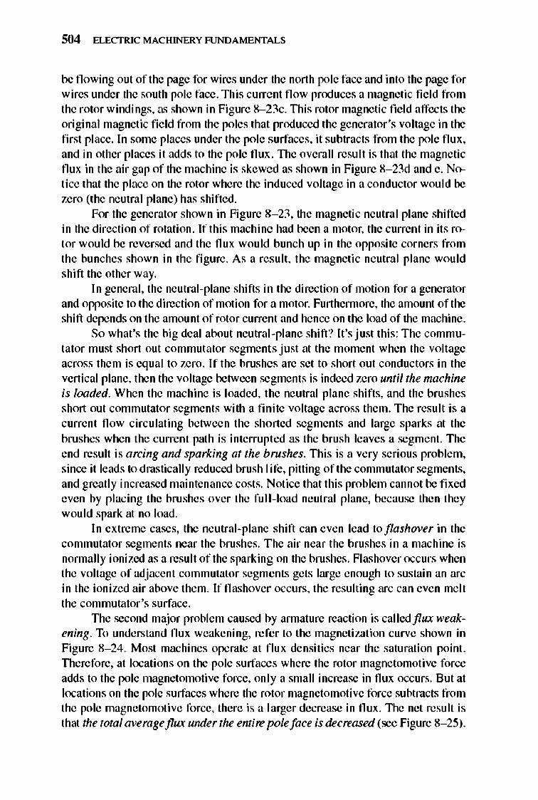
504 ELECTRIC MACHINERY RJNDAMENTALS
be flowing out of the page for wires under the north pole face and into the page for wires under the south pole face . This current fl ow produces a magnetic fi e ld from the rotor windings, as shown in Figure 8- 23c. This rotor magnetic field affects the original magnetic fie ld from the poles that produced the generator's voltage in the first place. In some places under the pole surfaces, it subtracts from the pole flux , and in other places it adds to the pole flu x. The overall result is that the magnetic flu x in the air gap of the machine is skewed as shown in Figure 8- 23d and e. Notice that the place on the rotor where the induced voltage in a conductor would be zero (the neutral plane) has shifted.
For the generator shown in Figure 8- 23, the magnetic neutral plane shifted in the direction of rotation. If this machine had been a motor, the current in its rotor would be reversed and the nux would bunch up in the opposite corners from the bunches shown in the figure. As a result, the magnetic neutral plane would shift the other way.
I n general, the neutral-plane shifts in the direction of motion for a generator and opposite to the direction of motion for a motor. Furthennore, the amount of the shift depends on the amount of rotor current and hence on the load of the machine.
So what's the big deal about neutral-plane shift ? It 's just thi s: The commutator must short out commutator segments just at the moment when the voltage across them is equal to zero . Ifthe brushes are set to short out conductors in the vertical plane, then the voltage between segments is indeed zero until the machine is loaded. When the machine is loaded, the neutral plane shifts, and the brushes short out commutator segments with a finite voltage across them. The result is a current now circulating between the shorted segments and large sparks at the brushes when the current path is interrupted as the brush leaves a segment. The end result is arcing and sparking at the brushes. TIlis is a very serious problem, since it leads to drastically reduced brush I ife, pitting of the commutator segments, and greatly increased maintenance costs. Notice that this problem cannot be fi xed even by placing the brushes over the full-load neutral plane, because then they wou Id spark at no load.
In extreme cases, the neutral-plane shift can even lead to flashover in the commutator segments near the brushes. The air near the brushes in a machine is normally ionized as a result of the sparking on the brushes. Flashover occurs when the voltage of adjacent commutator segments gets large enough to sustain an arc in the ionized air above them. If flashover occurs, the resulting arc can even melt the commutator 's surface.
TIle second major problem caused by annature reaction is called flux weakening. To understand flux weakening, refer to the magnetization curve shown in Figure 8- 24. Most machines operate at flu x densities near the saturation point. TIlerefore, at locations on the pole surfaces where the rotor magnetomotive force adds to the pole magnetomotive force, only a small increase in nux occurs. But at locations on the pole surfaces where the rotor magnetomoti ve force subtracts from the pole magnetomoti ve force, there is a larger decrease in flu x. 1lle net result is that the total averageflux under the entire pole face is decreased (see Figure 8- 25) .
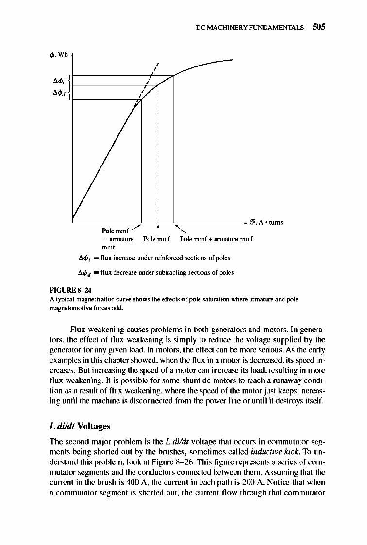
IX: MACHINERY FUNDAMENTALS 505
q,. Wb , ,
•• , 1 , , .. , , ,
L-------------cf---}--~--------------- ~·A . tums
Pole mmf ,/ """ - annature Pole mmf Pole mmf + annature mmf mmf
l1q, i - flux increase under reinforced sections of poles
l1q,d - flux decrease under subtracting sections of poles
FIGURE 8-24 A typical magnetization curve shows the effects of pole saturation where armature and pole magnetomotive forces add.
Flux weakening causes problems in bolh generators and motors. In generators, the effect of flux weakening is simply to reduce the voltage supplied by the generator for any given load . In motors, the effect can be more serious. As the early examples in this chapter showed, when the flux in a motor is decreased, its speed increases. But increasing the speed of a motor can increase its load, resulting in more flux weakening. It is possible for some shunt dc motors to reach a runaway condition as a result offlux weakening, where the speed of the motor just keeps increasing until the machine is disconnected from the power line or until it destroys itself.
L dildt Voltages
The second major problem is the L dildt voltage that occurs in commutator segments being shorted out by the brushes, sometimes called inductive kick. To understand this problem, look at Figure 8- 26. This figure represents a series of commutator segments and the conductors connected between them. Assuming that the current in the brush is 400 A, the current in each path is 200 A. Notice that when a commutator segme nt is shorted out, the current fl ow through that commutator
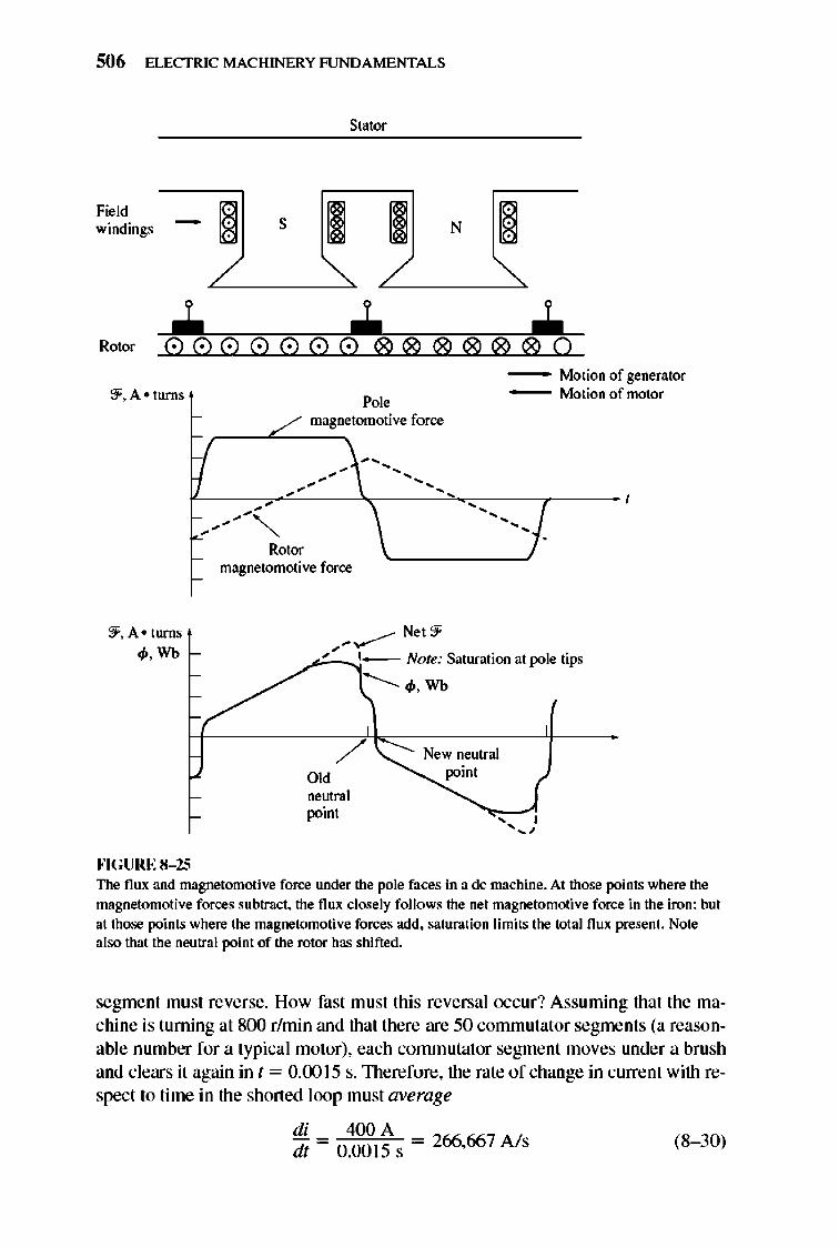
506 ELECTRIC MACHINERY RJNDAMENTALS
Stator
Field § windings - S § N
/ ~ __ "'--'>. L-/ __ "'--'>. 1
Rotor
- Motion of generator M fmotor ::f. A • turns - Oilon 0
Pole - / magnetomotive force
-", .............. ...............
"
-- , ............... , ................
, .
,
Rotor magnetomotive force
...... ..-- Net 9' '!f. A· turns
</>.Wb ... 1- Note: Saturation at pole tips
fo'IGURE 8- 25
--..........IP. Wb
/ Old neutral point
New neutral poim
The flux and magoetomotive force under the pole faces in a de machine. At those points where the magnetomotive forces subtract. the flux closely follows the net magoetomotive force in the iron; but at those points where the magnetomotive forces add, saturation limits the IOtal flux present. Note also that the neutral point of the rotor has shifted.
segment must reverse. How fast must this reversal occur? Assuming that the machine is turning at 800 r/min and that there are 50 commutator segments (a reasonable number for a typical motor), each commutator segme nt moves under a brush and clears it again in t = 0.00 15 s. 1l1erefore, the rate of change in current with respect to time in the shorted loop must average
di 400 A dt - 0.00 15 s - 266,667 A ls (8- 30)
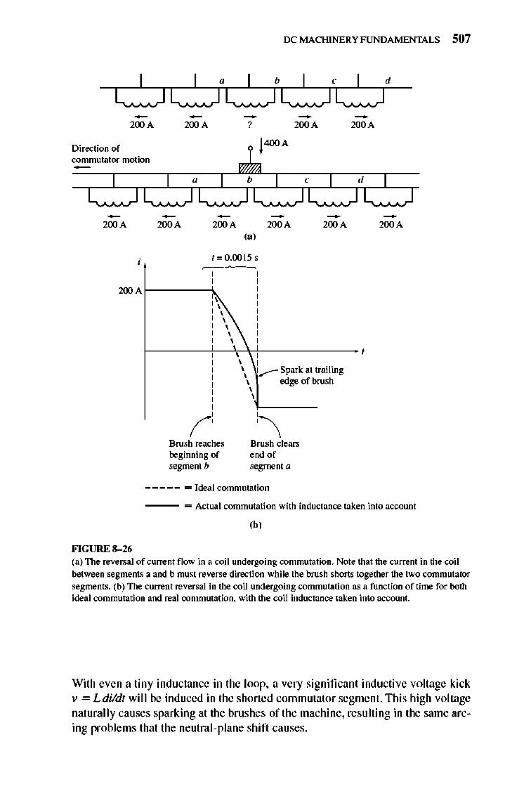
IX: MACHINERY FUNDAMENTALS 507
-200 A
Direction of commutator motion
200 A
-200 A
200 A
-?
200 A (a)
1=0.0015 s
200 Ar----"
- -200 A 200 A
200 A 200 A
\ r-------i-~,"i------------ ,
Brush reaches beginning of segment b
, , , , , , ...-- Spark at trailing
edge of brush
Brush clears end of segment a
----- - Ideal conunutation
200 A
- Actual commutation with inductance taken into account
(b)
FIGURE 8-26 (a) The revel"S3.1 of current flow in a coil undergoing commutation. Note that the current in the coil
between segments a and b must reverse direction while the brush ShOMS together the two commutator
segments. (b) The current reversal in the coil undergoing commutation as a function of time for both ideal commutation and real commutation. with the coil inductance taken into account.
With even a tiny inductance in the loop, a very significant inductive voltage kick v = Ldildt will be induced in the shorted commutator segment. This high voltage naturally causes sparking at the brushes of the machine, resulting in the same arcing problems that the neutral-plane shift causes.
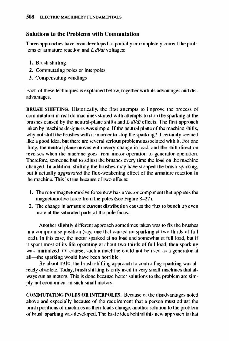
508 ELECTRIC MACHINERY RJNDAMENTALS
Solutions to the Problems with Commutation
TIlree approaches have been developed to partially or completely correct the problems of armature reaction and L dildt voltages:
I. Brush shifting
2. Commutating poles or interpoles
3. Compensating windings
E:1.ch of these techniques is explained below, together with its advantages and disadvantages.
BRUSH SHIFTING. Historically, the first attempts to improve the process of commutation in real dc machines started with attempts to stop the sparking at the brushes caused by the neutral-plane shifts and L dildt effects. The first approach taken by machine designers was simple: If the neutral plane of the machine shifts, why not shift the brushes with it in order to stop the sparking? It certainly seemed like a good idea, but there are several serious problems associated with it. For one thing, the neutral plane moves with every change in load, and the shift direction reverses when the machine goes from motor operation to generator operation. lllerefore, someone had to adjust the brushes every time the load on the machine changed . In addition, shifting the brushes may have stopped the brush sparking, but it actually aggravated the flux-weakening effect of the armature reaction in the machine. TIlis is true because of two effects:
I. The rotor magnetomotive force now has a vector component that opposes the magnetomotive force from the poles (see Figure 8- 27).
2. The change in annature current distribution causes the flux to bunch up even more at the saturated parts of the pole faces.
Another slightly different approach sometimes taken was to fix the brushes in a compromise position (say, one that caused no sparking at two-thirds of full load) . In this case, the motor sparked at no load and somewhat at full load, but if it spent most of its life operating at about two-thirds of full load, then sparking was minimized. Of course, such a machine could not be used as a generator at ,II-the sparking would have been horrible.
By about 19 10, the brush-shifting approach to controlling sparki ng was already obsolete . Today, brush shifting is only used in very small machines that always run as motors. TIli s is done because better solutions to the problem are simply not economical in such small motors.
COMMUTATING POLES OR INTERPOLES. Because of the disadvantages noted above and especially because of the requirement that a person must adjust the brush positions of machines as their loads change, another solution to the problem of brush sparking was developed. TIle basic idea behind this new approach is that
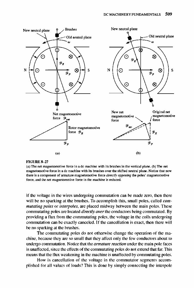
New neutral plane Brushes
Jc---r::..;O~d neutral plane
o
N o
o
FIGURE 8-27
Net magnetomotive force ::f ...
s
Rotor magnetomotive force ::fR
(a )
IX: MACHINERY FUNDAMENTALS 509
N
New neutral plane
Old neutral plane
---f=--- w
o ~,
o
o
New net magnetomotive ,
f_ "
(h)
s
Original net
I magnetomotive f=,
1 , : ::fR ,
(a) The net magnetomotive force in a dc machine with its brushes in the vertical plane. (b) The net magnetomotive force in a dc machine with its brushes over the shifted neutral plane. Notice that now there is a component of armature magnetomotive force directly oppOiling the poles' magnetomotive force. and the net magnetomotive force in the machine is reduced.
if the voltage in the wires undergoing commutation can be made zero, then there wi ll be no sparking at the brushes. To accomp li sh thi s, small poles, called commutating poles or interpoles, are placed midway between the main poles. These commutating poles are located directly over the conductors being commutated. By providing a flux from the commutating poles, the voltage in the coil s undergoing commutation can be exact ly canceled. If the cancell ation is exact, then there will be no sparking at the brushes.
The commutating poles do not otherwise change the operation of the machine, because they are so small that they affect only the few conductors about to undergo commutation. Notice that the armature reaction under the main pole faces is unaffected, since the effects of the commutating poles do not extend that far. nlis means that the flux weakening in the machine is unaffected by commutating poles.
How is cancell ation of the voltage in the commutator segment s accomplished for all values of loads? nlis is done by simply connecting the interpole
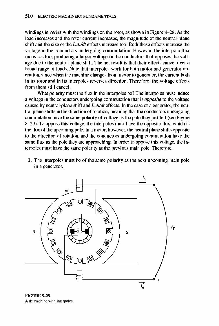
510 ELECTRIC MACHINERY RJNDAMENTALS
windings in series with the windings on the rotor, as shown in Figure 8- 28. As the load increases and the rotor current increases, the magnitude of the neutral-plane shift and the size of the L dildt effects increase too. Both these effects increase the voltage in the conductors undergoing commutation. However, the interpole flux increases too, producing a larger voltage in the conductors that opposes the voltage due to the neutral-plane shift. The net result is that their effects cancel over a broad range of loads. Note that interpoles work for both motor and generator operation, since when the machine changes from motor to generator, the current both in its rotor and in its interpoles reverses direction. Therefore, the voltage effects from them still cancel.
What polarity must the flux in the interpoles be? The interpoles must induce a voltage in the conductors undergoing commutation that is opposite to the voltage caused by neutral-plane shift and L dildt effects. In the case of a generator, the neutral plane shifts in the direction of rotation, meaning that the conductors undergoing commutation have the same polarity of voltage as the pole they just left (see Figure 8- 29). To oppose thi s voltage, the interpolcs must have the opposite flux, which is the flux of the upcoming pole. In a motor, however, the neutral plane shifts opposite to the direction of rotation, and the conductors undergoing commutation have the same flux as the pole they are approaching. In order to oppose this voltage, the interpoles must have the same polarity as the previous main pole. Therefore,
I. The interpoles mu st be of the same polarity as the next upcoming main pole in a generator.
-
v, N s
R -----d+ -I, ""GURE 8- 28 A de machine with imerpoles.
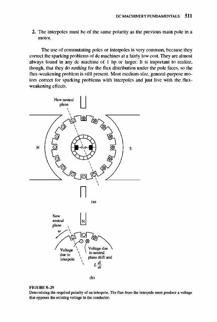
IX: MACHI NERY FUNDAMENTALS 511
2. The interpoles must be of the same polarity as the previous main pole in a motor.
The use of commutating poles or interpoles is very common, because they correct the sparking problems of dc machines at a fairly low cost. TIley are almost always found in any dc machine of I hp or larger. It is important to realize, though, that they do nothing for the flux distribution under the pole faces, so the flux-weakening problem is still present. Most medium-size, general-purpose motors correct for sparking problems with interpoles and just live with the fluxweakening effects.
N
New neutral plane
Now neutral plane
FIGURE 8-29
u
s
n (a)
(b)
Determining the required polarity of an interpole. The flux from the interpole must produce a voltage that opposes the existing voltage in the conductor.
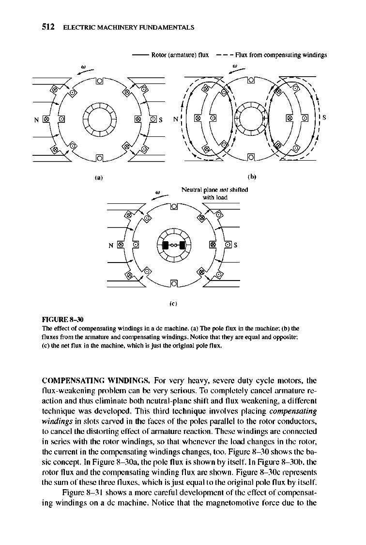
512 ELECTRIC MACHINERY RJNDAMENTALS
-- Rotor (amlature) flux - - - Aux from compensating windings
o , , " \ ,
N' , ,
, , IS , ,
I
o
,,'
N "
""GURE 8-30
(, ,
o
,b, Neutral plane no/ shifted
with load
The effect of compensating windings in a dc machine. (a) The pole flux in the machine; (b) the fluxes from the armature and compensating windings. Notice that they are equal and opposite; (c) the net flux in the machine. which is just the original pole flux.
, , , ,
COMPENSATING WINDINGS. For very heavy, severe duty cycle motors, the flux-weakening problem can be very serious. To complete ly cance l armature reaction and thus eliminate both neutral-plane shift and flux weakening, a different technique was developed. This third technique involves placing compensating windings in slots carved in the faces of the poles parallel to the rotor conductors, to cancel the distorting effect of annature reaction. These windings are connected in series with the rotor windings, so that whenever the load changes in the rotor, the current in the compensating windings changes, too. Figure 8- 30 shows the basic concept. In Figure 8- 30a, the pole flux is shown by itself. In Figure 8- 30b, the rotor fl ux and the compensating winding fl ux are shown. Figure 8- 3Oc represents the sum of these three flu xes, which is just equal to the original pole flux by itself.
Figure 8- 3 \ shows a more careful development of the effect of compensating windings on a dc machine. Notice that the magnetomoti ve force due to the
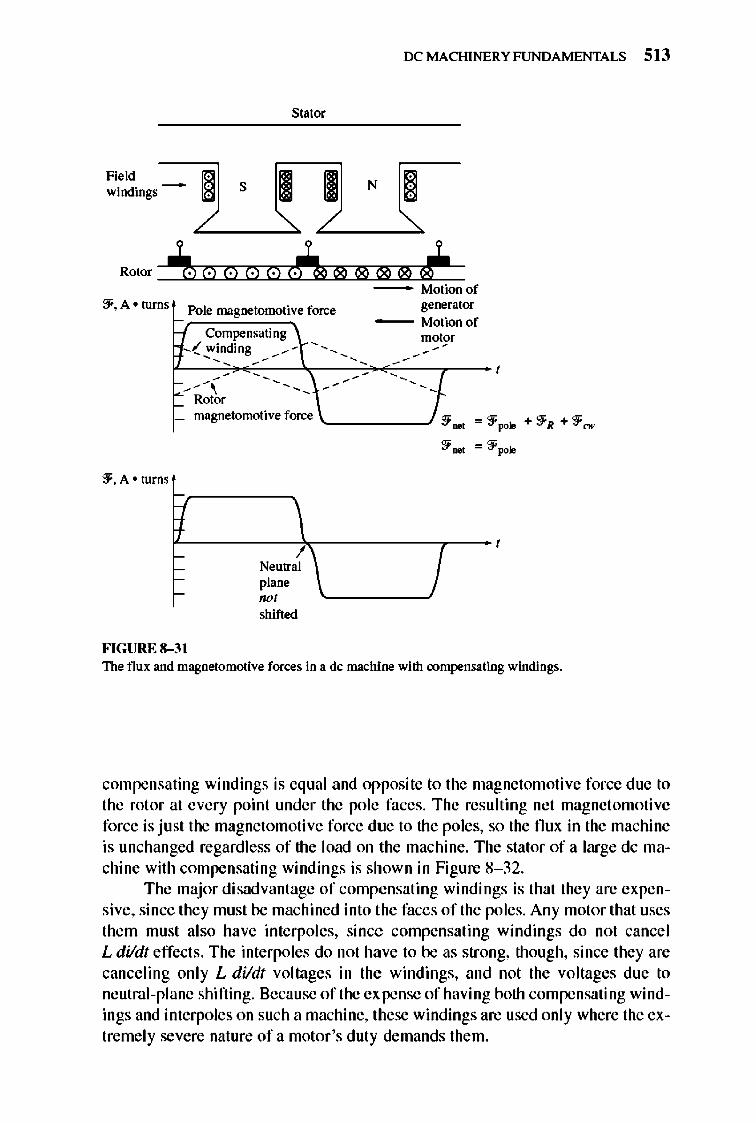
IX: MACHINERY FUNDAMENTALS 513
Stator
~~~i"" - L---~ s------'>.~ L---~ N------'>.~ j ! !
Rotor ~~~ClIT0J:]0~· ~0c·IT0J:]6~. ~"[]"'iJ,,~®~~,,~,,~~ - Motionof
::f,A· turns Pole magnetomotive force
Compensating ,,(!"inding /~
/\ r-~ Rotor
genel1ltor - Motion of
mmm
magnetomotiveforce '-_____ -':1..., =::fpole +::fR +::f""
::f. A • turns
FIGURE 8-3 1
I Neutral plane
00' shifted
:1..., =::f pole
The flux and magnetomotive forces in a de machine with compensating windings.
compensating windings is equal and opposite to the magnetomotive force due to the rotor at every point under the pole faces. The resulting net magnet omotive force is just the magnetomotive force due to the poles, so the flux in the machine is unchanged regardless of the load on the machine. The stator of a large dc machine with compensating windings is shown in Figure 8- 32.
The major disadvantage of compensating windings is that they are expensive, since they must be machined into the faces of the poles. Any motor that uses them must also have interpoles, since compensating windings do not cancel L dildt effects. The interpoles do not have to be as strong, though, since they are canceling only L dildt voltages in the windings, and not the voltages due to neutral-plane shifting. Because of the expense of having both compensating windings and interpoles on such a machine, these windings are used only where the extremely severe nature of a motor 's duty demands them.
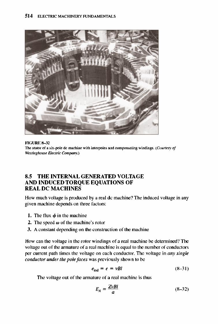
514 ELECTRIC MACHINERY RJNDAMENTALS
""GURE 8-32 The stator of a six-pole dc machine with imerpoIes and compensating windings. (Courtesy of Westinghouse Electric Company.)
8.5 THE INTERNAL GENERATED VOLTAGE AND INDUCED TORQUE EQUATIONS OF REAL DC MACHINES
How much voltage is produced by a real dc machine? The induced voltage in any given machine depends on three factors:
I. The flux <p in the machine
2. The speed W of the machine's rotor
3. A constant depending on the construction of the machine
How can the voltage in the rotor windings of a real machine be detennined? The voltage out of the annature of a real machine is equal to the number of conductors per current path times the voltage on eac h conductor. The voltage in any single conductor under the pole faces was previously shown to be
eind = e = vBI
TIle voltage out of the annature of a real machine is thus
E = ZvBI A a
(8- 3 1)
(8- 32)
IX: MACHINERY FUNDAMENTALS 515
where Z is the total number of conduct.ors and a is the number of current paths. The velocity of each conductor in the rotor can be expressed as v = rw, where r is the radius of the rotor, so
E = ZrwBI A a (8- 33)
nlis voltage can be reexpressed in a more convenient form by noting that the nux of a pole is equal to the nux density under the pole times the pole's area:
4> = BAp
The rotor of the machine is shaped like a cylinder, so its area is
A = 27frl (8- 34)
I f there are P poles on the machine, the n the portion of the area associated with each pole is the total area A divided by the number of poles P:
A = A = 27frl p P P (8- 35)
The total flux per pole in the machine is thus
4> = BAp = B(2 7frl) = 27fr1B p p (8- 36)
lllerefore, the internal generated voltage in the machine can be expressed as
Finally,
where
E _ ZrwBI
A- a (8- 33)
(8- 37)
(8- 38)
(8- 39)
In modern industrial practice, it is common to express the speed of a machine in revolutions per minute instead of radians per second. The conversi on from revolutions per minute to radians per second is
(8-40)
so the voltage equation with speed expressed in tenns of revolutions per minute is
516 ELECTRIC MACHINERY RJNDAMENTALS
I E, ~ K'<I>" I (8-4 1)
where I K'= ~ I (8-42)
How much torque is induced in the annature of a real dc machine? The torque in any dc machine depends on three factors :
I. The flux <p in the machine
2. The armature (or rotor) current I ... in the machine
3. A constant depending on the construction of the machine
How can the torque on the rotor of a real machine be determined? The torque on the armature of a real machine is equal to the number of conductors Z times the torque on each conductor. TIle torque in any single conductor under the pole faces was previously shown to be
(8-43)
If there are a current paths in the machine, then the total annature current I ... is split among the a current paths, so the current in a single conductor is given by
I, leo"" = a
and the torque in a single conductor on the motor may be expressed as
dAIB Tcood = - a-
(8-44)
(8-45)
Since there are Z conductors, the total induced torque in a dc machine rotor is
(8-46)
The flux per pole in this machine can be expressed as
J.. = BA = B(2 7rrD = 27rr1B '+' p P P (8-47)
so the total induced torque can be reexpressed as
(8-48)
Finally,
I Tind = K<pIA I (8-49)
where I K = ~ I (8- 39)
IX: MACHINERY FUNDAMENTALS 517
Both the inte rnal generated voltage and the induced torque equations just given are only approximations, because not alJ the conductors in the machine are under the pole faces at any given time and also because the surfaces of each pole do not cover an entire liP of the rotor's surface. To achieve greater accuracy, the number of conductors under the pole faces could be used instead of the total number of conductors on the rotor.
Example &-3. A duplex lap-wound annature is used in a six-pole dc machine with six brush sets. each spanning two conunutator segments. There are 72 coils on the armature, each containing 12 turns. The flux per pole in the machine is 0.039 Wb, and the machine spins at 400 r/min.
(a) How many current paths are there in this machine? (b) What is its induced voltage EA?
Solutioll (a) The number of current paths in this machine is
a = mP = 2(6) = 12 current paths
(b) The induced voltage in the machine is
EA = K'qm
K' = ZP 60a
The number of conductors in this machine is
Z = 2CNc = 2(72)(12) = 1728 conductors
Therefore, the constant K' is
K' = ZP = (1728X6) = 144 60a (60XI2) .
and the voltage EA is
EA = K'cpn
= (14.4)(0.039 Wb)(400 r/min)
= 224.6 V
(8--26)
(8-41)
(8-42)
(8-22)
EXllmple 8-4. A 12-pole dc generator has a simplex wave-wound annature containing 144 coils of 10 turns each. The resistance of each turn is 0.011 n. Its flux per pole is 0.05 Wb, and it is turning at a speed of 200 r/min.
(a) How many current paths are there in this machine? (b) What is the induced annature voltage of this machine? (c) What is the effective annature resistance of this machine? (d) If a I-ill resistor is connected to the tenninals of this generator, what is the re
sulting induced countertorque on the shaft of the machine? (Ignore the internal annature resistance of the machine.)
518 ELECTRIC MACHINERY RJNDAMENTALS
Solutio" (a) There are a = 2m = 2 current paths in this winding. (b) There are Z = 2CNc = 2(144X 10) = 2880 conductors on this generator 's rotor.
Therefore,
K' = ZP = (2880XI2) = 288 60a (60)(2)
Therefore, the induced voltage is
E}, = K'q>n
= (288XO.OS Wb)(200 r/min)
= 2880 V
(e) There are two parallel paths through the rotor of this machine, each one consisting of 712 = 1440 conductors, or 720 turns. Therefore, the resistance in each current path is
Resistancelpath = (720 turnsXO.OII !lIturn) = 7.92 n Since there are two parallel paths, the effective armature resistance is
R}, = 7.9; n = 3.96 n
(d) If a lOOO~ load is connected to the tenninals of the generator, and if R}, is ignored, then a current of 1 = 2880 V/HXX) n = 2.88 A flows. The constant K is given by
K = ZP = (2880)(12) = 2750:2 27TO" (27T)(2) .
Therefore, the countertorque on the shaft of the generator is
"Tind = Kt$/}, = (27S0.2XO.05 Wb)(2.88 A)
= 396 Nom
8.6 THE CONSTRUCTION OF DC MACHINES
A simplified sketch of a dc machine is shown in Figure 8- 33, and a more detailed cutaway diagram of a dc machine is show n in Figure 8- 34.
TIle physical structure of the machine consists of two parts: the stator or stationary part and the rotor or rotating part. TIle stationary part of the machine consists of the frame, which provides physical support, and the pole pieces, which project inward and provide a path for the magnetic flux in the machine. TIle ends of the pole pieces that are near the rotor spread out over the rotor surface to distribute its flu x evenly over the rotor surface. TIlese ends are called the pole shoes. 1lle exposed surface of a pole shoe is called a pole face, and the distance between the pole face and the rotor is calJed the air gap.
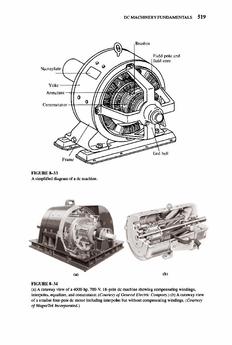
IX: MACHINERY FUNDAMENTALS 519
Field pole and
r.J "Oid Nameplate
-+--,'1--'<:. Yoke ----j'!-
Frame
FIGURE 8-33 A simplified diagram of a de machine.
(a)
FIGURE 8-34 (a) A cutaway view of a 4O(X)..hp, 700, V. 18-pole de machine showing compensating windings. interpoles. equalizer. and commutator. (Courtesy ofGeneml Electric Company.) (b) A cutaway view of a smaller four'pole de motor including interpoles but without compensating windings. (Courtesy of MagneTek lncorpomted.)
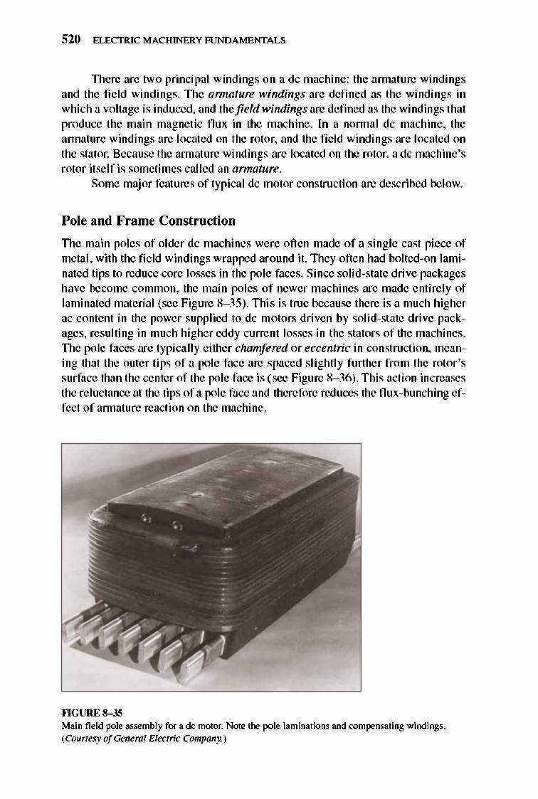
520 ELECTRIC MACHINERY RJNDAMENTALS
TIlere are two principal windings on a dc machine: the annature windings and the field windings. The armature windings are defined as the windings in which a voltage is induced, and the field windings are defined as the windings that produce the main magnetic flux in the machine. In a nonnal dc machine, the annature windings are located on the rotor, and the fi e ld windings are located on the stator. Because the annature windings are located on the rotor, a dc machine's rotor itself is sometimes called an armature.
Some maj or features of typical dc motor construction are described below.
Pole and Frame Construction
TIle main poles of older dc machines were oft en made of a single cast piece of metal, with the field windings wrapped around it. TIley often had bolted-on laminated tips to reduce core losses in the pole faces. Since solid-state drive packages have become common, the main poles of newer machines are made entirely of laminated material (see Figure 8- 35). This is true because there is a much higher ac content in the power supplied to dc motors driven by solid-state drive packages, resulting in much higher eddy current losses in the stators of the machines. TIle pole faces are typi cally either chamfered or eccentric in construction, meaning that the outer tips of a pole face are spaced slightly further from the rotor's surface than the center of the pole face is (see Figure 8- 36) . This action increases the reluctance at the tips of a pole face and therefore reduces the flux-bunching effect of annature reaction on the machine.
""GURE 8- 35 Main field pole assembly for a de motor. Note the pole laminations and compensating windings. (Courtesy of General Electric Company.)
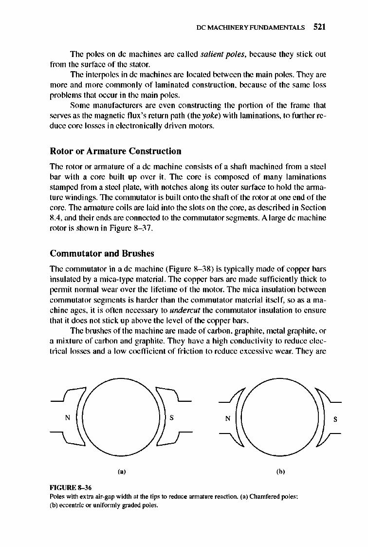
IX: MACHINERY FUNDAMENTALS 521
The poles on dc machines are ca lled salient poles, because they stick out from the surface of the stator.
The interpoles in dc machines are located between the main poles. TIley are more and more commonly of laminated construction, because of the same loss problems that occur in the main poles.
Some manufacturers are even constructing the portion of the frame that serves as the magnetic flux 's return path (the yoke) with laminations, to further reduce core losses in electronically driven motors.
Rotor or Armature Construction
The rotor or armature of a dc machine consists of a shaft machined from a steel bar with a core built up over it. The core is composed of many laminations stamped from a stccl plate, with notches along its outer surface to hold the arrnature windings. TIle commutator is built onto the shaft of the rotor at one end of the core. TIle annature coils are laid into the slots on the core, as described in Section 8.4, and their ends are connected to the commutator segments. A large dc machine rotor is shown in Figure 8- 37.
Commutator and Brushes
The commutator in a dc machine (Figure 8- 38) is typically made of copper bars insulated by a mica-type material. TIle copper bars are made sufficiently thick to pennit normal wear over the lifetime of the motor. The mica insulation between commutat or segments is harder than the commutator material it self, so as a machine ages, it is often necessary to undercut the commutator insulation to ensure that it does not stick up above the level of the copper bars.
The brushes of the machine are made of carbon, graphite, metal graphite, or a mixture of carbon and graphite. They have a high conductivity to reduce e lectricallosses and a low coeffi cient of fri ction to reduce excessive wear. They are
N s
,., ,b, FIGURE 8-36 Poles with extra air-gap width at the tips to reduce armature reaction. (a) Chamfered poles; (b) eccentric or uniformly graded poles.
s
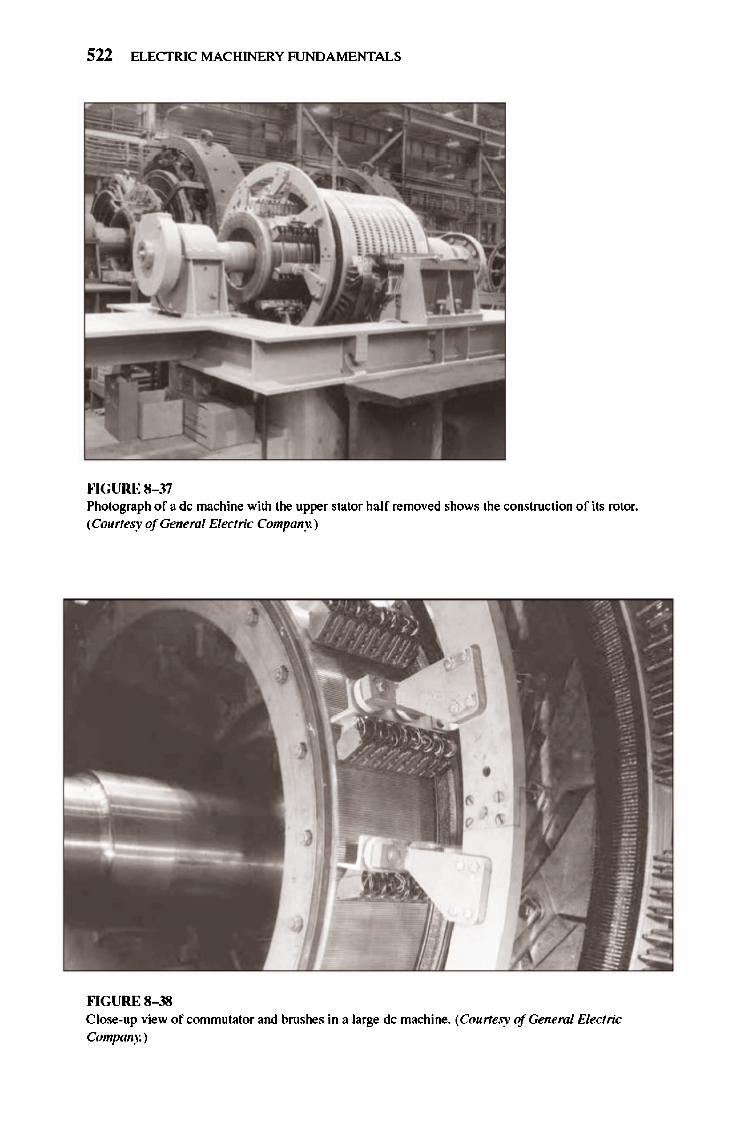
522 ELECTRIC MACHINERY RJNDA MENTALS
""GURE 8-37 Photograph of a dc machine with the upper stator half removed shows the construction of its rotor. (Courtesy of General Electric Company.)
""GURE 8-38 Close-up view of commutator and brushes in a large dc machine. (Courtesy of General Electric Company.)
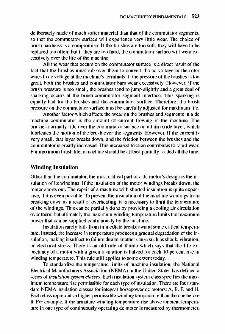
IX: MACHINERY FUNDAMENTALS 523
deliberately made of much softer material than that of the commutator segments, so that the commutator surface will experience very little wear. The choice of brush hardness is a compromise: If the brushes are too soft, they will have to be replaced too often ; but if they are too hard, the commutator surface will wear excessively over the life of the machine.
All the wear that occurs on the commutator surface is a di rect resu It of the fact that the brushes must rub over them to convert the ac voltage in the rotor wires to dc voltage at the machine 's terminals . If the pressure of the brushes is too great, both the brushes and commutator bars wear excessively. However, if the brush pressure is too small, the brushes tend to jump slightly and a great deal of sparking occurs at the brush-comm utator segment interface. This sparking is equall y bad for the bru shes and the commutator surface. TIlerefore, the brush pressure on the commutator surface must be carefully adjusted for maximum life.
Another factor which affects the wear on the brushes and segments in a dc machine commutat or is the amount of current fl owing in the machine. llle bru shes normally ride over the commutator surface on a thin ox ide layer, which lubricates the motion of the brush over the segment s. However, if the current is very small, that layer breaks down, and the fri ction between the brushes and the commutator is greatly increased. lllis increased fri ction contributes to rapid wear. For maximum brush life, a machine should be at least partially loaded all the time.
Winding Insulation
Other than the commutator, the most critical part of a dc motor's design is the insulation of its windings. I f the insulation of the motor windings breaks down, the motor shorts out. The repair of a machine with shorted insulation is quite expensive, if it is even possible. To prevent the insulation of the machine windings from breaking down as a result of overheating, it is necessary to limit the temperature of the windings . This can be partially done by providing a cooling air circulation over them, but ultimately the maximum winding temperature limits the maximum power that can be supplied continuously by the machine.
Insulation rarely fails from immediate breakdown at some critical temperature. Instead, the increase in temperature produces a gradual degradation of the insulation, making it subject to failure due to another cause such as shock, vibration, or e lectrical stress . There is an old rule of thumb which says that the life expectancy of a motor with a gi ven insulation is halved for each JO percent rise in winding temperature. This rule still app lies to some extent today.
To standardize the temperature limits of machine insulation, the National Electrical Manufact urers Association (NEMA) in the United States has defined a series of insulation system classes . Each insulation system class specifies the maximum temperature rise permissible for each type of insulation. lllere are four standard NEMA insulation classes for integral-horsepower dc motors: A, 8, F, and H. Each class represents a higher pennissible winding temperature than the one before it. For example, if the annature winding temperature rise above ambient temperature in one type of continuously operating dc motor is measured by thermometer,
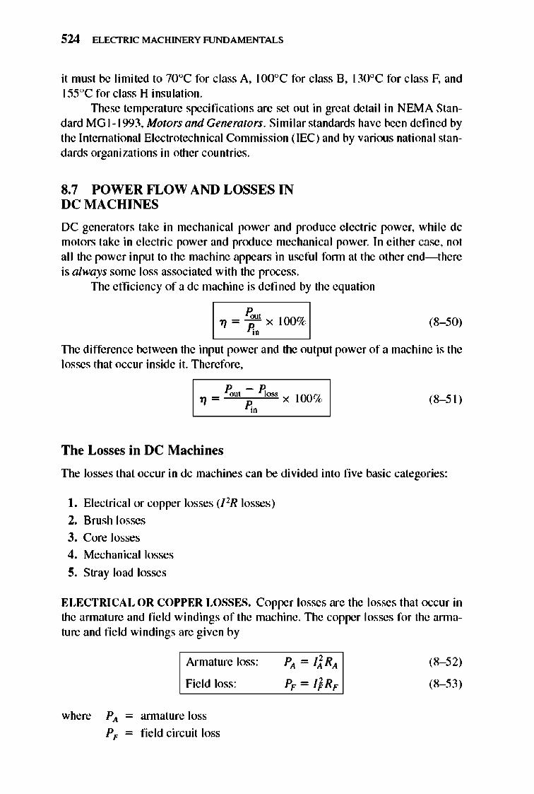
524 ELECTRIC MACHINERY RJNDAMENTALS
it must be limited to 70°C for class A, WO°C for class B, \30°C for class F, and ISSoC for class H insulation.
TIlese temperature specifications arc set out in great detail in NEMA Standard MG I -1993, Motors and Generators. Similar standards have been defined by the International Electrotechnical Commission (lEC) and by various national standards organizations in other countries.
8.7 POWER FLOW AND LOSSES IN DC MACHINES
DC generators take in mechanical power and produce e lectric power, while dc motors take in electric power and pnxluce mechanical power. In either case, not all the power input to the machine appears in useful fonn at the other end-there is always some loss associated with the process.
TIle efficiency of a dc machine is defined by the equation
(8- 50)
TIle difference between the input power and the output power of a machine is the losses that occur inside it. Therefore,
Poot - ~oss .,, = x 100% P;.o
(8- 51)
The Losses in DC Machines
The losses that occur in dc machines can be divided into fi ve basic categories:
I. Electrical or copper losses (l lR losses)
2. Brush losses
3. Core losses
4. Mechanical losses
5. Stray load losses
ELECTRICAL OR COPPER LOSSES. Copper losses are the losses that occur in the armature and field windings of the machine. TIle copper losses for the annature and field windings are given by
Armature loss:
Fie ld loss:
where P), - annature loss
P F - field circuit loss
PA = li RA
PF = I} RF
(8- 52)
(8- 53)
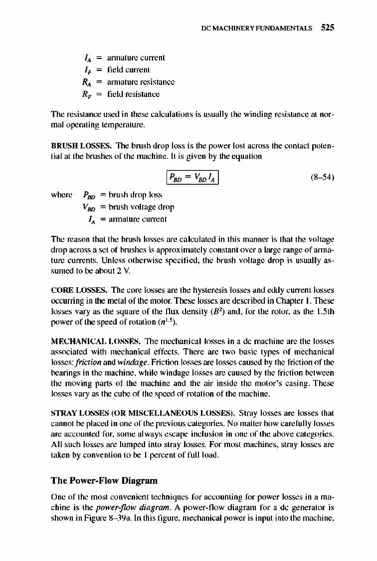
IX: MACHINERY FUNDAMENTALS 525
I, - annature current
I, - field current
R, - annature resistance
R, - field resistance
The resistance used in these calculations is usually the winding resistance at normal operating temperature.
BRUSH LOSSES. 1lle brush drop loss is the power lost across the contact potential at the brushes of the machine. It is given by the equation
IpsD - VsDIA I
where PBD = brush drop loss
VBD = brush voltage drop
IA = annature current
(8- 54)
The reason that the brush losses are ca lculated in this manner is that the voltage drop across a set of bru shes is approximate ly constant over a large range ofarrnature currents. Unless otherwise specified. the brush voltage drop is usually assumed to be about 2 V.
CORE LOSSES. The core losses are the hysteresis losses and eddy current losses occurring in the metal of the motor. These losses are described in Chapter 1. lllese losses vary as the square of the flux density (B 2) and. for the rotor, as the 1.5th power of the speed of rotation (n I. 5) .
1\"IECHANICAL LOSSES. 1lle mechanical losses in a dc machine are the losses associated with mechanical effects. There are two basic types of mechanical losses: friction and windage. Friction losses are losses caused by the friction of the bearings in the machine, while windage losses are caused by the fri ction between the moving parts of the machine and the air inside the motor 's casing. These losses vary as the cube of the speed of rotation of the machine.
STRAY LOSSES (OR MISCELLANEOUS LOSSES). Stray losses are losses that cannot be placed in one of the previous categories. No matter how carefully losses are accounted for, some always escape incl usion in one of the above categories. All such losses are lumped into stray losses. For most machines, stray losses are taken by convention to be I percent of full load.
The Power-Flow Diagram
One of the most convenient techniques for accounting for power losses in a machine is the power-flow diagram. A power-flow diagram for a dc generator is shown in Figure 8- 39a. In this fi gure, mechanical power is input into the machine,
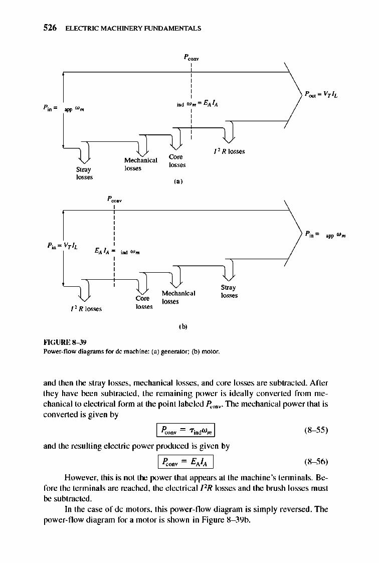
526 ELECTRIC MACHINERY RJNDAMENTALS
Stray losses
, , , , , ,
Mechanical losses
EA IA '" iDd Ul m
I'R losses
""GURE 8-39
Core losses
p~ ,
Core losses
,,'
Mechanical losses
,b,
I'R losses
Stray losses
Power-flow diagrams for de machine: (a) generator: (b) motor.
and then the stray losses, mechanical losses, and core losses are subtracted. After they have been subtracted, the remaining power is ideally converted from mechanical to electrical fonn at the point labeled P"ODV. TIle mechanical power that is converted is given by
I P"onv - Tindw m I (8- 55)
and the resulting electric power produced is given by
(8- 56)
However, this is not the power that appears at the machine 's tenninals. Before the terminals are reached, the electricalllR losses and the brush losses must be subtracted.
In the case of dc motors, this power-now diagram is simply reversed. The power-now diagram for a motor is shown in Figure 8- 39b.
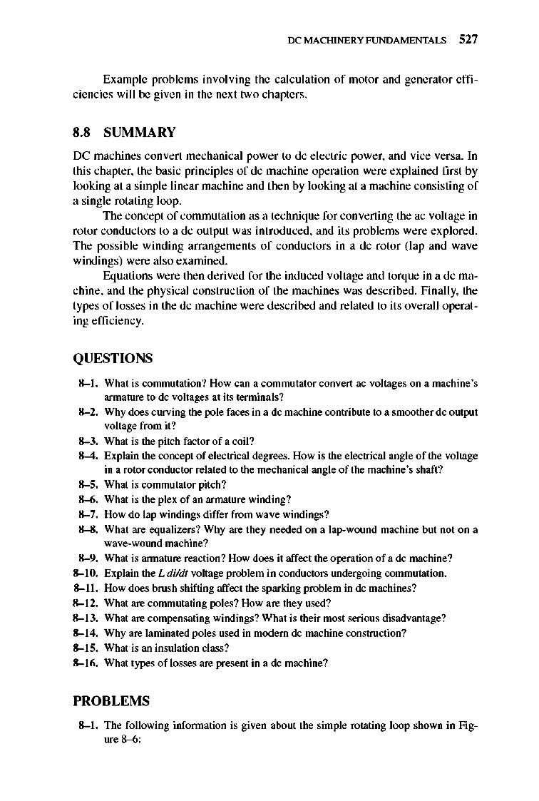
IX: MACHINERY FUNDAMENTALS 527
Example problems involving the calculation of motor and generator efficiencies will be given in the next two chapters.
S.S SUMMARY
DC machines convert mechanical power to dc e lectric power, and vice versa. In this chapter, the basic principles of dc machine operation were explained first by looking at a simple linear machine and then by looking at a machine consisting of a single rotating loop.
The concept of commutation as a technique for converting the ac voltage in rotor conductors to a dc output was introduced, and its problems were explored. The possible winding arrangements of conductors in a dc rotor (lap and wave windings) were also examined.
Equations were then derived for the induced voltage and torque in a dc machine, and the physical construction of the machines was described. Finally, the types of losses in the dc machine were described and related to its overall operating efficiency.
QUESTIONS
8-1, What is conunutation? How can a commutator convert ac voltages on a machine's armature to dc voltages at its terminals?
8-2, Why does curving the pole faces in a dc machine contribute to a smoother dc output voltage from it?
8-3, What is the pitch factor of a coil? 8-4, Explain the concept of electrical degrees. How is the electrical angle of the voltage
in a rotor conductor related to the mechanical angle of the machine's shaft? 8-5, What is conunutator pitch? 8-6, What is the plex of an armature winding? 8-7, How do lap windings differ from wave windings? 8-8, What are equalizers? Why are they needed on a lap-wound machine but not on a
wave-wolUld machine? 8-9, What is annature reaction? How does it affect the operation of a dc machine?
8-10, Explain the L dildt voltage problem in conductors lUldergoing commutation. 8-11, How does brush shifting affect the sparking problem in dc machines? 8-12, What are conunutating poles? How are they used? 8-13, What are compensating windings? What is their most serious disadvantage? 8-14, Why are laminated poles used in modem dc machine construction? 8-15, What is an insulation class? 8-16, What types of losses are present in a dc machine?
PROBLEMS
8-1, The following infonnation is given about the simple rotating loop shown in figure 8--6:
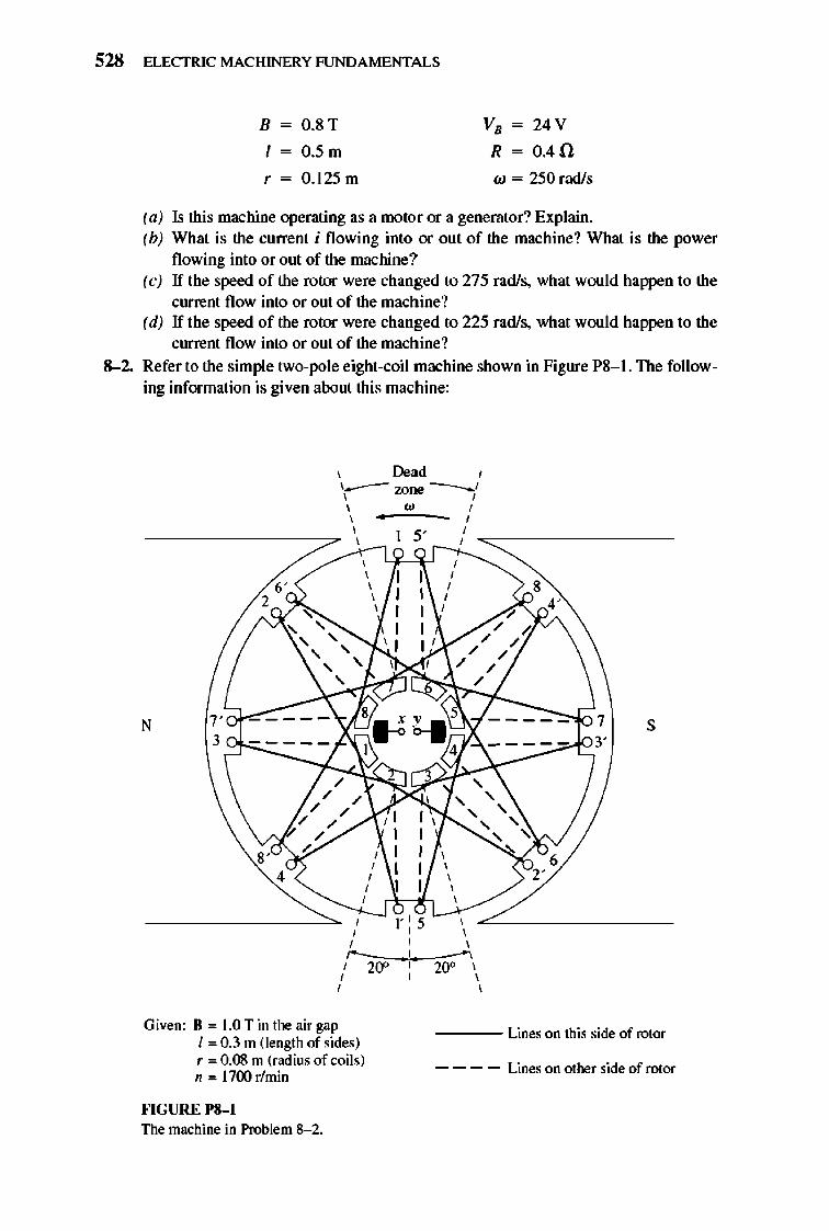
528 ELECTRIC MACHINERY RJNDA MENTALS
B = O.S T
l = O.5 m
r = O.I 25 m
VB = 24 V
R = 0.4 0
w = 250 radls
(a) Is this machine operating as a motor or a generator? Explain. (b) What is the curre nt i fl owing into or out of the machine? What is the power
flowing into or out of the machine? (c) If the speed of the rotor were changed to 275 rad/s, what would happen to the
current flow into or out of the machine? (d) If the speed of the rotor were changed to 225 rad/s, what would happen to the
current flow into or out of the machine?
&-2. Refer to the simple two-pole eight-coil machine shown in Figure PS- I. The following information is given about this machine:
\ ~ad I I __ wne __ ' , , , w , I .. I
---------:::/~_~'',., - 5' -i/_-"'=:::---------
N
, , , I I , , I I
, , , , , I I , , , I I , , , I I ' , , , , ,
7""~-~-~-:=-~-~~8~.~,~O~6~.~5~~-~-~------,£~ 7 3 3' - -- -- I 4 ---- -
, , I
I , I , I , , ,
, , , , , / 1' : 5 \ , , , r----'-----"'
I 20" I 20° I , , ,
, , , , , , ,
, ,
s
Give n: II '" 1.0 T in the air gap I '" 0.3 m (length of sides) r '" 0.08 m (radius of coils) n '" 1700 r!min
---- Lines on this side of rotor
- - - - Lines on other side of rotor
Jo'IGURE 1'8-1 The machine in Problem 8- 2.
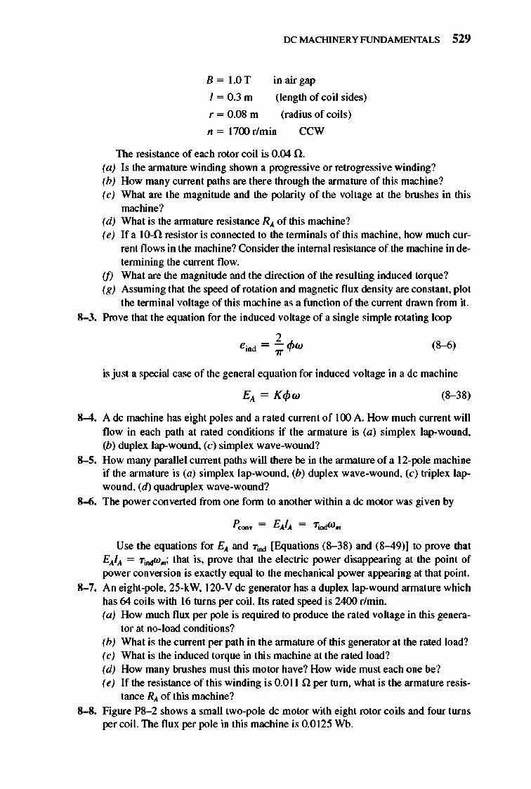
IX: MACHINERY FUNDAMENTALS 529
B = 1.0T in air gap
1 = 0.3 m (length of coil sides)
r = 0.08 m (radius of coils)
n = 1700 rlmin ccw
The resistance of each rotor coil is 0.04 n. (a) Is the armature winding shown a progressive or retrogressive winding? (b) How many current paths are there through the armature of this machine? (c) What are the magnitude and the polarity of the voltage at the brushes in this
machine? (d) What is the annature resistance RA of this machine? (e) If a 1O~ resistor is connected to the tenninals of this machine, how much cur
rent flows in the machine? Consider the internal resistance of the machine in detennining the current flow.
(f) What are the magnitude and the direction of the resulting induced torque? (g) Assuming that the speed of rotation and magnetic flux density are constant, plot
the terminal voltage of this machine as a flUlction of the current drawn from it. 8-3. Prove that the equation for the induced voltage of a single simple rotating loop
2 , . , = - "'w In 7T '+' (8-6)
is just a special case of the general equation for induced voltage in a dc machine
(8--38)
8-4. A dc machine has eight poles and a rated current of 100 A. How much current will flow in each path at rated conditions if the armature is (a) simplex lap-wound, (b) duplex lap-wound, (c) simplex wave-wound?
8-5. How many parallel current paths will there be in the armature of a 12-pole machine if the armature is (a) simplex lap-wolUld, (b) duplex wave-wound, (c) triplex lapwound, (d) quadruplex wave-wolUld?
8-6. The power converted from one fonn to another within a dc motor was given by
Use the equations for EA and "Tiod [Equations (8--38) and (8-49)] to prove that EAtA = "Tiodw .. ; that is. prove that the electric power disappearing at the point of power conversion is exactly equal to the mechanical power appearing at that point.
8-7. An eight-pole, 25-kW, 120-V dc generator has a duplex lap-wound armature which has 64 coils with 16 turns per coil. Its rated speed is 2400 r/min. (a) How much flux per pole is required to produce the rated voltage in this genera-
tor at no-load conditions? (b) What is the current per path in the annature of this generator at the rated load? (c) What is the induced torque in this machine at the rated load? (d) How many brushes must this motor have? How wide must each one be? (e) If the resistance of this winding is 0.011 0: per turn, what is the armature resis
tance RA of this machine? 8-8. Figure PS- 2 shows a small two-pole dc motor with eight rotor coils and four turns
per coil. The flux per pole in this machine is 0.0125 Wh.
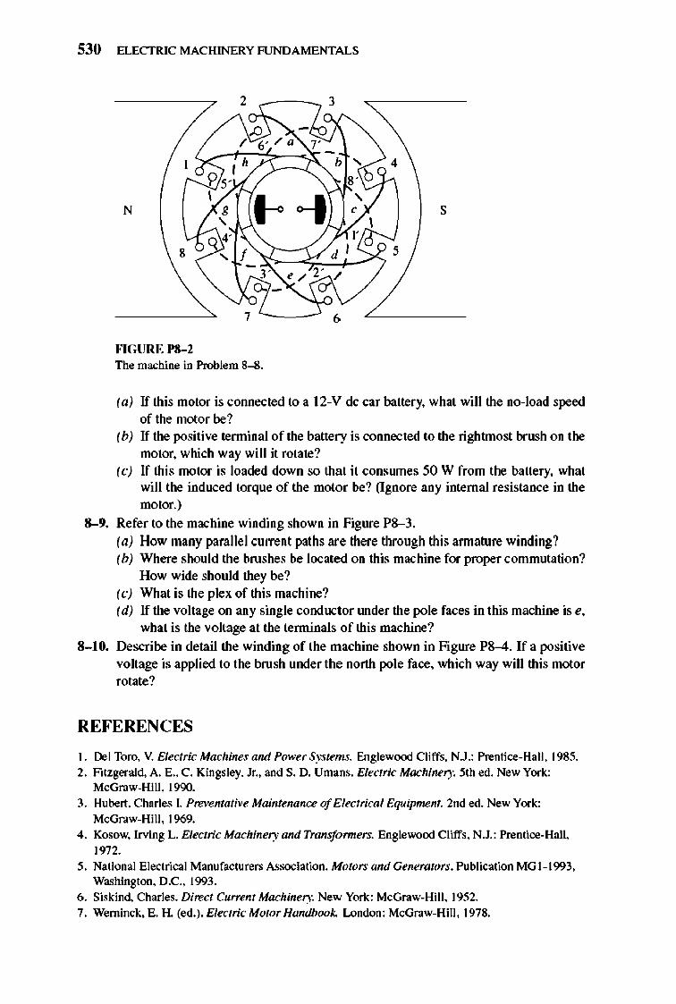
530 ELECTRIC MACHINERY RJNDAMENTALS
2 3
N s
""GURE 1'8-2 The machine in Problem 8--8.
(a) If this motor is cOIUlected to a 12-V dc car battery, whal will the no-load speed of the motor be?
(b) If the positive terminal of the battery is connected to the rightmost brush on the motor, which way will it rotate?
(c) If this motor is loaded down so that it consrunes 50 W from the battery, what will the induced torque of the motor be? (Ignore any internal resistance in the motor.)
&-9. Refer to the machine winding shown in Figure P8-3. (a) How many parallel current paths are there through this annature winding? (b) Where should the brushes be located on this machine for proper commutation?
How wide should they be? (c) What is the plex of this machine? (d) If the voltage on any single conductor lUlder the pole faces in this machine is e,
what is the voltage at the lenninals of this machine?
8-10. Describe in detail the winding of the machine shown in Figure PS-4. If a positive voltage is applied to the brush under the north pole face, which way will this motor rotate?
REFERENCES
I. Del Toro. V. Electric Machines and Pov.·er Systems. Englewood Cliffs. N.J.: Prentice-Ha.lt. 1985. 2. Fitzgerald. A. E., C. Kingsley. Jr .. and S. D. Umans. Electric Machinery. 5th ed. New York:
McGraw-Hilt. 1990. 3. Hubert. Charles I. Preventative Maintenance of Electrical Equipment. 2nd ed. New York:
McGraw-Hilt. 19ff}.
4. Kosow. Irving L. Electric Machinery and Transfanners. Englewood Cliffs. N.J.: Premice-HatJ. 1972.
5. Na.tional Electrical Manufacturers Association. Motors and Generators, Publication MG 1-1993. Washington, D.C.. 1993.
6. Siskind. Charles. Direct Current Machinery. New York: McGraw-Hilt. 1952. 7. Werninck. E. H. (ed.). Electric Motor Handbook.. London: McGraw-Hilt. 1978.
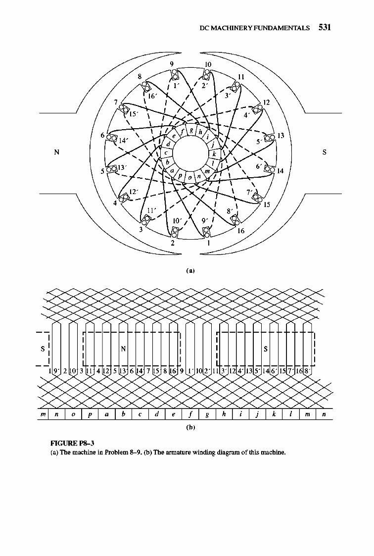
IX: MACHINERY FUNDAMENTALS 531
9 10
8 11
/ 16' I 3'
7 I , I / 12 , I / -15' I , , I / - --
6 I I g h 13 j ,
N , I , , , , 6' 5 " m , 14 , P " "
I - / I , I --- /
, -/
, 8' I 11'
/ \0'/
3 16
2
('1
:x ~~ :XXX
-- --- --, , , , ,
" , N
, , , , , , , , , , , ,
--- ---
~ m " " p " b , d , f g h ; j , , m "
(hI
FIGURE P8-J (a) The machine in Problem 8--9. (b) The annature winding diagram of this machine.
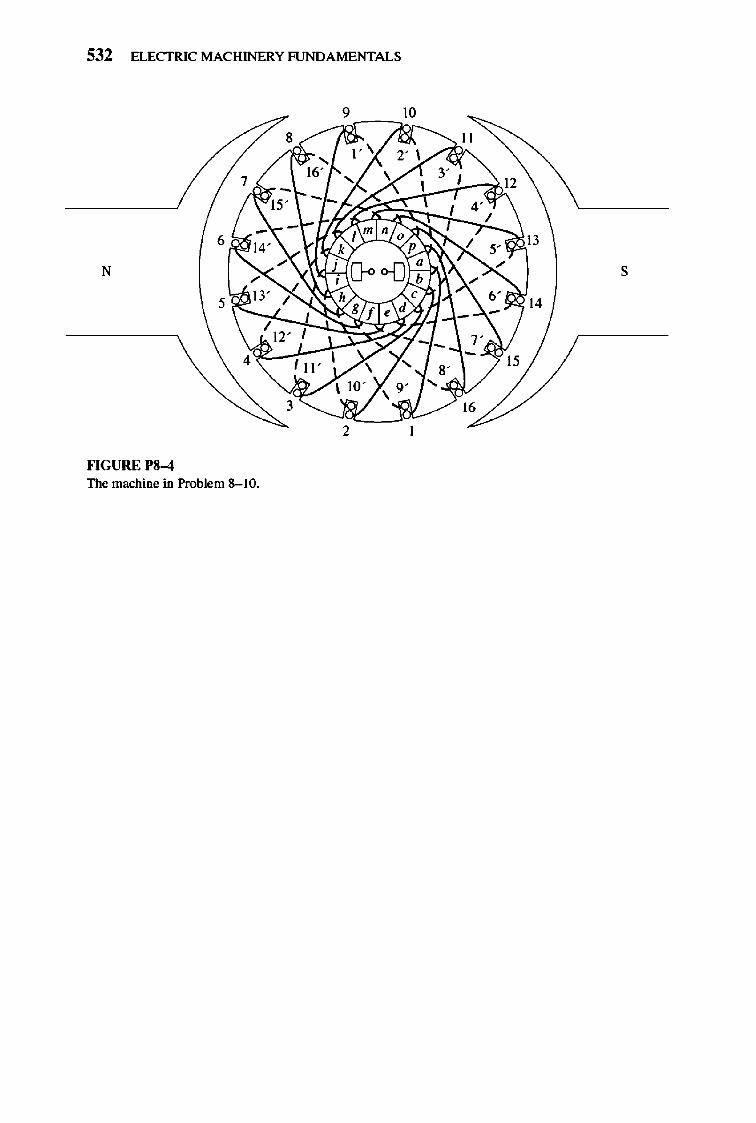
532 ELECTRIC MACHINERY RJNDAMENTALS
' __ 10
N s
14
2
""GURE 1'8-4 The machine in Problem 8- 10.
CHAPTER
9 DC MOTORS
AND GENERATORS
Dc motors are de machines used as motors, and de generators are de machines used as generators. As noted in Chapter 8, the same physical machine can op
erate as either a motor or a generator-it is simply a question of the direction of the power now through it. This chapter will examine the different types of de motors that can be made and explain the advantages and disadvantages of each. It will include a discussion of de motor starting and solid-state control s. Finally, the chapter will conclude with a discussion of de generators.
9.1 INTRODUCTION TO DC MOTORS
The earliest power systems in the United States were de systems, but by the 1890s ac power systems were clearly winning out over de systems. Despite this fact, de motors continued to be a significant fraction of the machinery purchased each year through the 1960s (that fraction has declined in the last 40 years). Why were dc motors so common, when dc power systems themselves were fairly rare?
There were several reasons for the continued popularity of dc motors. One was that dc power syste ms are still common in cars, trucks, and aircraft. Whe n a vehicle has a dc power syste m, it makes sense to consider using dc motors. Another application for dc motors was a situation in which wide variations in speed are needed. Before the widespread use of power e lectronic rectifier-inverters, dc motors were unexcelled in speed control applications. Eve n ifno dc power source were available, solid-state rectifier and chopper circuits were used to create the necessary dc power, and dc motors were used to provide the desired speed control.
533
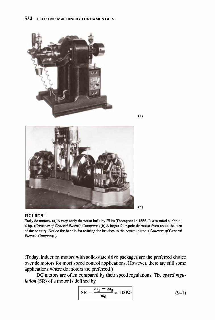
534 ELECTRIC MACHINERY RJNDA MENTALS
,.,
,b, ""GURE 9- 1 Early de motors. (a) A very early de motor built by Elihu Thompson in 1886. It was rated at about \oj hp. (Courtesy ofGeneml Electric Company.) (b) A larger four-pole de motor from about the turn of the century. Notice the h.andle for shifting the brush.es to the neutral plane. (Courtesy ofGeneml Electric Company. )
(Today, induction motors with solid-state drive packages are the preferred choice over dc motors for most speed control applications. However, there are still some applications where dc motors are preferred .)
DC motors are oft en compared by their speed regul ations. TIle speed regulation (S R) of a motor is defined by
'I S-R-~--:W~"-' Wn=~W~"-X-l-()()-%'1 W-l )
rx: MmDRS AND GENERATORS 535
I SR = nul ~ nfl x 100% I (9-2)
It is a rough measure of the shape of a motor 's torque- speed characteristic-a positive speed regulation means that a motor's speed drops with increasing load, and a negative speed regulation means a motor's speed increases with increasing load . The magnitude of the speed regulation te lls approximately how steep the slope of the torque- speed curve is .
DC motors are, of course, driven from a dc power supply. Unless otherwise specified, the input voltage to a de motor is assumed to be constant, because that assumption simplifies the analysis of motors and the comparison between different types of motors.
There are five major types of dc motors in general use :
I. 1lle separately excited dc motor
2. 1lle shunt dc motor
3. 1lle pennanent-magnet dc motor
4. 1lle series dc motor
5. 1lle compounded dc motor
Each of these types will be examined in turn.
9.2 THE EQUIVALENT CIRCUIT OFADC MOTOR
The equivalent circuit of a dc motor is shown in Figure 9-2. In this figure, the armature circuit is represented by an ideal voltage source E), and a resistor R),. This representation is really the Thevenin eq uivalent of the entire rotor structure, including rotor coils, interpoles, and compensating windings, if present. The brush voltage drop is represented by a small battery V bru<h opposing the direction of current flow in the machine. 1lle field coils, which produce the magnetic flux in the generator, are represented by inductor LF and resistor RF. The separate resistor R odj
represents an external variable resistor used to control the amount of current in the field circuit.
There are a few variations and si mplifications of this basic equivalent circuit. 1lle brush drop voltage is often only a very tiny fraction of the generated voltage in a machine. Therefore, in cases where it is not too critical, the brush drop voltage may be left out or approximately included in the value of R), . Also, the internal resistance of the fi e ld coil s is sometimes lumped together with the variable resistor, and the total is called RF (see Figure 9-2b). A third variation is that some generators have more than one field coil , all of which will appear on the equivalent circuit.
The internal generated voltage in this machine is given by the equation
(8- 38)
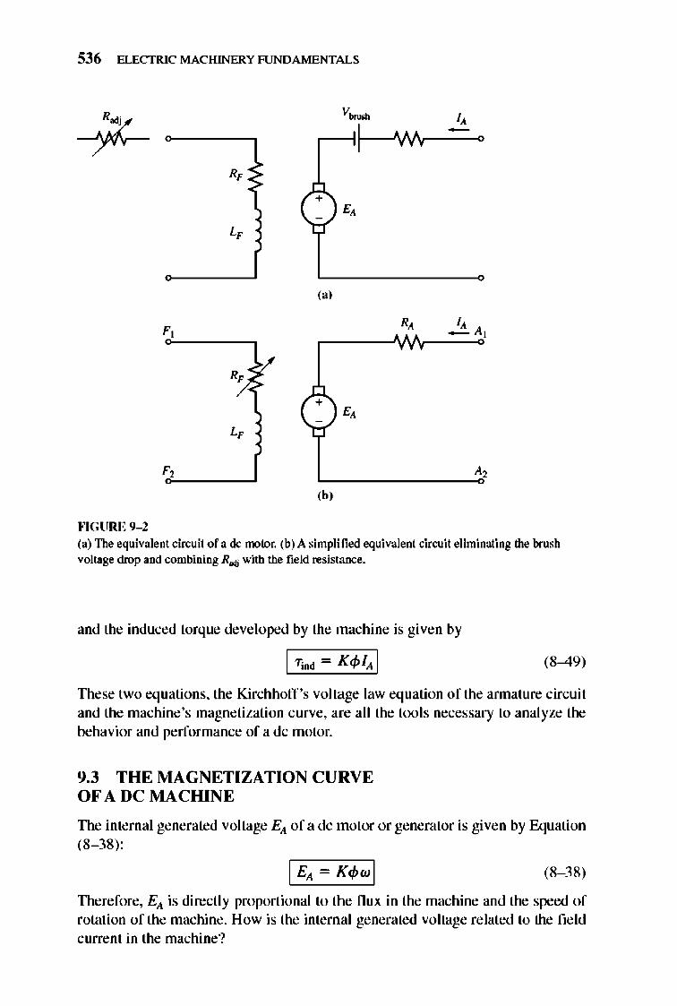
536 ELECTRIC MACHINERY RJNDAMENTALS
--iJ:-V~ I,
I 'VI/v ,
R,
E,
L,
(a)
R, I, _ A,
R,
+ E,
L,
A,
,b, ""GURE 9- 2 (a) The equivalent circuit of a dc motor. (b) A simplified equivalent circuit eliminating the brush voltage drop and combining R..., with the field resistance.
and the induced torque developed by the machine is given by
(8-49)
TIlese two equations, the Kirchhoff 's voltage law equation of the annature circuit and the machine's magnetization curve, are all the tools necessary to analyze the behavior and performance of a dc motor.
9.3 THE MAGNETIZATION CURVE OF A DC MACHINE
The internal generated voltage Ell of a dc motor or generator is given by Equation (8- 38) ,
(8- 38)
Therefore, Ell is directly proportional to the nux in the machine and the speed of rotation of the machine . How is the internal generated voltage related to the field current in the machine?
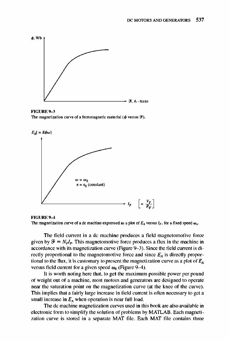
rx: MmDRS AND GENERATORS 537
~.Wb
'---------------- 3'. A· turns
FIGURE 9-3 The magnetization curve of a ferromagnetic material (4) versus 3').
"'="'0 n ="0 (constant)
'---------------- IF [= ~; ]
FIGURE 9-4 The magnetization curve of a dc machine expressed as a plot of E,t versus IF. for a fixed speed ." ..
The field current in a dc machine produ ces a field magnetomotive force given by '?} = NFIF. nlis magnetomoti ve force produces a flu x in the machine in accordance with its magnetization curve (Figure 9- 3) . Since the field current is directly proportional to the magnetomoti ve force and since EA is directly proportional to the flux, it is customary to present the magnetization curve as a plot of EA versus fi e ld current for a given speed Wo (Figure 9--4).
It is worth noting here that, to get the maximum possible power per pound of weight out of a machine, most motors and generators are designed to operate near the saturation point on the magnetization curve (at the knee of the curve). This implies that a fairly large increase in field current is often necessary to get a small increase in EA when operation is near full load.
The dc machine magnetization curves used in this book are also available in electronic form to simplify the solution of problems by MATLAB. Each magnetization curve is stored in a separate MAT file. Each MAT fil e contains three
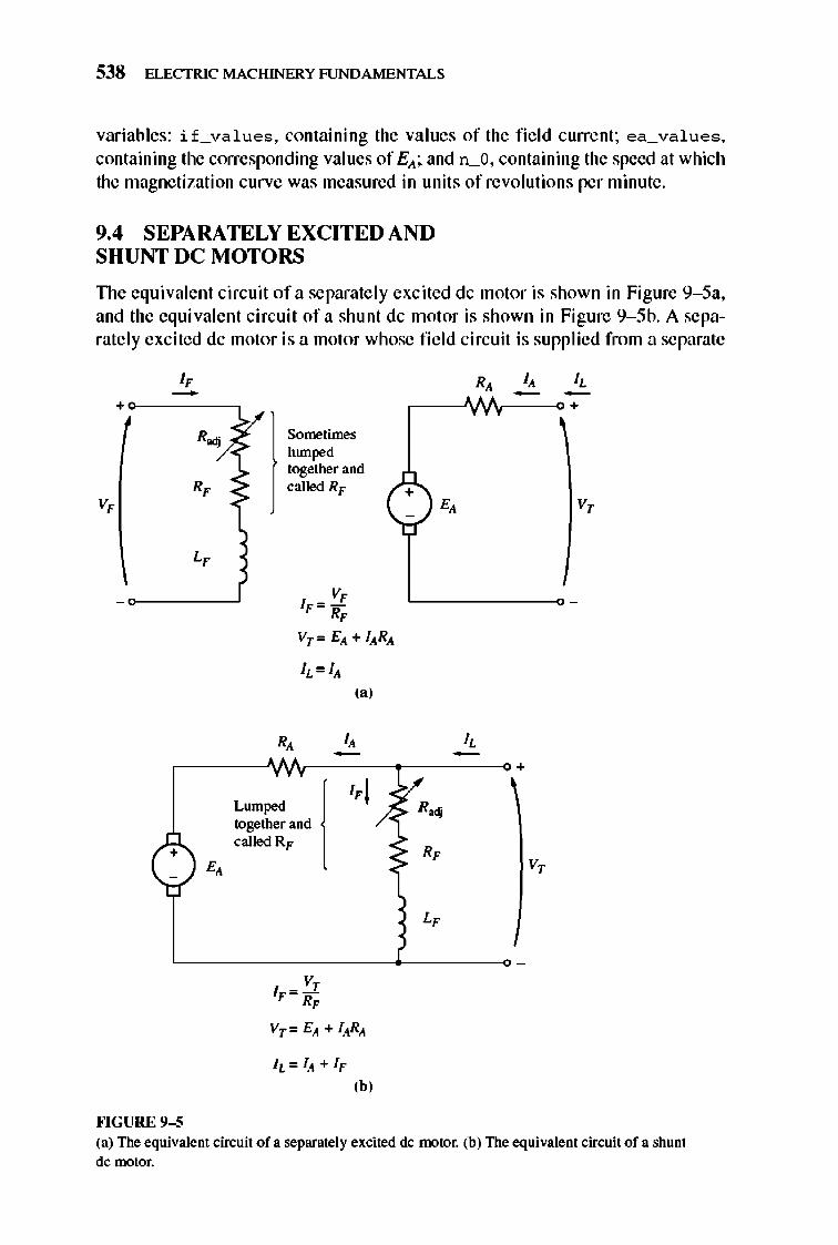
538 ELECTRIC MACHINERY RJNDAMENTALS
variables: if_va l ues , containing the values of the fi e ld current; ea_val ues, containing the corresponding val ues of E).; and n_O, containing the speed at which the magnetization curve was measured in unit s of revolutions per minute .
9.4 SEPARATELY EXCITED AND SHUNT DC MOTO RS
TIle equivalent circuit of a separate ly excited dc motor is shown in Figure 9- 5a, and the equivalent circuit of a shunt dc motor is shown in Figure 9- 5b. A separately excited dc motor is a motor whose fie ld circuit is supplied from a separate
I, -+
R.,
R, V,
L,
+ E,
""GURE 9-5
R,
Sometimes lumped together and called RF C )E,
V, IF = -R, Vr = E). + lARA
lL=IA
R,
Lumped together and called RF
V, IF= RF
[
(a)
I, -l,j
Vr = EA + lARA
'bJ
I, -R ...
R,
L,
I, I, - -+
V,
+
V,
(a) The equivalent circuit of a separately excited dc lootor. (b) The equivalent circuit of a shunt dc motor.
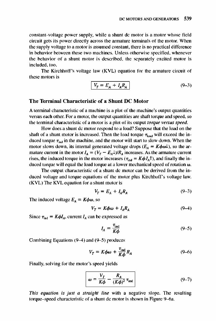
rx: MmDRS AND GENERATORS 539
constant-vo ltage power supply, while a shunt dc motor is a motor whose fi e ld circuit gets its power directly across the armature terminals of the motor. Whe n the supply voltage to a motor is assumed constant, there is no practical difference in behavior between these two machines. Unless otherwise specified, whenever the behavior o f a shunt motor is described, the separately excited motor is included, too .
The Kirchhoff 's voltage law (KVL) equation for the armature circuit of these motors is
(9- 3)
The Terminal Char acteristic of a Shunt DC Motor
A tenninal characteristic of a machine is a plot of the machine's output quantities versus each other. For a motor, the output quantities are shaft torque and speed, so the terminal characteristic of a motor is a plot of its output torque versus speed.
How does a shunt dc motor respond to a load? Suppose that the load on the shaft of a shunt motor is increased . The n the load torque "Tlood will exceed the induced torque "TiOO in the machine, and the motor wil I start to slow down. When the motor slows down, its internal generated voltage drops (EA = K4>wJ. ), so the armature current in the motor IA = (VT - EAJ. )/RA increases. As the annature current rises, the induced torque in the motor increases (1]00 = K4> IA i ), and finally the induced torque will equal the load torque at a lower mechanical speed of rotation w.
TIle output characteristic of a shunt dc motor can be derived from the induced voltage and torque equations of the motor plus Kirchhoff's voltage law. (KVL) TIle KVL equation for a shunt motor is
VT = EA + lARA
The induced voltage EA = K4>w, so
VT = K¢w + lARA
Since "Tind = K4>IA, current IA can be expressed as
"Tind
IA = K4>
Combining Equations (9-4) and (9-5) prOOuces
Finally, solving for the motor 's speed yields
(9- 3)
(9-4)
(9- 5)
(9-6)
(9- 7)
This equation is just a straight line with a negative slope. TIle resulting torque- speed characteristic of a shunt dc motor is shown in Figure 9--6a.
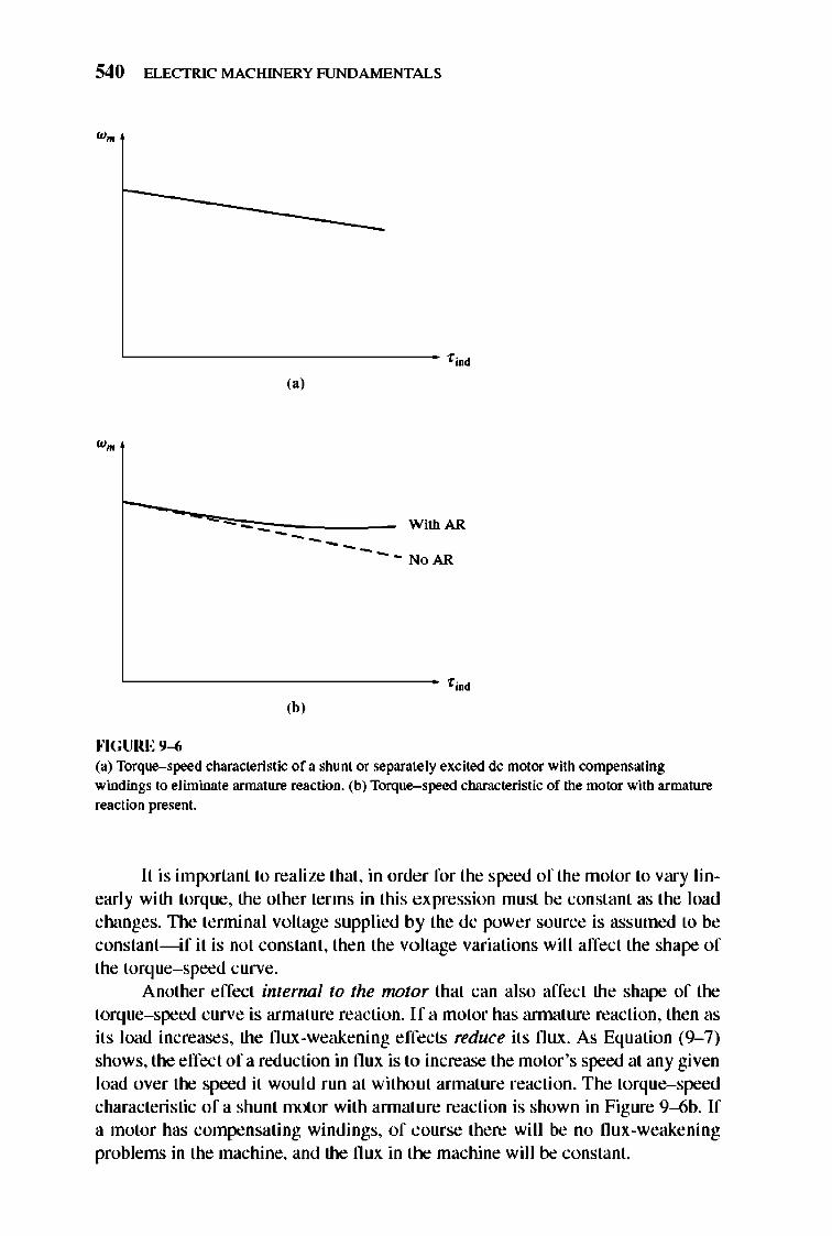
540 ELECTRIC MACHINERY RJNDAMENTALS
"---------------------------- '00 (a)
------ WithAR
---NoAR
"---------------------------- '00 ,b, ""GURE 9--6 (a) Torque-speed characteristic of a shunt or separately excited dc motor with compensating windings to eliminate armature reaction. (b) Torque-speed characteristic of the motor with annature reaction present.
II is important to realize that, in order for the speed of the motor to vary linearly with torque, the other terms in this expression must be constant as the load changes. TIle tenninal voltage supplied by the dc power source is assumed to be constant- if it is not constant, then the voltage variations will affect the shape of the torque- speed curve.
Another effect internal to the motor that can also affect the shape of the torque-speed curve is armature reaction. If a motor has annature reaction, then as its load increases, the flux-weakening effects reduce its flux. As Equation (9-7) shows, the effect ofa reduction in flux is to increase the motor's speed at any given load over the speed it would run at without armature reaction. The torque-speed characteristic of a shunt motor with annature reaction is shown in Figure 9--6b. If a motor has compensating windings, of course there will be no flux-weakening problems in the machine, and the flux in the machine will be constant.
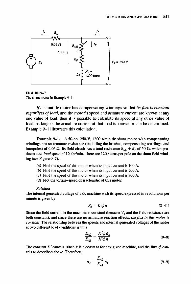
rx: MmDRS AND GENERATORS 541
" R, " - - +
0.060 R;). ~ I', son
+ R, < ~
E, VT",250V
L, NF '" 1200tuTns
FIGURE 9- 7 The shunt motor in Example 9--1.
Ifa shunt dc motor has compensating windings so that its flux is constant regardless of load, and the motor's speed and armature current are known at any one value of load, then it is possible to calculate its speed at any other value of load, as long as the armature current at that load is known or can be detennined. Example 9- 1 illustrates this calculation.
Example 9-1. A 50-hp, 250-V, 1200 r/min dc shunt motor with compensating windings has an armature resistance (including the brushes, compensating windings, and interpoles) of 0.06 n. Its field circuit has a total resistance Rodj + RF of 50 fl , which produces a no-load speed of 1200 r/min. There are 1200 tlU1lS per pole on the shunt field winding (see Figure 9-7).
(a) Find the speed of this motor when its input current is 100 A. (b) Find the speed of this motor when its input current is 200 A. (c) Find the speed of this motor when its input current is 300 A. (d) Plot the torque-speed characteristic of this motor.
Solutioll The internal generated voltage of a dc machine with its speed expressed in revolutions per minute is given by
(8-41)
Since the field current in the machine is constant (because Vr and the field resistance are both constant), and since there are no annature reaction effects, the flux in this motor is constant. The relationship between the speeds and internal generated voltages of the motor at two different load conditions is thus
(9-8)
The constant K ' cancels, since it is a constant for any given machine, and the flux <p cancels as described above. Therefore,
(9-9)
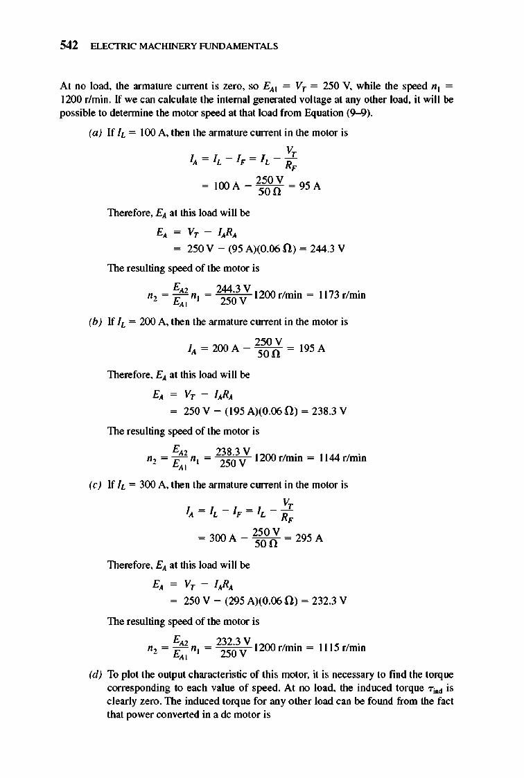
542 ELECTRIC MACHINERY RJNDAMENTALS
At no load, the armature current is zero, so E"I = Vr = 250 V, while the speed nl = 12DO r/min. If we can calculate the internal generated voltage at any other load, it will be
possible to detennine the motor speed at that load from Equation (9--9).
(a) If h = lDO A, then the armature current in the motor is
V, I" = It. - IF = It. - RF
- lOOA _ 250 V - 95A - son -
Therefore, E" at this load will be
E" = Vr - I"R" = 250 V - (95 A)(O.06 ll) = 244.3 V
The resulting speed of the motor is
E"2 244.3 V 1200 / . n2 = E"I n l = 250V rmm = 1173 r/min
(b) If h = 2DO A, then the armature current in the motor is
I _ 2DOA _ 250V - 195A ,, - son -
Therefore, E" at this load will be
E" = Vr - I"R" = 250 V - (195 A)(O.()5 ll) = 238.3 V
The resulting speed of the motor is
E"2 238.3 V 1200 / . 1144 / . n2= Enl= 250V rmm = rmm
" (e) If h = 3DO A, then the armature current in the motor is
V, I" = It. - IF = It. - RF
- 300 A _ 250 V - 295 A - son -
Therefore, E" at this load will be
E" = Vr - I"R" = 250 V - (295 A)(O.()5 ll) = 232.3 V
The resulting speed of the motor is
E"2 232.3 V 1200 / . n2 = E"I n l = 250V rmm = 1115r/min
(d) To plot the output characteristic of this motor, it is necessary to find the torque corresponding to each value of speed. At no load, the induced torque "Tind is clearly zero. The induced torque for any other load can be fOlUld from the fact that power converted in a dc motor is
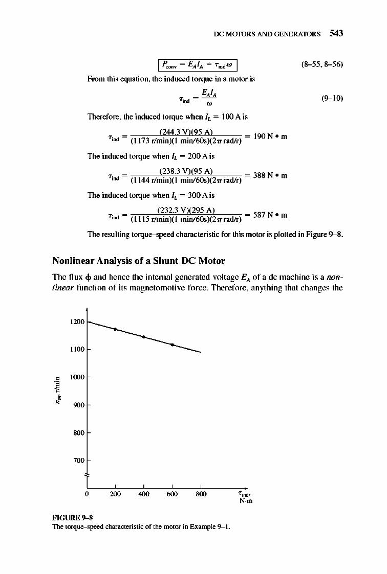
rx: MmDRS AND GENERATORS 543
I PCQDV Ell!'" 7ind W I
From this equation, the induced torque in a motor is
E",!", 7iod = -
w
Therefore, the induced torque when !L = 100 A is
_ (244.3 V)(95 A) _ 7 ;00 - (1173 r/minXI min/60sX27T rad!r) -
The induced torque when h = 200 A is
(238.3 V)(95 A) = 388 N • m 7 ;00 = (1144 r/minXI min/60sX27T rad!r)
The induced torque when !L = 300 A is
(232.3 VX295 A) = 587 N • m 7 iOO = (1115 r/minXI min/60sX27T rad!r)
(8- 55,8--56)
(9--10)
The resulting torque-speed characteristic for this motor is plotted in Figure 9--8.
Nonlinear Analysis of a Shunt DC Motor
T he nux $ and hence the inte rnal generated vo ltage E", of a dc machine is a nonlinear fun ction of its magne tomotive force. T here fore , anything that changes the
1200
11110
0 11X1O
~ • 0
900
800
7110
T o 200 400 600 800
FIGURE 9- 8 The torque-speed characteristic of the motor in Example 9--1.
f iOO' N·m
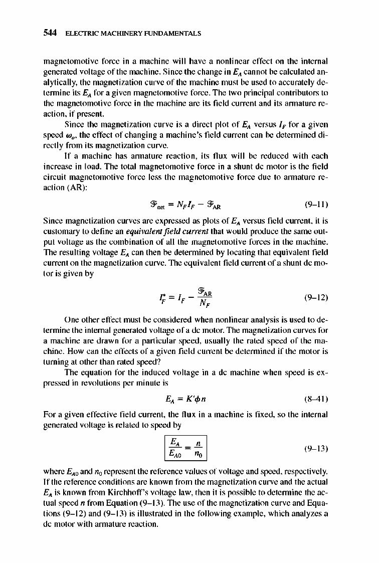
544 ELECTRIC MACHINERY RJNDAMENTALS
magnetomotive force in a machine will have a nonlinear effect on the internal generated voltage of the machine. Since the change in Ell cannot be calculated analytically, the magnetization curve of the machine must be used to accurately detennine its Ell for a given magnetomotive force. The two principal contributors to the magnetomoti ve force in the machine are its field current and its annature reaction, if present.
Since the magnetization curve is a direct plot of Ell versus IF for a given speed wo , the effect of changing a machine 's field current can be detennined directly from its magnetization curve.
If a machine has annature reaction, its flux will be reduced with each increase in load. The total magnet omotive force in a shunt dc motor is the field circuit magnetomotive force less the magnetomotive force due to annature reaction (AR):
(9-11 )
Since magnetization curves are expressed as plots of Ell versus field current, it is customary to define an equivalent field current that wou ld produce the same output voltage as the combination of all the magnet omotive forces in the machine. 1lle resulting voltage Ell can then be detennined by locating that equivalent field current on the magnetization curve. 1lle equivalent fie ld current of a shunt dc motor is given by
(9- 12)
One other effect must be considered when nonlinear analysis is used to determine the internal generated voltage ofa dc motor. The magnetization curves for a machine are drawn for a particular speed, usually the rated speed of the machine. How can the effects of a given field current be determined if the motor is turning at other than rated speed?
1lle equation for the induced voltage in a dc machine when speed is expressed in revolutions per minute is
Ell = K'cp n (8-4 1)
For a given effective fie ld current, the flu x in a machine is fixed, so the internal generated voltage is related to speed by
(9- 13)
where Ello and 110 represent the reference values of voltage and speed, respectively. If the reference conditions are known from the magnetization curve and the actual Ell is known from Kirchhoff 's voltage law, then it is possible to determine the actual speed n from Equation (9-1 3).1lle use of the magnetization curve and Equations (9-1 2) and (9-1 3) is illustrated in the following example, which analyzes a dc motor with armature reaction.
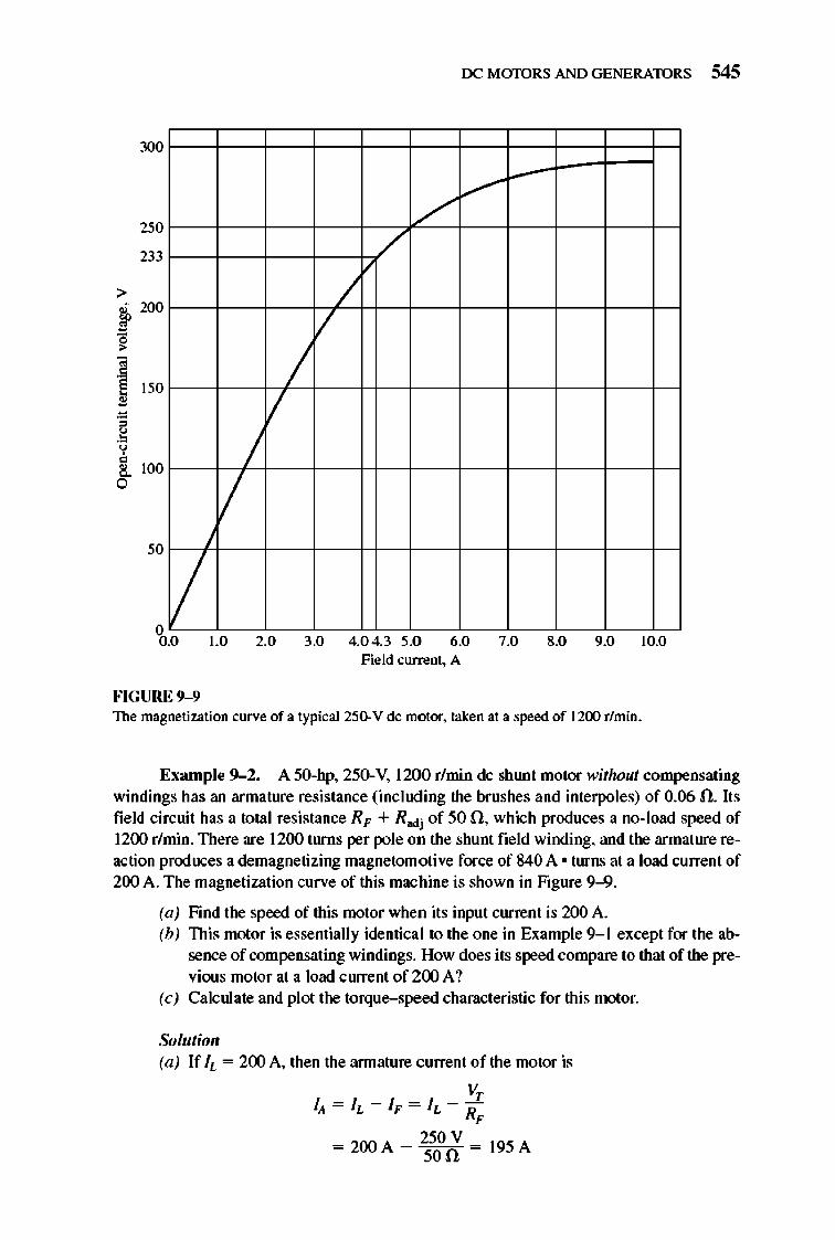
>
t " ., § ." " .~ , !. a
300
250
233
200
150
100
50
II o 0.0
II /
II
1.0 2.0
rx: MmDRS AND GENERATORS 545
,/ V
/
/ V
/
3.0 4.0 4.3 5.0 6.0 7.0 8.0 9.0 10.0 Field current, A
FIGURE 9-9 The magnetization curve of a typical 25()' V dc motor. taken at a speed of 1200 r/min.
EXllmple 9-2. A 5O-hp, 250-V, 1200 r/min dc shlUlt motor without compensating windings has an armature resistance (including the brushes and interpoles) of 0.06 n. Its field circuit has a total resistance RF + Radj of 50 n, which produces a no-load speed of 1200 r/min. There are 1200 turns per pole on the shunt field winding, and the armature reaction produces a demagnetizing magnetomotive force of 840 A • turns at a load current of 200 A. The magnetization curve of this machine is shown in Figure 9-9.
(a) Find the speed of this motor when its input current is 200 A. (b) This motor is essentially identical to the one in Example 9- 1 except for the ab
sence of compensating windings. How does its speed compare to that of the previous motor at a load current of 200 A?
(c) Calculate and plot the torque-speed characteristic for this motor.
Solutioll (a) If IL = 200 A, then the armature current of the motor is
V, lit = IL - IF = h - R ,
- 2ooA - 250 V - 195A - 50n -
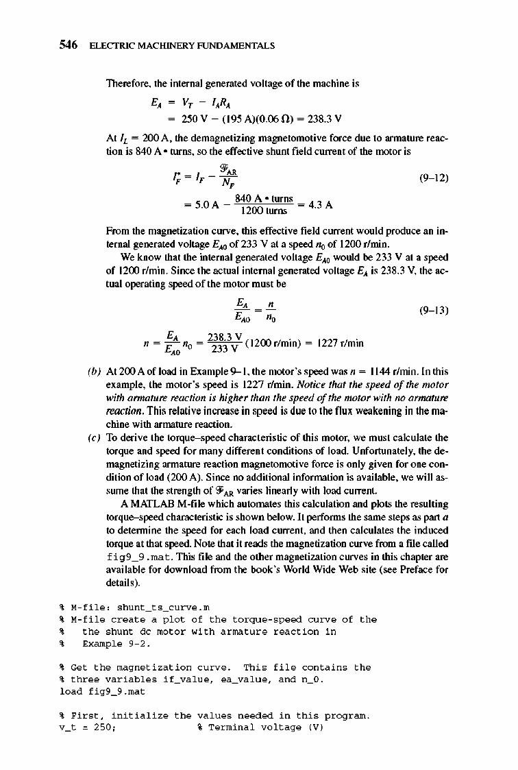
546 ELECTRIC MACHINERY RJNDA MENTALS
Therefore, the internal generated voltage of the machine is
EA = Vr - lARA
= 250 V - (195 A)(O.()5 fi) = 238.3 V
At h = 200 A, the demagnetizing magnetomoti ve force due to armature reaction is 840 A · turns, so the effective shunt field current of the motor is
"'" r,,= IF - N , (9-1 2)
From the magnetization curve, this effective field current would produce an internal generated voltage EAO of 233 Vat a speed 110 of 1200 r/min.
We know that the internal generated voltage EAO would be 233 V at a speed of 1200 r/min. Since the actual internal generated voltage EA is 238.3 V, the actual operating speed of the motor must be
(9-1 3)
EA 238.3 V ( 1200 I . ) n= £ no = 233V rmm =
" 1227 r/min
(b) At 200 A of load in Example 9--1, the motor 's speed was n = 11 44 r/min. In this example, the motor 's speed is 1227 r/min. Notice that the speed of the motor with armature reaction is higher than the speed of the motor with no armature reaction . This relative increase in speed is due to the flux weakening in the machine with armature reaction.
(c) To derive the torque- speed characteristic of this motor, we must calculate the torque and speed for many different conditions of load. Unfortunately, the demagnetizing armature reaction magnetomotive force is only given for one condition of load (200 A). Since no additional information is available, we will assrune that the strength of '.JAR varies linearly with load current.
A MATLAB M-file which automates this calculation and plots the resulting torque-speed characteristic is shown below. It peIfonns the same steps as part a to detennine the speed for each load current, and then calculates the induced torque at that speed. Note that it reads the magnetization curve from a file called f i g9 _ 9 . ma t. This file and the other magnetization curves in this chapter are available for download from the book's World Wide Web site (see Preface for details).
~ M-file: s hunt_ t s_curve. m ~ M-file c r eat e a p l o t o f the t o r q u e - speed cu rve o f the ~ the s hunt dc mo t o r with a r ma ture r eactio n in ~ Exampl e 9- 2.
~ Get the magne ti zatio n c u rve. Thi s fil e conta ins the ~ three variabl es if_va lu e, ea_va lue, a nd n_O. l oad fi g9_9. ma t
~ Firs t , initia li ze the va lues n eeded in thi s p r ogr am. v_t = 250; % Te rmina l vo lt age (V)
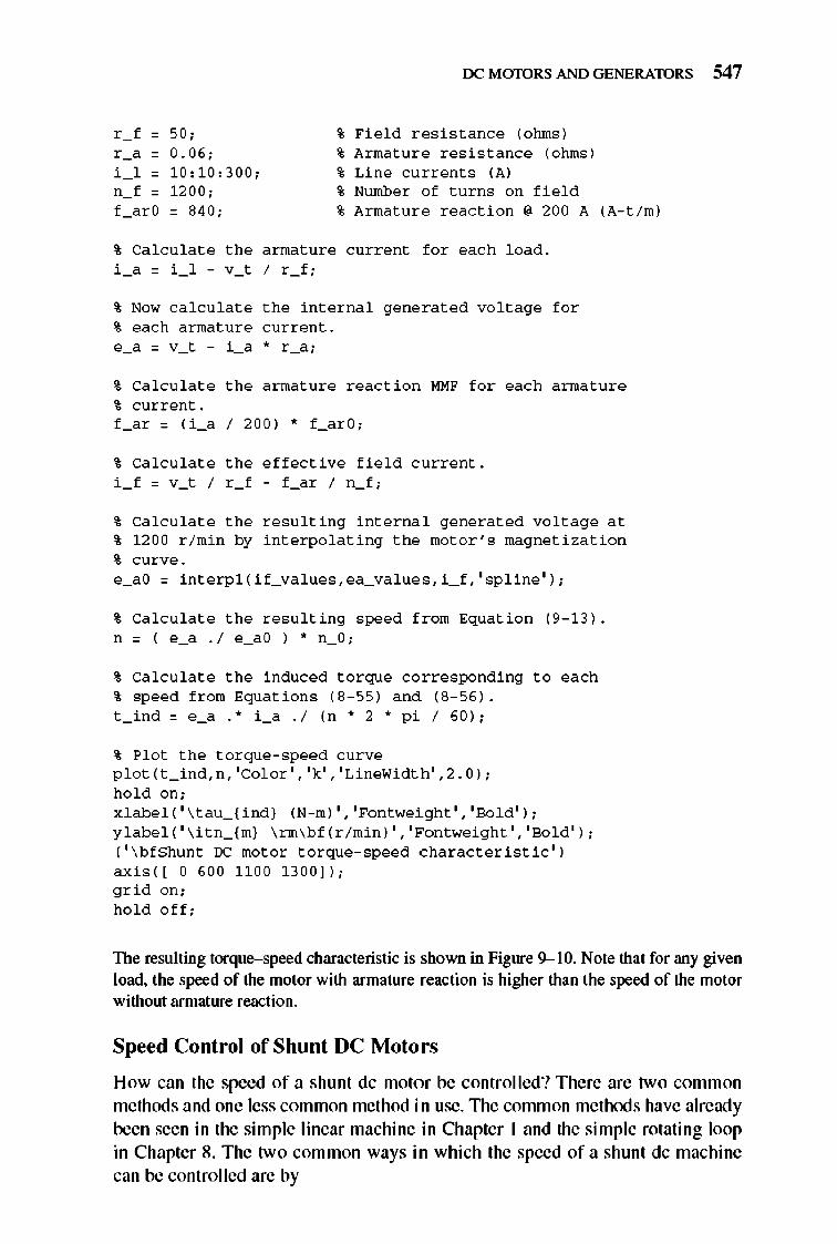
rx: MmDRS AND GENERATORS 547
c - f 0 50 ; • Fi e l d r es i s t a nce (ohms) c -" 0 0 . 06 ; • Arma tur e r es i s t a nce (ohms) i 1 0 1 0, 1 0,300 ; • Li n e curre nt s (A )
0 - f 0 1200 ; • Number o f turns 0 0 fi e l d f - " c O 0 84 0 ; • Arma tur e r eact i o n , 200 A
% Ca l c u l a t e the a rma ture c urre nt f o r each l oad . i _a = i _ l - v_t I r _ f ;
% Now ca l c u l a t e the i nt e rna l gen e r a t ed vo l t age f o r % each a rma ture c urre nt. e_a = v_t - i _a * r _a;
(A- t i m)
% Ca l c u l a t e the a rma ture r eact i o n MM F f o r each a rma ture % c urre nt. f _a r = ( i _a I 200) * f _a r O:
% Ca l c u l a t e the e ff ect i ve fi e l d c urre nt. i f = v_t I r _ f - f _a r I n_ f :
% Ca l c u l a t e the r esu l t i n g i nt e rna l gen e r a t ed vo l t age a t % 1200 r / mi n by i nt e r po l a t i n g the mo t o r 's magn e t i z a t i o n
% c urve . e_aO = i nt e r p l ( if_va l ues, ea_ va l u e s, i _ f , ' sp lin e ' ) ;
% Ca l c u l a t e the r esult i n g speed f r om Eq u a t i o n (9 - 13 ) . n = ( e_a . 1 e_aO ) .. n_O:
% Ca l c u l a t e the i n d uced t o r q u e co rrespon d i n g t o each % speed f r om Eq u a t i o n s ( 8- 55 ) a n d (8- 56 ) . t _ i n d = e_a . * i _a .1 (n .. 2 .. p i I 60):
% Pl o t the t o r q u e - speed c u rve p l o t ( t _ i nd, n , ' Col o r' , 'k' , 'Lin eWi d th' ,2 . 0 ) ;
h o l d o n ; x l abe l ( ' \ t a u _( i nd} (N- m) ' , ' Fontwei ght' , 'Bo l d ' ) ; y l abe l ( ' \ i tn_( m} \ rm \ b f ( r / mi n ) ' , 'Fontwei ght' , 'Bo l d ' ) : ( ' \ b f Shunt OC mo t o r t o r q u e - speed c h a r ac t e r i s t i c ' )
ax i s( [ 0 600 11 00 1300 ] ) ; g r i d o n ; h o l d o ff ;
The resulting torque-speed characteristic is shown in Figure 9-10. Note that for any given load. the speed of the motor with armature reaction is higher than the speed of the motor without armature reaction.
Speed Control of Shunt DC Motors
How can the speed of a shunt dc motor be controlled? There are two comm on methods and one less common method in use. 1lle common methods have already been seen in the simple linear machine in Chapter 1 and the simple rotating loop in Chapter 8. The two common ways in which the speed of a shunt dc machine can be controlled are by
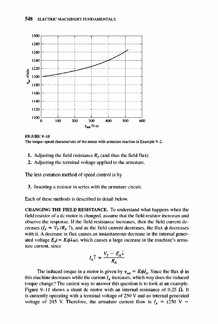
548 ELECTRIC MACHINERY RJNDAMENTALS
1300 ,------,--,----,------,--,------,
1280
1260
1240
1220 t--~---'---:~ 1200
./"80
]]60
]]40
]]20
]]00 '-----c'cC_-~-__C'c---c'cC_-~-~ o 100 200 300 400 500 600
'tiD<! N·m
""GURE 9- 10 The torque--speed characteristic of the motor with armature reaction in Example 9--2.
I . Adjusting the field resistance RF (and thus the fi e ld nux)
2. Adjusting the tenninal voltage applied to the annature.
The less common method of speed control is by
3. Inserting a resistor in series with the armature circuit.
E:1.ch of these methods is described in detail below.
CHANGING THE FIELD RESISTANCE. To understand what happens when the field resistor of a dc motor is changed. assume that the field resistor increases and observe the response. If the field resistance increases, then the field current decreases (IF = Vr lRF i ), and as the field current decreases, the nux <P decreases with it. A decrease in nux causes an instantaneous decrease in the internal generated voltage EA(= K<p-tw), which causes a large increase in the machine's annature current, since
1lle induced torque in a motor is given by "TiDd = K<pfA' Since the nux <p in this machine decreases while the current fA increases, which way does the induced torque change? 1lle easiest way to answer thi s question is to look at an example. Figure 9- 1 I shows a shunt dc motor with an internal resistance of 0.25 O. lt is currently operating with a tenninal voltage of 250 V and an internal generated voltage of 245 V. 1llerefore, the annature current now is fA = (250 V -
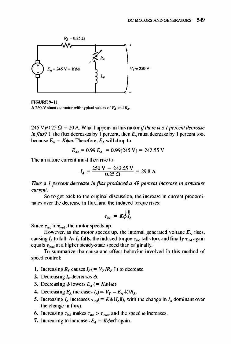
rx: MmDRS AND GENERATORS 549
RA '" 0.250
+
+ EA",245 V'" Kfw VT ", 250 V
FIGURE 9- 11 A 250-V shunt de motor with typical values of EA and RA.
245 V)/0.25 n = 20 A. What happens in this motor if there is a I percent decrease influx? If the flux decreases by I percent, then EA must decrease by I percent too, because EA = K4>w. Therefore, EA will drop to
EA2 = 0.99 EAt = 0.99(245 V) = 242 .55 V
The annature current must then rise to
f = 250 V - 242.55 V = 298 A A 0.25 n .
Thus a I percent decrease in flux produced a 49 percent increase in armature current.
So to get back to the original discussion, the increase in current predominates over the decrease in flu x, and the induced torque rises :
U Tjnd = K4> fA
Since Tind > Tto"," the motor speeds up. However, as the motor speeds up, the internal generated voltage EA rises,
causing fA to fall. As fA falls, the induced torque Tind falls too, and fmally T;Dd again equals Ttood at a higher steady-state speed than originally.
To summari ze the cause-and-effcct behavior in volved in this method of speed control:
I. Increasing RF causes fF(= VT IRF i ) to decrease.
2. Decreasing IF decreases 4>. 3. Decreasing 4> lowers EA (= K4>J..w) .
4. Decreasing EA increases fA(= VT -EA J..)IRA-
5. Increasing fA increases T;od(= K4>UAfI ), with the change in fA dominant over the change in flux ).
6. Increasing Tind makes T;od > Ttood, and the speed w increases.
7. Increasing to increases EA = Kcf>wi again.
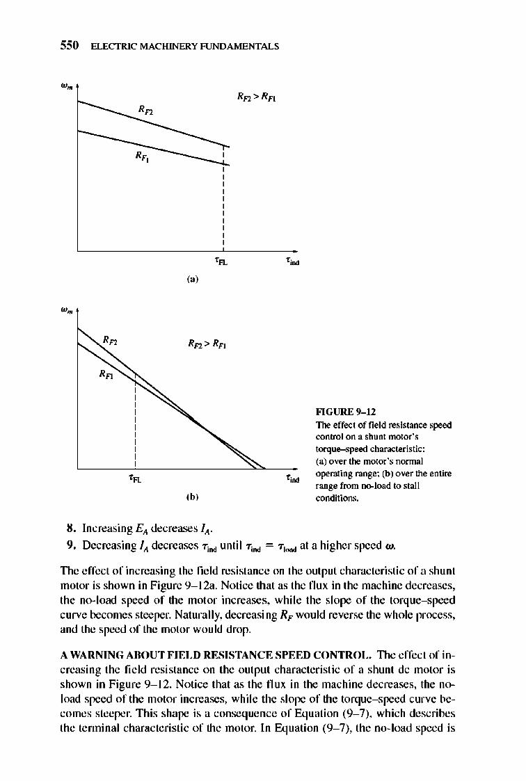
550 ELECTRIC MACHINERY RJNDAMENTALS
(a)
,b,
8. Increasing Elt decreases lit-
FlGURE 9-12 The effect of field resistance speed control on a shunt motor's torque-speed characteristic: (a) over the motor's normal operating range: (b) over the entire range from no-load to stall conditions.
9. Decreasing lit decreases "Tind until "Tind = "TJoad at a higher speed w.
The effect of increasing the field resistance on the output characteristic of a shu nt motor is shown in Figure 9-1 2a. Notice that as the flux in the machine decreases, the no- load speed of the motor increases, whi le the slope of the torque-speed curve becomes steeper. Naturally, decreasing RF would reverse the whole process, and the speed of the motor wou ld drop.
A WARNING ABOUT FIELD RESISTANCE SPEED CONTROL. TIle effect of increasing the field resistance on the output characteristic of a shunt dc motor is shown in Figure 9-1 2. Notice that as the flux in the machine decreases, the noload speed of the motor increases, while the slope of the torque-speed curve becomes steeper. This shape is a conseq uence of Equation (9- 7), which describes the tenninal characteristic of the motor. In Equation (9- 7), the no-load speed is
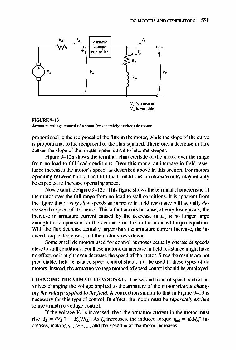
R, I, Variable -
+ voltage
controller
+ E, V,
-
-
FIGURE 9-13
/-
rx: MmDRS AND GENERATORS 551
I, -y,,! I, ~ R,
L,
VTis oonstant VA is variable
+
V,
Armature voltage control of a shunt (or separately excited) dc motor.
proportional to the reciprocal of the nUX: in the motor, while the slope of the curve is proportional to the reciprocal of the flux squared. Therefore, a decrease in flux causes the slope of the torque- speed curve to become steeper.
Figure 9- I 2a shows the tenninal characteristic of the motor over the range from no-load to full-load conditions. Over this range, an increase in field resistance increases the motor 's speed, as described above in this section. For motors operating between no- load and full-l oad conditions, an increase in RF may reliably be expected to increase operating speed.
Now examine Figure 9- 12h. This fi gure shows the tenninal characteristic of the motor over the full range from no- load to stall conditions. It is apparent from the figure that at very slow speeds an in crease in fie ld resistance will actually decrease the speed of the motor. TIli s effect occurs because, at very low speeds, the increase in annature current caused by the decrease in Ell. is no longer large enough to compensate for the decrease in flux in the induced torque equation. With the flux decrease actually larger than the armature current increase, the induced torque decreases, and the motor s lows down.
Some small dc motors used for control purposes actually operate at speeds close to stall conditions. For these motors, an increase in field resistance might have no effect , or it might even decrease the speed of the motor. Since the results are not predictable, field resistance speed control should not be used in these types of dc motors. Instead, the annat ure voltage method of speed control shou ld be employed.
CHANG ING THE ARMATURE VOLTAGE. TIle second form of speed control involves changing the voltage applied to the armat ure of the motor without changing the voltage applied to the field. A connection similar to that in Figure 9- \3 is necessary for this type of control. In effect, the motor must be separately excited to use armature voltage control.
If the voltage VA is increased, then the annature current in the motor must rise [Ill. = (VA i - EA)IRAl As /11. increases, the induced torque "Tind = K4>IA i increases, making "Tind > "TJoad, and the speed w of the motor increases.
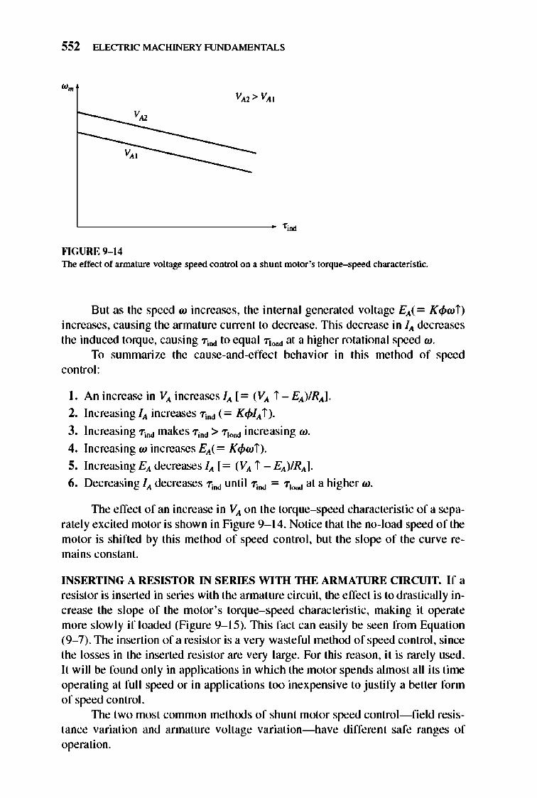
552 ELECTRIC MACHINERY RJNDAMENTALS
v"
'---------------- f ind
""GURE 9-14 The effect of armature voltage speed control on a shunt motor's torque-speed characteristic.
Bul as the speed w increases, the internal generaled voltage EA(= K4>wi) increases, causing the armature current to decrease. This decrease in JA decreases the induced torq ue, causing Tind to equal Ttoad at a higher rotational speed w.
To summarize the cause-and-effect behavior in this method of speed control:
I . An increase in VA increases JA [= (VA i - EA)/RA].
2. Increasing JA increases Tind (= K4>JA i ).
3. Increasing Tind makes TiDd > TJoad increasing w.
4. Increasing w increases EA(= K4>wi).
5. Increasing EA decreases JA [= (VA i - EA)/RAl
6. Decreasing JA decreases Tind until Tind = TJoad at a higher w.
TIle effect of an increase in VA on the torque-speed characteristic of a separately excited motor is shown in Figure 9- 14. Notice that the no-load speed of the motor is shifted by this method of speed control , but the slope of the curve remains constant.
INSERTING A RESISTOR IN SERIES WITH THE ARl\l ATURE c m.CUIT. If a resistor is inserted in series with the annature circuit, the e ffect is to drastically increase the slope of the motor's torque-speed characteristic, making it operate more slow ly if loaded (Figure 9- 15). lllis fact can easily be seen from Equation (9- 7). The insertion of a resistor is a very wasteful method of speed control, since the losses in the inserted resistor are very large. For this reason, it is rarely used . It will be found only in applications in which the motor spends almost all its time operating at fuJI speed or in applications too inexpensive to justify a better form of speed control.
TIle two most common methods of shunt motor speed control- fi e ld resistance variation and armature voltage variation- have different safe ranges of operation.
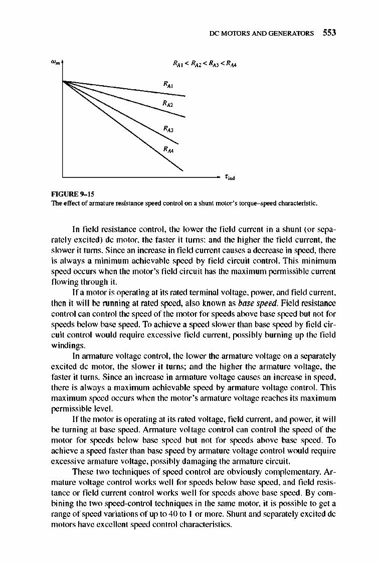
rx: MmDRS AND GENERATORS 553
'------------------ '00
FIGURE 9-15 The effect of armature resistance speed control on a shunt motor' s torque-speed characteristic.
In field resistance control , the lower the fie ld current in a shunt (or separately excited) dc motor, the faster it turns: and the higher the fi e ld current, the slower it turns. Since an increase in field current causes a decrease in speed, there is always a minimum achievable speed by field circuit control. This minimum speed occurs when the motor's fie ld circuit has the maximum permissible current flowing through it.
If a motor is operating at its rated terminal voltage, power, and fi e ld current , then it will be running at rated speed, also known as base speed. Field resistance control can control the speed of the motor for speeds above base speed but not for speeds below base speed. To achieve a speed slower than base speed by fie ld circuit control would require excessive fi e ld current, possibly burning up the fie ld windings.
In armature voltage control, the lower the armature voltage on a separately excited dc motor, the slower it turns; and the higher the armature voltage, the faster it turns. Since an increase in annature voltage causes an increase in speed, there is always a maximum achievable speed by armature voltage control. This maximum speed occurs when the motor 's armature voltage reaches its maximum permissible level.
If the motor is operating at its rated voltage, field current, and power, it will be turning at base speed . Annature voltage control can control the speed of the motor for speeds below base speed but not for speeds above base speed . To achieve a speed faster than base speed by armature voltage control would require excessive annature voltage, possibly damaging the annature circuit.
These two techniques of speed control are obviously complementary. Armature voltage control works well for speeds below base speed, and field resistance or field current control works well for speeds above base speed . By combining the two speed-control techniques in the same motor, it is possible to get a range of speed variations of up to 40 to I or more. Shunt and separately excited dc motors have excellent speed control characteristics.
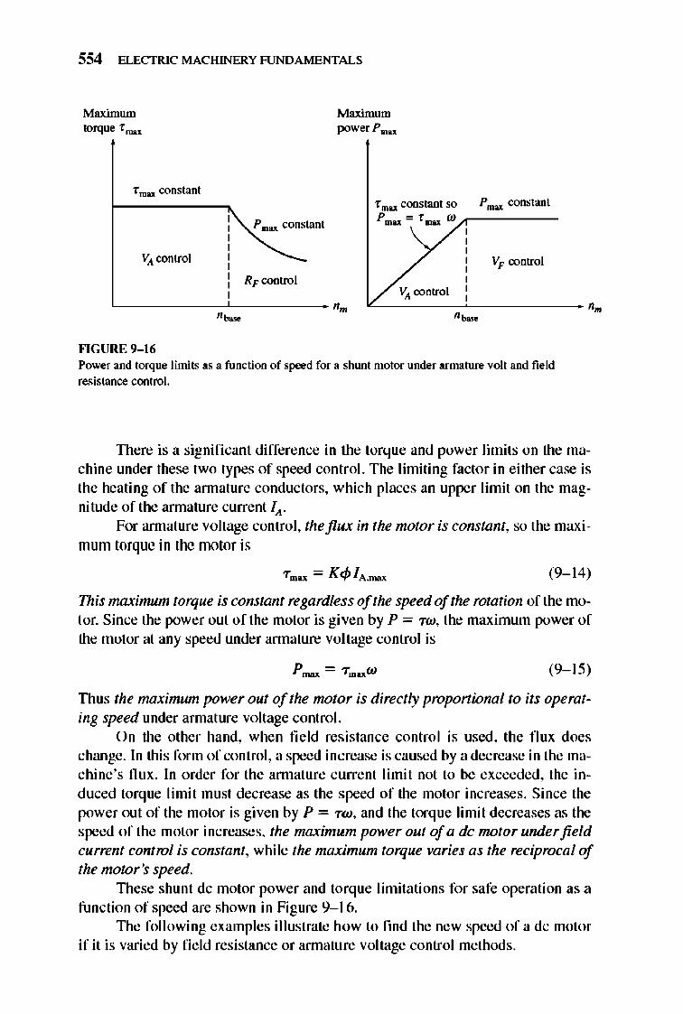
554 ELECTRIC MACHINERY RJNDAMENTALS
Maximum torque fmax
Maximum powerPmu
fmax constant
P mu constant
VA control
RFcontrol
"------cC------ ,,~
""GURE 9-16
fmu constant so P rmx constant P IOU '" f mn w..,-_____ _
V" control
VA control <-----~------- ,.
,~
Power and torque limits as a function of speed for a shunt motor under annature volt and field resistance control.
TIlere is a signifi cant difference in the torque and power limits on the machine under these two types of speed control. The limiting factor in either case is the heating of the annature conductors, which places an upper limit on the magnitude of the annature current Ill. .
For annature voltage control, the flux in the motor is constant, so the maximum torque in the motor is
(9-1 4)
This maximum torque is constant regardless of the speed of the rotation of the motor. Since the power out of the motor is given by P = "TW, the maximum power of the motor at any speed under annature voltage control is
(9- 15)
TIlUS the maximum power out of the motor is directly proportional to its operating speed under armature voltage control.
On the other hand, when field resistance control is used, the flux does change. In this form of control, a speed increase is caused by a decrease in the machine's flux. In order for the annature current limit not to be exceeded, the induced torque li mit must decrease as the speed of the motor increases. Since the power out of the motor is given by P = "TW, and the torque limit decreases as the speed of the motor increases, the maximum power out of a dc motor under field current control is constant, whi le the maximum torque varies as the reciprocal of the motor's speed.
TIlese shunt dc motor power and torq ue limitati ons for safe operation as a function of speed are shown in Figure 9-16.
TIle fo ll owing examples illustrate how to fmd the new speed of a dc motor if it is varied by fie ld resistance or annature voltage control methods.
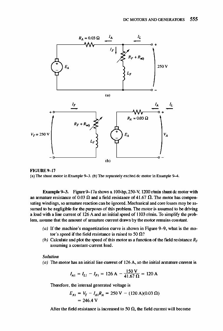
rx: MaJ"ORS AND GENERATORS 555
RA '" 0.03 n - -
", +~-------, ,-----v./v--~ +
+
,b, FIGURE 9-17 (3) The shunt motor in Example 9--3. (b) The separately excited de motor in Example 9--4.
Example 9-3. Figure 9--17a shows a 1000hp. 250-V, 1200 rhnin shlUlt dc motor with an armature resistance of 0.03 n and a field resistance of 41.67 O. The motor has compensating windings. so armature reaction can be ignored. Mechanical and core losses may be assumed to be negligible for the purposes of this problem. The motor is assmned to be driving a load with a line current of 126 A and an ini tial speed of 1103 r/min. To simplify the problem. assmne that the amolUlt of armature current drawn by the motor remains constant.
(a) If the machine's magnetization curve is shown in Figure 9-9. what is the motor 's speed if the field resistance is raised to 50 n1
(b) Calculate and plot the speed of this motor as a ftmction of the field resistance RI' assuming a constant-current load.
Solutioll (a) The motor has an initial line current of 126 A, so the initial armature current is
150 V IA I = lu - 1Ft = 126A - 41.67 n = 120A
Therefore, the internal generated voltage is
EA I = VT - IA tRA = 250 V - (120 A)(0.03fi)
= 246.4 V
After the field resistance is increased to 50 n, the field current will become
556 ELECTRIC MACHINERY RJNDAMENTALS
I - VT _2S0V -SA F2 - RF - 50 n -
The ratio of the internal generated voltage at one speed to the internal generated voltage at another speed is given by the ratio of Equation (&--41) at the two speeds:
Elll _ K'q,l n2 Ell l - K'q,[n[
(9- 16)
Because the armature current is assumed constant, EIlI = Elll , and this equation reduces to
~, n2=q,lnl (9- 17)
A magnetization curve is a plot of Ell versus IF for a given speed. Since the values of Ell on the curve are directly proportional to the flux, the ratio of the internal generated voltages read off the curve is equal to the ratio of the fluxes within the machine. At IF = 5 A, Ello = 250 V, while at IF = 6 A, Ello = 268 V. There-fore, the ratio of fluxes is given by
q,[ 268 V = = 1.076 q,l 250 V
and the new s~ed of the motor is
n2 = !:nl = (1.076XII03r/min) = 1187r/min
(b) A MATLAB M-file that calculates the s~ed of the motor as a ftmction of RF is shown below.
~ M-file, r f _speed_contro l .m ~ M-file c reate a p l o t o f the speed of a s hunt dc ~ mo t o r as a f unc t i o n o f f i e l d r es i s tance, assumi ng ~ a con s tant armature c urrent (Exampl e 9- 3).
~ Get the magnet i zat i o n c urve. Thi s f il e conta i n s the ~ three var i abl es if_va l u e, ea_va l u e, and n_O. l oad fi g9_9.mat
~ Fir s t , i nit i a li ze v_t = 250; c - f 0 40,1:70; c -" 0 0.03; i -" 0 12 0;
the va l u es n eeded i n thi s program. ~ Termi na l vo l tage (V) ~ Fie l d re s i s tance (ohms) ~ Armature re s i s tance (ohms) ~ Armature c urrent s (A)
~ The approach here i s t o ca l c u l ate the e_aO at the ~ re f erence fi e l d c urrent , and then to ca l cu l ate the ~ e_aO f o r every fi e l d c urrent. The r e f e rence speed i s ~ 11 03 r / mi n , so by knowi ng the e_aO and r e f e rence ~ speed, we will be abl e to ca l cu l ate the speed at the ~ other fi e l d c urrent.
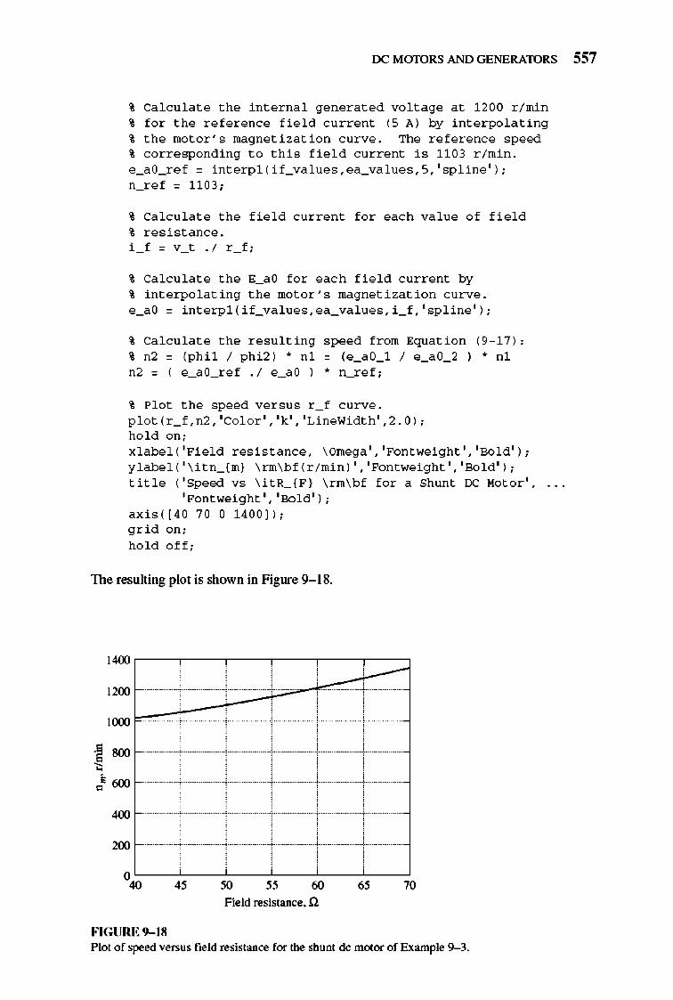
rx: M mDRS AND GENERATORS 557
% Ca l c ula t e the int e rna l gen e r a t ed vo lt age a t 1 200 r / min % f o r the r e f e r e nce fi e l d c urre nt (5 A) by int e r po l a ting % the mo t o r 's magne tiz a tio n c urve. The r e f e r e nce speed % correspond ing t o thi s fi e l d c urre nt i s 11 03 r / min . e_aO_r e f = int e r p l ( if_va lues, ea_va lues, 5, ' sp line ' ) ; n_ r e f = 1103;
% Ca l c ula t e the fi e l d c urre nt f o r each va lue o f fi e l d % r es i s t a nce. i _ f = v_t . / r _ f ;
% Ca l c ula t e the E_aO f o r eac h fi e l d c urre nt by % int e r po l a ting the mo t o r 's magne ti zatio n c urve. e_aO = int e r p l ( if_va lues, ea_va lues, i _ f , ' sp line ' ) ;
% Ca l c ula t e the r esulting speed from Eq ua tio n (9 -17): % n2 = (phil / phi2 ) .. nl = (e_aO_l / e_aO_2 ) .. nl n2 = ( e_aO_r e f . / e_aO ) .. n_ r e f ;
% Plo t the speed ver s u s r _ f c urve. p l o t ( r _ f , n2, ' Col or' , 'k' , 'LineWi dth' ,2.0 ) ; h o l d o n ; x l abe l ( 'Fi e l d r es i s t a nce, \Omega ' , 'Fontwei ght' , 'Bo l d ' ) ; y l abe l ( ' \ itn_( m} \ rm\ b f ( r / min ) ' , 'Fontwei ght' , 'Bo l d ' ) ; title ( ' Speed vs \ itR_( F ) \ rm\ b f f o r a Shunt IX: Mo t or' ,
'Fontwei ght' , 'Bo l d ' ) ; ax i s( [40 70 0 1400 ] ) ; g rid o n ; h o l d o ff ;
The resulting plot is shown in Figure 9-1 8.
1400
1200 , ,
IlXXl
.§ 800 ~
• 600 0
400
200
0 40 45 60 65 70
Field resistance. n
FIGURE 9- 18 Plot of speed versus field resistance for the shunt dc motor of Example 9-3.
558 ELECTRIC MACHINERY RJNDAMENTALS
Note that the assumption of a constant annature current as RF changes is not a very go<Xl one for real loads . The current in the annature will vary with speed in a fashion depende nt on the torque required by the type of load attached to the motor. These differences wi ll cause a motor 's speed-versus-RF curve to be slightly different than the one shown in Fig ure 9-1 8, but it will have a similar shape.
Example 9-4. The motor in Example 9- 3 is now cotUlected separately excited, as shown in Figure 9-1 7b. The motor is initially flmning with VA = 250 V, IA = 120 A, and n = 1103 rlmin, while supplying a constant-torque load. What will the speed of this motor be if VA is reduced to 200 V?
Solutio" The motor has an initial line current of 120 A and an armature voltage VA of 250 V, so the internal generated voltage EA is
EA = Vr - lARA = 250 V - (l20AXO.03!l) = 246.4 V
By applying Equation (9-1 6) and realizing that the flux ~ is constant, the motor's speed can be expressed as
To find EJa use Kirchhoff's voltage law:
", =
EJa = Vr - lJaRA
(9-1 6)
Since the torque is constant and the flux is constant, IA is constant. This yields a voltage of
EJa = 200 V - (120 AXO.03 !l) = 196.4 V
The final speed of the motor is thus
E A2 196.4V,'03 /· 879/· ~ = E At n t = 246.4 V r mill = r min
The Effect of an Open Field Circuit
TIle previous section of this chapter contained a discussion of speed control by varying the field resistance of a shunt moto r. As the field resistance increased, the speed of the motor increased with it. What would happen if this effect were taken to the extreme, if the fi e ld resistor really increased? What would happen if the field circ uit actually opened while the motor was running? From the previous discussion, the flux in the machine would drop drastically, all the way down to ~res,
and EA(= K~w) would drop with it. This wo uld cause a really enonnous increase in the armature current, and the resulting induced torque would be quite a bit higher than the load torque on the motor. TIlerefore, the motor 's speed starts to rise and just keeps going up.
rx: MmDRS AND GENERATORS 559
The results of an open fi e ld circuit can be quite spectacular. When the author was an undergraduate, his laboratory group once made a mistake of this sort. The group was working with a small motor-generator set being driven by a 3-hp shunt dc motor. The motor was connected and ready to go, but there was just one little mistake- when the field circuit was connected, it was fused with a O.3-A fuse instead of the 3-A fu se that was supposed to be used.
When the motor was started, it ran nonnally for about 3 s, and then suddenly there was a flash from the fuse. ]mmediate ly, the motor 's speed skyrocketed. Someone turned the main circuit breaker off within a few seconds, but by that time the tachometer attached to the motor had pegged at 4000 r/min. TIle motor itself was only rated for 800 rim in.
Need less to say, that experience scared everyone present very badly and taught them to be most careful about fi e ld circuit protection. In dc motor starting and protection circuits, afield loss relay is nonnally included to disconnect the motor from the line in the event of a loss of fie ld current.
A similar effect can occur in ordinary shunt dc motors operating with light fields if their annature reaction effects are severe enough. If the annature reaction on a dc motor is severe, an increase in load can weaken its flu x enough to actually cause the motor 's speed to rise . However, most loads have torque-speed curves whose torque increases with speed, so the increased speed of the motor increases its load, which increases its annature reaction, weakening its flu x again. TIle weaker flux causes a further increase in speed, further increasing load, etc., until the motor overspeeds. nlis condition is known as runaway.
In motors operating with very severe load changes and duty cycles, this fluxweakening problem can be solved by installing compensating windings. Unfortunately, compensating windings are too expensive for use on ordinary run-ofthe-mill motors. TIle solution to the runaway problem employed for less-expensive, less-severe duty motors is to provide a turn or two of cumulative compounding to the motor 's poles. As the load increases, the magnetomoti ve force from the series turns increases, which counteracts the demagnetizing magnetomotive force of the annature reaction. A shunt motor equipped with just a few series turns like this is calJed a stabilized shunt motor.
9.5 THE PERMANENT-MAGNET DC MOTOR
A permanent-magnet de (PM DC) motor is a dc motor whose poles are made of pennanent magnets. Permanent-magnet dc motors offer a number of benefits compared with shunt dc motors in some applications. Since these motors do not require an external field circuit, they do not have the field circuit copper losses associated with shunt dc motors. Because no fi e ld windings are required, they can be smalle r than corresponding shunt dc motors. PMDC motors are especially common in smaller fractional- and subfractional-horsepower sizes, where the expense and space of a separate field circuit cannot be justified.
However, PMDC motors also have disadvantages. Pennanent magnets cannot produce as high a flux density as an externally supplied shunt fi e ld, so a
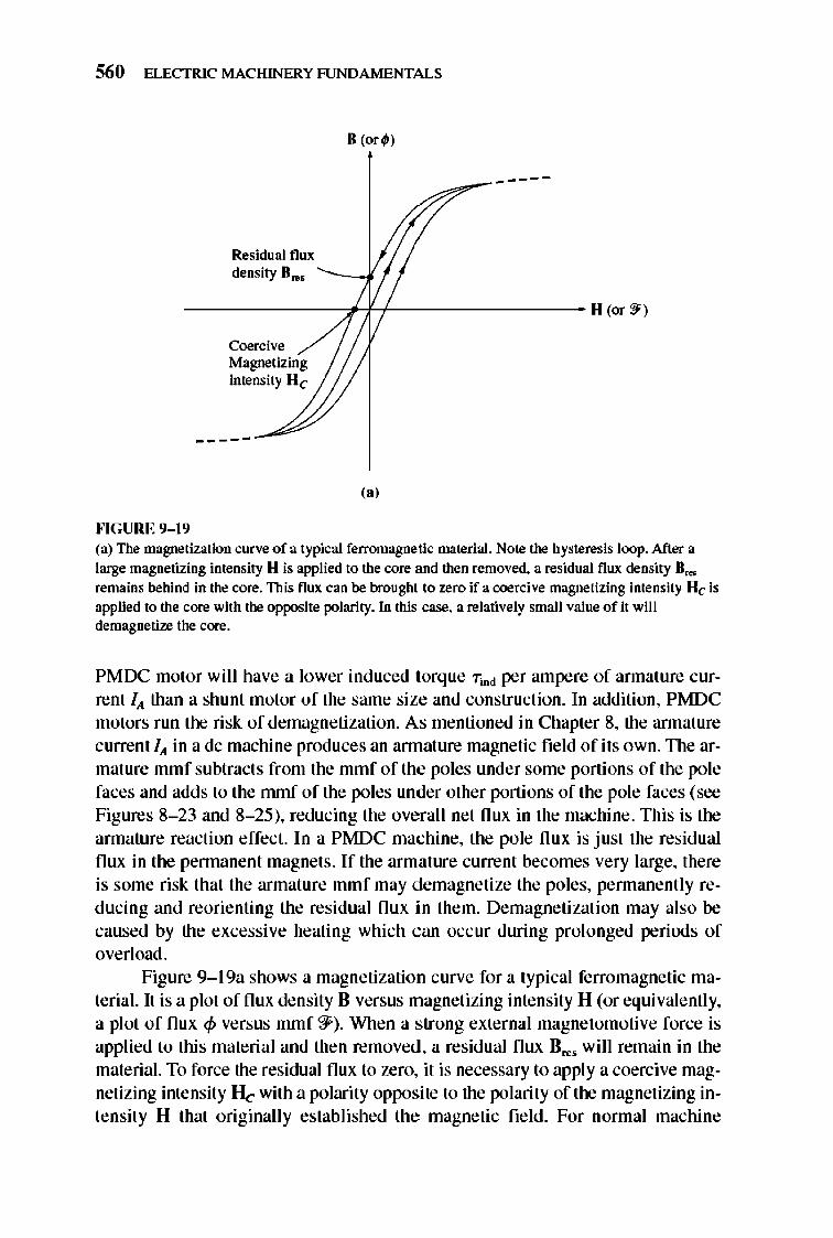
560 ELECTRIC MACHINERY RJNDAMENTALS
Residual flux density n ...
----
--------------.f~t-----------------H ~r~)
""GURE 9-19
Coercive Magnetizing intensity H e
--- --
(.j
(a) The magnetization curve of a typical ferromagnetic material. Note the hysteresis loop. After a large ntagnetizing intensity H is applied to the core and then removed. a residual flux density n ... rentains behind in the core. This flux can be brought to zero if a coercive magnetizing intensity He is applied to the core with the opposite polarity. In this case. a relatively sntall value of it will demagnetize the core.
PMDC motor will have a lower induced torque "rind per ampere of annature current lit than a shunt motor of the same size and construction. In addition, PMDC motors run the risk of demagnetization. As mentioned in Chapler 8, the annature c urrent lit in a dc machine produces an annature magnetic field of its own. The armature mlllf subtracts from the mmf of the poles under some portions of the pole faces and adds to the rnrnfofthe poles under other portions of the pole faces (see Figures 8- 23 and 8- 25), reducing the overall net nux in the machine. This is the armature reaction effect. In a PMDC mac hine, the pole nux is just the residual flux in the pennanent magnets . If the armature current becomes very large, there is some risk that the armature mmf may demagnetize the poles, pennanenlly reducing and reorienting the residual flux in them. Demagnetizalion may also be caused by the excessive heating which can occ ur during prolonged periods of overl oad .
Figure 9- 19a shows a magnetization curve for a typical ferromagnetic material. II is a plot of flux density B versus magnelizing intensity H (or equivalently, a plot of flux <p versus mlllf ?]i). When a strong external magnetomotive force is applied 10 thi s material and then removed, a residual flux B .... will remain in the material. To force the residual flux to zero, it is necessary to apply a coercive magnetizing inlensity H e with a polarity opposite 10 the polarity of the magnetizing inlensity H that originally established the magnetic field. For normal machine
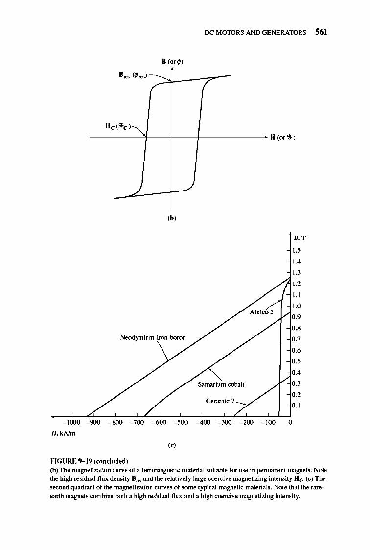
rx: M mDRS AND GENERATORS 561
II (or¢)
HcC3'C)~ -----'f----+--+------- H (or 3')
,b,
Alnico 5
Samarium cobalt
Ceramic 7 _~,
B. T
I., 1.4
1.3
1.2
U
1.0
0.9
0.8
0.7
0.6
0.'
0.4
0.3
0.2
0.1
- 1000 - 900 - 800 - 700 - 600 - 500 - 400 - 300 - 200 - 100 0
H.kAlm
"I
FIGURE 9- 19 (roncludtd) (b) The magnetization curve of a ferromagnetic material suitable for use in permanent magnets. Note the high residual flux density II ... and the relatively large coercive magnetizing intensity He. (c) The
second quadrant of the magnetization curves of some typical magnetic materials. Note that the rareearth magnets combine both a high residual flux and a high coercive magnetizing intensity.
562 ELECTRIC MACHINERY RJNDAMENTALS
applications such as rotors and stators, a ferromagnetic material should be picked which has as small a Br .. and Hc as possible, since such a material will have low hysteresis losses.
On the other hand, a good material for the poles of a PMDC motor should have as large a residualflux density Bros as possible, while simultaneously having as large a coercive magnetizing intensity Hcas possible. The magnetization curve of such a material is shown in Figure 9- I 9b. TIle large Br• s produces a large fl ux in the machine, while the large Hc means that a very large current would be required to demagnetize the poles.
In the last 40 years, a number of new magnetic materials have been developed which have desirable characteri stics for making pennanent magnets. The major types of materials are the ceramic (fe rrite) magnetic materials and the rareearth magnetic materials. Figure 9- I 9c shows the second quadrant of the magnetization curves of some typical ceramic and rare-earth magnets, compared to the magnetization curve of a conventional ferromagnetic alloy (A lnico 5). It is obvious from the compari son that the best rare-earth magnets can produce the same residual flux as the best conventional ferromagnetic alloys, while simultaneously being largely immune to demagnetization problems due to annature reaction.
A pennanent-magnet dc motor is basically the same machine as a shunt dc motor, except that the flux ofa PMDC motor isfixed. TIlerefore, it is not possible to control the speed of a PMDC motor by varying the field current or flux. The only methods of speed control available for a PM DC motor are armature voltage control and annature resistance control.
For more information about PMDC motors, see References 4 and 10.
9.6 THE SERIES DC MOTOR
A series dc motor is a dc motor whose field windings consist of a relatively few turns connected in series with the annature circuit. TIle equivalent circuit of a series dc motor is shown in Figure 9- 20 . In a series motor, the annature current, field current, and line current are all the same. TIle Kirchhoff 's voltage law equation for this motor is
(9- 18)
Induced Torque in a Series DC Motor
TIle tenninal characteristic of a series dc motor is very different from that of the shunt motor previously studied. The basic behavior of a series dc motor is due to the fact that the flux is directly proP011iolUll to the armature current, at least until saturation is reached. As the load on the motor increases, its flux increases too. As seen earlier, an increase in flu x in the motor causes a decrease in its speed. TIle result is that a series motor has a sharply drooping torque-speed characteristic.
TIle induced torque in this machine is given by Equation (8-49):
(8-49)
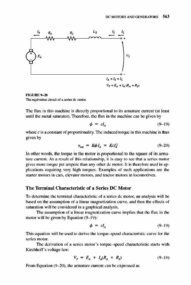
rx: MmDRS AND GENERATORS 563
+ v,
llt = ls= IL
VT= EIt + lit (RIt + Rs)
FIGURE 9- 10 The equiva.lent circuit of a series dc motor.
The nux in this machine is directly proportional to its armature current (at least until the metal saturates) .lllerefore, the nux in the machine can be given by
(9-1 9)
where c is a constant of proportionality. TIle induced torque in this machine is thus given by
(9- 20)
In other words, the torque in the motor is proportional to the square of its annature current. As a result of this re lationship, it is easy to see that a series motor gives more torque per ampere than any other dc motor. It is therefore used in applications requiring very high torques . Examples of such applications are the starter motors in cars, elevator motors, and tractor motors in locomoti ves.
The Terminal Characteristic of a Series DC Motor
To detennine the tenninal characteristic of a series dc motor, an analysis will be based on the assumption of a linear magnetization curve, and then the effects of saturation will be considered in a graphical analysis.
The assumption of a linear magne tization curve implies that the nux in the motor will be given by Equation (9-1 9) :
(9-1 9)
This equation will be used to derive the torque-speed characteri stic curve for the series motor.
The derivation of a series motor 's torque-speed characteristic starts with Kirchhoff's voltage law:
VT = Elt + IIt( RIt + Rs) (9-1 8)
From Equation (9- 20), the armature current can be expressed as
564 ELECTRIC MACHINERY RJNDAMENTALS
Also, Ell = K~w. Substituting these expressions in Equation (9- 18) yields
(T:::; VT = K~w + Vic(RA + Rs) (9- 21)
If the nux can be e liminated from this expression, it will directly re late the torque of a motor to its speed . To eliminate the nux from the expression, notice that
and the induced torque equation can be rewritten as
K Tind = cq?
TIlerefore, the nux in the motor can be rewritten as
~ = H'Jrind (9- 22)
Substituting Equation (9- 22) into Equation (9- 21) and solving for speed yields
" {T:::; VT = Kv; ('Jrindw + VKc (RA + Rs)
RA + Rs 'I/KC VTindW = VT - ',IKe VTind
VT RA + Rs w = VKc VTind - Ke
TIle resulting torque- speed re lati onship is
VT I RA + Rs w - ----- -- VKc VTind Ke
(9- 23)
Notice that for an unsaturated series motor the speed of the motor varies as the reciprocal of the sq uare root of the torque . TImt is quite an unu sual relationship! TIlis ideal torque-speed characteristic is plotted in Figure 9- 21.
One disadvantage of series motors can be seen immed iately from this equati on. When the torque on this motor goes to zero, its speed goes to infinity. In practice, the torque can never go entirely to zero because of the mechanical, core, and stray losses that must be overcome. However, if no other load is connected to the motor, it can turn fast enough to serious ly damage itself. Never completely unload a series motor, and never connect one to a load by a belt or other mechanism that could break. If that were to happen and the motor were to become unloaded while running, the results could be serious.
TIle nonlinear analysis of a series dc motor with magnetic saturation effects, but ignoring armature reaction, is illustrated in Example 9- 5.
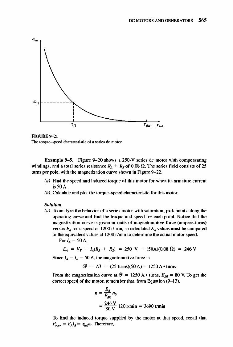
rx: MmDRS AND GENERATORS 565
'n
FIGURE 9-21 The torque-speed characteristic of a series dc motor.
Example 9-5. Figure 9--20 shows a 250-V series dc motor with compensating windings. and a total series resistance RA + Rs of 0.08 ll. The series field consists of 25 turns per pole. with the magnetization curve shown in Figure 9- 22.
(a) Find the speed and induced torque of this motor for when its armature current is 50A.
(b) Calculate and plot the torque-speed characteristic for this motor.
Solutioll (a) To analyze the behavior of a series motor with saturation. pick points along the
operating curve and find the torque and speed for each point. Notice that the magnetization curve is given in lUlits of magnetomotive force (ampere-turns) versus EA for a speed of 1200 r/min. so calculated EA values must be compared to the equivalent values at 1200 r /min to detennine the actual motor speed.
For IA = 50 A.
EA = Vr - IA(RA + Rs) = 250 V - (50AXO.080) = 246 V
Since IA = I" = 50 A. the magnetomotive force is
?:f = NI = (25turnsX50A) = 1250A o tums
From the magnetization curve at?:f = 1250 A ° turns. EAO = 80 V. To get the correct speed of the motor. remember that. from Equation (9- 13).
E, " =- "" E"
= 286\; 120 r/min = 3690 r/min
To find the induced torque supplied by the motor at that speed. ra;all that p 00IfV = EAIA = 7; .... W. Therefore.
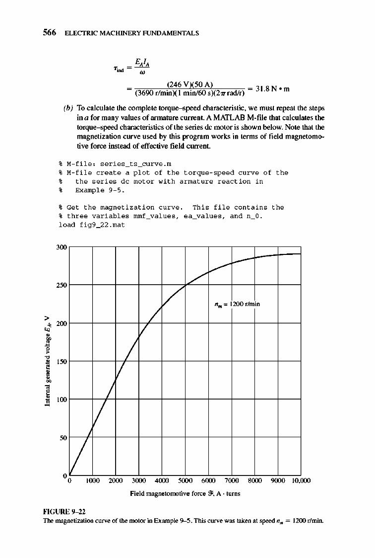
566 ELECTRIC MACHINERY RJNDAMENTALS
> J • 00 • ~ " • , , • 00
• 0
~
= (246 VX50 A) _ • (3690r/minXlmin/60sX27Tradlr) - 31.8N m
(b) To calculate the complete torque-speed characteristic, we must repeat the steps in a for many values of armature current. A MATLAB M-file that calculates the torque-speed characteristics of the series dc motor is shown below. Note that the magnetization curve used by this program works in terms of field magnetomotive force instead of effective field current.
% M-fi l e : seri es_t s_curve .m
% M-fi l e c r eat e a p l o t o f the t o rque- speed c urve o f the % the seri es dc mo t o r with armat ure reac tio n in % Exampl e 9 - 5.
% Ge t the magne tizati o n c urve . Thi s fil e cont a in s the % three variabl es mmf_values, ea_va lues, a n d n_O. l oad fig9_22 .mat
300
2'" ./"
.....-
/ II .. '" 1200 rhnin
/ /
200
/ / I'"
/ II
100
II 1000 2000 3000 4(xx) 5000 6(XXl 7000 g(XX) 9000 1O.(xx)
Field magnetomotive force 3'. A . turns
HGURE 9-12 The magnetization curve of the motor in Example 9-5. This curve was taken at speed II,. = 1200 r/min.
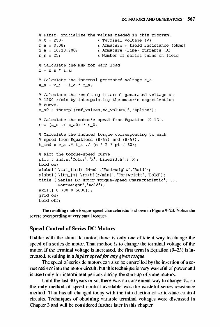
rx: MmDRS AND GENERATORS 567
% Firs t , i n itia liz e v_t = 250;
the values needed in thi s program. % Te rminal vo lt age (V)
r _ 0
i 0 -n_ o
0 0.08; 0 1 0, 1 0,300; 0 25;
% Armature + fi e l d r es i s tance (ohms) % Armature (line) c urre nt s (A) % Numbe r o f series turn s o n fi e l d
% Ca l culat e the MMF f o r each l oad f=n_s *i_a;
% Ca l culat e the int e rnal generated volt age e_a . e_a = v_t - i _a * r _a;
% Ca l culat e the r esulting interna l generated volt age at % 1 200 r / min by int e rpolating the mo t o r 's mag n e tizatio n
% curve. e_aO = int e rpl (mmf_va lues,ea_values, f ,'spline');
% Ca l culat e the motor's speed fr om Equat i o n (9 -1 3) .
n = (e_a . 1 e_aO) * n_O;
% Ca l culat e the induced t o rque corresponding t o each % speed fro m Equations (8 - 55 ) and (8 - 56 ) . t _ ind = e_a .* i _a . 1 (n * 2 * p i I 60);
% Plo t the t o rque - speed curve p l o t ( t _ ind, n , ' Co l o r' , 'k' , 'LineWi dth', 2 . 0) ;
h o l d o n; x l abel ( ' \ tau_ {ind) (N-m) ' , ' Fontwe i ght ' , 'So l d' ) ;
y l abel ( ' \ itn_ {m) \ nn\bf ( r I min ) , , 'Fo ntwe i ght ' , 'So l d' ) ; titl e ( ' Serie s IX: Mo t o r To rque - Speed Chara c t e ri s ti c ' ,
'Fo nt we i ght , , 'So l d' ) ;
axi s( [ 0 700 0 5000 ] ) ; gri d o n; h o l d o ff;
The resulting motor torque-speed characteristic is shown in Figure 9- 23. Notice the severe overspeeding at very small torques.
Speed Control of Series DC Motors
Unlike with the shunt dc motor, there is only one efficient way to change the speed of a series dc motor. That method is to change the terminal voltage of the motor. If the terminal voltage is increased, the first term in Equation (9-23) is increased, resulting in a higher speed for any given torque.
The speed of series dc motors can also be controlled by the insertion of a series resistor into the motor circuit , but this technique is very wasteful of power and is used only for intennittent periods during the start-up of some motors.
Until the last 40 years or so, there was no convenient way to change VT, so the only method of speed control available was the wasteful series resistance method. That has all changed today with the introduction of solid-state control circuits . Techniques of obtaining variable terminal voltages were discussed in Chapter 3 and will be considered further later in this chapter.
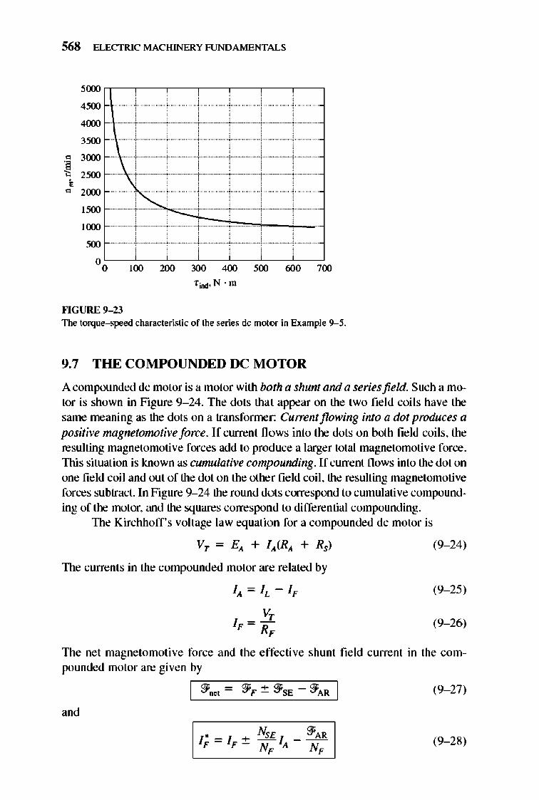
568 ELECTRIC MACHINERY RJNDAMENTALS
5(XX)
4500
4(xx)
3500
" 3(xx)
~ 2500
• " 2(xx)
1500
I(xx)
500
00 100 2lXl 3O\l 400 '00 6\lll 700
fiDd· N · m
""GURE 9-23 The torque-speed characteristic of the series dc motor in Example 9--5.
9.7 THE COMPOUNDED DC MOTOR
A compounded dc motor is a motor with both a shunt and a seriesfield. Such a motor is shown in Figure 9- 24. The dots that appear on the two fie ld coils have the same meaning as the dots on a transfonner: Cu"ent flowing into a dot produces a positive magnetonwtive force. If current fl ows into the dots on both field coils, the resulting magnetomotive forces add to produce a larger total magnetomotive force . This situation is known as cumulative compounding. If current flows into the dot on one field coil and out of the dot on the other field coil , the resulting magnetomotive forces subtract. In Figure 9-24 the round dots correspond to cumulative compounding of the motor, and the squares correspond to differential compounding.
1lle Kirchhoff's voltage law equation for a compounded dc motor is
Vr = E), + f), (R), + Rs)
1lle currents in the compounded motor are related by
fA= IL - 1F
VT f F = -RF
(9- 24)
(9- 25)
(9- 26)
1lle net magnetomotive force and the effective shunt field current in the compounded motor are given by
,nd
~-~~-~
I 9i'oet - 9i'F ~ 9i'SE 9i'AR I (9- 27)
(9- 28)
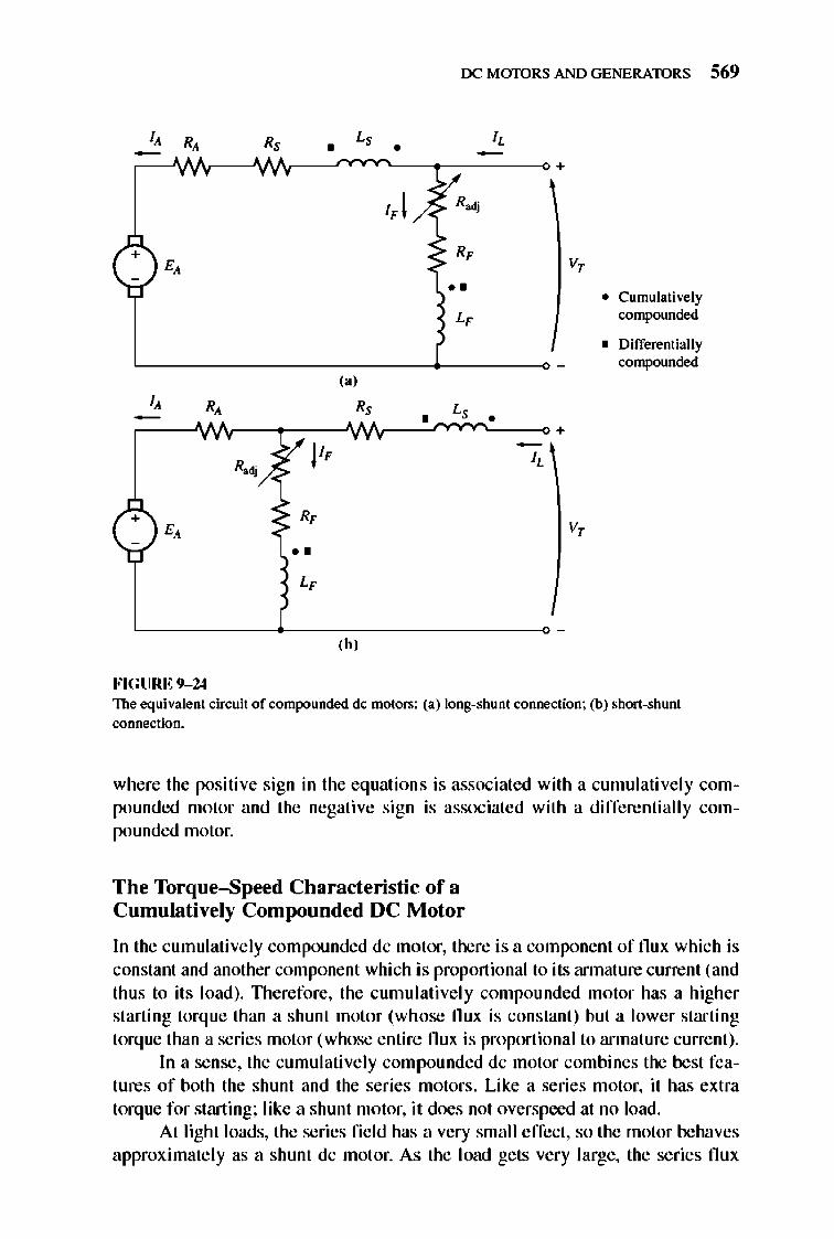
rx: MmDRS AND GENERATORS 569
(b'
FIGURE 9-24 The equiva.lent circuit of contpounded dc motors: (a.) Ions-shunt connection: (b) shon-shunt connection.
where the positive sign in the equations is associated with a cumulatively compounded motor and the negative sign is associated with a differentially compounded motor.
The Torque-Speed Characteristic of a Cumulatively Compounded DC Motor
In the cumulatively compounded dc motor, there is a component of flux which is constant and another component which is proportional to its annature current (and thus to it s load). TIlerefore, the cumulatively compounded motor has a higher starting torque than a shunt motor (whose flux is constant) but a lower starting torque than a series motor (whose entire flux is proportional to armature current).
In a sense, the cumulatively compounded dc motor combines the best features of both the shunt and the series motors. Like a series motor, it has extra torque for starting; like a shunt motor, it does not overspeed at no load.
At light loads, the series fi e ld has a very small effect, so the motor behaves approximately as a shunt dc motor. As the load gets very large, the series flux
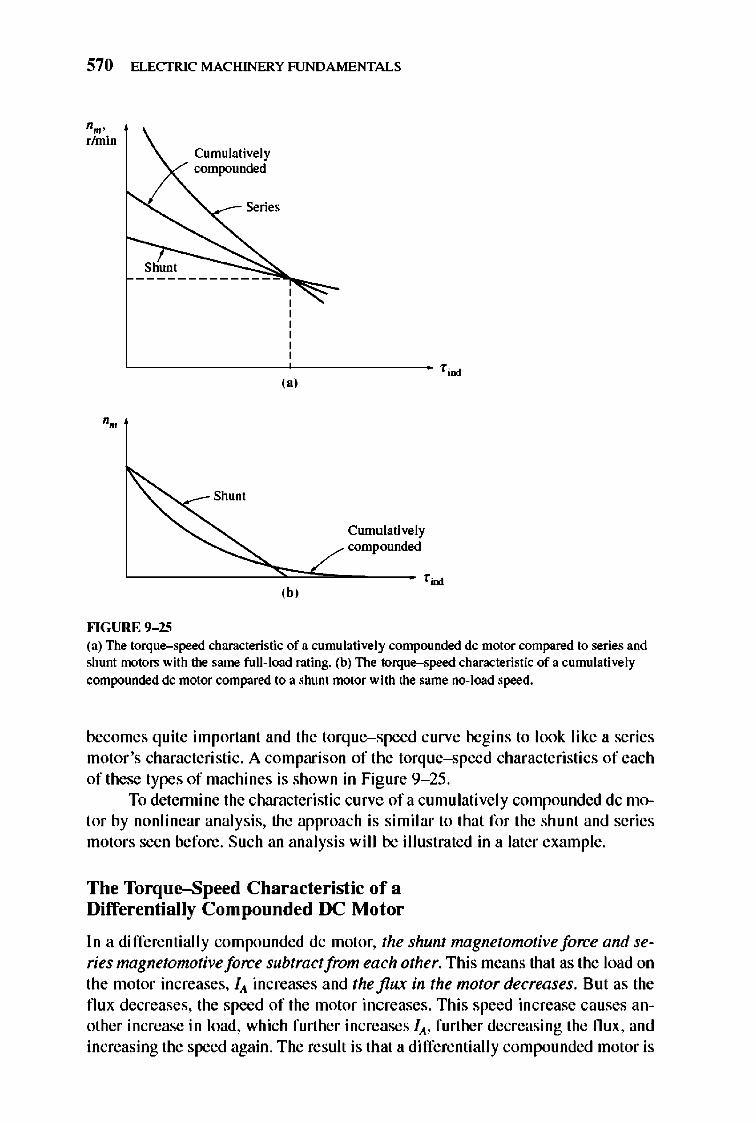
570 ELECTRIC MACHINERY RJNDAMENTALS
"m' rhnin
Shunt
Cumulatively compounded
,~- Series
L _______ ~ ________ fjnd
,,'
,~_ Shunt
Cumulatively compounded
~----=:::::::=L._ ,~ ,b,
""GURE 9- 25 (a) The torque-speed characteristic of a cumulatively compounded dc motor compared to series and shunt motors with the same full-load rating. (b) The torque-speed characteristic of a cumulatively compounded dc motor compared to a shunt motor with the same no-lood speed.
becomes quite important and the torque-speed curve begins to look like a series motor 's characteristic. A comparison of the torque-speed characte ristics of each of these types of machines is shown in Figure 9- 25 .
To detennine the characteristic curve ofa cumulatively compounded dc motor by nonlinear analysis, the approach is similar to that for the shunt and series motors seen before. Such an analysis will be illustrated in a later example.
The Torque-Speed Characteristic of a Differentially Compounded DC Motor
In a differentially compounded dc motor, the shunt magnetomotive force and series magnetomotive force subtract from each other. This means that as the load on the motor increases, lit increases and the flux in the motor decreases. But as the flux decreases, the speed of the motor increases. This speed increase causes another increase in load, which further increases lit, further decreasing the flu x, and increasing the speed again. The result is that a differentially compounded motor is
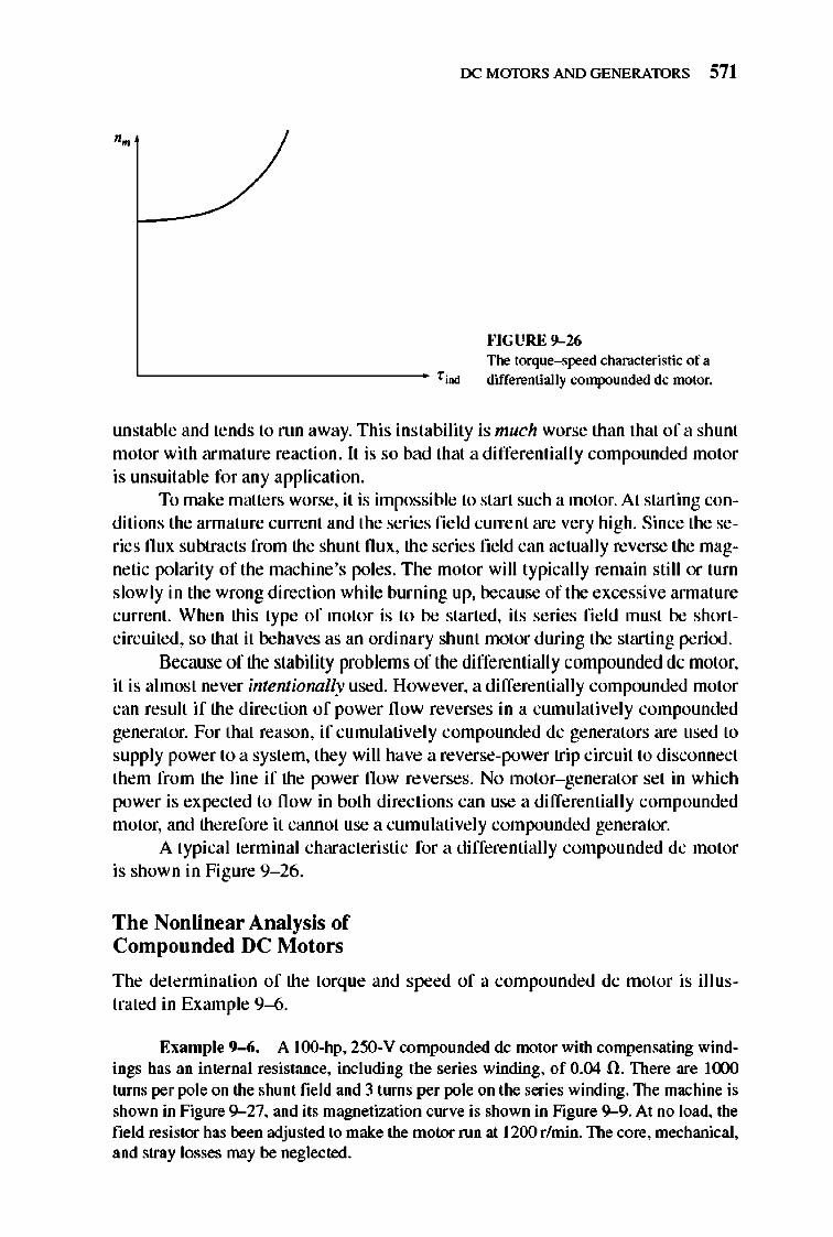
rx: MmDRS AND GENERATORS 571
H GURE 9-26 The torque-speed characteristic of a
L _____________ fjmd differentially compounded dc motor.
unstable and tends to run away. This instability is much worse than that of a shunt motor with armature reaction. It is so bad that a differentially compounded motor is unsuitable for any application.
To make matters worse, it is impossible to start such a motor. At starting conditions the annature current and the series field current are very high. Since the series flux subtracts from the shunt flux, the series field can actually reverse the magnetic polarity of the machine's poles. The motor will typically remain still or turn slowly in the wrong direction while burning up, because of tile excessive annature current. When this type of motor is to be started, its series fi e ld must be shortcircuited, so that it behaves as an ordinary shunt motor during the starting perioo.
Because of the stability problems of the differentially compounded de motor, it is almost never intentionally used. However, a differentially compounded motor can result if the direction of power flow reverses in a cumulative ly compounded generator. For that reason, if cumulative ly compounded dc generators are used to supply power to a system, they will have a reverse-power trip circuit to disconnect them from the line if the power flow reverses. No motor- generator set in which power is expected to fl ow in both directions can use a differentiall y compounded motor, and therefore it cannot use a cumulative ly compounded generator.
A typical terminal characteristic for a differentially compounded dc motor is shown in Figure 9- 26.
The Nonlinear Analysis of Compounded DC Motors
The determination of the torque and speed of a compounded dc motor is ill ustrated in Example 9--6.
EXllmple 9-6. A lOO-hp, 250-V compounded dc motor with compensating windings has an internal resistance, including the series winding, of 0.04 O. There are J(X)O turns per pole on the shunt field and 31lU1lS per pole on the series winding. The machine is shown in Figure 9-27, and its magnetization curve is shown in Figure 9-9. At no load, the field resistor has been adjusted to make the motor run at 1200 r/min. The core, mechanical, and stray losses may be neglected.
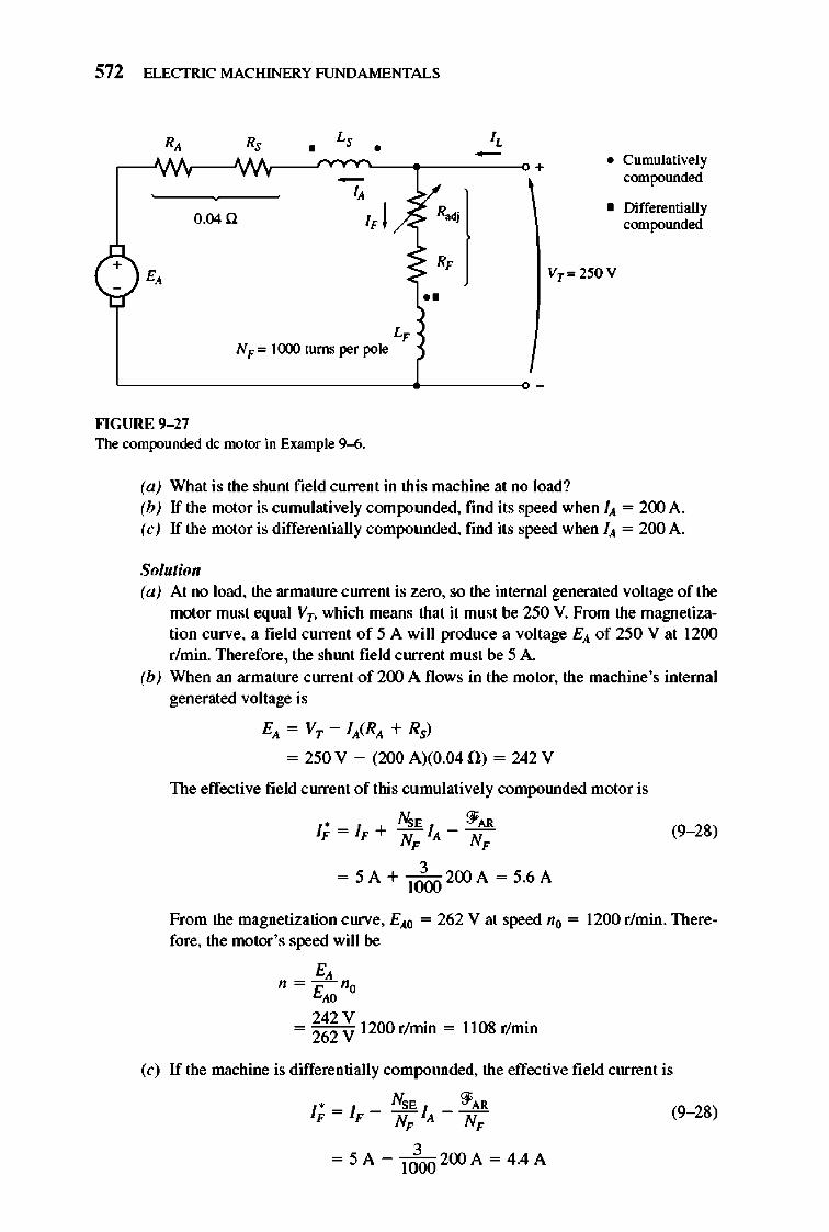
572 ELECTRIC MACHINERY RJNDAMENTALS
+
O.04n
<
L, N F = ](XXl turns per pole
••
• Cumulatively compounded
• Differentially compounded
Vr= 250 V
""GURE 9- 27 The compounded dc motor in Example 9--6.
(a) What is the shunt field current in this machine al no load? (b) If the motor is cumulatively compOlUlded, find its speed when I}, = 200 A. (c) If the motor is differentially compounded, find its speed when I}, = 200 A.
Solutioll (a) Al no load, the armature ClUTent is zero, so the internal generated vollage of the
motor must equal Vr, which means that it must be 250 V. From the magnetization curve, a field current of 5 A will produce a vollage E}, of 250 V at 1200 r/min. Therefore, the shlUll field ClUTent must be 5 A.
(b) When an armature ClUTent of 200 A flows in the motor, the machine's internal generated vollage is
E}, = Vr - I},(R}, + Rs)
= 250 V - (200 A)(0.04fi) = 242 V
The effective field c lUTenl of this cumulatively compolUlded motor is
• A\;E ~AR IF = IF + HI}, - N (9- 28)
F ,
3 = 5A + I ()(X) 200 A = 5.6A
From the magnetization curve, E},o = 262 V at speed no = 1200 r/min. Therefore, the motor 's speed will be
E, n = - n"
E" 242 V .
= 262 V 1200 rlnnn = 1108 rlmin
(c) If the machine is differentially compounded, the effective field current is
• NSE '3'AR IF = IF - NF I}, - NF (9- 28)
3 = 5A - 1000 200 A = 4.4 A
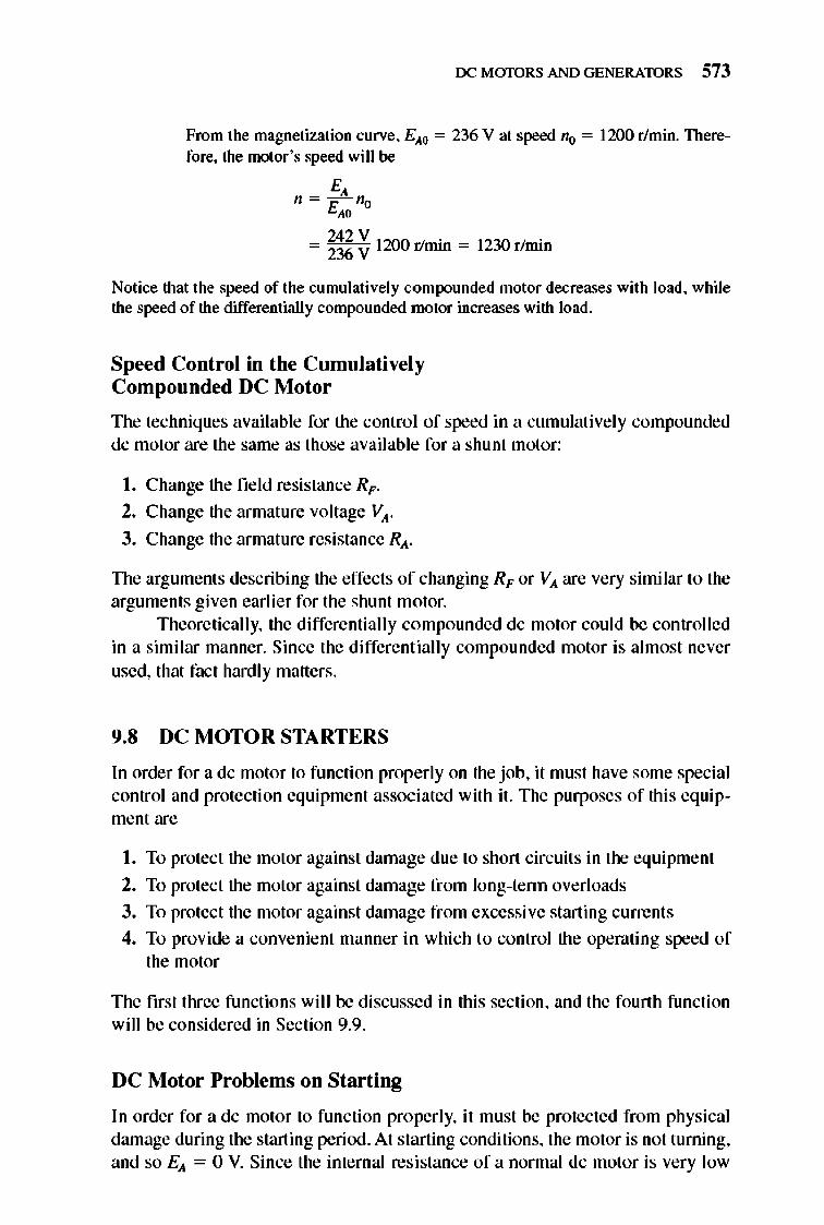
rx: MmDRS AND GENERATORS 573
From the magnetization curve, EAO = 236 V at speed fit! = 1200 r/min. Therefore, the motor 's speed will be
E, n=rno
" = ~~ ~ 1200 r/min = 1230 r/min
Notice that the speed of the cumulatively compounded motor decreases with load, while the speed of the differentially compounded motor increases with load.
Speed Control in the Cumulati vely Compounded DC Motor
The techniques available for the control of speed in a cumulative ly compounded dc motor are the same as those available for a shunt motor:
I . Change the field resistance RF .
2_ Change the armature voltage VA'
3. Change the armature resistance RA .
The arguments describing the effects of changing RF or VA are very similar to the arguments given earlier for the shunt motor.
Theoretically, the differentially compounded dc motor could be controlled in a similar manner. Since the differe ntially compounded motor is almost never used, that fact hardly matters.
9.8 DC MOTOR STARTERS
In order for a dc motor to function properly on the job, it must have some special control and protection equipment associated with it. The purposes of this equipment are
I. To protect the motor against damage due to short circuits in the equipment
2_ To protect the motor against damage from long-tenn overloads
3. To protect the motor against damage from excessive starting currents
4. To provide a convenient manner in which to control the operating speed of the motor
The first three functions will be discussed in this section, and the fourth function will be considered in Section 9.9.
DC Motor Problems on Starting
In order for a dc motor to functi on properly, it must be protected from physical damage during the starting period. At starting conditions, the motor is not turning, and so EA = 0 V. Since the internal resistance of a normal dc motor is very low
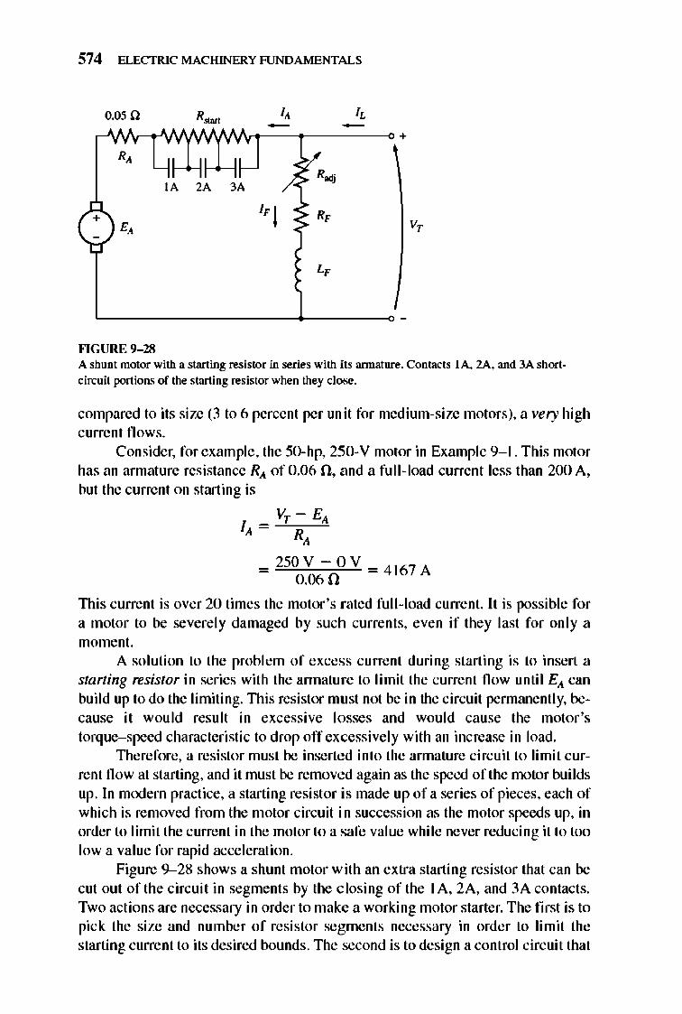
574 ELECTRIC MACHINERY RJNDAMENTALS
o.osn R.~ I, I,
+ R,
IA 2A 3A R.,
+ 1'1 R, V, E,
L,
""GURE 9- 28 A shunt motor with a starting resistor in series with its annature. Contacts lA. 2A. and 3A short· circuit portions of the start ing resistor when they close.
compared to its size (3 to 6 percent per unit for medium·size motors), a very high current fl ows.
Consider, for example, the 50·hp, 250·Y motor in Example 9-1. This motor has an armature resistance Rio. of 0.06 n, and a full·load current less than 200 A, but the current on starting is
VT - EA
RA
_ 250 Y -O Y =4 167A 0.060
lllis current is over 20 times the motor 's rated full·l oad current. It is possible for a motor to be severe ly damaged by such currents, even if they last for only a moment.
A solution to the problem of excess current during starting is to insert a starting resistor in series with the annature to limit the current flow until EIo. can build up to do the limiting. This resistor mu st not be in the circuit pennanently, be· cause it would result in excessive losses and would cause the motor 's torque-speed characteristic to drop off excessively with an increase in load.
1l1erefore, a resistor must be inserted into the annature circuit to limit cur· rent flow at starting, and it must be removed again as the speed of the motor builds up. In mooem practice, a starting resistor is made up of a series of pieces, each of which is removed from the motor circuit in succession as the motor speeds up, in order to limit the current in the motor to a safe value while never reducing it to too Iowa value for rapid acceleration.
Figure 9-28 shows a shunt motor with an extra starting resistor that can be cut out of the circuit in segments by the c losing of the lA, 2A, and 3A contacts. Two actions are necessary in order to make a working motor starter. The first is to pick the size and number of resistor segments necessary in order to limit the starting current to its desired bounds. The second is to design a control circuit that
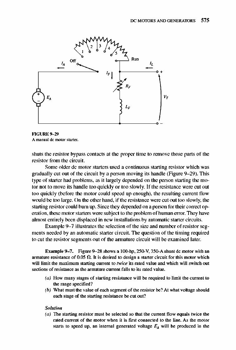
rx: MmDRS AND GENERATORS 575
3
Off R."
f----~+
v,
FIGURE 9-29 A manual de motor starter.
shuts the resistor bypass contacts at the proper time to remove those parts of the resistor from the circuit.
Some o lder de motor starters used a continuous starting resistor which was gradually cut out of the circuit by a person moving its handle (Figure 9- 29). nlis type of starter had problems, as it largely depended on the person starting the molar not to move its handle too quickly or too slowly. Irthe resistance were cut out too quickly (before the motor could speed up enough), the resulting current flow would be too large. On the other hand, if the resistance were cut out too slowly, the starting resistor could burn up. Since they depended on a person for their correct operation, these motor starters were subject to the problem of human error. 1lley have almost entirely been displaced in new in stallations by automatic starter circuits.
Example 9- 7 illustrates the selection of the size and number of resistor segments needed by an automatic starter circuit. The question of the timing required to cut the resistor segments out of the annature circuit will be examined later.
EXllmple 9-7. Figure 9- 28 shows a lOO-hp. 250-V. 350-A shunt dc motor with an armature resistance of 0.05 O. It is desired to design a starter circuit for this motor which will limit the maximum starting current to twice its rated value and which will switch out sections of resistance as the armature current falls to its rated value.
(a) How many stages of starting resistance will be required to limit the current to the range specified?
(b) What must the value of each segment of the resistor be? At what voltage should each stage of the starting resistance be cut out?
Solutioll (a) The starting resistor must be selected so that the current flow equals twice the
rated current of the motor when it is first connected to the line. As the motor starts to speed up. an internal generated voltage EA will be produced in the
576 ELECTRIC MACHINERY RJNDAMENTALS
motor. Since this voltage opposes the terminal voltage of the motor, the increasing internal generated voltage decreases the current fl ow in the motor. When the current flowing in the motor falls to rated current , a section of the starting resistor must be taken out to increase the starting ClUTe nt back up to 200 percent of rated current. As the motor continues to speed up, EA continues to rise and the annature current continues to fall. When the current fl owing in the motor fall s to rated current again, another section of the starting resistor must be taken out. This process repeats lUltil the starting resistance to be removed at a given stage is less than the resistance of the motor 's annature circuit. At that point, the motor 's annature resistance will limit the current to a safe value all by itself.
How many steps are required to accomplish the current limiting? To find out , define R'rA as the original resistance in the starting circuit. So R'rA is the sum of the resistance of each stage of the starting resistor together with the resistance of the armature circuit of the motor:
+ R, (9- 29)
Now define R'rA.i as the total resistance left in the starting circuit after stages I to i have been shorted out. The resistance left in the circuit after removing stages I through i is
+ R,
Note also that the initial starting resistance must be
V, R,<J, = -1-
m ..
(9- 30)
In the first stage of the starter circuit, resistance RI must be switched out of the circuit when the current I.It falls to
VT - EA fA = R = fmin ,.
After switching that part of the resistance out , the annature current must jump to
VT - EA R = fm:lx
,<J,.l fA =
Since E,It (= Kef-) is directly proportional to the speed of the motor, which cannot change instantaneously, the quantity VT- E,It must be constant at the instant the resistance is switched out. Therefore,
frrm,R' rA = VT - E,It = f mnR,ot.l
or the resistance left in the circuit after the first stage is switched out is
fmin = -I - R~ - (9- 31)
By direct extension, the resistance left in the circuit after the nth stage is switched out is
(9- 32)
rx: MmDRS AND GENERATORS 577
The starting process is completed when R'<AJI for stage n is less than or equal to the internal annature resistance RA of the motor. At that point, RA can limit the ClUTent to the desired value all by itself. At the boundary where RA = R,OC,II
(9--33)
R, = ('m'")" RkJ! lmIlJ.
(9--34)
Solving for n yields
(9--35)
where n must be rounded up to the next integer value, since it is not possible to have a fractional number of starting stages. If n has a fractional part, then when the final stage of starting resistance is removed, the armature current of the motor will jwnp up to a value smaller than lmu.
In this particular problem, the ratio lminllr=. = 0.5, and RIOt is
VT 250 V R~ - -, - = 700 A = 0.357 n
m n
log (RAiR,,J log (0.05 fIA). 357 fi) n= = =2 84 log (lmin1Imax) log (350 MOO A) .
The number of stages required will be three.
(b) The annature circuit will contain the annature resistor RA and three starting resistors RI , R2, and RJ . This arrangement is shown in Figure 9--28.
At first, EA = 0 V and IA = 700 A, so
_ Vr _ IA - R + R + R + R - 700 A
A I 2 J
Therefore, the total resistance must be
(9--36)
This total resistance will be placed in the circuit WItii the ClUTent falls to 350 A. This occurs when
EA = Vr - IAR,,,, = 250 V - (350 AX0.357 !l) = 125 V
When EA = 125 V,IA has fallen to 350 A and it is time to cut out the first starting resistor RI . When it is cut out, the ClUTent should jump back to 7ooA. Therefore,
R + R + R = Vr - EA = 250 V - 125 V = 0 1786 n A 2 J I 700 A .
mn
(9--37)
This total resistance will be in the circuit untillA again falls to 350A. This occurs when EA reaches
EA = Vr - IAR,,,, = 250 V - (350A)(0.1786!l) = 187.5 V
578 ELECTRIC MACHINERY RJNDAMENTALS
When EA = 187.5 V, fA has fallen to 350 A and it is time to cut out the second starting resistor R2. When it is cut out, the current should jump back to 700 A. Therefore,
R +R = VT -EA =250V-187.5V =008930 A 1 I 700 A .
~
(9- 38)
This total resistance will be in the circuit until fA again falls to 350 A. This occurs when EA reaches
EA = VT - fAR,o< = 250V - (350A)(0.08930) = 218.75V
When EA = 218.75 V, fA has fallen to 350 A and it is time to cut out the third starting resistor R1. When it is cut out, only the internal resistance of the motor is left. By now, though, RA alone can limit the motor's current to
VT - EA 250 V - 218.75 V lAo = R = 0.050 ,
= 625 A (less than allowed maximrun)
From this point on, the motor can speed up by itself. From Equations (9- 34) to (9- 36), the required resistor values can be
calculated:
RJ = R'OI.3 - RA = 0.08930 - 0.05 0 = 0.03930
R2 = R'0I2 - RJ - RA = 0.1786 0 - 0.0393 0 - 0.05 0 = 0.0893 0
R] = R"".l - R2 - R3 - RA = 0.357 0 - 0.1786 0 - 0.0393 0 - 0.05 0 = 0.1786 0
And RJ, Rl., and RJ are cut out when EA reaches 125, 187.5, and 2 18.75 V, respectively.
DC Motor Starting Circuits
Once the starting resistances have been selected, how can their shorting contacts be controlled to ensure that they shut at exact ly the correct moment? Several different schemes are used to accomplish thi s switching, and two of the most common approaches will be examined in this section. Before that is done, though, it is necessary to intrrxluce some of the components used in motor-starting circuits .
Fig ure 9- 30 illustrates some of the devices commonly used in motorcontrol circuits. 1lle devices illustrated are fuses, push button switches, relays, time delay relays, and overl oads.
Fig ure 9- 30a shows a symbol for a fuse. The fuses in a motor-control circ uit serve to protect the motor against the danger of short circui ts. They are placed in the power supply lines leading to motors. If a motor develops a short circuit, the fuses in the line leading to it wi ll burn out, opening the circuit before any damage has been done to the motor itself.
Figure 9-30b shows spring-type push button switches. There are two basic types of such switches-normally open and nonnally shut. Nonnally open contacts are open when the button is resting and closed when the button has been
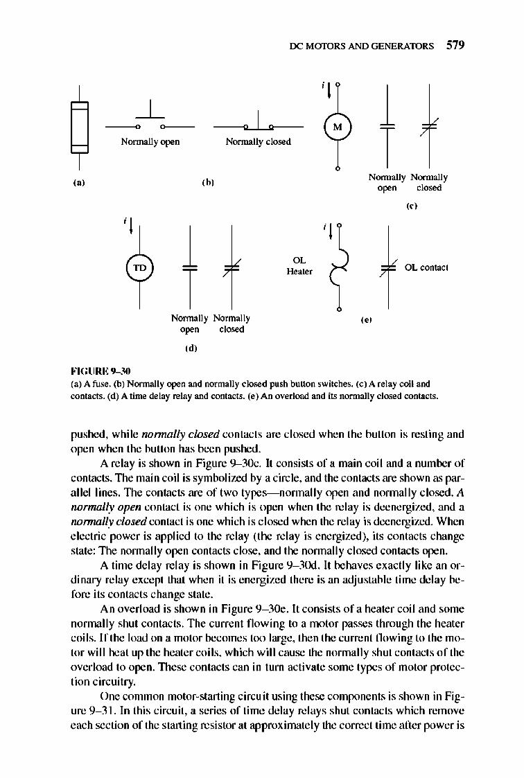
rx: MmDRS AND GENERATORS 579
-~o O~-- 0 1 0 Normally open Normally closed
,,'
FIGURE 9-30
1 T
,b,
Normally Nonnally open closed
,d,
OL Heater
, .,
(a) A fuse. (b) Normally open and normally closed push button switches. (c) A relay coil and comacts. (d) A time delay relay and contacts. (e) An overload and its normally closed contacts.
pushed, while normally closed contacts are closed when the button is resting and open when the button has been pushed.
A relay is shown in Figure 9-30c. It consists of a main coil and a number of contacts.1lle main coil is symbolized by a circle, and the contacts are shown as parallel1ines. TIle contacts are of two types- nonnally open and nonnally closed. A normally open contact is one which is open when the relay is deenergized, and a normally closed contact is one which is c losed when the relay is deenergized. When electric power is applied to the relay (the relay is energized), its contacts change state: 1lle nonnally open contacts close, and the nonnally closed contacts open.
A time delay relay is shown in Figure 9- 3Od. It behaves exactly like an ordinary relay except that when it is energized there is an adjustable time delay before its contacts change state .
An overload is shown in Figure 9- 30e. It consists ofa heater coil and some nonnally shut contacts. The current fl owing to a motor passes through the heater coils. If the load on a motor becomes too large, then the current fl owing to the motor wi 11 heat up the heater coils, which will cause the normally shut contacts of the overload to open. TIlese contacts can in turn activate some types of motor protection circuitry.
One common motor-starting circuit using these components is shown in Figure 9- 3 1. In this circuit, a series of time delay relays shut contacts which remove each section of the starting resistor at approximately the correct time after power is
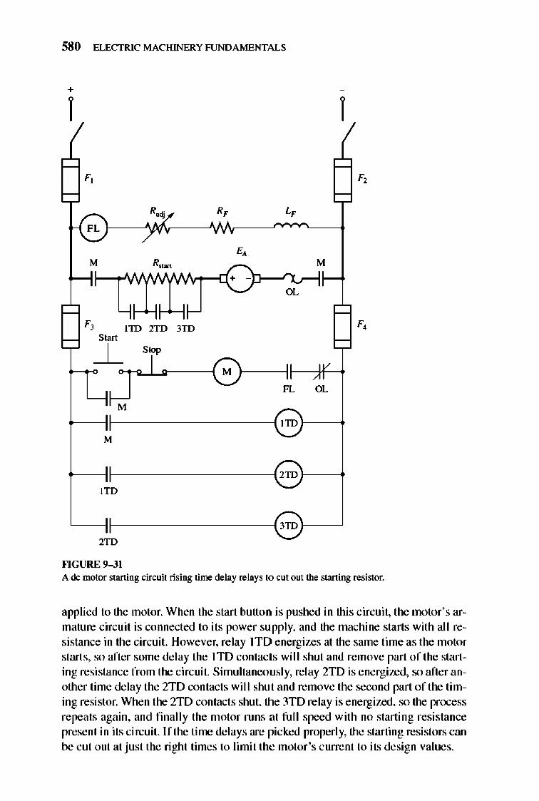
580 ELECTRIC MACHINERY RJNDAMENTALS
+
1 1
F, F,
R .. R, L,
FL
E, M R"., M
+ -
OL
F, lID 2TD 3TO F, SO",
~ Srop
I 0 J ,
FL OL
lID
M
2ID
ITO
3ID
2TO
""GURE 9-31 A dc motor starting circuit rising time delay relays to cut out the starting resistor.
applied to the motor. When the start button is pushed in this circuit, the motor 's armature circuit is connected to its power supply, and the machine starts with all resistance in the circuit. However, relay ITO energizes at the same time as the motor starts, so after some delay the ITO contacts will shut and remove part of the starting resistance from the circuit. Simultaneously, relay 2m is energized, so after another time delay the 2TD contacts wil I shut and remove the second part of the timing resistor. When the 2TD contacts shut, the 3TD relay is e nergized, so the process repeats again, and finally the motor runs at full speed with no starting resistance present in its circuit. I fthe time delays are picked properly, the starting resistors can be cut out at just the right times to limit the motor 's current to its design values.
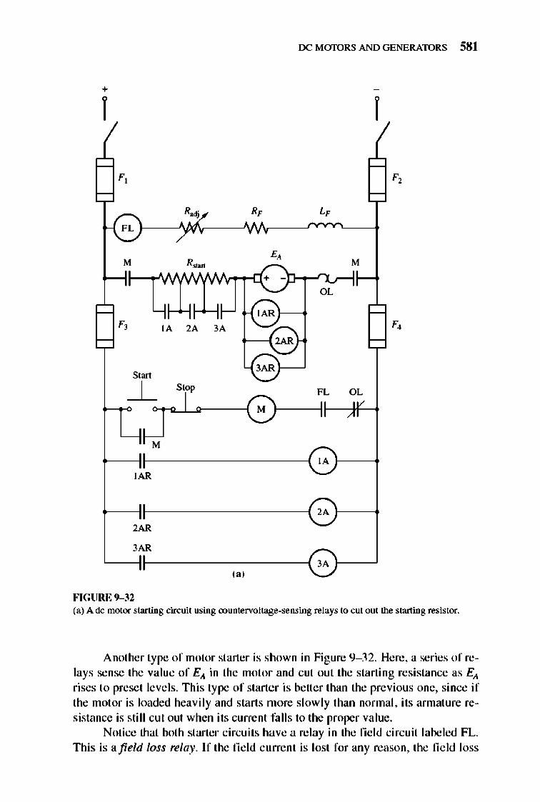
rx: MmDRS AND GENERATORS 581
+
I I
Radj
OL
S"rt
FL OL ~ Stop
~ J~I Or------{0 M
IA }---1 IAR
~-j~---------{ 2A }---1
2AR
3AR ~-Ie---------~ 3A }--~
FIGURE 9-32 (a) A de motor starting circuit using oountervoltage-sensing relays to eut out the starting resistor.
Another type of motor starter is shown in Figure 9- 32. Here, a series of relays sense the value of Ell in the motor and cut out the starting resistance as Ell rises to preset levels. This type of starter is better than the previous one, since if the motor is loaded heavily and starts more slowly than normal , its armature resistance is still cut out when its current falls to the proper value.
Notice that both starter circuits have a relay in the fie ld circuit labeled FL. This is afield loss relay. If the field current is lost for any reason, the field loss
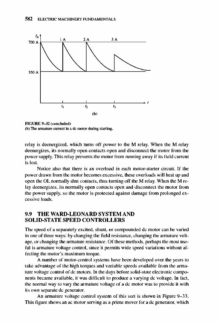
582 ELECTRIC MACHINERY RJNDAMENTALS
I, I A 2A 3 A
700 A k----'T'----~T----"-''------
" I, I,
,b, ""GURE 9- 32 (conclud ... >d) (b) The armature current in a dc motor during starting.
re lay is deenergized, which turns off power to the M relay. When the M re lay deenergizes, its nonnally open contacts open and disconnect the motor from the power supply. This relay prevents the motor from running away if its fie ld current is lost.
Notice also that there is an overload in each motor-starte r circuit. If the power drawn from the motor becomes excessive, these overloads will heat up and open the OL nonnally shut contacts, thus turning off the M relay. When the M relay deenergizes, its nonnally open contacts open and disconnect the motor from the power suppl y, so the motor is protected against damage from prol onged excessive loads.
9.9 THE WARD·LEONARD SYSTEM AND SOLID·STATE SPEED CONTROLLERS
TIle speed of a separate ly excited, shunt, or compounded dc motor can be varied in one of three ways: by changing the fie ld resistance, changing the annature voltage, or changing the armature resistance. Of these methods, perhaps the most useful is annature voltage control, since it permits wide speed variations without affecting the motor's maximum torque.
A number of motor-control systems have been developed over the years to take advantage of the high torques and variable speeds available from the annature voltage control ofdc motors. In the days before solid-state electronic components became avai lable, it was difficult to produce a varying dc volt age. In fact, the nonnal way to vary the armature voltage of a dc motor was to provide it with its own separate dc generator.
An armature voltage control system of this sort is shown in Figure 9- 33. TIlis fi gure shows an ac motor serving as a prime mover for a dc generator, which
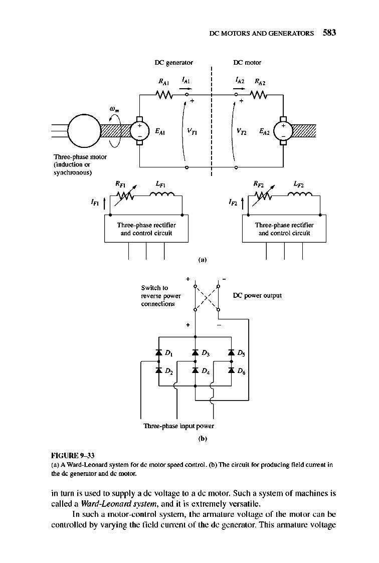
rx: M mDRS AND GENERATORS 583
IX generator rx: motor
R" I" I" R"
+ + wm
E" v" Vn E"
Three-phase motor (induction or synchronous)
Rn Ln Rn Ln
In I In I Three-phase rectifier Three-phase rectifier
and control circuit and control circuit
(a)
+ -
Switch to , , ' IX "" reverse power >' connections ' ' , '
weroutput
+ -
D, D, D,
D, D, D.
Three-phase input power
,b, FIGURE 9-33 (a) A Ward-Leonard system for dc motor speed control. (b) The circuit for producing field current in the dc generator and dc motor.
in turn is used to supply a dc voltage to a dc motor. Such a system of machines is called a Ward-Leonard system, and it is extremely versatile .
In such a motor-control system, the annature voltage of the motor can be controlled by varying the fi e ld current of the dc generator. This annature voltage
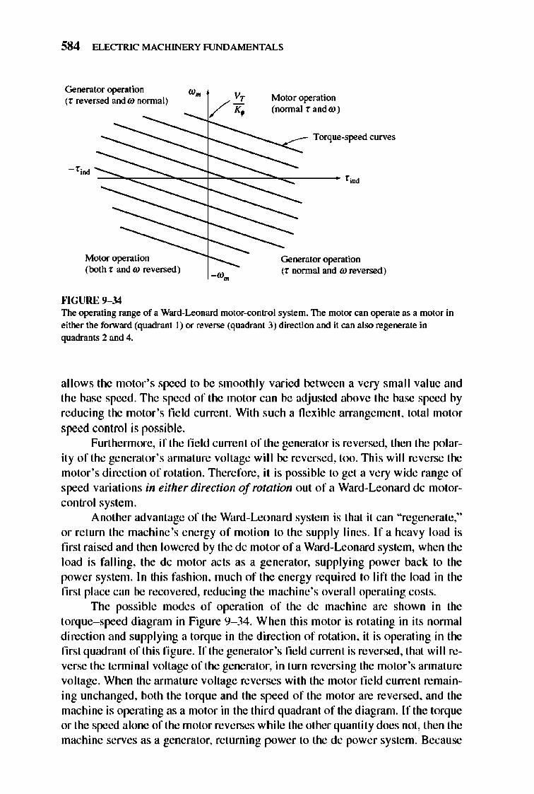
584 ELECTRIC MACHINERY RJNDAMENTALS
Generator operation (r reversed and ro normal)
- rind
Motor operation (both rand ro reversed)
""GURE 9-34
Motor operation (normal r andro)
Torque-speed curves
Generator operation (r normal and ro reversed)
The operating range of a Ward-Leonan:l motor-control system. The motor can operate as a motor in either the forward (quadram 1) or reverse (quadrant 3) direction and it can also regenerate in quadrams 2 and 4.
allows the motor 's speed to be smoothly varied between a very small value and the base speed . The speed of the motor can be adjusted above the base speed by reducing the motor 's field current. With such a fl exible arrangement, total motor speed control is possible.
Furthermore, if the fi e ld current of the generator is reversed, then the polarity of the generator's annature voltage will be reversed, too. This will reverse the motor's direction of rotation. Therefore, it is possible to get a very wide range of speed variations in either direction of rotation out of a Ward-Leonard dc motorcontrol system.
Another advantage of the Ward-Leonard system is that it can "regenerate," or return the machine 's energy of moti on to the supply lines. If a heavy load is first raised and then lowered by the dc motor ofa Ward-Leonard system, when the load is falling, the dc motor acts as a generator, supplying power back to the power system. In this fashion, much of the energy required to lift the load in the first place can be recovered, reducing the machine's overall operating costs.
TIle possible modes of operation of the dc machine are shown in the torque- speed diagram in Figure 9- 34. When this motor is rotating in its nonnal direction and supplying a torque in the direction of rotation, it is operating in the first quadrant of this figure. If the generator's field current is reversed, that will reverse the tenninal voltage of the generator, in turn reversing the motor 's annature voltage. When the armature voltage reverses with the motor field current remaining unchanged, both the torque and the speed of the motor are reversed, and the machine is operating as a motor in the third quadrant of the diagram. If the torque or the speed alone of the motor reverses while the other quantity does not, then the machine serves as a generator, returning power to the dc power system. Because
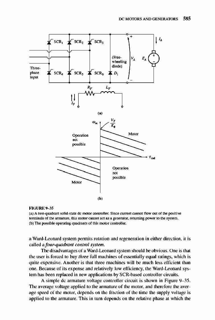
rSCR]
Th~ r ph= SCR., input
FIGURE 9-35
lr SCR2
l,-SCR~
I I I,
Operation
"0' possible
lr SCRJ
V-SC~
(.,
(b,
rx: MmDRS AND GENERATORS 585
,Free-wheeling diode)
D,
v, K.
Operation "oj possible
+ I
v, E,C)
-
(a) A two-quadrant solid-state dc motor controller. Since current cannot flow out of the positive terminals of the armature. this motor cannot act as a generator. returning power to the system. (b) The possible operating quadrants of this motor controller.
a Ward-Leonard system pennits rotation and regeneration in either direction, it is called afour-quadrant control system.
The disadvantages of a Ward-Leonard system should be obvious. One is that the user is forced to buy three full machines of essentially equal ratings, which is quite expensive. Another is that three machines will be much less efficient than one. Because of its expense and relatively low efficiency, the Ward-Leonard system has been replaced in new applications by SCR-based controller circuits.
A simple dc armature voltage controller circuit is shown in Figure 9- 35. The average voltage applied to the armature of the motor, and therefore the average speed of the motor, depends on the fraction of the time the supply voltage is applied to the armature. This in turn depends on the relative phase at which the
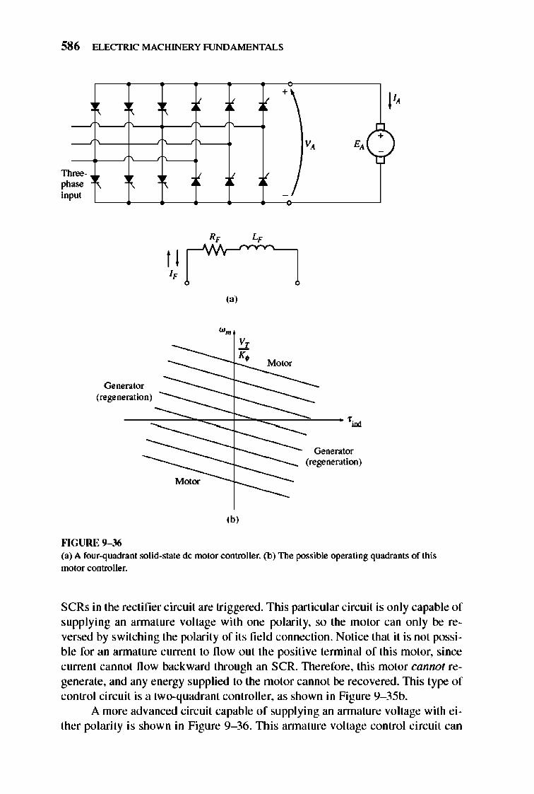
586 ELECTRIC MACHINERY RJNDAMENTALS
-. Th ph inp '" m
t I "
-Generator (regeneration) -...
""GURE 9-36
(a)
,b,
V +\
V, E,
_I
Motor
Generator __ (regeneration)
-
I' + -
(a) A four-quadrant solid-state dc motor controller. (b) The possible operating quadrants of this motor controller.
SCRs in the rectifier circuit are triggered . This particular circuit is only capable of supplying an annature voltage with one polarity, so the motor can only be reversed by switching the polarity of its fie ld connection. Notice that it is not possible for an annature current to now out the positive terminal of this motor, since current cannot now backward through an SCR. nlerefore, this motor cannot regenerate, and any energy supplied to the motor cannot be recovered. This type of control circuit is a two-quadrant controller, as shown in Figure 9- 35b.
A more advanced circuit capable of supplying an annature voltage with either polarity is shown in Figure 9- 36. n lis annature voltage control circuit can
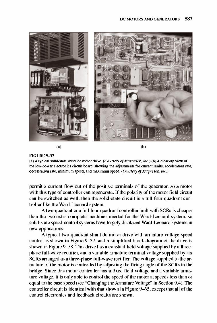
rx: MmDRS AND GENERATORS 587
(a)
FIGURE 9-37 (a) A typical solid-state shunt dc motor drive. (Courtesy of MagneTek, Inc. ) (b) A close-up view of the low-power electronics circuit board. showing the adjustmems for current limits. acceleration rate. deceleration rate. minimum speed. and maximum speed. (Courtesy of MagneTel;. Inc.)
pennit a current fl ow out of the positive terminals of the generator, so a motor with this type of controller can regenerate. If the polarity of the motor fi eld circuit can be switched as well, then the solid -state circuit is a full four-quadrant controller like the Ward-Leonard system.
A two-quadrant or a full four-quadrant controller built with SCRs is cheaper than the two extra complete machines needed for the Ward-Leonard system, so solid-state speed-control systems have largely displaced Ward-Leonard systems in new applications.
A typical two-quadrant shunt dc motor drive with armature voltage speed control is shown in Figure 9- 37, and a simplified block diagram of the drive is shown in Figure 9- 38 . nlis drive has a constant fi e ld voltage supplied by a threephase full -wave rectifier, and a variable annature terminal voltage supplied by six SCRs arranged as a three-phase full-wave rectifier. The voltage supplied to the armature of the motor is controlled by adjusting the firing angle of the SCRs in the bridge. Since this motor controller has a fixed fi e ld voltage and a variable annature voltage, it is only able to control the speed of the motor at speeds less than or equal to the base speed (see "Changing the Armature Voltage" in Section 9.4). The controller circuit is identical with that shown in Figure 9- 35, except that all of the control e lectronics and feedback circuits are shown.
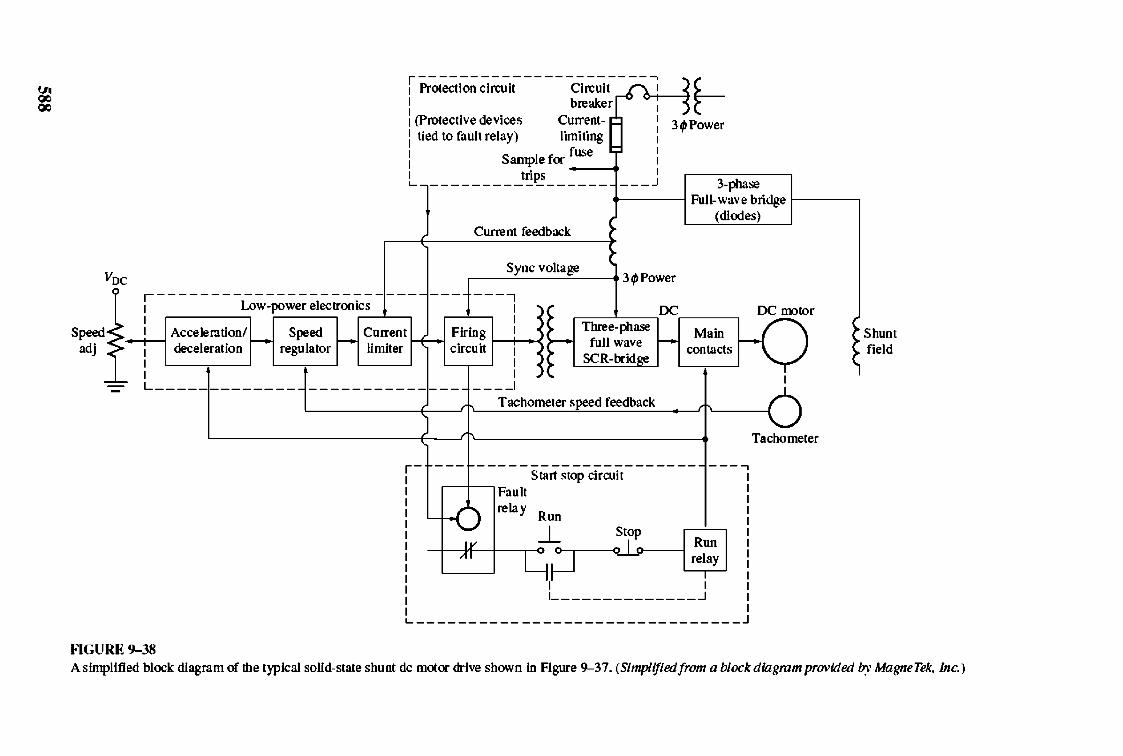
~ ~
: Pr~-;ct~~ci~i~ -----;l~~---: t-: (Protective devices Current- 1
: tied to fault relay) In;~~ng !
: Sample foc 1
1 trips J L__________________ _
341 P()',\o"er
3-phase , I Full-wave bridge ~I --,
(diodes) Current feedback
Voc Sync voltage T 341 P()',\o"er
1-------
Speed<: i Low-pow~;I.;;:;~~;T -~ adj ~ Accelerutionl I I
: deceleration r-- s",,,, regulator
Current
---, I I
Firing I ! •
circuit r-r-: I---I OC~_~ rx: motor
1 Three-phase 1 full wave
SCR-bridge
Main H V limiter
I L --,-
FlGURE 9-38
I I
____ I
T achometer speed feedback
contacts
-----------------4---, r-t~--r-~-- Start stop circuit
Fault
relay Run
-.l .:L I R" I -l---colf-t-T ~ re~a! I , 1 _____________ -.l
L ______________________________ _
I
Tachometer
Shunt field
A simplified block diagram of the t)pical solid-state shunt dc motoc drive shown in Figure 9--37. (Simplified/rom a block diagmm provided l7y MagneTek, Inc.)
rx: MmDRS AND GENERATORS 589
The major sections of this dc motor drive include:
I. A protection circuit section to protect the motor from excessive armature currents. low tenninal voltage. and loss of fie ld current.
2. A start/stop circ uit to connect and disconnect the motor from the line.
3. A high-power electronics section to convert three-phase ac power to dc power for the motor 's annature and field c ircuits.
4. A low-power electronics section to provide firing pulses to the SCRs which supply the annature voltage to the motor. This section contains several major subsections, which will be described below.
Protection Circuit Section
The protection circuit section combines several different devices which together ensure the safe operation of the motor. Some typical safety devices included in this type of drive are
I. Current-limiting fuses, to disconnect the motor quickly and safe ly from the power line in the event of a short c ircuit within the motor. Current- limiting fuses can interrupt currents of up to several hundred thousand amperes.
2. An instantaneous static trip, which shuts down the motor if the annature current exceeds 300 percent of its rated value . If the armature current exceeds the maximum allowed value, the trip circuit activates the fault relay, which deenergizes the run relay, opening the main contactors and disconnecting the motor from the line.
3. An inverse-time overload trip, which guards against sustained overcurrent conditi ons not great enough to trigger the instantaneous static trip but large e nough to damage the motor if allowed to continue inde finite ly. TIle term inverse time implies that the higher the overcurrent fl owing in the motor, the faster the overload acts (Figure 9- 39). For example, an inverse-time trip might take a full minute to trip if the current fl ow were 150 percent of the rated current of the motor, but take 10 seconds to trip if the current now were 200 percent of the rated current of the motor.
4. An undefi!oltage trip, which shuts down the motor if the line voltage supplying the motor drops by more than 20 percent.
5. Afield loss trip, which shuts down the motor if the field circuit is lost.
6. An overtemperature trip, which shuts down the motor if it is in danger of overheating.
StartlStop Circuit Section
The start/stop circuit section contains the controls needed to start and stop the motor by opening or closing the main contacts connecting the motor to the line . The motor is started by pushing the run button, and it is stopped either by pushing the
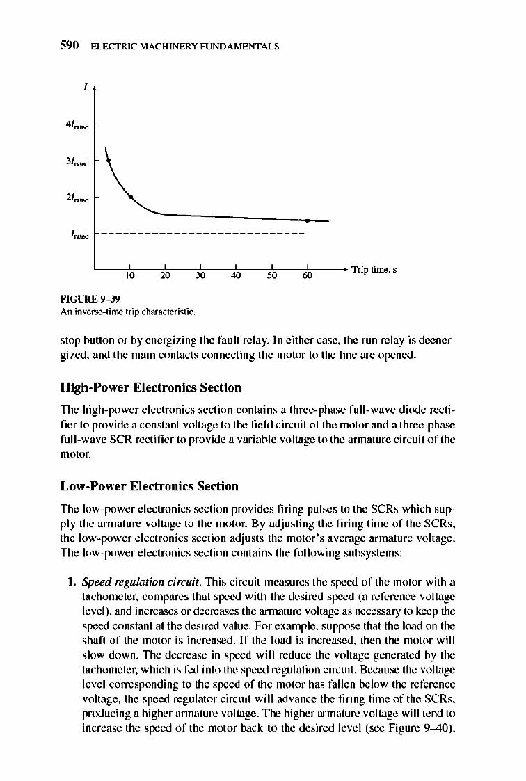
590 ELECTRIC MACHINERY RJNDAMENTALS
I
3/",oed
I",oed ----------------------------
"--':10'--- '2"0--30"'- --'40"- ':50'--- '60"-- Trip time. s
""GURE 9-39 An inverse-time trip characteristic.
stop button or by e nergizing the fault relay. In either case, the run relay is deenergized, and the main contacts connecting the motor to the line are opened.
High-Power Electronics Section
The high-power e lectronics section contains a three-phase full-wave diode rectifier to provide a constant voltage to the fie ld circuit of the motor and a three-phase full-wave SCR rectifier to provide a variable voltage to the annature circuit of the motor.
Low-Power Electronics Section
TIle low-power e lectronics section provides firing pulses to the SCRs which supply the annature voltage to the motor. By adjusting the firing time of the SCRs, the low-power e lectronics section adjusts the motor's average armature voltage . TIle low-power e lectronics section contains the foll owing subsystems:
I. Speed regulation circuit. TIlis circuit measures the speed of the motor with a tachometer, compares that speed with the desired speed (a reference voltage level), and increases or decreases the annature voltage as necessary to keep the speed constant at the desired value . For exrunple, suppose that the load on the shaft of the motor is increased . If the load is increased, then the motor will slow down. TIle decrease in speed wi II reduce the voltage generated by the tachometer, which is fed into the speed regulation circuit. Because the voltage level corresponding to the speed of the motor has fall en below the reference voltage, the speed regulator circuit will advance the firing time of the SCRs, producing a higher annature voltage. The higher armature voltage will tend to increase the speed of the motor back to the desired level (see Figure 9-40) .
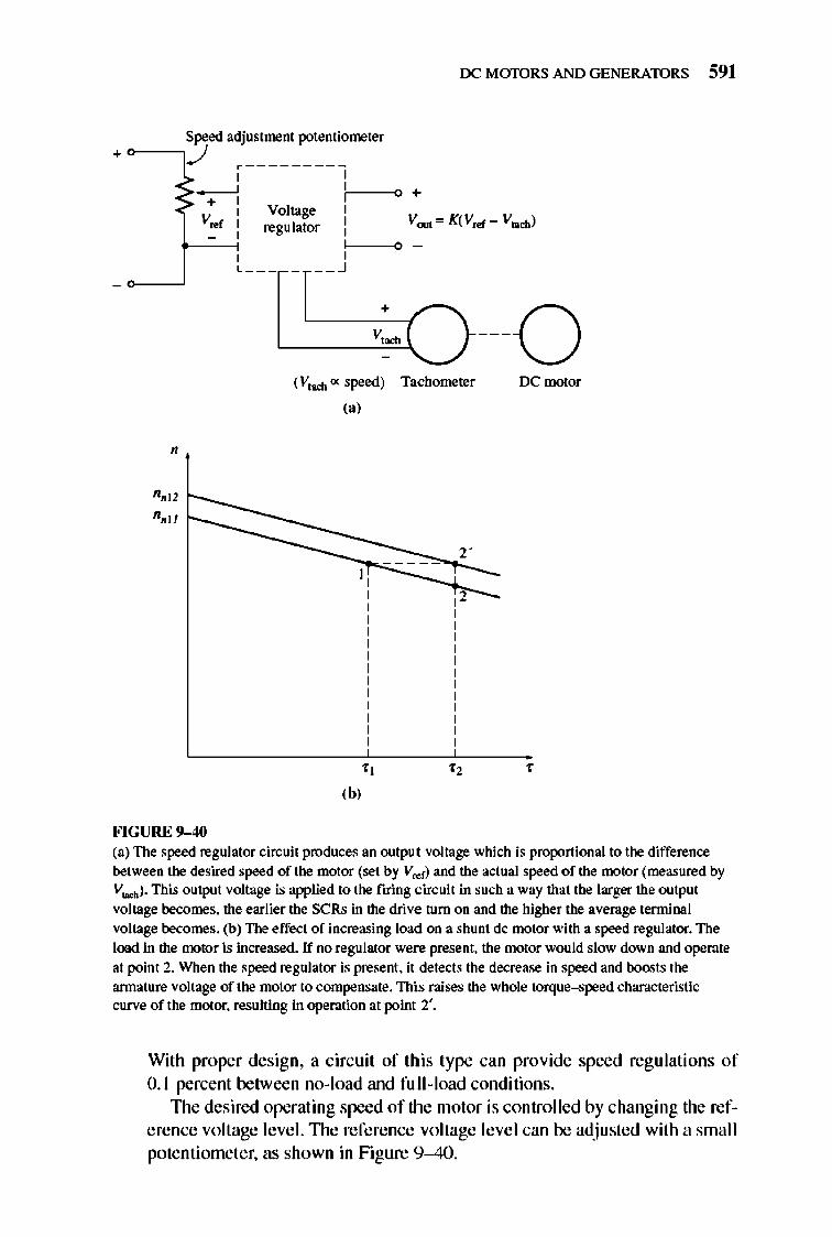
rx: MmDRS AND GENERATORS 591
Speed adjustment potentiometer +~,J
1--------1 -----' C' -_0 +
+ I I I Voltage I
V .. r I I I regulator I t--'~ c-' -~O -, ,
l ______ -.l
(V,oo:b ex speed) Tachometer rx: motor ,.,
2
" , ,b,
FIGURE 9-40 (a) The speed regulator cin:uit produces an output voltage which is proportional to the difference between the desired speed of the motor (set by V <d') and the actual speed of the nx>tor (measured by Vtoob ). This output voltage is applied to the firing cin:uit in such a way that the larger the output voltage becomes, the earlier the SCRs in the drive turn on and the higher the average terminal voltage becomes. (b) The effect of increasing load on a shunt dc motor with a speed regulator. The load in the nx>tor is increased. If no regulator were present. the motor would slow down and operate at point 2. When the speed regulator is present. it detects the decrease in speed and boosts the armature voltage of the motor to compensate. This raises the whole torque-speed characteristic curve of the motor. resulting in operation at point 2'.
With proper design, a circuit of this type can provide speed regulations of 0. 1 percent between no-load and full-load conditions.
1lle desired operating speed of the motor is controlled by changing the reference voltage level. The reference voltage level can be adjusted with a small potentiometer, as shown in Figure 9-40.
592 ELECTRIC MACHINERY RJNDAMENTALS
2. Current-limiting circuit. This circuit measures the steady-state current fl owing to the motor, compares that current with the desired maximum current (set by a reference voltage level), and decreases the annature voltage as necessary to keep the current from exceeding the desired maximum value. The desired maximum current can be adjusted over a wide range, say from 0 to 200 percent or more of the motor's rated current. This current limit should typicall y be set at greater than rated current , so that the motor can accelerate under full-l oad conditions.
3. Acceleration/deceleration circuit. TIli s circuit limits the acceleration and deceleration of the motor to a safe val UC. Whenever a dramatic speed change is commanded, this circuit intervenes to ensure that the transition from the original speed to the new speed is smooth and does not cause an excessive annature current transient in the motor.
TIle acceleration/dece leration circuit completely e liminates the need for a starting resistor, since starting the motor is just another kind of large speed change, and the acceleration/deceleration circuit acts to cause a smooth increase in speed over time. TIlis gradual smooth increase in speed limits the current fl owing in the machine's annature to a safe value.
9.10 DC MOTOR EFFICIENCY CALCULATIONS
To calcu late the efficiency of a dc motor, the following losses must be detennined:
I. Copper losses
2. Brush drop losses
3. Mechanical losses
4. Core losses
5. Stray losses
TIle copper losses in the motor are the { 2R losses in the armat ure and field circuits of the motor. These losses can be found from a knowledge of the currents in the machine and the two resistances. To determine the resistance of the annature circuit in a machine, block its rotor so that it cannot turn and apply a small dc voltage to the armature tenninals. Adjust that voltage until the current fl owing in the annature is equal to the rated annat ure current of the machine. TIle ratio of the applied voltage to the resulting armat ure current fl ow is Rio.' The reason that the current should be about equal to full-load value when this test is done is that Rio. varies with temperature, and at the full-l oad value of the current , the annature windings will be near their normal operating temperature.
TIle resulting resistance will not be entirely accurate, because
I. The cooling that normally occurs when the motor is spinning will not be
present.

rx: MmDRS AND GENERATORS 593
2. Since there is an ac voltage in the rotor conductors during nonnal operation, they suffer from some amount of skin effect, which further raises armature resistance.
IEEE Standard 11 3 (Reference 5) deals with test procedures for dc machines . It gives a more accurate procedure for determining RA , which can be used if needed.
The field resistance is detennined by supplying the full-rated fi e ld voltage to the fie ld circuit and measuring the resulting field current. TIle fie ld resistance RF is just the ratio of the field voltage to the field current.
Brush drop losses are often approximately lumped together with copper losses. If they are treated separately, they can be detennined from a plot of contact potential versus current for the particular type of brush being used. The brush drop losses are just the product of the brush voltage drop VBO and the annature current IA .
The core and mechanical losses are usually detennined together. If a motor is allowed to tum freely at no load and at rated speed, then there is no output power from the machine. Since the motor is at no load, IA is very small and the annature copper losses are negligible . Therefore , if the fi e ld copper losses are subtracted from the input power of the motor, the remaining input power mu st consist of the mechanical and core losses of the machine at that speed . TIlese losses are called the no-load rotational losses of the motor. As long as the motor 's speed remains nearly the same as it was when the losses were measured, the no-load rotational losses are a gD<Xl estimate of mechanical and core losses under load in the machine.
An example of the detennination of a motor 's effi ciency is given below.
Example 9-8. A SO-hp. 2S0-V. 1200 rlmin shunt dc motor has a rated armature current of 170 A and a rated field current of 5 A. When its rotor is blocked. an armature voltage of 10.2 V (exclusive of brushes) produces 170 A of current flow. and a field voltage of2S0 V produces a field current flow of S A. The brush voltage drop is assumed to be 2 V. At no load with the terminal voltage equal to 240 V. the annature current is equal to 13.2 A. the field current is 4.8 A. and the motor 's speed is IISO r/min.
(a) How much power is output from this motor at rated conditions? (b) What is the motor 's efficiency?
Solutioll The armature resistance of this machine is approximately
RA = 10.2 V =006 0 170A .
and the field resistance is
R~=2S0 V =50 0 , 5 A
Therefore, at full load the armature [2R losses are
PA = (l70A)2(0.06!l) = 1734 W
and the field circuit [ 2R losses are
594 ELECTRIC MACHINERY RJNDAMENTALS
PF = (SA:Y(500) = 12S0W
The brush losses at full load are given by
Pbtuob = VBofA = (2 V)(170A) = 340W
The rotational losses at full load are essentially equivalent to the rotational losses at no load, since the no-load and full-load speeds of the motor do not differ too greatly. These losses may be ascertained by detennining the input power to the armature circuit at no load and assuming that the annature copper and brush drop losses are negligible, meaning that the no-load armature input power is equal to the rotationa1losses:
P,ot. = POOle + P_ = (240 VX13.2 A) = 3168W
(a) The input power of this motor at the rated load is given by
P~ = VrlL = (250VXI7SA) = 43,7S0W
Its output power is given by
P 00' = Pm - Pb<wb - P <:U - P <Ote - P 1DOC.b - P !MaY
= 43,7S0W - 340 W - 1734 W - 1250W - 3168W - (O.OIX43,750W)
= 36,82oW
where the stray losses are taken to be I percent of the input power. (b) The efficiency of this motor at full10ad is
T] = ~ou, x 100% ~
_ 36,820W - 43,7SoW x 100% = 84.2%
9.11 INTRODUCTION TO DC GENERATORS
DC generators are dc machines used as generators. As previously pointed out, there is no real difference between a generator and a motor except for the direction of power fl ow. There are five maj or types of dc generators, classified according to the manner in which their fie ld flu x is produced:
I. Separately excited generator. In a separately excited generator, the field flux is derived from a separate power source independe nt of the generator itself.
2. Shunt generator. In a shunt generator, the field flux is derived by connecting the fie ld circuit directly across the tenninals of the generator.
3. Series generator. In a series generator, the field flux is produced by connecting the fie ld circuit in series with the armature of the generator.
4. Cumulatively compounded generator. In a cumulatively compounded generator, both a shunt and a series field are present, and their effects are additive.
S. Differentially compounded generator. In a differentiall y compounded generator, both a shunt and a series fie ld are present, but their effects are subtracti ve .
TIlese vario us types of dc generators differ in their terminal (voJtage--current) characteristics, and therefore in the applications to which they are suited.
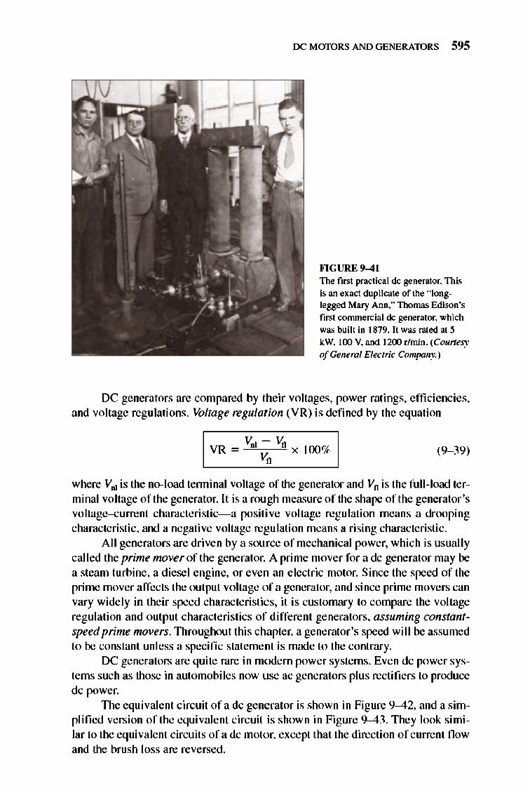
rx: MmDRS AND GENERATORS 595
FI GURE 9-41 The first practical dc generator. This is an exact duplicate of the "longlegged Mary Ann." Thomas Edison's first commerdal dc generator. which was built in 1879. It was rated at 5 kW. 100 V. and 1200 r/min. (Courtesy ofGeneml Electric Company.)
DC generators are compared by their voltages, power ratings, efficiencies, and voltage regulations. Voltage regulation (VR) is defined by the equation
I VR = Vol ~ Va x 100% I (9- 39)
where V .. is the no- load tenninal voltage of the generator and VfI is the full- load terminal voltage of the generator. It is a rough measure of the shape of the generator 's voltage-current characteristic-a positive voltage regu lation means a drooping characteristic, and a negative voltage regulation means a rising characteristic.
All generators are driven by a source of mechanical power, which is usually called the prime nwver of the generator. A prime mover for a dc generator may be a steam turbine, a diesel engine, or even an electric motor. Since the speed of the prime mover affects the output voltage of a generator, and since prime movers can vary widely in their speed characteristics, it is customary to compare the voltage regulation and output characteristics of different generators, assuming constantspeed prime movers. Throughout this chapter, a generator's speed wi ll be assumed to be constant unless a specific statement is made to the contrary.
DC generators are quite rare in modern power systems. Even dc power systems such as those in automobi les now use ac generators plus rectifie rs to produce dc power.
The equi valent circuit ofa dc generator is shown in Figure 9-42, and a simplified version of the equivalent circuit is shown in Figure 9-43. They look simi lar to the equivalent circuits ofa dc motor, except that the direction of current fl ow and the brush loss are reversed .
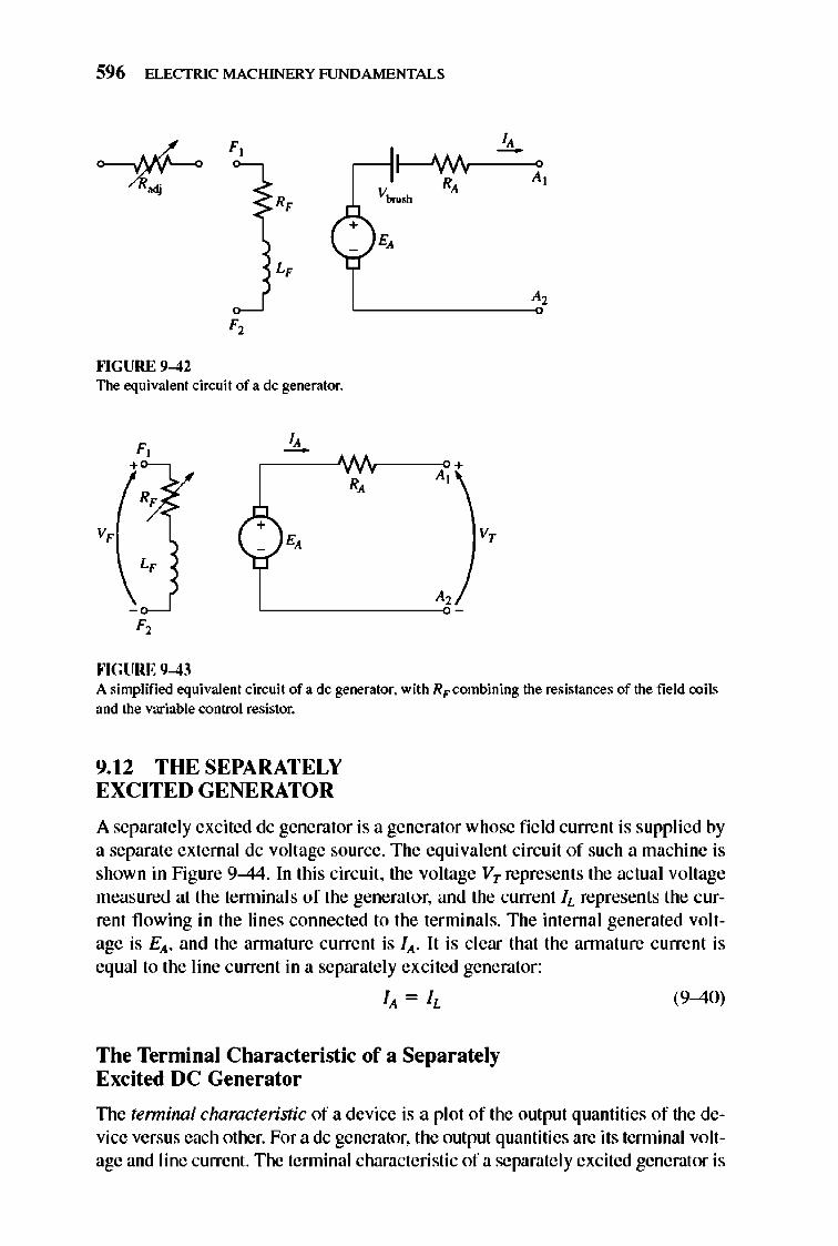
596 ELECTRIC MACHINERY RJNDAMENTALS
+
""GURE 9-42 The equivalent ein:uit of a de generator.
v,
""GURE 9-43
I, -~----AN .. V---A-;>, + R,
v,
A simplified equivale nt ein:uit of a de generator. with RF eombining the resistances of the field coils and the variable control resistor.
9. 12 THE SEPARATELY EXCITED GENERATOR
A separately excited dc generator is a gene rator whose field current is supplied by a separate external dc voltage source. The equivalent circuit of such a machine is shown in Figure 9-44. In this circuit, the voltage VT represents the actual voltage measured at the te nninals of the generato r, and the current II. represents the current flowing in the lines connected to the terminals. The internal generated voltage is Ell, and the armature current is lit- It is clear that the annature c urrent is equal to the line c urrent in a separate ly excited generator:
The Terminal Characteristic of a Separately Excited DC Generator
(9-40)
TIle terminnl characteristic of a device is a plot of the output quantities of the device versus each other. For a dc generator, the output quantities are its tenninal voltage and line current. llle tenninal characteristic of a separate ly excited generator is
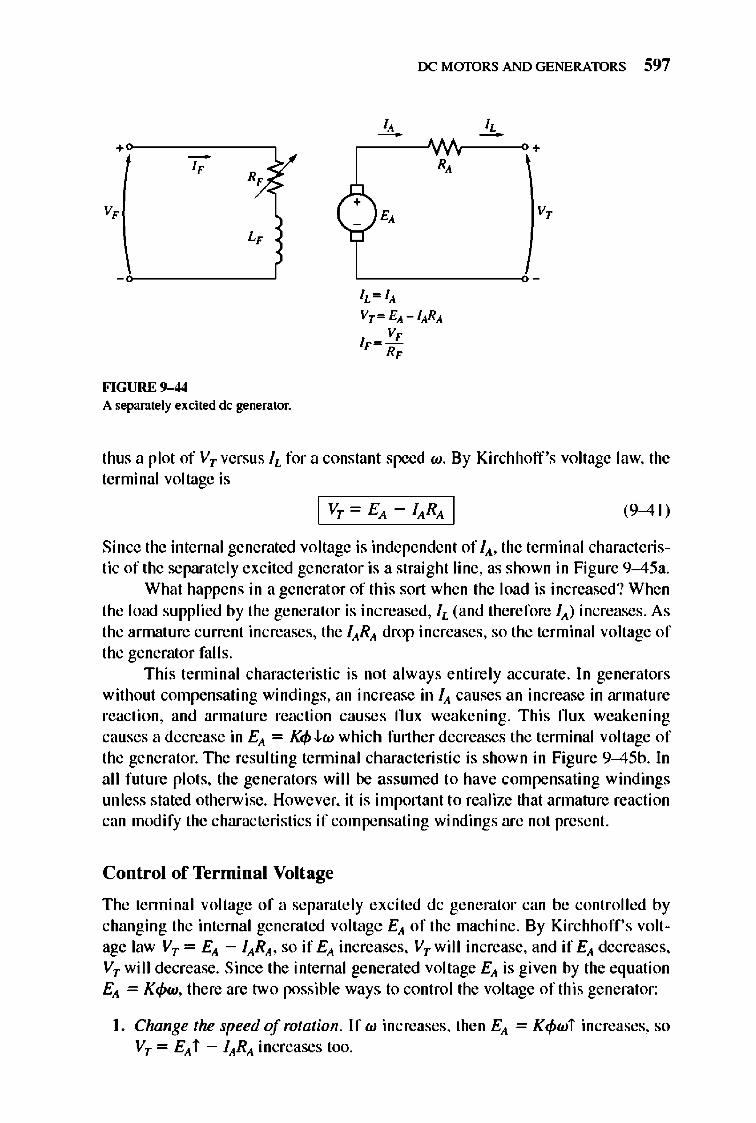
rx: MmDRS AND GENERATORS 597
I, -,-----".fII'V--~+
+ v,
FIGURE 9-44 A separate ly excited de generator.
thus a plot of VT versus IL for a constant speed w. By Kirchhoff 's voltage law, the terminal voltage is
(9-41)
Since the internal generated voltage is independent of lA, the tenninal characteristic of the separate ly excited generator is a straight line, as shown in Figure 9-45a.
What happens in a generat or of this sort when the load is increased? When the load supplied by the generator is increased, IL (and therefore IA) increases. As the annature current increases, the lARA drop increases, so the terminal voltage of the generator falls.
This tenninal characteristic is not always entirely accurate. In generators without compensating windings, an increase in IA causes an increase in armature reaction, and armature reaction causes flux weakening. This flux weakening causes a decrease in EA = K<p J..w which further decreases the tenninal voltage of the generator. TIle resulting tenninal characteristic is shown in Figure 9-45b. In all future plots, the generators will be assumed to have compensating windings unless stated otherwise. However, it is important to realize that annature reaction can modify the characteristics if compensating windings are not present.
Control of Terminal Voltage
The tenninal voltage of a separately excited dc generator can be controlled by changing the internal generated voltage EA of the machine. By Kirchhoff's voltage law VT = EA - lARA, so if EA increases, VT will increase, and if EA decreases, VT will decrease. Since the internal generated voltage EA is given by the equation EA = K<pw, there are two possible ways to control the voltage of this generator:
I. Change the speed of rotation. If w increases, then EA = K<pwi increases, so VT = EA i - lARA increases too.
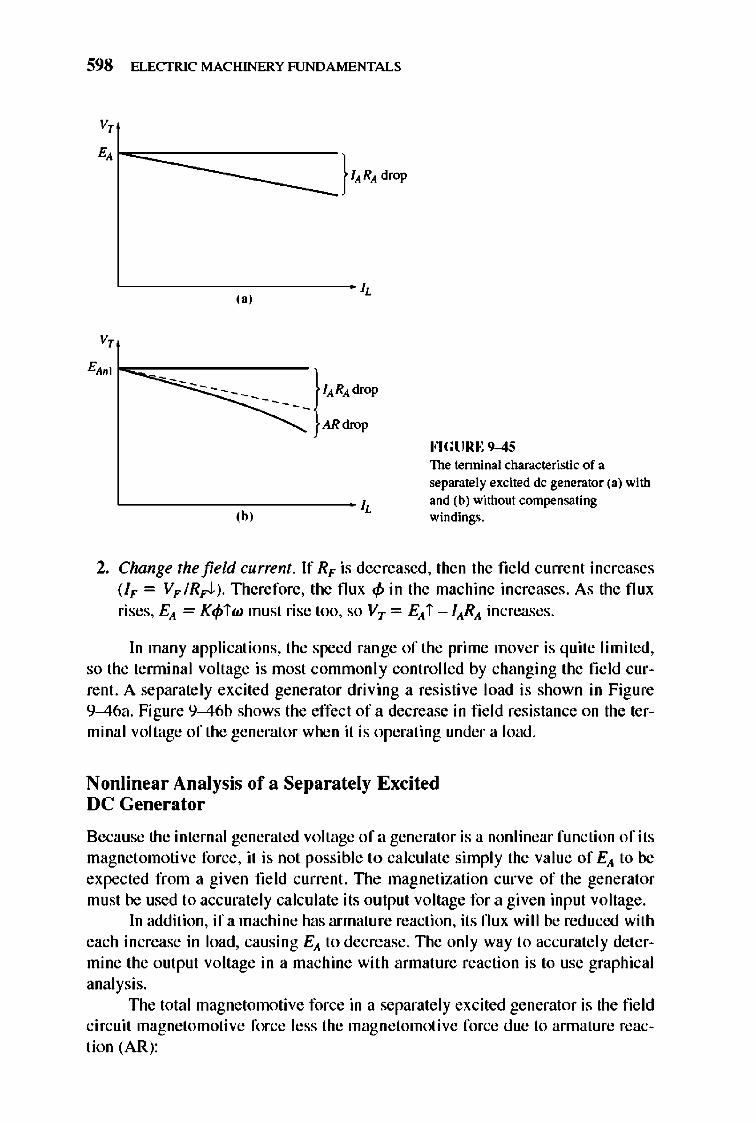
598 ELECTRIC MACHINERY RJNDAMENTALS
V,
E, 1:::::::::::::::::=====I"R, drop
v,
"--------------------- ~ ,,'
---------- l"R'drop -----ARdrop
"----------cc--------- ~ ,b,
FlGURE 9-45 The terminal characteristic of a separately excited dc generator (a) with and (b) without compensating windings.
2. Change the field current. If RF is decreased. then the field current increases (IF = VF IR~) TIlerefore, the nux <f.> in the machine increases . As the nux rises, EA = K<f.>iw must rise too, so VT = EA i -lARA increases.
In many applications, the speed ran ge of the prime mover is quite limited, so the tenninal voltage is most commonly controlled by changing the field current. A separate ly excited generator driving a resistive load is shown in Figure 9-46a. Figure 9-46b shows the effect of a decrease in fie ld resistance on the terminal voltage of the generator when it is operating under a load.
Nonlinear Analysis of a Separately Excited DC Generator
Because the internal generated voltage of a generator is a nonlinear function of its magnet omotive force, it is not possible to calculate simply the value of EA to be expected from a given fie ld current. TIle magnetization curve of the generator must be used to accurately calculate its output voltage for a given input voltage.
In addition, if a machine has armature reaction, its nux will be reduced with each increase in load, causing EA to decrease. TIle only way to accurately determine the output voltage in a machine with annature reaction is to use graphical analysis.
TIle total magnetomotive force in a separately excited generator is the field circuit magnetomotive force less the magnetomoti ve force due to annature reaction (AR):
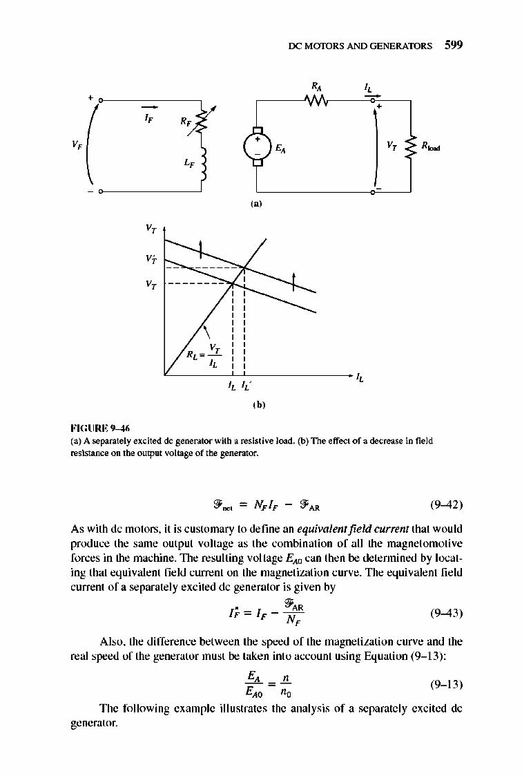
+
v,
FIGURE 9-46
I,
v,
v' ,
R,
L,
( ?-1
(a)
VT -------- "~"-
\
'bJ
rx: MmDRS AND GENERATORS 599
R, I,
+
E, v, R~
(a) A separately excited de generator with a resistive load. (b) The effect of a decrease in field resistance on the output voltage of the generator.
(9-42)
As with de motors, it is customary to define an equivalent field current that would produce the same output voltage as the combination of all the magnetomotive forces in the machine. The resulting voltage EAO can then be detennined by locating that equivalent field current on the magnetization curve. The equivalent field current of a separate ly excited de generator is given by
• "'AR IF=IF-N F
(9-43)
Also, the difference between the speed of the magnetization curve and the real speed of the generator must be taken int o account using Equation (9- 13) :
EA _!!.. EAO no
(9- 13)
The fo llowing example illustrates the analysis of a separate ly excited de generator.
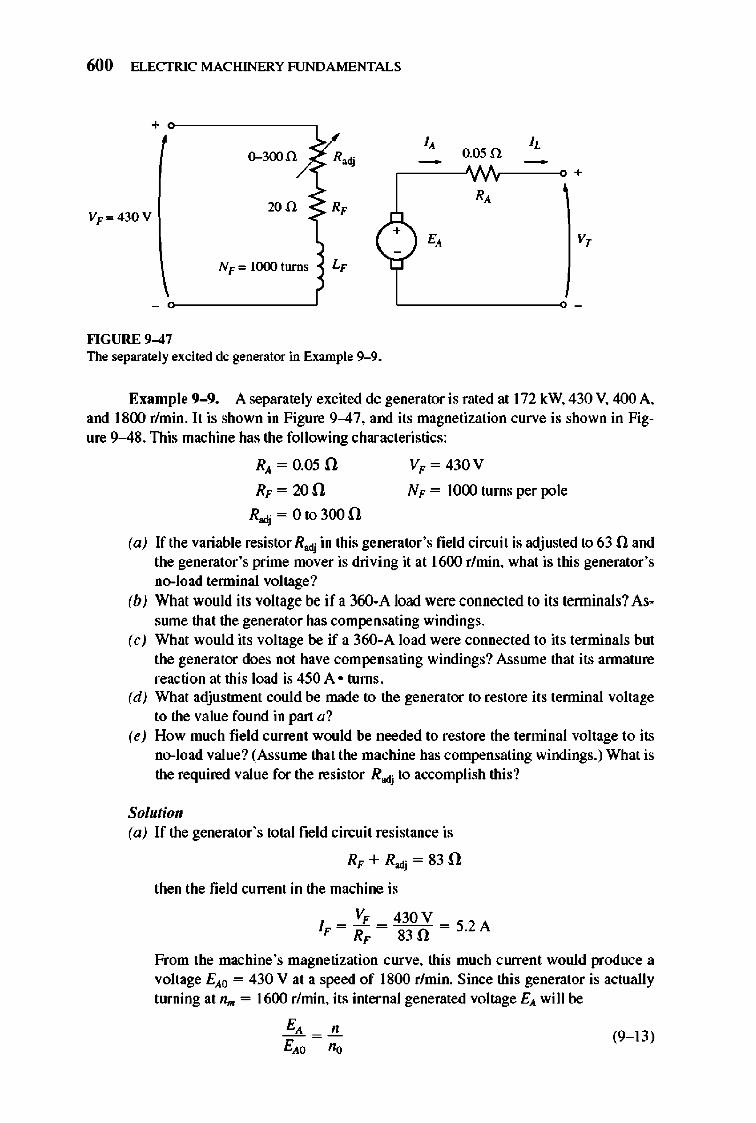
600 ELECTRIC MACHINERY RJNDA MENTALS
+
v" .. I, 0.05.n
I, 0-300.\1 ~
+
20fi R, R,
VF", 430 V (+) E, V,
NF",!()(Xlturns L,
""GURE 9-47 The separately excited dc generator in Example 9--9.
Example 9-9. A separately excited dc generator is rated at 172 kW. 430 V. 400 A. and 1800 r/min.1t is shown in Figure 9-47. and its magnetization curve is shown in Figure 9-48 . This machine has the following characteristics:
RA = 0.05 n RF = 20 n
Rodj = Ot03oo n
VF = 430V
NF = J()(X) turns per pole
(a) If the variable resistor Rodj in this generator 's field circuit is adjusted to 63 n and the generator 's prime mover is driving it at 1600 rlmin, what is this generator 's no-load tenninal voltage?
(b) What would its voltage be if a 360-A load were connected to its tenninals? Asswne that the generator has compensating windings.
(c) What would its voltage be if a 360-A load were connected to its terminals but the generator does not have compensating windings? Asswne that its annature reaction at this load is 450 A · turns.
(d ) What adjustment could be made to the generator to restore its tenninal voltage to the value found in part a?
(e) How much field current would be needed to restore the terminal voltage to its no-load value? (Assume that the machine has compensating windings.) What is the required value for the resistor R ..Jj to accomplish this?
Solutio" (a) If the generator 's total field circuit resistance is
RF + R ..Jj = 83 n
then the fi eld current in the machine is
VF 430 V IF = RF = 83 n = 5.2 A
From the machine's magnetization curve, this much current would produce a voltage EAO = 430 V at a speed of 1800 r/min. Since this generator is actually turning at n .. = 1600 rlmin, its internal generated voltage EA will be
E, " = (9- 13)
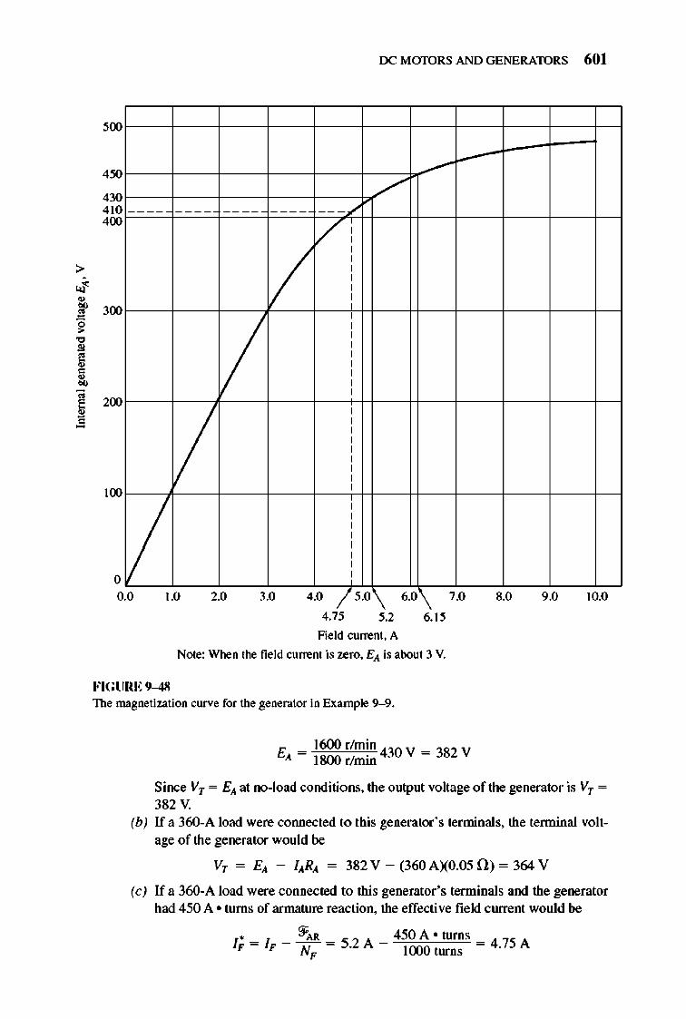
500
450
430 410 400
300
200
100
o
II
rx: M mDRS AND GENERATORS 601
/'
/
V
0.0 1.0 2.0 3.0 4.0 /5.0 6.0 7.0 8.0 9.0 10.0
4.75 5.2 6.15
Field current. A
Note: When the field current is zero, E" is about 3 V.
FIGURE 9-48 The magnetization curve for the generator in Example 9--9.
E = 1600 r/m~n 430 V = 382 V " 1800 r/mm
Since Vr = E" at no-load conditions, the output voltage of the generator is Vr = 382 V.
(b) If a 360-A load were cotUlected to this generator's terminals, the tenninal voltage of the generator would be
Vr = E" - I"R" = 382 V - (360 AXO.05 0 ) = 364 V
(c) If a 360-A load were connected to this generator 's terminals and the generator had 450 A ° turns of armature reaction, the effective field current would be
1* = I _ ~AR = S.2 A _ 450A o turns = 4 .75A F F N F J(X)() turns
602 ELECTRIC MACHINERY RJNDAMENTALS
From the magnetization curve, EAO = 410 V, so the internal generated voltage at 1600 rlmin would be
= EAO no
E = 1600 r/m~n 410 V = 364 V A 1800 r/mlll
Therefore, the tenninal voltage of the generator would be
Vr = EA - lARA = 364 V - (360 AXO.05 0) = 346 V
It is lower than before due to the annature reaction.
(9-13)
(d) The voltage at the tenninals of the generator has fallen, so to restore it to its original value, the voltage of the generator must be increased. This requires an increase in EA, which implies that R..tj must be decreased to increase the field current of the generator.
(e) For the terminal voltage to go back up to 382 V, the required value of EA is
EA = Vr + lARA = 382 V + (360 AXO.05 0) = 400 V
To get a voltage EA of 400 V at n .. = 1800 rlmin would be
1600 rlmin, the equivalent voltage at
EA _ .!!. (9-13)
E = 18oor/m~n 400 V = 450 V AO 1600 r/mlll
From the magnetization curve, this voltage would require a field current of IF = 6.15 A. The field circuit resistance would have to be
V, RF + Radj = T ,
430V 200 + Radj = 6.15A = (:f).90
Radj = 49.90 - 500
Notice that, for the same field current and load current, the generator with annature reaction had a lower output voltage than the generator without annature reaction. The annature reaction in this generator is exaggerated to illustrate its effects- it is a good deal smaller in well-designed modem machines .
9.13 THE SHUNT DC GE NERATOR
A shunt dc generator is a de generator that supplies its own field current by having its field connected directly across the terminals of the machine. The equi valent circuit of a shunt dc generator is shown in Figure 9-49. In this circuit, the armature current of the machine supplies both the field circuit and the load attached to the machine:
(9-44)
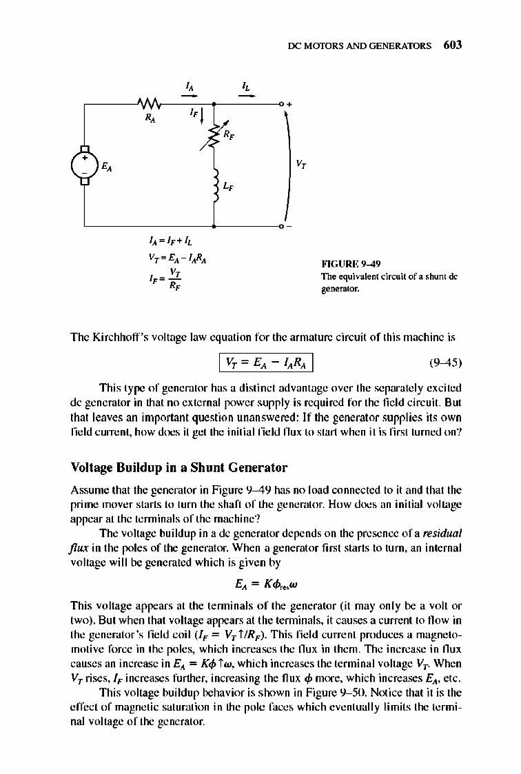
+ E,
I,
" -R, "1
/.
IA = IF+h
Vr = EA - lARA
V, IF = -
R,
I, -v.,
L,
rx: MmDRS AND GENERATORS 603
+
v,
HGURE 9-49 The equivalent circuit of a shunt de generator.
The Kirchhoff 's voltage law equation for the armature circuit of this machine is
(9-45)
Thi s type of generator has a distinct advantage over the separate ly excited dc generator in that no external power supply is required for the fie ld circuit. But that leaves an important question unanswered: If the generat or supplies its own field current, how does it get the initial field nux to start when it is first turned on?
Voltage Build up in a Shunt Gener ator
Assume that the generator in Figure 9-49 has no load connected to it and that the prime mover starts to turn the shaft of the generator. How does an initial voltage appear at the terminal s of the machine?
The voltage buildup in a dc generator depends on the presence ofa residual flux in the poles of the generator. When a generat or first starts to turn, an internal voltage will be generated which is given by
EA = K<Pre.w
This voltage appears at the tenninals of the generator (it may only be a volt or two) . But when that voltage appears at the tenninals, it causes a current to fl ow in the generator 's field coil (IF = Vr i /RF). Thi s fi e ld current produces a magnetomotive force in the poles, which increases the nux in them. 1lle increase in nux causes an increase in EA = K<p iw, which increases the terminal voltage Vr. When Vr rises, IF increases further, increasing the fl ux <p more, which increases EA, etc.
This voltage buildup behavior is shown in Figure 9- 50. Notice that it is the effect of magnetic saturation in the pole faces which eventually limits the terminal voltage of the generator.
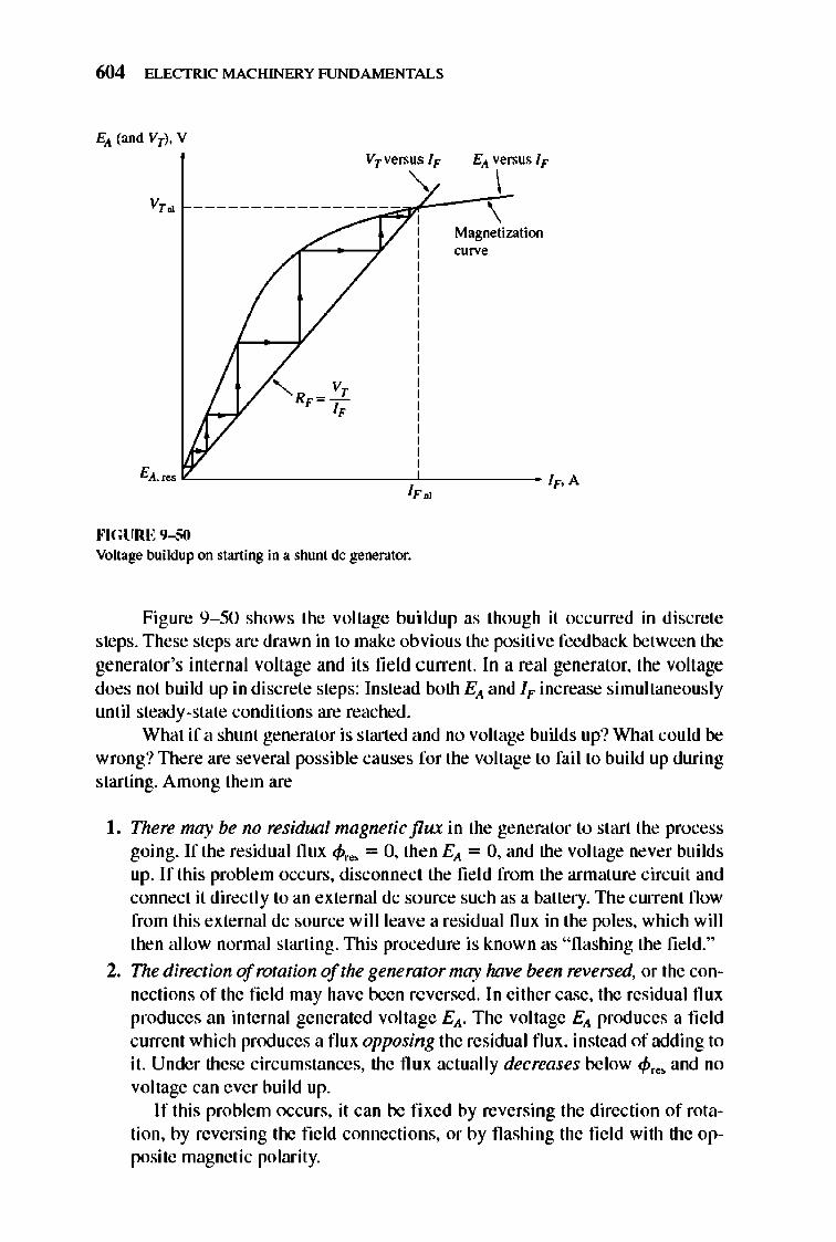
604 ELECTRIC MACHINERY RJNDAMENTALS
EA (and VT), V
v,. VTversus IF EA versus IF
" \ --------------~--1""--?f__\\ Magnetization curve
EA, res "------------~------ IF' A IF "
""GURE 9-50 Voltage buildup on starting in a shunt dc generator,
Figure 9-50 shows the voltage buildup as though it occurred in di screte steps, These steps are drawn in to make obvious the positive feedback between the generator's internal voltage and its field current. In a real generator, the voltage does not build up in discrete steps: Instead both E A and IF increase simultaneously until steady-state conditions are reached,
What if a shunt generator is started and no voltage builds up? What could be wrong? nlere are several possible causes for the voltage to fail to build up during starting, Among them are
L There may be no residual magnetic flux in the generator to start the process going, If the residual flux ~re. = 0, then E A = 0, and the voltage never builds up, If this problem occurs, disconnect the fi e ld from the armature circuit and connect it directly to an external dc source such as a battery, 1lle current fl ow from this external dc source will leave a residual flux in the poles, which will then allow normal starting, nlis procedure is known as "flashing the fie ld,"
2. The direction of rotation of the generator may have been reversed, or the connections of the field may have been reversed, In either case, the residual flux produces an internal generated voltage EA, The voltage EA produces a field current which produces a flu x opposing the residual flu x, instead of adding to it. Under these circumstances, the flux actually decreases below ~r •• and no voltage can ever build up,
If this problem occurs, it can be fixed by reversing the direction of rotation, by reversing the field connections, or by flashing the fie ld with the opposite magnetic polarity,
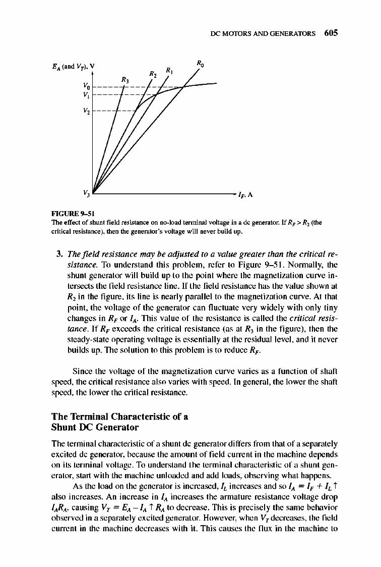
v" v,
v,
R,
rx: MmDRS AND GENERATORS 605
~ '------------------------------ /F.A
FIGURE 9-5 1 The elTect of shunt fietd resistance on no-load tenninal voltage in a dc generator. If Rr > Rl (the critical resistance). then the generator's voltage will never build up.
3. The field resistance may be adjusted to a value greater than the critical resistance. To understand this problem, refer to Figure 9- 51. Nonnally, the shunt generator will build up to the point where the magnetization curve intersects the fie ld resistance line. If the fie ld resistance has the value shown at Rl in the fi gure, it s line is nearly parallel to the magnetization curve. At that point, the voltage of the generator can fluctuate very widely with only tiny changes in RF or lit. nlis value of the resistance is called the critical resistance. If RF exceeds the critical re sistance (as at R3 in the fi gure), then the steady-state operating voltage is essentially at the residual leve l, and it never builds up. The solution to this prob lem is to reduce Rr .
Since the voltage of the magnetization curve varies as a function of shaft speed, the critical resistance also varies with speed. In general, the lower the shaft speed, the lower the critical resistance.
The Terminal Characteristic of a Shunt DC Generator
The terminal characteristic of a shunt dc generator differs from that of a separately excited dc generator, because the amou nt of field current in the machine depends on its terminal voltage . To understand the terminal characteristic of a shunt generator, start with the machine unl oaded and add loads, observing what happens.
As the load on the generator is increased, II- increases and so lit = IF + IL i also increases. An increase in lit increases the annature resistance voltage drop IItRIt, causing Vr = Elt - l it i RIt to decrease. This is precisely the same behavior observed in a separately excited generat.or. However, when Vr decreases, the field current in the machine decreases with it. This causes the flux in the machine to
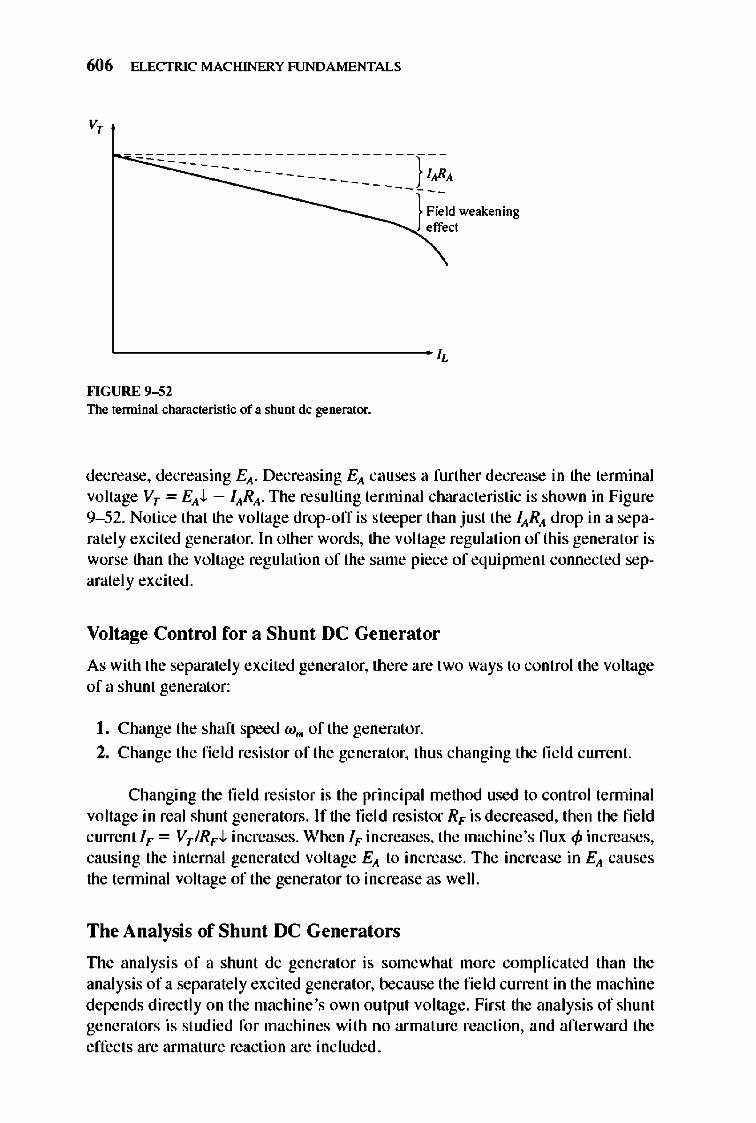
606 ELECTRIC MACHINERY RJNDAMENTALS
v,
---=::---===--------------}-:~A
---I-;i:Id weakening
effect
L-____________________________ ~
""GURE 9-52 The terminal characteristic of a shunt dc generator.
decrease, decreasing EA- Decreasing EA causes a further decrease in the terminal voltage Vr = EAJ.. - lARA' TIle resulting terminal characteristic is shown in Figure 9-52. Notice that the voltage drop-off is steeper than just the lARA drop in a separately excited generator. In other words, the voltage regulation of this generator is worse than the voltage regulation of the same piece of equipment connected separatelyexcited.
Voltage Control for a Shunt DC Generator
As with the separate ly excited generator, there are two ways to control the voltage of a shunt generator:
I . Change the shaft speed W m of the generator.
2. Change the field resistor of the generator, thus changing the field current.
Changing the field resistor is the principal method used to control tenninal voltage in real shunt generators. If the field resistor RF is decreased, then the field c urrent IF = Vr IRFJ.. increases. When IF in creases, the machine's flu x <P increases, causing the inte rnal generated voltage EA to increase. The increase in EA causes the tenninal voltage of the generator to increase as well.
The Analysis of Shunt DC Generators
TIle analysis of a shunt dc generator is somewhat more complicated than the analysis of a separate ly excited generator, because the field current in the machine depends directly on the machine 's own output voltage. First the analysis of shunt generators is studied for machines with no armature reaction, and afterward the effects are annature reaction are included .
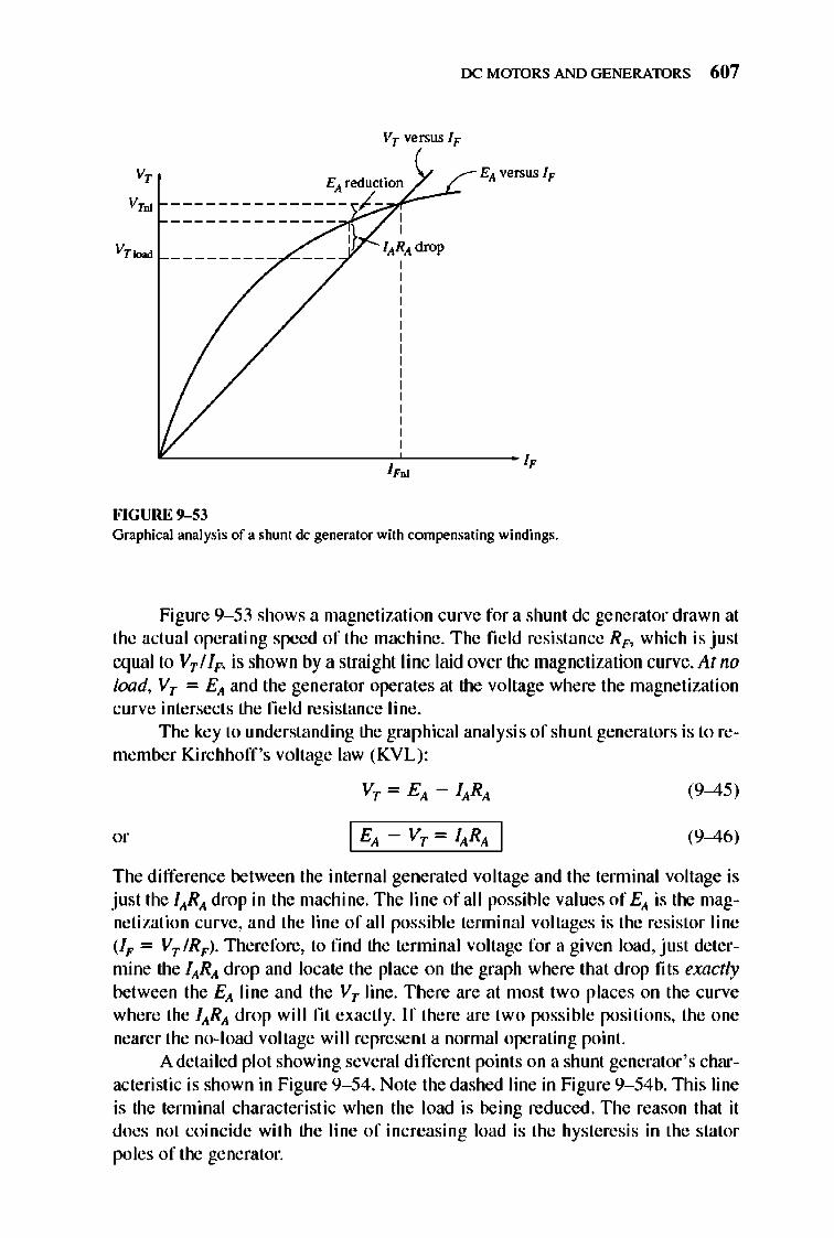
rx: MmDRS AND GENERATORS 607
v, V,.
V,~
VT versus IF
EA reduction --------------- >6/-r~ , ,
EA versus IF
'-________________ -.L-________ ~ 11'01
FIGURE 9-53 Graphical ana lysis of a shunt dc generator with contpensating windings.
Figure 9- 53 shows a magnetization curve for a shunt dc generator drawn at the actual operating speed of the machine . The field resistance RF> which is just equal to VTIIF> is shown by a straight line laid over the magnetization curve. At no load, VT = E A and the generator operates at the voltage where the magnetization curve intersects the field resistance line.
The key to understanding the graphical analysis of shunt generators is to remember Kirchhoff 's voltage law (KVL):
(9-45)
(9-46)
The difference between the internal generated voltage and the tenninal voltage is just the lARA drop in the machine. The line of a 11 possible values of EA is the magnetization curve, and the line of all possible tenninal voltages is the resistor line (IF = VT IRF)· Therefore, to find the tenninal voltage for a given load, just determine the lARA drop and locate the place on the graph where that drop fit s exactly between the E A line and the V T line . There are at most two places on the curve where the lARA drop will fit exactly. If there are two possible positions, the one nearer the no-load voltage will represent a normal operating point.
A detailed plot showing several di fferent points on a shunt generator 's characteristic is shown in Figure 9- 54. Note the dashed line in Figure 9- 54b. lllis line is the terminal characteri stic when the load is being reduced. llle reason that it does not coincide with the line of increasing load is the hysteresis in the stator poles of the generator.
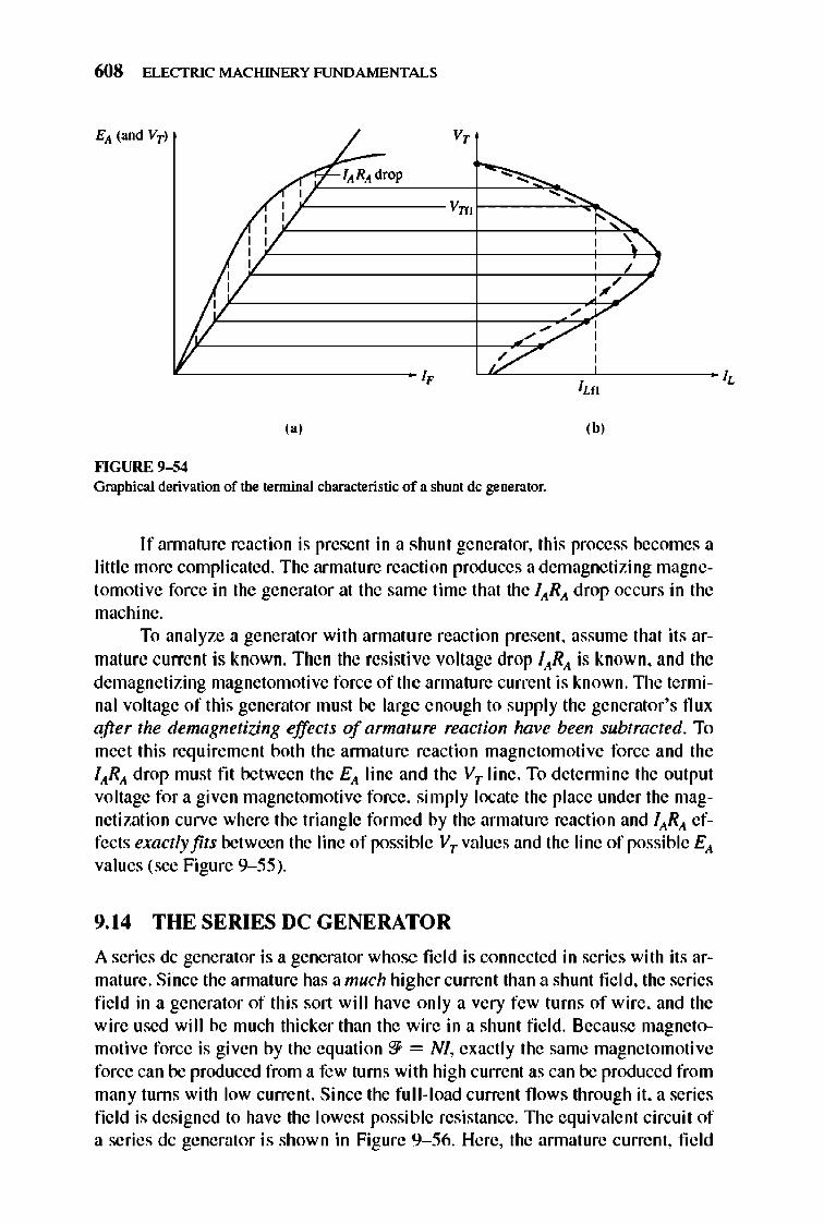
608 ELECTRIC MACHINERY RJNDAMENTALS
, L V,
1. lARA drop -- -I V VIT> -~
, :; , ,". , , ,
I ,
1".// VV /
/,/ /// , ,
~ ,/ , ,
I,
,,' ,b, ""GURE 9-54 Graphical derivation of the terminal characteristic of a shunt dc generator.
If annature reaction is present in a shunt generator, this process becomes a little more complicated. The armature reaction produces a demagnetizing magnetomotive force in the generator at the same time that the lARA drop occurs in the machine.
To analyze a generator with annature reaction present, assume that its armature current is known. Then the resistive voltage drop lARA is known, and the demagnetizing magnetomotive force of the annature current is known.1lle tenninal voltage of this generator must be large enough to supply the generator's nux after the demagnetizing effects of armature reaction have been subtracted. To meet this requirement both the annature reaction magnetomotive force and the lARA drop must fit between the Ell. line and the VT line. To detennine the output voltage for a given magnetomotive force, simply locate the place under the magnetization curve where the triangle formed by the armature reaction and lARA effects exactly fits between the line of possible VT values and the line of possible Ell. values (see Figure 9-55).
9. 14 THE SERIES DC GENERATOR
A series dc generator is a generator whose fi e ld is connected in series with its armature. Since the annature has a much higher current than a shunt fie ld, the series fie ld in a generator of this sort will have only a very few turns of wire, and the wire used will be much thicker than the wire in a shunt fie ld. Because magnetomoti ve force is given by the equation'?} = NI, exactly the same magnetomoti ve force can be produced from a few turns with high current as can be produced from many turns with low current. Since the fu ll-load current fl ows through it, a series field is designed to have the lowest possible resistance. 1lle equivalent circuit of a series dc generator is shown in Figure 9-56. Here, the annature current, field
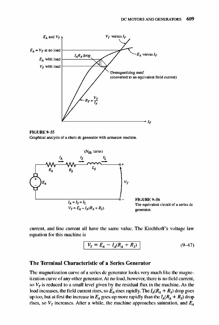
rx: MmDRS AND GENERATORS 609
Ell. '" Vr at no load r ---------:;::'J ......... C lARA drop
Ell. with load r---"-''----'-''<;::/lr( Ell. versus IF
Vr with load f------y"-"'k;Y Demagnetizing mmf (converted to an equivalent field current)
'-------------------------- ~
FIGURE 9-55 Graphical analysis of a shunt dc generator with annature reaction.
(NSF. turns)
+ v,
HGURE 9-S6 111. "' ls"'IL
Vr",EA -IA(RA+Rs) The equivalent circuit of a series dc generator.
c urrenl , and line curre nl all have the same value . The Kirchhoff 's voltage law equation for this machine is
(9-47)
The Terminal Characteristic of a Series Generator
The magnetization curve of a series dc generator looks very much like the magnetization curve of any other generator. At no load, however, there is no field current , so Vr is reduced to a small level given by the residual nux in the machine . As the load increases, the field current rises, so E ll. rises rapidly. The iA(RA + Rs) drop goes up too, but at first the increase in Ell. goes up more rapidly than the iA(RA + Rs) drop rises, so Vr increases. After a while, the machine approaches saturation, and Ell.
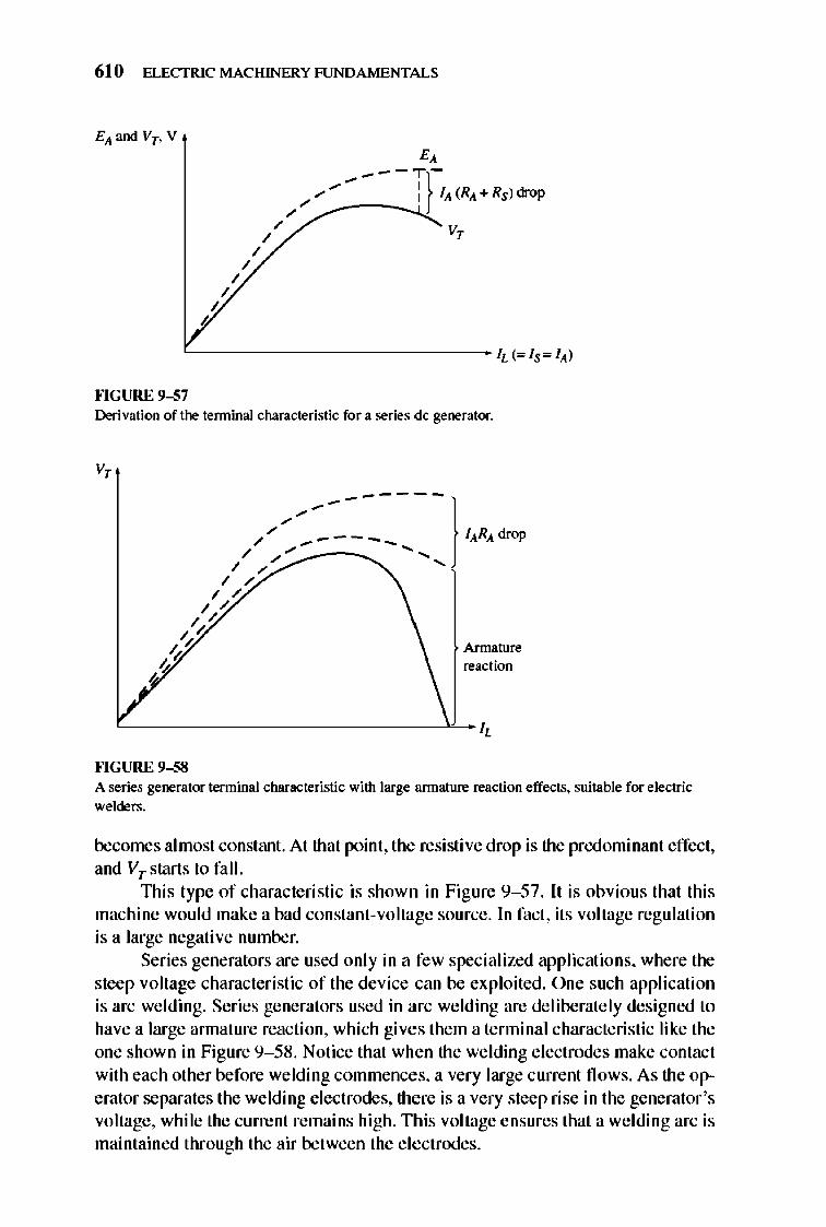
610 ELECTRIC MACHINERY RJNDAMENTALS
/ /
b
/
/ /
~~---T)-/","'" I 111. (RA + Rs) drop
/ / V,
'--------------- h (= Is= 111.)
""GURE 9-57 Derivation of the terminal characteristic for a series dc generator.
V,
Armature reaction
'--____________ -'L-~
""GURE 9-58 A series generator tenninal characteristic with large armature reaction effects. suitable for electric welders.
becomes almost constant. At that point, the resistive drop is the predominant effect, and VT starts to fall.
lllis type of characteristic is shown in Figure 9- 57. It is obvious that thi s machine would make a bad constant-voltage source. In fact, its voltage regulation is a large negative number.
Series generators are used only in a few specialized applications, where the steep voltage characteristic of the device can be exploited. One such application is arc welding. Series generators used in arc welding are deliberately designed to have a large annature reaction, which gives them a terminal characteristic like the one shown in Figure 9- 58. Notice that when the welding electrodes make contact with each other before welding commences, a very large current flows. As the operator separates the welding electrodes, there is a very steep rise in the generator 's voltage, while the current remains high. This voltage ensures that a welding arc is maintained through the air between the e lectrodes.
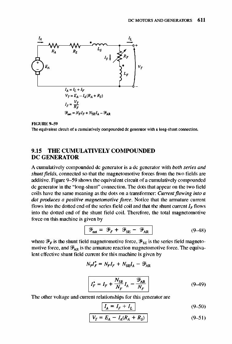
OCMmDRSANDGENERATORS 611
+
FIGURE 9-59
IIt "'h+IF
vT '" Elt -11t(RIt + Rsl
v, IF"'1fF
:¥ .... '" NF IF + NSFJIt - ::fAR
• v,
The equivalent cirwit of a cumulatively compounded dc generator with a long-shunt connection.
9.15 THE CUMULATIVELY COMPOUNDED DC GENERATOR
A cumulative ly compounded dc generator is a dc generator with both series and shunt fields, connected so that the magnetomoti ve forces from the two fi e lds are additive. Figure 9- 59 shows the equival ent circuit ofa cumulative ly compounded dc generator in the "long-shunt" connec tion. TIle dots that appear on the two field coil s have the same meaning as the dots on a transfonner: Current flowing into a dot produces a positive magnetomotive force. Notice that the annature current flows into the dotted end of the series field coil and that the shunt current IF flows into the dotted end of the shunt fi e ld coil. Therefore, the total magnet omotive force on thi s machine is given by
(9-48)
where 'ifF is the shunt fi e ld magnetomotive force, 'ifSE is the series field magnetomotive force, and 2FAR is the armature reaction magnetomotive force. The equivalent effective shunt fie ld current for this machine is given by
NFl; = NFIF + NsEJA - 2FAR
The other voltage and current relationships for this generator are
IIA - iF + I, I
(9-49)
(9- 50)
(9- 51)
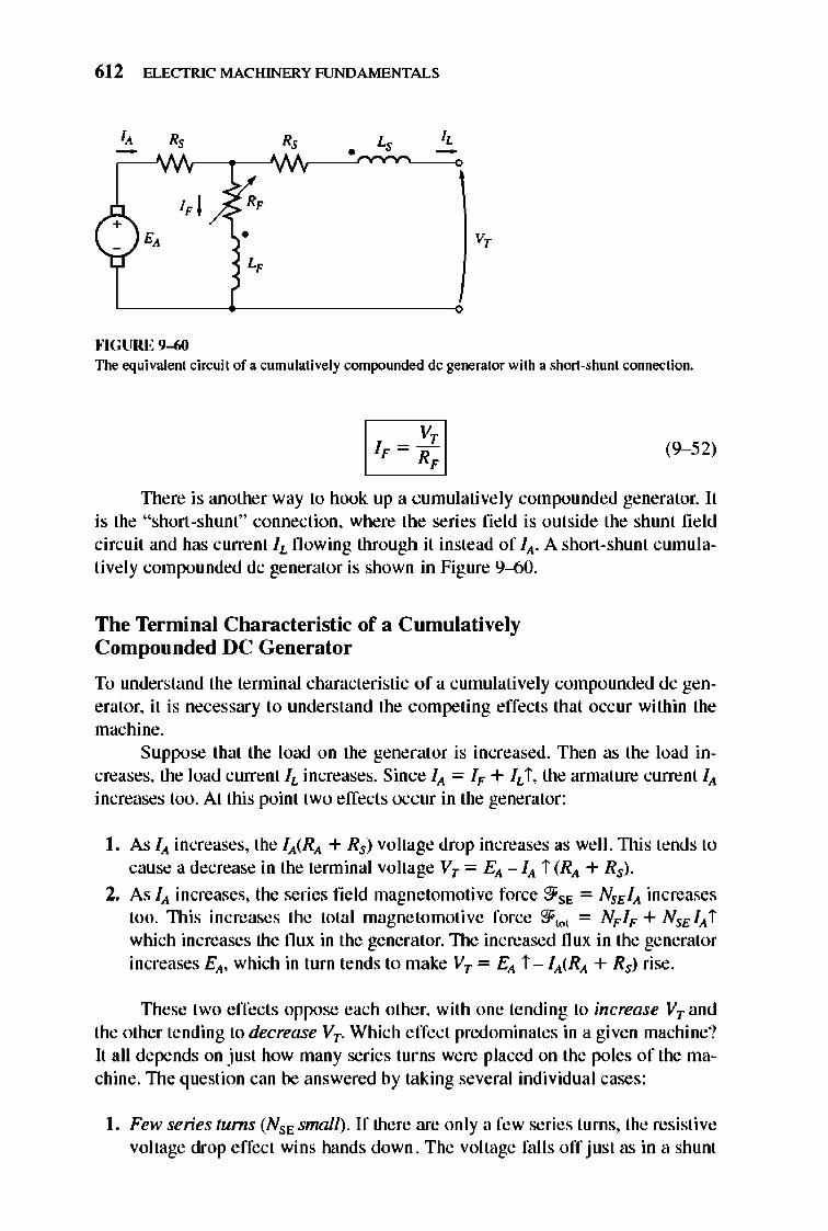
612 ELECTRIC MACHINERY RJNDAMENTALS
•
v,
""GURE 9-60 The equivalent cin;uit of a cumulatively compounded dc generator with a short-shunt connection.
(9- 52)
TIlere is another way to hook up a cumulatively compounded generator. It is the "short-shunt" connection, where the series field is outside the shunt field circuit and has current IL flowing through it instead of I .... A short-shunt cumulatively compounded dc generator is shown in Figure 9-60.
The Terminal Characteristic of a Cumulatively Compounded DC Generator
To understand the terminal characteristic of a cumulatively compounded dc generator, it is necessary to understand the competing effects that occur within the machine.
Suppose that the load on the generat or is increased. Then as the load increases, the load current IL increases. Since IA = IF + IL i , the annature current IA increases too. At this point two effects occur in the generator:
I. As IA increases, the IA(RA + Rs) voltage drop increases as well.1l1is tends to cause a decrease in the terminal voltage VT = EA - IA i (RA + Rs) .
2. As IA increases, the series field magnetomotive force 91'SE = NSEIA increases too. This increases the total magnetomotive force 91"0' = NFIF + NSEIA i which increases the flux in the generator.1l1e increased flux in the generator increases EA, which in turn tends to make VT = EA i - IA(RA + Rs) rise.
TIlese two effects oppose each other, with one tending to increase VT and the other tending to decrease VT . Which effect predominates in a given machine? It all depends on just how many series turns were placed on the poles of the machine. The question can be answered by taking several individual cases :
I. Few series turns (NSE smnll). If there are only a few series turns, the resistive voltage drop effect wins hands down. The voltage falls off just as in a shunt
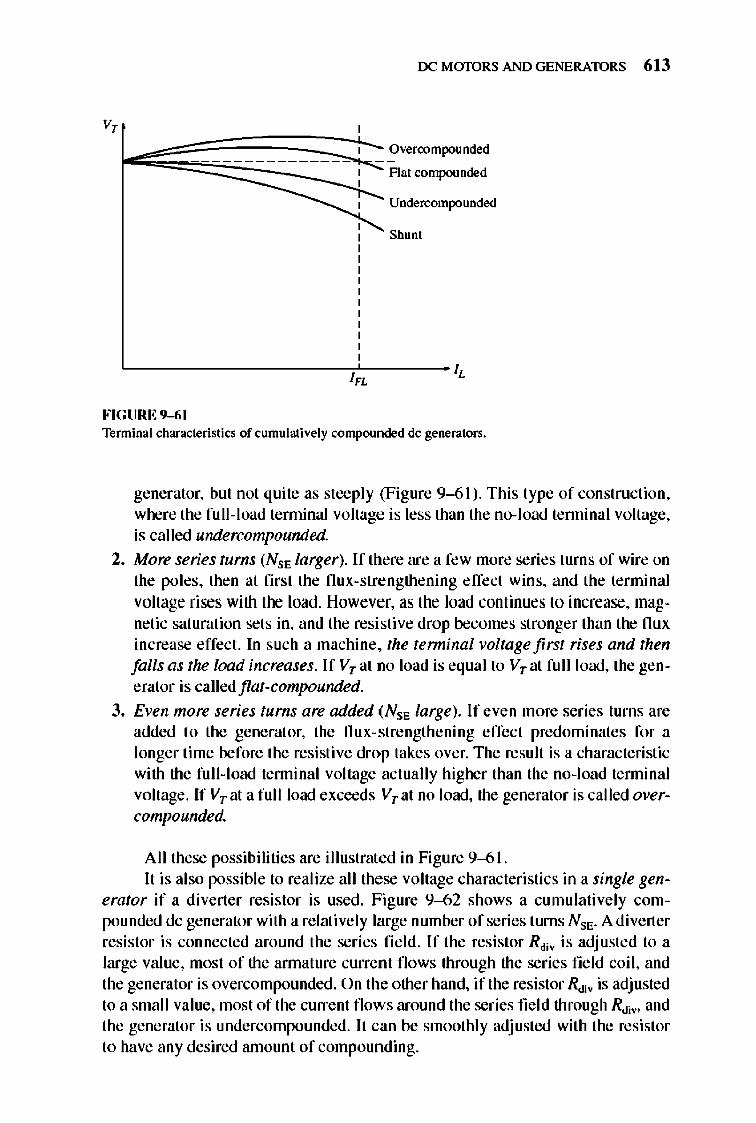
OCMmDRSANDGENERATORS 613
v,
Undercompounded
Shum
L-___________________ /~-------~
" FIGURE 9-61 Terminal characteristics of cumulatively compounded dc generators.
generator, but not quite as steeply (Figure 9--61). This type of construction, where the full-load tenninal voltage is less than the no-load tenninal voltage, is called undercompounded.
2. More series turns (NSE larger). If there are a few more series turns of wire on the poles, then at first the flux-strengthening effect wins, and the terminal voltage rises with the load . However, as the load continues to increase, magnetic saturation sets in, and the resistive drop becomes stronger than the flux increase effect. In such a machine, the terminal voltage first rises and then falls as the load increases. If VT at no load is equal to VTat full load, the generator is called flat-compounded.
3. Even more series turns are added (NSE large). If even more series turns are added to the generator, the flux-strengthening effect predominates for a longer time before the resistive drop takes over. The result is a characteristic with the fu ll-load tenninal voltage actua lly higher than the no-l oad tenninal voltage. If VTat a full load exceeds VTat no load, the generator is called overcompounded.
A ll these possibilities are illustrated in Figure 9--61. lt is also possible to realize all these voltage characteristics in a single gen
erator if a diverter resistor is used . Figure 9--62 shows a cumulatively compounded dc generator with a relatively large number of series turns NSE. A diverter resistor is connected around the series fi e ld. If the resistor Rdh is adjusted to a large value, most of the annature current flows through the series field coil , and the generator is overcompounded. On the other hand, if the resistor RcJjy is adjusted to a small value, most of the current fl ows around the series fie ld through RcJjy, and the generator is undercompounded. lt can be smoothly adjusted with the resistor to have any desired amount of compounding.
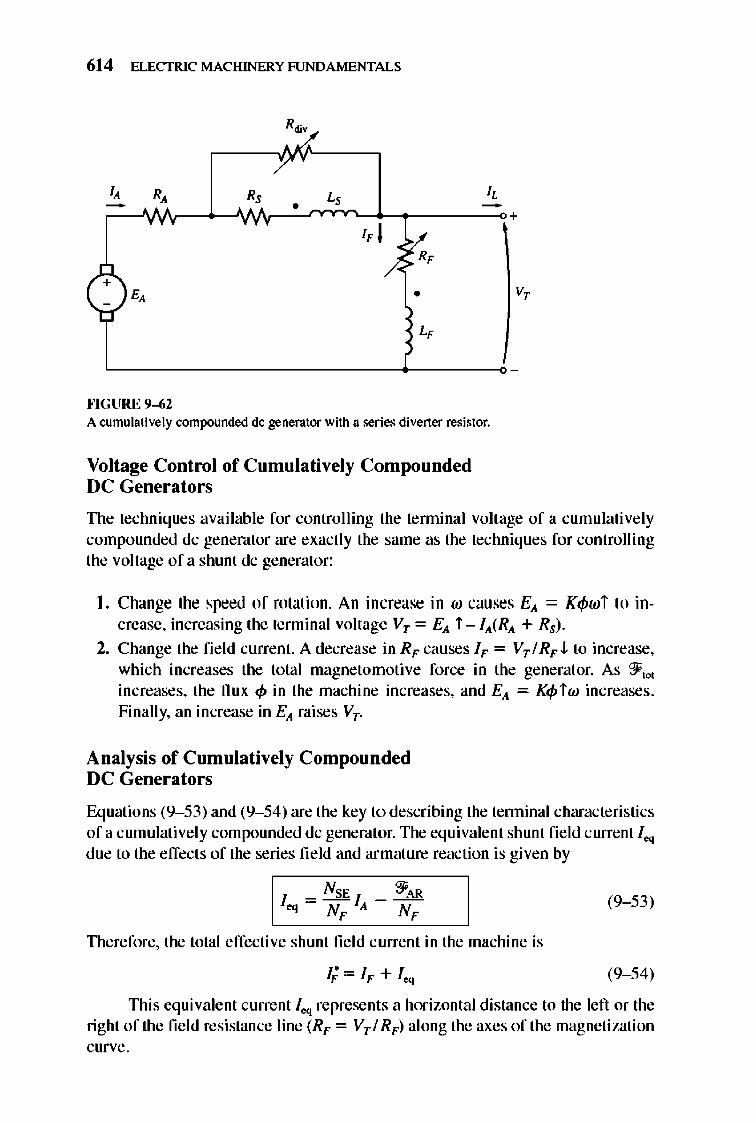
614 ELECTRIC MACHINERY RJNDAMENTALS
"/. Y
I, R, R, L, I, - • -• •
I, I y.:
(+)£, /- R,
•
L,
""GURE 9-62 A cumulatively compounded dc generator with a series diverter resistor.
Voltage Control of Cumulatively Compounded DC Generators
+
v,
-
TIle techniques available for controlling the tenninal volt age of a cumulati vely compounded dc generator are exactly the same as the techniques for controlling the voltage of a shunt dc generator:
I. Change the speed of rotation. An in crease in w causes Ell = KtPwi to increase, increasing the terminal voltage VT = Ell i - IIl(RIl + Rs) .
2. Change the fie ld current. A decrease in RF causes IF = VT I RFJ.. to increase, which increases the total magnetomotive force in the generat or. As ?ft ",
increases, the nux <p in the machine increases, and Ell = KtPiw increases . Finally, an increase in Ell raises VT.
Analysis of Cumulati vely Compounded DC Generators
Equations (9- 53) and (9- 54) are the key to describing the tenninal characteristics of a cumulative ly compounded dc generator. The equivalent shunt fie ld current leq due to the effects of the series field and armature reaction is given by
I
NSE ?fAR leq = NF IA - NF
Therefore, the total effective shunt fi e ld current in the machine is
1;= IF + leq
(9- 53)
(9- 54)
TIlis equivalent current leq represents a horizontal distance to the left or the right of the fi e ld resistance line (RF = VTI RF) along the axes of the magnetization curve.
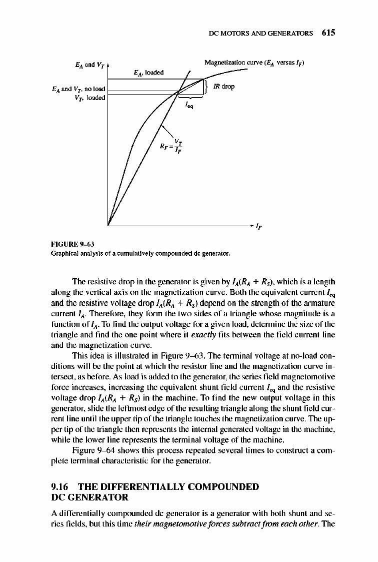
OCMmDRS ANDGENERATORS 6 15
E" and Vr Magnetization curve (E" versus I F)
~ __ ~E~,".~IO~"~~d~ __ ~~", __ -----
E" and Vr . no load 1-::=====7::fi~.=~} IR drop Vr· loaded I
'-------------------------- ~
FIGURE 9-63 Graphica l analysis of a cumulatively compounded dc generator.
The resistive drop in the generator is given by I"(R,, + Rs), which is a length along the vertical ax is on the magnetization curve. Both the equivalent current le<j and the resistive voltage drop I"(R,, + Rs) depend on the strength of the armature current I". 1llerefore, they form the two sides of a triangle whose magnitude is a function of I", To find the output voltage for a given load, detennine the size of the triangle and fmd the one point where it exactly fits between the fie ld current line and the magnetization curve.
This idea is illustrated in Figure 9--63 . 1lle tenninal voltage at no- load conditions will be the point at which the res istor line and the magnetization curve intersect, as before. As load is added to the generator, the series fi eld magnetomotive force increases, increasing the equivalent shunt field current leq and the resistive voltage drop I"(R,, + Rs) in the machine. To find the new output voltage in this generator, slide the leftmost edge of the resulting triangle along the shunt field current line until the upper tip of the triangle touches the magnetization curve. The upper tip of the triangle then represents the internal generated voltage in the machine, while the lower line represents the tenninal voltage of the machine.
Figure 9--64 shows this process repeated several times to construct a complete terminal characteristic for the gene rat or.
9.16 THE DIFFERENTIALLY COMPOUNDED DC GENERATOR
A differentially compounded dc generator is a generator with both shunt and series fi e lds, but this time their magnetomotiveforces subtract from each other. The
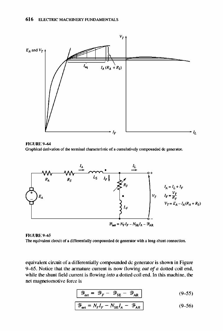
616 ELECTRIC MACHINERY RJNDAMENTALS
v,
L-_________ ~ '------------1,
""GURE 9-64 Graphical derivation of the terminal characteristic of a cumulatively compounded dc generator.
I, I,
" - • +
R, R, L, I, I v.,
/- I" = IL+I,,
+ V, E, • V, 1,,=][; ,
L, Vr = E" - I" (R" + Rsl
""GURE 9-65 The equivalent cin:uit of a differentially compounded dc generator with a long-shunt connection.
equivalenl circuit of a differentially compounded dc generator is shown in Figure 9--65 . Notice that the armature current is now fl owing out of a dotted coil end, while the shunt field current is fl owing into a dotted coil end. In this machine, the net magnetornotive force is
(9- 55)
~AR I (9- 56)
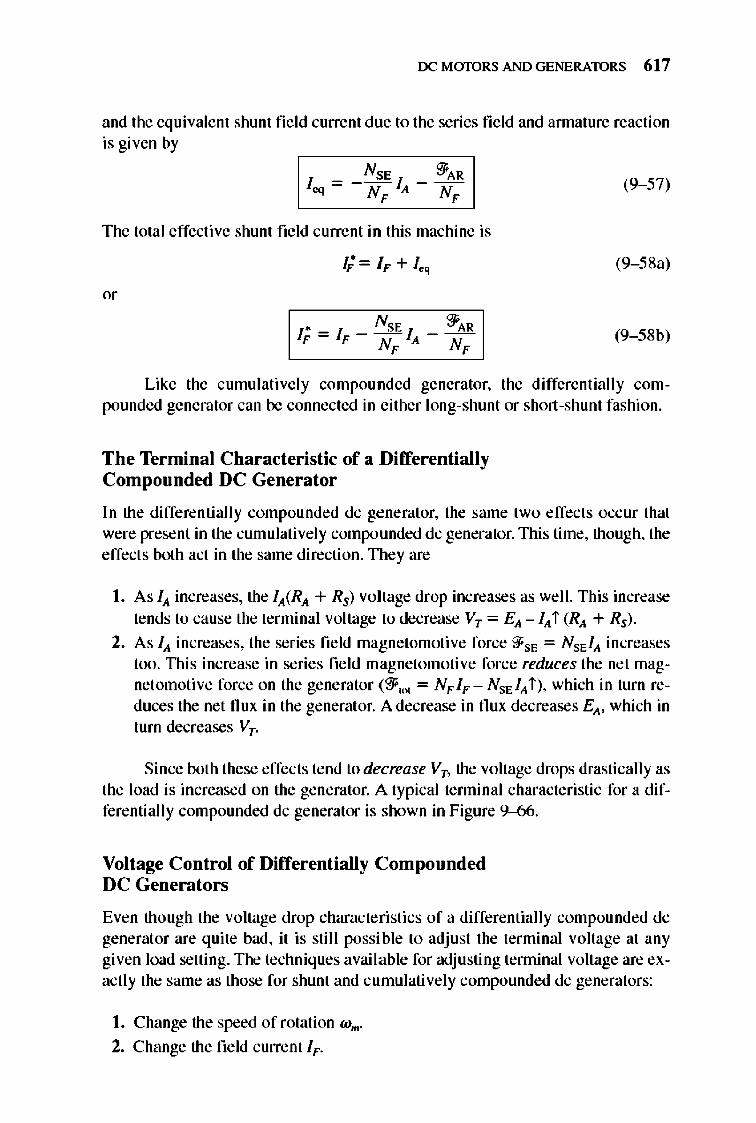
OCMmDRSANDGENERATORS 617
and the equivalent shunt fi e ld current due to the series fi e ld and annature reaction is given by
NSE :fAR leq = - NF IA - -N-
F- (9- 57)
The total effective shunt field current in this machine is
(9- 58a)
(9- 58b)
Like the cumulatively compounded generator, the differentially compounded generator can be connected in either long-shunt or short-shunt fashion.
The Terminal Characteristic of a Differentially Compounded DC Generator
In the differentiall y compounded dc generator, the same two effects occur that were present in the cumulatively compounded dc generator.lltis time, though, the effects both act in the same direction. They are
I. As Iii increases, the lli(RIi + Rs) voltage drop increases as well. This increase tends to cause the terminal voltage to decrease VT = Eli -Iii i (Rli + Rs) .
2. As Iii increases, the series field magnetomotive force '3'SE = NSE IIi increases too. lltis increase in series field magnetomotive force reduces the net magnet omotive force on the generator (2F,OI = NFIF - NSE IIi i ), which in turn reduces the net flux in the generat or. A decrease in flux decreases Eli, which in turn decreases VT.
Since both these effects tend to decrease Vn the voltage drops drastically as the load is increased on the generator. A typical tenninal characte ristic for a differentiall y compounded dc generator is shown in Figure 9-66.
Voltage Control of Differentially Compounded DC Generators
Even though the voltage drop characteristics of a differentially compounded dc generat or are quite bad, it is sti ll possible to adjust the terminal voltage at any given load setting. The techniques avai lable for adjusting tenninal voltage are exactly the same as those for shunt and cumulatively compounded dc generators:
I. Change the speed of rotation W m .
2. Change the field current IF.
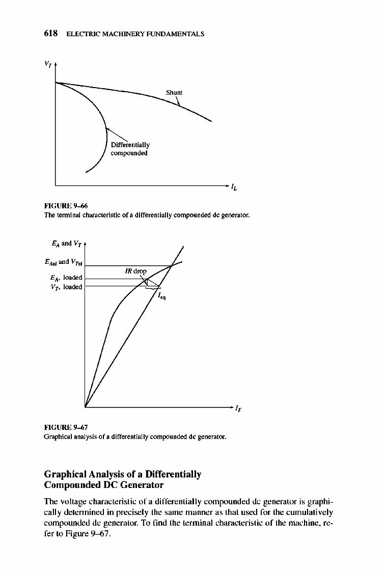
618 ELECTRIC MACHINERY RJNDAMENTALS
v,
Differentially contpounded
Shunt
L--------------_I,
""GURE 9-66 The terminal characteristic of a differentially contpounded dc generator.
EAnJ and Vrnl f------CCCO---7r' IRdrop
EA' loaded f::====::;;2ti¥ Vr. loaded r-
I.,
'--------------1,
""GURE 9-67 Graphical analysis of a differentially contpounded dc generator.
Craphical Analysis of a Differentially Compounded DC Generator
TIle voltage characteristic of a differentiall y compounded dc generator is graphicall y detennined in precisely the same manner as that used for the cumulatively compounded dc generator. To find the terminal characteristic of the machine, refer to Figure 9--67.
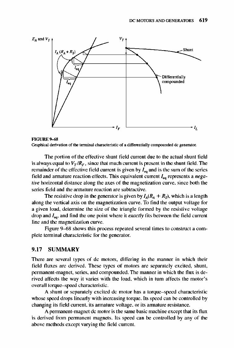
OCMmDRSANDGENERATORS 6 19
v,
1~7"1'----------t----4;- DifferentiallY leq compounded
'---------- l, '------------ l,
FIGURE 9-68 Graphical derivation of the terminal characteristic of a differentially contpounded dc generator.
The portion of the effecti ve shunt fi e ld current due to the actual shunt field is al ways equal to VT IRF , since that muc h current is present in the shunt field. The remainder of the effective fie ld current is given by Ieq and is the sum of the series field and annature reaction effects . This equivalent current 1O<j represents a negative horizontal distance along the axes of the magnetization curve, since both the series fie ld and the armature reaction are subtractive .
The resistive drop in the generator is given by IA(RA + Rs), which is a length along the vertical axis on the magnetization curve. To fmd the output voltage for a given load, detennine the size of the triang le formed by the resistive voltage drop and 1O<j' and find the one point where it exactly fits between the fie ld c urrent line and the magnetization curve.
Figure 9--68 shows this process re peated several times to construct a complete terminal characteristic for the generat or.
9.17 SUMMARY
There are several types of dc motors, differing in the manner in which their field fluxes are deri ved. These types o f motors are separate ly excited, shunt, permanent-magnet, series, and compounded. TIle manner in which the flux is derived affects the way it varies with the load , which in turn affects the motor's overall torque-speed characteristic .
A shunt or separately excited dc motor has a torque- speed characte ristic whose speed drops linearly with increasing torque. Its speed can be controlled by changing its fi e ld current, its annature voltage, or its annature resistance.
A pennane nt-magnet dc motor is the same basic machine except that its flux is derived from pennanent magnets . Its speed can be controlled by any of the above methods except varying the field current.
620 ELECTRIC MACHINERY RJNDAMENTALS
A series motor has the highest starting torque of any dc motor but tends to overspeed at no load. It is used for very high-torque applications where speed regulation is not important, such as a car starter.
A cumulative ly compounded dc motor is a compromise between the series and the shunt motor, having some of the best characteristics of each. On the other hand, a differentially compounded dc mo tor is a complete disaster. It is unstable and te nds to overspeed as load is added to it.
DC generators are dc machines used as generat ors. TIlere are several different types of dc generators, differing in the manner in which their field fluxes are derived. These methods affect the output characteristics of the different types of generators . The common dc generator types are separate ly excited, shunt, series, c umulatively compounded, and differentially compounded.
TIle shunt and compounded dc generators depend on the nonlinearity of their magnetization curves for stable output voltages. If the magnetization curve of a dc machine were a straight line, then the magnetization curve and the tenninal voltage line o f the generator would never intersect. TIlere would thus be no stable no- load voltage for the generator. Since nonlinear effects are at the heart of the generator's operation, the output voltages of dc generators can onl y be determined graphically or numericall y by using a computer.
Today, dc generators have been replaced in many applications by ac power sources and solid-state electronic compone nts. TIlis is true even in the automobi le, which is one of the most common users of dc power.
QUESTIONS
9-1. What is the speed regulation of a dc motor? 9-2. How can the speed of a shunt dc motor be controlled? Explain in detail. 9-3. What is the practical difference between a separately excited and a shunt dc motor? 9-4. What effect does annature reaction have on the torque-speed characteristic of a
shunt dc motor? Can the effects of annature reaction be serious? What can be done to remedy this problem?
9-5. What are the desirable characteristics of the permanent magnets in PMDC machines?
9-6. What are the principal characteristics of a series dc motor? What are its uses? 9-7. What are the characteristics of a cumulatively compOlmded dc motor? 9-8. What are the problems associated with a differentially compounded dc motor? 9-9. What happens in a shlUlt dc motor if its field circuit opens while it is flmning?
9-10. Why is a starting resistor used in dc motor circuits? 9-11. How can a dc starting resistor be cut out of a motor's armature circuit at just the
right time during starting? 9-12. What is the Ward-Leonard motor control system? What are its advantages and
disadvantages? 9-13. What is regeneration? 9-14. What are the advantages and disadvantages of solid-state motor drives compared to
the Ward-Leonard system?
rx: MmDRS AND GENERATORS 621
9-15. What is the pwpose of a field loss relay? 9-16. What types of protective features are included in typical solid-state dc motor drives?
How do they work?
9-17. How can the direction of rotation of a separately excited dc motor be reversed? 9-18. How can the direction of rotation of a shunt dc motor be reversed? 9-19. How can the direction of rotation of a series dc motor be reversed?
9-20. Name and describe the features of the fi ve types of generators covered in this chapter.
9-21. How does the voltage buildup occur in a shunt dc generator during starting? 9-22. What could cause voltage buildup on starting to fail to occur? How can this problem
be remedied? 9-23. How does armature react ion affect the output voltage in a separately excited dc
generator? 9-24. What causes the extraordinarily fast voltage drop with increasing load in a differen
tially compounded dc generator?
PROBLEMS
Problems 9-1 to 9-1 2 refer to the following dc motor:
Prned = 15 hp
Vr=240 V
nrned = 1200 r/min
RA = 0.40 n Rs = 0.04 n
h..,,'od = 55 A
NF = 2700 turns per pole
NSE = 27 turns per pole
RF = 100 0
Rodj = 100 to 400 0
Rotational losses are 1800 W at full load. Magnetization curve is as shown in Figure P9--I. In Problems 9-1 through 9- 7. assrune that the motor described above can be con
nected in shlUlt. The equivalent circuit of the shunt motor is shown in Figure P9-2.
9-1. If the resistor Rodj is adjusted to 175 n what is the rotational speed of the motor at no-load conditions?
9-2. Assuming no annature reaction. what is the speed of the motor at full load? What is the speed regulation of the motor?
9-3. If the motor is operating at full load and if its variable resistance Rodj is increased to 250 n. what is the new speed of the motor? Compare the full -load speed of the motor with Rodj = 175 n to the full-load speed with Rodj = 250 O. (Assume no annature reaction. as in the previous problem.)
9-4. Assume that the motor is operating at full load and that the variable resistor Rodj is again 175 n. If the annature reaction is 1200 A· turns at full load. what is the speed of the motor? How does it compare to the result for Problem 9--2?
9-5. If Rodj can be adjusted from 100 to 400 n. what are the maximum and minimrun noload speeds possible with this motor?
9-6. What is the starting ClUTent of this machine if it is started by connecting it directly to the power supply Vr? How does this start ing current compare to the full -load current of the motor?
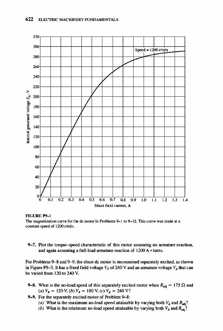
622 ELECTRIC MACHINERY RJNDAMENTALS
>
-' f ~
~ !,
" E • •
320
300 Speed 1200r/min
280
260 V
/'
240
220
V 200
180 / 160
140 / 120
100 / 80
60 / 40
20 / ,II o 0.1 0.2 0.3 0.4 0.5 0.6 0.7 0.8 0.9 1.0 l.l 1.2 1.3 1.4
Shum field currem. A
""GURE 1'9- 1 The masnetization curve for the dc motor in Problems 9--1 to 9- 12. This curve was made at a constam speed of 1200 r/min.
9-7. Plot the torque-speed characteristic of this motor assuming no armature reaction. and again assuming a full-load armature reaction of 1200 A ollU1lS.
For Problems 9--8 and 9-9. the shunt dc motor is reconnected separately excited. as shown in Figure P9- 3. It has a fixed field voltage V I' of 240 V and an annature voltage VA that can be varied from 120 to 240 V.
9-8. What is the no-load speed of this separately excited motor when R>dj = 175 nand (a) VA = 120 V. (b) VA = 180 V. (c) VA = 240 V?
9-9. For the separately excited motor of Problem 9--8: (a) What is the maximwn no-load speed attainable by varying both VA and R>dj? (b) What is the minimwn no-load speed attainable by varying both VA and R>dj?
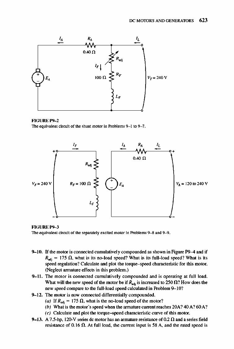
rx: MmDRS AND GENERATORS 623
- -0.4On ~
IF I ~ Rodj
+ lOon Vr = 240 V
FIGURE P9-2 The equiva.lent circuit of the shunt ntotor in Problems 9- 1 to 9- 7.
I, I, R, I, - - " -+ +
0.40 n R.,
+ VF= 240 V RF = 100 n E, VA =120to240V
FIGURE P9-J The equiva.lent circuit of the separately excited motor in Problems 9--8 and 9--9.
9-10. If the motor is connected cumulatively compOlUlded as shown in Figure P9-4 and if R adj = 175 O. what is its no-load speed? What is its full-load speed? What is its speed regulation? Calculate and plot the torque-speed characteristic for this motor. (Neglect annature effects in this problem.)
9- 11. The motor is connected cumulatively compounded and is operating at full load. What will the new speed of the motor be if Radj is increased to 250 O ? How does the new speed compare to the full-load speed calculated in Problem 9--1O?
9-12. The motor is now connected differentially compounded. (a) If Radj = 175 O. what is the no-load speed of the motor? (b) What is the motor's speed when the annature current reaches 20A? 40 A? 60A? (c) Calculate and plot the torque-speed characteristic curve of this motor.
9-13. A 7.5-hp. l20-V series dc motor has an armature resistance of 0.2 0 and a series field resistance of 0.16 O. At full load. the current input is 58 A. and the rated speed is
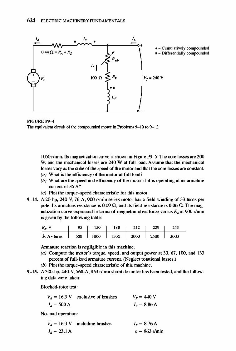
624 ELECTRIC MACHINERY RJNDAMENTALS
O.4411",RA +RS . '" Cumulatively compounded • '" Differentially compounded
+ 100 n VT ", 240 V
••
""GURE 1'9-4 The equivalent cin:uit of the compounded motor in Problems 9- 10 to 9--12.
1050 r/min. Its magnetization curve is shown in Figure P9-5. The core losses are 200 W, and the mechanical losses are 240 W al full load. Assume that the mechanical losses vary as the cube of the speed of the motor and that the core losses are constant. (a) What is the efficiency of the motor at fullload1 (b) What are the speed and efficiency of the motor ifit is operating at an annature
current of 35 A 1 (c) Plot the torque-speed characteristic for this motor.
9-14. A 20-hp, 240-V, 76-A, 900 r/min series motor has a field winding of 33 turns per pole. Its annature resistance is 0.09 n, and its field resistance is 0.06 n. The magnetization curve expressed in terms of magnetomotive force versus EA at 900 r/min is given by the following table:
95 188 212 229 243
:Ji. A • turns '00 1500 2000 2500 3000
Annature reaction is negligible in this machine. (a) CompUle the motor's torque, speed, and output power a133, 67,100, and 133
percent of full-load armalure ClUTent. (Neglect rotational losses.) (b) Plot the torque-speed characteristic of this machine.
9-15. A300-hp, 44O-V, 560-A, 863 r/min shunt dc motor has been tested, and the following data were taken:
Blocked-rotor test:
VA = 16.3 V exclusive of brushes
110. = 500 A
No-load operation:
VA = 16.3 V including brushes
110. = 23.1 A
VF = 440 V
IF = 8.86A
IF = 8.76A
n = 863 r/min
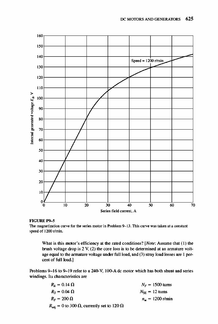
> J • ~ • " ~ • • , , a 1! ~
160
150
140
130
120
110
100
90
80
70
60
50
/ 40
30
20
/ /
/ 10
/ o o 10
/ /
rx: MmDRS AND GENERATORS 625
5,.., 1200r~
/" /
/ /
/
/
20 30 40 60 70
Series field current . A
FIGURE 1'9-5 The magnetization curve for the series moior in Problem 9--13. This curve was taken al a constant speed of 1200 r/min.
What is this motor 's efficiency at the rated conditions? [Note: Assrune that ( 1) the brush voltage drop is 2 V, (2) the core loss is to be determined at an armature voltage equal to the armature voltage lUlder full load, and (3) stray load losses are 1 percent of full load.]
Problems 9- 16 to 9-- 19 refer to a 240-V, IOO-A de motor which has both shunt and series windings. Its characteristics are
RA =O.14f.!
Rs = 0.04 n R" = 200 n
Radj = 0 to 300 n, currently set to 120 n
N" = 1500 turns
Nsf', = 12 turns
nO. = 1200 r/min
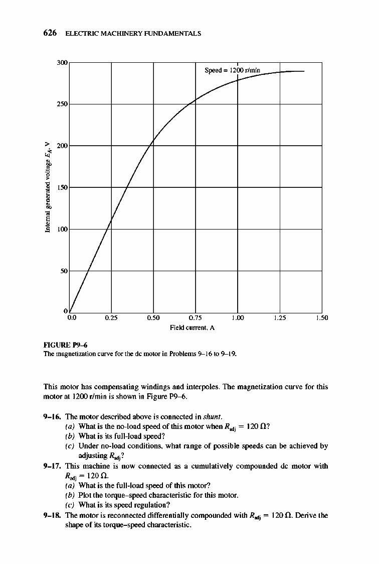
626 ELECTRIC MACHINERY RJNDAMENTALS
300
250
> 200 j
"' ~
/ ~ 150 , ~
• E • • 100
/ /
o 0.0
""GURE 1'9-6
0.25
S"",d 1200 r/min
/
/ /
0.50 0.75
Field current. A
1.00
The masnetization curve for the dc motor in Problems 9--16 to 9--19.
1.25 1.50
This motor has compensating windings and interpoles. The magnetization curve for this motor at 1200 rfmin is shown in Figure P9--6.
9-16. The motor described above is connected in shunt. (a) What is the no-load speed of this motor when R odj = 120 0 ? (b) What is its full -load speed? (c) Under no-load conditions. what range of possible speeds can be achieved by
adjusting Rodj?
9-17. This machine is now connected as a cumulatively compounded dc motor with Rodj = 120 n. (a) What is the full-load speed of this motor? (b) Plot the torque-speed characteristic for this motor. (c) What is its speed regulation?
9-18. The motor is recotulected differentially compolUlded with R adj = 120 O. Derive the shape of its torque-speed characteristic.
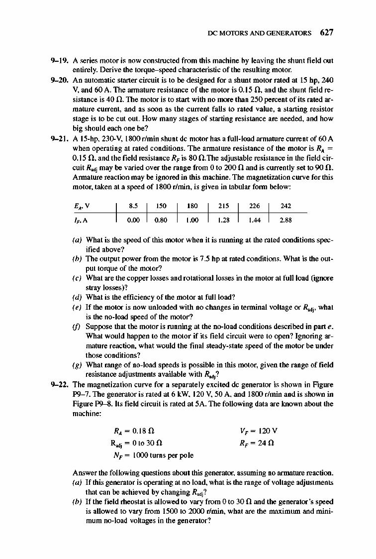
rx: MmDRS AND GENERATORS 627
9-19. A series motor is now constructed from this machine by leaving the shlUlt field out entirely. Derive the torque-speed characteristic of the resulting motor.
9-20. An automatic starter circuit is to be designed for a shlUlt motor rated at 15 hp. 240 V. and 60 A. The annature resistance of the motor is 0.15 n. and the shunt field resistance is 40 n. The motor is to start with no more than 250 percent of its rated armature current. and as soon as the current falls to rated value. a starting resistor stage is to be cut out. How many stages of starting resistance are needed. and how big should each one be?
9-2 1. A 15-hp. 230-V. 1800 rlmin shunt dc motor has a full-load armature current of 60 A when operating at rated conditions. The annature resistance of the motor is RA = 0.15 n. and the field resistance R" is 80 n.The adjustable resistance in the field circuit R>dj may be varied over the range from 0 to 200 n and is currently set to 90 n. Annature reaction may be ignored in this machine. The magnetization curve for this motor. taken at a speed of 1800 r/min. is given in tabular fonn below:
0.80 1.00 1.28
242 8.' I 150 I
180
0.00 2.88
(a) What is the speed of this motor when it is ruIllling at the rated conditions specified above?
(b) The output power from the motor is 7.5 hp at rated conditions. What is the output torque of the motor?
(c) What are the copper losses and rotational losses in the motor at full load (ignore stray losses)?
(d) What is the efficiency of the motor at full load? (e) If the motor is now unloaded with no changes in tenninal voltage or R>dj' what
is the no-load speed of the motor? (f) Suppose that the motor is running at the no-load conditions described in part e.
What would happen to the motor if its field circuit were to open? Ignoring armature reaction. what would the final steady-state speed of the motor be under those conditions?
(g) What range of no-load speeds is possible in this motor. given the range offield resistance adjustments available with Radj?
9-22. The magnetization curve for a separately excited dc generator is shown in Figure P9- 7. The generator is rated at 6 kW, 120 V. 50 A. and ISOO rlmin and is shown in Figure P9-8. Its field circuit is rated at SA. The following data are known about the machine:
RA = O.ISO
~j = Ot030n
N" = 1000 turns per pole
V,, = 120V
R,, =24n
Answer the following questions about this generator. assruning no armature reaction. (a) If this generator is operating at no load. what is the range of voltage adjustments
that can be achieved by changing Radj? (b) If the field rheostat is allowed to vary from 0 to 30 n and the generator's speed
is allowed to vary from 1500 to 2()(x) r/min. what are the maximwn and minimum no-load voltages in the generator?
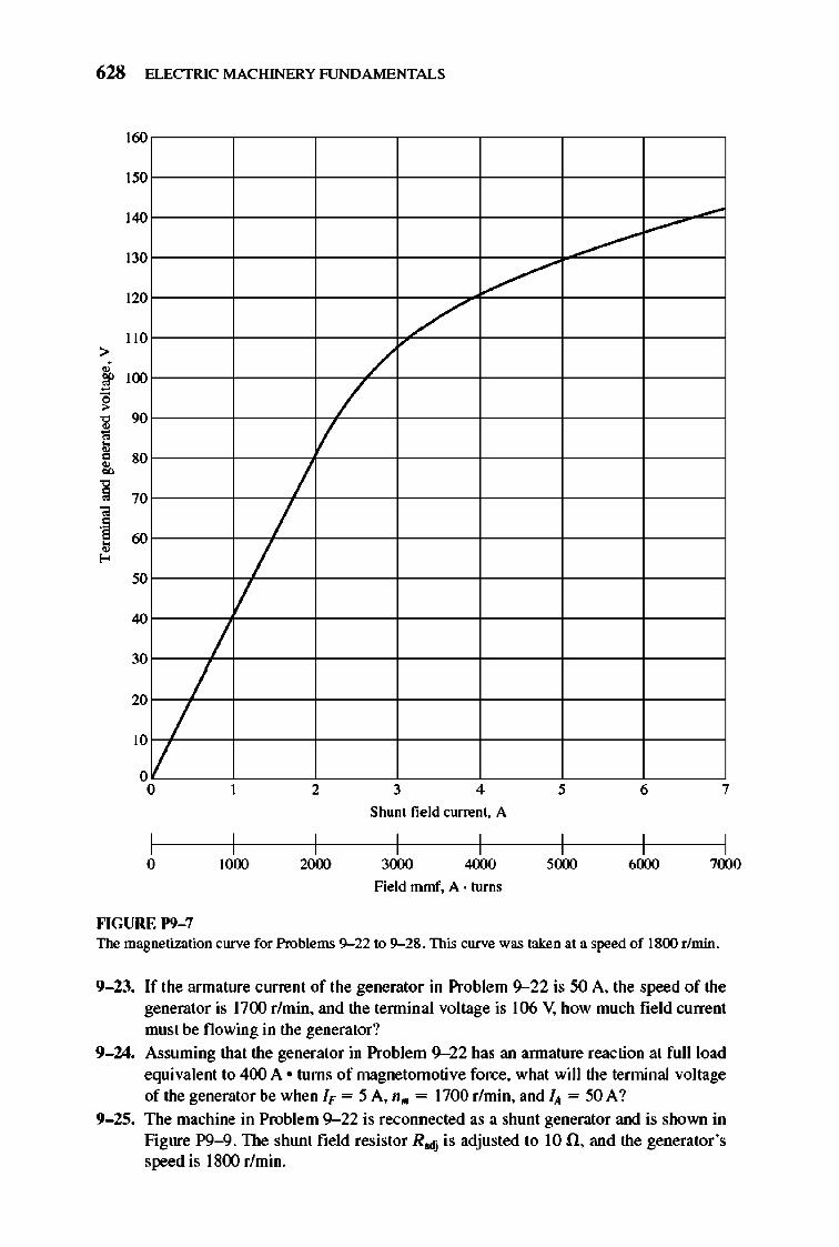
628 ELECTRIC MACHINERY RJNDAMENTALS
160
150
140
a ---V-a
a /"
13
12
II
/ /
II a
a I /
/ II
40
/ a /
a /
,II
30
2
a 2 3 4 , 6 7
Shunt field current. A
a 1000 2000 3000 4000 5000 6000 7000
Field mmf. A· turns
""GURE 1'9-7 The magnetization curve for Problems 9--22 to 9--28. This curve was taken at a speed of 1800 r/min.
9-23. If the armature current of the generator in Problem 9--22 is 50 A. the speed of the generator is 1700 r/min. and the tenninal voltage is 106 V, how much field current must be flowing in the generator?
9-24. Assuming that the generator in Problem 9- 22 has an annature reaction at full load equivalent to 400 A • turns of magnetomotive force. what will the terminal voltage of the generator be when I" = 5 A. n .. = 1700 r/min. and IA = 50 A?
9-25. The machine in Problem 9--22 is reconnected as a shunt generator and is shown in Figure P9-9. The shunt field resistor R>dj is adjusted to 10 n. and the generator's speed is 1800 r/min.
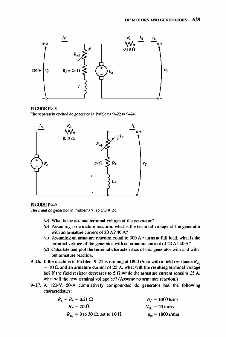
rx: M mDRS AND GENERATORS 629
I, R, I, I, - - -+ O.~8n
+
:/ R~
120 V V, RF=24f1 ~ c,JE' V,
L,
FIGURE 1'9-8 The separately excited de generator in Problems 9--22 to 9--24.
R,
,-~-----"V'VV'--------~e--C----~+ 0.18 n i'" J IF
R-».
+ 24 n ~ RF V,
FIGURE 1'9-9 The shunt de generator in Problems 9- 25 and 9--26.
(a) What is the no-load lennina! voltage of the generator? (b) Assruning no armature reaction, what is the terminal vo ltage of the generator
with an armature current of 20 A ? 40 A? (c) Assruning an annature reaction e qual to 300 A • turns at [unload, what is the
lennina! voltage of the generator with an armature current of 20 A ? 40 A ? (d) Calculate and plot the terminal c haracteristics of this generator w ith and with
out armature reaction.
9-26. If the machine in Problem 9--25 is running at 1800 r/min with a fi eld resistance Rodj = 10 n and an annature current of 25 A, what will the resulting terminal voltage be? If the field resistor decreases to 5 n while the armature curre nt remains 25 A, what will the new terminal voltage be? (Assrune no armature reaction. )
9-27. A 120-V, 50-A cumulatively compounded dc generator has the following characteristics:
RA + Rs = 0.2 1 n RF = 20 n
R>dj = 0 to 30 n, set to 10 n
N F = J()(X) turns
NSE = 20 turns
n .. = 1800 r/min
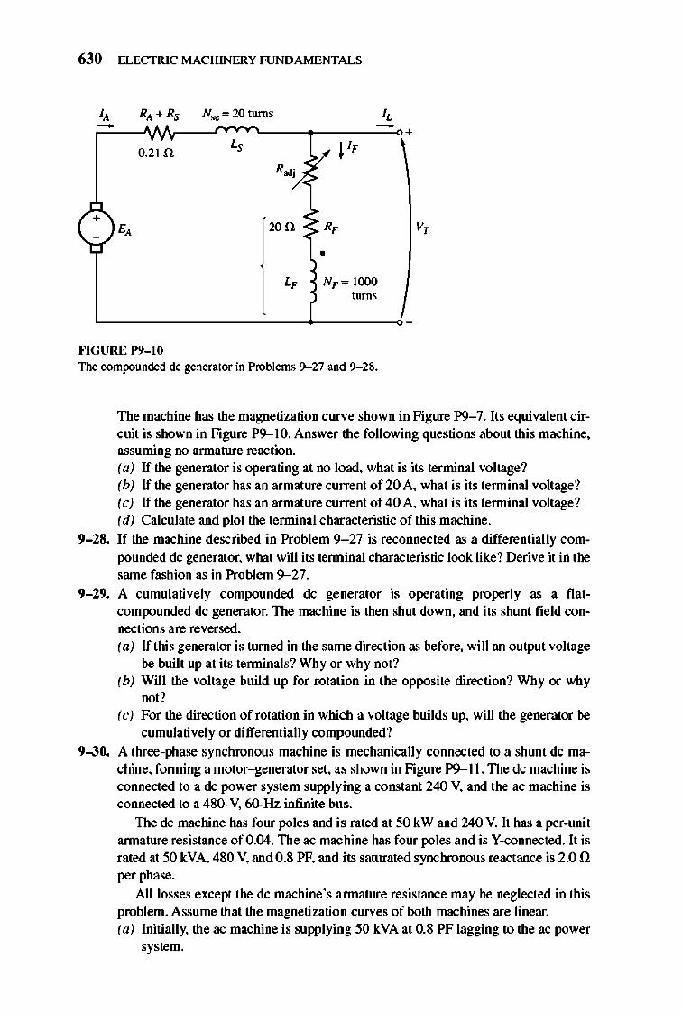
630 ELECTRIC MACHINERY RJNDA MENTALS
0.21 n
+ 200 v,
• L" N,,= 1000
turns
""GURE 1'9- 10 The compounded dc generator in Problems 9--27 and 9- 28.
The machine has the magnetization curve shown in Figure P9- 7. Its equivalent circuit is shown in Figure P9--1O. Answer the following questions about this machine, assuming no annature reaction. (a) If the generator is operating at no load, what is its terminal voltage? (b) If the generator has an armature current of 20 A, what is its tenninal voltage? (c) If the generator has an armature current of 40 A, what is its tenninal voltage? (d) Calculate and plot the tenninal characteristic of this machine.
9-28. If the machine described in Problem 9- 27 is reconnected as a differentially compounded dc generator, what will its teoninal characteristic look like? Derive it in the same fashion as in Problem 9-27.
9-29. A cumulatively compounded dc generator is operating properly as a fl atcompounded dc generator. The machine is then shut down, and its shunt field connections are reversed. (a) If this generator is turned in the same direction as before, will an output voltage
be built up at its tenninals? Why or why not? (b) Will the voltage build up for rotation in the opposite direction? Why or why
not? (c) For the direction of rotation in which a voltage builds up, will the generator be
cumulatively or differentially compolUlded? 9-30. A three-phase synchronous machine is mechanically connected to a shlUlt dc ma
chine, fonning a motor-generator set, as shown in Figure P9--ll. The dc machine is connected to a dc power system supplying a constant 240 V, and the ac machine is connected to a 480-V, 60-Hz infinite bus.
The dc machine has four poles and is rated at 50 kW and 240 V. It has a per-unit annature resistance of 0 .04. The ac machine has four poles and is V-connected. It is rated at 50 kVA, 480 V, and 0.8 PF, and its saturated synchronous reactance is 2.0 n per phase.
All losses except the dc machine's annature resistance may be neglected in this problem. Assume that the magnetization curves of both machines are linear. (a) Initially, the ac machine is supplying 50 kVA at 0.8 PF lagging to the ac power
system.
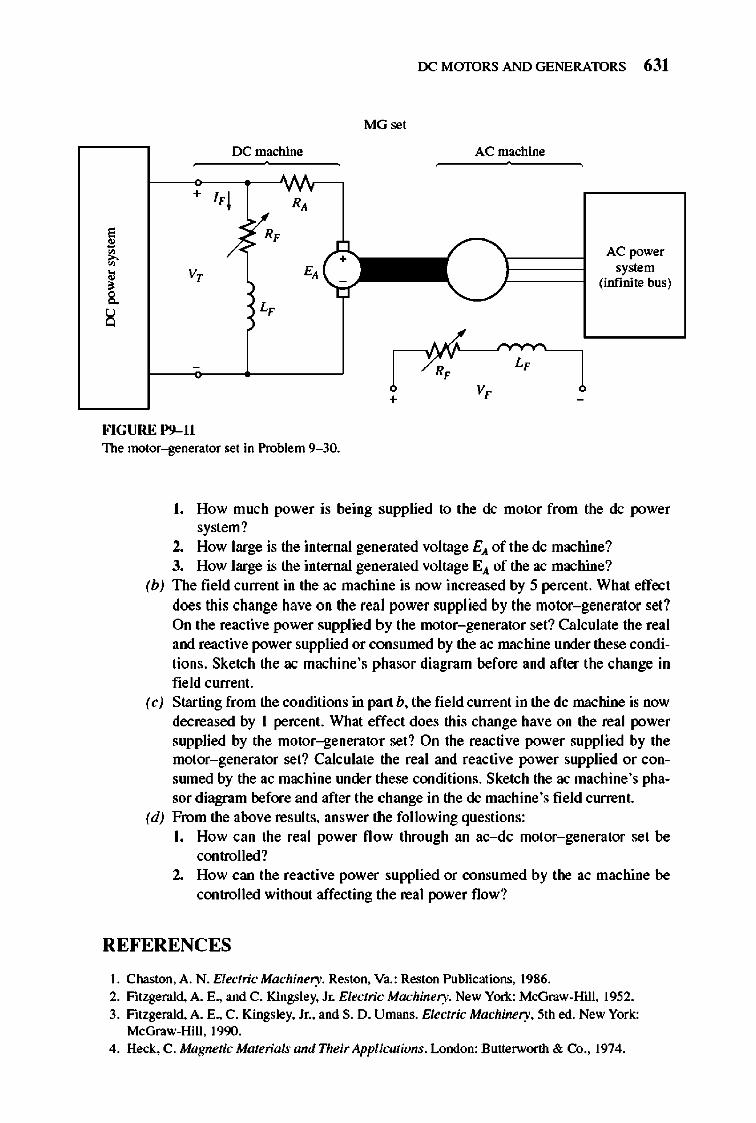
rx: MmDRS AND GENERATORS 631
MGset
rx: machine AC machine
1'1 R,
6 R,
~ AC power , V, E, system , (infinite bus) & L, ~
R, L,
+ V,
FIGURE 1'9- 11 The motor-generator set in Problem 9- 30.
I. How much power is being supplied to the dc motor from the dc power system?
2. How large is the internal generated voltage EA of the dc machine? 3. How large is the internal generated voltage EA of the ac machine?
(b) The field current in the ac machine is now increased by 5 percent. What effect does this change have on the real power supplied by the motor- generator set? On the reactive power supplied by the motor- generator set? Calculate the real and reactive power supplied or consumed by the ac machine under these conditions. Sketch the ac machine's phasor diagram before and after the change in field current.
(c) Starting from the conditions in part b. the field current in the dc machine is now decreased by I percent. What effect does this change have on the real power supplied by the motor-generator set? On the reactive power supplied by the motor- generator set? Calculate the real and reactive power supplied or conswned by the ac machine lUlder these conditions. Sketch the ac machine's phasor diagram before and after the change in the dc machine's field current.
(d) From the above results. answer the following questions: I. How can the real power flow through an ac-dc motor- generator set be
controlled? 2. How can the reactive power supplied or consumed by the ac machine be
controlled without affecting the real power flow?
REFERENCES
1. Chaston. A. N. Electric Machinery. Reston. Va.: Reston Publications. 1986. 2. Fitzgerald. A. E.. and C. Kingsley. Jr. Electric Machinery. New YorK: McGraw-Hill. 1952. 3. Fitzgerald. A. E.. C. Kingsley. Jr .• and S. D. Umans. Electric Machinery. 5th ed. New York:
McGraw-Hill. 1990. 4. Heck. C. Magnetic Materials and Their AppliCllTions. London: Butterwonh & Co .. 1974.

632 ELECTRIC MACHINERY RJNDAMENTALS
5. IEEE Standard 113-1985. Guide on Test Procedures for DC Machines. Piscataway. N.J .: IEEE. 1985. (Note that this standard has been officially withdrawn but is still available.)
6. Kloeftler. S. M .• R. M. Ken;hner. and J . L. Brenneman. Direct Current Machinery. Rev. ed.
New York: Macmillan. 1948. 7. Kosow. Irving L. Electric Machinery atuf Tmnsjormers. Englewood ClilTs. N.J .: Prentice-Hall.
1972. 8. McPherson. George. An Introduction 10 Electrical Machines and Tmnsfonners . New York:
Wiley. 1981. 9. Siskind. Charles S. Direct-Current Machinery. New York: McGraw-Hill. 1952.
10. Siemon. G. R .• and A. Straughen. Electric Machines. Reading. Mass.: Addison-Wesley. 1980. II. Werninck. E. H. (ed.). Electric MOlOr Handbook. London: McGraw-Hili. 1978.
CHAPTER
10 SINGLE-PHASE AND
SPECIAL-PURPOSE MOTORS
Chapters 4 through 7 were devoted to the operation orthe two major classes of ac machines (synchronous and induction) on three-phase power systems.
Motors and generators of these types are by far the most common ones in larger commercial and indu strial settings. However, most homes and small businesses do not have three-phase power available. For such locations, all motors must run from single-phase power sources. nlis chapter deals with the theory and operation of two major types of single-phase motors: the uni versal motor and the singlephase induction motor. The uni versal motor, which is a straightforward extension of the series de motor, is descri bed in Section 10.1.
The single-phase inducti on motor is described in Sections 10.2 to 10.5. The major problem associated with the design of single-phase induction motors is that, unlike three-phase power sources, a sing le-phase source does not produce a rotating magnetic fi e ld. Instead, the magneti c fie ld produced by a single-phase source remains stationary in position and pulses with time. Since there is no net rotating magnetic field , conve ntional induction motors cannot functi on, and special designs are necessary.
In addition, there are a number of special-purpose motors which have not been previously covered. These include reluctance motors, hysteresis motors, stepper motors, and brushless dc motors. 1lley are included in Section 10.6.
633
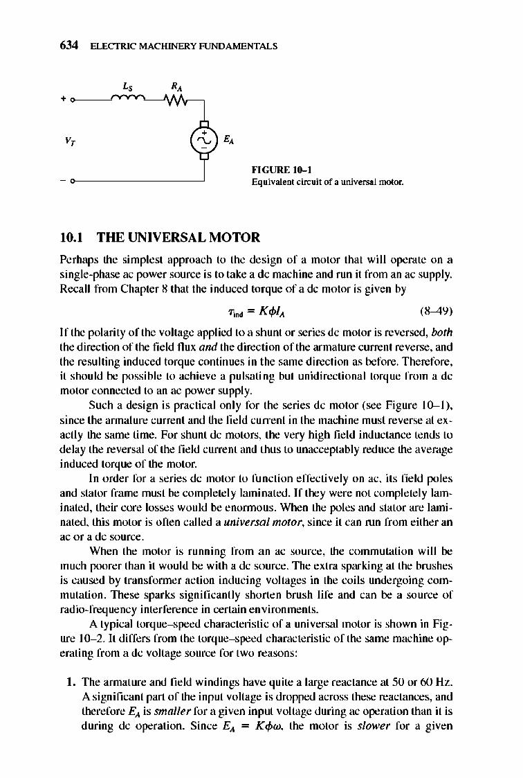
634 ELECTRIC MACHINERY RJNDAMENTALS
v,
""CURE 10-1 Equivalent cin;uit of a univeTS3.1 motor.
10.1 THE UNIVERSAL MOTOR
Perhaps the simplest approach to the design of a motor that will operate on a single-phase ac power source is to take a dc machine and run it from an ac supply. Recall from Chapter 8 that the induced torque of a dc motor is given by
(8-49)
If the polarity of the voltage applied to a shunt or series dc motor is reversed, both the direction of the fie ld flux and the direction of the armature current reverse, and the resulting induced torque continues in the same direction as before. Therefore , it should be possible to achieve a pulsating but unidirectional torque from a dc motor connected to an ac power supply.
Such a design is practical only for the series dc motor (see Figure 10- 1), since the annature current and the field current in the machine must reverse at exactly the same time. For shunt dc motors, the very high fie ld inductance tends to delay the reversal of the fie ld current and thus to unacceptably reduce the average induced torque of the motor.
In order for a series dc motor to function effectively on ac, its field poles and stator frame must be complete ly lami nated. If they were not complete ly laminated, their core losses would be enonnous. When the poles and stator are laminated, this motor is often called a universal motor, since it can run from either an ac or a dc source.
When the motor is running from an ac source, the commutation will be much poorer than it would be with a dc source. The extra sparking at the brushes is caused by transfonner action inducing voltages in the coil s undergoing commutati on. These sparks significantly shorten brush life and can be a source of radio-frequency interference in certain environments.
A typical torque-speed characteristic of a universal motor is shown in Figure 10- 2. It differs from the torque-speed characteristic of the same machine operating from a dc voltage source for two reasons:
I. The armature and field windings have quite a large reactance at 50 or 60 Hz. A significant part of the input voltage is dropped across these reactances, and therefore Ell is smaller for a given input voltage during ac operation than it is during dc operation. Since Ell = Kcpw, the motor is slower for a given
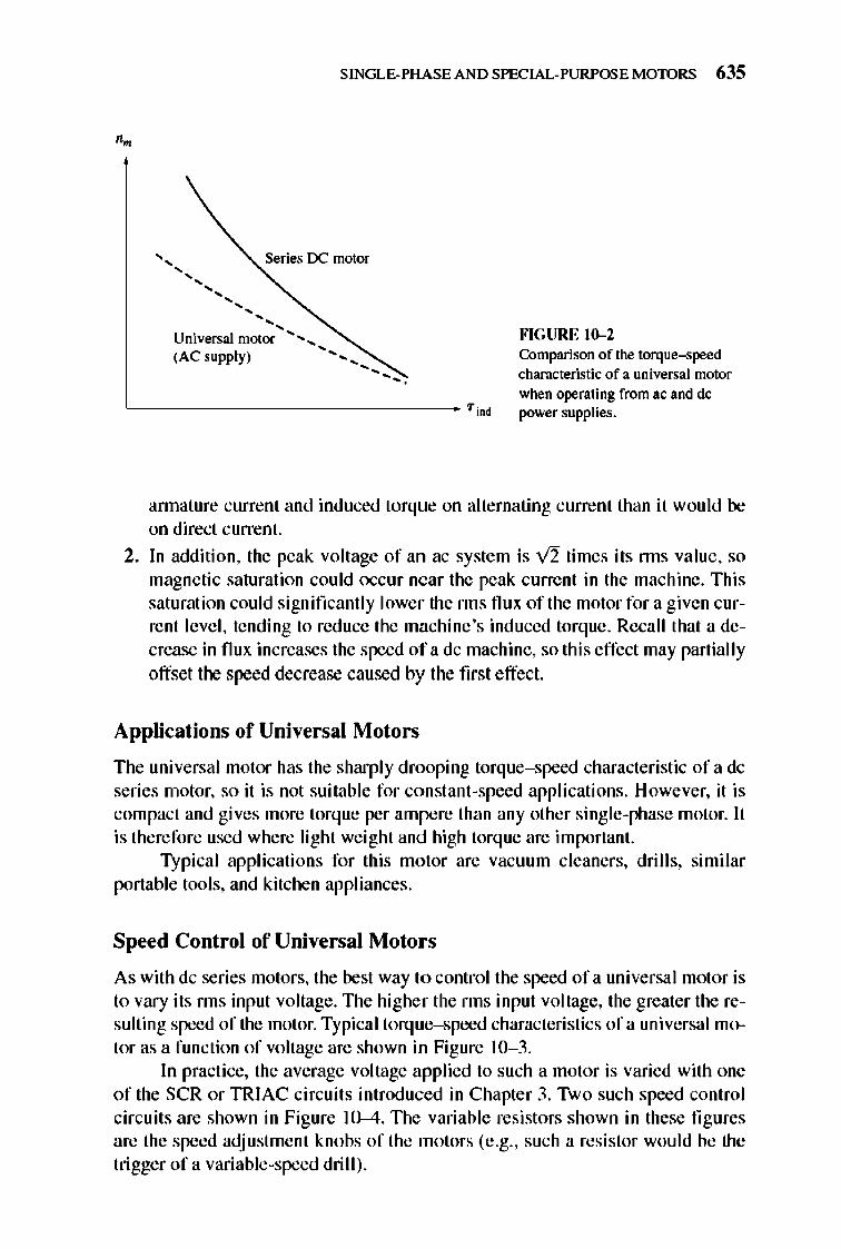
SINGLE-PHASE AND SPECIAL-PURPOSE MOTORS 635
" Series IX motor
""""""
Universal motor .........
(AC supply) ........................ ...
""GURE 10-2 Comparison of the torque-speed characteristic of a universal motor
when operating from ac and dc L ________________ Tind power supplies.
annature current and induced torque on alternating current than it wou ld be on direct current.
2. In addition, the peak voltage of an ac system is V2 times its nns value, so magnetic saturation could occur near the peak current in the machine. This saturation could significantly lower the nns nux of the motor for a given current level, tending to reduce the machine 's induced torque. Recall that a decrease in flux increases the speed of a dc machine, so this effect may partially offset the speed decrease caused by the first effect.
Applications of Universal Motors
The universal motor has the sharply drooping torque- speed characteristic of a dc series motor, so it is not suitable for constant-speed applications. However, it is compact and gives more torq ue per ampere than any other single-phase motor. It is therefore used where light weight and high torq ue are important.
Typical applications for this motor are vacu um cleaners, dri ll s, similar portable tools, and kitchen appliances.
Speed Control of Universal Motors
As with dc series motors, the best way to control the speed of a universal motor is to vary its nns input voltage. The higher the rms input voltage, the greater the resulting speed of the motor. Typical torq ue-speed characteristics of a universal motor as a function of voltage are shown in Figure 10- 3.
In practice, the average voltage applied to such a motor is varied with one of the SCR or TRIAC circuit s introduced in Chapter 3. Two such speed control circuits are shown in Figure 10-4. TIle variable resistors shown in these fi gures are the speed adjustment knobs of the motors (e.g., such a resistor would be the trigger of a variable-speed dri II ).
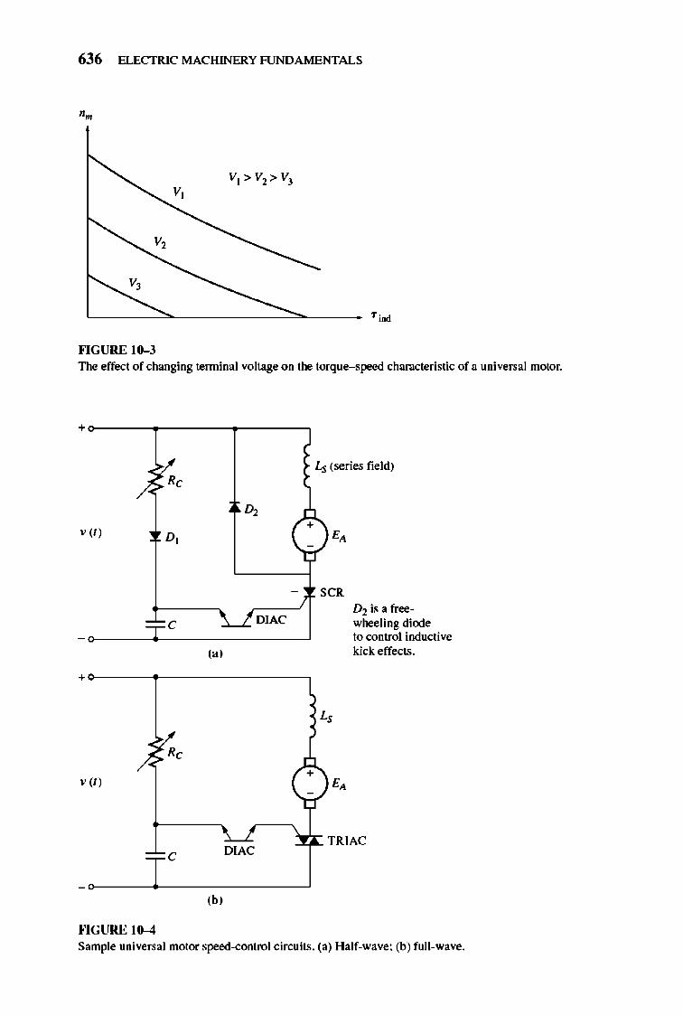
636 ELECTRIC MACHINERY RJNDA MENTALS
v,
v,
v,
'--------''--------------',,------___ Tjoo
""GURE 10-3 The effect of changing teffilinal voltage on the torque-speed characteristic of a universal motor.
+
/. ~c 0,
,n D,
= = C ~DIAC
(a)
L, (series field)
C;) - s CR
D2 is a freewheeling diode to control inductive k:ick: effects.
+~----~------------,
Rc
+ v (t)
TRIAC C
,b, ""GURE 10-4 Sample universal motor speed-control ci["(;uits. (a) Half-wave; (b) full-wave.
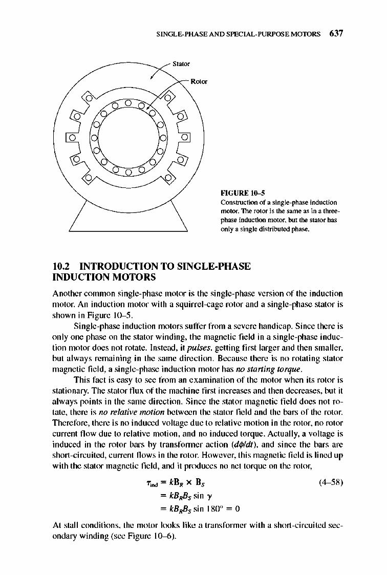
o o
o
SINGLE-PHASE AND SPECIAL-PURPOSE MOTORS 637
Stator
o o
FlGURE 10-5 Construction of a single-phase induction motor. The rotor is the same as in a threephase induction motor. but the stator has only a single distributed phase.
10.2 INTRODUCTION TO SINGLE-PHASE INDUCTION MOTORS
Another common sing le-phase motor is the sing le-phase version of the induction motor. An induction motor with a squirre l-cage rotor and a single-phase stator is shown in Figure 10-5.
Single-phase induction motors suffer from a severe handicap. Since there is only one phase on the stator winding, the magnetic field in a single-phase induction motor does not rotate. Instead, it pulses, getting first larger and the n smaller, but a lways remaining in the same direction. Because the re is no rotating stator magnetic fie ld, a single-phase induction motor has no staning torque.
Thi s fact is easy to see from an examination of the motor when its rotor is stationary. The stator flu x of the machine first increases and then decreases, but it always points in the same di rection. Si nce the stat or magnetic fi e ld does not rotate, there is no relative motion between the stator field and the bars of the rotor. Therefore, there is no induced voltage due to relative motion in the rotor, no rotor current fl ow due to re lative motion, and no induced torque. Actually, a voltage is induced in the rotor bars by transfonner action (df/JIdt), and since the bars are short-circuited, current flows in the rotor. However, this magnetic fie ld is lined up with the stator magnetic field , and it produces no net torque on the rotor,
"rind = kBR X Bs
= kBRBS sin "y
= kBRBS sin 1800 = 0
(4- 58)
At stall conditions, the motor looks like a transformer with a short-circuited secondary winding (see Figure 10-6).
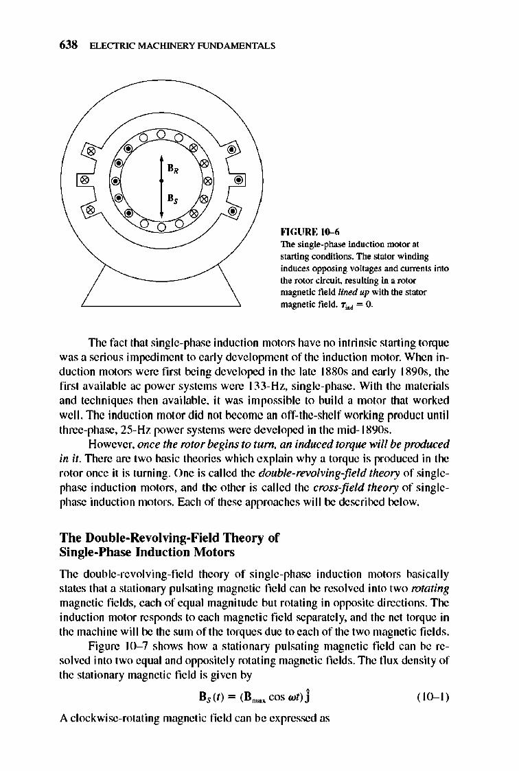
638 ELECTRIC MACHINERY RJNDAMENTALS
II,
FlGURE 10-6 The single-phase induction motor at starting conditions. The stator winding induces opposing voltages and currents into the rotor cirwit. resulting in a rotor magnetic field lined up with the stator magnetic field. 7;M = O.
TIle fact that single-phase induction motors have no intrinsic starting torq ue was a serious impedime nt to early development of the induction motor. When induction motors were first being developed in the late l880s and early 1890s, the first available ac power systems were 133-Hz, single-phase . With the materials and techniques then available, it was impossible to build a motor that worked well. The induction motor did not become an off-the-she lf working product until three-phase, 25- Hz power systems were developed in the mid- 189Os .
However, once the rotor begins to tum, an induced torque will be produced in it. TIlere are two basic theories which explain why a torque is produced in the rotor once it is turning. One is called the double-revolving-field theory of singlephase induction motors, and the other is called the cross-field theory of singlephase induction motors. E.1.ch of these approaches will be described below.
The Double-Revolving-Field Theory of Single-Phase Induction Motors
TIle double-revolving-field theory of single-phase induction motors basically states that a stationary pulsating magnetic field can be resolved into two rotating magnetic fields, each of equal magnitude but rotating in opposite directions. The induction motor responds to each magneti c field separate ly, and the net torque in the machine will be the sum of the torques due to each of the two magnetic fie lds .
Figure 10- 7 shows how a stationary pulsating magnetic field can be resolved into two equal and opposite ly rotating magnetic fields. The flu x density of the stationary magnetic field is given by
, Bs (t) = (Bmn cos wt) J
A clockwise-rotating magnetic field can be expressed as
( 10-1 )
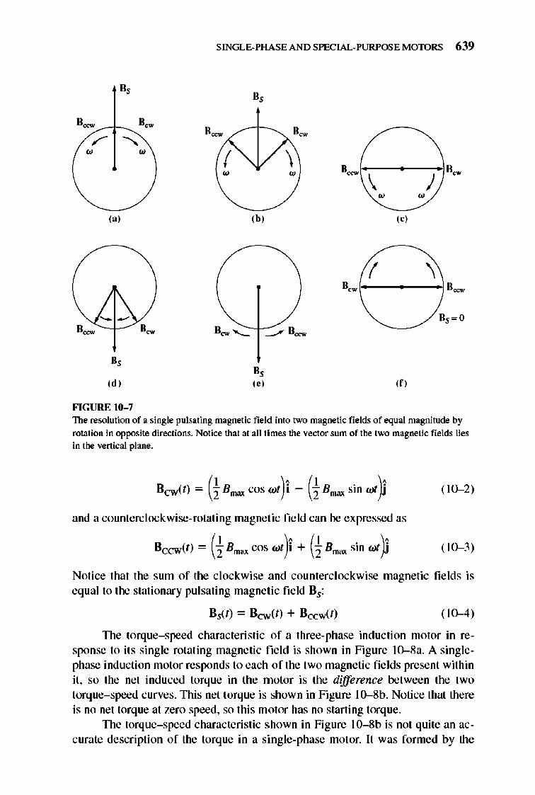
0,
0- lie ...
/' " W W
(:1 )
", ,d,
FIGURE 10-7
SINGLE-PHASE AND SPECIAL-PURPOSE MOTORS 639
"-W
II,
,b,
", ,.,
"-W "- \ )
o-
W W
, "
( \ "ow 1--------1 "_
,f,
The resolution of a single pulsating magnetic field into two magnetic fields of equal magnitude by rotation in opposite directions. Notice that at all times the vector sum of the two magnetic fields lies in the vertical plane.
Bew(r) = (t Bmax cos wt)i - (t Bmax sin wi fi ( 10-2)
and a counlerc lockwise-rotating magnetic field can be expressed as
Bcew(t) = (1 Bmax cos wt)i + (1 Bmax sin wi fi ( 10-3)
Notice that the sum of the clockwise and counterclockwise magnetic fie lds is equal to the stationary pulsating magnetic field Bs:
8 ,(1) ~ B~(I) + BccwCt) (IO-d)
TIle torque-speed characteristic of a three-phase induction motor in response to it s single rotating magnetic field is shown in Figure 10--8a. A singlephase induction motor responds to each of the two magnetic fields present within it, so the net induced torque in the motor is the difference between the two torque- speed curves. This net torque is shown in Figure lO--8b. Notice that there is no net torq ue at zero speed, so this motor has no starting torque.
TIle torque- speed characteristic shown in Figure 1 0--8b is not quite an accurate description of the torque in a single-phase motor. It was formed by the
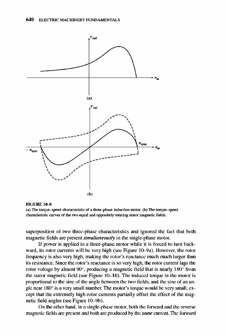
640 ELECTRIC MACHINERY RJNDAMENTALS
----------------------t----------------'------ '.
-----------
""GURE 10-8
,,' --, " ' , , , , , ,
-' , " , --- , ,
---------------
,b,
(a) The torque-speed characteristic of a three-phase induction motor. (b) The torque-speed characteristic curves of the two equal and oppositely rota.ting stator magnetic fields.
superposition of two three-phase characteristics and ignored the fact that both magnetic fields are present simultaneously in the single-phase motor.
If power is applied to a three-phase motor while it is forced to turn backward, its rotor currents will be very high (see Figure 10--9a). However, the rotor frequency is also very high, making the rotor's reactance much much larger than its resistance. Since the rotor's reactance is so very high, the rotor current lags the rotor voltage by almost 900, pnxlucing a magnetic fi e ld that is nearly 180 0 from the stator magnetic field (see Figure 10- 10). The induced torque in the motor is proportional to the sine of the angle between the two fi e lds, and the sine of an angle near 1800 is a very small number. TIle motor 's torque would be very small, except that the extremely high rotor currents partially offset the effect of the magnetic field angles (see Figure 10- 9b).
On the other hand, in a single-phase motor, both the forward and the reverse magnetic fields are present and both are produced by the same current.llle forward
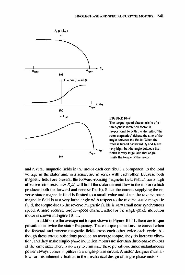
SINGLE-PHASE AND SPECIAL-PURPOSE MOTORS 641
- n,j'DC ,,' PF =cosfl =sinll
'. '.~ ,b,
fo'IGURE 10-9 The torque-speed characteristic of a three-phase induction motor is
proportional to both the strength of the rotor magnetic field and the sine of the angle between the fields. When the rotor is turned bad:waro. IN and Is are
'. very high. but the angle between the
'.~ fields is very large. and that angle
'0' limits the torque of the motor.
and reverse magnetic fields in the motor each contribute a component to the total voltage in the stator and, in a sense, are in series with each other. Because both magnetic fie lds are present, the forward-rotating magnetic field (which has a high effective rotor resistance Ris) will limit the stator current now in the motor (which produces both the forward and reverse fields). Since the current supplying the reverse stator magnetic fi e ld is limited to a small value and since the reverse rotor magnetic field is at a very large angle with respect to the reverse stator magnetic field, the torque due to the reverse magnetic fields is very small near synchronous speed. A more accurate torque-speed characteristic for the single-phase induction motor is shown in Figure 10-11.
In addition to the average net torque shown in Figure 10-11 , there are torq ue pulsations at twi ce the stator frequency. 1l1ese torque pulsations are caused when the forward and reverse magnetic fi e lds cross each other twice each cycle. Although these torque pulsations pnxluce no average torque, they do increase vibration, and they make single-phase induction motors noisier than three-phase motors of the same size. 1l1ere is no way to e liminate these pulsations, since instantaneous power always comes in pulses in a single-phase circuit. A motor designer must allow for this inherent vibration in the mechanical design of single-phase motors.
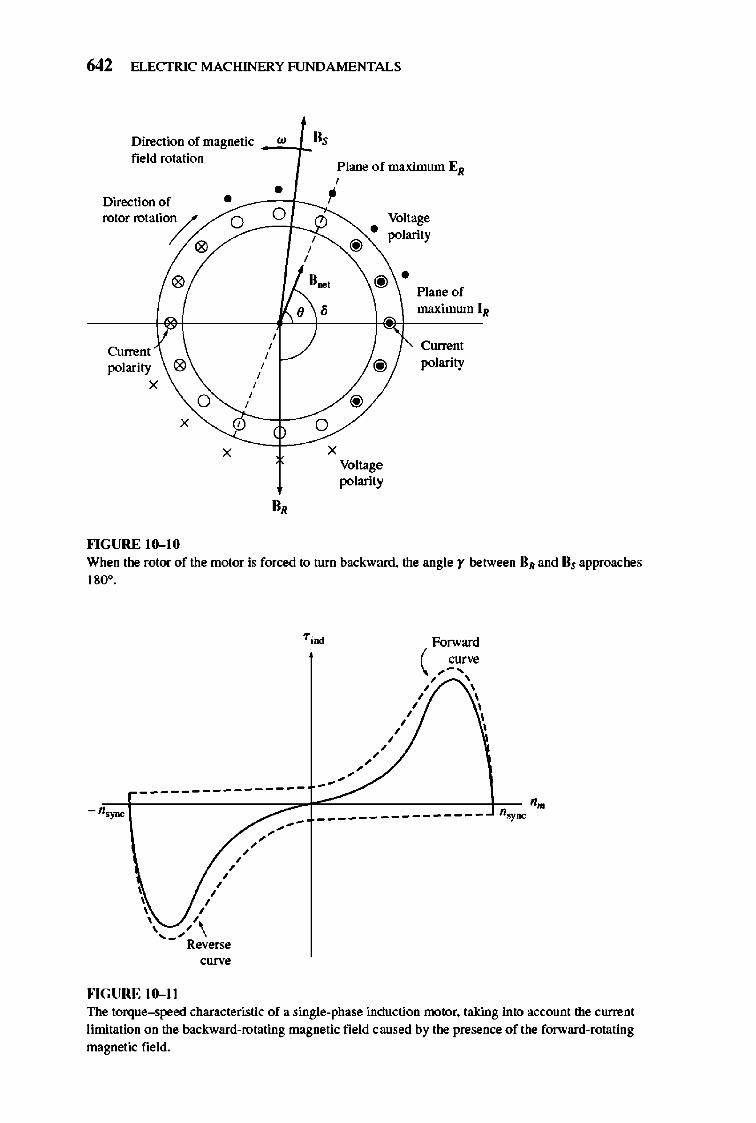
642 ELECTRIC MACHINERY RJNDAMENTALS
Direction of magnetic w 0, field rotation
Plane of maximum EI/ , • ~ Direction of •
rotor rotati0/-j 0 0 Voltage • ,
@ polarity
" , ,
" II .. , @ • Plane of , , maximum 11/
, Current
, Current , polarity " , @ polarity ,
X , 0
, @ ,
X , 0 X X
Voltage polarity
0,
""GURE 111-10 When the rotor of the motor is forced to turn backwmd. the angle r between 111/ and Bs approaches 180°.
1";00 Forward
.... ".".". "..
, ,
( CUn-ll ,-, , , , , , , , , , ,
/ '
----------------.--+=~-~¥-=----__+.c_ '. - n,}'DC _____ __ _________ n.y""
/'"..". .... -,
, , , , , , , ' \
, , , ,
'-' Reverse curve
""GURE III-II The torque--speed characteristic of a single-phase induction nx>toT. taking into account the current limitation on the backward-rotating magnetic field caused by the presence of the forward-rotating magnetic field.
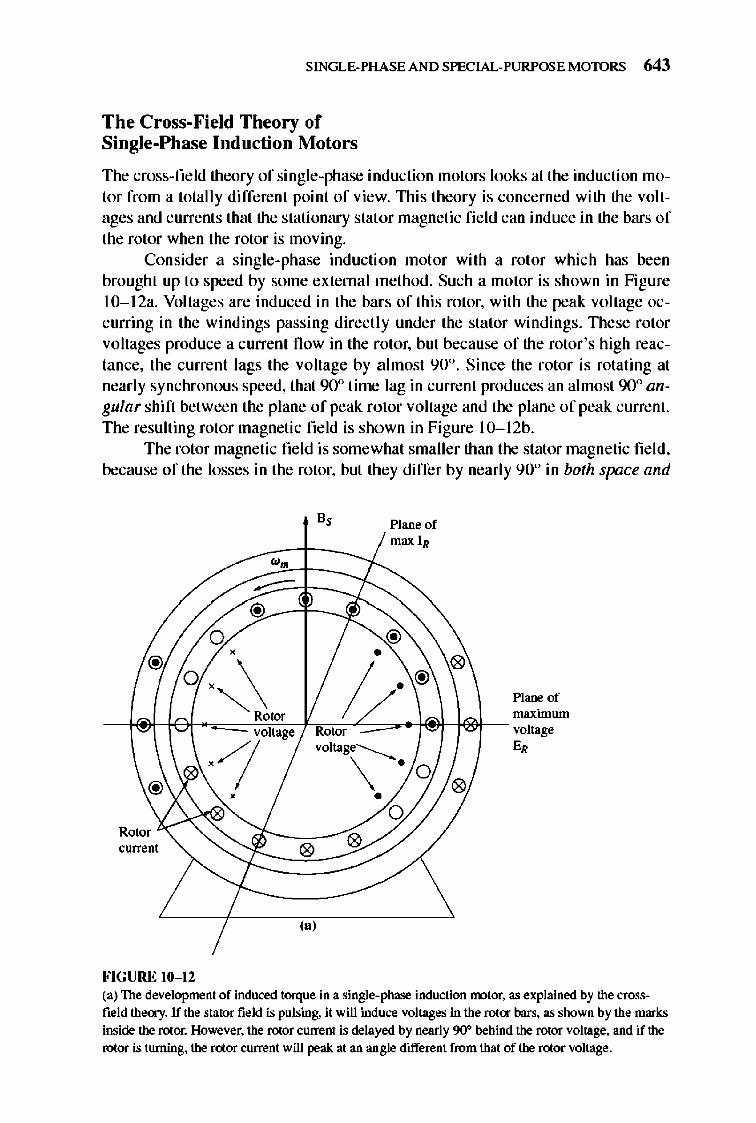
SINGLE-PHASE AND SPECIAL-PURPOSE MOTORS 643
The Cross-Field Theory of Single-Phase Induction Motors
The cross-field theory of single-phase induction motors looks at the induction motor from a totally different point of view. 1l1is theory is concerned with the voltages and currents that the stationary stator magnetic fie ld can induce in the bars of the rotor when the rotor is moving.
Consider a single-phase induction mot or with a rotor which has been brought up to speed by some externa l method. Such a motor is shown in Figure 1O-1 2a. Voltages are induced in the bars of this rotor, with the peak voltage occurring in the windings passing direct ly under the stator windings. 1l1ese rotor voltages produce a current now in the rotor, but because of the rotor's high reactance, the current lags the voltage by a lmost 90°. Since the rotor is rotating at nearly synchronous speed, that 90° time lag in current produces an almost 90° angular shift between the plane of peak rotor voltage and the plane of peak current. The resulting rotor magnetic field is shown in Figure 1O-1 2b.
The rotor magnetic field is somewhat smaller than the stator magnetic fi e ld, because of the losses in the rotor, but they differ by nearly 90° in both space and
current
FIGURE 10- 12
Plane of max IR
voltage-----....
\ ' ,
Plane of maximum . I
E,
(a) The development of induced torque in a single-phase induction nx>tor. as explained by the crossfield theocy. If the stator field is pulsing, it will induce voltages in the rot<r bars. as shown by the marks inside the rotor. Hoy/ever. the rotor current is delayed by nearly 90" behind the rotor voltage, and if the rotor is turning, the rotor current will peak at an angle different from that of the rotor voltage.
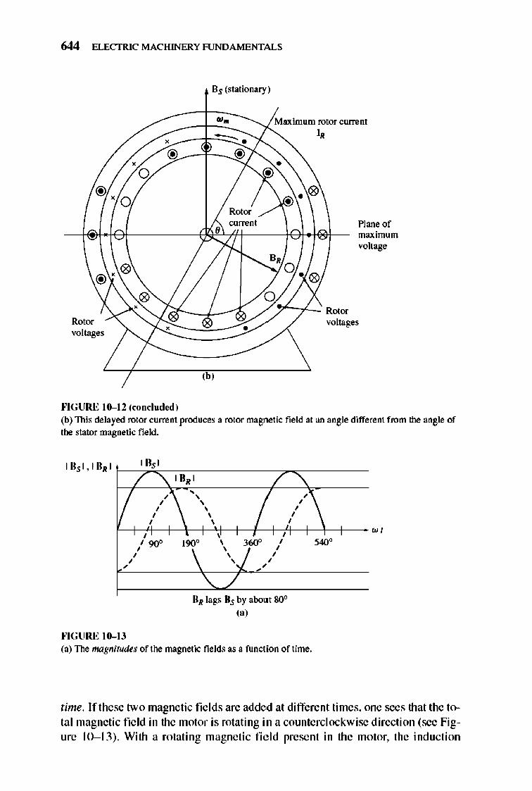
644 ELECTRIC MACHINERY RJNDAMENTALS
Bs (stationary)
w.
~ . Maximum rotor currem I,
• o @
'0
•
o
•
Plane of maximum voltage
/ ~:>"--r'-' Rmm Rotor volta.ges
""GURE 10-12 (concluded)
-~. voltages
(b'
(b) This delayed rotor current produces a rotor magoetic field at an angle different from the angle of the stator magnetic fie ld.
I I . I , / "'\ I URI /'\
/ , , , ,
""GURE 10-13
'\ " I , , , , , , , , , , ,
, 9<Y' 190\ \ )~ I , , , , , , , \.../
UR lags "5 by about 80 (a)
,
, , , , ,
(a) The magnitudes of the magnetic fields as a function of time.
w, ''''''
time. If these two magnetic fie lds are added at different times, one sees that the 10-tal magnetic field in the motor is rotating in a counterclockwise direction (see Figure 10- 13) . With a rotating magnetic fi e ld present in the motor, the induction
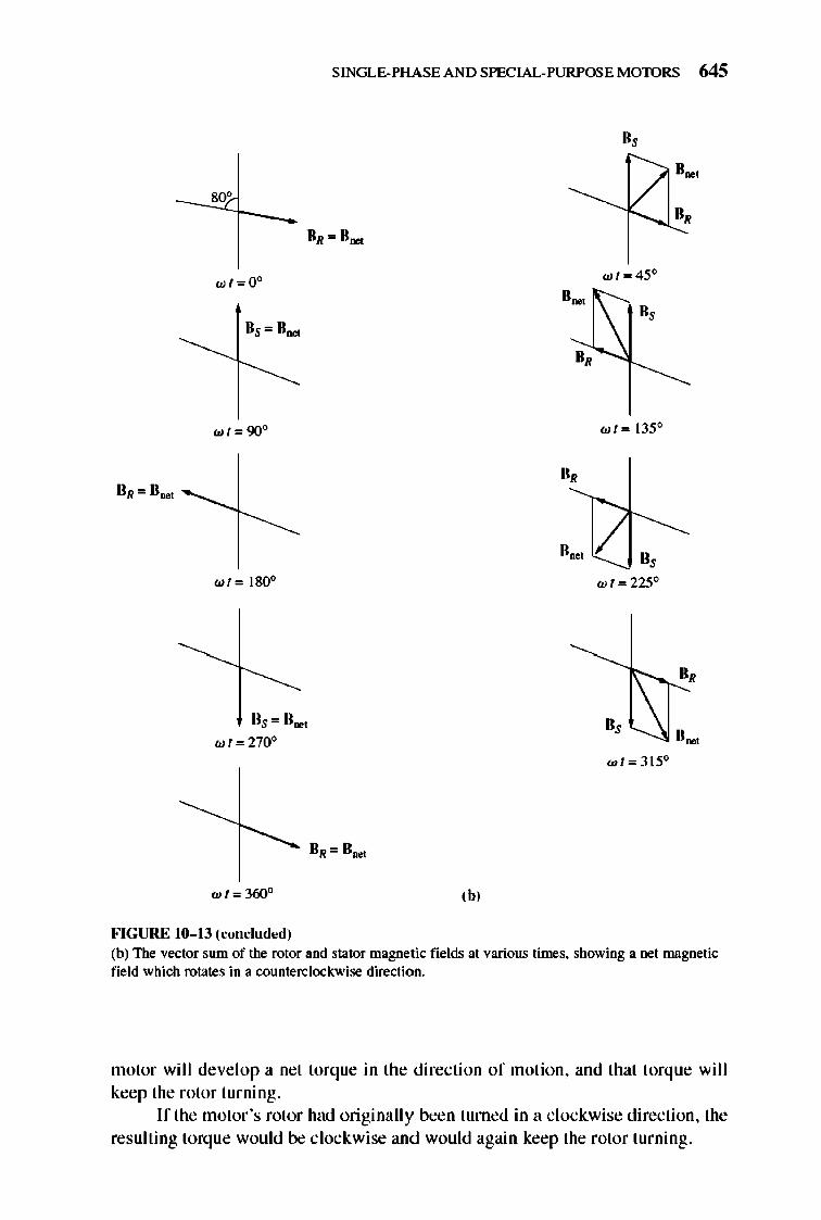
80'
",t=OO
",1=90°
wt= ISOo
lis = II .. ,
",t = 270°
wl=360°
FIGURE 10- 13 (conclud ... >d)
SINGLE-PHASE AND SPECIAL-PURPOSE MOTORS 645
II,
II,
,b,
wt=45°
wl= 135°
0,
"'t=225°
",t=315°
II .. ,
(b) The vector sum of the rotor and stator magnet ic fields at various times. showing a net magnetic field which rotates in a counterclockwise direction.
motor wi ll develop a net torque in the direction of motion, and that torque wi ll keep the rotor turning.
If the motor 's rotor had originally been turned in a clockwise direction, the resulting torq ue would be clockwise and would again keep the rotor turning.
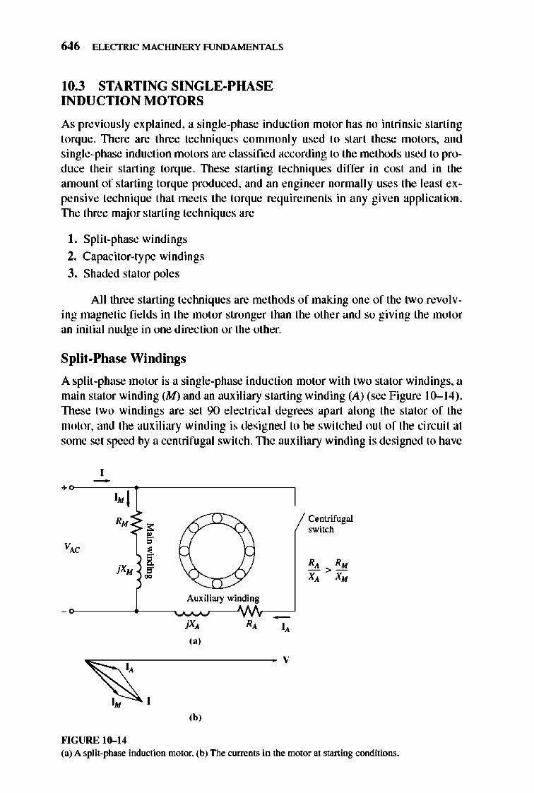
646 ELECTRIC MACHINERY RJNDAMENTALS
10.3 STARTING SINGLE-PHASE INDUCTION MOTORS
As previously explained, a single-phase inducti on motor has no intrinsic starting torque. TIlere are three techniques commonly used to start these motors, and single-phase induction motors are classified according to the methods used to produce their starting torque. These starting techniques differ in cost and in the amount of starting torque produced, and an engineer normally uses the least expensive technique that meets the torque requirements in any given application. TIle three major starting techniques are
I. Split-phase windings
2. Capacitor-type windings
3. Shaded stator poles
All three starting techniques are methods of making one of the two revolving magnetic fi e lds in the motor stronger than the other and so giving the motor an initial nudge in one direction or the other.
Split-Phase Windings
A split-phase motor is a single-phase indu ction motor with two stator windings, a main stator winding (M) and an auxiliary starting winding (A) (see Figure 10- 14) . TIlese two windings are set 90 electrica l degrees apart along the stator of the motor, and the auxiliary winding is designed to be switched oul of the circuit at some set speed by a centrifugal switch. TIle auxiliary winding is designed to have
+ 1· 1 R. < ,.
VAC , ~.
jXM a 5· ~
~ I. I
""GURE 10-14
Auxiliary winding
jX" R,
(a)
,b,
-I,
V
Centrifugal switch
(a) A split-phase induction motor. (b) The currents in the motor at starting conditions.
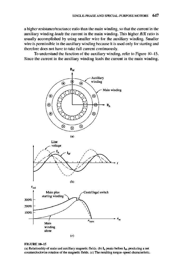
SINGLE-PHASE AND SPECIAL-PURPOSE MOTORS 647
a higher resistance/reactance ratio than the main winding, so that the current in the auxiliary winding leads the current in the main winding. This higher RIX ratio is usually accomplished by using smaller wire for the auxiliary winding. Smaller wire is pennissible in the auxiliary winding because it is used only for starting and therefore does not have to take full current continuously.
To understand the function of the auxiliary winding, refer to Figure 10-15. Since the current in the auxi liary winding leads the current in the main winding,
300%
®
®
®
®
0
Line fvoItage
/,,-, ~_I,'/ / /" \ "-, /
, "-, , , ,
Main plus starting winding
,
200%~_""---100%
Main winding alone
FIGURE 10-15
". ®
0 0
,.,
'-, ,
,b,
,
,.,
Auxiliary winding
Main winding
0
II,
0
Centrifugal switch
, , , , ,
(a) Relationship of main and auxiliary magnetic fields. (b) I .. peaks before 1M • producing a net counterclockwise rotation of the magnetic fields. (c) The resulting torque-speed characteristic.
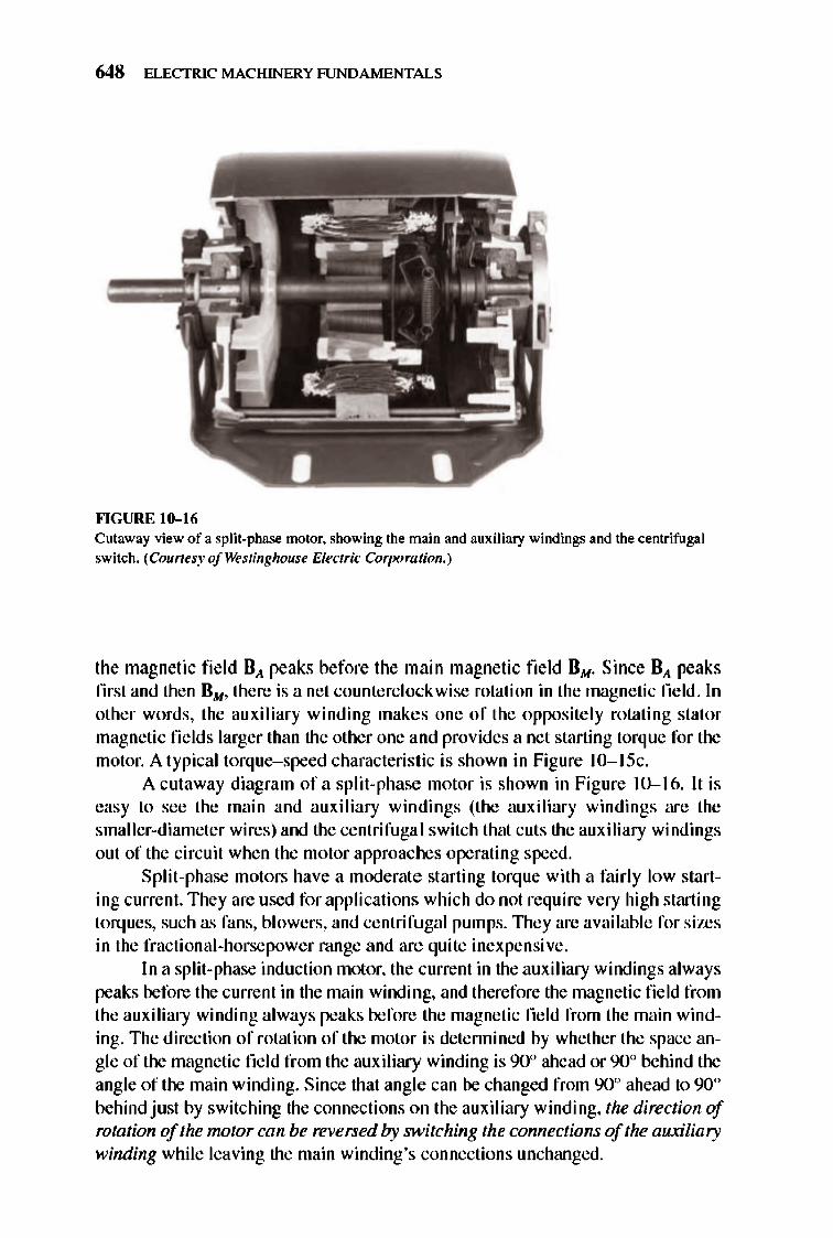
648 ELECTRIC MACHINERY RJNDAMENTALS
""GURE 10-16 Cutaway view of a split-phase motor. showing the main and auxiliary windings and the centrifugal switch. (Courtesy of Westinghouse Electric Corpomtion. )
the magnetic fie ld BA peaks before the main magnetic field BM . Since BA peaks first and then BM , Ihere is a net counterclockwise rotation in the magnetic field. In other words, the auxi liary winding makes one of the oppositely rotating stator magnetic fie lds larger than the other one and provides a net starting torque for the motor. A Iypicallorque-speed characteristic is shown in Figure 1O-I Sc.
A culaway diagram of a split-phase motor is shown in Figure 10-16. It is easy to see the main and auxiliary windings (the auxi liary windings are the smaller-diameler wires) and the cenlrifuga l switch that cuts the auxiliary windings oul of the circuit when the motor approaches operating speed.
Split -phase motors have a moderate starting torque with a fairly low starting current. They are used for applications which do not require very high starting torq ues, such as fans, blowers, and cenlrifugal pumps. 1lley are available for sizes in the fractional-horsepower range and are quite inexpensive.
I n a split-phase induction motor, the current in the auxiliary windings always peaks before the current in the main winding, and therefore the magnetic field from the auxiliary winding always peaks before the magnetic field from the main winding. The direction of rotation of the motor is detennined by whether the space angie of the magnetic field from the auxiliary winding is 90° ahead or 90° behind the angle of the main winding. Since that angle can be changed from 90° ahead to 90° behind just by switching the connections on the auxiliary winding, the direction of rotation of the nwtor can be reversed by switching the connections of the auxiliary winding while leaving the main winding's connections unchanged.
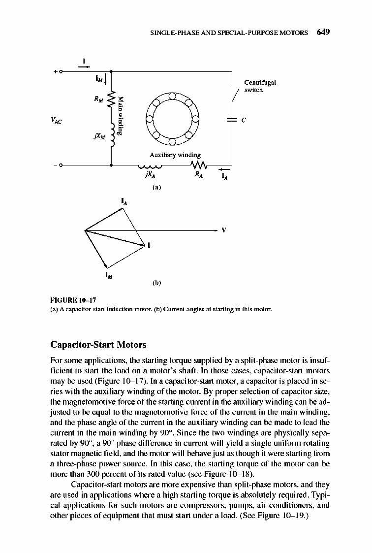
SINGLE-PHASE AND SPECIAL-PURPOSE MOTORS 649
+o---~--~-------------------,
1· 1 Centrifugal
R. i sWItch
C
Auxiliary winding
,,'
I.
'h' FIGURE 10- 17 (a) A capacitor-start induction motor. (b) Current .angles at starting in this motor.
Capacitor-Start Motors
For some applications, the starting torq ue supplied by a split-phase motor is insufficient to start the load on a motor 's shaft. In those cases, capacitor-start motors may be used (Figure 10-1 7). In a capacitor-start motor, a capacitor is placed in series with the auxi liary winding of the motor. By proper selection of capacitor size, the magnetomoti ve force of the starting current in the auxiliary winding can be adjusted to be equal to the magnetomotive force of the current in the main winding, and the phase angle of the current in the auxi liary winding can be made to lead the current in the main winding by 90°. Since the two windings are physically separated by 90°, a 90° phase difference in current will yield a single unifonn rotating stator magnetic fie ld, and the motor will behave just as though it were starting from a three-phase power source. In this case, the starting torque of the motor can be more than 300 percent of its rated value (see Figure 10-1 8).
Capacitor-start motors are more expensive than split-phase motors, and they are used in applications where a high starting torque is absolutely required. Typical applications for such motors are compressors, pumps, air conditi oners, and other pieces of equipment that must start under a load. (See Figure 10-1 9.)
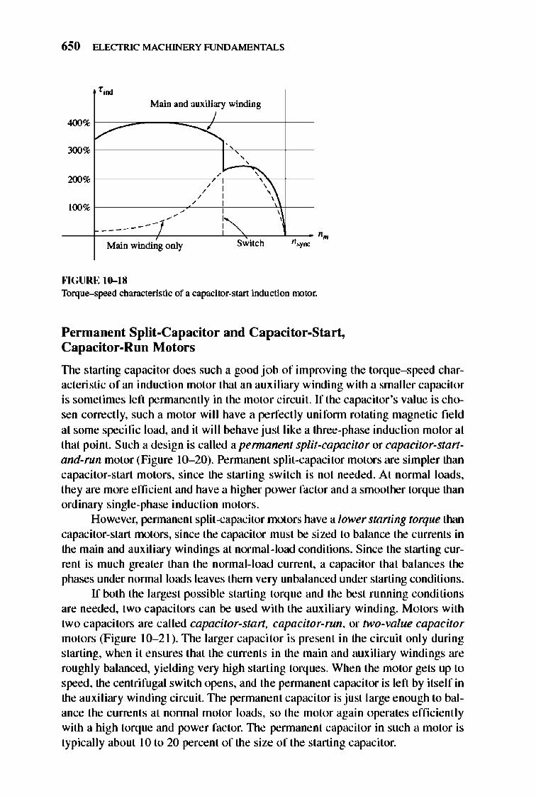
650 ELECTRIC MACHINERY RJNDAMENTALS
,~
400%
Main and aUXilip winding
V 300% , ,
~ ,
200%
'\ , , , , ,
100% ~ ,
,
~ ,
-(' , - ----- - -
Main winding only Switch ,~
""GURE 10-18 Torque-speed characteristic of a capacitor-start induction motor.
Permanent Split-Capacitor and Capacitor-Start, Capacitor-Run Motors
The starting capacitor does such a good jo b of improving Ihe torque-speed characteristic of an induction motor that an auxiliary winding with a smaller capacitor is sometimes left pennanently in the molo r circuit. If the capacitor's value is chosen correctly, such a motor will have a perfect ly unifonn rotating magnetic field at some specifi c load, and it will behave just like a three-phase inducti on motor at that point. Such a design is called a pennanent split-capacitor or capacitor-startand-run motor (Figure 10- 20). Pennane nt split-capacitor motors are simpler than capacitor-start motors, since the starting switch is not needed. At normal loads, Ihey are more effi cie nt and have a higher power factor and a smoother torque than ordinary single-phase induction motors.
However, pennanent split-capacitor molors have a lower starting torque Ihan capacitor-start motors, since the capacitor must be sized to balance lhe currents in the main and auxiliary windings at normal-load conditions. Since the starting current is much greater than the nonnal-load current, a capacitor that balances the phases under nonnal loads leaves them very unbalanced under starting conditions.
If both the largest possible starting lorque and the best running conditions are needed, two capacitors can be used with the auxiliary winding. Motors with two capacitors are called capacitor-stan, capacitor-run, or two-value capacitor motors (Figure 10- 2 1). TIle larger capacitor is present in the circuit only during starting, when it ensures that Ihe currents in the main and auxiliary windings are roughly balanced, yielding very high starting torques. When Ihe motor gets up 10
speed , the cenlrifugal switch opens, and the pennanent capacitor is left by itself in the auxi liary winding circuit. TIle pennanent capacitor is just large enough to balance the currents at nonnal motor loads, so the motor again operates efficienl ly with a high torque and power factor. TIle pennanent capacitor in such a motor is typically about 10 10 20 percent of the size of the starting capacitor.
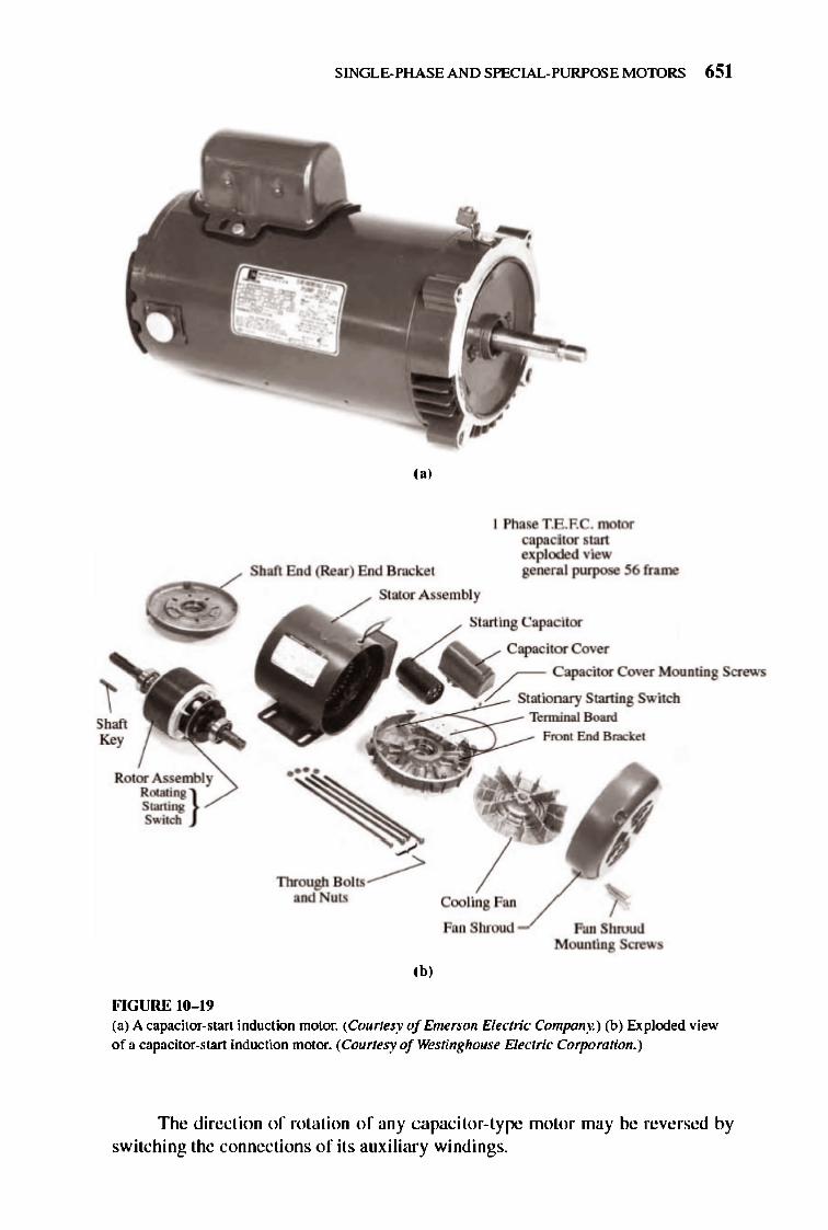
Sh," !(oy
Rotor Assembly Rotllling } Staning Switch
FIGURE 10- 19
SINGLE-PHASE AND SPECIAL-PURPOSE MOTORS 651
('J
Shaft End (Rear) End Bracket
I Phase T.E.F.e. motor capa.citor start exploded view general purpose 56 frame
Stator Assembly
Starting Capacitor
Capacitor Cover
/ -- Capacitor Cover Mounting Screws
_~::::~;:-~Stationary Starting Switch ;: Tenninat Board
Front End Bmcket
Fan Shroud
(bJ
Fan Shroud Mounting Screws
(a) A capa.citor-start induction ntotor. (Courtesy of Emerson Electric Company.) (b) Exploded view of a capacitor-start induction motor. (Courtesy of Westinghouse Electric Corpomtion.)
The direction of rotation of any capacitor-type motor may be reversed by switching the connections of its auxiliary windings.
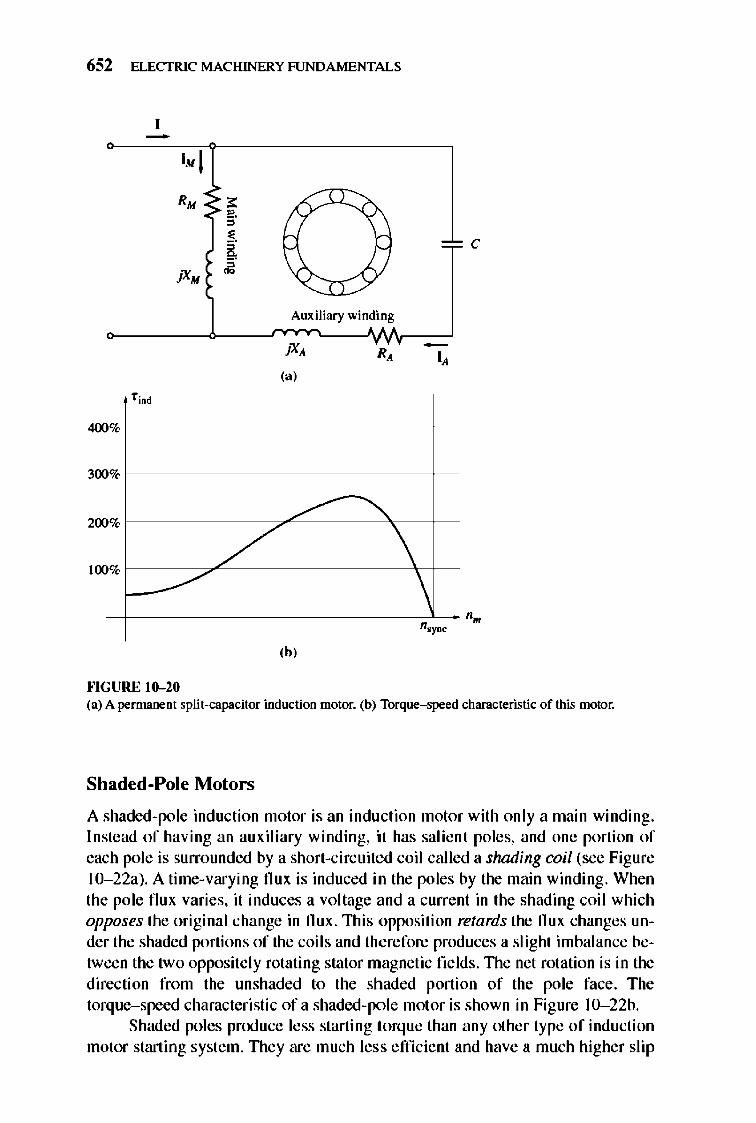
652 ELECTRIC MACHINERY RJNDAMENTALS
I. j
R. ~ ~ ~ < ,. , ~.
0 ~ C ~ , ~':l:/ jX. ~
Auxiliary win~i~g
jX, R, I, (a)
'00
400 %
300 %
100
% /' '" / \
% /' \
200
'.~
'h' ""GURE 10-20 (a) A permanent split-capacitor induction ntotor. (b) Torque-speed characteristic of this motor.
Shaded-Pole Motors
A shaded-pole induction motor is an indu ction molor with only a main winding. Instead of having an auxiliary winding, it has salient poles, and one portion of each pole is surrounded by a short-circuited coil called a shading coil (see Figure 1O- 22a). A time-varying flux is induced in Ihe poles by the main winding. When the pole flux varies, it induces a voltage and a current in the shading coil which opposes Ihe original change in flUX.1lli s opposition retards the flux changes under the shaded portions of the coils and therefore produces a slighl imbalance between Ihe two opposite ly rotating stator magnetic fields. TIle net rolation is in Ihe direction from the unshaded to the shaded portion of the pole face. The torque-speed characteristic of a shaded-po le molar is shown in Figure IO- 22b.
Shaded poles produce less starting torq ue than any other type of induction motor starting system. TIley are much less e ffi cient and have a much higher slip
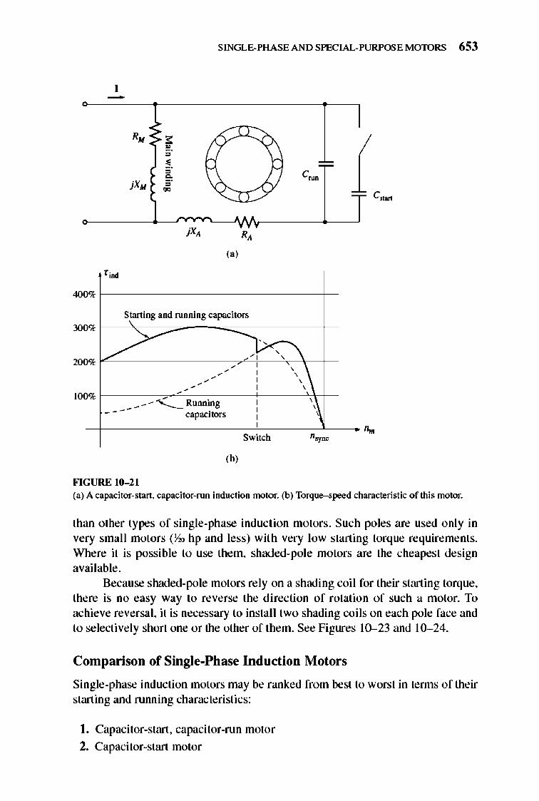
SINGLE-PHASE AND SPECIAL-PURPOSE MOTORS 653
-~ ').
I RM < I' 7 '\ '\ ,.
" ~. := " c_ ~ " "" 5/ jXM
00 ,
(., fjmd
400 %
Starting and ru nning capacitors %
/ Y" \ % , , , , , , , , , , , ,
, , , ,
300
2llll
(00 % ,
_---<- Runmng , , , , --- capacitors , , , Switch "~
(b'
FIGURE 10- 21 (a) A capacitor-start. capacitor-run induction motor. (b) Torque-speed characteristic of this motor.
than other types of single-phase induction motors . Such poles are used only in very small motors (Y..o hp and less) with very low starting torque requirements. Where it is possible to use them, shaded-pole motors are the cheapest design available.
Because shaded-pole motors rely on a shading coil fo r their starting torque, there is no easy way to reverse the directi on of rotation of such a motor. To achieve reversal, it is necessary to install two shading coils on each pole face and to selecti vely short one or the other of them. See Figures 10-23 and 10- 24 .
Comparison of Single-Phase Induction Motors
Single-phase induction motors may be ranked from best to worst in tenns of their starting and running characteristics:
I. Capacitor-start , capacitor-run motor
2. Capacitor-start motor
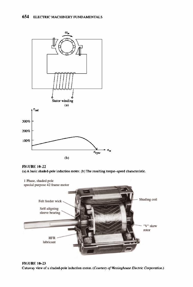
654 ELECTRIC MACHINERY RJNDA MENTALS
300%
200%
Stator winding ,,'
"-------------------------~--- "m "."" ,b, ""GURE 10-22 (a) A basic shaded-pole induction motor. (b) The resulting torque-speed characteristic.
I Phase. shaded pole special purpose 42 frame motor
Self-aligning sleeve bearing
HFR -~~ lubricant
""GURE 10-23
Shading coil
"V" skew rotor
Cutaway view of a shaded-pole induction motor. (Courtesy ofWestin8lwuse Electric Corporation.)
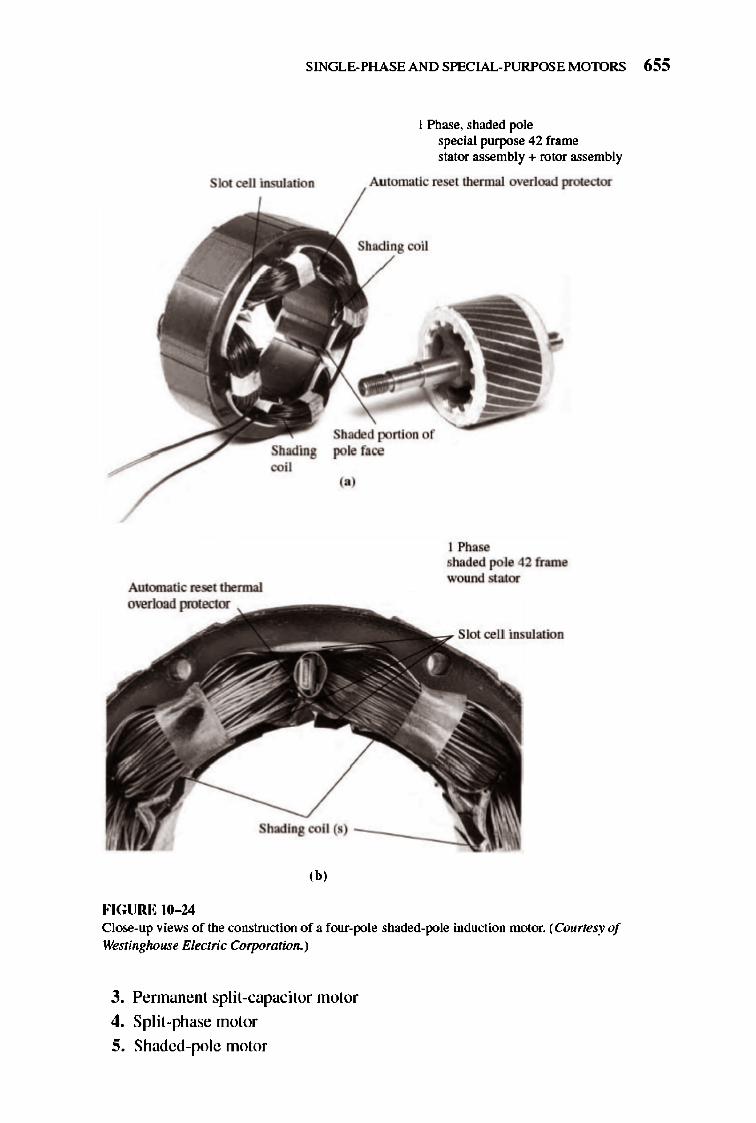
SINGLE-PHASE AND SPECIAL-PURPOSE MOTORS 655
Slot cell insulation
Automatic reset thermal overload protector
I Phase. shaded pole special purpose 42 frame stator assembly + rotor assembly
,',moo.';",~, thennal overload protector
Shading coil
Shaded portion of pole face
(.,
I Phase shaded pole 42 frame wound stator
Slot cell insulation
Shading coil (5) ______ ~
(b'
FIGURE 10- 14 Close-up views of the construction of a four-pole shaded-pole induction motor. (Courtesy of Watinghouse Electric Corporation.)
3. Pennanent split-capacitor motor
4. Split-phase motor
S. Shaded-pole motor
656 ELECTRIC MACHINERY RJNDAMENTALS
Naturally, the best motor is also the most expensive, and the worst motor is the least expensive . Also, not all these starting techniques are avai lable in all motor size ranges. It is up to the design e ngineer to select the cheapest available motor for any given application that will do the job.
10.4 SPEED CONTROL OF SINGLE-PHASE INDUCTION MOTORS
In general, the speed of sing le-phase induction motors may be controlled in the same manner as the speed of polyphase induction motors. For squirrel-cage rotor motors, the foll owing techniques are available :
I. Vary the stator freque ncy.
2. Change the number of poles.
3. Change the applied tenninal voltage VT .
In practical designs involving fairly high-slip motors, the usual approach to speed control is to vary the terminal vo ltage of the motor. 1lle voltage applied to a motor may be varied in one of three ways :
I. An autotransformer may be used to continually adjust the line voltage. nlis is the most expensive methexl of voltage speed control and is used only when very smooth speed control is needed.
2. An SCR or TRIAC circuit may be used to reduce the nns voltage applied to the motor by ac phase control. nlis approach chops up the ac wavefonn as described in Chapter 3 and somewhat increases the motor's noise and vibration. Solid-state control circuits are considerably cheaper than autotransfonners and so are becoming more and more common.
3. A resistor may be inserted in series with the motor's stator circuit. This is the cheapest methexl of voltage control , but it has the disadvantage that considerable power is lost in the resistor, reducing the overall power conversion efficiency.
Another technique is also used with very high-slip motors such as shadedpole motors. Instead of using a separate a ut otransformer to vary the voltage applied to the stator of the motor, the stator winding itself can be used as an autotransfonner. Figure 10--25 shows a sche matic representati on of a main stator winding, with a number of taps along its length. Since the stator winding is wrapped about an iron core, it behaves as an autotransfonner.
When the full line voltage V is applied across the entire main winding, then the induction motor operates normally. Suppose instead that the full line voltage is applied to tap 2, the center tap of the winding.1lle n an identical voltage will be induced in the upper half of the winding by transformer action, and the total winding
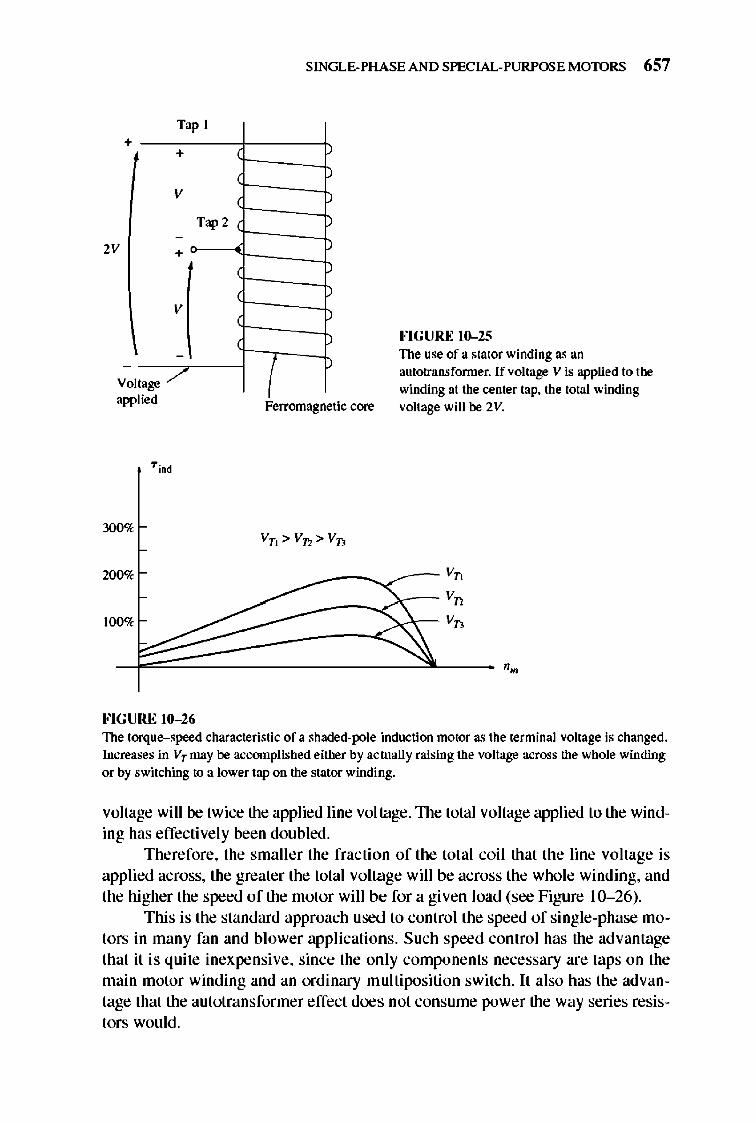
Tap I +
+
V
-2V +
V
oltage /" V
apphed
300%
2llll%
100%
FIGURE 10-26
T", 2
SINGLE-PHASE AND SPECIAL-PURPOSE MOTORS 657
Ferromagnetic core
Jo'I GURE 10-25 The use of a stator winding as an autotransformer. If voltage V is applied to the winding at the center tap. the total winding voltage will he 2V.
~~ _ _____ ~_ Vo
Vo
Vo
The torque-speed characteristic of a shaded-pole induction motor as the terminal voltage is changed. Increases in VTmay he accomplished either by actually raising the voltage across the whole winding or by switching to a lower tap on the stator winding.
voltage will be twice the applied line voltage.1lle total voltage applied to the winding has effectively been doubled.
Therefore, the smaller the fraction of the total coil that the line voltage is applied across, the greater the total voltage will be across the whole winding, and the higher the speed of the motor wi ll be for a given load (see Figure 10- 26).
This is the standard approach used to control the speed of single-phase motors in many fan and blower applications. Such speed control has the advantage that it is quite inexpensive, since the only components necessary are taps on the main motor winding and an ordinary multiposition switch. It also has the advantage that the autotransformer effect does not consume power the way series resistors would.
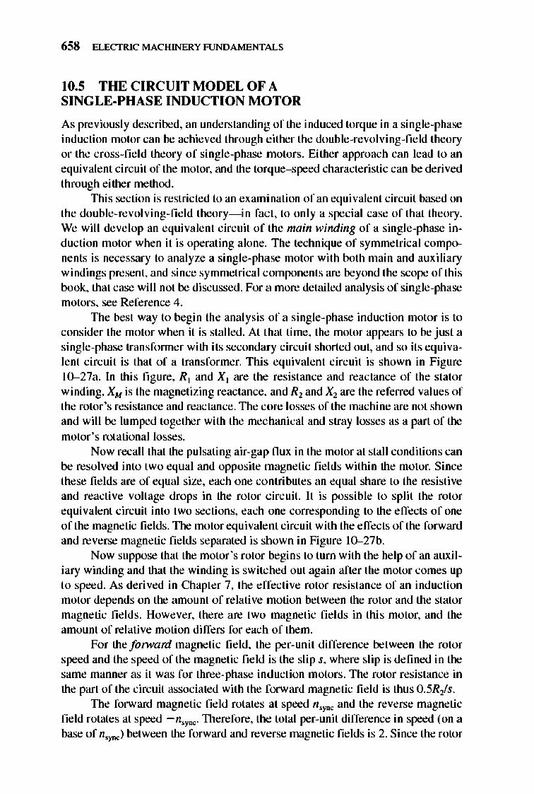
658 ELECTRIC MACHINERY RJNDAMENTALS
10.5 THE CIRCUIT MODEL OF A SINGLE-PHASE INDUCTION MOTOR
As previously described, an understanding of the induced torque in a single-phase induction motor can be achieved through either the double-revolving-field theory or the cross-fi e ld theory of single-phase motors. Either approach can lead to an equi vale nt circuit of the motor, and the torque-speed characteristic can be derived through either method.
TIlis section is restricted to an examination of an equi valent circuit based on the double-revolving-field theory- in fact, to only a special case of that theory. We will devel op an equivalent circuit of the main winding of a single-phase induction motor when it is operating alone. The technique of symmetrica l components is necessary to analyze a single-phase motor with both main and auxiliary windings present, and since symmetrical components are beyond the scope of this book, that case will not be discussed. For a more detailed analysis of single-phase motors, see Reference 4.
TIle best way to begin the analysis of a single-phase induction motor is to consider the motor when it is stalled. At that time, the motor appears to be just a single-phase transfonner with its secondary circuit shorted out, and so its equi valent circuit is that of a transformer. Thi s equivalent circuit is shown in Figure 100027a. In this fi gure, Rl and Xl are the resistance and reactance of the stator winding, XM is the magnetizing reactance, and Rl and X2 are the referred values of the rotor's resistance and reactance. The core losses of the machine are not shown and will be lumped together with the mec hanical and stray losses as a part of the motor's rotational losses.
Now recall that the pulsating air-gap flu x in the motor at stall conditions can be resolved into two equal and opposite magnetic fi e lds within the motor. Since these fie lds are of equal size, each one contributes an equal share to the resistive and reactive volt age drops in the rotor c ircuit. It is possible to split the rotor equivalent circuit into two sections, each one corresponding to the e ffects of one of the magnetic fi e lds. The motor equi valent circuit with the effects of the forward and reverse magnetic fie lds separated is shown in Figure 10--27b.
Now suppose that the motor 's rotor begins to turn with the help of an auxiliary winding and that the winding is switched out again after the motor comes up to speed. As derived in Chapter 7, the effective rotor resistance of an induction motor depends on the amount of relati ve motion between the rotor and the stator magnetic fie lds. However, there are two magnetic fi e lds in this motor, and the amount of relative motion differs for each of them.
For the fOlward magnetic field , the per- unit difference between the rotor speed and the speed of the magnetic field is the slip s, where slip is defined in the same manner as it was for three-phase induction motors. The rotor resistance in the part of the circuit associated with the forward magnetic fie ld is thus O.5R.Js.
TIle forward magnetic field rotates at speed n.ync and the reverse magnetic field rotates at speed -n.ync. TIlerefore, the total per-unit difference in speed (on a base of n.ync) between the forward and reverse magnetic fields is 2. Since the rotor
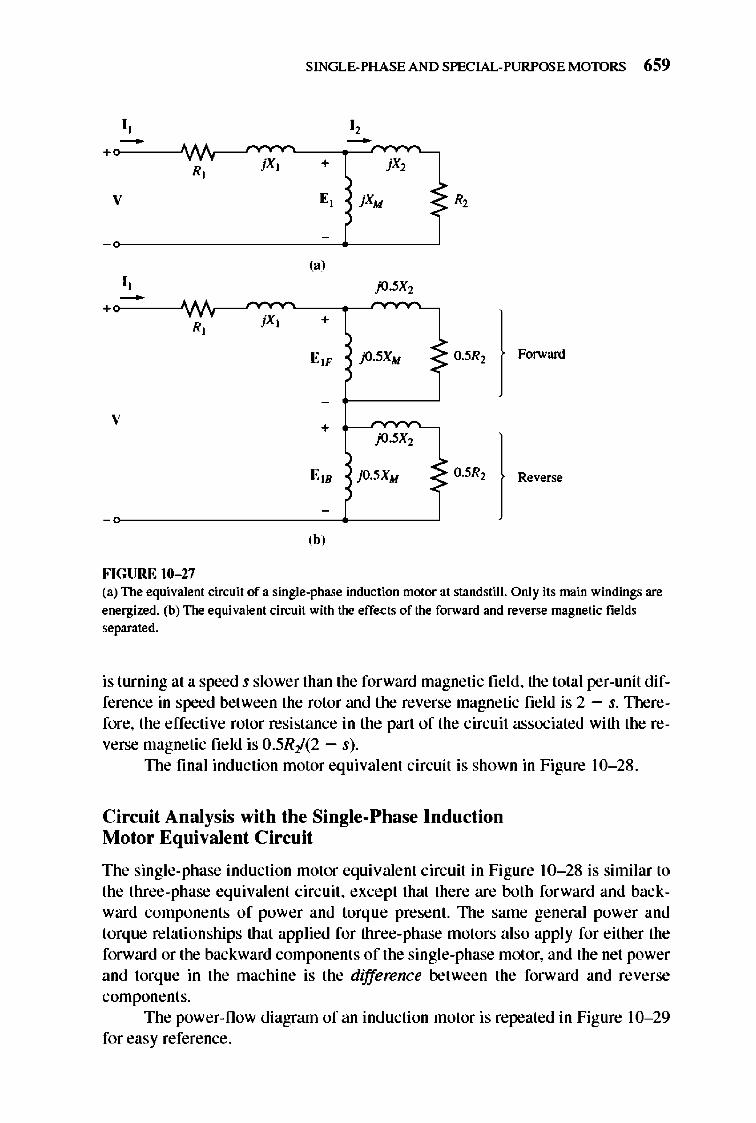
SINGLE-PHASE AND SPECIAL-PURPOSE MOTORS 659
I , I , - -+ R, j X ] + jX2
V E , jXM R,
(a) I, -+
R, jX] +
E" jO.5XM 0.5R2 Forward
-
V + jO.5X2
E" jO.5XM ~ 0.5R2 Reverse
-
,b, FIGURE 10-27 (a) The equivalent circuit of a single-phase induction motor at standstill. Only its main windings are energized. (b) The equivalent circuit with the effects of the forward and reverse magnetic fields separated.
is turning at a speed s slower than the forward magnetic field, the total per-unit difference in speed between the rotor and the reverse magnetic field is 2 - s. Therefore, the effective rotor resistance in the part of the circuit associated with the reverse magnetic field is 0.SRI(2 - s).
The final induction motor equivalent circuit is shown in Figure 10- 28 .
Circuit Analysis with the Single-Phase Induction Motor Equi valent Circuit
The single-phase induction motor equivalent circuit in Figure 10- 28 is similar to the three-phase equivalent circuit, except that there are both forward and backward components of power and torque present. 1lle same general power and torque relationships that applied for three-phase motors also apply for either the forward or the backward components or the single-phase motor, and the net power and torq ue in the machine is the difference between the forward and reverse components.
The power-now diagram of an induction motor is repeated in Figure 10- 29 for easy reference .
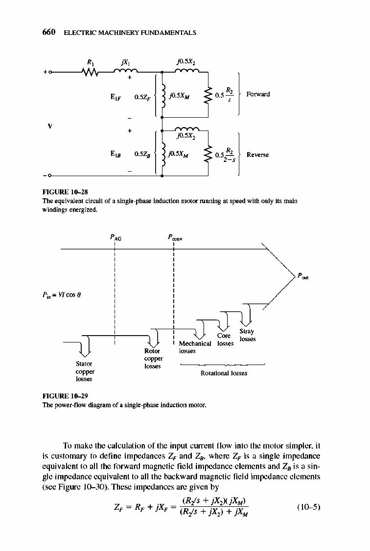
660 ELECTRIC MACHINERY RJNDAMENTALS
R, + " +
E lF O.5ZF jO.5XM 0.5 R2 Forward ,
-
V +
jO.5X2
E IB 0.5ZB jO.5XM 0.5 R2 Reverse 2->
-
""GURE 10-28 The equivalent cin:uit of a single-phase induction motor running at speed with only its main windings energized.
Slator 00_ losses
""GURE 10-29
Rotor copper losses
Core Mechanical losses losses
Stray losses
Rotational losses
The power-flow diagram of a single-phase induction motor.
To make Ihe calculalion of the input current fl ow into the motor simpler, it is customary to define impedances ZF and ZB, where ZF is a single impedance equivalent to all the forward magnetic fi e ld impedance elements and ZB is a single impedance equivalent to all the backward magnetic fie ld impedance e lements (see Figure 10-30). These impedances are given by
. (Ris + jX.0(jXM) ZF = RF + }XF = (Ris + jX
2) + jXM ( 10-5)
-+
z, v
-+
z, V
D
SINGLE-PHASE AND SPECIAL-PURPOSE MOTORS 661
Fl G URE 10-30 A series oombination of RF andJXF is the
jXp Thevenin equivalent of the forwaJd-field impedance elements. and therefore Rr must consume the same power from a given current as Rlls would.
. [RI(2 - s) + jX2](jXM) ZB = RB + JXB = [R2/(2 s) + jX21 + jXM ( 10-<5)
In tenns of Zp and ZB, the current fl owing in the induction motor's stator winding is
( 10-7)
The per-phase air-gap power of a three-phase induction motor is the power consumed in the rotor circuit resistance O.5RJs. Simi larly, the forward air-gap power of a single-phase inducti on motor is the power consumed by 0.5R2/s, and the reverse air-gap power of the motor is the power consumed by O.5RJ(2 - s). Therefore, the air-gap power of the motor could be calculated by detennining the power in the forward resistor O.5RJs, detennining the power in the reverse resistor 0.5Ri(2 - s), and subtracting one from the other.
TIle most difficult part of this calculation is the determination of the separate currents fl owing in the two resistors. Fortunately, a simplification of this calculation is possible. Notice that the only resistor within the circuit elements composing the equivalent impedance Zp is the resistor Ris . Since Zp is equivalent to that circuit, any power consumed by ZF must also be consumed by the original circuit, and since Ris is the only resistor i n the original circuit , its power consumption must equal that ofimpedancc Zp. Therefore, the air-gap power for the forward magnetic fie ld can be expressed as
662 ELECTRIC MACHINERY RJNDAMENTALS
( 10-8)
Similarly, the air-gap power for the reverse magnetic fie ld can be expressed as
PAGJJ = n(0.5 RB) ( 10--9)
1lle advantage of these two equations is that only the one current / 1 needs to be calculated to detennine both powers.
TIle total air-gap power in a single-phase induction motor is thus
(10-10)
TIle induced torque in a three-phase induction motor can be found from the equation
PAG Tind = -
w,"" where PAG is the net air-gap power given by Equati on (10-10).
(10-11 )
1lle rotor copper losses can be fou nd as the sum of the rotor copper losses due to the forward fie ld and the rotor copper losses due to the reverse fi e ld.
(10- 12)
TIle rotor copper losses in a three-phase induction motor were equal to the perunit relative motion between the rotor and the stator field (the slip) times the airgap power of the machine. Similarly, the forward rotor copper losses of a singlephase induction motor are given by
P RCL•F = SPAG•F (10- 13)
and the reverse rotor copper losses of the motor are given by
(10-14)
Since these two power losses in the rotor are at different frequencies, the total rotor power loss is just their sum.
TIle power converted from electrical to mechanical fonn in a single-phase induction motor is given by the same equation as P.:OD¥ for three-phase induction motors. TIlis equation is
Since Wm = (1 - s)w. ync, this equation can be reexpressed as
PC<JJI¥ = Tind(1 - s)wm
From Equation (10-11 ), PAG = TiDdW, y .. ,,, so P.:oo¥ can also be expressed as
P.:ODV = ( I - s) PAG
(10-15)
(10-16)
(10-17)
As in the three-phase induction motor, the shaft output power is not equal to P.:OD¥' since the rotational losses must still be subtracted. In the single-phase induction motor model used here, the core losses, mechanical losses, and stray losses must be subtracted from P.:ODV in order to get POll '.
SINGLE-PHASE AND SPECIAL-PURPOSE MOTORS 663
Example 10-1. A ~hp, lID-V, 60-Hz, six-pole, split-phase induction motor has the following impedances:
R] = 1.52Q
R2 = 3.13 Q
X ] =2.100
Xl = 1.56Q
XM = 58.2 Q
The core losses of this motor are 35 W, and the friction, windage, and stray losses are 16 W. The motor is operating at the rated voltage and frequency with its starting winding open, and the motor 's slip is 5 percent. Find the following quantities in the motor at these conditions:
(a) Speed in revolutions per minute (b) Stator current in amperes (c) Stator power factor (d) Pin (e) PAG
(f) P_ (g) "TiOO
(h) P "'" (i) "Tj.,.;l
0) Efficiency
Solution The forward and reverse impedances of this motor at a slip of 5 percent are
_ . _ (Ris + jx.zXjXM) ZF - RF + }XF - (Ris + jX2) + jXM
(3.13 flAI.05 + jl.56 0)(j58.2 0) = (3.13 OAI.05 + jl.56 0) + j58.2 0
(62.6L 1.430 OXj5S.2 0) = (62.60 + jl.56 0) + j5S.2 0
= 39.9L50.5° 0 = 25.4 + j30.7 0
_ . _ [Rf(2 - s) + jX2](jXM) ZB - RB + }XB - [Rf(2 s) + jX2] + jXM
(3.13 fl/1.95 + jl.56 0)(j58.2 0) = (3.13 fl/1.95 + jl.56 0) + j58.2 0
(2.24L44.2° OXj5S.2 0) = (1.61 0 + jl.56 0) + j5S.2 0
= 2.ISL45.9° 0 = 1.51 + jl.56 0
These values will be used to detennine the motor clUTent, power, and torque.
(a) The synchronous speed of this motor is
II = 12Qf, = 120(60 Hz) = .ync P 6 pole 1200 r/min
Since the motor is operating at 5 percent slip, its mechanical speed is
11m = (I - s)n~yDC
(10-5)
(10--6)
664 ELECTRIC MACHINERY RJNDAMENTALS
n .. = (I - 0.05X 1200 r/min) = 1140 r/min
(b) The stator current in this motor is
"">CCC,"or,",,<o"".i~i~O~L~O,""V~"'C-"'7<""C-"'CC"" = 1.52 n + j2.10 n + 0.5(25.4 n + j30.7 n) + 0.5(1.51 n + j1.56 n)
= .""i'iii'0,;L,O"",,VCcon - lIOLO° V _ 466L 50 6° A 14.98 n + jI8.23 n - 23.6L50.6° n - . - .
(c) The stator power factor of this motor is
PF = cos ( - 50.6°) = 0.635 lagging
(d) The input power to this motor is
Pm = VI cos ()
= (110 VX4.66 AXO.635) = 325 W
(e) The forward-wave air-gap power is
PAGE = l i(o.5 RF)
= (4.66 A)2(12.7 0) = 275.8 W
and the reverse-wave air-gap power is
PAG.B = l i(o.5 RB)
= (4.66 A)2(0.755 V) = 16.4 W
Therefore, the total air-gap power of this motor is
PAG = PAG.F - PAG.B
= 275.8 W - 16.4 W = 259.4 W
if) The power converted from electrical to mechanical fonn is
P OO<IV = (I - s) PAG
= (I - 0.05)(259.4 W) = 246 W
(g) The induced torque in the motor is given by
= 259.4 W = 2(x;N o (1200r/min)(lminJ60sX27Tradlr) . m
(h) The output power is given by
POlS. = Pooov - P~ = Pooov - POOle - PIDOCb - P_ y
= 246 W - 35 W - 16 W = 195 W
(i) The load torque of the motor is given by
p~ T_ = w".
(10--7)
(10--8)
(10-9)
(10--10)
(10--17)
(10--11 )
SINGLE-PHASE AND SPECIAL-PURPOSE MOTORS 665
= 195W = 163N o (1140 r/minXI min/60 s)(21Tradlr) . m
OJ Finally, the efficiency of the motor at these conditions is
195 W 100% = 325 W x 100% = 60%
10.6 OTHER TYPES OF MOTORS
Two other types of motors- reluctance motors and hysteresis motors-are used in certain special-purpose appli cations . These motors differ in rotor constructi on from the ones previously described, but use the same stator design. Like induction motors, they can be built with either sin gle- or three-phase stators. A third type of special-purpose motor is the stepper motor. A stepper motor requires a polyphase stator, but it does not require a three-phase power supply. The final specialpurpose motor discussed is the brushless dc motor, which as the name suggests runs on a dc power supply.
Reluctance Motors
A reluctance motor is a motor which depends on reluctance torque for its operation. Reluctance torque is the torque induced in an iron object (such as a pin) in the presence of an external magnetic field , which causes the object to line up with the external magnetic fie ld. TIli s torque occurs because the external field induces an internal magnetic field in the iron of the object, and a torque appears between the two fie lds, twisting the object around to line up with the external field. In order for a reluctance torque to be produced in an object, it must be elongated along axes at angles corresponding to the angles between adjacent poles of the external magnetic fi e ld.
A simple schematic of a two-pole re luctance motor is shown in Figure 1O-3 \. It can be shown that the torque applied to the rotor of this motor is proportional to sin 20, where 0 is the electrical angle between the rotor and the stator magnetic fields. TIlerefore, the reluctance torque ofa motor is maximum when the angle between the rotor and the stator magnetic fields is 45 °.
A simple reluctance motor of the sort shown in Figure 10-3 I is a synchronous motor, since the rotor will be locked into the stator magnetic fie lds as long as the pullout torque of the motor is not exceeded. Like a nonnal synchronous motor, it has no starting torque and will no t start by it self.
A self-starting reluctance motor that will operate at sy nchronous speed until its maximum reluctance torque is exceeded can be built by modifying the rotor of an induction motor as shown in Figure 10- 32. In this fi gure, the rotor has salient poles for steady-state operati on as a re luctance motor and also has cage or amortisseur windings for starting. TIle stator of such a motor may be e ithe r of single- or three-phase construction. The torque- speed characteristic of this motor, which is sometimes called a synchronous induction motor, is shown in Figure 10-33.
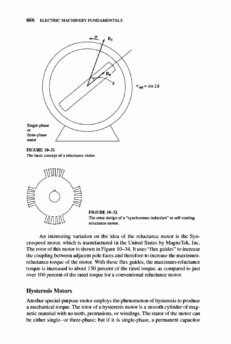
666 ELECTRIC MACHINERY RJNDAMENTALS
Single-phase 0' three-phase stator
""GURE 10-31
, "iDd""sin2/i
The basic concept of a reluctance motor.
o FIGURE 10-32 The rotor design of a "synchronous induction" or self-starting reluctance motor.
An inleresting variation on Ihe idea of Ihe reluctance motor is Ihe Syncrospeed motor, which is manufactured in the United States by MagneTek, Inc . TIle rotor of this motor is shown in Figure 10- 34. It uses " flux guides" to increase Ihe coupling between adjacenl pole faces and therefore to increase the maximumre luctance lorque of the motor. With these flux guides, Ihe maximum-re luctance torque is increased to about 150 percent o f the rated torque, as compared to just over 100 percent of the rated torque for a conve ntional reluctance motor.
Hysteresis Motors
Another special-purpose motor employs the phenomenon of hysteresis to produce a mechanical lorque . TIle rotor of a hysteresis motor is a smoolh cylinder of magnetic material with no teeth, protrusions, or windings. TIle stator of the motor can be either single- or three-phase; but if it is single-phase, a permanent capacitor
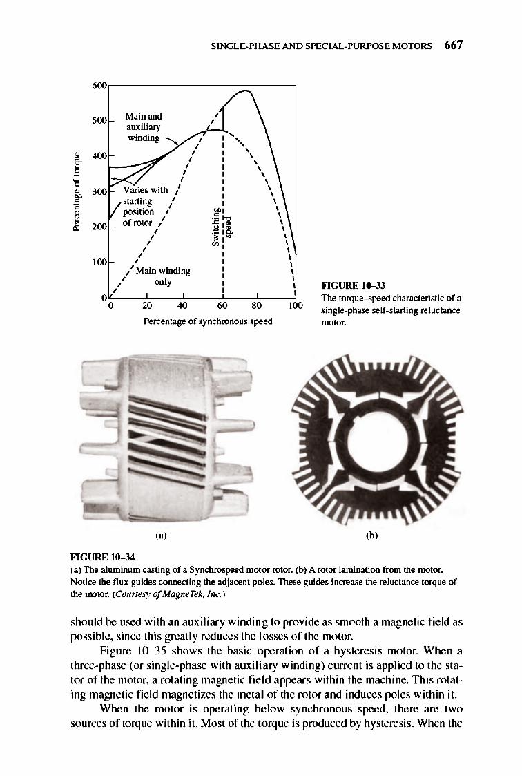
SINGLE-PHASE AND SPECIAL-PURPOSE MOTORS 667
~,-------------~~---,
500
, 400
Main and auxiliary
, , winding I I "', , , , , , '
~ f--;;:; I I \ , , , , , , , , ,
Varies with / I \ , , starting I I \
position " ::? I \ of rotor " :c: :al \
I . .e! 12!.. \ I OJ I '"' \
" '" I \ , , , , , , " Main winding I \ , ,
" only I
200
100
, ,
O~--~--~--~--~--~ o 20 40 60 80 100
Percentage of synchronous speed
(a)
FIGURE 10-34
""GURE 10-33 The torque-speed characteristic of a single-phase self-starting reluctance ntotor.
'h' (a) The aluminum casting of a Synchrospeed motor rotor. (b) A rotor lamination from the motor. Notice the flux guides connecting the adjacent poles. These guides increase the reluctance torque of the motor. (Courtesy of MagneTek, I nc.)
should be used with an auxiliary winding to provide as smooth a magnetic field as possible, since this greatly reduces the losses of the motor.
Figure 10-35 shows the basic operation of a hysteresis motor. Whe n a three-phase (or sing le-phase with auxi li ary winding) current is applied to the stator of the motor, a rotating magnetic fi e ld appears within the machine. This rotating magnetic fie ld magnetizes the meta l of the rotor and induces poles within it.
Whe n the motor is operating below synchronous speed, there are two sources of torq ue within it. Most of the torque is produced by hysteresis. When the
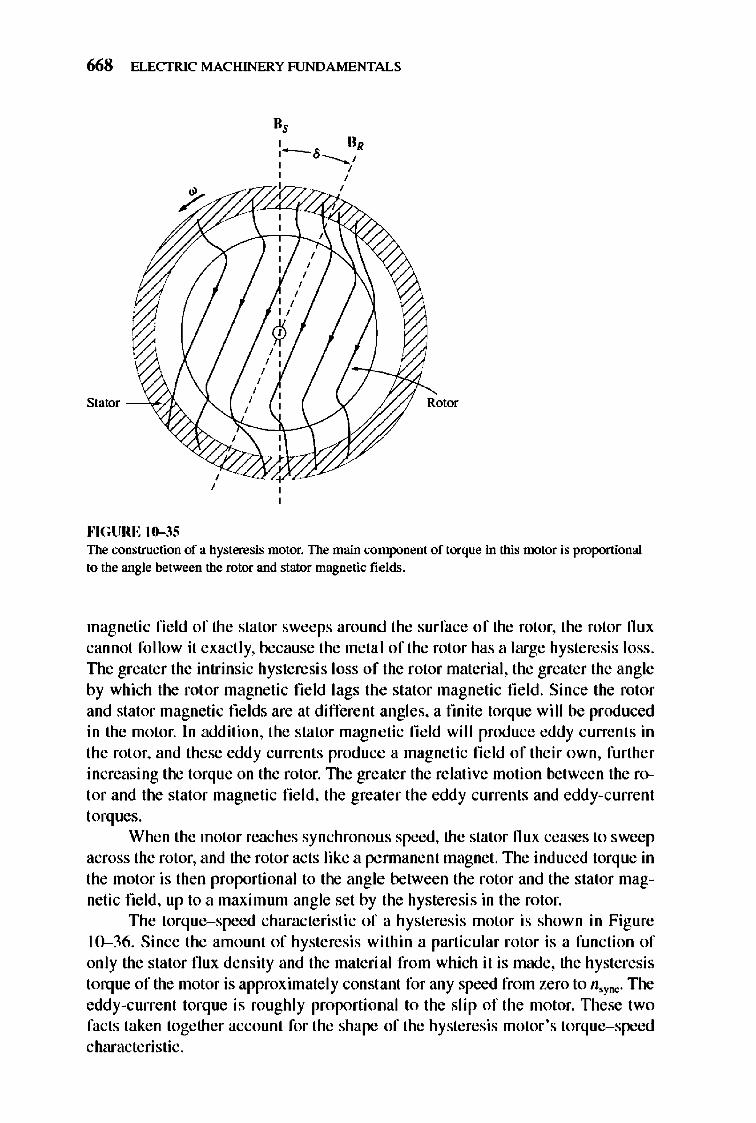
668 ELECTRIC MACHINERY RJNDAMENTALS
Stator - "6-}
""GURE 10-35
, ,
II, , 0, 1-6---..1 , , , ,
~777 ' ,
Rotor
The construction of a hysteresis motor. The main component of torque in this motor is proponional to the angle between the rotor and stator magnetic fields.
magnetic fie ld of the stator sweeps around the surface of the rotor, the rotor flux cannot follow it exactly, because the metal of the rotor has a large hysteresis loss . TIle greater the intrinsic hysteresis loss of the rotor material, the greater the angle by which the rotor magnetic field lags the stator magnetic field. Since the rotor and stator magnetic fields are at different angles, a fmite torque will be produced in the motor. In addition, the stator magnetic fi e ld will produce eddy current s in the rotor, and these eddy currents produce a magnetic field of their own, further increasing the torque on the rotor. TIle greater the relative motion between the rotor and the stator magnetic fi e ld, the greater the eddy currents and eddy-current torques.
When the motor reaches synchronous speed, the stator flux ceases to sweep across the rotor, and the rotor acts like a pennanent magnet. The induced torque in the motor is then proportional to the angle between the rotor and the stator magnetic field , up to a maximum angle set by the hysteresis in the rotor.
TIle torque-speed characte ristic of a hysteresis motor is shown in Figure 10--36. Since the amount of hysteresis within a particular rotor is a function of only the stator flux density and the material from which it is made, the hysteresis torque of the motor is approximately constant for any speed from zero to n,ync. The eddy-c urrent torque is roughly proportional to the slip of the motor. TIlese two facts taken together account for the shape of the hysteresis motor's torque-speed characteristic .
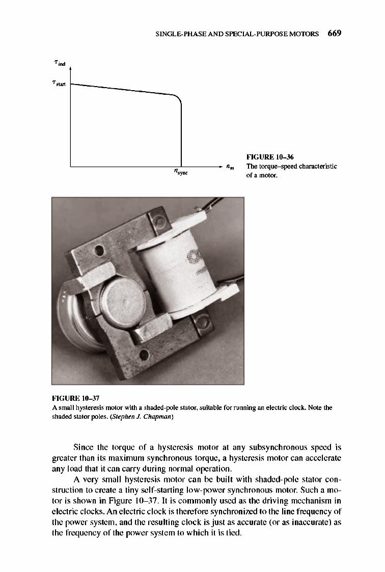
FIGURE 10-37
SINGLE-PHASE AND SPECIAL-PURPOSE MOTORS 669
""GURE 10-36 n.. The torque--speed characteristic
ofa motor.
A small hysteresis motor with a shaded-pole stator. suitable for running an electric clock. Note the shaded stator poles. (Stt'phen J. Chapman)
Since the torque of a hysteresis motor at any subsynchronous speed is greater than its maximum synchronous torque, a hysteresis motor can accelerate any load that it can carry during normal operation.
A very small hysteresis motor can be bui lt with shaded-pole stator construction to create a tiny self-starting low-power synchronous motor. Such a motor is shown in Figure 10- 37. It is commonly used as the driving mechanism in electric clocks. An electric clock is therefore synchronized to the line frequency of the power system, and the resulting clock is just as accurate (or as inaccurate) as the frequency of the power system to which it is tied.
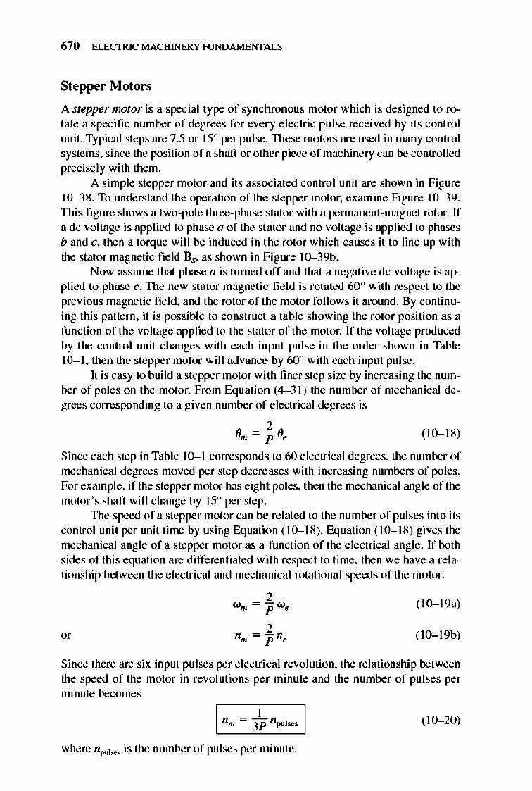
670 ELECTRIC MACHINERY RJNDAMENTALS
Stepper Motors
A stepper nwtor is a special type of synchronous motor which is designed to rotate a specifi c number of degrees for every e lectric pulse received by its control unit. Typical steps are 7.5 or 15° per pulse. 1llese motors are used in many control systems, since the position of a shaft or other piece of machinery can be controlled precisely with them.
A simple stepper motor and its associated control unit are shown in Figure 1 0- 3S. To understand the operation of the stepper motor, examine Figure 10-39. TIlis fi gure shows a two-pole three-phase stator with a pennanent-magnet rotor. If a dc voltage is applied to phase a of the stator and no voltage is applied to phases band c, then a torque wi ll be induced in the rotor which causes it to line up with the stator magnetic field Bs, as shown in Figure 10--39b.
Now assume that phase a is turned o ff and that a negative dc voltage is applied to phase c. TIle new stator magnetic field is rotated 60° with respect to the previous magnetic field , and the rotor of the motor fo llows it around. By continuing this pattern, it is possible to construct a table showing the rotor position as a function of the voltage applied to the stator of the motor. If the voltage produced by the control unit changes with each input pulse in the order shown in Table 10-1, then the stepper motor will advance by 60° with each input pulse.
It is easy to bui ld a stepper motor with finer step size by increasing the number of poles on the motor. From Equation (4- 3 1) the number of mechanical degrees corresponding to a give n number of electrical degrees is
(10- 18)
Since each step in Table 10-1 corresponds to 60 electrical degrees, the number of mechanical degrees moved per step decreases with increasing numbers of poles. For example, if the stepper motor has eight poles, then the mechanical ang le of the motor's shaft will change by 15° per step.
1lle speed of a stepper motor can be related to the number of pulses int o its control unit per unit time by using Equation (10-IS). Equation (10-1S) gives the mechanical angle of a stepper motor as a function of the electrical angle . If both sides of this equation are differentiated with respect to time, then we have a relationship between the electrical and mechanical rotational speeds of the motor:
2 (1O-19a) wm = pW~
2 ( IO-19b) "' nm = p n~
Since there are six input pulses per electrical revolution, the relationship between the speed of the motor in revolutions per minute and the number of pulses per minute becomes
I nm = -iP npul ses ( 10- 20)
where n pulse< is the number of pulses per minute.
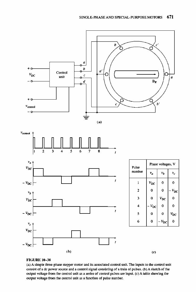
SINGLE-PHASE AND SPECIAL-PURPOSE MOTORS 671
b
" + b
Control "' ( ) Voc unit
, d B,
+~--~
( a)
1 2 3 4 , 6 7 8 ,
Voc 1---, Phase voltages. V
,"1~
number '. '. " 1 Voc 0 0
'. 2 0 0 - Voc
3 0 Voc 0
4 - Voc 0 0
5 0 0 Voc
6 0 - Voc 0
(b' ( " FIGURE 10-38 (a) A simple three-phase stepper motor and its associated control unit. The inputs to the control unit consist of a de power source and a control signal consisting of a train of pulses. (b) A sketch of the output voltage from the control unit as a series of control pulses are input. (e) A table showing the
output voltage from the control unit as a function of pulse number.
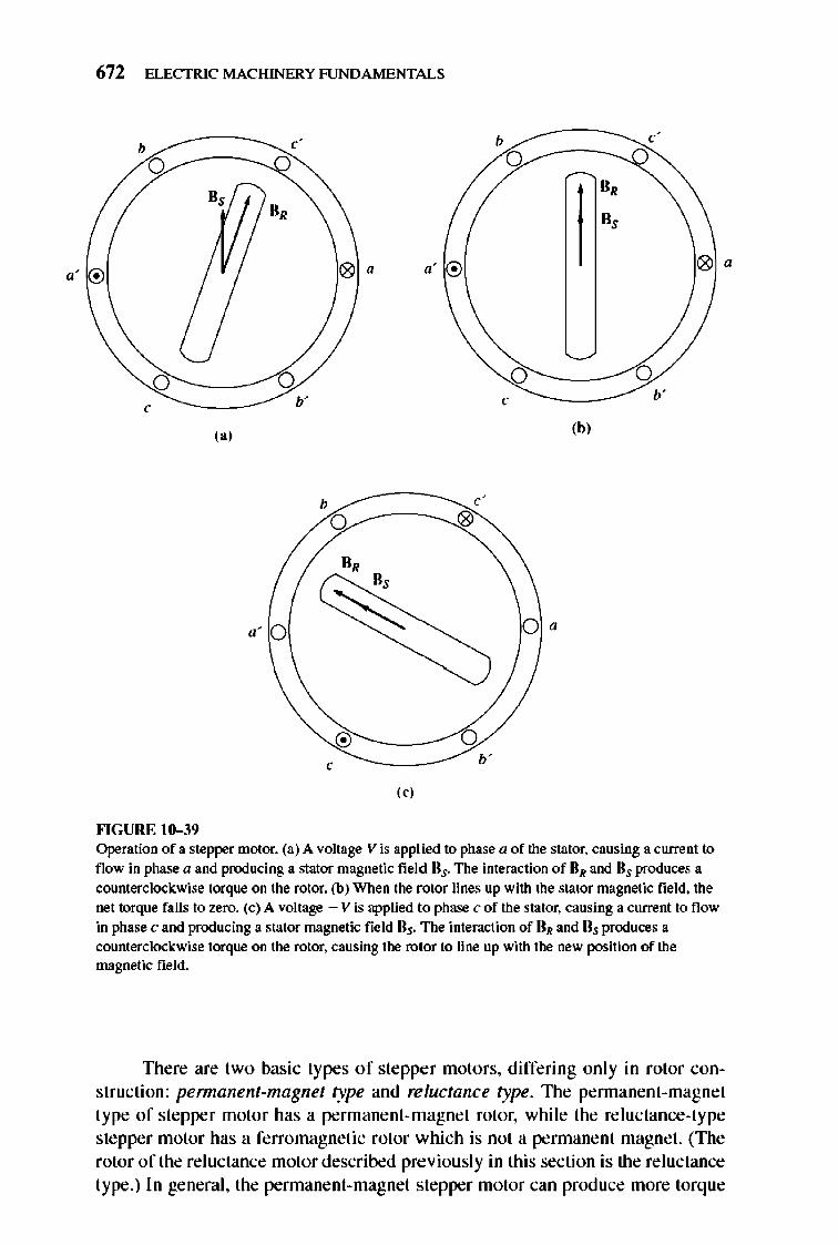
672 ELECTRIC MACHINERY RJNDAMENTALS
b
o B,
0,
" .
b'
('J (bJ
b c'
0 0
0, B,
.' ~ O·
b'
(cJ
""GURE 10-39 Operation of a stepper motor. (a) A voltage V is applied to phase a of the stator. causing a current to flow in phase a and producing a stator magnetic field ns. The interaction of nR and ns produces a counterclockwise torque on the rotor. (b) When the rotor lines up with the stator magnetic field. the net torque falls to zero. (c) A voltage - V is applied to phase c of the stator. causing a current to flow in phase c and producing a stator magnetic field ns. The interaction of DR and Ds produces a counterclockwise torque on the rotor. causing the rotor to line up with the new position of the magnetic field.
•
TIlere are two basic types of stepper motors, differing only in rotor construction: permanent-magnet l)pe and reluctance l)pe. TIle pennanent-magnet type of stepper motor has a permanent-magnet rotor, while the reluctance-type stepper motor has a ferromagnetic rotor which is not a pennanent magnet. (The rotor of the reluctance motor described previously in this section is the reluctance type.) In general, the pennanent-magnet stepper motor can produce more torq ue
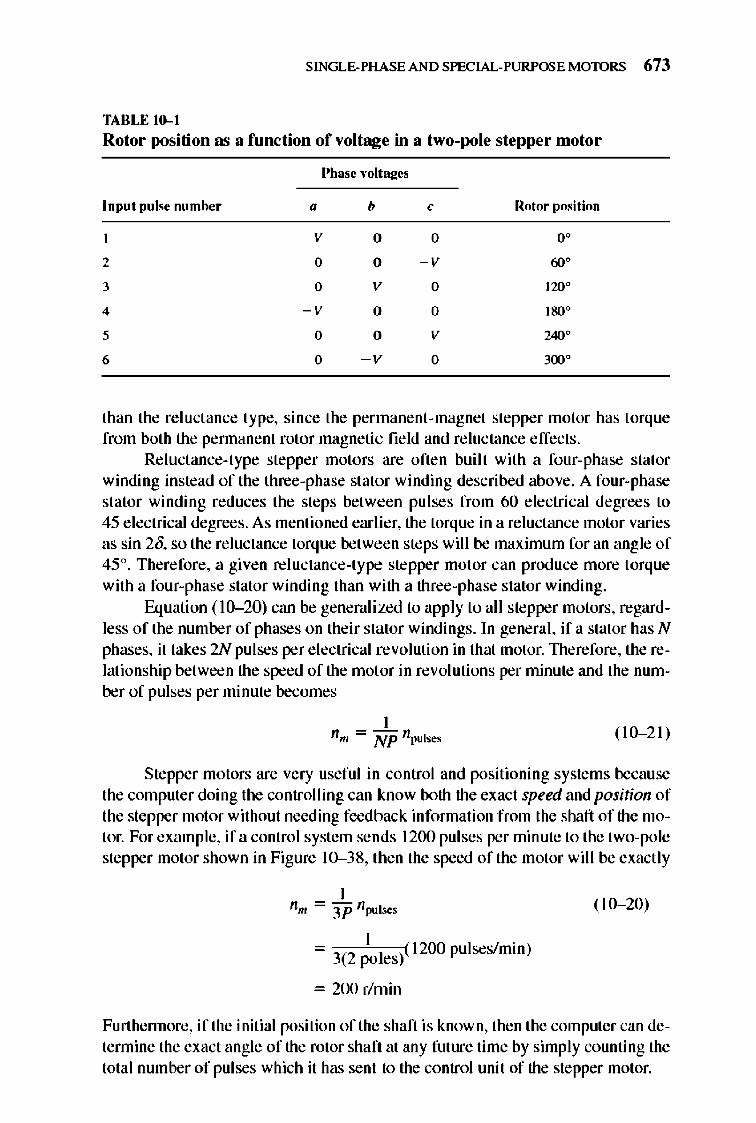
SINGLE-PHASE AND SPECIAL-PURPOSE MOTORS 673
TABLE 10-1
Rotor positi on as a function of voltage in a two-pole stepper motor
Input pulse number
2
3
4
5
6
Phase ,·o ltaj!cs
" b
V 0
0 0
0 V
- V 0
0 0
0 - v
, Rotor position
0 0 °
- V 60°
0 120°
0 1SO°
V 240°
0 3lX1°
than the reluctance Iype, since the permanent-magnel stepper motor has lorque from both the pennanent rotor magnetic field and reluctance effects.
Reluctance-type stepper motors are often bui lt with a four-phase stator winding instead of the three-phase stator winding described above. A four-phase stator winding reduces the steps belween pulses from 60 electrical degrees to 45 e lectrical degrees. As menlioned earlier, the torque in a reluctance motor varies as sin 20, so the reluctance torque between steps will be maximum for an angle of 45°. Therefore, a given reluctance-type stepper motor can produce more torque with a four-phase stator winding than with a three-phase stator winding.
Equation ( 10- 20) can be generali zed to apply to all stepper motors, regardless of the number of phases on their stator windings. In general, if a stator has N phases, it takes 2N pulses per e lectrical revolution in thai motor. 1l1erefore, the relationship between the speed of the motor in revolutions per minute and the number of pulses per minute becomes
( 10- 21)
Stepper motors are very useful in control and positioning systems because the compuler doing the controlling can know both the exact speed and position of the stepper motor without needing feedback infonnation from the shaft of the motor. For example, if a control system sends 1200 pulses per minute 10 the two-pole stepper motor shown in Figure 10--38, then the speed of the motor will be exacl ly
- 3(2 ; oles}l 200 pulses/min)
= 200 r/rnin
(10- 20)
Furthennore, if the initial position of the shaft is known, then the computer can detennine the exact angle of the rotor shaft at any fulure time by simply counting the total number of pulses which it has sent to the control unit of the stepper motor.
674 ELECTRIC MACHINERY RJNDAMENTALS
Example 10-2. A three-phase permanent-magnet stepper motor required for one particular application must be capable of controlling the position of a shaft in steps of 7.5°, and it must be capable of running at speeds of up to 300 r/min.
(a) How many poles must this motor have? (b) At what rate must control pulses be ra:eived in the motor's control unit if it is to
be driven at 300 r/min?
Solutioll (a) In a three-phase stepper motor, each pulse advances the rotor's position by
60 electrical degrees. This advance must correspond to 7.5 ma:hanical degrees. Solving Equation (10--18) for P yields
'. (60") P =20m
=2 7.5° = 16 poles
(b) Solving Equation (10--21) for npuhe. yields
npul ... = NPn ..
= (3 phasesX 16 poles)(300 r/min)
= 240 pulsesls
Brushless DC Motors
Conventional dc motors have traditionally been used in applications where dc power sources are available, such as on aircraft and automobiles. However, small de motors of these types have a number of disadvantages. nle principal disadvantage is excessive sparking and brush wear. Small, fast dc motors are too small to use compensating windings and interpoles, so armature reaction and L dildt effects tend to produce sparking on their commutator brushes. In addition, the high rotational speed of these motors causes increased brush wear and requires regular mainte nance every few thousand hours. I f the motors mu st work in a low-pressure environment (such as at high altitudes in an aircraft), brush wear can be so bad that the brushes require replacement after less than an hour of operation!
In some applications, the regular maintenance required by the brushes of these dc motors may be unacceptable . Consider for example a dc motor in an artificial heart-regular maintenance would require opening the patient's chest. In other applications, the sparks at the brushes may create an explosion danger, or unacceptable RF noise. For all of these cases, there is a need for a small, fast dc motor that is highly reliable and has low noise and long life.
Such motors have been developed in the last 25 years by combining a small motor much like a pennanent magnetic stepper motor with a rotor position sensor and a solid-state electronic switching circuit. These motors are called brushless de nwtors because they run from a dc power source but do not have commutators and brushes. A sketch of a small brushless dc motor is shown in Figure 10-40, and a photograph of a typical brushless dc motor is shown in Figure 10-41. The rotor is similar to that of a pennanent magnet stepper motor, except that it is nonsalient. nle stator can have three or more phases (there are four phases in the exmnple shown).
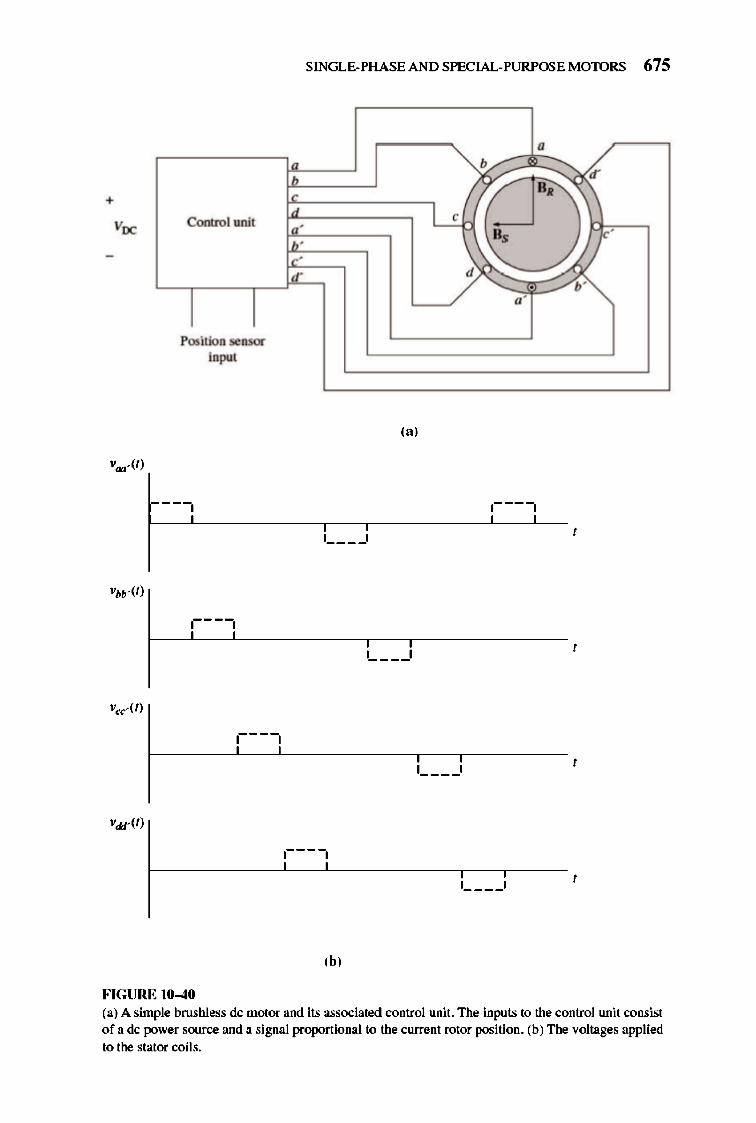
SINGLE-PHASE AND SPECIAL-PURPOSE MOTORS 675
"
+ ~ d' H,
I , Control unit "' H,
~' ,
,
d' d /1"
"' Position sensor
input
(a)
r-~-----------,--,_---------L---L-- , 1 ____ 1
,- ___ I ,
1 ____ 1 ,
r---------~---L----------,_--,_---- , 1 ____ 1
(b,
FIGURE 10-40 (a) A simple brushless dc motor and its associated control unit. The inputs to the control unit consist of a dc power source and a signal proportional to the current rotor position. (b) The voltages applied to the stator coils.
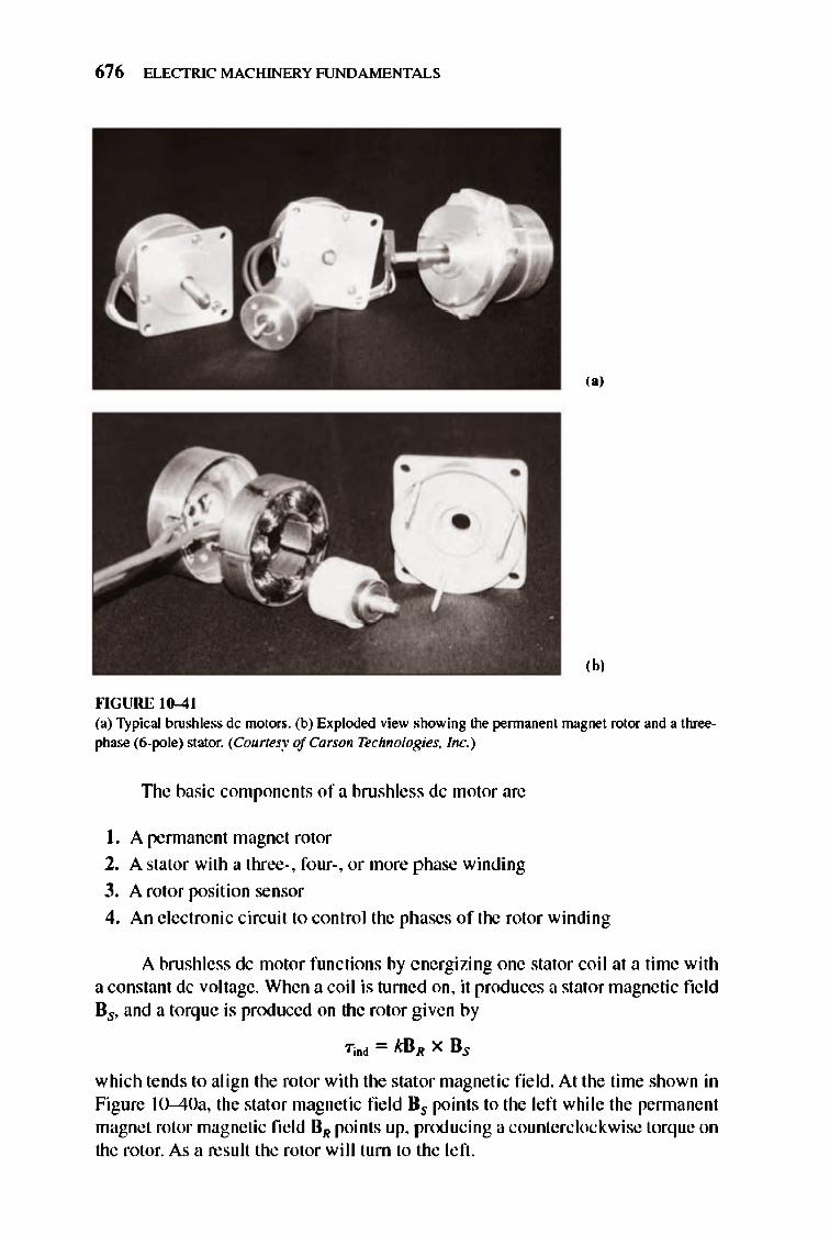
676 ELECTRIC MACHINERY RJNDAMENTALS
,,'
(h,
""GURE 10-41 (a) Typical brushless dc motors. (b) Exploded view showing the permanent magnet rotor and a threephase (6-pole) stator. (Counesy of Carson Technologies. Inc.)
TIle basic components of a brushless dc motor are
I. A rennanent magnet rolor
2. A stator with a three-. four-, or more phase winding
3. A rotor position sensor
4. An e lectronic circuit 10 control the phases of the rotor winding
A brushless dc motor functions by energizing one stator coil at a time with a constanl dc voltage. When a coil is turned on, it prod uces a stator magnetic field Bs, and a lorque is produced on the rotor g ive n by
which lends 10 align the rolor with the stator magnelic field. At the time shown in Figure 1O--40a, the stal or magnelic fie ld Bs points to the left whi le the pennanent magnet rotor magnetic field BR points up, prOO ucing a counterclockwise lorque on the rotor. As a resuli Ihe rotor wi ll tum to the left .
SINGLE-PHASE AND SPECIAL-PURPOSE MOTORS 677
If coil a remained energized all of the time, the rotor would turn until the two magnetic fi e lds are aligned, and the n it would stop, just like a stepper motor. The key to the operation of a brushless dc motor is that it includes a position sensor, so that the control circuit will know when the rotor is almost aligned with the stator magnetic fi e ld. At that time coil a will be turned off and coil b will be turned on, causing the rotor to again experience a counterclockwise torque, and to continue rotating. nlis process continues indefinite ly with the coils turned on in the order a, b, C, d, - a, - b, -C, - d, etc., so that the motor turns continuously.
The e lectronics of the control circuit can be used to control both the speed and direction of the motor. The net effect of this design is a motor that runs from a dc power source, with full control over both the speed and the direction of rotation.
Brushless dc motors are available only in small sizes, up to 20 Wor so, but they have many advantages in the size range over which they are avai lable. Some of the major advantages include:
I. Relatively high efficiency.
2. Long life and high re liability.
3. Little or no maintenance.
4. Very little RF noise compared to a dc motor with brushes.
5. Very high speeds are possible (greater than 50,000 r/min).
The principal disadvantage is that a brushless dc motor is more expensive than a comparable bru sh dc motor.
10.7 SUMMARY
The ac motors described in previous chapters required three-phase power to function. Since most residences and small businesses have only single-phase power sources, these motors cannot be used. A series of motors capable of running from a single-phase power source was described in this chapter.
The first motor described was the universal motor. A uni versal motor is a series dc motor adapted to run from an ac supply, and its torque-speed characteristic is similar to that of a series dc motor. The universal motor has a very high torque, but it s speed regulation is very poor.
Single-phase induction motors have no intrinsic starting torque, but once they are brought up to speed, their torque-speed characteristics are almost as good as those of three-phase motors of comparable size. Starting is accomplished by the additi on of an auxi liary winding with a current whose phase angle differs from that of the main winding or by shading portions of the stator poles.
The starting torque of a single-phase induction motor depends on the phase angle between the current in the primary winding and the current in the auxiliary winding, with maximum torque occurring when that angle reaches 90°. Since the split-phase construction provides only a small phase difference between the main and auxi liary windings, its starting torque is modest. Capacitor-start motors have
678 ELECTRIC MACHINERY RJNDAMENTALS
auxiliary windings with an approx imately 90° phase shift , so they have large starting torques . Permane nt split-capacit or motors, which have smaller capacitors, have start ing torques intennediate between those of the split-phase motor and the capacitor-start motor. Shaded-pole motors have a very small effecti ve phase shift and therefore a small starting torque .
Re luctance motors and hysteresis motors are special-purpose ac motors which can operate at synchrono us speed without the rotor field windings required by synchrono us motors and which can accelerate up to synchronous speed by the mselves. These motors can have either single- or three-phase stators.
Stepper motors are motors used to advance the position of a shaft or other mechanical device by a fi xed amount each time a control pulse is received . 1lley are used extensively in control syste ms for positioning objects.
Brushless dc motors are simil ar to s tepper motors with pennanent magnet rotors, except that they include a position sensor. 1lle position sensor is used to switch the energized stator coil whenever the rotor is almost aligned with it, keeping the rotor rotating a speed set by the control e lectronics. Brushless dc motors are more expensive than ordinary dc motors, but require low maintenance and have high reliability, long life, and low RF noise. They are available only in small sizes (20 W and down).
QUESTIONS
10- 1. What changes are necessary in a series dc motor to adapt it for operation from an ac power source?
10-2. Why is the torque-speed characteristic of a lUli versal motor on an ac source different from the torque-speed characteristic of the same motor on a dc source?
10-3. Why is a single-phase induction motor lUlable to start itself without special auxiliary windings?
10-4. How is induced torque developed in a single-phase induction motor (a) according to the double revolving-field theory and (b) according to the cross-field theory?
10-5. How does an auxiliary winding provide a starting torque for single-phase induction motors?
10-6. How is the current phase shift accomplished in the auxiliary winding of a splitphase induction motor?
10-7. How is the current phase shift accomplished in the auxiliary winding of a capacitor-start induction motor?
10-8. How does the starting torque of a pennanent split-capacitor motor compare to that of a capacitor-start motor of the same size?
10-9. How can the direction of rotation of a split-phase or capacitor-start induction mo-tor be reversed?
10-10. How is starting torque produced in a shaded-pole motor? 10-11. How does a reluctance motor start ? 10-12. How can a reluctance motor run at synchronous speed? 10-13. What mechanisms produce the starting torque in a hysteresis motor? 10-14. What mechanism produces the synchronous torque in a hysteresis motor?
SINGLE-PHASE AND SPECIAL-PURPOSE MOTORS 679
10-15. Explain the operation of a stepper motor. 10-16. What is the difference between a permanent-magnet type of stepper motor and a
reluctance-type stepper motor? 10-17. What is the optimal spacing between phases for a reluctance-type stepper motor?
Why? 10-18. What are the advantages and disadvantages of brush less de motors compared to or
dinary brush dc motors?
PROBLEMS
lO-1. A 120-V, ~hp, 60-Hz, four-pole, split-phase induction motor has the following impedances:
RI = 1.80n R2 = 2.50 n
XI = 2.40 n X2 = 2.40 n
At a slip of 0.05, the motor's rotational losses are 51 W. The rotational losses may be assumed constant over the normal operating range of the motor. If the slip is 0.05, find the following quantities for this motor: (a) Input power (b) Air-gap power (c) P coov
(d) POOl (e) "T"md
(j) "", (g) Overall motor efficiency (h) Stator power factor
10-2. Repeat Problem 10-1 for a rotor slip of 0.025. 10-3. Suppose that the motor in Problem 10-1 is started and the auxiliary winding fails
open while the rotor is accelerating through 400 r/min. How much induced torque will the motor be able to produce on its main winding alone? Assuming that the rotationallosses are still 51 W, will this motor continue accelerating or will it slow down again? Prove your answer.
10-4. Use MATLA8 to calculate and plot the torque-speed characteristic of the motor in Problem 10--1, ignoring the starting winding.
10-5. A 220-V, 1.5-hp, SO-Hz, two-pole, capacitor-start induction motor has the following main-winding impedances:
RI = 1.40n
R2 = 1.50n
Xl = 1.90n
X2 = 1.90n
At a slip of 0.05, the motor 's rotational losses are 291 W. The rotational losses may be assumed constant over the normal operating range of the motor. Find the following quantities for this motor at 5 percent slip: (a) Stator ClUTent (b) Stator power factor (c) Input power (d) PAG
(e) P coov
680 ELECTRIC MACHINERY RJNDAMENTALS
(j) P(g) Tind
(h) Tlood
(i) Efficiency
10-6. Find the induced torque in the motor in Problem 10--5 ifit is operating at 5 percent slip and its terminal voltage is (a) 190 V, (b) 208 V, (c) 230 V.
10-7. What type of motor would you select to peIform each of the following jobs? Why? (a) Vacuum cleaner (b) Refri gerator (c) Air conditioner compressor (d) Air conditioner fan (e) Variable-speed sewing machine (j) Clock (g) Electric drill
10-8. For a particular application, a three-phase stepper motor must be capable of stepping in 10° increments. How many poles must it have?
10-9. How many pulses per second must be supplied to the controllUlit of the motor in Problem 10-8 to achieve a rotational speed of 600 r/min?
10-10. Construct a table showing step size versus number of poles for three-phase and four-phase stepper motors.
REFERENCES
I. Fitzgerald. A. E. . and C. Kingsley. Jr. Electric Machinery. New Yort: McGraw-Hill. 1952. 2. National Electrical Manufacturers Association. Motors and Generators. Publication No. MG I-
1993. Washington. D.C.: NEMA. 1993. 3. Veinott. G. C. Fractional and Sulifractional Horsepov."er Electric Motors. New York: : McGraw
Hill. 1970. 4. Werninck:. E. H. (ed.). Electric Motor Handbook.. London: McGraw-Hill. 1978.
APPENDIX
A THREE-PHASE
CIRCUITS
A lmost all e lectric power generation and most of the power transmission in the world looay is in the form of three-phase ac circuits. A three-phase ac power
system consists of three-phase generators, transmission lines, and loads. AC power systems have a great advantage over de systems in that their voltage levels can be changed with transfonners to reduce transmission losses, as described in Chapter 2. Three-phase ac power systems have two major advantages over singlcphase ac power systems: (I) it is possible to get more power per kilogram of mctal from a three-phase machine and (2) the power delivered to a three-phase load is constant at all times, instead of pulsing as it does in single-phase systems. llucephase systems also make the use of induction motors easier by allowing them to start without special auxiliary starting windings.
A.I GENERATION OF THREE-PHASE VOLTAGES AND CURRENTS
A three-phase generator consists of three single-phase generators, with voltages equal in magnitude but differing in phase angle from the others by l20?E.1.ch of these three generators could be connected to one of three identical loads by a pair of wires, and the resulting power system would be as shown in Fig ure A-l c. Such a syste m consists of three single-phase circuits that happen to differ in phase ang le by I 20?The current flowing to each load can be found from the equati on
(A-I )
681
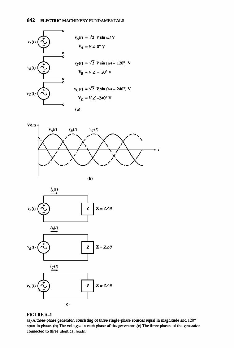
682 ELECTRIC MACHINERY RJNDA MENTALS
«)
""GURE A- I
VA(t) ",,fi Vsin w/V
VA ",VLOoV
VB(t) '" ,fi V sin (wt _ 120°) V
VB "'VL - 1200V
Vdt) '" ,fi V sin (wt _ 240°) V
Vc '" V L _240° V
(.)
(b)
Z Z ",ZL(J
Z Z ",ZL(J
Z Z ",ZL(J
(a) A three-phase generator. consisting of three single-phase sources equal in magnitude and 120° apart in phase. (b) The voltages in each phase of the generator. (c) The three phases of the generator connected to three identicalloods.
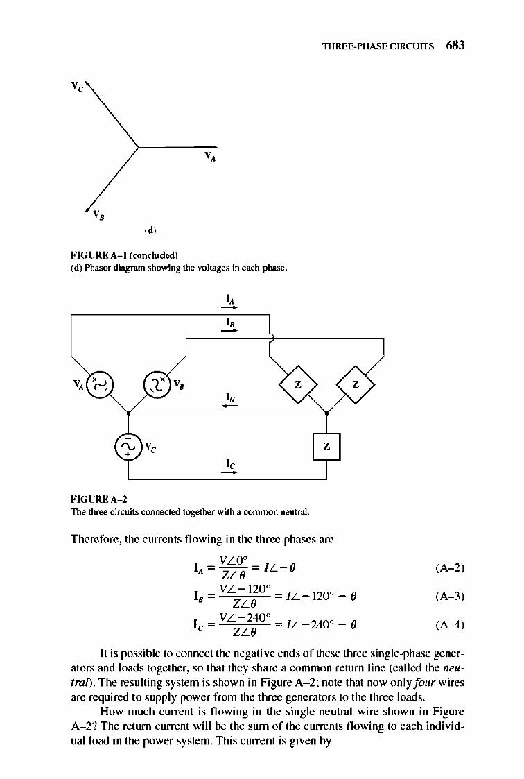
lHREE-PHASE CIRCUITS 683
v,
v,
'" F'IGUREA- l (concluded) (d) Pltasor dia.gram showing the voltages in each phase.
.... x V , C ,
'\.... Ve +
F'IGUREA- 2
" -z
'N
z
The three ci["(;uits connected together with a. common neutral.
Therefore, the currents fl owing in the three phases are
I = VLO° = iL- (J A ZL 6
1 = VL-120° = iL- 120 o - (J B ZL 6
1 = VL-240° =/L-240o - (J e ZL 6
(A- 2)
(A- 3)
(A-4)
It is possible to connect the negati ve ends of these three single-phase generators and loads together, so that they share a common return line (called the neutral). The resulting system is shown in Figure A- 2; note that now only four wires are required to supply power from the three generators to the three loads.
How much current is fl owing in the single neutral wire shown in Figure A- 2? The return current will be the sum of the currents fl owing to each individual load in the power system. This current is given by
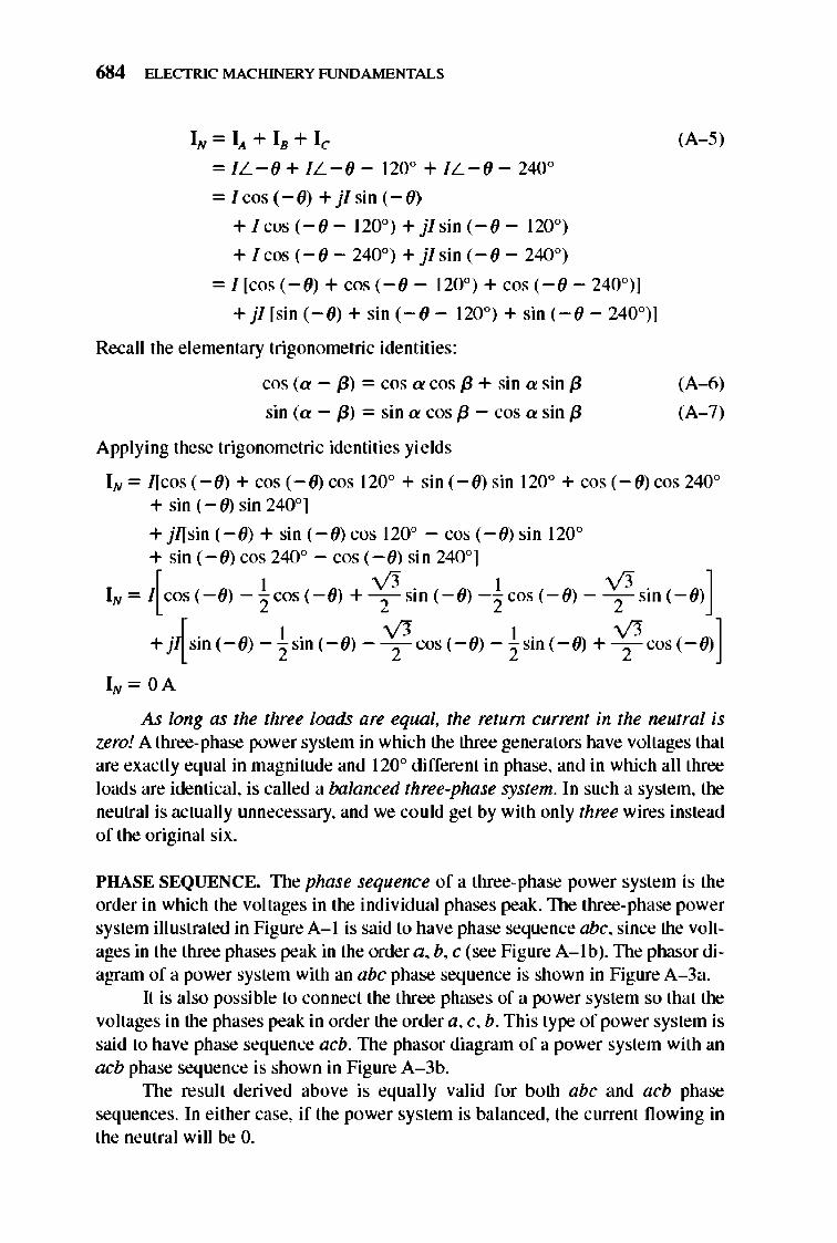
684 ELECTRIC MACHINERY RJNDAMENTALS
IN = IA + IB + Ie = /L- O + /L- O - 1200 + /L- O - 2400
= / cos (- 0) + jf sin (- 0)
+ I cos (- () - 120°) + jf sin (- () - 120°)
+ l cos (- () - 240°) + jlsin (- () - 240°)
= f[eos (- (}) + cos(- () - 120°) + cos (- (} - 240°)]
+ jf [sin (- 0) + sin (- (} - 120°) + sin (- (} - 240°)]
Recall the e le mentary trigonometric identities :
cos (a - m = cos a cos {3 + sin a sin {3
sin (a - m = sin a cos {3 - cos a sin (3
Applying these trigonometri c identities yields
(A- 5)
(A-6)
(A- 7)
IN= [[cas (- 0) + cos (- U) cos 1200 + sin (- 0) sin 1200 + cos (- 0) cos 240° + sin (- (f) sin 240°]
+ j/[sin (- 0) + sin (- 0) cos 120° - cos (- 0) sin 1200
+ sin (- () cos 240° - cos (- () sin 240°]
[ 1 0. 1 0.]
IN = I cos (- 0) -"2 cos (- 0) + 2 Sin (- (}) -"2 cos (- (}) - - ,- Sin (- (})
+jIsin C- O)_ l sin c-O)- 0"COS(-O)_ l Sill C- O) + 0 cos C-0)] lL 2 2 2 2
As long as the three loads are equal, the return current in the neutral is zero! A three-phase power system in which the three generators have voltages that are exactly equal in magnitude and 120° different in phase, and in which alJ three loads are ide ntical, is called a balanced three-phase system. In such a system, the neutral is actually unnecessary, and we could get by with only three wires instead of the original six.
PHASE SEQUENCE. The phase sequence of a three-phase power system is the order in which the voltages in the indi vidual phases peak.1lle three-phase power system illustrated in Figure A-I is said to have phase seque nce abc, since the voltages in the three phases peak in the order a, b, c (see Figure A-I b). TIle phasor diagram of a power system with an abc phase seq uence is shown in Fig ure A-3a.
It is also possible to connect the three phases of a power syste m so that the voltages in the phases peak in order the order a, c, b. This type of power system is said to have phase sequence acb. 1lle phasor diagram of a power system with an acb phase seque nce is shown in Fig ure A- 3b.
TIle result derived above is equally valid for both abc and acb phase seque nces. In either case, if the power system is balanced, the current flowing in the ne utral will be O.
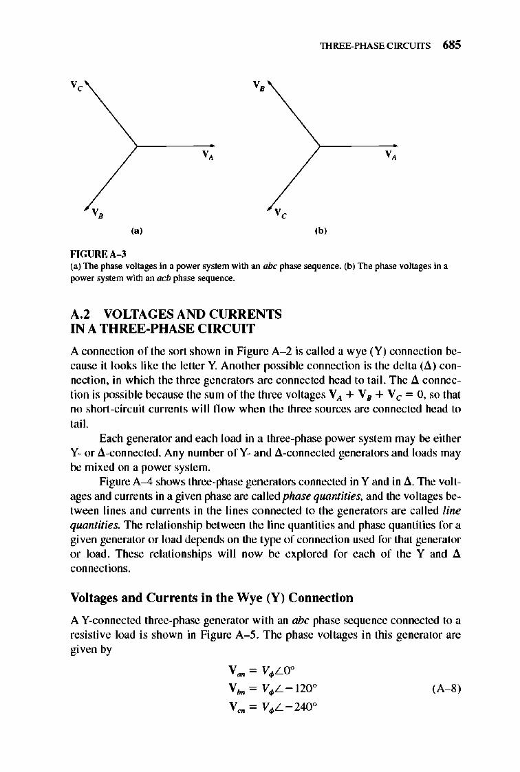
lHREE-PHASE CIRCUITS 685
v c
v ,
FIGUREA-3
v,
v ,
v c
v,
(b)
(a) The phase voltages in a power system with an abc phase sequence. (b) The phase voltages in a power system with an acb phase sequence.
A.2 VOLTAGES AND CURRENTS IN A THREE-PHASE CIRCUIT
A connection of the sort shown in Figure A- 2 is called a wye (Y ) connection because it looks like the letter Y. Another possible connection is the delta (.6.) connection, in which the three generators are connected head to tail. The 11 connection is possible because the sum of the three voltages VA + VB + V c = 0, so that no short-circuit current s wi ll fl ow when the three sources are connected head to tail.
Each generator and each load in a three-phase power system may be either Y- or l1-connected. Any number of Y- and l1-connected generators and loads may be mixed on a power system.
Figure A-4 shows three-phase generators connected in Y and in 11. 1lle voltages and currents in a given phase are called phase quantities, and the voltages between lines and current s in the lines connected to the generators are called line quantities. The relationship between the line quantities and phase quantities for a given generator or load depends on the type of connection used for that generator or load . These relationships wi ll now be explored for each of the Y and 11 connections.
Voltages and Currents in the Wye (Y) Connection
A Y-connected three-phase generator with an abc phase sequence connected to a resistive load is shown in Figure A- 5. The phase voltages in this generator are given by
V = V LO° - . V",. = Vo/>L- 120°
Ven = Vo/>L-240°
(A-8)
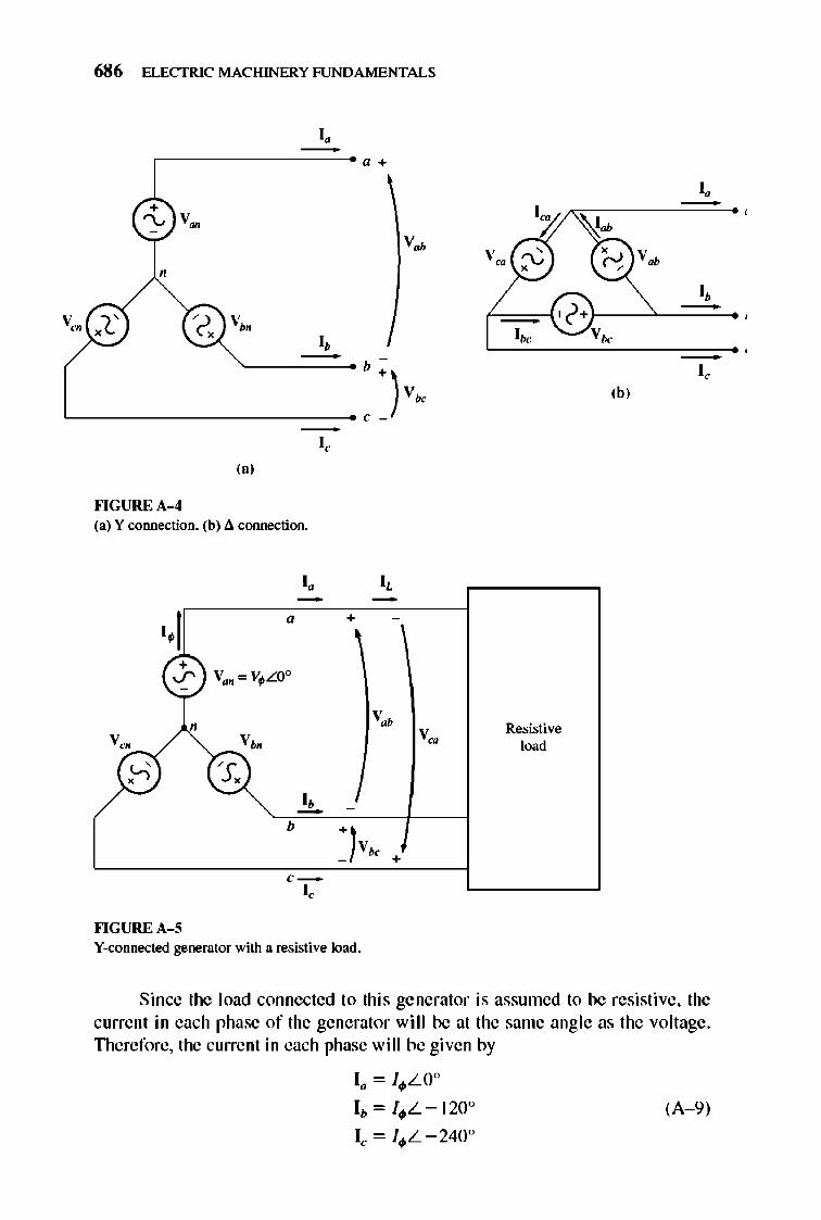
V co
/
686 ELECTRIC MACHINERY RJNDAMENTALS
'. - "+
C'BV~ V~
,
).' " ". VM
" '. -b ~)
v. , -
,.)
""GURE A-4 (a) Y connection. (b) ;l. connection.
. , - -'.1 •
V '"
'. -b
""GURE A-S Y-connected generator with a resistive load.
V. '0 \100 ,
~ ~ ~
'2· '.
Resistive load
V.
(h)
'. Voo
'. --
"
Since the load connected to this generator is assumed to be resistive, the current in each phase of the generator will be at the same angle as the voltage. Therefore, the current in each phase will be given by
Ia = J<I>LO°
I b = J<I>L- 120° (A- 9)
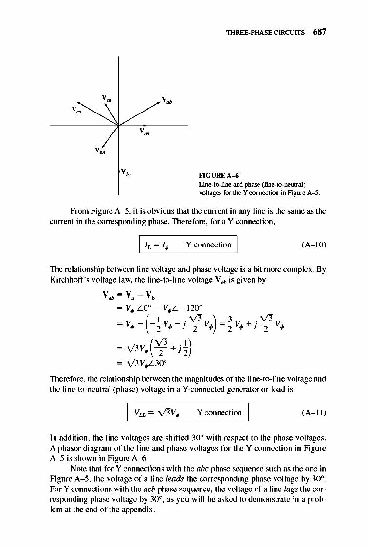
v •
lHREE-PHASE CIRCUITS 687
FlGUREA-6 Line-to-line and phase (line-to-neutral) voltages for the Y connection in Figure A- 5.
From FigureA- 5, it is obvious that the current in any line is the same as the current in the corresponding phase. TIlerefore, for a Y connection,
Y connection I (A-I 0)
llle relationship between line voltage ,md phase voltage is a bit more complex. By Kirchhoff's voltage law, the line-to- line voltage Vah is given by
Vah = Va - Vb
= Vo/> LO° - Vo/>L- 120°
= Vo/> - (-~ Vo/> - J V; Yo/»~ =~ Vo/> + J V; Yo/>
- v'3Vo/>(~ + J1) - v'jV~30°
Therefore, the relationship between the magnitudes of the line-to-line voltage and the line-to-neutral (phase) voltage in a V-connected generator or load is
Y connection I (A-II )
In addition, the line voltages are shifted 30° with respect to the phase voltages. A phasor diagram of the line and phase voltages for the Y connection in Figure A- 5 is shown in Figure A-6.
Note that for Y connections with the abc phase seq uence such as the one in Figure A- 5, the voltage of a line leads the corresponding phase voltage by 30°. For Y connections with the acb phase sequence, the voltage of a line lags the corresponding phase voltage by 30°, as yo u will be asked to demonstrate in a problem at the end of the appendix.
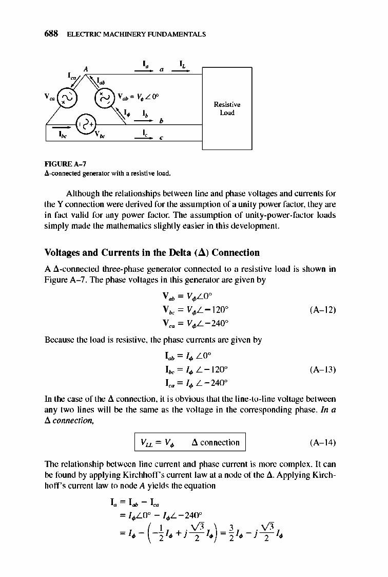
688 ELECTRIC MACHINERY RJNDAMENTALS
'. " " -A -
""GURE A-7 ~-oonnected generator with a resistive load.
Resistive Lo ..
Although the relationships between line and phase voltages and currents for the Y connection were derived for the assumption of a unity power factor, they are in fact valid for any power factor. The assumption of unity-power-factor loads simply made the mathematics slightly eas ier in this development.
Voltages and Currents in the Delta (d ) Connection
A .6.-connected three-phase generator connected to a resistive load is shown in Figure A-7. The phase voltages in this generator are given by
V ab = V~LO°
V".. = V~L-1 20°
Yea = V~L-240°
Because the load is resistive, the phase currents are given by
lab = 14> LO°
1"..= I4>L-120°
t, = 14> L -2400
(A-1 2)
(A- 13)
In the case of the .6. connection, it is obvious that the line-to-line voltage between any two lines will be the same as the voltage in the corresponding phase. In a .6. connection,
.6. connection I (A-1 4)
1lle relationship between line current and phase current is more complex. It can be found by applying Kirchhoff's current law at a node of the .6.. Applying Kirchhoff's current law to node A yields the equation
la = lab - lea
= 14>LO° - 14>L-240°
( I .0 ) 3 .0
= 14>- -"2 /4> +} T I4> ="2 /4> -} TI4>
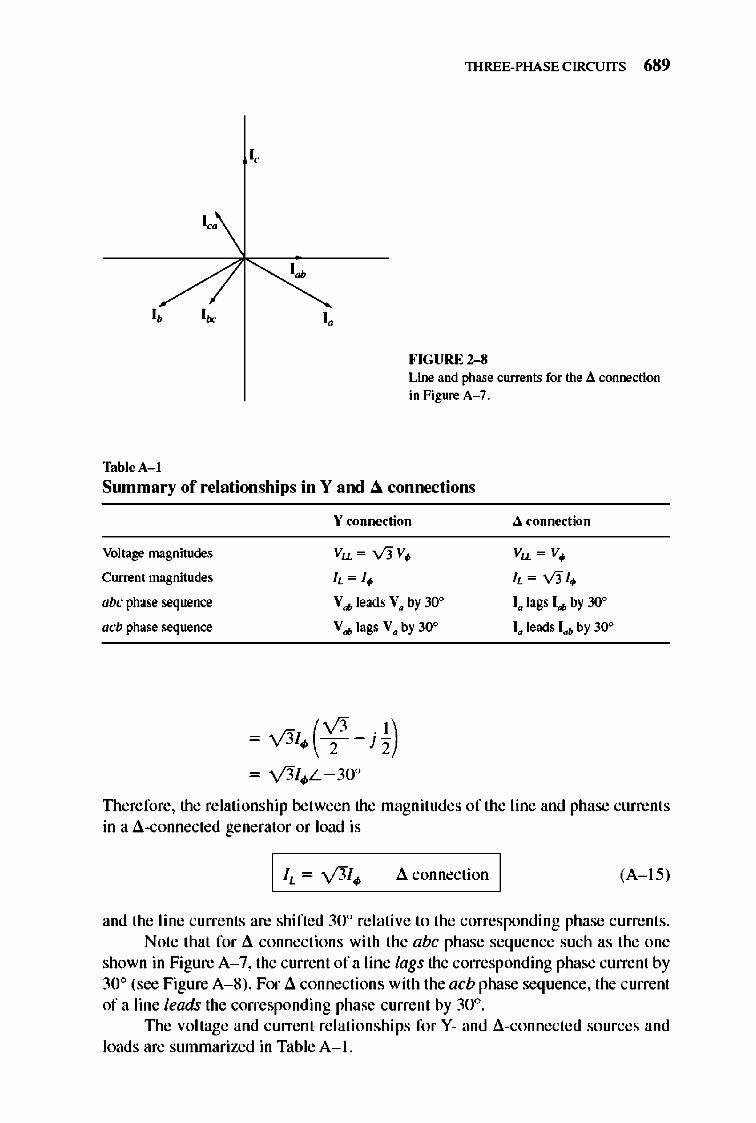
I. I.
TablcA- l
I .
lHREE-PHASE CIRCUITS 689
FIGURE 2-8 Line and phase currents for the;l. cOlloection in Figure A- 7.
Summary of relationships in Y and &. connections
\' connection ;l. connl.>etion
Voltage magnitudes Vu = v'3V. Vu = V.
Current magnitudes it = I . it = 0 /. abc phase sequence \' ... leads \'. by 30° I. lags I ... by 30°
acb phase sequence \' ... lags \'. by 30° I. leads lob by 30°
- 0 /. (': - jk) - y'3J",L-30°
Therefore, the relationship between the magnitudes of the line and phase currents in a .6.-connected generator or load is
.6. connection I (A-I S)
and the line currents are shifted 30° re lati ve 10 the corresponding phase currents. Note that for .6. connections with the abc phase sequence such as the one
shown in Figure A- 7, the current of a line lags the corresponding phase current by 30° (sec Figure A- 8) . For .6. connections with the acb phase sequence, the current of a line leads the corresponding phase current by 30°.
TIle voltage and current re lationships for Y- and .6.-connected sources and loads are summarized in Table A- I.
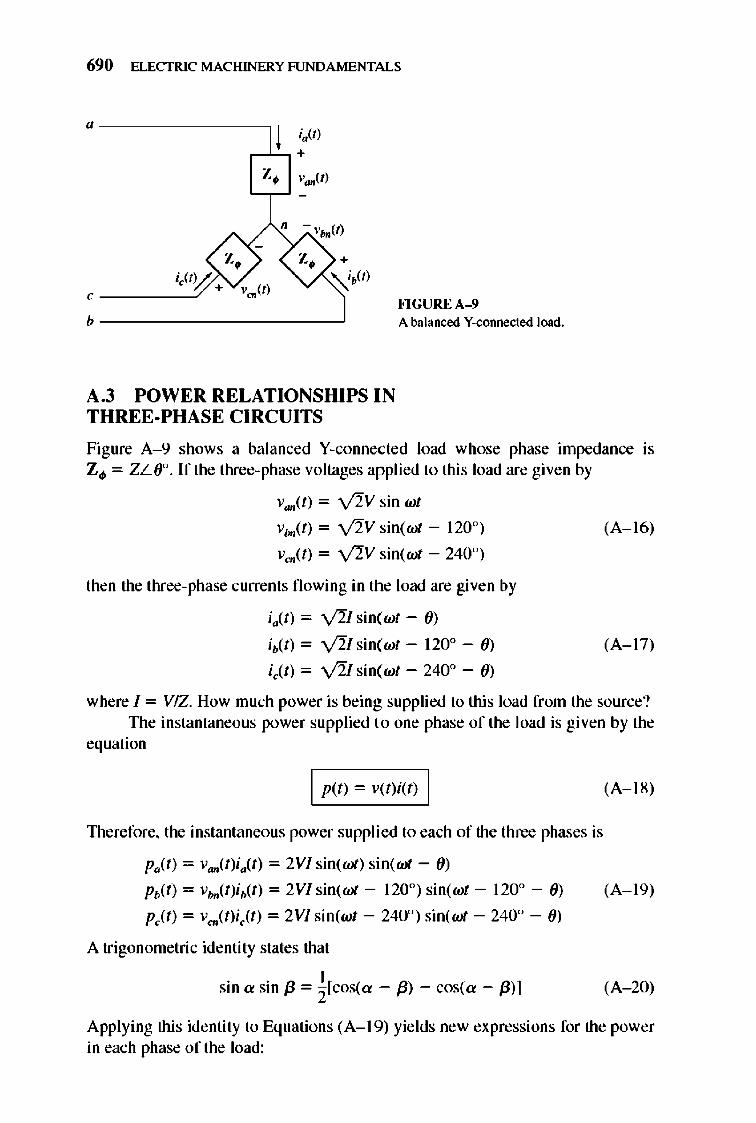
690 ELECTRIC MACHINERY RJNDAMENTALS
, ----y
I ;.'" ,-L'-, +
Z~ v",,(t)
b --------------~
A.3 POWER RELATIONSHIPS IN THREE-PHASE CIRCUITS
FlGUREA- 9 A balanced Y-connected load.
Figure A- 9 shows a bal anced V-connected load whose phase impedance is Z", = Z L (f'. If the three-phase voltages applied to this load are given by
van(t) = V2V sin wt
Vbn(t) = V2V sin(wI' - 120°)
vao(t) = y2V sin(wI' - 240°)
then the three-phase currents fl owing in the load are given by
iit) = V'Ll sin(wt - ())
ib(t) = v'2Isin(wt - 120° - ())
( (t) = v'2I sin(wt - 240° - ())
(A-1 6)
(A-1 7)
where I = VIZ. How much power is being supplied to this load from the source? TIle instantaneous power supplied 1.0 one phase of the load is given by the
equation
I p et) = v(t)i(t) I
lllerefore, the instantaneous power supplied to each of the three phases is
PaCt) = van(tKlt ) = 2VI sin(wI') sin(wI' - ())
Pb(t) = v",,(t)ib(t) = 2 VI sin(wI' - 120°) sine wt - 120° - ())
pJt) = vao(t)iJt) = 2Vl sin(wt - 240°) sin(wI' - 2400 - ())
A trigonometric identity states that
sin a sin (3 = k[cos(a - (3) - cos(a - (3)1
(A- 18)
(A-1 9)
(A- 20)
Applying this identity to Equ ations (A-1 9) yields new expressions for the power in each phase of the load:
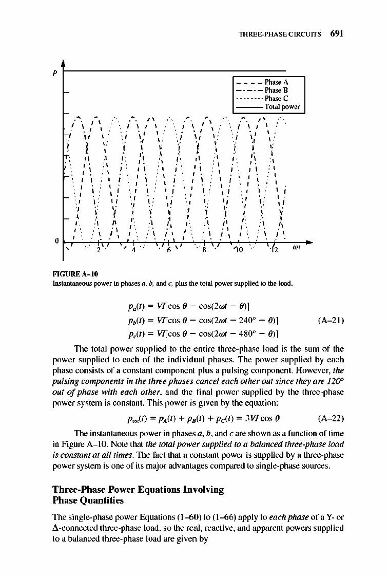
lHREE-PHASE CIRCUITS 691
p
I-____ PhaseA
-·_·-PhaseB -------. Phase C
Total power
- " , \ I \ ,'.
~. I \ " 1\' \I \ ,'
, I. 'i ti. 1\ ~ . ~ /.
" / ~ ; , ; ,
, , , " I "
.' , , , ,
" I \ I \ " , , , , , , '\ I \ ./ \ ,'
, I
'i .. , , , , , I ' ,
-\
, , \ , "
• , \ , , ,
-I :', , , ' , ' , " " , , , , , , , ,
I ' ,',
" I
\ I \ : ' , ; " '
"
• \ I ' / i , " ,
I ' I \ ,
, ; , , ; , ; , ; , , , , , , , ,
, , , ; , ; , ; , , , , , , , ,
, , \ , , , , , , \ ;
, ; , , " ,
F'IGUREA- 1O
, , " I
, ' , , " I
, , , , " , , " , , , , , ,
, , , , ' , , \ ' ,
, , , ; , , "
I , ;\
" '; I " I , ,
I, , , , , , , , ,
'" 8 , 2
Instantaneous power in phases a, b, and c, plus the total power supplied to the load.
PaCt) = V/[COS () - cos(2wl - ())]
Pb(t) = V/[COS () - cos(2wl - 2400 - ())]
p/t) = V/[COS () - cos(2wl - 4800 - ())]
WI
(A - 2I)
TIle total power supplied to the e ntire three-phase load is the sum of the power supplied to each of the individual phases. The power supplied by each phase consists of a constant component plus a pulsing component. However, the pulsing components in the three phases cancel each other out since they are 12(? out of phase with each other, and the final power supplied by the three-phase power system is constant. This power is given by the equation:
p,jl) = Plt(t) + Ps(t) + pel,t) = 3Vl cos () (A - 22)
llle instantaneous power in phases a, b, and c are shown as a function of time in Figure A-I O. Note that the total power supplied to a balanced three-phase load is constant at all times. TIle fact that a constant power is supplied by a three-phase power system is one of its major advantages comp.:1.red to single-phase sources.
Three-Phase Power Equations Involving Phase Quantities
The single-phase power Equations (1-60) to (1-66) apply to each phase ofa Y- or a-connected three-phase load, so the real , reactive, and apparent powers supplied to a balanced three-phase load are given by
692 ELECTRIC MACHINERY RJNDAMENTALS
p = 3 V",1 ,/>COS () (A- 23)
Q = 3V",I", sin () (A- 24)
S =3 V",I", I (A- 2S)
p = 3/~Z cos () (A- 26)
Q = 3/~Z sin () (A- 27)
S = 3/~Z (A- 2S)
1lle angle () is again the angle between the voltage and the current in any phase of the load (it is the same in all phases), and the power factor of the load is the cosine of the impedance angle (). The power-triangle relationships apply as well.
Three-Phase Power Equations Involving Line Quantities
It is also possible to derive expressions for the power in a balanced three-phase load in tenns of line quantities. This deri vation must be done separately for Y- and ~-connec ted loads, since the relationships between the line and phase quantities are different for each type of connection.
For a Y-connected load, the power consumed by a load is given by
p = 3 Vo/>lo/> cos () (A- 23)
For this type of load, II- = 10/> and Vu = V3V 0/> , so the power consumed by the load can also be expressed as
(A- 29)
For a l1-connected load, the power consumed by a load is given by
(A- 23)
For this type of load, II- = V3/0/> and Va = V 0/> , so the power consumed by the load can also be expressed in tenns of line quantities as
P = 3Vu ( ~) cos ()
= V3Vull- cos () (A- 29)
lHREE-PHASE CIRCUITS 693
This is exactly the same equation that was derived for a V-connected load, so Equation (A-29) gives the power of a balanced three-phase load in tenns of line quantities regardless of the connection of the load, The reactive and apparent powers of the load in terms of line quantities are
(A-3D)
(A-31)
It is important to realize that the cos () and sin ()terms in Equations (A-29) and (A-30) are the cosine and sine of the angle between the phase voltage and the phase current , not the angle between the line-to- line voltage and the line current. Remember that there is a 300 phase shift between the line-to-line and phase voltage for a Y connection, and between the line and phase current for a .1.. connection, so it is important not to take the cosine of the angle between the line-to-line voltage and line current.
A.4 ANALYSIS OF BALANCED THREE-PHASE SYSTEMS
If a three-phase power system is balanced, it is possible to determine the voltages, currents, and powers at various points in the circuit with a per-phase equivalent circuit, This idea is illu strated in Figure A-II. Figure A-II a shows a V-connected generat or suppl ying power to a V-connected load through a three- phase transmission line.
In such a balanced system, a neutral wire may be inserted with no effect on the system, since no current fl ows in that wire. nlis system with the extra wire inserted is shown in Figure A-II b. Also, notice that each of the three phases is identical except for a 1200 shift in phase angle. Therefore, it is possible to analyze a circuit consisting of one phase and the neutral, and the results of that analysis wil I be valid for the other two phases as well if the 1200 phase shift is included. Such a per-phase circuit is shown in Figure A-Il c.
There is one problem associated with this approach, however. It requires that a neutral line be avai lable (at least conceptually) to provide a return path for current fl ow from the loads to the generat or. nlis is fine for V-connected sources and loads, but no neutral can be connected to .1..-connected sources and loads .
How can .1..-connected sources and loads be included in a power system to be analyzed? The standard approach is to transfonn the impedances by the Y--h. transfonn of e lementary circuit theory. For the special case of balanced loads, the Y - .1.. transformation states that ad-con nected load consisting of three equal impedances, each of value Z, is totally equivalent to a V-connected load consisting of three impedances, each of value Z /3 (see Figure A-1 2). This equi valence means that the voltages, currents, and powers supplied to the two loads cannot be distinguished in any fashion by anything external to the load itself.
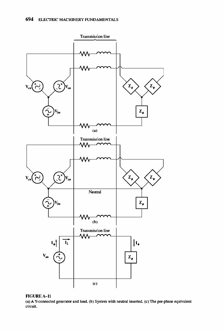
694 ELECTRIC MACHINERY RJNDA MENTALS
Transmission line
(a)
Transmission line
Neutral
,b, Transmission line
• • 1 - II • I,
+ "-- Z.
-
" , H GURE A- l1 (a) A Y-connected generator and load. (b) System with neutral insened. (c) The per-phase equivalent circuit.
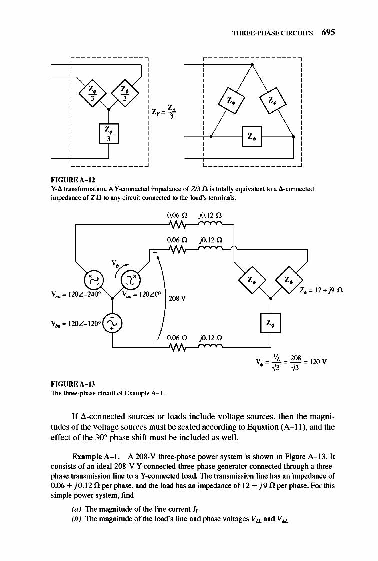
lHREE-PHASE CIRCUITS 695
, -------------, ,-----------------,
~ 3
L _____________ -.l L _________________ ~
FIGUREA- 12 Y-;I. transformation. A Y-connected impedance of 713 n is totally equivalent to a ;I.-connected impedance of Z n to any circuit connected to the load's terminals.
0.06 0 jO.120
0.06 0 jO.12 n +
Vc~ '" l20L- 240o v"" '" l20LO" 208 V
0.060 jO.120
FlGUREA- 13 The three-phase circuit of Example A- I.
If a.-connected sources or loads include voltage sources, then the magnitudes of the voltage sources must be sca led according to Equation (A- II ), and the effect of tile 30° phase shift must be included as well.
Example A- I. A 208-V three-phase power system is shown in Figure A- 13. It consists of an ideal 208-V V-connected three-phase generator cOlUlected through a threephase transmission line to a V-connected load. The transmission line has an impedance of 0.06 + jO.12 n per phase, and the load has an impedance of 12 + j9 n per phase. For this simple power system, find
(a) The magnitude of the line current IL (b) The magnitude of the load's line and phase voltages V u and V#.
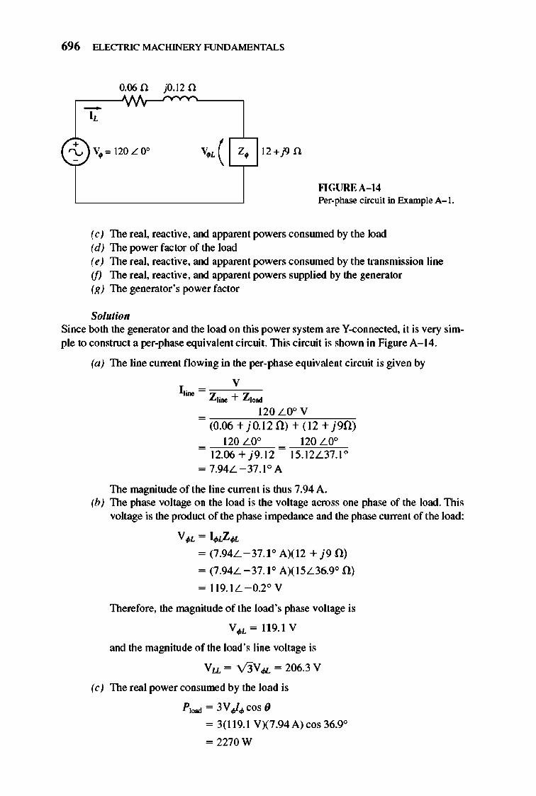
696 ELECTRIC MACHINERY RJNDAMENTALS
+ "-' -
0.06 n jO.l2 n
-I,
V. '" 120 L 0° V,,( Z, I 2+fJ n
Fl GUREA- 14 Per-phase circuit in Example A- I.
(e) The real, reactive, and apparent powers consruned by the load (d) The power factor of the load (e) The real, reactive, and apparent powers conswned by the transmission line if) The real , reactive, and apparent powers supplied by the generator (g) The generator 's power factor
Solutioll Since both the generator and the load on this power system are V-connected, it is very simple to construct a per-phase equivalent circuit. This circuit is shown in Figure A- 14.
(a) The line current fl owing in the per-phase equivalent circuit is given by
v 11' = ,--:;""'" Zl ... + Zl ....
120 L O° V = m(oCi.06;C:;:+-'j"O.'C12"'1l"):o'+~(I"2C;+:Cj"'9mll)
120LO° 120 L O° = ~~"' - ~~'" 12.06 + j9.12 - IS.12L 37.1 0 = 7.94L -37 .l o A
The magnitude of the line current is thus 7.94 A. (b) The phase voltage on the load is the voltage across one phase of the load. This
voltage is the product of the phase impedance and the phase current of the load:
V . L = 1. t.Z#, = (7.94L -37.l o AXl2 + j9 0 )
= (7 .94L -37.1 ° AXI5L36.9° 0)
= 11 9.IL - 0.2° V
Therefore, the magnitude of the load 's phase voltage is
V . L = 11 9.1 V
and the magnitude of the load 's line voltage is
Vu.= V3V#-=206.3 V
(e) The real power consumed by the load is
P_=3VV.cos (J
= 3(11 9.1 VX7 .94 A) cos 36.9°
= 2270 W
lHREE-PHASE CIRCUITS 697
The reactive power consumed by the load is
QIood = 3 V.I. sin 0
= 3(119.1 VX7.94 A) sin 36.90
= 1702 var
The apparent power consumed by the load is
Slood = 3VJ.
(d) The load power factor is
= 3(119. 1 VX7.94A)
= 2839 VA
PFIood = cos 0 = cos 36.90 = 0.8 lagging
(e) The current in the transmission line is 7 .94L -37.1 A, and the impedance of the line is 0.06 + jO.12 n or O.134L63.4° n per phase. Therefore, the real, reactive, and apparent powers consumed in the line are
PliDe = 31iZ cos 0
= 3(7.94 A? (0.1340) cos 63.4 0
= 11.3 W
Q1ine = 31lZ sin 0
= 3(7.94 A? (0.1340) sin 63.40
= 22.7 var
S1ine = 31iZ
= 3(7.94A?(0.1340)
= 25.3 VA
(A- 26)
(A- 27)
(A- 28)
(jJ The real and reactive powers supplied by the generator are the swn of the powers consumed by the line and the load:
P sea = P1iDe + Plood
= I1.3W+2270W =2281 W
Q8«1 = Q1ine + QIood
= 22.7var + 1702var = 1725var
The apparent power of the generator is the square root of the sum of the squares of the real and reactive powers:
s = yp2 + Q2 = 2860 VA to" t"" t""
(g) From the power triangle, the power-factor angle 0 is
_ _ IQ8"' _ _ 11725VAR _ 0 08", - tan p - tan 2281 W - 37.1 ."
Therefore, the generator's power factor is
PF gen = cos 37. 10 = 0.798 lagging
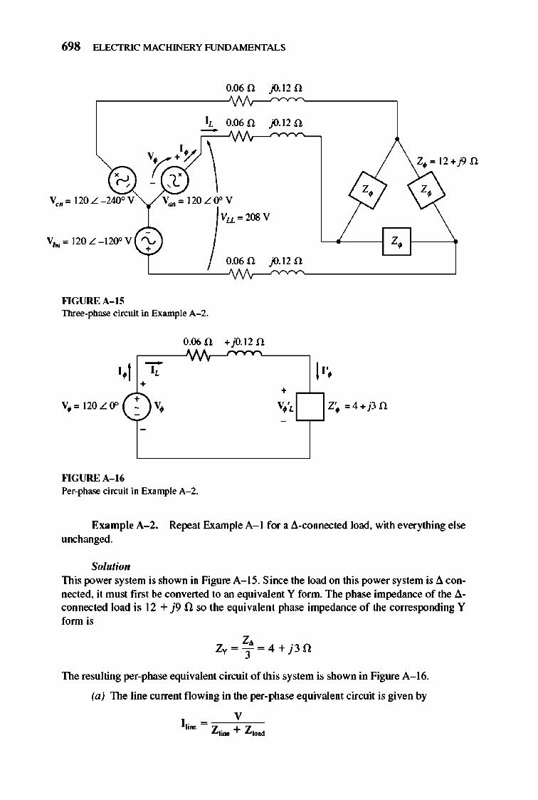
698 ELECTRIC MACHINERY RJNDAMENTALS
0.060 p.120
IL 0.06 0 p.12 0
Ven ", 120 L - 240° Y V",,'" 120LOoy
Vu ",208 V
V",,'" 120L - 120oV '\..... Z~ +
0.06 0 p.12 0
Jo'IGURE A- IS Three-phase circuit in Example A- 2.
0.06 0 +jO.1 2 0
.1 - I" " + • +
+ V. '" 120 L 0" - V. v '
" --
-
Jo'IGURE A- 16 Per-phase circuit in Example A- 2.
Example A-2. Re~at Example A- I for a ~-connected load, with everything else unchanged.
Solutioll This power system is shown in FigureA- 15. Since the load on this power system is ~ connected, it must first be converted to an equivalent Y form. The phase im~dance of the ~
connected load is 12 + j9 n so the equivalent phase impedance of the corresponding Y fonn is
z, . ZY = T = 4+}3n
The resulting per-phase equivalent circuit of this system is shown in Figure A- 16.
(a) The line current fl owing in the per-phase equivalent circuit is given by
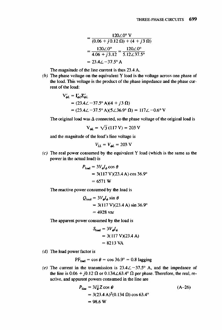
lHREE-PHASE CIRCUITS 699
120L O° V = "(O".06= +c)"· O".1C:2~1l~):-:+;',;( 4OC+~j 3'Om)
120L O° 120L O° = =
4.06 + j3 .1 2 5.12L37.5°
= 23 .4L -37 .5° A
The magnitude of the line current is thus 23 .4 A. (b) The phase voltage on the equivalent Y load is the voltage across one phase of
the load. This voltage is the product of the phase impedance and the phase current of the load:
V, - I ' Z ' .L-.L.L = (23 .4L -37 .5° A X4 + j3 fl)
= (23 .4L -37.5" A X5L36.9° n ) = 11 7L - 0.6° V
The original load was ~ cOlUlected, so the phase voltage of the original load is
V¢L= V3(11 7 V)=203 V
and the magnitude of the load's line voltage is
Va = V.u, = 203 V
(c) The real power consumed by the equivalent Y load (which is the same as the power in the actual load) is
P_=3V.,t.cos (J
= 3(11 7 VX23.4 A) cos 36.9°
= 657 1 W
The reactive power consumed by the load is
Q 1Nd = 3V.,t.sin (J
= 3( 11 7 V)(23.4 A) sin 36.9°
= 4928 var
The apparent power consumed by the load is
SI""" = 3V.,t.
(d) The load power factor is
= 3(11 7 V)(23 .4A)
= 82 13 VA
PF_ = cos (J = cos 36.9° = 0.8 lagging
(e) The current in the transmission is 23 .4L -37.5° A, and the impedance of the line is 0.06 + j O.1 2 n or O.1 34L63.4° n per phase. Therefore, the real, reactive, and apparent powers consruned in the line are
PliDe = 31l Z cos (J
= 3(23 .4A)2(O.1 34 n ) cos 63.4°
= 98.6 W
(A-26)
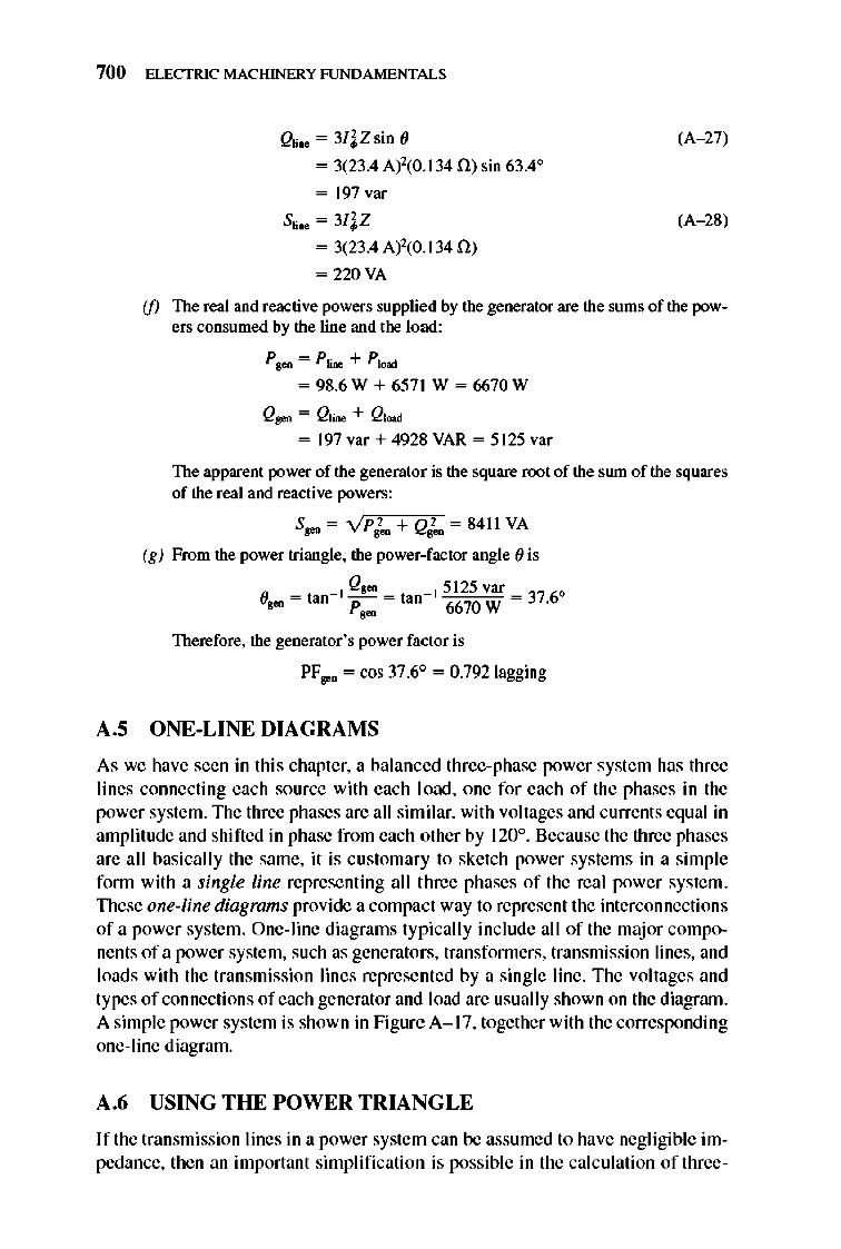
700 ELECTRIC MACHINERY RJNDAMENTALS
Qti ... = 3/lZ sin (J
= 3(23.4 A:Y(0.1 34 f.!) sin 63.4 0
= 197var
Sti ... = 3/lZ
= 3(23.4 A:Y(0.1 34 f.!)
= 220 VA
(A- 27)
(A- 28)
(f) The real and reactive powers supplied by the generator are the sums of the powers consumed by the line and the load:
P800 = PbJte + P_
= 98.6W + 6571 W = 6670W
Q gen = Qlime + QIoad
= 197 var + 4928 VAR = 5125 var
The apparent power of the generator is the square root of the SlUll of the squares of the real and reactive powers:
S = yp2 + Q2 = 8411 VA ~ 800 800
(g) From the power triangle, the power-factor angle (J is
_ _ IQ8ea _ _ 15 125var _ 0 (J800 - tan p - tan 6670 W - 37.6 ,-
Therefore, the generator's power factor is
PF seo = cos 37.6° = 0.792 lagging
A.S ONE-LINE DIAGRAMS
As we have seen in this chapter, a balanced three-phase power system has three lines connecting each source with each load, one for each of the phases in the power system. The three phases are all similar, with voltages and currents equal in amplitude and shifted in phase from each other by 120°. Because the three phases are all basicall y the same, it is customary to sketch power systems in a simple fonn with a single line representing all three phases of the real power system. These one-line diagrams provide a compact way to represent the interconnections of a power system. One-line diagrams typicall y include all of the maj or components of a power system, such as generators, transformers, transmission lines, and loads with the transmission Jines represented by a single line. The voltages and types of connections of each generator and load are usually shown on the diagrrun. A simple power system is shown in Figure A- I 7, together with the corresponding one- line diagram.
A.6 USING THE POWER TRIANGLE
I f the transmission lines in a power system can be assumed to have negligible impedance, then an important simplification is possible in the calculation of three-
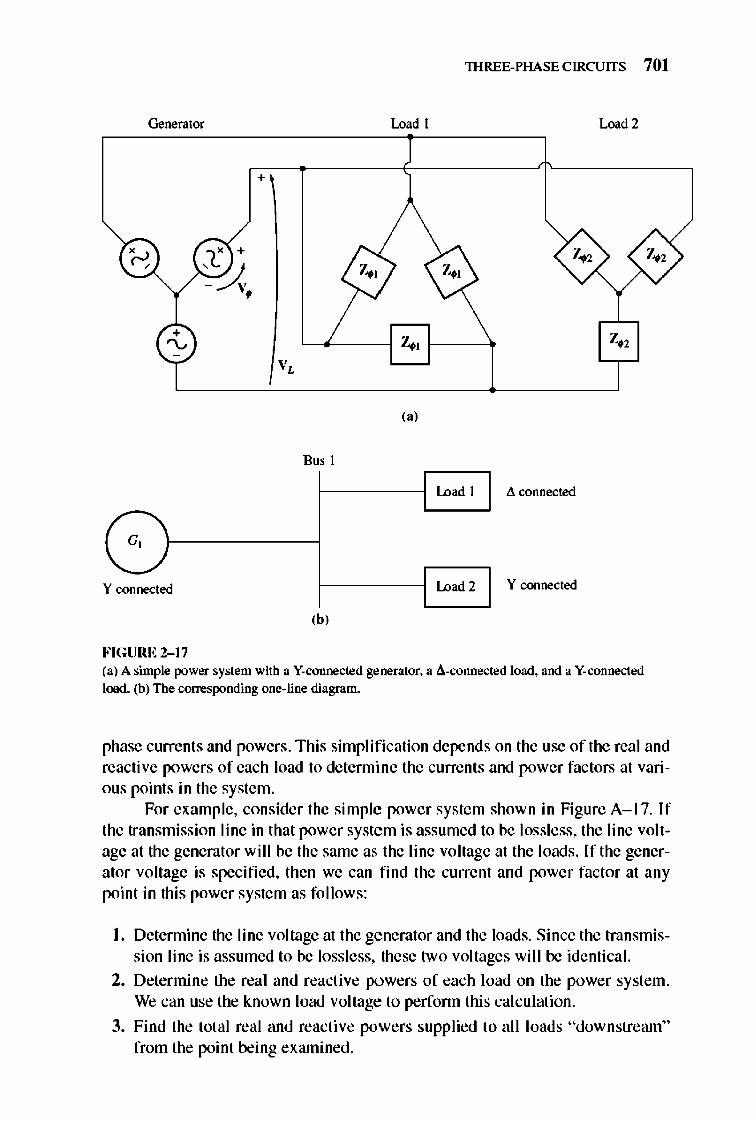
lHREE-PHASE CIRCUITS 701
Generator Load I Lood2
+
t' +
'~ •
7..,1
('j
Bus I
L",", ( A connected
"-G,
Y connected '"'''''2 Y connected
(bj
FIGURE 2-17 (a) A simple power system with a V-connected generator. a A-connected load. and a V- connected load. (b) The corresponding one-line diagram.
7-'2
phase currenls and powers. This simplificalion depends on the use of the real and reactive powers of each load to detennine the currents and power factors at various points in the system.
For example, consider the simple power system shown in Figure A-1 7. If the transmission line in that power system is assumed to be lossless, the line voltage at the generatorwilJ be the same as the line voltage at the loads. If the generator voltage is specified, then we can find the current and power factor at any point in this power system as fo llows:
I. Detennine the line voltage at the generator and the loads. Since the transmission line is assumed to be lossless, these two voltages will be identical.
2. Determine the real and reacti ve powers of each load on the power system. We can use the known load voltage to perfonn this calculation.
3. Find the total real and reactive powers supplied to all loads "downstream" from the point being examined.
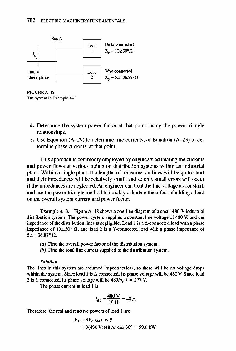
702 ELECTRIC MACHINERY RJNDAMENTALS
BusA
, ,
I" ~
, ,
480 V three-phase
HGURE A- IS The system in Example A- 3.
Lo,' I
Lo,' 2
Delta connected Z, '" IOL30on
Wye connected Z, '" 5L- 36.87°n
4. Determine the system power factor at that point, using the power-triangle relationships.
5. Use Equation (A- 29) to detennine line currents, or Equation (A- 23) to detennine phase currents, at that point.
nlis approach is commonly employed by engineers estimating the currents and power fl ows at various points on distribution systems within an industri al plant. Within a single plant, the lengths of transmission Ii nes will be quite short and their impedances will be relatively small , and so only small errors will occur if the impedances are neglected. An engineer can treat the line voltage as constant, and use the power triangle method to quickly calc ulate the effect of adding a load on the overall system current and power factor.
Example A-3. Figure A- 18 shows a one-line diagram of a sma11480-V industrial distribution system. The power system supplies a constant line voltage of 480 V, and the impedance of the distribution lines is negligible . Load I is a ~-connected load with a phase impedance of IOL30° n, and load 2 is a V-connected load with a phase impedance of 5L -36.87° n.
(a) Find the overall power factor of the distribution system. (b) Find the total line current supplied to the distribution system.
Solutioll The lines in this system are assumed impedanceless, so there will be no voltage drops within the system. Since load I is ~ cormected, its phase voltage will be 480 V. Since load 2 is Y connected, its phase voltage will be 4801\13 = 277 V.
The phase current in load I is
Therefore, the real and reactive powers of load I are
P I = 3V'I/'1 cos (J
= 3(480 V)(48 A) cos 30° = 59.9 kW
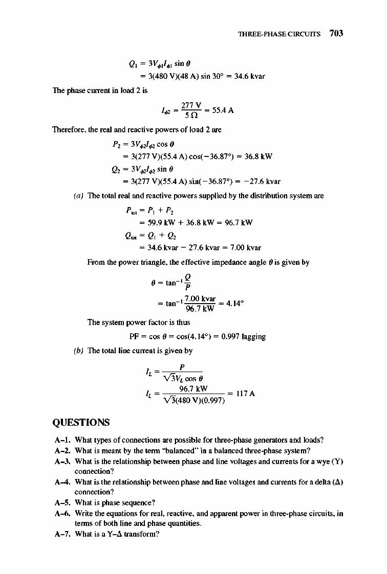
lHREE-PHASE CIRCUITS 703
QI = 3V. I/. I sin (J
= 3(480 VX48 A) sin 30° = 34.6 kvar
The phase ClUTent in load 2 is
I~ = 2~70V = 55.4 A
Therefore, the real and reactive powers of load 2 are
P2 = 3 V.2/~cos (J
= 3(277 V)(55.4 A) cos( - 36.87°) = 36.8 kW
Q2 = 3 V~/.2 sin (J
= 3(277 V)(55.4 A) sin( -36.87°) = -27.6 kvar
(a) The total real and reactive powers supplied by the distribution system are
P,ot = PI + P2
= 59.9 kW + 36 .8 kW = 96.7 kW
Q,ot = QI + Q2
= 34.6 kvar - 27.6 kvar = 7.00 kvar
From the power triangle, the effective impedance angle (J is given by
(J = tan- I ~ _ - I 7.00 kvar _ 4140 - tan 96.7 kW - .
The system power factor is thus
PF = cos (J = cos(4.14°) = 0.997 lagging
(b) The total line current is given by
QUESTIONS
h = ~o-"P-V3VLcos ()
1 - 96.7 kW = 1l7 A L - V3(480 V)(0.997)
A-I. What types of cOlUlections are possible for three-phase generators and loads? A-2. What is meant by the tenn "balanced" in a balanced three-phase system? A-3. What is the relationship between phase and line voltages and currents for a wye (Y)
cOlUlection? A-4. What is the relationship between phase and line voltages and currents for a delta (.6.)
cOlUlection? A-5. What is phase sequence? A-6. Write the equations for real, reactive, and apparent power in three-phase circuits, in
tenns of both line and phase quantities. A-7. What is a Y-6. transform?
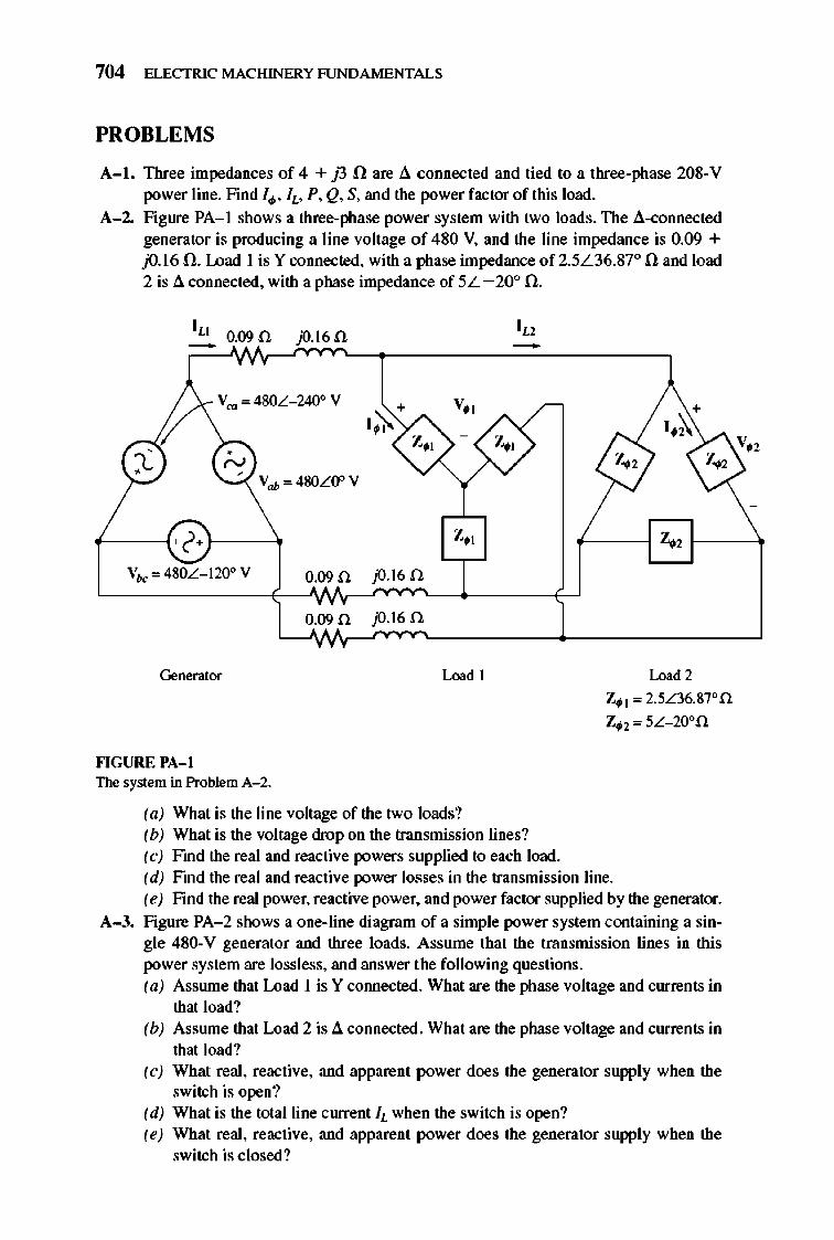
704 ELECTRIC MACHINERY RJNDAMENTALS
PROBLEMS
A- I. TIrree impedances of 4 + j3 n are.6. connected and tied to a three-phase 208-V power line. Find I., IL' P, Q, S, and the power factor of this load.
A-2. Figure PA- I shows a three-phase power system with two loads. The a-connected generator is producing a line voltage of 480 V, and the line impedance is 0.09 + fJ.16 n. Load I is Y connected, with a phase impedance of2.5L36.87° n and load 2 is a connected, with a phase impedance of 5L -200 n.
I" 0.090 jO.l60 -V""",480L- 2400Y
• ' ".1 N
Vah '" 480LO" Y
Vbe ",480L- 1200 V 0.09 n jO.l6 n
0.09 n jO.l6 n
Generator Loodl
fo'IGURE I'A-1 The system in Problem A- 2.
(a) What is the line voltage of the two loads? (b) What is the voltage drop on the transmission lines? (c) Find the real and reactive powers supplied to each load.
Lood2
Z.t '" 2.5L36.87°n
Z.2'" 5L- 20on
(d) Find the real and reactive power losses in the transmission line. (e) Find the real power, reactive power. and power factor supplied by the generator.
A-3. Figure PA- 2 shows a one-line diagram of a simple power system containing a single 480-V generator and three loads. Assume that the transmission lines in this power system are lossless, and answer the following questions. (a) Assrune that Load I is Y cOlUlected. What are the phase voltage and currents in
that load? (b) Assrune that Load 2 is.6. connected. What are the phase voltage and currents in
that load? (c) What real, reactive, and apparent power does the generator supply when the
switch is open? (d) What is the total line current IL when the switch is open? (e) What real, reactive, and apparent power does the generator supply when the
switch is closed?
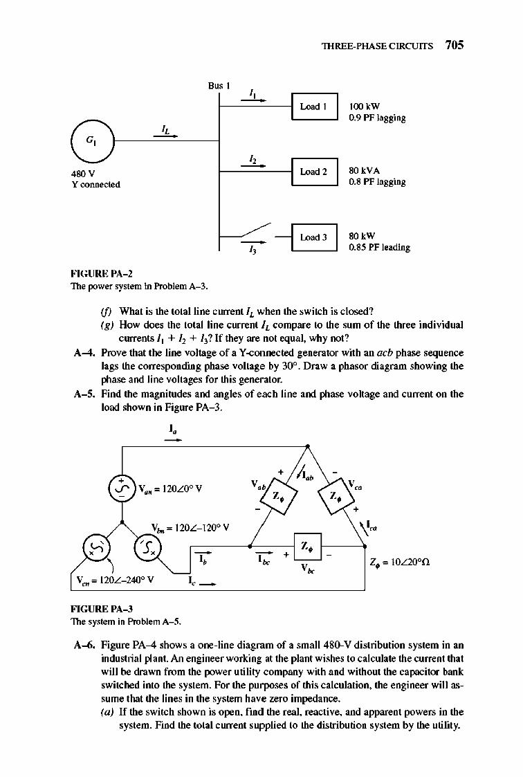
lHREE-PHASE CIRCUITS 705
Bus I I , - Lood I lOO kW
0.9 PF lagging
480 V 1.0"'2 SO kVA Y connected O.S PF lagging
SO kW 0.S5 PF leading -1 1.0'" 3 I
FIGURE PA- 2 The power system in Problem A- 3.
(f) What is the total line current h when the switch is closed? (g) How does the total line current h compare to the sum of the three individual
currents It + 12 + 13? If they are not equal, why not?
A-4. Prove that the line voltage of a Y -connected generator with an acb phase sequence lags the corresponding phase voltage by 30° . Draw a phasor diagram showing the phase and line voltages for this generator.
A-5. Find the magnitudes and angles of each line and phase voltage and current on the load shown in Figure PA-3.
" -
'«
FIGURE PA- 3 The system in Problem A- 5.
A-6. Figure PA-4 shows a one-line diagram of a small 480-V distribution system in an industrial plant. An engineer working at the plant wishes to calculate the current that will be drawn from the power utility company with and without the capacitor bank switched into the system. For the purposes of this calculation, the engineer will assume that the lines in the system have zero impedance. (a) If the switch shown is open, ftnd the real, reactive, and apparent powers in the
system. Find the total current supplied to the distribution system by the utility.
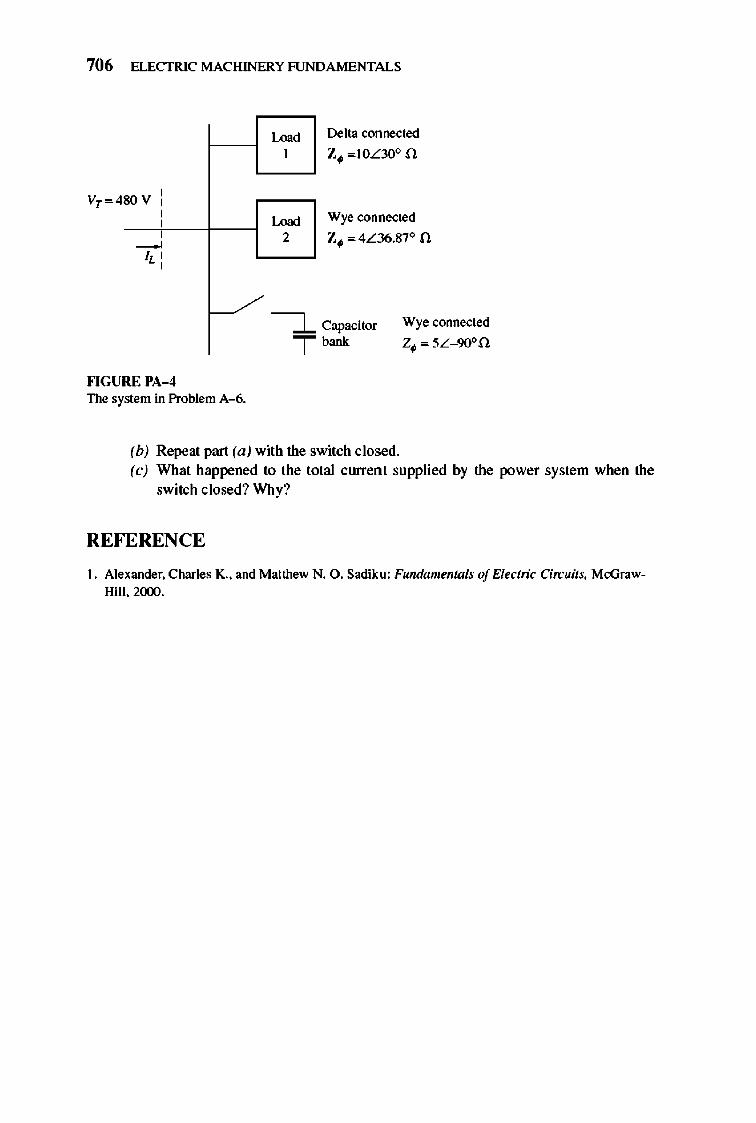
706 ELECTRIC MACHINERY RJNDAMENTALS
SOV , , , , , ~
I, ' ,
""GURE PA- 4 The system in Problem A--6.
Lood I
Lood 2
~ T
Delta connected
z. ",IOL30o n
Wye connected
z. '" 4L36.87° n
Capacitor
"',' Wye connected
z. '" 5L- 90on
(b) Repeat part (a) with the switch closed. (c) What happened to the total current supplied by the power system when the
switch closed? Why?
REFERENCE
I. Alexander. Charles K. , and Matthew N. O. Sadiku: Fundamentals of Electric Circuits, McGrawHill. 2CXXl.
APPENDIX
B COIL PITCH
AND DISTRIBUTED
WINDINGS
As mentioned in Chapter 4, the induced voltage in an ac machine is sinusoidal only if the harmonic components of the air-gap flu x density are suppressed.
This appendix describes two techniques used by machinery designers to suppress harmonics in machines .
B.1 THE EFFECT OF COIL PITCH ON AC MACHINES
In the simple ac machine design of Section 4.4, the output voltages in the stator coil s were sinusoidal because the air-gap flux density distribution was sinu soidal. If the air-gap flux density distribution had not been sinusoidal , then the output voltages in the stator would not have been sinusoidal either. They would have had the same nonsinusoidal shape as the flux density distribution.
In general, the air-gap flu x density distribution in an ac machine will not be sinusoidal. Machine designers do their best to pnxluce sinusoidal flux distributions, but of course no design is ever perfect. llle actual flu x distribution will consist of a fundamental sinusoidal component plus hannonics. TIlese hannonic components of flu x will generate hannonic components in the stator 's voltages and currents.
The hannonic components in the stator voltages and currents are undesirable, so techniques have been developed to suppress the unwanted hannonic components in the output voltages and currents ofa machine. One important technique to suppress the harmonics is the use offractionnl-pitch windings.
707
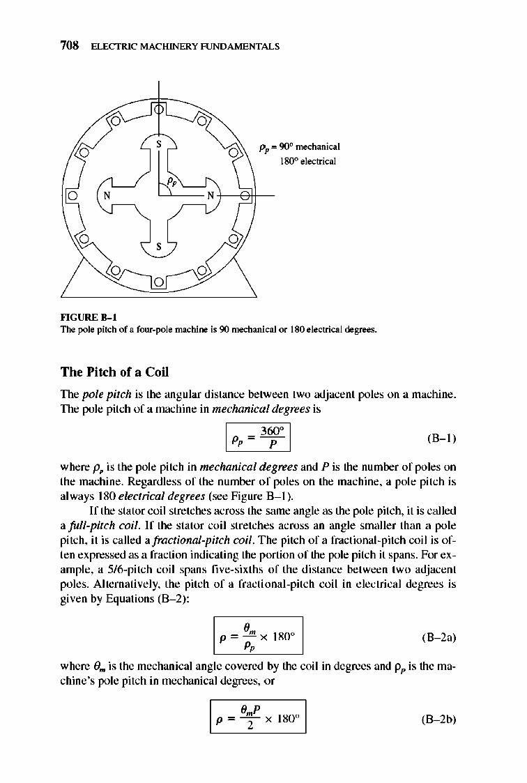
708 ELECTRIC MACHINERY RJNDAMENTALS
o
o N r-,
o
fo'IGURE 8- 1
s 0 Pp'" 90° mechanical Il 180° electrical
~Nl---e!l-
s
The pole pitch of a four-pole machine is 90 mechanical or 180 electrical degrees.
The Pitch of a Coil
The pole pitch is the angular distance between two adjacent poles on a machine. TIle pole pitch of a machine in mechanical degrees is
I pp=~ 1 (8- 1)
where Pp is the pole pitch in mechanical degrees and P is the number of poles on the machine. Regard less of the number of poles on the machine, a pole pitch is always 180 electrical degrees (see Figure B- 1).
I f the stator coil stretches across the same angle as the pole pitch, it is called afull-pitch coil. If the stator coil stretches across an angle smaller than a pole pitch, it is called afractional-pitch coil. The pitch of a fractional-pitch coil is often expressed as a fraction indicating the portion of the pole pitch it spans. For example, a 5/6-pitch coil spans fi ve-sixths of the distance between two adjacent poles. Alternatively, the pitch of a fracti onal-pitch coil in electrical degrees is given by Equations (B- 2) :
em P ~ - x 180 0
P, (B- 2a)
where Om is the mechanical angle covered by the coil in degrees and Pp is the machine's pole pitch in mechanical degrees, or
(8 - 2b)
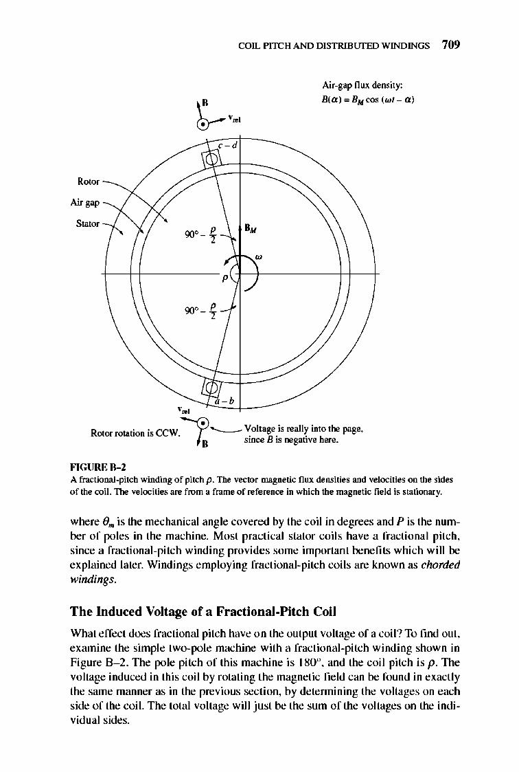
COIL PITCH AND DISTRIBlJfED WINDINGS 709
Air-gap flUl( density:
B(a ):. BM cos (wl - a)
, -d
Rotor
Air gap
Stator
+-+f----- p
90" P - ~
, - b '., --~CC~e-------R ,
"
.. ccw~'---VoltageiSreallYintothepage. oorroalonlS. . B· . h II smce IS negatIVe ere.
FIGURE B-2 A fractional-pitch winding of pitch p. The vector magnetic flux densities and velocities on the sides of the coil. The velocities are from a frame of reference in which the magnetic field is stationary.
where e", is the mechanical angle covered by the coil in degrees and P is the number of poles in the machine. Most practical stator coils have a fractional pitch, since a fractional-pitch winding provides some important benefits which will be explained later. Windings employing fractional-pitch coils are known as chorded windings.
The Induced Voltage of a Fractional-Pitch Coil
What effect does fractional pitch have on the output voltage of a coil ? To find out, examine the simple two-pole machine with a fractional-pitch winding shown in Figure 8-2. TIle pole pitch of this machine is 180°, and the coil pitch is p. 1lle voltage induced in this coil by rotating the magnetic field can be found in exactly the same manner as in the previous section, by detennining the voltages on each side of the coil. The total voltage wil l just be the sum of the voltages on the individual sides.
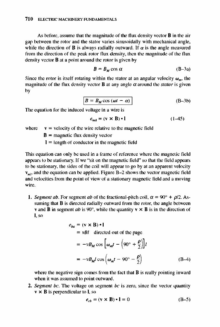
710 ELECTRIC MACHINERY RJNDAMENTALS
As before, assume that the magnitude of the flu x density vector B in the air gap between the rotor and the stator varies sinusoidally with mechanical angle, while the direction of B is always radial ly outward. If a is the angle measured from the direction of the peak rotor flux density, then the magnitude of the flux density vector B at a point around the rotor is given by
B = BM cosa (8-3a)
Since the rotor is itself rotating within the stator at an angular velocity W m , the magnitude of the flu x density vector B at any angle a around the stator is given by
I B - BM cos (wt a ) I
The equation for the induced voltage in a wire is
eiD<! = (v x B) - 1
where v = velocity of the wire relative to the magnetic fie ld
B = magnetic flu x density vector
1 = length of conductor in the magnetic fi e ld
(B-3 b)
( 1-45)
lllis equation can only be used in a frame of reference where the magnetic field appears to be stationary. If we "sit on the magnetic fie ld" so that the fi e ld appears to be stationary, the sides of the coil wi ll appear to go by at an apparent velocity vre], and the equation can be applied. Figure 8-2 shows the vector magnetic field and velocities from the point of view of a stationary magnetic fie ld and a moving wire.
I. Segment abo For segme nt ab of the fractional-pitch coil , a = 90° + pl2. Assuming that B is directed radially outward from the rotor, the angle between v and B in segme nt ab is 900, whi le the quantity v x B is in the direction of I, so
eba = (v x B) -I
= vBI directed out of the page
- -vBM cos [w,,! - (900 + ~)] I
- -vBt.I cos (wmt - 90° - ~) (B-4)
where the negative sign comes from the fact that B is really pointing inward when it was assumed to point outward.
2. Segment be. The voltage on segment be is zero, since the vector quantity v x B is perpendicular to I, so
ecb = (v x B). 1 = 0 (8-5)
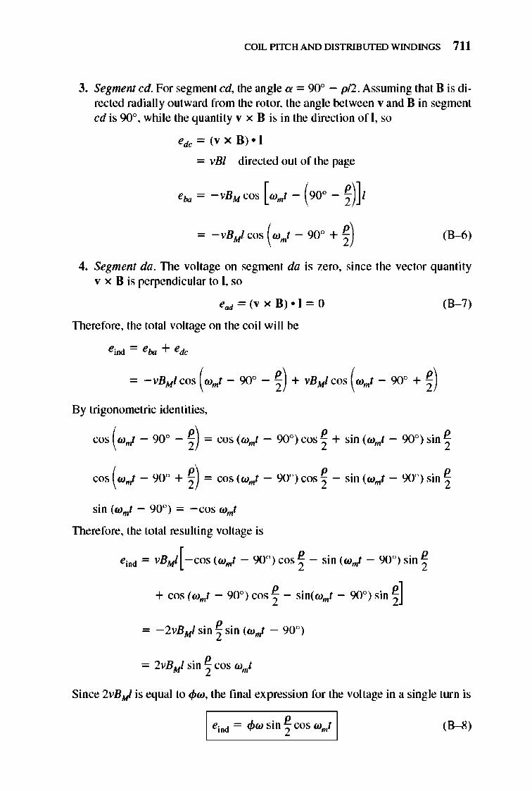
COIL PITCH AND DISTRIBlJfED WINDINGS 711
3. Segment cd. For segment cd, the angle a = 90° - pI2. Assuming that B is directed radially outward from the rotor, the angle between v and B in segment cd is 90°, while the quantity v x B is in the direction ofl , so
edc = (v x B) · I
= vBI directed out of the page
= -vBt.! cos (W"I - 90° + ~) (8-6)
4. Segment da. TIle voltage on segment da is zero, since the vector quantity v x B is perpendicular to I, so
ead = (v x B) • I = 0 (8-7)
Therefore, the total voltage on the coil will be
By trigonometric identities,
cos (W"I - 90° - ~) = cos (wmt - 90°) cos ~ + sin (wmt - 90°) sin ~
cos (W"I - 90° + ~) = cos (wmf - 90°) cos ~ - sin (wmt - 90°) sin ~
sin (wmf - 90°) = -cos wmf
Therefore, the total resulting voltage is
eind = VBMI[-cos(wmt - 900)COS ~ - sin (w"I- 900)Sin~
+ cos (wmt - 90°) cos ~ - sin(wmt - 90°) sin ~]
Since 2vB&l is equal to <pw, the fmal expression for the voltage in a single turn is
I eind = <pw sin ~ cos wmt I (8-8)
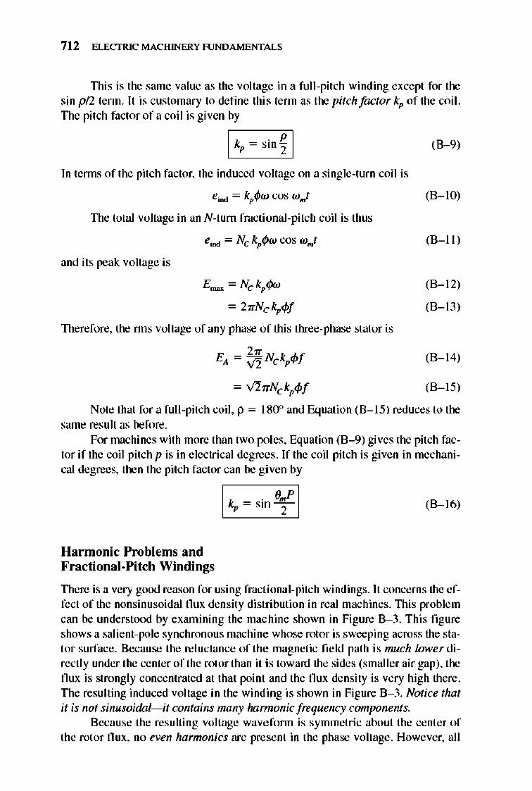
712 ELECTRIC MACHINERY RJNDAMENTALS
TIlis is the same value as the voltage in a full-pitch winding except for the sin pl2 term. It is customary to define this term as the pitch factor kp of the coil. TIle pitch factor of a coil is given by
CI-k,-~-'-i-n~~"1
In tenns of the pitch factor, the induced voltage on a single-turn coil is
eind = kp<Ptu cos wmt
TIle total voltage in an N-turn fractional-pitch coil is thus
eind = Nc kp<Ptu cos wmt
and its peak voltage is
= 27rNckp4>f
TIlerefore, the nns voltage of any phase of this three-phase stator is
2" EA = V2 Nc kp4>f
= V'17rNc kp4>f
(8-9)
(8-10)
(8-11 )
(8-12)
(8-13)
(8-14)
(8-15)
Note that for a full-pitch coil, p = 1800 and Equation (8-15) reduces to the same result as before.
For machines with more than two poles, Equation (B-9) gives the pitch factor if the coil pitch p is in electrical degrees. If the coil pitch is given in mechanical degrees, then the pitch factor can be given by
Harmonic Problems and Fractional-Pitch Windings
I kp = sin¥1 (8-16)
TIlere is a very good reason for using fractional-pitch windings. It concerns the effect of the nonsinusoidal flux density distribution in real machines. nlis problem can be understood by examining the machine shown in Figure 8-3. This fi gure shows a salient-pole synchronou s machine whose rotor is sweeping across the stator surface. 8ecause the reluctance of the magnetic field path is much lmverdirectly under the center of the rotor than it is toward the sides (smaller air gap), the flux is strongly concentrated at that point and the flux density is very high there. TIle resulting induced voltage in the winding is shown in Figure B-3. Notice that it is not sinusoidal-it contains many harmonic frequency components.
Because the resu lting voltage wavefonn is symmetric about the center of the rotor flux , no even harmonics are present in the phase voltage. However, all
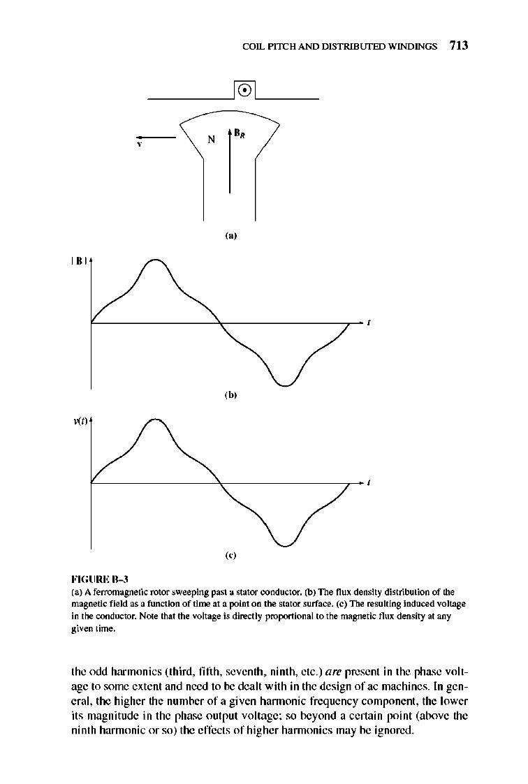
COIL PITCH AND DISTRIBlJfED WINDINGS 7 13
N B,
,,' 181
,b,
, " FIGURE B-3 (a) A ferromagnetic rotor sweeping past a stator conductor. (b) The flux density distribution of the magnetic field as a function of time at a point on the stator surface. (c) The resulting induced voltage in the conductor. Note that the voltage is directly proponional to the magnetic flux density at any given time.
the odd harmonics (third, fifth , seventh, ninth, etc.) are present in the phase voltage to some extent and need to be dealt with in the design of ac machines. In general, the higher the number of a given hannonic frequency component , the lower its magnitude in the phase output voltage; so beyond a certain point (above the ninth harmonic or so) the effects of higher hannonics may be ignored .
714 ELECTRIC MACHINERY RJNDAMENTALS
When the three phases are Y or 6. connected, some of the hannonics disappear from the output of the machine as a result of the three-phase connection. The third-harmonic component is one of these . If the fundamental voltages in each of the three phases are given by
ea(t) = EM] sin wt V
e,,(t) = EM] sin (wt - 120°)
eJ t) = EM] sin (wI - 240°)
v
V
then the third-hannonic components of voltage will be given by
e,,3(t) = EM) sin 3wl V
eblt) = EM) sin (3wl - 360°)
ec3(t) = EM) sin (3wl - 720°)
V
V
(8 - 17a)
(8 - 17b)
(8 - 17c)
(8 - 18a)
(8 - 18b)
(8 - 18c)
Notice that the third-harmonic components of voltage are all identical in each phase. If the synchronous machine is V-connected, then the third-harmonic voltage beMeen any Mo terminnls will be zero (even though there may be a large third-hannonic component of voltage in each phase). If the machine is 6.-connected, then the three third-hannonic components all add and drive a thirdharmonic current around inside the 6.-wi ndi ng of the machine. Since the thirdharmonic voltages are dropped across the machine's internal impedances, there is again no significant third-hannonic component of voltage at the tenninals.
This result applies not only to third-harmonic component s but also to any multiple of a third-harmonic component (such as the ninth hannonic). Such special harmonic frequencies are called triplen harmonics and are automatically suppressed in three-phase machines.
1lle remaining hannonic frequencies are the fifth , seventh, e leventh, thirteenth, etc. Since the strength of the hannonic components of voltage decreases with increasing frequency, most of the actual distortion in the sinusoidal output of a synchronous machine is caused by the fifth and seventh harmonic frequencies, sometimes called the belt harmonics. If a way could be found to reduce these components, then the machine's output voltage would be essentially a pure sinusoid at the fundamental frequency (50 or 60 Hz).
How can some of the harmonic content of the winding's terminal voltage be e liminated?
One way is to design the rotor itself to distribute the flux in an approximate ly sinusoidal shape. Although this acti on will he lp reduce the hannonic content of the output voltage, it may not go far enough in that direction. An additional step that is used is to design the machine with fractional-pitch windings.
1lle key to the effect of fractional-pitch windings on the voltage prrxluced in a machine's stator is that the e lectrical angle of the nth hannonic is n times the electrical angle of the fundrunental frequency component. In other words, if a coil spans 150 electrical degrees at its fundamental frequency, it wil I span 300 electrical degrees at its second-hannonic frequency, 450 electrical degrees at its third-hannonic frequency, and so forth. If p represents the electrical angle spanned by the coil at its
COIL PITCH AND DISTRIBlJfED WINDINGS 715
f undamental freq uency and v is the number of the hannonic being exmnined, then the coil will span vp electrical degrees at that harmonic frequency. Therefore, the pitch factor of the coil at the hannonic freq uency can be expressed as
I kp = sinT I (8-1 9)
The important consideration here is that the pitch factor of a winding is different for each harnwnic frequency . By a proper choice of coil pitch it is possible to almost eliminate harmonic freq uency compone nts in the output of the machine. We can now see how hannonics are suppressed by looking at a simple example problem.
Example B-1. A three-phase, two-pole stator has coils with a 5/6 pitch. What are the pitch factors for the harmonics present in this machine's coils? Does this pitch help suppress the harmonic content of the generated voltage?
Solution The pole pitch in mechanical degrees of this machine is
360° P = -- = 180° , P (B-1 )
Therefore, the mechanical pitch angle of these coils is fi ve-sixths of 180°, or 1500•
From Equation (B-2a), the resulting pitch in electrical degrees is
p = £1m X 180° = 150° X 180° = 150° Pp 1800 (B-2a)
The mechanical pitch angle is equal to the electrical pitch angle only because this is a twopole machine. For any other number of poles, they would not be the same.
Therefore, the pitch factors for the fundamental and the higher odd harmonic frequencies (remember, the even hannonics are already gone) are
Fundamental:
Third harmonic :
Fifth hannonic:
Seventh hannonic:
Ninth harmonic :
150" kp = sin - 2- = 0.966
k = sin 3(1 50°) = -0.707 , 2
k = . 5(1 50°) = 0259 pS1ll 2 .
k = . 7(1 50°) = 0259 pS1ll 2 .
k = sin 9(1 50°) = -0.707 , 2
(This is a triplen hannonic not present in the three-phase output. )
(This is a triplen hannonic not present in the three-phase output. )
The third- and ninth-hannonic components are suppressed only slightly by this coil pitch, but that is unimportant since they do not appear at the machine's terminals anyway. Between the effects of triplen hannonics and the effects of the coil pitch, the third, fifth, seventh, and ninth hannonics are suppressed relative to the futuiamentalfrequency . Therefore, employing fractional-pitch windings will drastically reduce the harmonic content of the machine's output voltage while causing only a small decrease in its ftmd amental voltage.
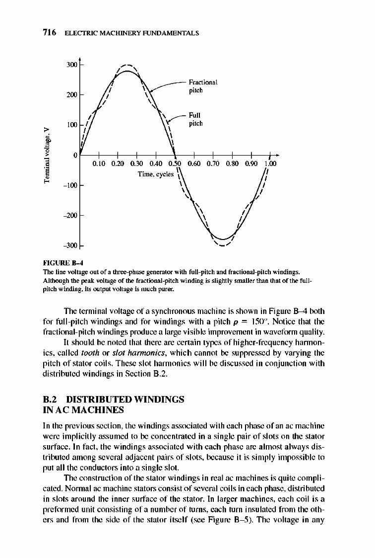
716 ELECTRIC MACHINERY RJNDAMENTALS
300
200
> 100
~ ~ > 0 ;;
0.10 0
! ~ - 100
- 200
- 300
fo'IGURE 8-4
~-I ,
~_- Fractional pitch
\ ....-- Full Y pitch , , ,
0.20 0.30 0.40 0.50 0.60 0.70 0.80 0.90
Time. cycles \ , \ , ,
\ \ ,
I I
I I
I
1.00 I I
I I
The line voltage out of a three-phase generator with full-pitch and fractional-pitch windings. Although the peak voltage of the fractional-pitch winding is slightly smaller than that of the fullpitch winding. its output voltage is much purer.
TIle tenni nal voltage of a synchronous machine is shown in Figure 8-4 both for full-pit ch windings and for windings with a pitch p = 150°. Notice that the fractional-pitch windings produce a large visible improvement in waveform quality.
It should be noted that there are certain types of higher-frequency hannonics. called tooth or slot hamwnics. which cannot be suppressed by varying the pitch of stator coils. These slot harmonics will be discussed in conjuncti on with distributed windings in Section B.2.
8.2 DISTRIBUTED WINDINGS IN A C MA CHINES
In the previous section. the windings associated with each phase of an ac machine were implicitly assumed to be concentrated in a single pair of slots on the stator surface . In fact, the windings associated with each phase are almost always di stributed among several adjacent pairs of s lots, because it is simply impossible to put all the conductors into a single slot.
TIle construction of the stator windings in real ac machines is quite complicated. Normal ac machine stators consist of several coils in each phase, distributed in slots around the inner surface of the stator. In larger machines, each coil is a preformed unit consisting of a number of turns, each turn insulated from the others and from the side of the stator itself (see Figure 8-5). The voltage in any
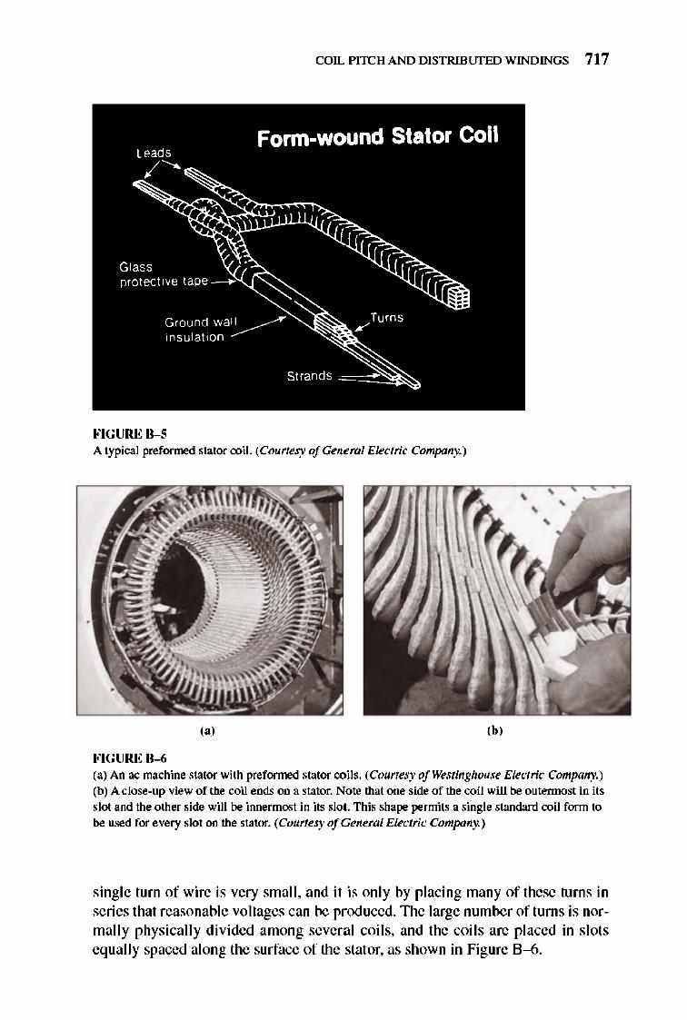
COIL PITCH AND DISTRIBlJfED WINDINGS 717
FIGURE B-S A typica l preformed stator coil. (Courtesy ofGeneml Electric Company.)
,., ,b, FIGURE B-6 (a) An ac machine stator with preformed stator coils. (Courtesy of Westinghouse Electric Company.) (b) A close-up view of the coil ends on a stator. Note that one side of the coil will be outennosl in its slot and the other side will be innermost in its slol. This shape permits a single standard coil form to be used for every slot on the stator. (Courtesy ofGeneml Electric Company.)
single turn of wire is very small , and it is onl y by placing many of these turns in series that reasonable voltages can be prod uced. 1lle large num ber of turns is normall y physicall y divided among several coil s, and the coils are placed in slots eq ually spaced along the surface of the stator, as shown in Figure 8 -6.
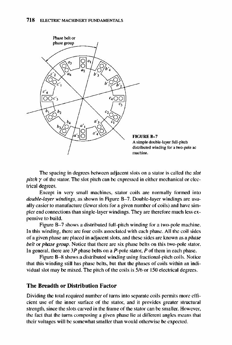
718 ELECTRIC MACHINERY RJNDAMENTALS
Phase belt or
ph= =gro~"~P _ _ _ --I
FIGURE 11-7 A simple double-layer full-pitch distributed winding for a two-pole ac machine.
TIle spacing in degrees between adjacent slots on a stator is called the slot pitch r of the stator. The slot pitch can be expressed in either mechanical or electrical degrees.
Except in very small machines, stator coils are normally fonned into double-layer windings, as shown in Figure 8-7. Double- layer windings are usuall y easier to manufacture (fewer slots for a given number of coil s) and have simpler end connections than single-layer windings. They are therefore much less expensive to build.
Figure 8-7 shows a distributed full -pitch winding for a two-pole machine. In this winding, there are four coils associated with each phase. All the coil sides ofa given phase are placed in adjacent slots, and these sides are known as aphase belt or phase group. Notice that there are six phase belts on this two-pole stator. In general, there are 3P phase belts on a P-pole stator, P of them in each phase .
Figure 8-8 shows a distributed winding using fracti onal-pitch coils. Notice that this winding still has phase belts, but that the phases of coils within an individual slot may be mixed. The pitch of the coils is 5/6 or 150 e lectrical degrees.
The Breadth or Distribution Factor
Dividing the total required number of turns into separate coils permits more efficient use of the inner surface of the stator, and it provides greater structural strength, since the slots carved in the frame of the stator can be smaller. However, the fact that the turns composing a given phase lie at different angles means that their voltages will be somewhat smaller than would otherwise be expected.
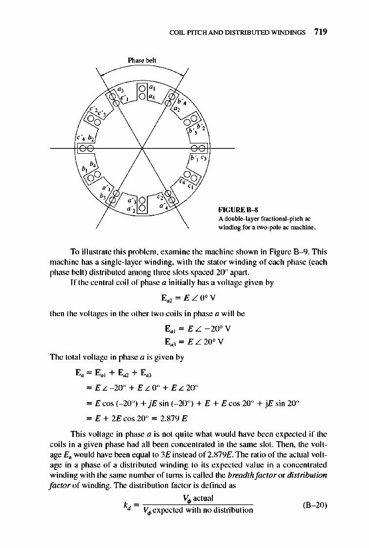
COIL PITCH AND DISTRIBlJfED WINDINGS 719
Phase belt
FIGURE B-8 A double-layer fractional-pitch ac winding for a lI'.o-pole ac machine.
To illustrate thi s proble m, examine the machine shown in Figure 8-9. This machine has a single-laye r winding, with the stat or winding of each phase (each phase belt) distributed among three slots spaced 20° apart.
If the central coil of phase a initially has a voltage given by
Ea2 = E LOoy
then the voltages in the other two coils in phase a will be
E,,]=EL-20o y
E,,3= EL200y
The total voltage in phase a is given by
E" = Ea ] + Ea2 + E,,)
= EL-20° + ELO° + EL20°
= E cos (_20°) + jEsin (_20°) + E + E cos 20° + jEsin 20°
= E + 2Ecos 20° = 2.879E
nlis voltage in phase a is not qu ite what would have been expected if the coils in a given phase had all been concentrated in the same slot. nlen, the voltage Ea wou ld have been equal to 3E instead of2.879E. The ratio of the actual voltage in a phase of a distributed winding to its expected value in a concentrated winding with the same number of turns is called the breadth factor or distribution factor of winding. The distribution factor is defined as
_ V.p actual
kd - V4>expected with no distribution (8-20)
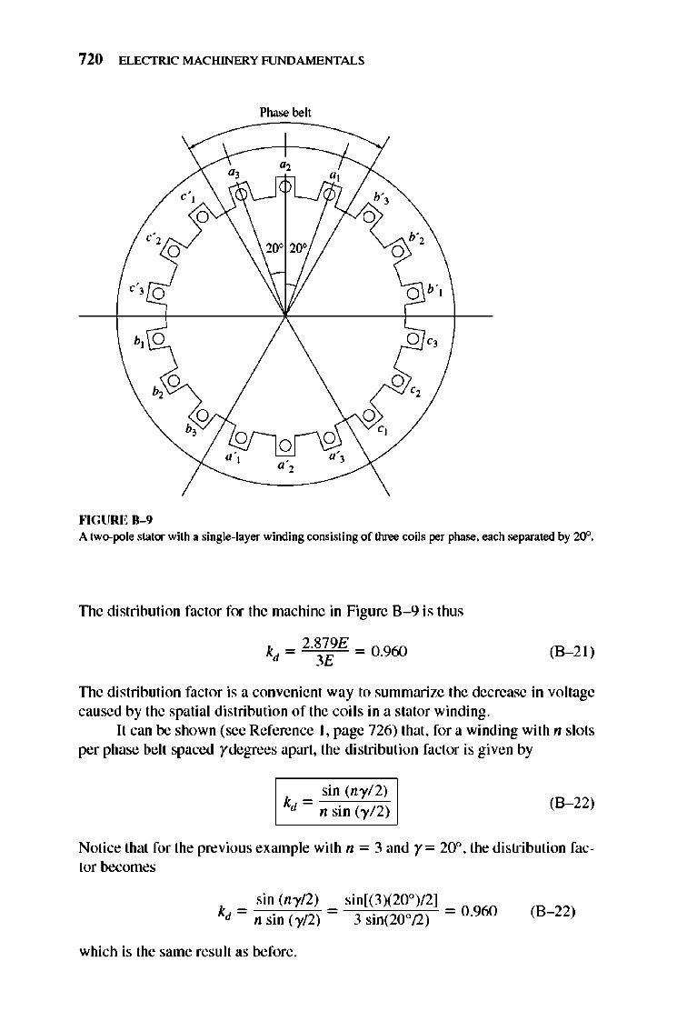
720 ELECTRIC MACHINERY RJNDAMENTALS
Phase belt
""GURE 11- 9 A two-pole stator with a single-layer witxling cOI\Sisting of three coils per phase, each separated by 20".
TIle distribution factor for the machine in Figure 8 - 9 is thus
(B- 21)
TIle distribution factor is a convenient way to summarize the decrease in voltage caused by the spatial distribution of the coil s in a stator winding.
It can be shown (see Reference I, page 726) that, for a winding with n slots per phase belt spaced ydegrees apart, the distribution factor is given by
sin (nyf2) k ~ ="'f'2c
d n sin (yf2) (B- 22)
Notice that for the previous example with n = 3 and y= 20°, the distribution factor becomes
s in (ny!2) k - -
d - n sin (yf2) -
which is the same result as before.
sin[(3)(200)!2] 3 sin(200!2) = 0.960 (B- 22)
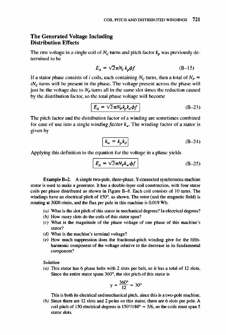
COIL PITCH AND DISTRIBlJfED WINDINGS 721
The Generated Voltage Including Distribution Effects
The nns voltage in a s ing le coil of Nc turns and pitch fac tor kp was previous ly detennined to be
(8-15)
If a stator phase cons ists of i coils, each containing Nc turns, then a total of Np = iNc turns will be present in the phase. The voltage present across the phase will just be the voltage due to N p turns all in the same s lot times the reduction caused by the distribution factor, so the total phase voltage will become
(8-23)
The pitch factor and the distribution factor of a winding are sometimes combined for ease of use into a sing le winding factor k.,. The winding facto r of a stator is g iven by
I k. - k,k, I (8-24)
Applying this defmition to the equation for the voltage in a phase yields
I EA ~ V2wNpk.<I>f I (8-25)
Example B-2. A simple two.JXlle, three.phase, Y·connected synchronous machine stator is used to make a generator. It has a double-layer coil construction, with four stator coils per phase distributed as shown in Figure 8-8. Each coil consists of 10 turns. The windings have an electrical pitch of 150°, as shown. The rotor (and the magnetic field) is rotating at 3000 rlmin, and the flux per pole in this machine is 0.019 Wb.
(a) What is the slot pitch of this stator in mechanical degrees? In electrical degrees? (b) How many slots do the coils of this stator span? (c) What is the magnitude of the phase voltage of one phase of this machine's
stator? (d) What is the machine's tenninal voltage? (e) How much suppression does the fractional-pitch winding give for the fifth
harmonic component of the voltage relative to the decrease in its fundamental component?
Solutioll (a) This stator has 6 phase belts with 2 slots per belt, so it has a total of 12 slots.
Since the entire stator spans 3600, the slot pitch of this stator is
360" ")' = ---u- = 30°
This is both its electrical and mechanical pitch, since this is a two-pole machine. (b) Since there are 12 slots and 2 poles on this stator, there are 6 slots per pole. A
coil pitch of 150 electrical degrees is 150°1180° = 5/6, so the coils must span 5 stator slots.
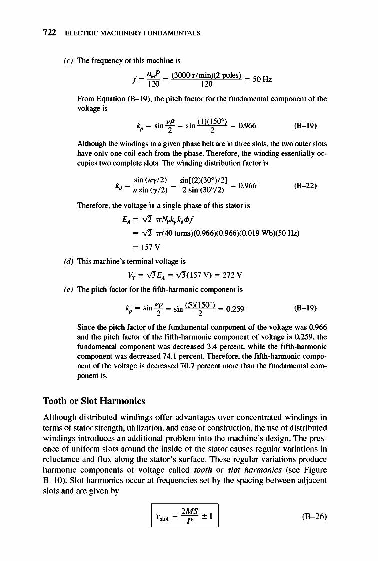
722 ELECTRIC MACHINERY RJNDAMENTALS
(e) The frequency of this machine is
f = n"'p = (3000 r/ min)(2 poles) = 50 H 120 120 z
From Equation (8-19), the pitch factor for the fundamental component of the voltage is
k = sin vP = sin (1)(150°) = 0966 p 2 2 . (B-19)
Although the windings in a given phase belt are in three slots, the two outer slots have only one coil each from the phase. Therefore, the winding essentially occupies two complete slots. The winding distribution factor is
sin (n),12) sin[(2)(300)12] kd = n sin (),12) = 2 sin (30°12) = 0.966
Therefore, the voltage in a single phase of this stator is
E}, = V2" 7rNpkpkd~f
(B-22)
= V2" 7r(40 tums)(O.966)(0.966XO.019 WbX50 Hz)
= 157 V
(d) This machine's tenninal voltage is
VT = v'5E}, = V3"( 157 V) = 272 V
(e) The pitch factor for the fifth-harmonic component is
k =sinvP _ . (5XI500)_0259 p 2- S1ll 2-' (B-19)
Since the pitch factor of the fundamental component of the voltage was 0.966 and the pitch factor of the fifth-harmonic component of voltage is 0.259, the fundamental component was decreased 3.4 percent, while the fifth-hannonic component was decreased 74.1 percent. Therefore, the fifth-hannonic component of the voltage is decreased 70.7 percent more than the fundamental com-ponent is.
Tooth or Slot Harmonics
Although distributed windings offer advantages over concentrated windings in terms of stator strength, utilization, and ease of construction, the use of distributed windings introduces an additional problem into the machine's design. The prese nce of uniform slots around the inside of the stat or causes regular variations in re luctance and flu x along the stator's surface . These regular variations produce harmonic components of voltage called tooth or slot harmonics (see Fig ure B-JO). Slot harmonics occur at freque ncies set by the spacing between adjacent s lots and are given by
(B-26)
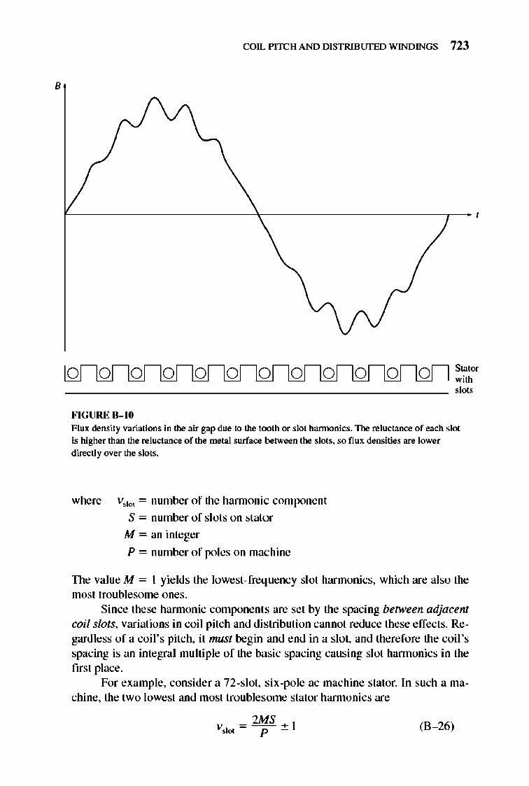
B
COIL PITCH AND DISTRIBlJfED WINDINGS 723
FIGURE B-1O
Stator with slots
Flux density variations in the air gap due to the tooth or slot hannonics. The reluctance of each slot is higher than the reluctance of the metal surface between the slots. so flux densities are lower directly over the slots.
where volo< = number of the hannonic component
S = number of slots on stator
M = an integer
P = number of poles on machine
The valueM = 1 yields the lowest-freq uency slot harmonics, which are also the most troublesome ones .
Since these hannonic components are set by the spacing between adjacent coil slots, variations in coil pitch and distribution cannot reduce these effects. Regardless ofa coil 's pitch, it must begin and end in a slot, and therefore the coil 's spacing is an integral multiple of the basic spacing causing slot hannonics in the first place.
For example, consider a 72-s10t, six-pole ac machine stator. In such a machine, the two lowest and most troubles.ome s.tator hannonics are
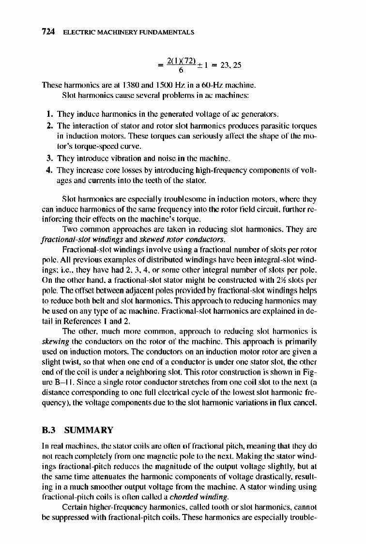
724 ELECTRIC MACHINERY RJNDAMENTALS
= 2(1)(72) + 1 = 23 25 6 '
These hannonics are at 1380 and 1500 Hz in a 6O-Hz machine. Slot harmonics cause several problems in ac machines:
I. They induce harmonics in the generated voltage of ac generators.
2. The interaction of stator and rotor slo t harmonics produces parasitic torq ues in induction motors. 1llese torques can seriously affect the shape of the motor 's torque-speed curve.
3. They introduce vibration and noise in the machine.
4. They increase core losses by introducing high-frequency components of voltages and currents into the teeth of the stator.
Slot hannonics are especially troublesome in induction motors, where they can induce harmonics of the same frequency into the rotor field circuit , further reinforcing their effects on the machine's torque.
Two common approaches are taken in reducing slot hannonics . They are fractional-slot windings and skewed rotor conductors.
Fractional-slot windings involve using a fractional number of slots per rotor pole. All previous examples of distributed windings have been integral-slot windings; i.e ., they have had 2, 3, 4, or some other integral number of slots per pole. On the other hand, a fractional-slot stator might be constructed with 2~ slots per pole. TIle offset between adjacent poles provided by fractional-slot windings helps to reduce both belt and slot harmonics. This approach to reducing hannonics may be used on any type ofac machine. Fractional-slot hannonics are explained in detail in References 1 and 2.
1lle other, much more common, approach to reducing slot hannonics is skewing the conductors on the rotor of the machine. nlis approach is primarily used on induction motors. llle conductors on an induction motor rotor are given a slight twist, so that when one end of a conductor is under one stator slot, the other end of the coil is under a neighboring slot. This rotor construction is shown in Figure 8-1 I. Since a single rotor conductor stretches from one coil slot to the next (a distance corresponding to one full e lectrical cycle of the lowest slot hannonic frequency), the voltage components due to the slot hannonic variations in flux cancel.
0,3 SUMMARY
In real machines, the stator coils are often of fractional pitch, meaning that they do not reach complete ly from one magnetic pole to the next. Making the stator windings fractional-pitch reduces the magnitude of the output voltage slightly, but at the same time attenuates the hannonic co mponents of voltage drastically, resulting in a much smoother output voltage from the machine. A stator winding using fractional-pitch coi Is is often cal led a chorded winding.
Certain higher-frequency hannonics, called tooth or slot harmonics, cannot be suppressed with fractional-pitch coils. These harmonics are especially trouble-
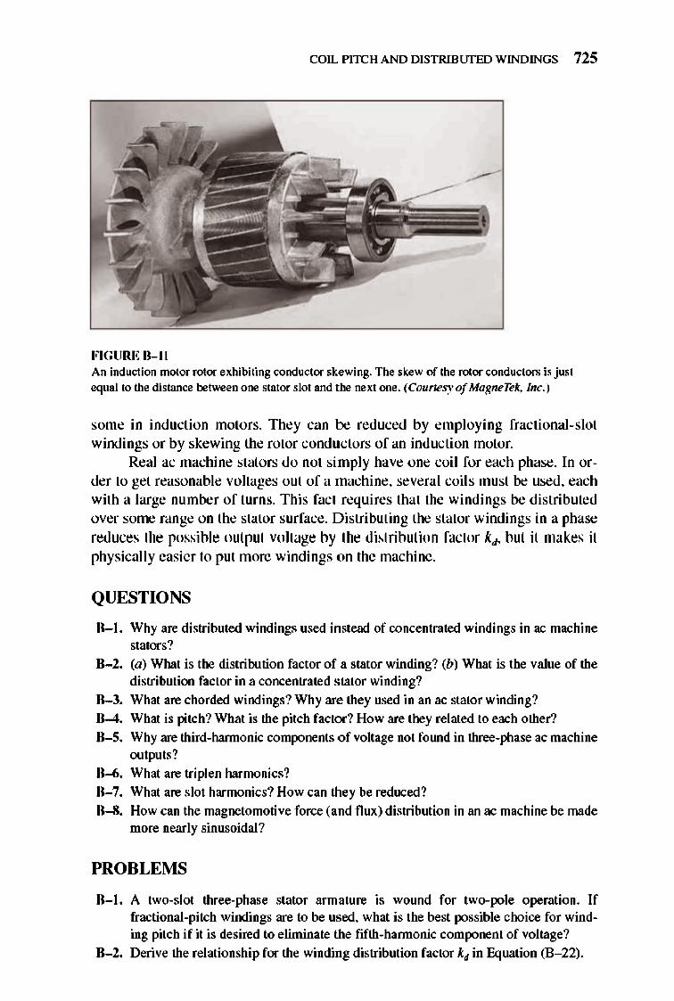
COIL PITCH AND DISTRIBlJfED WINDINGS 725
FIGURE 0-11 An induction motor rotor exhibiting conductor skewing. The skew of the rotor conductors is just equal to the distance between one stator slot and the next one. (Courtesy of MagneTek, Inc.)
some in induction motors. They can be reduced by employing fractiona l-slot windings or by skewing the rotor conductors of an induction motor.
Real ac machine stators do not simply have one coil for each phase. In order to get reasonable voltages out of a machine, several coils must be used, each with a large number of turns. This fact requires that the windings be distributed over some range on the stator surface. Distributing the stator windings in a phase reduces the possible output voltage by the distribution factor kd' but it makes it physicall y easier to put more windings on the machine.
QUESTIONS
B-1. Why are distributed windings used instead of concentrated windings in ac machine stators?
B-2. (a) What is the distribution factor of a stator winding? (b) What is the value of the distribution factor in a concentrated stator winding?
B-3. What are chorded windings? Why are they used in an ac stator winding?
B-4. What is pitch? What is the pitch factor ? How are they related to each other?
B-5. Why are third-hannonic components of voltage not fOlUld in three-phase ac machine outputs?
B-6. What are triplen harmonics? B-7. What are slot harmonics? How can they be reduced?
B-8. How can the magnetomotive force (and flux) distribution in an ac machine be made more nearly sinusoidal?
PROBLEMS
B-1. A two-slot three-phase stator armature is wOlUld for two-pole operation. If fractional-pitch windings are to be used. what is the best possible choice for winding pitch if it is desired to eliminate the fifth-hannonic component of voltage?
B-2. Derive the relationship for the winding distribution factor kd in Equation (B- 22).
726 ELECTRIC MACHINERY RJNDAMENTALS
B-3. A three-phase four-pole synchronous machine has 96 stator slots. The slots contain a double-layer winding (two coils per slot) with four turns per coil. The coil pitch is 19124. (a) Find the slot and coil pitch in electrical degrees. (b) Find the pitch, distribution, and winding factors for this machine. (c) How well will this winding suppress third, fifth, seventh, ninth, and eleventh
harmonics? Be sure to consider the effects of both coil pitch and winding distribution in your answer.
B-4. A three-phase four-pole winding of the double-layer type is to be installed on a 48-slot stator. The pitch of the stator windings is 5/6, and there are 10 tlU1lS per coil in the windings. All coils in each phase are cOIUlected in series, and the three phases are cormected in 6.. The flux per pole in the machine is 0.054 Wb, and the speed of rotation of the magnetic field is 1800 r/min. (a) What is the pitch factor of this winding? (b) What is the distribution factor of this winding? (c) What is the frequency of the voltage produced in this winding? (d) What are the resulting phase and tenninal voltages of this stator?
B-5. A three-phase, Y-cOIUlected, six-pole synchronous generator has six slots per pole on its stator winding. The winding itself is a chorded (fractional-pitch) double-layer winding with eight tlU1lS per coil. The distribution factor kd = 0.956, and the pitch factor kp = 0.98 1. The flux in the generator is 0.02 Wb per pole, and the speed of rotation is 1200 r/min. What is the line voltage produced by this generator at these conditions?
B-6. A three-phase, Y -cormected, 50-Hz, two-pole synchronous machine has a stator with 18 slots. Its coils form a double-layer chorded winding (two coils per slot), and each coil has 60 turns. The pitch of the stator coils is 8/9. (a) What rotor flux would be required to produce a terminal (line-to-line) voltage
of 6 kV? (b) How effective are coils of this pitch at reducing the fifth-hannonic component
of voltage? The seventh-hannonic component of voltage? B-7. What coil pitch could be used to completely eliminate the seventh-harmonic com
ponent of voltage in ac machine armature (stator)? What is the minimum number of slots needed on an eight-pole winding to exactly achieve this pitch? What would this pitch do to the fifth -harmonic component of voltage?
B-8. A 13.8-kV, V-connected, 60-Hz, 12-pole, three-phase synchronous generator has 180 stator slots with a double-layer winding and eight tlU1lS per coil. The coil pitch on the stator is 12 slots. The conductors from all phase belts (or groups) in a given phase are connected in series. (a) What flux per pole would be required to give a no-load terminal (line) voltage
of 13.8 kV? (b) What is this machine's winding fac tor kO'?
REFERENCES
1. Fitzgerald, A. E.. and Charles Kings ley. Electric Machinery. New York: McGraw-Hili, 1952. 2. Liwschitz-Garik, Michael . and Clyde Whipple . A lternating-Current Machinery. Princeton. N.J.:
Van Nostrand. 1961. 3. Werninck. E. H. (ed.). Electric Motor Handbook.. London: McGraw-Hill. 1978.
APPENDIX
C SALIENT-POLE
THEORY OF SYNCHRONOUS
MACHINES
The equivalent circuit for a synchronous generator derived in Chapter 5 is in fact valid only for machines built with cylindrical rotors, and not for machines
built with salient-pole rotors. Likewi se, the expression for the relationship betwccn the torq ue angle 8 and the power supplied by the generator [Equation (5- 20)] is valid only for cylindrical rotors. In Chapter 5, we ignored any effects due to the saliency of rotors and assumed that the simple cylindrical theory applied. This assumption is in fact not too bad for steady-state work, but it is quite poor for examining the transient behavior of generators and motors.
The problem with the simple equivalent circuit of induction motors is that it ignores the effect of the reluctance torque on the generator. To understand the idea of reluctance torque, refer to Figure C-l. nlis fi gure shows a salient-pole rotor with no windings inside a three-phase stator. I f a stator magnetic field is produced as shown in the fi gure, it will induce a magnetic fie ld in the rotor. Since it is much easier to produce a flux along the axis of the rotor than it is to produce a flux across the axis, the flux induced in the rotor will line up with the axis of the rotor. Since there is an angle between the stator magnetic fi e ld and the rotor magnetic field , a torque will be induced in the rotor which will tend to line up the rotor with the stator field. The magnitude of this torque is proportional to the sine of twice the angle between the two magnetic fields (sin 20).
Since the cyli ndrical rotor theory of synchronous machines ignores the fact that it is easier to establish a magnetic fi e ld in some directions than in others (i.e ., ignores the effect of reluctance torques), it is inaccurate when salient-pole rotors are involved.
727
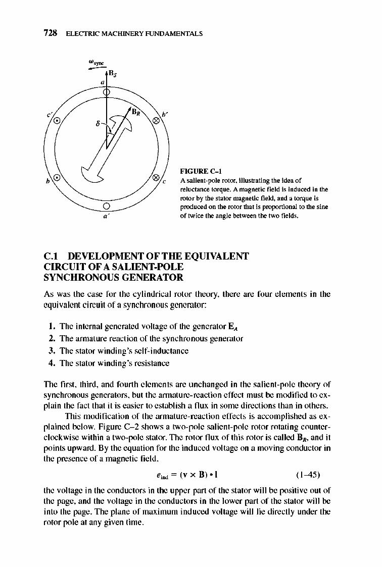
728 ELECTRIC MACHINERY RJNDAMENTALS
c' o b' o
FIGURE C-l
o
A salient-pole rotor, illustrating the idea of reluctance torque, A magnetic field is induced in the rotor by the stator magnetic field, and a torque is pnxluced on the rotor that is proportional to the sine of twice the angle between the two fields,
CI DEVELOPMENTOFTHE EQUIVALENT CIRCUIT OF A SALIENT-POLE SYNCHRONOUS GENERATOR
As was the case for the cy lindrical rotor theory, there are four e lements in the equivalent circuit of a synchronous generator:
I. The internal generated voltage of the generator E),
2. The armature reaction of the synchronous generator 3. The stator winding's self-inductance
4. The stator winding's resistance
TIle first, third, and fo urth e lements are unchanged in the salient-pole theory of synchronous generators, but the annature-reaction effect must be modified to explain the fact that it is easier to establish a flu x in some directions than in others,
TIlis modification of the armature-reaction effects is accomplished as explained below, Figure C- 2 shows a two-pole salient-pole rotor rotating counterclockwise within a two-pole stator, TIle rotor flu x of this rotor is called GR, and it points upward, By the equation for the induced voltage on a moving conductor in the presence of a magnetic fi e ld,
ei!>d = (v x B) • I ( 1-45)
the voltage in the conductors in the upper part of the stator wi ll be positive out of the page, and the voltage in the conductors in the lower part of the stator wi ll be into the page, The plane of maximum induced voltage will lie directly under the rotor pole at any given time,
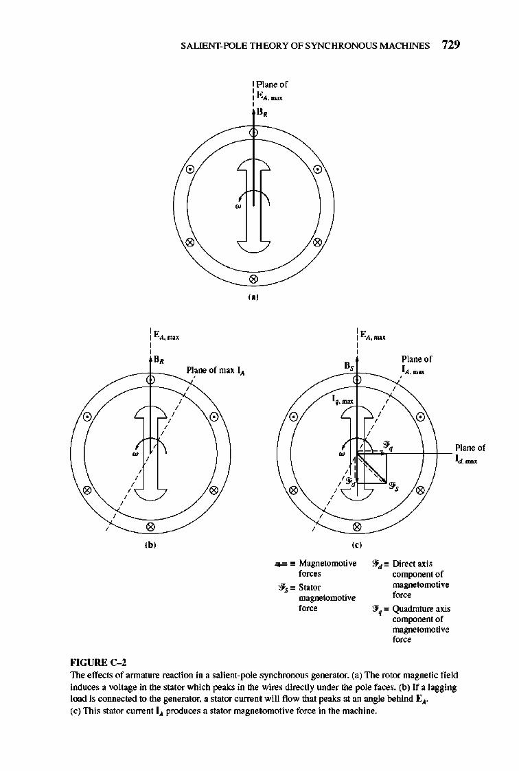
o
o , ,
FIGURE C-2
, , , ,
SALIENT-POLE THEORY OF SYNCHRONOUS MACHINES 729
, '" I "A,1nH , , II,
o
•
c-~_ Pl~ne of max 1..1
-~,
, ,
(b,
, , , , o
o
: Plane of Ii!:A,1nH , B,
o (.,
o
o
, '" I "A,1nH
B,
o
, ,
Plane of lA, max
~~:
, , ,
, , , o
"'l=~.'(''----f-+- Plane of ~ Id, InH
o
o (,'
-= " Magnetomotive fo=
'3is " Stator magnetomotive fo=
o
:J d" Direct axis component of magnetomotive f=.
:J~ .. Quadrature axis component of magnetomotive f=.
The effects of annalure reaction in a salient-pole synchronous generator. (a) The rotor magnetic field induces a voltage in the stator which peaks in the wires directly under the pole faces. (b) If a lagging load is connected to the generator. a stator curren t will flow that peaks at an angle behind EA' (c) This stator current 1..1 produces a stator magne tomotive force in the machine.
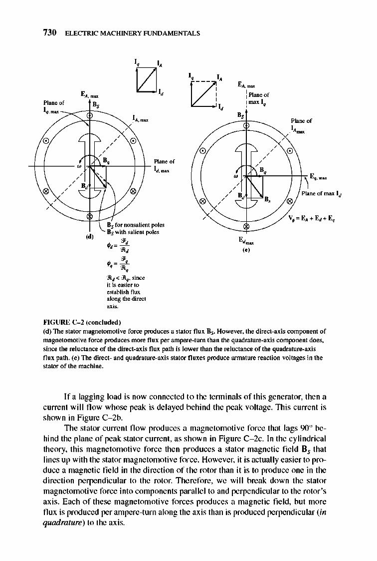
730 ELECTRIC MACHINERY RJNDAMENTALS
EA. "'"" Plane of Bs
I •. ~~
• • •
• / 0
B. Plane of ++--. Hd-'-T'----- ++- IJ.",ox
• •
,d,
, ,
Bs fornonsalient pole, Bs with ,alient poles
" ?d" -~,
• ?" ..:...J... . ~. ~J< m.,since it is easierto establish nux alons the di=t axis.
""GURE C-l (concluded)
0
® • • • •
•
'A~ : Plane of I max I. ,
• • • • ".
•
• •
" ~ ,.,
" .
•
Plane of I, ~
0
'\ '.-. Plane of max IJ
®
V~ " EA+Ed +E.
(d) The stator magnetomotive force produces a stator flux lis. However. the direct-axis component of magnetomotive force produces more flux per ampere-turn than the quadrature-axis component does. since the reluctance of the direct-axis flux path is lower than the reluctance of the quadrature-axis flux path. (e) The direct- and quadrature-axis stator fluxes produce armature reaction voltages in the stator of the machine.
I f a lagging load is now connected to the tenninals of thi s generator, then a currefll will flow whose peak is delayed behind the peak voltage. lllis current is shown in Figure C- 2b.
llle stator currefll flow produces a magnetomotive force that lags 900 behind the plane of peak stator current, as shown in Figure C- 2c. In the cylindrical theory, this magnetomotive force then produces a stator magnetic fi e ld Bs that lines up with the stator magnetomotive force. However, it is actually easier to produce a magnetic field in the direction of the rotor than it is to produce one in the direction perpendicular to the rotor. Therefore, we will break down the stator magnetomotive force into componeflls parallel to and perpendicular to the rotor's axis. Each of these magnetomotive forces produces a magnetic field, but more flux is produced per ampere-turn along the axis than is produced perpendicular (in quadrature) to the axis.
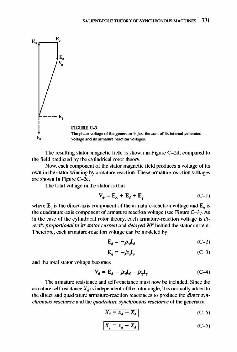
I I I E,
E, v,
---- E •
SALIENT-POLE THEORY OF SYNCHRONOUS MACHINES 731
FIGURE C-3 The phase voltage of the generator is just the sum of its internal generated voltage and its armature reaction voltages.
The resulting stator magnetic fie ld is shown in Figure C- 2d, compared to the fi e ld predicted by the cylindrical rotor theory.
Now, each component of the stator magnetic fi e ld produces a voltage of its own in the stator winding by annature reaction. These annature-reaction voltages are shown in Figure C- 2e .
The total voltage in the stator is thus
(C-l )
where EJ is the direct-axis component of the annature-reaction voltage and Eq is the quadrature-axis component of annature reaction voltage (see Figure C- 3). As in the case of the cy lindrical rotor theory, each armature-reaction voltage is directly proportional to its stator current and delayed 90° behind the stator current. Therefore, each armature-reaction voltage can be modeled by
EJ = -jxJIJ
Eq = -jxqIq
and the total stator voltage becomes
Vo/> = E ... - jxJIJ - jxqIq
(C- 2)
(C- 3)
(C-4)
The annature resistance and self-reactance must now be included. Since the annature self-reactance X ... is independent of the rotor angle, it is nonnally added to the direct and quadrat ure annature-reaction reactances to produce the direct synchronous reactance and the quadrature synchronous reactance of the generator:
IXrx,+ XAI
IXq - Xq + XA I
(C- 5)
(C-6)
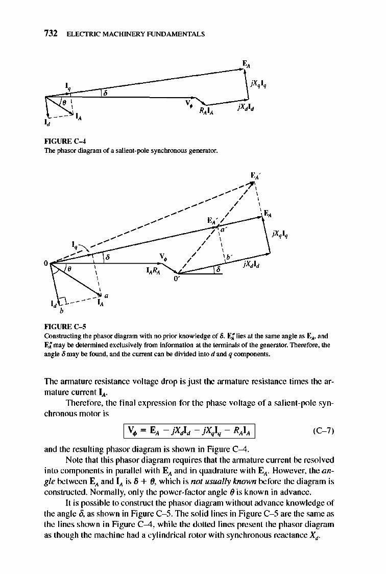
732 ELECTRIC MACHINERY RJNDAMENTALS
""GURE C-4 The phasor diagram of a salient-pole synchronous generator.
o 0'
I, b
""GURE C-S Constructing the phasor diagram with no prior knowledge of 8. E; lies at the same angle as EA. and E; may be determined exclusively from information at the terminals of the generator. Therefore. the angle 6 may be found. and the current can be divided into d and q components.
TIle annature resistance voltage drop is just the armature resistance times the armature current IA .
lllerefore, the final expression for the phase voltage of a salient-pole synchronous motor is
(C- 7)
and the resulting phasor diagram is shown in Figure C-4. Note that this phasor diagram requires that the annature current be resolved
into components in parallel with EA and in quadrature with EA. However, the angie between EA and IA is lj + (), which is not usually known before the diagram is constructed. Normally, only the power-factor angle () is known in advance.
It is possible to construct the phasor diagram without advance knowledge of the angle 0, as shown in Figure C- S. TIle solid lines in Figure C- S are the same as the lines shown in Figure C-4, while the dotted lines present the phasor diagram as though the machine had a cylindrical rotor with synchronous reactance Xd .
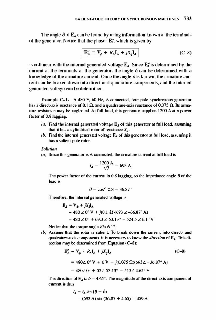
SALIENT· POLE THEORY OF SYNCHRONOUS MACHINES 733
The angle 0 of EA can be found by using infonnation known at the tenninals of the generator. Notice that the phasor E;' which is given by
I EA = V4> + RAIA + jXqIA I (C-8)
is collinear with the internal generated voltage EA' Since E; is determined by the current at the terminal s of the generator, the angle {) can be detennined with a know ledge of the annature current. Once the angle 0 is known, the annature cur· rent can be broken down into direct and quadrature components, and the internal generated voltage can be detennined.
Example C- 1. A 480-V, 60-Hz, d-cOIlllected, four-pole synchronous generator has a direct-axis reactance of 0.1 n, and a quadrature-axis reactance of 0.075 n. Its annature resistance may be neglected. At fun load, this generator supplies 1200 A at a power factor of 0.8 lagging.
(a) Find the internal generated voltage EA of this generator at full load, assruning that it has a cylindrical rotor of reactance Xd .
(b) Find the internal generated voltage EA of this generator at fun load, assuming it has a salient-pole rotor.
Solutioll (a) Since this generator is d-connected, the armature current at fun load is
IA = 12~A = 693 A
The power factor of the current is 0.8 lagging, so the impedance angle () of the load is
() = cos- l 0.8 = 36.87°
Therefore, the internal generated voltage is
EA = V4> + jXSIA
= 480 L 0° V + j(O.1 nX693 L - 36.87° A)
= 480 L 0° + 69.3 L 53.13° = 524.5 L 6.1° V
Notice that the torque angle 8 is 6.1°. (b) Asswne that the rotor is salient. To break down the current into direct- and
quadrature-axis components, it is necessary to know the direction of EA. This direction may be detennined from Equation (C- 8):
= 480L 0° V + 0 V + j(0JJ75 nX693L -36.87° A)
= 480LO° + 52L53.13° = 513L4.65" V
(C-8)
The direction of EA is 8 = 4.65". The magnitude of the direct-axis component of ClUTent is thus
Id = IA sin ({) + /)) = (693 A) sin (36.87 + 4.65) = 459 A
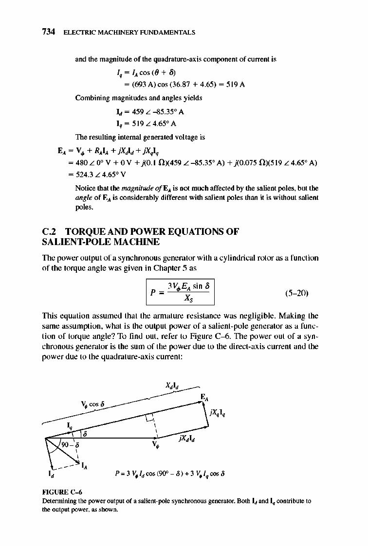
734 ELECTRIC MACHINERY RJNDAMENTALS
and the magnitude of the quadrature-axis component of current is
Iq = IA cos «() + Ii) = (693 A) cos (36.87 + 4.65) = 519 A
Combining magnitudes and angles yields
Id = 459 L -85.35° A
Iq = 519 L 4.65° A
The resulting internal generated voltage is
EA = Vo/> + RAIA + jXdld + jX,}-q
= 480 L 0° V + 0 V + j(O.1 0)(459 L -85.35" A) + j(0.075 OX519 L 4.65" A)
= 524.3 L 4.65° V
Notice that the magnitude O/ EA is not much affected by the salient poles, but the angle of EA is considerably different with salient poles than it is without salient poles.
C.2 TORQUE AND POWER EQUATIONS OF SA LIENT-POLE MACHINE
TIle power output of a synchronous generator with a cylindrical rotor as a function of the torque angle was give n in Chapter 5 as
_3~V.~E-;A,"'_i_" ~S p = -X,
(5- 20)
TIlis equation assumed that the annature resistance was negligible. Making the same assumption, what is the output power of a salient-pole generator as a functi on of torque angle? To find out, refer to Fig ure C--6. TIle power out of a synchronous generator is the sum of the power due to the direct-axis current and the power due to the quadrature-axis current:
v~ cos {j
I, , 90 - ' , ,
IA I,
""GURE C-6
, , v •
Determining the power output of a salient-pote synchronous generator. Both I~ and I. contribute to the output power. as shown.
SALIENT-POLE THEORY OF SYNCHRONOUS MACHINES 735
P = Pd+ Pq (C- 9)
= 3 V4>ld cos (900- 8) + 3 V ¥q cos 8
= 3V4>ld sin8+ 3 V4> lq cos 8
From Figure C-6, the direct-axis current is given by
_ EA - \j, cos 5 ld - X , (C-I O)
and the quadrature-axis current is given by
_ V1> sin 5 lq - X , (C-II )
Substituting Equations (C- IO) and (C-ll ) into Equation (C- 9) yields
(EA - V1> cos 8) ( V1> sin 8)
P = 3 V1> X; sin 8 + 3 V1> Xq cos 8
3V1>EA (I 1) = X sin 5 + 3 vt X - X sin 5 cos 5 , "
Since, sin 8 cos 8 = ~sin 28, this expression reduces to
P = 1> Asin5+~ d q sin25 3VE 3V2(X - X) Xd 2 J<JXq
(C-1 2)
The first tenn of this expression is the same as the power in a cylindrical ro
tor machine, and the second tenn is the additional power due to the relu ctance torque in the machine.
Since the induced torque in the generator is given by T iD<! = P.:ODv1wm, the induced torque in the motor can be expressed as
(C- 13)
TIle induced torque out of a salient-pole generator as a function of the torque angle {j is plotted in Figure C- 7.
PROBLEMS
C-1. A 4S0-V, 200-kVA, O.S-PF-Iagging, 6O-Hz, four-]Xlle, Y-connected synchronous generator has a direct-axis reactance of 0.25 n, a quadrature-axis reactance ofO.IS n and an annature resistance of 0.03 n. Friction, windage, and stray losses may be assruned negligible. The generator's open-circuit characteristic is given by Figure P5-I. (a) How much field current is required to make Vrequal to 480 V when the gener
ator is flmning at no load? (b) What is the internal generated voltage of this machine when it is operating at
rated conditions? How does this value of E,\ compare to that of Problem 5- 2b?
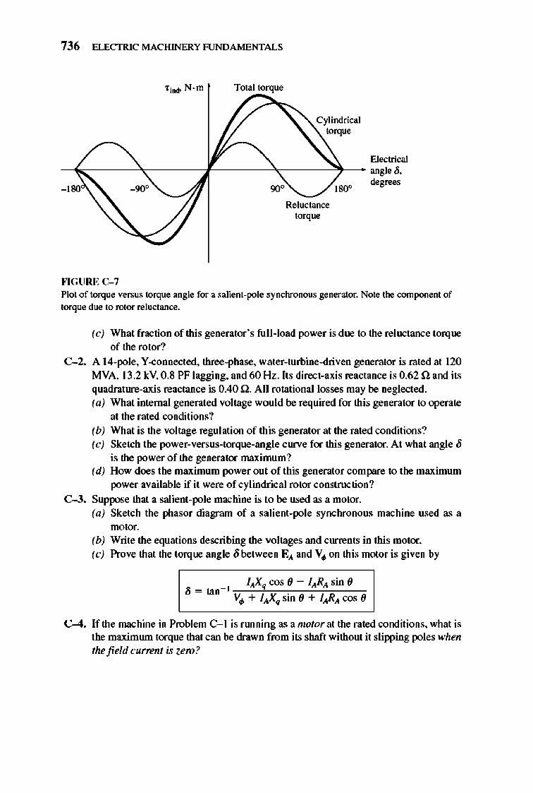
736 ELECTRIC MACHINERY RJNDAMENTALS
f ind> N·m Total torque
Electrical -~~----'''----~----~-----'~-- angle 0.
90"
""GURE C-7
Reluctance torque
1800 degrees
Plot of torque versus torque angle for a salient-pole synchronous generator. Note the component of torque due to rotor reluctance.
(c) What fraction of this generator 's full-load power is due to the reluctance torque of the rotor?
C-2. A l4-pole, Y -connected, three-phase, water-turbine-driven generator is rated at 120 MVA, 13.2 kV, 0.8 PF lagging, and 60 Hz. Its direct-axis reactance is 0.62 n and its quadrature-axis reactance is 0.40 n. All rotational losses may be neglected. (a) What internal generated voltage would be required for this generator to operate
at the rated conditions? (b) What is the voltage regulation of this generator at the rated conditions? (c) Sketch the power-versus-torque-angle curve for this generator. At what angle 0
is the power of the generator maximum? (d) How does the maximum power out of this generator compare to the maximum
power available if it were of cylindrical rotor construction?
C-3. Suppose that a salient-pole machine is to be used as a motor. (a) Sketch the phasor diagram of a salient-pole synchronous machine used as a
motor. (b) Write the equations describing the voltages and currents in this motor. (c) Prove that the torque angle obetween E,\ and V. on this motor is given by
C-4. If the machine in Problem C- l is flmning as a motor at the rated conditions, what is the maximrun torque that can be drawn from its shaft without it slipping poles when the field current is zero?
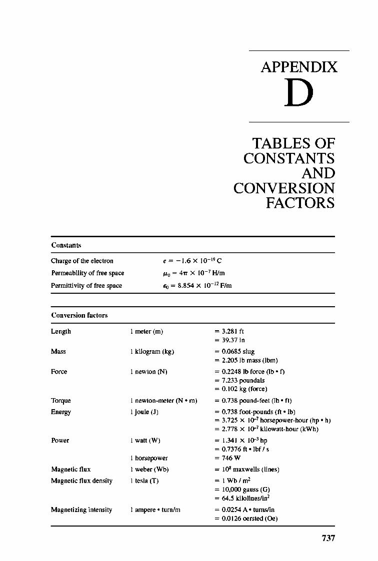
Constan ts
Charge of the electron
Permeability of free space
Permittivity of free space
COD"crsion fa ctors
Length
F~
Torque
Energy
Power
Magnetic flux
Magnetic flux density
Magnetizing intensity
APPENDIX
D TABLES OF
CONSTANTS AND
CONVERSION FACTORS
e = - 1.6X to- 19 C
tto = 47'1 X 10- 7 Him
£0 = 8.854 X 10- 11 F/m
I meter (m)
I kilogram (kg)
I newton (N)
I newlon-meter (N • m)
I joule (1)
I watt (W)
I horsepower
I weber (Wb)
I tesla (f)
I ampere ' turn/m
= 3.281 ft
= 39.37 in
= 0.0685 slug = 2.205 lb mass (Ibm)
= 0.22481b force (lb ' n = 7.233 poundals = 0.102 kg (force)
= 0.738 pound-feet (lb ' ft)
= 0.738 foot-pounds (ft ' lb) = 3.725 X 10⁻¹ horsepower-hour (hp ' It) = 2.778 X 10⁻¹ kilowatt-hour (kWh)
= 1.341 X IO-J hp
= 0.7376 ft · lbf Is = 746W
= ]Oi maxwells (lines)
= ]Wb/m1
= 10,000 gauss (G)
= 64.5 kilolineslinl
= 0.0254 A • turns/in = 0.0126 oersted (Oe)
737

oOC p.-.. "que""e, 684, 68~, 689 -..-, iD<h>cbon ll"DOH'or, 461J.-464 .oymcJ.""""" ll"DOH'or, 267~.Su
abo SJ'DC1ronow gonmtOor >c machine, 231J.-472
""'lpitch. 707_716 do machine.<, ~ 681 <le6DO<l 2JO di,,,ibolod wiDdiDgS. 716-72~ efficiOJlC)'.261 iD<h>cbon motor, 380-472. SN abo
[_""moIor 100 ..... 261_262 _tomooive for<:elflux di,,,ibo1ioo,
_m power_tbw di.uam- 262, 263 .~ reguh. ioD, 26J.-264 .oymcJ.ODOOIS !l"DOH,orS, 267_34.'1. Sa
abo SJ'DC1mnow S.,...,.... symcJ.ODOUII """on, 346-379. Su
abo SJ'DC1moow mol" ..
'(II" .... , 237_2J8, ~~~8 von!", 2B, 2~.'!.'! v()hlIS·ro~OD,26l-261 wiDdiD,l! imulotioo:>, 2'! 8-260
>C Olochine ""'orl, 716 >C lDOIor. Sa lnWctioo moIor,
SyncIroDow IOOIor >c phase ""810 COIIIro!. ] W-H16 >c phase OJIItrol 177_186 ocb p.-.. "que""e, 684, 68.'1, 689 Ac<:elentiOlO'<IocolontiOll circui~ m Acro .. _the-liDe .wting, 430, 4]2 Air gap,.'In Air_SlIP flux deruity di<lributiOll, 707 Air_SlIP line, 284 Air-SlIP_or, M . 397, 408, 661--662 Allor .. ,,, ... Su S}'DChrnDous se,.""'",,, Amon;,...., windi"l'. 367--371 ~"um1J11, 737 ~·.1a .... 8 Analog po>he ll"DOntioa ciJ<:uiu. 171 Ana]yoi,. Sn abo Noali ..... analyst. <:wwlati""ly~dc
genontOlll.614-61.'! diJJe ... ti. Uy ~dc
gmont<n.618-619 _ de S .... ""or. 6()6...«)Il
Aoplar oe<:elontioa. 4 Angular position. J Aoplar velocity, l-4 Apporo .. _r. 4<J-j()
oymcJ.""""" ll"DOH'or. 327 tnmsfonool. ]]8- lJ9
Apporo .. _, rating odvaot"8".
112-113 ~xi ...... tnmsfonoe:r models, 89 Anna, ... , 490 • .'120 Anna,,,,,, Irus, .'124 Anna,,,,,, .. ""ion
do machine.<,~ • .'120 pole foe ... .'120 ool"",.ly exci,ed de geJ.""'or, ~98 _de.-or,~
oymcJ.""""" l!, ,,,on'or, 274
AJmatore reoctioa vonge, 276 AJmatore re,si""""" vong. drop, 732 AJmatore winding,,- 26/, 492-493, ~20 A01""" .. fonne:r,I09-H6
'ppare1I' power nlilll adv""ge, H2-H3
di>adv"'''ge, H ~ inler .. li~,m variable-voltage_ H~ voltay/""""'" rel " iorubips. III
A01""" .. fonne:r , taner (indUCIioo .-or~ 432
Av<Rf-O flux per ,~ .. , 73 Av<Rf-O power, 48.. 49
Balanced thru-p..... "'Y"em<. 69J-700 Balanced Y-<:O<IDOCOed Iood, 690 Base , pee<l438, ~~3 Belt lwlDOlliCl, 714 Blockod_roIor CODditioo, 390 Blockod_roIor ""or reac1aD::e, 391 Blockod_roIor Ie", 4.l~ Bre:dh factor, 718.-720 BreakOOw. 'orque, 409. Sa aIu! Pullou,
'orqu. Breakover voltay (V""~ I~~ Br",b,268 Br",b drop 10< .... ~~, ~93 Br",b kwe., ~~ Br",b shifting, ~ Br",b voltage <kq>, ~~ Br",be., 489, ~21--,'!2J Br",bl .. , de !DOlor, 674--(,77 Br",bl .. , exciters , 268-271
Cage iooOC1ioo mo<or, 382 Cage rotQ1, 380, 3g), 417-419 Copability CIlJve, 3 29...J34 Copability di"llf>l'l- 329 Copacitive ~ ~I Copaci!or-Q ar', capaci'Q1_JILII !DOlor,
MI),M3 Copacitor-Q ar'motIn, 64~~3 C .. lnt .... ,28 Ownferod pole .. ~20, ~21 Ow). of !be eleC1rolll, 737 Qde,171 a.opper, 186-193
forcedcomm01"ioo, 187, 18S-189 ponllel-<:","""or <:<>m.un"ion
circuits, 191_193 series-apaci'or cornmu,,,ion cir<:uiu,
189-191 a.or<Iod ...mding, 491 a.or<Iod...u.dings, 700 Circulatlog """"., cyclocoove:rler,
21~218 Code letter, 4J(), 431 Coercive DI>[lI>01<>DlO1ive force, 27 ~Ipitcb, 707_716
fno::1ioruol_pitcb coil. 709-712 fno::1ioruol_pitcb wiDdi"W', 712-716 barmooicpob ...... , 712-716 pitch of o ooil708-700
Commoa "'""'" <£.0), 109
INDEX
Cormnoo voltage (V d, 100 Cormnoo winding, 100 CormnutatiD,l! ouochlnery. SN de ~
CormnutatiD,l! pole.<fIO'e:rpoI .... ~II CormnutatiOll
choppe:r circui,., 18S-189 cyclocoovetter,210 defined, 479, 4&'!, 439 ew nW COI1llW1lItioa i.verler, 194 fcreed, 187, US-189, 210 four_loop de oucl1ine, ~90
panllel-<:apOcitor commOO " ioo circui" 191 _ 193
.. If-<:Ol1lDllltatiOll iovene:r, I~ =ie.-<:apOcitor commU1ll'ioo circui"
189-191 CormnutatQ1, 473. 499, ~19, ~21--,'!23 Cormnutat<>1 pi,cb, 492 CormnutatQ1 "[lIBOJI,., 479, 489 Coq>ar:o'or, 202 Coq>e1Wlting wiDdi"W', ~IWlJ Coq>lex power, ~ I ~oded de [lOJ>On1Q1
CUDaIlatively compout><lood, 611--t;1~ dilJeTe.otially ~d, 61~19 ~oded de !DOlor, ~73
oqui .. leD1 circuit, ~ Kirchbo/J', voltage law, ~ ... g .... omotive force, S68-569 oooli ..... aruolysit, HI--,'!73 , peed coDtrol. ~73 'orqu~ chlInocleru1ioc
(<U111Ulat,vely ~ """"'~ Wh'!70
'orqu~ chlInocleru1ioc (differenlially 00I1lJl0Il1><le """"'~ nO_.,'I71
CoqJu1er ...... = program. Sa MATI.AB
Condenser, J64 ConWct ance, 12 ConWctor, 490 ConWctor .kewlog, 724, 7~ Conoeque'" pole., 437 Coruta1Jl -frequeJJC)' cyclocoovener, 209 Coruta1Jl _borsepowe:r conoec1iOll, 439 Coruta1Jl-<lU1pII1 _power conoec1iOll, 438 Coru ....... 737 Coruta1Jl _torqu. <:O<IDOCIiOll, 438, 439 CorrveniOll faC1<n, 737, Sa aIu! U .. ,.
of ... 1!UJO
-~. '" machioe .. 261 demodJj .... ,~24--.,'I~ de lOOIor" ~92 i_OIl motors, 39~ modeHD,I!,86 RCL. 261. 662 =-~, . ingle-pba<e i_OIl !DOIOI"I, 662 ,YnChrODOW ~oen1or, 321! 1nn>fonne:r, 86, 102
~'"'. '" machioe .. 261 _262 demodJj .... ,~~
739
740 INDEX
Core 10 .. _ _ C""'demo«n, ~3 inWctioa .-or.<, 3~
Core_form tnmsforme:r, til Core_Jo... ~ 83 Cou.o'OJvoItlIge-seruing reI. ys, ~81 Cross_field 1boory, 64l-64~ CSlI%-I99 euo..Jati"" ~g, ~ euo..Jati""ly <:<>mJlOlUlded de l"DOH1Or,
611~1~
euo..Jati""ly <:<>mJlOlUlded de motor,
~" ~"'
<:OIIll1lOII, 100 <:<re-Iou, 83 .1 COIIDOCtiOll, 6&8-M9 excin. ioo, 83 inrush. 140 I>WIll, ~I Ie><li.og, ~2 magnetiuion. 81--1l2 ..n...,I09 _ _ phase circuit, ~9
Y <:oaDOCIion. 68~--688 eurr..t u.u.b, )]9-140 eurr..t source invo:r1OJ (CSI). 1~199 eurr..t lnASforlDOr, 68, 14 1_ 142 eurr..t-~mitilll circuit, ~92 eurr..t-~mitilll flUeS, ~89 Cyclooor!verto .. , 209-21 8
basic coacoplS, 209-14 circu1atilll <WRJII, 21~218 <X)II .... t_frequom::y,1I:» forced comm01"ioo, 210 DtM>Cirwbting <UrrOJI~ 21 4-21~ ~i"'le -f .. quOJ>C)', 11:»
CyHt>drical_lDOIor ouocmn., 247
~ wiOOings. >67-371 de ...... , ... voltage coruoller
ciJ<:uit, ~&'! de genenton, ~94-619
""mub'ively cornp:>Illlded, 611~1~ "'f"",d,~
diff ... "'i.uyc~61~19 oquival ... , ciJ<:uit, ~~, ~96 _lan,y, ~~ prjlDO JOOVer, m >epar1IIoly excited. ~. Su abo
Sepanoely exciled do:: genentor series, ti08--filO shlLll~ 602--6()Ij. Su also ShILll' do:: .--types, ~94 voltage .. guI"'ion. ~9~
do:: machine, 473_1;]2 >C modlioo., compand, 681
..,...."'" reacti"", ~ brush .biftilll, ~ brushe.!, ~21....,'!2J
OOIIllDItatiog poIe ... inlOJp:> .... ,
~" OOIIllDItation. 4~89 OOIIllDIta1Or, 473, ~19, ~21....,'!23 OOIIlJ>O"SIIIilll winding., ~ IW 13 coastn>ction. ~ IW2J efficiency, ~24 fum_loop mxbillO, 48~-4\1O froJI-Ie! wit>di,,!!, ~1....j(J2 Il"lIOJaton. SN de go,.,,"'01'1 iMul" ioo, ~21....,'!2J LJiIdI vohgo, ~ lap wit>di,,!!, 49l-497 Io.<oo.,~~~
moIOI'I. Sa de moton
poIoIfnme <:oo>1rI><:ti0ll, ~2(h'!21 power_llowdiogom. ~~....,'!26 proI>le,,",,~14
roIlIting loop between curved pole face., 473-4&'!
""orlarmature ..,...uuctioo, ~21 ""or coil., 49()....492 ""or (armature) ...mdings, 492-493 torque, ~2, ~ I(h'! 17 voltage, 47~80, ~ IWI6
.... ve winding. 497....j(J1
de machine _tintiOll CIlJ""" ~36-,'!38
de motor, UJ_,'!94 ~de.-or.,~Tl
COII1JoI and P"'octior> oquipme.t, ~73 OffOCieDCY, ~92-,'!94 "'lui ...... circuit, ~3~....,'!>6 10 ..... m-,w3 DIlIg...,; .. tioa curve, Hli-,'!38 motor.otarting circuit!. HW82 PMDC moton, ~~2 J>OP"Iacity, ~34 >epanoely oxciled ..... or, ~JWJ9,
~~1. SN 000 S_ de~.
_ie. de motor .. ~2--,'!68
• t.rnI de mot"", ~3B-.'!39. SN abo Shu.t de motor .
loIid_ ... ,e de motor "","roller, ~8~....,'!92. SN also Sclid_ . .... do:: motor<:Olltroller
.peed .. guI"'ioo (SR~ ~3W3~
.tarting proI>lemslsoJutiOD!l, ~'73--,'!ll2
type" ~3~ Ward_l«>nard 'Y""'" ~83-,'!&,!
de motor .tarting circllib, SlB-.'!82 de Ie", oB4-4.l~ dc-to-do:: <:OIIvo:r1ers, 1S6-193. S" aI.!o
a.,.,., D<ep-bar rotor, 420-422 DeIt . (.1) conDectioo, ~8--U9 DeIt .-dek. (.1-.l.) OOIIDOcti"", 12J DeIt . _wye (.1_ y) <:O<U>octioo, 121_ 122 Denti,,!!, 134, 441 o..ig. da .. A lDOIor .. 422 o..ig. dass B motors, 422 o..ig. dass C mo«n, 422 o..ig. clas. D lDOIon, 422-423 o..ig. dass F inWctioa motor, 42J o..ig. clas .... , 421-42J Develq>ed mod>anicaI power, 397 Develq>ed torquo, 398 DlAC. 1~8 Differenlially 00IIlJ>0Il1"I0 de 8"DOH'or,
61~19 Differenlially OOIIlpoundood de motor,
~" Digital pulse genentiOA circuit., 171 Diode, I~J-I~
defillOd, m fru-wboelins, 186 PN,I54 PNPN, I~I~~ . .. itching time, I~ "iger, 1~4
D;"ct .oyo:bromu ... act ance, 73 I Dj,,,ibuted wit>dioy, 716-72'!
bRodtWdistributioo foetor, 718-720 dOl bar!DOllioc .. 722-724 volt"!!,,,721
Dj,,,ibutioo factor, 71 !!-720 Dj,,,ibutioo tnmsforme:r, til, 98 Dj,,,ibutioo tnmsforme:r oamepb ,o, 141 Di""rter re,si"or, 6)], 614 DooW .. 1:1 Dot COO"".tiOll, 70, 84 Double-<:"!!,, ""or, 4:D-422
Double_laye:r wit>di"!!,,, 718 Double_ .. voh ing_field tbeory, 6]8-642
Doubly excited .!J"I"-' machine,31S
Duplex lap winding. 496 Duplex NOor winding. 492 Dynamioc " ability Hmit, 3D
Ecc ... tric pol .. , ~20, ~21 Eddy cmrenI !two" 28
Fancby'. b w,31 ferromap>etic <xu, 28 tnmsformor, 86, 102 Eddy~31
Edi.on. 'Thomas A .. 66 EffociellC)'. Sa 000 EDe~ lou
IOC macmn., 261 do:: machine .. ~24 do:: lDOIon, ~W94 illlh>ctioo motors, 428-430 nominal, 428-429 tnmsforme:r, 102
ElectJic ciJ<:uit, II ElectJic.l degru .. 490. ~ ElectJic.lloose.!, 261. Su aI.!o Cq>pe:r
b •• ElectJic.l macbiDO, I ElectJooic.s circuit 00ard, ~87
EIIOlJ!J< 737 EIIOlJ!Y Jo...
IOC macbine.s, 261_262 bub !two., ~~ copper 10<00 •. SN Cq>pe:r 10< ... ""'" ...... SN Cae Jo... do:: machine .. ~24-~m do:: IDOIOI'I, ~W93
oddy """""'10< .... SN Eddy """".t b _
ferromap>etic <xu, 26-28 fricoo.. Itwe" 262 hY"leresi. Iou, 28 illlh>ctioo motor<, 394-396 mocba.oical 10.<00., 262 00-_ roIlItiOlllll Jo..., 262 rotatiooW 10.<00., 39~ .tr>y los .... 262 tnmsfonoon, 102 wit>date Ioose.!, 262
Eopisb 'Y'tem of unit, 2. ~3, 737. Su aI.!o Units of 1D01!UrO
Equalizers, 494. 496, 498 Equalirilll woo"!!,,, 494, 496. 498 Equi ...... circuit
cornp:>Illldod do:: IDOIOI'I, ~
<IlDlIII"'i",,1y ~ de g .... ""or, 61). 612
do:: genen<or, ~ ~97 do:: lDOIor, ~3WJ6 diffe .... ially OOIIlpow><lod de
go .. ""or, 616 ideallnn>fonne:r, 73 illlh>ctioo motor,3!8--.J94 per_~. SN Pe:r-pbaoe oquivole'"
circuit .uJj"'-poIe .yo:/>roIIt>w l"lIOJator,
728-734 "pon'ely exci,ed de go .. ""or, ~
"pon'ely exci,ed de~, ~3l! .. rie. do:: genen<or, ti09 ..w.. de 8"oo",'or, 603 ..w.. de motor, ~38 'J'~' 8"DOH'or, 1:14-1:19 'J'~' motor, 347 tnmsforme:r, 86-94
Equi ...... field CIlJre.t, ~, ~99
Excitati ... ""' ...... BJ Ex .................. _ i __ •. 194
""" """"" ,.; • ~J9 """ """"" ........ «8. (51 _1'010",.2&-32 F ... -<KO...,. I>i",.op<ed dio:Ioe.s. IS. F • • I,. l21.J26 FerrornaS .... i< mllori ....
delined, 8 ... ..,. _ .. U--2B ~ __ 21_Z
mopoti...o.c. """,,.lO6O porroeotQty.21
Fiold emil. llol H.1d <mil 101 .. 514 F..1d1oM .. loy. 559. 581 H.1d 10M trip. 569 F .. Id ..... ' ...... m Fioldwiodi .... 26/. 520 FiIRri .. _if ... 0I>IpJ!.171 Firioe;...po. 179. l!1 _IM _05 .... r .. ld,_ Flosboo .... 5(M
FIat~d.61J ~,
'" ....:hi .... l46--ZO .... pt> flu.< ....... y diooib.nioo, 701 Ie..".. 0 . 7l. 79 ~ cimHI. 12-13 _III. 7l. 79 _idalll.27 .. ne.dc_56l
FIo .. <k";'y. 10. 19-11 Flo .. de";'y vector. 247 Flo .. linb, .. ll, T1 Flu _ok""" ~ F<rco. 737 _""""""' ....... lin. 113-169. 210 f<lrm.w<Ulld .. .-or ~ 717 m..1oop ~ dc'-DO. 48j
m..paIo """wound dc ..-.. 495 Fow.poIo iIIo<Ied.p<>1e iD<h>aioo
m,," ... 6;H Fow.poIo$II"" wiDdi.D,. 243 Fwr'!"'io ........... 0<1 dc _ ... 499 m...,.odn. oow.-dc ___
conIrOlIef. 516 F .............. ail. 491. 11)8, 709-712 F ........... piIdI wi!ldi_&,. m. 712-716 Froctiooal .. ..,. ..........., .. 724 F ....... 518 Flftow .... li.' diode. 1!6 --, illlMctioro -.. 386-J8II. 43&-40 ",_._.326-311 ", __ 373
1nB1annor. 1J4 Froq ... ""y.powe. d>ono::t<rilllX.
.104-J05. ll7.119
Froq"''''''''_'_or diogml. JO'l.110
Frielioo _ .. 262 5Z
mlOPJ·fJea. 14 """.Ie, wi!ldi"", 1001 • .'JO:Z hII-lood "Oa.c_ ~t.ioG. 100 FoIl--piIdI ail. (90. 1011 Full· ..... rr<'\if.rr
... "' ... ph .... 167_168 _ph_.169--17O
F ........... 1IIaJ (roqtoeO<)'. :1).1
F ... d7l.579
G .. "'""'"' (GTO) tII)'Rroar. 157 60 __ ElKtric.~ ___ .• :/9
6oDOnl."...,.- pol ..... 4411 • .w9
~-dc • .s<J4-61 9. Su /JbtJ dc ....... _ ...... , i ......... 46Cl-46I b .... cklDOlOr • • 1-4241 .JII<bronoo •• 267-3<15 , SHabo
Sy.:trDnou. II""R"" 0. ..... '01 ocb .... 8. l5 GbosI pb .... 126 00_ mocllanis .... )Of
tnpbiclll _11 .... SH JuWy"a GTO m,n-t. 157
lWf--onve....,;r .. r .... &Ie~ 163-166 tJ. ... ~ 168-169
H""",,,"c problems. 218-221. 712-116 Ho.ting limiI. )35 Hip ......... uanomia"" Ii . .. 16 Hi~.IocIfoooi<:o...ruor.. ~ Hi~ .oIid-.-<kn-. Sa _ .1ecUooIi",
Hi&fw~p rqioo. oIQ5 Hi~.torq ... pol ..... 4411. 4,;) HoIdi", """ ... (I~~ 155 H<n<p<>W .... 737 H""", diogml. 309. III Hyo&eH!i .. 26 Hyo&eH!io """". n Hy~io ....,... 26.. XO Hpocraio -. 2S H,.-n ..-... 666-669
Ie. 109 [.' ]]0. I~' Ie.. llO [.~ 109 I'R -. Saeq,p. bun IdcodlrWlO_. 67_76
cin:ui ... 72-16 ."._ 01 .. 01 ...... formor to, 56 doo COIIYemioo. 70 iJI¥dmoo Ir'USformo'ioa, 71 _72 magnetizatioo CUtVO. 85 _.wI, 71 __ c.ymboI.~
twim ...;o.@ IGBT. [61_162 21» ........... _oJ.,..,..... ll5
<kfuood. 71 ideal Ir'USformer. 71_72 ........ 1 .....,hitIo. 2&S rotor circo~ ",0<101.)91 Tbov ..... 4111 ~ • ..p . .tS. 49. ~l. 51 __ ,,-'12-33 _ """",. Su ~ !Jduoced YOl~. SN Volt. InduoctiOll ....... or. <l6()...464 IndlloCtiOIlmoclli .... 2JO.}8() IndooctiOll_. J8(l.472
odju!I>bIo ...,~-.,. ....... 448. 451
OfF""" 380-312.<117-419 cin:ui, _I por_1tn. ~5:z...16O ...... ~n~466 de t ... ~ (S<l-4H deep.bor roICJf. (20-422 <k .. !" clawa. 421-423 diOling&iollod re ....... 31t'J _~ ......... 42n-422
,..;_........,2 cfficic...,.. '~30 . _ frequon<,'" _. 3116·JU
equiyolc.t cin:ui~ 113-l94
INDEX 741
bistorical .............. (~211 iO<b:ed Iorque. :l84-JSS. <lOI--IOII liK~ . • )S."'O liK "Oltqe..uJ Io<:to<I-...- -. (jj..(~ ~.~ ... ,"";c field, <102 Dl>!"";c.-or M •• r ciKuit.
432-4:14 ...!..,.;mioot ........ :189. 390 -mod of ~ pole>. 43&-431 ....... ......., ___ • .02-454
_"'too.t' • ......-. '". ___ •. ~ 4]),-4]4
pc • .pw.e eqWyoi..- ciKui~ 194 pole clwJsin& 4:16-4)8 _or. 39t\.J98. <166 _or limio. 4tS6 _ ... _di ....... J94
po_ """", .• I0-411 P"o\'M ctT<a. 4.U-447 "";ap. 464-466 ...uti ... _ cin:ui~ (J4. 435 r<JOor cin:ui, !DOdo1. J9O.J9l ""or fro","ncy. 387 rotor ", ... Ianc" 44J..414 ,OIor sip. 38(i ""'" __ ......... _ 4.S1. 4.S1 scponlio&"- coppor lr>acof_. ,~,
_.cin:uit ..... ___ .·~ m .illlgle-plwe __ 637-665, Sa
abo 50", ... "" ... iD<h>aioo - , >peed <:am>1. 434-444 ...... ,, 430-4l4 ..... ,code ......... 30. 431 a, ___ ope«!. Jas. 435-436
""'fK. :l84-JSS. )91, 401..«JII. 410-411 ~ -".ri.oUc. 401-416 tnn>fonneJ _I. l89-l90 YOl, •• 44.1 . 465--166 voLtaso ", .. s. 46S-466 ·oItase· ...... ·f~ po"" .... ~,
..... 0<1 ..-. llW50I bdocWrI __ "'*"'" cimoi<x OJ bdocWrI...- <Ieoi,1 c_. 421-423 tr.t.ctioo ...,." ... i ..... 441-452 lodoctioo JOOt<Jr .. tinp. ~ lodoctioo """'" ",""I .. cirouiu.
432-434 t..doct;.. kid" ,;)5 t.mct;..1ood, 5l. 1&4-186 1Dr .... bas, lOS IDpoo: wiodi"", 66 In.wl .. : ........ J40 1"'_ .......... k trip. :!89 lrutrurDeJl' nnsfortntn. 140-1 42 JruoJ>tod.g>te bipol .. tnruiotor ( IGBT~
161_ H'i21JYj ~
oc ...-bi"a 259.260 dc __ (91. 52l-514
_"-;0s. 335. )]6 r<JOor coih. 491 .}'Id>roIows • __ . ll5
l .. orruol rnxbi .. lmpc<to_. 285 Inve._,;"", .,..,.lood trip. ~9 In ....... 193
CIIIft1Il ......... I9S-I99 .mna[~ ... I9( PWM.202-209 -ar ... ·i.Y ...... (9)"1JYj v~ ""'""'. 195. 196. 199-,2Q2
742 INDEX
bolt II). 7.17
IGlosram (q). 7.l7 lGlovolwll>oon. 371 Kirdobotr', """ ... 1_. 688 Kir"""""', ""hp la~
e<>cnpo .. dod doc moI<Jr. 568 O<I"iv ... ., cu.:.~ ('j'Dcluonow
81'_).216 ""'"v ..... cu.:.~ ('j'Dcluonow _~ :141
r .. 1d ~nt __ (,~ _~ l:!1
~_de-,J7
MJIOI"*Iy ""ciood de ........... WI MJIOI"*/y ""ciood de --. 519 ...... de~. 1iO\I ....... de_.~ ...... de ........... 6W ..... 'de_.339 Inn .. onn .. pho .... di._lOO V ......... icJn.OO
Knee. 21 KVL .q ... "i .... 5<. Kirchb:>If' ,
volt .. .. ..
L dildt ""~ op. ~-501 l..o"'''1~''' 51 l..o","1 po..... r....". .~ , _ ..... 289. 290 .)'IIdII<Inoo. _. :I49.1~
lMni .... -.31 Lop ..;odi .. OW.J....oW/ I.atp po.- ."....... JOII....312 Lndi .. _.S2 Lndi .. po.-r-.-
. ).0:1 . .... _ . , ....... 290
')_ ""*-. 3S2. J62 l.nIr;op nu.... LJ. 7l. 79. 116 l.nIr;l# n:1IctIR: .. 417 ~1l7 lAN.'. 1,'0'. 29. 30. 3 I. ~ U .. lrequellC)". 4J8-44.J U .. q ... titiu. 685 Uno .. de 0'>i0chiDe.:I(;....47
I ..... boo;" "'!u .. .,.".l6-17 ge-.to<. .. 41-42. 44 ""*-.... 19-41.44 ......... .... ..-.... J7-39. 4l-47 .......... .,...".,.,..,.. __ 239-299
.,...".,.,..,.. ""*-. 351-J.S5 ~_~.I\14 Lo:""""""",, __ J90
Lo:I:ockooor .... 455-451 u., ...... , -.......ioD. 611. 616 Lou.. .s.. Enav lou Low.po......1octroDic.s .. eli .... 59()....S92
Low .... '" n:]!ioon. 4m
M.,..ti. ci"",i~ 11_21 M.,..ti. ca .. 9 M.,..ti. don>aiu.. V M.,..1ic f>tld. 8-21
bolie Fri""iples. I .ifm 0I.........up. 32. n FIIMIoy"' .... 28-32 rri ...... 1Joa. 14 itoioced ........ _. l4-J.'I ~0I-,,402 .-..pel;" .m.;~ 11_21 ~oJ.8-IO "" .. i., field. 1J1-246. .s.. _
Roari", ... pic f .. 1d .impIo loop. 2.JO...ZJ8 "os"·ph_ iD<b:Iioo .-or. .'"'" 'ync"""""" moIor. :147-350
~ r .. 1d il""'I)'. 9. 10 MapIic flu. 7.17 MapIic flu do";'y. 9--10. 1~21. 737 MapIic...,...... _ c_. 432-434
MapIic ........ 1 pl-. 502
Mapl;" "" ........ liIy. 9. 21 Mapliulioo ........ 21. 22
de _or •• 53~3!. 545 I.""",,,,,,,,,;., ., . .. ri ... 560 ide .. ttonsl"' .... ,. U illll><!ioo onodIiDe. 46J illll><!ioo _ .lIl9. J90 .,.-......... ........,..Vl ..--.fomw. n 136. J90 lJIYllS.V Inaofunnoo-. 136 2»-V de ............ SCI
MopeIili .. "'1Uq.. 21. m MopeIili .. .........". 319
MopIoo>oIi .. 'on:. Ie ....... _~
In ... ,,"fti<'6- 5()@.. ;'A)9
"""'I'"",at"''''"''np. 51WLJ ~de_or.568
~1ati .. ly """'pollDdod de
80" .... ""'. (;11 deon""""". 305. ~. 51W13 dift" ... .,i .. ly~de
80 ........... 616 _I"";. ci""';~ II ..,... .. ly . ........ dc geDOnl<><. 598 ..... d_11
Mope....,. .. 'on:. (....t). II Moi.IrMdormor. III
t.'-al de ........... " '" '75 ...... m MATI.AO fiolll_......,.(.~
O>OIor).m fuing IIlJIe. 111-113 I ..... de _or. 46 ... S .... iccircuil. I6-11 ... S .... i .. 'i". OIl ....... 537...,'138 ripple 10C!<f. 165-166 roIO!l",,,,....k: field. 245....246 .pe«l (ohurl de 1JIOI<Jr~ ~1 ........... 1 cIranc: .. n..ic of . ,.-.........
ge ............. 2\Il-299 """",,"",pe«l_ (ill<loctio. ~. 41S-416. 424-425
"""""....,...ed _ (-;.. de _.,...,., 1OIqUO....,...ed_( .... de
_). S46-.l-i1 ..... tep"tioo. 106-](17 .011: .... &equoncy nolinp. 1l6-1.18
Mo_ .... nt. S .. tini" of ......... Moch .... col cIop<oo .. 708 M",hoaicol los-. Ui2. 52!l. ~J Met .. ("'~ 137 Method d . oaseq •• ., pole .. 436-438
M·file. St. MA11.AB MUuII_ loooe.s. 262. 525 .,."... 11 • .s... M~ ... fm:e ~p .. poa.4O!l MoowoIdl ....... 6 MoIor onioo. .. n .....
tn ... 1eso. 674-6n dc..~. s..-_de_
dor. ..... 1 by ......... 666-669 ioGlClioo. 310-412. St. _
[_"'-_ I ..... de 1IICIIOr. 39--41. 44 .. 11IOl.......,. 665-666 . inglo.pIwo.6))
Ii..p.pbuo • .-. ..... 631--665. s..t>Ut> SO.&Je-tltI- ioGICIi"" -.-=iol.putpOOO. 665.-667
>IO"ppOf. 6~74 .I}"~" 346-31'9. 5<. abo Sy __
00l ...... 6J4...6J(;
... ples 1'9 ",ndlo,. 496 Multiple.o!Olor ... Indlo, .. 4J8 Multiple ........ ";r><Ii"lo 500 Multiple .... ,JodI .... 491 M .... 01 fluJ. 78. 19
_pIm. 1010. 141 ildottiorr ......... 4601-46.5 .,.do __ .173
.............. 1.0.141 Ntpr; .. FOIIp. 21 4 NEMA""""_n.4]1 NEldAi ....... ,;OI .......
i .. ognoI.lIoDoroo-' Ie nocbi .... 259 i .. ognoI.IIoDoJlO"'<' de moI<Jn. 523 ...... , ... Iotion lif. yo. ",odiOS
~roIUI •• :zro NEMA nomio" .ff.:",1IC)"
. tondonls. 429 NEMAS_MGI ·I991/M_,..
4 1fd Gt.,,,,,,,,,,.l :tl9. 524 _&, Ntooonll'lano .... n. SOWOt __ (N). 737 ___ ...... (N . ... ~ 7)1 __ · ... wof~6 N<>.1ood to!lIionoI -. 262. ~3
ND.1ood ....... .ol ""bs .. W ND.1ood ..... 4}2-4$4 NomiDoI 011".:",,,,,,. 425-429 Noocircu .............. "FIDe ............
214-215 NorIU .... ",oly'; •. S .. abo ....... Iy ....
-'P""odocl doc """"". 571...,'173 "ponlOly .. doed de , .........
....." """" de _. 54)...,'147 ~poIo.26! ~-poIe _ ..... 247
-.um-pole ......... 26! NamotlY . _"""'_ m Namotly operr .......... ~7a...,'l7Il -, ooc.= QIun·.I ..... 12. SO Om<>omi.,._. )01
Obo·~ .. di ......... XIO Opo...,it .. ~ _m>ric (OCC).
2U_214 Opoo..citco.n 1011
.I}"~' ."""'''''. 23.J
....... 1 ............ 90-91 Opeo.4 """"".,iOll. 126-129 OpeI."OI)'I ... -<lella .......... ion.
1)()..]Jl
Oulplll "OIlodios. 66 Ow«oonpoo-. 61 3 Owrbe","", d windinp. 1l:!. 136 0-_'" 0-.... ,"_ ..... ,,,..." o-..~ trip. ~19
Pw:ollol .,.......,.. of .. ..-..
"'-'" odvulO,U. lOO-lOl ~.po'I'"<f . h.-rUli .....
311. 319 , .... toton d oomo Ii ... . 112-J18 inf,DiIO 100 .. J08...J 12
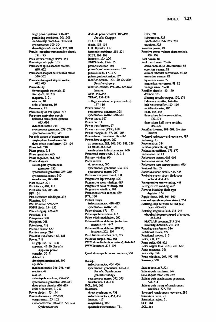
lars.P"'""'rsySlOlW, lO8-312 panlleling <>JDdj,ions, JOI--J03 Slep-by->'ep procew.., lO3-J04 symcJ.rucq>e, JOJ--J()ol _~gbt-bulb metbo<l 302, JOJ
Parallel-ap.dtor <:OIIllIUI,,,, joo circui~
191_ 193 Peal illvon>e vohg. (PlY), I~ P=e-..;o of rippl., 163 Per ........ , spH'-<:,.,acitor moton,
"" M' Per ........ ,_mapIO, de (PMOC) .-or, ~~9-j62
Per ........ ,_mapIO, Slepper motor, ~~;
Per .... bility ferromagnet ic ... ,ori. ls, 21 fne spac., 10, 737 mapIOtic, 9,21 rei",;"", 10 ... tsof ......... , to
Per ... """", 12 Permittivity of fne space, 737 Per_phase .q.;vole'" circui,
balao::ed _p.. .. sySlOlW. 693,694
iDdoction moIor, 394 symcJ.ODOOIS ll"DOH'or, !l8-!l9 symcJ.ODOUII """or, 348
Per_omit system of .... ......"..,.., ';D,I;le-phase tnmsforme:r, 94 _pbaoetnmsfonoor,12l-124
Phasebek,718 Phasegroop,718 Ph ... q.aotitie.!l, 6&l Phase .. qoeoce, 6&4, 6&'! Pbasor diagnm
..tienl _pole ,ynd>romo. gonontor, 732
.ymcJ.OGOWi geDmlior, !l9-280 symcJ.ODOOIS motor, 349 tnmsfonoor,IOO-101
Pilot .xciler, 271 Pitch foetor, 491, 712 Pitch of . ooil, 708-700 PlY, 154 Plex (armature windiog.). 492 PloW"l,41O PMOC motar, ~~9-j62 PNPN diode, I~m Pol. dwipD,I;, 436-438 PoI.faee,~18
PoI.piece .. ~18 Pol. pitch, 701! PoI.oboe.,~18
I'ooition """", 6/7 I'ooitiv.groop, 21 4 Pot •• tiol tnrufor ... r, 68, 141 _r,7--11
oir gap, 3~, 397. 4()Ij
_"', 49-j(]. Su aIu> A"...._
<:<JqI1ex, ~ I <le6DOd, 7 <levolopod mocbankol, 397 eq."'ion. 7 iDdoction motor, 396-.198. 466 reactiv.,49 reol,43 ..tienl _pole macbiDe, 734-73~
'ymcJ.ODOWlll"DOH'or, 280-283 _pbaoe circuits, fi9O-fi93 ."ts of ........ , 7, 737
_rdio<le.!, 1~J-I54 _r.lectronic. , I~W29 ~1~J-162
cyclocon_ .... ~18. Su aIu> Cyclocollvon ....
de_to-<Ic power conroI, 186-193. Su abo Cl>q>per
DIAC, I~8
diode, 1~3_ 154 010 tbyJUtor, I S7 hormonic poblem.!, 2U_221 IOBT,161_ 162 in_oro. 193--10} PNPN diode, I~m power tnmsUtor, 160 powerlsJ-d coonparUoru, 162 I"lsecircoit.,111_ ln I"Ise . yr>chnJDizatioo, In rectifier circuits. 163_ 170. Su aI>o
Roctifio:r circuits rectifier_i""" ... r. 193--109. Su aoo ~".
SCR 1~~_ lS7 TRIAC, 1~8-1~9 voltay voriatioo ( II<: pbaoe coruol),
In_ l86 P<>wer factor, ~2
.yr>chrnnow g""""or, 328
.yr>chrnnow ImIor, 360-J63 P<>wer ~mits, 327 P<>werOll',71 P<>wer tnmsfor ... "" 6/ P<>wer tnmsis'or (PTR~ 160 P<>wer triangle, ~I -.B. 700-703 P<>wer_foetor correc:tiOll, 360-.J63 P<>wer_no... diogom, 262
"" g."""or, 262, 263, 280-Z81. ~26 ""motor, 263, ~26 . ingle_pbose induoctioo motor, 660
J>r.for ... d ",It or <:Oils, 716. 717 Pri.....,. windi"l, 66 Prime IDOVOJ
de ll"DOH'or, m .yr>chrnnow g""""or, 304, JO~ . yr>chrnnow ImIor. 367
Prime-mover P"'""'r limit, 331 Progro ... "" lap ...mding, 4~ Progro ... "" rotor ...mding, 493 Progro ... "" .... ve .. inding, ~I Progro ... "" windi.S, 492 Protoction cir<:oit .. ctiOll, ~89 P1R,I60 Pollou, 'orque
induction motor, 41(]...413 .yr>chrnnow motor, 3~1
Polo. circuits, 171 _ ln Polo • • yr>clmniuion, In Pol_width 1IlOWhtti0ll, 202 Pol_width 1IlOWhtti0ll (indooctior>
motor,~ 444--447 Pol_width 1IlOWhtti0ll (PWM)
i""""',",202-209 Posh bot'OIl.wi,d>e., ~78. S79 Posho"", 'orq •• , 460. 461 PWM drive (indoclion 1OOI0IlI~ 444--447 PWM illvonon, 202-209
R"'ing. induction motor, 464-466
. yr>chrnnow g""""OII, 326-J36. Su abo SyAClrODOUS l"oontor rating •
. yr>chrnnow ImIor, 372-373 tnrufor ... r, 134-139
RQ., 261. 662 ,.-direct .yr>chrnnolU, 731 induction motors , 4.17. 4~8 leak"8",417 magnetizing, 389 qua<htic.yr>chronoIU. 731
INDEX 743
NOor,391 , ubtnmsie"',3l'! ,YnChrODOUS. 276. 28~. 286 tnnoienl, 32~
Reoctive power, 49 Reocti"" power_voltay cbaracleristic, ~
Real p<>Wer, 48 Real tnMformor, 76-36
""""""ion of, '0 ide. l1nn>fo:r, 8.'! """,_to.. <:mreJII, 83
""""'" ",,;ado! COII"".tiO<l, 84-8.'! .XCitatiOll CIlJ"'.', 83 bystere.oi. CIlJ"", n .... goe1i .. 'ion <OrreJI~ 81--32 vol,"8" ratio, 7Il--110
Rectifier circuits, 163_ 170 defiDOd, 163 fiboriD,l; rectifio:r output. 170, 171 f.U_w"".nctiC .. r,I6/_ 16I! bolf_ .... v.rectifier, 163_ 166 ",ctiCIOJ_illvono:r, 193 SCR, 1~~I56 ~pbaoe f.U_w. v. noetiC .. r,
170-171 ~pbaoe bolf_ ....... rectifier,
169-170 Rectifier_i""" ... r, 193--109. Su abo
Refo:rnd re"Slane. and ",actaDc., 393 Refo:ning, 73 RegmontiOll, ~!4 Rel"ive po:r .... bility, 10 ReIOXlltioo OIciUator, 17l_ ln Reluctar>c., 12, 13 Reluctaoc. 1OOI0Ill, 66~ Reluctar>c.,orque, 66.'! Reluctaoce-'ype ""opper mot"'", 6/3 Re .. Wol flux. 27 Re .. W"" .tanor circoi~ 434. 433 Re"Slive .tarler circoit (i_OIl
IDOIOII). 434. 43~ ~ve rotor ... indiog, 493 ~ve ...mding, 492 Reverse_blocking diode ~ype
tbyJisIor, 154 Ripple foctor, 163, 164-166 IOU voltay (~phase ",,"'or~ l'!4 R0001iog loop be1wuo CIlJvM pole
bee.!!, 47J-.U~ R0001iog .... goe1ic C .. ld, 2J8-246
.lec1ricrol frequoer>:y1s!-d of rotatiOll, U~
MATLAB prognm, 24~246 "''''''''ing direction. ~6
R0001iog 1nn>formo:r, 386 Roootiomllosse.r, 3~ Roootiomi motion. 3-,'1
Rotor, 231. 473 Rotor coils, 490-492 Rotor _ 1o .. (R(1). 261. 662
Rotor reactao::e. 391 Rotor .Up. 386 Rotor windiog. , 26/. 492-493 Runa .... y, ~~
Salie., pole, 26/, ~21 Salie.,_poI. machine., 247 Salient_pol. rotor, 268, 269 Salient_pole symcJ.OIIOUS ll"DOH'or,
728-734 Salient_pole 1beory of .yr>chrnnow
machine .. 727_736 S"' ..... od .ynd>romo. ",octane., 286 S"' ..... ion curv., 21 S"' ..... ion regiOll, 21 sec, 284 SQ.,261
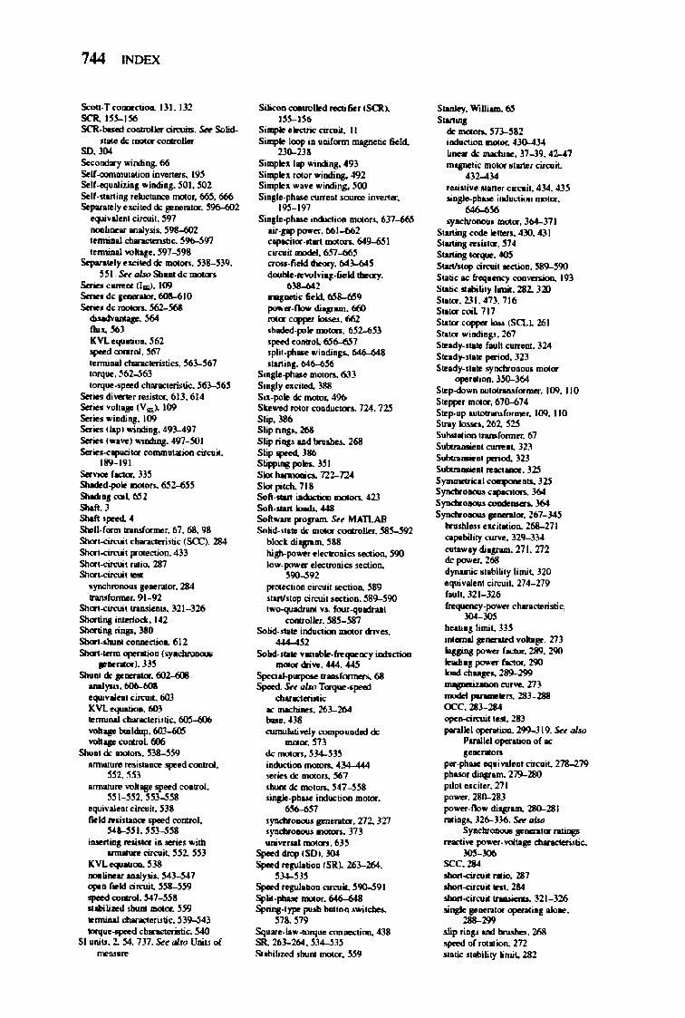
744 INDEX
Soou-T~ BI.1l2 SCR.I»-I~ SCR.- _110< dmoi ... s.r Solid.
>l1II.do_OOIIIroIIo< .,. '" .sec-:I.y windi,,&- 66 Solf.a>mllllltllliooo ",..run. 19~ Solf-eq .. lillnl windill,l;. ~1. ~2 Solf •• tanial ,duc\ao;:e ~. 66.'1. 666 s.,..r.ltly .""iled do 8"",,,. 11,.. ~
oquivol..., c"""~. m _u_ moIy.lli .. ~'111-602
IOnniul ~Iic. ~%-.'I91 .. nniul~. '91-.j911
s.por.lyc.cllOdde -.... 5l11--5l9, 551 . Sn_Sbo .. de-.
Series ....... (1.), 100 Series de .--. 6OS-tiiO SoriOIde~~ ~ •• 564
"', '" ICVLcq.roliaa. ~ .".d 00IIIr0I. 561 .. nnioaJ clIonocIeri.rtia. 563--567 tr>rq .... 561-UJ torq ... ...".d choncle:ristic. 563-j6,
s.. ... 1Ii_Io, , ... ilUJr. 6lJ. 61 4 s.. ... volt. (Val. 100 s.. ... ..,IIIIi." 100 Setin ( lop) wiD<li." 491-4'11 Setin ( ... ..,) wirrdi"50 oI91-.'iOl Setin ........ too commoo ..... cirail.
189-191 Servioo f ...... , ill
-~~ SIIodi", coil ~l ...... , ""'-, SIIoI~f ...... _ ....... 67. 611, 98 Sbor!.a.:u;t clIonocIeri.rlic (SCC), 284 SbcfI.amri1Ilf"leClioo. 433 Sbcfl.amril .. 00, 237 Sbcfl.circuit 10.
.)'t'IOIIr'Dnoo. I ........ 284 hOUf",,,,,, •• 91_92
Sbor!.a.a.;t ~ 321 _326 Shortina b" .. 1ock, 142 SborOna " top. J.8O SborI.-..-"", 6 12 SborI-oenn q>enlioo (.,.~
........ ). lJ!l SM .. de ........ , Ii02.-alII
_,..u,6Ci6-MI oqui._ .u.:.;,. 6W ICVLoquotK.. 6W IOrmioai ~c, ~
""'"II" tUl<lIp.l!W--&S ""'"II" _L 1'106
SII.ru de """"""' B8_-l!!9 """lOut. ,..,; ... "'" >peed c"""oI.
'52. HJ """lOut. vall • .".d <X>II1roI.
"I~n. HJ-.j~ oquivolun c"""~. 538 field mblu<z ..-<>JDroI, "~I,HW~
iaotrtirls _ ... i • ..;.. ..m _cirait, 552, 5.'13
ICVLoquoo;... H8 _,_.....".... S(3-5(7
""'. fodd dmoi~ ~ ..-_. "1--555 .'''''-.1 __ 3.W IOrmioai ~ 53'1-.S43 lI>rq'M...,...d chooracleriolic. ,S4(I
SI ~oill. 2, 54, 731. Su abo UDiLt ot ~.-
SiIi<oII_1ed recoir.... (SCR~ I»-U6
Sialplocleariccirail. II Siaoplo loop I •• oiform ~ field,
»>-m Siaoplo.lop windi,,&- 493 Si.",Io. roIOr windi"ll, 492 Si"",lo. wov ... indi"!l:. ~ Si.!Io-ph .... """.n1 """"'" i""""or.
19S-191 Si.!Io-ph .... I.....,.'" _ .. 637-66.'1
w-pp JIO""OI. 661-M2 copocilor ... .-t ~ 649--6!11 cimr. model. 6S1-6/i!1 atIIII· fodd -,.. 60._645 <Ior.obIwo ........ __ 1d tboay. .,..., .......... &.old, ~1-6S9 J'O"'or.flow 1Ii..- fi(j(]
.....". """"'" _. 662 Wcled-p>Io mot<n, 652---M)
"""" 0I>I'III'0l. ~ 7 lpIiI.pt>_ .iodi.lS. 646-648 .lOtIi.l. 646--656
Sin!Io-ph'" 0'I0I0r>, 6JJ Si.!ly .. cited, 311S SiJ.pole de """"'. 496 S ....... d ""'" ~or .. 724. 72'1 SL;p, }86
SI;p rinp. :za SI;p rillP 00<1 tn ...... 268 Slip .pted. JU Slippiaspola. )$1
SIoI iIInI>ooiao. T.ll-724 SIoI pildL, 11' Sol\-JWI iIIIioooioro -.. 423 Sol-JWI -.. <t48 Soft ...... propwA Sa MAJLYI SoIicl-flMo do ..,.." <:OOOoJIo<. ~
block iii ...... 3101] 1O""power .lo<.-IroDic.o 0<0CIi0D, ~ Jow' J'O"'or doolroaiCi JeClioo.
59O-.!l92 p«>I'<'Iioa ci.",,;, .. cIiOll, ~89 • ...v.1Op dlWit oecIiooo. ~90 ''''''"'l''- v •. ftur.q."d"" .. _Ior.~
SoIOcWWI in<h<:tlorr __ driVCl,
~" SoW-mIO v.n.t.Je.h""""1 irrdoctioo
_dri..,.4t4. 0145 SpoQ~n.bmon. 611 Spoo<I. Sn_T~
-..:. .... K rnodoi_ 26J-.264 _m C\IIIW.JMi..,ey ......,.,~odod de
rnoIOf.573 de n1OIor •• 5~J5 iO<kl<tiClrl """""'- 4l4-444 ...... de rn<JIOD, 561 . i>.lnI de mo«:n. 341-.j~ ....... pIwo IndlOCIX>D_.
"'-'" .~ .......... Z72,JZ7 .~ """""- J7l .... ..,1'$Il moron. 635
Spot<l drop (SO~ )()l Spot<l rqulllliorr (SR~ 2M-264.
"'-'" Spood .. pIIoIioa cirait. 5\11hS91 Splil.phuo ...,.",.. 646-6411 Spri",.I",. pooh batto • ..;tcbos,
571. 579 Sqo ... low-lOtqooe C<><lJIeCIioro, 438 SR 26J-.:!6-I. 5~1'I Slobitao<l , i>.lnI _. 5.'19
s-io)', Wolli-. ~ ...... de --. 51]..3&2 iao.h><liooo rnoIOI • .tJO-U4 00. do rnaohi ... 37-39. ~2---I7 ""I"<'Iic """'" .!arIo. circoir.
432---1:1-1 ... Uti •• IW'I ... in-u;,. 434. 4J~ oi..p.1"'- i""oC'Iiooo roo!<Jr.
...." .,.oo:t.oaooo. _ . J64..J71
$wt"'s cocIo lotIOn, 4]0, 411 S .............. n • S .............. 0105 SwWtop ciJaril ..."iOG, ~ Srmc ac &e; , :) "",,--.., 19J SboIi.c .111.,,1)' limit. 2Sl. l<n St.Ior. 231 . ' n, 116 Stoia- coil. 1 11 St.Ior <appor _ (SCl.~ 261
St.Ior wifllli .... 261 S .. ody-flOlO f .. _ oarrero:. 124 S .. ody-,oWl period. 32) S"ody-,oWl .,. __
""' ....... 350-J64 S .. p.do...., MII_f",,,,,,,,. 100. 110 S .. ppo. """"'. 670-674 S"p."I' ,"""""",for",,, •• 109. 110 Sin)' 1Dooo •• 262, '25 S.,*-iooo InnOtorr... 67 S"""" ..... , .... rot. 11l S"""" .... '" ponod, 12.l S"""" .... '" .. ..,,_. 12'1 S,_i<oJ~_l25
S~ copocioors. J64 S~-",l64 S~""""",.267....J45
InohNI.> clCillllioa. 2(il..271
o;::opobiJi!y """"". l29-lM MOWOY eli.,..... 271. 712 <Ie JIO""OI. 268 dynamic .tabiU,y Urnil. 320 oqu;v"'", d"""~ 27 .... 279 f..,I,.32I-326 froqumcy.,..,... .. . b.-riRie,
""-'" ~.,~";~ lH i_ .. __ ......... 773
... power f...,.. 289. 290 ftdi .. pCI'IO'« fKoor. 2'10 ......... """" rmpotiuIioa __ 213
IIIOdod J*'MIt ...... 2U-2118 occ.= ~moi'I .... W ponJlol opmoIioa. 299..J19. s.. aUo
PonIJd r>p<nIioa of K 1· ... nIIDrO
.,...pIwo <;.i""Io., cirelli,. 278--27'9 p/Ia><r lliovan>. 179-280 pik!Ir .. cit ... 271 po ....... 280-lIJ power.f1Dw llioparn. 280-2111 "'in,o. 126-JJ6. s.. _ Sr-F-nIiIrp
.-.;.., power ....... """'--iolic.
"""'" .ce.,.. ~ ... io.,211 ohr:IIt-ararilleSt. 2&01 ohr:IIt-ararii tna.IIiau. 12J---326 .IIi ..... _ opmoIUo,'_,
"'-m .Iip ri ... ond 1INoha. :za "*'" ot .01 ...... m ""ie "abi~1)' ~mil. 282
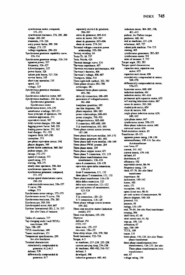
ay~_.......,..a.
311-312 ay~ ... octanu. 216., 2M. 286 ~2Sl-m .......... 319-326 ."ty_ &coor. 2ti. 290 '""lias" 113. 321 '""lias' ~ 19O-191
5~..,....wcopobi~I)''''''', ,"-'"
5~..,....w fIIj .... l26-lJ6
_'" J'C""Of. m ~.J26...J21 kilo~.ll7 _f""""'.328 .u.,.o..polo Iheofy. 127_136 .. moo fo<Iox lJ5 """'.tin opmItion. JJ5 _m """"so. 327 S~ grnom" ..... ielllS.
319--326 Syacbr""""" ioduclioo moIOf. 665 S~ "'oelIi .... no. Src obo
Sy...m-w grnm.t,,; Sy...m-w""""
Sy...m-w """Of. J. 6-379 OJIOtiloow wi..,;.".lo61-371 buic priociplo of opmItion. J.46 romII'oOI> ~atioc>. J1J oqoivu.," c"","~ 3017 r .. 1d ....... , <l>uc'" J5S-360 "w._f""""'.loI9.J~ .. 0<1; .. ..,...., r"""",. J52. 362 Imd~ l!II-l!I5 "'"P""'" r .. 1d, :U1-3~ """"Platt. 313 ""' ............. 01 <i_it. ).q ~ 4iopI>. l49 po ...... ~«mCIiOi. 36O-36l puIlouI """'"- l!Il rIliap.. l1W13 opo«IoI "" .... 313 IP""'I ...as. m --.. )6.1-311 .....,.._ "",1'IItio». J».J6.I ay""'-'- apcilor. )6.1
ay""'-'-.-. ~ 171-312
~~~.utic...,... .. "..",
.odofOu:i .. dIovuucited, l56-l!l7 V < ...... J56 ."""so. 313 S~"""" flljj,,,.11l-l73 S~ _ V C'UtYO. 156 Syacbr""""" 10'''''''Il0l. 276., 28.5 Sya.d>raooopo. MJ-104 Syacbr_d _. 666. 667
Sy"~"" J"' ...... """" (51). 2. 54. 737. Sr. oIs<J Uoiu cf ...... "'.
T.bIo.oI~ .. u. 737 T"" dw9n8 UIIdef _ (TCl)t.)
...... &.r"""'.I09 T_ I08-I09 TCUl. ,"",bmoo.l09 T ............... """"',. III Yrmpe ... _ .... df><a!ioN.~.
Su tJI", ..... 1.;0" T ......... ~ri,.;<
cumliloti ... ty............-* ............. 611-613
do&DOd., '19 ~ .. .......,. «IIIl""'-*
.-.-..617
__ I)" aci .. d * poonkO".
""'" _* ..... "".6()9...610 _*_.~~1
..... de paonoor. 005--W6
..... de -. 539-.S4J Tormiat .... _~_
~I ....... 10S-J06 yn.,_.,66 Tall (T). 10. 1n T .... 1'1-. 426 lbonDO! ....,.. ......... 136 n.. ...... iq>tdaa: .. 4(J7 n.. ...... ...a..-:. oad 1n<UIII: .. _
n.. ...... · . .......... 406 n.. ....... """"So. 401>-4(17 n.c....- Elibu. ~ n.-~JIb<.bolIb IDO!bod, .lO2. Jro n.-pt..<...rc.iu. 631_106
........... 631 bot_ !hr .. ~ ' )"10 ..... M~~
del .. (.1) <>JODOCtiooo. 688-689 FDOnIioon of ""ttav ... """" ..... M'~
~ooIptwe ",mj,io •• 00 "",,·Iine di.~. 700 fb- OOIJOeDOe. 684. 00 _r ,elOliomltipo. 69()...691
_rlri .. sle, .1OO-103 ""1Ia,\IO ... """" ..... 63~ Y COIIDe<:!ion. 68J-688, 689 Y·lo n..f~ i\93. 69S
11fte.pbooe.......- ..,."" i""" ..... 197_199
n.-.,t.-fuU-"a", lKlif_. 1m-ITO 'tlfte.pbao paon<m. 611. 682 'tlfte.pbao b&tf_ .. a~ IKli6er. 161--169 'tlfte.pbao PWM iD_. 204 'tlfte.pbao _ . 219 'tlfte.pbao __ -. 6/1
1tfte.pb.oYm :1;"" 131.13) 1tfte.pb.o .... _ (r.o
-..on). 126--133 "",...to __ 126--129
"", ... ..,e; do"'~ IJO--JJI
Sooa_T......-.... Ill. 132 -....... T «> __ 131.132
llfte.pb-. .... _.II6--I26 deb_."""""Clioo., III dek .. ..,o ~ 121_122 ..... _I)' ... "'ofmo......,... ...
12J-124 <ypa. 117 y . .1_. 120-121 y.y~"". 118--120
n.-pho>e"""SO IOII(ce invenor.
'~m n.-"." .. ,i"ive " "'or (in<b:ti""
.-or). 4JS n.-.. ;.. tbyri'<OO. ISS--IS6 ThyTi"<JI
deflDOd.l54 010. 1ST
....... ;... 1S4--1~ T ......... .,. .. Ia,.. ~loI. 51'9. SAO Tl:.JOb...-.... 722--124 _.W
'" modIi ..... 211-2lo11. 2'lS--2511 ~......,..~ loop. 2J4.-23II .., __ ~:z. 511h'111
'"'""' , <k~Joped. JII8 _~.400.~1
INDEX 745
ildKtioo. _ . 184-38!1. 39&, «11,,(13
... Ilooot. Su ......,.. .....,...
...-~ 0160, <161 rnJ "" _. 2J1_llS ~~~121 .aIioOI-f"*.....::biDe. 7J.t-13' ...... '" .,---11"_ 2I2-2IJ ., ____ .331
_01",,-..5.137 T<Y<pIO ..... lSl. 213 T~~"
_iIor ...... ~1Or ..... _.M1
capoci<oo ..... _. 650 rumnIoIivolJ.",..",..odod de .... Of. ....,'" diffeuolioJly """"""",d de moIOI.
57O.,S11 by......,;. moIOI. 668. 669 io<i><ti"" moclIi ... 461 io<i><ti"" m<It<f, 401-4)6 1"""WI<o, .1p~'-<,opoci,,,,,...-.. 651 ..If"'''''i,. .. 11I<\aIQ """"". 66/ ",ie. de IrO)IOr" ~
.bodod.poIo m<It<f. 6;S4
.b"", de moon. 540
.i.<.p/lAoo i_oo _. 639.
""M' . pli<.pt..< _. 6017 . ytd>rooolw _. )~51
~i-"'_.640 uniwroal _. 616
Too .. aalMioo """"at. 8)
Trudamos,65-151 .......... _ ....... I)8..J19 __ ~ 109-II6.,Su.,J,.,
~
""'"' f ...... 6/ ...,., ... 141_142 ~'"imlHb.ll9-loIO <kr,.", diMibuoioo., 6/ offia...cy. 100 eqoi.uOl...rc.it. IJ6..9.I ~""'I-I~ idoooL 61-'M. Sff ... kIoal ....... i~66 i ..... _ ... 141)..1.2 _.102 "";n. III umopb ... 14Q 141 " . ,.iI ... " 9(1..9)
por.uni! .y ... m of ............... "'. 94 phaooo diosr- 100-10; p" •• Ii.lI41 1""_.66 raliOjS, 134-139 ... l 16-M. Su ~..., R.oJ InIUfor .... '
"""i." :lS6 .boll f<JIm. 6/. 68 .t.<.t.ciKui, ..... 91-92 "tp-op. 109, 110 . ubo!o!ioo., 6/
' ..... 108-109 =C," _.1lI ~ 116-126. SfftJI",n.r.. -_ .... -.....~ (,-
......ror-..). 116-13). s.....s.o ~ ..-...f<noIMj<ll (r.o ......... ,
....,~
.............. 134
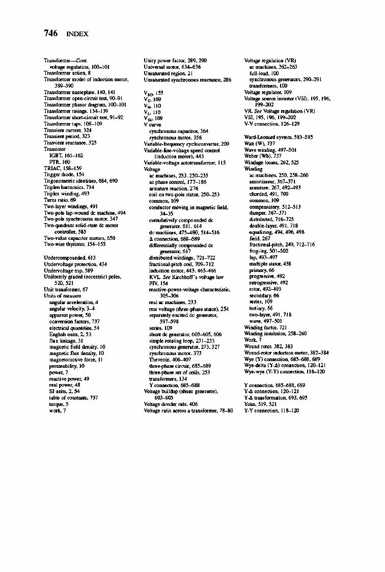
746 INDEX
Trmsf",,....-Con< voIIage .. gul"'ion. 100-101
Trmsf",,.... actiO<l, 8 Trmsf",,.... ID<XIeI of i_OIl moIor, ,~~
Trmsf",,.... ...... pl"'., 140, 141 Trmsf",,.... opoD_drcuil' •• ~ 90---91 Trmsf",,....pbasordiagnm, 100-101 Trmsf",,.... "lings, 134-139 Trmsf",,.... ohon-<ircui" .... , 91_92 Trmsf",,....,aps. 108-109 Tr>Mion1 <UrrOD1, 324 T ...... .,. period, 323 T ...... .,. re:o::w.::o, 3~
T ...... " or IOBT, 161_ 162 PTR, 160
TRIAC. 1~8-1~9 Trigor dioo.. 154 Tr~e ideotiti ... , 6&4, 690 Trip"" barmoni<:.r, 714 Triplex willdi"-l, 493 Tor", ratio, 69 Two-byer...u.dings.491 Two-polo bp-_do:: rnachlno, 494 Two-polo .oy~. molar, 347 T~ ootid_ . .... do:: """or
CO<lrrnl .... , ~ 8~ Two-value capaci'or motor" MIl Two-wi .. thyri"or, 1~4- I~~
U~Ddod,6lJ
Undoorvol1log. protectiOll, 434 Undoorvol1loS' rrip, ~89 Uniformly gndod (occOJlrric) po .... ,
~D. ~21
Unir 1nD>f"'''''>r, 6/ Uni .. ot .... :.s"..
angular :lCcolonilioo, 4 angular voloc!'y, 3---4 ' WM01I' _er, 50 <X>llvorsioo (""or. , 737 .locIrical qw.owic., 54 English .nits, 2, ~3
llux linbS" 31 magnetic field doruiry, 10 magnetic flux doruiry, 10 magnetomotivo foR:o, II por ..... biliry, 10 l""""'r,7 reocrivo l""""'r, 49 real power, 48 SI .nits. 2, 54 ,oblo of """" .... , 737 ' orquo, ~ •• u
Uni'y power (ocror, 2l!9, 290 Univor..J """or, 634--f;36 U ... 1l1r1IIod rogiOll, 21 U ... 1l1r1IIod .oy~ ... actaoc., 286
VI<> I~~ Ve,l09 V .. 110 V,,110 V .. ' 109 "--. )'1>CIror>ow eapociro, 364
. )'1>CIror>ow """or, 3~ Varioble-freqo>on::y Cfclooorrv.:" .r, 200 Varioble-line-vol1loS' • .,-1 <:O<I1ro1
(inWcriorr motor). 443 Varioble-vol1loS' aur"" .... formor, II~
"oo~ II<: rnachlno .. 233, 230-~~ II<:p/>asoconroL 177_ 186 . mat .... ">C1ioo, 276 coil orr tw<>-poIo . tator, 250-~3
~'OO C<>Dth>ctor movloS i. magDOlic f .. ld, ~,
cwmJatjvoly compoW><lod de !l"DOn'or, 611. 614
dcmoo:bi ..... 47~---480, ~IWI6 -<I. COIIDOCIioo, 688-689 diftoroJlrially ~d de
!l"DOn'or, 617 disrriburod...u.dings,721 _722 fncriOllllI_pi'cb coil 709-712 i_OIl """or, 443, 46~ lCVL Sa till_·, voIIage la ... PN,I54 .. activo_power _ vol,>-y cl1lonocleruric, W~
... Ioe machino.<, 233 rms vohg. (rhne_phaso " "'or). 254 >epanIOly .xciled de SOllOrator,
~97~98 soric., 100 . t.rnr de SOllOrator, 603---60:'!, 606 .~Io """rioS loop. 2J 1_233 . )'1>CIror>ow gonontor, 273, 327 . )'1>CIror>ow """or, 3Tl Thovenio, 406-407 three--pIw>o circuil, ~ three--pIw>o .., of coil~ ~3 rnnsform . .. ,I34 Y oonoocUOII, 685---68Il
Vo/rage Wi]Wp (shlUl' S.,..nllor). ~
Vo/rage dividoor rul., 406 Vo/r age nllio ocross . lnMf",,...., 78-80
Vol,,,!!,, .. gub'ioo (VR) oe Dl:lCbino.s, 262-263 full_lood, 100 .oy~. !l"DOn,or. , 290-291 1r1mSf"""",,", 100
Volr"!!,, "gub ,or, 109 Volr"!!""",,,,co illVOnor (VSl), I~, 196,
199-202 VR. Su Vo/rage rogulariO<l (VR) VSI. I~, 196, 199--W2 V_VoonooC1ioo, 126-129
Word_l=nard 'y'lOm, ~83~8~ W.D (W). 737 W.v • .,;00;"8, 497---5()1 W.ber (Vr'b), 737 Wlodago los .... 262, ~2'! Wllldi"-l
oe macbino.s, 250, 2~~ omorIir..-or, 36/--.l71 lIrDIlI'uro, 267, 492-493 <:borded, 491. 700 0JIIIID0Il,109 <:OIIIpO""ory. ~IWlJ darnpor,36/--.l71 di.rriOOrod, 716-7~ doublo-l' yo:r,491. 718 'quolizio.'!, 494. 496, 498 f .. ld,267 fr>Ctioool_pircb,249,712-716 froS-IoS, 501---502 b p,493---497 rwlripl. ""or, 438 pimory, 66 pogre"ivo,492 _ogre .. ivo. 492 rot",, 492---493 .. cor><lory, 66 .. rio .. 109 '011i.,., 66 'wo-b yor, 491. 718 W. vo, 497..j()1
Wllldi"-l foctor, 721 Wllldi"-l ;""'b riOll, ~8-260 -, wo.u.d NOor, 382, 383 wo.u.d_rotor inWcrioa .-or, 382--384 Wyo (Y) oonoocUorr,~, 689 Wyo-dol,. (Y-.1J <:OIIDOCI:iOll, 120-121 Wyo-wyo (Y-Y) COIIDOCIion. 118-120
Y oormocUorr, 685---68Il, 689 Y_-<I. <:OIIDOCI:iOll, 120-121 Y_-<l.1r1mSformatioo, 693, 69~ Yoke. ~19, ~21 Y-Y COIIDOCIion. 118-120


Higher Education
http://highered.mcgraw-hill.com/sites/0072465239
The Online Learning Center (OLC) provides students with activities to further explore topics presented within the book and ensure a successful grade for the course.
Activities may include:
• interactive quizzes
• Internet links to related materials
• animations
• flashcards
• additional readings
• answers to selected end-of-chapter questions
• a career center
Instructors will also appreciate how the OLC's library of teaching aids and compatibility with course management systems, including WebCT, BlackBoard, PageOut , and eColiege , make life a little easier.
The McGraw'HiII Companies