elastic fields of quantum dots in subsurface layers
TRANSCRIPT
JOURNAL OF APPLIED PHYSICS VOLUME 89, NUMBER 8 15 APRIL 2001
Elastic fields of quantum dots in subsurface layersA. E. RomanovA. F. Ioffe Physico-Technical Institute, Russian Academy of Sciences, 194021 St. Petersburg, Russia
G. E. Beltz and W. T. FischerDepartment of Mechanical and Environmental Engineering, College of Engineering,University of California, Santa Barbara, California 93106
P. M. Petroff and J. S. Specka)
Materials Department, College of Engineering, University of California, Santa Barbara, California 93106
~Received 22 August 2000; accepted for publication 11 January 2001!
In this work, models based on conventional small-strain elasticity theory are developed to evaluatethe stress fields in the vicinity of a quantum dot or an ordered array of quantum dots. The modelsare based on three different approaches for solving the elastic boundary value problem of amisfitting inclusion embedded in a semi-infinite space. The first method treats the quantum dot asa point source of dilatation. In the second approach we approximate the dot as a misfitting oblatespheroid, for which exact analytic solutions are available. Finally, the finite element method is usedto study complex, but realistic, quantum dot configurations such as cuboids and truncated pyramids.We evaluate these three levels of approximation by comparing the hydrostatic stress componentnear a single dot and an ordered array of dots in the presence of a free surface, and find very goodagreement except in the immediate vicinity of an individual quantum dot. ©2001 AmericanInstitute of Physics.@DOI: 10.1063/1.1352681#
nton
m
iatheeth
tictr
u-
duth
th
ofva-
isaselsinc
con-iontrix.lds
the
ec-ticldstrix
trix,freeherm.lemof
ion.to
ity
I. INTRODUCTION
Self-assembled quantum dots~SAQDs! have attractedsubstantial recent attention because they offer the potefor three-dimensional confinement of carriers and excitand have ‘‘atom-like’’ electronic states.1,2 SAQD formationis commonly observed in large mismatch epitaxy of checally similar materials.1,3 For example, the Stranski–Krastanow~SK! growth of InAs ~or InxGa12xAs! on GaAsfirst involves the growth of a;1 to 2 monolayer thick ‘‘wet-ting layer’’ followed by coherent island formation.1,3 TheSAQDs may be buried by the growth of the same materas the underlying substrate. Subsequent growth ofstrained composition on the buried dot template has bshown to lead to vertical stacking of dots provided thatthickness of the intervening layer~‘‘spacer layer’’! is in theorder or thinner than the lateral dimensions of the dot.4
It is now clear that dot ordering is driven by the elasfield of subsurface stressors. Usually, these subsurface ssors are buried dots themselves~which give rise to verticalordering!.4–9 In group IV and III–V SAQD growth, the firstdot layer does not demonstrate lateral order and subseqlayers show only vertical ordering~however, other subsurface stressors such as regular dislocation arrays10 or buriedstrained layers grown on patterned substrates11 can initiatelateral ordering!. Buried subsurface stressors lead to a molation in the stress field and associated strain field ongrowth surface which affects both adatom diffusion12 and SKisland nucleation rates.13
The strain fields caused by SAQDs strongly affectelectronic properties in the vicinity of the dots.14–19 Two
a!Electronic mail: [email protected]
4520021-8979/2001/89(8)/4523/9/$18.00
Downloaded 03 Apr 2001 to 128.111.70.86. Redistribution subjec
ials
i-
lsen
e
es-
ent
-e
e
strain effects are predominant in the electronic propertiesIII–V semiconductors: changes in the conduction andlence band levels~deformation potentials! and local electricfields due to piezoelectric effects. The conduction bandonly affected by the hydrostatic strain, often referred tothe dilatation or trace of the strain tensor. The valence levcan change both with hydrostatic and shear strain. For zblende structures, deviatoric strains~those strains which dif-fer from pure hydrostatic strains! give rise to piezoelectri-cally induced electric fields.16 In the general case for zinblende SAQDs, strain causes negligible change in the cfined energy levels within the dots, however, the conductand valence levels can be changed in the surrounding maFurther, strain can cause local piezoinduced electric fiewithin the dots and in the surrounding matrix.18 Additionally,strain can strongly modify the phonon frequencies withindots in the surrounding material.17
Both for understanding ordering and the effects on eltronic properties, it is important to determine the full elasfields in the dots and surrounding matrix. The elastic fiedepend on the lattice mismatch between the dot and mamaterial, the elastic properties of both the dot and the mathe dot shape, and the position of dot with respect to thesurface. A complete solution of the elasticity problem in tmost general case is not possible in closed analytical foIndependent of quantum dots, the general inclusion probwas extensively developed in the pioneering workEshelby20,21and we address this approach in the next sectIn the SAQD field, three main methods have been applieddetermine the elastic strains and stresses, namely:~i! theoryof inclusions based on the analytical solution of elasticequations~‘‘Eshelby-like’’ or related approaches!,8,14,16,22–24
~ii ! finite element methods~FEM!,25–28 and ~iii ! atomistic
3 © 2001 American Institute of Physics
t to AIP copyright, see http://ojps.aip.org/japo/japcr.jsp

x-selinicv
ecoluarere
do
orcc
thd
sc
doaif
anssttica
ly
eisi
oa
atcka
-
smweotrsyns-
edb-erspedntal
ttletheed
lshe
lto-ofdhehean-al,otr-
bys;
nalee
n in
mof
u-ple,liedite
, aby
in-
tu-
th
4524 J. Appl. Phys., Vol. 89, No. 8, 15 April 2001 Romanov et al.
modeling.29–31The theory of inclusions provides integral epressions for elastic fields which can be integrated in cloform only for the simplest inclusion shapes, such as cyders or spheres. Even with the simplification of isotropelasticity, the known application to quantum dots so far haneglected the effects of the free surface. FEM is very efftive for particular cases but does not provide general stions and is furthermore affected by the choice of boundconditions for the modeling domain. Atomistic models rquire accurate interatomic potentials and are furtherstricted to small systems of atoms in comparison withsizes and the surrounding matrix.
In this article we apply two analytic approaches fSAQD mechanics which include the effect of the free surfaand the dot shape and compare these results with FEMculations. We concentrate on the far field solutions inanalytic approaches, as our main interests are related toordering. However, we believe the analytic solutions are uful for determining the strain effects on the electronic struture of the matrix.
II. MODELING OF QUANTUM DOTS
From a continuum mechanics viewpoint, a quantumcan be thought of as an inclusion of some prescribed shembedded in a dissimilar matrix. Due to compositional dferences which give rise to a lattice parameter mismatchpossibly a thermal expansion mismatch, the inclusionsurrounding matrix will be under a residual state of streMoreover, the inclusion may possesses different elamoduli from the matrix material. Assuming a linear elasresponse, the resulting stress fields for such problemsvery cumbersome and have only been worked out anacally for limited geometries, including cuboids32,33 andellipsoids34,35 in infinite and semi-infinite domains. For thcase of an ellipsoid in an infinite matrix, the solutions for thclass of problems were originally developed by Eshelbythe 1950s.20,21
Figure 1 shows a schematic based on experimentalservations, in which a wetting layer initially forms whenmaterial of new composition is deposited onto a substrAfter the wetting layer achieves several monolayers of thiness, an instability in growth leads to isolated island formtion ~future quantum dots!.1,3,4 Currently, there are also indi
FIG. 1. General schematic of a buried quantum dot~QD!. A wetting layer~WL! is shown, which may precede the formation of an island duringdeposition of a dissimilar material onto a substrate. The island~quantumdot! is subsequently covered by additional matrix~substrate! material.
Downloaded 03 Apr 2001 to 128.111.70.86. Redistribution subjec
d-
e--
y--t
eal-eot
e--
tpe-ord
s.ic
reti-
n
b-
e.--
cations that the wetting~transitional! layer may be muchthicker ~comparable with the dot height! and may possesdifferent chemical composition than nucleating quantudots. We do not address this issue in this article. Rather,only consider the elastic field from the dot itself and do nconsider the wetting. Although there is another controveover the actual shape of quantum dots, it is clear from tramission electron microscopy~TEM! studies that they ini-tially form as four-sided pyramids. Truncation of capppyramids may be an illusion induced by strain fields oserved by TEM. This possibility is supported by researchreporting detailed contrast evidence in favor of sharp-cappyramids.4 This controversy has implications for the presefinite-element study. However, upper levels of pyramiddots are relatively unstrained, and therefore would add limechanical energy. For this reason, it is believed thatquestion of pyramid truncation will not have a pronounceffect on the conclusions to be obtained by modeling.
In this article we propose a number of simplified modeto describe the elastic field surrounding a quantum dot. Tsimplest approach is to ignore the geometry of the dot agether, and to regard it as a point source of dilatationprescribed strengthf V, wheref represents the mismatch anV represents the volume of an ‘‘equivalent’’ dot, that is, treal dot that is being simulated by the point source. Tparameterf represents the strain state developed in the qutum dot, relative to an equivalent volume of matrix materiif it were not constrained by the matrix; for example, if a dwith lattice parameterad is deposited onto a substrate suface with lattice parameteras , the misfit strainf is taken as(as2ad)/ad . When the island is subsequently surroundedmatrix material, the constraint is uniform in three directionhence the misfit strain components becomef d i j . Similarly, athermal expansion mismatch gives rise to such a dilatatioself-strain ~also known in the literature as the stress-frstrain or the ‘‘eigenstrain’’!, so all sources of misfit may beincorporated into the single parameterf. Of course, such anapproach is expected to yield expressions that break dowthe general vicinity of the dot.
A powerful method for the solution of a broad spectruof problems in elasticity derives from a considerationpoint forces applied at some point in the elastic body.36,37 Ifthe response of a body to a point force~i.e., the Green’sfunction! is known, the deformation caused by any distribtion of forces can be obtained by superposition. For examthe displacement field caused by a single point force appanywhere in an infinite elastic solid may be determined qustraightforwardly from the field equations of elasticity.37 Ifthe body is finite, as in the case of a semi-infinite spacetraction-free boundary condition must be satisfied, theregiving a corrective term to the displacement field for anfinite solid.
In the case of a point source of expansion, three mually perpendicular pairs of forces~each pair consists of adipole of opposing forces of magnitudeP, separated by adistanced along their mutual line of action! may be used~seeFig. 2!. If one considers a cube of volumeV5d3, the aver-age stress in the cube isP/d2, which in turn can be related tothe strains arising from the misfitf via Hooke’s law. Apply-
e
t to AIP copyright, see http://ojps.aip.org/japo/japcr.jsp

riv
a-r
rcryo
lus
eu
a
mte
orwt
rrre
e-edd
tiod’thoumstay
n-
it inke
isa
ntse
ting-onsandp-sris-ththes
ayclu-ot-rixatedustults
tedd byin-ed,antif-for
dif-in-
lo-is
-
4525J. Appl. Phys., Vol. 89, No. 8, 15 April 2001 Romanov et al.
ing such an argument to an isotropic medium, one may arat the relationPd5@2(11n)m/(122n)# f V, wherem is thematerial shear modulus andn is Poisson’s ratio. By takingthe limit as d→0, maintainingPd constant, the completeelastic field for a point of expansion of a given strength mbe identified. Mindlin38 and Mura34,35 have provided the appropriate expressions for such point sources, not only fogenerally anisotropic medium, but also for a point soulocated in a semi-infinite, isotropic medium. The primaadvantage with this method is that the expressions are cpact, especially for the case of an isotropic medium, as iltrated in Sec. III A.
The next level of complexity would be to idealize thquantum dot as an inclusion of some simplified shape, sas spherical, ellipsoidal, or cuboidal. Mura34,35has developedexpressions for an ellipsoidal inclusion in a half-space inextension of the point-source analysis described aboveintegrating the appropriate Green’s function over the voluof the inclusion. Chiu32,33 has provided similar results, bufor a cuboidal inclusion embedded in a semi-infinite mdium. Despite these relatively simple shapes, closed fsolutions are only possible for the ellipsoid when at least tof the semiaxes are identical, as demonstrated below. Inexample to be discussed in Sec. III B, an oblate spheroid~anellipsoid with semiaxesa15a2.a3!, a depthh from the sur-face, will be considered, either alone or as an ordered aof spacingl ~see Fig. 3!. Although the stress expressions amore cumbersome than for the point sources of dilatation~asgiven below in Sec. III B!, the advantage is that a more ralistic idealization of the quantum dot geometry is achievand in such a way that the effect of the aspect ratio of themay be efficiently evaluated.
For the case of quantum dots with extreme aspect rafor example, a relatively flat square or ‘‘penny-shapequantum dot, the stress field may be approximated asdue to an appropriately shaped prismatic dislocation lothe stress fields for which are well-known. As the quantdot deviates from an extreme aspect ratio, this methodworks, because the shape may be represented by an arrprismatic dislocation loops. Li39 and Gutkin andcoworkers40,41 have exploited this equivalence for determi
FIG. 2. Point source of dilatation at distanceh from a free surface, represented as a cube with infinitely small dimensiond. Three force dipolesP areapplied to the faces of this cube.
Downloaded 03 Apr 2001 to 128.111.70.86. Redistribution subjec
e
y
ae
m--
ch
nbye
-mohe
ay
,ot
s,’at
p,
illof
ing the stress fields around various inclusion shapes, albea different context from quantum dot behavior. For the saof brevity, we do not outline this method in this article.
The final level of complexity undertaken in this articleto evaluate the complete stress field in the vicinity ofcuboidal or trapezoidal inclusion via the finite elememethod ~FEM!. In other words, we model the geometriesimilar to that of Fig. 1, excluding the wetting layer. ThFEM models can easily be expanded to include the wetlayer ~see, for example, Ref. 28!; however, we do not undertake that here since the primary goal is to make compariswith the quantum dot models based on point sourcesellipsoidal inclusions mentioned earlier. For a typical traezoidal inclusion within a matrix unit cell, elastic solutionmay be approximated using a finite element mesh comping one quadrant of an arbitrarily deep matrix unit cell, wiappropriate boundary conditions imposing symmetry atlateral faces~see Sec. III C!. The primary advantage with thimethod is that more details concerning the stress field mbe revealed, especially near the sharp corners of the insion. The FEM technique can readily include elastic anisropy combined with different elastic constants for the matand the dot. The disadvantage is that a mesh must be crefor each dot geometry, and the size of the matrix mesh mbe made arbitrarily large in order to compare these reswith those of the point source or the inclusion.
To simulate this residual strain in the model presenhere, perfect bonding is assumed, and strains are impartea ‘‘phantom’’ thermal expansion mismatch between theclusion and the matrix. Of course, in the system simulatthermal expansion mismatch may or may not be a significeffect. However, since the effect of introducing such a dferential expansion is to change the zero-stress lattice sizeboth materials, there is no analytical difference betweenferential strains induced by lattice mismatch, and thoseduced by thermal expansion mismatch.
III. ELASTIC SOLUTIONS FOR SUBSURFACEQUANTUM DOT STRESSORS
A. Point source of dilatation
For the case of a single point source of expansioncated a distanceh from the surface, the displacement field
FIG. 3. Ellipsoidal inclusions used to model quantum dots.~a! An isolatedellipsoidal inclusion at distanceh from the surface, with semiaxesa1 , a2 ,anda3 in the corresponding coordinate directions.~b! A rectangular array ofthe same ellipsoidal inclusions, with periodicityl in the lateral coordinatedirections.
t to AIP copyright, see http://ojps.aip.org/japo/japcr.jsp

to
esoutiameawth
ts
one
-th
at
ishn
a-
eus
ingby
he
lly
lthe
id
orake
4526 J. Appl. Phys., Vol. 89, No. 8, 15 April 2001 Romanov et al.
given by Mura.34,35We have differentiated that expressionobtain strain through the relation« i j 5
12(ui , j1uj ,i) and sub-
sequently used Hooke’s law, s i j 52m(« i j 1@n/(12n)#d i j «kk) to obtain the result
s i j 5m f V~11n!
2p~12n! F2S 1
R1D
,i j
2x3S 2
R2D
,3i j
1~324n!~d3i1d3 j21!S 1
R2D
,i j
2d3 j S 1
R2D
,3i
2d3i S 1
R2D
,3j
1nd i j S 4
R2D
,33G , ~1!
where, as before,m is the shear modulus,n is the Poisson’sratio, f is the mismatch,V is the dot volume, andd i j is theKronecker delta. The quantitiesR1 and R2 are given byAx1
21x221(x32h)2 and Ax1
21x221(x31h)2, respectively.
The notation (),i indicates]/]xi() while repeated indices arsummed from 1 to 3. The use of a finite volume in theformulas is an approximation, as discussed in the previsection, since the expressions really derive from differenequations and are exact for the case of a vanishingly sinclusion. These expressions are expected to only yield ristic results when considering target distances comparedthe characteristic length of the quantum dot, for example,stresses at the surface for cases where the quantum doburied sufficiently beneath the surface.
In order to graphically illustrate the stress distributinear a quantum dot and to facilitate comparisons with othmore precise representations of the stress field, we usetrace of the stress tensorskk rather than individual components. This component is the key quantity for calculatinginteraction energy between a quantum dot and an adatomthe surface, and thus the driving force for adatom diffusionthe surface. The trace is related to the pressure throughrelationp52 1
3skk and is given by
skk52m f V~11n!2
p~12n! S 1
R2D
,33
52m f V~11n!2
p~12n!
@2~x31h!22x122x2
2#
@x121x2
21~x31h!2#5/2. ~2!
The local dilatation, «kk , is given by 2p@3(122n)/2m(11n)#, where the quotient of elastic constantsthe inverse of what is referred to as the bulk modulus. Tdilatation is of interest due to its effect on the electronic bastructure in and near the quantum dot16 and on dot nucleationand growth due to the surface diffusion.12 We note that inEqs.~1! and ~2!, all terms containingR1 comprise the solu-tion for the case when the point source is embedded ininfinite medium, and the terms withR2 represent the correction due to the presence of the free surface. Henceskk50for an infinite solid but not for the semi-infinite solid. Theffect of the free surface on the dilatation field of varioinclusions was studied in greater detail by Michelet al.42,43
For the case of an ordered array of quantum dots~seeFig. 3!, the stress field can be obtained by summing Eq.~1!
Downloaded 03 Apr 2001 to 128.111.70.86. Redistribution subjec
esl
alll-
itheare
r,the
eonthe
ed
n
or Eq.~2! over all dots. For a square array of dots of spacl , the trace of the stress tensor at all locations is given
skk52m f V~11n!2
p~12n!
3 (i 52`
`
(j 52`
`@2~x31h!22~x12 i l !22~x22 j l !2#
@~x12 i l !21~x22 j l !21~x31h!2#5/2,
~3!
whereh represents the depth of the planar array of dots. Tdouble sum represented in Eq.~3!, to our knowledge, has noanalytic representation; however, it can be numericaevaluated by replacing with some suitably large integer.
B. Ellipsoidal dilatated inclusion
As shown by Mura,34,35 the stress field for an ellipsoidainclusion in a half space can be obtained by integratingdisplacement field that gave rise to Eq.~1! over the domain
x182
a12 1
x282
a22 1
~x382h!2
a32 <1, ~4!
wherea1 , a2 , anda3 denote the semiaxes of the ellipsoalong the respective coordinate directions, andh denotes thedepth of the center of the ellipsoid from the surface. Fpoints exterior to the inclusion, the stress components tthe form
s i j 5m f V~11n!
2p~12n!@2c ,i j 22x3f ,3i j 1~324n!
3~d3i1d3 j21!f ,i j 2~d3i1d3 j !f ,i j 14nd i j f ,33#,
~5!
where
c53
4 El
`12S y1
2
a121s
1y2
2
a221s
1y3
2
a321sD
A~a121s!~a2
21s!~a321s!
ds ~6!
with
y12
a121l
1y2
2
a221l
1y3
2
a321l
51 ~7!
and
f53
4 El
`12S z1
2
a121s
1z2
2
a221s
1z3
2
a321sD
A~a121s!~a2
21s!~a321s!
ds ~8!
with
z12
a121l
1z2
2
a221l
1z3
2
a321l
51. ~9!
The coordinate transformation foryi and zi is defined suchthat
x15y15z1 , x25y25z2 ,~10!
x35y31h5z32h.
t to AIP copyright, see http://ojps.aip.org/japo/japcr.jsp
.
n
uc
tho
ef ebyer
oomscaa-lens
lupno-erax-
al
al-sn
es
erite,a
ef
eim
eminh
p-
ob-ular
edce-lu-
thent
on-eallsar,eeary
ard
foldam-trun--
ume
4527J. Appl. Phys., Vol. 89, No. 8, 15 April 2001 Romanov et al.
We have found that the integrals represented by Eqs~6!and ~8!, which require the roots of Eqs.~7! and ~9!, respec-tively, for l can be obtained analytically in terms of elemetary functions if at least two of the semiaxesa1 , a2 , anda3
are equal. Accordingly, we have chosena15a253a3 for theexample results to be displayed below. The volume of san inclusion is given byV512pa3
3. Here, the ellipsoid looksround when viewed from the surface, but its thickness inx3 direction may be varied for a basic study of the effectaspect ratio on the stress field.
As with the point sources discussed in the previous stion, the stress field associated with an ordered array olipsoidal inclusions may be straightforwardly determinedsumming Eq.~5! over all dot positions, in the precise mannas shown for Eq.~3!.
C. Cuboidal and trapezoidal inclusions „finite-elementmethod …
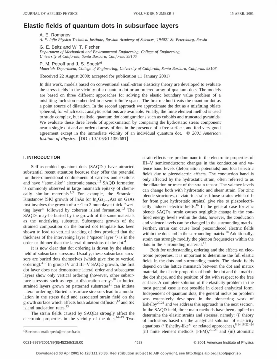
The finite element method is best suited to modelingelastic fields associated with inclusion geometries more cplex than ellipsoids. For the creation of the meshes, we ua widely available finite-element analysis software applition, ABAQUS. ABAQUS permits the closely controlled genertion of finite-element meshes through the use of input ficontaining complete instructions for node-by-node aelement-by-element mesh specification, along with impotion of boundary conditions. For a typical trapezoidal incsion within a matrix unit cell, elastic solutions may be aproximated using a finite-element mesh comprising oquadrant of an arbitrarily deep matrix unit cell, with apprpriate boundary conditions imposed at the lateral facMeshes generated included one quarter of a cuboidal or tezoidal inclusion, at various depths, embedded in a matriidentical elastic properties~see Fig. 4!. The mesh uses eightnode linear brick elements withm51 andn51/3. The mis-match strainf was taken as unity by identifying the thermexpansion strain in the inclusion,aDT, with unity. In thisfashion, any value off may be considered due to linearity.
Depths of the inclusion centroid varied between 3a3 and12a3 , for direct comparison with point source and ellipsoidinclusion results~recall a3 denotes the half-height of the elipsoidal inclusion!. The FEM domain has lateral dimensionof 6a3 in each direction, appropriate for an interinclusiospacing of 12a3 . For the inclusion shape, truncation anglof 0° and 30° were used~see inset, Fig. 4!. The former werefer to as a cuboid, and the latter a trapezoid. The latdimension of the inclusion is determined by enforcing thatvolume is identical to that of an ellipsoidal inclusion with thsame height, 2a3 . With the volume and thickness fixedthere is an inclusion base dimension associated with echoice of truncation anglea. The inclusions consist of 125evenly spaced elements, while the matrix elements includdimensional bias such that they become larger near thewalls, but smaller again as they approach the free surfac
Two general types of cases were investigated. The splest was the case of a single inclusion submerged in a sinfinite half space. The second type of case involved anfinite two-dimensional array of submerged inclusions. T
Downloaded 03 Apr 2001 to 128.111.70.86. Redistribution subjec
-
h
ef
c-l-
f-
ed-
sdi---e
s.p-
of
l
als
ch
aar.-i--
e
latter is more difficult to approximate using analytical aproaches because of the sum given by Eq.~3!. Somewhatsurprisingly, however, the periodic case presents fewerstacles to the finite-element approach than does the singcase.
For models of a single trapezoidal inclusion submergin a semi-infinite half space, we insist that normal displament must vanish at the two walls in contact with the incsion, consistent with the division of the inclusion~and matrixunit cell! into symmetric quadrants.
The bottom surface is constrained similarly, althoughtype of condition imposed at the bottom is less importathan the depth, which should be sufficiently large to be csidered ‘‘far field.’’ It must be admitted that the use of thsame boundary condition as that imposed at the lateral win contact with the inclusion does, in fact, give rise tosimilar periodicity in depth, which is not intended. Howevewith a large dimension of matrix below the inclusion, theffect of this depth image stress field will be minimal. Wcould just as easily use a fully encastered or free boundcondition~or any other that would result in a traction-free ffield surface condition!, so long as the depth is large an
FIG. 4. Mesh used in finite element calculations of elastic fields for~a!cuboidal (a50°), and ~b! trapezoidal (a530 °) quantum dot configura-tions. One quarter of the domain is needed in this calculation due to foursymmetry about the longitudinal axis. The inset shows the critical pareters used to describe the geometry of the quantum dot, including thecation anglea. The depthh is always taken from the centroid of the quantum dot, and the lateral dimension of the dot is chosen such that its volis the same as an ellipsoidal dot discussed in Fig. 3.
t to AIP copyright, see http://ojps.aip.org/japo/japcr.jsp
l-oioixteleit
eeaa
oee
ca
lls
ofns.rorall,
in-nd
sub-is-p-ere
dtis
For
ight
ceti-omlot
ves-s thethegthrete
e-as
yticfar
astiedtsthe
ter-sult,
his
tohen in
er afth
In
eth
4528 J. Appl. Phys., Vol. 89, No. 8, 15 April 2001 Romanov et al.
inclusion volume is small in comparison to the matrix voume. Since the intention is to simulate a semi-infinite dmain, the depth of the matrix below the deepest inclusmust be ‘‘much larger’’ than the thickness of the matrseparating the inclusion from the surface. For a finielement model limited to a relatively small number of ements, this requirement becomes increasingly costly wlarger quantum dot submergences. In each case, we makdepth of the overall mesh large enough that there is at lfour times more matrix below the base of the inclusion thabove it.
The two remaining lateral walls in the mesh for the islated quantum dot must not reflect a symmetry betwgroups of four unit cells~to do so would imply an infinitetwo-dimensional array of submerged inclusions!. Rather, weuse a condition similar to that used at the bottom surfathat is, we require that the distance between the inclusionthe far lateral walls be large.
For the periodic case, symmetry was enforced withzero normal displacement condition at all four lateral wa
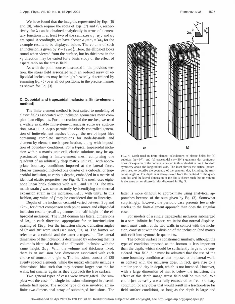
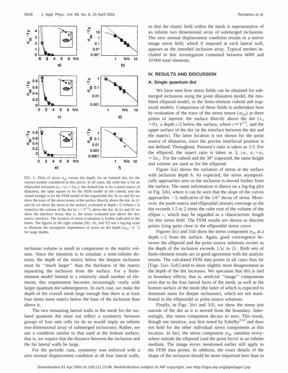
FIG. 5. Plots of stressskk versus dot depth, for an isolated dot, for thvarious models considered in this article. In all cases, the solid line is foellipsoidal inclusion (a15a253a3); the dashed line is for a point source odilatation, the open square is for the FEM model of the cuboid, andclosed triangle is for the FEM model of the trapezoidal dot. In~a! and~b! weshow the trace of the stress tensor at the surface directly above the dot.~c!and~d! we show the stress at the surface, evaluated at depthc/2 ~wherec isrelated to the volume of the dot byc5V1/3!, above the dot. In~e! and~f! weshow the interface stress, that is, the stress evaluated just above thmatrix interface. The location of stress evaluation is further indicated ininsets. The figures in the right column@~b!, ~d!, and~f!# use a log-log scaleto illustrate the asymptotic dependence of stress on dot depth (skk;h23)for large depths.
Downloaded 03 Apr 2001 to 128.111.70.86. Redistribution subjec
-n
--hthest
n
-n
e,nd
a,
so that the elastic field within the mesh is representativean infinite two dimensional array of submerged inclusioThe zero normal displacement condition results in a mirimage stress field, which if imposed at each lateral wappears as the intended inclusion array. Typical meshescluded in this investigation contained between 6000 a10 000 total elements.
IV. RESULTS AND DISCUSSION
A. Single quantum dot
We have seen how stress fields can be obtained formerged inclusions using the point dilatation model, the mfitted ellipsoid model, or the finite-element cuboid and traezoid models. Comparison of these fields is undertaken hby evaluation of the trace of the stress tensor (skk) at threepoints of interest: the surface directly above the dot (x3
50), a depthc/2 below the surface, wherec[V1/3, and theupper surface of the dot~at the interface between the dot anthe matrix!. The latter location is not shown for the poinsource of dilatation, since the precise interfacial positionnot defined. Throughout, Poisson’s ratio is taken as 1/3.the ellipsoid, the aspect ratio is taken as 3, i.e.,a15a2
53a3 . For the cuboid and the 30° trapezoid, the same heand volume are used as for the ellipsoid.
Figure 5~a! shows the variation of stress at the surfawith inclusion depthh. As expected, the stress asymptocally approaches zero as the inclusion is moved further frthe surface. The same information is shown on a log-log pin Fig. 5~b!, where it can be seen that the slope of the curapproaches23, indicative of the 1/h3 decay of stress. Moreover, the point source and ellipsoidal stresses converge adot exceeds 1.5 to 2 times the cube root of the volume ofellipse c, which may be regarded as a characteristic lenfor this stress field. The FEM results are shown as discpoints lying quite close to the ellipsoidal stress curve.
Figures 5~c! and 5~d! show the stress componentskk at adepth c/2 from the surface. Again, good convergence btween the ellipsoid and the point source solutions occursthe depth of the inclusion exceeds 1.5c to 2c. Both sets offinite-element results are in good agreement with the analresults. The calculated FEM data points in all cases thus@Figs. 5~a!–5~d!# tend to show slightly more disagreementthe depth of the dot increases. We speculate that this isto boundary effects, that is, artificial ‘‘image’’ componenexist due to the four lateral faces of the mesh, as well asbottom surface of the mesh~the latter of which is expected todominate more for deeper inclusions!, which are not mani-fested in the ellipsoidal or point source solutions.
Finally, in Figs. 5~e! and 5~f!, we show the stress jusoutside of the dot as it is moved from the boundary. Intestingly, this stress component decays to zero. This rethough not intuitive, was first noted by Eshelby9,10 and doesnot hold for the other individual stress components at tlocation. In fact, the stress componentskk vanishes every-where outside the ellipsoid~and the point force! in an infinitemedium. The image errors mentioned earlier still applythe FEM data points. In addition, the exact details of tshape of the inclusion should be more important here tha
n
e
dot/e
t to AIP copyright, see http://ojps.aip.org/japo/japcr.jsp

atiicao
ativeicatedo
re
4529J. Appl. Phys., Vol. 89, No. 8, 15 April 2001 Romanov et al.
FIG. 6. Contour plots of the trace of the stress tensor at the surfaceskk ~inunits of fm!, for an array of quantum dots at depth 3a3 and spacingl
512a3 . In all cases, positive stresses are denoted by a solid line, negvalues are denoted by a dashed line, and a zero value of stress is indby the long dashes.~a! Array of point dilatations: values of the nonzercontours are~1! 20.3, ~2! 20.2, ~3! 0.3, and~4! 0.8, with a minimum of20.31 and a maximum of 3.3.~b! Array of ellipsoids (a15a253a3): val-ues of the nonzero contours are~1! 20.4, ~2! 20.3, ~3! 20.2, ~4! 0.3, ~5!1.0, and~6! 1.5, with a minimum of20.42 and a maximum of 1.8.~c! Arrayof cuboids: values of the nonzero contours are~1! 20.38, ~2! 20.3, ~3!20.2,~4! 0.3,~5! 1.0, and~6! 1.5, with a minimum of20.4 and a maximumof 1.9. ~d! Array of trapezoids: values of the nonzero contours are~1!20.29,~2! 20.25,~3! 20.1, ~4! 0.3, ~5! 0.7, and~6! 1.0, with a minimum of20.28 and a maximum of 1.9.
Downloaded 03 Apr 2001 to 128.111.70.86. Redistribution subjec
veted
FIG. 7. Contour plots of the trace of the stress tensor at the surfaceskk ~inunits of fm!, for an array of quantum dots at depth 6a3 and spacingl
512a3 . In all cases, positive stresses are denoted by a solid line, negvalues are denoted by a dashed line, and a zero value of stress is indby the long dashes.~a! Array of point dilatations: values of the nonzercontours are~1! 20.1, ~2! 20.05, ~3! 20.02, ~4! 0.05, ~5! 0.1, and~6! 0.2,with a minimum of20.11 and a maximum of 0.3.~b! Array of ellipsoids(a15a253a3): values of the nonzero contours are~1! 20.1, ~2! 20.05,~3!20.02, ~4! 0.05, ~5! 0.1, and~6! 0.2, with a minimum of20.14 and amaximum of 0.28.~c! Array of cuboids: values of the nonzero contours a~1! 20.1, ~2! 20.05, ~3! 20.02, ~4! 0.05, ~5! 0.1, and~6! 0.2, with a mini-mum of 20.13 and a maximum of 0.25.~d! Array of trapezoids: values ofthe nonzero contours are~1! 20.09,~2! 20.05,~3! 20.02,~4! 0.05,~5! 0.1,and ~6! 0.15, with a minimum of20.1 and a maximum of 0.22.
t to AIP copyright, see http://ojps.aip.org/japo/japcr.jsp

ap-ree-
at
thendesstionface.y
n-aresashere-thethepseid,er. Ase to
an-ther attryvedisith
ofs
entpth.theareeri-er,bead-
-
f
es,ex-ent
as
f
4530 J. Appl. Phys., Vol. 89, No. 8, 15 April 2001 Romanov et al.
FIG. 8. Contour plots of surface stressskk ~in units of f m!, for an array ofquantum dots at depth 12a3 and spacingl 512a3 . In all cases, positivestresses are denoted by a solid line, negative values are denoted by a dline, and a zero value of stress is indicated by the long dashes.~a! Array ofpoint dilatations: values of the nonzero contours are~1! 20.005,~2! 20.004,~3! 20.002,~4! 0.002,~5! 0.005, and~6! 0.009, with a minimum of20.0071and a maximum of 0.0093.~b! Array of ellipsoids (a15a253a3): values ofthe nonzero contours are~1! 20.006,~2! 20.004,~3! 20.002,~4! 0.002,~5!0.005, and~6! 0.008, with a minimum of20.0072 and a maximum o0.0093.~c! Array of cuboids. The values of the nonzero contours are~1!20.005,~2! 20.004,~3! 20.002,~4! 0.002,~5! 0.005, and~6! 0.007, with aminimum of 20.0066 and a maximum of 0.0083.~d! Array of trapezoids:values of the nonzero contours are~1! 20.004,~2! 20.002,~3! 20.001,~4!0.001,~5! 0.003, and~6! 0.005, with a minimum of20.0056 and a maxi-mum of 0.0068.
Downloaded 03 Apr 2001 to 128.111.70.86. Redistribution subjec
the earlier cases; therefore, it is not surprising that the trezoid and cuboid results show a modest level of disagment with the analytical solution.
B. Ordered array of dots
In this section we consider a square array of dotsvarious prescribed depthsh and spacingl 512a3 @see Fig.3~b!#. We continue to use the stress trace (skk) as a basis forcomparison. Specifically, we use surface contour plots ofstress trace predicted by the point dilatation, ellipsoid, afinite-element models. These plots for the trace of the strtensor at the surface are shown in Figs. 6–8. No evaluawas made of differences between stresses below the sur
In Figs. 6~a!–6~d! we show stress contours for an arraof dots at depthh53a3 . Specific values denoted by the cotours, as well as the maximum and minimum values,given in the caption in units off m. The extrema of the stresdistribution appear directly above a given dot, as welldirectly above a square quadruplet of four dots. Of all tdepths we consider, the dissimilarities between all foursults are most evident here, due to the close proximity ofdots to the surface. Moreover, we note the symmetry ofstress distributions due to the point dilatation and the elliare of a circular nature, while for the cuboid and trapezothe perfect circular symmetry is slightly broken. In othwords, the contours reflect the shape of the particular dotthe dot moves closer to the surface, we expect this featurbecome more dominant.
In Fig. 7 the corresponding results are shown forarray of dots at depthh56a3 . There is moderate quantitative agreement between all four models, indicating thatprecise shape of the dot is a much less important factothis depth. In addition, elements of a square-like symmebegin to appear in the stress distribution at locations remofrom the point directly above any given dot. Moreover, thsquare-like motif in the stress contours in rotated by 45° wrespect to the original square lattice of dots.
Finally, in Fig. 8, the results are shown for an arraydots at depthh512a3 . A square-like symmetry to the stresdistribution ~also rotated by 45°!, similar to the previouscase, is more pervasive. The quantitative level of agreemis good, but not nearly as good as expected for this deSeveral sources of error can be identified that can explaindisagreement: in the FEM results, no image contributionsexpected from the lateral walls of the mesh, since the podic nature of the geometry is perfectly captured. Howevthe image error from the bottom surface is expected tomost prevalent at this depth than in the earlier cases. Indition, the number of terms needed for the sums in Eq.~3! toobtain good convergence~applicable to the point of dilatation and ellipsoid arrays! became exceedingy large whenh isgreater than;10a3 , and accordingly, we are confident othe results in Figs. 8~a! and 8~b! only to within about65%.
V. SUMMARY
We conclude that over a wide range of geometrisimple analytical models based on ellipsoids, or to sometent based on point dilatations, may be the most effici
hed
t to AIP copyright, see http://ojps.aip.org/japo/japcr.jsp

st
ell inenidncin
tep
soutlle
s
ese
s
b
lee
atoW
t oan
u
erro
ys.
v,
nol.
l.
.
na,
l.
h-
.
e
4531J. Appl. Phys., Vol. 89, No. 8, 15 April 2001 Romanov et al.
means of obtaining reasonable estimates of the elastresses associated with quantum dots. In particular,finite-element models described in this article very closmatched the predictions of the ellipsoidal inclusion modethe isolated and periodic cases. This close correspondbetween the analytical ellipsoid and the FEM cubotrapezoid persists to remarkably shallow submergedepths, indicating a potentially high usefulness in modeltypical three-dimensional dot array geometries.
The exception to the close match of ellipsoid and finielement models is the case of predicted stresses at the uinterface between the dot and the matrix. The interface liea region characterized by large stress gradients, which whave an expected detrimental effect on the accuracy offinite-element models. However, even with an exceptionafine mesh, differences in modeled dot shape should bepected to give rise to variations in predicted stress valuethe interface. These differences would be attributed bothvariations in interface depth and to differences in local strconcentrations at the top center interface of dots of differshape.
Of perhaps more use to the modeler of SAQD systemthat only one ‘‘primary’’ dot~or region associated therewith!should be considered in detail, while all other dots mayapproximated as ellipsoids or point sources.
Finally, we note that the calculations in this articclearly show that quantum dots either on the free surfacnear the free surface lead to large hydrostatic stressesstrains in the matrix. The hydrostatic strain will leadchanges in both the conduction and valence band levels.believe that this effect should be included in the treatmenthe matrix electronic properties for near surface dotsstressors.
ACKNOWLEDGMENTS
This work was supported by the AFOSR Award~Dr.Dan Johnstone, Contract Monitor!. A.E.R. was supported inpart by Grant No. 97-3006 from the Russian Research Cocil ‘‘Physics of Solid Nanostructures.’’
1D. Leonard, K. Pond, and P. Petroff, Phys. Rev. B50, 11687~1994!.2A. Zunger, MRS Bull.23, 15 ~1998!.3D. Bimberg, M. Grubdmann, and N. N. Ledentsov, MRS Bull.23, 31~1998!.
4S. Rouvimov, Z. Liliental-Weber, W. Swider, J. Washburn, E. R. WebA. Sasaki, A. Wakahara, Y. Furkawa, T. Abe, and S. Noda, J. ElectMater.27, 427 ~1998!.
Downloaded 03 Apr 2001 to 128.111.70.86. Redistribution subjec
tichey
ce/e
g
-perinld
heyx-attos
nt
is
e
ornd
efd
n-
,n.
5Q. Xie, A. Madhukar, P. Chen, and N. P. Kobayashi, Phys. Rev. Lett.75,2542 ~1995!.
6V. A. Shchukin, N. N. Ledentsov, P. S. Kop’ev, and D. Bimberg, PhRev. Lett.75, 2968~1995!.
7J. Tersoff, C. Teichert, and M. G. Lagally, Phys. Rev. Lett.76, 1675~1996!.
8V. A. Shchukin, D. Bimberg, V. G. Malyshkin, and N. N. LedentsoPhys. Rev. B57, 12262~1998!.
9Y. W. Zhang, S. J. Xu, and C.-H. Chiu, Appl. Phys. Lett.74, 1809~1999!.10A. E. Romanov, P. M. Petroff, and J. S. Speck, Appl. Phys. Lett.74, 2280
~1999!.11H. Lee, J. A. Johnson, J. S. Speck, and P. M. Petroff, J. Vac. Sci. Tech
~to be published!.12F. Jonsdottir and L. B. Freund, Mech. Mater.20, 337 ~1995!.13T. R. Mattsson and H. Metiu, Appl. Phys. Lett.75, 926 ~1999!.14M. Grundmann, O. Stier, and D. Bimberg, Phys. Rev. B52, 11969~1995!.15H. Jiang and J. Singh, Physica E~Amsterdam! 2, 614 ~1998!.16J. H. Davies, J. Appl. Phys.84, 1358~1998!.17J. Groenen, C. Priester, and R. Carles, Phys. Rev. B60, 16013~1999!.18J. H. Davies, Appl. Phys. Lett.75, 4142~1999!.19J. A. Barker and E. P. O’Reilly, Phys. Rev. B61, 13840~2000!.20J. D. Eshelby, Proc. R. Soc. London, Ser. A241, 376 ~1957!.21J. D. Eshelby, Proc. R. Soc. London, Ser. A252, 561 ~1959!.22J. R. Downes, D. A. Faux, and E. P. O’Reilly, J. Appl. Phys.81, 6700
~1997!.23A. D. Andreev, J. R. Downes, D. A. Faux, and E. P. O’Reilly, J. App
Phys.86, 297 ~1999!.24G. S. Pearson and D. A. Faux, J. Appl. Phys.88, 730 ~2000!.25T. Benabbas, P. Franc¸ois, Y. Androussi, and A. Lefebvre, J. Appl. Phys
80, 2763~1996!.26A. Ponchet, D. Lacombe, L. Durand, D. Alquier, and J.-M. Cardon
Appl. Phys. Lett.72, 2984~1998!.27T. Benabbas, Y. Androussi, and A. Lefebvre, J. Appl. Phys.86, 1945
~1999!.28G. Muralidharan, Jpn. J. Appl. Phys., Part 239, L658 ~2000!.29W. Yu and A. Madhukar, Phys. Rev. B79, 905 ~1997!.30C. Pryor, J. Kim, L. W. Wang, A. J. Williamson, and A. Zunger, J. App
Phys.83, 2548~1998!.31M. E. Bachlechner, A. Omeltchenko, A. Nakano, R. K. Kalia, P. Vas
ishta, I. Ebbsjo¨, A. Madhukar, and P. Messina, Appl. Phys. Lett.72, 1969~1998!.
32Y. P. Chiu, J. Appl. Mech.44, 587 ~1977!.33Y. P. Chiu, J. Appl. Mech.45, 302 ~1978!.34T. Mura, Micromechanics of Defects in Solids~Martinus Nijhoff, Boston,
1987!.35K. Seo and T. Mura, J. Appl. Mech.46, 568 ~1979!.36J. P. Hirth and J. Lothe,Theory of Dislocations~Wiley, New York, 1982!.37R. De Wit, Solid State Phys.10, 249 ~1960!.38R. D. Mindlin and D. H. Cheng, J. Appl. Phys.21, 931 ~1950!.39J. C. M. Li, Metall. Trans. A9A, 1353~1978!.40K. L. Malyshev, M. Yu. Gutkin, A. E. Romanov, A. A. Sitnikova, and L
M. Sorokin, Sov. Phys. Solid State30, 1176~1988!.41V. I. Vladimirov, M. Yu. Gutkin, and A. E. Romanov, Mech. Composit
Mater.3, 450 ~1987!.42B. Michel, Arch. Mech.32, 73 ~1980!.43F. Loges, B. Michel, and A. Christ, Z. Angew. Math. Mech.65, 65 ~1985!.
t to AIP copyright, see http://ojps.aip.org/japo/japcr.jsp